
SECTION E - ENGINES
CAUTION:
HSV vehicles are equipped with a Supplemental Restraint System (SRS). An SRS consists of seat belt
pre-tensioners (fitted to all front seats), and a driver’s-side air bag or a driver’s-side air bag AND a
passenger’s-sid e air bag and left and right hand side air bags.. Ref er to CAUTIO NS, Section 12M , of the
VS Series Service Informatio n or Section 12M , of the VT Series II Service Information before performing
any service operation on or around SRS components, the steering mechanism or wiring. Failure to
follow the CAUTIONS could result in personal injury or unnecessary SRS system repairs.
PURPOSE
The purpos e of this s upplement is to pr ovide inf or mation on the various engine pac kages f itted to the HSV VT2 and
HSV VS models. This inform ation is designed to supplem ent that given in the Holden VT Series II and VS Series
Service Info rmation, and details are given where diff erences occ ur between the HSV models , and st andard Holden
models. A series of instruction drawings detail the design changes and indicate specific part numbers, fitting
instructions and relevant notes for vehicle servicing.
NOTE: If specific technical data on a HSV model is not contained in this supplement, obtain data for that model
from Section 6A3 - Engine Mechanical - GEN III V8 Engine of the VT Series II Service Information or from the
relevant VS Series Service Information. References are made throughout this section to Holden Service
Information, to assist in providing information for specific service operations.
CAUTION: When hoisting (or jacking) HSV models, ensure that the lifting head of the hoist lifts on the chassis
before the arm of the hoist contacts the side-skirt
Techline

1. ENGINES - GENERAL INFORMATION
W ith the intr oduction of VT 2 GTS, HSV will have its f ourth engine variant available. T hese will include two variants
of the Chevrolet sourced LS1 5.7 litre alloy V8, the supercharged 3.8 litre Holden V6, and the final iteration of the
HSV specific 195kW 5.0 litre Holden V8. These engines are spread across the HSV range, with the LS1 and
supercharged engines being available on VT2 and WH models, while the 195kW engine is now only available on
the VS III Maloo.
The prem ium HSV engine for VT2 is the 300kW vers ion of the LS1 (designated C4B) available with the VT 2 GT S.
This engine was developed from the base 250 LS1 engine, with assistance from Callaway Cars in the USA. The
modifications include a new, high lift camshaft, upgraded ovate wire valve springs and associated components.
This engine is easily the most powerful yet offered by HSV, putting the performance of the GTS into the exotic
range.
The 250 LS1 engine package consists of an unmodified base engine, and uses an HSV specific calibration to
optimise the benefits of the specific HSV exhaust and inlet systems. As part of the development process, these
changes have then been proven thr ough ex tensive tes ting thr oughout Aus tralia, as is the c ase with all engines f itted
to HSV models.
From the start of 1999, the VS III Maloo and VS III Grange has been available with the 195k W engine developed f or
VT Series I. For more information on this engine (also fitted to HSV XU8) refer to the HSV VT Series I Service
Information.
Although the 195i and 300kW C4B engines may be fitted with unique HSV c omponents ( s uch as cams haf t, pis tons,
valve train and the like), as s embly procedures, torque s ettings , engine diagnosis , valve timing proc edures and other
parameters are the same as for the standard GMHA product unless stated otherwise in this Supplement. The
various HSV engines are discussed in the following paragraphs.
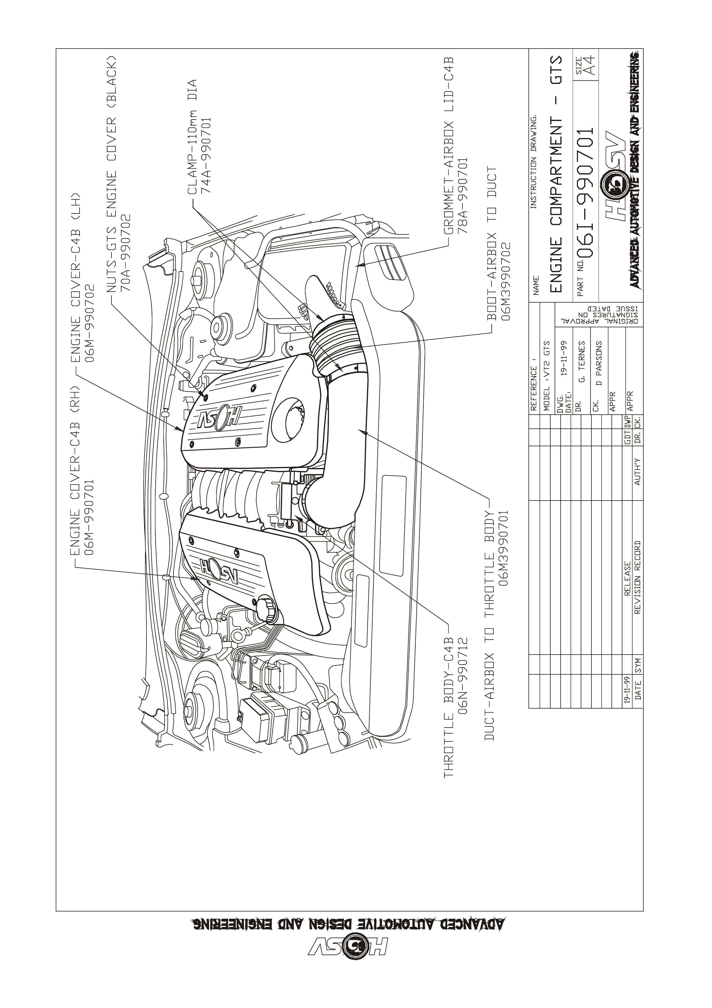
Engine Dress Covers - The HSV LS1 V8 engine is fitted with a specific decorative engine cover. This is a large
one piece plastic cover that enc ases the f uel r ail and c oil packs, as well as the inlet manif old and thr ottle body. T he
cover includes a moulded-in HSV Lion and Helmet logo, and is painted black, with silver highlights.
The HSV C4B LS1 V8 engine comes with specifically designed engine covers, that cover the two banks of the
engine, leaving the centre of the inlet manifold exposed. The covers are moulded in a red polypropylene
copolymer, and incorporate HSV logos and 300kW signage.
HSV supercharged V6 engines use the standar d silver V6 S/C engine cover, but have a black 180 badge applied to
the leading edge of the cover.
HSV 195 engines have a 3 piece cast aluminium cover that is powder coated bright red. Part numbers for these
components are:
LS1
06M-990601 COVER ASM: LS-1 ENGINE (SILVER HIGHLIGHT)
06M-991901 COVER ASM: LS-1 SV99 ENGINE (HACKETT GOLD HIGHLIGHT)
C4B LS1
06M-990701 COVER - ENGINE RH-GTS
06M-990702 COVER - ENGINE LH-GTS
V6 S/C
06M-971702 BADGE: "180" (ENGINE COVER)
195
06M-970301B7 COVER ASM: FUEL RAIL RHS
06M-970302B7 COVER ASM: FUEL RAIL LHS
06N-970302B7 COVER ASM: THROTTLE BODY

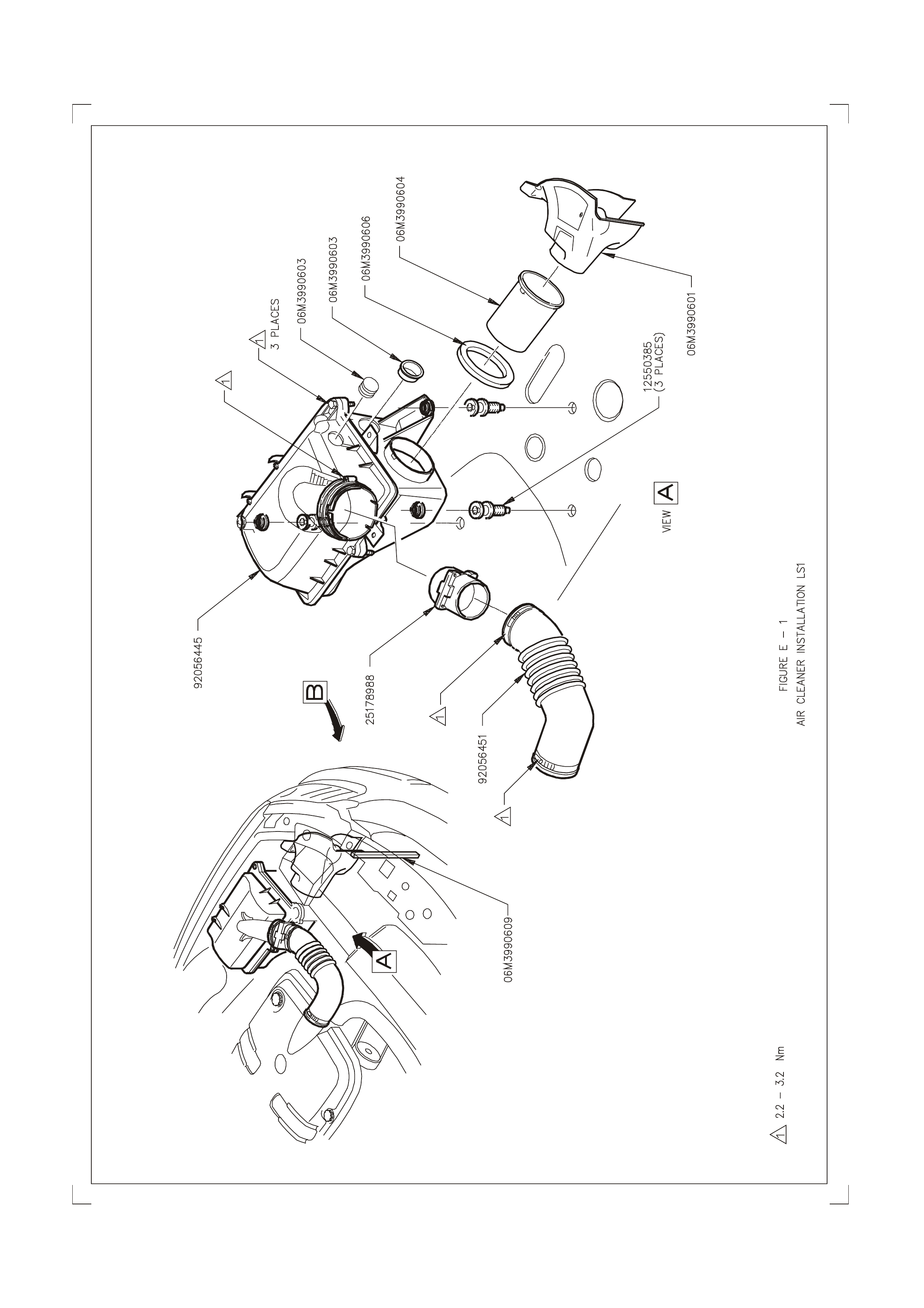
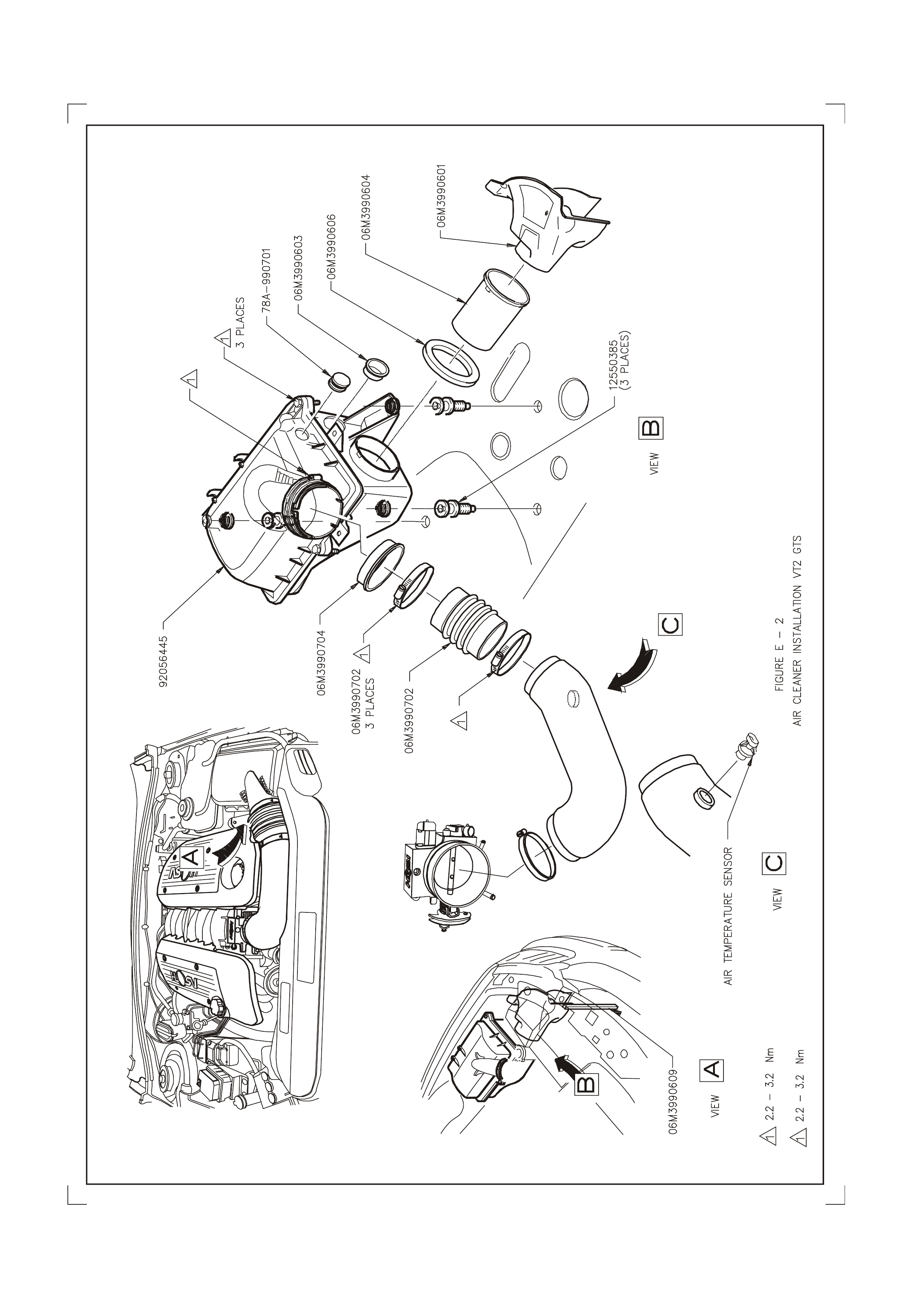
Engine Air Induction System - The air induction system on the HSV C4B LS1 varies from the standard Holden
system, (and also that used on the 250kW LS1) in that it does not use the original equipm ent Mass Air Flow (MAF)
Sensor. Instead, the engine runs on a speed/dens ity based calibration system, us ing a Manifold Abso lute Pressur e
(MAP) Sensor, Intake Air Temperature (IAT) Sensor and engine rpm to calculate the mass of air entering the
engine. Due to this change, the C4B engine uses a specific duct and boot combination from the airbox to the
throttle body. As part of these changes, the IAT sensor is relocated to the inlet duct, as this gives faster response to
changing intake air temperature changes.
The res t of the intake s ystem is comm on with the 250 LS1 introduced with VT2, and this inc orporates m uch of the
standard Holden system, with the difference being concentrated on ensuring the engine receives as m uch cold air
as possible. This was found to give the greatest perform ance advantage, and also helped r educe the perfor mance
lost due to stop start warm weather driving.
The intake system on the HSV LS1 uses the standard Holden air filter element, Mass Air Flow (MAF) Sensor and
Inlet Air Te mperatur e (IAT) sensor. Servic e requirem ents for the f ilter are desc ribed in the Holden service m anual,
and no adjustment is possible on the MAF sensor.
To remove the HSV inlet duc t, it is neces sary to release the coolant system surge tank f rom its locating s tuds, then
pull the airbox base away from its locating studs, pulling the rear away first, and then away from the inlet duct. T o
rem ove the duct, it is best to take the outboard edge of the duct and rotate it inboar d and up to c lear bodywork, then
pull out.
For replacement part numbers see Figure E1 and Figure E2 and 06I-990701.
For inf ormation and diagram s of intak e system for HSV V6 S/C m odels, see Section E of the HSV VT Series I
Information.
Specific HSV Engine Components - As the HSV C4B LS1 engine is a specific assembly for HSV, there are
several components that warrant a specific mention in this section. These components are the specific valve
springs, which are of a constant diameter, and made from an oval formed wire, specific Titanium valve spring
retainers to m atch the s prings, and a new, high lift cam shaf t. Details of this new cam shaft are detailed in the table
below:
HSV C4B CAMSHAFT SPECIFICATION
INTAKE EXHAUST
Lobe Lift 8.331mm (0.327”) 8.356mm (0.329”)
Duration at 1.27mm (0.050”)
lift 184.7° 189.0°
Duration 278.8° 283.0°
Valve Timing at 1.27mm
(0.050”) lift
-Open
-Close
25.1° ATDC
29.8° ABDC
31.3° BBDC
22.3° BTDC
Also fitted on the HSV C4B engine ar e specific, high perf ormanc e connecting rod bolts. T hese bolts are specif ic to
HSV and standard connecting rod bolts should not be used.
Torquing of this bolt is different to the standard LS1 procedure and is as follows:
Step 1 Clean thread thoroughly with an oil based solvent.
Step 2 Lubricate thread with clean engine oil (10W-50W or similar).
Step 3 After ensuring cap is seated correctly and both bolts evenly,
torque bolts to 30-35Nm, then to 65-70Nm.
Note: Total bolt stretch should be 0.178mm (0.007”) ± 0.0127mm (0.0005”)
For details on HSV spec ific engine com ponents f itted to the VS III HSV Maloo and VS III Gr ange 195i vehicles , s ee
the relevant section in the HSV VT V8 Service Supplement.

2. CLUBSPORT, SV99, SENATOR AND GRANGE 250 LS1
2.1 GENERAL DESCRIPTION.
All HSV VT2 V8 models use the new, Chevrolet developed LS1 engine. This engine is common with the Holden
GEN III V8 engine, and has a capacity of 5668cm3, produced by a bore of 99.00mm and a stroke of 92.00 mm. The
compression ratio for this engine is 10.1:1.
The bas e engine design is that of a 90° V8, two valve per c ylinder engine. The engine features an alum inium block
and heads, with cast iron sleeves cast into the block during manufacture, while the heads have powdered metal
valve guides and seats pressed in place.
For more inf ormation regar ding the LS1 engine, r ef er to Sect ion 6A3 - Engine M echanical - G EN III V8 Engine of
the VT Series II Service Information.
The HSV LS1 engine does have an optimised Cold air Induction System, a Low Restr iction Exhaus t System and an
Optimised Engine Management System. These improvements allow the engine to develop 250kW at 5,600 rpm
and 475Nm at 4,400 rpm.

2.2 SERVICE OPERATIONS
The HSV LS1 engine fitted to ClubSport, Senator and Grange models is to be serviced in accordance with the
procedures detailed in Section 6A3 - Engine Mechanical - GEN III V8 Engine of the VT Series II Service
Information.
All HSV models however, are f itted with a specific HSV PCM to control the engine m anagem ent system . The PCM
contains a s pecific engine (and in the cas e of automatic vehicles, transm ission) calibr ation, which can be identified
and serviced by the part numbers in the following chart. These PCMs contain a calibration that is available only
through HSV spare parts, and cannot be re-program med by HSV or Holden Service T echnicians as is the c ase for
Holden calibrations.
P/NO Description Delco/Holden P/N
12F-990601 PCM-GEN3-Blank 09368041
12F-990602 Calibration-HSV G3 Manual
12F-990603 Calibration-HSV G3 Auto
12F-990604 PCM-HSV G3 Manual (Calibrated)
12F-990605 PCM-HSV G3 Auto (Calibrated)

3. GTS 300 C4B LS1
3.1 GENERAL DESCRIPTION.
The HSV GTS sees the return of a second tier engine to HSV. With a Holden production option designation of
C4B, this engine is based on the s tandard LS1 engine com mon with the 250kW m odels. T he differences over the
LS1 engine are related to cylinder head and camshaft modifications.
The engine hardware was developed in conjunction with Callaway Cars in the USA, and the rest of the vehicle
development and validation carried out by HSV.
The changes included a specific camshaft, upgraded valve springs and titanium valve spring retainers, stainless
steel intake and exhaust valves, revised cylinder head porting and combustion chamber modifications, and a
specific, larger bore machined throttle body. The throttle body is the easiest identifier for the engine, as it is
anodised bright red. Additional marking is also evident on the cylinder heads, where the C4B designation is
machined into the head, on the exhaust port face.
The swept volume of the C4B LS1 engine is unchanged from the LS1 engine, although, due to the combustion
chamber modifications the compression ratio has been lowered slightly to 9.95:1. This gives improved engine
performance across the entire speed range, as it allows more spark advance, due to less knock sensitivity, to be
calibrated into the engine, particularly at low to medium engine speeds.
The HSV C4B LS1 engine uses a high flow induction system, that does not require a Mass Air Flow Meter, and
incorporates this with the optimised Cold air Induction System, a Low Restriction Exhaust System (including a
specif ic, straight through design rear muf f ler) and an Optim ised Engine Managem ent System . Thes e im provem ents
allow the engine to develop 300kW at 6,000 rpm and 510 Nm at 4,800 rpm.

3.2 SERVICE OPERATIONS
The HSV C4B LS1 engine fitted to the VT2 GTS is to be serviced in accordance with the procedures detailed in
Section 6A3 - Engine Mechanical - GEN III V8 Engine of the VT Series II Service Information however, due to the
deletion of the MAF sensor, the following service bulletin was released by HSV.
Dealer Bulletin - HSV GTS MAF Sensor Deletion
As part of the modifications made by HSV to achieve the 300kW output of the C4B engine, it was decided to use
the less restrictive Speed/Density calibration system. This allowed HSV to remove the Mass Air Flow (MAF) Sensor
from the intake system, removing the restriction it creates at high engine speeds advance requirements of the
engine by using a software model. This model incorporates inputs from the Manifold Absolute Pressure (MAP)
Sensor, along with the Inlet Air Temperature (IAT) Sensor and the engine rpm to predict airflow rate and volume
into the engine, and therefore fuelling requirements.
One effect of this system is that the engine no longer runs on 2 separate spark maps, resulting in the potential f or
som e audible knoc k under c ertain conditions when using 91 Ron Unleaded. It should be noted that the engine still
runs an advanced knock control, and a level of detonation will not harm the engine.
When carrying out diagnostic work on the HSV VT2 GTS, it is important that you are aware that the PCM will always
log Diagnostic Trouble Code 0102 - Mass Air Flow Sensor Circuit Low Frequency. The calibration has been
modified to prevent the Malf unction Indic ator Lamp f rom illuminating at this DTC the Ins tr ument will als o log an f ault
code in this case DTC 19, which indicates that the instrument has detected a fault code in the PCM.
HSV GT S vehicles are also fitted with a PCM containing a s pecific engine calibr ation. This PCM is serviced in the
same manner as that for the HSV LS1 PCM.
P/NO Description Delco/Holden P/N
12F-990601 PCM-GEN3-Blank 09368041
12F-990701 Calibration-HSV C4B Manual
12F-990702 PCM-HSV C4B Manual (Calibrated)

3.3 ENGINE ASSEMBLY - SERVICE
Specific HSV components that have been included in the LS1 C4B 300 engine assembly are detailed below. The
part numbers for these components are listed for servicing requirements.
Part Number Description
06Z-990701 ENGINE ASM-LS1 C4B AS SHIPPED
06X-990702 CAMSHAFT-C4B
06X-990703 VALVE SPRING-C4B
06X-990704 RETAINER-VALVE SPRING
06X-990705 SHIM-0.030"
06X-990706 SHIM-0.015"
06X-990707 VALVE-EXHAUST-C4B
06X-990708 VALVE-INLET-C4B
06A-990709 CYLINDER HEAD-MACHINED-C4B
06A-990710 CYLINDER HEAD ASM-C4B
73A-990711 BOLT-CONNECTING ROD
06N-990712 THROTTLE BODY-C4B

4. SENATOR, XU6. WH GRANGE 180 S/C
4.1 GENERAL DESCRIPTION.
The XU6, Senator and Grange Supercharged V6 vehicles are fitted with a sequential fuel-injected Holden
Supercharged V6 engine assembly. A specific package of HSV designed components are fitted to the engine to
enhance engine performance. This package incorporates a Cold Air Induction system, Low Restriction Exhaust,
and an Optimised Engine Management System. These improvements allow the engine to develop 180 kW of
power at 5000 rpm and 380 Nm of torque at 3200 rpm.
The Cold Air Induction System consis ts of a HSV designed air c leaner box and a free-f low air duct. T he assem bly
seals between the radiator support panel and hood. The Air Induction System uses the original Holden air filter
element.
The Superc harged V6 engined vehicles are fitted with a spec ific HSV ECM/PCM to c arry out engine managem ent.
The ECM/PCM’s are fitted with specific MEM-CAL’s to suit the 180i engine package.

4.2 SERVICE OPERATIONS
The 180 engine pac kage in the X U6 and Senator vehic les is to be s erviced as specif ied in Sectio n 6A1-2 - Engine
Mechanical – V6 Superchar ged Engine of the VT Ser ies I Service Inf orm ation. In addition, ECM/PCM’s and MEM-
CALS can be identified and serviced by the HSV part numbers in the following chart.
Delco - part number Delco - broadcast code HSV Service
VT 1 PCM 09363258 CNPR 12F-971701
Memcal 09363210 n/a 12F-971702
VT 2 PCM 09378768 CXWK 12F-971701
Memcal 16262786 n/a 12F-991301

5. VS III GRANGE AND VS III MALOO 195i
5.1 GENERAL DESCRIPTION
The VSIII G range and VSIII Maloo 195i vehic les ar e f itted with a development of the s equential f uel- injec ted Holden
V8 engine. Improvements to the basic engine were designed and tested by HSV, and these improvements include;
• Roller follower high-lift high-duration Cam shaft, timing sprockets and timing chain.
• New cylinder heads incorporating larger HSV valve springs.
• An improved Engine Management System - customised by HSV - to provide optimum engine
performance for all driving conditions.
The Cold Air Induction System consists of a HSV designed free-flow air duct. The assembly seals between the
radiator support panel and hood. The Air Induction System uses the original Holden air filter element. A knock
sensor is fitted on the engine and this sensor detects engine detonation under load and varies ignition timing
accordingly.
The VS III Grange and Maloo 195i vehicles are fitted with a specific HSV ECM/PCM to control the engine
management system. The ECM/PCM’s are fitted with specific MEM-CAL’s to suit the 195i engine package.

5.2 SERVICE OPERATIONS
The 195i engine fitted to VS III Maloo and VS III Grange vehicles is to be serviced as specified in
Section 6A2 - Engine Mechanical - V8 Engine of the VT Series I Servic e Inf ormation. In addition, ECM/PCMs and
MEM-CALS can be identified and serviced by the part numbers in the following chart
Delco -
Part Number Delco -
Broadcast Code HSV Service
195 Manual MEMCAL 98363158 CNPC 12F-990501
195 Auto PCM ―――
195 Auto MEMCAL 09363168 CNPD 12F-990502

5.3 ENGINE ASSEMBLY - SERVICE
Specific HSV components have been included in the 195i engine assembly. The part number for these
replacement service components and assemblies are detailed in the table below.
Part Number Description
06A2970301 Head Assembly - Cylinder
06A-211902 Seat - Valve Spring
06X-121905 Valve - Exhaust
06X-121907 Sprocket - Camshaft
06X-121908 Sprocket - Crankshaft
06X-121909 Chain - Camshaft Drive
06X-121910 Damper - Timing Chain
06X-121911 Bolt - Chain Damper to Cylinder Block
06X-211906 Spring and Damper Assembly - Valve
06X-970301 Camshaft
06Z-970301 Engine Assembly - As Shipped - Auto
06Z-970302 Engine Assembly - As Shipped - Manual
71A-111701 Washer – Header to engine —16 places
72H-381101 Bolt – Header to engine –16 places
06D-711902 Piston and Pin Assembly - 0.020" O/S
06D-711903 Piston and Pin Assembly - 0.030" O/S
06D-711904 Ring Set - Piston (STD)
06D-711905 Ring Set - Piston - 0.020" O/S
06D-711906 Ring Set - Piston - 0.030" O/S
06X-121906 Package Chain Drive
06X-711901 Valve - Exhaust - 0.008"0/S

6. XU8 195I
6.1 GENERAL DESCRIPTION
For inf ormation regar ding HSV s pecific components of the Cold Air Induction System , Fr ee F lowing exhaus t s ystem
and HSV specific Engine Control Modules, see HSV VT Series 1 Service Information.
For information regarding the 195i engine assembly, see the appropriate sections of the VS III Maloo & VS III
Grange 195i in Section 5 of this Service Information.

6.2 SERVICE OPERATIONS
The 195i engine fitted to the XU8 is to be serviced as specified in Section 6A2 - Engine Mechanical - V8 Engine of
the VT Series I Service Information.
For inform ation regarding ECN / PCM and MEM-CAL service and part num bers see the HSV VT Series 1 Service
Information of this Service Information CD.