
Engine Cooling – V6 Engine Page 6B1–1
Section 6B1
Engine Cooling – V6 Engine
ATTENTION
Before performing any Service Operation or other procedure described in this Section, refer to 00 Warnings,
Cautions and Notes for correct workshop practices with regard to safety and/or property damage.
1 General Information ...............................................................................................................................4
1.1 MY2006 VZ Models................................................................................................................................................. 4
1.2 MY2006 VZ Update Models.................................................................................................................................... 5
2 General Description ...............................................................................................................................6
2.1 Radiator Assembly ................................................................................................................................................ 6
2.2 Cooling Fans – Standard Specification ............................................................................................................... 8
Overview................................................................................................................................................................. 8
Relays................................................................................................................................................................ 9
Cooling Fans and Shroud Assembly.................................................................................................................. 9
Fan Motors....................................................................................................................................................... 10
Operation.............................................................................................................................................................. 12
Stage 1 Fan Operation..................................................................................................................................... 12
Conditions for Stage 1 Fan Operation.............................................................................................................. 13
Stage 2 Fan Operation..................................................................................................................................... 14
Conditions for Stage 2 Fan Operation.............................................................................................................. 15
2.3 Cooling Fans – High Power Specification ......................................................................................................... 17
Overview............................................................................................................................................................... 17
Relays.............................................................................................................................................................. 18
Cooling Fans and Shroud Assembly................................................................................................................ 18
Fan Motors....................................................................................................................................................... 19
Operation.............................................................................................................................................................. 20
Stage 1 Fan Operation..................................................................................................................................... 20
Conditions for Stage 1 Fan Operation.............................................................................................................. 22
Stage 2 Fan Operation..................................................................................................................................... 23
Conditions for Stage 2 Fan Operation.............................................................................................................. 24
2.4 Coolant Pump....................................................................................................................................................... 25
2.5 Coolant Outlet Housing....................................................................................................................................... 26
MY2006 VZ Models............................................................................................................................................... 26
MY2006 VZ Update............................................................................................................................................... 26
2.6 Thermostat ........................................................................................................................................................... 27
2.7 Coolant Filler Cap................................................................................................................................................ 28
MY2006 VZ HFV6 Models .................................................................................................................................... 28
MY2006 VZ Update HFV6 Models ....................................................................................................................... 28
2.8 Coolant Recovery Reservoir............................................................................................................................... 30
2.9 Air Baffle, Chutes and Shroud............................................................................................................................ 31
2.10 Engine Coolant Temperature Sensor................................................................................................................. 33
3 Service Operations...............................................................................................................................34
3.1 Service Notes....................................................................................................................................................... 34
Safety.................................................................................................................................................................... 34
Periodic Servicing................................................................................................................................................ 34
Environmental Issues.......................................................................................................................................... 34
3.2 Coolant Maintenance........................................................................................................................................... 35
Topping Up the Cooling System......................................................................................................................... 35
Testing Coolant Concentration........................................................................................................................... 36
Method 1 – Refractometer................................................................................................................................ 36
Method 2 – Hydrometer.................................................................................................................................... 38
Page 6B1–1

Engine Cooling – V6 Engine Page 6B1–2
3.3 Draining and Filling Cooling System ................................................................................................................. 39
Draining ................................................................................................................................................................ 39
Filling.................................................................................................................................................................... 39
3.4 Cleaning Cooling System.................................................................................................................................... 42
Cooling System Reverse Flush .......................................................................................................................... 42
Radiator............................................................................................................................................................ 42
Engine.............................................................................................................................................................. 43
Heater Hoses and Core.................................................................................................................................... 44
3.5 Drive Belt Tension ............................................................................................................................................... 45
Inspect .................................................................................................................................................................. 46
3.6 Coolant Hoses...................................................................................................................................................... 47
3.7 Pressure Testing.................................................................................................................................................. 49
MY2006 VZ Models............................................................................................................................................... 49
Coolant Filler Cap Pressure Testing................................................................................................................. 49
Cooling System Pressure Testing.................................................................................................................... 51
MY2006 VZ Update Models.................................................................................................................................. 52
Coolant Filler Cap Pressure Testing................................................................................................................. 52
Cooling System Pressure Testing.................................................................................................................... 53
3.8 Thermostat ........................................................................................................................................................... 55
Remove................................................................................................................................................................. 55
Test ....................................................................................................................................................................... 58
Dismantle.............................................................................................................................................................. 58
Reassembly.......................................................................................................................................................... 59
Reinstall................................................................................................................................................................ 59
3.9 Coolant Recovery Reservoir............................................................................................................................... 61
Remove................................................................................................................................................................. 61
Inspect .................................................................................................................................................................. 61
Install .................................................................................................................................................................... 62
3.10 Air Baffle and Chutes .......................................................................................................................................... 63
Remove................................................................................................................................................................. 63
Standard Air Baffle Configuration – Vi ew ‘C’.................................................................................................... 63
Calais / S / SV6 Vehicles – View ‘D’................................................................................................................. 64
AWD Vehicles (Wagon and Crew Cab) – View ‘E’........................................................................................... 64
Cross 6 Vehicles – View ‘F’.............................................................................................................................. 64
Install .................................................................................................................................................................... 64
3.11 Coolant Pump....................................................................................................................................................... 65
Remove................................................................................................................................................................. 65
Inspect .................................................................................................................................................................. 71
Reinstall................................................................................................................................................................ 71
3.12 Coolant Outlet Housing....................................................................................................................................... 73
MY2006 VZ Models............................................................................................................................................... 73
Remove............................................................................................................................................................ 73
Reinstall ........................................................................................................................................................... 74
MY2006 VZ Update Models.................................................................................................................................. 75
Remove............................................................................................................................................................ 75
Reinstall ........................................................................................................................................................... 76
3.13 Coolant Inlet Pipe................................................................................................................................................. 77
Remove................................................................................................................................................................. 77
Reinstall................................................................................................................................................................ 78
3.14 Cooling Fan and Shroud Assembly ................................................................................................................... 80
Remove................................................................................................................................................................. 80
Install .................................................................................................................................................................... 82
Disassemble......................................................................................................................................................... 83
Reassemble.......................................................................................................................................................... 83
3.15 Flexible Transmission Cooler Hose ................................................................................................................... 84
Replace................................................................................................................................................................. 84
3.16 Radiator ................................................................................................................................................................ 86
Remove................................................................................................................................................................. 86
Reinstall................................................................................................................................................................ 88
Page 6B1–2

Engine Cooling – V6 Engine Page 6B1–3
Radiator Repair Procedure ................................................................................................................................. 89
Repairable Leaks ............................................................................................................................................. 89
Repair Method.................................................................................................................................................. 90
Tube Blocking................................................................................................................................................... 90
Header Repair.................................................................................................................................................. 91
General Core Repair........................................................................................................................................ 91
Transmission Oil Cooler Leak Test .................................................................................................................. 92
Transmission Oil Cooler Seal Replacement..................................................................................................... 92
4 Engine Cooling System Diagnosis.....................................................................................................93
4.1 Poor Heater Operation......................................................................................................................................... 93
4.2 Leaking Cylinder Head Gasket ........................................................................................................................... 94
4.3 Question the Customer ....................................................................................................................................... 95
4.4 Diagnostic Chart.................................................................................................................................................. 96
4.5 Problems Not Requiring Disassembly of Cooling System............................................................................... 98
4.6 Problems Requiring Disassembly of Cooling System...................................................................................... 99
4.7 Black Light and Dye Leak Diagnosis Method.................................................................................................. 100
5 Specifications.....................................................................................................................................101
6 Torque Wrench Specifications..........................................................................................................103
7 Special Tools .................................................................................................................. ....................104
Page 6B1–3

Engine Cooling – V6 Engine Page 6B1–4
1 General Information
1.1 MY2006 VZ Models
The cooling system for the V6 Alloytec engine has been re-designed to accommodate this engine’s unique configuration
and engine cooling performance requirements. The following list is a summary of new and modified compon ents:
• Revised radiator assembly (new tanks incorporating integral a drain tap and coolant air bleed facility).
• New plumbing including radiator hoses, inlet pipe, heater pipes, heater hoses and heater water valve.
• New rear mount thermostat assembly and thermostat housing.
• New coolant outlet incorporating a ‘screw on’ pressure cap.
• New coolant specification (common with GEN III V8 vehicles).
• New side chutes and radiator shroud (common with GEN III V8 vehicles).
• New fan mounting shroud (common with GEN III V8 vehicles).
• Modified cooling fan operating strategy (both cooling fans are controlled by the Engine Control Mod ule).
Depending on the model, a standard or high-power cooling fan system may be fitted to the vehicle. However, all models
use a two stage, cooling fan operating strategy.
• On the standard cooling fan system, t wo, single-speed electric cooling fans are fitted When operating on Stage 1,
only the right (larger diameter) fan motor is enabled. When Stage 2 is required, the left (smaller diamete r) fan is
also activated. For Stage 1, only one fan motor is operational and for Stage 2, both fan motors are operational.
• On the high power cooling fan s ystem each fan motor is du al-speed and has a different power rating. Both fan
motors fitted operate either on low-speed (Stage 1) or high-speed (Stage 2).
The cooling fan diameters are the same on all models. Regardless of the system fitted, operation of the cooling fans is
dependent on engine coolant temperature, vehicle speed, A/C request (where fitted) and A/C system pressure. Refer to
Section 6C1-1 Engine Management – V6 – General Information for further information.
The air conditioning system condenser is mounted to the front of the radiator and is located and supported by four clips
moulded into the front of the plastic radiator tanks. The lower clips lock the condenser in place and can be released by
hand to facilitate condens er removal.
The condenser, filter drier receiver, radiator and the fan motors/blades/shroud assembly can each be removed a nd
installed from/to the vehicle. For removal and install ation procedures relating to air conditioning components, refer to
Section 2C HVAC Climate Control (Manual A/C) – Removal and Installation.
Page 6B1–4

Engine Cooling – V6 Engine Page 6B1–5
1.2 MY2006 VZ Update Models
The engine cooling system fitted to these vehicles carries over from MY2006 VZ Models except for the coolant outlet
housing and the pressur e cap. The service operations that are affected by these changes have been incorporated into
this Section and can be selected from the Co ntents page.
Page 6B1–5

Engine Cooling – V6 Engine Page 6B1–6
2 General Description
2.1 Radiator Assembly
When the vehicle is built, the condenser, filter drier receiver, cooli ng fans, fan shroud and radiator are installed into the
engine bay as an assembled unit. This unit is describ ed as the radiator assembly or as the Condenser, Radiator and Fan
Module (CRFM).
The radiator has an aluminium core and is of the cross-flow design. Plastic side tanks are attached to the core by clinch
tabs. The clinch tabs are formed as part of the core assem bl y.
Pegs are attached to the lower frame and the upper area of each side tank. These pegs are used to support the radiator
in four rubber mounts. The assembly is hel d in position by two spring clips at the upper mounting loc ati ons.
A high temperature rubber seal is used to seal the mating surface between the core and each side tank. The seal(s)
must be replaced any time the side tank is removed from the core.
NOTE
The radiator core side tanks or transmission
oil cooler cannot be replaced separately. If there
is a fault with any of these components, the
radiator assembly must be replaced. Small
core repairs may be made using an aluminised
silicon based liquid repair agent. Refer to
3.16 Radiator – Radiator Repair Pr ocedure in this
Section.
For vehicles with automatic transmission, a transmission oil cooler is located in the right-han d side radiator tank. The
cooler pipes from and to the transmission are connected to the oil cooler flexible hos es by means of quick connect
fittings.
When air conditioning is fitted, the air conditioning condens er is mounted to the front of the radiator and is located and
supported by four clips moulded into the front of the plastic radiator tanks. The lower clips lock the condenser in place
and can be released by hand to facilitate condenser removal. The air conditioning rece iver drier also forms a part of the
complete CRFM assembly.
Each of the cooling fan motors are attached by three screws to the one-piece plastic fan shroud. In turn, the fan shroud is
mounted to the rear of the radiator and is located and supported by four clips moulded into the rear of the plastic radiator
tanks. The upper clips lock the fan shroud in place and can be released by hand to facilitate fan shroud removal. The
shroud must be removed to allow fan motor and blade asse mbly removal.
Two harness connectors are mounted to the upper section of the fan shroud allowing the fan motor and blade
assemblies to be removed from the shroud. The fan motor and blade is balanc ed as an assembly. These two
components are serviced only as a unit an d are not to be separated.
Two types of CRFM are fitted to Alloytec V6 models – ‘standard’ and ‘high power’ systems. Alloytec V6 cooling fan
motors and operating strategies differ according to market and / or model application. All components other than the fan
motors are common to both types of Alloytec V6 CRFM. For a comprehensive descripti on of the different operating
strategies and electrical wiring for the ‘standard’ and ‘high power’ systems, refer to 2.2 Cooling Fans – Standard
Specification and 2.3 Cooling Fans – High Power Specification in this Section.
The shroud, fan assemblies and transmiss ion cooler hoses can be removed and i nstalled individually from the vehicle.
For removal and installation procedures, refer to 3.14 Cooling Fan and Shroud Assembly, 3.15 Flexib le Transmission
Cooler Hose and 3.16 Radiator in this Section. For removal and installation procedures relati ng to the air conditioning
components of the CRFM, refer to Section 2C HVAC Climate Control (Manual A/C).
Page 6B1–6
Engine Cooling – V6 Engine Page 6B1–7
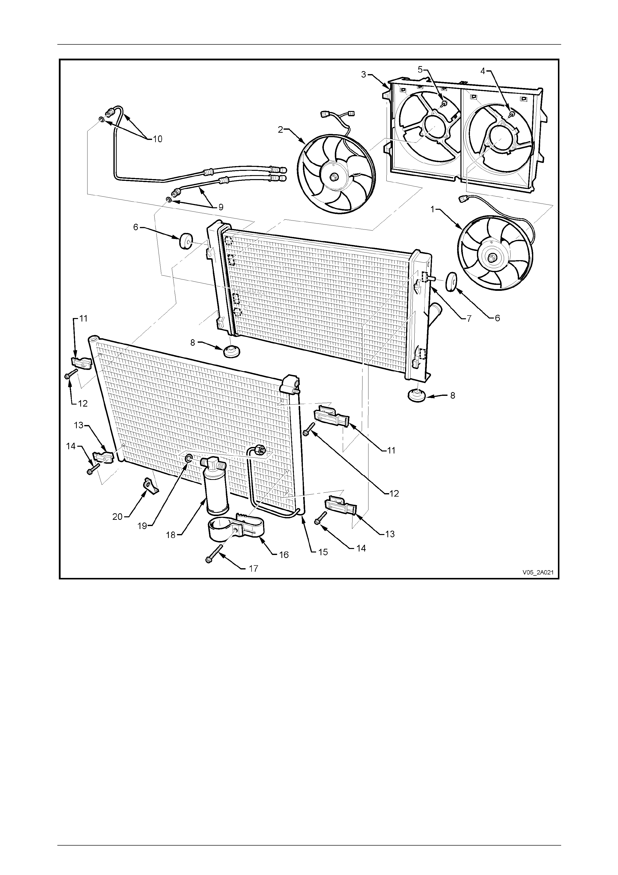
Figure 6B1 – 1
Legend
1 LHS (Small) Fan and Motor Assembly
2 RHS (Large) Fan and Motor Assembly
3 Fan Shroud
4 LHS Fan Retaining Screw (3 places)
5 RHS Fan Retaining Screw (3 places)
6 Upper Radiator Insulators (2 places)
7 Radiator
8 Lower Radiator Insulators (2 places)
9 Lower Transmission Cooling Line and Seal
10 Upper Transmission Cooling Line and Seal
11 Upper Condenser Mounting Clips (2 places)
12 Upper Condenser Mounting Clip Screws (2 places)
13 Lower Condenser Mounting Clips (2 places)
14 Lower Condenser Mounting Clip Screws (2 places)
15 Condenser
16 Filter Drier Receiver Mounting Bracket
17 Filter Drier Receiver Mounting Bracket Screw
18 Filter Drier Receiver
19 Filter Drier Receiver O-ring
20 Ambient Air Temperature Sensor Mounting Bracket (OCC A/C only)
Page 6B1–7
Engine Cooling – V6 Engine Page 6B1–8
2.2 Cooling Fans – Standard Specification
Overview
All MY 2005 VZ Series Alloytec V6 RHD sedan, wagon and utility mod els are fitted with a standard cooling fan system
(280 Watt), which consists of two single-speed fans. This cooling fan system operates as follows:
• Stage 1 – large diameter fan operates at maximum speed.
• Stage 2 – small and large dia m eter fans both operate at maximum speed.
The smaller fan on the left is 293 mm in diameter with a motor rated at 120 Watts, while the larger fan on the right is 342
mm in diameter with a motor power rating of 160 Watts.
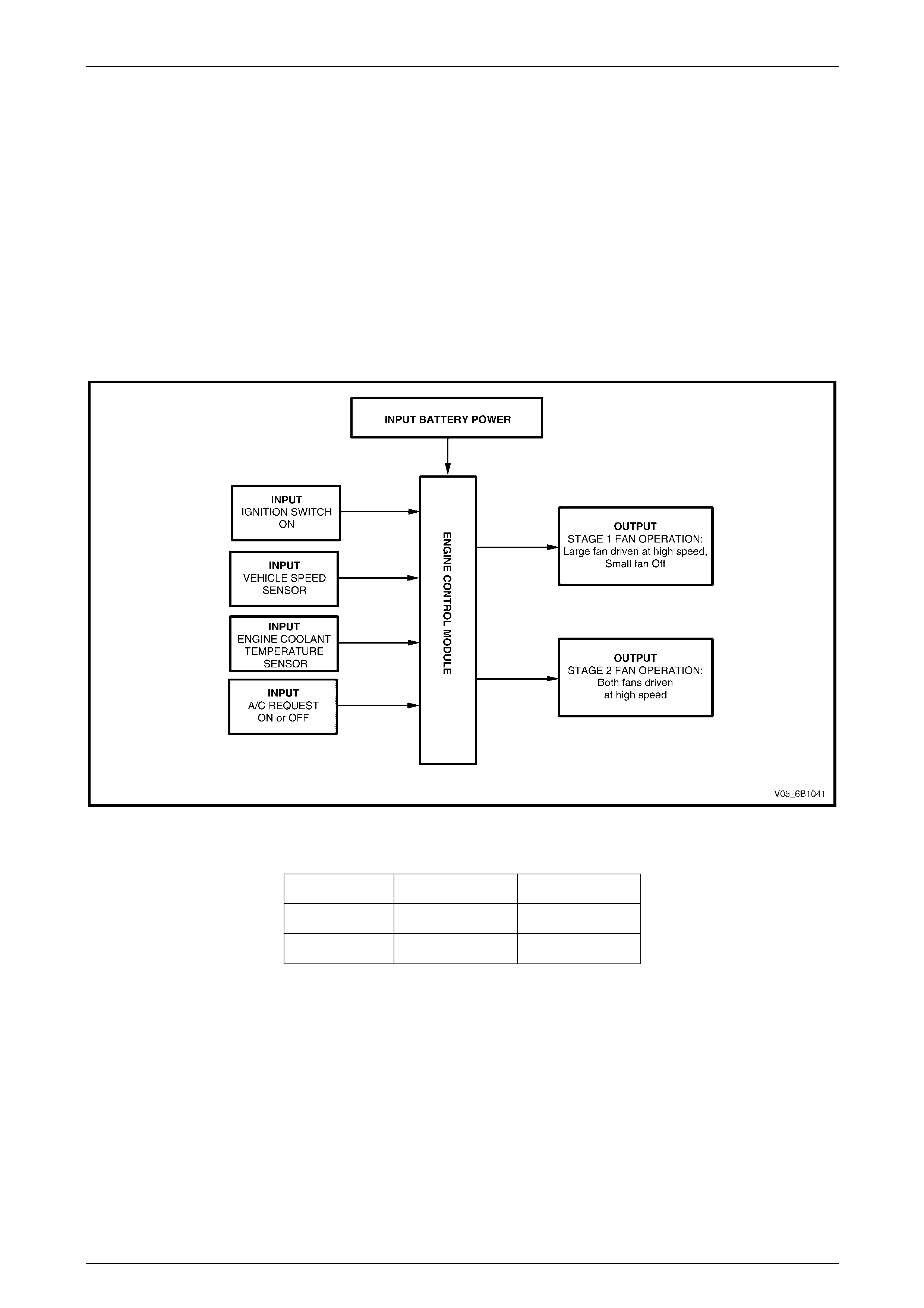
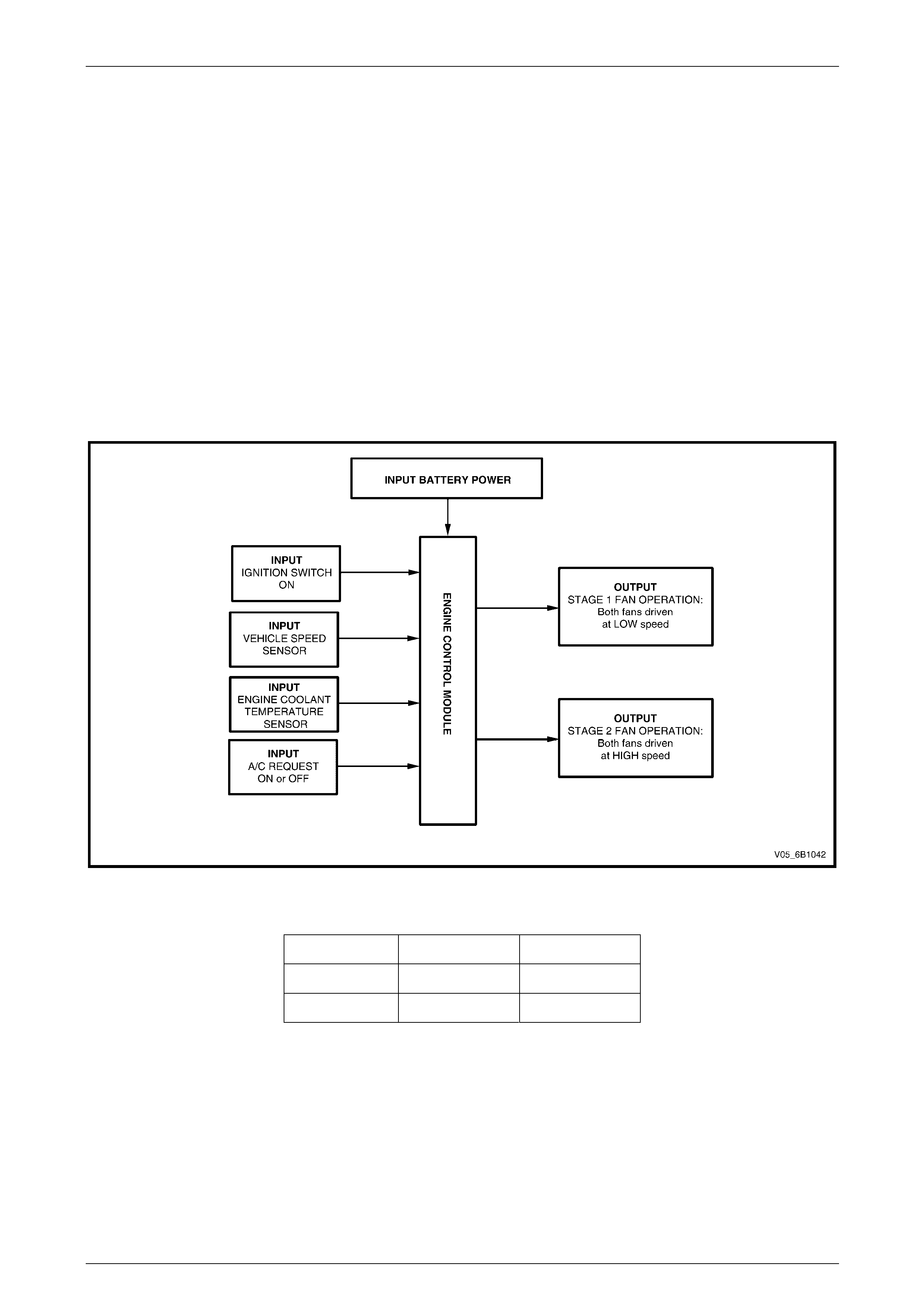
The following outlines the ope r ation of the co oling system, at block level, also showing what inputs the Engine Control
Module (ECM) requires.
Figure 6B1 – 2
With 12 volts applied and the fans mount ed to the radiator with a condenser fitted, the operating speeds are:
Stage 1 Stage 2
Large Fan 2,050 ± 150 rpm 2,050 ± 150 rpm
Small Fan Inoperative 2,250 ± 150 rpm
Page 6B1–8
Engine Cooling – V6 Engine Page 6B1–9
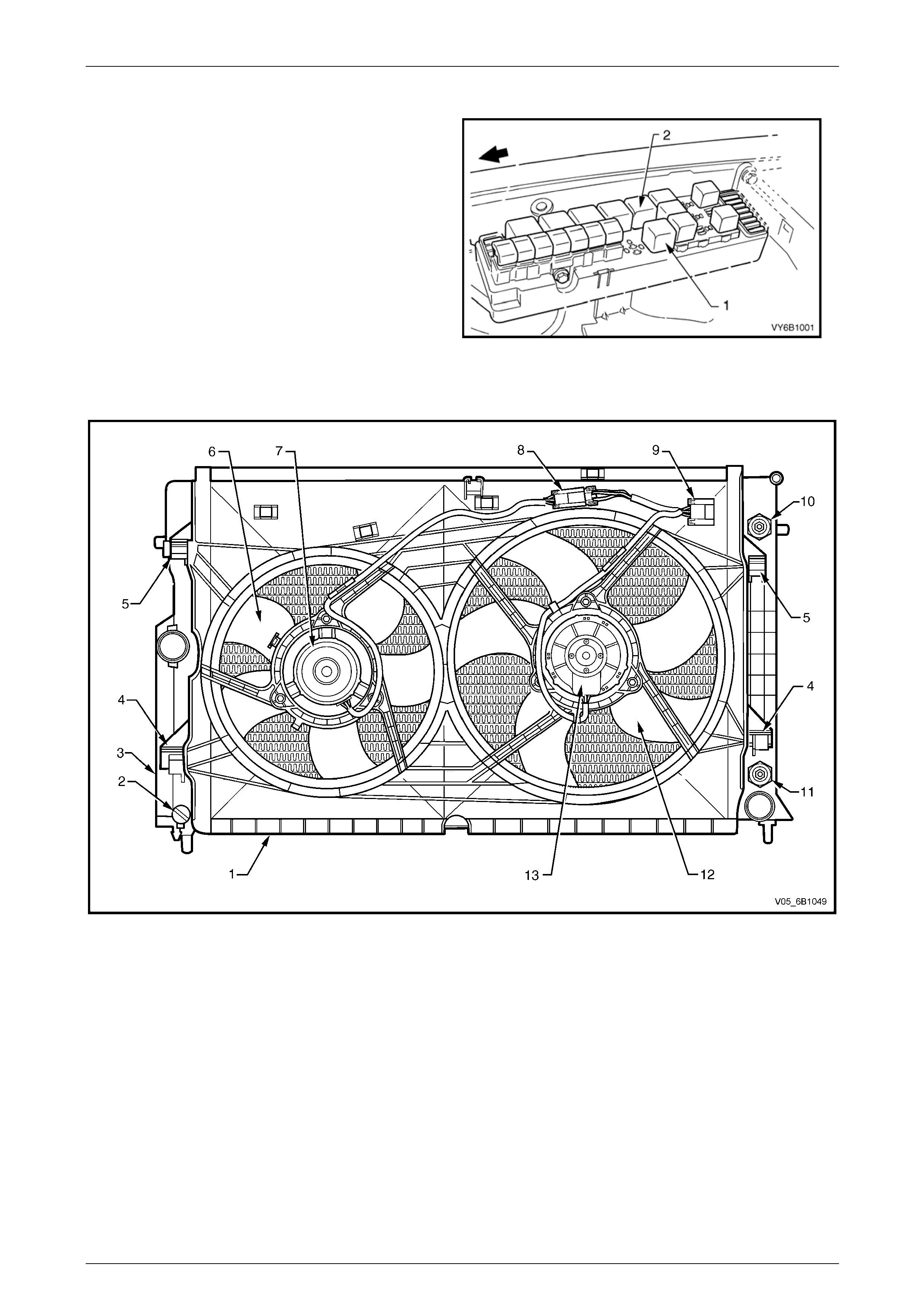
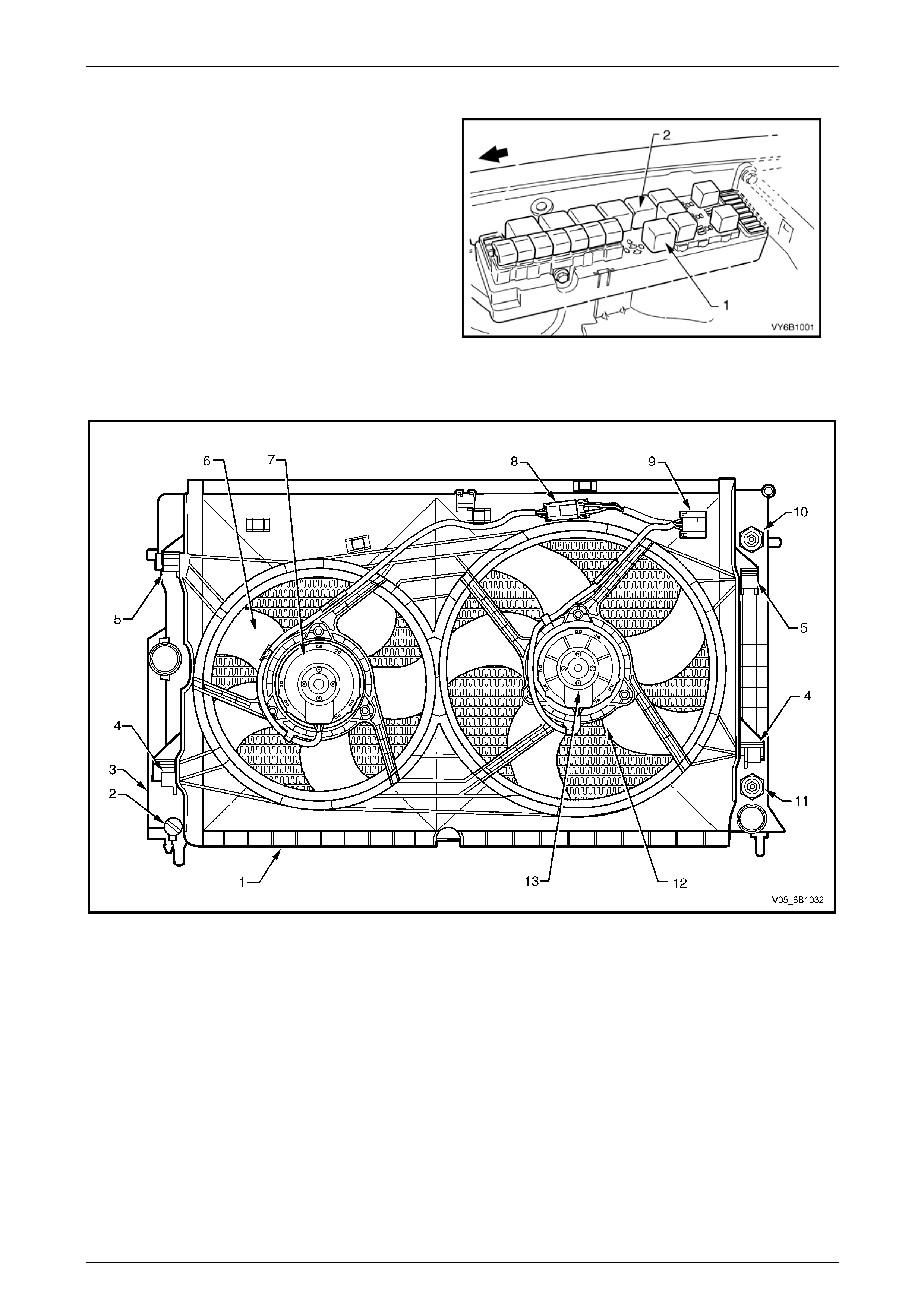
Relays
The engine cooling fan relays are located in the fuse and
relay compartment under the hood.
Legend
1 Cooling Fan Relay 1 for large fan operation.
2 Cooling Fan Relay 2 for small fan operation.
Figure 6B1 – 3
Cooling Fans and Shroud Assembly
Figure 6B1 – 4
Legend
1 Fan Shroud
2 Radiator Drain Tap
3 Radiator
4 Fan Shroud Lower Support
5 Fan Shroud Upper Support / Locking Retainer
6 Small, Left Fan – 5 Blade, 293 mm Diameter
7 Small, Left Fan Motor – 120 Watt, Single-speed
8 Left Fan Motor Harness Connector (2 terminal)
9 Left and Right Fan Motor Harness Connector (4 terminal)
10 Oil Cooler, Upper Line Connection (Auto. Trans. only)
11 Oil Cooler, Lower Line Connection (Auto. Trans. only)
12 Large, Right Fan – 5 Blade, 342 mm Diameter
13 Large, Right Fan Motor – 160 Watt, Single-speed
Page 6B1–9
Engine Cooling – V6 Engine Page 6B1–10
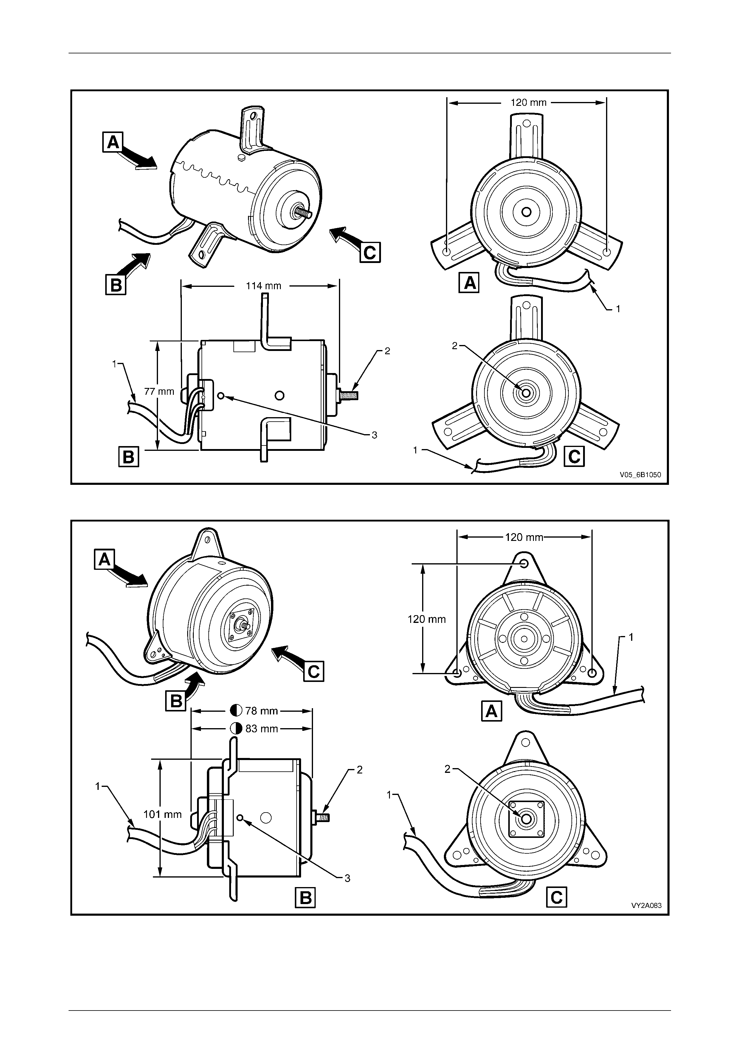
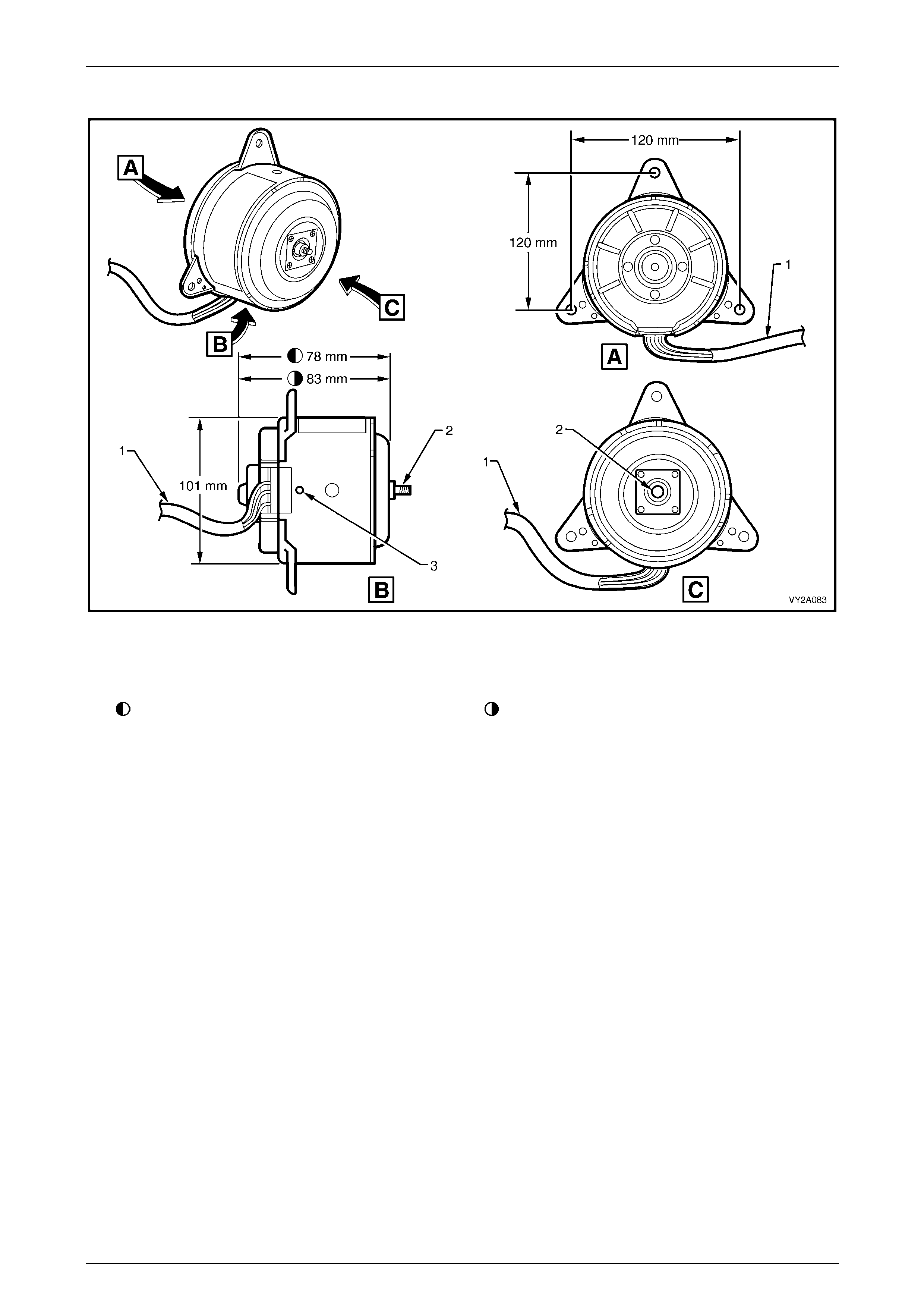
Fan Motors
Figure 6B1 – 5 – 120 W Co oling Fan Motor
Figure 6B1 – 6 – 160 W Co oling Fan Motor
Legend
1 Two-wire Harness 2 Armature Shaft 3 Drain Hole
Page 6B1–10

Engine Cooling – V6 Engine Page 6B1–11
When the Standard Cooling Fan System is fitted to an Alloytec V6 engin e, the fan motors are 12 Volt and single-speed.
The internal construction of the 120 Watt fan motor consists of two brushes and two permanent magnets ( r efer to
Figure 6B1-5) , whereas the 160 Watt motor has four brushes and four permanent magnets (refer to Figure 6B1-6).
A two-wire pigtail harness is permanently connected to each motor and is attached to the polypropylene fan shroud at
two locations by integral clips moulded as pa rt of the fan shroud.
The RHS motor harness is directly connected to the engine harness through a 6-pin connector. It also carries an
additional 2-pin connector, which attaches to the LHS motor harness and enables in dividual removal of the LHS and
RHS fan and motor assemblies when necessary, refer to Figure 6B1 – 4. The two associated electrical connectors are
attached to the shroud by way of slide lock clips. Each motor is attached to the fan shroud by three bolts at threaded
mounting flanges spot-welded symmetrically around the fan housing, refer to Figures 6B1 – 5 and 6B1-6.
The enclosed fan motor housing is constructed of yellow zinc coated steel. A drain hole is located in the bottom of the
housing to allow for breathing and dra ining of any moisture ingress.
Both fan motors rotate in an anticlockwise direction when viewed from the fan motor side.
The RHS motor is rated at 160 Watts and drives the larger diameter (342 mm) fan blade at approximately
2,050 ± 150 rpm.
The LHS motor is rated at 120 Watts and drives the smaller diameter (293 mm) fan blad e at approximately
2,250 ± 150 rpm.
Both LHS and RHS fan and motor are bala nced as a unit and fan blades must not be separated from their respective
motors. Fan motors and blades are serviced only as an assembled unit. However, it should be noted that the central nut
attaching the fan blade to the motor shaft has a left-hand thread.
There are also suppression capacitors incorporated into the fan motor, located on the brush holders. These suppression
capacitors help eliminate fan motor noise through the radio speakers. As these capacitors are not serviced separately,
should a problem occur with either capacitor, the motor assembly must be replaced.
Page 6B1–11
Engine Cooling – V6 Engine Page 6B1–12
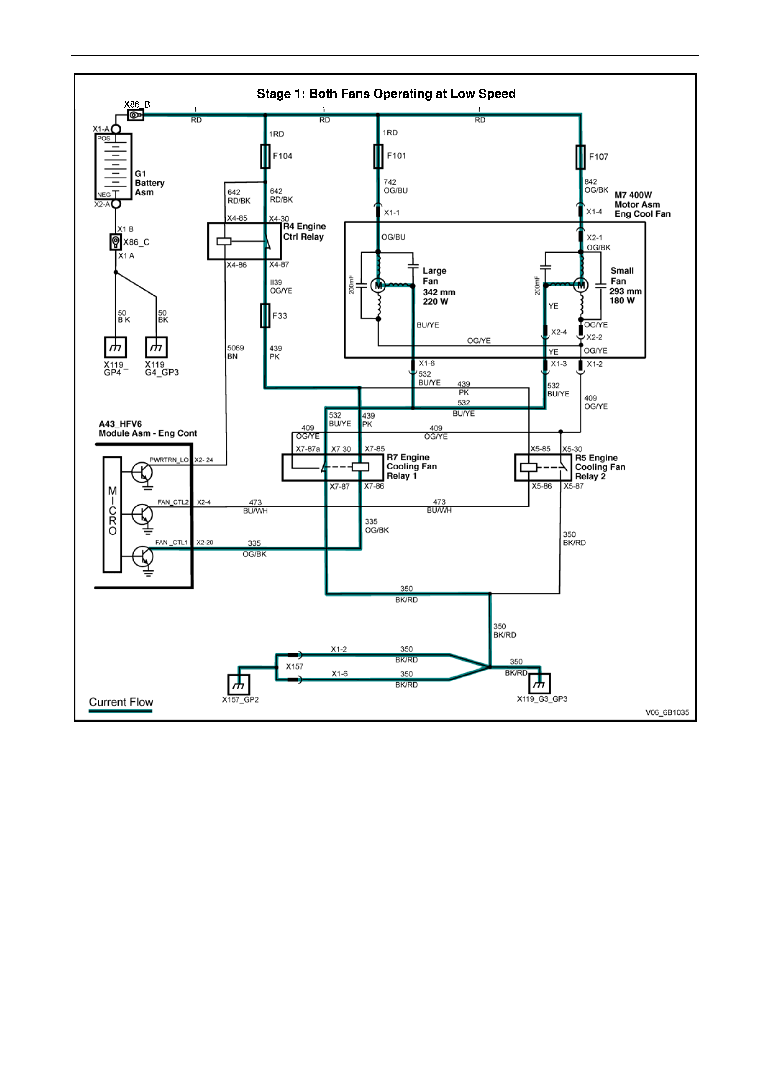
Operation
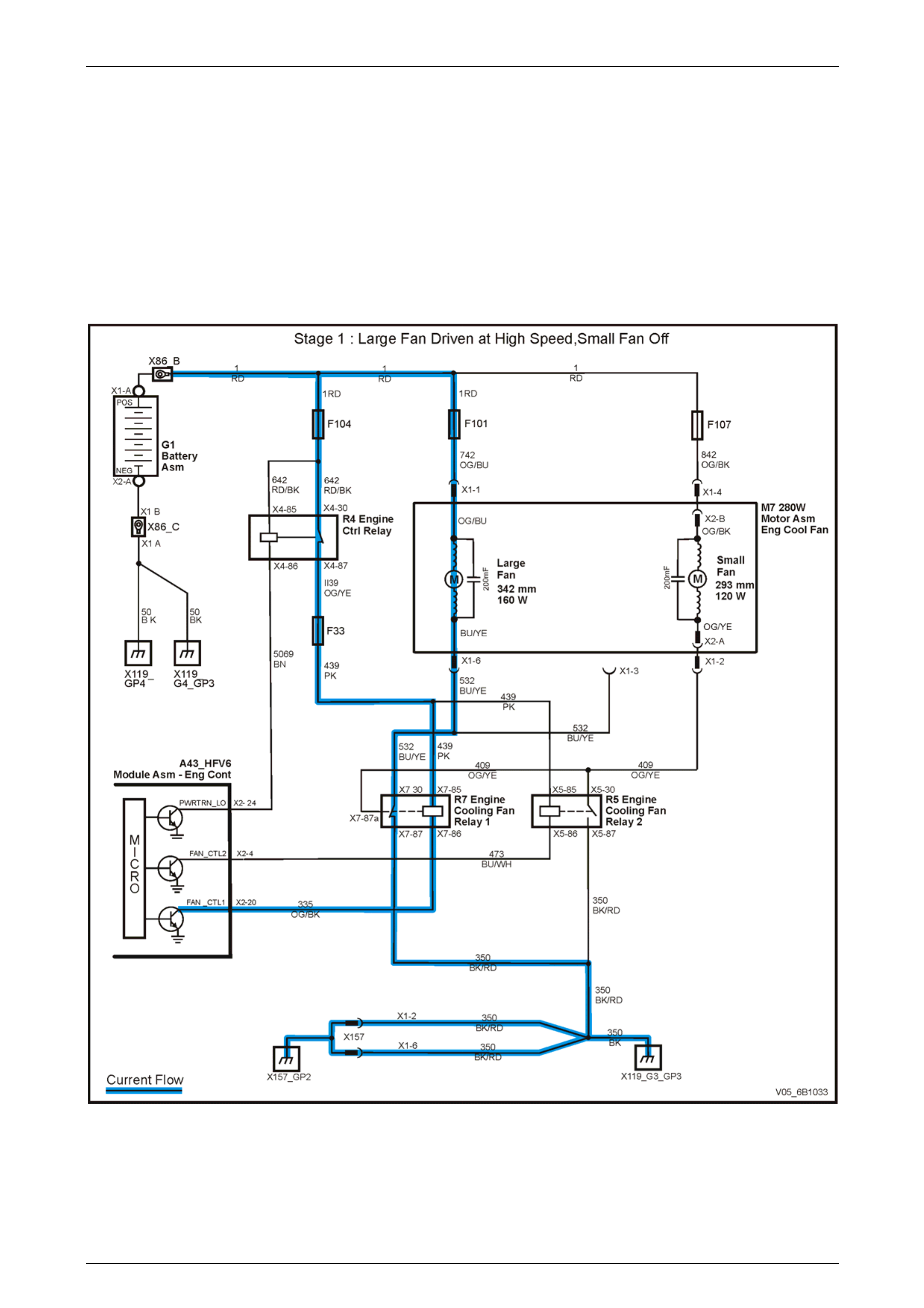
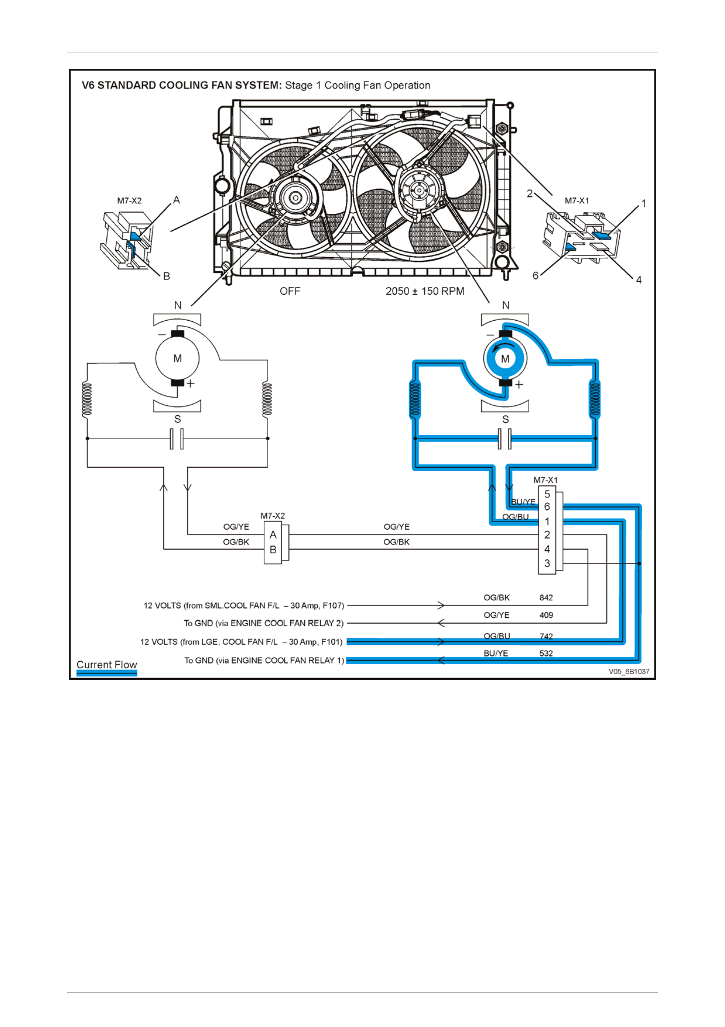
On MY 2005 VZ Series vehicles with Alloytec V6 engines and standard specification fan motors, each of the engine
cooling fan motors has t wo terminals; one positive and one negative. The positive terminals are permanently connected
to battery voltage, via fusible links F101 (large fan) and F107 (small fan).
Stage 1 Fan Operation
The large cooling fan operation is enabl ed when the ECM via circuit 335 energises the Engine Cooling Fan Relay 1 (R7).
When the negative terminal is connected to ground through Engine Cooling Fan Relay 1 (R7), the large cooling fan
(right) operates.
The ECM determines when to ena ble the Engine Cooling Fan Relay 1 (R7), based on inpu ts from the A/C request signal,
Engine Coolant Temperature (ECT) sensor and the Vehicl e Speed Sensor (VSS).
Figure 6B1 – 7
Page 6B1–12
Engine Cooling – V6 Engine Page 6B1–13
Figure 6B1 – 8
Conditions for Stage 1 Fan Operation
1 The ECM turns Engine Cooling Fan Relay 1 (R7) ON when:
• Air conditioning request indicated (YES) and the vehicle speed is less than 30 km/h;
• Air conditioning pressure is greater than 1,500 kPa;
• Coolant temperature is greater than 104° C; or
• An ECT sensor failure is detected by the ECM. Refer to Section 6C1-2 Engine Management – V6 – Diagnostics
in this Service Information for additional information; or
• When the ignition s witch is turned from ON to OFF and the engine coolant temperature is above 117° C, the
ECM will continue to energis e the Engine Cooling Fan Relay 1 (R7) for approximately four minutes.
2 The ECM turns Engine Cooling Fan Relay 1 (R7) OFF when the following conditions have been met:
• Air conditioning request not indic ated (NO) and the coolant temperature is less than 99° C; or
• Air conditioning request indicated (YES) with pressure less than 1,170 kPa, vehicle spe ed greater than
50 km/h and coolant tempera t ure less than 99° C.
Page 6B1–13
Engine Cooling – V6 Engine Page 6B1–14
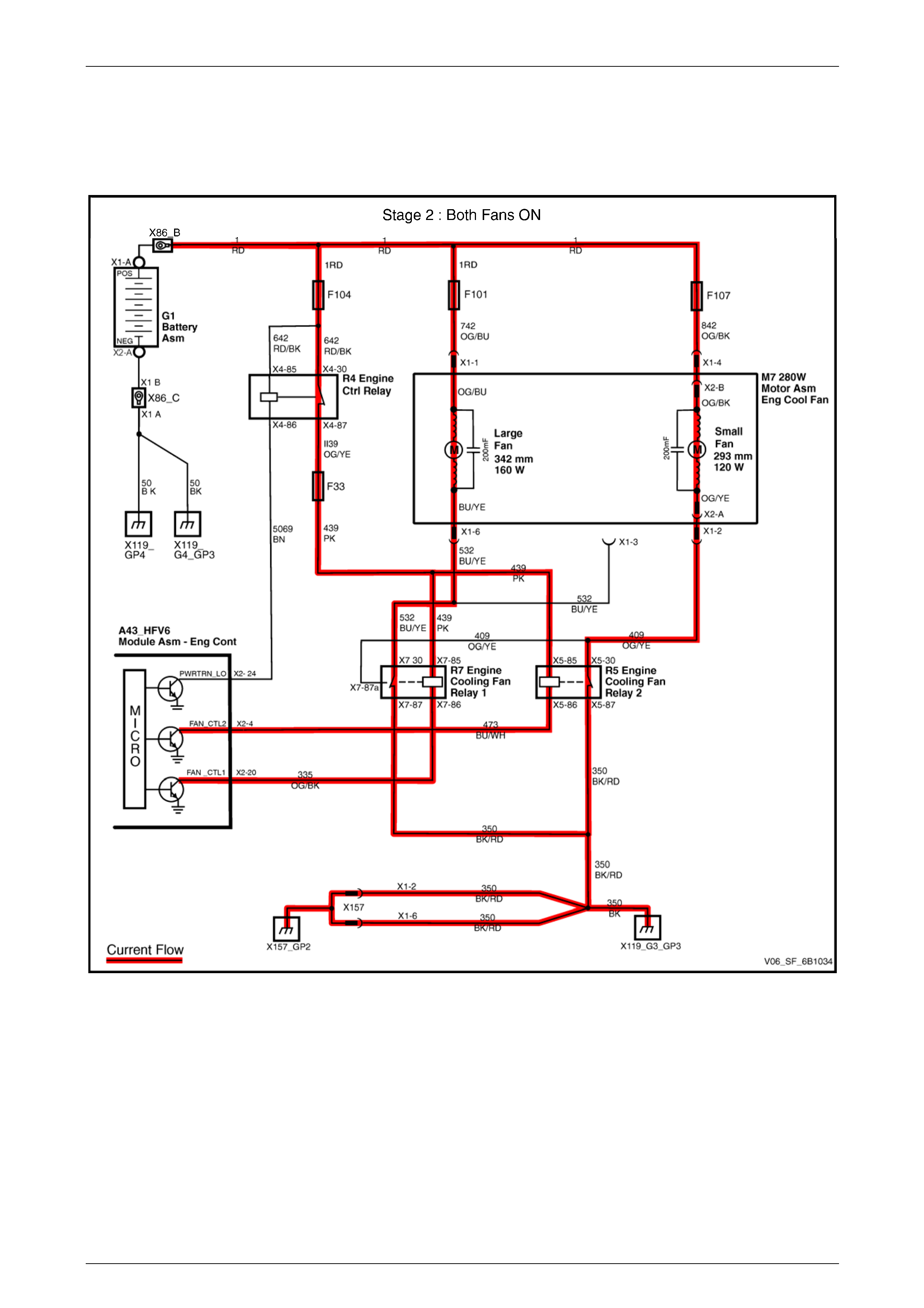
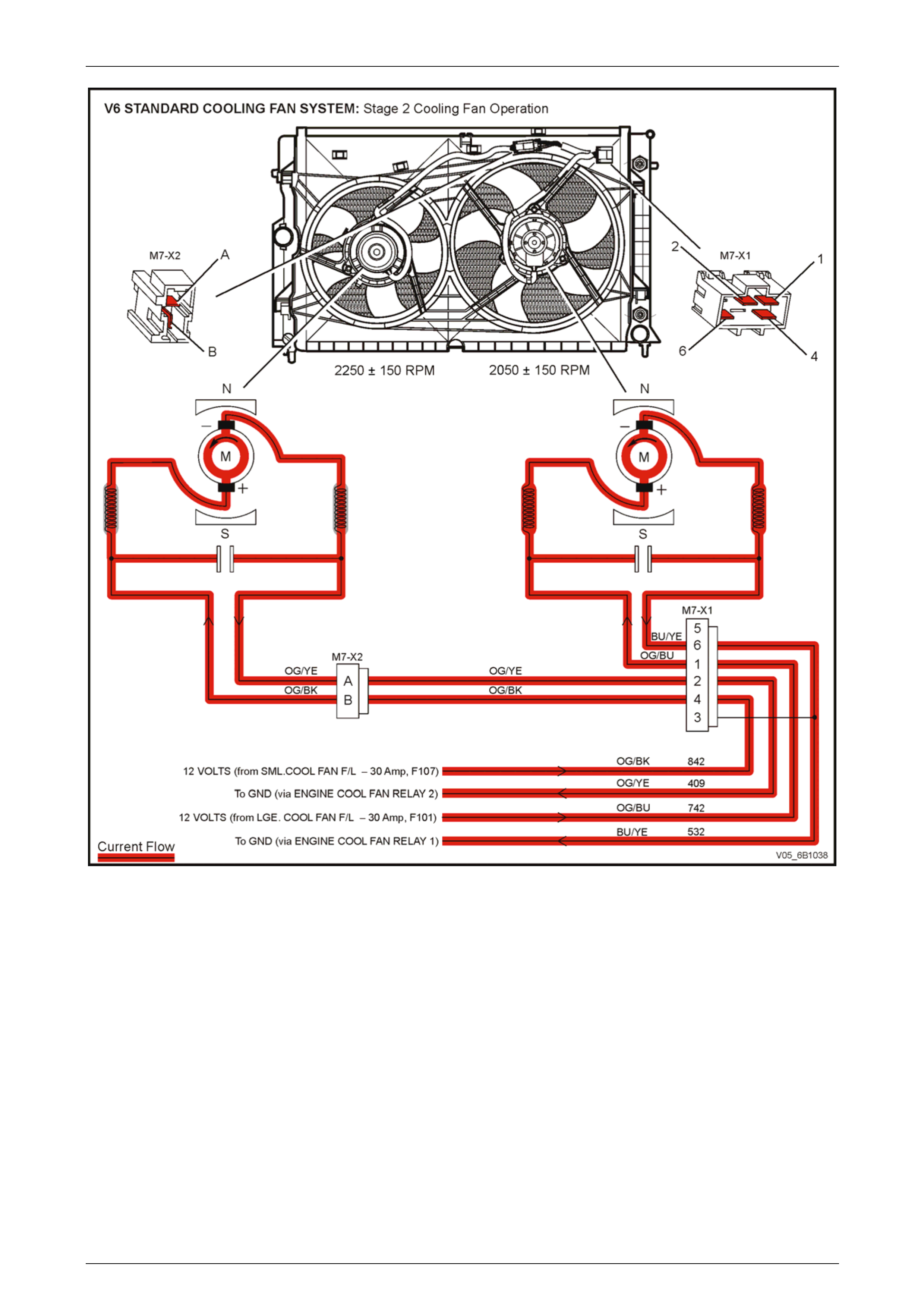
Stage 2 Fan Operation
The small (left) cooling fan operation is enabled when the ECM via circuit 473 energises the Engi ne Cooling Fan Relay 2
(R5). When the negative terminal is connected to earth via the Engine Cooling Fan Relay 2 (R5), the small cooling fan
operates. Both cooling fans ar e now operational, the large fan via Engine Cooling Fan Relay 1 (R7) and the small cooling
fan via Engine Cooling Fan Relay 2 (R5).
Figure 6B1 – 9
Page 6B1–14
Engine Cooling – V6 Engine Page 6B1–15
Figure 6B1 – 10
Conditions for Stage 2 Fan Operation
The ECM determines when to ena ble the Engine Cooling Fan Relay 2 (R5), based on inputs from the ECT sensor.
1 The ECM turns Engine Cooling Fan Relay 2 (R5) ON if the Engine Cooling Fan Relay 1 (R7) has b een energised
for one second and the following conditions have been met:
• If there is a ECM message response fault, setting a DTC P125 8;
• The ECM detects an ECT sensor failure. Refer to Section 6C1-2 Engine Management – V6 – Diagnostics in
this Service Information for additional information;
• Engine coolant temperature is above 1 08° C; or
• Air conditioning pressure is greater than 2,000 kPa.
NOTE
If the large engine-cooling fan is off when the
criteria for turning the small engine-co oling fan o n
are first met, the small engin e-cooli ng fan will turn
on 5 seconds after the large engine-coo ling fan is
switched on.
Page 6B1–15

Engine Cooling – V6 Engine Page 6B1–16
2 If both the large and small cooling fans ar e enabled, the ECM turns the small engine-cooling fan OFF (via Engine
Cooling Fan Relay 2) when:
• The engine coolant temperature is less than 103° C; and
• Air conditioning request is not indicated (NO); or
• Air conditioning request is indicated (YES) and the press ure is less than 1,500 kPa.
Page 6B1–16
Engine Cooling – V6 Engine Page 6B1–17
2.3 Cooling Fans – High Power Specification
Overview
All MY 2005 VZ Series Alloytec V6 LHD models, Alloytec V6 RHD cab chassis (2WD and AWD) and Alloytec V6 R HD
AWD wagon models are fitted with a high power cooling fan system (400 Watt), which consists of two dual-speed fans.
This cooling fan system operates as follows:
• Stage 1 – both fans operate at low-speed.
• Stage 2 – both fans operate at high-speed.
The smaller fan on the left is 293 mm in diameter with a motor rated at 180 Watts, while the larger fan on the right is
342 mm in diameter with a motor power rating of 220 Watts.
While both the standard and high power assemblies have the same diameter fans, the power rating of the electric
motors, changes and can be seen visually by the larger diameter motor for the high power assemblies.
The following block diagram outlin es the op eration of the cooling system that also sho ws the inputs the Engine Control
Module (ECM) requires.
Figure 6B1 – 11
With 12 volts applied and the fans mount ed to the radiator with a condenser fitted, the operating speeds are:
Stage 1 Stage 2
Large Fan 2,050 ± 150 rpm 2,300 ± 150 rpm
Small Fan 2,350 ± 150 rpm 2,750 ± 150 rpm
Page 6B1–17
Engine Cooling – V6 Engine Page 6B1–18
Relays
The engine cooling fan relays are located in the fuse and
relay compartment under the hood.
Legend
1 Cooling Fan Relay 1 for low-speed fan operation.
2 Cooling Fan Relay 2 (in conjunction with Cooling Fan
Relay 1) for high-speed fan operation.
Figure 6B1 – 12
Cooling Fans and Shroud Assembly
Figure 6B1 – 13
Legend
1 Fan Shroud
2 Radiator Drain Tap
3 Radiator
4 Fan Shroud Lower Support
5 Fan Shroud Upper Support / Locking Retainer
6 Small, Left Fan – 5 Blade, 293 mm Diameter
7 Small, Left Fan Motor – 180 Watt, Dual-speed
8 Left Fan Motor Harness Connector (3 terminal)
9 Left and Right Fan Motor Harness Connector (5 terminal)
10 Oil Cooler, Upper Line Connection (Auto. Trans. only)
11 Oil Cooler, Lower Line Connection (Auto. Trans. only)
12 Large, Right Fan – 5 Blade, 342 mm Diameter
13 Large, Right Fan Motor – 220 Watt, Dual-speed
Page 6B1–18
Engine Cooling – V6 Engine Page 6B1–19
Fan Motors
Figure 6B1 – 14
Legend
1 Three-wire Harness 2 Armature Shaft 3 Drain Hole
Dimension applicable to small diameter fan blade Dimension applicable to large diameter fan blade
Whenever a High Po wer Cooling Fan System is fitted, the fan motors are 12 Volt and dual-speed. Accord ingly, the
internal construction of the fan motor consists of four brushes and four per manent magnets. A three-wire pigtail harn ess
is permanently attached to both motors and is attached to the polypropylene fan shro ud at two locations by integral clips
moulded as part of the shroud. The RHS motor harness is connected directly to the engin e harness through a 5-pin
connector, refer to ‘9’ in Figure 6B1 – 13. It also carries an additional 4-p in connector that attaches to the LHS motor
harness and enables individual removal of the LHS and RHS fan and m otor assemblies when necessar y, refer to ‘8’ in
Figure 6B1 – 13. The t wo associated electrical connectors are attached to the shroud b y way of slide lock clips. The
motor is attached to the polypropylene fan shroud by three bolts installed at the threaded mounting flanges, which
protrude symmetrically from the rear of the fan motor housing, refer to F igure 6B1 – 14.
The enclosed fan motor housing is constructed of yellow zinc coated steel. A drain hole is located in the bottom of the
housing to allow for breathing and dra ining of any moisture ingress.
Both fan motors rotate in an counter-clock wise direction when viewed from the fan motor side.
The LHS motor is rated at 180 Watts and drives the smaller diameter (293 mm) fan blad e. During Stage 1 operation, the
fan is driven at 2,350 ± 150 rpm. During Stage 2 operatio n, the fan is driven at 2,750 ± 150 rpm.
The RHS motor is rated at 220 Watts and drives the larger diameter (342 mm) fan blade. During Stage 1 oper ation, the
fan is driven at approximately 2,050 ± 150 rpm. During Stag e 2 operation, the fan is driven at 2,300 ± 15 0 rpm.
Both LHS and RHS fan and motor are bala nced as a unit and fan blades must not be separated from their respective
motors. Fan motors and blades are serviced only as an assembled unit. However, it should be noted that the central nut
attaching the fan blade to the motor shaft has a left-hand thread.
There are also suppression capacitors incorporated into the fan motor, located on the brush holders. These suppression
capacitors help eliminate fan motor noise through the radio speakers. As these capacitors are not serviced separately,
should a problem occur with either capacitor, and then the motor assembly must be replaced.
Page 6B1–19

Engine Cooling – V6 Engine Page 6B1–20
Operation
The electrical circuitry for the high power specification cooling fans is different to that used for the standard specification
system. Each high power fan motor has three terminals; one positive and two negative (one for low-speed operation and
one for high-speed operation). The positive terminals are permanently connected to battery voltage, via fusible links
F101 (large fan) and F107 (small fan).
The fan motors are also connected electrically, as follows:
• The low-speed negative wires from each motor go through the radiator fan connector separately and ar e spliced
together in the main wiring harness before reaching Engin e Cooling Fan Relay 1.
• The high-speed wires from each motor are spliced together before the radiator fan connector and go through the
connector as one circuit, to Engine Cooling Fan Relay 2.
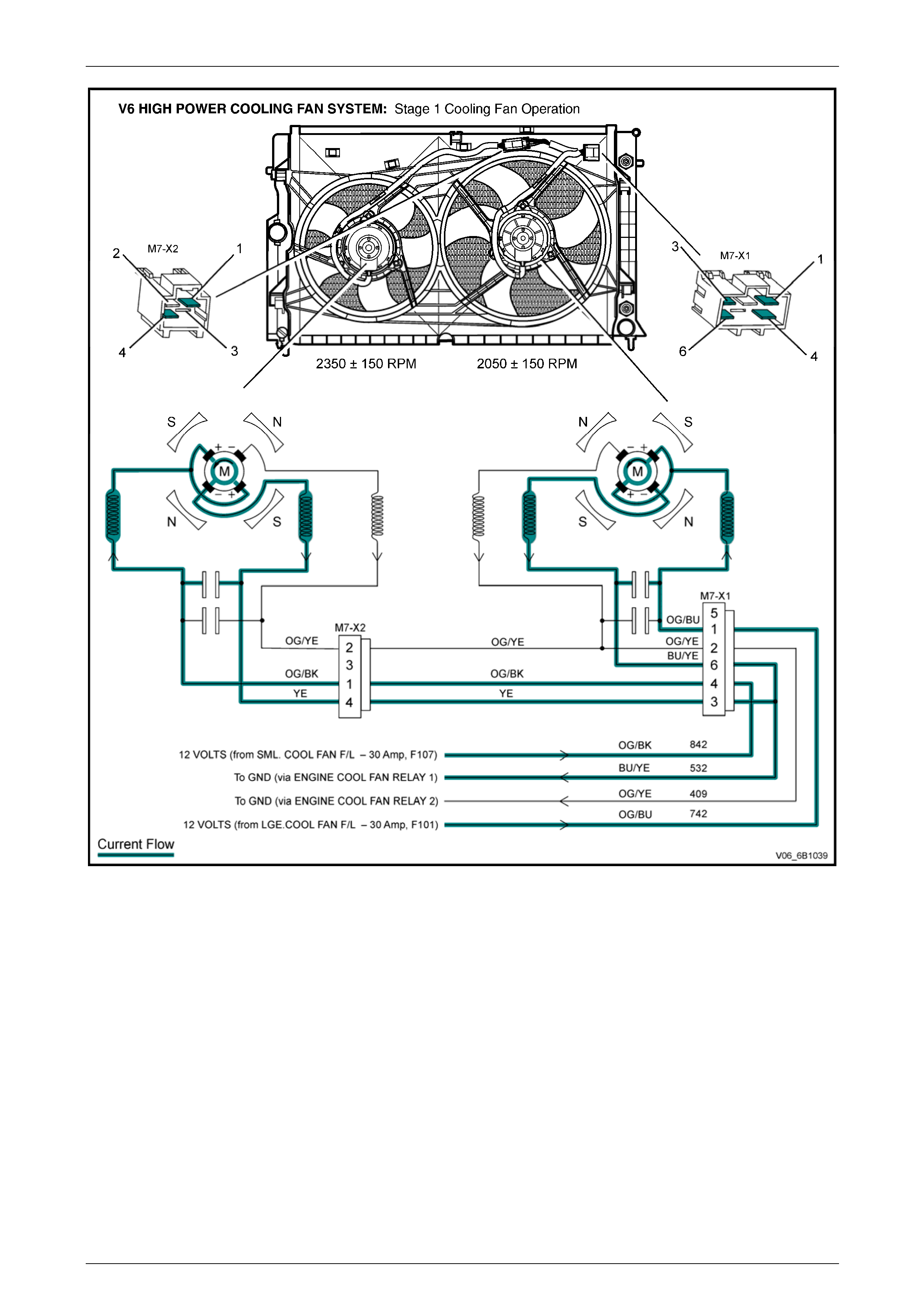
Stage 1 Fan Operation
When the low-speed negative terminal from each motor is connected to groun d via Engine Cooling Fan Relay 1 (R7),
both cooling fans will oper ate at Stage 1 (Large fan at 2,050 ± 150 rpm, Small fan at 2,350 ± 150 rpm). W ith Engine
Cooling Fan Relay 1 still activated, when the high-s peed negative terminal from each motor is connected to ground via
Engine Cooling Fan Relay 2 (R5), both fans operate at Stage 2 (Large fan at 2,300 rpm ± 150 rpm, Small fan at 2,750 ±
150 rpm).
Stage 1 cooling fan operation is enabled when the ECM via circuit 335 energises the Engine Cooling Fan Relay 1.
The ECM determines when to enable Stage 1, based on inputs from the A/C request signal, Engine Coolant
Temperature (ECT) sensor and the Vehicle Speed Sensor (VSS).
Page 6B1–20
Engine Cooling – V6 Engine Page 6B1–21
Figure 6B1 – 15
Page 6B1–21
Engine Cooling – V6 Engine Page 6B1–22
Figure 6B1 – 16
Conditions for Stage 1 Fan Operation
1 The Engine Coolin g Fan Relay 1 is turned ON when:
• Air conditioning request indicated (YES) and the vehicle speed is less than 30 km/h;
• Air conditioning pressure is greater than 1,500 kPa;
• Coolant temperature is greater than 104° C; or
• An engine coolant temperature sensor failure is detected by the PCM. Refer to Section 6C1-2 Engine
Management – V6 – Diagnostics for additional informati on; or
• When the ignition s witch is turned from ON to OFF and the engine coolant temperature is above 117° C, the
ECM will continue to energis e the Engine Cooling Fan Relay 1 (R7) for approximately four minutes.
2 The ECM switches OFF Engine Cooling Fan Relay 1 when the following conditions have been met:
• Air conditioning request not indic ated (NO) and the coolant temperature is less than 99° C, or
• Air conditioning request indicated (YES) with pressure less than 1,170 kPa, vehicle spe ed greater than
50 km/h and coolant tempera t ure less than 99° C.
Page 6B1–22
Engine Cooling – V6 Engine Page 6B1–23
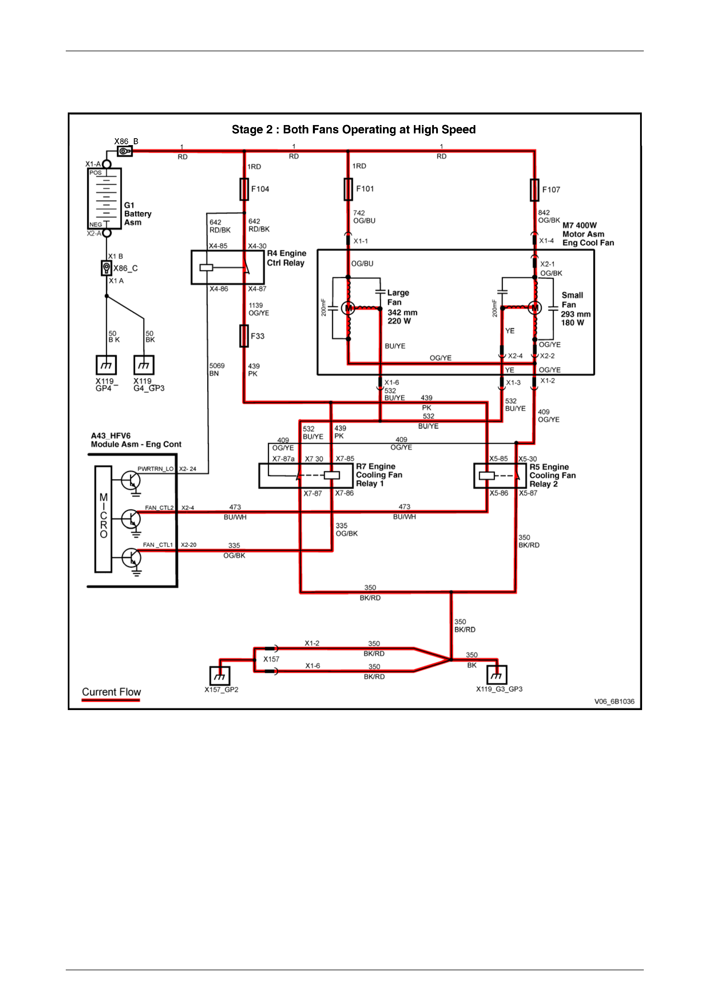
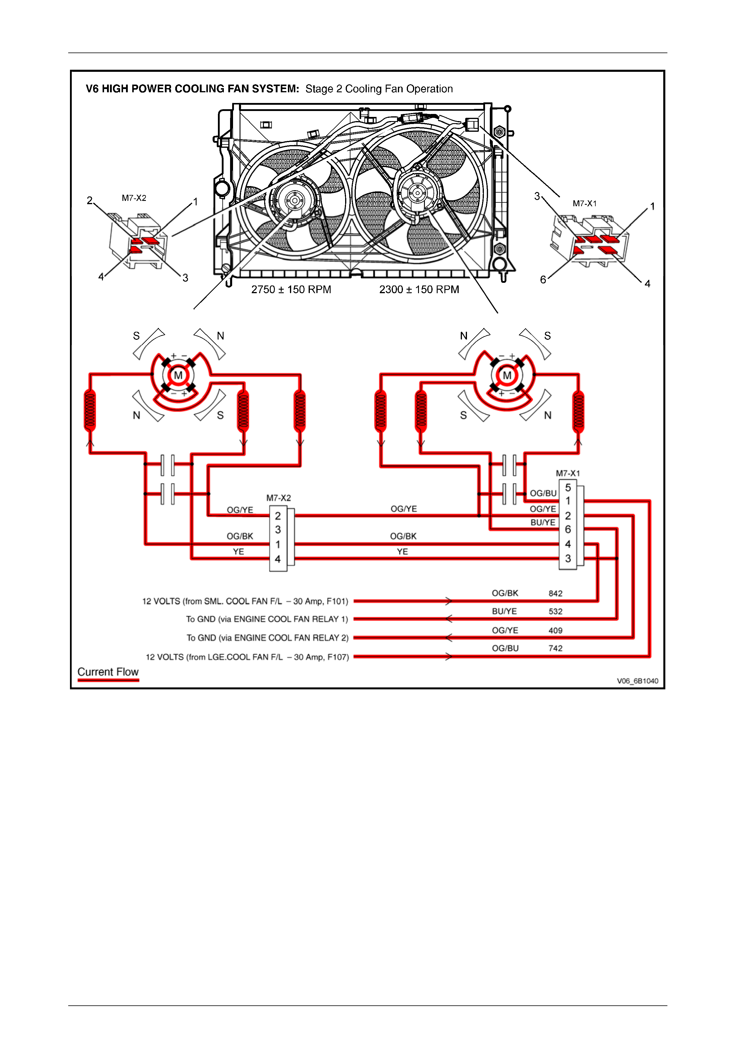
Stage 2 Fan Operation
Stage 2 cooling fan operation is enabled when the ECM via circuit 473 energises the Engine Cooling Fan Relay 2.
Figure 6B1 – 17
Page 6B1–23
Engine Cooling – V6 Engine Page 6B1–24
Figure 6B1 – 18
Conditions for Stage 2 Fan Operation
The ECM determines when to ena ble the Engine Cooling F an Relay 2, based on inputs from the ECT sensor.
1 Engine Cooling F an Relay 2 is turned ON if the Engine Cooling Fan Relay 1 has been energised for one second
and the following conditions h ave been met:
• If there is a ECM message response fault, setting a DTC P125 8;
• An ECT sensor failure is detected by the ECM. Refer to Section 6C1-2 Engine Management – V6 – Diagnostics
in this Service Information for additional information;
• Engine coolant temperature is above 1 08° C; or
• Air conditioning pressure is greater than 2,000 kPa.
2 If Stage 2 has been enabled, the ECM reverts to Stage 1 operation when:
• The engine coolant temperature is less than 103° C; and
• Air conditioning request is not indicated (NO); or
• Air conditioning request is indicated (YES) and the press ure is less than 1,500 kPa.
Page 6B1–24
Engine Cooling – V6 Engine Page 6B1–25
2.4 Coolant Pump
The coolant pump is a centrifugal vane imp eller type pump. The pump consists of a housing and an impeller. The
impeller is a flat plate mounte d on the pump shaft with a series of flat or curved blades (vanes). When the impeller
rotates, the coolant between the vanes is thrown outward by centrifugal force. The impel ler shaft is supported by sealed
bearings. The sealed bearings do not need to be lubricated. Grease cannot leak out, dirt and water cannot get in as long
as the seal is not damaged or worn.
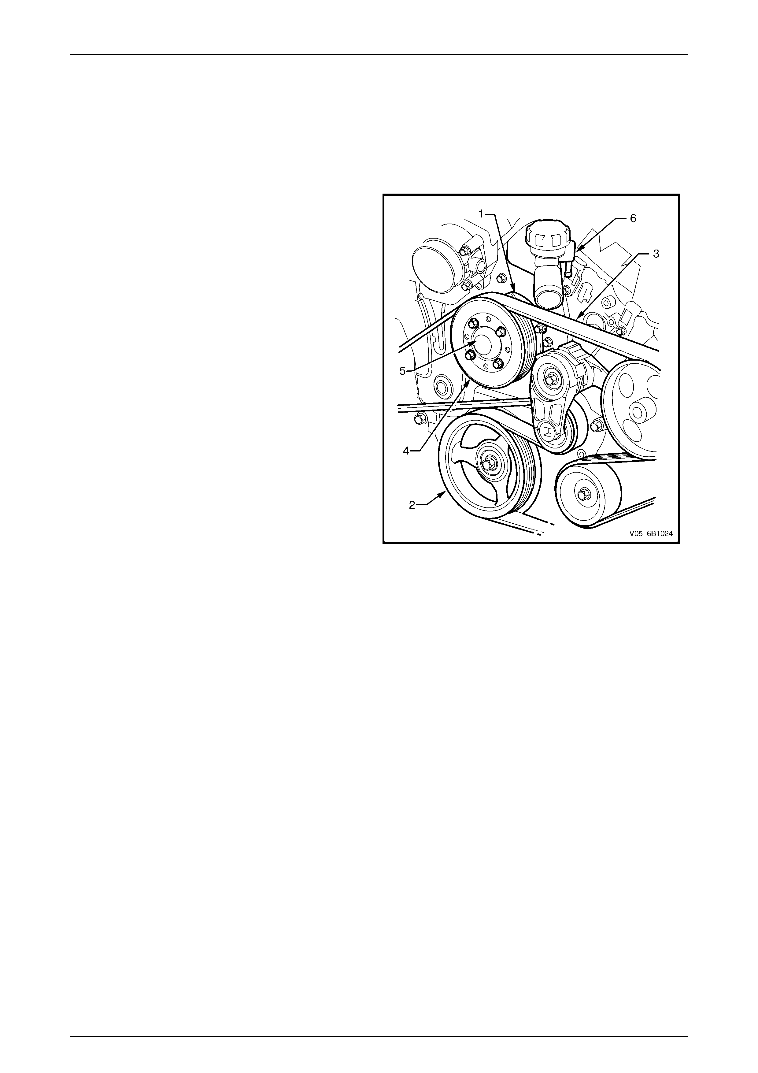
The coolant pump (1) is mounted to the engine front cover
and is driven by the crankshaf t pulley (2) via a multi-ribbed
drive belt (3), turning the pump pulle y (4), bolted to the
coolant pump flange (5). Coolant enters the engine
through the coolant inlet pipe and thermostat at the rear of
engine and passes throug h the engine to the coolant
pump on the front engine cover and exits via the coolant
outlet housing (6) located at the front of the intake
manifold.
Figure 6B1 – 19
Page 6B1–25
Engine Cooling – V6 Engine Page 6B1–26
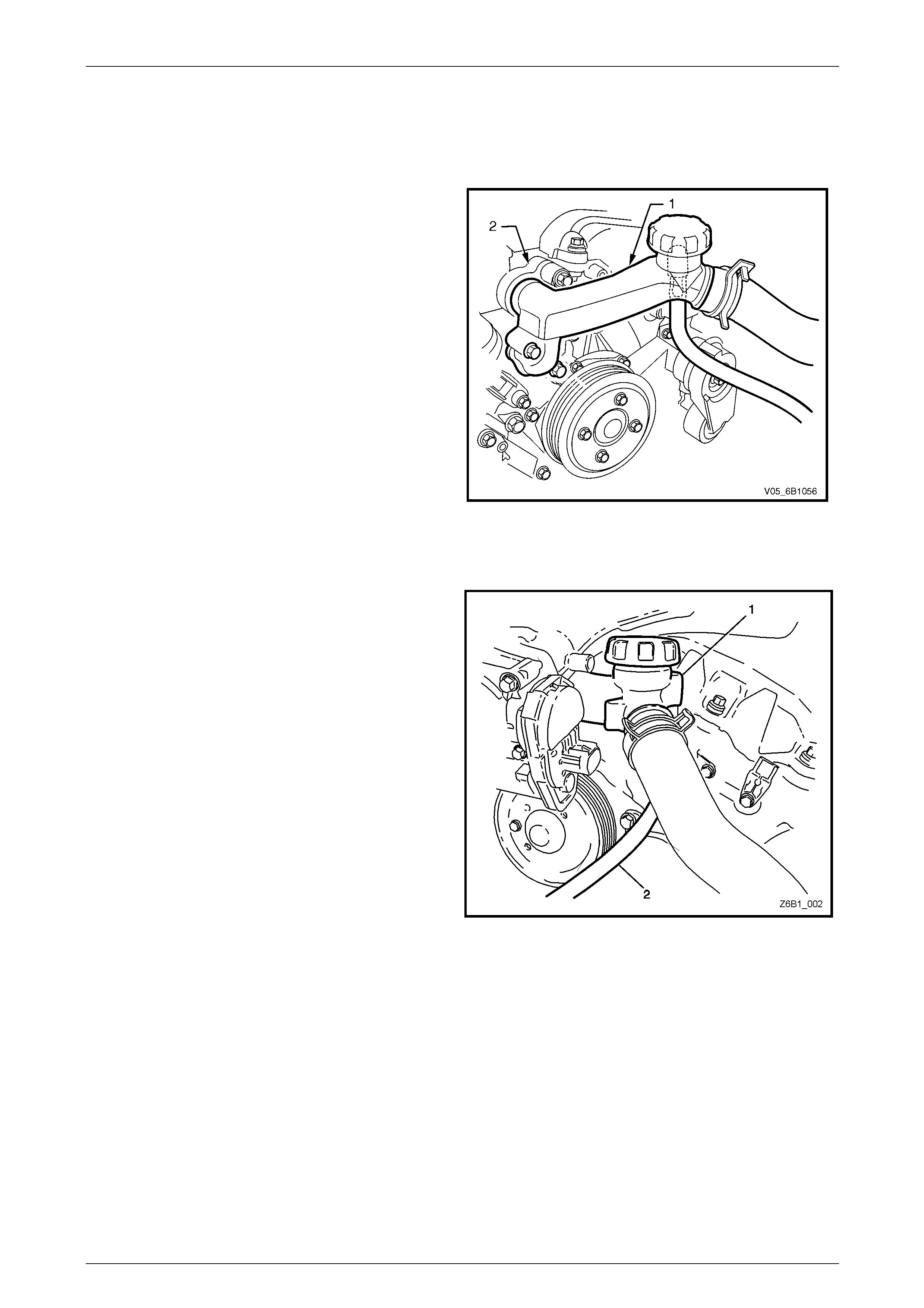
2.5 Coolant Outlet Housing
MY2006 VZ Models
The coolant outlet housing (1) is located at the front of the
intake manifold (2).
The coolant outlet housing i ncorporates the coolant filler
pressure cap and coolant recover y reserv oir hose
connection.
Figure 6B1 – 20
MY2006 VZ Update
The coolant outlet housing (1) is bolted to the front of the
intake manifold.
The coolant outlet housing (1) incorporates the coolant filler
pressure cap and coolant recovery reserv oir hose (2).
Figure 6B1 – 21
Page 6B1–26
Engine Cooling – V6 Engine Page 6B1–27
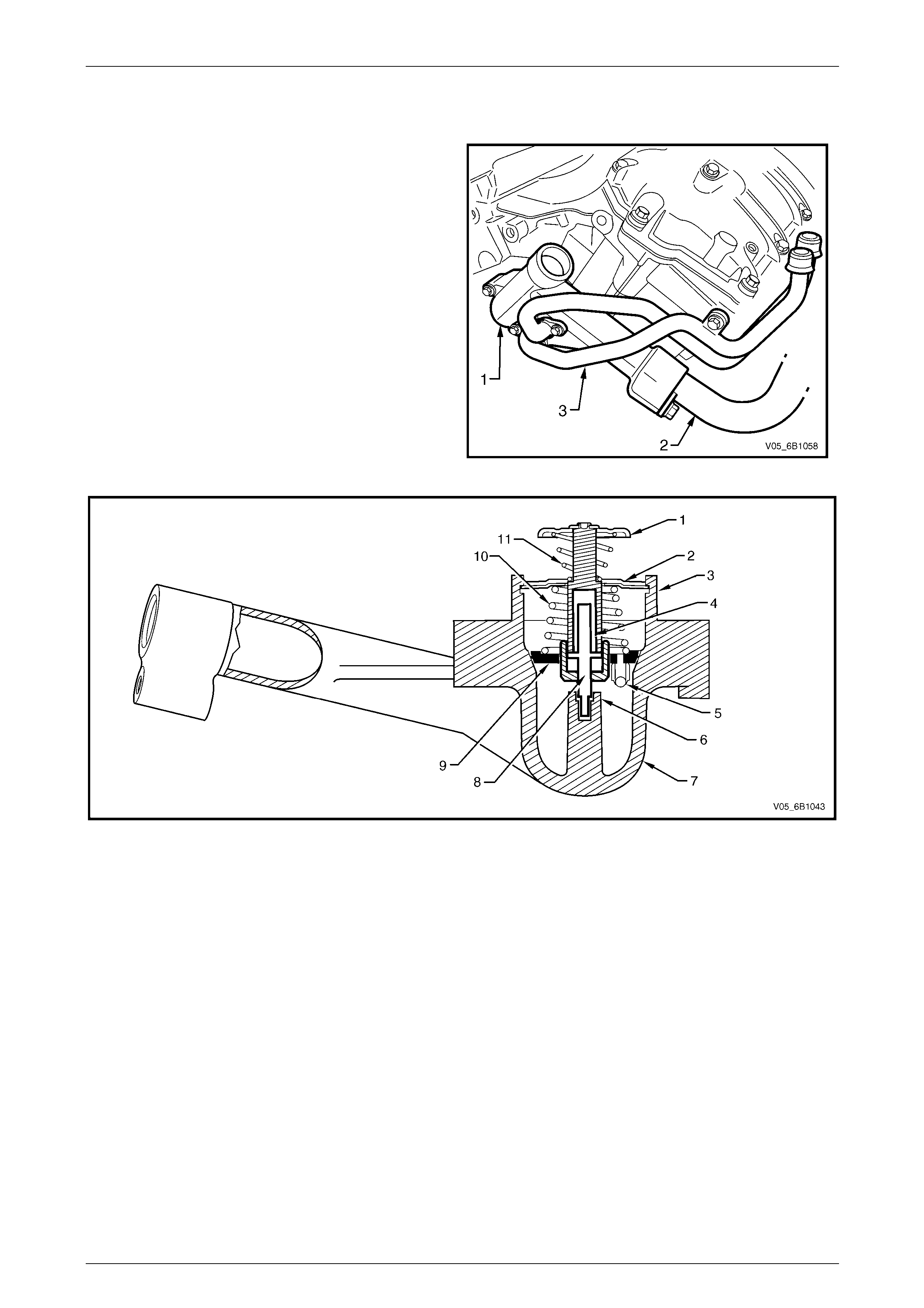
2.6 Thermostat
The thermostat housing (1) is located between the coolant
inlet pipe (2) and the rear of the intake manifold,
underneath the heater pipe assembly (3).
Figure 6B1 – 22
Figure 6B1 – 23
Legend
1 Bypass Valve
2 Thermostat Retaining Bar
3 Thermostat Assembly Retaining Lugs
4 Wax Pellet
5 Air Bleed Valve
6 Piston Centre Support
7 Thermostat Housing
8 Piston
9 Rubber Diaphragm
10 Thermostat Spring
11 Bypass Spring
A wax pellet type thermostat is used in the coolant inlet passage to control the flow of coolant, providing fast engi ne
warm up and regulating coo lant temperature. The wax pellet or power element in the thermostat expan ds when heated
and contracts when cooled. The wax pellet is connecte d through a piston to a valve and when the pellet is heated,
pressure is exerted against a metal valve, which is forced to open.
As the pellet is cooled, the contraction allows a spring to close the valve. Thus, the valve remains closed whil e the
coolant is cold, preventing circ ulation of coolant through the radiator, but allo wing the coolant to circulate throughout the
engine to warm it quickly and evenly. As the engine becomes warm, the pellet expands and the thermostat opens,
permitting the coolant to flow through to the radiator where heat is transferred to the surrounding air, through the ra diator
walls.
This opening and closing of the thermostat valve permits enough coolant to enter the radiator to keep the engine within
specified temperature limits.
The thermostat also provides a restriction in the cooling system, even after it has opened. This restriction creates a
pressure difference, which prevents cavitation at the coolant pump and forces coolant to circulate through the engine
block.
Page 6B1–27
Engine Cooling – V6 Engine Page 6B1–28
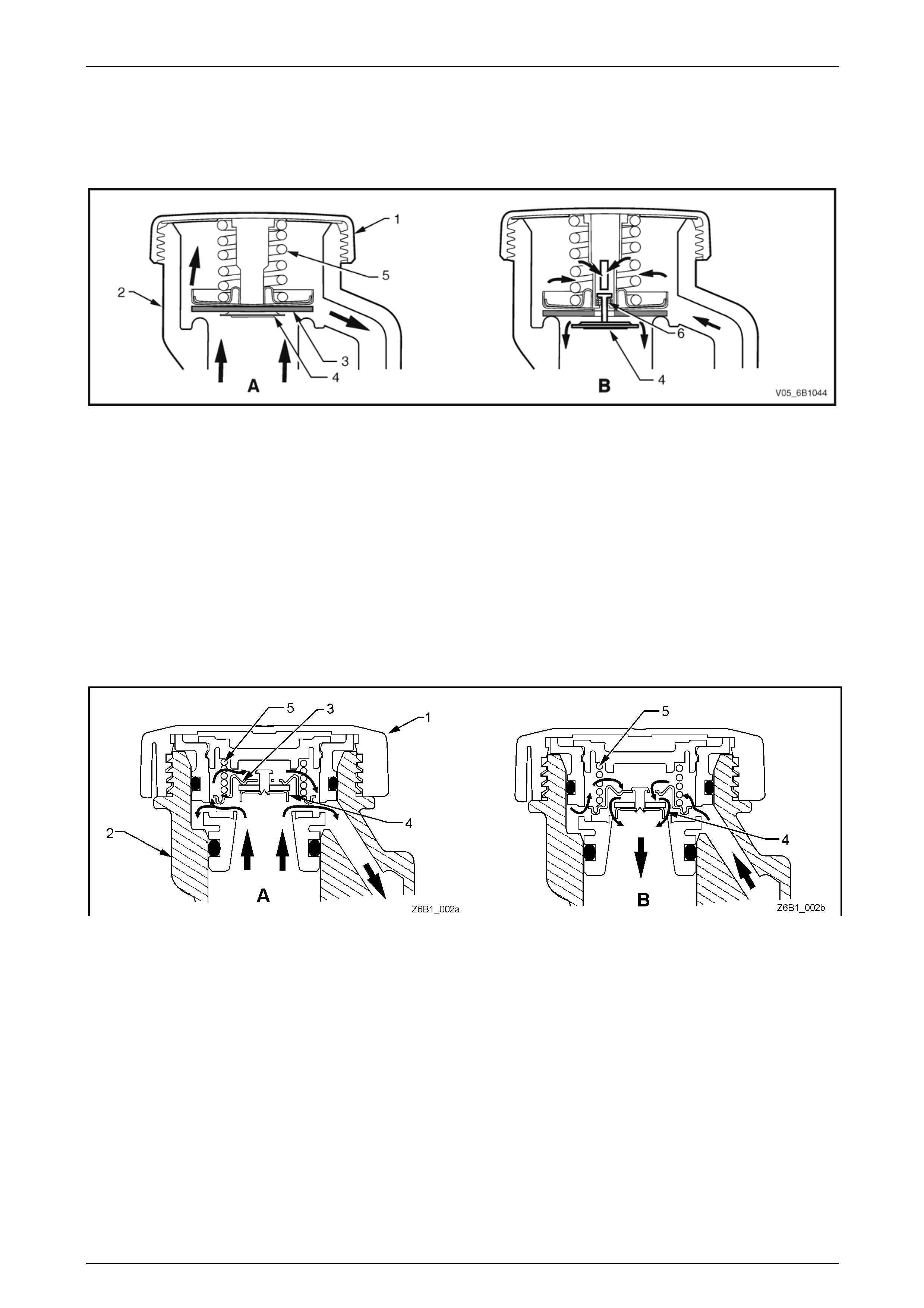
2.7 Coolant Filler Cap
MY2006 VZ HFV6 Models
Figure 6B1 – 24
The pressurised coolant filler cap (1), fitted to the filler neck (2) on the coolant outlet housing, causes the cooling system
to operate at higher than atmospher ic pressure. The higher pressure raises the boiling point of the coolant, resulting in
increased engine efficienc y. The coolant filler cap contains a pressure valve (3) and a vacuum (atmospheric) valve (4).
Referring to view ‘A’, the pressure valve is held against its seat by a spring (5), which determines the maximum operating
pressure of the cooling system (135 kPa for the Allo ytec V6 engine).
Referring to view ‘B’, the vacuum valve (4) is held against its seat by a light spring (6) and opens during cool down
because of the drop in pressure with contraction of the coolant volume. This pressure drop over-com es the spring force
and the vacuum valve is opened, preventing the radiator hoses from colla psin g. In additi on, coolant can also flow back
into the cooling system from the coolant recovery reservoir while this valve is open maintaining a full volume of coolant
within the engine and rad iator.
MY2006 VZ Update HFV6 Models
Figure 6B1 – 25
While the revised design coolant pressure cap operates in a similar way to the earlier cap, there are some differences:
• The coolant filler cap contains a pressure valve (3) and a vacuum (atmospheric) valv e (4).
• Referring to view ‘A’, the pressure valve (3) is held against its seat by a spring (5), which determines the maximum
operating pressure of the coo ling system (135 kPa for the Alloytec V6 engine). The view shows the pressure valve
has been unseated by the engin e coolant pressure, allo wing excess coolant to flow to the reservoir.
• View ‘B’ shows the situation where the eng ine coolant has cooled enough to allo w the pressure difference
(atmospheric versus engine coolant), to cause the vacuum valve (4) to be unseated. With atmospher ic pressure
acting on the surface of the coolant in the reservoir, coolant will flow back into the engine cooling system, through
the unseated vacuum valve until the pressure each side of the valve becomes equal. When the engine i s started,
the pressure difference that will soon bui ld up, seats the vacuum valve, allowing the pressure to build to the value
set by the pressure spring (5).
Page 6B1–28

Engine Cooling – V6 Engine Page 6B1–29
Should the radiator pressure cap require
replacement, only fit the correct cap (w ith the
correct pressure-rating) for this engine. Refer
to the current release of Partfinder™ for this
information.
Page 6B1–29
Engine Cooling – V6 Engine Page 6B1–30
2.8 Coolant Recovery Reservoir
The coolant is maintained at the ideal l evel in the radiator by the coolant filler cap and the coolant recover y reservoir,
resulting in increased cooling efficiency.
The coolant recovery reservoir is located on the left-hand side front of the engine compartment, between the radiator
support panel and air cleaner assembly. The coolant recover y reservoir is connected to the radiator overflow connection
by a small diameter hose.
As the engine temperature rises, the coolant is heated and expands. The fluid displaced by expansion flows from the
radiator into the recovery reservoir.
When the engine is turned OFF , the coolant contracts as it cools. Coolant is then drawn back into the radiator through
the coolant filler cap atmospheric valv e.
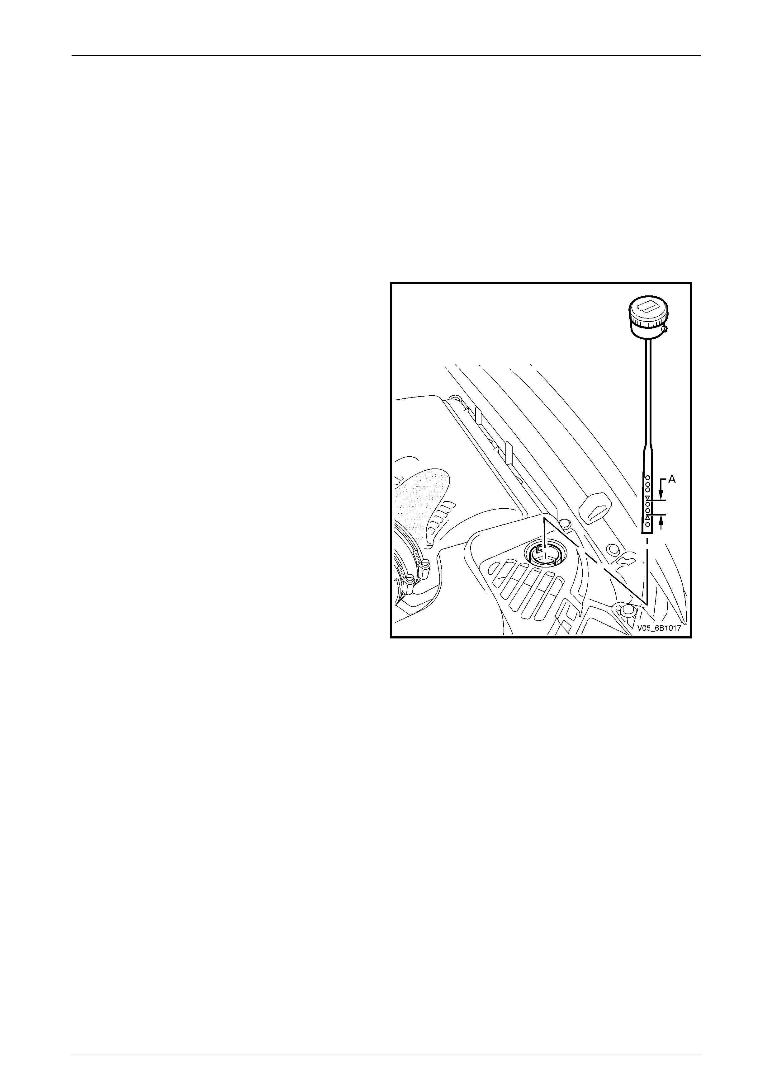
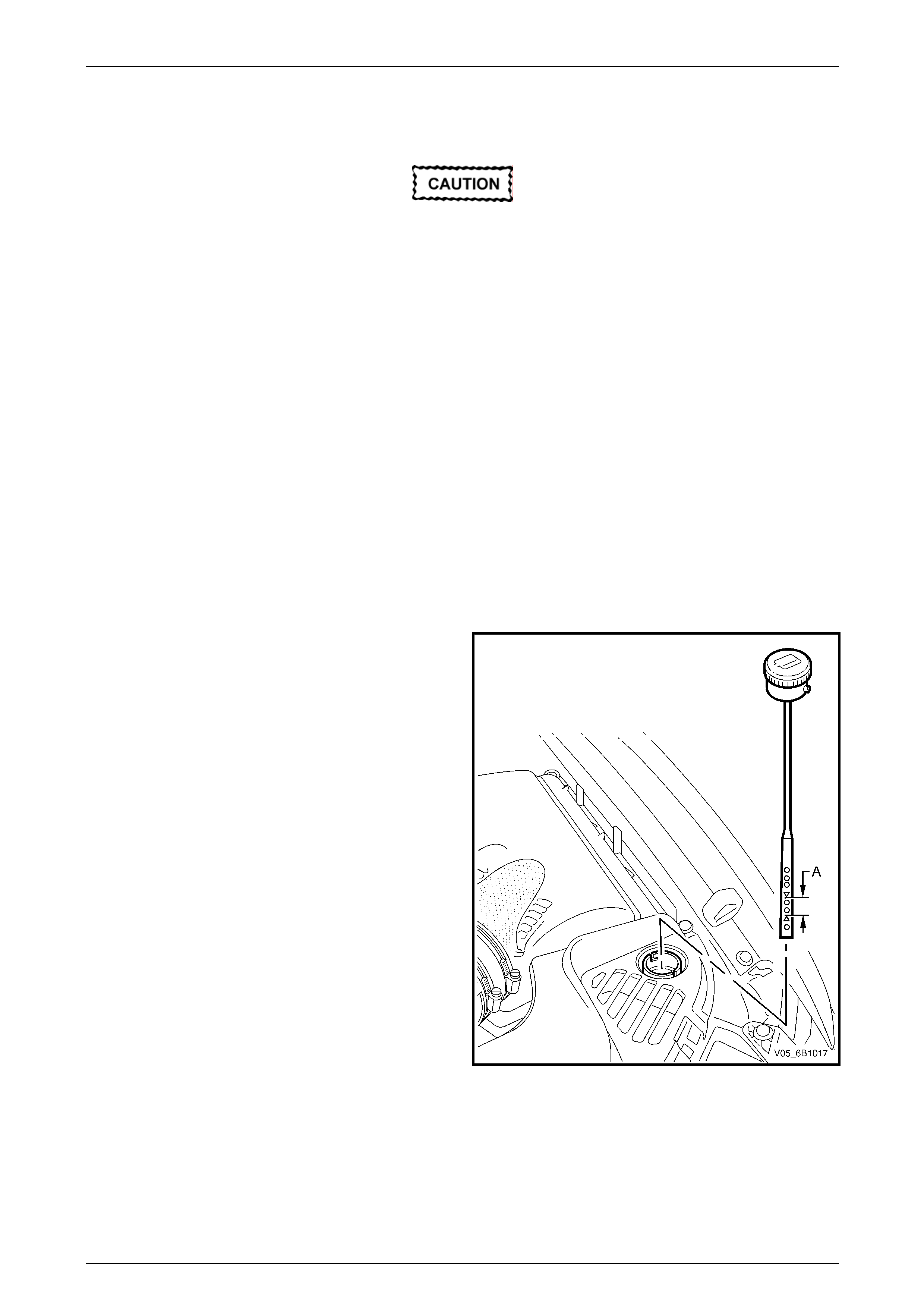
Coolant level shou ld be maintained between indicator
arrows (‘A’) on the coolant recovery reservoir dipstick, as
shown in Figure 6B1 – 26, when the e ngine is cold.
The cooling system is design ed to use a coolant, DEX-
COOL® long-life coolant or equival ent to GM specification
6277M (a mixture of ethylene glycol antifree ze and
corrosion inhibitors and water), rather than plain water to
maintain the integrity of the cooling s ystem, and to prevent
oxidation occurring within the engine.
NOTE
Some MY 2005 VZ Series vehicle markets c all
for DEX-COOL® long-life coolant and others
for its equivalent, known as Extended Life Anti-
freeze Coolant, conforming to GM specification
6277M. If in doubt regarding the correct
coolant to be used, refer to the MY 2005 VZ
Series Owner’s Handbook.
Figure 6B1 – 26
Page 6B1–30
Engine Cooling – V6 Engine Page 6B1–31
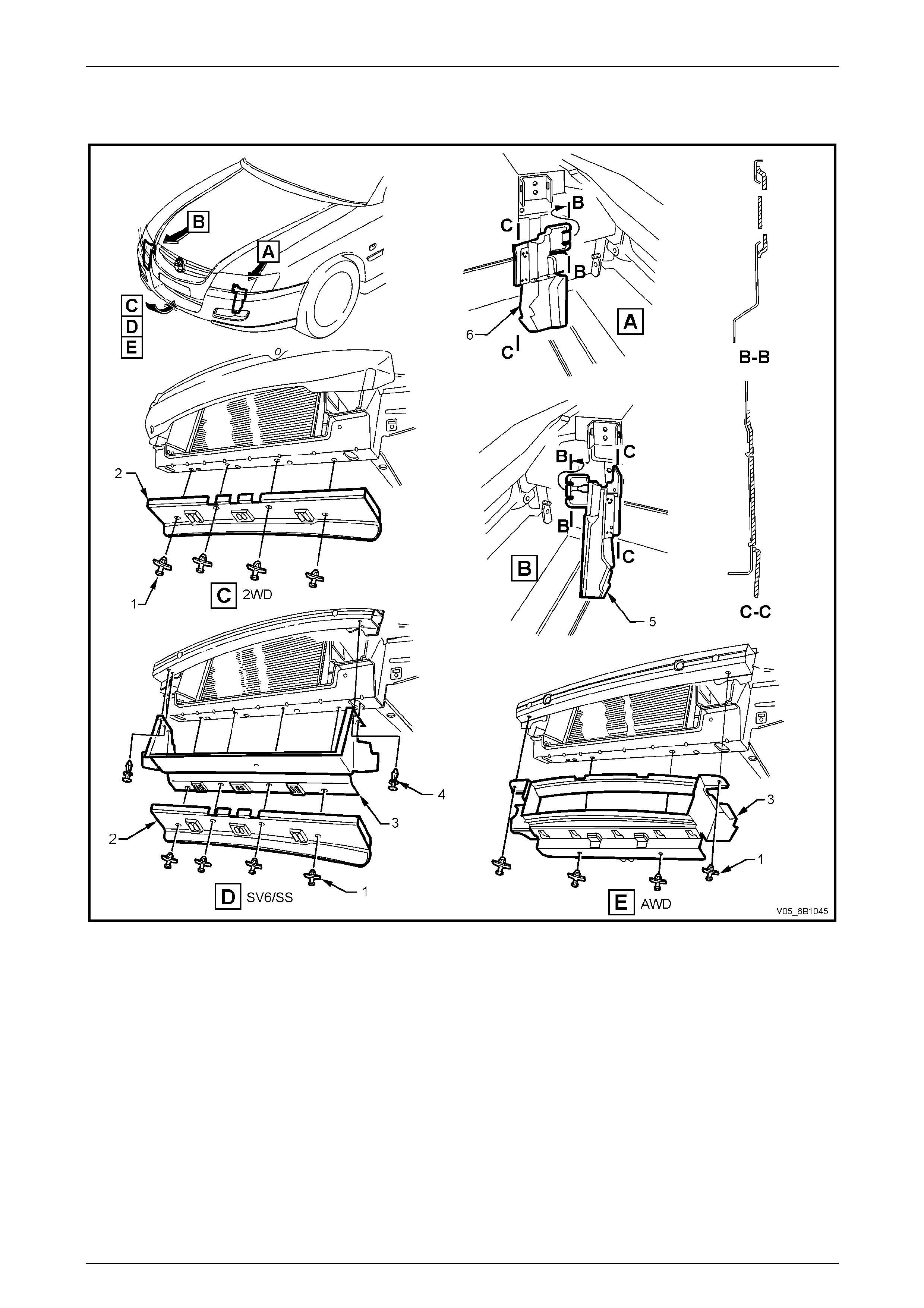
2.9 Air Baffle, Chutes and Shroud
Figure 6B1 – 27
Legend
1 Plastic Fasteners (4 places)
2 Lower Air Chute Baffle 3 Lower Air Chute Extension Duct
4 Plastic Fasteners (2 places) 5 Right-hand Side Air Chute
6 Left-hand Side Air Chute
A lower air chute baffle and side chutes are fitted to the front end of the vehicle to direct and promote airflow through the
radiator to provide maximum cooling. A lower air chute extension duct is fitted to S / SV6 sedans and AWD wagon
vehicles to increase airflo w through the radiator core.
With reference to Figure 6B1 – 27, view ‘C’ shows the standard Alloytec V6 lower air chute baffle, view ‘D’ shows the
Alloytec V6 Calais, ‘S’ and ‘SV6’ pack co nfiguration, view ‘E’ shows the Alloytec V6 AWD wagon configuration and vi ew
‘E’ shows the Alloytec Cross 6 configuration .
The purpose of the lower air chute baffle is to create a low-pressure area behind the radiator whilst the vehicle is at
speed. This enables additional airflow through the radiator core to mainta in the desired engine cooling.
The air baffle or chutes should only be removed for service work. If either the air baffle or chutes are damaged, this will
reduce the cooling system efficienc y, and therefore they must be replaced.
Page 6B1–31
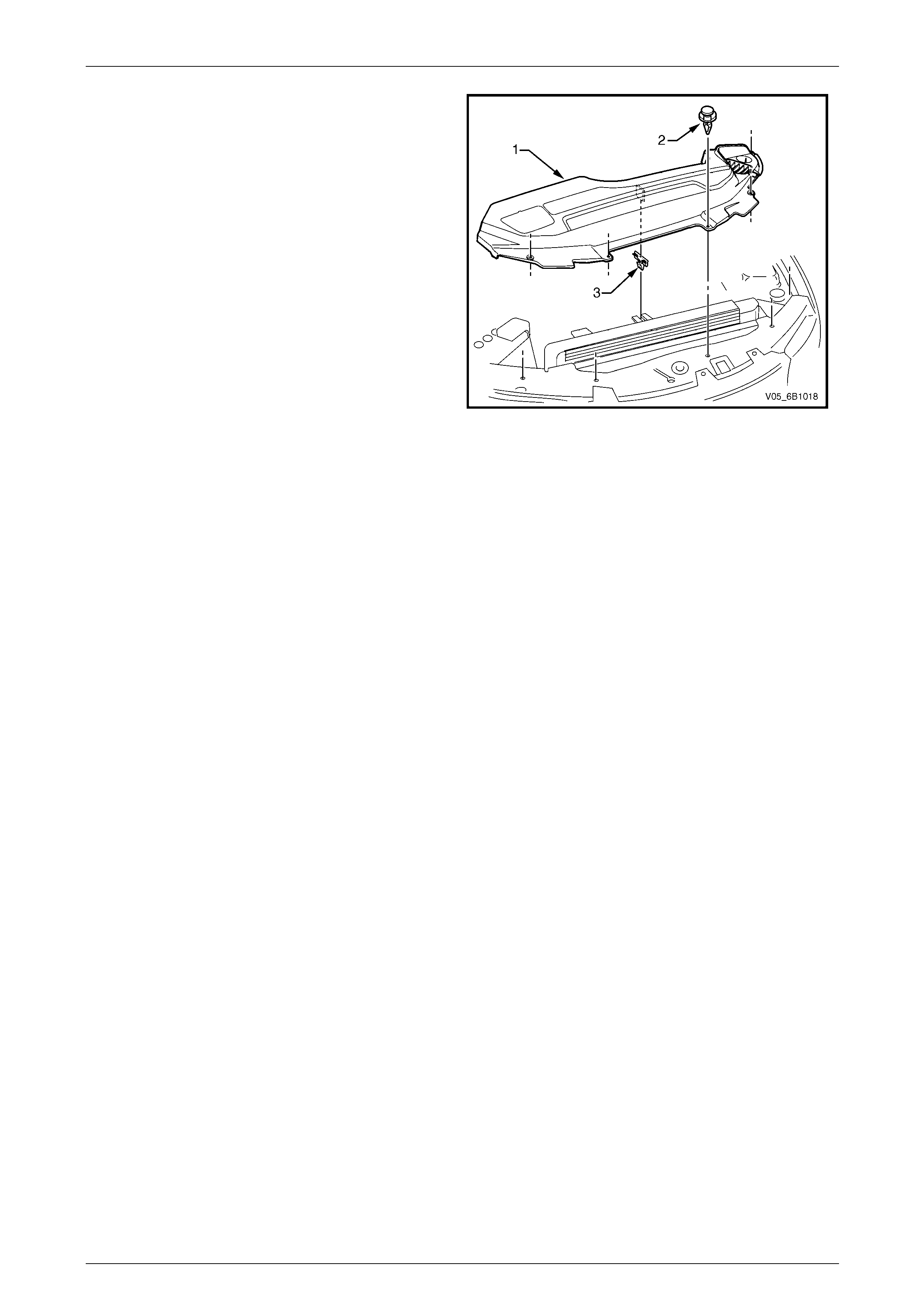
Engine Cooling – V6 Engine Page 6B1–32
An upper radiator shroud (1) is fitted between the upper
radiator support panel and the radiator assembly to
minimise the recirculation of hot air from the rear of the
radiator back over the core and to direct cool incoming air
from the front of the vehicle through the radiator core. The
shroud is held in place by five plastic scrivets (2) and a
retaining clip (3).
Figure 6B1 – 28
Page 6B1–32
Engine Cooling – V6 Engine Page 6B1–33
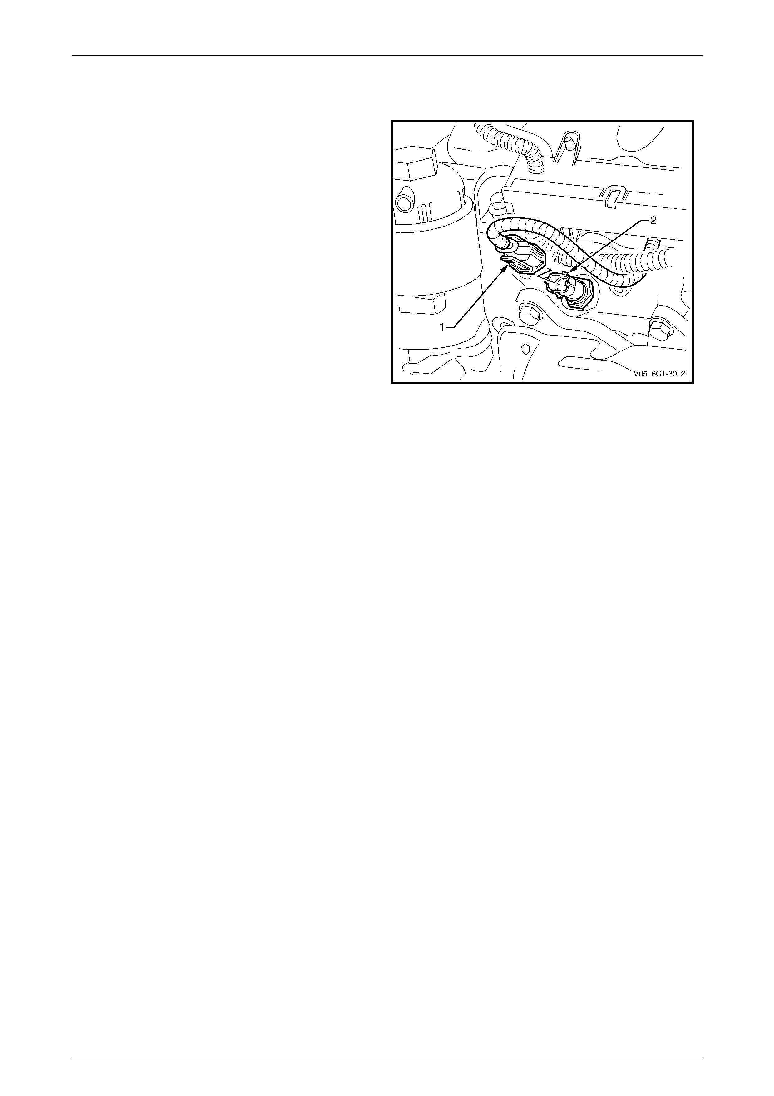
2.10 Engine Coolant Temperature Sensor
An Engine Coolant Temperatur e (ECT) sensor (2) is
mounted in the left-hand side c ylinder he ad, just behind
the oil filter housing. The ECT sensor is used in
conjunction with the instrument panel tempe r ature gauge.
The ECT sensor generates a signal, which is used by the
engine management system for calculatio n of the various
engine management functions.
Figure 6B1 – 29 shows the wiring h arness connector (1)
and the ECT sensor (2).
Refer to Section 6C1-1 Engine Management – V6 –
General Information for further information on the ECT
sensor.
Figure 6B1 – 29
Page 6B1–33
Engine Cooling – V6 Engine Page 6B1–34
3 Service Operations
3.1 Service Notes
Safety
• To avoid serious personal injury, never
remove the coolant filler pressure cap on
the coolant outlet housing when the
engine is hot, even if the cooling system
should require filling. Sudden release of
cooling system pressure is very
dangerous.
• The vehicle is fitted with twin electric
radiator cooling fans. When working
around the engine compartment, keep
clear of the fans as they may start without
warning.
Before removing the coolant filler cap, allow the engine to cool, then place a shop rag over the coolant filler cap and then
slowly turn the cap anticlockwise, approx imately 1½ turns, until the pressure relief position is reached. The pressure
relief position will allow any r emaining pressure within the system to escape into the coolant recovery reservoir. Continue
to rotate the cap anticlockwise until the cap can be safely removed.
Periodic Servicing
The cooling system requires little attention except for maintaining the coolant to the correct level in the recovery reservoir
and periodic servicing at the time or distance intervals as outlined in Section 0B Lubrication and Serv ice.
Periodic servicing includ es:
1 Checking coolant level. Refer to 3.3 Draining and Filling Co oling System in this Section.
2 Checking coolant concentration. Refer to 3.2 Coolant Maintenance – Testing Coolant Concentration in this Section.
3 Pressure test cooling system and coolant filler cap. Refer to 3.7 Pressure Testing in this Section.
4 Tighten hose clamps and ins pect all hoses. Refer to 3.6 Coolant Hoses in this Section. R eplace hoses if swollen or
deteriorated.
Always wear protective safety glasses when
working with spring type hose clamps. Failure
to do so could result in eye injury.
5 Clean out cooling system, refer to 3.4 Cleaning Cooling System – Cooling System Flush, in this Section and refill.
Refer to 3.3 Draining and Filling Cooling System in this Section.
Environmental Issues
To reduce environmental impact and mai nte nance cost, whenever the coolant is drained from any engine, the service
records are to be checked to determi ne when the coolant was last changed. If more than six months life is left before the
next coolant change, then the following procedure is to be followed:
1 When draining the cool ant from the engine, use a clean container to hold at least 12 litres of coolant and ensure
that the coolant is not contaminated in the draining process.
2 After repairs have been completed, refill the engi ne cooling system with the drained cool ant.
3 Top up as required, using a 50 / 50 mix of clean water and the recommended cool ant, which is either DEX-COOL®
long-life coolant or its equivalent, known as Extended Life Anti-freeze Coolant conforming to GM specification
6277M. Refer to 3.2 Coolant Maintenance and 3.3 Draini ng and Filling Cooling System in this Section, for the
necessary procedures and further information.
Page 6B1–34
Engine Cooling – V6 Engine Page 6B1–35
3.2 Coolant Maintenance
Do not mix different types of anti-freeze or
corrosion inhibitors, as they may be
incompatible. If a different type ha s been used
in the cooling system, flush the system with
clean water, refer to 3.4 Cleaning Cooling
System – Cooling System Flush in this
Section and refill cooling system with the
correct coolant. Refer to 3.3 Draining and
Filling Cooling System in this Section.
The cooling system is design ed to use a coolant (a mixture of ethylene glycol antifreeze with added corrosion inhibitors,
and water), rather than plain water. T he use of glycol also raises the boiling point and incr eases the cooling system
efficiency. For this reason, it is of the utmost importance that the correct concentration level of ethylene glycol in the
cooling system is maintained.
Addition of plain water into the cooling system when 'topping-up' ma y dilute the coolant mixture to a point where the
antifreeze / anti-boil and corrosion inhibitor properties of ethylen e gl ycol become ineffective.
The coolant should comprise of a mixture 50% ethylene gl ycol antifreeze / inhibitor with 50% clear, clean water.
Ethylene glycol conforming to the correct specificatio n is either named DEX-COOL® long-life coolant or its equivalent,
known as Extended Life Anti-freeze C oolant conforming to GM specification 6277M. Both are ava ilable in a number of
different quantities. Check the current release of Partfinder ™ for specific details.
Topping Up the Cooling System
Under normal operating conditions, the cooling system
should not be topped up at the coolant filler cap. The level
can be checked at the coolant recover y reservoir, and
coolant (in the correct concentration with clear, clean
water) added as necessary to bring the level to between
the indicator arrows (‘A’) on the coolant recovery reservoir
dipstick, as shown in Figure 6B1 – 30, when the engine is
cold.
Figure 6B1 – 30
Page 6B1–35
Engine Cooling – V6 Engine Page 6B1–36
Testing Coolant Concentration
To ensure the specified ethylene glycol concentration is maintained in the engine coolant, the coolant concentration must
be checked at the time or distance intervals outlined in the MY 2005 VZ Series Owner’s Handbook or Service Booklet in
the glove box.
NOTE
• While a number of coolant concentration
measuring devices are available, the two
preferred types are as described.
• The procedures detailed, apply to either
coolant type used.
Method 1 – Refractometer
NOTE
• Coolant tester, Tool No. J26568,
automatically compensates for temperature.
• Ensure that the eyepiece of the tester is free
of coolant before looking through it.
• Before each use, swing back the plastic cove r
at the slanted end of the coolant tester,
exposing the measuring window and the
bottom of the plastic cover. Carefull y wipe the
measuring window dry with a tissue or clean,
soft cloth. Close the plastic cover.
1 Check the calibration of the coolant tester as follows:
a Place a few drops of distilled water (between 21 and 29° C) onto the measuring window, then close the
plastic cover.
b Point the tester toward any light source, look into the eyepiece and ch eck that the indicated reading is zero. If
not, then re-calibrate the tester as detailed at the end of this Test Method, Calibrating the Tester.
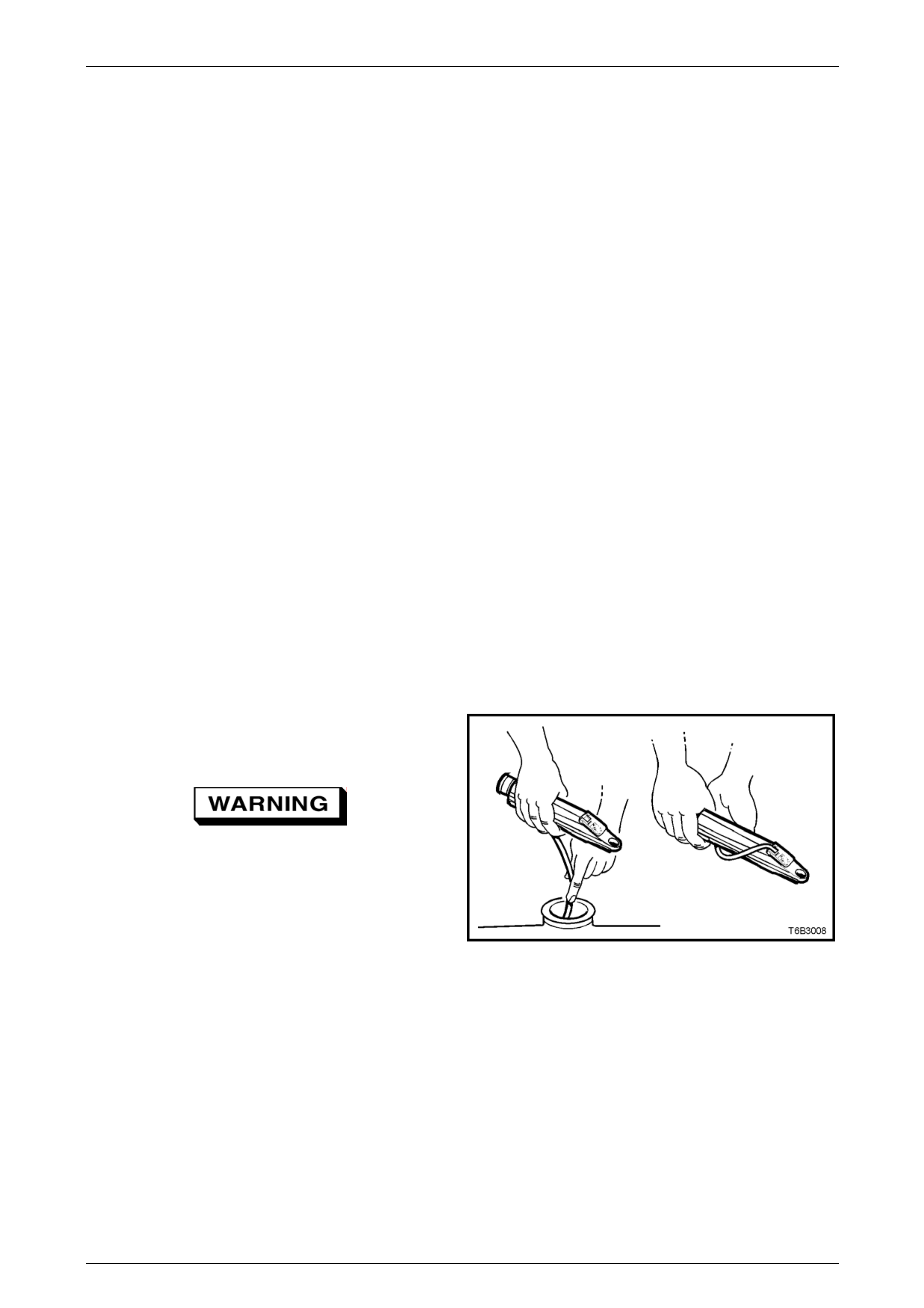
2 Release the tip of the bulb pump from under the
refractometer body. It is not necessary to remove the
complete pump from the tool.
Refer to 3.1 Service Notes in this Section,
for important safety items.
3 Carefully remove the coolant filler cap.
4 Insert the tube of the pump into the coolant, and
then press the bulb to obtain a sample.
5 Bend the tube around and insert the end into the
cover plate opening.
Figure 6B1 – 31
6 Press the pump bulb to deposit a few drops of coolant onto the measuring surface. Do not open the plas tic cover
when taking readings, as moisture evaporation will change the reading obtained.
Page 6B1–36
Engine Cooling – V6 Engine Page 6B1–37
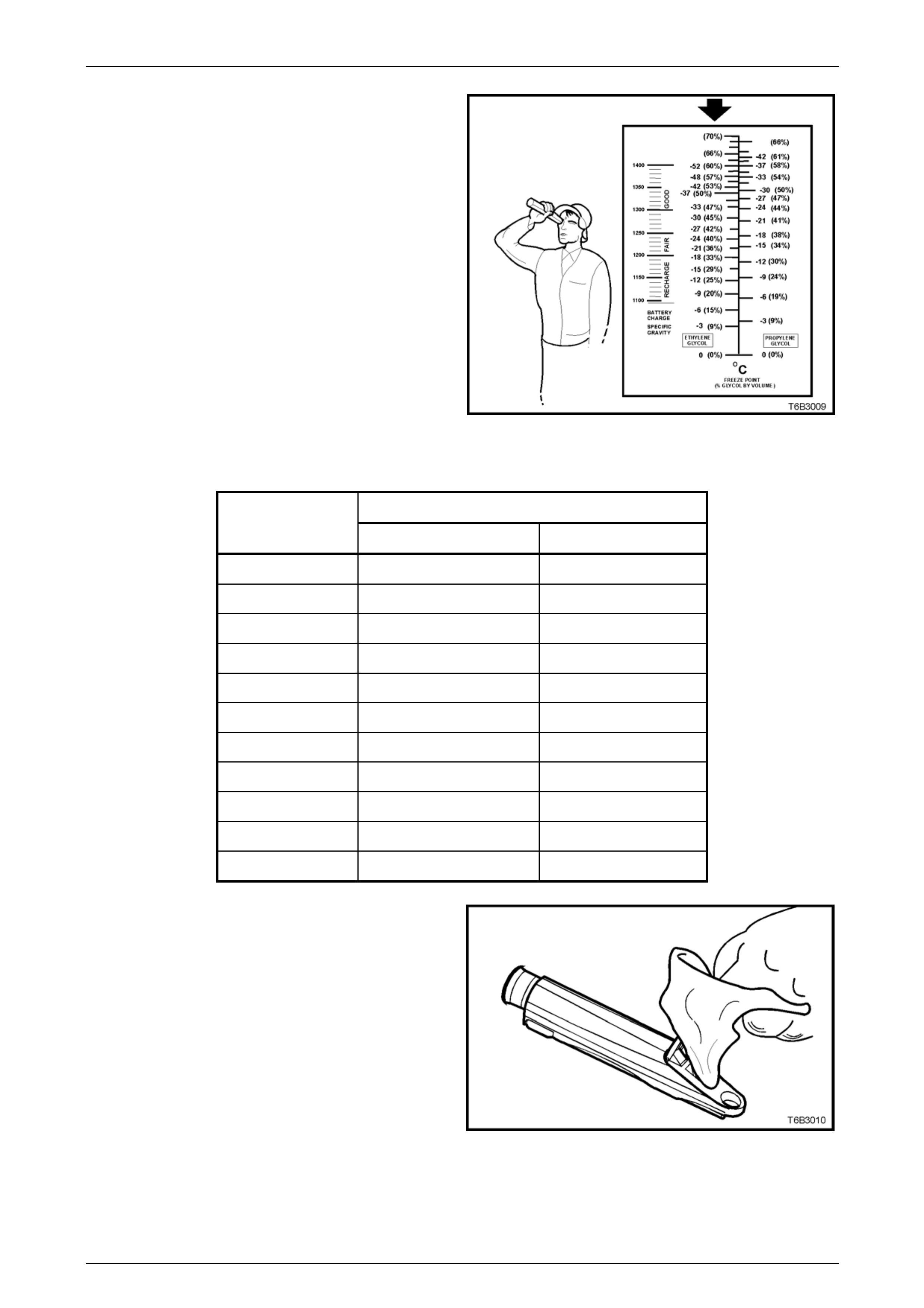
7 Point the coolant tester toward any light source,
looking into the eyepiece.
a The coolant protection read ing is at the point
where the dividing line between the light and
dark, crosses the scale.
b The scale for ethylene glycol (bold arrow) is
the reference scale for either DEX-COOL®
long-life coolant or its equivale nt, known as
Extended Life Anti-freeze Coolant conforming
to GM specification 6277M.
NOTE
The temperature scale is reversed from that of
a conventional thermometer. Below zero
readings are on the upper half of the scale.
8 A reading between – 30 and – 52°C (corresponding
to a coolant concentration between 45 to 60%), is
satisfactory for the Alloytec V6 engine cooling
system. Figure 6B1 – 32
COOLANT CONCENTRATION
Litres Of Coolant To Be Added
Concentration
Reading % Automatic Transmission Manual Transmission
0 4.95 5.15
5 4.46 4.62
10 3.96 4.12
15 3.47 3.61
20 2.97 3.08
25 2.48 2.57
30 1.98 2.01
35 1.48 1.54
40 0.99 1.05
45 0.50 0.52
50 0 0
NOTE
If the reading is not clear, then properly clean
and dry the measuring surface, then conduct
another test. Also ensure that there is
sufficient fluid on the measuring prism.
9 If the reading shows that the concentration level of
the coolant is inadequate, refer to the Coolant
Concentration table to determine the amount of
coolant that needs to be added to the coolant
recovery reservoir.
10 Start and run the engine until normal operating
temperature is reached, to allow the adde d coolant
to be distributed throughout the engine cooling
system. Figure 6B1 – 33
Page 6B1–37
Engine Cooling – V6 Engine Page 6B1–38
Calibrating the Tester
The coolant tester calibration is checked at manufacture. If however, the calibration check detailed in Step 1 of this
method shows that the instrument is not reading correctly, then conduct the following recalibration procedure:
1 Remove the sealant covering the adjustme nt screw on the underneath of the tester.
2 With a distilled water sample on the measuring surface, carefully adjust the screw until a zero reading is obtained.
NOTE
DO NOT completely remove the screw.
3 After recalibration, reseal the screw with a small amount of silicone sealant.
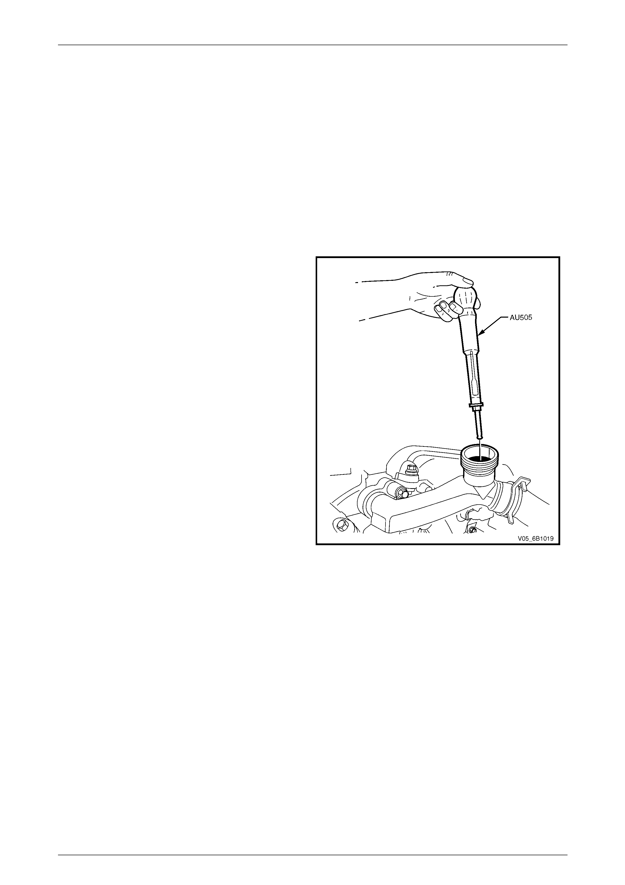
Method 2 – Hydrometer
1 The cooling system should be at or close to ambient
temperature.
2 Carefully remove the coolant filler cap from the
coolant outlet housing and, while holding the rubber
bulb squeezed, insert nozzle of coolant tester
hydrometer, Tool No. AU505 into coolant. Re leasing
the rubber bulb will then draw sufficient coolant into
the tester to float hydrometer bulb freely.
3 Hold tester at eye level and read scale on
hydrometer bulb at coolant level.
The reading shows the percentage of ethylene
glycol antifreeze contained in the engine coolant.
4 The hydrometer reading should show 50% if the
coolant concentration is correct.
• If a reading of less than 50% is achieved, the
cooling system requires topping up with either
DEX-COOL® long-life coola nt or its equivalent,
known as Extended Life Anti-freeze Coolant
conforming to GM specification 6277M.
• Refer to the Coolant Concentration tab le
shown for the previous method to determine
how much coolant additive of either type is
required to be added to the cooling system to
bring the coolant to the specified
concentration.
Figure 6B1 – 34
5 Drain sufficient quantity of coolant from cooling system to allow top-up with coolant additive, then add the required
amount of the correct additive. Install coolant filler cap to the coolant outlet housing.
6 Start and run the engine until normal operating temperature is reache d. This will allow the added coolant to be
distributed throughout the engine cooling system.
Page 6B1–38
Engine Cooling – V6 Engine Page 6B1–39
3.3 Draining and Filling Cooling System
Draining
Refer to 3.1 Service Notes in this Section, for
important safety items.
1 Allow engine to cool to ambient temperature (less than 50° C), and then remove the coolant filler cap (l ocated near
the front left-hand side of the engine throttle body).
Disconnection of the battery affects certain
vehicle electronic systems. Refer to
Section 00 Warnings, Cautions and Notes,
before removing the ground lead.
2 Disconnect the battery ground lead. Refer to Section 12A Battery.
3 On AWD vehicles, remove the front bumper fascia under-tray (where fitted). Refer to Section 1D Bumper Bars.
4 Drain the coolant from the system via the radiator dra in tap on the lower LHS of the radiator. Attach a suitable piece
of rubber tubing to the tap outlet to help direct the flow of the coolant into a suitable container (capacity at least
12 litres).
Filling
During any service operation that requires the cooling system to be partly or completely drained, the following
instructions must be followed when refilling the cooling system, to ensure that all air is ble ed from system.
• Refer to 3.1 Service Notes in this Section,
for important safety items.
• Before opening the radiator bleed screw,
the cooling system must first be
completely depressurised with the engine
coolant filler cap removed.
Do not mix different types of anti-freeze or
corrosion inhibitors, as they may be
incompatible. Always check which coolant is
to be added to the particular vehicle being
serviced. If a different type has been used in
the cooling system (or is added accidentally),
flush the system with clean water. Refer to
3.4 Cleaning Cooling System – Cooling
System Flush in this Section.
NOTE
Ensure that the radiator drain tap located at the
bottom of left-hand side radiator tank is closed
before proceeding.
Page 6B1–39
Engine Cooling – V6 Engine Page 6B1–40
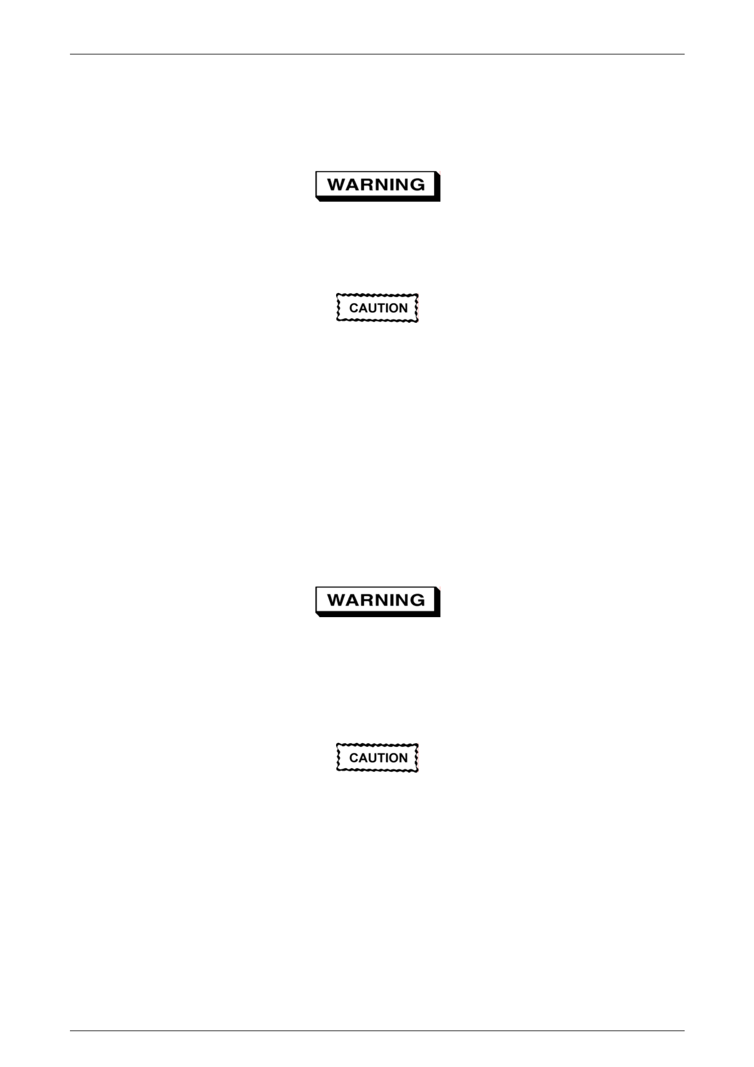
1 With the engine off, remove the coolant filler cap (1)
on the coolant outlet housing (2), located at the front
left-hand side of the engine.
Figure 6B1 – 35
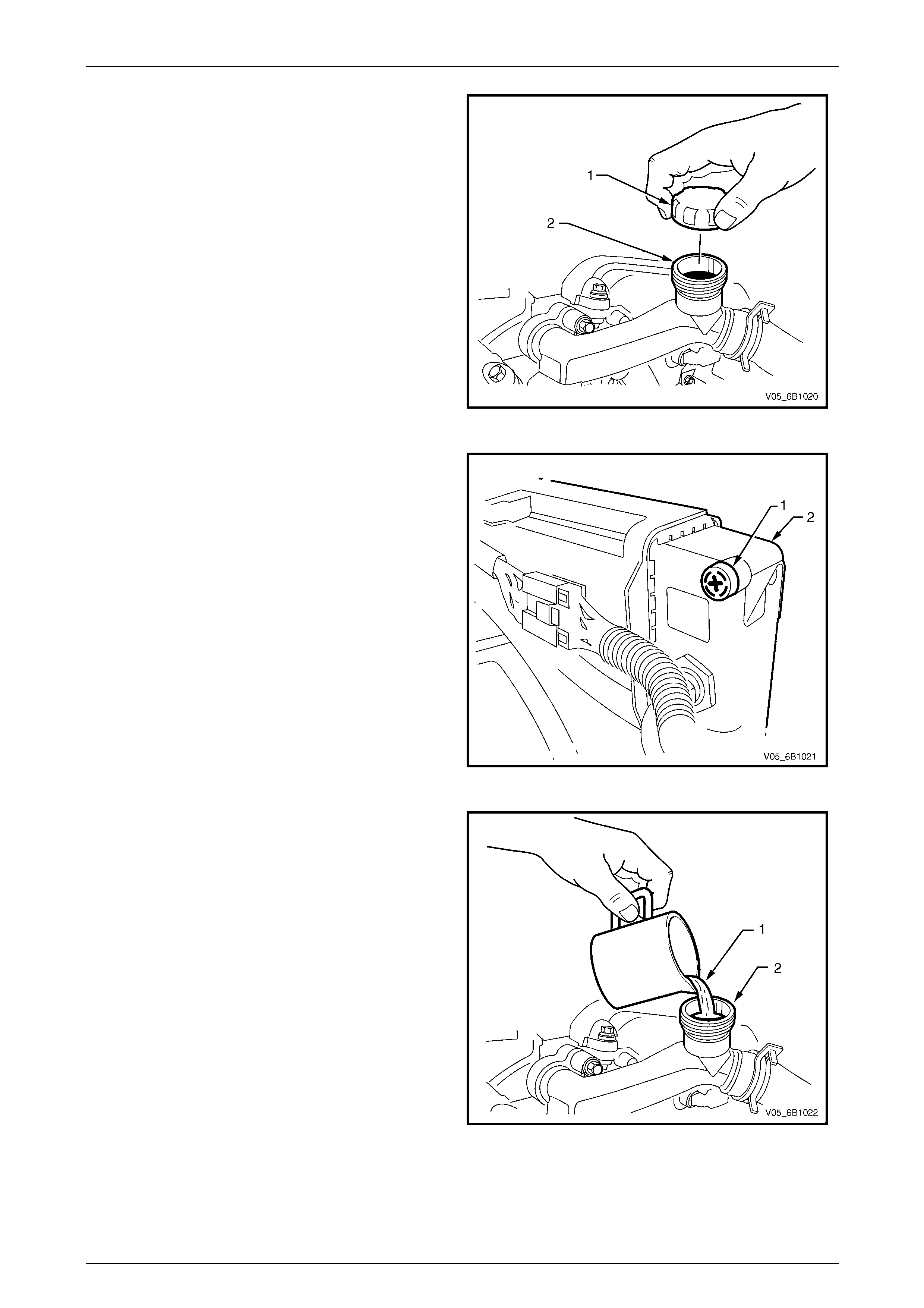
2 Open the radiator bleed screw (1) on the top of the
right-hand side radiator tank (2).
Figure 6B1 – 36
3 If filling a completely empty cooling s ystem for
automatic transmission models, mix 5 litres of clean
water with 5 litres of the recommended coolant or
5.2 litres of each for manual transmission models.
4 Add coolant (1) via the engine coolant filler neck (2)
on the coolant outlet housing until it le aks from the
radiator bleed scre w.
5 When the coolant leaks from the bleed screw hole,
close the bleed screw and continue fil ling until full.
NOTE
Do not replace the coolant filler cap before
starting the engine (in ste p 6). Leaving the filler
cap off allows the engine to warm up without
pressurising.
6 Reconnect battery ground lead. Refer to
Section 12A Battery.
7 Start the engine and set the HVAC controls to:
• Full hot.
• Low fan.
• A/C OFF.
Figure 6B1 – 37
Page 6B1–40
Engine Cooling – V6 Engine Page 6B1–41
8 Run the engine at approximately 2,000 rpm to warm up the engine.
9 Wait until the radiator fan(s) switch on.
10 When the radiator fans have switched on, let the engine rpm drop back to idle.
11 Turn the engine off when the radiator fans switch off.
12 Open the radiator bleed screw.
13 Add coolant until it leaks past the radiator bleed screw.
14 Close the radiator bleed screw.
Do not over-tighten the radiator bleed screw
as the radiator assembly would have to be
replaced if the screw hole thread is damaged .
Radiator bleed scre w
torque specification........................................1 – 1.5 Nm
15 Top up the coolant until full and fit the coolant filler cap to the coolant outlet housing.
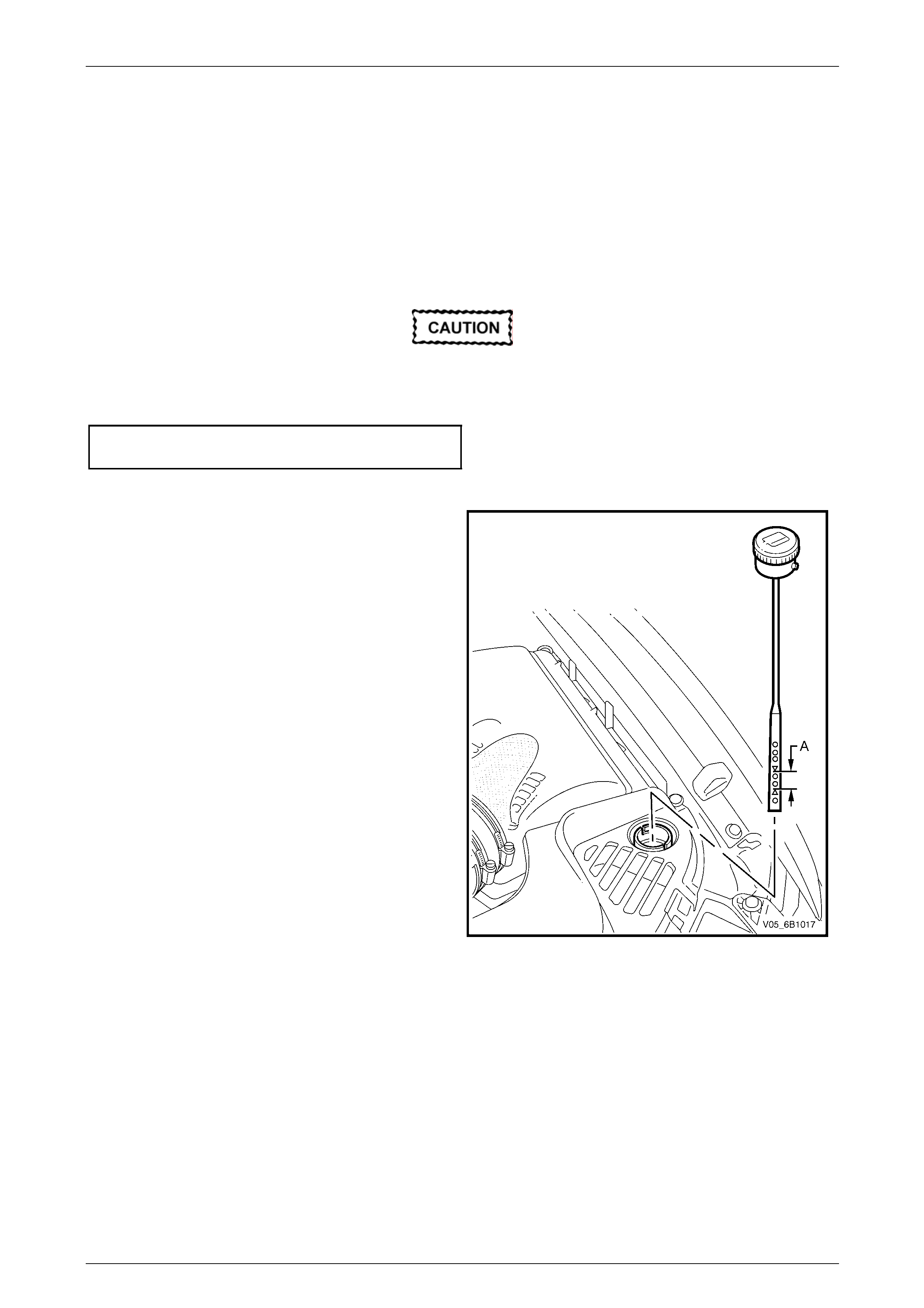
16 Top up the radiator cool ant recovery reservoir to the
top mark on the dipstick.
17 Reinstall the coolant recovery reservoir cap.
NOTE
This condition only applies when the cooling
system is first being filled after a major loss of
coolant. The level of coolant in the reservoir
will then drop, once the engine is started and
normal operating temperature is reached. The
coolant level should then be maintained at the
correct level (between the two dipstick
arrows ‘A’).
18 On AWD vehicles, install the front bump er fascia
under-tray (where fitted). Refer to Section 1D
Bumper Bars.
Figure 6B1 – 38
Page 6B1–41
Engine Cooling – V6 Engine Page 6B1–42
3.4 Cleaning Cooling System
NOTE
• Before carrying out reverse flushing
procedures, it is recommended that a
cleaning solution be use d to loosen scale and
corrosion. Only use a Holden approved
radiator cleaner following the instructions on
the container label.
• This operation should only be carried out
when the engine and radiator are at ambient
temperature.
• When using specialised cooling system
flushing equipment, conn ect the equipm ent as
recommended by the manufacturer.
Cooling System Reverse Flush
Radiator
Refer to ‘Environmental Issues’ in 3.1 Service
Notes, before draining the coolant.
1 Drain the cooling system. Refer to 3.3 Draining and Filling Cooling System – Draining in this Section.
Always wear eye protection when working
with spring-type hose clamps. Failure to do
so may result in eye injury.
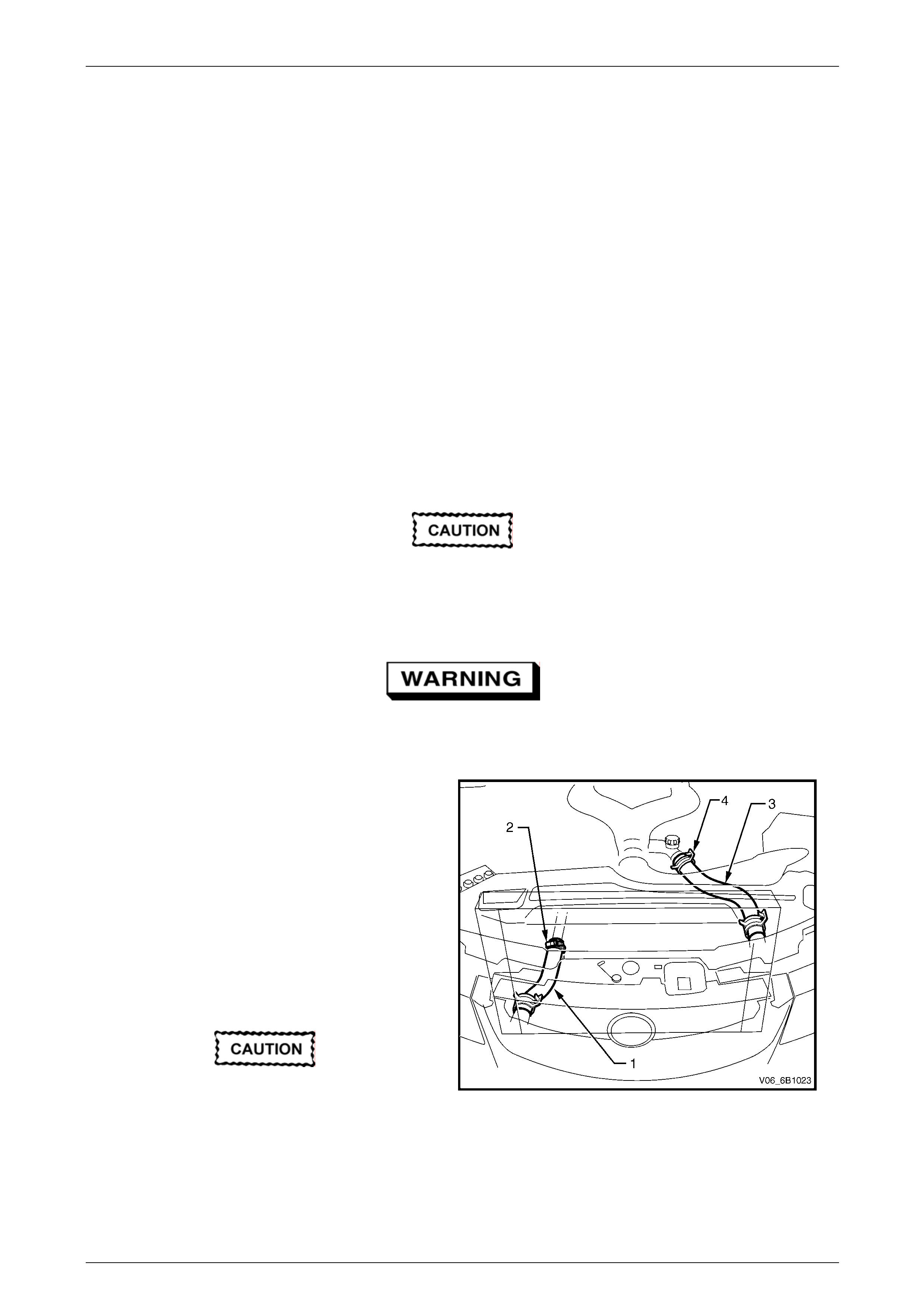
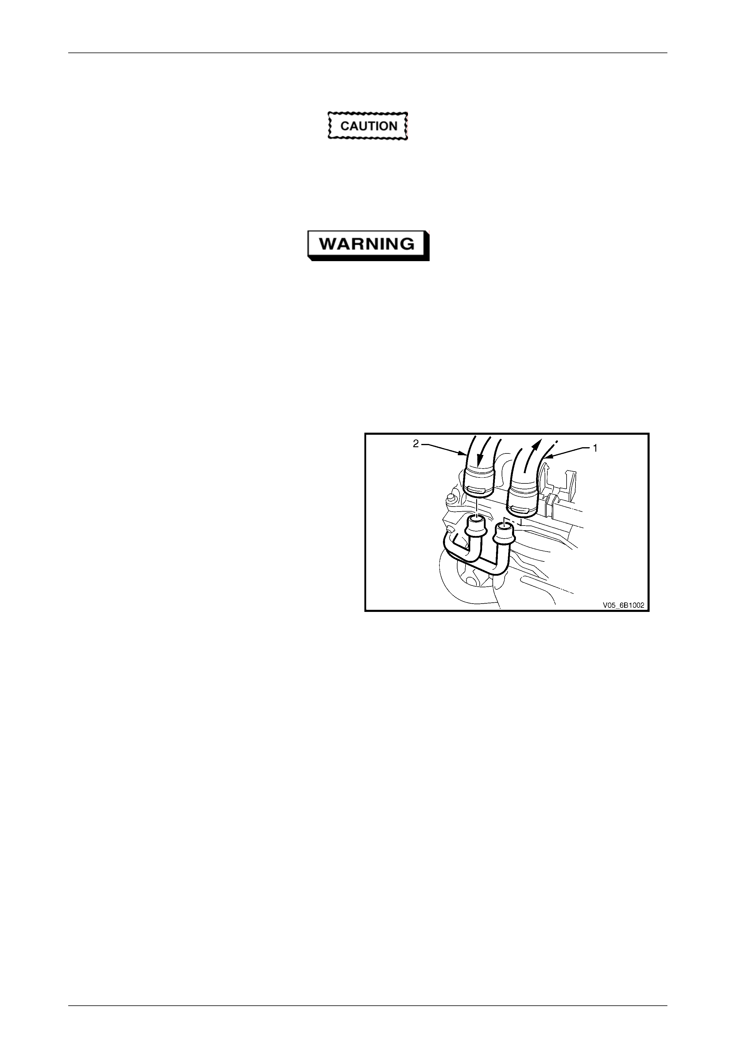
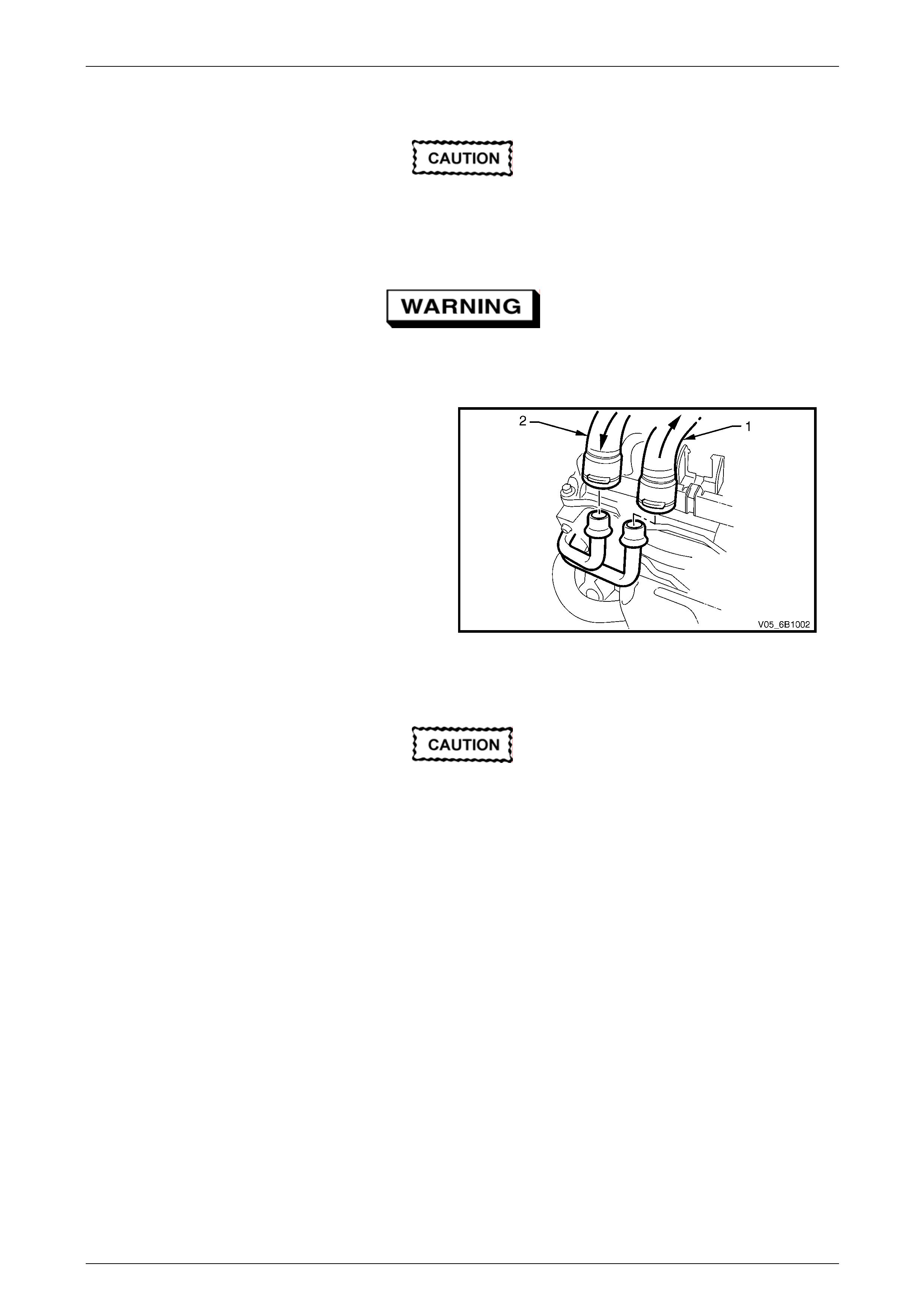
2 Remove the lower radiator outlet hose (1) at the
coolant inlet pipe worm drive clamp (2).
3 Remove the upper radiator inlet hose (3) at the
coolant outlet housing connection (4).
4 Attach a lead-away hose to the open en d of the
upper radiator hose.
5 Attach a suitable piece of hose or adaptor be tween
the flushing gun and the open end of the lower
radiator hose.
6 Connect and operate the flushing equipment as
recommended by the manufacturer.
Apply air pressure gradually and not in
excess of 120 kPa, otherwise radiator
damage will result.
Figure 6B1 – 39
7 Continue flushing until the water from the lead-away hose runs clean and clear.
8 Install all disconnected hoses, ensuri ng that they are correctly positioned and securely clamped.
9 Fill the cooling system. Refer to 3.3 Draining and Filling Cooling System – Filling in this Section.
10 Pressure test the cooling system. Refer to 3.7 Pressure Testing in this Section.
Page 6B1–42
Engine Cooling – V6 Engine Page 6B1–43
Engine
Refer to ‘Environmental Issues’ in 3.1 Service
Notes, before draining the coolant.
1 Drain the cooling system. Refer to 3.3 Draining and Filling Cooling System – Draining in this Section.
Always wear eye protection when working
with spring-type hose clamps. Failure to do
so may result in eye injury.
2 Remove the upper and lo wer radiator hoses from the coolant outlet housing and coola nt inlet pipe connections.
Refer to Figure 6B1 – 39.
3 Remove the thermostat housing from the rear of the intake manifold. Refer to 3.8 Thermostat in this Section.
4 Remove the thermostat from the thermostat housing and reinstall the housing to the rear of the intake manifold.
Refer to 3.8 Thermostat in this Section.
5 Remove both heater hoses (1) and (2) from their
connections at the heater pipe assembly, noting
which hose was connected to which connection.
Seal the heater pipe assembly connections by
looping the heater inlet connection to the outlet
connection using a suitable piece of hose and two
hose clamps.
6 Install a lead-away hose to the coolant inlet pipe
connection and a length of suitabl e hose between
the coolant outlet housing connection and the
flushing equipment.
7 Connect and operate the flushing equipment as
recommended by the manufacturer.
Figure 6B1 – 40
8 Continue flushing until the water from the lead-away hose runs clear.
9 Remove the coolant recovery reservoir, flush it out with clean water and install. Refer to 3.9 Coolant Recovery Reservoir
in this Section.
10 Install the thermostat. Refer to 3.8 Thermostat in this Section.
11 Install all disconnected hoses, ensuring that they are correctly positioned and securely clamped.
12 Fill the cooling system. Refer to 3.3 Drai ning and Filling Cooling System – Filling in this Section.
13 Pressure-test the cooling system. Refer to 3.7 Pressure T esting in this Section.
Page 6B1–43
Engine Cooling – V6 Engine Page 6B1–44
Heater Hoses and Core
Refer to ‘Environmental Issues’ in 3.1 Service
Notes, before draining the coolant.
1 Drain the cooling system. Refer to 3.3 Draining and Filling Cooling System – Draining in this Section.
Always wear eye protection when working
with spring-type hose clamps. Failure to do
so may result in eye injury.
2 Remove both heater hoses (1) and (2) from their
connections at the heater pipe assembly, noting
which hose was connected to which connection.
3 Direct the hose (1) that was connected to the
heater pipe assembly’s front connection into a
suitable container.
4 Attach the hose (2) from the rear-most connection
to the flushing gun.
5 Cycle the heater switch to ensure that the water
valve is open.
Figure 6B1 – 41
6 Connect and operate the flus hing equipment as recommended by the manufacturer.
Apply air pressure gradually and not in
excess of 130 kPa, otherwise heater core
damage will result.
7 Install all disconnected hoses, ensuri ng that they are correctly positioned and securely clamped.
NOTE
For heater hose routing, refer to Figure 6B1 – 45.
8 Fill the cooling system. Refer to 3.3 Draining and Filling Coo ling System, Filling in this Section.
9 Pressure test the cooling system. Refer to 3.7 Pressure Testing in this Section.
Page 6B1–44
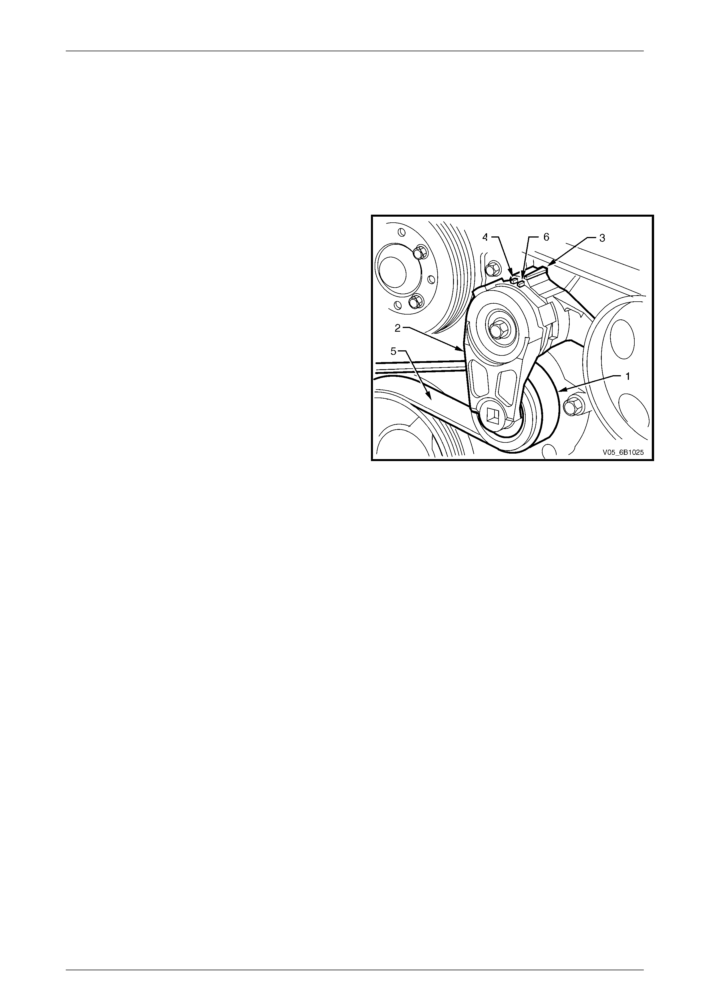
Engine Cooling – V6 Engine Page 6B1–45
3.5 Drive Belt Tension
An automatic tensioner asse mbly provides drive belt tension. The tensioner is an i dler pulley mounted on a spring-loaded
arm that maintains the drive belt at the prope r tension, without imposing undue loads on the various components.
NOTE
AWD vehicles have two drive belts and therefore
two automatic tensioners, one for each drive belt.
Throughout its functional travel, the tensioner mechanism
will maintain correct belt tension, using a pulley (1) mounted
to a spring-loaded arm (2), which compensates for increases
in belt wear and stretch.
When the indicator pointer (3) on the tensioner has reached
minimum tension range (4), the tensioner has reach ed the
full extent of its travel and replacement of the belt (5) is
necessary.
The maximum tension ran ge is shown as (6).
Drive belt tension can be checked usi ng Tool No. BT3373-F.
Refer to Section 6A1 Engine Mechanical – V6.
Figure 6B1 – 42
Page 6B1–45
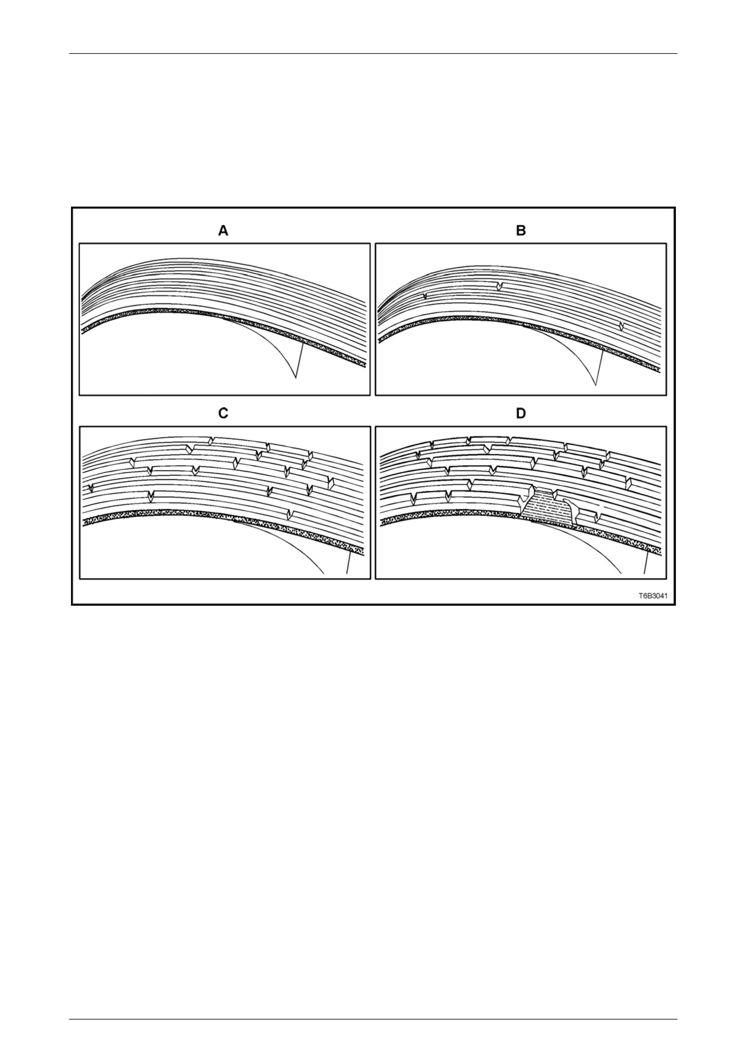
Engine Cooling – V6 Engine Page 6B1–46
Inspect
The four views in Figure 6B1 – 43 show the various stages of drive belt wear, to assist in belt replacement decisio ns.
NOTE
Condition of the belt ribs can be better assessed
if the belt is wrapped over the coolant pump drive
pulley.
Figure 6B1 – 43
Legend
A New Belt: No cracks or chunks.
B Moderately Used Belt: Few cracks, with some wear on the ribs and in the grooves. B elt replacement not required.
C Severely Used Belt: Several cracks per 30 mm. Should be replaced before chunking occurs
D Failed Belt: Separation of rib material from backing (chunking). Belt must be replaced immediately.
Page 6B1–46
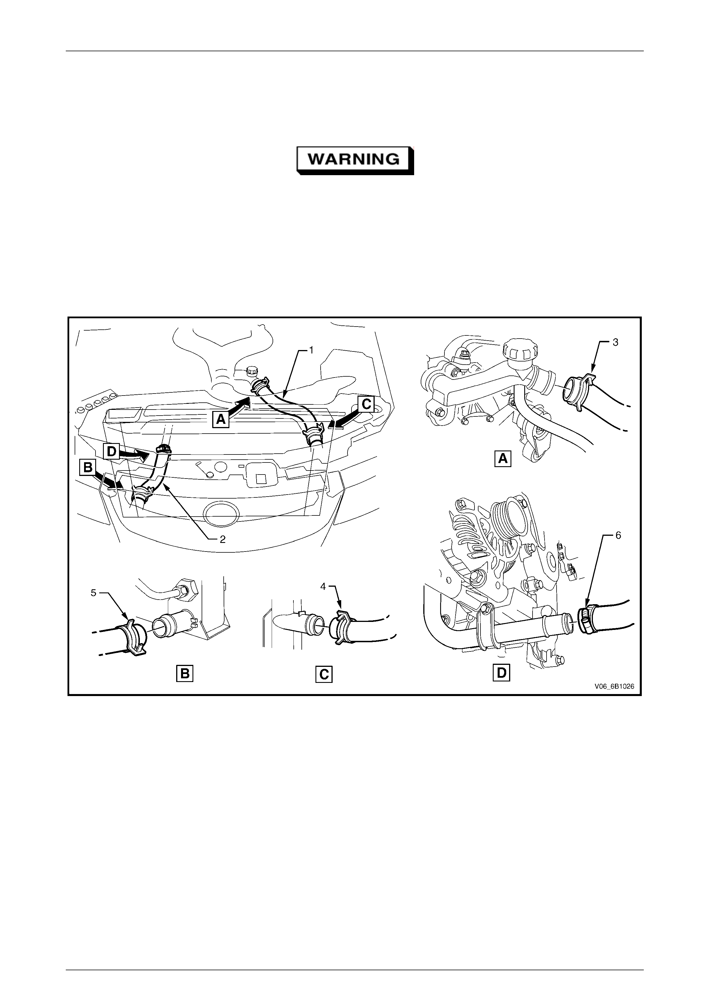
Engine Cooling – V6 Engine Page 6B1–47
3.6 Coolant Hoses
LT Section No. – 01 – 160
Always wear protective safety glasses when
working with spring type hose clamps. Failure
to do so could result in eye injury.
Coolant hoses are installed as shown in the following illustrations, taking note that there are a number of variants,
depending on a specific vehicle specification.
Hose connections should be thorough ly cleaned before installing any new hose.
After all hoses are installed, always refill the cooling system with correct concentration of cool ant, refer to 3.3 Drai ning
and Filling Coo ling System and pressure test cooling system, refer to 3.7 Pressure Testing in this Section.
Figure 6B1 – 44
Legend
1 Radiator Hose – Upper
2 Radiator Hose – Lower
3 Hose Clamp – Upper Hose to Engine Outlet Housing
4 Hose Clamp – Upper Hose to Radiator Inlet
5 Hose Clamp – Lower Hose to Radiator Outlet
6 Hose Clamp – Worm Drive – Lower Hose to Engin e Coolant
Inlet Pipe
Page 6B1–47
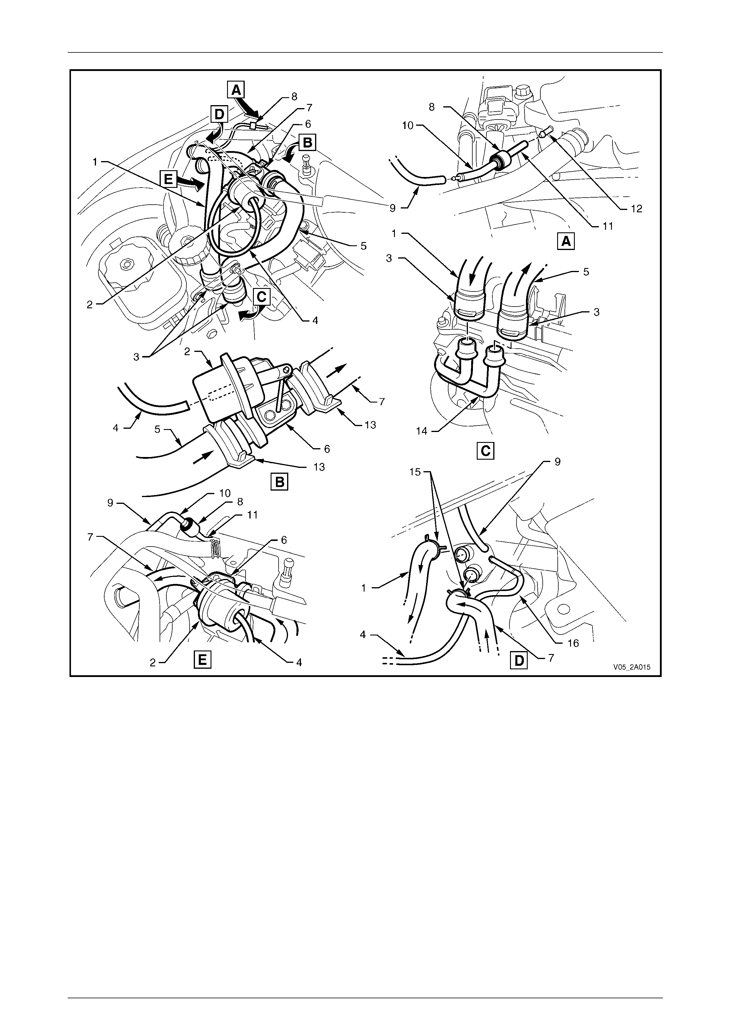
Engine Cooling – V6 Engine Page 6B1–48
Figure 6B1 – 45
Legend
1 Heater Hose from Cabin
2 Water Valve Actuator
3 Heater Hose Connectors (2 places)
4 Vacuum Hose to Water Valve Actuator
5 Heater Hose to Water Valve
6 Water Valve
7 Heater Hose to Cabin
8 Vacuum Check Valve
9 Vacuum Hose to HVAC Vacuum Tank
10 Vacuum Hose to Check Valve
11 Vacuum Hose to Inlet Manifold
12 Inlet Manifold Connection
13 Hose Clamps Water Valve (2 places)
14 Heater Pipes
15 Hose Clamps HVAC Unit (2 places)
16 Vacuum Hose to Water Valve Vacuum Switch
Page 6B1–48
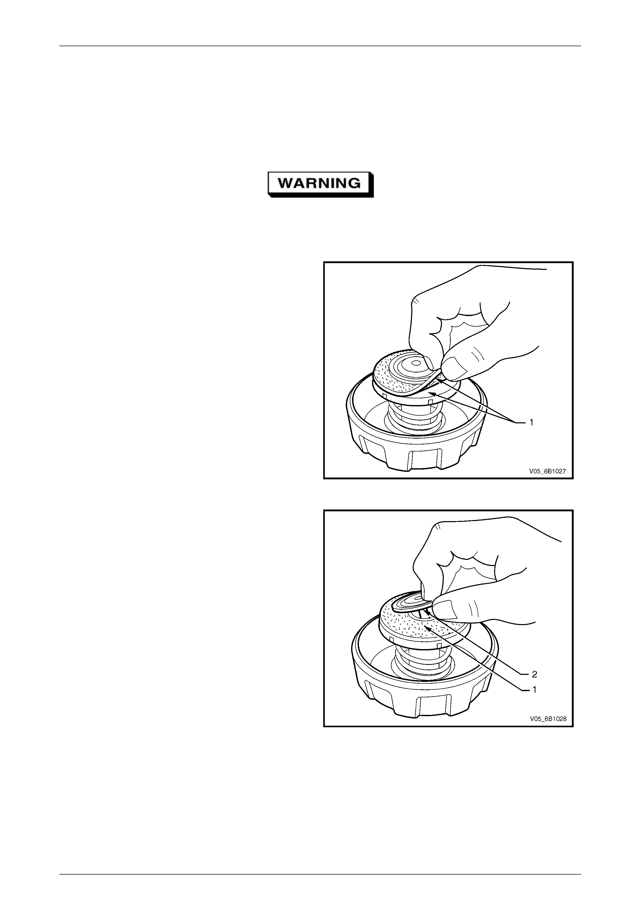
Engine Cooling – V6 Engine Page 6B1–49
3.7 Pressure Testing
MY2006 VZ Models
Coolant Filler Cap Pressure Testing
Refer to 3.1 Service Notes in this Section, for
important safety items.
1 Allow engine to cool to ambient temperature (less than 50° C), then remove coolant filler cap.
2 Inspect and clean both sides (1) of coolant filler cap
gasket with a wet cloth.
NOTE
Use only water to wet the cleaning cloth.
Figure 6B1 – 46
3 Lift centre vacuum valve. Clean and inspect the
gasket (1) and sealing surface of the under
valve (2).
Figure 6B1 – 47
Page 6B1–49
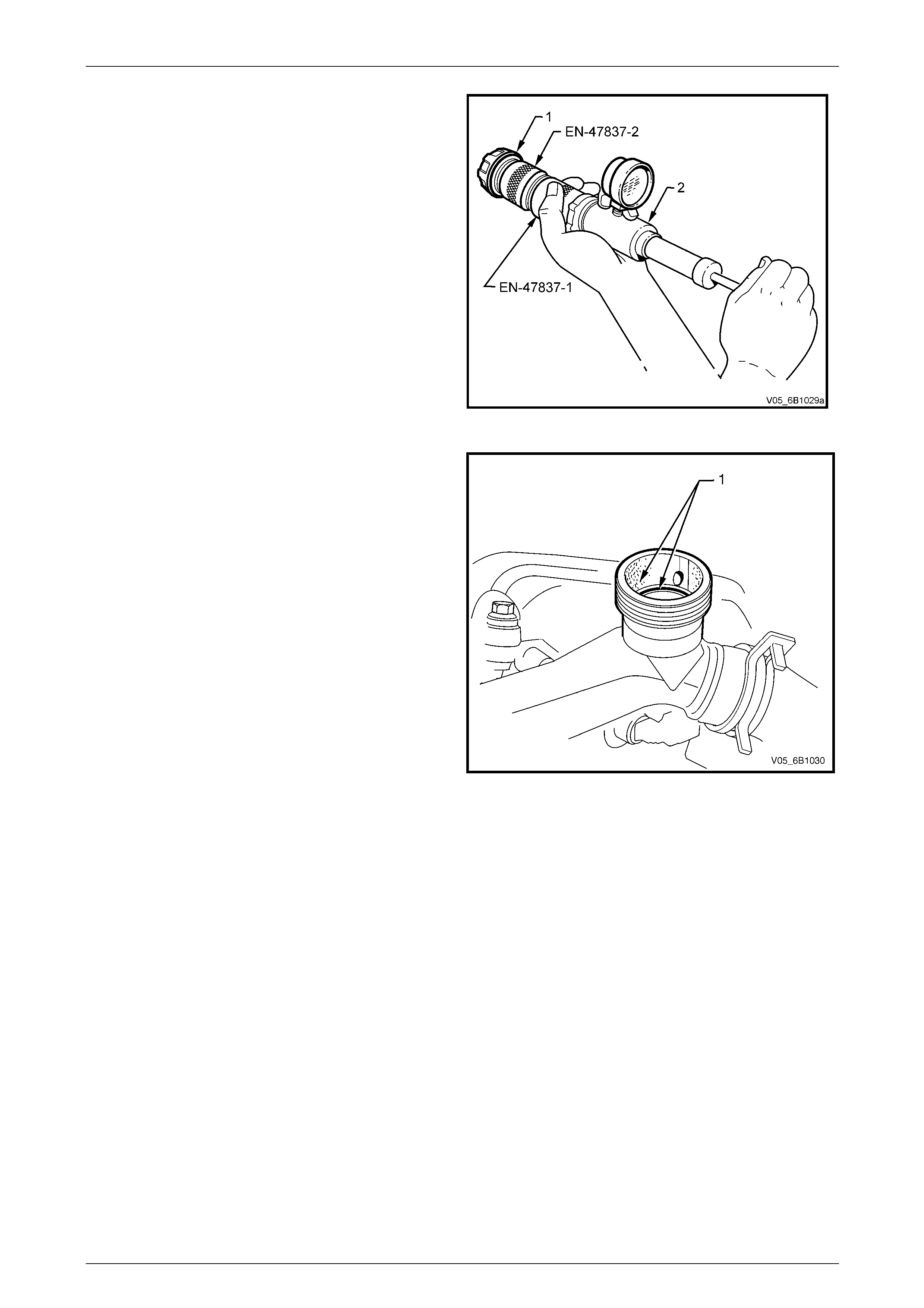
Engine Cooling – V6 Engine Page 6B1–50
4 Attach coolant filler cap (1) to a commercially
available cooling system pressure tester (2), using
the pressure cap adaptor, Tool No. EN-47837-2, and
the pressure tester adaptor, Tool No. EN-47837- 1.
5 Slowly pressurise cap to 120 – 130 kPa. The cap is
serviceable if it unloads slightly above this pressure
range and holds pressure at 1 20 kPa.
NOTE
Should the cap fail to reach or hold the
specified pressure, replace the cap.
Figure 6B1 – 48
6 Prior to installing coolant filler cap ensure that the
coolant filler neck cap seating surface (1) is clean
and free from obstruction.
Figure 6B1 – 49
Page 6B1–50
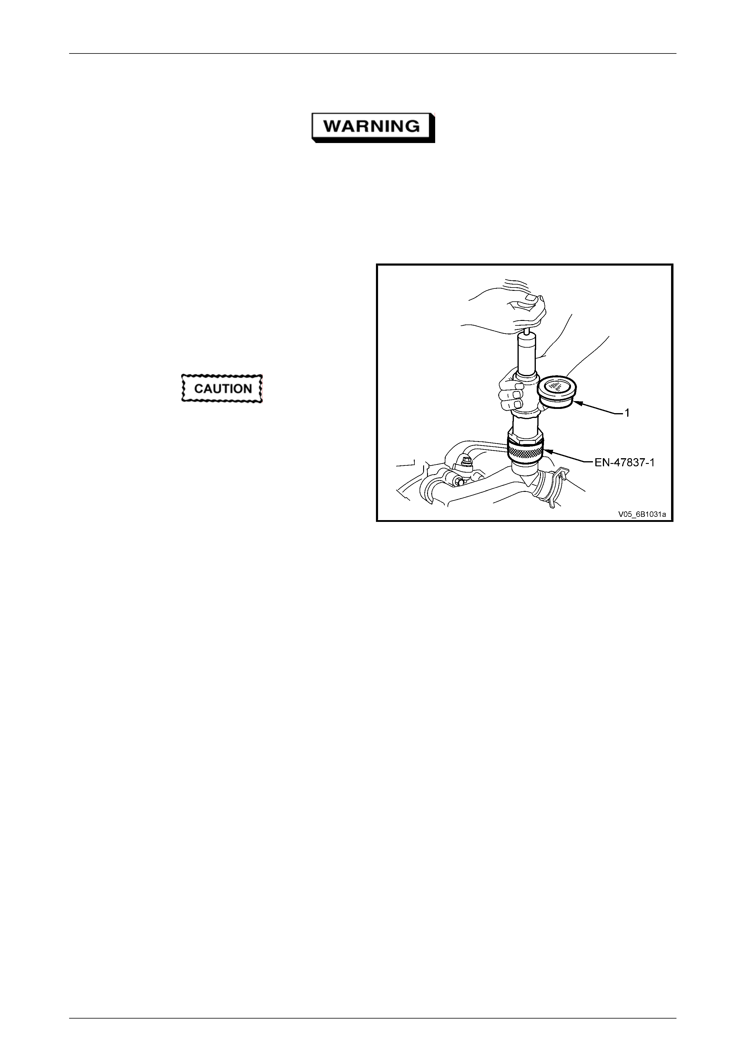
Engine Cooling – V6 Engine Page 6B1–51
Cooling System Pressure Testing
Refer to 3.1 Service Notes in this Section, for
important safety items.
1 Allow the engine to cool to ambient temperature (less than 50° C), then remove coolant filler cap.
2 Test the serviceability of the coolant pressure cap. Refer to the procedure in this section.
3 Ensure that the coolant level is correct.
4 Install the coolant filler neck adaptor, Tool No.
EN-47837-1 to a commercially available cooling
system pressure tester (1),.
5 Install the assembly to the engine coolant fill er neck.
6 Using compressed air, blow dry any spilled coolant
around coolant filler neck.
Do not exceed the stated pressure, as
damage to the cooling system could
otherwise result.
7 Using the cooling system pressure tester pump,
pressurise cooling system to 130 kPa absolute
maximum and check for leaks at the following points:
• All hoses and hose connectio ns.
• Overflow hose connection at coolant outlet
housing conne c tion. Figure 6B1 – 50
• Radiator seams and core.
• Corroded or faulty engine Welch plugs.
• Coolant pump and gasket.
• Thermostat housing and coolant inlet pipe connection.
• Radiator drain tap and bleed screw.
• Vehicle heating system (e.g. heater core an d water valve).
• Check the engine oil dipstick for any traces of coolant contam ination of the engine lubrica nt.
NOTE
For heater Removal and Installation, refer to
Section 2C HVAC Climate Control (Manual A/C)
– Removal and Installation.
8 Check engine oil dipstick for evid ence of engine oil contamination with coolant.
9 If pressure will not hold, there is a leak in the cooling system. Repair as necessary.
NOTE
If visible loss of coolant is not evident from
pressure testing, then the use of a dye and black
light, may be necessary. Refer to 4.7 Black Light
and Dye Leak Diagnos is Method, in this Section.
Page 6B1–51
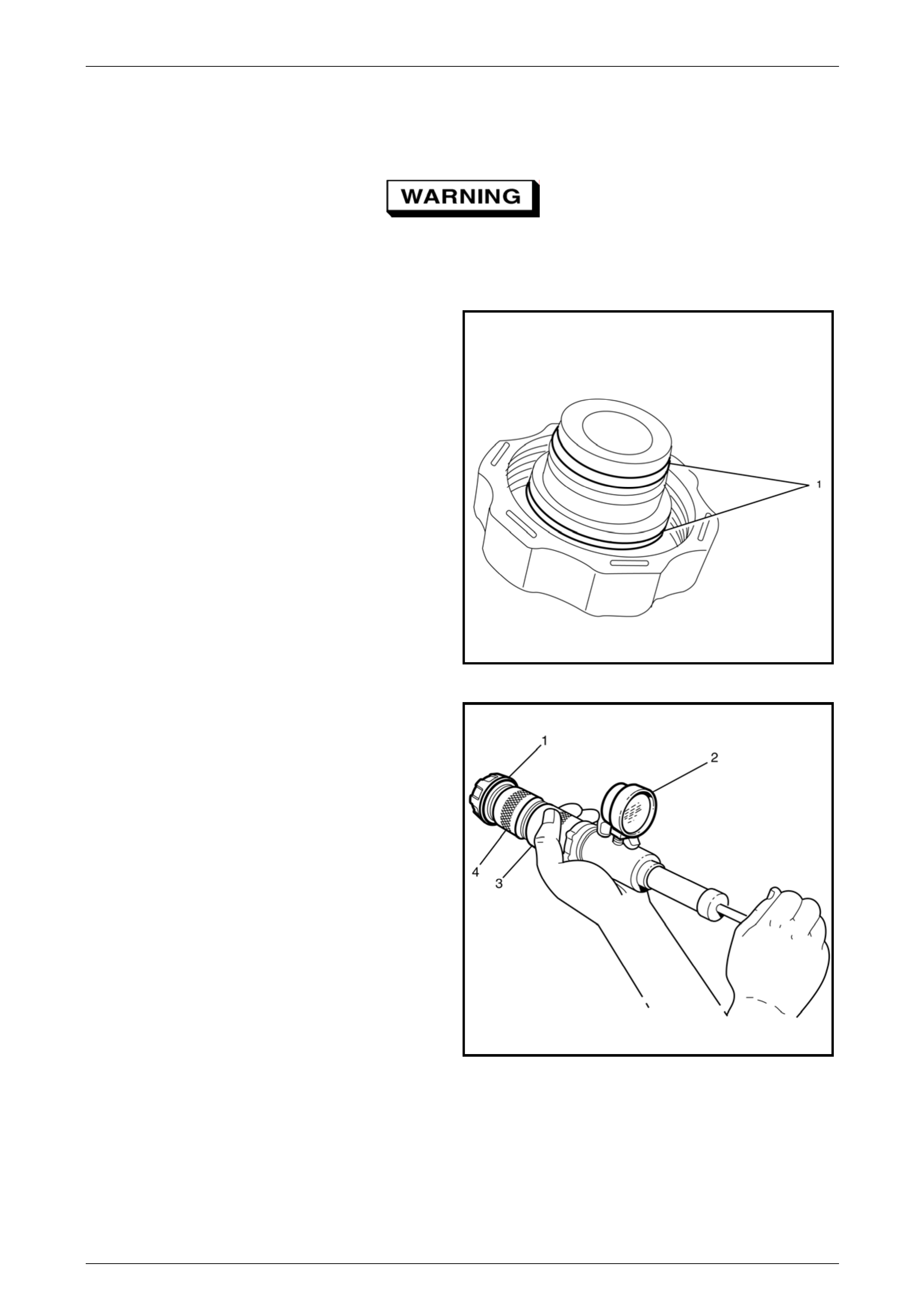
Engine Cooling – V6 Engine Page 6B1–52
MY2006 VZ Update Models
Coolant Filler Cap Pressure Testing
Refer to 3.1 Service Notes in this Section, for
important safety items.
1 Allow engine to cool to ambient temperature (less than 50° C), then remove coolant filler cap.
NOTE
Only use a cloth moistened with water
2 Inspect and clean the sealing O-Rings (1) with a wet
cloth.
Figure 6B1 – 51
3 Attach the coolant filler cap (1) to a commercially
available cooling system pres sure tester (2), using the
pressure cap adaptor – EN-48501 (4) and the
pressure tester adaptor – J-42401(3).
4 Slowly pressurise the cap to between 120 – 130 kPa.
The cap is serviceable if it unloads in this pre ssure
range and holds pressure at 1 20 kPa.
NOTE
If the cap does not reach or hold the specified
pressure, replace the cap.
Figure 6B1 – 52
Page 6B1–52
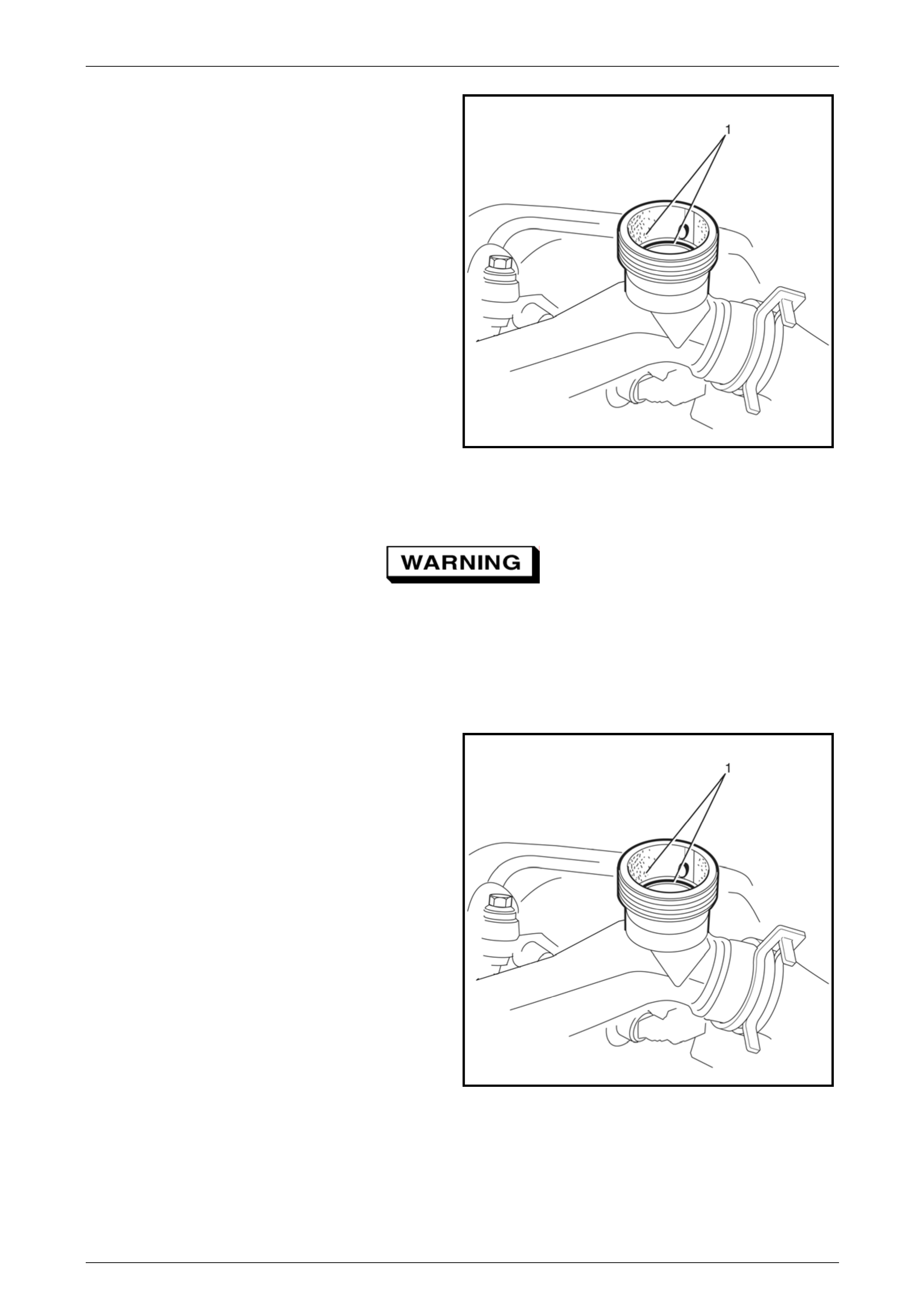
Engine Cooling – V6 Engine Page 6B1–53
5 Before reinstalling the pressure cap, check that the
filler neck sealing surface (1) is clean and free from
sediment or build-up of deposi ts.
Figure 6B1 – 53
Cooling System Pressure Testing
Refer to 3.1 Service Notes in this Section, for
important safety items.
1 Allow the engine to cool to ambient temperature (less than 50° C), then remove coolant filler cap.
2 Test the serviceability of the coolant pressure cap. Refer to the procedure in this section.
3 Ensure that the coolant level is correct.
4 Before installing the coolant pressure tester, check
that the filler neck sealing surface (1) is clean and
free from sediment or build-up of deposits.
222101305
Figure 6B1 – 54
Page 6B1–53
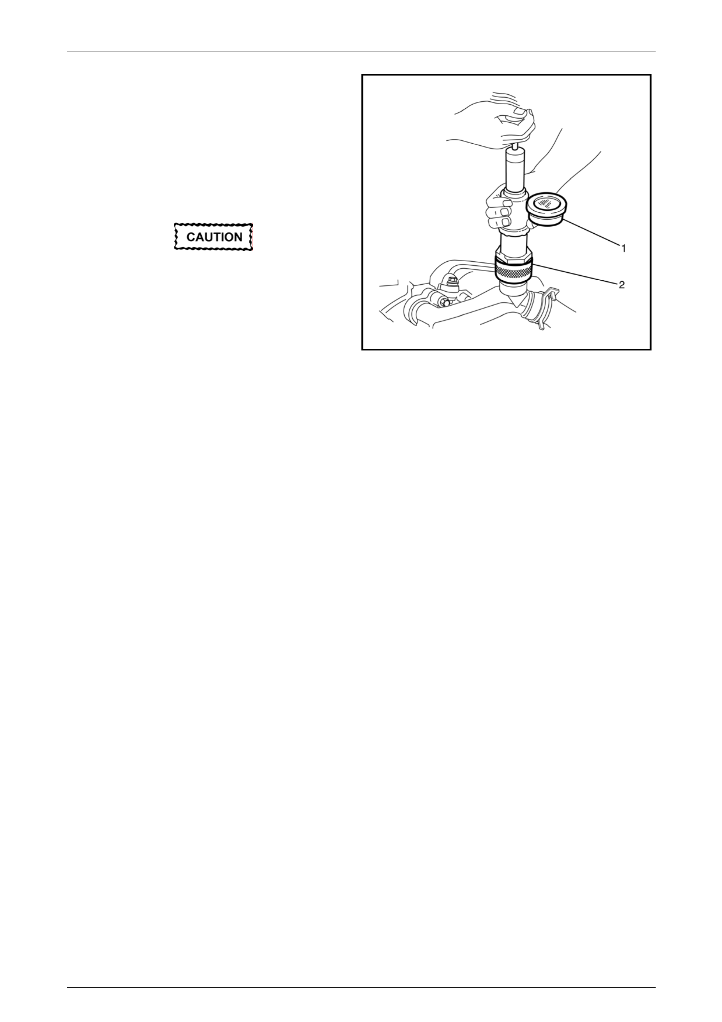
Engine Cooling – V6 Engine Page 6B1–54
5 Assemble the cooling system adaptor KM-6327 and
pressure tester adaptor KM-471.
6 Install the coolant filler neck adaptor assemb ly (2) to a
commercially availabl e cooling system pressure tester
(1).
7 Install the assembly to the engine coolant fill er neck.
8 Using compressed air, blow dry any spilled coolant
around the coolant filler neck.
Do not exceed the specified pressure, as
damage to the cooling system may occur.
9 Using the cooling system pressure tester pump,
pressurise the cooling system to an absolute
maximum pressure of 130 kPa.
10 While maintaining that pressure, check the cooling
system for leaks at each of the following:
• All hoses and hose connectio ns.
2221013058151
Figure 6B1 – 55
• Overflow hose connection at coolant outlet housing connection.
• Radiator seams and core.
• Corroded or faulty engine Welch plugs.
• Coolant pump and gasket.
• Thermostat housing and coolant inlet pipe connection.
• Radiator drain tap and bleed screw.
• Vehicle heating system (e.g. heater core an d water valve).
• Check the engine oil dipstick for any traces of coolant contam ination of the engine lubrica nt.
11 Repair any leaks that are evident.
NOTE
If a visible loss of coolant is not found externally,
and the system pressure does not hold, the use
of dye and black lamp testing will help to pinpoint
the leak. Refer to 4.7 Black Light and Dye Leak
Diagnosis Method, in this Section.
Page 6B1–54
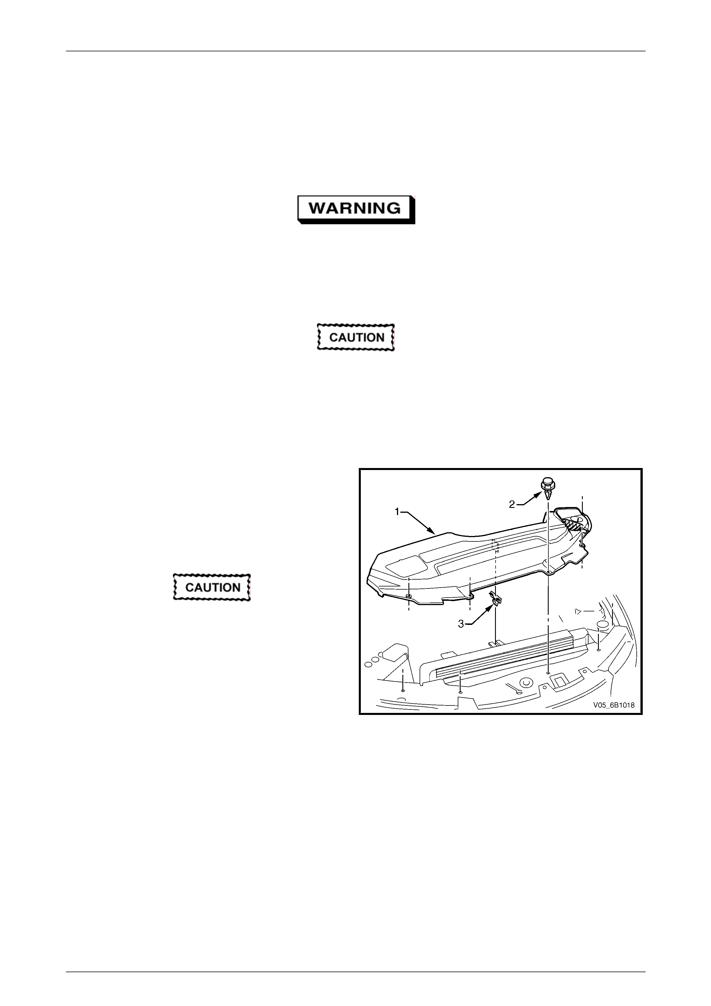
Engine Cooling – V6 Engine Page 6B1–55
3.8 Thermostat
LT Section No. – 00–350
Remove
Do not remove coolant filler cap while the
engine cool ant temperature is ab ove 50° C, as
personal injury may result.
1 Allow engine to cool to ambient temperature (less than 50° C), then remove the coolant filler cap (located at the
front left-hand side of the engine).
Disconnection of the battery affects certain
vehicle electronic systems. Refer to
Section 00 Warnings, Cautions and Notes,
before removing the ground lead.
2 Disconnect the battery ground lead. Refer to Section 12A Battery.
3 Remove the engine dress covers. Refer to Section 6A1 Eng ine Mechanical – V6.
4 Remove the upper radiator shroud (1) as fol lows:
a Using a fine, flat-blade screwdriver to prise the
centre pin of the scrivet (2) upward, then remove
the scrivet, in five places.
b Lift up the radiator shroud to disengage the
retaining clip (3), then remove the shroud.
Refer to ‘Environmental Issues’ in 3.1 Service
Notes, before draining the coolant.
5 Drain the coolant from the system. Refer to
3.3 Draining and Filling Cooling System in this
Section.
6 Remove the complete intake manifold assembly. Refer
to Section 6A1 Engine Mechanical – V6.
7 Plug each of the exposed intake ports with lint free
cloth to prevent the entry of foreign matter.
8 Remove the coolant inlet pipe. Refer to 3.13 Coolant
Inlet Pipe in this Section.
Figure 6B1 – 56
Page 6B1–55
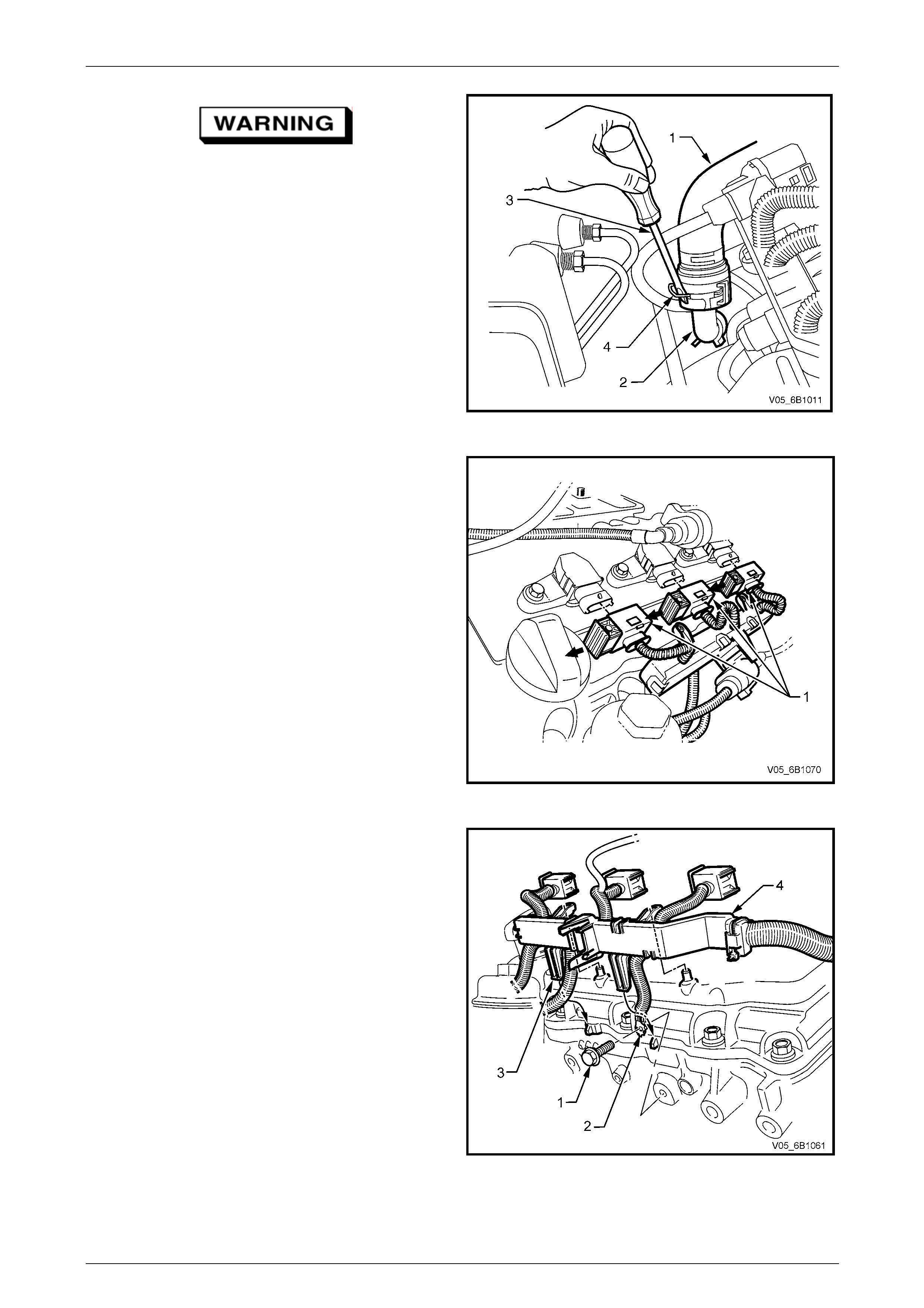
Engine Cooling – V6 Engine Page 6B1–56
Always wear protective safety glasses when
working with spring type hose clamps.
Failure to do so could result in eye injury.
9 Use a straight-blade screwdriver (3) to releas e the
heater hose quick connect clips (4).
10 Disconnect the heater hoses (1) from the heater pipes
(2) in two places.
Figure 6B1 – 57
11 To gain easier access to the heater pipe flange and
thermostat housing bolts, disconnect the engine
harness and lay back on the right side of the engine
bay. Apart from those harness connectors removed
during the intake manifold removal, this inv olves the
removal of wiring harness connectors a nd fasteners,
as detailed:
a Pull out the release bar (arrows) on each of the
ignition coil packs (1) on cylinders 2, 4 and 6,
before disconnecting each connector.
b The coolant temperature sen sor.
c The left side Pre-O2 sensor connector, 2, 4 & 6.
NOTE
Refer to Section 12O Fuses and Wiring Harnesses
for the location of harness connectors, not sho wn.
Figure 6B1 – 58
12 Remove the bolt (1) securing the en gine harness
ground terminal (2), to the cylinder block.
13 Prise both locking legs of the l eft side en gine harness
former (4), free, then lift up on the harness former to
release.
Figure 6B1 – 59
Page 6B1–56
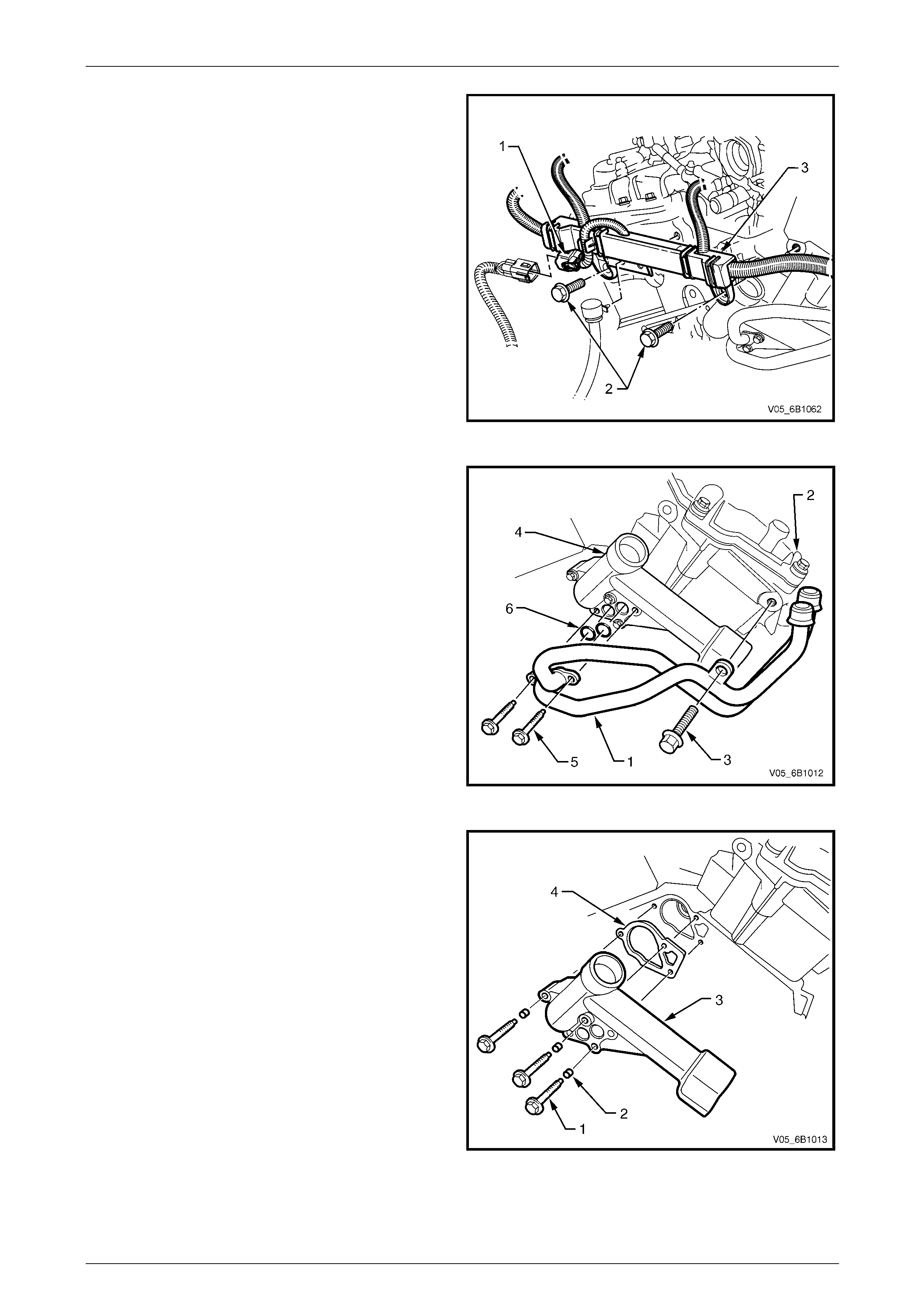
Engine Cooling – V6 Engine Page 6B1–57
14 Working at the rear of the engi ne, disconnect the
engine harness to transmission harness connector (1),
as required.
15 Remove the two bolts (2) securing the engine harness
former (3) to the rear of the engine.
16 Carefully lift the engine harness free and drape on the
right side of the engine.
Figure 6B1 – 60
17 Remove the heater pipe assembly (1) to right-hand
side cylinder head (2) attaching bolt (3).
18 Remove the heater pipe assembl y to thermostat
housing (4) attaching bolts (5 ), then remove the heater
pipe assembly.
19 Remove and discard the heater pipe assembl y to
thermostat housing O-ring seals (6).
Figure 6B1 – 61
20 Remove the three thermostat hous ing attaching bolts
(1), rubber grommets (2), then remove the thermostat
housing (3).
NOTE
The upper thermostat housing attaching bolt is
longer than the two lower bolts.
21 Remove and discard the thermostat housing to engine
block gasket (4).
Figure 6B1 – 62
Page 6B1–57
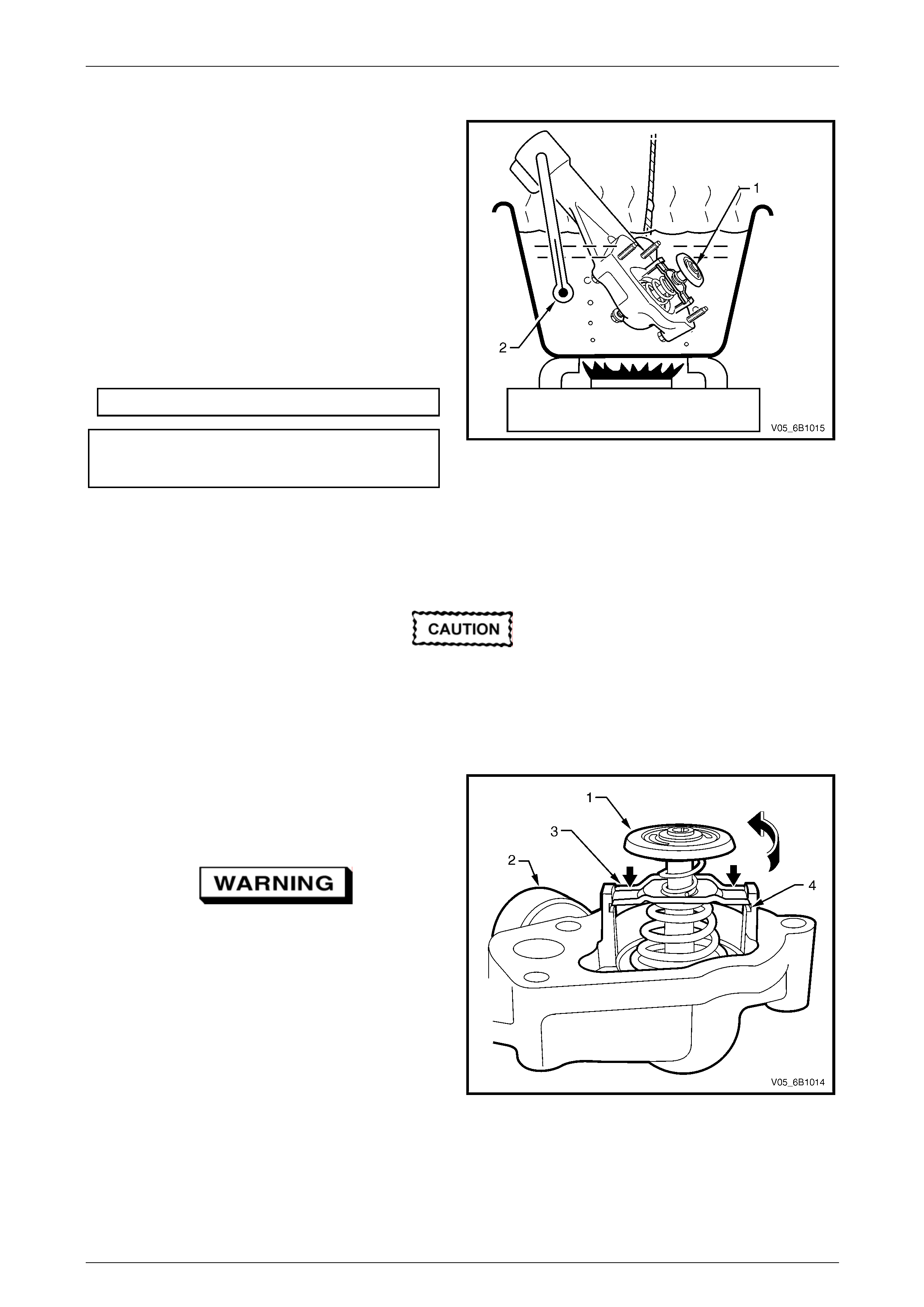
Engine Cooling – V6 Engine Page 6B1–58
Test
1 With the thermostat (1) installed in the housing,
suspend it and a suitable thermometer (2) in a
container of 50% clean fresh water and 50% Dexron ®
long life coolant, (conforming to GM 6277M).
NOTE
Neither the thermostat assembly (1) nor the
thermometer (2) should rest on the bottom of the
container because of uneven concentration of
heat at this point when the container is heated.
2 Heat container until thermostat begins to open.
Agitate solution to ensure uniform temperature.
Note temperature and ensure thermostat opens
within specified temperature range.
Thermostat Opening Specification s
Opening Temperature 82° C
Fully Open Temperature 95° C
3 Replace thermostat if it does not meet these operating
conditions.
Figure 6B1 – 63
Dismantle
Only dismantle the thermostat if a reverse
flushing operation of the cylinder block is to
be carried out. If the testing operation
indicates that the thermostat is faulty, then
the housing and thermostat are only serviced
as an assembly.
1 Remove thermostat (1) from thermostat housing (2) as
follows:
a Secure the thermostat housing by grippin g in a
vice fitted with soft jaws.
Always wear protective safety glasses when
working with spring-loaded devices. Failure
to do so could result in eye injury.
b Depress the retaining bar (3) on both si des of
the thermostat and rotate the thermostat until it
clears the retaining lugs (4) on the thermostat
housing (2).
c Release the thermostat spring force.
d Remove the thermostat assembly from the
thermostat housing. Figure 6B1 – 1
Page 6B1–58
Engine Cooling – V6 Engine Page 6B1–59
Reassembly
The reassembly process is the reverse to that used for disassembly, with the following exceptions:
1 Check that the valve sealing surface is undamaged.
2 Wipe the valve sealing surface to ensure a clean surface.
Reinstall
Always wear protective safety glasses when
working with spring -load ed de vices. Fail ure to
do so could result in eye injury.
1 Install the thermostat into the housing (rever s e to removal procedure).
2 Ensure that the engine block and thermostat housing mating surfaces are clean a nd dry.
3 Install a new gasket to the thermostat housing.
4 Install the thermostat housing to the engine block and secure with the attaching bolts (with rubber grommets
installed). Tighten all bolts to the correct torque spec ification.
Thermostat housing to engine
block bolt torque specification...............................10 Nm
5 Ensure that the heater pipe assembly and the rmostat housin g mating surfaces are clean and dry.
6 Install new O-rings to the heater pipe assembly.
7 Install heater pipe assembly to thermostat housing and secure with the attaching bolts. Tighten all bolts to the
correct torque specification.
Heater pipe assembly to thermostat
housing bolt torque specification...........................10 Nm
8 Install heater pipe assembly to right-hand cylinder head bolt. Tighten bolt to the correct torque specific ation.
Heater pipe assembly to cylinder
head bolt torque specification ...............................58 Nm
Always wear protective safety glasses when
working with spring type hose clamps. Failure
to do so could result in eye injury.
9 Reinstall the engine wiring harness, securing the rear harness former to the rear of the engine with the two
retaining bolts, tightened to the correct torque specific ation.
Rear engine harness former
retaining bolts torque specification........................15 Nm
10 Reinstall the le ft side engine harness former to the two locating pegs, then push inward to secure.
11 Reinstall the bolt securi ng the engine harness ground terminal, to the left side of the cylinder block an d tighten to
the correct torque specification.
Engine harness ground terminal
attaching bolt torque specification.........................12 Nm
12 Reinstall each wiring harness connector to its correct location, ensuring that all security clips are installed correctly.
13 Connect the heater hoses to the heater pipe assembly.
Page 6B1–59

Engine Cooling – V6 Engine Page 6B1–60
14 Reinstall the coolant inlet pipe. Refer to 3.13 Coolant Inlet Pipe in this Section.
15 Close the radiator drain tap on the lower LHS of the radiator and rem ove the piece of rubber tubing to the tap
outlet.
16 Reinstall the complete intake manifold assembly. Refer to Section 6A1 Engine Mechanic al – V6.
17 Refill cooling system. Refer to 3.3 Draining and Filling Cooling System in this Section.
18 Check for coolant leaks. Refer to 3.7 Pressure Testing in this Section.
19 Install the radiator shroud.
20 Install the engine dress covers. Refer to Section 6A1 Engine Mechanical – V6.
21 Reconnect battery ground l ead. Refer to Section 12A Battery.
22 Road test the vehicle to check for correct operation.
Page 6B1–60
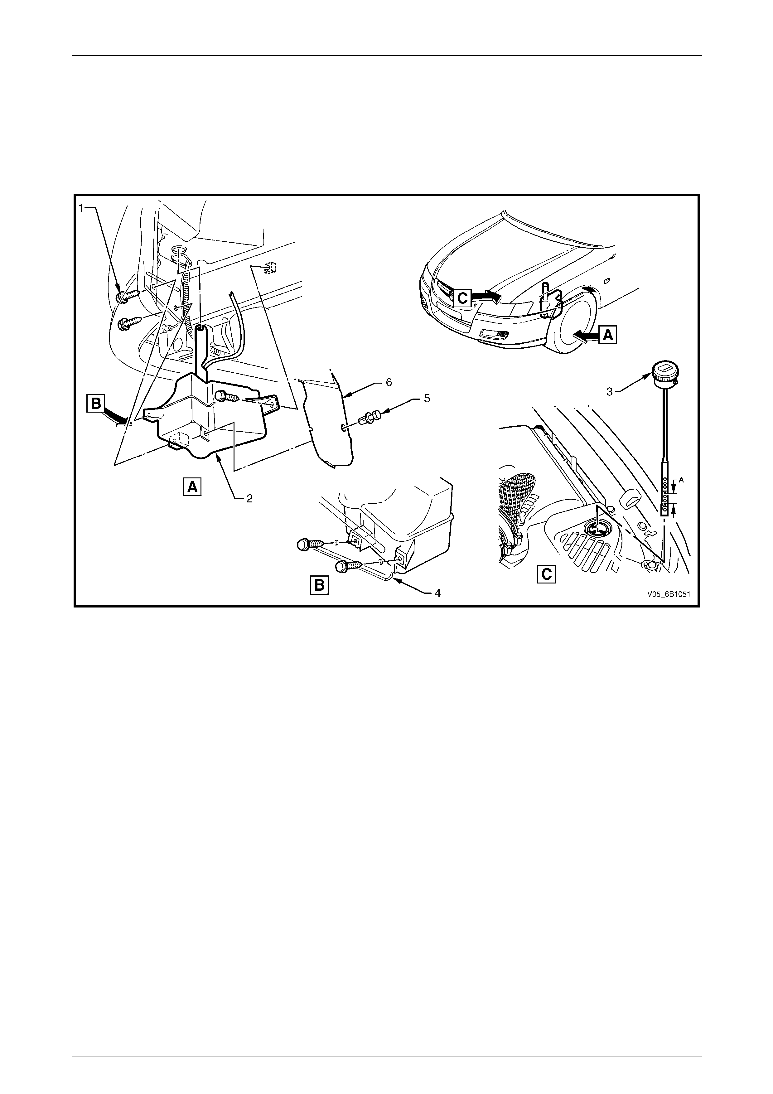
Engine Cooling – V6 Engine Page 6B1–61
3.9 Coolant Recovery Reservoir
LT Section No. – 01–140
Remove
Figure 6B1 – 64
Legend
1 Screw (3 places)
2 Reservoir 3 Coolant Dipstick
4 Console Front Panel 5 Scrivet Fastener
6 Wheelhouse Liner
1 Remove the coolant recovery hose from the underside of the coolant outlet housing, and then remove the hose
from the fan shroud retaining clip.
2 On AWD vehicles, remove the front bumper fascia under-tray (where fitted). Refer to Section 1D Bumper Bars.
3 Raise front of vehicle and support on safet y stands. Refer to Section 0A Gener al Information for the location of
jacking and support points.
4 Remove the scrivet fastener attaching the wheelhous e liner to the coolant recovery reservoir.
5 Remove reservoir assembly attaching screws, and remove reservoir assembly from under the vehicle.
Inspect
1 Drain contents from reservoir assembly.
2 Clean the reservoir assembl y wit h water and dry using compressed air.
3 Check reservoir and assembly for damage, for example abrasions, cracks or distortion. Replace if required.
Page 6B1–61

Engine Cooling – V6 Engine Page 6B1–62
Install
Installation of the reservoir assembly is the r everse of removal procedures, noting the following points:
1 For ease of access, it may be necessary to remove the upper radiator shroud.
2 Refill cooling recovery reservoir and cooling system with the correct concentration of coolant. Refer to
3.3 Draining and Filling Cooling System in this Section.
3 Check coolant recovery system for leaks.
Page 6B1–62
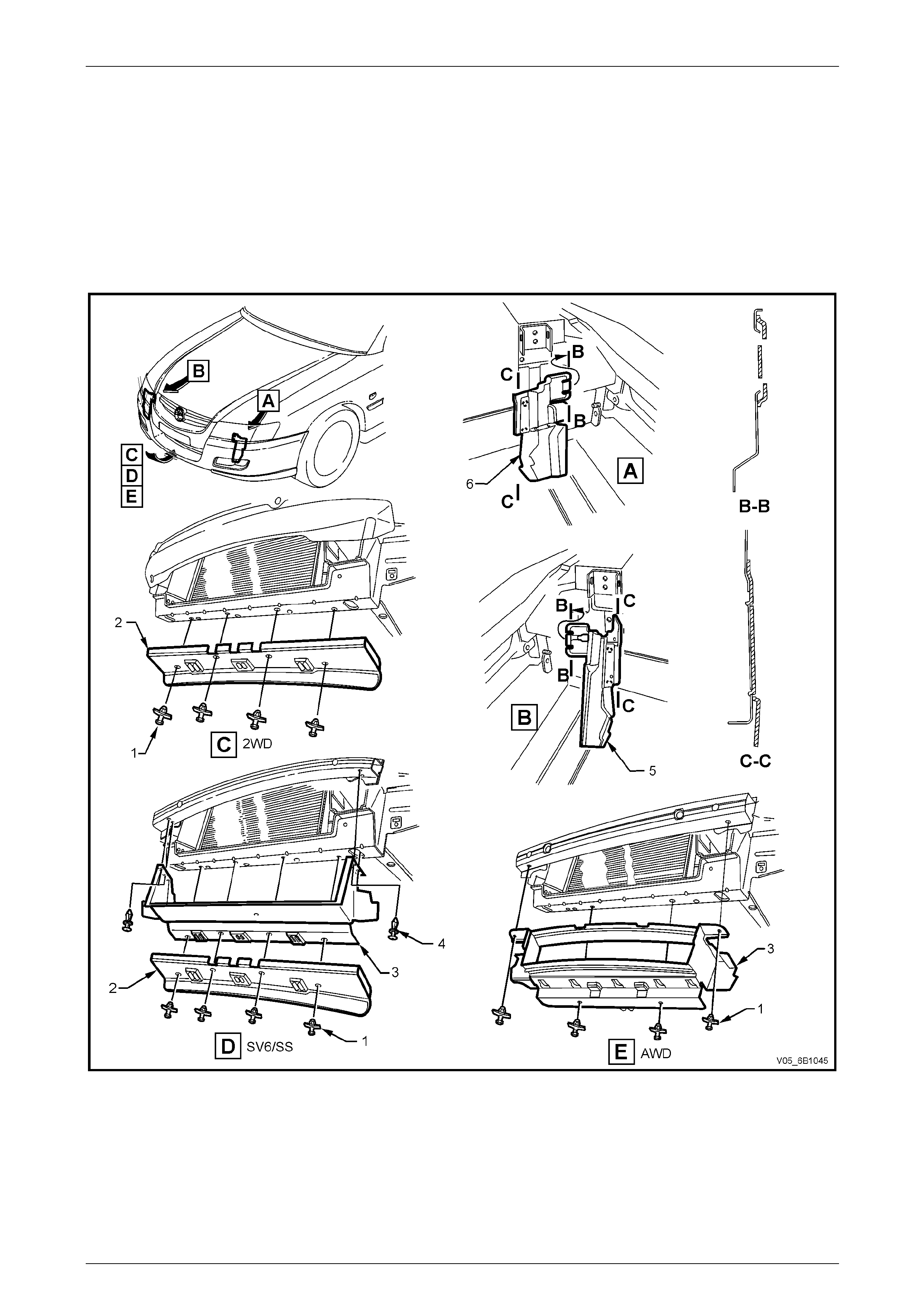
Engine Cooling – V6 Engine Page 6B1–63
3.10 Air Baffle and Chutes
LT Section No. –
Remove
In Figure 6B1 – 65, view ‘C’ sho ws the standard Alloytec V6 lo wer air chute baffle, vie w ‘D’ shows the Alloytec V6 Calais,
‘S’ and ‘SV6’ pack configuration, view ‘E’ shows the Alloytec V6 AWD wagon and view ‘F’ shows the Cross 6
configuration.
Figure 6B1 – 65
1 Raise front of vehicle and support on safet y stands. Refer to Section 0A Gener al Information for the location of
jacking and support points.
Standard Air Baffle Configuration – View ‘C’
a Remove the four scrivet fasteners (1) securing the lower air chute baffle (2) to the radiator support
crossmember, then remove the baffle from the vehicle.
Page 6B1–63

Engine Cooling – V6 Engine Page 6B1–64
Calais / S / SV6 Vehicles – View ‘D’
a Remove the front bumper bar fascia. Refer to Section 1D Bumper Bars.
NOTE
While the air chute extension duct can be
removed without first removing the bumper bar,
excessive distortion of the ch ute is required, both
on removal and installation. Also the installation
of the two upper scrivets is extremely difficult.
b Remove the four scrivet fasteners (1) securing both the lo wer air chute baffle (2) and the air chute extension
duct (3) to the radiator support crossmember, then remove the baffle from the vehicle.
c Remove the two upper fasteners (4) securin g the air chute extension duct, to the front upper panel assembly,
then remove the duct from the vehicle.
AWD Vehicles (Wagon and Crew Cab) – View ‘E’
a Remove the front bumper bar fascia and und er-tray. Refer to Section 1D Bumper Bars.
b Remove the two lower scrivet fasteners securing the air chut e extension duct (3) to the radiator support
crossmember.
c Remove the two upper scrivet fasteners (1) securi ng the air chute extension duct to the front upper panel
assembly, and then remove the air chute extension duct from the vehicle.
Cross 6 Vehicles – View ‘F’
a Remove the front bumper bar fascia and under-tray. Refer to 1D Bumper Bars.
b Remove the two lower scrivet fasteners (1) securing the air chute (3) to the radiator support crossmember.
c Remove the two upper scrivet fasteners (4) securi ng the air chute (3) to the front upper panel assembly, and
then remove the air chute from the vehicle.
Install
Installation is the reverse to removal procedures.
Page 6B1–64
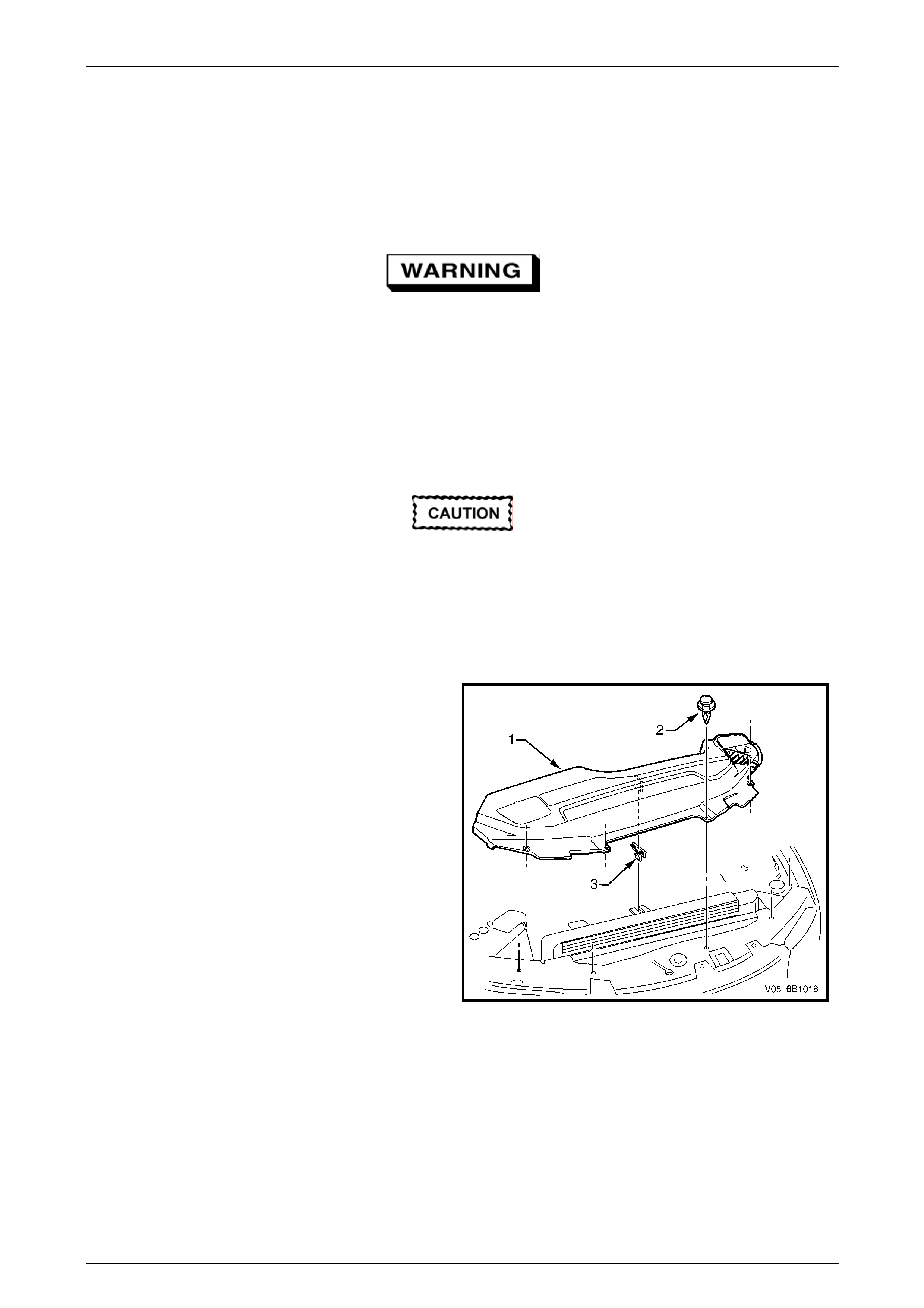
Engine Cooling – V6 Engine Page 6B1–65
3.11 Coolant Pump
LT Section No. – 00–325
Remove
Refer to 3.1 Service Notes in this Section, for
important safety items.
NOTE
The coolant pump is not to be disassembled and
is replaced only as an assembly.
1 Allow engine to cool to ambient temperature (less than 50° C), and then remove the coolant filler cap (l ocated at
the front left-hand side of the engine).
Disconnection of the battery affects certain
vehicle electronic systems. Refer to
Section 00 Warnings, Cautions and Notes,
before removing the ground lead.
2 Disconnect the battery ground lead. Refer to Section 12A Battery.
3 Remove the engine dress covers. Refer to Section 6A1 Eng ine Mechanical – V6.
4 Remove the upper radiator shroud (1) as fol lows:
a Using a fine, flat-blade screwdriver to prise
the centre pin of the scrivet (2) upward and
remove the scrivet, five places.
b Lift up the radiator shroud to disengage the
retaining clip (3) and remove the shroud.
Figure 6B1 – 66
Page 6B1–65
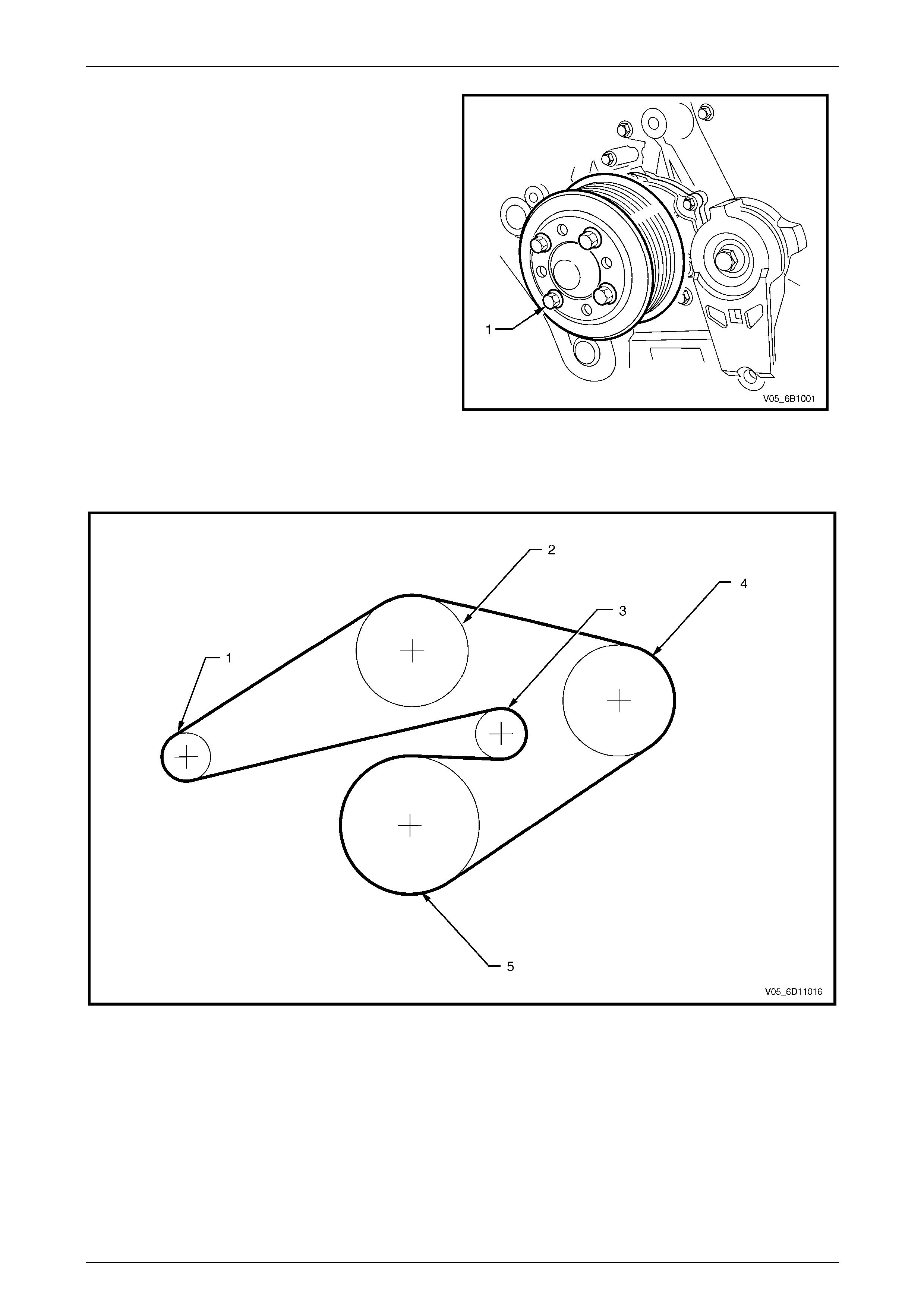
Engine Cooling – V6 Engine Page 6B1–66
5 Loosen coolant pump pulle y to hub bolts (1).
NOTE
While the view shows the drive belt removed,
it will be easier to loosen the four pulle y bolts,
with the belt installed.
Figure 6B1 – 67
Figure 6B1 – 68 shows the drive belt routing for the Alloytec V6 engine without air conditioni ng.
Figure 6B1 – 68
Legend
1 Generator
2 Coolant Pump
3 Tensioner
4 Power Steering
5 Crankshaft
Page 6B1–66
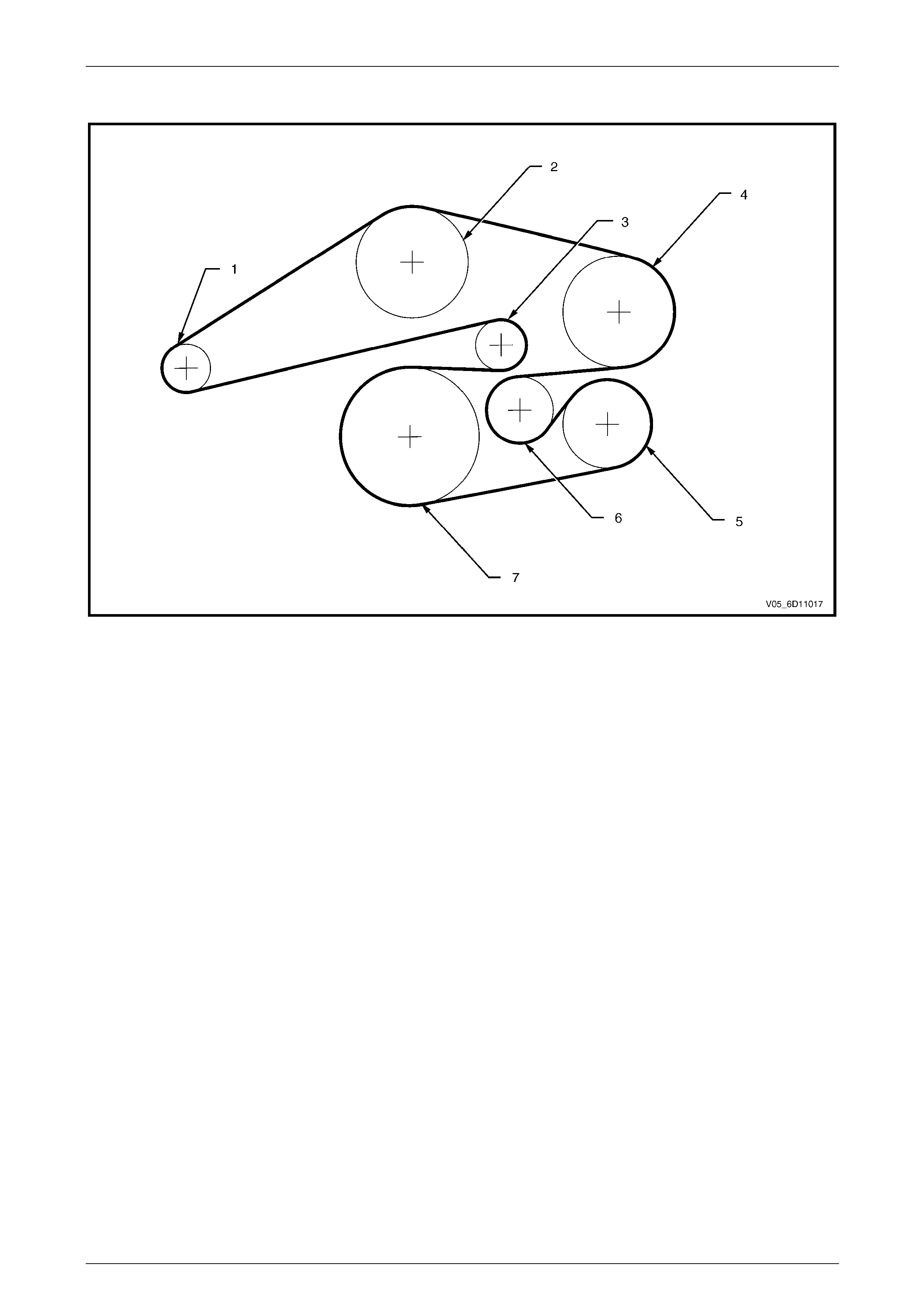
Engine Cooling – V6 Engine Page 6B1–67
Figure 6B1 – 69 shows the drive belt routing for the Alloytec V6 RWD engine with air conditioning.
Figure 6B1 – 69
Legend
1 Generator
2 Coolant Pump
3 Tensioner
4 Power Steering
5 A/C Compressor
6 Idler
7 Crankshaft
Page 6B1–67
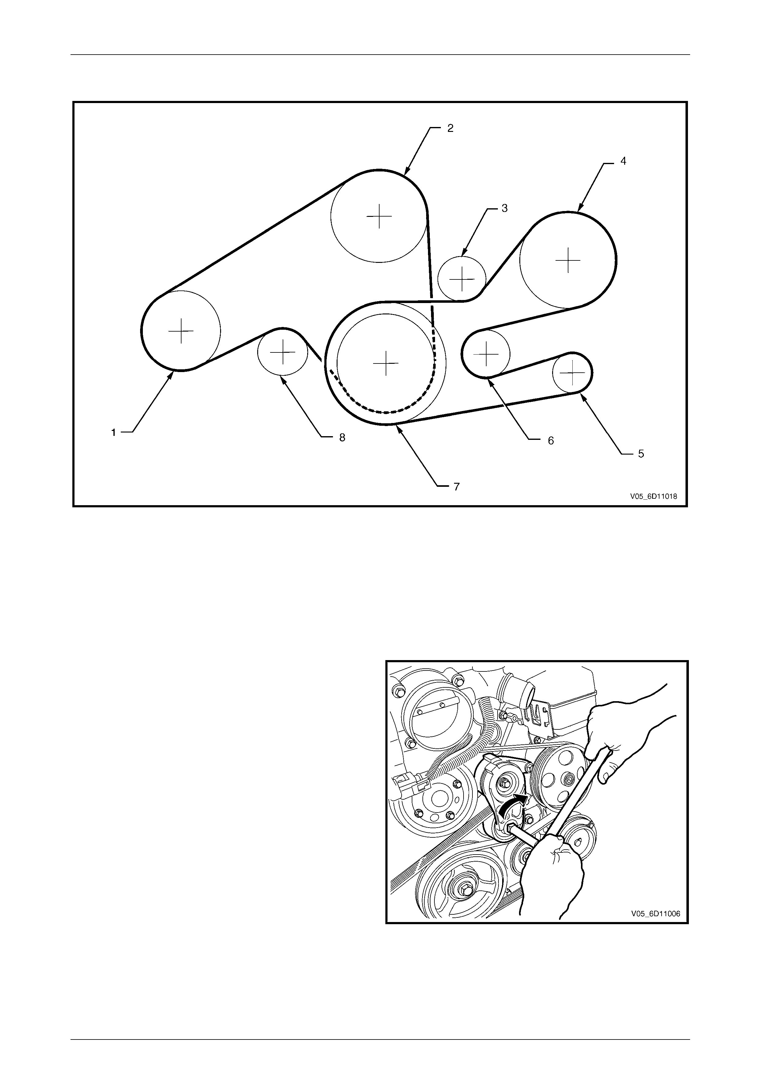
Engine Cooling – V6 Engine Page 6B1–68
Figure 6B1 – 70 shows the drive belt routing for the Alloytec V6 AWD engine with air conditioning.
Figure 6B1 – 70
Legend
1 A/C Compressor
2 Coolant Pump
3 Tensioner (power steering / generator)
4 Power Steering
5 Generator
6 Idler
7 Crankshaft
8 Tensioner (air conditioning / coolant pump)
6 Remove the drive belt from the coolant pum p
pulley:
• For 2WD vehicles (Figur e 6B1 – 71):
a Rotate the drive belt tensioner pulley
clockwise (arrow) using a 1/2” drive
extension in order to release the drive
belt tension.
b Remove the drive belt from the coolant
pump pulley.
c Slowly release the drive belt tensioner.
Figure 6B1 – 71
Page 6B1–68
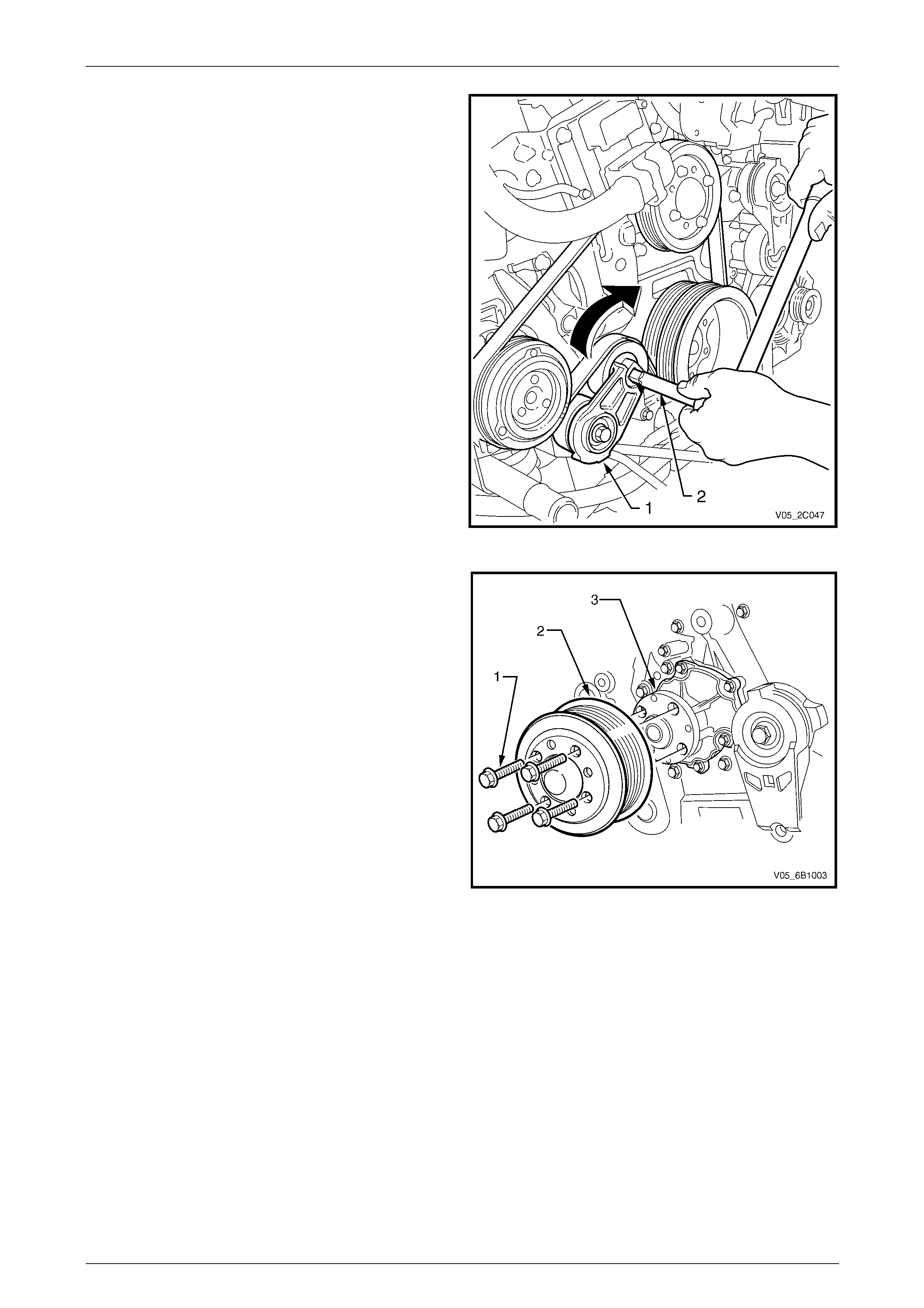
Engine Cooling – V6 Engine Page 6B1–69
• For AWD vehicles (Figure 6B1 – 72), proceed
as follows:
a Rotate the air conditioning / coolant
pump drive belt tensioner p ulley (1)
clockwise (arrow) using a 1/2” drive
extension (2) to release the dr ive belt
tension.
b Remove the drive belt from the coolant
pump pulley.
c Slowly release the drive belt tensioner.
7 Drain the coolant from the system. Refer to
3.3 Draining and Filling Cooling System in this
Section.
Figure 6B1 – 72
8 Remove the four coolant pump pul ley attaching
bolts (1), then remove the pulley (2) from the
hub (3).
Figure 6B1 – 73
Page 6B1–69
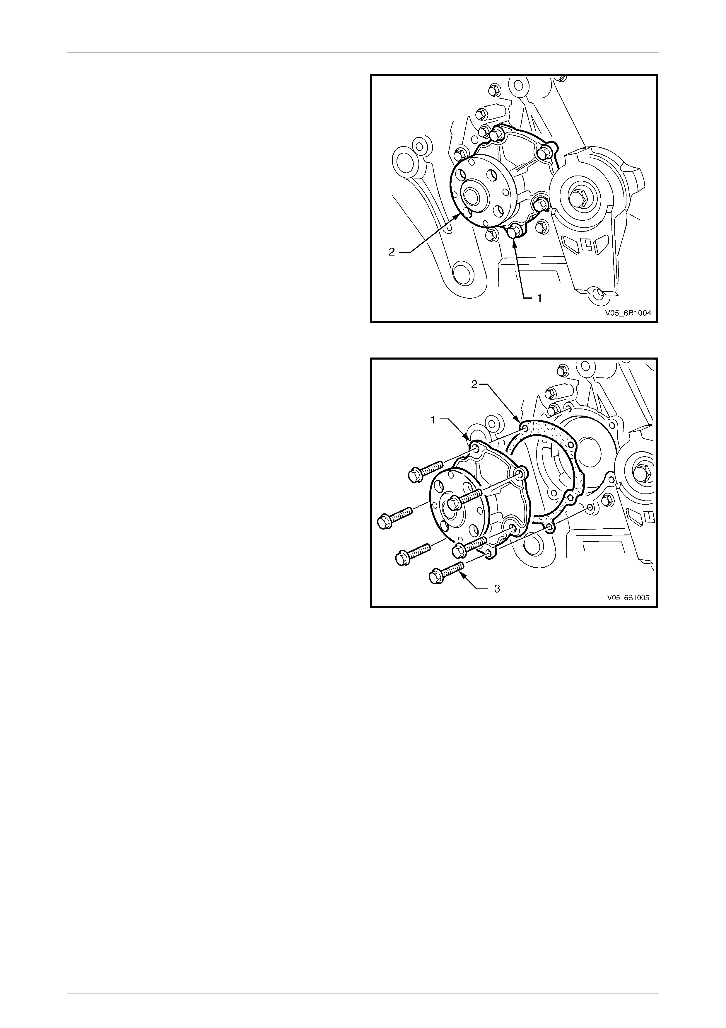
Engine Cooling – V6 Engine Page 6B1–70
9 Remove the six coolant pump attaching bolts (1)
from the coolant pump (2).
Figure 6B1 – 74
10 Remove the coolant pump (1) from the engine front
cover.
NOTE
If necessary, use a soft-faced hammer to
lightly tap coolant p ump hous ing to s eparate it
from front cover.
11 Remove coolant pump to front cover gasket (2) and
discard.
Figure 6B1 – 75
Page 6B1–70
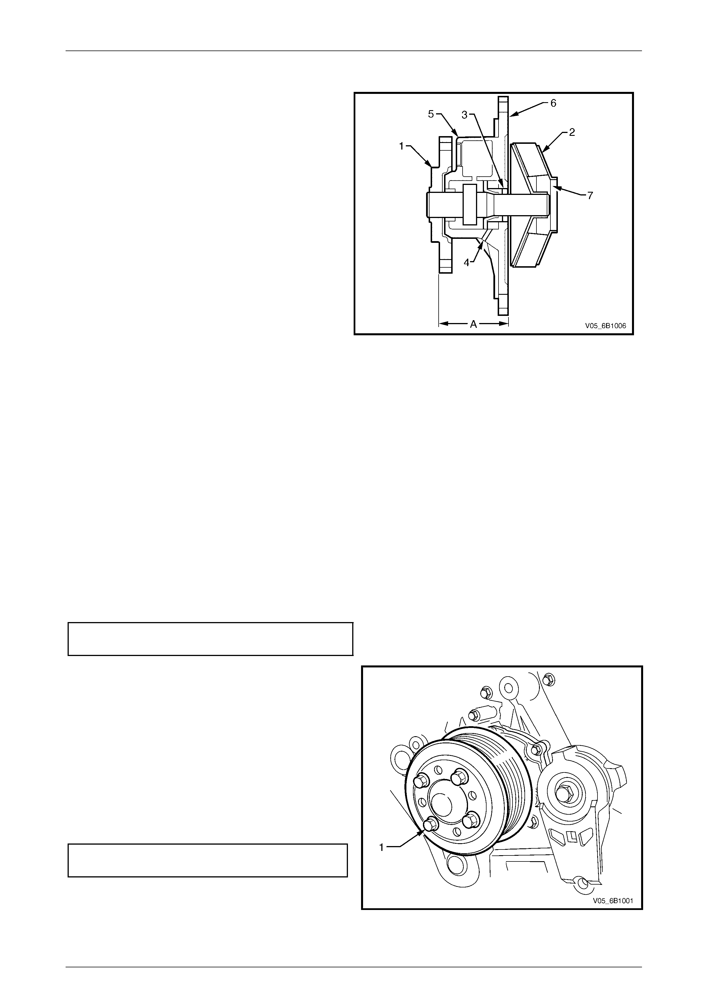
Engine Cooling – V6 Engine Page 6B1–71
Inspect
1 Rotate the coolant pump hub (1). T he hub and
impeller (2) should turn straight and smoothly. If the
hub wobbles, is noisy or feels rough when rotated,
replace the coolant pump.
2 Inspect the exterior of the coolant pump for the
following:
• Damage to the coolant pump hub bolt threads
for the coolant pump pulley.
• Damage to the coolant pump bolt holes.
3 Examine the coolant pum p shaft (3) and the weep
hole (4) in the coolant pump housing (5) for signs of
leakage. If coolant leakage is evident, replace the
coolant pump.
4 Inspect the interior of the coolant pump for the
following:
• Damage to the coolant pump gasket-sealing
flange surface (6).
Figure 6B1 – 76
• Damage, corrosion or restrictions to the coolant pump impeller.
• Damage, corrosion or restrictions to the coolant passa ges (7).
NOTE
Hub Flange to rear of Pump Housing
measurement (A) should be 4 3.76 ± 0.25 mm.
5 Replace the coolant pump as necessary.
Reinstall
1 Ensure that the coolant pump and front cover mating surfac es are clean and dry.
2 Install a new gasket to the front cover.
3 Clean threads of coolant pump to front cover and cylinder block attaching bolts.
4 Install coolant pump and attaching bolts. Tighten all bolts to the correct torque specification.
Coolant pump to front cover
bolt torque specification........................................ 10 Nm
5 Install coolant pump pulley and attaching bolts (1).
6 Install drive belt (reverse to removal procedures) and
ensure that the drive belt is aligne d with all accessory
pulleys and crankshaft balancer drive belt grooves.
NOTE
Refer to Figure 6B1 – 68, Figure 6B1 – 69 and
Figure 6B1 – 70 as required for the correct
drive belt routing.
7 Tighten coolant pump pulley attaching bolts (1) to the
correct torque specification.
Coolant pump pulley to hub
bolt torque specification....................................10 Nm
8 Close the radiator drain tap on the lower LHS of the
radiator and remove the piece of rubber tubing to the
tap outlet.
Figure 6B1 – 77
Page 6B1–71

Engine Cooling – V6 Engine Page 6B1–72
9 Refill cooling system. Refer to 3.3 Draining and Filling Cooli ng System in this Section.
10 Check for coolant leaks. Refer to 3.7 Pressure Testing in this Section.
11 Install the radiator shroud.
12 Install the engine dress covers. Refer to Section 6A1 Engine Mechanical – V6.
13 Reconnect battery ground l ead. Refer to Section 12A Battery.
Page 6B1–72

Engine Cooling – V6 Engine Page 6B1–73
3.12 Coolant Outlet Housing
LT Section No. – 00–350
MY2006 VZ Models
Remove
Refer to 3.1 Service Notes in this Section, for
important safety items.
1 Allow engine to cool to ambient temperature (less than 50° C), and then remove the coolant filler cap (l ocated at
the front left-hand side of the engine).
Disconnection of the battery affects certain
vehicle electronic systems. Refer to
Section 00 Warnings, Cautions and Notes,
before removing the ground lead.
2 Disconnect the battery ground lead. Refer to Section 12A Battery.
3 Remove the engine dress covers. Refer to Section 6A1 Eng ine Mechanical – V6.
4 Remove the upper radiator shroud (1) as fol lows:
a Using a fine, flat-blade screwdriver to prise
the centre pin of the scrivet (2) upward and
remove the scrivet, five places.
b Lift up the radiator shroud to disengage the
retaining clip (3) and remove the shroud.
Refer to ‘Environmental Issues’ in
3.1 Service Notes, before draining the
coolant.
5 Draining the coolant from the system. Refer to
3.3 Draining and Filling Cooling System in this
Section.
6 Remove the complete intake manifold assembly.
Refer to Section 6A1 Engine Mechanical – V6.
Figure 6B1 – 78
Always wear protective safety glasses when
working with spring type hose clamps. Failure
to do so could result in eye injury.
Page 6B1–73
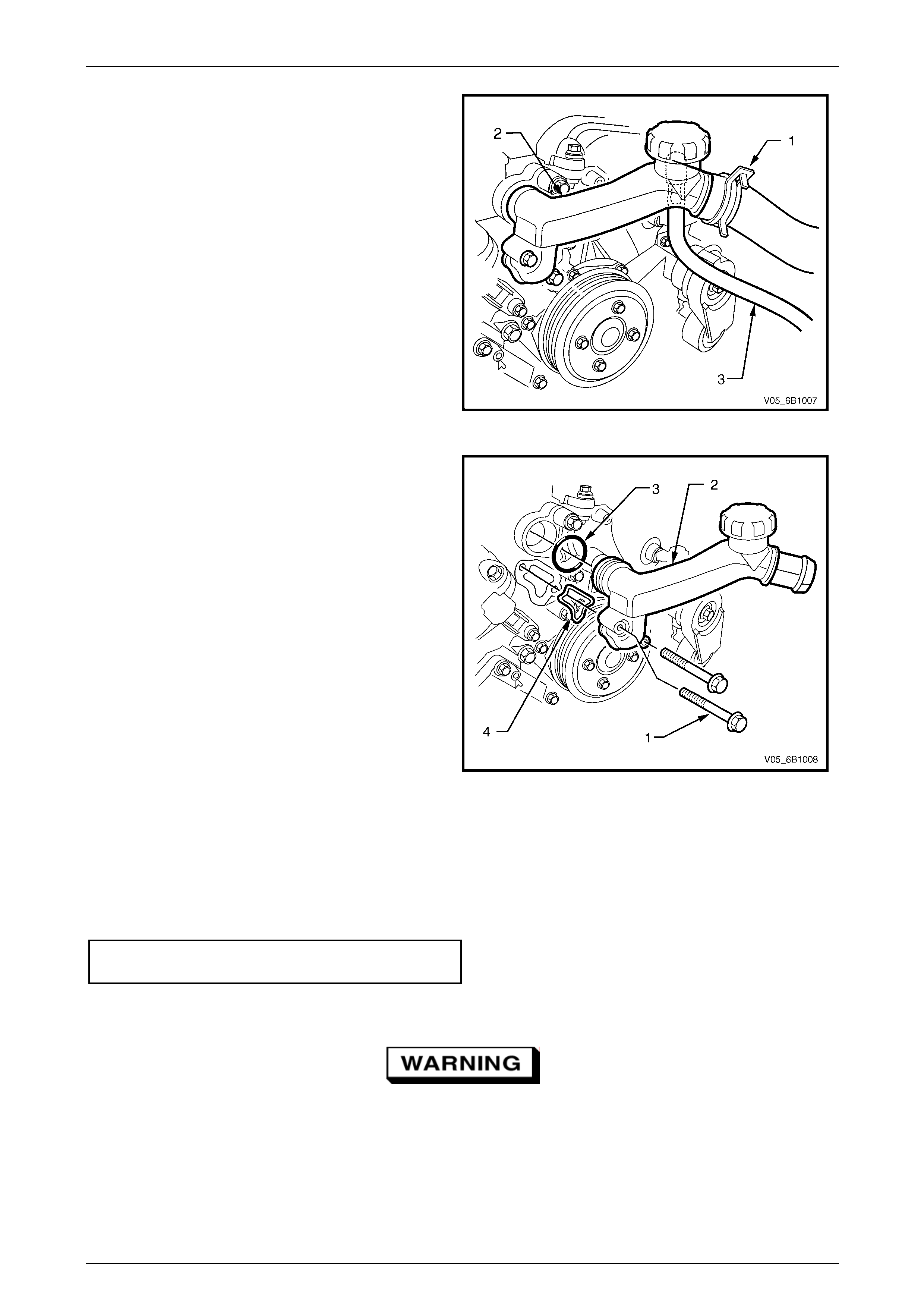
Engine Cooling – V6 Engine Page 6B1–74
7 Remove upper radiator hose clamp (1) at the
coolant outlet housing connection (2), disconnect
hose from coolant outlet.
8 Disconnect the coolant outlet housing to coolant
recovery reservoir hose (3) from und erside of the
coolant outlet.
Figure 6B1 – 79
9 Remove the two coolant outlet housing attaching
bolts (1), and remove coolant outlet housing (2).
10 Remove and discard coolant outlet housing
O-ring (3) and seal (4).
Figure 6B1 – 80
Reinstall
1 Ensure that the coolant outlet housing and front outlet mating surfaces are clean and dry.
2 Install new O-ring and seal to coolant outlet housing.
3 Install coolant outlet housing and attaching bolts. Tighten all bolts to the correct torque specification.
Coolant outlet housing to intake
manifold bolt torque specification..........................10 Nm
4 Connect the coolant outlet housing to cool ant recovery reservoir hose to underside of the coolant outlet.
Always wear protective safety glasses when
working with spring type hose clamps. Failure
to do so could result in eye injury.
5 Connect the upper radiator hose and clamp to the coolant outlet housing connectio n.
6 Close the radiator drain tap on the lower LHS of the radiator and remove the piece of rubber tubing to the tap
outlet.
Page 6B1–74
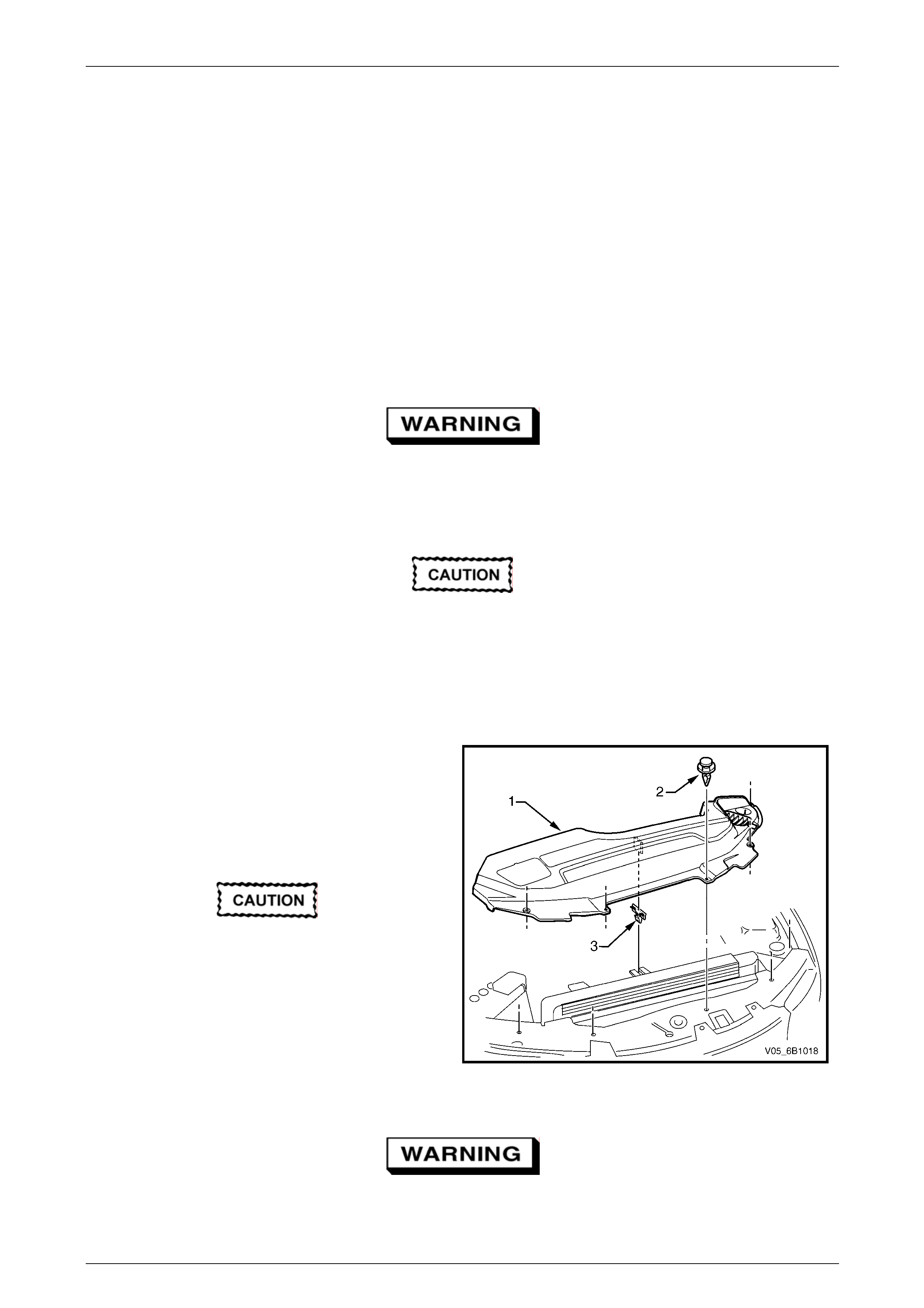
Engine Cooling – V6 Engine Page 6B1–75
7 Reinstall the intake manifold assembly. Refer to Section 6A1 Engine Mechanical – V6.
8 Refill cooling system. Refer to 3.3 Draining and Filling Cooli ng System in this Section.
9 Check for coolant leaks. Refer to 3.7 Pressure Testing in this Section.
10 Install the radiator shroud.
11 Install the engine dress covers. Refer to Section 6A1 Engine Mechanical – V6.
12 Reconnect battery ground l ead. Refer to Section 12A Battery.
LT Section No. – 00–350
MY2006 VZ Update Models
Remove
Refer to 3.1 Service Notes in this Section, for
important safety items.
1 Allow engine to cool to ambient temperature (less than 50° C), and then remove the coolant filler cap (l ocated at
the front left-hand side of the engine).
Disconnection of the battery affects certain
vehicle electronic systems. Refer to
Section 00 Warnings, Cautions and Notes,
before removing the ground lead.
2 Disconnect the battery ground lead. Refer to Section 12A B attery.
3 Remove the engine dress covers. Refer to Section 6A1 Eng ine Mechanical – V6.
4 Remove the upper radiator shroud (1) as fol lows:
a Using a fine, flat-blade screwdriver to prise
the centre pin of the scrivet (2) upward and
remove the scrivet, five places.
b Lift up the radiator shroud to disengage the
retaining clip (3) and remove the shroud.
Refer to ‘Environmental Issues’ in
3.1 Service Notes, before draining the
coolant.
5 Drain the coolant from the system. Refer to
3.3 Draining and Filling Cooling System in this
Section.
6 Remove the air intake duct as an assem bly. Refer
to Section 6A1 Engine Mechanical – V6.
Figure 6B1 – 81
Always wear protective safety glasses when
working with spring type hose clamps. Failure
to do so could result in eye injury.
Page 6B1–75
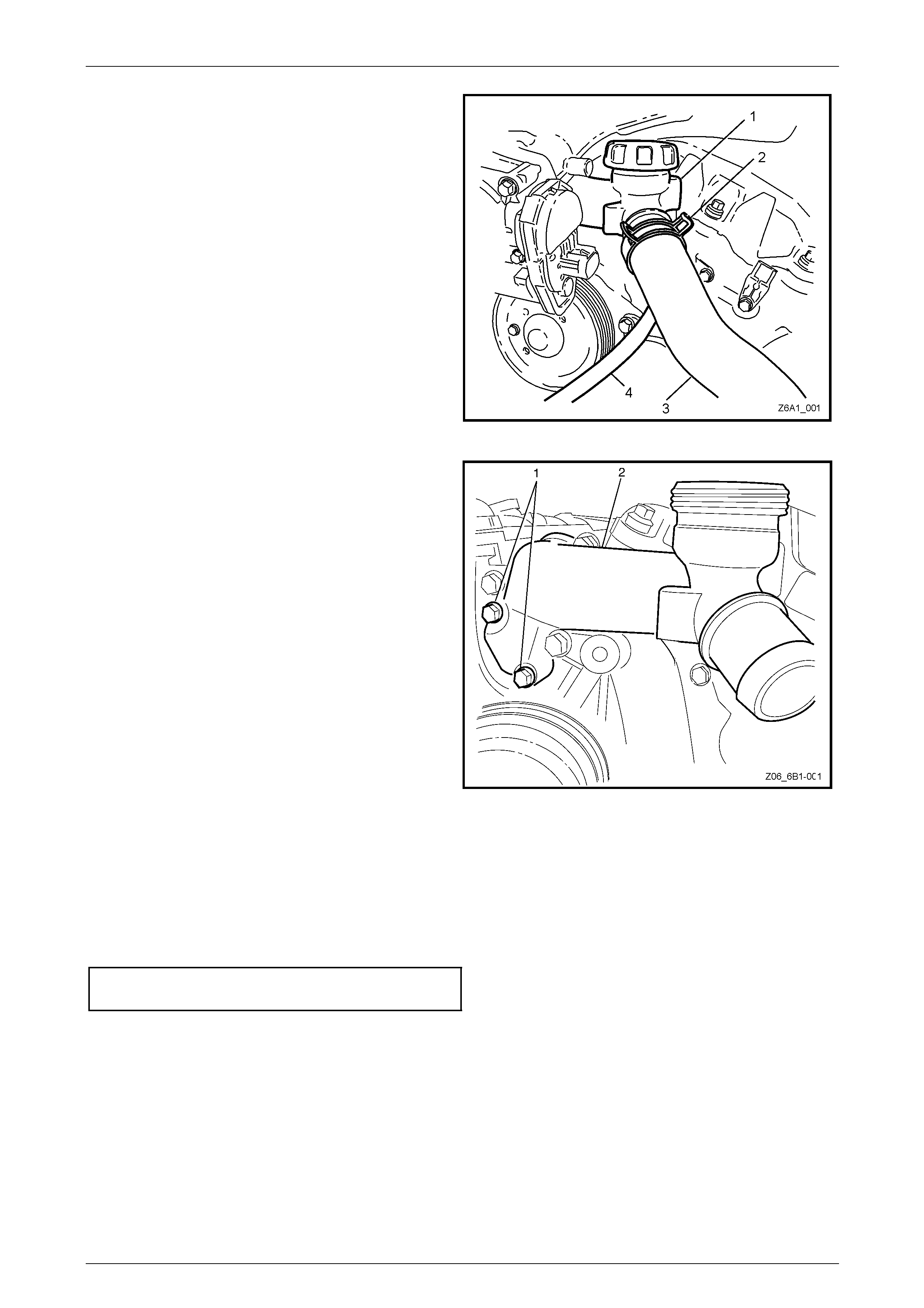
Engine Cooling – V6 Engine Page 6B1–76
7 Using suitable pliers, compress the hose clamps (2)
and slide back along the respective hoses of:
• Coolant outlet hose (both ends) (3).
• Coolant recovery reservoir hose (4) (partly
hidden).
8 Twist each hose to break the seal and remo ve.
Figure 6B1 – 1
9 Remove the bolts (1) securing the outlet housing (2)
to the intake manifold.
10 If required, use a rubber faced hammer to jar the
housing seal, then remove th e outlet housing and O-
Ring seal.
11 Discard the O-Ring seal.
Figure 6B1 – 2
Reinstall
Reinstallation is the reverse to removal procedures except for the following items:
1 Install a NEW O-Ring seal to the outlet housing.
2 Following installation of the housin g to0 the intake manifold, install and tighten the attaching bolts to the correct
torque specification.
Coolant outlet housing
bolt torque specification........................................ 10 Nm
3 Reinstall all removed hoses a nd check that the retaining clamps are correct ly installed.
4 Refill the cooling system, refer to 3.3 Draini ng and Filling Coolin g System.
5 On completion, pressurise the coolant system (refer to 3.7 Pressure Testing) and check for leaks, correcting as
required.
Page 6B1–76
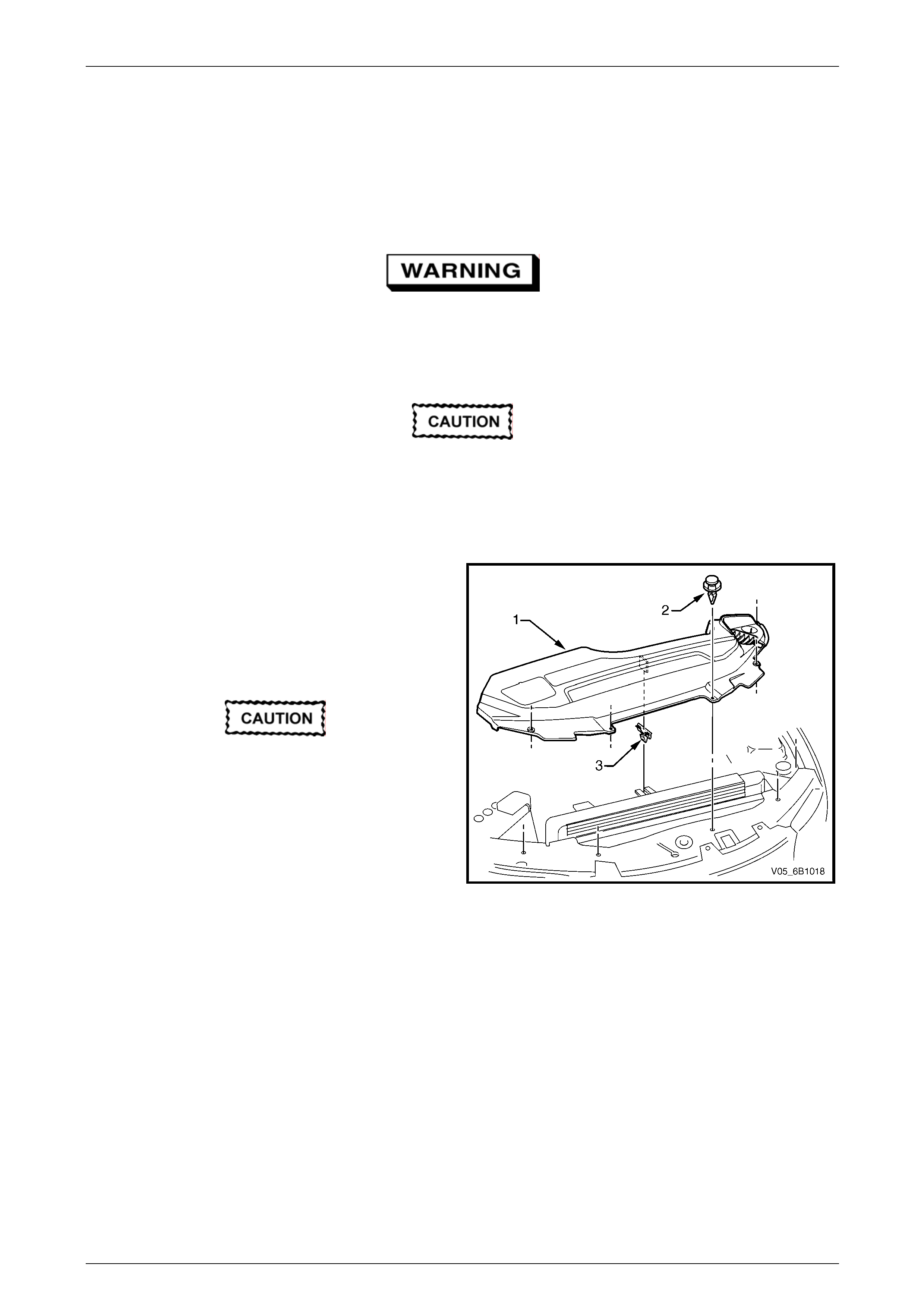
Engine Cooling – V6 Engine Page 6B1–77
3.13 Coolant Inlet Pipe
LT Section No. – 01–160
Remove
Refer to 3.1 Service Notes in this Section, for
important safety items.
1 Allow engine to cool to ambient temperature (less than 50° C), and then remove the coolant filler cap (l ocated at
the front left-hand side of the engine).
Disconnection of the battery affects certain
vehicle electronic systems. Refer to
Section 00 Warnings, Cautions and Notes,
before removing the ground lead.
2 Disconnect the battery ground lead. Refer to Section 12A Battery.
3 Remove the upper radiator shroud (1) as fol lows:
a Using a fine, flat-blade screwdriver to prise the
centre pin of the scrivet (2) upward and remove
the scrivet, five places.
B Lift up the radiator shroud to disengage the
retaining clip (3) and remove the shroud.
Refer to ‘Environmental Issues’ in 3.1 Service
Notes, before draining the coolant.
4 Draining the coolant from the system. Refer to
3.3 Draining and Filling Cooling System in this
Section.
5 Raise the front of the vehicle and support on safety
stands. Refer to Section 0A General Information for
the location of jacking and support points. Figure 6B1 – 82
Page 6B1–77
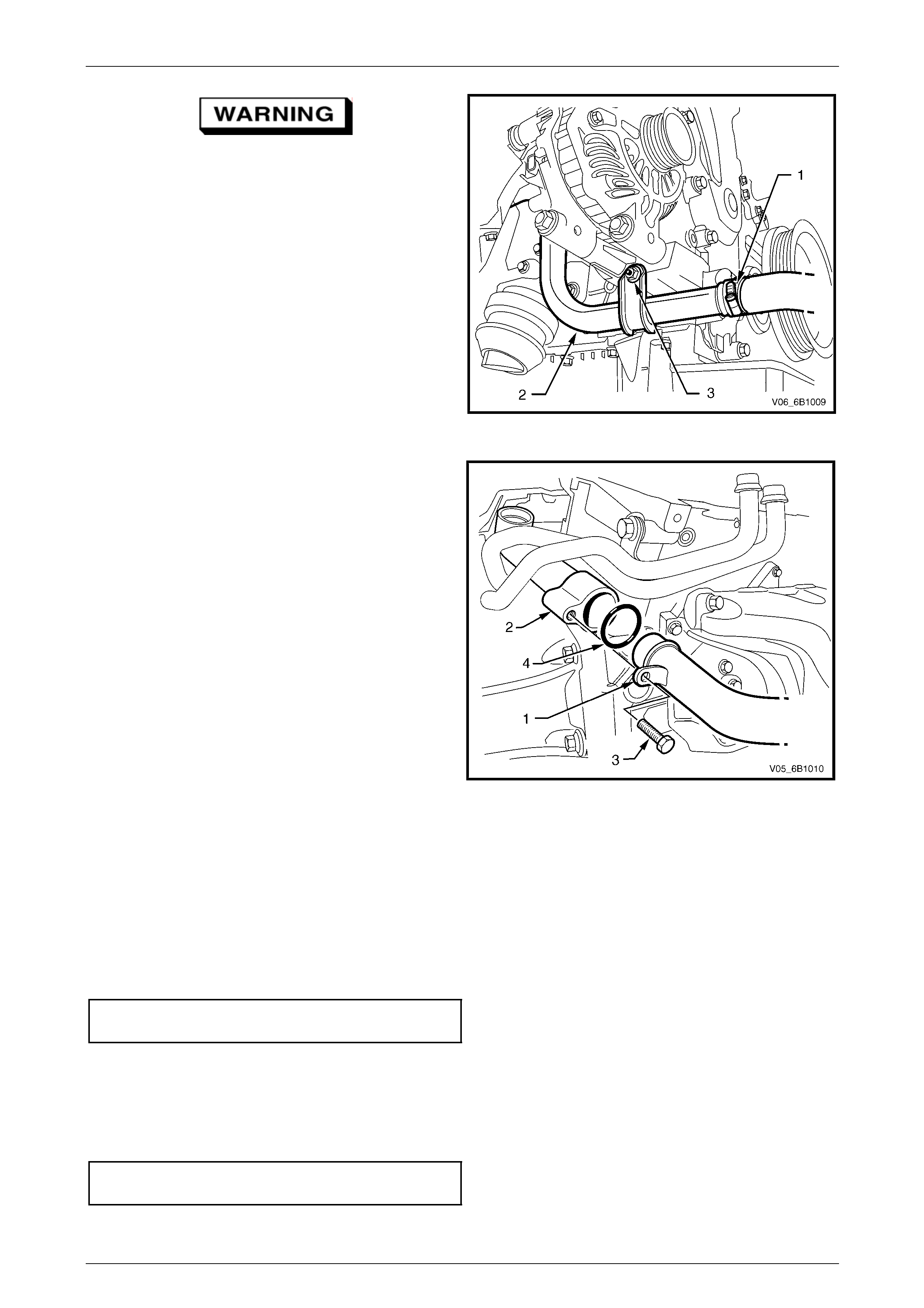
Engine Cooling – V6 Engine Page 6B1–78
Always wear protective safety glasses when
working with spring type hose clamps.
Failure to do so could result in eye injury.
6 Loosen the lower radiator outl et, worm drive hose
clamp (1) at the coolant inlet pipe connection, then
disconnect the hose from coolant inlet pip e (2).
NOTE
Shown is the RWD arrangement.
7 Remove the coolant inlet pipe to generator bracket
(RHS engine mount bracket on AWD vehicles)
attaching nut (3).
Figure 6B1 – 83
8 Remove the coolant inlet pipe (1) to thermostat
housing (2) attaching bolt (3).
9 Remove the coolant inlet pipe b y manoeuvring the
pipe to the front of the vehicle and withdrawing the
pipe from below the vehicle, bet ween the cross
member and radiator.
10 Remove and discard coolant inlet pipe O-ring (4) from
the thermostat end of the coolant inlet pipe.
Figure 6B1 – 84
Reinstall
1 Ensure that the coolant inlet pipe and thermostat housing mating surfaces are clean and dry.
2 Install new O-ring to the coolant inlet pipe.
3 Lubricate O-ring with petroleum jelly (e.g. Vaseline™ or similar), to assist with reassembly.
4 Install coolant inlet pipe at the thermostat housing and secure with the attaching bolt. Tighten all bolts to the correct
torque specification.
Coolant inlet pipe to thermostat
housing bolt torque specification...........................23 Nm
5 Raise the front of the vehicle and support on safety stands. Refer to Section 0A General Information for the location
of jacking and support points.
6 For RWD vehicles, reinstall the coolant inlet pipe to the generator stud and secure with a nut tightened to the
correct torque specification. For AWD models, reinstall the coolant inlet pipe to the air conditioning compressor stud
and secure with a nut tightened to the correct torque specification
Coolant inlet pipe to generator / A/C
compressor bolt/nut torque specification...............25 Nm
Page 6B1–78

Engine Cooling – V6 Engine Page 6B1–79
Always wear protective safety glasses when
working with spring type hose clamps. Failure
to do so could result in eye injury.
7 Connect the lower radiator outlet hose and cl amp to the coolant inlet pipe connection.
8 Close the radiator drain tap on the lower LHS of the radiator and remove the piece of rubber tubing to the tap
outlet.
9 Lower the front of the vehicle.
10 Refill cooling system. Refer to 3.3 Draining and Filling Cooling System in this Section.
11 Check for coolant leaks. Refer to 3.7 Pressure Testing in this Section.
12 Reinstall the radiator shroud.
13 Reconnect battery ground l ead. Refer to Section 12A Battery.
Page 6B1–79
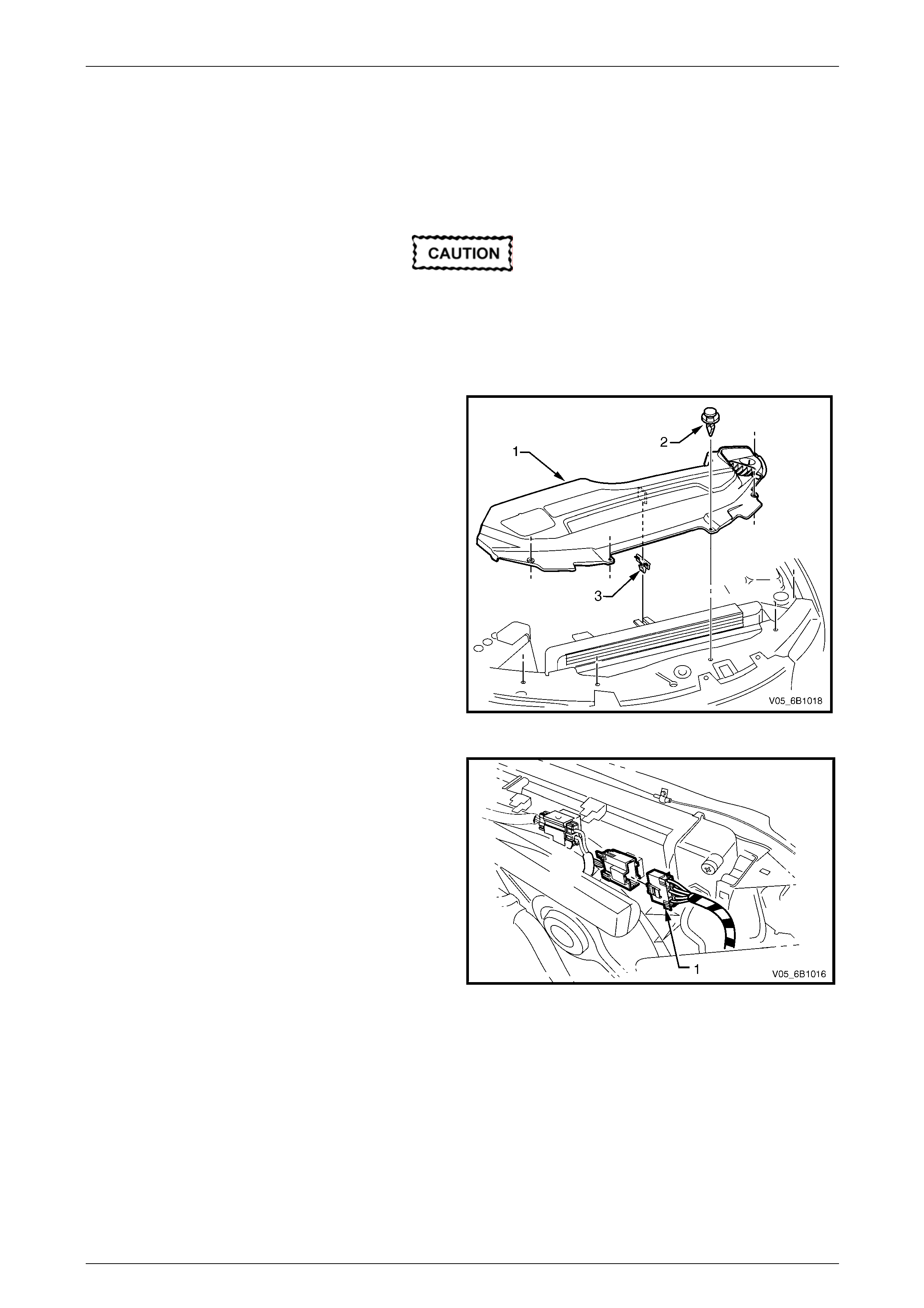
Engine Cooling – V6 Engine Page 6B1–80
3.14 Cooling Fan and Shroud Assembly
LT Section No. – 01–105
Remove
Disconnection of the battery affects certain
vehicle electronic systems. Refer to
Section 00 Warnings, Cautions and Notes,
before removing the ground lead.
14 Disconnect the battery ground lead. Refer to Section 12A Battery.
15 Remove the upper radiator shroud (1) as follows:
a Using a fine, flat-blade screwdriver to prise the
centre pin of the scrivet (2) upward and remove
the scrivet, five places.
B Lift up the radiator shroud to disengage the
retaining clip (3) and remove the shroud.
16 Remove the intake duct and mass air flow as an
assembly. Refer to Section 6A1 Engine Mechanical –
V6.
17 Remove the coolant recovery hose from the fan
shroud retaining clip.
Figure 6B1 – 85
18 Depress tang on main wiring harness to cooling fan
motor wiring harness connector and separate
connector (1).
Figure 6B1 – 86
Page 6B1–80
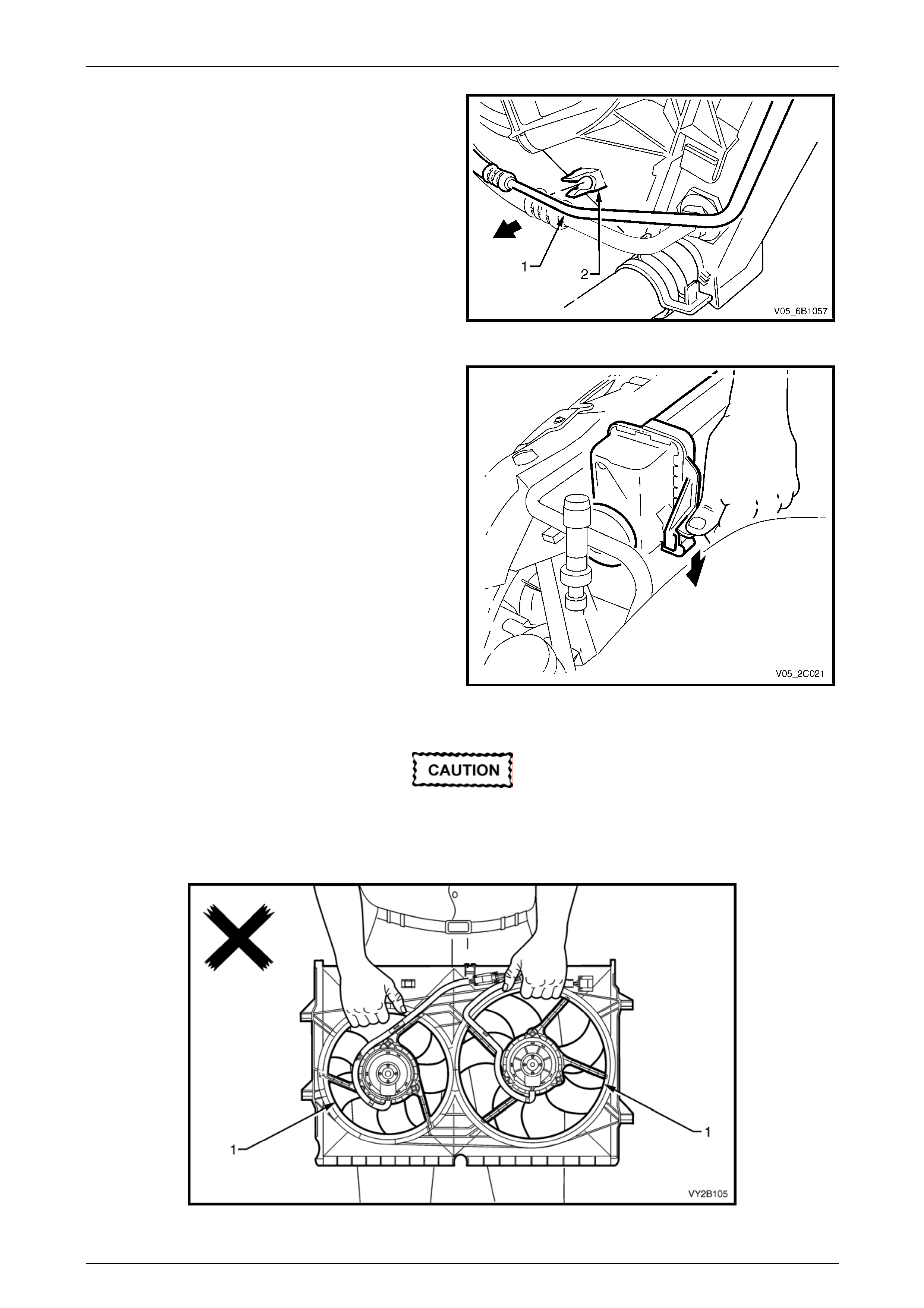
Engine Cooling – V6 Engine Page 6B1–81
19 Where fitted, release the upper automatic transmission
cooling pipe (1) (if fitted) from the integral clip (2) on
the fan shroud.
Figure 6B1 – 87
20 Release the fan shroud to radiator clips by holding one
of the lugs out with the fingers of one hand while lifting
the shroud with the other. Repeat this operation to
release the other side.
Figure 6B1 – 88
When removing, transporting or installing the
fan assembly, do not grasp the assembly by
the fan rings (1) as this may bend the fan
motor shafts and cause fan vibrations
Figure 6B3 – 89
Page 6B1–81
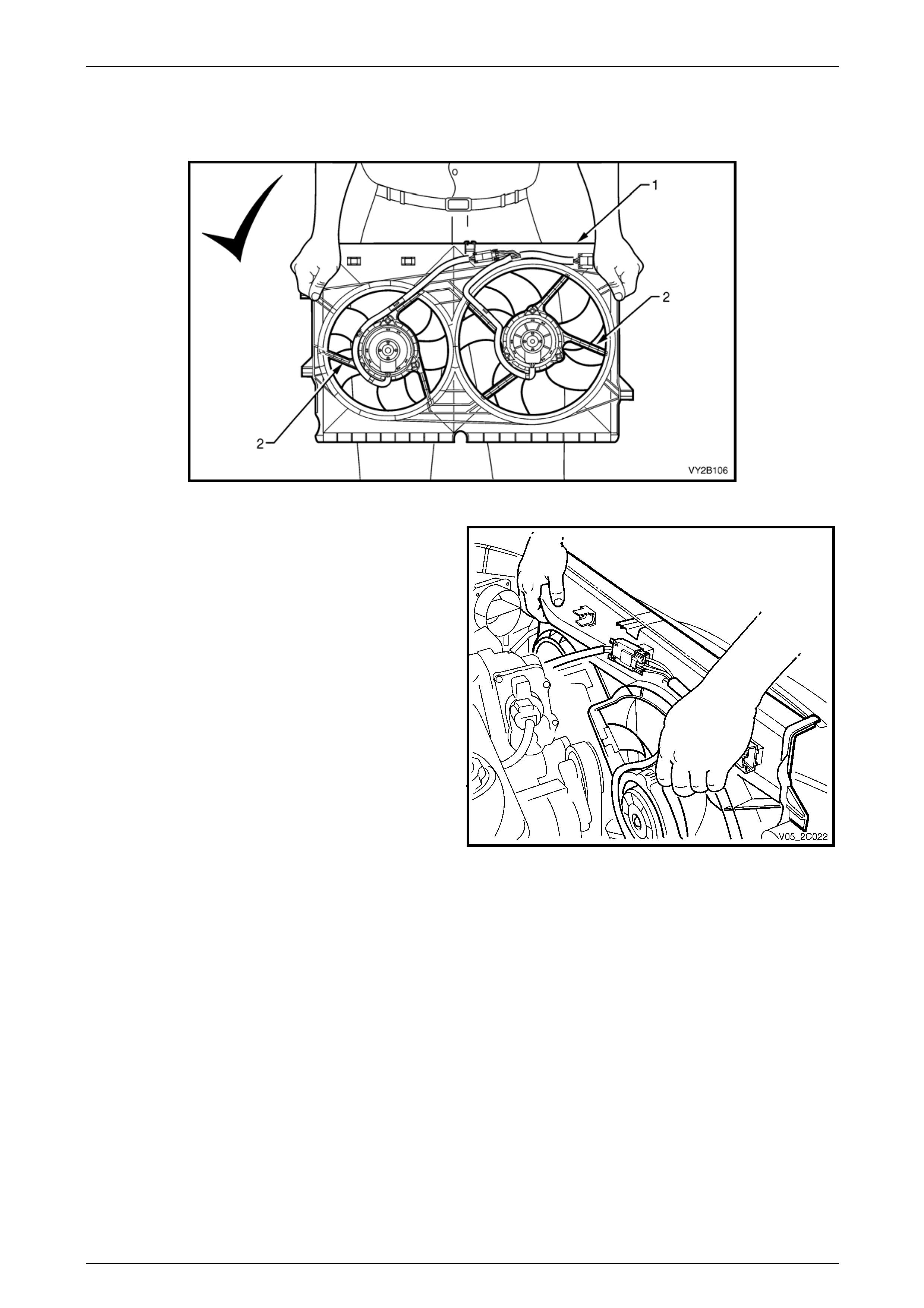
Engine Cooling – V6 Engine Page 6B1–82
When handling the fan assembly, always hold
the assembly at the fan shroud (1) or fan
motor mounting struts (2).
Figure 6B3 – 90
21 Lift the shroud and fan assembly clear from the engine
bay, grasping the motor mounting struts.
Figure 6B1 – 91
Install
Installation of the cooling fan and shroud assembly is the reverse of removal procedures, noting the following points:
1 Ensure that fan and shroud assembly to radiator attaching clips are fully engaged.
2 Ensure that the top automatic transmission cooling pipe (if fitted) is installed to the integral shrou d clip.
3 Check cooling fan operation. Refer to Section 6C1-2 Engine Management – V6 – Diagnostics. Also check for
correct rotational direction of cooling fans.
Page 6B1–82
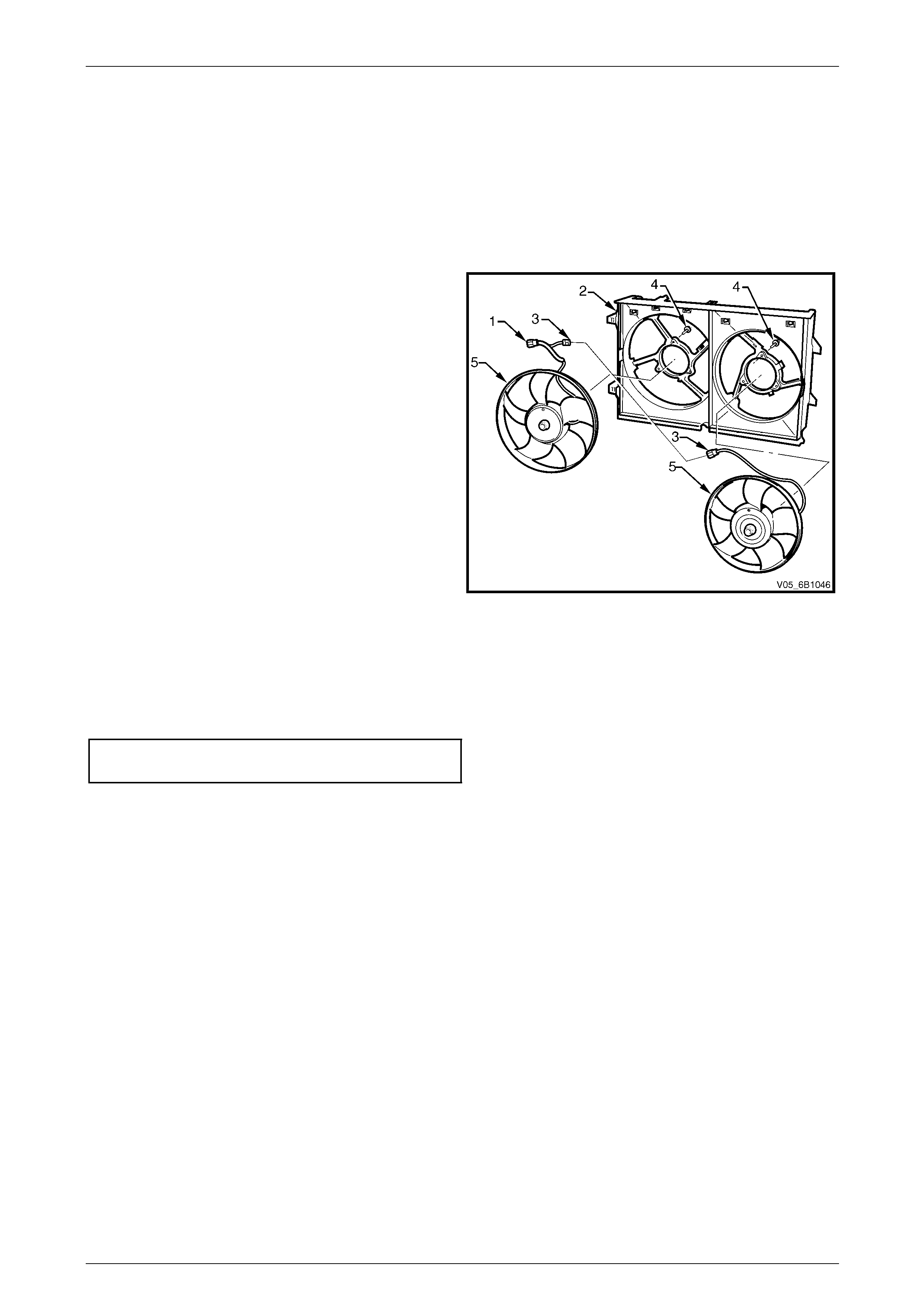
Engine Cooling – V6 Engine Page 6B1–83
Disassemble
1 Remove cooling fan and shro ud assembly as previously described.
NOTE
Neither fan is to be separated from its fan motor.
The assembly is carefully balanced during
manufacture and duplicating this balance on
reassembly, is not possible.
2 Remove the motor assembly wiring harness (1) from
the integral clips that form a part of the shroud (2).
3 Separate the intermediate wiring harness
connector (3).
4 Remove screws (4) attaching the motor assembly (to
the shroud, then remove each motor, fan and wiring
assembly (5) from the shroud.
Figure 6B1 – 92
Reassemble
Reassembly is the reverse of disass embly procedures, noting the following points:
1 Tighten motor to shroud attaching screws to the correct torque specification. Do not over-tighten.
Fan motor to shroud screw
torque specification.................................................5 Nm
2 Ensure that all wiring is routed correctly and secured by the shroud clips. In stall the intermediate connector.
3 Install cooling fan and shroud assembly to the radiator, as previously describe d.
Page 6B1–83
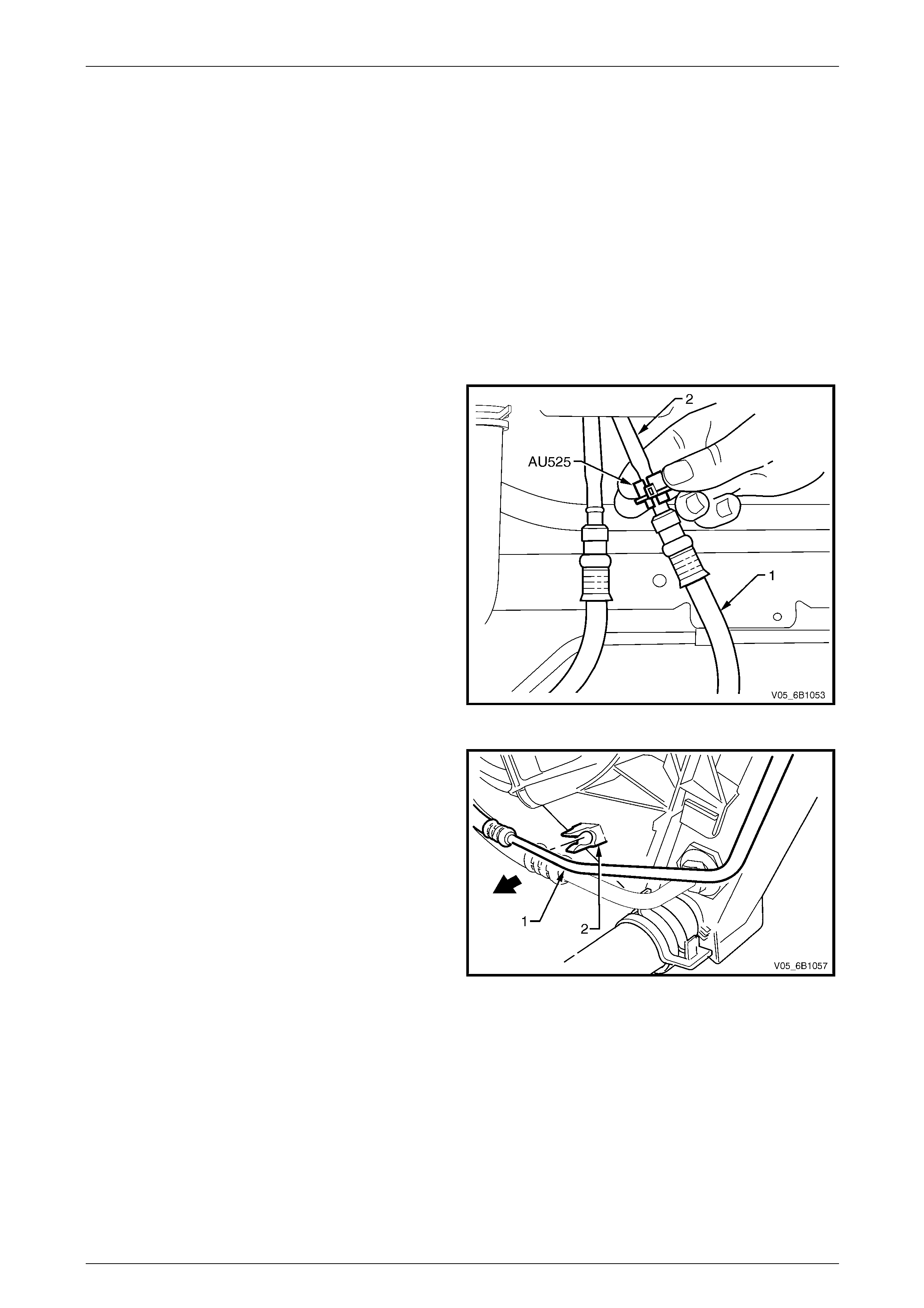
Engine Cooling – V6 Engine Page 6B1–84
3.15 Flexible Transmission Cooler Hose
LT Section No. – 04–150
Replace
NOTE
The flexible hoses are not serviced separately.
Therefore, should a hose require replacement,
then the hose and radiator to hose cooler pipe
assembly must be fitted.
1 Place a drip tray beneath the engine and rad iator section.
2 Disconnect the transmission cooler pipe(s) from the
flexible hose(s) using Tool No. AU525.
• Open release tool AU525, then close a nd clip
around the pipe to be disconnected.
• While holding the flexible hose (1) with one
hand, push the tool into the connection.
• Push the hose (1) inwards, then pull back to
separate the connection.
• Repeat for the second fitting, if required.
3 Plug both pipe openings and hoses to minimise fluid
loss and prevent foreign matter entry.
Figure 6B1 – 93
4 If removing the upper automatic transmission cooling
pipe (1), then release it from the integral clip (2) on the
fan shroud.
Figure 6B1 – 94
Page 6B1–84
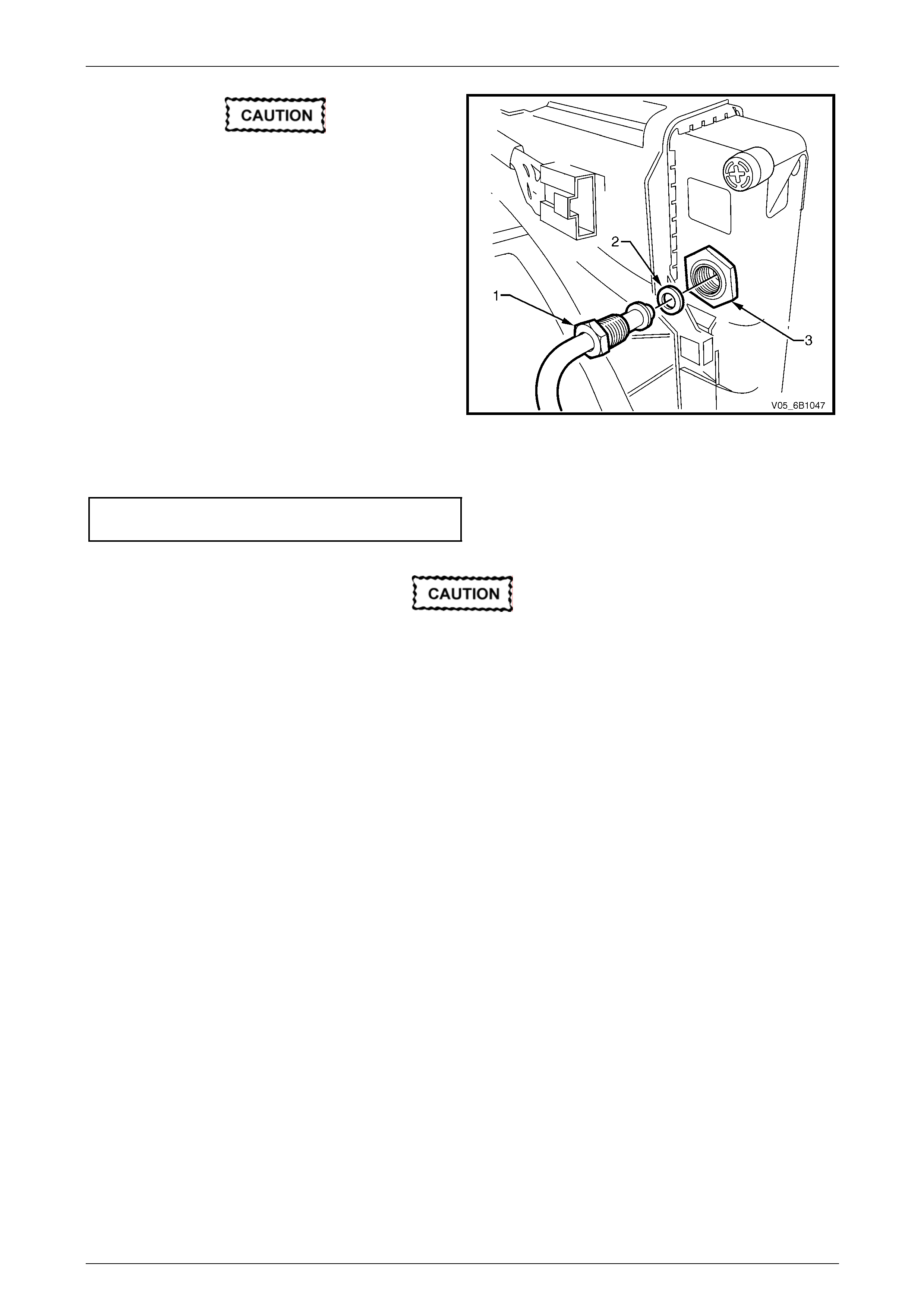
Engine Cooling – V6 Engine Page 6B1–85
A back-up spanner must be used on the
larger cooler, flare nut fitting (3) to prevent it
from loosening.
5 Using a suitable set spanner, hold the flare n ut fitting
(3), then loosen the cooler pipe tube nut (1).
6 Remove, taking care not to lose the sealing washer
(2). Plug both open ends to prevent fluid loss and / or
dirt entry.
7 Repeat for the second pipe / hose assembly.
8 Before installing each pipe to the cool er, carefully
inspect the pipe-sealing washer (2). If the centre,
silicone portion shows signs of distress or damage, it
must be replaced.
9 Remove the plugging from the pipe an d fittings, fit the
sealing washer to the cleaned pipe and reinst all into
the cooler. Figure 6B1 – 95
10 Reinstall the tube nut and, while holding the flare nut fitting, tighten the tube nut to the correct torque specification.
Oil cooler pipe tube nut
torque specification...............................................25 Nm
A back-up spanner must be used on the
larger cooler, flare nut fitting (3) to prevent it
from loosening.
13 Check the transmission fluid level. Refer to the following references as required:
• Section 7C4 Automatic Transmission – 4L60E On-vehicle Servicing
• Section 7D4 Automatic Transmission – 4L65E On-vehicle Servicing
• Section 7E4 Automatic Transmission – 5L40E On-vehicle Servicing
Page 6B1–85
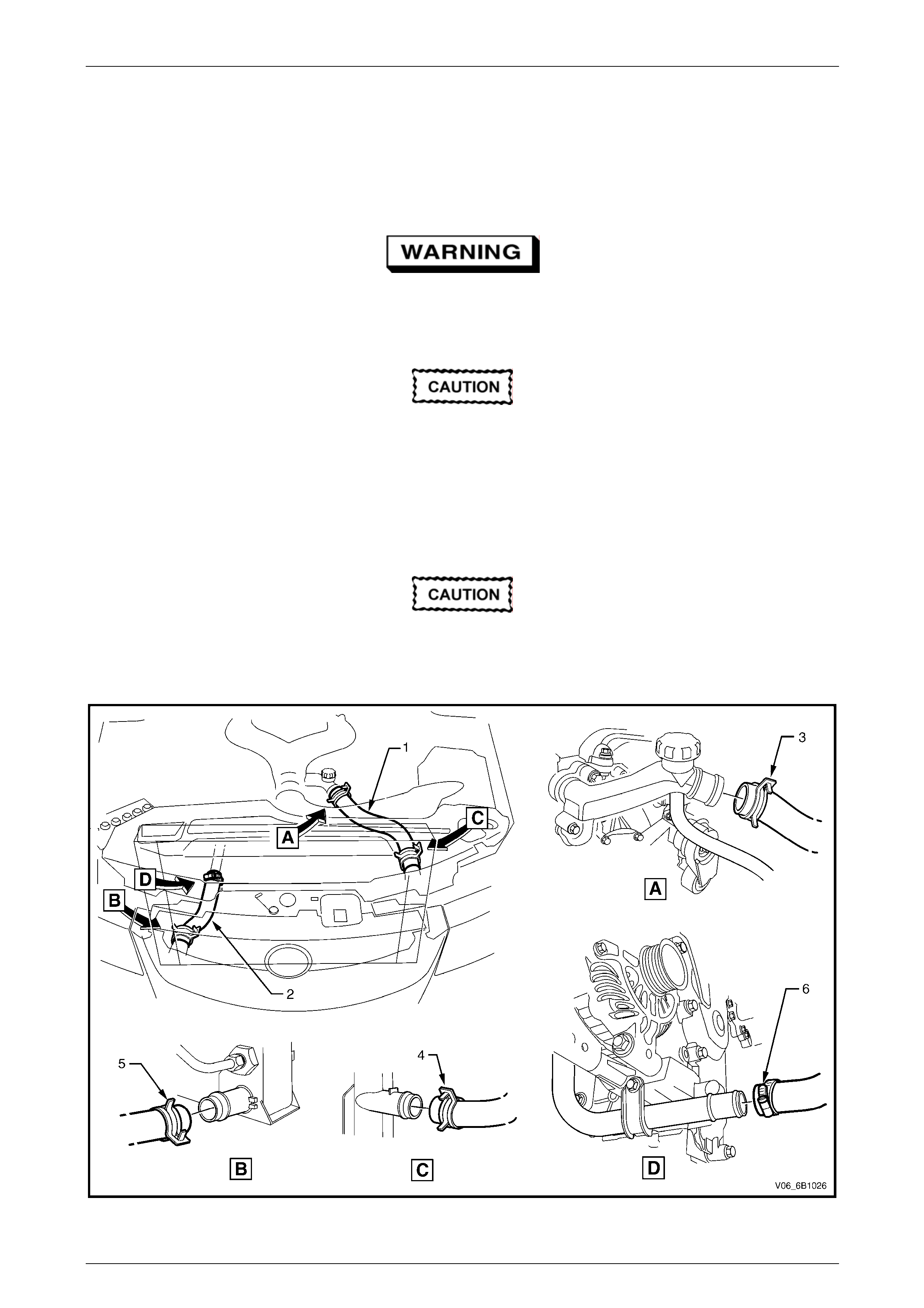
Engine Cooling – V6 Engine Page 6B1–86
3.16 Radiator
LT Section No. – 01–105
Remove
Refer to 3.1 Service Notes in this Section, for
important safety items.
1 Allow engine to cool to ambient temperature (less than 50° C), then remove coolant filler cap.
Disconnection of the battery affects certain
vehicle electronic systems. Refer to
Section 00 Warnings, Cautions and Notes,
before removing the ground lead.
2 Disconnect the battery ground lead. Refer to Section 12A Battery.
3 Remove the radiator cooling fans and shroud assembly. Refer to 3.14 Cooling Fans and Shroud Assembly in this
Section.
Refer to ‘Environmental Issues’ in 3.1 Service
Notes, before draining the coolant.
4 Drain the coolant from the system. Refer to 3.3 Draining and Filling Cooling System in this Section.
Figure 6B1 – 96
Page 6B1–86
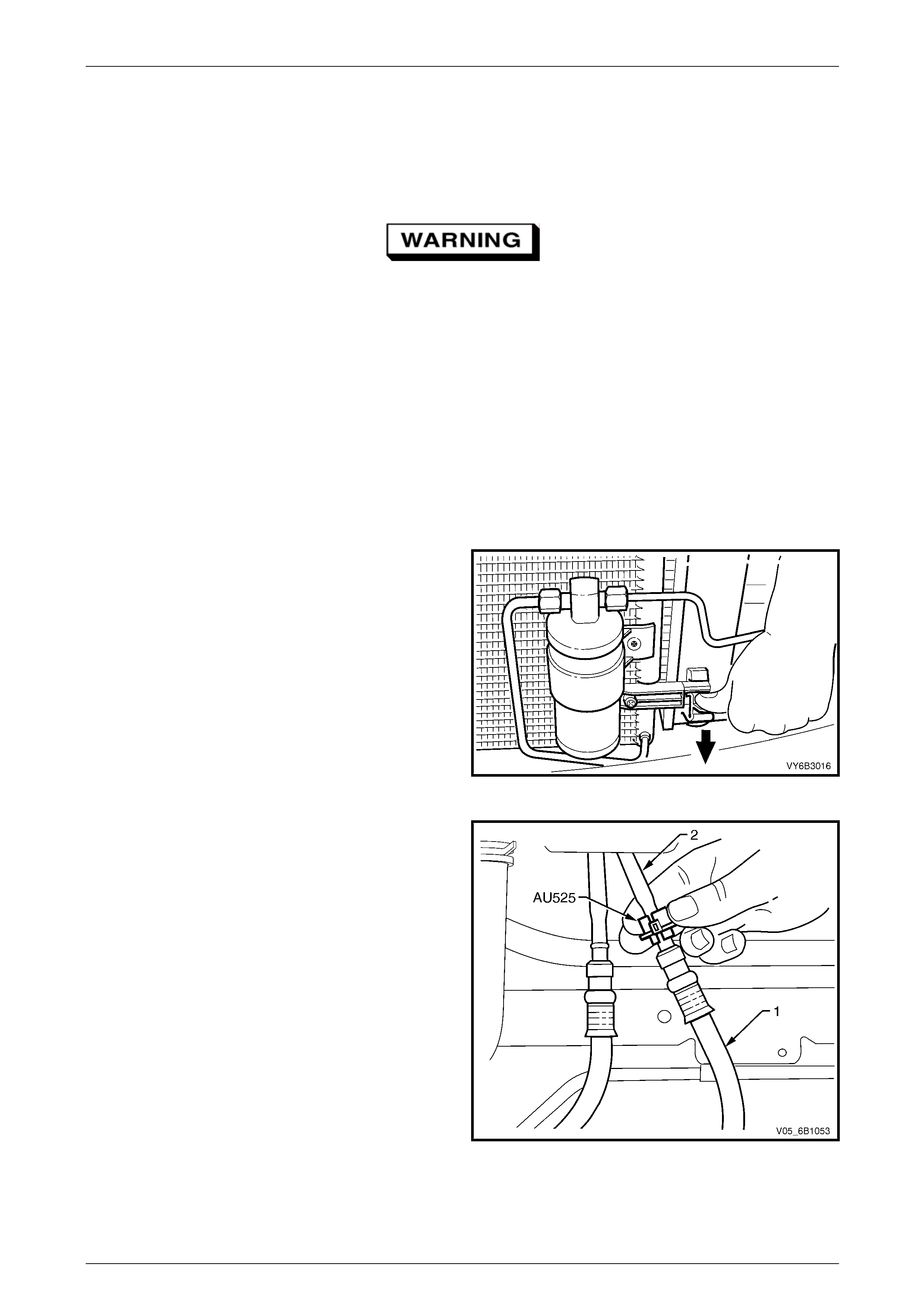
Engine Cooling – V6 Engine Page 6B1–87
Legend
1 Radiator Hose – Upper
2 Radiator Hose – Lower
3 Hose Clamp – Upper Hose to Engine Outlet Housing
4 Hose Clamp – Upper Hose to Radiator Inlet
5 Hose Clamp – Lower Hose to Radiator Outlet
6 Worm Drive Hose Clamp – Lower Hose to Engine Coolant
Inlet Pipe
Always wear protective safety glasses when
working with spring type hose clamps. Failure
to do so could result in eye injury.
5 Remove radiator upper hose (1) from radiato r connection.
6 Remove radiator lower hose (2) from radiator connection.
NOTE
If fitted with air conditioning, the condenser must
be separated from the radiator assembly. This
action will allow the radiator removal without
having to open any refrigerant lines.
7 Remove the radiator grille. Re fer to Section 1C Radiator Gril le.
8 Working through the grille ope ning, release one of
the clips securing the condens er to the radiator (bold
arrow). Do this by pressing down on the lug with the
fingers of one hand, while lifting the condenser
assembly with the other. Repeat for the other side.
NOTE
It is not necessary to remove the receiver dr ier,
nor disturb the air conditioning refrigerant
system (where fitted), for this operation. The
condenser can be lifted a sufficient amo unt with
the refrigerant pipes remaining attached.
9 Once released, pull the condenser assembly forward
to clear the radiator mounting lugs.
Figure 6B1 – 97
10 If vehicle is equipped with an automatic transmission,
disconnect the transmission oil cooler line quick
connect fittings, using Tool No. AU525:
• Open release tool AU525, then close a nd clip
around the pipe to be disconnected.
• While holding the flexible hose (1) with one
hand, push the tool into the connection.
• Push the hose (1) inwards, then pull back to
separate the connection.
• Repeat for the second fitting.
NOTE
If Tool No. AU525 is not available, the cooler
pipes can be disconnected from the cooler, in
the right side radiator tank. Refer to
3.15 Flexible T ransmission Cooler Hose, in this
Section, for critical information regarding this
procedure.
• Plug all openings to minimis e fluid loss and
prevent dirt entry.
Figure 6B1 – 98
Page 6B1–87

Engine Cooling – V6 Engine Page 6B1–88
11 Depress tang on main wiring harness to cooling fan
motor wiring harness connector (1) and separate
connector.
Figure 6B1 – 99
12 Using a screwdriver, compress and lever out radiator
retaining clips (1) from radiator upper mounting
brackets.
13 Lift radiator upwards out of lower insulators. To
remove the radiator assembly from the vehicle, after
clearing the top insulators, move the radiator
rearward on the left side, then across to the left, to
allow the right side to clear the mounting brackets.
14 Remove upper and lower insulators from the radiator.
Figure 6B1 – 100
Reinstall
Installation of the radiator is the reverse of removal procedures, noting th e following points:
1 Before installing radiator, inspect core to ens ure that there is no foreign matter in core fins. Clean out between core
fins with compressed air, blowing from rear to front.
2 Ensure that the radiator lower mounting pins are correctly located in lower insulators.
3 Ensure that the upper insulators are installed on upper mounting pins and radiator retainers are installed.
4 If the vehicle is fitted with an automatic transmission, remove plugs from the remove d cooling pipe ends and the
two quick connect fittings.
5 After wiping cooler pipe ends and smearin g clean automatic transmission fluid over each flared pipe end, push into
the quick connect fitting to engage. As a securit y check, tug on each pipe to ensure correct engagement.
NOTE
If the transmission cooler pipe tube nuts were
removed from the right hand radiator tank,
inspect the sealing washer for serviceability
before reinstallation. Replace the sealing
washer(s) as required.
6 As required, reinstall the tube nut.
7 While holding the flare nut fitting at the radiator, tighten the tube nut to the correct torque specification.
Oil cooler pipe tube nut
torque specification...............................................25 Nm
Page 6B1–88
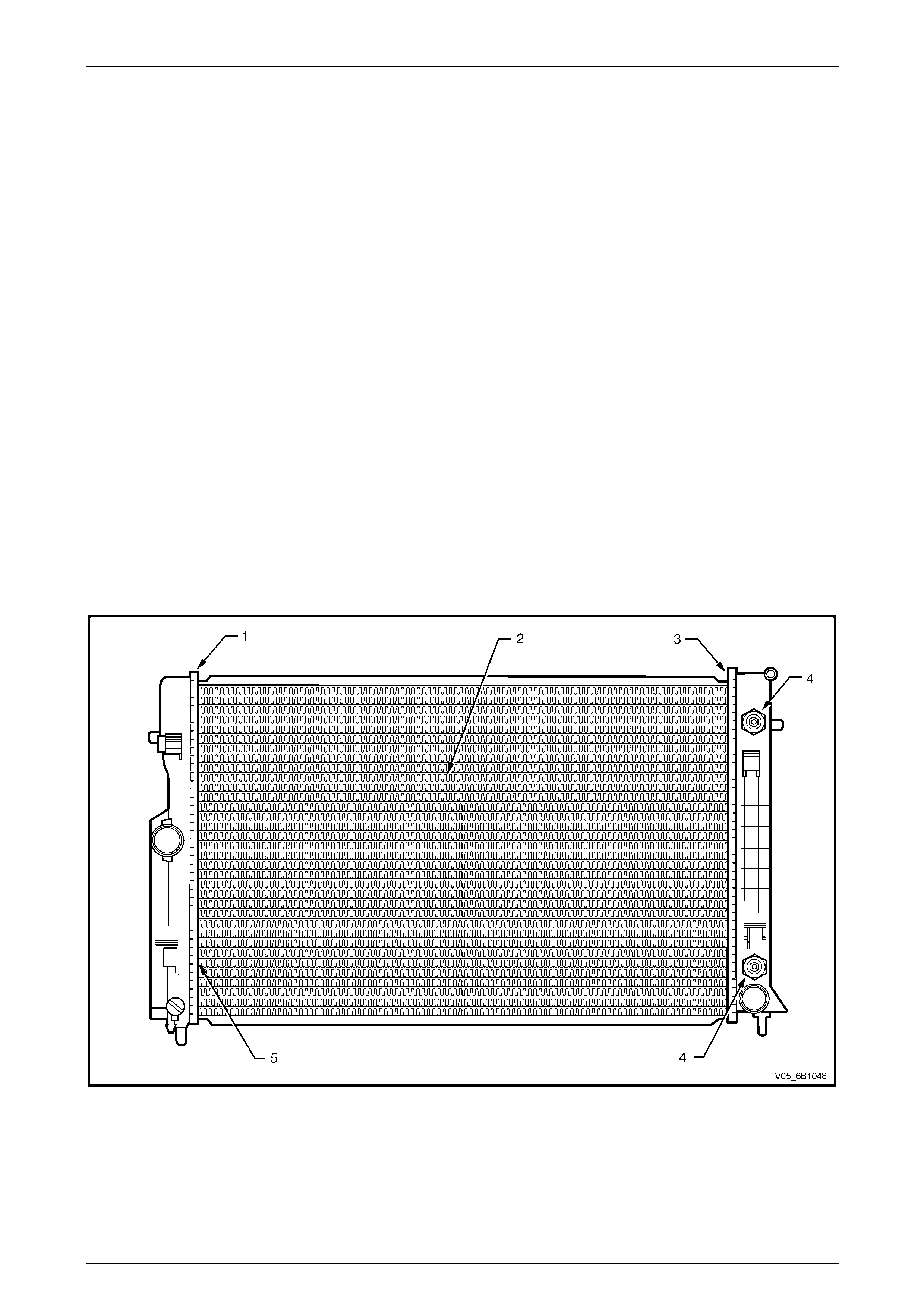
Engine Cooling – V6 Engine Page 6B1–89
8 Check the transmission fluid level. Refer to the following references as required:
• Section 7C4 Automatic Transmission – 4L60E On-vehicle Servicing
• Section 7D4 Automatic Transmission – 4L65E On-vehicle Servicing
• Section 7E4 Automatic Transmission – 5L40E On-vehicle Servicing
9 After reinstalling the condenser assembl y to the four retaining clips, ensure that the two lower clips have fully
engaged.
10 Install the radiator grille. Refer to Section 1C Radiator Grille.
11 Install the following hoses:
a. Lower radiator hose, securing with the hose c lamp.
b. Upper radiator hose, securing with the hose clamp.
12 Install the radiator cooling fans and shroud assembly. Refer t o 3.14 Cooling Fans and Shroud Assemb ly in this
Section. Ensure that electrical connectors and the transmission cooler lines are seated correctly in the integral
retainer clips before install upper radiator shroud.
13 Refill cooling system. Refer to 3.3 Draining and Filling Cooling System in this Section.
14Check for coolant leaks. Refer to 3.7 Pressure Testing in this Section.
15Reconnect battery ground lead. Refer to Section 12A Battery.
16Check cooling fan operation. Refer to Section 6C1-2 Engine Managem ent – V6 – Diagnostics. Also check for
correct rotational direction of cooling fa ns.
Radiator Repair Procedure
Repairable Leaks
Figure 6B1 – 101
Legend:
1 Left-hand Side Tank Seal
2 Core Tubes
3 Right-hand Side Tank Seal
4 Oil Cooler Pipe Fittings
5 Joint Between Tube and Header
Page 6B1–89
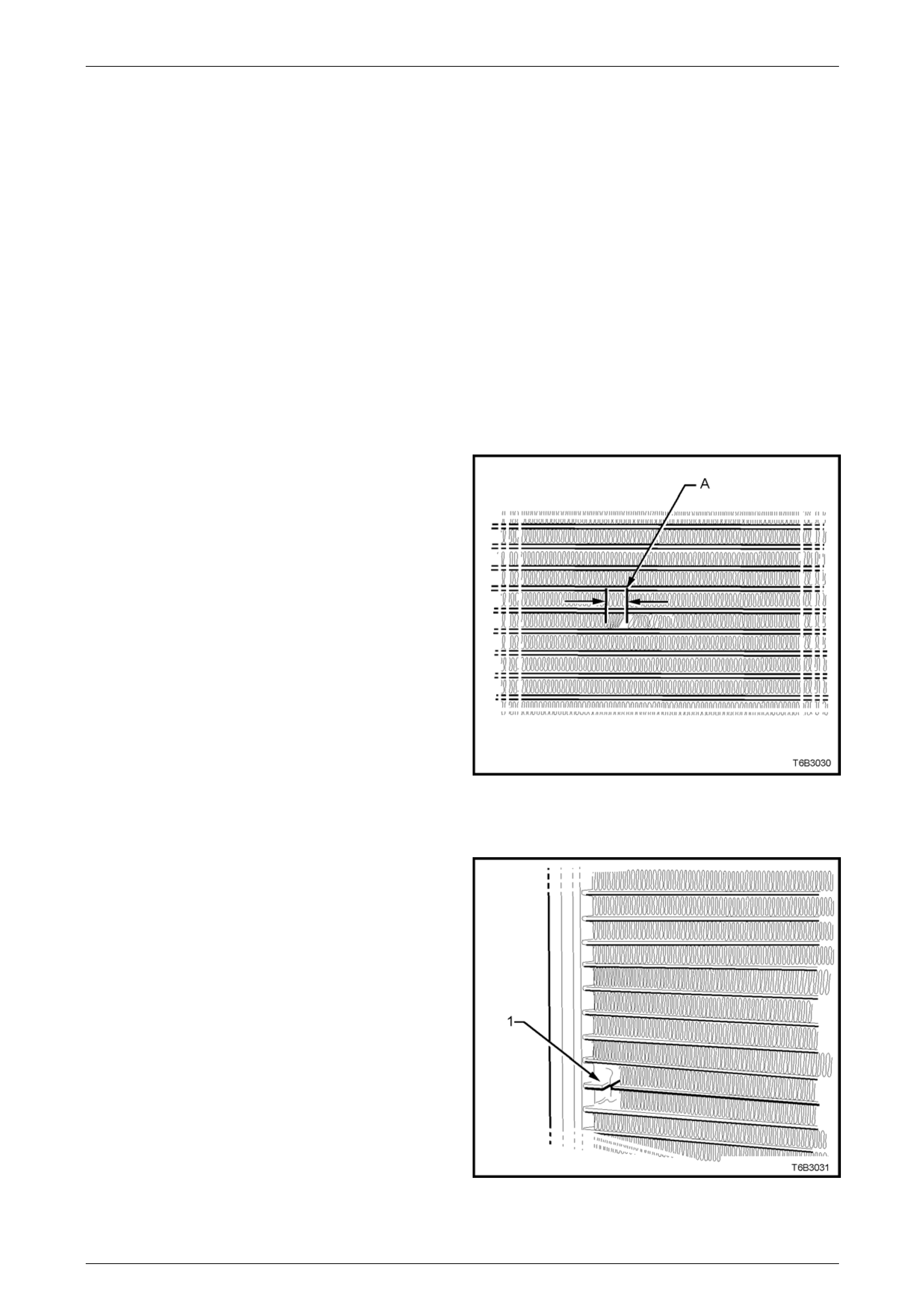
Engine Cooling – V6 Engine Page 6B1–90
There are two types of leaks that can b e repaired on the aluminium-plastic radiator; core leaks and automatic
transmission oil cooler seal leaks. Leaks in the plastic tanks or the seals between the side tanks and the headers can not
be repaired; therefore the radiator must be replaced.
Core leaks may occur in a tube or in the joints between the tubes and the headers. Seal leaks ma y occur in the joints
between the plastic tanks and the headers or in the joints between the oil cooler fittings and the tank (vehicles with
automatic transmission).
While some leaks can be repaire d while the radiator is installed in the vehicle, it is strongly recommended that the
radiator is first removed from the vehicle.
NOTE
Minor damage to tubes, or tube to header joint
(holes up to 1 mm diameter max.) can be
repaired. Core replacement is necessary if
damage is any greater.
Repair Method
Repairs to the aluminium radiator core should only be made using the recommended ‘A luminised Silicon’ based liquid
repair agent, in accordance with the recommended procedur e outlined in General Core Re pair in this Section. Refer to
the current Partfinder™ for Aluminised Silicon base liquid part number.
For damaged areas that are between the cooling fi ns, it
may be necessary to remove some of the fins. Do not
remove more fins than is necessary. Usually 6 mm
(distance ‘A’) beyond the leak or dama ge area, up to a
maximum of 25 mm of total fin material, is enough to
make an effective repair.
Figure 6B1 – 102
Tube Blocking
If a tube is severely damaged, it can be blocked off.
NOTE
Do not block off more than two tubes in a
radiator. Blocking off more than two tubes will
reduce the cooling capacity and efficiency of
the system and possibly result in an
overheated engine.
The tube should be cut off 6 mm from the header (1) and
pinched shut before it is clean ed and sealed. Refer to
General Core Repair in this Section.
Figure 6B1 – 103
Page 6B1–90
Engine Cooling – V6 Engine Page 6B1–91
Header Repair
If the header or a tube near the header requires a repair, the side tank does not have to be removed. If the repair
requires the removal of the header tank, then the radi ator must be replaced.
General Core Repair
NOTE
The need for careful prepar ation of the surface in
the repair area cannot be ove r-emphasised. If the
leak area surface is not clean, the repair ma terial
will not adhere to the surface.
Refer to ‘Environmental Issues’ in 3.1 Service
Notes, before draining the coolant.
1 Drain the coolant from the system. Refer to 3.3 Draining and Filling Cooling System in this Section.
2 Remove the radiator. Refer to 3.16 Radiator – Remove in this Section.
3 If necessary, carefully cut away fins to expose the damaged area.
NOTE
Do not cut away more than 25 mm total fin
material.
4 Clean away dirt etc. with water. Dry the affected area using hot air from a hair drier.
Do not apply flame to dry damaged area.
5 Clean affected area with petrol to remove any traces of oil.
6 Thoroughly stir contents of repair a gent.
NOTE
In cases of extended shelf life, the silicon in
solution may separate from the thinner base.
Should this occur, mix contents well until agent is
again homogeneous.
7 Apply repair agent spari ngly to damaged area. Do not apply an excessive amount, as this will cause blockage of
the radiator tube.
NOTE
Use a clean, dry wooden applicator to ‘DRIP’
agent onto damaged area of radiator.
8 Allow radiator to stand in a clean, dr y area for a minimum of 3 hours (at ambient temperature of 20 – 30° C) with
adequate ventilation.
NOTE
Do not apply heat or flame to promote drying.
9 Reinstall the radiator. Refer to 3.16 Radiator – Install in this Section.
Page 6B1–91

Engine Cooling – V6 Engine Page 6B1–92
Transmission Oil Cooler Leak Test
If the transmission oil cooler is suspected of leaki ng oil, test it before the radiator is replaced, as follo ws:
1 Disconnect oil cooler pipes at the flexible hose connections. Refer to 3.15 Flexible Transmi ssion Cooler Hose, in
this Section.
2 Plug one of the connections, using a blocked pipe fitting and attach an air supply to the other flexible hose.
3 Remove coolant filler cap and check that the coolant is fille d to the coolant filler cap filler neck.
4 APPLY AIR PRESSURE GRADUALLY, increasing up to an absolute maximum of 110 kPa. If bubbles appear in
radiator neck, the oil cooler is leaking and the radiator assembly must be replaced.
Transmission Oil Cooler Seal Replacement
It is strongly recommended that the transmission oil cooler connector fittings to the right-hand side radiator header tank,
not be disturbed. If coolant is found to leak from either of these two areas, then the radiator should be replaced.
Page 6B1–92

Engine Cooling – V6 Engine Page 6B1–93
4 Engine Cooling System
Diagnosis
4.1 Poor Heater Operation
Little or no heat coming from the heater, especially at idle could be an indication of a cooling system problem.
As the coolant level begins to get lower than normal, air enters the system to replace the missing coolant. The heater
core is one of the highest parts of the cooling system and therefore, the first area to lose coolant circulation.
At first, with a small amount of coolant loss, lack of heat will be most noticeable at idle. As driving spee d increases, the
engine pumps more coolant and more heat is now able to pass through the heater core.
If coolant level drops even lower, heater operation will become less effective, even during normal driving. Cooling and
engine systems can be adver s ely affected if problem is not corrected before overh eating occurs.
Page 6B1–93

Engine Cooling – V6 Engine Page 6B1–94
4.2 Leaking Cylinder Head Gasket
Combustion gases leaking past the cylinder head gasket can pressurise the cooling system, forcing cool ant out of the
system and into the coolant recovery res ervoir.
Indications are air bubbles in the coolant or an overflow condition of the recovery reservoi r.
Page 6B1–94

Engine Cooling – V6 Engine Page 6B1–95
4.3 Question the Customer
To avoid needless time and c ost in dia gnosing cooling system complaints, the customer should be questioned about
driving conditions that place abnormal loads on the co oling system.
1 Is overheating occurring after prolonged idle, in gear, with air conditioni ng system operating?
If answer is YES – instruct owner on driving techniques that would avoid overheating such as:
• Idle in neutral as much as possible – increase engine rpm to get higher air flow (due to an increase in voltage
to the fan) and coolant flow through the radiator.
• Turn air conditioning s ystem off during extended idling periods if overheatin g is indicated on temperature
gauge. Further diagnostic che cks should not be required.
2 Is overheating occurring after prolong ed driving in slo w city traffic, traffic jams, parades, etc?
If answer is YES, explain driving technique to the customer, that would avoid overheating – same as for prolonged
idle – No.1. Further diagnostic checks should not be required.
Page 6B1–95
Engine Cooling – V6 Engine Page 6B1–96
4.4 Diagnostic Chart
If none of the above conditions apply, refer to the following Diagnosis Chart.
To effectively use this chart, question the customer to determine which of the following three categories apply to the
complaint:
1 If complaint is hot indication on temperature gauge.
Was temperature reading accompa nied by boiling?
• If answer is YES, go to overheating on diagnosis chart.
• If answer is NO, check temperature gauge and sender.
2 If complaint is boiling – go to overheating on diagnosis chart.
3 If complaint is coolant loss. Determine if customer is filling the system corr ectly.
4 If incorrect filling is not the problem, go to coolant loss in the diagnosis chart.
Refer to 3.1 Service Notes in this Section, for
important safety items before removing the
coolant filler pressure cap or servicing the
system.
The cooling system is designed to operate at
120 – 130 kPa and a maximum temperature
not above 130°C.
Cooling System Diagnosis
Step Action Result Yes No
1 Check Temperature gauge reading High Temp.
Low Temp.
Go to Step 2
Go to Step 6 –
2 Check drive belt condition and tension. Ref er to 6A1
Engine Mechanical – V6. To Specification Go to Step 3 Replace drive
belt or
tensioner.
3 Check coolant Boiling Go to Step 4 Go to Step 5
4 Check coolant level. Refer to 3.2 Coolant Maintenance
in this Section. Low Go to Step 10 Go to Step 6
5 Check coolant filler cap. Refer to 3.7 Pressure Testing
– Coolant Filler Cap Pressure Testing in this Section OK? Go to Step 8 Replace
Coolant filler
cap
6 Check thermostat. Refer to 3.8 Thermostat in this
Section. OK? Go to Step 9 Go to Step 13
7 Check Engine Coolant Temperature (ECT) sensor.
Refer to 6C1 Engine Managem ent – V6. Faulty Replace Go to Step 12
8 Check cooling fan operation. Refer to 6C1 Engine
Management – V6. Operational Go to Step 10 Repair
9 Check for col la psed upper or lower radiator hose. Collapsed Replace Go to Step 13
10 Visua l system check Leaks Go to Step 13 Go to Step 11
Page 6B1–96
Engine Cooling – V6 Engine Page 6B1–97
Step Action Result Yes No
11 Check co olant concentration. Refer to 3.2 Coolant
Maintenance – Testing Coola nt Concentration. To Specification Go to Step 12 Correct
Concentration
Level
12 Check ra diator core for bent fins, dirt, bugs or other
obstructions. Obstructed Clean or
straighten Go to Step 14
13 Pressure Test cooling system. Refer to 3.7 Pressure
Testing – Cooling System Pressure Testing in this
Section. Leaks Repair System OK
14 If none of the a bove require repair, the problem is
complex or of a major nature.
Refer to 4.5 Problems Not Requiring Disassembly of
Cooling System or 4.6 Problems Requiri ng
Disassembly of Cooling S ystem.
– – –
Page 6B1–97

Engine Cooling – V6 Engine Page 6B1–98
4.5 Problems Not Requiring Disassembly of
Cooling System
1 Large obstructions blocking radiator or cond enser airflow.
• Auxiliary oil coolers.
• License plate.
• Obstruction of radiator grille, for example, driving lights or mud.
2 Loose, damaged or missing a ir chute side panels.
3 Missing or damaged air baffle.
4 Cracked or loose coolant recover y system hose.
5 Leaking heater compon ent such as the heater core or water valve.
Page 6B1–98

Engine Cooling – V6 Engine Page 6B1–99
4.6 Problems Requiring Disassembly of
Cooling System
1 Damaged cooling fan or faulty motor operation.
2 Pressure test cooling system.
3 Defective coolant pump.
• Eroded or broken impeller van es.
• Failed bearing or seal – check for shaft or bearing end play.
4 Internally blocked radiator core.
5 Obstruction of coolant recovery system.
6 Internal system leaks.
• Head gaskets.
• Cracked cylinder block.
• Engine front cover.
• Intake manifold gaskets.
7 Blocked coolant passages in cylinder heads or block – remove cylinder heads and check.
Page 6B1–99

Engine Cooling – V6 Engine Page 6B1–100
4.7 Black Light and Dye Leak Diagnosis
Method
It is strongly recommended that this diagnostic method be us ed to diagnose fluid leaks. This method is a proven and
reliable method that identifies the specific le ak source.
The black light kit can be used for the leak detection of a number of fluids, when used with the appropriate tracer dye.
Examples are: Coolant, Engine Oil, Automati c Transmission Fluid and Air Conditioning Refrigerant (R134A).
The following is a summary of the steps invo lved in detecting a cooling system fluid leak u s ing black light and dye:
1 Pour specified amount of dye into the cooli ng system via the coolant filler cap on the outlet housing. Refe r
3.1 Service Notes in this Section.
2 Road test the vehicle under normal operati ng conditions.
3 Direct the light towards the suspect area. The fluid leak will appear as a brightl y coloured path leading from the
source.
4 Repair fluid leak and recheck to ensure that leak has been rectified.
5 Refer to the manufacturer’s directions when using this method.
Page 6B1–100

Engine Cooling – V6 Engine Page 6B1–101
5 Specifications
General
Coolant Filler Cap Pressure Rating .............................................................................120 kPa
Cooling System Capacity
Automatic Transmission........................................................................................ 9.9 litres
Manual Transmission.......................................................................................... 10.3 litres
Coolant Corrosion Inh ibitor Quantity When Refilling System
Automatic Transmission Models......................................................................... 5 litres
Manual Transmission Models.......................................................................... 5.2 litres
NOTE
DEX-COOL® long life coolant or equivalent such
as Extended Life Anti-freez e Coolant, conforming
to GM Specification 6277M, must be used when
changing coolant.
Thermostat
Type...............................................................................................Power element (wax pellet)
Start to Open at .........................................................................................................82 ± 2° C
Fully Open at ..........................................................................................................95° C max.
Coolant Pump
Type.........................................................................................................................Centrifugal
Drive................................................................................................ Multi-Vee Serpentine Belt
Bearing Type ....................................................................................Double Row Ball Bearing
Radiator
Core type......................................................................................... Aluminium crossflow core
Overall width................................................................................................................826 mm
Core width ...................................................................................................................683 mm
Overall height ..............................................................................................................430 mm
Core height..................................................................................................................455 mm
Core thickness...............................................................................................................27 mm
Plastic Tanks ...............................................................................Nylon 6.6 (30% Glass Filled)
Radiator Hoses Lower Upper
Number...............................................................................One ............................ One
Type................................................................................ Moulded......................Moulded
Inside diameter..............................................................30.85 mm.....................34.1 mm
Page 6B1–101

Engine Cooling – V6 Engine Page 6B1–102
Small Engine Cooling Fan (LHS) Standard High Power
Electric motor drive (Nominal Power Rating)........ 120 Watts 180 Watts
Rotational Speed (with 12 volts applied, Radiator and Con denser installed)
– Stage 1 ..................... OFF 2,350 ± 150 rpm
– Stage 2..................... 2,250 ± 150 rpm 2,750 ± 150 rpm
Number of Blades...................................................................................................................5
Fan – Design ..........................................Asymmetrical spaced, curved blades with outer ring
Material..................................Nylon 6,6 (30% Glass Filled), with zinc coated metal hub insert
Diameter......................................................................................................................293 mm
Fan Motor – Type Single-speed Dual-speed
Housing ...........................................................Semi-sealed, zinc-coated steel with drain hole
Direction of Rotation.............................................. Anticlockwise (as viewed from motor side)
Large Engine Cooling Fan (RHS) Standard High Power
Electric motor drive (Nominal Power Rating)........ 160 Watts 220 Watts
Rotational Speed (with 12 volts applied, Radiator and Con denser installed)
– Stage 1 .................... 2,050 ± 150 rpm 2,050 ± 150 rpm
– Stage 2 .................... 2,050 ± 150 rpm 2,300 ± 150 rpm
Number of Blades...................................................................................................................5
Fan – Design ..........................................Asymmetrical spaced, curved blades with outer ring
Material..................................Nylon 6,6 (30% Glass Filled), with zinc coated metal hub insert
Diameter......................................................................................................................342 mm
Fan Motor – Type Single-speed Dual-speed
Housing ...........................................................Semi-sealed, zinc-coated steel with drain hole
Direction of Rotation.............................................. Anticlockwise (as viewed from motor side)
Pressure Transducer
Low Pressure Cut Out .................................................................................................180 kPa
Low Pressure Cut In....................................................................................................240 kPa
High Pressure Cut Out..............................................................................................2,900 kPa
High Pressure Cut In ................................................................................................2,000 kPa
Page 6B1–102

Engine Cooling – V6 Engine Page 6B1–103
6 Torque Wrench Specifications
Nm
Coolant Outlet housing to Intake Manifold Attaching Bolts.............................10
Coolant Pump to Front Cover Attaching Bolts................................................10
Coolant Pump Pulley Attaching Bolts.............................................................10
Coolant Inlet Pipe to Thermostat Housing Attaching Bolt...............................35
Coolant Inlet Pipe to Generator / A/C Compressor (AWD) Attaching Nut
..........25
Fan Motor Assembly to Shroud Attaching Screws ...........................................5
Heater Pipe Assembly to Thermostat Housing Attaching Bolts......................10
Heater Pipe Assembly to Cylinder Head Attaching Bolt .................................58
Oil Cooler Pipe to Oil Cooler Tube Nut...........................................................25
Radiator Bleed Screw....................................................................................1.5
Thermostat Housing to Engine Block Attaching Bolts ....................................10
Page 6B1–103
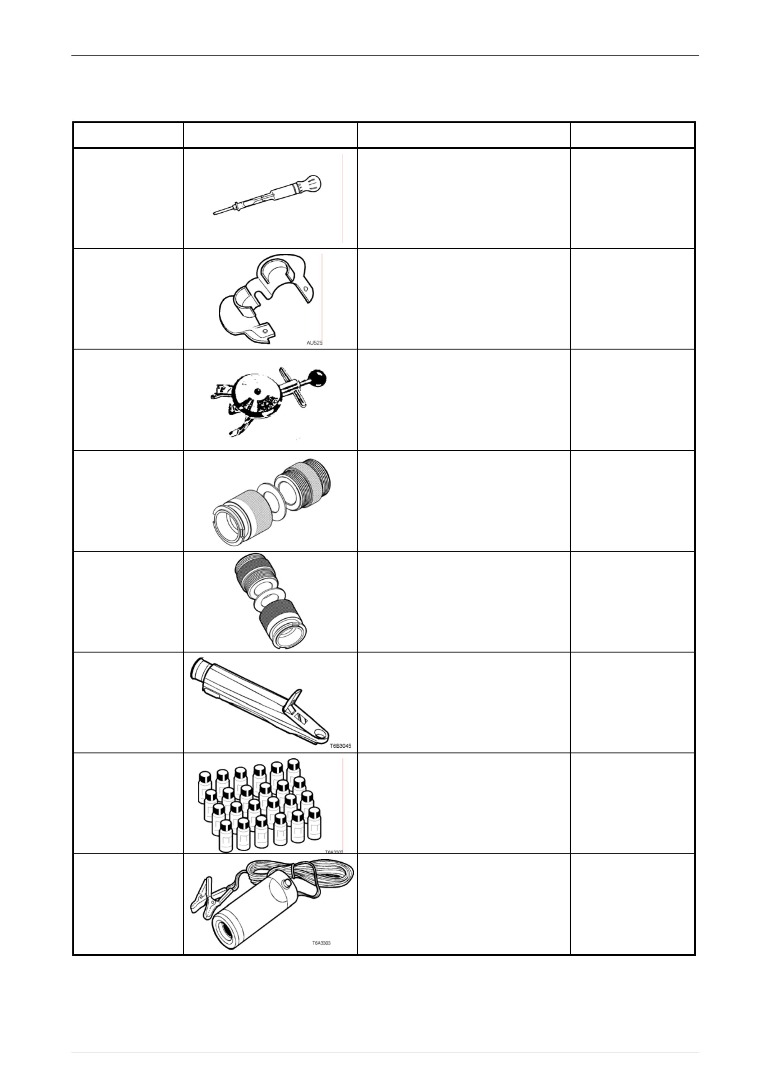
Engine Cooling – V6 Engine Page 6B1–104
7 Special Tools
Tool number Illustration Description Classification
AU505
Coolant Tester
Used for testing the coolant
concentration level.
Previously released.
Mandatory
AU525
Quick Connect Release Tool
Used to release the quick connect
fittings on automatic transmission fluid
cooler lines at the radiator end, when
fitted. Previously released.
Mandatory
BT3373–F
Belt Tension Gauge
Used when checking drive and
accessory belt tension and
adjustments.
Previously released.
Desirable
EN-47837 Cooling System Test Adaptors
Used with cooling system pres sure
tester to pressure test coolant filler
pressure cap and cooling system.
Previously released
Mandatory
EN-48501
Cooling System Test Adaptors
Used with cooling system pres sure
tester to pressure test coolant filler
pressure cap and cooling system.
Used for VZ Update pressure cap.
New release
Mandatory
J 26568
Refractometer
Used for testing coolant concentration
level.
Previously released, as AU 435.
Mandatory
J28431–B Fluid Dye
Available in 24 x 1-ounc e bottles.
Used in conjunction with a black light
such as J42220 to locate the source
of various fluid leaks.
Previously released.
Desirable
J42220 Black Li ght, Leak Detection Lamp
Used with dye, J28431–B to locate the
source of various vehicle fluid leaks.
Previously released.
Desirable
Page 6B1–104
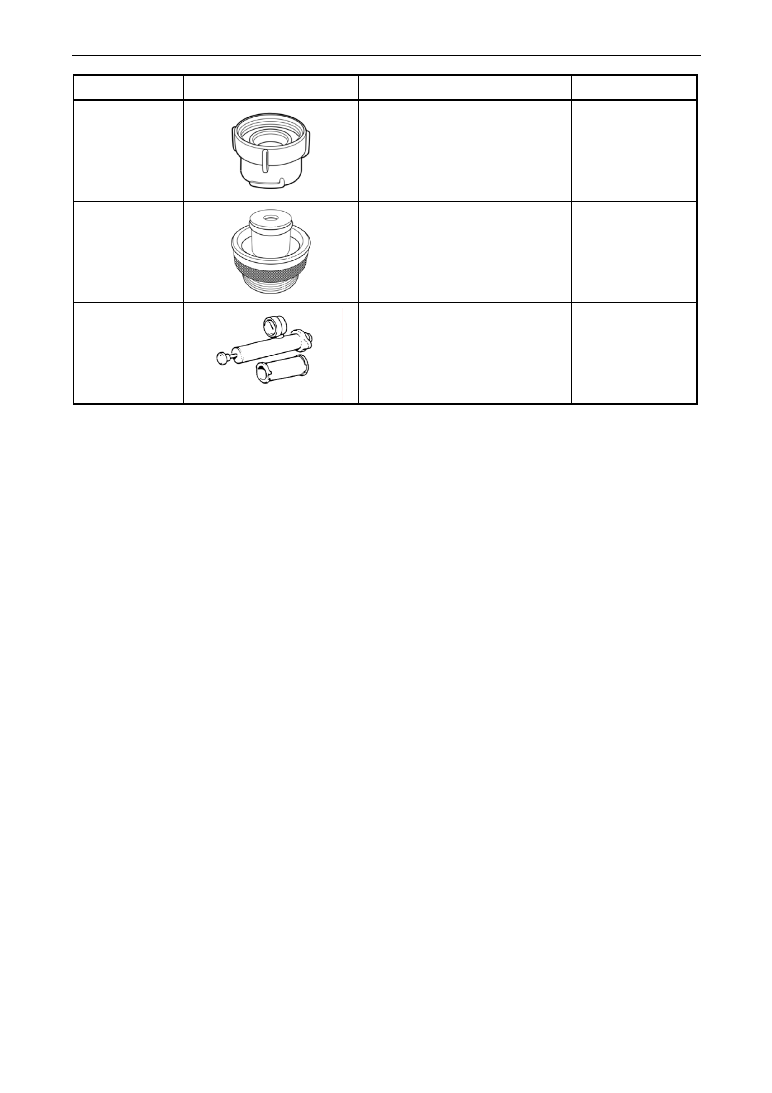
Engine Cooling – V6 Engine Page 6B1–105
Tool number Illustration Description Classification
KM-471 Pressure Tester Adaptor
Used for VZ Update pressure cap.
Previously released for Vectra.
Mandatory
KM-6327
Cooling System Adaptor
Used for VZ Update pressure cap.
Previously released for Vectra.
Mandatory
N/A Cooling System Pressure Tester
Previously released.
Commercially available.
Mandatory
Page 6B1–105