
GEN IV V8 Engine Mechanical Page 6A4 – 1
Section 6A4
Engine Mechanical – GEN IV V8
ATTENTION
Before performing any service operation or other procedure described in this Section, refer to 00 Warnings,
Cautions and Notes for correct workshop practices with regard to safety and/or property damage.
1 General Information ...............................................................................................................................3
1.1 Engine Views.......................................................................................................................................................... 4
Engine View Left-hand Side.................................................................................................................................. 4
Lower Engine Assembly ....................................................................................................................................... 7
Cylinder Head......................................................................................................................................................... 9
Intake Manifold..................................................................................................................................................... 11
1.2 Engine Serial Number.......................................................................................................................................... 12
1.3 Engine Construction............................................................................................................................................ 13
Cylinder Block...................................................................................................................................................... 13
Cylinder Heads..................................................................................................................................................... 14
Valve Train............................................................................................................................................................ 15
Crankshaft............................................................................................................................................................ 15
Piston and Connecting Rod................................................................................................................................ 16
Camshaft and Drive ............................................................................................................................................. 17
Intake Manifold..................................................................................................................................................... 17
Exhaust Manifold................................................................................................................................................. 18
Oil Pan .................................................................................................................................................................. 19
1.4 Engine Lubrication Sy s t em................................................................................................................................. 20
Oil pump ....................................................................................................................... ........................................ 20
Oil Flow................................................................................................................................................................. 21
Oil Seals................................................................................................................................................................ 22
Positive Crankcase Ventilation System............................................................................................................. 22
1.5 Service Notes....................................................................................................................................................... 24
2 Diagnosis ..............................................................................................................................................25
2.1 General Information............................................................................................................................................. 25
3 Minor Service Operations....................................................................................................................26
3.1 Air Intake Duct Resonator................................................................................................................................... 26
Remove................................................................................................................................................................. 26
Reinstall................................................................................................................................................................ 26
3.2 Engine Dress Cover............................................................................................................................................. 27
Remove................................................................................................................................................................. 27
Reinstall................................................................................................................................................................ 27
3.3 Oil Pressure Sensor............................................................................................................................................. 28
Remove................................................................................................................................................................. 28
Reinstall................................................................................................................................................................ 28
3.4 Oil Level Indicator and Tube............................................................................................................................... 29
Remove................................................................................................................................................................. 29
Reinstall................................................................................................................................................................ 29
3.5 Crankcase Ventilation Hoses/Pipes................................................................................................................... 30
Remove................................................................................................................................................................. 30
Reinstall................................................................................................................................................................ 30
3.6 Intake Manifold Assembly................................................................................................................................... 31
Remove................................................................................................................................................................. 31
Disassemble..................................................................................................................................................... 37
Clean and Inspect ............................................................................................................................................ 38
Reassemble ..................................................................................................................................................... 39
Reinstall................................................................................................................................................................ 40
Page 6A4 – 1

GEN IV V8 Engine Mechanical Page 6A4 – 2
3.7 Coolant Vapour Vent Pipe and Covers .............................................................................................................. 42
Remove................................................................................................................................................................. 42
Reinstall................................................................................................................................................................ 42
3.8 Engine Valley Cover ............................................................................................................................................ 44
Remove................................................................................................................................................................. 44
Clean and Inspect ............................................................................................................................................ 45
Reinstall................................................................................................................................................................ 45
3.9 Hydraulic Valve Lifters ........................................................................................................................................ 46
Remove................................................................................................................................................................. 46
Disassemble......................................................................................................................................................... 47
Clean and Inspect................................................................................................................................................ 48
Reassemble.......................................................................................................................................................... 49
Testing Lifter Leak-down Rate............................................................................................................................ 50
Reinstall................................................................................................................................................................ 51
3.10 Crankshaft Balancer............................................................................................................................................ 52
Remove................................................................................................................................................................. 52
Clean and Inspect................................................................................................................................................ 54
Reinstall................................................................................................................................................................ 54
3.11 Crankshaft Front Oil Seal.................................................................................................................................... 57
Remove................................................................................................................................................................. 57
Reinstall................................................................................................................................................................ 57
4 Major Service Operations....................................................................................................................58
4.1 Engine Assembly................................................................................................................................................. 58
4.2 Oil Pan Assembly................................................................................................................................................. 59
4.3 Engine Front Cover.............................................................................................................................................. 60
Remove................................................................................................................................................................. 60
Clean and Inspect................................................................................................................................................ 60
Reinstall................................................................................................................................................................ 61
4.4 Crankshaft Spigot Bearing.................................................................................................................................. 63
Remove................................................................................................................................................................. 63
Reinstall................................................................................................................................................................ 63
4.5 Oil Pump, Pump Screen and Deflector .............................................................................................................. 65
Remove................................................................................................................................................................. 65
Oil Pump Disassemble ........................................................................................................................................ 66
Clean and Inspect................................................................................................................................................ 67
Oil Pump Reassemble ......................................................................................................................................... 68
Reinstall................................................................................................................................................................ 68
4.6 Timing Chain and Sprockets............................................................................................................................... 70
Remove................................................................................................................................................................. 70
Clean and Inspect................................................................................................................................................ 72
Reinstall................................................................................................................................................................ 73
5 Specifications.......................................................................................................................................76
5.1 Engine................................................................................................................................................................... 76
5.2 Lubrication System.............................................................................................................................................. 77
6 Torque Wrench Specifications............................................................................................................78
6.1 Engine................................................................................................................................................................... 78
6.2 Special Tool Fasteners........................................................................................................................................ 80
7 Special Tools .................................................................................................................. ......................81
Page 6A4 – 2

GEN IV V8 Engine Mechanical Page 6A4 – 3
1 General Information
Where available for fitment to MY 2006 VZ Update vehicles, the V8 engine is the 6.0 litre GEN IV. T his updated version
is based on the previous GEN IV engine released to comply with Euro III emission regulations in January, 2006. This
update contains a number of revisions that ar e detailed in this Section.
Cylinder layout remains as 1, 3, 5, and 7 for the left-hand bank and 2, 4, 6 and 8 for the right-hand bank, with a firing
order of 1-8-7-2-6-5-4-3. The engine has a compression ratio of 10.4:1.
Two knock sensors are attached externally, one between cylinders 3 and 5 for the left bank and one between cylinders 4
and 6 for the right bank, behind the exhaust manifolds. The camshaft sensor is attached to the engine front cover an d a
reluctor incorporated into the camshaft timing gear. A Manif old Absolute Pressure Sensor is fitted to the front of the
intake manifold. For further information relating to engine management sensors fitted to the GEN IV V8 engine, refer to
Section 6C4 Engine Management – GEN IV V8.
Engine throttle control is achieved by an electronic throttle body, which is controlled through the engine management
system, refer to Section 6C4 Engine Management – GEN IV V8.
NOTE
Unless noted otherwise, the information
contained in this Section is appropriate for both
manual and automatic transmission vehicles.
Among the revisions to this updated GEN IV V8 eng ine are:
• Deletion of the Displacement on Demand® (DoD) mechanical features such as the valv e lifter oil manifold (VLOM)
assembly and associated components, cylinder block modifications and the DoD hydraulic valve lifters.
• Changed design of camshaft sprocket an d chain tensioner.
• The flywheel spigot bearing o n manual transmission engines has been changed from a roller to a sealed-for-life
ball bearing.
NOTE
• While the mechanical DoD components
have been removed from the engine, some
views may retain evidence of the system.
Unless otherwise noted, all service
operations remain unchang ed.
• For those service operations not included in
this Section refer to MY 2006 VZ Series
Service Information.
Page 6A4 – 3
GEN IV V8 Engine Mechanical Page 6A4 – 4
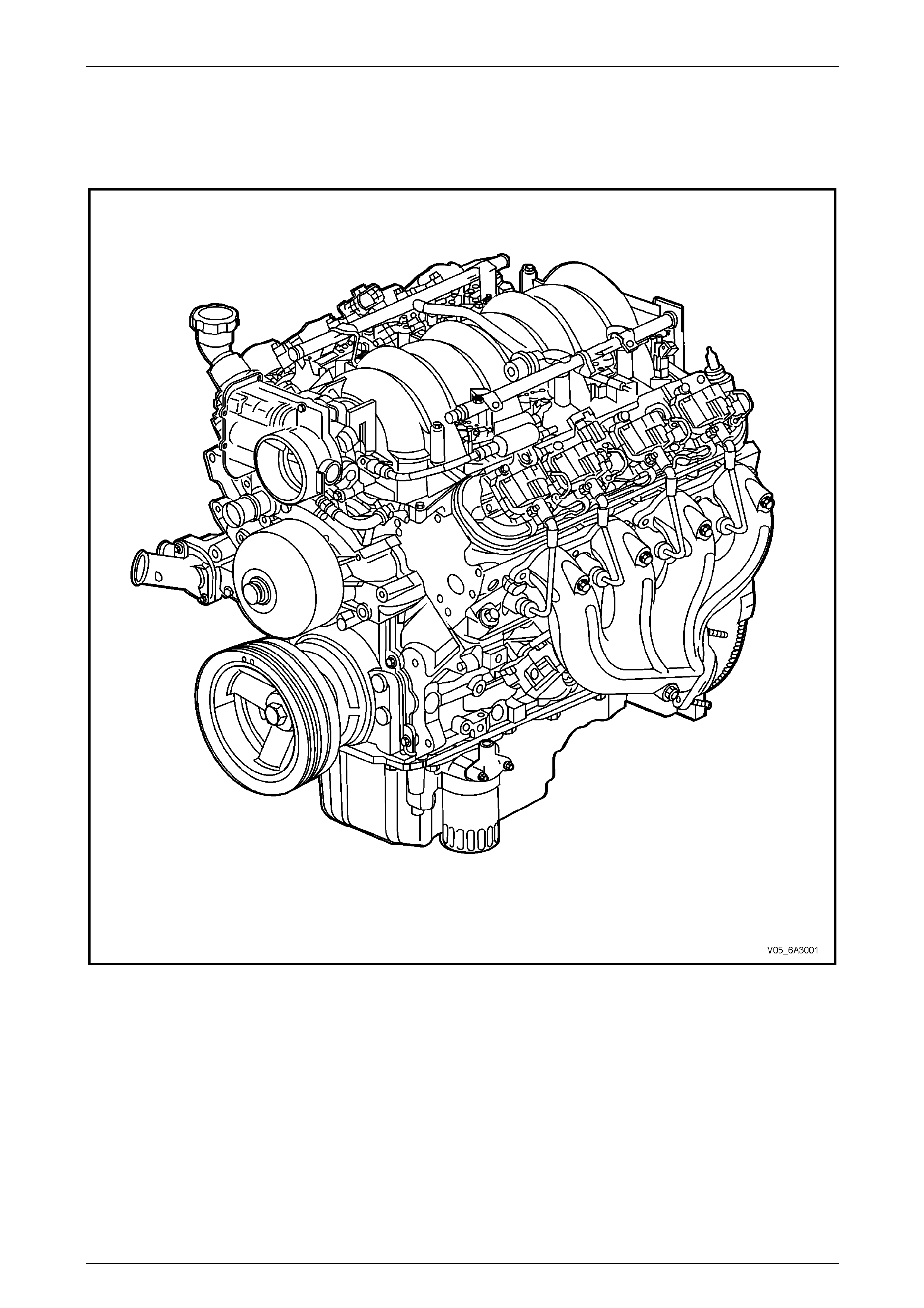
1.1 Engine Views
Engine View Left-hand Side
Figure 6A4 – 1
Page 6A4 – 4
GEN IV V8 Engine Mechanical Page 6A4 – 5
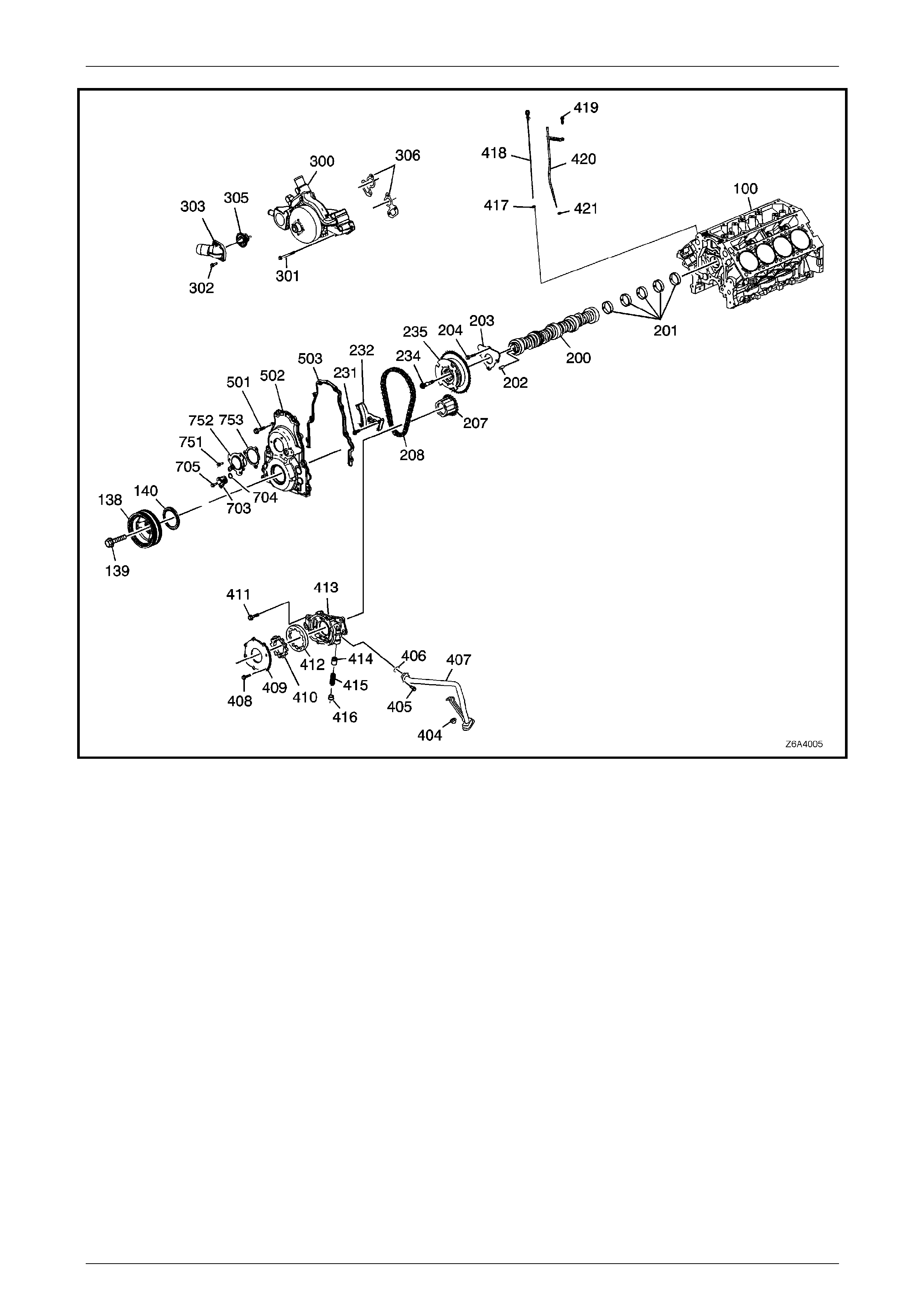
Figure 6A4 – 2
Page 6A4 – 5

GEN IV V8 Engine Mechanical Page 6A4 – 6
Legend
100 Engine Block
138 Crankshaft Balancer
139 Crankshaft Balancer Retaining Bolt
140 Crankshaft Front Oil Seal
200 Camshaft
201 Camshaft Bearings
202 Camshaft Sprocket Locating Pin
203 Camshaft Retainer
204 Camshaft Retainer Attaching Bolt, 4 places
207 Crankshaft Sprocket
208 Timing Chain
234 Camshaft Sprocket Retaining Bolt
231 Timing Chain Tensioner Bolt
232 Timing Chain Tensioner
235 Timing Chain Sprocket and Sensor Actuator
300 Coolant Pump
301 Coolant Pump Retaining Bolt
302 Thermostat Housing Bolt
303 Thermostat Housing
305 Engine Coolant Thermostat
502 Engine Front Cover
503 Engine Front Cover Gasket
703 CMP Sensor
704 CMP Sensor O-Ring
306 Coolant Pump Gaskets
404 Oil Pump Pick-up Pipe Nut
405 Oil Pump Pick-up Pipe Bolt
406 Oil Pump Pick-up O-Ring
407 Oil Pump Pick-up Pipe
408 Oil Pump Cover Bolt
409 Oil Pump Cover Plate
410 Oil Pump Drive Gear
411 Oil Pump Retaining Bolt
412 Oil Pump Driven Gear
413 Oil Pump Housing
414 Oil Pressure Relief Valve
415 Oil Pressure Relief Valve Spring
416 Oil Pressure Relief Valve Bore Plug
417 Oil Level Indicator O-Ring Seal
418 Oil Level Indicator
419 Oil Level Indicator Tube Bolt
420 Oil Level Indicator Tube
421 Oil Level Indicator Tube O-Ring
501 Engine Front Cover Attaching Bolt, 10 places
705 CMP Sensor Bolt
751 CMP Actuator Hub Cover Bolt
752 CMP Actuator Magnet
753 CMP Actuator Magnet Gasket
Page 6A4 – 6

GEN IV V8 Engine Mechanical Page 6A4 – 7
Lower Engine Assembly
Figure 6A4 – 3
Page 6A4 – 7

GEN IV V8 Engine Mechanical Page 6A4 – 8
Legend
1 Camshaft Position Sensor
Attaching Bolt
2 Camshaft Position Sensor
3 Oil Pressure Sensor
4 Cylinder Block
5 Piston Rings
6 Piston and Connecting Rod
Assembly
7 Connecting Rod Bearings
8 Connecting Rod Cap
9 Connecting Rod Attaching
Bolt, 2 places
10 Crankshaft Oil Deflector
11 Engine Flywheel – Manual
Transmission.
12 Engine Flexplate –
Automatic Transmission.
13 Oil Pump Pick-up Screen
and Pipe
14 Oil Pump Pick-up to Pump
Attaching Screw
15 Oil Deflector and Oil Pump Pick-up
Attaching Nut
16 Oil Pan Baffle Attaching Bolt
17 Oil Pan Baffle
18 Oil Transfer Tube
19 Oil Transfer Tube Gasket, 2 places
20 Oil Pan Gasket
21 Engine Flywheel/Flexplate Attaching Bolt, 6
places
22 Oil Pan Closeout Cover Attaching Bolt (right-
hand)
23 Oil Pan Closeout Cover (right-hand)
24 Oil Pan Closeout Cover (left-hand)
25 Oil Pan Closeout Cover Attaching Bolt (left-
hand)
26 Oil Pan Gallery Plug (3 external, 1 internal)
27 Oil Pan Transfer Tube Attaching Bolt
28 Oil Pan
29 Oil Transfer Cover Stud O-ring, 2 places
30 Oil Transfer Cover Gasket
31 Oil Transfer Cover
32 Oil Transfer Cover Attaching Nut, 2 places
33 Oil Bypass Valve
34 Oil Filter Adaptor
35 Oil Filter
36 Oil Drain Plug
37 Crankshaft Main Bearing Cap Side
Attaching Bolt, 10 places
38 Crankshaft Main Bearing Caps
39 Main Bearing Cap Attaching Stud, 5
places
40 Main Bearing Cap Attaching Bolt, 5 places
41 Crankshaft Main Bearings
42 Crankshaft Main Thrust Bearings
43 Crankshaft Rear Plug
44 Manual Transmission Spigot Bearing
45 Oil Pump Pick-up O-ring
46 Crankshaft
47 Crankshaft Sprocket Key
48 Cylinder Block Front Oil Gallery Plug
49 Cylinder Block Plug, 3 places
Page 6A4 – 8

GEN IV V8 Engine Mechanical Page 6A4 – 9
Cylinder Head
Figure 6A4 – 4
Page 6A4 – 9

GEN IV V8 Engine Mechanical Page 6A4 – 10
Legend
1 Valve Rocker Arm Cover Attaching Bolt, 4 places
2 Valve Rocker Arm Cover Grommet, 4 places
3 Cylinder Head Bolt (M8), 5 places
4 Cylinder Head
5 Cylinder Head Attaching Bolt (M11), 10 places
6 Valve Stem Collets
7 Valve Spring Cap
8 Valve Spring
9 Oil Seal Incorporating the Valve Spring Shim
10 Valve
11 Exhaust Manifold Gasket
12 Exhaust Manifold Assembly
13 Exhaust Manifold to Exhaust Pipe Flange Attaching Stud
14 Exhaust Manifold Heat Shield Attaching Bolt
15 Pushrod, 8 places
16 Coolant Temperature Sensor
17 Valve Rocker Arm Attaching Bolt
18 Valve Rocker Arm
19 Valve Rocker Arm Pivot Support
20 Cylinder Head Gasket
21 Valve Rocker Arm Cover Gasket
22 Valve Rocker Arm Cover
23 Oil Fill Tube
24 Oil Fill Tube Cap
25 Ignition Coil and Bracket Assembly
26 Ignition Coil Bracket Assembly Attaching Stud, 7 places
27 Ignition Coil Bracket Assembly Attaching Screw. (Rear on
each side)
28 Exhaust Manifold Attaching Bolt, 6 places
Page 6A4 – 10
GEN IV V8 Engine Mechanical Page 6A4 – 11
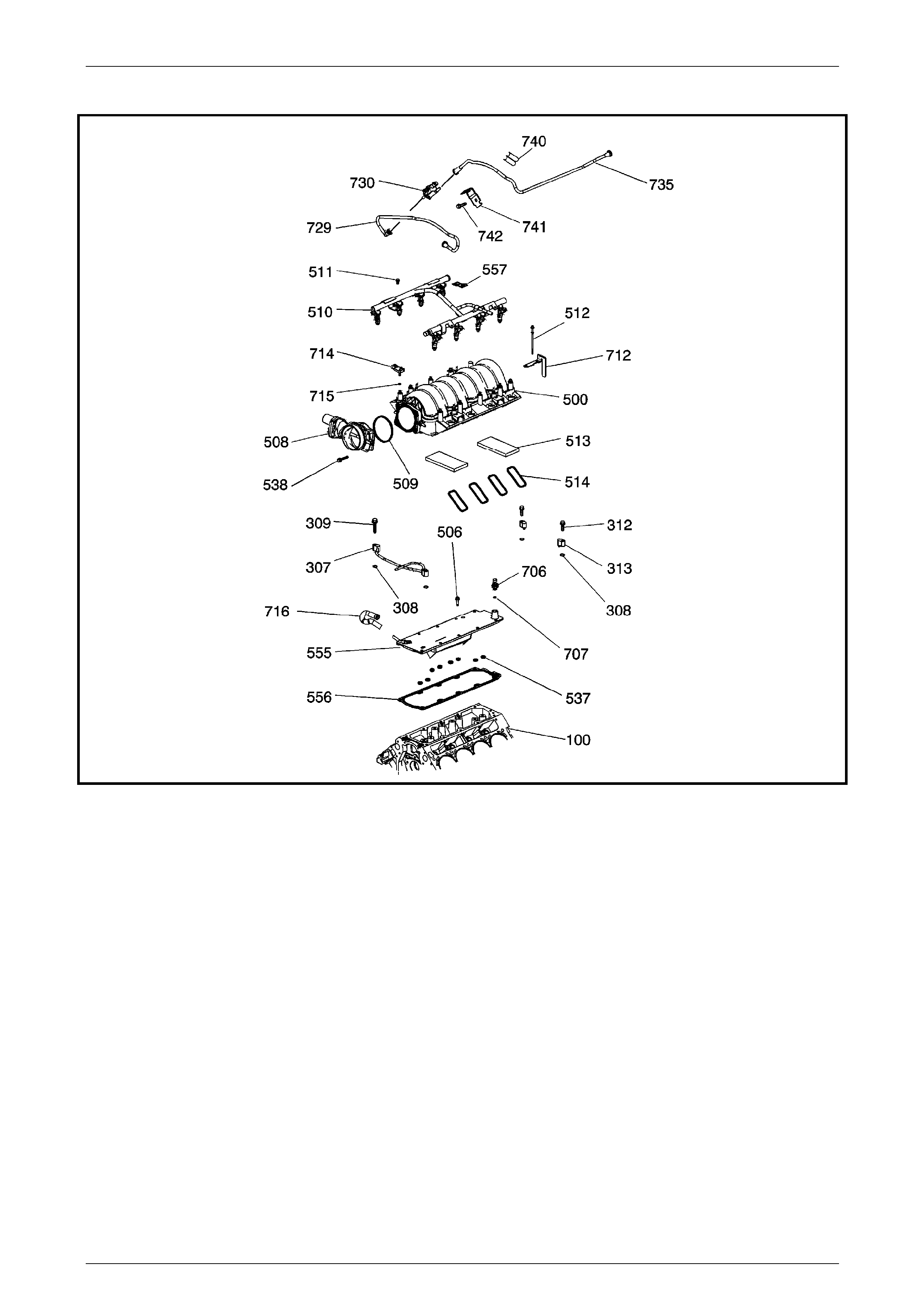
Intake Manifold
1408839
Figure 6A4 – 5
Legend
100 Engine Cylinder Block
307 Vapour Vent Tube
308 Vapour Vent Tube Gasket, 4 places
309 Vapour Vent Tube Stud, 2 places
312 Vapour Vent Cover Bolt, 2 places
313 Vapour Vent Cover
500 Intake Manifold
506 Valley Cover
508 Throttle Body Actuator
509 Throttle Body O-Ring
510 Fuel Rail
511 Fuel Rail Stud, 4 places
512 Intake Manifold Bolt, 10 places
513 Seal
514 Intake Manifold to Cylinder Head Seals, 8 places
537 Valley Cover O-Ring Seals
538 Throttle Body Attaching Bolt
555 Valley Cover
556 Valley Cover Gasket
557 Fuel Rail Ground Strap
706 Oil Pressure Sensor
707 Oil Pressure Sensor O-Ring Seal
712 Fuel Rail Stop Bracket, 2 places
714 Manifold Absolute Pressure Sensor (MAP)
715 MAP Sensor O-Ring
716 Valley Cover to Throttle Body Blow-by Hose
729 Fuel Vapour Pipe from Purge Solenoid to Intake Manifold
730 Evaporative Emission Canister Purge Valve
735 Fuel Vapour Pipe from Emission Canister
740 Fuel Vapour Pipe Mounting Clips
741 Fuel Vapour Pipe Mounting Clip
742 Mounting Strap Bolt
Page 6A4 – 11
GEN IV V8 Engine Mechanical Page 6A4 – 12
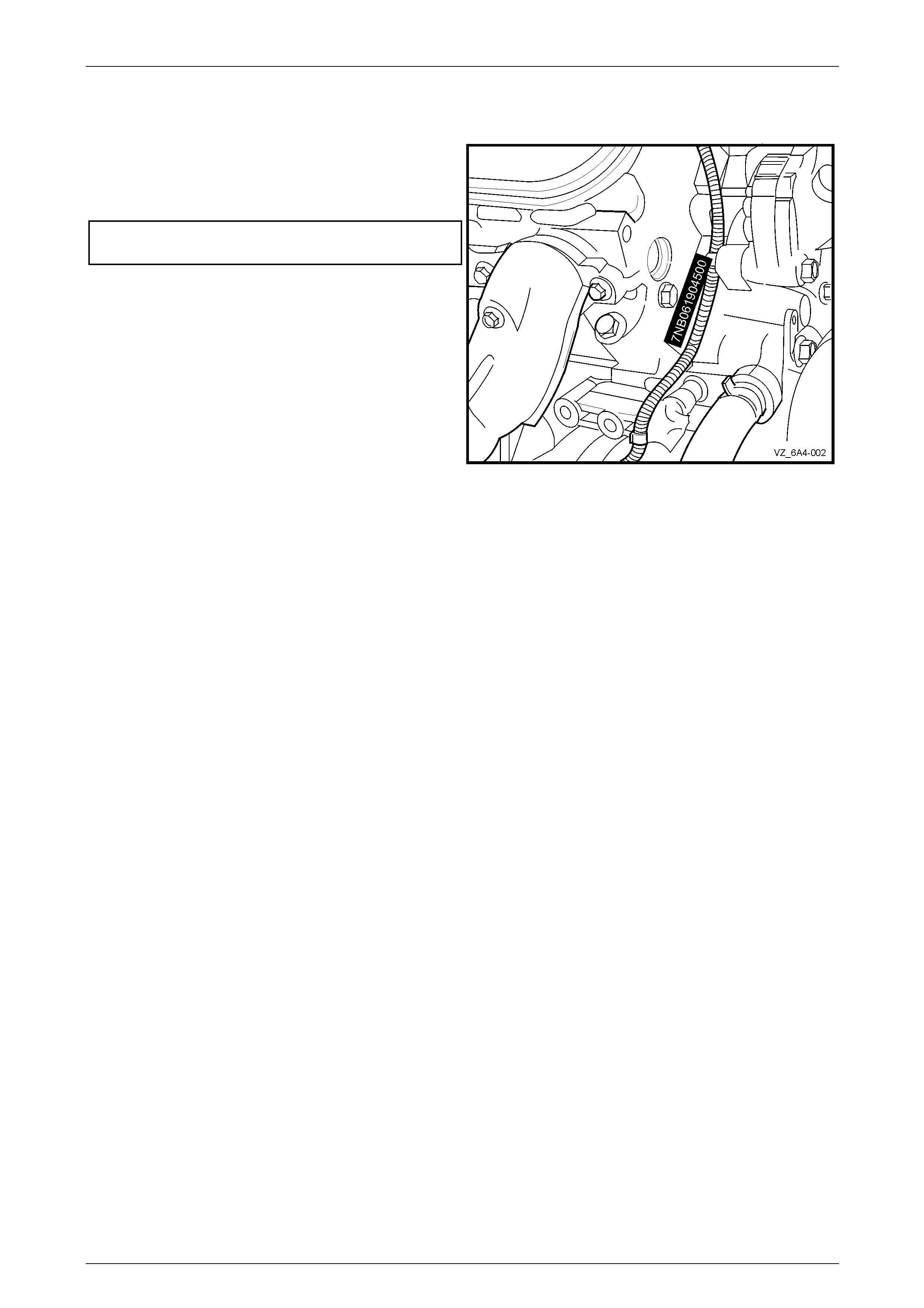
1.2 Engine Serial Number
The engine serial n umber is stamped on the right-hand side
at the front of the engine cylinder block. The number is
prefixed by a three digit identification. For MY2006 VZ
Update, an ‘L98’, 6.0 Litre GEN IV V8 has a prefix of:
7NB...........................................Automatic Transmission
CAK ..............................................Manual Transmission
The following is a breakdown of the engine numbering
system using 7NB061904500 as an example;
• The prefix of ‘7NB’ indicates that an automatic
transmission is fitted.
• The first two numbers, 06 = 2006 i ndicates the engine
model year.
• The next three numbers, 190 is the Julian date, which
is the day of the year the engine was manufactured.
• The next four numbers are the daily sequential build
number. Figure 6A4 – 6
Page 6A4 – 12
GEN IV V8 Engine Mechanical Page 6A4 – 13
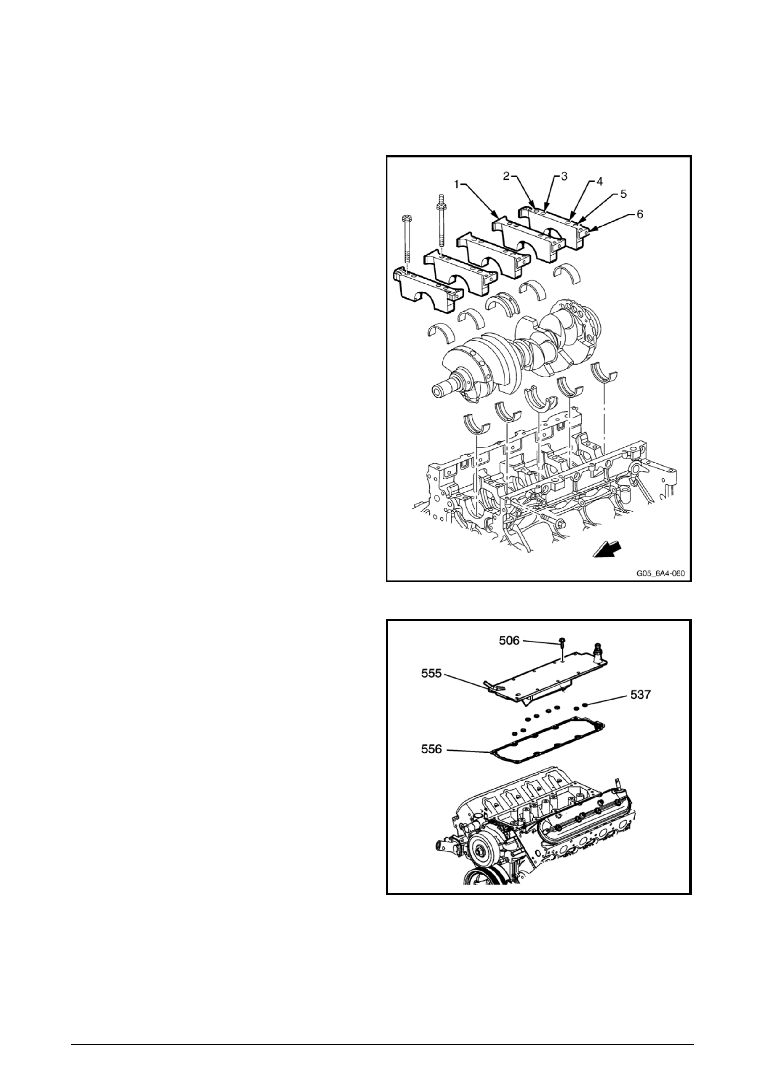
1.3 Engine Construction
Cylinder Block
The engine cylinder block is a cam-in-block, deep skirt, 90°
V configuration with five crankshaft beari ng caps,
manufactured from forged powdered metal. The engine
block is aluminium with cast-in-place cast iron cylinder bore
liners. The five cross-bolted cr ankshaft bearing caps each
have four vertical M10 (2, 3, 4, and 5) and two horizontal M8
(1 and 6) mounting bolts. The cylinder bore must not be
bored and only cylinder bore honing is permitted.
The crankcase skirt length, bearing cap width, deck width
and upper rails have been optimised for stre ngth using finite
element analys is.
The camshaft is supported by five camshaft bear ings
pressed into the block.
Figure 6A4 – 7
A structural die cast aluminium valley cover (565) is
attached to the block using 11 M6 bolts (506). A gasket
(556) and O-Rings (537) seal the assembly to the engine
block. Having a closed valle y area prevents hot oil from
contacting the lower surface of the intake manifold. This
allows cooler air to enter the cylinders.
The cylinder block incorporates enclosed valve lifter bores
under each cylinder head that results in a mo re stiff
structure with quieter operation.
Overall, the cylinder block construction weighs 48% less
than an equivalent cast iron block. This structural d esig n
combined with the alumini um cylinder heads results in a
lightweight engine with unique stiffness.
1408895
Figure 6A4 – 8
Page 6A4 – 13
GEN IV V8 Engine Mechanical Page 6A4 – 14
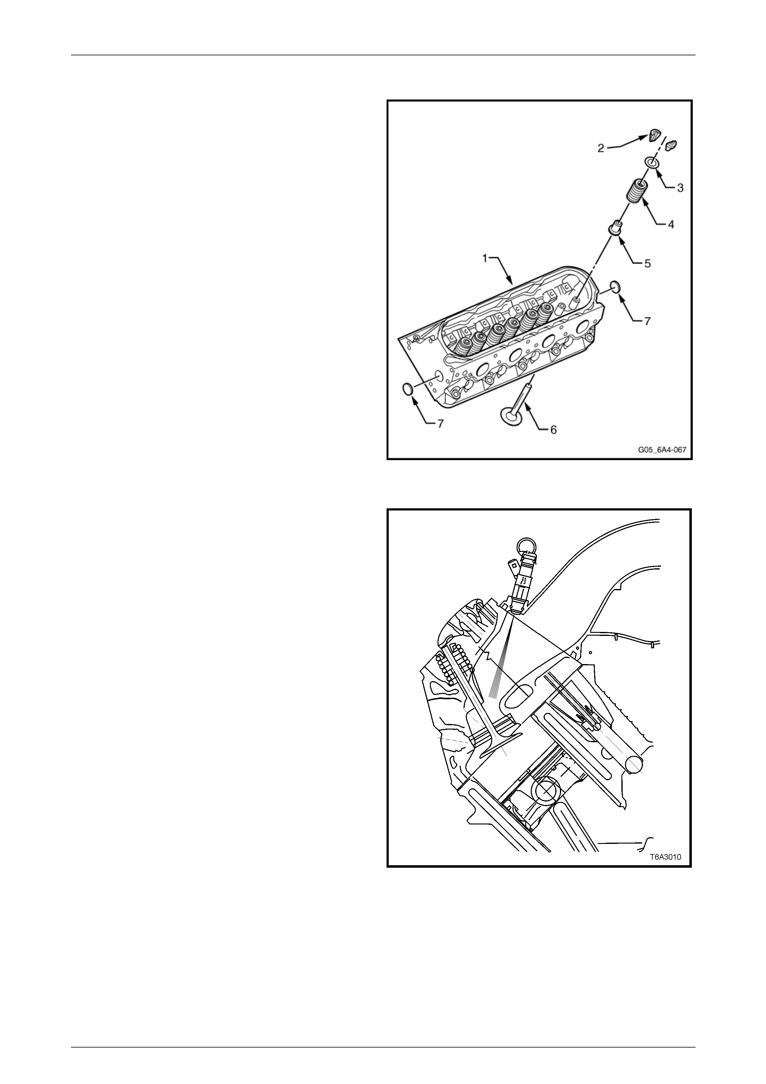
Cylinder Heads
The cylinder head assemblies are cast aluminium with
powdered metal valve guides and valve seats pressed into
the cylinder head casting.
The intake and exhaust ports are identica l fo r each cylinder,
ensuring a balanced airflow distribution for balanced
combustion.
The cylinder head is attached to the cylinder block using 10
M11 and five M8 bolts, with the M11 bolts being a deep
threaded arrangement. This arrangement re duces distortion
of the cylinder bore, which then allows low friction pistons
and piston rings to be used for improved fuel consumption.
Cylinder head gaskets are a laminated steel type and
feature stainless steel PTFE coated flanges and lacing.
Legend
• Cylinder Head (1)
• Valve Stem Collets (2)
• Valve Spring Cap (3)
• Valve Spring (4)
• Valve Stem Oil Seal/Shim Combination (5)
• Valve (6)
• Cylinder Head Core Plugs (7) Figure 6A4 – 9
The additional hei ght of the intake ports are designed to
enhance fuel injector targeting. As the air flows down to the
valve guide, the port narrows then widens to the size of the
intake valve seat.
Figure 6A4 – 10
Page 6A4 – 14
GEN IV V8 Engine Mechanical Page 6A4 – 15
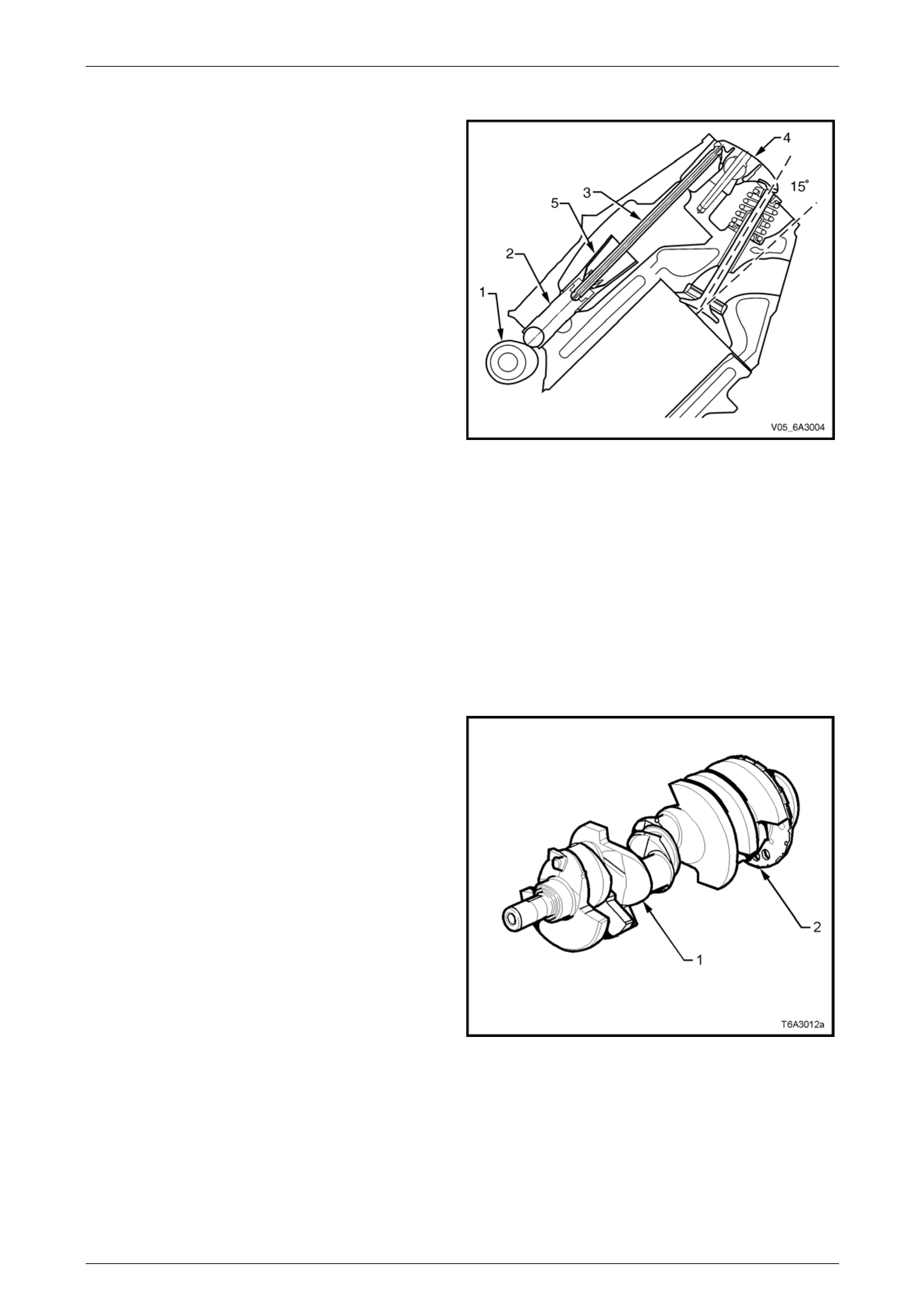
Valve Train
Motion is transmitted from the camshaft (1) to the hydraulic
valve lifters (2) and the tubular pushrod (3) then to the
rocker arms (4), which pivot and in doing so, control the
opening and closing of the valves.
Hydraulic valve lifter guides (5) mounted within the cylinder
block position and retain the hydraulic roller valve lifters
within the cylinder block.
The valve rocker arms for each bank of the cylinders are
mounted on pivot supports. The pivot supports are attached
to the cylinder head by a bolt. Valve lash is adjuste d
automatically with oil pressure through each cycle of the
hydraulic valve lifters.
Both the inlet and exhaust valves are angled at 15° to the
cylinder bore centreline. This allows a shallow combustion
chamber and a flat top piston to be used resulting in a
compression ratio of 10.1:1.
Both the exhaust and intake valve seat angle s are at 46°
with an intake valve head diameter of 50.8 mm and exhau st
valve head diameter of 39.4 mm. Figure 6A4 – 11
The valve springs are conical in shape and are made from chromium silicone spring steel. The reduced diameter end
coils allow a smaller diameter, lower mass, steel spring retainer to be used with single bead valve stem collets. This
spring design also reduces spring mass and coupled with the increased stiffness in the v alve train, results in a reduction
in the valve spring pre-load, thereby reducing friction and val ve train noise.
The rocker arms are manufactured from inve stment cast steel and have a ratio of 1.7:1. This allows a lower cam lobe lift
resulting in lower valve train loading and less noise.
The valve rocker arm covers are cast aluminium an d use a pre-moulded silicone gasket for sealing. There are four
individual ignition coils mounted to each rocker cover. Incorporate d into th e rocker covers is the oil fill tube and the fitting
for the fresh air hose, which is part of the Positive Crankcase Ventilation (PCV) s ystem.
Crankshaft
The crankshaft (1) is manufactured from nodular cast iron
and is supported by five main bearings. Each main bearing
cap is attached to the cylinder block by six bol t s, two of
which are attached from the side. T he main bearing caps
are machined with the cylinder block for cor rect alignment
and clearance and must be kept in their original location
when servicing.
A 24X reluctor ring (2) is attached to the rear of the numb er
eight crankshaft counter weight. The reluctor ring is not
serviced separately.
Thrust is controlled by a thrust bearing at the centre (No. 3)
main bearing. This location is used to reduce the expansion
differences between the cast iron crankshaft and the
aluminium cylinder block.
The crankshaft has a 25.4 mm hole dr illed through the
centre of the main journals 2, 3, 4 and 5. Apart from a
reduction in crankshaft weight, this also enh ances engine
breathing at low speeds. Figure 6A4 – 12
Page 6A4 – 15
GEN IV V8 Engine Mechanical Page 6A4 – 16
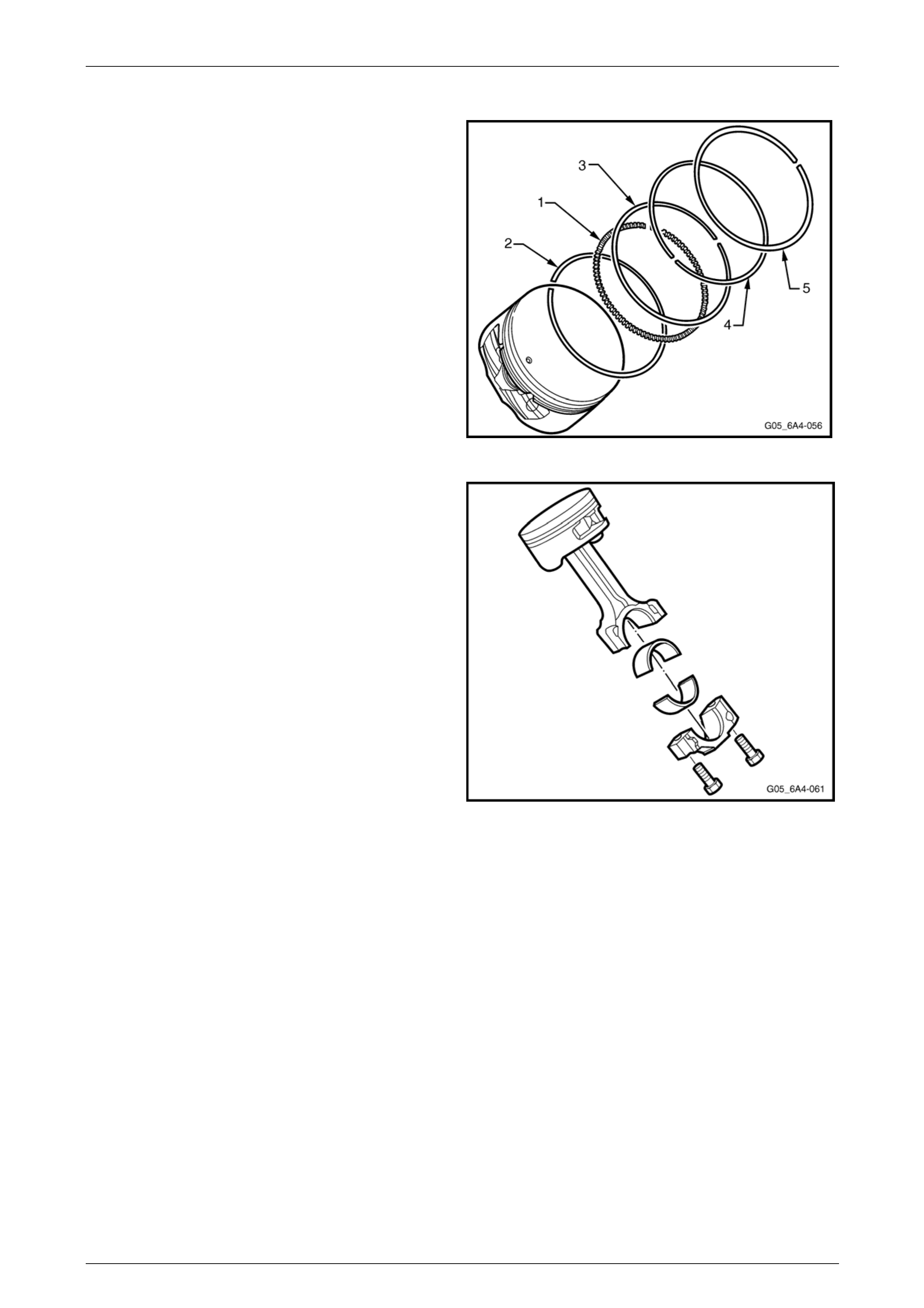
Piston and Connecting Rod
The cast aluminium pistons are fitted with two compression
rings (4, 5) and one oil control ring ass embl y (1,2,3). The
piston rings are a thin low friction des ign. The top ring is
located close to the top of the piston crown to reduce
hydrocarbon emissions and blow-by. The pistons are a low
friction lightweight design with a flat top and a barrel shaped
skirt.
The piston pins are chromium steel an d are a floating fit in
the piston and the connecting rod. The piston pin is retained
by a circlip in each side of the piston.
Figure 6A4 – 13
The connecting rods are forged powdered metal. The
connecting rod cap is separated during the manufacturing
process using the fracture method. This creates a stronger
visually seamless rod to cap union. The reassembled rod is
then machined for the correct clearance.
A 0.25 mm oversize piston and piston ring set is available
for service should cylinder honing be required. Boring of the
cylinder is not permitted.
Figure 6A4 – 14
Page 6A4 – 16
GEN IV V8 Engine Mechanical Page 6A4 – 17
Camshaft and Drive
The camshaft is machined from a steel billet and is supported by five bearings pressed into the cylinder block. It also has
a machined camshaft sensor reluctor ring incorporated between the fourth and fifth bear ing journals and has a 17 mm
hole drilled down its length to reduce weight. The intake and exhaust cam lobes have slow velocity closing ramps to
reduce valve train noise.
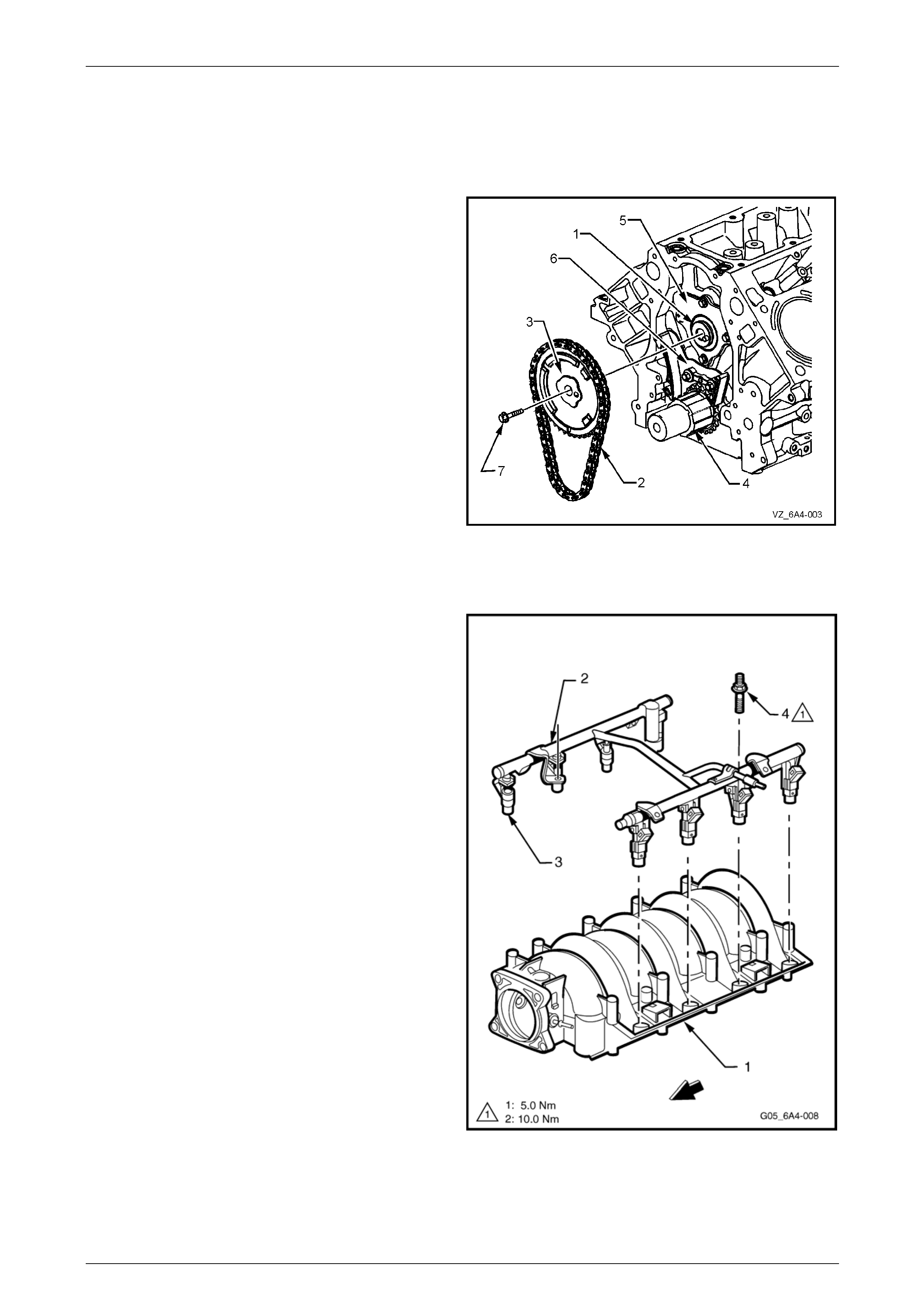
The camshaft (1) is driven by a traditional 9.52 mm pitch
roller chain (2) and powdered metal timing sprockets (3)
mounted to the front of the camshaft and crankshaft (4). A
retaining plate (5) mounted to the front of the engine block
maintains the camshaft location.
The crankshaft sprocket (4) is splined internally and drives
the oil pump.
A timing chain dampener (6) is used to red uce chain noise
and resonance and is attached to the engine block just
above the crankshaft timing gear.
The camshaft sprocket is attached to the camshaft by a
single bolt (7).
Figure 6A4 – 15
Intake Manifold
The intake manifold (1) is a one-piece composite design that
incorporates metal threaded inserts for attaching the fuel rail
(2) and the throttle body.
The intake manifold is sealed to the cylinder heads by eight
separate non-reusable si licone gaskets, which press into the
grooves of the intake housing.
The electronic controlled throttle body assembly bolts to the
front of the intake manifold. The throttle body is sealed to
the intake manifold by a one piece push in place silicone
gasket.
The fuel rail assembly has eight separate fu el injectors (3)
and is attached to the intake manifold b y four studs (4). T he
injectors are seated in their individ ual manifold bores with O-
ring seals to provide sealin g.
Fuel rail stop brackets are positioned both sides at the rear
of the fuel rail and are attached by the intake manifold
attaching bolts, refer to Figure 6A4 – 42.
There are no coolant passage s within the intake manifold.
The Manifold Absolute Pressure (MAP) sensor is instal led in
the front of the Intake manifold and is sealed by an O-ring
seal, refer to Section 6C4-3 Engine Management Service
Operations
Figure 6A4 – 16
Page 6A4 – 17
GEN IV V8 Engine Mechanical Page 6A4 – 18
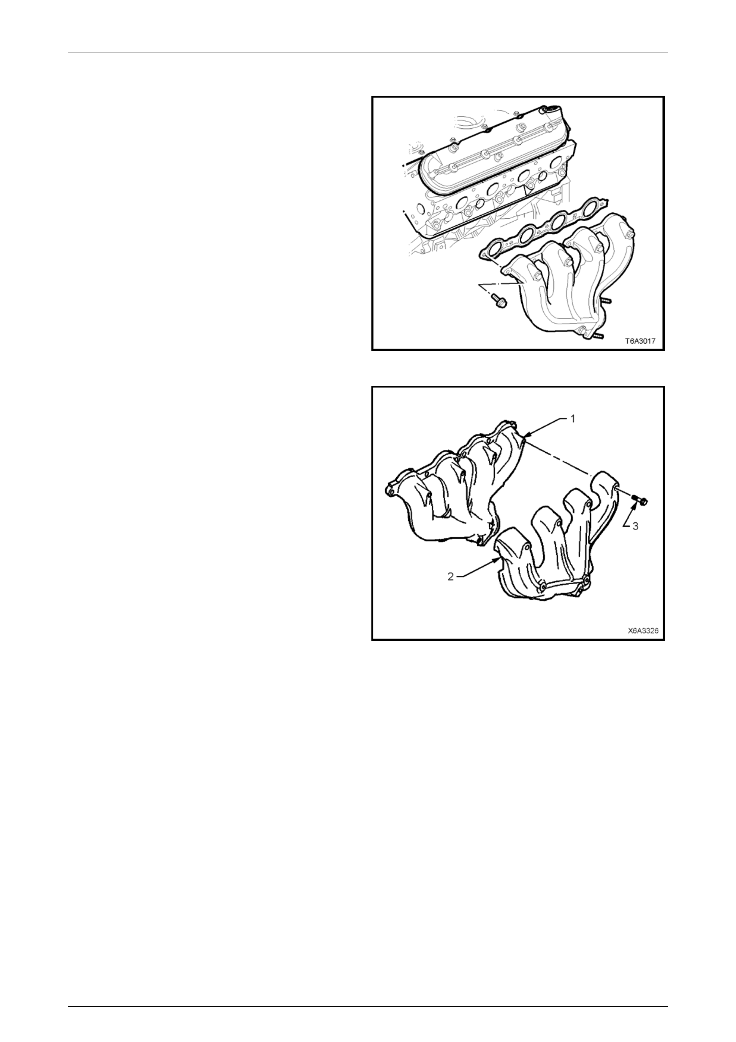
Exhaust Manifold
The exhaust manifolds are one piece, high temperature
silicone molybdenum cast iron manifold.
The exhaust manifolds dir ect the e xhaust gases from the
combustion chambers to the exhaust s ystem.
The exhaust manifolds are attached to each cylinder head
using six M8 bolts.
Figure 6A4 – 17
Each exhaust manifold (1) has an externall y mounted dual
wall heat shield (2) made of aluminised steel that is attached
to the manifold by five M6 bolts (3).
Figure 6A4 – 18
Page 6A4 – 18
GEN IV V8 Engine Mechanical Page 6A4 – 19
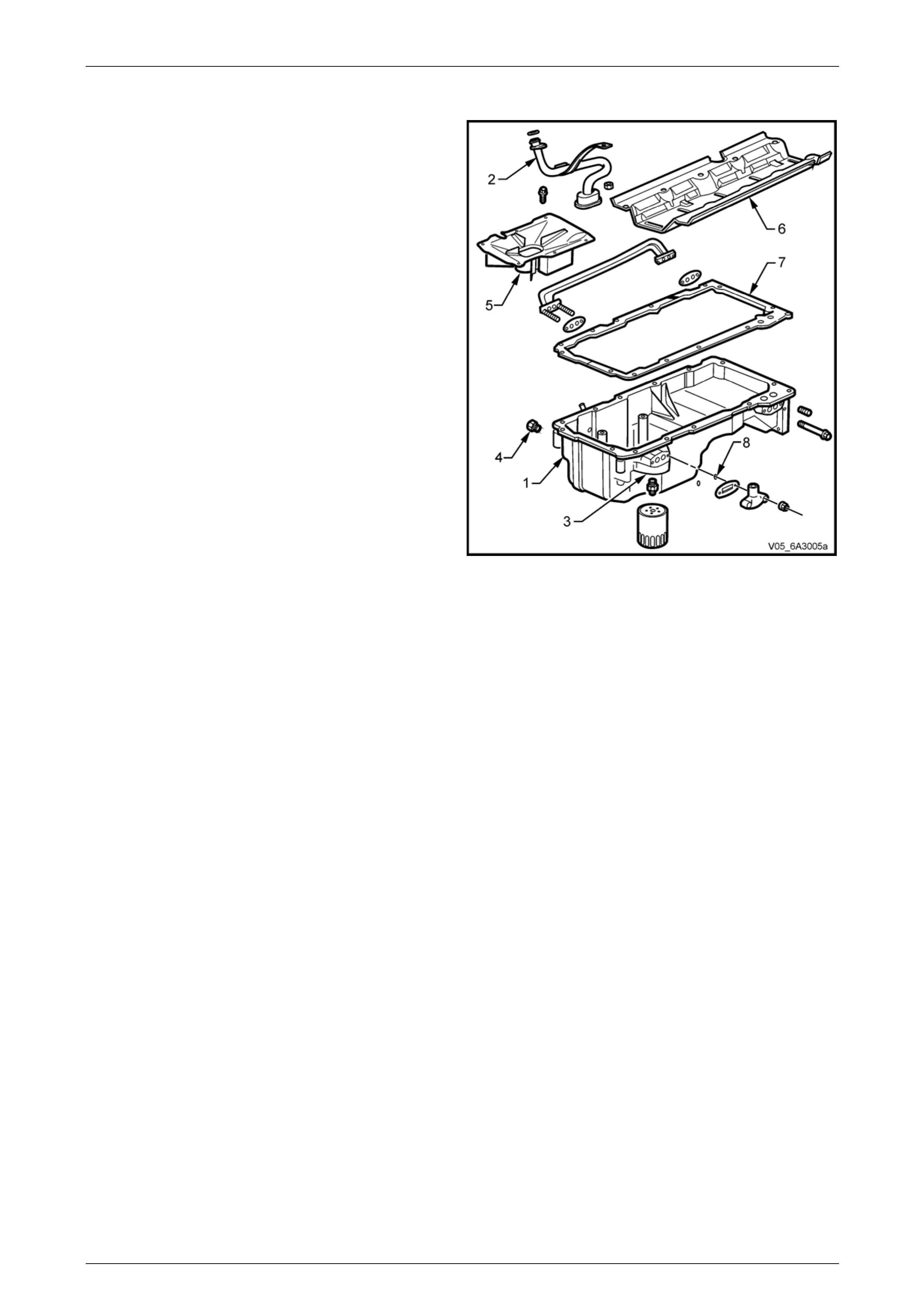
Oil Pan
The cast aluminium oil pan (1) forms a structural p art of the
Engine by providing a 360° mounting for the transmission,
whether it be manual or automatic.
Incorporated into the oil pan casting are cast-in dams.
These dams minimise oil migration during braking and
cornering manoeuvres an d assist in guiding oil to the pick-
up screen (2) via the strategically placed openings in the
dam walls.
Also incorporated in the oil pan casting is the oil filter
mounting boss (3), an opening for the drain plug (4) and a
stamped oil pan baffle (5). The oil pan baffle maintains an
area around the pick-up screen to prevent oil starvation and
aeration.
A crankshaft oil deflector (6) is attached to the main bearing
caps and controls windage, removes return oil from the
crankshaft and facilitates drain back, thus reduci ng aeration.
The oil pan gasket (7) is a controlled compression
aluminium carrier gasket with silicone used as the sealing
agent.
Two O-ring seals (8) are fitted to stop oil leaks along the
studs attaching the oil transfer cover to the oil pan.
Figure 6A4 – 19
Page 6A4 – 19
GEN IV V8 Engine Mechanical Page 6A4 – 20
1.4 Engine Lubrication System
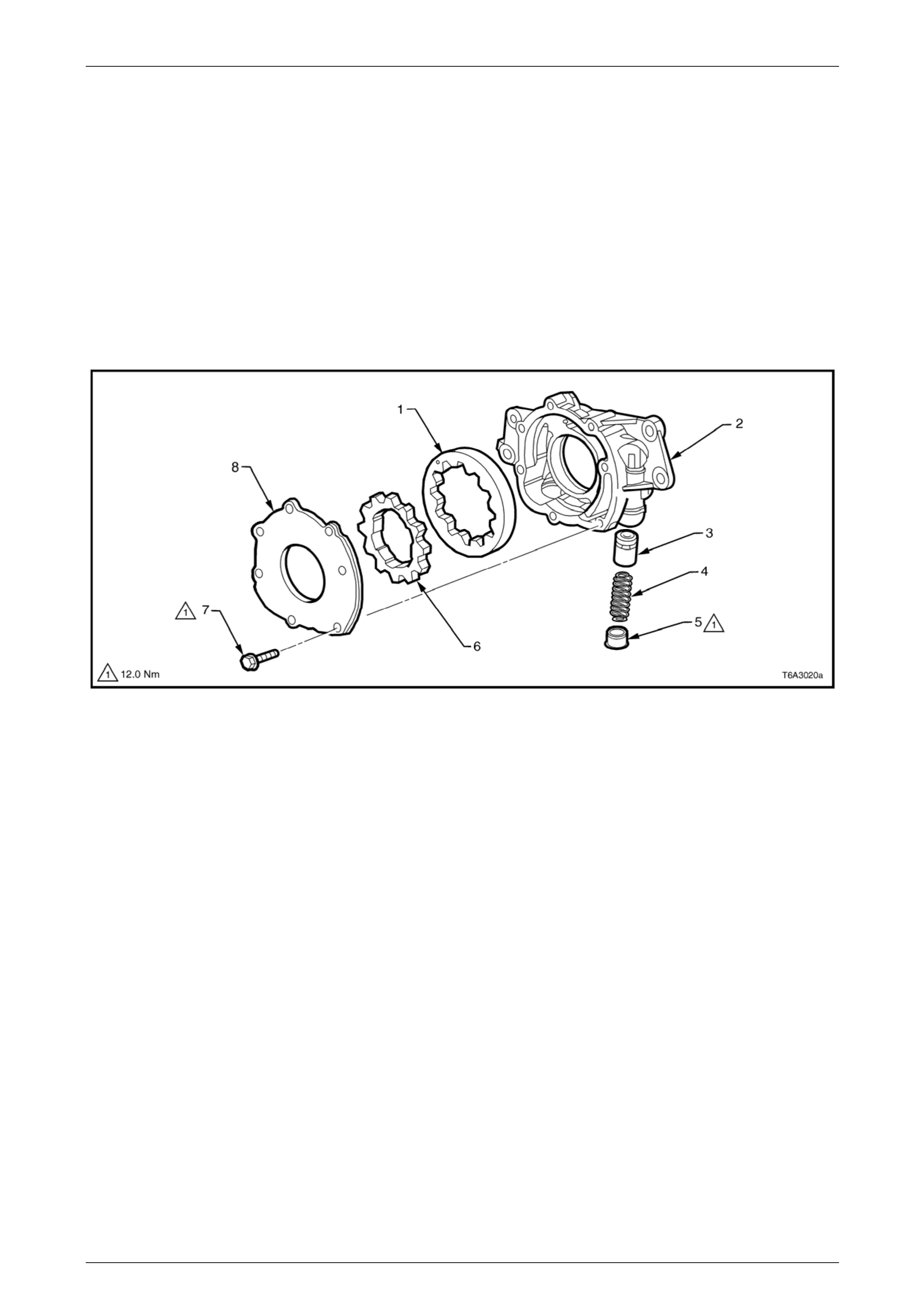
Oil pump
A “gerotor” type oil pump assembly supplies the engine lubrication, refer to Figure 6A4 – 20. The pump is attached to the
front of the cylinder block and is driven directly by the crankshaft sprocket. The pump gears rotate and draw oil from the
oil pan sump through a pick-up screen and pipe. Contained within the oil pump assembl y is a pressure relief valve that
maintains oil pressure within a specified range.
Pressurised oil is directed thr ough the lower gallery to the full flow oil filter wher e harmful contaminants are removed.
Incorporated into the oil filter is a bypass valve, which allows oil to flow through the engine in the event the filter becomes
blocked.
The oil is pressurised as it passes through the pump and is then pumped throu gh the cylinder block via the oil galleries,
refer to Figure 6A4 – 21.
Figure 6A4 – 20
Legend
1 Driven Gear
2 Oil Pump Housing
3 Pressure Relief Valve
4 Pressure Relief Valve Spring
5 Plug
6 Drive Gear
7 Cover Bolt, 7 places
8 Cover
Page 6A4 – 20
GEN IV V8 Engine Mechanical Page 6A4 – 21
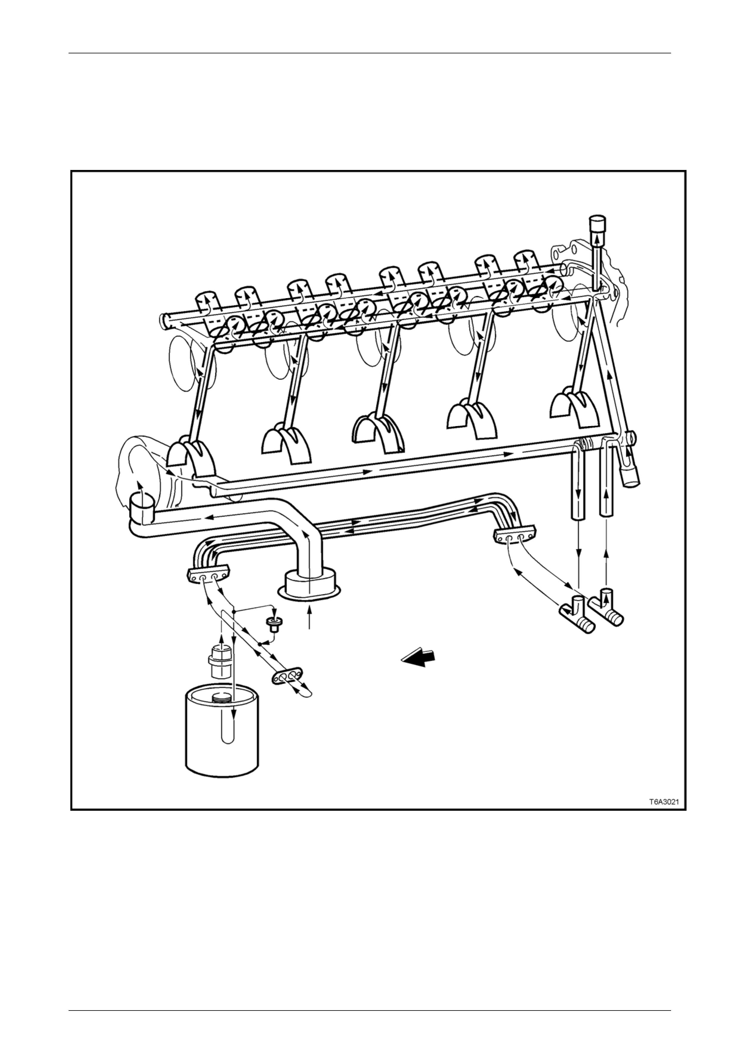
Oil Flow
Oil is directed to the drilled upper main oil g alleries just above the camshaft assembly at the rear of the cylinder block,
refer to Figure 6A4 – 21. From there, oil is then directed to the crankshaft and camsh aft bear ings. Oil that has entered
the upper main oil galler ies also pressurises the valve lifter assemblies and is then pumped through the pushrods to
lubricate the valve rocker arms and valve stems. The crankshaft oil deflector (not shown) directs returning oil back to the
oil pan.
Figure 6A4 – 21
Page 6A4 – 21
GEN IV V8 Engine Mechanical Page 6A4 – 22
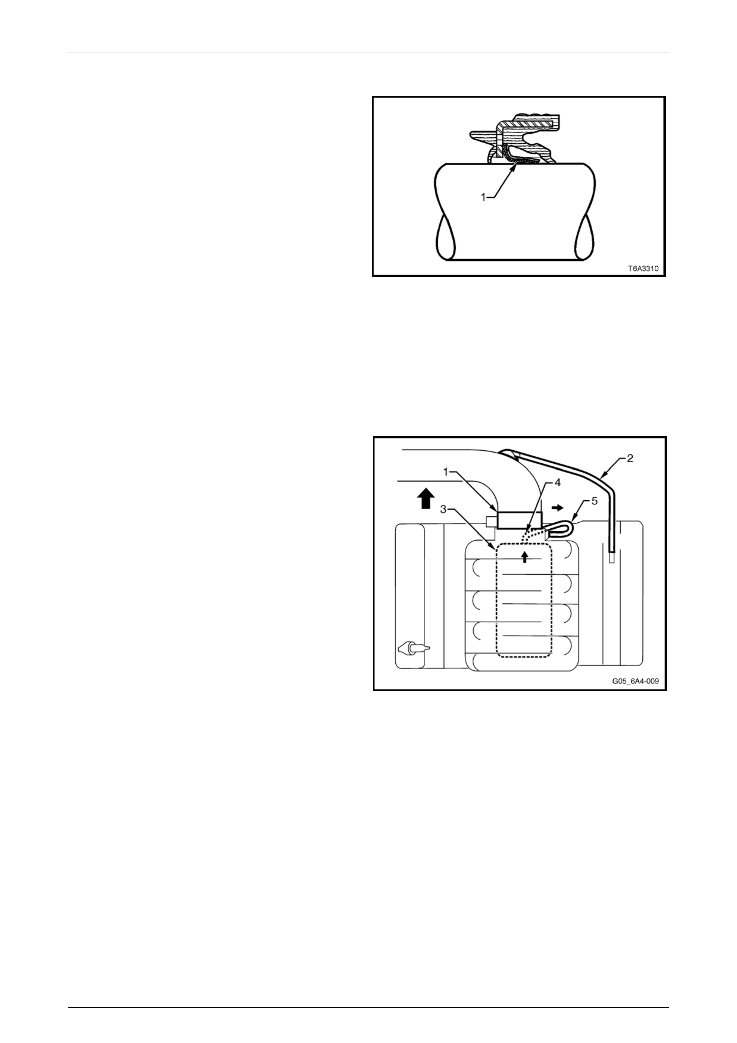
Oil Seals
The rear main oil seal is a multiple lip oil seal designed for
long life operation.
The seal includes a Polytetrafluoro ethylene (PTFE) Teflon
centre lip (1) to minimise rear main oil seal leaks. The anti-
friction property of the PTFE reduces the chances of
choking or build-up of degraded oil on the lip causing the lip
to lift off the shaft resulting in a leak.
Similar to the rear main oil seal, the front crankshaft oil seal
also incorporates a PTFE lip.
The PTFE is actually deposited on the dry crankshaft seal
surface during initial operation by the heat generated from
the rotating shaft.
NOTE
Lubricant must not be applied to the PTFE seal
lip or the shaft on which it runs during installatio n
as this will prevent correct break-in of the seal.
The outside of the seal may be lubricated
sparingly for ease of installation.
Figure 6A4 – 22
Positive Crankcase Ventilation System
The crankcase ventilation s ys tem was developed to remove
the engine combustion blow-by vapours and minimise the
following:
• Crankcase pressure build-up
• Oil deterioration
• Oil consumption
• Evaporative/exhaust emissions
During normal idle and part throttle operation, filtered fresh
air is routed from upstream of the throttle body (1) blade to
the front of the right-hand rocker cover via the fresh air inlet
hose (2).
Blow-by gas (oil vapour) in the crankcase valley passes
through the oil separator (3) attached to the valley cover and
then flows through the fixed internal flow-restricting orifice
(4) within the valley cover then via the foul ai r hose (5). The
blow-by gas is directed from the valley cover right-hand
corner to the Intake manifold on the engine side of the
throttle plate.
Under heavy load operation and high engine speeds, an
acceptable reverse flow condition may occur in the fresh air
inlet hose.
Figure 6A4 – 23
Page 6A4 – 22
GEN IV V8 Engine Mechanical Page 6A4 – 23
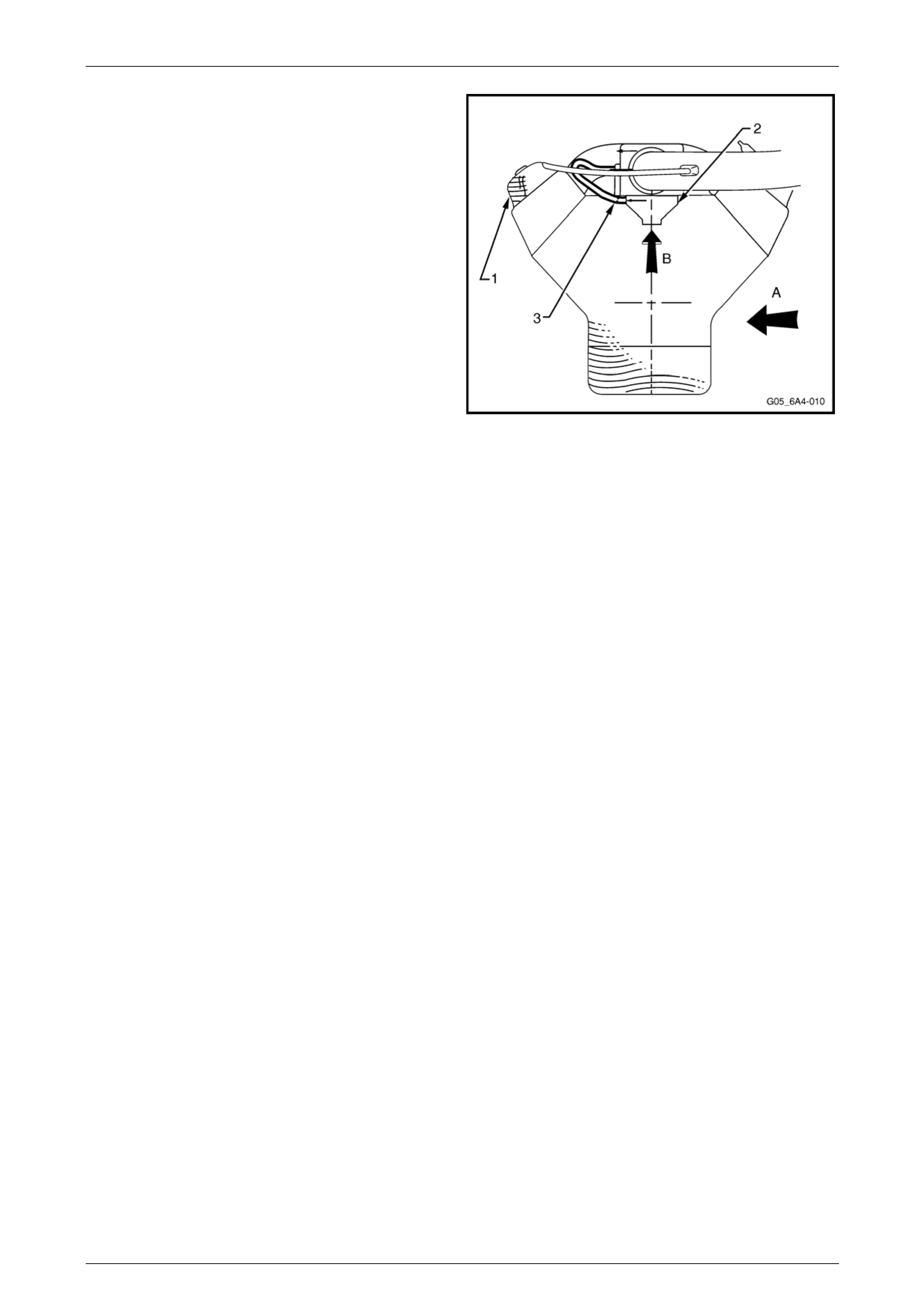
During sustained maximum lateral acceleration (A), the
outboard rocker cover may be overloaded with oil (1). If the
blow-by gas is dra wn from the rocker cover as in previ ous
designs, oil may be ingested into the intak e manifo ld.
Instead of the blow-by gas be ing drawn from the rocker
cover, a high efficiency oil separator (2) in conju nction with
an internal flow-restricting orifice (3) is fitted und er the valley
cover to draw the blow-by gas from the crankcase (B),
preventing oil from bei ng ingested during severe vehicle
cornering manoeuvres.
Figure 6A4 – 24
Page 6A4 – 23

GEN IV V8 Engine Mechanical Page 6A4 – 24
1.5 Service Notes
The degree of expertise with general
workshop practice and the selection of
sealants is critical to the successful outcome
of the service procedures detailed, here.
It is therefore, critical that the Service Notes
included in Section 6A4 GEN IV V8 Engine in
the MY 2006 VZ Service Information be
adopted.
Page 6A4 – 24

GEN IV V8 Engine Mechanical Page 6A4 – 25
2 Diagnosis
2.1 General Information
The engine diagnostic procedures related to the symptoms listed here, remain unch anged from those detailed in
Section 6A4 Engine Mechanical – GEN IV V8, in the MY2006 Service Information. Therefore refer to these diagnostic
tables for specific information on the following symptoms:
• General Engine Diagnosis.
• Engine Noise.
• Valve Train Noise.
• Oil Consumption.
• Oil Pressure.
• Oil Leaks.
• Compression Check and Interpretin g the Re adings Taken.
Page 6A4 – 25
GEN IV V8 Engine Mechanical Page 6A4 – 26
3 Minor Service Operations
ATTENTION
All engine fasteners are important attaching parts as they affect th e performance of vital componen ts and/or
could result in majo r repair expense. Where specified in this Section, fasteners MUST be rep laced with parts
of the same part number or an approved equivalent. Do not use fasteners of an inferior quality or substitute
design.
Torque values must be used as specified during reassembly to ensure correct retention of all components.
Throughout this Section, fastener torque wrench specifications may be accompanied with the following
identification marks:
Fasten ers must be replaced after loosen ing.
Fasteners either have micro encapsulated sealant applied or incorporate a mechanical thread lock and
should only be re-used once. If in doubt, replacement is recommended.
If one of these identification marks is present alongside a fastener torque wrench specification, the
recommendation regarding that fastener must be adhered to.
3.1 Air Intake Duct Resonator
LT Section No. — 03–250
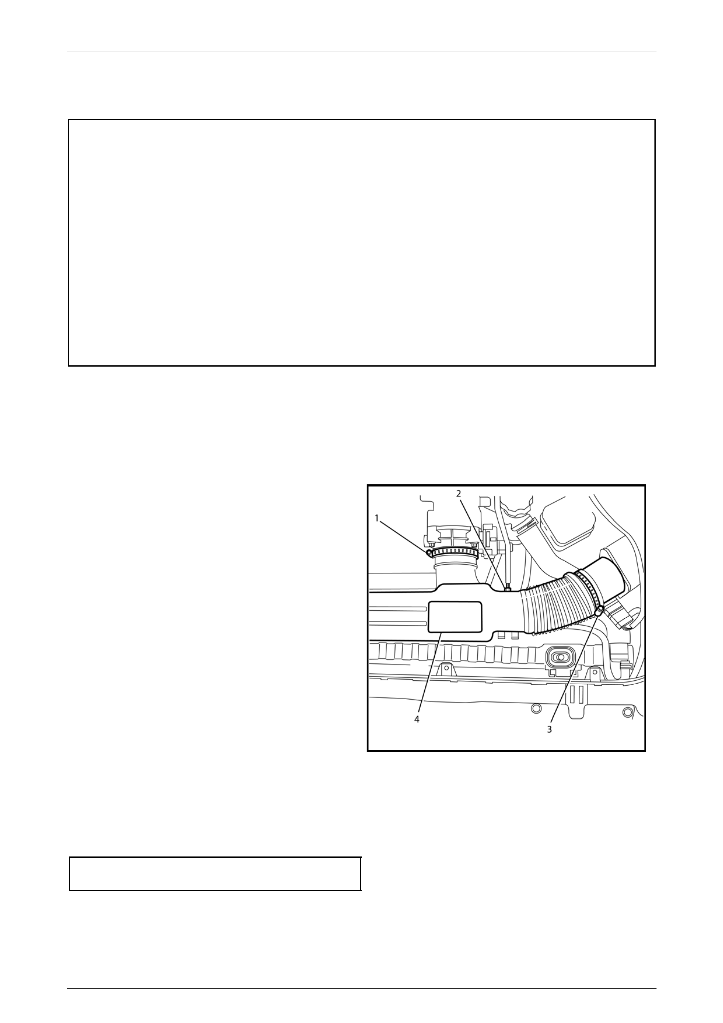
Remove
1 Remove the positive crankcase ventil ation (PCV)
hose (2) from the air cleaner duct resonator (4).
2 Remove the air cleaner duct to throttle bod y retaining
clamp (1).
3 Remove the air cleaner duct to intake air temperature
(IAT) / mass air flow (MAF) sensor retaining clamp
(3).)
4 Remove the air cleaner duct resonator.
Figure 6A4 – 25
Reinstall
Reinstallation of the air intak e duct is the re verse of the removal procedure ensuring all hose clamps are tightened to the
correct torque specification.
Air intake duct clamps
(both) torque specification...........................1.5 – 2.5 Nm
Page 6A4 – 26
GEN IV V8 Engine Mechanical Page 6A4 – 27
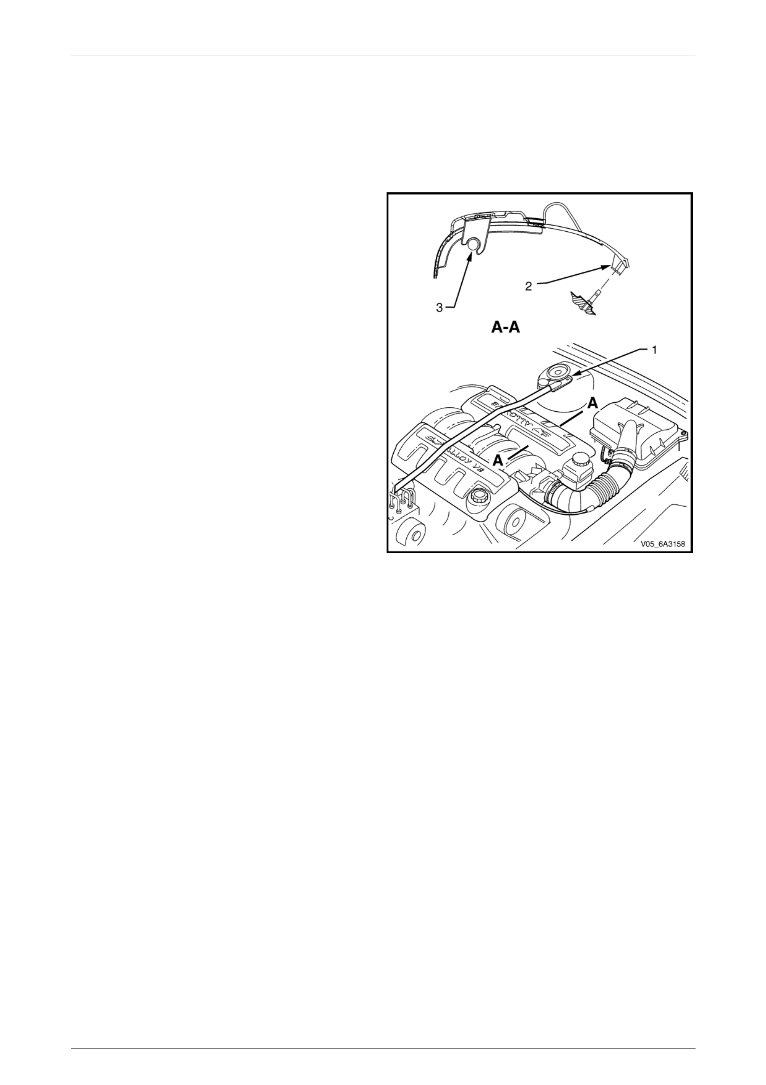
3.2 Engine Dress Cover
LT Section No. — 00–508
Remove
1 If required, remove the strut tower brace (1), refer to
Section 1A1 Body.
2 Disengage the engine dress cover retaining clips (2)
by pulling upward.
3 Rotate the cover to unlock it from the fuel rail (3) and
remove the cover.
Figure 6A4 – 26
Reinstall
Reinstallation of the engine dress covers is the reverse of the removal procedure ensuring the retaining clips are fully
engaged.
Page 6A4 – 27
GEN IV V8 Engine Mechanical Page 6A4 – 28
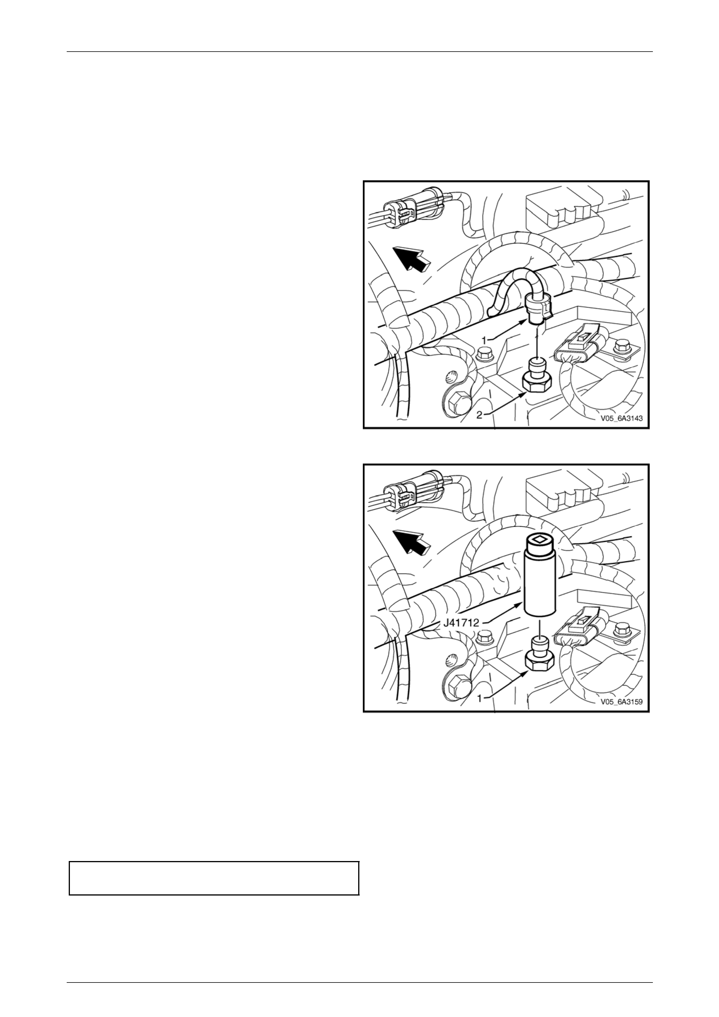
3.3 Oil Pressure Sensor
LT Section No. — 02–000
Remove
1 Release the wiring harness connector (1) locking tang
from the oil pressure sensor (2) and remove the
connector from the sensor.
Figure 6A4 – 27
2 Using the oil pressure sensor socket, T ool No. J41712
and suitable 3/8” drive socket equipment, remove the
oil pressure sensor (1) from the left-hand rear of the
cylinder block.
Figure 6A4 – 28
Reinstall
1 Clean the threads of the oil pressure sensor.
2 Apply Loctite 565 sealant or equivalent to the cleaned oil pressure sensor threads.
3 Reinstall the oil pressure sensor and tighten to the correct torque specification using oil pressure sensor socket
Tool No. J 41712 and suitable 3/8” drive socket equipment.
Oil pressure sensor
torque specification...............................................20 Nm
4 Start the engine and check for correct operat ion and leaks.
Page 6A4 – 28
GEN IV V8 Engine Mechanical Page 6A4 – 29
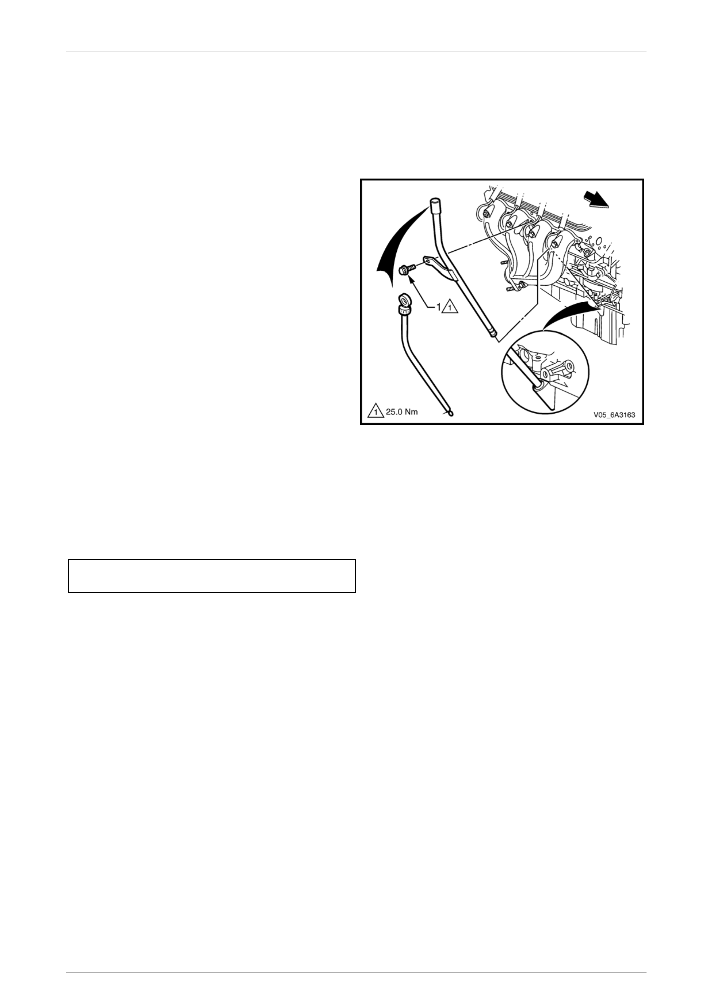
3.4 Oil Level Indicator and Tube
LT Section No. — 00–580
Remove
1 Remove the oil level indicator from the oil level
indicator tube.
2 Remove the oil level indicator tube bracket attaching
bolt (1) from the right hand exhaust manifold.
3 Remove the oil level indicator tube from the engine.
4 Remove the O-ring from the tube and discard .
NOTE
If the oil level indicator tube is not to be
reinstalled immediately, plug the opening in the
oil pan to prevent dirt entry.
Figure 6A4 – 29
Reinstall
1 Clean the oil level indicator tube and install a new O-ring to the lower end of the tube.
2 Reinstall the oil level indicator tube to the engine and rotate it to the correct position.
3 Reinstall the oil level indicator tube bracket attaching bolt and tighten to the correct torque specification.
Oil level indicator tube attachi ng bolt
torque specification...............................................25 Nm
4 Reinstall the oil level indicator to the tube.
Page 6A4 – 29
GEN IV V8 Engine Mechanical Page 6A4 – 30
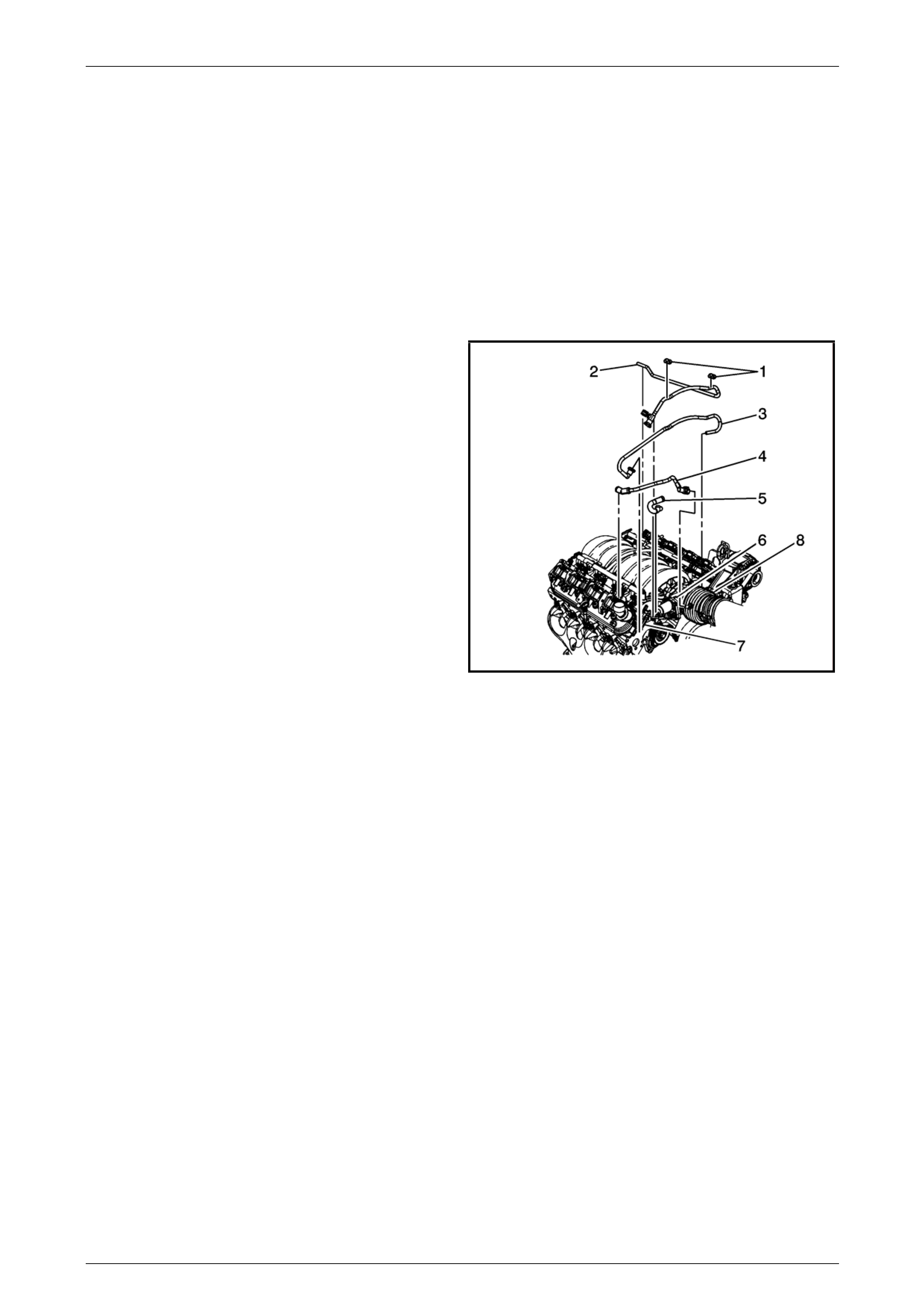
3.5 Crankcase Ventilation Hoses/Pipes
Remove
1 Remove the engine dress covers, refer to 3.2 Engine Dress Cover.
NOTE
During this procedure, it may be necessary to
remove the evaporative emission (EVAP) valve
solenoid to gain access the crankcase blow-by
hose from the valley cover.
2 Remove the evaporative emission canister purge
valve (7). Refer to Section 6C4 Engine Contr ols, in the
MY 2006 Service Information.
3 Remove the retaining clips (1) for the EVAP pipes (2.
and 3).
4 Remove the EVAP pipes (2 and 3).
5 Remove the EVAP pipe (4) from the of the intake
manifold on the left side front.
6 Remove the PCV (foul air) hose (5) from the throttle
body and engine valley cover.
1481776
Figure 6A4 – 30
Reinstall
1 The reinstallation process is the reverse to the removal steps.
Page 6A4 – 30
GEN IV V8 Engine Mechanical Page 6A4 – 31
3.6 Intake Manifold Assembly
LT Section No. — 00–375
Remove
Disconnection of the battery affects certain
vehicle electronic systems. Refer to
Section 00, 5 Battery Disconnection
Procedures in the MY 2006 VZ Service
Information before disconnecting the battery.
NOTE
Unless components such as the throttle body,
fuel injection rail and/or injectors are to be
removed individuall y, then it is recomme nded that
the complete intake manifold assembly be
removed.
1 Disconnect the negative batter y cable from the battery.
2 Drain the cooling system. Refer to Section 6B4 Engine Cooling – GEN IV V8.
3 Remove the strut tower brace. Refer to Section 1A1 Body in the MY 2006 VZ Service Information.
4 Remove the air intake duct resonator. Refer to 3.1 Air Intake Duct Resonator.
5 Remove the engine dress covers, refer to 3.2 Engine Dress Cover.
6 De-pressurise the fuel rail. Refer to Section 8A1 Fuel System, section 4.1 in the MY 2006 VZ Service Information.
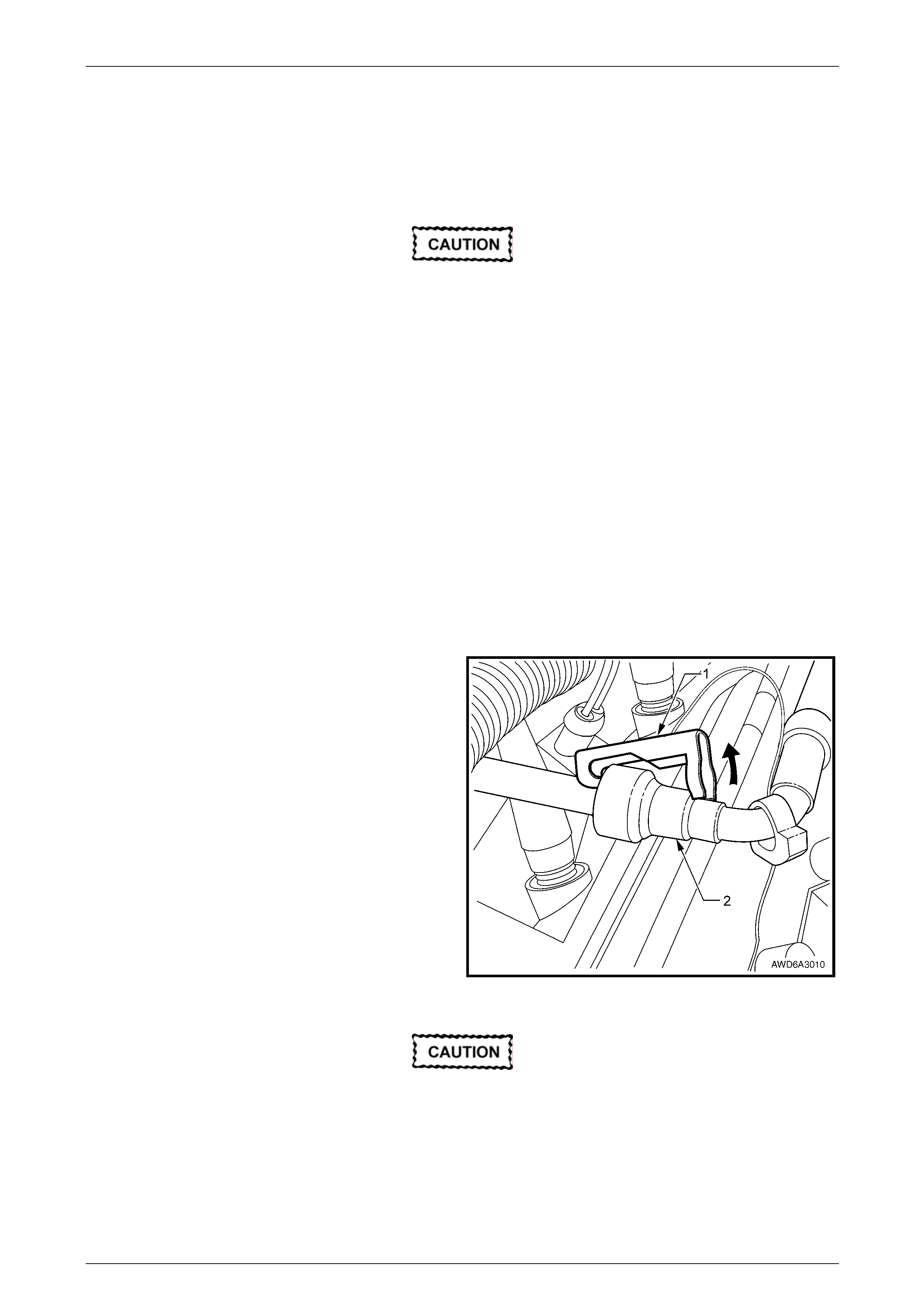
7 Using a small screwdriver, release the security lock
(1), at each of the fuel supply hose quick connect
fittings (2).
NOTE
The security lock at the fuel rail side only, is fitted
to a tether to prevent loss.
8 Install the quick connect release Tool No. 7371 over
the fuel line, refer to Section 6C4 Engine Management
– GEN IV V8.
Figure 6A4 – 31
Ensure the fuel system has been
depressurised before removing the fuel line
from the fuel rail, refer to Section 8A1 Fuel
System, 4.1 in the MY 2006 VZ Service
Information.
Page 6A4 – 31
GEN IV V8 Engine Mechanical Page 6A4 – 32
Plug both the fuel feed pipe (1) and the fuel
rail tube open ends to prevent fuel loss
and/or contamination.
9 While holding the fuel l ine quick connect (1), push on
Tool 7371 to release the qu ick connect fitting from the
fuel rail. Pull back on the quick connect and remove
the fuel line.
Figure 6A4 – 32
Plug the open ends of all disconnected
pipes/hoses and the EVAP purge valve to
prevent fuel loss and/or contamination .
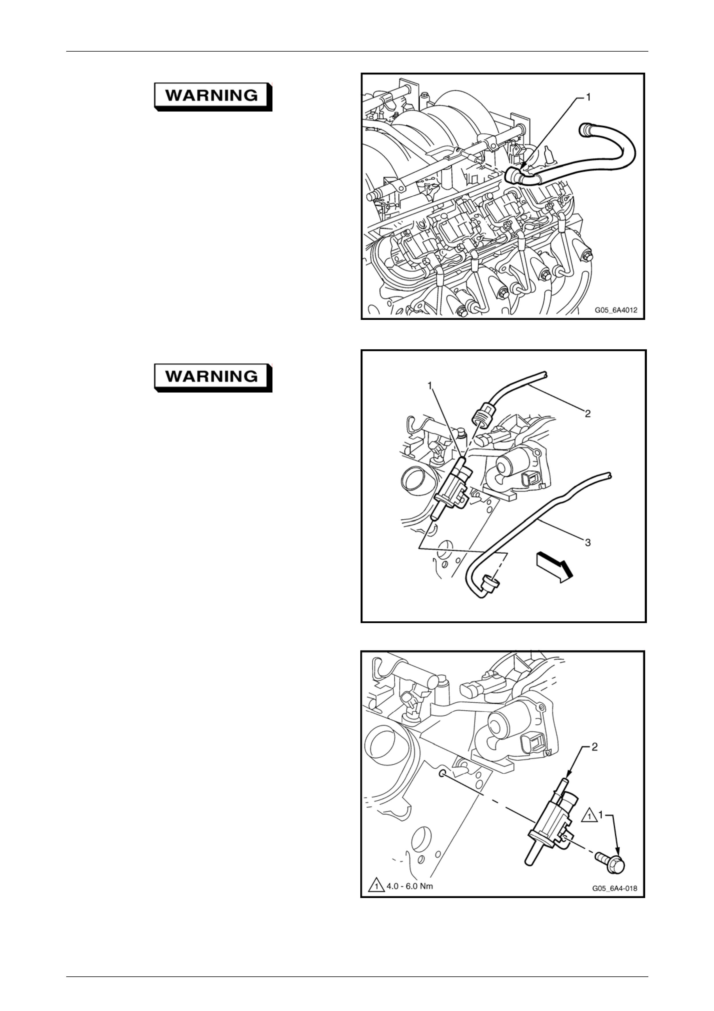
10 Disconnect the EVAP purge valve (1) to fuel tank hose
(2). Plug all open pipe/hose ends to preve nt fuel leaks
and/or contamination.
11 Disconnect the throttle body to EVAP purge valve
hose (3) from the EVAP purge valve (1).
13059925
Figure 6A4 – 33
12 Remove the bolt (1) attaching the EVAP canister
purge valve and bracket assembly (2) from the right-
hand cylinder head.
NOTE
It is recommended to remove the purge valve
from the cylinder head to avoid possible damage
to the valve when removing the intake manifold.
Figure 6A4 – 34
Page 6A4 – 32
GEN IV V8 Engine Mechanical Page 6A4 – 33
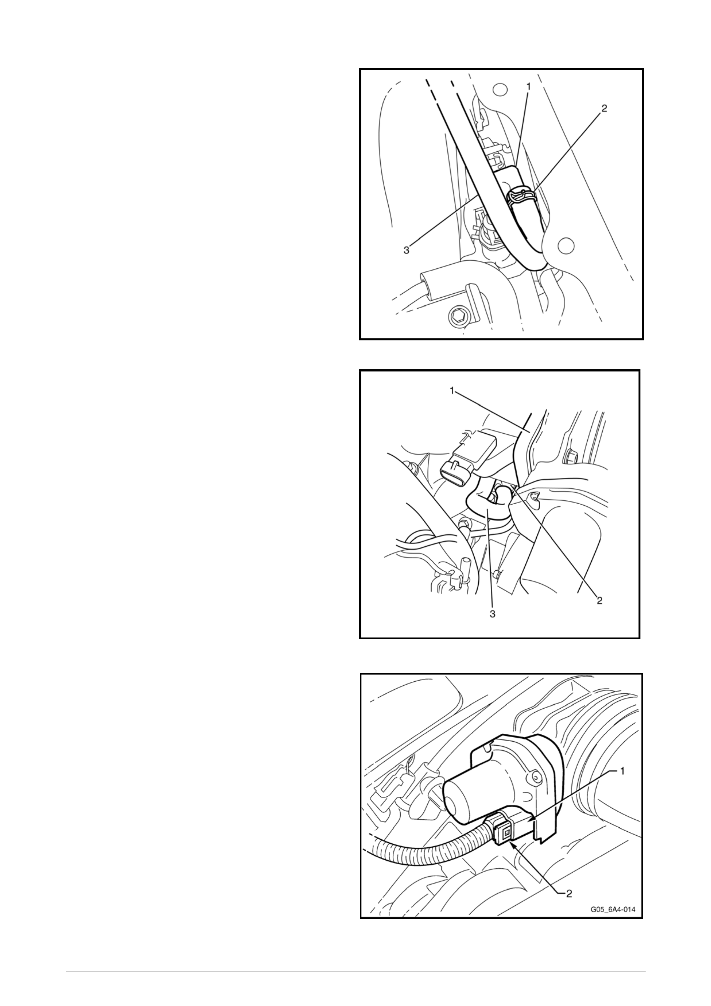
13 Compress the vacuum brake booster h ose clip (2) at
the intake manifold port (1), then slide the clip back
along the hose (3) about 30 mm.
14 Disconnect the vacuum brake booster hose (3) from
the intake manifold vacuum port (1).
1402630
Figure 6A4 – 35
15 Disconnect the wiring harness connector from the
MAP sensor.
16 Remove the crankcase blow-by hose (3) from the
throttle body (1) and the restricting orifice external
connection from the valley cover (2).
17 Disconnect the generator wiring harness connector.
3060062
Figure 6A4 – 36
18 Disconnect the electronic throttle control bo dy wiring
harness connector (1) from the throttle body by
removing the connector lock (2) and the n pulling on
the connector.
Figure 6A4 – 37
Page 6A4 – 33
GEN IV V8 Engine Mechanical Page 6A4 – 34
19 Disconnect the oil pressure sensor wiring harness
connector (1).
20 Disconnect the HVAC vacuum hose. Plug both open
ends top prevent contamination ingr ess.
3059977
Figure 6A4 – 38
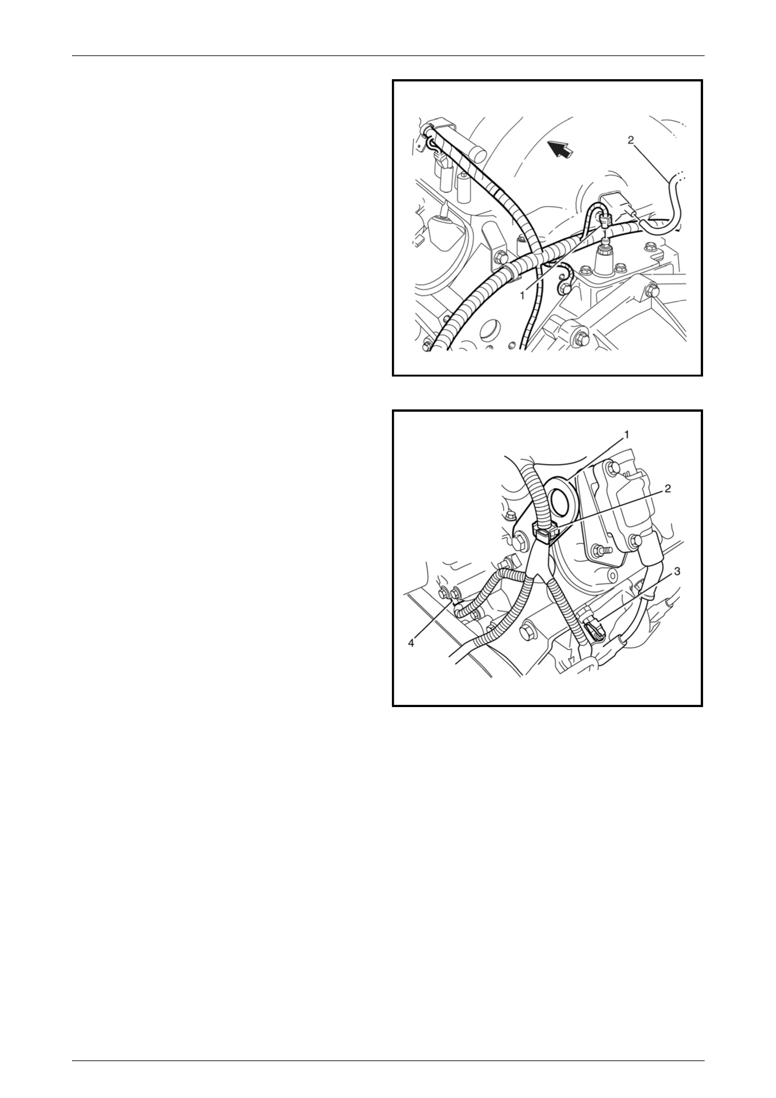
21 Disconnect the camshaft position se nsor connector
(4).
22 Disconnect the coolant temperature sensor connector
(3).
23 Disconnect the wiring harness retaining clip (2) from
the engine lifting bracket (1).
3059966
Figure 6A4 – 39
Page 6A4 – 34
GEN IV V8 Engine Mechanical Page 6A4 – 35
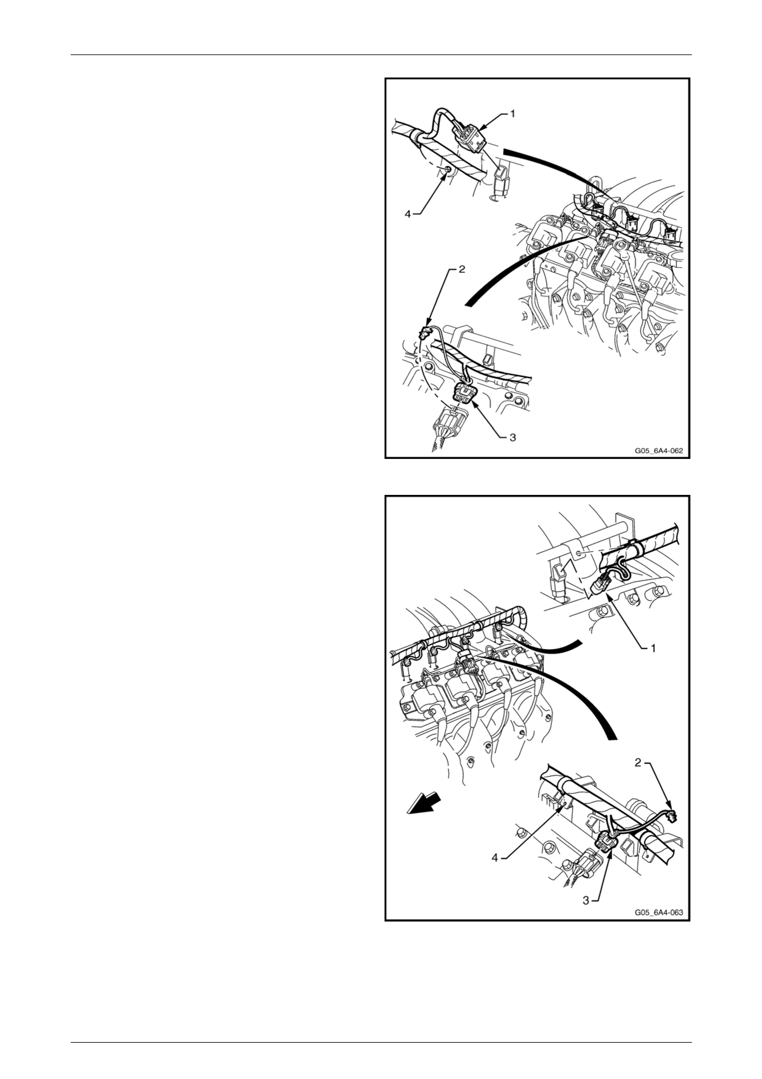
24 Disconnect the fuel injector wiring harness connectors
(1), four places, from the right-hand bank of fuel
injectors.
25 Remove the CPA lock (2) from the ignition coil main
connector (3) on the right-hand side. Remove the
connector then the harness attaching clips fr om the
fuel rail brackets (4) and set the harness to one side.
Figure 6A4 – 40
26 Disconnect the fuel injector wiring harness connectors
(1), four places, from the left-hand bank of fuel
injectors.
27 Remove the CPA lock (2) from the ignition coil main
connector (3) on the left-hand side, then rem ove the
connector.
28 Remove the wiring harness connector from the
canister purge valve (4).
29 Remove the harness securing clips from the fuel rail
brackets (5) and set the harness to one side.
30 Disconnect the manifold absolute pressure (MAP)
sensor wiring harness connector, refer to
Section 6C4-3 Engine Management GEN IV –
Service operations.
Figure 6A4 – 41
Page 6A4 – 35
GEN IV V8 Engine Mechanical Page 6A4 – 36
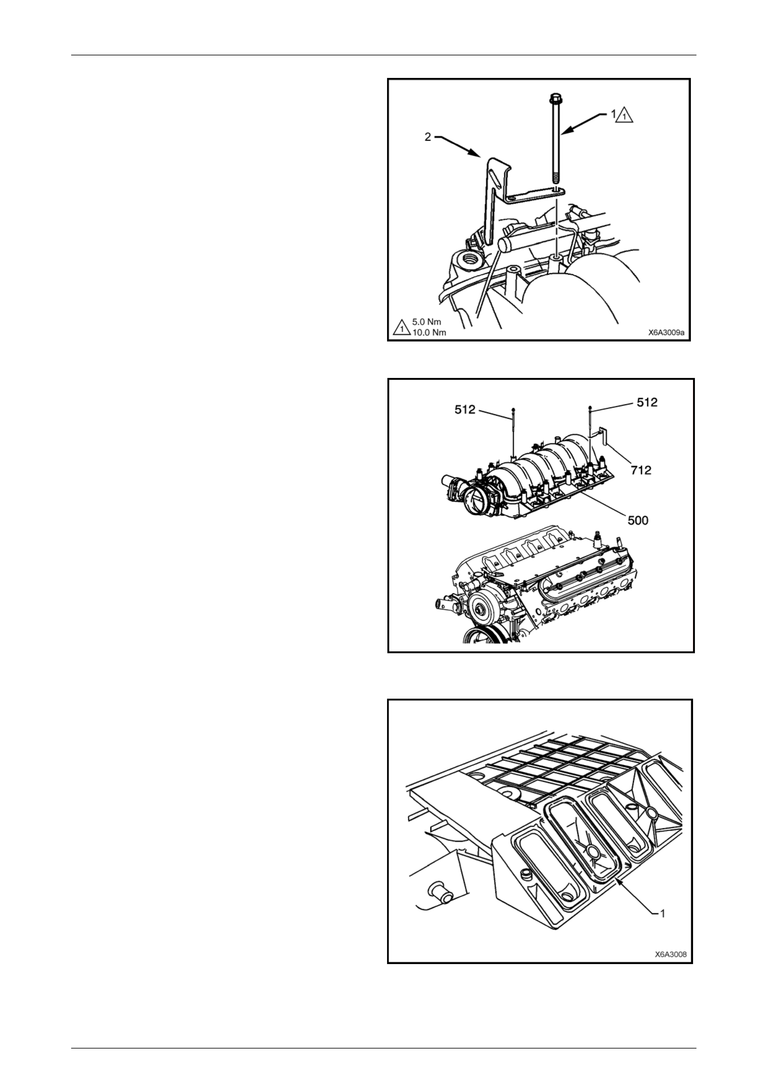
31 Progressively loosen all the intake manifold retaining
bolts (1), working diagonally from outsid e to insid e.
32 Remove the fuel rail stop bracket (2), two places and
set to one side.
NOTE
The fuel rail stop brackets are attache d using the
two rear bolts on each side ( 3, 9, 5 and 8) of the
Intake manifold. Refer to Figure 6A4 – 52.
Figure 6A4 – 42
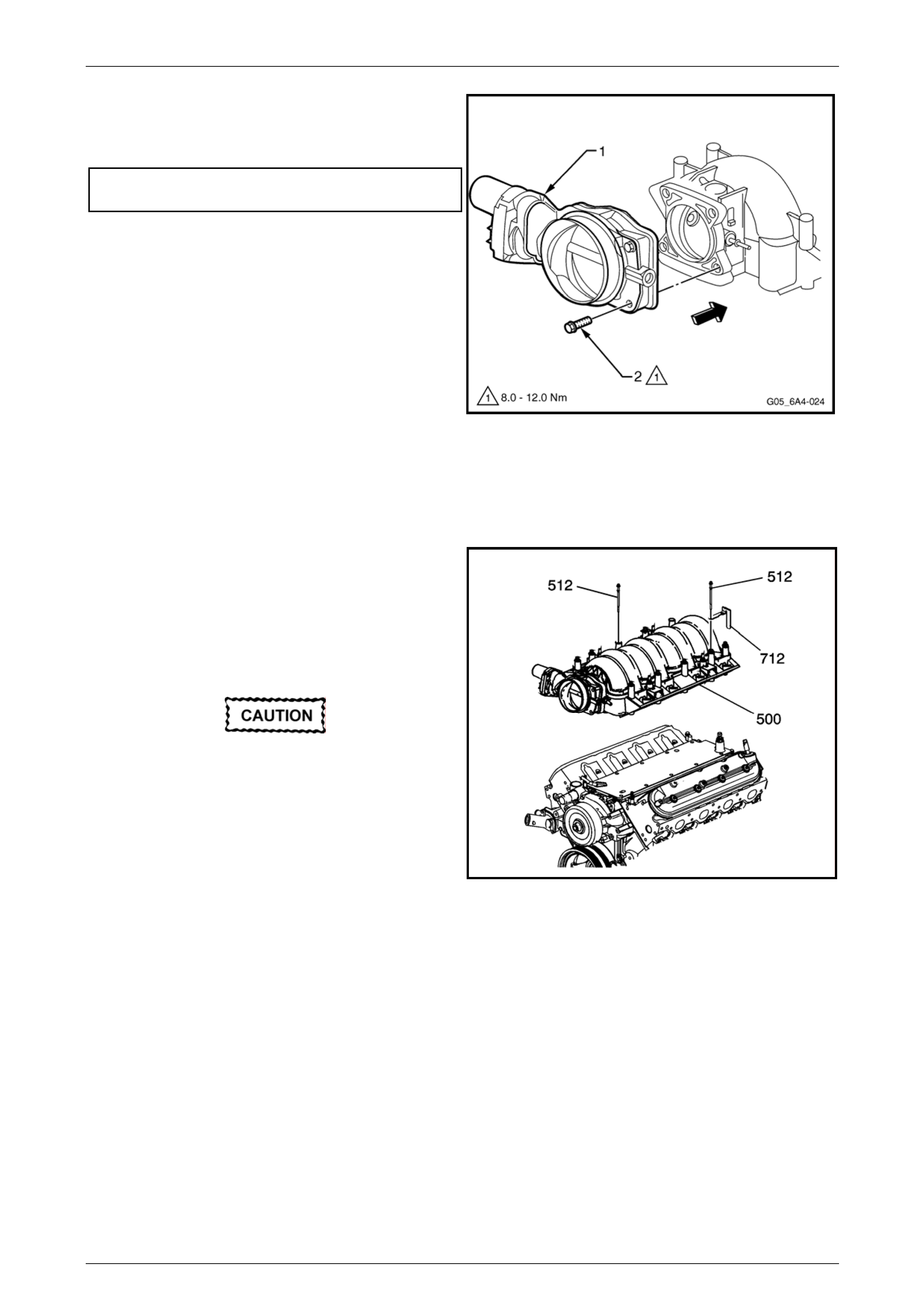
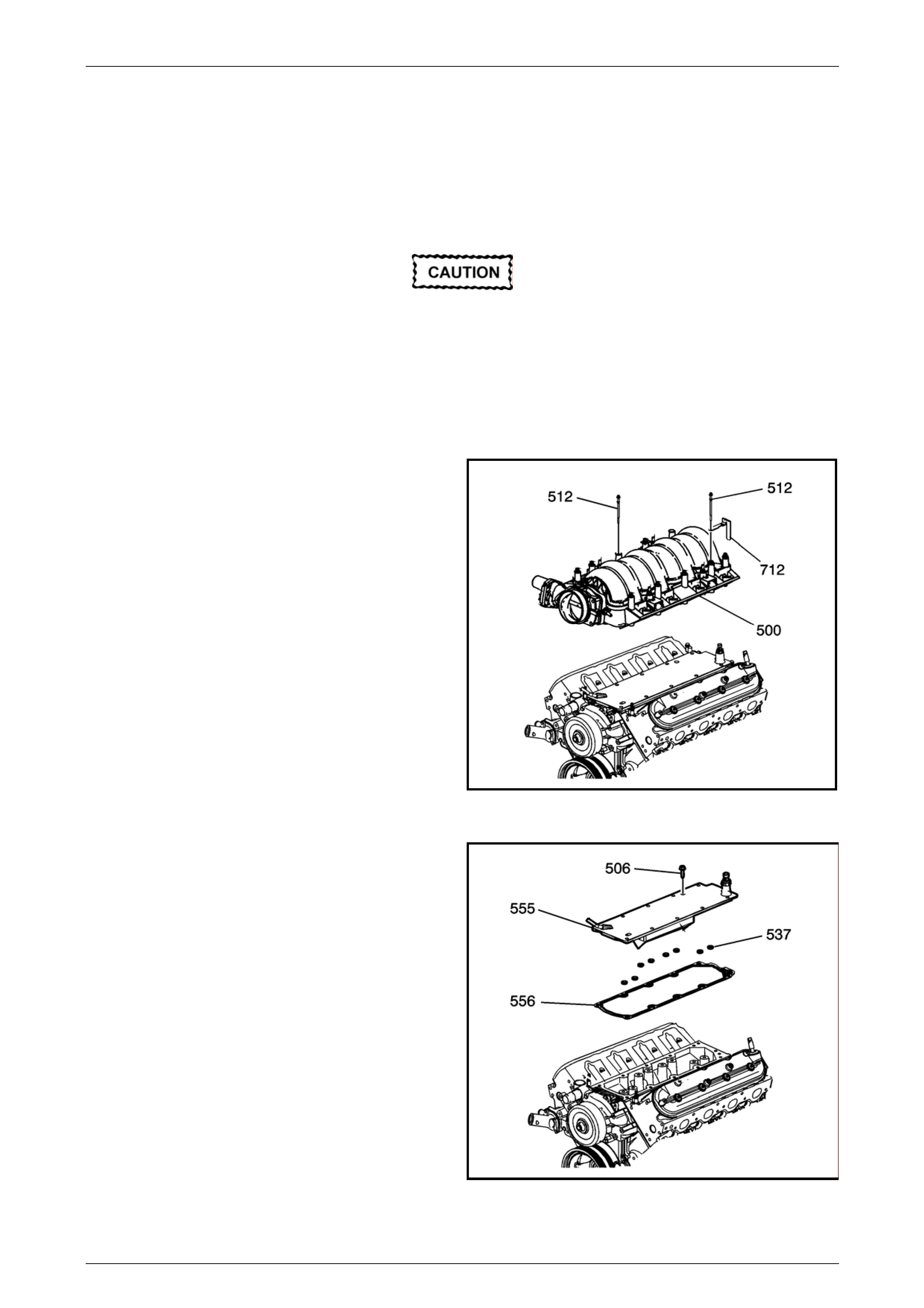
33 After removing all retaining b olts (512), Carefully tap
the intake manifold assembly (500) with a rubber
mallet to break the gasket seal and then lift it from the
engine.
34 Plug all intake manifo ld openings in the cylinder heads
to stop foreign objects from entering the engine.
1408894
Figure 6A4 – 43
35 Remove the intake manifold to cylinder head gaskets
(1) and discard the gaskets.
NOTE
New Intake manifold gaskets must be used
when reinstalling the Intake manifold.
Figure 6A4 – 44
Page 6A4 – 36
GEN IV V8 Engine Mechanical Page 6A4 – 37
Disassemble
As required, remove the following c omponents from the intake man ifold:
Manifold Absolute Pressure Sensor (MAP)
1 Remove the Manifold Absolute Pressure (MAP) sensor from the intake manifold, refer to
Section 6C4-3 Engine Manag ement – GEN IV V8 – Service Operations.
Throttle Body
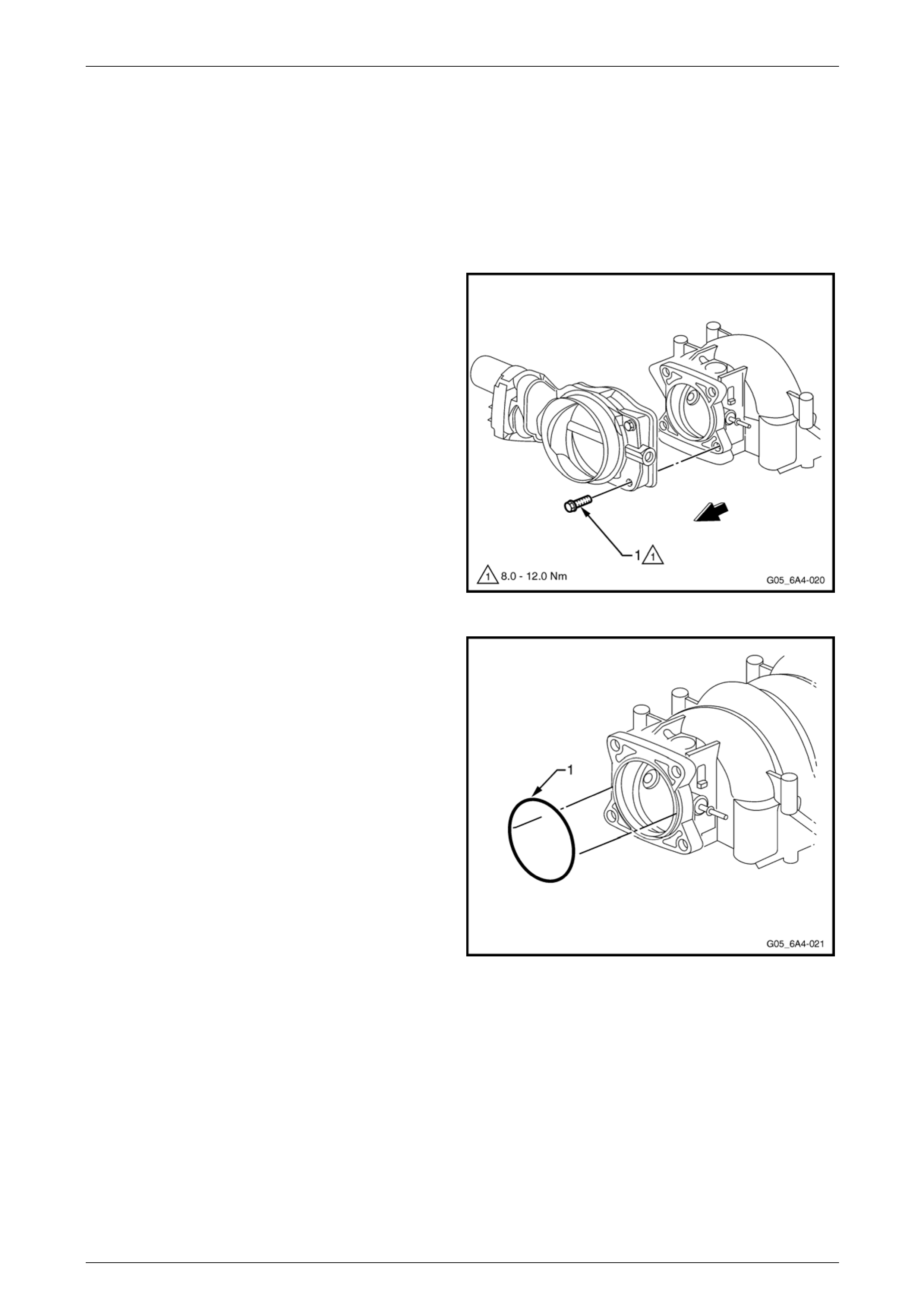
2 Remove the throttle body attaching bolt (1), four
places and remove the throttle body.
Figure 6A4 – 45
3 Remove the throttle body O-ring (1) from the Intake
manifold and discard.
NOTE
Do not re-use the throttle body O-ring.
Figure 6A4 – 46
Page 6A4 – 37

GEN IV V8 Engine Mechanical Page 6A4 – 38
Fuel Injectors
NOTE
The fuel rail and fuel injectors can be removed
without removing the intake manifold.
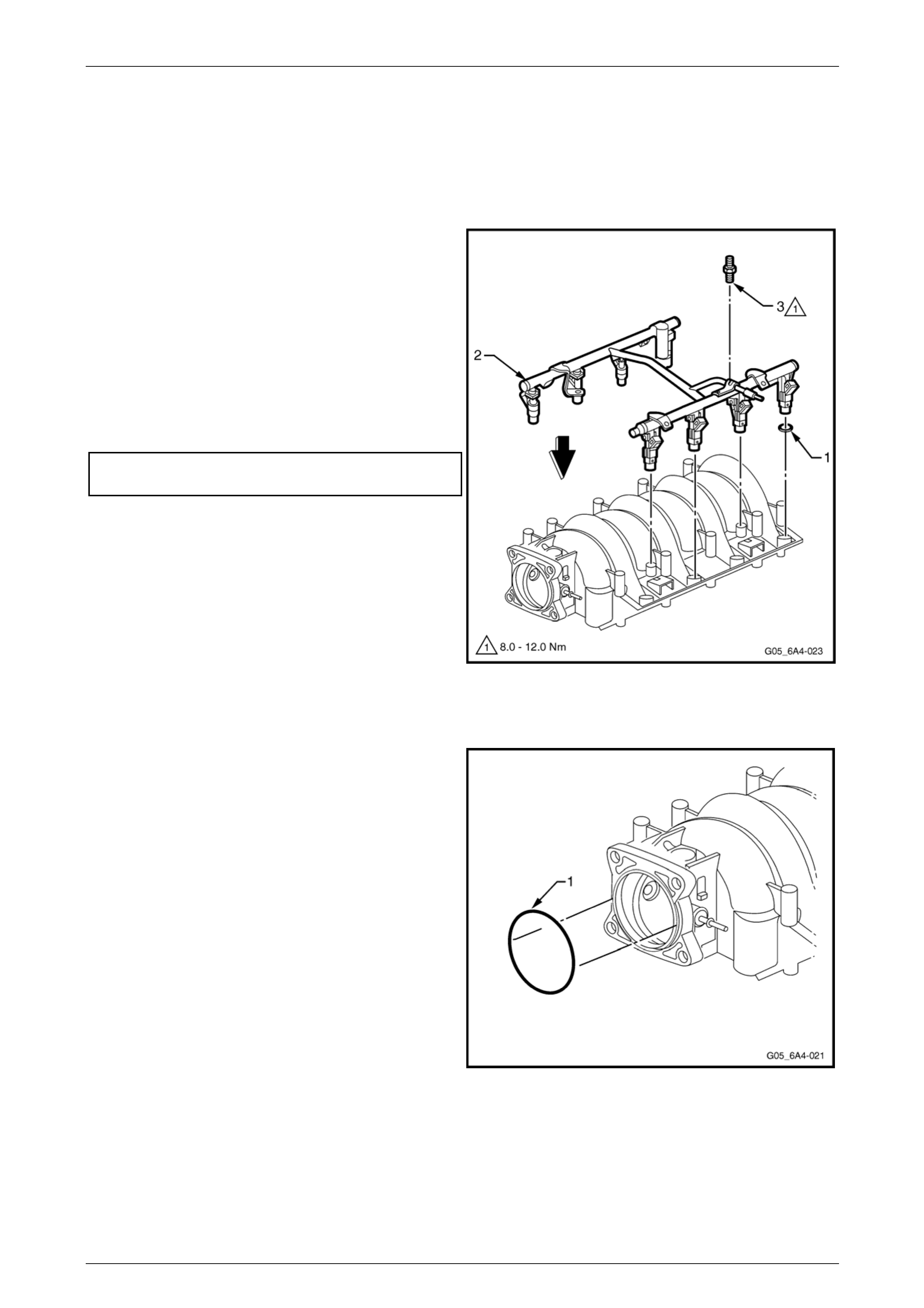
4 If removing the fuel rail with the intake manifold still
installed, remove the bolt (1) securing the ground
strap.
5 Remove the four studs (2) attaching the fuel rail (2)
and injectors to the intake manifold.
6 Lift the fuel rail and injectors assembly (3) evenly to
separate from the intake manifold.
NOTE
Should further disassembly of the fuel injectors
be required, refer to Section 6C4 Engine
Management – GEN IV V8.
3059963
Figure 6A4 – 47
Clean and Inspect
Wear the appropriate safety glasses and
gloves when using compressed air and
cleaning fluids to avoid eye and skin injury.
1 Clean the intake manifold in a commercially available cleaning fluid and then blow dry using compressed air.
2 Ensure that the intake manifold gasket grooves and the vacuum passages in the rear of the intake manifold are all
clean and clear from obstructions.
3 Inspect the throttle body and fuel rail bolt inserts in the intake manifold for looseness and/or damage d threads,
repair as required. Refer to 6 T hread Repair in Section 6A4 Engine Mechanical – GEN IV V8 of the MY 2006 VZ
Service Information.
4 Inspect the intake manifold for cracks or damage includi ng the areas between the intake runners.
5 Inspect the fuel injector bores for excessive scoring or damage.
6 Inspect the intake manifold to cylinder head faces for warpage as follows:
a Place a straight edge across each of the two surfaces and check for warpage using feeler gauges.
b An intake manifold with warpage in excess of 0.5 mm must be replaced.
Page 6A4 – 38
GEN IV V8 Engine Mechanical Page 6A4 – 39
Reassemble
Manifold Absolute Pressure Sensor (MAP)
1 Reinstall the MAP sensor, refer to Section 6C4-2 Engine Management – GEN IV V8 – Service Operations.
Fuel Rail and Injectors
2 Lubricate the new injector O-ring seals (1), eight
places, with clean engine oil.
3 Install the new O-rings onto the fuel injectors.
4 Install the fuel rail and injector assembly (2) into the
intake manifold, pressing even ly on each side until the
injectors are all full y seated i n their bores.
5 Apply a 5 mm band of thread sealant such as Loctite
242 or equivalent to the cleaned threads of the fuel rail
attaching studs (3), four places, and install.
6 Tighten the studs to the correct torque specification.
Fuel rail attaching studs
torque specification...............................................10 Nm
Figure 6A4 – 48
Throttle Body
7 Install a new throttle body O-ring (1) to the intake
manifold, ensuring it is pressed firmly into place.
Figure 6A4 – 49
Page 6A4 – 39
GEN IV V8 Engine Mechanical Page 6A4 – 40
8 Install the throttle body (1), ho lding it in place by hand.
9 Install the throttle body attac hi ng bolt (2), four places,
and tighten to the correct torque specification.
Throttle body attaching bolt
torque specification...............................................10 Nm
Figure 6A4 – 50
Reinstall
1 Install the eight new intake manifol d to cylinder head gaskets, refer to Figure 6A4 – 44, and then carefully lower the
intake manifold assembly (1) to the c ylinder h eads.
2 Sparingly appl y thread sealant such as Loctite 242 or
equivalent, to the cleaned threads of the two central
intake manifold attaching bolts (512) and then tighten
these by hand.
3 Sparingly appl y thread sealant such as Loctite 242 or
equivalent, to the cleaned threads of the eight
remaining intake manifold attaching bolts.
Do not overlook installing the two fuel stop
brackets (712) – one on each side. The stop
brackets serve as a protective shield for the
fuel rails in the event of a vehicle front end
collision. If the fuel rail stop brackets are not
installed and the vehicle is involved in a
collision, the rails may become damaged.
This can cause the pressurised fuel in the
rails to leak, possibly causing a fire and
personal injury from burns. The fuel stop
brackets are attached by bolts (3, 9, 5 and 8),
refer to Figure 6A4 – 52.
4 Install the remaining intake manifold bolts, including
the two at the rear on each side, which also attach the
fuel rail stop brackets.
3059977
Figure 6A4 – 51
Page 6A4 – 40
GEN IV V8 Engine Mechanical Page 6A4 – 41
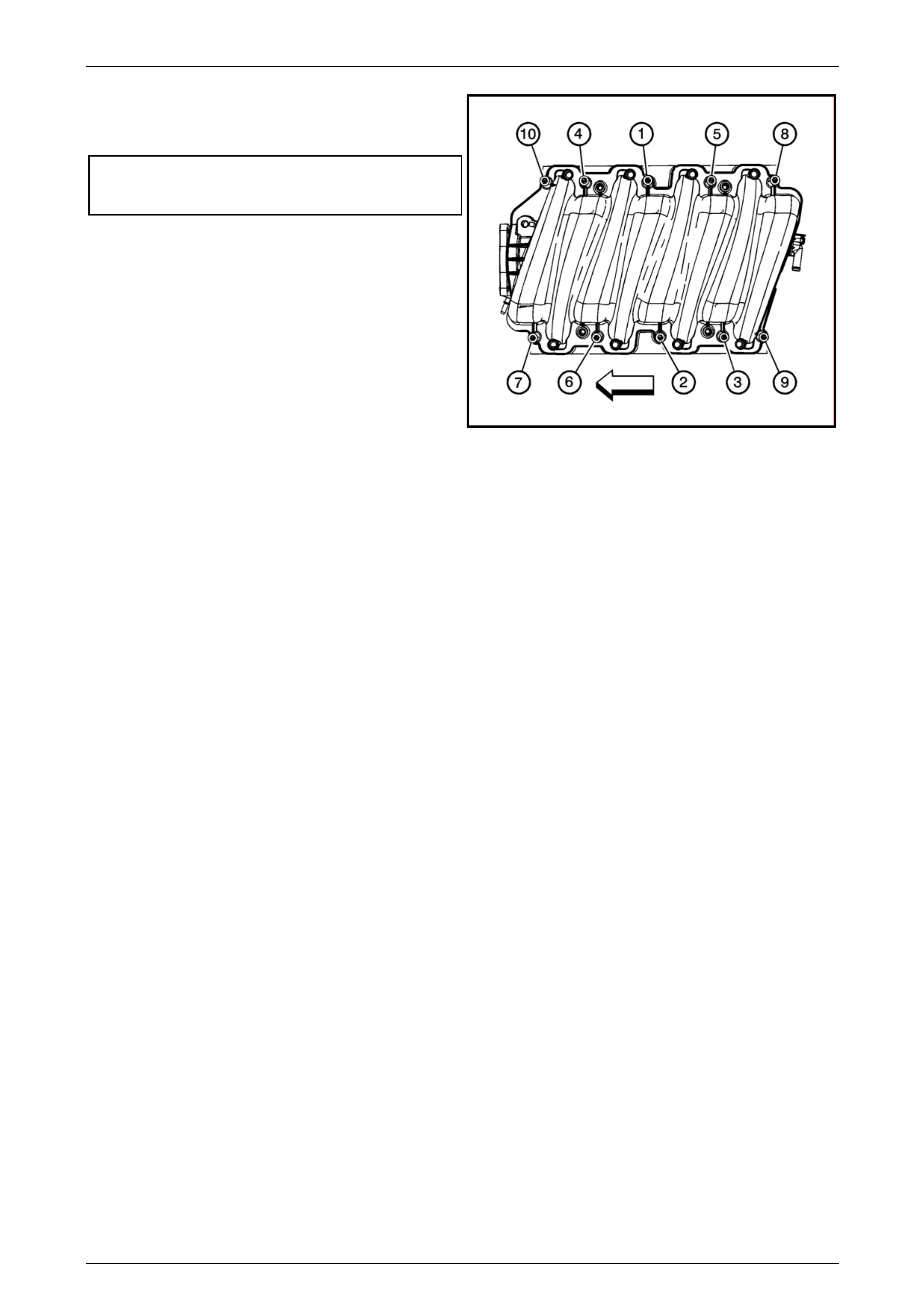
5 Tighten the ten intake manifold bolts in two stages in
the sequence shown to the correct torque
specification.
Intake manifold bolts torque specification
Stage 1 ...................................................................5 Nm
Stage 2 .................................................................10 Nm
NOTE
The fuel stop brackets are attached by bolts (3, 9
and 5, 8).
1552512
Figure 6A4 – 52
6 Reinstall all pipes/hoses and electrical connectors in the reverse to the removal process.
7 The remainder of the intake manifold installation is the reverse to the removal process.
Page 6A4 – 41
GEN IV V8 Engine Mechanical Page 6A4 – 42
3.7 Coolant Vapour Vent Pipe and Covers
LT Section No. — 00–249
Remove
1 Remove the intake manifold, refer to 3.6 Intake Manifold Assembly.
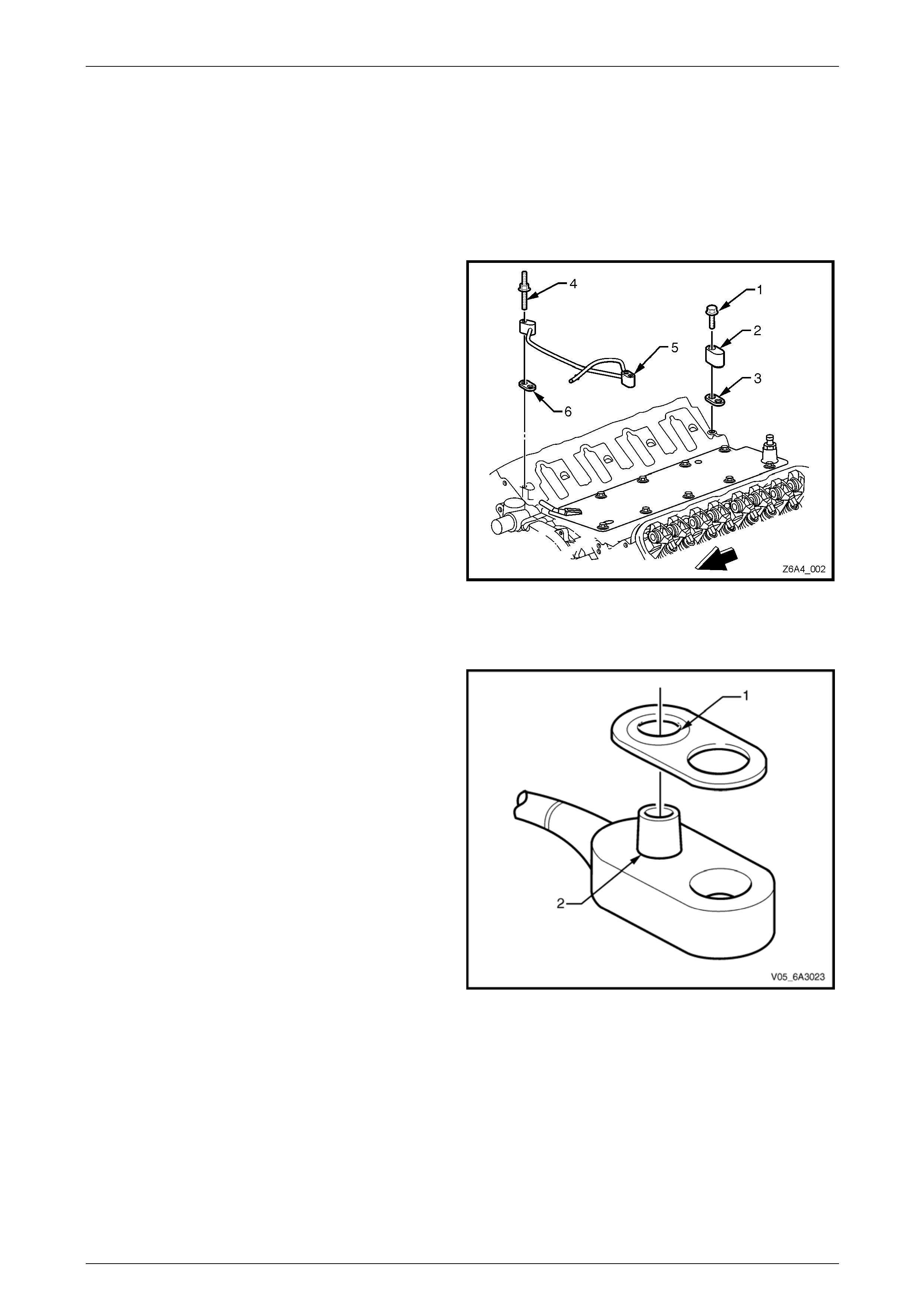
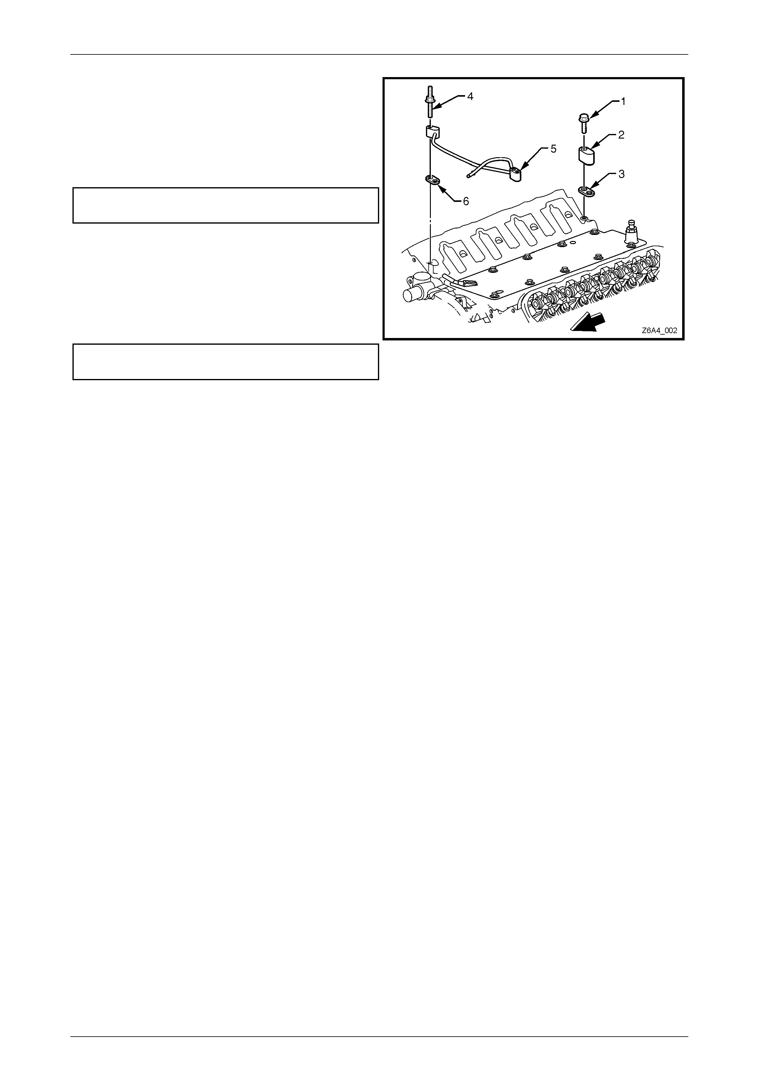
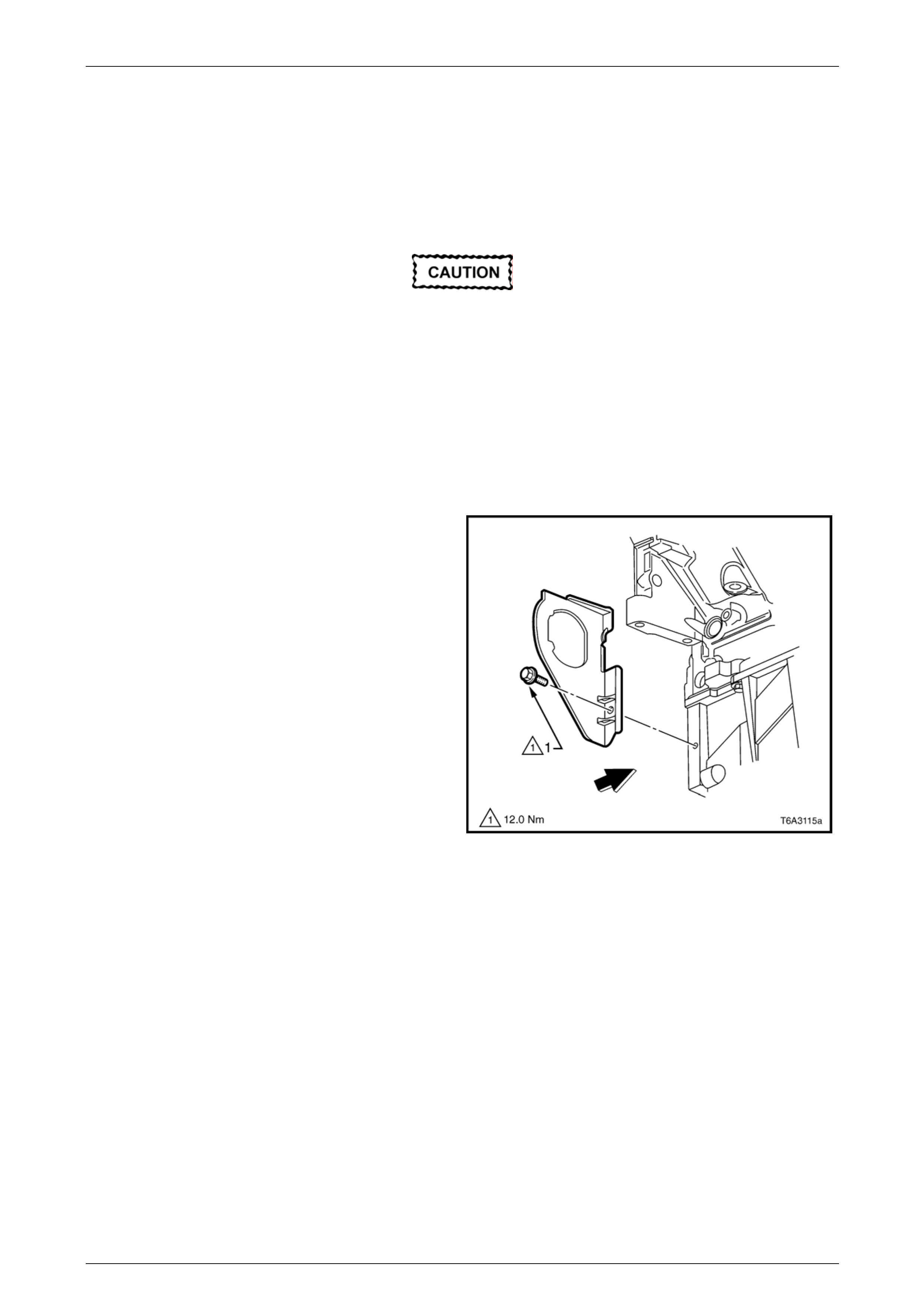
2 If required, remove the attaching bolt (1) from the rear
engine coolant vapour ble ed vent cover (2).
3 Remove the cover and gasket (3) and discard the
gasket. If required, repeat for the other vapour vent
cover (not shown).
4 Remove the vapour vent pipe double ended stud (4) in
two places, attaching the vapour vent pipe (5) to the
cylinder heads.
5 Remove the vapour vent pipe and gaskets (6).
6 Discard both gaskets.
Figure 6A4 – 53
Reinstall
1 Correctly install a new vapour pip e gasket by fitting the
O-ring seal section (1) over the pipe fitting ni pple (2).
Figure 6A4 – 54
Page 6A4 – 42
GEN IV V8 Engine Mechanical Page 6A4 – 43
2 Install NEW engine coolant air bleed pipe seals (3) to
the two rear coolant air bleed covers (2).
3 Reinstall each of the coolant air bleed covers (2) to the
cylinder heads and secure with a bolt (1) in each.
4 Tighten the two bolts to the correct torque
specification.
Coolant air bleed cover
bolt torque specification........................................12 Nm
5 Install NEW engine coolant air bleed pipe seals (6) to
the coolant air bleed pipe (5).
6 Reinstall the coolant air bleed pipe to the cylinder
heads, securing with a double ended stud.
7 Tighten the double ended studs to the correct torque
specification.
Coolant air bleed pipe
stud torque specification .......................................12 Nm
8 Reinstall the intake manifold, refer to
3.6 Intake Manifold Assembly.
Figure 6A4 – 55
Page 6A4 – 43
GEN IV V8 Engine Mechanical Page 6A4 – 44
3.8 Engine Valley Cover
LT Section No. —
Remove
Disconnection of the battery affects certain
vehicle electronic systems. Refer to
Section 00, 5 Battery Disconnection
Procedures in the MY 2006 VZ Service
Information before disconnecting the battery.
1 Disconnect the negative batter y cable terminal from the battery.
2 Drain the cooling system. Refer to Section 6B4 Engine Cooling – GEN IV V8.
3 Remove the intake manifold (500). Refer to
3.6 Intake Manifold Assembly
4 Remove the coolant vapour vent pipe. Refer to
3.7 Coolant Vapour Vent Pipe and Covers (already
removed in the view shown).
1408894
Figure 6A4 – 56
5 Remove the bolt (506), 11 places, attachin g the
valley cover (2) to the c ylinder block.
6 Remove the valley cover and gasket (3) from the block
and discard the gasket.
1408897
Figure 6A4 – 57
Page 6A4 – 44
GEN IV V8 Engine Mechanical Page 6A4 – 45
Clean and Inspect
Wear the appropriate safety glasses and
gloves when using compressed air and
cleaning fluids to avoid eye and skin injury.
1 Clean the valley cover in a co mmercially available cleaning fluid and blow dry using compressed air.
2 Clean the gasket surface with a plastic scraper or similar.
NOTE
Do not use a metal scraper to remove gaskets.
as damage to aluminium components can occur
resulting in oil leaks.
3 Inspect the valley cover sealing surfaces for excessive scratches or other damage.
4 Ensure the fixed internal flow-restricting orifice is clean and free from foreign obstructions.
Reinstall
Reinstallation of the valley cover is the reverse of the removal procedure noting the following:
1 Install a new gasket to the valley cover and install the cov er to the engine.
2 Install the 10 valley cover attaching bolts and tighten to the correct torque specification.
Valley cover attaching bolt
torque specification...............................................25 Nm
3 Reinstall the intake manifold, including the fuel rail stop brackets, during the intake manifold reinstallation
procedure. Refer to 3.6 Intake Manifold Assembly.
The stop brackets s erve as a pro tecti ve shield
for the fuel rails in the event of a vehicle front
end collision. If the fuel rail stop brackets are
not installed and the vehicle is involved in a
collision, the rails may become damaged.
This can cause the pressurised fuel in the
rails to leak, possibly causing a fire and
personal injury from burns. The fuel stop
brackets are attached by bolts (3, 9, 5 and 8),
refer to Figure 6A4 – 52.
4 Install the remaining intake manifo ld bolts, including the two at the rear on each side, which also attach the fuel rail
stop brackets.
Page 6A4 – 45
GEN IV V8 Engine Mechanical Page 6A4 – 46
3.9 Hydraulic Valve Lifters
LT Section No. — 00–050
Remove
NOTE
Store all removed valve train components in the
same order they were removed. This will ensure
that when they are reinstalled in the same
relationship as on removal.
1 Remove the cylinder head on the side requiring the hydraulic valve lifter removal. Refer to 4.15 Cylinder Head in
Section 6A4 Engine Mechanical – GEN IV V8 of the MY2006 VZ Service Information.
2 Remove the valve lifter. Refer to Valve Lifter Removal
NOTE
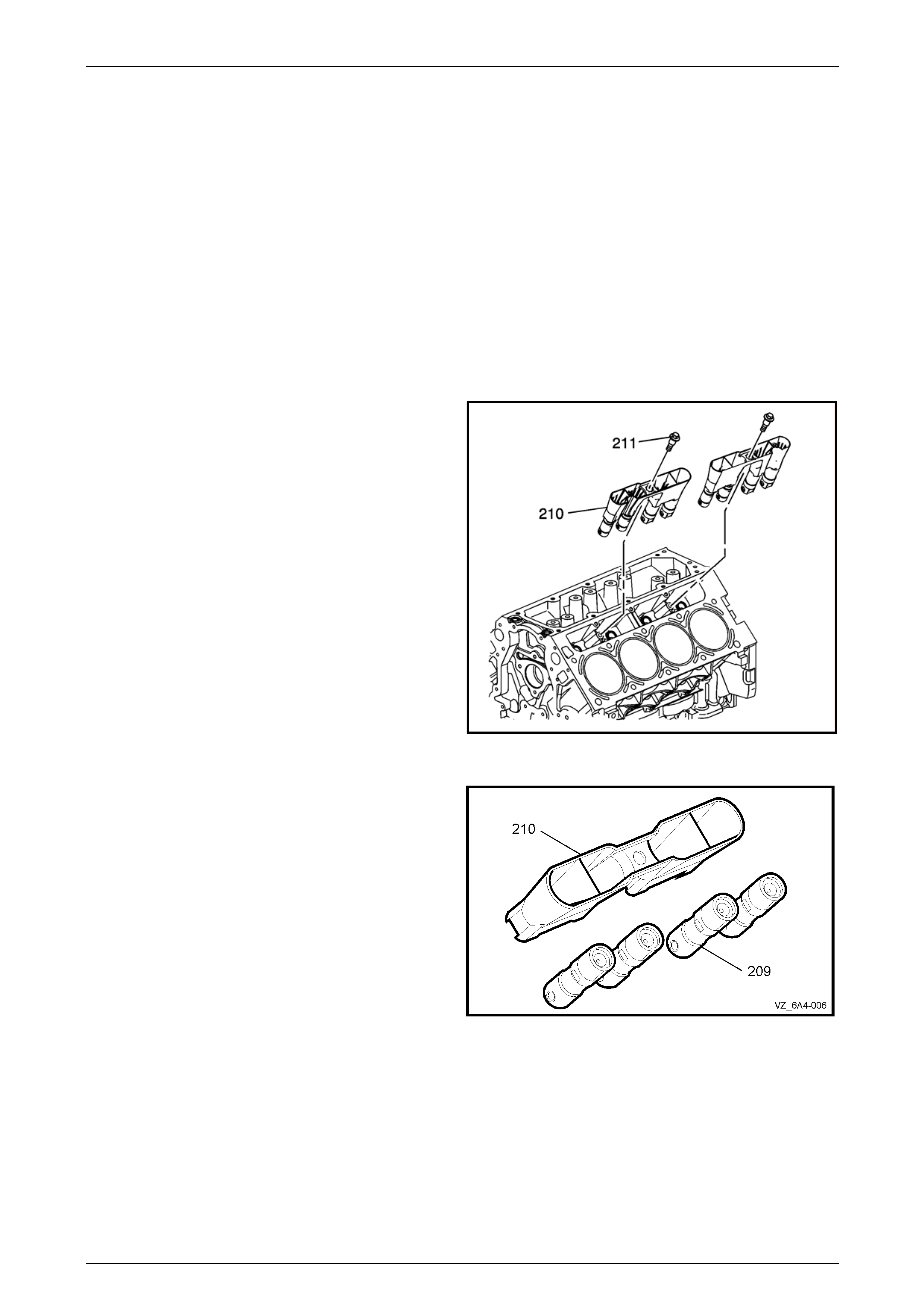
There is one retaining bolt and four hydraulic
valve lifters in each guide.
3 Clean and inspect the valve lifters. Refer to Valve
Lifters and Guides Cleaning and Inspection ..
NOTE
Use care when removing the hydraulic valve
lifter guide as the hydraulic valve lifter may fall
out of the guide while the guide is being
removed.
1403318
Figure 6A4 – 58
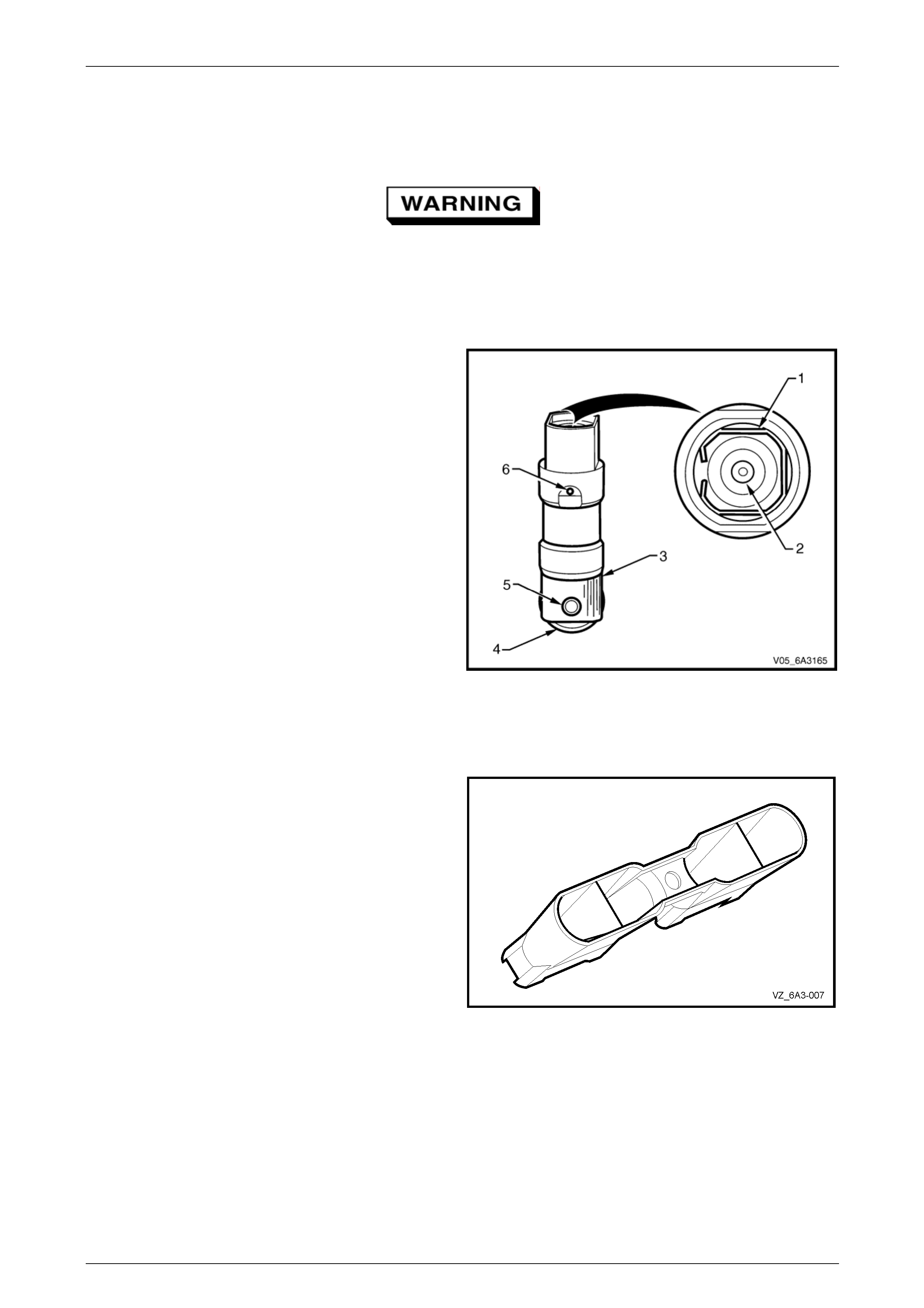
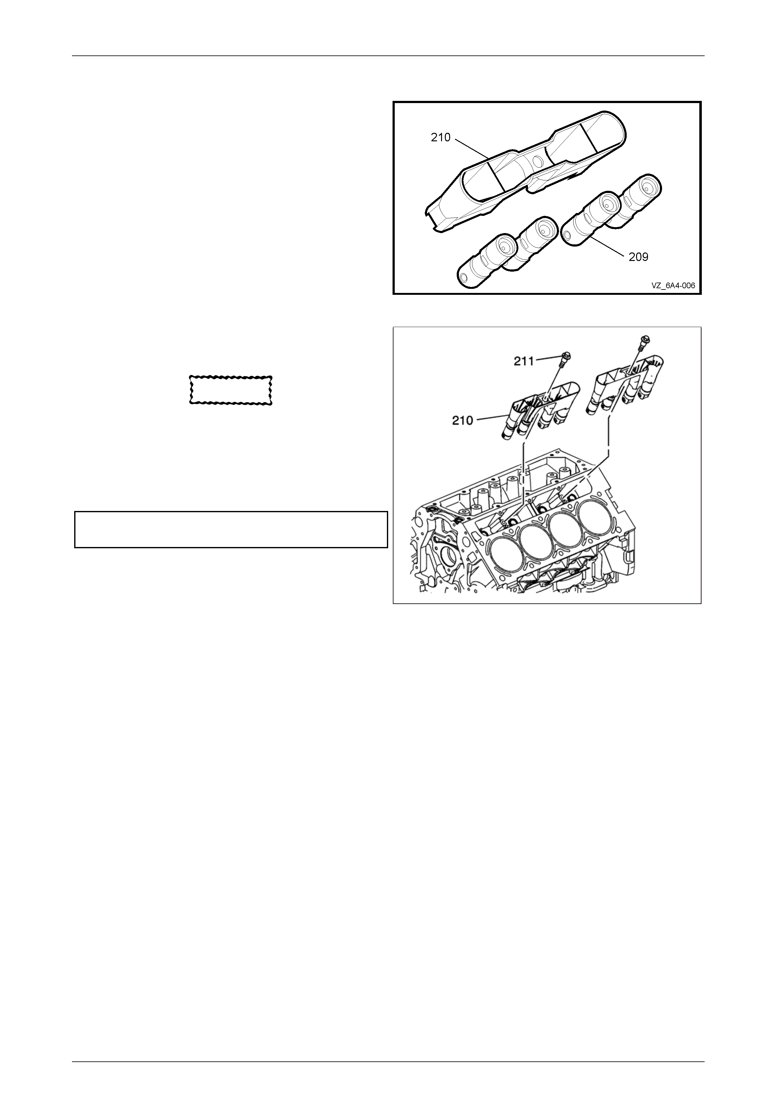
4 Remove the valve lifters (209) from the guide (210).
Figure 6A4 – 59
Page 6A4 – 46
GEN IV V8 Engine Mechanical Page 6A4 – 47
Disassemble
1 Organise or mark (e.g. felt tipped pin) the components
to ensure that each lifter is reinstalled in its origin al
location.
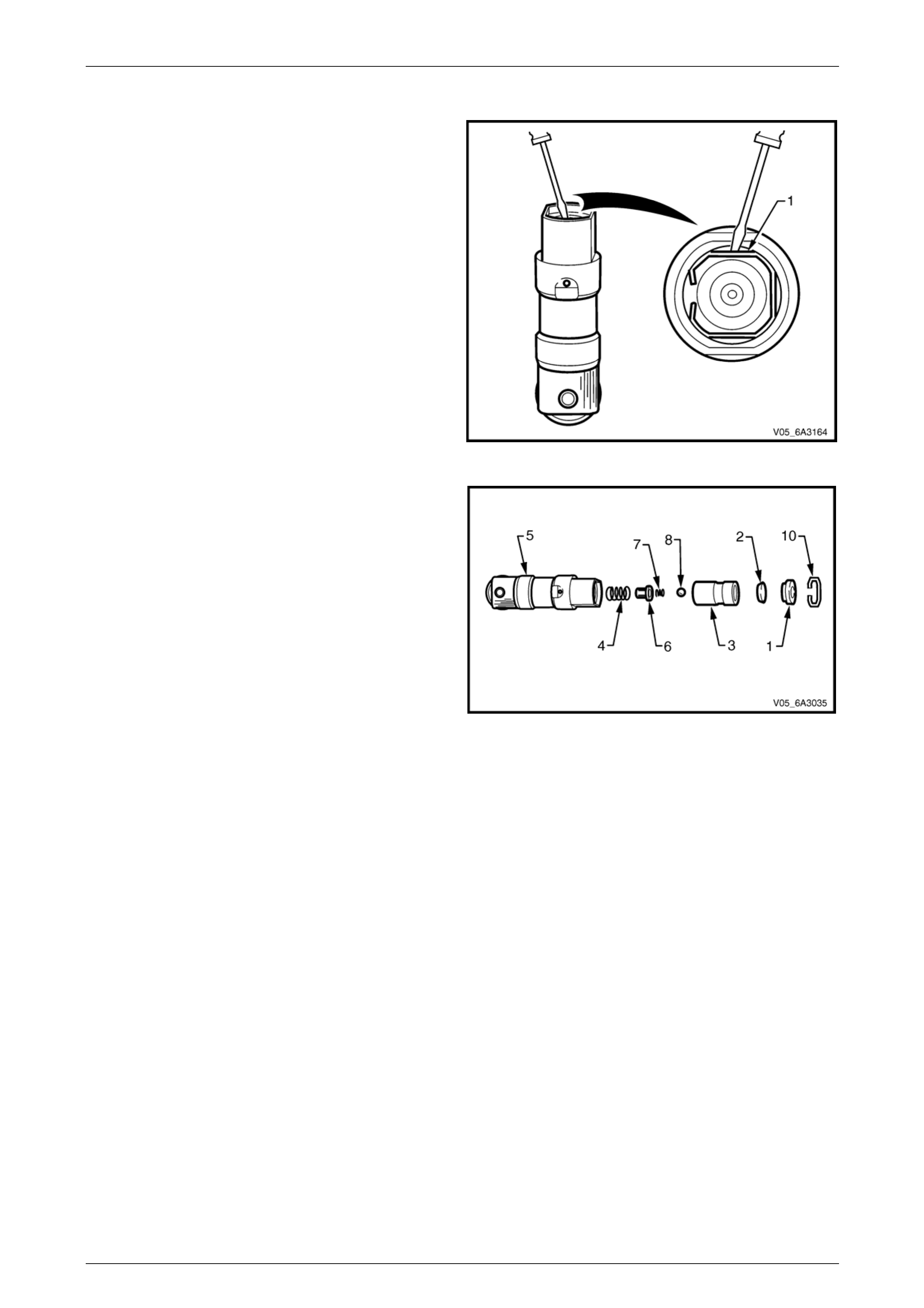
2 Remove the push rod seat retaining clip (1) by using a
small flat bladed screwdriver and carefu lly prising the
clip out of the groove in the lifter.
Figure 6A4 – 60
3 Remove in order the following:
• Push rod seat (1).
• Oil metering valve (2).
• Plunger assembly (3).
• Plunger spring (4) from the lifter body (5).
NOTE
If the plunger is stuck in the lifter body, turn the
lifter body upside down and tap the lifter body on
a block of wood. If this is not effective, soak the
lifter assembly in a suitable cleaning fluid.
4 Remove the ball check retainer (6), ball check spring
(7) and ball (8) from the plunger.
Figure 6A4 – 61
Page 6A4 – 47
GEN IV V8 Engine Mechanical Page 6A4 – 48
Clean and Inspect
It is recommended the hydraulic valve lifter b e repl aced if faulty. However, cleaning of the lifter can remove a build up of
deposits that sometimes can cause the lifter internals to stick causing valve train noise.
To avoid personal injury, wear safety glasses
and the appropriate gloves when using
compressed air an d cleaning fluids.
1 Thoroughly cle an all parts in a commercially available cleaning flu id and blow all the parts dry using compressed
air.
2 Inspect the valve lifters for:
• Bent or broken clip (1).
• Worn pushrod socket (2). If the seat is worn,
inspect the matching push rod and rep lace the
push rod if worn.
• Scuffed or worn lifter body (3).
NOTE
Inspect the lifter bore in the cylinder block.
• Worn or damaged roller bearing (4). Replace the
lifter if the roller binds or roughness can be f elt.
• Loose or damaged p in (5).
• Partially blocked oil hole (6).
NOTE
If the roller bearing on the lifter is worn, inspect the
camshaft for wear. If worn, replace the camshaft, refer
to Section 6A4 Engine Mechanical - GEN IV V8, in the
MY 2006 VZ Service Information.
Figure 6A4 – 62
3 Inspect the valve lifter guides for:
• Cracks or damage.
• Excessive wear in the lifter mounting b ores.
Figure 6A4 – 63
Page 6A4 – 48
GEN IV V8 Engine Mechanical Page 6A4 – 49
Reassemble
NOTE
Do not attempt to recondition a lifter by taking
parts from other unserviceabl e lifters. Cleanliness
is extremely important when handling valve
lifters. Lint or dirt can result in a failed lifter.
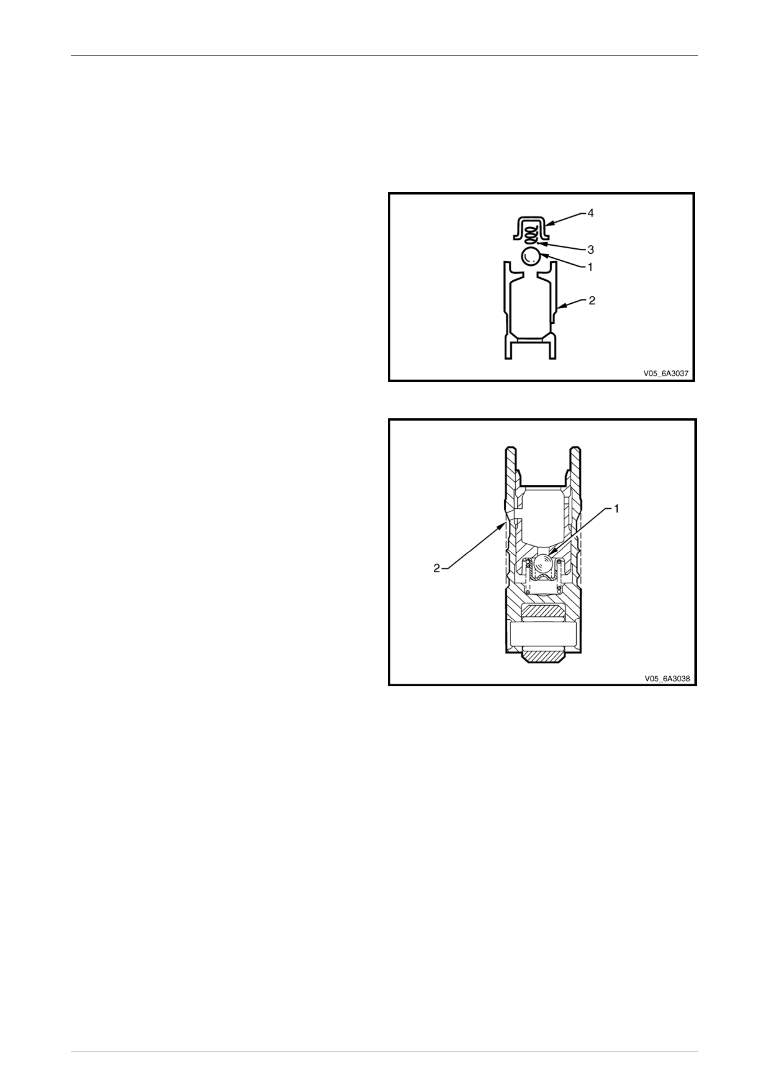
1 Place the check ball (1) over the smal l hole in the
plunger (2).
2 Carefully place the check ba ll spring (3) and the
retainer (4), over the check ball and press the retainer
into position within the plun ger with a small flat blade
screwdriver.
3 Half fill the valve lifter body with the test fluid SPX No.
E1151 or oil with a viscosity rating of 10W.
Figure 6A4 – 64
4 Reinstall the plunger spring into the lifter body.
5 Install the plunger assembly in the body taking care to
align oil feed holes (2).
6 Using a 1 mm diameter pin punch or sim ilar, unseat
the check ball (1) in the plunger then push the plunger
down to the full extent of its travel.
7 Use Tool 6A24 (or a suitable sized p in punch) to align
the oil feed holes (2) in the body and plunger.
8 Fill the lifter with specified test fluid.
9 Reinstall the oil metering valve, push rod seat (cup
side facing out) and the retaining clip.
Figure 6A4 – 65
Page 6A4 – 49
GEN IV V8 Engine Mechanical Page 6A4 – 50
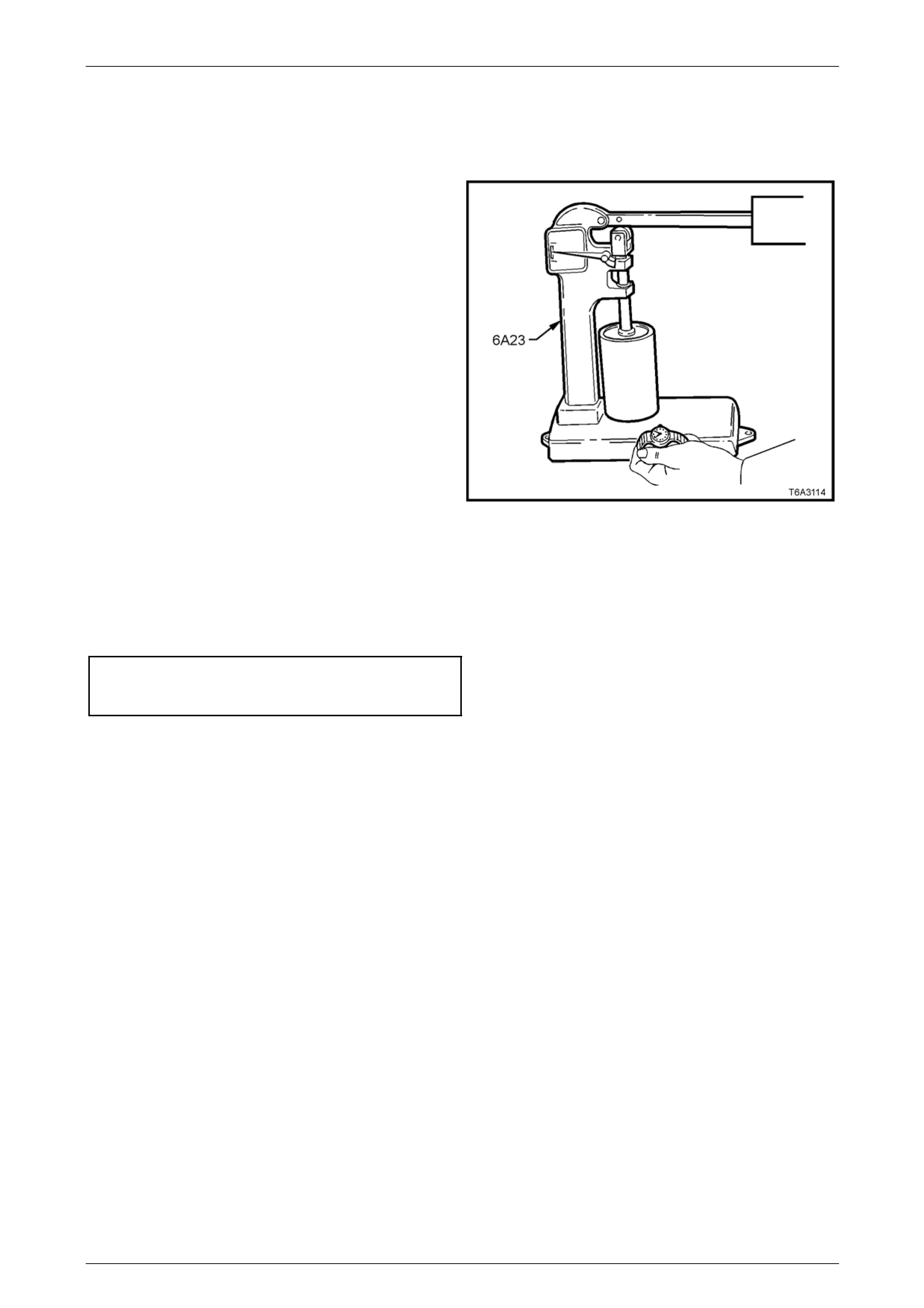
Testing Lifter Leak-down Rate
After the hydraulic lifter has been cleaned, inspected and reassembled, it must be tested before being reinstalled. Lifter
test fixture Tool No 6A23 has been designed to test the leak-down rate of the lifter to ensure the lifter will operate as
intended when reinstalled.
2 Ensure the test cup is clean. Install the cup on the
fixture and place the lifter in the cup.
NOTE
Some versions of Tool No. 6A23 may require
modification to hold the base of the lifter inside
the tester cup.
2 Add the test fluid SPX No. E1151 or engine oil with a
viscosity rating of 10W to completely cover the
hydraulic valve lifter when in Tool No 6A23.
3 Place the ball bearing supp lied with the test fixture in
the push rod seat of the hydraulic v alve l ifter.
4 Lower the test fixture ram so it can rest on the ball
bearing.
5 Operate the lifter plunger through its maximum travel
to force all the air out of the lifter by using a vigorous
pumping action on the test fixture weight arm.
Continue the pumping action until considerable
resistance is built up in the lifter and the lifter becomes
solid.
Figure 6A4 – 66
6 Raise the weight arm to allow the lifter plunger to come up to its retainer then lower the arm to rest on the ram.
7 Using a stop watch, measure the time required for the indicator needle on the tester to travel from the Start position
to the 0.125" position on the scale a nd ensure the lifter is within the specified limit.
Hydraulic valve lifter bleed
down rate specified limit:
Start to 0.125" stroke ...........................10 to 30 sec onds
NOTE
A suspect lifter should be tested several times
before being discarded. Cl ean the test fixture cup
and refill with clean test fluid after several lifters
have been tested.
8 Stand the tested lifters in an upright position so the fluid does not drain from the oil holes.
Page 6A4 – 50
GEN IV V8 Engine Mechanical Page 6A4 – 51
Reinstall
NOTE
• When the original v alve lifters are bein g
re-used, install them in their original
locations.
• If camshaft replacement is required, the
valve lifters must also be replaced.
1 Lubricate the valve lifters (209) and engine block valve
lifter bores with clean engine oil.
2 Insert the valve lifters into the lifter guides (210).
Figure 6A4 – 67
3 Install the valve lifters and guide assembl y (210) to the
engine block.
CAUTION
Refer to Fastener Notice in Section 00
Cautions, Warnings and Notes in the MY2006
VZ Service Information.
4 Install the valve lifter guide bolts (211) and tighten to
the specified torque.
Valve lifter guide bolts
torque specifications .............................................10 Nm
1403318
Figure 6A4 – 68
Page 6A4 – 51
GEN IV V8 Engine Mechanical Page 6A4 – 52
3.10 Crankshaft Balancer
LT Section No. — 00–540
Remove
Disconnection of the battery affects certain
vehicle electronic systems. Refer to
Section 00 Warnings, Cautions and Notes
before disconnecting the battery.
1 Disconnect the ground battery cable termi nal from the battery.
2 Remove the radiator, refer to Section 6B4 Engine Cooling – GEN IV V8.
3 Remove the engine accessory and air conditioner drive belts. Refer to 4.6 Engi ne Drive Belts and Pulleys in
Section 6A4 Engine Mechanical GEN IV V8.
4 Remove the starter motor. Refer to Section 6D3-2 Starting System – GEN IV V8.
5 Remove the bolt (1), attaching the right-hand close- out
cover to the cylinder block.
NOTE
The close out covers seal off the area between
the cylinder block and transmission assembly.
Figure 6A4 – 69
Page 6A4 – 52
GEN IV V8 Engine Mechanical Page 6A4 – 53
NOTE
Ensure the teeth of the holding tool engage
correctly with the ring gear before tightening the
fasteners.
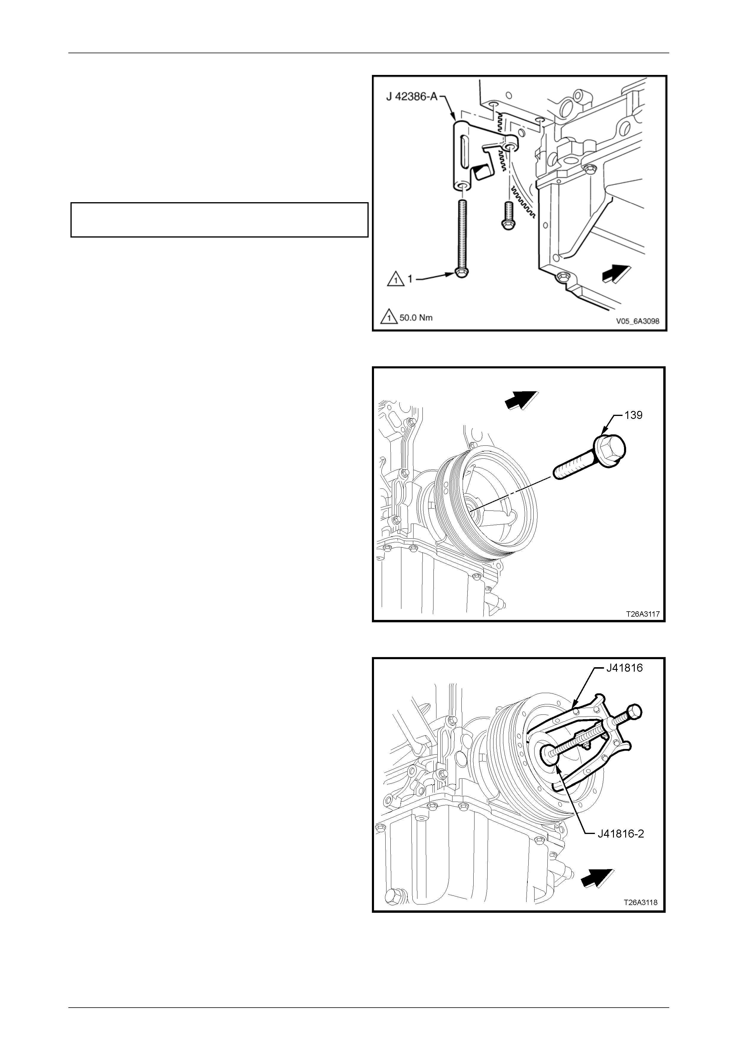
6 Using the two starter motor bolts, install the ring gear
holding Tool No. J 42386-A a nd tighten the bolts to the
correct torque specification.
Ring gear holding tool, Tool NO. J 42386-A
attaching bolt torque specification.........................50 Nm
Figure 6A4 – 70
7 Remove the bolt (1) attaching the crankshaft bal ancer.
NOTE
Do not discard the bolt at this stage, as it will be
required later for the installation process. The
crankshaft bolt is to be replaced during the final
stage of the assembly procedure.
Figure 6A4 – 71
8 Use the crankshaft end protector, T ool No. J 41816-2
and puller, Tool No.J41816 or equivalent to remove
the crankshaft balancer.
Figure 6A4 – 72
Page 6A4 – 53
GEN IV V8 Engine Mechanical Page 6A4 – 54
Clean and Inspect
To avoid personal Injury, wear safety glasses
and the appropriate gloves when using
compressed air an d cleaning fluids.
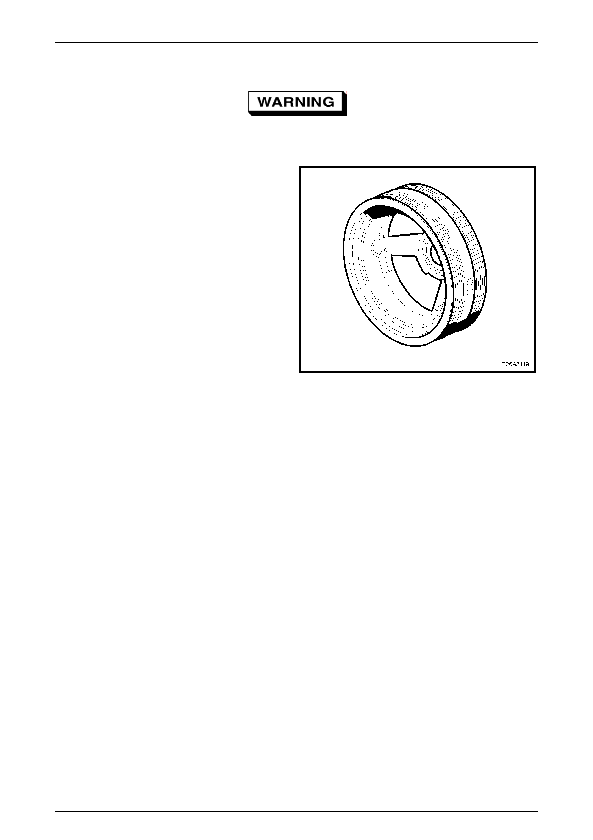
1 Clean the crankshaft balancer in a suitable cleaning
fluid and dry the crankshaft bala ncer using
compressed air.
NOTE
Do not use solvent based cleani ng fluids to clea n
the crankshaft balancer as this may damage the
rubber in the balancer.
2 Using a wire brush, clean the belt gro oves to remove
all dirt or debris.
3 Inspect the crankshaft balancer for:
• Excessive scoring, grooves or rust on the hub
seal surface. Minor imperfections on the hub
seal surface may be removed with a polishing
compound or a fine grade of em ery cloth.
• Rusted or damaged belt grooves.
• Worn, chunking or deteriorated rubber between
the hub and pulley.
NOTE
The balancer belt grooves should be free of any
nicks, gouges, or other damage that may not
allow the belt to track correctly. For the belt to
track correctly, the belt grooves should be free of
all dirt or debris. Minor imperfections may be
removed with a fine file.
Figure 6A4 – 73
Reinstall
NOTE
The crankshaft balancer reinstallation and bolt
tightening involves a multi-stage tightening
process. The first pass uses the used bolt and
ensures the balancer is fully installed. The
remaining stages tighten the new bolt to the
correct torque specification.
1 Ensure the teeth of the ring gear locking T ool No. J 42386-A are correctly engaged.
2 Apply a smear of clean engine oil onto th e seal surface of the balancer then install the bal ancer onto the end of the
crankshaft.
NOTE
The balancer should be positioned onto the end
of the crankshaft as straight as possible before
the tool installation.
Page 6A4 – 54
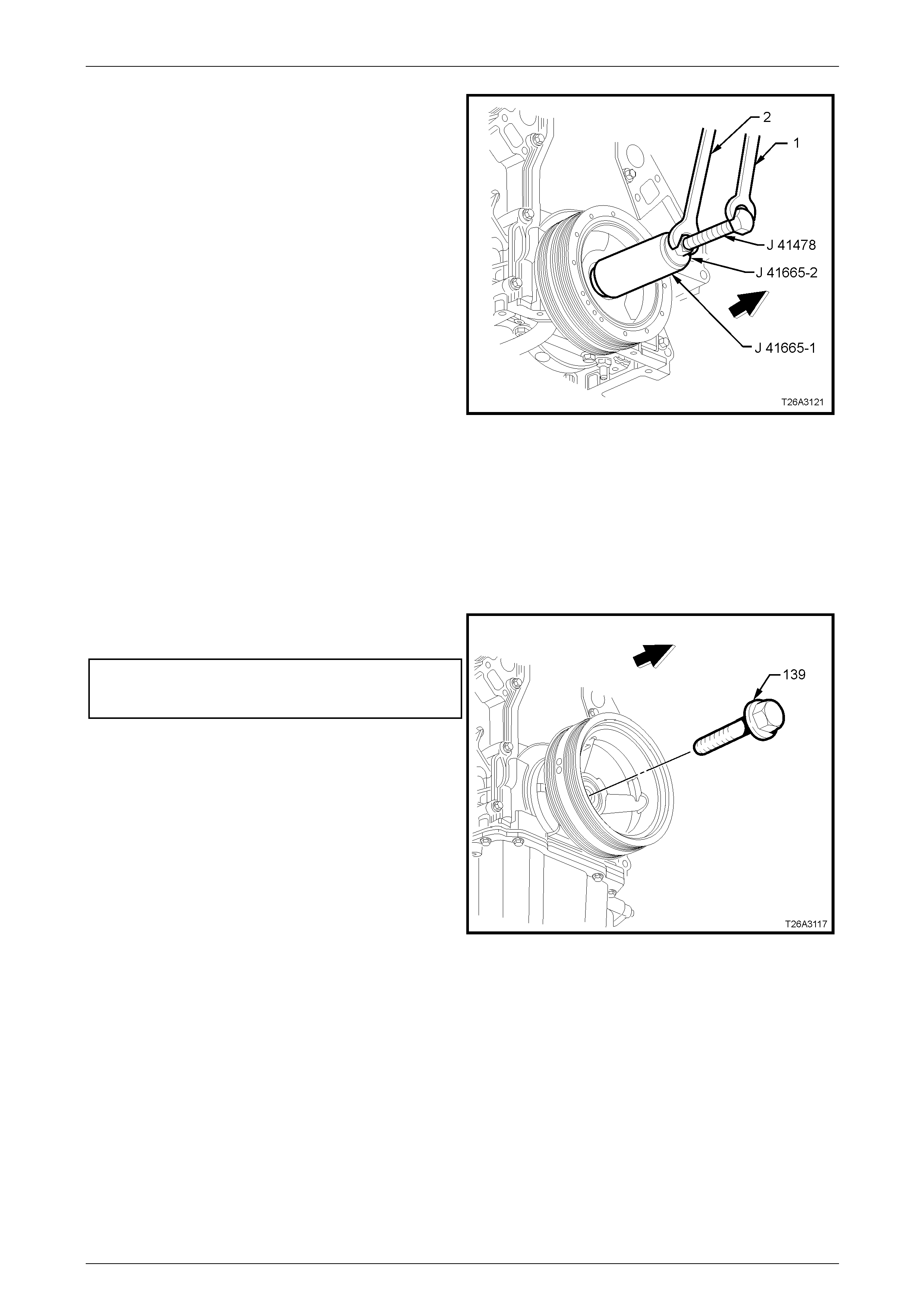
GEN IV V8 Engine Mechanical Page 6A4 – 55
3 Use installer, Tool No. J 41665 and instal l the tool to
the crankshaft balancer as follows:
a Select the threaded rod, nut, washer and
installer from Tool No. J 41478.
b Insert the installer sleeve, Tool No. J 41665-1
into the front of the balancer and back up with
the plate, Tool No. J 41665-2.
NOTE
Insert the stepped end of sleeve Tool No.
J 41665-1 into the balancer in this initial stage.
4 Use a suitable spanner (1) to hold the he xagonal end
of the threaded rod. Use a second spanner (2) to
rotate the installation tool nut clockwise until the
balancer is started onto the crankshaft.
5 Remove the stepped sleeve of Tool No. J 41665-1 and
reverse it so the larger end of the installer is against
the front of the balancer.
6 Use a suitable spanner to hold the hexagonal end of
the threaded rod. With a second spanner, rotate the
installation tool nut clockwise until the balancer is
installed into the crankshaft.
7 Remove the balancer installation tool.
Figure 6A4 – 74
8 Reinstall the engine accessory and air conditioner drive belt s. Refer to 4.6 Engine Drive Belts and Pulleys in
Section 6A4 Engine Mechanical GEN IV V8.
9 Install the used crankshaft balancer bolt (139) and
tighten to the correct torque specification.
Crankshaft balancer installation
torque specification
Used Bolt (stage 1).............................................150 Nm
10 Remove the used balancer bolt and discard.
Figure 6A4 – 75
Page 6A4 – 55
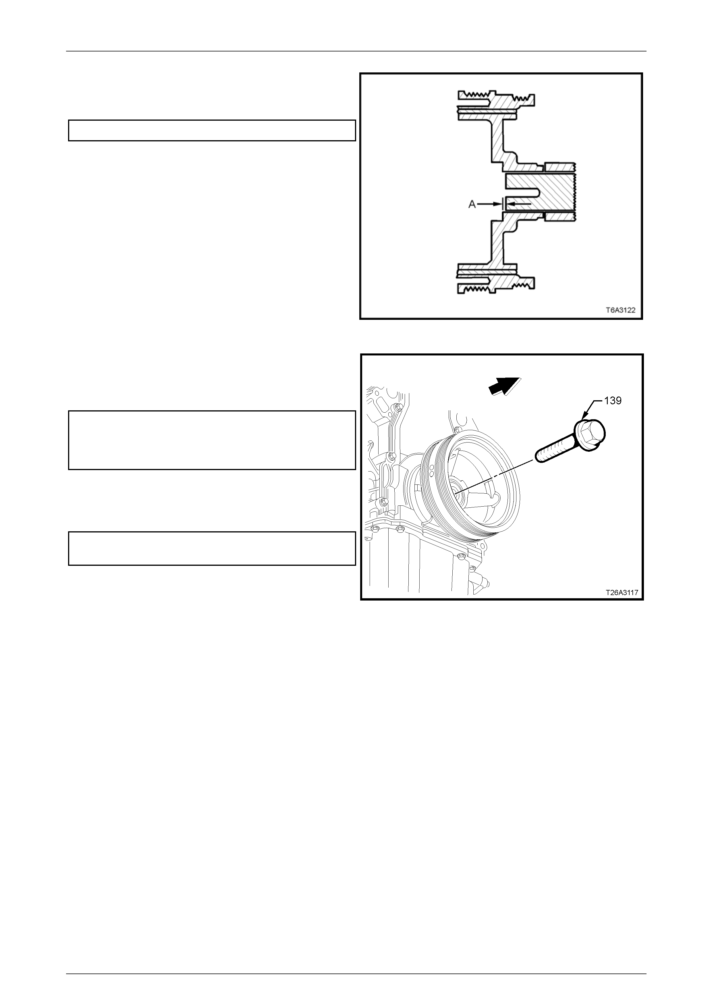
GEN IV V8 Engine Mechanical Page 6A4 – 56
11 Measure the distance the balancer protrudes from the
crankshaft nose and ensure dimension (A) is to
specification.
Dimension (A)........................................ 2.40 – 4.48 mm
12 If the dimension is not correct, repeat Steps 1 to 8.
Figure 6A4 – 76
13 Install a new crankshaft balancer bolt (139) and
tighten to the correct torque specification in two stages
using a suitable torque wrench and a torque angle
wrench Tool No. E 7115 or similar.
Crankshaft balancer bolt
torque specification
Stage 2 .................................................................50 Nm
Stage 3 ..................................................140° turn angle.
14 Remove the ring gear holding Tool No. J 42386-A.
15 Reinstall the close-out cover and tig hten the attaching
bolt to the correct torque specification.
Right-hand close-out cover attaching bolt
torque specification...............................................10 Nm
16 Reinstall the starter motor, refer to Section 6D3-2
Starting System – GEN IV V8.
17 Remove the engine accessory and air conditioner
drive belts. Refer to 4.6 Engine Drive Belts and
Pulleys in Section 6A4 Engine Mechanical GEN IV V8.
18 Reinstall the radiator, refer to Section 6B4 Engine
Cooling – GEN IV V8.
Figure 6A4 – 77
Page 6A4 – 56
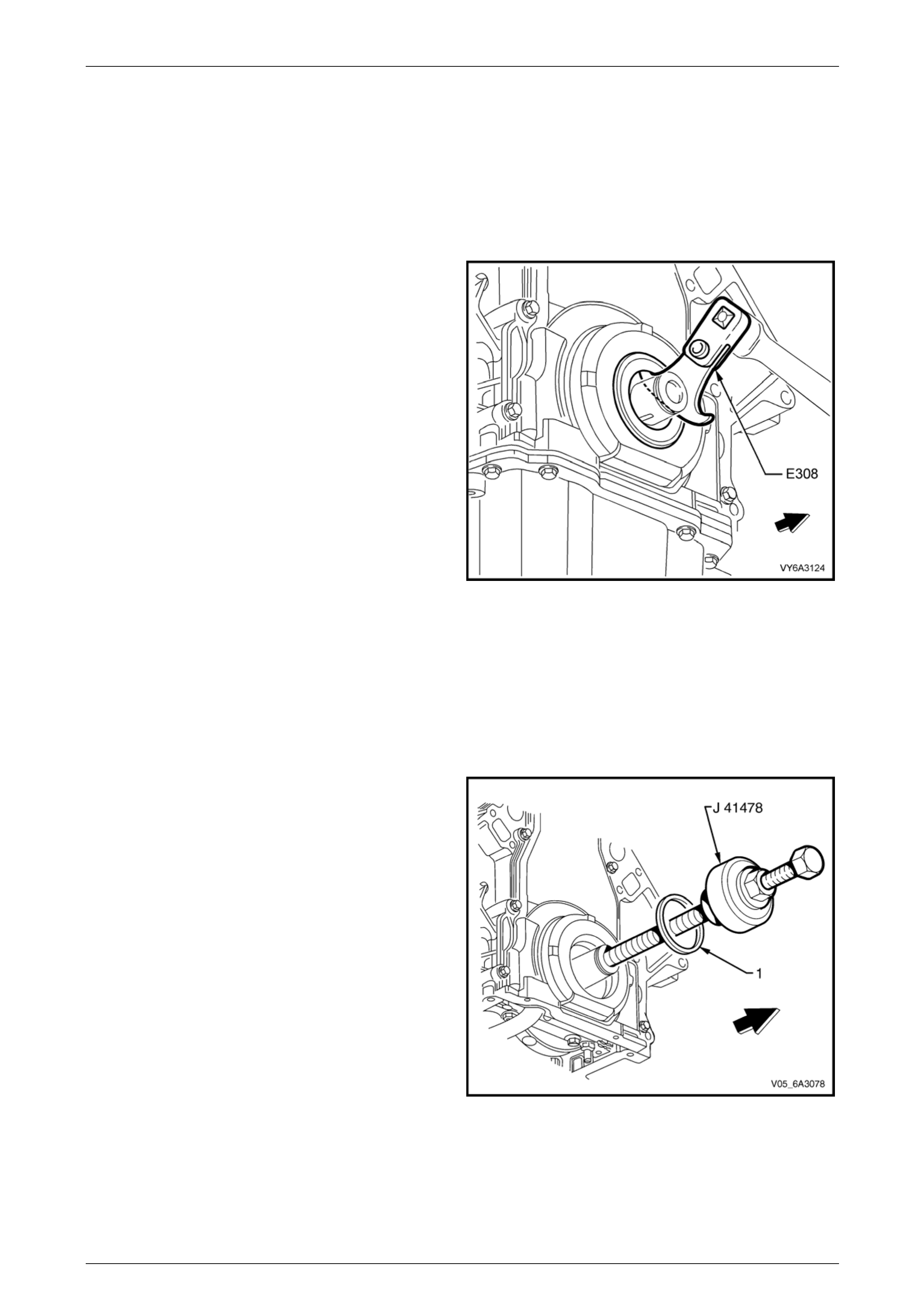
GEN IV V8 Engine Mechanical Page 6A4 – 57
3.11 Crankshaft Front Oil Seal
LT Section No. — 00–325
Remove
1 Remove the crankshaft balancer, refer to 3.10 Crankshaft Balancer .
2 Using Tool No. E308 or equivalent, carefully prise the
seal from the front engine cover.
NOTE
Take car not to scratch the front engine cover
when removing the seal.
Figure 6A4 – 78
Reinstall
NOTE
Do not lubricate the oil seal sealing surface.
For further information refer to Oil Seals in
1.4 Engine Lubrication System.
1 Lubricate the outer edge of the new oil seal (1) and the
front cover oil seal bore with clean engine oil.
2 Install the crankshaft front oil seal onto the guide of
Tool No. J 41478.
3 Install the threaded rod with the nut, washer , guide,
and oil seal of Tool No. J 41478 into the end of the
crankshaft.
4 Using a suitable spanner, ho ld the head of the installer
bolt. Using a second spanner rotate the installer nut
clockwise until the seal bottoms in the front cover
bore.
5 Remove the tool from the crankshaft.
6 Inspect the oil seal for correct installation. T he oil seal
should be installed evenly and completely into the
front cover.
7 Reinstall the crankshaft balancer. Refer to
3.10 Crankshaft Balancer. Figure 6A4 – 79
Page 6A4 – 57

GEN IV V8 Engine Mechanical Page 6A4 – 58
4 Major Service Operations
ATTENTION
All engine fasteners are important attaching parts as they affect th e performance of vital componen ts and/or
could result in majo r repair expense. Where specified in this Section, fasteners MUST be rep laced with parts
of the same part number or a GM approved equivalent. Do not use fasteners of an inferior quality or
substitute design.
Torque values must be used as specified during reassembly to ensure proper retention of all engine
components.
Through out this Section, fastener torque wrench specifications may be accompanied with the following
Identification marks:
Fasteners must be repl aced after loosening.
Fasteners either have micro encapsulated sealant applied or incorporate a mechanical thread lock and
should only be re-used once. If in doubt, replacement is recommended.
If one of these identification marks is present alongside a fastener torque wrench specification, the
recommendation regarding that fastener must be adopted.
4.1 Engine Assembly
LT Section No. — 00–500
Refer to the procedures detailed in Secti on 6A4 – Engine Mechanical GEN IV V8 in the MY2006 VZ Service Information.
Page 6A4 – 58

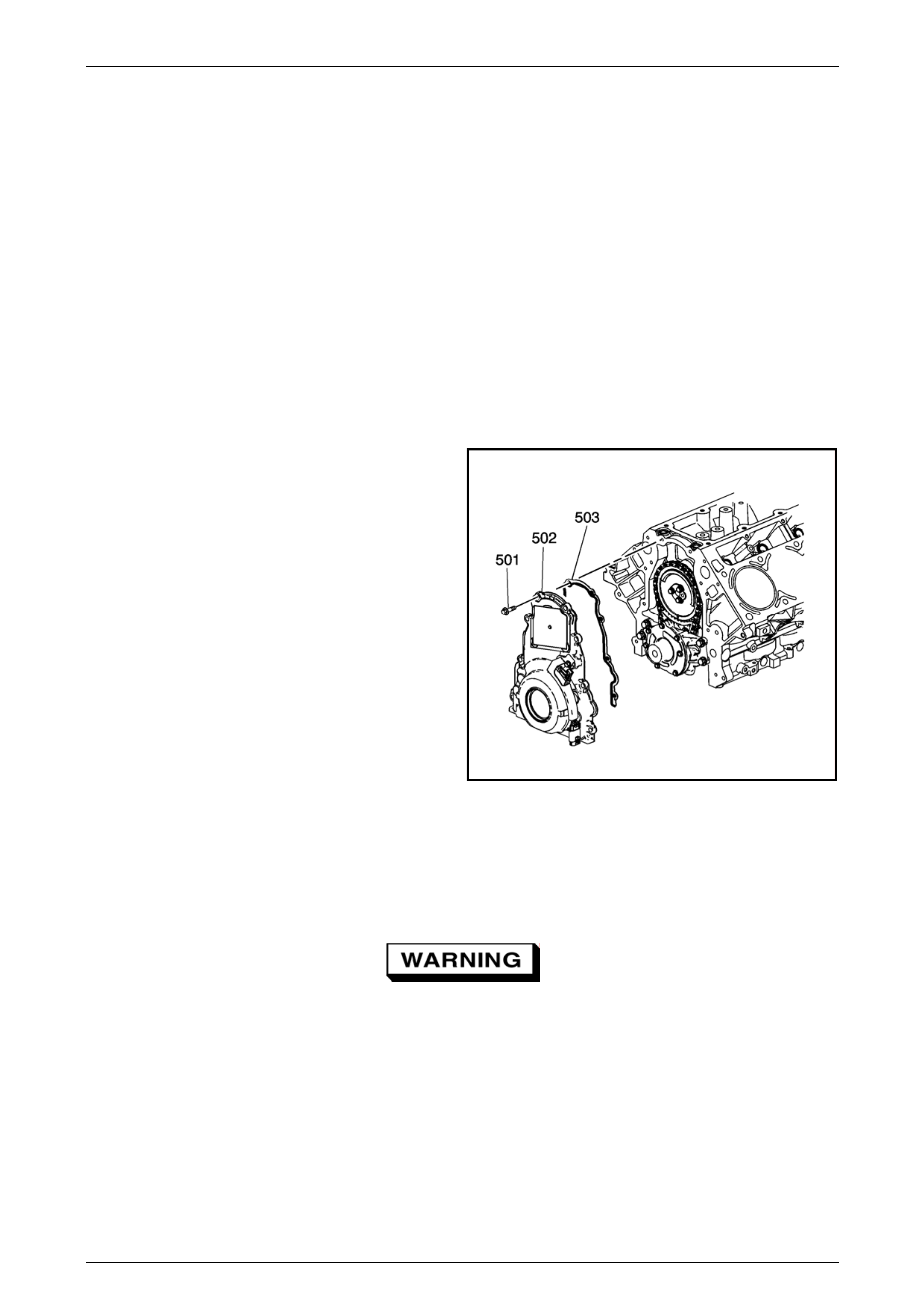
GEN IV V8 Engine Mechanical Page 6A4 – 60
4.3 Engine Front Cover
LT Section No. — 00–325
Remove
NOTE
Due to critical alignment procedures required for
the reinstallation of the front cover and oil pan, it
is strongly recommended the engine assembly is
removed from the vehicle, before oil pan removal.
1 Remove the coolant pump, refer to Section 6B4 Engine Cooling – GEN IV V8.
2 Remove the engine oil pan, refer to 5.2 Oil Pan Assemb ly in Section 6A4 – Engine Mechanical GEN IV V8 in the
MY2006 VZ Service Information.
3 Remove the crankshaft balancer, refer 3.10 Crankshaft Bal ancer .
4 Remove the bolt (501), eight places, attaching the
front engine cover (502) to the cylinder block.
5 Remove the front cover and gasket (503).
1402049
Figure 6A4 – 80
Clean and Inspect
1 Prise the old oil seal from the front cover and discard. Take care not to scratch the front cover seal bore during the
seal removal process
To avoid personal injury, wear safety glasses
and the appropriate gloves when using
compressed air an d cleaning fluids.
2 Clean the front cover in a commercially available cleaning fluid and blow dry with compressed air.
3 Inspect the front cover sealing surfaces for excessiv e scra tches and/or gouges.
4 Inspect the front cover gasket for damage to the membrane or distortio n to the aluminium carrier.
5 Inspect the front cover to oil pan threaded holes for damaged threads or de bris, refer to 6 Thread Repair, in
Section 6A4 – Engine Mec ha nical GEN IV V8 in the MY2006 VZ Service Information. if rectification is requ ired.
6 Inspect the front cover crankshaft oil seal bore for damage.
Page 6A4 – 60

GEN IV V8 Engine Mechanical Page 6A4 – 61
Reinstall
Prior to reinstallation of the engine front cover, observe the follo wing:
• Do not reuse the crankshaft oil seal.
• Do not apply any type of sealant to the front cover gasket.
• The special tools in this procedure must be used to correctly align the engine front cover at the oil pan surface and
to centre the crankshaft front oil seal.
• All gasket surfaces are to be free of oil or other foreign material during assembly.
• The crankshaft front oil seal must be centred in relation to the crankshaft.
• The oil pan sealing surface at the front cover and cylinder block must also be aligned within specifications.
• An incorrectly aligned front cover may cause premature front oil seal wear and/or engine assembly oil leaks.
1 Install the front cover attaching bolt (501), eight
places, through the front cover (502) and gasket
(503).
2 Install the front cover with the bolts and gask et.
Finger tighten the bolts.
Figure 6A4 – 81
3 Assemble alignment Tool No. J 4148 0 to the front
cover and install the bolts (1) (part of Tool No.
J 41480) in the locations shown, but do not tighten.
4 Install the two bolts (2) from alignment Tool No
J 41480 to the cylinder block and tighten to the
correct torque specification.
Front cover alignment tool to cylinder block
attaching bolt torque specification........................25 Nm
Figure 8A2 – 1
Page 6A4 – 61
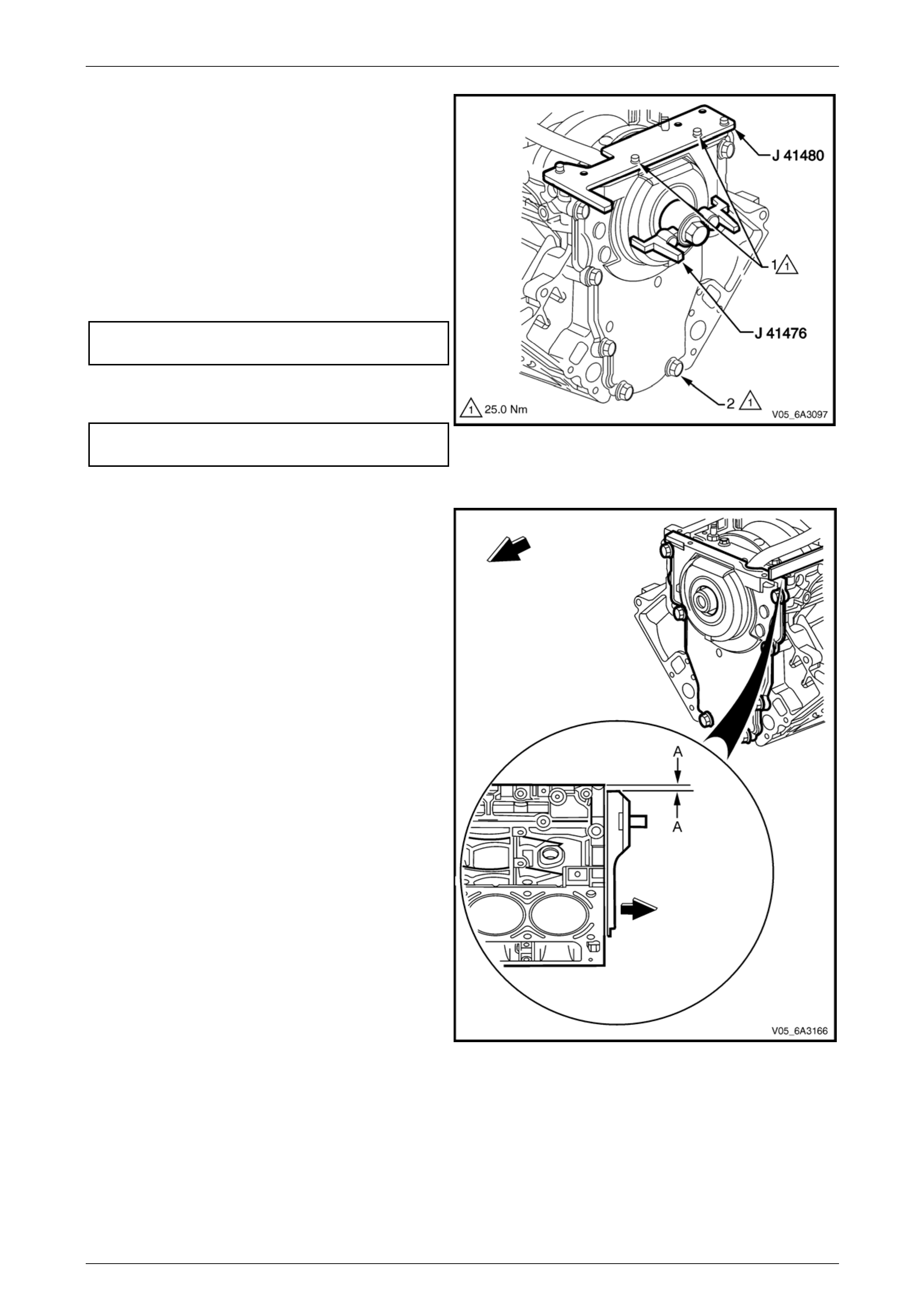
GEN IV V8 Engine Mechanical Page 6A4 – 62
5 Install the centralising Tool J 4147 6 and hold in
position by hand. Align the tapered legs of th e tool
with the machined alignment surfaces on the front
cover.
NOTE
Do not tighten the crankshaft balancer bolt to
retain the alignment tool. If the bolt is installed
and over-tightened the alignment tool will be
damaged.
6 Tighten the bolt (1), two places, attaching Tool No.
J 41480 to the front cover to the specified torque.
Alignment tool to front cover
bolt torque specification.......................................25 Nm
7 Tighten the engine front cover attaching bolts (2) to
the correct torque specification.
Engine front cover attaching bolt
torque specification..............................................25 Nm Figure 6A4 – 82
8 Remove the alignment tools.
9 Measure the oil pan surface to front cover for
flatness, as follows:
a Place a straight edge across the cylinder block
and front cover oil pan sealing surfaces. Avoid
contact with the portion of the gasket that
protrudes into the oil pan surface.
b Insert a feeler gauge between the front cover
and the straight edge tool. T he clear ance
should not exceed 0.25 mm (A).
c If the front cover-to-cylinder block oil pan
surface alignment is not within specifications ,
repeat the cover alignment procedure.
10 If the correct front cover to cylinder block alignment
cannot be obtained, replace the front cover.
11 Install crankshaft front oil seal. Refer to
3.11 Crankshaft Front Oil Seal.
12 Install the crankshaft balancer, refer to
3.10 Crankshaft Balancer.
13 Reinstall the oil pan. refer to 5.2 Oil Pan Asse mbly
in Section 6A4 – Engine Mechanical GEN IV V8 in
the MY2006 VZ Service Information.
14 Reinstall the cool ant pump, refer to
Section 6B4 Engine Cooling – GEN IV V8.
Figure 6A4 – 83
Page 6A4 – 62
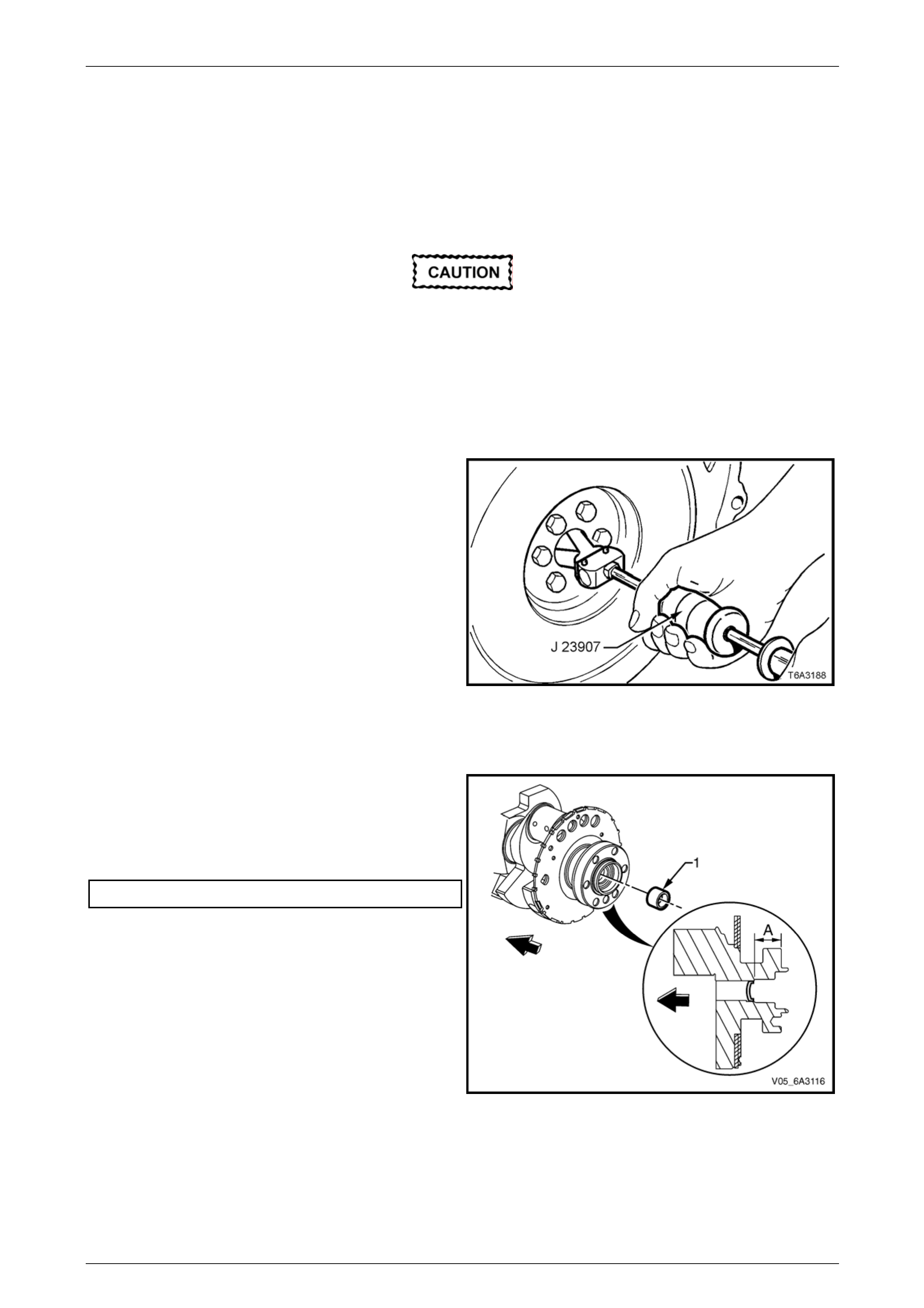
GEN IV V8 Engine Mechanical Page 6A4 – 63
4.4 Crankshaft Spigot Bearing
LT Section No. — 00–200
Remove
Disconnection of the battery affects certain
vehicle electronic systems. Refer to
Section 00 Warnings Cautions and Notes
before disconnecting the battery.
1 Disconnect the ground battery cable termi nal from the battery.
2 Remove the manual transmission and the clutch assembly, Refer to Section 7B2 Manual Transmission – GEN IV V8
and Section 7A3 Clutch – GEN IV V8.
3 Using the Tool No. J 23907, (also released as Tool
No. 6A22-2 and the slide hammer Tool No. 7A28) or
equivalent, remove the spigot bearing from the rear of
the crankshaft and discard the removed bear ing.
Figure 6A4 – 84
Reinstall
1 Check the crankshaft rear oil galler y plug (1) is not a
loose fit, damaged or leaking.
2 If replacement is required, apply sealant such as
Loctite 242 or equivalent, to the sides of a new plug
and install it to the correct depth.
Oil gallery plug installed distance ‘A’.......31.2 – 31.6 Nm
Figure 6A4 – 85
Page 6A4 – 63
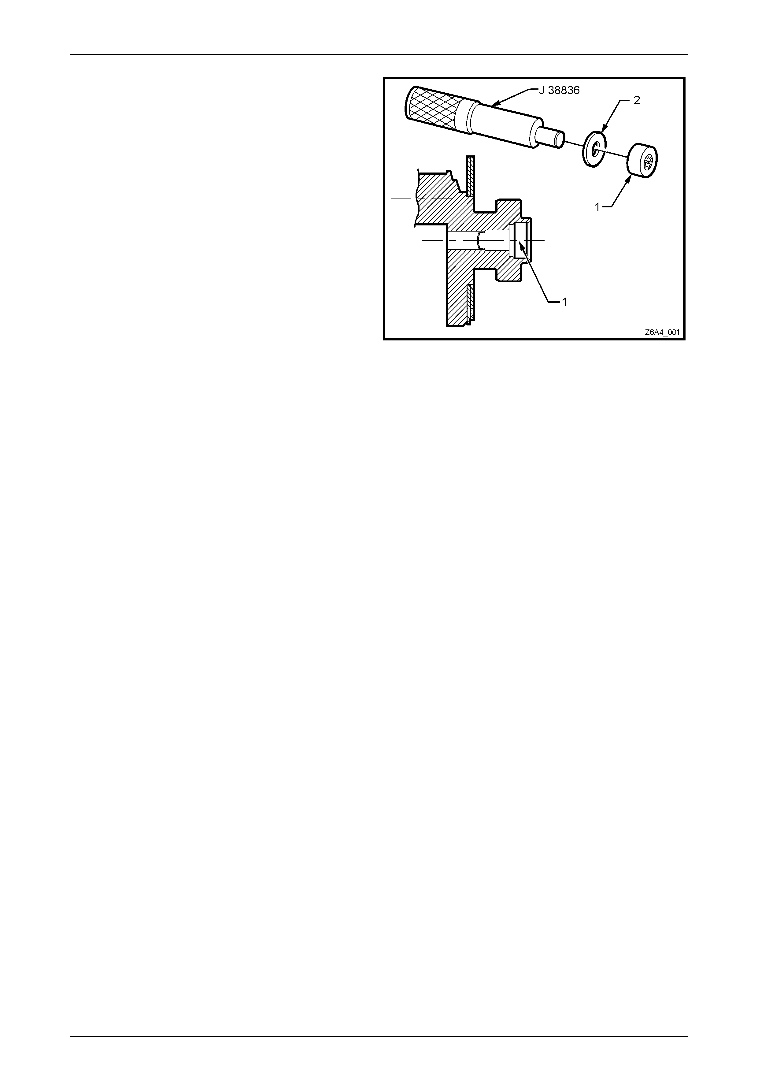
GEN IV V8 Engine Mechanical Page 6A4 – 64
3 Select a flat washer (2) that has an ID to slide over the
stepped driver J 38836 and a n OD that is marginally
less than the OD of the bearing (1).
4 Install the replacement bearing (1) over the stepped
driver and install to the rear of the crankshaft until the
bearing has bottomed in the crankshaft counter-bore,
as shown.
5 Reinstall the clutch assembly and ma nual
transmission, refer to Section 7B2 Manual
Transmission – GEN IV V8 and Section 7A3 Clutch –
GEN IV V8.
6 Reconnect the battery ground lead, refer to
Section 00 Warnings, Cautions and Notes.
Figure 6A4 – 86
Page 6A4 – 64
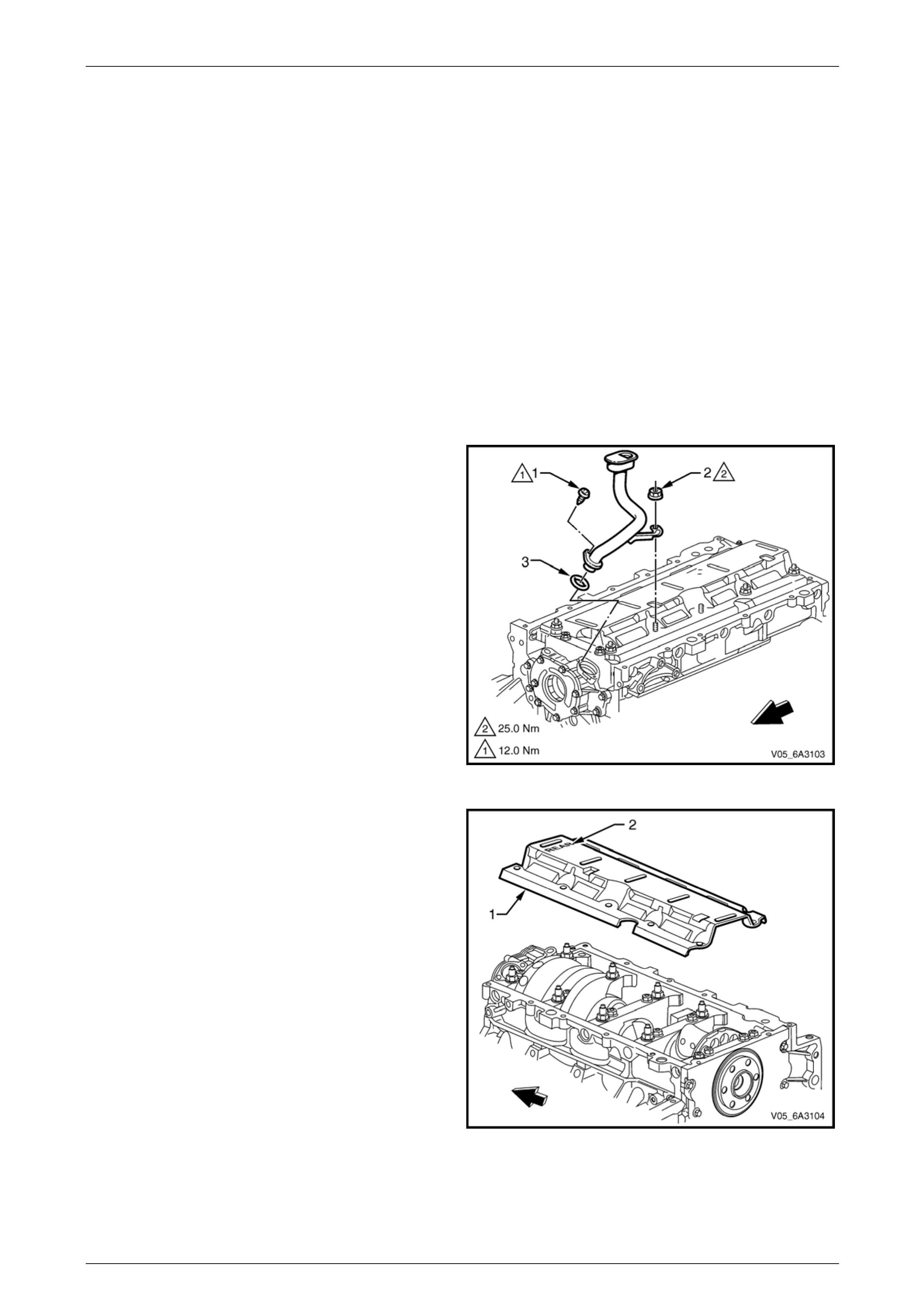
GEN IV V8 Engine Mechanical Page 6A4 – 65
4.5 Oil Pump, Pump Screen and Deflector
LT Section No. — 00–251 and 01–500
Remove
NOTE
Due to the critical alignment procedures required
for the reinstallation of the rear cover an d oil pan,
it is strongly recommended the engine assembly
be removed from the vehicle before oil pan
removal.
1 Remove the engine front cover, refer to 4.3 Engine Front Co ver .
2 Remove the engine oil pan, refer to 5.2 Oil Pan Assemb ly in Section 6A4 – Engine Mechanical GEN IV V8 in the
MY2006 VZ Service Information.
3 Remove the oil pump pick-up screen and tube
attaching screw (1) and crankshaft oil deflector
attaching nut (2), which also attaches the oil pump
pick-up screen and tube to the cylinder block.
4 Remove the oil pump pick-up screen and tube
assembly and the O-ring seal (3) from the oil pump
bore. Discard the O-ring.
Figure 6A4 – 87
5 Remove the remaining crankshaft oil deflector
attaching nuts, nine places.
6 Remove the crankshaft oil deflector (1), noting the
cover orientation is stamped "REAR" (2) to assist in
the correct installation.
Figure 6A4 – 88
Page 6A4 – 65
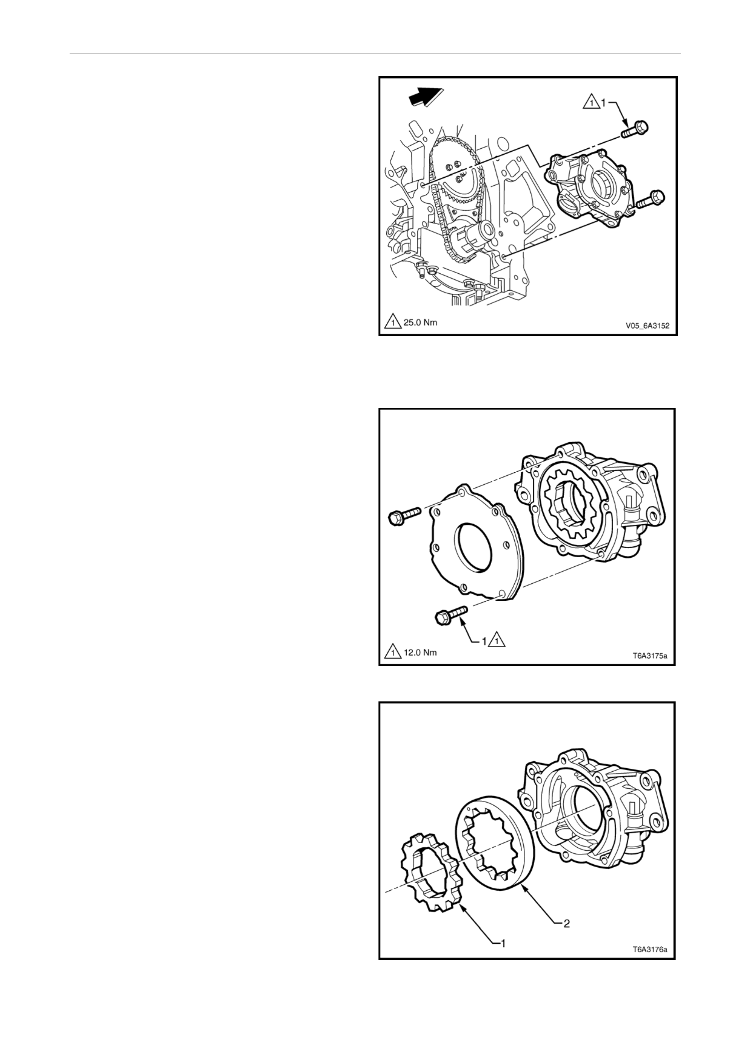
GEN IV V8 Engine Mechanical Page 6A4 – 66
7 Remove the bolt (1), four places, attaching the oil
pump to the front of the engine and remove t he oil
pump from the crankshaft.
8 If the oil pump is not being serviced, plug all openings
to avoid the entry of foreign material to the system.
Figure 6A4 – 89
Oil Pump Disassemble
1 Remove the bolt (1), seven places, attaching the oil
pump cover to the pump and remove the cover.
Figure 6A4 – 90
NOTE
Prior to disassembly, mark or identify the
relationship of the gears for reassembly.
2 Remove the inner drive gear (1) and the outer driven
ring (2), from the oil pump body.
Figure 6A4 – 91
Page 6A4 – 66
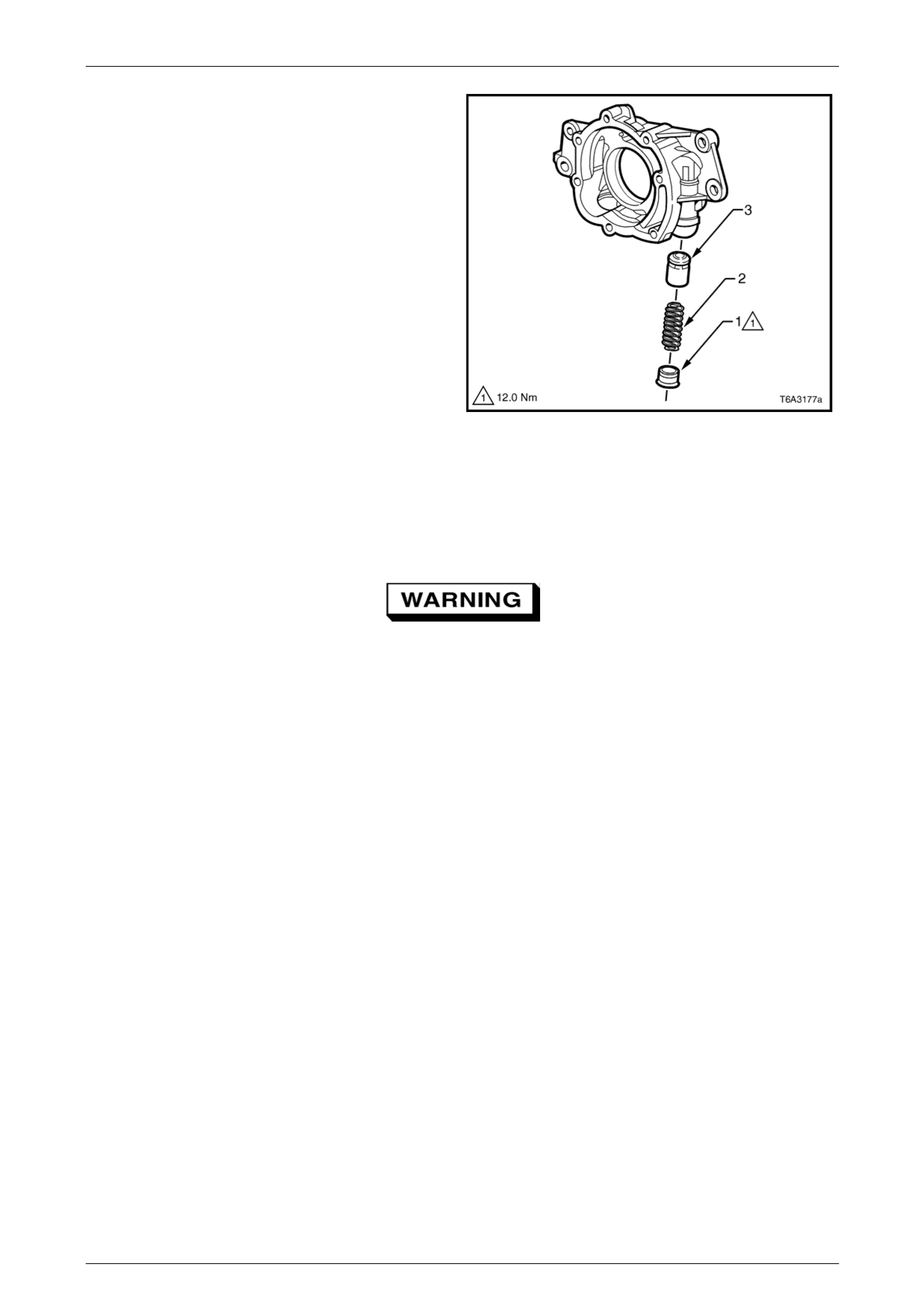
GEN IV V8 Engine Mechanical Page 6A4 – 67
3 Unscrew the oil pressure relief valve plug (1) and
remove the spring (2), and valve (3) from the oil pump
body.
Figure 6A4 – 92
Clean and Inspect
With the exception of the oil p r essure relief valve spring there are no parts in the oil pum p or the oil pump pick-up screen
and pipe that are serviced separately. If either component is found to be worn or damaged the assembly must be
replaced.
To avoid personal injury, wear safety glasses
and the appropriate gloves when using
compressed air an d cleaning fluids.
1 Clean all parts in a commercially available cleaning fluid and blow dry using compressed air.
2 Inspect the following components:
a Oil pump housing for cracks, excessive wear, scoring or casting imperfections.
b Oil pump housing to cylinder block oil gallery surface for scratches or gouging.
c Inspect the oil pump housing for damag ed bolt hole threads, refer to 6 Thread Repair, Section 6A4 GEN IV V8,
in the MY 2006 VZ Service Information, as required.
d Oil pump relief valve plug and bore for scratched or damaged surfaces and the screw thread for damage. The
pressure relief valve must be able to move freely within its bore with no restrictions.
e Oil pump internal oil passages for restrictions.
f Inspect the drive and driven gears for chipping or wear. Minor burrs or imperfections on the gears can be
removed with a fine oil stone.
g Inner gear drive splines for excessive wear.
h Oil pump pick-up screen and pipe assembly and replace if either of the following conditions are observed.
• Oil pump pick-up screen is clogg ed with debris or restriction.
• Screen mesh is broken or has loose stran ds.
Page 6A4 – 67
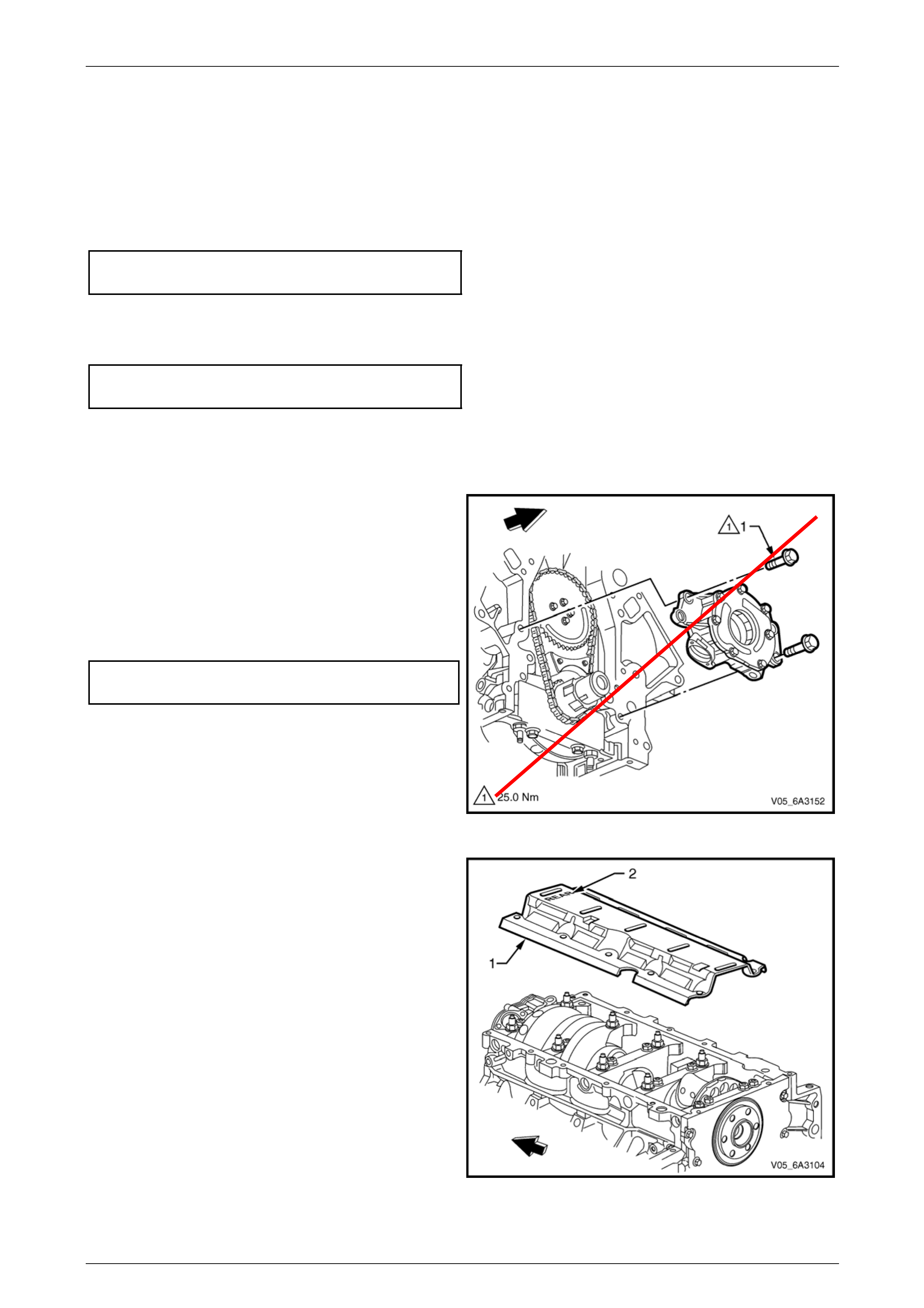
GEN IV V8 Engine Mechanical Page 6A4 – 68
Oil Pump Reassemble
Reassembly of the oil pump is the reverse of the disassemble procedure, noting the following:
1 Liberally coat all oil pump com ponents with clean engine oil before assembly.
2 When assembling the oil p ump, ensure the relationship of the inner to the outer oi l pump gears is matched as
marked in the removal procedure.
3 Tighten the oil pump cover attachi ng screws to the correct torque specification.
Oil pump cover/pump body
attaching bolt torque specification.........................12 Nm
4 Install a new pressure relief valve spri ng.
5 Tighten the pressure relief valv e plug to the correct torque specification.
Oil pump pressure relief plug
torque specification...............................................12 Nm
6 Rotate the assembled pump checking for smoothness of operation by rotating the inner drive gear.
Reinstall
1 Ensure the oil pump and cyli nder block oil gallery
passages are free from any debris or foreign material.
2 Align the splined surfaces of the crankshaft sprocket
and the oil pump drive gear and install the oil pump
onto the sprocket until the pu m p housing contacts the
face of the cylinder block.
3 Install the two oil pump attaching bolts (1) and tighten
to the correct torque specification.
Oil pump attaching bolt
torque specification................................................ 25 Nm
Figure 6A4 – 93
4 Install the crankshaft oil deflector (1), ensuri ng the
"REAR" stamping (2) on the deflector is located at the
rear of the engine.
Figure 6A4 – 94
Page 6A4 – 68
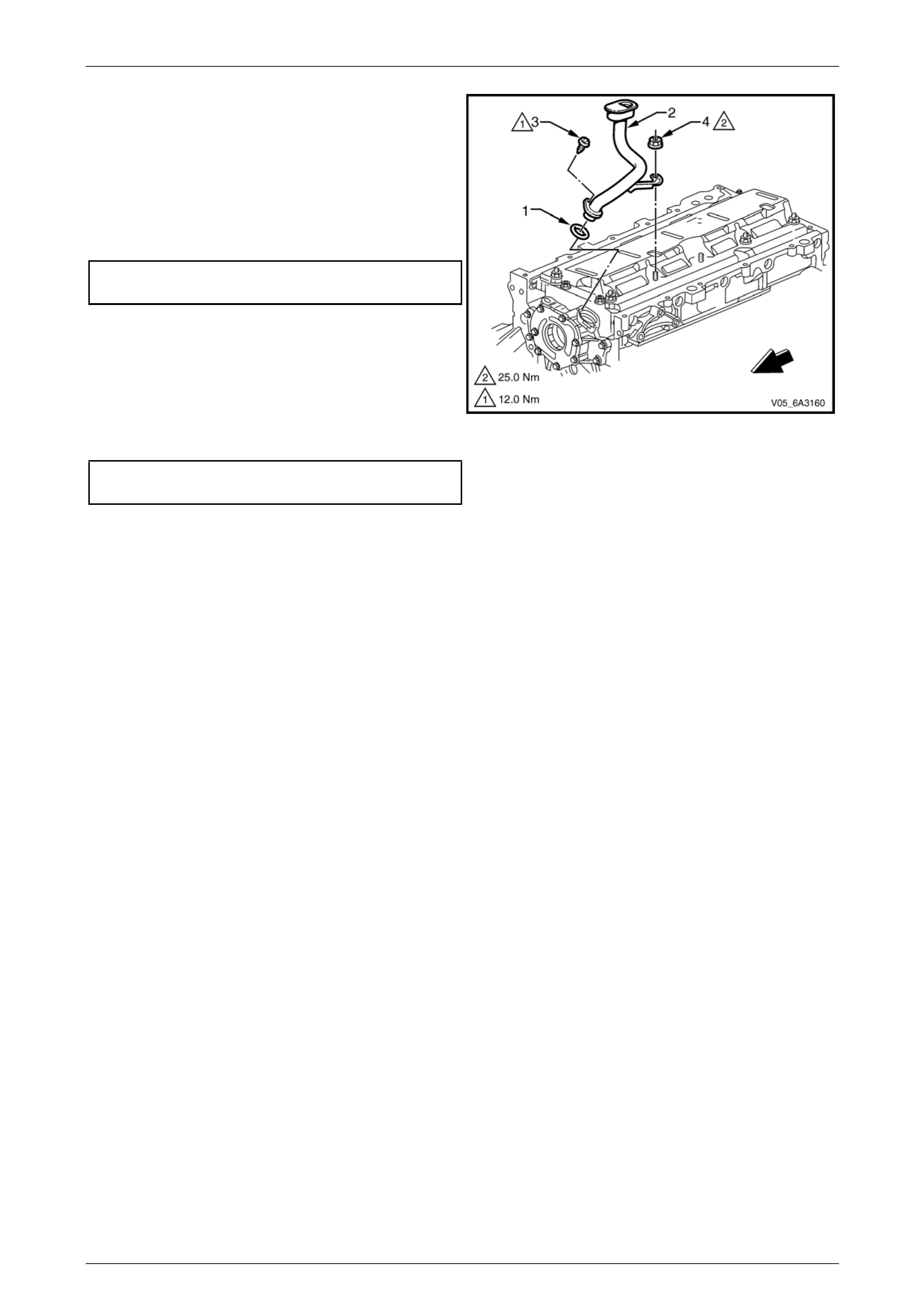
GEN IV V8 Engine Mechanical Page 6A4 – 69
5 Lubricate a new oil pump pic k -up tube O-ring (1) with
clean engine oil and install into the oil pump pick-up
tube (2).
6 Fully install the pick-up tube into the oil pump housing
aligning the support bracket with the mai n b earing cap
stud.
7 Install the pick-up tube attaching screw (3) and tighten
to the correct torque specification.
Oil pump pick-up tube attaching
screw torque specification.....................................12 Nm
NOTE
Ensure the pick-up tube is fully installed before
tightening the attaching screw.
8 Install the crankshaft oil deflector attaching nut (4) 10
places, to the main bearing cap studs and tighten to
the correct torque specification.
Crankcase oil deflector attaching nut
torque specification...............................................25 Nm
9 Reinstall the front engin e cover, refer to
4.3 Engine Front Cover.
Figure 6A4 – 95
Page 6A4 – 69
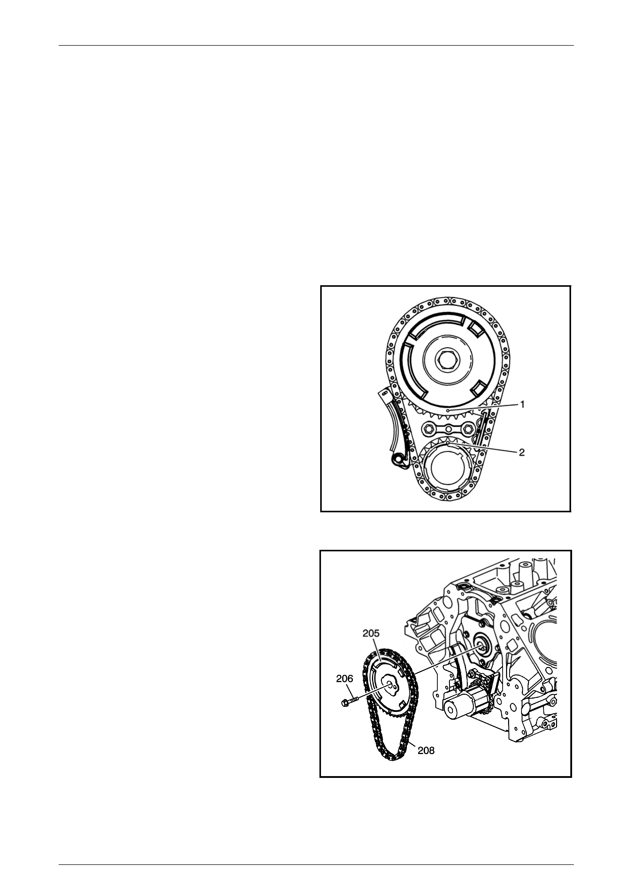
GEN IV V8 Engine Mechanical Page 6A4 – 70
4.6 Timing Chain and Sprockets
LT Section No. — 00–225
Remove
NOTE
Due to the critical alignment procedures required
for the reinstallation of the engine front cover and
oil pan, it is strongly recommended the engine
assembly be removed from the vehicle before oil
pan removal.
1 Remove the crankshaft balancer and front engine cover, refer to 3.10 Crankshaft Balancer and
4.3 Engine Front Cover.
2 Temporarily install the harmonic balancer bolt and turn
the engine over by hand until the timing marks (1 and
2) on the camshaft and crankshaft sprockets are
aligned.
3 Remove the oil pump, refer to 4.5 Oil Pump, Pump
Screen and Deflector.
1658268
Figure 6A4 – 96
4 Remove the camshaft sprocket attaching bolt (206),
then remove the sprocket (205) and chain (2 08) from
the camshaft and crankshaft.
1658265
Figure 6A4 – 97
Page 6A4 – 70
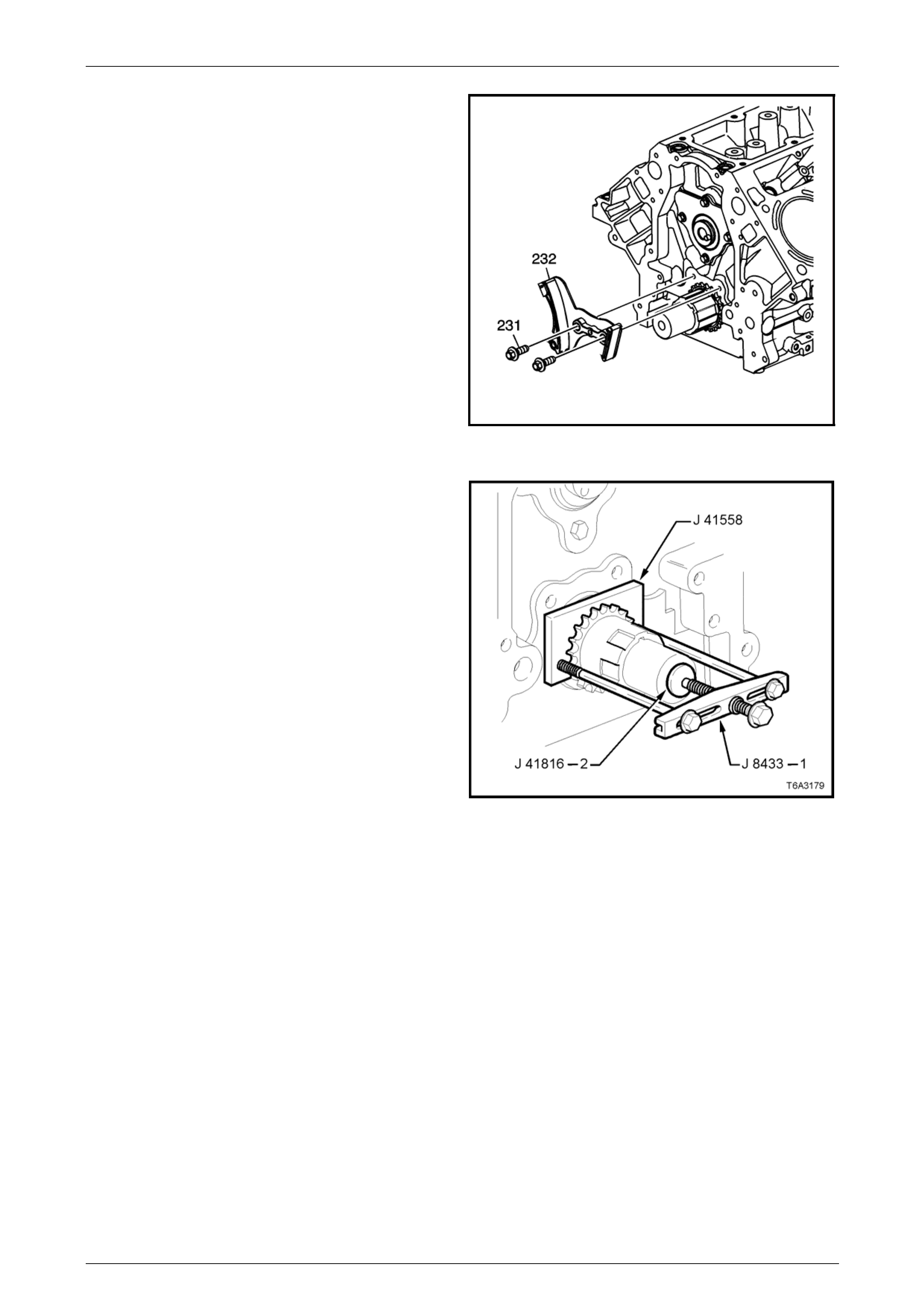
GEN IV V8 Engine Mechanical Page 6A4 – 71
5 Remove the two bolts (232), attaching the timing chain
tensioner (232) to the cylinder block.
1658251
Figure 6A4 – 98
6 Use Tool No’s J 41558, J 41816-2, the b olts from
J 1427-01 and puller J 8433-1 to remove the
crankshaft sprocket from the nose of the crankshaft
7 If required, remove the crankshaft timing sprocket
drive key from the crankshaft nose.
Figure 6A4 – 99
Page 6A4 – 71
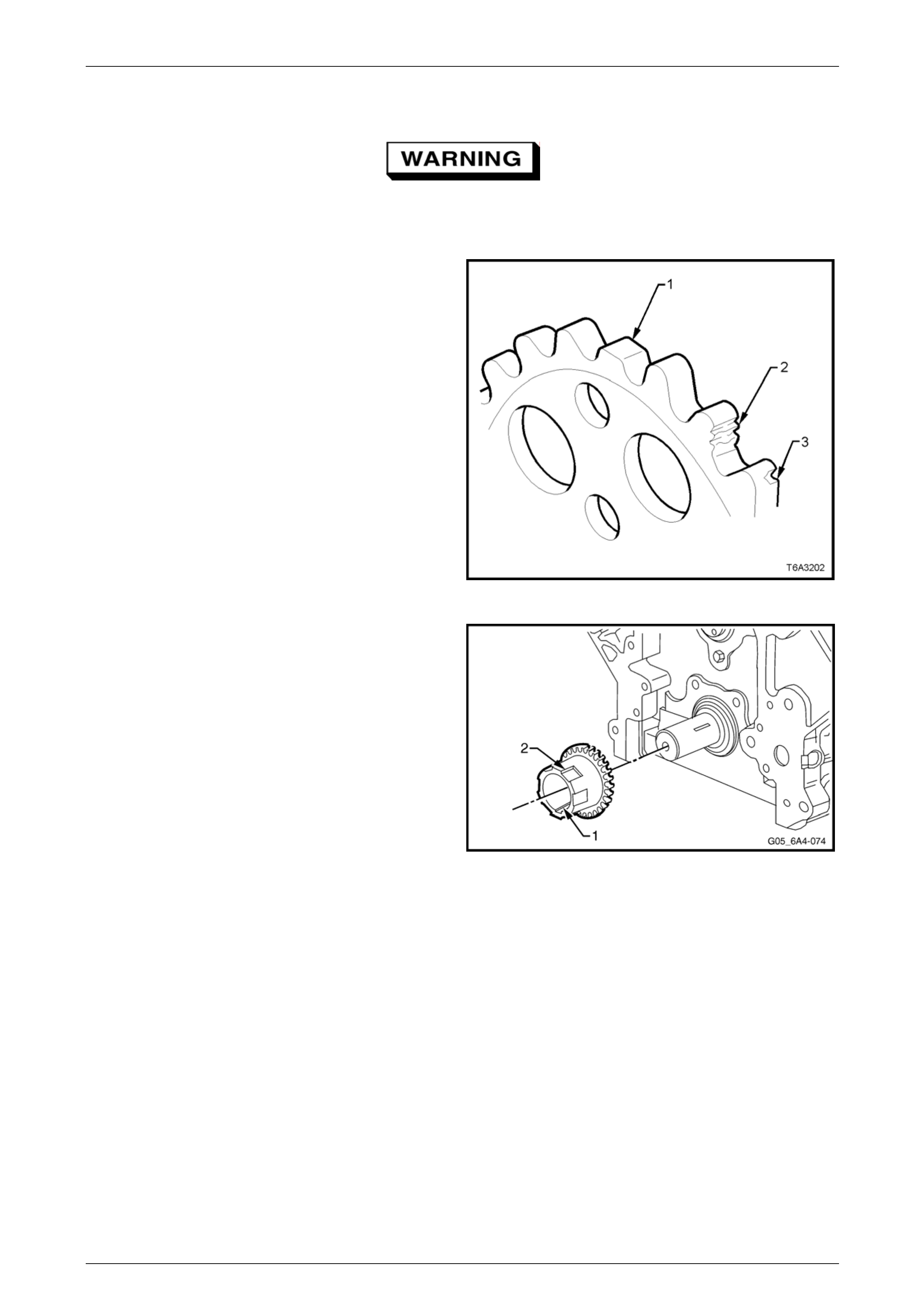
GEN IV V8 Engine Mechanical Page 6A4 – 72
Clean and Inspect
To avoid personal injury, wear safety glasses
and the appropriate gloves when using
compressed air an d cleaning fluids.
1 Clean the timing sprockets and timing chain in
commercially availa ble cleaning fluid and blow dr y with
compressed air.
2 Inspect the timing chain for binding or wear.
3 Inspect the camshaft and crankshaft sprockets for:
• Worn teeth (1)
• Damaged teeth (2)
• Chipped teeth (3)
• Worn valleys between the sprocket teeth
Figure 6A4 – 100
4 Inspect the crankshaft timing sprocket keyway (1) for
wear.
5 Inspect the crankshaft timing sprocket oil pump drive
splines (2) for wear.
NOTE
Replace any worn parts with new components.
Although not mandatory, it is also rec ommended
the timing gears and chain be relaced as a
complete set.
Figure 6A4 – 101
Page 6A4 – 72
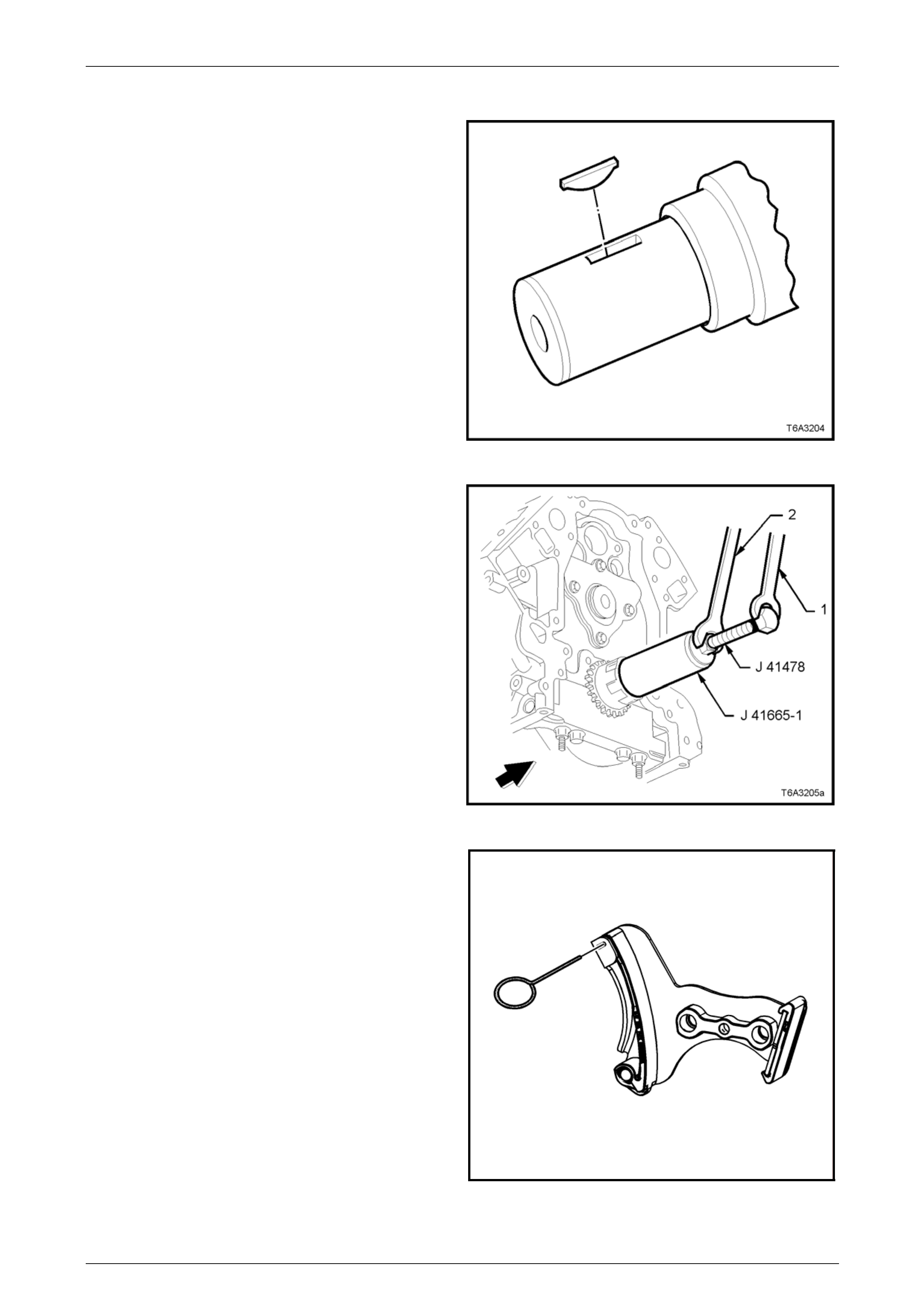
GEN IV V8 Engine Mechanical Page 6A4 – 73
Reinstall
1 If removed, reinstall the crankshaft sprocket drive
keyway into the crankshaft. The key should be tapped
into place until each end bottoms on the crankshaft.
2 Reinstall the crankshaft sprocket onto the crankshaft
aligning the keyway with the key.
Figure 6A4 – 102
3 Use Tool No. J 41665 to reinstall the crankshaft
sprocket, as follows:
a Install the threaded bolt, nut and flat washer from
Tool No. J 41478 through the end p late and
stepped sleeve of Tool No. J 41665-1.
b Screw the threaded bolt into the crankshaft,
using a spanner (1).
c While holding the threade d bo lt with the spanner,
turn the nut with a second set spanner (2),
moving the installer Tool No. J 41665 to fully
install the crankshaft sprocket onto the
crankshaft nose.
d When the crankshaft sprocket has been fully
installed, remove the installation tools.
Figure 6A4 – 103
4 Compress the timing chain tensioner blade and retain,
using Tool No. EN 46330.
1658249
Figure 6A4 – 104
Page 6A4 – 73
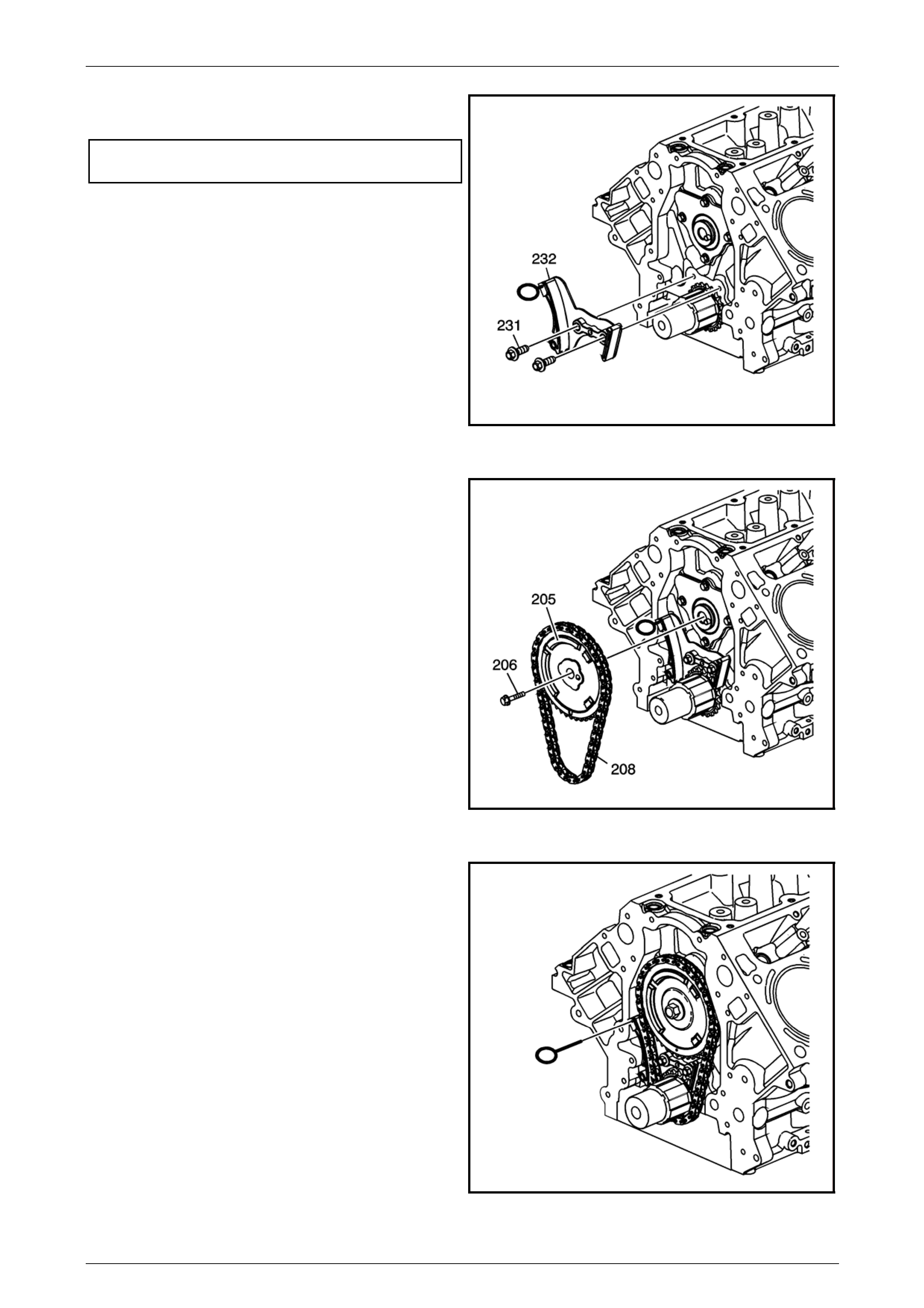
GEN IV V8 Engine Mechanical Page 6A4 – 74
5 Install the timing chain tensioner and retain with two
bolts, tightening to the correct torque specification.
Timing chain tensioner
bolts torque specification ......................................25 Nm
1658251
Figure 6A4 – 105
6 Check that the crankshaft timing mark is vertically
upward (12 o’clock position).
7 Temporarily install the camshaft sprocket to ensure
that the drive pin engages with the sprocket, with the
timing mark facing vertically downwar d (6 o’clock
position). If not, then the camshaft must be rotated
until this engagement occurs.
8 Install the timing chain (208), over the crankshaft
sprocket, with the camshaft sprocket in the chain, as
shown.
9 Install the timing sprocket to the camshaft, engaging
the drive pin with the hole in the sprocket.
10 Loosely inst all the camshaft sprocket retaining bolt
(206) to retain the sprocket in position.
11658265-a
Figure 6A4 – 106
11 Remove the loading pin (EN 46330) from the timing
chain tensioner.
1658271
Figure 6A4 – 107
Page 6A4 – 74
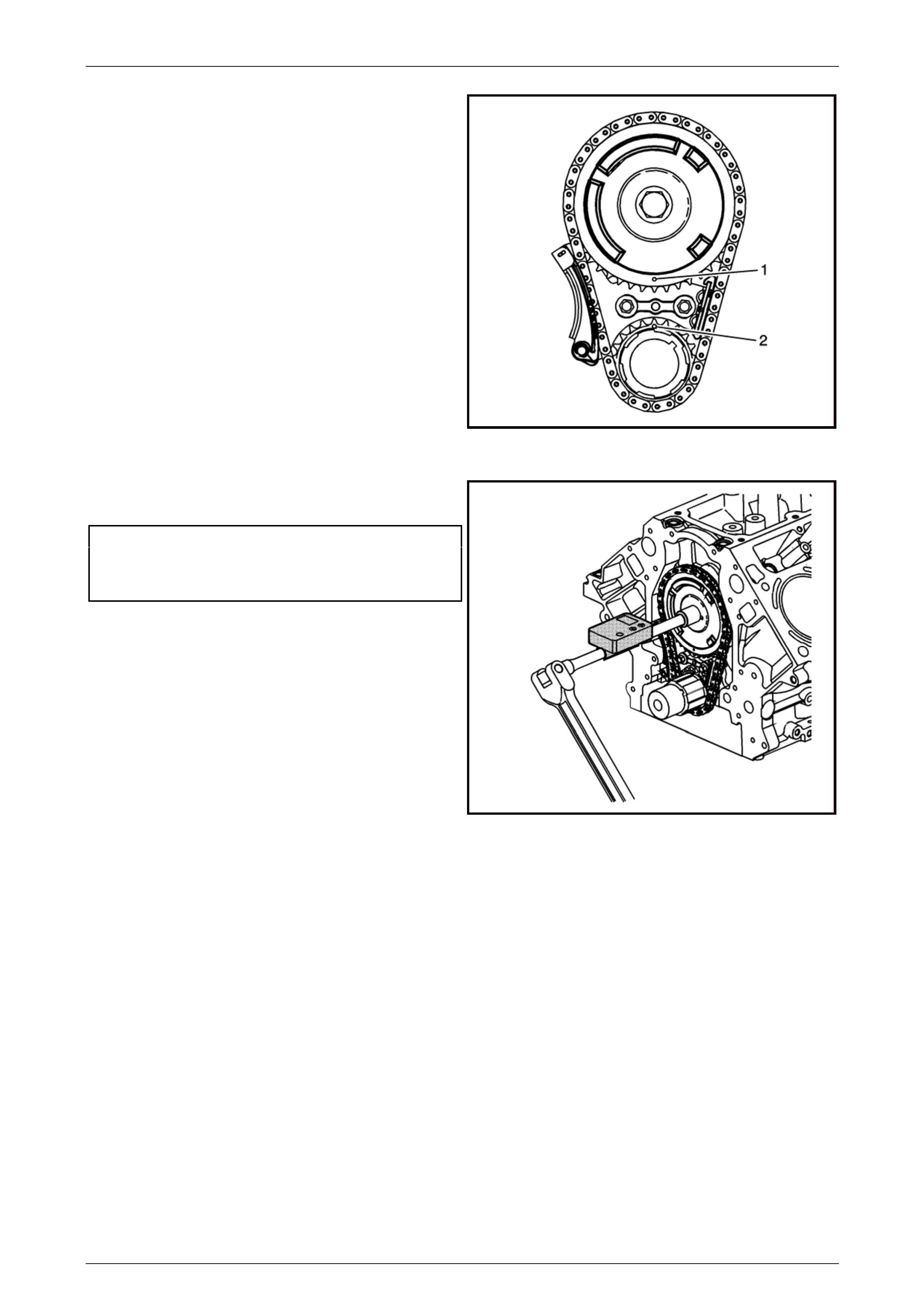
GEN IV V8 Engine Mechanical Page 6A4 – 75
12 Check that the timing marks (1 and 2) are in alignment
as shown.
1658268
Figure 6A4 – 108
13 Install a NEW camshaft sprocket retaining b olt and
tighten to the correct torque specification.
Camshaft sprocket retaining
bolt torque specification
Stage 1 ........................................................75 Nm
Stage 2 ............................................50° turn angle
NOTE
An electronic torque wrench adaptor is being
used in the illustration.
1658274
Figure 6A4 – 109
14 Reinstall the oil pump, refer to 4.5 Oil Pump, Pump Scree n and Deflector.
15 Reinstall the front cover an d harmonic balancer, refer to 4.3 Engine Front Cover .
Page 6A4 – 75

GEN IV V8 Engine Mechanical Page 6A4 – 76
5 Specifications
NOTE
Only those specifications related to the service
operations contained within this Section are
included here. For other Specifications for this
engine refer to Section 6A4 E ngine Mechan ical in
the MY2006 VZ Service Information
5.1 Engine
General
Engine Type .........................................................................................................90° OHV V8
Displacement...............................................................................................6 litre (5,967 cm3)
Bore..........................................................................................................................101.6 mm
Stroke.........................................................................................................................92.0 mm
Compression Ratio.........................................................................................................10.4:1
Firing Order ......................................................................................................1-8-7-2-6-5-4-3
Cylinder layout, front to rear: ....................................................Left-hand bank.......3, 5 and 7
Right-hand bank.....4, 6 and 8
Spark Plugs –
Production................................................................................................AC Delco 41-985
Gap.....................................................................................................1.02 + 0.08 / – 0.07 mm
Intake Manifold
Intake Manifold Cylinder Head
Deck Flatness..........................................................0.50 mm (Over Gasket Sealing Surfaces)
Oil Pan – Front and Rear Cover Alignment
Oil Pan to Rear of Cylinder Block Alignment
(Maximum at Transmission Housing Mounting Surface) .............................0.000 – 0.250 mm
Front Cover Alignment (at Oil Pan Surface) ....................................................0.00 – 0.50 mm
Rear Cover Alignment (at Oil Pan Surface) ...................................................0.00 –- 0.50 mm
Sealants and Adhesives
Coolant Sensor Threads....................................................................Loctite 565 or equivalent
Crankshaft Rear Oil Gallery Plug.......................................................Loctite 242 or equivalent
Cylinder Head Core Hole Plugs.........................................................Loctite 242 or equivalent
Cylinder Head Expansion Plugs ........................................................Loctite 242 or equivalent
Engine Flywheel Bolt Threads...........................................................Loctite 242 or equivalent
Exhaust Manifold Bolt Threads..........................................................Loctite 272 or equivalent
Fuel Rail Bolt Threads.......................................................................Loctite 242 or equivalent
Ignition Coil and Bracket Assembly Bolt Threads..............................Loctite 242 or equivalent
Intake Manifold Bolt Threads.............................................................Loctite 242 or equivalent
Oil Pan Surface at Front and Rear Covers........................................Loctite 565 or equivalent
Oil Pressure Sensor Threads ............................................................Loctite 565 or equivalent
Page 6A4 – 76

GEN IV V8 Engine Mechanical Page 6A4 – 77
5.2 Lubrication System
Oil Capacity:
Without Oil Filter Change............................................................................................ 5.7 litres
With Oil Filter Change................................................................................................. 6.2 litres
Minimum Oil Pressure
Engine Hot...............................................................................................90 kPa @ 1,000 rpm
124 kPa @ 2,000 rpm
165 kPa @ 4,000 rpm
Lubricant
Oil Type:
Initial Fill...................................................................................................5W / 30 SM GF4
Service Refill.........................................................................................10W – 30 SM GF4
Page 6A4 – 77

GEN IV V8 Engine Mechanical Page 6A4 – 78
6 Torque Wrench Specifications
ATTENTION
All engine fasteners are important attaching parts as they affect th e performance of vital componen ts and/or
could result in majo r repair expense. Where specified in this Section, fasteners MUST be rep laced with parts
of the same part number or an approved equivalent. Do not use fasteners of an inferior quality or substitute
design.
Torque values must be used as specified during reassembly to ensure proper retention of all engine
components.
Throughout this Section, fastener torque wrench specifications may be accompanied with the following
identification marks:
Fasten ers must be replaced after loosen ing.
Fasteners either have micro encapsulated sealant applied or incorporate a mechanical thread lock and
should only be re-used once. If in doubt, replacement is recommended.
If one of these identification marks is present alongside a fastener torque wrench specification, the
recommendation regarding that fastener must be adhered to.
NOTE
Only those torque specifications related to
the service operations contained within this
Section are included here. For the remaining
torque specifications for this engine refer to
Section 6A4 Engine Mechanical in the MY2006
VZ Service Information.
6.1 Engine
Air Intake Duct Hose Clamp..........................................................1.5 – 2.5 Nm
Engine Oil Pan Drain Plug.......................................................................25 Nm
Close-Out Cover Attaching Screw (right and left-hand)...........................10 Nm
Coolant Vapour Vent Pipe Bolt/Stud .......................................................12 Nm
Crankshaft Balancer Attaching Bolt
Stage 1 (Used Bolt)...............................................................................150 Nm
Stage 2 (New Bolt) ..................................................................................50 Nm
Stage 3......................................................................................140° turn angle
Camshaft Position Sensor Attaching Bolt................................................25 Nm
Camshaft Retainer Attaching Bolt ...........................................................25 Nm
Camshaft Sprocket Attaching Bolt....................... 75 Nm, then turn through 50°
Crankcase Oil Deflector Attaching Nut....................................................25 Nm
Engine Front Cover Attaching Bolt..........................................................25 Nm
Engine Oil Filter.......................................................................................30 Nm
Fuel Rail Attaching Studs........................................................................10 Nm
Hydraulic Valve Lifter Guide Attaching Bolt.............................................10 Nm
Intake Manifold Attaching Bolts (In Sequence):
Stage 1......................................................................................................5 Nm
Stage 2....................................................................................................10 Nm
Oil Level Indicator Tube Attaching Bolt....................................................25 Nm
Oil Pan/Cylinder Block Attaching Bolt......................................................25 Nm
Page 6A4 – 78

GEN IV V8 Engine Mechanical Page 6A4 – 79
Oil Pan/Front Cover Attaching Bolt..........................................................25 Nm
Oil Pan/Rear Cover Attaching Bolt..........................................................12 Nm
Oil Pressure Sensor ................................................................................20 Nm
Oil Pump Attaching Bolt...........................................................................25 Nm
Oil Pump Cover to Pump Body Attaching Bolt.........................................12 Nm
Oil Pump Pick-up Tube Attaching Screw.................................................12 Nm
Oil Pump Pressure Relief Plug................................................................12 Nm
PCV Oil Separator Attaching Bolt..............................................................8 Nm
Throttle Body Attaching Bolt....................................................................10 Nm
Timing Chain Tensioner Attaching Bolt ...................................................25 Nm
Valley Cover Attaching Bolt.....................................................................25 Nm
Valve Lifter Guide Attaching Bolt.............................................................10 Nm
Vapour Vent Pipe Attaching Bolt/Stud.....................................................12 Nm
Page 6A4 – 79

GEN IV V8 Engine Mechanical Page 6A4 – 80
6.2 Special Tool Fasteners
Flywheel Holding Tool, No. J 42386-A Attaching Bolts ...........................50 Nm
Alignment Tool to Front Cover Attaching Bolt..........................................25 Nm
Front Engine Cover Alignment Tool to Cylind er Block
Attaching Bolt..........................................................................................25 Nm
Page 6A4 – 80
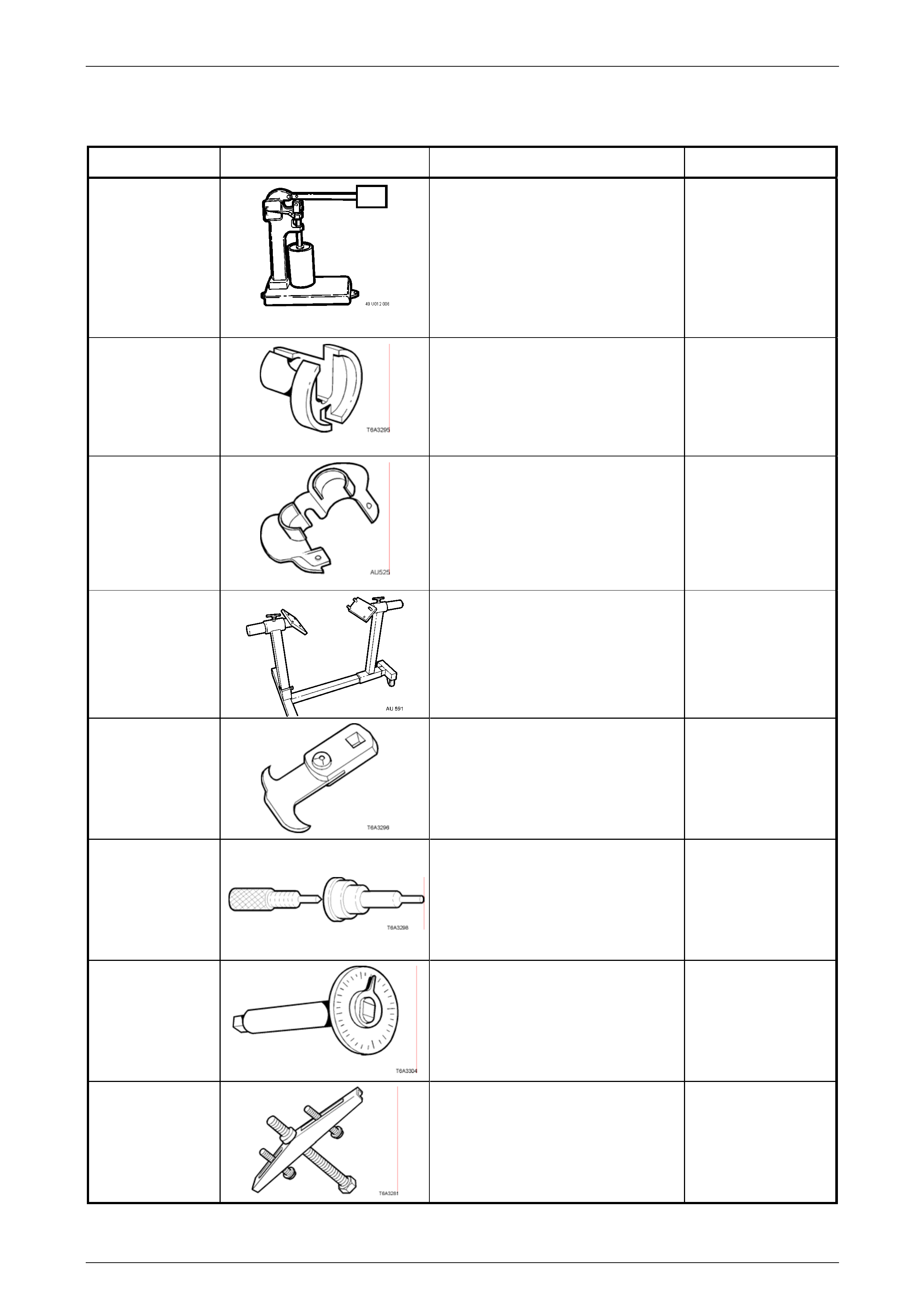
GEN IV V8 Engine Mechanical Page 6A4 – 81
7 Special Tools
Tool Number Illustration Description Classification
49 U012 006
Hydraulic Valve Lifter Tester
Used in conjunction with testing fluid
SPX No. E1151
Also numbered 6A23.
Previously released.
Unique
7371
Quick Connect Release Tool
Previously released for releasing fuel
line quick connects after fuel system
has been de-pressurised.
Previously released
Mandatory
AU 525
Quick Connect Release Tool
Use to release the quick connect
fittings on the automatic transmission
fluid cooler lines at the radiator end,
when the vehicle is so equipp ed.
Previously released.
Mandatory
AU 591 Engine stand
Used to support the GEN IV V8 engine
at the engine mount locations .
Allows for a 360° rotation capability.
Previously released.
Available
E308
Seal remover
Previously released.
Also numbered 56750
Desirable
E1152
Valve lifter assembly tools
Used to assist in assembly of the
hydraulic valve lifters.
Previously released as 6A24.
Unique
E 7115
Torque angle wrench
Used to accurately tighten fasteners
when an angle torque is requir ed.
Previously released.
Unique
J 8433-1
Pulley puller
Used to remove crankshaft timing
gear sprocket, in conjunction with J
41558 and J 41816 –2.
Previously released.
Unique
Page 6A4 – 81
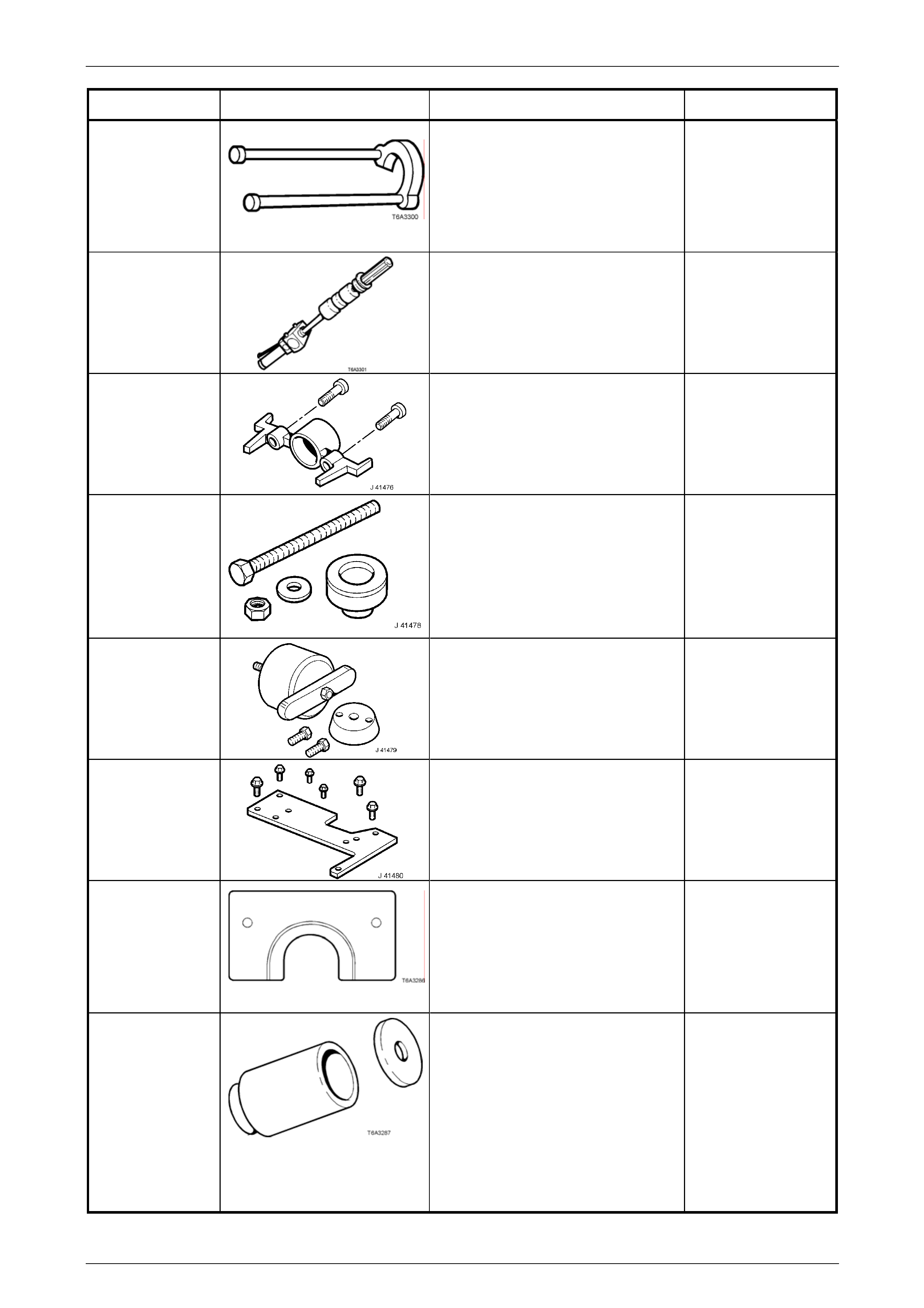
GEN IV V8 Engine Mechanical Page 6A4 – 82
Tool Number Illustration Description Classification
J 21427-01 Puller adaptor
Used in conjunction with J 8433-1,
J 41558 and J 41816-2 to remove
crankshaft timing gear sprocket.
Previously released to remove
automatic transmission speed sensor
ring.
Unique
J 23907 Slide hammer
Also released as remover, 6A22-2 and
slide hammer 7A28.
Previously released.
Unique
J 41476
Front and rear cover alignment tool
Used to align both the front and rear
engine covers during insta llation.
Previously released.
Mandatory
J 41478
Crankshaft front oil seal installer
Threaded bolt, nut and washer are
also used in conjunction with
J 41665 to install the crankshaft
balancer.
Previously released.
Desirable
J 41479 Crankshaft rear oil seal installer
Previously released.
Desirable
J 41480 Front and rear cover alignment tool
Used in conjunction with alignm ent
tool J 41476, to correctly align the
front and rear engine covers.
Previously released.
Mandatory
J 41558 Crankshaft sprocket remover
Used in conjunction with the bolts
from J 21427-01 and pulley puller J
8433, to remove the crankshaft
sprocket.
Previously released.
Desirable
J 41665 Crankshaft balancer installer
Comprises:
Stepped sleeve, J 41665-1 a nd end
plate J 41665-2. Used in conjunction
with Tool J 41478, to install the
crankshaft balancer and crankshaft
sprocket.
Previously released.
Mandatory
Page 6A4 – 82
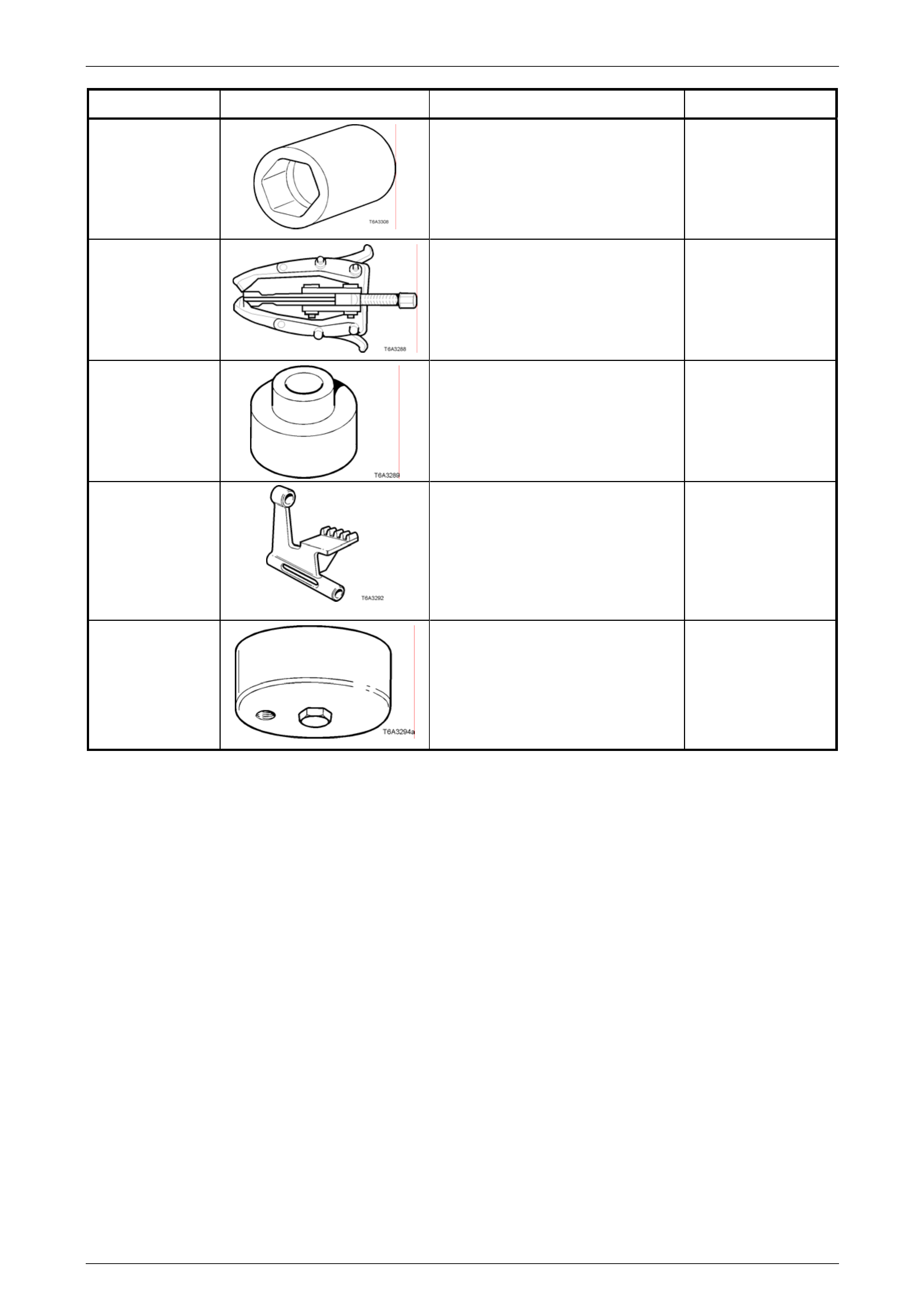
GEN IV V8 Engine Mechanical Page 6A4 – 83
Tool Number Illustration Description Classification
J 41712
Oil pressure sensor socket
Used in conjunction with 3/8” drive
socket equipment to remove/reinstall
oil pressure sensor.
Previously released.
Desirable
J 41816
Three legged puller
Used in conjunction with J 41816-2 to
remove crankshaft balancer.
Also commercially available.
Previously released.
Desirable
J 41816-2 Adaptor
Used in conjunction with puller J
41816 to remove crankshaft balancer.
Previously released.
Desirable
J 42386 A
Flywheel holding tool
Previously released.
Desirable
J 42907
Oil pressure adaptor
Fitted to the oil filter adaptor and use d
in conjunction with a commer cially
available oil pressure gauge and
hose.
Previously released.
Desirable
Page 6A4 – 83