
Powertrain Interface Module – GEN III V8 Page 6E3–1
Page 6E3–1
Section 6E3
Powertrain Interface Module – GEN III V8
ATTENTION
Before performing any service operations or other procedure described in this Section, refer to Section 00
Warnings, Cautions and Notes for correct workshop practices with regard to safety and/or property damage.
1 General Information ...............................................................................................................................5
1.1 General Description............................................................................................................................................... 5
Serial Data Communication .................................................................................................................................. 5
Bus..................................................................................................................................................................... 5
Serial Data ......................................................................................................................................................... 5
Serial Data Communication Protocols................................................................................................................ 5
Serial Data Layout.................................................................................................................................................. 6
2 Component Location .............................................................................................................................7
2.1 Engine Compartment............................................................................................................................................. 7
2.2 Interior .................................................................................................................................................................... 8
3 Component Description and Operation...............................................................................................9
3.1 Powertrain Interface Module................................................................................................................................. 9
Communication Gateway...................................................................................................................................... 9
3.2 Powertrain Interface Module Gateway Components ........................................................................................ 10
Powertrain Control Module................................................................................................................................. 10
Body Control Module........................................................................................................................................... 10
Throttle Actuator Control Module....................................................................................................................... 10
3.3 Powertrain Interface Module Direct Input Switches.......................................................................................... 11
Cruise Control Switch ......................................................................................................................................... 11
Stop Lamp Switch................................................................................................................................................ 11
4 Diagnostics...........................................................................................................................................12
4.1 Diagnostic General Descriptions........................................................................................................................ 12
Diagnostic Trouble Code (DTC) Tables ............................................................................................................. 12
Multiple DTCs................................................................................................................................................... 12
Diagnostic Trouble Codes (DTCs)...................................................................................................................... 13
Status of DTCs................................................................................................................................................. 13
Current DTCs................................................................................................................................................... 13
History DTCs.................................................................................................................................................... 13
Conditions for Clearing DTCs........................................................................................................................... 13
Tech 2 PIM Diagnostic Tests............................................................................................................................... 13
Tech 2 Limitations............................................................................................................................................ 13
Tech 2 Intermittent Fault Tests......................................................................................................................... 13
Tech 2 Data List............................................................................................................................................... 13

Powertrain Interface Module – GEN III V8 Page 6E3–2
Page 6E3–2
5 Wiring Diagram and Connector Chart................................................................................................14
5.1 Wiring Diagrams .................................................................................................................................................. 14
Except AWD.......................................................................................................................................................... 14
AWD ...................................................................................................................................................................... 15
5.2 Connector Chart................................................................................................................................................... 16
5.3 Connector Information ........................................................................................................................................ 17
Body Control Module........................................................................................................................................... 17
Pin Description – Connector X2 ....................................................................................................................... 17
Cruise Control Switch Assembly........................................................................................................................ 17
Pin Description................................................................................................................................................. 17
Data Link Connector............................................................................................................................................ 17
Pin Description................................................................................................................................................. 17
Ignition Switch ..................................................................................................................................................... 18
Pin Description................................................................................................................................................. 18
Powertrain Control Module................................................................................................................................. 18
Pin Description A84-X1 (Blue).......................................................................................................................... 18
Pin Description A84-X2 (Red).......................................................................................................................... 18
Powertrain Interface Module............................................................................................................................... 19
Pin Description................................................................................................................................................. 19
Start Relay............................................................................................................................................................ 20
Pin Description................................................................................................................................................. 20
Stop Lamp Switch................................................................................................................................................ 20
Pin Description................................................................................................................................................. 20
Throttle Actuator Control Module....................................................................................................................... 20
Pin Description................................................................................................................................................. 20
6 Diagnostic Starting Point ....................................................................................................................21
6.1 Diagnostic Requirements, Precautions and Preliminary Checks.................................................................... 21
Basic Knowledge Required................................................................................................................................. 21
Basic Diagnostic Tools Required....................................................................................................................... 21
Diagnostic Precautions....................................................................................................................................... 22
Preliminary Checks.............................................................................................................................................. 22
6.2 Diagnostic System Check................................................................................................................................... 23
6.3 Powertrain Interface Module – Module Presence Check Failure Diagnostic Table........................................ 24
7 Intermittent Fault Conditions..............................................................................................................25
7.1 Intermittent Conditions Diagnostic Table.......................................................................................................... 25
Description........................................................................................................................................................... 25
Diagnostic Table.................................................................................................................................................. 25
8 DTC Tables............................................................................................................................................27
8.1 DTC List................................................................................................................................................................ 27
8.2 DTC U1000 – No Class 2 Serial Data .................................................................................................................. 28
DTC Description................................................................................................................................................... 28
Circuit Description............................................................................................................................................... 28
Additional Information......................................................................................................................................... 28
Conditions for Running the DTC........................................................................................................................ 28
Condition for Setting the DTC............................................................................................................................. 28
Action Taken when the DTC Sets....................................................................................................................... 28
Condition for Clearing the DTC .......................................................................................................................... 28
Test Description................................................................................................................................................... 28
DTC U1000 Diagnostic Table .............................................................................................................................. 29

Powertrain Interface Module – GEN III V8 Page 6E3–3
Page 6E3–3
8.3 DTC U1001 – No Serial Data From PCM............................................................................................................. 30
DTC Description................................................................................................................................................... 30
Circuit Description............................................................................................................................................... 30
Additional Information......................................................................................................................................... 30
Conditions for Running the DTC........................................................................................................................ 30
Condition for Setting the DTC............................................................................................................................. 30
Action Taken when the DTC Sets....................................................................................................................... 30
Condition for Clearing the DTC .......................................................................................................................... 30
Test Description................................................................................................................................................... 30
DTC U1001 Diagnostic Table .............................................................................................................................. 31
8.4 DTC U1064 – No Serial Data From BCM............................................................................................................. 32
DTC Description................................................................................................................................................... 32
Circuit Description............................................................................................................................................... 32
Additional Information......................................................................................................................................... 32
Conditions for Running the DTC........................................................................................................................ 32
Condition for Setting the DTC............................................................................................................................. 32
Action Taken when the DTC Sets....................................................................................................................... 32
Condition for Clearing the DTC .......................................................................................................................... 32
Test Description................................................................................................................................................... 32
DTC U1064 Diagnostic Table .............................................................................................................................. 33
8.5 DTC U1002 – No Oil Pressure Information ........................................................................................................ 34
DTC Description................................................................................................................................................... 34
Circuit Description............................................................................................................................................... 34
Additional Information......................................................................................................................................... 34
Conditions for Running the DTC........................................................................................................................ 34
Condition for Setting the DTC............................................................................................................................. 34
Action Taken when the DTC Sets....................................................................................................................... 34
Condition for Clearing the DTC .......................................................................................................................... 34
Test Description................................................................................................................................................... 34
DTC U1002 Diagnostic Table .............................................................................................................................. 35
8.6 DTC B1009 – EEPROM Checksum Error............................................................................................................ 36
DTC Description................................................................................................................................................... 36
Circuit Description............................................................................................................................................... 36
Additional Information......................................................................................................................................... 36
Conditions for Running the DTC........................................................................................................................ 36
Condition for Setting the DTC............................................................................................................................. 36
Action Taken when the DTC Sets....................................................................................................................... 36
Condition for Clearing the DTC .......................................................................................................................... 36
Test Description................................................................................................................................................... 36
DTC B1009 Diagnostic Table .............................................................................................................................. 37
8.7 DTC B0575 or B0576 – Fuel Level Information.................................................................................................. 38
DTC Description................................................................................................................................................... 38
Circuit Description............................................................................................................................................... 38
Additional Information......................................................................................................................................... 38
Conditions for Running the DTC........................................................................................................................ 38
Condition for Setting the DTC............................................................................................................................. 38
DTC B0575 ...................................................................................................................................................... 38
DTC B0576 ...................................................................................................................................................... 38
Action Taken when the DTC Sets....................................................................................................................... 38
Condition for Clearing the DTC .......................................................................................................................... 38
Test Description................................................................................................................................................... 38
DTC B0575 or B0576 Diagnostic Table.............................................................................................................. 39

Powertrain Interface Module – GEN III V8 Page 6E3–4
Page 6E3–4
8.8 DTC B1019 – Configuration Mismatch............................................................................................................... 40
DTC Description................................................................................................................................................... 40
Circuit Description............................................................................................................................................... 40
Additional Information......................................................................................................................................... 40
Conditions for Running the DTC........................................................................................................................ 40
Conditions for Setting the DTC........................................................................................................................... 40
Action Taken when the DTC Sets....................................................................................................................... 40
Condition for Clearing the DTC .......................................................................................................................... 40
Test Description................................................................................................................................................... 40
DTC B1019 Diagnostic Table .............................................................................................................................. 41
8.9 DTC B3027 – Starter Enable Circuit Range / Performance............................................................................... 42
DTC Description................................................................................................................................................... 42
Circuit Description............................................................................................................................................... 42
Additional Information......................................................................................................................................... 42
Conditions for Running the DTC........................................................................................................................ 42
Condition for Setting the DTC............................................................................................................................. 42
Action Taken when the DTC Sets....................................................................................................................... 42
Condition for Clearing the DTC .......................................................................................................................... 42
Test Description................................................................................................................................................... 42
DTC B3027 Diagnostic Table .............................................................................................................................. 43
8.10 DTC P1554 – Cruise Control Cancel Circuit Malfunction ................................................................................. 44
DTC Description................................................................................................................................................... 44
Circuit Description............................................................................................................................................... 44
Additional Information......................................................................................................................................... 44
Conditions for Running the DTC........................................................................................................................ 44
Condition for Setting the DTC............................................................................................................................. 44
Action Taken when the DTC Sets....................................................................................................................... 44
Condition for Clearing the DTC .......................................................................................................................... 44
Test Description................................................................................................................................................... 44
DTC P1554 Diagnostic Table............................................................................................................................... 45
8.11 DTC P1585 – Cruise Control Enable Circuit Malfunction ................................................................................. 46
DTC Description................................................................................................................................................... 46
Circuit Description............................................................................................................................................... 46
Additional Information......................................................................................................................................... 46
Conditions for Running the DTC........................................................................................................................ 46
Condition for Setting the DTC............................................................................................................................. 46
Action Taken when the DTC Sets....................................................................................................................... 46
Condition for Clearing the DTC .......................................................................................................................... 46
Test Description................................................................................................................................................... 46
DTC P1585 Diagnostic Table............................................................................................................................... 47
9 Service Operations...............................................................................................................................48
9.1 Safety and Precautionary Measures .................................................................................................................. 48
9.2 Powertrain Interface Module............................................................................................................................... 49
Remove................................................................................................................................................................. 49
Reinstall................................................................................................................................................................ 50
10 PIM Security and Programming................................................................................................... .......51
10.1 Security and Programming Information ............................................................................................................ 51
Vehicle Security Card.......................................................................................................................................... 51
10.2 PIM Configuration................................................................................................................................................ 52
Configuring a New PIM........................................................................................................................................ 52
Changing Existing PIM Variant Configuration................................................................................................... 52
Programming the VIN.......................................................................................................................................... 53
10.3 BCM Link to PCM / PIM........................................................................................................................................ 54
11 Special Tools ........................................................................................................................................55

Powertrain Interface Module – GEN III V8 Page 6E3–5
Page 6E3–5
1 General Information
The powertrain interface module (PIM) fitted to vehicles with a GEN III V8 engine inc orp orates the following functionality:
• The serial data communicatio n protoco l between the powertrain control module (PCM), and the PIM is Class 2.
• There is PCM to PIM and PIM to body control module (BCM) authenticatio n for improved vehicle security.
• The cruise control on / off / cancel switch is directly wired into the PIM.
• The PIM initiates cruise control operation via the throttle actuator control module (TACM).
• The start relay is controlled via the PIM.
1.1 General Description
Serial Data Communication
The various electronic control modules fitted to the vehicle communicate with each other through a serial data bus. The
PCM and PIM communicate on the serial data bus usi ng the Class 2 communication protocol. The BCM communicates
with the instrument cluster, audio head unit (AHU) and occupant protection system sensing and di agnostic module
(SDM) using the universal asynchronous receive and transmit (UART) communication protocol.
The PIM is integrated into the serial data network and acts as a transparent bi-directional translation device that enabl es
the control modules on the Class 2 serial data bus to communicate with control modules on the UART serial data bus.
For further information on the UART serial data bus, refer to Section 12J Body Control Module.
Bus
A bus is a physical circuit or circuits which provides a communication path between two or more control modules.
UART and Class 2 Serial Data Bus
Both UART and Class 2 communic ation use a single wire bus. Although communication between the various modul es is
on a single wire, the communication language or protocol, and how these modules communicate with each other is
different, making it necessary to separate the two buses.
Serial Data
When information is sent from one control module to another via the serial data bus, the information sent is known as
serial data. Serial data in its electronic form is made up of rapidly changing high to low voltage pulses strung toget her.
Each string of voltage pulses represents a message.
• UART serial data is a single 5 V data line that toggles the voltage to ground. When there is no communicat ion on
the data line, the system voltage is 5 V.
• Class 2 serial data is a single 7 V data line that toggles the voltage to ground. W hen there is no communication on
the data line, the system voltage is 0 V.
Serial Data Communication Protocols
Universal Asynchronous Receive and Transmit
Universal asynchronous receive and transmit (UART) is a communication protocol that has a master module which
controls the message traffic on the serial data bus. The body control module (BCM) is the UART bus master.
Class 2
Class 2 communication protocol enables communication directly between the modules on the bus without the need for a
bus master.
Figure 6E3 – 1 illustrates a typical serial data communication network.
NOTE
Serial data Components shown in Figur e 6E3 – 1
will vary depending on vehicle options.

Powertrain Interface Module – GEN III V8 Page 6E3–6
Page 6E3–6
Serial Data Layout
Figure 6E3 – 1
Legend
1 Powertrain Interface Module (PIM)
2 Powertrain Control Module (PCM)
3 Body Control Module (BCM)
4 Occupant Protection System Sensing and Diagnostic
Module (SDM)
5 Audio Head Unit (AHU)
6 Instrument Cluster
7 Data Link Connector
A Class 2 Serial Data Circuit
B Primary UART Serial Data Circuit
C Secondary UART Serial Data Circuit
D Tertiary UART Serial Data Circuit
Powertrain Interface Module – GEN III V8 Page 6E3–7
Page 6E3–7
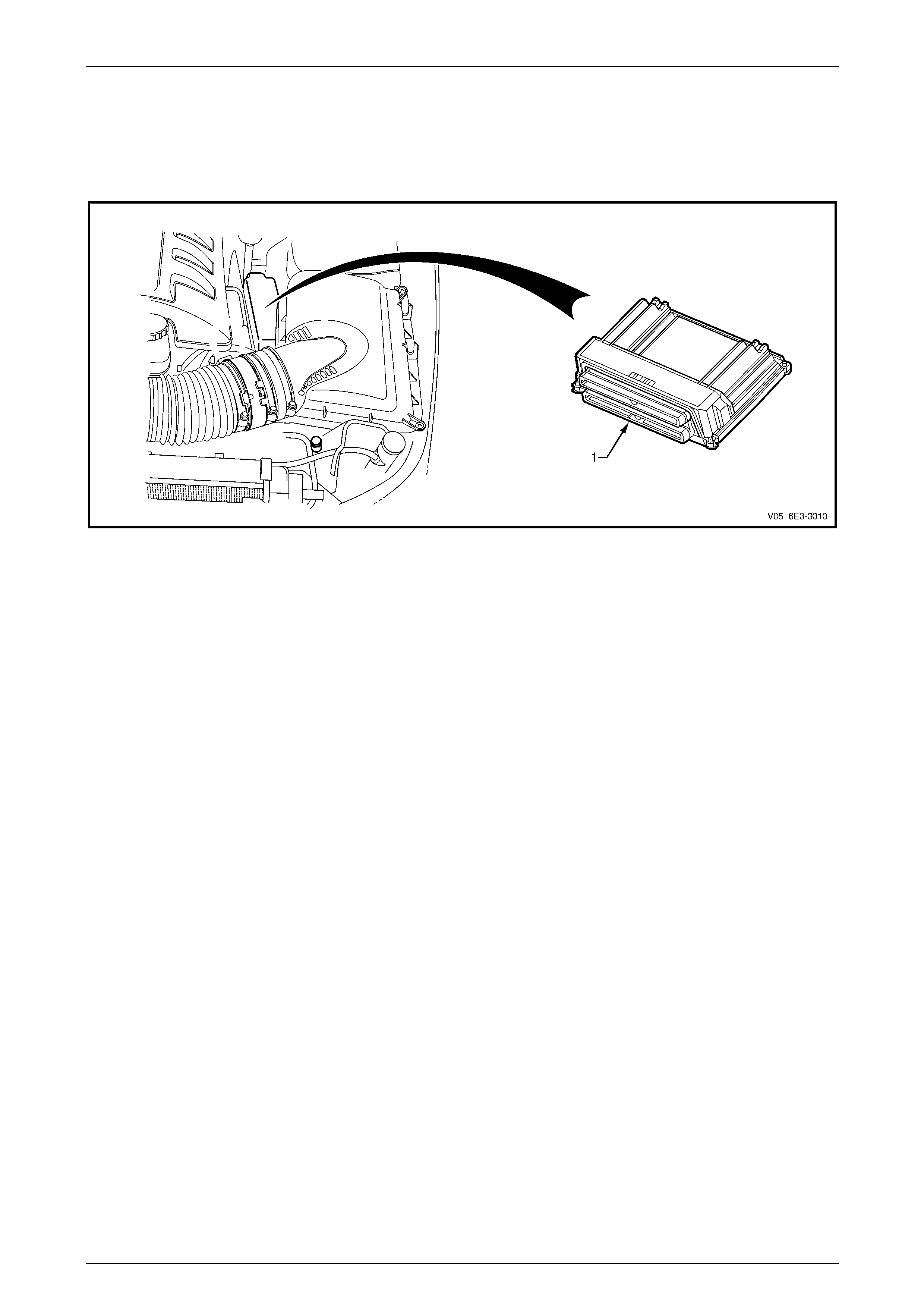
2 Component Location
2.1 Engine Compartment
Figure 6E3 – 2
Legend
1 Powertrain Control Module
Powertrain Interface Module – GEN III V8 Page 6E3–8
Page 6E3–8
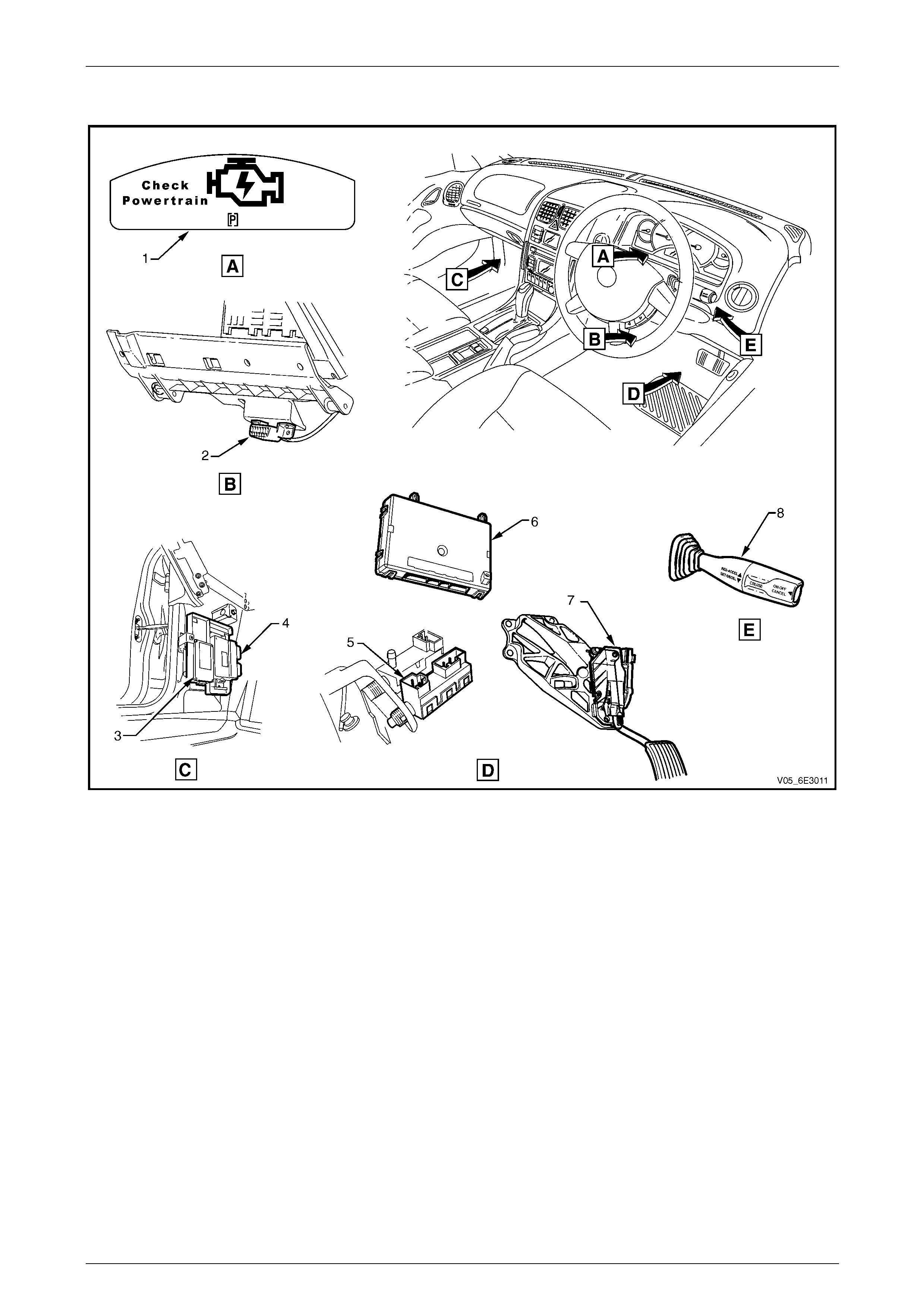
2.2 Interior
Figure 6E3 – 3
Legend
1 Check Powertrain Icon
2 Data Link Connector
3 Powertrain Interface Module (PIM)
4 Throttle Actuator Control Module (TACM)
5 Stop Lamp Switch
6 Body Control Module (BCM)
7 Accelerator Pedal Assembly
8 Cruise Control Switch Assembly
Powertrain Interface Module – GEN III V8 Page 6E3–9
Page 6E3–9
3 Component Description and
Operation
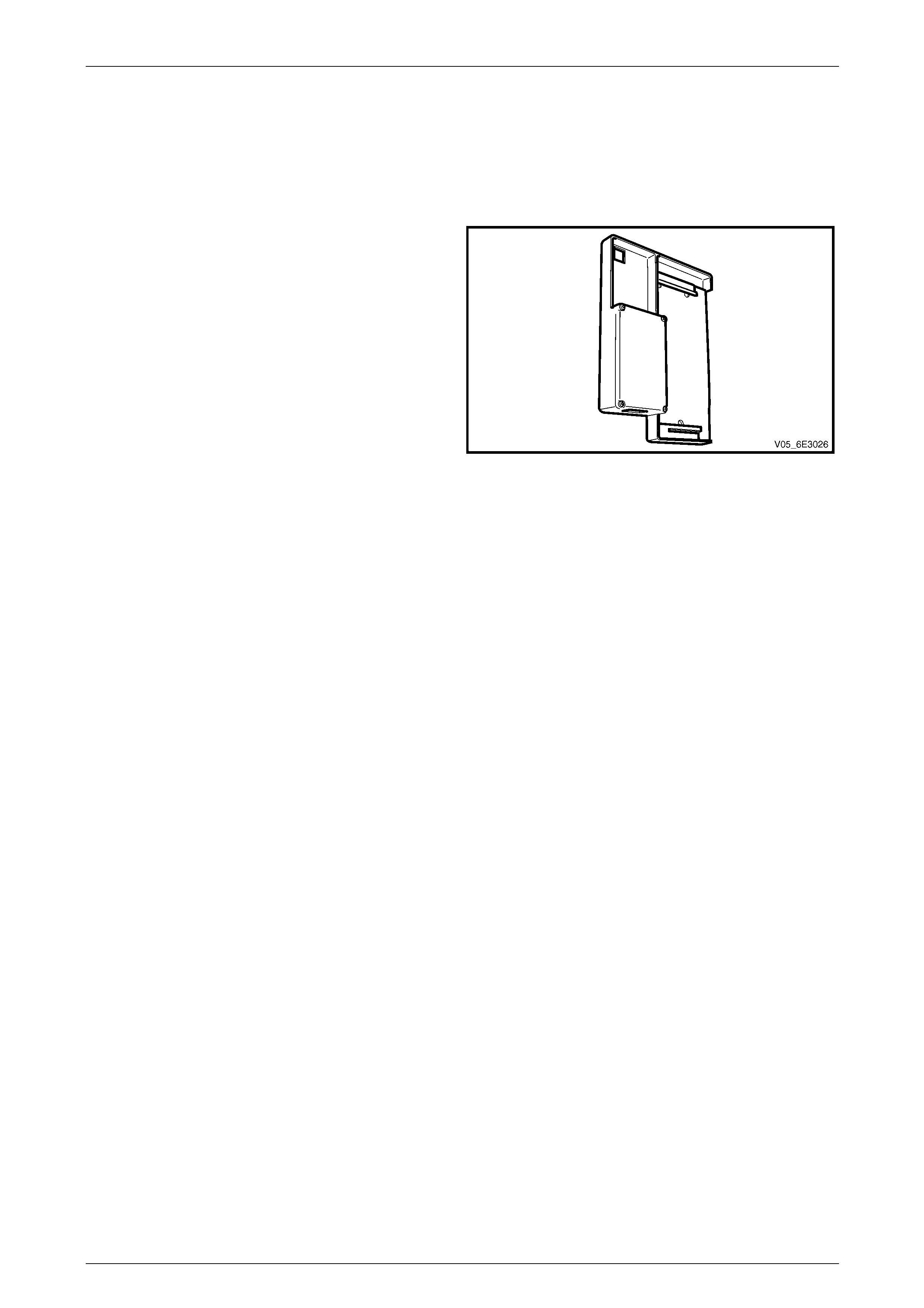
3.1 Pow ertrain Interface Module
The powertrain interface module (PIM) is located behind the
left-hand body hinge pillar lower trim.
Figure 6E3 – 4
Communication Gateway
The PIM performs the following functions:
• The PIM acts as the communication gateway between the class 2 communications protoco l and the universal
asynchronous receive and transmit (UART) protocol.
As the class 2 protocol is not compatible with UART, the PIM is integrated into the serial data communication
system to enable bi-directional communication flow between control modules on the UART side and the class 2
side of the communication net work.
• The PIM receives an analogue input signal from the cruise control ON / OFF / CANCEL switch. The PIM on
receiving the input from the switch, outputs a signal to the throttle actuator control module (TACM).
• The PIM is responsible for au thenticating the body control module (BCM) prior to the powertrain control module
(PCM) authenticating the PIM. If any of these authentication processes fail, the vehicle will not start. For further
information on the theft deterrent system, refer to Section 12J Body Control Module.
Powertrain Interface Module – GEN III V8 Page 6E3–10
Page 6E3–10
3.2 Pow ertrain Interface Module Gateway
Components
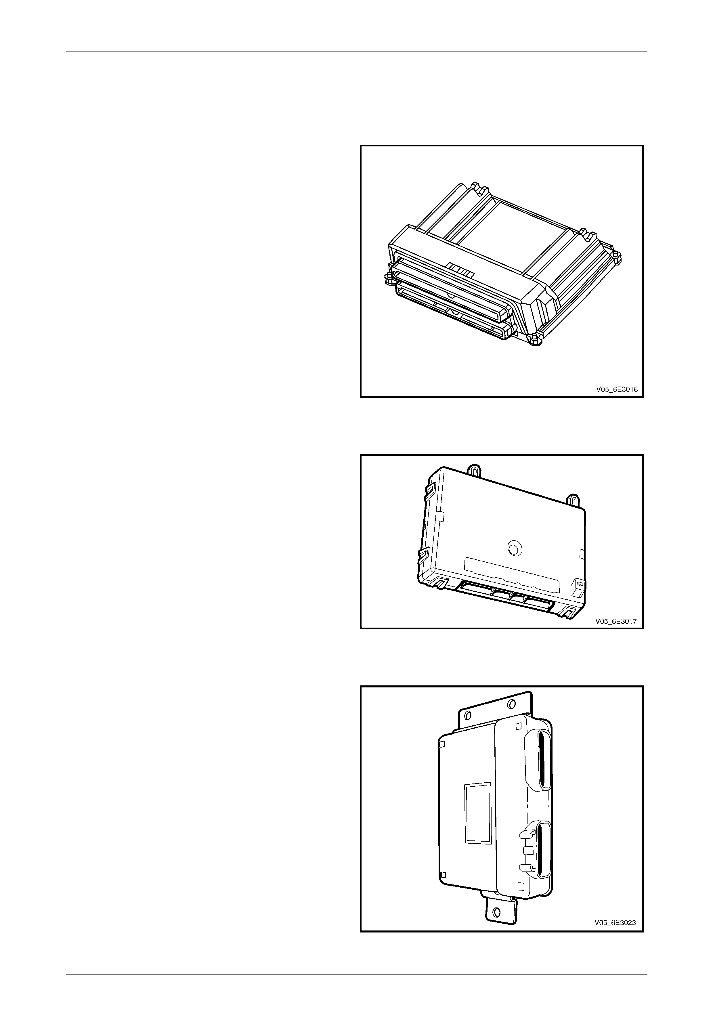
Powertrain Control Module
Located at the left-hand side of the engine compartment, the
powertrain control module (PCM) communicates directly
with the PIM via the serial data network. The PCM, via the
PIM, also communicates with the BCM and instrument
cluster.
The PCM is also an integral part of the vehicle security
system. For further information on vehicle security, refer to
Section 12J Body Control Module.
Figure 6E3 – 5
Body Control Module
The body control module (BCM) is mounted vertically
behind the instrument panel fuse panel.
The BCM controls various vehicle electrica l systems, and is
an integral part of the serial data communication network.
The BCM communicates with other vehicle modules using
the universal asynchronous receive and transmit (UART)
serial data protocol.
The BCM is connected to the PIM and the data link
connector (DLC) via the primary serial data circuit. The BCM
communicates via this circuit with the PCM. Refer to
Section 12J Body Control Module for further information on:
• serial data communication, a nd
• theft deterrent system. Figure 6E3 – 6
Throttle Actuator Control Module
The throttle actuator control module (TACM) in conjunction
with the powertrain control module (PCM) controls the
operation of the throttle body according to vehicle operating
conditions.
The TACM is also responsible for converting the PIM cruise
control ON / OFF / CANCEL request into digital serial data.
This digital serial data is sent to the PCM via the TACM /
PCM UART serial data bus.
Figure 6E3 – 7
Powertrain Interface Module – GEN III V8 Page 6E3–11
Page 6E3–11
3.3 Pow ertrain Interface Module Direct Input
Switches
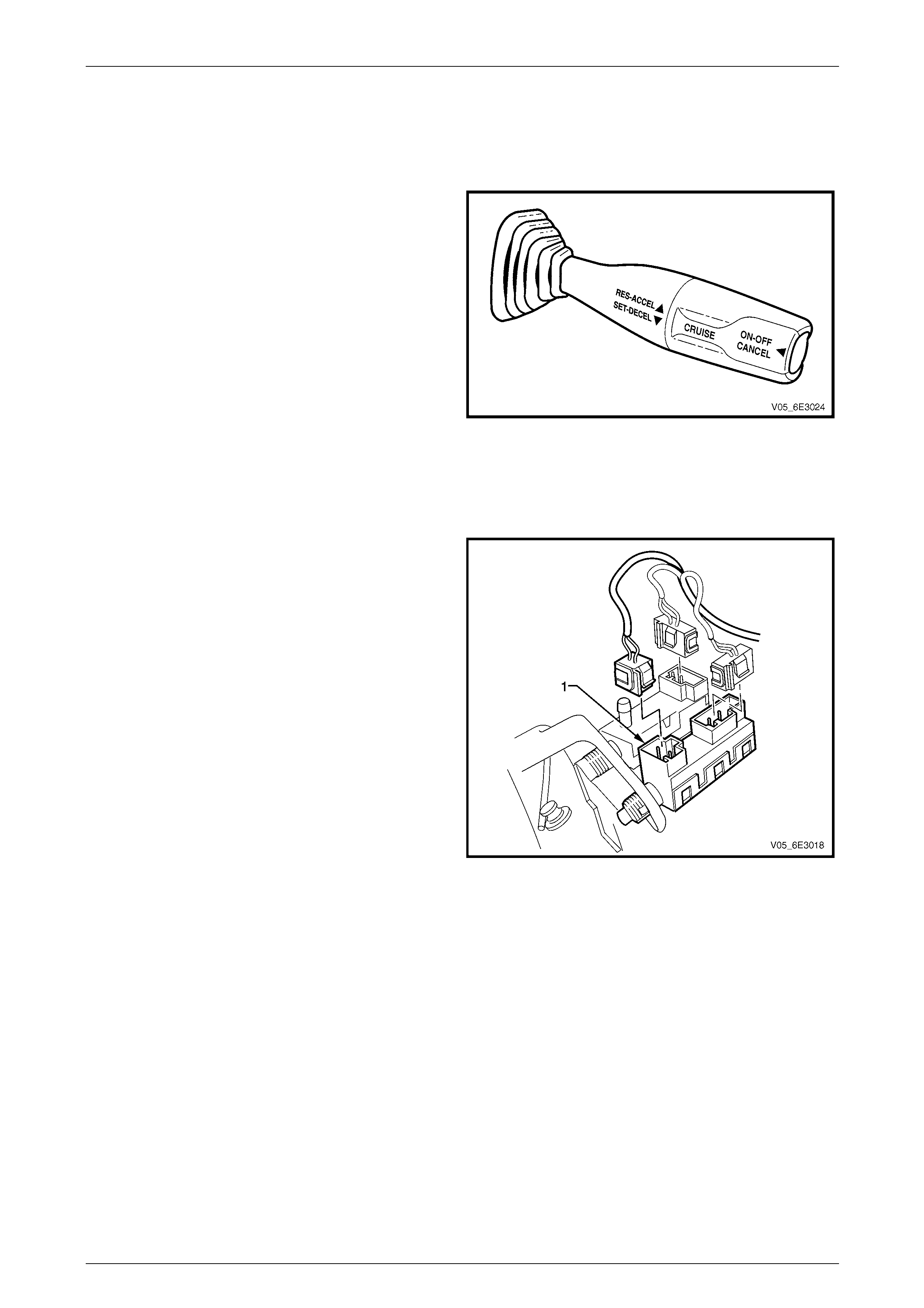
Cruise Control Switch
The cruise control switch is located on th e right-hand side of
the steering column.
The switch is comprised of three momentary contact
switches which control the follo wing function s:
• cruise control push button switch (ON / OFF /
CANCEL),
• cruise control resume – accelerate (RES–ACCEL),
and
• cruise control set – decelerate (SET–DECEL).
The cruise control ON / OFF / CANCEL switch directly
inputs into the PIM. When this switch is activated, the PIM
outputs a 12 Volt signal to the throttle actuator control
module. For further information on the cruise control system,
refer to Section 12E Cruise Control.
Figure 6E3 – 8
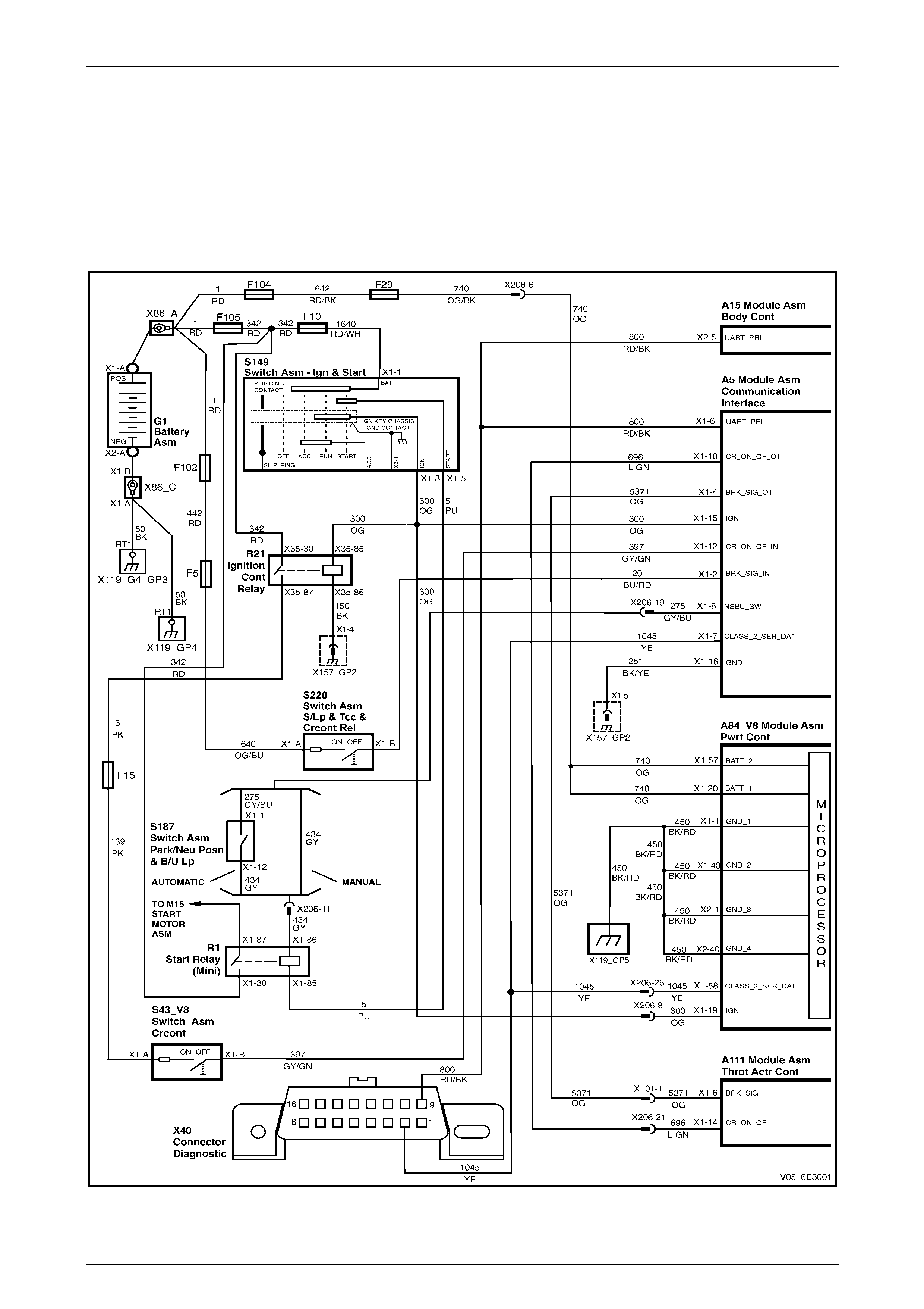
Stop Lamp Switch
The stop lamp switch (1) is a normally open switch that
closes when the brake pedal is depressed.
The PIM uses the stop lamp switch signal voltage to
determine when the brake pedal is depressed.
For stop lamp switch service operations, refer to
Section 12B Lighting System.
Figure 6E3 – 9

Powertrain Interface Module – GEN III V8 Page 6E3–12
Page 6E3–12
4 Diagnostics
4.1 Diagnostic General Descriptions
The powertrain interface module (PIM) diagnostic procedure is organised in a logical structure that begins with the PIM
Diagnostic System Check. The Diagnostic System Check directs the diagnostic procedure to the logical steps or
appropriate diagnostic tab le re quired to diagnose a PIM fault condition.
The diagnostic tables locate a faulty circuit or component through a logical based process of elimination. Correct use of
the diagnostic tables is essential to reduce di agnostic time and to prevent misdiagnosis.
In addition, the Diagnostic System Check provides the following information:
• Identification of the PIM,
• condition of the diagnostic circuit, and
• identification and status of the DTCs if present.
Diagnostic Trouble Code (DTC) Tables
The diagnostic procedure is directed to a diagnostic trouble code (DTC) table if there are DTCs currently stored in the
PIM.
The diagnostic tables are designed to locate a faulty circuit or component through a logical based process of elimination.
The diagnostic tables are developed with the follo wing assumptions:
• the vehicle functioned correctly at the time of assembly,
• there are no multiple faults, and
• the problem currently exists.
Multiple DTCs
When performing a DTC check and there are multiple DTCs, the diag nostic process must begin with the most likely DTC
that may trigger other DTCs. The following situation is an exampl e of a DT C that may trigger other vehicle system DTCs
to set.
• If there is an open circuit condition with the Class 2 serial data circuit between the PIM and the powertrain control
module (PCM), DTC U1001 No Serial Data From PCM may set. This condition may also cause the following DTCs
to set in other control modules:
• Instrument cluster – DTC 11 No Serial Data from the PCM.
• Body Control Module (BCM) – DTC 7 No Serial Data from the PCM.
Knowledge of the PIM and Tech 2 limitations are important to reduce diagnostic time and to prevent misdiagnosis.
Refer to 6.1 Diagnostic Requirements, Preca utions and Preliminary Checks.

Powertrain Interface Module – GEN III V8 Page 6E3–13
Page 6E3–13
Diagnostic Trouble Codes (DTCs)
When the ignition s witch is turned on, the PIM performs an internal integrity check that detects and isolates any internal
faults. The PIM also monitors the cruise control switch circuit and the serial data bus for messages from the PCM on the
Class 2 bus and from the BCM on the UART bus. If a fault is detected by the PIM, it will log a Diagnostic Trouble Code
(DTC) that represents the fault detected. The DT Cs stored in the PIM ma y be accessed using Tech 2.
Refer to Section 0C Tech 2 for further information on T ech 2.
Status of DTCs
The PIM designates the DT Cs logged into a Current or History DTC.
Current DTCs
If the fault condition that triggers the DTC is present during the last PIM self test, that DTC will be designated as a current
DTC.
History DTCs
If the fault condition that triggers the DTC is not present during the last PIM self test, that DTC will be designated as a
history DTC.
Conditions for Clearing DTCs
• If there is no DTC logged in the current PIM self test, the current DTC will be cleared.
• If there is no DTC logged after 100 consecutive drive cycles, the history DTC will be cleare d.
Tech 2 PIM Diagnostic Tests
NOTE
Refer to Section 0C Tech 2 a nd the Tech 2 Users
Manual for detailed information and instructions
regarding the use of Tech 2.
Tech 2 Limitations
Some DTCs trigger other DTCs to set, which causes Tech 2 to display multiple DTCs. In those situations, Tech 2 may
display more DT Cs than is neede d to rectify a fault.
When Tech 2 displays an o utp ut function, it displays only the command given by the PIM. If a connector is disconnected,
that fault will not register in the PIM output function. Tech 2 does not verify the command action.
The service technician must understand t he system being diagnosed as well as the corre c t use and limitations of Tech 2
to be able to perform diagnostic procedures efficiently and successfully.
Tech 2 Intermittent Fault Tests
The following are lists of Tech 2 diagnostic tests that may be used to diagnose intermittent faults:
• Wiggle test the suspected PIM wiring harness and connector while observing Tech 2 operating parameters of the
circuit being tested. If Tech 2 read-out fluctuates during this procedure, check the wiring harness circuit for loose
connection.
• Road test the vehicle in conditions that trigger the intermittent fault while an assistant observes the suspected Tech
2 operating parameter data.
• Capture and store data in the Snapshot mode when the fault occurs. The stored data may be replayed at a slower
rate to aid in diagnostics. Refer to Tech 2 User Instructions for more infor mation o n the Snapshot function.
• Operate suspected components to test their operation using Tech 2 Output Control Data.
Tech 2 Data List
The Tech 2 Data List contains the operating parameters that may be used to analyse the PIM.
The technician is able to compare the op erating parameter of the vehicle be ing diagnosed to the typical data value of a
known serviceable vehicle. NOTE
The Tech 2 Data List Typical Data Values are
obtained from a correctly operating vehicle under
the following conditions:
• ignition switched on,
• engine not running, and
• vehicle is stationary.
Powertrain Interface Module – GEN III V8 Page 6E3–14
Page 6E3–14
5 Wiring Diagram and Connector
Chart
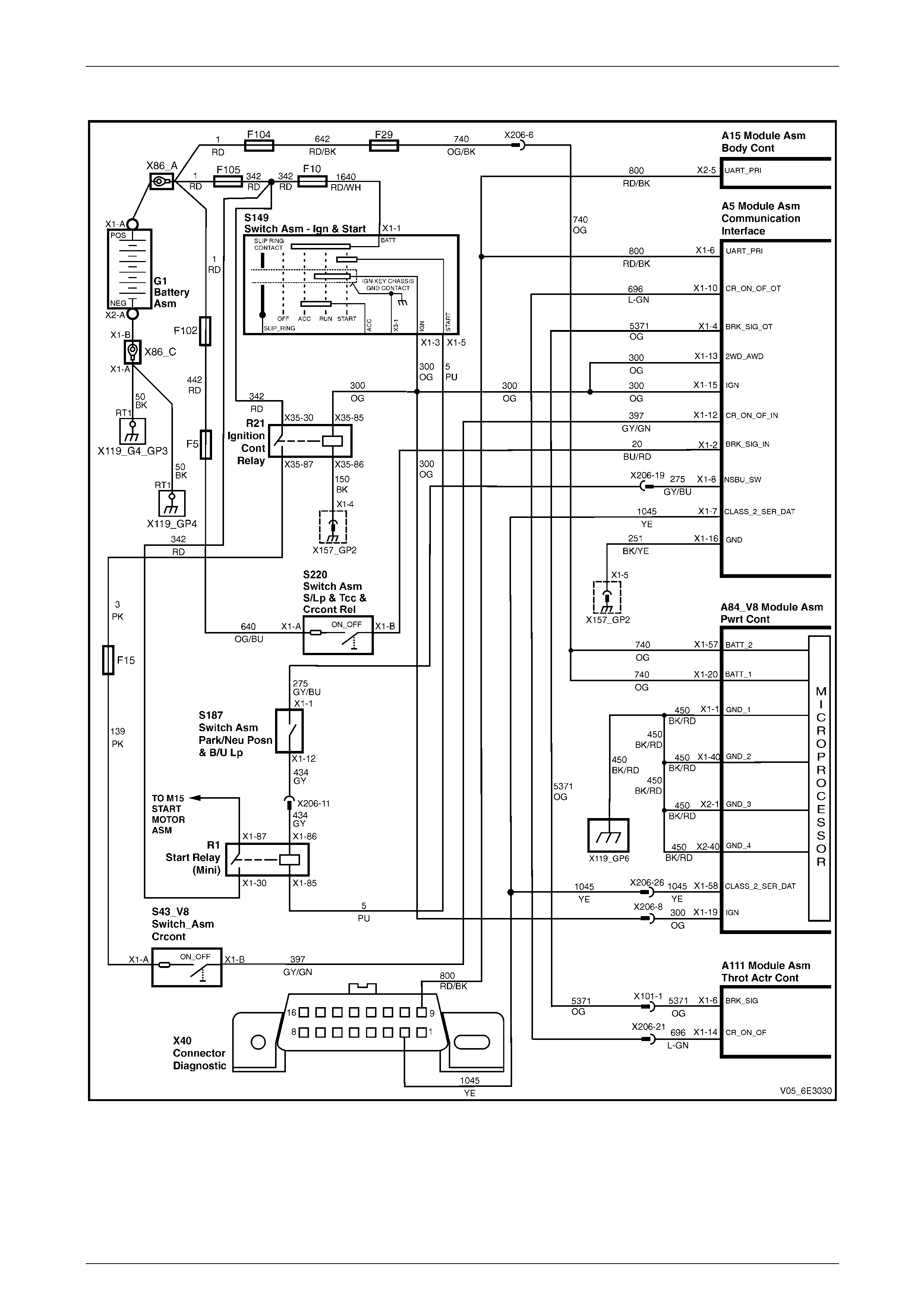
5.1 Wiring Diagrams
Except AWD
Figure 6E3 – 10
Powertrain Interface Module – GEN III V8 Page 6E3–15
Page 6E3–15
AWD
Figure 6E3 – 11
Powertrain Interface Module – GEN III V8 Page 6E3–16
Page 6E3–16
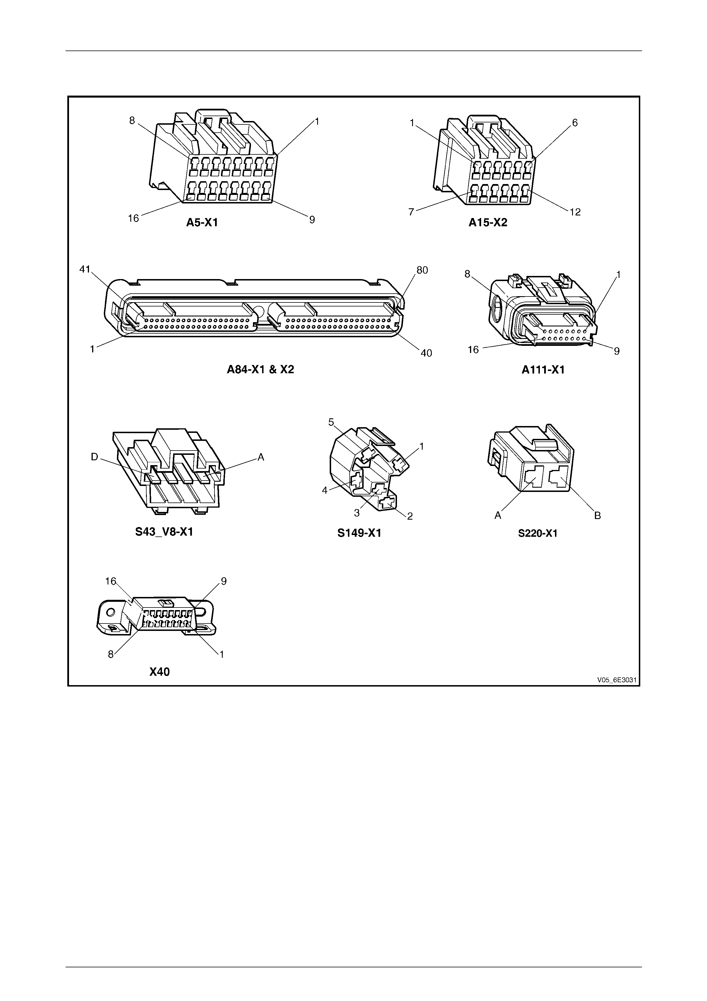
5.2 Connector Chart
Figure 6E3 – 12
Powertrain Interface Module – GEN III V8 Page 6E3–17
Page 6E3–17
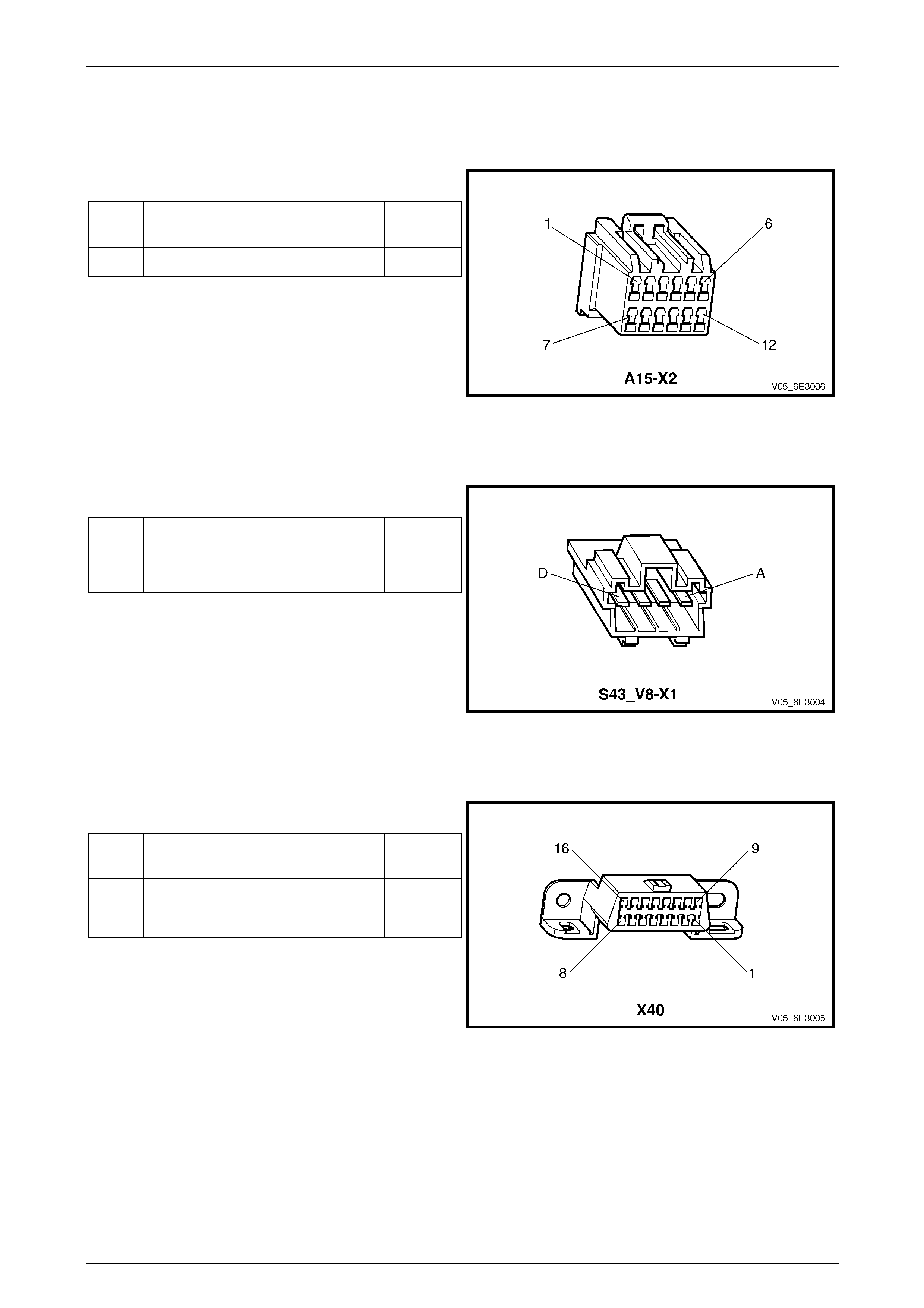
5.3 Connector Information
Body Control Module
Pin Description – Connector X2
Pin Function Circuit
Number
5 UART Serial Data 800
Figure 6E3 – 13
Cruise Control Switch Assembly
Pin Description
Pin Function Circuit
Number
B On / Off / Cancel Signal 397
Figure 6E3 – 14
Data Link Connector
Pin Description
Pin Function Circuit
Number
9 UART - Serial Data 800
2 Class 2 - Serial Data 1045
Figure 6E3 – 15
Powertrain Interface Module – GEN III V8 Page 6E3–18
Page 6E3–18
Ignition Switch
Pin Description
Pin Function Circuit
Number
3 Ignition 300
5 Start 5
Figure 6E3 – 16
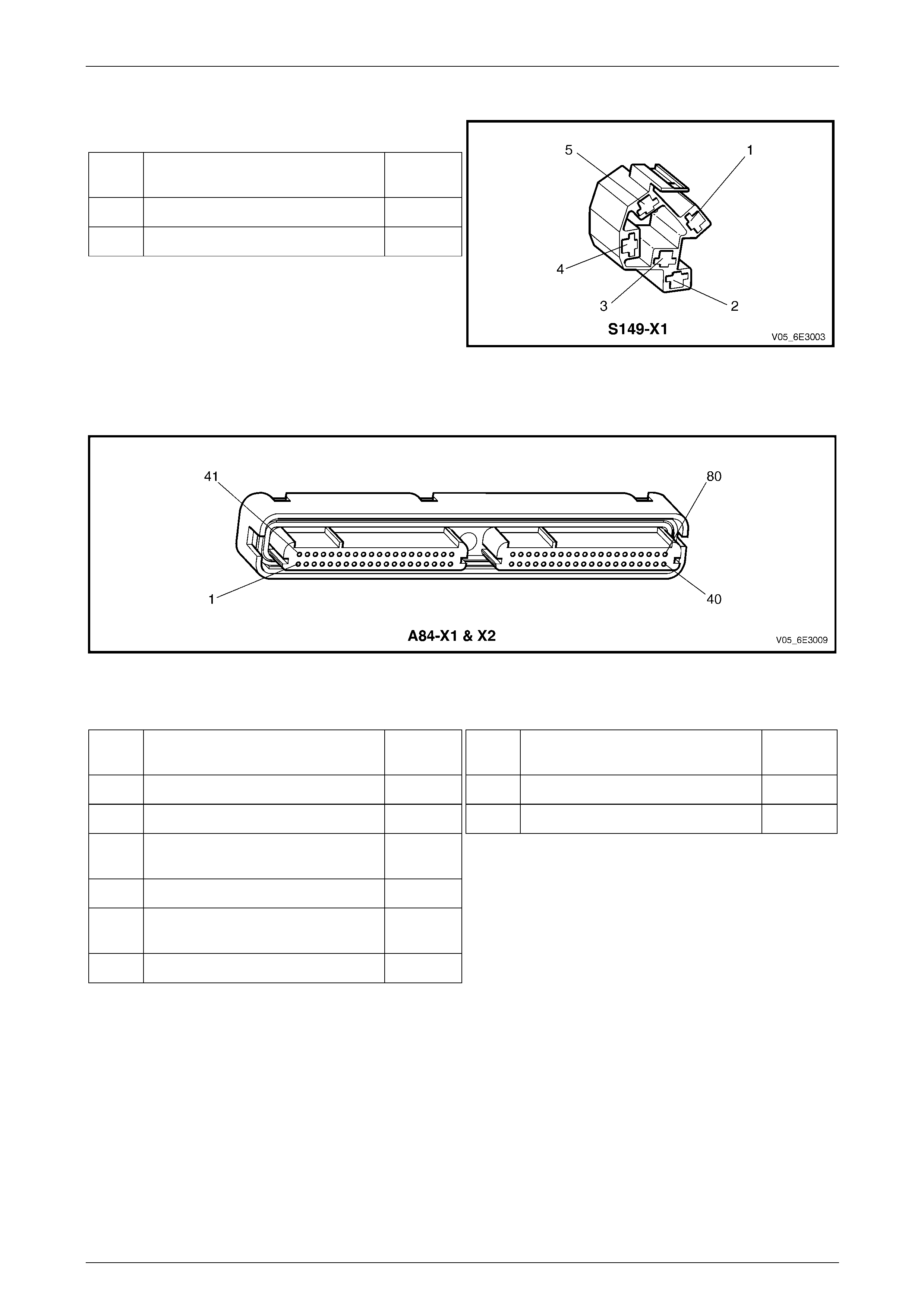
Powertrain Control Module
Figure 6E3 – 17
Pin Description A84-X1 (Blue)
Pin Function Circuit
Number
1 Main Ground Circuit 450
19 Ignition Supply Voltage 300
20 12 V Uninterrupted Supply Voltage
– Fuse F29 740
40 Main Ground Circuit 450
57 12 V Uninterrupted Supply Voltage
– Fuse F29 740
58 Class 2 - Serial Data 1045
Pin Description A84-X2 (Red)
Pin Function Circuit
Number
1 Main Ground Circuit 450
40 Main Ground Circuit 450
Powertrain Interface Module – GEN III V8 Page 6E3–19
Page 6E3–19
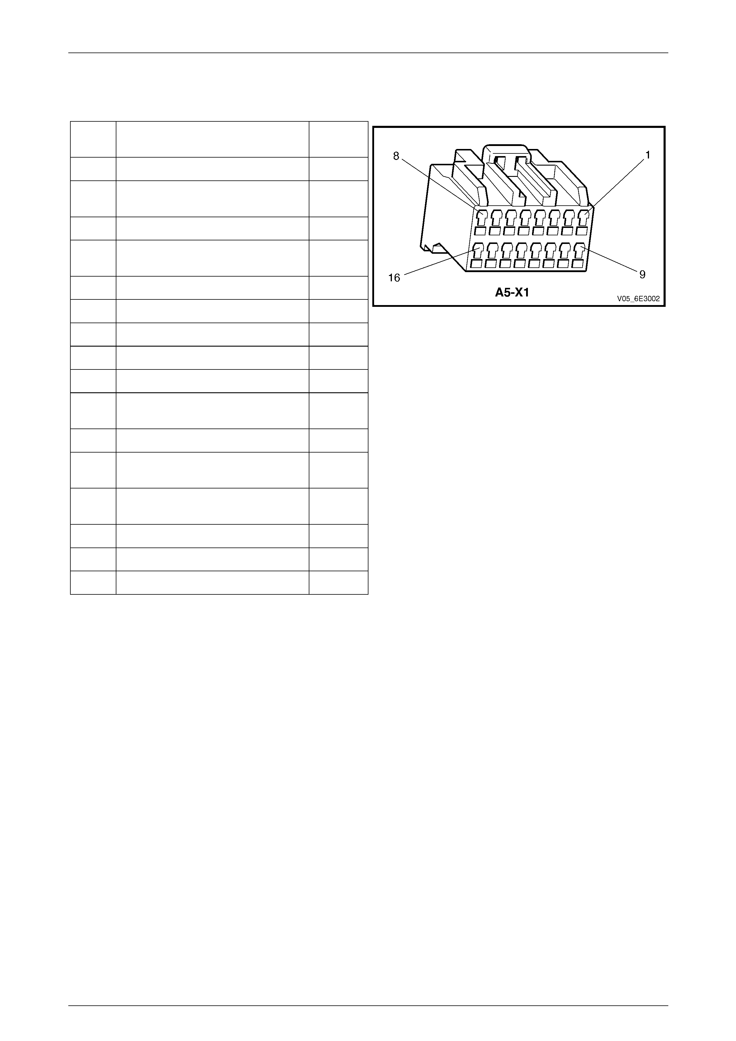
Powertrain Interface Module
Pin Description
Pin Function Circuit
Number
1 Not Connected —
2 Stop Lamp Switch – 12V Input Signal
Circuit 20
3 Not Connected —
4 Stop Lamp Sig nal – 12 V Output
Signal Circuit 5371
5 Not Connected —
6 UART Primary – Serial Data Circuit 800
7 Class 2 – Serial Data Circuit 1045
8 Start Relay – Ground Signal Circuit 275
9 Not Connected —
10 Cruise Control On – 12V Output
Signal Circuit 696
11 Not Connected —
12 Cruise Control Switch On, Off or
Cancel – 12 V Input Signal Circuit 397
13 All Wheel Drive – 12V Input Signal
Circuit 300
14 Not Connected —
15 Ignition Supply Voltage 300
16 Main Ground Circuit 251
Figure 6E3 – 18
Powertrain Interface Module – GEN III V8 Page 6E3–20
Page 6E3–20
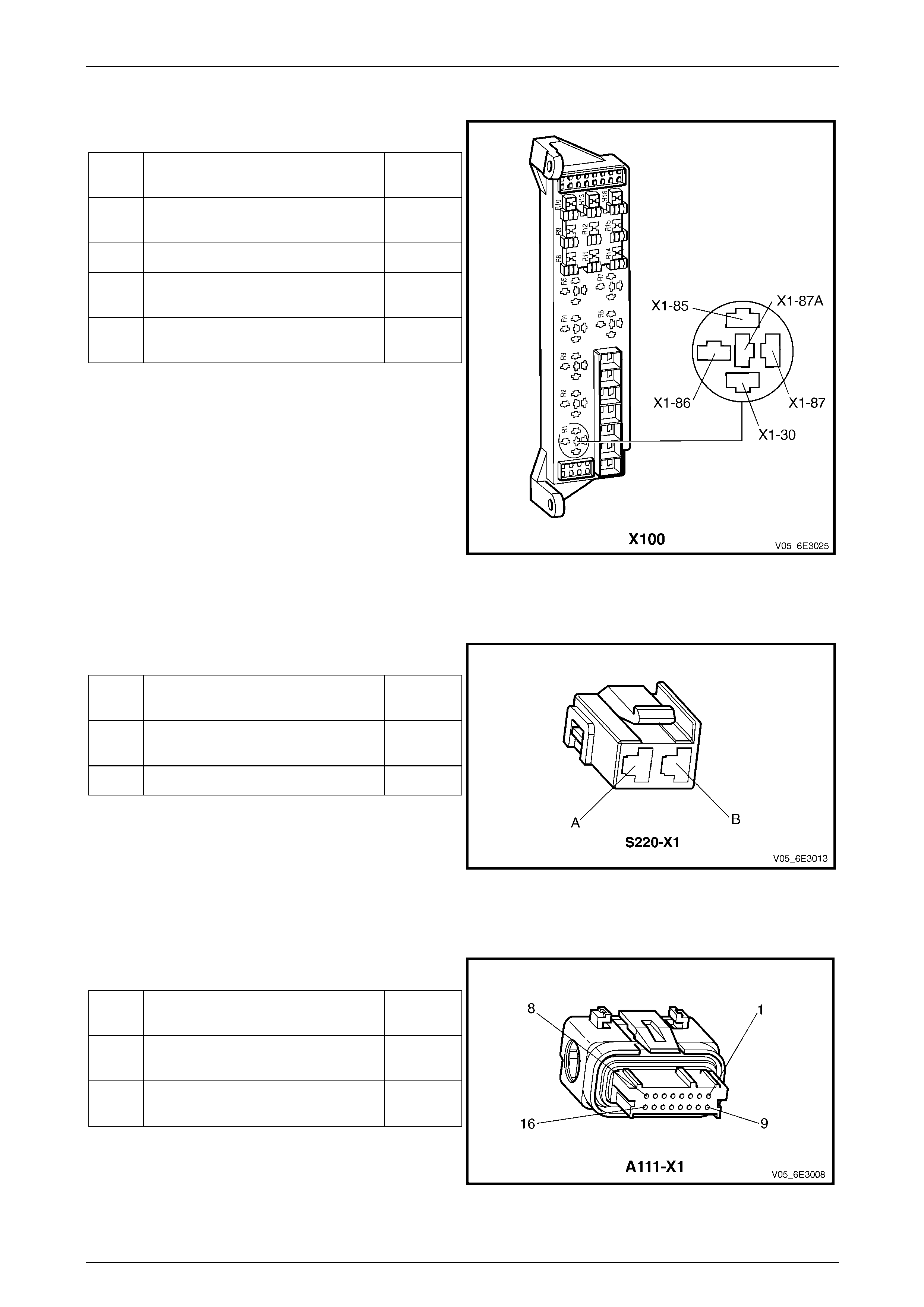
Start Relay
Pin Description
Pin Function Circuit
Number
85 Ignition Switch, Start – 12 V Control
Circuit 5
86 Start Relay – Ground Signal Circuit 434
87 Starter Motor Solenoid – 12 V
output 6
30 12 V Uninterrupted Supply Voltage
– Fuse F105 342
Figure 6E3 – 19
Stop Lamp Switch
Pin Description
Pin Function Circuit
Number
A Stop Lamp Switch Suppl y – Fuse
F5 640
B Stop Lamp Switch Signal Voltage 20
Figure 6E3 – 20
Throttle Actuator Control Module
Pin Description
Pin Function Circuit
Number
6 Stop Lamp Switch – 12V in put
Signal 5371
14 Cruise Control On, Off or Cancel –
12 V Signal Circuit 696
Figure 6E3 – 21

Powertrain Interface Module – GEN III V8 Page 6E3–21
Page 6E3–21
6 Diagnostic Starting Point
6.1 Diagnostic Requirements, Precautions
and Preliminary Checks
Basic Knowledge Required
A lack of basic understanding of electronics,
electrical wiring circuits and use of electrical
circuit testing tools when performing the PIM
diagnostic procedures could result in
incorrect diagnostic results or damage to
components.
In addition, a general understanding of the PIM and its component operation is essential to prevent misdiagnosis and
component damage.
Basic Diagnostic Tools Required
Use of incorrect electrical circuit diagnostic
tools when performing the PIM diagnostic
procedures could result in incorrect
diagnostic results or damage to components.
The following electrical circuit testing tools are required to perform the diagnostic procedur es detailed in this Section:
• Tech 2, refer to Section 0C Tech 2 for further information.
• Test light, refer to Section 12P Wiring Diagrams for further information.
• Digital multimeter with 10 MΩ ohms impedance, refer to Section 12P Wiring Diagrams for further information.
• Connector test adapter kit Tool No. J35616-A.

Powertrain Interface Module – GEN III V8 Page 6E3–22
Page 6E3–22
Diagnostic Precautions
In addition to the safety and precautionary
measures listed in 9.1 Safety and
Precautionary Measures, the following
diagnostic precautions must be observed
when performing any PIM diagnostic
procedure:
• Use only the test equipment specified in the diagnostic tables. Other test equipment may either give incorrect
results or damage serviceable components.
• Do not clear any DTCs unless instructed.
• The fault must be present when using the DTC diagnostic tables otherwise misdiagnosis or replacement of
serviceable parts may occur.
• Always use connector adapters such as those contained in connector test adapter kit Tool No. J35616-A to prevent
connector terminal damage.
• Thorough inspection of the wiring circuits and connectors listed in the diagnostic procedures must be performed
otherwise misdiagnosis may occur.
• Inspect the electrical circuitry or connector terminals that are suspected to be causing the complaint for the
following conditions:
• backed-out connector terminals,
• improper wiring connector mating,
• broken wiring connector locks,
• damaged connector terminals, and
• physical damage to the wiring harness.
• Before replacing a component, inspect its connector terminal for corrosion or deformation that may cause the fault
condition.
Preliminary Checks
The PIM preliminar y check examines easily accessible components which may cause problems with the PIM. This visual
and physical inspection proc edure may quickly identif y the fault condition and elimin ate the need for additional dia gnosis.
• Is the fault specifically isolated to this system / module? If unsure, refer to Section 0D Vehicle Dia gnostics.
• Refer to Service Techlines for releva nt information regarding the fault condition.
• Ensure the battery is fully charged.
• Check the battery connections for corrosion or a loose terminal.
• Perform a visual and physical inspection of the following:
• PIM component wiring harness and terminals for proper connections, pinches or cuts, and
• PIM wiring harness routing which may b e positioned very close to a high voltage or high current devices such
as aftermarket audio systems.
NOTE
High voltage or high current devices may induce
electrical noise on a circuit, which can interfere
with normal circuit operation.
• The PIM is sensitive to electro-magnetic interference (EMI). Check for incorrect aftermarket theft deterrent
devices, lights or mobile phon e installations if an intermittent malfunction is suspected.

Powertrain Interface Module – GEN III V8 Page 6E3–23
Page 6E3–23
6.2 Diagnostic System Check
Step Action Yes No
1 Have you met the basic diagnostic requirements listed in the PIM
Diagnostic Starting Point?
Go to Step 2
Refer to 6.1
Diagnostic
Requirements,
Precautions and
Preliminary Ch ecks
2 Have you read the Diagnostic Precautions?
Go to Step 3
Refer to 6.1
Diagnostic
Requirements,
Precautions and
Preliminary Ch ecks
3 Have you performed the Prelim inary Checks?
Go to Step 4
Refer to 6.1
Diagnostic
Requirements,
Precautions and
Preliminary Ch ecks
4 1 Switch off the ignition.
2 Connect Tech 2 to the Data Link Connector (DLC).
3 Switch on the ignition with the engine not running.
4 Press Tech 2 power button on.
Does Tech 2 screen illuminate and display Tech 2? Go to Step 5 Refer to Section 0C
Tech 2
5 Using Tech 2, perform a Module/ECU Presence Check.
Does Tech 2 display the BCM as being Present? Go to Step 7 Go to Step 6
6 Refer to Section 12J Body Control Module to rectify the BCM
communication fault.
Was the BCM communication fault rectified? Go to Step 7 —
7 Does Tech 2 display the PIM as being Pres ent?
Go to Step 8
Refer to 6.3
Powertrain Interface
Module – Module
Presence Check
Failure Diagnostic
Table
8 Using Tech 2, view and record all DTCs.
Does Tech 2 display a ny DTCs? Go to Step 9
Refer to
7 Intermittent Fault
Conditions
9 Does DTC B1009 fail this ignition cycle? Refer to 8.6 DTC
B1009 – EEPROM
Checksum Error Go to Step 10
10 Does DTC U1000 fail this ignition cycle? Refer to 8.2 DTC
U1000 – No Class 2
Serial Data G to Step 11
11 Does DTC U1001 fail this ignition cycle? Refer to 8.3 DTC
U1001 – No Serial
Data From PCM Go to Step 12
12 Does Tech 2 display mu ltiple DTCs? Go to Step 13 Refer to the relevant
DTC table
13 Refer to the DTC Table of the fault condition that is most likely to
trigger multiple DTCs. Refer to 3.1 Diagnostic General Descriptions for
information on multiple DTCs fault condition. — —
When all diagno sis an d repairs are completed, clear all DTCs an d check the system for correct operation.

Powertrain Interface Module – GEN III V8 Page 6E3–24
Page 6E3–24
6.3 Powertrain Interface Module – Module
Presence Check Failure Diagnostic Table
Step Action Yes No
1 Has the PIM Diagnostic System Check been performed?
Go to Step 2
Refer to 6.2
Diagnostic System
Check
2 Test the following PIM circuits for a high resistance, open circuit or
short to ground fault condition. Refer to Section 12P W iring Diagrams
for information on electrical diagnosis:
• 12 V battery supply circuit 300 ,
• ground circuit 16.
Was a fault found and rectified? Go to Step 5 Go to Step 3
3 Test the UART serial data primary circuit 800 for a high resistance or
an open circuit fault condition
Was a fault found and rectified? Go to Step 5 Go to Step 4
4 Replace the PIM. Refer to 9.2 Powertrain Interface Module.
Was the repair completed? Go to Step 5 —
5 Using Tech 2, perform a Module/ECU Presence Check.
Does Tech 2 display the PIM as being Present? Go to Step 6
Refer to 6.2
Diagnostic System
Check
6 1 Using Tech 2, clear all DTCs.
2 Switch off the ignition for 30 seconds.
3 Check for DTCs.
Does Tech 2 display any PIM DTCs?
Refer to 6.2
Diagnostic System
Check Go to Step 7
7 Does Tech 2 display an y other DTCs? Refer to the
appropriate section System OK
When all diagno sis an d repairs are completed, clear all DTCs an d check the system for correct operation.

Powertrain Interface Module – GEN III V8 Page 6E3–25
Page 6E3–25
7 Intermittent Fault Conditions
7.1 Intermittent Conditions Diagnostic Table
Description
A fault condition is intermittent if one of the following conditions exists:
• The fault condition is not al ways present.
• The fault condition cannot be presently duplicated.
• There is no Current DTC but a Histor y DTC is stored.
Diagnostic Table
Checks Actions
Preliminary • Perform the Preliminary Checks, refer to 2.4 Preliminary Checks.
• Gather information from the customer regarding the conditions that trigger the
intermittent fault such as:
• At what engine or ambient temperature range do es the fault occur?
• Does the fault occur when operating aftermarket electrical equi pment inside
the vehicle?
• Does the fault occur on rough roads or in wet road conditions?
• If the intermittent fault is a start and then stall condition, check theft deterrent
system. Refer to Section 12J Body Control Modu le.
Tech 2 Tests The following are lists of Tech 2 diagnostic tests that may be used to diagnose
intermittent faults:
• Wiggle test the suspected wiring harness and connectors while observin g the
Tech 2 operating parameters. If the Tech 2 read-out fluctuates during this
procedure, check the tested wiring harness ci rcuit for a loose connection.
• Observe the Freeze Frame / Failure Records for the suspected history DTC and
then operate the vehicle in the conditions that triggers the intermittent fault while
an assistant observes the suspected Tech 2 operating parameter data.
• Capture and store data in the Snapshot mode when the fault occurs. The stored
data may be played back at a slower rate to aid in diagnostics. Refer to the Tech 2
User Instructions for more information on the Snapshot fun ction.
• Compare the engine operating parameters of the engine being diagnosed to the
engine operating parameters of a known good engine.
Warning Indicator The following conditions may cause an intermittent Warning Indicator Lamp fault with no
DTC listed:
• Electromagnetic interference (EMI) caused by a faulty relay, PCM controlled
solenoid, switch or other external source.
• Incorrect installation of aftermarket electrical equipment such as the following:
• mobile phones,
• theft deterrent alarms,
• lights, or
• radio equipment.
• Loose PIM ground connections.

Powertrain Interface Module – GEN III V8 Page 6E3–26
Page 6E3–26
Checks Actions
Temperature Related The Tech 2 Freeze Frame / Failure Records or Snapshot data may be used if applicable
to the fault condition. Refer to 4.1 Diagnostic General Descriptions for information on
Tech 2 ECU diagnostic tests.
• If the intermittent fault is heat related, review the Tech 2 data in relationshi p to the
following:
• high ambient temperature,
• underhood / engine generate d heat,
• circuit generated heat due to a poor electrical connection or high e lectrical
load, and
• higher than normal load conditions (towing, etc.).
• If the intermittent fault is related to cold ambient or engine temperature, review the
Tech 2 data in relationship to the following:
• low ambient temperature, and
• the fault condition that occurs only on a cold start situation.
Additional Tests • Check for incorrect installation of aftermarket electrical equipment such as the
following:
• mobile phones,
• theft deterrent alarms,
• lights, or
• radio equipment.
• Check for electromagnetic interference (EMI) caused by a faulty relay, PCM
controlled solenoid or switch.
• Check the A/C compressor clutch and some rela ys that contain a clamping diode
or resistor for an open circuit.
• Check the generator for a faulty rectifier bridge that may allow A/C noise into the
PIM electrical circuit.
When all diagnosis and rep airs are completed, check the engine management system for correct operation.

Powertrain Interface Module – GEN III V8 Page 6E3–27
Page 6E3–27
8 DTC Tables
8.1 DTC List
DTC Description Diagnostic Table
B0575 Wrong Fuel Information 8.7 DTC B0575 or B0576 – Fuel Level
Information
B0576 No Fuel Level Information 8.7 DTC B0575 or B0576 – Fuel Level
Information
B1009 EEPROM Checksum Error 8.6 DTC B1009 – EEPROM Checksum Error
B1019 Configuration Mismatch 8.8 DTC B1019 – Configuration Mismatch
B3027 Starter Enable Circuit Range / Performance 8.9 DTC B3027 – Starter Enable Circuit Range /
Performance
P1554 Cruise Control Cancel Circuit Malfunction 8.10 DTC P1554 – Cruise Control Cancel Circuit
Malfunction
P1585 Cruise Control Enable Circuit Malfuncti on 8.11 DTC P1585 – Cruise Control Ena ble Circuit
Malfunction
U1000 No Class 2 Serial Data 8.2 DTC U1000 – No Class 2 Serial Data
U1001 No Serial Data From PCM 8.3 DTC U1001 – No Serial Data From PCM
U1064 No Serial Data From BCM 8.4 DTC U1064 – No Serial Data From BCM
U1002 No Oil Pressure Information 8.5 DTC U1002 – No Oil Pressure Information

Powertrain Interface Module – GEN III V8 Page 6E3–28
Page 6E3–28
8.2 DTC U1000 – No Class 2 Serial Data
DTC Description
This diagnostic procedure supports DTC U1000 – No Class 2 Serial Data.
Circuit Description
The powertrain interface module (PIM) continuousl y receives messages from any Class 2 device con ne c ted to the Class
2 serial data circuit. If the PIM does not receive a message from any Class 2 device, including itself, within the last five
seconds, DTC U1000 sets.
Additional Information
• Refer to 5 Wiring Diagram and Connector Chart for the foll owing information:
• PIM connector illustration and terminal assignment, and
• PIM wiring diagram.
• Refer to Section 6C3-2 Powertrain Management – GEN III V8 – Diagnostics for powertrain diagnostic information.
• For intermittent fault conditions, refer to 7 Intermittent Fault Conditions.
• Since fault conditions in a wiring con nector may trigger DTCs, always test the connectors related to this diagnostic
procedure for shorted terminals or poor wiring connection before replacing any component.
Refer to Section 12P Wiring Diagrams for information on electrical fault diagnosis.
Conditions for Running the DTC
Conditions for running the DTC are:
• The ignition is switched on.
• The ignition volt age is 10.0 – 16.0 V.
Condition for Setting the DTC
The PIM does not receive a Class 2 serial data message within a predetermined time.
Action Taken when the DTC Sets
When the DTC sets, a Service Vehicle Soon icon is displayed on the instrument cluster multi-function display.
Condition for Clearing the DTC
Refer to 4.1 Diagnostic General Descriptions for information on the conditions for clearing the DTC.
Test Description
The following numbers refer to the step numbers in the diagnostic table:
2 Checks if the DTC is current.
3 Establishes if there is a fault with the PCM.
4 Tests Class 2 serial data circuit 1045 between the PCM, PIM and data link connector.
5 Tests the integrity of the PCM 12 V battery supply circuit and ground conn ections.
7 Tests the integrity of the PIM 12 V ignition circuit and ground connectio ns.

Powertrain Interface Module – GEN III V8 Page 6E3–29
Page 6E3–29
DTC U1000 Diagnostic Table
Step Action Yes No
1 Has the Diagnostic System Check been performed?
Go to Step 2
Refer to 6.2
Diagnostic System
Check
2 1 Switch off the ignition for 30 seconds.
2 Operate the vehicle within the conditions for setting DTC U1000.
3 Using Tech 2, select the DTC displ ay function.
Does DTC U1000 fail this ignition cycle? Go to Step 3
Refer to Additional
Information in this
Section
3 1 Disconnect connector A84 – X1 from the PCM.
2 Switch off the ignition for 10 seconds.
3 Operate the vehicle within the conditions for setting DTC U1000.
4 Using Tech 2, select the DTC display function and check if DTC
U1000 fails this ignition cycle.
NOTE
Other DTCs may set when the PCM connector is
disconnected and the ignition is switched on. Disregard
DTCs that set under this condition on this DTC Table.
Does DTC U1000 fail this ignition cycle? Go to Step 4 Go to Step 5
4 Test serial data circuit 1045 b etween the PCM, PIM and data link
connector for a short to voltage, short to ground or open circuit
condition. Refer to Section 12P Wiring Diagrams for information on
wiring circuit testing and repair.
Was a fault found and rectified? Go to Step 9 Go to Step 7
5 Test the following PCM circuits for a high resistance, op en circuit or
short to ground fault condition. Refer to Section 12P W iring Diagrams
for information on electrical diagnosis:
• 12 V battery supply circuit 740 , and
• PCM ground circuits 450.
Was a fault found and rectified? Go to Step 9 Go to Step 6
6 Replace the PCM. Refer to Section 6C3-3 Powertrain Management –
GEN III V8 – Service Operations.
Was the repair completed? Go to Step 9 —
7 1 Test all ground circuits of the PIM for a high resistance or an
open circuit fault condition. Refer to Section 12P Wiring
Diagrams for information on electrical fault diagnosis.
2 Test the PIM fuses and replace as requ ired. Refer to Section
12O Fuses, Relays and Wiring Harnesses.
3 Test the PIM ignition supply voltage circuit for a high resistance,
open circuit or short to ground fault condition. Refer to Section
12P Wiring Diagrams for information on el ectrical fault
diagnosis.
Was a fault found and rectified? Go to Step 9 Go to Step 8
8 Replace the PIM. Refer to 9.2 Powertrain Interface Module.
Was the repair completed? Go to Step 9 —
9 1 Using Tech 2, clear the DTC.
2 Switch off the ignition for 30 seconds.
3 Start the engine.
4 Operate the vehicle within the conditions for running the DTC.
Does DTC U1000 fail this ignition cycle? Go to Step 2 Go to Step 10
10 Using Tech 2, select the DTC displa y function.
Does Tech 2 display a ny DTCs? Go to the
appropriate DTC
Table System OK
When all diagno sis an d repairs are completed, clear all DTCs an d check the system for correct operation.

Powertrain Interface Module – GEN III V8 Page 6E3–30
Page 6E3–30
8.3 DTC U1001 – No Serial Data From PCM
DTC Description
This diagnostic procedure su pports DTC U1001 – No Serial Data Fr om PCM.
Circuit Description
The powertrain interface module (PIM) continuously receives messages from the powertrain control module (PCM). If the
PIM does not receive a message within a predetermined time from the PCM, DTC U1001 sets.
Additional Information
• Refer to 5 Wiring Diagram and Connector Chart for the foll owing information:
• PIM connector illustration and terminal assignment, and
• PIM wiring diagram.
• Refer to Section 6C3-2 Powertrain Management – GEN III V8 – Diagnostics for powertrain diagnostic information.
• For intermittent fault conditions, refer to 7 Intermittent Fault Conditions.
• Since fault conditions in a wiring con nector may trigger DTCs, always test the connectors related to this diagnostic
procedure for shorted terminals or poor wiring connection before replacing any component.
Refer to Section 12P Wiring Diagrams for information on electrical fault diagnosis.
Conditions for Running the DTC
Conditions for running the DTC are:
• The ignition is switched on.
• The ignition volt age is 10.0 – 16.0 V.
Condition for Setting the DTC
The PIM does not receive a serial data message from the PCM for greater than five seconds.
Action Taken when the DTC Sets
When the DTC sets, a Service Vehicle Soon icon is displayed on the instrument cluster multi-function display.
Condition for Clearing the DTC
Refer to 4.1 Diagnostic General Descriptions for information on the conditions for clearing the DTC.
Test Description
The following numbers refer to the step numbers in the diagnostic table:
2 Checks if the DTC is current, and if so, indicates the PIM has an interna l problem.
5 Tests the integrity of the PCM 12 V battery supply circuit and ground conn ections.
6 Tests Class 2 serial data circuit 1045 between the PCM, PIM and data link connector.
9 Tests the integrity of the PIM 12 V ignition circuit and ground connectio ns.

Powertrain Interface Module – GEN III V8 Page 6E3–31
Page 6E3–31
DTC U1001 Diagnostic Table
Step Action Yes No
1 Has the Diagnostic System Check been performed?
Go to Step 2
Refer to 6.2
Diagnostic System
Check
2 1 Switch off the ignition for 10 seconds.
2 Operate the vehicle within the conditions for setting DTC U1001.
3 Using Tech 2, select the DTC displ ay function.
Does DTC U1001 fail this ignition cycle? Go to Step 3
Refer to Additional
Information in this
Section
3 Using Tech 2, attempt to communicate with the PCM.
Does Tech 2 communicate with the PCM? Go to Step 8 Go to Step 4
4 1 Disconnect connector A5 – X1 from the PIM
2 Using Tech 2, attempt to communicate with the PCM.
Does Tech 2 communicate with the PCM Go to Step 9 Go to Step 5
5 Test the following PCM circuits for a high resistance, op en circuit or
short to ground fault condition. Refer to Section 12P W iring Diagrams
for information on electrical diagnosis:
• 12 V battery supply circuit 740 , and
• PCM ground circuits 450.
Was a fault found and rectified? Go to Step 11 Go to Step 6
6 Test serial data circuit 1045 b etween the PCM, PIM and data link
connector for a short to voltage, short to ground or open circuit
condition. Refer to Section 12P Wiring Diagrams for information on
wiring circuit testing and repair.
Was a fault found and rectified? Go to Step 11 Go to Step 7
7 Replace the PCM. Refer to Section 6C3-3 Powertrain Management –
GEN III V8 – Service Operations.
Was the repair completed? Go to Step 11 —
8 Test serial data circuit 1045 b etween the PIM and the PCM for an
open circuit condition. Refer to Section 12P W iring Diagrams for
information on wiring circuit testing and repai r .
Was a fault found and rectified? Go to Step 11 Go to Step 9
9 1 Test all ground circuits of the PIM for a high resistance or an
open circuit fault condition. Refer to Section 12P Wiring
Diagrams for information on electrical fault diagnosis.
2 Test the PIM fuses and replace as requ ired. Refer to Section
12O Fuses, Relays and Wiring Harnesses.
3 Test the PIM battery supply voltage circuit for a high resistance,
open circuit or short to ground fault condition. Refer to Section
12P Wiring Diagrams for information on el ectrical fault
diagnosis.
Was a fault found and rectified? Go to Step 11 Go to Step 10
10 Replace the PIM. Refer to 9.2 Powertrain Interface Module.
Was the repair completed? Go to Step 11 —
11 1 Using Tech 2, clear the DTC.
2 Switch off the ignition for 30 seconds.
3 Start the engine.
4 Operate the vehicle within the conditions for running the DTC.
Does DTC U1001 fail this ignition cycle? Go to Step 2 Go to Step 12
12 Using Tech 2, select the DTC displa y function.
Does Tech 2 display a ny DTCs? Go to the
appropriate DTC
Table System OK
When all diagno sis an d repairs are completed, clear all DTCs an d check the system for correct operation.

Powertrain Interface Module – GEN III V8 Page 6E3–32
Page 6E3–32
8.4 DTC U1064 – No Serial Data From BCM
DTC Description
This diagnostic procedure su pports DTC U1064 – No Serial Data Fr om BCM.
Circuit Description
The powertrain control module (PCM) transmits and receiv es data usi ng the Class 2 serial data protoco l, while the body
control module (BCM) and other vehic le control modules use the univers al asynchronous receive and transmit (UART)
serial data protocol.
As the Class 2 and UART protocols are not compatible, a powertrain interface module (PIM) is integrated into the serial
data system to enable communication b etween the two different protocols.
The PIM monitors the UART serial data bus for traffic, and if the PIM does not detect any traffic on the UART serial data
bus, DTC U1064 sets.
Additional Information
• Refer to 5 Wiring Diagram and Connector Chart for the foll owing information:
• PIM connector illustration and terminal assignment, and
• PIM wiring diagram.
• Refer to Section 12J Body Control Module for BCM diagnosis.
• For intermittent fault conditions, refer to 7 Intermittent Fault Conditions.
• Since fault conditions in a wiring con nector may trigger DTCs, always test the connectors related to this diagnostic
procedure for shorted terminals or poor wiring connection before replacing any component.
Refer to Section 12P Wiring Diagrams for information on electrical fault diagnosis.
Conditions for Running the DTC
Conditions for running the DTC are:
• The ignition is switched on.
• The ignition volt age is 10.0 – 16.0 V.
Condition for Setting the DTC
The PIM does not see any serial data communication on the UART serial data circuit 800 for longer than 10 seconds.
Action Taken when the DTC Sets
When the DTC sets, there is no message displayed on the instrument cluster multi-function display.
Condition for Clearing the DTC
Refer to 4.1 Diagnostic General Descriptions for information on the conditions for clearing the DTC.
Test Description
The following number refers to the step number in the diagnostic table:
2 Checks if the DTC is current.
3 Checks if Tech 2 can communicate with the BCM.

Powertrain Interface Module – GEN III V8 Page 6E3–33
Page 6E3–33
DTC U1064 Diagnostic Table
Step Action Yes No
1 Has the Diagnostic System Check been performed?
Go to Step 2
Refer to 6.2
Diagnostic System
Check
2 1 Switch off the ignition for 10 seconds.
2 Operate the vehicle within the conditions for setting DTC U1064.
3 Using Tech 2, select the DTC displ ay function.
Does DTC U1064 fail this ignition cycle? Go to Step 3
Refer to Additional
Information in this
Section
3 Using Tech 2, view the BCM identification informatio n.
Does Tech 2 display the BCM identification information? Go to Step 4
Refer to Section 12J
Body Control
Module
4 Using Tech 2, view the BCM Normal Mode Data.
Does Tech 2 display n ormal mode data? Go to Step 5
Refer to Section 12J
Body Control
Module
5 Replace the PIM. Refer to 9.2 Powertrain Interface Module.
Was the repair completed? Go to Step 6 —
6 1 Using Tech 2, clear the DTC.
2 Switch off the ignition for 30 seconds.
3 Start the engine.
4 Operate the vehicle within the conditions for running the DTC.
Does DTC U1064 fail this ignition cycle? Go to Step 2 Go to Step 7
7 Using Tech 2, select the DTC display function.
Does Tech 2 display a ny DTCs?
Go to the
appropriate DTC
Table System OK
When all diagno sis an d repairs are completed, clear all DTCs an d check the system for correct operation.

Powertrain Interface Module – GEN III V8 Page 6E3–34
Page 6E3–34
8.5 DTC U1002 – No Oil Pressure
Information
DTC Description
This diagnostic procedure supports DTC U1002 – No Oil Pressure Information.
Circuit Description
The powertrain interface module (PIM) continuously receives engine oil pressure messages from the powertrain control
module (PCM) via the class 2 serial data circuit. If the PIM does not receive an oil pressure message, within a
predetermined time, DTC U1002 sets.
Additional Information
• Refer to 5 Wiring Diagram and Connector Chart for the foll owing information:
• PIM connector illustration and terminal assignment, and
• PIM wiring diagram.
• Refer to Section 6C3-2 Powertrain Management – GEN III V8 – Diagnostics for powertrain diagnostic information.
• For intermittent fault conditions, refer to 7 Intermittent Fault Conditions.
• Since fault conditions in a wiring con nector may trigger DTCs, always test the connectors related to this diagnostic
procedure for shorted terminals or poor wiring connection before replacing any component.
Refer to Section 12P Wiring Diagrams for information on electrical fault diagnosis.
Conditions for Running the DTC
Conditions for running the DTC are:
• The ignition is switched on.
• The ignition volt age is 10.0 – 16.0 V.
Condition for Setting the DTC
The PIM receives an oil pressure failure report from the PCM or the PIM does not receive a oil pressure message from
the PCM for five seconds or more.
Action Taken when the DTC Sets
When the DTC sets, there is no message displayed on the instrument cluster multi-function display.
Condition for Clearing the DTC
Refer to 4.1 Diagnostic General Descriptions for information on the conditions for clearing DTCs.
Test Description
The following numbers refer to the step numbers in the diagnostic table:
2 Checks if the DTC is current.
3 Establishes if there is a fault with the PCM.
4 Establishes if there is a programming fault with the PCM.

Powertrain Interface Module – GEN III V8 Page 6E3–35
Page 6E3–35
DTC U1002 Diagnostic Table
Step Action Yes No
1 Has the Diagnostic System Check been performed?
Go to Step 2
Refer to 6.2
Diagnostic System
Check
2 1 Switch off the ignition for 10 seconds.
2 Operate the vehicle within the conditions for setting DTC U1002.
3 Using Tech 2, select the DTC displ ay function.
Does DTC U1002 fail this ignition cycle? Go to Step 3
Refer to Additional
Information in this
Section
3 Are DTC's P0522, P0523, P0601, P06 02 and P0604 set in the PCM?
Refer to Section 6C3-2 Powertrain Management – GEN III V8.
Was a fault found and rectified? Go to Step 6 Go to Step 4
4 Attempt to program the PCM. Refer to Section 0C Tech 2.
Was the programming successful? Go to Step 6 Go to Step 5
5 Replace the PCM. Refer to Section 6C3-3 Powertrain Management –
GEN III V8 – Service Operations.
Was the repair completed? Go to Step 6 —
6 1 Using Tech 2, clear the DTCs.
2 Switch off the ignition for 30 seconds.
3 Start the engine.
4 Operate the vehicle within the conditions for running the DTC.
Does DTC U1002 fail this ignition cycle? Go to Step 2 Go to Step 7
7 Using Tech 2, select the DTC display function.
Does Tech 2 display a ny DTCs?
Go to the
appropriate DTC
Table System OK
When all diagno sis an d repairs are completed, clear all DTCs an d check the system for correct operation.

Powertrain Interface Module – GEN III V8 Page 6E3–36
Page 6E3–36
8.6 DTC B1009 – EEPROM Checksum Error
DTC Description
This diagnostic procedure supports DTC B1009 – EEPROM Checksum Error.
Circuit Description
The powertrain interface module (PIM) is the control centre for the communication lang uage conversion between Class 2
serial data and UART serial data. If there is an internal microprocessor integrity fault condition with the PIM, DTC B1009
sets.
Additional Information
• Refer to 5 Wiring Diagram and Connector Chart for the foll owing information:
• PIM connector illustration and terminal assignment, and
• PIM wiring diagram.
• For intermittent fault conditions, refer to 7 Intermittent Fault Conditions.
• Since fault conditions in a wiring con nector may trigger DTCs, always test the connectors related to this diagnostic
procedure for shorted terminals or poor wiring connection before replacing any component.
Refer to Section 12P Wiring Diagrams for information on electrical fault diagnosis.
Conditions for Running the DTC
Conditions for running the DTC are:
• The ignition is switched on.
• The ignition volt age is 10.0 – 16.0 V.
Condition for Setting the DTC
An internal PIM fault exists.
Action Taken when the DTC Sets
The action taken when the DTC sets will depend on the severit y of the error. This ma y vary from no visual or audible
warning messages to a Service Vehicle Soon icon is displayed on the instr ument clus ter multi-functi on display.
Condition for Clearing the DTC
Refer to 4.1 Diagnostic General Descriptions for information on the conditions for clearing the DTC.
Test Description
The following numbers refer to the step numbers in the diagnostic table:
2 Checks if the DTC is current, and if so, indicates the PIM has an interna l problem.
3 Tests the integrity of the PIM 12 V ignition circuit and ground connectio ns.

Powertrain Interface Module – GEN III V8 Page 6E3–37
Page 6E3–37
DTC B1009 Diagnostic Table
Step Action Yes No
1 Has the Diagnostic System Check been performed?
Go to Step 2
Refer to 6.2
Diagnostic System
Check
2 1 Switch off the ignition for 30 seconds.
2 Operate the vehicle within the conditions for setting DTC B1009.
3 Using Tech 2, select the DTC displ ay function.
Does DTC B1009 fail this ignition cycle? Go to Step 3
Refer to Additional
Information in this
Section
3 1 Test all ground circuits of the PIM for a high resistance or an
open circuit fault condition. Refer to Section 12P Wiring
Diagrams for information on electrical fault diagnosis.
2 Test the PIM fuses and replace as requ ired. Refer to
Section 12O Fuses, Relays and Wiring Harnesses.
3 Test the PIM battery supply voltage circuit for a high resistance,
open circuit or short to ground fault condition. Refer to
Section 12P Wiring Diagrams for information on el ectrical fault
diagnosis.
Was a fault found and rectified? Go to Step 5 Go to Step 4
4 Replace the PIM. Refer to 9.2 Powertrain Interface Module.
Was the repair completed? Go to Step 5 —
5 1 Using Tech 2, clear the DTC.
2 Switch off the ignition for 30 seconds.
3 Start the engine.
4 Operate the vehicle within the conditions for running the DTC.
Does DTC B1009 fail this ignition cycle? Go to Step 2 Go to Step 6
6 Using Tech 2, select the DTC display function.
Does Tech 2 display a ny DTCs?
Go to the
appropriate DTC
Table System OK
When all diagno sis an d repairs are completed, clear all DTCs an d check the system for correct operation.

Powertrain Interface Module – GEN III V8 Page 6E3–38
Page 6E3–38
8.7 DTC B0575 or B0576 – Fuel Level
Information
DTC Description
This diagnostic procedure supports the following DTCs:
DTC B0575 – Wrong Fuel Information
DTC B0576 – No Fuel Level I nformation
Circuit Description
The powertrain interface module (PIM) continuousl y receives fuel level messages from the powertrain control module
(PCM) via the class 2 serial data circuit. If the PIM does not receive a fuel level message, or it receives a fuel error
detected message within a predetermined time, DT C B0575 or DTC B0576 sets.
Additional Information
• The following are descriptions of the DTCs:
• B0575 – Wrong Fuel Lev el Information
• B0576 – No Fuel Level Information
• Refer to 5 Wiring Diagram and Connector Chart for the foll owing information:
• PIM connector illustration and terminal assignment, and
• PIM wiring diagram.
• Refer to Section 6C3-2 Powertrain Management – GEN III V8 – Diagnostics for powertrain diagnostic information.
• For intermittent fault conditions, refer to 7 Intermittent Fault Conditions.
• Since fault conditions in a wiring con nector may trigger DTCs, always test the connectors related to this diagnostic
procedure for shorted terminals or poor wiring connection before replacing any component.
Refer to Section 12P Wiring Diagrams for information on electrical fault diagnosis.
Conditions for Running the DTC
Conditions for running the DTC are:
• The ignition is switched on.
• The ignition volt age is 10.0 – 16.0 V.
Condition for Setting the DTC
DTC B0575
The PIM receives a wrong fuel level error message from the PCM
DTC B0576
The PIM does not receive a fuel level perce nt message fro m the PCM for 5 seconds or more.
Action Taken when the DTC Sets
When the DTC sets, there is no message displayed on the instrument cluster multi-function display.
Condition for Clearing the DTC
Refer to 4.1 Diagnostic General Descriptions for information on the conditions for clearing DTCs.
Test Description
The following numbers refer to the step numbers in the diagnostic table:
2 Checks if the DTC is current.
3 Establishes if there is a fault with the PCM.
4 Establishes if there is a programming fault with the PCM.

Powertrain Interface Module – GEN III V8 Page 6E3–39
Page 6E3–39
DTC B0575 or B0576 Diagnostic Table
Step Action Yes No
1 Has the Diagnostic System Check been performed?
Go to Step 2
Refer to 6.2
Diagnostic System
Check
2 1 Switch off the ignition for 10 seconds.
2 Operate the vehicle within the conditions for setting DTC B0575
or B0576.
3 Using Tech 2, select the DTC displ ay function.
Does DTC B0575 or B0576 fail this ignition cycle? Go to Step 3
Refer to Additional
Information in this
Section
3 Are DTC's P0461, P0462, and P0463 set in the PCM? Refer to
Section 6C3-2 Powertrain Management – GEN III V8.
Was a fault found and rectified? Go to Step 6 Go to Step 4
4 Attempt to program the PCM. Refer to Section 0C Tech 2.
Was the programming successful? Go to Step 6 Go to Step 5
5 Replace the PCM. Refer to Section 6C3-3 Powertrain Management –
GEN III V8 – Service Operations.
Was the repair completed? Go to Step 6 —
6 1 Using Tech 2, clear the DTCs.
2 Switch off the ignition for 30 seconds.
3 Start the engine.
4 Operate the vehicle within the conditions for running the DTC.
Does DTC B0575 or B0576 fail this ignition cycle? Go to Step 2 Go to Step 8
7 Using Tech 2, select the DTC display function.
Does Tech 2 display a ny DTCs?
Go to the
appropriate DTC
Table System OK
When all diagno sis an d repairs are completed, clear all DTCs an d check the system for correct operation.

Powertrain Interface Module – GEN III V8 Page 6E3–40
Page 6E3–40
8.8 DTC B1019 – Configuration Mismatch
DTC Description
This diagnostic procedure supports DTC B1019 – Configurat ion Mismatch.
Circuit Description
The powertrain interface module (PIM) is configured for either a rear wheel drive or all wheel drive ve hicle. The PIM
determines if the vehicle is an all wheel drive vehicle by looking for a 12 V ignition switch input at pin 13 of the PIM
harness connector. If the vehicle is rear wheel drive, a 12 Volt ignition switch input at pin 13 will not be present.
Additional Information
• Refer to 10.2 PIM Configuration for drive configuration.
• Refer to 5 Wiring Diagram and Connector Chart for the following information:
• PIM connector illustration and terminal assignment, and
• PIM wiring diagram.
• For intermittent fault conditions, refer to 7 Intermittent Fault Conditions.
• Since fault conditions in a wiring con nector may trigger DTCs, always test the connectors related to this diagnostic
procedure for shorted terminals or poor wiring connection before replacing any component.
Refer to Section 12P Wiring Diagrams for information on electrical fault diagnosis.
Conditions for Running the DTC
Conditions for running the DTC are:
• The ignition is switched on.
• The ignition volt age is 10.0 – 16.0 V.
Conditions for Setting the DTC
Conditions for setting the DTC are:
• The PIM is configured for:
• Rear wheel drive and the vehi cle is an all wheel drive vehicle.
• All wheel drive and the vehicle is a rear wheel drive veh icle.
Action Taken when the DTC Sets
A Service Vehicle Soon message is d isplayed on the instrument cluster m ulti-functi on display.
On AWD vehicles, the antilock brakin g and traction control system warning icons are displayed on the instrument cluster
multi-function display.
Condition for Clearing the DTC
Refer to 4.1 Diagnostic General Descriptions for information on the conditions for clearing the DTC.
Test Description
The following numbers refer to the step numbers in the diagnostic table:
2 Checks if the DTC is current.
3 Determines if the PIM is correctly configured for either rear wheel drive or all wheel drive.
6 Determines if supply voltage is present at the all wheel drive select circuit 300.
7 Tests the PIM voltage supply circuit and all wheel drive select circuit 300.

Powertrain Interface Module – GEN III V8 Page 6E3–41
Page 6E3–41
DTC B1019 Diagnostic Table
Step Action Yes No
1 Has the Diagnostic System Check been performed?
Go to Step 2
Refer to 6.2
Diagnostic System
Check
2 1 Switch off the ignition for 30 seconds.
2 Operate the vehicle within the conditions for setting DTC B1019.
3 Using Tech 2, select the DTC displ ay function.
Does DTC B1019 fail this ignition cycle? Go to Step 3
Refer to Additional
Information in this
Section
3 Using Tech 2, check if the PIM is correctly configured for either rear
wheel drive or all wheel drive.
Is the PIM correctly configured? Go to Step 5 Go to Step 4
4 Using Tech 2, correctly configure the PIM for rear wheel or all wheel
drive. Refer to 10.2 PIM Configuration.
Were you able to configure the PIM? Go to Step 9 Go to Step 7
5 Is the vehicle rear wheel drive? Go to Step 8 Go to Step 6
6 Switch on the ignition and backprobe connector A5 – X1 pin 13 with a
test lamp.
Does the test lamp illuminate? Go to Step 8 Go to Step 7
7 Test the PIM ignition supply voltage circuit 300 for a hig h re sistance,
open circuit or short to ground fault condition. Refer to Section 12P
Wiring Diagrams for information on electrical fault diagnosis.
Was a fault found and rectified? Go to Step 9 —
8 Replace the PIM. Refer to 9.2 Powertrain Interface Module.
Was the repair completed? Go to Step 9 —
9 1 Using Tech 2, clear the DTC.
2 Switch off the ignition for 30 seconds.
3 Start the engine.
4 Operate the vehicle within the conditions for running the DTC.
Does DTC B1019 fail this ignition cycle? Go to Step 2 Go to Step 10
10 Using Tech 2, select the DTC displ ay function.
Does Tech 2 display a ny DTCs?
Go to the
appropriate DTC
Table System OK
When all diagno sis an d repairs are completed, clear all DTCs an d check the system for correct operation.

Powertrain Interface Module – GEN III V8 Page 6E3–42
Page 6E3–42
8.9 DTC B3027 – Starter Enable Circuit
Range / Performance
DTC Description
This diagnostic procedure su pports DTC B3027 – Starter Enable Circuit Range / Performance.
Circuit Description
As soon as the ignition switch is turned to the ON position and the vehicl e security authentication between the BCM, PIM
and PCM has been successfully complete d, the PIM grounds the start relay ground signal circuit. When the ignition
switch is moved to the START position, battery voltage is applied to the start relay control circuit. When the start relay is
active, the start relay applies battery voltage to the starter motor solenoid c ontrol circuit to operate the starter motor.
Refer to Section 6D Starting System for information on the cranking system operation.
The PIM monitors the current flo wing through the start relay ground signal circuit. If the PIM detects excessive current
flow due to a short to voltage, etc, the PIM will disable the earth to this circuit and set DTC B3027.
Additional Information
• Refer to Section 6D Starting System for information on the cranking system operation.
• For an intermittent fault condition, refer to 7 Intermittent Fault Conditions.
• Refer to 5 Wiring Diagram and Connector Chart for the foll owing information:
• PIM connector illustration and terminal assignment, and
• PIM wiring diagram.
• Since fault conditions in a wiring con nector may trigger DTCs, always test the connectors related to this diagnostic
procedure for shorted terminals or poor wiring connection before replacing any component.
Refer to Section 12P Wiring Diagrams for information on electrical fault diagnosis.
Conditions for Running the DTC
Conditions for running the DTC are:
• The ignition is in the ON or START position.
• The ignition volt age is 10.0 – 16.0 V.
Condition for Setting the DTC
The PIM detects excessive current flow through the start relay ground signal circuit.
Action Taken when the DTC Sets
When the DTC sets, there is no message displayed on the instrument cluster multi-function display.
Condition for Clearing the DTC
Refer to 4.1 Diagnostic General Descriptions for information on the conditions for clearing the DTC.
Test Description
The following number refers to the step number in the diagnostic table:
2 Checks if the DTC is current.
5 Tests the start relay ground signal circuit 275 between the PIM and the start relay for a short to voltage.

Powertrain Interface Module – GEN III V8 Page 6E3–43
Page 6E3–43
DTC B3027 Diagnostic Table
Step Action Yes No
1 Has the Diagnostic System Check been performed?
Go to Step 2
Refer to 6.2
Diagnostic System
Check
2 1 Switch Off the ignition for 30 seconds.
2 Operate the vehicle within the conditions for running the DTC.
3 Using Tech 2, select the DTC displ ay function.
Does DTC B3027 fail this ignition cycle? Go to Step 3
Refer to Additional
Information in this
Section
3 1 Switch Off the ignition.
2 Disconnect connector A5 – X1 from the PIM.
3 Connect a test light between the start relay ground signal circuit
terminal X1 –8 of the PIM connector and a good ground.
Does the test light illuminate? Go to Step 4 Go to Step 7
4 Whilst the test light is still connected to the PIM harness connector,
remove the start relay.
Does the test light remain illuminated? Go to Step 5 Go to Step 6
5 Test start relay ground signal circuit 275 between the PIM and the
start relay for a short to voltage condition. Refer to Section 12P Wiring
Diagrams for information on wiring circuit testing an d repair.
Was a fault found and rectified? Go to Step 8 —
6 Replace the starter relay. Refer to Section 12O Fuses, Relays and
Wiring Harnesses.
Was the repair completed? Go to Step 8 —
7 Replace the PIM. Refer to 9.2 Powertrain Interface Module.
Was the repair completed? Go to Step 8 —
8 1 Using Tech 2, clear the DTC.
2 Switch off the ignition for 30 seconds.
3 Start the engine.
4 Operate the vehicle within the conditions for running the DTC.
Does DTC B3027 fail this ignition cycle? Go to Step 2 Go to Step 9
9 Using Tech 2, select the DTC displa y function.
Does Tech 2 display a ny DTCs?
Go to the
appropriate DTC
Table System OK
When all diagno sis an d repairs are completed, check th e engine management system for correct operation.

Powertrain Interface Module – GEN III V8 Page 6E3–44
Page 6E3–44
8.10 DTC P1554 – Cruise Control Cancel
Circuit Malfunction
DTC Description
This diagnostic procedure su pports DTC P1554 – Cruise Control Cancel Circuit Malfunction.
Circuit Description
During normal cruise control operation, the powertrain interface module (PIM) will cancel cruise control when it detects a
12 V signal input from the cruise control on / off / cancel switch, or stop lamp switch. As soon as the PIM detects an input
from one of these switches, the PIM outputs a 12 V signal on the stop lamp output signal circuit to the throttle actuator
control module (TACM). T he T A CM converts this 12 V input from the PIM into serial data, which is used by the
powertrain control module (PCM) to disable cruise control.
The PIM monitors the stop lamp output circuit for a short to ground condition. When a short to ground condition is
detected, the PIM disables the cruise control system and sets DTC P1554.
Additional Information
• Refer to Section 12E Cruise Control for information on the cruise control system operation.
• For an intermittent fault condition, refer to 7 Intermittent Fault Conditions.
• Refer to Section 6C3-2 Powertrain Management – GEN III V8 – Diagnostics for powertrain diagnostic information.
• Refer to 5 Wiring Diagram and Connector Chart for the foll owing information:
• PIM connector illustration and terminal assignment, and
• PIM wiring diagram.
• Since fault conditions in a wiring con nector may trigger DTCs, always test the connectors related to this diagnostic
procedure for shorted terminals or poor wiring connection before replacing any component.
Refer to Section 12P Wiring Diagrams for information on electrical fault diagnosis.
Conditions for Running the DTC
Conditions for running the DTC are:
• The ignition is switched on.
• The ignition volt age is 10.0 – 16.0 V.
• Cruise control has been ena bled.
Condition for Setting the DTC
Cruise control has been ena bled and the PIM detects a short to ground in the stop lamp output sig nal circuit when either
the stop lamp or cruise control cancel switch is activated.
Action Taken when the DTC Sets
When the DTC sets, there is no message displayed on the instrument cluster multi-function display.
Condition for Clearing the DTC
Refer to 4.1 Diagnostic General Descriptions for information on the conditions for clearing the DTC.
Test Description
The following numbers refer to the step numbers in the diagnostic table:
2 Checks if the DTC is current.
3 Establishes if there is a fault with the TACM.
5 Tests the stop lamp output signal circuit 5371 for a short to ground.

Powertrain Interface Module – GEN III V8 Page 6E3–45
Page 6E3–45
DTC P1554 Diagnostic Table
Step Action Yes No
1 Has the Diagnostic System Check been performed?
Go to Step 2
Refer to 6.2
Diagnostic System
Check
2 1 Switch Off the ignition for 30 seconds.
2 Operate the vehicle within the conditions for running the DTC.
3 Using Tech 2, select the DTC displ ay function.
Does DTC P1554 fail this ignition cycle? Go to Step 3
Refer to Additional
Information in this
Section
3 1 Switch off the ignition for 10 seconds.
2 Disconnect connector A111 – X1 from the throttle actuator
control module (TACM).
3 Operate the vehicle within the conditions for setting DTC P1554.
4 Using Tech 2, select the DTC display function and check if DTC
P1554 fails this ignition cycle.
NOTE
Other DTCs may set when the TACM connector is
disconnected and the ignition is switched on. Disregard
DTCs that set under this condition on this DTC Table.
Does DTC P1554 fail this ignition cycle? Go to Step 5 Go to Step 4
4 Replace the TACM, refer to Section 6C3-3 Powertrain Management –
GEN III V8 – Service Operations.
Was the repair completed? Go to Step 7 —
5 Test the PIM stop lamp output circuit 537 1 for a short to ground. Refer
to Section 12P Wiring Diagrams for information on electrical fault
diagnosis.
Was a fault found and rectified? Go to Step 7 Go to Step 6
6 Replace the PIM. Refer to 9.2 Powertrain Interface Module.
Was the repair completed? Go to Step 7 —
7 1 Using Tech 2, clear the DTC.
2 Switch off the ignition for 30 seconds.
3 Start the engine.
4 Operate the vehicle within the conditions for running the DTC.
Does DTC P1554 fail this ignition cycle? Go to Step 2 Go to Step 8
8 Using Tech 2, select the DTC displa y function.
Does Tech 2 display a ny DTCs?
Go to the
appropriate DTC
Table System OK
When all diagno sis an d repairs are completed, check th e engine management system for correct operation.

Powertrain Interface Module – GEN III V8 Page 6E3–46
Page 6E3–46
8.11 DTC P1585 – Cruise Control Enable
Circuit Malfunction
DTC Description
This diagnostic procedure su pports DTC P1585 – Cruise Control Enable Circuit Malfunction.
Circuit Description
The cruise control on / off / cancel switch is a normally open switch that closes when the switch is activated. When
activated, the switch supplies signal voltage to the cruise control on signal circuit. The powertrain interfa ce module (PIM)
on receiving the cruise control on signal will, depending on t he current cruise control status, enable or disabl e the cruise
control system and send a serial data messa ge to the instruments to display the cruise control status.
Cruise Control On
When the PIM receives a cruise on request, the PIM outputs a 12 V signal on the cruise control on outp ut signal circuit to
the throttle actuator control module (TACM). The TACM converts this 12 V inp ut from the PIM into serial data, which is
used by the powertrain control module (PCM) to enable cruise control.
Cruise Control Off
When the PIM receives a cruise off request, the PIM disables the 12 V output signal to the TACM. The TA CM detects the
drop in voltage and sends a serial data message to the PCM, which is used by the PCM to disabl e the cruise control.
The PIM monitors the cruise control on output signal circuit for a short to ground condition. When a short to ground
condition is detected, the PIM disa bles th e cruise on / off output to the TACM and sets DTC P1585.
Additional Information
• Refer to Section 12E Cruise Control for information on the cruise control system operation.
• For an intermittent fault condition, refer to 7 Intermittent Fault Conditions.
• Refer to Section 6C3-2 Powertrain Management – GEN III V8 – Diagnostics for powertrain diagnostic information.
• Refer to 5 Wiring Diagram and Connector Chart for the foll owing information:
• PIM connector illustration and terminal assignment, and
• PIM wiring diagram.
• Since fault conditions in a wiring con nector may trigger DTCs, always test the connectors related to this diagnostic
procedure for shorted terminals or poor wiring connection before replacing any component.
Refer to Section 12P Wiring Diagrams for information on electrical fault diagnosis.
Conditions for Running the DTC
Conditions for running the DTC are:
• The ignition is switched on.
• The ignition volt age is 10.0 – 16.0 V.
• Cruise control has been ena bled.
Condition for Setting the DTC
Cruise control has been ena bled and the PIM detects a short to ground in the cruise control on output signal circuit.
Action Taken when the DTC Sets
When the DTC sets, there is no message displayed on the instrument cluster multi-function display.
Condition for Clearing the DTC
Refer to 4.1 Diagnostic General Descriptions for information on the conditions for clearing the DTC.
Test Description
The following numbers refer to the step numbers in the diagnostic table:
2 Checks if the DTC is current.
3 Establishes if there is a fault with the TACM.
5 Tests the cruise control on output signa l circuit 696 for a short to ground.

Powertrain Interface Module – GEN III V8 Page 6E3–47
Page 6E3–47
DTC P1585 Diagnostic Table
Step Action Yes No
1 Has the Diagnostic System Check been performed?
Go to Step 2
Refer to 6.2
Diagnostic System
Check
2 1 Switch Off the ignition for 30 seconds.
2 Operate the vehicle within the conditions for running the DTC.
3 Using Tech 2, select the DTC displ ay function.
Does DTC P1585 fail this ignition cycle? Go to Step 3
Refer to Additional
Information in this
Section
3 1 Switch off the ignition for 10 seconds.
2 Disconnect connector A111 – X1 from the throttle actuator
control module (TACM).
3 Operate the vehicle within the conditions for setting DTC P1585.
4 Using Tech 2, select the DTC display function and check if DTC
P1585 fails this ignition cycle.
NOTE
Other DTCs may set when the TACM connector is
disconnected and the ignition is switched on. Disregard
DTCs that set under this condition on this DTC Table.
Does DTC P1585 fail this ignition cycle? Go to Step 5 Go to Step 4
4 Replace the TACM, refer to Section 6C3-3 Powertrain Management –
GEN III V8 – Service Operations.
Was the repair completed? Go to Step 7 —
5 Test the PIM cruise control on output signal ci rcuit 696 for a short to
ground. Refer to Section 12P Wiring Diagrams for information on
electrical fault diagnos is.
Was a fault found and rectified? Go to Step 7 Go to Step 6
6 Replace the PIM. Refer to 9.2 Powertrain Interface Module.
Was the repair completed? Go to Step 7 —
7 1 Using Tech 2, clear the DTC.
2 Switch off the ignition for 30 seconds.
3 Start the engine.
4 Operate the vehicle within the conditions for running the DTC.
Does DTC P0565 fail this ignition cycle? Go to Step 2 Go to Step 8
8 Using Tech 2, select the DTC displa y function.
Does Tech 2 display a ny DTCs?
Go to the
appropriate DTC
Table System OK
When all diagno sis an d repairs are completed, check th e engine management system for correct operation.

Powertrain Interface Module – GEN III V8 Page 6E3–48
Page 6E3–48
9 Service Operations
9.1 Safety and Precautionary Measures
The following safety and precautionary
measures must be followed when servicing
and diagnosing the powertrain interface
module (PIM) System.
• When using electric welding equipment, disconnec t the wiring harness connector from the PIM.
• Never disconnect or reconnect the PIM wiring harness connector when the ignition is switched on.
• To prevent possible electrosta tic discharge damage do not touch the PIM connector pins or soldered co mponents
on the PIM circuit board.
• To avoid wiring connector ter m inal damage, al ways use suitable wiring harness test leads (such as those in Tool
No, J35616) when performing tests on the PIM wiring connector.
• The PIM is extremely se nsitive to electro-magnetic interference (EMI). Ensure the PIM wiring harness is r outed
correctly and securely fitted to mounting clips when performing service procedures.
• Due to the sensitive nature of the PIM circuitry, specific wiring repair procedures have been developed. These
procedures and instructions ar e detailed in Section 12P Wiring Diagrams and are the only recommended and
approved wiring repair methods.
• Ensure that all wiring harness connectors are seated correctly.
• Never disconnect the battery from the vehicle electrical system while the engine is run ning.
• Always disconnect the battery from the vehicle electrical system before ch arging.
• Do not use a fast charger for starting the vehicle.
• Ensure the battery cable terminals ar e secure.
• Before installing a new PIM, ensure the correct type is fitted. Always refer to the latest spare parts information.
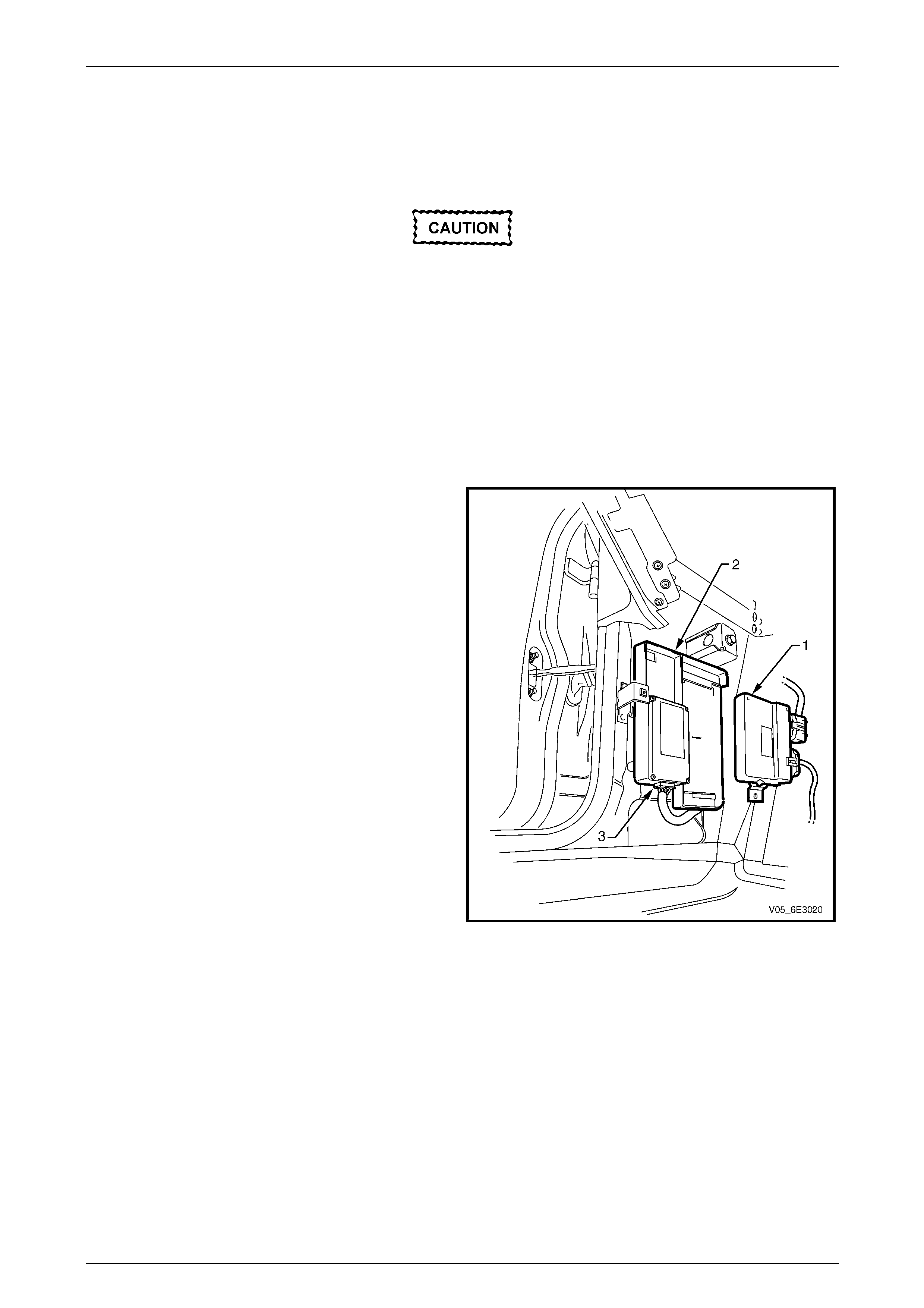
Powertrain Interface Module – GEN III V8 Page 6E3–49
Page 6E3–49
9.2 Pow ertrain Interface Module
LT Section No. — 99–150
Do not touch the powertrain interface module
wiring connector pins as electrostatic
discharge (ESD) damage may result. For
further information on ESD, refer to
Section 00 Warnings, Cautions and Notes .
Remove
1 Turn the ignition switch off.
2 Disconnect the battery, refer to Section 00 Warnings, Cautions and Notes .
3 Remove the left-hand front body hinge pillar trim assembly, refer to Section 1A8 Headlining and Interior Trim.
NOTE
It is not necessary to disconnect the harness
connectors from the throttle actuator control
module (TACM).
4 Slide the TACM (1) forward to release it from the
powertrain interface module (PIM) (2).
5 Disconnect the PIM wiring harness connector (3).
Figure 6E3 – 22
6 Using a screwdriver (1), depress the retaining tang (2) to release the PIM from the hinge pillar inner panel, refer to
Figure 6E3 – 23.
7 Whilst depressing the retai ning tang, pull the bottom of the PIM mounting bracket in the direction of the arrow (3).
8 Slide the PIM downwards to release the upper locking tang (4) from the hinge pi llar inner panel and remove the
PIM.
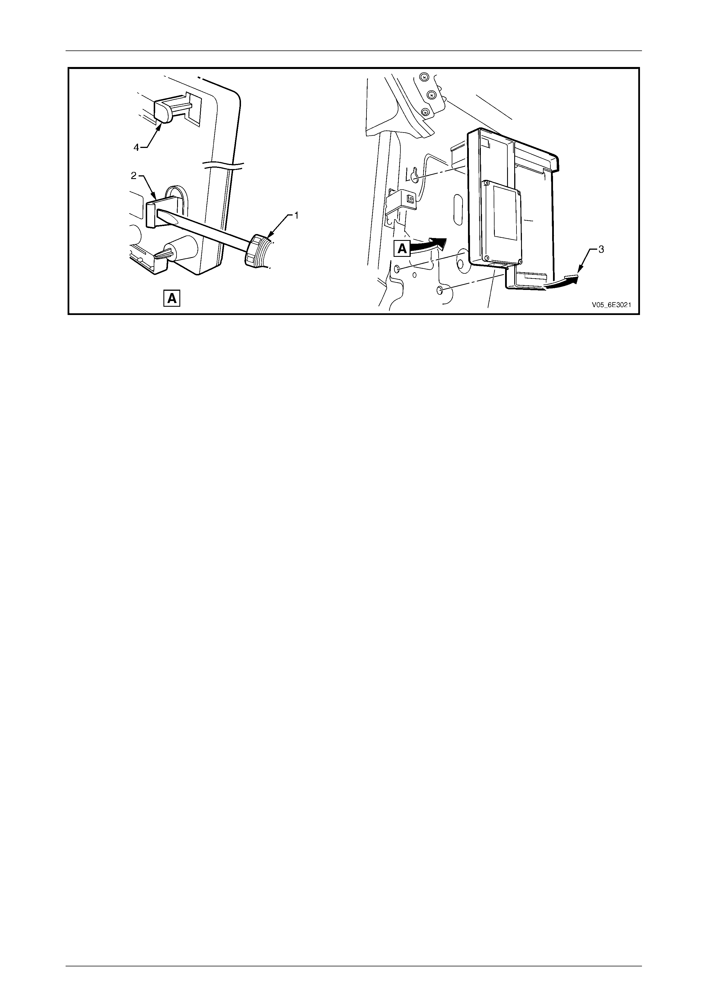
Powertrain Interface Module – GEN III V8 Page 6E3–50
Page 6E3–50
Figure 6E3 – 23
Reinstall
Reinstallation of the powertrain interface module (PIM) is the reverse of the removal procedure, noting the following:
1 Ensure the PIM wiring harness is correctly routed.
2 Ensure the upper and lower PIM retaining tangs are fully latched.
3 If the PIM has been replaced, perform the following procedures:
• PIM Configuration, refer to 10.2 PIM Configuration.
• PIM service programming, refer to 10.3 BCM Link to PCM / PIM.
• Main diagnostic functional check, Refer to 6.2 Diagnostic S ystem Check.
4 Road test the vehicle and check for correct vehicle operation.
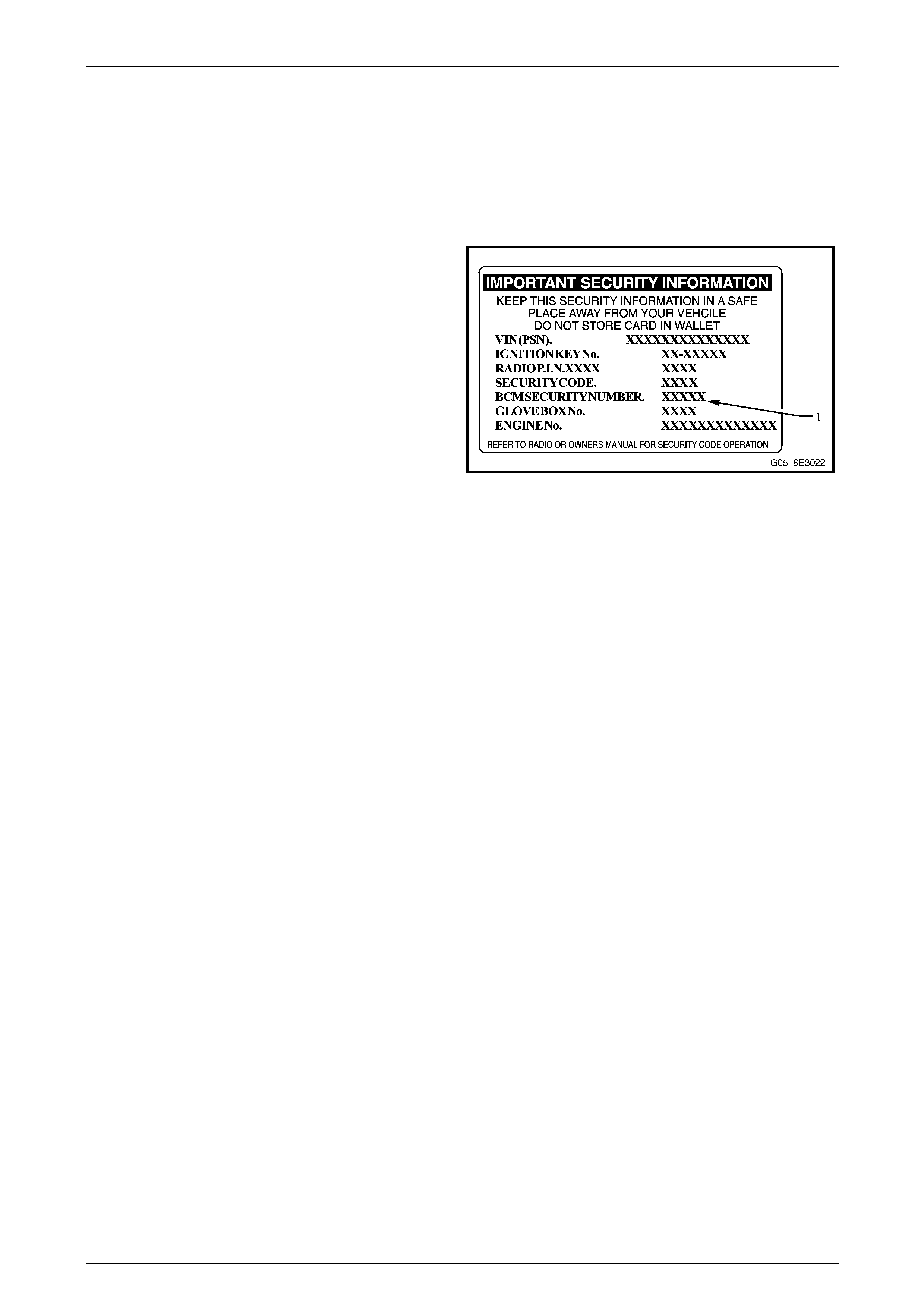
Powertrain Interface Module – GEN III V8 Page 6E3–51
Page 6E3–51
10 PIM Security and Programming
10.1 Security and Programming Information
Vehicle Security Card
When performing the BCM lin k to PCM / PIM function using
Tech 2, you may be prompted to enter the BCM five digit
Security Number (1). This information is found on the
vehicle security card issued with the vehicle when new. If
the card is unavailable, contac t the Holden Technical
Assistance (TAS) centre to obtain the relevant BCM security
number.
Figure 6E3 – 24

Powertrain Interface Module – GEN III V8 Page 6E3–52
Page 6E3–52
10.2 PIM Configuration
When a new PIM has been inst alled into a vehicle, the Vehicle Identification Number (VIN) and the drive variant must be
programmed into the PIM. To program:
• a new PIM, refer to Configuring a New PIM, in this Section,
• an existing PIM, refer to Changing Existing PIM Variant Configur ation, in this Section,
• the VIN number, refer to Programming the VIN, in this Section.
Configuring a New PIM
1 Connect Tech 2 to the data link connector (DLC).
2 On Tech 2 select: Body / Powertrain Interface Module / Program / Program ECU.
3 Press the Modify soft key.
4 Using the up or down arrow selection keys, select RWD for rear wheel drive vehicles or AWD for all-wheel drive
vehicles.
5 Press the Confirm soft key. Tech 2 reverts to the main Tech 2 Program ECU screen where the selection made in
the previous step is displayed .
6 Press the Program soft key.
7 Enter the VIN using the Tech 2 arrow selection keys.
NOTE
The left and right arrow selection keys move the
Tech 2 cursor along the VIN number, whilst the
up and down selection arrows change the
character value.
8 After entering the VIN, press the Enter key. T he changes are now programmed into the PIM.
9 When Tech 2 displays Turn Ignition Off, switch off the ignition and then press the Confirm soft key.
10 When Tech 2 displays Turn Ignition On, switch on the ignition.
11 When Tech 2 displays Programming Successful, press the Confirm soft key to return to the Tech 2 Program
screen.
Changing Existing PIM Variant Configuration
1 Connect Tech 2 to the data link connector (DLC).
2 On Tech 2 select: Body / Powertrain Interface Module / Program / Program Variant Configuration.
3 Press the Modify soft key.
4 Using the up or down arrow selection keys, select RWD for rear wheel drive vehicles or AWD for all-wheel drive
vehicles.
5 Press the Confirm soft key. Tech 2 reverts to the main Tech 2 Program Variant Configuration screen where the
selection made in the previous step is displayed.
6 When finished, press the Program soft key. The changes are now programmed into the PIM.
7 When Tech 2 displays Turn Ignition Off, switch off the ignition and then press the Confirm soft key.
8 When Tech 2 displays Turn Ignition On, switch on the ignition.
9 When Tech 2 displays Programming Successfu l, press the Confirm soft key to return to the Tech 2 Program
screen.

Powertrain Interface Module – GEN III V8 Page 6E3–53
Page 6E3–53
Programming the VIN
1 Connect Tech 2 to the data link connector (DLC).
2 On Tech 2 select: Body / Powertrain Interface Module / Program / Program VIN.
3 Enter the VIN using the Tech 2 arrow selection keys.
NOTE
The left and right arrow selection keys move the
Tech 2 cursor along the VIN number, whilst the
up and down selection arrows change the
character value.
4 After entering the VIN number, press the Enter key. The changes are now programmed into the PIM.
5 When Tech 2 displays Turn Ignition Off, switch off the ignition and then press the Confirm soft key.
6 When Tech 2 displays Turn Ignition On, switch on the ignition.
7 When Tech 2 displays Programming Successfu l, press the Confirm soft key to return to the Tech 2 Program
screen.

Powertrain Interface Module – GEN III V8 Page 6E3–54
Page 6E3–54
10.3 BCM Link to PCM / PIM
When the powertrain interface modu le (PIM) has been replaced, it is necessary to link the PIM to the body control
module (BCM) and po wertrain control modul e (PCM) before the vehicle will start.
1 Prior to performing the linking procedure, obtain the BCM security number. For further information,
refer to Vehicle Security Card, in this section.
2 Connect Tech 2 to the data link connector (DLC).
3 On Tech 2 select: Body / Powertrain Interface Module / Security / BCM Link to PCM / PIM.
4 When Tech 2 displays Select Engine Type u s e the up and down arrow selection keys to select the appropriate
engine type and then press the Enter ke y.
NOTE
When Tech 2 requests programming approval,
obtain TIS approval. For further information on
TIS approval, refer to Section 0C Tech 2.
5 When Tech 2 displays BCM Security No., enter the BCM security number, press the Enter key.
6 When Tech 2 displays Turn Ignition Off, switch off the ignition.
7 When Tech 2 displays Turn Ignition On, switch on the ignition.
8 When Tech 2 displays Turn Ignition Off, switch off the ignition and then press the Confirm soft key.
9 When Tech 2 displays R un Engine at Idle Speed, start the engine and allow to idle. Once the engine is idling, press
the Confirm soft key.
10 When Tech 2 displays Successfully Programmed, press the Confirm soft key to return to the Tech 2 Security
screen.
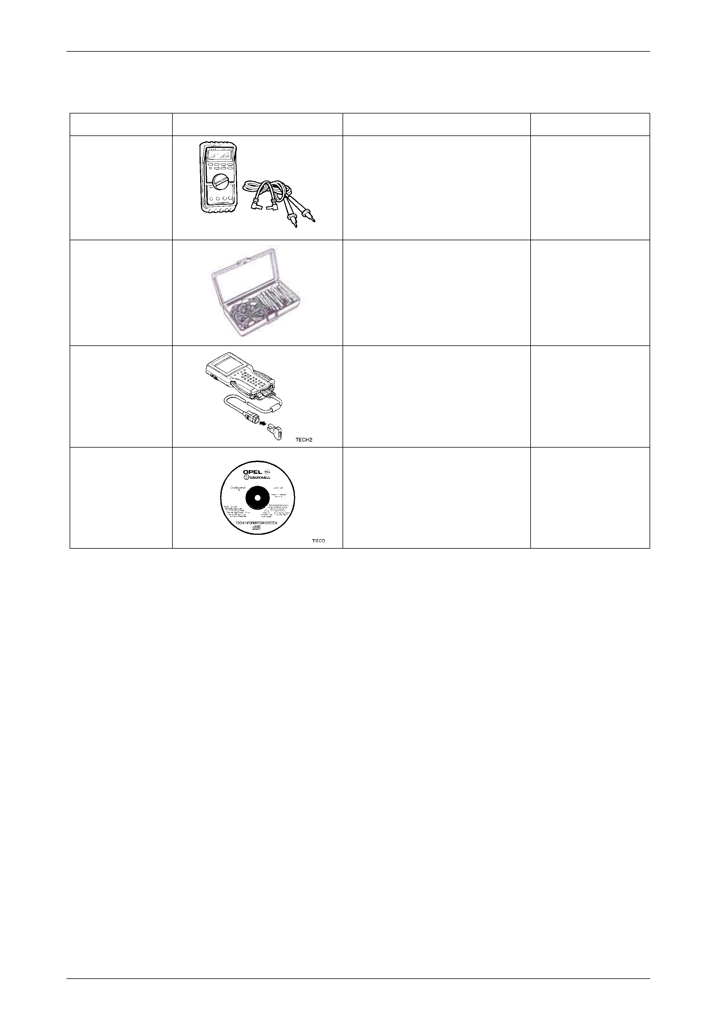
Powertrain Interface Module – GEN III V8 Page 6E3–55
Page 6E3–55
11 Special Tools
Tool Number Illustration Description Tool Classification
3588
Digital Multimeter
Also Previously released as J 39200 or
equivalent.
NOTE: The instrument must have 10
mega ohms impedanc e and be
capable of reading frequencies.
Mandatory
J35616
Connector Test Adaptor Kit
Used when carrying out electric al
diagnostic circuit checks.
Desirable
70000861
Tech 2 Diagnostic Scan Tool
Previously released.
Mandatory
N/A
Technical Information System (TIS)
CD ROM
Available to Authorised Dealers.
Mandatory