
Clutch – GEN IV V8 Engine 7A4 – 1
Section 7A4
Clutch – GEN IV V8
ATTENTION
Before performing any Service Operation or other procedure described in this Section, refer to Section 00
Warnings, Cautions and Notes for correct workshop practices with regard to safety and/or property damage.
1 General Information ...............................................................................................................................2
1.1 Self Adjusting Clutch Pressure Plate................................................................................................................... 2
1.2 Clutch Control........................................................................................................................................................ 3
Arrangement........................................................................................................................................................... 3
Operation................................................................................................................................................................ 3
Clutch Master Cylinder Operation........................................................................................................................ 4
Clutch Actuating Cylinder Operation................................................................................................................... 4
2 Service Operations.................................................................................................................................5
2.1 Service Warnings, Cautions and Notes............................................................................................................... 5
2.2 Fluid Level Check .................................................................................................................................................. 6
2.3 Clutch Hydraulic System, Bleed........................................................................................................................... 7
2.4 Clutch Fluid – Change........................................................................................................................................... 8
2.5 Clutch Master Cylinder.......................................................................................................................................... 9
2.6 Clutch Actuating Cylinder................................................................................................................................... 10
Remove................................................................................................................................................................. 10
Disassemble......................................................................................................................................................... 10
Clean and Inspect ................................................................................................................................................ 10
Reinstall................................................................................................................................................................ 11
2.7 Clutch Throw out Bearing................................................................................................................................... 12
Remove................................................................................................................................................................. 12
Clean and Inspect ................................................................................................................................................ 12
Reinstall................................................................................................................................................................ 12
2 8 Clutch Pedal Assembly....................................................................................................................................... 14
2.9 Clutch Cruise Control Calib ration and Cancel Switch...................................................................................... 15
2.10 Clutch and Pressure Plates................................................................................................................................. 16
Remove................................................................................................................................................................. 16
Inspect .................................................................................................................................................................. 16
Clutch Pressure Plate Adjustment..................................................................................................................... 17
Reinstall................................................................................................................................................................ 18
2.11 Engine Flywheel................................................................................................................................................... 20
Replace................................................................................................................................................................. 20
2.12 Ring Gear.............................................................................................................................................................. 21
Replace................................................................................................................................................................. 21
2.13 Crankshaft Spig o t Bearing.................................................................................................................................. 22
Replace................................................................................................................................................................. 22
3 Diagnosis ..............................................................................................................................................23
4 Specifications.......................................................................................................................................25
5 Torque Wrench Specifications............................................................................................................26
6 Special Tools ........................................................................................................................................27
7A4 – 1
Clutch – GEN IV V8 Engine 7A4 – 2
1 General Information
1.1 Self Adjusting Clutch Pressure Plate
The self-adjusting feature for the clutch pressure plate fitted to the GEN IV V8 engine and the six speed manu al
transmission, has been retained, that achieves several advantages:
a The clutch pedal loading is maintained at a consistent level throughout the life of the assembly, as the diaphragm
spring leverage over the pivot rings remai ns the same.
b This also results in the fact that the clutch ‘take-up’ remains at a constant point, with the clutch pedal feel also
remaining constant.
c No maintenance adjustments are req uire d.
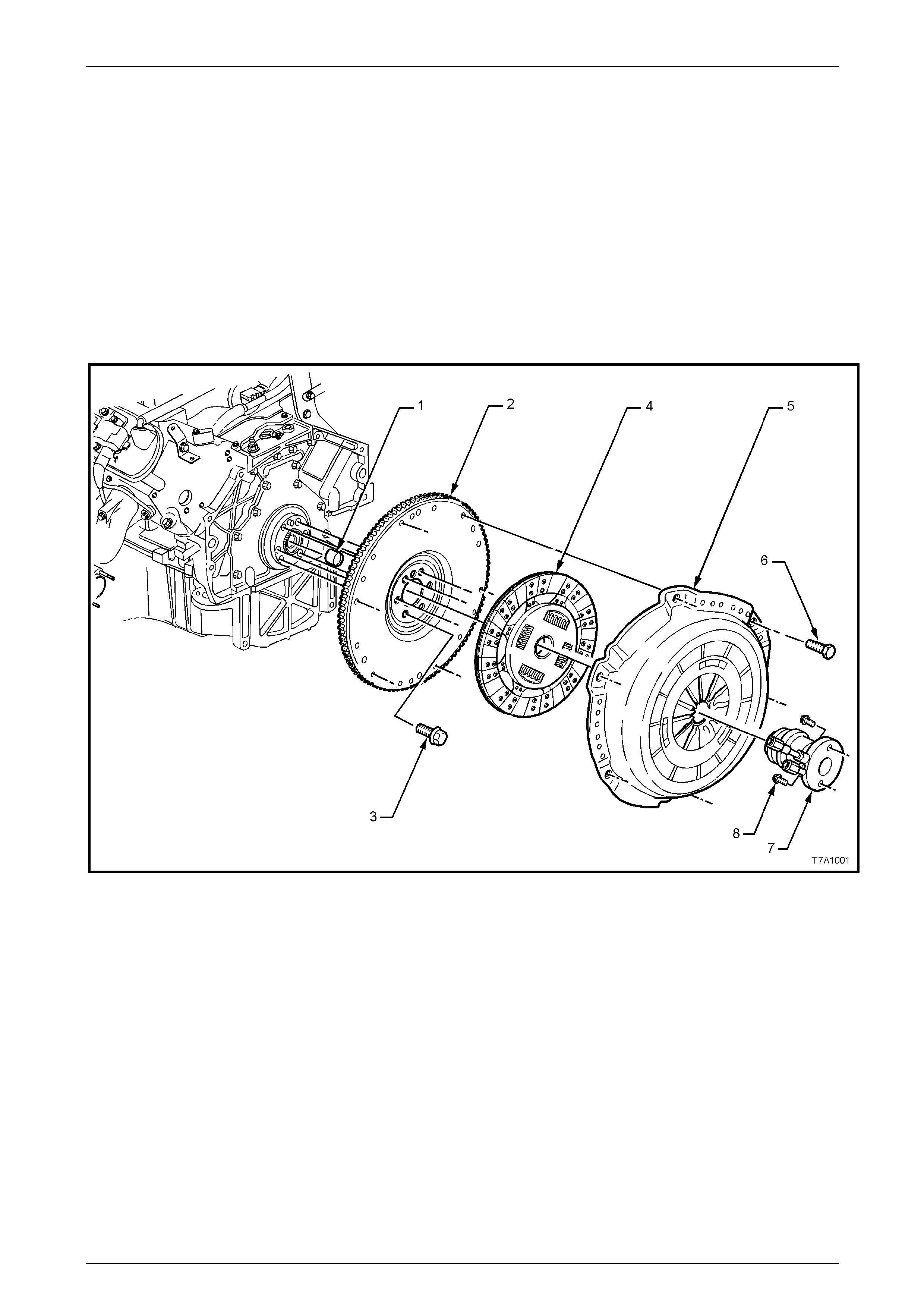
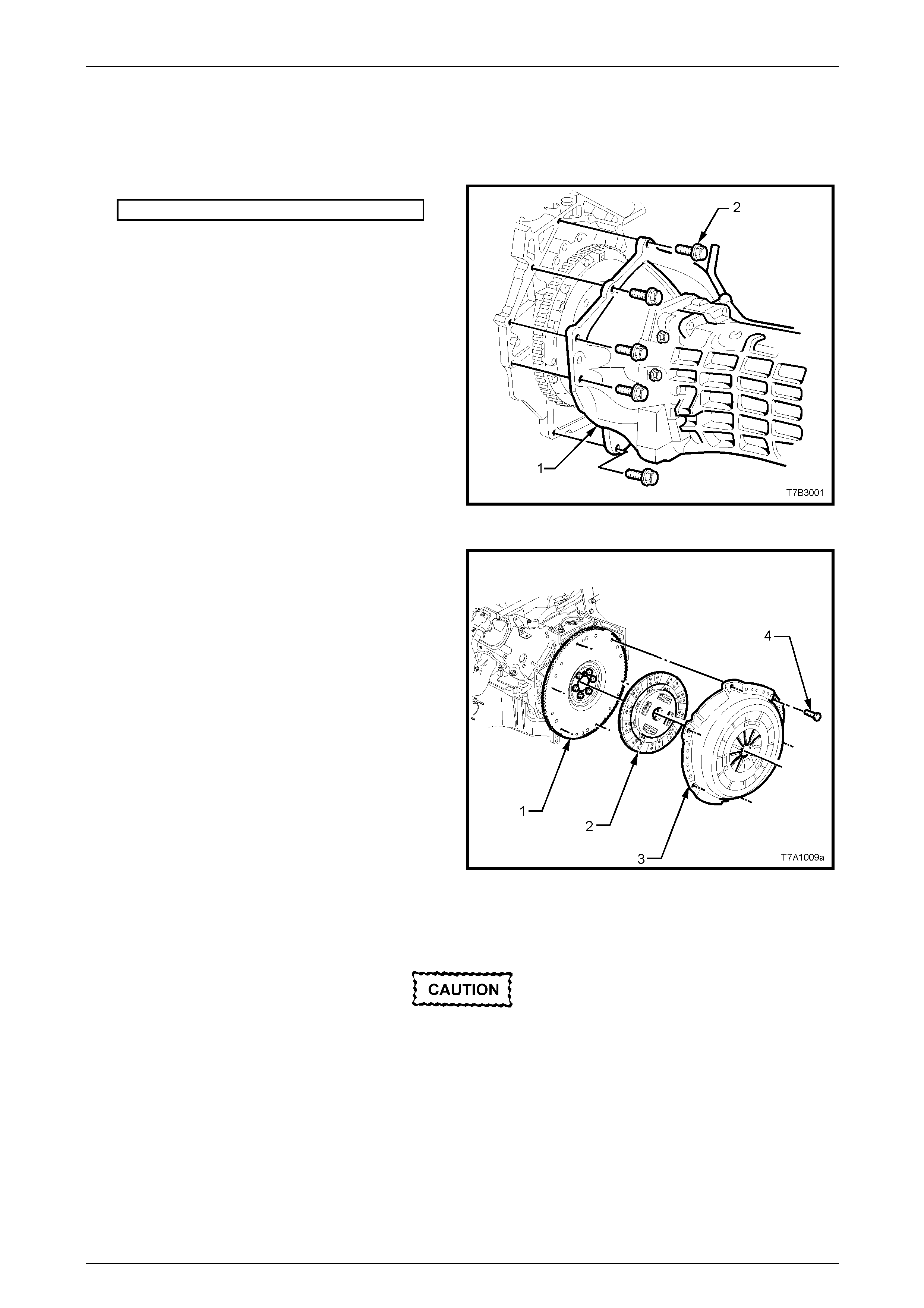
Figure 7A3 – 1 Clutch Components
Legend
1 Bearing - Clutch Pilot
2 Flywheel - Engine
3 Bolt - Flywheel (6 places)
4 Plate - Clutch Driven
5 Plate - Clutch Pressure
6 Bolt - Pressure Plate (6 places)
7 Assembly - Clutch Actuating
8 Bolt - Actuating Cylinder (2 places)
7A4 – 2
Clutch – GEN IV V8 Engine 7A4 – 3
1.2 Clutch Control
Hydraulic actuation for the clutch has been retain ed for the GEN IV V8 applicati on with manual transmission and uses
some common clutch pedal with the V6 engi ned vehicle.
Arrangement
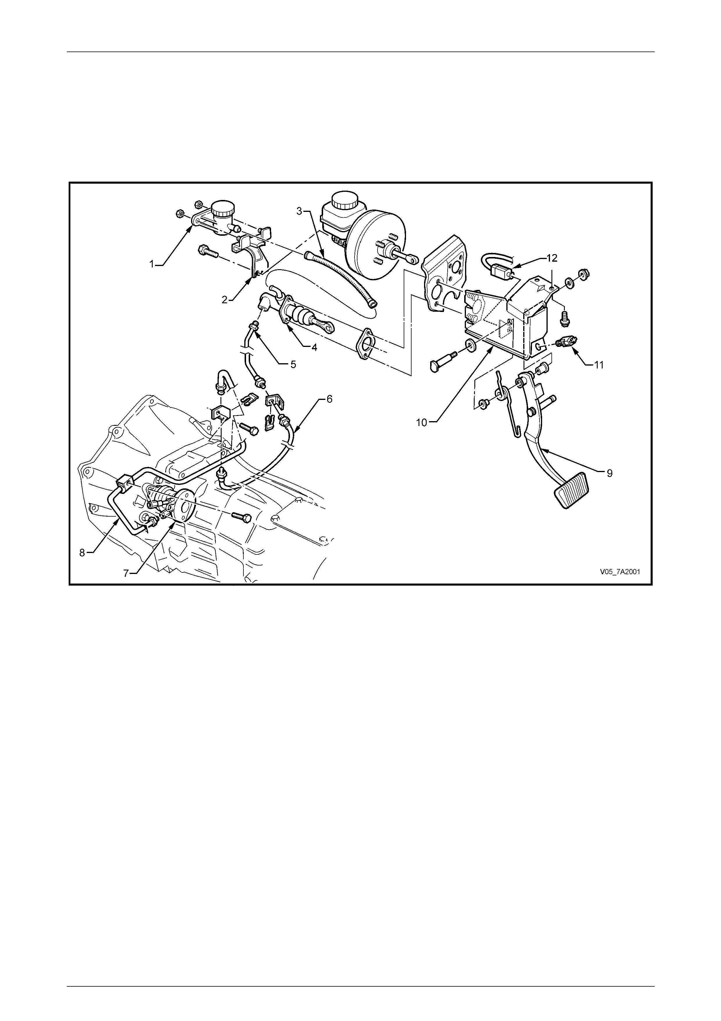
Figure 7A3 – 2 Clutch Control Layout
Legend
1 Reservoir – Clutch Fluid
2 Bracket – Clutch Fluid Reservoir
3 Hose – Reservoir to Master Cylinder
4 Master Cylinder
5 Pipe – Master Cylinder to Flexible Hose
6 Hose – Master Cylinder Pipe to Actuating Cylinder Pipe
7 Assembly – Actuating Cylinder and Bearing
8 Pipe – Hose to Actuating Cylinder
9 Pedal – Clutch
10 Bracket – Clutch Pedal Support
11 Switch – Cruise Control Cancel
12 Switch – Safety Start Switch
Operation
Brake fluid is fed to the clutch master cylinder from a remote reservoir mounted to a bracket, bolted to the end of the
brake master cylinder. A flexible line connects the two components.
The master cylinder and vac uum booster assembly is attached to the firewall in the engine compartment.
The clutch pedal is mounted in the clutch/br ake peda l support bracket, bolted to the dash panel.
The clutch master cylinder piston is con nected to the clutch pedal by a quick connect fitting on the end of the push rod,
that clips onto a grooved pin attached to the clutch pedal.
No clutch adjustments are required.
7A4 – 3
Clutch – GEN IV V8 Engine 7A4 – 4
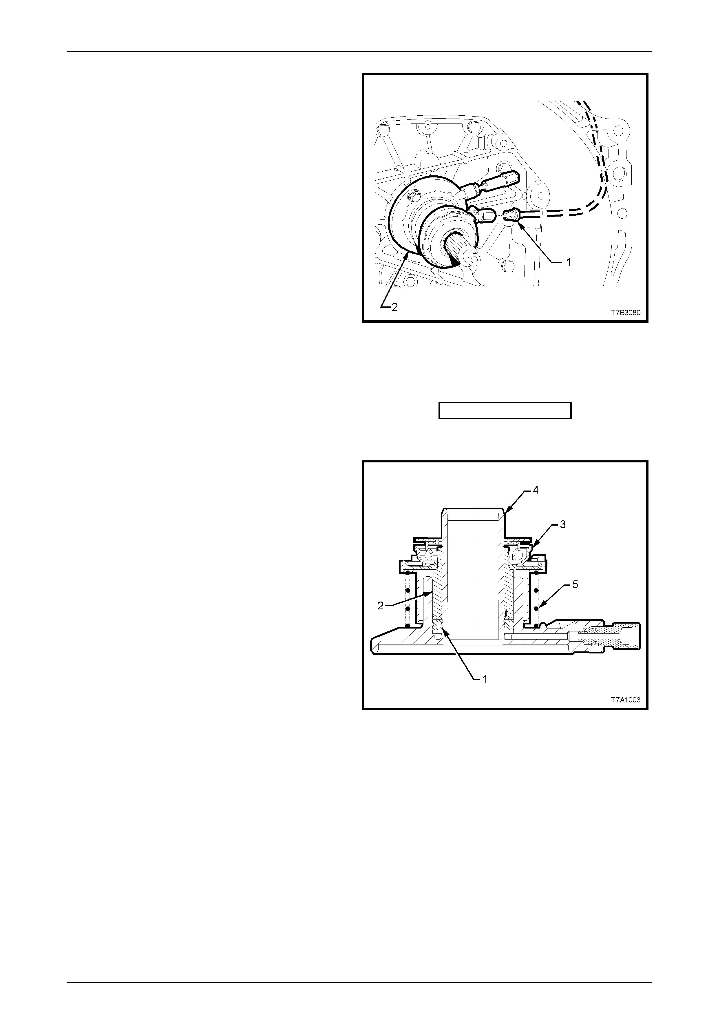
Stroking of the clutch throw out bearing is achieve d by using
a concentric hydraulic clutch actuating cylind er (2) mounted
to the front of the transmission adaptor plate housi ng.
Hydraulic connection to the master cylinder is b y steel
piping from the master cylinder, flexible hose to the
transmission and steel pipe again from the flexible hose to
the actuating cylinder (1) (Also see Figure 7A3-2).
The actuating cylinder is fitted with a bleed valve to assist in
removal of air from the hydraulic system.
Apart from the throw out bearing assembly and load spring,
there are no other serviceab le parts in the actuating cylinder
and, if found to be faulty, the assembly must be replaced.
Figure 7A3 – 3
Clutch Master Cylinder Operation
As the operation of the clutch master c ylinder fitted to GEN IV V8 engined vehicles is the same as for all manual
transmission equipped MY 2005 VZ series vehicles, refer to the description in Section 7A1 Clutch – V6.
Clutch Actuating Cylinder Operation
When pressurised fluid from the clutch mast er cylinder acts
upon the seal (1), the seal moves, stroking the sleeve (2)
before it. As the throw out bearing assembly (3) is attached
to the sleeve (2), the throw out bearing also moves with the
sleeve, to force the diaphragm fingers of the pressure plate
to move against its in-built spring force.
As the actuating cylinder sleeve (2) continues to be moved
along the guide of the cylinder body (4), the force applied to
the pressure plate diaphragm spring causes the spring to
pivot, thus releasing the applied force on th e clutch driven
plate, allowing it to spin. When this situation occurs, the
frictional link between the engine flywheel and the
transmission input shaft is broken and gear chan ging can
then safely take place, without undue stress being placed
upon the transmission synchromesh assemblies.
When the clutch pedal is released, the pressure plate
diaphragm spring force, moves the thro w out beari ng (3)
and actuating cylinder sleeve ( 2), back along the actuating
cylinder body guide (4), returning displaced fluid back to the
master cylinder reservoir. Figure 7A3 – 4
Coil spring (5) acts to maintain constant contact of the throw out bearing with the pressure plate diaphragm spring
fingers, thereby reducing pedal travel to begin initial movement by compens ating for any slight finger height variatio n in
the diaphragm spring.
As the clutch pressure plate is self-adjusting, the ‘at rest’ position of the throw out bearing and clutch actuating cylinder
sleeve (2), remains relatively constant throughout the life of the assembly, compared to other clutch control systems.
7A4 – 4
Clutch – GEN IV V8 Engine 7A4 – 5
2 Service Operations
2.1 Service Warnings, Cautions and Notes
ATTENTION
All fasteners are important attaching parts as they affect the performance of vital components and/or could
result in major repair expense. W here specified in this Section, fasteners MUST be replaced w ith parts of the
same part number or an app roved equivalent. Do not use fasteners of an inferior quality or substitute design.
Torque values must be used as specified during reassembly to ensure proper retention of all components.
Throughout this Section, fastener torque wrench specifications may be accompanied with the following
identification marks:
Fasteners must be repl aced after loosening.
Vehicle must be at curb height before final tightening.
Fasteners either have micro encapsulated sealant applied or incorporate a mechanical thread lock and
should only be re-used once. If in doubt, replacement is recommended.
If one or more of these identification marks is present alongside a fastener torque wrench specification, the
recommendation regarding that fastener must be adhered to.
Asbestos
• While Holden clutch parts are not asbestos based in their material composition, a danger exists
that replacement non-genuine parts may contain asbestos.
• Not only is it in the interests of personal safety but also the safe and reliable operation of the
clutch system, that only genuine parts are used for replacemen t purposes.
• Even so, when servicing clutch parts, do not create dust by grinding or sanding the clutch plate,
or clean clutch parts w ith a dry brush or w ith compressed air. Breathing in dust th at may contain
asbestos fibres can cause serio us bodily harm over a protracted period of time.
• A water dampened cloth or water based solution should be used to remove any dust on clutch
parts. Equipment is commercially available to perform this washing function. These wet methods
prevent clutch component fibres from becoming airborne.
Brake Fluid
Brake fluid is extremely damaging to paint. If
fluid should accidentally come into contact
with a painted surface, immediately wash the
fluid from the paint and clean the painted
surface.
• The polyglycol brake fluid used in the MY 2005 VZ Series vehicles is hygroscopic and absorbs
moisture from the air through the flexible clutch hose etc. Therefore, for maximum clutch
effectiveness, a tw o yearly change of brake flui d is mandatory, refer to 2.4 Clutch Fluid – Change,
in this Section.
• To prevent the absorption of moisture from the air or other contamination, it is recommended that
the brake fluid be stored in small (500 ml) containers and that any surplus fluid remaining in a
container after use be discarded.
• The only approved brake fluid is DOT 4 or Super DOT 4 and is available in 250 and 500 ml
containers. If pressure bleeding equipment is used, it must be of an approved type with a
diaphragm separating the brake fluid from the air.
7A4 – 5
Clutch – GEN IV V8 Engine 7A4 – 6
2.2 Fluid Level Check
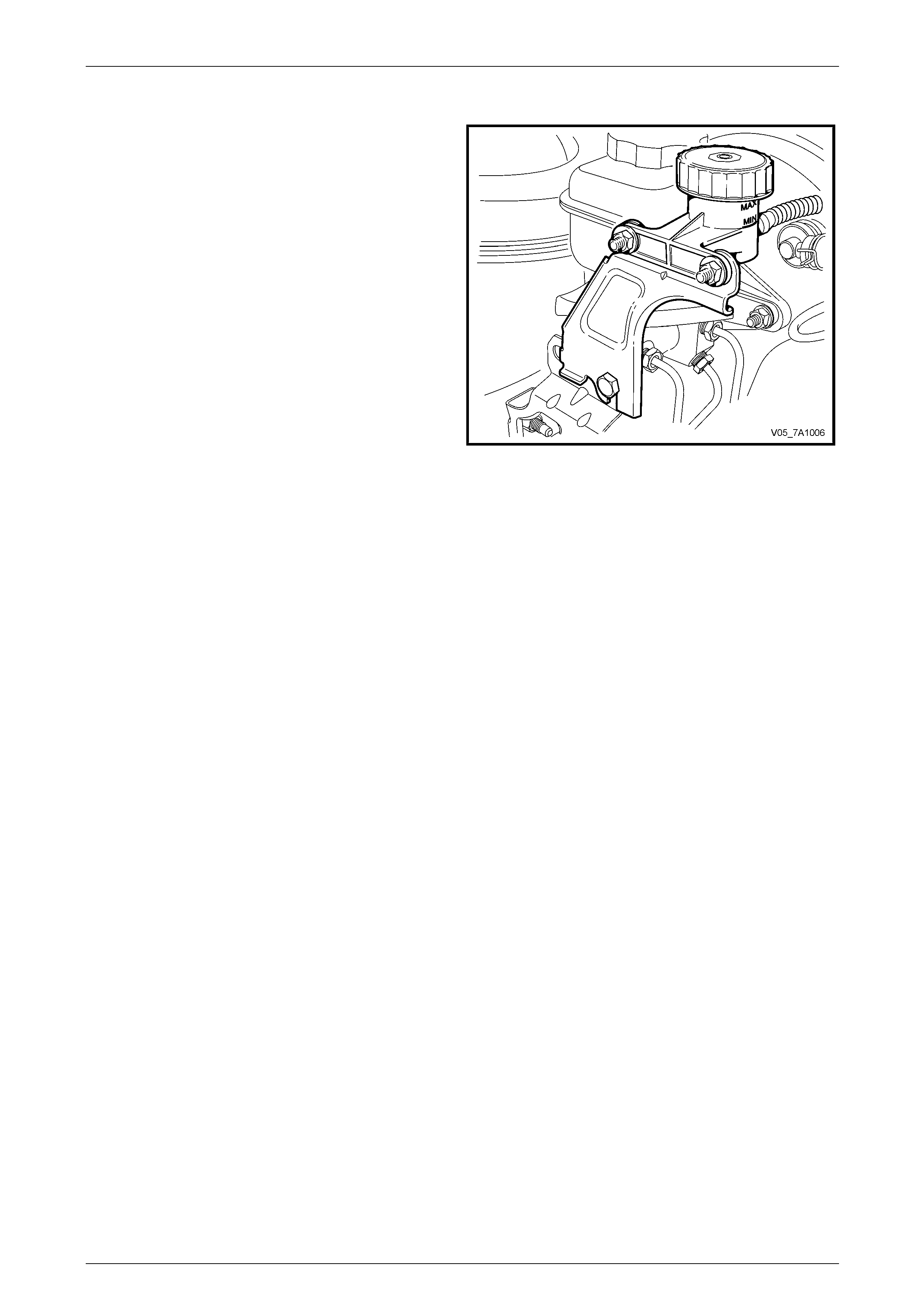
1 Check that the fluid level is between the two guidelines
on the translucent reservoir housing. Should the
addition of fluid be required, remove the reservoir cap
and use heavy duty brake flu id, such as DOT 4 or
Super DOT 4.
Figure 7A3 – 5
7A4 – 6
Clutch – GEN IV V8 Engine 7A4 – 7
2.3 Clutch Hydraulic System, Bleed
The clutch hydraulic system must be bled whenever the hydraulic line has been d isconnected, or when a leak has
allowed air to enter the system. Air trapped in the system can prevent full disengagement of the clutch.
During bleeding operatio ns, the master cylinder reservoir must be kept at least half full with hydraulic brake fluid.
1 Carefully clean any dirt from around the fluid reservoir cap.
2 Remove the filler cap and top up reservoir as required, with heavy duty hydraulic brake flu id, such as DOT 4 or
Super DOT 4.
3 Using an 11 mm, 3/8 drive socket, short extension and
socket bar, loosen the actuating cylinder b le eder,
located in the upper aperture of the transmis s ion
adaptor plate/clutch housing, on the left hand side.
4 Then, using just the socket and extension, tighten the
bleeder, using light finger force only.
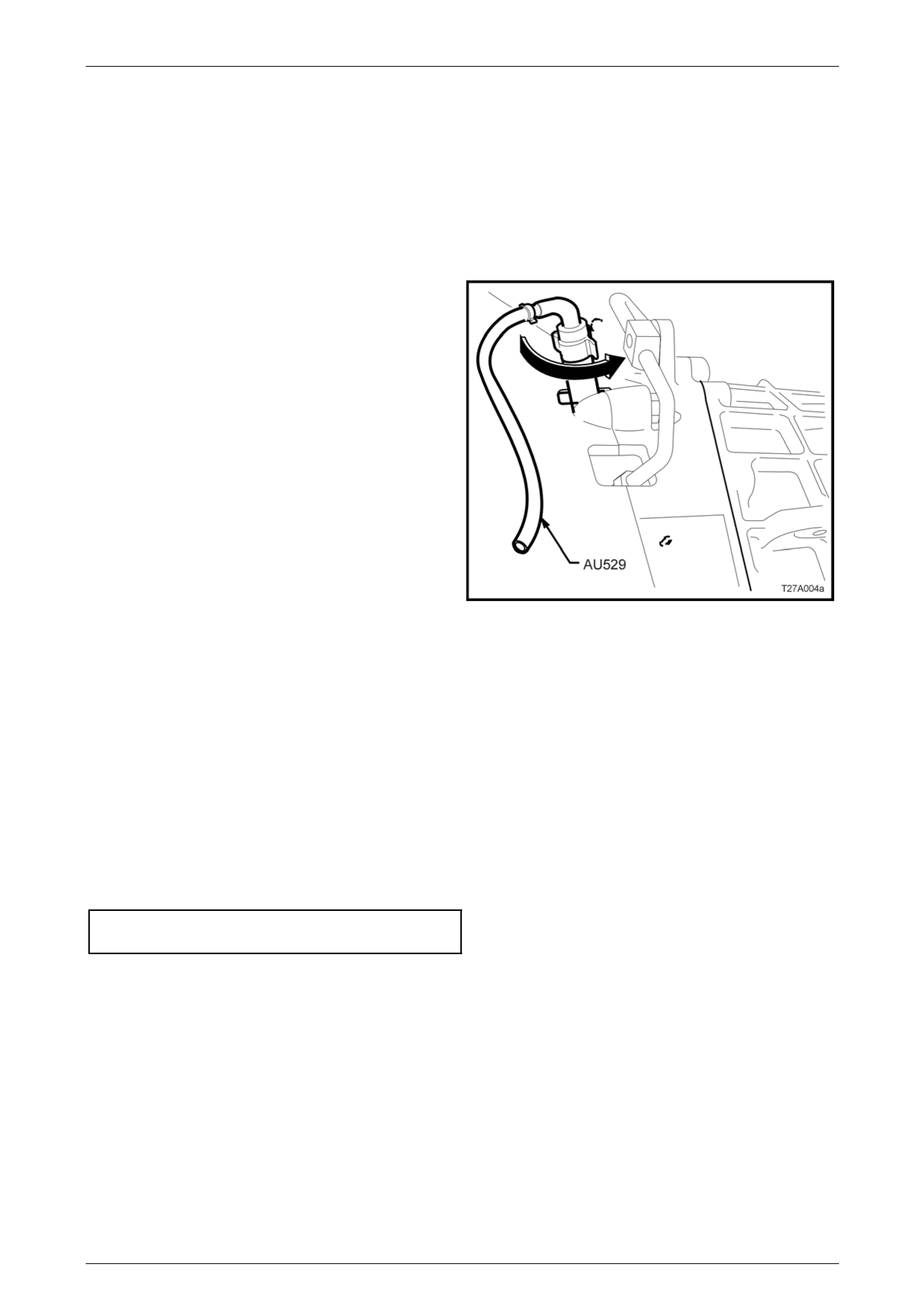
5 Insert the end of the rubber tube of Tool AU529 over
the end of the bleeder, positioned at the 9 o’clock
position.
6 With the other end of the bleeder tool inserted into a
clean glass container such as a jar, that has been
partially filled with ne w brake fluid, open the bleeder
1/4 turn, using the rubber on the bleeder tool to
provide the required grip. Ensure that the end of the
hose always remains submer ged in the brake fluid
during bleeding operations.
7 Using an assistant, slo wly depress the clutch pedal by
hand, one single time and, while holding the pedal
depressed, close the bleed er using Tool AU529. Figure 7A3 – 6
8 Once the bleeder is closed, the clutch pedal can be allowed to slowly release. Ensure that the pedal fully returns to
the 'UP' position – lift by hand, if required. Repeat this process until all bub bles cease to appear at the end of the
bleeder hose.
NOTE
Do not pump the clutch pedal repeatedly during
bleeding operations, as entrapped air will cause
the fluid to foam, making air removal extremely
difficult. Also, as the hydraulic steel piping is
routed over the top of the transmission housing,
air can be trapped in that section.
9 When all air has been remove d, close off the bleeder and remove Tool AU529. With the clutch pedal still
depressed, tighten the bleeder screw to the correct torque specification.
Clutch actuating cylinder blee d
screw torque specification....................................18 N.m
10 Once all bleeding operations have been completed, ensure that the fluid level in the reservoir is correct.
NOTE
Alternative methods of bleeding would be to use
either a pressure bleeder, with a commercially
available reservoir cap or use the vacuum
method, with the assistance of a hand operated
vacuum pump such as Tool No. J23738-A (also
commercially available as a ‘MityVac’™) and an
air tight, glass container.
11 Road test the vehicle to check for correct clutch operation.
7A4 – 7

Clutch – GEN IV V8 Engine 7A4 – 8
2.4 Clutch Fluid – Change
At the interval specified in the Owners Handbook, the clutch fluid must be changed. Discolouration of the fluid is n o
reason for fluid replacement. The recommended method is to use a commercially ava ilable pressure bleeder, together
with an appropriate fluid reservoir cap. Follow the manufacturer’s instructions regarding the use of the pressure bleeding
equipment.
1 Fit bleeder adaptor AU529 to the actuati ng cylinder bleeder as described in 2.3 Clutch Hydraulic System, Bleed, in
this Section, then use the pressure bleeder to force fluid throug h the hydraulic system.
2 Continue allowing fluid to flow through the system until the fluid runs clear in the bleeder hose , immersed in a
clean glass container.
3 Following the fluid change operation, ensure that the fluid level in the reservoir is correct and that the actuating
cylinder bleeder screw is tightened to the correct torque sp ecification.
Clutch actuating cylinder blee d
screw torque specification....................................18 N.m
NOTE
An alternative method would be to use the
vacuum method, with the assistance of a hand
operated vacuum pump such as Tool No.
J23738-A (also commercially available as a
‘MityVac’™) and an air tight, glass container.
7A4 – 8

Clutch – GEN IV V8 Engine 7A4 – 10
2.6 Clutch Actuating Cylinder
Remove
1 Remove the transmission from the vehicle. Refer to Section 7B2 Man ua l Transmission – GEN III V8.
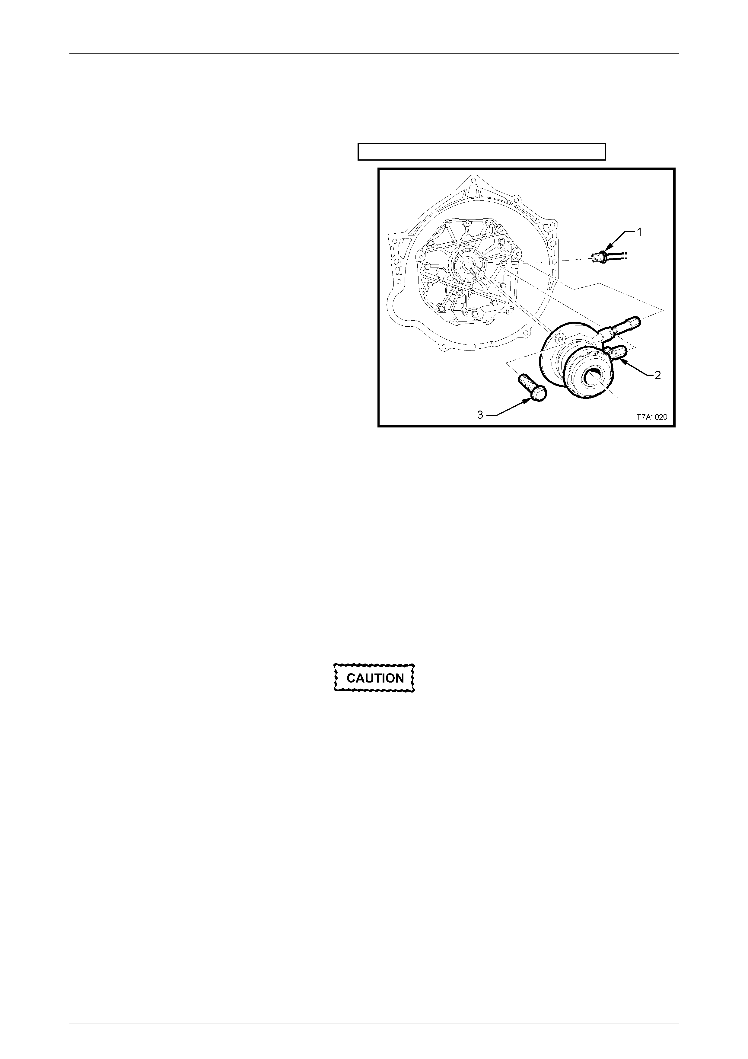
2 Unscrew the pipe fitting (1) from the clutch actuating
cylinder (2).
3 Remove the two screws (3) securing the clutch
actuating cylinder assembly to the transmission
adaptor plate, then remove the actuating c ylinder.
Figure 7A3 – 7
Disassemble
If required, remove the throw out bearing. Refer to 2.7 Clutch Throw out Bearing, in this Section.
NOTE
Apart from this bearing and the spring behind it,
there are no other serviceable parts in the clutch
actuating cylinder assembly.
Clean and Inspect
Do not wash hands in petrol or oil before
cleaning or handling hydraulic parts; always
use a soap and water based hand cleaning
product.
1 Inspect the actuating cylinder for any evidence of fluid le akage. If found, replace the assembly.
2 Remove the bleeder screw and inspect the actuating cylinder threaded apertures for da mage. Replace the
actuating cylinder assembly as necessary.
3 Check that the bleeder screw thread is unda maged and that the drilled passage is cl ear of debris.
4 Inspect the throw out bearing. Refer to 2.7 Clutch Throw out Bearing, in this Section.
7A4 – 10

Clutch – GEN IV V8 Engine 7A4 – 11
Reinstall
Installation is the reverse of removal operations except for the following points:
1 Install actuating cylinder and the 2 retai ning bolts, then tighten the bolts to the correct torque specification.
Clutch actuating cylinder
screw torque specification....................................10 N.m
2 Install and tighten hydraulic pipe flare nut to the actuating cylinder, tightening to the correct torque specification.
Hydraulic flare nut to actuating
cylinder torque specification.................................13 N.m
3 Reinstall the transmission. R efer to Section 7B2 Manual Transmission – GEN III V8.
4 Bleed the clutch hydraulic system, refer to 2.3 Clutch Hydr aulic System, Bleed, in this Section.
5 Following bleeding operations, check that the hydraulic fluid level is correct, refer to 2.2 Fluid Level Ch eck.
6 Road test the vehicle and check for correct clutch and trans m ission operation.
7A4 – 11
Clutch – GEN IV V8 Engine 7A4 – 12
2.7 Clutch Throw out Bearing
Remove
1 Remove the transmission. Refer to Section 7B2 Manual Transmission – GEN III V8.
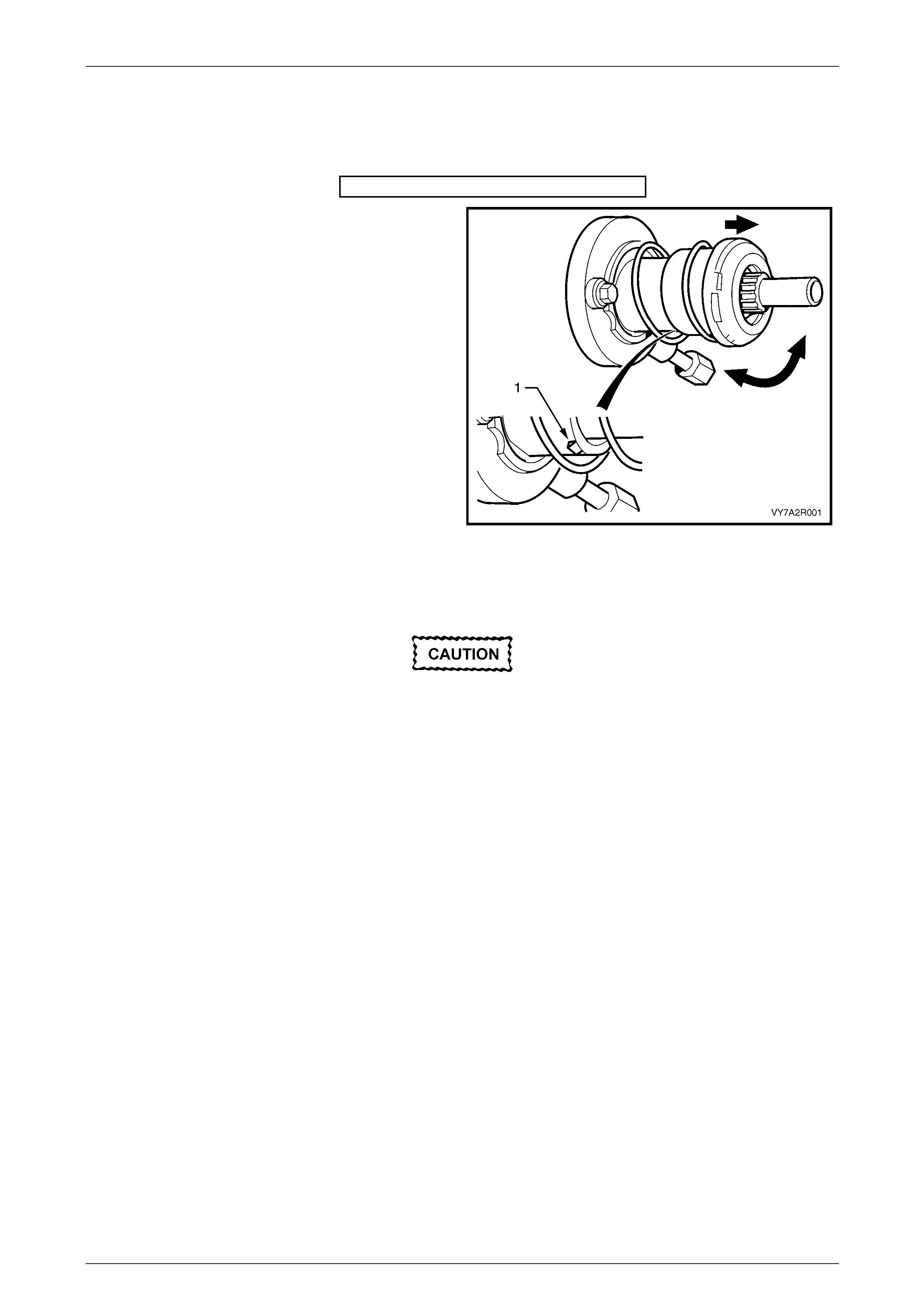
2 While grasping the throw out bearing, twist and pull
the bearing to release the actuating cylinder guide
sleeve retaining tab (1) from the thro w out bearing
guide sleeve.
Figure 7A3 – 8
Clean and Inspect
Do not use cleaners or chemicals on the
bearing guide sleeve.
1 Inspect the throw out bearing for any signs of roughness or dryness by rotating the bearing when a light load is
applied. If either of these conditions are evident, replace th e throw out bearing.
2 Examine the bearing guide sleeve for signs of damage, abrasion or scuffing. Renew the throw out bearing if either
of these conditions exist.
NOTE
The throw out bearing guide is not serviced
separately and is supplied complete with the
throw out bearing.
3 Inspect the actuating cylinder. Refer to 2.6 Clutch Actuating Cylinder.
4 Use a water dampened cloth or water based solution to wipe the actuating cylinder clean.
Reinstall
1 Using a clean dry rag, wipe the exposed portion of the throw out bearing guide sle eve.
2 Sparingly apply an NLGI No. 2 lithium soap based EP grease with molybdenum disulphide, such as Shell Retin ax
HDX2 grease or BP Energrease LMS-EP 2 3 (or equivalent) to the actuating cylinder guide sle eve.
NOTE
If replacing the throw out bearing, grease may
have been applied to the new clutch throw out
bearing.
7A4 – 12

Clutch – GEN IV V8 Engine 7A4 – 13
3 Install the clutch throw out bearing to the guide
sleeve, by firmly pushing the new bearing onto the
sleeve, until it snaps into place over the retaining
tab (1).
4 Install the transmission. Refer to Section 7B2
Manual Transmission – GEN III V8.
5 Road test the vehicle and check for correct clutch
and transmission operation.
Figure 7A3 – 9
7A4 – 13


Clutch – GEN IV V8 Engine 7A4 – 16
2.10 Clutch and Pressure Plates
Remove
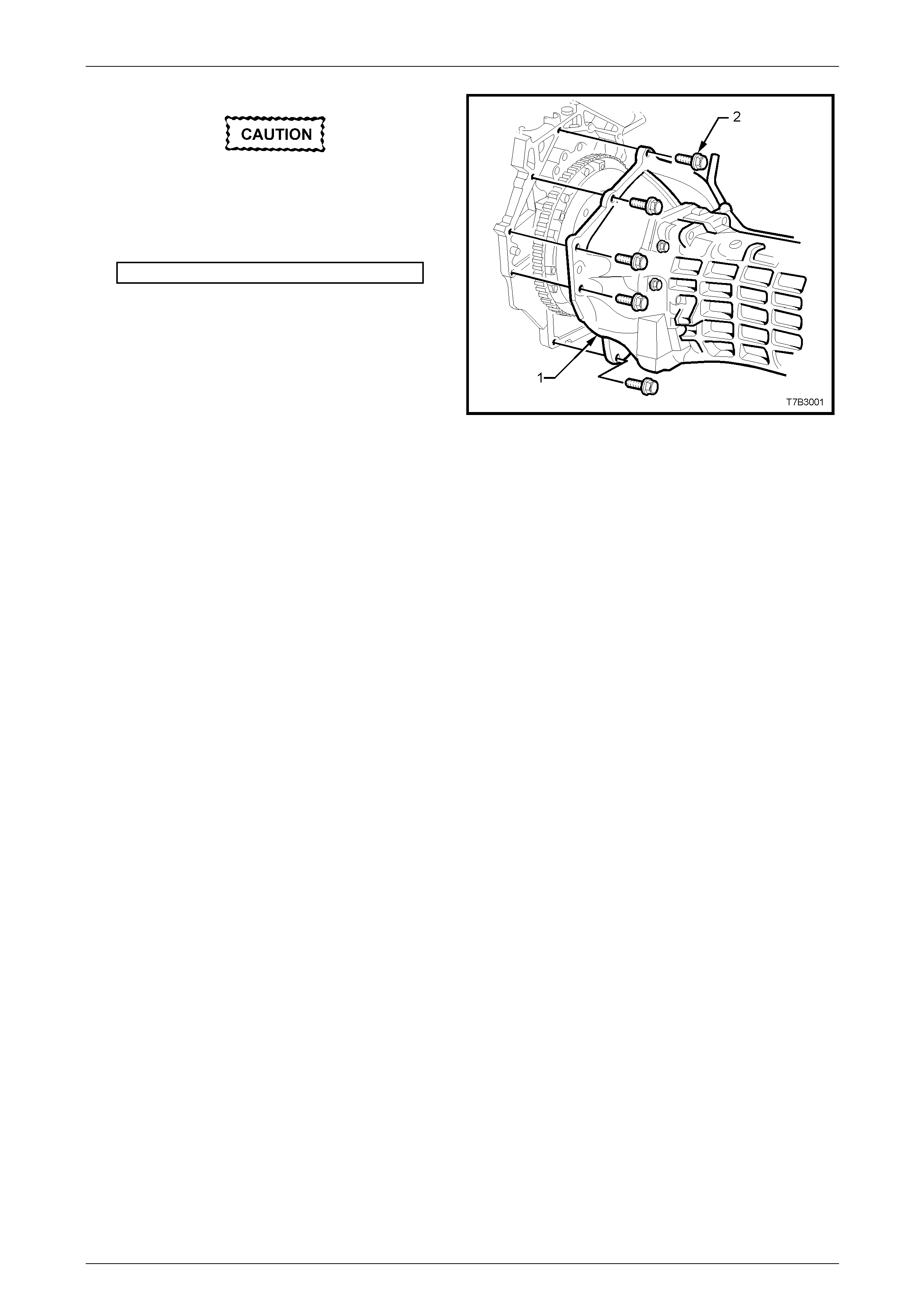
1 Remove transmission assembly (1). Refer to
Section 7B2 Manual Transmission – GEN III V8.
Figure 7A3 – 10
2 Initially loosen all pressure plate retaining bolts (4),
working from opposite sides, to avoid distorti on of the
cover (3).
3 Continue loosening bolts from opposite sides, until all
are removed, then lift the clutch driven plate (2) and
pressure plate (3) assemblies from the fl ywheel (1).
NOTE
The two locating dowel pins in the flywheel are
set 170° apart, which means that marking the
pressure plate relationship to the flywheel is not
required.
Figure 7A3 – 11
Inspect
Do not wash the pressure plate nor the
actuating cylinder with liquid petroleum
based products or use compressed air.
1 Use a water dampened cloth or water based solution to wipe the pressure plate and flywheel surfaces.
2 Remove, inspect and clean the actuating cylinder. Refer to 2.6 Clutch Actuating Cylinder.
3 Inspect the crankshaft spigot bearing for wear. If necessary, replace the bearing. Refer to 2.13 Crankshaft Spigot
Bearing in this Section.
4 Inspect flywheel and clutch pressure plate friction surfaces for burn marks scoring or roughness. Slight roug hness
may be smoothed with fine emery cloth. Scoring of flywheel or pressure plate surfaces will require replaceme nt of
the damaged component/s.
7A4 – 16
Clutch – GEN IV V8 Engine 7A4 – 17
5 Inspect clutch driven plate for lining wear or other damage, such as oil or fluid contamination.
NOTE
If oil or fluid is found on the clutch linings, locate
and correct the cause of the leak before
proceeding with any clutch re pairs.
6 Before installing the clutch driven plate, check clutch hub for a free sliding fit on input gear clutch shaft splines.
Clutch Pressure Plate Adjustment
Before installing the pressure plate, the self-
adjusting feature must be pre-set. If not
carried out before installation, then probable
failure of the pressure plate w ill result.
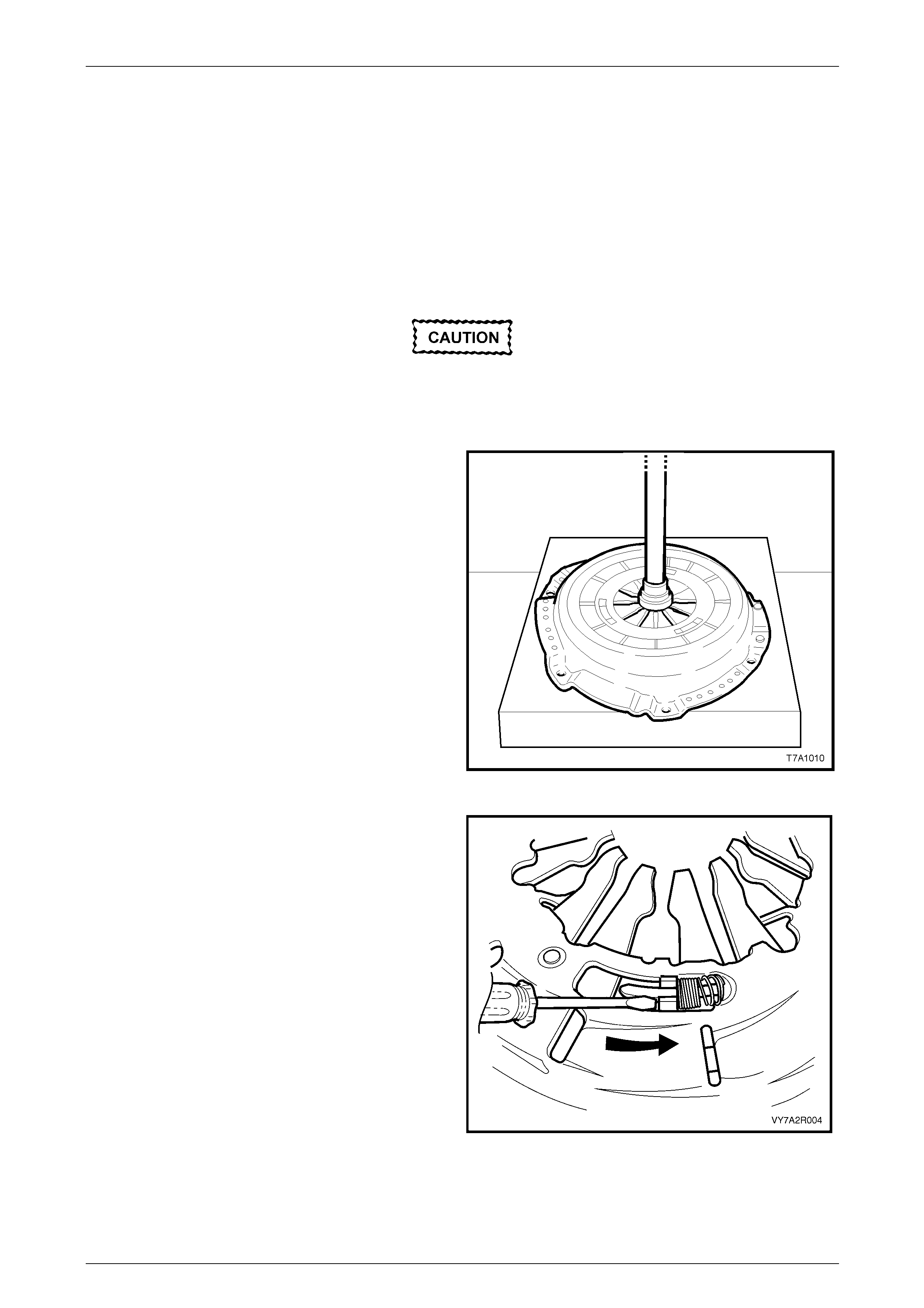
1 Place the flat side of the clutch plate down wards on
flat press plates, then place the pressure plate
assembly over it.
2 Using a hydraulic press, compress the press ure plate
diaphragm spring until tension is released from the
clutch driven plate.
NOTE
Care must be exercised when compressing the
pressure plate diaphragm spring. If the
diaphragm spring is compressed to far, damage
to the pressure plate may result.
Figure 7A3 – 12
3 Hold a screwdriver (1) or other suitable tool, aga inst
the stepped adjusting ring tens ion spring stop (2) in
front of the adjusting ring tension spr ing (3)
4 Using the screwdriver, rotate the stepped adjusting
ring, counter-clockwise (arrow), fully compressing the
tension springs.
NOTE
• Minimal effort is required to rotate the
adjustment ring. If difficulty is experienced in
rotating the adjustment ring check that the
diaphragm spring has been adequately
compressed.
• Do not force the adjustment ring as damage
to the pressure plate may result.
5 While holding the tension springs in the full y loaded
position, release the force on t he diaphragm spring.
This will then retain the springs in the fully loaded
position. Figure 7A3 – 13
6 Remove the pressure plate and clut ch driven plate from the press.
7A4 – 17
Clutch – GEN IV V8 Engine 7A4 – 18
Reinstall
1 Sparingly appl y an NLGI No. 2 lithium soap based EP
grease with molybdenum disulphide, such as Shell
Retinax HDX2 grease or BP Energrease LMS-EP 23
(or equivalent), to the input shaft splines and spigot.
2 While holding the clutch driven plate up to the engine
flywheel, insert a suitable clutch centring tool
(commercially available) into the spigot bearing,
through the driven plate.
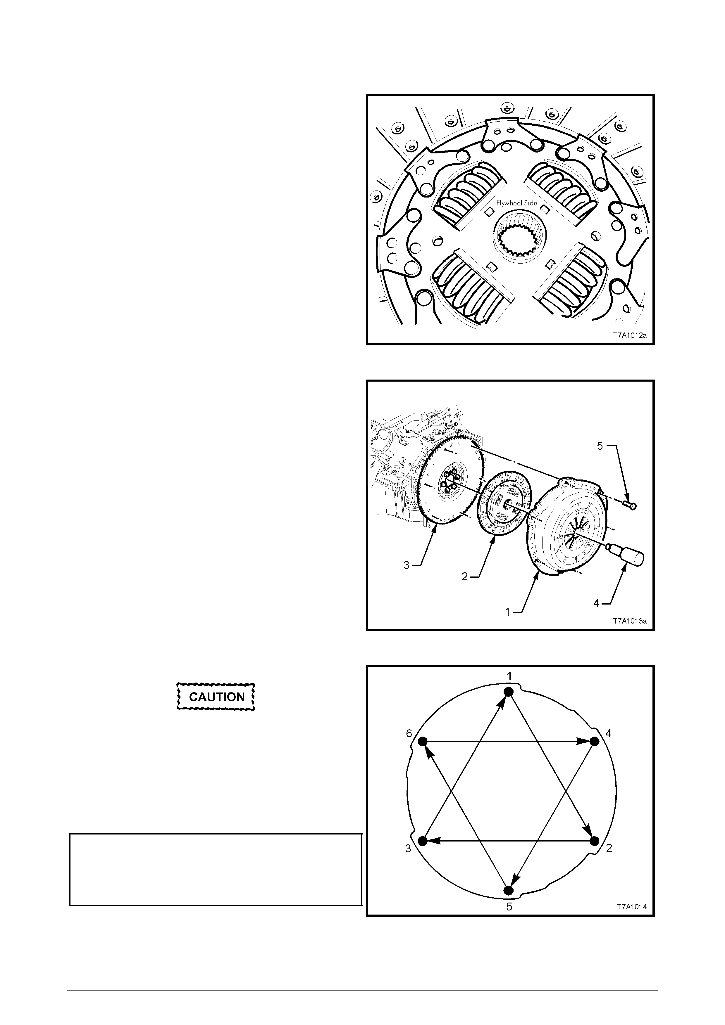
NOTE
The clutch driven plate is installed with the flat
side of the hub, facing forward to the flywheel.
The word ‘Flywheel Sid e’ is also stamped on the
inner surface, as shown.
Figure 7A3 – 14
3 Reinstall the pressure plate assembly (1) over the
alignment tool (4) and clutch driven plate (2), aligning
the offset dowel pins in the flywheel (3) with the mating
holes in the pressure plate cover (1).
4 Loosely install the six pressure plate to flywheel bolts
(5).
Figure 7A3 – 15
Tightening to the torque setting s, stages and
in the sequence listed are all necessary, to
avoid permanent distortion of the pressure
plate cover.
5 Tighten the 6 pressure plate retaining bolts in
sequence shown an d evenly over 4 stages until the
correct torque specification is reach ed.
Clutch pressure plate
bolt torque specification..........Stage 1................15 N.m
Stage 2................35 N.m
Stage 3................55 N.m
Stage 4................70 N.m
Figure 7A3 – 16
7A4 – 18
Clutch – GEN IV V8 Engine 7A4 – 19
Under no circumstances should a lubricant
be applied to the bearing face of the clutch
throw out bearing. Should a lubricant be
applied, premature clutch failure may result.
6 Reinstall the transmission assembly. Refer to
Section 7B2 Manual Transmission – GEN III V8.
NOTE
When installing the transmission, do not allow it
to ‘hang’ on the input gear splines, as the clutch
driven plate will be damaged.
7 Bleed the hydraulic clutch act uating system. Refer to
2.3 Clutch Hydraulic System, Bleed, in this Section. Figure 7A3 – 17
8 Depress the clutch pedal several times to allow the self-adjusting function of the pressure plate to take effect.
9 Start engine, and check for exhaust leaks bef ore road testing the vehicle to check for correct clutch operation.
7A4 – 19


Clutch – GEN IV V8 Engine 7A4 – 23
3 Diagnosis
Condition Probable Cause Corrective Action
Slipping Worn or oil-soaked lining.
Grease on linings from excess ive
application to the input shaft splines
Driven plate sticking on main drive
gear splines.
Weak or broken diaphragm spring
Master or actuating cylinder defective
Replace driven plate, correct oil le ak.
Replace driven plate, remove excess
lubrication.
Clean splines and check clutch hub
for a free sliding fit.
Replace pressure pl ate and
diaphragm assembly. Refer 2.10
Clutch Driven Plate and Pres sure
Plate, in this Section.
Overhaul defective cylinder as
detailed in 2.5 Master Cylinder or 2.6
Clutch Actuating Cylinder, in this
Section.
Drag or Failure to Release Air trapped in hydraulic system.
Leak In hydraulic system.
Clutch master or actuating cylinder
defective.
Dry input shaft
Cracked or oil-soaked linings.
Excessive driven plate run-out or
distorted.
Driven plate sticking on splines.
Transmission input shaft spigot
partially seized in crankshaft spigot
bearing.
Bleed system as outlined under 2.3
Clutch Hydraulic System Bleed, in this
Section.
Correct leak and bleed hydrau lic
system.
Overhaul defective cylinder as
outlined under 2.5 Master Cylinder or
2.6 Clutch Actuating Cylinder, in this
Section.
Apply grease o n input shaft
Replace clutch driven plate. Refer
2.10 Clutch Driven Plate and Pressure
Plate, in this Section.
Replace driven plate. Refer Operation
2.10 Clutch Driven Plate and Pressure
Plate, in this Section.
Clean splines and check clutch hub
for a free sliding fit.
Remove clutch, replace bush. Refer to
2.13 Crankshaft Spigot Bearing, in
this Section.
Grab or Chatter Oil on linings.
Worn transmission input shaft splines.
Rough, or grooved, flywheel or
pressure plate.
Loose engine mountings.
Loose or worn propeller shaft
coupling/s or damaged pinion flange.
Defective clutch driven plate.
Replace driven plate, correct oil le ak.
Replace transmission input shaft.
Refer to Section 7B2 Manual
Transmission – GEN III V8.
Replace flywheel or replace both
flywheel and pressure plate. Refer to
2.10 Clutch and Pressure Plates or
2.11 Engine Flywheel.
Tighten or replace mountings. Refer
to Section 6A4 Engine Mechanical –
GEN IV V8.
Tighten or replace propeller shaft
coupling/s and/or pinion fla nge. Refer
to Section 4C1 Rear Propeller Shaft
and Universal Joints.
Replace clutch driven plate. Refer
2.10 Clutch and Pressure Plates, in
this Section.
7A4 – 23

Clutch – GEN IV V8 Engine 7A4 – 24
Harsh or Stiff Clutch Operation Clutch pedal bush seized or tight on
pedal shaft.
Blockage in fluid hydraulic pipe.
Replace bushes as detail ed in 2.8
Clutch Pedal Assembly in this
Section.
Clean lines and bleed hydraulic
system. Refer 2.3 Clutch Hydraulic
System, Bleed in this Section.
Clutch Engagement Too Slow Blockage in fluid hydraulic pipe.
Clutch master or actuating cylinder
defective.
Incorrect brake fluid used.
Loose pressure plate bolts
Clean lines and bleed hydraulic
system. Refer 2.3 Clutch Hydraulic
System, Bleed in this Section.
Replace defective cylinder, refer to
2.5 Master Cylinder or 2.6 Clutch
Actuating Cylinder, in this Section.
Flush and bleed hydraulic system.
Refer 2.3 Clutch Fluid Change in this
Section.
Check pressure plate bolt torques.
Readjust clutch, refer to 2.10 Clutch
and Pressure Plates
7A4 – 24

Clutch – GEN IV V8 Engine 7A4 – 25
4 Specifications
NOTE
Only those specifications relating specifically to
this Section are quoted here. For all remaining
specifications, refer to Section 7A1 Clutch – V6.
Master Cylinder
Type...........................................................................................................Compensating por t.
Bore Size..................................................................................................................19.05 mm
Nominal Stroke..............................................................................................................30 mm
Clutch Actuating Cylinder
Type............................Concentric hydraulic actuating cylinder with side feed and bleed ports
Bore Size..........................................................................I.D. 36 mm/O.D 47.6 mm (nominal)
Available Stroke..........................................................................................22.8 mm (nominal)
Brake Fluid
Type.....................................................................................................DOT 4 or Super DOT 4
Clutch Driven Plate
Type.........................................................................................................Single plate dry disc.
Disc Facing:
Outside Diameter.........................................................................................................297 mm
Inside Diameter............................................................................................................198 mm
GEN IVThickness of disc assembly with 11,000 N load applied........................8.8 ± 0.30 mm
Clutch Pressure Plate
Type..........................................................Self-adjusting with a pressed steel cover plate and
a multi-fingered Belleville dia phragm spring.
Clutch Throw out Bearing
Type...........................................................................................................................Ball race.
Lubrication......................................................................................Sealed with grease for life.
Lubricant
Actuating cylinder guide sleeve
and transmission input shaft splines.................NLGI No. 2 lithiumsoap basedEP grease with
molybdenum disulphide, such as Shell Retinax HDX2
grease or BP Energrease L MS-EP 23 (or equivalent).
7A4 – 25

Clutch – GEN IV V8 Engine 7A4 – 26
5 Torque Wrench Specifications
ATTENTION
Fasteners must be repl aced after loosening.
Vehicle must be at curb height before final tightening.
Fasteners either have micro encapsulated sealant applied or incorporate a mechanical thread lock and
should only be re-used once. If in doubt, replacement is recommended.
NOTE
Only those torque specifications referred to in this
Section are quoted here. For all remaining t orque
specifications, refer to Section 7A1 Clutch – V6.
Clutch pressure plate bolt to flywheel (in sequence) ........Stage 1.........15 N.m
Stage 2.........35 N.m
Stage 3.........55 N.m
Stage 4.........70 N.m
Clutch actuating cylinder bleed screw....................................................18 N.m
Clutch actuating cylinder mounting screw ..............................................10 N.m
Flywheel to crankshaft mounting bolts..............................Stage 1.........20 N.m
Stage 2.........50 N.m
Stage 3.......100 N.m
Hydraulic pipe flare nut to actuating cylinder and flexible hose..............13 N.m
Master cylinder hydraulic pipe to flexible hose flare nut .........................13 N.m
7A4 – 26
Clutch – GEN IV V8 Engine 7A4 – 27
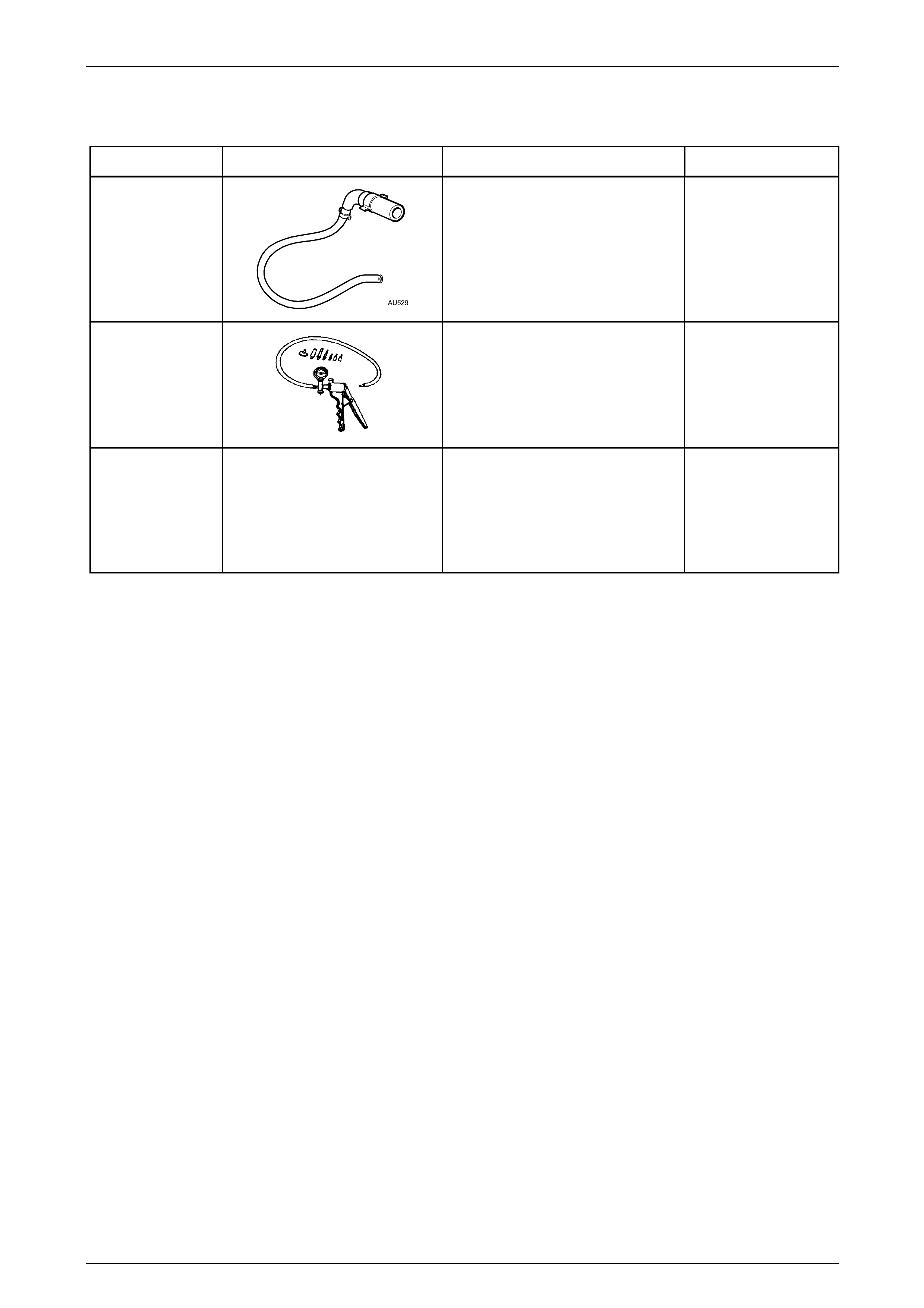
6 Special Tools
Tool Number Illustration Description Tool Classification
AU529
Clutch Actuating Cylinder Bleed
Tool
Used to bleed air from the Central
Actuating Cylinder (CSC) fitted to the
T56, 6 speed manual transmission
available for the GEN III V8.
Previously Released
Desirable
J 23738-A
Hand Vacuum Pump
Used where an applied vacuum is
required such as brake/clutch system
bleeding and/or fluid cha nging etc.
Previously released and commercially
available
Mandatory
N/A
Clutch Centring Tool
Commercially available
7A4 – 27