
Automatic Transmission – 4L60E – Electrical Diagnosis Page 7C2–1
Section 7C2
Automatic Transmission – 4L60E – Electrical
Diagnosis
ATTENTION
Before performing any service operation or other procedure described in this Section, refer to Section 00
Warnings, Cautions and Notes for correct workshop practices with regard to safety and/or property damage.
1 General Information ...............................................................................................................................9
1.1 Introduction............................................................................................................................................................ 9
1.2 General Description............................................................................................................................................. 10
Transmission Adaptive Functions ..................................................................................................................... 12
Limp Home Mode Description ............................................................................................................................ 12
1.3 Transmission Indicators and Messages............................................................................................................ 13
MFD Displays ....................................................................................................................................................... 13
Power Mode..................................................................................................................................................... 13
Normal Mode.................................................................................................................................................... 13
Shift Range Selected........................................................................................................................................ 13
1.4 Electronic Component Description.................................................................................................................... 14
Transmission Control Module (TCM)................................................................................................................. 14
2 Wiring Diagrams and Connector Cha rt..............................................................................................16
2.1 Wiring Diagrams .................................................................................................................................................. 16
Euro II (excludes Input Speed Sensor) .............................................................................................................. 17
Euro III (with Input Speed Sensor)...................................................................................................................... 20
2.2 Connector Chart................................................................................................................................................... 23
2.3 Connector Information........................................................................................................................................ 25
In-line 20-Way Conn ector End View................................................................................................................... 25
Transmission Side – X121–X 1......................................................................................................................... 25
Harness Side – X121–X1................................................................................................................................. 26
Internal Connector End Views............................................................................................................................ 27
Vehicle Speed Sensor...................................................................................................................................... 27
Input Speed Sensor.......................................................................................................................................... 27
1-2 Shift Solenoid Valve Connector.................................................................................................................. 27
2-3 Shift Solenoid Valve Connector.................................................................................................................. 27
Pressure Control (PC) Solenoid Valve Connector............................................................................................ 28
Transmission Manual Shift Shaft S witch Assembly.......................................................................................... 28
3-2 Shift Solenoid Valve Assembly Connector................................................................................................. 28
Torque Converter Clutch (T CC) Pulse-Width Modulated (PWM) Solenoid Valve Connector........................... 28
Torque Converter Clutch (T CC) Solenoid Valve Connector............................................................................. 29
Transmission Control Module Connector End View – A112–X1...................................................................... 29
3 Tech 2 Information...............................................................................................................................31
3.1 Tech 2 Diagnostics.............................................................................................................................................. 31
Test Modes........................................................................................................................................................... 31
Diagnostic Trouble Codes................................................................................................................................31
Data Display..................................................................................................................................................... 31
Snapshot.......................................................................................................................................................... 32
Additional Functions......................................................................................................................................... 32
Miscellaneous Tests......................................................................................................................................... 32
Programming.................................................................................................................................................... 33
Page 7C2–1
Techline
Techline

Automatic Transmission – 4L60E – Electrical Diagnosis Page 7C2–2
3.2 Data Display ......................................................................................................................................................... 34
Transmission Data............................................................................................................................................... 34
Transmission Data Parameters........................................................................................................................ 34
TCC Data............................................................................................................................................................... 35
TCC Data Parameters...................................................................................................................................... 35
1-2 Shift Data........................................................................................................................................................ 36
1-2 Shift Data Parameters................................................................................................................................36
2-3 Shift Data........................................................................................................................................................ 36
2-3 Shift Data Parameters................................................................................................................................36
3-4 Shift Data........................................................................................................................................................ 37
3-4 Shift Data Parameters................................................................................................................................37
Pressure Control Solenoid Data......................................................................................................................... 37
Pressure Control Solenoid Data Parameters ................................................................................................... 37
Transmission Adapts .......................................................................................................................................... 38
1-2 Adapt Data................................................................................................................................................. 38
2-3 Adapt Data................................................................................................................................................. 38
3-4 Adapt Data................................................................................................................................................. 38
Steady State Adapt Data.................................................................................................................................. 39
3.3 Tech 2 Data Definitions ....................................................................................................................................... 40
3.4 Miscellaneous Tests............................................................................................................................................ 42
4 Diagnostics...........................................................................................................................................46
4.1 Introduction.......................................................................................................................................................... 46
4.2 Precautions .......................................................................................................................................................... 47
4.3 Diagnostic Trouble Code Tables........................................................................................................................ 48
Multiple DTCs Fault Condition............................................................................................................................ 48
4.4 Diagnostic Trouble Code Definitions................................................................................................................. 49
Type A – Emission Related DTCs....................................................................................................................... 49
Type B – Emission Related DTCs....................................................................................................................... 49
Conditions for Clearing Type A or Type B DTCs.............................................................................................. 49
Type C – Non-emission Related DTCs............................................................................................................... 50
Conditions for Clearing Type C DTCs.............................................................................................................. 50
Current DTCs........................................................................................................................................................ 50
History DTCs........................................................................................................................................................ 50
4.5 Diagnostic System Check................................................................................................................................... 51
Description........................................................................................................................................................... 51
Test Description................................................................................................................................................... 51
4.6 Diagnostic Trouble Code List............................................................................................................................. 52
4.7 DTC P0218 – Transmission F luid Overtemperature.......................................................................................... 55
DTC Description................................................................................................................................................... 55
Circuit Description............................................................................................................................................... 55
Conditions for Running the DTC........................................................................................................................ 55
Conditions for Setting the DTC........................................................................................................................... 55
Action Taken When the DTC Sets ...................................................................................................................... 55
Conditions for Clearing the DTC ........................................................................................................................ 55
Diagnostic Aids.................................................................................................................................................... 55
Test Description................................................................................................................................................... 55
DTC P0218 Diagnostic Table...............................................................................................................................56
4.8 DTC P0562 – System Voltage Low ..................................................................................................................... 58
DTC Description................................................................................................................................................... 58
Circuit Description............................................................................................................................................... 58
Conditions for Running the DTC........................................................................................................................ 58
Conditions for Setting the DTC........................................................................................................................... 58
Action Taken When the DTC Sets ...................................................................................................................... 58
Conditions for Clearing the DTC ........................................................................................................................ 58
Diagnostic Aids.................................................................................................................................................... 58
Test Description................................................................................................................................................... 58
DTC P0562 Diagnostic Table...............................................................................................................................59
Page 7C2–2

Automatic Transmission – 4L60E – Electrical Diagnosis Page 7C2–3
4.9 DTC P0563 – System Voltage High..................................................................................................................... 61
DTC Description................................................................................................................................................... 61
Circuit Description............................................................................................................................................... 61
Conditions for Running the DTC........................................................................................................................ 61
Conditions for Setting the DTC........................................................................................................................... 61
Action Taken When the DTC Sets ...................................................................................................................... 61
Conditions for Clearing the DTC ........................................................................................................................ 61
Diagnostic Aids.................................................................................................................................................... 61
Test Description................................................................................................................................................... 61
DTC P0563 Diagnostic Table...............................................................................................................................62
4.10 DTC P0601 to P0604 o r P1621 – TCM Malfunction............................................................................................ 64
DTC Description................................................................................................................................................... 64
Circuit Description............................................................................................................................................... 64
Conditions for Running the DTC........................................................................................................................ 64
Conditions for Setting the DTC........................................................................................................................... 64
Action Taken When the DTC Sets ...................................................................................................................... 64
Conditions for Clearing the DTC ........................................................................................................................ 64
Test Description................................................................................................................................................... 64
DTC P0601 to P0604 or P1621 Diagnostic Table............................................................................................... 65
4.11 DTC P0711 to P0713 – Transmission Flui d Temperature Sensor.................................................................... 66
DTC Description................................................................................................................................................... 66
Circuit Description............................................................................................................................................... 66
Conditions for Running the DTC........................................................................................................................ 66
DTC P0711 ...................................................................................................................................................... 66
DTC P0712 ...................................................................................................................................................... 66
DTC P0713 ...................................................................................................................................................... 66
Conditions for Setting the DTC........................................................................................................................... 66
DTC P0711 ...................................................................................................................................................... 66
DTC P0712 ...................................................................................................................................................... 67
DTC P0713 ...................................................................................................................................................... 67
Action Taken When the DTC Sets ...................................................................................................................... 67
Conditions for Clearing the DTC ........................................................................................................................ 67
Diagnostic Aids.................................................................................................................................................... 67
Test Description................................................................................................................................................... 67
DTC P0711 to P0713 Diagnostic Table............................................................................................................... 68
4.12 DTC P0716 – Input Speed Sensor Performance................................................................................................ 70
DTC Description................................................................................................................................................... 70
Circuit Description............................................................................................................................................... 70
Conditions for Running the DTC........................................................................................................................ 70
Conditions for Setting the DTC........................................................................................................................... 70
Action Taken When the DTC Sets ...................................................................................................................... 70
Conditions for Clearing the MIL / DTC............................................................................................................... 70
Diagnostic Aids.................................................................................................................................................... 71
DTC P0716 Diagnostic Table...............................................................................................................................71
4.13 DTC P0717 – Input Speed Sensor Circuit Low Voltage.................................................................................... 74
DTC Description................................................................................................................................................... 74
Circuit Description............................................................................................................................................... 74
Conditions for Running the DTC........................................................................................................................ 74
Conditions for Setting the DTC........................................................................................................................... 74
Action Taken When the DTC Sets ...................................................................................................................... 74
Conditions for Clearing the MIL / DTC............................................................................................................... 74
Diagnostic Aids.................................................................................................................................................... 75
DTC P0717 Diagnostic Table...............................................................................................................................75
Page 7C2–3

Automatic Transmission – 4L60E – Electrical Diagnosis Page 7C2–4
4.14 DTC P0719 – Brake Switch Circuit High Input (Stuck On)................................................................................ 78
DTC Description................................................................................................................................................... 78
Circuit Description............................................................................................................................................... 78
Conditions for Running the DTC........................................................................................................................ 78
Conditions for Setting the DTC........................................................................................................................... 78
Action Taken When the DTC Sets ...................................................................................................................... 78
Conditions for Clearing the DTC ........................................................................................................................ 78
Diagnostic Aids.................................................................................................................................................... 78
Test Description................................................................................................................................................... 78
DTC P0719 Diagnostic Table...............................................................................................................................79
4.15 DTC P0722 – Vehicle Speed Sensor Circuit Low Voltage ................................................................................ 80
DTC Description................................................................................................................................................... 80
Circuit Description............................................................................................................................................... 80
Conditions for Running the DTC........................................................................................................................ 80
Conditions for Setting the DTC........................................................................................................................... 80
Action Taken When the DTC Sets ...................................................................................................................... 80
Conditions for Clearing the DTC ........................................................................................................................ 80
Diagnostic Aids.................................................................................................................................................... 81
Test Description................................................................................................................................................... 81
DTC P0722 Diagnostic Table...............................................................................................................................81
4.16 DTC P0723 – Vehicle Speed Sensor Circuit Intermittent.................................................................................. 83
DTC Description................................................................................................................................................... 83
Circuit Description............................................................................................................................................... 83
Conditions for Running the DTC........................................................................................................................ 83
Conditions for Setting the DTC........................................................................................................................... 83
Action Taken When the DTC Sets ...................................................................................................................... 83
Conditions for Clearing the DTC ........................................................................................................................ 83
Diagnostic Aids.................................................................................................................................................... 84
Test Description................................................................................................................................................... 84
DTC P0723 Diagnostic Table...............................................................................................................................84
4.17 DTC P0724 – Brake Switch Circuit Low Input (Stu ck Off) ................................................................................ 86
DTC Description................................................................................................................................................... 86
Circuit Description............................................................................................................................................... 86
Conditions for Running the DTC........................................................................................................................ 86
Conditions for Setting the DTC........................................................................................................................... 86
Action Taken When the DTC Sets ...................................................................................................................... 86
Conditions for Clearing the DTC ........................................................................................................................ 86
Diagnostic Aids.................................................................................................................................................... 86
Test Description................................................................................................................................................... 86
DTC P0724 Diagnostic Table...............................................................................................................................87
4.18 DTC P0741 – Torq u e Converter Clutch System – Stuck Off............................................................................. 88
DTC Description................................................................................................................................................... 88
Circuit Description............................................................................................................................................... 88
Conditions for Running the DTC........................................................................................................................ 88
Conditions for Setting the DTC........................................................................................................................... 88
Action Taken When the DTC Sets ...................................................................................................................... 88
Conditions for Clearing the DTC ........................................................................................................................ 89
Diagnostic Aids.................................................................................................................................................... 89
Test Description................................................................................................................................................... 89
DTC P0741 Diagnostic Table...............................................................................................................................89
4.19 DTC P0742 – Torque Converter Clutch System – Stuck On............................................................................. 91
DTC Description................................................................................................................................................... 91
Circuit Description............................................................................................................................................... 91
Conditions for Running the DTC........................................................................................................................ 91
Conditions for Setting the DTC........................................................................................................................... 91
Action Taken When the DTC Sets ...................................................................................................................... 91
Conditions for Clearing the DTC ........................................................................................................................ 92
Diagnostic Aids.................................................................................................................................................... 92
Test Description................................................................................................................................................... 92
DTC P0742 Diagnostic Table...............................................................................................................................92
Page 7C2–4

Automatic Transmission – 4L60E – Electrical Diagnosis Page 7C2–5
4.20 DTC P0751 – 1-2 Shift Solenoi d Valve Performance – No Fi rst or Fourth Gear ............................................. 94
DTC Description................................................................................................................................................... 94
Circuit Description............................................................................................................................................... 94
Conditions for Running the DTC........................................................................................................................ 94
Conditions for Setting the DTC........................................................................................................................... 94
Action Taken When the DTC Sets ...................................................................................................................... 94
Conditions for Clearing the DTC ........................................................................................................................ 94
Diagnostic Aids.................................................................................................................................................... 95
Test Description................................................................................................................................................... 95
DTC P0751 Diagnostic Table...............................................................................................................................95
4.21 DTC P0752 – 1-2 Shift Solenoid Valve Performance – No Second or Third Gear........................................... 97
DTC Description................................................................................................................................................... 97
Circuit Description............................................................................................................................................... 97
Conditions for Running the DTC........................................................................................................................ 97
Conditions for Setting the DTC........................................................................................................................... 97
Action Taken When the DTC Sets ...................................................................................................................... 97
Conditions for Clearing the DTC ........................................................................................................................ 97
Diagnostic Aids.................................................................................................................................................... 98
Test Description................................................................................................................................................... 98
DTC P0752 Diagnostic Table...............................................................................................................................98
4.22 DTC P0756 – 2-3 Shift Solenoid Valve Performance – No First or Second Gear.......................................... 100
DTC Description................................................................................................................................................. 100
Circuit Description............................................................................................................................................. 100
Conditions for Running the DTC...................................................................................................................... 100
Conditions for Setting the DTC......................................................................................................................... 100
Action Taken When the DTC Sets .................................................................................................................... 100
Conditions for Clearing the DTC ...................................................................................................................... 100
Diagnostic Aids.................................................................................................................................................. 101
Test Description................................................................................................................................................. 101
DTC P0756 Diagnostic Table............................................................................................................................. 101
4.23 DTC P0757 – 2-3 Shift Solenoi d Valve Performance – No Third o r Fourth Gear .......................................... 103
DTC Description................................................................................................................................................. 103
Circuit Description............................................................................................................................................. 103
Conditions for Running the DTC...................................................................................................................... 103
Conditions for Setting the DTC......................................................................................................................... 103
Action Taken When the DTC Sets .................................................................................................................... 103
Conditions for Clearing the DTC ...................................................................................................................... 103
Diagnostic Aids.................................................................................................................................................. 104
Test Description................................................................................................................................................. 104
DTC P0757 Diagnostic Table............................................................................................................................. 104
4.24 DTC P0787 – 3-2 Shift Solenoi d Control Circuit Low Voltage........................................................................ 106
DTC Description................................................................................................................................................. 106
Circuit Description............................................................................................................................................. 106
Conditions for Running the DTC...................................................................................................................... 106
Conditions for Setting the DTC......................................................................................................................... 106
Action Taken When the DTC Sets .................................................................................................................... 106
Conditions for Clearing the DTC ...................................................................................................................... 106
Test Description................................................................................................................................................. 107
DTC P0787 Diagnostic Table............................................................................................................................. 107
4.25 DTC P0788 – 3-2 Shift Solenoi d Control Circuit High Voltage ....................................................................... 110
DTC Description................................................................................................................................................. 110
Circuit Description............................................................................................................................................. 110
Conditions for Running the DTC...................................................................................................................... 110
Conditions for Setting the DTC......................................................................................................................... 110
Action Taken When the DTC Sets .................................................................................................................... 110
Conditions for Clearing the DTC ...................................................................................................................... 110
Test Description................................................................................................................................................. 111
DTC P0788 Diagnostic Table............................................................................................................................. 111
Page 7C2–5

Automatic Transmission – 4L60E – Electrical Diagnosis Page 7C2–6
4.26 DTC P0894 – Transmission Component Slipping........................................................................................... 113
DTC Description................................................................................................................................................. 113
Circuit Description............................................................................................................................................. 113
Conditions for Running the DTC...................................................................................................................... 113
Conditions for Setting the DTC......................................................................................................................... 113
Action Taken When the DTC Sets .................................................................................................................... 114
Conditions for Clearing the DTC ...................................................................................................................... 114
Diagnostic Aids.................................................................................................................................................. 114
Test Description................................................................................................................................................. 114
DTC P0894 Diagnostic Table............................................................................................................................. 115
4.27 DTC P0961 – Lin e Pressure Control Solenoi d System Performance ............................................................ 120
DTC Description................................................................................................................................................. 120
Circuit Description............................................................................................................................................. 120
Conditions for Running the DTC...................................................................................................................... 120
Conditions for Setting the DTC......................................................................................................................... 120
Action Taken When the DTC Sets .................................................................................................................... 120
Conditions for Clearing the DTC ...................................................................................................................... 120
Diagnostic Aids.................................................................................................................................................. 120
Test Description................................................................................................................................................. 120
DTC P0961 Diagnostic Table............................................................................................................................. 121
4.28 DTC P0973 – 1-2 Shift Solenoi d Control Circuit Low Voltage........................................................................ 123
DTC Description................................................................................................................................................. 123
Circuit Description............................................................................................................................................. 123
Conditions for Running the DTC...................................................................................................................... 123
Conditions for Setting the DTC......................................................................................................................... 123
Action Taken When the DTC Sets .................................................................................................................... 123
Conditions for Clearing the DTC ...................................................................................................................... 123
Test Description................................................................................................................................................. 124
DTC P0973 Diagnostic Table............................................................................................................................. 124
4.29 DTC P0974 – 1-2 Shift Solenoi d Control Circuit High Voltage ....................................................................... 128
DTC Description................................................................................................................................................. 128
Circuit Description............................................................................................................................................. 128
Conditions for Running the DTC...................................................................................................................... 128
Conditions for Setting the DTC......................................................................................................................... 128
Action Taken When the DTC Sets .................................................................................................................... 128
Conditions for Clearing the DTC ...................................................................................................................... 128
Test Description................................................................................................................................................. 128
DTC P0974 Diagnostic Table............................................................................................................................. 129
4.30 DTC P0976 – 2-3 Shift Solenoi d Control Circuit Low Voltage........................................................................ 131
DTC Description................................................................................................................................................. 131
Circuit Description............................................................................................................................................. 131
Conditions for Running the DTC...................................................................................................................... 131
Conditions for Setting the DTC......................................................................................................................... 131
Action Taken When the DTC Sets .................................................................................................................... 131
Conditions for Clearing the DTC ...................................................................................................................... 131
Test Description................................................................................................................................................. 132
DTC P0976 Diagnostic Table............................................................................................................................. 132
4.31 DTC P0977 – 2-3 Shift Solenoi d Control Circuit High Voltage ....................................................................... 136
DTC Description................................................................................................................................................. 136
Circuit Description............................................................................................................................................. 136
Conditions for Running the DTC...................................................................................................................... 136
Conditions for Setting the DTC......................................................................................................................... 136
Action Taken When the DTC Sets .................................................................................................................... 136
Conditions for Clearing the DTC ...................................................................................................................... 136
Test Description................................................................................................................................................. 136
DTC P0977 Diagnostic Table............................................................................................................................. 137
Page 7C2–6

Automatic Transmission – 4L60E – Electrical Diagnosis Page 7C2–7
4.32 DTC P1810, P1815, P181 6 and P1818 – Transmission Fluid Pressure Position Switch .............................. 139
DTC Description................................................................................................................................................. 139
Circuit Description............................................................................................................................................. 139
Conditions for Running the DTC...................................................................................................................... 139
DTC P1810 .................................................................................................................................................... 139
DTC P1815 .................................................................................................................................................... 139
DTC P1816 .................................................................................................................................................... 139
DTC P1818 .................................................................................................................................................... 139
Conditions for Setting the DTC......................................................................................................................... 140
DTC P1810 .................................................................................................................................................... 140
DTC P1815 .................................................................................................................................................... 140
DTC P1816 .................................................................................................................................................... 140
DTC P1818 .................................................................................................................................................... 140
Action Taken When the DTC Sets .................................................................................................................... 140
Conditions for Clearing the DTC ...................................................................................................................... 140
Diagnostic Aids.................................................................................................................................................. 140
Test Description................................................................................................................................................. 141
DTC P1810, P1815, P1816 and P1818 Diagnostic Table ................................................................................. 141
4.33 DTC P2763 – Torque Converter Clutch Pressure Contro l So lenoid Control Circuit High Voltag e ............. 144
DTC Description................................................................................................................................................. 144
Circuit Description............................................................................................................................................. 144
Conditions for Running the DTC...................................................................................................................... 144
Conditions for Setting the DTC......................................................................................................................... 144
Action Taken When the DTC Sets .................................................................................................................... 144
Conditions for Clearing the DTC ...................................................................................................................... 144
Test Description................................................................................................................................................. 145
DTC P2763 Diagnostic Table............................................................................................................................. 145
4.34 DTC P2764 – Torque Converter Clutch Pressure Control So lenoid Control Circuit Low Voltage.............. 147
DTC Description................................................................................................................................................. 147
Circuit Description............................................................................................................................................. 147
Conditions for Running the DTC...................................................................................................................... 147
Conditions for Setting the DTC......................................................................................................................... 147
Action Taken When the DTC Sets .................................................................................................................... 147
Conditions for Clearing the DTC ...................................................................................................................... 147
Test Description................................................................................................................................................. 148
DTC P2764 Diagnostic Table............................................................................................................................. 148
4.35 DTC P2769 – Torque Converter Clutch Enable Solenoid Control Circuit Low Voltage............................... 151
DTC Description................................................................................................................................................. 151
Circuit Description............................................................................................................................................. 151
Conditions for Running the DTC...................................................................................................................... 151
Conditions for Setting the DTC......................................................................................................................... 151
Action Taken When the DTC Sets .................................................................................................................... 151
Conditions for Clearing the DTC ...................................................................................................................... 152
Diagnostic Aids.................................................................................................................................................. 152
Test Description................................................................................................................................................. 152
DTC P2769 Diagnostic Table............................................................................................................................. 152
4.36 DTC P2770 – Torque Converter Clutch Enable Solenoid Control Circuit High Voltage .............................. 155
DTC Description................................................................................................................................................. 155
Circuit Description............................................................................................................................................. 155
Conditions for Running the DTC...................................................................................................................... 155
Conditions for Setting the DTC......................................................................................................................... 155
Action Taken When the DTC Sets .................................................................................................................... 155
Conditions for Clearing the DTC ...................................................................................................................... 156
Test Description................................................................................................................................................. 156
DTC P2770 Diagnostic Table............................................................................................................................. 156
Page 7C2–7

Automatic Transmission – 4L60E – Electrical Diagnosis Page 7C2–8
4.37 DTC U2107– Lost Communication with Body Control Module...................................................................... 157
DTC Description................................................................................................................................................. 157
Circuit Description............................................................................................................................................. 157
Conditions for Running the DTC...................................................................................................................... 157
Conditions for Setting the DTC......................................................................................................................... 157
Action Taken When the DTC Sets .................................................................................................................... 157
Conditions for Clearing the DTC ...................................................................................................................... 157
Diagnostic Aids.................................................................................................................................................. 157
Test Description................................................................................................................................................. 157
DTC U2107 Diagnostic Table ............................................................................................................................ 158
5 Electrical Specifications....................................................................................................................159
5.1 Transmission Fluid Temperature (TFT) Sensor Specifications..................................................................... 159
5.2 Range Reference................................................................................................................................................ 160
5.3 Transmission Fluid Pressure Manu al Valve Position Switch Logic.............................................................. 161
5.4 Transmission Range Switch Logic................................................................................................................... 162
5.5 Component Resistance..................................................................................................................................... 163
5.6 Shift Solenoid Valve State and Gear Ratio ...................................................................................................... 164
5.7 Line Pressure..................................................................................................................................................... 165
6 Special Tools ......................................................................................................................................166
Page 7C2–8

Automatic Transmission – 4L60E – Electrical Diagnosis Page 7C2–9
1 General Information
1.1 Introduction
This Section covers the electrical diagnostic for the 4L60E automatic transmission when mated to a V6 engine.
For diagnosis of the 4L60E automatic transmission when mated to a GEN III V8 engine, refer to Section 6C3-2
Powertrain Management – GEN III V8 – Diagnostics.
Page 7C2–9

Automatic Transmission – 4L60E – Electrical Diagnosis Page 7C2–10
1.2 General Description
The 4L60E automatic transmission incorporates electronic controls that utilise a transmission control module (TCM) to
control shift points through:
• the 1-2 and 2-3 shift solenoid valves,
• the 3-2 downshift solenoid valve,
• a torque converter clutch (TCC) solenoid val ve,
• apply and release through th e TCC pulse width modulated (PWM) solenoid valve, and
• line pressure through the pressure control (PC) solenoid valve.
Electrical signals from various sensors pr ovide information to the TCM about the following:
• vehicle speed,
• throttle position,
• engine coolant temperatur e,
• transmission fluid temperature,
• gear range selector position,
• engine speed,
• converter turbine speed,
• input shaft speed and
• engine load braking and operating mode.
The TCM uses this information to determine the precise moment to upshift or downshift, apply or release the TCC and
what fluid pressure is needed to apply the clutches. This type of control provides consist ent and precise shift points and
shift quality based on the operating conditions of the vehicle.
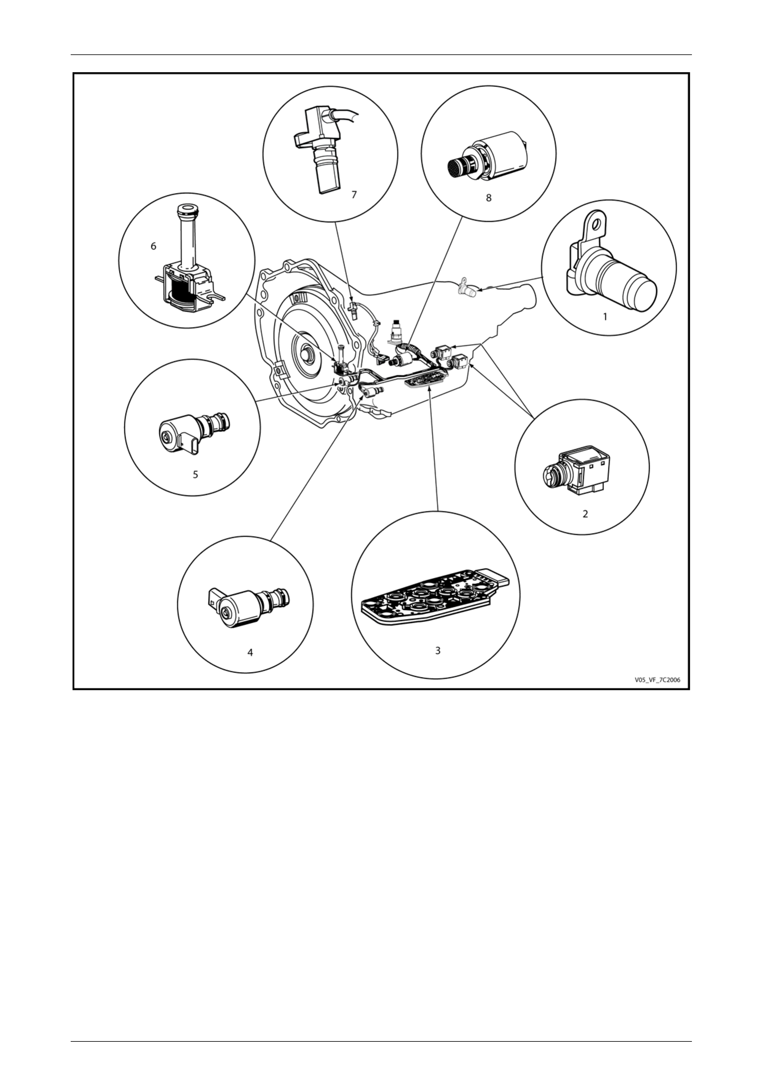
Figure 7C2 – 1 shows the location of the internal electronic components in the transmission.
Page 7C2–10
Automatic Transmission – 4L60E – Electrical Diagnosis Page 7C2–11
Figure 7C2 – 1
Legend
1 Vehicle Speed Sensor 5 Torque Converter Clutch Pulse Width Modulation (TCC
PWM) Solenoid Valve
2 1-2 Shift Solenoid (Solenoid A) and 2-3 Shift Solenoid
(Solenoid B) 6 Torque Converter Clutch (TCC) Solenoid Valve
3 Automatic Transmission Fluid Pressure (TFP) Manual Valve
Position 7 Input Speed Sensor
4 3-2 Downshift Solenoid 8 Pressure Control (PC) Solenoid Valve
Page 7C2–11

Automatic Transmission – 4L60E – Electrical Diagnosis Page 7C2–12
Transmission Adaptive Fun ns
The 4L60E automatic transmission uses a line pressure control system, which has the ability to adapt the system line
ure is similar in function to the long term/short term fuel trim feature of the engine management system.
ssion uses the adapt function for garage shifts, upshifts and torque convert er clutch (TCC)
M monitors the engine torque to determine if the shift is occurring too fast or too slow and adjusts the
pressure control solenoid to maintain the correct shift feel.
vehicle safety or damage the transmission d urin g norma l
CM enters a limp home mode. In the limp home mode, the transmission operates in the following
manner:
• The pressure control solenoid is off and the li ne pressure is at maximum to minimise clutch slippage.
• The TCC solenoid is off, therefore the torque converter clutch is disabled.
• The two shift solenoids are turned off. The transmission will operate in fourth has successfully
he vehicle has not completed a 1-2 upshift in the current
r. ion is operating in fourth gear, third gear
re-started.
In limp home mode, the gear selector lev er is ineffective at selecting forward gear ranges. In third or fourth gear, heat
ansmission quickly, particularly in stop and go traffic. Excessive heat build-up may cause transmission
home mode.
ctio
pressure to compensate for normal wear within the transmission, such as the clutch pack fibre plates, seals, springs, etc.
The adapt feat
The 4L60E automatic transmi
application. The TC
Limp Home Mode Description
If a major electrical system failure occurs which could affect
operation, the T
gear if the vehicle
completed a 1-2 upshift in the current ignition cycle. If t
ignition cycle, the transmission will operate in third gea
may be obtained if the engine is stopped briefly and If the transmiss
builds up in the tr
failure if the vehicle is driven for extended distances in limp
Page 7C2–12
Automatic Transmission – 4L60E – Electrical Diagnosis Page 7C2–13
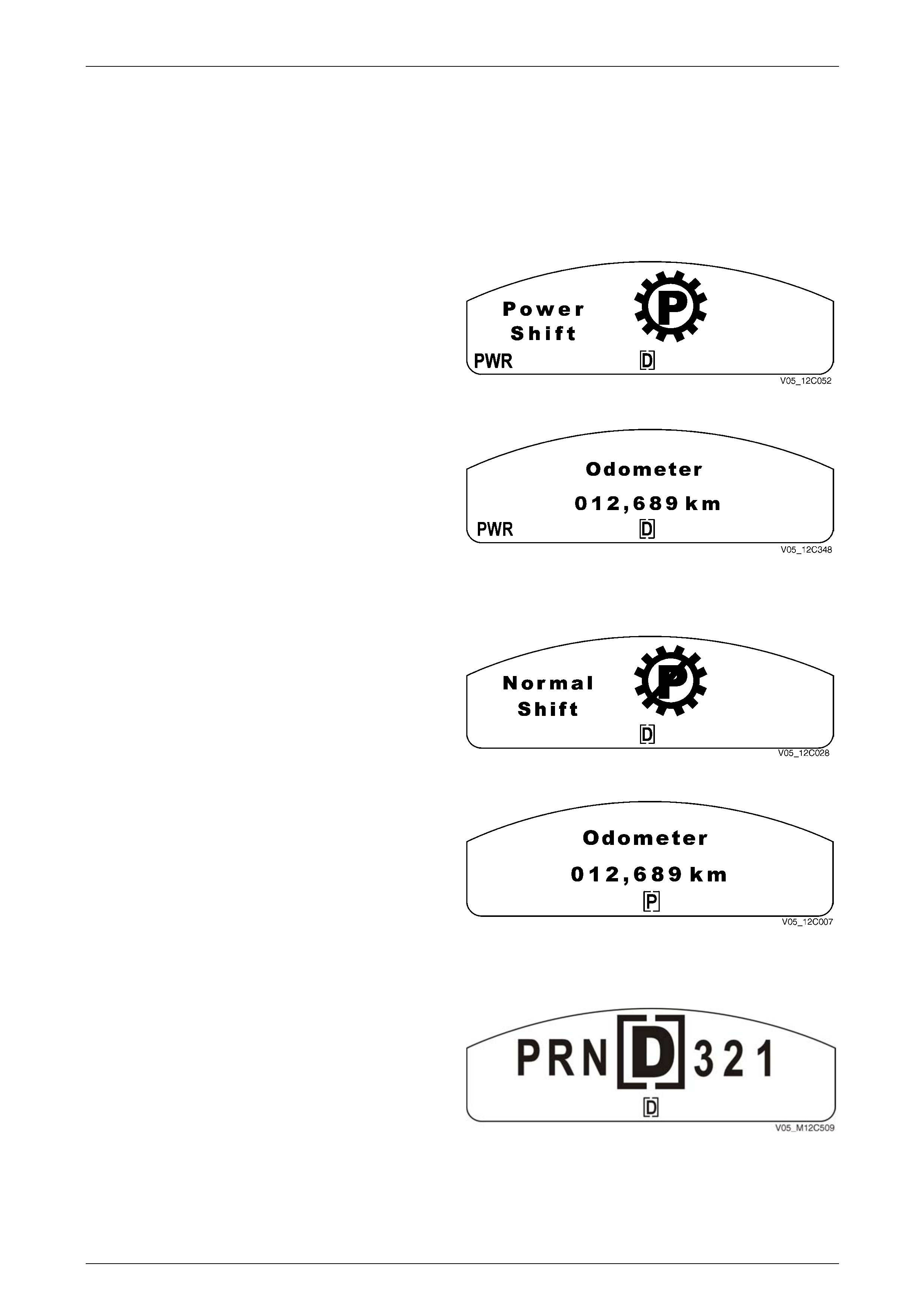
1.3 Transmissi
The instrument clusters m
on Indicators and Messages
ulti-function display (MFD) component of the Instrument may displa y messages relating to this
w
hen ode, the PWR
n i tion is displayed
transmission.
MFD Displays
Po er Mode
W the transmission is placed in Power M
ico lluminates and the Power Shift anima
for 2 seconds.
Figure 7C2 – 2
lay extinguishes and th e
PWR icon remains. The display reverts to the previously
pla een.
After 2 seconds, the animated disp
dis yed trip computer scr
Figure 7C2 – 3
Normal Mode
When the transmission is change d from Power Mode to
Normal Mode, the PWR icon exti nguishes immediatel y and
the Normal Shift animation is displa yed for 2 seconds.
Figure 7C2 – 4
After 2 seconds, the animated display extinguishes and the
display reverts to the previous ly displayed trip computer
screen.
Figure 7C2 – 5
Shift Range Selected
The gear icon remains for 2 seconds after it is selected.
While the transmission selector is moving, the constant
icons reflect the selector movement through the gears.
NOTE
If any warning is active, the large displ ay symbol
is not shown and only the bracketed constant
icon at the bottom changes when the automatic
transmission selector is moved. Figure 7C2 – 6
Page 7C2–13
Automatic Transmission – 4L60E – Electrical Diagnosis Page 7C2–14
1.4 Electronic Component Description
r a section, refer to General Motors Powertrain Group Electronically
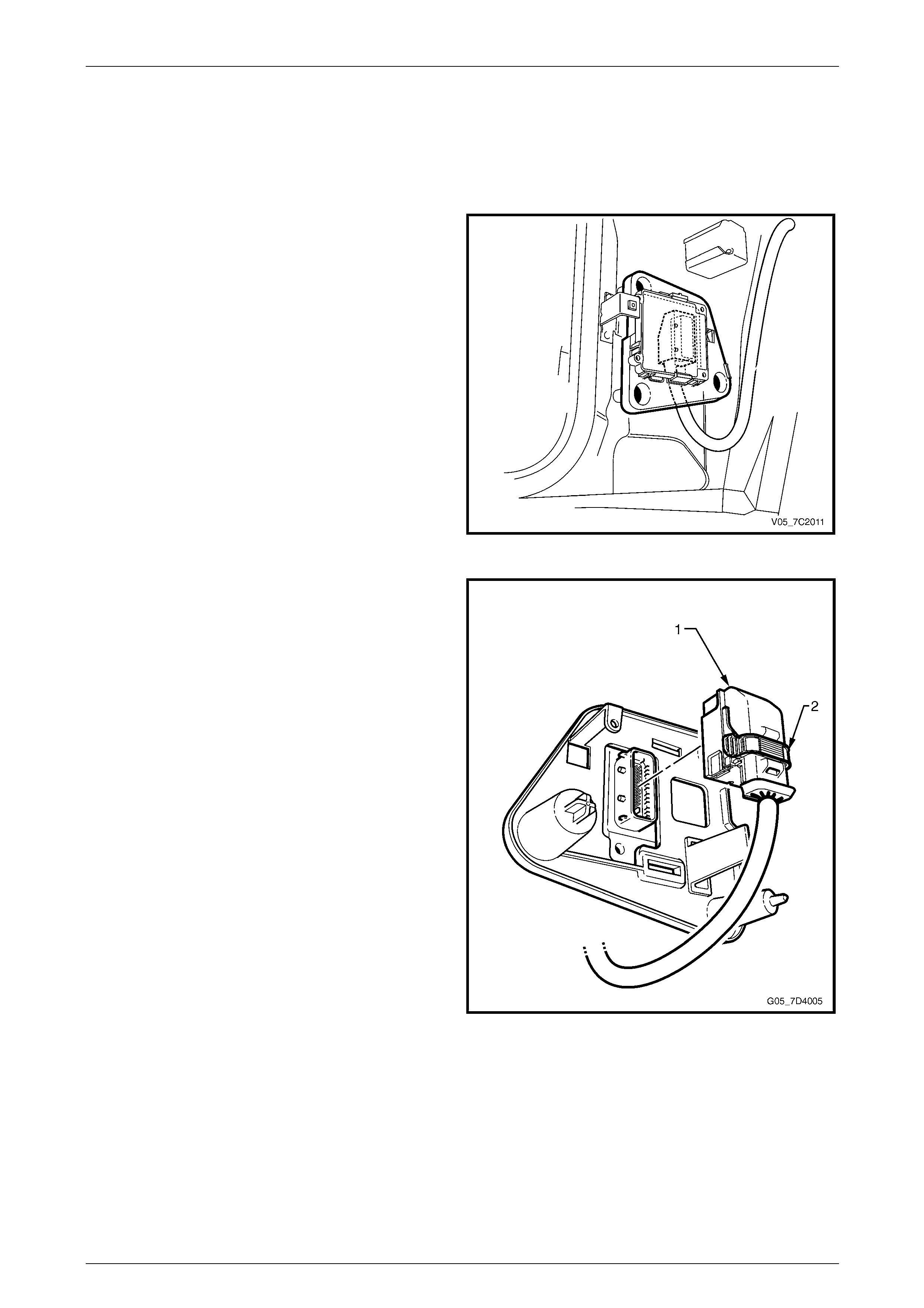
Transmission Control Module (TCM)
ehind
ects
e 49-way
nn n the
hic and the TCM.
Fo ll other electrical components not covered in this
Controlled Automatic Transmission Technician's Guide.
The Transmission Control Mo dule (TCM) is located b
the left-hand body hinge pillar trim assembly and conn
directly to the transmission wiring harness. A singl
co ector is used to make the connection betwee
ve le wiring harness
Figure 7C2 – 7
The TCM is an electronic cont rol module receiving input or
providing output to control the operation of the 4L60E
automatic transmission.
The TCM receives the following in puts from the engine
control module (ECM):
• engine speed and torque values,
• engine intake air temperature (IAT), accelerator pedal
position (APP) information,
• engine coolant temperatur e (ECT),
• driver selected shift mode, and
• air-conditioning (A/C) status.
The ECM provides this data to the TCM through the
databus.
Other TCM inputs are:
• battery and ignition voltage,
• brake switch status,
• transmission fluid temperature (TFT),
• input speed sensor (ISS) and
• vehicle speed sensor (VSS). Figure 7C2 – 8
Page 7C2–14

Automatic Transmission – 4L60E – Electrical Diagnosis Page 7C2–15
The TCM provides the following outp to control the a
• shift solenoids to control trans ion
• torque converter clutch (TCC) pulse w ted (PWM) solenoid operation to contr ol the apply and release of
the torque converter clutch as
• pressure control (PC) solenoi d e.
• check powertrain icon illuminat ion request,
• vehicle speed,
• transmission input speed,
• transmission fluid temperature,
• commanded gear status,
• TCC status, and
• torque reduction requests.
uts utomatic transmission:
miss shifting,
idth modula
sembly, and
to regulate the transmission line pressur
Other TCM outputs provided to the ECM / PIM are:
Page 7C2–15

Automatic Transmission – 4L60E – Electrical Diagnosis Page 7C2–16
2 Wiring Diagrams and Connector
Chart
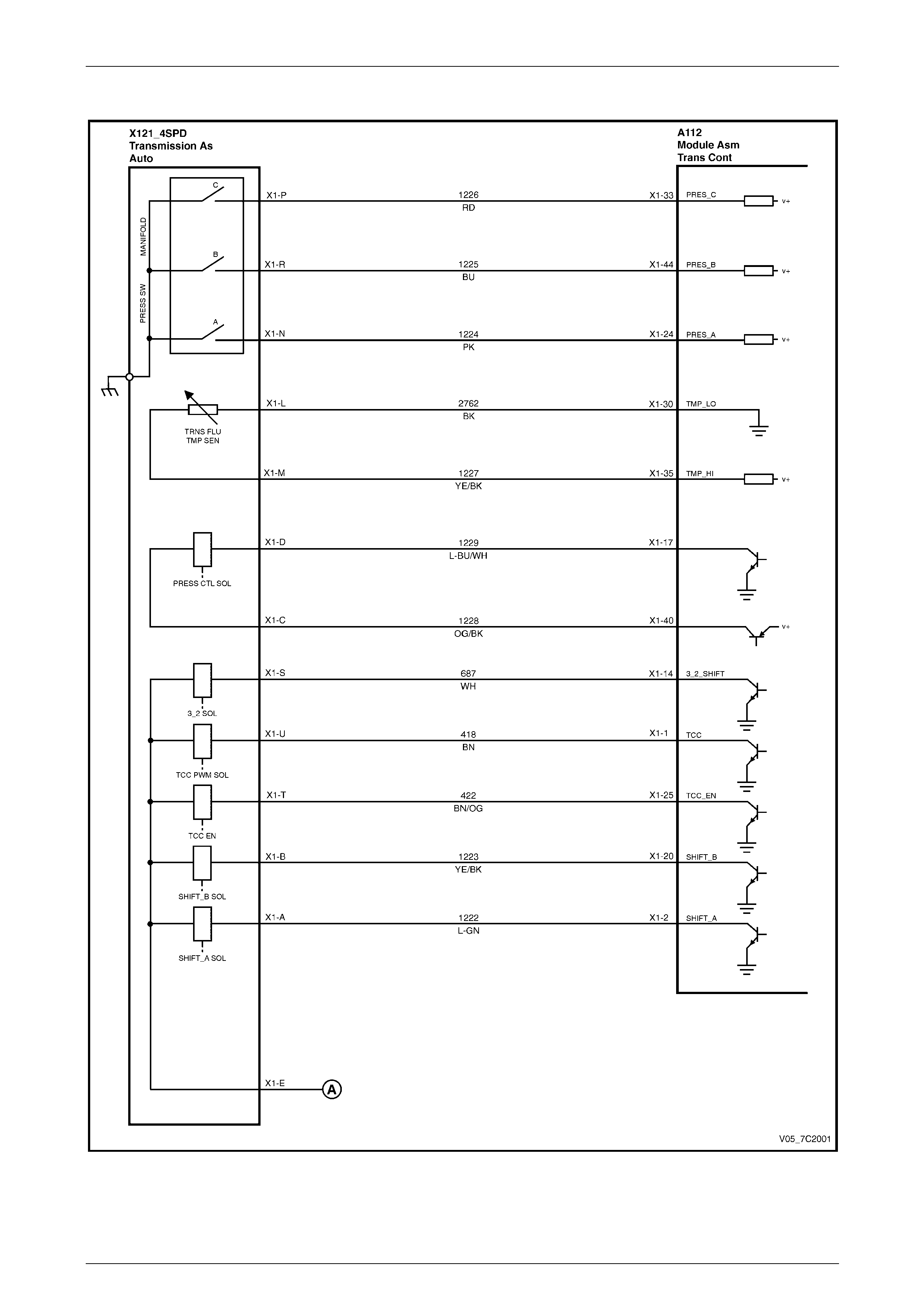
2.1 Wiring Diagrams
Page 7C2–16
Automatic Transmission – 4L60E – Electrical Diagnosis Page 7C2–17
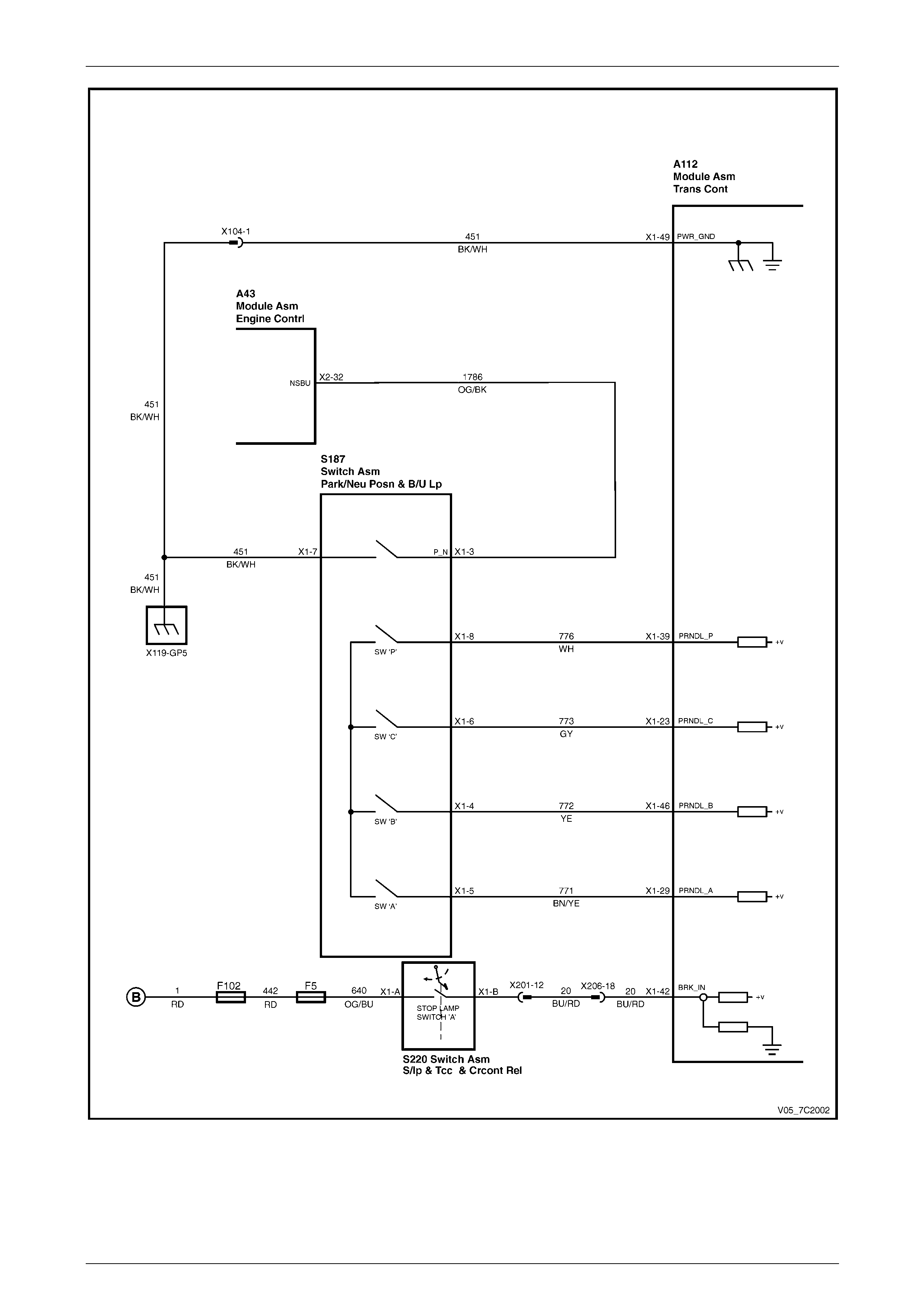
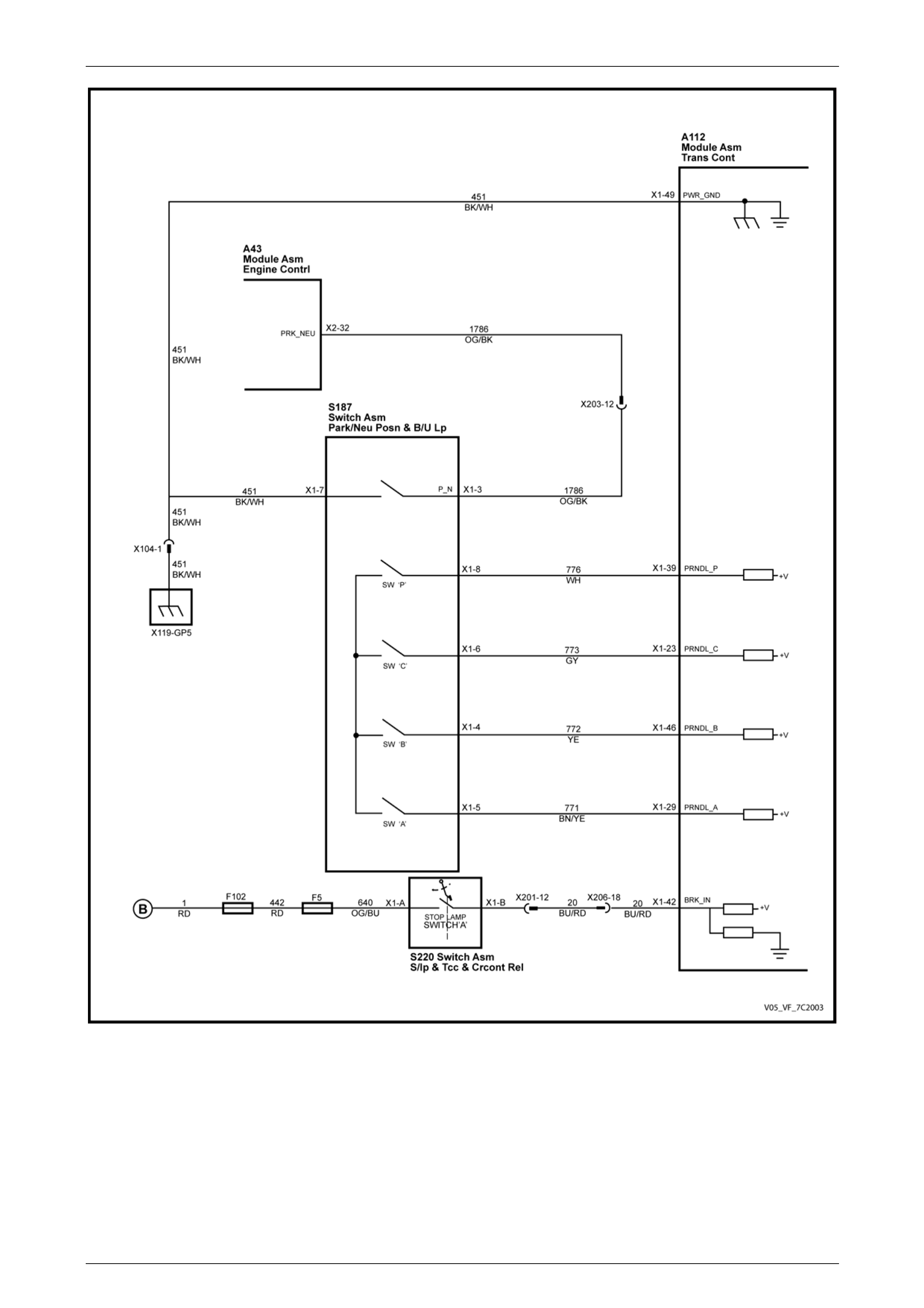
Euro II (excludes Input Speed Sensor)
Figure 7C1 – 9
Page 7C2–17
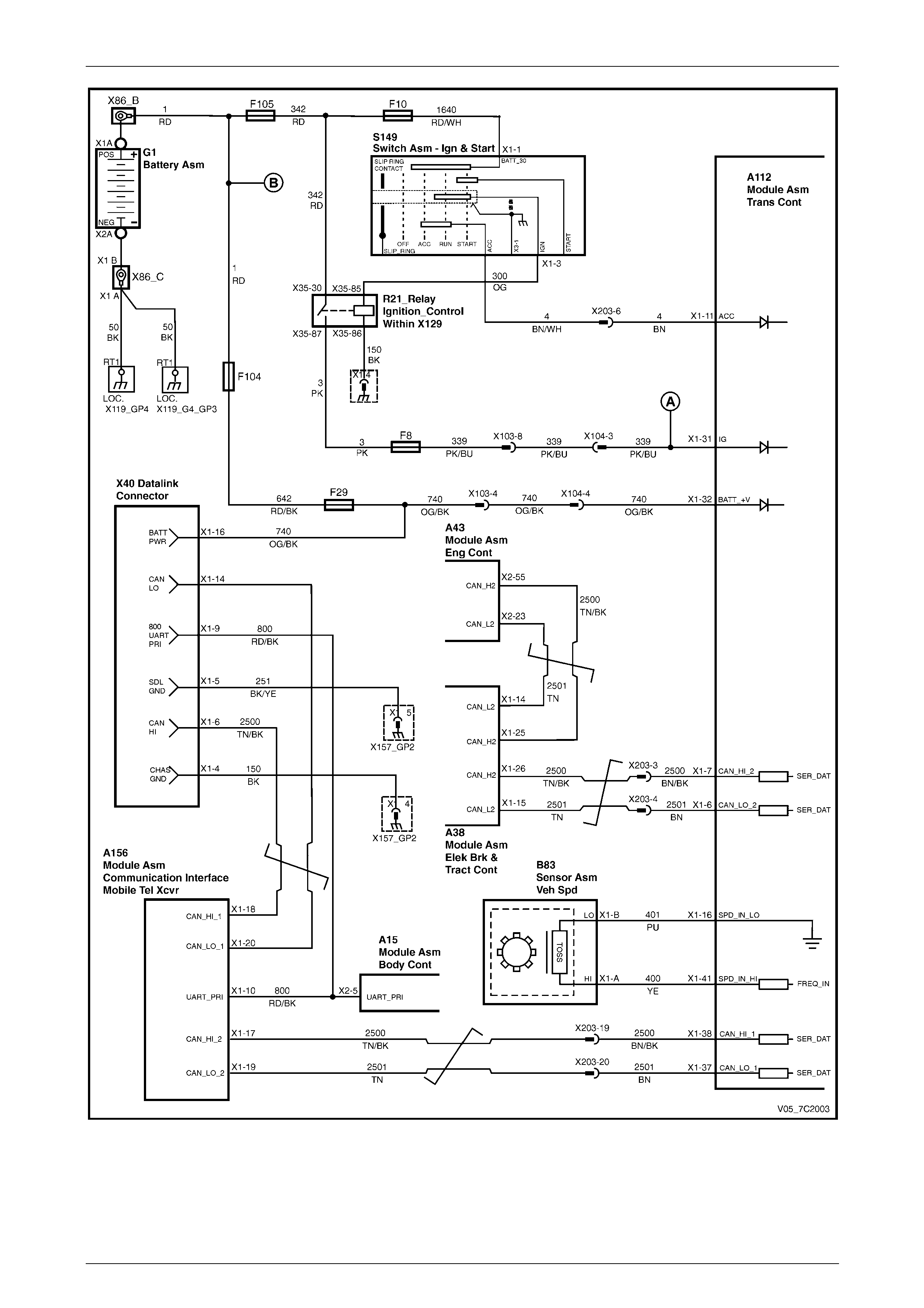
Automatic Transmission – 4L60E – Electrical Diagnosis Page 7C2–18
Figure 7C1 – 10
Page 7C2–18
Automatic Transmission – 4L60E – Electrical Diagnosis Page 7C2–19
Figure 7C1 – 11
Page 7C2–19
Automatic Transmission – 4L60E – Electrical Diagnosis Page 7C2–20
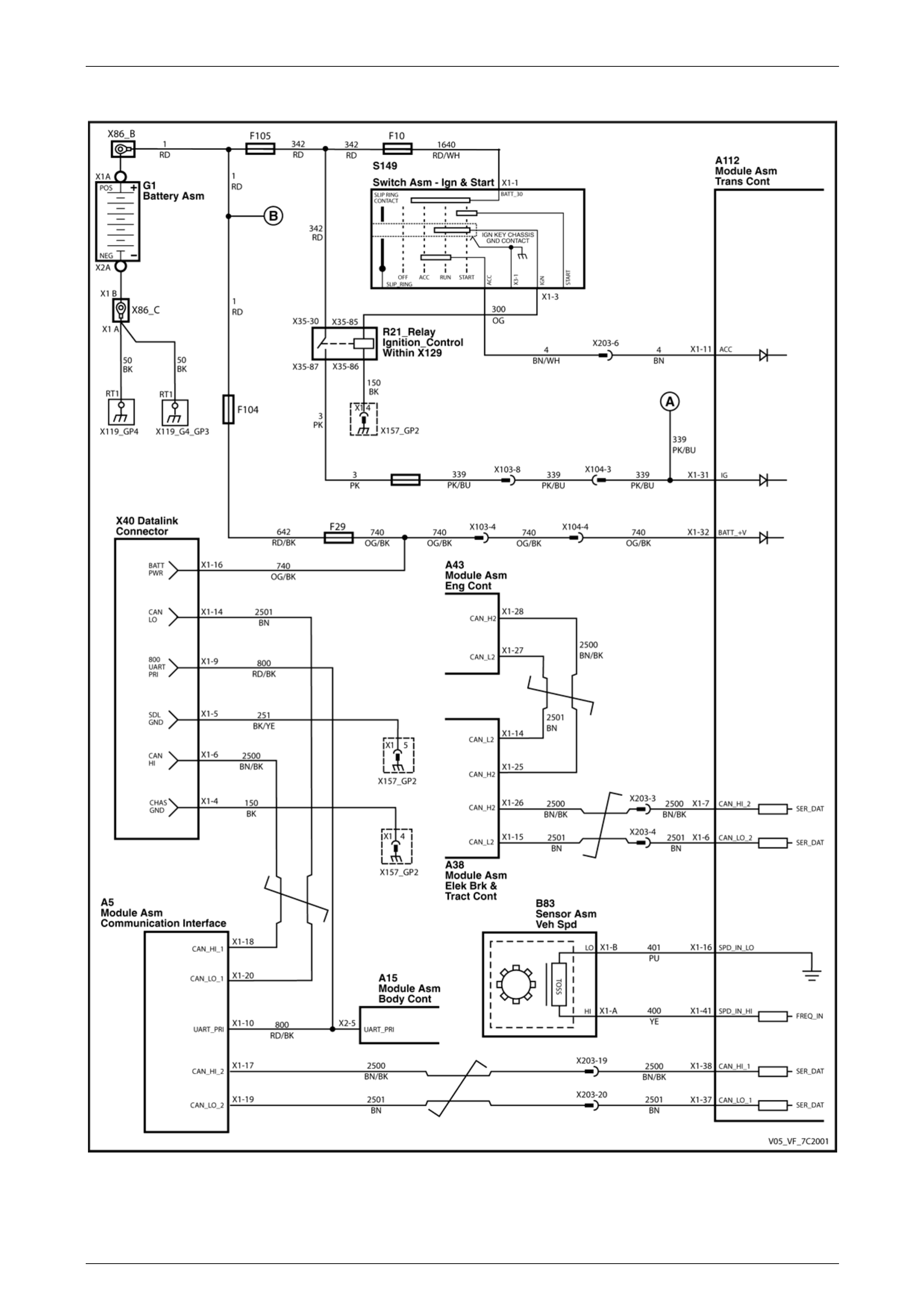
Euro III (with Input Speed Sensor)
Figure 7C2 – 12
Page 7C2–20
Automatic Transmission – 4L60E – Electrical Diagnosis Page 7C2–21
Figure 7C2 – 13
Page 7C2–21
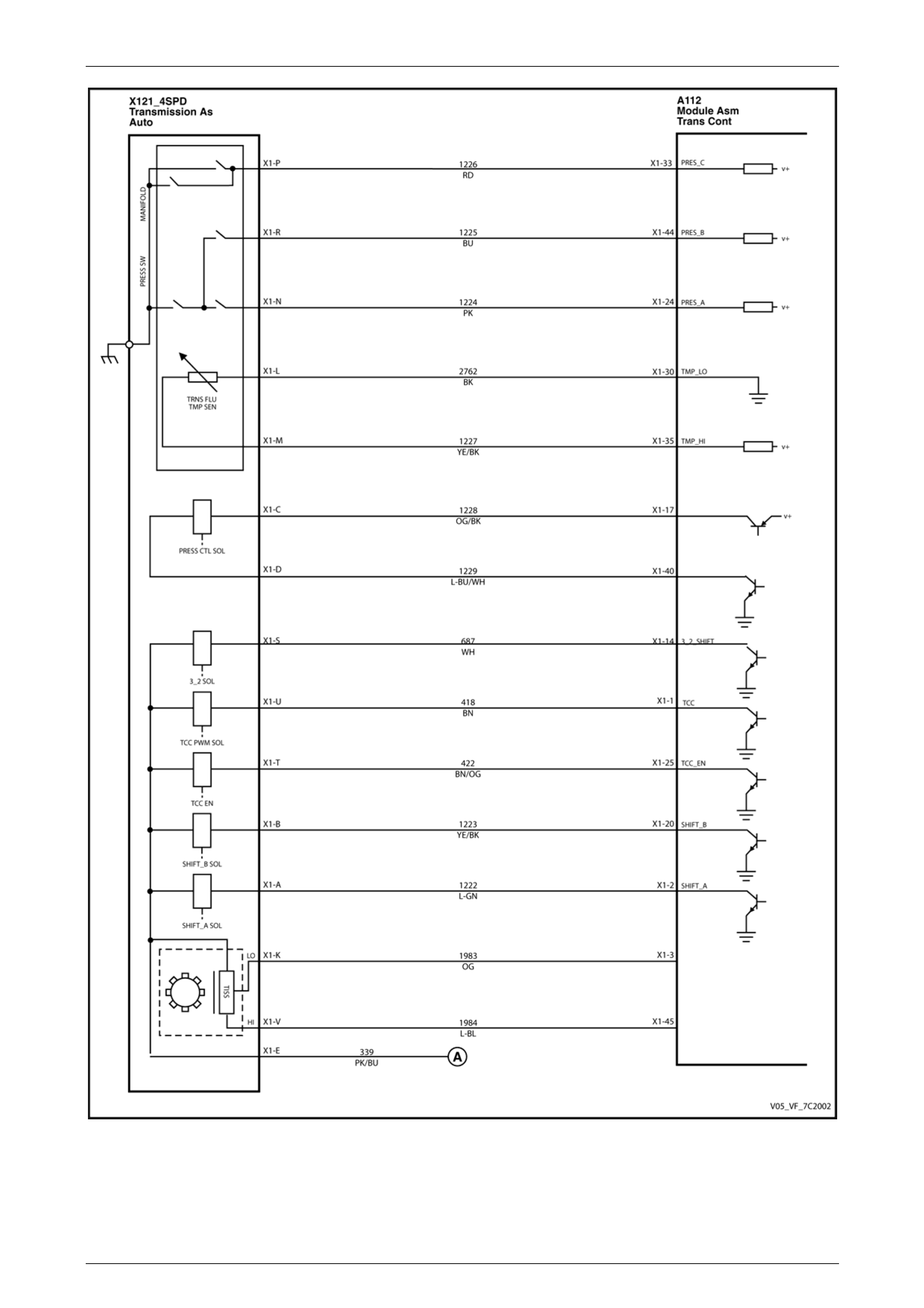
Automatic Transmission – 4L60E – Electrical Diagnosis Page 7C2–22
Figure 7C2 – 14
Page 7C2–22
Automatic Transmission – 4L60E – Electrical Diagnosis Page 7C2–23
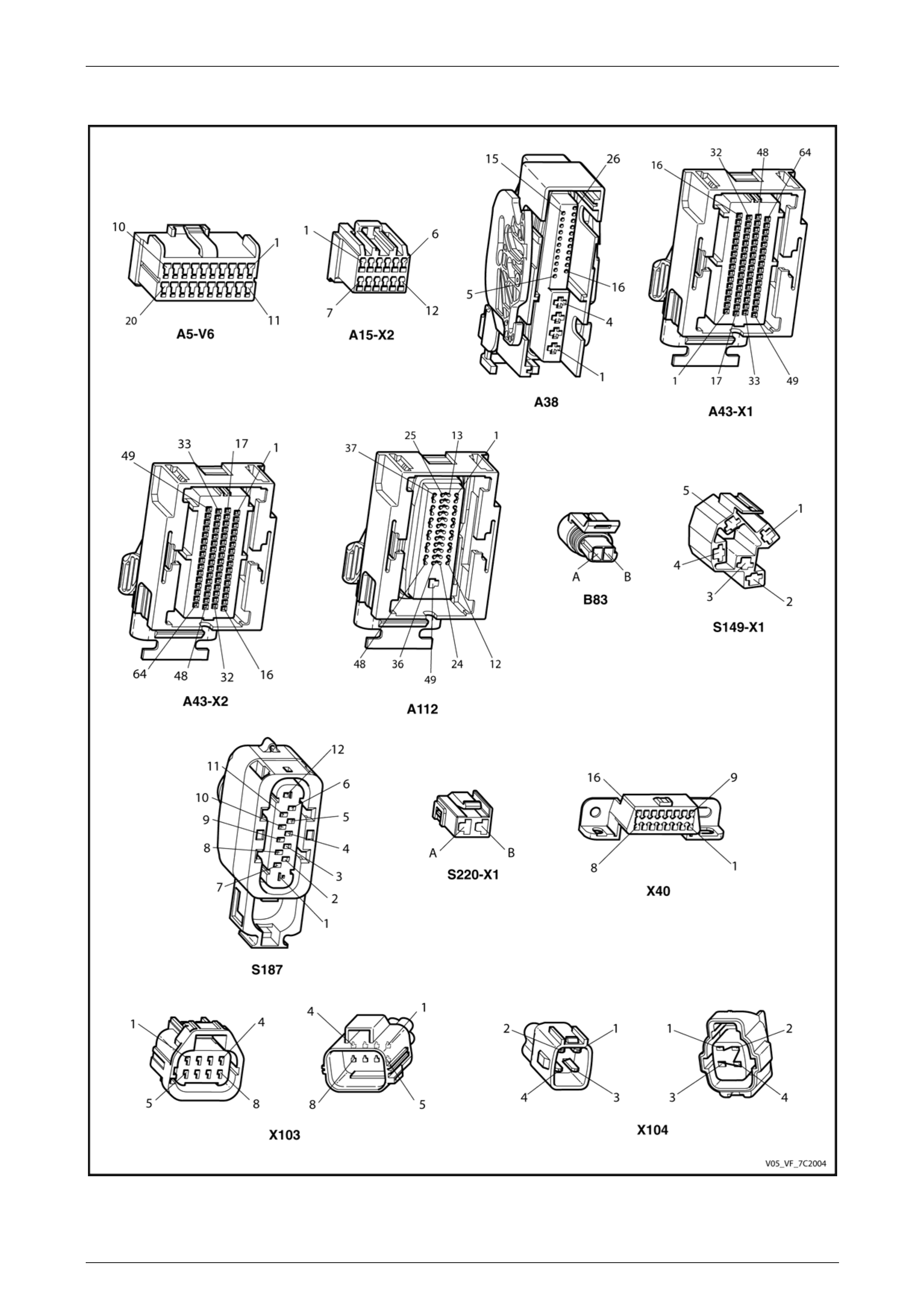
2.2 Connector Chart
Figure 7C2 – 15
Page 7C2–23
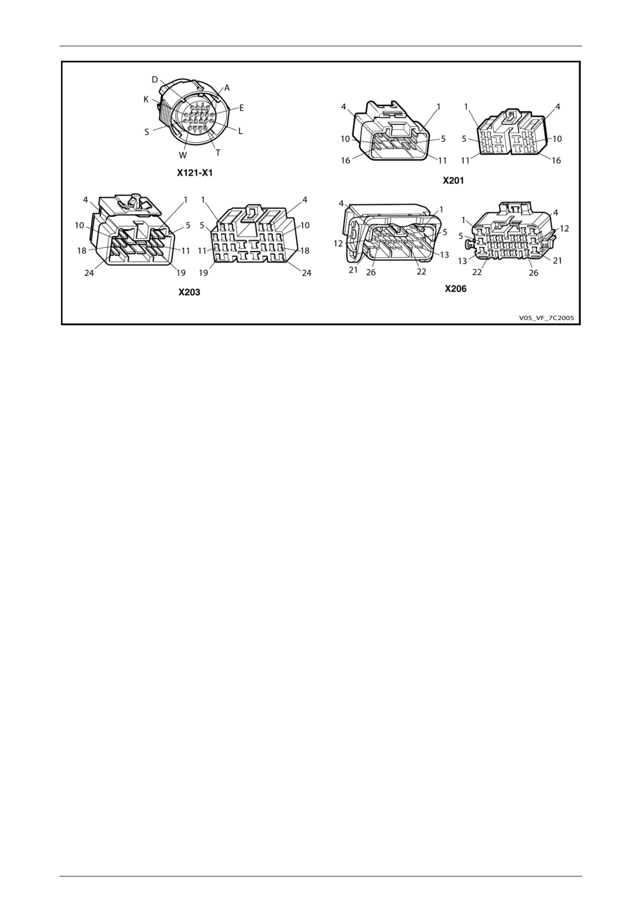
Automatic Transmission – 4L60E – Electrical Diagnosis Page 7C2–24
Figure 7C2 – 16
Page 7C2–24
Automatic Transmission – 4L60E – Electrical Diagnosis Page 7C2–25
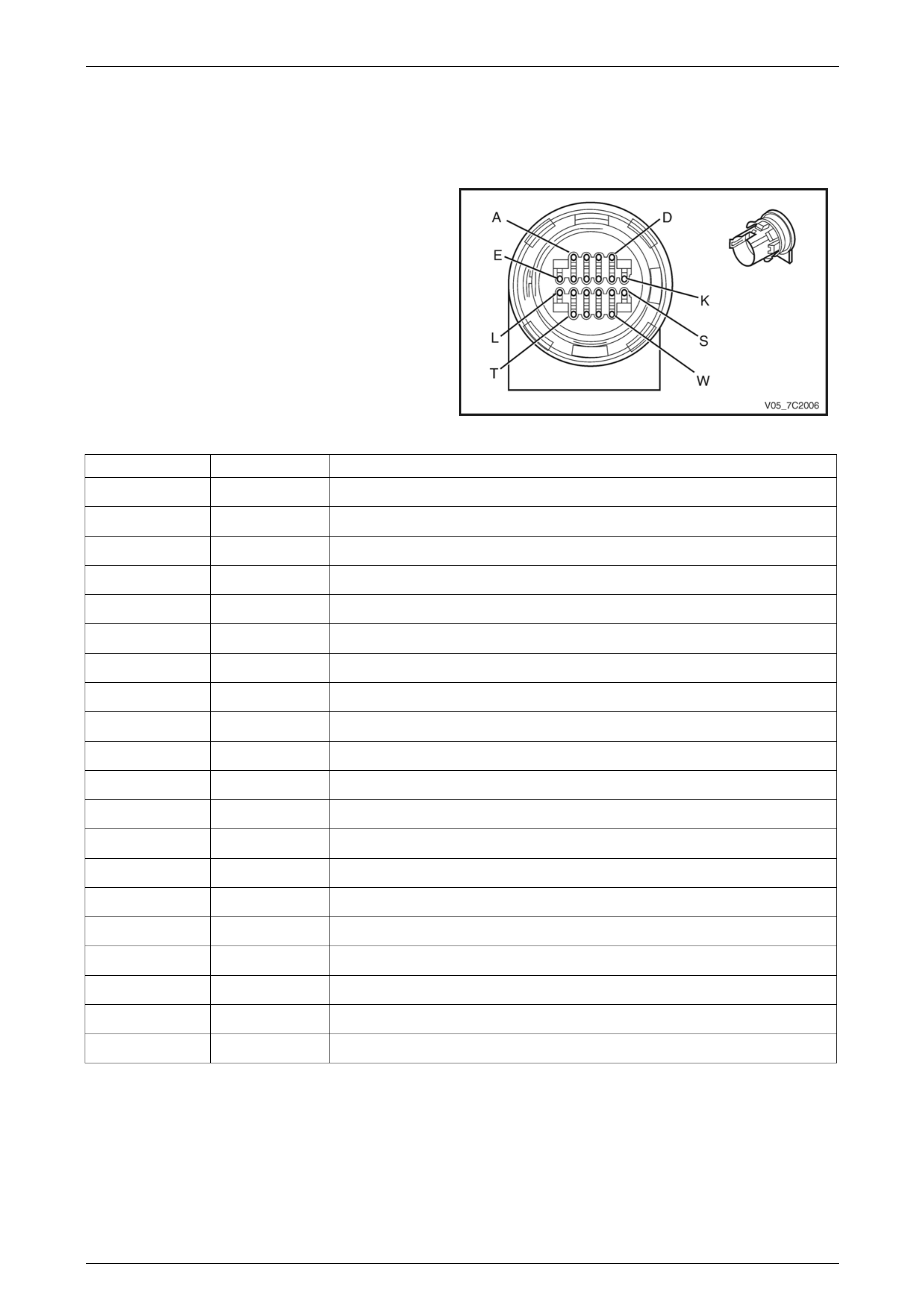
2.3 Connector Information
In-line 20-Way ctor End View
Transmission Side – X121–X1
Conne
Figure 7C2 – 17
Terminal / Pin Wire Colour Function
X1–A L-GN 1-2 Shift Solenoid Valve Control
X1–B YE 2-3 Shift Solenoid Valve Control
X1–C PU Pressure Control (PC) Solenoid Valve Low Control
X1–D L-BU Pressure Control (PC) Solenoid Valve High Control
X1–E RD Ignition Voltage
X1–F — Not Used
X1–G — Not Used
X1–H — Not Used
X1–J — Not Used
X1–K OG ISS signal
X1–L BN Transmission Fluid Temperature (TFT) Sensor Low Reference
X1–M GY Transmission Fluid Temperature (TFT) Sensor Signal
X1–N PK Transmission Fluid Pressure Switch A Sensor Signal
X1–P OG Transmission Fluid Pressure Switch C Sensor Signal
X1–R BU Transmission Fluid Pressure Switch B Sensor Signal
X1–S WH 3-2 Shift Solenoid Valve Control
X1–T BK Torque Converter Clutch (T CC) Solenoid Valve Control
X1–U BN Torque Converter Clutch (TCC) PWM Solenoid Valve Control
X1–V L–BU ISS Reference Voltage
X1–W — Not Used
Page 7C2–25
Automatic Transmission – 4L60E – Electrical Diagnosis Page 7C2–26
Harness Side – X121–X1
Figure 7C2 – 18
Terminal / Pin Wire Colour Circuit No. Function
X1–A L-GN 122 2 1-2 Shift Solenoid Valve Control
X1–B YE / BK 1223 2-3 Shift Solenoid Valve Control
X1–C OG / BK 1228 Pressure Control (PC) Solenoid Valve Low Control
X1–D L-BU / WH 1229 Pressure Control (PC) Solenoid Valve High Control
X1–E PK / BU 339 Ignition Voltage
X1–F — — Not Used
X1–G — — Not Used
X1–H — — Not Used
X J — — Not Used 1–
X1–K OG 1983 ISS Signal
X1– Fluid Temperature (TFT) Sensor Low Reference L BK 2762 Transmission
X M YE / BK 1227 Transmission Fluid T emperature (TFT) Sensor Signal 1–
X1–N PK 1224 Transmission Fluid Pressure Switch A Sensor Signal
X1–P RD 1226 Transmission Fluid Pressure Switch C Sensor Signal
X1–R BU B Sensor Signal 1225 Transmission Fluid Pressure Switch
X1–S WH 687 3-2 Shift Solenoid Valve Control
X1–T BN / OG Torque Converter Clutch (T CC) Solenoi d Valve Control 422
X1–U BN 418 Torque Converter Clutch (TCC) PWM Solenoid Valve Control
X1–V L–BU 1984 ISS Reference Voltage
X1–W — — Not Used
Page 7C2–26
Automatic Transmission – 4L60E – Electrical Diagnosis Page 7C2–27
Inte al
Vehicle Speed Sensor
Pin
C
rn Connector End View s
Wire Circuit Function
olour No.
A YE VSS High Signal 400
B PU 401 VSS Low Signal
Figure 7C2 – 19
Function
Input Speed Sensor
Pin
Wire
Colour
A BK ISS Signal
B RD Ignition Voltage
C D–GN Low Reference
Figure 7C2 – 20
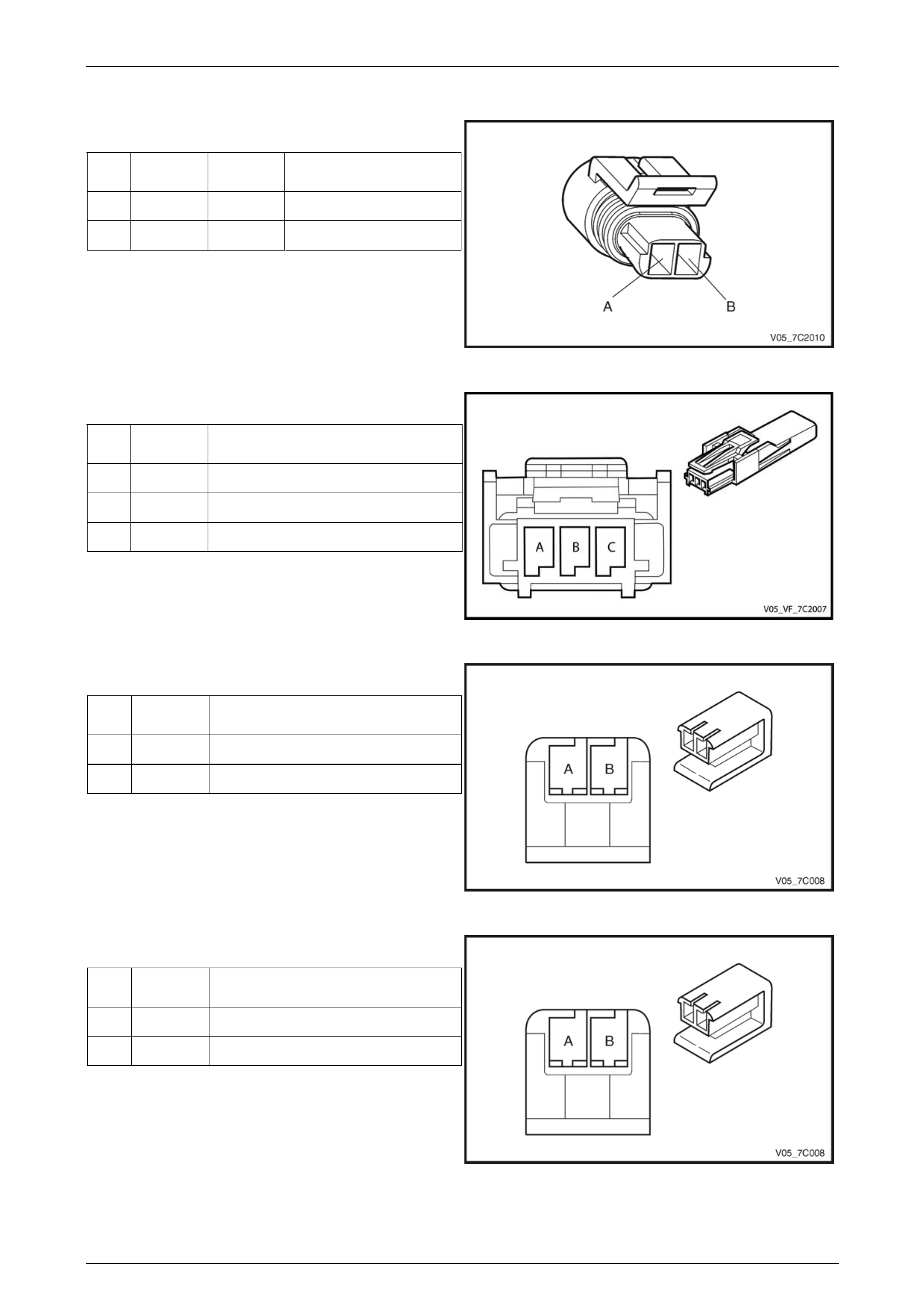
1-2 Shift Solenoid Valve Connector
Pin
Wire
Colour Function
A L-GN 1-2 Shift Solenoid Valve Cont rol
B RD Ignition Voltage
Figure 7C2 – 21
Pin
Colour Function
2-3 Shift Solenoid Valve Connector
Wire
A YE 2-3 Shift Solenoid Valve Control
B RD Ignition Voltage
Figure 7C2 – 22
Page 7C2–27
Automatic Transmission – 4L60E – Electrical Diagnosis Page 7C2–28
Pressure Control (PC) Solen
Connector
Pin
Wire
Colour
oid Valve
Function
A PU PC Solenoid Valve High Control
B L-BU PC Solenoid Valve Control
Figure 7C2 – 23
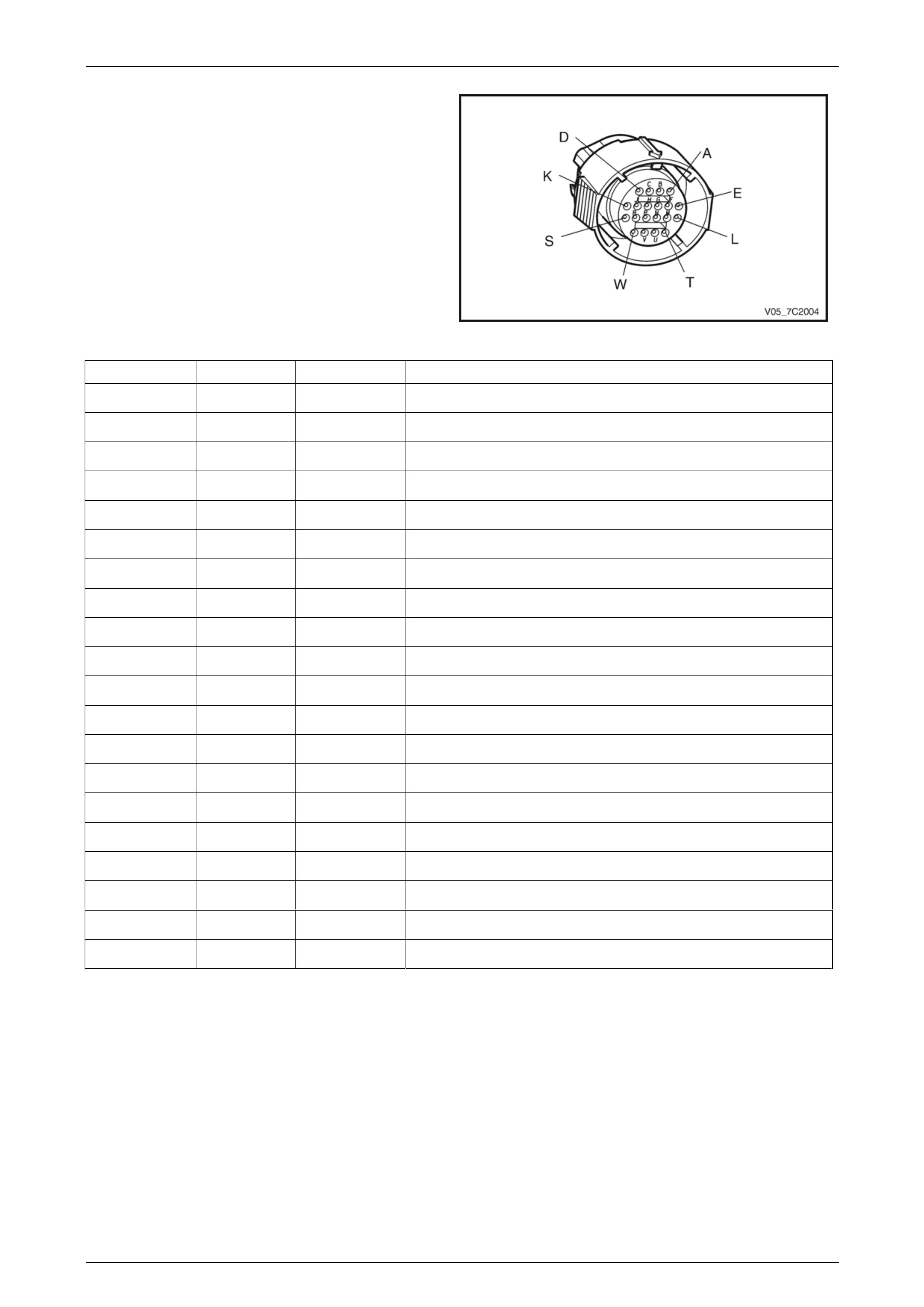
Transmission Manual Shift Shaft S witch
Assembly
Pin Wire
Colour Function
A BN Transmission Fluid Temperature
(TFT) Sensor Low Reference
B GY Transmission F luid Temperat ure
(TFT) Sensor Signal
C PK Transmission Fluid Pressure Switch
Signal A
D OG Transmission Fluid Pressure S witch
Signal C
E BU Transmission Fluid Pressure S witch
Signal B
Figure 7C2 – 24
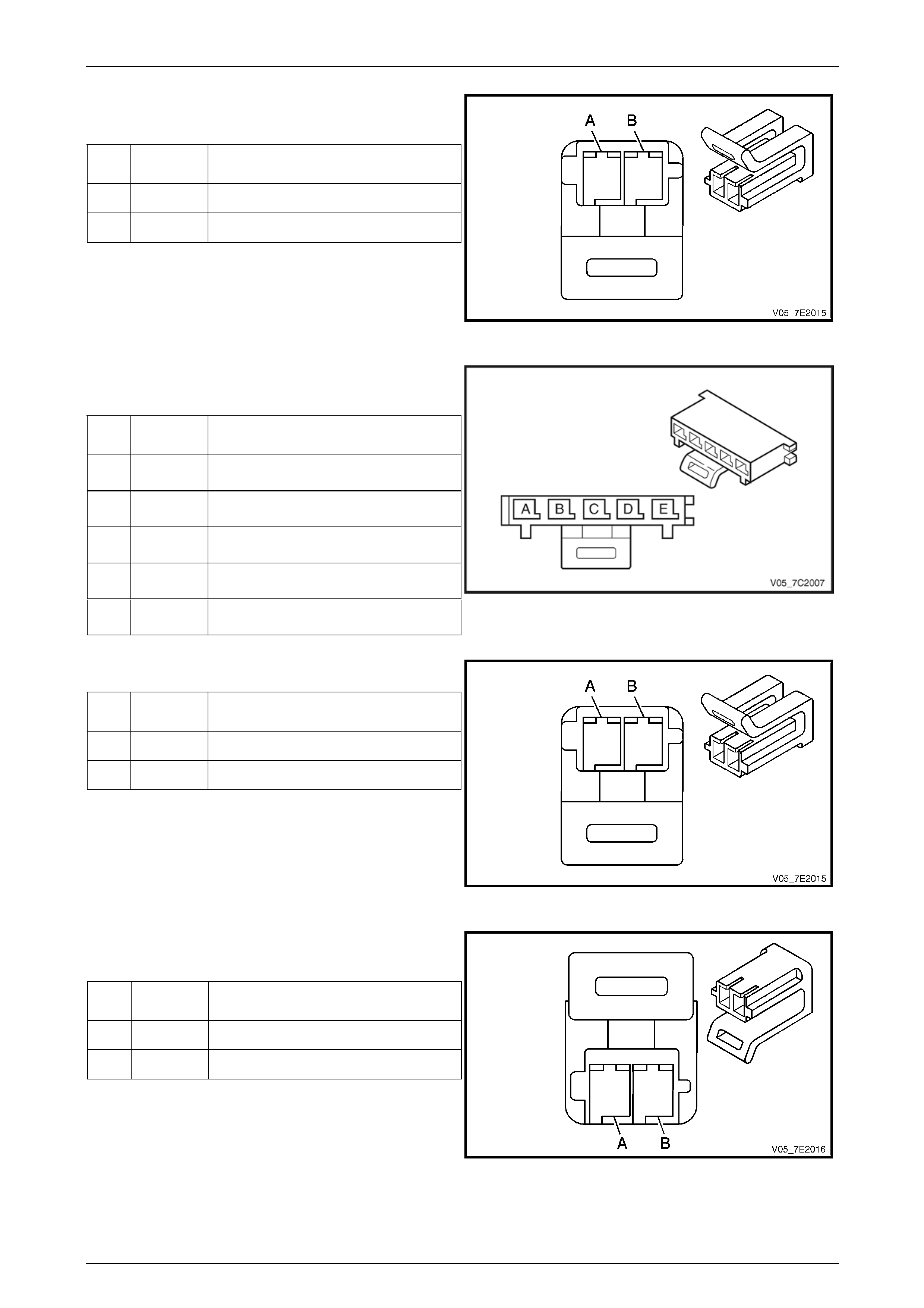
3-2 Shift Solenoid Valve Assembly Connector
Pin
Wire
Colour Function
A RD Ignition Voltage
B WH 3-2 Do wnshift Solenoid Valve Control
Figure 7C2 – 25
Torque Converter Clutch (TCC) Pulse-Width
Modulated (PWM) Solenoid Valve Connector
Pin
Wire
Colour Function
A RD Ignition Voltage
B TN TCC PWN Solenoid Valve Control
Figure 7C2 – 26
Page 7C2–28
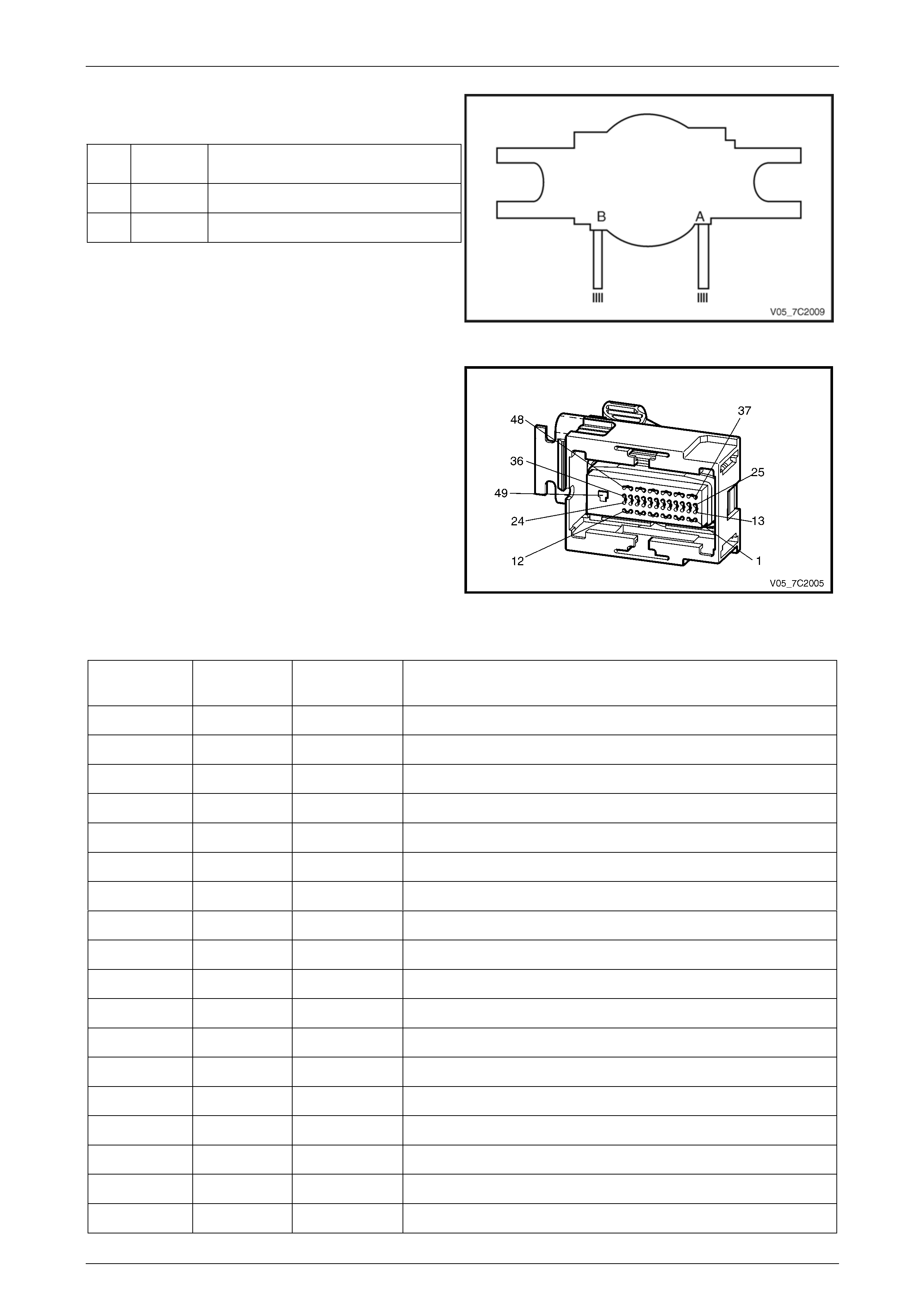
Automatic Transmission – 4L60E – Electrical Diagnosis Page 7C2–29
Torque Converter Clutch (TC
Function
C) Solenoid Valve
Connector
Pin Wire
Colour
A RD / BK Ignition Voltage
B BK TCC Solenoid Valve C ontrol
Figure 7C2 –
Transmission Control Module Connector En
View – A11
27
d
2–X1
Figure 7C2 – 28
Terminal/ Circuit No. Function
Pin Wire Colour
X1–1 418 (TCC) PWM Sol ontrol BN Torque Converter Clutch enoid Valve C
X1–2 L-GN 1222 ntrol (Solenoid A) 1-2 Shift Solenoid Valve Co
X1–3 OG 1983 ISS Signal
X1–4 — — Not Used
X1–5 — — Not Used
X1–6 1 High S d GMLAN Serial Data Bus – (CAN BN 250 pee 2 Low)
X1–7 2500 High S d GMLAN Serial Data Bus – (CANBN / BK pee 2 High)
X1–8 — — Not Used
X1–9 — — Not Used
X1–10 — — Not Used
X1–11 BN 4 Accessor age y Volt
X1–12 — — Not Used
X1–13 — — Not Used
X1–14 687 3-2 Do ift Solenoid Valve Control WH wnsh
X1–15 — — Not Used
X1–16 401 Output Speed (OSS) Sensor – Low Signal PU
X1–17 H 1229 enoid Valve High CL-BU / W Pressure Control (PC) Sol ontrol
X1–18 — — Not Used
Page 7C2–29

Automatic Transmission – 4L60E – Electrical Diagnosis Page 7C2–30
X1–19 — — Not Used
X1–20 1223 lve Control (Solenoid BYE / BK 2-3 Shift Solenoid Va )
X1–21 — — Not Used
X1–22 — — Not Used
X1–23 773 Pa Position and Back-up Lamp Sw gnal GY rk/Neutral itch C Si
X1–24 1224 Transmission Fluid Pressure Switch A SignalPK
X1–25 422 To erter Clutch (TCC) Solenoid Val rol BN / OG rque Conv ve Cont
X1–26 — — Not Used
X1–27 — — Not Used
X1–28 — — Not Used
X1–29 771 and Back-up Lamp Sw gnal BN / YE Park/Neutral Position itch A Si
X1–30 BK 2762 Tr ansmission Fluid Temperature (TFT) Sensor Low Reference
X1–31 PK / BU 339 Ignition Voltage
X1–32 OG / BK 740 Battery Voltage
X1–33 RD 1226 Transmission Fluid Pressure Switch C Signal
X1–34 — — Not Used
X1–35 1227 emperature (TFTYE / BK Transmission Fluid T ) Sensor High Signal
X1–36 — — Not Used
X1–37 2501 High S al Data Bus (CAN 1 LoBN peed GMLAN Seri w)
X1–38 2500 High al DataBN / BK Speed GMLAN Seri Bus (CAN 1 High)
X1–39 776 ack-up Lamp Swi ignal WH Park/Neutral Position and B tch P S
X1–40 OG / BK 1228 Pres ontrol (PC) Solenoid Valve Low Control sure C
X1–41 400 Output Speed (OSS) Sensor – High Signal YE
X1–4 20 Stop Lamp Switch Signal 2 BU / RD
X1–43 — — Not Used
X1–44 1225 Transmission Fluid Press ure Switch B SignalBU
X1–45 L–BU 1984 ISS Reference
X1–46 772 Park/Neutral Position and Back-up Lamp Sw gnal YE itch B Si
X1–47 — — Not Used
X1–48 — — Not Used
X1–49 451 Pow BK / WH er Ground
Page 7C2–30
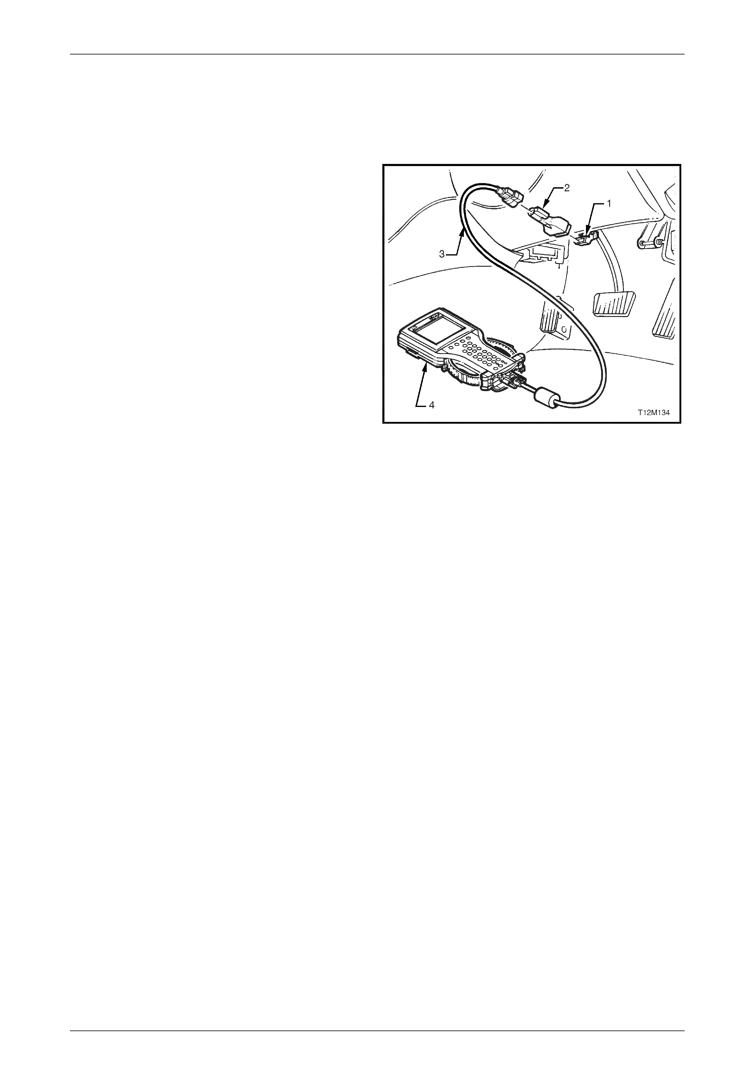
Automatic Transmission – 4L60E – Electrical Diagnosis Page 7C2–31
3 Tech 2 Information
3.1 Tech 2 Diagnostics
when con nk connector (D
read transm nd testing serial data. The
DLC is atta ment panel trim retainer
beneath th
1 DLC
2 DLC A
3 DLC C
4 T
For additional general information on connecting and
operating ech 2.
Tech 2, with the appropriate software, cables and adapters,
nected to the serial data li LC) can
ission diagnostic a
ched to the instru
e steering wheel.
dapter
able
ech 2
Tech 2, refer to 0C T
Figure 1A7 –
Test Modes
Tech 2 has six test modes for diagnos ing the transmission. To get to these various test modes, on Tech 2 select:
Diagnos del / Transmission / Au c Transmission
and follow Tech 2’s prompts. This will then display the following menu operations.
es
Once selected, both current and history diagnostic trouble codes (DTCs) stored in the
• Clea ission DTC(s) – On stored in the transmi (TCM)
and le (ECM) memory m
• Freez rds – Shows Freeze Failure Records information. Fre / Failure
Recor apshots stored in the mem TCM and contain data parameters from the TCM at
the time the D
For a complete l M DTCs, refer to
4.6 Diagnostic Tr de List. For further
inform to 0C
Tech 2.
Data
If Data Dis selection list is displayed tains:
• Trans Once is selected, a list of transmissio n components and the T CM inputs are displayed along
with their statu
• TCC Data isplays specific parameter i formation about the torque converter clutch controlling
devic .
• 1-2 Sh selected, displays specific p er information about the 1-2 shift solenoid valve (shift
sol .
29
tics / Model Year / Mo tomati
Diagnostic Trouble Cod
If Diagnostic Trouble Codes is selected, a selection list is displayed which contains:
• Read DTC Information –
transmission control module will b e displayed.
r Engine & Transm
engine control modu ce selected, DTCs
ay be cleared. ssion control module
e Frame / Failure Reco Frame / eze Frame
ds are types of sn ory of the
TC set.
NOTE
ist of TC
ouble Co
ation on T ech 2 and it f unctio ns, refer
Display
play is selected, a which con
mission Data –
s.
– Once selected, d
es and their circuits n
ift Data – Once aramet
enoid A) and its circuits
Page 7C2–31

Automatic Transmission – 4L60E – Electrical Diagnosis Page 7C2–32
• 2-3 Shift Data
valve (shift soleno
– Once this mode is selected, displays spec ific parameter information about the 2-3 shift solenoid
id B) and its circuits.
• 3-4 Shift Data – Once selected, displays information on 3-4 shift timing.
id Data – Once selected, displays specific parameter information about the PC solenoid
• Tran Once selected, it ha s:
• In this mode Tech 2 contin onitors and displays 1-2 TAP cell data parameters.
• In this mode Tech 2 contin nitors and displays 2-3 T AP cell data parameters.
• this mode Tech 2 contin onitors and displays 3-4 TAP cell data parameters.
• S apt Data – In this mode Te nuously monitors and displays S tate TAP data
param
• System : In this mode, Tech 2 will d on identification screen. T wing items
will b er, Partnumber, Hardware P mber, Alpha Code, Software Versio mber, Software
Partnumb 10, VIN Digit 11-17.
NOTE
Further information Data Display mode
and the data pa r is contained in
3.2 Data Display.
Snapshot
In this test ures TCM data before and after a forced manual trigger.
Addition
If Additional Functions is selected, a selections list is displayed which contains:
Tech 2 will display the transmission identification screen. The following items
er, Hardware Partnumber, Alpha Code, Soft ware Version Number, Software
s:
• TCC an command the TC off. Tech 2 will displ olenoid
is active or inactive.
• TCC PWN Solenoid ech 2 can command the TCC PWM solenoid on and off. T ech 2
TC ve or inactive and torque tage.
• TCC n command the TCC on w e is above 50 km/h.
• Shif 2 can command the shift s id A (1-2 shift solenoid) on and off.
• San command the shift s id B (2-3 shift solenoid) on and off.
• 3/2 Do id – Tech 2 can command th ownshift solenoid (3-2 shift solen off.
• Gincrementally command noid states to correspond to r ear states. The
TCM will only allow single shift increments or decrements and does not allow a shift if it causes the engine RPM to
excee
• High S his test is not applicable.
• High is test is not applicable.
• Pressure Control Solenoid – This function allows the user to control state of the pressure control solenoid in
increments of 100 mA.
NOTE
For operating parameters of the Miscellaneous
Test, refer to 3.4 Miscellaneous Tests.
• Pressure Control Soleno
and its circuits.
smission Adapts – s further sub menu
1-2 Adapt Data – uously m
2-3 Adapt Data – uously mo
3-4 Adapt Data –In uously m
teady State Ad
eters. ch 2 conti teady S
Identification isplay the transmissi he follo
e displayed; Identifi
er, VIN Digit 1- artnu n Nu
about the
ramete
mode, Tech 2 capt
al Functions
• System Identification– In this mode,
will be displayed; Identifier, Pa rtnumb
Partnumber, VIN Digit 1-10, VIN Digit 11-17.
Miscellaneous Tests
If Miscellaneous Functions is selected, a selections list is displayed which contain
Solenoid –Tech 2 c C solenoid on and ay whether the TCC s
– T will display whether the
C PWM solenoid is acti percen
Apply – Tech 2 ca hen the vehicl
t Solenoid A – Tech oleno
hift Solenoid B – Tech 2 c oleno
wnshift Soleno e 3/2 d oid) on and
ear Control – Tech 2 can shift sole elative g
d a calibrated limit.
ide Driver 1 – T
Side Driver 2 – Th
Page 7C2–32

Automatic Transmission – 4L60E – Electrical Diagnosis Page 7C2–33
Programming
If Programming is selected, a selection list is displayed which contains:
lls – This test allows the user to reset the Transmission Adapt (TAP) cells by pressing the Reset soft
NOTE
Upon resetting the TAP cells the TCM loses all
learnt adaptive functions. When the ve hicle is first
is
harshness will e learns the T A P
cells.
• Reset TAP Ce
key.
driven after this, the shifts may be harsh. Th
ase as the T CM re
Page 7C2–33

Automatic Transmission – 4L60E – Electrical Diagnosis Page 7C2–34
3.2 Data Display
If Data Display is selected, a selection list is displayed which contains the following:
Once this ission components s are displayed alon
Transmis s
For definitio ers in this table, refer to 3. Data Definitions.
Units Typic alue
Transmission Data
mode, a list of transm and the TCM input g with their status.
sion Data Parameter
ns of the paramet 3 Tech 2
Tech 2 Parameter Displayed al Data V
Engine Torque Nm Varies
Throttle Position Percent Varies
Engine Speed RPM Varies
AT Input Speed RPM Varies
AT Output Speed RPM Varies
Vehicle Speed km/h 0
Commanded Gear 1,2,3,4 1
Shift Solenoid A On / Off Varies
Shift Solenoid B On / Off Varies
3-2 Downshift Solenoid On/Off On
Estimated Gear Ratio Ratio 8.00:1
Speed Ratio Ratio 8.00:1
Torque Converter Efficiency Ratio .00:1
TFP Gear Park/Neutral, Reverse, Drive4,
Drive3, Drive2, Drive1 or Inval id Park/Neutral
TFP Switch A Open 12 V / Closed 0 V Varies
TFP Switch B Open 12 V / Closed 0 V Varies
TFP Switch C Open 12 V / Closed 0 V Varies
Engine Coolant Temperature °C Varies
Transmission Fluid Temp °C Varies
Transmission Hot Mode On/Off Off
PCS Actual Current Amps Varies (0.1 – 1.1 A)
PCS Desired Current Amps Varies (0.1 – 1.1 A)
PCS Duty Cycle Percent Varies
High Side Driver 1 N/A N/A
TCC Solenoid On / Off Varies
TCC PWM Solenoid Percent 0%
TCC Slip Speed RPM +/-50 RPM from Engine Speed
High Side Driver 2 N/A N/A
TR Switch A Open 12 V / Closed 0 V Varies
TR Switch B Open 12 V / Closed 0 V Varies
Page 7C2–34

Automatic Transmission – 4L60E – Electrical Diagnosis Page 7C2–35
Tech 2 Parameter Typical Data Value Units Displayed
TR Switch C Open 12 V / Closed 0 V Varies
TR Switch P Open 12 V / Closed 0 V Varies
Latest Shift Seconds Varies
1-2 Shift Time Seconds Varies
2-3 Shift Time Seconds Varies
3-4 Shift Time Seconds Varies
Cruise Control Active / Inactive Varies
A/C Clutch On / Off Varies
Ignition Voltage Volts 12-14 V
Shift Pattern Normal/ Power / Cruise Varies
TCC Data
Once this mode is selected, displays specific parameter information abo ut the torque converter clutch controlling devices
and their circuits.
TCC Data Parameters
For definitions of the parameters in this table, refer to 3.3 Tech 2 Data Definitions.
Tech 2 Parameter Units Displayed Typical Data Value
TCC Solenoid On / Off Varies
TCC PWM Solenoid Percent 0%
TCC Slip Speed RPM +/-50 RPM from Engine Speed
TCC Duty Cycle Circuit Open or Shorted / Short to Battery /
Okay Okay
High Side Driver 2 N/A N/A
High Side Driver 2 Circuit N/A N/A
Throttle Position Percent Varies
Engine Speed RPM Varies
AT Input Speed RPM Varies
AT Output Speed RPM Varies
Engine Torque Nm Varies
Vehicle Speed km/h 0
Commanded Gear 1,2,3,4 1
Engine Coolant Temperature °C Varies
Transmission Fluid Temp °C Varies
Estimated Gear Ratio Ratio 8.00:1
Transmission Hot Mode On / Off Off
Page 7C2–35

Automatic Transmission – 4L60E – Electrical Diagnosis Page 7C2–36
1-2 Shift Data
Once this mode is selected, displays specific parameter information abo ut the 1-2 shift solenoid valve and its circuits.
.
1-2 Shift Data Parameters
For definitions of the parameters in this table, refer to 3.3 Tech 2 Data Definitions
Tech 2 Parameter Units Displayed Typical Data Value
Shift Solenoid A On / Off Varies
Shift Solenoid B On / Off Varies
Commanded Gear 1,2,3,4 1
1-2 Shift Time Seconds Varies
1-2 Shift Error Seconds Varies
Shift Solenoid A Circuit Open or Shorted / Short to Battery /
Okay Okay
High Side Driver 2 N/A N/A
High Side Driver 2 Circuit N/A N/A
Throttle Position Percent Varies
Engine Speed RPM Varies
AT Input Speed RPM Varies
AT Output Speed RPM Varies
Vehicle Speed km/h 0
Estimated Gear Ratio Ratio 8.00:1
2-3 Shift Data
Once this mode is selected, displays specific parameter information abo ut the 2-3 shift solenoid valve and its circuits.
2-3 Shift Data Parameters
For definitions of the parameters in this table, refer to 3.3 Tech 2 Data Definitions.
Tech 2 Parameter Units Displayed Typical Data Value
Shift Solenoid A On / Off Varies
Shift Solenoid B On / Off Varies
Commanded Gear 1,2,3,4 1
2-3 Shift Time Seconds Varies
2-3 Shift Error Seconds Varies
Shift Solenoid B Circuit Open or Shorted / Short to Battery / Okay
Okay
High Side Driver 2 N/A N/A
High Side Driver 2 Circuit N/A N/A
Throttle Position Percent Varies
Engine Speed RPM Varies
AT Input Speed RPM Varies
AT Output Speed RPM Varies
Vehicle Speed km/h 0
Estimated Gear Ratio Ratio 8.00:1
Page 7C2–36

Automatic Transmission – 4L60E – Electrical Diagnosis Page 7C2–37
3-4 Shift Data
Once this mode is selected, displays information on 3-4 shif t timing.
3 ters
For definitions of the para ter
Tech 2 Parameter ue
-4 Shift Data Parame
me s in this table, refer to 3.3 Tech 2 Data Definitions.
Units Displayed Typical Data Val
Shift Solenoid A On / Off Varies
Shift Solenoid B On / Off Varies
Commanded Gear 1 1,2,3,4
3-4 Shift Time Varies Seconds
3-4 Shift Error Seconds Varies
High Side Driver 2 N/A N/A
High Side Driver 2 Circuit N/A N/A
Throttle Position s Percent Varie
Engine Speed RPM Varies
AT Input Speed RPM Varies
AT Output Speed RPM Varies
Vehicle Speed km/h 0
Estimated Gear Ratio Ratio 8.00:1
Pressure Control Solenoid D
Displays specific parameter info ati
Pressure Control Solenoid Data Parameters
For definitions of the parameters in this table, refer to 3.3 Tech 2 Data Definitions.
Tech 2 Parameter Units Displayed Typical Data Value
ata
rm on about the PC solenoid and its circ uits.
PCS Actual Current Amps Varies (0.1 – 1.1 A)
PCS Desired Current Amps Varies (0.1 – 1.1 A)
PCS Duty Cycle Percent Varies
High Side Driver 1 N/A N/A
High Side Driver 1 Circuit N/A N/A
Engine Speed RPM Varies
Transmission Fluid Temp °C Varies
Throttle Position Percent Varies
Vehicle Speed km/h 0
Commanded Gear 1,2,3,4 1
Page 7C2–37

Automatic Transmission – 4L60E – Electrical Diagnosis Page 7C2–38
Transmission Adapts
Once this is selected, it has furt
1-2 Adapt Data
In this mode Tech 2 continuousl
1-2 Adapt Data Paramete
For definitions of the parameter th
Tech 2 Parameter
her sub menus.
y monitors and displays 1-2 TAP cell data parameters.
r
s in is table, refer to 3.3 Tech 2 Data Definitions.
Units Displayed Typical Data Value
1-2 Shift Time Seconds Varies
1-2 Shift Error Seconds Varies
Current TAP Cell 4-16 Varies
Throttle Position s Percent Varie
1-2 Tap Cell (1 – 17) kPa Varies
2-3 Adapt Data
In this mode Tech 2 continuousl o
2-3 Adapt Data Parameters
For definitions of the parameters in th Definitions.
Tech 2 Parameter
y m nitors and displays 2-3 TAP cell data parameters.
is table, refer to 3.3 Tech 2 Data
Units Displayed Typical Data Value
2-3 Shift Time Seconds Varies
2-3 Shift Error Varies Seconds
Current TAP Cell 4-16 Varies
Throttle Position Varies Percent
2-3 Tap Cell (1 – 17) Varies kPa
3-4 Adapt Data
In this mode Tech 2 continuously mo
3-4 Adapt Data Parameters
F s of the para ter
e r
nitors and displays 3-4 TAP cell data parameters.
or definition me s in this table, refer to 3.3 Tech 2 Data Definitions.
Tech 2 Param te Units Displayed Typical Data Value
3-4 Shift Time Seconds Varies
3-4 Shift Error Seconds Varies
Current TAP Cell 4-16 Varies
Throttle Position Percent Varies
3-4 Tap Cell (1 – 17) kPa Varies
Page 7C2–38

Automatic Transmission – 4L60E – Electrical Diagnosis Page 7C2–39
Steady State Adap t Da
In this mode TECH 2 continuou
Steady State Adapt Data Parameters
For definitions of the parameter
Tech 2 Parameter
ta
sly monitors and displays Steady State TAP data paramet ers.
s in this table, refer to 3.3 Tech 2 Data Definitions.
Units Displayed Typical Data Value
Current TAP Cell Varies 4-16
Throttle Position Percent Varies
Gear (1-4) TAP Cell kPa Varies
TCC (1-4) TAP Cell kPa Varies
Reverse Gear TAP Cell kPA Varies
Page 7C2–39

Automatic Transmission – 4L60E – Electrical Diagnosis Page 7C2–40
3.3 Tech 2 Data Definitions
displays the difference between the desired 1-2 shift time and the actual 1-2 shift time
or fast shift and the actual shift time was shorter than the desired shift time. A neg
shift and the actual shift time was long
1-2 Shift Error: This parameter . A
positive number indicates a firm ative
number indicates a soft or slow er than the desired shift time. This value is only
accurate if the shift was adaptabl
1-2 Shift Time: This parameter m.
drop after the commanded 1-2 s
1his param of transmission adaptive press ure (TAP), based on 17 Nm of
engine torque increment p cel t. A positive number
indicates that long shifts have been d hift time. A
negative number indicates that rt
increase shift time.
2-3 Shift Error: This parameter displ time. A
positive number indicates a firm fa
number indicates a soft or slow ift,
accurate if the shift was adaptable.
2-3 Shift Time: This parameter e r.p.m
drop after the commanded
2-3 TAP Cell (1-17): This param of
engine torque increment p cel
indicates that long shifts have b
negative number indicates that enoid pressure has been subtracted to
increase shift time.
3-4 Shift Error: This parameter displa
positive number indicates a firm fa
number indicates a soft or slow shift,
accurate if the shift was adaptable.
3-4 Shift Time: This parameter display
drop after the commanded 3-4 shift. T
3-4 TAP Cell (1-17): This parameter of
engine torque increment per cell, add er
indicates that long shifts have been detected and PC solenoid pressure has been added to decrease shift time. A
negative number indicates that rt
increase shift time.
A/C Clutch: This parameter displays
AT Input Speed: This paramete isp t
shaft speed. Tech 2 displays inp t sh
AT Output Speed: This parameter di output shaft. Tech 2 displays output
haft speed as revolutions per minute (RPM).
Commanded Gear: This parameter displays the current commanded state of the shift solenoid valves. Tech 2 displays
1, 2, 3 or 4.
Current TAP Cell: This parameter displays the current transmission adaptive pressure (TAP) cell in use for transmission
line pressure adaptation. The cells are based on 17 Nm of engine torque. The higher the engine torq ue, the higher the
current TAP cell. The last cell used will remai n displa yed until the next adaptable upshift occurs.
Engine Coolant Temperature: This parameter displays the input signal from the engine coolant temperate (ECT )
sensor. ECT is high at 151°C when the signal voltage is low, 0 V. ECT is low at -40°C when the signal voltage is high,
5 V.
Engine Speed: This parameter displays the rotational speed of the eng ine expressed as revolutions per minute.
Engine Torque: This parameter displays the calcul ated value based on engine load, throttle position, mass air flow, and
other engine inputs. This parameter is accurate to within 20 Nm of actual measured engine torque.
Estimated Gear Ratio: This parameter displays the estimated turbine speed divided by the transmission output speed.
Estimated turbine speed is calculate d from engine speed and engine torque.
Ignition Voltage: This parameter displays the system voltage measured at the ignition feed.
Latest Shift: This parameter displays the actual time of the last upshift. This value is only accurate if the shift was
adaptable.
e.
displays the actual time of the last 1-2 shift. The shift time is based on the engine r.p.
hift. This value is only accurate if the shift was adaptable.
eter displays the amount -2 TAP Cell (1-17): Ter l, added to or subtracted from shift pressure during a 1-2 upshif
etected and PC solenoid pressure has been added to decrease s
sho shifts have been detect ed and PC solenoid pressure has bee n subtracted to
ays the difference between the desired 2-3 shift time and the actual 2-3 shift
or st shift, the actual shift time was shorter than the desired shift time. A negative
sh the actual shift time was longer than the desired shift time. This value is only
displays the actual time of the last 2-3 shift. The shift time is based on the engin
2-3 shift. This value is only accurate if the shift was adaptable.
eter displays the amount of transmission adaptive pressure (TAP), based on 17 Nm
er l, added to or subtracted from shift pressure during a 2-3 upshift. A positive number
een detected and PC solenoid pressure has been added to decrease shift time. A
short shifts have been detected and PC sol
ys the difference between the desired 3-4 shift time and the actual 3-4 shift time. A
or st shift, the actual shift time was shorter than the desired shift time. A negative
the actual shift time was longer than the desired shift time. This value is only
s the actual time of the last 3-4 shift. The shift time is based on the engine r.p.m.
his value is only accurate if the shift was adaptable.
displays the amount of transmission adaptive pressure (TAP), based on 17 Nm
ed to or subtracted from shift pressure during a 3-4 upshift. A positive numb
sho shifts have been detect ed and PC solenoid pressure has bee n subtracted to
the condition of the airconditioning compress or as either On or Off.
r d lays the rotational speed of the turbine shaft rotor, translating to transmission inpu
u aft speed as revolutions per minute (RPM).
splays the rotational speed of the transmission
s
Page 7C2–40

Automatic Transmission – 4L60E – Electrical Diagnosis Page 7C2–41
PCS Actual Current: This parameter displays the current flow through the pressure con trol solenoid circuit, which is
measured by the control module. Hi ssure. Low current flow results in high line
pressure.
PCS Duty Cycle: This parameter displays the commanded state of the pressure control solenoid, expressed as a
percentage of energised on ti me. A s zero on time, non-energised, or no current flow. A
high percent at idle indicates maxim current flow.
Shift Pattern: This parameter displays Normal, Power or Cruise depending on what mode the transmission is i n.
Shift Solenoid A: This parameter displays the comman ded state of the 1-2 shift solenoid valve. When the transmissi on
is in 1st and 4th gear, the display should indicate On; current is flowing through the solenoid. When the transmission is in
2nd and 3rd gear, the display should indicate Off; current is not flowing through the solenoid.
Shift Solenoid A Circuit: This parameter displays whether an open or a short to ground, short to battery or the circuit is
okay in the 1-2 shift solenoid valve feedb ack signal. The 1-2 shift solenoid valve must be commanded off and on.
Shift Solenoid B: This parameter displays the commanded state of the 2-3 shift solenoid valve. When the transmission
is in 1st and 4th gear, the display should indicate On; current is flowing through the solenoid. When the transmission is in
2nd and 3rd gear, the display should indicate Off; current is not flowing through the solenoid.
Shift Solenoid B Circuit: This parameter displays whether an open or a short to ground, short to battery or the circuit is
okay in the 2-3 shift solenoid valve feedb ack signal. The 2-3 shift solenoid valve must be commanded off and on.
Speed Ratio: This parameter displays the calculated speed ratio of the transmission.
TCC Duty Cycle Circuit: This parameter displays whether an open or a short to ground, short to battery or the circuit is
okay in the TCC PWM solenoid valv e feedback signal. The TCC PW M solenoid valve must be commanded off and on.
TCC Solenoid: This parameter displays the commanded sate of the T CC solenoid. On indicates a commanded
energised state; current is flowing throug h the solenoid. Off indicates a commanded non-energised state; current is not
flowing through the solenoid. This commanded state occurs at various vehicle speeds between applications.
TCC Slip Speed: This parameter displays the differenc e between transmission output speed an d engine speed. A
negative value indicates the e ngine speed is less than the output speed, deceleration. A positive value indicates the
engine speed is greater tha n the output speed, acceleration. A value of zero indicates the eng ine speed is equal to the
output speed, TCC applied.
TCC PWM Solenoid: This parameter displays the commanded percentage of on time for the T CC PW M solenoid. A high
percentage represents an on, energised, commanded state.0 percent represents an off, non-energised, commanded
state.
TFP Gear: This parameter displays Park/Neutral, Reverse, Drive4, Drive3, Drive2, Drive1 or Invalid. This parameter
is the decoded status of the three A/B/C inputs from the automatic transmission fluid pressure manual valve position
switch. If a valid combination of inputs is not detected, invalid will be dis played.
TFP Swi A/B/C: This parameter displays Open 12 V / Closed 0 V for each switch. This parameter indicates the statues
of the three inputs from the automatic transmission fluid pressure man ual valve position switch assembly.
Throttle Position: This parameter displays a calculated value, which is determined by the accelerat or ped al position and
the actual throttle position, used to optimis e transmission controls. It represents the driver’s intended requested for
torque or acceleration. The range is 0-100%, 0% represents an idle or coas t request and 100% represents a request for
wide open throttle (WOT).
Torque Converter Efficiency: This parameter displays a ratio of 0.00:1 to 2:1. The ratio is calculates by multiplying the
speed ratio by a value related to the ‘K factor’ of the torque converter. The ‘K factor’ is the looseness or tightness of the
torque converter for a given torqu e. The nearer the torque converter is to full coupling, i.e. 1:1, the closer the torque
converter efficiency number will be to 1.
TR Switch A/B/C/P: This parameter displays the status of the four inputs from the transmission rang e switch. Tech 2
displays Open 12V / Closed 0 V. Open 12 V indicates an ignitio n voltage input to the control module. Closed 0 V
indicates a zero voltage input to the control module.
Transmission Fluid Temperature: This parameter displays the input signal of the transmission fluid temperature
sensor. Transmission fluid temperature is high, 151°C, when signal volta ge is low, 0 V. Transmission fluid temperature is
low, -40°C, when signal voltage is high, 5 V.
Transmission Hot Mode: This parameter displays the automatic transmission fluid temperature (TFT ) and displays On
or Off. Off indicates the TFT has not exceeded 130°C. On indic ates the T FT has exceeded 130°C and has not cooled to
120°C for greater than 5 seconds. These numbers are appr oximate and differ with transmissions.
Vehicle Speed: This paramet er displays the speed at which the vehicle is travelling. Tech 2 displays veh icle speed as
kilometres per hour (km/h). The vehicle s peed is calculates based on the input signal from the automatic transmission
output shaft speed sensor.
gh current flow results in low line pre
reading of low percent indicate
um on time, energised, or high
PCS Desired Current: This parameter displays the commanded current of the pressure control solenoid circuit. High
current results in low line pressure. Low current results in high line pressure.
Page 7C2–41

Automatic Transmission – 4L60E – Electrical Diagnosis Page 7C2–42
3.4 Miscellaneous Tests
Tech 2
Miscellaneous Tests Description
1-2 Solenoid
• The TCM commands the 1-2 shift solenoid valve on and off. Tech 2’s Shift Solenoid A
Pa Commanded Gear
par bination. Refer to
5.6
• When the ignition is on, and the engine is off, there no limits to this control. The
solenoid remains on until commanded off, and vice versa. When the test is exited, the
solenoid state is determined by the TCM.
• When the engine is running, the following control limits apply:
• Only sequential gear changes are allowed. For example, 1st to 3rd is not allowed.
If a non-sequential gear change is attempted, the messag e Non-sequential
gear changes n ot allowed. Gear changes must be made in order appears
on Tech 2.
• The vehicle speed must be b elow a calibrated value. If the vehicl e speed is too
high, the message Vehicle speed too high appears on Tech 2.
• The engine speed must be below a calibrated value. If the engine speed is too
high, the message Engine speed too high appears on Tech 2.
• Downshifts are allowed only when the vehicle speed is below a calibrated value.
If the vehicle speed is too high, the message Eng. is on and veh. speed to hi
for 3-2 or 2-1 downshift appears on T ech 2.
• The gear requested may not be greater than the current selected transmission
range (PRNDL). For example, 3rd gear is not allowed if the transmission range is
D2. If the gear requested is greater than the current selected transmission
range, the message Eng. running and gear request is greater than the
current TR appears on Tech 2.
• The solenoid remains on until commanded off, and vice versa. When the test is
exited, the solenoid state is determined by the TCM.
rameter should match the commanded stat e. T ech 2’s
ameter should correspond with the shift solenoid com
Shift Solenoid Valve State and Gear Ratio.
Page 7C2–42

Automatic Transmission – 4L60E – Electrical Diagnosis Page 7C2–43
2-3 Solenoid
• The Tech 2’s Shift Solenoid B
par mmanded Gear
CM.
following control limits apply:
y sequential gear changes are allowed. For example, 1st to 3rd is not allowed.
If a non-sequential gear change is attempted, the messag e Non-sequential
gear changes no t allowed. Gear changes must be made in ord er appears
• The vehicle speed must be b elow a calibrated value. If the vehicl e speed is too
h, the message Vehicle speed too high appe ars on Tech 2.
• The engine speed must be below a calibrated value. If the engine speed is too
• e.
may not be greater than the current sel ected transmission
. For example, third gear is not allowed if the transmission range
r requested is greater than the current selected transmission
vice versa. When the test is
TCM commands the 2-3 shift solenoid valve on and off.
ameter should match the commanded state. Tech 2’s Co
parameter should correspond with the shift solenoid combination. Refer to
5.6 Shift Solenoid Valve State and Gear Ratio.
• When the ignition is on, and the engine is off, there no limits to this control. The
solenoid remains on until commanded off, and vice versa. When the test is exited, the
solenoid state is determined by the T
• When the engine is running, the
• Onl
on Tech 2.
hig
high, the message Engine speed too high appears on Tech 2.
Downshifts are allowed only when the vehicle speed is below a calibrated valu
If the vehicle speed is too high, the message Eng. is on and veh. speed to hi
for 3-2 or 2-1 downshift appears on Tech 2.
• The gear requested
range (PRNDL)
is D2. If the gea
range, the message Eng. running and gear request is greater than the
current TR appears on Tech 2.
• The solenoid remains on until commanded off, and
exited, the solenoid state is determined by the TCM.
3-2 Downshift Solenoid
wnshift
manded state.
ne is off, there are no limits to this control. The
solenoid remains on until commanded off, and vice versa. When the test is exited, the
• When the engine is running, the following control limits apply:
• The transmission range (PRNDL) must be Park or Neutral. If the transmission
range is not in Park or Neutral, the message :Engine running and
transmission range is not Park/N eutral appears on Tech 2.
• The solenoid remains on until commanded off, and vice versa. When the test is
exited, the solenoid state is determined by the TCM.
• The TCM commands the 3-2 shift solenoid valve on and off. Tech 2’s 3-2 Do
Sol. parameter should match the com
• When the ignition is on, and the engi
solenoid state is determined by the TCM.
Clear TAPS
(Transmission Adaptive
Pressures)
• The TCM clears (or resets) the TAP cells to the ori ginal base value.
• There are no limits to using this test. It may be performed with the engine running or
when the ignition is on, and the engine is off.
Page 7C2–43

Automatic Transmission – 4L60E – Electrical Diagnosis Page 7C2–44
PC Solenoid
• The o control
transmissio ure decreases. As
e
ontrolled within calibrated limits. Tech 2’s parameter PCS Desired Current
by the parameter PCS Actual Current does not change. The reference
s until commanded other wise.
ine is running, the following control limits apply:
• When the transmission range is Park or Neutral, the reference (commanded)
current may be con thin calibrated limits. The engine speed must be
t than 1,500 r.p.m, the
ver 1,500 RPM appears on
rrent and PCS Actual Current
until commanded otherwise.
• the reference current can
y the TCM. The TCM does
ed that may cause damage to the transmission. If
the requested amperage is m ore than allowed by the TCM, the message
sted current for the PC Solenoid is too high appears on Tech 2.
e DTCs must not be active. If a transmission range DTC is
ng with transmission DTC present appears
on Tech 2.
TCM commands the current to the pressure control soleno id t
n line pressure. As the current increases, the line press
the current decreases, the line pressure increases. The current range is 0.00 – 1.10 A
and may be commanded in one-tenth of a n amp increments.
• When the ignition is on, and the engine is off, the reference (commanded) amperag
may be c
changes
current remain
• When the eng
trolled wi
less than 1,500 r.p.m. If the engine speed is grea
message TR in park/neutral and engin e speed o
Tech 2. Both Tech 2 parameters PCS Desir ed Cu
parameters change. Both current read ings remain
When the transmission range is not in Park or Neutral,
only be controlled less than th e current determined b
not allow a value to be select
Reque
• Transmission rang
active, the message Engine runni
Shift Transmissio
pshifts and downshifts. Tech 2’s Commanded Gea r parameter
the shift solenoid combination. Ref er to 5.6 Shift Solenoid
• When the ignition is on, and the engine is off, there are no limits to this control. The
Tech 2 shift solenoid states changes to match the Commanded Gear selected.
gine is running, the following control limits apply:
ine r.p.m. to exceed a
ated limit. If a gear is requested and the engine speed is too high, the
age Engine speed too high appears on Tech 2.
nshift if the vehicle speed exceeds a
w a 4-3 downshift if this vehicle speed exceeds a
calibrated limit. If a 4-3 downshift is requested and the vehicle speed is too high,
• The TCM does not allow an upshift if the vehicle speed exceeds a calibrated
equested and the vehicle speed is to o high, the message
gh appears on Tech 2.
rrent selected
current selected transmission range, the message Eng. running and gear
• The TCM commands u
should correspond with
Valve State and Gear Ratio.
• When the en
• The TCM does not allow a shift if it causes the eng
calibr
mess
n calibrated limit. If either downshift is requested and the vehicle speed is too high,
the message Eng. is on and veh. Speed too hi for 3-2 or 2-1 downshift
• The TCM does not allow a 3-2 or 2-1 dow
appears on Tech 2.
• The TCM does not allo
the message Vehicle speed to h igh appears on Tech 2.
limit. If an upshift is r
Vehicle speed to hi
• The TCM does not allow an upshift that is greater than the cu
transmission range (PRNDL). For exampl e 3rd gear is not all owed if the
transmission range is D2. If an upshift is requested that is greater than the
request is greater than the cu rren t TR appears on Tech 2.
Page 7C2–44

Automatic Transmission – 4L60E – Electrical Diagnosis Page 7C2–45
TCC Control Solenoid
ds the duty cycle of the TCC PWM solenoid. The duty cycle is
gised) time. Approximately 90-10 0 percent
commanded state. Zero percent represents
tate. Tech 2 TCC PWM Solenoid parameter
solenoid remains on (90-100 percent duty cycle) until commanded off (zero percent
e), and vice versa. When the test is exited, the so lenoid duty cycle is
determined by the TCM.
• When the engine is runn llowing control limits apply:
• ion is in hot mode, the TCC
nded off. If the solenoid is requested off, the
message TCC OFF command disabled in Hot Mode appears on Tech 2.
control solenoid may not be comm anded off for more than a calibrated
amount of time,
n Tech 2.
• The TCM comman
represented by a percentage of on (ener
duty cycle represents an on (energised)
an off (non-energised) commanded s
should match the commanded state.
• When the ignition is on, and the engine is off, there are no limits to this control. The
duty cycl
ing, the fo
If the transmission range is Park, and the transmiss
control solenoid may not be comma
• The TCC
amount of time. If the solenoid is commanded off for a certain
the message TCC OFF time has been exc eeded appears o
TCC Enable
s TCC
noid parameter shou ld match the commended state.
• When the ignition is on, and the engine is off, there are no limits to this control. The
solenoid remains on until commanded off, and vice versa. When the test is exited, the
solenoid state is determined by the TCM.
• If the transmission range is Park or Neutral, the TCC enable solenoid may not
be commanded off for more than a calibrated amou nt of time. If the solenoi d is
been exceeded appears on Tech 2.
• If the transmission range is Park or Neutral and the TCC control solenoid duty
cycle is less than maximum capac ity, the TCC solenoid may not be commanded
on. If the solenoid is requested on during these conditions, the message TCC
Control Solenoid is not set to maximum Pressure appears on Tech 2.
• If the TCC control solenoid duty cycle is less than ma ximum capacity, the TCC
solenoid may not be commanded on. If the solenoid is commanded on during
these conditions the message TCC Control Solenoid is not set to maximum
Pressure appears on Tech 2.
• If the transmission is in hot mode, the TCC solenoid may not be commanded off.
If the solenoid is requested off the message TCC OFF command disabled in
Hot Mode appears on the scan tool display.
• The TCM commands the TCC enable solenoid valve on and off. Tech 2’
Sole
• When the engine is running, the following control limits apply:
commanded off for a certain amount of time, the message TCC OFF time has
Page 7C2–45

Automatic Transmission – 4L60E – Electrical Diagnosis Page 7C2–46
4 Diagnostics
4.1 Introduction
The transmission diagnostic p rocedure is organised in a logical structure that begins with the diag nostic system check
and as such must always be used as the starting point. The diagnostic system check directs the technician to the logical
nose a transmission driveabil ity fault condition. steps necessary to diag
Page 7C2–46

Automatic Transmission – 4L60E – Electrical Diagnosis Page 7C2–47
4.2 Precautions
When tests are required on connector
terminals, u adapters in connector
adaptor to prevent damage to
se the
kit J35616-C
terminals.
Page 7C2–47

Automatic Transmission – 4L60E – Electrical Diagnosis Page 7C2–48
4.3 Diagnostic Trouble Code Tables
T ostic tem rop
tables if there is C cu d in the TCM.
The diagnostic tables on
di tabl re
• the vehicle functioned correctly at the time of assembly,
• are mu
• the problem cur
Und ing and the correct use of the diagnostic tables are essential to reduce t
misdiagnosis.
Multiple DTCs Fault Co
Some fault con ons trigger multiple component DTCs even if the fault condition
there are multiple DTCs stored in t w and rec
R be en the logged DTCs can then be analysed to determine the sou ays
begin the diagnostic proc y trigger oth
T ing fault conditions may trigger multiple DTCs:
• lt in se
• a system voltage that is too low may cause incorrect transmission tem op eration or transmission component
uncti
• a system voltage that is too high may damage the TCM and/or other compone
• cond n in e
• fault condition in
• erl nnected sensor or component wiring connector.
If there are no obviou
R e D n e
he diagn sys
a DT check and the DTC list, directs the technician to the app
rrently store riate diagnostic trouble code (DTC)
locate a faulty circuit or component through a logic based
developed with the following assumptions: the process of elimination. These
agnostic es a
there no ltiple faults, and
rently exists.
erstand diagnostic time and to preven
ndition
diti exists only on a single component. If
he TCM, the service technicia n must vie ord all DTCs logged.
rce of the fault condition. Alwelationship twe ess with the DTC table of the fault condition that ma er DTCs to set.
he follow
a fau the rial data communication circuit,
malf on,
nts,
fault itio the TCM Read Only Memory (ROM) or Random Access M mory (RAM),
the TCM internal circuitry or programming, or
improp y co
s faults to begin a multiple DTC fault condition diagnostic pro
ach diagnostic. cedure, refer to the Conditions for
unning th TC i
Page 7C2–48

Automatic Transmission – 4L60E – Electrical Diagnosis Page 7C2–49
4.4 Diagnostic Trouble Code Definitions
T cons tly p fault
condition in the transmission operati ng parameters, the TCM sets a DTC to repres The following
are the types of DTCs classified a
• sion Relate d DTCs,
• Type B – Emiss
• Type C – Non-e ed DTCs.
NOTE
Depending on the t ype of DTC set, the TCM may
command the check powertrain icon display to
display on the instrument clusters multi-function
display (MFD) and warn the driver there is a fault
in the transmission. Refer to
Section 12C Instruments for further information
on the check powertrain icon.
Type A – Emission Related DTCs
The TCM takes the following action when a Type A DTC runs and fails:
• sets a current Type A DTC that represents the fault condition,
• illuminates the MFD check powertrain icon, and
• records the operating condition at the time the diagnost ic fails and stores this information in the Freeze Frame/
Failure Record.
Type B – Emission Related DTCs
The TCM takes the following actions when a Type B DTC runs and fails.
• On the first time a Type B DTC fails:
• sets a current Type B DTC that represents the fault condition, and
• records the operating conditions at the time the fault sets and stores this information in the Failure Records.
• On the second consecutive ignition cycle that a T ype B DTC fails:
• illuminates the MFD check powertrain icon, and
• records the operating condition at the time the diagnostic fai ls and stores th is information in the Freeze
Frame/ Failure Record.
Conditions for Clearing Type A or Type B DTCs
• The current DTC clears when there is no fa ult condition in the current TCM self-diagnostics.
• If there are no DTCs logged after six consecutive ignition cycles, the TCM deactivates the MFD check powertrain
icon.
• Type A or Type B History DTC clears when there is no fault condition after 40 consecutive warm-up cycles.
• Use of Tech 2 to clear DTCs.
he TCM tan erforms self-diagnostic tests on the transmission a nd it components. When the TCM detects a
ents that fault condition.
programmed in the TCM. In addition, DTCs are s either Current or Hi story DTC.
Type A – Emis
ion Related DT Cs, and
mission Relat
Page 7C2–49

Automatic Transmission – 4L60E – Electrical Diagnosis Page 7C2–50
Type C – Non-emission Re
The TCM takes the following action when a
C that represents the fault condition,
ation in the Failure Record,
age.
40 consecutive warm-up cycles.
• Use of Tech 2 to clear DTCs.
DT hat triggers the DTC is present during the l ast TCM self-diagnostics.
TC is not present during the last TCM self-diagnostics.
lated DTCs
Type C DTC runs and fails:
• sets a current Type C DT
• records the operating conditions at the time the DT C is logged and stores this inform
and
• the MFD may display a mess
NOTE
The MFD check powertrain icon does not
illuminate when a Type C DTC sets.
Conditions for Clearing Type C DTCs
• The current DTC clears when there is no fa ult condition in the current TCM self-diagnostics.
• Type C History DTC clears when there is no fault condition after
Current DTCs
A C is a Current DTC if the fault condition t
History DTCs
A DTC is a History DTC if the fault condition that triggers the D
Page 7C2–50

Automatic Transmission – 4L60E – Electrical Diagnosis Page 7C2–51
4.5 Diagnostic System Check
De r
This section procedure is organis ed in a logical structure that begins with the diagn heck.
system check directs you in a logical direction to the appropriate Section or diagnostic pr
Test D c
The following numbers refer to the step in the diagnostic table:
1 If you a ue is affecting a number of vehicle functions,
proceed
2 Within O at must be met before you can start
diagnos
3 Checks if there is data commu nication between Tech 2 and the TCM.
4 Checks nctional test must be performed, which diagnoses
the hyd smission.
Step Yes No
sc iption
ostic system c
ocedure. The diag nostic
es ription
numbers
re unsure whether the problem is isol ated to the TCM or the iss
to OD Vehicle Diagnostics.
D Vehicle Diagnostics there are a n umber of requirements th
is.
if the TCM has set any DTCs. If no DTCs have set, the fu
ro-mechanical functions of the tran
Action
1 Is the fault spe olated to this system / module? Go to Step 2 Refer to Section OD
Vehicle Diagnostics
cifically is
2 Have d the Basic Diagnostic Require ments, Diagnostic
Precauti nd Preliminary Checks? Go to Step 3 Refer to Section OD you rea
ons a Vehicle Diagnostics
3 1 Connect Tech 2 to the DLC.
2 ion / Automatic Transmission
and follow the instruction on Tech 2.
Does Tech 2 display the TCM specifications? Go to Step 4 Powe face
Module
On Tech 2 select:
Transmiss Refer to
Section 6E1
rtrain Inter
4 On T
Diagnostic Trouble Codes / Read DTC Information
Does Tech 2 display a ny DTCs?
Go to
4.6 Diagnostic
Trouble Code List
Perform the
Functional Test,
refer to Section 7C3
Automatic
Transmission –
4L60E – Hydraulic
and Mechanical
Diagnosis
ech 2 select:
Page 7C2–51

Automatic Transmission – 4L60E – Electrical Diagnosis Page 7C2–52
4.6 Diagnostic Trouble Code List
NOTE ed in
this list, refer to Section OD Vehicle Diagnostics.
DTC Type Description Diagnostic Table
If the DTC listed on Tech 2 is not contain
P0218 mission Fluid Overtemperature 4.7 DTC P0218 – Transmission F luid
Overtemperature
C
Trans
P0562 4.8 DTC P0562 – System Voltage
Low
C
System Voltage Low
P056 4.9 DTC P0563 – System Voltage
High
3 C
System Voltage High
P060 Control Module (TCM) Read Only Memory 4.10 DTC P0601 to P0604 or P1621
– TCM Malfunction
1 A
Transmission
(ROM)
P060 Control Module (TCM) Not Programmed 4.10 DT tion
2 A
Transmission C P0601 to P06
– TCM Malfunc 04 or P1621
P060 m Access 4.1 601 to P06 04 or P1621
ion
3 A
Transmission Control Modu le (TCM) Rando
Memory (RAM) 0 DTC P0
– TCM Malfunct
P0604 A rm Memory to P 1 Transmission Control Module (TCM) Long Te
Performance – TCM Malfunction
4.10 DTC P0601 0604 or P162
P0711 C
Transmission Fluid Temperature (TFT) Sensor
Performance 4.11 DTC P0711 to P0713 –
Transmission Fluid Temperat ure
Sensor
P0712 C
Transmission Fluid Temperature (TFT) Sensor Circuit L ow
Voltage 4.11 DTC P0711 to P0713 –
Transmission Fluid Temperat ure
Sensor
P0713 C
Transmission Fluid Temperature (TFT) Sensor Circuit High
Voltage 4.11 DTC P0711 to P0713 –
Transmission Fluid Temperat ure
Sensor
P0716 B
Input Speed Sensor Performance 4.12 DTC P0716 – Input Speed
Sensor Performance
P0717 B
Input Speed Sensor Circuit Low Voltage 4.13 DTC P0717 – Input Speed
Sensor Circuit Low Voltage
P0719 C
Brake Switch Circuit High Input (Stuck On) 4.14 DTC P0719 – Brake Switch
Circuit High Input (Stuck On)
P0722 B
Vehicle Speed Sensor Circuit Low Voltage 4.15 DTC P0722 – Vehicle Spee d
Sensor Circuit Low Voltage
P0723 B
Vehicle Speed Sensor Circuit Intermittent 4.16 DTC P0723 – Vehicle Spee d
Sensor Circuit Intermittent
P0724 C
Brake Switch Circuit Low Input (Stuck Off) 4.17 DTC P0724 – Brake Swit ch
Circuit Low Input (Stuck Off)
P0741 B
Torque Converter Clutch (TCC) System – Stuck Off 4.18 DTC P0741 – Torque Converter
Clutch System – Stuck Off
P0742 B
Torque Converter Clutch (TCC) System – Stuck On 4.17 DTC P0724 – Brake Switch
Circuit Low Input (Stuck Off)
P0751 B
1-2 Shift Solenoid (SS) Valve Performance – No First or
Fourth Gear 4.20 DT C P0751 – 1-2 Shift Solenoid
Valve Performance – No First or
Fourth Gear
P0752 B
1-2 Shift Solenoid (SS) Valve Performance – No Second or
Third Gear 4.21 DTC P0752 – 1-2 Shift Solenoi d
Valve Performance – No Second or
Third Gear
Page 7C2–52

Automatic Transmission – 4L60E – Electrical Diagnosis Page 7C2–53
DTC Type iagnostic Table Description D
P0756 A
S
2-3 Shift Solenoid (SS) Valve Performance – No First or
econd Gear 4.22 DTC P0756 – 2-3 Shift Solenoi d
Valve Performance – No First or
Second Gear
P0757 A hird or
Fourth Gear 4.23 DT C P0757 – 2-3 Shift Solenoid
Valve Performance – No Third or
Fourth Gear
2-3 Shift Solenoid (SS) Valve Performance - No T
P0787 A
3-2 Shift Solenoid (SS) Control Circuit Lo w Voltage 4.24 DTC P0787 – 3-2 Shift Solenoid
Control Circuit Low Voltage
P0788 A
3-2 Shift Solenoid (SS) Control Circuit High Voltage 4.25 DTC P0788 – 3-2 Shift Solenoid
Control Circuit High Voltage
P0894 B
Transmission Component Slippi ng 4.26 DTC P0894 – Transmission
Component Slipping
P0961 C
Line Pressure Control (PC) Solenoid System Performance 4.27 DTC P0961 – Line Pressure
Control Solenoid System Performanc e
P0973 B
1-2 Shift Solenoid (SS) Control Circuit Lo w Voltage 4.28 DTC P0973 – 1-2 Shift Solenoid
Control Circuit Low Voltage
P0974 B
1-2 Shift Solenoid (SS) Control Circuit High Voltage 4.29 DTC P0974 – 1-2 Shift Solenoid
Control Circuit High Voltage
P0976 A
2-3 Shift Solenoid (SS) Control Circuit Lo w Voltage 4.30 DTC P0976 – 2-3 Shift Solenoid
Control Circuit Low Voltage
P0 hift Solenoid
ge
977 A
2-3 Shift Solenoid (SS) Control Circuit High Voltage 4.31 DTC P0977 – 2-3 S
Control Circuit High Volta
P1 – TCM Malfunction
621 A
Transmission Control Module (TCM) Long Term Memory
Performance 4.10 DTC P0601 to P0604 or P1621
P1810 B FP) Position Switch Circuit 4.32 DTC P1810, P1815, P1816 and
P1818 – Transmission Flu id Pressure
Position Switch
Transmission Fluid Press ure (T
P1 nd
re
Position Switch
815 B
Transmission Fluid Press ure (TFP) Valve Position Switch -
Start in Wrong Range 4.32 DTC P1810, P1815, P1816 a
P1818 – Transmission Flu id Pressu
P1816 B n Fluid Pressure (TFP) Valve Position Switch
Indicates Park/Neutral (P/N) with Drive Ratio 4.32 DTC P1810, P1815, P1 816 and
P1818 – Transmission Flu id Pressure
Position Switch
Transmissio
P1 Position Switch
818 B
Transmission Fluid Press ure (TFP) Valve Position Switch
Indicates Drive Without Drive Ratio 4.32 DTC P1810, P1815, P1816 and
P1818 – Transmission Flu id Pressure
P2 CC) Pressure Control (PC) 4.33 DTC P2763 – Torque Converter
Clutch Pressure Control Solenoid
Control Circuit High Voltage
763 B
Solenoid Control Circuit High Voltage
Torque Converter Clutch (T
P2764 B
Sole
Torque Converter Clutch (TCC) Pressure Control (PC)
noid Control Circuit Lo w Voltage 4.34 DTC P2764 – Torque Converter
Clutch Pressure Control Solenoid
Control Circuit Low Voltage
P276 ntrol 4.35 DTC P2769 – Torque Converter
it
9 B
Circuit Low Voltage Clutch Enable Solenoi d Control Circu
Low Voltage
Torque Converter Clutch (T CC) Enable Sol enoid Co
P 770 B
Circuit High Voltage Clutch Enable Solenoi
High Voltage
2lenoid Control 4.36 DTC P2770 – Torque Converter
d Control Circuit
Torque Converter Clutch (T CC) Enable So
U130 m Refer to Section 6E1 Powertrain
ce Module – V6.
4 B Interfa
Lost Communications with UART Syste
U 100 B
No Communication with CAN
2 bus (High Speed) Refer to Section 6E1 Powertrain
Interface Module – V6.
Page 7C2–53

Automatic Transmission – 4L60E – Electrical Diagnosis Page 7C2–54
DTC Type Description Diagnostic Table
U2105 B
CAN Bus No Com n with Engine C ontrol Module Refer to Section 6E1 Powe
Interface Module – V6.
municatio rtrain
U2107 C
Lost Communication with Body Control Module Refer to 4.37 DTC U
with
Module
2107– Lost
Body Control Communication
U210 h ABS-TCS Electronic Refer to Section 6E1 Powertrain
Interface Module – V6.
8 C
CAN Bus No Communication wit
Control Unit
Page 7C2–54

Automatic Transmission – 4L60E – Electrical Diagnosis Page 7C2–55
4.7 DTC P0218 – Transmission Fluid
Overtemperature
DTC D c
This dia os emperature.
Circu
The flo ntrol valve bo
transmission y pressurises the fluid and dir
pressure regu arious components and hyd
the tran iss lows through the converter clutch apply valve an
transmissio e vehicle radiator, and auxiliary cooler if equipped. F
cooler, e transmission. In forward drive ranges, D4 fluid
valve is routed through an orificed cup plug in the rear of the transmission case to f be f
Wh t on fluid temperature (TFT) fo
tim D
Refer to rt to aid in diagnosis.
Conditions for Running the DTC
•
• The ignition s ds.
C
The TF r 600 seconds (10 minutes).
Action Taken When the DTC Sets
• T TC e rtrain icon.
• T TC
• The TC conditions when the conditions for setting the DTC are met. The TCM stores this
informati
• The TCM sto in TCM history.
Conditions for Clearing the DTC
• Tech 2 can clear the DTC.
• The TC tes 40 warm-up cycles without a non-emission
related dia
• T C default actions when the fault no longer exists and es.
Diagnostic Aids
• T normal oper hen s
• Ask abo
• Refer to Symptoms - Automatic Transmission in Section 7C3 Automatic Transmission – 4L60E – Hydraul ic
and Mechanical Diagnosis.
Test Description
The following numbers refer to the step numbers in the diagnostic table:
2 Low transmission fluid can cause the transmission to overh eat.
3 T his step inspe cts for airflow restrictions or damage, which may result in the transmission overheating.
4-5 Decreased line pressure will cause the transmission to overheat. The torque converter stator is the pump for the
transmission fluid. If the torque converter is damaged, it may not be producing the required pressure.
es ription
gn tic procedure supports DTC P0218 Transmission Fluid Overt
it Description
w of transmission fluid starts in the bottom pan and is drawn through the filter, co
case and into the oil pump assembly. The oil pump assembl
lator valve where it becomes the main supply of fluid to the v
dy assembly,
ects it to the
raulic circuits in
d into the
rom the
sm ion. Hot fluid exiting the torque converter f
n cooler lines, to the oil cool er located in th
fluid returns to cool and lubricate the front of th from the manual
luid circuit. eed the rear lu
en
e, he transmission control modul e (TCM) detects a high transmissi
TC P0218 sets. DTC P0218 is a type C DTC. r a long period of
2 Wiring Diagrams and Connector Cha
No DTCs P0711, P0712 or P0713.
witch is on for 5 secon
onditions for Setting the DTC
T is greater than 130°C fo
he M does not request the ECM to illuminate the check pow
he M freezes transmission adapt functions.
M records the operating
on as Failure Records.
res DTC P0218
M clears the DTC from TCM history if the vehicle comple
gnostic fault occurring.
he TCM cancels the DT the DTC pass
ech 2’s Transmission Fluid Temp. should rise steadily to a ating temperatur e, t tabilise.
ut the customer's driving habits, trailer towing, etc. Trailer towing shou ld occur in D3.
Page 7C2–55

Automatic Transmission – 4L60E – Electrical Diagnosis Page 7C2–56
DTC P0218 Diagnostic Tab
Step Action Yes No
le
1 Has the Diagnostic System Check been performed?
Go to Step 2
Refer to
4.5 Diagnostic
System Check
2 1 Connect Tech 2 to the DLC.
e Tech 2 Freeze
parameters at the time the DTC set. Using Tech 2 to clear
rd
records from the TCM.
mission / Automatic Transmission / Diagnostic
Trouble Codes / Freeze Frame.
note the parameters at the time of
5 On Tech 2 select: lear Engine & Transmission
– 4L60E – On-vehicle
Did you perform the fluid che cking procedure? Go to Step 3
Perform the
transmission fluid
edure,
refer to
Automatic
Transmission –
4L60E – On-vehicle
Servicing
2 T urn on the ignition, with the engine off.
NOTE
Before clearing the DTC, use th
Frame/Failure Record to record the transmission
the DTC(s) erases the Freeze Frame/Failure Reco
3 On Tech 2 select:
Trans
4 Select the relevant DTC and
the DTC setting.
Diagnostic Trouble Codes / C
DTCs.
6 Follow the instructions on Tech 2 and clear the DTCs. checking proc
7 Inspect for correct transmission fluid level, refer to
Section 7C4 Automatic Transmission Section 7 C4
Servicing.
3 1 Inspect the engine cooling s ystem and trans mission cooling
ge
bris
2 Inspect the transmission cooling system for damaged cooler
3 Check the flow rate of the transmission fluid, refer to
Did Go to Step 6 Go to Step 4
system for the following conditions:
• Air flow restrictions
• Air flow blocka
• De
lines.
Section 7C4 Automatic Transmission – 4L60E – On-vehicle
Servicing.
you find and correct the condition?
4 Test for correct line pr c
Tra is.
d correct the condition? Go to Step 6 Go to Step 5
essure, refer to Section 7C3 Automati
nsmission – 4L60E – Hydraulic and Mechanical Diagnos
Did you find an
5 Diagnose the torque converter stator, refer to Section 7C3 Automatic
Transmission – 4L60E – Hydraulic and Mechanical Diagnosis.
Did you find and correct the condition? the circuit, r
Section 12P
Go to Step 6
Check for an
intermittent fault in
efer to
Wiring
Diagrams
Page 7C2–56

Automatic Transmission – 4L60E – Electrical Diagnosis Page 7C2–57
Step Action Yes No
6 Perform the following proced ure the repair:
Diagnostic Trouble Codes / Clear Engine & Transmission
DTCs.
h 2 and clear any DTCs.
ormal operating
temperature.
4
5
6 Transmission Fluid Temp. and ensure
it has stabilised and is less than 129°C.
Go to Step 2 Go to Step 7
to verify
1 On Tech 2 select:
2 Follow the instructions on Tec
3 Start and idle the en gine until it reaches n
On Tech 2 select:
Data Display / Transmission Data.
Drive the vehicle for 10 minutes.
On Tech 2, monitor the
7 On Tech 2 select:
Diagnostic Trouble Codes / Read DTC Information.
Has DTC P0218 set?
7 On T
gnos des / Read DTC Information.
Does
Refer to
4.6 Diagnostic
Trouble Code List System OK
ech 2 select:
Dia tic Trouble Co
Tech 2 display a ny DTCs you have not diagnosed?
When all diagno sis and repairs are completed, ch eck the system for correct operation.
Page 7C2–57

Automatic Transmission – 4L60E – Electrical Diagnosis Page 7C2–58
4.8 C P0562 – System Voltage Low
DTC D c
This diagnos
Circu e
The tra is ly monitors the system voltage on the battery (circuit 740) and ignition
(circuit 339) c y be inadequate to operate the transmission control solenoids
properl ion operation a nd tie-up conditions, which may res ult
in internal damage.
When the TC C P0562 sets. DTC P0562 is a type C DTC.
Refer to 2 Wiring D onnector Chart to aid in diagnosis.
Conditions for Runnin
The engine speed is gr eater than 1,200 r.p.m.
Conditions for Setting
The TCM detects system voltage less than 11 V for 10 seconds.
Actio
• The ate the check po on.
• The TCM records the op
information as a Failure Record.
• The TCM stores DTC P0562 in TCM history.
Conditions for Clearing the DTC
• The TCM clears the DTC from TCM histor y if the vehicle co mpletes 40 warm-up cycles without a non-em ission
related diagnostic fault occurring.
• Tech 2 can clear the DTC.
Diagnostic Aids
• Observe the instrument cluster’s multi-function display mess aging that would indicate the electrical system requires
service.
• Inspect for the following conditions:
• Loose or damaged termi nals at the generator, and
• Loose or worn generator drive belt.
Test Description
The following numbers refer to the step numbers in the diagnostic table:
3 T he alternator warning indicator will illuminate if there is a problem with the charging system of the vehicle.
4 Checks the charging system voltage with a nominal load.
5 Checks if the ignition voltage measurement reported by the TCM is within acceptable parameters.
7 Checks if there is battery voltage supplied to the TCM.
8 Checks if there is battery voltage supplied through the ignition circuit to the TCM.
9 Checks the ground circuits of the TCM.
DT
es ription
tic procedure supports DTC P0562 System Voltage Low.
it D scription
nsm sion control module (TCM) continuous
ircuits. Lower than normal voltage ma
y. Improper solenoid operation may cause erratic transmiss
M detects low voltage, DT
iagrams and C
g the DTC
the DTC
n Taken When the DTC Sets
TCM does not request the engine control module (ECM) to illumin wertrain ic
erating conditions when the conditions for setting the DTC are met. The TCM records this
Page 7C2–58

Automatic Transmission – 4L60E – Electrical Diagnosis Page 7C2–59
DTC P0562 Diagnostic Tab
Step Acti Yes No
le
on
1 Has the Diagnostic System Check been performed?
Go to Step 2
Refer to
4.5 Diagnostic
System Check
2 1 Connect Tech 2 to the DLC.
2 T urn on the ignition, with the engine off.
NOTE
Before clearing the DTC, use the Tech 2 Freeze
Frame/Failure Record to record the transmission
parameters at the time the DTC set. Using Tech 2 to clear
the DTC(s) erases the Freeze Frame/Failure Record
records from the TCM.
3 On Tech 2 select:
ime of
ar Engine & Transmission
ge, probe across the
11 V ? Go to Step 3
Check the
serviceability of the
battery, refer to
Section 12A Battery
Transmission / Automatic Transmission / Diagnostic
Trouble Codes / Freeze Frame.
4 Select the relevant DTC and note the parameters at the t
the DTC setting.
5 On Tech 2 select:
Diagnostic Trouble Codes / Cle
DTCs.
6 Follow the instructions on Tech 2 and clear the DTCs.
7 Using a multimeter set to measure volta
battery terminals.
Does the multimeter display greater than
3 1 Start the engine.
2 Allow the engine to warm up to normal operating temperature. Refer to
Section 6D1-1
Charging system –
V6 Go to Step 4 Is the alternator fail warning indicator illuminated?
4
to the highest speed setting.
4 Increase the engine speed to 1,500 r.p.m.
sure voltage, probe across the
Go to Step 5
Refer to
Section 6D1-1
V6
1 T urn on the high beam headlamps.
2 T urn the HVAC fan control
3 T urn on the rear window demister.
5 Using a multimeter set to mea
battery terminals.
Does the multimeter display 12.5 – 14.5 V? Charging system –
5 speed to 1,500 r.p.m.
smission Data
14.5 V?
the circuit, refer to
Diagrams Go to Step 6
1 Increase the engine
2 On Tech 2 select:
Data Display / Tran Check for an
intermittent fault in
Does Tech 2 display the Ignition Voltage parameter within 12.5 – Section 12P Wiring
6 Check the fuses F8 and F 29 for serviceability.
Go to Step 7
Replace the
affected fuse(s). If
the fuse(s) blow
again, check for a
short to ground in
the fuses circuit
Go to Step 13
Are the fuses serviceable?
Page 7C2–59

Automatic Transmission – 4L60E – Electrical Diagnosis Page 7C2–60
Step Action Yes No
7 1 Turn off the ignition.
3 Using a multimeter set to measure voltage, probe between
connector A112 – X1 pin 32 and a known ground.
Does the multimeter display battery voltage? Go to Step 8
Check ts 740
and 6
re t
Repair or replace
the affected circuit
2 Disconnect the TCM connector A112 – X1.
circui
42 for an
open, high
sistance or shor
to ground
8 set to measure voltage, probe between
2
splay battery voltage? Go to Step 9
Check circuits 3 and
339 for an open,
high resistance or
short to ground
R e
the affected circuit
1 Using a multimeter
connector A112 – X1 pin 31 and a known ground.
Turn on the ignition, with the engine off.
Does the multimeter di epair or replac
9 Using
conn 2 – X1 pin 49 and a known ground.
Got to Step 10
Check circuit 451 for
an open or high
resistance
Repair or replace
circuit 451
a multimeter set to measure resistance, probe between
ector A11
Does the multimeter display continuity?
10 pla o Section 7C4 Automatic Transmission –
4L60
Re ce the TCM, refer t
E – On-vehicle Servicing
Is the action complete? Go to Step 11 —
11 Perform the foll owing procedure to verify the repair:
1 On Tech 2 select:
Diagnostic Trouble Codes / Clear Engine & Transmission
DTCs.
DTCs.
3
art the engine.
.
ne speed to at least 1,200 r.p.m.
onds.
rouble Codes / Read DTC Information.
Go to Step 12
2 Follow the instructions on Tech 2 and clear any
Operate the vehicle under the following conditions:
a St
b Allow the engine to warm up to normal operating
temperature
c Raise the engi
d T CM voltage must be greater than 11 V for 12 sec
4 On Tech 2 select:
Diagnostic T
Has DTC P0562 set? Go to Step 2
12 Diagn
Does Tech 2 display a ny DTCs you have not diagnosed? Trouble Code List System OK
On Tech 2 select:
ostic Trouble Codes / Read DTC Information. Refer to
4.6 Diagnostic
When all diagno sis and repairs are completed, ch eck the system for correct operation.
Page 7C2–60

Automatic Transmission – 4L60E – Electrical Diagnosis Page 7C2–61
4.9 DTC P0563 – System Voltage High
DTC Description
This diagnostic procedure supports DTC P0563 System Voltage H igh.
ry (circuit 740) and ignition
mission to operate improperly
or damage solid-state components insid e the TCM.
h voltage, DTC P0563 sets. DTC P0563 is a type C DTC.
n 18 V for 10 seconds.
n When the DTC Sets
trol module (ECM) to illuminate the check powertrain icon.
itions for setting the DTC are met. The TCM records this
• le completes 40 warm-up cycles without a non-emission
•
the instrument cluster’s multi-function display for messaging that would indicate the electrical system
service.
ther modules for voltage relat ed DTCs.
hated cells.
umbers refer to the step numbers in the diagnostic table:
ll illuminate if there is a problem with the charging system of the vehicle.
he charging system voltage with a minimal load.
d the voltage measur e in an earlier step.
Circuit Description
The transmission control module (T CM) continuously monitors the system voltage on the batte
(circuit 339) circuits. Higher than normal voltage may cause the solenoids insid e the trans
When the TCM detects hig
Refer to 2 Wiring Diagrams and Connector Chart to aid in diagnosis.
Conditions for Running the DTC
The ignition is on.
Conditions for Setting the DTC
The TCM detects system voltage greater tha
Action Take
• The TCM does not request the engin e con
• The TCM records the operating conditions when the cond
information as a Failure Record.
• The TCM stores DTC P0563 in TCM history.
Conditions for Clearing the DTC
The TCM clears the DTC from TCM histor y if the vehic
related diagnostic fault occurring.
Tech 2 can clear the DTC.
Diagnostic Aids
• Observe
requires
• Use Tech 2 to inspect all o
• Running the engine with a battery charger attached may cause DTC P0563 to set.
• Inspect the charging circuit for high resistance.
• Inspect the vehicle battery for open or sulp
Test Description
The following n
3 T he alternator warning indicator wi
4 Checks t
5 Checks if there is a difference between the Tech 2 reading an
Page 7C2–61

Automatic Transmission – 4L60E – Electrical Diagnosis Page 7C2–62
DTC P0563 Diagnostic Table
te Yes No S p Action
1 Refer to
Has the Diagnostic System Check been performed?
Go to Step 2 4.5 Diagnostic
System Check
2 1 Connect Tech 2 to the DLC.
urn on the ignition, with the engine off.
Before clearing the DTC, use the Tech 2 Freeze
e Record to record the transmission
eters at the time the DTC set. Using Tech 2 to clear
Trouble Codes / Freeze Frame.
te the parameters at the time of
& Transmission
ech 2 and clear the DTCs.
s / Read DTC Information. Refer to
4.8 DTC P0562 –
System Voltage Low Go to Step 3
2 T
NOTE
Frame/Failur
param
the DTC(s) erases the Freeze Frame/Failure Record
records from the TCM.
3 On Tech 2 select:
Transmission / Automatic Transmission / Diagnostic
4 Select the relevant DTC and no
the DTC setting.
5 On Tech 2 select:
Diagnostic Trouble Codes / Clear Engine
DTCs.
6 Follow the instructions on T
7 On Tech 2 select:
Diagnostic Trouble Code
Has DTC P0562 set?
3 1 Start the engine.
2 Allow the engine to warm up to normal operating temperature.
Is the alternator fail warning indicator illuminated?
Refer to
Section 6D1-1
Charging system –
V6 Go to Step 4
4 ories.
3 Using the multi meter set to measure voltage, probe across the
rminals. Record the measurement for reference. Refer to
Section 6D1-1
Charging system –
1 T urn off all electrical access
2 Increase the engine speed to 2,000 r.p.m.
battery te
Does the multimeter display 12.5 – 14.5 V? Go to Step 5 V6
5
Data Display / Transmission Data
rve the Ignition Voltage on Tech 2.
Go to Step 6
1 Leave the engine running.
2 On Tech 2 select:
and obse
3 Increase the engine speed to 2,000 r.p.m.
Is the difference between the voltage displayed on Tech 2 and the
voltage measurement in Step 4 gr eater than the specified value? Go to Step 7
6 Did DTC P0563 reset?
Go to Step 7
Check for an
intermittent fault in
the circuit, refer to
Section 12P
Wiring Diagrams
7 Replace the TCM, refer to Section 7C 4 Automatic Transmission –
4L60E – On-vehicle Servicing.
Is the action complete? Go to Step 8 —
Page 7C2–62

Automatic Transmission – 4L60E – Electrical Diagnosis Page 7C2–63
Step Action Yes No
8 Perform the following proced ure the repair:
Diagnostic Trouble Codes / Clear Engine & Transmission
DTCs
h 2 and clear any DTCs.
Data Display / Transmission Data
4
Ignition Voltage on Tech 2.
onds.
5
Has DTC P0563 set? Go to Step 2 Go to Step 9
to verify
1 On Tech 2 select:
2 Follow the instructions on Tec
3 On Tech 2 select:
Operate the vehicle under the following conditions:
a Start the engin e.
b Allow the engine to warm up to normal operating
temperature.
c Observe the
d Ignition Voltage must remain below 18 V for 12 sec
On Tech 2 select:
Diagnostic Trouble Codes / Read DTC Information.
9 On T
Diag rouble Codes / Read DTC Information. Refer to
4.6 Diagnostic
Trouble Code List System OK
ech 2 select:
nostic T
Does Tech 2 display a ny DTCs you have not diagnosed?
When all diagno sis and repairs are completed, ch eck the system for correct operation.
Page 7C2–63

Automatic Transmission – 4L60E – Electrical Diagnosis Page 7C2–64
4.10 DTC P0601 to P0604 or P1621 – TCM
DTC D
Th ia os e following DTCs:
• D ry (ROM),
• DT
• DTC P0 rm Memory Reset,
• D M) Random Access Memory (R
• D ry Performance.
Circuit Des
The internal fault detection is han dled inside the transmission control module (TCM). No external circuits are involved.
Th
Refer to 2 Wiring Diagrams and Connector Chart to aid in diagnosis.
Condition
The TCM run ng. The only requirements are voltage and
ground. This ltage is out of the valid operating range.
Cond DTC
Th C
Action Taken When the DTC Sets
• ertrain icon.
• T TC e.
• The TC s the operating conditions when the cond itions for setting the DTC are met. The TCM stores this
informati
• T EC rating conditions when the conditions for setting the DTC are met. The ECM stores this
in a ram e.
Condition
• T EC ecutive drive trip in which the TCM does not send a
check p
• T
• mpletes 40 warm-up thout an emission-related
di
• To
Test Description
The following numbers refer to the step numbers in the diagnostic table:
2 DT C P0602 indicates the TCM is not programmed.
Malfunction
escription
is d gn tic procedure supports th
TC P0601 Transmission Control Module (TCM) Read Only Memo
C P0602 Transmission Control Module (TCM) Not Programmed,
603 Transmission Control Module (TCM) Long Te
TC P0604 Transmission Control Module (TC AM), and
TC P1621 Transmission C ontrol Module (TCM) Long T erm Memo
cription
ese DTCs are type A DTCs.
s for Running the DTC
s the program to detect an internal fault when the engine is ru nni
program runs even if the vo
itions for Setting the
e T M has detected an internal malfunction.
The TCM requests the ECM to illuminate the check pow
he M allows the vehicle to operate in transmission prote ction mod
M record
on as a Failure Record.
he M records the ope
form ti on as a Freeze F
s for Clearing the DTC
he M turns off the check powertrain icon after the third cons
owertrain icon illuminat ion request.
ech 2 can clear the DTC.
The TCM clears the DTC from TCM history if the vehicle co
agnostic fault occurring. cycles wi
ugh to power down the The TCM cancels the DTC default actions when the ign ition is off long en CM.
Page 7C2–64

Automatic Transmission – 4L60E – Electrical Diagnosis Page 7C2–65
DTC P0601 to P0604 or P1621 Diagnostic Table
Step i No Act on Yes
1 Has the Diagnostic System Check been performed?
Go to Step 2
Refer to
4.5 Diagnostic
System Check
2 1 Connect Tech 2 to the DLC.
2 T urn on the ignition, with the engine off.
3 On Tech 2 select:
Transmission / Automatic Transmission / Diagnostic
Trouble Codes / Read DTC Information.
Has DTC P0602 set? Go to Step 3 Go to Step 4
3 1 On Tech 2 select:
Diagnostic Trouble Codes / Clear Engine & Transmission
DTCs
2 Follow the instructions on Tech 2 and clear any DTCs.
ction 7C4 Automatic Transmission
– 4L60E – On-vehicle Servic ing.
4 On Tech 2 select:
ble Codes / Read DTC Information.
Go to Step 4 Go to Step 5
3 Program the T CM, refer to Se
Diagnostic Trou
Has DTC P0602 set?
4 ransmission –
Did you complete the replacement? Go to Step 5 —
Replace the TCM, refer to Section 7C4 Automatic T
4L60E – On-vehicle Servicing.
5 Perform the following proced ure to verify the repair:
1 On Tech 2 select: / Clear Engine & Transmission
Go to Step 2 Go to Step 6
Diagnostic Trouble Codes
DTCs.
2 Follow the instructions on Tech 2 and clear any DTCs.
3 Start the engin e.
4 On Tech 2 select:
Diagnostic Trouble Codes / Read DTC Information.
Have any of the DTCs in this procedure set?
6 Diagnostic Trouble Codes / Read DTC Information.
Does Tech 2 display a ny DTCs you have not diagnosed?
Refer to
4.6 Diagnostic
Trouble Code List System OK
On Tech 2 select:
When all diagno sis and repairs are completed, ch eck the system for correct operation.
Page 7C2–65

Automatic Transmission – 4L60E – Electrical Diagnosis Page 7C2–66
4.11 DTC P0711 to P0713 – Transmission
is
• DTC P0711 – Transmission Fluid Temperature (TFT) Sensor Performance,
• DTC P0712 – Transmission Fluid Temperature (TFT) Sensor Circuit Low Voltage, and
• DTC P0713 – Transmission Fluid Temperature (TFT) Sensor Circuit High Voltage.
Circuit Description
e (TFT) sensor is part of the automatic transmission fluid pressure (TFP)
m valve position switch. The auto T sensor is a negative coefficient therm The transmissio
m (TCM) supplies a 5 volt referen to the sensor and measures the voltag in the circuit. W the
tra i e TCM detects high signal voltage. As the flui ture
inc ses, the resistanc ers the signal voltage. This diagnostic mon
circuit. The circuit may be functional, but not in the norma l operating range. This dia tes st
intermittent, skewed, or inaccurate values, indicating poor system performance. The 0 –
Re to W r Chart to aid in diagnosis.
Conditions for Running the D
DTC P0711
• No DTC
• DTC P0 ot passed in the current ignition cycle.
• The engin than 5 seconds.
• The tra
• For conditions 1 and 2 in Con ditio ns for Setting the DTC, the engine coolant temperature is greater than 70°C and
has cha
• Fo nditions for Setting the DTC, the TCC slip speed is 12 0 r.p.m. or greater for
600 sec
DTC P0712
The en r
DTC P0713
• No DTC
• The ou tes and 20 seconds) cumulative.
• T . for 200 seconds (3 minutes an cum
• T en s.
Cond n
DTC P0711
One of the fo
Conditi
• T
• The vehicle speed is greater than 8 km/h for 900 seconds (15 minutes) cumulativ el y.
• The transmission fluid temperature has n ot changed by more than 2°C sinc e start-up for 100 seconds (1 minute
and 40 seconds).
Fluid Temperature Sensor
DTC Description
Th diagnostic procedure supports the following DTCs:
The automatic transmission fluid temperatur
anual
odule matic TF
ce signal istor.
e drop n control
hen
nsm
rea ssion fluid is cold, the sensor resistance is high and th
e of the sensor decreases, which low d tempera
itors the TFT
uck, erratic,
151°C.
gnostic indica
TFT range is -4
fer 2 iring Diagrams and Conn ecto
TC
P0117, P0118, P0722 or P0723.
711 has n
e run time is greater
nsmission fluid temperature is -39 – 149°C.
nged by at least 50°C since start-up.
r conditions 1 and 2 in Co
onds (10 minutes) cumulatively.
gine un time is greater than 5 seconds.
s P0722, P0723.
tput shaft speed is greater than 200 r.p.m. for 200 seconds (3 minu
he TCC slip speed is greater than 120 r.p.m d 20 seconds) ulative.
he gine run time is greater than 5 second
itio s for Setting the DTC
llowing conditions occurs:
on 1
he transmission fluid temperature at start-up is -40 – 21°C.
Page 7C2–66

Automatic Transmission – 4L60E – Electrical Diagnosis Page 7C2–67
Condition 2
• T tra p is 129 – 150°C.
• T veh s) cumulatively.
• The tra hanged by more than 2°C since start-up for 100 seconds (1 minute
and 40
Conditi 3
The tra is ged by 20°C or greater within 250 milliseconds and it has done this 14 times
within 7
DTC P0712
The TC ds.
DTC P0713
Th C r 25 seconds.
Action Taken When the DTC Sets
• The TC the engine control module (ECM) to illuminate the check powertrain ic on.
• The TC sion adaptive functions.
• T fluid temperature based on engin ratur
te
• T rds the operating conditions when the conditions for setting the DT C are met. T he TCM stores this
in ma ailure Record.
• T TC n TCM history.
Conditions for Clearin
• T
• T y if the vehicle completes 40 warm ut a n
relate
• Txists and the DTC passes.
Diagnostic Aids
• Tech 2 displa ion fluid temperature in degr ees. After the transmission is operating, the f luid
te er adily to a normal operating temperature, then stabilise.
• V habits, trailer towing, etc. Trailer towing should
Test Desc
The foll ng
3 Checks the har re components that affect the transmission fluid temperature.
4 Checks there is po FT sensor.
5 Checks the T ference circuit for serviceability.
6 Check the T F bility.
7 Checks the T it for serviceability.
he nsmission fluid temperature at start-u
he icle speed is greater t han 8 km/h for 600 seconds (10 minute
nsmission fluid temperature has not c
seconds).
on
nsm sion fluid temperature has chan
seconds.
M detects a transmission fluid temperature of 150°C or more for 2 secon
e T M detects a transmission fluid temperature of -39°C or less fo
M does not request
M freezes transmis
he TCM calculates a default transmission e coolant tempe e, intake air
mperature and engine run time.
he TCM reco
for tion as a F
he M stores the DTC i
g the DTC
ech 2 can clear the DTC.
he TCM clears the DTC from TCM histor
d diagnostic fault occurring. -up cycles witho on-emission-
he TCM cancels the DTC default actions when the fault n o longer e
ys the transmiss
mp ature should rise ste
erify the customer's driving occur in D3.
ription
owi numbers refer to the step numbers in the diagnostic table:
dwa
wer supplied to the T
FT sensor high re
T sensor for servicea
FT sensor low reference circu
Page 7C2–67

Automatic Transmission – 4L60E – Electrical Diagnosis Page 7C2–68
DTC P0711 to P0713 Diagnostic Table
Step Yes No Action
1
Go to Step 2
Refer to
4.5 D
System Check
Has the Diagnostic System Check been performed? iagnostic
2 1 Connect Tech 2 to the DLC.
2 T urn on the ignition, with the engine off.
reeze
ilure Record to record the transmission
set. Using Tech 2 to clear
ze Frame/Failure Record
t DTC and note the parameters at the time of
& Transmission
6
/ Transmission Data
wing
2.25°C in 409 seconds since start-up
• The Trans. Fluid Temp. changes more than 20°C in
200 milliseconds 14 times within 7 seconds
• The Trans. Fluid Temp. less than -39°C?
Does Tech 2 display any of the above conditions? Go to Step 4 Go to Step 3
NOTE
Before clearing the DTC, use the Tech 2 F
Frame/Fa
parameters at the time the DTC
the DTC(s) erases the Free
records from the TCM.
3 On Tech 2 select:
Transmission / Automatic Transmission / Diagnostic
Trouble Codes / Freeze Frame.
4 Select the relevan
the DTC setting.
5 On Tech 2 select:
Diagnostic Trouble Codes / Clear Engine
DTCs.
Follow the instructions on Tech 2 and cl ear the DTCs.
7 On Tech 2 select:
Data Display
8 Drive the vehicle and observe Tech 2 for either of the follo
conditions:
• The Trans. Fluid Temp. does not change more than
3 Inspect the transmission and related components for the following:
• transmission fluid level,
• transmission fluid cooling syst em restrictions / blockages,
• debris in the transmission fluid,
• incorrect line pressure,
• torque converter stator operation, an d
• transmission overload.
Was a fault found and rectified? Go to Step 10
Check for an
intermittent fault in
the circuit, refer to
Section 12P
Wiring Diagrams
4 1 Switch off the ignition.
2 Disconnect co nnector X121 – X1 from the transmission.
3 Using a multimeter set to measure voltage, probe between
harness connector X121 – X1 pin M and a known ground.
Does the multimeter display 4 .8 – 5.2 V? Go to Step 6 Go to Step 5
Page 7C2–68

Automatic Transmission – 4L60E – Electrical Diagnosis Page 7C2–69
Step i No Act on Yes
5 Test the TFT sensor signal circuit (c h resistance,
open circuit, short to ground or short to voltage fault conditi on.
d correct the condition? Go to Step 10 Go to Step 9
ircuit 1227) for a hig
Did you find an
6 1 Switch off the ignition.
2 Remove the T CM fuses F29 and F8, refer to Section 12O
and Wiring Harnesses. Fuses, Relays
3 Using a multimeter set to measure resistance, probe between
connector X121 – X1 pin L and a known ground.
Does the multimeter display l ess than 5 ? Go to Step 8 Go to Step 7
7 Test the TFT sensor low reference circuit (circuit 2762) for high
resistance, open circuit, short to ground or short to voltage fault
condition.
Was any fault found and rectified? Go to Step 10 —
8 Replace the TFT sensor, refer to Section 7C4 Automatic
Servicing.
ged wiring (short to ground, short to
esistance or open circuit) or poor
nside the transmission assembly before
FT sensor.
Go to Step 10 —
Transmission – 4L60E – On-vehicle
NOTE
Check for dama
voltage, high r
connections i
replacing the T
Was the repair complete?
9 Replace the TCM, refer to Section 7C 4 Automatic Transmission –
Go to Step 10 —
4L60E – On-vehicle Servicing
Was the repair completed?
10 Perform the foll owing procedure to verify the repair:
ear any DTCs.
ons for running the DTC or
cords.
ormation.
1 On Tech 2 select:
Diagnostic Trouble Codes / Clear Engine & Transmission
DTCs.
2 Follow the instructions on Tech 2 and cl
3 Start the engin e.
4 Operate the vehicle within the conditi
within the conditions in the Failure Re
5 On Tech 2 select:
Diagnostic Trouble Codes / Read DTC Inf
Have any of the DTCs in this procedure set? Go to Step 2 Go to Step 11
11
Does Tech 2 display a ny DTCs you have not diagnosed? 4.6 Diagnostic
Trouble Code List System OK
On Tech 2 select:
Diagnostic Trouble Codes / Read DTC Information. Refer to
When all diagno sis and repairs are completed, ch eck the system for correct operation.
Page 7C2–69

Automatic Transmission – 4L60E – Electrical Diagnosis Page 7C2–70
4.12 DTC P0716 – Input Speed Sensor
Performance
DTC Description
This diagnostic procedure supports DTC P0716 – Input Speed Sensor Performance.
e a shaft speed (AT ISS) sensor assembly is a three-wire hall-effect sensor that is
mounted internally to the transmission on the oil pump assembly. The AT ISS utilises the gear teeth, located on the
varying frequency that corresponds to the rotational speed of the turbine
rol module (TCM) and is used to determine line pressure,
transmission shift patterns, torque converter CC) slip speed and gear ratio.
If the TC C P0716 sets. DTC P0716 is a type B DTC.
Refer to 2 Wiring Diagrams and Connector Chart to aid in diagnosis.
Co n
• No vehi
• No AT ISS DTC P0717.
• No shif
• The AT
• The veh is greater than 16 km/h.
• The engin han 90 Nm.
• The thr
Cond n
The AT ISS RPM changes abruptly by grea ter than 1300 RPM for 5 seconds.
Action Taken When the DTC Sets
• T TC te the malfunction indicator lamp (MIL)
• T TC um line pressure.
• The TCM freezes transmission adapts.
• The TCM calculates a default AT ISS RPM.
• T erating conditions when the Conditions for Setting the DT met. The ECM stores this
information as Freeze Frame and Failure Records.
• The TC the DTC are met. The TCM stores this
in a
• T TC onsecutive trip in which the Conditions for Setting
the DTC
Conditions for Clearin
• Tich the TCM does not send an MIL
ll
• A
• The TCM clears the DTC from TCM history if the vehicle completes 40 warm-up cycles without an emission-related
diagnostic occurring.
Circuit Description
Th utomatic transmission input
turbine shaft, to generate a voltage signal of
shaft. The AT ISS signal is an input to the transmission cont
clutch (T
M detects an unrealistically large change in the AT ISS speed, DT
nditio s for Running the DTC
cle speed sensor (VSS) DT Cs P0722 or P0723.
t solenoid (SS) DTCs P0757, P0973 or P097 4.
ISS speed is 300-1000 RPM for 2 seconds.
icle speed
e torque is greater t
ottle position is greater than 10 percent.
itio s for Setting the DTC
he M requests the engine control module (ECM) to illumina
he M commands maxim
he ECM records the op C are
M records the operating conditions when the Conditions for Setting
form ti on as Failure Records.
he M stores DTC P0716 in TCM history during the second c
are met.
g the MIL / DTC
he ECM turns OFF the MIL after the third consecutive drive trip in wh
umination request. i
scan tool can clear the MIL / DTC.
Page 7C2–70

Automatic Transmission – 4L60E – Electrical Diagnosis Page 7C2–71
Diagnostic Aids
• In ct S, and all other circuit connecting points for an intermittent condition.
• In ct
• Road test the vehicl ransmission ISS parameter on Tech 2. The Transmission ISS
parame e speed changes and not abruptly drop out.
• In ct re.
• In ct nector.
• In ct
DTC P071
Step Yes No
spe the connectors at the TCM, the AT IS
spe the circuit wiring for an intermittent condition.
e while monitoring the T
ter should vary with engin
spe for an open or shorted AT ISS wi
spe for a disconnected AT ISS con
spe for a faulty AT ISS.
6 Diagnostic Table
Action
1 Has the Diagnostic System Check been performed?
Go to Step 2
Refer to
4.5 Diagnostic
System Check
2 ech 2 to the DLC.
the On position, with the engine Off.
NOTE Tech 2 Freeze Frame /
n parameters at
the Freeze Frame / Failure Record records from
the TCM.
Transmission / Automatic Transmission / Diagnostic
tting.
ion
6 Follow the instructions on Tech 2 and clear the DTCs.
7 On Tech 2 select: smission Data.
d observe Tech 2 for indication the
tuates or drops greater than
Go to Step 3 Go to Diagnostic
Aids
1 Connect T
2 T urn the ignition to
Before clearing the DTCs, use the
Failure Record to record the transmissio
the time the DTC set. Using Tech 2 to clear the DTC(s)
erases
3 On Tech 2 select:
Trouble Codes / Freeze Frame.
4 Select the relevant DTC and note the parameters at the time of
the DTC se
5 On Tech 2 select:
Diagnostic Trouble Codes / Clear Engine & Transmiss
DTCs.
Data Display / Tran
8 Drive the vehicle an
Transmission AT ISS parameter fluc
1300 RPM.
Does Tech 2 display the above condition?
3
2 onnector X121 – X1 from the transmission.
3 rn with the engine Off.
4 to measure voltage, probe between
harness connector A121 – X1 pin E and a known ground.
Does the multimeter indicate approximately 12V and not fluctuate? Go to Step 4 Go to Step 7
1 T urn the ignition to the Off position.
Disconnect c
Tu the ignition to the On position,
Using a multimeter set
4 Using a multimeter set to measure voltage, probe between harness
conn or A .
Go to Step 5 Go to Step 8
ect 121 – X1 pins V and E
Does the multimeter indicate 12V an d not fluctuate?
Page 7C2–71

Automatic Transmission – 4L60E – Electrical Diagnosis Page 7C2–72
Step Action Yes No
5 1 Turn the ignition to the Off position.
2 Connect the J– 38522 Variable Signal Generator, to harness
connector A121 – X1 pins K and V.
y to 300Hz.
2 select: .
2 rpm Go to Step 9 Go to Step 6
3 Adjust the sign al to 12V.
4 Adjust the frequenc
5 Adjust the duty cycle to 50%.
6 T urn the ignition to the On position, with the engine Off.
7 On Tech
Data Display / Transmission Data
Does Tech 2 indicate AT ISS input speed of approximately 60
and not fluctuate?
6 st
condi
Did yo Go to Step 14 Go to Step 13
Te the AT ISS signal circuit (circuit 1983) for the following
tions:
• An open
• A short to ground
• A short to voltage
u find and correct the condition?
7 st llowing
conditions:
Go to Step 13
Te the AT ISS 12 volt reference circuit (circuit 339) for the fo
• An open
• A short to ground
Did you find and correct the condition? Go to Step 14
8
Did you find and correct the condition? Go to Step 14 Go to Step 13
Test the AT ISS low reference circuit (circuit 1984) for an open or a
short to voltage.
9 Test the AT ISS internal transmission harness for the following
conditions:
• An open
• A short to ground
• A short to voltage
Did you find a condition ? Go to Step 11 Go to Step 10
10 1 Remove the AT ISS sensor, refer to Section 7C5 Automatic
Transmission – 4L60E – Unit Repair.
2 Inspect the AT ISS and the transmissio n for the foll owing
conditions:
• An incorrect AT ISS
• A loose AT ISS
• A damaged AT ISS
• Incorrect AT ISS installation
• Turbine shaft damage
3 Repair an y of the above conditions as necessary.
Did you find and correct the condition? Go to Step 14 Go to Step 12
Page 7C2–72

Automatic Transmission – 4L60E – Electrical Diagnosis Page 7C2–73
Step i No Act on Yes
11 Repl ace the internal transmission ha C4
Automatic Transmission – 4L60E – On-vehicle Servicing.
te the action? Go to Step 14 —
rness. Refer to Section 7
Did you comple
12 Remove the AT ISS sensor, refer to Section 7C5 Automatic
Transmission – 4L60E – Unit Repair.
he replacement? Go to Step 14 —
Did you complete t
13 Repl ace the TCM, refer to Section 7C4 Automatic Transmission –
4L60E – On-vehicle Servicing for replacement, setup and
programming.
Did you complete the replace ment? Go to Step 14 —
14 Perform the foll owing procedure in order to verif y the repair:
1 On Tech 2 select:
Diagnostic Trouble Cod es / Clear En gine & Transmission DT Cs.
ch 2 and clear any DTCs.
4 Operate the vehicle within the conditions for running the DT C or
ailure Records.
Diagnostic Trouble Cod es / Read DTC Information.
re set? Go to Step 2 Go to Step 15
2 Follow the instructions on Te
3 Start the engin e.
within the conditions in the F
5 On Tech 2 select:
Have any of the DTCs in this procedu
15 Diag nostic Trouble Codes / Read DTC Information.
Trouble Code List System OK
On Tech 2 select: Refer to
Does Tech 2 display a ny DTCs you have not diagnosed? 4.6 Diagnostic
W d, clear all DTCs and check the system for correct o peration. hen all diagnosis and repairs are complete
Page 7C2–73

Automatic Transmission – 4L60E – Electrical Diagnosis Page 7C2–74
4.13 DTC P0717 – Input Speed Sensor Circuit
w Voltage
DTC Description
The diagnostic proce Input Speed Sensor Circuit Low Voltage.
Circu e
The automatic transmissio l y is a three-wire hall-effect sensor that is
mounte te ssembly. The AT ISS utilises the gear teeth, located on the
turbine shaft, to generate a voltage signal of ing frequency that corresponds to the rotationa of the turbine
shaft. The AT ISS signal is an input to the transmission control module (TCM) and is used to determine line pressure,
transmission p speed and gear ra
If the TC C
DTC.
Re to
Cond
• No vehi
• No AT
• No TFP DTC P1810.
• The veh
• The engine torque is greater than 90 Nm.
Co
The AT for 5 seconds.
Ac
• T TC ine control module (ECM) to illuminate the malfunction indicator lamp (MIL) during the
second met.
• The TC ands maximum line pressure.
• T C
• The TC
• The EC rec the DTC are met. The ECM stores this
information as and Failure Records.
• The TC onditions for Setting the DTC are met. The TCM stores this
informa
• T TC 7 in TCM history during the second consecutive trip in which the Conditions f or Setting
the DTC
Conditions for Clearin
• T trip in which the TCM does not send an MIL illumination
request.
• A scan too can clear the MIL / DTC.
• The TCM clears the DTC from TCM history if the vehicle completes 40 warm-up cycles without an emission-related
diagnostic fault occurring.
Lo
dure supports DTC P0717
it D scription
n input shaft speed (AT ISS) sensor assemb
d in rnally to the transmission on the oil pump a
vary l speed
tio.
P0717 sets. DTC P0717 is a T
shift patterns, torque converter clutch (TCC) sli
M detects AT ISS input less than 100 rpm with the engine running, DT ype B
fer 2 Wiring Diagrams and Connector Chart to aid in diagnosis.
itions for Running the DTC
cle speed sensor (VSS) DT Cs P0722 or P0723.
ISS DTC P0716.
icle speed is greater than 1 6 km/h.
nditions for Setting the DTC
ISS RPM is less than 100 rpm
tion Taken When the DTC Sets
he M requests the eng
consecutive trip in which the Conditions for Setting the DTC are
M comm
he T M freezes transmission adapts.
M calculates a default AT ISS RPM.
M ords the operating conditions when the Conditions for Setting
Freeze Frame
M records the operating conditions when the C
tion as Failure Record s.
he M stores DTC P071
are met.
g the MIL / DTC
he ECM turns off the MIL after the third consecutive drive
Page 7C2–74

Automatic Transmission – 4L60E – Electrical Diagnosis Page 7C2–75
Diagnostic Aids
• Inspect the connectors at the TCM, th onnecting points for an intermittent condition.
wiring for an intermittent condition.
l. The Transmission ISS
r shorted AT ISS wire.
Step Action Yes No
e AT ISS, and all other circuit c
• Inspect the circuit
• Road test the vehicle while monitor ing the Transmission ISS parameter on the scan too
parameter should vary with engine speed changes and not abruptly drop o ut.
• Inspect for an open o
• Inspect for a disconnected AT ISS connector .
• Inspect for a faulty AT ISS.
DTC P0717 Diagnostic Table
1 Has the Diagnostic System Check been performed?
Go to Step 2
Refer to
4.5 Diagnostic
System Check
2 1 Connect Tech 2 to the DLC.
2 T urn the ignition to the On position, with the engine Off.
NOTE
Cs, use the Tech 2 Freeze Frame /
to record the transmission parameters at
C set. Using tech 2 to clear the DTC(s)
ord records from
the TCM.
Transmission / Automatic Transmission / Diagnostic
.
4 Select the relevant DTC and note the parameters at the time of
lear Engine & Transmission
ons on Tech 2 and clear t he DTCs.
Data Display / Transmission Data.
8 Start the engin e and vary the RPMs.
Does Tech 2 indicate Transmission AT ISS parameter greater than Go to Diagnost ic
Before clearing the DT
Failure Record
the time the DT
erases the Freeze Frame / Failure Rec
3 On Tech 2 select:
Trouble Codes / Freeze Frame
the DTC setting.
5 On Tech 2 select:
Diagnostic Trouble Codes / C
DTCs.
6 Follow the instructi
7 On Tech 2 select:
400 RPM? Aids Go to Step 3
3 1 Turn the ignition to the Off position.
engine off.
4 Using a multimeter set to measure voltage, probe between
pin E and a known ground.
2 Disconnect co nnector X121 – X1 from the transmission.
3 T urn the ignition to the On position, with the
harness connector X121 – X1
Does the multimeter indicate approximately 12V? Go to Step 4 Go to Step 7
4 robe between harness
V and E.
Using a multimeter set to measure voltage p
connector X121 – X1 pins
Does the multimeter indicate approximately 12V? Go to Step 5 Go to Step 8
Page 7C2–75

Automatic Transmission – 4L60E – Electrical Diagnosis Page 7C2–76
Step Action Yes No
5
erator, to harness
3 Adjust the sign al to 12V.
frequency to 300 Hz.
7 On Tech 2 select: ata.
rpm Go to Step 9 Go to Step 6
1 T urn the ignition to the Off position.
2 Connect the J 385 22 Variable Signal Gen
connector A121 – X1 pins K and V.
4 Adjust the
5 Adjust the duty cycle to 50%.
6 T urn the ignition to the On position, with the engine off.
Data Display / Transmission D
Does Tech 2 indicate AT ISS input speed of approximately 602
and not fluctuate?
6
• A short to ground
Did you find and correct the condition? Go to Step 14
Test the AT ISS signal circuit (circuit 1983) for the following
conditions:
• An open
• A short to voltage
Go to Step 13
7 Te ISS 12 volt reference ci
co tions:
st the AT rcu it (circuit 339) for the following
ndi
• A short to ground
Did y Go to Step 14 Go to Step 13
• An open
ou find and correct the condition?
8 Test
short
Did you find and correct the condition? Go to Step 14 Go to Step 13
the AT ISS low reference circuit (circuit 1984) for an open or a
to voltage.
9 st
condi
•
Did y condition? Go to Step 11 Go to Step 10
Te the AT ISS internal transmission harness for the following
tions:
• An open
A short to ground
• A short to voltage
ou find a
10 atic
2 ISS and the transmissio n for the foll owing
T ISS
3 Repair an y of the above conditions as necessary.
Did you find and correct the condition? Go to Step 14 Go to Step 12
1 Remove the AT ISS sensor, refer to Section 7C5 Autom
Transmission – 4L60E – Unit Repair.
Inspect the AT
conditions:
• An incorrect AT ISS
• A loose AT ISS
• A damaged A
• Incorrect AT ISS installation
• Turbine shaft damage
Page 7C2–76

Automatic Transmission – 4L60E – Electrical Diagnosis Page 7C2–77
Step Action Yes No
11 Re ce the internal transmipla ssion harness. Refer to Section 7C4
Did you complete the action? Go to Step 14
Automatic Transmission – 4L60E – On-vehicle Servicing.
12 Repl a n 7C5 Automatic Transmission –
yo Go to Step 14
ce the AT ISS, refer to Sectio
4L60E – Unit Repair.
Did u complete the replacem ent?
13 Repla –
gr
Go to Step 14
ce the TCM. Refer to Section 7C4 Automatic T r ansmission
4L60E – On-vehicle Servicing for replacement, setup and
pro amming.
Did you complete the replace m ent?
14 y the repair:
2 and clear and DTCs.
e DTC or
5 T
ag odes / Read DTC Information.
Have y o this procedure set? Go to Step 15 Go to Step 2
Perform the following procedure in order to verif
1 On Tech 2 select:
Diagnostic Trouble Codes / Clear Engine & Transmission
DTCs.
2 Follow the instructions on Tech
3 Start the engin e.
4 Operate the vehicle within the conditions for running th
with the conditions in the Failure Recor ds.
On ech 2 select:
Di nostic Trouble C
an f the DTCs in
15 On T nformation. 4
Trouble Code List System OK
ech 2 select:
Diagnostic Trouble Cod es / Read DTC I
Does Tech 2 display a ny DTCs you have not diagnosed?
Refer to
.6 Diagnostic
Wh , clear all DTCs and check the system for correct o peration. en all diagnosis and repairs are completed
Page 7C2–77

Automatic Transmission – 4L60E – Electrical Diagnosis Page 7C2–78
4.14 DTC P0719 – Brake Sw itch Circuit Hi
Input (Stuck On) gh
nds, then greater than 40 km/ h for 7 seconds.
DTC
T stop lamp switch signal circuit during acceleration.
ol module (ECM) to illuminate the check powertrain icon.
• The TCM records the operating conditions when the conditions for setting the DTC are met. The TCM records this
DTC Description
This diagnostic procedure supports DTC P0719 Brake Switch Circuit High Voltage.
Circuit Description
The transmission control module (T CM) has a direct input from the stop lamp switch assembly. When the brake pedal is
pressed, 12 V is supplied to the TCM through connector A112 – X1 pin 42.
When the TCM detects a voltage on the stop lamp switch signal circuit during acceleratio n, then DTC P0719 sets.
DTC P0719 is a type C DTC.
Refer to 2 Wiring Diagrams and Connector Chart to aid in diagnosis.
Conditions for Running the DTC
• No DTCs P0722, P0723 or P0724.
• The vehicle speed is 8 – 40 km/h for 6 seco
Conditions for Setting the
The CM detects voltage on the
Action Taken When the DTC Sets
• The TCM does not request the engin e contr
information as a Failure Record.
• The TCM stores DTC P0719 in TCM history.
Conditions for Clearing the DTC
• The TCM clears the DTC from TCM histor y if the vehicle co mpletes 40 warm-up cycles without a non-em ission
related diagnostic fault occurring.
• Tech 2 can clear the DTC.
Diagnostic Aids
• Verify if the brake pedal position sensor is
• e vehicle if a switch or circuit
cannot be located. An
intermittent condition may be duplicated
g a test drive.
lication of the brake pedal while
e f
2 h is serviceable.
adjusted properly, refer to Section 12E
Cruise Control.
Test drive th
condition
durin
• App
accelerating may cause this DTC to set.
Test Description
Th ollowing numbers refer to the step numbers in the diagnostic table:
Checks the stop lamp switc
4 Checks if there is a stop lamp switch signal to the TCM.
Page 7C2–78

Automatic Transmission – 4L60E – Electrical Diagnosis Page 7C2–79
DTC P0719 Diagnostic Table
te Yes No S p Action
1 ed?
Go to Step 2
Refer to
4.5 Diagnostic
System Check
Has the Diagnostic System Check been perform
2 1 Connect Tech 2 to the DLC.
2 On Tech 2 select: a.
on. Check for an
intermittent fault in
the circuit, refer to
Section 12P
Wiring Diagrams Go to Step 3
Engine / V6 Engine / Data Display / Cruise / Traction Dat
3 T urn on the ignition, with the engine off.
NOTE
Ensure the brake pedal is in the rest positi
Does the Stop Lamp Pedal Switch parameter indicate Inactive?
3
ly serviceable? Go to Step 4
Replace the stop
lamp switch
assembly.
Test the stop lamp switch assembly, refer to Section 12E Cruise
Control.
Is the stop lamp switch assemb
4 1 Disconnect connector A11 rom the TCM.
e between
wn ground.
NOTE
e rest position.
Does the multimeter display battery voltage?
Repair or replace
circuit 20
Go to Step 6 Go to Step 5
2 – X1 f
2 Using a multimeter set to measure voltage, prob
harness connector A112 – X1 pin 42 and a kno
Ensure the brake pedal is in th
5 Repla
4L60
Did y Go to Step 6 —
ce the TCM, refer to Section 7C4 Automatic T ransmission –
E – On-vehicle Service.
ou complete the replacement?
6 Perfo re to verif y the repair:
ion
3 e under the following conditions:
4 Codes / Read DTC Information.
Go to Step 2 Go to Step 7
rm the following procedu
1 On Tech 2 select:
Diagnostic Trouble Codes / Clear Engine & Transmiss
DTCs
2 Follow the instructions on Tech 2 and clear any DTCs.
Operate the vehicl
• Turn on the ignition, with the engine off for at least
2 seconds.
• Start the vehicle and idle for 5 seconds.
• Drive in D4 from 0 – 60 km/h 8 times in 1 ignition cycle.
On Tech 2 select:
Diagnostic Trouble
Has DTC P0719 set?
7 Te formation. Refer to
4.6 Diagnostic
Trouble Code List System OK
On ch 2 select:
Diagnostic Trouble Codes / Read DTC In
Does Tech 2 display a ny DTCs you have not diagnosed?
When all diagno sis and repairs are completed, ch eck the system for correct operation.
Page 7C2–79

Automatic Transmission – 4L60E – Electrical Diagnosis Page 7C2–80
4.15 DTC P0722 – Vehicle Speed Sensor
Circuit Low Voltage
DTC Descri
This diagnos 0722 Vehicle Speed Sensor Circuit Low Voltage.
Ci e
The vehicle s ation to the transmission control modul e (TCM). The VSS
is a permane using facing the rear internal gear which is
splined the rotor of the internal gear
produces AC v sensor. T e level an
numbe conver o vehic
TC s th ine shift timing and torque converter clutch (TCC) scheduling.
If the T range, then DTC P0722 sets.
DTC P0 2 i
Refer to W hart to aid in diagnosis.
Co n
• No DTC
• Ignition ltag
• TFT is °C
• The engine ru an 5 seconds.
• The thro le p than 12 percent.
• The engin
Conditions for Setting
Th a
Actio
• T he second consecutive trip in which the Conditions for
S ng
• The TC
• T TC
• T TC speed from the automatic transmission engine r.p.m. and commanded gear.
• At the ti the operating conditions when the conditions for setting the DTC are
met. Th
• At the ti s when the conditions for setting the DTC
are met. on as a Freeze Frame.
• The TC
Conditions for Clearing the DTC
• T consecutive driv TCM does not send
a
• Tech 2 c
• The TCM clears the DTC from TCM history if the vehicle completes 40 warm-up cycles without an emission related
diagnostic fault occurring.
• The TCM cancels the default actions when the ignition is off long enough to power down the TCM.
ption
tic procedure supports DTC P
rcuit D scription
peed sensor (VSS) provides vehicl e speed inform
nt magnet generator. The sensor is mounted in the extension ho
to output shaft assembly. As the output shaft and internal gear rotate, the toothed
oltage as the rotor teeth pass through the magn etic field of the
r of pulses increase as the speed of the vehicle increases. The TCM he AC voltag
ts the voltage t d the
le speed. The
M u es e output shaft speed signal to determ
CM detects no vehicle speed when there is engin e speed in a drive gear
72 s a type B DTC.
2 iring Diagrams and Conn ector C
nditio s for Running the DTC
s P0723, P1810, P1815 or P1816.
vo e is 8 – 18 V.
-40 – 150°C.
n time is greater th
tt osition is greater
e torque is 108 – 882 Nm.
the DTC
e tr nsmission outp ut shaft speed is l ess than 50 r.p.m. for 3 secon ds.
n Taken When the DTC Sets
he TCM illuminates the check po wertrain icon during t
etti the DTC are met.
M commands maximum line pressure.
he M freezes transmission adaptive functions.
he M calculates vehicle
me of the first failure, the TCM records
e TCM stores this information as a Failure Record.
me of the second failure, the ECM records the operating condition
The ECM stores this informati
M stores DTC P0722 in TCM history.
he ECM turns off the check powertrain icon after the sixth e trip in which the
check powertrain icon illumination request.
an clear the DTC.
Page 7C2–80

Automatic Transmission – 4L60E – Electrical Diagnosis Page 7C2–81
Diagnostic Aids
• Inspect the rear internal gear teeth for
• Visually inspect the VSS for cracks or damage.
s properly torqued to the extension housing.
Test Description
er to the step numbers in the diagnostic table:
5 Checks the VSS produces an AC voltage when the output shaft is rotated.
ween the TCM and the VSS.
Yes No
damage.
• Ensure the VSS i
The following numbers ref
2 Disable the tra c tion control system when performing this step. W hen the ignition key is cycled off and then cycled
back on, the traction control system defaults to on.
3 Checks the VSS for correct resistance.
4 Checks if the VSS and associated circuits are shorted to ground.
6 Checks the integrity of the circuits bet
DTC P0722 Diagnostic Table
Step Action
1 Has the Diagnostic System Check been performed?
Go to Step 2
Refer to
4.5 Diagnostic
System Check
2 1 Connect Tech 2 to the DLC.
2 T urn on the ignition, with the engine off.
E
Frame/Failure Record to record the transmission
Freeze Frame/Failure Record
ansmission / Diagnostic
d note the parameters at the time of
5 On Tech 2 select:
tic Trouble Codes / Clear Engine & Transmission
6 Follow the instructions on Tech 2 and clear the DTCs.
7 Raise and support the rear a
Information.
8 Start the engin e.
9 Disable the tra ction co r
10 Place the trans m ission in
11 On Tech 2 select:
lay / Transmission Data.
Check for an
intermittent fault in
the circuit, refer to
Section12P
Wiring Diagrams Go to Step 3
NOT
Before clearing the DTC, use the Tech 2 Freeze
parameters at the time the DTC set. Using Tech 2 to clear
the DTC(s) erases the
records from the TCM.
3 On Tech 2 select:
Transmission / Automatic Tr
Trouble Codes / Freeze Frame.
4 Select the relevant DTC an
the DTC setting.
Diagnos
DTCs.
xle assembly, refer to 0A General
nt ol system.
any drive range.
Data Disp
With the drive wheels rotating, does the Tech 2 AT Output Speed
parameter increase with the drive wheel speed?
Page 7C2–81

Automatic Transmission – 4L60E – Electrical Diagnosis Page 7C2–82
Step Action Yes No
3 1 Turn off the ignition.
.
3 Using a multimeter set to measure resistance, probe across the
speed sensor pins A and B.
Does the multimeter display 976 – 2354 ? Go to Step 4 Go to Step 6
2 Disconnect co nnector B83 – X1 from the sensor
4 1 connector B83 – X1 pin A and a kno wn ground.
nce, probe between
B and a known ground.
?
Using a multimeter set to measure resistance, probe between
2 Using a multimeter set to measure resista
connector B83 – X1 pin
Does the multimeter display greater than 50 k in both instances Go to Step 5 Go to Step 6
5 1 Place the transmission in neutral.
2 Using a multimeter set to measure AC volta
speed sensor pins A and B. ge, probe across the
Go to Step 6 Go to Step 7
3 Rotate a rear whe el by hand.
Does the multimeter display 0. 3 V AC?
6 1 Disconnect connector A112 – X1 from the TCM.
2 T est circuits 400 and 401 for the following conditions:
•
Go to Step 9 Go to Step 8
Short to ground
• Open circuit
• Short together
Did you find and correct the condition?
7 pla d sensor, refer to Section 7C4 Automatic
Trans
Did you complete the replacement? Go to Step 9 —
Re ce the vehicle spee
mission – 4L60E – On-vehicle Service.
8 Replace the TCM, refer to Section 7C 4 Automatic Transmission –
60
Did y Go to Step 9 —
4L E – On-vehicle Service.
ou complete the replacement?
9 Perform the following proced ure to verify the repair:
1 On Te
ag
DTCs
ons on Tech 2 and clear any DTCs.
3 greater
r 3 seconds.
lect:
ch 2 select:
Di nostic Trouble Codes / Clear Engine & Transmission
.
2 Follow the instructi
Operate the vehicle so the transmission output speed is
than 500 r.p.m. fo
4 On Tech 2 se
Diagnostic Trouble Codes / Read DTC Information.
Has DTC P0722 set? Go to Step 2 Go to Step 9
10 On Te
Diagnostic Trouble Codes / Read DTC Information.
Does Tech 2 display a ny DTCs you have not diagnosed? 4.6 Diagnostic
Trouble Code List System OK
ch 2 select: Refer to
When all diagno sis and repairs are completed, ch eck the system for correct operation.
Page 7C2–82

Automatic Transmission – 4L60E – Electrical Diagnosis Page 7C2–83
4.16 DTC P0723 – Vehicle Speed Sensor
Circuit Intermittent
DTC Description
This diagnostic procedure su pports DTC P0723 Vehicle Speed Sens or Circuit Intermittent.
Circuit Description
The vehicle speed sensor (V SS) provides vehicle speed information to the transmissi on control module (T CM). T he VSS
is a permanent magnet gener ator. The sensor is mounted in the extension housing faci ng the rear internal gear which is
splined to the output shaft assembly. As the output shaft and internal gear rotate, the toothed rotor of the internal ge ar
produces AC voltage as the rotor teeth pass through the magnetic field of the sensor. The AC voltage level and the
number of pulses increase as the speed of the vehic le increases. The TCM converts the voltage to vehicle speed. The
TCM uses the output shaft speed signal to determine shift timing and torque converter clutch (TCC) scheduling.
If the TCM detects an unrealistic drop in output shaft speed, DTC P0723 sets. DTC P0723 is a type B DTC.
816.
r than 5 seconds.
e t han 1,000 r.p.m. for at least 3.4 seconds.
Action Taken When the DTC Sets
con during the second consecutive trip in which the conditions for
tions.
nsor and commanded
gear.
ecords the operating conditions when the conditions for setting the DTC are
• erating conditions when the conditions for setting the DTC
this information as a Freeze Fram e.
xth consecutive drive trip in which the TCM does not send
•
•
nition is off long enough to power down the TCM.
Refer to 2 Wiring Diagrams and Connector Chart to aid in diagnosis.
Conditions for Running the DTC
• No DTCs P0722, P1810, P1815 or P1
• Ignition voltage is 8 – 18 V.
• TFT is -40°C and 150°C.
• The engine run time is greate
• The throttle position is greater than 12 percent.
• The engine torque is 108 – 882 Nm.
Conditions for Setting the DTC
Th ransmission output shaft speed drops greater t
• The TCM illuminates the check powertrain i
setting the DTC are met.
• The TCM commands maximum line pressure.
• The TCM freezes transmission adaptive func
• The TCM calculates vehicle speed from the automatic transmission input shaft speed se
• At the time of the first failure, the TCM r
met. The TCM stores this information as a Failure Record.
At the time of the second failure, the ECM records the op
are met. The ECM stores
• The TCM stores DTC P0723 in TCM history.
Conditions for Clearing the DTC
• The ECM turns off the check powertrain icon after the si
a check powertrain icon illumination request.
Tech 2 can clear the DTC.
The TCM clears the DTC from TCM history if the vehicle completes 40 warm-up cycles without an emission related
diagnostic fault occurring.
• The TCM cancels the default actions when the ig
Page 7C2–83

Automatic Transmission – 4L60E – Electrical Diagnosis Page 7C2–84
Diagnostic Aids
• Inspect the rear internal gear teeth for damage.
• Visually inspect the VSS for cracks or damage.
• Ensure the VSS is properly torqued to the transmission hou s ing.
Test Description
The follo
l system when performing this step. W hen the ignition key is cycled off and then cycled
tion control system defaults to on.
d.
ity of the circuits between the TCM and the VSS.
wing numbers refer to the step numbers in the diagnostic table:
2 Disable the tra c tion contro
back on, the trac
3 Checks the VSS for correct resistance.
4 Checks if the VSS and associated circuits are shorted to ground.
5 Checks the VSS produces an AC voltage when the output shaft is rotate
6 Checks the integr
DTC P0723 Diagnostic Table
Step Action Yes No
1
Go to Step 2
Refer to
4.5 Diagnostic
System Check
Has the Diagnostic System Check been performed?
2 1 Connect Tech 2 to the DLC.
2 T urn on the ignition, with e off.
Before clearing the DTC, use the Tech 2 Freeze
C set. Using Tech 2 to clear
e/Failure Record
3
4 f
ion
7 the rear axle assembly, refer to Section 0A
n.
8
ion in D3 range.
11
12
ting, does the Tech 2 AT Output Speed
parameter drop or fluctuate more than 1,300 r.p.m.? Go to Step 3
Check for an
intermittent fault in
the circuit, refer to
Wiring Diagrams
the engin
NOTE
Frame/Failure Record to record the transmission
parameters at the time the DT
the DTC(s) erases the Freeze Fram
records from the TCM.
On Tech 2 select:
Transmission / Automatic Transmission / Diagnostic
Trouble Codes / Freeze Frame.
Select the relevant DTC and note the parameters at the time o
the DTC setting.
5 On Tech 2 select:
Diagnostic Trouble Codes / Clear Engine & Transmiss
DTCs.
6 Follow the instructions on Tech 2 and clear the DTCs.
Raise and support
General Informatio
Start the engine.
9 Disable the tra ction control system.
10 Place the transmiss
With the drive wheels rotating, slowly accelerate to 2,000 r.p .m.
and hold. Road test the vehicle if necessary.
On Tech 2 select:
Data Display / Transmission Data.
With the drive wheels rota Section 12P
Page 7C2–84

Automatic Transmission – 4L60E – Electrical Diagnosis Page 7C2–85
Step Action Yes No
3 1 Turn off the ignition.
2 Disconnect co nnector B83 – X1 from the sensor.
d B.
Go to Step 4 Go to Step 7
3 Using a multimeter set to measure resistance, probe across the
speed sensor pins A an
Does the multimeter display 976 – 2354 ?
4 ween
e, probe between
Go to Step 5 Go to Step 7
1 Using a multimeter set to measure resistance, probe bet
connector B83 – X1 pin A and a known ground.
2 Using a multimeter set to measure resistanc
connector B83 – X1 pin B and a known ground.
Does the multimeter display greater than 50 k in both instances?
5 1
robe across the
speed sensor pins A and B.
Go to Step 6 Go to Step 7
Place the transmission in neutral.
2 Using a multimeter set to measure AC voltage, p
3 Rotate a rear whe el by hand.
Does the multimeter display 0. 3 V AC?
6 1 nnector A112 – X1 from the T CM.
nd,
y the condition? Go to Step 9 Go to Step 8
Disconnect co
2 T est circuits 400 and 401 for the following conditions:
• Short to grou
• Short to battery,
• Open circuit, and
• Short together.
Did ou find a nd correct
7 Repla – On-vehicl e Service.
acement? Go to Step 9 —
ce the vehicle speed se nsor, refer to Section 7C4 Automatic
Transmission – 4L60E
Did you complete the repl
8 mission – Replace the TCM, refer to Section 7C4 Automatic Trans
4L60E – On-vehicle Service.
Did you complete the replace ment? Go to Step 9 —
9 Perfor
1 On Tech 2 select:
Diagnostic Trouble Codes / Clear Engine & Transmission
DTCs.
2 Follow the instructions on Tech 2 and clear any DTCs.
3 On Tech 2 select:
Data Display / Transmission Data.
4 Operate the vehicle ensuring the transmiss ion output speed
drop is less than 500 r.p.m. for 2 seconds and output speed is
greater than 500 r.p.m.
5 On Tech 2 select:
Diagnostic Trouble Codes / Read DTC Information.
Has DTC P0723 set? Go to Step 2 Go to Step 10
m the following procedure to verify the repair:
10 On Tech 2 select:
Diagnostic Trouble Codes / Read DTC Information.
Does Tech 2 display a ny DTCs you have not diagnosed?
Refer to
4.6 Diagnostic
Trouble Code List System OK
When all diagno sis and repairs are completed, ch eck the system for correct operation.
Page 7C2–85

Automatic Transmission – 4L60E – Electrical Diagnosis Page 7C2–86
4.17 DTC P0724 – Brake Sw itch Circuit Low
Input (Stuck Off)
DTC Description
This diagnostic procedure supports DTC P0724 Brake Switch Circuit Low Voltage.
Circuit Description
The transmission control module receives a direct input from the stop lamp switch assembly. When the brake pedal is
pressed, 12 V is supplied to the TCM through connector A112 – X1 pin 42.
When the TCM detects an open or short to ground on the stop lamp signal circuit during stopping then DTC P0724 se
DTC P0724 is a type C DTC.
Refer to 2 Wiring Diagrams and Connector Chart to aid in diagnosis.
ts.
• The vehicle speed is greater than 40 km/h for 7 seconds, then 8 – 40 km/h for 5 seconds, then less than 8 km/h.
vious criteria have been met.
DTC
T p lamp switch signal circuit when the circuit should be high,
eck powertrain icon.
ns when the conditions for setting the DTC are met. The TCM records this
information as a Failure Record.
The TCM stores DTC P0724 in TCM history.
from TCM history if the vehicle completes 40 warm-up cycles without a non-emission
related diagnostic fault occurring.
Conditions for Running the DTC
• No DTCs P0719, P0722 or P0723.
• Continuously eight times once the pre
Conditions for Setting the
The CM detects an open or short to ground on the sto
battery voltage.
Action Taken When the DTC Sets
• The TCM does not request the engin e control module (ECM) to illuminate the ch
• The TCM records the operating conditio
•
Conditions for Clearing the DTC
• The TCM clears the DTC
• Tech 2 can clear the DTC.
Diagnostic Aids
• Verify
adjus the brake pedal position sensor is
ted properly, refer to Section 12E
hicle if a switch or circuit
annot be located. An
ondition may be duplicated
e f
3
the TCM.
Cruise Control.
• Test drive the ve
condition c
intermittent c
during a test drive.
Test Description
Th ollowing numbers refer to the step numbers in the diagnostic table:
Checks if the stop lamp switch is serviceable.
4 Checks if there is a stop lamp switch signal to
Page 7C2–86

Automatic Transmission – 4L60E – Electrical Diagnosis Page 7C2–87
DTC P0724 Diagnostic Table
S p Action Yes No te
1 ?
Go to Step 2
Refer to
4.5 Diagnostic
System Check
Has the Diagnostic System Check been performed
2 .
Engine / V6 Engine / Data Display / Cruise / Traction Data.
the ignition, with the engine off.
indicate Act iv e?
Check for an
intermittent fault in
Wiring Diagrams Go to Step 3
1 Connect Tech 2 to the DLC
2 On Tech 2 select:
3 T urn on
4 Press the brake pedal. the circuit, refer to
Section 12P
Does the Stop Lamp Pedal Switch parameter
3 sembly, refer to Section 12E Cruise
Control.
mbly serviceable? Go to Step 4
Replace the stop
lamp switch
assembly
Test the stop lamp switch as
Is the stop lamp switch asse
4
nector A112 – X1 pin 42 and a known ground.
brake pedal.
Go to Step 5
Repair or replace
circuit 20
Go to Step 6
1 Disconnect co nnector A112 – X1 from the TCM.
2 Using a multimeter set to measure voltage, probe between
harness con
3 Press the
Does the multimeter display battery voltage?
5 ervicing.
Go to Step 6 —
Replace the TCM, refer to Section 7C4 Automatic Transmission –
4L60E – On-vehicle S
Did you complete the replace ment?
6 Perform the following proced ure to verify the repair:
1 On Tech 2 select:
Diagnostic Trouble Code r Engine & Transmission
2 Follow the instructions on Tech 2 and clear any DTCs.
3 Operate the vehicle under the following conditions:
• Turn on the ignition, with the engine off for at least
2 seconds.
• Start the vehicle and idle for 5 seconds.
• Drive in D4 from 0 – 60 km/h then brake, eight times in one
ignition cycle.
4 On Tech 2 select:
Diagnostic Trouble Codes / Read DTC Information.
Has DTC P0724 set? Go to Step 2 Go to Step 7
s / Clea
DTCs.
7 On Tech 2 select:
Diagnostic Trouble Codes / Read DTC Information.
Does Tech 2 display a ny DTCs you have not diagnosed?
Refer to
4.6 Diagnostic
Trouble Code List System OK
When all diagno sis and repairs are completed, ch eck the system for correct operation.
Page 7C2–87

Automatic Transmission – 4L60E – Electrical Diagnosis Page 7C2–88
4.18 DTC P0741 – Torque Converter Clutch
System – Stuck Off
DTC Description
This diagnos CC) System - Stuck Off.
Circuit De
The torque c st valve that is used with the torque converter
clutch pulse w WM) solenoid valve to control fluid acting on the converter clutch apply valve. The
TCC solenoid he transmission case assembly extending into the pump cover. When grounded by the
transmission erter signal oil from exhausting. This causes
converter sig ply valve against spring force and into the
apply position en to an exhaust port and converter feed fluid fills the apply fluid circuit.
The co rte ground path, the TCC solenoid valve de-
energizes an sts, releasing the TCC.
When the TC C P0741 sets. DTC P0741 is
a type B DTC
Refer to W
Cond n
• No DTC
• The IM
• Ig
• T
• T en
• T thr
• T ge
• 1
• 0
• T
• T than 3 seconds.
Cond n
The TCM commands the TCC on, and the TCC slip is greater than 250 r.p.m. for 3 seconds.
Action Taken When the DTC Sets
• The TC g the secon d con s ecutive drive trip in
which the conditions for setting the DT
• The TC
• The TC on is in Hot Mode.
• The TC
• T issio n ada ptive functions.
• At the time of the first failure, the TCM records the operating conditio ns when the conditions for setting the DTC are
m
• Aing conditions C
are met. The ECM stores this information as a Freeze Frame.
• The TCM stores DTC P0741 in TCM history.
tic procedure supports DTC P0741 Torque Converter Clutch (T
scription
onverter clutch (TCC) solenoid v alve is a n ormally-open exhau
idth modulation (TCC P
valve attaches to t
control module (T CM), the TCC solenoid valve stops conv
nal oil pressure to increase and move the converter clutch ap
. In this position, releas e fluid is op
nve r feed fluid applies the TCC. When the TCM no l onger provides a
d apply fluid exhau
M detects high torque converter slip when the TCC is commanded off, then DT
.
2 iring Diagrams and Conn ector Chart to aid in diagnosis.
itio s for Running the DTC
s P0722, P0723, P0742, P2763 or P2764.
S range is D2, D3 or D4.
nition voltage is 8 – 18 V.
he transmission fluid temperature is greater than 20°C.
he gine torque is 108 – 881 Nm.
he ottle position is greater than 10 percent.
he ar ratio is within the following ranges:
.41:1 – 1.56:1 — 2nd gear,
.95:1 – 1.05:1 — 3rd gear.
he TCC is commanded on 0.1 seconds.
he TCC duty cycle is greater than 60 percent for more
itio s for Setting the DTC
M requests the ECM to illuminate the check powertrain icon durin
C are met.
M inhibits TCC.
M inhibits 4th gear if the transmissi
M commands elevated line pressure.
he TCM freezes transm
et. The TCM stores this information as a Failure Record.
t the time of the second failure, the ECM records the operat when the conditions for setting the DT
Page 7C2–88

Automatic Transmission – 4L60E – Electrical Diagnosis Page 7C2–89
Conditions for Clearing the
• The ECM turns off the check powertrai CM does not send
a check powertrain icon illumination request.
the DTC.
related diagnostic fault occurring.
default actions when the ignition is off long enough to power down the TCM.
ve body.
• Internal damage to the torque converter may prevent TCC application.
e f step numbers in the diagnostic table:
he TCC solenoid valve off, the slip
DTC and their state.
te Yes No
DTC
n icon after the sixth consecutive drive trip in which the T
• Tech 2 can clear
• The TCM clears the DTC from TCM histor y if the vehicle co mpletes 40 warm-up cycles without a non-em ission
• The TCM cancels the
Diagnostic Aids
• Inspect the transmission fluid lines to the radiator. The lines may be pinched, blocked or twisted.
• Contamination may cause the TCC apply valve to stick in the val
Test Description
Th ollowing numbers refer to the
2 T his step tests the hydraulic state of the T CC. When the TCM commands t
speed should increase.
3 Checks the mechan ical components that cause the
DTC P0741 Diagnostic Table
S p Action
1 Has the Diagnostic System Check been performed?
Go to Step 2
Refer to
4.5 Diagnostic
System Check
2 1 Connect Tech 2 to the DLC.
2 T urn on the ignition, with the engine off.
NOTE
Before clearing the DTC,
Frame/Failure Record to use the Tech 2 Freeze
record the transmission
Diagnostic
the time of
6 Follow the instructions on Tech 2 and clear the DTCs.
in second, third, or fourth
leration, with a TP angle at 20%.
On Tech 2, while TCC Solenoid status is On, is the TCC Slip Speed Refer to Diagnostic
Aids within this
parameters at the time the DTC set. Using Tech 2 to clear
the DTC(s) erases the Freeze Frame/Failure Record
records from the TCM.
3 On Tech 2 select:
Transmission / Automatic Transmission /
Trouble Codes / Freeze Frame.
4 Select the relevant DTC and note the parameters at
the DTC setting.
5 On Tech 2 select:
Diagnostic Trouble Codes / Clear Engine & Transmission
DTCs.
7 On Tech 2 select:
Automatic Transmission / Data Display / Transmission Data.
8 Drive the vehicle in the D4 drive range
gear under steady acce
within -20 to +20 RPM? Section Go to Step 3
Page 7C2–89

Automatic Transmission – 4L60E – Electrical Diagnosis Page 7C2–90
Step Action Yes No
3 cond
• e mechanically stuck in the off posit ion
• lve stuck in the off position.
ing.
le valve stuck in the off position.
Go to Step 4 —
The TCC system is hydraulically stuck off. Inspect for the following
itions:
TCC PWM solenoid valv
or leaking.
TCC regulator apply va
• TCC solenoid valve stuck in the off position or leak
• TCC enab
• Incorrectly aligned, damaged or leaking valve bod y gasket.
• Inspect the forward clutch input housing assembly for the input
shaft fluid seal ring leaking or worn.
Did you find and correct any of the above conditions?
4 Perform the following proced ure to verify the repair:
Diagnostic Trouble Cod r Engine & Transmission
DTCs.
Cs.
3 On Tech 2 select: ata Display / Transmission Data.
nd the throttle above
peed between -25 to
+25 RPM for 3 seconds.
5
Has D Go to Step 2 Go to Step 5
1 On Tech 2 select: es / Clea
2 Follow the instructions on Tech 2 and clear any DT
Automatic Transmission / D
4 Drive the vehicle in D4 with the TCC on a
10%. Ensure Tech 2 displays TCC Slip S
On Tech 2 select:
Diagnostic Trouble Codes / Read DTC Information.
TC P0741 set?
5 On T
Diagnostic Trouble Codes / Read DTC Information.
es
Refer to
4.6 Diagnostic
Trouble Code List System OK
ech 2 select:
Do Tech 2 display any DTCs you have not diagnos ed?
When all diagno sis and repairs are completed, ch eck the system for correct operation.
Page 7C2–90

Automatic Transmission – 4L60E – Electrical Diagnosis Page 7C2–91
4.19 DTC P0742 – Torque Converter Clutch
uck On
DTC Desc
This diagnos dure sup ports DTC P0742 Torque Converter Clutch (TCC) System – Stuck On.
Circu e
The torque c ormally-open exhaust valve that is used with the torque converter
clutch pulse w d valve to control fluid acting on the converter clutch apply valve. The
TCC solenoid alve case assembly extending into the pump cover. When grounded by the
transmission solenoid valve stops converter signal oil from exhausting. This causes
converter sig oil move the converter clutch apply valve against spring force and into the
apply position lease fluid is open to an exhaust port and converter feed fluid fills the apply fluid circuit.
The con rte rovides a ground path, the TCC solenoid valv e de-
energizes and
When the T que converter slip when the TCC is commanded off, then DT
a t B
Refer to is.
Conditions
• No DTCs P0722, P0723, P0741 P02763, P02764, P02769 or P02770.
• Ignition voltage is 8 – 18 V.
• The engine run time is greater than 5 seconds.
• The IMS range is D4.
• The transmission fluid temperature is 10 – 130°C.
• The engine speed is 500 – 6,500 r.p.m. for 5 seconds, then 800 – 4,400 r.p.m.
• The engine torque is 156 – 881 Nm.
• The throttle position is greater than 10 percent.
• The transmission is not in 1st gear and the gear ratio is 0.95:1 – 1.56:1.
• The vehicle speed is greater than 15 km/h.
• TCC is commanded off.
Conditions for Setting the DTC
The following conditions occur four times in one ignition cycle:
• The TCM commands the TCC off.
• The TCC slip is -15 – +15 r.p.m. for greater than 3 sec on ds.
Action Taken When the DTC Sets
• The TCM requests the ECM to illuminate the check powertrain icon during the second consecutive drive trip in
which the conditions for setting the DTC are met.
• The TCM commands maximum line pressure.
• The TCM freezes transmission adaptive functions.
• At the time of the first failure, the TCM records the operating conditio ns when the conditions for setting the DTC are
met. The TCM stores this information as a Failure Record.
• At the time of the second failure, the ECM records the operating conditions when the conditions for setting the DTC
are met. The ECM stores this information as a Freeze Frame.
• The TCM stores DTC P0742 in TCM history.
System – St
ription
tic proce
it D scription
onverter clutch (TCC) solenoid v alve is a n
idth modulation (TCC PWM) solenoi
v attaches to the transmission
control module (T CM), the TCC
nal pressure to increase a nd
. In this position, re
ve r feed fluid applies the TCC. When the TCM no l onger p
apply fluid exhausts, releasing the TCC.
CM detects low tor C P0742 sets. DTC P0742 is
ype DTC.
2 Wiring Diagrams and Connector Chart to aid in diagnos
for Running the DTC
Page 7C2–91

Automatic Transmission – 4L60E – Electrical Diagnosis Page 7C2–92
Conditions for Clearing the
• The ECM turns off the check powertrai
a check powertrain icon illumination req
the DTC.
related diagnostic fault occurring.
default actions when the ignition is off long enough to power down the TCM.
• The parking brake is applied.
alve body.
converter may cause no TCC apply.
e f diagnostic table:
n the TCM commands the TCC solenoid valve off, the slip
C and their state.
DTC
n icon after the sixth consecutive drive trip in which the TCM does not send
uest.
• Tech 2 can clear
• The TCM clears the DTC from TCM histor y if the vehicle co mpletes 40 warm-up cycles without a non-em ission
• The TCM cancels the
Diagnostic Aids
The TCC fluid hydraulic ally applies the TCC, possibly causing an engine stall, under the following conditions:
• The TCC is hydraulically stuck in the on position
• Any gear range is selected.
• Contamination may cause the TCC apply valve to intermittently stick in the v
• Internal damage in the torque
Test Description
Th ollowing numbers refer to the step numbers in the
2 T his step tests the hydraulic state of the T CC. Whe
speed should increase.
3 Checks the mechan ical components that cause the DT
DTC P0742 Diagnostic Table
Step Action Yes No
1 Has the Diagnostic System Check been performed?
Go to Step 2
Refer to
4.5 Diagnostic
System Check
Page 7C2–92

Automatic Transmission – 4L60E – Electrical Diagnosis Page 7C2–93
Step Action Yes No
2
2 , with the engine off.
NOTE
C, use the Tech 2 Freeze
d to record the transmission
Record
records from the TCM.
2 select:
C setting.
Diagnostic Trouble Codes / Clear Engine & Transmission
6 Follow the instructions on nd clear the DTCs.
smission Data.
8 Drive the vehicle in the D4 drive range in second, third, or fo urth
gear under steady acceleration, with a TP angle at 10%.
T tus is On, is the TCC Slip Speed
hin Go to Step 3
Refer to Diagnostic
Aids within this
Section
1 Connect Tech 2 to the DLC.
Turn on the ignition
Before clearing the DT
Frame/Failure Recor
parameters at the time the DTC set. Using Tech 2 to clear
the DTC(s) erases the Freeze Frame/Failure
3 On Tech
Transmission / Automatic Transmission / Diagnostic
Trouble Codes / Freeze Frame.
4 Select the relevant DTC and note the parameters at the time of
the DT
5 On Tech 2 select:
DTCs.
Tech 2 a
7 On Tech 2 select:
Automatic Transmission / Data Display / Tran
On ech 2, while TCC Solenoid sta
wit -20 to +20 RPM?
3 The TCC is hydrau lically stuck ON. Inspect for the following:
•
•
•
• Restricted release passage.
Did y Go to Step 4 —
Blocked exhaust orifice in the TCC solenoid valve.
Converter clutch apply valv e stuck in the apply position.
Incorrectly aligned or damaged valve body gasket.
• Restricted transmission cooler line.
ou find and correct the condition?
4
4 rive ove
2,500 RPM
Go to Step 2 Go to Step 5
Perform the following procedure to verify the repair:
1 On Tech 2 select:
Diagnostic Trouble Codes / Clear Engine & Transmission
DTCs.
2 Follow the instructions on Tech 2 and clear any DTCs.
3 On Tech 2 select:
Automatic Transmission / Data Display / Transmission Data.
D the vehicle in D4 with the TCC ON and the throttle ab
10%. Ensure Tech 2 displays TCC Slip Speed between 100 –
for 3 seconds.
5 On Tech 2 select:
Diagnostic Trouble Codes / Read DTC Information.
Has DTC P0742 set?
5 T
Diag
Does ?
Refer to
4.6 Diagnostic
Trouble Code List System OK
On ech 2 select:
nostic Trouble Codes / Read DTC Information.
Tech 2 display a ny DTCs you have not diagnosed
When all diagno sis and repairs are completed, ch eck the system fo peration. r correct o
Page 7C2–93

Automatic Transmission – 4L60E – Electrical Diagnosis Page 7C2–94
4.20 DTC P0751 – 1-2 Shift Solenoid Valve
DTC D c
This diagnos dure sup ports DTC P0751 1-2 Shift Solenoid (SS) Valve Performance – No First or Fourth Gear.
Circu e
The 1-2 shift acting on the 1-2 and 3-4 shift valves. The 1-2 SS valve is a
normally-ope xh 2-3 SS valve, to allow four different shifting combinations.
If the transmi on tects a 2-2-3-3 shift pattern, then DTC P0751 sets. DTC P0751 is a type B
DTC.
Refer to W
Cond the DTC
• N0976, P0977 or P181
• Ig
• The eng
• The transmission fluid temperature is 20 – 130°C.
• The throttle position is greater than 10 percent.
• The input shaft speed is 200 – 6,800 r.p.m.
• The output shaft speed is greater than 100 r.p.m.
Conditions for Setting the DTC
Both of the following conditions must occur twice during the same trip:
• Fail Case 1: The TCM commands 1st gear and the resulting gear ratio is 1.44:1 – 1.50:1 for 2 seconds.
• Fail Case 2: The TCM commands 4th gear and the resulting gear rati o is 0.98:1 – 1.03:1 for 4 seconds.
Action Taken When the DTC Sets
• The TCM requests the ECM to illuminate the check powertrain icon during the second consecutive trip in which the
Conditions for Setting the DTC are met.
• The TCM commands maximum line pressure.
• The TCM freezes transmission adaptive functions.
• At the time of the first failure, the TCM records the operating conditio ns when the conditions for setting the DTC are
met. The TCM stores this information as a Failure Record.
• At the time of the second failure, the ECM records the operating conditions when the conditions for setting the DTC
are met. The ECM stores this information as a Freeze Frame.
• The TCM stores DTC P0751 in TCM history during the second consecutiv e trip in which the conditions for setting
the DTC are met.
Conditions for Clearing the DTC
• The ECM turns off the check powertrain icon after the fourth consecutive drive trip in which the TCM does not send
a check powertrain icon illumination request.
• Tech 2 can clear the DTC.
• The TCM clears the DTC from TCM histor y if the vehicle co mpletes 40 warm-up cycles without a non-em ission
related diagnostic fault occurring.
• The TCM cancels the DTC default actions when the ignition is off long enough to power down the TCM.
Performance – No First or Fourth Gear
es ription
tic proce
it D scription
solenoid (SS) valve controls the fluid flow
n e aust valve that is used with the
ssi control module (T CM) de
2 iring Diagrams and Conn ector Chart to aid in diagnosis.
itions for Running
o DTCs P0722, P0723, P0742, P089 4, P0973, P0974, P 5.
nition voltage is 8 – 18 V.
ine r.p.m. is 500 – 6,500 r.p.m. for greater than 5 seconds.
Page 7C2–94

Automatic Transmission – 4L60E – Electrical Diagnosis Page 7C2–95
Diagnostic Aids
• If you clear DTC P0751, and then can
ination,
• Restricted fluid circuits.
lenoid Valve State and Gear Ratio.
numbers refer to the step numbers in the diagnostic table:
alves responded correct ly, and if all the shifts did
C and their state.
DTC P0751 Diagnostic Table
Yes No
not reset DTC P0751, the following conditions may exist:
• Fluid contam
• Blocked fluid circuits, or
• Refer to 5.6 Shift So
Test Description
The following
2 T his step tests the T CM commanded all shifts, all shift sole noid v
not occur.
3 Checks the mechan ical components that cause the DT
Step Action
1 ?
Go to Step 2
Refer to
4.5 Diagnostic
System Check
Has the Diagnostic System Check been performed
2
2 T urn on the ignition, with the engine off.
TE e
3 On Tech 2 select: nsmission / Diagnostic
.
the DTC setting.
ine & Transmission
DTCs.
6 Follow the instructions on Tech 2 and clear the DTCs.
gears.
Go to Step 3
Refer to Diagnostic
Aids within this
Section
1 Connect Tech 2 to the DLC.
NO
Before clearing the DTC, use the Tech 2 Freez
Frame/Failure Record to record the transmission
parameters at the time the DTC set. Using Tech 2 to clear
the DTC(s) erases the Freeze Frame/Failure Record
records from the TCM.
Transmission / Automatic Tra
Trouble Codes / Freeze Frame
4 Select the relevant DTC and note the parameters at the time of
5 On Tech 2 select:
Diagnostic Trouble Codes / Clear Eng
7 Drive the vehicle in D4 range under the following conditions:
• Accelerate the vehicle
• Ensure the TCM commands 1st, 2nd, 3rd and 4th
Did you detect a 2-2-3-3 shift pattern?
3 Inspect the shift solenoid/h ydraulic circuit for the following conditions:
• Damaged seals on the shift solenoid valve. Perform the shift
fer to Section 7C3 Automatic Transmission
ition? Go to Step 4 —
• An internal malfunction.
solenoid leak test, re
– 4L60E – Hydraulic and Mec hanical Diagnosis.
Did you find and correct the cond
Page 7C2–95

Automatic Transmission – 4L60E – Electrical Diagnosis Page 7C2–96
Step Action Yes No
4
1 des / Clear Engine & Transmission
2 on Tech 2 and clear any DTCs.
conditions,
only if traffic and road conditions permit:
the throttle at 20%, and
gnostic Trouble Codes / Read DTC Information.
Go to Step 2 Go to Step 5
Perform the following procedure to verify the repair:
On Tech 2 select:
Diagnostic Trouble Co
DTCs
Follow the instructions
3 Drive the vehicle in D4 range under the following
• Hold
• Accelerate to 88 km/h.
4 On Tech 2 select:
Dia
Has DTC P0751 set?
5 On Tech 2 select:
Diagnostic Trouble Codes / Read DTC Information.
Does Tech 2 display a ny DTCs not diagnosed?
Refer to
4.6 Diag
Trouble Code List System OK you have nostic
When all diagno sis and repairs are completed, ch eck the system for correct operation.
Page 7C2–96

Automatic Transmission – 4L60E – Electrical Diagnosis Page 7C2–97
4.21 DTC P0752 – 1-2 Shift Solenoid Valve
econd or Third Gear
DTC Descri tion
This diagnostic proced ve Performance – No Second or Third Gear.
Circuit Descrip
The 1-2 shift solen flow acting on the 1-2 and 3-4 shift valves. The 1-2 SS valve is a
normally-open exhaust valve that is used with the 2-3 SS valve, to allow four different shifting combinations.
When the transmis odule (TCM) detects a 1-1-4-4 shift pattern, then DTC P0752 sets. DTC P0752 is a
type B DTC.
Refer to 2 Wiring Diagrams and Connector Chart to aid in diagnosis.
Conditions for
• No DTCs P072 742, P0894, P0973, P0974, P0976, or P0977.
• Ignition
• T nds.
• T
• T thr ter than 10 percent.
• The ou
• T en
Cond n
The TCM com an ear ratio is 2.42:1 – 2.52:1, 1st gear ratio for 2 seconds twice during
the same trip.
Action Taken When the DTC Sets
• The TC con during the second consecutive trip i n which the
C DT C are met.
• T maximum line pr essure.
• The
• The TCM inhibits 3-2 do wnshifts if the vehicle speed is greater than 40 km/
• At the time of the first failure, the DTC are
met. The TCM stores this information as a Failure Record.
• At the time of the second failure, the ECM records the operating conditions when the conditions for setting the DTC
are met. The ECM stores this information as a Freeze Frame.
• The TCM stores DTC P0752 in TCM history during the second consecutiv e trip in which the conditions for setting
the DTC are met.
Conditions for Clearing the DTC
• The ECM turns off the check powertrain icon after the fourth consecutive drive trip in which the TCM does not send
a check powertrain icon illumination request.
• Tech 2 can clear the DTC.
• The TCM clears the DTC from TCM histor y if the vehicle co mpletes 40 warm-up cycles without a non-em ission
related diagnostic fault occurring.
• The TCM cancels the DTC default actions when the ignition is off long enough to power down the TCM.
Performance – No S
p
ure supports DTC P0752 1-2 Shift Solenoid (SS) Val
tion
oid (SS) valve controls the fluid
sion control m
Running the DTC
2, P0723, P0
voltage is 8 – 18 V.
he engine run time is greater than 5 seco
he transmission fluid temperature is 20 – 130°C.
he ottle position is grea
tput shaft speed is greater than 150 r.p.m.
he gine torque is 108 – 882 Nm.
itio s for Setting the DTC
m ds 2nd gear and the resulting g
M requests the ECM to illuminate the check powertrain i
onditions for Setting the
he TCM commands
TCM freezes transmission adaptive functions.
h.
the TCM records the operating conditions when the c onditions for setting
Page 7C2–97

Automatic Transmission – 4L60E – Electrical Diagnosis Page 7C2–98
Diagnostic Aids
• If you clear DTC P0752, and then can
• Fluid contamination,
d circuits, or
lenoid Valve State and Gear Ratio.
p tests the TCM commanded all shifts, all shift solenoid valves responde d correctly, and if all the shifts did
3 Checks the mechan ical components that cause the DTC and their state.
te on Yes No
not reset DTC P0752, the following conditions may exist:
• Blocked flui
• Restricted fluid circuits.
• Refer to 5.6 Shift So
Test Description
The following numbers refer to the step numbers in the diagnostic table:
2 T his ste
not occur.
DTC P0752 Diagnostic Table
S p Acti
1 med?
Go to Step 2
Refer to
4.5 Diagnostic
System Check
Has the Diagnostic System Check been perfor
2
NOTE ech 2 Freeze
the DTC(s) erases the Freeze Frame/Failure Record
smission / Diagnostic
eters at the time of
ons:
• Ensure the TCM commands 1st, 2nd, 3rd and 4th gears.
? Go to Step 3
Refer to Diagnostic
Aids within this
Section
1 Connect Tech 2 to the DLC.
2 T urn on the ignition, with the engine off.
Before clearing the DTC, use the T
Frame/Failure Record to record the transmission
parameters at the time the DTC set. Using Tech 2 to clear
records from the TCM.
3 On Tech 2 select:
Transmission / Automatic Tran
Trouble Codes / Freeze Frame.
4 Select the relevant DTC and note the param
the DTC setting.
5 On Tech 2 select:
Diagnostic Trouble Codes / Clear Engine & Transmission
DTCs.
6 Follow the instructions on Tech 2 and clear the DTCs.
7 Drive the vehicle in D4 range under the following conditi
• Accelerate the vehicle, and
Did you detect a 1-1-4-4 shift pattern
3
• An internal malfunction.
• Damaged seals on the shift solenoid valve. Perform the shift
echanical Diagnosis.
Inspect the shift solenoid/hydraulic circuit for the following conditions:
solenoid leak test, refer to Section 7C3 Automatic Transmission
– 4L60E – Hydraulic and M
Did you find and correct the condition? Go to Step 4 —
Page 7C2–98

Automatic Transmission – 4L60E – Electrical Diagnosis Page 7C2–99
Step Action Yes No
4
1 des / Clear Engine & Transmission
2 on Tech 2 and clear any DTCs.
conditions,
only if traffic and road conditions permit:
the throttle at 20%, and
gnostic Trouble Codes / Read DTC Information.
Go to Step 2 Go to Step 5
Perform the following procedure to verify the repair:
On Tech 2 select:
Diagnostic Trouble Co
DTCs
Follow the instructions
3 Drive the vehicle in D4 range under the following
• Hold
• Accelerate to 88 km/h.
4 On Tech 2 select:
Dia
Has DTC P0752 set?
5 On Tech 2 select:
Diagnostic Trouble Codes / Read DTC Information.
Does Tech 2 display a ny DTCs not diagnosed?
Refer to
4.6 Diag
Trouble Code List System OK you have nostic
When all diagno sis and repairs are completed, ch eck the system for correct operation.
Page 7C2–99

Automatic Transmission – 4L60E – Electrical Diagnosis Page 7C2–100
4.22 DTC P0756 – 2-3 Shift Solenoid Valve
e – No First or Second Gear
DTC D c
This diagnos dure sup ports DTC P0756 2-3 Shift Solenoid (SS) Valve Performance – No First or Second Gear.
Circuit Description
The 2-3 ift ift valves. The 2-3 SS valve is a normall y-
open exhaust valve that is us ow four different shifting combinations.
When the transmission c 3-4 shift pattern, then DTC P0756 sets. DTC P0756 is a
type A DTC.
Refer to W Connector Chart to aid in diagnosis.
Cond the DTC
• N 22, P0723, P0742, P0973, P0974, P097 6, P0977 or P1815.
• T
• T
• The tran
• The throttle position is greater than 10 percent.
• The output shaft speed is greater than 150 r.p.m.
Conditions for Setting the DTC
Both of the following conditions must occur twice during the same trip:
• Fail Case 1: The TCM commands 1st gear when the output shaft speed is 200 r.p.m. or greater, the engine torque
is 40 – 350 Nm, and the resulting gear rati o is 0.73:1 – 0.77:1 for 2.8 seconds.
• Fail Case 2: The TCM commands 2nd gear when the engine torque is 36 – 350 Nm and the resulting gear ratio is
1.56:1 – 1.64:1 for 1 second.
Action Taken When the DTC Sets
• The TCM requests the ECM to illuminate the check powertrain icon during the second consecutive trip in which the
conditions for setting the DTC are met.
• The TCM inhibits 1st gear.
• The TCM commands maximum line pressure.
• The TCM freezes transmission adaptive functions.
• At the time of the first failure, the TCM records the operating conditio ns when the conditions for setting the DTC are
met. The TCM stores this information as a Failure Record.
• At the time of the second failure, the ECM records the operating conditions when the conditions for setting the DTC
are met. The ECM stores this information as a Freeze Frame.
• The TCM stores DTC P0756 in TCM history.
Conditions for Clearing the DTC
• The ECM turns off the check powertrain icon after the fourth consecutive drive trip in which the TCM does not send
a check powertrain icon illumination request.
• Tech 2 can clear the DTC.
• The TCM clears the DTC from TCM histor y if the vehicle co mpletes 40 warm-up cycles without a non-em ission
related diagnostic fault occurring.
• The TCM cancels the DTC default actions when the ignition is off long enough to power down the TCM.
Performanc
es ription
tic proce
sh solenoid (SS) valve controls the fluid flow acting on the 2-3 sh
ed with the 1-2 SS valve, to all
ontrol module (TCM) detects a 4-3-
2 iring Diagrams and
itions for Running
o DTCs P0120, P07
he engine torque is 108 – 882 Nm.
he engine run time is greater than 5 seconds.
smission fluid temperature is 20 – 130°C.
Page 7C2–100

Automatic Transmission – 4L60E – Electrical Diagnosis Page 7C2–101
Diagnostic Aids
• If you clear DTC P0756, and then can wing conditions may exist:
• Fluid contamination,
d circuits, or
chanical components that cause the DTC and their state.
Table
Yes No
not reset DTC P0756, the follo
• Blocked flui
• Restricted fluid circuits.
• Refer to 5.6 Shift Solenoid Valve State and Gear Ratio.
Test Description
The following numbers refer to the step numbers in the diagnostic table:
2 T his step tests the T CM commanded all shifts, all shift sole noid valves responded correct ly, and if all the shifts did
not occur.
3 Checks the me
DTC P0756 Diagnostic
Step Action
1 Has the Diagnostic System Check been performed?
Go to Step 2
Refer to
4.5 Diagnostic
System Check
2
gine off.
NOTE ech 2 Freeze
the DTC(s) erases the Freeze Frame/Failure Record
smission / Diagnostic
eters at the time of
ar Engine & Transmission
Did you detect a 4-3-3-4 shift pattern? Go to Step 3
Section
1 Connect Tech 2 to the DLC.
2 T urn on the ignition, with the en
Before clearing the DTC, use the T
Frame/Failure Record to record the transmission
parameters at the time the DTC set. Using Tech 2 to clear
records from the TCM.
3 On Tech 2 select:
Transmission / Automatic Tran
Trouble Codes / Freeze Frame.
4 Select the relevant DTC and note the param
the DTC setting.
5 On Tech 2 select:
Diagnostic Trouble Codes / Cle
DTCs.
6 Follow the instructions on Tech 2 and clear the DTCs.
7 Drive the vehicle in D4 range under the following conditions:
• Accelerate the vehicle, and
• Ensure the TCM commands 1st, 2nd, 3rd and 4th gears. Refer to Diagnostic
Aids within this
Page 7C2–101

Automatic Transmission – 4L60E – Electrical Diagnosis Page 7C2–102
Step Action Yes No
3 1 Inspect the shift solenoid/hydraulic circuit for the following
conditions:
• Debris or chips in the AFL oil passage.
body bore.
• A 2-3 shuttle valve which is stuck or hung up in its bore.
the shift solenoid valves. Perform the
shift solenoid leak test, refer to Section 7C3 Automatic
Transmission – 4L6 raulic and Mechanic al
2 Clean an d inspect the related valves, bores and the valve body
for debris or contamination.
y n? Go to Step 4 —
• Debris or chips restricting oil flow in passage #29 of the
case or through the spacer plate gasket into the valve
body.
• A cracked 2-3 shift solenoid.
• A 2-3 shift valve which is stuck or hung up in the valve
• Damaged seals on
0E – Hyd
Diagnosis.
Did ou find and correct the conditio
4 pair:
1 On Tech 2 select:
2
3 ange under the following c onditions,
only if traffic and road conditions permit:
le Codes / Read DTC Information.
Go to Step 2 Go to Step 5
Perform the following procedure to verify the re
Diagnostic Trouble Codes / Clear Engine & Transmission
DTCs
Follow the instructions on Tech 2 and clear any DTCs.
Drive the vehicle in D4 r
• Hold the throttle at 40%, and
• Accelerate to 64 km/h.
4 On Tech 2 select:
Diagnostic Troub
Has DTC P0756 set?
5 On T ect:
gnos
not diagnosed?
Refer to
4.6 Diagnostic
Trouble Code List System OK
ech 2 sel
Dia tic Trouble Codes / Read DTC Information.
Does Tech 2 display a ny DTCs you have
When all diagno sis and repairs are completed, ch eck the system for correct operation.
Page 7C2–102

Automatic Transmission – 4L60E – Electrical Diagnosis Page 7C2–103
4.23 DTC P0757 – 2-3 Shift Solenoid Valve
Performance – No Third or Fourth Gear
DTC Description
This diagnostic ve P ird or Fourth Gear.
Circuit Description
The 2-3 shift solenoid (SS) valve controls the fluid flow acting on the 2-3 shift valves. The 2-3 SS valve is a normally-
open e rent shifting combinations.
When the transmission control module tects a 1-2-2-1 shift pattern, then DT C P0757 sets. DTC P0757 is a
type A DTC.
Refer to W
Cond n
• No DTC r P1815.
• The en Nm.
• T n 5 seconds.
• T tra
• T thr ter than 10 percent.
• The ou
Cond n
The TC 52:1, 1st gear, nds.
Ac
• T TC ring the second consecutive trip in which the
conditio
• T TC
• T ctions.
• T TC
• At the ti of when the conditions for setting the DTC are
met. Th CM
• At the ti of ition s for setting the DTC
are me he
• Tdi
th
Cond n
• The EC dr e TCM d end
a check ion request.
• T
• The TC a
related t occurring.
• The when the ignition is off long enough to p n the T
procedure supports DTC P0757 2-3 Shift Solenoid (SS) Val erformance – No Th
xhaust valve that is used with the 1-2 SS valve to allo w four diffe
(TCM) de
2 iring Diagrams and Conn ector Chart to aid in diagnosis.
itio s for Running the DTC
s P0120, P0722, P0723, P0742, P0973, P0974, P097 6, P0977 o
gine torque is 108 – 882
he engine run time is greater tha
he nsmission fluid temperature is 20 – 130°C.
he ottle position is grea
tput shaft speed is greater than 150 r.p.m.
itio s for Setting the DTC
M commands 3rd gear and the res ulting gear ratio is a 1.44:1 – 1. for 2.25 seco
tion Taken When the DTC Sets
he M requests the ECM to illuminate the check powertrain icon du
ns for setting the DTC are met.
he M commands maximum line pressure.
he TCM freezes transmission adaptive fun
he M inhibits 4th gear.
me the first failure, the TCM records the operating conditions
e T stores this information as a Failure Recor d.
me the second failure, the ECM records the operating cond
t. T ECM stores this information as a Freeze Frame. s when the con ditio n
e trip in which the conhe TCM stores DTC P0757 in TCM history during the second consecutiv
e DTC are met. tions for setting
itio s for Clearing the DTC
M turns off the check powertrain icon after the fourth consecutive
powertrain icon illuminat ive trip in which th
rm-up cycles without a no
oes not s
n-emission
ech 2 can clear the DTC.
M clears the DTC from TCM history if the vehicle completes 40 w
diagnostic faul
TCM cancels the DTC default actions ower dow CM.
Page 7C2–103

Automatic Transmission – 4L60E – Electrical Diagnosis Page 7C2–104
Diagnostic Aids
• f c 7, the following conditions may exist:
• Fl
• B
• R
• R r to
Test D
Th ll table:
2 T ifts, all shift solenoid valves respo and if
n
3 ks e.
DTC P 5
Step Action No
I you lear DTC P0757, and then cann ot reset DTC P075
uid contamination,
locked fluid circuits, or
estricted fluid circuits.
efe 5.6 Shift Solenoid Valve State a nd Gear Ratio.
escription
e fo owing numbers refer to the step numbers in the diagnostic
his step tests the TCM commanded all sh
ot occur. nded correctly, all the shifts did
Chec the mechanical components that cause the DTC and their stat
07 7 Diagnostic Table
Yes
1 rformed ? Refer to
4.5 Diagnostic
Has the Diagnostic System Check been pe
Go to Step 2 System Check
2 1 Connect Tech 2 to the DLC.
2 T urn on the ignition, with the engine off.
NOTE reeze
ission
et. Using Tech 2 to clear
rame/Failure Record
rame.
te the parameters at the time of
D4 range under the foll owing conditions:
.
Did y pattern? Go to Step 3
Refer to Diagnostic
Aids within this
Section
Before clearing the DTC, use the Tech 2 F
Frame/Failure Record to record the transm
parameters at the time the DTC s
the DTC(s) erases the Freeze F
records from the TCM.
3 On Tech 2 select:
Transmission / Automatic Transmission / Diagnostic
Trouble Codes / Freeze F
4 Select the relevant DTC and no
the DTC setting.
5 On Tech 2 select:
Diagnostic Trouble Codes / Clear Engine & Transmission
DTCs.
6 Follow the instructions on Tech 2 and clear the DTCs.
7 Drive the vehicle in
• Accelerate the vehicle, and
• Ensure the TCM commands 1st, 2nd, 3rd and 4th gears
ou detect a 1-2-2-1 shift
3 ditions:
nction
s on the shift solenoid valve. Perform the shift
ransmission
Did yo —
Inspect the shift solenoid/hydraulic circuit for the following con
• An internal malfu
• Damaged seal
solenoid leak test, refer to Section 7C3 Automatic T
– 4L60E – Hydraulic and Mec hanical Diagnosis.
u find and correct the condition? Go to Step 4
Page 7C2–104

Automatic Transmission – 4L60E – Electrical Diagnosis Page 7C2–105
Step i No Act on Yes
4 Perform the following proced ure to v
2 select:
Trouble Codes / Clear Engine & Transmission
2 Follow the instructions on Tech 2 and clear any DTCs.
le in D4 range under the following conditions,
h 2 select:
Go to Step 2 Go to Step 5
erify the repair:
1 On Tech
Diagnostic
DTCs.
3 Drive the vehic
only if traffic and road conditions permit:
• Hold the throttle at 15%, and
• Accelerate to 80 km/h.
4 On Tec
Diagnostic Trouble Codes / Read DTC Information.
Has DTC P0757 set?
5 On Tech 2 select:
Diagnostic Trouble Codes / Read DTC Information.
have not diagnosed?
Refer to
4.6 Diagnostic
Trouble Code List System OK Does Tech 2 display a ny DTCs you
When all diagno sis and repairs are completed, ch eck the system for correct operation.
Page 7C2–105

Automatic Transmission – 4L60E – Electrical Diagnosis Page 7C2–106
4.24 DTC P0787 – 3-2 Shift Solenoid Control
This diagnostic procedure supports the following DTC:
ntrol Circuit Low Voltage.
Ci
The 3-2 shift solenoid (SS) valve is a normally-closed, 3-port, on/off device that controls wnsh
attaches to the control valve body within the transmission. The solenoid receives ig hroug
cir ( uit l module (TCM) controls the so lenoid by providing a ground path on the 3-2
shi o oid 7). During a 3-2 downshift, the 2-4 band applies as the 3-4 clutch releases.
The TC ase and the 2-4 band apply depending on the vehicle speed an d
the throttle pos
When the TCM detects a continuous o rt to ground in the 3-2 SS valve circuit, then DTC P0787 sets.
DTC P0787 i
Refer to 2 W
Conditions for Runnin
• T s 18 V.
• The en
• Vehicle
Cond n e DTC
The TCM com 0 V.
Actio ak
• The TC inate the check powertrain icon during the second consecutive trip in which the
conditio
• The TCM commands maximum li re.
• The TCM freezes transm
• T TC
• The C
• A ti ns when the c onditions for setting the DT C are
m h
• A he ECM records the oper ating conditions w o ns for setting the DTC
a rmation as a Freeze Frame.
• T TC utive trip in which the conditions for setting
the DTC are met.
Condition
• T er the fourth consecutive driv TC d
a check powertrain icon illumination request.
• Tech 2 can clear the DTC.
• The TCM clears the DTC from TCM histor y if the vehicle co mpletes 40 warm-up cycles without a non-em ission
related diagnostic fault occurring.
• The TCM cancels the DTC default actions when the ignition is off long enough to power down the TCM.
Circuit Low Voltage
DTC Description
DTC P0787 3-2 Shift Solenoid (SS) Co
rcuit Description
the 3-2 do
nition voltage t ift. The solenoid
h the ignition 1
cuit
ft s circ 3 39). The transmission contro
len valve control circuit (circuit 68
M varies the timing between the 3-4 clutch rele
ition.
pen or sho
s a type A DTC.
iring Diagrams and Connector Chart to aid in diagnosis.
g the DTC
he sy tem voltage is 10 –
gine speed is greater than 450 r.p.m. for 5 seconds.
speed is less than 200 km/h.
itio s for Setting th
mands the solenoid off and the voltage feedback remains low,
n T en When the DTC Sets
M requests the ECM to illum
ns for setting the DTC are met.
ne pressu
ission adaptive functions.
he M commands 3rd gear.
T M inhibits TCC engagement.
t the me of the first failure, the T CM records the operating conditio
et. T e T CM stores this inform ation as a F ailure Record.
t the time of the second failure, t
re met. The ECM stores this info hen the conditi
he M stores DTC P0787 in TCM history during the second consec
s for Clearing the DTC
he ECM turns off the check powertrain icon aft e trip in which the M does not sen
Page 7C2–106

Automatic Transmission – 4L60E – Electrical Diagnosis Page 7C2–107
Test Description
Th ll ng tic table:
4 C ks
5 Checks
6 C ks it.
8 C ks -
9 Checks if the 3-2 SS or control valve body wiring harness is shorted to the t r ansmission housing.
13 C is shorted to ground.
14 C e transmission are shorted to ground.
DTC P0787
Step Action Yes No
e fo owi numbers refer to the step numbers in the diagnos
hec the ability of the TCM to control the s olenoid.
for supply voltage to the 3-2 SS valve.
hec the ability of the TCM and wiring to control the ground circu
hec the resistance of the control valve body wiring harness and the 3 2 SS valve.
hecks if the control valve body wiring harness
hecks if any of the other solenoids in th
Diagnostic Table
1 en performed?
Go to Step 2
Refer to
4.5 Diagnostic
System Check
Has the Diagnostic System Check be
2
2 the ignition, with the engine off.
the DTC, use the Tech 2 Freeze
eze Frame.
evant DTC and note the parameters at the time of
mission
D
6 Follow the instructions on Tech 2 and clear the DTCs.
Are any of the following DTCs also set?
• P0961
• P0973
• P0976
• P2764
• P2769. Go to Step 3 Go to Step 4
1 Connect Tech 2 to the DLC.
Turn on
NOTE
Before clearing
Frame/Failure Record to record the transmission
parameters at the time the DTC set. Using Tech 2 to clear
the DTC(s) erases the Freeze Frame/Failure Record
records from the TCM.
3 On Tech 2 select:
Transmission / Automatic Transmission / Diagnostic
Trouble Codes / Fre
4 Select the rel
the DTC setting.
5 On Tech 2 select:
Diagnostic Trouble Codes / Clear Engine & Trans
TCs.
3 Inspect fuse F8 and check if it is blown, refer to Section 12O Fuses,
Relays and Wiring Harnesses.
Is the fuse blown?
Replace the fuse
Go to Step 12 Go to Step 5
Page 7C2–107

Automatic Transmission – 4L60E – Electrical Diagnosis Page 7C2–108
Step i No Act on Yes
4 1 On Tech 2 select:
Automatic Transmission / Miscellaneous Tests / 3-2
olenoid.
Does Tech 2 display the 3-2 Downshift Solenoid as Active and
ly?
Check for an
ircuit, refer to
Section 12P
Wiring Diagrams Go to Step 5
Downshift S
2 With Tech 2 command the 3-2 shift solenoid ON and OFF. intermittent fault in
the c
Inactive respective
5 1 Turn off the ignition.
2 Disconnect co nnector X121 – X1 from the transmission.
NOTE
Additional DTCs may set
the
harness connector X121 – X1.
Go to Step 6
Check circuit 339 for
an open circuit
e
circuit 339
Go to Step 18
3 Install T ool No. J 44152 Jumper Harness (20 pins) on to
4 T urn on the ignition, with the engine off.
5 Using a test lamp, probe between connector X121 – X1 pin E
and a known ground. Repair or replac
Does the test lamp illuminate?
6 onnector X121 – X1 pin E with the
1 pin S.
eous Tests / 3-2
ach command? Go to Step 8 Go to Step 7
1 Using a test lamp, probe c
ground lead to connector X12 1 – X
2 On Tech 2 select:
Automatic Transmission / Miscellan
Downshift Solenoid.
3 With Tech 2 command the 3-2 shift solenoid ON and OFF three
times.
Does the test lamp turn on and off with e
7 tes? Go to Step 15 Go to Step 16 Is the test lamp always illumina
8 121 –
X1 and install on to the transmission connector X121 – X1.
asure resistance, probe across
Go to Step 9 Go to Step 10
1 Remove Tool No. J44152 from the harness connector X
2 Using a multimeter set to me
transmission connector X121 – X1 pins E and S.
Does the multimeter display 2 0 – 32 ?
9 nce, probe between:
d a known
ground.
• Transmission connector X121 – X1 p known
ground.
Does the multimeter display r
Check for an
intermittent fault in
uit, refer to
Section 12P Wiring
Diagrams Go to Step 11
1 Using a multimeter set to measure resista
• Transmission connector X121 – X1 pin E an
in S and a the circ
g eater than 250 k in both instances ?
10 1 Remove Tool No. J44
2 Gain access to the 3-2 SS an
harness, refer to Sect
– On-vehicle Servicin
3 Disconnect the internal c
4 Using a multimeter se
3-2 SS pins.
Does the multimeter display
Replace the control
valve body wiring
tion 7C4
tomatic
Transmission –
– On-vehicle
rvicing.
to Step 18
Replace the 3-2 SS,
refer to
Section 7C4
Automatic
Transmission –
4L60E – On-vehicle
Servicing.
Go to Step 18
152 from the transmission.
d the control valve body wiring
ion 7C4 Automatic Transmission – 4L6 0E
g.
onnector from the 3-2 SS.
harness, refer to
Sec
Au
t to measure resistance, probe across the
20 – 32 ?
4L60E
Se
Go
Page 7C2–108

Automatic Transmission – 4L60E – Electrical Diagnosis Page 7C2–109
Step Action Yes No
11 1 Remove Tool No. J44152 from the transmission.
2 Gain access to the 3-2 SS an d the control valve body wiring
ess, refer to Section 7C4 Automatic Transmission – 4L60E
le Servicing.
4 Using a multimeter set to measure resistance, probe between
2 SS pins and the transmission case.
Replace the control
valve body wiring
harness, refer to
Section 7C4
Transmission –
4L60E – On-vehicle
Servicing.
Replace the 3-2
shift solenoid, refer
to Section 7C4
Transmission –
4L60E – On-vehicle
Servicing.
8
harn
– On-vehic
3 Disconnect the internal connector from the 3-2 SS. Automatic Automatic
each of the 3-
Does the multimeter display 2 50 k in b oth instances? Go to Step 18 Go to Step 1
12 Test circuit 339 for a short to ground between connector
Go to Step 18 Go to Step 13
X121 – X1 pin E and the splice.
Did you find and correct the condition?
13 1 Gain access to the control valv
Section 7C4 Automatic Transmi
e body wiring harness, refer to
ssion – 4L60E – On-vehicle
ontrol valve body wiring
harness.
Replace the control
valve body wiring
Automatic
Transmission –
4L60E – On-vehicle
Servicing.
Go to Step 18 Go to Step 14
Servicing.
2 T est for a short to ground in the c
harness, refer to
Section 7C4
Did you find a short to ground condition?
14 short to ground,
Did you complete the replace ment? Go to Step 18 —
1 T est each solenoid in the transmission for a
refer to 12P Wiring Diagrams.
2 Replace the faulty solenoid as necessary.
15 Using a multimeter, test circuit 687 for a short to ground.
Did you find and correct the condition? Go to Step 18 Go to Step 17
16 r, test circuit 687 for an open circuit.
n? Go to Step 18 Go to Step 17
Using a multimete
Did you find and correct the conditio
17 Repl ace the TCM, refer to Section 7C4 Automatic Transmission –
Go to Step 18 —
4L60E – On-vehicle Servicing.
Did you complete the replace ment?
18 edure to verify the repair:
/ Clear Engine & Transmission
2 Follow the instructions on Tech 2 and clear any DTCs.
2 select:
5 On Tech 2 select:
Trouble Codes / Read DTC Information.
7 set? Go to Step 2 Go to Step 19
Perform the following proc
1 On Tech 2 select:
Diagnostic Trouble Codes
DTCs.
3 On Tech
Automatic Transmission / Data Display / Transmission Data.
4 Drive the vehicle in D3 or D4 and perform a 3-2 downshift.
Ensure the 3-2 Downsh ift Solenoid parameter displa ys On
when the shift occurs.
Diagnostic
Has DTC P078
19 On Tech 2 select: Refer to
nostic
Trouble Code List System OK
Diagnostic Trouble Codes / Read DTC Information. 4.6 Diag
Does Tech 2 display a ny DTCs you have not diagnosed?
When all diagno sis and repairs are completed, ch eck the system for correct operation.
Page 7C2–109

Automatic Transmission – 4L60E – Electrical Diagnosis Page 7C2–110
4.25 DTC P0788 – 3-2 Shift Solenoid Control
cuit High Voltage
DTC Descri
This diagnostic procedure su pports DTC P0788 3-2 Shift Solenoid (SS) Control Cir ge.
Circu
The 3-2 -port, on/off device that controls the 3-2 downshi d
attaches to the control valve body within the transmission. The solenoid receives ignition v oltage through
circuit (circuit 339). The transmission control module (TCM) controls the solenoid by providing a groun
shift solenoid valve control circuit (circuit 687). During a 3-2 downshift, the 2-4 band applies as the 3-
The TCM varies the timing between the 3-4 clutch release and the 2-4 band apply h e vehic d
the ro po
When the TC the 3-2 shift solenoid valve control circuit, then DTC P0788 sets.
DTC P0 8 i
Refer to 2 Wiring Diagrams and Conn to aid in diagnosis.
Condition
• The sys
• The engine speed is 450 r.p.m. for 5 seconds.
• T en
Cond n
DTC P0788 s mands the solenoid on and the voltage feedback remains high, battery voltage.
Action Tak
• T TC on during the second consecutive trip in which the
C iti
• The TCM commands maximum li re.
• The TC
• The TC
• The TCM inhibits TCC engag ement.
• At e ti hen the conditions for setting the DTC are
met. Th
• At the time of the seco itions when the conditions
a
• The during the second consec utive trip in ditions for setting
the DTC
Condition or
• The EC tur nsecutive drive trip in which the TCM does not send
a check powe
• T
• The TC 0 warm-up cycles without a non-em ission
related diagn
• The TC off long enough to power down the TCM.
Cir
ption
cuit High Volta
it Description
shift solenoid (SS) valve is a normally-closed, 3 ft. The solenoi
the ignition 1
d path on the 3-2
4 clutch releases.
le speed andepending on t
th ttle sition.
M detects a continuous short to voltage in
78 s a type A DTC.
ector Chart
s for Running the DTC
tem voltage is 10 – 18 V.
he gine is not in fuel cut off.
itio s for Setting the DTC
ets if the TCM com
en When the DTC Sets
he M requests the ECM to illuminate the check powertrain ic
ond ons for Setting the DTC are met.
ne pressu
M freezes transmission adaptive functions.
M commands 3rd gear.
th me of the first failure, the TCM records the operating conditions w
e TCM stores this information as a Failure Record.
nd failure, the ECM records the operating cond for setting the DTC
re met. The ECM stores this information as a Freeze Frame.
TCM stores DTC P0788 in TCM history which the con
are met.
s f Clearing the DTC
M ns off the check powertrain icon after the fourth co
rtrain icon illumi nation request.
ech 2 can clear the DTC.
M clears the DTC from TCM history if the vehicle completes 4
ostic fault occurring.
M cancels the DTC default actions when the ignition is
Page 7C2–110

Automatic Transmission – 4L60E – Electrical Diagnosis Page 7C2–111
Test Description
Th ll ng :
2 Checks voltage in the 3-2 SS signal circuit.
3 Checks r th
DTC P0788 Dia
Step Yes No
e fo owi numbers refer to the step numbers in the diagnostic table
for a short to
fo e service ability of the 3-2 SS.
gnostic Table
Action
1 Has the Dia
Go to Step 2
Refer to
4.5 Diagnostic
System Check
gnostic System Check been performed?
2 1 Conn
Before clearing the DTC, use the Tech 2 Freeze
param Using Tech 2 to clear
rame/Failure Record
smission / Diagnostic
4 at the time of
d clear the DTCs.
8 the transmission.
Harness (20 pins) on to the
harness connector X121 – X1.
10 Turn on the ignition, with the engine off.
11
d.
Go to Step 5 Go to Step 3
ect Tech 2 to the DLC.
2 T urn on the ignition, with the engine off.
NOTE
Frame/Failure Record to record the transmission
eters at the time the DTC set.
the DTC(s) erases the Freeze F
records from the TCM.
3 On Tech 2 select:
Transmission / Automatic Tran
Trouble Codes / Freeze Frame.
Select the relevant DTC and note the parameters
the DTC setting.
5 On Tech 2 select:
Diagnostic Trouble Codes / Clear Engine & Transmission
DTCs.
6 Follow the instructions on Tech 2 an
7 T urn off the ignition.
Disconnect connector X121 – X1 from
NOTE
Additional DTCs may set
9 Install T ool No. J 44152 Jumper
Using a test lamp and Tool No. J 35616-C, probe between
connector X121 – X1 pin S and a known groun
Does the test lamp illuminate?
3 e transmission connector X121 –
X1.
2 nce, probe across
Does Go to Step 4 Go to Step 6
1 Install T ool No. J 44152 to th
Using a multimeter set to measure resista
transmission connector X121 – X1 pins E and S.
the multimeter display l ess than 20 ?
Page 7C2–111

Automatic Transmission – 4L60E – Electrical Diagnosis Page 7C2–112
Step Action Yes No
4 1 Remove Tool No. J44152 from the transmission.
2 Gain access to the 3-2 SS an d the control valve body wiring
Automatic Transmission – 4L60E
– On-vehicle Servicing.
3 Disconnect the internal connector from the 3-2 SS.
4 Using a multimeter set to measure resistance, probe across the
Does the mu
Replace the 3-2 SS,
refer to
Section 7C4
Automatic
Transmission –
4L60E – On-vehicle
Servicing
Go to Step 7
Replace the control
valve body wiring
harness, refer to
Section 7C4
Automatic
Transmission –
4L60E – On-vehicle
Servicing.
Go to Step 7
harness, refer to Section 7C4
3-2 SS pins.
ltimeter display less than 20 ?
5
yo Go to Step 7 Go to Step 6
Test circuit 687 for a short to voltage.
Did u find and correct the condition ?
6 Replace the T 4 Automatic Transmission –
4L60 O
Did y Go to Step 7 —
CM, refer to Section 7C
E – n-vehicle Servicing.
ou complete the replacement?
7 Perfo the ir:
1 T
Diag ission
DTCs.
3 On Te
to Data.
4 ownshift.
Ensure the 3-2 Downsh ift Solenoid parameter displa ys On
en er instances
5 T
Diagnostic Trouble Codes / Read DTC Information.
Has DTC P0787 set? Go to Step 2 Go to Step 8
rm following procedure to verify the repa
On ech 2 select:
nostic Trouble Codes / Clear Engine & Transm
2 Follow the instructions on Tech 2 and clear any DTCs.
ch 2 select:
Au matic Transmission / Data Display / Transmission
Drive the vehicle in D3 or D4 and perform a 3-2 d
wh the shift occurs and Off in all oth
On ech 2 select:
8 On Tech 2 select:
Diagnostic
Does ch diagnosed?
Refer to
4.6 Diagnostic
Trouble Code List System OK
Trouble Codes / Read DTC Information.
Te 2 display any DTCs you have not
W n all diagnosis and rhe epairs are completed, check the system for correct operation.
Page 7C2–112

Automatic Transmission – 4L60E – Electrical Diagnosis Page 7C2–113
4.26 DTC P0894 – Transmission Component
DTC D sc
This dia os n Component Slipping.
Circu e
The tra is e between engine speed and transmissio n output speed.
In D3 drive ra ld closely match the transmission output speed. In D4
drive ra e, w 0 to +50 r.p.m.
When the TC ed, then DTC P0894 sets. DTC P0894 is a
type B DTC.
Refer to
Cond n
• No DTC 0756, P0757, P0973, P0974, P1810,
P1815,
• T en
• The engine is not in fuel cut-off.
• T
•
• T en 3,750 r.p.m.
• The speed rati o is engine speed divid ed by the transmission output speed.
• The gear range is D4.
• The command
• The TF
• T shi unters are zero .
Conditions for Setting
DTC P0894 se CC cycles.
• The TCC is commanded on for 5 seconds.
• The throttle position is gr ercent.
• T TC . for 10 seconds.
NOTE
actions may occur before the D
• TCC is commanded on for 10 seconds, and
• the TCC is at 75 percent duty cycle for
5 seconds, and
• the TP angle is 10 – 99 percent, and
• the transmission slip counter has incremented
to either 1 or 2, out of 3 to increment the fail
counter for the current ignition cycle,
then the following slip conditi ons and actions ma y
increment the fail counter for the current ignition
cycle. These conditions must occur seque nti ally.
Slipping
e ription
gn tic procedure supports DTC P0894 Transmissio
it D scription
nsm sion control module (TCM) monitors the differenc
nge with the TCC engaged, the engine speed shou
ng it h the TCC engaged, the TCC slip speed sho uld b e -2
M detects excessive TCC slip when the TCC should be engag
2 Wiring Diagrams and Connector Chart to aid in diagnosis.
itio s for Running the DTC
s P0122, P0123, P0722, P0723, P0741, P07 42, P0751, P0752, P
P1816, P2763 or P2764.
he gine speed is greater than 450 r.p.m. for 5 seconds.
he engine torque is 108 Nm – 882 Nm.
The vehicle speed is 48 – 177 km/h.
he gine speed is 1,200 –
o is 0.70 – 2.25, speed rati
ed gear is not 1st gear.
T is 20 – 130°C.
he ft solenoid performance diagnostic co
the DTC
ts if the following conditions occur for three T
eater than 10 p
he C slip speed is 100 – 550 r.p.m
The following
sets, if the: TC
Page 7C2–113

Automatic Transmission – 4L60E – Electrical Diagnosis Page 7C2–114
Condition 1
If sli then the TCM will command maximum line pressure and freeze
sh s f
Condition 2
If Condition 1 i d is 100 – 550 r.p.m. for 10 seconds, then the TCM will command the TCC off
for 1.5 secon
Condition 3
If Condition 2 onds, then the fail counter on the current
ignition cycle
The above sli tions may be disregarded if the TCC is commanded off at any time, because of a driving
manoe , s
Actio
• ertrain icon during the second consecutive trip in which the
o
• T TC
• The TC s transmission adaptive functions.
• T C
• T TC
• A e ti conditions when the conditions for setting the DTC are
met. Th
• At the ti e of itions when the conditions for setting the DTC
are met. The ECM stores this information as a Freeze Frame.
• The TC e trip in which the conditions for setting
the DTC are
Condition
• T wertrain icon after the fourth consecutive driv TC d
on illumination request.
• T
• The 0 war
related d
• The TCM cancels the DTC default actions when the ignition is off long enough to power down the TCM.
Diagnostic Aids
• Bronze material found in the transmission o il pan may indica te stator shaft bushing wear. If bushing wear is
suspected, inspect the stator shaft and the input, turbine, shaft for damage.
• Perform the Torque Converter Diagnosis Procedure, refer to Section 7C3 Automatic Transmission – 4L60E –
Hydraulic and Mechanical Di agnosis.
Test Description
The following numbers refer to the step numbers in the diagnostic table:
3 Checks the torque converter for slippage while in a commanded lock-up state.
4-12 Checks the mechanical components that cause the DTC and their state.
13 When the TAP cells are cleared the TCM needs to relearn the TAP cells for the transmission. As such, when the
vehicle is first driven, the shifts may be harsh. The transmission shifts should become s m oother the more the
vehicle is driven until the TCM has relearned all TAP cells.
the T
ift adCC p speed is 100 – 550 r.p.m. for 10 seconds,
apt rom being updated.
s met and the TCC slip spee
ds.
is met and the TCC slip speed is 100 – 550 r.p.m. for 10 sec
is incremented.
p conditions and ac
uvre udden acceleration or dec eleration.
n Taken When the DTC Sets
T
che TCM requests the ECM to illuminate the check pow
nditions for setting the DTC are met.
he M commands maximum line pressure.
M freeze
he T M inhibits TCC.
he M inhibits 4th gear if in hot mode.
t th me of the first failure, the TCM records the operating
e TCM stores this information as a Failure Record.
m the second failure, the ECM records the operating co nd
M stores DTC P0894 in TCM history during the second consecutiv
met.
s for Clearing the DTC
he ECM turns off the check po e trip in which the M does not sen
a check powertrain ic
ech 2 can clear the DTC.
TCM clears the DTC from TCM history if the vehicle completes 4 m-up cycles without a non-emission
iagnostic fault occurring.
Page 7C2–114

Automatic Transmission – 4L60E – Electrical Diagnosis Page 7C2–115
DTC P0894 Diagnostic Tab
Step Acti s No
le
on Ye
1 Has the Diagnostic System Check been performed? Refer to
4.5 Diagnostic
m Check
Go to Step 2 Syste
2 Inspect for correct transmission fl
Automatic Transmi uid l evel, refer to Section 7C4
ssion – 4L60E – On-vehicle Servicing. Check the
transmission fluid
icle
Did you perform the fluid checking procedure?
Go to Step 3
level, refer to
Section 7C4
Automatic
Transmission –
4L60E – On-veh
Servicing
3 1 Connect Tech 2 to the DLC.
2 T urn on the ignition, with the engine off.
the DTC, use the Tech 2 Freeze
on
rame/Failure Record
Automatic Transmission / Diagnostic
Trouble Codes / Freeze Frame.
note the parameters at the time of
lear Engine & Transmission
ycles to occur
to verify a slipping condition. It may also be necessary to
re performing this
ata Display / Transmission Data.
id status is On, is the TCC Slip Speed
7 seconds? Go to Step 4
Refer to Diagnostic
Aids within this
Section
NOTE
Before clearing
Frame/Failure Record to record the transmissi
parameters at the time the DTC set. Using Tech 2 to clear
the DTC(s) erases the Freeze F
records from the TCM.
3 On Tech 2 select:
Transmission /
4 Select the relevant DTC and
the DTC setting.
5 On Tech 2 select:
Diagnostic Trouble Codes / C
DTCs.
6 Follow the instructions on Tech 2 and clear the DTCs.
NOTE
It may be necessary to allow multiple TCC c
ensure the transmission is warm befo
step.
7 On Tech 2 select:
Automatic Transmission / D
8 Drive the vehicle in 4th gear with the TCC commanded on.
On Tech 2, while TCC Soleno
within 130 – 800 RPM for
4 1 Inspect t
followinghe torque converter clutch (TCC) solenoid valve for the
conditions:
aged seals, refer to Section 7C4 Automatic
modulation
nditions:
Did you find and correct the condition? Go to Step 14 Go to Step 5
• internal malfunction, such as sediment or damage, and
• dam
Transmission – 4L60E – On-vehicle Servicing.
2 Inspect the torque converter clutch pulse width
(TCC PWM) solenoid valve for the follo wing co
• internal malfunction, such as sediment or damage, and
• damaged seals, refer to Section 7C4 Automatic
Transmission – 4L60E – On-vehicle Servicing.
Page 7C2–115

Automatic Transmission – 4L60E – Electrical Diagnosis Page 7C2–116
Step Action Yes No
5 1 Inspect the 1-2 shift solen valve for the following
• internal malfunction, such as sediment or damage, and
atic
On-vehicle Servicin g.
or the following
conditions:
3 noid valve assembly for the following
conditions:
nd
Automatic Transmission –
Did y the condition? Go to Step 14 Go to Step 6
oid (SS)
conditions:
• damaged seals, refer to Section 7C4 Autom
Transmission – 4L60E –
2 Inspect the 2-3 shift soleno id (SS) valve f
• internal malfunction, such as sediment or damage, and
• damaged seals, refer to Section 7C4 Automatic
Transmission – 4L60E – On-vehicle Servicing.
Inspect the 3-2 shift sole
• internal malfunction, such as sediment or damage, a
• damaged seals, Section 7C4
4L60E – On-vehicle Servicing.
ou find and correct
6
• gulator apply valve, and
ssion – 4L60E – Unit Repair.
Did y Go to Step 13 Go to Step 7
Inspect the valve body assembly for the following conditions:
stuck re
• scored regulator apply valve body, refer to Section 7C5
Automatic Transmi
ou find and correct the condition?
7
or roller clutch not holding, and
, refer to Section 7C5 Automatic
y Go to Step 13 Go to Step 8
Inspect the torque converter assembly for the following conditions:
• front stator shaft bushing for wear,
• stat
• external damage/leaks
Transmission – 4L60E – Unit Repair.
Did ou find a nd correct the condition?
8 Inspe ing conditions:
mbled backwards,
ce cup plugs, and
evenly tightened pump body to cover bolts,
Automatic Transmission – 4L60E – Unit
Go to Step 13 Go to Step 9
ct the oil pump assembly for the follo w
• a stuck converter clutch valve,
• the converter clutch valve is asse
• a incorrectly position converter clutch valve retaining ring,
• a cocked converter clutch outer valve spring,
• a incorrectly positioned pump to case gasket,
• restricted orifice cup plugs,
• damaged orifi
• over-tightened, or un
refer to Section 7C5
Repair.
Did you find and correct the condition?
Page 7C2–116

Automatic Transmission – 4L60E – Electrical Diagnosis Page 7C2–117
Step Action Yes No
9 Inspect the input housing and shaft assembly for the following
conditions:
• ass embl y, and
nd ball assembly, refer to
air.
Go to Step 13 Go to Step 10
• cut turbine shaft O-ring seal,
• damaged turbine shaft O-ring seal,
restricted turbine shaft retainer and ball
• damaged turbine shaft retainer a
Section 7C5 Automatic Transmission – 4L60E – Unit Rep
Did you find and correct the condition?
10 ditions:
band,
tioned 2-4 band,
embled 2-4 band, and
ed, refer to Section 7C5
pair.
e 2-4 servo assembly,
2nd apply piston pin,
n pin,
maged fourth servo piston,
• damaged piston seals,
in the case,
• damaged piston seal grooves,
• plugged orifice cup plug, and
• missing orifice cup plug, refer to Section 7C5 Automatic
Transmission – 4L60E – Unit Repair.
Did you find and correct the condition? Go to Step 13 Go to Step 11
1 Inspect the 2-4 band assembly for the following con
• worn 2-4 band,
• damaged 2-4
• incorrectly posi
• incorrectly ass
• the band anchor pin is not engag
Automatic Transmission – 4L60E – Unit Re
2 Inspect the 2-4 servo assemb ly for the following conditions:
• restricted apply passages in th
• blocked apply passages in the 2-4 servo assembly,
• nicks or burrs on the
• damaged 2nd apply pisto
• incorrect 2nd apply piston p in,
• nicks or burrs on the pin bore in the case,
• da
• incorrectly assembled fourth servo piston,
• damaged servo bore in the case,
• missing piston seals,
• cut piston seals,
• porosity in the pistons,
• porosity in the cover,
• porosity
Page 7C2–117

Automatic Transmission – 4L60E – Electrical Diagnosis Page 7C2–118
Step i No Act on Yes
11 Inspect the forward clutch assembly
• worn clutch plates,
n the forward clutch piston,
ard clutch piston inn er and outer seals,
ousing to forward clutch housin g O-ring seal,
iner and ball assembl y, and
embly is not sealing,
sion – 4L60E – Unit
Did you find and correct the condition? Go to Step 13 Go to Step 12
for the following conditions:
• porosity i
• damaged forward clutch piston,
• missing forw
• cut forward clutch piston inner and outer seals,
• damaged forward clutch piston inner an d outer seals,
• missing input housing to for ward clutch housing O-ring seal,
• cut input housing to forward clutch housing O-ring seal,
• damaged input h
• damaged forward clutch housing,
• damaged forward clutch housing reta
• forward clutch housing retain er and ball ass
refer to Section 7C5 Automatic Transmis
Repair.
12 Inspect the 3-4 clutch assembly for the following conditions:
ter seals,
Go to Step 13
Check for an
Section 12P
Wiring Diagrams
• worn clutch plates,
• porosity in the 3-4 clutch piston,
• damaged 3-4 clutch piston,
• missing 3-4 clutch inner and ou
• cut 3-4 clutch inner and outer seals,
• damaged 3-4 clutch inner a nd outer seals,
• damaged 3-4 clutch spring assembly,
• damaged 3-4 clutch apply ring,
• damaged piston seal grooves,
• blocked orifice cup plug, an d
• missing orifice cup plug, refer to Section 7C5 Automatic
Transmission – 4L60E – Unit Repair. intermittent fault in
the circuit, refer to
Did you find and correct the condition?
Page 7C2–118

Automatic Transmission – 4L60E – Electrical Diagnosis Page 7C2–119
Step Action Yes No
13 1 Change the transmissio n fluid and filter.
2 Inspect for correct transmission fluid level, refer to
4L60E – On-vehicle
4 On Tech 2 select: ming / Reset TAP Cells
tions.
Did you complete the above pro Go to Step 14
Section 7C4 Automatic Transmission –
Servicing.
3 Add new fluid as necessary.
NOTE
The Clear TAPS function will clear all adapt cells. This may
affect transmission performance. The TCM will update the
transmission adapt cell values as the vehicle is drive n.
Transmission / Program
and follow Tech 2 instruc
cedure? —
14 Perform the foll owing procedure to verify the repair:
1 On Tech 2 select: ar Engine & Transmission
ar any DTCs.
3 On Tech 2 select: ta.
4
sure the TCC Slip Speed is -20 to +50 RPM
5
Has D Go to Step 2 Go to Step 15
Diagnostic Trouble Codes / Cle
DTCs.
2 Follow the instructions on Tech 2 and cle
Automatic Transmission / Data Display / Transmission Da
Operate the vehicle under the following conditions:
• Drive the vehicle in D4, with the TCC on, and a throttle
position at 20%.
• On Tech 2 en
for at least 7 seconds.
On Tech 2 select:
Diagnostic Trouble Codes / Read DTC Information.
TC P0894 set?
15 T
Diag
Does Tech 2 display a ny DTCs you have not diagnosed?
Refer to
4.6 Diagnostic
Trouble Code List System OK
On ech 2 select:
nostic Trouble Codes / Read DTC Information.
When all diagno sis and repairs are completed, ch eck the system for correct operation.
Page 7C2–119

Automatic Transmission – 4L60E – Electrical Diagnosis Page 7C2–120
4.2 C P096 1 – Line Pressure Co l
Solenoid System Performance
DTC Desc
This dia os C) Soleno formance.
Circuit De
The pre egulates tra ssur
current flo he coil move al valv
va p lator valve. The transmission control module (TCM) controls the PC solenoid valve
by apply g a v nt can vary from 0.1 – 1.1 A. Low current,
0.1 A, indicat pressure. The duty cycle of the PC solenoid
valve is expressed as a percentage of e ero percent indicates zero on time, non-energised, or no
current flow. Approximately 60 percent icates maximum on time, energised, or high current flow. The TCM
determines the appropriate lin by comparing the throttle position, the engine speed and other
inputs.
When the TC nd in the PC solenoid valve circuit, then DTC P0961 sets.
DTC P0961 is a type C DTC.
Refer to 2 Wiring Diagrams and Connector Chart to aid in diagnosis.
Condition DTC
• T
• T en
Cond n e DTC
The PC solen cycle reaches its high limit, approximately 95 percent, or lo w limit, approximately 2 percent.
Actio ak
• T) to illuminate the rain ico
• Tns when the conditions for setting th The T
n
• T TC
• The TC maximum line pressure.
• T TC
Cond
• Ts 40 warm-up cycles without a non-emission
related dia
• Te
Diagn
DT 0 1 m lectrical system demands.
Test D c
The following p numbers in the diagnostic table:
2 C ks
3 C ks C
5 Checks the ser circuits contained in the control valv ness.
6-8 Checks the serviceability the power and signal circuits bet ween the T CM and the transmission.
7 DT ntro
ription
gn tic procedure supports DTC P0961 Line Pressure Contro l (P id Syst em Per
nsmission line pre
s the solenoid's intern
scription
ssure control (PC) solenoid valve is an el ectronic device that r
w through its coil winding. The magnetic field produced by t e based on the
e, which
ries ressure to the pressure regu
in arying amount of current to the solenoid. The applied curre
es high line pressure. Hig h current, 1.1 A, indicates low line
nergised on time. Z
at idle ind
e pressure for a given load
M detects a continuous open or short to grou
s for Running the
he system voltage is 8 – 18 V.
he gine is running.
itio s for Setting th
oid valve duty
n T en When the DTC Sets
he TCM does not request the engine control mod ule (ECM check powert n.
he TCM records the operating conditio
formation as a Failure Record. e DTC are met. CM records this
i
he M freezes transmission adaptive functions.
M commands
he M stores DTC P0961 in TCM history.
itions for Clearing the DTC
he TCM clears the DTC from TCM history if the vehicle complete
gnostic fault occurring.
ch 2 can clear the DTC.
ostic Aids
C P 96 ay set under low voltage conditions caused by high e
es ription
numbers refer to the ste
hec the ability of the TCM to control the s olenoid.
hec the resistance of the control valve body wiring harness and the P solenoid.
viceability of the PC solenoid e body wiring har
Page 7C2–120

Automatic Transmission – 4L60E – Electrical Diagnosis Page 7C2–121
DTC P0961 Diagnostic Table
Step No Action Yes
1 4
S
Has the Diagnostic System Check been performed?
Go to Step 2
Refer to
.5 Diagnostic
ystem Check
2
2
NOTE reeze
to record the transmission
ech 2 to clear
Frame/Failure Record
3 select:
Transmission / Automatic Transmission / Diagnostic
4 Select the relevant DTC and note the parameters at the time of
5 On Tech 2 select:
Diagnostic Trouble Codes / Clear Engine & Transmission
the DTCs.
Miscellaneous Tests / Pressure Control Solenoid.
sure control solenoid on and off three
Off when commanded by
Check for an
intermittent fault in
the circuit, refer to
Wiring Diagrams Go to Step 3
1 Connect Tech 2 to the DLC.
Turn on the ignition, with the engine off.
Before clearing the DTC, use the Tech 2 F
Frame/Failure Record
parameters at the time the DTC set. Using T
the DTC(s) erases the Freeze
records from the TCM.
On Tech 2
Trouble Codes / Freeze Frame.
the DTC setting.
DTCs.
6 Follow the instructions on Tech 2 and clear
7 On Tech 2 select:
8 Using T ech 2, turn the pres
times.
Does Tech 2 display the PCS as On and
Tech 2? Section 12P
3
ion.
arness (20 pins) on to the
measure resistance, probe across
transmission connector X121 – X1 pins C and D.
Does the multimeter display 3 – 7 ? Go to Step 4 Go to Step 5
1 T urn off the ignition.
2 Disconnect co nnector X121 – X1 from the transmiss
3 Install T ool No. J 44152 Jumper H
transmission connector X121 – X1.
4 Using the multi m eter set to
4 Using the multimeter set to measur e resistance, probe between
connector X121 – X1 pin C and the transmission case.
Does the multimeter display greater than 250 k? Go to Step 6 Go to Step 5
5 Test circuits 1228 and 1229 between connector X121 – X1 and the
solenoid for the following:
• open circuit,
• short together, and
• short to ground.
Did you find any of the conditions tested?
Replace the control
valve body wiring
harness, refer to
Section 7C4
Automatic
Transmission –
4L60E – On-vehicle
Servicing.
Go to Step 11
Replace the PC
solenoid valve, refer
to Section 7C4
Automatic
Transmission –
4L60E – On-vehicle
Servicing
Go to Step 11
Page 7C2–121

Automatic Transmission – 4L60E – Electrical Diagnosis Page 7C2–122
Step Action Yes No
6 1 Disconnect Tool No. J 44152 from connector X121 – X1.
to the transmission.
3
tween
es Go to Step 7 Go to Step 8
2 Connect X121 – X1
Disconnect connector A112 – X1 from the TCM.
4 Using a multimeter set to measure resistance, probe be
connector A112 – X1 pins 17 and 40.
Do the multimeter display 3 – 7 ?
7 conn 2 – X1 pin 40 and a known ground.
Does e m Go to Step 9 Go to Step 8
Using a multimeter set to measure resistance, probe between
ector A11
th ultimeter display greater than 250 k?
8 Test circuit
A112 X1
• open
• ort
conditions tested?
Repair or replace
the affected circuit
s 1228 and 1229 between connectors X121 – X1 and
– for the following:
circuit,
sh together, and
• short to ground.
Did you find any of the Go to Step 11 —
9 Test circuits 1228 a
X121 – X1 and the solenoi d.
nd 1229 for short to voltage between connector
Go to Step 11 Go to Step 10
Did you find and correct the condition?
10 Repl ace the TCM, refer to Section 7C4 Automatic Transmission –
4L60E – On-vehicle Servicing.
Did you complete the replace ment? Go to Step 11 —
11 Perform the foll owing procedure to verify the repair:
1 On Tech 2 select:
Diagnostic Trouble Codes / Clear Engine & Transmission
DTCs.
2 Follow the instructions on Tech 2 and clear any DTCs.
3 On Tech 2 select:
Data Display / Pressure Control Solenoid Data.
4 Start the engin e and ensure the difference on Tech 2 between
the PCS Actual Current and the PCS Desired Current is less
than 16 mA.
5 On Tech 2 select:
Diagnostic Trouble Codes / Read DTC Information.
Has DTC P0961 set? Go to Step 2 Go to Step 20
12 On Tech 2 select:
Diagnostic Trouble Codes / Read DTC Information.
Does Tech 2 display a ny DTCs you have not diagnosed?
Refer to
4.6 Diagnostic
Trouble Code List System OK
When all diagno sis and repairs are completed, ch eck the system for correct operation.
Page 7C2–122

Automatic Transmission – 4L60E – Electrical Diagnosis Page 7C2–123
4.28 DTC P0973 – 1-2 Shift Solenoid Control
Circuit Low Voltage
DTC Description
This diagnostic procedure su pports DTC P0973 1-2 Shift Solenoid (SS) Control Circuit Low Voltage.
Circuit Description
The 1-2 shift solenoid (SS) valve controls the fluid flow acting on the 1-2 and 3-4 shift valves. T he solenoid is a normal
open exhaust valve. With the 2-3 SS valve, the 1-2 SS valve allows four different shifting combinations. The soleno
attaches to the control valve body within the transmissi on. The 1-2 SS valve receives ignition voltage through the
ignition 1 voltage circuit (circuit 339). The transmission control
ly-
id
module (TCM) controls the solenoid by providing the
nuous open or short to ground in the 1-2 SS valve circuit, then DTC P0973 sets.
Refer to 2 Wiring Diagrams and Connector Chart to aid in diagnosis.
C
ons occurs for 4.3 seconds:
• 2 shift solenoid valve circuit when the 1-2 SS is commanded on.
te the check powertrain icon during the second consecutive drive trip in
which the conditions for setting the DTC are met.
•
e
mation as a Failure Record.
CM records the operating conditions when the conditions for setting the DTC
•
Conditions for Clearing the DTC
• n icon after the fourth consecutive drive trip in which the TCM does not send
a check powertrain icon illumination request.
• Tech 2 can clear the DTC.
he DTC from TCM history if the vehicle completes 40 warm-up cycles without an emission related
ng enough to power down the TCM.
ground path on the 1-2 SS valve control circuit (circuit 1222).
When the TCM detects a conti
DTC P0973 is a type B DTC.
Conditions for Running the DT
• The engine run time is greater than 5 seconds.
• The 1-2 SS is commanded on.
Conditions for Setting the DTC
DTC P0973 sets when either of the following conditi
• The TCM detects an open in the 1-2 shift soleno id valve circuit when the 1-2 SS is commanded o n.
The TCM detects a short to ground in the 1-
Action Taken When the DTC Sets
• The TCM requests the ECM to illumina
• The TCC commands maximum line pressure.
• The TCM inhibits 3-2 shift if vehicle speed is less than 40 km/h.
The TCM freezes transmission adaptive functions.
• At the time of the first failure, the TCM records the operating conditio ns when the conditions for setting the DTC ar
met. The TCM stores this infor
• At the time of the second failure, the E
are met. The ECM stores this information as a Freeze Frame.
The TCM stores DTC P0973 in TCM history.
The ECM turns off the check powertrai
• The TCM clears t
diagnostic fault occurring.
• The TCM cancels the default actions when the ignition is off lo
Page 7C2–123

Automatic Transmission – 4L60E – Electrical Diagnosis Page 7C2–124
Test Description
T owing numbers refer to the step in the diagnostic table:
4 C
5 Checks for supply voltage to the 1-2 SS valve.
6 C ks ng to control the ground circuit.
8 C ks iring harness and the 1-2 SS valve.
9 Checks if the 1-2 SS or control va wiring harness is shorted to the transmission housing.
13 Checks
14 Checks ground.
DTC P097
Step Action Yes No
he foll numbers
hecks the ability of the TCM to control the solenoid.
hec the ability of the TCM and wiri
hec the resistance of the control valve body w
lve body
if the control valve body wiring harness is shorted to ground.
if any of the other solenoids in the transmission ar e shorted to
3 Diagnostic Table
1 Has t
Go to Step 2
Refer to
4.5 Diagnostic
System Check
he Diagnostic System Check been performed?
2 1 the DLC.
NOTE eze
record the transmission
nsmission / Diagnostic
.
time of
ion
DTCs.
6 Follow the instru the DTCs.
•
•
Connect Tech 2 to
2 T urn on the ignition, with the engine off.
Before clearing the DTC, use the Tech 2 Fre
Frame/Failure Record to
parameters at the time the DTC set. Using Tech 2 to clear
the DTC(s) erases the Freeze Frame/Failure Record
records from the TCM.
3 On Tech 2 select:
Transmission / Automatic Tra
Trouble Codes / Freeze Frame
4 Select the relevant DTC and note the parameters at the
the DTC setting.
5 On Tech 2 select:
Diagnostic Trouble Codes / Clear Engine & Transmiss
ctions on Tech 2 and clear
Are any of the following DTCs also set?
P0787
• P0976
P2764
• P2769. Go to Step 3 Go to Step 4
3 Inspect fuse F8 and check if it is blown, refer to Section 12O Fuses,
s and WiringRelay Harnesses. Replace the fuse
Go to Step 12 Go to Step 5
Is the fuse blown?
Page 7C2–124

Automatic Transmission – 4L60E – Electrical Diagnosis Page 7C2–125
Step Action Yes No
4 1 On Tech 2 select:
Transmission / Automatic Transmission / Miscellaneous
Tests / Shift Solenoid A.
With Tech 2 command th2 e shift solenoid A ON and OFF.
Does y the Shift Solenoid A Circuit as Okay?
intermittent fault in
the circuit, refer to
Wi s Go to Step 5
3 On Tech 2 select:
Data Display / 1-2 Shift Data.
Tech 2 displa
Check for an
Section 12P
ring Diagram
5
umper Harness (20 pins) on to the
probe between connector X121 – X1 pin E
Does the test lamp illuminate? Go to Step 6 Go to Step 15
1 T urn off the ignition.
2 Disconnect co nnector X121 – X1 from the transmission.
NOTE
Additional DTCs may set.
3 Install T ool No. J 44152 J
harness connector X121 – X1.
4 T urn on the ignition, with the engine off.
5 Using a test lamp,
and a known ground.
6 he
nector X121 – X1 pin A.
2
3 ith
es
Does e te Go to Step 8 Go to Step 7
1 Using a test lamp, probe connector X121 – X1 pin E with t
ground lead to con
On Tech 2 select:
Automatic Transmission / Miscellaneous Tests / Shift
Solenoid A.
W Tech 2 command the shift solenoid A On and Off three
tim .
th st lamp turn on and off with each command?
7 Is the test l Go to Step 16 Go to Step 17 amp always illuminated?
8 1 connector
all on to the transmission connector
er set to measure resistance, probe across
ector X121 – X1 pins E and A.
Go to Step 9 Go to Step 10
Remove Tool No. J44152 from the harness
X121 – X1 and inst
X121 – X1.
2 Using a multimet
transmission conn
Does the multimeter display 1 9 – 31 ?
9 en:
• T
• Transmission connector X121 – X1 pin A and a known ground.
Does the multimeter display greater than 250 k in both instances?
the circuit, refer to
Section 12P
Wiring Diagrams Go to Step 11
Using a multimeter set to measure resistance, probe betwe
ransmission connector X121 – X1 pin E and a known ground. Check for an
intermittent fault in
10 1 Remove Tool No. J44152 from the transmission.
2 Gain access to the 1-2 SS an d the control valve body wiring
harness, refer to Section 7C4 Automatic Transmission – 4L60E
– On-vehicle Servicing.
3 Disconnect the internal connector from the 1-2 SS.
4 Using a multimeter set to measure resistance, probe across the
1-2 SS pins.
Does the multimeter display 1 9 – 31 ?
Replace the control
valve body wiring
harness, refer to
Section 7C4
Automatic
Transmission –
4L60E – On-vehicle
Servicing
Go to Step 19
Replace the 1-2 SS,
refer to
Section 7C4
Automatic
Transmission –
4L60E – On-vehicle
Servicing.
Go to Step 19
Page 7C2–125

Automatic Transmission – 4L60E – Electrical Diagnosis Page 7C2–126
Step A tio No c n Yes
11 1 Remove Tool No. J441 m
2 Gain access to the 1-2 SS an d the control valve body wiring
refer to Section 7C4 Automatic Transmission – 4L60E
cle Servicing.
each of the 1-2 SS pins and a known ground.
er display 250 k in both instances ?
valve body wiring
harness, refer to
Section 7C4
Automatic
Servicing
Go to Step 19
Replace the 1-2 SS,
refer to
Section 7C4
Automatic
Transmission –
4L60E – On-vehicle
Servicing.
Go to Step 19
52 fro the transmission. Replace the control
harness,
– On-vehi
3 Using a multimeter set to measure resistance, probe between Transmission –
4L60E – On-vehicle
Does the multimet
12 Test circuit 339 for a short to ground between connector
X121 – X1 pin E and the splice.
Did you find and correct the condition? Go to Step 19 Go to Step 13
13 1 Gain access to the control valve body wiring harness, refer to
Section 7C4 Automatic Transmission – 4L60E – On-vehicle
Servicing.
Replace the control
valve body wiring
2 T est for a short to ground in the control valve body wiring
harness.
tion?
harness, refer to
Section 7C4
Automatic
Transmission –
4L60E – On-vehicle
Servicing
Go to Step 19 Go to Step 14
Did you find a short to ground condi
14 1 Test each sole noid for a short to ground.
s necessary.
Go to Step 19 —
2 Replace the faulty solenoid a
Did you complete the replace ment?
15 X121 – X1 pin E and the splice.
Did you find and correct the condition? Go to Step 19 —
Test circuit 339 for an open circ uit between connector
16 Using a multimeter, test circuit 1222 for a short to ground.
Go to Step 19 Go to Step 18
Did you find and correct the condition?
17 en circuit.
Go to Step 19 Go to Step 18
Using a multimeter, test circuit 1222 for an op
Did you find and correct the condition?
18 Transmission – Replace the TCM, refer to Section 7C4 Automatic
4L60E – On-vehicle Servicing.
Did you complete the replacement? Go to Step 19 —
Page 7C2–126

Automatic Transmission – 4L60E – Electrical Diagnosis Page 7C2–127
Step Action Yes No
19 Perform the foll owing procedure to verify the repair:
1 On Tech 2 select:
Diagnostic Trouble Codes / Clear Eng
DTCs. ine & Transmission
uit status parameter displays Okay.
Shift Solenoid A Off and the
Shift Solenoid A C tus parameter displays Okay.
5 On Tech 2 select:
Diagnostic Trouble Codes / Read DTC Information.
Go to Step 2 Go to Step 20
2 Follow the instructions on Tech 2 and clear any DTCs.
3 On Tech 2 select:
Data Display / 1-2 Shift Data.
4 Drive the vehicle in D4 and ensure the following conditions are
met::
• The TCM commands the Shift Solenoid A On and the
Shift Solenoid A Circ
• The TCM commands the
ircuit sta
• All conditions are met for 5 seconds.
Has DTC P0973 set?
20 Te
Diagnostic Trouble Codes / R Information.
Does
Refer to
4.6 Diagnostic
Trouble Code List System OK
On ch 2 select: ead DTC
Tech 2 display a ny DTCs you have not diagnosed?
When all diagno sis and repairs are completed, ch eck the system for correct operation.
Page 7C2–127

Automatic Transmission – 4L60E – Electrical Diagnosis Page 7C2–128
4.29 DTC P0974 – 1-2 Shift Solenoid Control
Circuit High Voltage
DTC Desc
This dia os rol Circuit High Voltage.
Circu e
The 1-2 shift fluid flow acting on the 1-2 and 3-4 sh lenoid is a normally-
open e ur different ns. T
attaches to the e receiv e throug
ign n olt . The transmission control module (TCM) controls the solen oid by providing the
ground p th on
When the TCM detects a continuous short to voltage in the 1-2 shift solenoid valve control circuit, then DTC P097 4 sets.
DTC P0974 is a type A DTC.
Refer to 2 Wiring Diagrams a diagnosis.
Condition
• T s
• T en
Cond
DT 0 4 s back remains high, battery voltage.
Action Taken When the DTC Sets
• The TC during the second con secutive trip in which the
Conditi
• T TC
• The TC on adaptive functions.
• The
• At the time of the first failure, the TCM records the operating conditio ns when the conditions for setting the DTC are
met. Th
• At the time of the seco nditions when the conditions for setting the DTC
are met. on as a Freeze Frame.
• The TC cond consecutive trip in which the conditions for setting
the DTC are met.
Co
• T EC driv TCM does not send
a eck
• Te h 2
• The warm-up c
d
• T TC en
Test Desc
The foll ng table:
2 C ks
3 Checks voltage in the 1-2 SS signal circuit.
4 C the control valve body wiring har
ription
gn tic procedure supports DTC P0974 1-2 Shift Solenoid (SS) Cont
it D scription
solenoid (SS) valve controls the ift valves. The so
shifting combinatio
es ignition voltag
xhaust valve. With the 2-3 SS valve, the 1-2 SS valve allows fo
control valve body within the transmission. T he 1-2 SS valv he solenoid
h the
itio 1 v age circuit (circuit 339)
a the 1-2 SS valve control circuit (circuit 1222).
nd Connector Chart to aid in
s for Running the DTC
he sy tem voltage is 8 – 18 V.
he gine speed is 500 r.p.m. for 5 seconds.
itions for Setting the DTC
C P 97 ets if the TCM comman ds the sole noid on and the voltage feed
M requests the ECM to illuminate the check powertrain icon
ons for Setting the DTC are met.
he M commands maximum line pressure.
M freezes transmissi
TCM inhibits TCC engagement.
e TCM stores this information as a Failure Record.
nd failure, the ECM records the operating co
The ECM stores this informati
M stores DTC P0974 in TCM history during the se
nditions for Clearing the DTC
he M turns off the check powertrain icon after the fourth consecutive
ch powertrain icon illumination request. e trip in which the
ycles without a no
c can clear the DTC.
TCM clears the DTC from TCM history if the vehicle completes 40 n-emission
relate diagnostic fault occurring.
he M cancels the DTC default actions when the ignition is off long
ription
ough to power down the TCM.
owi numbers refer to the step numbers in the diagnostic
hec the ability of the TCM to command the 1-2 SS valve.
for a short to
hecks the serviceability of the 1-2 SS andness.
Page 7C2–128

Automatic Transmission – 4L60E – Electrical Diagnosis Page 7C2–129
DTC P0974 Diagnostic Table
Step No Action Yes
1 4
S
Has the Diagnostic System Check been performed?
Go to Step 2
Refer to
.5 Diagnostic
ystem Check
2
2
NOTE reeze
to record the transmission
ech 2 to clear
Frame/Failure Record
3 select:
Transmission / Automatic Transmission / Diagnostic
4 Select the relevant DTC and note the parameters at the time of
5 On Tech 2 select:
Diagnostic Trouble Codes / Clear Engine & Transmission
the DTCs.
Transmission / Automatic Transmission / Miscellaneous
ift solenoid A ON and OFF.
A Circuit as Okay?
Check for an
intermittent fault in
the circuit, refer to
Section 12P
W
1 Connect Tech 2 to the DLC.
Turn on the ignition, with the engine off.
Before clearing the DTC, use the Tech 2 F
Frame/Failure Record
parameters at the time the DTC set. Using T
the DTC(s) erases the Freeze
records from the TCM.
On Tech 2
Trouble Codes / Freeze Frame.
the DTC setting.
DTCs.
6 Follow the instructions on Tech 2 and clear
7 On Tech 2 select:
Tests / Shift Solenoid A.
8 With Tech 2 command the sh
9 On Tech 2 select:
Data Display / 1-2 Shift Data.
Does Tech 2 display the Shift Solenoid iring Diagrams Go to Step 3
3 1 Turn off the ignition.
2 Disconnect co nnector X121 – X1 from the transmission.
l DTCs may set
r Harness (20 pins) on to the
harness connector X121 – X1.
4 T urn on the ignition, with the engine off.
5 Using a test lamp, probe between connector X121 – X1 pin A
and a known ground.
Does the test lamp illuminate?. Go to Step 6 Go to Step 4
NOTE
Additiona
3 Install T ool No. J 44152 Jumpe
4 1 Install Tool No. J44152 on to the transmissio n connector
X121 – X1.
2 Using a multimeter set to measure resistance, probe across
transmission connector X121 – X1 pins E and A.
Does the multimeter display l ess than 20 ? Go to Step 5 Go to Step 7
Page 7C2–129

Automatic Transmission – 4L60E – Electrical Diagnosis Page 7C2–130
Step Action Yes No
5 1 Remove Tool No. J44152 from the transmission.
1-2 SS and the control valve body wiring
hicle Servicing.
set to measure resistance, probe across the
Replace the 1-2 SS,
refer to
Section 7C4
Automatic
Transmission –
4L60E – On-vehicle
Servicing.
Go to Step 8
Replace the control
valve body wiring
harness, refer to
Section 7C4
Automatic
Transmission –
4L60E – On-vehicle
Servicing
Go to Step 8
2 Gain access to the
harness, refer to Section 7C4 Automatic Transmission – 4L60E
– On-ve
3 Disconnect the internal connector from the 1-2 SS.
4 Using a multimeter
1-2 SS pins.
Does the multimeter display l ess than 20 ?
6 Using eter, test circuit 1222 for a sh ort to voltage.
Did yo fin Go to Step 8 Go to Step 7
a multim
u d and correct the condition?
7 Replace th
4L60E – O
Did you complete the replacement? Go to Step 8 —
e TCM, refer to Section 7C4 Automatic Transmission –
n-vehicle Servicing
8 cedur e to verify the repair:
1 ble Codes / Clear Engine & Transmission
Cs.
4 D
met::
• The TCM commands the Shift Solenoid A On and the
Shift Solenoid A Circuit status parameter displays Okay.
• The TCM commands the Shift Solenoid A Off and the
Shift Solenoid A Circuit status parameter displays Okay.
• All conditions are met for 5 seconds.
5 On Tech 2 select:
Diagnostic Trouble Codes / Read DTC Information.
Has DTC P0974 set? Go to Step 2 Go to Step 9
Perform the following pro
On Tech 2 select:
Diagnostic Trou
DTCs.
2 Follow the instructions on Tech 2 and clear any DT
3 On Tech 2 select:
Data Display / 1-2 Shift Data.
rive the vehicle in D4 and en sure the following conditions are
9 On Tech 2 select:
Diagnostic Trouble Codes / Read DTC Information.
Does Tech 2 display a ny DTCs you have not diagnosed?
Refer to
4.6 Diagnostic
Trouble Code List System OK
When all diagno sis and repairs are completed, ch eck the system for correct operation.
Page 7C2–130

Automatic Transmission – 4L60E – Electrical Diagnosis Page 7C2–131
4.30 DTC P0976 – 2-3 Shift Solenoid Control
Circuit Low Voltage
DTC Description
This diagnostic procedure su pports DTC P0976 2-3 Shift Solenoid (SS) Control Circuit Low Voltage.
t
(circuit 339). The transmission control module (TCM) controls the solenoid by providing the groun d path on the 2-3 SS
When the TCM detects a continuous open or short to ground in the 2-3 SS valve control circuit, then DTC P0976 sets.
Chart to aid in diagnosis.
C
ons occurs for 4.3 seconds:
• noid valve circuit when the 2-3 SS is commanded on.
te the check powertrain icon.
• The TCM inhibits 3-2 shift if vehicle speed is less than 40 km/h.
•
e
s this information as a Failure Record.
CM records the operating conditions when the conditions for setting the DTC
ion as a Freeze Fram e.
e DTC
nd
uest.
he DTC from TCM history if the vehicle completes 40 warm-up cycles without an emission related
g.
The TCM cancels the default actions when the ignition is off long enough to power down the TCM.
Circuit Description
The 2-3 shift solenoid (SS) valve controls the fluid flow acting on the 2-3 shift valves. The solenoid is a normally- open
exhaust valve. With the 1-2 SS valve, the 2-3 SS valve allo ws four different shifting combinations. The solenoid attaches
to the control valve body within the transmission. The 2-3 SS valve receives voltage through the ignition 1 voltage circui
valve control circuit (circuit 1223).
DTC P0976 is a type A DTC.
Refer to 2 Wiring Diagrams and Connector
Conditions for Running the DT
• The engine run time is greater than 5 seconds.
• The 2-3 SS is commanded on.
Conditions for Setting the DTC
DTC P0976 sets when either of the following conditi
• The TCM detects an open in the 2-3 shift soleno id valve circuit when the 2-3 SS is commanded o n.
The TCM detects a short to ground in the 2-3 shift sole
Action Taken When the DTC Sets
• The TCM requests the ECM to illumina
• The TCC commands maximum line pressure.
The TCM freezes transmission adaptive functions.
• At the time of the first failure, the TCM records the operating conditio ns when the conditions for setting the DTC ar
met. The TCM store
• At the time of the second failure, the E
are met. The ECM stores this informat
• The TCM stores DTC P0976 in TCM history.
Conditions for Clearing th
• The ECM turns off the check powertrain icon after the fourth consecutive drive trip in which the TCM does not se
a check powertrain icon illumination req
• Tech 2 can clear the DTC.
• The TCM clears t
diagnostic fault occurrin
•
Page 7C2–131

Automatic Transmission – 4L60E – Electrical Diagnosis Page 7C2–132
Test Description
T owing numbers refer to the step in the diagnostic table:
4 C
5 Checks for supply voltage to the 2-3 SS valve.
6 C ks ng to control the ground circuit.
8 C ks iring harness and the 2-3 SS valve.
9 Checks if the 2-3 SS or control va wiring harness is shorted to the transmission housing.
13 Checks
14 Checks rted to ground.
DTC P097
Step Action Yes No
he foll numbers
hecks the ability of the TCM to control the solenoid.
hec the ability of the TCM and wiri
hec the resistance of the control valve body w
lve body
if the control valve body wiring harness is shorted to ground.
whether any of the other solenoids in the transmission are sho
6 Diagnostic Table
1 Has t
Go to Step 2
Refer to
4.5 Diagnostic
System Check
he Diagnostic System Check been performed?
2 1 the DLC.
NOTE eze
record the transmission
3 2 select:
Transmission / Automatic Transmission / Diagnostic
Trouble Codes / Freeze Frame.
ion
6 Follow the instructions on nd clear the DTCs.
Are any of the followin
• Go to Step 3 Go to Step 4
Connect Tech 2 to
2 T urn on the ignition, with the engine off.
Before clearing the DTC, use the Tech 2 Fre
Frame/Failure Record to
parameters at the time the DTC set. Using Tech 2 to clear
the DTC(s) erases the Freeze Frame/Failure Record
records from the TCM.
On Tech
4 Select the relevant DTC and note the parameters at the time of
the DTC setting.
5 On Tech 2 select:
Diagnostic Trouble Codes / Clear Engine & Transmiss
DTCs.
Tech 2 a
g DTCs also set?
• P0787
• P0973
• P2764
P2769.
3 blown, refer to Section 12O Fuses,
lay
Is the fuse blow
Replace the fuse
Go to Step 12 Go to Step 5
Inspect fuse F8 and check if it is
Re s and Wiring Harnesses.
n?
Page 7C2–132

Automatic Transmission – 4L60E – Electrical Diagnosis Page 7C2–133
Step Action Yes No
4 1 On Tech 2 select:
Transmission / Automatic Transmission / Miscellaneous
Tests / Shift Solenoid B.
With Tech 2 command th2 e shift solenoid B ON and OFF three
rcuit as Okay?
Check for an
intermittent fault in
Section 12P
W s
times.
3 On Tech 2 select:
Data Display / 2-3 Shift Data.
Does Tech 2 display the Shift Solenoid B Ci
the circuit, refer to
iring Diagram Go to Step 5
5 1 Turn off the ignition.
2 Disconnect co nnector X121 – X1 from the transmission.
r Harness (20 pins) on to the
Go to Step 6 Go to Step 15
NOTE
Additional DTCs may set.
3 Install T ool No. J 44152 Jumpe
harness connector X121 – X1.
4 T urn on the ignition, with the engine off.
5 Using a test lamp, probe between connector X121 – X1 pin E
and a known ground.
Does the test lamp illuminate?
6 probe b etween connector X121 – X1 pin E
r X121 – X1 pin B.
d B.
3 ith
times.
Does e te Go to Step 8 Go to Step 7
1 Using a test lamp,
with the ground lead to connecto
2 On Tech 2 select:
Automatic Transmission / Miscellaneous Tests / Shift
Solenoi
W Tech 2 command the shift solenoid B On and Off three
th st lamp turn on and off with each command?
7 Is the st l Go to Step 16 Go to Step 17 te amp always illuminated?
8 44152 from the harness connector
nce, probe across
onnector X121 – X1 pins E and B.
Go to Step 10
1 Remove Tool No. J
X121 – X1 and install on to the transmission connector
X121 – X1.
2 Using a multimeter set to measure resista
transmission c
Does the multimeter display 1 9 – 31 ? Go to Step 9
9 een:
• T
• Transmission connector X121 – X1 pin B and a known ground.
Does the multimeter display greater than 250 k in both instances?
intermittent fault in
the circuit, refer to
Section 12P
Wiring Diagrams Go to Step 11
Using a multimeter set to measure resistance, probe betw
ransmission connector X121 – X1 pin E and a known ground. Check for an
10 1 Remove Tool No. J44152 from the transmission.
2 Gain access to the 2-3 SS an d the control valve body wiring
harness, refer to Section 7C4 Automatic Transmission – 4L60E
– On-vehicle Servicing.
3 Disconnect the internal connector from the 2-3 SS.
4 Using a multimeter set to measure resistance, probe across the
2-3 SS pins.
Does the multimeter display 1 9 – 31 ?
Replace the control
valve body wiring
harness, refer to
Section 7C4
Automatic
Transmission –
4L60E – On-vehicle
Servicing
Go to Step 19
Replace the 2-3 SS,
refer to
Section 7C4
Automatic
Transmission –
4L60E – On-vehicle
Servicing
Go to Step 19
Page 7C2–133

Automatic Transmission – 4L60E – Electrical Diagnosis Page 7C2–134
Step Action Yes No
11 1 Remove Tool No. J44152 from the transmission.
2 Gain access to the 2-3 SS an d the control valve body wiring
refer to Section 7C4 Automatic Transmission – 4L60E
cle Servicing.
ce, probe between
Replace the control
valve body wiring
harness, refer to
Section 7C4
Automatic
Transmission –
4L60E – On-vehicle
Servicing
Replace the 2-3 SS,
refer to
Section 7C4
Automatic
Transmission –
4L60E – On-vehicle
Servicing
Go to Step 19
harness,
– On-vehi
3 Using a multimeter set to measure resistan
each of the 2-3 SS pins and a known ground.
Does the multimeter display 2 50 k in b oth instances? Go to Step 19
12 – X1 pin E and the splice.
p 13
Test circuit 339 for a short to ground between connector
X121
Did you find and correct the condition? Go to Step 19 Go to Ste
13 1 Gain access
Section 7C4
to the control valve body wiring harness, refer to
Automatic Transmission – 4L60E – On-vehicle Replace the control
valve body wiring
Servicing.
2 T est for a short to ground in the control valve body wiring
harness.
Did you find a short to ground condition?
harness, refer to
Section 7C4
Automatic
Transmission –
4L60E – On-vehicle
Servicing
Go to Step 19 Go to Step 14
14 1 Test each sole noid for a short to ground.
2 Replace the faulty solenoid as necessary.
Did you complete the replace ment? Go to Step 19 —
15 Test circuit 339 for an open circuit between connector
X121 – X1 pin E and the splice.
Did you find and correct the condition? Go to Step 19 —
16 Using a multimeter, test circuit 1223 for a short to ground.
u find and correct the condition? Go to Step 19 Go to Step 20
Did yo
17 223 for an open circuit.
Go to Step 19 Go to Step 20
Using a multimeter, test circuit 1
Did you find and correct the condition?
18 Repl ace the TCM, refer to Section 7C4 Automatic Transmission –
ng.
Go to Step 19 —
4L60E – On-vehicle Servici
Did you complete the replacement?
Page 7C2–134

Automatic Transmission – 4L60E – Electrical Diagnosis Page 7C2–135
Step Action Yes No
19 Perform the foll owing procedure to verify the repair:
3 On Tech 2 select:
/ 2-3 Shift Data.
id B On and the
parameter displays Okay.
lenoid B Off and the
Shift Solenoid A Circuit status parameter displays Okay.
• All conditions are met for 5 seconds.
Tech 2 select:
Has DTC P0976 set? Go to Step 2 Go to Step 20
1 On Tech 2 select:
Diagnostic Trouble Codes / Clear Engine & Transmission
DTCs.
2 Follow the instructions on Tech 2 and clear any DTCs.
Data Display
4 Drive the vehicle in D4 and ensure the following conditions are
met::
• The TCM commands the Shift Soleno
Shift Solenoid A Circuit status
• The TCM commands the Shift So
5 On
Diagnostic Trouble Codes / Read DTC Information.
20 On Tech 2 select:
Diagnostic Trouble Codes / Read DTC Information.
Does Tech 2 display a ny DTCs you ha
Refer to
4.6 Diagnostic
ve not diagnosed? Trouble Code List System OK
When all diagno sis and repairs are completed, ch eck the system for correct operation.
Page 7C2–135

Automatic Transmission – 4L60E – Electrical Diagnosis Page 7C2–136
4.31 DTC P0977 – 2-3 Shift Solenoid Control
Voltage.
Circuit Description
shift valves. The solenoid is a normally-open
exha With the 1-2 SS valve, the 2- lows four different shifting com he solenoi es
to the control valve body within the tran . The 2-3 SS valve receives voltage thr the igniti on 1 vol circuit
(ci t the solenoid by providing the ground path on the 2-3 SS
val c
When the TCM detects a continuous short to voltage in the 2-3 shift solenoid valve then .
DT 0
Refer to is.
Conditions for Running the DTC
• The system voltage is 8 – 18 V.
• T en econds.
Conditions for Setting the DTC
DTC P0977 s back remains high, battery voltage.
Action Tak
• The TC uring the second consecutive trip in which the
conditions for s
• T TC um line pressure.
• The TC nctions.
• T TC
• At the time of the first failure, the TCM records the operating conditio ns when the conditions for setting the DTC are
met. Th formation as a Failure Record.
• At the time of the seco s when the conditions for setting the DTC
are met. on as a Freeze Frame.
• The TCM stores DTC P0977 in TCM history during the second consecutiv e trip in which the conditions for setting
the DTC
Conditions for Clearin
• Th EC th consecutive drive trip in TCM does not send
a check po
• Te
• T from TCM history if the vehic 0 war t a n
related diagnostic fault occurring.
• The TCM cancels the DTC default actions when the ignition is off long enough to power down the TCM.
Test Description
The following numbers refer to agnostic table:
3 C ks circuit.
4 C
Circuit High Voltage
DTC Description
This diagnostic procedure su pports DTC P0977 2-3 Shift Solenoid (SS) Control Circuit High
The 2-3 shift solenoid (SS) valve controls the fluid flow acting on the 2-3
ust valve. 3 SS valve al
smission binations. T
ough d attach
tage
rcui
ve 339). The transmission control module (TCM) controls
ontrol circuit (circuit 1223).
control circuit, DTC P0977 sets
C P 977 is a type A DTC.
2 Wiring Diagrams and Connector Chart to aid in diagnos
he gine speed is 500 r.p.m. for 5 s
ets if the TCM commands the solenoid on a nd the voltage feed
en When the DTC Sets
M requests the ECM to illuminate the check powertrain icon d
etting the DTC are met.
he M commands maxim
M freezes transmission adaptive fu
he M inhibits TCC engagement.
e TCM stores this in
nd failure, the ECM records the operating condition
The ECM stores this informati
are met.
g the DTC
e M turns off the check powertrain icon after the four
wertrain icon illumination request. which the
m-up cycles withou
ch 2 can clear the DTC.
he TCM clears the DTC le completes 4 on-emission
the step numbers in the di
hec for a short to voltage in the 2-3 SS signal
hecks the serviceability of the 2-3 SS.
Page 7C2–136

Automatic Transmission – 4L60E – Electrical Diagnosis Page 7C2–137
DTC P0977 Diagnostic Table
Step Action Yes No
1
Go to Step 2
Refer to
4.5 Diagnostic
System Check
Has the Diagnostic System Check been performed?
2 1 Connect Tech 2 to the DLC.
2 engine off.
e Tech 2 Freeze
ram the transmission
t. Using Tech 2 to clear
the DT rame/Failure Record
/ Freeze Frame.
4 meters at the time of
the DTC setting.
5 On Tech 2 select:
ag e & Transmission
Transmission / Automatic Transmission / Miscellaneous
9 On Tech 2 select: Check for an
intermittent fault in
the circuit, refer to
Section 12P
Wiring Diagrams Go to Step 3
Turn on the ignition, with the
NOTE
Before clearing the DTC, use th
F e/Failure Record to record
parameters at the time the DTC se
C(s) erases the Freeze F
records from the TCM.
3 On Tech 2 select:
Transmission / Automatic Transmission / Diagnostic
Trouble Codes
Select the relevant DTC and note the para
Di nostic Trouble Codes / Clear Engin
DTCs.
6 Follow the instructions on Tech 2 and clear the DTCs.
7 On Tech 2 select:
Tests / Shift Solenoid B.
8 With Tech 2 command the sh ift solenoid B ON and OFF three
times.
Data Display / 2-3 Shift Data.
Does Tech 2 display the Shift Solenoid B Circuit as Okay?
3 ignition.
rom the transmission.
152 Jumper Harness (20 pins) on to the
harness connector X121 – X1.
4 T urn on the ignition, with the engine off.
5 Using a test lamp, probe between connector X121 – X1 pin B
and a known ground.
Go to Step 6 Go to Step 4
1 T urn off the
2 Disconnect co nnector X121 – X1 f
NOTE
Additional DTCs may set.
3 Install T ool No. J 44
Does the test lamp illuminate?
4 ion connector
2 Using a multimeter set to measure resistance, probe across
transmission connector X121 – X1 pins E and B.
Does the multimeter display l ess than 20 ? Go to Step 5 Go to Step 7
1 Install T ool No. J44152 on to the transmiss
X121 – X1.
Page 7C2–137

Automatic Transmission – 4L60E – Electrical Diagnosis Page 7C2–138
Step Action Yes No
5 1 Remove Tool No. J44152 from the transmission.
2-3 SS and the control valve body wiring
hicle Servicing.
across the
2-3 SS pins.
Does the m lay less than 20 ?
Replace the 2-3 SS,
refer to
Section 7C4
Automatic
Transmission –
4L60E – On-vehicle
Servicing.
Go to Step 8
Replace the control
valve body wiring
harness, refer to
Section 7C4
Automatic
Transmission –
4L60E – On-vehicle
Servicing
Go to Step 8
2 Gain access to the
harness, refer to Section 7C4 Automatic Transmission – 4L60E
– On-ve
3 Disconnect the internal connector from the 2-3 SS.
4 Using a multimeter set to measure resistance, probe
ultimeter disp
6 Using tage.
Did y Go to Step 8 Go to Step 7
a multimeter, test circuit 1223 for a short to vol
ou find and correct the condition?
7 Replace th
4L60E – O ervicing
y lacement? Go to Step 8 —
e TCM, refer to Section 7C4 Automatic Transmission –
n-vehicle S
Did ou complete the rep
8 Perform the foll
rouble Codes / Clear Engine & Transmission
s.
3 O
Data Display
4 Drive the vehicle in D4 and ensure the following conditions are
met::
• The TCM commands the Shift Solenoid B On and the
Shift Solenoid B Circuit status parameter displays Okay.
• The TCM commands the Shift Solenoid B Off and the
Shift Solenoid B Circuit status parameter displays Okay.
• All conditions are met for 5 seconds.
4 On Tech 2 select:
Diagnostic Trouble Codes / Read DTC Information.
Has DTC P0977 set? Go to Step 2 Go to Step 9
owing procedure to verify the repair:
1 On Tech 2 select:
Diagnostic T
DTCs.
2 Follow the instructions on Tech 2 and clear any DTC
n Tech 2 select:
/ 2-3 Shift Data.
9 On Tech 2 select:
Diagnostic Trouble Codes / Read DTC Information.
Does Tech 2 display a ny DTCs you have not diagnosed?
Refer to
4.6 Diagnostic
Trouble Code List System OK
When all diagno sis and repairs are completed, ch eck the system for correct operation.
Page 7C2–138

Automatic Transmission – 4L60E – Electrical Diagnosis Page 7C2–139
4.32 DTC P1810, P1815, P1816 and P1818 –
Transmission Fluid Pressure Positio
Switch n
DTC Description
pports the following DTCs:
• DTC P1815 Transmission Fluid Pressure (TFP) Valve Position Switch – Start in Wrong Range.
ssion Fluid Pressure (TFP ) Valve Position Switch Indicates Park/Neutral (P/N) with Drive
tic transmission fluid pressure (TF P ) manual valve position switch consists of five pressure switches
e
one or more of these circuits through vario us combi na tions of the pressure switches,
pares the actual voltage combination of the
ed in memory.
ot distinguish bet ween park and neutral because the monitored valve body
and the ignition switch on, the T F P manual valve position switch indicates
park/neutral. Disconnecting connector X121 – X1 from the transmission removes the ground potential for the three range
signals to the TCM. In this case, with the engine off, and the ignition switch on, D2 will be indicated.
hen the T osition switch circuit by deciphering the T F P manual
C P1810, P1815, P1816 or P1818 sets. All theses DTCs are a type B DTC.
to aid in diagnosis.
Conditions for Running the DTC
C
•
5 seconds.
C
C P1816
• P0723.
• The system voltage is 8 – 18 V.
., then 50 – 650 r.p.m. for 0.75 seconds, then greater than 650 r.p.m. for
•
C P1818
This diagnostic procedure su
• DTC P1810 Transmission Flu id Pressure (TFP) Position Switch Circuit.
• DTC P1816 Transmi
Ratio.
• DTC P1818 Transmission Fluid Pressure (TFP) Valve Position Switch Indicates Drive Without Drive Ratio
Circuit Description
The automa
(two normally-closed and three normally-open) and a transmission fluid temperature (TFT) sensor combined into
one unit. The combined unit mounts on the valve body. The transmission control mo dule (TCM) supplies igniti on voltag
for each range signal. By grounding
the TCM detects which manual valve position you select. The T CM com
switches to a TFP manual valve position switch combination chart stor
The TFP manual valve position switch cann
pressures are identical. With the en gine off
W CM detects an invalid state of the TFP manual valve p
valve position switch inputs, then either DT
Refer to 2 Wiring Diagrams and Connector Chart
DT P1810
The system voltage is 8 – 18 V.
• The engine speed is greater than 500 r.p.m. for
DT P1815
• No DTCs P0722 or P0723.
• The system voltage is 8 – 18 V.
• The engine speed is less tha n 50 r.p.m., then 50 – 6 50 r.p. m. for 0.75 seconds, then greater than 650 r.p.m. for
5 seconds.
• Output shaft speed less than 250 r.p.m.
DT
No DTCs P0722 or
• The engine speed is less tha n 50 r.p.m
5 seconds.
Output shaft speed less than 250 r.p.m.
DT
• The system voltage is 8 – 18 V.
• The engine speed is greater 500 r.p.m. for 5 seconds.
Page 7C2–139

Automatic Transmission – 4L60E – Electrical Diagnosis Page 7C2–140
Conditions for Setting the DTC
C P1810 se for 60 seconds.
DTC P1815
s D2 only, TFP manual valve position s witch state after engine start for 7 seconds.
DT
DT 1 ons for 13 seconds:
• park/neutral indicated with a 1st gear ratio,
• park/ne rati o,
• park/ne
• park/neutral indicated with a 4th g
DTC P1818
DTC P1818 s o for 5 seconds.
Action Taken When the DTC Sets
• The TC uring the second consecutive trip in which the
conditio
• T TC
• T TC sion adaptive functions.
• The TC
• The TC
• At the time of the first failure, the TCM records the operating conditio ns when the conditions for setting the DTC are
met. Th
• At the ti M records the operating conditions when the conditions for setting the DT C
are met.
• The TC T C in TCM history during the second consecutive trip in ditions for setting the
D
Cond
• T wertrain icon after the fourth consecutive drive trip in which the TCM does not send
a ck nation request.
• T
• The TCM clears the DTC from TC if the vehicle completes 40 warm-up cycles without a non-emission
related diagnostic fault o
• T TC enough to power down the TCM.
Diagn tic
• R r to witch Logic for the normal range signals and
the inva e table, LOW is 0 V, HI is ignition voltage.
• S ause impro per operation of the TFP manua switch ce
of sediment is suspected, clean the valve body and replace the TFP manual valve position switch.
DTC P1810
DT ts when the TCM detects an in valid TFP manual valve position switch state
DTC P1815 sets when the TCM detect
C P1816
C P 816 se ts when the TCM detects one of the following conditi
utral indicated with a 2nd gear
utral indicated with a 3rd gear ratio, or
ear ratio.
ets when the TCM detects a TFP drive positio n with a reverse gear rati
M requests the ECM to illuminate the check powertrain icon d
ns for setting the DTC are met.
he M commands maximum line pressure.
he M freezes transmis
M inhibits TCC engagement.
M commands 4th gear.
e TCM stores this information as a Failure Record.
me of the second failure, the EC
The ECM stores this information as a Freeze Frame.
M stores the D which the con
TC are met.
itions for Clearing the DTC
he ECM turns off the check po
che powertrain icon illumi
ech 2 can clear the DTC.
M history
ccurring.
he M cancels the DTC default actions when the ignition is off long
os Aids
efe the 5.3 Transmission F luid Pressure Manual Valve Position S
lid combinations. On th
ediment in the valve body may c l valve position . If the presen
Page 7C2–140

Automatic Transmission – 4L60E – Electrical Diagnosis Page 7C2–141
Test Description
Th ll ng
3 Checks the indicated range signal to the selected manual valve position.
4-5 C ks - way connector.
6 C nal circuits.
DT P 1 Table
Step
e fo owi numbers refer to the step numbers in the diagnostic table:
hec for correct voltage from the T CM to the transmission inline 20
hecks if there is a short between any of the sig
C 18 0, P1815, P1816 and P1818 Diagnostic
Action Yes No
1 Has t 4
he Diagnostic System Check been performed?
Go to Step 2
Refer to
.5 Diagnostic
System Check
2 Autom – On-vehicle Servicing. S
Transmission –
4L60E – On-vehicle
Inspect for correct transmission fluid level, refer to Section 7C4
atic Transmission – 4L60E
Did you perform the fluid checking procedure?
Go to Step 3
Refer to
ection 7C4
Automatic
Servicing
3 1 Connect Tech 2 to the DLC.
2 T urn on the ignition, with the engine off.
E 2 Freeze
time the DTC set. Using Tech 2 to clear
from the TCM.
tomatic Transmission / Diagnostic
ame.
sion
6 Follow the instructions on Tech 2 and clear the DTCs.
rature.
9 O
Data Display / Transmission Data.
10 Select each tra nsmissio n ran ge: P, R, N, D4, D3, D2 and D1.
Does each selected transmission range match the TFP Gear
displayed on Tech 2?
Check for an
intermittent fault in
the circuit, refer to
Section 12P
Wiring Diagrams Go to Step 4
NOT
Before clearing the DTC, use the Tech
Frame/Failure Record to record the transmission
parameters at the
the DTC(s) erases the Freeze Frame/Failure Record
records
3 On Tech 2 select:
Transmission / Au
Trouble Codes / Freeze Fr
4 Select the relevant DTC and note the parameters at the time of
the DTC setting.
5 On Tech 2 select:
Diagnostic Trouble Codes / Clear Engine & Transmis
DTCs.
7 Start the engin e and idle at normal operating tempe
8 Apply the brake pedal.
n Tech 2 select:
4 1 Turn off the ignition.
2 Disconnect co nnector X121 – X1 from the transmission.
NOTE
Additional DTCs may set.
3 T urn on the ignition, with the engine off.
Does Tech 2 display Open 12V for any of the TFP Switch. A/B/C
parameters? Go to Step 5 Go to Step 7
Page 7C2–141

Automatic Transmission – 4L60E – Electrical Diagnosis Page 7C2–142
Step i No Act on Yes
5 1 Turn off the ignition.
2 Install T ool No. J 44152 Jumper Harness (20 pins) on to the
onnector X121 – X1.
multimeter set to measure voltage, probe between the
s and ground:
harness c
3 T urn on the ignition, with the engine off.
4 Using a
following pin
• connector X121 – X1 pin P,
• connector X121 – X1 pin R, and
• connector X121 – X1 pin N.
Did the multimeter display 1 0 – 12 V for all the tests? Go to Step 6 Go to Step 8
6 1 Disconnect connector A112 – X1 from the TCM.
s P and N, and
1 pins R and N.
Go to Step 9 Go to Step 10
2 Using a multimeter set to measure resistance, probe across the
following pins:
• connector X121 – X1 pins P and R,
• connector X121 – X1 pin
• connector X121 – X
Does the multimeter display continuity in any of the tests?
7 Test the circuit (A/B/C) that displaye
ground bet ween connector X121 – d Closed on Tech 2, for a short to
X1 and A112 – X1.
Go to Step 12 Go to Step 11 Did you find and correct the condition?
8
Did you find and correct the condition? Go to Step 12 Go to Step 11
Test the signal circuits of the TFP manual val ve position switch that
did not indicate battery voltage for an open circuit between connectors
X121 – X1 and A112 – X1.
9 Test the affected signal circuits of the TFP manual valve positio n
Go to Step 12 Go to Step 11
switch for a shorted together cond ition between connectors X121 – X1
and A112 – X1.
Did you find and correct the condition?
10 condition between
connector X121 – X1 and the TFP manual valve position switch. Replace the control
valve body wiring
harness, refer to
Section 7C4
Automatic
Servicing.
Replace the TFP
manual valve
position switch, refer
to Section 7C4
Automatic
Servicing.
Test the TFP circuits for an open circuit or shorted
Did you find a condition?
Transmission –
4L60E – On-vehicle Transmission –
4L60E – On-vehicle
Go to Step 12 Go to Step 12
11
Did you complete the replacement? Go to Step 12 —
Replace the TCM refer to Section 7C4 Automatic Transmission –
4L60E – On-vehicle Servicing.
Page 7C2–142

Automatic Transmission – 4L60E – Electrical Diagnosis Page 7C2–143
Step Action Yes No
12 Perform the foll owing procedure to verify the repair:
1 On Tech 2 select:
Diagnostic Trouble Codes / Clear Engine & Transmission
• Start the vehicle and idle for 5 seconds.
TCC locks for 10 seconds.
• Continue to run the r at least 60 seconds from
4 On Tech 2 select:
Diagnostic Trouble Codes / Read DTC Information.
Go to Step 2 Go to Step 13
DTCs.
2 Follow the instructions on Tech 2 and clear any DTCs.
3 Operate the vehicle under the following conditions:
• Turn on the ignition, with the engine off for at least
2 seconds.
• Drive in D4 until the
engine fo
start-up.
Has DTC P1810 set?
13 Te
Diagnostic Trouble Codes / R Information.
Does
Refer to
4.6 Diagnostic
Trouble Code List System OK
On ch 2 select: ead DTC
Tech 2 display a ny DTCs you have not diagnosed?
When all diagno sis and repairs are completed, ch eck the system for correct operation.
Page 7C2–143

Automatic Transmission – 4L60E – Electrical Diagnosis Page 7C2–144
4.33 DTC P2763 – Torque Converter Clutch
Pressure Control Solenoid Control
e
DTC Description
This diagnostic TCC) Pressure Control (PC) Solenoid Control
Circuit
Circu e
The tor c lve controls the fluid acting on the convert er
clutch valve. lve controls the TCC application and release. The solenoid attaches to the control
valve b solenoid receives voltage through ignition v t (circu
transmi trols the solenoid by providing a ground pat WM
control circui y cycle, percentage of on and off
tim C TCC by oper ating during a duty cycle percent
of on time.
When the TC id valve control circuit, then DTC P2763
sets. DTC P2
Refer to W
Cond
• T
• T en
Conditions for Setting the DTC
DTC P2 3 s dback remains high, battery voltage.
Actio
• Tn during the second consecutive trip in which the
conditio
• T TC
• T
• TC
• T TC
• At the ti onditions whe r settin
met. Th rd.
• A e ti s ns fo
a e
• The TC M history during the second consecutive trip e conditions for setting
th
Conditions for Clearin
• The EC onsecutive dri e TCM nd
a check
• T
• The TC 0 warm-u thout a no
re
• The TCM cancels the DTC default actions when the ignition is off long enough to power down the TCM.
Circuit High Voltag
procedure supports DTC P2763 Torque Converter Clutch (
High Voltage.
it D scription
que onverter clutch pulse width modulation (TCC PWM) solenoid va
The converter clutch va
ody within the transmission. The
ssion control module (TCM) con oltage 1 circui
h on the TCC P it 339). The
solenoid valve
t (circuit 418). Current flows through the solenoid coil according to the dut
he T C PWM solenoid valve provid es a smooth engagement of the e. T
M detects a continuous short to voltage in the TCC PWM soleno
763 is a type A DTC.
2 iring Diagrams and Conn ector Chart to aid in diagnosis.
itions for Running the DTC
he system voltage is 8 – 18 V.
he gine speed is 500 r.p.m. for 5 seconds.
76 ets if the TCM commands the solenoid on and the voltage fee
n Taken When the DTC Sets
he TCM requests the ECM to illuminate the check powertrain ico
ns for setting the DTC are met.
he M commands maximum line pressure.
he TCM freezes transmission adaptive functions.
The M inhibits TCC engagement.
he M inhibits 4th gear if in hot mode.
me of the first failure, the TCM records the operating c
e TCM stores this information as a Failure Reco n the conditions fo
when the conditio
in which th
g the DTC are
r setting the DTC t th me of the second failure, the ECM records the operating condition
re m t. The ECM stores this information as a Freeze Frame.
M stores DTC P2763 in TC
e DTC are met.
g the DTC
M turns off the check powertrain icon after the fourth c
powertrain icon illumination request. ve trip in which th
p cycles wi
does not se
n-emission
ech 2 can clear the DTC.
M clears the DTC from TCM history if the vehicle completes 4
lated diagnostic fault occurring.
Page 7C2–144

Automatic Transmission – 4L60E – Electrical Diagnosis Page 7C2–145
Test Description
Th ll table:
2 C TCC PWM solenoid valve signal circuit.
3 C solenoid valve.
DTC P276
Step No
e fo owing numbers refer to the step numbers in the diagnostic
hecks for a short to voltage in the
hecks the serviceability of the TCC PWM
3 Diagnostic Table
Action Yes
1 Has t stic System Check been performed?
Go to Step 2
Refer to
4.5 Diagnostic
System Check
he Diagno
2 1 Connect Tech 2 to the DLC.
use the Tech 2 Freeze
Frame/Failure Record to record the transmission
Freeze Frame/Failure Record
mission / Diagnostic
at the time of
2 and clear the DTCs.
tomatic Transmission / Miscellaneous
8 ch 2 command the TCC PWM solenoid ON and OFF
Check for an
intermittent fault in
the circuit, refer to
Section 12P
Wiring Diagrams Go to Step 3
2 T urn on the ignition, with the engine off.
NOTE
Before clearing the DTC,
parameters at the time the DTC set. Using Tech 2 to clear
the DTC(s) erases the
records from the TCM.
3 On Tech 2 select:
Transmission / Automatic Trans
Trouble Codes / Freeze Frame.
4 Select the relevant DTC and note the parameters
the DTC setting.
5 On Tech 2 select:
Diagnostic Trouble Codes / Clear Engine & Transmission
DTCs.
6 Follow the instructions on Tech
7 On Tech 2 select:
Transmission / Au
Tests / TCC PWM Solenoid.
With Te
three times.
9 On Tech 2 select:
Data Display / TCC Data.
Does Tech 2 display the TCC Duty Cycle Circuit as Okay?
3 1
2 Disconnect co nnector X121 – X1 from the transmission.
NOTE
Additional DTCs may set
on to the
4 T urn on the ignition, with the engine off.
5 Using
and a known ground.
Does the test lamp illuminate? Go to Step 6 Go to Step 4
Turn off the ignition.
3 Install T ool No. J 44152 Jumper Harness (20 pins)
harness connector X121 – X1.
a test lamp, probe between connector X121 – X1 pin U
Page 7C2–145

Automatic Transmission – 4L60E – Electrical Diagnosis Page 7C2–146
Step i No Act on Yes
4 1 Install Tool No. J44152 on to t
X121 – X1.
2 Using a multimeter set to measure resistance, probe across
ion connector X121 – X1 pins E and U.
he transmission connector
transmiss
Does the multimeter display l ess than 20 ? Go to Step 5 Go to Step 7
5 1 Remove Tool No. J44152 from the transmission.
to the TCC PWM solenoid and the control valve
arness, refer to Section 7C4 Automatic Replace the TCC
PWM solenoid,
refer to
Replace the control
valve body wiring
harness, refer to
–
hicle
Go to Step 8
2 Gain access
body wiring h
Transmission – 4L60E – On-vehicle Servicing.
3 Disconnect the internal connector from the TCC PWM solenoid.
4 Using a multimeter set to measure resistance, probe across the
TCC PWM solenoid pins.
Does the multimeter display l ess than 20 ?
Section 7C4
Automatic
Transmission –
4L60E – On-vehicle
Servicing.
Go to Step 8
Section 7C4
Automatic
Transmission
4L60E – On-ve
Servicing
6 Using a multimeter, test circuit 418 for a short to
Did you find and correct the Step 8 Go to Step 7
voltage.
condition? Go to
7 Replace the TCM, refer to S
4L60E – On-vehicle Servici
Did you complete the replacement? Go to Step 8 —
ection 7C4 Automatic Transmission –
ng.
8 Perform the following proced ure to verify the repair:
Diagnostic Trouble Codes / Clear Engine & Transmission
Tech 2 and clear any DTCs.
nsure the TCC Duty Cycle Circuit
5 seconds.
9
1 On Tech 2 select:
DTCs.
2 Follow the instructions on
3 On Tech 2 select:
Data Display / TCC Data.
4 Drive the vehicle in D4 and e
parameter displays Okay for
5 On Tech 2 select:
Diagnostic Trouble Codes / Read DTC Information.
Has DTC P2763 set? Go to Step 2 Go to Step
9 On Tech 2 select: TC Information. Refer to
4.6 Diagnostic
Diagnostic Trouble Codes / Read D
Does Tech 2 display a ny DTCs you have not diagnosed? Trouble Code List System OK
When all diagno sis and repairs are completed, ch eck the system for correct operation.
Page 7C2–146

Automatic Transmission – 4L60E – Electrical Diagnosis Page 7C2–147
4.34 DTC P2764 – Torque Converter Clutch
is rol
Circu
n
d valve controls the fluid acting on the converter
clutch valve. The converter clutch valve controls the TCC application and release. The solenoid attaches to the control
ission. The solenoid receives voltage through ignition 1 voltage circuit (circuit 339). The
dule (TCM) controls the solenoid b y providing a ground path on the T CC PWM solenoid valve
ng to the duty cycle, percentage of on and off
e TCC by operating dur ing a duty cycle percent
en M solenoid valve control circuit, then
C
• The engine speed is 500 r.p.m. for 5 seconds.
DTC P2764 sets when either of the follo wing conditions occurs for 5 seconds:
• The TCM detects an open in the T CC PWM shift solenoid valve circuit when is com
• The TC CC PWM shift solenoid valve circuit when the TCC PWM is
co a
Action Taken When the DTC S
• The TC ring the second consecutive trip in which the
Conditi
• The TC
• The TCM freezes transmission adaptive functions.
• The TC
• The TC
• At the time of the first failure, when the conditions for setting the DTC are
met. Th nformation as a Failure Record.
• At e ti ons when the conditions for setting the DTC
are me
• T TC nsecutive trip in which the conditions for setting
the DTC are met.
Conditions for Clearing the DTC
• T wertrain icon after the fourth consecutive drive trip in which the TCM does not send
a eck in icon illumination request.
• T 2 the DTC.
• T TC the DTC from TCM histor y if the vehicle co mpletes 40 warm- out a n
related diagnostic fault occurring.
Pressure Control Solenoid Control
Circuit Low Voltage
DTC Description
Th diagnostic procedure supports DTC P2764 Torque Converter Clutch (T CC) Pressure Control (PC) Solenoid Cont
it Low Voltage.
Circuit Descriptio
The torque converter clutch pulse width modulation (TCC PWM) solenoi
valve body within the transm
transmission control mo
control circuit (circuit 422). Current flo ws through the solenoid coil accordi
time. The TCC PWM solenoid valve provides a smooth engagement of th
of on time.
Wh the TCM detects a continuous open or short to ground in the TCC PW
DT P2764 sets. DTC P2764 is a type A DTC.
Refer to 2 Wiring Diagrams and Connector Chart to aid in diagnosis.
Conditions for Running the DTC
• The system voltage is 8 – 18 V.
Conditions for Setting the DTC
the TCC PWM manded on.
M detects a short to ground in the T
mm n ded on.
ets
M requests the ECM to illuminate the check powertrain icon du
ons for Setting the DTC are met.
M commands maximum line pressure.
M inhibits TCC engagement.
M inhibits 4th gear if in hot mode.
the TCM records the operating conditions
e TCM stores this i
th me of the second failure, the ECM records the operating conditi
t. The ECM stores this information as a Freeze Frame.
he M stores DTC P2764 in TCM history during the second co
he ECM turns off the check po
ch powertra
ech can clear
he M clears up cycles with on-emission
Page 7C2–147

Automatic Transmission – 4L60E – Electrical Diagnosis Page 7C2–148
Te D
The foll numbers in the diagnostic table:
4 C he TCM to control the solenoid.
5 C ks he TCC PWM solenoid valve.
6 C ks cuit.
8 Checks the resistance of the control valve body wiring harness and the TCC PWM solenoid valve.
9 Checks if the TCC PWM alve body wiring harness is shorted to the transmission housing.
13 C ks
14 Checks e transmission are shorted to ground.
DTC P2764
Step Action Yes No
st escription
owing numbers refer to the step
hecks the ability of t
hec for supply voltage to t
hec the ability of the TCM and wiring to control the ground cir
solenoid valve or control v
hec if the control valve body wiring harness is shorted to ground.
if any of the other solenoids in th
Diagnostic Table
1 ck been performed?
Go to Step 2 4.5 Diagnostic
System Check
Has the Diagnostic System Che Refer to
2 1 Connect Tech 2 to the DLC.
NOTE
Failure Record to C set. Using Tech 2 to clear
Record
4 Select the relevant DTC and note the parameters at the time of
5 Engine & Transmission
DTCs.
6 Follow the instructions on Tech 2 and clear the DTCs.
Are any of the following DTCs also set?
2 T urn on the ignition, with the engine off.
Before clearing the DTC, use the Tech 2 Freeze
Frame/ record the transmission
parameters at the time the DT
the DTC(s) erases the Freeze Frame/Failure
records from the TCM.
3 On Tech 2 select:
Transmission / Automatic Transmission / Diagnostic
Trouble Codes / Freeze Frame.
the DTC setting.
On Tech 2 select:
Diagnostic Trouble Codes / Clear
• P0787
• P0973
• P0976
• P2769. Go to Step 3 Go to Step 4
3 Inspect fuse F8 and check if it is blown, refer to Section 12O Fuses,
Relays and Wiring Harnesses.
Is the fuse blown? Go to Step 12
Replace the fuse
Go to Step 5
4 1 On Tech 2 select:
Transmission / Automatic Transmission / Miscellaneous
2 With Tech 2 command the TCC PWM solenoid ON and OFF
three times.
3 On Tech 2 select:
Data Display / TCC Data.
Does Tech 2 display the TCC Duty Cycle Circuit as Okay?
Check for an
intermittent fault in
the circuit, refer to
Section 12P
Wiring Diagrams Go to Step 5
Tests / TCC PWM solenoid.
Page 7C2–148

Automatic Transmission – 4L60E – Electrical Diagnosis Page 7C2–149
Step No Action Yes
5 1 ignition.
NOTE y set.
3 Install T ool No. J 44152 Jumper Harness (20 pins) on to the
harness connector X121 – X1.
r X121 – X1 pin E
and a known ground.
Does the test lamp illuminate? Go to Step 6 Go to Step 15
Turn off the
2 Disconnect co nnector X121 – X1 from the transmission.
Additional DTCs ma
4 T urn on the ignition, with the engine off.
5 Using a test lamp, probe between connecto
6 nnector X121 – X1 pin E with the
ground lead to connector X12 1 – X1 pin B.
2 On Tech 2 select: CC PWM
and Off
ach command?
1 Using a test lamp, probe co
Automatic Transmission / Miscellaneous Tests / T
Solenoid.
3 With Tech 2 command the TCC PWM Solenoid On
three times.
Does the test lamp turn on and off with e Go to Step 8 Go to Step 7
7 Is the test lamp always illuminated? Go to Step 16 Go to Step 17
8 the harness connector
transmission connector
set to measure resistance, probe across
Does ltimeter displa y 10 – 15 ? Go to Step 9 Go to Step 10
1 Remove Tool No. J44152 from
X121 – X1 and install on to the
X121 – X1.
2 Using a multimeter
transmission connector X121 – X1 pins E and U.
the mu
9 :
nd a known ground.
Does th instances?
Check for an
intermittent fault in
the circuit, refer to
Section 12P
Wiring Diagrams Go to Step 11
Using a multimeter set to measure resistance, probe between
• Transmission connector X121 – X1 pin E a
• Transmission connector X121 – X1 pin U and a known ground.
the multimeter display greater than 250 k in bo
10
TCC PWM solenoid and the control valve
ss, refer to Section 7C4 Automatic
– 4L60E – On-vehicle Servic ing.
M solenoid.
across the
T
Does the multimeter display 1 0 – 15 ?
Replace the control
va
harness, refer to
Section 7C4
4
Go to Step 19
Replace the TCC
Section 7C4
Automatic
Tr
4L6 rvicing.
Go to Step 19
1 Remove Tool No. J44152 from the transmission.
2 Gain access to the
body wiring harne
Transmission
3 Disconnect the internal connector from the TCC PW
4 Using a multimeter set to measure resistance, probe
CC PWM solenoid pins. Servicing Se
lve body wiring
Automatic
Transmission –
L60E – On-vehicle
PWM solenoid,
refer to
ansmission –
0E – On-vehicle
11 1 Remove Tool No. J44152 from the transmission.
2 Gain access to the T CC PWM solenoid and the control valve
body wiring harness, refer to Section 7C4 Automatic
Transmission – 4L60E – On-vehicle Servicing.
3 Using a multimeter set to measure resistance, probe between
each of the TCC PWM solenoid pins and a known ground.
Does the multimeter display 2 50 k in both instances?
Replace the control
valve body wiring
harness, refer to
Section 7C4
Automatic
Transmission –
4L60E – On-vehicle
Servicing
Go to Step 19
Replace the TCC
PWM solenoid,
refer to
Section 7C4
Automatic
Transmission –
4L60E – On-vehicle
Servicing.
Go to Step 19
Page 7C2–149

Automatic Transmission – 4L60E – Electrical Diagnosis Page 7C2–150
Step i No Act on Yes
12 Test circuit 339 for a short to ground
X121 – X1 pin E and the splice.
Did you find and correct the condition? Go to Step 19 Go to Step 13
between connector
13 1 Gain access to the control valve body wiring harness, refer to
2 T est for a short to ground in the control valve body wiring
Replace the control
Section 7C4
Automatic
Transmission –
4L60E – On-vehicle
Section 7C4 Automatic Transmission – 4L60E – On-vehicle
Servicing. valve body wiring
harness, refer to
harness.
Did you find a short to ground condition? Servicing
Go to Step 19 Go to Step 14
14 1 Test each sole noid for a short to ground.
2 Replace the faulty solenoid as necessary.
Did you complete the replace ment? Go to Step 19 —
15 Test circuit 339 for an open
X121 – X1 pin E and the sp
Did you find and correct the —
circuit between connector
lice.
condition? Go to Step 19
16 Using a multimeter, test circuit 418 for a short to ground.
Did you find and correct the condition? Go to Step 19 Go to Step 20
17 Using a multimeter, test circuit 418 for an open circuit.
Did you find and correct the condition? Go to Step 19 Go to Step 20
18 Repl ace the TCM, refer to Section 7C4 Automatic Transmission –
Go to Step 19 —
4L60E – On-vehicle Servicing.
Did you complete the replacement?
19 Perform the foll owing procedure to verify the repair:
DTCs.
2 and clear any DTCs.
Duty Cycle Circuit
ead DTC Information.
Go to Step 2 Go to Step 20
1 On Tech 2 select:
Diagnostic Trouble Codes / Clear Engine & Transmission
2 Follow the instructions on Tech
3 On Tech 2 select:
Data Display / TCC Data.
4 Drive the vehicle in D4 and ensure the TCC
parameter displays Okay for 5 seconds.
5 On Tech 2 select:
Diagnostic Trouble Codes / R
Has DTC P2764 set?
20
4.6 Diagnostic
On Tech 2 select:
Diagnostic Trouble Codes / Read DTC Information. Refer to
Does Tech 2 display a ny DTCs you have not diagnosed? Trouble Code List System OK
When all diagno sis and repairs are completed, ch eck the system for correct operation.
Page 7C2–150

Automatic Transmission – 4L60E – Electrical Diagnosis Page 7C2–151
4.35 DTC P2769 – Torque Converter Clutch
e
DTC Description
This diagnostic procedure su pports DTC P2769 Torque Converter Clutch (TCC) Enable S ole noid Control Circuit Low
n
at is used with the torque converter clutch
and release. The TCC solenoid valve attaches
h
ignitio CM) controls the solenoid by pr oviding the
ground path on the TCC solenoid valve co ntrol circuit (circu it 422). The TCM monitors the throttle position (T P) voltage,
etermine when to energize the TCC solenoid valve.
NOTE part of the control
ness. To replace the
solenoid valve, the control valve body harne
must be replaced.
When the TC C solenoid valve control circuit, then DTC P2769
sets. D
Refer to 2 Wiring Diagrams and Conn to aid in diagnosis.
Cond n
• The system vo
• The engin
Cond
DT 2 5 seconds:
• T noid valve circuit when the TCC is n.
• Tcuit when the TCC is commanded on.
Actio
• T ertrain icon during the second consecutive trip in which the
conditions for s C are met.
• The TC
• The TCM inhibits TCC engag ement.
• The TC
• At the time of the first failure, the TCM records the operating conditio ns when the conditions for setting the DTC are
met. Th
• At the time of the seco lure, the ECM records the operating conditions wh ns for setting the DTC
a this informati on as a Freeze Frame.
• T ond consecutive trip e conditions for setting
th
Enable Solenoid Control Circuit Low
Voltag
Voltage.
Circuit Descriptio
The torque converter clutch (TCC) soleno id valve is an electrical device th
pulse width modulation (TCC PWM) solenoid valve to control TCC appl y
to the transmission case assembly extending into the pump cover. The TCC solenoid valve receives voltage throug
n voltage 1 circuit (circuit 339). The transmission control module (T
the vehicle speed and other i nputs to d
The TCC solenoid valve is
valve body wiring har ss
M detects a continuous open or short to ground in the TC
TC P2769 is a type B DTC.
ector Chart
itio s for Running the DTC
ltage is 8 – 18 V.
e speed is 500 r.p.m. for 5 seconds.
itions for Setting the DTC
C P 769 se ts when either of the following conditions occurs for
he TCM detects an open in the TCC sole commanded o
he TCM detects a short to ground in the TCC shift solenoid valve cir
n Taken When the DTC Sets
he TCM requests the ECM to illuminate the check pow
etting the DT
M freezes transmission adaptive functions.
M inhibits 4th gear if in hot mode.
e TCM stores this information as a Failure Record.
nd fai
re met. The ECM stores en the conditio
he TCM stores DTC P2769 in TCM history during the sec
e DTC are met. in which th
Page 7C2–151

Automatic Transmission – 4L60E – Electrical Diagnosis Page 7C2–152
Conditions for Clearing the
• The ECM turns off the check powertrai e drive trip in which the TCM does not send
a check powertrain icon illumination request.
the DTC.
emission
related diagnostic fault occurring.
ply voltage to the 3-2 SS valve.
cuit.
7 Checks the resistance of the control valve body wiring harness and the TCC solenoid valve.
ontrol valve body wiring harness is shorted to the transmission housing.
g harness is shorted to ground.
ed to ground.
1 Has the Diagnostic System Check been performed?
Go to Step 2
Refer to
4.5 Diagnostic
System Check
DTC
n icon after the fourth consecutiv
• Tech 2 can clear
• The TCM clears the DTC from TCM histor y if the vehicle co mpletes 40 warm-up cycles without a non-
Diagnostic Aids
With the TCC engaged, the TCC slip spee d should be -20 – +40 r.p.m.
Test Description
The following numbers refer to the step numbers in the diagnostic table:
4 Checks for sup
5 Checks the abi lity of the TCM and wiring to control the ground cir
8 Checks if the TCC solenoid valve or c
10 Checks if the control valve body wirin
11 Checks whether any of the other solenoids i n the transmission are short
DTC P2769 Diagnostic Table
2 1 Connect Tech 2 to the DLC.
2 T urn on the ignition, with the engine off.
Before clearing the DTC, use the Tech 2 Freeze
record the transmission
C set. Using Tech 2 to clear
ch 2 select:
Transmission / Automatic Transmission / Diagnostic
des / Freeze Frame.
the time of
Diagnostic Trouble Codes / Clear Engine & Transmission
• P0976
• P2764. Go to Step 3 Go to Step 4
NOTE
Frame/Failure Record to
parameters at the time the DT
the DTC(s) erases the Freeze Frame/Failure Record
records from the TCM.
3 On Te
Trouble Co
4 Select the relevant DTC and note the parameters at
the DTC setting.
5 On Tech 2 select:
DTCs.
6 Follow the instructions on Tech 2 and clear the DTCs.
Are any of the following DTCs also set?
• P0787
• P0973
Page 7C2–152

Automatic Transmission – 4L60E – Electrical Diagnosis Page 7C2–153
3 Inspect fuse F8 and check if it is blown, refer to Section 12O Fuses,
Relays and Wiring Harnesses.
Is the fuse blown?
Replace th
Go to Step 9 Go to Step 5
e fuse
4 1 Turn off the ignition.
2
Additional DTCs may set.
er Harness (20 pins) on to the
4 T urn on the ignition, with the
5
Does Go to Step 7 Go to Step 12
Disconnect connector X121 – X1 from the transmission.
NOTE
3 Install T ool No. J 44152 Jump
harness connector X121 – X1.
engine off.
Using a test lamp, probe between con nector X121 – X1 pin E
and a known ground.
the test lamp illuminate?
5 1 co nnector X121 – X1 pin E with the
ground lead to connector X12 1 – X1 pin T.
Go to Step 7 Go to Step 6
Using a test lamp, probe
2 On Tech 2 select:
Automatic Transmission / Miscellaneous Tests / T CC
Solenoid.
3 With Tech 2 command the TCC Solenoid On and Off three
times.
Does the test lamp turn on and off with each command?
6 Is the test lamp always illuminated? Go to Step 13 Go to Step 14
7 all on to the transmission connector
, probe across
T.
?
Replace the control
valve body wiring
harn
Transmission –
4L6
Go to Step 16
1 Remove Tool No. J44152 from the harness connector
X121 – X1 and inst
X121 – X1.
2 Using a multimeter set to measure resistance
transmission connector X121 – X1 pins E and
Does the multimeter display 2 1 – 33
Go to Step 8
ess and TCC
solenoid, refer to
Section 7C4
Automatic
0E – On-vehicle
Servicing
8 Using a multimeter set to measure resista nce , probe between:
• ission connector X121 – X1 pin T and a known ground.
nces? Check for an
intermittent fault in
the circuit, refer to
12P Wiring
Diagrams
Replace the control
valve body wiring
harness and TCC
solenoid, refer to
Section 7C4
Automatic
Transmission –
4L60E – On-vehicle
Servicing
Go to Step 16
• Transmission connector X121 – X1 pin E and a known ground.
Transm
Does the multimeter display greater than 250 k in both insta
9 ort to ground between connector
d the splice.
Go to Step 10
Test circuit 339 for a sh
X121 – X1 pin E an
Did you find and correct the condition? Go to Step 16
Page 7C2–153

Automatic Transmission – 4L60E – Electrical Diagnosis Page 7C2–154
10 1 Gain access to the control val
Section 7C4 Automati
Servicing.
2 T est for a short to gro
harness.
Did you find a short to ground condi
ntrol
ing
CC
solenoid, refer to
Transmission –
4L60E – On-vehicle
Go to Step 16 Go to Step 11
ve body wiring harness, refer to
c Transmission – 4L60 E – On-vehicle Replace the co
valve body wir
harness and T
und in the control valve body wiring
tion?
Section 7C4
Automatic
Servicing
11 1 est each solenoid for a short to ground.
2 eplace the faulty as necessary.
Di ete the rep t? tep 16
T
R solenoid
d you compl lacemen Go to S —
12 Te cuit 339 for an op it between conn
X121 – X1 pin E and the splice.
Did u find and correct the condition ?
st cir en circu ector
yo Go to Step 16 —
13 Using a multimeter, test circuit 422 for a short to ground.
Did u find and correct the condition ? Go to Step 15 yo Go to Step 16
14 Using a multimeter, test circuit 422 for an open circuit.
Did u find and correct the condition ? Go to Step 15 yo Go to Step 16
15 Repl e TCM, refer to Section 7C4 Automatic T
4L – On-vehicle Servi
Did you complete the repl Step 16
ace th ransmission –
60E cing.
acement? Go to —
16 Perform the foll owing proc y the repai
1 On Tech 2 select:
Diagnostic Trouble Codes / Clear Engine & Transmission
TCs
2 ollow the instructio Tech 2 and clear a Cs.
3 n Tech 2 select:
Miscellaneous Tests / TCC Solenoid.
4 hicle in D ith Tech 2 command the TCC solenoid
lve On for 5 seconds and Off for 5 second
5 n Tech 2 select:
Diagnostic Trouble Codes / Read DTC Information.
Has DTC P2769 set? Go to Step 2 Go to Step 17
edure to verif r:
D
F ns on ny DT
O
Drive the ve 4. W
va s
O
17 On Tech 2 select:
Diagnostic Trouble Codes / Read DTC Information.
Does Tech 2 display a ny DTCs you have not diagnosed?
Refer to
4.6 Diagnostic
Trouble Code List System OK
When all diagno sis and repairs are completed, ch eck the system for correct operation.
Page 7C2–154

Automatic Transmission – 4L60E – Electrical Diagnosis Page 7C2–155
4.36 DTC P2770 – Torque Converter Clutch
Enable Solenoid Control Circuit High
oltage
DTC Description
T ic procedure rts D 770 u v l (TCC) E i n c i
V
Circuit Description
T verter clutch (TCC) solenoid valve is an electrical device that is used with the torque converter clutch
pu odulation (TCC PWM) solenoid valve to control TCC apply and release. The TCC solenoid valve attaches
to the transmission case as mbly exte ing into e p h CC soleno alve receiv vo e th h
igniti e 1 circuit (circuit 339). The transmission control module (TCM) controls the solenoid by pr ng the
gr on the TCC solenoid valve co ntrol circuit (circuit 422). The CM monitors the throttle positio P) voltage,
t ed and othe puts to determine en to energ the oid alve.
OT
The TCC solenoid valve is part of the control
valve body iring arn T rep e
sole id val the ntro alve ody rne
must be replaced.
W M detects a continuous short to voltage in the TCC solenoid valve control circuit, then DTC P2770 sets.
DTC P2770 is a type B DTC.
Refer to iring Diagrams and Conn ector Chart diagnosis.
Conditions for Running the DTC
• ystem voltage is 8 – 18 V.
ine speed is 500 r.p.m. for 5 seconds.
Conditions for Setting the DTC
DT ds the solenoid on and the voltage feedback remains high, batter y voltage.
e trip in which the
• The TCM commands maximum line pressure.
• The TCM freezes transmission adaptive functions.
• The TCM inhibits TCC engag ement.
• The TCM inhibits 4th gear if in hot mode.
• At the time of the first failure, the TCM records the operating conditio ns when the conditions for setting the DTC are
met. The TCM stores this information as a Failure Record.
• At the time of the second failure, the ECM records the operating conditions when the conditions for setting the DTC
are met. The ECM stores this information as a Freeze Frame.
• The TCM stores DTC P2770 in TCM history during the second consecutiv e trip in which the conditions for setting
the DTC are met.
V
his diagnost
oltage. suppo TC P2 Torq e Con erter C utch nable Soleno d Co trol Cir uit H gh
he torque con
lse width m se nd th ump cover. T e T id v es ltag
ovidi roug
on voltag
ound path
he vehicle spe T
TCC solen n (T
r in wh ize v
N E
w
ve, h
co ess.
l v o
b lac
ha the
ss no
hen the TC
2 W to aid in
The s
• The eng
C P2770 sets if the TCM comman
Action Taken When the DTC Sets
• The TCM requests the ECM to illuminate the check powertrain icon during the second consecutiv
conditions for setting the DTC are met.
Page 7C2–155

Automatic Transmission – 4L60E – Electrical Diagnosis Page 7C2–156
Conditions for Clearing the DTC
• The ECM turns off the check powertrai p in which the TCM does not send
a check powertrain icon illumination req
• TC.
• The C from TC le completes 4 ycles without a no
relat tic fault occurring.
• The T els the DTC defaul n the ignition is o h to power down
Test Description
The following numbers refer to the step numb agnostic tabl
2 Checks for a short to voltage in the T e signal circ whether the TCM or the
solenoid valve and control valve b rness are at fault
DTC P2770 Diagnostic Table
Step Action Yes No
n icon after the fourth consecutive drive tri
uest.
Tech 2 can clear the D
TCM clears the DT M history if the vehic 0 warm-up c n-emission
ed diagnos
CM canc t actions whe ff long enoug the TCM.
ers in the di e:
CC solenoid valv uit. Isolates TCC
ody wiring ha .
1 Has the Diagnostic System Check been performed?
Go to Step 2
Refer to
4.5 Diagnostic
System Check
2 1 Turn off the ignition.
2 Disconnect co nnector X121 – X1 from the transmission.
NOTE
Additional DTCs may set.
3 Install T ool No. J 44152 Jumper Harness (20 pins) on to the
harness connector X121 – X1.
4 T urn on the ignition, with the engine off.
5 Using a test lamp, probe connector X121 – X1 pin T to ground.
Does the test lamp illuminate? Go to Step 3
Replace the internal
wiring harness and
TCC solenoid valve,
refer to
Section 7C4
Automatic
Transmission –
4L60E – On-vehicle
Servicing.
Go to Step 5
3 Using a multimeter, test circuit 422 for a short to voltage.
Did you find and correct the condition? Go to Step 5 Go to Step 4
4 Replace the TCM, refer to Section 7C 4 Automatic Transmission –
4L60E – On-vehicle Service
Did you complete the replacement? Go to Step 5 —
5 Perform the following proced ure to verify the repair:
1 On Tech 2 select:
Diagnostic Trouble Codes / Clear Engine & Transmission
DTCs
2 Follow the instructions on Tech 2 and clear any DTCs.
3 Drive the vehicle in D4.
4 On Tech 2 select:
Diagnostic Trouble Codes / Read DTC Information.
Has DTC P2770 set? Go to Step 2 Go to Step 6
6 On Tech 2 select:
Diagnostic Trouble Codes / Read DTC Information.
Does Tech 2 display a ny DTCs you have not diagnosed?
Refer to
4.6 Diagnostic
Trouble Code List System OK
When all diagno sis and repairs are completed, ch eck the system for correct operation.
Page 7C2–156

Automatic Transmission – 4L60E – Electrical Diagnosis Page 7C2–157
4.37 DTC U2107– Lost Communication w
Body Control Module
ith
DTC D on
This d edure supp 07 – Lost C n with Body ule (BCM)
Circuit Des
The bod ule (BCM) is the vehicle’s bus master s on UART ue
to the T n a GMLAN bus, the po face modu le uired to tra
information between each mo dule, in both directions.
Operating information and commands are exchanged between the modules. The modules have pre-recorded information
about w es are need ged on th circuits, for network. T
are supervised and also, some periodic messages are used by the receiver module as an availability indication of the
transmitter module. The supervision time-out period is 250 ms. Each message contains the identification number of the
transmitter module.
Refer to 2 Wiring Diagrams and Connector Chart to aid in diagnosis.
Conditions for Running the DTC
• No DTCs U1304, U2100 or U2105.
• Voltage supplied to the BCM is in the normal operati ng voltage range.
• The vehicle power mode requires serial data communication to occur.
• The DTC U2100 does not hav e a current status.
Conditions for Setting the DTC
A supervised periodic message that includes the transmitter module availability has not been rece ived.
Action Taken When the DTC Sets
The module uses a default value for the missing parameter.
Conditions for Clearing the DTC
• A current DTC clears when the malfunction is no lon ger present.
• A history DTC clears when the module ignition cycle counter reaches the reset thresho ld , without a repeat of the
malfunction.
Diagnostic Aids
• A poor connection at the BCM may cause this code to set.
• An improperly powered module may caus e this code to set.
Test Description
The following numbers refer to the step numbers in the diagnostic table:
2 Checks if T ech 2 can commu nicate with the BCM. If Tech 2 cannot communicate with the BCM, the fault is isolated
to the BCM and its circuitry.
3 Checks if T ech 2 can communicate with the PIM. If Tech 2 cannot communicate with the PIM, the fault is isolated to
the PIM and its circuitry.
escripti
iagnostic proc orts DTC U21 ommunicatio Control Mod .
cription
y control mod . The BCM relie protocol to communicate and d
CM being o protocol data wertrain inter (PIM) is req nslate the
hat messag ed to be exchan e serial data each virtual he messages
Page 7C2–157

Automatic Transmission – 4L60E – Electrical Diagnosis Page 7C2–158
DTC U2107 Diagnostic Tab
Step Action Yes No
le
1 Did you perfor m the Diagnostic System Check?
munication DTCs are set by the powertrain
odule (PIM). Ensure the PIM t any
Go to Step 2 System Check
NOTE
Most com
interface m
DTCs. has not se Refer to
4.5 Diagnostic
2 1 Connect Tech 2 to the DLC.
e ignition, he engine off.
fore clearing the DTC, use the Tech 2 Freeze
Frame/Failure Record to record the transmission
ers at the ti D TC set. Using o clear
C(s) erases the Freeze Frame/Failure Record
C
Tech 2 select:
nsmission / Automatic Transmission / Diagnostic
des / Fr rame.
relevant D nd note the e
the DTC setting.
5 On Tech 2 select:
Trouble s / Clear Engin mission
7 On Tech 2 select:
Body / Body Control Module
Are the BCM specifications displayed on Tech 2? Go to Step 2
Refer to
Section 12J Body
Control Module
2 T urn on th with t
NOTE
Be
paramet
the DT me the Tech 2 t
records from the T
3 On
Tra
M.
Trouble Co eeze F
4 Select the TC a parameters at the tim of
Diagnostic Code e & Trans
DTCs.
6 Follow the instructions on Tech 2 and clear the DTCs.
3 On Tech 2 select:
Body / Powertrain Interface Module.
Are the PIM specifications displayed on Tech 2? Go to Step 3
Refer to
Section 6E1
Powertrain Interface
Module – V6
4 Perform the following proced ure to verify the repair:
1 On Tech 2 select:
Diagnostic Trouble Codes / Clear Engine & Transmission
DTCs
2 Follow the instructions on Tech 2 and clear any DTCs.
3 T urn the ignitio n on.
4 On Tech 2 select:
Diagnostic Trouble Codes / Read DTC Information.
Has DTC U2107 set? Go to Step 2 Go to Step 5
5 On Tech 2 select:
Diagnostic Trouble Codes / Read DTC Information.
Does Tech 2 display a ny DTCs you have not diagnosed?
Refer to
4.6 Diagnostic
Trouble Code List System OK
When all diagno sis and repairs are completed, ch eck the system for correct operation.
Page 7C2–158

Automatic Transmission – 4L60E – Electrical Diagnosis Page 7C2–159
5 Electrical Specifications
5.1 Transmission Flui
nsor Specification
Tempera re Minimum Resist Normal Resistance Maximum Resistance l
d Temperature (TFT)
Se s
tu ance Signa
°C Volts
-40 90636 100707 110778 5.00
-30 47416 52684 57952 4.78
-20 25809 28677 31545 4.34
-10 14558 16176 17794 3.89
0 8481 9423 10365 3.45
10 5104 5671 6238 3.01
20 3164 3515 3867 2.56
30 2013 2237 2461 1.80
40 1313 1459 1605 1.10
50 876 973 1070 3.25
60 600 667 734 2.88
70 420 467 514 2.56
80 299 332 365 2.24
90 217 241 265 1.70
100 159 177 195 1.42
110 119 132 145 1.15
120 89.9 99.9 109.9 0.87
130 69.1 76.8 84.5 0.60
140 53.8 59.8 65.8 0.32
150 42.5 47.2 51.9 0.00
Page 7C2–159

Automatic Transmission – 4L60E – Electrical Diagnosis Page 7C2–160
5.2 Range Reference
Ran 4 1 ge Park Reverse Neutral 3 2
Gear 1st 2nd 3rd 4th 1st 2nd ** 2nd 1st 2nd *** 3rd 1st
Shift
Solenoid A
(1-2 Shift
Solenoid)
ON* ON* ON* ON OFF OFF ON ON OFF OFF ON OFF ON OFF
Shift
Solenoid B
(2-3 Shift
Solenoid)
ON* ON* ON* ON ON OFF OFF ON ON OFF ON ON ON ON
2-4 Band - - - A - A - A - - A - A -
Reverse
Input Clutch - A - - - - - - - - - - - -
Overrun
Clutch - - - A A - - A A A A A - A
Forward
Clutch - - A A A A A A A A A A - A
Forward
Sprag Clutch
Assembly - - - H H H - H H H H H H H
3-4 Clutch - - - - - A A - - A - - - -
Lo/Roller
Clutch - - - H - - - H - - H - H -
Lo/Rev
Clutch A A - - - - - - - - - - A -
A = Applied
H = Holding
ON = Solenoid is energised
OFF = Solenoid is de-ener gised
* Shift solenoid state is a function of the vehicles speed a nd may change if the vehicle speed incr eases sufficiently
** Manual shift from second to first gear is electronically prevented under normal operating conditions
*** Manual shift from first to second gear is only available above approximatel y 48 – 5 6 km/h
Page 7C2–160

Automatic Transmission – 4L60E – Electrical Diagnosis Page 7C2–161
5.3 Transmission Fluid Pr
Valve Position Switchessure Manual
Logic
Gear Selector Position Signal A Signal B Signal C
Park/Neutral Open 12 V Closed 0 V Open 12 V
Reverse Close d 0 V Closed 0 V Open 12 V
Drive 4 Open 12 V Closed 0 V Closed 0 V
Drive 3 Open 12 V Open 12 V Closed 0 V
Drive 2 Open 12 V Open 12 V Open 12 V
Drive 1 Closed 0 V Open 12 V Open 12 V
Closed 0 V Open 12 V Closed 0 V
Invalid Closed 0 V Closed 0 V Closed 0 V
Page 7C2–161

Automatic Transmission – 4L60E – Electrical Diagnosis Page 7C2–162
Page 7C2–162
5.4 Transmission Range Switch Logic
Gear Selector Position Signal A Signal B Signal C Signal P
Park (P) Closed 0 V Open 12 V Open 12 V Closed 0 V
Reverse (R) Closed 0 V Closed 0 V Open 12 V Open 12 V
Neutral (N) Open 12 V Closed 0 V Open 12 V Closed 0 V
Drive 4 (OD) Open 12 V Closed 0 V Closed 0 V Open 12 V
Drive 3 (3) Closed 0 V Closed 0 V Closed 0 V Closed 0 V
Drive 2 (2) Closed 0 V Open 12 V Close d 0 V Open 12 V
Drive 1 (1) Open 12 V Open 12 V Closed 0 V Closed 0 V

Automatic Transmission – 4L60E – Electrical Diagnosis Page 7C2–163
Page 7C2–163
5.5 Component Resistance
Component Pass/Thru Pins Resistance at 20°C Resistance at 100°C Resistance to Ground
(Case)
Shift Solenoid A (1-2
Shift Solenoid Valve) A, E 19 – 24 24 – 31 Greater than 250 k
Shift Solenoid B (2-3
Shift Solenoid Valve) B, E 19 – 24 24 – 31 Greater than 250 k
TCC Solenoid Valve T, E 21 – 26 26 – 33 Greater than 250 k
TCC PWM Solenoid
Valve U, E 10 – 11 13 – 15 Greater than 250 k
3-2 Shift Solenoid
Valve S, E 20 – 24 29 – 32 Greater than 250 k
Pressure Control
Solenoid Valve C, D 3 – 5 4 – 7 Greater than 250 k
*Transmission Fluid
Temperature (TFT)
Sensor
M, L 3088 – 3942 159.3 – 198.0 Greater than 10 M
Vehicle Speed Sensor A, B 1420 @ 25°C 2140 @ 150°C Greater than 10 M
Input Speed Sensor A, B Greater than 29 M Greater than 29 M Greater than 10 M
Input Speed Sensor A. C 1 – 2 M 1 – 2 M Greater than 10 M
Input Speed Sensor B, C 8 – 9 M 8 – 9 M Greater than 10 M
*: The resistance of this device is necess arily temperature dependent and will ther efore vary far more than any other
device. Refer to 5.1 Transmission Fluid Temperature (TFT ) Sensor Specifications.

Automatic Transmission – 4L60E – Electrical Diagnosis Page 7C2–164
Page 7C2–164
5.6 Shift Solenoid Valve State and Gear
Ratio
Gear 1-2 Shift Solenoid 2-3 Shift Solenoid Gear Ratio
1 ON ON 3.059:1
2 OFF ON 1.625:1
3 OFF OFF 1.000:1
4 ON OFF 0.696:1

Automatic Transmission – 4L60E – Electrical Diagnosis Page 7C2–165
Page 7C2–165
5.7 Line Pressure
Pressure Control Solenoid Current (Amp) Approximate Line Pressure (PSI)
0.00 198 – 227
0.10 197 – 226
0.20 189 – 221
0.30 181 – 216
0.40 168 – 205
0.50 154 – 193
0.60 137 – 175
0.70 114 – 156
0.80 90 – 132
0.90 64 – 105
1.00 53 – 85
1.10 53 – 68
