
Automatic Transmission – 4L65E – Electrical Diagnosis Page 7D2–1
Section 7D2
Automatic Transmission – 4L65E – Electrical
Diagnosis
ATTENTION
Before performing any service operation or other procedure described in this Section, refer to Section 00
Warnings, Cautions and Notes for correct workshop practices with regard to safety and/or property damage.
1 General Information ...............................................................................................................................8
1.1 Introduction............................................................................................................................................................ 8
1.2 General Description............................................................................................................................................... 9
Transmission Adaptive Functions ..................................................................................................................... 10
Limp Home Mode Description ............................................................................................................................ 11
1.3 Transmission Indicators and Messages............................................................................................................ 12
MFD Displays ....................................................................................................................................................... 12
1.4 Electronic Component Description.................................................................................................................... 13
Transmission Control Module (TCM)................................................................................................................. 13
2 Wiring Diagrams and Connector Charts............................................................................................15
2.1 Wiring Diagrams .................................................................................................................................................. 15
GEN IV V8 Euro III 4L65E (with Input Speed Sensor)........................................................................................ 16
2.2 Connector Chart................................................................................................................................................... 19
2.3 Connector Information ........................................................................................................................................ 21
In-line 20-Way Connector End View................................................................................................................... 21
Internal Connector End Views............................................................................................................................ 23
Transmission Control Module Connector End View – A112–X1...................................................................... 25
3 Diagnostics...........................................................................................................................................27
3.1 Introduction.......................................................................................................................................................... 27
Test Modes........................................................................................................................................................... 27
3.2 Data Display ......................................................................................................................................................... 30
Transmission Data............................................................................................................................................... 30
TCC Data............................................................................................................................................................... 31
1-2 Shift Data........................................................................................................................................................ 32
2-3 Shift Data........................................................................................................................................................ 32
3-4 Shift Data........................................................................................................................................................ 33
Pressure Control Solenoid Data......................................................................................................................... 33
Transmission Adapts .......................................................................................................................................... 34
3.3 Tech 2 Data Definitions ....................................................................................................................................... 36
3.4 Miscellaneous Tests............................................................................................................................................ 38
4 Diagnostics...........................................................................................................................................42
4.1 Introduction.......................................................................................................................................................... 42
4.2 Precautions .......................................................................................................................................................... 43
4.3 Diagnostic Trouble Code Tables........................................................................................................................ 44
Multiple DTCs Fault Condition............................................................................................................................ 44
4.4 Diagnostic Trouble Code Definitions................................................................................................................. 45
Type A – Emission Related DTCs....................................................................................................................... 45
Type B – Emission Related DTCs....................................................................................................................... 45
Type C – Non-emission Related DTCs............................................................................................................... 46
Current DTCs........................................................................................................................................................ 46
History DTCs........................................................................................................................................................ 46
Page 7D2–1
Techline

Automatic Transmission – 4L65E – Electrical Diagnosis Page 7D2–2
4.5 Diagnostic System Check................................................................................................................................... 47
Description........................................................................................................................................................... 47
Test Description................................................................................................................................................... 47
4.6 Diagnostic Trouble Code List............................................................................................................................. 48
4.7 DTC P0218 – Transmission Fluid Overtemperature.......................................................................................... 51
DTC Description................................................................................................................................................... 51
Circuit Description............................................................................................................................................... 51
Conditions for Running the DTC........................................................................................................................ 51
Conditions for Setting the DTC........................................................................................................................... 51
Action Taken When the DTC Sets ...................................................................................................................... 51
Conditions for Clearing the DTC ........................................................................................................................ 51
Diagnostic Aids.................................................................................................................................................... 51
Test Description................................................................................................................................................... 51
DTC P0218 Diagnostic Table............................................................................................................................... 52
4.8 DTC P0562 – System Voltage Low ..................................................................................................................... 54
DTC Description................................................................................................................................................... 54
Circuit Description............................................................................................................................................... 54
Conditions for Running the DTC........................................................................................................................ 54
Conditions for Setting the DTC........................................................................................................................... 54
Action Taken When the DTC Sets ...................................................................................................................... 54
Conditions for Clearing the DTC ........................................................................................................................ 54
Diagnostic Aids.................................................................................................................................................... 54
Test Description................................................................................................................................................... 54
DTC P0562 Diagnostic Table............................................................................................................................... 55
4.9 DTC P0563 – System Voltage High..................................................................................................................... 57
DTC Description................................................................................................................................................... 57
Circuit Description............................................................................................................................................... 57
Conditions for Running the DTC........................................................................................................................ 57
Conditions for Setting the DTC........................................................................................................................... 57
Action Taken When the DTC Sets ...................................................................................................................... 57
Conditions for Clearing the DTC ........................................................................................................................ 57
Diagnostic Aids.................................................................................................................................................... 57
Test Description................................................................................................................................................... 57
DTC P0563 Diagnostic Table............................................................................................................................... 58
4.10 DTC P0601 to P0604 or P1621 – TCM Malfunction............................................................................................ 60
DTC Description................................................................................................................................................... 60
Circuit Description............................................................................................................................................... 60
Conditions for Running the DTC........................................................................................................................ 60
Conditions for Setting the DTC........................................................................................................................... 60
Action Taken When the DTC Sets ...................................................................................................................... 60
Conditions for Clearing the DTC ........................................................................................................................ 60
Test Description................................................................................................................................................... 60
DTC P0601 to P0604 or P1621 Diagnostic Table............................................................................................... 61
4.11 DTC P0711 to P0713 – Transmission Fluid Temperature Sensor.................................................................... 62
DTC Description................................................................................................................................................... 62
Circuit Description............................................................................................................................................... 62
Conditions for Running the DTC........................................................................................................................ 62
Conditions for Setting the DTC........................................................................................................................... 62
Action Taken When the DTC Sets ...................................................................................................................... 63
Conditions for Clearing the DTC ........................................................................................................................ 63
Diagnostic Aids.................................................................................................................................................... 63
Test Description................................................................................................................................................... 63
DTC P0711 to P0713 Diagnostic Table............................................................................................................... 64
Page 7D2–2

Automatic Transmission – 4L65E – Electrical Diagnosis Page 7D2–3
4.12 DTC P0716 – Input Speed Sensor Performance................................................................................................ 66
DTC Description................................................................................................................................................... 66
Circuit Description............................................................................................................................................... 66
Conditions for Running the DTC........................................................................................................................ 66
Conditions for Setting the DTC........................................................................................................................... 66
Action Taken When the DTC Sets ...................................................................................................................... 66
Conditions for Clearing the MIL / DTC............................................................................................................... 66
Diagnostic Aids.................................................................................................................................................... 67
DTC P0716 Diagnostic Table............................................................................................................................... 67
4.13 DTC P0717 – Input Speed Sensor Circuit Low Voltage.................................................................................... 70
DTC Description................................................................................................................................................... 70
Circuit Description............................................................................................................................................... 70
Conditions for Running the DTC........................................................................................................................ 70
Conditions for Setting the DTC........................................................................................................................... 70
Action Taken When the DTC Sets ...................................................................................................................... 70
Conditions for Clearing the MIL / DTC............................................................................................................... 70
Diagnostic Aids.................................................................................................................................................... 71
DTC P0717 Diagnostic Table............................................................................................................................... 71
4.14 DTC P0719 – Brake Switch Circuit High Input (Stuck On) ................................................................................ 74
DTC Description................................................................................................................................................... 74
Circuit Description............................................................................................................................................... 74
Conditions for Running the DTC........................................................................................................................ 74
Conditions for Setting the DTC........................................................................................................................... 74
Action Taken When the DTC Sets ...................................................................................................................... 74
Conditions for Clearing the DTC ........................................................................................................................ 74
Diagnostic Aids.................................................................................................................................................... 74
Test Description................................................................................................................................................... 74
DTC P0719 Diagnostic Table............................................................................................................................... 75
4.15 DTC P0722 – Vehicle Speed Sensor Circuit Low Voltage ................................................................................ 76
DTC Description................................................................................................................................................... 76
Circuit Description............................................................................................................................................... 76
Conditions for Running the DTC........................................................................................................................ 76
Conditions for Setting the DTC........................................................................................................................... 76
Action Taken When the DTC Sets ...................................................................................................................... 76
Conditions for Clearing the DTC ........................................................................................................................ 76
Diagnostic Aids.................................................................................................................................................... 77
Test Description................................................................................................................................................... 77
DTC P0722 Diagnostic Table............................................................................................................................... 77
4.16 DTC P0723 – Vehicle Speed Sensor Circuit Intermittent.................................................................................. 79
DTC Description................................................................................................................................................... 79
Circuit Description............................................................................................................................................... 79
Conditions for Running the DTC........................................................................................................................ 79
Conditions for Setting the DTC........................................................................................................................... 79
Action Taken When the DTC Sets ...................................................................................................................... 79
Conditions for Clearing the DTC ........................................................................................................................ 79
Diagnostic Aids.................................................................................................................................................... 80
Test Description................................................................................................................................................... 80
DTC P0723 Diagnostic Table............................................................................................................................... 80
4.17 DTC P0724 – Brake Switch Circuit Low Input (Stuck Off) ................................................................................ 82
DTC Description................................................................................................................................................... 82
Circuit Description............................................................................................................................................... 82
Conditions for Running the DTC........................................................................................................................ 82
Conditions for Setting the DTC........................................................................................................................... 82
Action Taken When the DTC Sets ...................................................................................................................... 82
Conditions for Clearing the DTC ........................................................................................................................ 82
Diagnostic Aids.................................................................................................................................................... 82
Test Description................................................................................................................................................... 82
DTC P0724 Diagnostic Table............................................................................................................................... 83
Page 7D2–3

Automatic Transmission – 4L65E – Electrical Diagnosis Page 7D2–4
4.18 DTC P0741 – Torque Converter Clutch System – Stuck Off............................................................................. 84
DTC Description................................................................................................................................................... 84
Circuit Description............................................................................................................................................... 84
Conditions for Running the DTC........................................................................................................................ 84
Conditions for Setting the DTC........................................................................................................................... 84
Action Taken When the DTC Sets ...................................................................................................................... 84
Conditions for Clearing the DTC ........................................................................................................................ 85
Diagnostic Aids.................................................................................................................................................... 85
Test Description................................................................................................................................................... 85
DTC P0741 Diagnostic Table............................................................................................................................... 85
4.19 DTC P0742 – Torque Converter Clutch System – Stuck On............................................................................. 87
DTC Description................................................................................................................................................... 87
Circuit Description............................................................................................................................................... 87
Conditions for Running the DTC........................................................................................................................ 87
Conditions for Setting the DTC........................................................................................................................... 87
Action Taken When the DTC Sets ...................................................................................................................... 87
Conditions for Clearing the DTC ........................................................................................................................ 88
Diagnostic Aids.................................................................................................................................................... 88
Test Description................................................................................................................................................... 88
DTC P0742 Diagnostic Table............................................................................................................................... 88
4.20 DTC P0751 – 1-2 Shift Solenoid Valve Performance – No First or Fourth Gear ............................................. 90
DTC Description................................................................................................................................................... 90
Circuit Description............................................................................................................................................... 90
Conditions for Running the DTC........................................................................................................................ 90
Conditions for Setting the DTC........................................................................................................................... 90
Action Taken When the DTC Sets ...................................................................................................................... 90
Conditions for Clearing the DTC ........................................................................................................................ 90
Diagnostic Aids.................................................................................................................................................... 91
Test Description................................................................................................................................................... 91
DTC P0751 Diagnostic Table............................................................................................................................... 91
4.21 DTC P0752 – 1-2 Shift Solenoid Valve Performance – No Second or Third Gear........................................... 93
DTC Description................................................................................................................................................... 93
Circuit Description............................................................................................................................................... 93
Conditions for Running the DTC........................................................................................................................ 93
Conditions for Setting the DTC........................................................................................................................... 93
Action Taken When the DTC Sets ...................................................................................................................... 93
Conditions for Clearing the DTC ........................................................................................................................ 93
Diagnostic Aids.................................................................................................................................................... 94
Test Description................................................................................................................................................... 94
DTC P0752 Diagnostic Table............................................................................................................................... 94
4.22 DTC P0756 – 2-3 Shift Solenoid Valve Performance – No First or Second Gear............................................ 96
DTC Description................................................................................................................................................... 96
Circuit Description............................................................................................................................................... 96
Conditions for Running the DTC........................................................................................................................ 96
Conditions for Setting the DTC........................................................................................................................... 96
Action Taken When the DTC Sets ...................................................................................................................... 96
Conditions for Clearing the DTC ........................................................................................................................ 96
Diagnostic Aids.................................................................................................................................................... 97
Test Description................................................................................................................................................... 97
DTC P0756 Diagnostic Table............................................................................................................................... 97
4.23 DTC P0757 – 2-3 Shift Solenoid Valve Performance – No Third or Fourth Gear............................................ 99
DTC Description................................................................................................................................................... 99
Circuit Description............................................................................................................................................... 99
Conditions for Running the DTC........................................................................................................................ 99
Conditions for Setting the DTC........................................................................................................................... 99
Action Taken When the DTC Sets ...................................................................................................................... 99
Conditions for Clearing the DTC ........................................................................................................................ 99
Diagnostic Aids.................................................................................................................................................. 100
Test Description................................................................................................................................................. 100
DTC P0757 Diagnostic Table............................................................................................................................. 100
Page 7D2–4

Automatic Transmission – 4L65E – Electrical Diagnosis Page 7D2–5
4.24 DTC P0787 – 3-2 Shift Solenoid Control Circuit Low Voltage........................................................................ 102
DTC Description................................................................................................................................................. 102
Circuit Description............................................................................................................................................. 102
Conditions for Running the DTC...................................................................................................................... 102
Conditions for Setting the DTC......................................................................................................................... 102
Action Taken When the DTC Sets .................................................................................................................... 102
Conditions for Clearing the DTC ...................................................................................................................... 102
Test Description................................................................................................................................................. 103
DTC P0787 Diagnostic Table............................................................................................................................. 103
4.25 DTC P0788 – 3-2 Shift Solenoid Control Circuit High Voltage....................................................................... 106
DTC Description................................................................................................................................................. 106
Circuit Description............................................................................................................................................. 106
Conditions for Running the DTC...................................................................................................................... 106
Conditions for Setting the DTC......................................................................................................................... 106
Action Taken When the DTC Sets .................................................................................................................... 106
Conditions for Clearing the DTC ...................................................................................................................... 106
Test Description................................................................................................................................................. 107
DTC P0788 Diagnostic Table............................................................................................................................. 107
4.26 DTC P0894 – Transmission Component Slipping........................................................................................... 109
DTC Description................................................................................................................................................. 109
Circuit Description............................................................................................................................................. 109
Conditions for Running the DTC...................................................................................................................... 109
Conditions for Setting the DTC......................................................................................................................... 109
Action Taken When the DTC Sets .................................................................................................................... 110
Conditions for Clearing the DTC ...................................................................................................................... 110
Diagnostic Aids.................................................................................................................................................. 110
Test Description................................................................................................................................................. 110
DTC P0894 Diagnostic Table............................................................................................................................. 111
4.27 DTC P0961 – Line Pressure Control Solenoid System Performance ............................................................ 116
DTC Description................................................................................................................................................. 116
Circuit Description............................................................................................................................................. 116
Conditions for Running the DTC...................................................................................................................... 116
Conditions for Setting the DTC......................................................................................................................... 116
Action Taken When the DTC Sets .................................................................................................................... 116
Conditions for Clearing the DTC ...................................................................................................................... 116
Diagnostic Aids.................................................................................................................................................. 116
Test Description................................................................................................................................................. 116
DTC P0961 Diagnostic Table............................................................................................................................. 117
4.28 DTC P0973 – 1-2 Shift Solenoid Control Circuit Low Voltage........................................................................ 119
DTC Description................................................................................................................................................. 119
Circuit Description............................................................................................................................................. 119
Conditions for Running the DTC...................................................................................................................... 119
Conditions for Setting the DTC......................................................................................................................... 119
Action Taken When the DTC Sets .................................................................................................................... 119
Conditions for Clearing the DTC ...................................................................................................................... 119
Test Description................................................................................................................................................. 120
DTC P0973 Diagnostic Table............................................................................................................................. 120
4.29 DTC P0974 – 1-2 Shift Solenoid Control Circuit High Voltage....................................................................... 124
DTC Description................................................................................................................................................. 124
Circuit Description............................................................................................................................................. 124
Conditions for Running the DTC...................................................................................................................... 124
Conditions for Setting the DTC......................................................................................................................... 124
Action Taken When the DTC Sets .................................................................................................................... 124
Conditions for Clearing the DTC ...................................................................................................................... 124
Test Description................................................................................................................................................. 124
DTC P0974 Diagnostic Table............................................................................................................................. 125
Page 7D2–5

Automatic Transmission – 4L65E – Electrical Diagnosis Page 7D2–6
4.30 DTC P0976 – 2-3 Shift Solenoid Control Circuit Low Voltage........................................................................ 127
DTC Description................................................................................................................................................. 127
Circuit Description............................................................................................................................................. 127
Conditions for Running the DTC...................................................................................................................... 127
Conditions for Setting the DTC......................................................................................................................... 127
Action Taken When the DTC Sets .................................................................................................................... 127
Conditions for Clearing the DTC ...................................................................................................................... 127
Test Description................................................................................................................................................. 128
DTC P0976 Diagnostic Table............................................................................................................................. 128
4.31 DTC P0977 – 2-3 Shift Solenoid Control Circuit High Voltage....................................................................... 132
DTC Description................................................................................................................................................. 132
Circuit Description............................................................................................................................................. 132
Conditions for Running the DTC...................................................................................................................... 132
Conditions for Setting the DTC......................................................................................................................... 132
Action Taken When the DTC Sets .................................................................................................................... 132
Conditions for Clearing the DTC ...................................................................................................................... 132
Test Description................................................................................................................................................. 132
DTC P0977 Diagnostic Table............................................................................................................................. 133
4.32 DTC P1810, P1815, P1816 and P1818 – Transmission Fluid Pressure Position Switch .............................. 135
DTC Description................................................................................................................................................. 135
Circuit Description............................................................................................................................................. 135
Conditions for Running the DTC...................................................................................................................... 135
Conditions for Setting the DTC......................................................................................................................... 136
Action Taken When the DTC Sets .................................................................................................................... 136
Conditions for Clearing the DTC ...................................................................................................................... 136
Diagnostic Aids.................................................................................................................................................. 136
Test Description................................................................................................................................................. 137
DTC P1810, P1815, P1816 and P1818 Diagnostic Table ................................................................................. 137
4.33 DTC P2763 – Torque Converter Clutch Pressure Control Solenoid Control Circuit High Voltage............. 140
DTC Description................................................................................................................................................. 140
Circuit Description............................................................................................................................................. 140
Conditions for Running the DTC...................................................................................................................... 140
Conditions for Setting the DTC......................................................................................................................... 140
Action Taken When the DTC Sets .................................................................................................................... 140
Conditions for Clearing the DTC ...................................................................................................................... 140
Test Description................................................................................................................................................. 141
DTC P2763 Diagnostic Table............................................................................................................................. 141
4.34 DTC P2764 – Torque Converter Clutch Pressure Control Solenoid Control Circuit Low Voltage.............. 143
DTC Description................................................................................................................................................. 143
Circuit Description............................................................................................................................................. 143
Conditions for Running the DTC...................................................................................................................... 143
Conditions for Setting the DTC......................................................................................................................... 143
Action Taken When the DTC Sets .................................................................................................................... 143
Conditions for Clearing the DTC ...................................................................................................................... 143
Test Description................................................................................................................................................. 144
DTC P2764 Diagnostic Table............................................................................................................................. 144
4.35 DTC P2769 – Torque Converter Clutch Enable Solenoid Control Circuit Low Voltage............................... 147
DTC Description................................................................................................................................................. 147
Circuit Description............................................................................................................................................. 147
Conditions for Running the DTC...................................................................................................................... 147
Conditions for Setting the DTC......................................................................................................................... 147
Action Taken When the DTC Sets .................................................................................................................... 147
Conditions for Clearing the DTC ...................................................................................................................... 148
Diagnostic Aids.................................................................................................................................................. 148
Test Description................................................................................................................................................. 148
DTC P2769 Diagnostic Table............................................................................................................................. 148
Page 7D2–6

Automatic Transmission – 4L65E – Electrical Diagnosis Page 7D2–7
4.36 DTC P2770 – Torque Converter Clutch Enable Solenoid Control Circuit High Voltage .............................. 151
DTC Description................................................................................................................................................. 151
Circuit Description............................................................................................................................................. 151
Conditions for Running the DTC...................................................................................................................... 151
Conditions for Setting the DTC......................................................................................................................... 151
Action Taken When the DTC Sets .................................................................................................................... 151
Conditions for Clearing the DTC ...................................................................................................................... 152
Test Description................................................................................................................................................. 152
DTC P2770 Diagnostic Table............................................................................................................................. 152
4.37 DTC U2107– Lost Communication with Body Control Module...................................................................... 153
DTC Description................................................................................................................................................. 153
Circuit Description............................................................................................................................................. 153
Conditions for Running the DTC...................................................................................................................... 153
Conditions for Setting the DTC......................................................................................................................... 153
Action Taken When the DTC Sets .................................................................................................................... 153
Conditions for Clearing the DTC ...................................................................................................................... 153
Diagnostic Aids.................................................................................................................................................. 153
Test Description................................................................................................................................................. 153
DTC U2107 Diagnostic Table ............................................................................................................................ 154
5 Electrical Specifications....................................................................................................................155
5.1 Transmission Fluid Temperature (TFT) Sensor Specifications..................................................................... 155
5.2 Range Reference................................................................................................................................................ 156
5.3 Transmission Fluid Pressure Manual Valve Position Switch Logic.............................................................. 157
5.4 Transmission Range Switch Logic................................................................................................................... 158
5.5 Component Resistance..................................................................................................................................... 159
5.6 Shift Solenoid Valve State and Gear Ratio ...................................................................................................... 160
5.7 Line Pressure..................................................................................................................................................... 161
6 Special Tools ......................................................................................................................................162
Page 7D2–7

Automatic Transmission – 4L65E – Electrical Diagnosis Page 7D2–8
1 General Information
1.1 Introduction
This Section covers the electrical diagnostic for the 4L65E automatic transmission when mated to a GEN IV V8 engine.
For diagnosis of the 4L65E automatic trans mission mated to a GEN III V8 engine, refer to Section 6C3-2 Powertrain
Management – GEN III V8 – Diagnostics.
Page 7D2–8

Automatic Transmission – 4L65E – Electrical Diagnosis Page 7D2–9
1.2 General Description
The 4L65E automatic transmission incorporates electronic controls that utilise a transmissi on control module (TCM) to
control shift points through:
• the 1-2 and 2-3 shift solenoid valves,
• the 3-2 downshift solenoid valve,
• a torque converter clutch (TCC) solenoid val ve,
• apply and release through th e TCC pulse width modulated (PWM) solenoid valve, and
• line pressure through the pressure control (PC) solenoid valve.
Electrical signals from various sensors pr ovide information to the TCM about the following:
• vehicle speed,
• throttle position,
• engine coolant temperatur e,
• transmission fluid temperature,
• gear range selector position,
• engine speed,
• converter turbine speed,
• input shaft speed and
• engine load braking and operating mode.
The TCM uses this information to determine the precise moment to upshift or downshift, apply or release the TCC and
what fluid pressure is needed to apply the clutches. This type of control provides consistent and precise shift points and
shift quality based on the operating conditions of the vehicle.
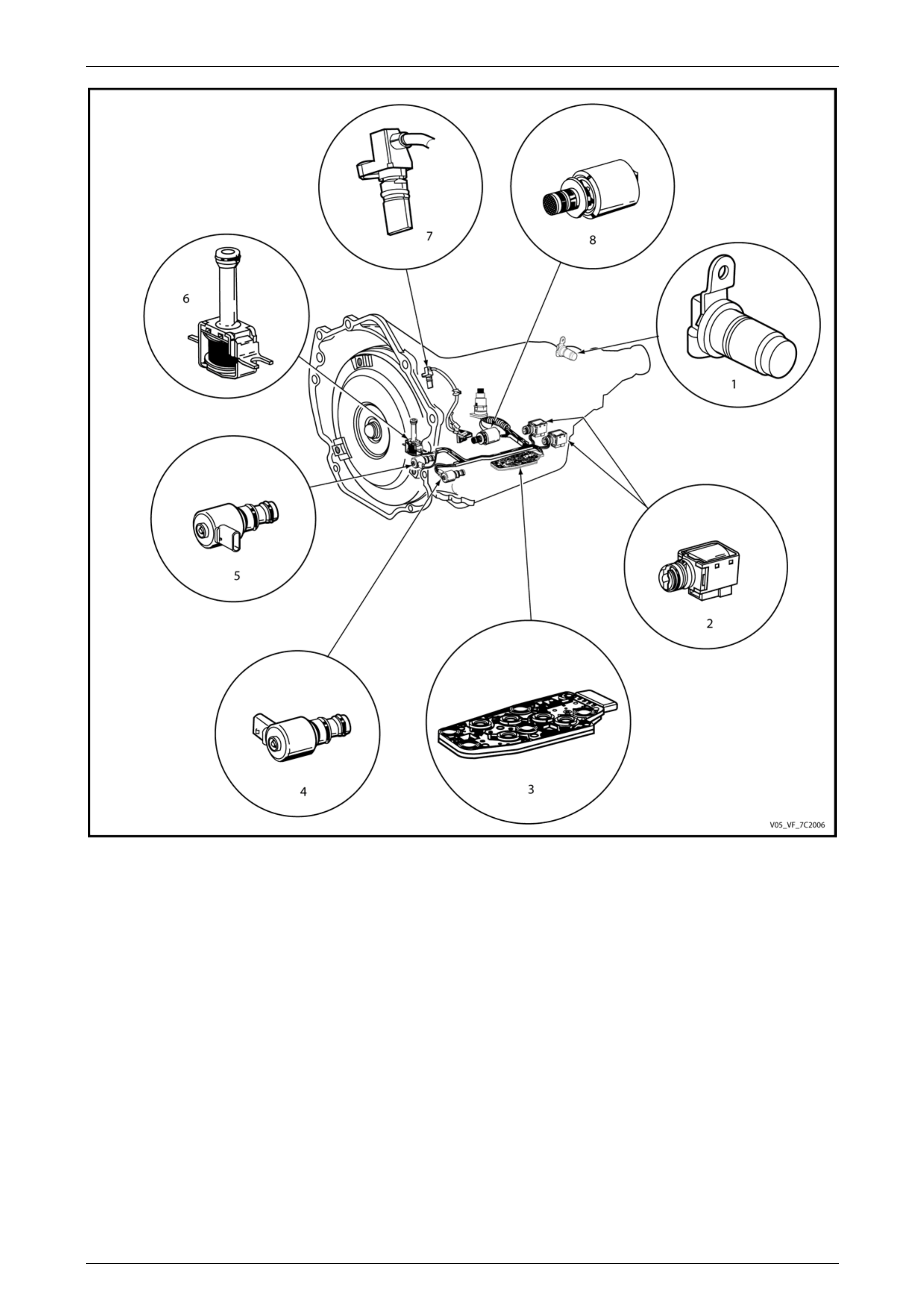
Figure 7D2 – 1 shows the location of the internal electronic components in the transmission.
Page 7D2–9
Automatic Transmission – 4L65E – Electrical Diagnosis Page 7D2–10
Figure 7D2 – 1
Legend
1 Vehicle Speed Sensor 5 Torque Converter Clutch Pulse Width Modulation (TCC
PWM) Solenoid Valve
2 1-2 Shift Solenoid (Solenoid A) and 2-3 Shift Solenoid
(Solenoid B) 6 Torque Converter Clutch (TCC) Solenoid Valve
3 Automatic Transmission Fluid Pressure (TFP) Manual Valve
Position 7 Input Speed Sensor
4 3-2 Downshift Solenoid 8 Pressure Control (PC) Solenoid Valve
Transmission Adaptive Functions
The 4L65E automatic transmission uses a line pressure control system, which has the ability to adapt the system line
pressure to compensate for normal wear within the transmission, such as the clutch pack fibre plates, seals, springs, etc.
The adapt feature is similar in function to the long term/short term fuel trim feature of the engi ne management system.
The 4L65E automatic transmission uses the adapt function for garage shift s , upshi fts and torque converter clutch (TCC)
application. The TCM monitors the engine torque to determine if the shift is occurring too fast or too slow and adjusts the
pressure control solenoid to maintain the correct shift feel.
Page 7D2–10

Automatic Transmission – 4L65E – Electrical Diagnosis Page 7D2–11
Limp Home Mode Descript
If a major electrical system failure occurs which could affect vehicle safety or damage the transmission during normal
control solenoid is off and the line pressure is at maximum to minimise clutch slippage.
• The TCC solenoid is off, therefore the torque converter clutch is disabled.
ift solenoids are turned off. The transmission will operate in fourth gear if the vehicle has successfully
the vehicle has not completed a 1-2 upshift in the current
If the transmission is operating in fourth gear, third gear
ted.
In limp home mode, the gear selector lev er is ineffective at selecting forward gear ranges. In third or fourth gear, heat
builds up in the transmission quickly, particularly in stop and go traffic. Excessive heat build-up may cause transmissi on
failure if the vehicle is driven for extended distances in limp home mode.
ion
operation, the TCM enters a limp home mo de. In the limp home mode, the transmission operates in the following
manner:
• The pressure
• The two sh
completed a 1-2 upshift in the current ignition cycle. If
ignition cycle, the transmission will operate in third gear.
may be obtained if the engine is stopped briefly and re-star
Page 7D2–11
Automatic Transmission – 4L65E – Electrical Diagnosis Page 7D2–12
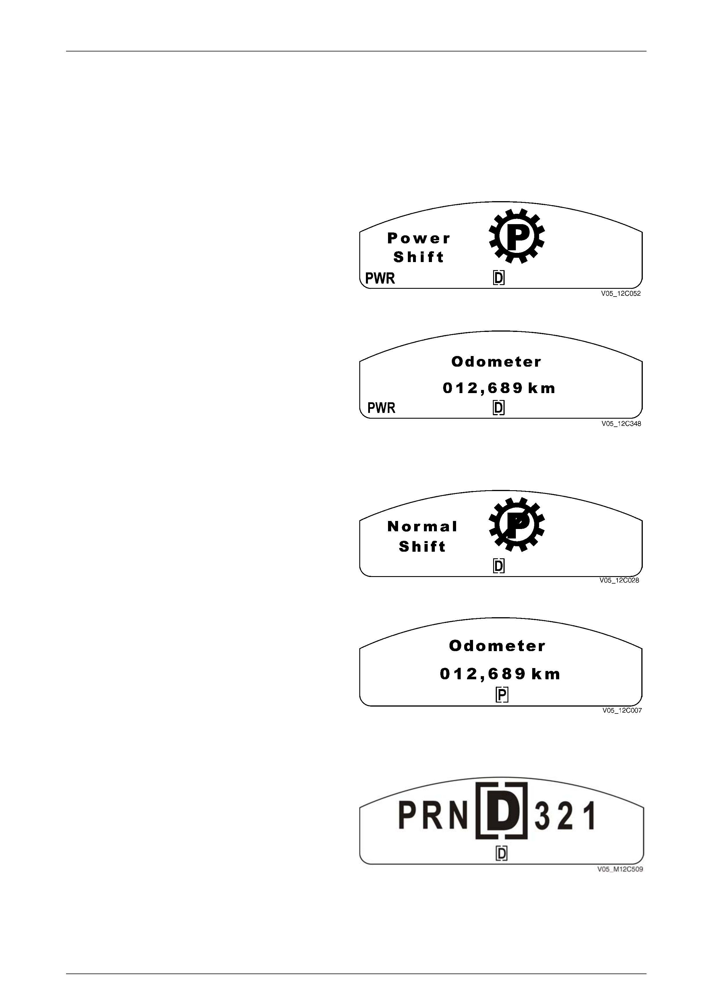
1.3 Transmissi
The instrument clusters m
on Indicators and Messages
ulti-function display (MFD) component of the Instrument may displa y messages relating to this
w
hen ode, the PWR
n i tion is displayed
transmission.
MFD Displays
Po er Mode
W the transmission is placed in Power M
ico lluminates and the Power Shift anima
for 2 seconds.
Figure 7D2 – 2
lay extinguishes and th e
PWR icon remains. The display reverts to the previously
pla een.
After 2 seconds, the animated disp
dis yed trip computer scr
Figure 7D2 – 3
Normal Mode
When the transmission is change d from Power Mode to
Normal Mode, the PWR icon exti nguishes immediatel y and
the Normal Shift animation is displa yed for 2 seconds.
Figure 7D2 – 4
After 2 seconds, the animated display extinguishes and the
display reverts to the previous ly displayed trip computer
screen.
Figure 7D2 – 5
Shift Range Selected
The gear icon remains for 2 seconds after it is selected.
While the transmission selector is moving, the constant
icons reflect the selector movement through the gears.
NOTE
If any warning is active, the large displ ay symbol
is not shown and only the bracketed constant
icon at the bottom changes when the automatic
transmission selector is moved. Figure 7D2 – 6
Page 7D2–12
Automatic Transmission – 4L65E – Electrical Diagnosis Page 7D2–13
1.4 Electronic Component Description
r a section, refer to General Motors Powertrain Group Electronically
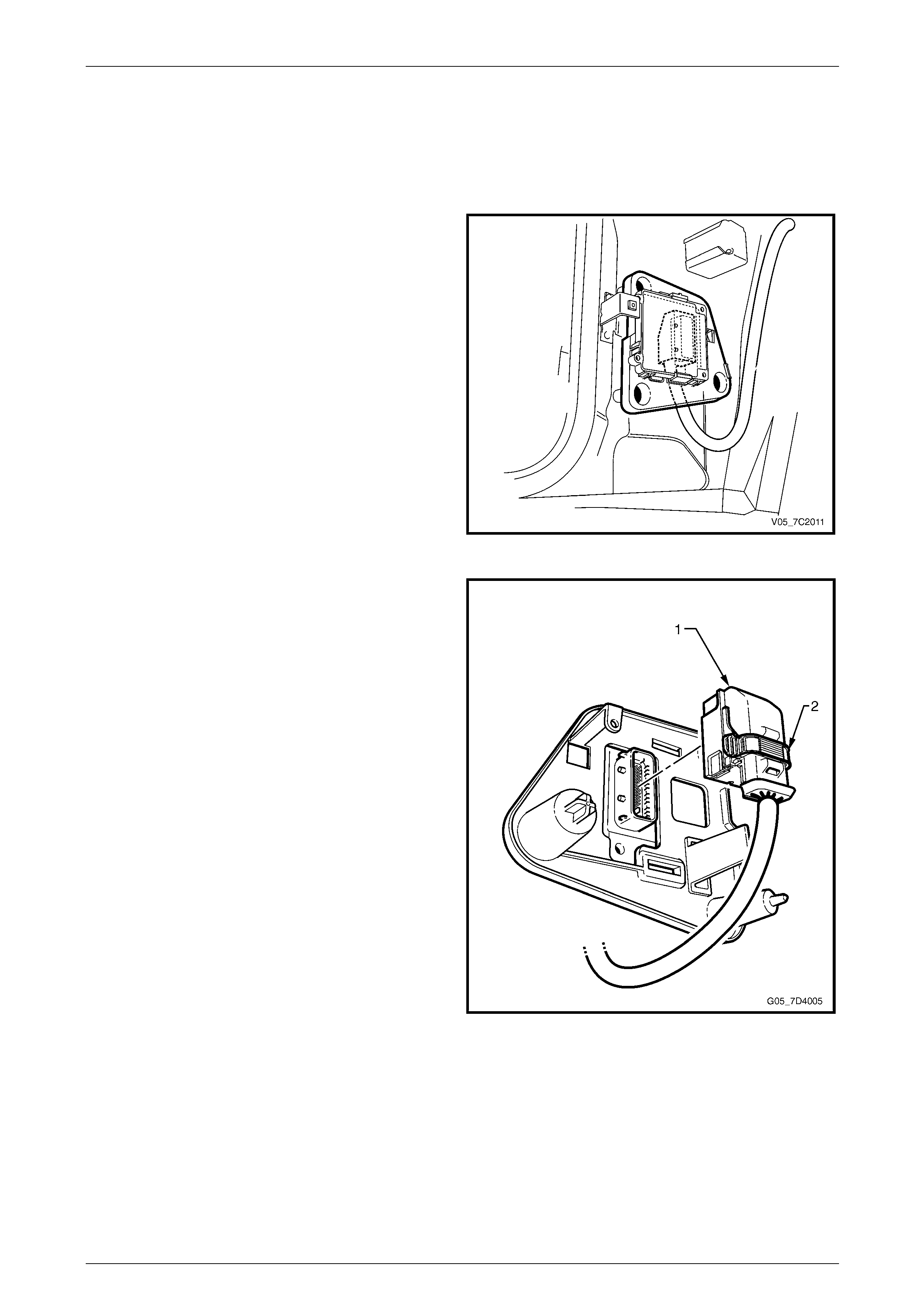
Transmission Control Module (TCM)
ehind
ects
e 49-way
nn n the
hic and the TCM.
Fo ll other electrical components not covered in this
Controlled Automatic Transmission Technician's Guide.
The Transmission Control Mo dule (TCM) is located b
the left-hand body hinge pillar trim assembly and conn
directly to the transmission wiring harness. A singl
co ector is used to make the connection betwee
ve le wiring harness
Figure 7D2 – 7
The TCM is an electronic cont rol module receiving input or
providing output to control the operation of the 4L65E
automatic transmission.
The TCM receives the following in puts from the engine
control module (ECM):
• engine speed and torque values,
• engine intake air temperature (IAT), accelerator pedal
position (APP) information,
• engine coolant temperatur e (ECT),
• driver selected shift mode, and
• air-conditioning (A/C) status.
The ECM provides this data to the TCM through the
databus.
Other TCM inputs are:
• battery and ignition voltage,
• brake switch status,
• transmission fluid temperature (TFT),
• input speed sensor (ISS) and
• vehicle speed sensor (VSS). Figure 7D2 – 8
Page 7D2–13

Automatic Transmission – 4L65E – Electrical Diagnosis Page 7D2–14
The TCM provides the following outp to control the a
• shift solenoids to control trans ion
• torque converter clutch (TCC) pulse w d (PWM) solenoid operation to control the ap ply and release of
the torque converter clutch assembly, and
• pressure control (PC) solenoi sure.
Other TCM outputs provided to the ECM / PIM are:
• check powertrain icon illuminat ion request,
• vehicle speed,
• transmission input speed,
• transmission fluid temperature,
• commanded gear status,
• TCC status, and
• torque reduction requests.
uts utomatic transmission:
miss shifting,
idth modulate
d to regulate the transmission line pres
Page 7D2–14

Automatic Transmission – 4L65E – Electrical Diagnosis Page 7D2–15
2 Wiring Diagrams and Connector
Chart
2.1 Wiring Diagrams
s
Page 7D2–15
Automatic Transmission – 4L65E – Electrical Diagnosis Page 7D2–16
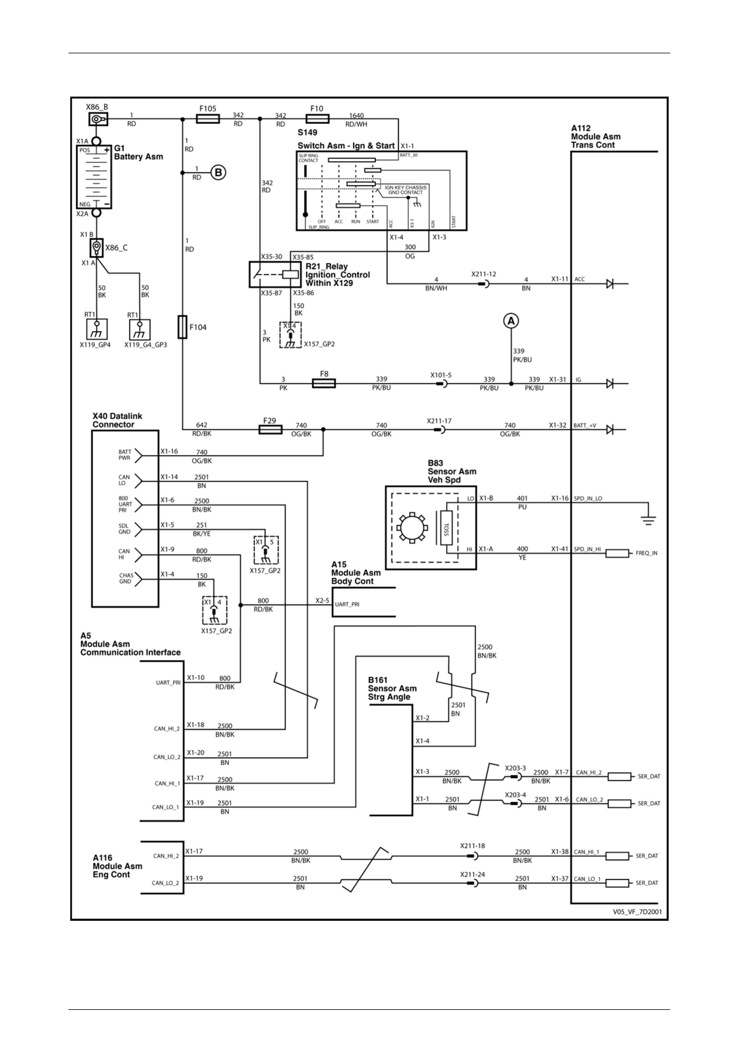
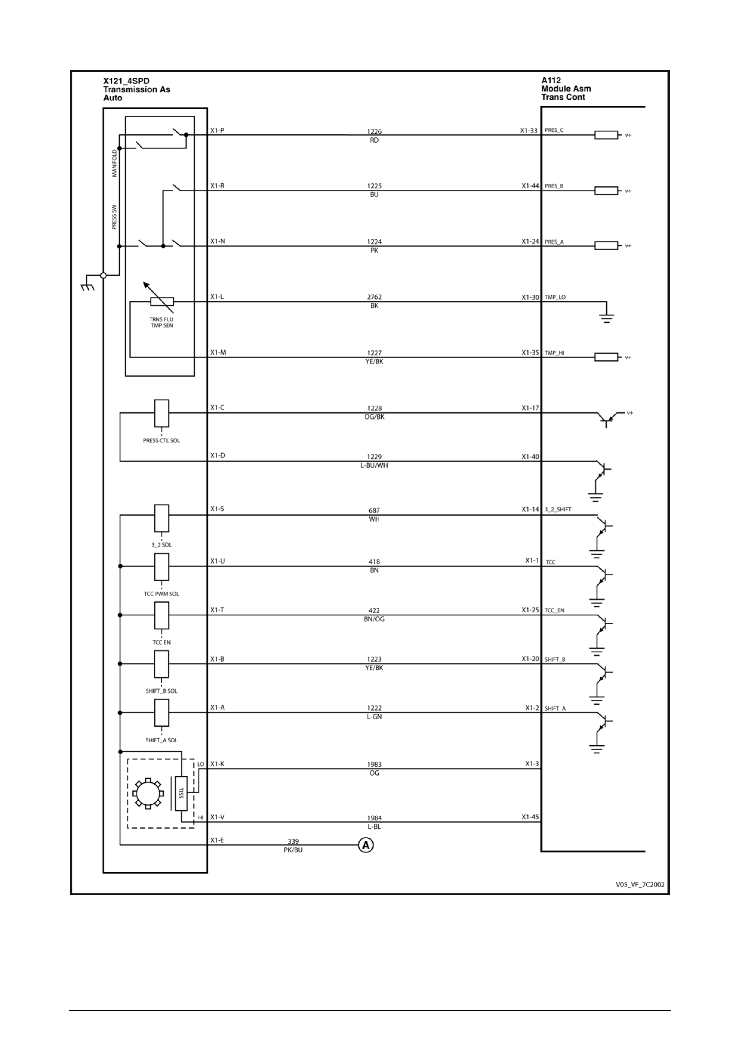
GEN IV V8 Euro III 4L65E (with Input Speed Sensor)
Figure 7D2 – 9
Page 7D2–16
Automatic Transmission – 4L65E – Electrical Diagnosis Page 7D2–17
Figure 7D2 – 10
Page 7D2–17
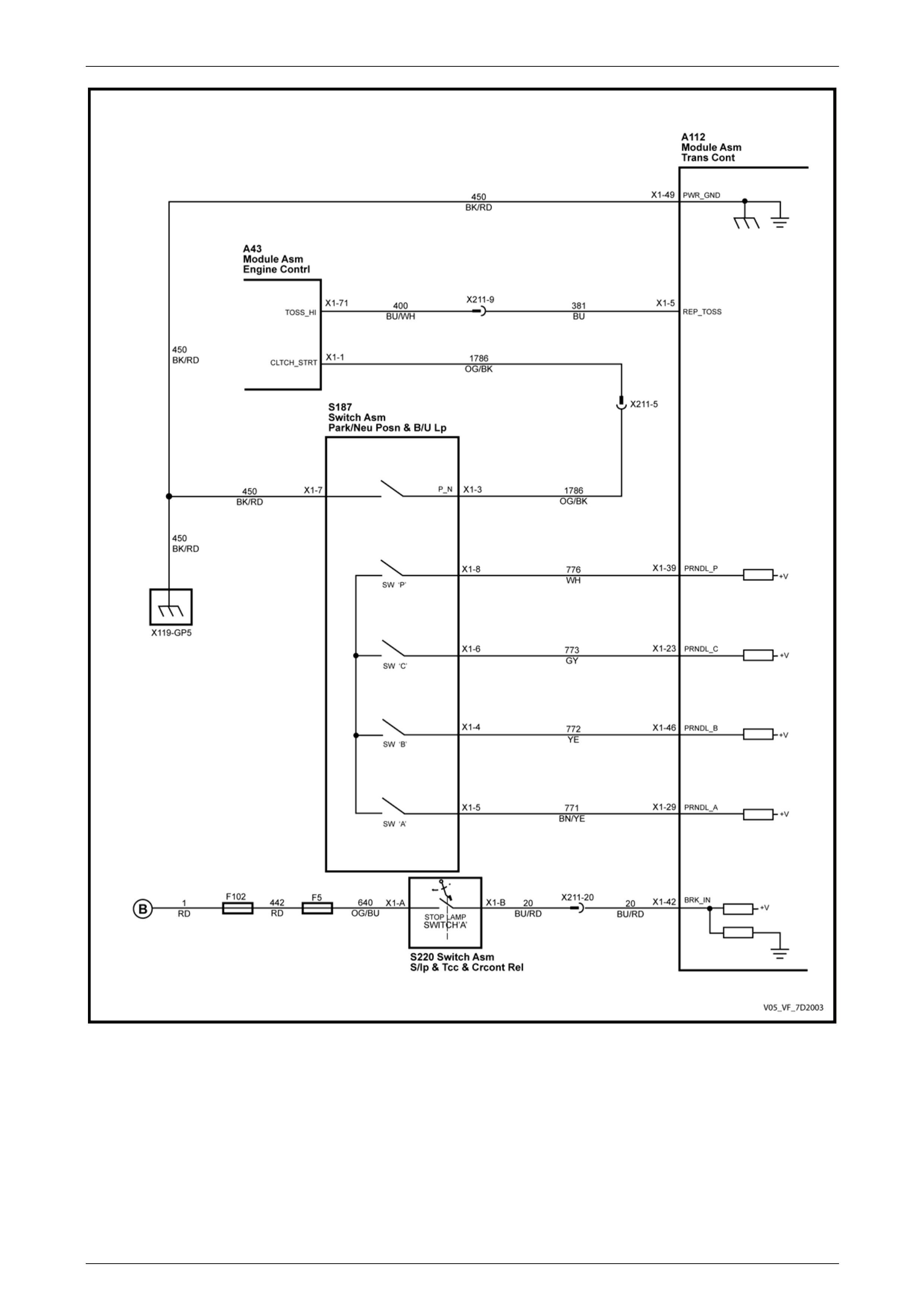
Automatic Transmission – 4L65E – Electrical Diagnosis Page 7D2–18
Figure 7D2 – 11
Page 7D2–18
Automatic Transmission – 4L65E – Electrical Diagnosis Page 7D2–19
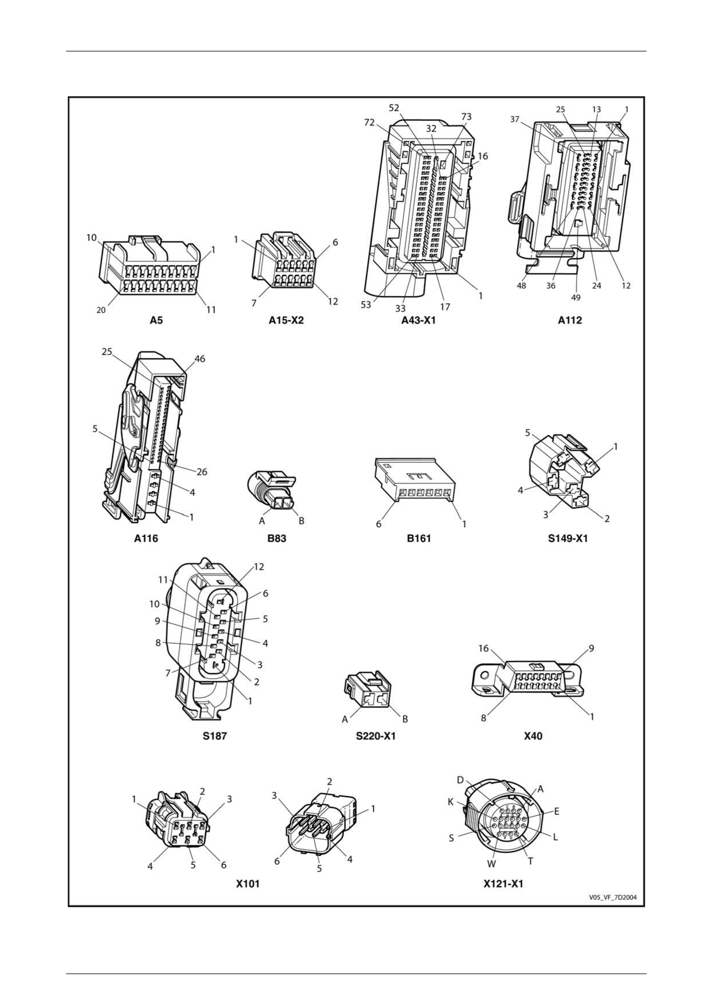
2.2 Connector Chart
Figure 7D2 – 12
Page 7D2–19
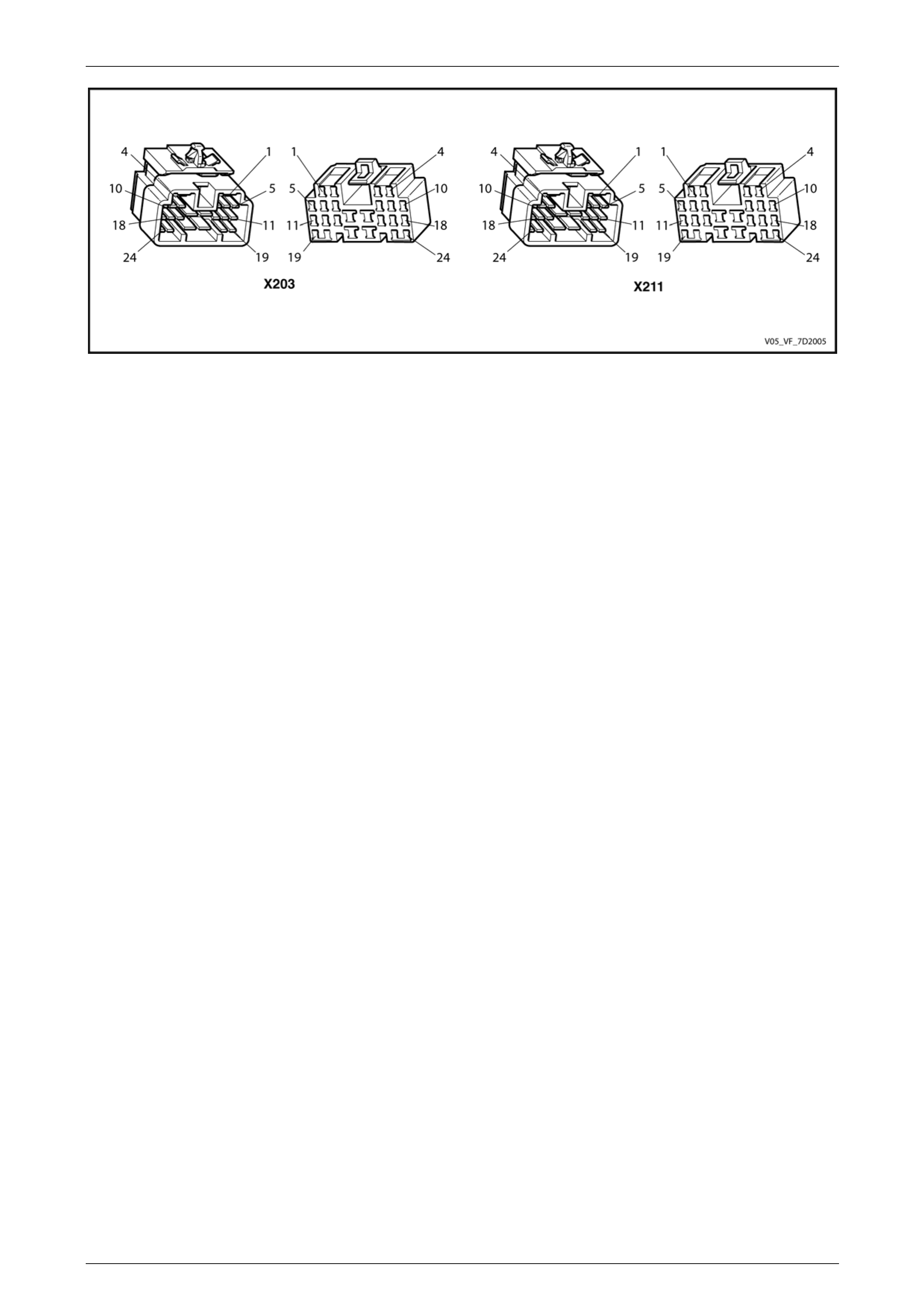
Automatic Transmission – 4L65E – Electrical Diagnosis Page 7D2–20
Figure 7D2 – 13
Page 7D2–20
Automatic Transmission – 4L65E – Electrical Diagnosis Page 7D2–21
2.3 Connector Information
In-line 20-Way C or End
Transmission Sid 121–
onnect View
e – X X1
Figure 7D2 – 14
Termin Wire Colour Function al / Pin
X1–A 1-2 Shift Solenoid Valve Control L-GN
X1–B 2-3 Shift Sole noid Valve Control YE
X1–C PU Pressure Control (PC) Solenoid Valve Low Control
X1–D L-BU Pressure Control (PC) Solenoid Valve High Control
X1–E RD n Voltage Ignitio
X1 — Used –F Not
X1–G — Not Used
X1–H — Not Used
X1–J — Not Used
X1–K OG ISS signal
X1–L BN Transmission Fluid Temperature (TFT) Sensor Low Reference
X1–M GY Transmission Fluid Temperature (TFT) Sensor Signal
X1–N PK Transmission Fluid Pressure Switch A Sensor Signal
X1 OG Fluid Pressure Switch C Se–P Transmission nsor Signal
X1 R BU ransmission Fluid Pressure Switch B Sensor Signal – T
X1–S WH 3-2 Shift Solenoid Valve Control
X1–T Torque Converter Clutch (T CC) Solenoid Valve Control BK
X1–U BN Torque Converter Clutch (T CC) PWM Solen oid Valve Control
X1–V L–BU ISS Reference Voltage
X1–W — sed Not U
Page 7D2–21
Automatic Transmission – 4L65E – Electrical Diagnosis Page 7D2–22
H
arness Side – X121–X1
Figure 7D2 – 15
Terminal / Pin Wire Colour Circuit No. Function
X1–A L-GN 1222 1-2 Shift Solenoid Valve Control
X1–B YE / BK 2-3 Shift Solenoid Valve Control 1223
X1 OG / BK 1228 Pressure Control (PC) Solenoid Valve Low Control –C
X1–D L-BU / W 9 Pressure Control (PC) Solenoid Valve H igh Control H 122
X1–E PK / BU n Voltage 339 Ignitio
X1–F — — Not Used
X1–G — — Not Used
X1–H — — Not Used
X1–J — — Not Used
X1–K OG 1983 ISS Signal
X1–L BK 2762 Transmission Fluid Temperat ow Reference ure (TFT) Sensor L
X1–M YE / BK Transmission Fluid Temperature (TFT) Sensor Sign al 1227
X1 PK 1224 Transmission Fluid Pressure Switch A Sensor Signal –N
X1–P RD 1226 Transmission Fluid Pressure Switch C Sensor Signal
X1–R BU 1225 Transmission Fluid Pressure Switch B Sensor Signal
X1–S WH 687 3-2 Shift Solenoid Valve Control
X1–T BN / OG Torque Converter Clutch (T CC) Solenoi d Valve Control 422
X1 BN 418 Torque Converter Clutch (TCC) PWM Solenoid Valve Control –U
X1–V L 84 ISS Reference Voltage –BU 19
X1–W — Not Used —
Page 7D2–22
Automatic Transmission – 4L65E – Electrical Diagnosis Page 7D2–23
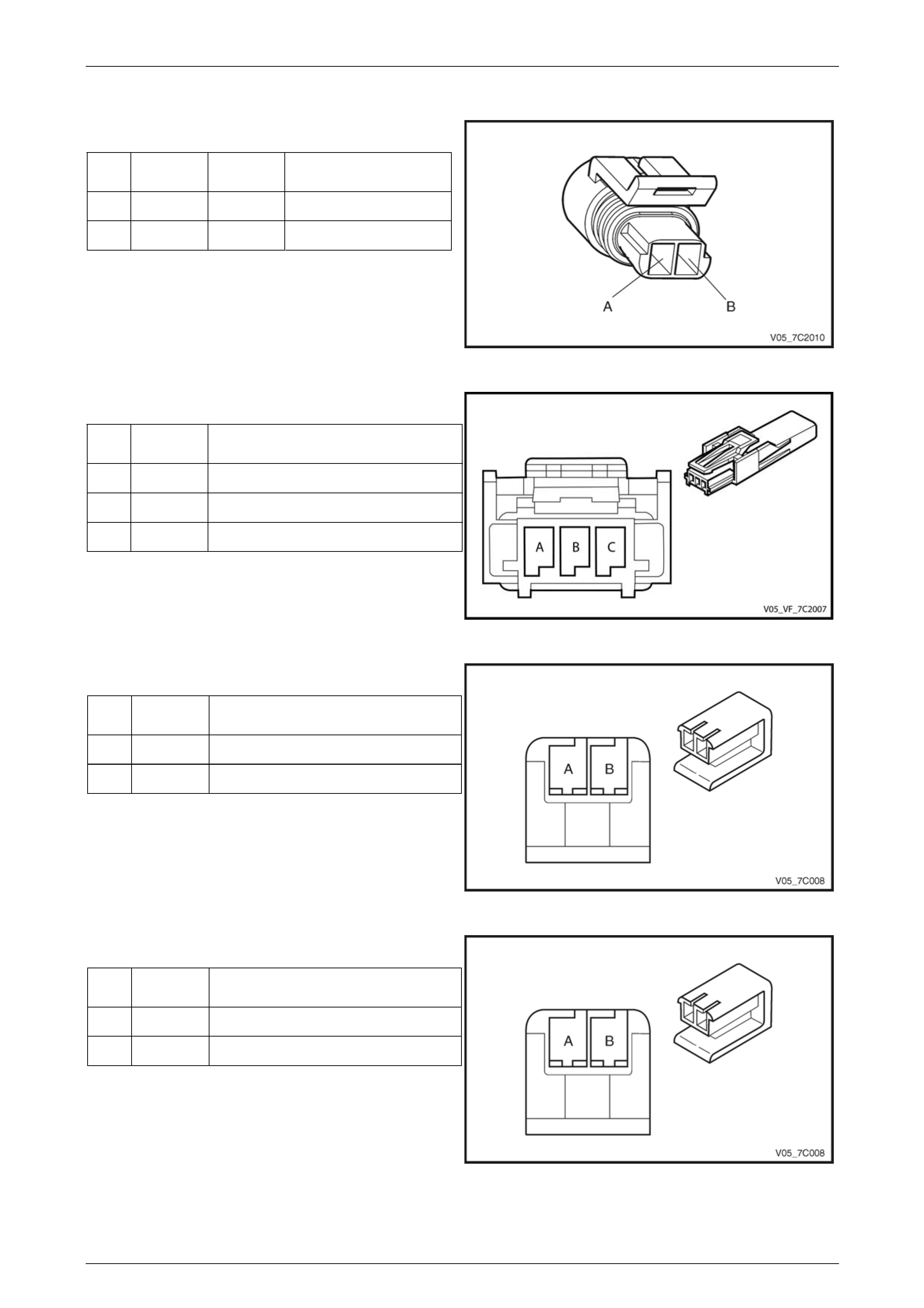
Internal Connector End View
Pin Wire
Colour Circuit
o. Function
s
Vehicle Speed Sensor
N
A YE 0 VSS High Signal 40
B PU VSS Low Signal 401
Figure 7D2 – 16
peed Sensor
Wire
Colour unction
Input S
Pin
F
A BK Signal ISS
B RD n VoltaIgnitio ge
C D–GN w ReferencLo e
Figure 7D2 – 17
1-2 Shift Solenoid Valve Con tor
Wire
Colour tion
nec
Pin
Func
A L-GN 1-2 Shift Solenoid Valve Cont rol
B RD Ignition Voltage
Figure 7D2 – 18
2-3 Shift Solenoid Valve Connector
Wire
Colour tion Pin
Func
A YE 2-3 Shift Sole Valve Contronoid l
B RD Ignition Voltage
Figure 7D2 – 19
Page 7D2–23
Automatic Transmission – 4L65E – Electrical Diagnosis Page 7D2–24
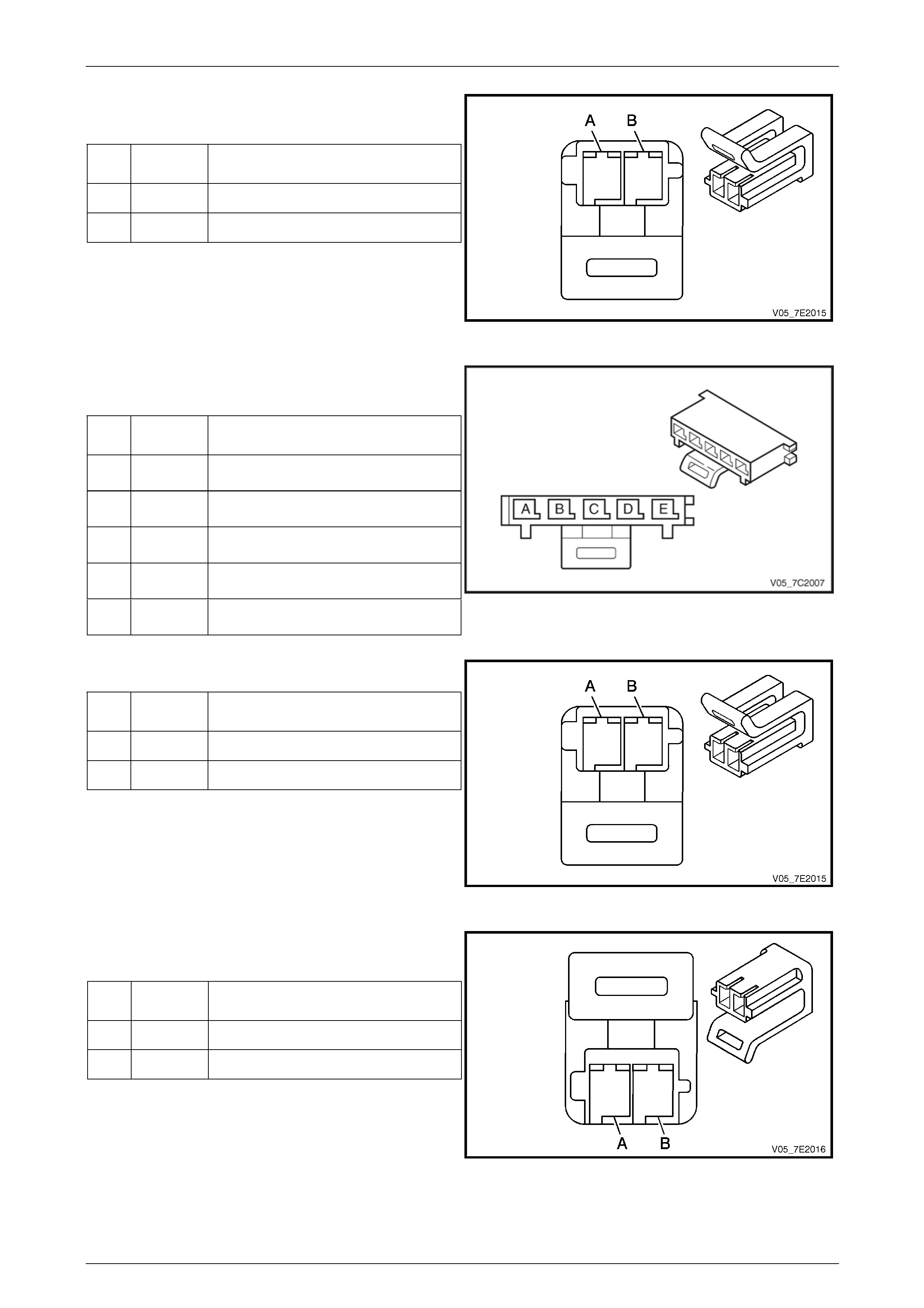
Pressure Control (PC) Solenoid Valv e
ec
Wire
Colour tion
Conn tor
Pin
Func
A PU PC Solenoid High ControValve l
B L-BU PC Solenoid e Control Valv
Figure 7D2 – 20
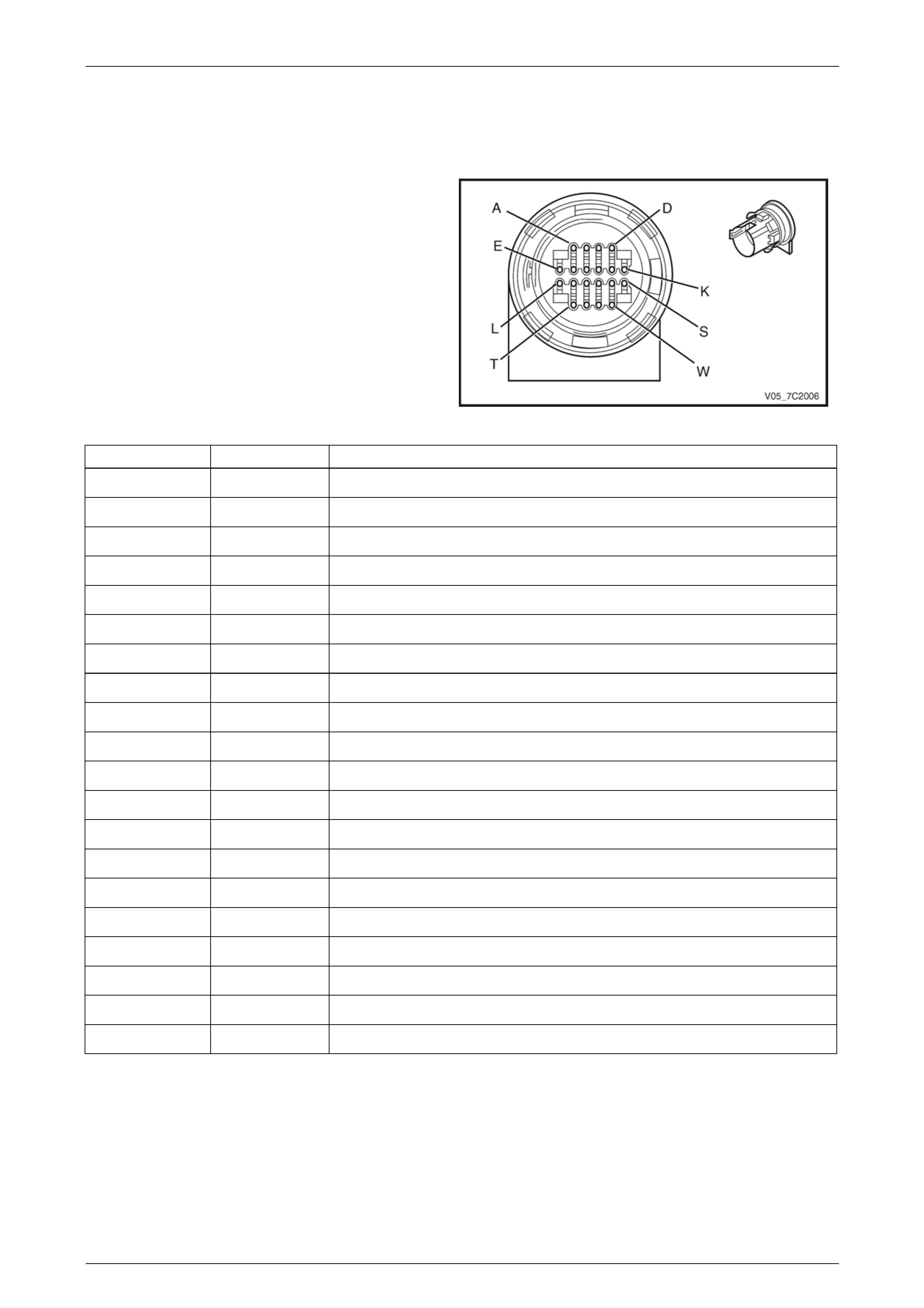
Transmissio
Ass n Manual Shift Shaft Switch
emb
Wire
Colour ction
ly
Pin Fun
A BN Transmission Fluid Temperature
(TFT) Sensor Low Reference
B GY Transmission F luid Temperat ure
(TFT) Sensor Signal
C PK Transmission Fluid Pressure Switch
Signal A
D OG Transmission Fluid Pressure S witch
Signal C
E BU Transmission Fluid Pressure S witch
Signal B
Figure 7D2 – 21
3-2 Shift Solenoid Valve Assembly Connector
Pin
Wire
Colour Function
A RD Ignition Voltage
B WH 3-2 Downshift Solenoid Valve Control
Figure 7D2 – 22
Torque Converter Clutch (TCC) Pulse-Width
Modulated (PWM) Solenoid Valve Connector
Pin
Wire
Colour Function
A RD Ignition Voltage
B TN TCC PWN Solenoid Valve Control
Figure 7D2 – 23
Page 7D2–24
Automatic Transmission – 4L65E – Electrical Diagnosis Page 7D2–25
Torque Converter Clutch (TC
Connector
Pin
Wire
Colour Function
C) Solenoid Valve
A RD / BK Ignition Voltage
B BK TCC Solenoid Valve Control
Figure 7D2 – 24
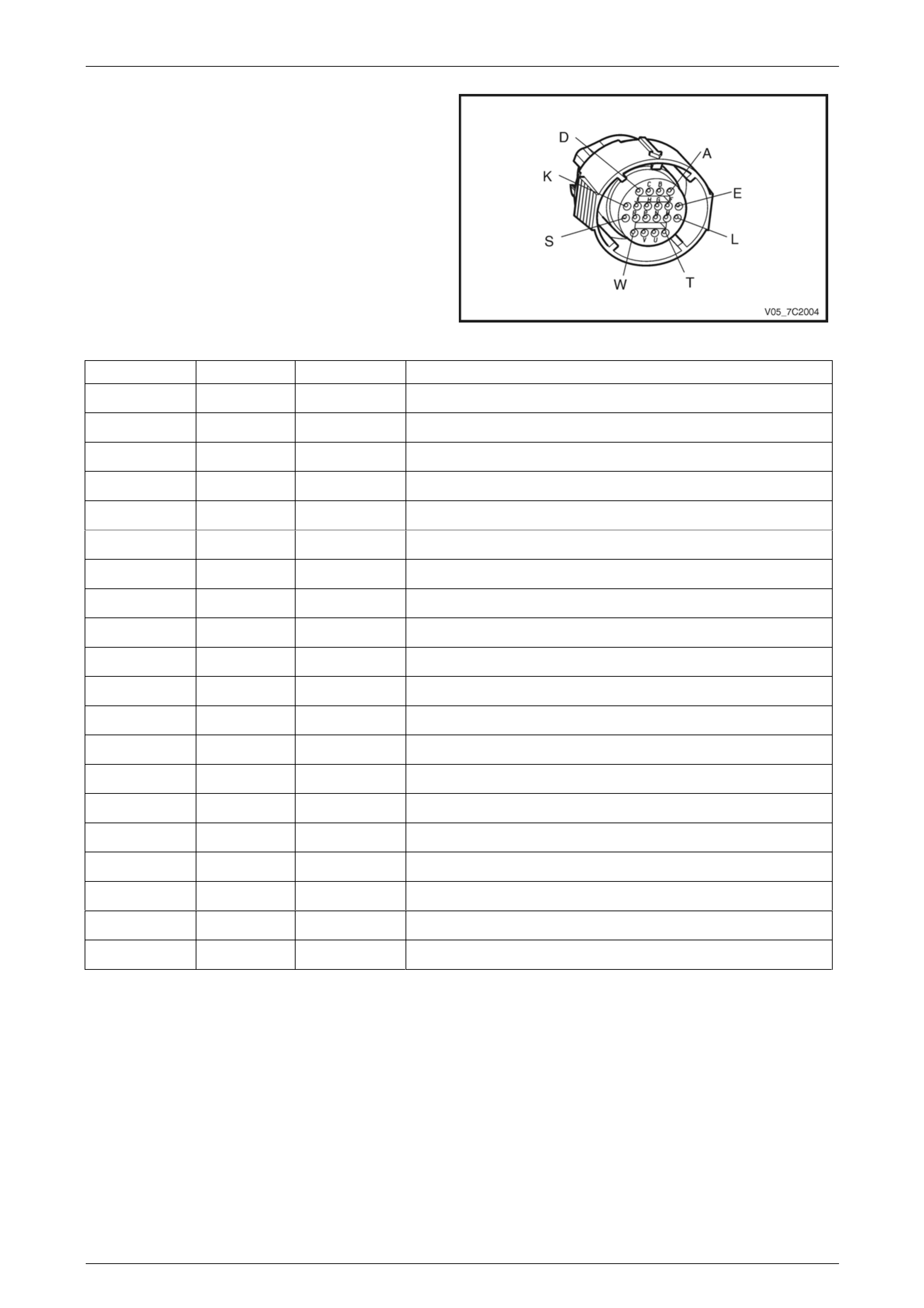
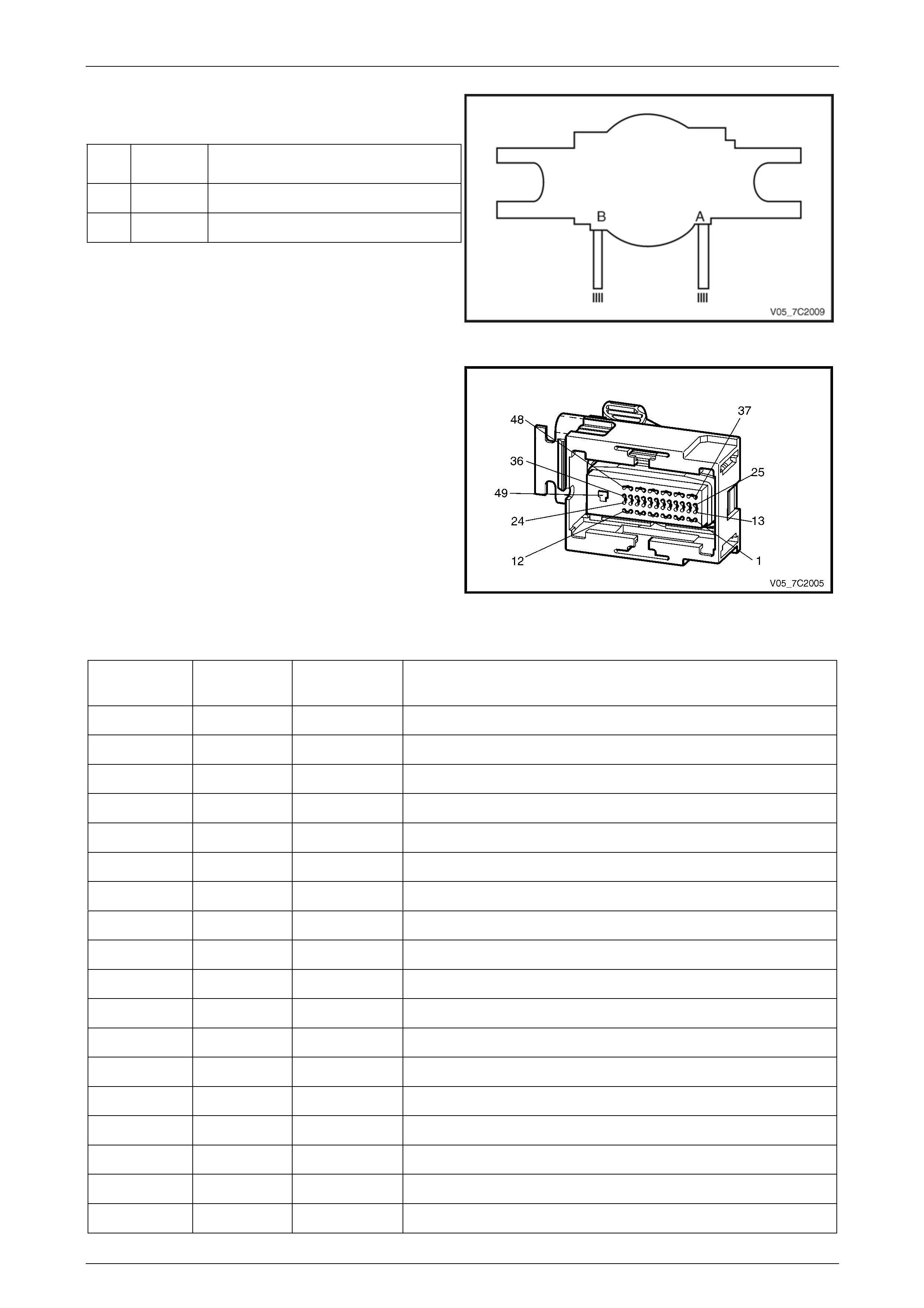
Control Module Connector End Transmission
View – A112–X1
Figure 7D2 – 25
Terminal/
Pin Wire Colour Circuit No. Function
X1–1 BN 418 Torque Converter Clutch (TCC) PWM Solenoid Valve Control
X1 2 L-GN 1222 1-2 Shift Solenoid Valve Control (Solenoid A) –
X1 3 OG 1983 ISS Signal –
X1–4 — — Not Used
X1 5 — — Rep Transmission Output Signal –
X1– 2501 High Speed GMLAN Serial Data Bus – (CAN 2 Low) 6 BN
X1–7 BN / BK 2500 High S al Data Bus – (CAN 2 High) peed GMLAN Seri
X1–8 — — Not Used
X1–9 — — Not Used
X1–10 — — Used Not
X1–11 BN 4 Accessory Voltage
X1–12 — — Not Used
X1–13 — — Not Used
X1– 687 3-2 Downshift Solenoid Valve Control 14 WH
X1 15 — — Not Used –
X1–1 401 Output Speed (OSS) Sensor – Low Signal 6 PU
X1–17 L-BU / WH 1229 Pressure Control (PC) Solenoid Valve High Control
X1–18 — — Not Used
Page 7D2–25

Automatic Transmission – 4L65E – Electrical Diagnosis Page 7D2–26
X1 19 — — Not Used –
X1 20 YE / BK 1223 2-3 Shift Solenoid Valve C– ontrol (Solenoid B)
X1 21 — — Not Used –
X1– — Not Used 22 —
X1 23 GY 773 Park/Neutral Position– and Back-up Lamp Switch C Signal
X1– 24 PK 1224 Transmission Fluid Pressure Switch A Signal
X1– 25 BN / OG 422 Torque Converter Clutch (T CC) Solenoi d Valve Control
X1–26 — — Not Used
X1–27 — — Not Used
X1–28 — — Not Used
X1–29 BN / YE 771 Park/Neutral Position and Back-up Lamp Switch A Signal
X1–3 Transmission Fluid Temperature (TFT) Sensor Low Reference 0 BK 2762
X1–31 PK / BU 339 Igni e tion Voltag
X1–32 OG / BK 740 Battery Voltage
X1–33 RD 1226 Transmission Fluid Pressure Switch C Signal
X1–34 — — Not Used
X1–35 YE / BK 1227 Transmission Fluid T emperature (TFT) Sensor High Signal
X1–36 — — Not Used
X1–37 BN 2501 High Speed GMLAN Serial Data Bus (CAN 1 Low)
X1 38 BN / BK 2500 High Speed GMLAN Serial Data Bus (CAN 1 High) –
X1– Park/Neutral Position and Back-up Lam p Switc h P Sign al 39 WH 776
X1–40 OG / BK 1228 Pressure C ontrol (PC) Solenoid Valve Low Control
X1–41 YE 400 Output Speed (OSS) Sensor – High Signal
X1 42 BU / RD 20 Stop Lamp Switch Signal –
X1– — Not Used 43 —
X1 44 BU 1225 Transmission Fluid Pressure Switch B Signal –
X1 5 L–BU 1984 ISS Reference –4
X1 46 YE 772 Park/Neutral Position and Back-up Lamp Switc– h B Signal
X1 47 — — Not Used –
X1 48 — — Not Used –
X1 9 BK / W H 451 Power Ground –4
Page 7D2–26
Automatic Transmission – 4L65E – Electrical Diagnosis Page 7D2–27
3 Diagnostics
3.1 Introduction
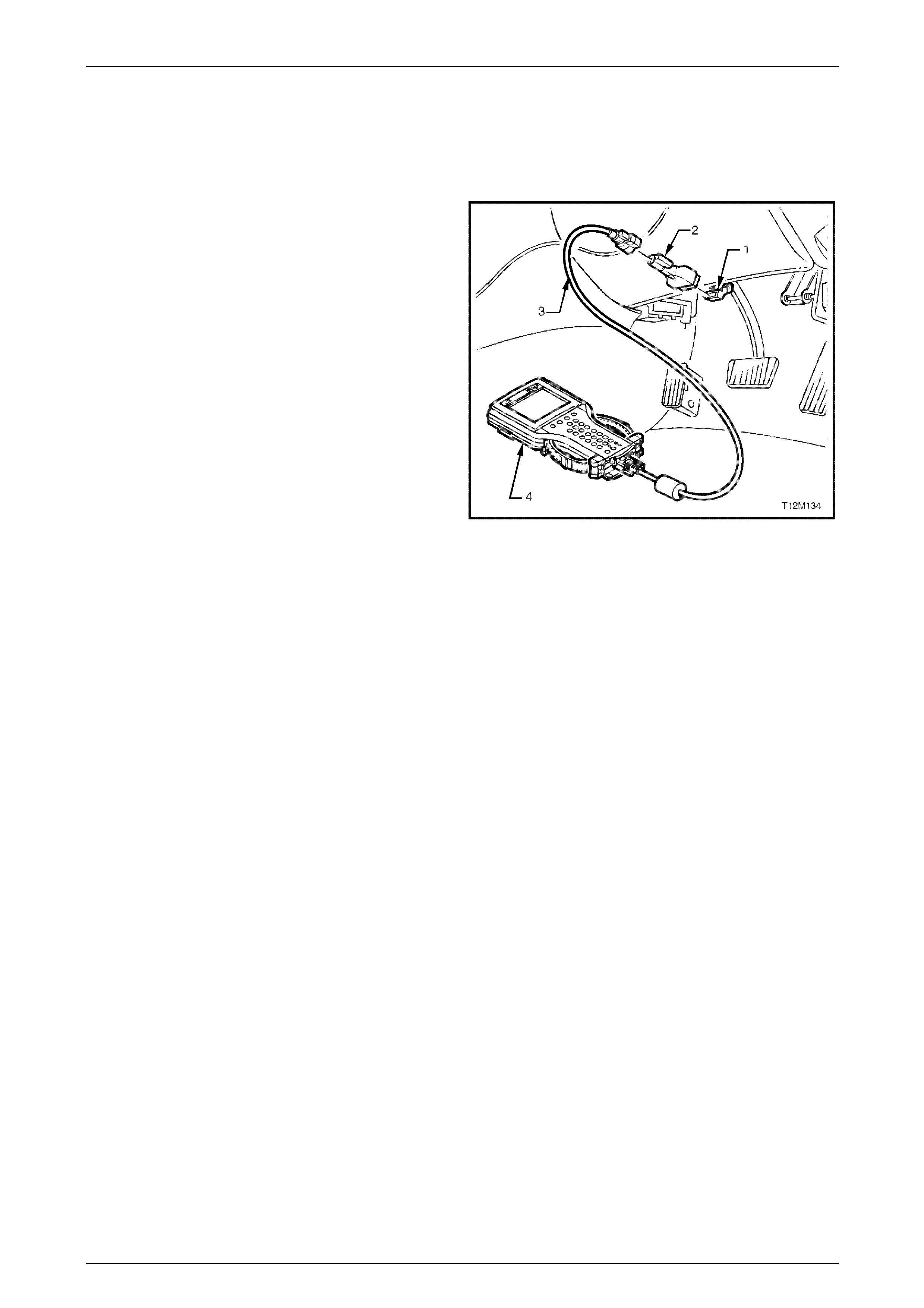
Tech 2, with the appropriate software, cables and adapt
when connected to the serial data li
read transmission diagnostic a nd te
DLC is attached to the instrument p
beneath the steering wheel.
1 DLC
2 DLC Adapter
3 DLC Cable
4 Tech 2
For additional general information on connecting and
operating Tech 2, refer to Section 0C Tech 2.
ers,
nk connector (DLC) can
sting serial data. The
anel trim retainer
Figure 1A7 – 26
Test Modes
Tech 2 has six test modes for diagnos ing the transmission. To get to these various test modes, on Tech 2 select:
Diagnostics / Model Year / Model / Transmission / Automatic Transmission
and follow Tech 2’s prompts. This will then display the following menu ope r ations.
Diagnostic Trouble Codes
If Diagnostic Trouble Codes is selected, a selection list is displayed which contains:
• Read DTC Information – Once selected, both current and history diagnostic trouble codes (DTCs) stored in the
transmission control module will b e displayed.
• Clear Engine & Transmission DTC(s) – Once selected, DTCs stored in the transmission contro l module (TCM)
and engine control module (ECM) memor y may be cleared.
• Freeze Frame / Failure Records – Shows Freeze Frame / Failure R ecords information. Freeze Frame / F ailure
Records are types of snapshots stored in the memory of the TCM and contain data parameters from the TCM at
the time the DTC set.
NOTE
For a complete list of TCM DTCs, refer to
4.6 Diagnostic Trouble Code List. For further
information on Tech 2 and it functions, refer to
Section 0C Tech 2.
Data Display
If Data Display is selected, a selection list is displayed which contains:
• Transmission Data – Once is selected, a list of transmission components and the TCM inputs are displayed along
with their status.
• TCC Data – Once selected, displays specific parameter i nfo rmation about the torque conv erter clutch controlling
devices and their circuits.
• 1-2 Shift Data – Once selected, displays specific parameter information about the 1-2 shift solenoid valve (shift
solenoid A) and its circuits.
Page 7D2–27

Automatic Transmission – 4L65E – Electrical Diagnosis Page 7D2–28
• 2-3 Shift Data – Once this mode is selected, displays spec ific parameter information about the 2-3 shift solenoid
valve (shift solenoid B) and its
• Pressure Control Solenoid Data – Once selected, displays specific parameter information about the PC solenoid
• 1-2 Adapt Data – In this mode Tech 2 continuously monitors and displays 1-2 TAP cell data param eters.
2-3 Adapt Data e Tech 2 continuously monitors and displays 2-3 TAP cell data parameters.
• 3-4 Adapt Data –In this mode Tech 2 continuously monitors and displays 3-4 TAP cell data parameters.
• Steady State Adapt Data – In this mode Tech 2 continuously monitors and displays Steady State TAP data
• Syste In this mode, Tech 2 will d on identification scre following items
will be dis rtnumber, Hardware Partn mber, Alpha Code, Software Vers Software
Partnu 1-10, VIN Digit 11-17.
Further information a e Data Display mode
and the data parameter is contained in
3.2 Data Display.
Snapsho
In this test tures TCM data before and after a forced manual trigger.
Additional Function
If Additional Functions ections list is dis which contains:
• System Identification ech 2 will di e transmission identification screen. T wing items
will be d tifier, Partnumber, Hardware mber, Alpha Code, Software Vers ber, Software
Partnumber, VIN Digit 1-10, VIN Digit 11-17.
Miscellaneo
If Miscellaneous Functions is selected, a ontains:
• TCC S 2 can command the . Tech 2 will display whether the TCC solenoid
is activ
• TCC P Tech 2 can comma id on and off. Tech 2 wil whether the
TCC PW or inactive an
• CC on when the vehicle is above 50 km/h.
• Shift Solenoid id A (1-2 shift solenoid) on and off.
• Shift Solenoid B and off.
• 3/2 Do – Tech 2 can command the nshift solenoid (3-2 shift solenoid) on
• Gear Control ntally command noid states to correspon The
TCM le shift increments or decr nd does not allow a shift if it causes the engine RPM to
exceed a calibrated limit.
• High Side Driver 1 – This test is not applicable.
• High Side Driver 2 – This test is not applicable.
• Pressure Control Solenoid – This function allows the user to control state of the pressure control solenoid in
increm
NOTE
For operati Miscellaneous
Test, refer to .
circuits.
• 3-4 Shift Data – Once selected, displays information on 3-4 shift timing.
and its circuits.
• Transmission Adapts – Once selected, it has further sub menus:
• –In this mod
parameters.
m Identification: isplay the transmissi en. The
played; Identifier, Pa
mber, VIN Digit u ion Number,
NOTE
bout th
t
mode, Tech 2 cap
s
is selected, a sel played
– In this mode, T splay th he follo
isplayed; Iden Partnu ion Num
us Tests
selections list is displa yed which c
olenoid –Tech TCC solenoid on and off
e or inactive.
WN Solenoid –
M solenoid is active nd the TCC PWM soleno
d torque percentage. l display
TCC Apply – Tech 2 can command the T
A – Tech 2 can command the shift soleno
– Tech 2 can command the shift solenoid B (2-3 shift solenoid) on
wnshift Solenoid 3/2 dow and off.
– Tech 2 can increme shift sole d to relative gear states.
will only allow sing ements a
ents of 100 mA.
ng parameters of the
3.4 Miscellaneous Tests
Page 7D2–28

Automatic Transmission – 4L65E – Electrical Diagnosis Page 7D2–29
Programming
If Programm , a selection list is d
• Reset T his test allows the us on Adapt (TAP) cells by g the Reset soft
key.
Upon resetting the TAP cells the TCM loses all
learnt adaptive func n the ve hicle is first
driven after this, the shifts may be harsh. This
harshness will ease M relearns the T A P
cells.
ing is selected isplayed which contai ns:
AP Cells – T er to reset the Transmissi pressin
NOTE
tions. Whe
as the TC
Page 7D2–29

Automatic Transmission – 4L65E – Electrical Diagnosis Page 7D2–30
3.2 Data Display
If Data Display is selected, a selection list is displayed which contains the following:
Once this ission components s are displayed alon
Transmis s
For definiti rs in this table, refer to 3.3 Data Definitions.
Te r Uni ed Typic alue
Transmission Data
mode, a list of transm and the TCM input g with their status.
sion Data Parameter
ons of the paramete Tech 2
ch 2 Paramete ts Display al Data V
Engine Torque Nm Varies
Throttle Position Percent Varies
Engine Speed Varies RPM
AT Input Speed RPM Varies
AT Output Speed RPM Varies
Vehicle Speed km/h 0
C ommanded Gear 1,2,3,4 1
Shift Solenoid A O n / Off Varies
Shift Solenoid B O Varies n / Off
3-2 Downshift Solenoid On/Off On
Estimated Gear Ratio Ratio 8.00:1
Speed Ratio Ratio 8.00:1
Torque Converter Efficiency Ratio .00:1
TFP Gear Park/Neutral, Reverse, Drive 4, Park/Neutral
Drive3, Drive2, Drive1 or Inval id
TFP Switch A Open 12 V / Closed 0 V Varies
TFP Switch B Open 1 ed 0 V 2 V / Clos Varies
TFP Switch C Open 1 ed 0 V 2 V / Clos Varies
Engi ture Varies ne Coolant Tempera °C
Trans emp mission Fluid T °C Varies
Tran ode smission Hot M On/Off Off
PCS Actual Current Amps Varies (0.1 – 1.1 A)
PCS Desired Current Varies (0.1 – 1.1 A) Amps
PCS Duty Cycle Percent Varies
High Side Driver 1 N/A N/A
TCC Solenoid On / Off Varies
T Percent CC PWM Solenoid 0%
TCC Slip Speed RPM +/-50 RPM from Engine Speed
H N/A igh Side Driver 2 N/A
TR Switch A Open 12 V / Closed 0 V Varies
TR Switch B Open 12 V / Closed 0 V Varies
Page 7D2–30

Automatic Transmission – 4L65E – Electrical Diagnosis Page 7D2–31
Tech 2 Parameter Units Displayed Typical Data Value
TR Switch C Open 12 V / Closed 0 V Varies
TR Switch P Open 12 V / Closed 0 V Varies
Latest Shift Seconds Varies
1-2 Shift Time Seconds Varies
2-3 Shift Time Seconds Varies
3-4 Shift Time Seconds Varies
Cruise Control Active / Inactive Varies
A/C Clutch On / Off Varies
Ignition Voltage Volts 12-14 V
Shift Pattern Normal/ P / Cruise Varies ower
TCC Data
Once this mode is sele isplays specific parameter in bout the torque converter clutch co ng devices
and their cir
TCC Data Parameters
For definitions e , refer to 3.3 efinitions.
Tech Units Disp Typical Data Value
cted, d
cuits. formation a ntrolli
of the parameters in this tabl Tech 2 Data D
2 Parameter layed
TCC Solenoid On / Off Varies
TCC PWM Solenoid Percent 0%
TCC Slip Speed RPM +/-50 RPM from Engine Speed
TCC Duty Cycle Circuit Open or Shorted / Short to Battery /
Okay Okay
High Side Driver 2 N/A N/A
Hig it h Side Driver 2 Circu N/A N/A
Throttle Position Percent Varies
Engine Speed RPM Varies
AT Input Speed RPM Varies
AT Output Speed RPM Varies
Engine Torque Nm Varies
Vehicle Speed km/h 0
Commanded Gear 1,2,3,4 1
Engin ature e Coolant Temper °C Varies
Tran emp Varies smission Fluid T °C
E 8.00:1 stimated Gear Ratio Ratio
Transmission Hot Mode On / Off Off
Page 7D2–31

Automatic Transmission – 4L65E – Electrical Diagnosis Page 7D2–32
1-2 Shift Data
Once this mode is selected, displays specific parameter information abo ut the 1-2 shift solenoid valve and its circuits.
rameters
Tech 2 Parameter Units Displayed Typical Data Value
1-2 Shift Data Pa
For definitions of the parameters in this table, refer to 3.3 Tech 2 Data Definitions.
Shift Solenoid A On / Off Varies
Shift Solenoid B On / Off Varies
Commanded Gear 1,2,3,4 1
1-2 Shift Time Seconds Varies
1-2 Shift Error Seconds Varies
Sh it Open or Shorted / Short to Battery /
Okay
ift Solenoid A Circu Okay
High Side Driver 2 N/A N/A
High Side Driver 2 Circuit N/A N/A
Throttle Position Percent Varies
Engine Speed RPM Varies
AT Input Speed RPM Varies
AT Output Speed RPM Varies
Vehicle Speed km/h 0
E stimated Gear Ratio Ratio 8.00:1
2-3 Shift D
Once this m isplays specific parameter i n tion about the 2-3 shift solenoid v
2-3 Shift D s
For defin s in this table, refer to 3.3 2 Data Definitions.
Tech 2 Parameter Units Displayed Typical Data Value
ata
ode is selected, d forma alve and its circuits.
ata Parameter
itions of the parameter Tech
Shift Solenoid A On / Off Varies
Shift Solenoid B On / Off Varies
Commanded Gear 1,2,3,4 1
2-3 Shift Time Seconds Varies
2-3 Shift Error Seconds Varies
Shift Solenoid B Circuit Open or Shorted / Short to Battery / Okay
Okay
H igh Side Driver 2 N/A N/A
Hig uit h Side Driver 2 Circ N/A N/A
Throttle Position Percent Varies
Engine Speed RPM Varies
AT Input Speed RPM Varies
AT Output Speed RPM Varies
Vehicle Speed km/h 0
Estimated Gear Ratio Ratio 8.00:1
Page 7D2–32

Automatic Transmission – 4L65E – Electrical Diagnosis Page 7D2–33
3-4 Shift Data
Once this mode is selected, displays information on 3-4 shif t timing.
3-4 Shift Data Parameters
For definitions of the parameters in this table, refer to 3.3 Tech 2 Data Definitions.
Tech 2 Parameter Units Displayed Typical Data Value
Shift Solenoid A On / Off Varies
Shift Solenoid B On / Off Varies
Commanded Gear 1,2,3,4 1
3-4 Shift Time Seconds Varies
3-4 Shift Error Seconds Varies
High Side Driver 2 N/A N/A
High Side Driver 2 Circuit N/A N/A
Throttle Position Percent Varies
Engine Speed RPM Varies
AT Input Speed RPM Varies
AT Output Speed RPM Varies
Vehicle Speed km/h 0
Estimated Gear Ratio Ratio 8.00:1
Pressure Control Solenoid Data
Displays specific parameter information about the PC solenoid and its circuits.
Pressure Control Solenoid Data Parameters
For definitions of the parameters in this table, refer to 3.3 Tech 2 Data Definitions.
Tech 2 Parameter Units Displayed Typical Data Value
PCS Actual Current Amps Varies (0.1 – 1.1 A)
PCS Desired Current Amps Varies (0.1 – 1.1 A)
PCS Duty Cycle Percent Varies
High Side Driver 1 N/A N/A
High Side Driver 1 Circuit N/A N/A
Engine Speed RPM Varies
Transmission Fluid Temp °C Varies
Throttle Position Percent Varies
Vehicle Speed km/h 0
Commanded Gear 1,2,3,4 1
Page 7D2–33

Automatic Transmission – 4L65E – Electrical Diagnosis Page 7D2–34
Transmission Adapts
In this mode Tech 2 continuously monitors and displays 1-2 TAP cell data parameters.
Once this is selected, it has further sub menus.
1-2 Adapt Data
1-2 Adapt Data Parameter
For definitions of the parameters in this table, refer to 3.3 Tech 2 Data Definitions.
Tech 2 Parameter Units Displayed Typical Data Value
1-2 Shift Time Seconds Varies
1-2 Shift Error Seconds Varies
Current TAP Cell 4-16 Varies
Throttle Position Percent Varies
1-2 Tap Cell (1 – 17) kPa Varies
2-3 Adapt Data
In this mode Tech 2 continuously monitors and displays 2-3 TAP cell data parameters.
2-3 Adapt Data Parameters
For definitions of the parameters in this table, refer to 3.3 Tech 2 Data Definitions.
Tech 2 Parameter Units Displayed Typical Data Value
2-3 Shift Time Seconds Varies
2-3 Shift Error Seconds Varies
Current TAP Cell 4-16 Varies
Throttle Position Percent Varies
2-3 Tap Cell (1 – 17) kPa Varies
3-4 Adapt Data
In this mode Tech 2 continuously monitors and displays 3-4 TAP cell data parameters.
3-4 Adapt Data Parameters
For definitions of the parameters in this table, refer to 3.3 Tech 2 Data Definitions.
Tech 2 Parameter Units Displayed Typical Data Value
3-4 Shift Time Seconds Varies
3-4 Shift Error Seconds Varies
Current TAP Cell 4-16 Varies
Throttle Position Percent Varies
3-4 Tap Cell (1 – 17) kPa Varies
Page 7D2–34

Automatic Transmission – 4L65E – Electrical Diagnosis Page 7D2–35
Steady State Adap t Data
In this mode TECH 2 continuously monitors and displays Steady State T AP data par ameters.
s.
Steady State Adapt Data Parameters
For definitions of the parameters in this table, refer to 3.3 Tech 2 Data Definition
Tech 2 Parameter Units Displayed Typical Data Value
Current TAP Cell 4-16 Varies
Throttle Position Percent Varies
Gear (1-4) TAP Cell kPa Varies
TCC (1-4) TAP Cell kPa Varies
Reverse Gear TAP Cell kPA Varies
Page 7D2–35

Automatic Transmission – 4L65E – Electrical Diagnosis Page 7D2–36
3.3 Tech 2 Data Definitions
1-2 Shift Error: his parameter displays the difference between the desired 1-2 shift time and the actual 1-2 shift time. A
p a firm or fast shift and the actual shift tim r than the desired shift time. A negative
n r slow shift and the actual shift time was longer than the desired shift time. This value is only
accurate if the shift was a ab
1-2 Shift Time: This parameter ine r.p.m.
drop after the commanded 1-2 s
1-2 TAP Cell (1-17): This parameter displays the amount of transmission adaptive pressure (TAP), based on 1 7 Nm of
engine torque increment p cel
indicates that long shifts have b
negative number indicates that enoid pressure has been subtracted to
increase shift time.
2-3 Shift Error: This parameter displa
positive number indicates a firm fa
number indicates a soft or slow shift,
accurate if the shift was adaptable.
2-3 Shift Time: This parameter display
d ommanded 2-3 shift. T
2-3 TAP Cell (1-17): This parameter displays the amount of transmission adaptive pressure (TAP), based on 1 7 Nm of
engine torque increment per cel dd
indicates that long shifts have been d hift time. A
negative number indicates that short shifts have bee
increase shift time.
3-4 Shift Error: This parameter displ t time and the actual 3-4 shift time. A
positive number indicates a firm or fast shift,
number indicates a soft or slow
accurate if the shift was adaptable.
3-4 Shift Time: This parameter displa r.p.m.
drop after the commanded 3-4 shift. T hift was adaptable.
3-4 TAP Cell (1-17): This param er f
engine torque increment per cell, add shift. A positive number
indicates that long shifts have been detected and PC solenoid pressure has been added to decrease shift time. A
negative number indicates that short shifts have bee n detected and PC solenoid press ure has been subtracted to
increase shift time.
A/C Clutch: This parameter displays the condition of the airconditioning compressor as either On or Off.
AT Input Speed: This parameter displays the rotational speed of the turbine shaft rotor, translating to transmission input
shaft speed. Tech 2 displays input shaft speed as revolutions per minute (RPM).
AT Output Speed: This parameter displays the rotational speed of the transmission output shaft. Tech 2 displays output
shaft speed as revolutions per minute (RPM).
Commanded Gear: This parameter displays the current commanded state of the shift solenoid valves. Tech 2 displays
1, 2, 3 or 4.
Current TAP Cell: This parameter displays the current transmission adaptive pressure (TAP) cell in use for transmission
line pressure adaptation. The cells are based on 17 Nm of engi ne torque. The higher the engine torque, the hi gher the
current TAP cell. The last cell used will remai n displa yed until the next adaptable u pshift occurs.
Engine Coolant Temperature: This parameter displays the input signal from the engine coolant temperate (ECT)
sensor. ECT is high at 151°C when the signal voltage is low, 0 V. ECT is low at -40°C when the signal voltage is hi gh,
5 V.
Engine Speed: This parameter displays the rotational speed of the eng ine expressed as revolutions per minute.
Engine Torque: This parameter displays the calcul ated value based on engine load, thr ottle position, mass air flow, and
other engine inputs. This parameter is accurate to within 20 Nm of actual measured engine torque.
Estimated Gear Ratio: This parameter displays the estimated turbine speed divided by the transmission output sp eed.
Estimated turbine speed is calculate d from engine speed and engine torque.
Ignition Voltage: This parameter displays the system voltage measured at the ignition feed.
Latest Shift: This parameter displays the actual time of the last upshift. This value is only accurate if the shift was
adaptable.
T
ositive number indicates
umber indicates a soft o e was shorte
dapt le.
displays the actual time of the last 1-2 shift. The shift time is based on the eng
hift. This value is only accurate if the shift was adaptable.
er l, added to or subtracted from shift pressure during a 1-2 upshift. A positive number
een detected and PC solenoid pressure has been added to decrease shift time. A
short shifts have been detected and PC sol
ys the difference between the desired 2-3 shift time and the actual 2-3 shift time. A
or st shift, the actual shift time was shorter than the desired shift time. A negative
the actual shift time was longer than the desired shift time. This value is only
s the actual time of the last 2-3 shift. The shift time is based on the engine r.p.m
his value is only accurate if the shift was adaptable. rop after the c
l, a ed to or subtracted from shift pressure during a 2-3 upshift. A positive number
etected and PC solenoid pressure has been added to decrease s
n detected and PC solenoid pressure has been subtracted to
ays the difference between the desired 3-4 shif
the actual shift time was shorter than the desired shift time. A negative
shift, the actual shift time was longer than the desired shift time. This value is only
ys the actual time of the last 3-4 shift. The shift time is based on the engine
his value is only accurate if the s
et displays the amount of transmission adaptive pr essure (TAP), based on 17 Nm o
ed to or subtracted from shift pressure during a 3-4 up
Page 7D2–36

Automatic Transmission – 4L65E – Electrical Diagnosis Page 7D2–37
PCS Actual Current: Thi ara
measured by the control module
pressure.
PCS Duty Cycle: This paramet control solenoid, expressed as a
percentage of energised on ti me. A readin w. A
high percent at idle indica ma
PCS Desired Current: This par the pressure control solenoid circuit. High
current results in low line pressure. Low current results in high line pressure.
Shift Pattern: This parameter displ ion is in.
Shift Solenoid A: This paramet dis
is in 1st and 4th gear, the display shou in
2nd and 3rd gear, the display should in
Shift Solenoid A Circuit: This ram is
o id va fe
Shift Solenoid B: This parameter disp on
is in 1st and 4th gear, the display in
2nd and 3rd gear, the display should in
Shift Solenoid B Circuit: This ram s
okay in the 2-3 shift solenoid valve fe
Speed Ratio: This parameter displays the calcul on.
TCC Duty Cycle Circuit: This p ram
okay in the TCC PWM solenoid valv e
TCC Solenoid: This parameter displa
energised state; current is flowing thr commanded non-energised state; current is not
flowing through the solenoid. Th
TCC Slip Speed: This parameter dis d engine speed. A
negative value indicates the e ngi
engine speed is greater th the e
output speed, TCC applied.
TCC PWM Solenoid: This para high
percentage represents an on, e
state.
Tte ispl Invalid. This parameter
is the decoded status of the three A/B/C inputs from the automatic transmission fluid pressure manual valve position
switch. If a valid combination of ut
TFP Swi A/B/C: This parameter displ es
of the three inputs from the automatic transmi bly.
Throttle Position: This parame r di
the actual throttle position, used to optimis intended requested for
torque or acceleration. The rang sents a request for
w ttle (WOT).
Torque Con he
spee y a value related to actor’ is the looseness or tightness of the
torque converter for a given torqu e. The nearer the torque converter is to full coupling, i.e. 1:1, the closer the torque
converter efficiency number will be to 1.
TR Switch A/B/C/P: This parameter displays the status of the four inputs from the transmission rang e switch. Tech 2
displays Open 12V / Closed 0 V. Open 12 V indicates an ignitio n voltage input to the control module. Closed 0 V
indicates a zero voltage input to the control module.
Transmission Fluid Temperature: This parameter displays the input signal of the transmission fluid temperature
sensor. Transmission fluid temperature is high, 151°C, when signal voltage is low, 0 V. Transmission fluid temperature is
low, -40°C, when signal voltage is high, 5 V.
Transmission Hot Mode: This parameter displays the automatic transmission fluid temperature (TFT) and displays On
or Off. Off indicates the TFT has not exceeded 130°C. On indic ates the T FT has exceeded 130°C and has not cooled to
120°C for greater than 5 seconds. These numbers are approximate and differ with transmissions.
Vehicle Speed: This paramet er displays the speed at which the vehicle is travelling. Tech 2 displays vehicle speed as
kilometres per hour (km/h). The vehicle s peed is calculates based on the input signal from the automati c transmission
output shaft speed sensor.
s p meter displays the current flow through the pressure control solenoid circuit, which is
. High current flow results in low line pressure. Low current flow results in high line
er displays the commanded state of the pressure
g of low percent indicates zero on time, non-energised, or no current flo
tes ximum on time, energised, or high current flow.
ameter displays the commanded current of
ays Normal, Power or Cruise depending on what mode the transmiss
er plays the commanded state of the 1-2 shift solenoid valve. When the transmission
ld indicate On; current is flowing through the solenoid. When the transmission is
dicate Off; current is not flowing through the solenoid.
pa eter displays whether an open or a short to ground, short to battery or the circuit
lve edback signal. The 1-2 shift solenoi d valve must be commanded off and on. kay in the 1-2 shift soleno
lays the commanded state of the 2-3 shift solenoid valve. When the transmissi
should indicate On; current is flowing through the solenoid. When the transmission is
dicate Off; current is not flowing through the solenoid.
pa eter displays whether an open or a short to ground, short to battery or the circuit i
edback signal. The 2-3 shift solenoid valve must be commanded off and on.
ated speed ratio of the transmissi
a eter displays whether an open or a short to ground, short to battery or the circuit is
feedback signal. The TCC PWM solenoid valve must be commanded off and on.
ys the commanded sate of the TCC solenoid. On indicates a commanded
ough the solenoid. Off indicates a
is commanded state occurs at various vehicle speeds between applications.
plays the difference be tween transmission output speed an
ne speed is less than the output speed, deceleration. A positive value indic ates the
an output speed, acceleration. A value of zero indicates the engine speed is equal to th
meter displays the commanded percentage of on time for the TCC PWM solenoid. A
nergised, commanded state.0 percent represents an off, non-energised, commanded
FP Gear: This parame r d a ys Park/Neutral, Reverse, Drive4, Drive3, Drive2, Drive1 or
inp s is not detected, invalid will be displayed.
ays Open 12 V / Closed 0 V for each switch. This parameter indicates the statu
ssion fluid pressure manual valve positio n switch assem
te splays a calculated value, which is determined by the accelerator pedal position and
e transmission controls. It represents the driver’s
e is 0-100%, 0% represents an idle or coast request and 100% repre
ide open thro
verter Efficiency:
d ratio b This parameter displays a ratio of 0.00:1 to 2:1. The ratio is calculates by multiplying t
the ‘K factor’ of the torque converter. The ‘K f
Page 7D2–37

Automatic Transmission – 4L65E – Electrical Diagnosis Page 7D2–38
3.4 Miscellaneous Tests
Description
Tech 2
Miscellaneous Tests
1-2 Solenoid
.
this control. The e
n
• When
•
•
• are allowed only when the vehicle speed is below a c alibrated value.
y not be greater than the current selected transmission
rd
est is
• The TCM commands the 1-2 shift solenoid valve on and off. Tech 2’s Shift Solenoid A
Parameter should match the commanded stat e. T ech 2’s Commanded Gear
parameter should correspond with the shift solenoid combination. Refer to
5.6 Shift Solenoid Valve State and Gear Ratio
• When the ignition is on, and the engine is off, there no limits to
solenoid remains on until commanded off, and vice versa. When the test is exited, th
sole oid state is determined by the TCM.
the engine is running, the following control limits apply:
Only sequential gear changes are allowed. For example, 1st to 3rd is not allowed.
If a non-sequential gear change is attempted, the messag e Non-sequential
gear changes n ot allowed. Gear changes must be made in order appears
on Tech 2.
The vehicle speed must be b elow a calibrated value. If the vehicl e speed is too
high, the message Vehicle speed too high appears on Tech 2.
• The engine speed must be below a calibrated value. If the engine speed is too
high, the message Engine speed too high appears on Tech 2.
Downshifts
If the vehicle speed is too high, the message Eng. is on and veh. speed to hi
for 3-2 or 2-1 downshift appears on T ech 2.
• The gear requested ma
range (PRNDL). For example, 3 gear is not allowed if the transmission range is
D2. If the gear requested is greater than the current selected transmission
range, the message Eng. running and gear request is greater than th e
current TR appears on Tech 2.
• The solenoid remains on until commanded off, and vice versa. When the t
exited, the solenoid state is determined by the TCM.
Page 7D2–38

Automatic Transmission – 4L65E – Electrical Diagnosis Page 7D2–39
2-3 Solenoid
id B
• When the ignition is on, and the engine is off, there no limits to this control. The e
•
1st to 3rd is not allowed.
e Non-sequential
•
• high, the message ech 2.
value.
on and veh. speed to hi
ot allowed if the transmission range
ected transmission
range, the message Eng. running and gear request is greater than th e
• d by the TCM.
• The TCM commands the 2-3 shift solenoid valve on and off. Tech 2’s Shift Soleno
parameter should match the commanded state. Tech 2’s Commanded Gear
parameter should correspond with the shift solenoid combination. Refer to
5.6 Shift Solenoid Valve State and Gear Ratio.
solenoid remains on until commanded off, and vice versa. When the test is exited, th
solenoid state is determined by the TCM.
When the engine is running, the following control limits apply:
• Only sequential gear changes are allowed. For example,
If a non-sequential gear change is attempted, the messag
gear changes no t allowed. Gear changes must be made in order appears
on Tech 2.
The vehicle speed must be b elow a calibrated value. If the vehicl e speed is too
high, the message Vehicle speed to o high appears on Tech 2.
The engine speed must be below a calibrated value. If the engine speed is too
Engine speed too high appears on T
• Downshifts are allowed only when the vehicle speed is below a calibrated
If the vehicle speed is too high, the message Eng. is
for 3-2 or 2-1 downshift appears on Tech 2.
• The gear requested may not be greater than the current selected transmission
range (PRNDL). For example, third gear is n
is D2. If the gear requested is greater than the current sel
current TR appears on Tech 2.
The solenoid remains on until commanded off, and vice versa. When the test is
exited, the solenoid state is determine
3-2 Downshift Solenoid
• T
Sol. p
• When
solenoid remains on until com
len
• When
• ark or Neutra l. If the transmission
• exited, the solenoid state is determined by the TCM.
The CM commands the 3-2 shift solenoid valve on and off. Tech 2’s 3-2 Downshift
arameter should match the commande d state.
the ignition is on, and the engine is off, there are no limits to this control. The
manded off, and vice versa. When the test is exited, the
so oid state is determined by the TCM.
the engine is running, the following control limits apply:
The transmission range (PRNDL) must be P
range is not in Park or Neutral, the message :Engine running and
transmission range is not Park/N eutral appears on Tech 2.
The solenoid remains on until commanded off, and vice versa. When the test is
Clear TAPS
(Transmission Adaptive
Pressures)
• The TCM clears (or resets) the TAP cells to the ori ginal base value.
• There are no limits to using this test. It may be performed with the engine running or
when the ignition is on, and the engine is off.
Page 7D2–39

Automatic Transmission – 4L65E – Electrical Diagnosis Page 7D2–40
PC Solenoid
• The ressure control solenoid to control
tran t increases, the line pressure decreases. As
the increases. The current range is 0.00 – 1.10 A
and may be commanded in one-tenth of a n amp increments.
• Wh gine is off, the reference (commanded) amperage
• When the engine is running, the following control limits apply:
• When the transmission range is Park or Neutral, the reference (commanded)
current may be controlled within calibrate d limits. The engine speed must be
less than 1,500 r.p.m. If the engine speed is great than 1,500 r.p.m, the
message TR in park/neutral and engin e speed over 1,500 RPM appears on
Tech 2. Both Tech 2 parameters PCS Desir ed Current and PCS Actual Current
parameters change. Both current read ings remain until commanded other wise.
• When the transmission range is not in Park or Neutral, the reference current can
only be controlled less than th e current determined by the TCM. The TCM does
not allow a value to be selected that may cause damage to the transmission. If
the requested amperage is m ore than allowed by the TCM, the message
Requested current for the PC Solenoid is too high appears on Tech 2.
• Transmission range DTCs must not be active. If a transmission range DTC is
active, the message Engine running with transmission DTC present appears
on Tech 2.
TCM commands the current to the p
smission line pressure. As the curren
current decreases, the line pressure
en the ignition is on, and the en
may be controlled within calibrated lim its. Tech 2’s parameter PCS Desired Current
changes by the parameter PCS Actual Current does not change. The reference
current remains until commanded otherwise.
Shift Transmission
• The TCM commands upshifts and downshifts. Tech 2’s Commanded Gear parameter
should correspond with the shift solenoid combination. Refer to 5.6 Shift Solenoid
Valve State and Gear Ratio.
• When the ignition is on, and the engine is off, there are no limits to this control. The
Tech 2 shift solenoid states changes to match the Commanded Gear selected.
• When the engine is running, the following control limits apply:
• The TCM does not allow a shift if it causes the engine r.p.m. to exceed a
calibrated limit. If a gear is requested and the engine speed is too high, the
message Engine speed too high appears on Tech 2.
• The TCM does not allow a 3-2 or 2-1 downshift if the vehicle speed exceeds a
calibrated limit. If either downshift is requested and the vehicle speed is too high,
the message Eng. is on and veh. Speed too hi for 3-2 or 2-1 downshift
appears on Tech 2.
• The TCM does not allow a 4-3 downshift if this vehicle speed exceeds a
calibrated limit. If a 4-3 downshift is requested and the vehicle speed is too high,
the message Vehicle speed to h igh appears on Tech 2.
• The TCM does not allow an upshift if the vehicle speed exceeds a calibrated
limit. If an upshift is requested and the vehicle speed is too high, the message
Vehicle speed to high appears on Tech 2.
• The TCM does not allow an upshift that is greater than the current selected
transmission range (PRNDL). For exampl e 3rd gear is not all owed if the
transmission range is D2. If an upshift is requested that is greater than the
current selected transmission range, the message Eng. running and gear
request is greater than the cu rren t TR appears on Tech 2.
Page 7D2–40

Automatic Transmission – 4L65E – Electrical Diagnosis Page 7D2–41
TCC Control Solenoid
• The e of the T CC PWM solenoid. The dut y cycle is
rep (energised) time. Approx imately 90-100 percent
duty cycle represents an on (energised) commanded state. Zero percent represents
an off (non-energised) commanded state. Tech 2 TCC PWM Solenoid parameter
should match the commande state.
• Wh o limits to this control. The
sol mmanded off (zero percent
dut solenoid duty cycle is
det he TCM.
• When the engine is running, the following control limits apply:
• If the transmission range is Park, and the transmission is in hot mode, the T CC
control solenoid may not be commanded off. If the solenoid is requested off, the
message TCC OFF command disabled in Hot Mode appears on Tech 2.
• The TCC control solenoid may not be commanded off for more than a cali brated
amount of time. If the solenoid is commanded off for a certain amount of time,
the message TCC OFF time has been exc eeded appears on Tech 2.
TCM commands the duty cycl
resented by a percentage of on
d
en the ignition is on, and the engine is off, there are n
enoid remains on (90-100 percent duty cycle) until co
y cycle), and vice versa. When the test is exited, the
ermined by t
TCC Enable
• The TCM commands the TCC enable solenoid valve on and off. Tech 2’s TCC
Solenoid param eter should match the commended state.
• When the ignition is on, and the engine is off, there are no limits to this control. The
solenoid remains on until commanded off, and vice versa. When the test is exited, the
solenoid state is determined by the TCM.
• When the engine is running, the following control limits apply:
• If the transmission range is Park or Neutral, the TCC enable solenoid may not
be commanded off for more than a calibrated amou nt of time. If the solenoi d is
commanded off for a certain amount of time, the message TCC OFF time has
been exceeded appears on Tech 2.
• If the transmission range is Park or Neutral and the TCC control solenoid duty
cycle is less than maximum capac ity, the TCC solenoid may n ot be commanded
on. If the solenoid is requested on during these conditions, the message TCC
Control Solenoid is not set to maximum Pressure appears on Tech 2.
• If the TCC control solenoid duty cycle is less than ma ximum capacity, the TCC
solenoid may not be commanded on. If the solenoid is commanded on during
these conditions the message TCC Control Solenoid is not set to maximum
Pressure appears on Tech 2.
• If the transmission is in hot mode, the TCC solenoid may not be commanded off.
If the solenoid is requested off the message TCC OFF command disabled in
Hot Mode appears on the scan tool display.
Page 7D2–41

Automatic Transmission – 4L65E – Electrical Diagnosis Page 7D2–42
4 Diagnostics
4.1 Introduction
The transmission diagnostic p rocedure is organised in a logical structure that begins with the diag nostic system check
nostic system check directs the technician to the lo gical
eps ndition.
and as such must always be used as the starting point. The diag
st necessary to diagnose a transmission driveability fault co
Page 7D2–42

Automatic Transmission – 4L65E – Electrical Diagnosis Page 7D2–43
4.2 Precautions
When tests are required on connector
, use the adapters in connector
adaptor kit J35616-C to prevent damage to
terminals
terminals.
Page 7D2–43

Automatic Transmission – 4L65E – Electrical Diagnosis Page 7D2–44
4.3 Diagnostic Trouble Code Tables
The diagnostic system check and the DTC list, directs the technician to the appropriate diag nostic trouble code (DTC)
e d
diagnostic tables are devel oped with the following assumptions:
he time of assembly,
• there are no multiple faults, and
• the problem currently exists.
Understanding and the correct use o reduce diagnostic time and to prevent
misdiagnosis.
component. If
.
lat Cs can then be analysed to determin e the source of the fault condition. Always
begin the diagnostic process with the DTC table of the fault condition that may trigger other DTCs to set.
onditions may trigger multiple DTCs:
age that is too low may cause incorrect transmission tem op eration or transmission component
• fault condition in the TCM Read Only Memory (ROM) or Random Access Memory (RAM),
• fault condition in the TCM internal circuitry or programming, or
• improperly connected sensor or compo ne nt wiring con nector.
If there are no obvious faults to begin a multiple DTC fault condition diagnostic procedure, refer to the Conditions for
Running the DTC in each diagnostic.
tables if there is a DTC currently stored in the TCM.
Th iagnostic tables locate a faulty circuit or component through a logic based on the process of elimination. These
• the vehicle functioned correctly at t
of the diagnostic tables are essential t
Multiple DTCs Fault Condition
Some fault conditions trigger multiple component DTCs even if the fault condition exists only on a single
there are multiple DTCs stored in the TCM, the service technician must view and record all DTCs logged
Re ionship between the logged DT
The following fault c
• a fault in the serial data communication circ uit,
• a system volt
malfunction,
• a system voltage that is too high may damage the TCM and/or other components,
Page 7D2–44

Automatic Transmission – 4L65E – Electrical Diagnosis Page 7D2–45
4.4 Diagnostic Trouble Code Definitions
ntly performs self-diagnostic tests on the transmission an d it compon ents. When the TCM detects a fault
ransmission operating parameters, the TCM sets a DTC to represents that fault condition. The following
n Related DT Cs, and
display on the instrument clusters multi-function
is a fault
r to
T
The TCM takes the following action when a Type A DTC runs and fails:
• se
• illum nd
• records the o gnost ic fails and stores this information in the Freeze Frame/
F re
Type
Th C actions when a Type B DTC runs and fails.
• O
• t represents the fault condition, and
• records the operating conditions at the time the fault sets and stores this information in the F
• On the second consecutive ignition cycle that a T ype B DTC fails:
• illuminates the MFD check powertrain icon, and
• records the operating condition at the time the diagnostic fai ls and stores th is information in the Freeze
Frame/ Failure Record.
Conditions for Clearing Type A or Type B DTCs
• The current DTC clears when there is no fa ult condition in the current TCM self-diagnostics.
• If there are no DTCs logged after six consecutive ignition cycl es, the TCM deactivates the MFD check powertrain
icon.
• Type A or Type B History DTC clears when there is no fault condition after 40 consecutive warm-up c ycles.
• Use of Tech 2 to clear DTCs.
The TCM consta
condition in the t
are the types of DTCs programmed in the T CM. In additio n, DTCs are classified as either Current or History DTC.
• Type A – Emission Related DTCs,
• Type B – Emissio
• Type C – Non-emission Related DTCs.
NOTE
Depending on the t ype of DTC set, the TCM may
command the check powertrain icon display to
display (MFD) and warn the driver there
in the transmission. Refe
Section 12C Instruments for further information
on the check powertrain icon.
ype A – Emission Related DTCs
ts a current Type A DTC that represents the fault condition,
inates the MFD check powertrain icon, a
perating condition at the time the dia
ailu Record.
B – Emission Related DTCs
e T M takes the following
n the first time a Type B DTC fails:
sets a current Type B DTC tha
ailure Records.
Page 7D2–45

Automatic Transmission – 4L65E – Electrical Diagnosis Page 7D2–46
Type C – Non-emission Re D
The TCM takes the following action when a Type C DTC runs and fails:
• sets a current Type C DTC that represents the faul ,
• records the operating conditio rmation in the Failure R ecord,
and
• MF display a message.
TE
The MFD check powertrain icon does not
te when a Type C DTC sets.
Conditions f le
• The current DTC s
• Type C History rs when there is no faul t condition after 40 consecu
• of Te 2 t
Current DT
A DTC is a Current DT
History DTCs
A His DT ondition that triggers the DTC is not present d .
lated TCs
t condition
ns at the time the DTC is logged and stores this info
the D may
NO
illumina
or C aring Type C DTCs
clears when there is no fault condition in the current TCM
DTC clea
elf-diagnostics.
tive warm-up cycles.
Use ch o clear DTCs.
Cs
C if the fault condition that triggers the DTC is present during the last TCM self-diagnostics.
DTC is a tory C if the fault c uring the last TCM self-diagnostics
Page 7D2–46

Automatic Transmission – 4L65E – Electrical Diagnosis Page 7D2–47
4.5 Diagnostic System Check
D tion
This section procedure is organis ed in a logical structure that begins with the diagnostic s eck. The diagnostic
system check directs no
Test Description
T ing numbers refer to the st
1 u are u sur sue is
eed to OD Vehic
2 Within OD Vehi uirements that mus
nosis
3 Checks if there
4 DTCs. If no DTCs have set, the functional tes
the hydro-mech
Step Action
escrip
ystem ch
you in a logical direction to the appropriate Section or diag stic procedure.
he follow ep numbers in the diagnostic table:
If yo
proc n e whether the problem is isolated to the TCM or the is
le Diagnostics. affecting a number of vehicle functions,
cle Diagnostics there are a number of req t be met before you can start
diag .
is data communication between Tech 2 and the TCM.
Checks if the TCM has set any t must be performed, which diagnoses
anical functions of the transmission.
Yes No
1 Is the f spe
agnostics
ault cifically isolated to this system / module? Go to Step 2 Refer to Section OD
Vehicle Di
2 Have y read
Precautions and Preliminar y Checks? ou the Basic Diagnostic Require ments, Diagnostic Go to Step 3 Refer to OD Vehicle
Diagnostics
3 1 C
2 On Tec
T sm
and follo n Tech 2.
es T 2
wertrain Interface
onnect Tech 2 to the DLC.
h 2 select:
ission / Automatic Transmission
w the instruction o
ran
Do ech display the TCM specifications? Go to Step 4 Module – GEN IV
V8
Refer to
Section 6E4
Po
4 On Tech 2 select:
Diagnostic T
es T 2
Trouble Code List
Perform the
Automatic
Diagnosis
rouble Codes / Read DTC Information
display any DTCs? Do ech
Go to
4.6 Diagnostic
Transmission –
4L65E – Hydraulic
and Mechanical
Functional Test,
refer to
Section 7D3
Page 7D2–47

Automatic Transmission – 4L65E – Electrical Diagnosis Page 7D2–48
4.6 Diagnostic Trouble Code List
NOTE ot contained
this list, refer to Section OD Vehicle Diagnostic
If the DTC listed on Tech 2 is n in
s.
DTC Type Description Diagnostic Table
P0218 C Fluid Overtemperature mission Fluid
Overtemperature
Transmission 4.7 DTC P0218 – Trans
P0562 C
System Voltage Low 4.8 DTC P0562 – System Voltage
Low
P0563 C
System Voltage High 4.9 DTC P0563 – System Voltage
High
P0601 A
Transmission Control Module (TCM) Read Only Memory
(ROM) 4.10 DTC P0601 to P0604 or P1621
– TCM Malfunction
P0602 A
Transmission Control Modu le (TCM) Not Programmed 4.10 DTC P0601 to P0604 or P1621
– TCM Malfunction
P0603 A
Transmission Control Modu le (TCM) Random Access
Memory (RAM) 4.10 DTC P0601 to P0604 or P1621
– TCM Malfunction
P0604 A
Transmission Control Module (TCM) Long Term Memory
Performance 4.10 DTC P0601 to P0604 or P1621
– TCM Malfunction
P0711 C
Transmission Fluid Temperature (TFT) Sensor
Performance 4.11 DTC P0711 to P0713 –
Transmission Fluid Temperat ure
Sensor
P0712 C
Transmission Fluid Temperature (TFT) Sensor Circuit Low
Voltage 4.11 DTC P0711 to P0713 –
Transmission Fluid Temperat ure
Sensor
P0713 C
Transmission Fluid Temperature (TFT) Sensor Circuit Hi gh
Voltage 4.11 DTC P0711 to P0713 –
Transmission Fluid Temperat ure
Sensor
P0716 B
Input Speed Sensor Performance 4.12 DTC P0716 – Input Speed
Sensor Performance
P0717 B
Input Speed Sensor Circuit Low Voltage 4.13 DTC P0717 – Input Speed
Sensor Circuit Low Voltage
P0719 C
Brake Switch Circuit High Input (Stuck On) 4.14 DTC P0719 – Brake Swit ch
Circuit High Input (Stuck On)
P0722 B
Vehicle Speed Sensor Circuit Low Voltage 4.15 DTC P0722 – Vehicle Spee d
Sensor Circuit Low Voltage
P0723 B
Vehicle Speed Sensor Circuit Intermittent 4.16 DTC P0723 – Vehicle Speed
Sensor Circuit Intermittent
P0724 C
Brake Switch Circuit Low Input (Stuck Off) 4.17 DTC P0724 – Brake Swit ch
Circuit Low Input (Stuck Off)
P0741 B
Torque Converter Clutch (TCC) System – Stuck Off 4.18 DTC P0741 – Torque C onverter
Clutch System – Stuck Off
P0742 B
Torque Converter Clutch (TCC) System – Stuck On 4.17 DTC P0724 – Brake Switch
Circuit Low Input (Stuck Off)
P0751 B
1-2 Shift Solenoid (SS) Valve Performance – No First or
Fourth Gear 4.20 DTC P0751 – 1-2 Shift Solenoid
Valve Performance – No First or
Fourth Gear
P0752 B
1-2 Shift Solenoid (SS) Valve Performance – No Second or
Third Gear 4.21 DTC P0752 – 1-2 Shift Solenoi d
Valve Performance – No Second or
Third Gear
Page 7D2–48

Automatic Transmission – 4L65E – Electrical Diagnosis Page 7D2–49
DTC Type Diagnostic Table Description
P0756 A
S
2-3 Shift Solenoid (SS First or
econd Gear 4.22 DTC P0756 – 2-3 Shift Solenoi d
Valve Performance – No First or
Second Gear
) Valve Performance – No
P0757 A
Fourth Gear DTC P0757 – 2-3 Shift Solenoi d
Valve Performance – No Third or
Fourth Gear
2-3 Shift Solenoid (SS) Valve Performance - No Third or 4.23
P0787 A
3-2 Shift Solenoid (SS) Control Circuit Lo w Voltage 4.24 DTC P0787 – 3-2 Shift Sole
Control Circuit Low Voltage noid
P0788 A
3-2 Shift Solenoid (SS) Control Circuit High Voltage 4.25 DTC P0788 – 3-2 Shift Sol
Control Circuit High Voltage enoid
P0894 B
Transmission Component Slippi ng 4.26 DT C P0894 – Transmission
Component Slipping
P0961 C
Line Pressure Control (PC) Solenoid System Performance 4.27 DTC P0961 – Line Pressure
Control Solenoid System Performanc e
P0973 B e 4.28 DTC P0973 – 1-2 Shift Solenoid
Control Circuit Low Voltage
1-2 Shift Solenoid (SS) Control Circuit Lo w Voltag
P0 S) Control Circuit High Voltage 4.29 DTC P0974 – 1-2 Shift Solenoid
Control Circuit High Voltage
974 B
1-2 Shift Solenoid (S
P0976 A ontrol Circuit Low Voltage 4.30 DTC P0976 – 2-3 Shift Solenoid
Control Circuit Low Voltage
2-3 Shift Solenoid (SS) C
P0977 A
2-3 Shift Solenoid (SS) Control Circuit High Voltage 4.31 DTC P0977 – 2-3 Shift Solenoid
Control Circuit High Voltage
P1621 A
Transmission Control M
Performance odule (TCM) Long Term Memory 4.10 DTC P0601 to P0604 or P1621
– TCM Malfunction
P1 C P1810, P1815, P1816 and
P1818 – Transmission Flu id Pressure
Position Switch
810 B
Transmission Fluid Press ure (TFP) Position Switch Circuit 4.32 DT
P1 ge
P1818 – Transmission Flu id Pressure
Position Switch
815 B
Transmission Fluid Press ure (TFP) Valve Position Switch -
Start in Wrong Ran 4.32 DTC P1810, P1815, P1816 and
P1816 B
Transmission Fluid Press
Indicates Park/Neutra ure (TFP) Valve Position Switch
l (P/N) with Drive Ratio 4.32 DTC P1810, P1815, P1816 and
P1818 – Transmission Flu id Pressure
Position Switch
P1 nd
re
Position Switch
818 B
Transmission Fluid Press ure (TFP) Valve Position Switch
Indicates Drive Without Drive Ratio 4.32 DTC P1810, P1815, P1816 a
P1818 – Transmission Flu id Pressu
P2763 B
Solenoid Control Circuit High Voltage Torque Converter
Clutch Pressure Control Solenoid
Control Circuit High Voltage
Torque Converter Clutch (TCC) Pressure Control (PC) 4.33 DTC P2763 –
P2764 B
Solenoid Control Circuit Low Voltage verter
Clutch Pressure Control Solenoid
w Voltage
Torque Converter Clutch (TCC) Pressure Control (PC) 4.34 DTC P2764 – Torque C on
Control Circuit Lo
P2 ow Voltage er
Clutch Enable Solenoi d Control Circuit
Low Voltage
769 B
Torque Converter Clutch (T CC) Enable Sol enoid Control
Circuit L 4.35 DTC P2769 – Torque Convert
P2770 B
Circuit High Voltage
Torque Converter Clutch (T CC) Enable Sol enoid Control 4.36 DT C P2770 – Torque Converter
Clutch Enable Solenoi d Control Circuit
High Voltage
U 304 B Interface Module – V6.
1Lost Communications with UART System Refer to Section 6E1 Powertrain
U2100 B
No Communication with CAN bus (Hig h Speed) Refer to Section 6E1 Powertrain
Interface Module – V6.
Page 7D2–49

Automatic Transmission – 4L65E – Electrical Diagnosis Page 7D2–50
DTC Type Description Diagnostic Table
U2105 B
CAN Bus No Com n with Engine Control Module Refer to Section 6E1 Powe
Interface Module – V6.
municatio rtrain
U2107 C
Lost Communication with Body Control Module Refer to 4.37 DTC U
with
Module
2107– Lost
Body Control Communication
U210 h ABS-TCS Electronic Refer to Section 6E1 Powertrain
Interface Module – V6.
8 C
CAN Bus No Communication wit
Control Unit
Page 7D2–50

Automatic Transmission – 4L65E – Electrical Diagnosis Page 7D2–51
4.7 DTC P0218 – Transmission Fluid
DTC D c
This diagnos e.
Circu e
The flo gh the filter, control valve body assembly,
transmission he oil pump assembly. The oil pump assembly pressurises the fluid and directs it to the
pressur becomes the main supply of fluid to the various components and hydraulic circuits in
the tran iss ter flows through the converter clutch apply valve and into the
transmission the vehicle radiator, and au xiliary cooler if equipped. From the
cooler, d r nt of the transmission. In forward drive ranges, D4 fluid from the manual
valve is routed n case to feed the rear lube fluid circuit.
When th tra erature (TFT) for a long period of
time, DTC P0218 sets. DT
Refer to .
Cond the DTC
• N
• T
Conditions
The TFT is greater than 130°C for 600 seconds (10 mi nutes).
Action Taken When the DTC Sets
• The TCM does not request the ECM to illuminate the check powertrain icon.
• The TCM freezes transmission adapt functions.
• The TCM records the operating conditions when the conditions for setting the DTC are met. The TCM stores this
information as Failure Record s.
• The TCM stores DTC P0218 in TCM history.
Conditions for Clearing the DTC
• Tech 2 can clear the DTC.
• The TCM clears the DTC from TCM histor y if the vehicle co mpletes 40 warm-up cycles without a non-emission
related diagnostic fault occurring.
• The TCM cancels the DTC default actions when the fault no longer exists and the DTC passes.
Diagnostic Aids
• Tech 2’s Transmission Fluid Temp. should rise steadily to a normal operating temperature, then stabilise.
• Ask about the customer's driving habits, trailer towing, etc. Trailer towing shou ld occur in D3.
• Refer to Symptoms - Automatic Transmission in Section 7D3 Automatic Transmission – 4L65E – Hydraulic and
Mechanical Diagnosis.
Test Description
The following numbers refer to the step numbers in the diagnostic table:
2 Low transmission fluid can cause the transmission to overheat.
3 T his step inspe cts for airflow restrictions or damage, which may result in the transmission overheating.
4-5 Decreased line pressure will cause the transmission to overheat. The torque converter stator is the pump for the
transmission fluid. If the torque converter is damaged, it may not be producing the required pressure.
Overtemperature
es ription
tic procedure supports DTC P0218 Transmission Fluid Overtemperatur
it D scription
w of transmission fluid starts in the bottom pan and is drawn throu
case and into t
e regulator valve where it
sm ion. Hot fluid exiting the torque conver
cooler lines, to the oil cooler located in
flui eturns to cool and lubricate the fro
through an orificed cup plug in the rear of the transmissio
e nsmission control module (TCM) detects a high tr ansmission fluid temp
C P0218 is a type C DT C.
2 Wiring Diagrams and Connector Charts to aid in diagnosis
itions for Running
o DTCs P0711, P0712 or P0713.
he ignition switch is on for 5 seconds.
for Setting the DTC
Page 7D2–51

Automatic Transmission – 4L65E – Electrical Diagnosis Page 7D2–52
DTC P0218 Diagnostic Tab
Step Action Yes No
le
1 Has the Diagnostic System Check been performed?
Go to Step 2
Refer to
4.5 Diagnostic
System Check
2 1 Connect Tech 2 to the DLC.
Failure Record to record the transmission
the DTC(s) erases the Freeze Frame/Failure Record
nsmission / Diagnostic
the parameters at the time of
Diagnostic Trouble Codes / Clear Engine & Transmission
Go to Step 3
Perform the
transmission fluid
checking procedure,
refer to
Section 7D4
Transmission –
4L65E – On-vehicle
Servicing
2 T urn on the ignition, with the engine off.
NOTE
Before clearing the DTC, use the Tech 2 Freeze
Frame/
parameters at the time the DTC set. Using Tech 2 to clear
records from the TCM.
3 On Tech 2 select:
Transmission / Automatic Tra
Trouble Codes / Freeze Frame.
4 Select the relevant DTC and note
the DTC setting.
5 On Tech 2 select:
DTCs.
6 Follow the instructions on Tech 2 and clear the DTCs.
7 Inspect for correct transmission fluid level, refer to
Section 7D4 Automatic Transmission – 4L65E – On-vehicle
Servicing. Automatic
Did you perform the fluid che cking procedure?
3 1 Inspect the engine cooling system and trans
system for the following condit mission cooling
ions:
ge
• Debris
he transmission cooling system for damaged cooler
heck the flow rate of the transmission fluid, refer to
Section 7D4 Automatic Transmission – 4L65E – On-vehicle
Did Go to Step 6 Go to Step 4
• Air flow restrictions
• Air flow blocka
2 Inspect t
lines.
3 C
Servicing.
you find and correct the condition?
4 Tes 3 Automatic Transmission –
4L65E – Hydraulic and Mech anical Diagnosis.
d correct the condition? Go to Step 6 Go to Step 5
t for correct line pressure, refer to 7D
Did you find an
5 Diagnose the torque converter stator, refer to Section 7D3 Automatic
Go to Step 6
Check for an
efer to
Section 12P
Wiring Diagrams
Transmission – 4L65E – Hydraulic and Mechanic al Diagnosis. intermittent fault in
the circuit, r
Did you find and correct the condition?
Page 7D2–52

Automatic Transmission – 4L65E – Electrical Diagnosis Page 7D2–53
Step Action Yes No
6 Perform the following proced ure the repair:
Diagnostic Trouble Codes / Clear Engine & Transmission
DTCs.
h 2 and clear any DTCs.
ormal operating
temperature.
4
5
6 Transmission Fluid Temp. and ensure
it has stabilised and is less than 129°C.
Go to Step 2 Go to Step 7
to verify
1 On Tech 2 select:
2 Follow the instructions on Tec
3 Start and idle the en gine until it reaches n
On Tech 2 select:
Data Display / Transmission Data.
Drive the vehicle for 10 minutes.
On Tech 2, monitor the
7 On Tech 2 select:
Diagnostic Trouble Codes / Read DTC Information.
Has DTC P0218 set?
7 On T
gnos des / Read DTC Information.
Does
Refer to
4.6 Diagnostic
Trouble Code List System OK
ech 2 select:
Dia tic Trouble Co
Tech 2 display a ny DTCs you have not diagnos ed?
When all diagno sis and repairs are completed, check the system for correct operation.
Page 7D2–53

Automatic Transmission – 4L65E – Electrical Diagnosis Page 7D2–54
4.8 DTC P0562 – System Voltage Low
DTC D c
This dia os
Circu
The transmission contro voltage on the battery (circ
(ci t ) c mission cont
properly. Imp sion operation and tie-up conditions,
in internal da
When t DTC P0562 is a type C DTC.
Refer to 2 Wiring Diagrams and Connector Charts to aid i n diagnosis.
Cond
The en
Conditions for Setting the DTC
The C
Action Taken When the DTC Sets
• The M) to illuminate the check powertrain icon.
• The TC ng the DTC are met. The TCM records this
informa ailure Record.
• T TC
Conditions for Clearin
• The TCM clears the DTC from TCM histor y if the vehicle co mpletes 40 warm-up cycles without a non-emission
related diagn
• Tech 2 can clear the DT
Diagnostic id
• O rv ng that would indicate the electrical system requires
service
• In onditions:
•
Test Descr
The following numbers refer to the step numbers in the diagnostic table:
3 T he alternator warning indicator will illuminate if there is a problem with the charging s ystem of the vehicle.
4 Checks the charging system voltage with a nominal load.
5 Checks if the ignition voltage measurement reported by the TCM is within acceptable parameters.
7 Checks if there is battery voltage supplied to the TCM.
8 Checks if there is battery voltage supplied through the ignition circuit to the TCM.
9 Checks the ground circuits of the TCM.
es ription
gn tic procedure supports DTC P0562 System Voltage Lo w.
it Description
l module (TCM) continuously monitors the system
339 ircuits. Lower than normal voltage may be in adequate to operate the trans
roper solenoid operation may cause erratic transmis
uit 740) and ignition
rol solenoids
which may result
rcui
mage.
he TCM detects low voltage, DTC P0562 sets.
itions for Running the DTC
gine speed is greater t han 1,200 r.p.m.
T M detects system voltage less than 11 V for 10 seconds.
TCM does not request the engine control module (EC
M records the operating conditions when the conditions for setti
tion as a F
he M stores DTC P0562 in TCM history.
g the DTC
ostic fault occurring.
C.
A s
bse e the instrument cluster’s multi-function display messagi
.
spect for the following c
• Loose or damaged termi nals at the generator, and
Loose or worn generator drive belt.
iption
Page 7D2–54

Automatic Transmission – 4L65E – Electrical Diagnosis Page 7D2–55
DTC P0562 Diagnostic Tab
Step Action Yes No
le
1 Has the Diagnostic System Check been performed?
Go to Step 2
Refer to
4.5 Diagnostic
System Check
2 1 Connect Tech 2 to the DLC.
e Tech 2 Freeze
parameters at the time the DTC set. Using Tech 2 to clear
d
records from the TCM.
mission / Automatic Transmission / Diagnostic
Trouble Codes / Freeze Frame.
note the parameters at the time of
5 On Tech 2 select: lear Engine & Transmission
V ? Go to Step 3
serviceability of the
battery, refer to
Section 12A Battery
2 T urn on the ignition, with the engine off.
NOTE
Before clearing the DTC, use th
Frame/Failure Record to record the transmission
the DTC(s) erases the Freeze Frame/Failure Recor
3 On Tech 2 select:
Trans
4 Select the relevant DTC and
the DTC setting.
Diagnostic Trouble Codes / C
DTCs.
6 Follow the instructions on Tech 2 and clear the DTCs.
7 Using a multimeter set to measure voltage, probe across the
battery terminals. Check the
Does the multimeter display greater than 11
3 1 Start the engine.
2 Allow the engine to warm up to normal operating temperatur e.
ator illuminated?
Refer to
Section 6D4-1
GEN IV V8 Go to Step 4 Is the alternator fail warning indic Charging system –
4 m headlamps.
2 T urn the HVAC fan control to the highest speed setting.
the rear window demister.
tep 5
Refer to
Section 6D4-1
Charging system –
GEN IV V8
1 T urn on the high bea
3 T urn on
4 Increase the engine speed to 1,500 r.p.m.
5 Using a multimeter set to measure voltage, probe across the
battery terminals.
Does the multimeter display 12.5 – 14.5 V? Go to S
5 1
2 Data Display / T ran smission Data
splay the Ignition Voltage parameter within 12.5 –
Check for an
intermittent fault in
the circuit, refer to
Section 12P
Wiring Diagrams Go to Step 6
Increase the engine speed to 1,500 r.p.m.
On Tech 2 select:
Does Tech 2 di
14.5 V?
6
Go to Step 7
the
the fuse(s) blow
again, check for a
ground in
the fuses circuit
Go to Step 13
Check the fuses F8 and F29 for serviceability. Replace
affected fuse(s). If
Are the fuses serviceable?
short to
Page 7D2–55

Automatic Transmission – 4L65E – Electrical Diagnosis Page 7D2–56
Step Action Yes No
7 1 Turn off the ignition.
3 Using a multimeter set to measure voltage, probe between
connector A112 – X1 pin 32 and a known ground.
Does the multimeter display battery voltage? Go to Step 8
Check ts 740
and 6
re t
Repair or replace
the affected circuit
2 Disconnect the TCM connector A112 – X1.
circui
42 for an
open, high
sistance or shor
to ground
8 1 Using a multimeter set to voltage, probe between
connector A112 – X1 pin known ground.
2
Does Go to Step 9
Check circuits 3 and
339 for an open,
high resistance or
short to ground
Repair or replace
the affected circuit
measure
31 and a
Turn on the ignition, with the engine off.
the multimeter display battery voltage?
9 Using a multimeter set to measure resista nce, probe between
connector A112 – X1 pin 49 and a known ground.
Does the multimeter display continuity?
Got to Step 10
Check circuit 451 for
an open or high
resistance
Repair or replace
circuit 451
10 Repl ace the TCM, refer to Section 7D4 Automatic Transmission –
65 icing
Is the action complete? Go to Step 11 —
4L E – On-vehicle Serv
11
sion
DTCs.
2 Follow the instructions on Tech 2 and clear any DTCs.
3 Operate the vehicle under the following conditions:
a Start the engin e.
b Allow the engine to warm up to normal operating
00 r.p.m.
4 On Tech 2 select: C Information.
Go to Step 2 Go to Step 12
Perform the following procedure to verify the repair:
1 On Tech 2 select:
Diagnostic Trouble Codes / Clear Engine & Transmis
temperature.
c Raise the engine speed to at least 1,2
d T CM voltage must be greater than 11 V for 12 seconds.
Diagnostic Trouble Codes / Read DT
Has DTC P0562 set?
12 T
Diag formation.
Does Tech 2 display a not diagnosed?
Refer to
4.6 Diagnostic
Trouble Code List System OK
On ech 2 select:
nostic Trouble Codes / Read DTC In
ny DTCs you have
When all diagno sis and repairs are completed, check the system for correct operation.
Page 7D2–56

Automatic Transmission – 4L65E – Electrical Diagnosis Page 7D2–57
4.9 C P0563 – System Voltage High
DTC D c
This diagnos
Circu e
The tra is ly monitors the system voltage on the battery (circuit 740) and ignition
(circuit 339) c ay cause the solenoids inside the transmission to operate improperly
or dam
When the TC T C P056 3 sets. DTC P0563 is a type C DTC.
Refer to 2 W .
Condition
The ignition i .
Condi n
The TC ge greater than 18 V for 10 seconds.
Ac o
• T to illuminate n ico
• The TCM ecords this
informati
• The TCM stores DTC P0563 in TCM history.
Conditions for Clearing the DTC
• The TCM clears the DTC from TCM histor y if the vehicle co mpletes 40 warm-up cycles without a non-emission
related diagnostic fault occurring.
• Tech 2 can clear the DTC.
Diagnostic Aids
• Observe the instrument cluster’s multi-function display for messaging that would indicate the electric al system
requires service.
• Use Tech 2 to inspect all other modul es for voltage related DTCs.
• Running the engine with a battery charger attached may cause DTC P0563 to set.
• Inspect the charging circuit for high resistance.
• Inspect the vehicle battery for open or sulphated cells.
Test Description
The following numbers refer to the step numbers in the diagnostic table:
3 T he alternator warning indicator will illuminate if there is a problem with the charging s ystem of the vehicle.
4 Checks the charging system voltage with a minimal load.
5 Checks if there is a difference between the Tech 2 reading and the voltage measure in an earl ier step.
DT
es ription
tic procedure supports DTC P0563 System Voltage High.
it D scription
nsm sion control module (TCM) continuous
ircuits. Higher than normal voltage m
age solid-state components insid e the TCM.
M detects high voltage, D
iring Diagrams and Connector Charts to aid in diagnosis
s for Running the DTC
s on
tio s for Setting the DTC
M detects system volta
ti n Taken When the DTC Sets
he TCM does not request the engine control mod ule (ECM) the check powertrai n.
records the operating conditions when the conditions for setting the DTC are met. The TCM r
on as a Failure Record.
Page 7D2–57

Automatic Transmission – 4L65E – Electrical Diagnosis Page 7D2–58
DTC P0563 Diagnostic Tab
Step Acti Yes No
le
on
1 Has the Diagnostic System Check been performed?
Go to Step 2
Refer to
4.5 Diagnostic
System Check
2 1 Connect Tech 2 to the DLC.
2 T urn on the ignition, with the engine off.
NOTE
Before clearing the DTC, use the Tech 2 Freeze
Frame/Failure Record to record the transmission
parameters at the time the DTC set. Using Tech 2 to clear
the DTC(s) erases the Freeze Frame/Failure Record
records from the TCM.
3 On Tech 2 select:
e of
ar Engine & Transmission
Read DTC Information. Refer to
4.8 DTC P0562 –
System Voltage Low Go to Step 3
Transmission / Automatic Transmission / Diagnostic
Trouble Codes / Freeze Frame.
4 Select the relevant DTC and note the parameters at the tim
the DTC setting.
5 On Tech 2 select:
Diagnostic Trouble Codes / Cle
DTCs.
6 Follow the instructions on Tech 2 and clear the DTCs.
7 On Tech 2 select:
Diagnostic Trouble Codes /
Has DTC P0562 set?
3 1 Start the engine.
2 Allow the engine to warm up to normal operating temperatur e. Refer to
Section 6D4-1
Charging system –
GEN IV V8 Go to Step 4 Is the alternator fail warning i ndicator illuminated?
4
to 2,000 r.p.m.
the measurement for reference.
4.5 V? Go to Step 5
Section 6D4-1
Charging system –
GEN IV V8
1 T urn off all electrical accessories.
2 Increase the engine speed
3 Using the multi meter set to measure voltage, probe across the
battery terminals. Record Refer to
Does the multimeter display 12.5 – 1
5
smission Data
ition Voltage on Tech 2.
Is the difference between the voltage displayed on T ech 2 and the tep 6
1 Leave the engine running.
2 On Tech 2 select:
Data Display / Tran
and observe the Ign
3 Increase the engine speed to 2,000 r.p.m.
voltage measurement in Step 4 gr eater than the specified value? Go to Step 7 Go to S
6 Did DTC P0563 reset?
Go to Step 7
Check for an
intermittent fault in
the circuit, refer to
Section 12P
Wiring Diagrams
7 Replace the TCM, refer to Section 7D 4 Automatic Transmission –
4L65E – On-vehicle Servicing.
Is the action complete? Go to Step 8 —
Page 7D2–58

Automatic Transmission – 4L65E – Electrical Diagnosis Page 7D2–59
Step Action Yes No
8 Perform the following proced ure the repair:
Diagnostic Trouble Codes / Clear Engine & Transmission
DTCs
h 2 and clear any DTCs.
smission Data
4
a Start the engin e.
b Allow the engine to warm up to normal operating
bserve the Ignition Voltage on Tech 2.
econds.
ation.
Go to Step 2 Go to Step 9
to verify
1 On Tech 2 select:
2 Follow the instructions on Tec
3 On Tech 2 select:
Data Display / Tran
Operate the vehicle under the following conditions:
temperature.
c O
d Ignition Voltage must remain below 18 V for 12 s
5 On Tech 2 select:
Diagnostic Trouble Codes / Read DTC Inform
Has DTC P0563 set?
9 On Te odes / Read DTC Information. 4.6 Diag
Trouble Code List System OK
ch 2 select:
Diagnostic Trouble C
Does Tech 2 display a ny DTCs you have not diagnos ed?
Refer to
nostic
When all diagno sis and repairs are completed, check the system for correct operation.
Page 7D2–59

Automatic Transmission – 4L65E – Electrical Diagnosis Page 7D2–60
4.10 DTC P0601 to P0604 or P1621 – TCM
Malfunction
DTC Description
This diagnostic procedure supports the following DTCs:
• DTC P0601 Transmission Control Module (TCM) Read Only Memory (RO M),
ssion Control Module (TCM) Random Access Memory (RAM), and
The TCM runs the program to detect an internal fault when the engine is running. The only requirements are voltage and
rogram runs even if the voltage is out of the valid operating range.
Conditions for Setting
T
• when the conditions for setting the DTC are met. The TCM stores this
on as a Failure Record.
when the conditions for setting the DTC are met. The ECM stores this
send a
• The TCM clears the DTC from TCM history if the vehicle completes 40 warm-up cycles without an emission-related
• The TCM cancels the DTC default actions when the ignition is off long enough to power down the TCM.
numbers refer to the step numbers in the diagnostic table:
• DTC P0602 Transmission Control Module (TCM) Not Programmed,
• DTC P0603 Transmission Control Module (TCM) Long Term Memory Reset,
• DTC P0604 Transmi
• DTC P1621 Transmission C ontrol Module (TCM) Long Term Memory Performance.
Circuit Description
The internal fault detection is han dled inside the transmission control module (TCM). No external circuits are involved.
These DTCs are type A DT Cs.
Refer to 2 Wiring Diagrams and Connector Charts to aid i n diagnosis.
Conditions for Running the DTC
ground. This p
the DTC
The CM has detected an internal malfunction.
Action Taken When the DTC Sets
• The TCM requests the ECM to illuminate the check powertrain icon.
• The TCM allows the vehicle to operate in transmission protection mode.
The TCM records the operating conditions
informati
• The ECM records the operating conditions
information as a Freeze Frame.
Conditions for Clearing the DTC
• The ECM turns off the check powertrain icon after the third consecutive drive trip in which the TCM does not
check powertrain icon illuminat ion request.
• Tech 2 can clear the DTC.
diagnostic fault occurring.
Test Description
The following
2 DT C P0602 indicates the TCM is not programmed.
Page 7D2–60

Automatic Transmission – 4L65E – Electrical Diagnosis Page 7D2–61
DTC P0601 to P0604 or P1621 Diagnostic Table
te Yes No S p Action
1 Refer to
Has the Diagnostic System Check been performed?
Go to Step 2 4.5 Diag nostic
System Check
2 1 Connect Tech 2 to the DLC.
urn on the ignition, with the engine off.
smission / Automatic Transmission / Diagnostic
Codes / Read DTC Information.
C P0602 set? Go to Step 3 Go to Step 4
2 T
3 On Tech 2 select:
Tran
Trouble
Has DT
3 1 On Tech 2 select:
gnostic Trouble Codes / Clear Engine & Transmission
ion 7D4 Automatic
icle Servicing.
rmation.
5
Dia
DTCs
2 Follow the instructions on Tech 2 and clear any DTCs.
3 Program the T CM, refer to Sect
Transmission – 4L65E – On-veh
4 On Tech 2 select:
Diagnostic Trouble Codes / Read DTC Info
Has DTC P0602 set? Go to Step 4 Go to Step
4 7D4 Automatic T r ansmission –
Go to Step 5 —
Replace the TCM, refer to Section
4L65E – On-vehicle Servicing.
Did you complete the replacement?
5 the repair:
ar Engine & Transmission
Diagnostic Trouble Codes / Read DTC Information.
e DTCs in this procedure set? Go to Step 2 Go to Step 6
Perform the following procedure to verify
1 On Tech 2 select:
Diagnostic Trouble Codes / Cle
DTCs.
2 Follow the instructions on Tech 2 and clear any DTCs.
3 Start the engin e.
4 On Tech 2 select:
Have any of th
6 r to
4.6 Diagnostic
ist System OK
On Tech 2 select:
Diagnostic Trouble Codes / Read DTC Information. Refe
Does Tech 2 display a ny DTCs you have not diagnos ed? Trouble Code L
When all diagno sis and repairs are completed, check the system for correct operation.
Page 7D2–61

Automatic Transmission – 4L65E – Electrical Diagnosis Page 7D2–62
4.11 DTC P0711 to P0713 – Transmission
id Temperature Sensor
DTC Description
This diagnostic wing DTCs:
• DTC P0711 – Transmission Fluid Temperature (TFT) Sensor Performance,
• DT FT) Sensor Circuit Low Voltage, and
• DTC P0713 – Transmission Fluid ture (TFT) Sensor Circuit High Voltage.
Circuit De
The automati tomatic transmission fluid pressure (TFP)
manual valve omatic TFT sensor is a negative coefficient thermistor. T he transmission control
module (TCM) supplies a 5 volt reference signal to the sensor and measures the voltage drop in the circuit. When the
transmission sor resistance is high and the TCM detects high signal voltage. As the fluid temperature
increases, th nal voltage. This diagnostic monitors the T FT
circuit. The ci nge. This diagnostic indic ates stuck, erratic,
intermittent, skewed, or inaccurate values, indicating poor system performance. The TFT range is -40 – 151°C.
Refer to 2 W Connector Charts to aid in diagnosis.
Condi n
DTC P0711
• No DTC 722 or P072 3.
• DTC P0 ition cycle.
• T en
• The transmission fluid temperature is -39 – 149°C.
• For condition ant temperature is greater than 70°C and
has changed
• For condition lip speed is 120 r.p.m. or greater for
600 seconds
DTC P0712
The en
DTC P0713
• No DTCs P0722, P0723.
• The output sha nutes and 20 seconds) cumulative.
• T TC r.p.m. for 200 seconds (3 minutes and 20 seconds) cumulative.
• T en an 5 seconds.
Conditions for Setting
DTC P
On f fo s:
Conditi 1
• T tra
• The vehicle sp tes) cumulatively.
• T hanged by more than 2°C since start-up for 100 secon
and 40 seconds).
Flu
procedure supports the follo
C P0712 – Transmission Fluid Temperature (T
Tempera
scription
c transmission fluid temperature (TFT) sensor is part of the au
position switch. The aut
fluid is cold, the sen
e resistance of the sensor decreases, which lowers the sig
rcuit may be functional, but not in the normal operating ra
iring Diagrams and
tio s for Running the DTC
P0117, P0118, P0
711 has not passed in the current ign
he gin e run time is greater than 5 seconds.
s 1 and 2 in Conditions for Setting the DTC, the engine cool
by at least 50°C since start-up.
s 1 and 2 in Conditions for Setting the DTC, the TCC s
(10 minutes) cumulatively.
gine run time is greater than 5 seconds.
ft speed is greater than 200 r.p.m. for 200 seconds (3 mi
he C slip speed is greater than 120
he gin e run time is greater th
the DTC
0711
e o the llowing conditions occur
on
he nsmission fluid temperature at start-up is -40 – 21°C.
eed is greater than 8 km/h for 900 secon ds (15 minu
he transmission fluid temperature has not c ds (1 minute
Page 7D2–62

Automatic Transmission – 4L65E – Electrical Diagnosis Page 7D2–63
Condition 2
• T
• T utes) cumulatively.
• T ged by more than 2°C since start-up for 100 secon
and 40
Conditi 3
The tra is 0 milliseconds and it has done this 14 times
within 7
DTC P
Th C seconds.
DTC P
The TC rature of -39°C or less for 25 seconds
Actio
• The TCM does not request the en rol module (ECM) to illuminate the check powertrain icon.
• The TC
• The TC engine coolant temperature, intake air
temper
• T ng conditions when the conditions for setting th The TCM stores this
informati rd.
• T
Cond DTC
• Te
• The TC warm-up cycles without a non-emission-
related
• T TC ger exists and the DTC passes.
Diagnostic Aids
• Tech 2 degrees. After the transmission is operating, the fluid
temperature should rise steadi ly to a normal operating temperature, then stabilise.
• Verify t wing should occur in D3.
Test Description
The foll c table:
3 C n fluid temper
4 Checks
5 Checks the T FT sensor high reference circuit for serviceability.
6 Check the T FT sensor for serviceability.
7 Checks the T FT sensor low reference circuit for serviceability.
he transmission fluid temperature at start-up is 129 – 150°C.
he vehicle speed is greater than 8 km/h for 600 seconds (10 min
he transmission fluid temperature has not chan ds (1 minute
seconds).
on
nsm sion fluid temperature has changed by 20°C or greater within 25
seconds.
0712
e T M detects a transmission fluid temperature of 150°C or more for 2
0713
M detects a transmission fluid tempe .
n Taken When the DTC Sets
gine cont
M freezes transmission adaptive functions.
M calculates a default transmission fluid temper ature based on
ature and engine run time.
he TCM records the operati
on as a Failure Reco e DTC are met.
he TCM stores the DTC in TCM history.
itions for Clearing the
ch 2 can clear the DTC.
M clears the DTC from TCM history if the vehicle completes 40
diagnostic fault occurring.
he M cancels the DTC default actions when the fault no lon
displays the transmission fluid temper ature in
he customer's driving habits, trailer towing, etc. Trailer to
owing numbers refer to the step numbers in the diagnosti
hecks the hardware components that affect the transmissio ature.
there is power supplied to the TFT sensor.
Page 7D2–63

Automatic Transmission – 4L65E – Electrical Diagnosis Page 7D2–64
DTC P0711 to P0713 Diagn
Step Acti Yes No
ostic Table
on
1 Has the Diagnostic System Check been performed?
Go to Step 2
Refer to
4.5 Diagnostic
System Check
2 1 Connect Tech 2 to the DLC.
2 T urn on the ignition, with the engine off.
Transmission / Automatic Transmission / Diagnostic
e.
at the time of
: ransmission
Cs.
either of the following
p. does not change more than
start-up
within 7 seconds
ess than -39°C?
NOTE
Before clearing the DTC, use the Tech 2 Freeze
Frame/Failure Record to record the transmission
parameters at the time the DTC set. Using Tech 2 to clear
the DTC(s) erases the Freeze Frame/Failure Record
records from the TCM.
3 On Tech 2 select:
Trouble Codes / Freeze Fram
4 Select the relevant DTC and note the parameters
the DTC setting.
5 On Tech 2 select
Diagnostic Trouble Codes / Clear Engine & T
DTCs.
6 Follow the instructions on Tech 2 and clear the DT
7 On Tech 2 select:
Data Display / Transmission Data
8 Drive the vehicle and observe Tech 2 for
conditions:
• The Trans. Fluid Tem
2.25°C in 409 seconds since
• The Trans. Fluid Temp. changes more than 20°C in
200 milliseconds 14 times
• The Trans. Fluid Temp. l
Does Tech 2 display any of the above conditions? Go to Step 4 Go to Step 3
3 llowing:
/ blockages,
eration, and
Was a fault found and rectified? Go to Step 10
Check for an
Section 12P
Wiring Diagrams
Inspect the transmission and related components for the fo
• transmission fluid level,
• transmission fluid cooling syst em restrictions
• debris in the transmission fluid,
• incorrect line pressure,
• torque converter stator op
• transmission overload. intermittent fault in
the circuit, refer to
4 1 Switch off the ignition.
2 Disconnect co nnector X121 – X1 from the transmission.
3 Using a multimeter set to measure volta
harness connector X121 – X1 ge, probe between
pin M and a known ground.
Does the multimeter display 4 .8 – 5.2 V? Go to Step 6 Go to Step 5
Page 7D2–64

Automatic Transmission – 4L65E – Electrical Diagnosis Page 7D2–65
Step Action Yes No
5 ndition.
Test the TFT sensor signal circuit (circuit 1227) for a high resistance,
open circuit, short to ground or short to voltage fault co
Did you find and correct the condition? Go to Step 10 Go to Step 9
6
2O
3 Using a multimeter set to measure resistance, probe between
pin L and a known ground.
? Go to Step 8 Go to Step 7
1 Switch off the ignition.
2 Remove the T CM fuses F29 and F8, refer to Section 1
Fuses, Relays and Wiring Harnesses.
connector X121 – X1
Does the multimeter display l ess than 5
7 Test the TFT sensor low reference circ cuit 276 2) for high
resistance, open circuit, short to or short to voltage fault
Was any fault found and rectified? Go to Step 10
uit (cir
ground
condition.
—
8 Replace the TFT sensor, refer to Section 7D4 Automatic
ns ing.
Check for damaged wi rt to ground, short to
Was omplete? Go to Step 10 —
Tra mission – 4L65E – On-vehicl e Servic
NOTE
ring (sho
voltage, high resistance or open circuit) or poor
connections inside the transmission assembly before
replacing the TFT sensor.
the repair c
9 Replace the TCM, refer to Section 7D4 Automatic
ns On-vehicle Servicing
Was Go to Step 10 —
Tra mission – 4L65E –
the repair completed?
10
1 e Codes / Clear Engine & Transmission
2 e instructions on Tech 2 and clear a ny DTCs.
ing the DTC or
cords.
5
Perform the following procedure to verify the repair:
On Tech 2 select:
Diagnostic Troubl
DTCs.
Follow th
3 Start the engin e.
4 Operate the vehicle within the conditions for runn
within the conditions in the Failure Re
On Tech 2 select:
Diagnostic Trouble Codes / Read DTC Information.
Have any of the DTCs in this procedure set? Go to Step 2 Go to Step 11
11 On ech 2 select: T
Diagnostic Trouble Codes / Read DTC Information. Refer to
4.6 Diagnostic
Trouble Code List System OK
Does Tech 2 display a ny DTCs you have not diagnos ed?
When all diagno sis and repairs are completed, check the system for correct operation.
Page 7D2–65

Automatic Transmission – 4L65E – Electrical Diagnosis Page 7D2–66
4.12 DTC P0716 – Input Speed Sen
ormance
DTC Desc
This dia os 0716 – Input Speed Sensor Performance.
Circuit Des
The au ati ly is a three-wire hall-effect sensor that is
mounte te AT ISS utilises the gear teeth, located on the
turbine ft, ge signal of varying frequency that corresponds to the rotational speed of the turbine
shaft. T T ion control module (TCM) and is used to determine line pressure,
transmission (TCC) slip speed and g ear ratio.
If the T P0716 716 is
Re to s.
Conditions for Running the DTC
• No vehi SS) DTCs P0722 or P0723.
• No AT
• N 3 or P0974.
• T
• T eed is greater than 1 6 km/h.
• T en is greater than 90 Nm.
• T thr ter than 10 percent.
Co
The AT s abruptly by greater than 1300 RPM for 5 seconds.
Ac
• T ests the engine control module (ECM) to illuminate the ma lfunction indicator lamp (MIL)
• T TC nds maximum line pressure.
• T C sion adapts.
• T TC AT ISS RPM.
• T ting conditions when the Conditions for Setting th . The ECM stores this
n a
• The TC ditions for Setting the DTC are met. The T CM stores this
in a
• The TC C P0716 in TCM history during the second consecutive trip in which the Conditi ons for Setting
the DTC re
Condition or MIL / DTC
• The EC tur the third consecutive drive trip in which the TCM does not send an MIL
illumina n re
• A scan l c
• T TC mpletes 40 warm-up cycles without an emission-related
diagnostic occurring.
sor
Perf
ription
gn tic procedure supports DTC P
cription
tom c transmission input shaft speed (AT ISS) sensor assemb
d in rnally to the transmission on the oil pump assembly. The
sha to generate a volta
he A ISS signal is an input to the transmiss
shift patterns, torque converter clutch
CM detects an unrealistically large change in the AT ISS speed, DTC sets. DTC P0 a type B DTC.
fer 2 Wiring Diagrams and Connector Charts to aid in diag nosi
cle speed sensor (V
ISS DTC P0717.
o shift solenoid (SS) DTCs P0757, P097
he AT ISS speed is 300-1000 RPM for 2 seconds.
he vehicle sp
he gin e torque
he ottle position is grea
nditions for Setting the DTC
ISS RPM change
tion Taken When the DTC Sets
he TCM requ
he M comma
he T M freezes transmis
he M calculates a default
he ECM records the opera e DTC are met
i form tion as Freeze Frame and Fai lure Records.
M records the operating conditions when the Con
form tion as Failure Records.
M stores DT
a met.
s f Clearing the
M ns OFF the MIL after
tio quest.
too an clear the MIL / DTC.
he M clears the DTC from TCM history if the vehicle co
Page 7D2–66

Automatic Transmission – 4L65E – Electrical Diagnosis Page 7D2–67
Diagnostic Aids
• nconnecting points for an interm ittent condition.
• Inspect the circ
• Roa ing the Transmission ISS parameter o n T
ptly drop out.
• Inspect for an ope ire.
• Inspect for a di .
• In
DTC P
Step Yes No
I spect the connectors at the TCM, the AT ISS, and all other circuit
uit wiring for an intermittent condition.
d test the vehicle while monitor ech 2. The Transmission ISS
parameter should vary with engine speed changes and not abru
n or shorted AT ISS w
sconnected AT ISS connector
spect for a faulty AT ISS.
0716 Diagnostic Table
Action
1 m Check been performed?
Go to Step 2
Refer to
4.5 Diagnostic
System Check
Has the Diagnostic Syste
2 1 Connect Tech 2 to the DLC.
2 T urn the ignition to the On position, with the engine Off.
DTCs, use the Tech 2 Freeze Frame /
ters at
C(s)
cord records from
the TCM.
stic
Trouble Codes / Freeze Frame.
the DTC setting.
5 On Tech 2 select:
Diagnostic Trouble Codes / Clear Engine & Transmission
DTCs.
6 Follow the instructions on Tech 2 and clear the DTCs.
7 On Tech 2 select:
Data Display / Transmission Data.
8 Drive the vehicle and observe Tech 2 for indication the
Transmission AT ISS parameter fluctuates or drops greater than
1300 RPM.
Does Tech 2 display the above condition? Go to Step 3 Go to Diagnostic
Aids
NOTE
Before clearing the
Failure Record to record the transmission parame
the time the DTC set. Using Tech 2 to clear the DT
erases the Freeze Frame / Failure Re
3 On Tech 2 select:
Transmission / Automatic Transmission / Diagno
4 Select the relevant DTC and note the parameters at the time of
3 1 Turn the ignition to the Off position.
2 Disconnect co nnector X121 – X1 from the transmission.
3 T urn the ignition to the On position, with the engine Off.
4 Using a multimeter set to measure voltage, probe between
harness connector A121 – X1 pin E and a known ground.
Does the multimeter indicate approximately 12V and not fluctuate? Go to Step 4 Go to Step 7
4 Using a multimeter set to measure voltage, probe between harness
connector A121 – X1 pins V and E.
Does the multimeter indicate 12V an d not fluctuate? Go to Step 5 Go to Step 8
Page 7D2–67

Automatic Transmission – 4L65E – Electrical Diagnosis Page 7D2–68
Step i No Act on Yes
5 1 Turn the ignition to the Off pos
2 Connect the J– 38522 Variable Signal Gener ator, to harness
r A121 – X1 pins K and V.
4 Adjust the frequency to 300Hz.
ty cycle to 50%.
ition.
connecto
3 Adjust the sign al to 12V.
5 Adjust the du
6 T urn the ignition to the On position, with the engine Off.
7 On Tech 2 select:
Data Display / Transmission Data.
Does Tech 2 indicate AT ISS input speed of approximately 602 rpm
and not fluctuate? Go to Step 9 Go to Step 6
6 Test the AT ISS signal circuit (circuit 1983) for the following
conditions:
• An open
• A short to ground
• A short to voltage
rect the condition? Go to Step 14 Go to Step 13 Did you find and cor
7 ircuit 339) for the following
Go to Step 14 Go to Step 13
Test the AT ISS 12 volt reference circuit (c
conditions:
• An open
• A short to ground
Did you find and correct the condition?
8 Test the AT ISS low reference circuit (circuit 1984) for an open or a
short to voltage.
Did you find and correct the condition? Go to Step 14 Go to Step 13
9
Go to Step 11 Go to Step 10
Test the AT ISS internal transmission harness for the following
conditions:
• An open
• A short to ground
• A short to voltage
Did you find a condition ?
10 – 4L65E – Unit Repair.
•
A damaged AT ISS
tion
ove conditions as neces sary.
Did you find and correct the condition? Go to Step 14 Go to Step 12
1 Remove the AT ISS sensor, refer to Section 7D5
Automatic Transmission
2 Inspect the AT ISS and the transmissio n for the foll owing
conditions:
• An incorrect AT ISS
A loose AT ISS
•
• Incorrect AT ISS installa
• Turbine shaft damage
3 Repair an y of the ab
Page 7D2–68

Automatic Transmission – 4L65E – Electrical Diagnosis Page 7D2–69
Step Action Yes No
11 ng.
Replace the internal transmission harness. Refer to Section 7D4
Automatic Transmission – 4L65E – On-vehicle Servici
Did you complete the action? Go to Step 14 —
12
Go to Step 14 —
Remove the AT ISS sensor, refer to Section 7D5 Automatic
Transmission – 4L65E – Unit Repair.
Did you complete the replacement?
13 4 Automatic Transmission –
ing for replacement, setup and
programming.
ent? Go to Step 14 —
Replace the TCM, refer to Section 7D
4L65E – On-vehicle Servic
Did you complete the replace m
14 Perform the foll owing procedure y the repair:
Diagnostic Trouble Cod es / Clear En gine & Transmission DTCs.
2 Follow the instructions on Tech 2 and clear any DTCs.
3 Start the engin e.
4 Operate the vehicle within the conditions for running the DTC or
within the conditions in th ecords.
5
Have Go to Step 2 Go to Step 15
in order to verif
1 On Tech 2 select:
e Failure R
On Tech 2 select:
Diagnostic Trouble Cod es / Read DTC Information.
any of the DTCs in this procedure set?
15 On Tech 2 select:
nostic T s / Read DTC Information.
Does
Refer to
4.6 Diagnostic
Trouble Code List System OK
Diag rouble Code
Tech 2 display a ny DTCs you have not diagnos ed?
When all diagno sis an d repairs are completed, clear all DTCs and check the system for correct operation.
Page 7D2–69

Automatic Transmission – 4L65E – Electrical Diagnosis Page 7D2–70
4.13 DTC P0717 – Input Speed Sensor Circuit
Voltage
DTC Desc
The dia st Input Speed Sensor Circuit Low Voltage.
Circuit Des
The au ati bly is a three-wire hall-effect sensor that is
mounte te AT ISS utilises the gear teeth, located on the
turbine ft, ge signal of varying frequency that corresponds to the rotational speed of the turbine
shaft. T T ion control module (TCM) and is used to determine line pressure,
transmission (TCC) slip speed and g ear ratio.
If the T C P P071
DTC.
Re to s.
Conditions for Running the DTC
• No vehi SS) DTCs P0722 or P0723.
• No AT
• N
• T
• T en is greater than 90 Nm.
Cond n e DTC
The AT onds.
Action Taken When the DTC Sets
• T ule (ECM) to illuminate the malfun mp (
se C are met.
• T mands maximum line pressure.
• T C transmission adapts.
• T TC AT ISS RPM.
• T EC ating conditions when the Conditi ons for Setting the DTC are met. The ECM stores this
in and Failure Records.
• TC itions for Setting the DTC are met. The TCM stores this
n ma
• T TC utive trip in which the Conditions f or Setting
the DTC
Conditions for Clearin
• The ECM turns off the MIL after the third consecutive drive trip in which the TCM does not send an MIL illumination
request
• A scan ca
• The TC istor y if the vehicle completes 40 warm-up cycles without an emission-related
dia
Low
ription
gno ic procedure s upports DTC P0717
cription
tom c transmission input shaft speed (AT ISS) sensor assem
d in rnally to the transmission on the oil pump assembly. The
sha to generate a volta
he A ISS signal is an input to the transmiss
shift patterns, torque converter clutch
CM detects AT ISS input less than 100 rpm with the engine running, DT 0717 sets. DTC 7 is a Type B
fer 2 Wiring Diagrams and Connector Charts to aid in diag nosi
cle speed sensor (V
ISS DTC P0716.
o TFP DTC P1810.
he vehicle speed is greater than 1 6 km/h.
he gin e torque
itio s for Setting th
ISS RPM is less than 100 rpm for 5 sec
he TCM requests the engine control mod ction indicat or la MIL) during the
cond consecutive trip in which the Conditions for Setting the DT
he TCM com
he T M freezes
he M calculates a default
he M records the oper
formation as Freeze Frame
T
ihe M records the operating conditions when the Cond
for tion as Failure Records.
he M stores DTC P0717 in TCM history during the second consec
are met.
g the MIL / DTC
.
too n clear the MIL / DTC.
M clears the DTC from TCM h
gnostic fault occurring.
Page 7D2–70

Automatic Transmission – 4L65E – Electrical Diagnosis Page 7D2–71
Diagnostic Aids
• nnnecting points for an intermittent condition.
• Inspect the circ
• Roa ing the Transmission ISS parameter on the scan too Transmission ISS
p out.
• Inspect for an ope d AT ISS wire.
• Inspect for a di .
• In
DTC P
Step Yes No
I spect the connectors at the TCM, the AT ISS, and all other circuit co
uit wiring for an intermittent condition.
d test the vehicle while monitor l. The
parameter should vary with engine speed changes and not abruptly dro
n or shorte
sconnected AT ISS connector
spect for a faulty AT ISS.
0717 Diagnostic Table
Action
1 m Check been performed?
Go to Step 2
Refer to
4.5 Diagnostic
System Check
Has the Diagnostic Syste
2
the On position, with the engine Off.
Freeze Frame /
record the transmission parameters at
gnostic
5 On Tech 2 select:
Diagnostic Trouble Codes / Clear Engine & Transmission
DTCs.
6 Follow the instructions on Tech 2 and clear the DTCs.
7 On Tech 2 select:
Data Display / Transmission Data.
8 Start the engin e and vary the RPMs.
Does Tech 2 indicate Transmission AT ISS parameter greater than
400 RPM? Go to Diagnostic
Aids Go to Step 3
1 Connect Tech 2 to the DLC.
2 T urn the ignition to
NOTE
Before clearing the DTCs, use the T ech 2
Failure Record to
the time the DTC set. Using tech 2 to clear the DTC(s)
erases the Freeze Frame / Failure Record records from
the TCM.
3 On Tech 2 select:
Transmission / Automatic Transmission / Dia
Trouble Codes / Freeze Frame.
4 Select the relevant DTC and note the parameters at the time of
the DTC setting.
3 1 Turn the ignition to the Off position.
2 Disconnect co nnector X121 – X1 from the transmission.
3 T urn the ignition to the On position, with the engine off.
4 Using a multimeter set to measure voltage, probe between
harness connector X121 – X1 pin E and a kno wn ground.
Does the multimeter indicate approximately 12V? Go to Step 4 Go to Step 7
4 Using a multimeter set to measure voltage probe between harness
connector X121 – X1 pins V and E.
Does the multimeter indicate approximately 12V? Go to Step 5 Go to Step 8
Page 7D2–71

Automatic Transmission – 4L65E – Electrical Diagnosis Page 7D2–72
Step i No Act on Yes
5 1 Turn the ignition to the Off pos
2 Connect the J 385 22 Variable Signal Genera tor, to harness
r A121 – X1 pins K and V.
4 Adjust the frequency to 300 Hz.
ty cycle to 50%.
rpm Go to Step 9 Go to Step 6
ition.
connecto
3 Adjust the sign al to 12V.
5 Adjust the du
6 T urn the ignition to the On position, with the engine off.
7 On Tech 2 select:
Data Display / Transmission Data.
Does Tech 2 indicate AT ISS input speed of approximately 602
and not fluctuate?
6 Test the AT ISS signal circuit (circui
conditions: t 1983) for the following
o to Step 14 Go to Step 13
• An open
• A short to ground
• A short to voltage
Did you find and correct the condition? G
7 Test the AT ISS 12 volt reference circuit (circuit 339) for the following
dition? Go to Step 14 Go to Step 13
conditions:
• An open
• A short to ground
Did you find and correct the con
8 1984) for an open or a
short to voltage.
n? Go to Step 14 Go to Step 13
Test the AT ISS low reference circuit (circuit
Did you find and correct the conditio
9
o ground
• A short to voltage
Did you find a condition ? Go to Step 11 Go to Step 10
Test the AT ISS internal transmission harness for the following
conditions:
• An open
• A short t
10 1 Remove the AT ISS s s
Automatic Transmissi
2 Inspect the AT ISS and the tra
conditions:
• An incorrect AT ISS
• A loose AT ISS
• A damaged AT ISS
rrect AT ISS installation
necessary.
Go to Step 14 Go to Step 12
en or, refer to Section 7D5
on – 4L65E – Unit Repair.
nsmission for the following
• Inco
• Turbine shaft damage
3 Repair an y of the above conditions as
Did you find and correct the condition?
Page 7D2–72

Automatic Transmission – 4L65E – Electrical Diagnosis Page 7D2–73
Step Action Yes No
11 Repl ace the internal transmissio ss. Refer to Section 7D4 –
ing.
Did you complete the action? Go to Step 14
n harne
Automatic Transmission – 4L65E – On-vehicle Servic
12 Repl ace the AT ISS, refer to Section 7D5 Automatic Transmission –
65
y lacement? Go to Step 14
4L E – Unit Repair.
Did ou complete the rep
13 ace th ransmission –
setup and
programming.
Did y
Repl e TCM. Refer to Section 7D4 Automatic T
4L65E – On-vehicle Servicing for replacement,
ou complete the replacement? Go to Step 14
14 Perform the foll owing procedure in order to verify the repair:
n
s.
r and DTCs.
5 On Tech 2 select: tion.
Have any of the DTCs in this procedure set? Go to Step 15 Go to Step 2
1 On Tech 2 select:
Diagnostic Trouble Codes / Clear Engine & Transmissio
DTC
2 Follow the instructions on Tech 2 and clea
3 Start the engin e.
4 Operate the vehicle within the conditions for running the DTC or
with the conditions in the Failure Recor ds.
Diagnostic Trouble Cod DTC Informaes / Read
15
s you have not diagnosed ?
Refer to
4.6 Diagnostic
Trouble Code List System OK
On Tech 2 select:
Diagnostic Trouble Cod es / Read DTC Information.
Does Tech 2 display a ny DTC
Wh mpleted, clear all DTCs and check t rrect op io n. en all diagnosis and repairs are co he system for co erat
Page 7D2–73

Automatic Transmission – 4L65E – Electrical Diagnosis Page 7D2–74
4.14 DTC P0719 – Brake Sw itch Circuit Hi
Input (Stuck On) gh
• No DTCs P0722, P0723 or P0724.
seconds, then greater than 40 km/ h for 7 seconds.
T p switch signal circuit during acceleration.
dule (ECM) to illuminate the check powertrain icon.
ns when the conditions for setting the DTC are met. The TCM records this
information as a Failure Record.
history.
Conditions for Clearing the DTC
tory if the vehicle completes 40 warm-up cycles without a non-emission
•
DTC Description
This diagnostic procedure supports DTC P0719 Brake Switch Circuit High Voltage.
Circuit Description
The transmission control module (T CM) has a direct input from the stop lamp switch assembly. When the brak e pedal is
pressed, 12 V is supplied to the TCM through connector A112 – X1 pin 42.
When the TCM detects a voltage on the stop lamp switch signal circuit during acceleration, then DTC P0719 sets.
DTC P0719 is a type C DTC.
Refer to 2 Wiring Diagrams and Connector Charts to aid i n diagnosis.
Conditions for Running the DTC
• The vehicle speed is 8 – 40 km/h for 6
Conditions for Setting the DTC
The CM detects voltage on the stop lam
Action Taken When the DTC Sets
• The TCM does not request the engin e control mo
• The TCM records the operating conditio
• The TCM stores DTC P0719 in TCM
• The TCM clears the DTC from TCM his
related diagnostic fault occurring.
Tech 2 can clear the DTC.
Diagnostic Aids
• Verif y if the brake pedal position sensor is
adjusted properly, refer to Section 12E
witch or circuit
cannot be located. An
ion may be duplicated
during a test drive.
lication of the brake pedal while
Test Description
The following numbers refer to the step numbers in the diagnostic table:
2 h is serviceable.
Cruise Control.
• Test drive the vehicle if a s
condition
intermittent condit
• App
accelerating may cause this DTC to set.
Checks the stop lamp switc
4 Checks if there is a stop lamp switch signal to the TCM.
Page 7D2–74

Automatic Transmission – 4L65E – Electrical Diagnosis Page 7D2–75
DTC P0719 Diagnostic Table
te Yes No S p Action
1 ed?
Go to Step 2
Refer to
4.5 Diagnostic
System Check
Has the Diagnostic System Check been perform
2 1 Connect Tech 2 to the DLC.
2 On Tech 2 select: a.
on. Check for an
intermittent fault in
the circuit, refer to
Section 12P
Wiring Diagrams Go to Step 3
Engine / V6 Engine / Data Display / Cruise / Traction Dat
3 T urn on the ignition, with the engine off.
NOTE
Ensure the brake pedal is in the rest positi
Does the Stop Lamp Pedal Switch parameter indicate Inactive?
3
ly serviceable? Go to Step 4
Replace the stop
lamp switch
assembly.
Test the stop lamp switch assembly, refer to Section 12E Cruise
Control.
Is the stop lamp switch assemb
4 1 Disconnect connector A11 rom the TCM.
e between
wn ground.
NOTE
e rest position.
Does the multimeter display battery voltage?
Repair or replace
circuit 20
Go to Step 6 Go to Step 5
2 – X1 f
2 Using a multimeter set to measure voltage, prob
harness connector A112 – X1 pin 42 and a kno
Ensure the brake pedal is in th
5 Repla
4L65
Did y Go to Step 6 —
ce the TCM, refer to Section 7D4 Automatic T ransmission –
E – On-vehicle Service.
ou complete the replacement?
6 Perfo re to verify the repair:
ion
3 e under the following conditions:
4 Codes / Read DTC Information.
Go to Step 2 Go to Step 7
rm the following procedu
1 On Tech 2 select:
Diagnostic Trouble Codes / Clear Engine & Transmiss
DTCs
2 Follow the instructions on Tech 2 and clear any DTCs.
Operate the vehicl
• Turn on the ignition, with the engine off for at least
2 seconds.
• Start the vehicle and idle for 5 seconds.
• Drive in D4 from 0 – 60 km/h 8 times in 1 ignition cycle.
On Tech 2 select:
Diagnostic Trouble
Has DTC P0719 set?
7 Te tion.
gnosed?
Refer to
4 System OK
On ch 2 select:
Diagnostic Trouble Codes / Read DTC Informa
Does Tech 2 display a ny DTCs you have not dia .6 Diagnostic
Trouble Code List
When all diagno sis and repairs are completed, check the syst ration. em for correct ope
Page 7D2–75

Automatic Transmission – 4L65E – Electrical Diagnosis Page 7D2–76
4.15 DTC P0722 – Vehicle Speed Sensor
Circuit Low Voltage
DTC D c
This dia os Low Voltage.
Circu
Th e e s nsmission control module (TCM). The VSS
is a permane e extension housing facing the rear internal gear which is
splined the tate, the toothed rotor of the internal gear
produce AC sensor. The AC voltage level and the
number of puls he TCM converts the voltage to vehicle spe ed. The
TCM us conve C) sche
If t T s engine speed in a drive gear range, then DTC P0722 sets.
DTC P0722 is a type B DTC.
Refer to 2 W Charts to aid in diagnosis.
Conditions for Running the DTC
• No DTCs P0723, P1810, P1815 or P18 16.
• Ignition volta
• TFT is -40°C – 150°
• The engine run than 5 seconds.
• The throttle position is gr than 12 percent.
• The engin
Co
The transmission outp 0 r.p.m. for 3 seconds.
Ac
• The in icon during the second consecutive trip in dition
S
• T
• T TC
• The TC ates vehicle speed from the automatic transmission engin e r.p.m. and commanded gear.
• A e ti ditions when the conditions for setting the DTC are
met. Th
• At the ti M records the operating conditions when the conditions for setting the DTC
a e is information as a Freeze Fram e.
• The TC
Conditions for Clearing the DTC
• T consecutive driv TCM does not send
a
• Tech 2 c
• The TCM clears the DTC from TCM history if the vehicle completes 40 warm-up cycles without an emission related
diagnostic fault occurring.
• The TCM cancels the default actions when the ignition is off long enou gh to power down the TCM.
es ription
gn tic procedure supports DTC P0722 Vehicle Speed Sensor Circ uit
it Description
e v hicl peed sensor (VSS) provides vehicle speed in formation to the tra
nt magnet generator. The sensor is mounted in th
to output shaft assembly. As the output shaft and internal gear ro
s voltage as the rotor teeth pass through the magnetic field of the
es increase as the speed of the vehicle incre ases. T
es the output shaft speed signal to determine shift timing and torque rter clu t ch (TC duling.
he CM detects no vehicle speed when there i
iring Diagrams and Connector
ge is 8 – 18 V.
C.
time is greater
eater
e torque is 108 – 882 Nm.
nditions for Setting the DTC
ut shaft speed is less than 5
tion Taken When the DTC Sets
TCM illuminates the check powertra
etting the DTC are met. which the Con s for
he TCM commands maximum line pressur e.
he M freezes transmission adaptive functions.
M calcul
t th me of the first failure, the TCM records the operating con
e TCM stores this information as a Failure Record.
me of the second failure, the EC
re m t. The ECM stores th
M stores DTC P0722 in TCM history.
he ECM turns off the check powertrain icon after the sixth e trip in which the
check powertrain icon illumination request.
an clear the DTC.
Page 7D2–76

Automatic Transmission – 4L65E – Electrical Diagnosis Page 7D2–77
Diagnostic Aids
• Inspect the rear internal gear teeth for
e VSS for cracks or damage.
te Yes No
damage.
• Visually inspect th
• Ensure the VSS is properly torqued to the extensio n housing.
Test Description
The following numbers refer to the step numbers in the diagnostic table:
2 Disable the tra c tion control system when performing this step. When the ignition key is cycled off and then cycled
back on, the traction control system defaults to on.
3 Checks the VSS for correct resistance.
4 Checks if the VSS and associated circuits are shorted to ground.
5 Checks the VSS produces an AC voltage when the output shaft is rotated.
6 Checks the integrity of the circuits between the TCM and the VSS.
DTC P0722 Diagnostic Table
S p Action
1 Check been performed?
Go to Step 2
Refer to
4.5 Diagnostic
System Check
Has the Diagnostic System
2
ech 2 Freeze
record the transmission
records from the TCM.
reeze Frame.
rameters at the time of
DTCs.
9 Disable the tra ction control system.
drive range.
ting, does the Tech 2 AT Output Speed
intermittent fault in
the circuit, refer to
Section 12P
1 Connect Tech 2 to the DLC.
2 T urn on the ignition, with the engine off.
NOTE
Before clearing the DTC, use the T
Frame/Failure Record to
parameters at the time the DTC set. Using Tech 2 to clear
the DTC(s) erases the Freeze Frame/Failure Record
3 On Tech 2 select:
Transmission / Automatic Transmission / Diagnostic
Trouble Codes / F
4 Select the relevant DTC and note the pa
the DTC setting.
5 On Tech 2 select:
Diagnostic Trouble Codes / Clear Engine & Transmission
6 Follow the instructions on Tech 2 and clear the DTCs.
7 Raise and support the rear axle assembly, refer to Section 0A
General Information.
8 Start the engin e.
10 Place the trans m ission in any
11 On Tech 2 select:
Data Display / Transmission Data. Check for an
With the drive wheels rota
parameter increase with the drive wheel speed? Wiring Diagrams Go to Step 3
Page 7D2–77

Automatic Transmission – 4L65E – Electrical Diagnosis Page 7D2–78
Step Action Yes No
3
sensor.
s the
speed sensor pins A and B.
eter display 976 – 2354 ? Go to Step 4 Go to Step 6
1 T urn off the ignition.
2 Disconnect co nnector B83 – X1 from the
3 Using a multimeter set to measure resistance, probe acros
Does the multim
4 1 Using a multimeter set to measure resistance, probe between
, probe between
wn ground.
? Go to Step 5 Go to Step 6
connector B83 – X1 pin A and a known ground.
2 Using a multimeter set to measure resistance
connector B83 – X1 pin B and a kno
Does the multimeter display greater than 50 k in both instances
5
the
Does the multimeter display 0. 3 Go to Step 6 Go to Step 7
1 Place the transmission in neutral.
2 Using a multimeter set to measure AC voltage, probe across
speed sensor pins A and B.
3 Rotate a rear whe el by hand.
V AC?
6 1 Disconnect connector A112 – X1 from the TCM.
2 T est circuits 400 and 401 for the following conditions:
• Short to ground
•
• Short together
Did y Go to Step 9 Go to Step 8
Open circuit
ou find and correct the condition?
7 Repla
Trans
Did y ent? Go to Step 9 —
ce the vehicle speed se nsor, refer to Section 7D4 Automatic
mission – 4L65E – On-vehicle Service.
ou complete the replacem
8 pla o Section 7D4 Automatic Transmission –
65
Did y Go to Step 9 —
Re ce the TCM, refer t
4L E – On-vehicle Service.
ou complete the replacement?
9
1 On Tech 2 select:
2 Follow the instructions on Tech 2 and clear any DTCs.
3 Operate the vehicle so the transmission output speed is greater
4 On Tech 2 select: le Codes / Read DTC Information.
Go to Step 2 Go to Step 9
Perform the following procedure to verify the repair:
Diagnostic Trouble Codes / Clear Engine & Transmission
DTCs.
than 500 r.p.m. for 3 seconds.
Diagnostic Troub
Has DTC P0722 set?
10 T
Does sed?
Refer to
4.6 Diagnostic
Trouble Code List System OK
On ech 2 select:
Diagnostic Trouble Codes / Read DTC Information.
Tech 2 display a ny DTCs you have not diagno
When all diagno sis and repairs are completed, check the system for correct operation.
Page 7D2–78

Automatic Transmission – 4L65E – Electrical Diagnosis Page 7D2–79
4.16 DTC P0723 – Vehicle Speed Sensor
Circuit Intermittent
DTC D c
This dia os Intermittent.
Circu
Th e e s nsmission control module (TCM). The VSS
is a permane e extension housing facing the rear internal gear which is
splined the tate, the toothed rotor of the internal gear
produce AC sensor. The AC voltage level and the
number of puls he TCM converts the voltage to vehicle spe ed. The
TCM us conve C) sche
If t T haft speed, DTC P0723 sets. DTC P0723 is a t ype B DTC.
Refer to W
Cond n
• N
• Ignition
• T
• The engine ru nds.
• The throttle position is gr ercent.
• The engine torque is 1
Cond
Th a onds.
Actio
• Tsecutive trip in which the conditions for
se
• T e.
• The
• The TC ut shaft speed sensor and command ed
gear.
• A e ti ditions when the conditions for setting the DTC are
met. Th formation as a Failure Record.
• At the ti ords the operating conditions when the conditions for setting the DTC
a e
• The TC
Condition
• T wertrain icon after the sixth consecutive drive e TCM does not send
on illumination request.
• T
• Tpletes 40 war t an e
diagnost
• The TCM cancels the default actions when the ignition is off long enou gh to power down the TCM.
es ription
gn tic procedure supports DTC P0723 Vehicle Speed Sensor Circuit
it Description
e v hicl peed sensor (VSS) provides vehicle speed in formation to the tra
nt magnet generator. The sensor is mounted in th
to output shaft assembly. As the output shaft and internal gear ro
s voltage as the rotor teeth pass through the magnetic field of the
es increase as the speed of the vehicle incre ases. T
es the output shaft speed signal to determine shift timing and torque rter clu t ch (TC duling.
he CM detects an unrealistic drop in output s
2 iring Diagrams and Connector Charts to aid in diag nosis.
itio s for Running the DTC
o DTCs P0722, P1810, P1815 or P18 16.
voltage is 8 – 18 V.
FT is -40°C and 150°C.
n time is greater than 5 seco
eater than 12 p
08 – 882 Nm.
itions for Setting the DTC
e tr nsmission output shaft speed drops greater than 1,000 r.p.m. for at least 3.4 sec
n Taken When the DTC Sets
he TCM illuminates the check po wertrain icon during the second con
tting the DTC are met.
he TCM commands maximum line pressur
TCM freezes transmission adaptive functions.
M calculates vehicle speed from the automatic transmission i np
t th me of the first failure, the TCM records the operating con
e TCM stores this in
me of the second failure, the ECM rec
re m t. The ECM stores this information as a Freeze Frame.
M stores DTC P0723 in TCM history.
s for Clearing the DTC
he ECM turns off the check po trip in which th
a check powertrain ic
ech 2 can clear the DTC.
he TCM clears the DTC from TCM history if the vehicle com m-up cycles withou mission related
ic fault occurring.
Page 7D2–79

Automatic Transmission – 4L65E – Electrical Diagnosis Page 7D2–80
Diagnostic Aids
• Inspect the rear internal gear teeth for
• Visually inspect the VSS for cracks or damage.
s properly torqued to the transmission housing.
Test Description
er to the step numbers in the diagnostic table:
5 Checks the VSS produces an AC voltage when the output shaft is rotated.
ween the TCM and the VSS.
Yes No
damage.
• Ensure the VSS i
The following numbers ref
2 Disable the tra c tion control system when performing this step. When the ignition key is cycled off and then cycled
back on, the traction control system defaults to on.
3 Checks the VSS for correct resistance.
4 Checks if the VSS and associated circuits are shorted to ground.
6 Checks the integrity of the circuits bet
DTC P0723 Diagnostic Table
Step Action
1 Has the Diagnostic System Check been performed?
Go to Step 2
Refer to
4.5 Diagnostic
System Check
2 1 Connect Tech 2 to the DLC.
2 T urn on the ignition, with the engine off.
E
Frame/Failure Record to record the transmission
Freeze Frame/Failure Record
ansmission / Diagnostic
d note the parameters at the time of
5 On Tech 2 select:
tic Trouble Codes / Clear Engine & Transmission
6 Follow the instructions on Tech 2 and clear the DTCs.
7 Raise and support the
General Information.
8 Start the engin e.
9 Disable the tra ction contr
10 Place the trans m ission in
wheels rotating, slowly accelerate to 2,000 r.p.m.
test the vehicle if necessary.
Speed Go to Step 3
Check for an
intermittent fault in
the circuit, refer to
Section 12P
Wiring Diagrams
NOT
Before clearing the DTC, use the Tech 2 Freeze
parameters at the time the DTC set. Using Tech 2 to clear
the DTC(s) erases the
records from the TCM.
3 On Tech 2 select:
Transmission / Automatic Tr
Trouble Codes / Freeze Frame.
4 Select the relevant DTC an
the DTC setting.
Diagnos
DTCs.
rear axle assembly, refer to Section 0A
ol system.
D3 range.
11 With the drive
and hold. Road
12 On Tech 2 select:
Data Display / Transmission Data.
With the drive wheels rotating, does the Tech 2 AT Output
parameter drop or fluctuate more than 1,300 r.p.m.?
Page 7D2–80

Automatic Transmission – 4L65E – Electrical Diagnosis Page 7D2–81
Step Action Yes No
3 1 Turn off the ignition.
.
3 Using a multimeter set to measure resistance, probe across the
speed sensor pins A and B.
Does the multimeter display 976 – 2354 ? Go to Step 4 Go to Step 7
2 Disconnect co nnector B83 – X1 from the sensor
4 1 connector B83 – X1 pin A and a known ground.
nce, probe between
B and a known ground.
?
Using a multimeter set to measure resistance, probe between
2 Using a multimeter set to measure resista
connector B83 – X1 pin
Does the multimeter display greater than 50 k in both instances Go to Step 5 Go to Step 7
5 1 Place the transmission in neutral.
2 Using a multimeter set to measure AC volta
speed sensor pins A and B. ge, probe across the
Go to Step 6 Go to Step 7
3 Rotate a rear whe el by hand.
Does the multimeter display 0. 3 V AC?
6 1 Disconnect connector A112 – X1 from the TCM.
owing conditions:
•
Short together.
Go to Step 9 Go to Step 8
2 T est circuits 400 and 401 for the foll
• Short to ground,
• Short to battery,
Open circuit, and
•
Did you find and correct the condition?
7 pla
Trans
y Go to Step 9 —
Re ce the vehicle speed sensor, refer to Section 7 D4 Automatic
mission – 4L65E – On-vehicle Service.
Did ou complete the replacement?
8 pla ssion –
65
Did y Go to Step 9 —
Re ce the TCM, refer to Section 7D4 Automatic Transmi
4L E – On-vehicle Service.
ou complete the replacement?
9 Perfo the
1 On Tech 2 select:
ag
DTCs
ons on Tech 2 and clear any DTCs.
3 ransmission Data.
ehicle ensuring the transmission output speed
ut speed is
D
Has DTC P0723 set? Go to Step 2 Go to Step 10
rm following procedure to verify the repair:
Di nostic Trouble Codes / Clear Engine & Transmission
.
2 Follow the instructi
On Tech 2 select:
Data Display / T
4 Operate the v
drop is less than 500 r.p.m. for 2 seconds and outp
greater than 500 r.p.m.
5 On Tech 2 select:
iagnostic Trouble Codes / Read DTC Information.
10 On Tech 2 select:
Diagnostic Trouble Codes / Read DTC Information.
Does Tech 2 display a ny DTCs you have not diagnos ed?
Refer to
4.6 Diagnostic
Trouble Code List System OK
When all diagno sis and repairs are completed, check the system for correct operation.
Page 7D2–81

Automatic Transmission – 4L65E – Electrical Diagnosis Page 7D2–82
4.17 DTC P0724 – Brake Sw itch Circuit Low
Input (Stuck Off)
DTC Description
This diagnostic procedure supports DTC P0724 Brake Switch Circuit Lo w Voltage.
Circuit Description
The transmission control module receives a direct input from the stop lamp switch assembly. When the brake pedal is
pressed, 12 V is supplied to the TCM through connector A112 – X1 pin 42.
When the TCM detects an open or short to ground on the stop lamp signal circuit duri ng stopping then DT C P0724 sets.
DTC P0724 is a type C DTC.
Refer to 2 Wiring Diagrams and Connector Charts to aid i n diagnosis.
P0719, P0722 or P0723.
40 km/h for 5 seconds, then less than 8 km/h.
vious criteria have been met.
T nd on the stop lamp switch signal circuit when the circuit sho uld be high,
ti
dule (ECM) to illuminate the check powertrain icon.
n the conditions for setting the DTC are met. The TCM records this
• T .
on
• rm-up cycles without a non-emission
Conditions for Running the DTC
• No DTCs
• The vehicle speed is greater than 40 km/h for 7 seconds, then 8 –
• Continuously eight times once the pre
Conditions for Setting the DTC
The CM detects an open or short to grou
battery voltage.
Ac on Taken When the DTC Sets
• The TCM does not request the engin e control mo
• The TCM records the operating conditions whe
information as a Failure Record.
The CM stores DTC P0724 in T CM history
C ditions for Clearing the DTC
The TCM clears the DTC from TCM histor y if the vehicle co mpletes 40 wa
related diagnostic fault occurring.
• Tech 2 can clear the DTC.
Diagnostic Aids
• Verify the brake pedal position sensor is
o Section 12E
e vehicle if a switch or circuit
ot be located. An
ition may be duplicated
The f le:
4 Checks if there is a stop lamp switch signal to the TCM.
adjusted properly, refer t
Cruise Control.
• Test drive th
condition cann
intermittent cond
during a test drive.
Test Description
ollowing numbers refer to the step numbers in the diagnostic tab
3 Checks if the stop lamp switch is serviceable.
Page 7D2–82

Automatic Transmission – 4L65E – Electrical Diagnosis Page 7D2–83
DTC P0724 Diagnostic Table
S p Action Yes No te
1 ?
Go to Step 2
Refer to
4.5 Diagnostic
System Check
Has the Diagnostic System Check been performed
2 .
Engine / V8 Engine / Data Display / Cruise / Traction Data.
the ignition, with the engine off. Check for an
intermittent fault in
Wiring Diagrams Go to Step 3
1 Connect Tech 2 to the DLC
2 On Tech 2 select:
3 T urn on
4 Press the brake pedal. the circuit, refer to
Section 12P
Does the Stop Lamp Pedal Switch parameter indicate Activ e ?
3
switch assembly serviceable? Go to Step 4
Replace the stop
lamp switch
assembly
Test the stop lamp switch assembly, refer to Section 12E
Cruise Control.
Is the stop lamp
4 1 Disconnect connector A112 – X1 from the TCM.
2 Using a multimeter set to measure voltage, probe between
harness connector A112 – X1 pin 42 and a known ground.
Does the multimeter display battery voltage? Go to Step 5
Repair or replace
circuit 20
Go to Step 6
3 Press the brake pedal.
5 Replace the TCM, refer to Section 7D 4 Automatic Transmission –
4L65E – On-vehicle Servicing.
Go to Step 6 Did you complete the replace ment? —
6 Perform the following proced ure to verify the repair:
ar Engine & Transmission
2 Follow the instructions on nd clear any DTCs.
3
dle for 5 seconds.
om 0 – 60 km/h then brake, eight times in one
4
Has DT Go to Step 2 Go to Step 7
1 On Tech 2 select:
Diagnostic Trouble Codes / Cle
DTCs.
Tech 2 a
Operate the vehicle under the following conditions:
• Turn on the ignition, with the engine off for at least
2 seconds.
• Start the vehicle and i
• Drive in D4 fr
ignition cycle.
On Tech 2 select:
Diagnostic Trouble Codes / Read DTC Information.
C P0724 set?
7 T
Diag Refer to
4.6 Diagnostic
Trouble Code List System OK
On ech 2 select:
nostic Trouble Codes / Read DTC Information.
Does Tech 2 display a ny DTCs you have not diagnos ed?
When all diagno sis and repairs are completed, check the system for correct operation.
Page 7D2–83

Automatic Transmission – 4L65E – Electrical Diagnosis Page 7D2–84
4.1 C P0741 – Torque Converter Clutch
DTC D sc
This diagnostic procedure su pports DTC P0741 Torque Conv erter Clutch (TCC) System - Stuck Off.
Circu e
The tor c ally-open exhau st valve that is used with the torque converter
clutch pulse width modulation (TCC PWM) solenoid valv e to control flu id acting on the converter clutch apply valve. The
TCC solenoid into the pump cover. When grounded by the
transmission c l oil from exhausting. This causes
converter sig alve against spring force and into the
apply position to an exhaust port and converter fee d fluid fills the apply fluid circuit.
The co nger provides a grou CC solenoid valve de-
energiz
Wh t CC is commanded off, then DTC P0741 sets. DTC P0741 is
a type B DTC
Refer to 2 W
Cond n
• No DTC
• The IMS range
• Ignition
• The tra is greater than 20°C.
• T en
• The throttle position is greater than 10 percent.
• The gear ratio is within the following ranges:
•
•
• The TCC
• The TCC duty cycle is greater than 60 percent for more than 3 seconds.
Conditions for Setting the DTC
The TCM commands the TCC on, and the TCC slip is greater than 250 r.p.m. for 3 seconds.
Action Taken When the DTC Sets
• The TCM requests the ECM to illuminate the check powertrain icon during the second consecutive drive trip in
which the conditions for setting the DTC are met.
• The TCM inhibits TCC.
• The TCM inhibits 4th gear if the transmission is in Hot Mode.
• The TCM commands elevat ed line pressure.
• The TCM freezes transmission adaptive functions.
• At the time of the first failure, the TCM records the operating conditio ns when the conditions for setting the DTC are
met. The TCM stores this information as a Failure Record.
• At the time of the second failure, the ECM records the operating conditions when the conditions for setting the DTC
are met. The ECM stores this information as a Freeze Frame.
• The TCM stores DTC P0741 in TCM history.
8 DT
System – Stuck Off
e ription
it D scription
que onverter clutch (TCC) sole noid valve is a norm
valve attaches to the transmission cas e assembly extending
ontrol module (TCM), the TCC solenoid valve stops converter signa
nal oil pressure to increase and move the converter clutch ap ply v
. In this position, releas e fluid is open
nverter feed fluid applies the TCC. W hen the TCM no lo
es and apply fluid e xhausts, releasing the TCC. nd path, the T
en he TCM detects high torque converter slip when the T
.
iring Diagrams and Connector Charts to aid in diagnosis.
itio s for Running the DTC
s P0722, P0723, P0742, P2763 or P2764.
is D2, D3 or D4.
voltage is 8 – 18 V.
nsmission fluid temperature
he gine torque is 108 – 881 Nm.
1.41:1 – 1.56:1 — 2nd gear,
0.95:1 – 1.05:1 — 3rd gear.
is commanded on 0.1 seconds.
Page 7D2–84

Automatic Transmission – 4L65E – Electrical Diagnosis Page 7D2–85
Conditions for Clearing the DTC
• The ECM turns off the check CM does not send
a check powertrain icon illumination re
C.
• The TCM clears the DTC from TCM histor y if the vehicle co mpletes 40 warm-up cycles without a non-emission
default actions when the ignition is off long enough to power down the TCM.
umbers refer to the step numbers in the diagnostic table:
mands the TCC solenoid valve off, the slip
speed should increase.
C and their state.
le
te Yes No
powertrain icon after the sixth consecutive drive trip in which the T
quest.
• Tech 2 can clear the DT
related diagnostic fault occurring.
• The TCM cancels the
Diagnostic Aids
• Inspect the transmission fluid lines to the radiator. The lines may be pinched, blocked or twisted.
• Contamination may cause the TCC apply valve to stick in the valve body.
• Internal damage to the torque converter may prevent TCC application.
Test Description
The following n
2 T his step tests the hydraulic state of the T CC. When the TCM com
3 Checks the mechan ical components that cause the DT
DTC P0741 Diagnostic Tab
S p Action
1 ystem Check been performed?
Go to Step 2
Refer to
4.5 Diagnostic
System Check
Has the Diagnostic S
2
the Tech 2 Freeze
d the transmission
time the DTC set. Using Tech 2 to clear
reeze Frame/Failure Record
Transmission / Diagnostic
ame.
e time of
the DTC setting.
ear the DTCs.
rd, or fourth
Speed Aids within this
Section Go to Step 3
1 Connect Tech 2 to the DLC.
2 T urn on the ignition, with the engine off.
NOTE
Before clearing the DTC, use
Frame/Failure Record to recor
parameters at the
the DTC(s) erases the F
records from the TCM.
3 On Tech 2 select:
Transmission / Automatic
Trouble Codes / Freeze Fr
4 Select the relevant DTC and note the parameters at th
5 On Tech 2 select:
Diagnostic Trouble Codes / Clear Engine & Transmission
DTCs.
6 Follow the instructions on Tech 2 and cl
7 On Tech 2 select:
Automatic Transmission / Data Display / Transmission Data.
8 Drive the vehicle in the D4 drive range in second, thi
gear under steady acceleration, with a TP angle at 20%.
On Tech 2, while TCC Solenoid status is On, is the TCC Slip Refer to Diagnostic
within - 20 to +20 RPM?
Page 7D2–85

Automatic Transmission – 4L65E – Electrical Diagnosis Page 7D2–86
Step Action Yes No
3
valve mechanically stuck in the off position
ck in the off position.
• TCC solenoid valve stuck in the off position or leaking.
ble valve stuck in the off position.
ssembly for the input
king or worn.
y of the above conditions? Go to Step 4 —
The TCC system is hydraulically stuck off. Inspect for the following
conditions:
• TCC PWM solenoid
or leaking.
• TCC regulator apply valve stu
• TCC ena
• Incorrectly aligned, damaged or leaking valve body gasket.
• Inspect the forward clutch input housing a
shaft fluid seal ring lea
Did you find and correct an
4
Diagnostic Trouble Codes / Clear Engine & Transmission
smission / Data Display / Transmission Data.
10%. Ensure Tech 2 displays TCC Slip Speed between -25 to
5 On Tech 2 select:
Diagnostic Trouble Cod DTC Information.
Go to Step 2
Perform the following procedure to verify the repair:
1 On Tech 2 select:
DTCs.
2 Follow the instructions on Tech 2 and clear any DTCs.
3 On Tech 2 select:
Automatic Tran
4 Drive the vehicle in D4 with the TCC on and the throttle abov e
+25 RPM for 3 seconds.
es / Read
Has DTC P0741 set? Go to Step 5
5 On Tech 2 select:
gnos DTC Information.
iagnosed?
Refer to
4.6 Diagnostic
Trouble Code List System OK
Dia tic Trouble Codes / Read
Does Tech 2 display a ny DTCs you have not d
When all diagno sis and are completed, check the system for correct o peration. repairs
Page 7D2–86

Automatic Transmission – 4L65E – Electrical Diagnosis Page 7D2–87
4.19 DTC P0742 – Torque Converter Clutch
n
DTC D sc
This dia os Clutch (TCC) System – Stuck On.
Circuit Des
The torque con ormally-open e xhaust valve that is used with the torque converter
clutch p d valve to control fluid acting on lutch apply v e. The
TCC solenoid valve attaches to the transmission case assembly extending into the pump cover. When grounded by the
tra i stops converter signal oil from exhausting. This causes
converter sign ase and move the converter clutch apply valve against spring force and into the
apply position d fluid fills the apply fluid circuit.
The converte a ground path, the TCC solenoid valve de-
energizes an luid exhausts, releasing the TCC.
When the TC manded off, then DTC P0742 sets. DTC P0742 is
a type B DTC
Refer to 2 W
Condition
• No DTCs P072 741 P02763, P02764, P02769 or P02770.
• Ignition
• T eater than 5 seconds.
• T
• T
• T00 – 4,400 r.p
• The eng
• The throttle position is greater than 10 percent.
• The transmission is not in 1st gear and the gear ratio is 0.95:1 – 1.56:1.
• The vehicle speed is greater than 15 km/h.
• TCC is commanded off.
Conditions for Setting the DTC
The following conditions occur four times in one ignition cycle:
• The TCM commands the TCC off.
• The TCC slip is -15 – +15 r.p.m. for greater than 3 sec on ds.
Action Taken When the DTC Sets
• The TCM requests the ECM to illuminate the check powertrain icon during the second consecutive drive trip in
which the conditions for setting the DTC are met.
• The TCM commands maximum line pressure.
• The TCM freezes transmission adaptive functions.
• At the time of the first failure, the TCM records the operating conditio ns when the conditions for setting the DTC are
met. The TCM stores this information as a Failure Record.
• At the time of the second failure, the ECM records the operating conditions when the conditions for setting the DTC
are met. The ECM stores this information as a Freeze Frame.
• The TCM stores DTC P0742 in TCM history.
System – Stuck O
e ription
gn tic procedure supports DTC P0742 Torque Converter
cription
verter clutch (TCC) solenoid valve is a n
ulse width modulation (TCC PWM) solenoi th e converter c alv
nsm ssion control module (TCM), the TCC solenoid valve
al oil pressure to incre
. In this position, releas e fluid is open to an exhaust port and converter fee
r feed fluid applies the TCC. W hen the TCM no longer provides
d apply f
M detects low torque converter slip when the TCC is com
.
iring Diagrams and Connector Charts to aid in diagnosis.
s for Running the DTC
2, P0723, P0
voltage is 8 – 18 V.
he engine run time is gr
he IMS range is D4.
he transmission fluid temperature is 10 – 130°C.
he engine speed is 500 – 6,500 r.p.m. for 5 seconds, then 8 .m.
ine torque is 156 – 881 Nm.
Page 7D2–87

Automatic Transmission – 4L65E – Electrical Diagnosis Page 7D2–88
Conditions for Clearing the
• The ECM turns off the check powertrai CM does not send
a check powertrain icon illumination re
the DTC.
ault actions when the ignition is off long enough to power down the TCM.
• Any gear range is selected.
ply valve to intermittently stick in the valve body.
Test Description
agnostic table:
2 CM commands the TCC solenoid valve off, the slip
se the DTC and their state.
DTC P0742 Diagnostic Table
tion Yes No
DTC
n icon after the sixth consecutive drive trip in which the T
quest.
• Tech 2 can clear
• The TCM clears the DTC from TCM histor y if the vehicle co mpletes 40 warm-up cycles without a non-emission
related diagnostic fault occurring.
• The TCM cancels the def
Diagnostic Aids
The TCC fluid hydraulic ally applies the TCC, possibly causing an engine stall, under the following conditions:
• The TCC is hydraulically stuck in the on position
• The parking brake is applied.
• Contamination may cause the TCC ap
• Internal damage in the torque converter may cause no TCC apply.
The following numbers refer to the step numbers in the di
This step tests the hydraulic state of the TCC. When the T
speed should increase.
3 Checks the mechan ical components that cau
Step Ac
1 Has the Diagnostic System Check been performed?
Go to Step 2 System Ch
Refer to
gnostic
eck
4.5 Dia
2 1 Connect Tech 2 to the DLC.
gine off.
e the Tech 2 Freeze
ing Tech 2 to clear
ailure Record
5 On Tech 2 select: ar Engine & Transmission
ssion / Data Display / Transmission Data.
tion, with a TP angle at 10%.
within -20 to +20 RPM?
Refer to Diagnostic
this
2 T urn on the ignition, with the en
NOTE
Before clearing the DTC, us
Frame/Failure Record to record the transmission
parameters at the time the DTC set. Us
the DTC(s) erases the Freeze Frame/F
records from the TCM.
3 On Tech 2 select:
Transmission / Automatic Transmission / Diagnostic
Trouble Codes / Freeze Frame.
4 Select the relevant DTC and note the parameters at the time of
the DTC setting.
Diagnostic Trouble Codes / Cle
DTCs.
6 Follow the instructions on Tech 2 and clear the DTCs.
7 On Tech 2 select:
Automatic Transmi
8 Drive the vehicle in the D4 drive range in second, third, or fourth
gear under steady accelera
On Tech 2, while TCC Solenoid status is On, is the TCC Slip Speed Go to Step 3 Aids within
Section
Page 7D2–88

Automatic Transmission – 4L65E – Electrical Diagnosis Page 7D2–89
Step Action Yes No
3
• fice in the TCC solenoid valve.
• alve stuck in the apply positio n.
• amaged valve body gasket.
transmission cooler line.
Go to Step 4 —
The TCC is hydraulicall y stuc k ON. Inspect for the following:
Blocked exhaust ori
Converter clutch apply v
Incorrectly aligned or d
• Restricted release passage.
• Restricted
Did you find and correct the condition?
4
Tech 2 select:
Tech 2 and clear any DTCs.
3 On Tech 2 select:
Automatic Transmission isplay / Transmission Data.
throttle above
10%. Ensure Tech 2 displays TCC Slip Speed between 100 –
2,500 RPM for 3 seconds.
Information.
Has DTC P0742 set? Go to Step 2 Go to Step 5
Perform the following procedure to verify the repair:
1 On
Diagnostic Trouble Codes / Clear Engine & Transmission
DTCs.
2 Follow the instructions on
/ Data D
4 Drive the vehicle in D4 with the TCC ON and the
5 On Tech 2 select:
Diagnostic Trouble Codes / Read DTC
5 On T
Diag
Does
Refer to
4.6 Diagnostic
Trouble Code List System OK
ech 2 select:
nostic Trouble Codes / Read DTC Information.
Tech 2 display a ny DTCs you have not diagnos ed?
When all diagno sis and repairs are completed, check the system for correct operation.
Page 7D2–89

Automatic Transmission – 4L65E – Electrical Diagnosis Page 7D2–90
4.20 DTC P0751 – 1-2 Shift Solenoid Valve
e – No First or Fourth Gear
DTC Desc
This diagnostic ve Performance – No First or Fourth Gear.
Circu e
The 1-2 shift solenoid (SS) valve controls the fluid flow acting on the 1-2 and 3-4 shift valves. The 1-2 SS valve is a
normally-ope xh 2-3 SS valve, to allo w four different shifting combinati ons.
If the transmi on tects a 2-2-3-3 shift pattern, then DTC P0751 sets. DTC P0751 is a type B
DTC.
Refer to 2 W .
Conditions for Running the DTC
• N0976, P0977 or P
• Ig
• The eng
• The transmission fluid temperature is 20 – 130°C.
• The throttle position is greater than 10 percent.
• The input shaft speed is 200 – 6,800 r.p.m.
• The output shaft speed is greater than 100 r.p.m.
Conditions for Setting the DTC
Both of the following conditions must occur twice during the same trip:
• Fail Case 1: The TCM commands 1st gear and the resulting gear ratio is 1.44:1 – 1.50:1 for 2 seconds.
• Fail Case 2: The TCM commands 4th gear and the resulting gear rati o is 0.98:1 – 1.03:1 for 4 seconds.
Action Taken When the DTC Sets
• The TCM requests the ECM to illuminate the check powertrain icon during the second consecutive trip in which the
Conditions for Setting the DTC are met.
• The TCM commands maximum line pressure.
• The TCM freezes transmission adaptive functions.
• At the time of the first failure, the TCM records the operating conditio ns when the conditions for setting the DTC are
met. The TCM stores this information as a Failure Record.
• At the time of the second failure, the ECM records the operating conditions when the conditions for setting the DTC
are met. The ECM stores this information as a Freeze Frame.
• The TCM stores DTC P0751 in TCM history during the second consecutive trip in which the conditions for setting
the DTC are met.
Conditions for Clearing the DTC
• The ECM turns off the check powertrain icon after the fourth consecutive drive trip in which the TCM does not send
a check powertrain icon illumination request.
• Tech 2 can clear the DTC.
• The TCM clears the DTC from TCM histor y if the vehicle co mpletes 40 warm-up cycles without a non-emission
related diagnostic fault occurring.
• The TCM cancels the DTC default actions when the ignition is off long enough to power down the TCM.
Performanc
ription
procedure supports DTC P0751 1-2 Shift Solenoid (SS) Val
it D scription
n e aust valve that is used with the
ssi control mo dule (TCM) de
iring Diagrams and Connector Charts to aid in diagnosis
o DTCs P0722, P0723, P0742, P089 4, P0973, P0974, P 1815.
nition voltage is 8 – 18 V.
ine r.p.m. is 500 – 6,500 r.p.m. for greater than 5 seconds.
Page 7D2–90

Automatic Transmission – 4L65E – Electrical Diagnosis Page 7D2–91
Diagnostic Aids
• If you clear DTC P0751, and then can
• Fluid contamination,
d circuits, or
lenoid Valve State and Gear Ratio.
p tests the TCM commanded all shifts, all shift solenoid valves responde d correctly, and if all the shifts did
3 Checks the mechan ical components that cause the DTC and their state.
te Action Yes No
not reset DTC P0751, the following conditions may exist:
• Blocked flui
• Restricted fluid circuits.
• Refer to 5.6 Shift So
Test Description
The following numbers refer to the step numbers in the diagnostic table:
2 T his ste
not occur.
DTC P0751 Diagnostic Table
S p
1 med?
Go to Step 2
Refer to
4.5 Diagnostic
System Check
Has the Diagnostic System Check been perfor
2
TE
Before clearing the DTC, use the Tech 2 Freeze
record the transmission
TC set. Using Tech 2 to clear
nsmission / Diagnostic
the parameters at the time of
& Transmission
ditions:
2-2-3-3 shift pattern? Go to Step 3
Refer to Diagnostic
Section
1 Connect Tech 2 to the DLC.
2 T urn on the ignition, with the engine off.
NO
Frame/Failure Record to
parameters at the time the D
the DTC(s) erases the Freeze Frame/Failure Record
records from the TCM.
3 On Tech 2 select:
Transmission / Automatic Tra
Trouble Codes / Freeze Frame.
4 Select the relevant DTC and note
the DTC setting.
5 On Tech 2 select:
Diagnostic Trouble Codes / Clear Engine
DTCs.
6 Follow the instructions on Tech 2 and clear the DTCs.
7 Drive the vehicle in D4 range under the following con
• Accelerate the vehicle
• Ensure the TCM commands 1st, 2nd, 3rd and 4th gears.
Did you detect a Aids within this
3 Inspect the shift solenoid/h ydraulic circuit for the following conditions:
• An internal malfunction.
lve. Perform the shift
3 Automatic Transmission
and Mechanical Diagnosis.
• Damaged seals on the shift solenoid va
solenoid leak test, refer to Section 7D
– 4L65E – Hydraulic
Did you find and correct the condition? Go to Step 4 —
Page 7D2–91

Automatic Transmission – 4L65E – Electrical Diagnosis Page 7D2–92
Step Action Yes No
4
1 des / Clear Engine & Transmission
2 on Tech 2 and clear an y DTCs.
onditions,
only if traffic and road conditions permit:
the throttle at 20%, and
gnostic Trouble Codes / Read DTC Information.
Go to Step 2 Go to Step 5
Perform the following procedure to verify the repair:
On Tech 2 select:
Diagnostic Trouble Co
DTCs
Follow the instructions
3 Drive the vehicle in D4 range under the following c
• Hold
• Accelerate to 88 km/h.
4 On Tech 2 select:
Dia
Has DTC P0751 set?
5 On Tech 2 select:
Diagnostic Trouble Codes / Read DTC Information.
Does Tech 2 display a ny DTCs not diagnosed?
Refer to
4.6 Diag
Trouble Code List System OK you have nostic
When all diagno sis and repairs are completed, check the system for correct operation.
Page 7D2–92

Automatic Transmission – 4L65E – Electrical Diagnosis Page 7D2–93
4.21 DTC P0752 – 1-2 Shift Solenoid Valve
e – No Second or Third Gear
DTC Desc
This diagnostic ve Performance – No Second or Third Gear.
Circu e
The 1-2 shift solenoid (SS) valve controls the fluid flow acting on the 1-2 and 3-4 shift valves. The 1-2 SS valve is a
normally-ope xh 2-3 SS valve, to allo w four different shifting combinati ons.
When the tra is ) detects a 1-1-4-4 shift pattern, then DT C P0752 sets. DTC P0752 is a
type B DTC.
Refer to 2 W .
Conditions for Running the DTC
• N0976, or P0977.
• Ig
• The eng
• The transmission fluid temperature is 20 – 130°C.
• The throttle position is greater than 10 percent.
• The output shaft speed is greater than 150 r.p.m.
• The engine torque is 108 – 882 Nm.
Conditions for Setting the DTC
The TCM commands 2nd gear and the resulting gear ratio is 2.42:1 – 2.52:1, 1st gear ratio for 2 secon ds twice during
the same trip.
Action Taken When the DTC Sets
• The TCM requests the ECM to illuminate the check powertrain icon during the second consecutive trip in which the
Conditions for Setting the DTC are met.
• The TCM commands maximum line pressure.
• The TCM freezes transmission adaptive functions.
• The TCM inhibits 3-2 do wnshifts if the vehicle speed is greater than 40 km/h.
• At the time of the first failure, the TCM records the operating conditio ns when the conditions for setting the DTC are
met. The TCM stores this information as a Failure Record.
• At the time of the second failure, the ECM records the operating conditions when the conditions for setting the DTC
are met. The ECM stores this information as a Freeze Frame.
• The TCM stores DTC P0752 in TCM history during the second consecutive trip in which the conditions for setting
the DTC are met.
Conditions for Clearing the DTC
• The ECM turns off the check powertrain icon after the fourth consecutive drive trip in which the TCM does not send
a check powertrain icon illumination request.
• Tech 2 can clear the DTC.
• The TCM clears the DTC from TCM histor y if the vehicle co mpletes 40 warm-up cycles without a non-emission
related diagnostic fault occurring.
• The TCM cancels the DTC default actions when the ignition is off long enough to power down the TCM.
Performanc
ription
procedure supports DTC P0752 1-2 Shift Solenoid (SS) Val
it D scription
n e aust valve that is used with the
nsm sion control module (TCM
iring Diagrams and Connector Charts to aid in diagnosis
o DTCs P0722, P0723, P0742, P089 4, P0973, P09 74, P
nition voltage is 8 – 18 V.
ine run time is greater than 5 seconds.
Page 7D2–93

Automatic Transmission – 4L65E – Electrical Diagnosis Page 7D2–94
Diagnostic Aids
• If you clear DTC P0752, and then can
• ation,
rcuits, or
• Restricted fluid circuits.
lenoid Valve State and Gear Ratio.
lves responded correct ly, and if all the shifts did
C and their state.
TC
n Yes No
not reset DTC P0752, the following conditions may exist:
Fluid contamin
• Blocked fluid ci
• Refer to 5.6 Shift So
Test Description
The following numbers refer to the step numbers in the diagnostic table:
2 T his step tests the T CM commanded all shifts, all shift solenoid va
not occur.
3 Checks the mechan ical components that cause the DT
D P0752 Diagnostic Table
Step Actio
1 ?
Go to Step 2
Refer to
4.5 Diagnostic
System Check
Has the Diagnostic System Check been performed
2 1 Connect Tech 2 to the DLC.
2 T urn on the ignition, with the engine off.
TE e
3 On Tech 2 select: nsmission / Diagnostic
.
ine & Transmission
he DTCs.
gears.
Go to Step 3
Refer to Diagnostic
Aids within this
Section
NO
Before clearing the DTC, use the Tech 2 Freez
Frame/Failure Record to record the transmission
parameters at the time the DTC set. Using Tech 2 to clear
the DTC(s) erases the Freeze Frame/Failure Record
records from the TCM.
Transmission / Automatic Tra
Trouble Codes / Freeze Frame
4 Select the relevant DTC and note the parameters at the time of
the DTC setting.
5 On Tech 2 select:
Diagnostic Trouble Codes / Clear Eng
DTCs.
6 Follow the instructions on Tech 2 and clear t
7 Drive the vehicle in D4 range under the following conditions:
• Accelerate the vehicle, and
• Ensure the TCM commands 1st, 2nd, 3rd and 4th
Did you detect a 1-1-4-4 shift pattern?
3 Inspect the shift solenoid/h ydraulic circuit for the following conditions:
lve. Perform the shift
fer to Section 7D3 Automatic Transmission
and Mechanical Diagnosis.
• An internal malfunction.
• Damaged seals on the shift solenoid va
solenoid leak test, re
– 4L65E – Hydraulic
Did you find and correct the condition? Go to Step 4 —
Page 7D2–94

Automatic Transmission – 4L65E – Electrical Diagnosis Page 7D2–95
Step Action Yes No
4
1 des / Clear Engine & Transmission
2 on Tech 2 and clear an y DTCs.
conditions,
only if traffic and road conditions permit:
the throttle at 20%, and
gnostic Trouble Codes / Read DTC Information.
Go to Step 2 Go to Step 5
Perform the following procedure to verify the repair:
On Tech 2 select:
Diagnostic Trouble Co
DTCs
Follow the instructions
3 Drive the vehicle in D4 range under the following
• Hold
• Accelerate to 88 km/h.
4 On Tech 2 select:
Dia
Has DTC P0752 set?
5 On Tech 2 select:
Diagnostic Trouble Codes / Read DTC Information.
Does Tech 2 display a ny DTCs not diagnosed?
Refer to
4.6 Diag
Trouble Code List System OK you have nostic
When all diagno sis and repairs are completed, check the system for correct operation.
Page 7D2–95

Automatic Transmission – 4L65E – Electrical Diagnosis Page 7D2–96
4.22 DTC P0756 – 2-3 Shift Solenoid Valve
irst or Second Gear
DTC Desc tio
This diagnos pro e Performance – No First or Second Gear.
Circuit Descrip
The 2-3 shift solen flow acting on the 2-3 shift valves. The 2-3 SS valve is a normally-
open exhaust valve that is used with the 1-2 SS valve, to allow four different shifting combinations.
When the transmis odule (TCM) detects a 4-3-3-4 shift pattern, then DTC P0756 sets. DTC P0756 is a
type A DTC.
Refer to 2 Wiring Diagrams and Connector Charts to aid i n diagnosis.
Conditions for
• No DTCs P01 0723, P0742, P0973, P0974, P 0976, P0977 or P1815.
• T en
• T nds.
• T
• T thr ter than 10 percent.
• The ou
Cond n
Both of fo
• Fail Cas output shaft speed is 200 r.p.m. or greater, the engine torque
is 40 – 0 N is 0.73:1 – 0.77:1 for 2.8 seconds.
• Fail Ca 2: T ar when the engine torque is 36 – 350 Nm and the resulting gear ratio is
1.56:1 – 1.64:1 for 1 second.
Action Tak
• T CM to illuminate the check powertrain icon during th ecutive e
co the DTC are met.
• T
• The
• The TCM
• At the time of the first failure, the TCM records the operating conditio ns when the conditions for setting the DTC are
met. The TCM stores this information as a Failure Record.
• At the time of the second failure, the ECM records the operating conditions when the conditions for setting the DTC
are met. The ECM stores this information as a Freeze Frame.
• The TCM stores DTC P0756 in TCM history.
Conditions for Clearing the DTC
• The ECM turns off the check powertrain icon after the fourth consecutive drive trip in which the TCM does not send
a check powertrain icon illumination request.
• Tech 2 can clear the DTC.
• The TCM clears the DTC from TCM histor y if the vehicle co mpletes 40 warm-up cycles without a non-emission
related diagnostic fault occurring.
• The TCM cancels the DTC default actions when the ignition is off long enough to power down the TCM.
Performance – No F
rip n
tic cedure supports DTC P0756 2-3 Shift Solenoid (SS) Val v
tion
oid (SS) valve controls the fluid
sion control m
Running the DTC
20, P0722, P
he gine torque is 108 – 882 Nm.
he engine run time is greater than 5 seco
he transmission fluid temperature is 20 – 130°C.
he ottle position is grea
tput shaft speed is greater than 150 r.p.m.
itio s for Setting the DTC
the llowing conditions must occur twice during the same trip:
e 1: The TCM commands 1st gear when the
35 m, and the resulting gear ratio
se he TCM commands 2nd ge
en When the DTC Sets
he TCM requests the E e second cons trip in which th
nditions for setting
he TCM inhibits 1st gear.
TCM commands maximum line pressure.
freezes transmission adaptive functions.
Page 7D2–96

Automatic Transmission – 4L65E – Electrical Diagnosis Page 7D2–97
Diagnostic Aids
• If you clear DTC P0756, and then can
• Fluid contamination,
d circuits, or
lenoid Valve State and Gear Ratio.
p tests the TCM commanded all shifts, all shift solenoid valves responde d correctly, and if all the shifts did
3 Checks the mechan ical components that cause the DTC and their state.
te on Yes No
not reset DTC P0756, the following conditions may exist:
• Blocked flui
• Restricted fluid circuits.
• Refer to 5.6 Shift So
Test Description
The following numbers refer to the step numbers in the diagnostic table:
2 T his ste
not occur.
DTC P0756 Diagnostic Table
S p Acti
1 med?
Go to Step 2
Refer to
4.5 Diagnostic
System Check
Has the Diagnostic System Check been perfor
2
NOTE ech 2 Freeze
the DTC(s) erases the Freeze Frame/Failure Record
smission / Diagnostic
eters at the time of
ons:
• Ensure the TCM commands 1st, 2nd, 3rd and 4th gears.
? Go to Step 3
Refer to Diagnostic
Aids within this
Section
1 Connect Tech 2 to the DLC.
2 T urn on the ignition, with the engine off.
Before clearing the DTC, use the T
Frame/Failure Record to record the transmission
parameters at the time the DTC set. Using Tech 2 to clear
records from the TCM.
3 On Tech 2 select:
Transmission / Automatic Tran
Trouble Codes / Freeze Frame.
4 Select the relevant DTC and note the param
the DTC setting.
5 On Tech 2 select:
Diagnostic Trouble Codes / Clear Engine & Transmission
DTCs.
6 Follow the instructions on Tech 2 and clear the DTCs.
7 Drive the vehicle in D4 range under the following conditi
• Accelerate the vehicle, and
Did you detect a 4-3-3-4 shift pattern
Page 7D2–97

Automatic Transmission – 4L65E – Electrical Diagnosis Page 7D2–98
Step Action Yes No
3
L oil passage.
l flow in passage #29 of the
he spacer plate gasket into the valve
• A cracked 2-3 shift solenoid.
3 shift valve which is stuck or hung up in the valve
Damaged seals on the shift solenoid valves. Perform the
d valves, bores and the valve body
for debris or contaminatio
Go to Step 4
1 Inspect the shif t solenoid/hydraulic circuit for the following
conditions:
• Debris or chips in the AF
• Debris or chips restricting oi
case or through t
body.
• A 2-
body bore.
• A 2-3 shuttle valve which is stuck or hung up in its bore.
• shift solenoid leak test, refer to Section 7D3 Automatic
Transmission – 4L65E – Hydraulic and Mechanical
Diagnosis.
2 Clean an d inspect the relate
n.
Did you find and correct the condition? —
4 Perform the following proced ure to verify the repair:
Clear Engine & Transmission
2 Follow the instructions on nd clear any DTCs.
3
Has DT Go to Step 2 Go to Step 5
1 On Tech 2 select:
Diagnostic Trouble Codes /
DTCs
Tech 2 a
Drive the vehicle in D4 range under the following conditions,
only if traffic and road conditions permit:
• Hold the throttle at 40%, and
• Accelerate to 64 km/h.
4 On Tech 2 select:
Diagnostic Trouble Codes / Read DTC Information.
C P0756 set?
5 On T
Diagnos des / Read DTC Information.
es
Refer to
4.6 Diagnostic
Trouble Code List System OK
ech 2 select:
tic Trouble Co
Do Tech 2 display any DTCs you have not diagnosed?
When all diagno sis and repairs are completed, check the system for correct operation.
Page 7D2–98

Automatic Transmission – 4L65E – Electrical Diagnosis Page 7D2–99
4.23 DTC P0757 – 2-3 Shift Solenoid Valve
e – No Third or Fourth Gear
DTC Desc
This diagnostic ve Performance – No Third or Fourth Gear.
Circu e
The 2-3 shift solenoid (SS) valve controls the fluid flow acting on the 2-3 shift valves. T he 2-3 SS valve is a normally-
open exhaus lve alve to allow four different shifting combinations.
When the tra is ) detects a 1-2-2-1 shift pattern, then DT C P0757 sets. DTC P0757 is a
type A DTC.
Refer to 2 W .
Conditions for Running the DTC
• N0976, P0977 or P
• T
• The eng
• The transmission fluid temperature is 20 – 130°C.
• The throttle position is greater than 10 percent.
• The output shaft speed is greater than 150 r.p.m.
Conditions for Setting the DTC
The TCM commands 3rd ge ar and the resulting gear ratio is a 1.44:1 – 1.52:1, 1st gear, for 2.25 seconds.
Action Taken When the DTC Sets
• The TCM requests the ECM to illuminate the check powertrain icon during the second consecutive trip in which the
conditions for setting the DTC are met.
• The TCM commands maximum line pressure.
• The TCM freezes transmission adaptive functions.
• The TCM inhibits 4th gear.
• At the time of the first failure, the TCM records the operating conditio ns when the conditions for setting the DTC are
met. The TCM stores this information as a Failure Record.
• At the time of the second failure, the ECM records the operating conditions when the conditions for setting the DTC
are met. The ECM stores this information as a Freeze Frame.
• The TCM stores DTC P0757 in TCM history during the second consecutive trip in which the conditions for setting
the DTC are met.
Conditions for Clearing the DTC
• The ECM turns off the check powertrain icon after the fourth consecutive drive trip in which the TCM does not send
a check powertrain icon illumination request.
• Tech 2 can clear the DTC.
• The TCM clears the DTC from TCM histor y if the vehicle co mpletes 40 warm-up cycles without a non-emission
related diagnostic fault occurring.
• The TCM cancels the DTC default actions when the ignition is off long enough to power down the TCM.
Performanc
ription
procedure supports DTC P0757 2-3 Shift Solenoid (SS) Val
it D scription
t va that is used with the 1-2 SS v
nsm sion control module (TCM
iring Diagrams and Connector Charts to aid in diagnosis
o DTCs P0120, P0722, P0723, P074 2, P0973, P0974, P 1815.
he engine torque is 108 – 882 Nm.
ine run time is greater than 5 seconds.
Page 7D2–99

Automatic Transmission – 4L65E – Electrical Diagnosis Page 7D2–100
Diagnostic Aids
• If you clear DTC P0757, and then can wing conditions may exist:
• Fluid contamination,
d circuits, or
chanical components that cause the DTC and their state.
Table
Yes No
not reset DTC P0757, the follo
• Blocked flui
• Restricted fluid circuits.
• Refer to 5.6 Shift Solenoid Valve State and Gear Ratio.
Test Description
The following numbers refer to the step numbers in the diagnostic table:
2 T his step tests the T CM commanded all shifts, all shift solenoid valves responded correctly, and if all the shifts did
not occur.
3 Checks the me
DTC P0757 Diagnostic
Step Action
1 Has the Diagnostic System Check been performed?
Go to Step 2
Refer to
4.5 Diagnostic
System Check
2
gine off.
NOTE ech 2 Freeze
the DTC(s) erases the Freeze Frame/Failure Record
smission / Diagnostic
eters at the time of
ar Engine & Transmission
Did you detect a 1-2-2-1 shift pattern? Go to Step 3
Section
1 Connect Tech 2 to the DLC.
2 T urn on the ignition, with the en
Before clearing the DTC, use the T
Frame/Failure Record to record the transmission
parameters at the time the DTC set. Using Tech 2 to clear
records from the TCM.
3 On Tech 2 select:
Transmission / Automatic Tran
Trouble Codes / Freeze Frame.
4 Select the relevant DTC and note the param
the DTC setting.
5 On Tech 2 select:
Diagnostic Trouble Codes / Cle
DTCs.
6 Follow the instructions on Tech 2 and clear the DTCs.
7 Drive the vehicle in D4 range under the following conditions:
• Accelerate the vehicle, and
• Ensure the TCM commands 1st, 2nd, 3rd and 4th gears. Refer to Diagnostic
Aids within this
3 Inspect the shift solenoid/h ydraulic circuit for the following conditions:
e. Perform the shift
fer to Section 7D3 Automatic Transmission
– 4L65E – Hydraulic and Mec hanical Diagnosis.
• An internal malfunction
• Damaged seals on the shift solenoid valv
solenoid leak test, re
Did you find and correct the condition? Go to Step 4 —
Page 7D2–100

Automatic Transmission – 4L65E – Electrical Diagnosis Page 7D2–101
Step Action Yes No
4 Perform the following proced ure to verify the repair:
1 On Tech 2 select:
Diagnostic Trouble Codes / Clear Eng
DTCs. ine & Transmission
4 On Tech 2 select: es / Read DTC Information.
Has DTC P0757 set? Go to Step 2 Go to Step 5
2 Follow the instructions on Tech 2 and clear any DTCs.
3 Drive the vehicle in D4 range under the following conditions,
only if traffic and road conditions permit:
• Hold the throttle at 15%, and
• Accelerate to 80 km/h.
Diagnostic Trouble Cod
5 On Tech 2 select:
Diagnostic Trouble Codes / Read DTC Information.
Does Tech 2 display a ny DTCs you have not diagnos ed?
Refer to
4
Tr t
.6 Diagnostic
ouble Code Lis System OK
When all diagno sis and repairs are completed, check the system for correct operation.
Page 7D2–101

Automatic Transmission – 4L65E – Electrical Diagnosis Page 7D2–102
4.2 C P0787 – 3-2 Shift Solenoid Control
Circuit Low Voltage
DTC Description
This diagnostic
DTC P0 SS) Control Circuit Low Voltage.
Circuit Description
The 3-2 shift solenoid (SS) valve is a normally-closed, 3-port, on/off device that controls the 3-2 downshift. The solenoid
attaches to the control valve body withi smission. The solenoid receives ignition voltage through the ignition 1
circuit (circuit 339). The transm M) controls the solenoid by providing a ground path on the 3-2
shift solenoid valve control circuit (circuit 687). During a 3-2 downshift, the 2-4 band applies as the 3-4 clutch releases.
The TC ly depending on the vehicle speed and
the thro po
When the TC round in the 3-2 SS valve circuit, then DTC P0
DTC P0787 is a type A DTC.
Refer to
Conditions for Runnin
• The sys
• T en r than 450 r.p.m. for 5 seconds.
• Vehicle
Cond n
The TC mains low, 0 V.
Ac
• T TC ring the second consecutive trip in which the
conditio
• The TC
• T ctions.
• T TC
• The TC
• At the time of the first failure, the TCM records the operating conditio ns when for setting the DTC are
met. Th CM
• At the time of nd failure, the ECM records the operating conditions C
a
• TC cond consecutive trip in which the conditions for setting
the DTC are met.
Condition
• T EC consecutive drive the TCM nd
a check powertrain icon illumination request.
• Tech 2 can clear the DTC.
• T if the vehicle completes 40 warm ut a n
related diagnostic fault occurring.
• The TCM cancels the DTC default actions when the ignition is off long enough to power down the TCM.
4 DT
procedure supports the following DTC:
787 3-2 Shift Solenoid (
n the tran
ission control module (T C
M varies the timing between the 3-4 clutch release and the 2-4 band app
ttle sition.
M detects a continuous open or short to g 787 sets.
2 Wiring Diagrams and Connector Charts to aid in diagnosis.
g the DTC
tem voltage is 10 – 18 V.
he gin e sp eed is greate
speed is less than 200 km/h.
itio s for Setting the DTC
M commands the solenoid off and the voltage feedback re
tion Taken When the DTC Sets
he M requests the ECM to illuminate the check powertrain icon du
ns for setting the DTC are met.
M commands maximum line pressure.
he TCM freezes transmission adaptive fun
he M commands 3rd gear.
M inhibits TCC engagement.
the conditions
when the conditions for setting the DT
e T stores this information as a Failure Recor d.
the seco
re met. The ECM stores this information as a Freeze Frame.
The M stores DTC P0787 in TCM history during the se
s for Clearing the DTC
he M turns off the check po wertrain icon after the fourth trip in which does not se
he TCM clears the DTC from TCM history -up cycles witho on-emission
Page 7D2–102

Automatic Transmission – 4L65E – Electrical Diagnosis Page 7D2–103
Test Description
Th ll ng tic table:
4 C ks
5 Checks
6 C ks it.
8 C ks 3-
9 Checks shorted to the transmission housing.
13 C to ground.
14 und.
DTC P
Step No
e fo owi numbers refer to the step numbers in the diagnos
hec the ability of the TCM to control the s olenoid.
for supply voltage to the 3-2 SS valve.
hec the ability of the TCM and wiring to control the ground circu
hec the resistance of the control valve body wiring harness and the
if the 3-2 SS or control valve body wiring harness is
2 SS valve.
hecks if the control valve body wiring harness is shorted
Checks if any of the other soleno ids in the transmission are shorted to gro
0787 Diagnostic Table
Action Yes
1 Has t tic System Check been p erformed ? Refer to
4.5 Diagnostic
System Check
he Diagnos
Go to Step 2
2
2 T urn on the ignition, with the engine off.
Tech 2 Freeze
Tech 2 to clear
ze Frame/Failure Record
Transmission / Automatic Transmission / Diagnostic
the parameters at the time of
the DTC setting.
Diagnostic Trouble Codes / Clear Engine & Transmission
DTCs.
•
• Go to Step 3 Go to Step 4
1 Connect Tech 2 to the DLC.
NOTE
Before clearing the DTC, use the
Frame/Failure Record to record the transmission
parameters at the time the DTC set. Using
the DTC(s) erases the Free
records from the TCM.
3 On Tech 2 select:
Trouble Codes / Freeze Frame.
4 Select the relevant DTC and note
5 On Tech 2 select:
DTCs.
6 Follow the instructions on Tech 2 and clear the
Are any of the following DTCs also set?
P0961
• P0973
• P0976
• P2764
P2769.
3 k if it is blown, refer to Section 12O Fuses,
Relay Replace the fuse
Inspect fuse F8 and chec
s and Wiring Harnesses.
Is the fuse blown? Go to Step 12 Go to Step 5
Page 7D2–103

Automatic Transmission – 4L65E – Electrical Diagnosis Page 7D2–104
Step i No Act on Yes
4 1 On Tech 2 select:
Automatic Transmission / Miscellaneous Tests / 3-2
olenoid.
Does Tech 2 display the 3-2 Downshift Solenoi d as Active and
ly?
Check for an
Section 12P
Wiring Diagrams Go to Step 5
Downshift S
2 With Tech 2 command the 3-2 shift solenoid ON and OFF. intermittent fault in
the circuit, refer to
Inactive respective
5 1 Turn off the ignition.
2 Disconnect co nnector X121 – X1 from the transmission.
NOTE
Additional DTCs may set
3 Install T ool No. J 44152 Jumper Harness (20 pins) on to the
harness connector X121 – X1.
4 T urn on the ignition, with the engine off.
5 Using a test lamp, probe between connector X121 – X1 pin E
Go to Step 6
Check circuit 339 for
an open circuit
Repair or replace
circuit 339
Go to Step 18
and a known ground.
Does the test lamp illuminate?
6 – X1 pin E with the
eous Tests / 3-2
times.
ach command? Go to Step 8 Go to Step 7
1 Using a test lamp, probe connector X121
ground lead to connector X12 1 – X1 pin S.
2 On Tech 2 select:
Automatic Transmission / Miscellan
Downshift Solenoid.
3 With Tech 2 command the 3-2 shift solenoid ON and OFF three
Does the test lamp turn on and off with e
7 Is the test lamp always illuminates? Go to Step 15 Go to Step 16
8 conn ector X121 –
nnector X121 – X1.
e, probe across
transmission connector X121 – X1 pins E and S.
– 32 ? Go to Step 9 Go to Step 10
1 Remove Tool No. J44152 from the harness
X1 and install on to the transmission co
2 Using a multimeter set to measure resistanc
Does the multimeter display 2 0
9 nce, probe between:
the circuit, refer to
1 Using a multimeter set to measure resista
• Transmission connector X121 – X1 pin E and a known
ground.
• Transmission connector X121 – X1 pin S and a known
ground.
Check for an
intermittent fault in
Does the multimeter display greater than 250 k in both instances? Section 12P
Wiring Diagrams Go to Step 11
10 1 Remove Tool No. J44152 from the transmis s ion.
alve body wiring
al connector from the 3-2 SS.
Replace the control
Section 7D4
Automatic
Transmission –
Section 7D4
Automatic
Transmission –
icle
tep 18
2 Gain access to the 3-2 SS an d the control v
harness, refer to Section 7D4 Automatic Transmission – 4L65E
– On-vehicle Servicing. valve body wiring
harness, refer to Replace the 3-2 SS,
refer to
3 Disconnect the intern
4 Using a multimeter set to measure resistance, probe across the
3-2 SS pins. 4L65E – On-vehicle
Servicing. 4L65E – On-veh
Servicing.
Does the multimeter display 2 0 – 32 ? Go to Step 18 Go to S
Page 7D2–104

Automatic Transmission – 4L65E – Electrical Diagnosis Page 7D2–105
Step Action Yes No
11 1 Remove Tool No. J44152 from the transmis s ion.
2 Gain access to the 3-2 SS an d the control valve body wiring
atic Transmission – 4L65E
nnector from the 3-2 SS.
4 Using a multimeter set to measure resistance, probe between
each of the 3-2 SS pins a nsmission case.
?
Replace the control
valve body wiring
harness, refer to
Section 7D4
Automatic
Transmission –
4L65E – On-vehicle
Se g.
Go to Step 18
Replace the 3-2
shift solenoid, refer
to Section 7D4
Automatic
Transmission –
4L65E – On-vehicle
Servicing.
harness, refer to Section 7D4 Autom
– On-vehicle Servicing.
3 Disconnect the internal co
nd the tra
Does the multimeter display 2 50 k in b oth instances
rvicin
Go to Step 18
12 Test circuit 339 for a short to ground between connector
21 –
Did you find and correct the condition? Go to Step 18 Go to Step 13
X1 X1 pin E and the splice.
13 ring harness, refer to
Section 7D4 Automatic T n – 4L65E – On-vehicle
2
Did y
Replace the control
valve body wiring
harness, refer to
Section 7D4
Automatic
Transmission –
4L65E – On-vehicle
Servicing.
Go to Step 18 Go to Step 14
1 Gain access to the control val v e body wi
ransmissio
Servicing.
Test for a short to ground in the control valve body wiring
harness.
ou find a short to ground conditi on?
14 1 ,
ms.
Did yo acement? Go to Step 18 —
Test each solenoid in the transmission for a short to ground
refer to Section 12P Wiring Diagra
2 Replace the faulty solenoid as necessar y.
u complete the repl
15 ing
Did y nd correct the condition? Go to Step 18 Go to Step 17
Us a multimeter, test circuit 687 for a short to ground.
ou find a
16
y condition? Go to Step 18 Go to Step 17
Using a multimeter, test circuit 687 for an open circuit.
Did ou find a nd correct the
17 ace th
4L65E – On-vehicle Servicing.
Did you complete the r Go to Step 18 —
Repl e TCM, refer to Section 7D4 Automatic Transmission –
eplacement?
18
1 e & Transmission
/ Data Display / Transmission Data.
re the 3-2 Downsh ift Solenoid parameter displays On
5 ormation.
Go to Step 19
Perform the following procedure to verify the repair:
On Tech 2 select:
Diagnostic Trouble Codes / Clear Engin
DTCs.
2 Follow the instructions on Tech 2 and clear any DTCs.
3 On Tech 2 select:
Automatic Transmission
4 Drive the vehicle in D3 or D4 and perform a 3-2 downshift.
Ensu
when the shift occurs.
On Tech 2 select:
Diagnostic Trouble Codes / Read DTC Inf
Has DTC P0787 set? Go to Step 2
19 On Tech 2 select:
Diagnostic Trouble Codes / Read DTC Information.
Does Tech 2 display a ny DTCs you have not diagnos ed?
Refer to
4.6 Diagnostic
Trouble Code List System OK
When all diagno sis and repairs are completed, check the system for correct operation.
Page 7D2–105

Automatic Transmission – 4L65E – Electrical Diagnosis Page 7D2–106
4.25 DTC P0788 – 3-2 Shift Solenoid Control
DTC D c
This diagnos C P0788 3-2 Shift Solenoid (SS) Co ntrol Cir ge.
Circu e
The 3-2 shift valve is a normally-closed, 3-port, on/off device that contr downshift id
attache ion. The solenoid receives ig hrough
circuit ( TCM) controls the solenoid b round
shi o During a 3-2 downshift, the 2-4 band applies as the 3-4 clutch releases.
The C utch release and the 2-4 band apply depending on the vehicle s peed and
the thro
Wh t id valve control circuit, then DTC P0788 sets.
DTC P0
Refer to harts to aid in diagnosis.
Conditions for Runnin
• The sys
• The engin 50 r.p.m. for 5 seconds.
• The engine is not in fuel cut off.
Conditions for Setting
DTC P0788 s dback remains high, battery volt age.
Action Taken When the DTC Sets
• The TC on during the second consecutive trip in which the
C DTC are met.
• T maximum line pressure.
• The
• The
• The TCM inhibi
• At the time of the first failure, the TCM records the operating conditio ns when the conditions for setting the DTC are
met. The TCM stores this information as a Failure Record.
• At the time of the second failure, the ECM records the operating conditions when the conditions for setting the DTC
are met. The ECM stores this information as a Freeze Frame.
• The TCM stores DTC P0788 in TCM history during the second consecutive trip in which the conditions for setting
the DTC are met.
Conditions for Clearing the DTC
• The ECM turns off the check powertrain icon after the fourth consecutive drive trip in which the TCM does not send
a check powertrain icon illumination request.
• Tech 2 can clear the DTC.
• The TCM clears the DTC from TCM histor y if the vehicle co mpletes 40 warm-up cycles without a non-emission
related diagnostic fault occurring.
• The TCM cancels the DTC default actions when the ignition is off long enough to power down the TCM.
Circuit High Voltage
es ription
tic procedure supports DT cuit High Volta
ols the 3-2
it D scription
solenoid (SS) . The soleno
s to the control valve body within the transmiss
circuit 339). The transmission control module ( nition v oltage t
y providing a g the ignition 1
path on the 3-2
ft s
Tlenoid valve control circuit (circuit 687).
M varies the timing between the 3-4 cl
ttle position.
en he TCM detects a continuous short to voltage in the 3-2 shift soleno
788 is a type A DTC.
2 Wiring Diagrams and Connector C
g the DTC
tem voltage is 10 – 18 V.
e speed is 4
the DTC
ets if the TCM commands the solenoid on a nd the voltage fee
M requests the ECM to illuminate the check powertrain ic
onditions for Setting the
he TCM commands
TCM freezes transmission adaptive functions.
TCM commands 3rd gea r .
ts TCC engagement.
Page 7D2–106

Automatic Transmission – 4L65E – Electrical Diagnosis Page 7D2–107
Test Description
The following numbers refer to the step num nostic table:
e in the 3-2 SS signal circuit.
3 Checks for the service ability of the 3-2 SS.
Step Action Yes No
bers in the diag
2 Checks for a short to voltag
DTC P0788 Diagnostic Table
1 Has the Diagnostic System Check been performed? Refer to
Go to Step 2 System Check
4.5 Diagnostic
2 1 Connect Tech 2 to the DLC.
TE
use the Tech 2 Freeze
DTC set. Using Tech 2 to clear
ord
mission / Diagnostic
e.
e parameters at the time of
t:
uble Codes / Clear Engine & Transmission
tions on Tech 2 and clear t he DTCs.
– X1 from the transmission.
y set
(20 pins) on to the
11 Using a test lamp and Tool No. J 35616-C, ween
connector X121 – X1
Does the test lamp illumina Go to Step 5 Go to Step 3
2 T urn on the ignition, with the engine off.
NO
Before clearing the DTC,
Frame/Failure Record to record the transmission
parameters at the time the
the DTC(s) erases the Freeze Frame/Failure Rec
records from the TCM.
3 On Tech 2 select:
Transmission / Automatic Trans
Trouble Codes / Freeze Fram
4 Select the relevant DTC and note th
the DTC setting.
5 On Tech 2 selec
Diagnostic Tro
DTCs.
6 Follow the instruc
7 T urn off the ignition.
8 Disconnect co nnector X121
NOTE
Additional DTCs ma
9 Install T ool No. J 44152 Jumper Harness
harness connector X121 – X1.
10 Turn on the ignition, with the engine off.
probe bet
pin S and a known ground.
te?
3 1 Install Tool No. J 44152 to the
X1.
2 Using a multimeter se
transmission connecto X
Does the multimeter display l es o Step 4 Go to Step 6
transmission connector X121 –
t to measure resistance, probe across
r 121 – X1 pins E and S.
s than 20 ? Go t
Page 7D2–107

Automatic Transmission – 4L65E – Electrical Diagnosis Page 7D2–108
Step Action Yes No
4 1 Remove Tool No. J44152 from the transmission.
2 Gain access to the 3-2 SS an d the control valve body wiring
ess, refer to Section 7D4 Automatic Transmission – 4L65E
– On-vehicle Servicing.
4 Using a multimeter set to measure resistance, probe across the
Replace the 3-2 SS,
refer to
Transmission –
4L65E – On-vehicle
Servicing
Replace the control
valve body wiring
harness, refer to
Transmission –
4L65E – On-vehicle
Servicing.
7
harn
3 Disconnect the internal connector from the 3-2 SS. Section 7D4
Automatic Section 7D4
Automatic
3-2 SS pins.
Does the multimeter display l ess than 20 ? Go to Step 7 Go to Step
5 Test circuit 687 for a short to voltage.
Did you find and correct the condition? Go to Step 7 Go to Step 6
6 Replace the TCM, refer to Section 7D 4 Automatic Transmission –
4L65E – On-vehicle Servicing.
Did you complete the replacement? Go to Step 7 —
7 fy the repair:
& Transmission
n Tech 2 and clear any DTCs.
nshift.
Has DTC P0787 set? Go to Step 2 Go to Step 8
Perform the following procedure to veri
1 On Tech 2 select:
Diagnostic Trouble Codes / Clear Engine
DTCs.
2 Follow the instructions o
3 On Tech 2 select:
Automatic Transmission / Data Display / Transmission Data.
4 Drive the vehicle in D3 or D4 and perform a 3-2 dow
Ensure the 3-2 Downsh ift Solenoid parameter displays On
when the shift occurs and Off in all other instances
5 On Tech 2 select:
Diagnostic Trouble Codes / Read DTC Information.
8 On Tech 2 select:
Diagnostic Trouble Codes / Read DTC Information.
Does Tech 2 display a ny DTCs you have no
Refer to
4.6 Diagnostic
t diagnosed? Trouble Code List System OK
When all diagno sis and repairs are completed, check the system for correct operation.
Page 7D2–108

Automatic Transmission – 4L65E – Electrical Diagnosis Page 7D2–109
4.26 DTC P0894 – Transmission Component
pping
DTC Descri
This diagnostic procedure supports DTC P0894 Transmission Component Slipping
Circu
The tra fference between engine speed and transmission .
In D3 drive range with the TCC engaged, the engine speed should closely match the transmission outpu
drive range, with the TCC engage d, the TCC slip speed should be -20 to +50 r.p.m.
When the TCM detects exces s ive TCC slip when the TCC should be engaged, the ets. DTC P0894 is a
typ C.
Refer to 2 Wiring Diagrams and Connector Charts to aid i n diagnosis.
Conditions for Running the D
• No DTC 2, P0756, P0757, P0973, P0974 , P1810,
P1815,
• The en
• The en
• T en m – 882 Nm.
• The veh
• The engin
• The spe .25, speed ratio is engine speed divided by the transmission output speed.
• T ge
• The com
• The TFT
• The shift solenoid performance diagn ostic counters are zero.
Condition
DTC P0894 s
• The TCC is commanded on for 5 seconds.
• T thr ter than 10 percent.
• The TC
NOTE e D
and
• the TCC is at 75 percent duty cycle for
nt, and
r has incremented
increment the fail
le,
d actions may
nt ignition
cycle. These conditions must occur seque nti ally.
Sli
ption
.
it Description
nsmission control module (TCM) monitors the di output speed
t speed. In D4
n DTC P0894 s
e B DT
TC
s P0122, P0123, P0722, P0723, P0741, P07 42, P0751, P075
P1816, P2763 or P2764.
gine speed is greater than 450 r.p.m. for 5 seconds.
gine is not in fuel cut-off.
he gine torque is 108 N
icle speed is 48 – 177 km/h.
e speed is 1,200 – 3,750 r.p.m.
ed ratio is 0.70 – 2
he ar rang e is D4.
manded gear is not 1st gear.
is 20 – 130°C.
s for Setting the DTC
ets if the following conditions occur for three TCC cycles.
he ottle position is grea
C slip speed is 100 – 550 r.p.m. for 10 seconds.
The following actions may occur before th
sets, if the: TC
• TCC is commanded on for 10 seconds,
5 seconds, and
• the TP angle is 10 – 99 perce
• the transmissio n slip counte
to either 1 or 2, out of 3 to
counter for the current ignition cyc
then the following slip conditi ons an
increment the fail counter for the curre
Page 7D2–109

Automatic Transmission – 4L65E – Electrical Diagnosis Page 7D2–110
Condition 1
If t T sli will command maximum line pressure and freeze
shi d s f
Condition 2
If Condition 1 me 0 seconds, then the TCM will command the TCC off
for 1.5 seconds.
Condition 3
If Condition 2 me nds, then the fail counter on the current
ignition cycle is incremented.
The above slip con C is commanded off at any time, because of a driving
manoeuvre, sudden acceleration or deceleration.
Action Taken When the DTC Sets
• The TCM requests the ECM to illuminate the check powertrain icon during the second consecutive trip in which the
conditio for
• The TCM commands maximum line pressure.
• The TCM freezes transmission adaptive functions.
• The TCM inhibits TCC.
• The TCM inhibits 4th gear if in hot mode.
• At the ti ng conditions when the conditions for setting the DTC are
met. The TCM stores this information as a Failure Record.
• At the time of the second failure, the ECM records the operating conditions when the conditions for setting the DTC
a
• T TC during the second consecutive trip in which the conditions for setting
the DTC are met.
Cond n
• The ECM turns off the check po n after the fourth consecutive driv TCM does
a st.
• T
• T TC tory if the vehicle completes 40 warm-up cycles without a non-emission
related
• T TC ng eno ugh to power down the TCM.
Diagn tic
• B ze ndicate stator shaft bushing wear. If bushing wear is
su ec nd the input, turbine, shaft for damage.
• P rm Procedure, refer to Section 7D3 Automatic Transmission – 4L65E –
Hy u
Test Desc
The foll agnostic table:
3 Checks the torque converter for slippage while in a commanded lock-up state.
4-12 Checks the mechanical components that cause the DTC and their state.
13 When the TAP cells are cleared the TCM needs to relearn th e TAP cells for the transmission. As such, when the
vehicle is first driven, the shifts may be harsh. The transmission shifts should become s m oother the more the
vehicle is driven until the TCM has relearned all TAP cells.
he
ft a CC p speed is 100 – 550 r.p.m. for 10 seconds, the n the TCM
apt rom being updated.
is t and the TCC slip speed is 100 – 550 r.p.m. for 1
is t and the TCC slip speed is 100 – 550 r.p.m. for 10 seco
ditions and actions may b e disregarded if the TC
ns setting the DTC are met.
me of the first failure, the TCM records the operati
re met. The ECM stores this information as a Freeze Frame.
he M stores DTC P0894 in TCM history
itio s for Clearing the DTC
wertrain ico
check powertrain icon illumination reque e trip in which the not send
ech 2 can clear the DTC.
he M clears the DTC from TCM his
diagnostic fault occurring.
he M cancels the DTC default actions when the ignition is off lo
os Aids
ron material found in the transmission oil pan may i
sp ted, inspect the stator shaft a
erfo the Torque Converter Diagnosis
dra lic and Mechanical Diagn osis.
ription
owing numbers refer to the step numbers in the di
Page 7D2–110

Automatic Transmission – 4L65E – Electrical Diagnosis Page 7D2–111
DTC P0894 Diagnostic Table
Step Yes No Action
1 nostic System Check been performed?
Go to Step 2
Refer to
4.5 Diagnostic
System Check
Has the Diag
2 Inspect for correct transmission fl er to Section 7D4
d y
Go to Step 3
Check the
transmission fluid
level, refer to
Section 7D4
Automatic
T
4L le
Servicing
uid level, ref
Automatic Transmission – 4L65E – On-vehicle Servicing.
Di ou perform the fluid checking pr ocedure?
ransmission –
65E – On-vehic
3 1 nn DLC.
2 rn e engine off.
Before clearing the DTC, use the Tech 2 Freeze
transmission
recor
ns
4 e of
5 Te
ag ngine & Transmission
6 llo TCs.
It may be necessary to allow multiple TCC cycles to occur
cessary to
performing this
p.
7 On Tech 2 select:
to ion / Data Display / Transmission Data.
8 ith the TCC commanded on.
On T 2, tus is On, is the TCC Slip Speed
within – 80 for 7 seconds? Go to Step 4
Refer to Diagnostic
Aids within this
Section
Co ect Tech 2 to the
Tu on the ignition, with th
NOTE
Frame/Failure Record to record the
parameters at the time the DTC set. Using Tech 2 to clear
the DTC(s) erases the Freeze Frame/Failure Record
ds from the TCM.
3 On Tech 2 select:
Tra mission / Automatic Transmission / Diagnostic
Trouble Codes / Freeze Frame.
Select the relevant DTC and note the parameters at the tim
the DTC setting.
On ch 2 select:
Di nostic Trouble Codes / Clear E
DTCs.
Fo w the instructions on Tech 2 and clear the D
NOTE
to verify a slipping condition. It may also be ne
ensure the transmission is warm before
ste
Au matic Transmiss
Drive the vehicle in 4th gear w
ech while TCC Solenoid sta
130 0 RPM
4 1 Inspect the torque converter clutch (TCC) solenoid valve for the
low
diment or damage, and
n 7D4 Automatic
2 Inspe lation
following conditions:
• internal malfunction, such as sediment or damage, and
• damaged seals, refer to Section 7D4 Automatic
Transmission – 4L65E – On-vehicle Servicing.
Did you find and correct the condition? Go to Step 14 Go to Step 5
fol ing conditions:
• internal malfunction, such as se
• damaged seals, refer to Sectio
Transmission – 4L65E – On-vehicle Servicing.
ct the torque converter clutch pulse width modu
(TCC PWM) solenoid valve for the
Page 7D2–111

Automatic Transmission – 4L65E – Electrical Diagnosis Page 7D2–112
Step Action Yes No
5 1 Inspect the 1-2 shift solenoid (SS) valve for the following
conditions:
• internal malfunction, such as sediment or damage, and
• damaged seals, refer to Section 7D4 Automatic
-vehicle Servicin g.
ing
d
wing
sediment or damage, and
d y Go to Step 14 Go to Step 6
Transmission – 4L65E – On
2 Inspect the 2-3 shift soleno id (SS) valve for the follow
conditions:
• internal malfunction, such as sediment or damage, an
• damaged seals, refer to Section 7D4 Automatic
Transmission – 4L65E – On-vehicle Servicing.
3 Inspect the 3-2 shift soleno id valve assembly for the follo
conditions:
• internal malfunction, such as
• damaged seals, Section 7D4 Automatic Transmission –
4L65E – On-vehicle Servicing.
Di ou find and correct the condition?
6 Inspect the valve body ass embly for the following condition s :
sion – 4L65E – Unit Repair.
yo Go to Step 13 Go to Step 7
• stuck regulator apply valve, and
• scored regulator apply valve body, refer to Section 7D5
Automatic Transmis
Did u find and correct the condition ?
7 ly for the following conditions:
d y Go to Step 13 Go to Step 8
Inspect the torque converter assemb
• front stator shaft bushing for wear,
• stator roller clutch not holding, and
• external damage/leaks, refer to Section 7D5 Automatic
Transmission – 4L65E – Unit Repair.
Di ou find and correct the condition?
8 following conditions:
ssembled backwards,
,
ing,
• a incorrectly positioned pump to case gasket,
• restricted orifice cup plugs,
• damaged orifice cup plugs, and
• over-tightened, or unevenl y tightene d pump body to cover bolts,
refer to Section 7D5 Automatic Transmission – 4L65E – Unit
Repair.
Did you find and correct the condition? Go to Step 13 Go to Step 9
Inspect the oil pump assembly for the
• a stuck converter clutch valve,
• the converter clutch valve is a
• a incorrectly position converter clutch valve retaining ring
• a cocked converter clutch outer valve spr
Page 7D2–112

Automatic Transmission – 4L65E – Electrical Diagnosis Page 7D2–113
Step Action Yes No
9 Inspect the input housing and shaft assembly for the following
itions:
•
• damaged turbine shaft O-ring seal,
• restricted turbine shaft retainer and ball assembly, and
•
Did y Go to Step 13 Go to Step 10
cond
cut turbine shaft O-ring seal,
damaged turbine shaft retainer and ball assembly, refer to
Section 7D5 Automatic Transmission – 4L65E – Unit Repair.
ou find and correct the condition?
10 d assembly for the follo wing conditions:
sembled 2-4 band, and
ction 7D5 Automatic Transmission – 4L65E – Unit
vo assembly for the following conditions:
bly,
• n pin,
urth servo piston,
y assembled fourth servo piston,
•
• damaged piston seals,
• porosity in the pistons,
• porosity in the cover,
• porosity in the case,
• damaged piston seal grooves,
• plugged orifice cup plug, and
• missing orifice cup plug, refer to Section 7D5 Automatic
Transmission – 4L65E – Unit Repair.
Did you find and correct the condition? Go to Step 13 Go to Step 11
1 Inspect the 2-4 ban
• worn 2-4 band,
• damaged 2-4 band,
• incorrectly positioned 2-4 band,
• incorrectly as
• the band anchor pin is not engag ed, refer to
Se
Repair.
2 Inspect the 2-4 ser
• restricted apply passages in the 2-4 servo assembly,
• blocked apply passages in the 2-4 servo assem
• nicks or burrs on the 2nd apply piston pin,
• damaged 2nd apply piston pin,
incorrect 2nd apply pisto
• nicks or burrs on the pin bore in the case,
• damaged fo
• incorrectl
• damaged servo bore in the case,
• missing piston seals,
cut piston seals,
Page 7D2–113

Automatic Transmission – 4L65E – Electrical Diagnosis Page 7D2–114
Step i No Act on Yes
11 Inspect the forward clutch assembly
h plates,
• damaged forward clutch piston,
ard clutch piston inn er and outer seals,
ousing retainer and ball assembly, and
g,
c Transmission – 4L65E – Unit
dition? Go to Step 13 Go to Step 12
for the following conditions:
• worn clutc
• porosity in the forward clutch piston,
• missing forw
• cut forward clutch piston inner and outer seals,
• damaged forward clutch piston inner an d outer seals,
• missing input housing to for ward clutch housing O-ring seal,
• cut input housing to forward clutch housing O-ring seal,
• damaged input housing to forward clutch housing O-ring seal,
• damaged forward clutch housing,
• damaged forward clutch h
• forward clutch housing retain er and ball assembly is not sealin
refer to Section 7D5 Automati
Repair.
Did you find and correct the con
12 assembly for the following conditions:
• damaged 3-4 clutch piston,
ter seals,
e condition? Go to Step 13
Check for an
intermittent fault in
to
Section 12P
Wiring Diagrams
Inspect the 3-4 clutch
• worn clutch plates,
• porosity in the 3-4 clutch piston,
• missing 3-4 clutch inner and ou
• cut 3-4 clutch inner and outer seals,
• damaged 3-4 clutch inner a nd outer seals,
• damaged 3-4 clutch spring assembly,
• damaged 3-4 clutch apply ring,
• damaged piston seal grooves,
• blocked orifice cup plug, an d
• missing orifice cup plug, refer to Section 7D5 Automatic
Transmission – 4L65E – Unit Repair. the circuit, refer
Did you find and correct th
Page 7D2–114

Automatic Transmission – 4L65E – Electrical Diagnosis Page 7D2–115
Step Action Yes No
13 1 Change the transmission filter.
Section 7D4 Automatic Transmission – 4L65E – On-vehicle
Servicing.
The Clear TAPS function all adapt cells. This may
4 mming / Reset TAP Cells
and follow Tech 2 instructions.
y procedure? Go to Step 14 —
fluid and
2 Inspect for correct transmission fluid level, refer to
3 Add new fluid as necessary.
NOTE
will clear
affect transmission performance. The TCM will update the
transmission adapt cell values as the vehicle is drive n.
On Tech 2 select:
Transmission / Progra
Did ou complete the above
14 Perfo the repair:
le Codes / Clear Engine & Transmission
DTCs.
2
3 ion Data.
under the follo wing cond itions:
Tech 2 ensure the TCC Slip Speed is -20 to +50 RPM
Tech 2 select: odes / Read DTC Information.
Go to Step 2 Go to Step 15
rm the following procedure to verify
1 On Tech 2 select:
Diagnostic Troub
Follow the instructions on Tech 2 and clear any DTCs.
On Tech 2 select:
Automatic Transmission / Data Display / Transmiss
4 Operate the vehicle
• Drive the vehicle in D4, with the TCC on, and a throttle
position at 20%.
• On
for at least 7 seconds.
5 On
Diagnostic Trouble C
Has DTC P0894 set?
15 T
Diag formation. Refer to
4.6 Diagnostic
Trouble Code List System OK
On ech 2 select:
nostic Trouble Codes / Read DTC In
Does Tech 2 display a ny DTCs you have not diagnos ed?
When all diagno sis and repairs are completed, check the system for correct operation.
Page 7D2–115

Automatic Transmission – 4L65E – Electrical Diagnosis Page 7D2–116
4.27 DTC P0961 – Line Pressure Co l
erformance
DTC D c
This diagnostic l (PC) Solenoid System Performance.
Circuit De
The pre electronic device that regulates tran ressur
cu t e coil moves the solenoid' s internal valve, which
var p module (TCM) controls the PC solenoid valve
by apply e applied current can var y from 0.1 – 1.1 A. Low current,
0.1 A, i cates low line pressure. of the
valve is expressed as a percentage of energised on time. Zero percent indicates zero on time, non-energised, or no
cu t , energised, or high current flo w. The TCM
determi ure for a given load by comparing the throttle position, the engine speed and other
inputs.
When the TC us open or short to ground in the PC solenoid valve circuit, then DTC P0961 sets.
DTC P0 1 i
Refer to W nnector Charts to aid in diagnosis.
Conditions for Runnin
• T
• T
Co
The PC imit, approximately 95 percent, roximately 2 percent.
Action Taken When the DTC Sets
• The TC ate the check powertrain icon.
• The TC s the operating conditions when the conditions for setting the DTC are met. The TCM records this
in a
• T TC sion adaptive functions.
• The TC
• T TC
Conditions for Clearing the DTC
• T TC tes 40 warm-up cycles without a non-emission
related
• T
Diagn
DTC P0 electrical syste
Test Description
The following numbers refer to the step numbers in the diagnostic table:
2 Checks the abilit y of the TCM to control the solenoid.
3 Checks the resistance of the control valve body wiring harness and the PC solenoid.
5 Checks the serviceability of the PC solenoid circuits contained in the control valve body wiring harness.
6-8 Checks the serviceability the power and signal circuits between the T CM and the transmission.
ntro
Solenoid System P
es ription
procedure supports DTC P0961 Line Pressure Contro
scription
ssure control (PC) solenoid valve is an smission line p e based on the
rren
ies flow through its coil winding. The magnetic field produced by th
ressure to the pressure regulator val v e. The transmission control
ing a varying amount of current to the solenoid. Th
ndicates high line pressure. High current, 1.1 A, indi The duty cycle PC solenoid
rren flow. Approximately 60 percent at idle indicates maximum on time
nes the appropriate line press
M detects a continuo
96 s a type C DTC.
2 iring Diagrams and Co
g the DTC
he system voltage is 8 – 18 V.
he engine is running.
nditions for Setting the DTC
solenoid valve duty cycle reac hes its high l or low limit, app
M does not request the engine control module (ECM) to illumin
M record
form tion as a Failure Record.
he M freezes transmis
M commands maximum line pressure.
he M stores DTC P0961 in TCM history.
he M clears the DTC from TCM history if the vehicle comple
diagnostic fault occurring.
ech 2 can clear the DTC.
ostic Aids
961 may set under low voltage conditions caused b y high m demands.
Page 7D2–116

Automatic Transmission – 4L65E – Electrical Diagnosis Page 7D2–117
DTC P0961 Diagnostic Tab
Step Acti Yes No
le
on
1 Has the Diagnostic System Check been performed?
Go to Step 2
Refer to
4.5 Diagnostic
System Check
2 1 Connect Tech 2 to the DLC.
2 T urn on the ignition, with the engine off.
e Record
Trouble Codes / Freeze Frame.
ote the parameters at the time of
s / Clear Engine & Transmission
DTCs.
ch 2 and clear the DTCs.
Off when commanded by the circuit, refer to
Section 12P
Wiring Diagrams Go to Step 3
NOTE
Before clearing the DTC, use the Tech 2 Freeze
Frame/Failure Record to record the transmission
parameters at the time the DTC set. Using Tech 2 to clear
the DTC(s) erases the Freeze Frame/Failur
records from the TCM.
3 On Tech 2 select:
Transmission / Automatic Transmission / Diagnostic
4 Select the relevant DTC and n
the DTC setting.
5 On Tech 2 select:
Diagnostic Trouble Code
6 Follow the instructions on Te
7 On Tech 2 select:
Miscellaneous Tests / Pressure Control Solenoid.
8 Using T ech 2, turn the pressure control solenoid on and off three
times. Check for an
intermittent fault in
Does Tech 2 display the PCS as On and
Tech 2?
3
he transmission.
he
ce, probe across
Go to Step 4 Go to Step 5
1 T urn off the ignition.
2 Disconnect co nnector X121 – X1 from t
3 Install T ool No. J 44152 Jumper Harness (20 pins) on to t
transmission connector X121 – X1.
4 Using the multi m eter set to measure resistan
transmission connector X121 – X1 pins C and D.
Does the multimeter display 3 – 7 ?
4
k? Go to Step 6 Go to Step 5
Using the multimeter set to measure resistance, probe between
connector X121 – X1 pin C and the transmission case.
Does the multimeter display greater than 250
5 Test circuits 1228 and 1229 betwee
solenoid for the following: n connector X121 – X1 and the
nditions tested?
Replace the control
valve body wiring
Automatic
Transmission –
4L65E – On-vehicle
Go to Step 11
Replace the PC
Automatic
Transmission –
4L65E – On-vehicle
Go to Step 11
• open circuit, harness, refer to
Section 7D4 solenoid valve, refer
to Section 7D4
• short together, and
• short to ground.
Did you find any of the co Servicing. Servicing
Page 7D2–117

Automatic Transmission – 4L65E – Electrical Diagnosis Page 7D2–118
Step Action Yes No
6 1 Disconnect Tool No. J 44152 from connector X121 – X1.
2 Connect X121 – X1 to the transmission.
3 Disconnect co nnector A112 – X1 from the TCM.
Go to Step 8
4 Using a multimeter set to measure resistance, probe between
connector A112 – X1 pins 17 and 40.
Does the multimeter display 3 – 7 ? Go to Step 7
7 Using a multimeter set to measure resista nce, probe between
connector A112 – X1 pin 40 and a known ground.
Does the multimeter display greater than 250 k? Go to Step 9 Go to Step 8
8 Test circuits 1228 and 1229 be
A112 – X1 for the following: tween connectors X121 – X1 and
• open circuit,
• short to ground.
y sted?
R e
the
Go to Step 11 —
• short together, and
Did ou find any of the conditions te
epair or replac
affected circuit
9 st between connector
X121 – X1 and the solenoi d.
Did y Go to Step 11 Go to Step 10
Te circuits 1228 and 1229 fo r short to voltage
ou find and correct the condition?
10 Repla
4L65
Did y ent? Go to Step 11 —
ce the TCM, refer to Section 7D4 Automatic T ransmission –
E – On-vehicle Servicing.
ou complete the replacem
11 cedure to verify the repair:
1 r Engine & Transmission
2 ions on Tech 2 and clear any DTCs.
tween
is less
2 select:
tic Trouble Codes / Read DTC Information.
1 set? Go to Step 2 Go to Step 20
Perform the following pro
On Tech 2 select:
Diagnostic Trouble Codes / Clea
DTCs.
Follow the instruct
3 On Tech 2 select:
Data Display / Pressure Control Solenoid Data.
4 Start the engin e and ensure the difference on Tech 2 be
the PCS Actual Current and the PCS Desired Current
than 16 mA.
5 On Tech
Diagnos
Has DTC P096
12 Te
ag ouble Codes / Read DTC Information. 4
Trouble Code List System OK
On ch 2 select:
Di nostic Tr
Does Tech 2 display a ny DTCs you have not diagnos ed?
Refer to
.6 Diagnostic
When all diagno sis and repairs are completed, check the syst ration. em for correct ope
Page 7D2–118

Automatic Transmission – 4L65E – Electrical Diagnosis Page 7D2–119
4.2 C P0973 – 1-2 Shift Solenoid Control
Circuit Low Voltage
DTC Description
This diagnostic C P0973 1-2 Shift Solenoid (SS) Control
Circuit Description
The 1-2 shift solenoid (SS) valve controls the fluid flow acting on the 1-2 and 3-4 shift valves. The solenoid is a normally-
op e valve, the 1-2 SS valve allows four different shifting combi nations. The solenoid
attaches to the e receives ignition voltage throug h the
ignition 1 volt (TCM) controls the solenoid by providing the
ground path on the 1-2 SS valve contro ircuit 1222).
When the TCM detects a conti und in the 1-2 SS valve circuit, then DTC P0973 sets.
DTC P0973 is a type B DTC.
Refer to
Conditions for Runnin
• The en nds.
• T
Co ditions for Setting the DTC
DTC P0973 sets when either of the following conditions occurs for 4.3 seconds:
• The TCM detects an open in the 1-2 shift soleno id valve circuit when the 1-2 SS is commanded on.
• T TC it when the 1-2 SS is commanded on.
Action Taken When the DTC Sets
• T te the check powertrain icon during th cutive
wh C are met.
• The TC
• The TC shift if vehicle speed is less than 40 km/h.
• T TC
• At the time of the first failure, the TCM records the operating conditio ns when for se re
met. The TCM stores this information as a Failure Record.
• At the time of the seco nditions wh ns for setting the DTC
a e
• T TC
Conditions for Clearin
• The ECM turns off the check powertrain icon after the fourth consecutive TCM does not send
a ck
• Tech 2
• T TC 0 warm- ut an
dia
• The TC default actions when the ignition is off long enough to po he TCM.
8 DT
procedure supports DT Circuit Low Voltage.
en xhaust valve. With the 2-3 SS
control valve body within the transmission. T he 1-2 SS valv
age circuit (circuit 339). The transmission control module
l circuit (c
nuous open or short to gro
2 Wiring Diagrams and Connector Charts to aid in diagnosis.
g the DTC
gine run time is greater than 5 seco
he 1-2 SS is commanded on.
n
he M detects a short to ground in the 1-2 shift solenoid valve circu
he TCM requests the ECM to illumina
ich the conditions for setting the DT e second con s e drive trip in
C commands maximum line pressure.
M inhibits 3-2
he M freezes transmission adaptive functions.
the conditions tting the DTC a
nd failure, the ECM records the operating co en the conditio
re m t. The ECM stores this information as a Freeze Frame.
he M stores DTC P0973 in TCM history.
g the DTC
drive trip in which the
up cycles witho
wer down t
che powertrain icon illumination request.
can clear the DTC.
he M clears the DTC from TCM history if the vehicle completes 4 emission related
gnostic fault occurring.
M cancels the
Page 7D2–119

Automatic Transmission – 4L65E – Electrical Diagnosis Page 7D2–120
Test Description
Th ll ng tic table:
4 C ks
5 Checks
6 C ks
8 Checks harness and the 1-2
9 C s shorted to the tr sing.
13 ground.
14 C s in the transmission are shorted to ground.
D P 7
Step No
e fo owi numbers refer to the step numbers in the diagnos
hec the ability of the TCM to control the s olenoid.
for supply voltage to the 1-2 SS valve.
hec the ability of the TCM and wiring to control the ground circuit.
the resistance of the control valve body wiring SS valve.
hecks if the 1-2 SS or control valve body wiring harness i ansmission hou
Checks if the control valve body wiring harness is shorted to
hecks if any of the other solenoid
TC 09 3 Diagnostic Table
Action Yes
1 Refer to
4.5 Diagnostic
System Check
Has the Diagnostic System Check been performed?
Go to Step 2
2
2 T urn on the ignition, with the engine off.
ech 2 Freeze
set. Using Tech 2 to clear
Record
tic
the parameters at the time of
r Engine & Transmission
ech 2 and clear the DTCs.
t?
• P0787
• P0976
• P2764
• P2769. Go to Step 3 Go to Step 4
1 Connect Tech 2 to the DLC.
NOTE
Before clearing the DTC, use the T
Frame/Failure Record to record the transmission
parameters at the time the DTC
the DTC(s) erases the Freeze Frame/Failure
records from the TCM.
3 On Tech 2 select:
Transmission / Automatic Transmission / Diagnos
Trouble Codes / Freeze Frame.
4 Select the relevant DTC and note
the DTC setting.
5 On Tech 2 select:
Diagnostic Trouble Codes / Clea
DTCs.
6 Follow the instructions on T
Are any of the following DTCs also se
3 Inspect fuse F8 and check if it is blown, refer to Section 12O Fuses,
Relays and Wiring Harnesses.
Is the fuse blown?
Replace the fuse
Go to Step 12 Go to Step 5
Page 7D2–120

Automatic Transmission – 4L65E – Electrical Diagnosis Page 7D2–121
Step Action Yes No
4 1 On Tech 2 select:
Transmission / A
Tests / Shift Solenoid A.
With Te
utomatic Transmission / Miscellaneous
2 ch 2 command the shift solenoi d A ON and OFF.
Does id A Circuit as Okay?
Check for an
intermittent fault in
the circuit, refer to
Section 12P
Wiring Diagrams Go to Step 5
3 On Tech 2 select:
Data Display / 1-2 Shift Data.
Tech 2 display the Shift Soleno
5
2 nect connector X121 – X1 from the transmission.
3 Instal
rne
, with the engine off.
5 pin E
und.
illuminate? Go to Step 6 Go to Step 15
1 T urn off the ignition.
Discon
NOTE
Additional DTCs may set.
l Tool No. J 44152 Jumper Harness (20 pins) on to the
ha ss connector X121 – X1.
4 T urn on the ignition
Using a test lamp, probe between con nector X121 – X1
and a known gro
Does the test lamp
6 E with the
2 O
A
Solenoid A.
3 With Tech 2 command the sh ift solenoid A On and Off three
times.
Does the test lamp turn on and off with each command? Go to Step 8 Go to Step 7
1 Using a test lamp, probe connector X121 – X1 pin
ground lead to connector X12 1 – X1 pin A.
n Tech 2 select:
utomatic Transmission / Miscellan eous Tests / Shift
7 Is the test lamp always illuminated? Go to Step 16 Go to Step 17
8 1 Remove Tool No. J44152 from the harness connector
X121 – X1 and install on to the transmission connector
X121 – X1.
2 Using a multimeter set to measure resistance, probe across
transmission connector X121 – X1 pins E and A.
Does the multimeter display 1 9 – 31 ? Go to Step 9 Go to Step 10
9 Using a multimeter set to measure resista nce , probe between:
• Transmission connector X121 – X1 pin E and a known ground.
• Transmission connector X121 – X1 pin A and a known ground.
Does the multimeter display greater than 250 k in both instances?
Check for an
intermittent fault in
the circuit, refer to
12P Wiring
Diagrams Go to Step 11
10 1 Remove Tool No. J44152 from the transmis s ion.
2 Gain access to the 1-2 SS an d the control valve body wiring
harness, refer to Section 7D4 Automatic Transmission – 4L65E
– On-vehicle Servicing.
3 Disconnect the internal connector from the 1-2 SS.
4 Using a multimeter set to measure resistance, probe across the
1-2 SS pins.
Does the multimeter display 1 9 – 31 ?
Replace the control
valve body wiring
harness, refer to
Section 7D4
Automatic
Transmission –
4L65E – On-vehicle
Servicing
Go to Step 19
Replace the 1-2 SS,
refer to
Section 7D4
Automatic
Transmission –
4L65E – On-vehicle
Servicing.
Go to Step 19
Page 7D2–121

Automatic Transmission – 4L65E – Electrical Diagnosis Page 7D2–122
Step i No Act on Yes
11 1 Remove Tool No. J44152 from
ss to the 1-2 SS and the control valve body wiring
refer to Section 7D4 Automatic Transmission – 4L65E
3 Using a multimeter set to measure resistance, probe between
-2 SS pins and a known ground.
Replace the control
valve body wiring
harness, refer to
Section 7D4
Transmission –
4L65E – On-vehicle
Servicing
Replace the 1-2 SS,
refer to
Section 7D4
Automatic
Transmission –
4L65E – On-vehicle
Servicing.
the transmission.
2 Gain acce
harness,
– On-vehicle Servicing. Automatic
each of the 1
Does the multimeter display 2 50 k in b oth instances? Go to Step 19 Go to Step 19
12 Test circuit 339 for a short to ground between connector
X121 – X1 pin E and the splice.
Did you find and correct the condition? Go to Step 19 Go to Step 13
13 1 Gain access to the control valve body wiring harness, refer to
Section 7D4 Automatic T Replace the co ntrol
ransmission – 4L65E – On-vehicle
e control valve body wiring
ondition?
valve body wiring
harness, refer to
Section 7D4
Automatic
Transmission –
4L65E – On-vehicle
Servicing
Go to Step 19 Go to Step 14
Servicing.
2 T est for a short to ground in th
harness.
Did you find a short to ground c
14 1 Test each solenoid for a short to ground.
Did you complete the replace ment? Go to Step 19 —
2 Replace the faulty solenoid as necessar y.
15 Test circuit 339 for an open circuit between connector
Go to Step 19 —
X121 – X1 pin E and the splice.
Did you find and correct the condition?
16 rt to ground.
? Go to Step 19 Go to Step 18
Using a multimeter, test circuit 1222 for a sho
Did you find and correct the condition
17
Go to Step 19 Go to Step 18
Using a multimeter, test circuit 1222 for an open circuit.
Did you find and correct the condition?
18 Repl ace the TCM, refer to Section 7D4 Automatic Transmission –
4L65E – On-vehicle Servicing.
Did you complete the replacement? Go to Step 19 —
Page 7D2–122

Automatic Transmission – 4L65E – Electrical Diagnosis Page 7D2–123
Step Action Yes No
19 Perform the foll owing procedure the repair:
Diagnostic Trouble Codes / Clear Engine & Transmission
DTCs.
h 2 and clear any DTCs.
Data Display / 1-2 Shift Data.
4
y.
• The TCM commands the Shift Solenoid A Off and the
id A Circuit status parameter displays Okay.
Go to Step 2 Go to Step 20
to verify
1 On Tech 2 select:
2 Follow the instructions on Tec
3 On Tech 2 select:
Drive the vehicle in D4 and en sure the following conditions are
met::
• The TCM commands the Shift Solenoid A On and the
Shift Solenoid A Circuit status parameter displays Oka
Shift Soleno
• All conditions are met for 5 seconds.
5 On Tech 2 select:
Diagnostic Trouble Codes / Read DTC Information.
Has DTC P0973 set?
20 On T
Diag rouble Codes / Read DTC Information. Refer to
4.6 Diagnostic
Trouble Code List System OK
ech 2 select:
nostic T
Does Tech 2 display a ny DTCs you have not diagnos ed?
When all diagno sis and repairs are completed, check the system for correct operation.
Page 7D2–123

Automatic Transmission – 4L65E – Electrical Diagnosis Page 7D2–124
4.29 DTC P0974 – 1-2 Shift Solenoid Control
oltage
DTC D c
This diagnos C P0974 1-2 Shift Solenoid (SS) Co ntrol Cir ge.
Circu e
The 1-2 shift valve controls th e fluid flow acting on the 1-2 and 3-4 shi oid lly-
open e valve allows four different s tions. T
attache ion. The 1-2 SS valve receiv ge thr
ign n ule (TCM) controls the solenoid by providing the
grou
When the TCM detects a continuous short to voltage in the 1-2 shift solenoid valve control circuit, then DTC P0974 sets.
DT 0
Refer to ector Charts to aid in diagnosis.
Co
• T s 8 V.
• The en
Cond n
DTC P0 4 s lenoid on and the voltage feedback remai ns hig h, battery voltage.
Actio ak
• The TC uring the second consecutive trip in which the
Conditi
• The TCM commands maximum line pressure.
• The TCM free
• The TC
• At the time of the first failure, the TCM records the operating conditio ns when the conditions for setting the DTC are
met. Th
• At the time of the seco lure, the ECM records the operating conditions wh ns for setting the DTC
a this information as a Freeze Frame.
• T P0974 in TCM history during the second consecutiv e trip in ditions for setting
th
Conditions for Clearing the DTC
• The ECM turns off the check powertrain icon after the fourth consecutive drive trip in which the TCM does not send
a check powertrain icon illumination request.
• Tech 2 can clear the DTC.
• The TCM clears the DTC from TCM histor y if the vehicle co mpletes 40 warm-up cycles without a non-emission
related diagnostic fault occurring.
• The TCM cancels the DTC default actions when the ignition is off long enough to power down the TCM.
Test Description
The following numbers refer to the step numbers in the diagnostic table:
2 Checks the abi lity of the TCM to command the 1-2 SS valve.
3 Checks for a short to voltag e in the 1-2 SS signal circuit.
4 Checks the serviceability of the 1-2 SS and the control valve body wiring harness.
Circuit High V
es ription
tic procedure supports DT cuit High Volta
ft valves. The solen
it D scription
solenoid (SS) is a norma
xhaust valve. With the 2-3 SS valve, the 1-2 SS
s to the control valve body within the transmiss hifting combina
es ignition volta he solenoid
ough the
itio
nd p
1 voltage circuit (circuit 339). The transmission control mod
ath on the 1-2 SS valve control circuit (circuit 1222).
C P 974 is a type A DTC.
2 Wiring Diagrams and Conn
nditions for Running the DTC
he sy tem voltage is 8 – 1
gine speed is 500 r.p.m. for 5 seconds.
itio s for Setting the DTC
97 ets if the TCM commands the so
n T en When the DTC Sets
M requests the ECM to illuminate the check powertrain icon d
ons for Setting the DTC are met.
zes transmission adaptive functions.
M inhibits TCC engagement.
e TCM stores this information as a Failure Record.
nd fai
re met. The ECM stores en the conditio
he TCM stores DTC
e DTC are met. which the con
Page 7D2–124

Automatic Transmission – 4L65E – Electrical Diagnosis Page 7D2–125
DTC P0974 Diagnostic Tab
Step Acti Yes No
le
on
1 Has the Diagnostic System Check been performed?
Go to Step 2
Refer to
4.5 Diagnostic
System Check
2 1 Connect Tech 2 to the DLC.
2 T urn on the ignition, with the engine off.
the Freeze Frame/Failure Record
Trouble Codes / Freeze Frame.
ote the parameters at the time of
s / Clear Engine & Transmission
DTCs.
ch 2 and clear the DTCs.
Check for an
intermittent fault in
the circuit, refer to
Section 12P
Wiring Diagrams Go to Step 3
NOTE
Before clearing the DTC, use the Tech 2 Freeze
Frame/Failure Record to record the transmission
parameters at the time the DTC set. Using Tech 2 to clear
the DTC(s) erases
records from the TCM.
3 On Tech 2 select:
Transmission / Automatic Transmission / Diagnostic
4 Select the relevant DTC and n
the DTC setting.
5 On Tech 2 select:
Diagnostic Trouble Code
6 Follow the instructions on Te
7 On Tech 2 select:
Transmission / Automatic Transmission / Miscellaneous
Tests / Shift Solenoid A.
8 With Tech 2 command the sh ift solenoid A ON and OFF.
9 On Tech 2 select:
Data Display / 1-2 Shift Data.
Does Tech 2 display the Shift Solenoid A Circuit as Okay?
3
3 Install T ool No. J 44152 Jumper Harness (20 pins) on to the
nector X121 – X1 pi n A
Go to Step 6 Go to Step 4
1 T urn off the ignition.
2 Disconnect co nnector X121 – X1 from the transmission.
NOTE
Additional DTCs may set
harness connector X121 – X1.
4 T urn on the ignition, with the engine off.
5 Using a test lamp, probe between con
and a known ground.
Does the test lamp illuminate?.
4
nce, probe across
y less than 20 ? Go to Step 5 Go to Step 7
1 Install T ool No. J44152 on to the transmission connector
X121 – X1.
2 Using a multimeter set to measure resista
transmission connector X121 – X1 pins E and A.
Does the multimeter displa
Page 7D2–125

Automatic Transmission – 4L65E – Electrical Diagnosis Page 7D2–126
Step Action Yes No
5 1 Remove Tool No. J44152 from the transmission.
2 Gain access to the 1-2 SS an d the control valve body wiring
Transmission – 4L65E Replace the 1-2 SS,
refer to
Section 7D4
Automatic
ion –
-vehicle
Go to Step 8
Replace the control
valve body wiring
harness, refer to
Section 7D4
Automatic
Transmission –
4L65E – On-vehicle
Servicing
Go to Step 8
harness, refer to Section 7D4 Automatic
– On-vehicle Servicing.
3 Disconnect the internal connector from the 1-2 SS.
4 Using a multimeter set to measure resistance, probe across the Transmiss
4L65E – On
1-2 SS pins. Servicing.
Does the multimeter display l ess than 20 ?
6 Using a multimeter, test circuit 1222 for a sh ort to voltage.
Did you find and correct the condition? Go to Step 8 Go to Step 7
7 Replace the TCM, refer to Section 7D 4 Automatic Transmission –
4L65E – On-vehicle Servicing
Go to Step 8
Did you complete the replacement? —
8 Perform the following proced ure to verify the repair:
ar Engine & Transmission
2 Follow the instructions on nd clear any DTCs.
3
4 e
• The TCM commands the Shift Solenoid A On and the
id A Circuit status parameter displays Okay.
eter displays Okay.
are met for 5 seconds.
Has D 74 set? Go to Step 2 Go to Step 9
1 On Tech 2 select:
Diagnostic Trouble Codes / Cle
DTCs.
Tech 2 a
On Tech 2 select:
Data Display / 1-2 Shift Data.
Drive the vehicle in D4 and en sure the following conditions ar
met::
Shift Soleno
• The TCM commands the Shift Solenoid A Off and the
Shift Solenoid A Circuit status param
• All conditions
5 On Tech 2 select:
Diagnostic Trouble Codes / Read DTC Information.
TC P09
9 Te Information.
isplay any DTCs you have not diagnosed?
Refer to
4.6 Diagnostic
Trouble Code List System OK
On ch 2 select:
Diagnostic Trouble Codes / Read DTC
Does Tech 2 d
When all diagno sis and repairs are completed, check the system for correct operation.
Page 7D2–126

Automatic Transmission – 4L65E – Electrical Diagnosis Page 7D2–127
4.3 C P0976 – 2-3 Shift Solenoid Control
Circuit Low Voltage
DTC Description
This diagnos dure supports DTC P0976 2-3 Shift Solenoid (SS) Control Cir e.
Circuit De
The 2-3 -3 shift valv s a n
exhaust valve. With the 1-2 SS valve, the 2-3 SS valve allo ws four different shifting combinations. The solenoid attaches
to c rol transmission. T he 2-3 SS valve rece ives voltage through the ignition 1 voltage circuit
(circuit oid by providing the ground path on the 2-3 SS
valve c
When the TCM detects a continuous o rt to ground in the 2-3 SS valve control circuit, then DTC P0976 sets.
DTC P0976 is a type A DTC.
Refer to 2 Wiring Diagrams and Connector Charts to aid i n diagnosis.
Cond n
• The engine run time is greater than 5 seconds.
• The 2-3 SS is commanded on.
Co n
DTC P0976 se
• The TC en the 2-3 SS is command ed on.
• The TC ort to ground in the 2-3 shift solenoid valve circuit when the 2-3 SS is commanded on.
Action Taken When the DTC Sets
• T ain icon.
• T e.
• T TC
• The TC nsmission adaptive functions.
• A e ti when the conditions for setting the DTC are
met. Th .
• A ecords the operating conditions w ons fo C
a
• T TC
Condi on
• The ECM turns off the check po ve trip in the TC
ck
• T
• The TC ar t an e
diagnostic fa
• The TCM cancels the default actions when the ignition is off long enou gh to TCM
0 DT
tic proce cuit Low Voltag
es. The solenoid i
scription
shift solenoid (SS) valve controls the fluid flow acting on the 2 ormally-open
the ont valve body within the
339). The transmission control module (TCM) controls the solen
ontrol circuit (circuit 1223).
pen or sho
itio s for Running the DTC
nditio s for Setting the DTC
ts when either of the following conditions occurs for 4.3 seconds:
M detects an open in the 2-3 shift solenoid valve circuit wh
M detects a sh
he TCM requests the ECM to illuminate the check powertr
he TCC commands maximum line pressur
he M inhibits 3-2 shift if vehicle speed is less than 40 km/h.
M freezes tra
t th me of the first failure, the TCM records the operating conditions
e TCM stores this information as a Failure Record
t the time of the second failure, the ECM r hen the conditi r setting the DT
re met. The ECM stores this information as a Freeze Frame.
he M stores DTC P0976 in TCM history.
ti s for Clearing the DTC
wertrain icon after the fourth consecutive dri which M does not send
a che powertrain icon illumination request.
ech 2 can clear the DTC.
M clears the DTC from TCM history if the vehicle completes 40 w
ult occurring. m-up cycles withou
power down the
mission related
.
Page 7D2–127

Automatic Transmission – 4L65E – Electrical Diagnosis Page 7D2–128
Test Description
Th ll ng tic table:
4 C ks
5 Checks
6 Checks the abi lity of the TCM and wiring to control the ground circuit.
8 Checks the resistance of the control valve body wiring harness and the 2-3
9 C s shorted to the tr sing.
13 ground.
14 C lenoids in the transmission are shorted to ground.
D P 7
Step No
e fo owi numbers refer to the step numbers in the diagnos
hec the ability of the TCM to control the s olenoid.
for supply voltage to the 2-3 SS valve.
SS valve.
hecks if the 2-3 SS or control valve body wiring harness i ansmission hou
Checks if the control valve body wiring harness is shorted to
hecks whether any of the other so
TC 09 6 Diagnostic Table
Action Yes
1 Refer to
4.5 Diagnostic
System Check
Has the Diagnostic System Check been performed?
Go to Step 2
2
2 T urn on the ignition, with the engine off.
ech 2 Freeze
set. Using Tech 2 to clear
Record
3 On Tech 2 select: tic
the parameters at the time of
r Engine & Transmission
ech 2 and clear the DTCs.
t?
• P0787
• P0973
• P2764
• P2769. Go to Step 3 Go to Step 4
1 Connect Tech 2 to the DLC.
NOTE
Before clearing the DTC, use the T
Frame/Failure Record to record the transmission
parameters at the time the DTC
the DTC(s) erases the Freeze Frame/Failure
records from the TCM.
Transmission / Automatic Transmission / Diagnos
Trouble Codes / Freeze Frame.
4 Select the relevant DTC and note
the DTC setting.
5 On Tech 2 select:
Diagnostic Trouble Codes / Clea
DTCs.
6 Follow the instructions on T
Are any of the following DTCs also se
3 Inspect fuse F8 and check if it is blown, refer to Section 12O Fuses,
Relays and Wiring Harnesses.
Is the fuse blown?
Replace the fuse
Go to Step 12 Go to Step 5
Page 7D2–128

Automatic Transmission – 4L65E – Electrical Diagnosis Page 7D2–129
Step Action Yes No
4 1 On Tech 2 select:
Transmission / A
Tests / Shift Solenoid B.
With Te
utomatic Transmission / Miscellaneous
2 ch 2 command the shift solenoi d B ON and OFF three
Check for an
intermittent fault in
the circuit, refer to
Section 12P
Wiring Diagrams Go to Step 5
times.
3 On Tech 2 select:
Data Display / 2-3 Shift Data.
Does Tech 2 display the Shift Solenoid B Circuit as Okay?
5 1 ff the ignition.
2
NOTE
3 pins) on to the
rne
, probe between connector X121 – X1 pin E
und.
Go to Step 6 Go to Step 15
Turn o
Disconnect connector X121 – X1 from the transmission.
Additional DTCs may set.
Install Tool No. J 44152 Jumper Harness (20
ha ss connector X121 – X1.
4 T urn on the ignition, with the engine off.
5 Using a test lamp
and a known gro
Does the test lamp illuminate?
6 X1 pin E
2 O
Automatic Transmission / Miscellaneous Tests / Shift
Solenoid B.
3 With Tech 2 command the sh ift solenoid B On and Off three
times.
Does the test lamp turn on and off with each command? Go to Step 8 Go to Step 7
1 Using a test lamp, probe between connector X121 –
with the ground lead to connector X121 – X1 pin B.
n Tech 2 select:
7 Is the test lamp always illuminated? Go to Step 16 Go to Step 17
8 1 Remove Tool No. J44152 from the harness connector
X121 – X1 and install on to the transmission connector
X121 – X1.
2 Using a multimeter set to measure resistance, probe across
transmission connector X121 – X1 pins E and B.
Does the multimeter display 1 9 – 31 ? Go to Step 9 Go to Step 10
9 Using a multimeter set to measure resista nce , probe between:
• Transmission connector X121 – X1 pin E and a known ground.
• Transmission connector X121 – X1 pin B and a known ground.
Does the multimeter display greater than 250 k in both instances?
Check for an
intermittent fault in
the circuit, refer to
Section 12P Wiring
Diagrams Go to Step 11
10 1 Remove Tool No. J44152 from the transmis s ion.
2 Gain access to the 2-3 SS an d the control valve body wiring
harness, refer to Section 7D4 Automatic Transmission – 4L65E
– On-vehicle Servicing.
3 Disconnect the internal connector from the 2-3 SS.
4 Using a multimeter set to measure resistance, probe across the
2-3 SS pins.
Does the multimeter display 1 9 – 31 ?
Replace the control
valve body wiring
harness, refer to
Section 7D4
Automatic
Transmission –
4L65E – On-vehicle
Servicing
Go to Step 19
Replace the 2-3 SS,
refer to
Section 7D4
Automatic
Transmission –
4L65E – On-vehicle
Servicing
Go to Step 19
Page 7D2–129

Automatic Transmission – 4L65E – Electrical Diagnosis Page 7D2–130
Step Action Yes No
11 1 Remove Tool No. J44152 from the transmis s ion.
ss to the 2-3 SS and the control valve body wiring
refer to Section 7D4 Automatic Transmission – 4L65E
3 Using a multimeter set to measure resistance, probe between
-3 SS pins and a known ground.
Replace the control
valve body wiring
harness, refer to
Section 7D4
Transmission –
4L65E – On-vehicle
Servicing
Replace the 2-3 SS,
refer to
Section 7D4
Automatic
Transmission –
4L65E – On-vehicle
Servicing
2 Gain ac
harnessce
,
– On-vehicle Servicing. Automatic
each of the 2
Does the multimeter display 2 50 k in b oth instances? Go to Step 19 Go to Step 19
12 Test circuit 339 for a short to ground between connector
X121 – X1 pin E and the splice.
Did you find and correct the condition? Go to Step 19 Go to Step 13
13 1 Gain access to the control valve body wiring harness, refer to
Section 7D4 Automatic T Replace the co ntrol
ransmission – 4L65E – On-vehicle
e control valve body wiring
ondition?
valve body wiring
harness, refer to
Section 7D4
Automatic
Transmission –
4L65E – On-vehicle
Servicing
Go to Step 19 Go to Step 14
Servicing.
2 T est for a short to ground in th
harness.
Did you find a short to ground c
14 1 Test each solenoid for a short to ground.
Did you complete the replace ment? Go to Step 19 —
2 Replace the faulty solenoid as necessar y.
15 Test circuit 339 for an open circuit between connector
? Go to Step 19 —
X121 – X1 pin E and the splice.
Did you find and correct the condition
16 Using a multimeter, test circuit 1223 for a short to ground.
Did you find and correct the condition? Go to Step 19 Go to Step 20
17 Using a multimeter, test circuit 1223 for an open circuit.
Did you find and correct the condition? Go to Step 19 Go to Step 20
18 Repl ace the TCM, refer to Section 7D4 Automatic Transmission –
4L65E – On-vehicle Servicing.
Did you complete the replacement? Go to Step 19 —
Page 7D2–130

Automatic Transmission – 4L65E – Electrical Diagnosis Page 7D2–131
Step Action Yes No
19 Perform the foll owing procedure the repair:
Diagnostic Trouble Codes / Clear Engine & Transmission
DTCs.
h 2 and clear any DTCs.
Data Display / 2-3 Shift Data.
4
y.
• The TCM commands the Shift Solenoid B Off and the
id A Circuit status parameter displays Okay.
Go to Step 2 Go to Step 20
to verify
1 On Tech 2 select:
2 Follow the instructions on Tec
3 On Tech 2 select:
Drive the vehicle in D4 and en sure the following conditions are
met::
• The TCM commands the Shift Solenoid B On and the
Shift Solenoid A Circuit status parameter displays Oka
Shift Soleno
• All conditions are met for 5 seconds.
5 On Tech 2 select:
Diagnostic Trouble Codes / Read DTC Information.
Has DTC P0976 set?
20 On T
Diag rouble Codes / Read DTC Information.
Does Tech 2 display a ny DTCs you have not diagnos ed?
Refer to
4.6 Diagnostic
Trouble Code List System OK
ech 2 select:
nostic T
When all diagno sis and repairs are completed, check the system for correct operation.
Page 7D2–131

Automatic Transmission – 4L65E – Electrical Diagnosis Page 7D2–132
4.31 DTC P0977 – 2-3 Shift Solenoid Control
oltage
DTC D c
This diagnos C P0977 2-3 Shift Solenoid (SS) Co ntrol Cir ge.
Circu e
The 2-3 shift valve controls the fluid flow acting on the 2-3 shift valves id is a nor
exhaus e allows four different shifting The so
to the c 2-3 SS valve receives voltag nition it
(ci t olenoid by providing the ground path on the 2-3 SS
valve co
When the TCM detects a continuous short to voltage in the 2-3 shift solenoid valve control circuit, then DTC P0977 sets.
DT 0
Refer to ector Charts to aid in diagnosis.
Co
• T s 8 V.
• The en
Conditions for Setting
DTC P0 7 s lenoid on and the voltage feedback remai ns hig h, battery voltage.
Action Taken When the DTC Sets
• The TC ring the second consecutive trip in which the
conditio for
• The TC
• The TCM free
• The TC
• At the time of the first failure, the TCM records the operating conditio ns when the conditions for setting the DTC are
met. Th
• A failure, the ECM records the operating conditions w ons for setting the DTC
are met. on as a Freeze Frame.
• T ond consecutive trip e conditions for setting
th
Conditions
• The ECM turns off the check powertrain icon after the fourth consecutive drive trip in which the TCM does not send
a check powertrain icon illumination request.
• Tech 2 can clear the DTC.
• The TCM clears the DTC from TCM histor y if the vehicle co mpletes 40 warm-up cycles without a non-emission
related diagnostic fault occurring.
• The TCM cancels the DTC default actions when the ignition is off long enough to power down the TCM.
Test Description
The following numbers refer to the step numbers in the diagnostic table:
3 Checks for a short to voltag e in the 2-3 SS signal circuit.
4 Checks the serv iceabi lity of the 2-3 SS.
Circuit High V
es ription
tic procedure supports DT cuit High Volta
. The soleno
it D scription
solenoid (SS) mally-open
t valve. With the 1-2 SS valve, the 2-3 SS valv
ontrol valve body within the transmission. The combinations.
e through the ig lenoid attaches
1 voltage circu
rcui 339). The transmission control module (TCM) controls the s
ntrol circuit (circuit 1223).
C P 977 is a type A DTC.
2 Wiring Diagrams and Conn
nditions for Running the DTC
he sy tem voltage is 8 – 1
gine speed is 500 r.p.m. for 5 seconds.
the DTC
97 ets if the TCM commands the so
M requests the ECM to illuminate the check powertrain icon du
ns setting the DTC are met.
M commands maximum line pressure.
zes transmission adaptive functions.
M inhibits TCC engagement.
e TCM stores this information as a Failure Record.
t the time of the second
The ECM stores this informati hen the conditi
he TCM stores DTC P0977 in TCM history during the sec
e DTC are met. in which th
for Clearing the DTC
Page 7D2–132

Automatic Transmission – 4L65E – Electrical Diagnosis Page 7D2–133
DTC P0977 Diagnostic Tab
Step Acti No
le
on Yes
1 Has the Diagnostic System Check b med ?
Go to Step 2
Refer to
4.5 Diagnostic
System Check
een perfor
2 1 Connect Tech 2 to the DLC.
2 T urn on the ignition, with the engine off.
NOTE
Before clearing the DTC, use the Tech 2 Freeze
Frame/Failure Record to record the transmission
parameters at the time the DTC set. Using Tech 2 to clear
the DTC(s) erases the Freeze Frame/Failure Record
records from the TCM.
8 With Tech 2 command the sh ift solenoid B ON and OFF three
9 On Tech 2 select:
/ 2-3 Shift Data.
Solenoid B Circuit as Okay?
Check for an
intermittent fault in
the circuit, refer to
Section 12P
Wiring Diagrams Go to Step 3
3 On Tech 2 select:
Transmission / Automatic Transmission / Diagnostic
Trouble Codes / Freeze Frame.
4 Select the relevant DTC and note the parameters at the time of
the DTC setting.
5 On Tech 2 select:
Diagnostic Trouble Codes / Clear Engine & Transmission
DTCs.
6 Follow the instructions on Tech 2 and clear the DTCs.
7 On Tech 2 select:
Transmission / Automatic Transmission / Miscellaneous
Tests / Shift Solenoid B.
times.
Data Display
Does Tech 2 display the Shift
3 1 Turn off the ignition.
nect connector X121 – X1 from the transmission.
NOTE
Additional DTCs may set.
3 Install T ool No. J 44152 Jumper Harness (20 pins) on to the
harness connector X121 – X1.
4 T urn on the ignition, with the engine off.
a test lamp, probe between connector X121 – X1 pin B
own ground.
ate? Go to Step 6 Go to Step 4
2 Discon
5 Using
and a kn
Does the test lamp illumin
4 1 Install Tool No. J44152 on to the transmission connector
X121 – X1.
2 Using a multimeter set to measure resistance, probe across
transmission connector X121 – X1 pins E and B.
Does the multimeter display l ess than 20 ? Go to Step 5 Go to Step 7
Page 7D2–133

Automatic Transmission – 4L65E – Electrical Diagnosis Page 7D2–134
Step Action Yes No
5 1 Remove Tool No. J44152 from the transmission.
le Servicing.
4 Using a multimeter set to measure resistance, probe across the
2-3 SS pins.
refer to
Section 7D4
Automatic
4L65E – On-vehicle
Servicing.
Step 8
Replace the control
body wiring
harness, refer to
Section 7D4
Automatic
4L65E – On-vehicle
Servicing
Go to Step 8
2 Gain access to the 2-3 SS an d the control valve body wiring
harness, refer to Section 7D4 Automatic Transmission – 4L65E Replace the 2-3 SS, valve
– On-vehic
3 Disconnect the internal connector from the 2-3 SS. Transmission – Transmission –
Does the multimeter display l ess than 20 ? Go to
6 hort to voltage.
Go to Step 8 Go to Step 7
Using a multimeter, test circuit 1223 for a s
Did you find and correct the condition?
7 ransmission –
Go to Step 8 —
Replace the TCM, refer to Section 7D4 Automatic T
4L65E – On-vehicle Servicing
Did you complete the replacement?
8 Perform the following proced ure to verify the repair:
Diagnostic Trouble Codes / Clear Engine & Transmission
2 Follow the instructions on Tech 2 and clear any DTCs.
Data Display / 2-3 Shift Data.
4 Drive the vehicle in D4 and ensure the following conditions are
Shift Solenoid B On and the
uit status parameter displays Okay.
•
• All conditions are met for 5 seconds.
4 On Tech 2 select:
77 set? Go to Step 2 Go to Step 9
1 On Tech 2 select:
DTCs.
3 On Tech 2 select:
met::
• The TCM commands the
Shift Solenoid B Circ
The TCM commands the Shift Solenoid B Off and the
Shift Solenoid B Circuit status parameter displays Okay.
Diagnostic Trouble Codes / Read DTC Information.
Has DTC P09
9 On Tech 2 select:
Diagnostic Trouble Codes / Read DTC Information. Refer to
4.6 Diagnostic
Does Tech 2 display a ny DTCs you have not diagnos ed? Trouble Code List System OK
When all diagno sis and repairs are completed, check the system for correct operation.
Page 7D2–134

Automatic Transmission – 4L65E – Electrical Diagnosis Page 7D2–135
4.32 DTC P1810, P1815, P1816 and P1818 –
ressure Position
is
cuit.
itch – Start in Wrong Rang e.
• C P1816 Transmission Fluid P TFP) Valve Position Switch Indicates Park/Neutral (P/N) with e
R
• DTC P1818 Transmission Fluid Pressure (TFP) Valve Position Switch Indicat ut Dri
Ci
The automatic transmissio lve position switch consists of five pressure switches
(two no nsmission fluid temperatur e (TFT) sensor combined into
one unit. The combined unit mounts on the valve body. The transmission control module (TCM) supplies ignition voltage
for each range signal. By grounding one or more of these circuits through various c f the pressure switches,
the TCM detects on you select. The TCM compares the actual voltage combination of the
sw e a itch combination chart stored in memory.
The TF between park and neutral bec ause the monitored valve body
pressures are identical. With the en gine off and the ignition switch on, the TFP manual valve position switch indicates
park/neutral. Disconnecting connector from the transmission removes the ground potential for the three range
signals to the D2 will be indicated.
When the TC itch circuit by deciphering the TFP manual
valve position ses DTCs are a type B DTC.
Refer to 2 W ector Charts to aid in diagnosis.
Condi n
DTC P1810
• The sys 18 V.
• T en r than 500 r.p.m. for 5 seconds.
DTC P1815
• No DTC
• T s
• T en r.p.m., then 50 – 6 50 r.p. m. for 0.75 seconds, then greater than 650 r.p.m. for
5 seconds.
• O ut
DTC P1816
• N
• The sy 8 V.
• The engine speed is less tha n 50 r.p.m., then 50 – 6 50 r.p. m. for 0.75 seconds, then greater than 650 r.p.m. for
5 on
• Output shaft speed less than 250
DTC P1818
• T s
• T
Transmission Fluid P
Switch
DTC Description
Th diagnostic procedure supports the following DTCs:
• DTC P1810 Transmission Flu id Pressure (TFP) Position Switch Cir
• DTC P1815 Transmission Fluid Pressure (TFP) Valve Position Sw
DT ressure ( Driv
atio.
es Drive Witho ve Ratio
rcuit Description
n fluid pressure (TFP) manual va
rmally-closed an d three normally-open) and a tra
ombinations o
which manual valve positi
s to TFP manual valve position switch
P manual valve position s witch cannot distinguish
X121 – X1
TCM. In this case, with the engine off, and the ignition switch on,
M detects an invalid state of the TFP manual valve positio n sw
switch inputs, then either DTC P1810, P1815, P1816 or P1 818 sets. All the
iring Diagrams and Conn
tio s for Running the DTC
tem voltage is 8 –
he gin e sp eed is greate
s P0722 or P0723.
he sy tem voltage is 8 – 18 V.
he gin e sp eed is less than 50
utp shaft speed less than 250 r.p.m.
o DTCs P0722 or P0723.
stem voltage is 8 – 1
sec ds.
r.p.m.
he sy tem voltage is 8 – 18 V.
he engine speed is greater 500 r.p.m. for 5 seconds.
Page 7D2–135

Automatic Transmission – 4L65E – Electrical Diagnosis Page 7D2–136
Conditions for Setting the DTC
DT P 10
DTC P1 0 s on switch state for 60 seconds.
DTC P1815
DTC P1 5 s witch state after engine start for 7 seconds.
DTC P1816
DTC P1816 s w llowing conditions for 13 seconds:
• park/ne
• p
• park/ne
• park/ne
DTC P1818
DTC P1818 sets when the TCM detects a TFP drive position with a reverse gear ratio for 5 seconds.
Action Tak n W
• T n icon during th ecutive e
cond
• T
• T nctions.
• T
• T .
• A ords the operating conditions when for se re
met. The TCM stores this information as a Failure Record.
• As when the conditions for setting the DTC
a stores this information as a Freeze Frame.
• T ing the second consecutive trip dition
DT
Conditions for Clearin
• The ECM turns off the check powertrain icon after the fourth consecutive drive the TC d
a check powertrain icon illumination request.
• Tech 2 can clear the DTC.
• The TCM clears the DTC from TCM histor y if the vehicle co mpletes 40 warm ut a non-emission
related diagnostic fault occurring.
• Tough to power down the TCM.
Diagnostic Aids
• Refer to the 5.3 Transmission Fluid Pressure Manu al Valve Position Switch Logic for the normal range signals and
the invalid combinations. On the table, LOW is 0 V, HI is ignition voltage.
• Sediment in the valve body may cause improper operation of the TFP manual valve position switch. If the presence
of sediment is suspected, clean the valve body and replace the TFP manual valve position switch.
C 18
81 ets when the TCM detects an invalid TFP manual valve positi
81 ets when the TCM detects D2 only, TFP manual valve position s
ets hen the TCM detects one of the fo
utral indicated with a 1st gear ratio,
ark/neutral indicated with a 2nd gear rati o,
utral indicated with a 3rd gear ratio, or
utral indicated with a 4th gear ratio.
e hen the DTC Sets
he TCM requests the ECM to illuminate the check powertrai e second cons trip in which th
itions for setting the DTC are met.
he TCM commands maximum line pressur e.
he TCM freezes transmission adaptive fu
he TCM inhibits TCC engagement.
he TCM commands 4th gear
t the time of the first failure, the TCM rec the conditions tting the DTC a
t the time of the second failure, the ECM records the operating condition
re met. The ECM
he TCM stores the DTC in TCM history dur in which the con s for setting the
C are met.
g the DTC
trip in which M does not sen
-up cycles witho
he TCM cancels the DTC default actions when the ign ition is off long en
Page 7D2–136

Automatic Transmission – 4L65E – Electrical Diagnosis Page 7D2–137
Test Description
Th ll e:
3 C ks selected manual valve position.
4-5 Checks ay connector.
6 C ks
DTC P 1 ble
Step Yes No
e fo owing numbers refer to the step numbers in the diagnostic tabl
hec the indicated range signal to the
for correct voltage from the TCM to the transmissio n inline 20-w
hec if there is a short between any of the signal circuits.
18 0, P1815, P1816 and P1818 Diagnostic Ta
Action
1 Has the Dia
Go to Step 2
Refer to
4.5 Diagnostic
System Check
gnostic System Check been performed?
2 Inspect for correct transmission fluid level, refer to Section 7D4
Automatic Transmission – 4L65E – On-vehicle Servicing.
y checking procedure?
Go to Step 3
Refer to
Section 7D4
Automatic
Transmission –
4L65E – On-vehicle
Servicing
Did ou perform the fluid
3 1 Connect Tech 2 to the DLC.
B
F
parameters at the time the DTC set. Using Tech 2 to clear
the DTC(s) erases the Freeze Frame/Failure Record
records from the TCM.
3 On Tech 2 select:
Transmission / Automatic Transmission / Diagnostic
Trouble Codes / Freeze Frame.
4 Select the relevant DTC and note the parameters at the time of
the DTC setting.
5 On Tech 2 select:
Diagnostic Trouble Codes / Clear Engine & Transmission
DTCs.
6 Follow the instructions on Tech 2 and clear the DTCs.
7 Start the engin e and idle at normal operating temperature.
8 Apply the brake pedal.
9 On Tech 2 select:
Data Display / Transmission Data.
10 Select each tra nsmissio n ran ge: P, R, N, D4, D3, D2 and D1.
Does each selected transmission range match the TFP Gear
displayed on Tech 2?
Check for an
intermittent fault in
the circuit, refer to
Section 12P
Wiring Diagrams Go to Step 4
2 T urn on the ignition, with the engine off.
NOTE
efore clearing the DTC, use the Tech 2 Freeze
rame/Failure Record to record the transmission
4 1 Turn off the ignition.
2 Disconnect co nnector X121 – X1 from the transmission.
NOTE
Additional DTCs may set.
3 T urn on the ignition, with the engine off.
Does Tech 2 display Open 12V for any of the TFP Switch. A/B/C
parameters? Go to Step 5 Go to Step 7
Page 7D2–137

Automatic Transmission – 4L65E – Electrical Diagnosis Page 7D2–138
Step i No Act on Yes
5 1 Turn off the ignition.
2 Install T ool No. J 44152 Jump
nector X121 – X1.
with the engine off.
following pins and ground:
tor X121 – X1 pin P,
er Harness (20 pins) on to the
harness con
3 T urn on the ignition,
4 Using a multimeter set to measure voltage, probe between the
• connec
• connector X121 – X1 pin R, and
• connector X121 – X1 pin N.
Did the multimeter display 1 0 – 12 V for all the tests? Go to Step 6 Go to Step 8
6 1 Disconnect connector A112 – X1 from the TCM.
2 Using a multimeter set to measure resistance, probe across the
following pins:
• connector X121 – X1 pins P and R,
• connector X121 – X1 pins P and N, and
s R and N.
tinuity in any of the tests? Go to Step 9 Go to Step 10
• connector X121 – X1 pin
Does the multimeter display con
7 on Tech 2, for a short to
ground bet ween connector X121 – X1 and A112 – X1.
? Go to Step 12 Go to Step 11
Test the circuit (A/B/C) that displayed Closed
Did you find and correct the condition
8 Test the signal circuits of the T F P manual valve position switch that
did not indicate battery voltage for an open circuit between connectors
X121 – X1 and A112 – X1.
Did you find and correct the condition? Go to Step 12 Go to Step 11
9 FP manual valve position
n connectors X121 – X1
Go to Step 12 Go to Step 11
Test the affected signal circui ts of the T
switch for a shorted together cond ition betwee
and A112 – X1.
Did you find and correct the condition?
10 cuit or shorted condition between
l valve position swit ch. Replace the control
valve body wiring
harness, refer to
Transmission –
Servicing.
Replace the TFP
manual valve
position switch, refer
Transmission –
Servicing.
Test the TFP circuits for an open cir
connector X121 – X1 and the TFP manua
Did you find a condition? Section 7D4
Automatic to Section 7D4
Automatic
4L65E – On-vehicle 4L65E – On-vehicle
Go to Step 12 Go to Step 12
11 4 Automatic Transmission – 4 L65E –
On-vehicle Servicing.
Go to Step 12 —
Replace the TCM refer to 7D
Did you complete the replacement?
Page 7D2–138

Automatic Transmission – 4L65E – Electrical Diagnosis Page 7D2–139
Step Action Yes No
12 Perform the foll owing procedure to verify the repair:
1 On Tech 2 select:
Diagnostic Trouble Codes / Clear Engine & Tran
DTCs. smission
Tech 2 and clear any DTCs.
3 Operate the vehicle unde wing conditions:
at least
• Start the vehicle and idle for 5 seconds.
locks for 10 seconds.
st 60 seconds from
start-up.
4
Has D Go to Step 2 Go to Step 13
2 Follow the instructions on
r the follo
• Turn on the ignition, with the engine off for
2 seconds.
• Drive in D4 until the TCC
• Continue to run the engine for at lea
On Tech 2 select:
Diagnostic Trouble Codes / Read DTC Information.
TC P1810 set?
13 On T
Diagnostic Trouble Codes / Read DTC Information. Refer to
4.6 Diagnostic
Trouble Code List System OK
ech 2 select:
Does Tech 2 display a ny DTCs you have not diagnos ed?
When all diagno sis and repairs are completed, check the system for correct operation.
Page 7D2–139

Automatic Transmission – 4L65E – Electrical Diagnosis Page 7D2–140
4.33 DTC P2763 – Torque Converter Clutch
lenoid Control
Circuit High Voltage
DTC Desc
This dia e Converter Clutch (TCC) Pressure Control (PC) S ol
Circuit High Voltage.
Circu e
The torque c M) solenoid valve g
clutch valve. The converter clutch valve controls the TCC application and release. aches to the control
valve b w ion (circ
transmission c d M
control circui
time. The TC ides a smooth engagement of the TCC by o ring a duty ent
of on tim
Wh t WM solenoid valve control circuit, then DTC P2763
sets. D
Refer to rts to aid in diagnosis.
Cond C
• T
• T
Condition
DTC P2 3 s back remains high, battery voltage.
Action Taken When the DTC Sets
• T TC g the second consecutive trip in which the
conditio
• T TC um line pressure.
• The TC
• T gagement.
• T
• Aconditions wh r sett are
met.
• At the tim ing the DTC
are met. The ECM stores this information as a Freeze Frame.
• The TCM stores DTC P2763 in TCM history during the second consecutive trip in which the conditions for setting
the DTC are met.
Conditions for Clearing the DTC
• The ECM turns off the check powertrain icon after the fourth consecutive drive trip in which the TCM does not send
a check powertrain icon illumination request.
• Tech 2 can clear the DTC.
• The TCM clears the DTC from TCM histor y if the vehicle co mpletes 40 warm-up cycles without a non-emission
related diagnostic fault occurring.
• The TCM cancels the DTC default actions when the ignition is off long enough to power down the TCM.
Pressure Control So
ription
gnostic procedure supports DTC P2763 Torqu olenoid Contr
it D scription
onverter clutch pulse width modulation (TCC PW controls the fluid actin
The solenoid att
voltage 1 circuit
path on the TCC PW
the duty cycle, percen
perating du
on the converter
uit 339). The
solenoid valve
tage of on and off
cycle perc
ody ithin the transm ission. The solenoid receiv es voltage through ignit
ontrol module (TCM) controls the solenoid by providing a groun
t (circuit 418). Current flows through the solenoid coil according to
C PWM solenoid valve prov
e.
en he TCM detects a continuous short to voltage in the TCC P
TC P2763 is a type A DTC.
2 Wiring Diagrams and Connector Cha
itions for Running the DT
he system voltage is 8 – 18 V.
he engine speed is 500 r.p.m. for 5 seconds.
s for Setting the DTC
76 ets if the TCM commands the solenoid on and the voltage feed
he M requests the ECM to illuminate the check powertrain icon durin
ns for setting the DTC are met.
he M commands maxim
M freezes transmission adaptive functions.
he TCM inhibits TCC en
he TCM inhibits 4th gear if in hot mode.
t the time of the first failure, the TCM records the operating
The TCM stores this information as a Failure Record. en the conditions fo ing the DTC
e of the second failure, the ECM records the operating conditions when the conditions for sett
Page 7D2–140

Automatic Transmission – 4L65E – Electrical Diagnosis Page 7D2–141
Test Description
The following numbers refer to the step num
2 Checks for a short to voltage in the TCC PWM solenoid valve signal circuit.
eability of the TCC PWM solenoid valve.
Step Action Yes No
bers in the diagnostic table:
3 Checks the serv ic
DTC P2763 Diagnostic Table
1 Has the Diagnostic System Check been performed? Refer to
Go to Step 2 4.5 Diag nostic
System Check
2 1 Connect Tech 2 to the DLC.
2 T urn on the ignition, with the engine off.
NOTE
ord the transmission
d
records from the TCM.
tic Transmission / Diagnostic
Trouble Codes / Freeze Frame.
4 Select the relevant DTC and note the parameters at the time of
Diagnostic Trouble Codes / Clear Engine & Transmission
DTCs.
6 Follow the instructions on Tech 2 and clear the DTCs.
7 On Tech 2 select: smission / Miscellaneous
9 On Tech 2 select:
Data Display / TCC Data.
Does Tech 2 display the TCC Duty Cycle Circuit as Okay?
Check for an
intermittent fault in
the circuit, refer to
Section 12P
Wiring Diagrams Go to Step 3
Before clearing the DTC, use the Tech 2 Freeze
Frame/Failure Record to rec
parameters at the time the DTC set. Using Tech 2 to clear
the DTC(s) erases the Freeze Frame/Failure Recor
3 On Tech 2 select:
Transmission / Automa
the DTC setting.
5 On Tech 2 select:
Transmission / Automatic Tran
Tests / TCC PWM Solenoid.
8 With Tech 2 command the TCC PWM solenoid ON and OFF
three times.
3 1 Turn off the ignition.
2 Disconnect co nnector X121 – X1 from the transmission.
NOTE
Additional DTCs may set
3 Install T ool No. J 44152 Jumper Harness (20 pins) on to the
harness connector X121 – X1.
Does the test lamp illuminate? Go to Step 6 Go to Step 4
4 T urn on the ignition, with the engine off.
5 Using a test lamp, probe between connector X121 – X1 pin U
and a known ground.
Page 7D2–141

Automatic Transmission – 4L65E – Electrical Diagnosis Page 7D2–142
Step Action Yes No
4 1 Install Tool No. J44152 on to the transmission connector
X121 – X1.
2 Using a multimeter set to measure resistance, probe
transmission connector X121 – X1 pins E and U. across
Go to Step 5 Go to Step 7 Does the multimeter display less than 20 ?
5
measure resistance, probe across the
Does the multimeter display l ess than 20 ?
Replace the TCC
PWM solenoid, refer
ection 7D4
Transmission –
4L65E – On-vehicle
Servicing.
Go to Step 8
valve body wiring
harness, refer to
Section 7D4
Automatic
Transmission –
4L65E – On-vehicle
Servicing
Go to Step 8
1 Remove Tool No. J44152 from the transmission.
2 Gain access to the T CC PWM solenoid and the control valve Replace the control
body wiring harness, refer to Section 7D4 Automatic
Transmission – 4L65E – On-vehicle Servicing.
3 Disconnect the internal connector from the TCC PWM solenoid. to S
Automatic
4 Using a multimeter set to
TCC PWM solenoid pins.
6 Using a multimeter, test circuit 418 for a short to voltage.
Did you find and correct the condition? Go to Step 8 Go to Step 7
7 Re ce the TCM, refer to Section 7pla D4 Automatic Transmission –
65
Did you complete the replacem Go to Step 8 —
4L E – On-vehicle Servicing.
ent?
8 Perfo
1
2 Follow the instructions on Tech 2 and clear any DTCs.
Has D 63 set? Go to Step 2 Go to Step 9
rm the following procedure to verify the repair:
On Tech 2 select:
Diagnostic Trouble Codes / Clear Engine & Transmission
DTCs.
3 On Tech 2 select:
Data Display / TCC Data.
4 Drive the vehicle in D4 and ensure the TCC Duty Cycle Circuit
parameter displays Okay for 5 seconds.
5 On Tech 2 select:
Diagnostic Trouble Codes / Read DTC Information.
TC P27
9 T Information.
isplay any DTCs you have not diagnosed?
Refer to
4.6 Diagnostic
Trouble Code List System OK
On ech 2 select:
Diagnostic Trouble Codes / Read DTC
Does Tech 2 d
When all diagno sis and repairs are completed, check the system for correct operation.
Page 7D2–142

Automatic Transmission – 4L65E – Electrical Diagnosis Page 7D2–143
4.3 C P2764 – Torque Converter Clutch
Pressure Control Solenoid Control
DTC D c
This diagnos upports DTC P2764 Torque Converter Clutch (TCC) Pressure Control (PC) Solenoid Control
Circuit V
Circu
Th r c idth modulation (TCC PW M) solenoid valve controls the fluid acting on the converter
clutch valve. T ntrols the TCC application and release. T he solenoid attaches to the control
valve b w gh ignition 1 voltage circu it (circuit 339). The
transmission control module (TCM) controls the solenoid by providing a ground path on the TCC PWM solenoid valve
control circuit (circuit 422). Current flo w the solenoi d coil according to the duty cycle, percentage of on and off
time. The TCC PWM solenoid gagement of the TCC by operating during a duty cycle percent
of on time.
When the TC M solenoid valve co ntrol circuit, then
DTC P2764 s .
Refer to W d in diagnosis.
Condition DTC
• T
• T en
Cond n e DTC
DTC P2764 s ther of the follo wing conditions occurs for 5 seconds:
• T TC when the TCC PWM is commanded on.
• The TC hort to ground in the TCC PWM shift solenoid valve circuit when the TCC PWM is
co
Ac
• T TC on during the second consecutive trip in which the
Conditi
• The TCM commands maximum line pressure.
• The TCM freezes transmission adaptive functions.
• T
• T
• A e ti hen for setting the DTC are
met. Th
• A e ti ns s for setting the DTC
a
• The TC ond consecutiv e trip in which the conditions for setting
C
Condition
• The ECM turns off the check powertrain icon after the fourth consecutive drive TC d
a ck
• T
• The TC y if the vehicle completes 40 warm-u thout a no
re
4 DT
Circuit Low Voltage
es ription
tic procedure s
Low olt age.
it Description
e to que onverter clutch pulse w
he converter clutch valve co
ody ithin the transm ission. The solenoid receiv es voltage throu
s through
valve provides a smooth en
M detects a continuous open or short to ground in the TCC PW
ets. DTC P2764 is a type A DTC
2 iring Diagrams and Connector Charts to ai
s for Running the
he system voltage is 8 – 18 V.
he gin e sp eed is 500 r.p.m. for 5 seconds.
itio s for Setting th
ets when ei
he M detects an open in the TCC PWM shift solenoid valve circuit
M detects a s
mmanded on.
tion Taken When the DTC Sets
he M requests the ECM to illuminate the check powertrain ic
ons for Setting the DTC are met.
he TCM inhibits TCC engagement.
he TCM inhibits 4th gear if in hot mode.
t th me of the first failure, the TCM records the operating conditions w
e TCM stores this information as a Failure Record. the conditions
when the conditiont th me of the second failure, the ECM records the operating conditio
re met. The ECM stores this information as a Freeze Frame.
M stores DTC P2764 in TCM history during the sec
are met. the DT
s for Clearing the DTC
trip in which the
p cycles wi
M does not sen
n-emission
che powertrain icon illumination request.
ech 2 can clear the DTC.
M clears the DTC from TCM histor
lated diagnostic fault occurring.
Page 7D2–143

Automatic Transmission – 4L65E – Electrical Diagnosis Page 7D2–144
Test Description
The following numbers refer to the step numbers in the diagnostic table:
4 Checks the abilit y of the TCM to control the solenoid.
5 Checks for supply voltage to the TCC PWM solenoid valve.
6 Checks the abi lity of the TCM and wiring to control the ground circuit.
8 Checks the resistance of the control valve body wiring harness and the TCC PWM solenoid valve.
9 Checks if the TCC PWM solenoid valve or control valve body wiring harness is shorted to the transmission housing.
13 ground.
14 Checks if any of the other sol enoids in the transmission are shorted to groun
D P 6
Step Action No
Checks if the control valve body wiring harness is shorted to
d.
TC 27 4 Diagnostic Table
Yes
1 Has the Diagnostic System Check been performed? Refer to
4.5 Diagnostic
System Check
Go to Step 2
2 1 Connect Tech 2 to the DLC.
NOTE
Before clearing the DTC, use the Tech 2 Freeze
Frame/Failure Record to record the transmission
Record
tic
at the time of
the DTC setting.
5 On Tech 2 select:
2 and clear the DTCs.
• P0787
• P0973
• P0976
• P2769. Go to Step 3 Go to Step 4
2 T urn on the ignition, with the engine off.
parameters at the time the DTC set. Using Tech 2 to clear
the DTC(s) erases the Freeze Frame/Failure
records from the TCM.
3 On Tech 2 select:
Transmission / Automatic Transmission / Diagnos
Trouble Codes / Freeze Frame.
4 Select the relevant DTC and note the parameters
Diagnostic Trouble Codes / Clear Engine & Transmission
DTCs.
6 Follow the instructions on Tech
Are any of the following DTCs also set?
3 Inspect fuse F8 and check if it is blown, refer to Section 12O Fuses,
Relays and Wiring Harnesses.
Is the fuse blown?
Replace the fuse
Go to Step 12 Go to Step 5
Page 7D2–144

Automatic Transmission – 4L65E – Electrical Diagnosis Page 7D2–145
Step i No Act on Yes
4 1 On Tech 2 select:
Transmission / Automatic Tr n / Miscellaneous
Tests / TCC PWM solenoid.
2 command the TCC PWM solenoid ON and OFF
s.
Data Display / TCC Data.
y the TCC Duty Cycle Circuit as Okay?
the circuit, refer to
Section 12P
Wiring Diagrams Go to Step 5
ansmissio
2 With Tech
three time
3 On Tech 2 select: Check for an
intermittent fault in
Does Tech 2 displa
5 1 Turn off the ignition.
2 Disconnect co nnector X121 – X1 from the transmission.
NOTE
Additional DTCs may set.
3 Install T ool No. J 44152 Jumper Harness (20 pins) on to the
harness connector X121 – X1.
4 T urn on the ignition, w
5 Using a test lamp, pro
and a known ground.
ith the engine off.
be between connector X121 – X1 pin E
Does the test lamp illuminate? Go to Step 6 Go to Step 15
6 1 Using a test lamp, probe connector X121 – X1 pin E with the
2 On Tech 2 select: iscellaneous T ests / T CC PWM
TCC PWM Solenoid On and Off
Does the test lamp turn on and off with each command? Go to Step 8 Go to Step 7
ground lead to connector X12 1 – X1 pin B.
Automatic Transmission / M
Solenoid.
3 With Tech 2 command the
three times.
7 Is the test lamp always illuminated? Go to Step 16 Go to Step 17
8 1 Remove Tool No. J44152 from the harness connector
X121 – X1 and install on to the transmission connector
X121 – X1.
2 Using a multimeter set to measure resistance, probe across
transmission connector X121 – X1 pins E and U.
? Go to Step 9 Go to Step 10 Does the multimeter display 10 – 15
9
d a known ground.
nd a known ground.
250 k in both instances?
Check for an
intermittent fault in
the circuit, refer to
Section 12P
Wiring Diagrams Go to Step 11
Using a multimeter set to measure resistance, probe between:
• Transmission connector X121 – X1 pin E an
• Transmission connector X121 – X1 pin U a
Does the multimeter display greater than
10
rol valve
ltimeter set to measure resistance, probe across the
TCC PWM solenoid pins.
Does the multimeter display 1 0 – 15 ?
valve body wiring
Section 7D4
Automatic
4L65E – On-vehicle
Servicing
Go to Step 19
Replace the TCC
to Section 7D4
Automatic
4L65E – On-vehicle
Servicing.
Go to Step 19
1 Remove Tool No. J44152 from the transmission.
2 Gain access to the T CC PWM solenoid and the cont Replace the control
body wiring harness, refer to Section 7D4 Automatic
Transmission – 4L65E – On-vehicle Servicing. harness, refer to PWM solenoid, refer
3 Disconnect the internal connector from the TCC PWM solenoid.
4 Using a mu Transmission – Transmission –
Page 7D2–145

Automatic Transmission – 4L65E – Electrical Diagnosis Page 7D2–146
Step Action Yes No
11
and the control valve
refer to Section 7D4 Automatic
Transmission – 4L65E – On-vehicle Servicing.
id pins and a known ground.
meter display 250 k in both i nstances?
valve body wiring
harness, refer to
Section 7D4
4L65E – On-vehicle
Servicing
Go to Step 19
PWM solenoid, refer
to Section 7D4
Automatic –
4L65E – On-vehicle
Servicing.
Go to Step 19
1 Remove Tool No. J44152 from the transmission.
2 Gain access to the T CC PWM solenoid
Replace the control Replace the TCC
body wiring harness,
3 Using a multimeter set to measure resistance, probe between
each of the TCC PWM soleno
Automatic
Transmission – Transmission
Does the multi
12 Test circuit 339 for a short to ground between connector
X121 – X1 pin E and the splice.
d correct the condition? Go to Step 19 Go to Step 13
Did you find an
13 1 Gain access to the control valve body wiring harness, refer
Section 7D4 Automatic Transmission – 4L65E – On-vehicleto
Replace the control
valve body wiring
harness, refer to
Section 7D4
Automatic
Go to Step 19 Go to Step 14
Servicing.
2 T est for a short to ground in the control valve body wiring
harness.
Did you find a short to ground condition? Transmission –
4L65E – On-vehicle
Servicing
1 1 Test each solenoid for a short to ground.
4
2 Replace the faulty solenoid as necessar y.
ent? Go to Step 19 —
Did you complete the replacem
15 Test circuit 339 for an open circuit between connector
X121 – X1 pin E and the splice.
Did you find and correct the condition? Go to Step 19 —
16 Using a multimeter, test circuit 418 for a short to ground.
yo Go to Step 19 Go to Step 20 Did u find and correct the condition?
17 Using
Did y Go to Step 19 Go to Step 20
a multimeter, test circuit 418 for an open circuit.
ou find and correct the condition?
18 Repla
4L65
Did you complete the replace ment? Go to Step 19 —
ce the TCM, refer to Section 7D4 Automatic T ransmission –
E – On-vehicle Servicing.
19 Perfo
1
ons on Tech 2 and clear any DTCs.
3 splay / TCC Data.
Circuit
Okay
tic Trouble Codes / Read DTC Information.
64 set? Go to Step 2 Go to Step 20
rm the following procedure to verify the repair:
On Tech 2 select:
Diagnostic Trouble Codes / Clear Engine & Transmission
DTCs.
2 Follow the instructi
On Tech 2 select:
Data Di
4 Drive the vehicle in D4 and ensure the TCC Duty Cycle
parameter displays for 5 seconds.
5 On Tech 2 select:
Diagnos
Has DTC P27
20 T ect:
ag ouble Codes / Read DTC Information.
isplay any DTCs you have not diagnosed?
Refer to
4.6 Diag
Tr t
On ech 2 sel
Di nostic Tr nostic
ouble Code Lis System OK
Does Tech 2 d
When all diagno sis and repairs are completed, check the system for correct operation.
Page 7D2–146

Automatic Transmission – 4L65E – Electrical Diagnosis Page 7D2–147
4.35 DTC P2769 – Torque Con
Enable Solenoid Control Circu
Voltage
DTC D c
This diagnostic procedure su pports DT orque Converter Clutch (TCC) Enable Solenoid Control Circuit Low
Voltage.
Circu e
The torque converter clutch (TCC) soleno id valve is an electrical device that is used with the torque converter clutch
pulse w ontrol T CC apply and release. The T CC solenoid valve attaches
to the t sm solenoid valve receives voltage through
ignition ltag ) controls the solenoid by providi ng the
ground path lve control circuit (circuit 422). The TCM monitors the throttle position (TP) voltage,
the veh termine when to energize the TCC solenoi
e is part of the control
valve body wiring harness. To replace the
ody harness
must be replaced.
When the TC id valve control circuit, then DTC P2769
sets. DTC P2769 is a type B DTC.
Refer to
Co n
• The sys
• T en
Cond
DTC P2769 sets when either of the follo wing conditions occurs for 5 seconds:
• The TCM detects an open in the T CC solenoid valve circuit when the TCC is n.
• Twhen the TCC is com
Action Taken When the DTC Sets
• The ring the second consecutive he
co
• The TCM freezes transmission adaptive functions.
• The TCM inhibits TCC engag ement.
• T
• A CM records the operating conditions when the conditi ons for setting the DTC are
m Failure Record.
• At the time of the second failure, the ECM records the operating conditions when the conditions for setting the DTC
are met. The ECM stores this information as a Freeze Frame.
• The TCM stores DTC P2769 in TCM history during the second consecutive trip in which the conditions for setting
the DTC are met.
verter Clutch
it Low
es ription
C P2769 T
it D scription
idth modulation (TCC PWM) soleno id valve to c
ran ission case assembly extending into the pump cover. The TCC
vo e 1 circuit (circuit 339). The transmission control module (TCM
on the TCC solenoid va
icle speed and other i nputs to de d valve.
NOTE
The TCC solenoid valv
solenoid valve, the control valve b
M detects a continuous open or short to ground in the TCC soleno
2 Wiring Diagrams and Connector Charts to aid in diagnosis.
nditio s for Running the DTC
tem voltage is 8 – 18 V.
he gin e sp eed is 500 r.p.m. for 5 seconds.
itions for Setting the DTC
commanded o
he TCM detects a short to ground in the TCC shift solenoid valve circuit manded on.
trip in which t
TCM requests the ECM to illuminate the check powertrain icon du
nditions for setting the DTC are met.
he TCM inhibits 4th gear if in hot mode.
t the time of the first failure, the T
et. The TCM stores this information as a
Page 7D2–147

Automatic Transmission – 4L65E – Electrical Diagnosis Page 7D2–148
C n
• The ECM turns off the check po tive d TCM does not send
a check icon illuminatio n request.
• Te
• T f the vehicle completes 40 wa a no n-emission
relate
Diagnostic Aids
W CC 0 – +40 r.p.m.
Test Description
The follo e:
4 C 2 SS valve.
5 C o control the ground circuit.
7 ss and the TCC solenoid valve.
8 C l valve body wiring harness is shorted to the transmissi
10 to ground.
11 C n the transmission are shorted to
DTC P
1 en performed?
Go to Step 2
Refer to
4.5 Diagnostic
System Check
onditio s for Clearing the DTC
wertrain icon after the fourth consecu
powertrain rive trip in which the
rm-up cycles without
ch 2 can clear the DTC.
he TCM clears the DTC from TCM history i
d diagnostic fault occurring.
ith the T engaged, the TCC slip speed should be -2
wing numbers refer to the step numbers in the diagnostic tabl
hecks for supply voltage to the 3-
hecks the ability of the TCM and wiring t
Checks the resistance of the control valve body wiring harne
hecks if the TCC solenoid valve or contro on housing.
Checks if the control valve body wiring harness is shorted
hecks whether any of the other soleno ids i ground.
2769 Diagnostic Table
Has the Diagnostic System Check be
2
2 the ignition, with the engine off.
the DTC, use the Tech 2 Freeze
the transmission
parameters at the time the DTC set. Using Tech 2 to clear
3 Transmission / Automatic Transmission / Diagnostic
Freeze Frame.
evant DTC and note the parameters at the time of
Dia
D
6 Follow the instructions on Tech 2 and clear the DTCs.
Are any of the following DTCs also set?
• P0787
• P0973
• P0976
• P2764. Go to Step 3 Go to Step 4
1 Connect Tech 2 to the DLC.
Turn on
NOTE
Before clearing
Frame/Failure Record to record
the DTC(s) erases the Freeze Frame/Failure Record
records from the TCM.
On Tech 2 select:
Trouble Codes /
4 Select the rel
the DTC setting.
5 On Tech 2 select:
gnostic Trouble Codes / Clear Engine & Transmission
TCs.
Page 7D2–148

Automatic Transmission – 4L65E – Electrical Diagnosis Page 7D2–149
3 Inspect fuse F8 and check if i w
Relays and Wiring Harness
Is the fuse blown? Go to Step 5
t is blo n, refer to Section 12O Fuses,
es. Replace the fuse
Go to Step 9
4 1 Turn off the ignition.
ct connector X121 – X1 from the transmission.
Additional DTCs may set.
o. J 44152 Jumper Harness (20 pins) on to the
ector X121 – X1.
ep 7 Go to Step 12
2 Disconne
NOTE
3 Install T ool N
harness conn
4 T urn on the ignition, with the engine off.
5 Using a test lamp, probe between connector X121 – X1 pin E
and a known ground.
Does the test lamp illuminate? Go to St
5 1 Using a test lamp, probe connector X121 – X1 pin E with the
ground lead to connector X12 1 – X1 pin T.
2 On Tech 2 select:
Automatic Transmis
Solenoid.
3 With Tech 2 command the TCC Solenoid On and Off three
on and off with each command? Go to Step 7 Go to Step 6
sion / Miscellaneous Tests / TCC
times.
Does the test lamp turn
6 Is the test lamp always illuminated? Go to Step 13 Go to Step 14
7 1 Remove Tool No. J44152 from
X121 – X1 and install on to the the harness connector
transmission connector
tance, probe across
nd T.
3 ?
Go to Step 8
Replace the control
valve body wiring
harness and TCC
solenoid, refer to
Section 7D4
Automatic
Transmission –
4L65E – On-vehicle
g
Go to Step 16
X121 – X1.
2 Using a multimeter set to measure resis
transmission connector X121 – X1 pins E a
Does the multimeter display 2 1 – 3 Servicin
8 Using a multimeter set to measure resista nce , probe between:
• Transmission connector X121 – X1 pin T and a known ground.
Does the multimeter display greater than 250 k in both instances? Check for an
intermittent fault in
the circuit, refer to
Section 12P
Wiring Diagrams
Replace the control
solenoid, refer to
Section 7D4
Automatic
Transmission –
4L65E – On-vehicle
Servicing
Go to Step 16
• Transmission connector X121 – X1 pin E and a known ground. valve body wiring
harness and TCC
9 Test circuit 339 for a short to ground between connector
X121 – X1 pin E and the splice.
Did you find and correct the condition? Go to Step 16 Go to Step 10
Page 7D2–149

Automatic Transmission – 4L65E – Electrical Diagnosis Page 7D2–150
10 1 Gain access to the control valve body wiring harness, refer to
n the control valve body wiring
Replace the control
solenoid, refer to
Section 7D4
Automatic
Servicing
Section 7D4 Automatic Transmission – 4L65E – On-vehicle
Servicing. valve body wiring
harness and TCC
2 T est for a short to ground i
harness.
Did you find a short to ground condition? Transmission –
4L65E – On-vehicle
Go to Step 16 Go to Step 11
11 1 Test each solenoid for a short to ground.
2 Replace the faulty solenoid as necessar y.
Did you complete the replacement? Go to Step 16 —
12 X121 – X1 pin E and the splice.
dition? Go to Step 16 —
Test circuit 339 for an open circ uit between connector
Did you find and correct the con
13 Using a multimeter, test circuit 422 for a short to ground.
Go to Step 16 Did you find and correct the condition? Go to Step 15
14 Using a multimeter, test circuit 422 for an open circuit.
y condition? Go to Step 16 Go to Step 15 Did ou find a nd correct the
15 pla –
4L65E – On-vehicle Servicing.
Did you complete the Go to Step 16
Re ce the TCM, refer to Section 7D4 Automatic Transmission
replacement? —
16
1 e & Transmission
2 command the TCC solenoid
valve On for 5 seconds and Off for 5 seconds
5 On Tech 2 select: ad DTC Information.
Has DTC P2769 set? Go to Step 2 Go to Step 17
Perform the following procedure to verify the repair:
On Tech 2 select:
Diagnostic Trouble Codes / Clear Engin
DTCs
2 Follow the instructions on Tech 2 and clear any DTCs.
3 On Tech 2 select:
Miscellaneous Tests / TCC Solenoid.
4 Drive the vehicle in D4. With Tech
Diagnostic Trouble Codes / Re
17 On Tech 2 select:
g s / Read DTC Information.
Does display any DTCs you have not diagnos ed?
Refer to
4.6 Diagnostic
Trouble Code List System OK
Dia nostic Trouble Code
Tech 2
When all diagno sis and repairs are completed, check the system for correct operation.
Page 7D2–150

Automatic Transmission – 4L65E – Electrical Diagnosis Page 7D2–151
4.36 onverter Clutch
Enable Solenoid Control Circuit High
Voltage
supports DTC P2770 Torque Converter Clutch (T CC) Enable Solenoid Control Circuit Hig h
d other inputs to determine when to energize the TCC solenoid valve.
NOTE
C solenoid valve is part of the control
ody wiring harness. To replace the
id valve, the control valve body harness
hen e control circuit, then DTC P2770 sets.
C P2770 is a t
Refer to 2 Wiring Diagrams and Connector Charts to aid i n diagnosis.
• The system voltage is 8 – 18 V.
conds.
Conditions for Setting the DTC
solenoid on and the voltage feedback remains high, battery voltage.
• ests the ECM to illuminate the check powertrain icon during the second consecutive trip i n which the
conditions for setting the DTC are met.
nds maximum line pressure.
4th gear if in hot mode.
ons when the conditions for setting the DTC are
information as a Freeze Fram e.
DTC P2770 – Torque C
DTC Description
This diagnostic procedure
Voltage.
Circuit Description
The torque converter clutch (TCC) soleno id valve is an electrical device that is used with the torque converter clutch
pulse width modulation (TCC PWM) solenoid valve to control TCC appl y and release. The TCC solenoid valve attaches
to the transmission case assembly extending into the pump cover. The TCC solenoid valve receives voltage through
ignition voltage 1 circuit (circuit 339). The transmission control module (TCM) controls the solenoid by providing the
ground path on the TCC solenoid valve co ntrol circuit (circu it 422). The TCM monitors the throttle position (TP) voltage,
the vehicle speed an
The TC
valve b
soleno
must be replaced.
W the TCM detects a continuous short to voltag e in the TCC solenoid valv
DT ype B DTC.
Conditions for Running the DTC
• The engine speed is 500 r.p.m. for 5 se
DTC P2770 sets if the TCM commands the
Action Taken When the DTC Sets
The TCM requ
• The TCM comma
• The TCM freezes transmission adaptive functions.
• The TCM inhibits TCC engag ement.
• The TCM inhibits
• At the time of the first failure, the TCM records the operating conditi
met. The TCM stores this information as a Failure Record.
• At the time of the second failure, the ECM records the operating conditions when the conditions for setting the DTC
are met. The ECM stores this
• The TCM stores DTC P2770 in TCM history during the second consecutive trip in which the conditions for setting
the DTC are met.
Page 7D2–151

Automatic Transmission – 4L65E – Electrical Diagnosis Page 7D2–152
Conditions for Clearing the DTC
• w on after the fourth consecutive drive trip ich the TCM do t send
a check po
• Tech 2 can clear the DTC.
• The TC 0 warm-up cycles without a non-emission
related
• The TC ls the DTC default actions when the ignition is off long enoug n the
Te D c
The foll ng diagnostic table:
2 Checks for a short to voltage in th lenoid valve signal circuit. Isolates whether the TCM or the TCC
solenoi
DTC P277
Step Action Yes No
The ECM turns off the check po ertrain ic in wh es no
wertrain icon illumination request.
M clears the DTC from TCM history if the vehicle completes 4
diagnostic fault occurring.
M cance h to power dow TCM.
st es ription
owi numbers refer to the step numbers in the
e TCC so
d valve and control valve body wiring harness are at fault.
0 Diagnostic Table
1 m Check been performed?
Go to Step 2
Refer to
4.5 Diagnostic
System Check
Has the Diagnostic Syste
2
2 ctor X121 – X1 from the transmission.
Additional DTCs may set.
the
X121 – X1.
4 gine off.
1 pin T to ground.
illuminate? Go to Step 3
Replace the internal
wiring harness and
TCC solenoid valve,
refer to
Section 7
A
T
4L le
S
Go to Step 5
1 T urn off the ignition.
Disconnect conne
NOTE
3 Install T ool No. J 44152 Jumper Harness (20 pins) on to
harness connector
Turn on the ignition, with the en
5 Using a test lamp, probe connector X121 – X
Does the test lamp
D4
utomatic
ransmission –
65E – On-vehic
ervicing.
3 Using a multimeter, test circuit 422 for a short to voltage.
Did you find and correct the condition? Go to Step 5 Go to Step 4
4 Replace the TCM, refer to Section 7D 4 Automatic Transmission –
4L65E – On-vehicle Service
Did you complete the replacement? Go to Step 5 —
5
des / Clear Engine & Transmission
2
4.
Go to Step 6
Perform the following procedure to verify the repair:
1 On Tech 2 select:
Diagnostic Trouble Co
DTCs
Follow the instructions on Tech 2 and clear any DTCs.
3 Drive the vehicle in D
4 On Tech 2 select:
Diagnostic Trouble Codes / Read DTC Information.
Has DTC P2770 set? Go to Step 2
6 On Tech 2 select:
Diagnostic Trouble Codes / Read DTC Information.
Does Tech 2 display a ny DTCs you have not diagnos ed?
Refer to
4.6 Diagnostic
Trouble Code List System OK
When all diagno sis and repairs are completed, check the system for correct operation.
Page 7D2–152

Automatic Transmission – 4L65E – Electrical Diagnosis Page 7D2–153
4.37 DTC U2107– Lost Communication with
DTC Description
This diagnostic procedure su pports DTC U2 ody Control Module (BCM).
Circuit Des
The body co ol module (BCM) is the vehicle’s bus master he BCM relies on UART nicate and due
to the TCM being on a GMLAN p a bus, the po nterface modul required to tran he
information between each mo dule, in both directions.
Operating information and commands are exchanged between the modules. The modules have pre-recorded information
about wha ssages are neede exchanged on th data circuits, for work. The messages
are supervised and also, some periodic messages are used by the receiver module as an availabilit y indication of the
transmitter module. The supervision time-out period is 25 ach message co e identification n
transmitter module.
Refer to 2 W ring Diagrams and Co to aid i nosis.
Conditions for Running the DTC
• No D U1304, U2100 or .
• Volta upplied to the BCM the normal operati nge.
• The vehicle power mode req serial data commu n to occur.
• The U2100 does not h current status.
Conditions for Setting the DTC
A supervis eriodic message that includes the transmitter module availability ha been received.
Action Taken When the DTC Sets
The modu es a default value for the missing paramete
Conditions for Clearing the DTC
• A current DTC clears when lfunction is no lon esent.
• A hi C clears when dule ignition cycle er reaches the reset threshold, without a re f the
mal
Diagnostic Aids
• A poor connection at the BCM may cause this code to set.
• An improperly powered module may caus e this code to set.
Test Description
The following numbers refer to the step numbers in the diagnostic table:
2 Checks if T ech 2 can commu nicate with the BCM. If Tech 2 cannot communicate with the BCM, the fault is isolated
to the BCM and its circuitry.
3 Checks if T ech 2 can communicate with the PIM. If Tech 2 cannot communicate with the PIM, the fault is isolated to
the PIM and its circuitry.
Body Control Module
107 – Lost Communication with B
cription
ntr . T protocol to commu
rotocol dat wertrain i e (PIM) is slate t
t me d to be e serial each virtual net
0 ms. E ntains th umber of the
i nnector Charts n diag
TCs U2105
ge s is in ng voltage ra
uires nicatio
DTC ave a
ed p s not
le us r.
the ma ger pr
story DT
function. the mo count peat o
Page 7D2–153

Automatic Transmission – 4L65E – Electrical Diagnosis Page 7D2–154
DTC U2107 Diagnostic Tab
Step Action Yes No
le
1 Did you perfor m the Diagnostic System Check?
NOTE
Most communication DTCs are set by the powertrain
interface mo (PIM) re I t
DTCs. Go to Step 2 4.5 Diagnostic
System Check
dule . Ensu the P M has not se any Refer to
2 1
2
Connect Tech 2 to the DLC.
Tu with the
TE
Before cleari ech 2 Freeze
Frame/Failure Record rec th
eters at e time th T C se Usin ech to cle
the DTC(s) erases the Freeze Frame/Failure Record
records from the TCM.
On T ch 2 select:
Tra mission / Automat ns sion / Dia tic
Trouble Codes / Freeze Frame.
ele the rele nt DT C and note ar ters the e o
C setting.
On ch 2 select:
Diagnostic Tr Code / Clear & Tra smis on
DTCs.
Follow the instructions on Tech 2 and cl ear the DTCs.
On
Body / Body Control Module
e BCM specifications displayed on Tech 2? Go to Step 2
Refer to
Section 12J
Body Control
Module
rn on the ignition, engine off.
NO
C, use the Tng the DT
th to
e D ord
t. e transmission
g Tparam 2 ar
3 e
ns ic Tra mis gnos
4 S
the DT
ct va the p am e at tim f
5 Te ouble s Engine n si
6
7 Tech 2 select:
Are th
3 On Tech 2 select: rface Module.
displayed on Tech 2? Go to Step 3
Refer to
Section 6E1
Powertrain Interface
Module – V6
Body / Powertrain Inte
Are the PIM specifications
4 Perform the following proced ure to verify the repair:
1 On Tech 2 select:
Diagnostic Trouble Codes / Clear Engine & Transmission
DTCs
2 Follow the instructions on Tech 2 and clear any DTCs.
3 T urn the ignitio n on.
4 On Tech 2 select:
Diagnostic Trouble Codes / Read DTC Information.
Has DTC U2107 set? Go to Step 2 Go to Step 5
5 On Tech 2 select:
Diagnostic Trouble Codes / Read DTC Information.
Does Tech 2 display a ny DTCs you have not diagnos ed?
Refer to
4.6 Diagnostic
Trouble Code List System OK
When all diagno sis and repairs are completed, check the system for correct operation.
Page 7D2–154

Automatic Transmission – 4L65E – Electrical Diagnosis Page 7D2–155
5 Electrical Specifications
5.1 Transmission Fluid Temperature (TFT)
r Specificat
Temp Minimum Res ormal Resistanc Resistance Signal
Senso ions
erature istance N e Maximum
°C Volts
-40 90636 100707 10778 1 5.00
-30 47416 52684 52 579 4.78
-20 25809 28677 45 315 4.34
-10 14558 16176 94 177 3.89
0 8481 9423 65 103 3.45
10 5104 5671 6238 3.01
20 3164 3515 3867 2.56
30 2013 2237 2461 1.80
40 1313 1459 1605 1.10
50 876 973 1070 3.25
60 600 667 734 2.88
70 420 467 514 2.56
80 299 332 365 2.24
90 217 241 265 1.70
100 159 177 195 1.42
110 119 132 145 1.15
120 89.9 99.9 109.9 0.87
130 69.1 76.8 84.5 0.60
140 53.8 59.8 65.8 0.32
150 42.5 47.2 51.9 0.00
Page 7D2–155

Automatic Transmission – 4L65E – Electrical Diagnosis Page 7D2–156
5.2 Range Reference
verse l 2 Range Park Re Neutra 4 3 1
Gear 1st 2 4
th 1
st 1
st ** 2 *** nd 3
rd 2
nd 3
rd nd 1
st 2
nd
S
Solenoi
(1-2
Sole
* ON* ON OF ON ON ON OF FF
hift
d A
Shift ON
noid)
ON* F OFF OFF OFF F ON O
Shift
Solen
(2-3
Sole
ON* ON* ON* ON ON OFF OFF ON ON OFF ON ON ON ON
oid B
Shift
noid)
2-4 B - - A A - - Aand - - - A - - A
Reverse
Input Clutch - A - - - - - - - - - - - -
Overrun
Clutch - - - - A A - - A A A A A A
Forward
Clutch - - - A A A A A A A A A A A
Forward
Sprag Clutch
Assembly - - - H H H - H H H H H H H
3-4 Clutch - - - - - A A - - A - - - -
Lo/Roller
Clutch - - - H - - - H - - H - H -
Lo/Rev
Clutch A A - - - - - - - - - - A -
A = Applied
H = Holding
ON = Solenoid is energised
OFF = Solenoid is de-ener gised
* Shift solenoid state is a function of the vehicles speed a nd may change if the vehicle speed increases sufficiently
** Manual shift from second to first gear is electronically prevented under normal operating conditions
*** Manual shift from first to second gear is only available above approximately 48 – 56 km/h
Page 7D2–156

Automatic Transmission – 4L65E – Electrical Diagnosis Page 7D2–157
5.3 Transmission Fluid Pressure Manual
Valve Position Switch Logic
Gear Selector Position Signal A Signal B Signal C
Park/Neutral Open 12 V Closed 0 V Open 12 V
Reverse Closed 0 V Closed 0 V Open 12 V
Drive 4 Open 12 V Closed 0 V Closed 0 V
Drive 3 Open 12 V Open 12 V Close d 0 V
Drive 2 Open 12 V Open 12 V Open 12 V
Drive 1 Closed 0 V Open 12 V Open 12 V
Closed 0 V Open 12 V Closed 0 V
Invalid Closed 0 V Close d 0 V Closed 0 V
Page 7D2–157

Automatic Transmission – 4L65E – Electrical Diagnosis Page 7D2–158
5.4 Transmission Range Switch Logic
Gear Selector Position Signal A Signal B Signal C Signal P
Par Clo Open 12 12 V V k (P) sed 0 V V Open Closed 0
Revers ) Closed 0 V Closed 0 V Open 12 V 12 V e (R Open
Neutra ) Open 12 V Closed 0 V Open 12 V l (N Closed 0 V
Drive 4 (OD) Open 12 V Closed 0 V Close d 0 V 12 V Open
Drive 3 (3) Closed 0 V Closed 0 V Closed 0 V Closed 0 V
Drive 2 (2) Closed 0 V Open 12 V Closed 0 V Open 12 V
Drive 1 (1) Open 12 V Open 12 V Closed 0 V Closed 0 V
Page 7D2–158

Automatic Transmission – 4L65E – Electrical Diagnosis Page 7D2–159
5.5 Component Resistance
C istance at 20°C
(Case)
omponent Pass/Thru Pins Res Resistance at 100°C Resistance to Ground
Shift Solenoid A (1-2
Shift Solenoid Valve) A, E 19 – 24 24 – 31 Greater than 250 k
Shift Solenoid B (2-3
Shift Solenoid Valve) B, E 19 – 24 24 – Greater than 250 k 31
TCC Solenoid Valve T, E 21 – 26 26 – 33 Greater than 250 k
TCC PWM Solenoid
Valve U, E 10 – 11 13 – 15 Greater than 250 k
3-2 Shift Solenoid
Valve S, E 20 – 24 29 – Greater than 2 50 k 32
Pressure Control
Solenoid Valve C, D 3 – 5 4 – 7 Greater than 250 k
*Transmission Fluid
Temperature (TFT)
Sensor
M, L 3088 – 3942 159.3 – 198.0 Greater than 10 M
Vehicle Speed Sensor A, B 1420 @ 25°C 2140 @ 150 Greater than 1 0 M °C
Input Speed Sensor A, B Greater than 29 M Greater than 29 M Greater than 10 M
Input Speed Sensor A. C 1 – 2 M 1 – 2 M Greater than 10 M
Input Speed Sensor B, C 8 – 9 M 8 – 9 M Greater than 10 M
*: The resistance of this device is necess arily temperature dependent and will therefore vary far more than any other
device. Refer to 5.1 Transmission Fluid Temperature (TFT ) Sensor Specifications.
Page 7D2–159

Automatic Transmission – 4L65E – Electrical Diagnosis Page 7D2–160
5.6 Shift Solenoid Valve S
Ratio tate and Gear
Gear 1-2 Shift Solenoid 2-3 Shift Solenoid Gear Ratio
1 ON ON 3.059:1
2 OFF ON 1.625:1
3 OFF OFF 1.000:1
4 ON OFF 0.696:1
Page 7D2–160

Automatic Transmission – 4L65E – Electrical Diagnosis Page 7D2–161
Page 7D2–161
5.7 Line Pressure
Pressure Control Solenoid Current (Amp) Approximate Line Pressure (PSI)
0.00 198 – 227
0.10 197 – 226
0.20 189 – 221
0.30 181 – 216
0.40 168 – 205
0.50 154 – 193
0.60 137 – 175
0.70 114 – 156
0.80 90 – 132
0.90 64 – 105
1.00 53 – 85
1.10 53 – 68
