
Fuel System Page 8A1–1
Page 8A1–1
Section 8A1
Fuel System
ATTENTION
Before performing any service operation or other procedure described in this Section, refer to Section 00
Warnings, Cautions and Notes for correct workshop practices with regard to safety and/or property damage.
1 General Information — Sedan, Wagon and Utility..............................................................................5
1.1 Modular Fuel Pump and Sender Assembly ......................................................................................................... 6
Fuel Pump .............................................................................................................................................................. 6
Single Turbine Fuel Pump.................................................................................................................................. 6
Single Line Fuel Delivery System......................................................................................................................... 7
Pressure Regulator................................................................................................................................................ 8
Fuel Level Sender Assembly ................................................................................................................................ 8
Rollover Valve........................................................................................................................................................ 9
1.2 Fuel Filler Cap...................................................................................................................................................... 10
1.3 System Components........................................................................................................................................... 11
V6 Engine ............................................................................................................................................................. 12
GEN III V8 Engine................................................................................................................................................. 13
2 General Information — Coupe ............................................................................................................14
2.1 Modular Fuel Pump and Sender Assembly ....................................................................................................... 17
Single Turbine Fuel Pump................................................................................................................................... 17
Functional Description of Modular Fuel Pump and Sender Assembly ........................................................... 18
Fuel Limiter Vent Valve ....................................................................................................................................... 18
Fuel Tank Pressure Sensor................................................................................................................................. 18
Pressure Regulator.............................................................................................................................................. 18
Suction Filter........................................................................................................................................................ 19
Fuel Filter Assembly............................................................................................................................................ 19
Fuel Level Sender Assembly .............................................................................................................................. 19
2.2 System Components........................................................................................................................................... 20
3 General Information — Regular Cab and Crew Cab.........................................................................21
3.1 Modular Fuel Pump and Sender Assembly ....................................................................................................... 23
Single Turbine Fuel Pump................................................................................................................................... 23
Functional Description of Modular Fuel Pump and Sender Assembly ........................................................... 24
Single Line Fuel Delivery System....................................................................................................................... 24
Pressure Regulator.............................................................................................................................................. 25
Suction Filter........................................................................................................................................................ 25
Fuel Filter Assembly............................................................................................................................................ 25
Fuel Level Sender Assembly .............................................................................................................................. 25
Rollover Valve...................................................................................................................................................... 26
3.2 System Components........................................................................................................................................... 27
V6 Engine ............................................................................................................................................................. 28
GEN III V8 Engine................................................................................................................................................. 29
4 System Checks.....................................................................................................................................30
4.1 Fuel System Depressurisation............................................................................................................................ 30
Repressurise........................................................................................................................................................ 31
4.2 Fuel Pressure Test............................................................................................................................................... 32
Installation............................................................................................................................................................ 32
Test ....................................................................................................................................................................... 33
Techline

Fuel System Page 8A1–2
Page 8A1–2
Removal................................................................................................................................................................ 33
4.3 Fuel Leak Test...................................................................................................................................................... 34
V6 Engine ............................................................................................................................................................. 34
GEN III V8 Engine................................................................................................................................................. 36
5 Service Operations — Sedan, Wagon and Utility..............................................................................38
5.1 Quick-connect Fittings........................................................................................................................................ 38
Quick-connect Fittings (Metal Collar) ................................................................................................................ 38
Remove............................................................................................................................................................ 38
Reinstall ........................................................................................................................................................... 39
Quick-connect Fittings (Plastic Collar).............................................................................................................. 41
Remove............................................................................................................................................................ 41
Reinstall ........................................................................................................................................................... 42
Tool No. AU533 .................................................................................................................................................... 43
Remove............................................................................................................................................................ 43
Reinstall ........................................................................................................................................................... 44
Tool Nos. 7370 and 7371 ..................................................................................................................................... 46
Remove............................................................................................................................................................ 46
Reinstall ........................................................................................................................................................... 46
5.2 Fuel Tank — Sedan and Wagon.......................................................................................................................... 47
Remove................................................................................................................................................................. 47
Reinstall................................................................................................................................................................ 51
5.3 Fuel Tank — Utility............................................................................................................................................... 52
Remove................................................................................................................................................................. 52
Reinstall................................................................................................................................................................ 54
5.4 Fuel Filter.............................................................................................................................................................. 55
Replace................................................................................................................................................................. 55
5.5 Modular Fuel Pump and Sender Assembly — Sedan and Wagon................................................................... 57
Remove................................................................................................................................................................. 57
Test ....................................................................................................................................................................... 61
Reinstall................................................................................................................................................................ 61
5.6 Modular Fuel Pump and Sender Assembly — Utility........................................................................................ 62
Remove................................................................................................................................................................. 62
Test ....................................................................................................................................................................... 65
Reinstall................................................................................................................................................................ 66
5.7 Rollover Valve — Utility....................................................................................................................................... 67
Remove................................................................................................................................................................. 67
Test ....................................................................................................................................................................... 67
Reinstall................................................................................................................................................................ 67
5.8 Fuel Pipes............................................................................................................................................................. 68
Sedan and Wagon................................................................................................................................................ 68
Remove............................................................................................................................................................ 68
Reinstall ........................................................................................................................................................... 70
Utility..................................................................................................................................................................... 71
Remove............................................................................................................................................................ 71
Reinstall ........................................................................................................................................................... 73
5.9 Evaporative Emission Control Canister............................................................................................................. 74
Remove................................................................................................................................................................. 74
Reinstall................................................................................................................................................................ 76
Service Checks .................................................................................................................................................... 77
6 Service Operations — Coupe..............................................................................................................78
6.1 Quick-connect Fittings........................................................................................................................................ 78
Quick-connect Fittings (Metal Collar) ................................................................................................................ 78
Remove............................................................................................................................................................ 78
Reinstall ........................................................................................................................................................... 79
Quick-connect Fittings (Plastic Collar).............................................................................................................. 81
Remove............................................................................................................................................................ 81
Reinstall ........................................................................................................................................................... 82

Fuel System Page 8A1–3
Page 8A1–3
Tool No. AU533 .................................................................................................................................................... 83
Remove............................................................................................................................................................ 83
Reinstall ........................................................................................................................................................... 85
Tool Nos. 7370 and 7371 ..................................................................................................................................... 86
Remove............................................................................................................................................................ 86
Reinstall ........................................................................................................................................................... 86
6.2 Fuel Tank Siphon Procedure .............................................................................................................................. 87
6.3 Fuel Tank.............................................................................................................................................................. 90
Remove................................................................................................................................................................. 90
Reinstall................................................................................................................................................................ 97
6.4 Fuel Filler Neck Assembly .................................................................................................................................. 98
6.5 Modular Fuel Pump and Sender Assembly ....................................................................................................... 99
Remove................................................................................................................................................................. 99
Test ..................................................................................................................................................................... 101
Disassemble....................................................................................................................................................... 102
Reassemble........................................................................................................................................................ 106
Reinstall.............................................................................................................................................................. 106
6.6 Fuel Level Sender Assembly ............................................................................................................................ 108
6.7 Suction Filter...................................................................................................................................................... 109
Remove............................................................................................................................................................... 109
Reinstall.............................................................................................................................................................. 109
6.8 Modular Fuel Pump............................................................................................................................................ 110
Remove............................................................................................................................................................... 110
Reinstall.............................................................................................................................................................. 111
6.9 Fuel Filter Assembly.......................................................................................................................................... 112
6.10 Pressure Regulator............................................................................................................................................ 113
Remove............................................................................................................................................................... 113
Reinstall.............................................................................................................................................................. 114
6.11 Modular Fuel Pump and Sender Assembly O-rings........................................................................................ 115
6.12 Fuel Tank Pressure Sensor............................................................................................................................... 116
Remove............................................................................................................................................................... 116
Reinstall.............................................................................................................................................................. 116
6.13 Fuel Fill Limiter Vent Valve Assembly ............................................................................................................. 117
Remove............................................................................................................................................................... 117
Reinstall.............................................................................................................................................................. 117
6.14 Fuel Filler Cap.................................................................................................................................................... 118
Remove............................................................................................................................................................... 118
Reinstall.............................................................................................................................................................. 118
6.15 Fuel Pipes........................................................................................................................................................... 119
Remove............................................................................................................................................................... 119
Reinstall.............................................................................................................................................................. 121
7 Service Operations — Regular Cab and Crew Cab, and Crew Cab with 'Delete Tub' Option....123
7.1 Quick-connect Fittings...................................................................................................................................... 123
Quick-connect Fittings (Metal Collar) .............................................................................................................. 123
Remove.......................................................................................................................................................... 123
Reinstall ......................................................................................................................................................... 124
Quick-connect Fittings (Plastic Collar)............................................................................................................ 126
Remove.......................................................................................................................................................... 126
Reinstall ......................................................................................................................................................... 127
Tool No. AU533 .................................................................................................................................................. 128
Remove.......................................................................................................................................................... 128
Reinstall ......................................................................................................................................................... 130
Tool Nos. 7370 and 7371 ................................................................................................................................... 131
Remove.......................................................................................................................................................... 131
Reinstall ......................................................................................................................................................... 131
7.2 Fuel Tank............................................................................................................................................................ 132
Regular Cab and Crew Cab with 'Delete Tub' Option ..................................................................................... 132
Remove.......................................................................................................................................................... 132

Fuel System Page 8A1–4
Page 8A1–4
Reinstall ......................................................................................................................................................... 134
Crew Cab ............................................................................................................................................................ 135
Remove.......................................................................................................................................................... 135
Reinstall ......................................................................................................................................................... 137
7.3 Fuel Tank Support Straps ................................................................................................................................. 138
Remove............................................................................................................................................................... 138
Reinstall.............................................................................................................................................................. 138
7.4 Support Bracket................................................................................................................................................. 139
Remove............................................................................................................................................................... 139
Reinstall.............................................................................................................................................................. 140
7.5 Modular Fuel Pump and Sender Assembly ..................................................................................................... 141
Remove............................................................................................................................................................... 141
Test ..................................................................................................................................................................... 143
Fuel Level Sender.......................................................................................................................................... 143
Disassemble....................................................................................................................................................... 144
Reassemble........................................................................................................................................................ 150
Reinstall.............................................................................................................................................................. 150
7.6 Fuel Filter Assembly.......................................................................................................................................... 152
7.7 Fuel Level Sender Assembly ............................................................................................................................ 153
Disassemble....................................................................................................................................................... 153
Reassemble........................................................................................................................................................ 158
7.8 Pressure Regulator............................................................................................................................................ 159
Remove............................................................................................................................................................... 159
Reinstall.............................................................................................................................................................. 159
7.9 Suction Filter...................................................................................................................................................... 160
Remove............................................................................................................................................................... 160
Reinstall.............................................................................................................................................................. 160
7.10 Modular Fuel Pump............................................................................................................................................ 161
Remove............................................................................................................................................................... 161
Reinstall.............................................................................................................................................................. 162
7.11 Rollover Valve.................................................................................................................................................... 163
7.12 Fuel Pipes........................................................................................................................................................... 164
Regular Cab and Crew Cab with 'Delete Tub' Option ..................................................................................... 164
Remove.......................................................................................................................................................... 164
Reinstall ......................................................................................................................................................... 166
Crew Cab ............................................................................................................................................................ 167
Remove.......................................................................................................................................................... 167
Reinstall ......................................................................................................................................................... 169
7.13 Evaporative Emission Control Canister........................................................................................................... 170
Remove............................................................................................................................................................... 170
Reinstall.............................................................................................................................................................. 172
7.14 Fuel Filler Neck and Splash Guard (Crew Cab Only)...................................................................................... 173
Remove............................................................................................................................................................... 173
Reinstall.............................................................................................................................................................. 174
8 Specifications — Sedan, Wagon and Utility....................................................................................175
9 Specifications — Coupe ....................................................................................................................176
10 Specifications — Regular Cab and Cre w Cab.................................................................................177
11 Torque Wrench Specifications — Sedan, Wagon and Utility ........................................................178
12 Torque Wrench Specifications — Coupe.........................................................................................179
13 Torque Wrench Specifications — Regular Cab and Crew Cab .....................................................180
14 Special Tools ......................................................................................................................................181

Fuel System Page 8A1–5
Page 8A1–5
1 General Information — Sedan,
Wagon and Utility
The 75-litre fuel tank is a high-density multi-layer polyethylene construction with an integral fuel filler neck. The fuel tank
is fitted under the load compartment floor and is supported by three mounting straps that differ marginally between the
different body styles.
The 70-litre fuel tank fitted to utility models is a pressed steel construction, with a separate fuel filler neck. The filler neck
is made up of a steel pipe lower section bolted to the tank, a flexible rubber centre section with hose clamps either end
and a steel upper pipe that incorpor ates the filler neck vent fitting and counter-siphon measures. The fuel tank is fitted
underneath the load floor front panel assembly and is retained by bolts and washers.
A seal is fitted around the fuel filler neck where it protrudes through the vehicle body. The fuel tank is not repairable on
any model and, if damaged, must be replaced.
An in-tank, modular fuel pump and sender a ssembly is used in all fuel tanks. The modular fuel pump and sender
assembly incorporates a fuel reservoir, the fuel sender, jet pump and the el ectric fuel pump. In sedan, wagon and all-
wheel drive wagon models, a rollover valve is also included; in the utility model, a rollover valve is fitted directly to the
tank.
The modular fuel pump an d sender unit incorporates a pressure regulator; the modular fuel pump and sender is serviced
as a complete assembly only.
Quick-connect fittings are used for all fuel line connections, including the modular fuel pump and sender assembl y,
evaporative emission control canister, fuel filter and the fuel feed line at both the fuel tank and engine ends.
Servicing details for these and other fuel tank and fuel l ine related items are covered in this Section.
For additional information regardi ng the pressure regulator and fuel system electrical diagnostic procedures not
contained in this Section, refer to:
• Section 6C1-3 Engine Management – V6 – Service Operations, or
• Section 6C3-3 Powertrain Management GEN III – V8 – Service Operations.
Fuel System Page 8A1–6
Page 8A1–6
1.1 Modular Fuel Pump and Sender
Assembly
The modular fuel pump an d sender assembly is designed to maintain an optimum fuel level in the reservoir. This ensures
a continuous fuel flow under all fuel lev el con ditio ns and vehicle attitudes. The modular fuel pump and sender assembly
also provides an accurate means of measur ing fuel level within the fuel tank.
Fuel Pump
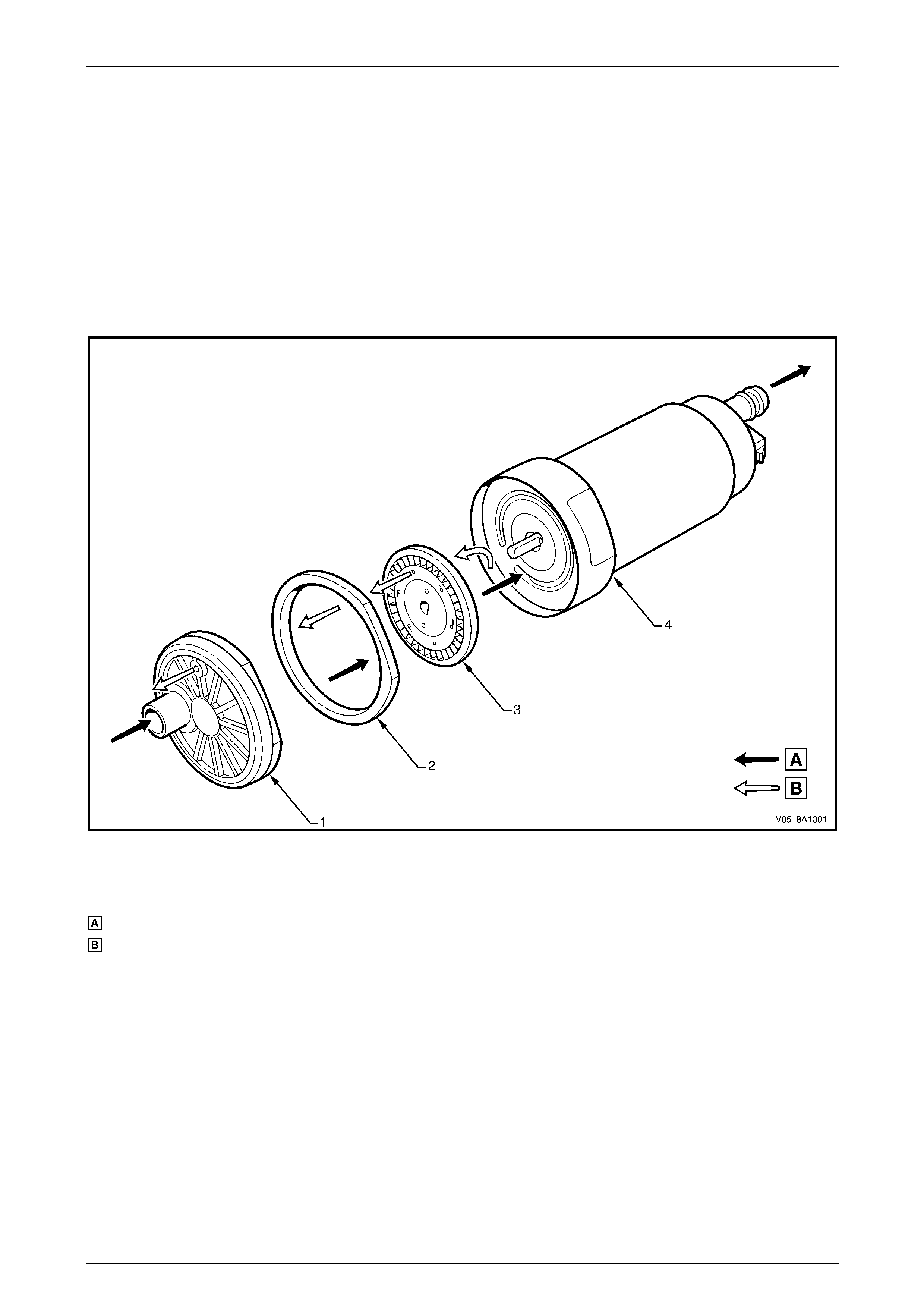
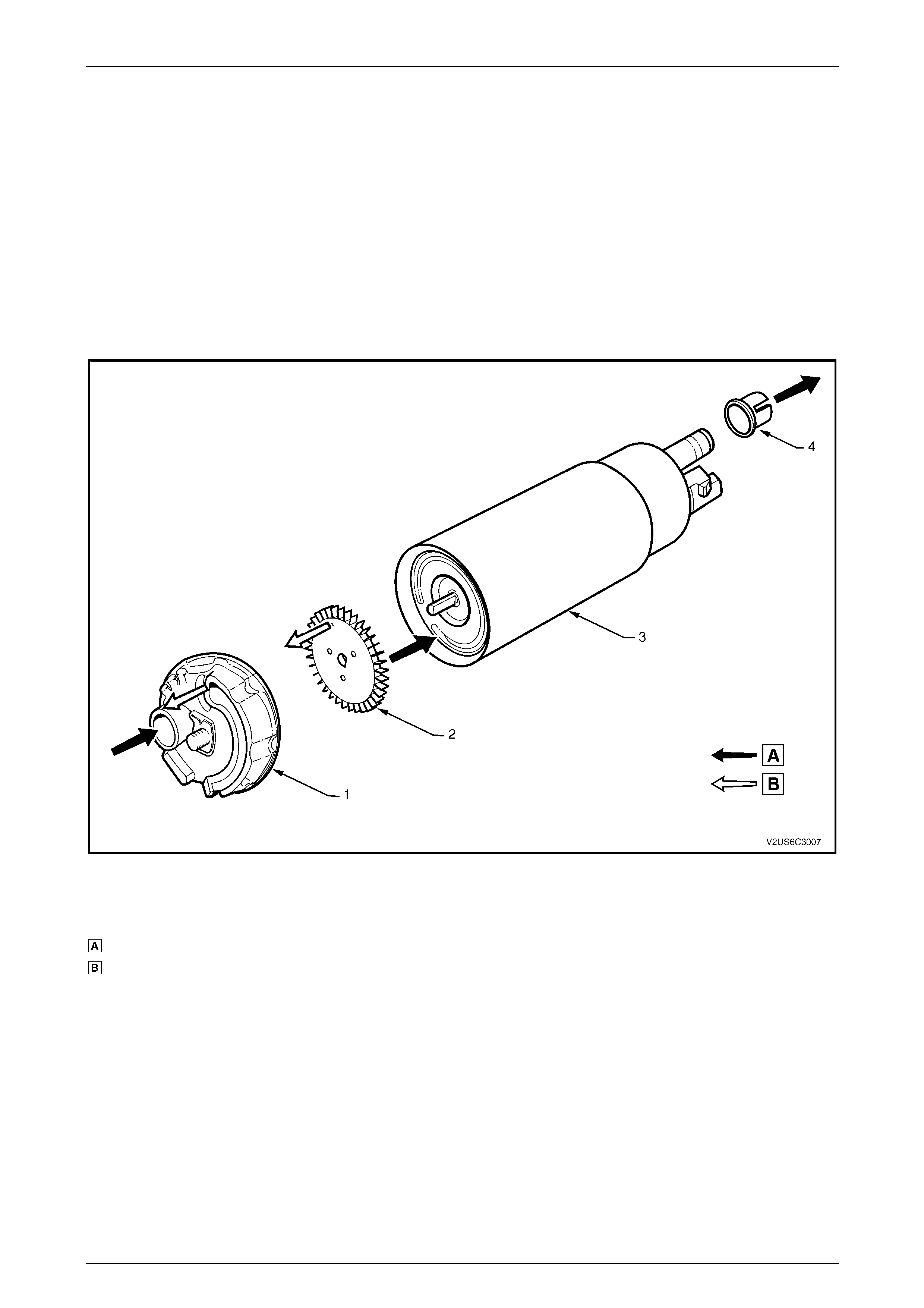
Single Turbine Fuel Pump
Figure 8A1 – 1 details fuel flow throug h the single turbine fuel pump.
Figure 8A1 – 1
Legend
Fuel
Vapour out
1 Inlet Body
2 Impeller Housing
3 Impeller
4 Fuel Pump Housing
Fuel System Page 8A1–7
Page 8A1–7
Fuel (A) is drawn into the modular fuel pump and sender
assembly reservoir from the fuel tank, through the primar y
umbrella valve (5) and into the fuel pump impeller, via the
internal strainer (4) at the fuel pump (1) inlet. At the impeller,
vapour (C) is separated from the fuel. The vapour is ejecte d
from the fuel pump into the reservoir via a po rt next to the
fuel pump inlet.
High-pressure fuel then flows through the end cap, the lower
connector and the flexible pipe. From the flexible pipe, fuel
exits the modular fuel pump and sender assembly through
the fuel feed port and flows on to the externally-mounted
fuel filter and the engine.
A fuel pressure regulator is located in th e modular fuel pump
and sender assembly; fuel no t used by the engine (B) is
returned to the modular fuel pump and sender assemb ly via
the fuel return line and the fuel return port in the modular
fuel pump and sender assembly cover. The return fuel
enters the jet pump standpipe (3) of the reservoir via the
return fuel tube.
Vehicle fuel line pressure is maintained by a pressure
regulator (2) located within the modular fuel pump and
sender assembly.
When the engine is switched off, the reservoir remains full of
fuel, due to the action of the primary umbrella valve. At high
fuel levels, fuel tank overflow enters the reservoir over the
top of the reservoir. Fuel level in the reservoir is also
maintained by returned engine fuel.
Electrical power is supplied to the fuel pump by a connector
secured to the modular fuel pump and send er assemb ly
cover. An internal harness (not shown) assembly completes
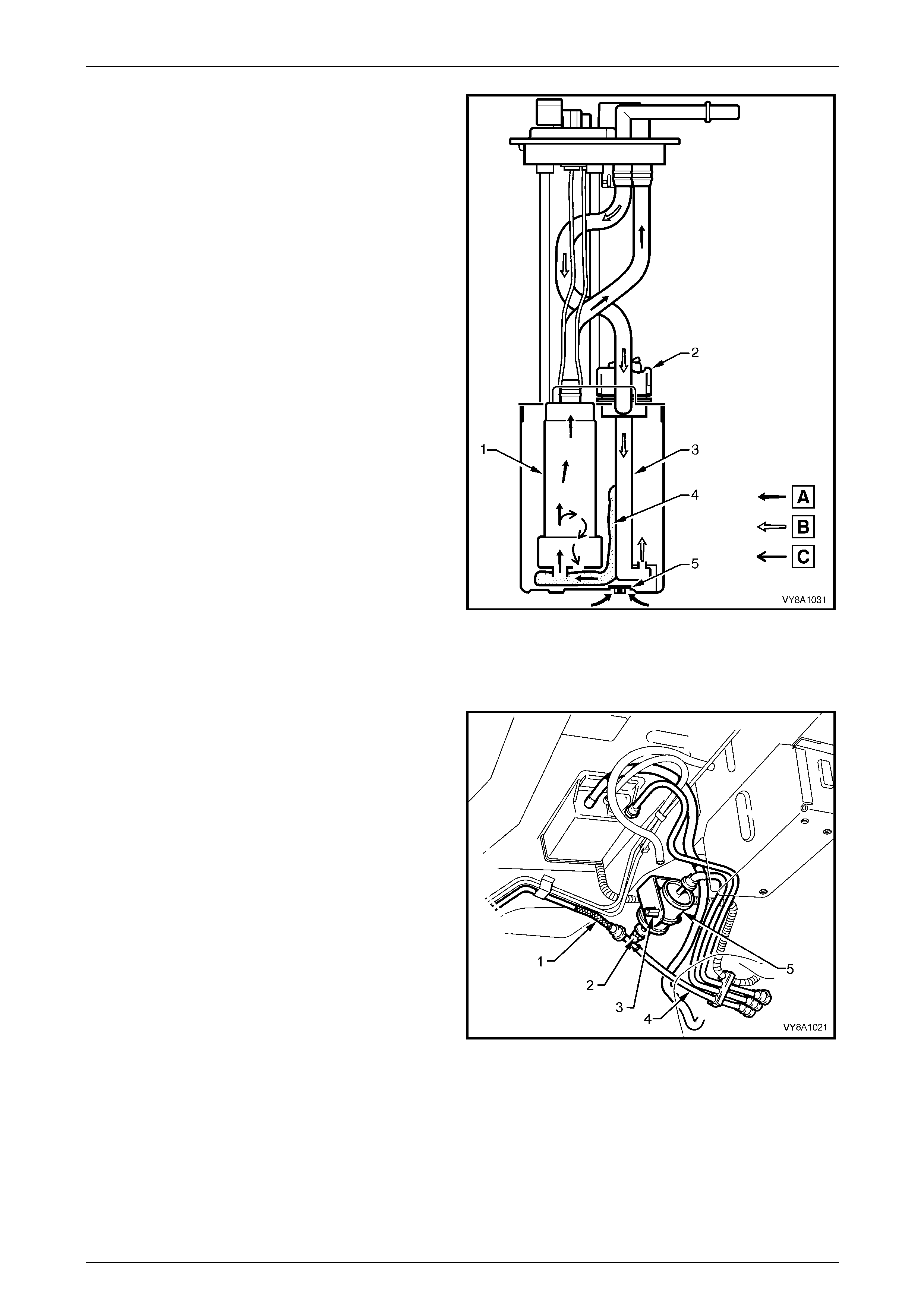
the connection to the pump. Figure 8A1 – 2
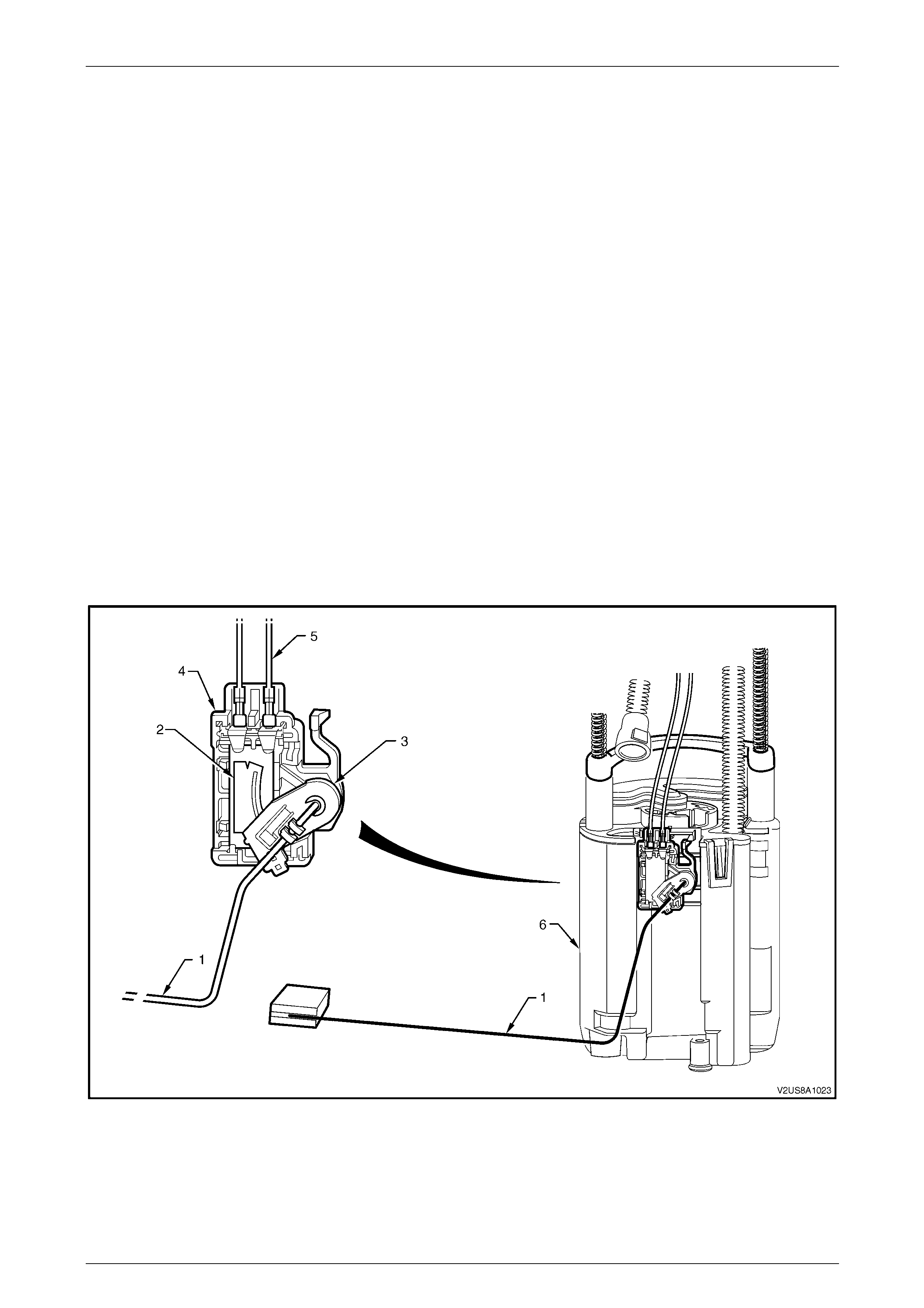
Single Line Fuel Delivery System
Fuel from the single turbine fuel pum p is forced through the
flexible pipe and exits the modular fuel pump and sender
assembly through the fuel feed port in the modu lar fuel
pump and sender assembly c over. F uel then flows through
the fuel filter (5) mounted to a bracket (3) secured to the
floor pan. From here, fuel is directed through the fuel filter
T-piece (2) and the flexible fuel feed hose (1) and on to the
engine bay and fuel rail. When fuel line pressure exceeds
410 kPa, the pressure regulator in the modul ar fuel pump
and sender assembly opens, allowing excess fuel at system
pressure to return to the fuel tank via the fuel return line (4).
This process occurs continuously while the fuel pump is
operating.
Figure 8A1 – 3
Fuel System Page 8A1–8
Page 8A1–8
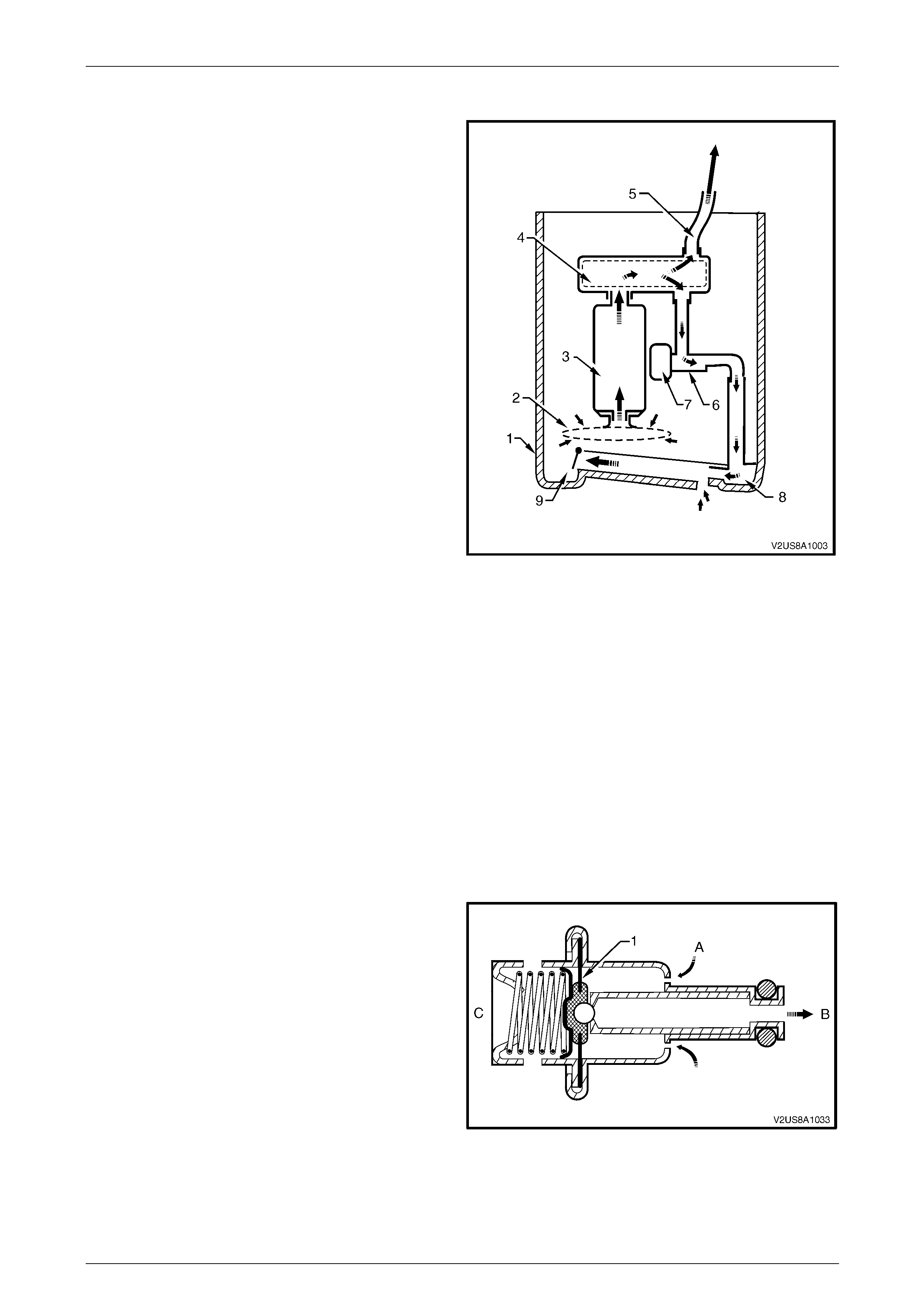
Pressure Regulator
The pressure regulator is a diaphragm-operated relief valve
located in the modular fuel pump and sender assembly. On
one side of the diaphragm, fuel is subject to fuel pump
pressure; on the other side, fuel is subject to ambient tank
pressure combined with mechanical spri ng pressure. The
pressure regulator maintains a controlled pressure at the
injectors at all times by regulating fuel flow into the fuel
return line.
Figure 8A1 – 4
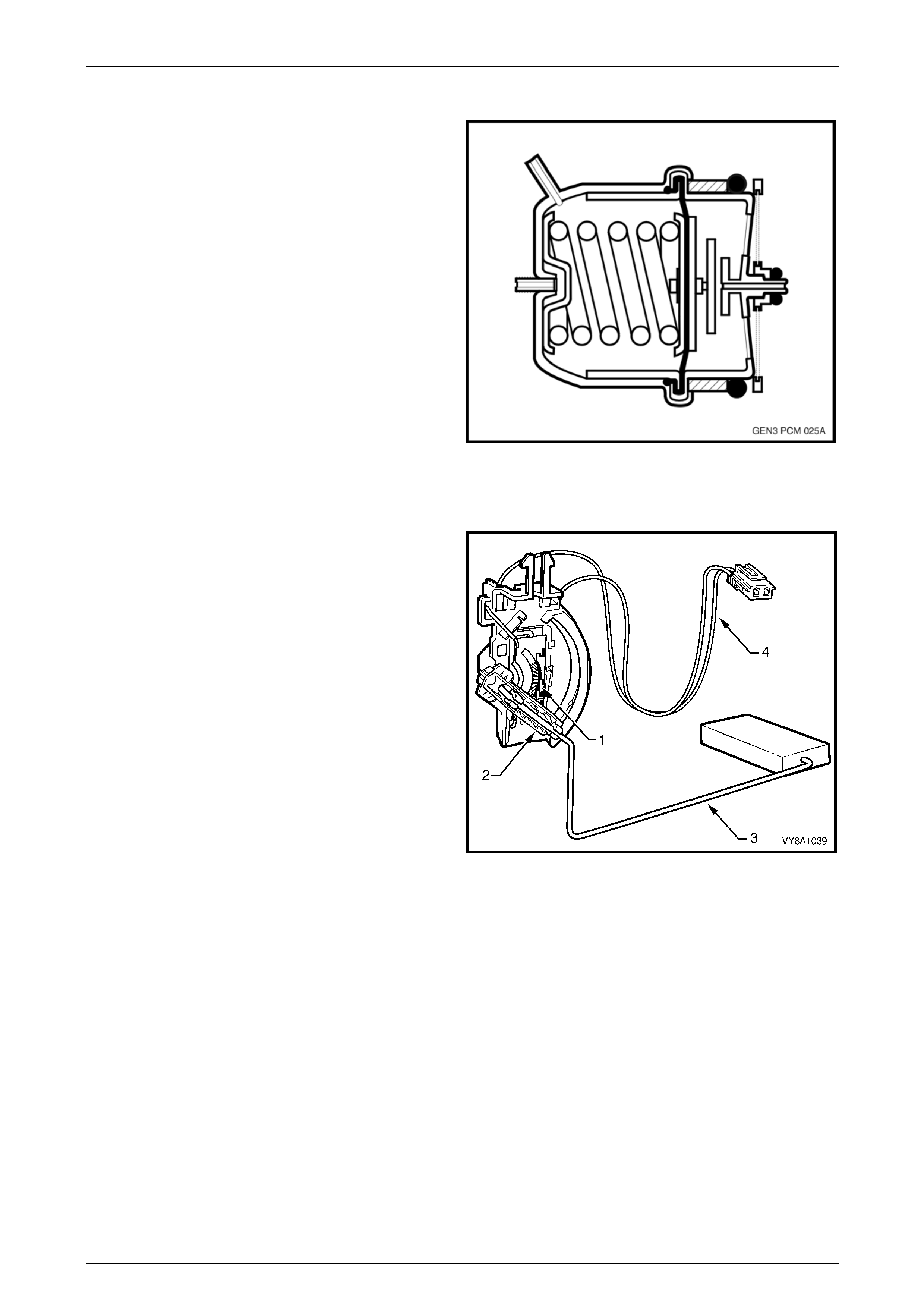
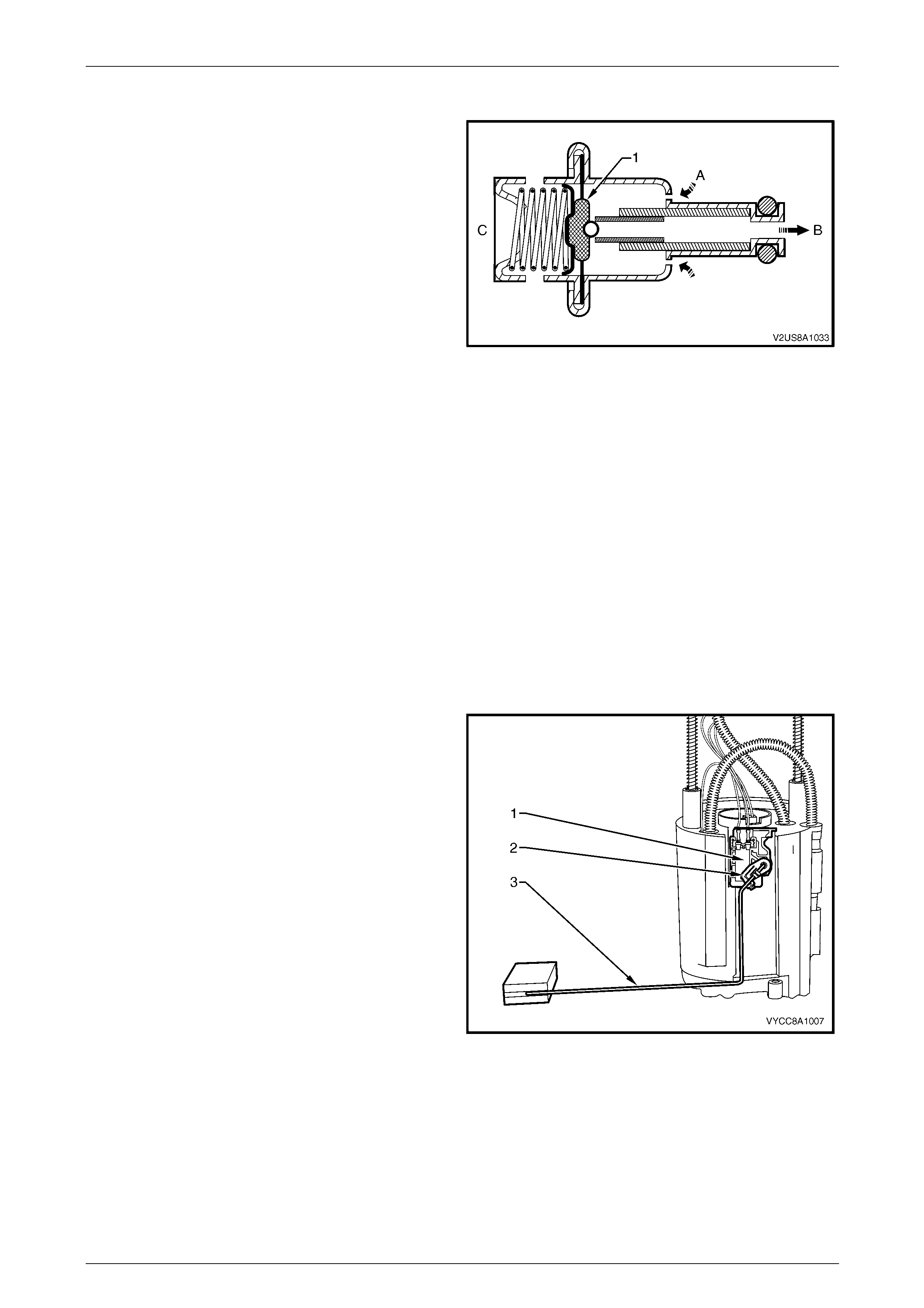
Fuel Level Sender Assembly
The fuel level sender assemb ly consists of a ceramic
variable resistor card (1), detachable nylon wiper piece (2),
fuel level sender float and arm (3), and a wiring harness (4).
These components convert the fuel lev el i n the fuel ta nk into
a variable electrical signal that provides the fuel level
information on the fuel gauge in the instrument panel.
The fuel level sender assembly mounting is part of the
modular fuel pump and sender assembly moulding. The fuel
level sender assembly is attached to the mounting and is
secured with a retainer. Two wires connect the ceramic
variable resistor card to the modular fuel pump and sender
assembly wiring harness.
The ceramic variable resistor card varies th e resistance,
dependent upon the position o f the fuel level sender float
and arm, and sends that signal via hard wire to the
instrument cluster. This resistance signal ch anges relative to
the wiper contact position on the conductive bars of the
ceramic variable resistor card.
Figure 8A1 – 5

Fuel System Page 8A1–9
Page 8A1–9
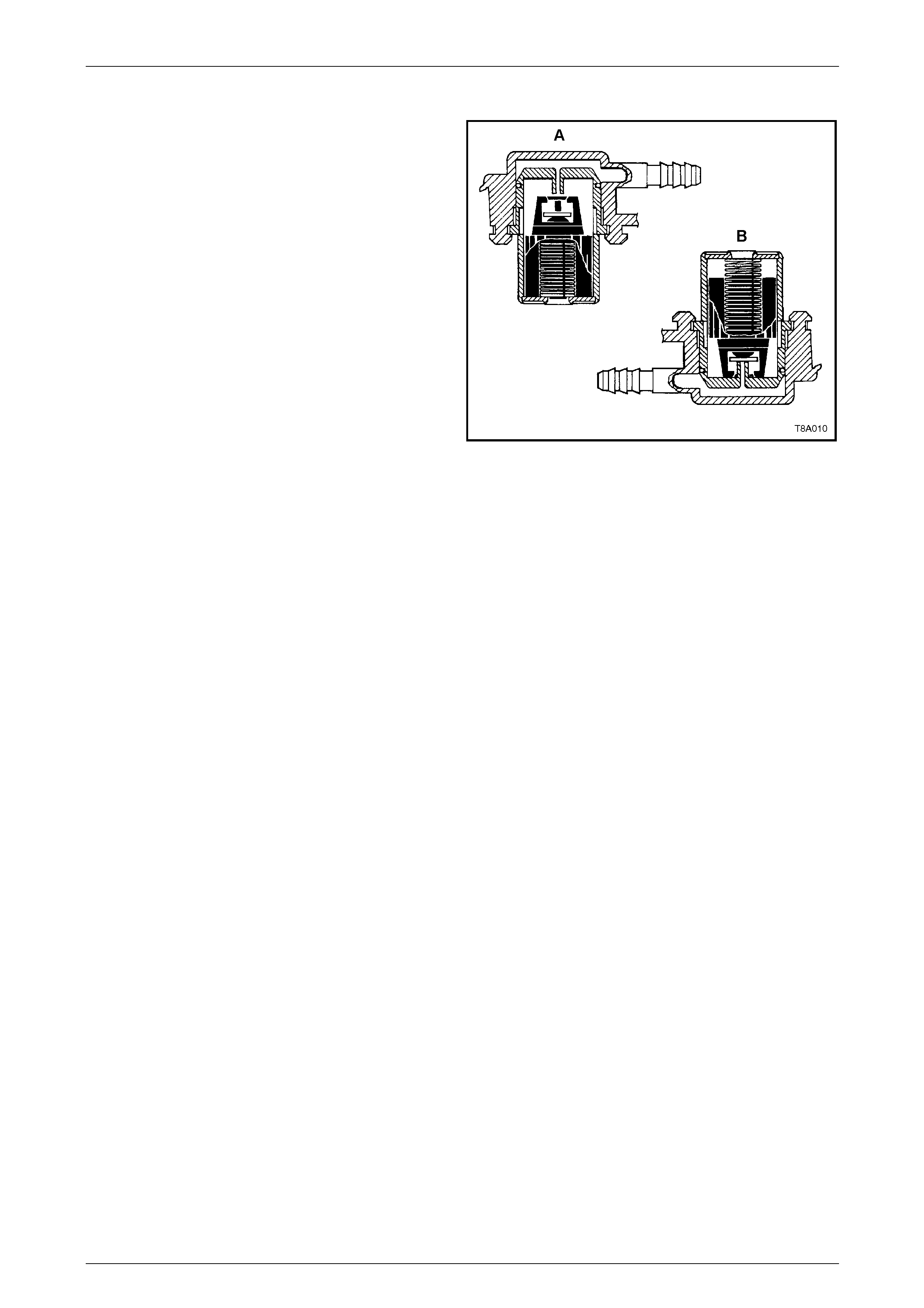
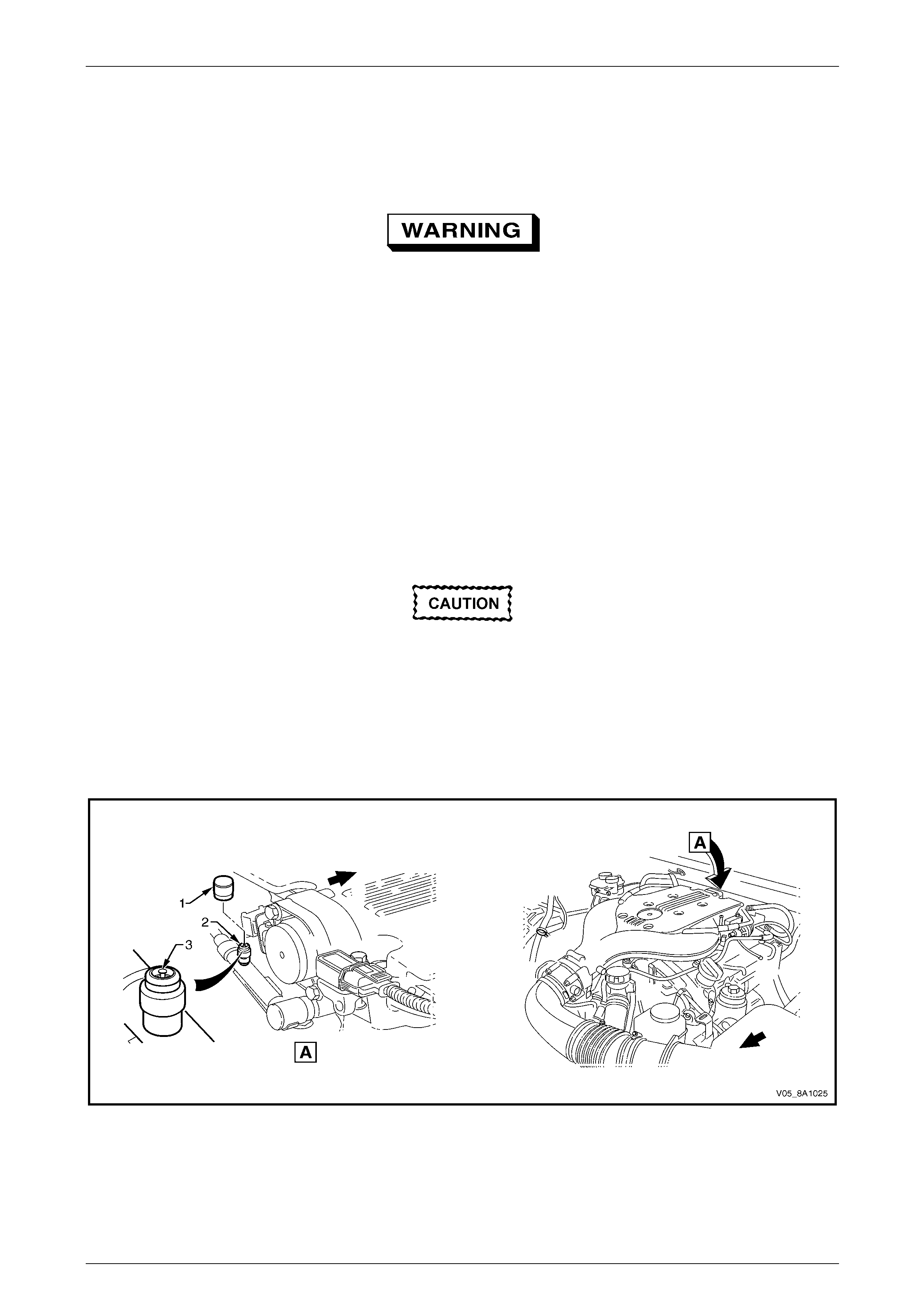
Rollover Valve
The modular fuel pump an d sender assembly fitted to the
sedan, wagon and all-wheel drive wagon models
incorporates a rollover valv e. The rollover valve limits
vapour venting to the evaporative emission control canister
using a fixed-sized orifice that is normally open (View A). If
the vehicle rolls over (Vie w B), the fuel tank vent line to the
evaporative emission control canister is safely shut off by
the rollover valve, preventing liquid fuel from flooding the
evaporative emission control canister.
NOTE
The rollover valve fitted to sedan, wagon and all-
wheel drive wagon models is not serviceable
separately. If it is faulty, the modular fuel pump
and sender assembly must be replaced.
NOTE
The rollover valve in utility models is fitted
directly onto the tank.
Figure 8A1 – 6
Fuel System Page 8A1–10
Page 8A1–10
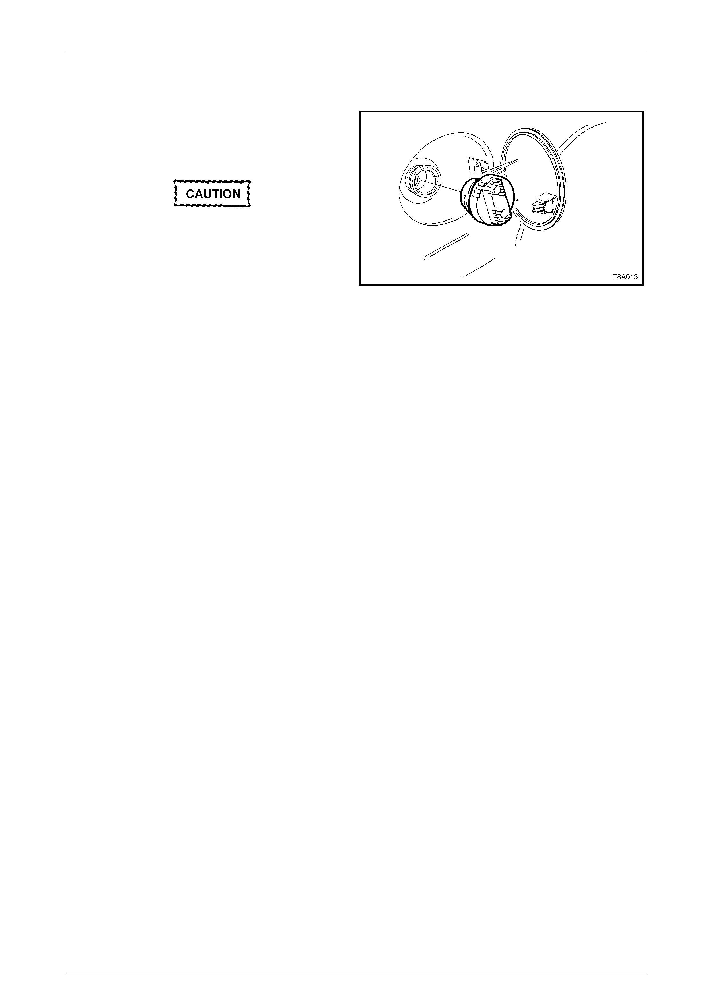
1.2 Fuel Filler Cap
The fuel filler cap is a 'screw on' type with a ratcheting
feature to prevent over-tightening. When installing the fuel
filler cap, tighten it until a ratcheting (clicking) sound is
audible, indicating it is tightened properly.
If a replacement fuel filler cap is required, use
only the correct black fuel cap. Using an
incorrect cap causes the emission control
system to malfunction.
NOTE
Vehicles using unleaded fuel have ‘UNLEADED
FUEL ONLY’ embossed into the top of the fuel
filler cap.
Figure 8A1 – 7
NOTE
Refer to Figure 8A1 – 7 the fuel filler door and
cap arrangement for the wagon; the arrangement
is similar for the sedan, all-wheel drive wagon
and utility.

Fuel System Page 8A1–11
Page 8A1–11
1.3 System Components
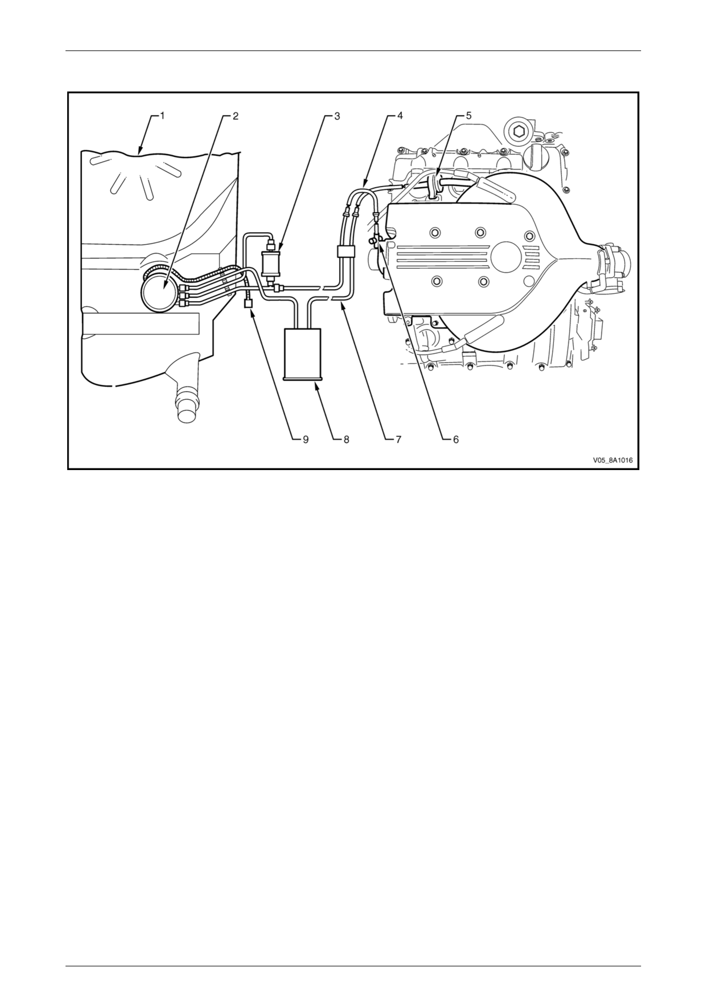
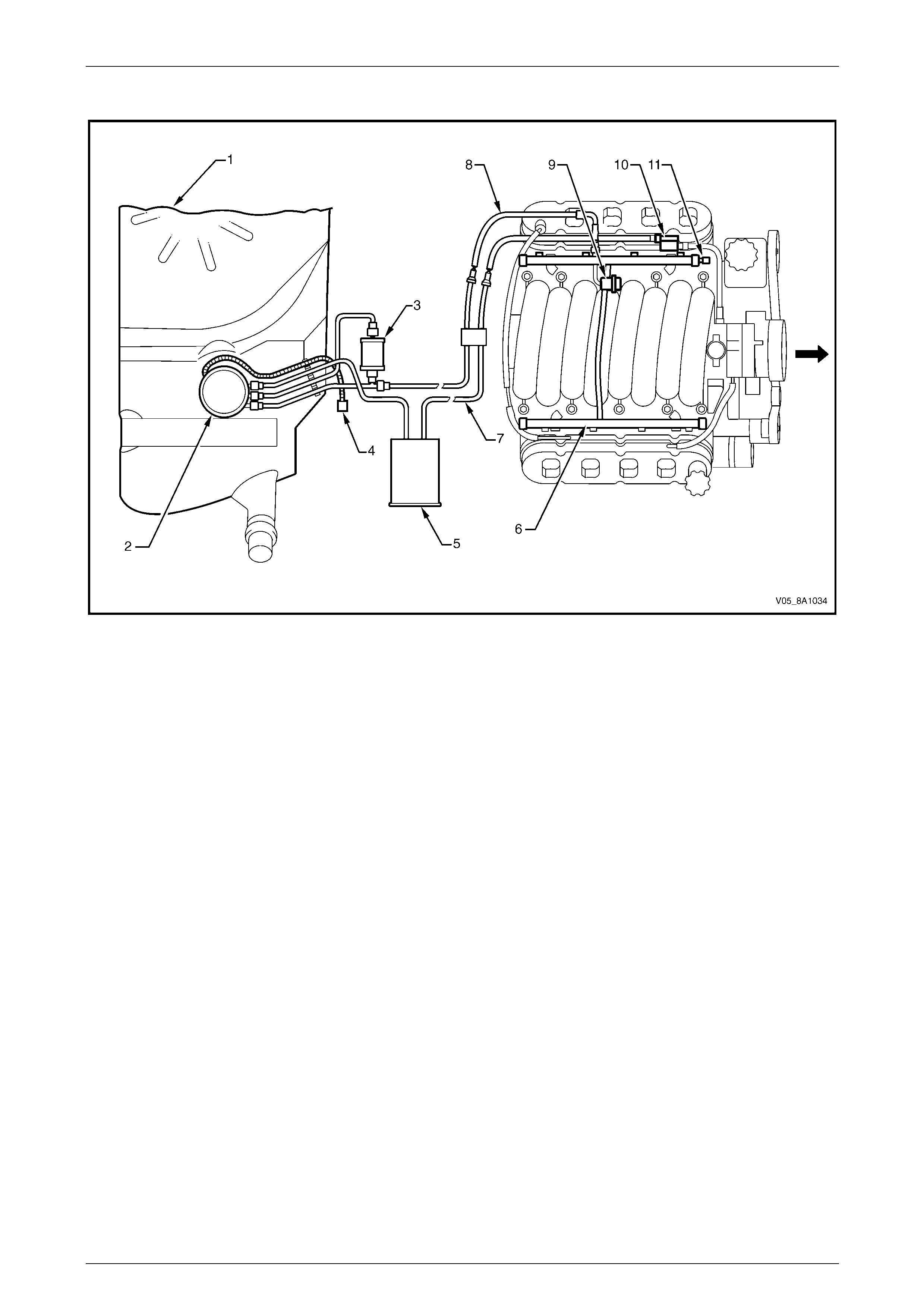
The Fuel Control System consists of the following components, refer to Figure 8A1 – 8 (for vehicles fitted with a
V6 engine) or Figure 8A1 – 9 (for vehicles fitted with a GEN III V8 engine):
• fuel tank;
• modular fuel pump and sender assembly, containing:
• pressure regulator,
• fuel pump assembly, and
• jet pump;
• fuel filter;
• fuel pump electrical connector;
• evaporative emission control canister;
• fuel rail;
• evaporative emission control canister purge line;
• evaporative emission control canister purge solenoid;
• fuel feed line;
• either:
• engine control module (ECM) on vehicles fitted with a V6 engine, or
• powertrain control module (PCM) on vehicles fitted with a GEN III V8 engine;
• fuel pump relay; and
• injectors.
Fuel System Page 8A1–12
Page 8A1–12
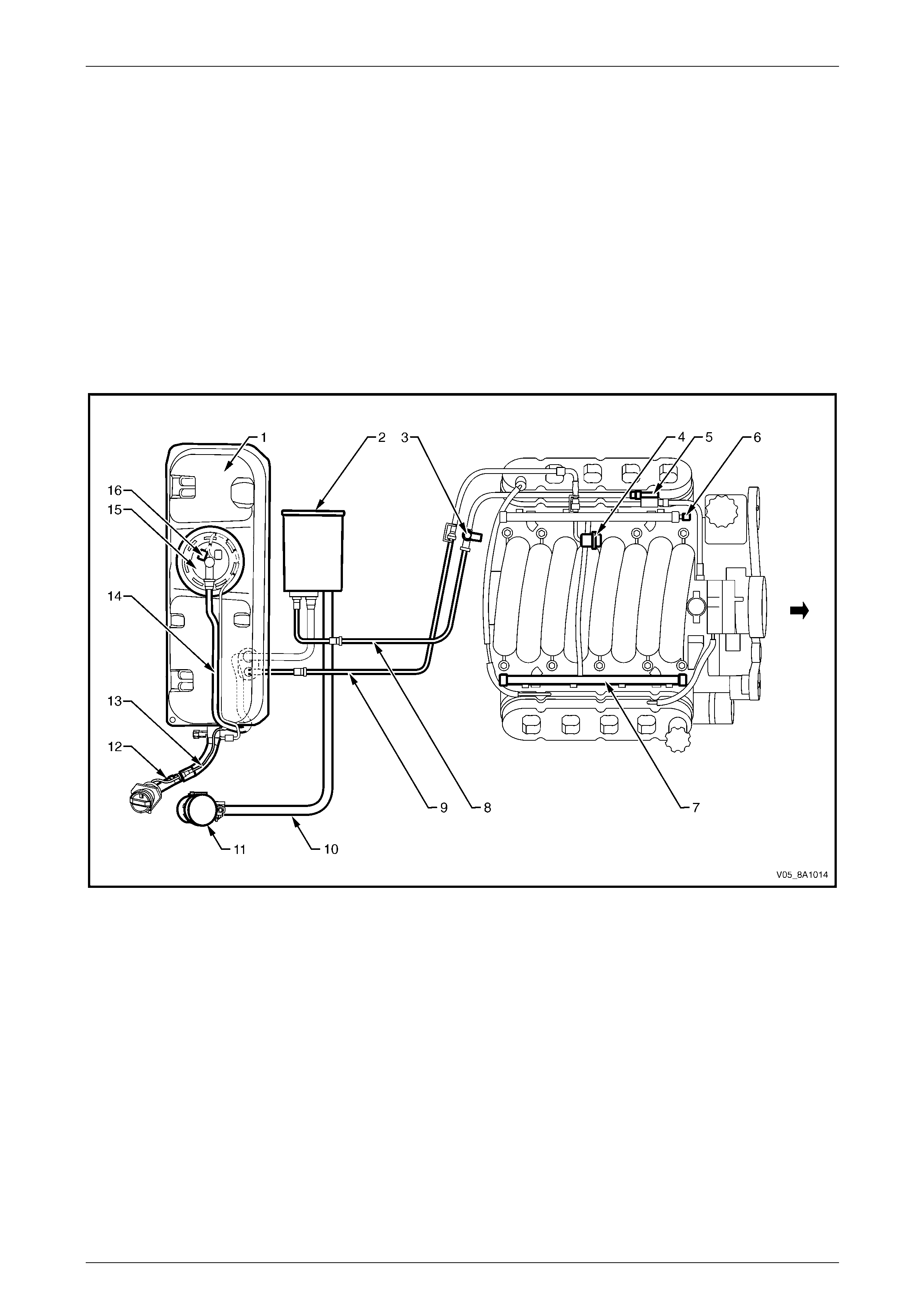
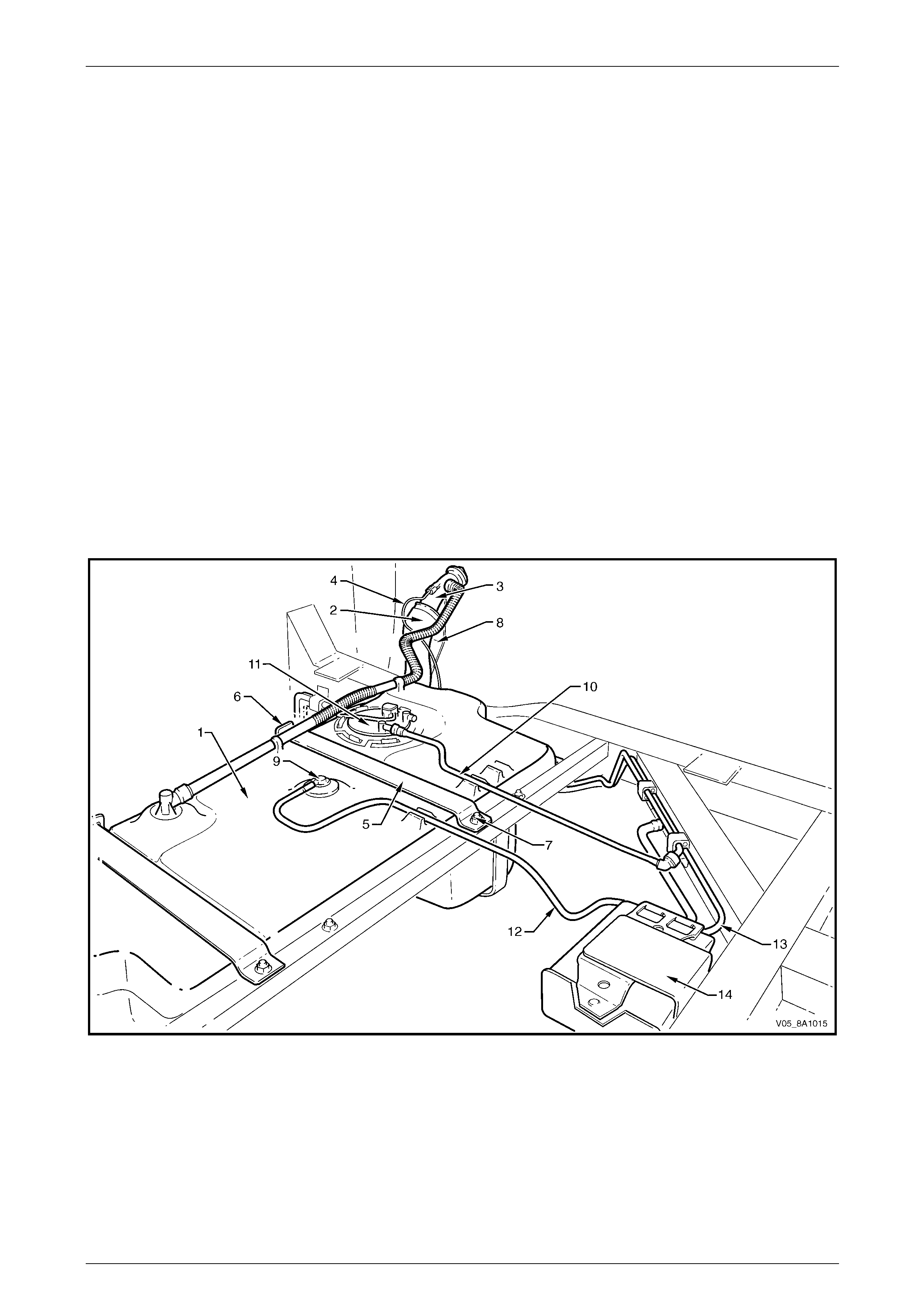
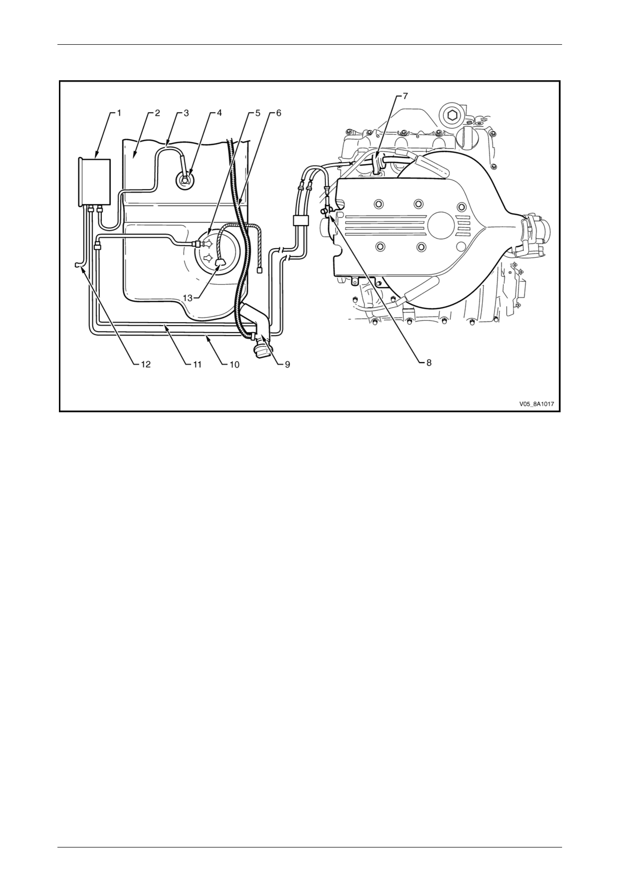
V6 Engine
Figure 8A1 – 8
Legend
1 Fuel Tank
2 Modular Fuel Pump and Sender
Assembly (including Pressure
Regulator)
3 Fuel Filter
4 Fuel Feed Line
5 Evaporative Emission Control
Canister Purge Solenoid
6 Evaporative Emission Control
Canister Purge Line Service Port
7 Fuel Vapour Line
8 Evaporative Emission Control
Canister
9 Fuel Pump Electrical Connector
Fuel System Page 8A1–13
Page 8A1–13
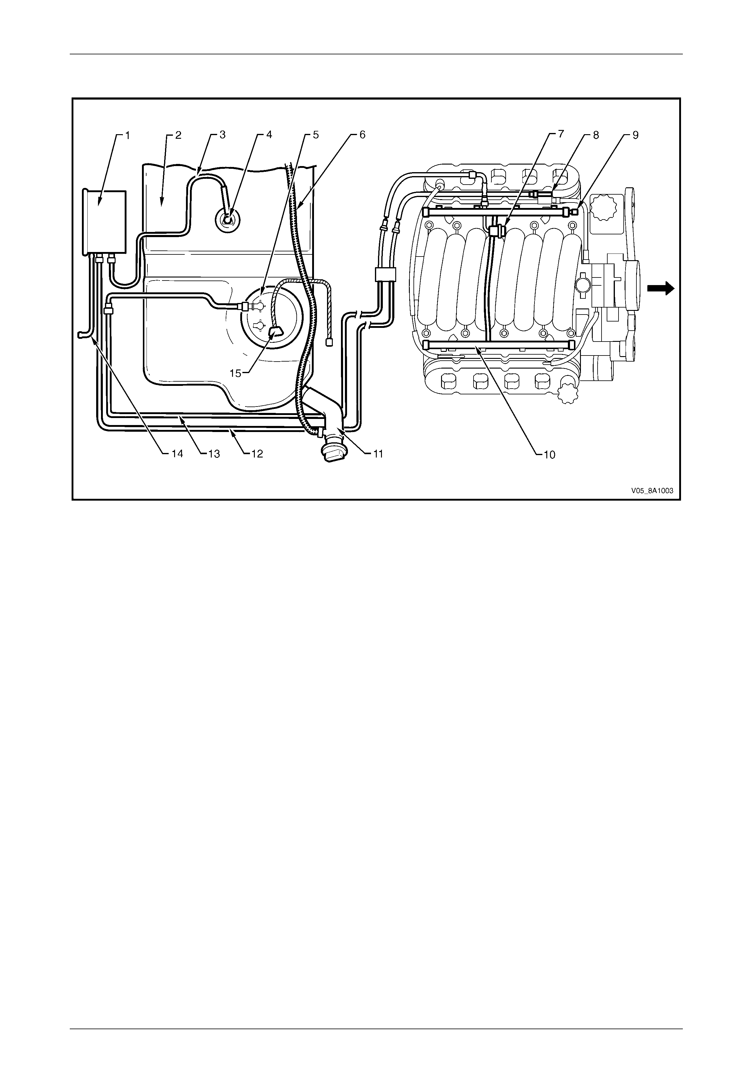
GEN III V8 Engine
Figure 8A1 – 9
Legend
1 Fuel Tank
2 Modular Fuel Pump and Sender
Assembly (including Pressure
Regulator)
3 Fuel Filter
4 Fuel Pump Electrical Connector
5 Evaporative Emission Control
Canister
6 Fuel Rail
7 Fuel Vapour Line
8 Fuel Feed Line
9 Fuel Pulse Dampener
10 Evaporative Emission Control
Canister Purge Solenoid
11 Evaporative Emission Control
Canister Purge Line Service Port
Fuel System Page 8A1–14
Page 8A1–14
2 General Information — Coupe
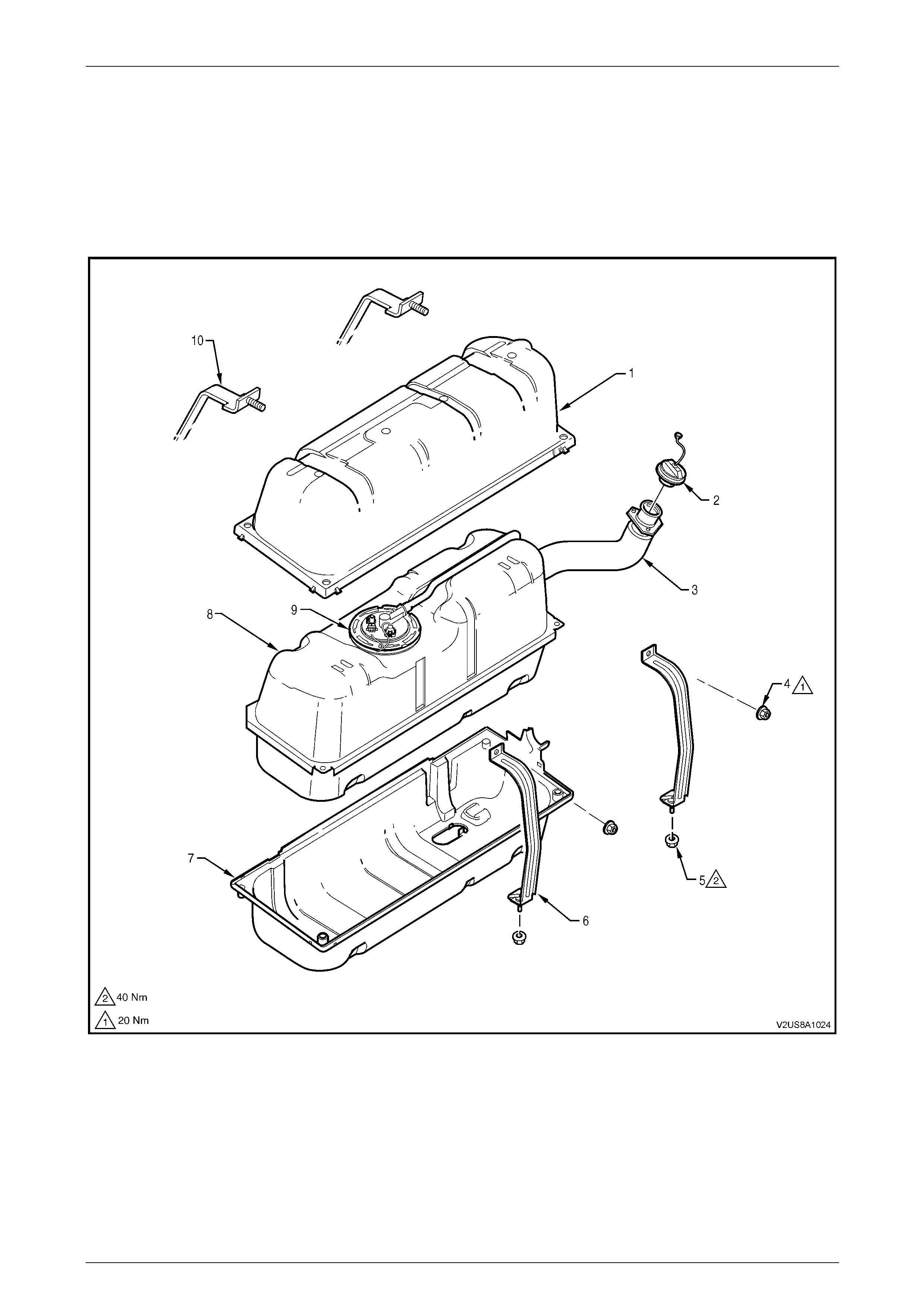
The 70-litre pressed steel fuel tank is enclosed by a two-piece high-density multi-layer polyethylene shell, refer to F igure
8A1 – 10. The fuel tank is fitted immediately beh ind the rear seat and is accessed through the rear compartment. The
fuel tank is held in place by two mounting straps. The fuel filler neck located in the rear right-hand quarter panel is
attached to the vehicle body with three fastening nuts at the fuel filler opening.
The fuel tank is not repairable and, if damaged, must be repl aced.
Figure 8A1 – 10
Legend
1 Fuel Tank Shell – Upper
2 Fuel Filler Cap
3 Fuel Filler Neck Assembly
4 Mounting Strap Nut – Upper (2 places)
5 Mounting Strap Nut – Lower (2 places)
6 Fuel Tank Mounting Strap (rear facing)
7 Fuel Tank Shell – Lower
8 Fuel Tank
9 Modular Fuel Pump and Sender Assembly
10 Fuel Tank Mounting Strap (front facing)

Fuel System Page 8A1–15
Page 8A1–15
An in-tank modular fuel pump and send er assembly is attached from the top of the fuel tank and incorporates a modular
fuel pump assembly, a suction filter and fuel filter, a reservoir, fuel level sender assembly, pressure regulator and
reservoir jet pump. A fuel fill limiter vent valve (FLVV) and fuel tank pressu re sensor is incorporated into the modular fuel
pump and sender cover asse mbly. The following items of the modular fuel pump and sender assembly are serviceable
items:
• fuel pump and strainer assembly,
• fuel filter,
• fuel level sender assembly,
• fuel pressure regulator,
• fuel fill limiter vent valve,
• fuel tank pressure sensor,
• modular fuel pump and sender assembly O-ring, and
• modular fuel pump and sender assembly shaft circlip.
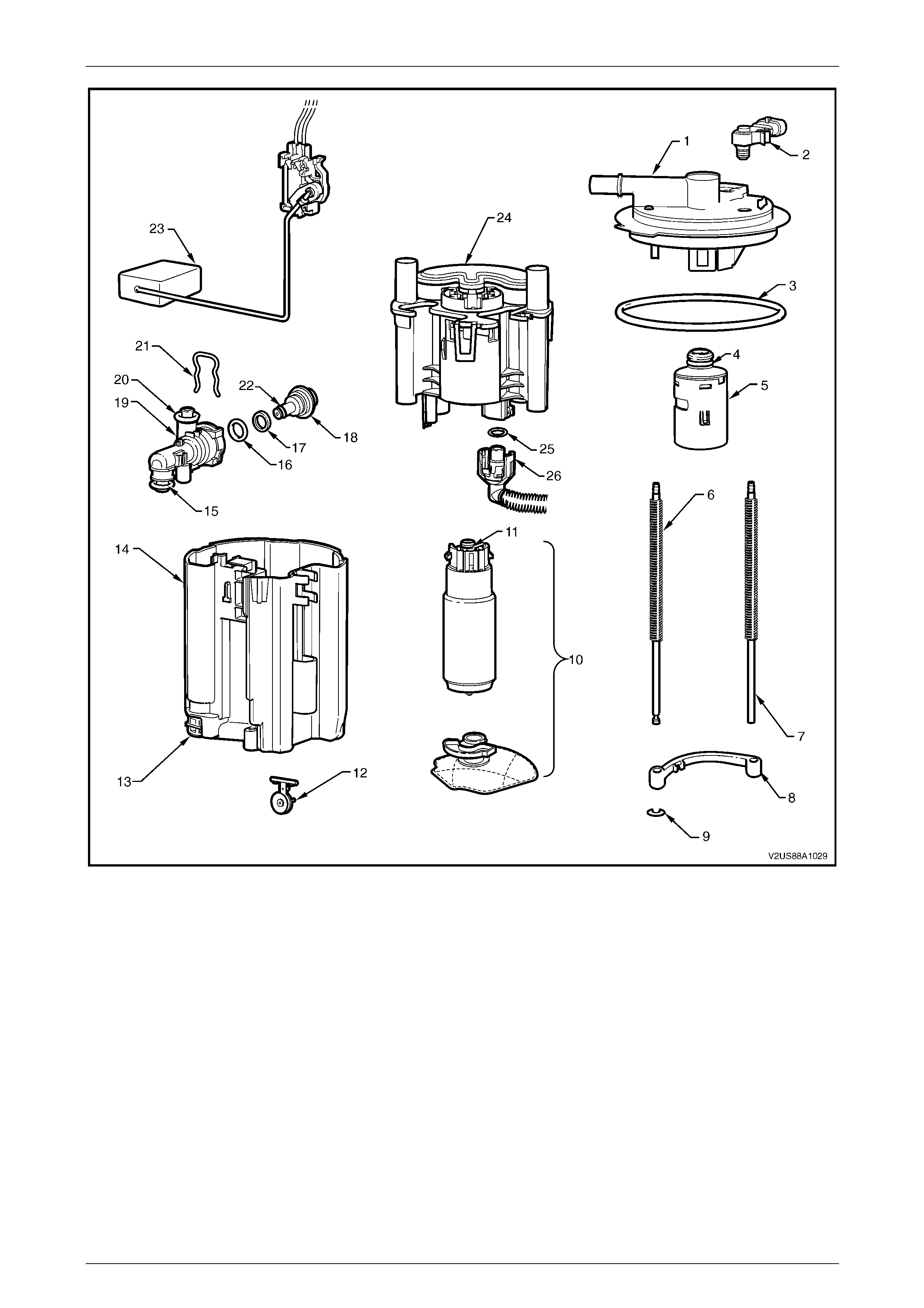
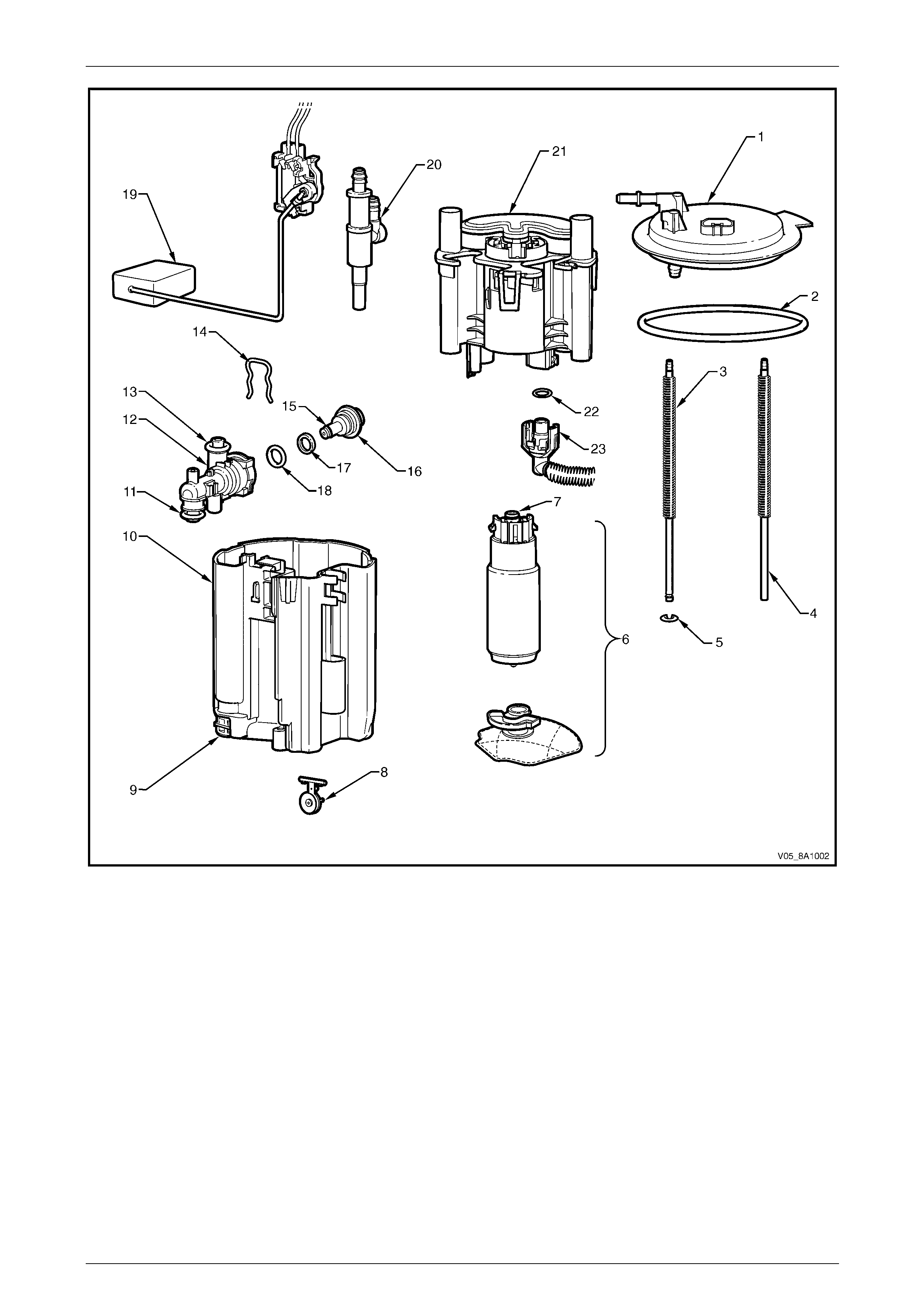
Refer to Figure 8A1 – 11 for an exploded view of the modular fuel pump and sender assembly.
For additional information regarding fuel system electrical diagnostic procedures not contained in this Section, refer to
Section 6C3-3 Powertrain Management GEN III – V8 – Service Operations. For information regarding service intervals of
fuel tank components, refer to Section 0B Lubrication and Service.
Fuel System Page 8A1–16
Page 8A1–16
Figure 8A1 – 11
Legend
1 Modular Fuel Pump and Sender
Assembly Cover
2 Fuel Tank Pressure Sensor
3 O-ring
4 O-ring
5 Fuel Fill Limiter Vent Valve
6 Spring (2 places)
7 Shaft (2 places)
8 Wiring Ground Bridge
9 Circlip
10 Fuel Pump and Suction Filter
Assembly
11 O-ring
12 Flapper Valve
13 Reservoir Jet Pump
14 Reservoir
15 O-ring
16 O-ring
17 Nylon Spacer
18 Pressure Regulator
19 Pressure Regulator Holder
20 O-ring
21 Retaining Clip
22 O-ring
23 Fuel Level Sender Assembly
24 Fuel Filter Assembly
25 O-ring
26 Fuel Outlet Connector
Fuel System Page 8A1–17
Page 8A1–17
2.1 Modular Fuel Pump and Sender
Assembly
The modular fuel pump an d sender assembly maintains an optimum fuel level in the reservoir. This ensures a continuous
fuel flow under all fuel level conditions a nd vehicle attitudes. The modular fuel pum p and sender assembly also provides
an accurate means of measuring the fuel level within the fuel tank.
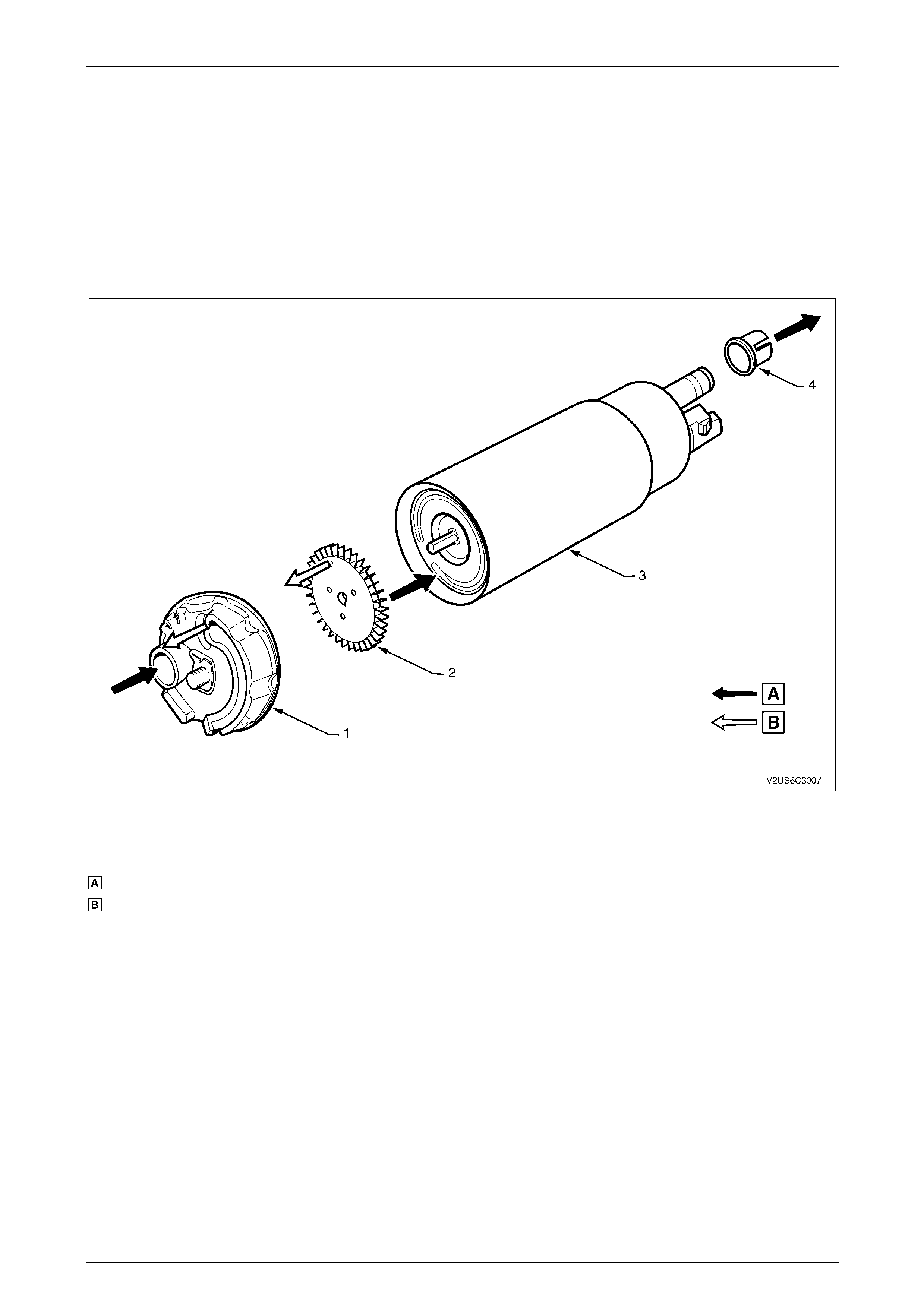
Single Turbine Fuel Pump
The fuel pump is incorporated into the modular fuel sender assembly and is an electric, hi gh-pressure, single-turbine
design, refer to Figure 8A1 – 12. T he fuel pump provides fuel to the fuel rail assembly at a specified flow and pressure.
The fuel pump delivers a constant flow of fuel to the engine, even during low fuel conditions or aggressive vehicle
manoeuvres. The powertrain control module (PCM) controls the electric fuel pump operation throug h the fuel pump relay.
Figure 8A1 – 12
Legend
Fuel
Vapour Out
1 Fuel Pump End Cap
2 Impeller
3 Fuel Pump Body
4 Fuel Pump Outlet O-ring Collar
Fuel System Page 8A1–18
Page 8A1–18
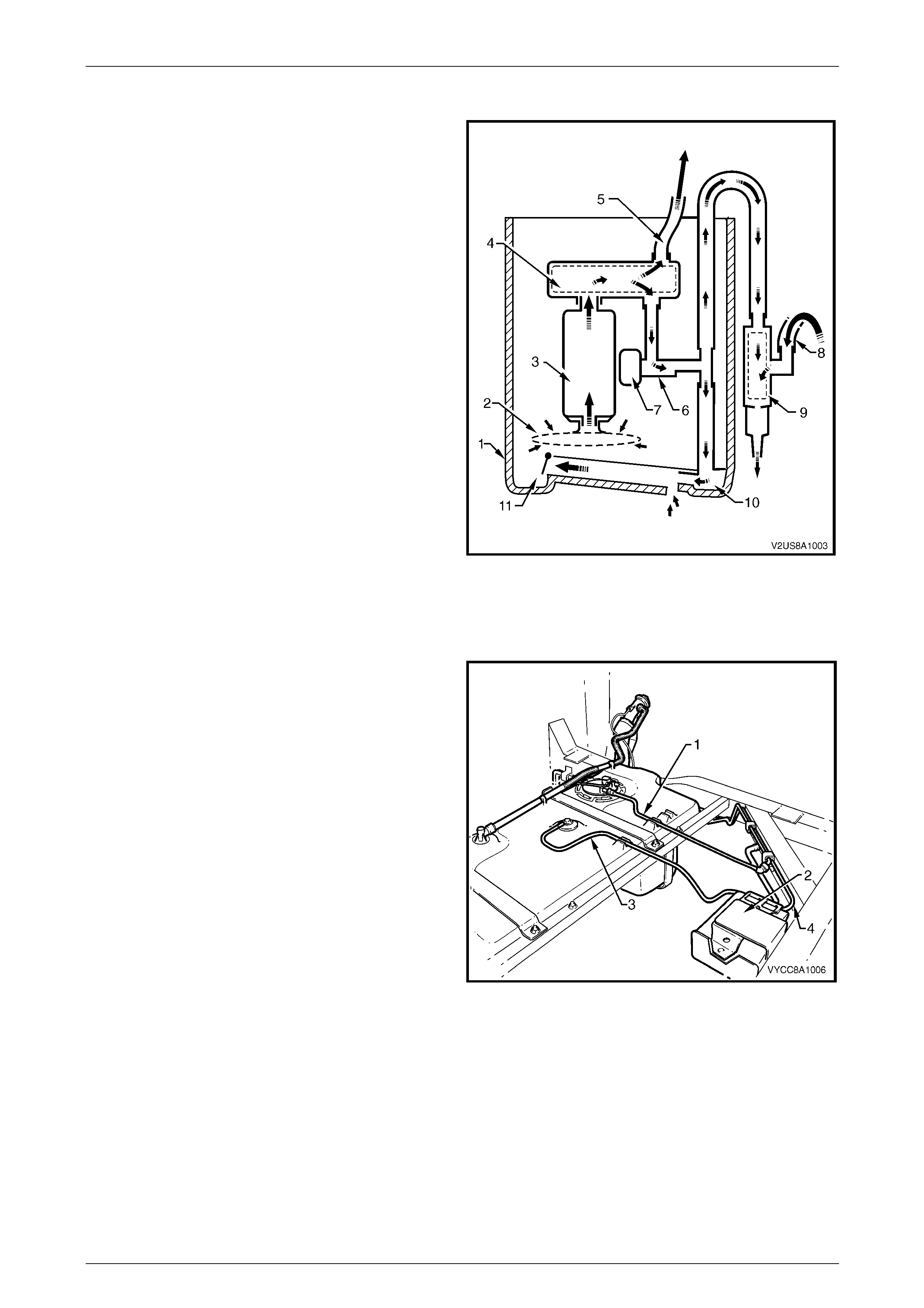
Functional Description of Modular Fuel Pump and Sender Assembly
Fuel is pumped from the fuel tank to the engine vi a an
internal pump in the modular fuel pump and sender
assembly.
Fuel in the reservoir (1) is drawn throu gh the suction
filter (2) and fuel pump (3), driven by a constant-speed
motor. Fuel flows under pressure through the fuel filter
assembly (4) and flexible pipe (5), exits the modular fuel
pump and sender assembly through the fuel feed port on
the modular fuel pump and send er assembly cover, then
through fuel lines into the engine.
When the engine is operating, fuel flows through the
pressure regulator holder (6); if fuel pressure increases, the
pressure regulator (7) bleeds fuel back into the reservoir.
Fuel from the pressure regulator holder flows through the
reservoir jet pump (8) and flapper valve (9) into the
reservoir. This flow ensures the reservoir is alwa ys full of
fuel; the flapper valve prevents fuel from exiting the
reservoir when the engine is turned off.
At high fuel levels, the modular fuel pump and sender
assembly is immersed in fuel. At low fuel levels, the fuel
level is to the top of the reservoir.
Electrical power is supplied to the fuel pump by an integral
connector on the modular fue l pump and sender assembly
cover. An internal harness assembly completes the
connection to the pump. Figure 8A1 – 13
Fuel Limiter Vent Valve
A fuel limiter vent valve is incorporated into the modular fuel pump and sender cover assembly. The fuel limiter vent
valve controls the fuel tank fill level b y closing the primar y vent from the fuel tank and prevents fuel from exiting the fuel
tank via the pipe to the evaporative emiss ion control canister. The fuel limiter vent valve also provides fuel spillage
protection if the vehicle rolls over by closing the vapour path from the fuel tank to the evaporative emission control
canister.
Fuel Tank Pressure Sensor
A fuel tank pressure sensor is mounted on th e modular fuel tank and sender assembly cover. When the powertrain
control module (PCM) commands a vacuum into the fuel system to check for leaks, the fuel tank pressure sensor
induces a potential voltage that fluctuates according to the pressure change in the fuel tank. The change in voltage is
monitored by the PCM via a circuit carried through the body wiring harness and fuel tank wiring har ness.
Pressure Regulator
The pressure regulator is a diaphragm-operated relief valve
located in the modular fuel pump and sender assembly. The
pressure regulator maintains a controlled pressure at the
injectors at all times by regulating fuel flo w into the fuel feed
line.
Fuel flows from the fuel pump, through the fuel filter
assembly and exits into the fuel feed line or pressure
regulator entry port (A). When pressure builds in the fuel
feed line, the diaphragm and valve (1) is progressively
pushed out, allowing fuel to exit through the port (B). The
valve is normally closed by mechanical spring pressure (C).
Fuel exiting the pressure regulator is directed into the
reservoir jet pump to provide continuous fuel circulation.
Figure 8A1 – 14
Fuel System Page 8A1–19
Page 8A1–19
Suction Filter
The suction filter connects onto the fuel pump inlet port on the end cap of the fuel pump assembly and consists of a
finely-woven plastic filter. The suction filter is fastened to the fuel pump end cap with a metal speed clip fastener.
The suction filter strains contaminants from the reservoir and also acts to 'wick' the fuel. The suction filter is serviced as
part of the fuel pump and filter assembly. Fuel block age at the suction filter indicates an abnormal amount of sediment in
the fuel tank that should be removed before reinsta lling the fuel tank into the vehicle, refer to 6.3 Fuel Tank.
Fuel Filter Assembly
The fuel filter assembly is contained within the modular fuel pump and sender assembly reservo ir and forms the housing
for the fuel pump. The fuel filter consists of a paper element that traps particles in the fuel that may damage the fuel
injection system. The fuel filter withstands maximum fuel system pressure, changes in temperature and exposure to fuel
additives.
Fuel Level Sender Assembly
The fuel level sender assemb ly consists of a fuel level sender float and arm (1), a ceramic variable resistor card (2) and a
detachable nylon wiper piece (3), refer to Figure 8A1 – 15. The ceramic variable resistor card is attached to a plastic card
holder (4) that attaches to the reservoir (6). These components convert the fuel lev el in the fuel tank into a variable
electrical signal that provides the fuel leve l information on the fuel gauge in the instrument panel. T his resistance signal
changes relative to the wiper contact position on the conductive bars of the ceramic variable resistor card.
The fuel level sender assembly mounting is part of the reservoir moulding. Two wires (5) connect the ceramic variable
resistor card to the modular fuel pump an d sender assembly wiring harness.
The ceramic variable resistor card varies the resistance (dependent upon the position of the fuel level sender float and
arm) and sends that signal via hard wire to the powertrain control modul e. The powertrain control module averages out
any slosh variation in the fuel tank and sends this signal to the fuel level indicator on the fuel gauge in the instrument
panel.
Figure 8A1 – 15
Legend
1 Fuel Level Sender Float and Arm
2 Ceramic Variable Resistor Card
3 Nylon Wiper
4 Card Holder
5 Circuit Wires
6 Reservoir
Fuel System Page 8A1–20
Page 8A1–20
2.2 System Components
Refer to Figure 8A1 – 16 for general components of the fuel control systems. A 2.1 litre three-port evaporative emission
control canister is mounted on a bracket un derneath the vehicle. The evaporative emission control canister can not be
repaired and is serviced onl y as a complete assembly. The evaporative emission control canister stores fuel vapour from
the fuel tank via the fuel tank vent line and releases it to the engine via the evaporative emission control canister pur ge
line. An evaporative emiss ion control canister purge line service port is attached alo ng the fuel vapour canister purge
line in the engine bay. An evaporative emission control canister purge so lenoid is installed downstream of the service
port and controls the flow of fuel vapour released into the intake manifold. A fuel tank vent line is routed from the
evaporative emission control canister to an evaporative emission control canister purge solenoid that controls fresh
air flow into the evaporative emission c ontrol canister. The evaporative emission control canister purge solenoid is
mounted to the inside of the rear right-hand side quarter panel and is accessible from underneath the vehicle, refer to
Section 6C3-3 Powertrain Management GEN III – V8 – Service Operations for detailed information on these systems.
Various styles of quick-connect fittings are used at most fuel line connections, including the modular fuel pump and
sender assembly, evaporative emission control canister, and fuel filter and fuel feed line at both the fuel tank and engine
ends.
Figure 8A1 – 16
Legend
1 Fuel Tank
2 Evaporative Emission Control Canister
3 Service Port
4 Fuel Pulse Dampener
5 Evaporative Emission Control Canister Purge Solenoid
6 Fuel Pressure Check Schrader Valve
7 Fuel Rail
8 Evaporative Emission Control Canister Purge Line
9 Fuel Feed Line
10 Evaporative Emission Control Canister Vent Line
11 Evaporative Emission Control Canister Vent Solenoid
12 Fuel Filler Neck
13 Fuel Filler Neck Vapour Recirculation Line
14 Fuel Tank Vent Line
15 Modular Fuel Pump and Sender Assembly
16 Modular Fuel Pump and Sender Assembly Harness
Connector
Fuel System Page 8A1–21
Page 8A1–21
3 General Information — Regular
Cab and Crew Cab
The 68.5-litre fuel tank (1) is a 'W'- type high-density multi-layer polyethylene construction with a separate fuel filler neck,
refer to Figure 8A1 – 17. The fuel filler neck consists of a flexible rubber centre section (2) with hose clamps either end
and a steel upper pipe (3) that incorporates the filler neck vent fitting and counter-siph on mechanism, and an earthing
wire (4). The fuel tank is fitted on a removable frame underneath the load floor front panel assembly. The fuel tank is
retained by two steel mounting straps (5) that fit into keyed steel risers (6) welded to the forward chassis crossmember.
Both steel mounting straps are anchored with a nut and spring washer to studs (7) welded to the rear chassis
crossmember.
The fuel filler neck is fixed to a support bracket (8) bolted to the chassis on Regular Cab vehicles (and on Crew Cab
vehicles with the 'delete tub' option). T he fuel tank is not repairable and, if damaged, must be replaced. A rollover
valve (9) is fitted directly into the top of the fuel tank, but is not serviceable.
Refer to 7.3 Fuel Tank Support Straps for information on the removable frame underneath the fuel tank.
Quick-connect fittings are used on the fuel feed line (10) at both the modular fuel pump and sender assembly (11) and
engine ends. Quick-connect fittings are also used on the fuel tank vent line (12) and the evaporative emission control
canister purge line (13) at the evaporative emission control canister (14).
The in-tank, modular fuel pump and sender assembly, refer to Figure 8A1 – 18, includes a fuel pump and suction filter
assembly (6), pressure regulator (12), reservoir (9), fuel level sender ass embly (19), reservoir jet pump (9) and cover (1).
Servicing details for these and other fuel tank and fuel l ine related items are covered in this Section.
Both the fuel pump and suction filter assembly, and the fuel level sender assembly are serviceable items. For service
intervals of these items, refer to Section 0B Lubrication and Service.
Figure 8A1 – 17
Legend
1 Fuel Tank
2 Fuel Filler Neck Flexible
Rubber Centre Section
3 Fuel Filler Neck Steel Upper
Pipe
4 Earthing Wire
5 Fuel Tank Mounting Strap
(2 places)
6 Fuel Tank Mounting Strap Front
Anchoring Point
7 Stud (2 places)
8 Fuel Inlet Support Bracket
9 Rollover Valve
10 Fuel Feed Line
11 Modular Fuel Pump and
Sender Assembly
12 Fuel Tank Vent Line
13 Evaporative Emission Control Canister
Purge Line
14 Evaporative Emission Control Canister
Fuel System Page 8A1–22
Page 8A1–22
Figure 8A1 – 18
Legend
1 Modular Fuel Pump and Sender
Assembly Cover
2 O-ring
3 Spring (2 places)
4 Shaft (2 places)
5 Circlip
6 Fuel Pump and Suction Filter
Assembly
7 O-ring
8 Flapper Valve
9 Reservoir Jet Pump
10 Reservoir
11 O-ring
12 Pressure Regulator Holder
13 O-ring
14 Retaining Clip
15 O-ring
16 Pressure Regulator
17 Nylon Spacer
18 O-ring
19 Fuel Level Sender Assembly
20 Transfer Jet Pump
21 Fuel Filter Assembly
22 O-ring
23 Fuel Outlet Connector
For additional information regardi ng the pressure regulator and fuel system electrical diagnostic procedures not
contained in this Section, refer to:
• Section 6C1-1 Engine Management – V6 – General Information, or
• Section 6C3-1 Powertrain Management GEN III – V8 – General Information.
Fuel System Page 8A1–23
Page 8A1–23
3.1 Modular Fuel Pump and Sender
Assembly
The modular fuel pump an d sender assembly maintains an optimum fuel level in the reservoir. This ensures a continuous
fuel flow under all fuel level conditions a nd vehicle attitudes. The modular fuel pum p and sender assembly also provides
an accurate means of measuring the fuel level within the fuel tank.
Single Turbine Fuel Pump
Refer to Figure 8A1 – 19 for an illustration showing fuel flow through the single turbine fuel pump.
Figure 8A1 – 19
Legend
Fuel
Vapour Out
1 Fuel Pump End Cap
2 Impeller
3 Fuel Pump Body
4 Fuel Pump Outlet O-ring Collar
Fuel System Page 8A1–24
Page 8A1–24
Functional Description of Modular Fuel Pump and Sender Assembly
Fuel is pumped from the fuel tank to the engine vi a an
internal pump in the modular fuel pump and sender
assembly.
Fuel in the reservoir (1) is drawn throu gh the suction
filter (2) and fuel pump (3), driven by a constant-speed
motor. Fuel flows under pressure through the fuel filter
assembly (4) and flexible pipe (5), exits the modular fuel
pump and sender assembly through the fuel feed port on
the modular fuel pump and send er assembly cover, then
through fuel lines into the engine.
When the engine is operating, fuel flows through the
pressure regulator holder (6); if fuel pressure increases, the
pressure regulator (7) limits the fuel flow. Fuel is drawn from
the other side of the fuel tank baffle via the low fuel level fuel
feed pipe (8), then through the transfer jet pump (9). Fuel
from the pressure regulator holder also flows through the
reservoir jet pump (10) and flapper valve (11) into the
reservoir. This flow ensures the reservoir is alwa ys full of
fuel; the flapper valve prevents fuel from exiting the
reservoir when the engine is turned off.
At high fuel levels, the modular fuel pump and sender
assembly is immersed in fuel. At low fuel levels, the fuel
level is to the top of the reservoir.
Electrical power is supplied to the fuel pump by an integral
connector on the modular fue l pump and sender assembly
cover. An internal harness assembly completes the
connection to the pump. Figure 8A1 – 20
Single Line Fuel Delivery System
Fuel is directed from the modular fuel pump and sender
assembly, then through the flexible fuel feed line (1) and on
to the engine bay and fuel rail.
When fuel feed line pressure exceeds 400 kPa (+/–3 kPa),
the pressure regulator in the modu lar fuel pump and sender
assembly opens, allowing excess fuel at system pressure to
return to the modular fuel pump and sender assembly via
the reservoir jet pump. This process occurs continuously
while the pump is operating.
A three-port evaporative emission co ntrol canister (2) is
mounted in a bracket on a chassis crossmember behind the
fuel tank. The evaporative emission c ontrol canister stores
fuel tank vapour via the fuel tank vent line (3) and releases it
to the fuel vapour overload breather p ipe (4).
Figure 8A1 – 21
Fuel System Page 8A1–25
Page 8A1–25
Pressure Regulator
The pressure regulator is a diaphragm-operated relief valve
in the modular fuel pump and sender assembly reservoir.
The pressure regulator maintains a controlled pressure at
the injectors at all times by regulating fuel flow into the fuel
feed line.
Fuel flows from the fuel pump, through the fuel filter
assembly and exits into the fuel feed line or pressure
regulator entry port (A). When pressure builds in the fuel
feed line, the diaphragm and valve (1) is progressively
pushed out, allowing fuel to exit through the port (B). The
valve is normally closed by mechanical spring pressure (C).
Fuel exiting the pressure regulator is directed into the
transfer jet pump and reservoir jet pump to provide
continuous fuel circulation.
Figure 8A1 – 22
Suction Filter
The suction filter connects onto the fuel pump inlet port on the end cap of the fuel pump assembly and consists of a finely
woven plastic filter. The suction filter is fastened to the fuel pump end cap with a metal speed clip fastener.
The suction filter strains contaminants from the reservoir and also acts to 'wick' the fuel. The suction filter is serviced as
part of the complete fuel pump and filter assembly. Fuel stoppage at the strainer indicates an abnormal amount of
sediment in the fuel tank that should be removed before reinstalling the fuel tank into the vehicle, refer to 7.2 Fuel Tank.
Fuel Filter Assembly
The fuel filter assembly is contained within the modular fuel pump and sender assembly reservo ir and forms the housing
for the fuel pump. The fuel filter consists of a paper element that traps particles in the fuel that may damage the fuel
injection system. The fuel filter withstands maximum fuel system pressure, changes in temperature and exposure to fuel
additives.
Fuel Level Sender Assembly
The fuel level sender assemb ly consists of a ceramic
variable resistor card (1), detachable nylon wiper piece (2)
and a fuel level sender float and arm (3). These components
convert the fuel level in the fuel tank into a variable electrical
signal that provides the fuel level information on the fuel
gauge in the instrument panel.
The fuel level sender assembly mounting is part of the
modular fuel pump and sender assembly reservoir
moulding. The fuel level sender assembly is attached to the
mounting and is secured with a retainer. Two wires connect
the ceramic variable resistor card to the modular fuel pump
and sender assembly wiring harness.
The ceramic variable resistor card varies th e resistance,
dependent upon the position o f the fuel level sender float
and arm, and sends that signal via hard wire to the
instrument cluster. This resistance signal ch anges relative to
the wiper contact position on the conductive bars of the
ceramic variable resistor card.
Figure 8A1 – 23
Fuel System Page 8A1–26
Page 8A1–26
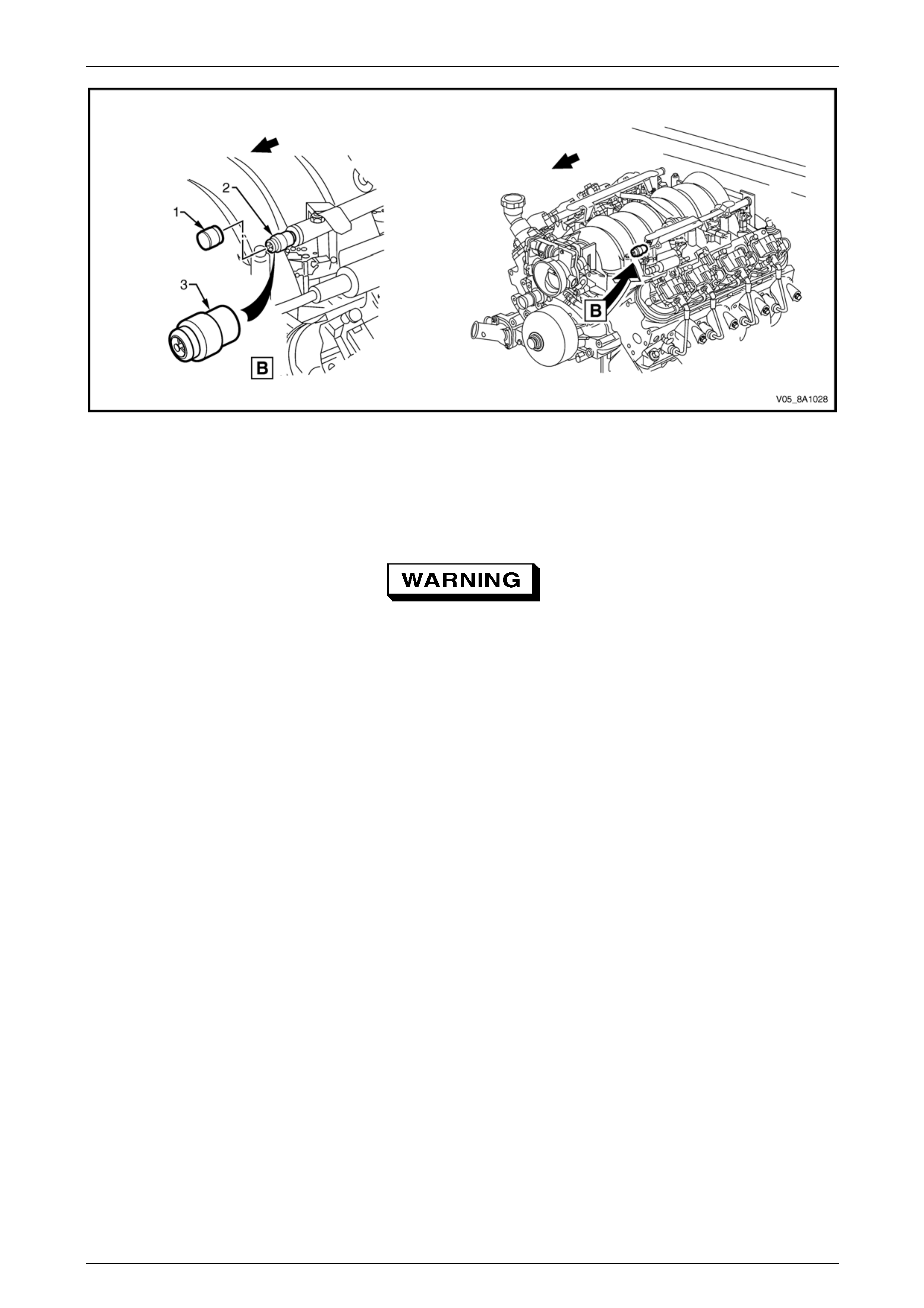
Rollover Valve
The fuel tank incorporates a rollover valve. The rollover
valve limits vapour venting to the evapor ative emission
control canister using a fixed- sized orifice that is normally
open (View A). If the vehicle rolls over (Vie w B), the fuel
tank vent line to the evaporative emission control can ister is
safely shut off by the rollover valve, preventing liquid fuel
from flooding the evaporative emissio n control canister.
NOTE
The rollover valve is fitted directly onto the tank
and is not serviceable separately. If it is faulty,
the tank (with a new rollover v alve fitted) must be
replaced.
Figure 8A1 – 24

Fuel System Page 8A1–27
Page 8A1–27
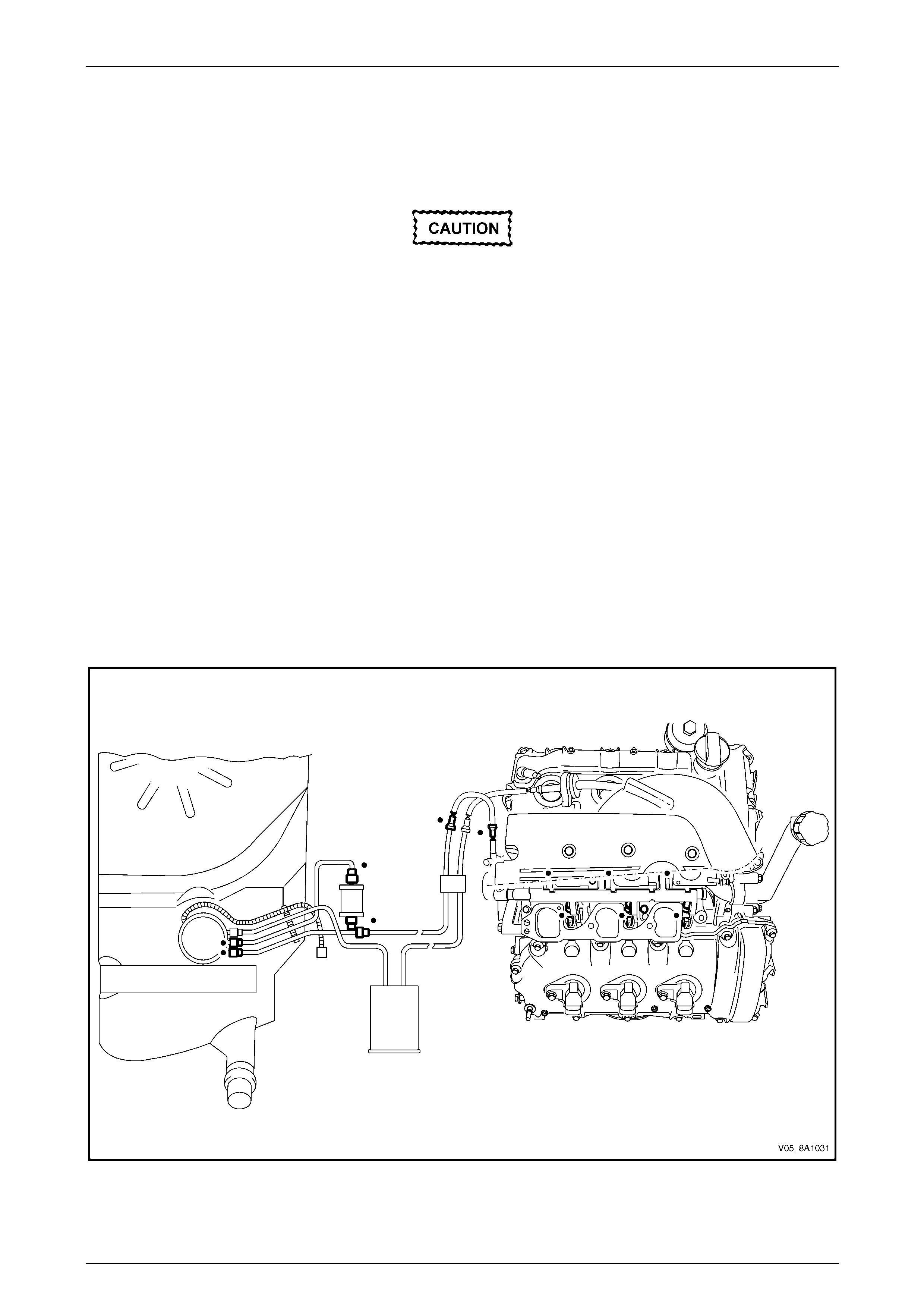
3.2 System Components
The pressure regulator is loca ted in the modular fuel pump and sender assembly. The fuel return line port on the modular
fuel pump and sender assembly cover is plugged. The Fuel Control System consists of the following components, refer
to Figure 8A1 – 25 for vehicles fitted with a V6 engine), or Figure 8A1 – 26 (for vehicles fitted with a GEN III V8 engine):
• evaporative emission control canister;
• fuel tank;
• fuel tank vent line;
• rollover valve;
• modular fuel pump and sender assembly, consisting of:
• modular fuel pump and sender assembly cover,
• sleeve rods and retaining s prings,
• reservoir,
• fuel pump and suction filter assembly,
• fuel level sender assembly,
• reservoir jet pump (integral with reservoir),
• valve and cap,
• transfer jet pump,
• pressure regulator,
• fuel pipes, and
• wiring harness and connectors;
• inlet breather pipe;
• evaporative emission control canister purge solenoid;
• fuel pressure check Schrader valve;
• fuel rail;
• modular fuel pump and sender assembly harness connector;
• fuel vapour overload breather pipe;
• fuel feed line;
• evaporative emission control canister purge line;
• fuel filler neck;
• fuel rail;
• either:
• engine control module (ECM) on vehicles fitted with a V6 engine, or
• powertrain control module (PCM) on vehicles fitted with a GEN III V8 engine;
• fuel pump relay; and
• injectors.
Fuel System Page 8A1–28
Page 8A1–28
V6 Engine
Figure 8A1 – 25
Legend
1 Evaporative Emission Control
Canister
2 Fuel Tank
3 Fuel Tank Vent Line
4 Rollover Valve
5 Modular Fuel Pump and Sender
Assembly
6 Inlet Breather Pipe
7 Evaporative Emission Control Canister
Purge Solenoid
8 Evaporative Emission Control Canister
Purge Line Service Port
9 Fuel Filler Neck
10 Evaporative Emission Control Canister
Purge Line
11 Fuel Feed Line
12 Fuel Vapour Overload Breather Pipe
13 Modular Fuel Pump and Sender
Assembly Harness Connector
Fuel System Page 8A1–29
Page 8A1–29
GEN III V8 Engine
Figure 8A1 – 26
Legend
1 Evaporative Emission Control
Canister
2 Fuel Tank
3 Fuel Tank Vent Line
4 Rollover Valve
5 Modular Fuel Pump and Sender
Assembly
6 Inlet Breather Pipe
7 Fuel Pulse Dampener
8 Evaporative Emission Control Canister
Purge Solenoid
9 Fuel Pressure Check Schrader Valve
10 Fuel Rail
11 Fuel Filler Neck
12 Evaporative Emission Control Canister
Purge Line
13 Fuel Feed Line
14 Fuel Vapour Overload Breather Pipe
15 Modular Fuel Pump and Sender
Assembly Harness Connector
Fuel System Page 8A1–30
Page 8A1–30
4 System Checks
4.1 Fuel System Depressurisation
To reduce the risk of fire or personal injury,
depressurise the fuel system before ser vicing
any fuel system components.
1 Turn the ignition switch off.
2 Remove the fuel pump fuse and fuel pump relay, refer to Section 12O Fuses, Relays and Wiring Harnesses.
3 Loosen the fuel filler cap to relieve the fuel tank vapour pressure.
4 With the throttle closed, crank the engine.
NOTE
The engine may start and operate until the fuel
remaining in the fuel deliv ery system depletes.
5 When the engine stops, crank the engi ne for another 10 seconds to ensure the fuel feed li ne pressure has been
fully relieved.
6 Clean the area around the fuel pressure test point.
A small amount of fuel may be released when
pressing on the Schrader valve. Cover the
fitting with a shop towel to absorb any fuel
spillage before removing the Schrader valve
sealing cap. After the fuel pressure relief
procedure, place the soiled towel in an
approved container for disposal.
7 At the fuel pressure test point (2), remove the Schrader valve sealing cap (1), refer to Figure 8A1 – 27 (for vehicles
fitted with a V6 engine) or Figure 8A1 – 28 (for vehicles fitted with a GEN III V8 engine).
Figure 8A1 – 27
Legend
1 Schrader Valve Sealing Cap
2 Pressure Test Point
3 Schrader Valve
Fuel System Page 8A1–31
Page 8A1–31
Figure 8A1 – 28
Legend
1 Schrader Valve Sealing Cap
2 Pressure Test Point 3 Schrader Valve
Wear safety g lasses when performing the fuel
pressure relief procedure.
8 Use a small screwdriver to press the Schrader valve (3).
9 Remove the soiled shop towel and place in an approved container.
Repressurise
1 Reinstall the fuel pump rela y and fuel pump fuse.
2 Perform the following procedur e to inspect for leaks at the fuel pressure test point:
a Turn the ignition switch on for two seconds.
b Turn the ignition switch off for 10 seconds.
c Turn the ignition switch on.
d Check for leaks at the fuel pressure test point.
3 Tighten the fuel filler cap.
4 Start the engine and recheck for leaks.
5 Reinstall the Schrader valve sealing cap.
Fuel System Page 8A1–32
Page 8A1–32
4.2 Fuel Pressure Test
To reduce the risk of fire or personal injury,
depressurise the fuel system before ser vicing
any fuel system components, refer to
4.1 Fuel System Depressurisation.
Installation
1 Turn the ignition switch off.
2 Depressurise the fuel system, refer to 4.1 Fuel System Depressurisation.
A small amount of fuel may be released when
connecting the fuel p ressure gaug e to the fuel
pressure test point. Cover the fittings with a
shop towel to absorb any fuel spillage before
connecting the fuel pressure gauge. After the
fuel pressure test procedure, place the soiled
towel in an approved container for disposal.
3 At the fuel pressure test point, remove the Schrader valve s ealing cap.
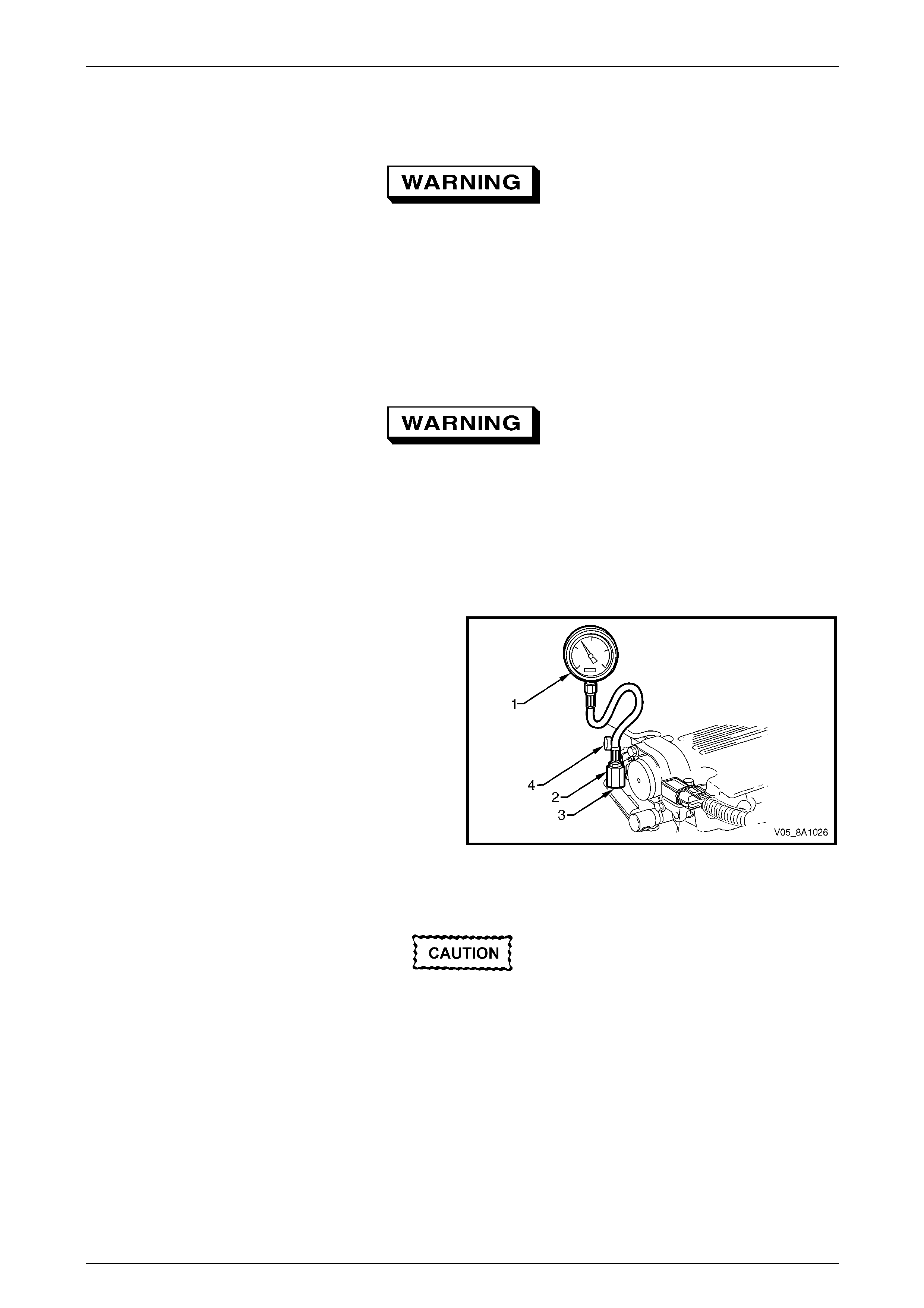
4 Connect the fuel pressure gauge (1) (tool
No. J 34730–1A) to the fuel gauge Schrader fitting
adapter (2) (tool No. AU453), then install to the fuel
pressure test port (3). Wrap a shop towel around the
fitting while connecting the fuel pressure ga uge to
avoid and/or capture any fuel spillage.
5 Route the bleed hose of the fuel gauge into an
approved fuel container.
NOTE
Figure 8A1 – 29 sho ws a fuel pressur e test on a
V6 engine. Refer to Figure 8A1 – 28 for the
location of the Schrader valve fitted to a GEN III
V8 engine.
Figure 8A1 – 29
After connecting the fuel pressure gauge and
pressurising the fuel system, inspect for fuel
leaks at the fuel pressure gauge and the fuel
pressure test point.
6 Either:
Using Tech 2, enable the fuel pump to pressurise the fuel system, refer to Section 0C Tech 2. Inspect for fuel leaks
at the fuel pressure gauge and fuel pressure test point, then bleed the air from the fuel pressure gauge.
or:
Reinstall the fuel pump rela y and fuel pump fuse, then open the fuel gauge ble ed valve (4) to bleed the air from the
fuel pressure gauge, refer to Figure 8A1 – 29.
7 Remove and place the shop towel in an approved container.
Fuel System Page 8A1–33
Page 8A1–33
Test
1 Start the engine and record the fuel pressure .
2 Turn the ignition switch off.
3 If required, perform any tests and/or diagnostic procedures:
• For the fuel system leak test, refer to 4.3 Fuel Leak Test.
• For the fuel injector leak-down test (for vehicles fitted with a V6 engine), refer to Section 6C1-3 Engine
Management – V6 – Service Operations.
• For the fuel injector leak-down test (for vehicles fitted with a GEN III V8 engine), refer to
Section 6C3-3 Powertrain Management GEN III – V8 – Service Operations.
4 Depressurise the fuel system, refer to 4.1 Fuel System Depressurisation.
Removal
1 Turn the ignition switch off.
2 Depressurise the fuel system, refer to 4.1 Fuel System Depressurisation.
After relieving the fuel system pressure, a
small amount of fuel may be released when
servicing the fuel lines or connections. Cover
the fittings with a shop towel before
disconnecting. This catches any leaking fuel.
Place the soiled towel in an approved
container when disconnection is completed.
3 Wrap a shop towel around the fuel pressure test point to absorb any fuel spillage.
4 Remove the fuel pressure gauge a nd drain any fuel remaining in the fuel pressure gauge into an approved fuel
container.
5 Remove the shop towel and place in an approved container.
6 Repressurise the fuel system, refer to Repressurise.
7 Road-test the vehicle and check for correct operation.
Fuel System Page 8A1–34
Page 8A1–34
4.3 Fuel Leak Test
V6 Engine
After installing any fuel system component
and before starting the engine, check the fuel
system for leaks.
NOTE
For the fuel injector leak-down test (for vehicles
fitted with a V6 engine), refer to Section 6C1-3
Engine Management – V6 – Service Operations.
1 Remove both engine dress covers, refer to Section 6A1 Engine Mechanical – V6 Engine.
2 Turn the ignition switch on for two seconds.
3 Turn the ignition switch off for 10 seconds.
4 Turn the ignition switch on.
5 Check for fuel leaks, particularly at points marked z (that is, quick-connect fittings, fuel pulse damp en er, fuel rails,
fuel injectors, Schrader valve and evaporati v e emission control canister purge solenoid):
• For Sedan, Wagon and AWD Wagon, refer to Figure 8A1 – 30. (The Utility is not shown, but is similar to the
layout shown in Figure 8A1 – 30.)
• For Regular Cab and Crew Cab vehicles, refer to Figure 8A1 – 31.
Figure 8A1 – 30
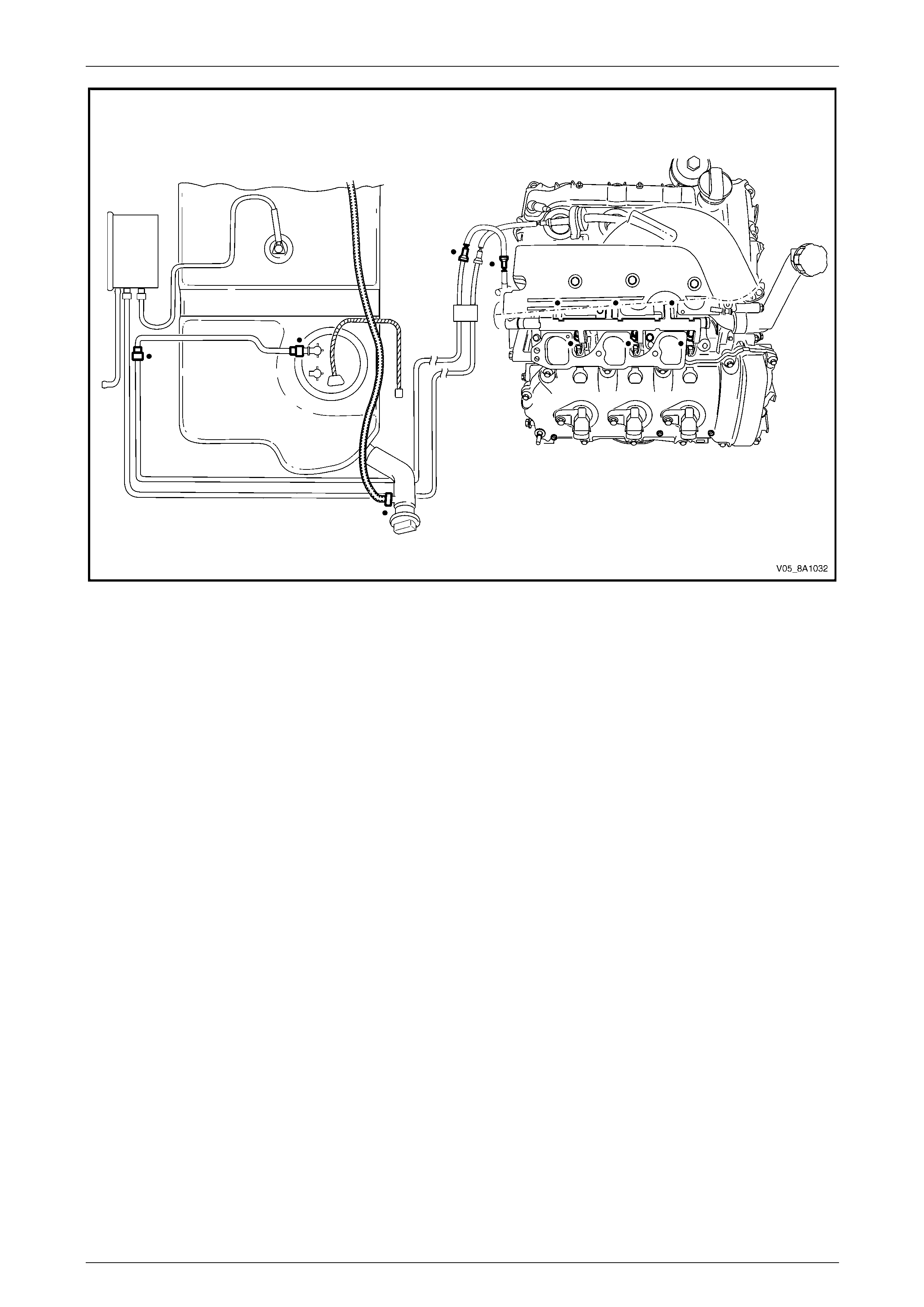
Fuel System Page 8A1–35
Page 8A1–35
Figure 8A1 – 31
6 Replace any faulty components and repeat step 2 to step 5 inclusive.
7 Replace all engine compo ne nts removed to perform the fuel leak test, refer to Section 6C1-3 Engine Management
– V6 – Service Operations.
8 Reinstall both engine dress covers, refer to Section 6A1 Engine Mechanic al – V6 Engine.
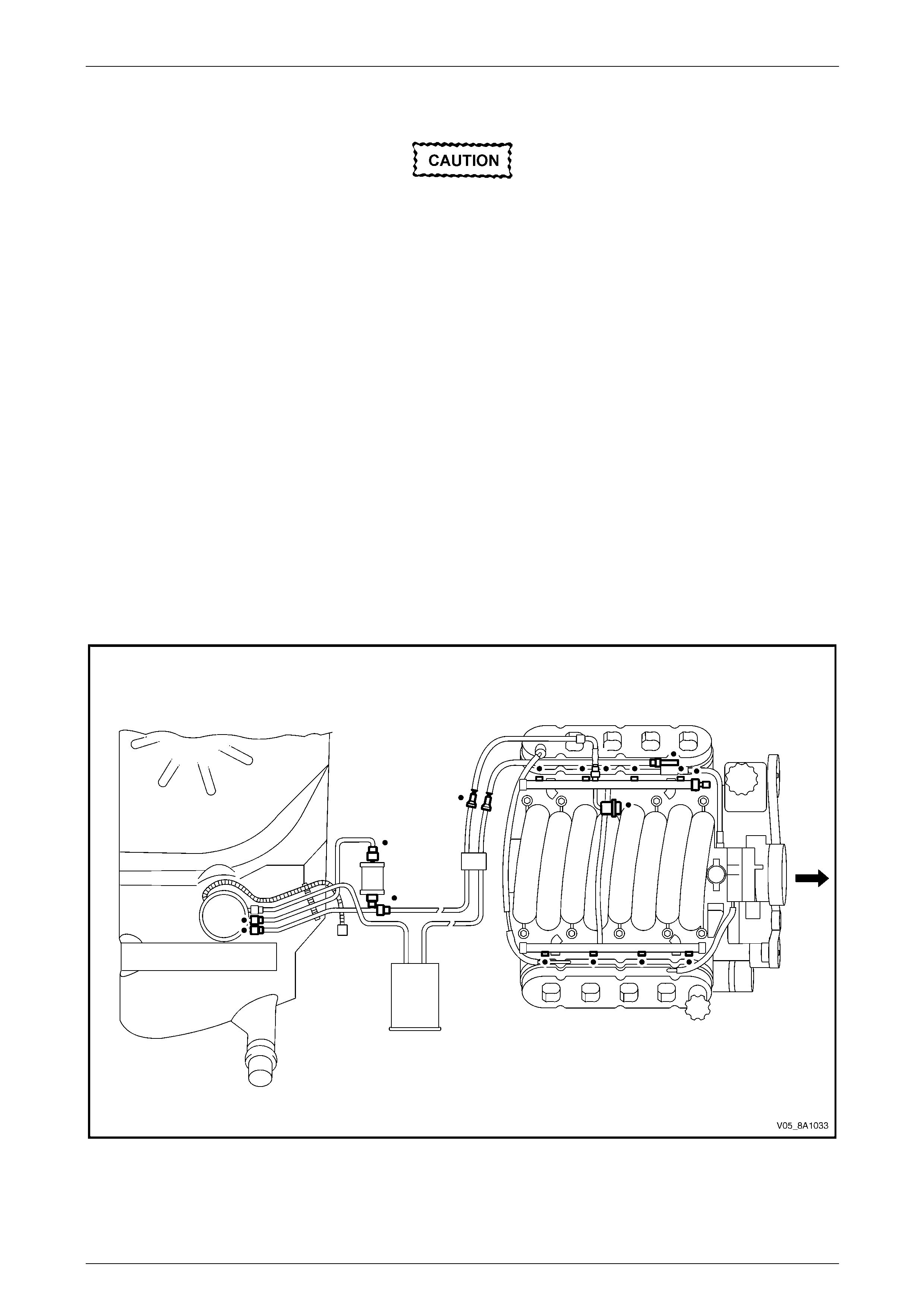
Fuel System Page 8A1–36
Page 8A1–36
GEN III V8 Engine
After installing any fuel system component
and before starting the engine, check the fuel
system for leaks.
NOTE
For the fuel injector leak-down test (for vehicles
fitted with a GEN III V8 engine), refer to
Section 6C3-3 Powertrain Management GEN III –
V8 – Service Operations.
1 Remove both engine dress covers, refer to Section 6A3 Engine Mechanical – GEN III V8.
2 Turn the ignition switch on for two seconds.
3 Turn the ignition switch off for 10 seconds.
4 Turn the ignition switch on.
5 Check for fuel leaks, particularly at points marked z (that is, quick-connect fittings, fuel pulse damp en er, fuel rails,
fuel injectors, Schrader valve and fuel vapour canister purge solenoid):
• For Sedan, Wagon and AWD Wagon, refer to Figure 8A1 – 32. (The Utility is not shown, but is similar to the
layout shown in Figure 8A1 – 32.)
• For Coupe, refer to Figure 8A1 – 33.
• For Regular Cab and Crew Cab vehicles, refer to Figure 8A1 – 34.
Figure 8A1 – 32
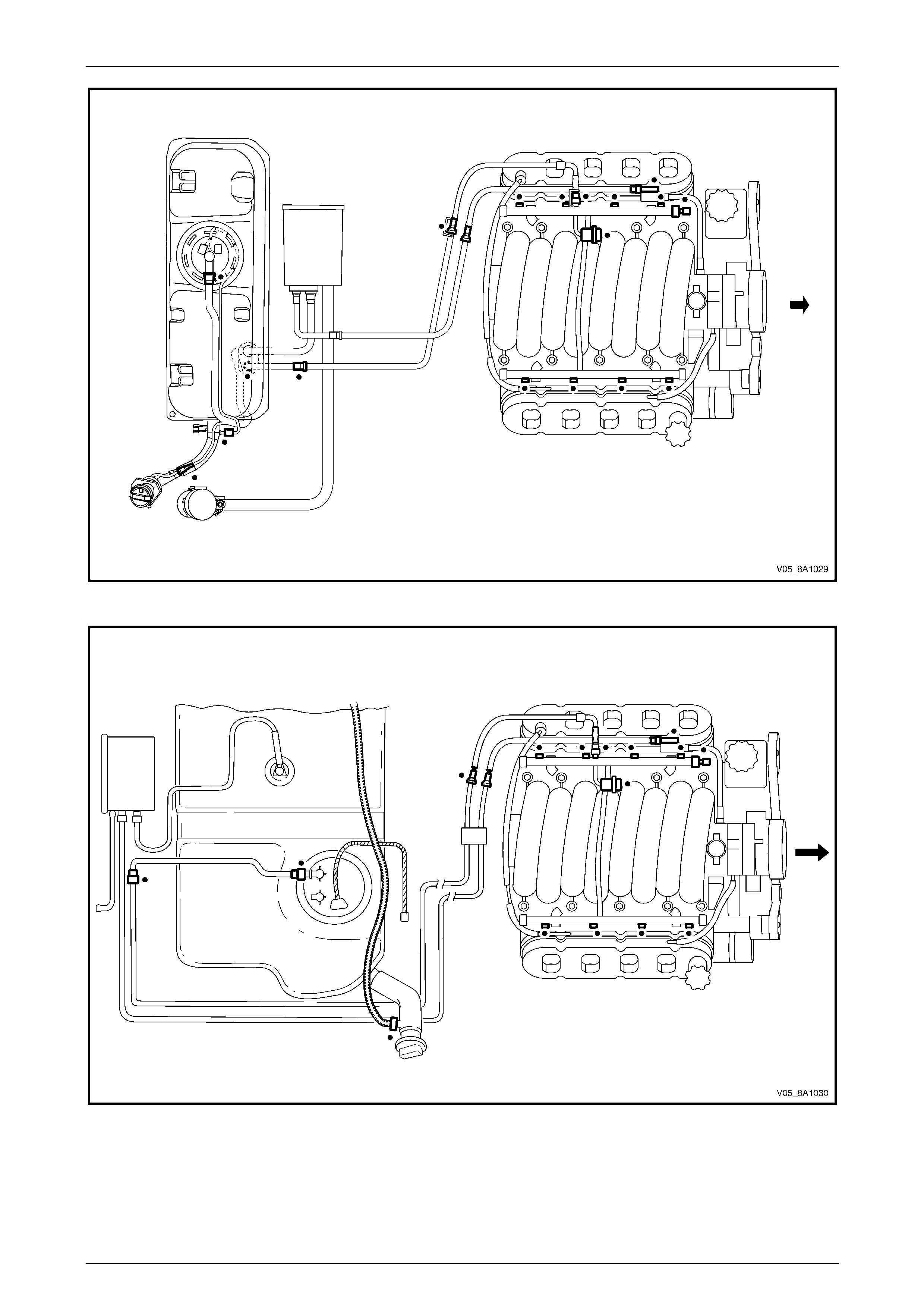
Fuel System Page 8A1–37
Page 8A1–37
Figure 8A1 – 33
Figure 8A1 – 34
6 Replace any faulty components and repeat step 2 to step 5 inclusive.
7 Replace all engine compo ne nts removed to perform the fuel leak test, refer to Section 6C3-3 Powertrain
Management GEN III – V8 – Service Operations.
8 Reinstall both engine dress covers, refer to Section 6A3 Engine Mechanical – GEN III V8.
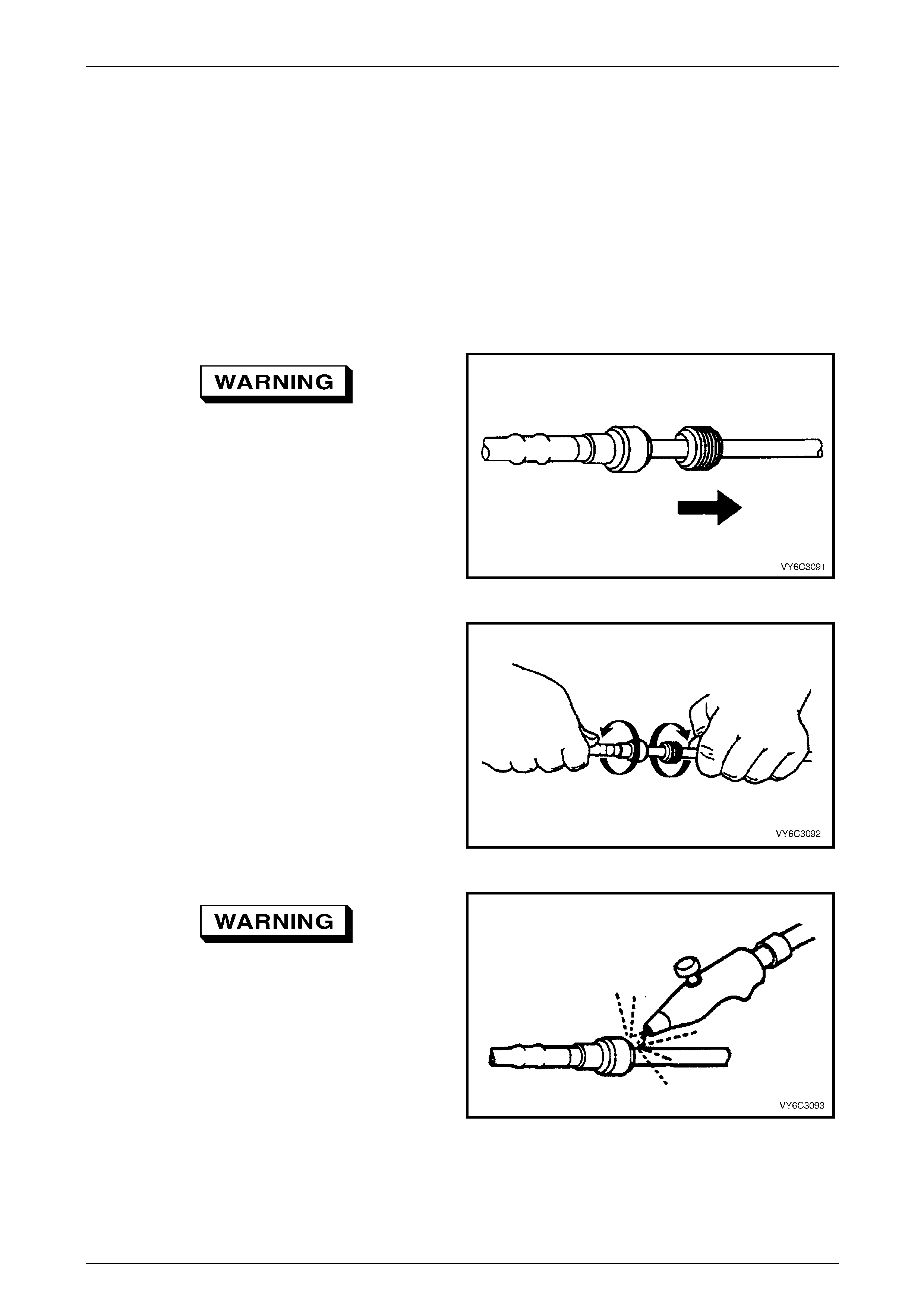
Fuel System Page 8A1–38
Page 8A1–38
5 Service Operations — Sedan,
Wagon and Utility
5.1 Quick-connect Fittings
Quick-connect Fittings (Metal Collar)
LT Section No. — 03–075
Remove
To reduce the risk of fire or personal injury,
relieve the fuel system pressure before
servicing any fuel system components, refer
to 4.1 Fuel System Depressurisation.
1 If fitted, slide the dust cover from the quick-connect
fitting.
Figure 8A1 – 35
2 Grasp both sides of the quick-connect fitting. Twist the
female side of the quick-connect fitting 1/4 turn in each
direction to loosen any dirt.
Figure 8A1 – 36
Wear safety glasses w hen usin g compressed
air. Do not blow compressed air onto any
body part.
3 Use compressed air to ensure that all dirt and foreign
materials are removed from all fuel conn ections before
the parts are disconnected.
Figure 8A1 – 37

Fuel System Page 8A1–39
Page 8A1–39
4 Choose the correct tool (1) to disconnect the quick-
connect fitting, refer to Tool Nos. 7370 and 7371.
Insert the tool into the female connector, then push
inward to release the locking t abs.
Figure 8A1 – 38
5 Pull the quick-connect fitting apart.
NOTE
If it is necessary to remove rust or burrs from a
fuel pipe, use emery cl oth in a radial motion with
the fuel pipe end to prevent damage to the
O-ring sealing surface.
6 Using a clean shop towel to wipe off the male pipe
end.
7 Inspect both ends of the fitting for dirt and burrs. Clean
or replace the components as required.
Figure 8A1 – 39
Reinstall
During normal operation, the O-ring located
in the female connector swells. To ensure
proper fitting, lubricate the male pipe end
before assembly.
1 Apply a few drops of clean engin e oil to the male pipe
end.
Figure 8A1 – 40
2 Push both sides of the quick-connect fitting together to
snap the retaining tabs into place.
Figure 8A1 – 41

Fuel System Page 8A1–40
Page 8A1–40
3 After installation, pull on both sides of the quick-
connect fitting to ensure the connection is secure.
Figure 8A1 – 42
4 Reposition the dust cover over the quick-con nect
fitting (if fitted).
Figure 8A1 – 43

Fuel System Page 8A1–41
Page 8A1–41
Quick-connect Fittings (Plastic Collar)
LT Section No. — 03–075
Remove
To reduce the risk of fire or personal injury,
relieve the fuel system pressure before
servicing any fuel system components, refer
to 4.1 Fuel System Depressurisation.
1 Grasp both sides of the quick-connect fitting. Twist the
female side of the quick-connect fitting 1/4 turn in each
direction to loosen any dirt.
Figure 8A1 – 44
Wear safety glasses w hen usin g compressed
air. Do not blow compressed air onto any
body part.
2 Use compressed air to ensure that all dirt and foreign
materials are removed from all fuel conn ections before
the parts are disconnected.
Figure 8A1 – 45
3 Squeeze the plastic retainer release tabs.
NOTE
Alternatively, use tool No. AU533 to release the
quick connect fitting:
• red = 5/16-inch fittings (fuel vapour lines), or
• blue = 3/8-inch fittings (fuel feed lines).
Figure 8A1 – 46

Fuel System Page 8A1–42
Page 8A1–42
4 Pull the quick-connect fitting apart.
Figure 8A1 – 47
Reinstall
During normal operation, the O-ring located
in the female connector swells. To ensure
proper fitting, lubricate the male pipe end
before assembly.
1 Apply a few drops of clean engin e oil to the male pipe
end.
Figure 8A1 – 48
2 Push both sides of the quick-connect fitting together to
snap the retaining tabs into place.
Figure 8A1 – 49
3 After installation, pull on both sides of the quick-
connect fitting to ensure the connection is secure.
Figure 8A1 – 50
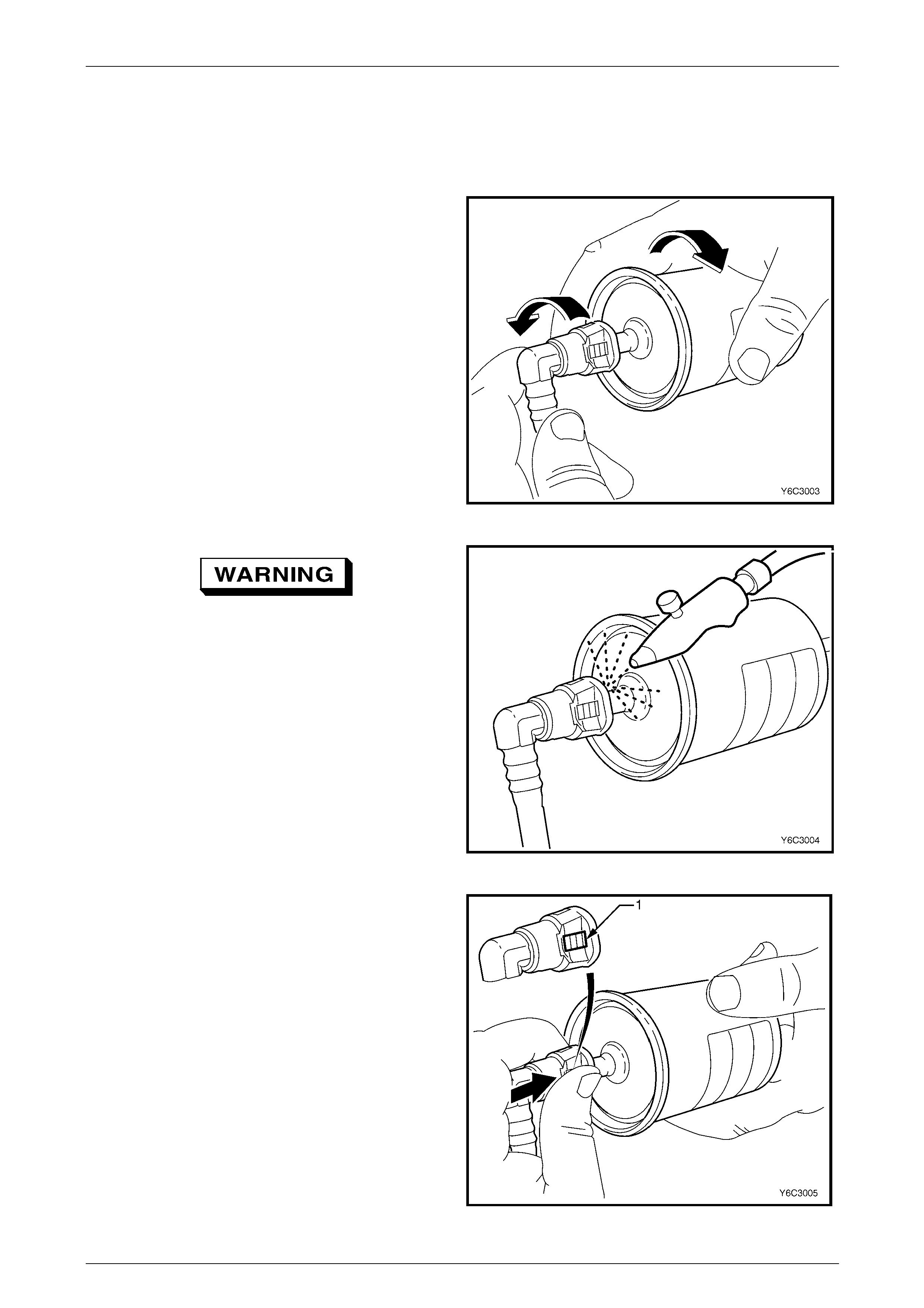
Fuel System Page 8A1–43
Page 8A1–43
Tool No. AU533
This procedure describes the removal of the quick-connect fittings on the fuel filter using tool No. AU533. This procedure
also applies to other quick-connect fittings.
Remove
1 Grasp both sides of the quick-connect fitting. Twist the
quick-connect fitting one quarter of a turn in e ach
direction to loosen any dirt within the quick-connect
fitting.
Figure 8A1 – 51
Wear safety glasses w hen usin g compressed
air. Do not blow compressed air onto any
body part.
2 Using compressed air, blow any dirt out of the quick-
connect fitting.
Figure 8A1 – 52
3 Grasp the female part and firmly support the male
part.
4 Squeeze the plastic retainer release tabs (1) on each
side of the quick-connect fitting while pus hing the
quick-connect fitting firmly inwards to release an y
tension on the release tabs.
Figure 8A1 – 53
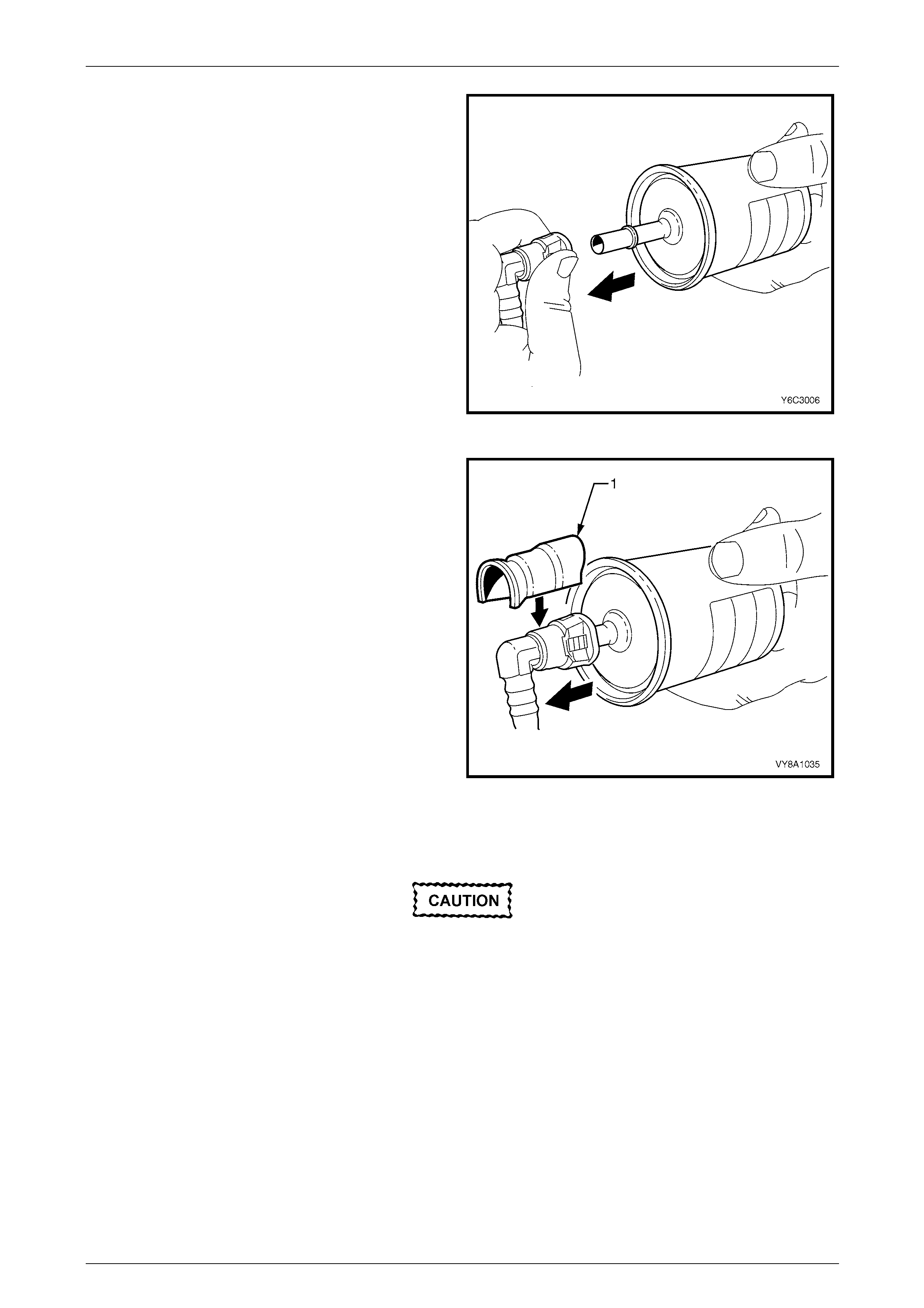
Fuel System Page 8A1–44
Page 8A1–44
5 While pressing the releas e tabs, pull the quick-connect
fitting apart.
Figure 8A1 – 54
6 Alternatively, for step 3 to step 5 inclusive, use tool
No. AU533 (1) to squeeze the release tabs and
release the quick-connect fittings.
NOTE
Tool No. AU533 will work only with retainer tabs
that sit proud of the connector body. Some filter
connectors have flush retainers that can be
pressed only by hand.
Figure 8A1 – 55
Reinstall
Before connecting quick-connect fittings,
apply a few drops of clean engine oil to the
male part. This ensures proper connection
and prevents a possible fuel leak. During
normal operation, the O-ring located in the
female part swells and may prevent proper
reconnection if not lubricated.
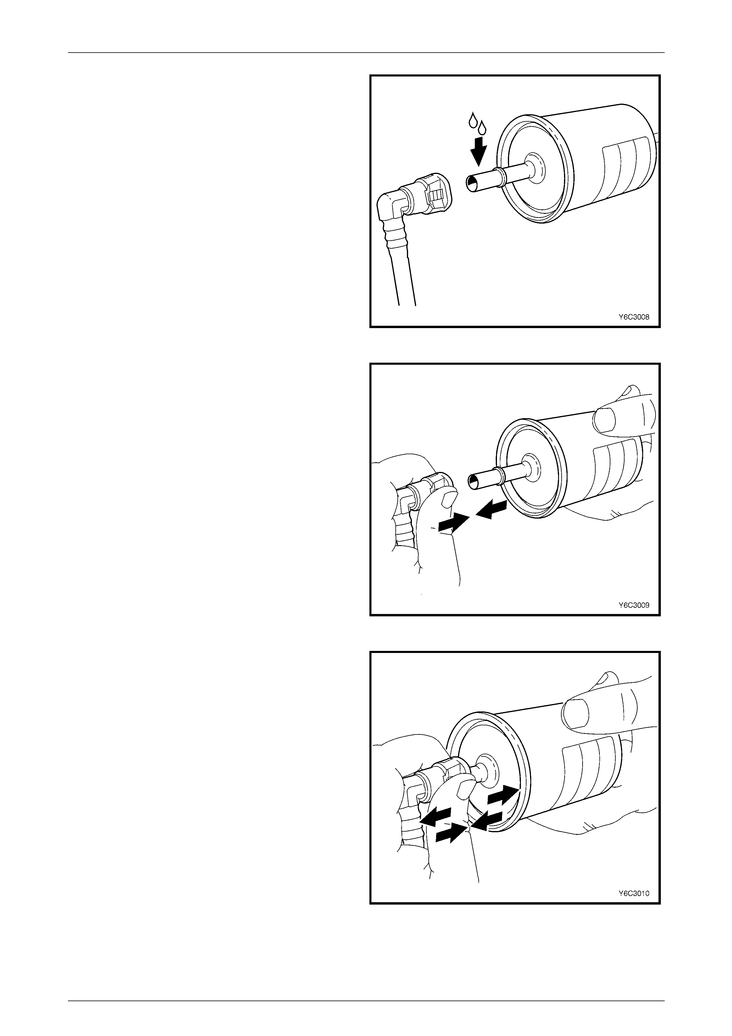
Fuel System Page 8A1–45
Page 8A1–45
1 Apply a few drops of clean engine oil to each male
part.
Figure 8A1 – 56
2 Push both parts of the quick-connect fitting together so
the retaining tabs snap into place.
Figure 8A1 – 57
3 After installation, pull and push on the quick-connect
fitting to ensure the connection is secure.
Figure 8A1 – 58
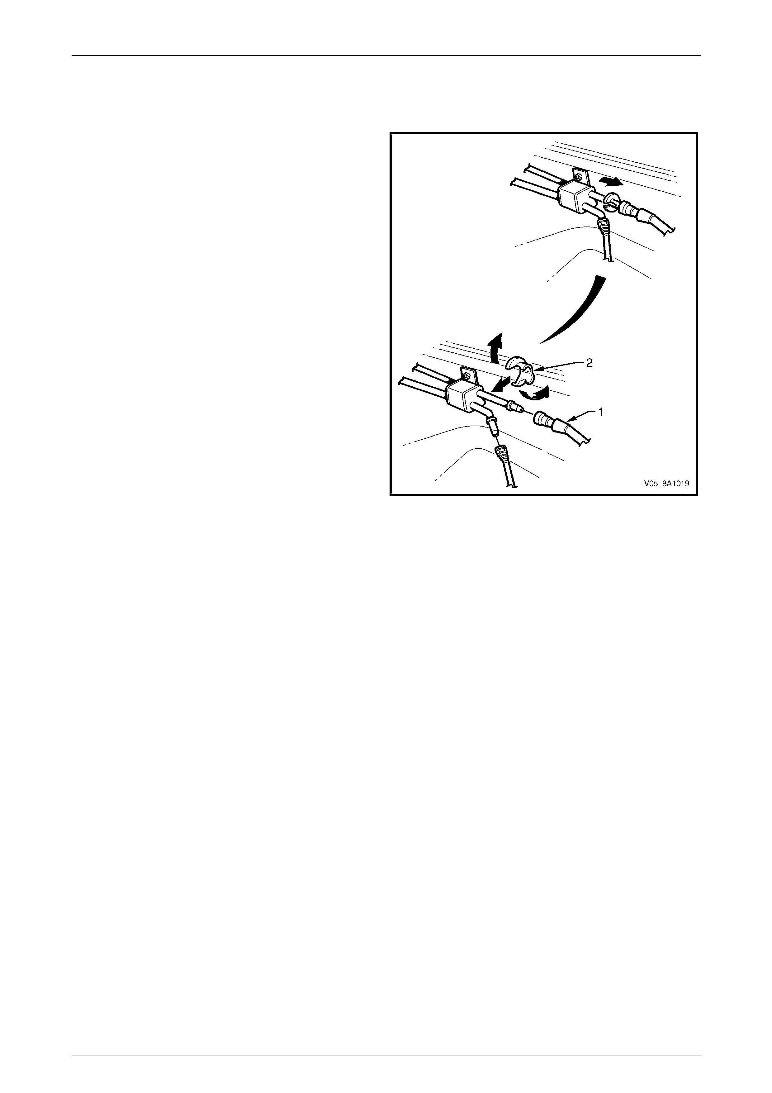
Fuel System Page 8A1–46
Page 8A1–46
Tool Nos. 7370 and 7371
Remove
Use tool Nos. 7370 and 7371 to disconnect the fuel lines at
the engine as follows:
1 Open the quick-connect release tool (2) and place it
over the fuel line (1).
2 Close the quick-connect release tool and pull it into the
fuel line quick-connect fitting to disconnect the fuel line
from the fuel pipe.
NOTE
Do not disconnect the fuel lines at th e fuel rail. If
the fuel lines are removed from the fuel rail, the
fuel lines must be replaced.
Figure 8A1 – 59
Reinstall
Reinstallation of the disconnected quick-connect fittings using tool Nos. 7370 and 7371 is the same as for tool
No. AU533, refer to Tool No. AU533.
Fuel System Page 8A1–47
Page 8A1–47
5.2 Fuel Tank — Sedan and Wagon
LT Section No. — 03–055
Remove
A depressurised fuel system contains fuel in
the fuel filter and fuel lines that can be spilled
during service operations.
Fuel vapour remains in the fuel tank even
when completely empty. Seal all openings in
the fuel tank using suitable material or a
plastic plug. Ensure no naked flames or other
ignition sources are nearby. Ensure all
cellular phones (and transmission devices
that may cause any metal objects to become
unintentional receiving antennas) are
switched off.
Place a dry chemical (Class B) fire
extinguisher nearby before performing any
on-vehicle service procedures. Failure to
follow these precautions may result in
personal injury.
Wear safety glasses when using compressed
air. Do not blow compressed air onto any
body part.
1 Remove the fuel pump relay, refer to Section 12O Fuses, Relays and Wiring Harnesses.
2 Depressurise the fuel system, refer to 4.1 Fuel System Depressurisation.
Never drain or store fuel into an open
container, due to the possibility of fire or
explosion.
3 Siphon the fuel tank, using commercially-available equipment.
4 Raise the vehicle, preferably on a hoist, refer to Section 0A General Information.
5 Remove the right-hand rear wheelho use liner, refer to Section 1A1 Body.
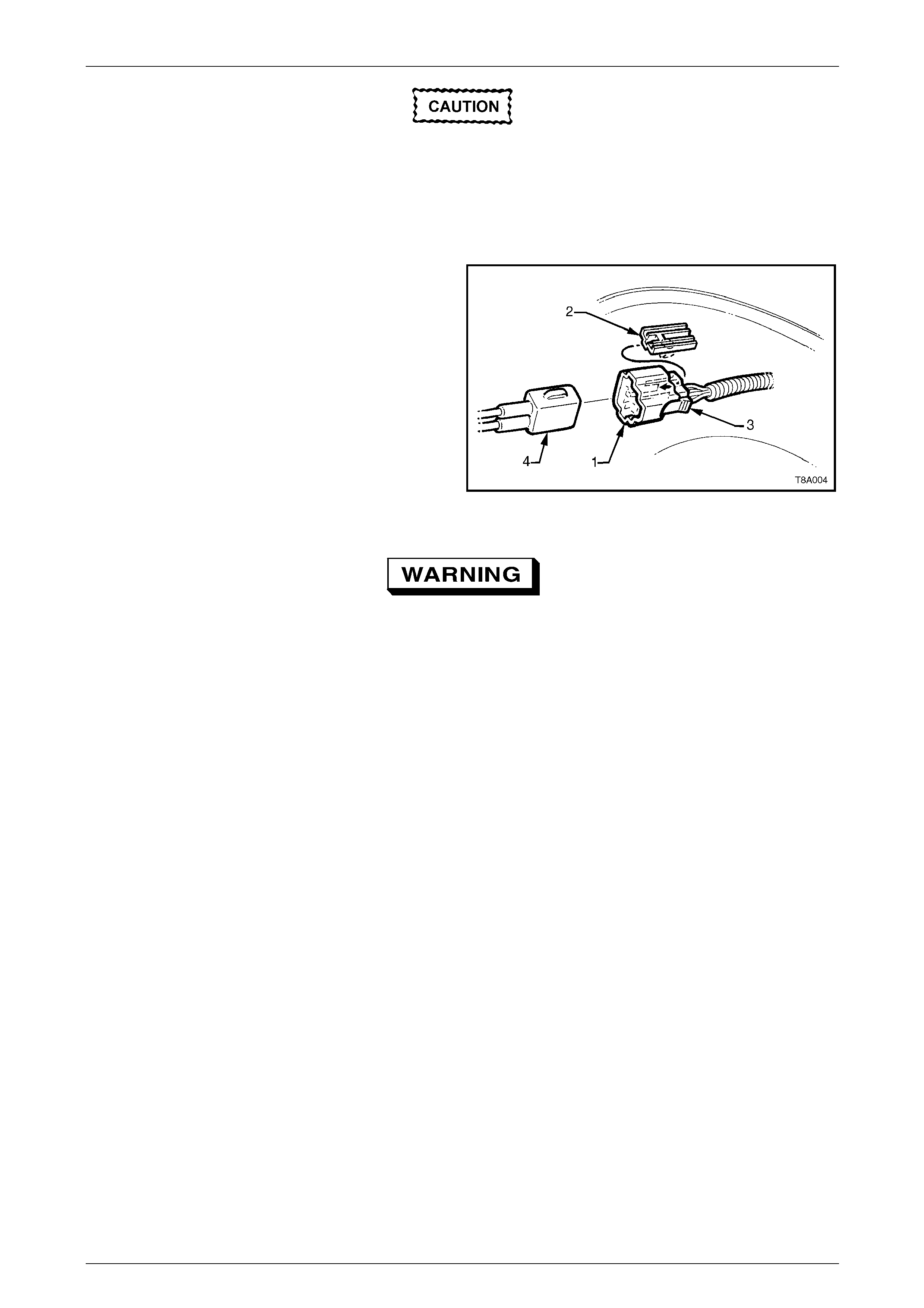
Fuel System Page 8A1–48
Page 8A1–48
Before proceedin g, clean all traces of dirt and
other foreign material from the top of the fuel
tank, near the modular fuel pump and sender
assembly.
6 Use compressed air to ensure that all dirt and foreign materials are removed from all fuel con nections before the
parts are disconnected.
7 Remove the fuel pump electrical connector (1) from its
mounting (2) by pulling it for ward to dislod ge the
assembled connector. After releasing, press the
locking tab (3) and separate the con nector halves
(1 and 4).
8 Place a drain tray under the fuel filter are a.
Figure 8A1 – 60
Fuel can spill from the disconnected filter.
9 If required, remove the fuel filter (7) by disconnecting the fuel feed line quick-connect fitting (8), refer to
Figure 8A1 – 61. Press both fuel filter strap retaining tangs (5), then remove the fuel filter from the bracket.
10 Disconnect the fuel filter T-piece quick-c onnect fitting (4). Support the fuel filter during removal.
11 Disconnect the quick-connect fittings to the ev aporative emission control canister (1) by pushing in wards to release
the seal pressure; press the side tangs of the quick-connect fitting, then pull to disconnect. Alternatively, use tool
No. AU533 to assist in pressing the tangs on the quick-connect fittings, refer to Tool No. AU533. Support the fuel
filter during removal.
12 Disconnect the fuel vapour canister breather hose from the evaporative emission control canister (2).
13 Disconnect the quick-connect fitting (3) at the flexibl e pipe and fuel filter T-piece, by supporting the quick-connect
fitting while pulling the fuel feed line from the quick-connect fitting.
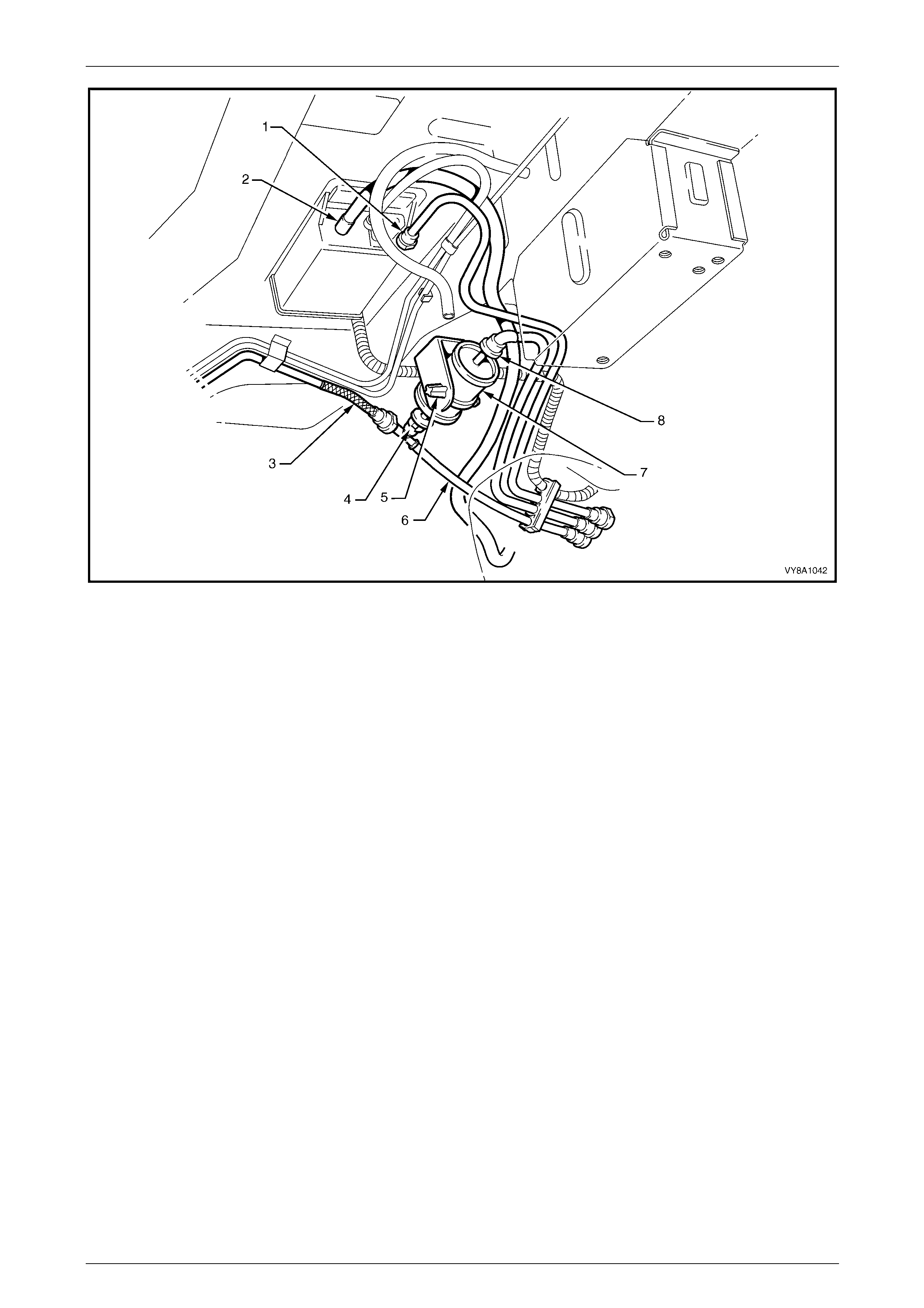
Fuel System Page 8A1–49
Page 8A1–49
Figure 8A1 – 61
Legend
1 Fuel Tank Vapour Line to Evaporative Emission Control
Canister Quick-connect
2 Evaporative Emission Control Canister Breather Hose
3 Flexible Fuel Feed Line
4 Fuel Filter T-piece Quick-connect
5 Fuel Filter Strap Retaining Tang
6 Fuel Return Line
7 Fuel Filter
8 Fuel Feed Line Quick-connect
14 Disconnect the filler neck ground strap from the spa de connector (9, in view A and view E), located under the front
mounting bolt (4, in view A) of the right-hand fuel tank mount ing strap (3, in view A), refer to Figure 8A1 – 62.
15 While supporting the fuel tank in the centre, remove the fu el tank mounting straps:
a Remove the centre fuel tank mounting strap (2, view D) by removing the rear retai nin g nut (5) and
washer (10), then unhook the centre fuel tank mounting strap from the front support (view C).
b Remove the bolt at the front (view A) and unhook the right-hand fuel tank mounting strap from the rear
support (view B), then remove the right-han d fuel tank mounting strap (3).
c Remove the left-hand fuel tan k mounting strap (1) by unscrewing the bolt and washer from each end (view C
and view D).
16 Lower the left-hand side of the fuel tank from the vehicle to release the fuel filler neck from the body opening. When
released, continue lowering the fuel tank.
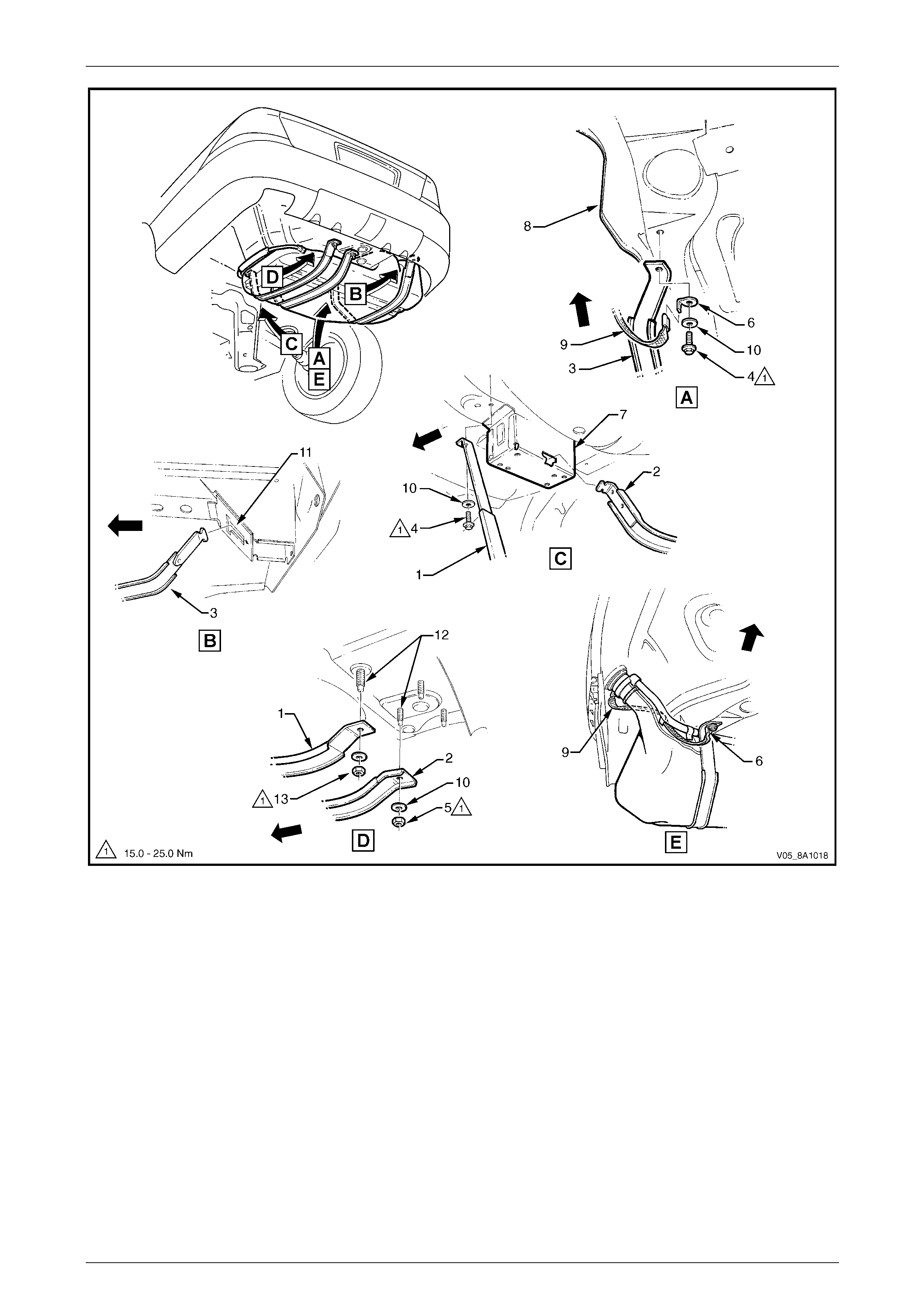
Fuel System Page 8A1–50
Page 8A1–50
Figure 8A1 – 62
Legend
1 Left-hand Fuel Tank Mounting Strap
2 Centre Fuel Tank Mounting Strap
3 Right-hand Fuel Tank Mounting Strap
4 Left-hand Fuel Tank Mounting Strap
Front Bolt
5 Centre Fuel Tank Mounting Strap
Rear Attaching Nut
6 Ground Strap Spade Connector
7 Front Support
8 Rear Longitudinal Extension
9 Filler Neck Ground Strap
10 Tank Strap Support Washer
11 Rear Support
12 Fuel Tank Reinforcement Studs
13 Left-hand Strap Rear Attaching Nut
Fuel System Page 8A1–51
Page 8A1–51
Reinstall
Reinstallation of the fuel tank is the reverse of the removal procedure, noting the following:
1 Check the insulation has not dislodged from the top of the fuel tank.
2 Lift the fuel tank, with the insulator attached, into position reinserting the fuel filler neck into the body opening.
Raise the fuel tank into place.
3 Fit the fuel tank mounting straps in the following order, refer to F igure 8A1 – 62:
a Loosely reattach the two outer fuel tank mounting straps (1, in view D and 3, in view A), ensuring the ground
strap spade connector (6, in view A) is fitted correctly.
b Ensure the filler neck seal is correctly located in the body opening.
c While pushing the fuel tank firmly to the right-hand side, tighten the front bolt (4, in view C) and rear nut (1, in
view D) for the left-hand fuel tank mounting strap.
d Tighten the front mounting bolt (4, in view A) on the right-hand fuel tank mounting strap (3, in view A).
e Hook the centre fuel tank mounting strap (2, in vie w D) into the front retainer (7, in view C), and replace the
nut and washer (5, in view D).
4 Tighten all fuel tank mounting strap fasteners to the correct torque specification.
Fuel tank mounting strap
nut and bolt
torque specification.................................15.0 – 25.0 Nm
5 Replace the fuel pump electrical connector, ensuring both locking tabs are in place. Engage the fuel pump
electrical connector to its mounting foot and push rearwards to engage the locking tabs.
Install the fuel filter with the flow arrow on its
body pointing in the same direction as the
fuel flow to the front of the vehicle.
6 Install the disconnected quick-connect fittings to the fuel filter and evaporative emission control canister. Refer to
Figure 8A1 – 61 for the correct compone nt routeings using the following sequence:
a evaporative emission control canister breather hose (2) to evaporative emission control canister;
b fuel tank vent line (1) to evaporative emission control caniste r ;
c fuel feed line (3) to flexible pipe quick-conne ct;
d fuel filter to fuel filter T-piece quick-connect (4), then fuel filter strap retainer (5) to fuel filter bracket; and
e fuel filter to fuel feed line quick-connect (8).
7 Install the right-hand rear wheelhouse liner, refer to Section 1A1 Body.
8 Before starting the vehicle, perform a fuel system leak test, refer to 4.3 Fuel Leak Test.
Fuel System Page 8A1–52
Page 8A1–52
5.3 Fuel Tank — Utility
LT Section No. — 03–055
Remove
A depressurised fuel system contains fuel in
the fuel filter and fuel lines that can be spilled
during service operations.
Fuel vapour remains in the fuel tank even
when completely empty. Seal all openings in
the fuel tank using suitable material or a
plastic plug. Ensure no naked flames or other
ignition sources are nearby. Ensure all
cellular phones (and transmission devices
that may cause any metal objects to become
unintentional receiving antennas) are
switched off.
Place a dry chemical (Class B) fire
extinguisher nearby before performing any
on-vehicle service procedures. Failure to
follow these precautions may result in
personal injury.
Wear safety glasses when using compressed
air. Do not blow compressed air onto any
body part.
1 Remove the fuel pump relay, refer to Section 12O Fuses, Relays and Wiring Harnesses.
2 Depressurise the fuel system, refer to 4.1 Fuel System Depressurisation.
3 Remove the load floor front panel assembly, refer to Section 1B Sheetmetal.
4 Remove the screws (2) securing the load compartment side panel inner front cover (1), refer to Figure 8A1 – 63.
5 Disconnect the modular fuel pump and sen der assembly harness connector (4).
6 Tag the fuel feed line (3) and fuel return line (6) connections located on top of the fuel tank.
NOTE
For identification purposes, the fuel return line is
tagged with a white band near the connector at
the top of the fuel tank.
7 Tag the fuel tank vent line (5) on top of the fuel tank and d isconnect by pulling the fuel tank vent line from the
rollover valve.

Fuel System Page 8A1–53
Page 8A1–53
NOTE
The fuel feed line has green retainer tabs.
8 Disengage the fuel return line (6) and the fuel feed line (3) quick-connect fittings using tool No. AU533, refer to T ool
No. AU533.
9 Remove the modular fuel pump and se nder assembly, refer to 5.6 Modular Fuel Pump and Sender Assembly —
Utility.
Never drain or store fuel into an open
container, due to the possibility of fire or
explosion.
10 Drain the fuel tank by pumping or siphoning fuel through the hole in the fuel tank (from which the modul ar fuel
pump and sender assembl y was removed) using commercially-available equipment.
NOTE
A permanent floodgate restriction in the lower fuel
filler neck prevents the fuel tank from being
drained through the filler aperture.
11 Remove the four mounting nuts (7), then remove the fuel tank b y mani pulating the filler neck free from the filler
neck grommet and past the inner quarter panel.
12 Remove the fuel tank isolator rubbers (9) and place in a safe location away from the immediate worksite.
Figure 8A1 – 63
Legend
1 Side Panel Inner Front Cover
2 Side Panel Screw (10 places)
3 Fuel Feed Line
4 Modular Fuel Pump and Sender
Assembly Harness Connector
5 Fuel Tank Vent Line
6 Fuel Return Line
7 Mounting Nut
8 Fuel Tank
9 Stud
Fuel System Page 8A1–54
Page 8A1–54
Reinstall
Reinstallation of the fuel tank is the reverse of the removal procedure, noting the following:
The connections for the fuel tank vent line are shown in View A, refer to Figure 8A1 – 63. Tighten all mountin g nuts to the
correct torque specification.
Fuel tank mounting nut
torque specification.................................15.0 – 20.0 Nm
Fuel System Page 8A1–55
Page 8A1–55
5.4 Fuel Filter
Replace
A depressurised fuel system contains fuel in
the fuel filter and fuel lines that can be spilled
during service operations.
Ensure no naked flames or other ignition
sources are nearby. Ensure all cellular
phones (and transmission devices that may
cause any metal objects to become
unintentional receiving antennas) are
switched off.
Place a dry chemical (Class B) fire
extinguisher nearby before performing any
on-vehicle service procedures. Failure to
follow these precautions may result in
personal injury.
The fuel filter removal and installation
procedure must be performed correctly.
Failure to adhere to these instructions may
result in permanent damage to the flexible
fuel feed line, resulting in unnecessary parts
replacement a nd expense.
NOTE
For details on disconnecting the quick-connect
fittings from the fuel filter, refer to 5.1 Quick-
connect Fittings.
1 Depressurise the fuel system, refer to 4.1 Fuel System Depressurisation.
Wear safety glasses when using compressed
air. Do not blow compressed air onto any
body part.
2 Use compressed air to ensure that all dirt and foreign materials are removed from all fuel con nections before the
parts are disconnected.
3 Push the fuel feed line quick-conn ect fitting (8) towards the filter and press the retainers together to disconnect it
from the fuel filter (7), refer to Figure 8A1 – 64. Alternatively, use tool No. AU533 to assist in pressing the quick-
connect fitting locking tangs, refer to Tool No. AU533. Support the fuel filter during removal.
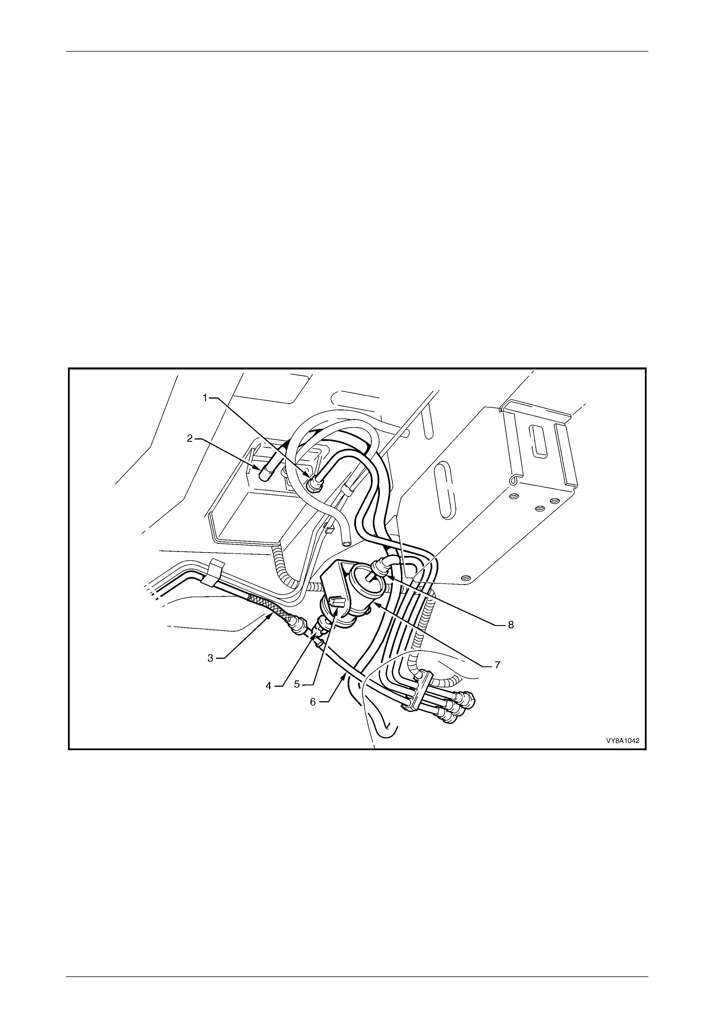
Fuel System Page 8A1–56
Page 8A1–56
4 Press the fuel filter strap retaining tangs (5) on the retainer strap, then remove the filter from the bracket.
5 To avoid permanent dama ge to the flexible fuel feed line at the fuel filter T-piece end of the filter, support the fuel
filter T-piece then press the filter into it while releasing the quick-connect fitting (4). Alternatively, fit the tool
No. AU533 over the fuel filter T-piece connector to press the quick-connect fitting locking tangs, refer to Tool No.
AU533.
6 Remove the fuel filter and retainer strap from the vehicle.
NOTE
Replacement fuel filters are supplied with a
retainer strap. Use only fuel filters with conductive
plastic retainer straps to ensure high-voltage
static electricity is dissipated without sparking.
7 Attach the support strap onto a replaceme nt fuel filter an d, while supporting the fuel filter T-piece, push the fuel
filter into the fuel filter T-piece quick-connect fitting until ful ly seated.
8 Install the filter strap retainer to the bracket. Install the quick-connect fitting to the remaining end of the filter.
9 Check each connector by firmly tugging on each on e to ensure it is in the locked position.
10 Before starting the vehicle, perform a fuel system leak test, refer to 4.3 Fuel Leak Test.
Figure 8A1 – 64
Legend
1 Fuel Tank Vapour Line to Evaporative Emission Control
Canister Quick-connect
2 Evaporative Emission Control Canister Breather Hose
3 Flexible Fuel Feed Line
4 Fuel Filter T-piece Quick-connect
5 Fuel Filter Strap Retaining Tang
6 Fuel Return Line
7 Fuel Filter
8 Fuel Feed Line Quick-connect

Fuel System Page 8A1–57
Page 8A1–57
5.5 Modular Fuel Pump and Sender
Assembly — Sedan and Wagon
LT Section No. — 03–074
Remove
A depressurised fuel system contains fuel in
the fuel filter and fuel lines that can be spilled
during service operations.
Fuel vapour remains in the fuel tank even
when completely empty. Seal all openings in
the fuel tank using suitable material or a
plastic plug. Ensure no naked flames or other
ignition sources are nearby. Ensure all
cellular phones (and transmission devices
that may cause any metal objects to become
unintentional receiving antennas) are
switched off.
Place a dry chemical (Class B) fire
extinguisher nearby before performing any
on-vehicle service procedures. Failure to
follow these precautions may result in
personal injury.
Wear safety glasses when using compressed
air. Do not blow compressed air directly onto
any body part.
1 Remove the fuel pump relay, refer to Section 12O Fuses, Relays and Wiring Harnesses.
2 Depressurise the fuel system, refer to 4.1 Fuel System Depressurisation.
Never drain or store fuel into an open
container, due to the possibility of fire or
explosion.
3 Siphon the fuel tank, using commercially-available equipment.
4 Remove the fuel tank, refer to 5.2 Fuel Tank — Sedan and Wagon.
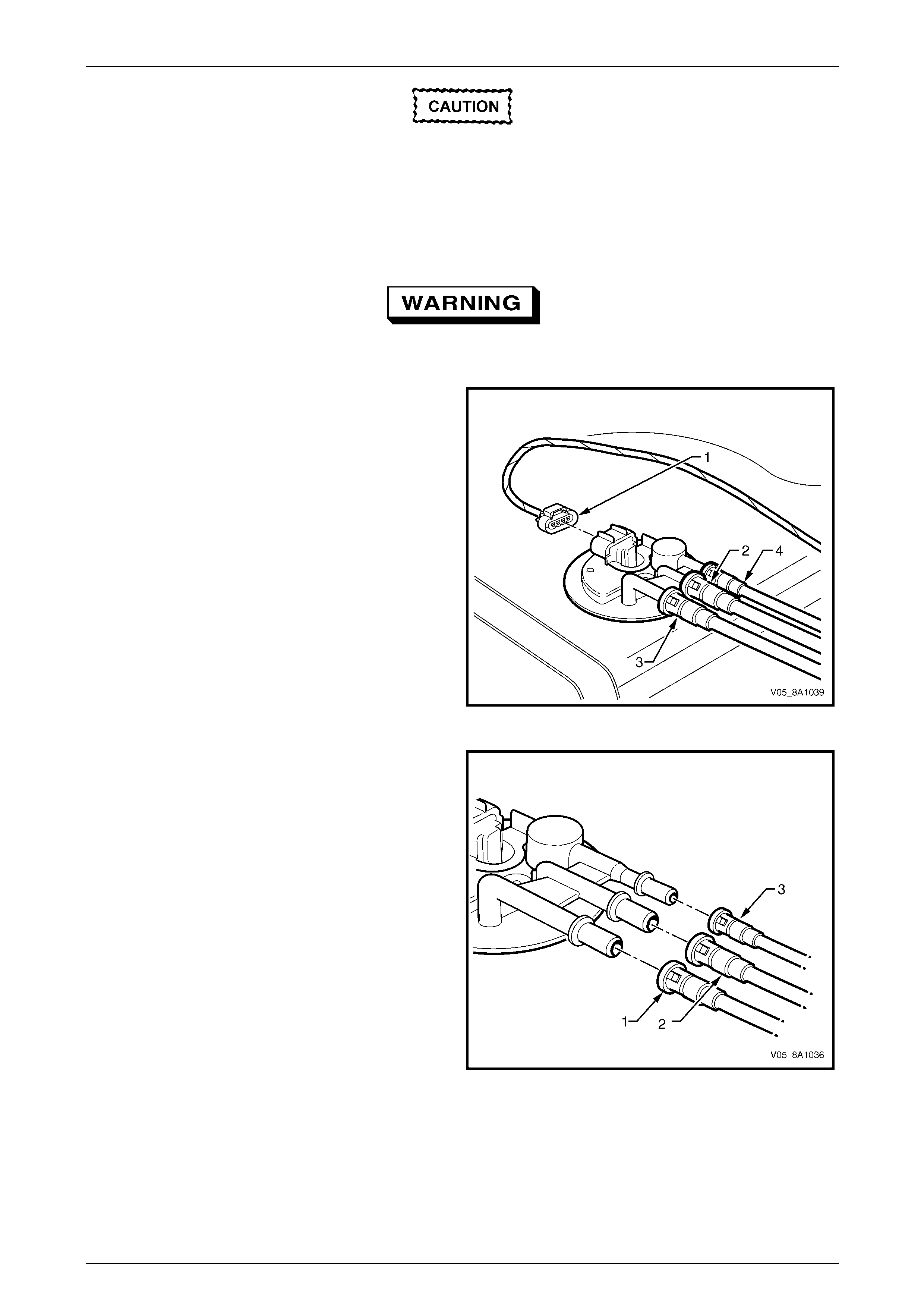
Fuel System Page 8A1–58
Page 8A1–58
Before proceedin g, clean all traces of dirt and
other foreign material from the top of the fuel
tank, near the modular fuel pump and sender
assembly.
5 Use compressed air to ensure all dirt and foreign materials are removed from all fuel con nections before
disconnecting the parts.
Fuel can spill from the disconnected modular
fuel pump and sender assembly.
6 Disconnect the modular fuel pump and sen der
assembly harness connector (1).
7 Tag the fuel feed line connecting the fuel feed port (2)
on the modular fuel pump and sender assembly cover.
8 Tag the fuel return port (3) on the modular fuel pump
and sender assembly cover.
9 Tag the fuel tank vent line (4) on the modula r fuel
pump and sender assembly c over.
Figure 8A1 – 65
10 Disengage the fuel return line quick-connect fitting (1)
using tool No. AU533 (3/8-inch), refer to Tool No.
AU533.
11 Disengage the fuel feed line quick-connect fitting (2)
using tool No. AU533 (3/8-inch), refer to Tool No.
AU533.
12 Disengage the fuel tank vent li ne quick-connect
fitting (3) using tool No. AU533 (5/16-inch), refer to
Tool No. AU533.
Figure 8A1 – 66
Fuel System Page 8A1–59
Page 8A1–59
Ensure tool No. AU469 is seated firmly and
positively in the modular fuel pump and
sender assembly cover retainer lock ring
while removing the modular fuel pump and
sender assemb ly.
Assistance w ill be required to hold the tank in
position during this procedure; if not held
adequately, you may slip and damage the
modular fuel pump and sender assembly.
13 Using tool No. AU469 (3) and a half-i nch bre aker
bar (1), remove the modular fuel pump a nd sender
assembly cover retainer lock ring (2) by turning it
anticlockwise.
Figure 8A1 – 67
14 Remove the modular fuel pump and se nder assembly cover retainer lock ring.
NOTE
The modular fuel pump and sender assembly
cover springs up when the retainer is remov ed.
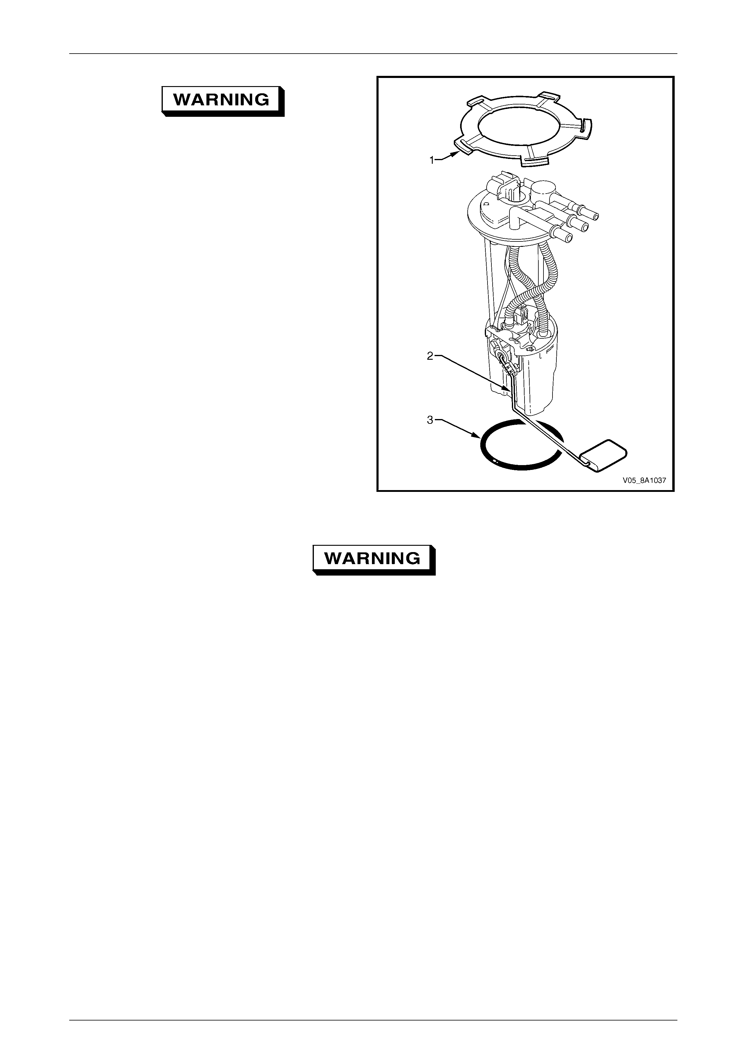
Fuel System Page 8A1–60
Page 8A1–60
The reservoir will be full of fuel. When the
modular fuel pump and sender assembly is
removed from the fuel tank, pour any
remaining fuel in the reser voir into a suitable
container. Do not drain or store fuel into an
open container, due to the possibility of fire
or explosion.
15 Place the modular fuel pump and sender assembly
cover retainer lock ring (1) in a safe location away
from the immediate worksite.
16 Carefully lift the modular fuel pump a nd sender
assembly from the fuel tank, taking care not to:
• damage the fuel level sender float and arm (2),
and
• spill any fuel remaining in the reservoir.
NOTE
The fuel sender float arm is not serviced
separately. If damaged, it is replaced as part of
the fuel level sender assembl y.
Figure 8A1 – 68
Fuel vapour remains in the fuel tank even
when completely empty. Seal all openings in
the fuel tank using suitable material or a
plastic plug. Ensure no naked flames or other
ignition sources are nearby. Ensure all
cellular phones (and transmission devices
that may cause any metal objects to become
unintentional receiving antennas) are
switched off.
17 Remove and discard the O-ring (3), refer to Figur e 8A1 – 68.
18 Place a suitable material over the opening in the fuel tank to prevent any foreign matter from entering the fuel
system.
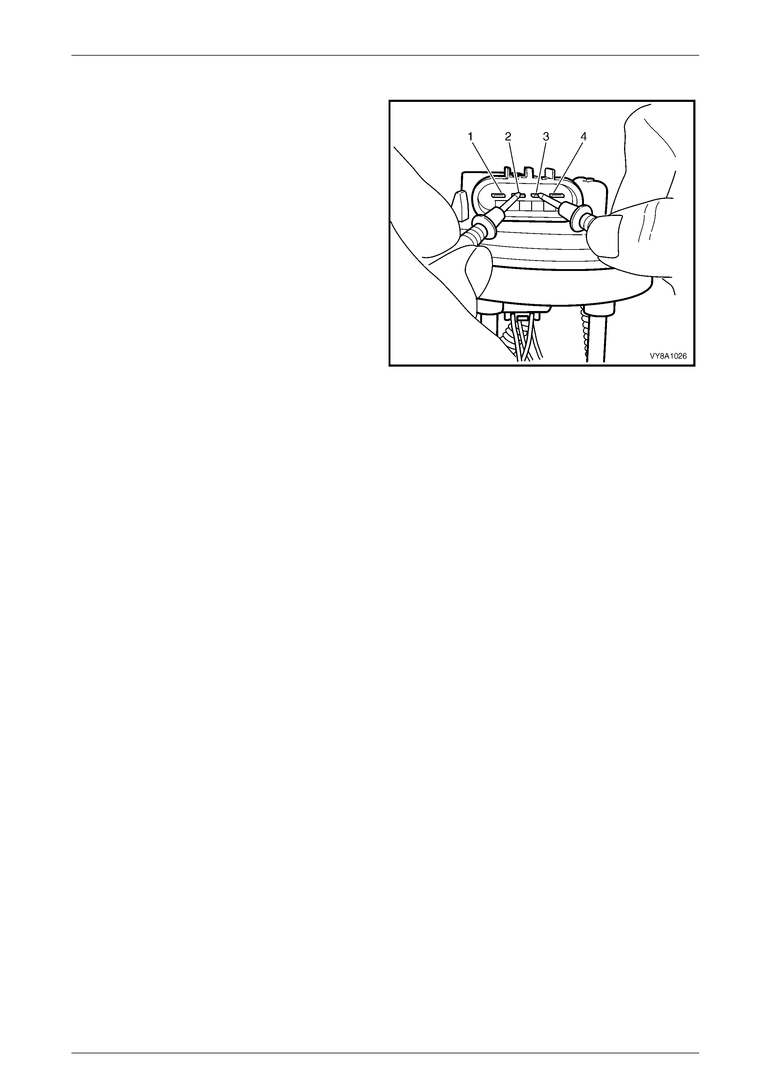
Fuel System Page 8A1–61
Page 8A1–61
Test
1 Measure the resistance acros s terminals 2 and 3 of
the fuel pump motor connector. Take the follo wing
measurements:
a With the float arm assembly in the empty
position, the resistance should be ap proximately
250 Ω.
b With the float arm assembly rotated to the full
position, the resistance should be ap proximately
40 Ω.
2 If the resistance at either of these positions is not
within tolerance, replace the fuel level sender
assembly.
Figure 8A1 – 69
Reinstall
Reinstallation of the modul ar fuel pump and sender assembly is the reverse of the removal procedure, noting the
following:
1 Fit a new O-ring (3) to the modular fuel pump and sender assembl y, refer to F igure 8A1 – 68.
2 Install the modular fuel pump and sender assembly into the fuel tank, taking care not to damage the fuel sender
float or arm.
3 Ensure the locator in the pump cover enga ges in the slot in the fuel tank opening.
4 Install the modular fuel pump and sender assembly retainer lock ring (1).
Fuel System Page 8A1–62
Page 8A1–62
5.6 Modular Fuel Pump and Sender
Assembly — Utility
LT Section No. — 03–074
Remove
A depressurised fuel system contains fuel in
the fuel filter and fuel lines that can be spilled
during service operations.
Fuel vapour remains in the fuel tank even
when completely empty. Seal all openings in
the fuel tank using suitable material or a
plastic plug. Ensure no naked flames or other
ignition sources are nearby. Ensure all
cellular phones (and transmission devices
that may cause any metal objects to become
unintentional receiving antennas) are
switched off.
Place a dry chemical (Class B) fire
extinguisher nearby before performing any
on-vehicle service procedures. Failure to
follow these precautions may result in
personal injury.
Wear safety glasses when using compressed
air. Do not blow compressed air directly onto
any body part.
1 Remove the fuel pump relay, refer to Section 12O Fuses, Relays and Wiring Harnesses.
2 Depressurise the fuel system, refer to 4.1 Fuel System Depressurisation.
Never drain or store fuel into an open
container, due to the possibility of fire or
explosion.
3 Siphon the fuel tank, using commercially-available equipment.
4 Remove the load floor front panel assembly, refer to Section 1B Sheetmetal.
5 Remove the screws (2) securing the load compartment side panel inner front cover (1), refer to Figure 8A1 – 63.
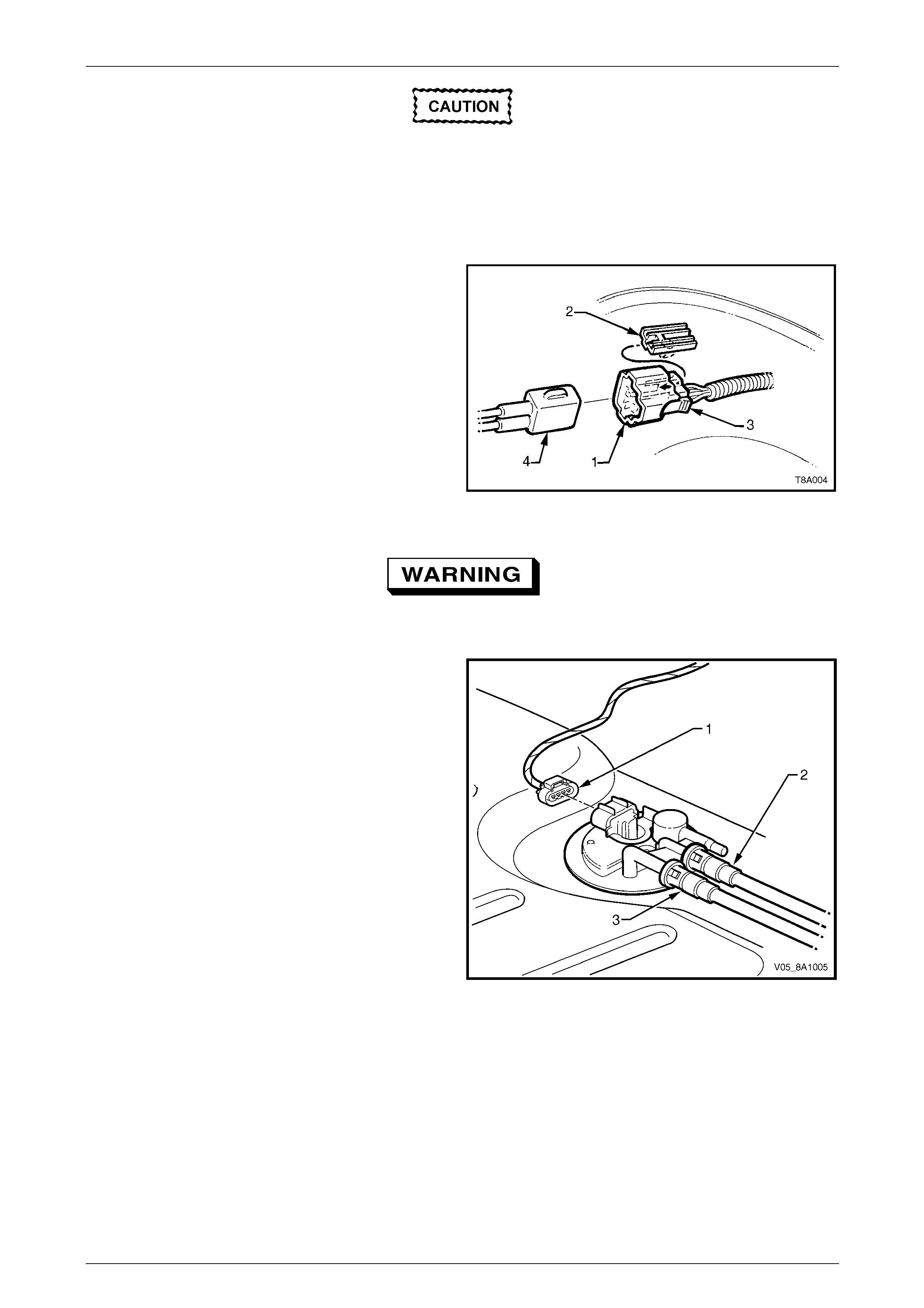
Fuel System Page 8A1–63
Page 8A1–63
Before proceedin g, clean all traces of dirt and
other foreign material from the top of the fuel
tank, near the modular fuel pump and sender
assembly.
6 Use compressed air to ensure all dirt and foreign materials are removed from all fuel con nections before
disconnecting the parts.
7 Remove the fuel pump electrical connector (1) from its
mounting (2) on the panel behin d the side panel inner
front cover by pulling it forward to dislodge the
assembled connector. After releasing, press the
locking tab (3) and separate the con nector halves
(1 and 4).
8 Place a drain tray under the fuel filter are a.
Figure 8A1 – 70
Fuel can spill from the disconnected modular
fuel pump and sender assembly.
9 Disconnect the modular fuel pump and sen der
assembly harness connector (1).
10 Tag the fuel feed line connecting the fuel feed port (2)
on the modular fuel pump and sender assembly cover.
11 Tag the fuel return port (3) on the modular fuel pump
and sender assembly cover.
Figure 8A1 – 71
12 Tag the fuel tank vent line (5) on top of the fuel tank and disconnect by pulling the fuel tank vent line from the
rollover valve, refer to Figure 8A1 – 63.
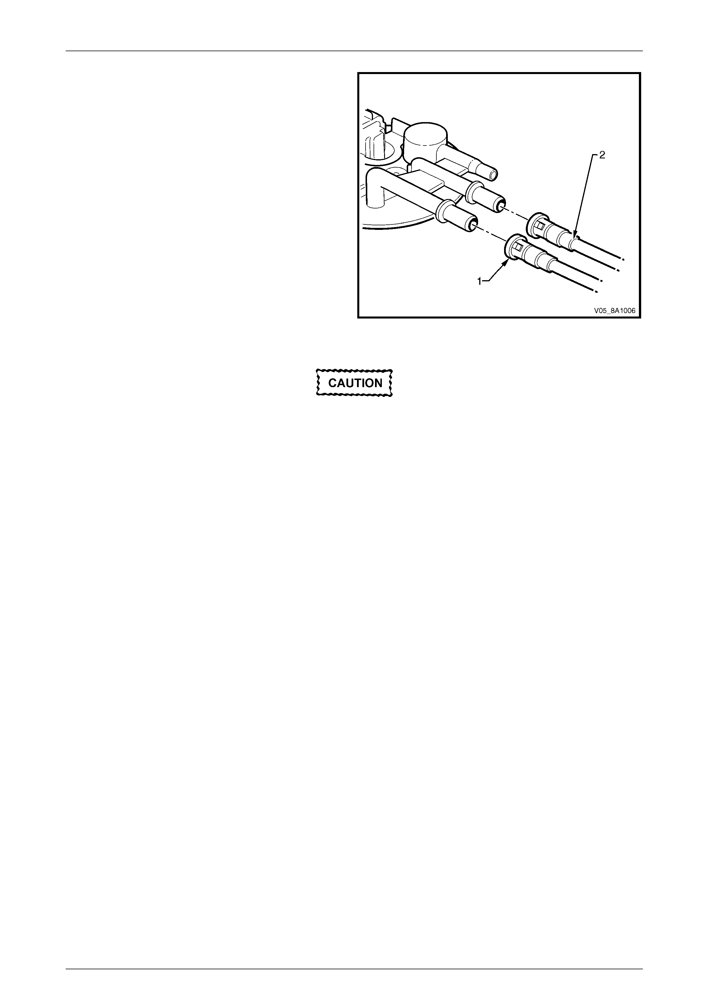
Fuel System Page 8A1–64
Page 8A1–64
13 Disengage the fuel return line quick-connect fitting (1)
using tool No. AU533 (3/8-inch), refer to Tool No.
AU533.
14 Disengage the fuel feed line quick-connect fitting (2)
using tool No. AU533 (3/8-inch), refer to Tool No.
AU533.
Figure 8A1 – 72
Ensure the internal circlip pliers are seated
firmly and positively in the modular fuel pump
and sender assembly cover circlip.
15 Using a pair of internal circlip pliers, remove the modular fuel pump an d sender assembly circlip.
NOTE
The modular fuel pump and sender assembly
springs up when the circlip is removed.
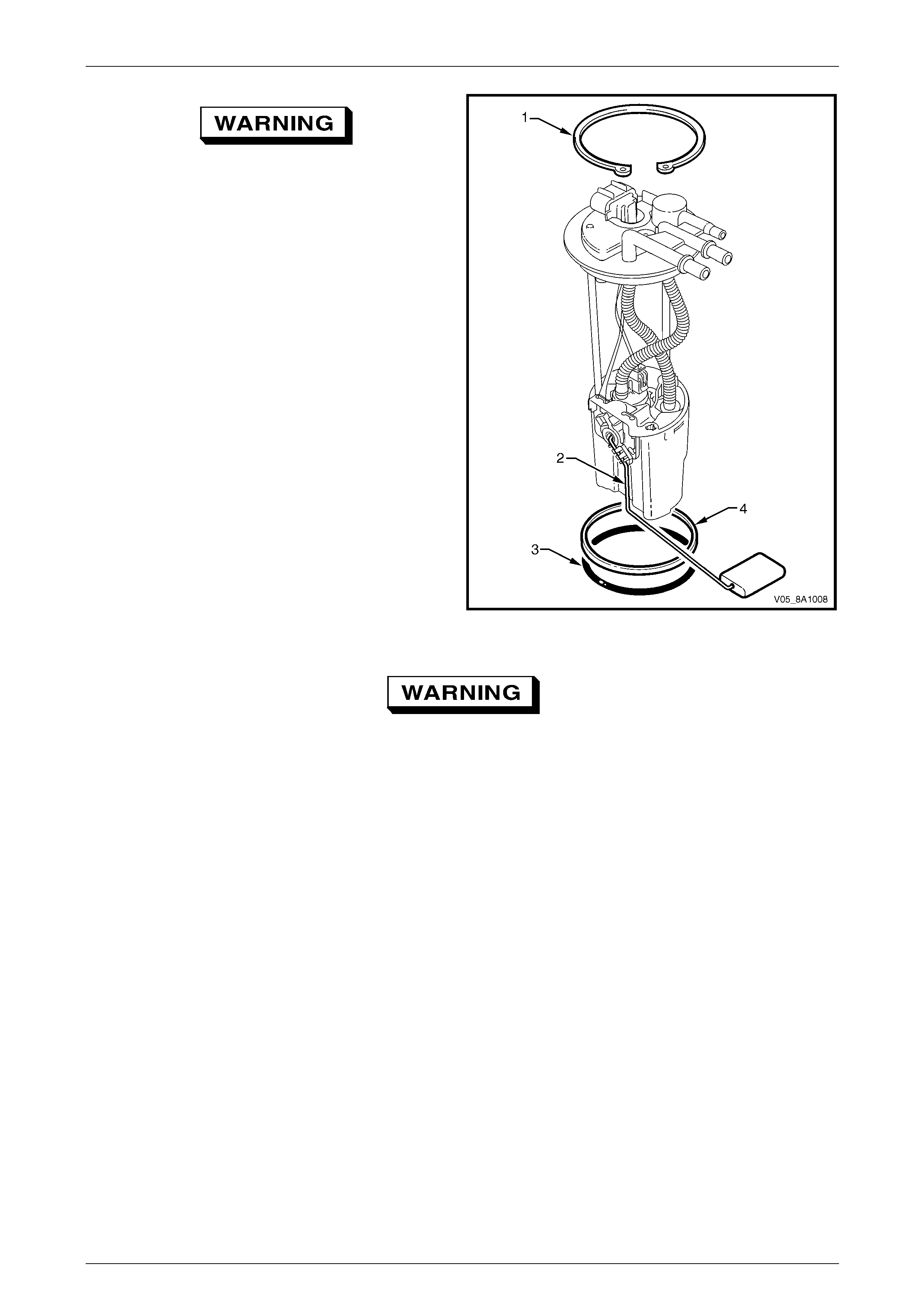
Fuel System Page 8A1–65
Page 8A1–65
The reservoir will be full of fuel. When the
modular fuel pump and sender assembly is
removed from the fuel tank, pour any
remaining fuel in the reser voir into a suitable
container. Do not drain or store fuel into an
open container, due to the possibility of fire
or explosion.
16 Place the modular fuel pump and sender assembly
circlip (1) in a safe location awa y from the immedi ate
worksite.
17 Carefully lift the modular fuel pump a nd sender
assembly from the fuel tank, taking care not to:
• damage the fuel level sender float and arm (2),
and
• spill any fuel remaining in the reservoir.
NOTE
The fuel sender float arm is not serviced
separately. If damaged, it is replaced as part of
the fuel level sender assembl y.
Figure 8A1 – 73
Fuel vapour remains in the fuel tank even
when completely empty. Seal all openings in
the fuel tank using suitable material or a
plastic plug. Ensure no naked flames or other
ignition sources are nearby. Ensure all
cellular phones (and transmission devices
that may cause any metal objects to become
unintentional receiving antennas) are
switched off.
18 Remove the spacer (4) and place it in a safe location away from the immediate worksite, refer to Figure 8A1 – 73.
19 Remove and discard the O-ring (3).
20 Place a suitable material over the opening in the fuel tank to prevent any foreign matter from entering the fuel
system.
Test
For the test procedure of the modular fuel pump and sender assembly, refer to 5.5 Modular Fuel Pump and Sender
Assembly — Sedan and Wagon.

Fuel System Page 8A1–66
Page 8A1–66
Reinstall
Reinstallation of the modul ar fuel pump and sender assembly is the reverse of the removal procedure, noting the
following:
1 Ensure the spacer (4) is fitted to the modular fuel pump sender assembly, refer to Figure 8A1 – 73.
2 Fit a new O-ring (3) to the modular fuel pump and sender assembl y.
3 Install the modular fuel pump and sender assembly into the fuel tank, taking care not to damage the fuel sender
float or arm.
4 Ensure the locator in the pump cover enga ges in the slot in the fuel tank opening.
5 Install the modular fuel pump and sender assembly circlip (1).
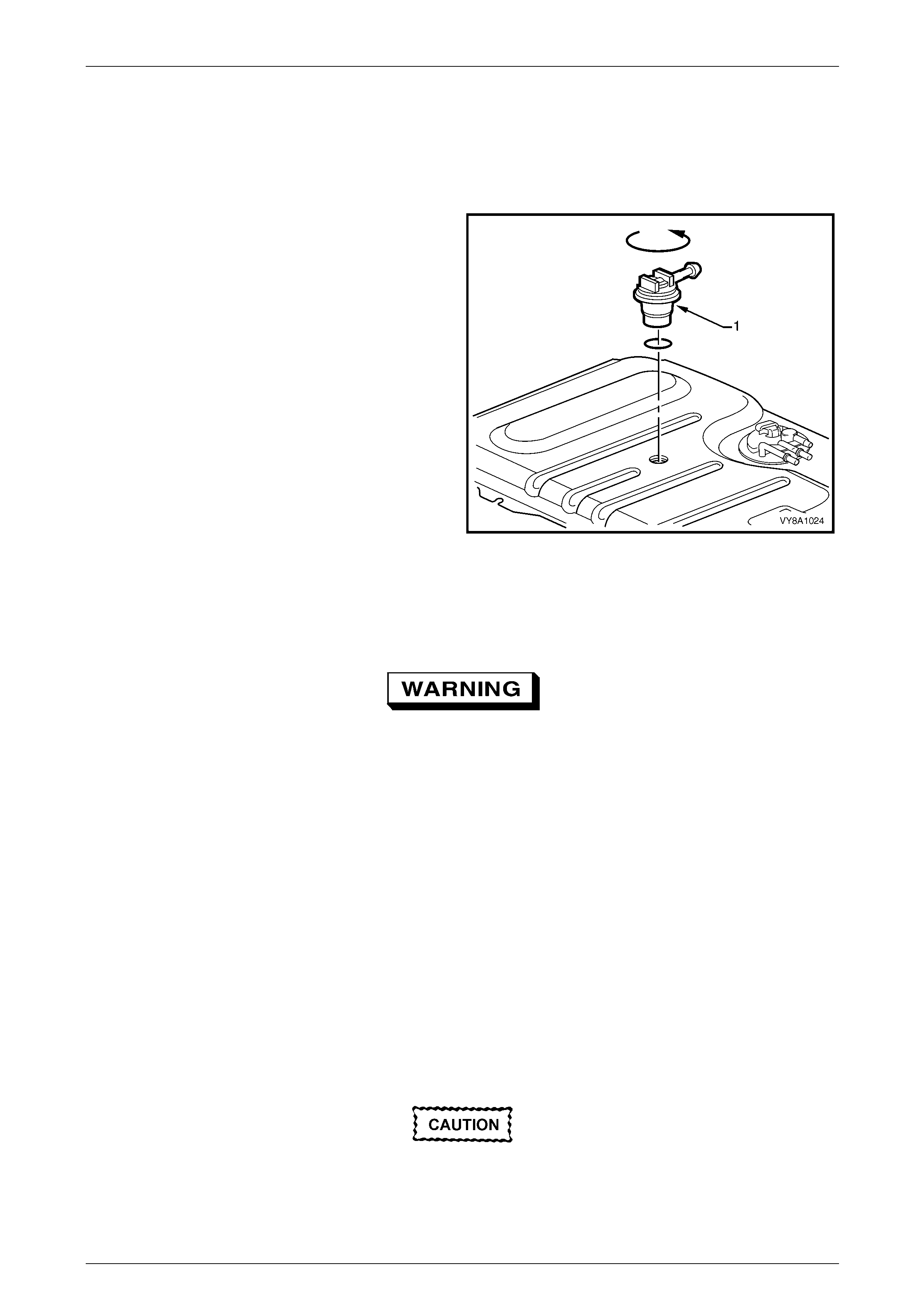
Fuel System Page 8A1–67
Page 8A1–67
5.7 Rollover Valve — Utility
LT Section No. — 03–055
Remove
1 Remove the load floor front panel assembly, refer to
Section 1B Sheetmetal.
2 Pull the fuel tank vent line from the rollover valve (1).
3 Apply a downward press ure on the rollover valve and
rotate it anticlockwise approximately 30°.
4 Remove the rollover valve from the fuel tank .
5 Place a suitable material over the opening in the fuel
tank to prevent any foreign matter from entering the
fuel tank.
Figure 8A1 – 74
Test
1 Remove the rollover valve from the fuel tank .
Wear safety glasses when using compressed
air. Do not blow compressed air onto any
body part.
2 Clean the rollover valve with compress ed air.
NOTE
Do not use compressed air for the following
procedure.
3 With the rollover valve upright, blow nitrogen at low pressure into the outlet pipe. The nitrogen should pass through
the valve and out the inlet holes in the bottom.
4 Continue to blow nitrogen into the outlet pipe and slowly rotate the rollover valve. At approximatel y 90° of rotation:
a the internal check valve should operate with an audible click, then
b nitrogen should stop passing through the valves.
Reinstall
If the tested rollover valve is faulty, replace it
with a serviceab le item.
Reinstallation of the rollov er valve is the rev erse of the removal procedure.
Fuel System Page 8A1–68
Page 8A1–68
5.8 Fuel Pipes
LT Section No. — 03–075
Sedan and Wagon
Remove
A depressurised fuel system contains fuel in
the fuel filter and fuel lines that can be spilled
during service operations.
Fuel vapour remains in the fuel tank even
when completely empty. Seal all openings in
the fuel tank using suitable material or a
plastic plug. Ensure no naked flames or other
ignition sources are nearby. Ensure all
cellular phones (and transmission devices
that may cause any metal objects to become
unintentional receiving antennas) are
switched off.
Place a dry chemical (Class B) fire
extinguisher nearby before performing any
on-vehicle service procedures. Failure to
follow these precautions may result in
personal injury.
Wear safety glasses when using compressed
air. Do not blow compressed air onto any
body part.
1 Remove the fuel pump relay, refer to Section 12O Fuses, Relays and Wiring Harnesses.
2 Depressurise the fuel system, refer to 4.1 Fuel System Depressurisation.
Never drain or store fuel into an open
container, due to the possibility of fire or
explosion.
3 Raise the vehicle, preferably on a hoist, refer to Section 0A General Information.
Before proceedin g, clean all traces of dirt and
other foreign material from the fuel pipes.
4 Use compressed air to ensure that all dirt and foreign materials are removed from all fuel con nections before the
parts are disconnected.
5 If required, remove the stone guards and fue l pipes. Use the following illustrations showing the fuel pipe la yout and
location of other items relating to the fuel system as a guide, refer to Figure 8A1 – 75 and Figure 8A1 – 76.
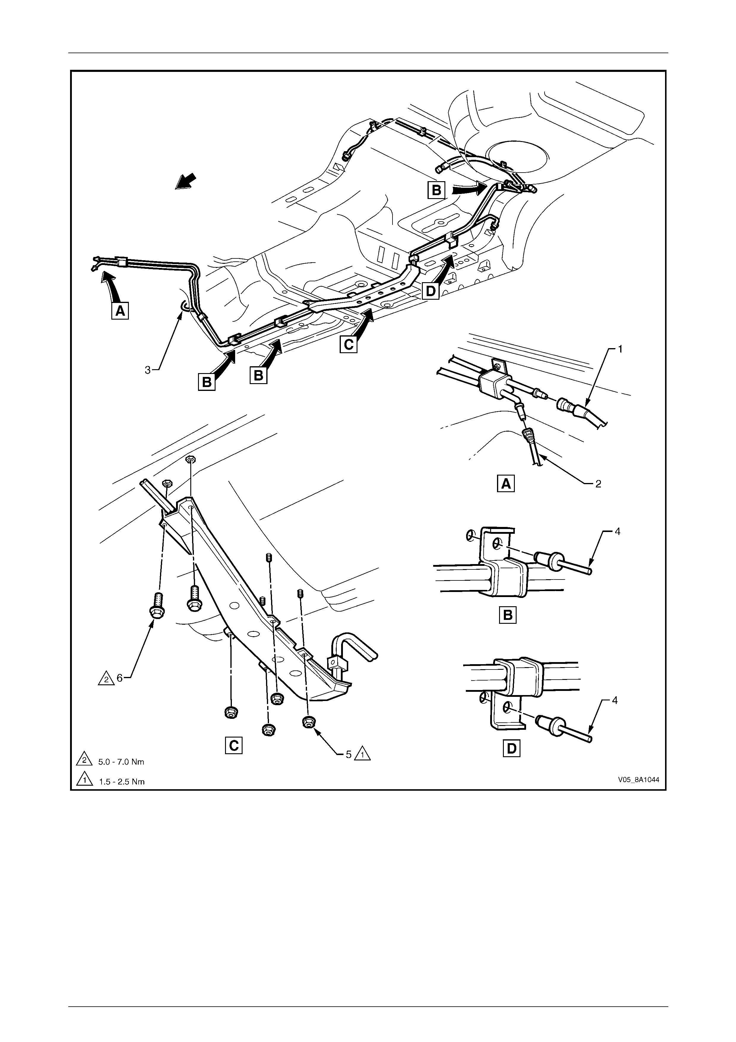
Fuel System Page 8A1–69
Page 8A1–69
Figure 8A1 – 75
Legend
1 Fuel Feed / Fuel Return Line
2 Fuel Vapour Line 3 Brake Fluid Pipe
4 Fuel Line Bracket Pop Rivet 5 Stone Guard Securing Nut
6 Stone Guard Securing Bolt
NOTE
Use tool No. 7371 to remove the fuel feed line (1)
quick-connect fitting, refer to Figure 8A1 – 75.
Use tool No. AU533 to remove the fuel vapour
line quick-connect fitting (2), refer to Tool No.
AU533.

Fuel System Page 8A1–70
Page 8A1–70
Reinstall
Ensure the rubber in the fuel line brackets is
in good condition before proceeding. If not,
replace the affected b racket.
Reinstallation of the stone guards and fuel pipes is the reverse of the removal procedure, noting the foll owing:
1 Tighten the stone guard securing nuts to the correct torque specification.
Stone guard securing nut
torque specification.....................................1.5 – 2.5 Nm
2 Tighten the stone guard securing bolts to the correct torque specification.
Stone guard securing bolt
torque specification.....................................5.0 – 7.0 Nm
Figure 8A1 – 76
Legend
1 Evaporative Emission Control
Canister
2 Electrical Harness Connector
3 Fuel Return Line
4 Fuel Filler Cap
5 Fuel Filler Neck Insulator
6 Modular Fuel Pump and Sender
Assembly
7 Fuel Tank
8 Right-hand Side Fuel Tank Mounting
Strap
9 Centre Fuel Tank Mounting Strap
10 Left-hand Side Fuel Tank Mounting
Strap
11 Insulator Kit
12 Fuel Filter
13 Fuel Filter Mounting Bracket
14 Filler Neck Breather Hose

Fuel System Page 8A1–71
Page 8A1–71
Utility
Remove
A depressurised fuel system contains fuel in
the fuel filter and fuel lines that can be spilled
during service operations.
Fuel vapour remains in the fuel tank even
when completely empty. Seal all openings in
the fuel tank using suitable material or a
plastic plug. Ensure no naked flames or other
ignition sources are nearby. Ensure all
cellular phones (and transmission devices
that may cause any metal objects to become
unintentional receiving antennas) are
switched off.
Place a dry chemical (Class B) fire
extinguisher nearby before performing any
on-vehicle service procedures. Failure to
follow these precautions may result in
personal injury.
Wear safety glasses when using compressed
air. Do not blow compressed air onto any
body part.
1 Remove the fuel pump relay, refer to Section 12O Fuses, Relays and Wiring Harnesses.
2 Depressurise the fuel system, refer to 4.1 Fuel System Depressurisation.
Never drain or store fuel into an open
container, due to the possibility of fire or
explosion.
3 Raise the vehicle, preferably on a hoist, refer to Section 0A General Information.
Before proceedin g, clean all traces of dirt and
other foreign material from the fuel pipes.
4 Use compressed air to ensure that all dirt and foreign materials are removed from all fuel con nections before the
parts are disconnected.
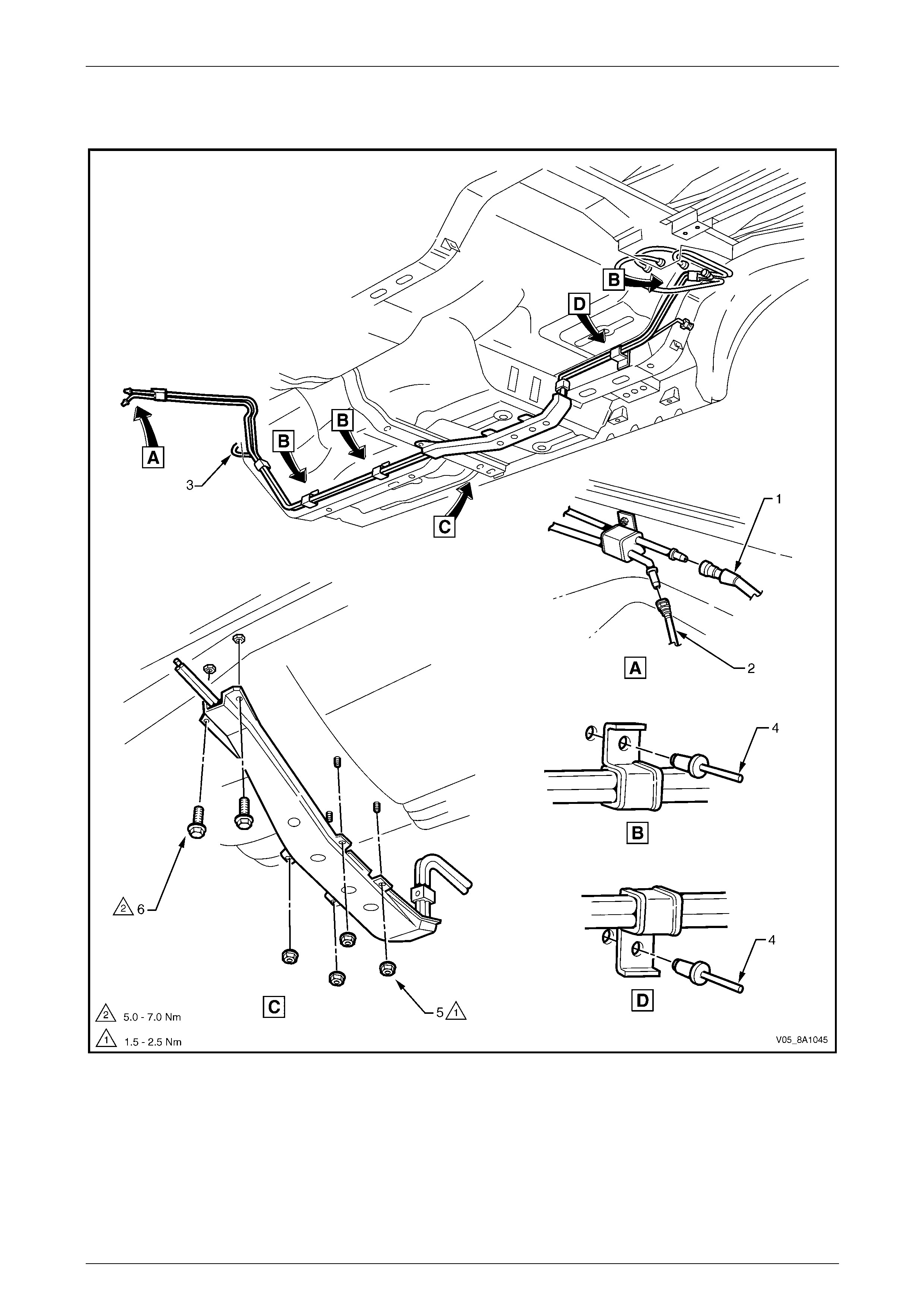
Fuel System Page 8A1–72
Page 8A1–72
5 If required, remove the stone guards and fue l pipes. Use the following illustrations showing the fuel pipe layout
and location of other items relating to the fuel system as a guide, refer to Figure 8A1 – 63, Figure 8A1 – 77 and
Figure 8A1 – 78.
Figure 8A1 – 77
Legend
1 Fuel Feed / Fuel Return Line
2 Fuel Vapour Line
3 Brake Fluid Pipe
4 Fuel Line Bracket Pop Rivet 5 Stone Guard Securing Nut
6 Stone Guard Securing Bolt
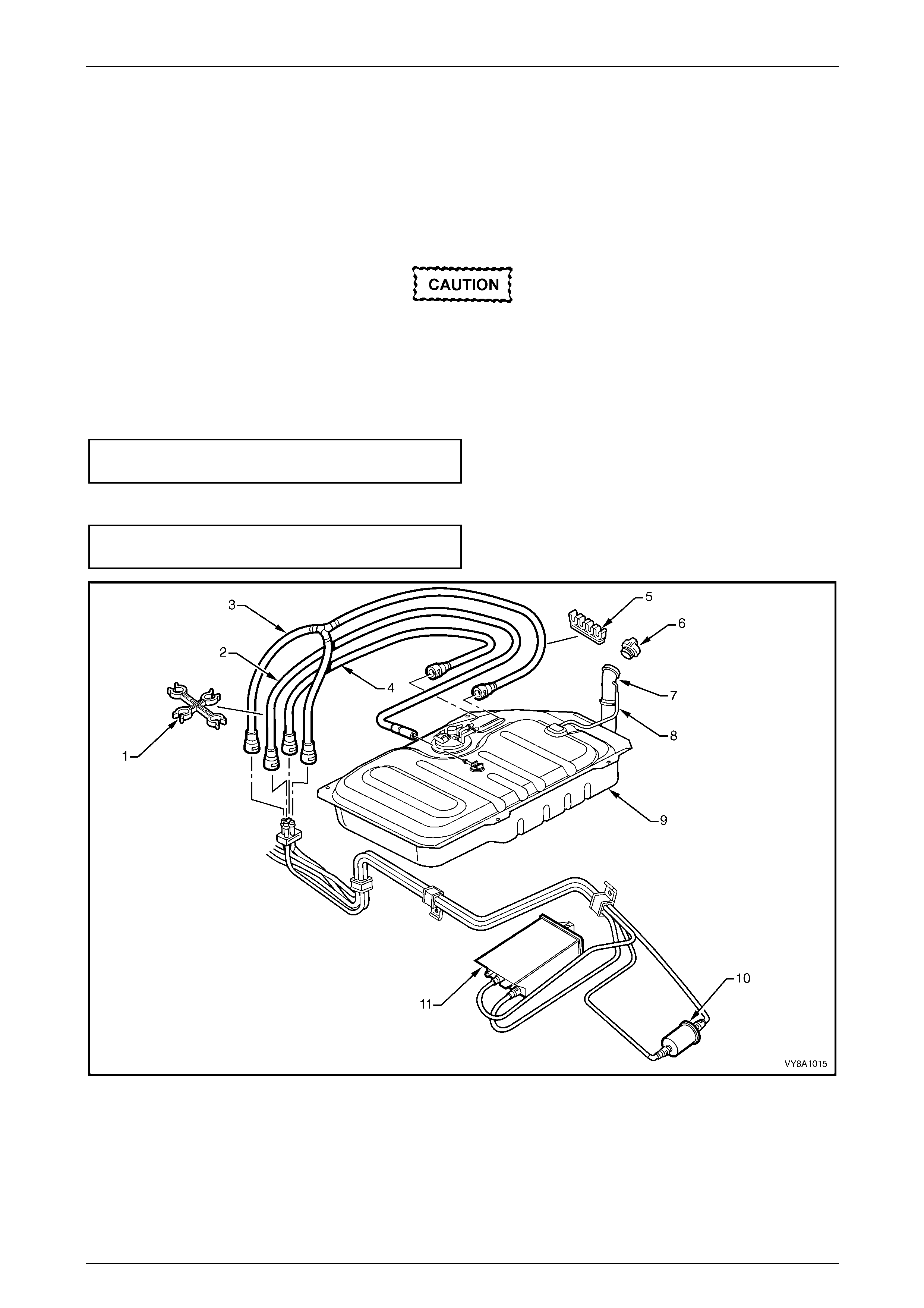
Fuel System Page 8A1–73
Page 8A1–73
NOTE
Use tool No. 7371 to remove the fuel feed line (1)
quick-connect fitting, refer to Figure 8A1 – 77.
Use tool No. AU533 to remove the fuel vapour
line quick-connect fitting (2), refer to Tool No.
AU533.
Reinstall
Ensure the rubber in the fuel line brackets is
in good condition before proceeding. If not,
replace the affected b racket.
Reinstallation of the stone guards and fuel pipes is the reverse of the removal procedure, noting the foll owing:
1 Tighten the stone guard securing nuts to the correct torque specification.
Stone guard securing nut
torque specification.....................................1.5 – 2.5 Nm
2 Tighten the stone guard securing bolts to the correct torque specification.
Stone guard securing bolt
torque specification.....................................5.0 – 7.0 Nm
Figure 8A1 – 78
Legend
1 Mounting Clip
2 Fuel Vapour Hose
3 Fuel Return Line
4 Fuel Feed Line
5 Mounting Clip
6 Fuel Filler Cap
7 Fuel Filler Neck
8 Fuel Tank Vent Hose
9 Fuel Tank
10 Fuel Filter
11 Evaporative Emission Control
Canister
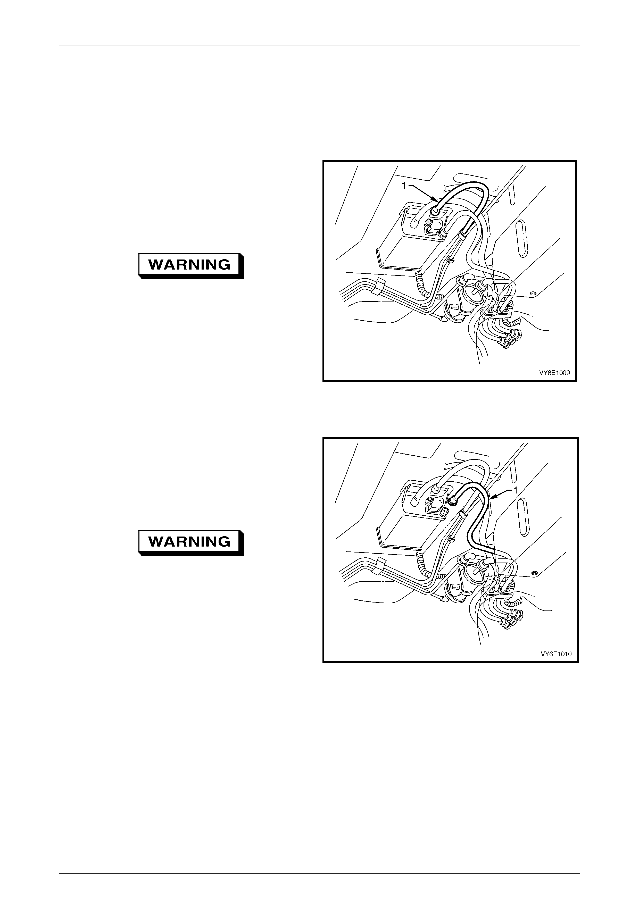
Fuel System Page 8A1–74
Page 8A1–74
5.9 Evaporative Emission Control Canister
LT Section No. — 03–165
Remove
1 Disconnect the evaporative emission control canister
purge line (1) by using the following procedure:
a Grasp both sides of the quick-connect fitting.
Twist the connector 1/4 turn in each direction in
order to loosen any dirt within the quick-conn ect
fitting.
Wear safety glasses w hen usin g compressed
air. Do not blow compressed air onto any
body part.
b Using compressed air, blow any dirt out of the
quick-connect fitting.
c Grasp the quick-connect fitting and push it
towards the canister.
d Squeeze the quick-connect fitting to release the
retaining tabs, then pull back on the connector to
remove the canister purge line from the canister.
Figure 8A1 – 79
2 Disconnect the fuel tank vent line (1) by using the
following procedure:
a Grasp both sides of the quick-connect fitting.
Twist the connector 1/4 turn in each direction in
order to loosen any dirt within the quick-conn ect
fitting.
Wear safety glasses w hen usin g compressed
air. Do not blow compressed air onto any
body part.
b Using compressed air, blow any dirt out of the
quick connect fitting.
c Grasp the quick-connect fitting and push it
towards the canister.
d Squeeze the quick-connect fitting to release the
retaining tabs, then pull back on the connector to
remove the tank vent line from the canister.
Figure 8A1 – 80
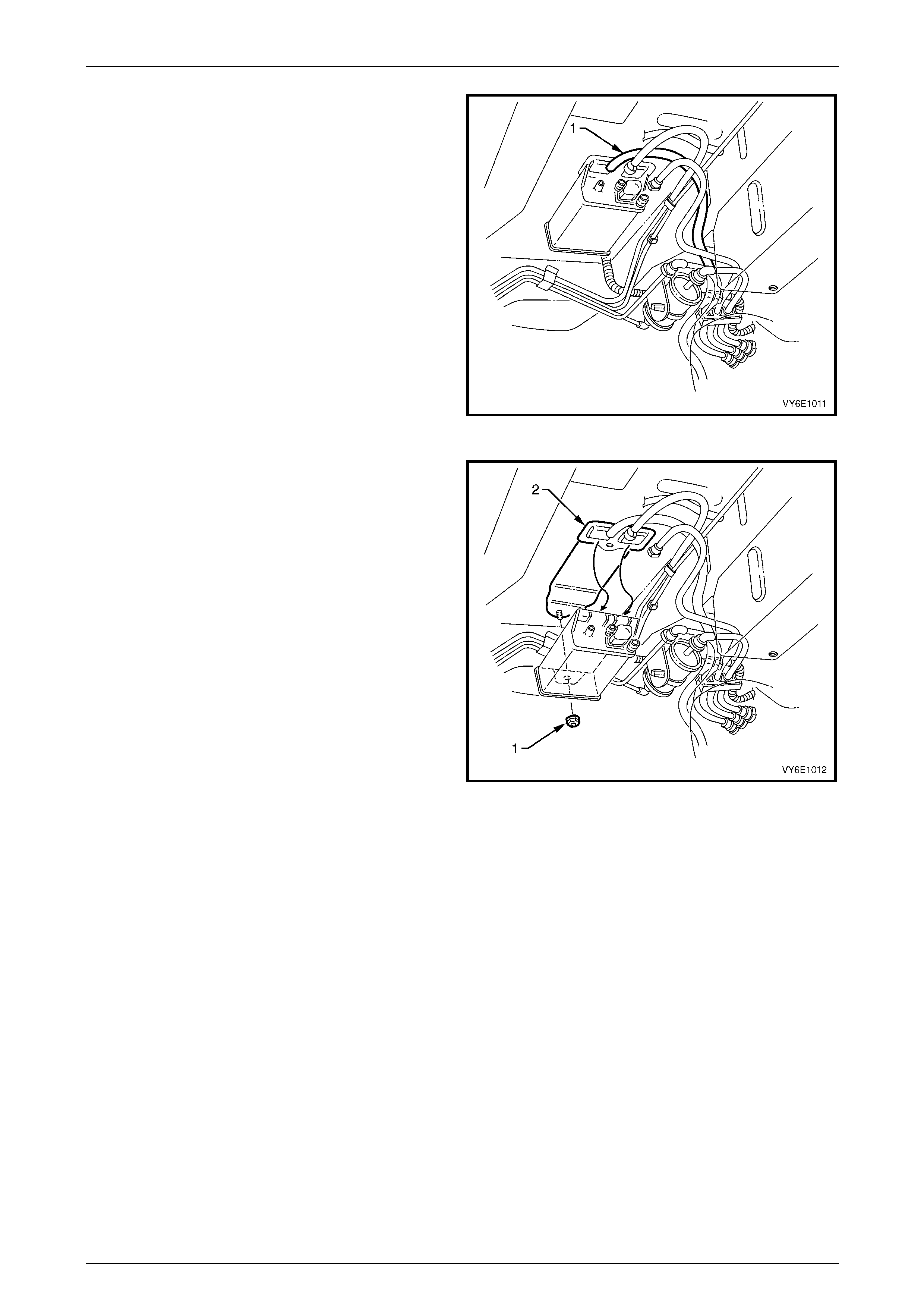
Fuel System Page 8A1–75
Page 8A1–75
3 Remove the canister vent line (1) from the canister by
twisting and pulling it off.
Figure 8A1 – 81
4 Remove the canister retaining nut (1).
5 Remove the canister from the retaining stud and then
slide the canister out of the retainer (2).
Figure 8A1 – 82
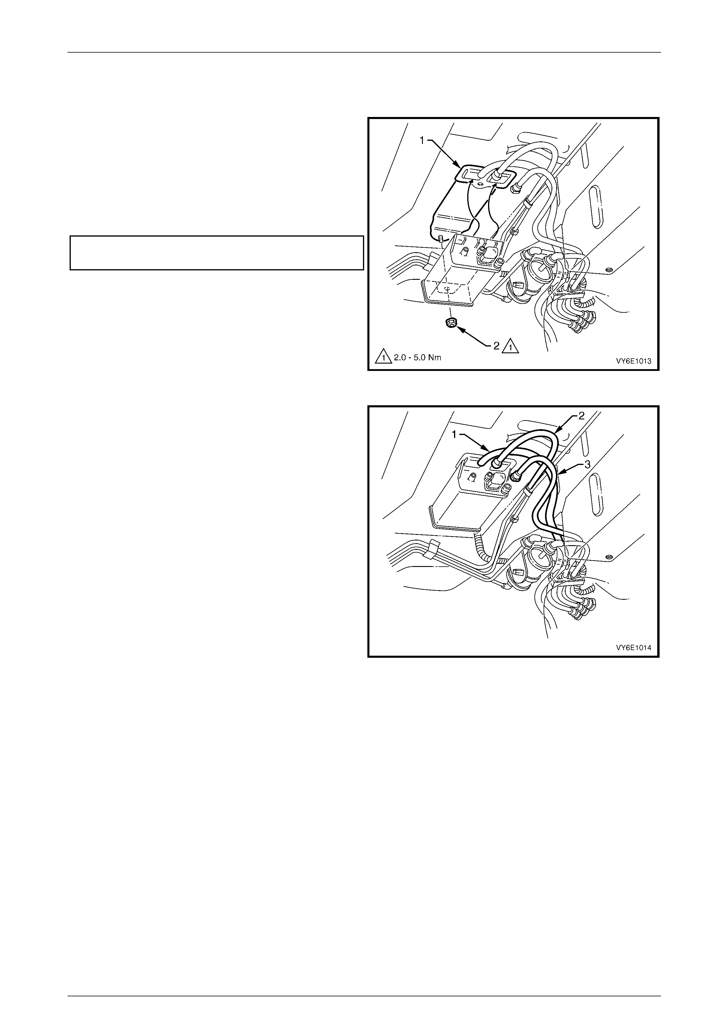
Fuel System Page 8A1–76
Page 8A1–76
Reinstall
1 Hoist the vehicle, refer to Section 0A General Information.
2 Reinstall the canister into the retainer (1) and over the
retaining stud.
3 Reinstall the canister retaini ng nut (2), then hand-
tighten.
4 Push the canister toward the centre of the vehicle and
tighten the canister retaining nut to the specified
torque.
Evaporative emission control canister
retaining nut torque specification ................2.0 – 5.0 Nm
Figure 8A1 – 83
5 Reinstall the canister vent lin e (1).
6 Align the canister purge line quick-connect (2) with the
canister purge line port. Push the quick-connect firmly
onto the port.
7 Align the fuel tank vent line quick-co nnect (3) with the
fuel tank vent port. Push the quick-connect firmly onto
the port.
8 After installation, pull on each quick-c onnect to ensure
the connections are secure and lock ed in position.
Figure 8A1 – 84
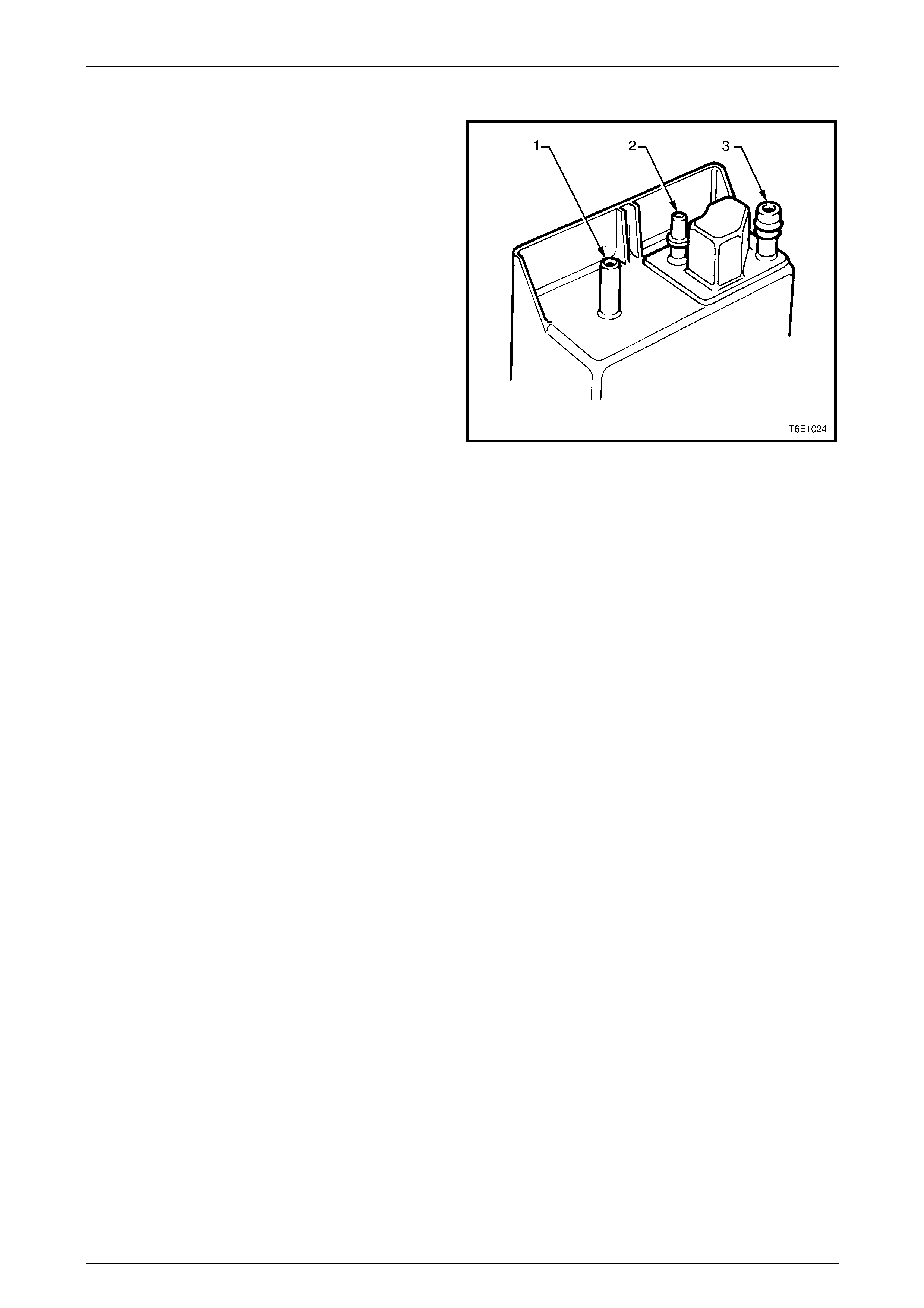
Fuel System Page 8A1–77
Page 8A1–77
Service Checks
1 Remove the canister, refer to 5.9 Evaporative
Emission Control Canister.
2 Shake the canister. There should be no audible sound
of carbon movement.
3 Using low pressure compressed air (20–35 kPa), blo w
into the tank vent port (3). Check that air flows freely
from the canister vent port (1). Block the canister vent
port (1); air should flow from the canister purge
port (2).
4 If airflow through the canister vent port (1) is limited,
clean the atmospheric filter b y blocking off the fuel
tank vent port (3) and blow compressed air at
approximately 300 kPa throug h the canister purge
port (2).
5 Check airflow through the filte r as in step 3. If airflow
through the canister vent port (1) is still limit ed, replace
the canister.
Figure 8A1 – 85
6 Block the canister vent port (1) and the canis t er purge port (2). Apply low-pressure compressed air
(20–35 kPa) to the tank vent port (3). If any air leaks from the canister (that is, around the ports or seams), replace
the canister.
NOTE
In dusty areas, an alternative is to block the
canister purge port (2). Blow air through the
canister vent (1) port and check that air is
expelled through the tank vent port (3).
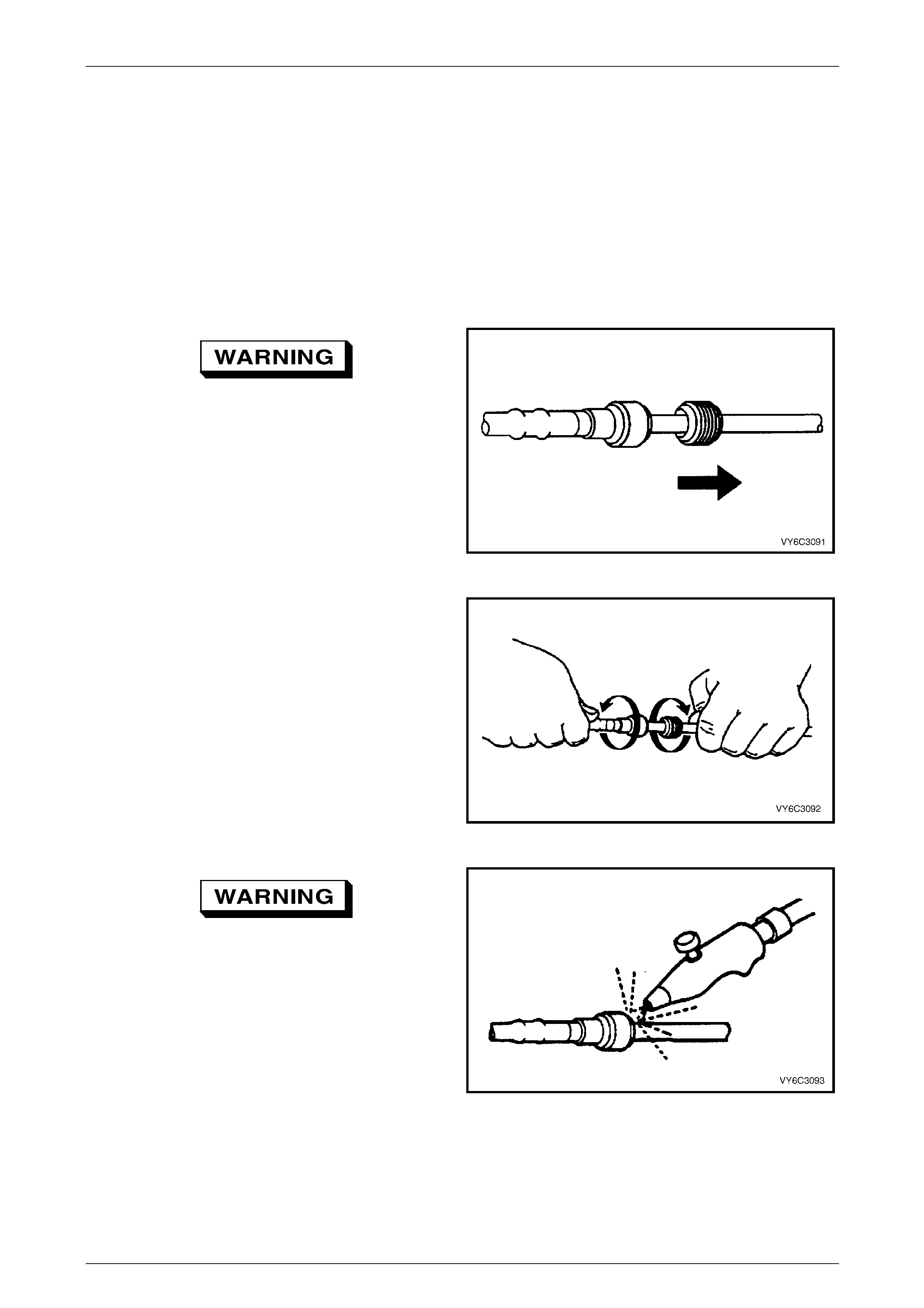
Fuel System Page 8A1–78
Page 8A1–78
6 Service Operations — Coupe
6.1 Quick-connect Fittings
Quick-connect Fittings (Metal Collar)
LT Section No. — 03–075
Remove
To reduce the risk of fire or personal injury,
relieve the fuel system pressure before
servicing any fuel system components, refer
to 4.1 Fuel System Depressurisation.
1 If fitted, slide the dust cover from the quick-connect
fitting.
Figure 8A1 – 86
2 Grasp both sides of the quick-connect fitting. Twist the
female side of the quick-connect fitting 1/4 turn in each
direction to loosen any dirt.
Figure 8A1 – 87
Wear safety glasses w hen usin g compressed
air. Do not blow compressed air onto any
body part.
3 Use compressed air to ensure that all dirt and foreign
materials are removed from all fuel conn ections before
the parts are disconnected.
Figure 8A1 – 88
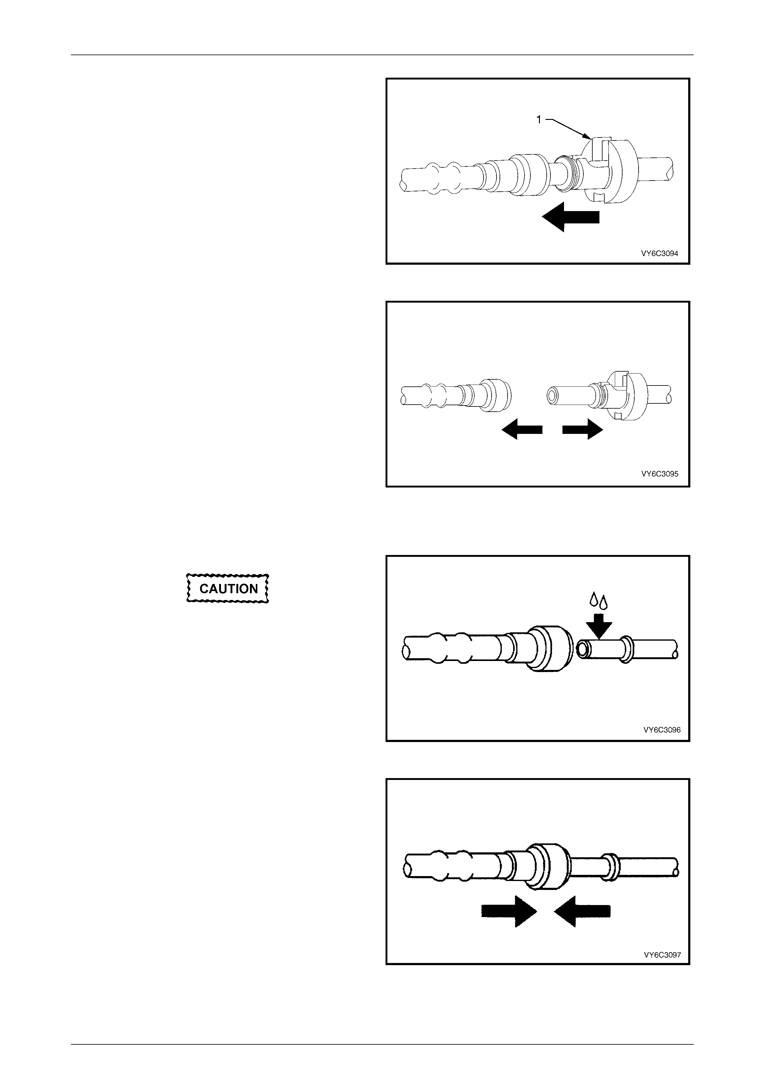
Fuel System Page 8A1–79
Page 8A1–79
4 Choose the correct tool (1) to disconnect the quick-
connect fitting, refer to Tool Nos. 7370 and 7371.
Insert the tool into the female connector, then push
inward to release the locking t abs.
Figure 8A1 – 89
5 Pull the quick-connect fitting apart.
NOTE
If it is necessary to remove rust or burrs from a
fuel pipe, use emery cl oth in a radial motion with
the fuel pipe end to prevent damage to the
O-ring sealing surface.
6 Using a clean shop towel to wipe off the male pipe
end.
7 Inspect both ends of the fitting for dirt and burrs. Clean
or replace the components as required.
Figure 8A1 – 90
Reinstall
During normal operation, the O-ring located
in the female connector swells. To ensure
proper fitting, lubricate the male pipe end
before assembly.
1 Apply a few drops of clean engin e oil to the male pipe
end.
Figure 8A1 – 91
2 Push both sides of the quick-connect fitting together to
snap the retaining tabs into place.
Figure 8A1 – 92
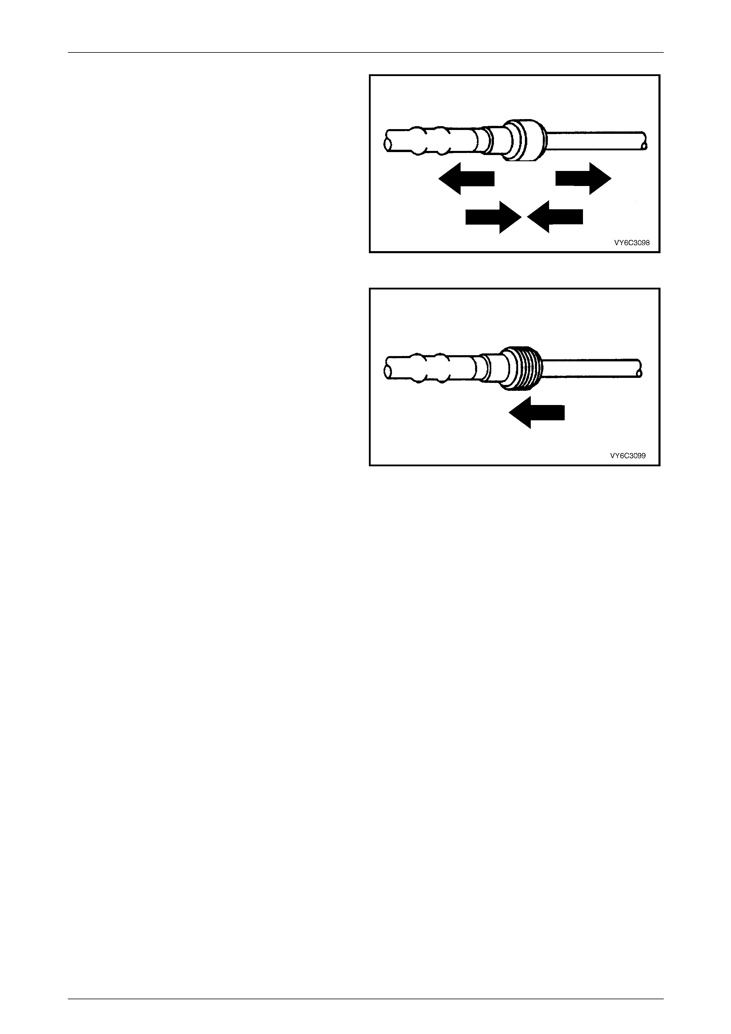
Fuel System Page 8A1–80
Page 8A1–80
3 After installation, pull on both sides of the quick-
connect fitting to ensure the connection is secure.
Figure 8A1 – 93
4 Reposition the dust cover over the quick-con nect
fitting (if fitted).
Figure 8A1 – 94
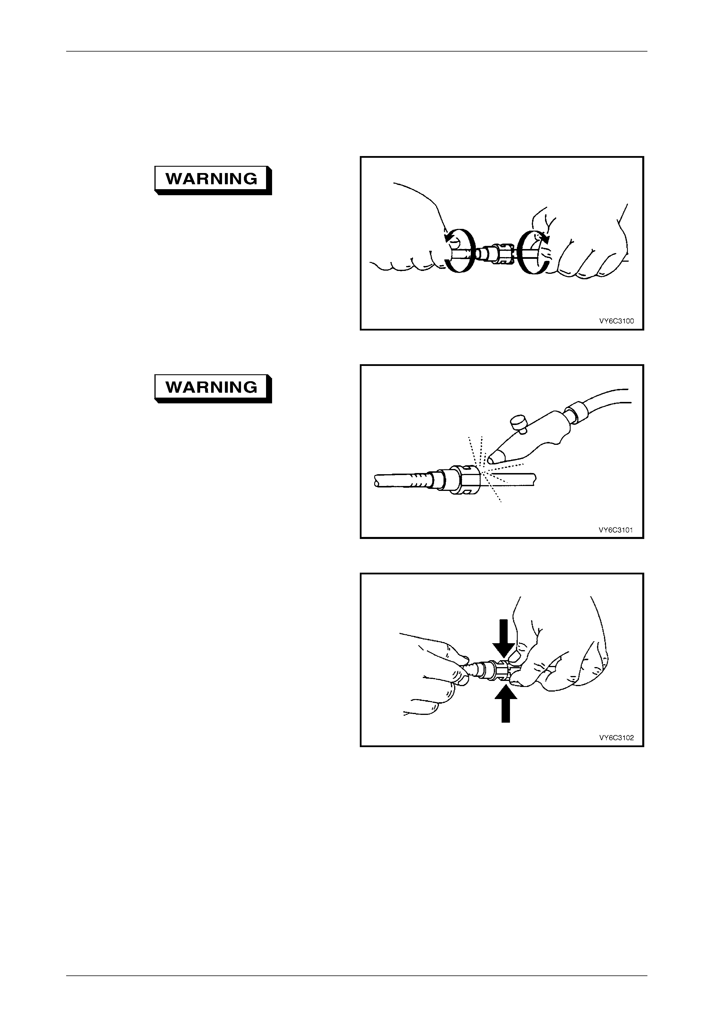
Fuel System Page 8A1–81
Page 8A1–81
Quick-connect Fittings (Plastic Collar)
LT Section No. — 03–075
Remove
To reduce the risk of fire or personal injury,
relieve the fuel system pressure before
servicing any fuel system components, refer
to 4.1 Fuel System Depressurisation.
1 Grasp both sides of the quick-connect fitting. Twist the
female side of the quick-connect fitting 1/4 turn in each
direction to loosen any dirt.
Figure 8A1 – 95
Wear safety glasses w hen usin g compressed
air. Do not blow compressed air onto any
body part.
2 Use compressed air to ensure that all dirt and foreign
materials are removed from all fuel conn ections before
the parts are disconnected.
Figure 8A1 – 96
3 Squeeze the plastic retainer release tabs.
NOTE
Alternatively, use tool No. AU533 to release the
quick connect fitting:
• red = 5/16-inch fittings (fuel vapour lines), or
• blue = 3/8-inch fittings (fuel feed lines).
Figure 8A1 – 97
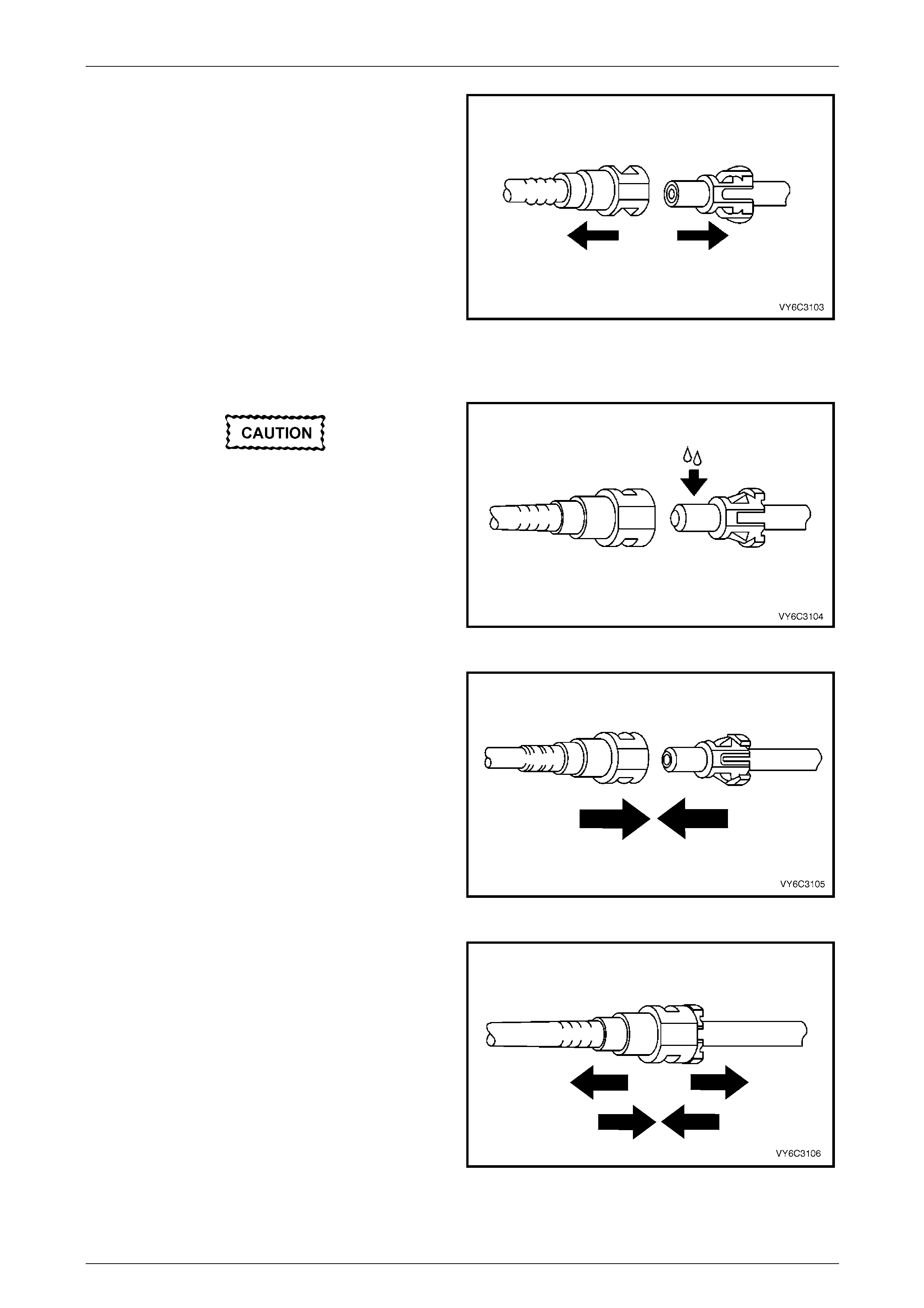
Fuel System Page 8A1–82
Page 8A1–82
4 Pull the quick-connect fitting apart.
Figure 8A1 – 98
Reinstall
During normal operation, the O-ring located
in the female connector swells. To ensure
proper fitting, lubricate the male pipe end
before assembly.
1 Apply a few drops of clean engin e oil to the male pipe
end.
Figure 8A1 – 99
2 Push both sides of the quick-connect fitting together to
snap the retaining tabs into place.
Figure 8A1 – 100
3 After installation, pull on both sides of the quick-
connect fitting to ensure the connection is secure.
Figure 8A1 – 101

Fuel System Page 8A1–83
Page 8A1–83
Tool No. AU533
This procedure describes the removal of the quick-connect fittings on the fuel filter using tool No. AU533. This procedure
also applies to other quick-connect fittings.
Remove
1 Grasp both sides of the quick-connect fitting. Twist the
quick-connect fitting one quarter of a turn in e ach
direction to loosen any dirt within the quick-connect
fitting.
Figure 8A1 – 102
Wear safety glasses w hen usin g compressed
air. Do not blow compressed air onto any
body part.
2 Using compressed air, blow any dirt out of the quick-
connect fitting.
Figure 8A1 – 103
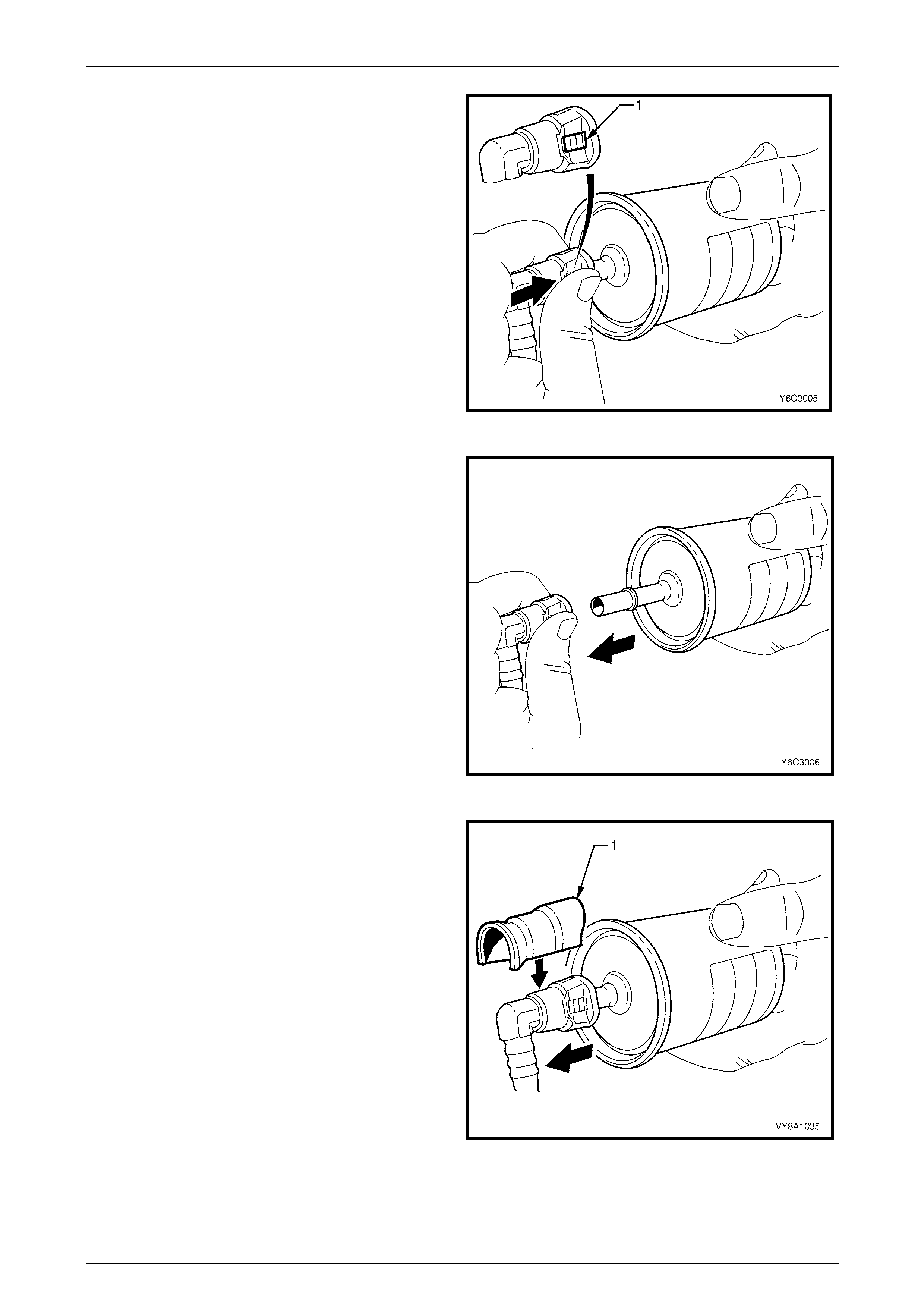
Fuel System Page 8A1–84
Page 8A1–84
3 Grasp the female part and firmly support the male
part.
4 Squeeze the plastic retainer release tabs (1) on each
side of the quick-connect fitting while pus hing the
quick-connect fitting firmly inwards to release an y
tension on the release tabs.
Figure 8A1 – 104
5 While pressing the releas e tabs, pull the quick-connect
fitting apart.
Figure 8A1 – 105
6 Alternatively, for step 3 to step 5 inclusive, use tool
No. AU533 (1) to squeeze the release tabs and
release the quick-connect fittings.
NOTE
Tool No. AU533 will work only with retainer tabs
that sit proud of the connector body. Some filter
connectors have flush retainers that can be
pressed only by hand.
Figure 8A1 – 106
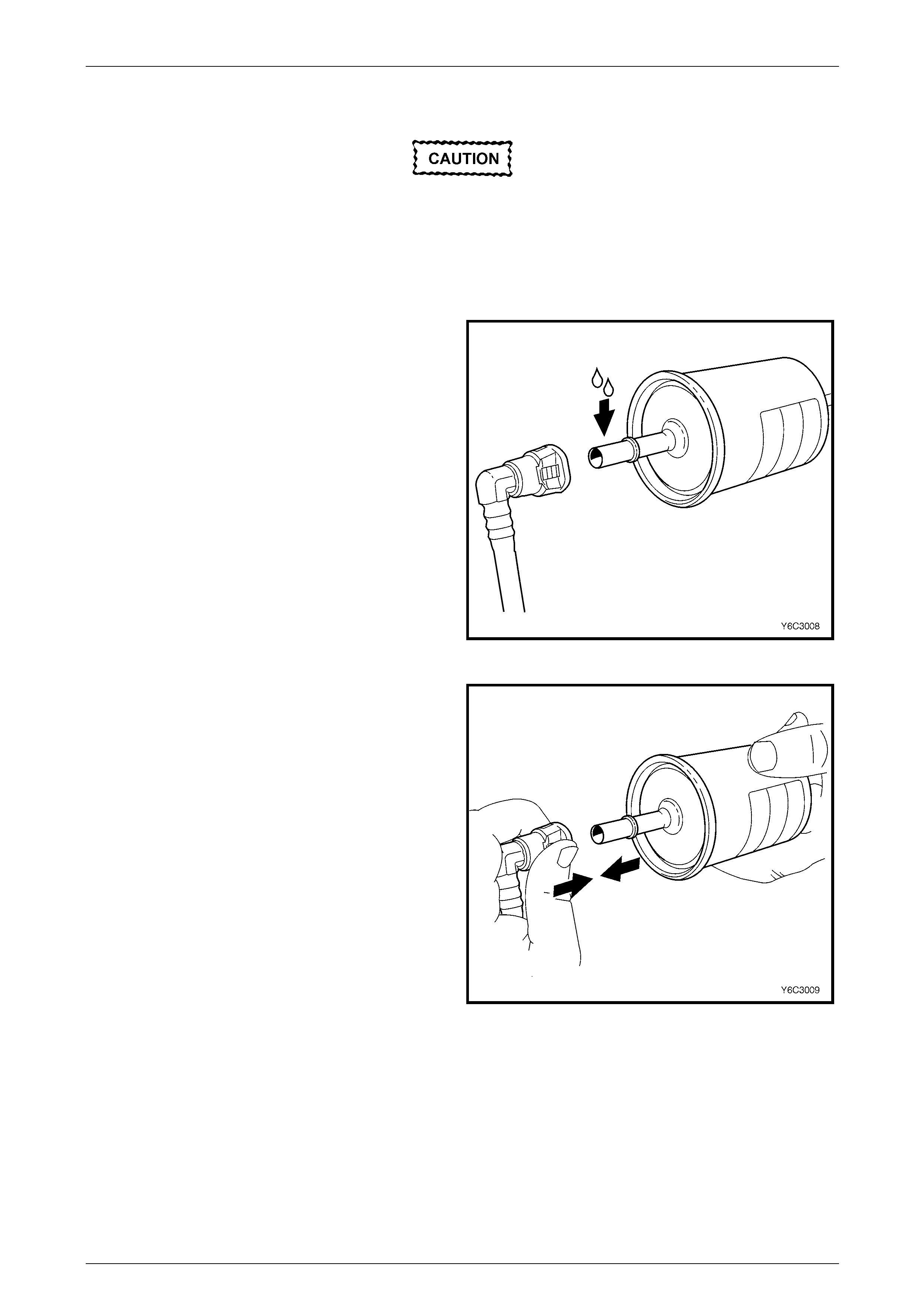
Fuel System Page 8A1–85
Page 8A1–85
Reinstall
Before connecting quick-connect fittings,
apply a few drops of clean engine oil to the
male part. This ensures proper connection
and prevents a possible fuel leak. During
normal operation, the O-ring located in the
female part swells and may prevent proper
reconnection if not lubricated.
1 Apply a few drops of clean engine oil to each male
part.
Figure 8A1 – 107
2 Push both parts of the quick-connect fitting together so
the retaining tabs snap into place.
Figure 8A1 – 108
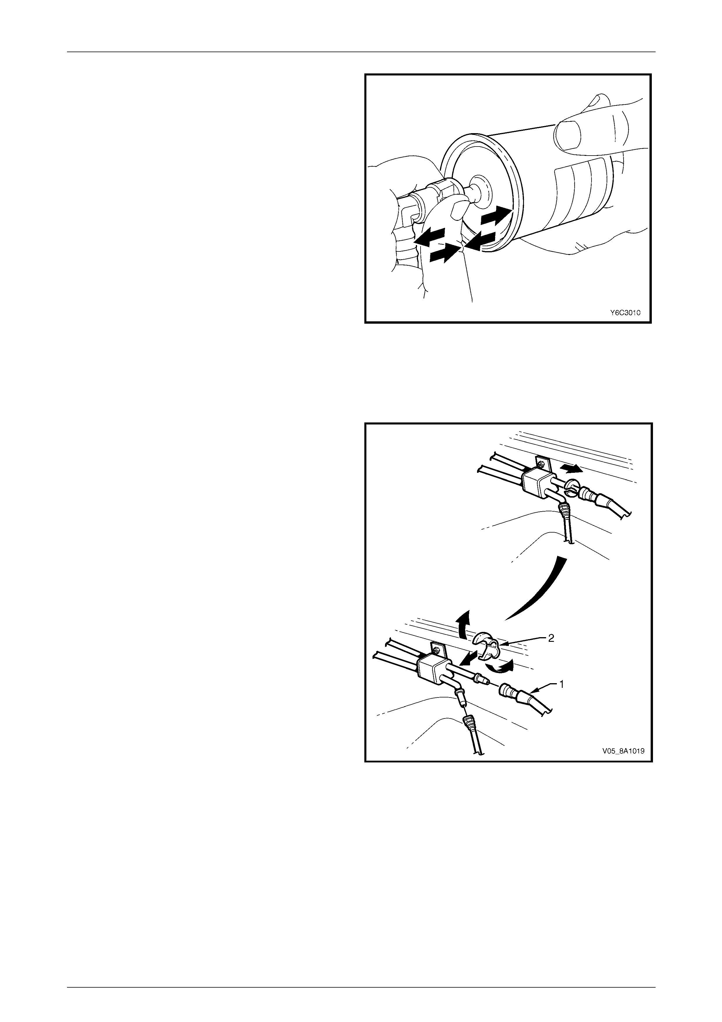
Fuel System Page 8A1–86
Page 8A1–86
3 After installation, pull and push on the quick-connect
fitting to ensure the connection is secure.
Figure 8A1 – 109
Tool Nos. 7370 and 7371
Remove
Use tool Nos. 7370 and 7371 to disconnect the fuel lines at
the engine as follows:
1 Open the quick-connect release tool (2) and place it
over the fuel line (1).
2 Close the quick-connect release tool and pull it into the
fuel line quick-connect fitting to disconnect the fuel line
from the fuel pipe.
NOTE
Do not disconnect the fuel lines at th e fuel rail. If
the fuel lines are removed from the fuel rail, the
fuel lines must be replaced.
Figure 8A1 – 110
Reinstall
Reinstallation of the disconnected quick-connect fittings using tool Nos. 7370 and 7371 is the same as for tool
No. AU533, refer to Tool No. AU533.
Fuel System Page 8A1–87
Page 8A1–87
6.2 Fuel Tank Siphon Procedure
Fuel vapour remains in the modular fuel pump
and sender assembly and fuel lines that can
be spilled during service operations. Ensure
no naked flames or oth er ignition sources are
nearby. Ensure all cellular phones (and
transmission devices that may cause any
metal objects to become unintentional
receiving antennas) are switched off.
Place a dry chemical (Class B) fire
extinguisher nearby before performing any
on-vehicle service procedures. Failure to
follow these precautions may result in
personal injury.
For an exploded view of fuel tank components, refer to Figure 8A1 – 10.
1 Depressurise the fuel system, refer to 4.1 Fuel System Depressurisation.
2 Reinstall the fuel pump rela y, refer to Section 12O Fuses, Relays and Wiring Harnesses.
Disconnecting the battery affects certain
vehicle electronic systems. Refer to
Section 00 Warnings, Cautions and Notes
before dis-connecting the battery.
3 Disconnect the negative battery terminal.
4 Remove the fuel filler cap.
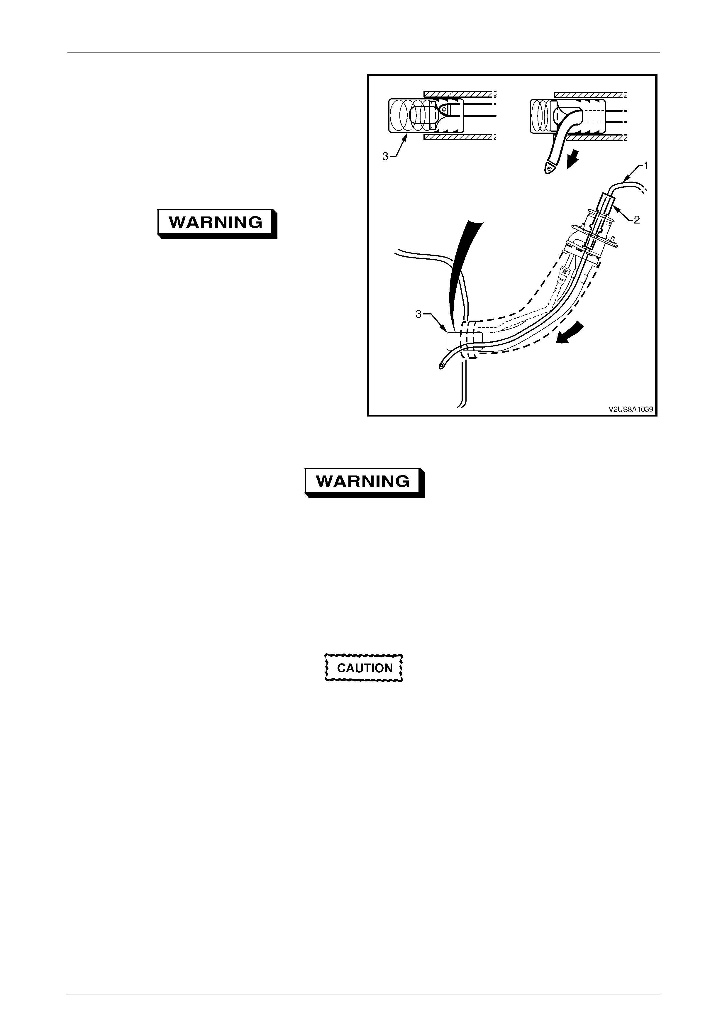
Fuel System Page 8A1–88
Page 8A1–88
NOTE
Lubricate the fuel siphon hose with J36850
TransJel Transmission Assembly Lubricant or
equivalent to aid hose insertion. Use only an
approved lubricant.
5 Install J44284–2 flapper door holder (2) into the fuel
filler neck to hold the door open.
Do not siphon, drain or store fuel into an
open container, due to the possibility of fire
or explosion, or contamination. Always use
and approved fuel storage co ntainer.
6 Insert the J45004–1 fuel tank siphon hose (1) into the
fuel tank filler neck and gradually twist it until the tip of
the hose meets the fuel tank check valve (3) and
continues to the bottom of the fuel tank.
7 Use a hand-operated or air-o perated pump device to
siphon as much fuel through the fuel fill pipe as
possible.
Figure 8A1 – 111
Fuel vapour remains in the fuel tank even
when completely empty. Seal all openings in
the fuel tank using suitable material or a
plastic plug. Ensure no naked flames or other
ignition sources are nearby. Ensure all
cellular phones (and transmission devices
that may cause any metal objects to become
unintentional receiving antennas) are
switched off.
Do not use excessive force when removing
the fuel siphon hose from the fuel filler neck.
If the fuel siphon hose gets stuck upon
removal, gently twist and tug the fuel siphon
hose back and forth until it releases.
NOTE
If fuel does not siphon from the fuel ta nk, the fuel
siphon hose may have entered the fuel tank
through a roof-facing check valve opening. If
required, insert the J45004–1 fuel siphon
hose (1) into the fuel tank filler neck, refer to
Figure 8A1 – 111, but twist the fuel siphon hose
90° as it slides down the filler neck. This enables
the fuel siphon hose to enter the fuel tank through
a floor-facing check valve opening.

Fuel System Page 8A1–89
Page 8A1–89
NOTE
The siphon procedure will not remove all fuel
from the fuel tank. If required, fuel remaining in
the fuel tank may be siphoned out through the top
of the fuel tank, once the modular fuel pump and
sender assembly is removed from the tank, refer
to 6.5 Modular Fuel Pump and Sender Assembly.
8 Remove the siphon equipment.
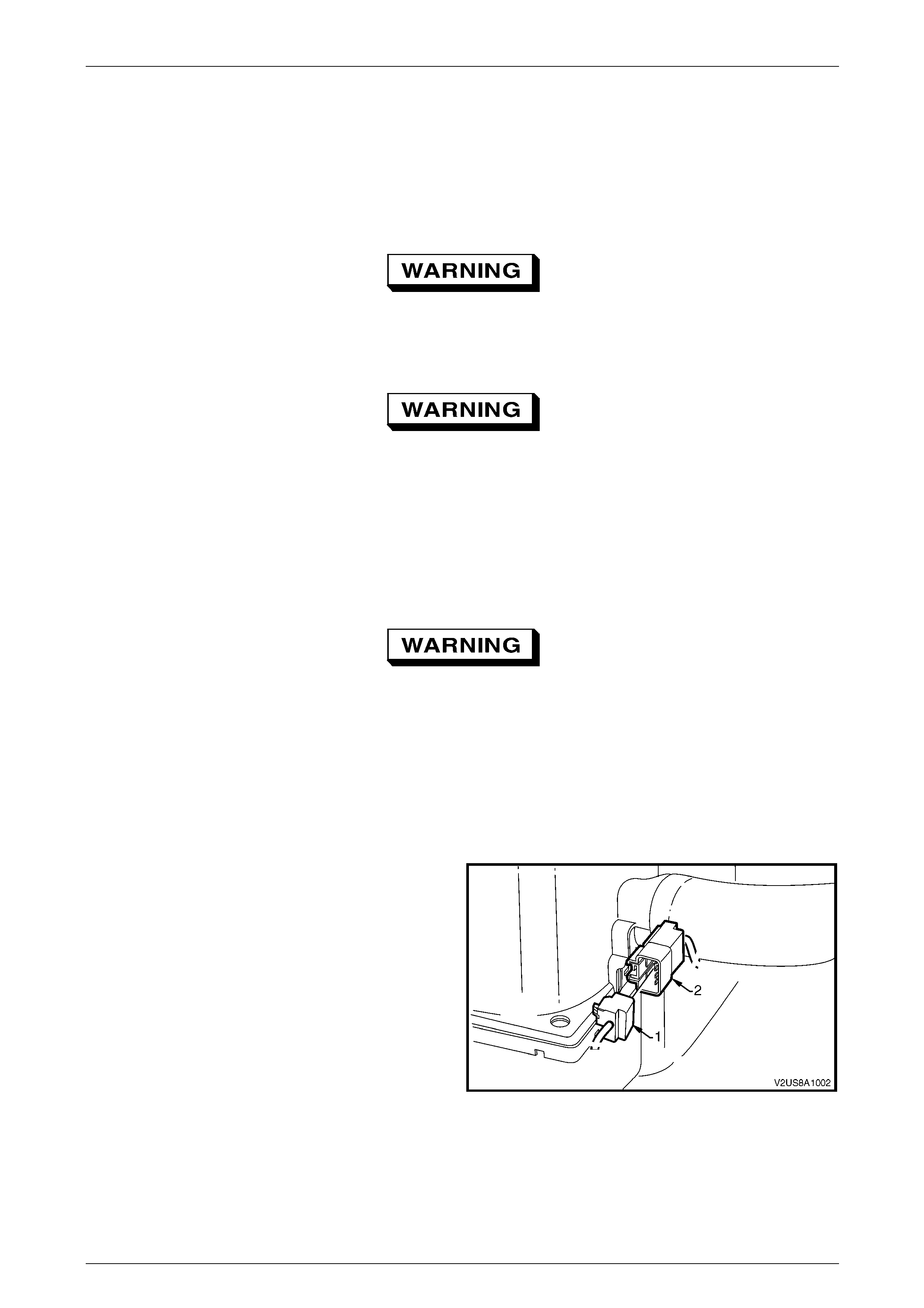
Fuel System Page 8A1–90
Page 8A1–90
6.3 Fuel Tank
LT Section No. — 03–055
Remove
A depressurised fuel system contains fuel in
the fuel filter and fuel lines that can be spilled
during service operations.
Fuel vapour remains in the fuel tank even
when completely empty. Seal all openings in
the fuel tank using suitable material or a
plastic plug. Ensure no naked flames or other
ignition sources are nearby. Ensure all
cellular phones (and transmission devices
that may cause any metal objects to become
unintentional receiving antennas) are
switched off.
Place a dry chemical (Class B) fire
extinguisher nearby before performing any
on-vehicle service procedures. Failure to
follow these precautions may result in
personal injury.
For an exploded view of fuel tank components, refer to Figure 8A1 – 10.
1 Siphon as much fuel as possible from the fuel tank, refer to 6.2 Fuel Tank Siphon Procedure.
2 Remove the frame assembly to access the fuel tank, refer to Section 1A1 Body.
3 Disconnect the body wiring ha rness to fuel tank wiring
harness connector (1) by pressing the re lease tang on
the inboard face of the connector and pu lling the
connector from the fuel tank wiring harness
connector (2).
Figure 8A1 – 112

Fuel System Page 8A1–91
Page 8A1–91
4 From behind the fuel filler doo r (1), unscrew the fuel
filler cap (4) and cover the end of the fuel filler neck
with a suitable material to prevent foreig n objects from
entering the fuel tank.
5 Remove the three nuts (2) securing the fuel filler neck
to the fuel filler pocket (3).
Figure 8A1 – 113
6 From underneath the vehicle, refer to Figure 8A1 – 114:
a Disconnect the fuel feed line quick-connect fitting (1) usi ng tool No. AU533 (3/8-inch), refer to Tool No.
AU533.
b Disconnect the fuel tank to fuel feed line quick-connect fitting (2) and place the feed line in a safe location
away from the immediate worksite.
c Remove the fuel tank vent line quick-connect fitting (3).
NOTE
After removing the fuel tank vent line quick-
connect fitting (1), it may be necessary to tug the
fuel tank vent line downwards to clear the quick-
connect fitting from the underbody p anelling. This
enables enough room to disconnect the quick-
connect fitting.
NOTE
For general information on correct servicing
procedures using quick-connect fittings, refer to
6.1 Quick-connect Fittings.
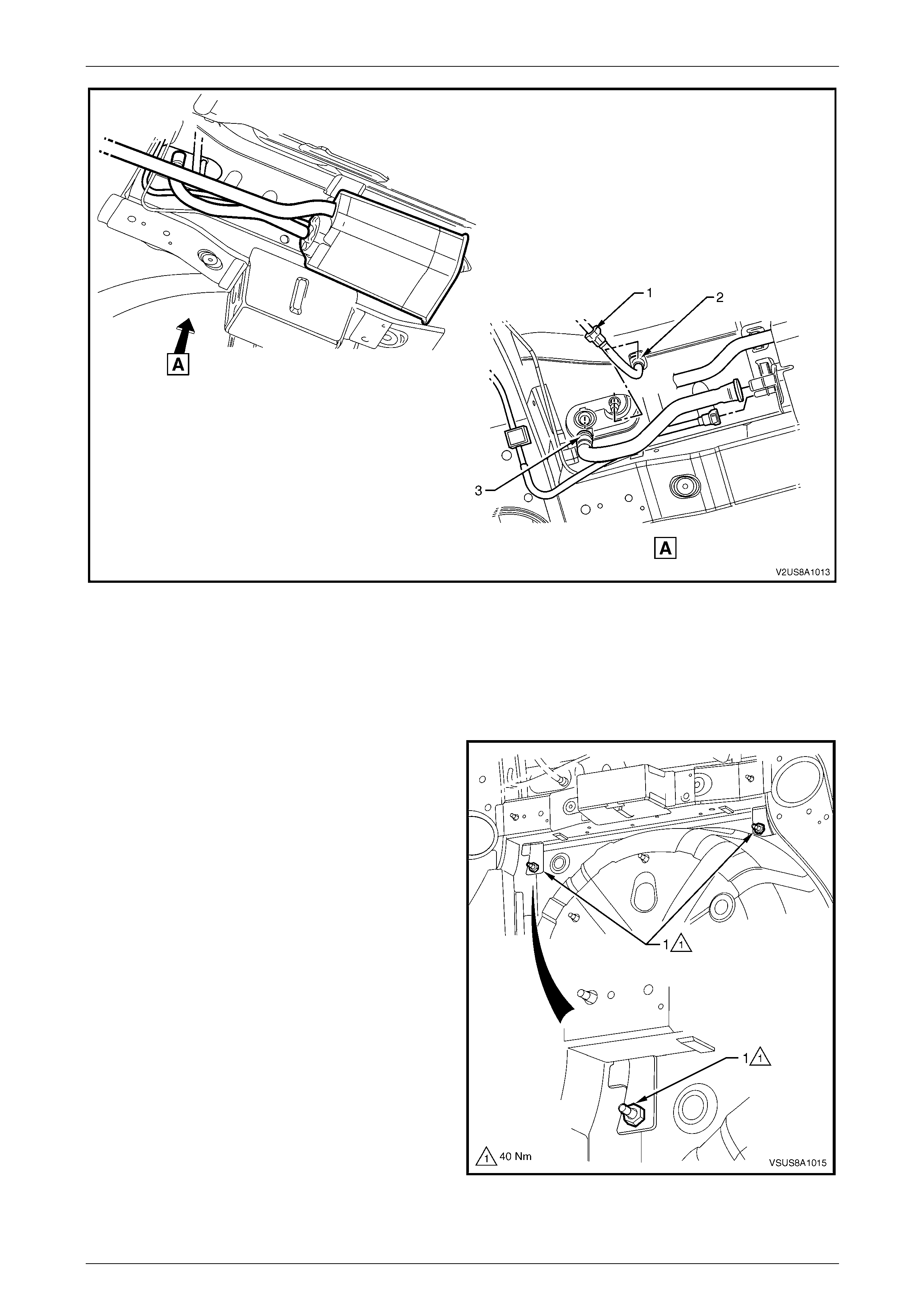
Fuel System Page 8A1–92
Page 8A1–92
Figure 8A1 – 114
Legend
1 Fuel Feed Line Quick-connect Fitting
2 Fuel Tank to Fuel Feed Line Quick-connect Fittings 3 Fuel Tank Vent Line Quick-connect Fitting
d If required, remove the rear underbody air
deflector to vehicle fastening bolts and nuts to
allow the rear underbody air deflector to be
pulled down. This allows improved access to the
fuel tank lower mounting strap nuts (1), refer to
Section 1A1 Body.
NOTE
The rear underbody air deflector is shown fully
removed for visual purposes only. Full removal
of the rear underbody air deflector is not
essential for this procedure.
7 Lower the vehicle. From within the rear compartment,
remove both fuel tank upper mounting strap nuts
(1) and remove both mounting straps (3), refer to
Figure 8A1 – 116.
Figure 8A1 – 115
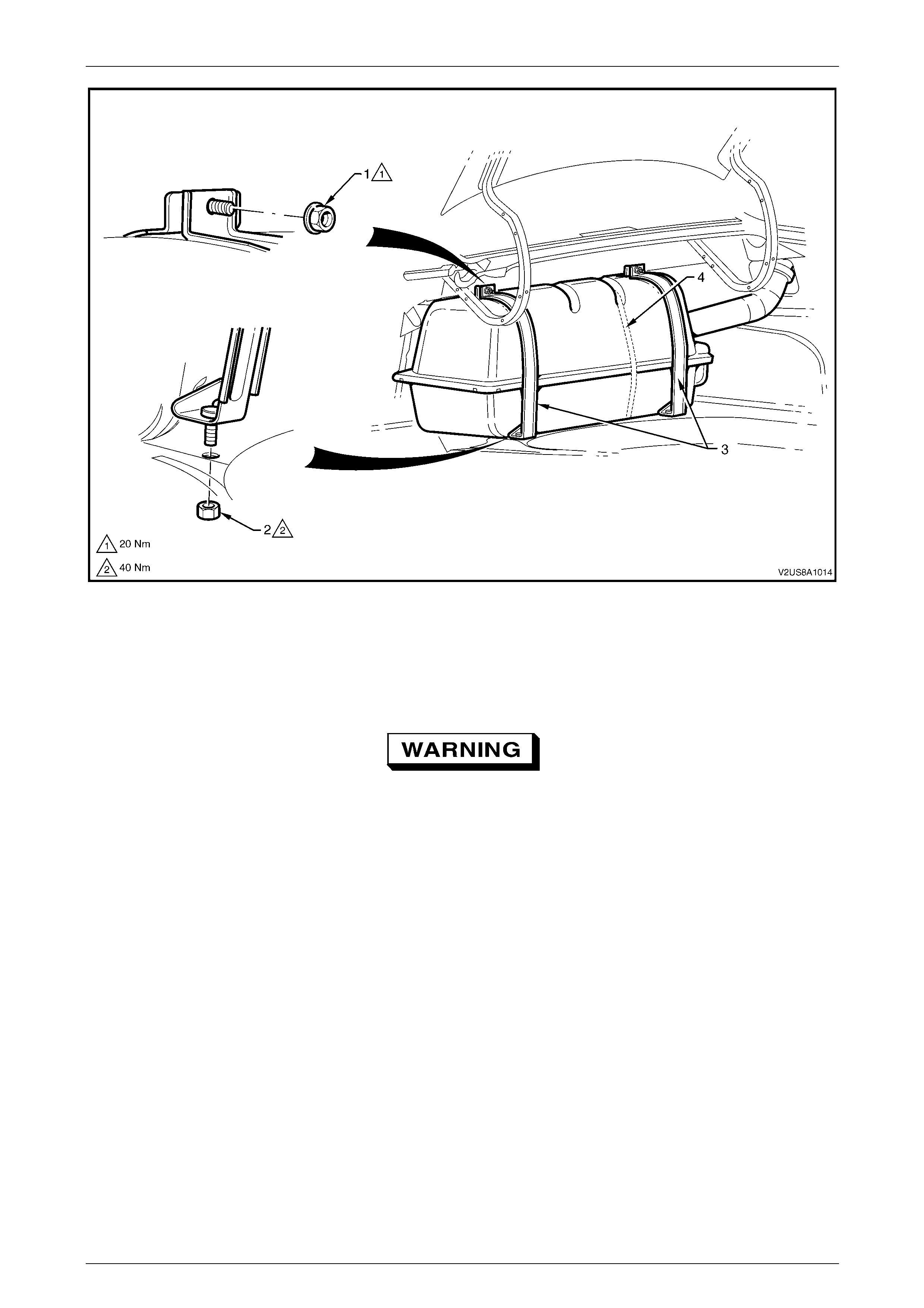
Fuel System Page 8A1–93
Page 8A1–93
Figure 8A1 – 116
Legend
1 Mounting Strap Upper Fastening Nut (2 places)
2 Mounting Strap Lower Fastening Nut (2 places) 3 Mounting Strap
4 Shipping Strap
The fuel tank will still contain fuel and may be
heavy. Ensure appropriate workshop lifting
practices are used during removal of the fuel
tank.
8 With the assistance of another person, remove the fuel tank and fuel filler neck from the vehicl e.
9 If installed, cut and dispose of the shipping strap (4), refer to Figure 8A1 – 116.
NOTE
The shipping strap is used for fuel tank shipping
purposes only and does not require reinstallation.
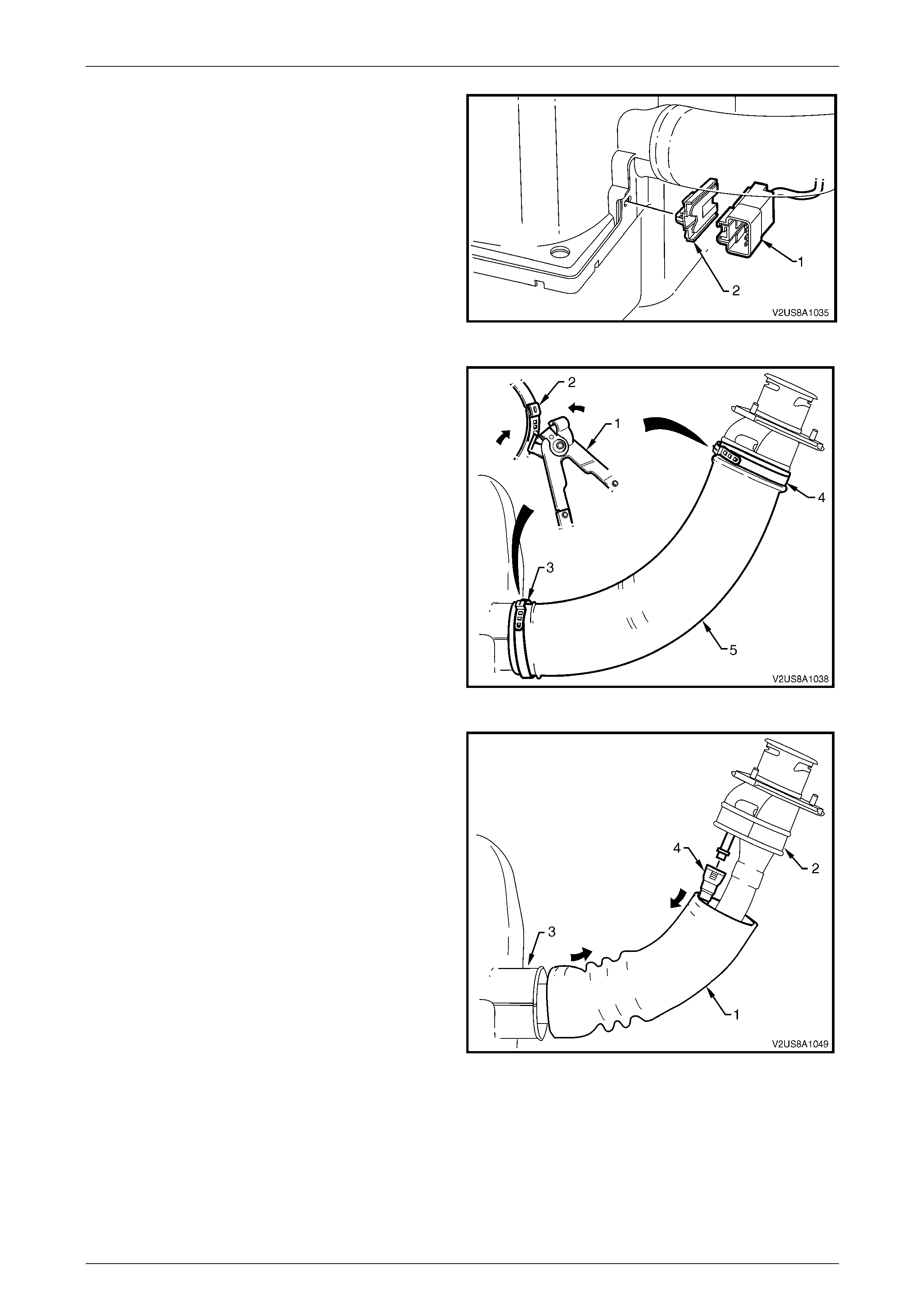
Fuel System Page 8A1–94
Page 8A1–94
10 Unclip the fuel tank to body wiring harness
connector (1) from its mounting clip (2) that connects
onto the lower plastic fuel tank shell.
Figure 8A1 – 117
11 Using keystone clamp pliers J22610 (1), position the
jaws across the clamp ear (2) and cut through to
release both clamps (3 and 4). Dispose of the used
clamp.
Figure 8A1 – 118
12 Manipulate the Santoprene® hose (1) away from the
filler neck flange moulding (2) and down the fuel filler
neck.
13 Disconnect the fuel tank vapour recirculatio n line
quick-connect fitting (4). If required, use tool
No. AU533 to assist disconnection of quick-connect
fitting, refer to Tool No. AU533.
NOTE
For information on quick-conn ect fittings, refer to
6.1 Quick-connect Fittings.
14 Manipulate the Santoprene® hose away from the fuel
tank cover flange (3).
Figure 8A1 – 119
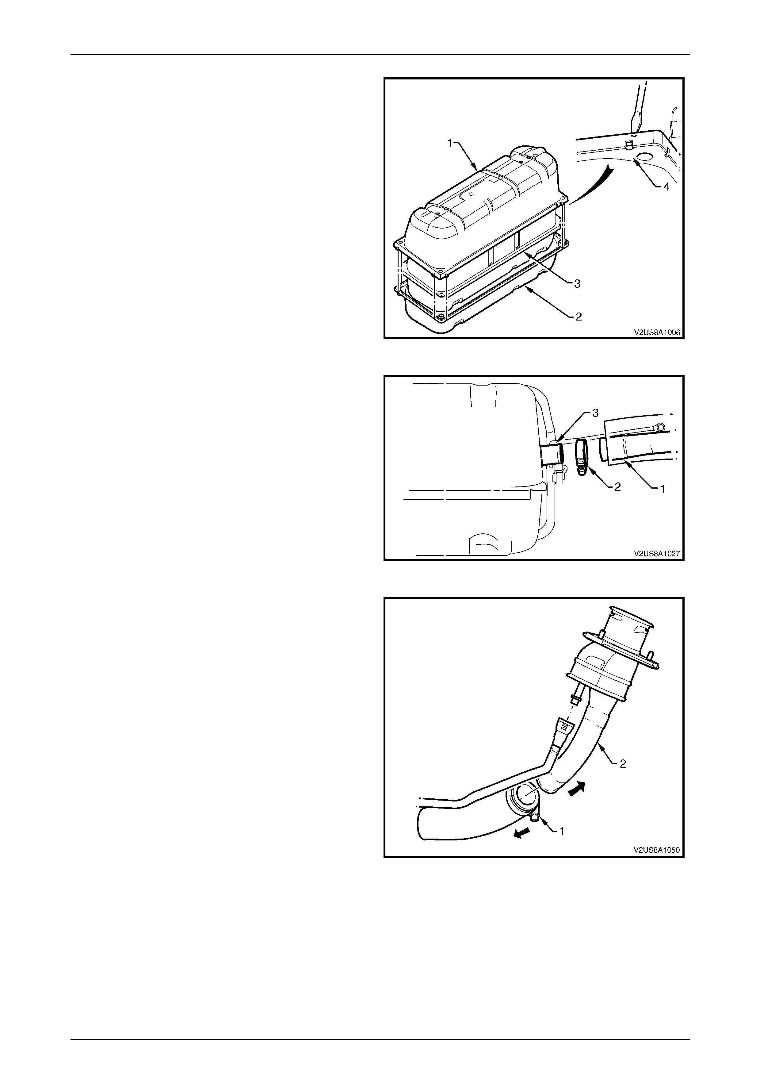
Fuel System Page 8A1–95
Page 8A1–95
15 Wedge a large flat-bladed screwdriver between the
side skirting of each of the upper and lower plastic fuel
tank shells (1 and 2), and pull the eig ht clipping
points (4) free to separate and remove the u pper
plastic fuel tank shell.
16 Lift and remove the fuel tank (3) from the lower plastic
fuel tank shell.
Figure 8A1 – 120
17 If removal of the fuel filler neck assembly is required,
loosen the hose-clamp (2) attachi ng the fuel tank filler
neck throat to the fuel filler neck flexible hos e and
prise the flexible hose (1) from the fuel tank filler neck
throat (3). Place the fuel filler neck assembly,
Santoprene® hose and hose-clamp in a safe location
away from the immediate worksite.
18 Cover the fuel tank filler neck throat with a suitable
material to prevent foreign objects from ente ring the
fuel tank.
Figure 8A1 – 121
19 If disassembly of the fuel filler neck assembly is
required, loosen the hose-clam p (1) attaching the
flexible hose to the fuel filler neck pipe (2). Pull the
flexible hose and fuel filler neck pipe apart to separate.
20 Cover the fuel tank opening with a suitable material to
prevent foreign objects from entering the fuel tank.
Figure 8A1 – 122

Fuel System Page 8A1–96
Page 8A1–96
21 Disconnect the fuel tank pressure sensor
connector (1), the fuel pump connector (2) and the fuel
vapour line quick-connect (3), using tool No. AU533
(3/8-inch), from the modular fuel pump and sender
assembly cover (4), refer to Tool No. AU533.
22 Cover the fuel vapour line quick-connect fitting with a
suitable material to prevent foreign objects from
entering the fuel tank.
Figure 8A1 – 123
23 Remove the flanged nut (1) securing the mod ular fue l
pump and sender assembl y gr ound terminal (2) to the
fuel tank flange stud (3) and remove the fuel tank
wiring harness.
Figure 8A1 – 124
24 If required, remove the modular fuel pump and sender assembly, refer to 6.5 Modular Fuel Pump and Sender
Assembly.
Fuel vapour remains in the fuel tank even
when completely empty. Seal all openings in
the fuel tank using suitable material or a
plastic plug. Ensure no naked flames or other
ignition sources are nearby. Ensure all
cellular phones (and transmission devices
that may cause any metal objects to become
unintentional receiving antennas) are
switched off.
Fuel System Page 8A1–97
Page 8A1–97
Reinstall
Reinstallation of the fuel tank is the reverse of the removal procedure, noting the following:
1 Tighten the modular fuel pump and se nder assembly earthing terminal nut to the correct torque specification.
Fuel pump and sender assembly
earthing terminal nut
torque specification..............................................7.0 Nm
2 When installing the fuel tank assembly into the lower plastic fuel tank shell, ensure the fuel vapour recirculation line
outlet is positioned through the slot provi de d in the lower plastic fuel tank shell.
3 Fit each end of the Santoprene® hose over the fuel tank cover flange and filler neck flange, and locate new ear-
type clamps at each end. Use keystone clamp pliers (tool No. J22610 or equivalent) to crimp the clamp ears to
fasten.
4 Tighten both fuel tank upper mounting strap nuts to the correct torque specification.
Fuel tank upper mounting
strap fastening nut
torque specification............................................20.0 Nm
5 Tighten both fuel tank lower mounting strap n uts to the correct torque specification.
Fuel tank lower mounting
strap fastening nut
torque specification............................................40.0 Nm
6 Tighten the three nuts securing the fuel fill er neck to the fuel filler pocket to the correct torque specification.
Fuel filler neck to fuel filler
pocket fastening nut
torque specification..............................................5.0 Nm
7 Fully install the fuel filler cap onto the fuel filler neck.
8 Before starting the vehicle, perform a fuel system leak test, refer to 4.3 Fuel Leak Test.

Fuel System Page 8A1–98
Page 8A1–98
6.4 Fuel Filler Neck Assembly
To reduce the risk of fuel spillage in the rear
compartment, do not remove the fuel filler
neck assembly without also removing the fuel
tank. Removal and disassembly of the fuel
filler neck assembly from the fuel tank forms
part of the fuel tank removal procedure, refer
to 6.3 Fuel Tank.
Fuel System Page 8A1–99
Page 8A1–99
6.5 Modular Fuel Pump and Sender
Assembly
LT Section No. — 03–074
Remove
A depressurised fuel system contains fuel in
the fuel filter and fuel lines that can be spilled
during service operations.
Fuel vapour remains in the modular fuel pump
and sender assembly and fuel lines that can
be spilled during service operations. Ensure
no naked flames or oth er ignition sources are
nearby. Ensure all cellular phones (and
transmission devices that may cause any
metal objects to become unintentional
receiving antennas) are switched off.
Place a dry chemical (Class B) fire
extinguisher nearby before performing any
on-vehicle service procedures. Failure to
follow these precautions may result in
personal injury.
Wear safety glasses when using compressed
air. Do not blow compressed air onto any
body part.
Removal of the fuel tank from the vehicle is
recommended for this service procedure to
reduce the risk of fuel spillage within the rear
luggage compartment, refer to 6.3 Fuel Tank.
Before proceedin g, clean all traces of dirt and
other foreign material from the top of the fuel
tank, near the modular fuel pump and sender
assembly. Use compressed air to ensure all
dirt and foreign materials are removed from
all appropriate fuel system connectors before
disconnection.
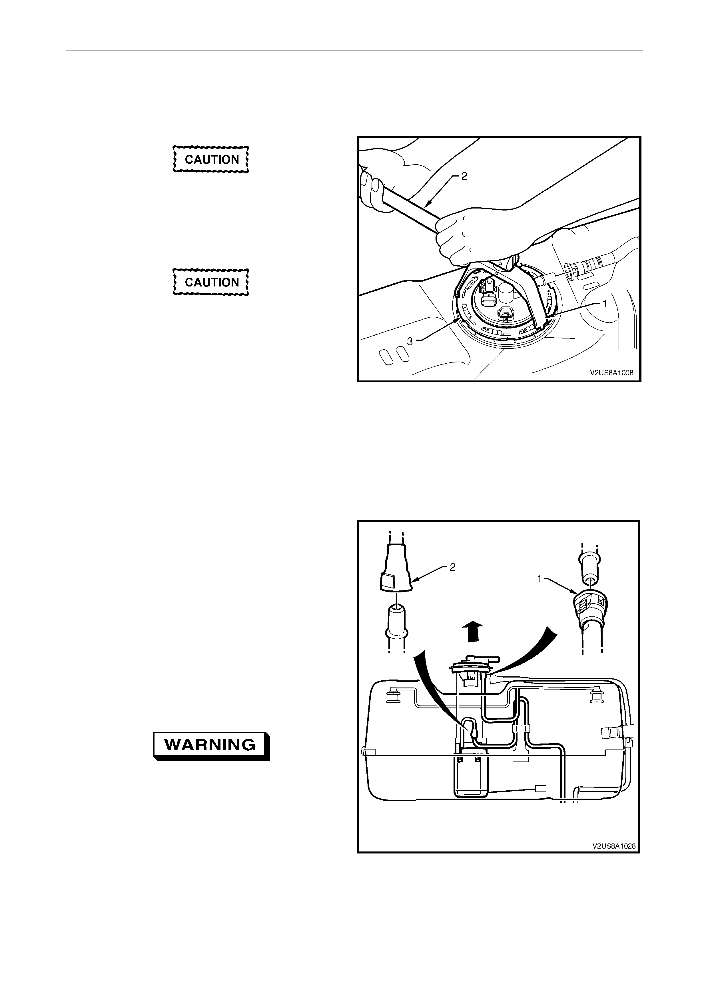
Fuel System Page 8A1–100
Page 8A1–100
1 Remove the fuel tank assembly from the vehicle to access the modular fue l pump and sender assembly and
remove the upper fuel tank plastic shell, refer to 6.3 Fuel Tank.
2 Disconnect the fuel tank pressure sensor connector, fuel pump conn ector and fuel vapour line quick-connect fitting
from the modular fuel pump and sender assembly cover, refer to 6.3 Fuel Tank.
Ensure tool No. J45722 is seated firmly and
positively in the modular fuel pump and
sender assembly cover retainer lock ring
while removing the modular fuel pump and
sender assemb ly.
Assistance will be required to hold the tank
in position during this procedure; if not held
adequately, you may slip and damage the
modular fuel pump and sender assembly.
3 Using tool No. J45722 (1) and a half-inch breaker
bar (2), remove the modular fuel pump a nd sender
assembly cover retainer lock ring (3) by turning it
anticlockwise. Figure 8A1 – 125
4 Remove the modular fuel pump and se nder assembly cover retainer lock ring.
NOTE
The modular fuel pump and sender assembly
cover springs up when the retainer is remov ed.
5 Partially lift the modular fuel pump and sender
assembly away from the fuel tank, taking care not to
damage the fuel level sender assembly.
6 Disconnect the fuel vapour line quick-connect
fitting (1) from the underside of the modular f uel pump
and sender assembly cover.
NOTE
If required, use tool No. AU533 to remove the
fuel vapour line quick-connect fitting, refer to
Tool No. AU533.
7 Reach into the fuel tank opening and disconnect the
fuel feed line quick-connect fitting (2).
The reservoir will be full of fuel. When the
modular fuel pump and sender assembly is
removed from the fuel tank, pour any
remaining fuel in the reser voir into a suitable
container. Do not drain or store fuel into an
open container, due to the possibility of fire
or explosion.
Figure 8A1 – 126
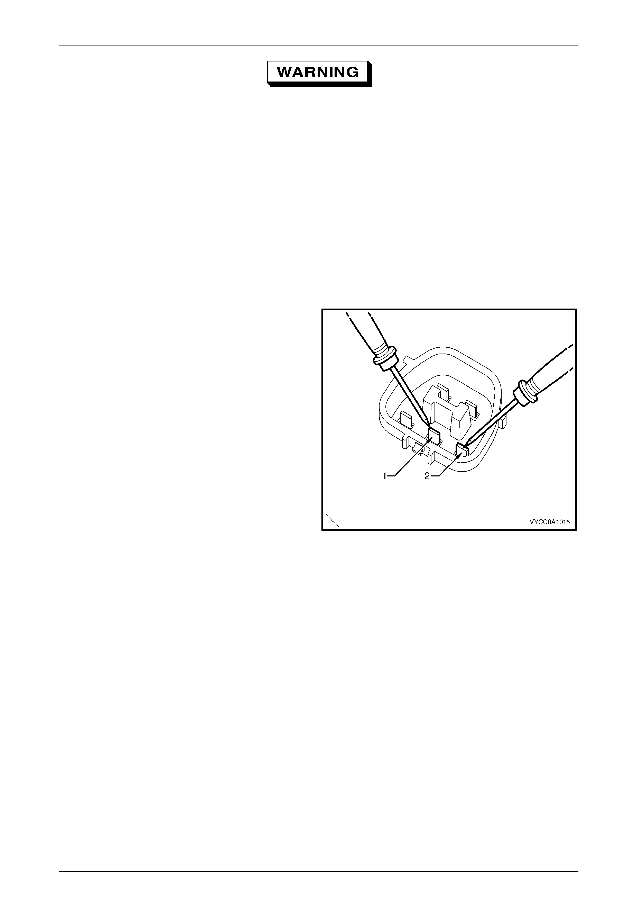
Fuel System Page 8A1–101
Page 8A1–101
Fuel vapour remains in the fuel tank even
when completely empty. Seal all openings in
the fuel tank using suitable material or a
plastic plug. Ensure no naked flames or other
ignition sources are nearby. Ensure all
cellular phones (and transmission devices
that may cause any metal objects to become
unintentional receiving antennas) are
switched off.
8 Remove the modular fuel pump and se nder assembly.
9 Remove and discard the O-ring.
10 Check the underside of the reservoir to ensu r e there are three rubber isolator feet attached to the bottom. If one or
more are missing, retrieve each from within the fuel tank and reinstall.
Test
1 Measure the resistance acr oss the positive (1) and
negative (2) fuel level sender terminals of the fuel
pump motor connector. Take the following
measurements:
a With the fuel level sender assembly in the e mpty
position, the resistance should be 40 Ω
(±2.5 Ω).
b With the fuel level sender assembly rotated to
full position, the resistance should be 248 Ω
(±3.5 Ω).
2 If the resistance at either of these positions is not
within tolerance, replace the fuel level sender
assembly, refer to 6.6 Fuel Level Sender Assembly.
Figure 8A1 – 127
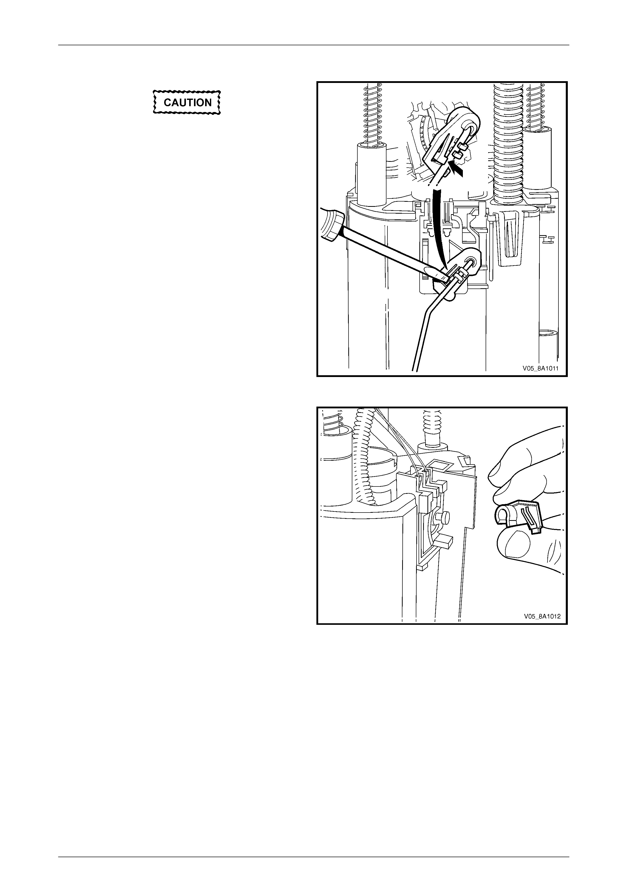
Fuel System Page 8A1–102
Page 8A1–102
Disassemble
Do not touch the ceramic variable resistor
card; if it is touched inadvertently, clean it
immediately with isopropyl alcohol.
1 Prise the tang open that holds the fuel level sender
float and arm onto the nylon wiper piece.
2 Lift the fuel level sender float and arm away from the
nylon wiper piece and place in a safe location away
from the immediate worksite.
Figure 8A1 – 128
3 Lift the nylon wiper piece off the ceramic variable
resistor card holder, then place in a safe location away
from the immediate worksite.
Figure 8A1 – 129

Fuel System Page 8A1–103
Page 8A1–103
4 Remove the 3-pin connector (the fuel level sender
assembly wires) from underneath the modular fuel
pump and sender assembly c over.
Figure 8A1 – 130
5 Remove the 2-pin connector (the fuel p ump motor
wires) from underneath the modular fuel pump and
sender assembly cover.
Figure 8A1 – 131
6 Press in the tang retaining the 2-pin connector on the
fuel pump and suction filter assembly, then remove the
connector.
Figure 8A1 – 132
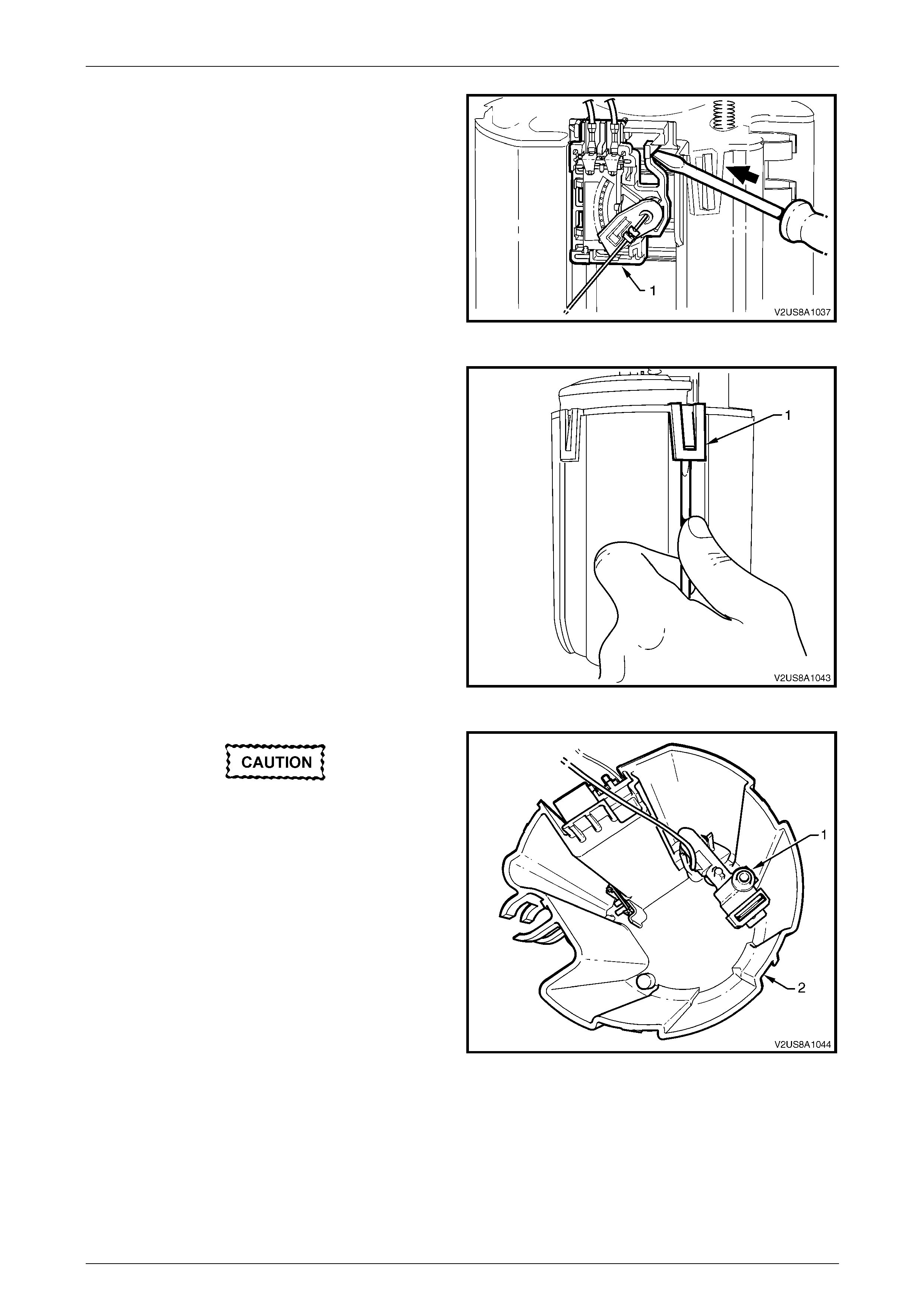
Fuel System Page 8A1–104
Page 8A1–104
7 Prise the tang open that holds the ceramic v aria ble
resistor card holder (1) to the side of the reservoir,
then lift it off the reservoir.
Figure 8A1 – 133
8 Prise the four tangs (1) with a flat-bladed screwdriver,
then remove the fuel pump and suction filter assembly,
and modular fuel pump an d sender assembly cover
from the reservoir.
NOTE
Another person may have to assist in removing
the fuel pump and suction filter assembly from
the reservoir.
Figure 8A1 – 134
Do not bend the spade connector on the
pressure regulator holder; this can be easily
damaged or broken.
9 Pull the modular fuel pump and sender assembly
cover, pressure regulator holder (1), and fuel pump
and suction filter assembly from the reservo ir bod y (2).
NOTE
Some difficulty may be experienced when lifting
these items from the reservoir body due to the
limited space availabl e.
Figure 8A1 – 135
10 Remove and discard the O-ring from the bottom of the pressure reg ulator holder.
NOTE
The O-ring may be lodged in the reservoir body.
11 Remove and discard the O-ring from the top of the pressure regulator holder.
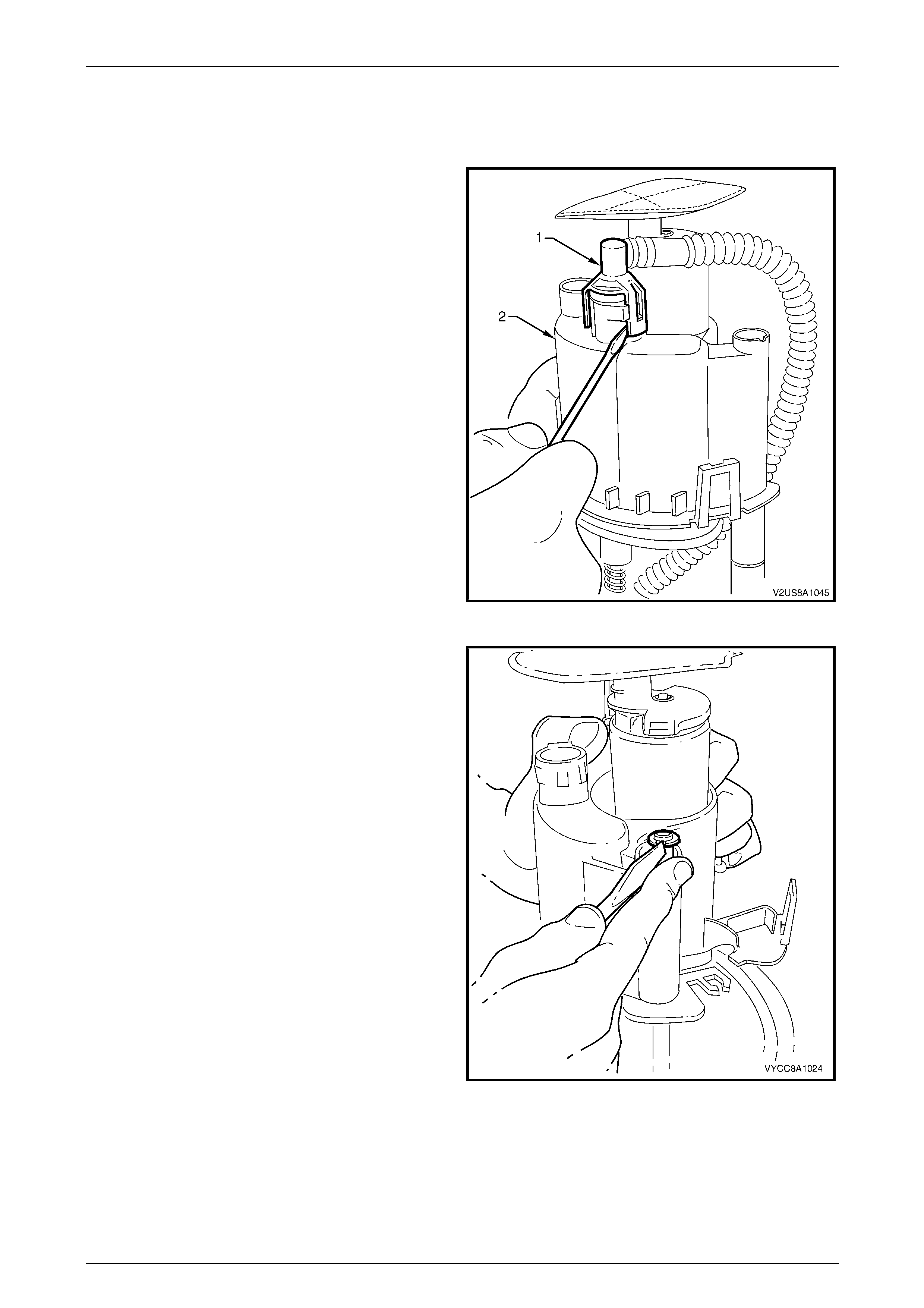
Fuel System Page 8A1–105
Page 8A1–105
NOTE
The O-ring may be lodged in the base of the fuel
pump and suction filter assembly.
12 Prise open both tangs on the fuel outlet connector (1)
on the bottom of the fuel pump and suction filter
assembly, then remove the fuel outlet pipe from the
fuel pump and suction filter assembly.
13 Remove and discard the O-ring from the fuel feed li ne
outlet underneath the fuel pump and suction filter
assembly.
NOTE
The O-ring may remain in the base of the fuel
pump and suction filter assembly.
Figure 8A1 – 136
14 Push the fuel pump and suction filter assembly down
the sprung shafts and remove the circlip (only o ne
shaft is fitted with a circlip) from the end of the shaft.
Place the circlip in a safe location away from the
immediate worksite.
Figure 8A1 – 137
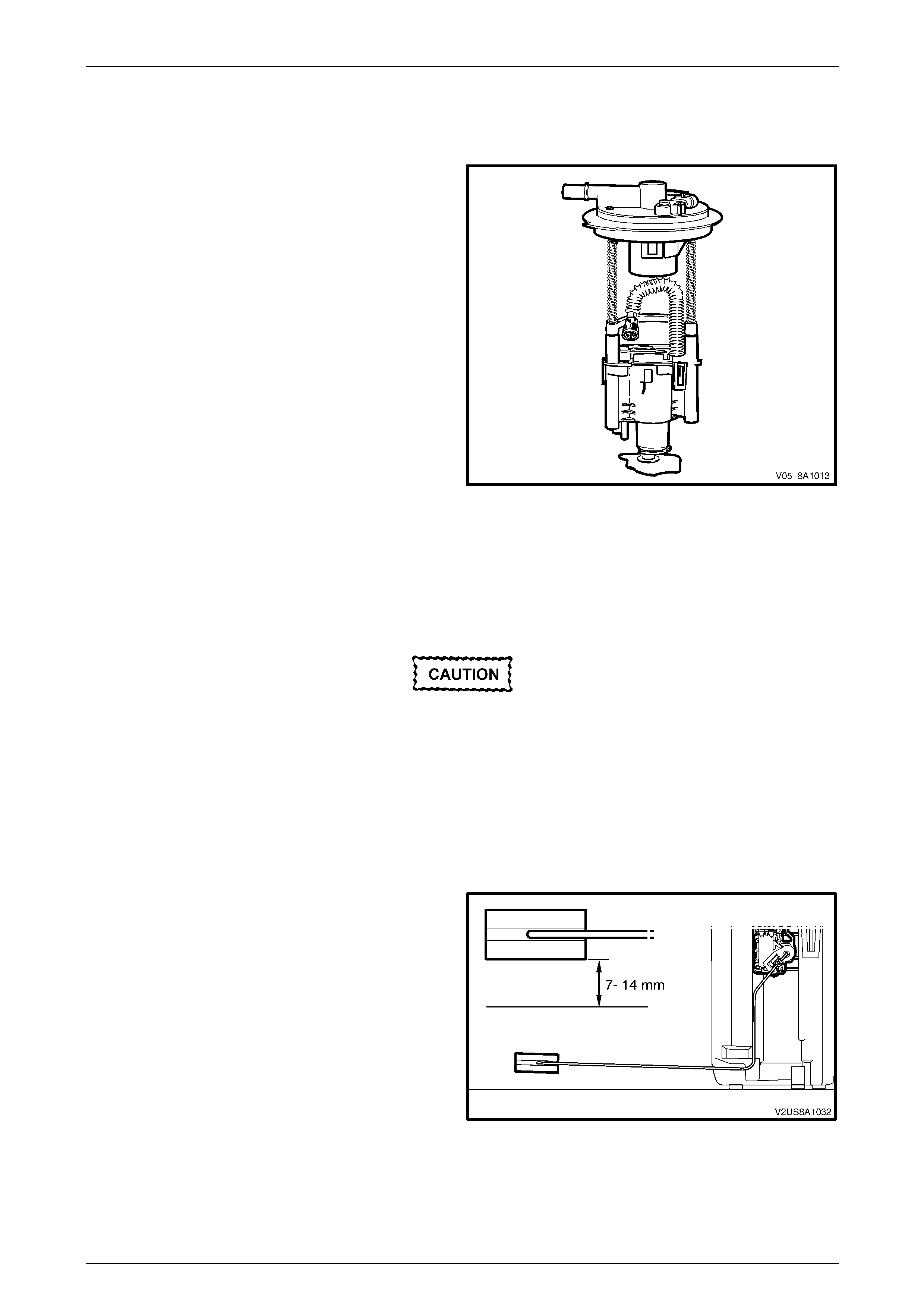
Fuel System Page 8A1–106
Page 8A1–106
Reassemble
The procedure for reassembling the modular fuel pump and sender ass embly is the reverse of the disassembly
procedure, noting the follo wing:
1 Locate and press the fuel outlet connector to its
position on the bottom of the fuel pump and suction
filter assembly, refer to Figure 8A1 – 136.
2 Locate and push the modular fuel pump and sender
assembly cover down the sprung shafts, then press
the circlip into the slot provided at the tip of one of the
shafts.
3 Fit a new O-ring onto the bottom of the pressure
regulator holder, refer to Figure 8A1 – 144. Firmly
press the pressure regulator holder into position inside
the reservoir, refer to Figure 8A1 – 135.
4 Ensure the wires to both electrical connectors and the
ceramic variable resistor card are inboard of the fuel
feed pipe.
5 Ensure the wires to the ceramic variable resistor card
and both connectors do not interfere when
reassembling the fuel pump and suction filter
assembly into the reservoir.
Figure 8A1 – 138
Reinstall
Reinstallation of the modul ar fuel pump and sender assembly is the reverse of the removal procedure, noting the
following:
When installing the modular fuel pump and
sender assembly, use only the custom-sized
O-rings supplied with the modular fuel pump
and sender assembly replacement parts kit.
Do not use off-the-shelf O-rings; refer to
6.11 Modular Fuel Pump and Sender
Assembly O-rings for O-ring specifications.
1 Position a new O-ring seal in the fuel tank recess.
2 Rest the modular fuel pump and sen der assembly on a flat surface.
3 Measure the distance between the bottom of the fuel
sender float and the flat surface.
4 Ensure the bottom of the fuel level sender float is a
nominal 7–14 mm above the surface. If not, carefully
bend the fuel level sender float arm to achiev e the
required distance.
NOTE
Do not damage the fuel level sender float and
arm when placing the modular fuel pump and
sender assembly into the fuel tank.
Figure 8A1 – 139
5 Install the modular fuel pump and sender assembly into the fuel tank, taking care not to damage the fuel level
sender float and arm.
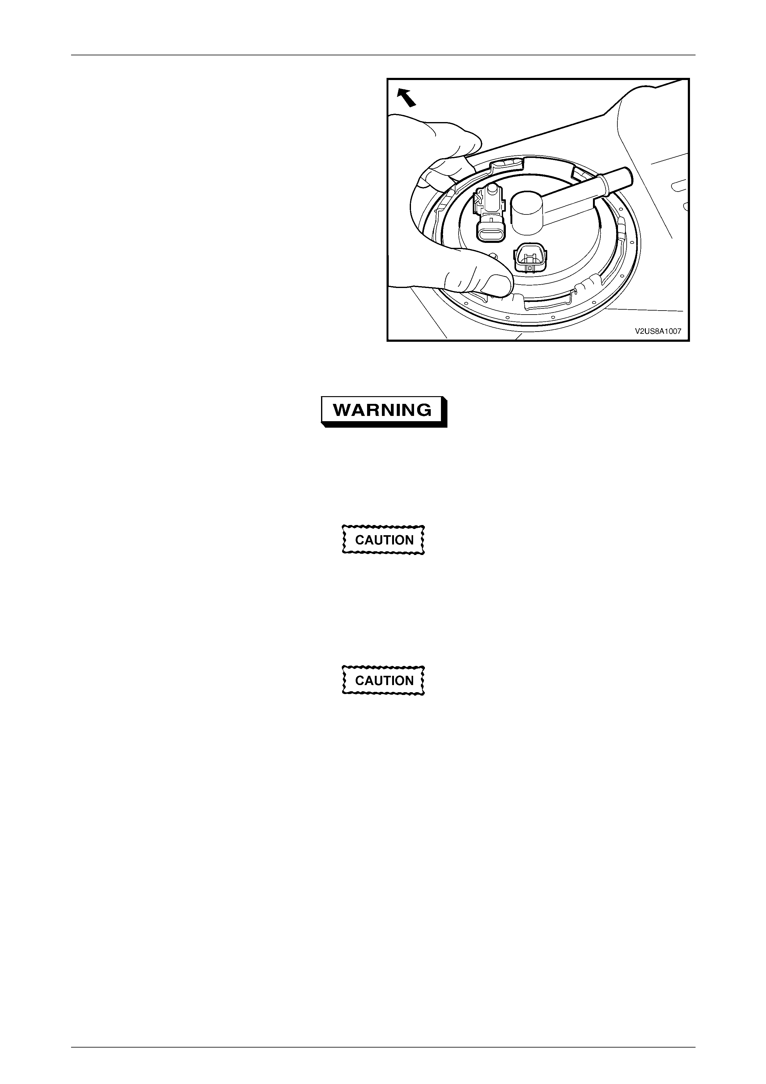
Fuel System Page 8A1–107
Page 8A1–107
6 Ensure the locator in the modular fuel pump and
sender assembly cover engages in the slot in the fuel
tank opening.
Figure 8A1 – 140
Ensure the lock ring is installed correctly.
Incorrect installation of the modular fuel
pump and sender assembly retainer could
cause fuel vapour leakage.
Ensure tool No. J45722 is seated firmly and
positively in the modular fuel pump and
sender assembly cover retainer lock ring
while tightening the modular fuel pump and
sender assemb ly.
Assistance w ill be required to hold the tank in
position during this procedure; if not held
adequately, you may slip and damage the
modular fuel pump and sender assembly.
7 Using tool No. J45722 (1) and a half-inch breaker bar (2), install the modular fuel pump and sender assembly cov er
retainer lock ring (3) by turning it clockwise, refer to Figure 8A1 – 125.
8 Install the fuel tank pressure sensor connector (1), fuel pump connector (2) and fuel vapour line quick-connect
fitting (3) to the modular fuel pump and sender assembly cover (4), refer to Figure 8A1 – 123 .
9 Tighten the modular fuel pump and se nder assembly cover retainer lock ring.

Fuel System Page 8A1–108
Page 8A1–108
6.6 Fuel Level Sender Assembly
LT Section No. — 03–074
The fuel level sender assemb ly is serviced as a complete assembly and attaches to the side of the modular fuel pump
and sender assembly reservo ir. T esting, removal a nd reinstallation of the fuel level sender assembly are contained within
the modular fuel pump and send er assembly service procedures, refer to 6.5 Modular Fuel Pump an d Sender Assembly.
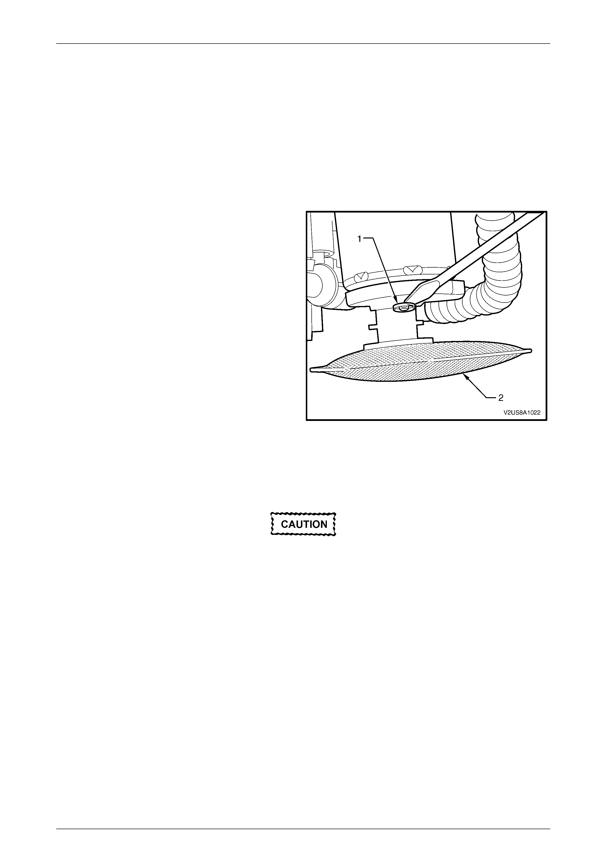
Fuel System Page 8A1–109
Page 8A1–109
6.7 Suction Filter
The suction filter is attached by an 'easy washer' to the fuel pump end cap. The suction fil t er is accessible after removal
of the fuel pump and fuel filter from the modular fuel pump and sender assembly reservoir.
Remove
1 Remove the modular fuel pump and se nder assembly from the fuel tank, refer to 6.5 Modular Fuel Pump and
Sender Assembly.
2 Disassemble the fuel pump and suction filter assembly, and modular fuel pump and sender assembl y cover from
the reservoir, refer to 6.5 Modular Fuel Pump and Sender Assembly.
3 Using a suitable blade or a flat-bladed screwdriver,
remove the 'easy washer' (1) from the fuel pump end
cap post.
4 Remove the suction filter (2).
Figure 8A1 – 141
Reinstall
Reinstallation of the suction filter is the reverse of the removal procedure, noting the following:
Check the 'easy washer' for serviceability and
replace if required.
Ensure the 'easy washer' is firmly installed along the fuel pump end cap post and firmly pressed up again s t the suction
filter moulding.

Fuel System Page 8A1–110
Page 8A1–110
6.8 Modular Fuel Pump
LT Section No. — 03–074
The modular fuel pump is contained within the fuel filter assembly.
Remove
1 Remove the suction filter, refer to 6.7 Suction Filter.
2 Remove the modular fuel pump from the fuel filter assembly, refer to 6.5 Modular Fuel Pump and Sender
Assembly.
3 Disassemble the modular fuel pump and sender assembly, refer to 6.5 Modular Fuel Pump and Se nder Assembly.
Do not overtigh ten the vice grips as this may
damage the fuel pump.
4 Clamp the protruding end of the fuel pump body (1) in
a soft-jawed vice (2) to support the modular fuel pump
and fuel filter assembly (3) in place.
5 Insert a medium-sized flat-bladed screwdriver through
each of the service holes in the fuel filter assembly.
6 Slide the screwdriver blade between the fuel pump
end cap and the internal fuel filter clips that hold the
fuel pump body in plac e.
Figure 8A1 – 142
7 Push the screwdrivers in far enough so the internal
fuel filter clips are deflected just free of each of the fuel
pump end cap retainer shoulders.
8 While holding the screwdrivers in place with one hand,
manipulate the fuel filter assembl y upwards to
separate it from the fuel pump.
Figure 8A1 – 143

Fuel System Page 8A1–111
Page 8A1–111
Reinstall
Reinstallation of the modul ar fuel pump is the reverse of the removal procedure, noting the following:
Do not use any tool that may damage either
the fuel pump body or the fuel filter assembly.
Check the 'easy washer' for serviceability and
replace if required.
When installing the modular fuel pump and
sender assembly, use only the custom-sized
O-rings supplied with the modular fuel pump
and sender assembly replacement parts kit.
Do not use off-the-shelf O-rings; refer to
6.11 Modular Fuel Pump and Sender
Assembly O-rings for O-ring specifications.
1 Ensure the 'easy washer' is firmly installed a long the fuel pump end cap post and firmly pressed up ag ainst the
suction filter moulding.
2 Using hands only, locate the fuel pump body in its correct orientation int o the fuel filter as sembly.
3 Push the fuel pump body firmly into plac e and lock the fuel pump into the fuel filter assembly.
4 Reassemble the modular fuel pump and sender assembly, refer to 6.5 Modular Fuel Pump and Sender Assembly.
5 Reinstall the modular fuel pump and sender assembly, refer to 6.5 Modular Fuel Pump and Sender Assembly.

Fuel System Page 8A1–112
Page 8A1–112
6.9 Fuel Filter Assembly
NOTE
The fuel filter assembly is part of the modular fuel
pump and sender assembl y and is not repairabl e.
If the fuel filter assembly becomes unserviceable,
replace the modular fuel pump and sender
assembly, refer to 6.5 Modular Fuel Pump and
Sender Assembly.
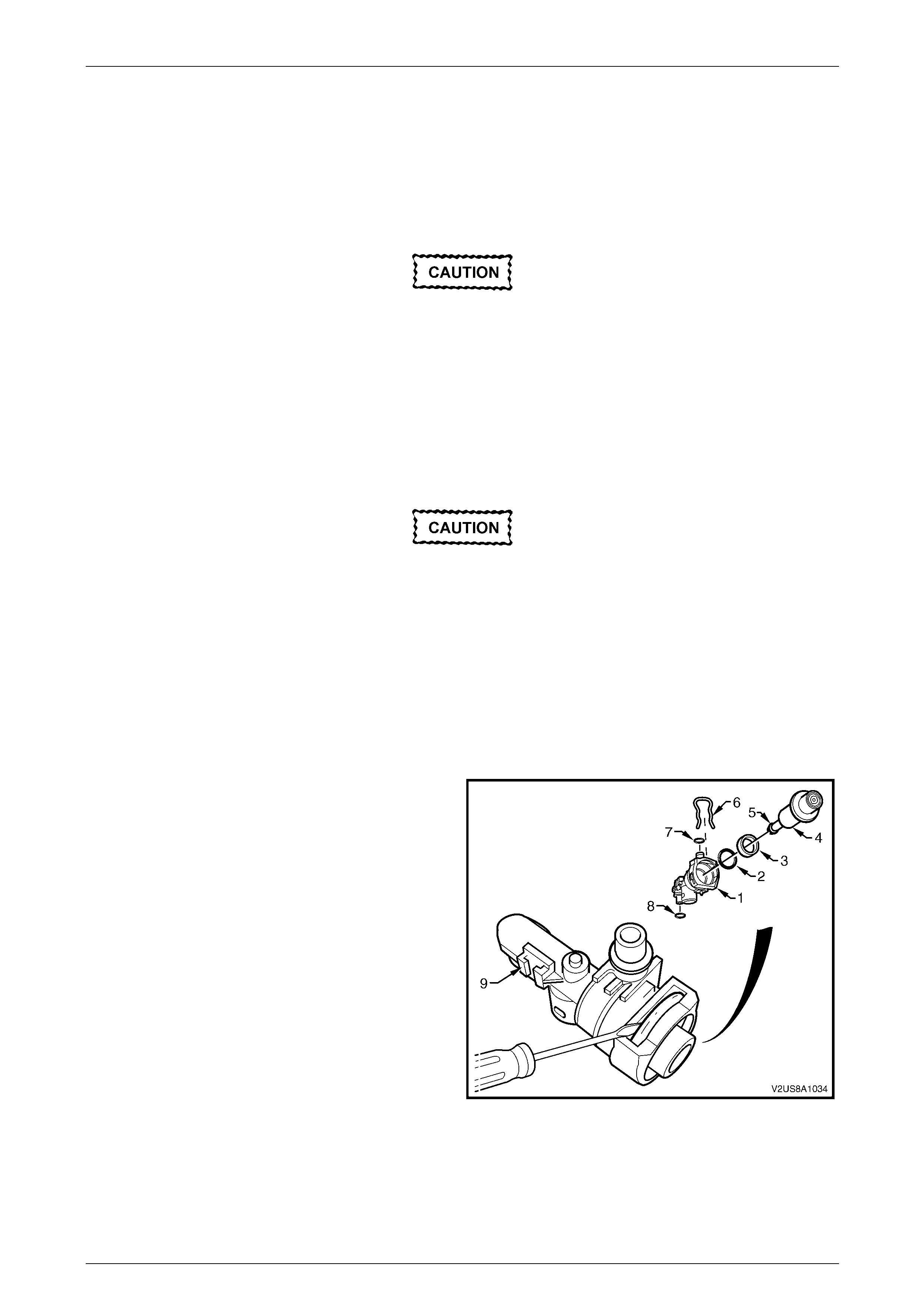
Fuel System Page 8A1–113
Page 8A1–113
6.10 Pressure Regulator
LT Section No. — 03–074
Remove
Refer to 6.11 Modular Fuel Pump and Sender
Assembly O-rings for O-ring service part
specifications.
1 Remove the modular fuel pump and se nder assembly from the fuel tank, refer to 6.5 Modular Fuel Pump and
Sender Assembly.
2 Remove the modular fuel pump and se nder assembly cover from the reservoir, refer to 6.5 Modular Fuel Pump
and Sender Assembly.
3 Remove the pressure regulator holder, refer to 6.5 Modular Fuel Pump and Sender Assembly.
Do not bend the spade connector on the
pressure regulator holder; this can be easily
damaged or broken.
NOTE
The pressure regulator can be remove d without:
• disassembling and removing the fuel level
sensor assembly, or
• disconnecting the fuel pump motor or fuel
level sensor patch wiring harness conn ectors.
4 Remove the spade connector from the terminal
connector moulding (9) of the pressure regulator
holder using a pair of long-nose pliers.
5 Remove the retaining clip (6) from the top of the
pressure regulator holder and place in a safe location
away from the immediate worksite.
6 Using a flat-bladed screwdriver, prise the pressure
regulator (4) from the pressure regulator holder (1).
7 If required, remove the nylon spacer (3), and remove
and tag the O-ring (2).
8 If required, remove and tag all O-rings (7 and 8, and 5)
and place in a safe location a way from the immediate
worksite.
Figure 8A1 – 144
Fuel System Page 8A1–114
Page 8A1–114
Reinstall
Reinstallation of the pressur e regulator is the reverse of the removal procedure, noting the following:
When installing the modular fuel pump and
sender assembly, use only the custom-sized
O-rings supplied with the modular fuel pump
and sender assembly replacement parts kit.
Do not use off-the-shelf O-rings; refer to
|6.11 Modular Fuel Pump and Sender
Assembly O-rings for O-ring specifications.
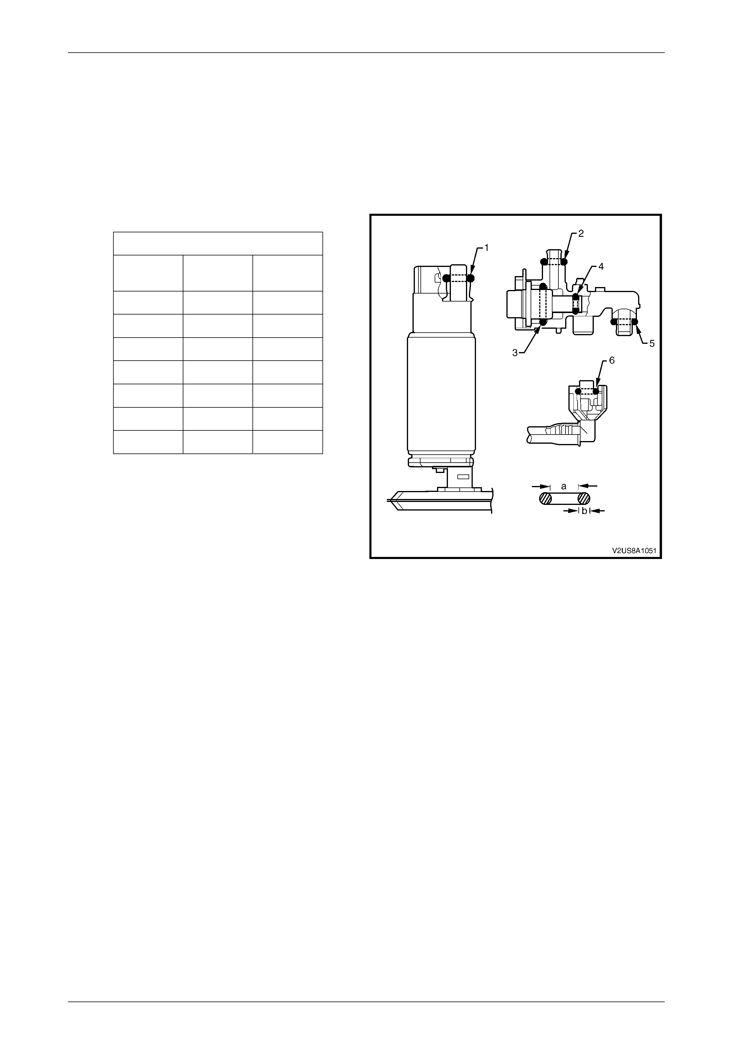
Fuel System Page 8A1–115
Page 8A1–115
6.11 Modular Fuel Pump and Sender
Assembly O-rings
LT Section No. — 03–074
O-rings seal various connections in the modular fuel pump and sender assembly, and are made of a special material.
Always service the O-ring seals with the correct service part as provided with the service kit. Refer to Figure 8A1 – 145 to
identify O-ring service part specifications.
O-ring Specifications
O-ring a
(mm) b
(mm)
1 8.20 3.50
2 7.52 3.53
3 15.4 2.90
4 4.25 2.60
5 8.20 3.50
6 8.20 3.50
7 8.20 3.50
Figure 8A1 – 145
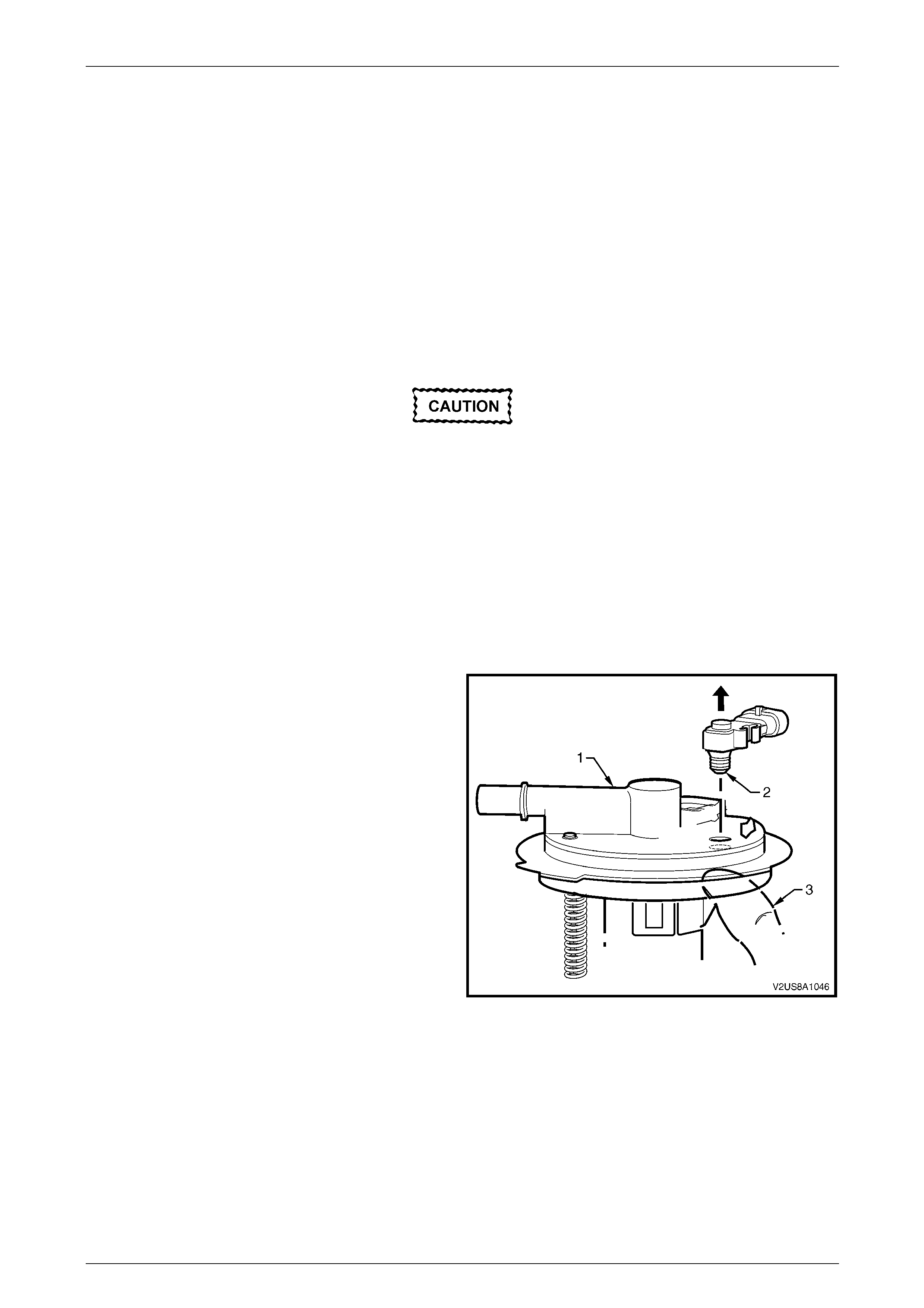
Fuel System Page 8A1–116
Page 8A1–116
6.12 Fuel Tank Pressure Sensor
LT Section No. — 03–074
The fuel tank pressure sensor is press-fitted to the modu lar fuel p ump a nd sender assembly cover. To access the fuel
tank pressure sensor for servicing, removal of the fuel tank from the vehicle is recomme nded. For information on fuel
tank pressure sensor and fuel tank leak test diagnostics, refer to 4.3 Fuel Leak Test.
Remove
1 Remove the fuel tank from the vehicle.
2 Remove the modular fuel pump and se nder assembly from the fuel tank, refer to 6.5 Modular Fuel Pump and
Sender Assembly.
Do not pull or lever the fuel tank pressure
sensor from the connector end as damage
may occur to the fuel tank pressure sensor
body.
NOTE
The pressure regulator can be remove d without:
• disassembling and removing the fuel level
sensor assembly, or
• disconnecting the fuel pump motor or fuel
level sensor patch wiring harness conn ectors.
3 Grasp the modular fuel pump and sender assembly
cover (1) and, from underneath, apply thumb
pressure (3) to the opening port (2) of the fuel tank
pressure sensor. To aid removal, pull the head of the
fuel tank pressure sensor directly away from the
modular fuel pump and sender assembly cover.
Figure 8A1 – 146
Reinstall
Reinstallation of the fuel tank pressure sensor is the reverse of the removal procedure, noting the fo llowing:
1 Check the rubber seal around the collar of the fuel tank pressure sensor opening port (2) for damag e. If required,
replace the fuel tank pressure sensor, refer to Figure 8A1 – 146.
2 Align the fuel tank pressure sensor with the opening port and guide support of the modular fuel p ump and sender
assembly cover, and press firmly into place.
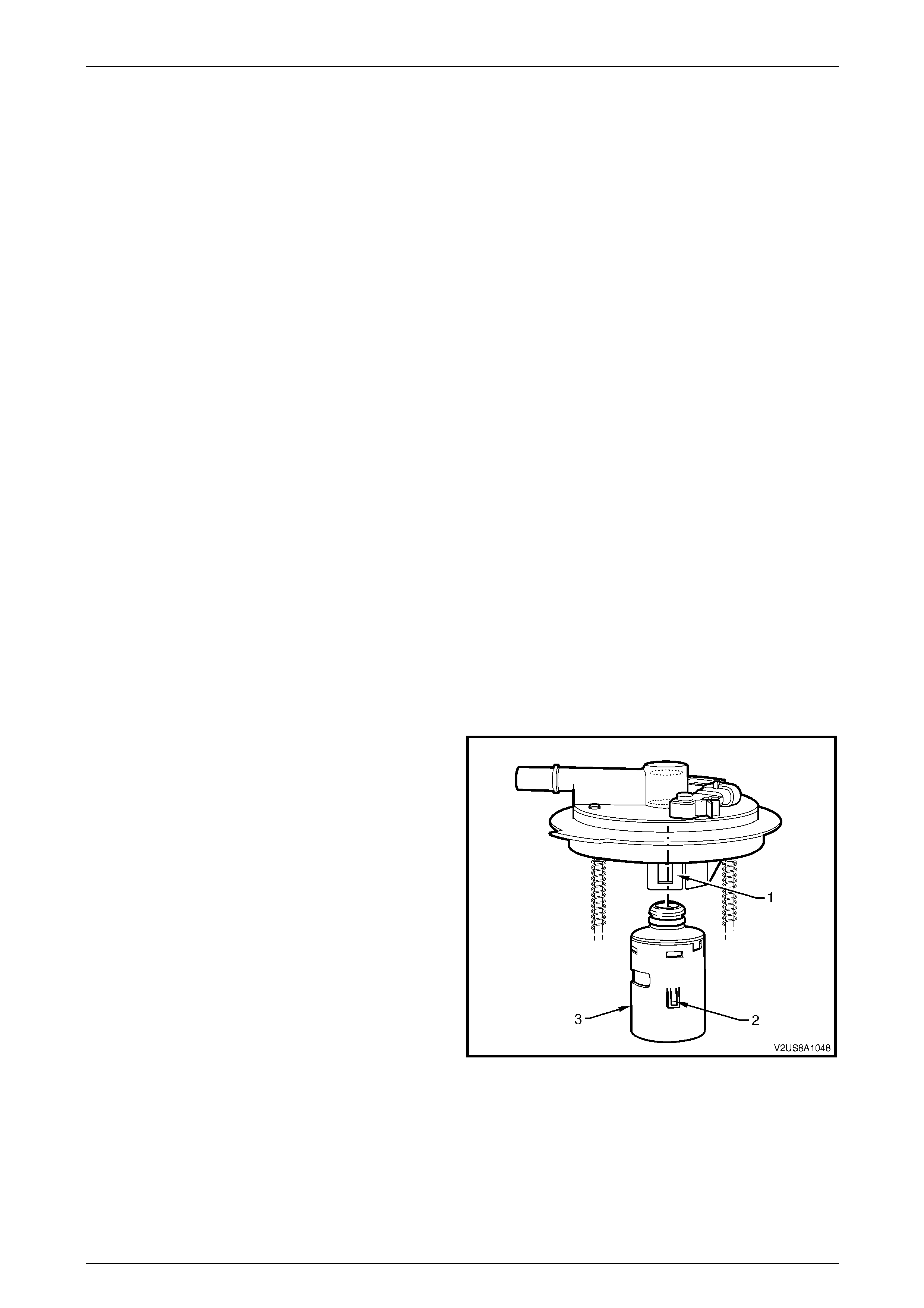
Fuel System Page 8A1–117
Page 8A1–117
6.13 Fuel Fill Limiter Vent Valve Assembly
LT Section No. — 03–074
The fill limiter vent valve assembl y is clipped underneath the modular fuel pump and sender assembly cover.
NOTE
To access the fuel fill limiter vent valve assembly
during servicing, remov al of t he fuel tank from the
vehicle is recommended.
NOTE
The fuel fill limiter vent valve assembly is
serviced as a complete assembly and further
disassembly after removal from the modular fuel
pump and sender assembl y is not required.
Remove
1 Remove the fuel tank assembly from the vehicle, refer to 6.3 Fuel Tank.
2 Remove the modular fuel pump and se nder assembly from the fuel tank, refer to 6.5 Modular Fuel Pump and
Sender Assembly.
NOTE
The fuel fill limiter vent valve assembly can be
removed without:
• disassembling and removing the fuel level
sensor assembly, or
• disconnecting the fuel pump motor or fuel
level sensor patch wiring harness conn ectors.
3 Lever both the modular fuel pump and sen der
assembly cover tangs (1) clear of the fuel fill limiter
vent valve locators (2) while pulling the fuel fi ll limiter
vent valve assembly (3) out to remove. If required, use
a flat-bladed screwdriver to assist levera ge of the
tangs.
Figure 8A1 – 147
Reinstall
Reinstallation of the fill limiter vent valve ass embly is the reverse of the removal procedure, noting the following:
Ensure correct alignment of the fuel fill limiter vent valve into the modular fuel pump and sender assembly cov er before
pressing firmly to click into place.
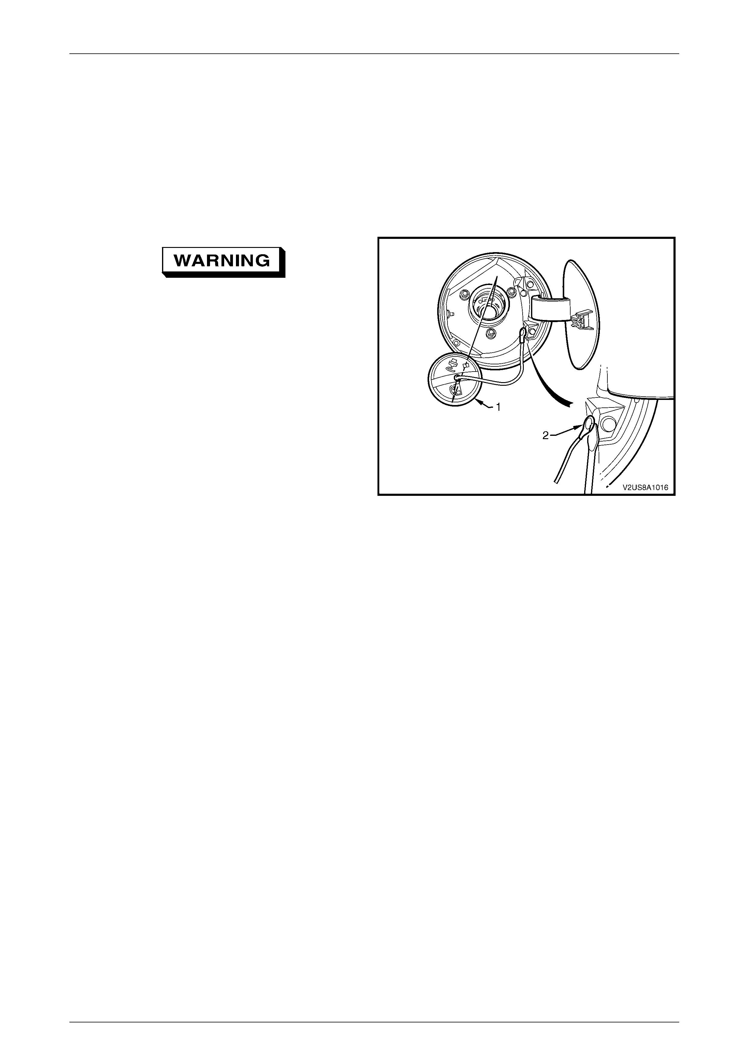
Fuel System Page 8A1–118
Page 8A1–118
6.14 Fuel Filler Cap
LT Section No. — 03–028
The fuel filler cap is a 'screw on' type, with an integrated tightening torque limiting mechanism. When in stalling the fuel
filler cap, tighten it until a ratcheting (clicking) sound is au dible, indicating the fuel filler cap is properly tightene d. The fuel
filler cap is tethered to the fuel filler pocket. The fuel filler cap requires a quarter of a turn to be removed.
Remove
If the fuel filler cap needs replacing, use only
a 'screw on' fuel tank filler cap with an
integrated tightening torque limiting
mechanism. Failure to use the correct fuel
tank filler cap can result in a serious
malfunction of the emission control system.
1 Untwist and remove the fuel filler cap (1) from the fuel
filler neck opening.
2 Using a flat-bladed screwdriver, prise the fuel filler cap
tether line fastener (2) from its mounting hole.
3 Cover the fuel filler opening with a suitable materia l to
prevent foreign objects from entering the fuel tank.
Figure 8A1 – 148
Reinstall
Reinstallation of the fuel filler cap is the reverse of the remo val procedure, noting the following:
NOTE
Check the fuel filler cap for serviceability and
replace if required.
Fuel System Page 8A1–119
Page 8A1–119
6.15 Fuel Pipes
LT Section No. — 03–075
Remove
A depressurised fuel system contains fuel in
the fuel filter and fuel lines that can be spilled
during service operations.
Fuel vapour remains in the fuel tank even
when completely empty. Seal all openings in
the fuel tank using suitable material or a
plastic plug. Ensure no naked flames or other
ignition sources are nearby. Ensure all
cellular phones (and transmission devices
that may cause any metal objects to become
unintentional receiving antennas) are
switched off.
Place a dry chemical (Class B) fire
extinguisher nearby before performing any
on-vehicle service procedures. Failure to
follow these precautions may result in
personal injury.
Wear safety glasses when using compressed
air. Do not blow compressed air onto any
body part.
1 Remove the fuel pump relay, refer to Section 12O Fuses, Relays and Wiring Harnesses.
2 Depressurise the fuel system, refer to 4.1 Fuel System Depressurisation.
Never drain or store fuel into an open
container, due to the possibility of fire or
explosion.
3 Raise the vehicle, preferably on a hoist, refer to Section 0A General Information.
Before proceedin g, clean all traces of dirt and
other foreign material from the fuel pipes.
4 Use compressed air to ensure that all dirt and foreign materials are removed from all fuel con nections before the
parts are disconnected.
5 If required, remove the stone guards and fue l pipes. Use the following illustrations showing the fuel pipe la yout and
location of other items relating to the fuel system as a guide, refer to Figure 8A1 – 149 and Figure 8A1 – 150.
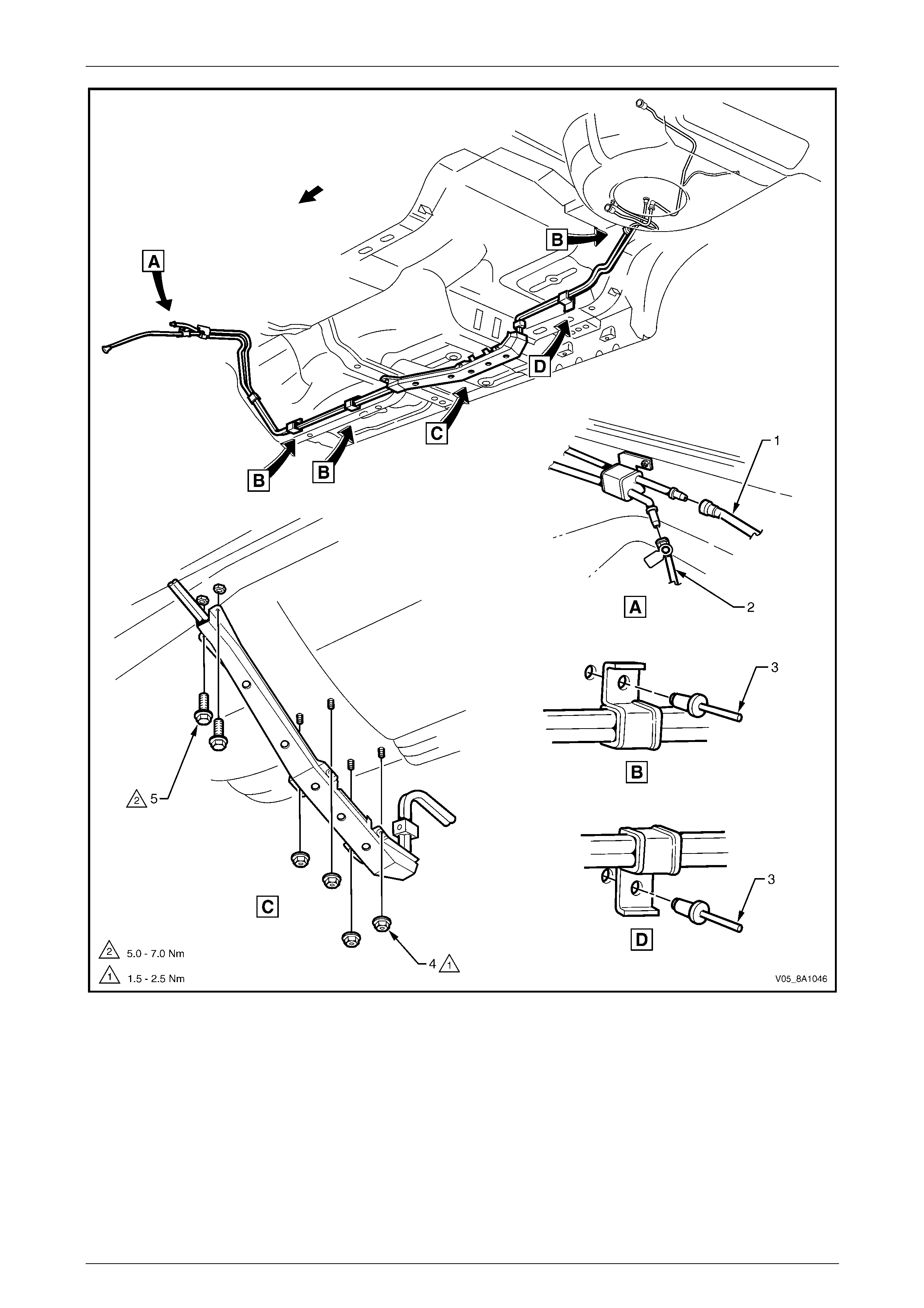
Fuel System Page 8A1–120
Page 8A1–120
Figure 8A1 – 149
Legend
1 Fuel Feed Line
2 Evaporative Emission Control
Canister Purge Line
3 Fuel Line Bracket Blind Rivet
4 Stone Guard Securing Nut (4 places) 5 Stone Guard Securing Bolt (2 places)
NOTE
Use tool No. 7371 to remove the fuel feed line (1)
quick-connect fitting, refer to Figure 8A1 – 149.
Use tool No. AU533 to remove the fuel vapour
line quick-connect fitting (2), refer to Tool No.
AU533.
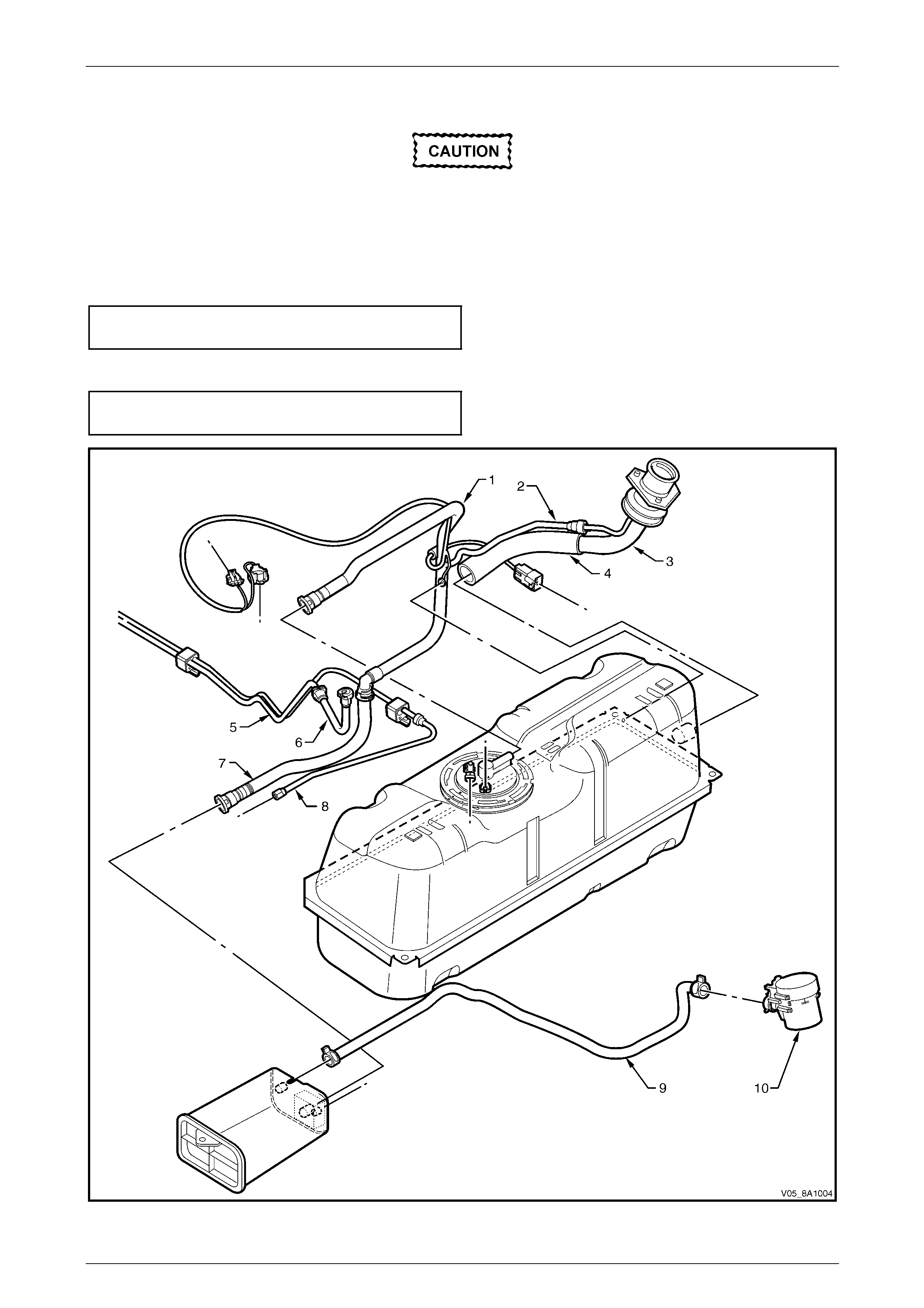
Fuel System Page 8A1–121
Page 8A1–121
Reinstall
Ensure the rubber in the fuel line brackets is
in good condition before proceeding. If not,
replace the affected b racket.
Reinstallation of the stone guards and fuel pipes is the reverse of the removal procedure, noting the foll owing:
1 Tighten the stone guard securing nuts to the correct torque specification.
Stone guard securing nut
torque specification.....................................1.5 – 2.5 Nm
2 Tighten the stone guard securing bolts to the correct torque specification.
Stone guard securing bolt
torque specification.....................................5.0 – 7.0 Nm
Figure 8A1 – 150

Fuel System Page 8A1–122
Page 8A1–122
Legend
1 Fuel Vapour Line (upstream)
2 Fuel Vapour Recirculation Line
3 Fuel Filler Neck
4 Fuel Filler Hose
5 Fuel Feed Line
6 Fuel Feed Line Extension Elbow
7 Fuel Vapour Line (downstream)
8 Fuel Vapour Purge Line
9 Fuel Vapour Vent Line
10 Fuel Vapour Vent Solenoid
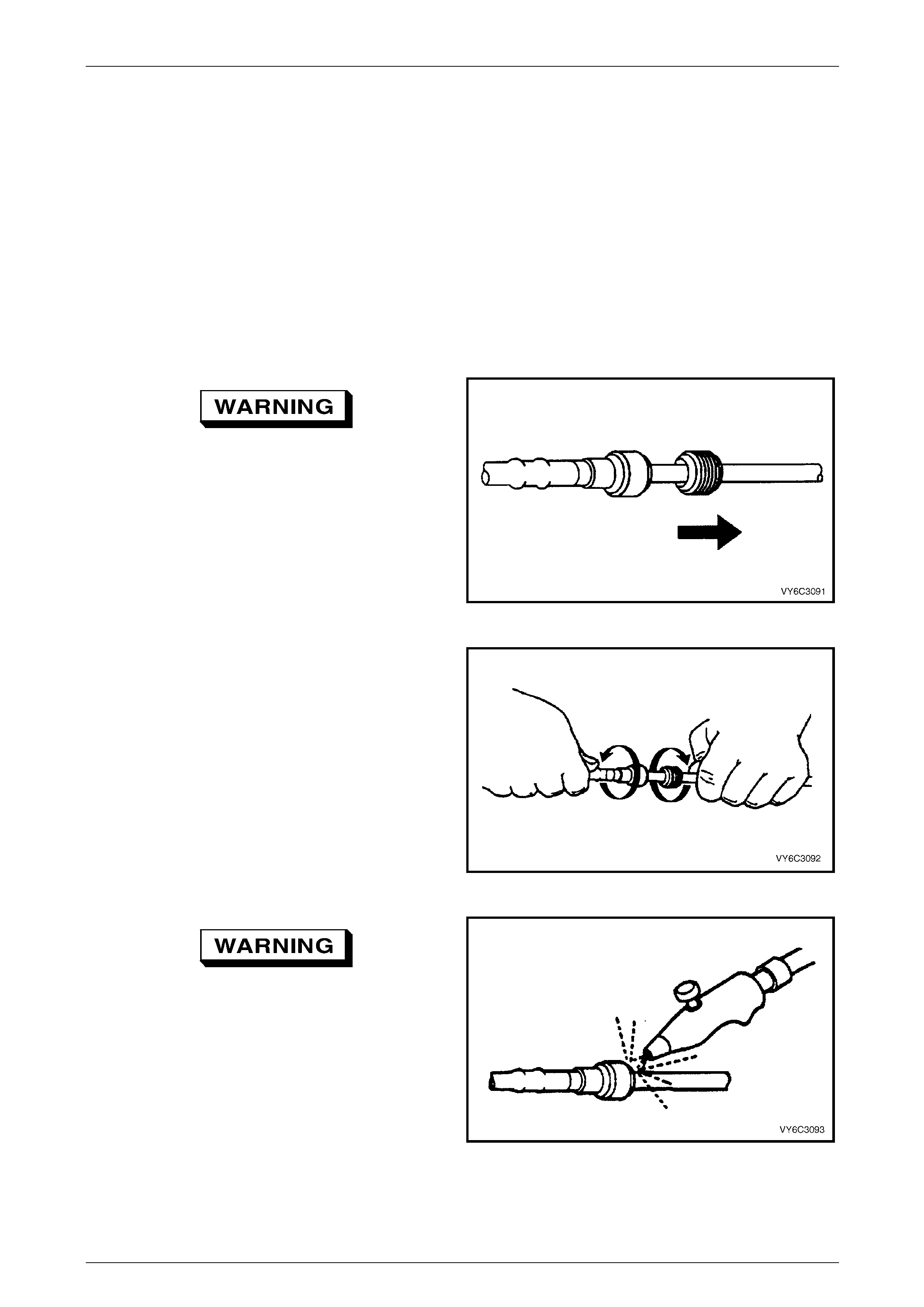
Fuel System Page 8A1–123
Page 8A1–123
7 Service Operations — Regular
Cab and Crew Cab, and Crew
Cab with 'Delete Tub' Option
7.1 Quick-connect Fittings
Quick-connect Fittings (Metal Collar)
LT Section No. — 03–075
Remove
To reduce the risk of fire or personal injury,
relieve the fuel system pressure before
servicing any fuel system components, refer
to 4.1 Fuel System Depressurisation.
1 If fitted, slide the dust cover from the quick-connect
fitting.
Figure 8A1 – 151
2 Grasp both sides of the quick-connect fitting. Twist the
female side of the quick-connect fitting 1/4 turn in each
direction to loosen any dirt.
Figure 8A1 – 152
Wear safety glasses w hen usin g compressed
air. Do not blow compressed air onto any
body part.
3 Use compressed air to ensure that all dirt and foreign
materials are removed from all fuel conn ections before
the parts are disconnected.
Figure 8A1 – 153

Fuel System Page 8A1–124
Page 8A1–124
4 Choose the correct tool (1) to disconnect the quick-
connect fitting, refer to Tool Nos. 7370 and 7371.
Insert the tool into the female connector, then push
inward to release the locking t abs.
Figure 8A1 – 154
5 Pull the quick-connect fitting apart.
NOTE
If it is necessary to remove rust or burrs from a
fuel pipe, use emery cl oth in a radial motion with
the fuel pipe end to prevent damage to the
O-ring sealing surface.
6 Using a clean shop towel to wipe off the male pipe
end.
7 Inspect both ends of the fitting for dirt and burrs. Clean
or replace the components as required.
Figure 8A1 – 155
Reinstall
During normal operation, the O-ring located
in the female connector swells. To ensure
proper fitting, lubricate the male pipe end
before assembly.
1 Apply a few drops of clean engin e oil to the male pipe
end.
Figure 8A1 – 156
2 Push both sides of the quick-connect fitting together to
snap the retaining tabs into place.
Figure 8A1 – 157

Fuel System Page 8A1–125
Page 8A1–125
3 After installation, pull on both sides of the quick-
connect fitting to ensure the connection is secure.
Figure 8A1 – 158
4 Reposition the dust cover over the quick-con nect
fitting (if fitted).
Figure 8A1 – 159

Fuel System Page 8A1–126
Page 8A1–126
Quick-connect Fittings (Plastic Collar)
LT Section No. — 03–075
Remove
To reduce the risk of fire or personal injury,
relieve the fuel system pressure before
servicing any fuel system components, refer
to 4.1 Fuel System Depressurisation.
1 Grasp both sides of the quick-connect fitting. Twist the
female side of the quick-connect fitting 1/4 turn in each
direction to loosen any dirt.
Figure 8A1 – 160
Wear safety glasses w hen usin g compressed
air. Do not blow compressed air onto any
body part.
2 Use compressed air to ensure that all dirt and foreign
materials are removed from all fuel conn ections before
the parts are disconnected.
Figure 8A1 – 161
3 Squeeze the plastic retainer release tabs.
NOTE
Alternatively, use tool No. AU533 to release the
quick connect fitting:
• red = 5/16-inch fittings (fuel vapour lines), or
• blue = 3/8-inch fittings (fuel feed lines).
Figure 8A1 – 162

Fuel System Page 8A1–127
Page 8A1–127
4 Pull the quick-connect fitting apart.
Figure 8A1 – 163
Reinstall
During normal operation, the O-ring located
in the female connector swells. To ensure
proper fitting, lubricate the male pipe end
before assembly.
1 Apply a few drops of clean engin e oil to the male pipe
end.
Figure 8A1 – 164
2 Push both sides of the quick-connect fitting together to
snap the retaining tabs into place.
Figure 8A1 – 165
3 After installation, pull on both sides of the quick-
connect fitting to ensure the connection is secure.
Figure 8A1 – 166

Fuel System Page 8A1–128
Page 8A1–128
Tool No. AU533
This procedure describes the removal of the quick-connect fittings on the fuel filter using tool No. AU533. This procedure
also applies to other quick-connect fittings.
Remove
1 Grasp both sides of the quick-connect fitting. Twist
the quick-connect fitting one quarter of a turn in each
direction to loosen any dirt within the quick-connect
fitting.
Figure 8A1 – 167
Wear safety glasses w hen usin g compressed
air. Do not blow compressed air onto any
body part.
2 Using compressed air, blow any dirt out of the quick-
connect fitting.
Figure 8A1 – 168
3 Grasp the female part and firmly support the male
part.
4 Squeeze the plastic retainer release tabs (1) on each
side of the quick-connect fitting while pus hing the
quick-connect fitting firmly inwards to release an y
tension on the release tabs.
Figure 8A1 – 169

Fuel System Page 8A1–129
Page 8A1–129
5 While pressing the releas e tabs, pull the quick-connect
fitting apart.
Figure 8A1 – 170
6 Alternatively, for step 3 to step 5 inclusive, use tool
No. AU533 (1) to squeeze the release tabs and
release the quick-connect fittings.
NOTE
Tool No. AU533 will work only with retainer tabs
that sit proud of the connector body. Some filter
connectors have flush retainers that can be
pressed only by hand.
Figure 8A1 – 171

Fuel System Page 8A1–130
Page 8A1–130
Reinstall
Before connecting quick-connect fittings,
apply a few drops of clean engine oil to the
male part. This ensures proper connection
and prevents a possible fuel leak. During
normal operation, the O-ring located in the
female part swells and may prevent proper
reconnection if not lubricated.
1 Apply a few drops of clean engine oil to each male
part.
Figure 8A1 – 172
2 Push both parts of the quick-connect fitting together so
the retaining tabs snap into place.
Figure 8A1 – 173
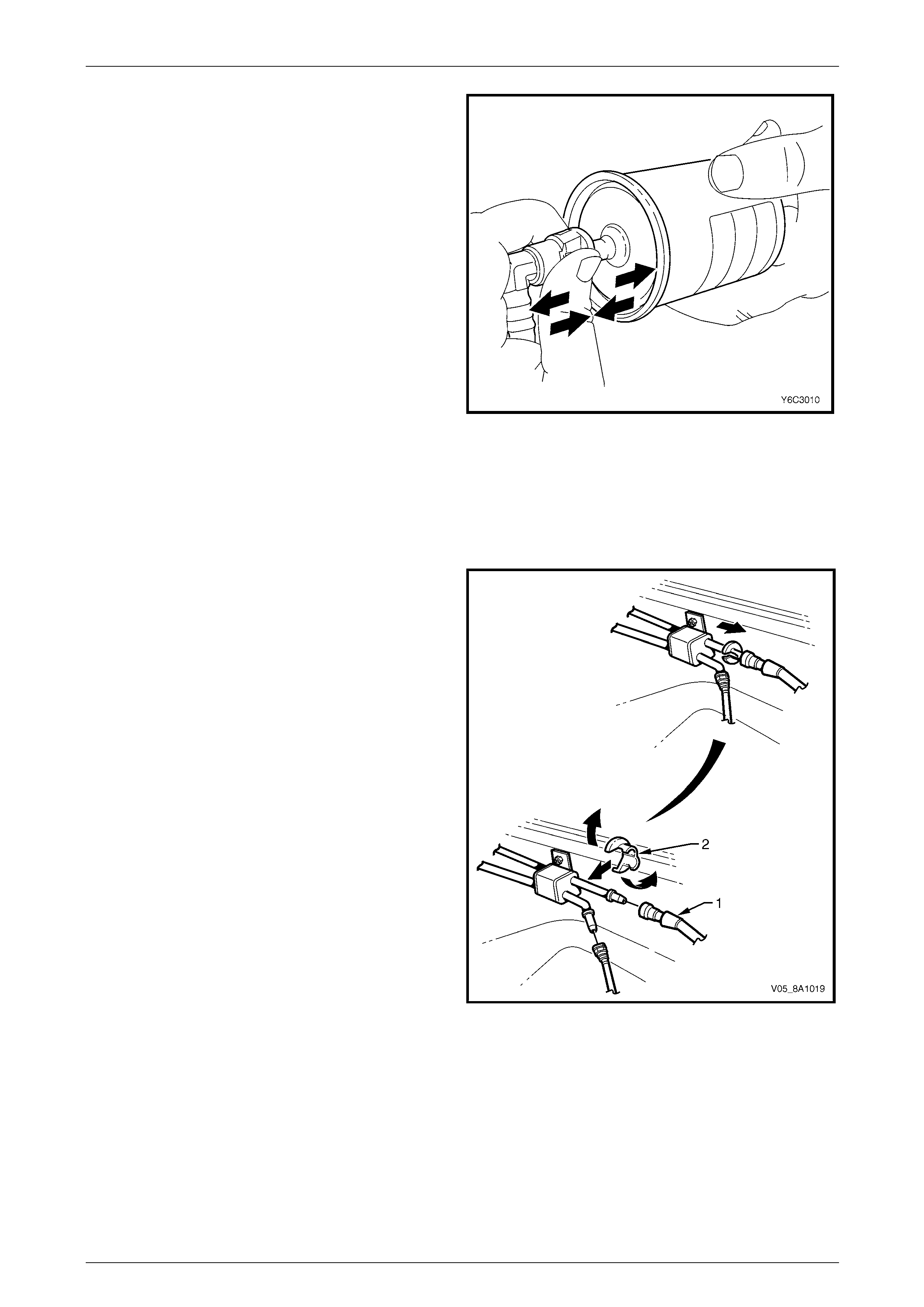
Fuel System Page 8A1–131
Page 8A1–131
3 After installation, pull and push on the quick-connect
fitting to ensure the connection is secure.
Figure 8A1 – 174
Tool Nos. 7370 and 7371
Remove
Use tool Nos. 7370 and 7371 to disconnect the fuel lines at
the engine as follows:
1 Open the quick-connect release tool (2) and place it
over the fuel line (1).
2 Close the quick-connect release tool and pull it into the
fuel line quick-connect fitting to disconnect the fuel line
from the fuel pipe.
NOTE
Do not disconnect the fuel lines at th e fuel rail. If
the fuel lines are removed from the fuel rail, the
fuel lines must be replaced.
Figure 8A1 – 175
Reinstall
Reinstallation of the disconnected quick-connect fittings using tool Nos. 7370 and 7371 is the same as for tool
No. AU533, refer to Tool No. AU533.
Fuel System Page 8A1–132
Page 8A1–132
7.2 Fuel Tank
LT Section No. — 03–055
Regular Cab and Crew Cab with 'Delete Tub' Option
Remove
A depressurised fuel system contains fuel in
the fuel filter and fuel lines that can be spilled
during service operations.
Fuel vapour remains in the fuel tank even
when completely empty. Seal all openings in
the fuel tank using suitable material or a
plastic plug. Ensure no naked flames or other
ignition sources are nearby. Ensure all
cellular phones (and transmission devices
that may cause any metal objects to become
unintentional receiving antennas) are
switched off.
Place a dry chemical (Class B) fire
extinguisher nearby before performing any
on-vehicle service procedures. Failure to
follow these precautions may result in
personal injury.
Wear safety glasses when using compressed
air. Do not blow compressed air onto any
body part.
1 Depressurise the fuel system, refer to 4.1 Fuel System Depressurisation.
2 Remove the fuel pump relay, refer to Section 12O Fuses, Relays and Wiring Harnesses.
3 Remove the tray, refer to Section 1B1 Tray.
4 Use compressed air to ensure all dirt and foreign materials are removed from all fuel connections before the parts
are disconnected, refer to Figure 8A1 – 176.
5 Disconnect the modular fuel pump and sen der assembly harness connector (3), refer to Figure 8A1 – 176.
6 Tag, remove and cover the following items with a suitable material to prevent foreign objects from entering:
a the fuel feed line (6),
NOTE
For information on quick-connect fittings, refer to
7.1 Quick-connect Fittings.
b inlet breather pipe (9) from the vapour collector, and
c fuel tank vent line (12).
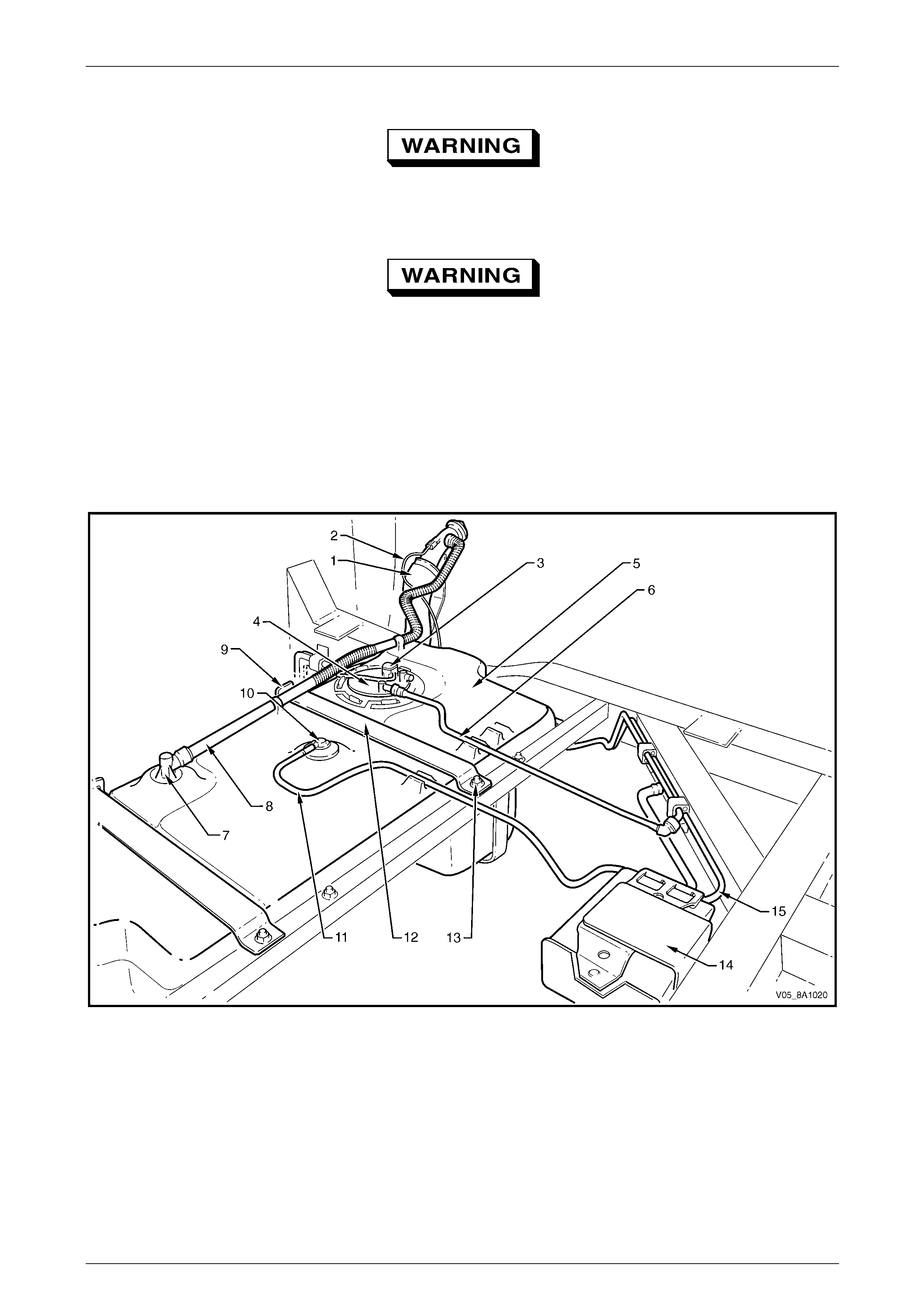
Fuel System Page 8A1–133
Page 8A1–133
7 Remove the modular fuel pump and se nder assembly (4), refer to 7.5 Modular Fuel Pump and Sender Assembly.
Never drain or store fuel into an open
container, due to the possibility of fire or
explosion.
Ensure fuel is pumped or siphoned from both
sides of the baffle in the fuel tank.
8 Drain the fuel tank by pumping or siphoning fuel through the hole in the fuel tank (from which the modul ar fuel
pump and sender assembl y was removed) using commercially-available equipment.
NOTE
A permanent floodgate restriction in the lower fuel
filler neck prevents the fuel tank from being
drained through the filler aperture.
Figure 8A1 – 176
Legend
1 Fuel Filler Neck
2 Earthing Wire
3 Modular Fuel Pump and Sender
Assembly Harness Connector
4 Modular Fuel Pump and Sender
Assembly
5 Fuel Tank
6 Fuel Feed Line
7 Vapour Collector
8 Inlet Breather Pipe
9 Fuel Tank Mounting Strap Front
Anchoring Point
10 Rollover Valve
11 Fuel Tank Vent Line
12 Fuel Tank Mounting Strap (2 places)
13 Stud (2 places)
14 Evaporative Emission Control Canister
15 Evaporative Emission Control Canister
Purge Line
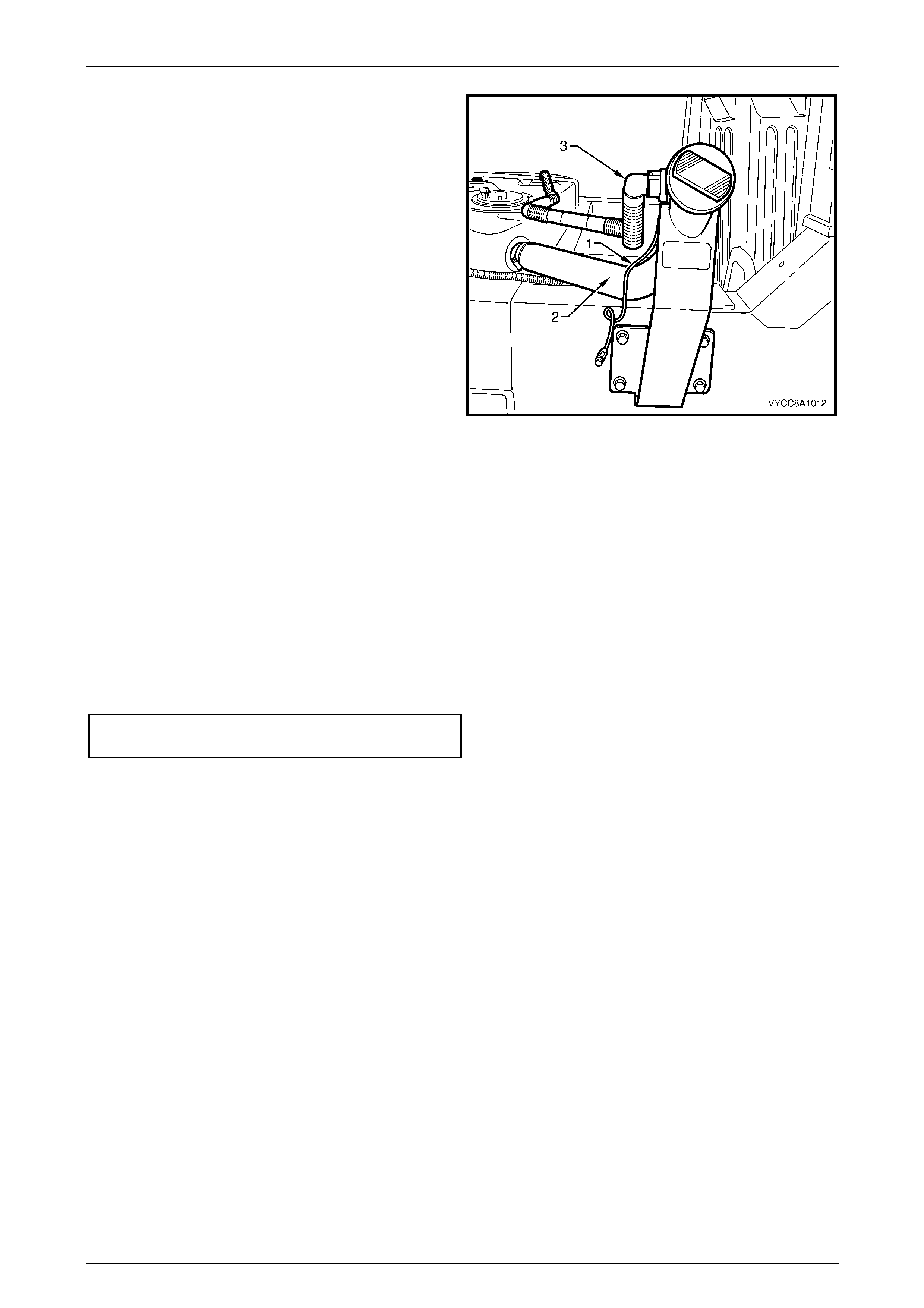
Fuel System Page 8A1–134
Page 8A1–134
9 Remove the grounding wire (1) from the spade
connector on the fuel filler ne ck.
10 Remove the grounding wire from the spade connector
screw mounting on the chassis member.
11 Place the grounding wire in a safe location away from
the immediate worksite.
12 Loosen the scre w clamp hol ding the flexible fuel inlet
pipe (2) onto the fuel filler neck.
13 Use compressed air to ensure all dirt and foreign
materials are removed from the inlet bre ath er pipe (3)
and fuel filler neck.
14 Remove the quick-connect fitting holding the inlet
breather pipe onto the fuel filler neck.
15 Cover the flexible fuel inlet pipe an d inlet breather pipe
with a suitable material to prevent foreig n objects from
entering. Figure 8A1 – 177
16 If required, remove the support bracket, refer to 7.4 Support Bracket.
17 Remove the nuts from both fuel tank mounting strap studs (13), refer to Figure 8A1 – 176.
18 Lift the fuel tank mounting straps away from the front anchoring points (9) and place in a safe location away from
the immediate worksite.
19 Remove the fuel tank from its support frame.
Reinstall
Reinstallation of the fuel tank is the reverse of the removal procedure, noting the following:
1 Ensure all parts are dust-free and clean before reinstalling.
2 Tighten both fuel tank mounting strap nuts to the correct torque specification.
Fuel tank mounting strap
nut torque specification...........................20.0 – 25.0 Nm
3 Before starting the vehicle, perform a fuel system leak test, refer to 4.3 Fuel Leak Test.
Fuel System Page 8A1–135
Page 8A1–135
Crew Cab
Remove
A depressurised fuel system contains fuel in
the fuel filter and fuel lines that can be spilled
during service operations.
Fuel vapour remains in the fuel tank even
when completely empty. Seal all openings in
the fuel tank using suitable material or a
plastic plug. Ensure no naked flames or other
ignition sources are nearby. Ensure all
cellular phones (and transmission devices
that may cause any metal objects to become
unintentional receiving antennas) are
switched off.
Place a dry chemical (Class B) fire
extinguisher nearby before performing any
on-vehicle service procedures. Failure to
follow these precautions may result in
personal injury.
Wear safety glasses when using compressed
air. Do not blow compressed air onto any
body part.
1 Depressurise the fuel system, refer to 4.1 Fuel System Depressurisation.
2 Remove fuel pump relay, refer to Section 12O Fuses, Relays and Wiring Harnesses.
3 Remove the front inner side panel cover from the rear body to enable access to the fuel filler neck, refer to
Section 1B Sheetmetal.
4 Remove the quick-connect fitting attaching the inlet breather pipe to the fuel filler neck, refer to
7.14 Fuel Filler Neck and Splash Guard and Figure 8A1 – 178.
5 Cover the end of the inlet breather pipe and the inlet breather pipe connection on th e fuel filler neck with a suitable
material to prevent foreign objects from ente r ing.
6 Remove the rear body, refer to Section 1B Sheetmetal.
7 Use compressed air to ensure all dirt and foreign materials are removed from all fuel connections before the parts
are disconnected, refer to Figure 8A1 – 178.
8 Disconnect the modular fuel pump and sen der assembly harness connector (1).
9 Tag, remove and cover the following items with a suitable material to prevent foreign objects from entering:
a the fuel feed line (5),
NOTE
For information on quick-connect fittings used on
Regular Cab and Crew Cab vehicles, refer to
7.1 Quick-connect Fittings.
b the inlet breather pipe (7) from the vapour collector, and
c the fuel tank vent line (10).
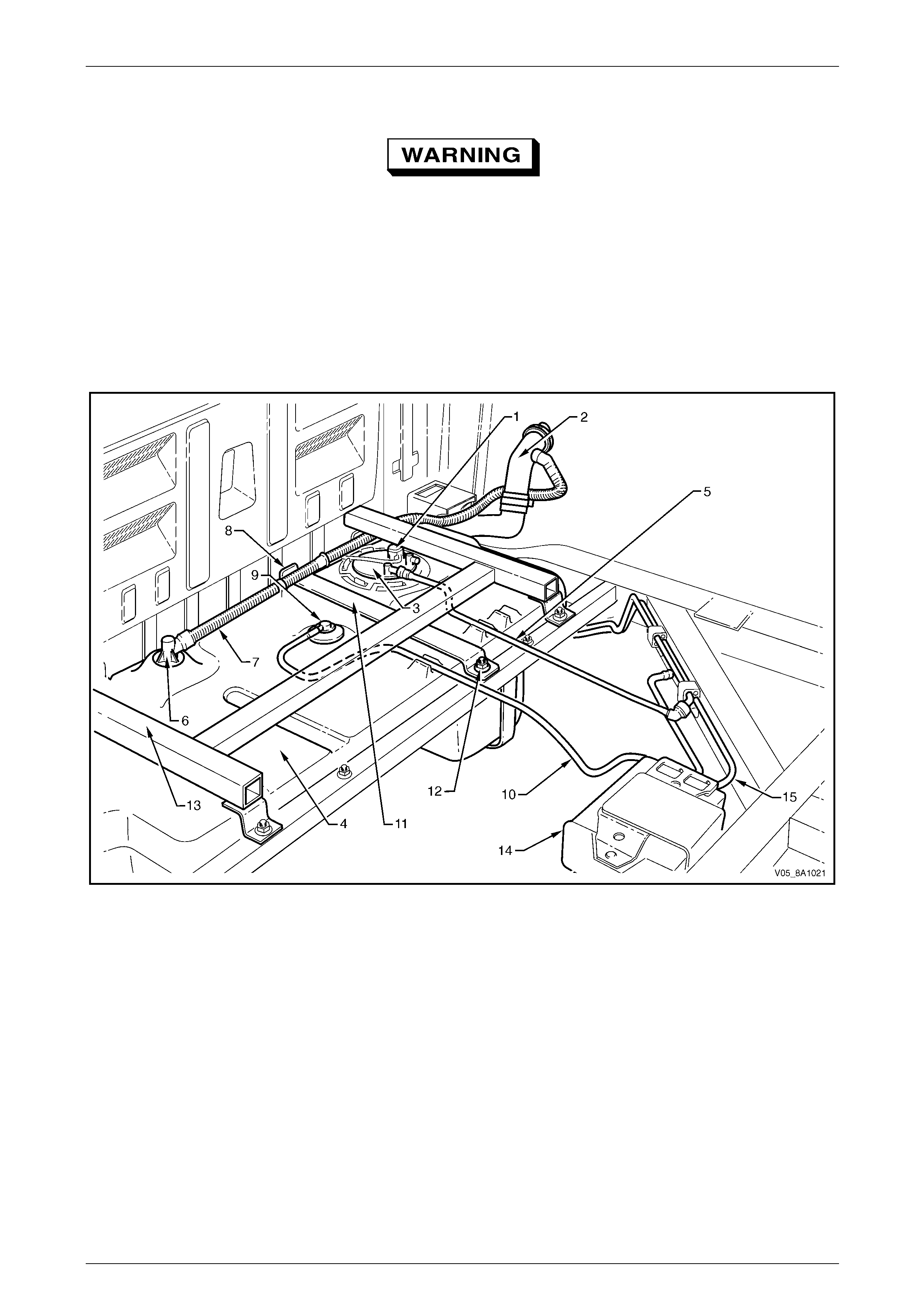
Fuel System Page 8A1–136
Page 8A1–136
10 Remove the modular fuel pump and se nder assembly (3), refer to 7.5 Modular Fuel Pump and Sender Assembly.
Ensure fuel is pumped or siphoned from both
sides of the baffle in the fuel tank.
11 Drain the fuel tank by pumping or siphoning fuel through the hole in the fuel tank (from which the modul ar fuel
pump and sender assembl y was removed) using commercially-available equipment.
NOTE
A permanent floodgate restriction in the lower fuel
filler neck prevents the fuel tank from being
drained through the filler aperture.
Figure 8A1 – 178
Legend
1 Modular Fuel Pump and Sender
Assembly Harness Connector
2 Fuel Filler Neck
3 Modular Fuel Pump and
Sender Assembly
4 Fuel Tank
5 Fuel Feed Line
6 Vapour Collector
7 Inlet Breather Pipe
8 Fuel Tank Mounting Strap Front
Anchoring Point (3 places)
9 Rollover Valve
10 Fuel Tank Vent Line
11 Fuel Tank Mounting Strap (1 place)
12 Stud (3 places)
13 Fuel Tank 'H'-frame (1 place)
14 Evaporative Emission Control
Canister
15 Evaporative Emission Control
Canister Purge Line
12 Loosen the scre w clamp from the fuel tank end of the flexible fuel filler neck.
13 Remove the flexible fuel filler neck from the fuel tank.
14 Cover the flexible fuel filler neck with a suitable material to prevent foreign objects from entering.
15 Remove both nuts from the fuel tank 'H'-frame (13), refer to Figure 8A1 – 178.
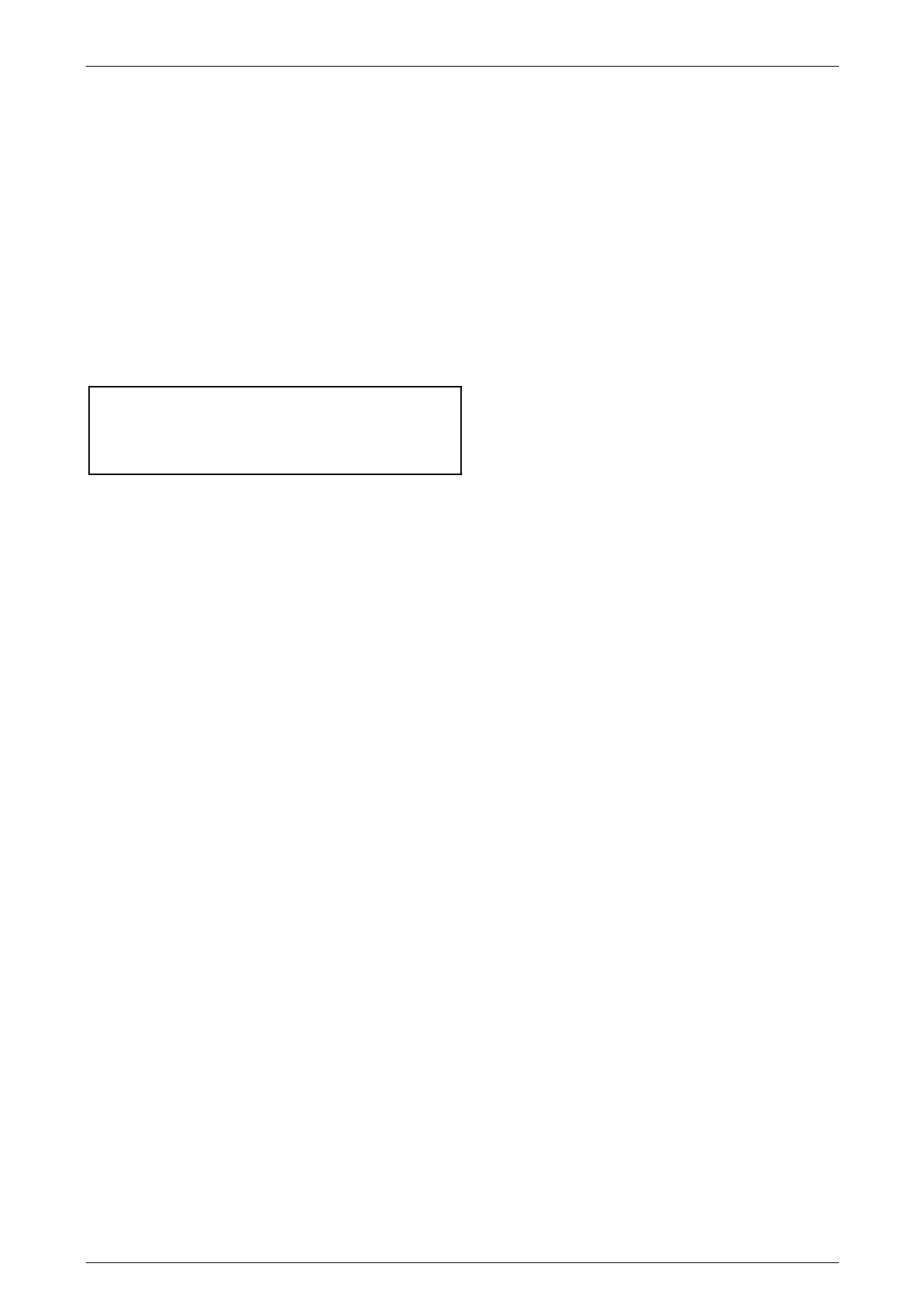
Fuel System Page 8A1–137
Page 8A1–137
16 Remove the nut from the centre fuel tank mounting strap (11).
17 Lift the fuel tank 'H'-frame away from the front anchoring points and place in a safe location away from the
immediate worksite.
18 Lift the fuel tank mounting strap away from the front anchoring point and place in a safe location away from the
immediate worksite.
19 Remove the fuel tank from its support frame.
Reinstall
Reinstallation of the fuel tank is the reverse of the removal procedure, noting the following:
1 Ensure all parts are dust-free and clean before reinstalling.
2 Tighten the fuel tank 'H'-frame nuts to the correct torque specification.
3 Tighten the fuel tank mounting strap nut to the correct torque specification.
Fuel tank 'H'-frame nut
torque specification.................................20.0 – 25.0 Nm
Fuel tank mounting strap
nut torque specification...........................20.0 – 25.0 Nm
4 Before starting the vehicle, perform a fuel system leak test, refer to 4.3 Fuel Leak Test.
Fuel System Page 8A1–138
Page 8A1–138
7.3 Fuel Tank Support Straps
LT Section No. — 03–055
Remove
1 Remove the fuel tank, refer to 7.2 Fuel Tank.
2 Remove the rear park brake cable(s) from the fuel
tank support straps, refer to Section 5A Service and
Park Braking System.
3 Remove the intermediate muffler, refer to
Section 8B Exhaust System.
4 Remove the heat shield from the left fuel tank support
strap, refer to Section 8B Exhaust System.
5 Remove the fuel tank support straps and place the
nuts (1), four places, in a safe location a way from the
immediate worksite.
Figure 8A1 – 179
Reinstall
Reinstallation of the fuel tank support straps is the reverse of the removal procedure, noting the following:
1 Ensure all parts are dust-free and clean before reinstalling.
2 Tighten the nuts that secure the fuel tank support straps to the correct torque specificatio n.
Fuel tank support strap attaching
nut torque specification...........................30.0 – 40.0 Nm
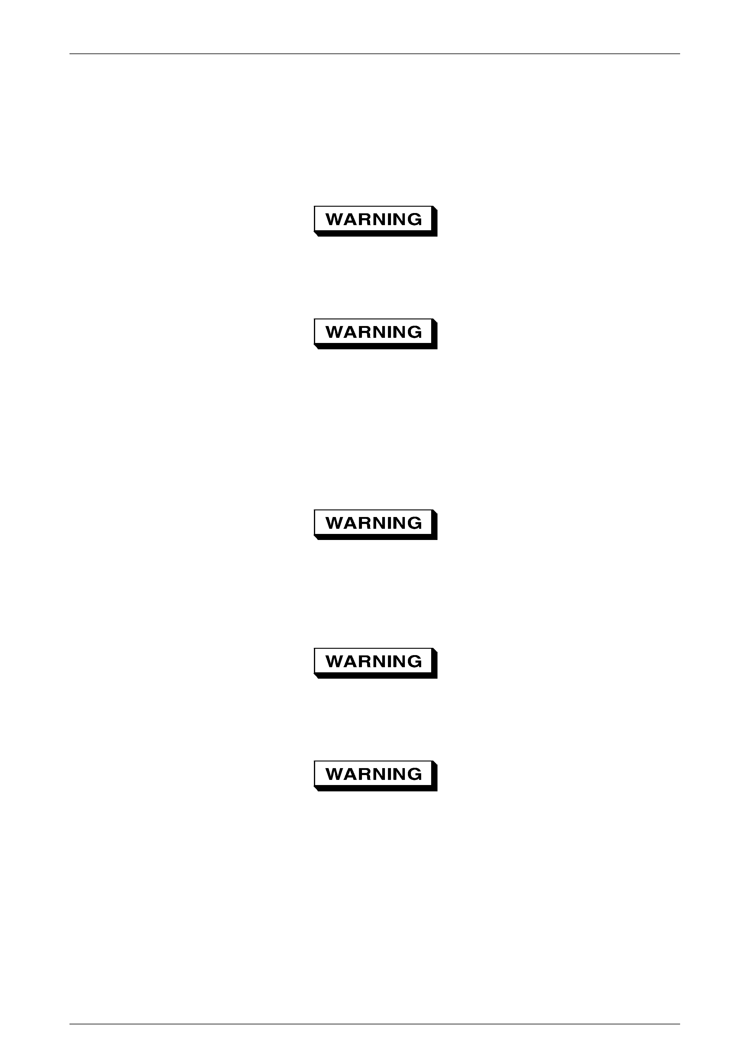
Fuel System Page 8A1–139
Page 8A1–139
7.4 Support Bracket
LT Section No. — 03–055
Remove
A depressurised fuel system contains fuel in
the fuel filter and fuel lines that can be spilled
during service operations.
Fuel vapour remains in the fuel tank even
when completely empty. Seal all openings in
the fuel tank using suitable material or a
plastic plug. Ensure no naked flames or other
ignition sources are nearby. Ensure all
cellular phones (and transmission devices
that may cause any metal objects to become
unintentional receiving antennas) are
switched off.
Place a dry chemical (Class B) fire
extinguisher nearby before performing any
on-vehicle service procedures. Failure to
follow these precautions may result in
personal injury.
Wear safety glasses when using compressed
air. Do not blow compressed air directly onto
any body part.
Ensure fuel is pumped or siphoned from both
sides of the baffle in the fuel tank.
1 Remove the modular fuel pump and se nder assembly, refer to 7.5 Modular Fuel Pump and Sender Assembly.
2 Drain the fuel tank by pumping or siphoning fuel through the hole in the fuel tank (from which the modul ar fuel
pump and sender assembl y was removed) using commercially-available equipment.
NOTE
A permanent floodgate restriction in the lower fuel
filler neck prevents the fuel tank from being
drained through the filler aperture.

Fuel System Page 8A1–140
Page 8A1–140
3 Remove the grounding wire (1) from the spade
connector on the fuel filler ne ck.
4 Remove the grounding wire from the spade connector
screw mounting on the chassis member.
5 Place the grounding wire in a safe location away from
the immediate worksite.
6 Loosen the scre w clamp hol ding the flexible fuel inlet
pipe (2) onto the fuel filler neck.
7 Use compressed air to ensure that all dirt and foreign
materials are removed from the inlet bre ath er pipe (3)
and fuel filler neck.
8 Remove the quick-connect fitting holding the inlet
breather pipe onto the fuel filler neck.
9 Cover the flexible fuel inlet pipe an d inlet breather pipe
with a suitable material to prevent foreig n objects from
entering. Figure 8A1 – 180
10 Remove both screw clamps (1) holding the flexible fuel
inlet pipe onto the fuel filler neck.
11 Remove the screw (2), four places, holding the
support bracket backing plate onto the chassis.
12 Cover the flexible fuel filler neck with a suitable
material to prevent foreign objects from ente ring.
Figure 8A1 – 181
Reinstall
Reinstallation of the support bracket is the reverse of the removal procedure, noting the following:
1 Ensure all parts are dust-free and clean before reinstalling.
2 Tighten the screws that secure the support bracket backing plate on the chassis to the correct torque specification.
Support bracket backing
plate attaching screw
torque specification.................................20.0 – 25.0 Nm

Fuel System Page 8A1–141
Page 8A1–141
7.5 Modular Fuel Pump and Sender
Assembly
LT Section No. — 03–074
Remove
A depressurised fuel system contains fuel in
the fuel filter and fuel lines that can be spilled
during service operations.
Fuel vapour remains in the fuel tank even
when completely empty. Seal all openings in
the fuel tank using suitable material or a
plastic plug. Ensure no naked flames or other
ignition sources are nearby. Ensure all
cellular phones (and transmission devices
that may cause any metal objects to become
unintentional receiving antennas) are
switched off.
Place a dry chemical (Class B) fire
extinguisher nearby before performing any
on-vehicle service procedures. Failure to
follow these precautions may result in
personal injury.
Wear safety glasses when using compressed
air. Do not blow compressed air directly onto
any body part.
1 Remove the fuel pump relay, refer to Section 12O Fuses, Relays and Wiring Harnesses.
2 Remove the tray, refer to Section 1B1 Tray.
3 Use compressed air to ensure that all dirt and foreign materials are removed from all fuel con nections before the
parts are disconnected.
Before proceedin g, clean all traces of dirt and
other foreign material from the top of the fuel
tank, near the modular fuel pump and sender
assembly.
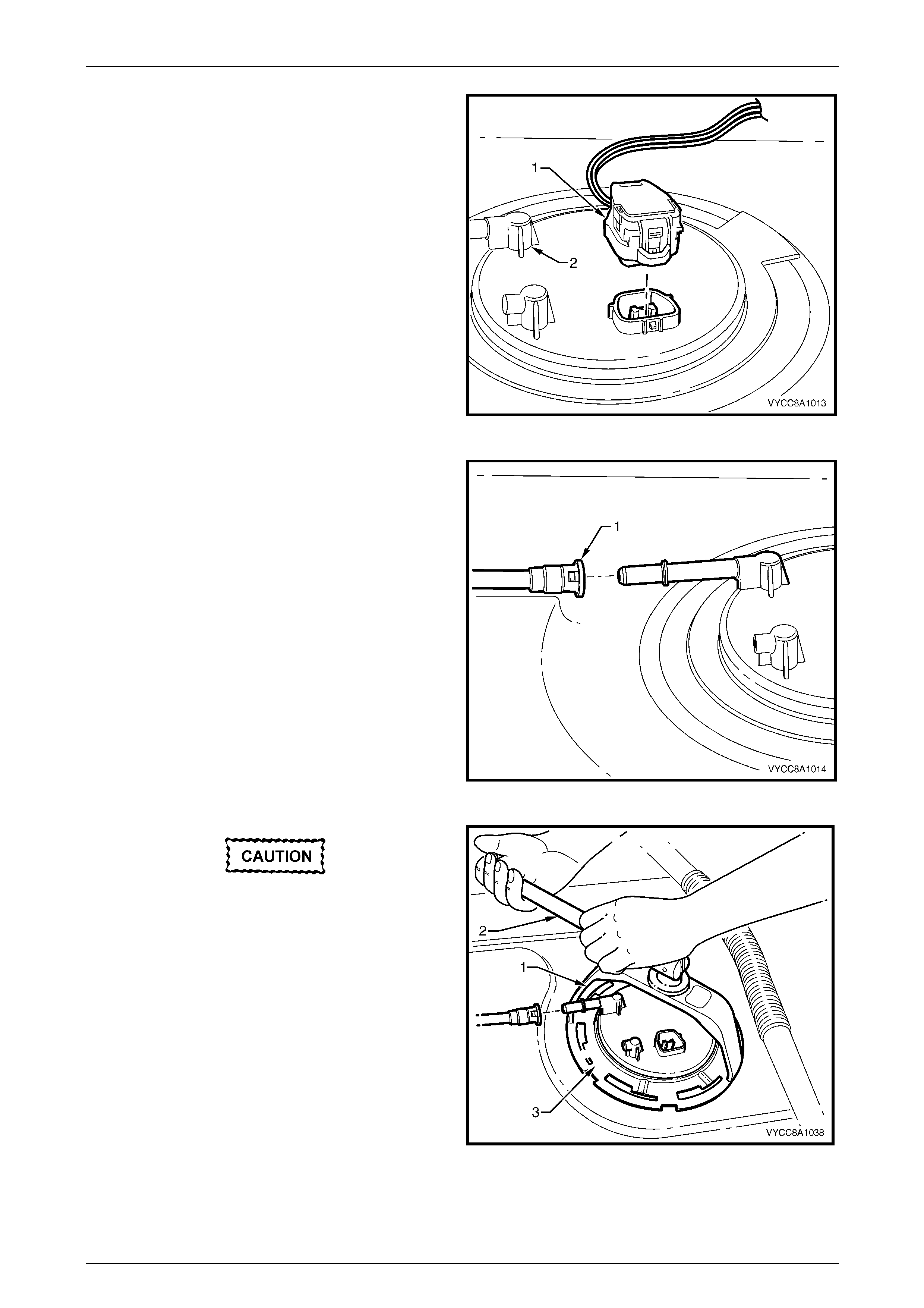
Fuel System Page 8A1–142
Page 8A1–142
4 Disconnect the modular fuel pump and sen der
assembly harness connector (1).
5 Tag the fuel feed line connecting the fuel feed port (2)
on the modular fuel pump and sender assembly cover.
Figure 8A1 – 182
6 Disengage the fuel feed line quick-connect fitting (1)
using tool No. AU533 (3/8-inch).
NOTE
For information on quick-connect fittings for
Regular Cab and Crew Cab vehicles, refer to
Tool No. AU533.
Figure 8A1 – 183
Ensure tool No. J45722 is seated firmly and
positively in the modular fuel pump and
sender assembly cover retainer lock ring
while removing the modular fuel pump and
sender assemb ly.
7 Using tool No. J45722 (1) and a half-inch breaker
bar (2), remove the modular fuel pump a nd sender
assembly cover retainer lock ring (3) by turning it
anticlockwise.
8 Remove the modular fuel pump and se nder assembly
cover retainer lock ring.
NOTE
The modular fuel pump and sender assembly
cover springs up when the retainer is remov ed.
Figure 8A1 – 184
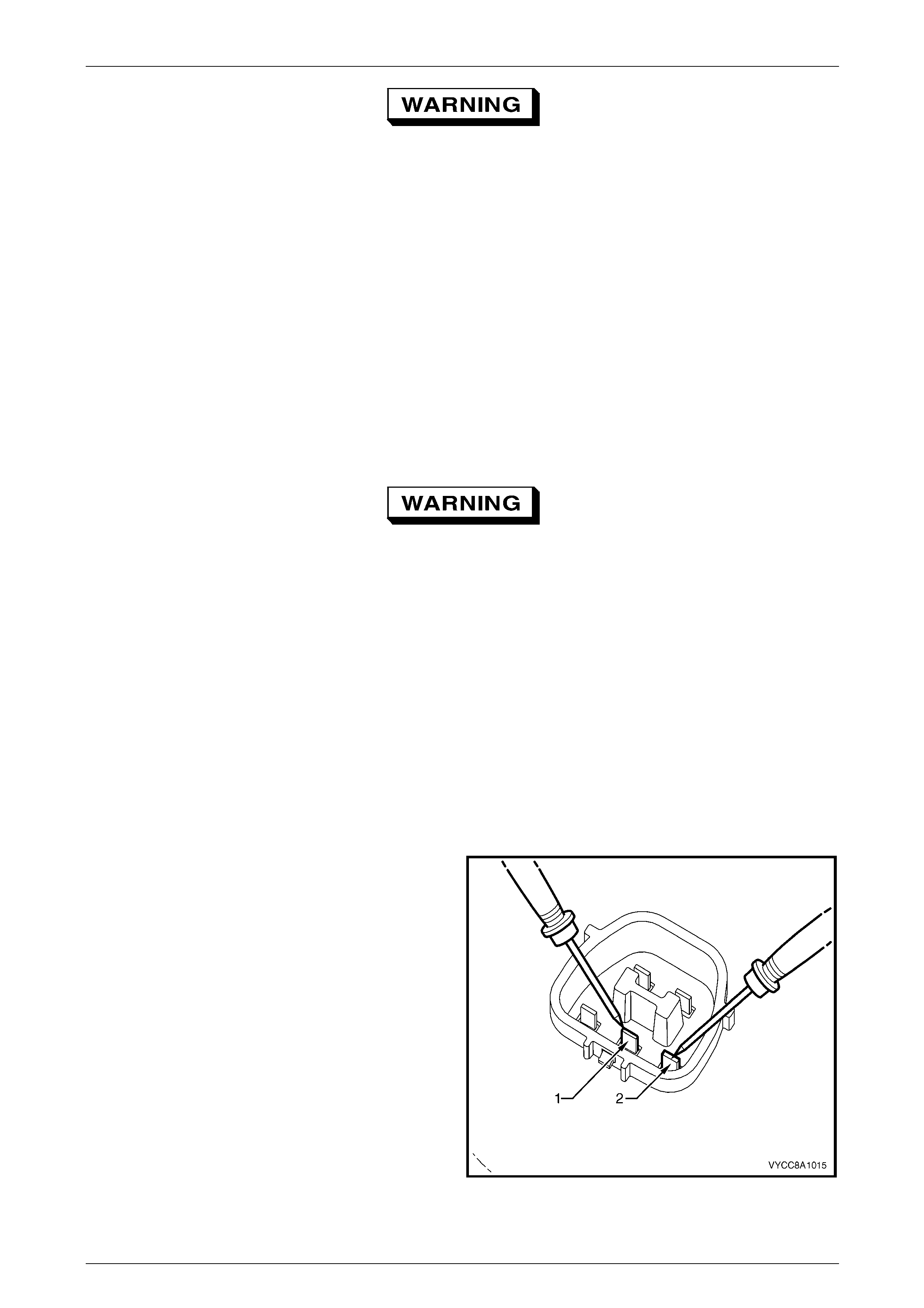
Fuel System Page 8A1–143
Page 8A1–143
The reservoir will be full of fuel. When the
modular fuel pump and sender assembly is
removed from the fuel tank, pour any
remaining fuel in the reservoir into a suitable
container. Do not drain or store fuel into an
open container, due to the possibility of fire
or explosion.
9 Carefully lift the modular fuel pump a nd sender assembly from the fuel tank, taking care not to:
• damage the fuel level sender float and arm, and
• spill any fuel remaining in the reservoir.
NOTE
The fuel sender float arm is not serviced
separately. If damaged, it is replaced as part of
the fuel level sender assembl y.
Fuel vapour remains in the fuel tank even
when completely empty. Seal all openings in
the fuel tank using suitable material or a
plastic plug. Ensure no naked flames or other
ignition sources are nearby. Ensure all
cellular phones (and transmission devices
that may cause any metal objects to become
unintentional receiving antennas) are
switched off.
10 Remove and discard the O-ring and spacer.
11 Place a suitable material over the opening in the fuel tank to prevent any foreign matter from entering the fuel
system.
Test
Fuel Level Sender
1 Measure the resistance acr oss the positive (1) and
negative (2) fuel level sender terminals of the fuel
pump motor connector. Take the following
measurements:
a With the fuel level sender assembly in the e mpty
position, the resistance should be 24 8.5 Ω
(±3.3 Ω).
b With the fuel level sender assembly rotated to
the full position, the resistance should be 40 Ω
(±2.5 Ω).
2 If the resistance at either of these positions is not
within tolerance, replace the fuel level sender
assembly, refer to 7.7 Fuel Level Sender Assembly.
Figure 8A1 – 185
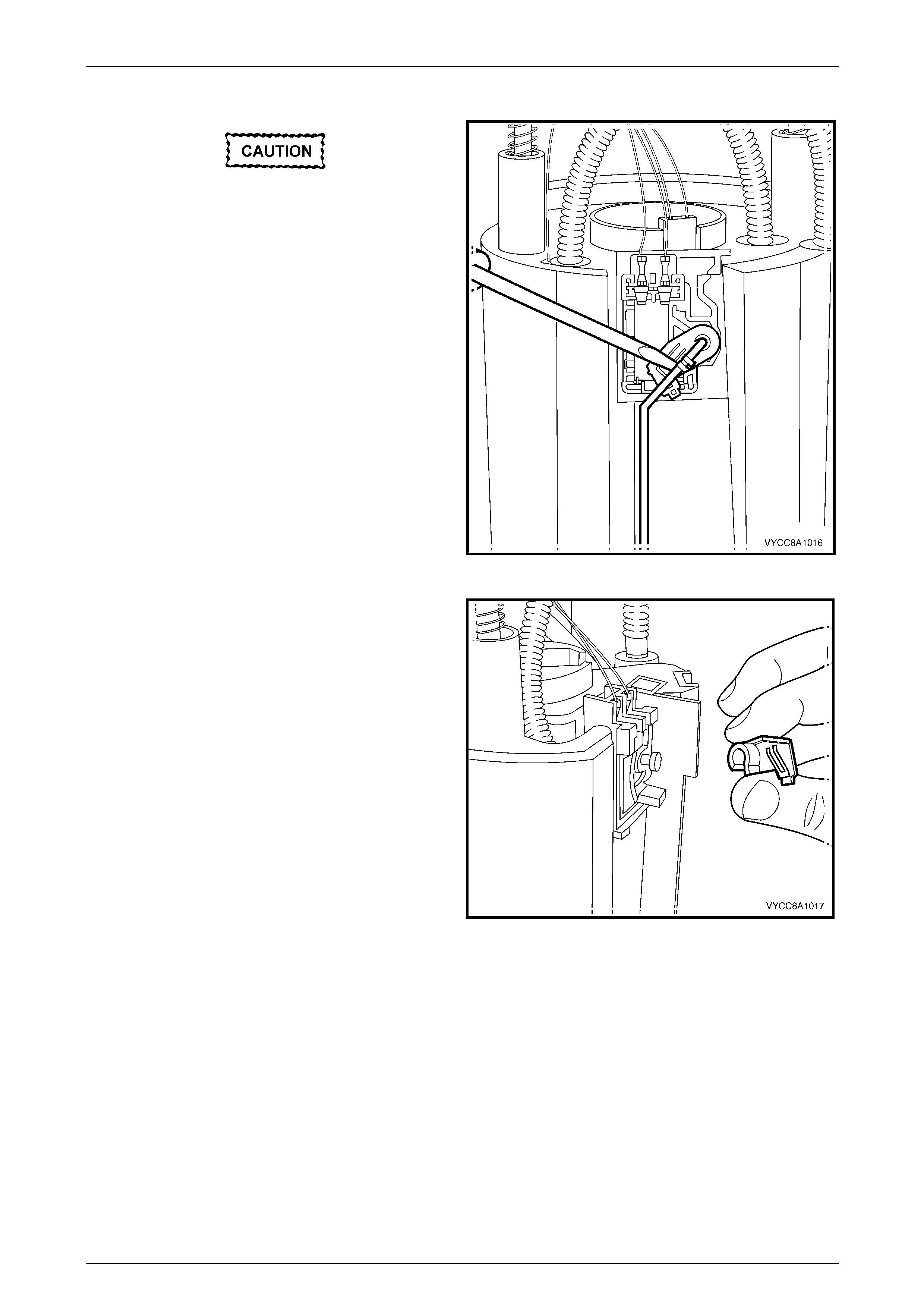
Fuel System Page 8A1–144
Page 8A1–144
Disassemble
Do not touch the ceramic variable resistor
card; if it is touched inadvertently, clean it
immediately with isopropyl alcohol.
1 Prise the tang open that holds the fuel level sender
float and arm onto the nylon wiper piece.
2 Lift the fuel level sender float and arm away from the
nylon wiper piece and place in a safe location away
from the immediate worksite.
Figure 8A1 – 186
3 Lift the nylon wiper piece off the ceramic variable
resistor card holder, then place in a safe location away
from the immediate worksite.
Figure 8A1 – 187
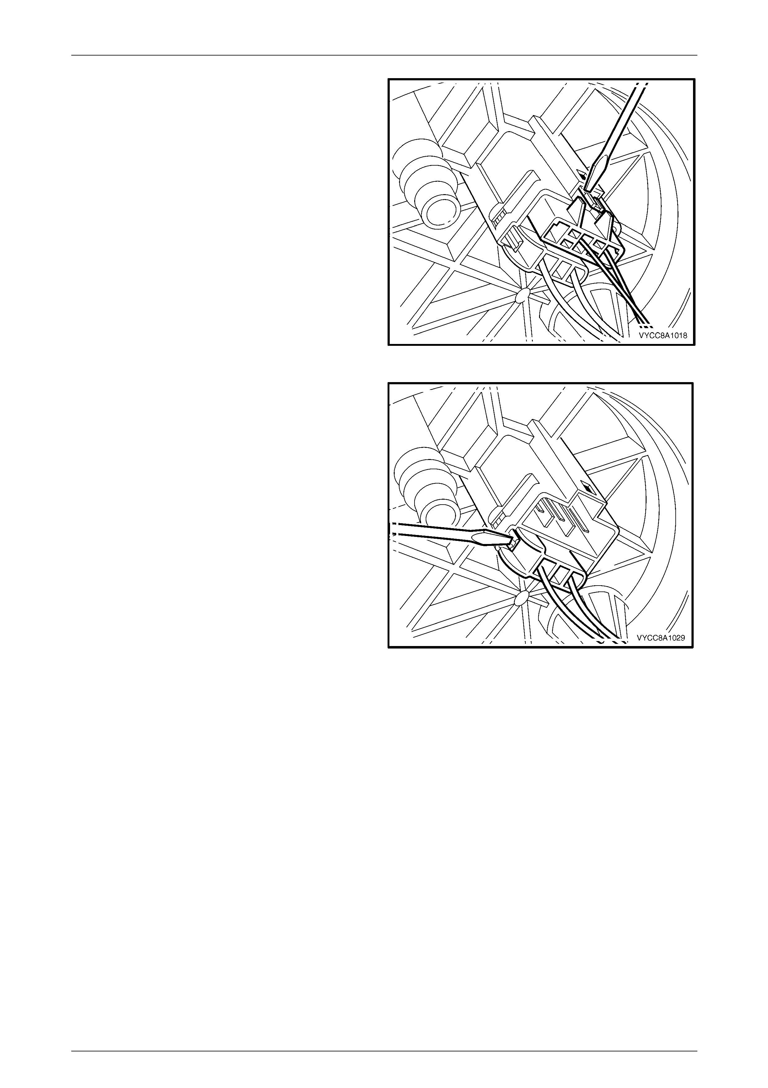
Fuel System Page 8A1–145
Page 8A1–145
4 Remove the 3-pin connector (the fuel level sender
assembly wires) from underneath the modular fuel
pump and sender assembly c over.
Figure 8A1 – 188
5 Remove the 2-pin connector (the fuel p ump motor
wires) from underneath the modular fuel pump and
sender assembly cover.
Figure 8A1 – 189
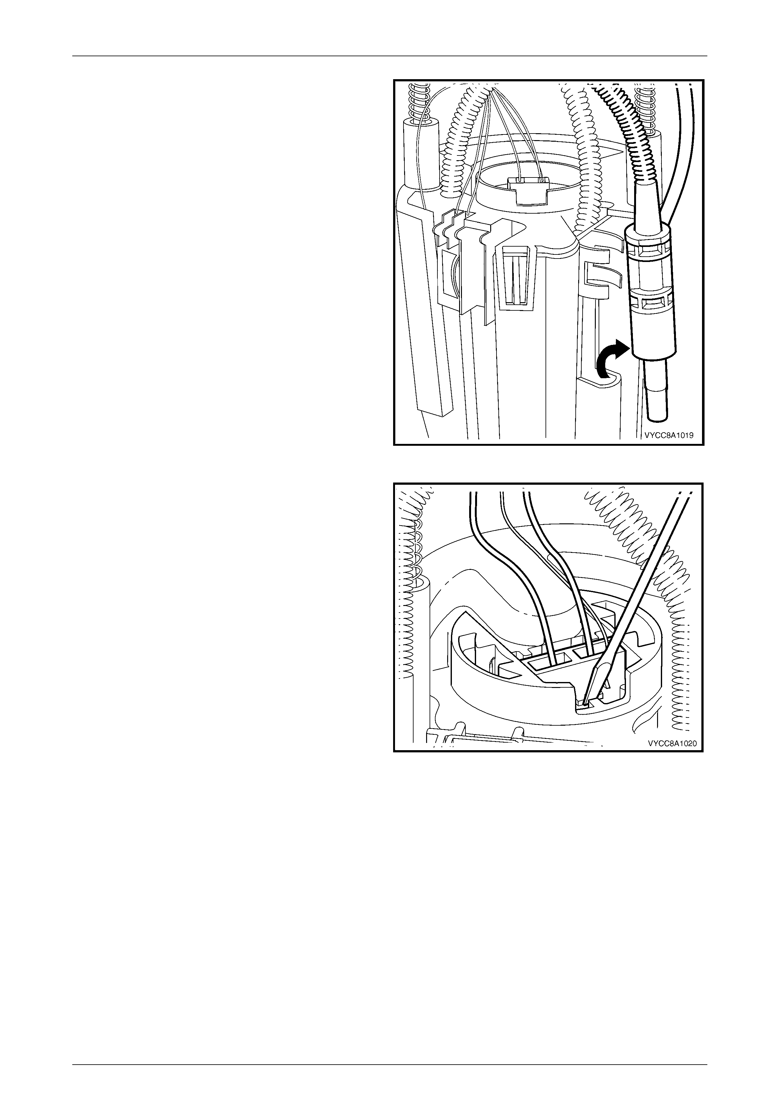
Fuel System Page 8A1–146
Page 8A1–146
6 Prise the transfer jet pump from the clips, then remove
from the reservoir.
Figure 8A1 – 190
7 Press in the tang retaining the 2-pin connector on the
fuel pump and suction filter assembly, then remove the
connector.
Figure 8A1 – 191
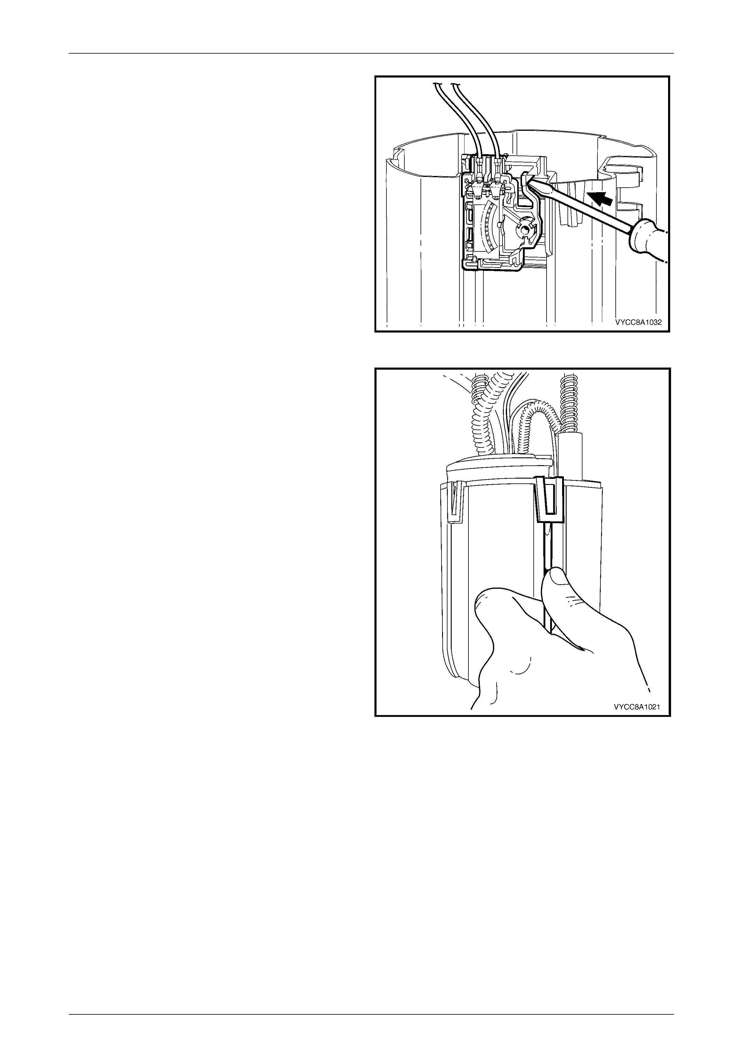
Fuel System Page 8A1–147
Page 8A1–147
8 Prise the tang open that holds the ceramic v aria ble
resistor card holder to the side of the reservoir, then lift
it off the reservoir.
Figure 8A1 – 192
9 Prise the four tangs with a flat-bladed screwdriver,
then remove the fuel pump and suction filter assembly,
and modular fuel pump an d sender assembly cover
from the reservoir.
NOTE
Another person may have to assist in removing
the fuel pump and suction filter assembly from
the reservoir.
Figure 8A1 – 193
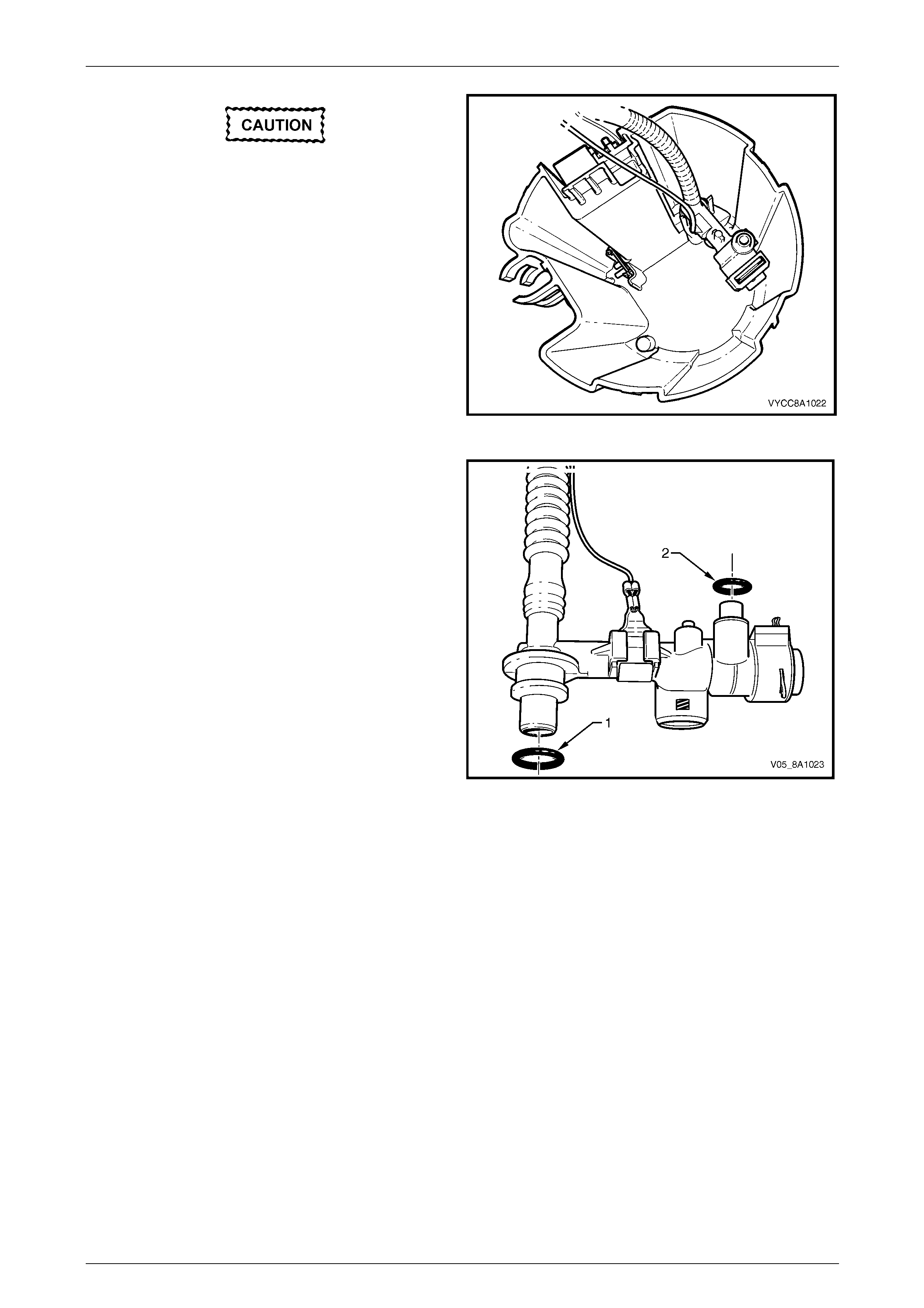
Fuel System Page 8A1–148
Page 8A1–148
Do not bend the spade connector on the
pressure regulator holder; this can be easily
damaged or broken.
10 Pull the modular fuel pump and sender assembly
cover, fuel pump and suction filter assembly, pressure
regulator holder and fuel feed pipe from the reservoir
body.
NOTE
Some difficulty may be experienced when lifting
these items from the reservoir body due to the
limited space availabl e.
Figure 8A1 – 194
11 Remove and discard the O-ring (1) from the bottom of
the pressure regulator holder.
NOTE
The O-ring may be lodged in the reservoir body.
12 Remove and discard the O-ring (2) from the top of the
pressure regulator holder.
NOTE
The O-ring may be lodge d in the base of the fuel
pump and suction filter assembly.
Figure 8A1 – 195
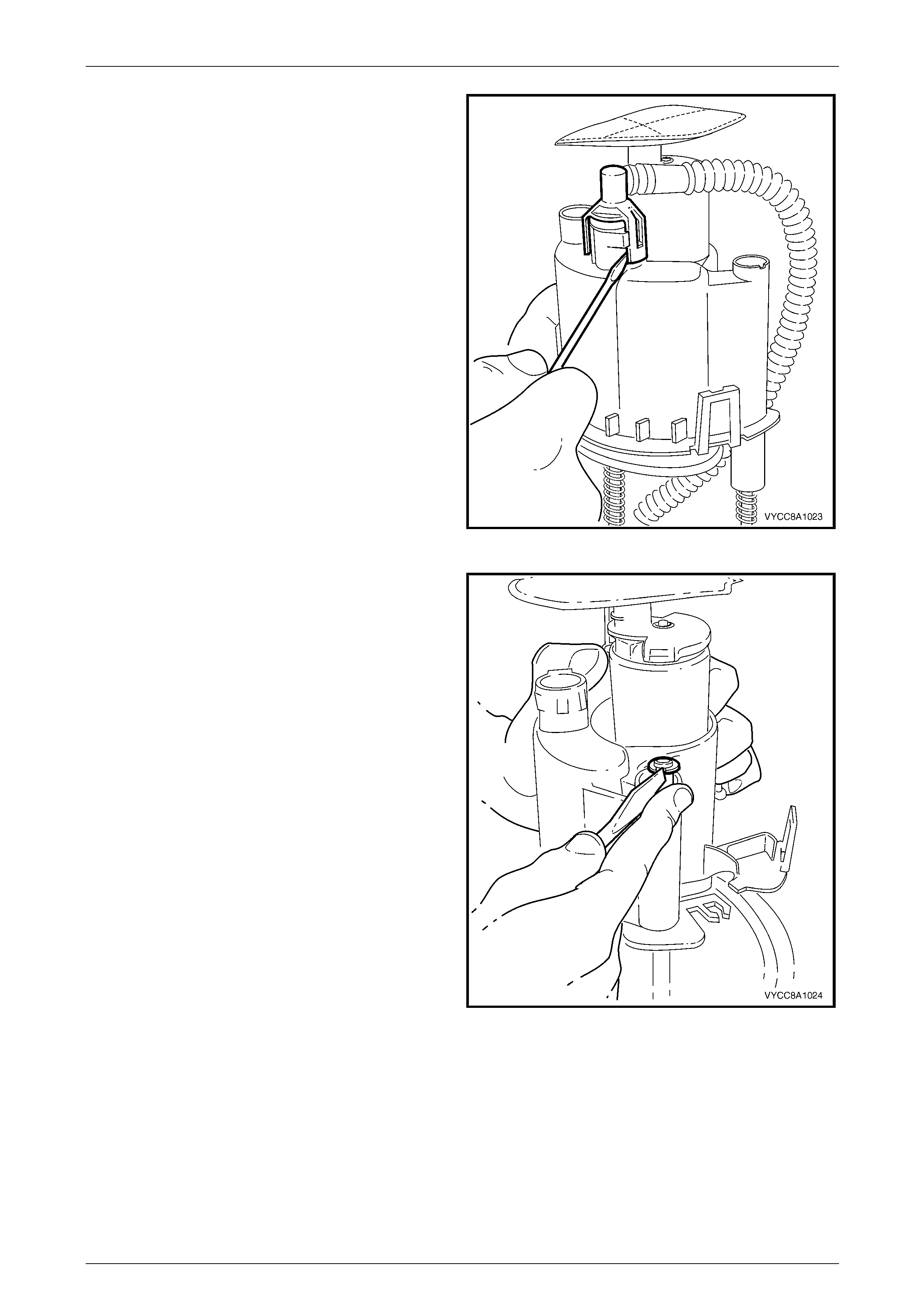
Fuel System Page 8A1–149
Page 8A1–149
13 Prise open both tangs on the fuel outlet connector on
the bottom of the fuel pump and suction filter
assembly, then remove the fuel outlet pipe from the
fuel pump and suction filter assembly.
14 Remove and discard the O-ring from the fuel feed li ne
outlet underneath the fuel pump and suction filter
assembly.
NOTE
The O-ring may remain in the base of the fuel
pump and suction filter assembly.
Figure 8A1 – 196
15 Push the fuel pump and suction filter assembly down
the sprung shafts and remove the circlip (only o ne
shaft is fitted with a circlip) from the end of the shaft.
Place the circlip in a safe location away from the
immediate worksite.
Figure 8A1 – 197
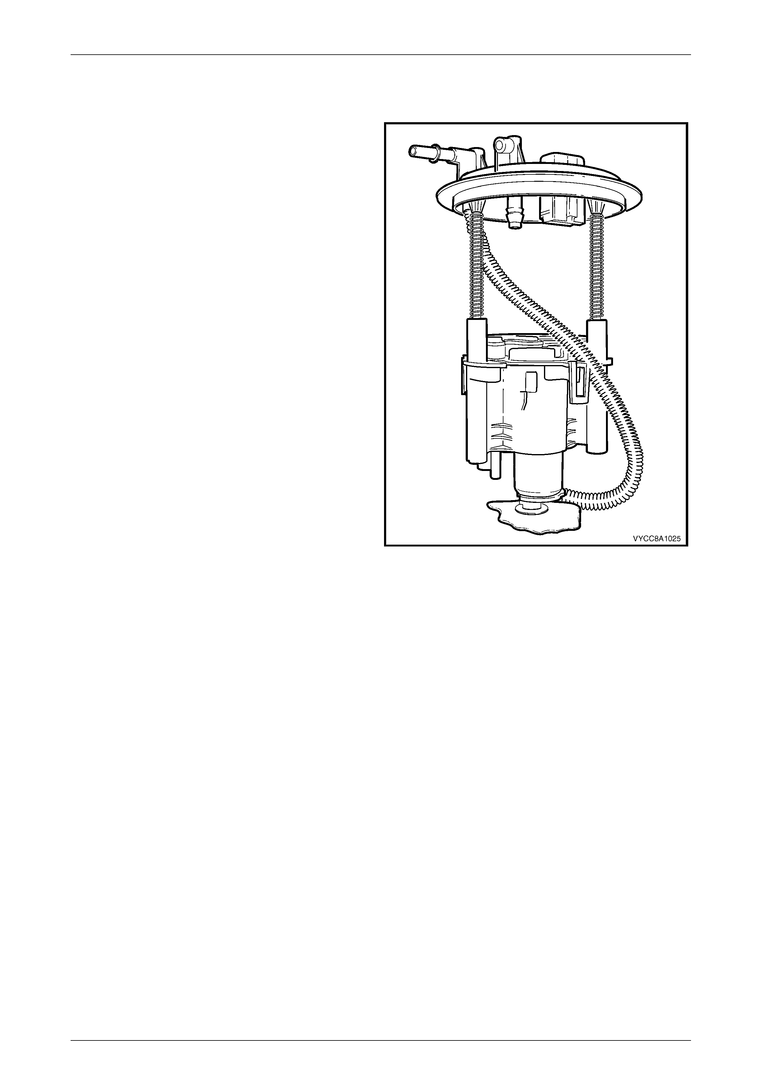
Fuel System Page 8A1–150
Page 8A1–150
Reassemble
Reassembly is the reverse of the disassembl y proc edure, noting the following:
1 Locate and press the fuel outlet connector to its
position on the bottom of the fuel pump and suction
filter assembly. (Loop the fuel outlet pipe through the
recess near the right-side top when the fuel filter
assembly is on the side facing away from you.)
Figure 8A1 – 198
2 Ensure the wires to both electrical connectors , the ceramic variable res istor card and the pressure regulator and
are inboard of the fuel feed pipe.
3 Ensure the wires to both electrical connectors , the ceramic varia ble resistor card and the pressure regulator do not
interfere when reassembling the fuel p ump and suction filter assembly into the reservoir.
Reinstall
Reinstallation of the modul ar fuel pump and sender assembly is the reverse of the removal procedure, noting the
following:
1 Position a new O-ring seal in the fuel tank recess.
2 Rest the modular fuel pump and sen der assembly on a flat surface.
3 Measure the distance between the centre of the fuel sender float and the flat surface.
4 Ensure the centre of the fuel level sender flo at is a nominal 18.5 mm abov e the surface. If not, carefully bend the
fuel level sender float arm to achieve the required distance.
NOTE
Do not damage the fuel level sender float and
arm when placing the modular fuel pump and
sender assembly into the fuel tank.
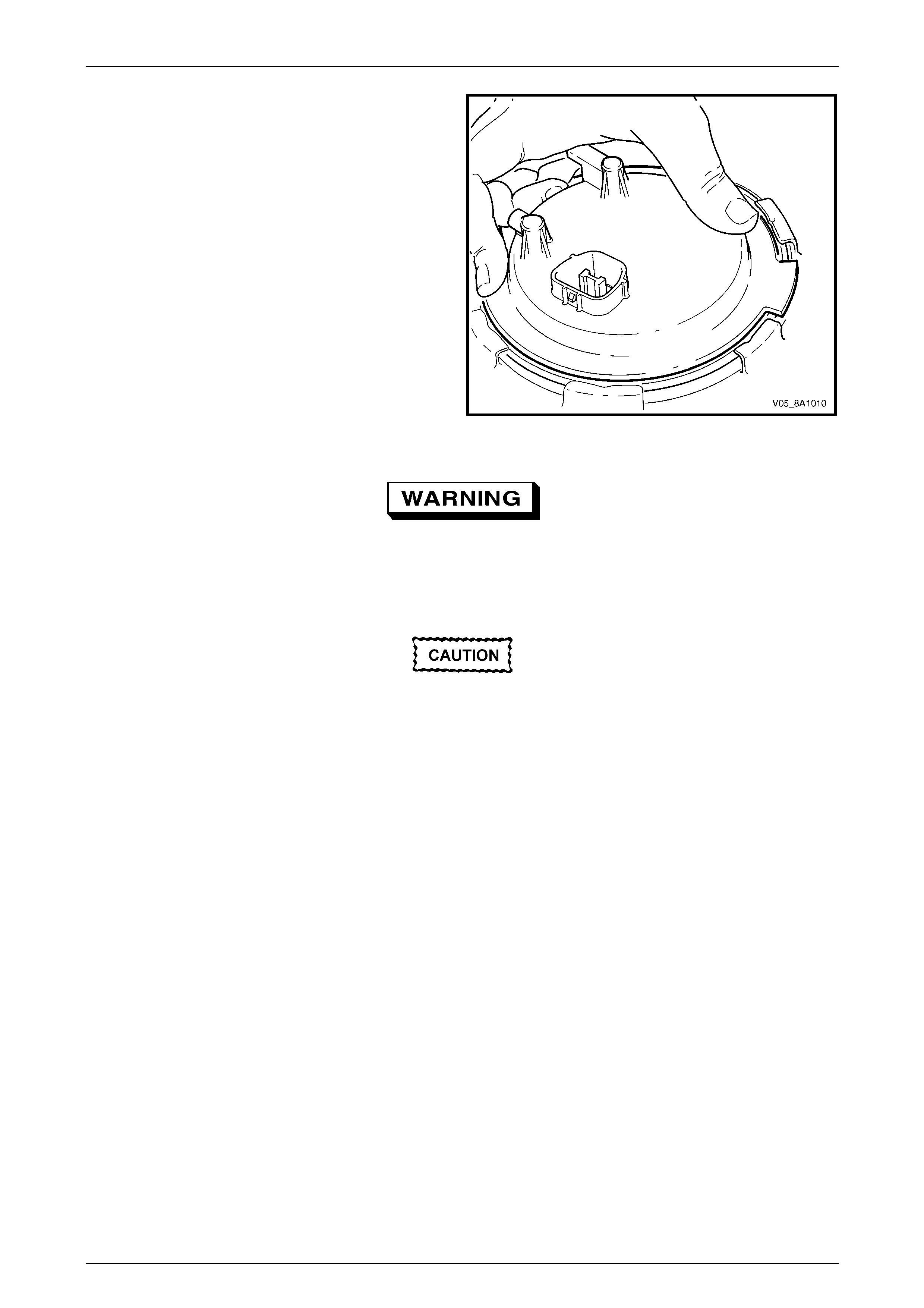
Fuel System Page 8A1–151
Page 8A1–151
5 Ensure the low fuel level feed pip e is located in the
fuel tank correctly (that is, on the side of the baffle
furthest away from the modular fuel pump and sender
assembly).
6 Ensure the locator in the modular fuel pump and
sender assembly cover engages in the slot in the fuel
tank opening.
Figure 8A1 – 199
Ensure the retainer lock ring is installed
correctly. Incorrect installation of the modular
fuel pump and sender assembly retainer
could cause fuel vapour leakage.
Ensure tool No. J45722 is seated firmly and
positively in the modular fuel pump and
sender assembly cover retainer lock ring
while tightening the modular fuel pump and
sender assemb ly.
7 Using tool No. J45722 (1) and a half-inch breaker bar (2), install the modular fuel pump and sender assembly cov er
retainer lock ring (3) by turning it clockwise, refer to Figure 8A1 – 184.
8 Install the modular fuel pump and sender assembly harness connector (1), refer to Figure 8A1 – 182.
9 Install the fuel feed line quick-conn ect fitting (1) to the modular fuel pump and sender assembly cover, refer to
Figure 8A1 – 183.
10 Tighten the modular fuel pump and se nder assembly cover retainer lock ring.

Fuel System Page 8A1–152
Page 8A1–152
7.6 Fuel Filter Assembly
NOTE
The fuel filter assembly is part of the modular fuel
pump and sender assembl y and is not repairabl e.
If the fuel filter assembly becomes unserviceable,
replace the modular fuel pump and sender
assembly, refer to 7.5 Modular Fuel Pump and
Sender Assembly.
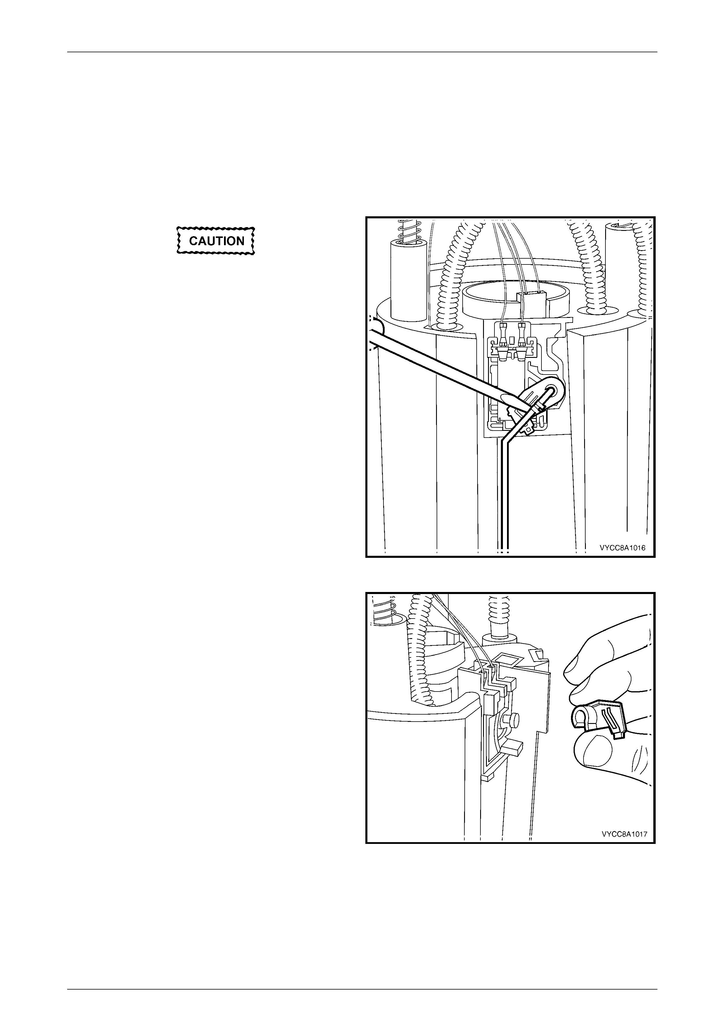
Fuel System Page 8A1–153
Page 8A1–153
7.7 Fuel Level Sender Assembly
LT Section No. — 03–074
Disassemble
1 Remove the modular fuel pump and se nder assembly from the fuel tank, refer to 7.5 Modular Fuel Pump and
Sender Assembly.
Do not touch the ceramic variable resistor
card; if it is touched inadvertently, clean it
immediately with isopropyl alcohol.
2 Prise the tang open that holds the fuel level sender
float and arm onto the nylon wiper piece.
3 Lift the fuel level sender float and arm away from the
nylon wiper piece and place in a safe location away
from the immediate worksite.
Figure 8A1 – 200
4 Lift the nylon wiper piece off the ceramic variable
resistor card holder, then place in a safe location away
from the immediate worksite.
Figure 8A1 – 201
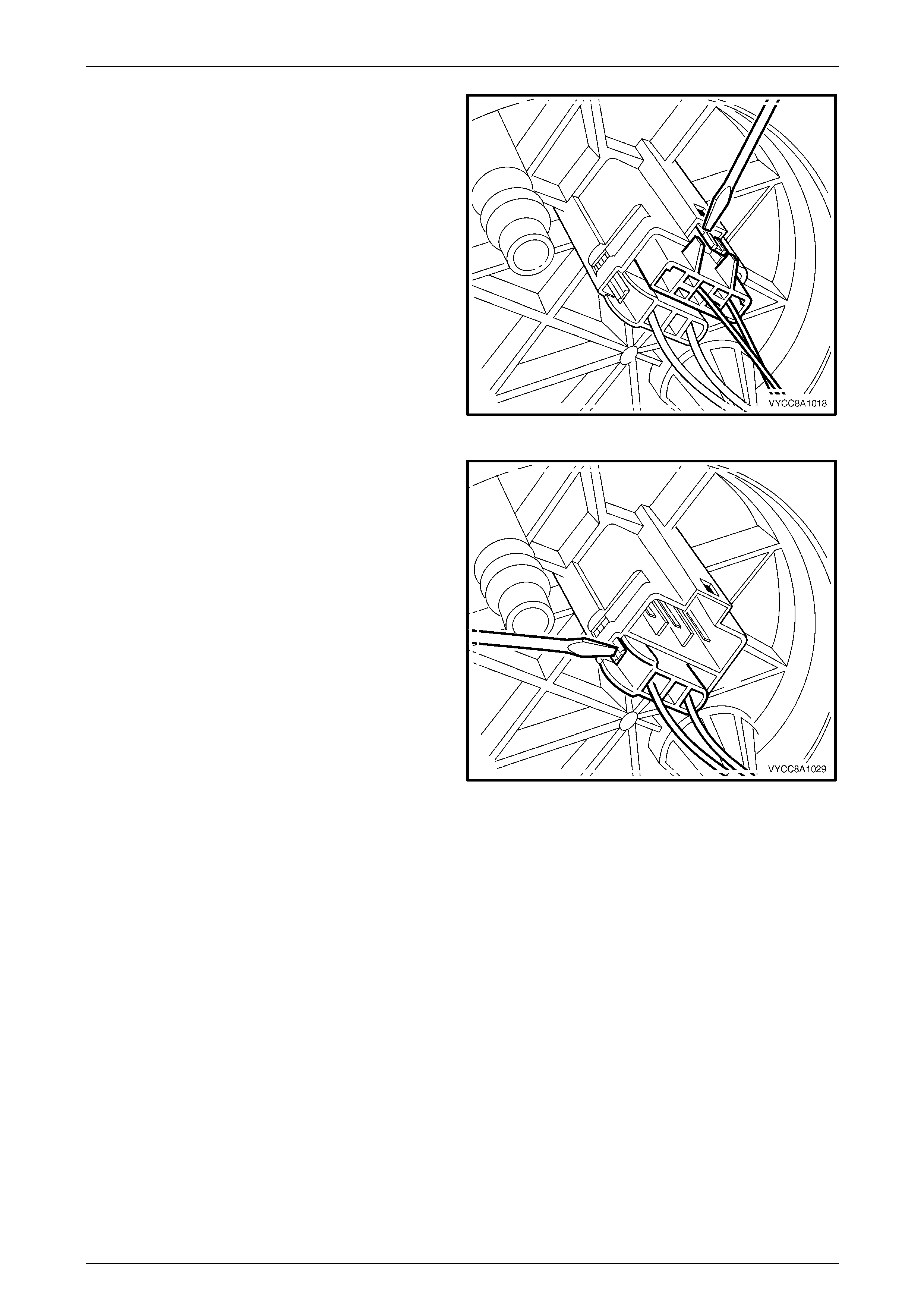
Fuel System Page 8A1–154
Page 8A1–154
5 Remove the 3-pin connector (the fuel level sender
assembly wires) from underneath the modular fuel
pump and sender assembly c over.
Figure 8A1 – 202
6 Remove the 2-pin connector (the fuel p ump motor
wires) from underneath the modular fuel pump and
sender assembly cover.
Figure 8A1 – 203
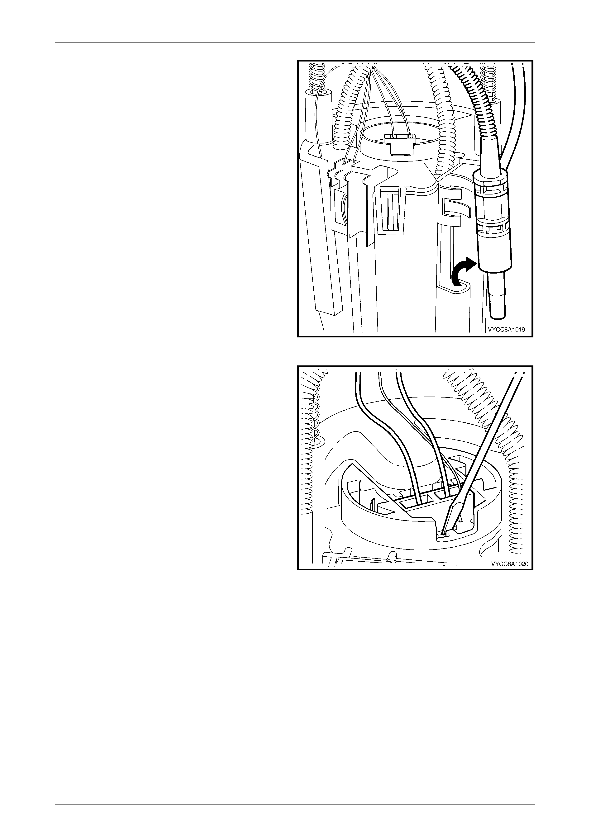
Fuel System Page 8A1–155
Page 8A1–155
7 Prise the transfer jet pump from the clips, then remove
from the reservoir.
Figure 8A1 – 204
8 Press in the tang retaining the 2-pin connector on the
fuel pump and suction filter assembly, then remove the
connector.
Figure 8A1 – 205
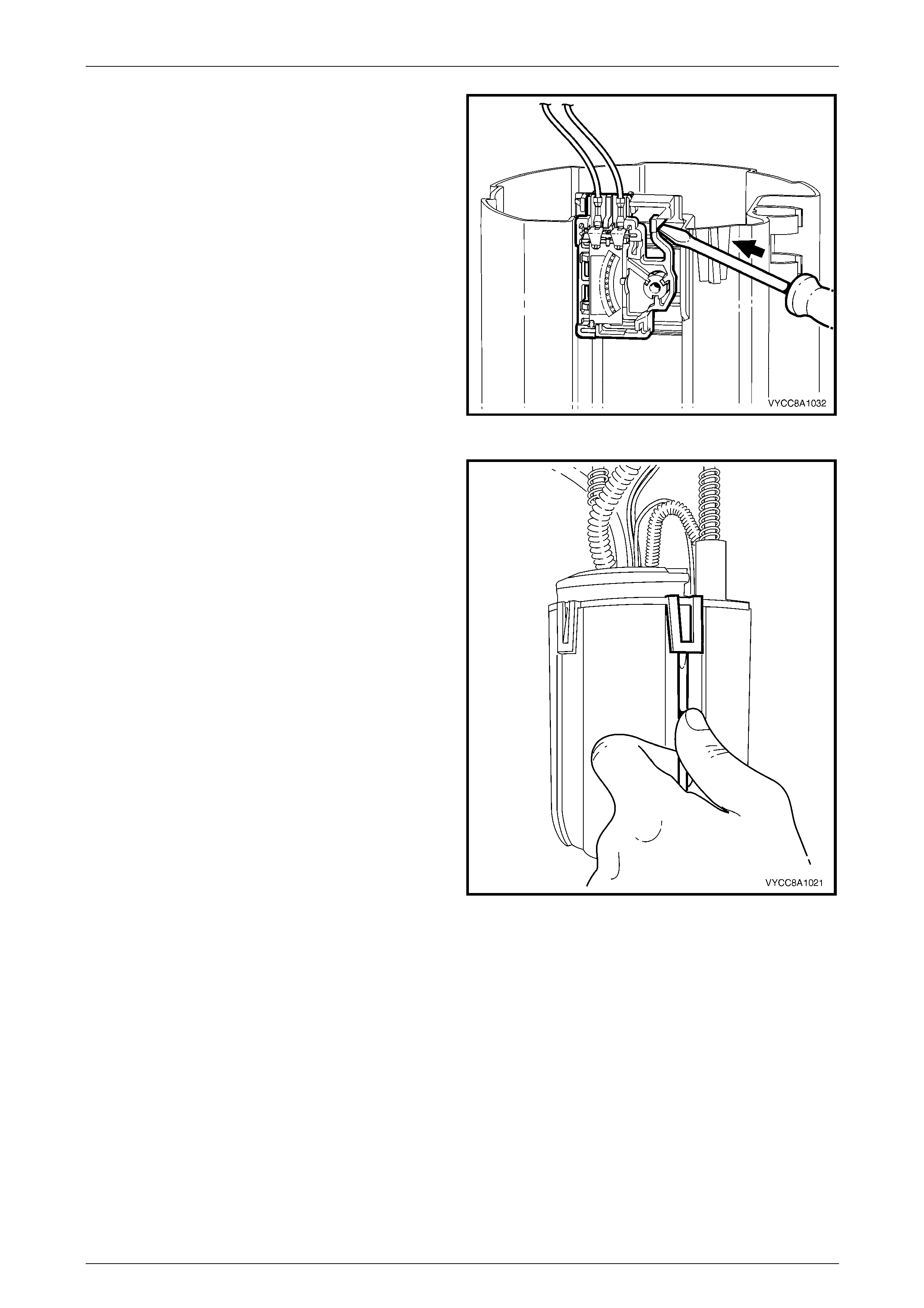
Fuel System Page 8A1–156
Page 8A1–156
9 Prise the tang open that holds the ceramic v aria ble
resistor card holder to the side of the reservoir, then lift
it off the reservoir.
Figure 8A1 – 206
10 Prise the four tangs with a flat-bladed screwdriver,
then remove the fuel pump and suction filter assembly,
and modular fuel pump an d sender assembly cover
from the reservoir.
NOTE
Another person may have to assist in removing
the fuel pump and suction filter assembly from
the reservoir.
Figure 8A1 – 207
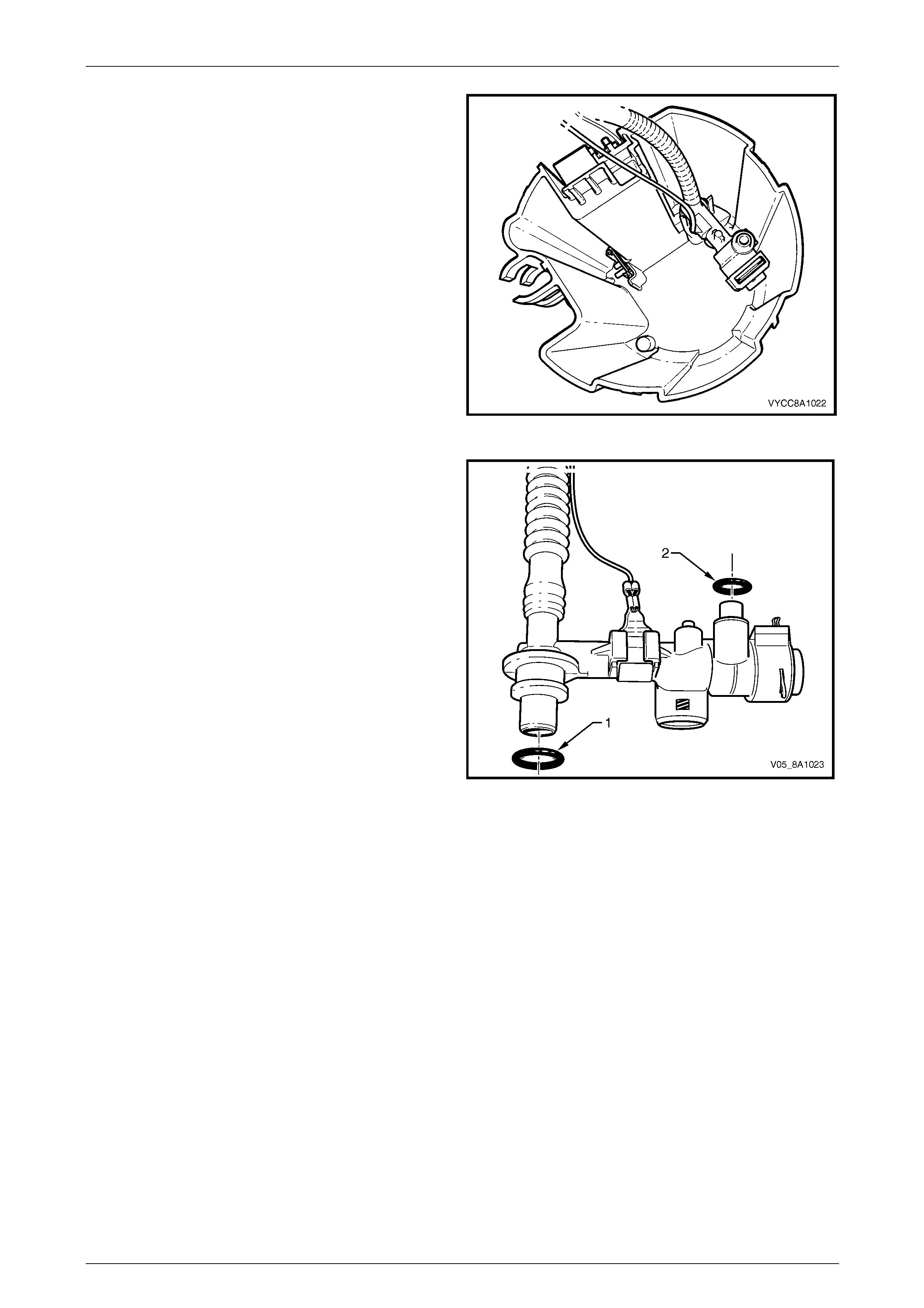
Fuel System Page 8A1–157
Page 8A1–157
11 Pull the modular fuel pump and sender assembly
cover, fuel pump and suction filter assembly, pressure
regulator holder and fuel feed pipe from the reservoir
body.
NOTE
Some difficulty may be experienced when lifting
these items from the reservoir body due to the
limited space availabl e.
Figure 8A1 – 208
12 Remove and discard the O-ring (1) from the bottom of
the pressure regulator holder.
NOTE
The O-ring may be lodged in the reservoir body.
13 Remove and discard the O-ring (2) from the top of the
pressure regulator holder.
NOTE
The O-ring may be lodge d in the base of the fuel
pump and suction filter assembly.
Figure 8A1 – 209
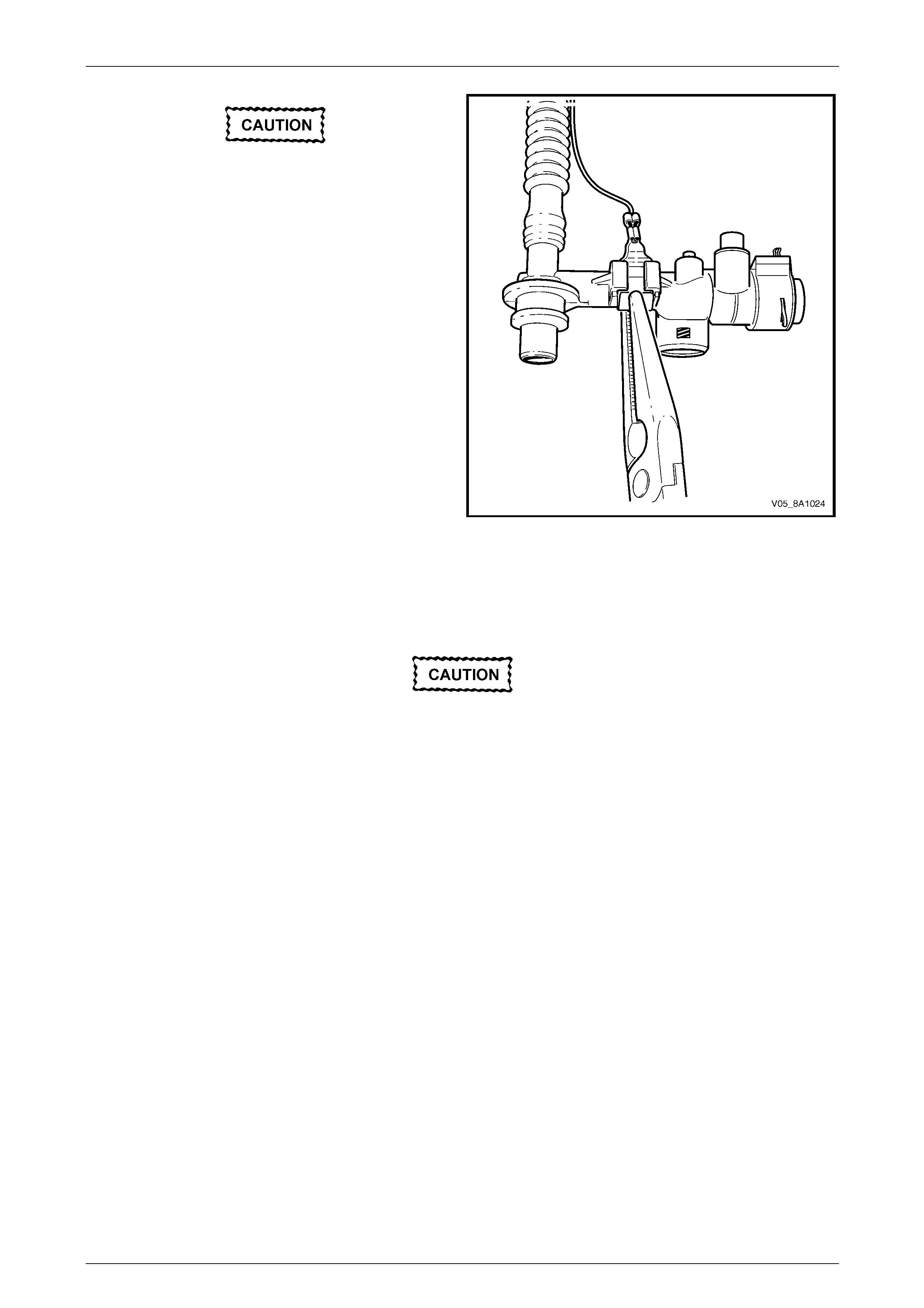
Fuel System Page 8A1–158
Page 8A1–158
Do not bend the spade connector on the
pressure regulator holder; this can be easily
damaged or broken.
14 Remove the spade connector from the press ure
regulator holder.
Figure 8A1 – 210
Reassemble
Reassembly is the reverse of the disassembl y proc edure, noting the following:
Do not touch the ceramic variable resistor
card; if it is touched inadvertently, clean it
immediately with isopropyl alcohol.
NOTE
Do not separate the fuel level sender float arm
from the nylon wiper piece on the replacement
fuel level sender assembly.
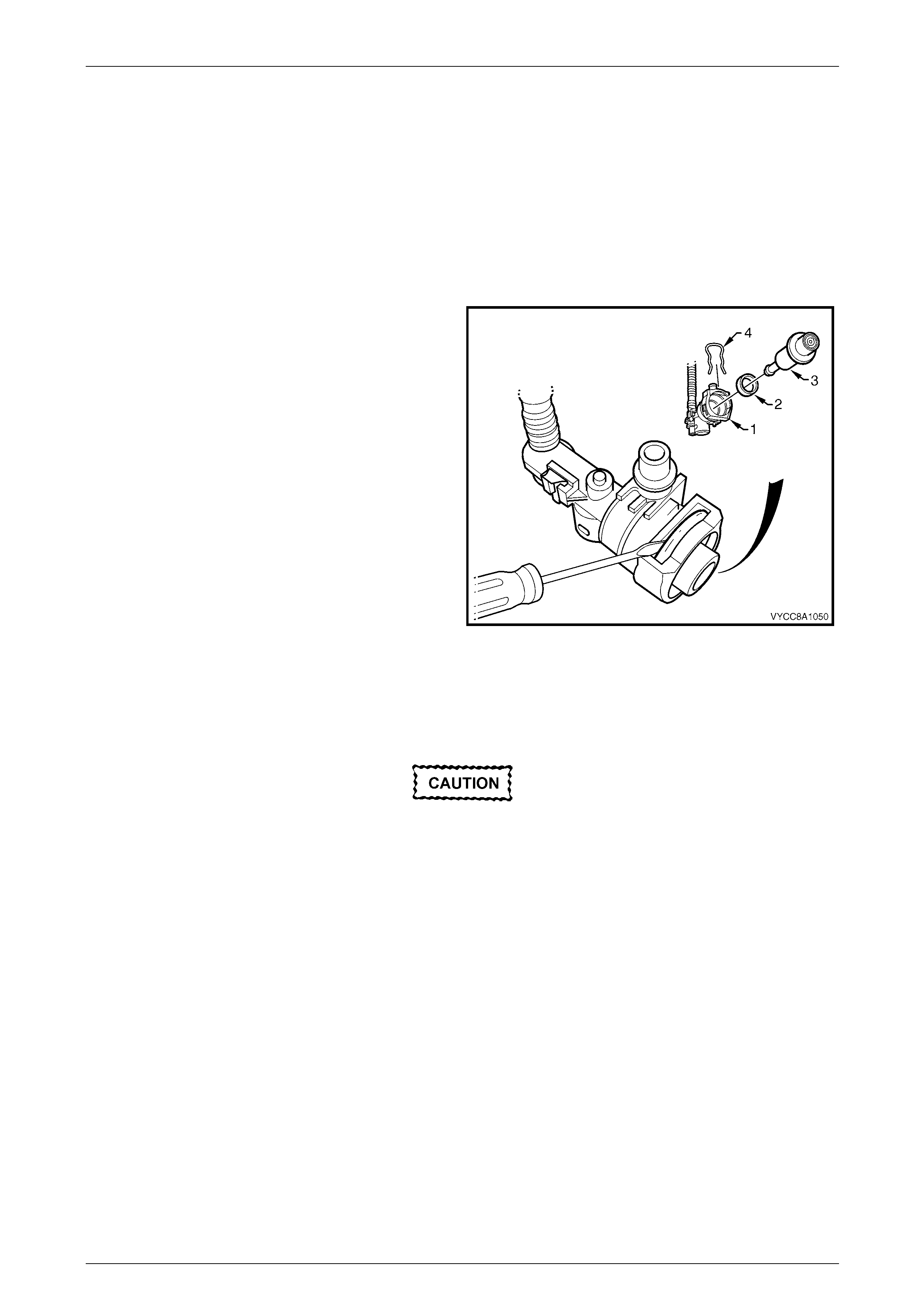
Fuel System Page 8A1–159
Page 8A1–159
7.8 Pressure Regulator
LT Section No. — 03–074
Remove
1 Remove the modular fuel pump and se nder assembly from the fuel tank, refer to 7.5 Modular Fuel Pump and
Sender Assembly.
2 Disassemble the modular fuel pump and sender assembly, refer to 7.5 Modular Fuel Pump and Se nder Assembly.
3 Remove the retaining clip (4) from the top of the
pressure regulator holder and place in a safe location
away from the immediate worksite.
4 Using a flat-bladed screwdriver, prise the pressure
regulator (3) from the pressure regulator holder (1).
5 Remove the nylon spacer (2) from the pressure
regulator holder and place in a safe location away
from the immediate worksite.
Figure 8A1 – 211
Reinstall
Reinstallation of the pressur e regulator is the reverse of the removal procedure, noting the following:
When installing the modular fuel pump and
sender assembly, use only the custom-sized
O-rings supplied with the modular fuel pump
and sender assembly replacement parts kit.
Do not use off-the-shelf O-rings; refer to
6.11 Modular Fuel Pump and Sender
Assembly O-rings for O-ring specifications.
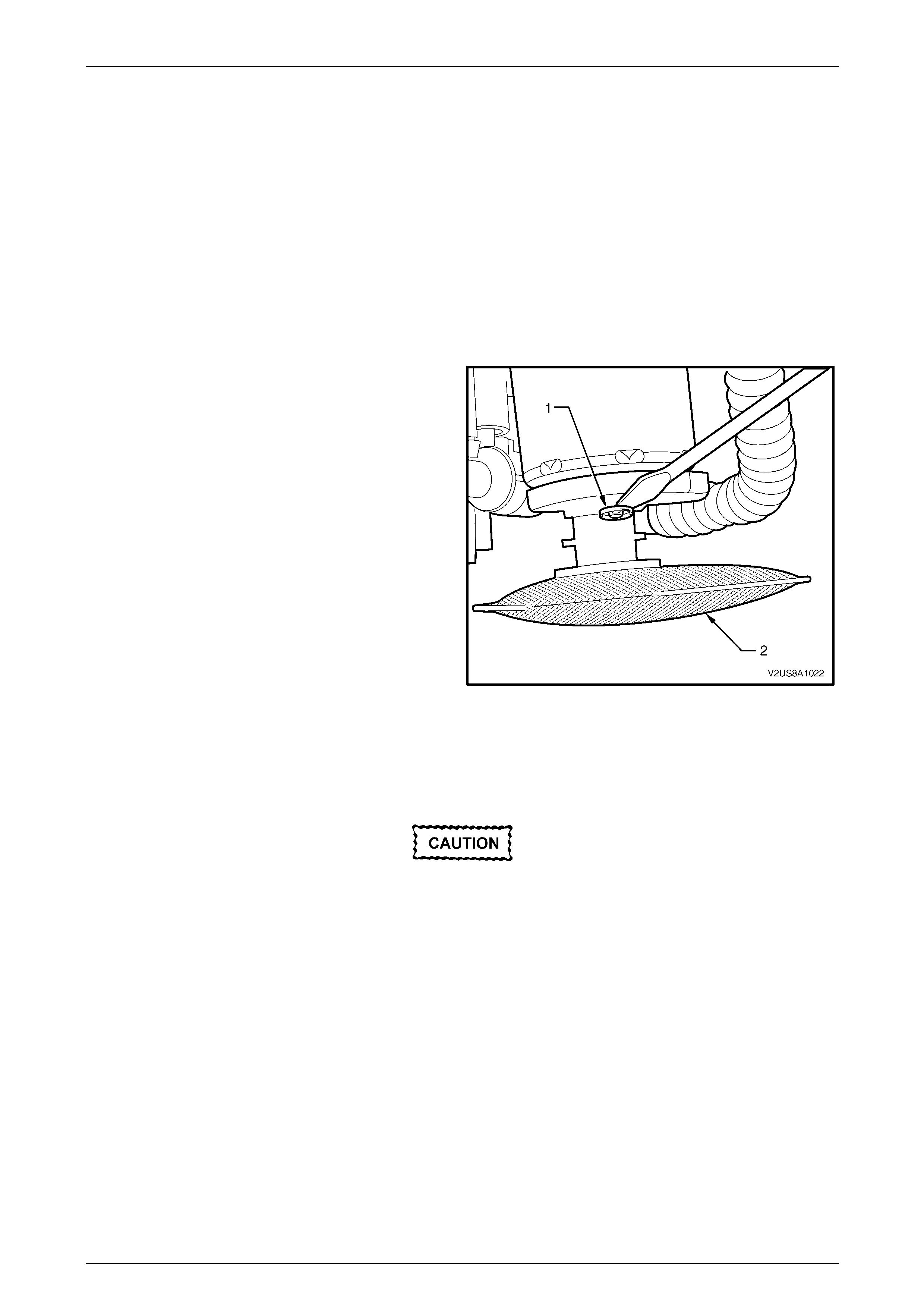
Fuel System Page 8A1–160
Page 8A1–160
7.9 Suction Filter
LT Section No. — 03–055
The suction filter is attached by an 'easy washer' to the fuel pump end cap. The suction fil t er is accessible after removing
the fuel pump and fuel filter from the modular fuel pump an d send er assembly reservoir.
Remove
1 Remove the modular fuel pump and se nder assembly from the fuel tank, refer to 7.5 Modular Fuel Pump and
Sender Assembly.
2 Disassemble the fuel pump and suction filter assembly, and modular fuel pump and sender assembly cover from
the reservoir, refer to 7.5 Modular Fuel Pump and Sender Assembly.
3 Using a suitable blade or a flat-bladed screwdriver,
remove the 'easy washer' (1) from the fuel pump end
cap post.
4 Remove the suction filter (2).
Figure 8A1 – 212
Reinstall
Reinstallation of the suction filter is the reverse of the removal procedure, noting the following:
Check the 'easy washer' for serviceability and
replace if required.
Ensure the 'easy washer' is firmly installed along the fuel pump end cap post and firmly pressed up again s t the suction
filter moulding.
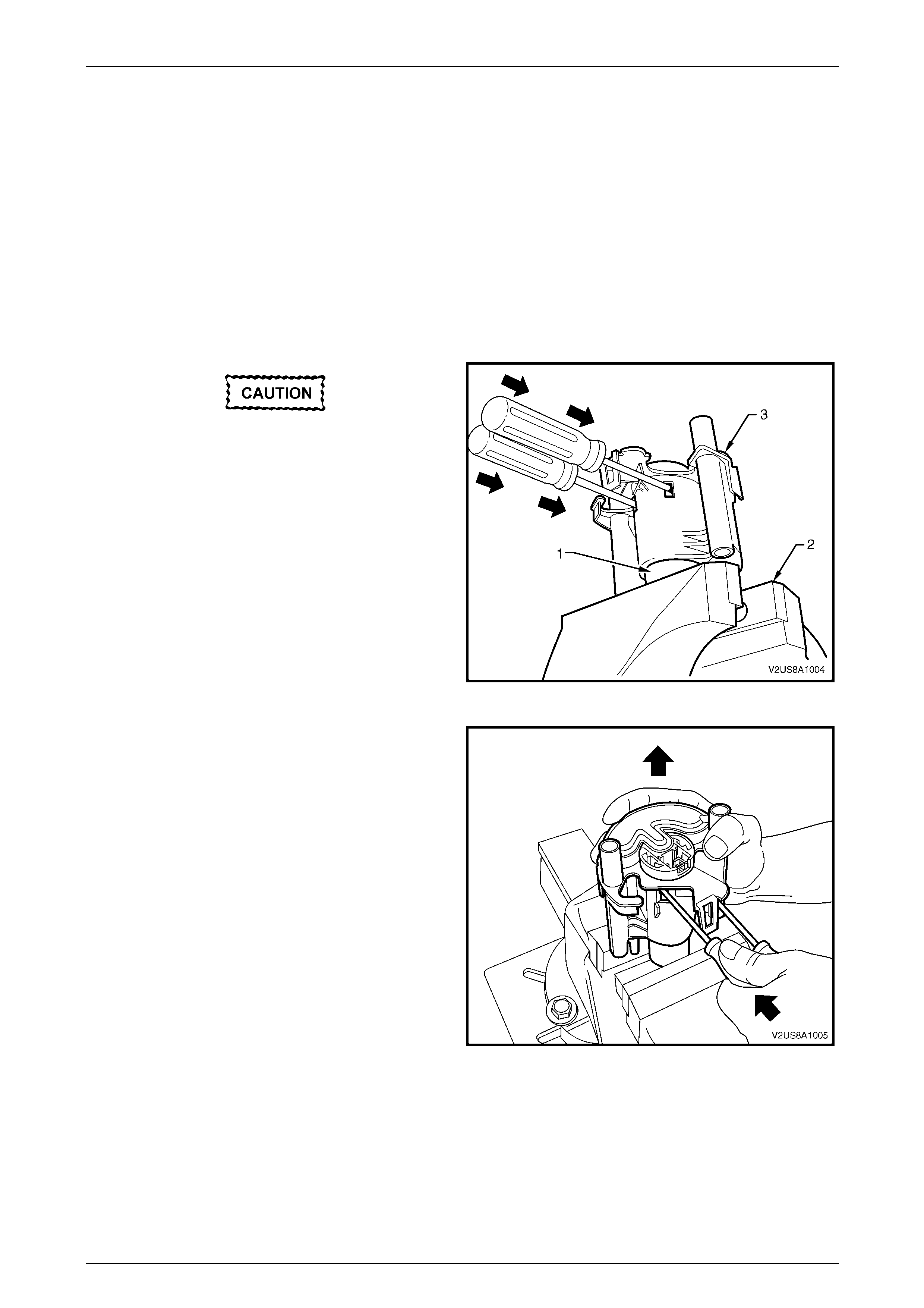
Fuel System Page 8A1–161
Page 8A1–161
7.10 Modular Fuel Pump
LT Section No. — 03–074
The modular fuel pump is contained within the fuel filter assembly.
Remove
1 Remove the suction filter, refer to 7.9 Suction Filter.
2 Remove the fuel pump and suction filter ass embl y from the modular fuel pump and sender assembly, refer to
7.5 Modular Fuel Pump and Sender Assembly.
3 Disassemble the modular fuel pump and sender assembly, refer to 7.5 Modular Fuel Pump and Se nder Assembly.
Do not overtigh ten the vice grips as this may
damage the fuel pump.
4 Clamp the protruding end of the fuel pump body (1) in
a soft-jawed vice (2) to support the modular fuel pump
and fuel filter assembly (3) in place.
5 Insert a medium-sized flat-bladed screwdriver through
each of the service holes in the fuel filter assembly.
6 Slide the screwdriver blade between the fuel pump
end cap and the internal fuel filter clips that hold the
fuel pump body in plac e.
Figure 8A1 – 213
7 Push the screwdrivers in far enough so the internal
fuel filter clips are deflected just free of each of the fuel
pump end cap retainer shoulders.
8 While holding the screwdrivers in place with one hand,
manipulate the fuel filter assembl y upwards to
separate it from the fuel pump.
Figure 8A1 – 214
Fuel System Page 8A1–162
Page 8A1–162
Reinstall
Reinstallation of the modul ar fuel pump is the reverse of the removal procedure, noting the following:
Do not use any tool that may damage either
the fuel pump body or the fuel filter assembly.
Check the 'easy washer' for serviceability and
replace if required.
When installing the modular fuel pump and
sender assembly, use only the custom-sized
O-rings supplied with the modular fuel pump
and sender assembly replacement parts kit.
Do not use off-the-shelf O-rings; refer to
6.11 Modular Fuel Pump and Sender
Assembly O-rings for O-ring specifications.
1 Ensure the 'easy washer' is firmly installed a long the fuel pump end cap post and firmly pressed up ag ainst the
suction filter moulding.
2 Using hands only, locate the fuel pump body in its correct orientation int o the fuel filter as sembly.
3 Push the fuel pump body firmly into plac e and lock the fuel pump into the fuel filter assembly.
4 Reassemble the modular fuel pump and sender assembly, refer to 7.5 Modular Fuel Pump and Sender Assembly.
5 Reinstall the modular fuel pump and sender assembly, refer to 7.5 Modular Fuel Pump and Sender Assembly.


Fuel System Page 8A1–164
Page 8A1–164
7.12 Fuel Pipes
LT Section No. — 03–075
Regular Cab and Crew Cab with 'Delete Tub' Option
Remove
A depressurised fuel system contains fuel in
the fuel filter and fuel lines that can be spilled
during service operations.
Fuel vapour remains in the fuel tank even
when completely empty. Seal all openings in
the fuel tank using suitable material or a
plastic plug. Ensure no naked flames or other
ignition sources are nearby. Ensure all
cellular phones (and transmission devices
that may cause any metal objects to become
unintentional receiving antennas) are
switched off.
Place a dry chemical (Class B) fire
extinguisher nearby before performing any
on-vehicle service procedures. Failure to
follow these precautions may result in
personal injury.
Wear safety glasses when using compressed
air. Do not blow compressed air onto any
body part.
1 Remove the fuel pump relay, refer to Section 12O Fuses, Relays and Wiring Harnesses.
2 Depressurise the fuel system, refer to 4.1 Fuel System Depressurisation.
Never drain or store fuel into an open
container, due to the possibility of fire or
explosion.
3 Raise the vehicle, preferably on a hoist, refer to Section 0A General Information.
Before proceedin g, clean all traces of dirt and
other foreign material from the fuel pipes.
4 Use compressed air to ensure that all dirt and foreign materials are removed from all fuel con nections before the
parts are disconnected.
5 If required, remove the stone guards and fue l pipes. Use the following illustration showing the fuel pipe layout and
location of other items relating to the fuel system as a guide, refer to Figure 8A1 – 215.
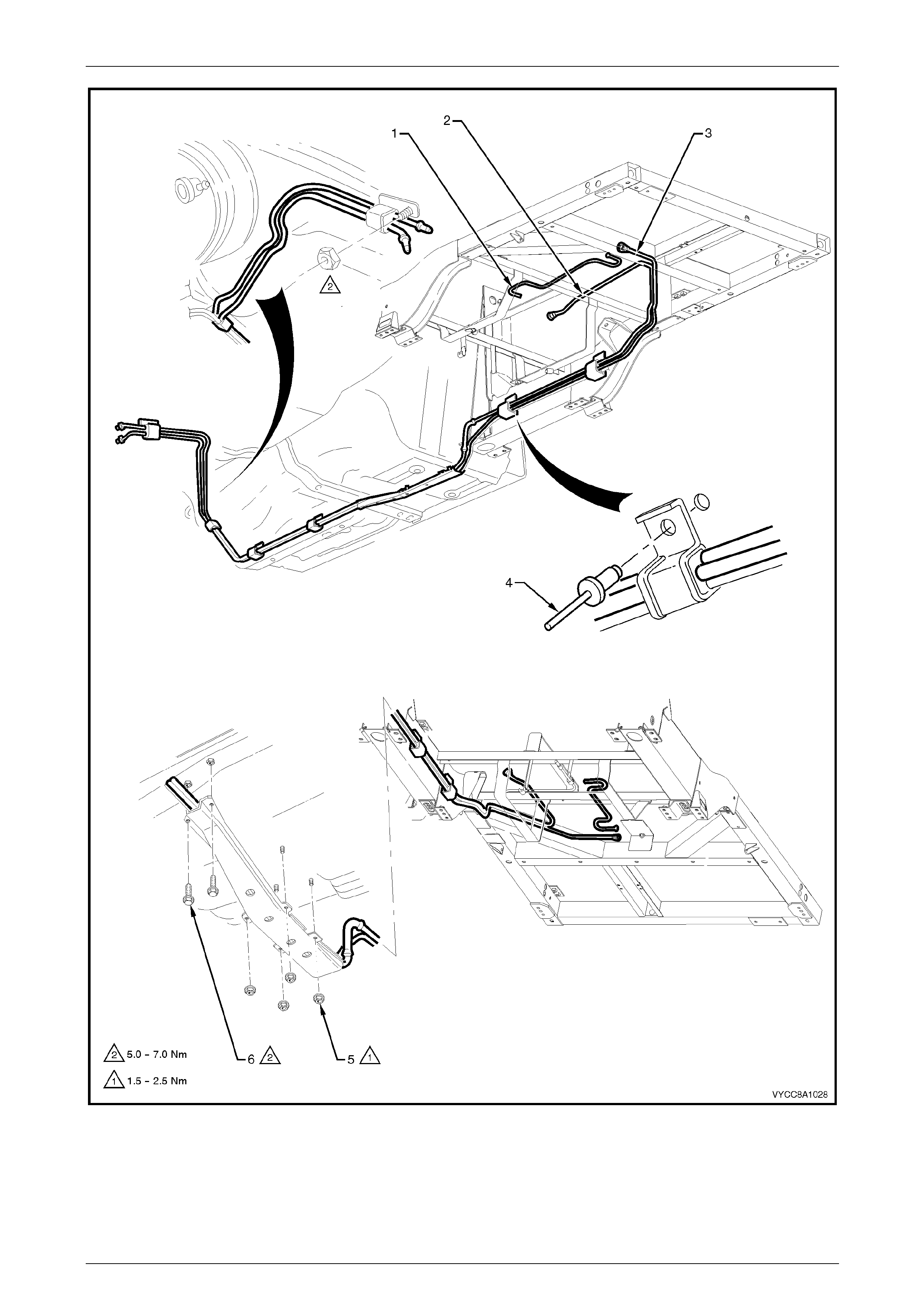
Fuel System Page 8A1–165
Page 8A1–165
Figure 8A1 – 215
Legend
1 Fuel Tank Vent Line
2 Fuel Feed Line 3 Evaporative Emission Control Canister
Purge Line
4 Fuel Line Bracket Blind Rivet
5 Stone Guard Securing Nut (4 places)
6 Stone Guard Securing Bolt (2 places)
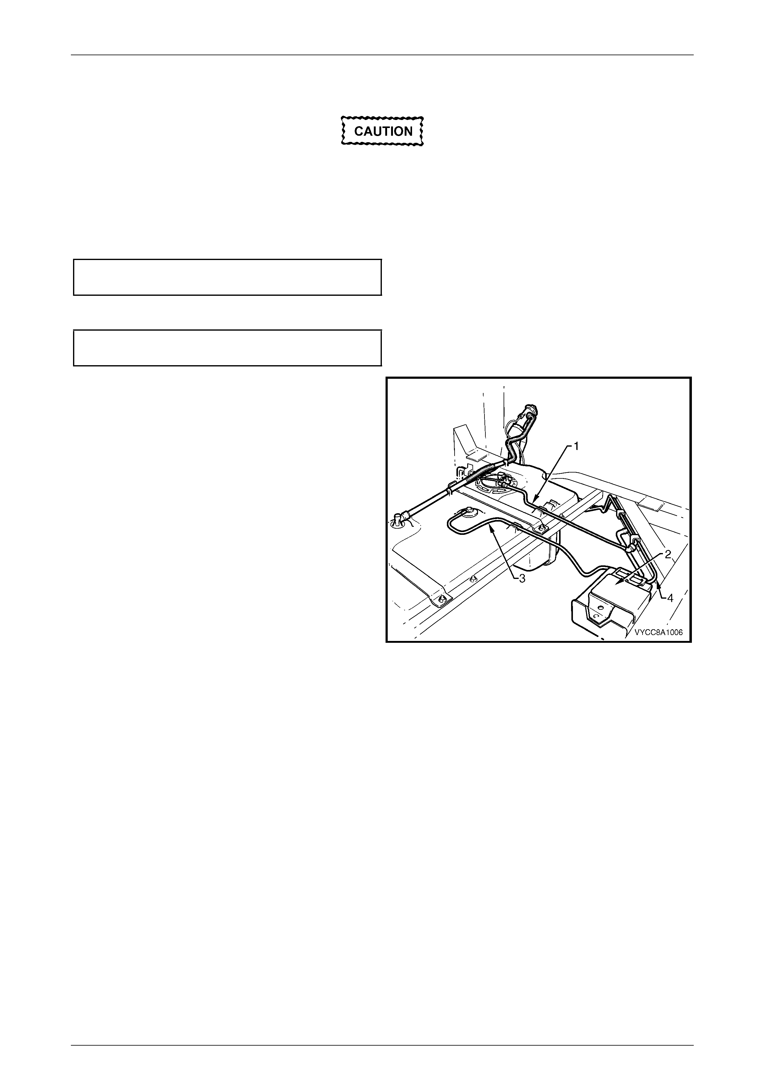
Fuel System Page 8A1–166
Page 8A1–166
Reinstall
Ensure the rubber in the fuel line brackets is
in good condition before proceeding. If not,
replace the affected b racket.
Reinstallation of the stone guards and fuel pipes is the reverse of the removal procedure, noting the foll owing:
1 Tighten the stone guard securing nuts to the correct torque specification.
Stone guard securing nut
torque specification.....................................1.5 – 2.5 Nm
2 Tighten the stone guard securing bolts to the correct torque specification.
Stone guard securing bolt
torque specification.....................................5.0 – 7.0 Nm
NOTE
Use tool No. AU533 to remove the fuel feed
line (1) quick-connect fitting, refer to Tool No.
AU533.
Figure 8A1 – 216
Legend
1 Fuel Feed Line
2 Evaporative Emission Control Canister 3 Fuel Tank Vent Line
4 Evaporative Emission Control Canister Purge Line
Fuel System Page 8A1–167
Page 8A1–167
Crew Cab
Remove
A depressurised fuel system contains fuel in
the fuel filter and fuel lines that can be spilled
during service operations.
Fuel vapour remains in the fuel tank even
when completely empty. Seal all openings in
the fuel tank using suitable material or a
plastic plug. Ensure no naked flames or other
ignition sources are nearby. Ensure all
cellular phones (and transmission devices
that may cause any metal objects to become
unintentional receiving antennas) are
switched off.
Place a dry chemical (Class B) fire
extinguisher nearby before performing any
on-vehicle service procedures. Failure to
follow these precautions may result in
personal injury.
Wear safety glasses when using compressed
air. Do not blow compressed air onto any
body part.
1 Remove the fuel pump relay, refer to Section 12O Fuses, Relays and Wiring Harnesses.
2 Depressurise the fuel system, refer to 4.1 Fuel System Depressurisation.
Never drain or store fuel into an open
container, due to the possibility of fire or
explosion.
3 Raise the vehicle, preferably on a hoist, refer to Section 0A General Information.
Before proceedin g, clean all traces of dirt and
other foreign material from the fuel pipes.
4 Use compressed air to ensure that all dirt and foreign materials are removed from all fuel con nections before the
parts are disconnected.
5 If required, remove the stone guards and fue l pipes. Use the following illustration showing the fuel pipe layout and
location of other items relating to the fuel system as a guide, refer to Figure 8A1 – 217.
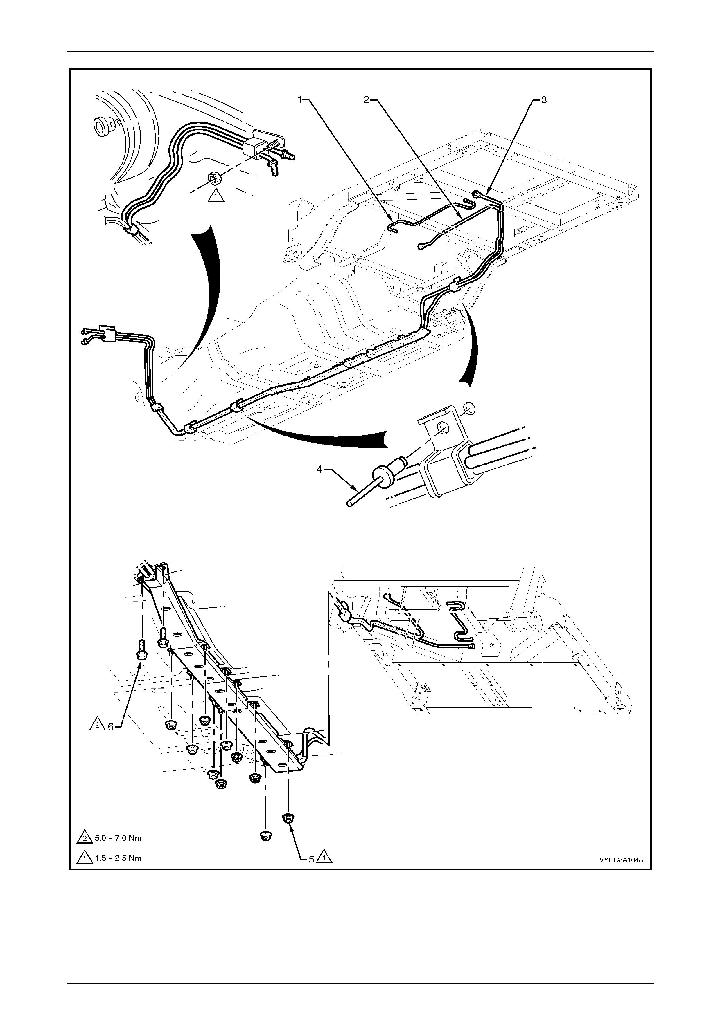
Fuel System Page 8A1–168
Page 8A1–168
Figure 8A1 – 217
Legend
1 Fuel Tank Vent Line
2 Fuel Feed Line 3 Evaporative Emission Control Canister
Purge Line
4 Fuel Line Bracket Blind Rivet
5 Stone Guard Securing Nut (10 places)
6 Stone Guard Securing Bolt (2 places)
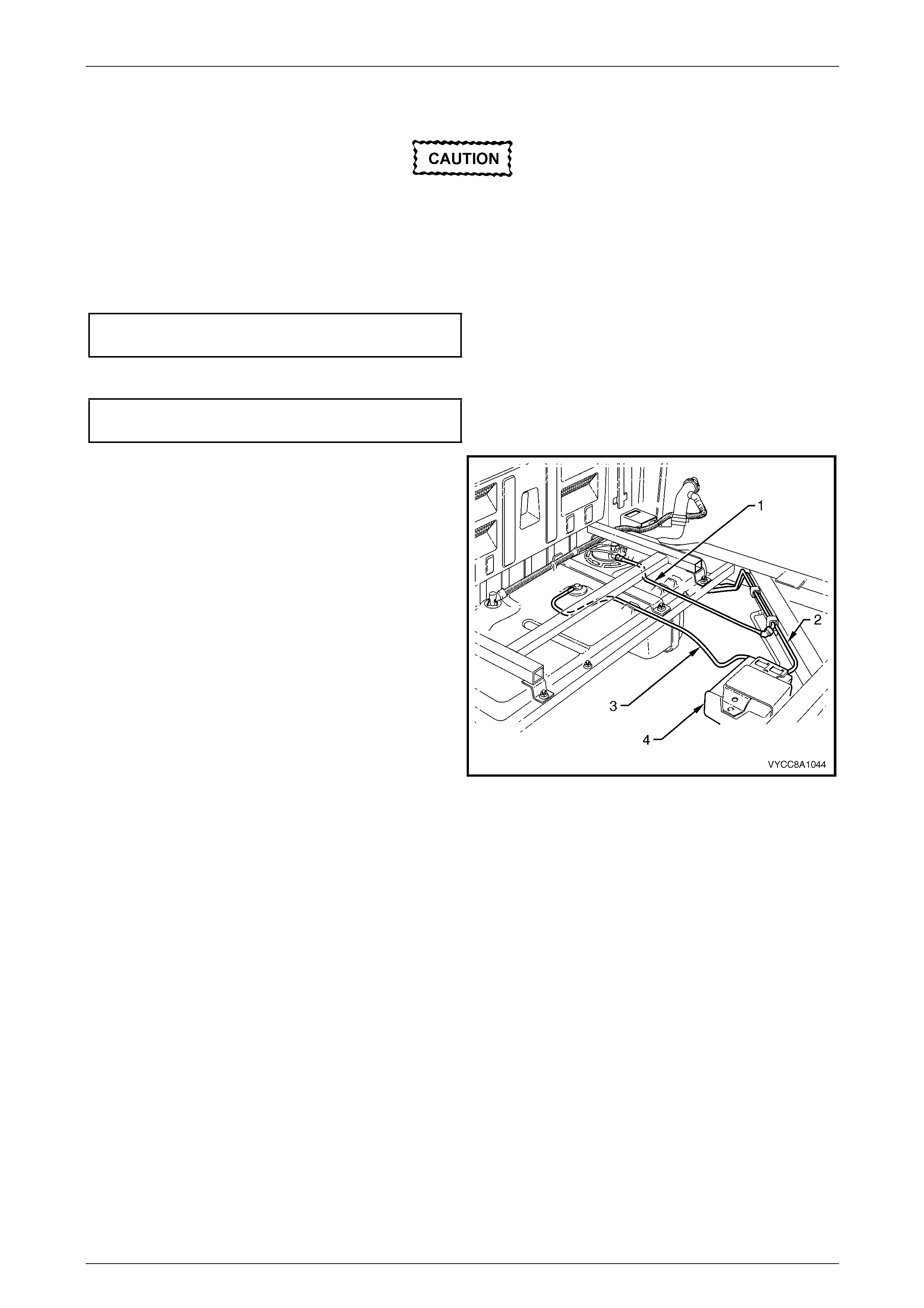
Fuel System Page 8A1–169
Page 8A1–169
Reinstall
Ensure the rubber in the fuel line brackets is
in good condition before proceeding. If not,
replace the affected b racket.
Reinstallation of the stone guards and fuel pipes is the reverse of the removal procedure, noting the foll owing:
1 Tighten the stone guard securing nuts to the correct torque specification.
Stone guard securing nut
torque specification.....................................1.5 – 2.5 Nm
2 Tighten the stone guard securing bolts to the correct torque specification.
Stone guard securing bolt
torque specification.....................................5.0 – 7.0 Nm
NOTE
Use tool No. AU533 to remove the fuel feed
line (1) quick-connect fitting, refer to Tool No.
AU533.
Figure 8A1 – 218
Legend
1 Fuel Feed Line
2 Evaporative Emission Control Canister Purge Line 3 Fuel Tank Vent Line
4 Evaporative Emission Control Canister
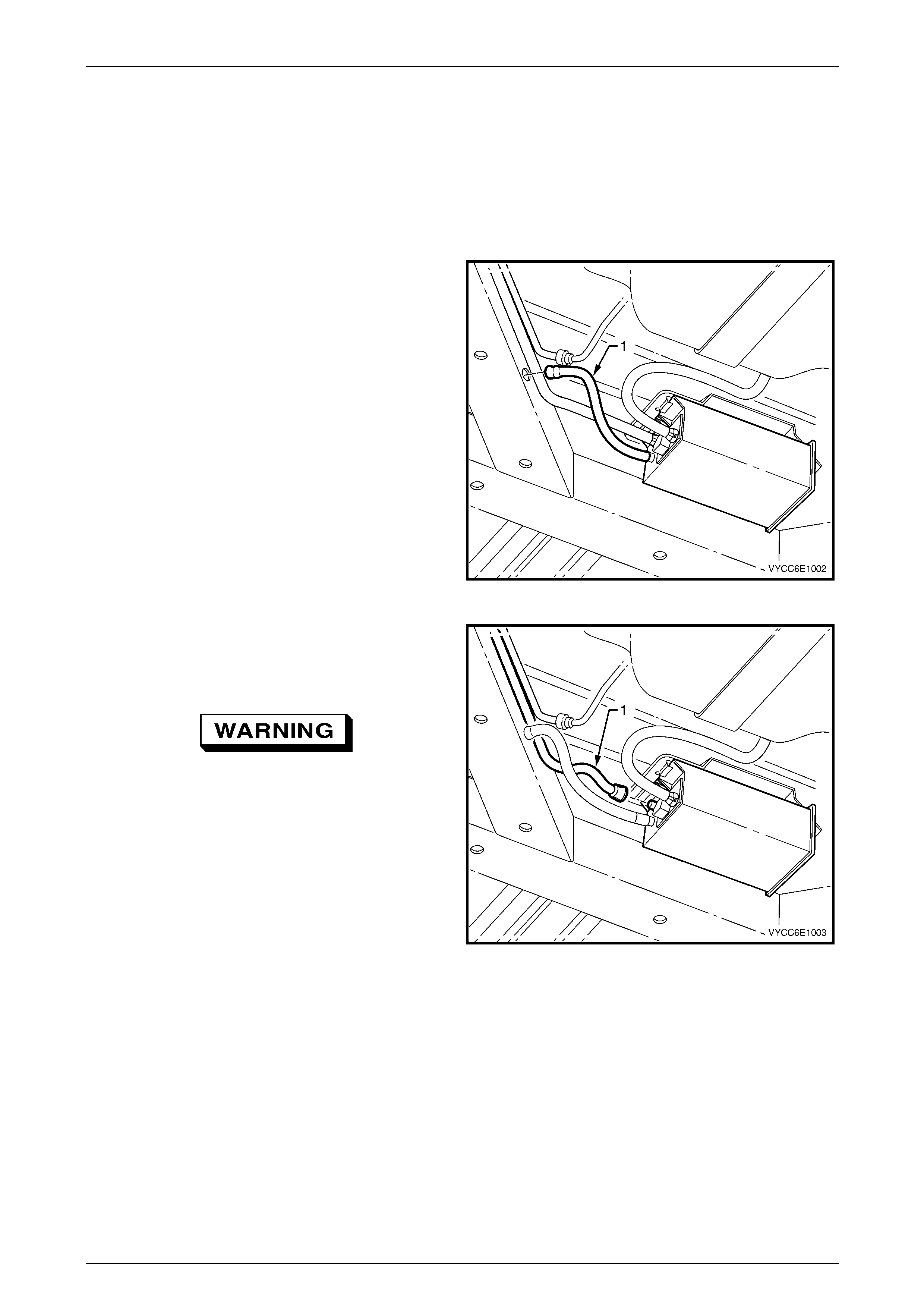
Fuel System Page 8A1–170
Page 8A1–170
7.13 Evaporative Emission Control Canister
LT Section No. — 03–165
Remove
1 Hoist the vehicle, refer to Section 0A General Information.
2 If required, remove the evaporative emission control
canister vent line (1) from the chassis by pulling it out
of the hole in the chassis.
Figure 8A1 – 219
3 Disconnect the canister purge line (1) b y gr asping both
sides of the quick-connect fitting. Twist the connector
1/4 turn in each direction to loosen any dirt within the
quick-connect fitting.
Wear safety glasses w hen usin g compressed
air. Do not blow compressed air onto any
body part.
4 Using compressed air, blow any dirt out of the quick-
connect fitting.
5 Either:
• Disconnect using tool No. AU533, refer to
Tool No. AU533.
• Disconnect without using tool No. AU533:
(1) Grasp the quick-connect fitting and push it
towards the canister.
Figure 8A1 – 220
(2) Squeeze the quick-connect fitting to release the retaining tabs, then pull back on the connector to
remove the canister purge line from the canister.
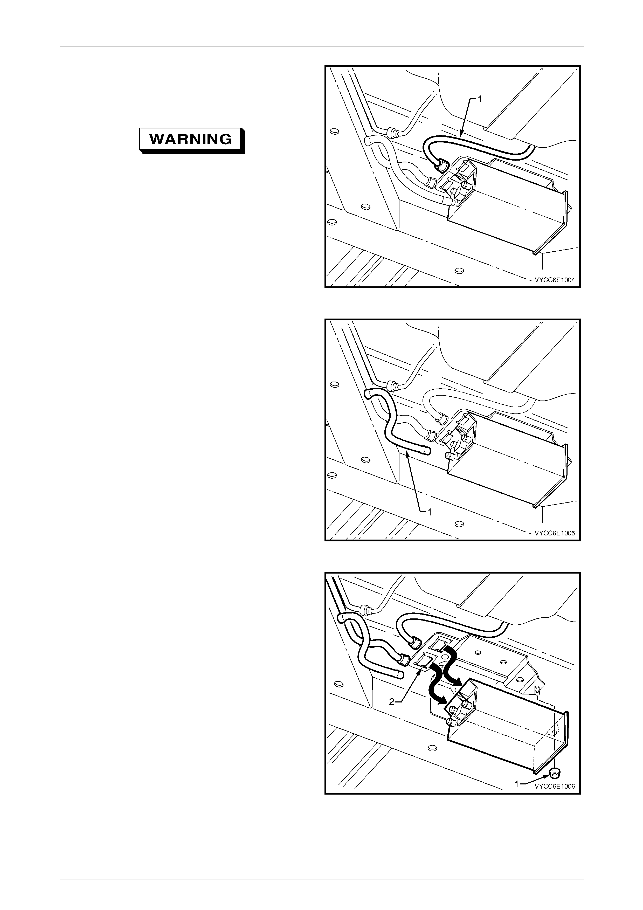
Fuel System Page 8A1–171
Page 8A1–171
6 Disconnect the fuel tank vent line (1) by grasping both
sides of the quick-connect fitting. Twist the connector
1/4 turn in each direction to loosen any dirt within the
quick-connect fitting.
Wear safety glasses w hen usin g compressed
air. Do not blow compressed air onto any
body part.
7 Using compressed air, blow any dirt out of the quick-
connect fitting.
8 Disconnect the quick-connect fitting by pushing it
towards the canister.
9 Squeeze the quick-connect fitting to release the
retaining tabs, then pull back on the connector to
remove the canister purge line from the canister. Figure 8A1 – 221
10 Remove the canister vent line (1) from the canister by
twisting and pulling it off.
Figure 8A1 – 222
11 Remove the canister retaining nut (1).
12 Remove the canister from the retaining stud, then slide
the canister out of the retainer (2).
Figure 8A1 – 223
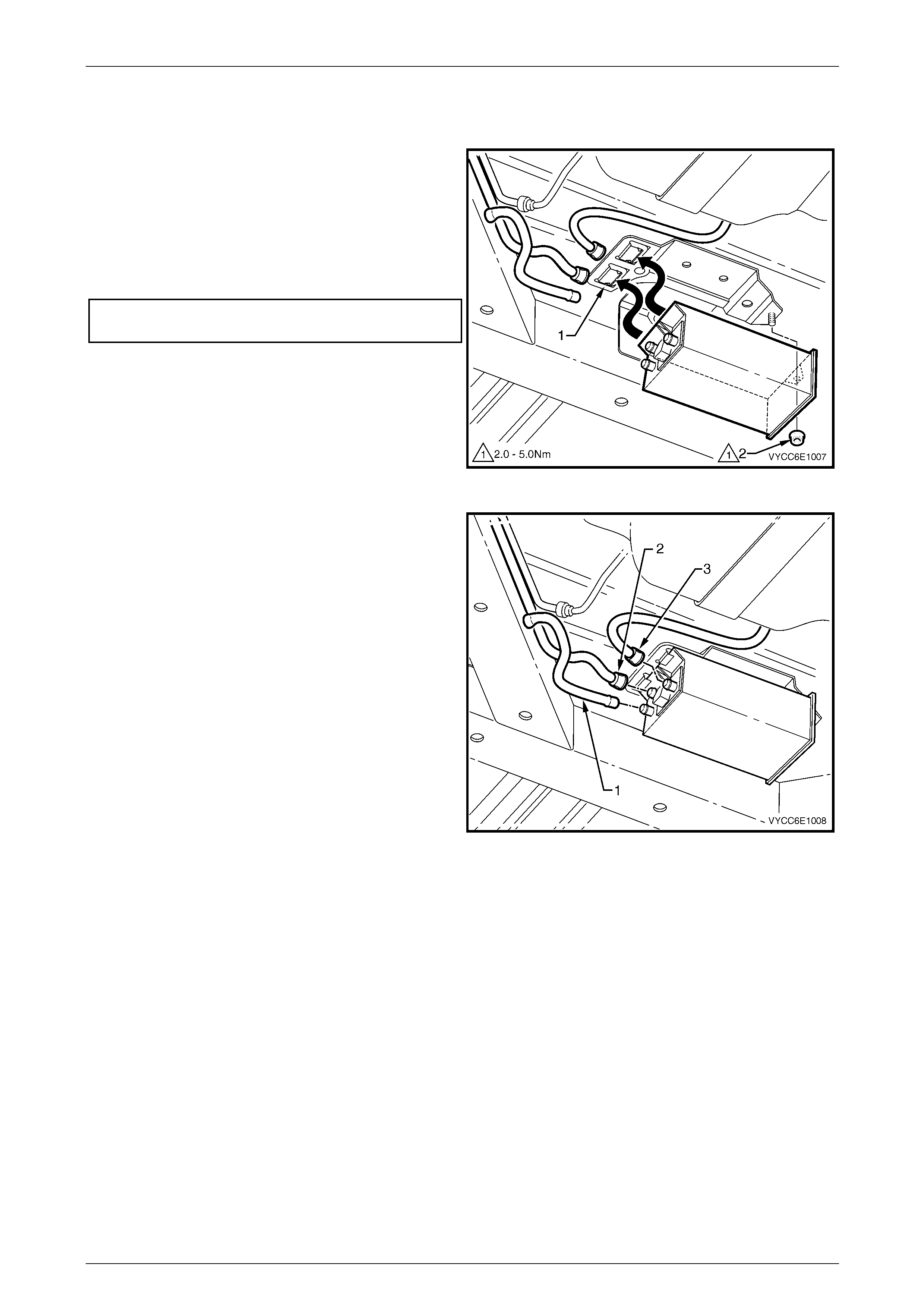
Fuel System Page 8A1–172
Page 8A1–172
Reinstall
1 Hoist the vehicle, refer to Section 0A General Information.
2 Reinstall the canister into the retainer (1) and over the
retaining stud.
3 Reinstall the canister retaini ng nut (2), then hand-
tighten.
4 Push the canister toward centre of the vehicle and
tighten the canister retaining nut to the specified
torque.
Evaporative emission control canister
retaining nut torque specification ................ 2.0 - 5.0 Nm
Figure 8A1 – 224
5 Reinstall the canister vent lin e (1).
6 Align the canister purge line quick-connect (2) with the
canister purge line port. Push the quick-connect firmly
onto the port.
7 Align the fuel tank vent line quick-co nnect (3) with the
fuel tank vent port. Push the quick-connect firmly onto
the port.
8 After installation, pull on each quick-c onnect to ensure
the connections are secure and lock ed in position.
Figure 8A1 – 225
Fuel System Page 8A1–173
Page 8A1–173
7.14 Fuel Filler Neck and Splash Guard (Crew
Cab Only)
LT Section No. — 03–028
Remove
A depressurised fuel system contains fuel in
the fuel filter and fuel lines that can be spilled
during service operations.
Fuel vapour remains in the fuel tank even
when completely empty. Seal all openings in
the fuel tank using suitable material or a
plastic plug. Ensure no naked flames or other
ignition sources are nearby. Ensure all
cellular phones (and transmission devices
that may cause any metal objects to become
unintentional receiving antennas) are
switched off.
Place a dry chemical (Class B) fire
extinguisher nearby before performing any
on-vehicle service procedures. Failure to
follow these precautions may result in
personal injury.
Wear safety glasses when using compressed
air. Do not blow compressed air directly onto
any body part.
Ensure fuel is pumped or siphoned from both
sides of the baffle in the fuel tank.
1 Remove the modular fuel pump and se nder assembly, refer to 7.5 Modular Fuel Pump and Sender Assembly.
2 Drain the fuel tank by pumping or siphoning fuel through the hole in the fuel tank (from which the modul ar fuel
pump and sender assembl y was removed) using commercially-available equipment.
NOTE
A permanent floodgate restriction in the lower fuel
filler neck prevents the fuel tank from being
drained through the filler aperture.
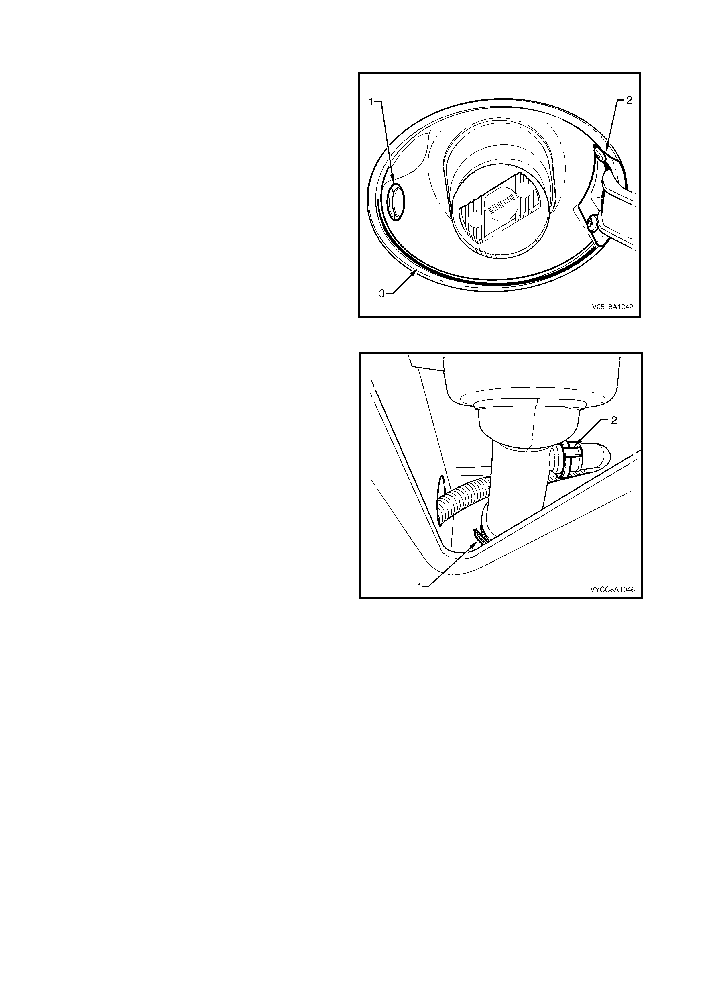
Fuel System Page 8A1–174
Page 8A1–174
3 Remove the grommet (1) from the left side of the fuel
filler splash guard.
4 Remove both screws (2) from the fuel filler door
opening.
5 Prise the circlip (3) from the fuel filler splash guard and
place in a safe location away from the immediate
worksite.
6 Use compressed air to ensure that all dirt and foreign
materials are removed from the fuel filler cap and fuel
filler neck.
7 Remove the fuel filler cap from the fuel filler neck.
8 Remove the fuel filler splash guard by pulling it over
the fuel filler neck.
9 Replace the fuel filler cap onto the fuel filler neck.
Figure 8A1 – 226
10 Remove the front inner side panel cover, refer to
Section 1B Sheetmetal.
11 Loosen and remove the screw clamp (1) holding the
flexible fuel inlet pipe onto the fuel filler neck.
12 Loosen and remove the quick-connect fitting (2)
holding the inlet breather pipe onto the fuel filler neck.
13 Cover the flexible fuel inlet pipe an d inlet breather pipe
with a suitable material to prevent foreig n objects from
entering.
Figure 8A1 – 227
Reinstall
Reinstallation of the fuel filler neck and splash guard is the reverse of the removal proced ure, ensuring all parts are dust-
free and clean before reinstalli ng.

Fuel System Page 8A1–175
Page 8A1–175
8 Specifications — Sedan, Wagon
and Utility
Fuel Tank Capacity:
Sedan and Wagon....................................................................................................... 75 litres
Utility............................................................................................................................ 70 litres
Fuel Tank Material:
Sedan and Wagon......................................................... High-density multi-layer polyethylene
Utility...................................................................................................................Pressed Steel
Fuel Filler Location:
All Models..................................................................................Right-hand rear quarter panel
Fuel Pump Type:
...........................................................................................................................Single Turbine
Fuel Pump Location:
All Models......................................................................................................................In tank
Fuel Pump Regulated Pressure:
............................................................................................................. approx. 410 kPa at idle
Minimum Fuel Pump Flow Capacity (at Regulated Pressure):
V6 Engine............................................................................................. 1.7 L/min @ 13.5 volts
GEN III V8 Engine ................................................................................ 2.5 L/min @ 13.5 volts
Fuel Pump Current Draw (Steady State at Regulated Pressure):
V6 Engine................................................................................................. 7.4 Amps maximum
GEN III V8 Engine ....................................................................................9.6 Amps maximum

Fuel System Page 8A1–176
Page 8A1–176
9 Specifications — Coupe
Fuel Tank Capacity:
.....................................................................................................................................70 litres
Fuel Tank Material:
..................................................Pressed steel with high-density multi-layer polyethylene shell
Fuel Filler Location:
...................................................................................................Right-hand rear quarter panel
Fuel Pump Type:
...........................................................................................................................Single Turbine
Pressure Regulator Location:
.......................................................................Inside modular fuel pump and sender assembly
Fuel Pump Location:
.......................................................................Inside modular fuel pump and sender assembly
Fuel Pump Regulated Pressure:
............................................................................................................. approx. 410 kPa at idle
Minimum Fuel Pump Flow Capacity (at Regulated Pressure):
............................................................................................................2.95 L/min @ 13.5 volts
...............................................................................................................2.33 L/min @ 12 volts
Fuel Pump Current Draw (Steady State at Regulated Pressure):
................................................................................................................11.0 Amps maximum

Fuel System Page 8A1–177
Page 8A1–177
10 Specifications — Regular Cab
and Crew Cab
Fuel Tank Capacity:
..................................................................................................................................68.5 litres
Fuel Tank Material:
.......................................................................... 'W'-type high-density multi-layer polyethylene
Fuel Filler Location:
.........................................................Attached to support bracket underneath right side of tray
Fuel Pump Type:
............................................................................................................................Single turbine
Pressure Regulator Location:
V6 Engine...............................................................................................................Engine bay
GEN III V8 Engine ................................................... Modular fuel pump and sender assembly
Fuel Pump Location:
................................................................................................................................In fuel tank
Fuel Pump Regulated Pressure:
............................................................................................................. approx. 410 kPa at idle
Minimum Fuel Pump Flow Capacity (at Regulated Pressure):
............................................................................................................2.95 L/min @ 13.5 volts
Fuel Pump Current Draw (Steady State at Regulated Pressure):
................................................................................................................11.0 Amps maximum
O-rings:
Pressure regulator (P/N 195306–0010)................................................................4.25 mm i.d.
Pressure regulator holder — top (P/N 195506–0150)...........................................7.52 mm i.d.
Pressure regulator holder — bottom (P/N 167529–0010).......................................8.2 mm i.d.
Fuel pump outlet (P/N 167529–0010).....................................................................8.2 mm i.d.
Pressure regulator (P/N 195306–0110)................................................................15.4 mm i.d.

Fuel System Page 8A1–178
Page 8A1–178
11 Torque Wrench Specifications —
Sedan, Wagon and Utility
Fuel Tank Mounting Strap Nuts/Bolts (Sedan and Wagon).......15.0 – 25.0 Nm
Fuel Tank Mounting Nut (Utility)................................................15.0 – 20.0 Nm
Stone Guard Securing Nut ............................................................1.5 – 2.5 Nm
Stone Guard Securing Bolt............................................................5.0 – 7.0 Nm
Evaporative Emission Cont rol Canister Mounting Nut...................2.0 – 5.0 Nm

Fuel System Page 8A1–179
Page 8A1–179
12 Torque Wrench Specifications —
Coupe
Fuel Pump and Sender Assembly Earthing Terminal Nut ......................7.0 Nm
Fuel Tank Mounting Strap Nut – Upper................................................20.0 Nm
Fuel Tank Mounting Strap Nut – Lo wer................................................40.0 Nm
Fuel Filler Neck to Fuel Filler Pocket Mounting Nut................................5.0 Nm
Mounting Nut................................................................................5.0 – 8.0 Nm
Stone Guard Securing Bolt............................................................5.0 – 7.0 Nm
Stone Guard Securing Nut ............................................................1.5 – 2.5 Nm

Fuel System Page 8A1–180
Page 8A1–180
13 Torque Wrench Specifications —
Regular Cab and Crew Cab
Fuel Tank Mounting Strap Nuts.................................................20.0 – 25.0 Nm
Fuel Tank Support Strap Attaching Nuts...................................30.0 – 40.0 Nm
Support Bracket Backing Plate Attaching Screws.....................20.0 – 25.0 Nm
Fuel Tank 'H'-frame Nut.............................................................20.0 – 25.0 Nm
Fuel Tank Mounting Strap Nut...................................................20.0 – 25.0 Nm
Stone Guard Securing Nut ............................................................1.5 – 2.5 Nm
Stone Guard Securing Bolt............................................................5.0 – 7.0 Nm
Evaporative Emission Cont rol Canister Mounting Nut...................2.0 – 5.0 Nm
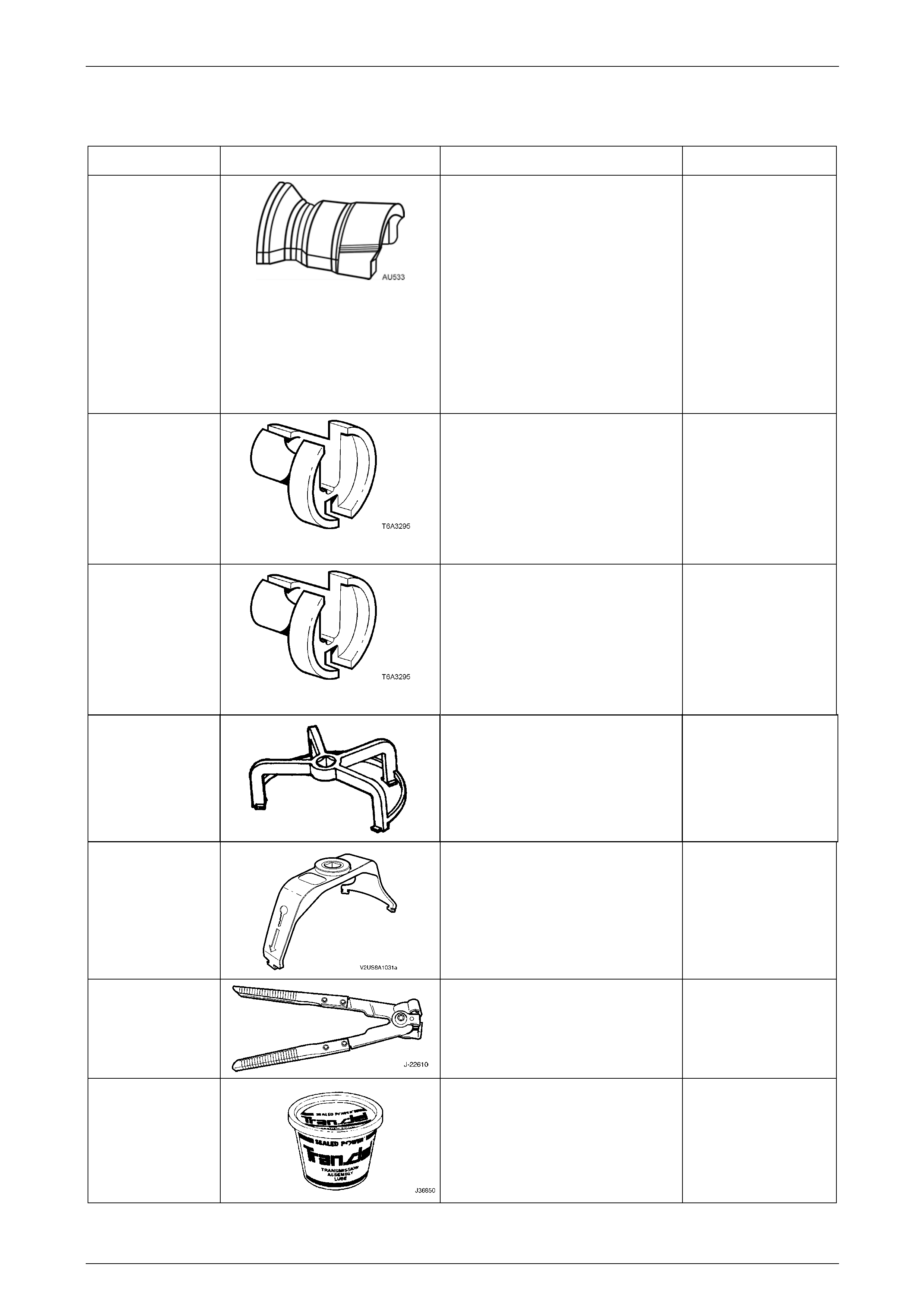
Fuel System Page 8A1–181
Page 8A1–181
14 Special Tools
Tool Number Illustration Description Tool Classification
AU533
Quick-connect Fitting
Release Tool
Released in two sizes:
• red for 5/16-inch fittings
(fuel vapour lines), and
• blue for 3/8-inch fittings
(fuel feed lines).
Commercially available under
P/N AUSP45.
Previously released.
Desirable
7370
Quick-connect Release
Tool — 5/16-inch
Used for releasing fuel line qu ick
connects at the dash panel and fuel
rail connections, after the fuel system
has been depressurised.
Previously released.
Mandatory
7371
Quick-connect Release
Tool — 3/8-inch
Used for releasing fuel line qu ick
connects at the dash panel and fuel
rail connections, after the fuel system
has been depressurised.
Previously released.
Mandatory
AU469
(J39765)
Modular Fuel Pump and Sender
Assembly Remover / Installer.
(Sedan, Wagon and Utility)
Previously released.
Mandatory
J45722
Modular Fuel Pump and Sender
Assembly Lock Ring Remove
and Install Tool.
(Coupe, Regular Cab
and Crew Cab)
Previously released.
Mandatory
J22610
Keystone Clamp Pliers
Used to remove and fasten ear-type
clamps.
Available
J36850 TransJel Lubricant
Used to lubricate fuel tank siphon
hose during fuel tank drain/siphon
procedures.
Desirable
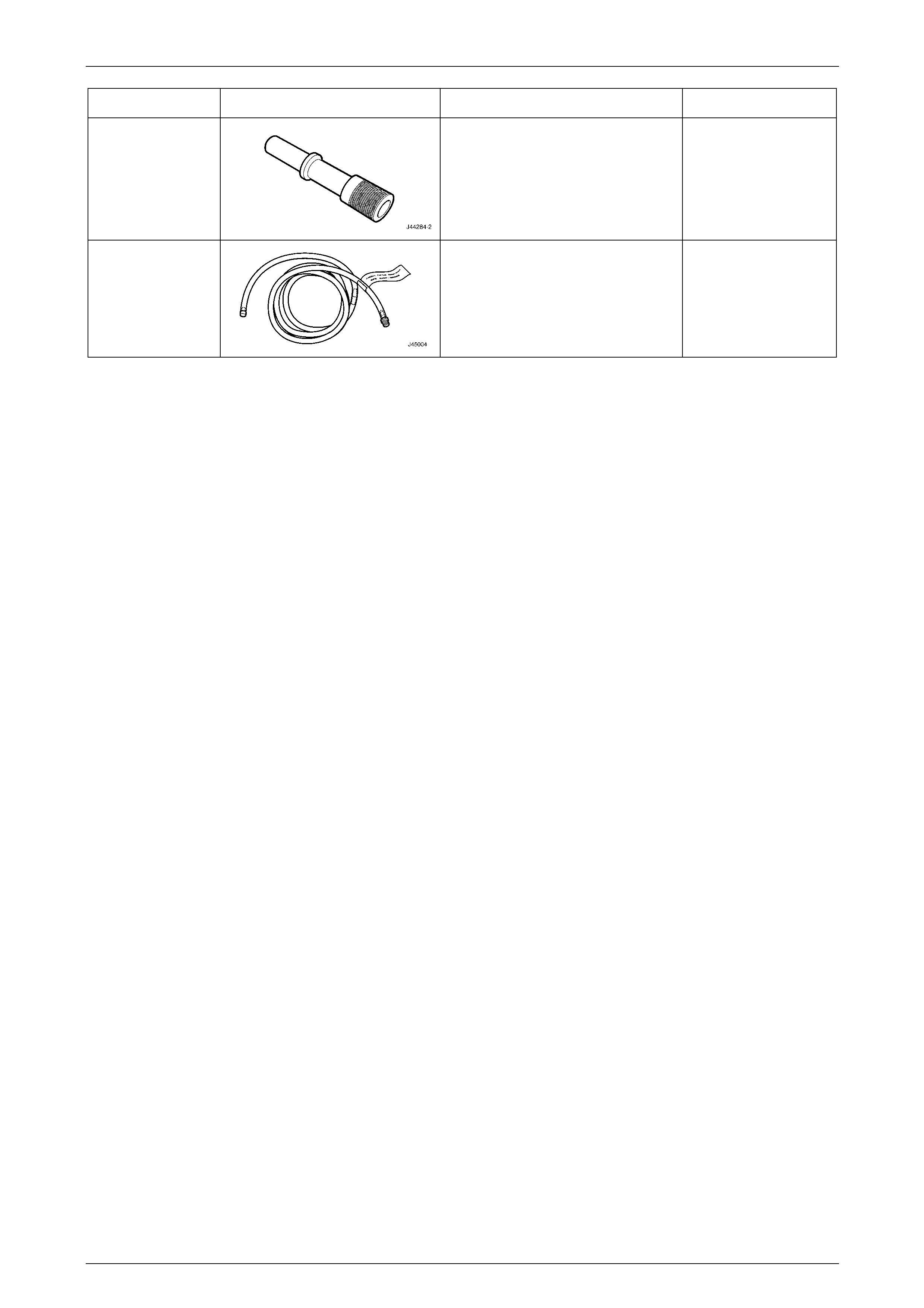
Fuel System Page 8A1–182
Page 8A1–182
Tool Number Illustration Description Tool Classification
J44284–2 Fuel Flapper Door Holder
Holds open the fuel filler neck flapper
door to allow the fuel tank siphon
hose to be fed down into the fuel filler
neck.
Mandatory
J45004–1
Fuel Tank Siphon Hose
Flexible fuel siphoning hose with
grounding wire and threa de d vacuum
pump fitting.
Mandatory