
Lighting System Page 12B–1
Page 12B–1
Section 12B
Lighting System
ATTENTION
Before performing any service operation or other procedure described in this Section, refer to Section 00
Warnings, Cautions and Notes for correct workshop practices with regard to safety and/or property damage.
1 General Information ...............................................................................................................................4
1.1 Headlamp Assembly.............................................................................................................................................. 4
1.2 Side Repeater Lamp Assembly............................................................................................................................. 5
1.3 Front Fog Lamp and Cornering Lamp Assembly................................................................................................ 6
1.4 Tail Lamp Assembly.............................................................................................................................................. 7
1.5 Hazard Warning Switch......................................................................................................................................... 8
1.6 Interior Illumination ............................................................................................................................................... 9
1.7 Instrument and Switch Illumination ................................................................................................................... 10
1.8 Dimming Control Module.................................................................................................................................... 11
2 Service Operations — Exterior Illumination......................................................................................12
2.1 Front Fog Lamp Aiming ...................................................................................................................................... 12
Front Fog Lamp Aim............................................................................................................................................ 12
2.2 Front Fog Lamp Bulb........................................................................................................................................... 14
Replace................................................................................................................................................................. 14
2.3 Front Cornering Lamp Bulb................................................................................................................................ 15
Replace................................................................................................................................................................. 15
2.4 Front Fog Lamp and Cornering Lamp Assembly Wiring Harness................................................................... 16
Remove................................................................................................................................................................. 16
Reinstall................................................................................................................................................................ 16
2.5 Tail Lamp Assembly Bulbs ................................................................................................................................. 17
Replace................................................................................................................................................................. 17
2.6 Headlamp Assembly Aiming............................................................................................................................... 19
Headlamp Assembly Aim.................................................................................................................................... 19
2.7 Headlamp Assembly............................................................................................................................................ 22
Remove................................................................................................................................................................. 22
Reinstall................................................................................................................................................................ 23
2.8 Headlamp and Park Lamp Assembly Bulbs...................................................................................................... 24
Replace — Low Beam Bulb................................................................................................................................. 24
Replace — High Beam Bulb................................................................................................................................ 25
Replace — Park Lamp Bulb ................................................................................................................................ 27
2.9 Front Turn Signal Lamp Bulb.............................................................................................................................. 28
Replace................................................................................................................................................................. 28
2.10 Front Fog Lamp and Cornering Lamp Assembly.............................................................................................. 29
Remove................................................................................................................................................................. 29
Reinstall................................................................................................................................................................ 29
2.11 Tail Lamp Assembly............................................................................................................................................ 30
Remove................................................................................................................................................................. 30
Reinstall................................................................................................................................................................ 31
2.12 Side Repeater Lamp Assembly........................................................................................................................... 32
Remove................................................................................................................................................................. 32
Reinstall................................................................................................................................................................ 32
2.13 High-mount Stop Lamp Assembly ..................................................................................................................... 33
Bulb Replacement................................................................................................................................................ 33
Remove................................................................................................................................................................. 33
Reinstall................................................................................................................................................................ 33
Techline
Techline

Lighting System Page 12B–2
Page 12B–2
2.14 Rear Licence Plate Lamp Assembly................................................................................................................... 34
Remove................................................................................................................................................................. 34
Reinstall................................................................................................................................................................ 34
2.15 Rear Licence Plate Wiring Harness.................................................................................................................... 35
3 Service Operations — Interior Illumination and Switching..............................................................36
3.1 Side Door Courtesy Lamp Assembly................................................................................................................. 36
Remove................................................................................................................................................................. 36
Reinstall................................................................................................................................................................ 36
3.2 Instrument Panel Compartment Lamp Assembly............................................................................................. 37
Remove................................................................................................................................................................. 37
Reinstall................................................................................................................................................................ 37
3.3 Instrument Panel Compartment Lamp Switch Assembly................................................................................. 38
Remove................................................................................................................................................................. 38
Reinstall................................................................................................................................................................ 38
3.4 Rear Compartment Courtesy Lamp Assembly.................................................................................................. 39
Remove................................................................................................................................................................. 39
Reinstall................................................................................................................................................................ 39
3.5 Rear Compartment Courtesy Lamp Switch Assembly ..................................................................................... 40
Remove................................................................................................................................................................. 40
Reinstall................................................................................................................................................................ 40
3.6 Roof Console Assembly...................................................................................................................................... 41
Bulb Replace........................................................................................................................................................ 41
Remove................................................................................................................................................................. 42
Reinstall................................................................................................................................................................ 42
3.7 Dimming Control Module.................................................................................................................................... 43
Remove................................................................................................................................................................. 43
Reinstall................................................................................................................................................................ 43
3.8 Door Ajar Switches.............................................................................................................................................. 44
Remove................................................................................................................................................................. 44
Reinstall................................................................................................................................................................ 44
3.9 Stepwell Lamps.................................................................................................................................................... 45
Replace................................................................................................................................................................. 45
3.10 Floor Console Compartment Lamp Assembly.................................................................................................. 46
Remove................................................................................................................................................................. 46
Reinstall................................................................................................................................................................ 46
3.11 Floor Console Compartment Lamp Switch Assembly...................................................................................... 47
Remove................................................................................................................................................................. 47
Reinstall................................................................................................................................................................ 47
3.12 Roof Rail Courtesy and Reading Lamp Assembly............................................................................................ 48
Remove................................................................................................................................................................. 48
Reinstall................................................................................................................................................................ 48
3.13 Automatic Transmission Control Position Lamp.............................................................................................. 49
Replace................................................................................................................................................................. 49
3.14 Ignition Lock Cylinder Bulb................................................................................................................................ 50
Replace................................................................................................................................................................. 50
3.15 Stop Lamp Switch Assembly.............................................................................................................................. 51
3.16 Switch Illumination.............................................................................................................................................. 52
Auxiliary Switch Bulbs ........................................................................................................................................ 52
Replace............................................................................................................................................................ 52
PWR Switch and T/C Switch (or A/S Switch) Bulbs.......................................................................................... 53
Replace............................................................................................................................................................ 53
3.17 Backup Lamp Switch Assembly......................................................................................................................... 57
3.18 Neutral Safety Backup Switch Assembly .......................................................................................................... 58
3.19 Turn Signal Switch Assembly (and Cruise Control)......................................................................................... 59
Remove................................................................................................................................................................. 59
Reinstall................................................................................................................................................................ 60
Test ....................................................................................................................................................................... 60
Turn Signal Switch Assembly........................................................................................................................... 61

Lighting System Page 12B–3
Page 12B–3
3.20 Headlamp Switch Assembly ............................................................................................................................... 62
Remove................................................................................................................................................................. 62
Reinstall................................................................................................................................................................ 62
Test ....................................................................................................................................................................... 62
Headlamp Switch Assembly............................................................................................................................. 63
3.21 Daylight Running Lamp Assembly (Option T82)............................................................................................... 64
Remove................................................................................................................................................................. 64
Reinstall................................................................................................................................................................ 64
Test ....................................................................................................................................................................... 65
3.22 Hazard Warning Switch Assembly ..................................................................................................................... 66
Remove................................................................................................................................................................. 66
Test ....................................................................................................................................................................... 66
Hazard Warning Switch Assembly................................................................................................................... 66
3.23 Hazard Warning Switch Bulb.............................................................................................................................. 67
Replace................................................................................................................................................................. 67
3.24 Rear Vanity Mirror Lamp Bulbs .......................................................................................................................... 68
Replace................................................................................................................................................................. 68
3.25 Rear Remote Control Bulbs................................................................................................................................ 70
Replace................................................................................................................................................................. 70
4 Specifications.......................................................................................................................................71
5 Torque Wrench Specifications............................................................................................................72
Lighting System Page 12B–4
Page 12B–4
1 General Information
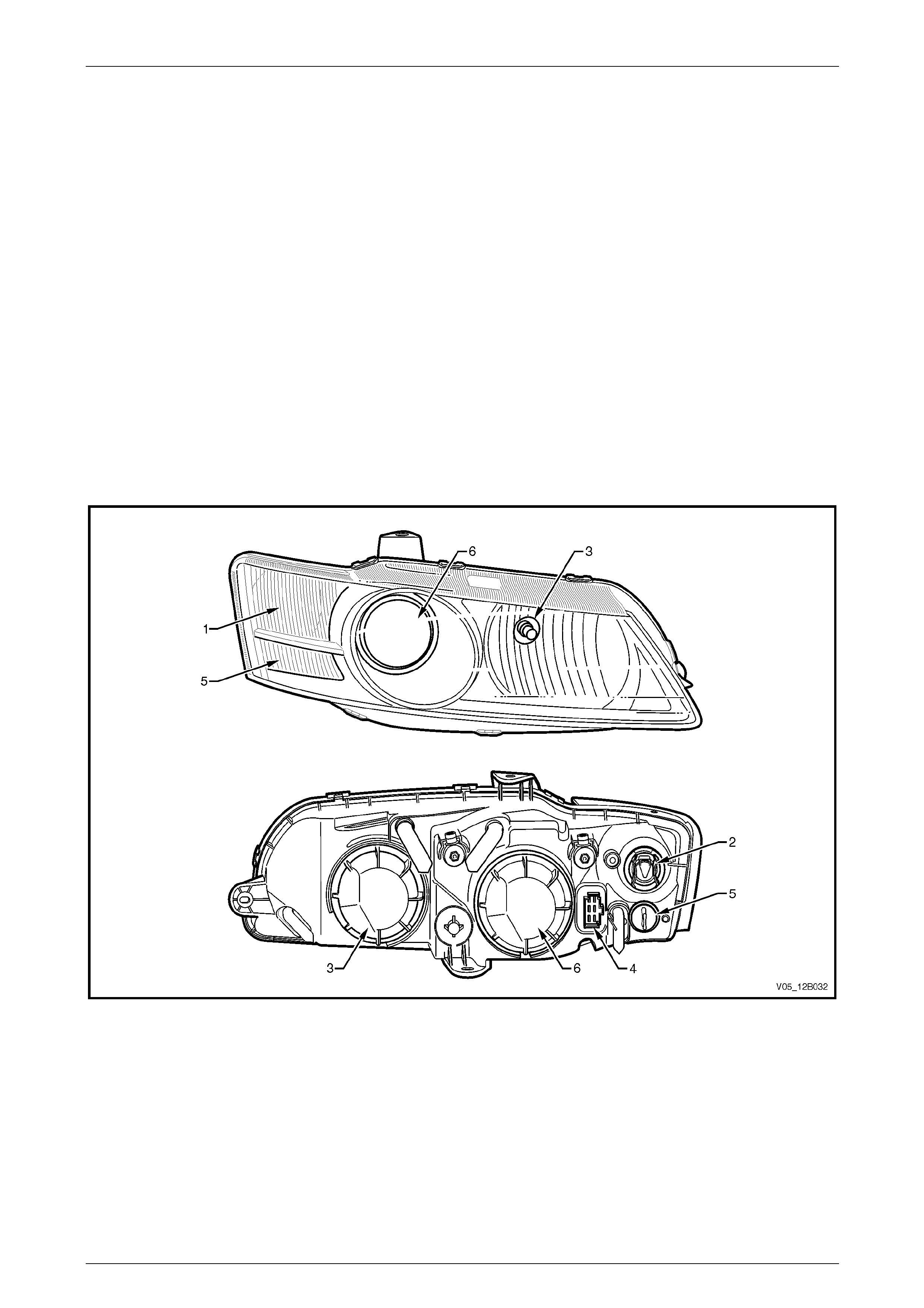
1.1 Headlamp Assembly
Headlamp assemblies inc orp orate two semi-sealed, dual-pocket, homofocal headlamps:
• The high beam lamp (located towards the inboard edge of the hea dlamp assembly) incorporates an H 9
specification quartz halogen bulb.
• The low beam lamp (located outboard of the high beam lamp) uses projector technology with an H11 specification
globe to provide optimum illu mination characteristics.
The turn signal lamp and park lamps are integrated along the outboard edge of each headlamp assembly. T he turn
signal lamp is located above the park lamp and incorpor ates an orange-tinted glass bulb and a clear lens. The park lamp
incorporates an untinted glass bulb and a clear lens. Chrome or black headl amp bezels have been fitted within the
headlamp assemblies to pr ovide distinctive styling between Level 4 and Level 5 veh icles.
NOTE
On vehicles fitted with the daylight running lamp
feature (option T82), the front headlamps operate
while the ignition s witch is on.
Figure 12B – 1
Legend
1 Turn Signal Lamp
2 Turn Signal Wiring Connector 3 Headlamp High Beam (H9)
4 Headlamp Wiring Connector 5 Park Lamp
6 Headlamp Low Beam (H11)

Lighting System Page 12B–5
Page 12B–5
1.2 Side Repeater Lamp Assembly
A turn signal side repeater lamp is fitted to both front fender panels, aft of the front wheel arch. The side repeater lamp
assembly incorporates a chrome-plated bulb shield, orange-tinted glass bulb, reflector and clear lens.
Lighting System Page 12B–6
Page 12B–6
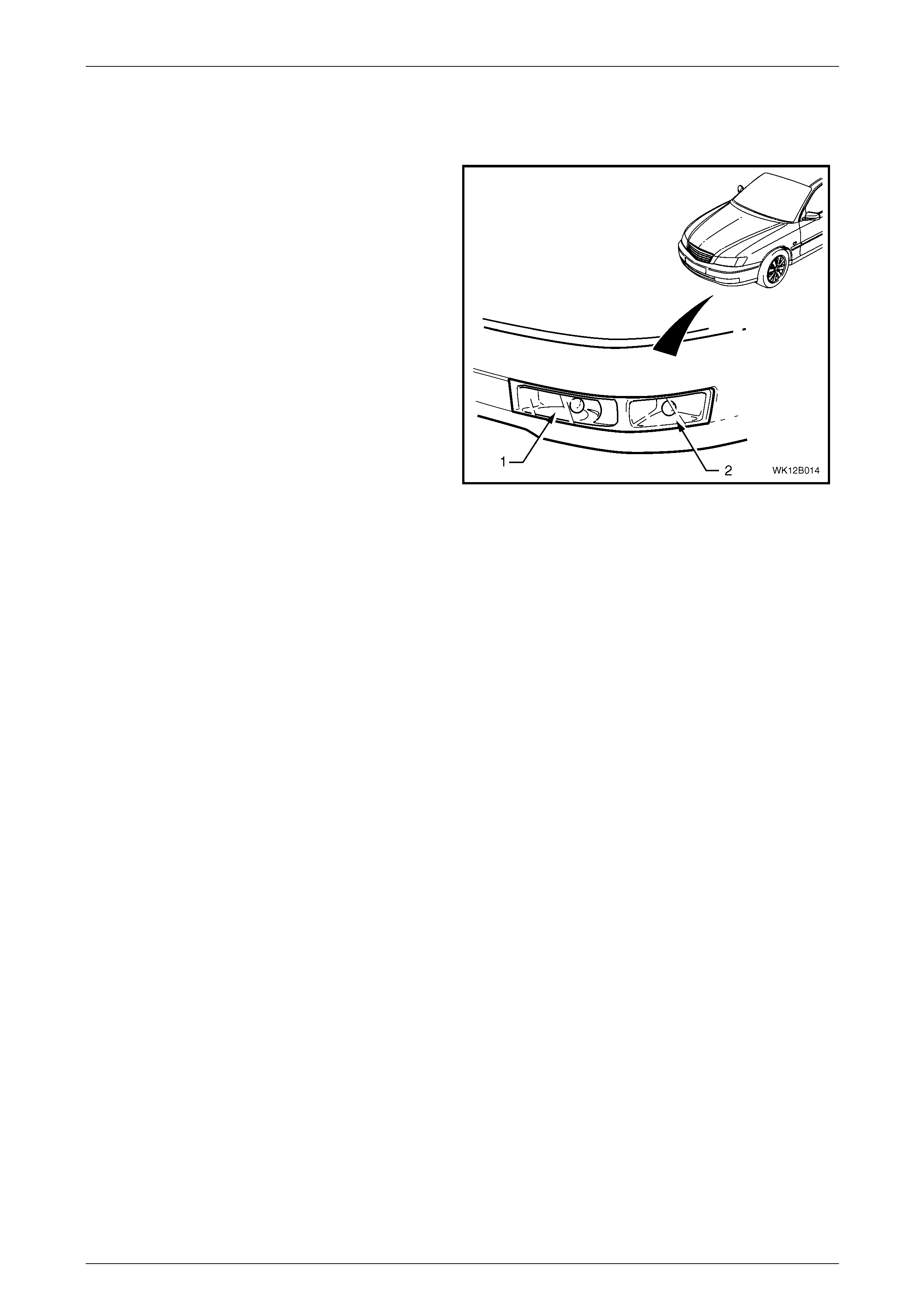
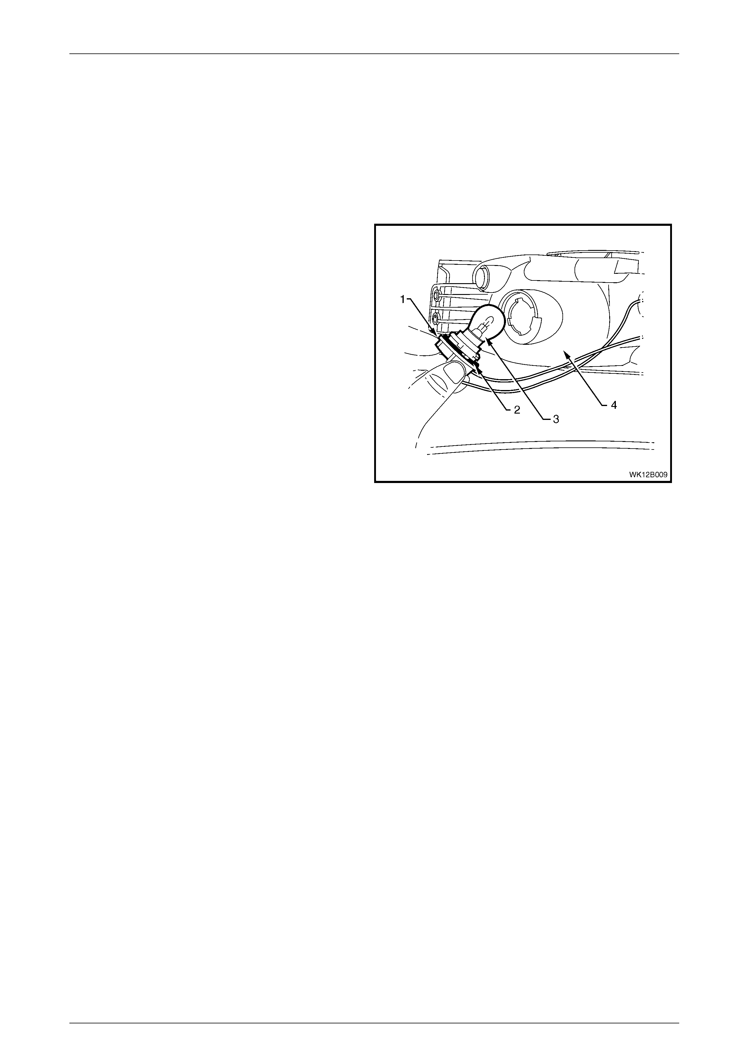
1.3 Front Fog Lamp and Cornering Lamp
Assembly
A front fog lamp and cornering lamp ass emb ly is fitted to
the front bumper fascia assembly, directly below each
headlamp assembly.
NOTE
On some vehicles, a metal str ip bracket may be
attached to the lamp housing to ensure rigidity
and reinforce the interfac e with the front bumpe r
fascia assembly. Razor-blade clips secure this
bracket to the attaching lugs on the front
bumper fascia assembly.
The front fog lamp and cornering lamp assemblies
incorporate chrome-plated bulb shields positioned in front
of the bulbs. The front fog lamp (1) is positioned on the
inboard side of each front fog lamp and cornering lamp
assembly; the cornering lamp (2) is positioned on the
outboard side.
NOTE
The front fog lamps operate only when the
headlamps are switched on and the front fog
lamps are selected on.
Figure 12B – 2
Lighting System Page 12B–7
Page 12B–7
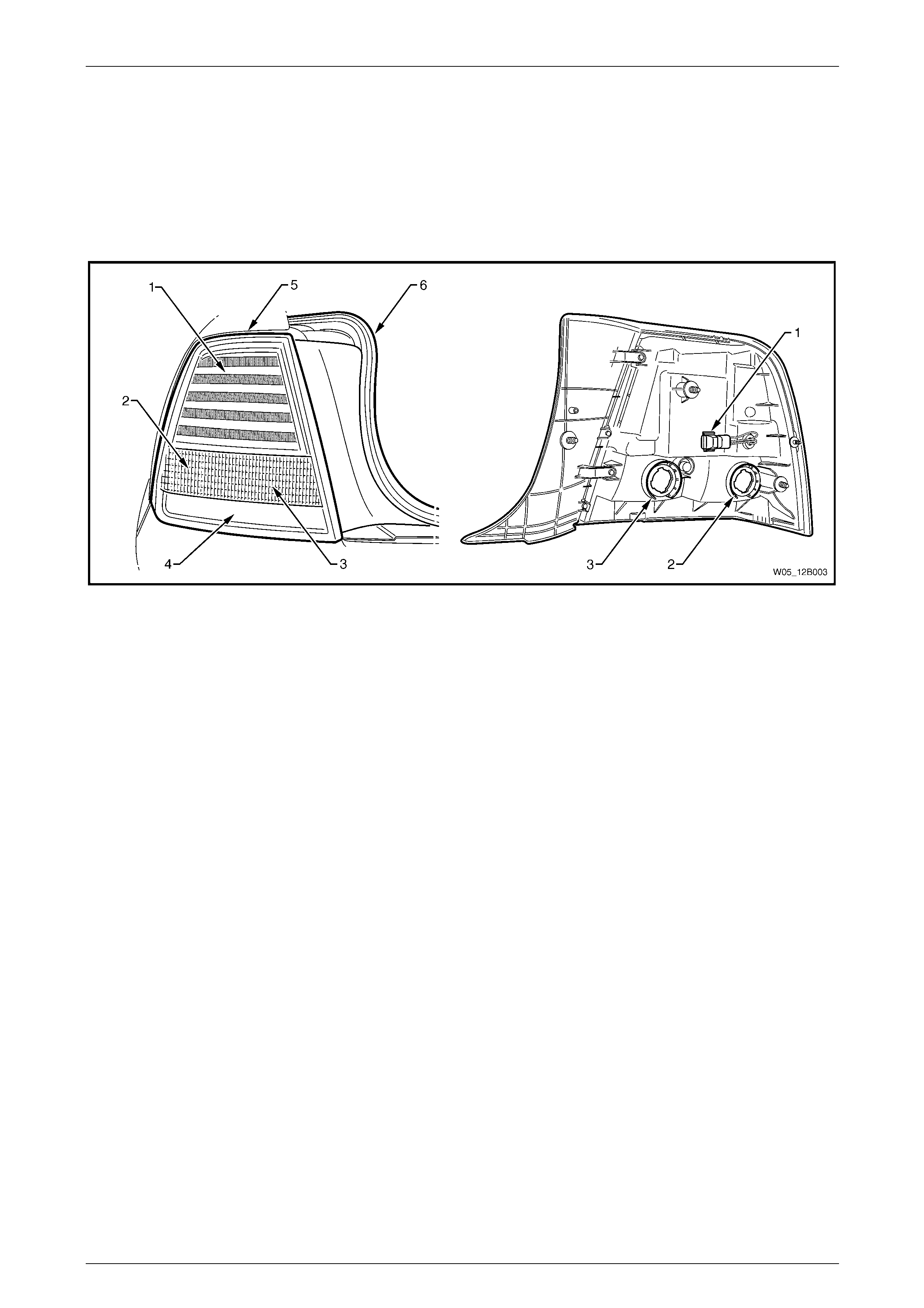
1.4 Tail Lamp Assembly
The tail lamp lens provides a distinctive all-red appearance; stop/tail lamp illumination is provided by LEDs, refer to
Figure 12B – 3.
Amber turn signal illumination is provided by an orange-tinted glass indicator bul b and clear lens provisions within the tail
lamp lens assembly.
Backup lamp illumination operates similarly, but the backup globe is not tinted.
Figure 12B – 3
Legend
1 Stop/Tail Lamp
2 Turn Signal Lamp
3 Backup Lamp
4 Reflex Reflector
5 Dust Seal
6 Rear Quarter Filler Panel

Lighting System Page 12B–8
Page 12B–8
1.5 Hazard Warning Switch
The hazard warning switch is located in the floor console as sembly.
Lighting System Page 12B–9
Page 12B–9
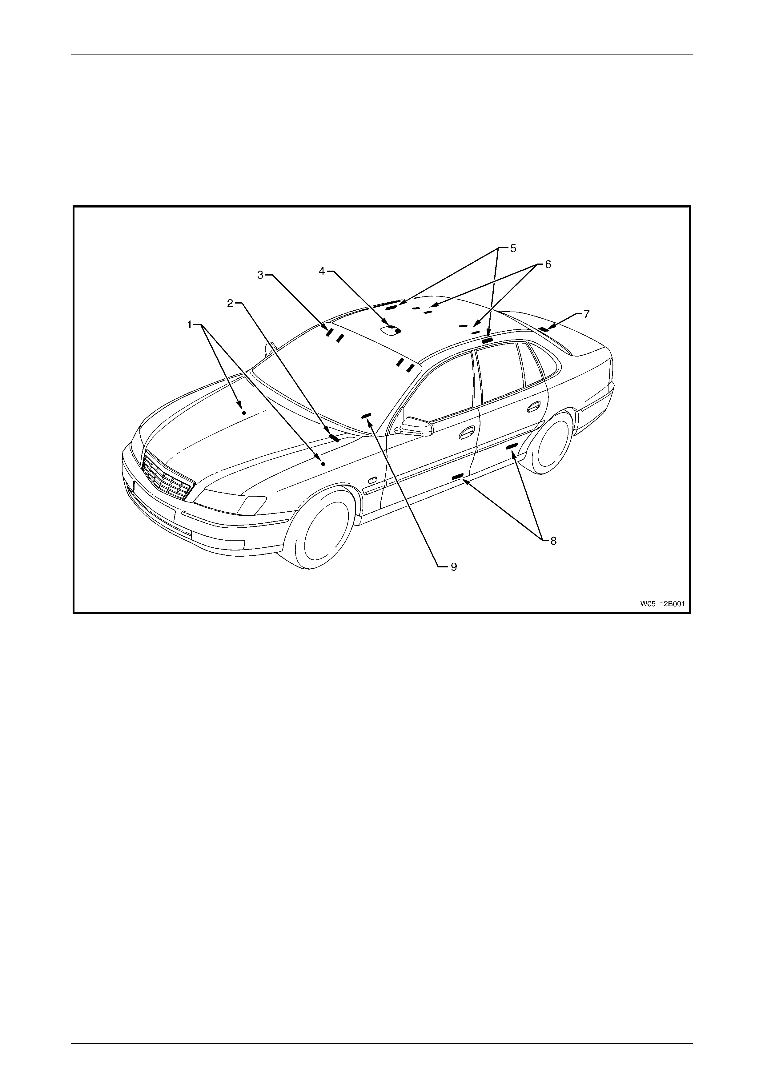
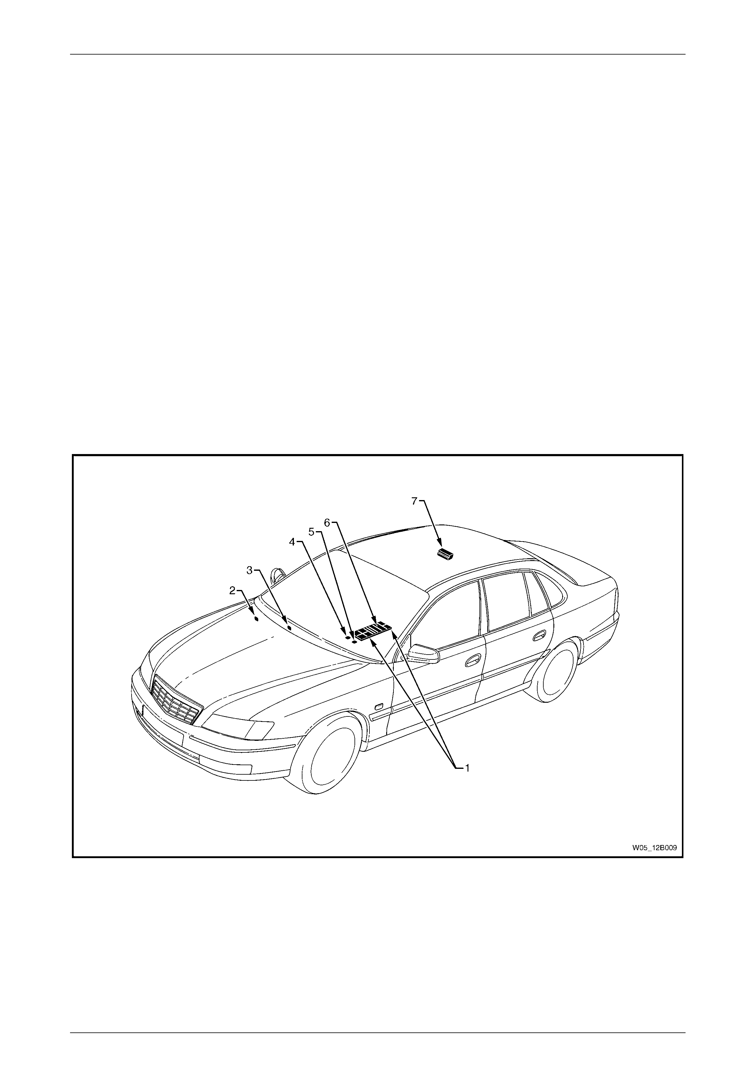
1.6 Interior Illumination
Interior illumination is provided by a roof console assembly that provides general interior and reading illuminati on. The
roof console assembly also incorpor ates a holder for sunglasses.
Additional interior lightin g is provided by courtesy lamps in the side door trims, front step well, instrument pan el
compartment, floor console compartment, vanity mirrors and the rear compartment, refer to Figure 12B – 4. Roof rail
courtesy and reading lamp assemblies are also installed an d may be switched on or off independently.
Figure 12B – 4
Legend
1 Front Stepwell Lamps
2 Instrument Panel Compartment Courtesy Lamp
3 Sunshade Vanity Mirror Lamps
4 Roof Console
5 Roof Rail Courtesy and Reading Lamps
6 Rear Vanity Mirror Lamps
7 Rear Compartment Courtesy Lamp
8 Side Door Courtesy Lamps
9 Floor Console Lamp
Lighting System Page 12B–10
Page 12B–10
1.7 Instrument and Switch Illumination
All instrument and switch illum ination is provided by light emitting diodes (LEDs) except the following (ill umin ated with
bulbs):
• hazard warning switch,
• T/C (traction control) switch,
• PWR (power) switch,
• A/S (active select) switch,
• electronic stability program (ESP) switch,
• dual park assist override switch,
• headlamp s witch assembly,
• ignition lock cylinder,
• trip computer switch, and
• rear remote control.
The headlamp and trip computer are sealed units and the conventional bulbs can not be serviced on these items.
LEDs are used instead of conventio nal bulbs due to their longevity in operation. If the illumination of any LED-equipped
item no longer operates correctl y and the LED is isolated as the fault, replace the affected assembly.
Figure 12B – 5
Legend
1 Auxiliary Switches
2 Headlamp Switch
3 Trip Computer Switch
4 T/C Switch or A/S Switch
5 PWR Switch
6 Hazard Warning Switch
7 Rear Controller Assembly

Lighting System Page 12B–11
Page 12B–11
1.8 Dimming Control Module
The body control module controls the duration the interior lighting is illuminated before d imming and turning the lam ps
off. The body control module is set to illuminate the interior lighting for a nominal 30 seconds at full brightness, but is
adjustable between 0 seco nds and 255 seconds via the trip computer switch. The interior lighting operates for the
selected duration after a door is ope ned and then closed, the ignition is switched to either the ACC or OFF position, or
with the operation of central door unlocking.
The dimming and rear fog lam p control module controls the interior lighting decay duration. This decay is not adjustable
and the interior lighting dims within 10 seconds.
Lighting System Page 12B–12
Page 12B–12
2 Service Operations — Exterior
Illumination
2.1 Front Fog Lamp Aiming
During front fog lamp aiming, do not use a
cloth or similar material to cover the lens of
the front fog lamp assembly not being
adjusted. Damage to the front fog lamp
assembly may result if the front fog lamp
beam is obstructed in this manner.
The front fog lamp assemblies must be aime d correctly to obtain the maximum road illumination and safety. Both front
fog lamps must be checked for correct aim whenever a b ulb or lamp assembly is replaced and after any adjustments or
repairs to the front-end sheetmetal or bumper fascia.
Headlamp and front fog lamp aimin g devices are in general use. When using a headlamp and front fog l amp aiming
device, ensure that it is in good condition and carefully follow the manufacturer's instructio ns.
Regardless of the method used for checking front fog lamp aim, the vehicle must be at kerb weight (that is, with full fuel
level, oil, water and spare tyre , but no passengers). Tyres must be uniformly inflated to their specified pressure.
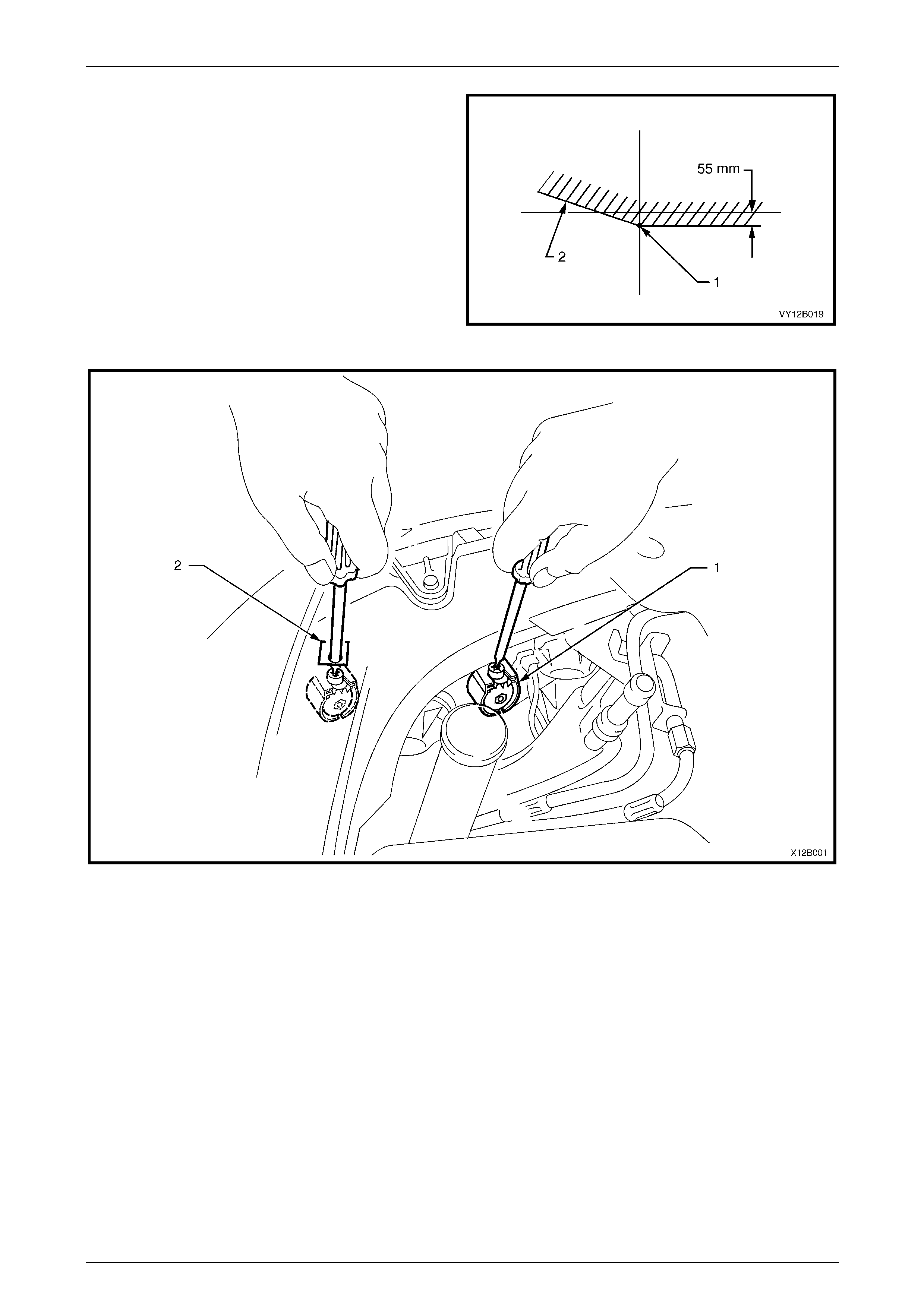
Front Fog Lamp Aim
LT Section No. — 02–300
If the vehicle regularly carries an unusually
heavy load in the rear compartment or tows a
trailer, these loads should be on the vehicle
when the front fog lamps are aimed.
NOTE
Use this procedure only when suitable test
equipment is unavailable.
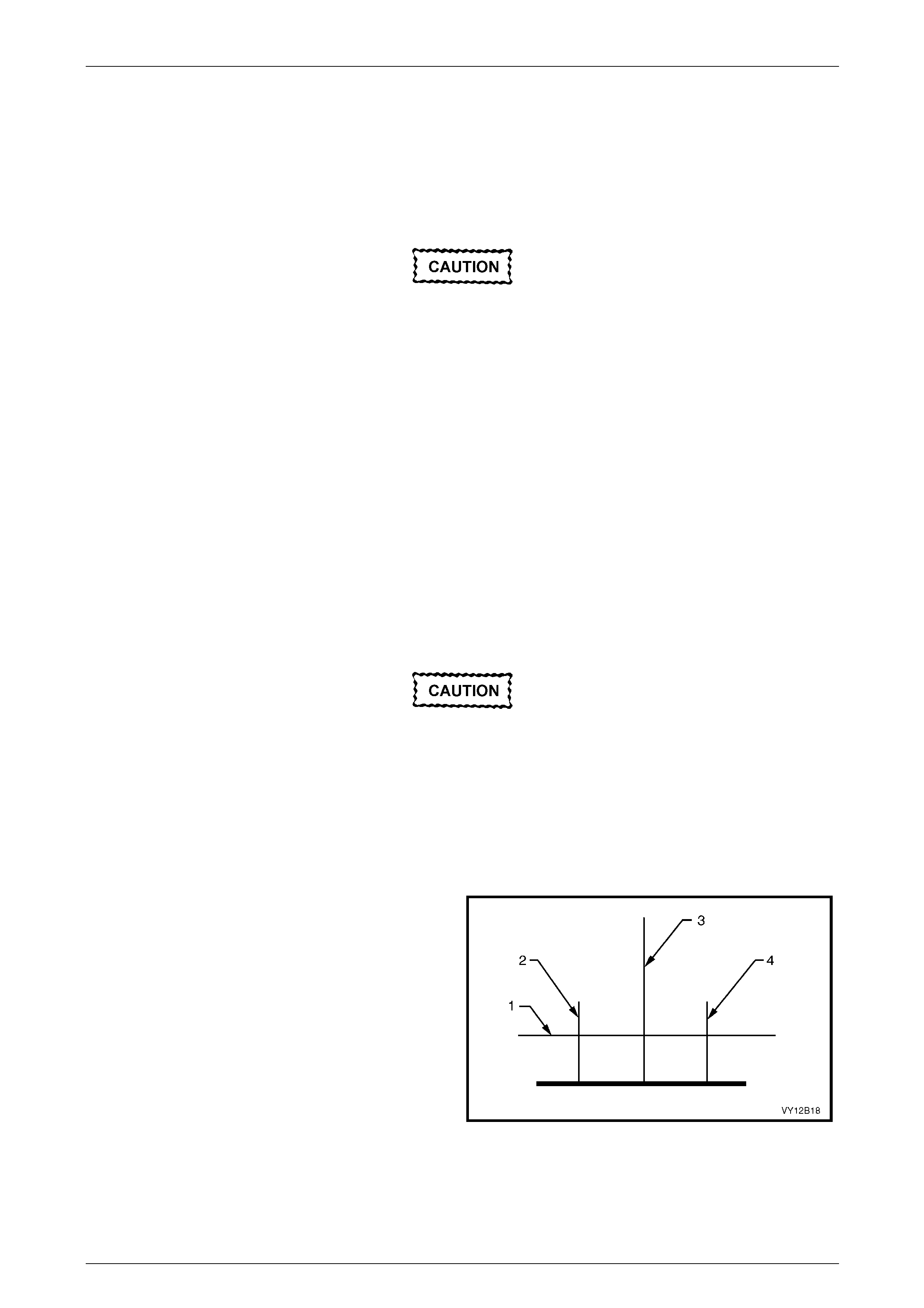
1 Set up a screen or use a vertical wall with a flat
horizontal floor. Park the vehi cle immediately in front
of a screen or wall and mark the following lines:
a a vertical centre-line (3), corresponding to the
centre of the vehicle;
b two vertical lines (2 and 4), corresponding to the
centre of the front fog lamp bulb on each side of
the vehicle; and
c a horizontal line (1), corresponding to the centre
of the front fog lamp bulb.
2 Turn on the front fog lamps to check if the marks are
correctly positioned. Figure 12B – 6
3 Reverse the vehicle straight back so the front is five metres in front of the screen or wall, ensuring the centre of the
vehicle is aligned with the vehicle centre-line mark (3) on the screen.
Lighting System Page 12B–13
Page 12B–13
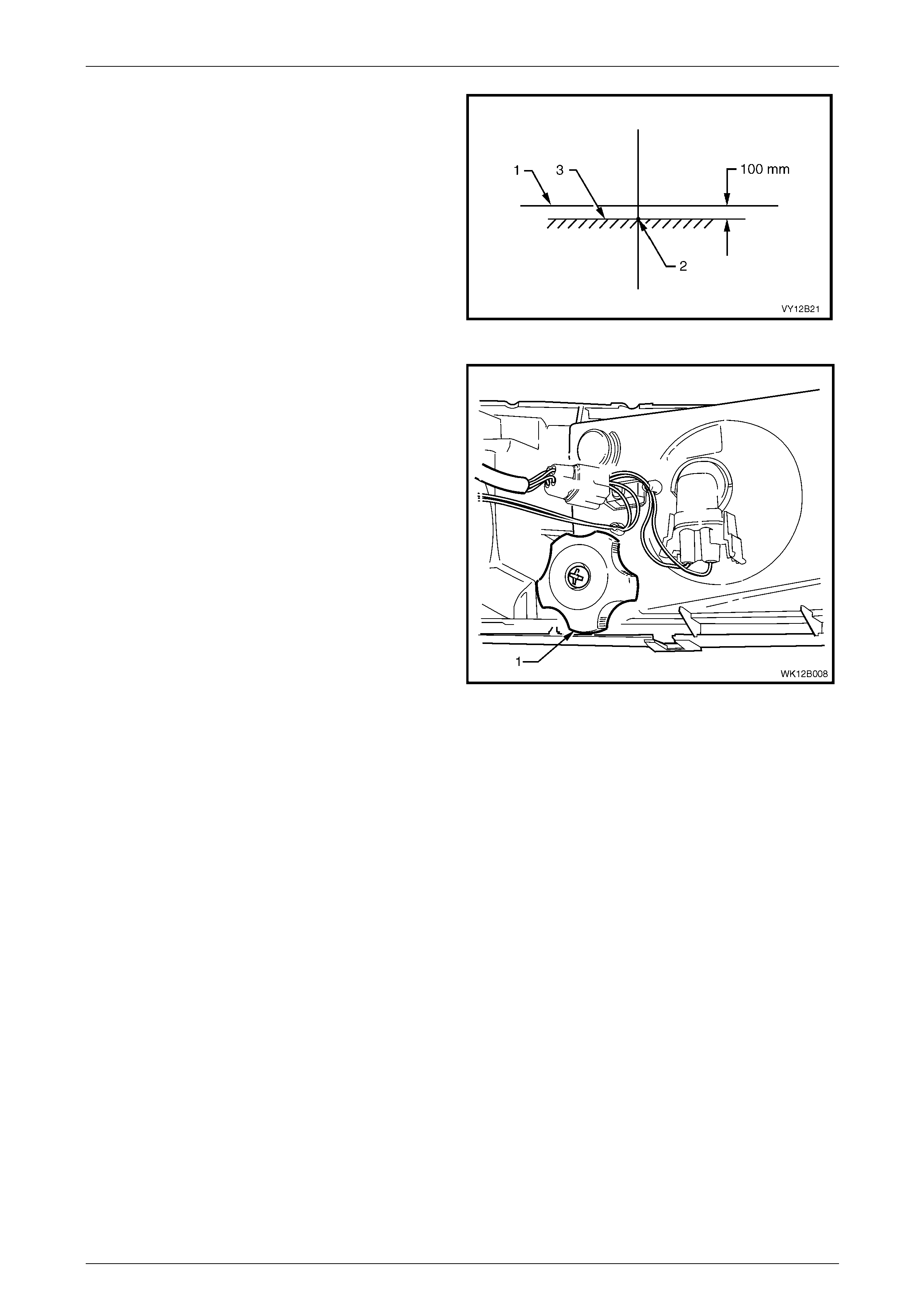
4 Turn the front fog lamps on. Aim each front fog lam p to
a point on its vertical centre-line (2), with the cut-off
line (3) 100 mm below the front fog lamp horizontal
centre-line (1).
NOTE
There is no provision for horizontal adjustment.
Front fog lamps are fixed to a vertical centre-line.
Figure 12B – 7
5 Adjust the front fog lamp aim by rotating the adj uster
knob (1) on the back of the lamp housing:
• Turn the adjuster anti-clockwise to lower the
beam.
• Turn the adjuster clockwise to raise the beam.
Figure 12B – 8
Lighting System Page 12B–14
Page 12B–14
2.2 Front Fog Lamp Bulb
LT Section No. — 02–325
Replace
1 Remove fusible link F102 from the engine compartment fuse and relay panel assemb ly, refer to
Section 12O Fuses, Relays and Wiring Harnesses.
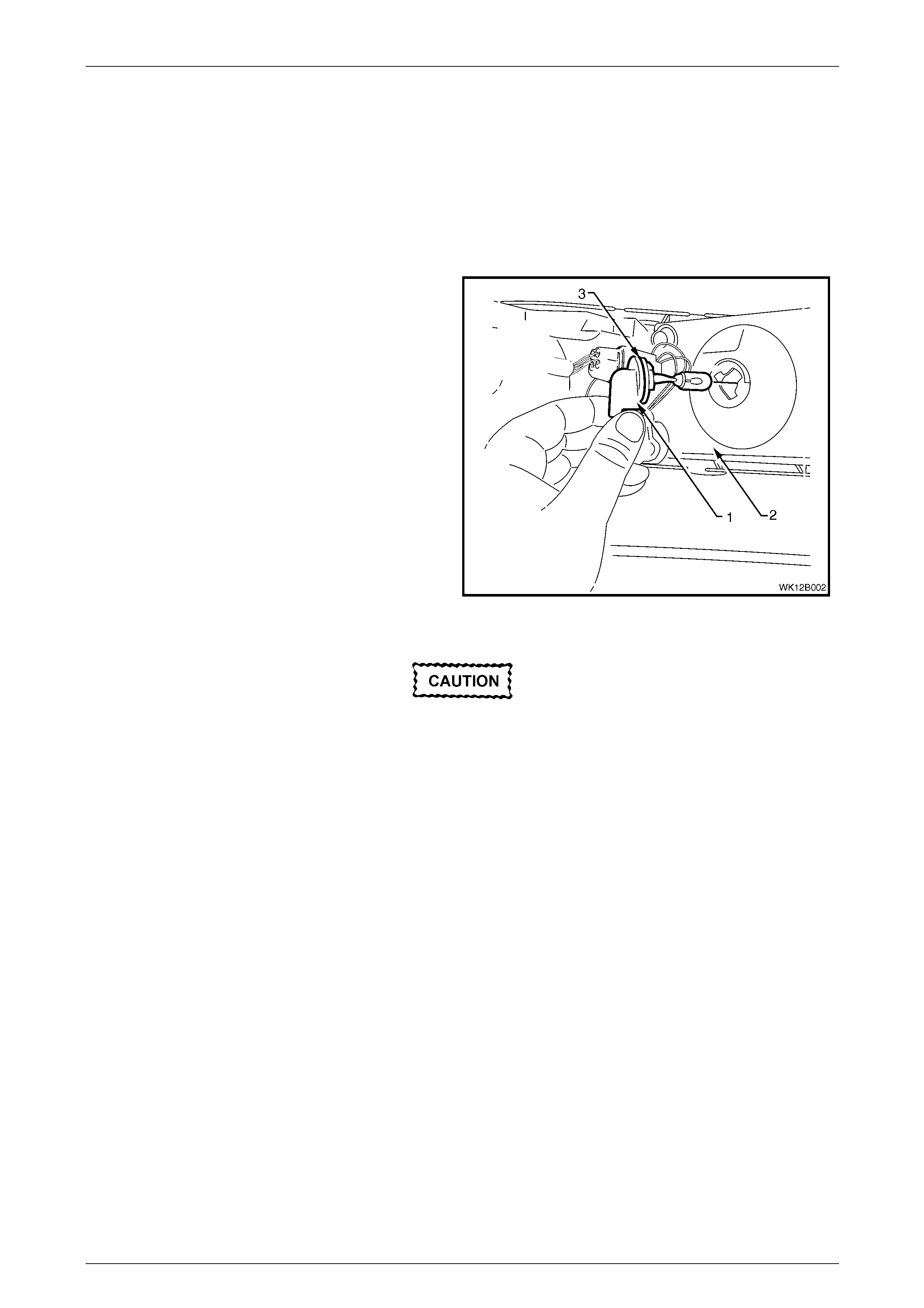
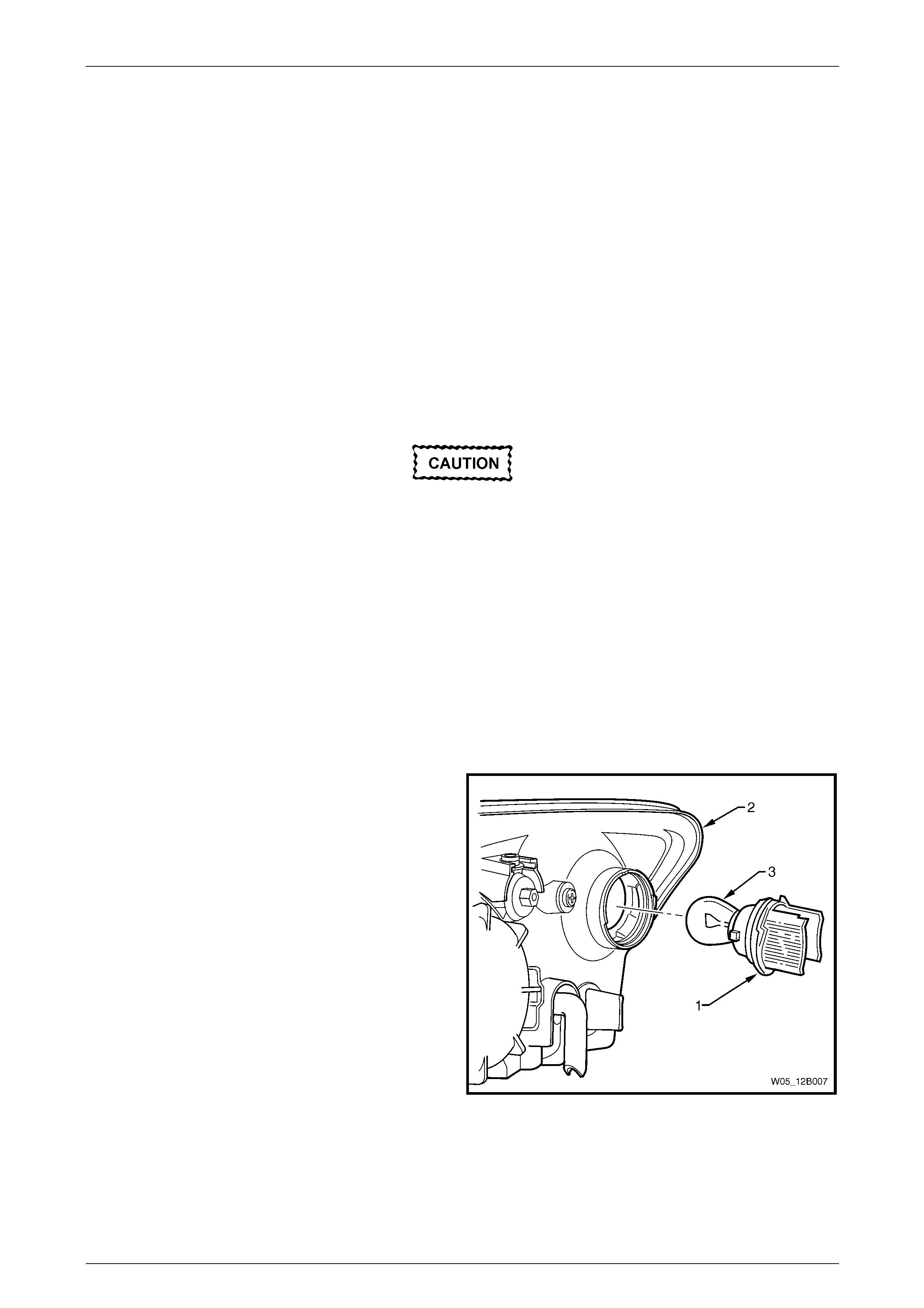
2 From behind the front fascia, rotate the front fog lamp
bulb and wiring harness connector assembly (1)
anticlockwise and remove from the front fog lamp and
cornering lamp assembly (2).
3 Disconnect the front fog lamp wiring harness
connector from the front fog lamp bulb by squeezing
both tangs together and pulling the co nnector down
from the bulb.
4 Inspect the condition of the O-ring seal (3). Replace
the seal if it is damaged or deformed.
Figure 12B – 9
Do not handle the quartz envelope of the front
fog lamp bulb. Wipe the quartz envelope
immediately with methylated spirits if it is
touched accidentally or the performance of
the bulb will deteriorate.
5 Install a new bulb into the bulb connector by sliding it into the base of the bulb until both tangs e ng age. Lock the
bulb in place by turning it clockwise.
6 Replace fusible link F102 on the engine compartment fuse and relay panel assembl y.
7 Check the front fog lamp operation a nd the aim of the front fog lamp as the bulb filament with respect to the
reflector may have changed, refer to 2.1 Front Fog Lamp Aiming.
Lighting System Page 12B–15
Page 12B–15
2.3 Front Cornering Lamp Bulb
LT Section No. — 02–325
Replace
1 Remove fusible link F102 from the engine compartment fuse and relay panel assemb ly, refer to
Section 12O Fuses, Relays and Wiring Harnesses.
2 From behind the front bumper fascia, twist the bulb
socket (1) to release it from the front fog lamp and
cornering lamp assembly (4), and remove the bulb
socket from the lamp assembly.
3 Press the bulb (3) into the bulb socket and rotate the
bulb anticlockwise to remove it.
4 Inspect the O-ring seal (2) on the bulb socket for
damage and correct seating. Replace the seal if
necessary.
5 Insert a new bulb into the bulb socket, then install the
bulb socket into the lamp assembly, and twist to lock.
6 Replace fusible link F102 on the engine compartment
fuse and relay panel assembly.
7 Check the cornering lamp oper ation.
Figure 12B – 10
Lighting System Page 12B–16
Page 12B–16
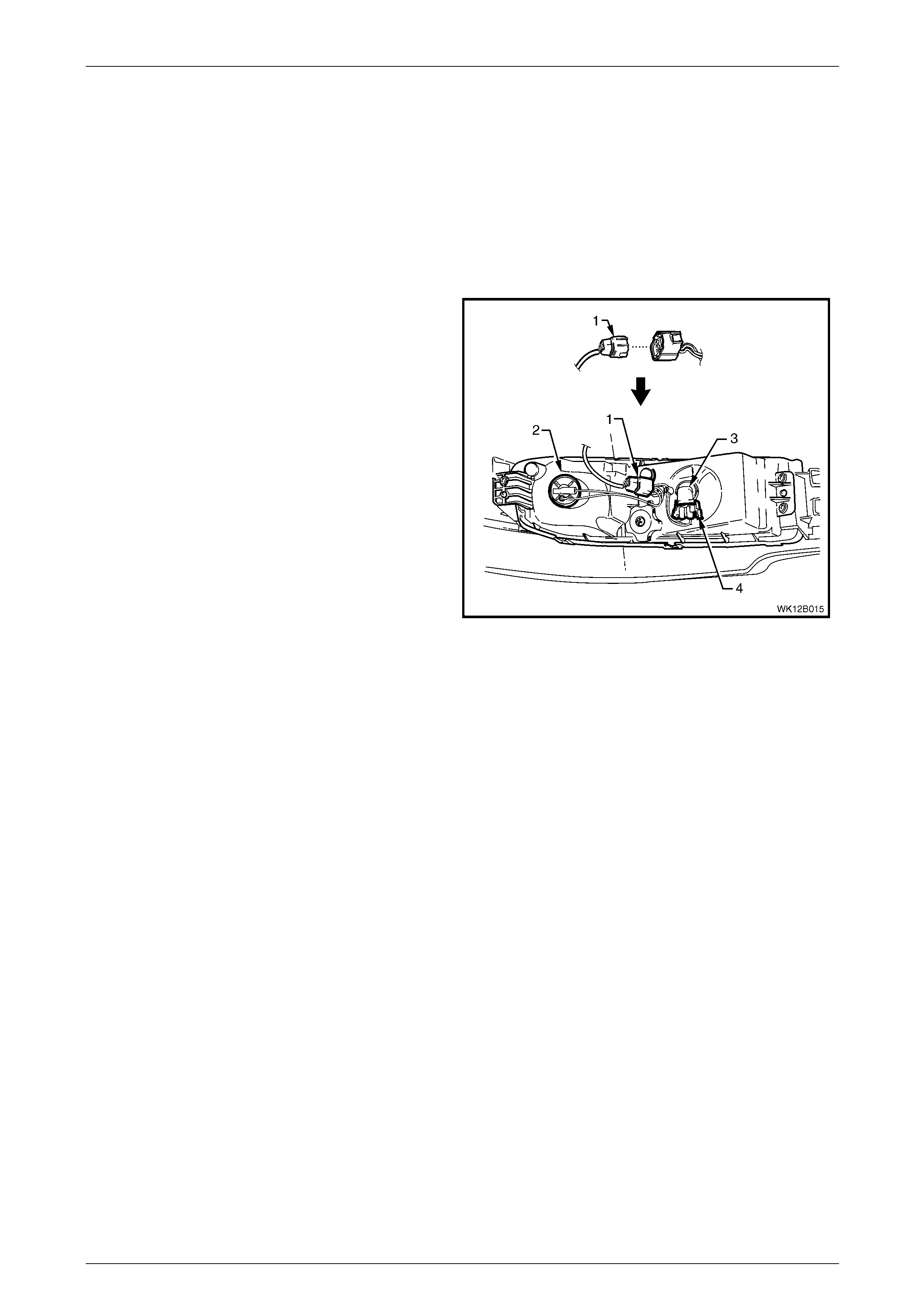
2.4 Front Fog Lamp and Cornering Lamp
Assembly Wiring Harness
LT Section No. — 02–325
Remove
1 Remove fusible link F102 from the engine compartment fuse and relay panel assemb ly, refer to
Section 12O Fuses, Relays and Wiring Harnesses.
2 From behind the front bumper fascia, disconnect the
main wiring harness (1) from the front fog lamp and
cornering lamp assembly wiring harness connector by
pressing the top tang and pulling the connectors
apart.
3 Twist the cornering lamp bulb socket (2) anticlockwise
and pull to remove the bulb socket from the lamp
assembly.
4 Disconnect the wiring connector (4) from the front fog
lamp bulb (3) by squeezing both side tangs together
and pulling the connector down from the bulb.
5 Unclip the wiring harness connector and wires from
the lamp assembly.
Figure 12B – 11
Reinstall
Reinstallation of the front fog lamp and cornering lamp wiring harness is the reverse of the removal procedure. Check the
operation of the front fog lamp and cornering lamps after reinstallation.
Lighting System Page 12B–17
Page 12B–17
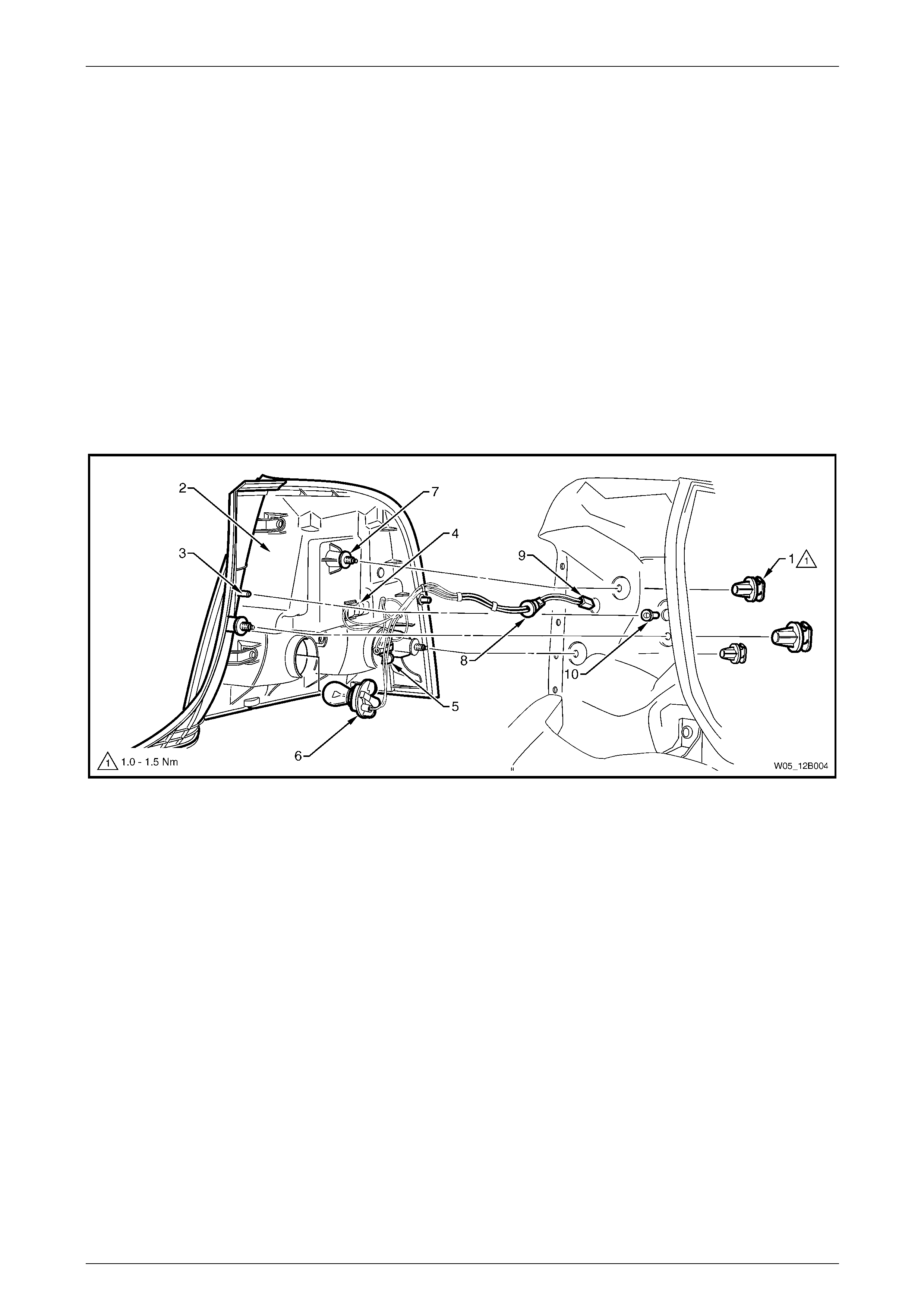
2.5 Tail Lamp Assembly Bulbs
LT Section No. — 02–350
Replace
NOTE
If any stop/tail lamp LEDs fail, replace the tail
lamp assembly.
1 Remove fusible link F102 from the engine compartment fuse and relay panel assemb ly, refer to
Section 12O Fuses, Relays and Wiring Harnesses.
2 Open the rear compartment lid.
3 Remove the quarter inner rear side carpet, refer to Section 1 A 8 Headlining and Interior Trim.
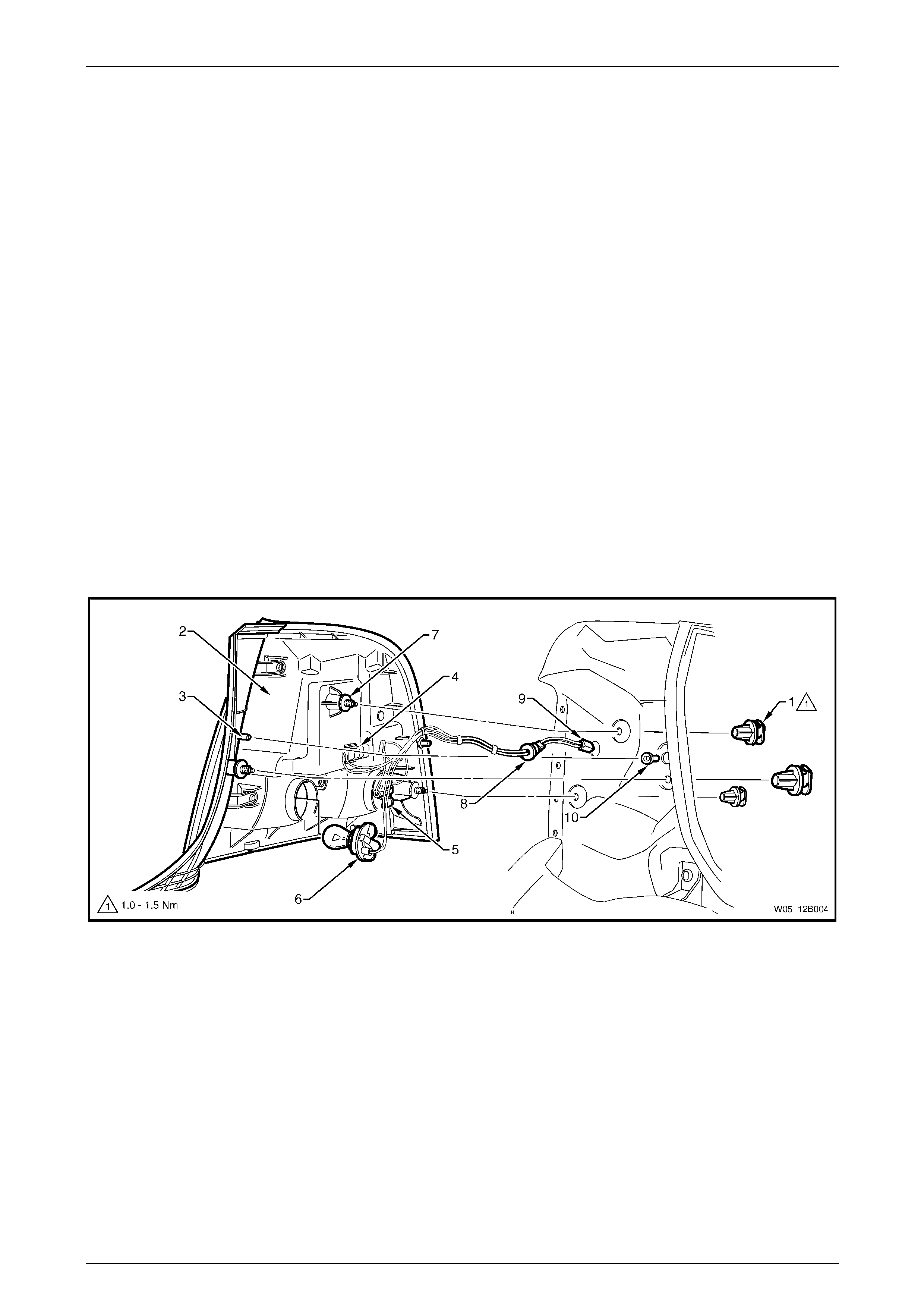
4 Remove the three tail lamp attaching nuts (1 ), refer to F igure 12B – 12.
Figure 12B – 12
Legend
1 Attaching Nut (3 places)
2 Tail Lamp Assembly
3 Pivot Pin
4 Stop/Tail Lamp LED Socket
5 Turn Signal Lamp Bulb Socket
6 Backup Lamp Bulb Socket
7 Locator Pin and Weather Seal Washer
8 Rubber Grommet
9 Harness Connector
10 Pivot Pin Locating Nutsert
5 From the exterior of the vehicle, pull the tail lamp assembly (2) away from the vehicle.
6 Remove the appropriate bulb socket (5 or 6) b y turning it anticlockwise and pulling it away from the tail la mp
assembly.
7 Remove the bulb from the bulb socket by pressing the bulb, then rotating it anticlockwise.
8 Inspect the bulb socket seal for damage and replace if necessary.
9 Insert a new bulb into the bulb socket and install it into the tail lamp assembly, ensuring it locks securely into place.

Lighting System Page 12B–18
Page 12B–18
NOTE
Bulb sockets have different lug configurations to
prevent installation into the incorrect tail lamp
assembly receptacle.
10 Install the tail lamp assembly onto the vehicl e.
11 Tighten the tail lamp assembly attaching nuts to the correct torque specification.
Tail lamp assembly attaching nut
torque specification.....................................1.0 – 1.5 Nm
12 Install fusible link F102 on the engine compartment fuse and relay panel assembly.
13 Check the tail lamp operation.

Lighting System Page 12B–19
Page 12B–19
2.6 Headlamp Assembly Aiming
During headlamp assembly aiming, use a
cloth or similar material to cover the lens of
the headlamp assembly being adjusted. Do
not cover the beam o f the headlamp asse mbly
not being adjusted. Damage to the headlamp
assembly will result if the headlamp beam is
obstructed in this manner.
The headlamp assemb lies must be correctly aimed to obtain the maximum road illumination and safety. Headlamps and
front fog lamps must be checked for correct aim whenever a bulb or lamp assembly is replaced and after any
adjustments or repairs to the front-end sheetmetal.
Headlamp aiming devices are in general use. When using one of these devices, ensure that it is in good condition;
carefully follow the instructions of the manufacturer.
Regardless of the method used for checking headlam p and front fog lamp aim, the vehicle must be at kerb weight (that
is, with full fuel level, oil, water and spare t yre , but no passengers). Tyres must be unifor mly inflated to their specified
pressure.
NOTE
If the vehicle regularly carries an unusual load in
the rear compartment or if it is used to tow a
trailer, these loads should be on th e vehic le when
the headlamps and front fog lamps are checked.
Headlamp Assembly Aim
LT Section No. — 02–300
NOTE
Use this procedure only when suitable test
equipment is unavailable.
1 Set up a screen or use a vertical wall with a flat
horizontal floor. Park the vehi cle immediately in front
of the screen or wall and mark the follo wing li nes:
a a vertical centre-line (3), corresponding to the
centre of the vehicle;
b two vertical lines (2 and 4), corresponding to the
centre of the low beam bulb on each side of the
vehicle; and
c a horizontal line (1) corresponding to the centre
of the low beam bulb.
2 Turn on the headlights to check if the marks are
correctly positioned. Figure 12B – 13
3 Reverse the vehicle straight back so the front is five metres in front of the screen or wall, ensuring the centre of the
vehicle is aligned with the vehicle centre-line mark (3) on the screen.
Lighting System Page 12B–20
Page 12B–20
4 Aim each headlamp to a point (1) on its vertical centre-
line, 55 mm below the headlamp horizontal centre-line.
Item 2 is the cut-off line. To adjust the headlamp
assembly, refer to Figure 12B – 15:
a Rotate the inboard adjuster (1) to move the
beam vertically.
b Rotate the outboard adjuster (2) to move the
beam horizontally.
Aiming directions for each adjuster are printed on the
headlamp assembly.
Figure 12B – 14
Figure 12B – 15
Legend
1 Inboard Adjuster 2 Outboard Adjuster
Lighting System Page 12B–21
Page 12B–21
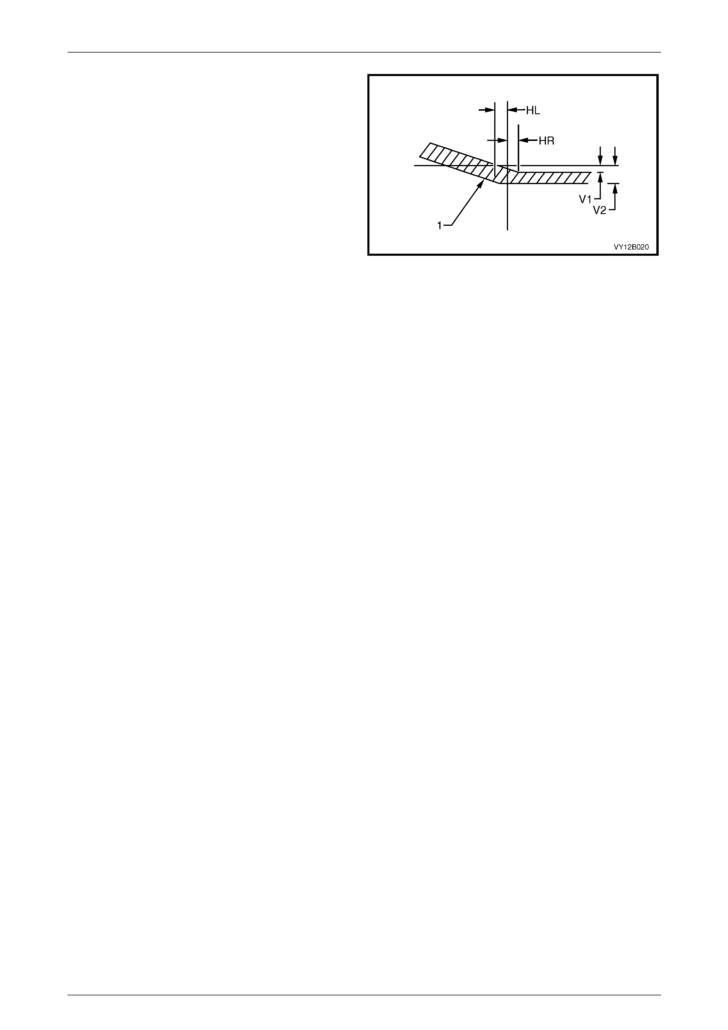
5 The allowable variations on headlamp aimin g point
settings shown in Figure 12B – 16 are:
HL 50 mm
HR 0 mm
V1 50 mm
V2 60 mm
Maximum allowable vertical variation between any pair of
headlamps must not exceed 1 0 mm.
NOTE
The cut-off line must be within the shaded
zone (1). Figure 12B – 16

Lighting System Page 12B–22
Page 12B–22
2.7 Headlamp Assembly
LT Section No. — 02–300
Remove
1 Remove fusible link F102 from the engine compartment fuse and relay panel assemb ly, refer to
Section 12O Fuses, Relays and Wiring Harnesses.
2 Remove the front bumper fascia assembly, refer to Section 1D Bumper Bars.
3 Remove the front fascia support, refer to Section 1D Bumper Bars.
4 If required, for vehicles with a GEN III V8 engine, remove the four retainers securing the upper ra diator shroud and
remove the shroud, refer to Section 6B3 Engine Cooling — GEN III V8.
5 For the right-hand headlamp assembly, it may be necessary to remove the battery to gain the required access.
a If required, remove the battery hold-down bracket and move the battery to gain access, refer to
Section 12A Battery.
Disconnection of the battery affects certain
vehicle electronic systems. Refer to
Section 00 Warnings, Cautions and Notes
before disconnecting the battery.
b If further access is required, remove the battery terminals from the battery and remove the battery from the
engine compartment, refer to Section 12A Battery.
6 For left-hand headlamp assemblies on vehicles with a V6 engine, remove the coolant filler bottle neck and plac e in
a safe location away from the immediate worksite.
7 Disconnect the turn signal and headlamp wiring harness connectors (1 and 2) from the rear of the headlamp
assembly (3), refer to Figure 12B – 17.
8 Remove the three headlamp retaining screws (4, 5 and 6) and remove the headlamp assembly.
Figure 12B – 17

Lighting System Page 12B–23
Page 12B–23
Legend
1 Turn Signal Lamp Wiring Harness Connector
2 Harness Wiring Harness Connector
3 Headlamp Assembly
4 Headlamp Retaining Screw
5 Headlamp Retaining Screw
6 Headlamp Retaining Screw
Reinstall
Reinstallation of the headlamp assembly is the reverse of the removal procedure, noting the following:
1 Install the headlamp assembly and tighten the headlamp retaining screws to the correct torque specification.
Headlamp assembly retaining
screw torque specification...........................2.0 – 5.0 Nm
2 Connect all wiring harness co nnectors, then check the headlamp, turn signal and park l amp operation.
3 Install the front bumper fascia assembly, refer to Section 1D Bumper Bars.
4 Check the headlamp and front fog lamp op eration, and adjust the aim, refer to 2.6 Headlamp Assembly Aiming.

Lighting System Page 12B–24
Page 12B–24
2.8 Headlamp and Park Lamp Assembly
Bulbs
LT Section No. — 02–300
Replace — Low Beam Bulb
1 Remove fusible link F102 from the engine compartment fuse and relay panel assemb ly, refer to
Section 12O Fuses, Relays and Wiring Harnesses.
2 Open the hood and disconnect the wiring harness connector from the rear of the appropriate headlamp assemb ly.
3 If required, for vehicles with a GEN III V8 engine, remove the four retainers securing the upper ra diator shroud and
remove the shroud, refer to Section 6B3 Engine Cooling — GEN III V8.
4 For the right-hand headlamp assembly, it may be necessary to remove the battery to gain the required access:
a If required, remove the battery hold-down bracket and move the battery to gain access, refer to
Section 12A Battery.
Disconnection of the battery affects certain
vehicle electronic systems. Refer to
Section 00 Warnings, Cautions and Notes
before disconnecting the battery.
b If further access is required, remove the battery terminals from the battery and remove the battery from the
engine compartment, refer to Section 12A Battery.
NOTE
For vehicles with a GEN III V8 engine, access the
left-hand bulb via the hole in the top of the air
intake duct.
5 For left-hand headlamp assemblies on vehicles with a V6 engine, remove the coolant filler bottle neck and plac e in
a safe location away from the immediate worksite.
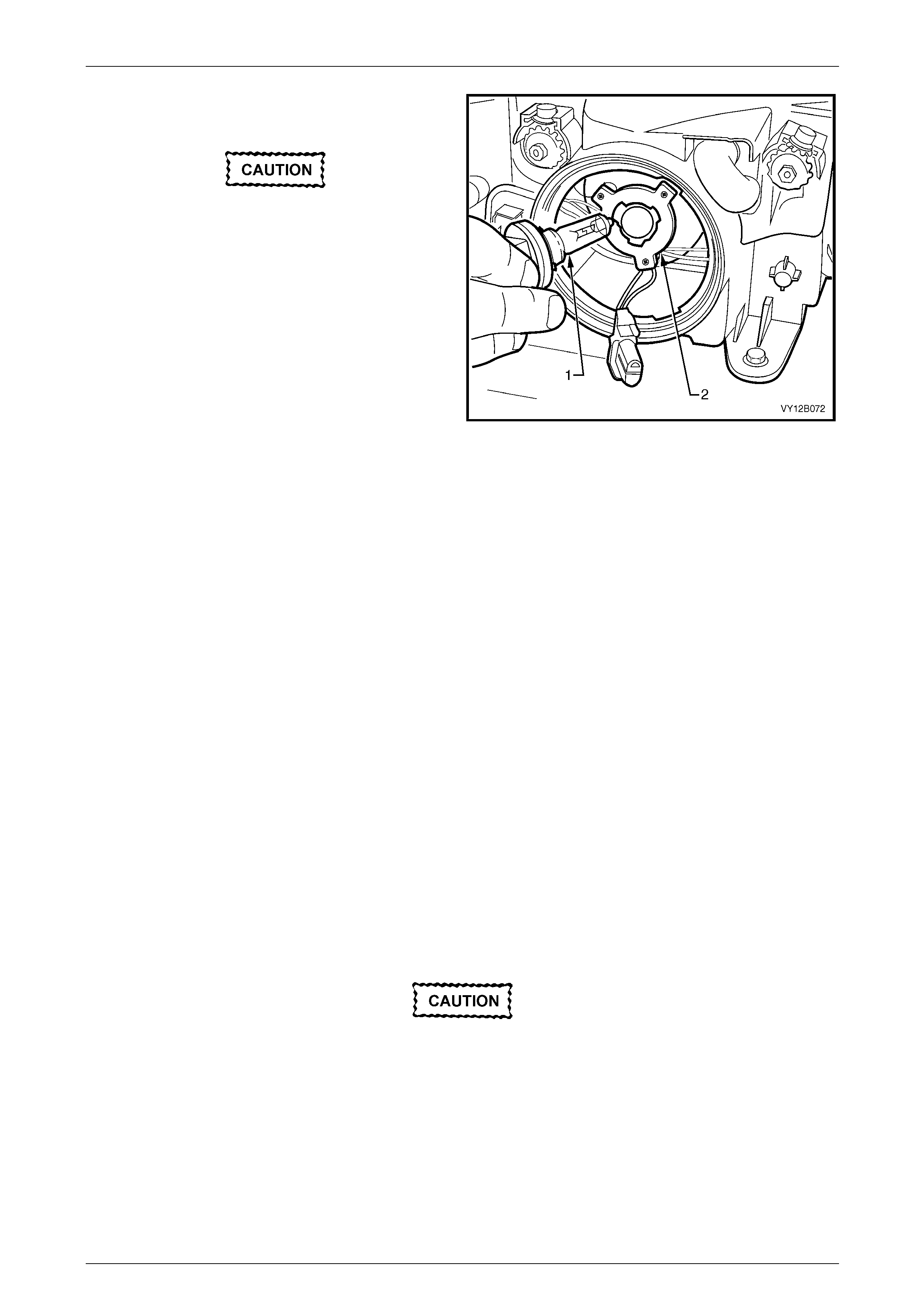
6 Remove the outboard dust cap (1) from the rear of the
headlamp assembly (2) by turning the dust cap
anticlockwise, then pulling it away from the assembly.
If the dust cap seal stays on the headlamp assembl y,
remove the seal and install it onto the dust cap.
7 Disconnect the wiring harness connector (3) from the
rear of the bulb (4) by squeezing both tangs together
and pulling the connector down from the bulb.
Figure 12B – 18
Lighting System Page 12B–25
Page 12B–25
8 Rotate the bulb (1) anticlockwise and rem ove the bulb
from the bulb holder (2).
Do not handle the quartz envelope of the
headlamp bulb. Wipe the quartz envelope
immediately with methylated spirits if it is
touched accidentally or the performance of
the bulb will deteriorate.
9 Install a new bulb into the bulb holder. Lock the bulb in
place by turning it clockwise. Fit the bulb connector by
pushing it into the base of the bulb until the tangs
engage.
NOTE
The different-sized locating lugs on the bulb
base and mating cut-outs in the bulb holder
allow the bulb to seat correctly i n one orientation
only. This ensures the correct positioning
between the bulb and the reflector. Figure 12B – 19
10 Inspect the seal on the dust cap to ensure it is not damaged and it is seated correctly in the dust cap. Replace the
seal if it is damaged.
11 Install the dust cap onto the rear of the headlamp assembly. The different-s ized lugs on the dust cap and the
mating cut-outs on the headlamp assembl y ensure the dust cap can be installed in only one or ientation. The
chamfered flats of the dust cap must face inboard for the dust cap to install correctly. Lock the dust cap into place
by turning it clockwise.
12 Connect the wiring harness connector to the rear of the headlamp assembly.
13 If required, install the coolant filler bottle neck, upper radiator shroud and ba ttery.
14 Install fusible link F102 on the engine compartment fuse and relay panel assembly.
15 Check the headlamp operatio n and adjust the aim; the position of the bulb filament with respect to the reflector may
have changed, refer to 2.6 Headlamp Asse mbly Aiming.
Replace — High Beam Bulb
1 Remove fusible link F102 from the engine compartment fuse and relay panel assemb ly, refer to
Section 12O Fuses, Relays and Wiring Harnesses.
2 Open the hood and disconnect the wiring harness connector from the rear of the appropriate headlamp assemb ly.
3 If required, for vehicles with a GEN III V8 engine, remove the four retainers securing the upper ra diator shroud and
remove the shroud, refer to Section 6B3 Engine Cooling — GEN III V8.
4 For the right-hand headlamp assembly, it may be necessary to remove the battery to gain the required access:
a If required, remove the battery hold-down bracket and move the battery to gain access, refer to
Section 12A Battery.
Disconnection of the battery affects certain
vehicle electronic systems. Refer to
Section 00 Warnings, Cautions and Notes
before disconnecting the battery.
b If further access is required, remove the battery terminals from the battery and remove the battery from the
engine compartment, refer to Section 12A Battery.
NOTE
For vehicles with a GEN III V8 engine, access the
left-hand bulb via the hole in the top of the air
intake duct.
Lighting System Page 12B–26
Page 12B–26
5 For left-hand headlamp assemblies on vehicles with a V6 engine, remove the coolant filler bottle neck and plac e in
a safe location away from the immediate worksite.
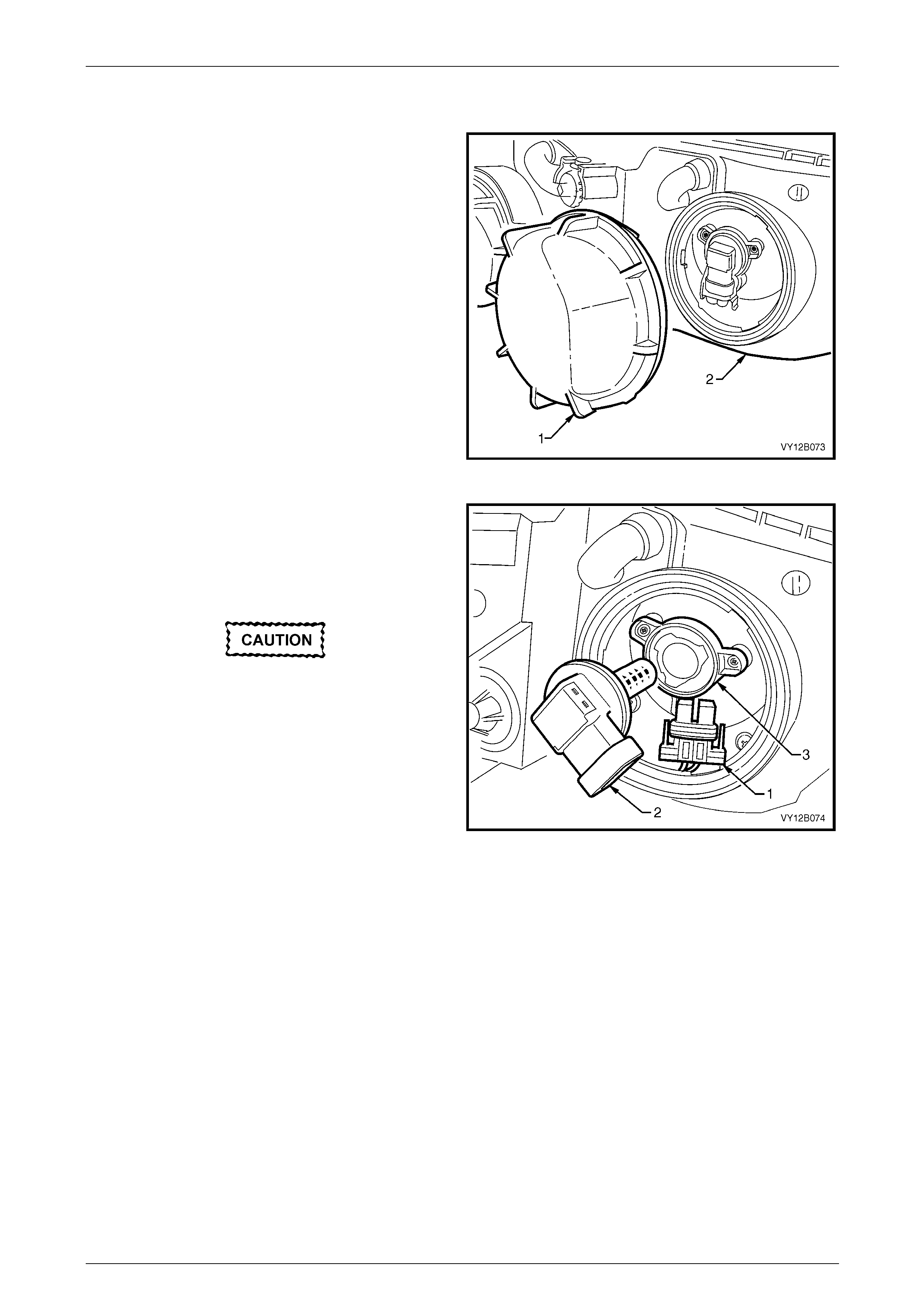
6 Remove the inboard high beam dust cap (1) from the
rear of the headlamp assembly (2) by turning the dust
cap anticlockwise, then pulli ng it away from the
headlamp assembly. If the dust cap seal stays on the
headlamp assembly, remove the seal and install it
onto the dust cap.
Figure 12B – 20
7 Disconnect the wiring connector (1) from the bul b by
squeezing both tangs together and pulling the
connector down from the bulb .
8 Rotate the bulb (2) anticlockwise and rem ove the bulb
from the bulb holder (3).
Do not handle the quartz envelope of the
inboard high beam bulb. Wipe the quartz
envelope immediately w ith methylated spirits
if it is touched accidentally or the perform-
ance of the bulb will deteriorate.
9 Install a new bulb into the bulb holder. Lock the bulb in
place by turning it clockwise. Fit the bulb connector by
pushing it into the base of the bulb until the tangs
engage.
Figure 12B – 21
NOTE
The different-sized locati ng lugs on the bulb base
and mating cut-outs in the bulb holder allow the
bulb to seat correctly in one orientation on ly. This
ensures the correct positioning between the bulb
and the reflector.
10 Inspect the seal on the dust cap to ensure it is not damaged and it is seated correctly on the dust cap. Replace the
seal if it is damaged.
11 Install the dust cap onto the rear of the headlamp assembly. The different-s ized lugs on the dust cap and the
mating cut-outs in the headlamp assembly ensure the dust cap can be installed on ly in one orientation. The
chamfered flats of the dust cap must face inboard for the dust cap to install correctly. Lock the dust cap into place
by turning it clockwise.
12 Connect the wiring harness connector to the rear of the headlamp assembly.
13 If required, install the coolant filler bottle neck, upper radiator shroud and ba ttery.
14 Install fusible link F102 on the engine compartment fuse and relay panel assembly.
Lighting System Page 12B–27
Page 12B–27
Replace — Park Lamp Bulb
1 Remove fusible link F102 from the engine compartment fuse and relay panel assemb ly, refer to
Section 12O Fuses, Relays and Wiring Harnesses.
2 Open the hood and disconnect the wiring harness connector from the rear of the appropriate headlamp assemb ly.
3 If required, for vehicles with a GEN III V8 engine, remove the four retainers securing the upper ra diator shroud and
remove the shroud, refer to Section 6B3 Engine Cooling — GEN III V8.
4 For the right-hand headlamp assembly, it may be necessary to remove the battery to gain the required access:
a If required, remove the battery hold-down bracket and move the battery to gain access, refer to
Section 12A Battery.
Disconnection of the battery affects certain
vehicle electronic systems. Refer to
Section 00 Warnings, Cautions and Notes
before disconnecting the battery.
b If further access is required, remove the battery terminals from the battery and remove the battery from the
engine compartment, refer to Section 12A Battery.
NOTE
For vehicles with a GEN III V8 engine, access the
left-hand bulb via the hole in the top of the air
intake duct.
5 For left-hand headlamp assemblies on vehicles with a V6 engine, remove the coolant filler bottle neck and plac e in
a safe location away from the immediate worksite.
6 Remove the park bulb socket (1) from the headlamp
assembly (2) by rotating it anticlockwise, then pulling it
away from the headlamp assembly.
7 Pull the bulb (3) away from the park bulb socket. Insert
a new bulb into the park bulb socket.
8 Inspect the seal on the park bulb socket to ensure it is
not damaged and it is seated correctly. Replace the
seal if it is damaged.
9 Install the park bulb socket into the rear of the
headlamp assembly and lock into place by turning it
clockwise. Connect the wiring harness con ne c tor to
the rear of the headlamp assembly.
Figure 12B – 22
10 If required, install the coolant filler bottle neck, upper radiator shroud and ba ttery.
11 Install fusible link F102 on the engine compartment fuse and relay panel assembly.
12 Check the park lamp operation.
Lighting System Page 12B–28
Page 12B–28
2.9 Front Turn Signal Lamp Bulb
The turn signal lamp bulb and socket is situated on the outboard extremity of each headlamp assembly. The turn signal
bulb socket is orange and has a separate wiring connector to the headlamp assembly.
Replace
LT Section No. — 02–300
1 Remove turn signal lamp fuse F12, refer to Section 12O Fuses, Relays and Wiring Harnesses.
2 If required, for vehicles with a GEN III V8 engine, remove the four retainers securing the upper ra diator shroud and
remove the shroud, refer to Section 6B3 Engine Cooling — GEN III V8.
3 For the right-hand headlamp assembly, it may be necessary to remove the battery to gain the required access:
a If required, remove the battery hold-down bracket and move the battery to gain access, refer to
Section 12A Battery.
Disconnection of the battery affects certain
vehicle electronic systems. Refer to
Section 00 Warnings, Cautions and Notes
before disconnecting the battery.
b If further access is required, remove the battery terminals from the battery and remove the battery from the
engine compartment, refer to Section 12A Battery.
NOTE
For vehicles with a GEN III V8 engine, access the
left-hand bulb via the hole in the top of the air
intake duct.
4 For left-hand headlamp assemblies on vehicles with a V6 engine, remove the coolant filler bottle neck and plac e in
a safe location away from the immediate worksite.
5 Disconnect the turn signal wiring harness co nnector
from the turn signal bulb socket (1).
6 Remove the turn signal bulb socket from the headlamp
assembly (2) by rotating it anticlockwise, then pulling it
away from the headlamp assembly.
7 Press the bulb (3) into the turn signal bul b socket and
rotate anticlockwise, then remove it from the reflector.
8 Inspect the seal on the turn signal bulb sock et for
damage and correct seating. Replace the seal if
necessary.
9 Install the new bulb into the turn signal bulb socket.
Install the turn signal bulb socket into the headlamp
assembly and lock it into place by turning it clockwise.
10 Connect the wiring harness connector to the turn
signal bulb socket.
11 If required, install the coolant filler bottle neck, upper
radiator shroud and battery. Figure 12B – 23
12 Fit turn signal lamp fuse F12.
13 Check the turn signal lamp operatio n.
Lighting System Page 12B–29
Page 12B–29
2.10 Front Fog Lamp and Cornering Lamp
Assembly
LT Section No. — 02–325
NOTE
For removal and installation of the front fog lamp
and cornering lamp assembly fitted with a metal
strip bracket attached to the front bumper fascia,
refer to Section 1D Bumper Bars.
Remove
1 Remove fusible link F102 from the engine compartment fuse and relay panel assemb ly, refer to
Section 12O Fuses, Relays and Wiring Harnesses.
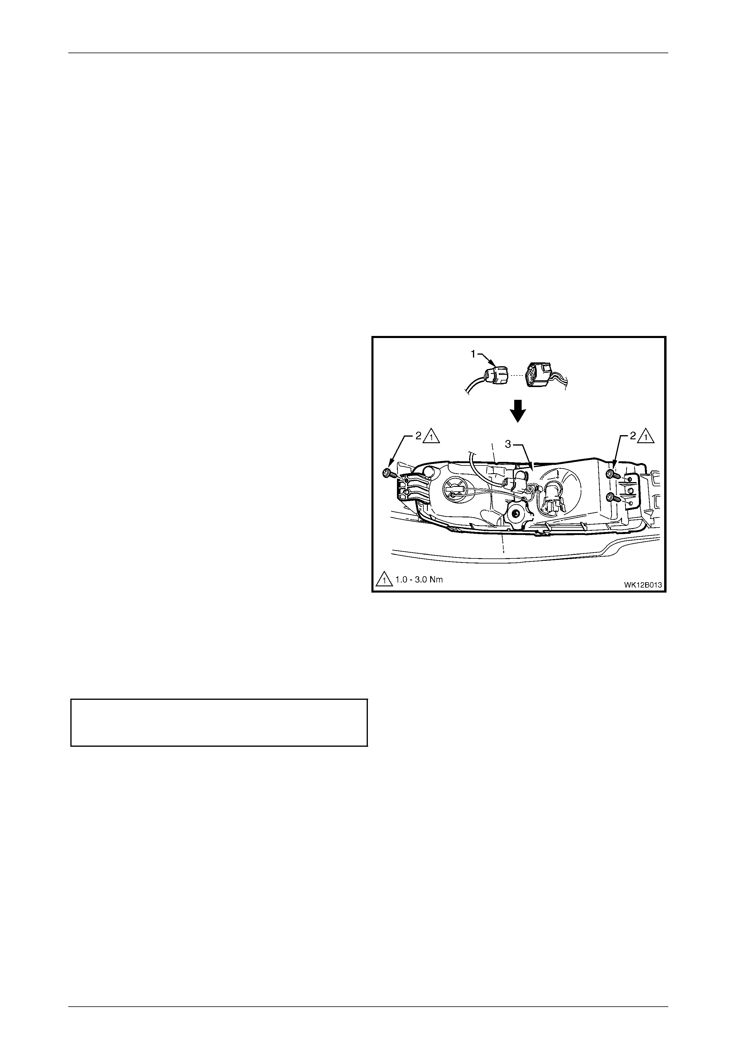
2 From behind the front bumper fascia, disconnect the
main wiring harness (1) from the front fog lamp and
cornering lamp assembly wiring harness connector by
squeezing the top tang and p ulling the connectors
apart.
3 Remove the three screws (2) securing the la mp
assembly (3).
4 Carefully pull the outboard end of the assembly away
from the front bumper fascia assembly mounting p in.
5 Slide the inboard end of the assembly from behind the
lower grille mounting lug, then away from the front
bumper fascia assembly mounting pin.
Figure 12B – 24
Reinstall
Reinstallation of the front fog lamp and cornering lamp assembly is the reverse of the removal proced ure. Tighten the
three screws attaching the lamp assembly to the front bumper fascia assembly to the correct torque specification.
Front fog lamp and corneri ng
lamp assembly attaching screw
torque specification.....................................1.0 – 3.0 Nm
Lighting System Page 12B–30
Page 12B–30
2.11 Tail Lamp Assembly
Remove
NOTE
If any stop/tail lamp LEDs fail, replace the tail
lamp assembly.
1 Remove fusible link F102 from the engine compartment fuse and relay panel assemb ly, refer to
Section 12O Fuses, Relays and Wiring Harnesses.
2 Open the rear compartment lid.
3 Remove the convenience net, refer to Section 1A8 Headlining and Interior T r im.
4 Remove the quarter inner rear side carpet, refer to Section 1 A8 Headlining and Interior Trim.
5 Unscrew the three tail lamp attaching nuts (1), refer to Figure 12B – 25.
6 From the exterior of the vehicle, pull the tail lamp assembly away from the vehicle and support the assembly.
7 Remove all the bulb sockets (5 and 6) by turnin g the sockets anticlockwise and pulling them away from the
reflector.
8 If removing the tail lamp assembly wiring h arness:
a Disconnect the tail lamp assembl y wiring h arness connector (9) from the body wiring harness.
b Pull the rubber grommet (8) away from the sheetmetal and remove the harness.
Figure 12B – 25
Legend
1 Attaching Nut (3 places)
2 Tail Lamp Assembly
3 Pivot Pin
4 Stop/Tail Bulb socket
5 Turn Signal Bulb socket
6 Backup Bulb socket
7 Locator Pin and Weather Seal Washer
8 Rubber Grommet
9 Harness Connector
10 Pivot Pin Locating Nutsert

Lighting System Page 12B–31
Page 12B–31
Reinstall
Reinstallation of the tail lamp assembly is the reverse of the removal procedure, noting the following:
1 Inspect the bulb socket to lamp assembly seals for damage and replace if required.
2 If required, replace the tail lamp wiring har ness.
3 Ensure the bulb sockets are correctly installed into the tail lamp assembly.
NOTE
Bulb sockets have different lug configurations to
prevent installation into the incorrect tail lamp
assembly receptacle.
4 Ensure the weather seal washer is fitted to the outboard tail lamp locator pin (7), refer to Figure 12B – 25.
5 Check that the pivot pin locating nutsert (10) is securely located in place.
6 Tighten the tail lamp assembl y attaching nuts (1) to the correct torque specification.
Tail lamp assembly attaching nut
torque specification.....................................1.0 – 1.5 Nm
Lighting System Page 12B–32
Page 12B–32
2.12 Side Repeater Lamp Assembly
LT Section No. — 02–300
Remove
1 Remove turn signal lamp fuse F12, refer to
Section 12O Fuses, Relays and Wiring Harnesses.
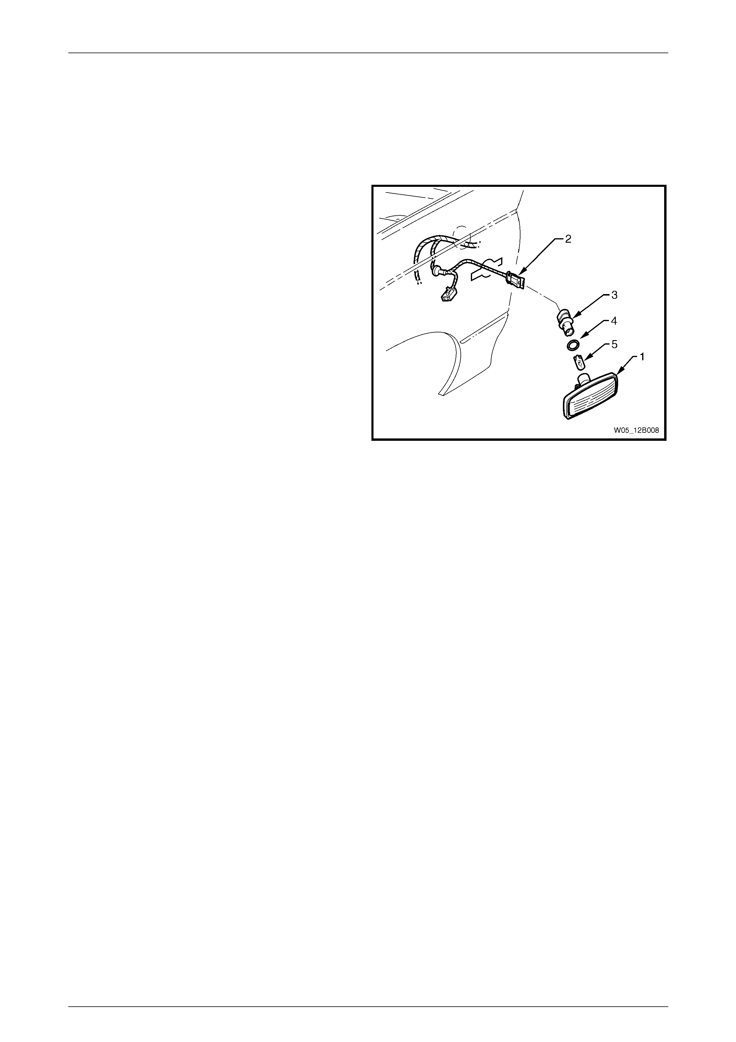
2 Grip the rear edge of the side repeater lamp
assembly (1) with finger tips and pull it forward, then
outwards and away from the front fender.
3 Disconnect the side repeater lamp assembly wiring
harness connector (2) from the front side turn signal
lamp assembly.
NOTE
Tape the side repeater lamp assembly wiring
harness to the front fender so the side turn
signal lamp assembly wiring harness and the
connector do not fall into the front fender.
4 Twist and remove the bulb socket (3), O-ring (4) and
bulb (5) from the side repeater lamp assembly.
5 If required, pull the bulb from the bulb socket. Figure 12B – 26
Reinstall
1 If required, install a new bulb into the bulb socket.
2 Inspect the side repeater lamp assembly and O-ring for damage and replace if necessary.
3 Insert the bulb socket into the side repeat er lamp assembly and twist to lock into position. Connect the si de
repeater lamp assembly wiring harness connector to the si de repeater lamp assembly.
4 Install turn signal lamp fuse F12 and check the operation of the lamp assembly.
5 Place the rear of the side repeater lamp ass embl y into the fender an d place the locking tab into the forward end of
the fender aperture. Push the front of the side repeater lamp assembly towards the fender to engage the locking
tab.
Lighting System Page 12B–33
Page 12B–33
2.13 High-mount Stop Lamp Assembly
LT Section No. — 02–350
Bulb Replacement
1 Remove fusible link F102 from the engine compartment fuse and relay panel assemb ly, refer to
Section 12O Fuses, Relays and Wiring Harnesses.
2 Open the rear compartment lid.
3 From under the rear window panel assembly, twist the
bulb socket to release it from the high-mount stop
lamp assembly. Pull the bulb socket down, into the
rear compartment.
NOTE
It may be necessary to use a pair of pointed
nose pliers to hold the bulb socket and release
the bulb.
4 Pull the bulb from the bulb socket.
5 Install a new bulb into the bulb socket and install the
bulb socket into the high-mount stop lamp assembly.
Twist the bulb socket and lock it into place.
6 Install fusible link F102 on the engine compartment
fuse and relay panel assembly and check the
operation of the high-mount stop lamp ass embly. Figure 12B – 27
Remove
1 Remove fusible link F102 from the engine compartment fuse and relay panel assemb ly, refer to
Section 12O Fuses, Relays and Wiring Harnesses.
2 Remove the rear parcel shelf trim, refer to
Section 1A8 Headlining and Interior Trim.
3 Remove the bulb socket from the tail lamp
assembly (1), refer to Bulb Replacement.
4 From under the rear window panel assembly,
disengage the retaining cl ips (2) securing the high-
mount stop lamp assembly to the rear window panel
assembly. Remove the high-mount stop la mp
assembly.
Figure 12B – 28
Reinstall
Reinstallation of the high-mo unt stop lamp assembly is the reverse of the removal procedure. Ensure the high-mount
stop lamp assembly is pushed fully rearward before engaging the retaining clips.
Lighting System Page 12B–34
Page 12B–34
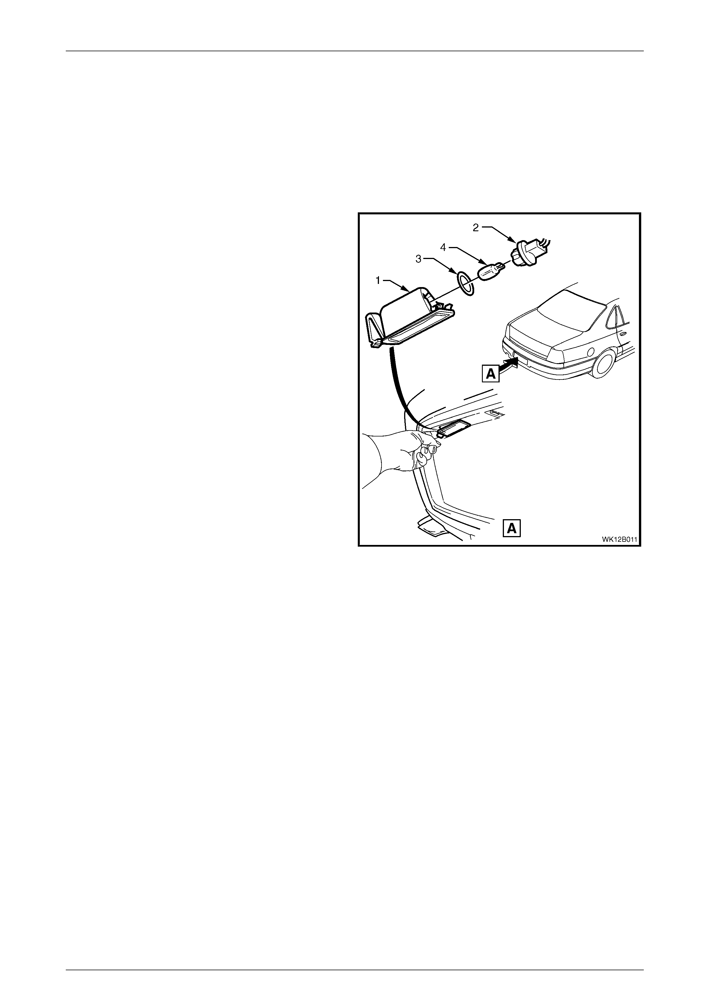
2.14 Rear Licence Plate Lamp Assembly
LT Section No. — 02–385
Remove
1 Remove fusible link F102 from the engine compartment fuse and relay panel assemb ly, refer to
Section 12O Fuses, Relays and Wiring Harnesses.
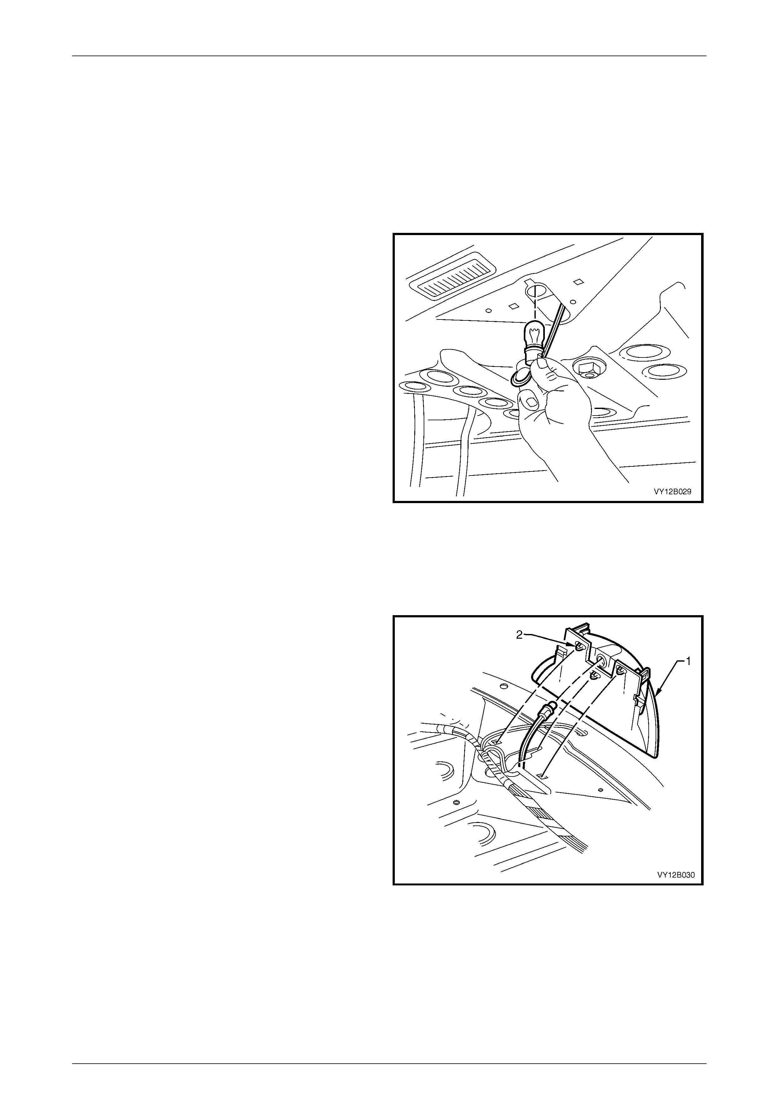
2 Push the locking tang located at the end of the rear
licence plate lamp housing (1) towards the lens. Pivot
the rear licence plate lamp housing down and remove
it from the aperture.
3 Remove the bulb socket (2) from the rear licence plate
lamp housing.
4 If required, replace the bulb (3) by pulling it from the
bulb socket and installing a new bulb.
5 Inspect the bulb socket seal (4) for damage and
replace if required.
Figure 12B – 29
Reinstall
Reinstallation of the rear licence plate lamp assembly is the reverse of the removal procedur e, noting the following:
1 If required, push a new bulb into the rear licence plate bu lb socket.
NOTE
The rear licence plate lamp housing installs into
the aperture in one direction only.
2 Install fusible link F102 on the engine compartment fuse and relay panel assembly.
3 Check the rear licence plate lamp assembly oper ation.

Lighting System Page 12B–36
Page 12B–36
3 Service Operations — Interior
Illumination and Switching
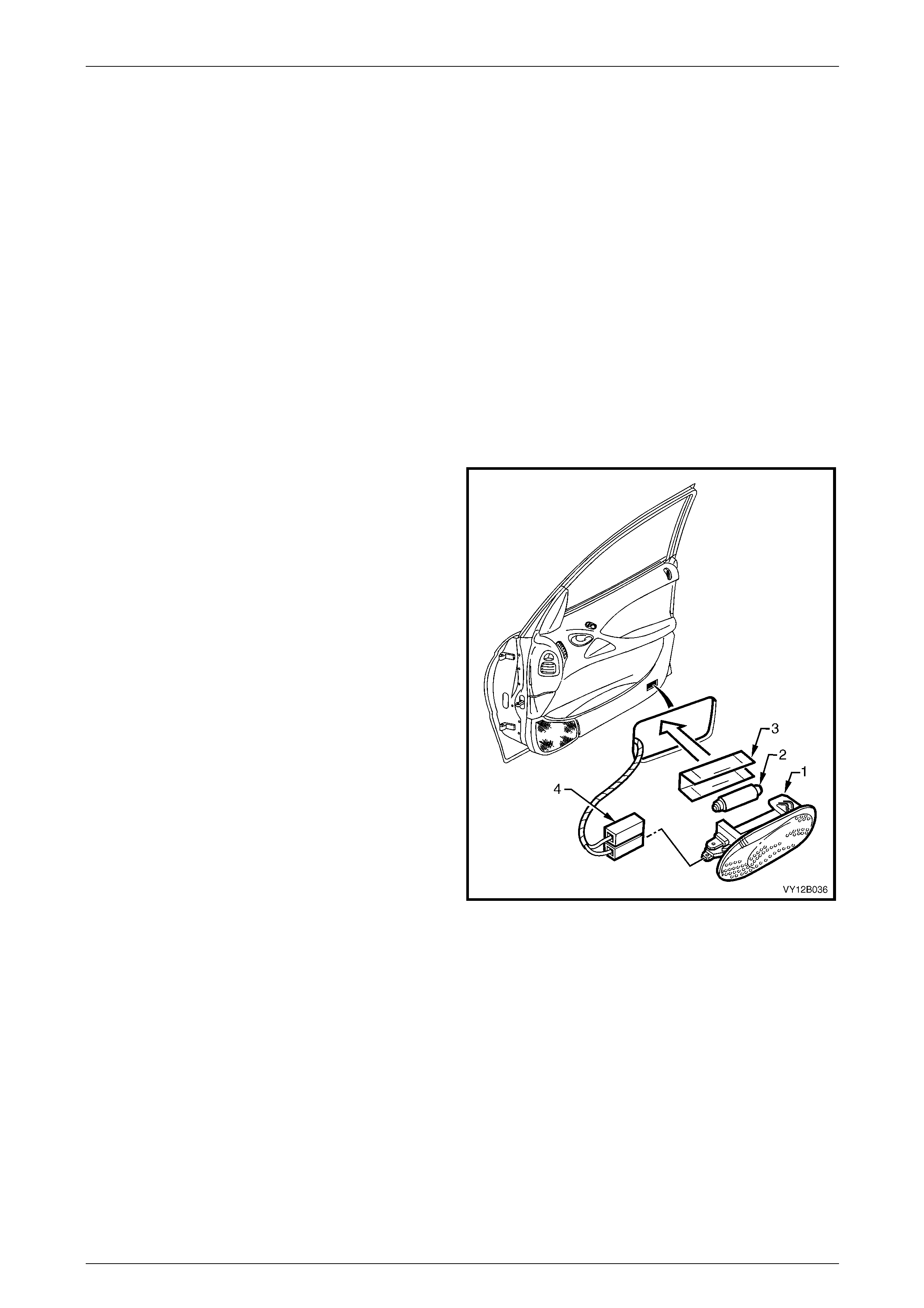
3.1 Side Door Courtesy Lamp Assembly
LT Section No. — 02–780
NOTE
Refer to Figure 12B – 30 for a view of the front
door assembly. The rear door assembly is
similar.
Remove
1 Remove fusible link F102 from the engine compartment fuse and relay panel assemb ly, refer to
Section 12O Fuses, Relays and Wiring Harnesses.
2 Insert a fine-bladed screwdriver into the notch at the
bottom edge of the lamp and press the locking tang.
3 Prise the side door courtesy lamp assembly (1) from
the door trim assembly.
4 Disconnect the side door courtesy lamp assembly
wiring harness connector (4) from the side door
courtesy lamp assembly.
5 If removing the bulb from the lamp:
a Pull the protective metal cover (3) from the rear
of the lamp to access the bulb (2).
b Bend back the lever contact retaining the bulb,
then remove the bulb.
6 Check the side door courtesy lamp assembly for
damage and replace if necessary.
NOTE
Ensure the side door courtesy lamp assembly
wiring harness connector does not fall into the
door cavity.
Figure 12B – 30
Reinstall
Reinstallation of the side doo r courtesy lamp assembly is the reverse of the removal procedure, noting the following:
1 If required, insert a new bulb into the side door courtesy lamp assemb ly.
2 Ensure the lens of the side door courtesy lamp assembly is flush with the side of the door trim assembly.
3 Check the side door courtesy lamp ass embl y operation.
Lighting System Page 12B–37
Page 12B–37
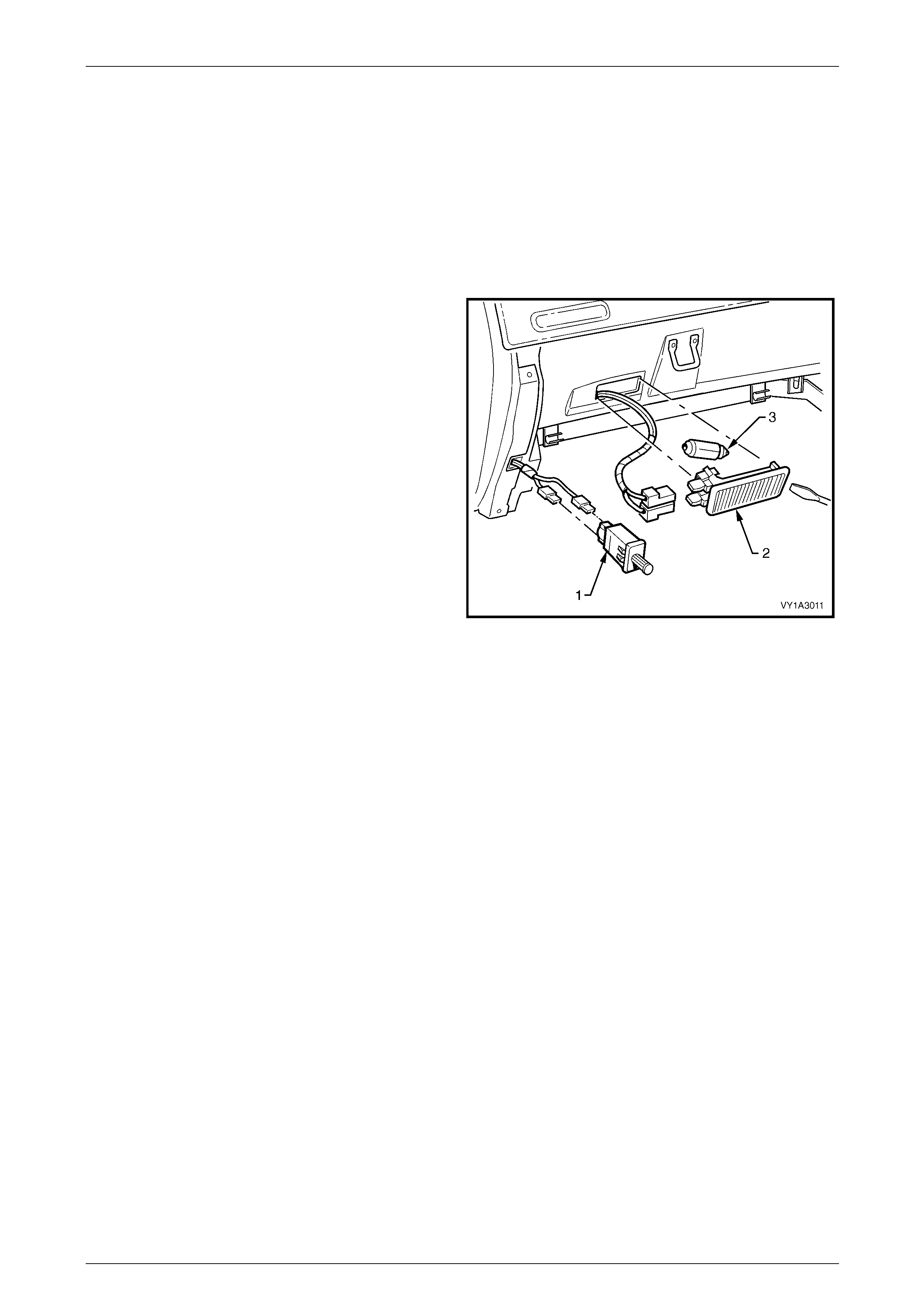
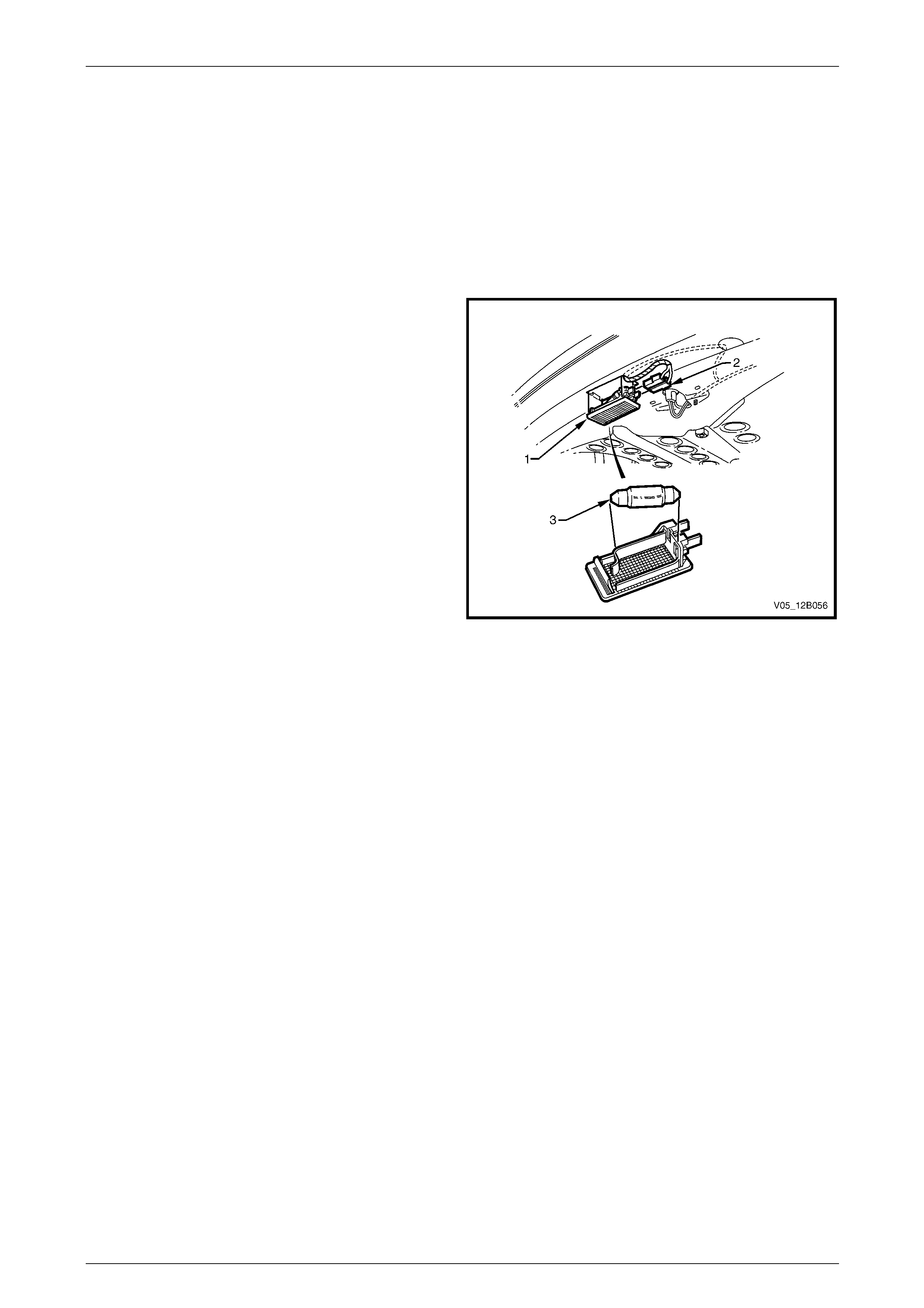
3.2 Instrument Panel Compartment Lamp
Assembly
LT Section No. — 02–780
Remove
1 Remove fusible link F102 from the engine compartment fuse and relay panel assemb ly, refer to
Section 12O Fuses, Relays and Wiring Harnesses.
2 Prise the instrument panel compartment lamp
assembly (2) from the compartment using a fine-
bladed screwdriver.
3 Disconnect the instrument panel compartme nt lamp
assembly wiring harness connector from the
instrument panel compartment lamp assembly. Check
the instrument panel compartment lamp assembly for
damage and replace if necessary.
NOTE
Ensure the instrument panel compartment lamp
assembly wiring harness connector does not fall
into the cavity behind the instrument panel
compartment.
4 If necessary, remove the bulb (3) from the instrument
panel compartment lamp assembly by pressing the
metal contact.
Figure 12B – 31
Reinstall
Reinstallation of the instrument panel compartment lamp assembly is the reverse of the removal procedure, notin g the
following:
1 Insert a new bulb in the instrument panel compartment lamp assembl y if required.
2 Ensure the lens is flush with the instrument panel compartment.
3 Check the instrument panel compartment lamp assemb ly operation.

Lighting System Page 12B–38
Page 12B–38
3.3 Instrument Panel Compartment Lamp
Switch Assembly
LT Section No. — 02–780
Remove
1 Remove fusible link F102 from the engine compartment fuse and relay panel assemb ly, refer to
Section 12O Fuses, Relays and Wiring Harnesses.
2 Prise the instrument panel compartment lamp switch assembly (1) from the instrument panel compartment lamp
assembly using a fine-bladed screwdriver, refer to Figure 12B – 31.
3 Disconnect the instrument panel compartme nt lamp assembly wiring harness connectors from the instrument panel
compartment lamp assembly. Check the inst rument panel compartment lamp switch assembly for damage and
replace if necessary.
NOTE
Ensure the instrument panel compartment lamp
assembly wiring harness connector does not fall
into the cavity behind the instrument panel
compartment.
Reinstall
Reinstallation of the instrument panel compartment lamp switch assembly is the reverse of the removal procedure.
Check the instrument panel compartment lamp switch assembly operation.
Lighting System Page 12B–39
Page 12B–39
3.4 Rear Compartment Courtesy Lamp
Assembly
LT Section No. — 02–780
Remove
1 Remove fusible link F102 from the engine compartment fuse and relay panel assemb ly, refer to
Section 12O Fuses, Relays and Wiring Harnesses.
2 Prise the rear compartment courtesy lamp
assembly (1) from the mating surface using a fine-
bladed screwdriver.
3 Disconnect the rear compartment courtesy lamp
assembly wiring harness connector (2) from the rear
compartment courtesy lamp assembly. Check the
lamp assembly for damage and replace if necessary.
4 If necessary, remove the bulb (3) from the rear
compartment courtesy lamp assembly by pressing the
metal contact.
Figure 12B – 32
Reinstall
Reinstallation of the rear com partment courtesy lamp assembly is the reverse of the removal procedure, noting the
following:
1 Insert a new bulb in the rear compartment courtesy lamp assembly if requ ired.
2 Ensure the lens is flush with the rear compartment roof.
3 Check the rear compartment courtes y lam p assemb ly operation.
Lighting System Page 12B–40
Page 12B–40
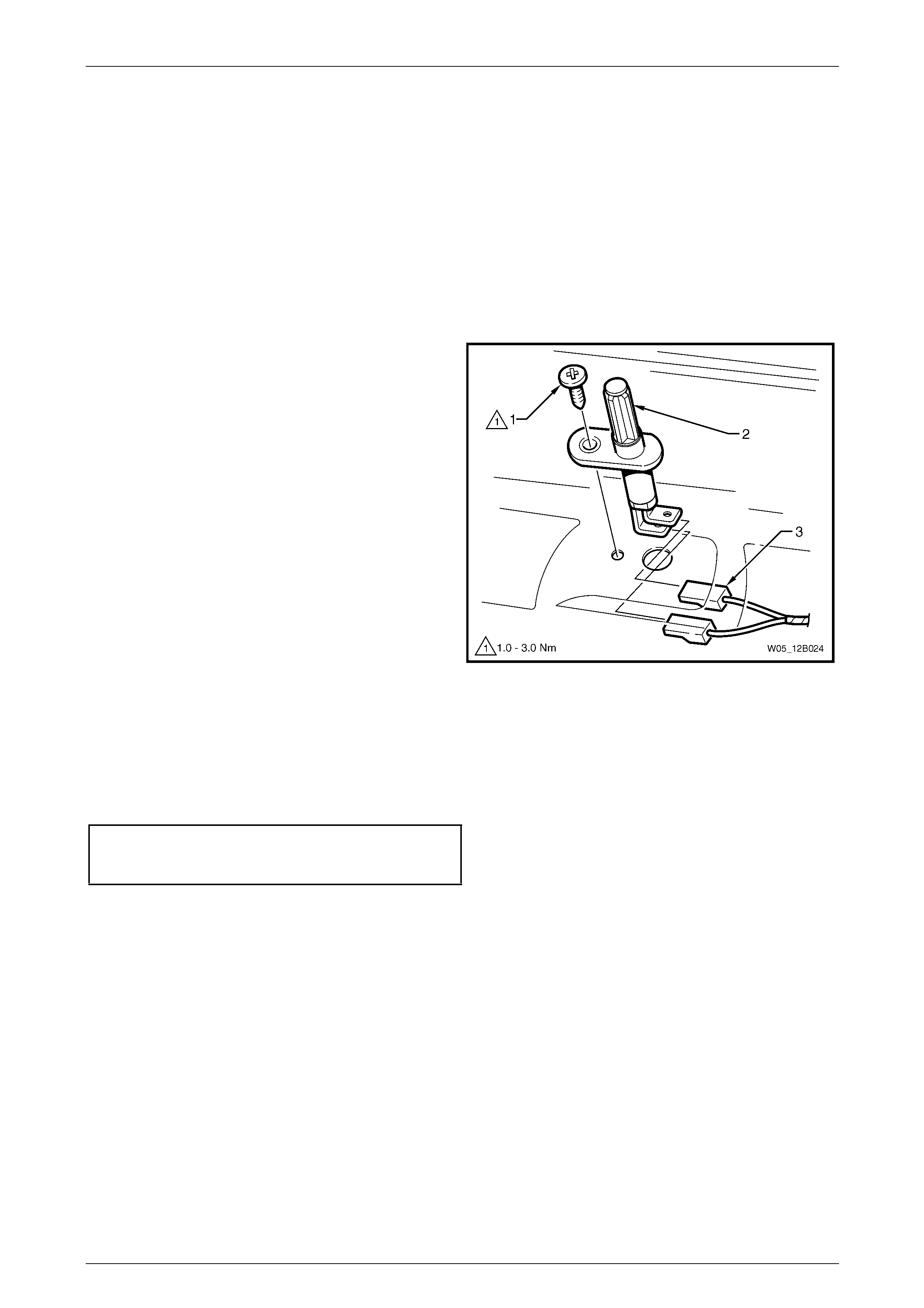
3.5 Rear Compartment Courtesy Lamp
Switch Assembly
LT Section No. — 02–780
The rear compartment courtesy lamp assembly is operated b y a switch attached to the rear compartment lid. The rear
compartment courtesy lamp switch assembly is actuated when either the compartment lid or liftgate is opened.
Remove
1 Remove fusible link F102 from the engine compartment fuse and relay panel assemb ly, refer to
Section 12O Fuses, Relays and Wiring Harnesses.
2 Remove the attaching screw (1) and pull the rear
compartment courtesy lamp switch assembly (2) out
far enough to access the rear compartment courtes y
lamp assembly wiring harness connectors (3).
3 Disconnect the rear compartment courtesy lamp
assembly wiring harness connectors and remove the
rear compartment courtesy lamp switch assembly.
Figure 12B – 33
Reinstall
Reinstallation of the rear com partment courtesy lamp switch assembly is the reverse of the removal procedure, noting
the following:
1 Tighten the attaching screw to the correct torque specification.
Rear compartment courtesy lamp
switch assembly attaching
screw torque specification...........................1.0 – 3.0 Nm
2 Check the rear compartment courtes y lam p assemb ly operation.
Lighting System Page 12B–41
Page 12B–41
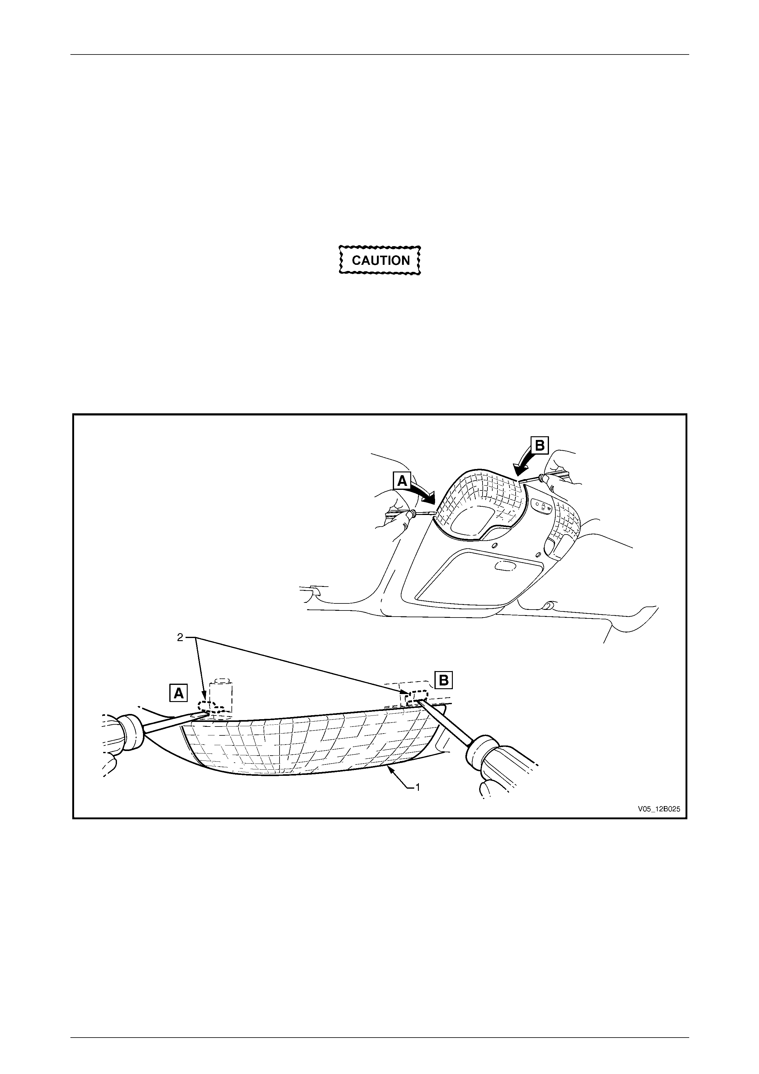
3.6 Roof Console Assembly
LT Section No. — 02–780
Bulb Replace
1 Remove fusible link F102 from the engine compartment fuse and relay panel assemb ly, refer to
Section 12O Fuses, Relays and Wiring Harnesses.
Insert the fine-bladed screwdriver only at the
points shown to engage the tabs (2) that act
as a leverage point, refer to Figure 12B – 34.
These tabs are hidden under the headlining
assembly.
2 Place a fine-bladed screwdriv er between the lens (1) and the headlining assembly, refer to Figure 12B – 34.
3 Prise the lens away from the roof console assembly.
Figure 12B – 34
4 Remove the bulb by pressing and turn ing it a quarter of a turn.
5 Insert a new bulb into the socket.
6 Install fusible link F102 on the engine compartment fuse and relay panel assembly.
7 Check the dome and reading l amp assembly operation.
Lighting System Page 12B–42
Page 12B–42
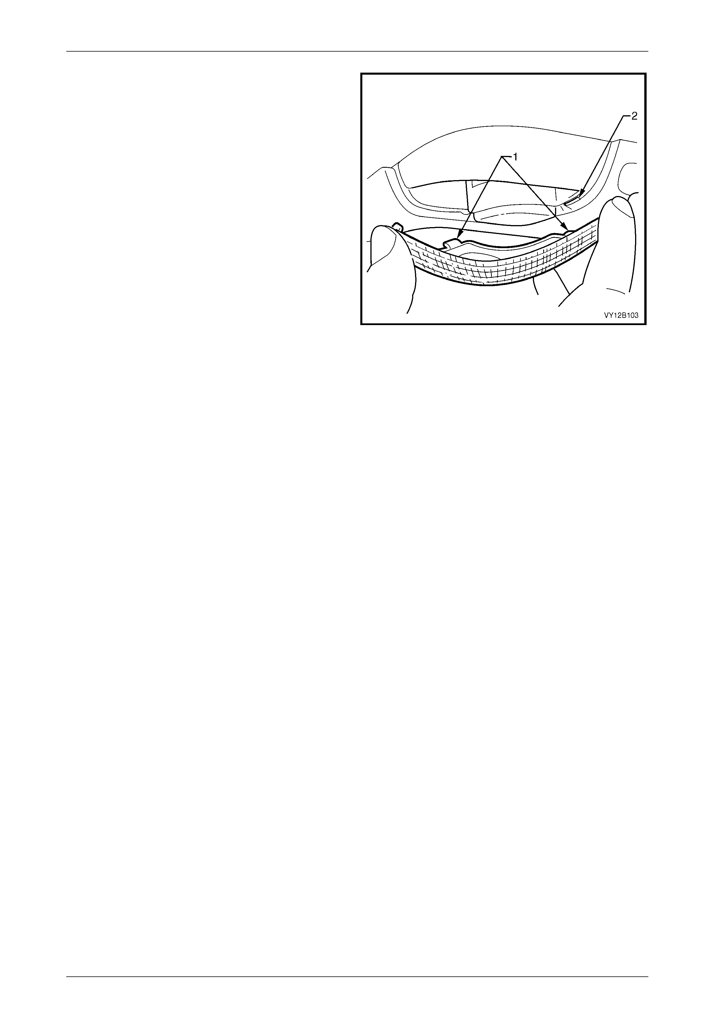
8 Fit the lens by inserting both tabs (1) on the lens into
the slots (2) in the roof console assembly.
9 Rotate the lens and lock it into place, ensuring it is
flush with the headlining assembly.
Figure 12B – 35
Remove
To remove the roof console assembly, refer to Section 1A8 Hea dlining and Interior Tr im .
Reinstall
To reinstall the roof console assembl y, refer to Section 1A8 Headlining and Interior Trim.
Lighting System Page 12B–43
Page 12B–43
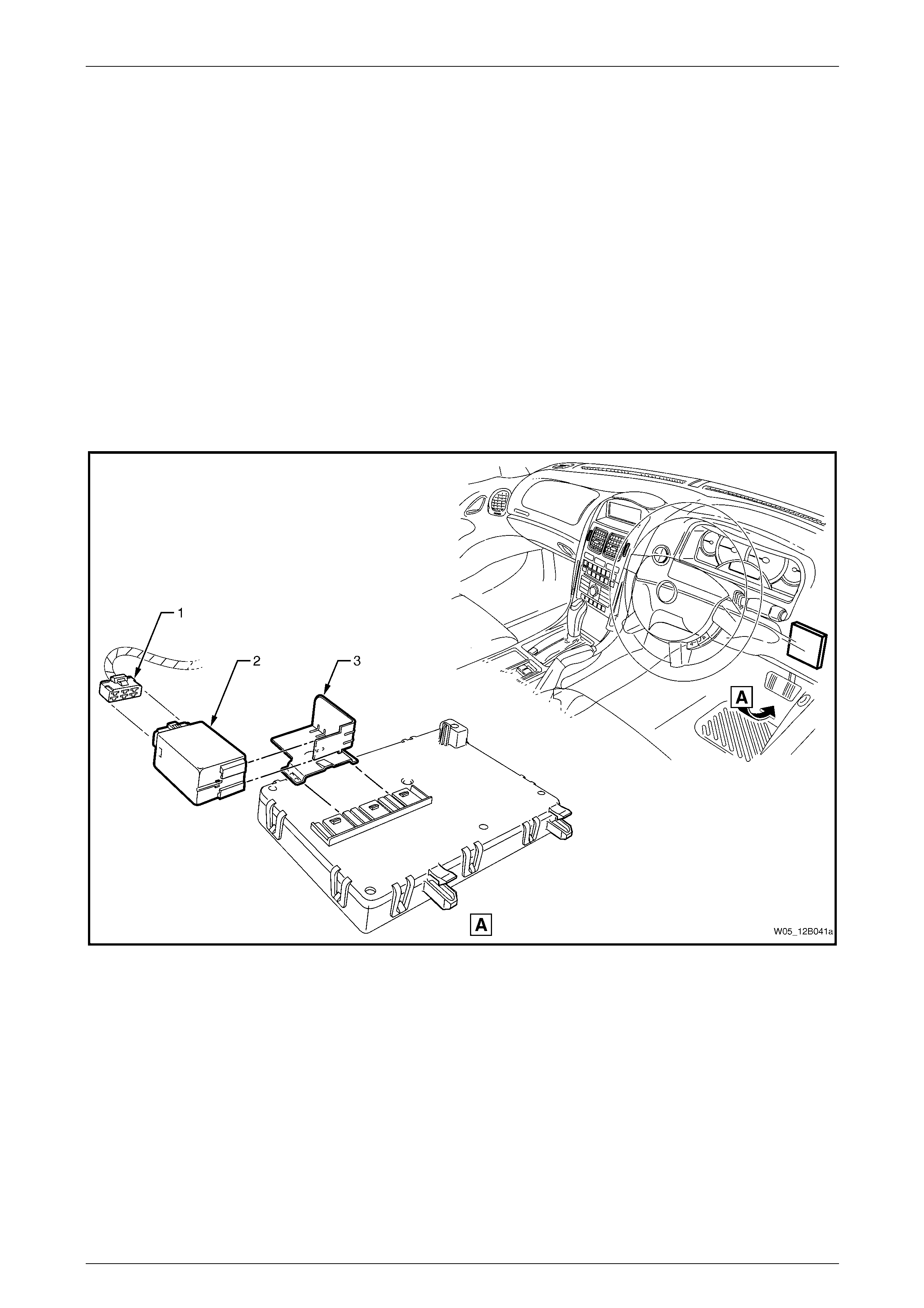
3.7 Dimming Control Module
LT Section No. — 02–800
For the location of the body control module, and dimming control module, refer to Figure 12B – 36. For a description of
the diagnostic test for the dimming control module, refer to Section 12J Body Control Module.
Remove
1 Disconnect the dimming control mod ule co nnector (1) from the rear of the dimming control module (2), refer to
Figure 12B – 36.
2 Remove the dimming control modu le from the dimmin g control module mounting bracket (3).
3 Remove the dimming control module mounting bracket from the top of the body control module.
Reinstall
Reinstallation of the dimming control module is the reverse of the removal procedure.
Figure 12B – 36
Lighting System Page 12B–44
Page 12B–44
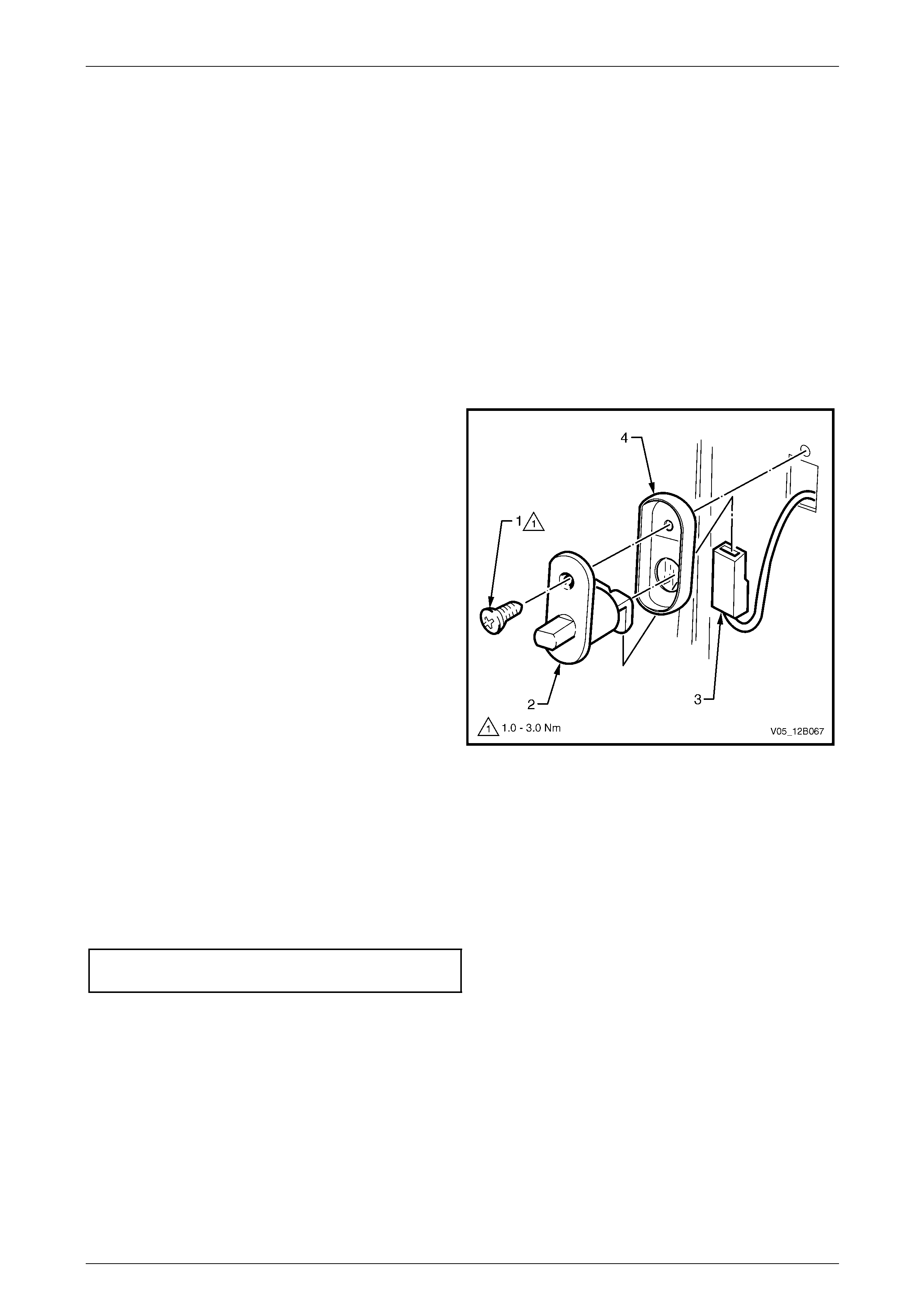
3.8 Door Ajar Switches
LT Section No. — 02–780
The door ajar switches ar e installed in the hin ge and centre pillars. The door ajar switches provide door status data to the
BCM:
• When the plunger is pressed, an open circuit is created, providing 'door closed' data to the BCM.
• When the plunger is released , the switch closes completing a circuit to earth, providing 'door op en' data to the
BCM.
To diagnose the door ajar switch circuit, refer to Section 12J Body Control Module.
This data is used by the BCM for many vehicle s ystems (for example, interior illumination dimming).
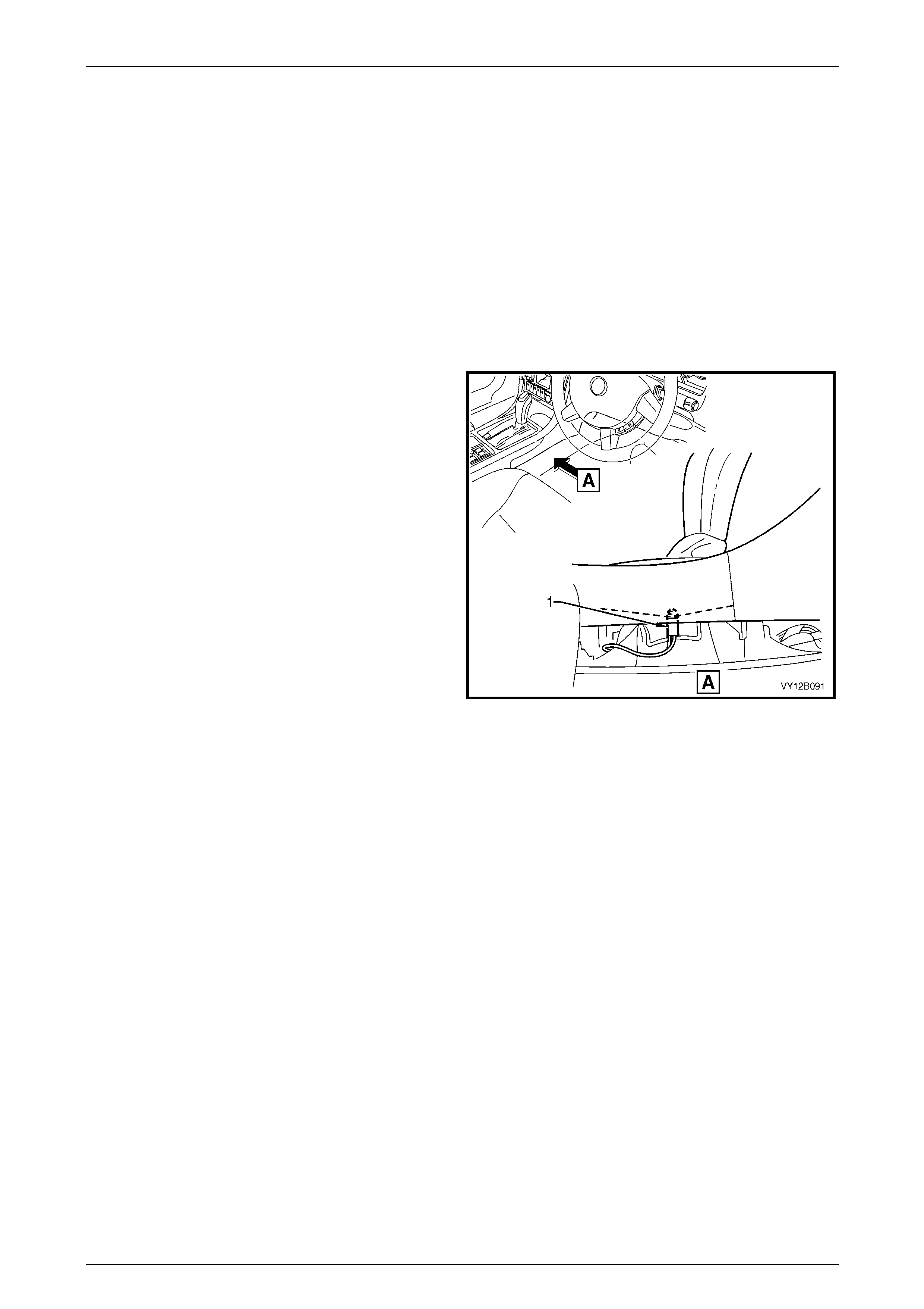
Remove
1 Remove the attaching screw (1) from the door ajar
switch (2).
2 Pull the door ajar switch from the aperture and, if
required, remove the door ajar s witch wiring harness
connector (3).
NOTE
Ensure the door ajar switch wiring harness
connector does not fall into the cavity.
Figure 12B – 37
Reinstall
Reinstallation of the door ajar switches is the reverse of the removal procedure, noting the following:
1 Ensure the door ajar switch seal (4) is fitted to the door ajar switch, refer to Figure 12B – 37.
2 Push the door ajar switch wiring harness connector onto the door ajar s witch.
3 Install the door ajar switch in the door jamb and tighten the attaching screw to the correct torque specification.
Door ajar switch attaching
screw torque specification...........................1.0 – 3.0 Nm

Lighting System Page 12B–45
Page 12B–45
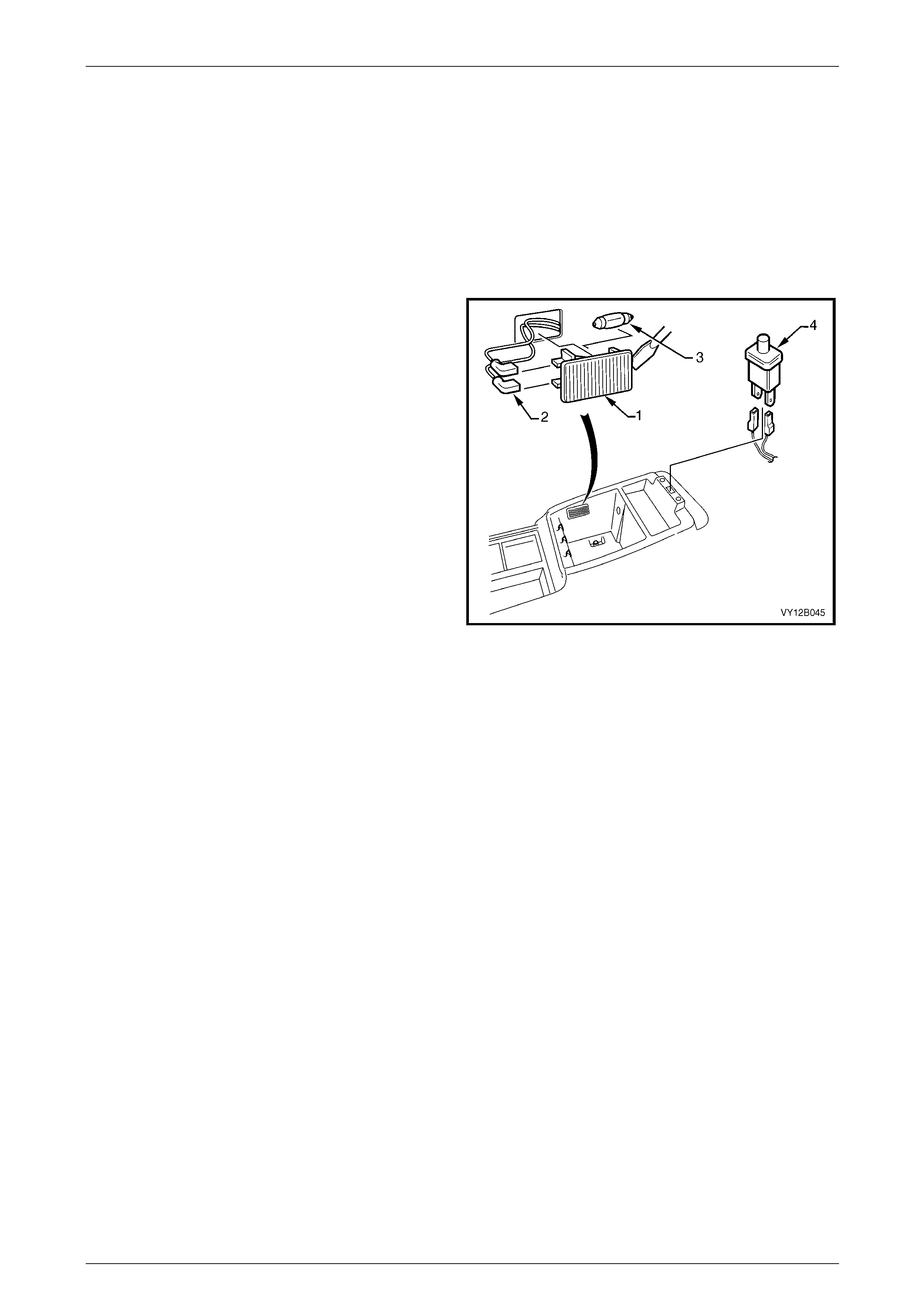
3.9 Stepwell Lamps
LT Section No. — 02–780
Stepwell lamps are located on either side of the vehicle and are attached to the instrument panel lower trim plate
assemblies. The stepwell bulb sockets are pa rt of the body wiring harness.
Replace
1 Remove fusible link F102 from the engine compartment fuse and relay panel assemb ly, refer to
Section 12O Fuses, Relays and Wiring Harnesses.
2 Remove the relevant instrument panel lower trim plate assembly, refer to Section 1A3 Instrument Panel and
Console.
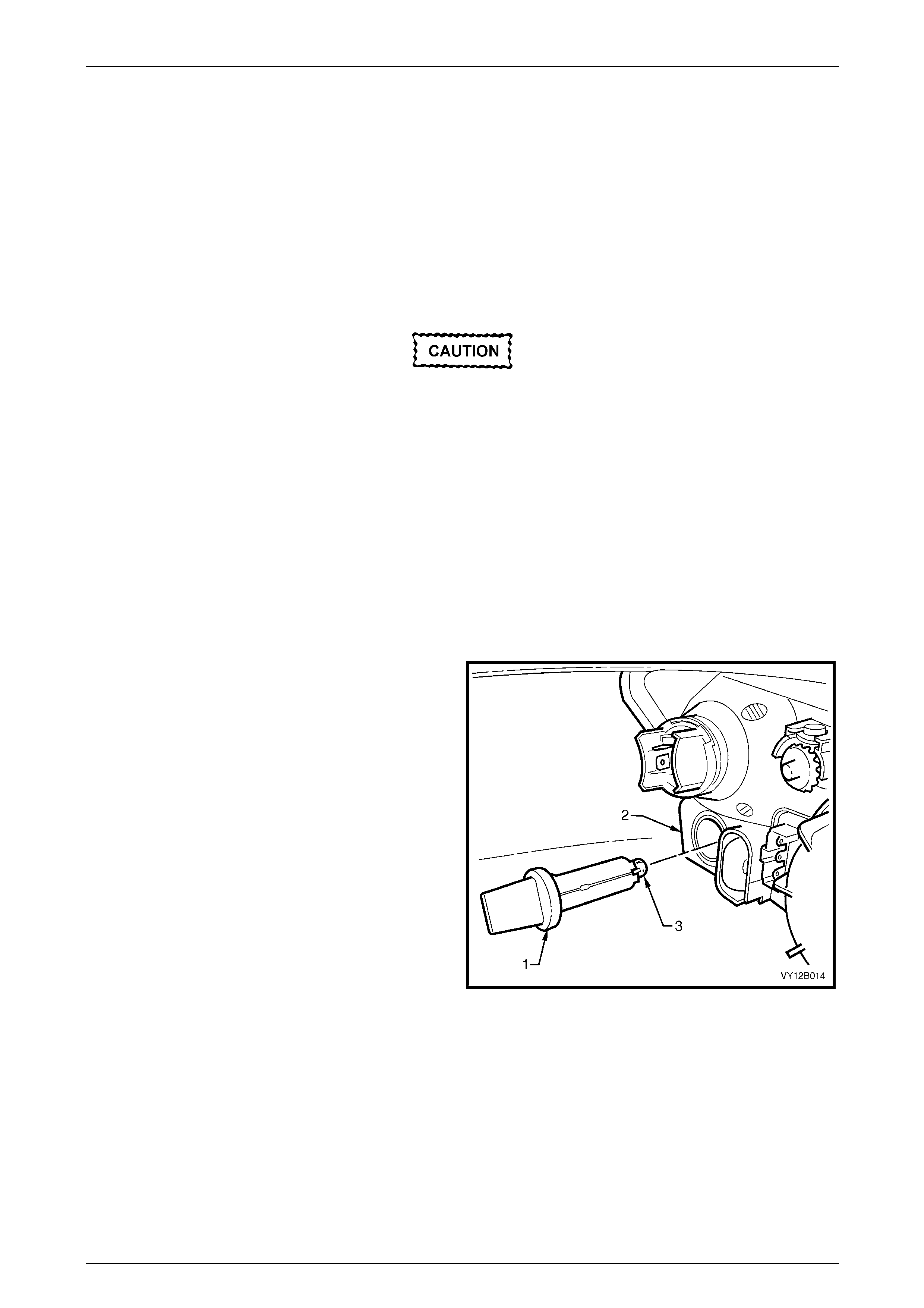
3 Pull the bulb sleeve (1) off the bulb (2) and pull the
bulb from the bulb socket.
4 Insert a new bulb into the bulb socket and fit the bulb
sleeve to the bulb.
5 Check the operation of the bulb.
6 Install the instrument panel lower trim plate assembly,
refer to Section 1A3 Instrument Panel and Consol e.
Figure 12B – 38
Lighting System Page 12B–46
Page 12B–46
3.10 Floor Console Compartment Lamp
Assembly
LT Section No. — 02–780
Remove
1 Remove fusible link F102 from the engine compartment fuse and relay panel assemb ly, refer to
Section 12O Fuses, Relays and Wiring Harnesses.
2 Prise the floor console compartment lamp
assembly (1) from the side of the floor console
compartment using a fine-bladed screwdriver.
3 Disconnect the floor console compartment la mp wiring
harness connectors (2) from the floor console
compartment lamp assembly. Check the lamp
assembly for damage and replace if necessary.
NOTE
Ensure the floor console compartment lamp
assembly wiring harness connectors do not fall
inside the floor console cavity.
4 If necessary, remove the bulb (3) from the floor
console compartment lamp assembly by pressing the
metal contact.
Figure 12B – 39
Reinstall
Reinstallation of the floor console compartment lamp assembly is the reverse of the removal procedure, noting the
following:
1 Insert a new bulb in the floor console compartment lamp assembly if required.
2 Ensure the lens is flush with the floor console compartme nt side.
3 Check the floor console compartment lamp assembly operation.

Lighting System Page 12B–47
Page 12B–47
3.11 Floor Console Compartment Lamp
Switch Assembly
LT Section No. — 02–780
Remove
1 Remove fusible link F102 from the engine compartment fuse and relay panel assemb ly, refer to
Section 12O Fuses, Relays and Wiring Harnesses.
2 Prise the floor console compartment lamp switch assembly (4) from the top of the floor console compartment using
a fine-bladed screwdriver, refer to Figure 12B – 39.
3 Disconnect the floor console compartment lamp switch assembly wiring harness from the floor console
compartment lamp assembly. Check the floo r console compartment lamp switch assembly for damage and replace
if necessary.
NOTE
Ensure the floor console compartment lamp
switch assembly wiring connector does not fall
inside the floor console cavity.
Reinstall
Reinstallation of the floor console compartment lamp s witch assembly is the reverse of the remov al procedure. Check
the floor console compartment lamp switch assembly operation.

Lighting System Page 12B–48
Page 12B–48
3.12 Roof Rail Courtesy and Reading Lamp
Assembly
LT Section No. — 02–780
Remove
1 Remove fusible link F102 from the engine compartment fuse and relay panel assemb ly, refer to
Section 12O Fuses, Relays and Wiring Harnesses.
2 Prise the roof rail courtesy and reading lamp
assembly (1) from the lens surround using a fine-
bladed screwdriver.
3 Disconnect the roof rail courtesy and reading lamp
assembly wiring harness connectors (2) from the roof
rail courtesy and reading lamp assembly. Check the
roof rail courtesy and reading lamp assembly for
damage and replace if necessary.
4 If necessary, remove the bulb (3) from the roof rail
courtesy and reading lamp assembly by pressing the
metal contact.
Figure 12B – 40
Reinstall
Reinstallation of the roof rail courtesy and reading lamp assembly is the reverse of the r emova l procedure, noting the
following:
1 If required, insert a new bulb into the roof rail courtesy and reading lamp assembly.
2 Ensure the lens is flush with the lens surround.
3 Check the roof rail courtesy and reading l amp assembly operation.
Lighting System Page 12B–49
Page 12B–49
3.13 Automatic Transmission Control
Position Lamp
LT Section No. — 04–190
Replace
1 Remove fusible link F102 from the engine compartment fuse and relay panel assemb ly, refer to
Section 12O Fuses, Relays and Wiring Harnesses.
2 Move the front seats to the rearmost position.
3 Remove the right-hand instrument panel lower extension side trim panel, refer to Section 1A3 Instrument Panel
and Console.
4 Remove the bulb socket (1) from the automatic
transmission control assembly by twisting
anticlockwise and pulling it down.
5 Insert a new bulb into the bulb socket.
6 Install fusible link F102 on the engine compartment
fuse and relay panel assembly.
7 Check the operation of the bulb by turning on the park
lamps.
8 Insert the bulb socket into the automatic transmission
control assembly and twist to lock into position.
9 Install the instrument panel lower e xtension side trim
panel, refer to Section 1A3 Instrument Panel and
Console.
Figure 12B – 41
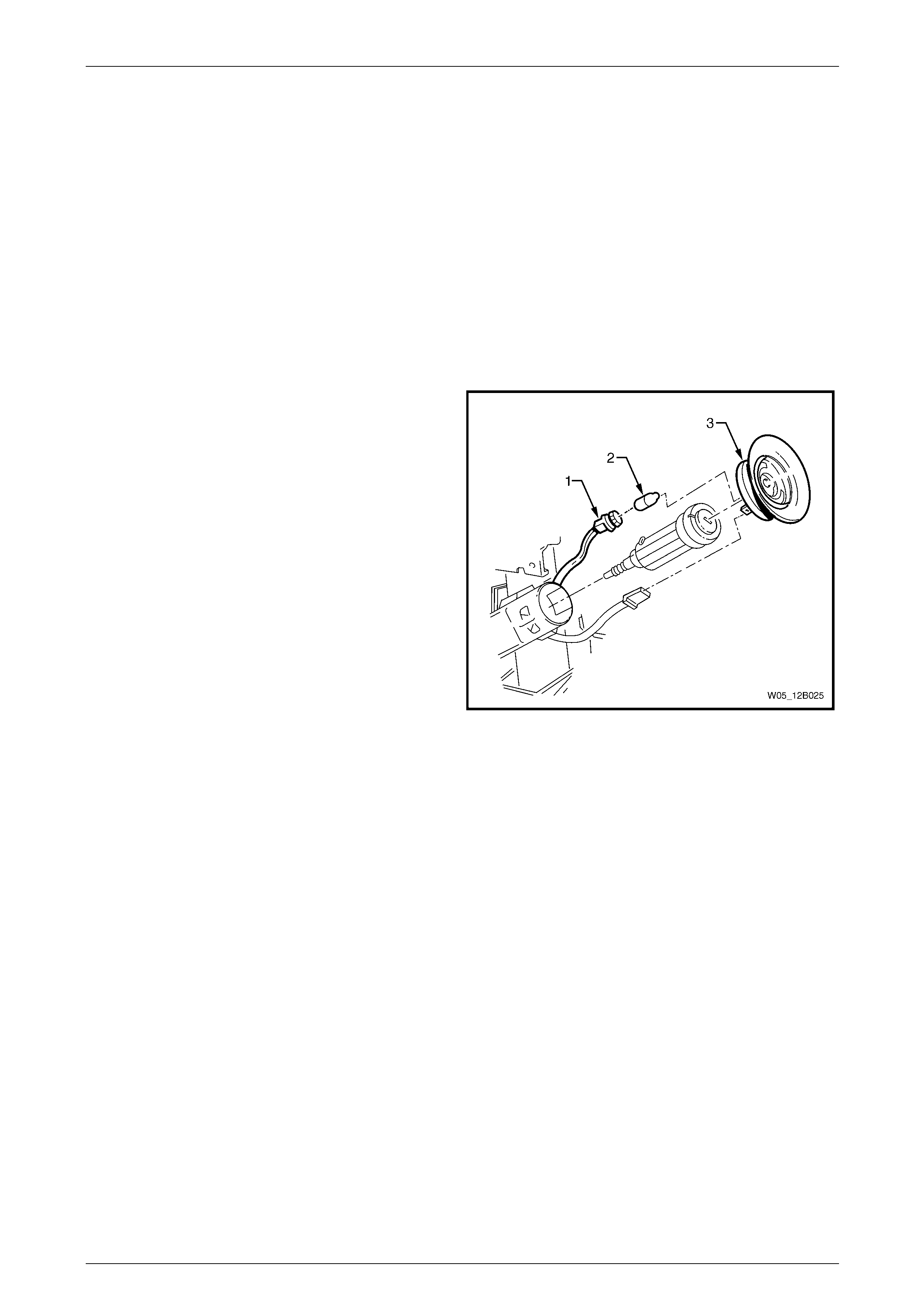
Lighting System Page 12B–50
Page 12B–50
3.14 Ignition Lock Cylinder Bulb
LT Section No. — 02–780
Replace
1 Remove fusible link F102 from the engine compartment fuse and relay panel assemb ly, refer to
Section 12O Fuses, Relays and Wiring Harnesses.
2 Remove the following items, refer to Section 9 Steering:
a steering column covers,
b ignition barrel and lock cylinder, and
c theft deterrent receiver assembly.
3 Replace the ignition lock cyli nder bulb (2).
4 Insert the bulb socket (1) into the theft deterrent
receiver assembly (3), then install the theft deterrent
receiver assembly into the steering column lower
cover.
Figure 12B – 42
5 Install fusible link F102 on the engine compartment fuse and relay panel assembly.
6 Check the ignition lock cylinder bulb operatio n.
7 Replace the following items, refer to Section 9 Steering:
a theft deterrent receiver assembly,
b ignition barrel and lock cylinder, and
c steering column covers.

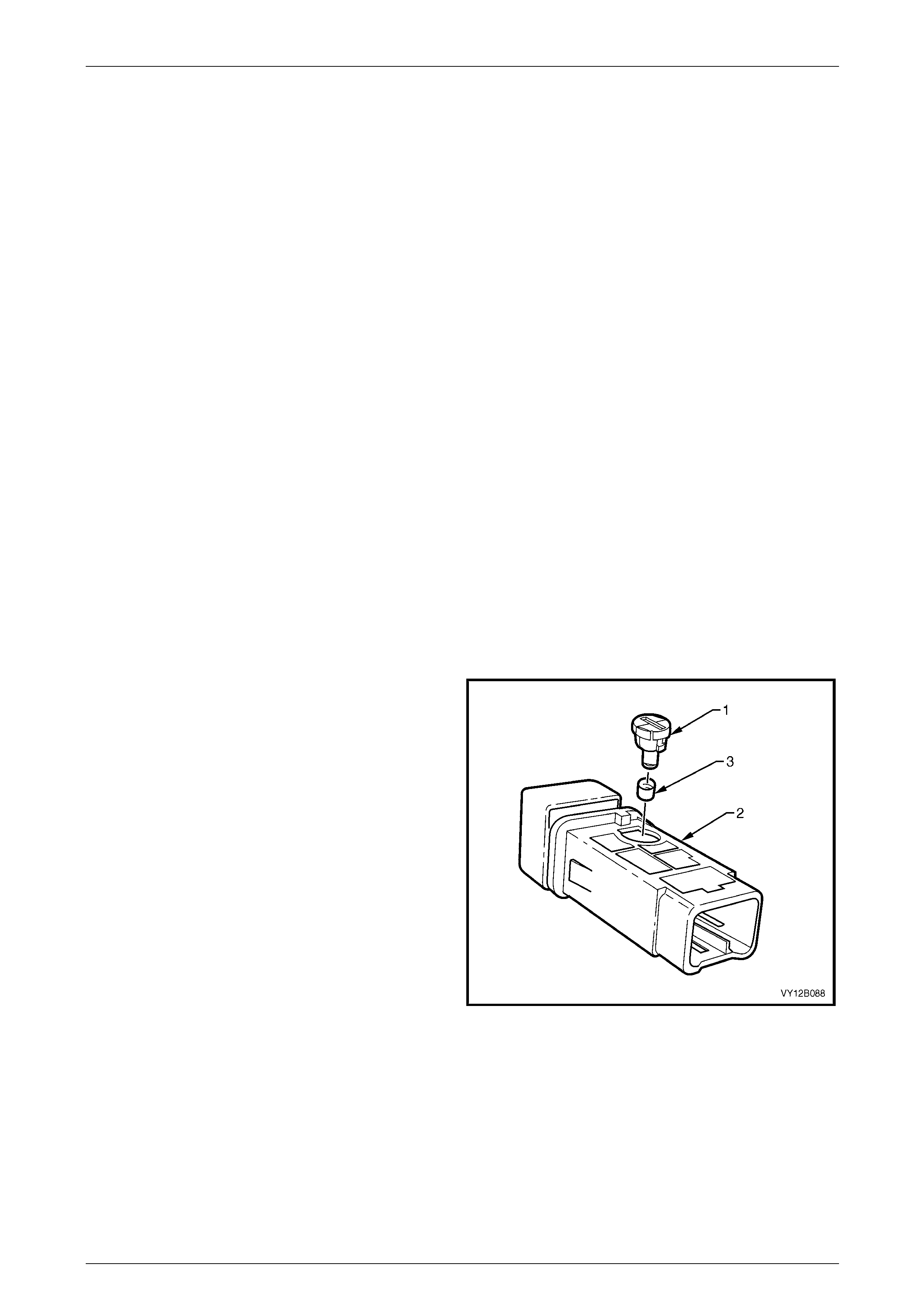
Lighting System Page 12B–52
Page 12B–52
3.16 Switch Illumination
LT Section No. — 02–780
The headlamp switch, trip computer switch and side windo w switch are illuminated with filament bulbs, but the switches
are sealed units and the bulbs are not serviceable, refer to Figure 1 2B – 5.
Auxiliary Switch Bulbs
Spaces are availabl e for auxiliary switches in the:
• floor console compartment cover assembly:
• ESP switch, and
• dual park assist override switch;
• behind the automatic transmission selector:
• PWR switch, and
• T/C switch or A/S switch.
Replace
1 Ensure the ignition switch is in the OFF position.
2 Remove fusible link F102 from the engine compartment fuse and relay panel assemb ly, refer to
Section 12O Fuses, Relays and Wiring Harnesses.
3 If required, remove the navigation system equipment, refer to Section 12L Navigation System.
4 Remove the floor console front compartment cover assembly, refer to Section 1A3 Instrument Panel and Console.
5 Remove the switch from the floor console front compartment cover assembly.
6 Using a fine-bladed screwdriver inserted into the
groove on the bulb socket, twist the bulb socket and
bulb assembly (1) anticlockwise and remove it from
the switch assembly (2).
7 Remove the green bulb sleeve (3) from the bulb
socket and bulb assembly.
8 Check the bulb sleeve for splits and replace it if
necessary.
9 Fit the bulb sleeve to the new bulb socket and bul b
assembly.
10 Insert the bulb socket and bulb assembly into the
switch assembly.
11 Connect the switch assembly to the wiring harness
connector in the floor console compartme nt cover
assembly.
12 Install fusible link F102 on the engine compartment
fuse and relay panel assembly. Figure 12B – 43
13 Check the switch assembly operati on while the park lamps are on.
14 Replace the floor console front compartment cover assembly, refer to Section 1A3 Instrument Panel and Console .
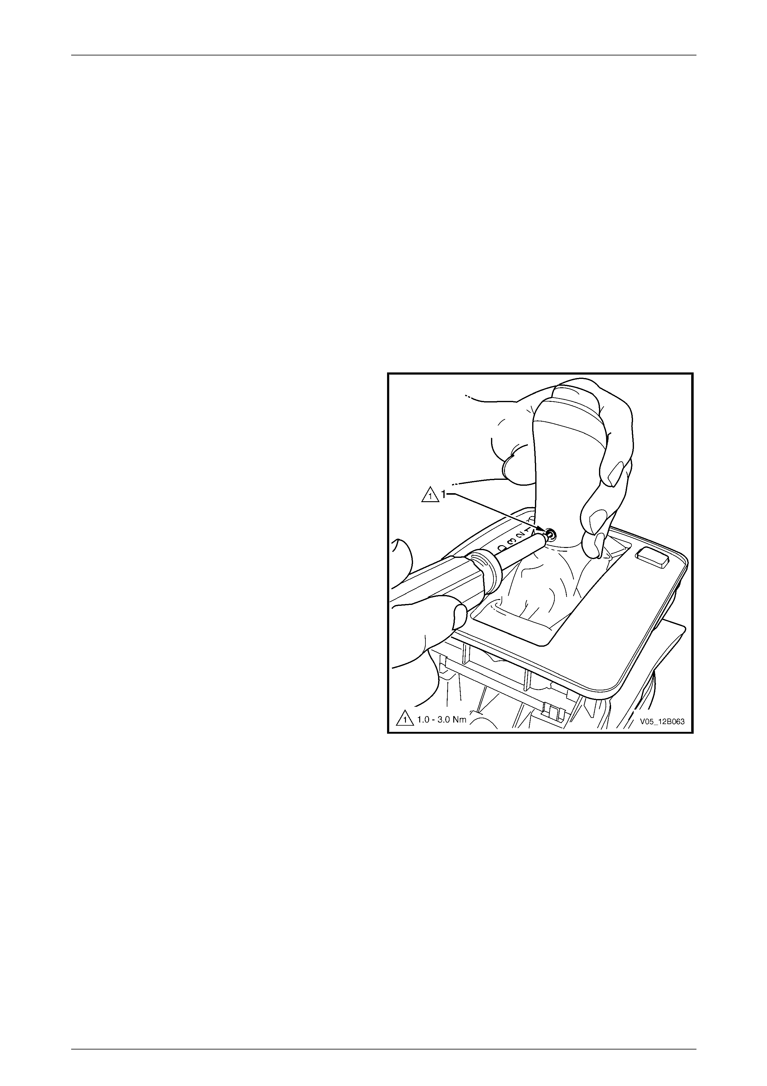
Lighting System Page 12B–53
Page 12B–53
PWR Switch and T/C Switch (or A/S Switch) Bulbs
Replace
Two switch assemblies can be installed into the automatic control selector i ndicator assembly:
• PWR switch, and
• either the T/C switch or the A/S switch.
The PWR switch is located at the rear of the shift lever lower housi ng on the side opposite the transmission selector len s
(PRNDL) on vehicles with automatic transmi ssion.
Depending on the model level of the vehicle, the T/C switch (or A/S switch) is located at the rear of the shift lever lower
housing on the same side as the transmission selector lens (PRNDL).
1 Ensure the ignition switch and the headlamp switch assembly are in the OFF position.
2 Ensure the park brake is applied.
3 Remove the floor console compartment cover assembly, refer to Section 1A3 Instrument Panel and Console.
4 Shift the transmission selector into the drive position.
5 Remove the Torx-head scre w (1) using a No. 25 Torx
bit from the transmission selector.
Figure 12B – 44
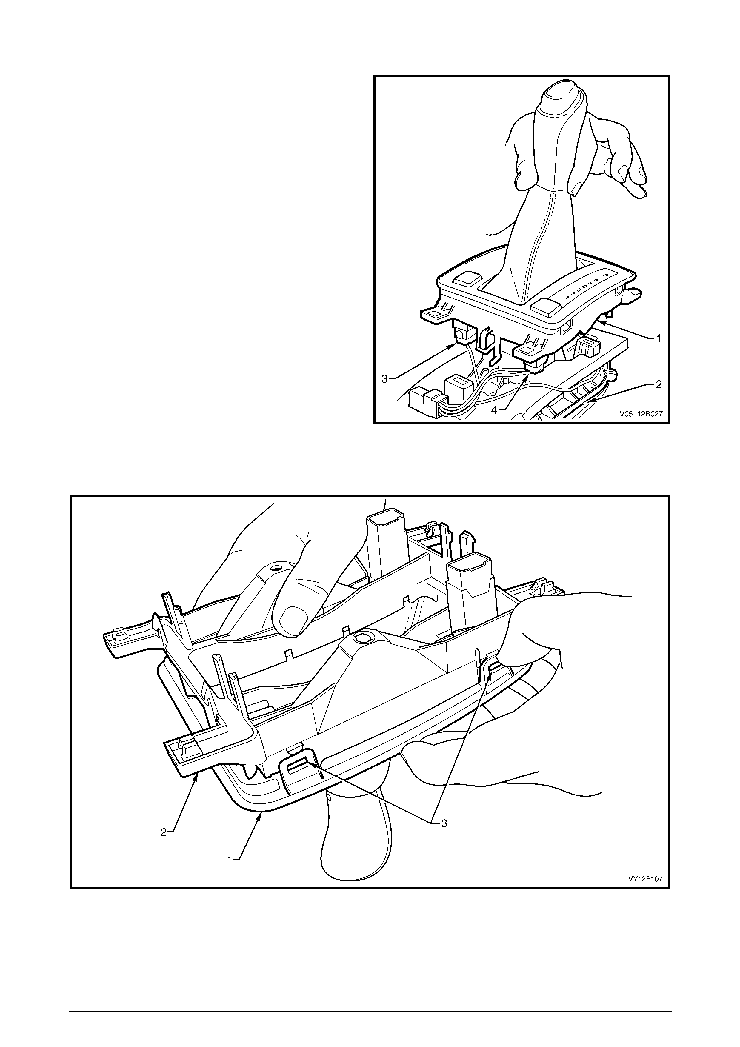
Lighting System Page 12B–54
Page 12B–54
6 Unclip the upper and lower transmission selector
housing assembly (1) from the transmissio n selector
base assembly (2) at three points.
7 Disconnect the wiring harness from the PW R
switch (3), and either the T/C switch or A/S switch (4).
8 Twist the automatic transmission control po sition lamp
anticlockwise and pull down, then remove it from the
lower transmission selector housing.
Figure 12B – 45
9 With the shift lever knob hanging down, unclip the upper transmission selector housing (1) from the lower
transmission selector housing (2) at four points (3), refer to Figure 12B – 46.
Figure 12B – 46
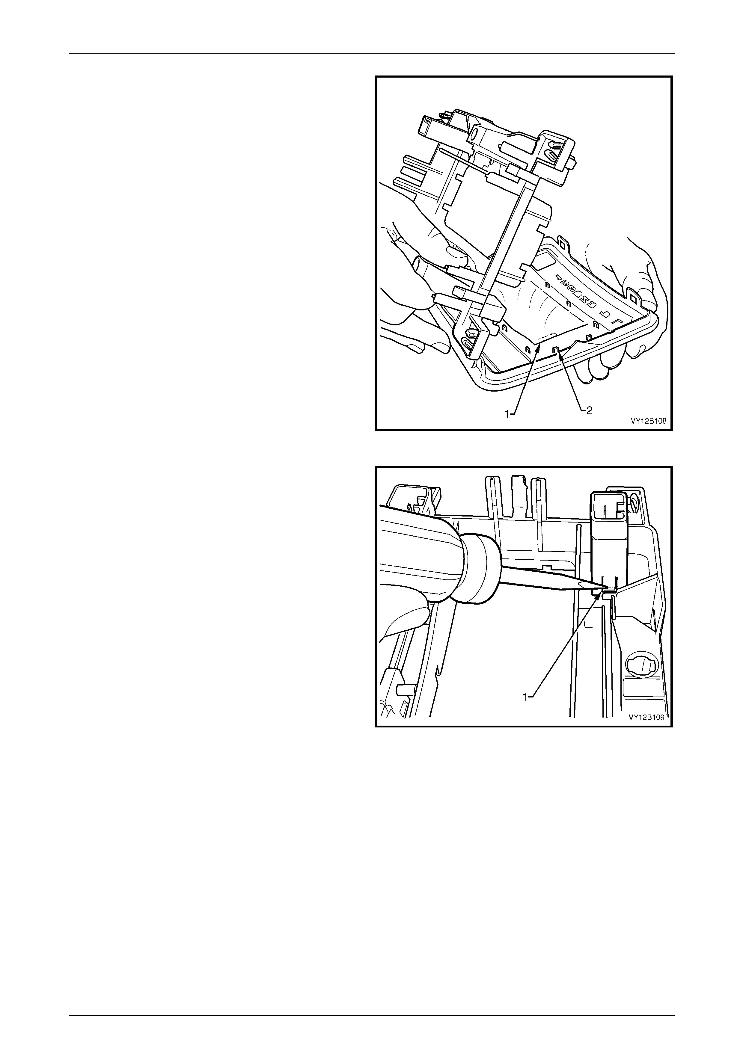
Lighting System Page 12B–55
Page 12B–55
10 Lift the lower transmission selector housin g from the
upper transmission selector housing.
NOTE
Leave the upper transmission selector housing
upside down (that is, with the shifter lever knob
keeping the boot (1) taut). This reduces the risk
of the boot coming a way from the tabs (2) on the
upper transmission selector housing.
Figure 12B – 47
11 Using a thin, flat-bladed screwdriver, press the tab (1)
on either side of the switch assembly and remove it
from the lower transmission selector housing.
NOTE
Figure 12B – 48 shows removal of the
T/C switch or A/S switch.
Figure 12B – 48
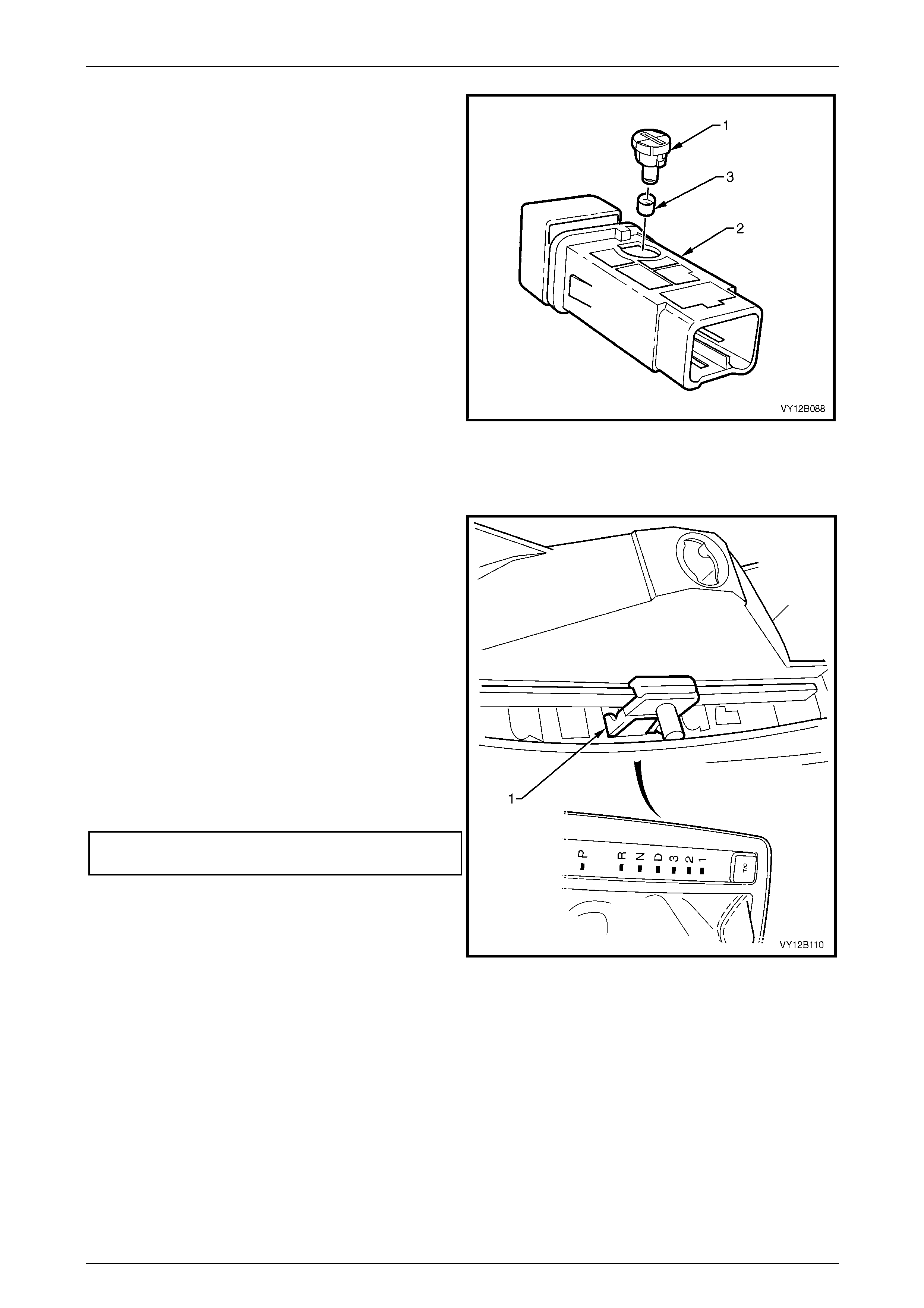
Lighting System Page 12B–56
Page 12B–56
12 Using a fine-bladed screwdriver inserted into the
groove on the bulb socket, twist the bulb socket and
bulb assembly (1) anticlockwise and remove it from
the switch assembly (2).
13 Remove the green bulb sleeve (3) from the bulb
socket and bulb assembly.
14 Check the bulb sleeve for splits and replace it if
necessary.
15 Fit the bulb sleeve to the new bulb socket and bul b
assembly.
16 Insert the bulb socket and bulb assembly into the
switch assembly.
17 Connect the switch assembly to the wiring harness
connector. Turn on the park lamps and check the lamp
operation. Disconnect the wiring harness connector
from the switch assembly.
18 Fit the switch back into the lower transmission selector
housing, ensuring it locks correctl y in place. Figure 12B – 49
19 Turn the lower transmission selector housing upside down. Clip the upper transmission se lector housing back into
place, ensuring the skirt is still placed over the tabs, refer to Figure 12B – 47.
20 Place the carrier indicator (1) so the 'D' is selected.
21 Place the upper and lower transmission sel ector
housing assembl y over the shift lever knob and ensure
the shift lever knob is correctly seated on the shift
lever knob.
22 Connect the wiring harness to the PWR switch and
T/C switch (or A/S switch).
23 Insert the automatic transmission control po s ition lamp
and turn clockwise to lock it into place.
24 Clip the upper and lower transmission selector
housing assembl y to the transmission selector base
assembly and ensure the carrier indicator engages
correctly in the slot.
25 Tighten the transmission selector knob attaching
screw to the correct torque specification.
Transmission selector knob
attaching screw torque specification...........1.0 – 3.0 Nm
26 Install the floor console compartment cover assembl y,
refer to Section 1A3 Instrument Panel and Consol e.
Figure 12B – 50

Lighting System Page 12B–57
Page 12B–57
3.17 Backup Lamp Switch Assembly
The backup lamp switch assembly is fitted to both manual transmission a ssembly configurations. The backup lamp
switch assembly is not adjustable and is fitted to the right-hand side of the transmission case.

Lighting System Page 12B–58
Page 12B–58
3.18 Neutral Safety Backup Switch Assembly
The neutral safet y backup switch assembly is fitted to vehicles with automatic transmission. The neutral safety backup
switch assembly activates the backup lamps when the transmission selector is in the reverse position. If the neutral
safety backup switch assembly requires changing, refer to:
• Section 7C4 Automatic Transmission – 4L60E – On-vehicle Servicing, or
• Section 7E4 Automatic Tr ansmission – 5L40E – On-vehicle Servicing.
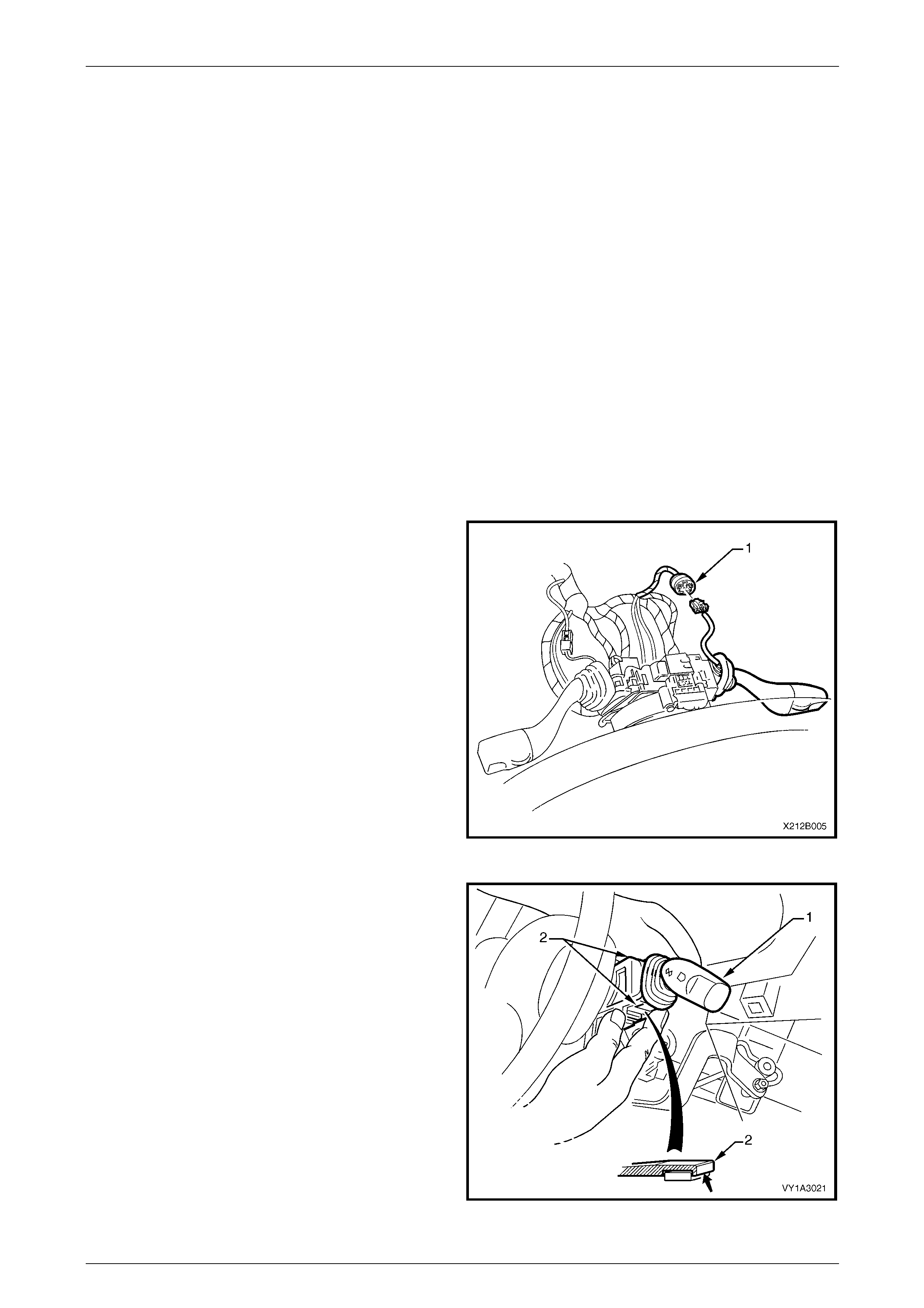
Lighting System Page 12B–59
Page 12B–59
3.19 Turn Signal Switch Assembly (and
Cruise Control)
LT Section No. — 06–250
The turn signal switch assembly prov ides the following functions:
• turn signal,
• pass, and
• high beam control, and
• cruise control.
For more information on the cruise control system, refer to Section 12E Cruise Control.
Remove
1 Remove fusible link F102 from the engine compartment fuse and relay panel assemb ly, refer to
Section 12O Fuses, Relays and Wiring Harnesses.
2 Remove the instrument lower trim panel assembl y, refer to Section 1A3 Instrument Panel and Console.
3 Remove the steering column lower cover, refer to Section 9 Steering.
4 Disconnect the cruise control switch assembly wiring
harness connector (1).
Figure 12B – 51
5 Press the retaining tangs (2) on the turn signal switch
assembly (1) and pull the turn signal switch assembly
away from the steering column.
Figure 12B – 52
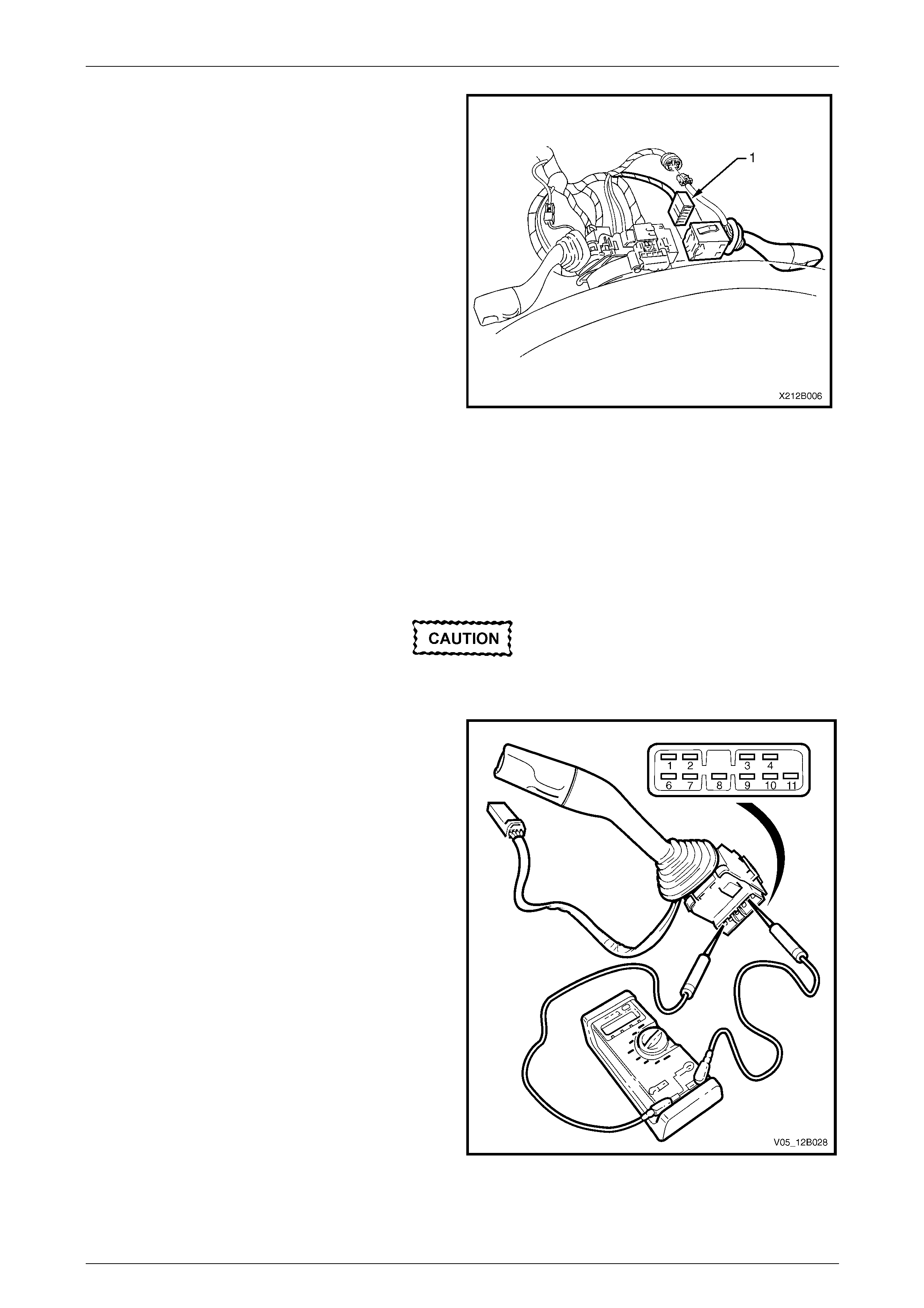
Lighting System Page 12B–60
Page 12B–60
6 Press the wiring harness connector tangs and pull the
connector (1) from the turn signal switch assembly.
Figure 12B – 53
Reinstall
Reinstallation of the turn signal switch assembly is the reverse of the removal procedure .
Test
To test the turn signal switch assembly, use a multimeter to check the continuity.
To test the cruise control features, refer to
Section 12E Cruise Control.
1 Perform the removal procedure for the turn signal
switch assembly, refer to Remove, but do not unclip
and remove the turn signal switch assem bl y from the
steering column. With the turn signal switch assembly
attached to the steering column, a stable platform with
which to carry out the testing is provided.
2 Place the turn signal switch assembly into the
positions detailed in the following Turn Signal Switch
Assembly table, refer to Turn Signal Switch Assembly.
Position the contacts of the multimeter onto the
terminals and take the reading. Compare the
multimeter readings with the values in the Turn Sig nal
Switch Assembly table.
3 If there is continuity between any terminals o t her than
those listed, the turn signal switch assembly is faulty. If
the turn signal switch assembly fails any part of the
test, replace the faulty turn signal switch assembly
with a serviceable item. To replace the turn signal
switch assembly, press the two retaining tangs and
pull the turn signal switch assembly away from the
steering column, refer to Figure 12B – 52. Insert a new
turn signal switch assembly.
4 Perform the reinstallation procedure, refer to Reinstall.
Figure 12B – 54

Lighting System Page 12B–61
Page 12B–61
Turn Signal Switch Assembly
Turn Signal Switch Assembly
Switch
Terminals Switch
Position Indication if Switch
is Serviceable
Turn Signal Switch Terminals
9 and 6 Switch in neutral position open circuit
9 and 6 Switch in left-hand turn position continuity
9 and 10 Switch in neutral position open circuit
9 and 10 Switch in right-hand turn pos ition continuity
Headlamp Pass Terminals
1 and 4 Switch in the neutral position open circuit
1 and 4 Switch pulled to the rear in the pass positio n continuity
Headlamp High Beam Terminals
1 and 3 Switch in neutral position open circuit
1 and 3 Switch pushed forward in the hig h beam position continuity
2 and 3 Switch in neutral position continuity
2 and 3 Switch pushed forward in the high beam position open circuit
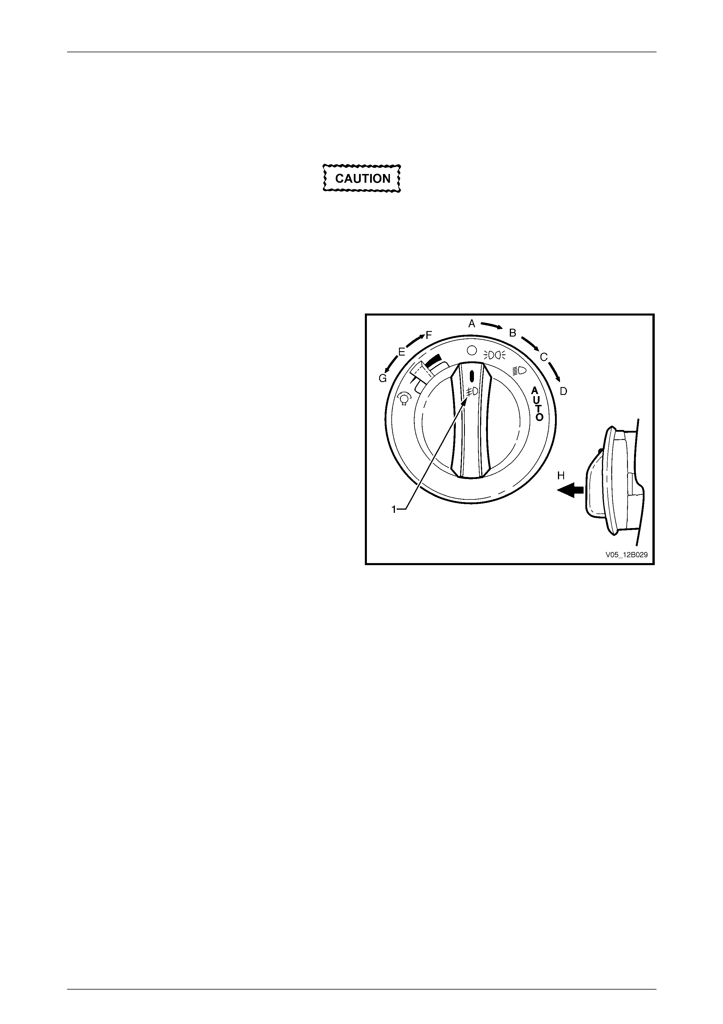
Lighting System Page 12B–62
Page 12B–62
3.20 Headlamp Switch Assembly
LT Section No. — 02–800
If replacing a headlamp switch assembly,
ensure the correct type is u sed.
NOTE
The headlamp switch assembly is also used to
turn the front fog lamps on and off.
Figure 12B – 55 shows the headlamp switch assembly and
the fog lamp icon (1).
The headlamp switch assembly has the following positions:
• Position A — headlamps are off.
• Position B — park lamps are on.
• Position C — headlamps are on (lo w beam).
• Position D — headlamps are controlled automatically
by the BCM.
• Positions E / F — instrumentation lighting brightens
when the dimmer switch is moved position E to F.
• Positions E / G — Instrumentation lighting dims when
the dimmer switch moves from position E to G.
• Position B, C or D — Front fog lamps are turned on
when the switch (1) is pulled out to position H. Figure 12B – 55
NOTE
The front fog lamps do not illuminate if the
headlamp s witch assembly is pulled to posit ion H
while also in position A.
Remove
For removal of the headlamp switch assembly, refer to Section 1A3 Instrument Panel and Console.
Reinstall
Reinstallation of the headlamp switch assembly is the reverse of the removal procedure. Ensure the headlamp switch
assembly retaining tangs are correctly seated.
Test
To test the headlamp s witch assembly, use an ohmmeter to check the continuity or resistance when the switch is
actuated.
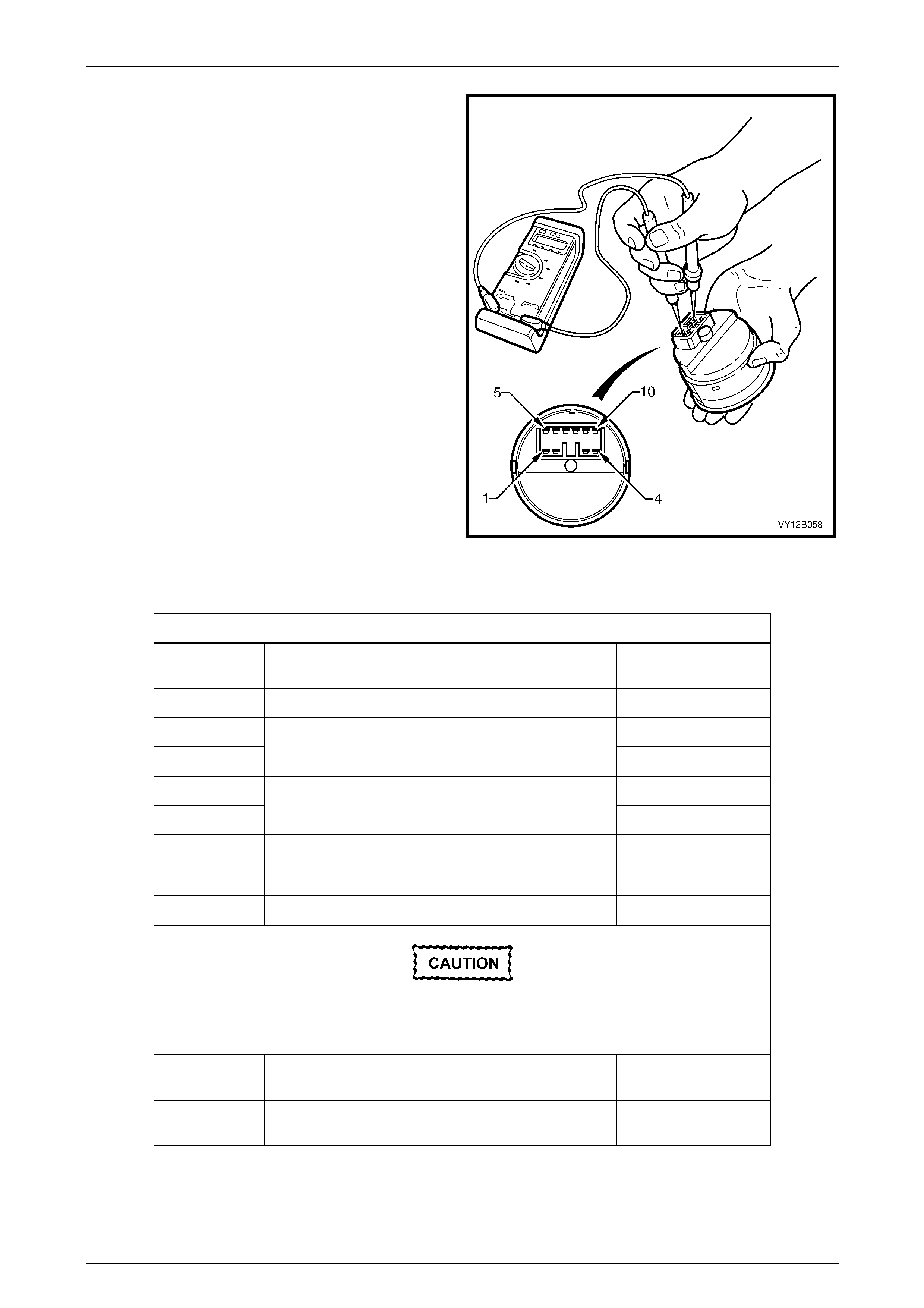
Lighting System Page 12B–63
Page 12B–63
NOTE
Refer to Figure 12B – 55 and Headlamp Switch
Assembly for headlamp switch assembly
positions.
1 Perform the removal procedure for the headlamp
switch assembly, refer to Section 1A3 Instrument
Panel and Console.
2 Place the headlamp switch assembly in the positions
detailed in the table, refer to Headlamp Switch
Assembly. Position the contacts of the ohmmeter onto
the terminals and take the reading; compare the
readings with those in the Headl amp Switch Assembly
table.
3 If there is continuity between any terminals o t her than
those listed, the headlamp switch assembl y is faulty. If
the headlamp switch assembly fails any part of the
test, replace the headlamp s witch assembl y with a
serviceable item.
4 Perform the reinstallation procedur e, refer to
Section 1A3 Instrument Panel and Co nsole.
Figure 12B – 56
Headlamp Switch Assembly
Headlamp Switch Assembly
Switch
Terminals Switch
Position Indication if Switch
is Serviceable
5 and 8 Switch in park lamp position; position B Continuity
5 and 8 Continuity
5 and 4 Switch in low beam position; position C Continuity
2 and 4 Continuity
2 and 8 Switch in AUTO position; position D Continuity
7 and 8 Dimmer in neutral position; p osition E 2.68 kΩ
7 and 8 Dimmer in high position, position F 5.36 kΩ
7 and 8 Dimmer in low position, position G 0 kΩ
The headlamp switch assembly must be in park,
low beam or AUTO position for the front fog
lamps to be activated.
5 and 6 Switch with front fog lamps activated; position H and
either park lamps or headlamps (low beam) on Continuity
2 and 6 Switch with front fog lamps activated; position H and
switch in AUTO position Continuity
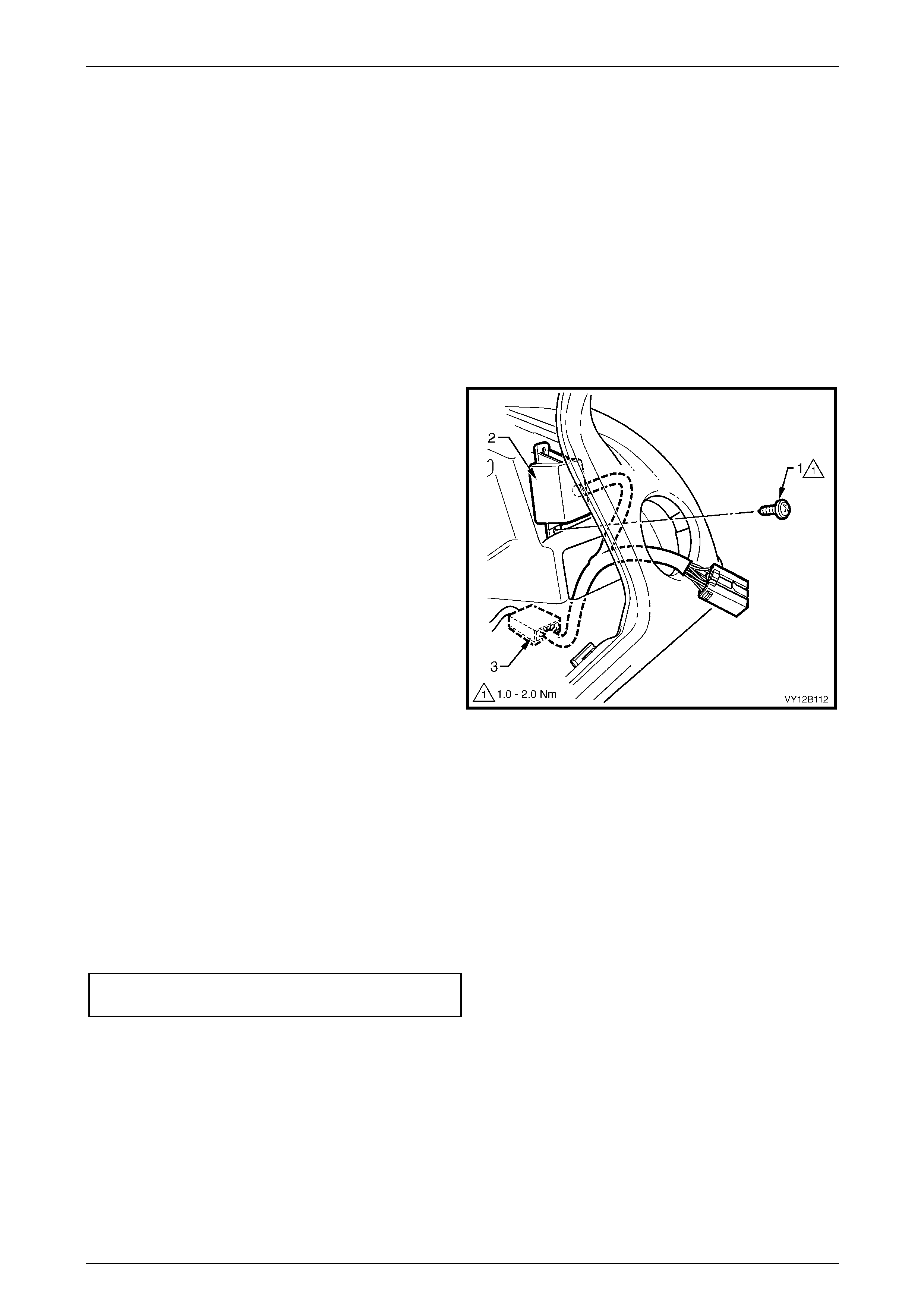
Lighting System Page 12B–64
Page 12B–64
3.21 Daylight Running Lamp Assembly
(Option T82)
LT Section No. — 02–780
For vehicles with the daylight running lamp assembly (option T82), the headlamps operate whenever the ignition switch
is on.
Remove
1 Remove fusible link F102 from the engine compartment fuse and relay panel assemb ly, refer to
Section 12O Fuses, Relays and Wiring Harnesses.
2 Remove the instrument panel lower trim panel assembly and instrument cluster trim assembly, refer to
Section 1A3 Instrument Panel and Co nsole.
3 To separate the daylight running lamp assembly from
the instrument panel:
a Remove the attaching screw (1) from the
daylight running lamp assembly and the
instrument panel using a magnetic-tipped
Phillips screwdriver. Access the attaching screw
through the headlamp switch assembly cavity.
b Prise the daylight running lamps assembly (2)
away from the instrument panel.
NOTE
The daylight running lamp assembly is fastened
to the instrument panel with double-sided ta pe. lf
necessary, use a flat-bladed screwdriver to
assist removal.
Figure 12B – 57
4 To disconnect the headlamp switch assembly main wiring harness connector (3), carefull y remove the da ylight
running lamp assembly wiring harness from behind the instrument pa nel.
5 Press the headlamp switch assembly main wiring harness connector tang and pull the connectors apart.
6 Remove the daylight running lamp assembly.
Reinstall
Reinstallation of the daylight running lamp assembly and daylight running lamp assembly wiring harness is the reverse of
the removal procedure, notin g the following:
1 Tighten the attaching scre w to the daylight running lamp assembly to the correct torque specification.
Daylight running lamps module
attaching screw torque specification...........1.0 – 2.0 Nm
2 Check the daylight running lamp assemb ly operation.
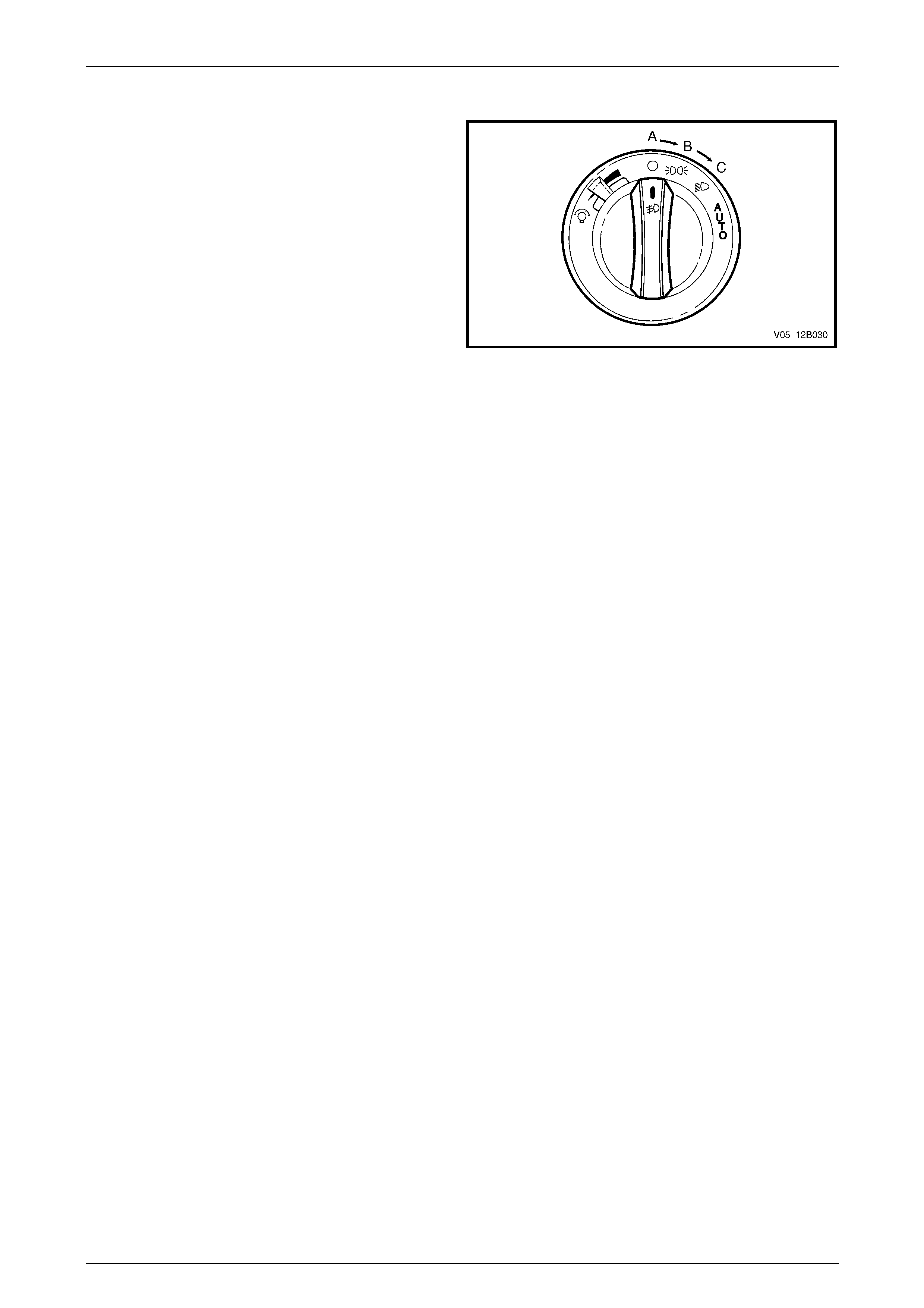
Lighting System Page 12B–65
Page 12B–65
Test
1 With the headlamp s witch in position A (the OFF
position), turn the ignition on.
2 If the headlamps illuminate, the daylight running lamps
assembly is operating correctly.
3 If the headlamps do not illuminate, turn the headlamp
switch assembly to position C (the hea dlamp low
beam position) and check if the low beam headlamps
illuminate.
4 If the low beam headlamps do not illum inate, replace
fusible link F102 on the engine compartment fuse and
relay panel assembly, refer to Section 12O Fuses,
Relays and Wiring Harnesses.
5 Repeat step 1 and check if the headl amps illuminate. Figure 12B – 58
6 If the headlamps illuminate, the daylight running lamp assembly is operating correctly.
7 If the headlamps do not illuminate, the daylight running lamp assembl y and headlamp switch assembl y main wiring
harness connector is faulty. Remove and rep lace the daylight running lamp assembl y and headlamp switch
assembly main wiring harness connector with a serviceable item.
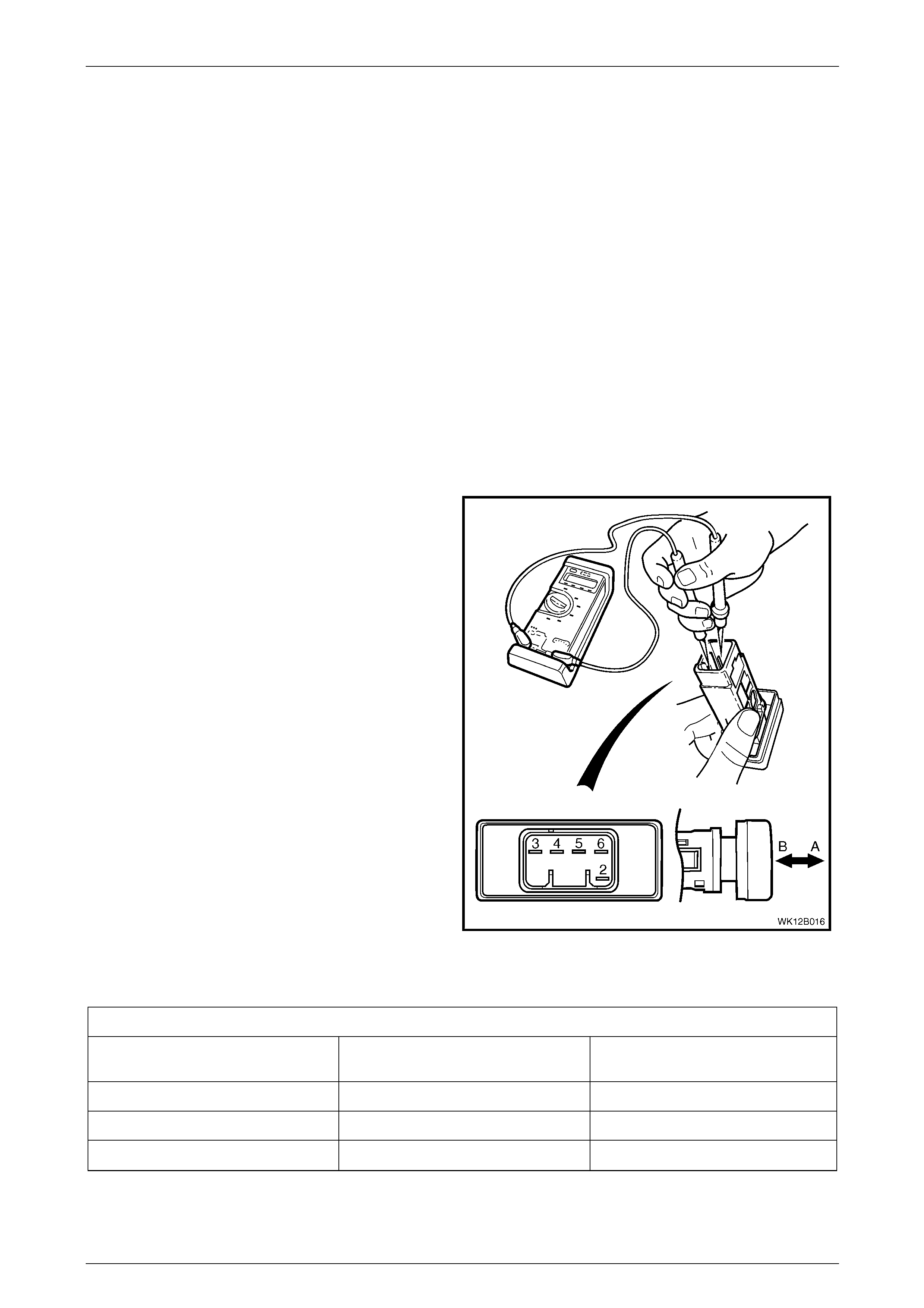
Lighting System Page 12B–66
Page 12B–66
3.22 Hazard Warning Switch Assembly
LT Section No. — 02–800
Remove
The hazard warning switch assembly is located in the front floor console.
1 Ensure the ignition switch is in the OFF position.
2 Remove fusible link F102 from the engine compartment fuse and relay panel assemb ly, refer to
Section 12O Fuses, Relays and Wiring Harnesses.
3 If required, remove the navigation system remote control cradle and pr esenter, and escutcheon, refer to
Section 1A3 Instrument Panel and Co nsole.
4 Remove the switch from the front floor console.
Test
To test the hazard warning switch assembly, use an ohmmeter to check the continuity or resistance when the switch is
actuated.
NOTE
Refer to Figure 12B – 59 and Hazard Warning
Switch Assembly for the hazard warning switch
positions.
1 Perform the removal procedure for the hazard
warning switch assembly, refer to Remove.
2 Place the hazard warning switch in the p ositi ons as
detailed in the Hazard Warning Switch Assembly
table. Position the contacts of the ohmmeter onto the
terminals and take the reading. Compare the reading
with those in the Hazard Warning Switch Assembly
table.
3 If there is continuity between any terminals o t her than
those listed, the hazard warning switch assembly is
faulty. If the hazard warning switch fails any part of
the test, replace the hazard warning switch assembly
with a serviceable item.
4 Perform the reinstallation procedur e, refer to
Section 1A3 Instrument Panel and Co nsole.
Figure 12B – 59
Hazard Warning Switch Assembly
Hazard Warning Switch Assembly
Switch
Position Switch
Terminals Indication if Switch
is Serviceable
Switch in the OFF position; position A 3 and 4 Continuity
Switch in the ON position; position B 3 and 5 Continuity
Switch in either position, ON or OFF 2 and 6 Approximately 30 Ω
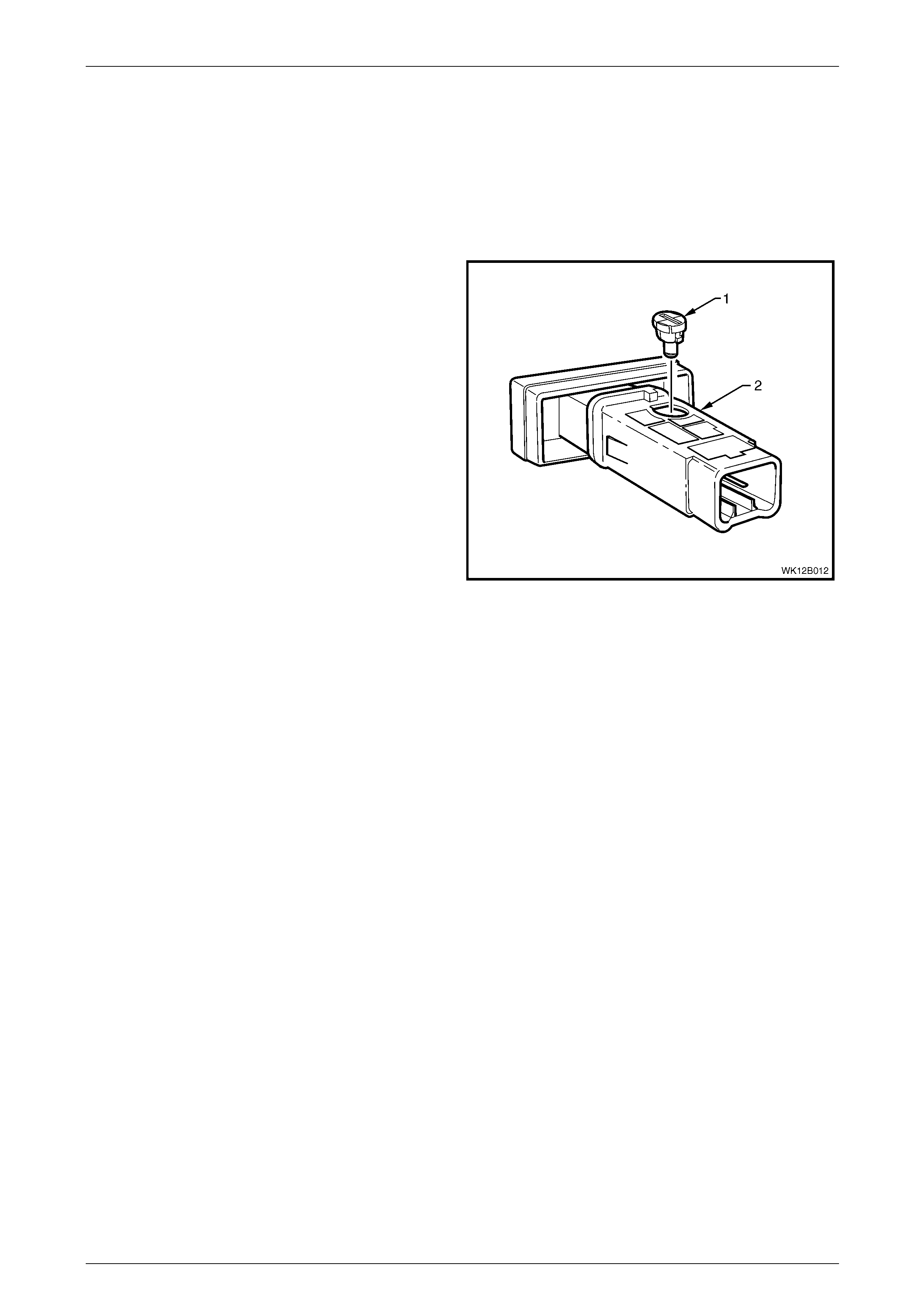
Lighting System Page 12B–67
Page 12B–67
3.23 Hazard Warning Switch Bulb
LT Section No. — 02–800
Replace
1 Remove the hazard warning switch assembly , refer to 3.22 Hazard W arnin g Switch Assembly.
2 Using a fine-bladed screwdriver inserted into the
groove on the bulb socket, twist the bulb socket and
bulb assembly (1) anticlockwise and remove it from
the hazard warning switch assembly (2).
3 Pull the bulb socket and bulb assembly from the
hazard warning switch assembly.
4 Insert the new bulb socket and bulb assembly into the
hazard warning switch assembly.
5 Install the hazard warning switch assembl y, refer to
3.22 Hazard Warning Switch Assembly.
Figure 12B – 60
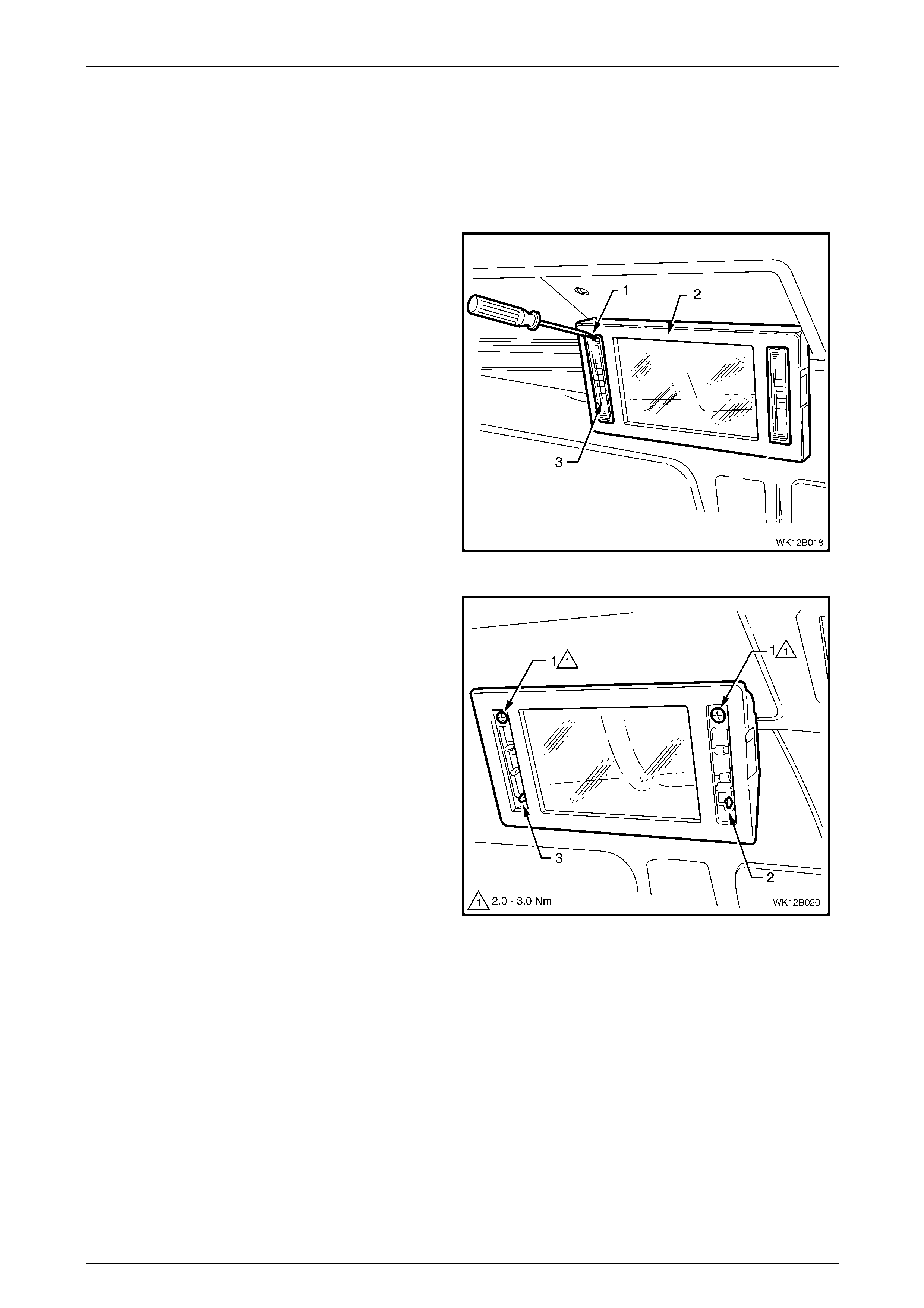
Lighting System Page 12B–68
Page 12B–68
3.24 Rear Vanity Mirror Lamp Bulbs
LT Section — 02–780
Replace
1 Press the rear vanity mirror assembly button and
allow the rear vanity mirror as sembly to swing down.
2 Using a fine-bladed screwdriver (1), carefully lever the
notched ends of the mirror lamp lens (3) from the rear
vanity mirror assembly (2).
Figure 12B – 61
3 Remove both screws (1).
4 Using a fine-blade screwdriver, lever up the retainers
(2 and 3). Remove the rear vanit y mirror assembly
from the rear vanity mirror housing.
NOTE
Take care not to lose the rear vanity mirror
assembly lamp switch slider (2) when
separating the rear vanity mirror assembly from
the rear vanity mirror housing, refer to
Figure 12B – 64.
Figure 12B – 62
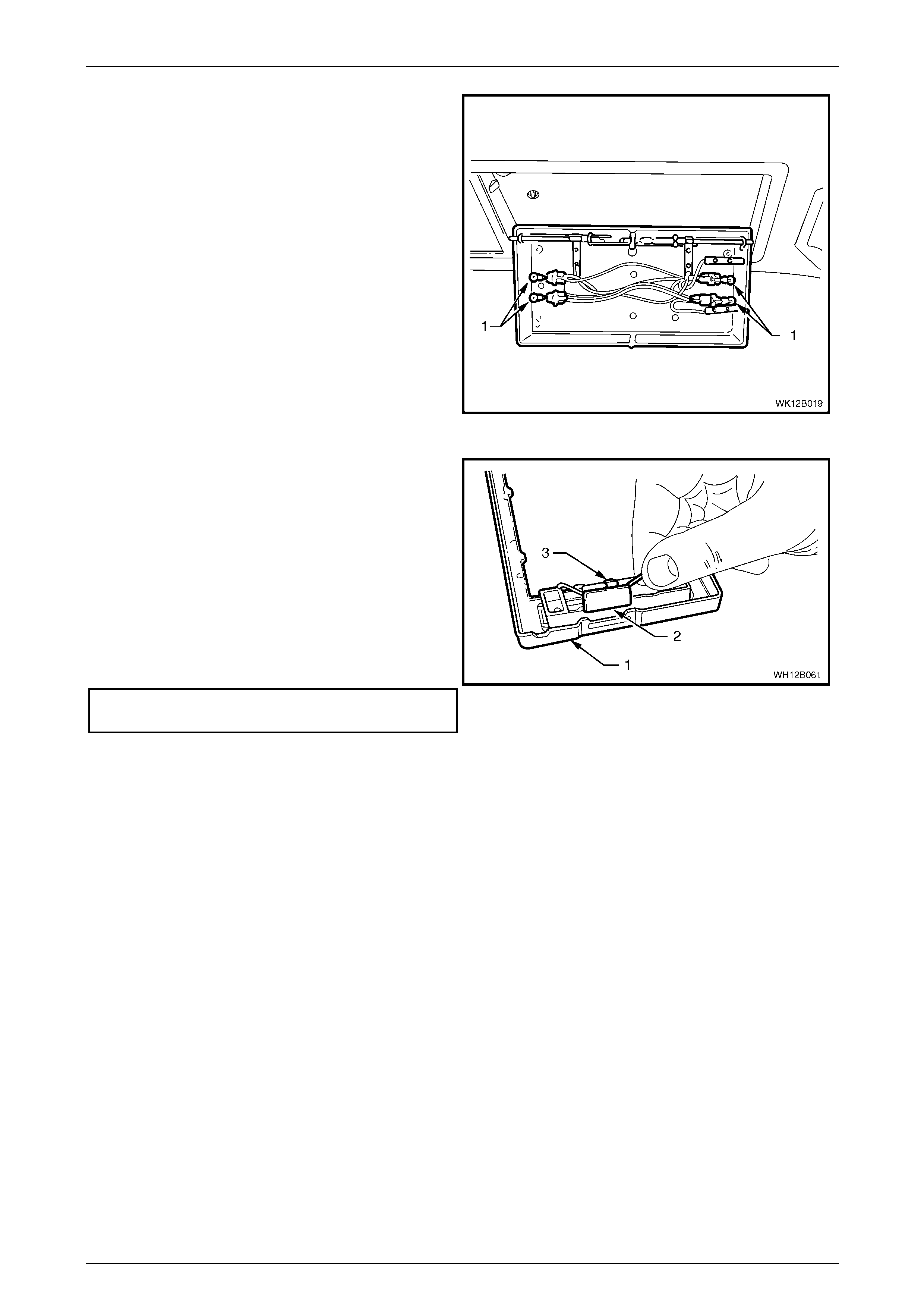
Lighting System Page 12B–69
Page 12B–69
5 Replace the bulbs (1) in the rear vanity mirror housing
if required.
Figure 12B – 63
6 Install the rear vanity mirror lamp assembly switch
slider (2) into the rear vanity mirror assembly (1) and
ensure it is located correctly in the slot on the side of
the rear vanity mirror housing.
7 Engage the rear vanity mirror assembl y onto the top
edge retainer of the rear vanit y mirror housing (3).
Squeeze the lower corners of the rear vanity mirror
assembly together to engage the retainers in each
bottom corner.
8 Secure the rear vanity mirror assembly with both
fastening screws and tighten to the correct torque
specification.
Rear vanity mirror assembl y attaching
screw torque specification...........................2.0 – 3.0 Nm Figure 12B – 64
9 Install the mirror lamp lens into the rear vanity mirror housing with the notched ends faci ng upward.
10 Switch the mirror lamp on and ensure the bulbs illuminate.
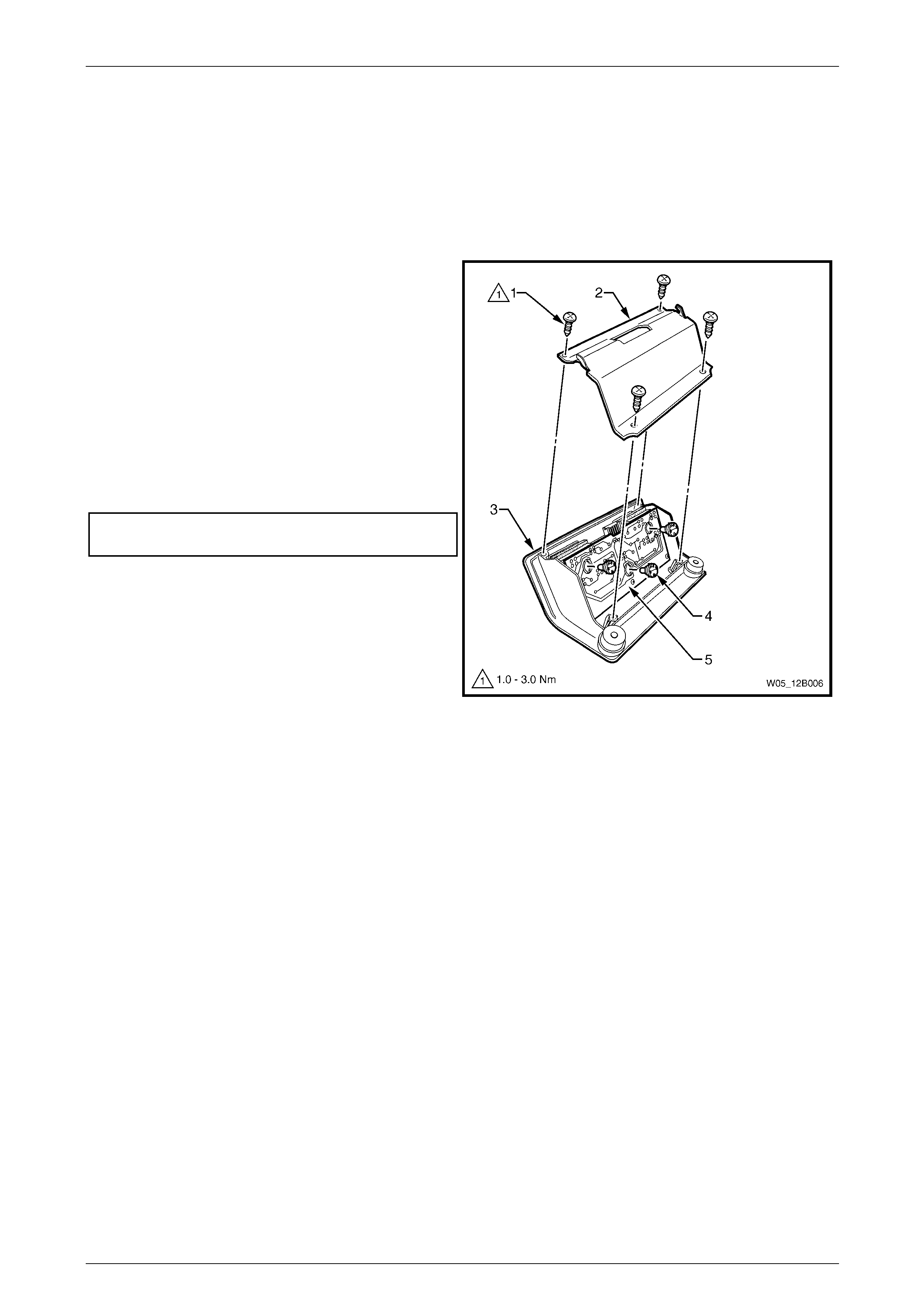
Lighting System Page 12B–70
Page 12B–70
3.25 Rear Remote Control Bulbs
LT Section — 02–780
Replace
1 Remove the rear remote control, refer to Section 1A8 Headli ning and Interior Trim.
2 Remove the four screws (1).
3 Remove the cover (2) from the rear remote
control (3).
4 Using a flat-bladed screwdriver, rotate the failed
bulb (4) approximately o ne quarter of a turn
anticlockwise.
5 Remove the failed bulb from the printed circuit
board (5).
6 Insert the new bulb and ensure it is locked into place.
7 Install the cover and tighten to the correct torque
specification.
Rear remote control cover attaching
screw torque specification...........................1.0 – 3.0 Nm
8 Install the rear remote control, refer to
Section 1A8 Headlining and Interior Trim.
Figure 12B – 65

Lighting System Page 12B–71
Page 12B–71
4 Specifications
Bulb Power Rating
(Watts) Type
Hi/lo beam (outboard)
High beam (inboard)
60 / 55
55
H11
H9
Park lamps (front) 5 wedge
Turn signal lamps (front)
Turn signal lamps (rear) 21 offset pin (orange glass)
Side repeater lamps 5 wedge
Front fog lamps 27 H27W/2
Front cornering lamps 21 P21W
Backup lamps 21 standard parallel pin
Licence plate lamps 5 wedge
Hazard warning lamp switch bulb 1 bayonet
PWR switch bulb 1 ba yonet
T/C switch bulb 1 bayo net
ESP switch bulb 1 bayonet
A/S switch bulb 1 bayonet
Dual park assist override s witch bul b 1 bayonet
Rear compartment lamp 10 festoon
Front seat reading lamp 5 standard parallel pi n
Roof console lamps 10 bayonet
Rear seat reading lamp 5 festoon
Instrument panel compartment lamp 5 festoon
Ignition lock bulb 1.4 wedge
Front stepwell lamps 2.7 wedge
Front vanity mirror lamp 1.4 wedge
Rear vanity mirror lamp 1.4 wedge
Door courtesy lamps 5 festoon
Floor console compartment lamp 5 festoon
High-mounted stop lamp 18 wedge
Front and rear cigar lighter bul b 1.2 wedge
Rear remote control bulb 1.2 bayonet

Lighting System Page 12B–72
Page 12B–72
5 Torque Wrench Specifications
Tail Lamp Assembly Attaching Nut................................................1.0 – 1.5 Nm
Headlamp Assembly Retaining Screw...........................................2.0 – 5.0 Nm
Front Fog Lamp and Cornering Lamp
Assembly Attaching Screw............................................................1.0 – 3.0 Nm
Rear Compartment Courtesy Lamp Switch Assembly
Attaching Screw ............................................................................1.0 – 3.0 Nm
Door Ajar Switch Attaching Screw.................................................1.0 – 3.0 Nm
Transmission Selector Knob Attaching Screw...............................1.0 – 3.0 Nm
Daylight Running Lamps Module Attaching Screw........................1.0 – 2.0 Nm
Rear Vanity Mirror Assembly Attaching Screw..............................2.0 – 3.0 Nm
Rear Remote Control Cover Attaching Screw...............................1.0 – 3.0 Nm