
Engine Mechanical – V6 Page 6A1–1
Page 6A1–1
Section 6A1
Engine Mechanical – V6
ATTENTION
Before performing any service operation or other procedure described in this Section, refer to Section 00
Cautions and Notes for correct workshop practices with regard to safety and/or property damage.
1 General Information ...............................................................................................................................9
1.1 Engine Components............................................................................................................................................ 10
Major Component Assemblies............................................................................................................................ 10
Intake Manifold Assembly................................................................................................................................... 11
Engine Front Cover.............................................................................................................................................. 12
Camshaft Timing Components........................................................................................................................... 13
Camshaft Cover Assembly.................................................................................................................................. 14
Cylinder Head Assembly..................................................................................................................................... 15
Oil Pump............................................................................................................................................................... 16
Engine Block Assembly...................................................................................................................................... 17
Pistons, Rings, Bearing and Connecting Rod................................................................................................... 18
Oil Pan Assembly................................................................................................................................................. 19
Oil Filter Assembly .............................................................................................................................................. 20
1.2 Engine Serial Number.......................................................................................................................................... 21
1.3 Engine Construction............................................................................................................................................ 22
Cylinder Block...................................................................................................................................................... 22
Cylinder Heads..................................................................................................................................................... 22
Crankshaft............................................................................................................................................................ 23
Pistons, Pins and Connecting Rods .................................................................................................................. 23
Camshaft Drive System....................................................................................................................................... 23
Camshaft Position Actuator Control System .................................................................................................... 24
Intake Manifold..................................................................................................................................................... 25
1.4 Engine Lubrication Sy s t em................................................................................................................................. 26
Lubrication Description....................................................................................................................................... 26
1.5 Service Notes....................................................................................................................................................... 27
Cleanliness and Care........................................................................................................................................... 27
Replacing Engine Gaskets.................................................................................................................................. 27
Re-Using Gaskets and Applying Sealants........................................................................................................ 27
Separating Components................................................................................................................................... 27
Cleaning Gasket Surfaces................................................................................................................................ 27
Assembling Components ................................................................................................................................. 27
Use of Room Temperature Vulcanising and Anaerobic Sealer........................................................................28
Room Temperature Vulcanising Sealer............................................................................................................ 28
Anaerobic Sealer.............................................................................................................................................. 28
Pipe Joint Compound....................................................................................................................................... 28
Separating Parts .................................................................................................................................................. 29
Tools and Equipment .......................................................................................................................................... 29
Fasteners.............................................................................................................................................................. 30
Clamp Load...................................................................................................................................................... 30
Torque Angle and Torque to Yield Fasteners................................................................................................... 30
Techline
Techline
Techline

Engine Mechanical – V6 Page 6A1–2
Page 6A1–2
2 Diagnosis ..............................................................................................................................................31
2.1 Engine Diagnosis................................................................................................................................................. 31
2.2 Symptoms ............................................................................................................................................................ 32
Strategy Based Diagnosis ................................................................................................................................... 32
Visual / Physical Inspection................................................................................................................................ 32
Intermittent........................................................................................................................................................... 32
2.3 Engine Misfire without Internal Engine Noises................................................................................................. 33
2.4 Engine Misfire with Abnormal Internal Lower Engine Noises.......................................................................... 35
2.5 Engine Misfire with Abnormal Valve Train Noise.............................................................................................. 36
2.6 Engine Misfire with Coolant Consumption........................................................................................................ 37
2.7 Engine Misfire with Excessive Oil Consumption.............................................................................................. 38
2.8 Engine Noise on Start-up, but only Lasting a Few Seconds............................................................................ 39
2.9 Upper Engine Noise, Regardless of Engine Speed........................................................................................... 40
2.10 Lower Engine Noise, Regardless of Engine Speed .......................................................................................... 41
2.11 Engine Noise Under Load ................................................................................................................................... 42
2.12 Engine Will Not Crank – Crankshaft Will Not Rotate ........................................................................................ 43
2.13 Coolant in Combustion Chamber....................................................................................................................... 44
Definition .............................................................................................................................................................. 44
2.14 Coolant in Engine Oil........................................................................................................................................... 45
Definition .............................................................................................................................................................. 45
2.15 Engine Compression Test................................................................................................................................... 46
Preliminary Steps................................................................................................................................................. 46
Engine Cylinder Compression Test ................................................................................................................... 46
Test Result Evaluation ........................................................................................................................................ 46
2.16 Cylinder Leakage Test......................................................................................................................................... 47
2.17 Engine Oil Consumption Diagnosis................................................................................................................... 48
Definition .............................................................................................................................................................. 48
2.18 Engine Oil Leak Diagnosis.................................................................................................................................. 49
Introduction.......................................................................................................................................................... 49
Locating and Identifying the Leak...................................................................................................................... 49
Visual Inspection ................................................................................................................................................. 49
Powder Method.................................................................................................................................................... 49
Black Light and Dye Method............................................................................................................................... 49
Possible Causes for Engine Oil Leaks............................................................................................................... 49
2.19 Engine Oil Pressure Diagnosis........................................................................................................................... 50

Engine Mechanical – V6 Page 6A1–3
Page 6A1–3
2.20 Accessory Drive Belt Diagnosis......................................................................................................................... 51
Tension Check ..................................................................................................................................................... 51
Inspect .................................................................................................................................................................. 52
Drive Belt Chirp.................................................................................................................................................... 53
Definition.......................................................................................................................................................... 53
Diagnostic Aids................................................................................................................................................. 53
Test Description ............................................................................................................................................... 53
Diagnostic Table............................................................................................................................................... 54
Drive Belt Squeal ................................................................................................................................................. 55
Definition.......................................................................................................................................................... 55
Diagnostic Aids................................................................................................................................................. 55
Test Description ............................................................................................................................................... 55
Diagnostic Table............................................................................................................................................... 56
Drive Belt Whine .................................................................................................................................................. 57
Definition.......................................................................................................................................................... 57
Diagnostic Aids................................................................................................................................................. 57
Test Description ............................................................................................................................................... 57
Diagnostic Table............................................................................................................................................... 58
Drive Belt Rumble................................................................................................................................................ 59
Definition.......................................................................................................................................................... 59
Diagnostic Aids................................................................................................................................................. 59
Test Description ............................................................................................................................................... 59
Diagnostic Table............................................................................................................................................... 60
Drive Belt Vibration.............................................................................................................................................. 61
Definition.......................................................................................................................................................... 61
Diagnostic Aids................................................................................................................................................. 61
Test Description ............................................................................................................................................... 61
Diagnostic Table............................................................................................................................................... 62
Drive Belt Falls Off............................................................................................................................................... 63
Definition.......................................................................................................................................................... 63
Diagnostic Aids................................................................................................................................................. 63
Test Description ............................................................................................................................................... 63
Diagnostic Table............................................................................................................................................... 64
Drive Belt Excessive Wear.................................................................................................................................. 65
Definition.......................................................................................................................................................... 65
Diagnostic Aids................................................................................................................................................. 65
Test Description ............................................................................................................................................... 65
Diagnostic Table............................................................................................................................................... 65
Accessory Drive Belt Tensioner Diagnosis....................................................................................................... 66
Diagnostic Table............................................................................................................................................... 66

Engine Mechanical – V6 Page 6A1–4
Page 6A1–4
3 Minor Service Operations....................................................................................................................67
3.1 Engine Dress Cover............................................................................................................................................. 68
Remove................................................................................................................................................................. 68
Reinstall................................................................................................................................................................ 68
3.2 Engine Oil............................................................................................................................................................. 69
Check.................................................................................................................................................................... 69
Replace................................................................................................................................................................. 69
Pressure Check.................................................................................................................................................... 70
3.3 Oil Filter Cartridge ............................................................................................................................................... 71
Replace................................................................................................................................................................. 71
3.4 Oil Filter Adaptor.................................................................................................................................................. 72
Remove................................................................................................................................................................. 72
Reinstall................................................................................................................................................................ 72
3.5 Oil Level Indicator Tube...................................................................................................................................... 73
Remove................................................................................................................................................................. 73
Reinstall................................................................................................................................................................ 73
3.6 Accessory Drive Belt........................................................................................................................................... 74
Remove................................................................................................................................................................. 74
Reinstall................................................................................................................................................................ 74
3.7 Accessory Drive Belt Idler Pulley....................................................................................................................... 75
Remove................................................................................................................................................................. 75
Reinstall................................................................................................................................................................ 75
3.8 Accessory Drive Belt Tensioner Assembly....................................................................................................... 76
Remove................................................................................................................................................................. 76
Reinstall................................................................................................................................................................ 76
3.9 Power Steering Reservoir and Pump Brackets................................................................................................. 77
Remove................................................................................................................................................................. 77
Reinstall................................................................................................................................................................ 77
3.10 Upper Intake Manifold ......................................................................................................................................... 78
Remove................................................................................................................................................................. 78
Disassemble......................................................................................................................................................... 81
Clean..................................................................................................................................................................... 82
Inspect .................................................................................................................................................................. 82
Reassemble.......................................................................................................................................................... 83
Reinstall................................................................................................................................................................ 83
3.11 Intake Manifold Assembly – Complete............................................................................................................... 84
Remove................................................................................................................................................................. 84
Disassemble......................................................................................................................................................... 88
Clean..................................................................................................................................................................... 89
Inspect .................................................................................................................................................................. 90
Reassemble.......................................................................................................................................................... 90
Reinstall................................................................................................................................................................ 91
3.12 Exhaust Manifold Assembly ............................................................................................................................... 92
Remove................................................................................................................................................................. 92
Disassemble......................................................................................................................................................... 94
Clean..................................................................................................................................................................... 94
Inspect .................................................................................................................................................................. 94
Reinstall................................................................................................................................................................ 95
3.13 Camshaft Cover ................................................................................................................................................... 96
Remove................................................................................................................................................................. 96
Clean and Inspect................................................................................................................................................ 99
Reinstall.............................................................................................................................................................. 100

Engine Mechanical – V6 Page 6A1–5
Page 6A1–5
3.14 Crankshaft Balancer Assembly........................................................................................................................ 103
Remove............................................................................................................................................................... 103
Clean and Inspect.............................................................................................................................................. 104
Reinstall.............................................................................................................................................................. 104
3.15 Crankshaft Front Seal........................................................................................................................................ 106
Replace............................................................................................................................................................... 106
3.16 Front Cover Assembly....................................................................................................................................... 107
Remove............................................................................................................................................................... 107
Disassemble....................................................................................................................................................... 108
Clean................................................................................................................................................................... 109
Inspect ................................................................................................................................................................ 110
Reassemble........................................................................................................................................................ 110
Reinstall.............................................................................................................................................................. 111
3.17 Timing Chains, Tensioners, Shoes and Guides.............................................................................................. 113
Primary and Left-hand Secondary Timing Chain Installation........................................................................ 114
Right-hand Secondary Timing Chain Installation........................................................................................... 115
Remove............................................................................................................................................................... 116
Right-hand Secondary Timing Chain.............................................................................................................. 116
Primary Timing Chain..................................................................................................................................... 120
Left-hand Secondary Timing Chain................................................................................................................ 122
Clean................................................................................................................................................................... 125
Inspect ................................................................................................................................................................ 126
Timing Chains ................................................................................................................................................ 126
Camshaft Intermediate Driveshaft Sprockets................................................................................................. 126
Inlet and Exhaust Camshaft Position Actuator ............................................................................................... 126
Crankshaft Sprocket....................................................................................................................................... 127
Primary Timing Chain Upper Guide................................................................................................................ 127
Primary Timing Chain Lower Guide................................................................................................................ 128
Primary Timing Chain Tensioner.................................................................................................................... 128
Left-hand Secondary Timing Chain Guide ..................................................................................................... 129
Left-hand Secondary Timing Chain Shoe....................................................................................................... 129
Left-hand Secondary Timing Chain Tensioner............................................................................................... 130
Right-hand Secondary Timing Chain Guide................................................................................................... 130
Right-hand Secondary Timing Chain Shoe.................................................................................................... 131
Right-hand Secondary Timing Chain Tensioner............................................................................................. 132
Reinstall.............................................................................................................................................................. 132
Left-hand Secondary Timing Chain Components........................................................................................... 132
Primary Timing Chain Components................................................................................................................ 142
Right-hand Secondary Timing Chain Components ........................................................................................ 150
3.18 Oil Pump Assembly........................................................................................................................................... 159
Remove............................................................................................................................................................... 159
Disassemble....................................................................................................................................................... 159
Clean................................................................................................................................................................... 161
Inspect ................................................................................................................................................................ 161
Reassemble........................................................................................................................................................ 163
Reinstall.............................................................................................................................................................. 163
3.19 Camshaft Position Actuator Assembly............................................................................................................ 164
Remove............................................................................................................................................................... 164
Right-hand Side.............................................................................................................................................. 164
Left-hand Side................................................................................................................................................ 167
Clean................................................................................................................................................................... 169
Inspect ................................................................................................................................................................ 169
Reinstall.............................................................................................................................................................. 169

Engine Mechanical – V6 Page 6A1–6
Page 6A1–6
3.20 Camshaft ............................................................................................................................................................ 170
Remove............................................................................................................................................................... 170
Right-hand Side.............................................................................................................................................. 170
Left-hand Side................................................................................................................................................ 171
Clean................................................................................................................................................................... 173
Inspect ................................................................................................................................................................ 173
Camshaft Visual Inspection............................................................................................................................ 173
Camshaft Measurement................................................................................................................................. 173
Reinstall.............................................................................................................................................................. 176
Right-hand Side.............................................................................................................................................. 176
Left-hand Side (Bank 2) ................................................................................................................................. 178
3.21 Rocker Arm......................................................................................................................................................... 182
Remove............................................................................................................................................................... 182
Clean and Inspect.............................................................................................................................................. 182
Reinstall.............................................................................................................................................................. 183
3.22 Stationary Hydraulic Lash Adjuster ................................................................................................................. 184
Remove............................................................................................................................................................... 184
Clean and Inspect.............................................................................................................................................. 184
Reinstall.............................................................................................................................................................. 185
3.23 Cylinder Head Assembly................................................................................................................................... 186
Remove............................................................................................................................................................... 186
Right-hand Side (Bank 1) Cylinder Head ....................................................................................................... 186
Left-hand Side (Bank 2) Cylinder Head.......................................................................................................... 187
Disassemble....................................................................................................................................................... 188
Clean................................................................................................................................................................... 191
Inspect ................................................................................................................................................................ 191
Visual Inspection............................................................................................................................................ 191
Cylinder Head Measurement.......................................................................................................................... 192
Valve Spring Inspection and Measurement.................................................................................................... 194
Valve and Seat Grinding ................................................................................................................................ 194
Assemble............................................................................................................................................................ 199
Reinstall.............................................................................................................................................................. 202
Right-hand Side (Bank 1) Cylinder Head ....................................................................................................... 202
Left-hand Side (Bank 2) Cylinder Head.......................................................................................................... 204
3.24 Engine Mounts and Brackets............................................................................................................................ 206
Remove............................................................................................................................................................... 206
Inspect ................................................................................................................................................................ 207
Reinstall.............................................................................................................................................................. 207
4 Major Service Operations..................................................................................................................208
4.1 Engine Assembly............................................................................................................................................... 209
Remove............................................................................................................................................................... 209
Disassemble....................................................................................................................................................... 215
Reassemble........................................................................................................................................................ 216
Reinstall.............................................................................................................................................................. 216
4.2 Oil Pan and Oil Pump Suction Pipe Assembly................................................................................................ 217
Remove............................................................................................................................................................... 217
Disassemble....................................................................................................................................................... 217
Clean................................................................................................................................................................... 218
Inspect ................................................................................................................................................................ 218
Reassemble........................................................................................................................................................ 219
Reinstall.............................................................................................................................................................. 220
4.3 Flexplate Assembly ........................................................................................................................................... 221
Remove............................................................................................................................................................... 221
Clean................................................................................................................................................................... 222
Inspect ................................................................................................................................................................ 222
Reinstall.............................................................................................................................................................. 223

Engine Mechanical – V6 Page 6A1–7
Page 6A1–7
4.4 Crankshaft Rear Seal and Plate Assembly...................................................................................................... 224
Remove............................................................................................................................................................... 224
Reinstall.............................................................................................................................................................. 225
4.5 Pistons, Pins, Rings, Connecting Rods and Big-end Bearings..................................................................... 227
Remove............................................................................................................................................................... 227
Disassemble....................................................................................................................................................... 230
Clean and Inspect.............................................................................................................................................. 231
Piston Cleaning Procedure............................................................................................................................. 231
Piston Inspection Procedure .......................................................................................................................... 231
Piston Measurement ...................................................................................................................................... 232
Piston Ring Measurement.............................................................................................................................. 233
Connecting Rod Cleaning Procedure............................................................................................................. 234
Connecting Rod Visual Inspection Procedure................................................................................................ 234
Connecting Rod Measurement Procedure ..................................................................................................... 234
Reassemble........................................................................................................................................................ 236
Piston and Piston Pin..................................................................................................................................... 236
Piston Ring..................................................................................................................................................... 237
Connecting Rod Bearing................................................................................................................................ 238
Reinstall.............................................................................................................................................................. 239
Piston Connecting Rod and Connecting Rod Bearing Installation.................................................................. 239
Connecting Rod Bearing Clearance Measurement Procedure....................................................................... 240
Connecting Rod Final Assembly Procedure................................................................................................... 241
4.6 Crankshaft and Main Bearings ......................................................................................................................... 242
Crankshaft End Play Measurement.................................................................................................................. 242
Remove............................................................................................................................................................... 242
Crankshaft Bearing......................................................................................................................................... 244
Clean and Inspect.............................................................................................................................................. 245
Crankshaft and Main Bearing Cleaning.......................................................................................................... 245
Crankshaft and Main Bearing Visual Inspection............................................................................................. 245
Crankshaft Main Bearing Inspection............................................................................................................... 246
Crankshaft Measurement............................................................................................................................... 247
Reinstall.............................................................................................................................................................. 249
Crankshaft Bearing Installation Procedure..................................................................................................... 249
Crankshaft Main Bearing Clearance Measurement........................................................................................ 250
Crankshaft Final Installation Procedure.......................................................................................................... 252
4.7 Cylinder Block.................................................................................................................................................... 254
Disassemble....................................................................................................................................................... 254
Clean................................................................................................................................................................... 258
Inspect ................................................................................................................................................................ 258
Visual Inspection............................................................................................................................................ 258
Measuring Cylinder Bore Diameter ................................................................................................................ 259
Measuring Cylinder Bore Taper...................................................................................................................... 259
Measuring Cylinder Bore Out-of-Round......................................................................................................... 259
Deck Flatness Inspection............................................................................................................................... 260
Reassemble........................................................................................................................................................ 260
4.8 Thread Repairs................................................................................................................................................... 265
General Information........................................................................................................................................... 265
General Thread Repair ...................................................................................................................................... 266
Main Bearing Cap Bolt Hole Thread Repair..................................................................................................... 272
Cylinder Head Bolt Hole Thread Repair........................................................................................................... 278

Engine Mechanical – V6 Page 6A1–8
Page 6A1–8
4.9 Thread Repair Specifications............................................................................................................................ 284
Left-hand Cylinder Head Camshaft Cover Face.............................................................................................. 284
Left-hand Cylinder Head Front Face................................................................................................................ 285
Left-hand Cylinder Head Intake Face............................................................................................................... 286
Left-hand Cylinder Head Exhaust Face ........................................................................................................... 287
Left-hand Cylinder Head Rear Face ................................................................................................................. 288
Right-hand Cylinder Head Camshaft Cover Face ........................................................................................... 289
Right-hand Cylinder Head Front Face.............................................................................................................. 290
Right-hand Cylinder Head Intake Face ............................................................................................................ 291
Right-hand Cylinder Head Exhaust Face......................................................................................................... 292
Right-hand Cylinder Head Rear Face............................................................................................................... 293
Engine Block Front............................................................................................................................................ 294
Engine Block Left-hand Side ............................................................................................................................ 295
Engine Block Right-hand Side.......................................................................................................................... 296
Engine Block Rear............................................................................................................................................. 297
Engine Block Bottom......................................................................................................................................... 298
Engine Block Left-hand Deck Face.................................................................................................................. 299
Engine Block Right-hand Deck Face................................................................................................................ 300
Engine Front Cover............................................................................................................................................ 301
Upper Intake Manifold Top................................................................................................................................ 302
Upper Intake Manifold Front ............................................................................................................................. 303
Upper Intake Manifold Rear............................................................................................................................... 304
Lower Intake Manifold Top................................................................................................................................ 305
Oil Pan Front ...................................................................................................................................................... 306
Oil Pan Rear........................................................................................................................................................ 307
Oil Pan Bottom................................................................................................................................................... 308
5 Specifications.....................................................................................................................................309
6 Torque Wrench Specifications..........................................................................................................313
7 Special Tools ......................................................................................................................................315
Engine Mechanical – V6 Page 6A1–9
Page 6A1–9
1 General Information
The V6 engine features a closed vee, d eep skirt die cast aluminium cylinder block with cast iron cylinder liners, internally
balanced crankcase, full length water jackets and six bolt main bearing caps.
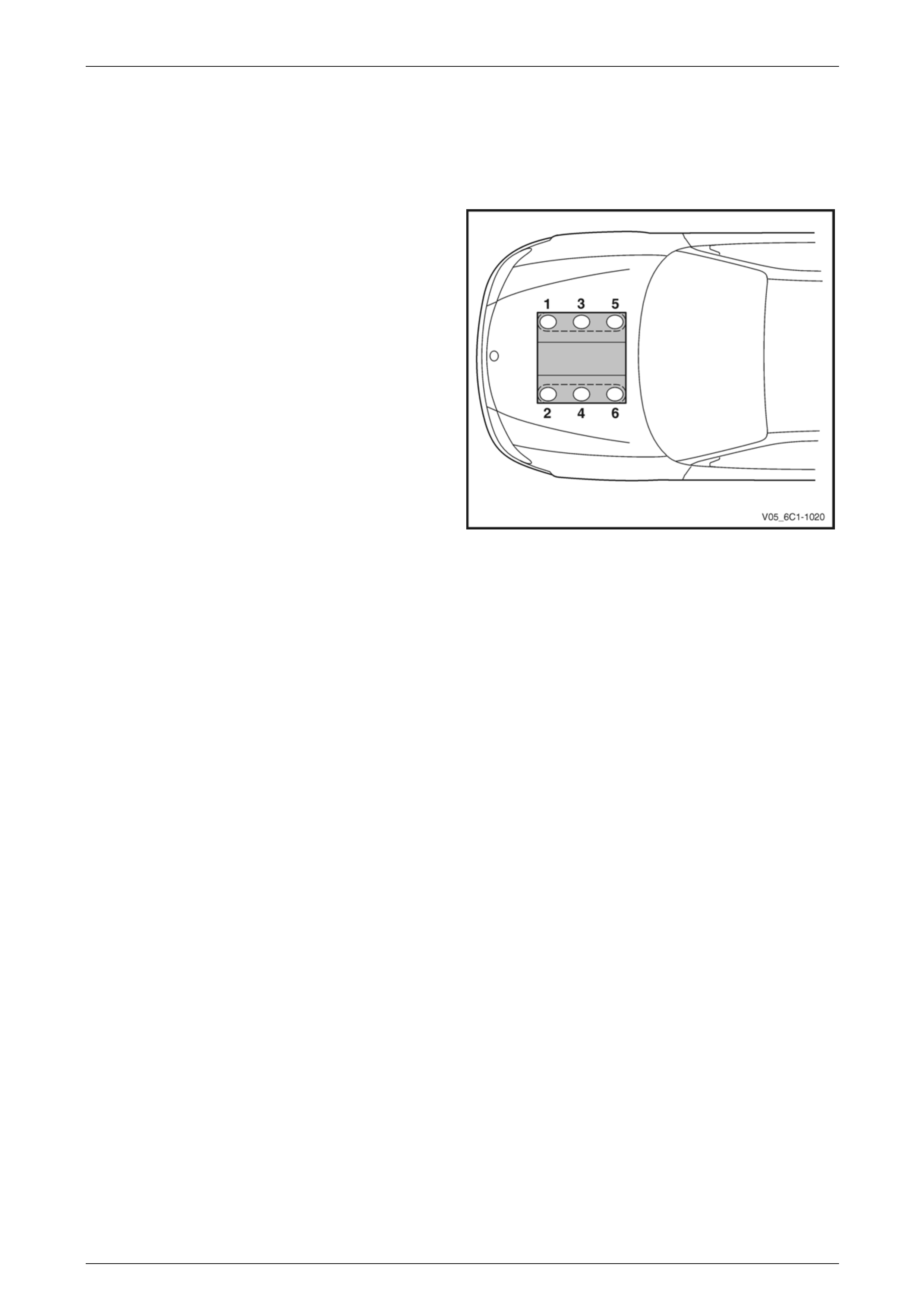
The cylinders are arranged in two banks of three with a 60 degree included angle between the two banks.
The right-hand bank of cylinders consists of number 1-3-5
cylinders and the left-hand bank of cylinders consists of
number 2-4-6.
The engine firing order is 1-2-3-4-5-6.
Each aluminium cylinder hea d is fitted with hardened valve
seats and four valves per cylinder: two intake and two
exhaust.
The valves are operated by two camshafts (DOHC) per
cylinder bank, one each for intake and exhaust valves.
Variable camshaft timing is provided via fo ur actuators fitted
at the front of each camshaft.
The crankshaft is manufactured from forged steel. A reluctor
wheel is pressed in place onto the rear of the crankshaft for
the crankshaft position sensor.
The connecting rods are manufactured from powdered
metal and the rod cap is separ ated during the manufacturing
process using the fractured met hod. This creates a stronger,
visually seamless rod to cap unio n. Figure 6A1 – 1
Engine Mechanical – V6 Page 6A1–10
Page 6A1–10
1.1 Engine Components
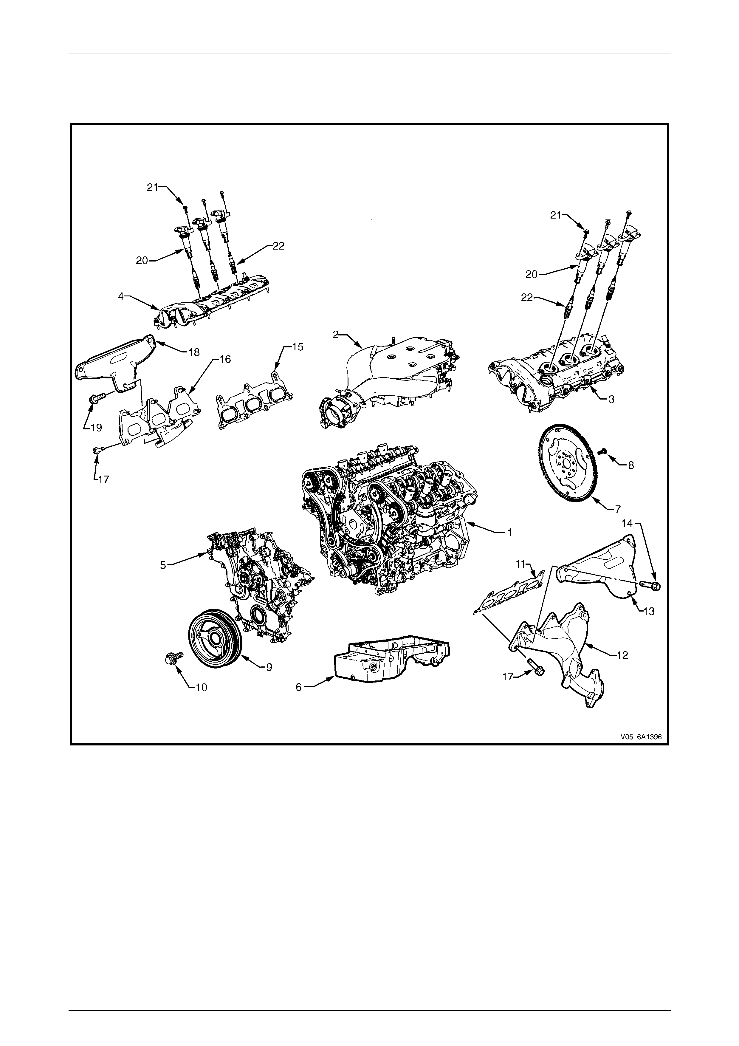
Major Component Assemblies
Figure 6A1 – 2
Legend
1 Engine Assembly
2 Intake Manifold Assembly
3 Camshaft Cover Assembly, Left-hand
4 Camshaft Cover Assembly, Right-hand
5 Engine Front Cover Assembly
6 Oil Pan Assembly
7 Engine Flywheel
8 Engine Flywheel Bolt
9 Crankshaft Balancer
10 Crankshaft Balancer Bolt
11 Exhaust Manifold Gasket, Left-hand
12 Exhaust Manifold, Left-hand
13 Exhaust Manifold Heat Shield, Left-hand
14 Exhaust Manifold Heat Shield Bolt, Left-hand
15 Exhaust Manifold Gasket, Right-hand
16 Exhaust Manifold, Right-hand
17 Cylinder Head Exhaust Manifold Bolt
18 Exhaust Manifold Heat Shield, Right-hand
19 Exhaust Manifold Heat Shield Bolt, Right-hand
20 Ignition Coil Assembly
21 Ignition Coil Assembly Bolt
22 Spark Plug
Engine Mechanical – V6 Page 6A1–11
Page 6A1–11
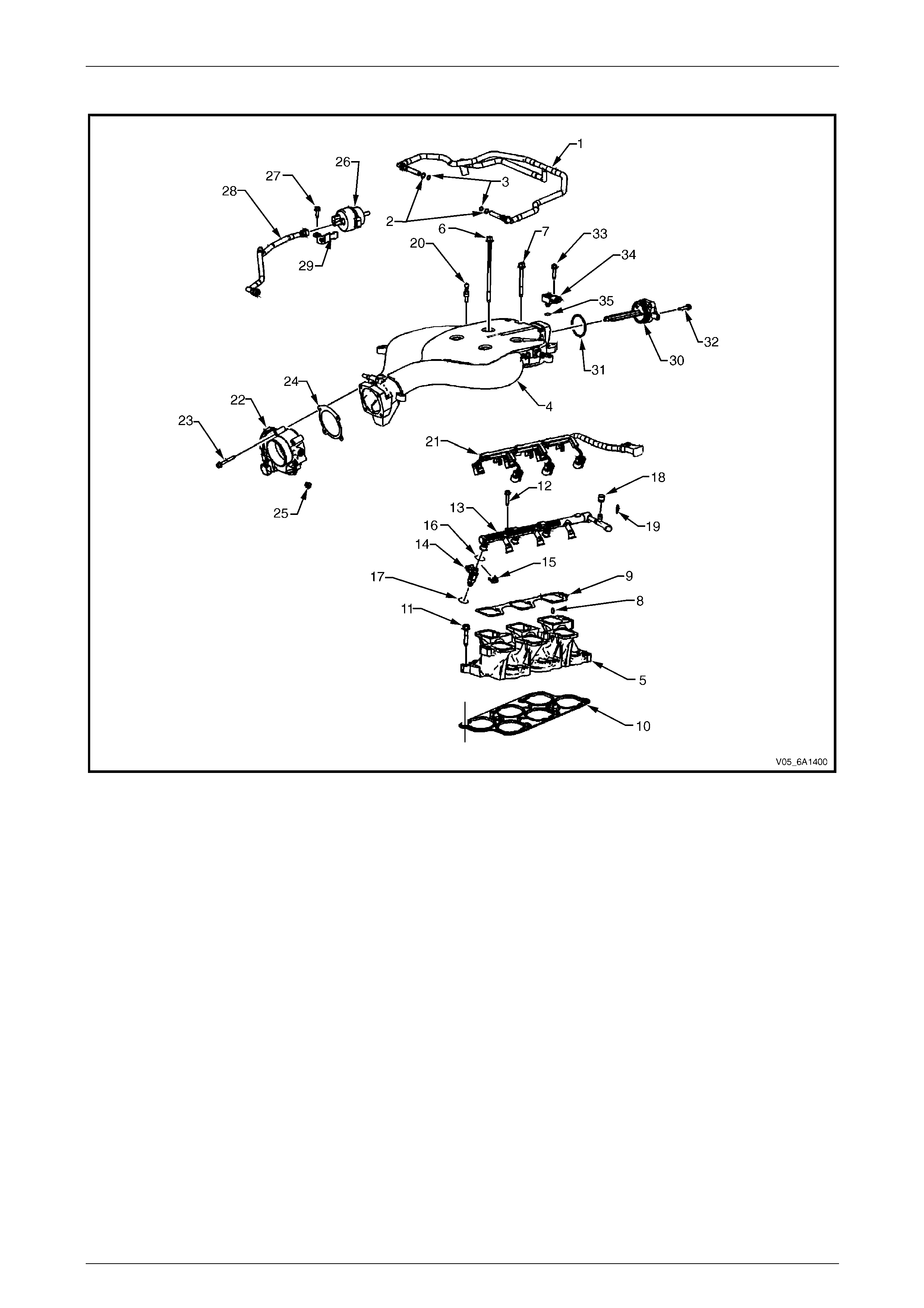
Intake Manifold Assembly
Figure 6A1 – 3
Legend
1 PCV Hose
2 PCV Hose O-Ring Outer (larger)
3 PCV Hose O-Ring Inner (smaller)
4 Upper Intake Manifold
5 Lower Intake Manifold
6 Upper Intake Manifold Bolt – Long
7 Upper Intake Manifold Bolt – Short
8 Lower Intake Manifold to Upper Intake Manifold Guide Pin
9 Upper Intake Manifold to Lower Intake Manifold Gasket
10 Lower Intake Manifold to Cylinder Head Gasket
11 Lower Intake Manifold Bolt
12 Fuel Rail Bolt
13 Fuel Rail
14 Fuel Injector
15 Fuel Injector Retainer
16 Fuel Injector Upper O-ring
17 Fuel Injector Lower O-ring
18 Fuel Pressure Service Valve Cap
19 Fuel Pressure Service Valve
20 Engine Dress Cover Ball Stud
21 Fuel Injector Wiring Harness
22 Throttle Body
23 Throttle Body Bolt
24 Throttle Body Gasket
25 Throttle Body Engine Wiring Harness Clip
26 EVAP Purge Solenoid
27 EVAP Purge Solenoid Bolt
28 EVAP Purge Solenoid Tube
29 EVAP Purge Solenoid Bracket
30 Intake Manifold Runner Control Valve
31 Intake Manifold Runner Control Valve O-Ring
32 Intake Manifold Runner Control Valve Bolt
33 BARO Sensor Bolt
34 BARO Sensor
35 BARO Sensor O-Ring
Engine Mechanical – V6 Page 6A1–12
Page 6A1–12
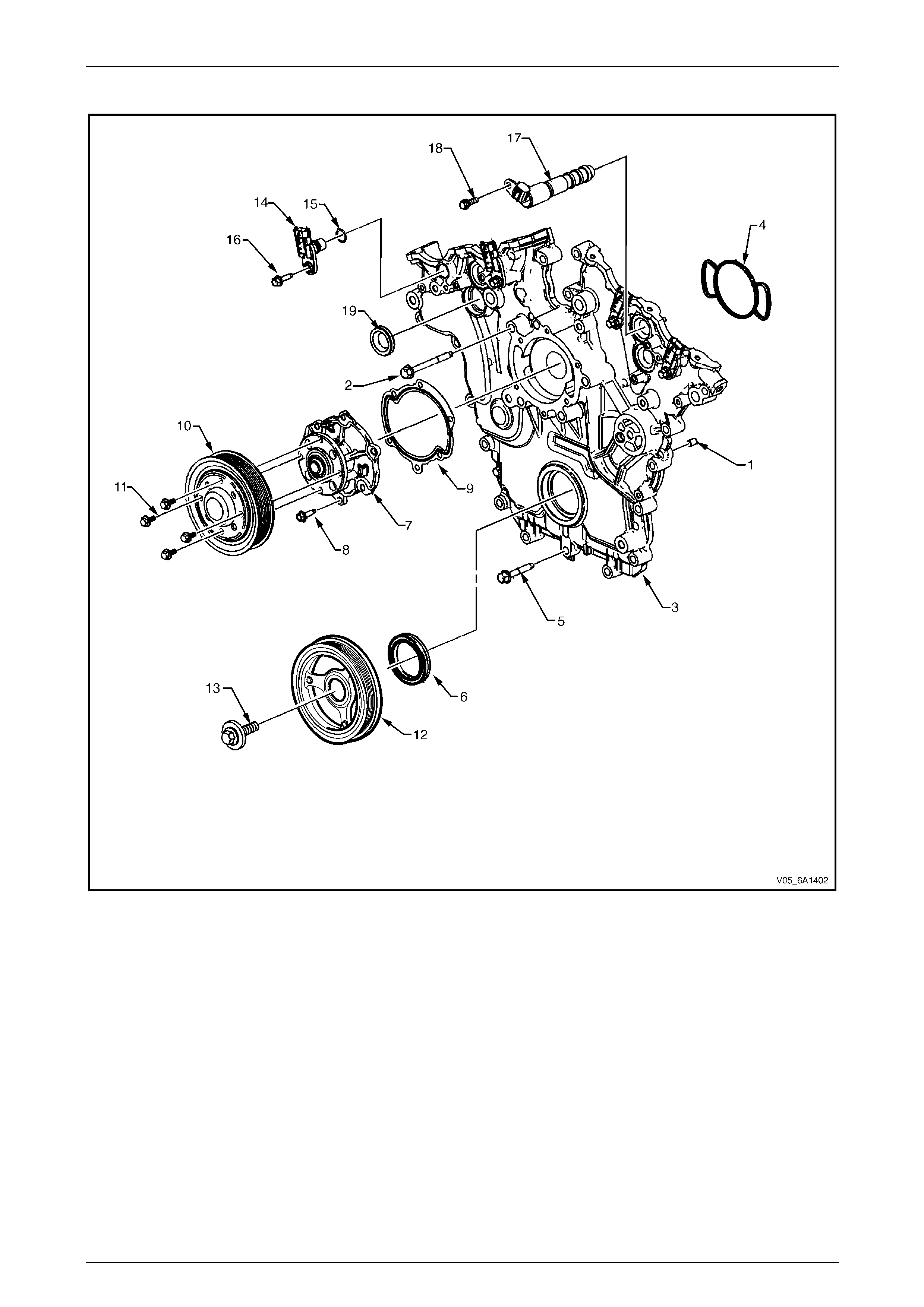
Engine Front Cover
Figure 6A1 – 4
Legend
1 Engine Front Cover Locating Pin
2 Engine Front Cover Bolt, M10
3 Engine Front Cover
4 Engine Front Cover Gasket
5 Engine Front Cover Bolt, M8
6 Engine Front Cover Seal
7 Coolant Pump Assembly
8 Coolant Pump Bolt
9 Coolant Pump Gasket
10 Coolant Pump Pulley
11 Coolant Pump Pulley Bolt
12 Crankshaft Balancer
13 Crankshaft Balancer Bolt
14 Camshaft Position Sensor
15 Camshaft Position Sensor O-ring
16 Camshaft Position Sensor Bolt
17 Camshaft Position Actuator Solenoid Valve
18 Camshaft Position Actuator Solenoid Valve Bolt
19 Camshaft Position Actuator Solenoid Valve Seal
Engine Mechanical – V6 Page 6A1–13
Page 6A1–13
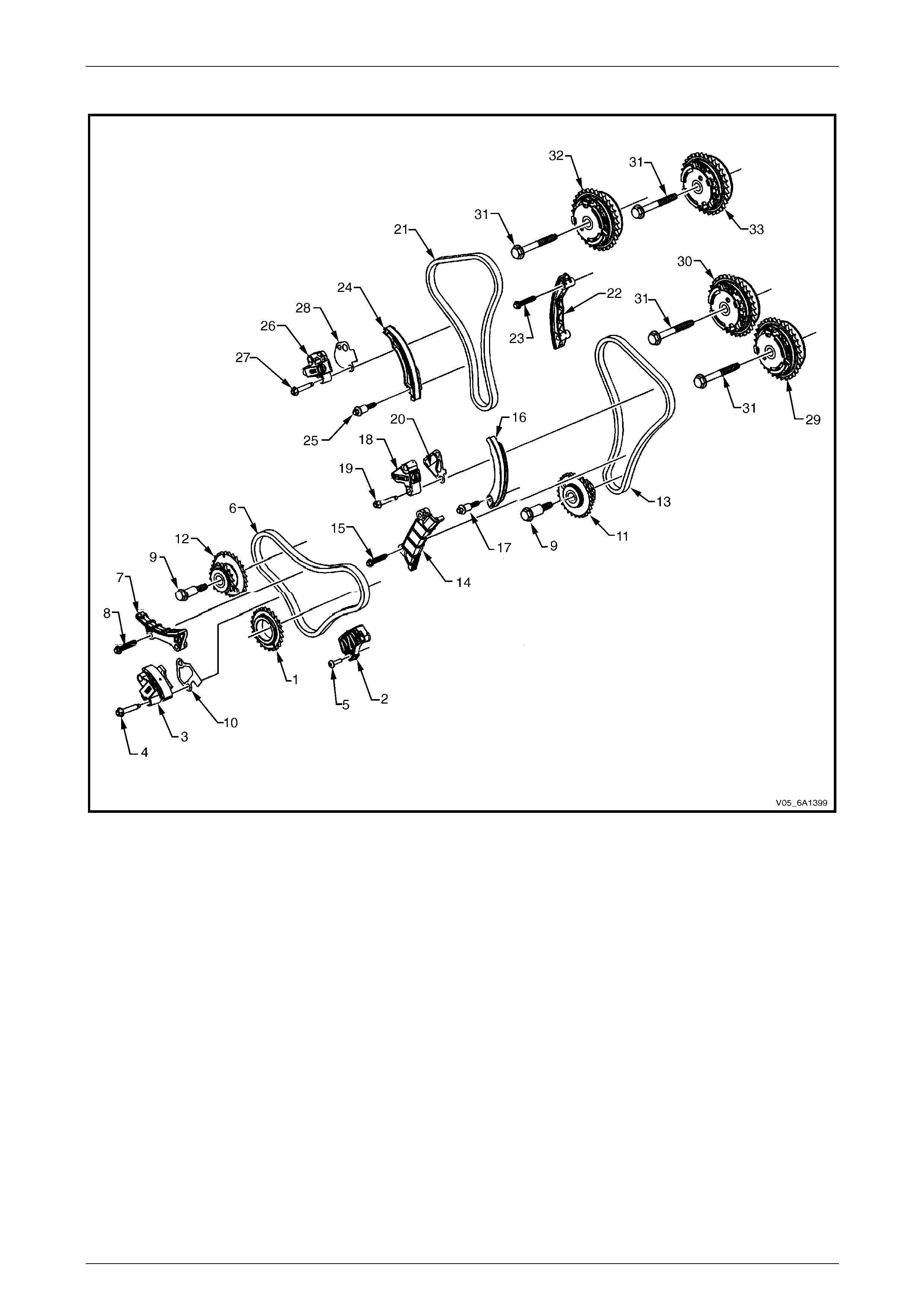
Camshaft Timing Components
Figure 6A1 – 5
Legend
1 Crankshaft Sprocket
2 Lower Primary Timing Chain Guide
3 Primary Timing Chain Tensioner
4 Primary Timing Chain Tensioner Bolt
5 Lower Primary Timing Chain Guide Bolt
6 Primary Timing Chain
7 Upper Primary Timing Chain Guide
8 Upper Primary Timing Chain Guide Bolt
9 Camshaft Intermediate Driveshaft Sprocket Bolt
10 Primary Timing Chain Tensioner Gasket
11 Camshaft Intermediate Driveshaft Sprocket, Left-hand
12 Camshaft Intermediate Driveshaft Sprocket, Right-hand
13 Secondary Timing Chain, Left-hand
14 Secondary Timing Chain Guide, Left-hand
15 Secondary Timing Chain Guide Bolt, Left-hand
16 Secondary Timing Chain Shoe, Left-hand
17 Secondary Timing Chain Shoe Bolt, Left-hand
18 Secondary Timing Chain Tensioner, Left-hand
19 Secondary Timing Chain Tensioner Bolt, Left-hand
20 Secondary Timing Chain Tensioner Gasket, Left-hand
21 Secondary Timing Chain, Right-hand
22 Secondary Timing Chain Guide, Right-hand
23 Secondary Timing Chain Guide Bolt, Right-hand
24 Secondary Timing Chain Shoe, Right-hand
25 Secondary Timing Chain Shoe Bolt, Right-hand
26 Secondary Timing Chain Tensioner, Right-hand
27 Secondary Timing Chain Tensioner Bolt, Right-hand
28 Secondary Timing Chain Tensioner Gasket, Right-hand
29 Exhaust Camshaft Position Actuator, Left-hand
30 Intake Camshaft Position Actuator, Left-hand
31 Camshaft Position Actuator Bolt
32 Exhaust Camshaft Position Actuator, Right-hand
33 Intake Camshaft Position Actuator, Right-hand
Engine Mechanical – V6 Page 6A1–14
Page 6A1–14
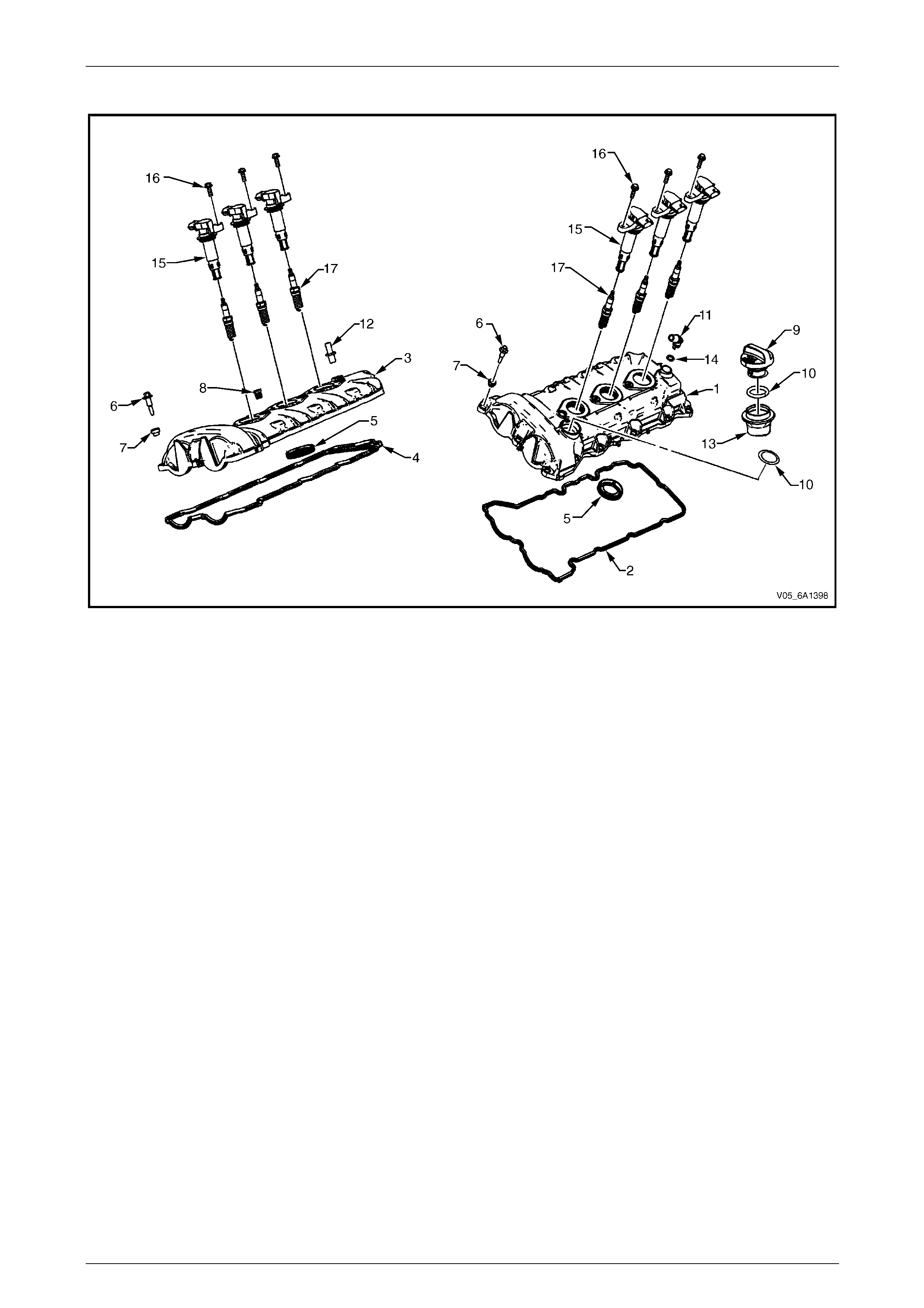
Camshaft Cover Assembly
Figure 6A1 – 6
Legend
1 Camshaft Cover, Left-hand
2 Camshaft Cover Gasket, Left-hand
3 Camshaft Cover, Right-hand
4 Camshaft Cover Gasket, Right-hand
5 Camshaft Cover Spark Plug Port Seal
6 Camshaft Cover Bolt
7 Camshaft Cover Bolt Insulator
8 Ignition Coil Bolt Thread Insert
9 Oil Fill Cap
10 Oil Fill O-Ring
11 Camshaft Cover PCV Fitting, Left-hand
12 Camshaft Cover PCV Fitting Orifice, Right-hand
13 Oil Fill Tube
14 Camshaft Cover PCV Fitting O-Ring, Left-hand
15 Ignition Coil
16 Ignition Coil Bolt
17 Spark Plug
Engine Mechanical – V6 Page 6A1–15
Page 6A1–15
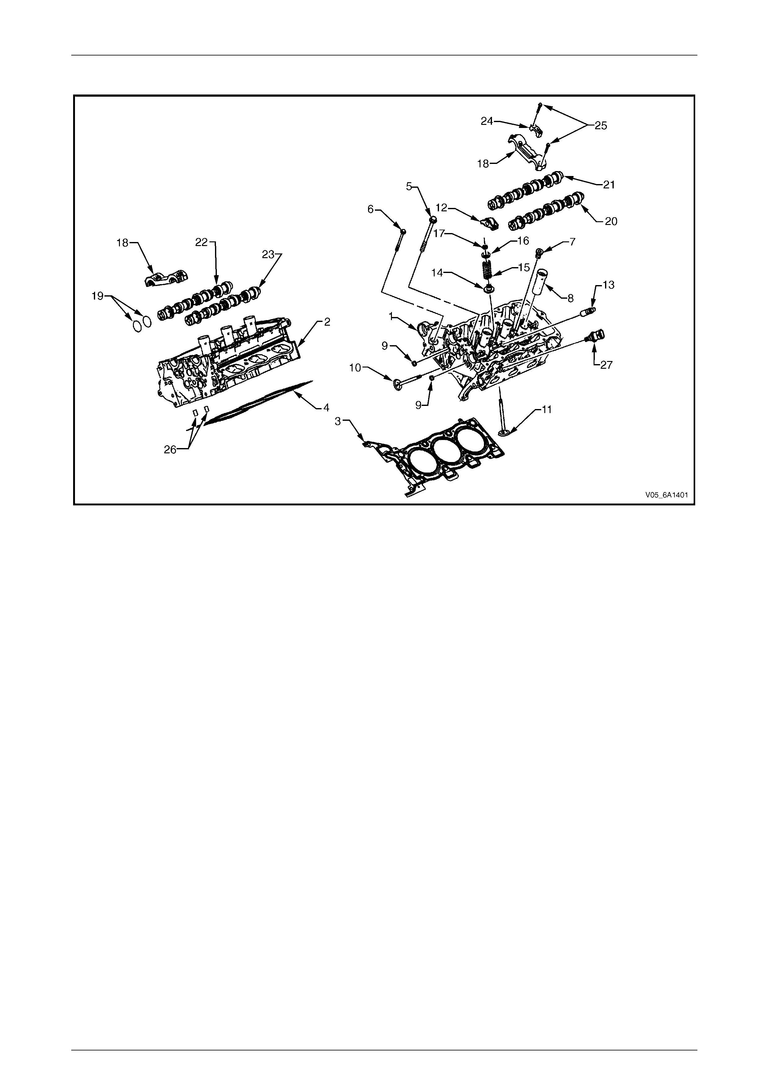
Cylinder Head Assembly
Figure 6A1 – 7
Legend
1 Cylinder Head, Left-hand
2 Cylinder Head, Right-hand
3 Cylinder Head Gasket, Left-hand
4 Cylinder Head Gasket, Right-hand
5 Cylinder Head Bolt
6 Cylinder Head Front Bolt
7 Cylinder Head Coolant Hole Threaded Plug
8 Spark Plug Sleeve
9 Cylinder Head Oil Gallery Expansion Plug
10 Exhaust Valve
11 Intake Valve
12 Valve Rocker Arm Assembly
13 Hydraulic Valve Lash Adjuster Assembly
14 Valve Stem Oil Seal
15 Valve Spring
16 Valve Spring Cap
17 Valve Stem Key
18 Cylinder Head Camshaft Front Thrust Bearing Cap
19 Camshaft Oil Seal Ring
20 Exhaust Camshaft
21 Intake Camshaft, Left-hand (bank 2)
22 Intake Camshaft, Right-hand (bank 1)
23 Exhaust Camshaft, Right-hand (bank 1)
24 Cylinder Head Camshaft Cap – Intermediate
25 Cylinder Head Camshaft Cap Bolt
26 Cylinder Head Oil Galley Check Valve
27 Engine Coolant Temperature Sensor
Engine Mechanical – V6 Page 6A1–16
Page 6A1–16
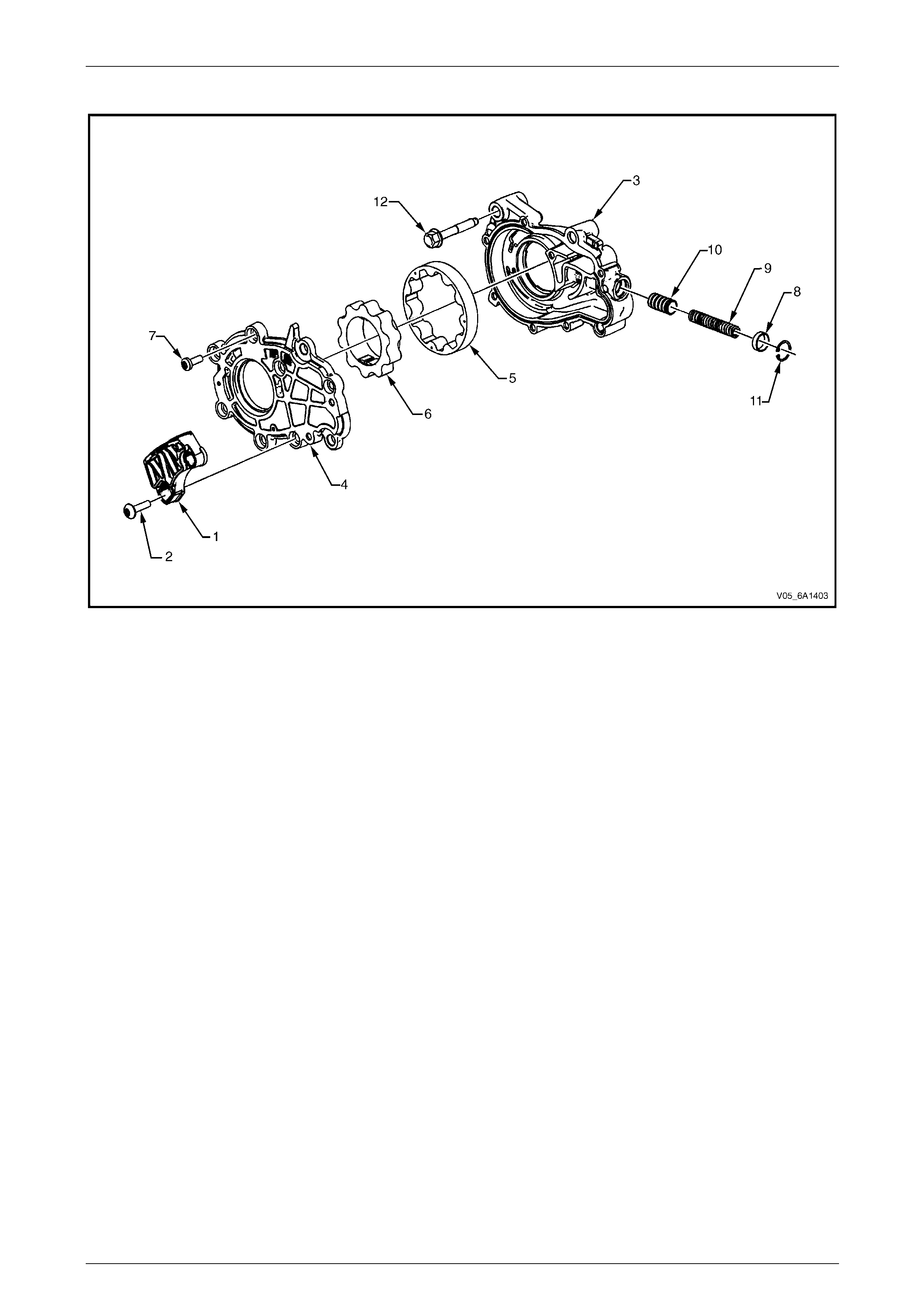
Oil Pump
Figure 6A1 – 8
Legend
1 Lower Primary Timing Chain Guide
2 Lower Primary Timing Chain Guide Bolt
3 Oil Pump Housing
4 Oil Pump Cover
5 Oil Pump Gerotor Outer Ring
6 Oil Pump Gerotor Inner Ring
7 Oil Pump Cover Bolt
8 Oil Pressure Relief Valve Bore Plug
9 Oil Pressure Relief Valve Spring
10 Oil Pressure Relief Valve
11 Oil Pressure Relief Valve Bore Plug Retainer Clip
12 Oil Pump Bolt
NOTE
Oil pump components are not serviced
individually.
Engine Mechanical – V6 Page 6A1–17
Page 6A1–17
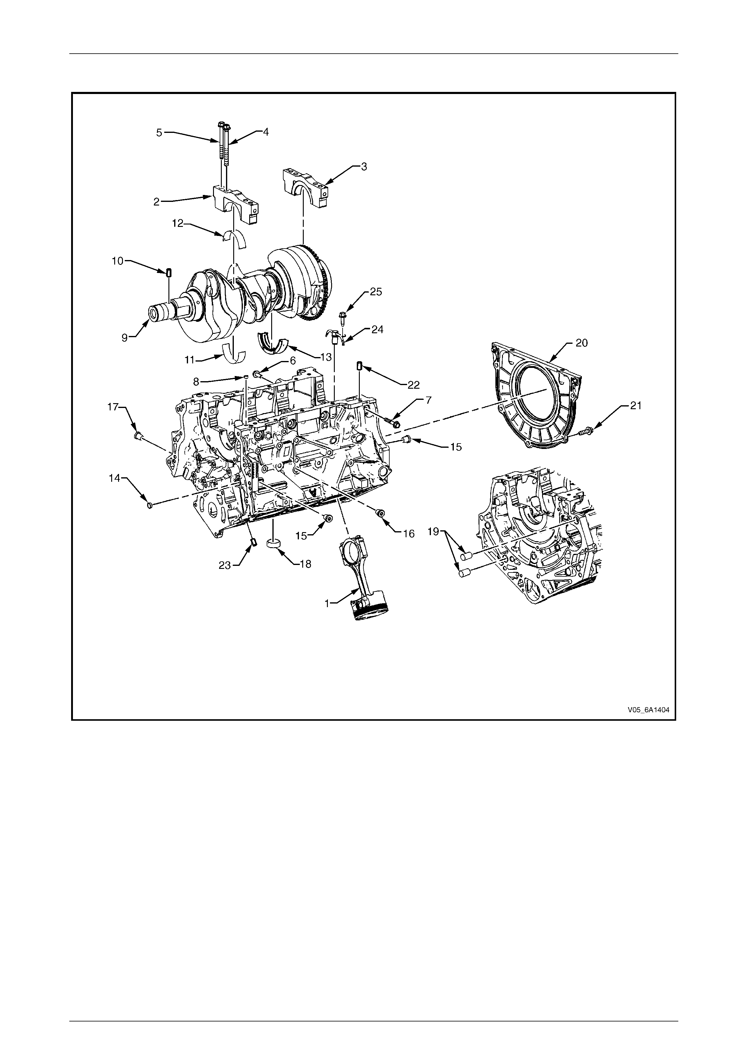
Engine Block Assembly
Figure 6A1 – 9
Legend
1 Piston and Connecting Rod Assembly
2 Crankshaft Bearing Cap
3 Crankshaft Bearing Thrust Cap
4 Crankshaft Bearing Cap Inboard Bolt
5 Crankshaft Bearing Cap Outboard Bolt
6 Crankshaft Bearing Cap Side Bolt, Short
7 Crankshaft Bearing Cap Side Bolt, Long
8 Engine Block Oil Gallery Expansion Plug, 10 mm
9 Crankshaft
10 Crankshaft Sprocket Locating Pin
11 Crankshaft Upper Bearing
12 Crankshaft Lower Bearing
13 Crankshaft Upper Thrust Bearing #3
14 Engine Block Oil Gallery Expansion Plug, 14 mm
15 Engine Block Oil Gallery Threaded Plug, 14 mm
16 Engine Block Coolant Drain Threaded Plug, 14 mm
17 Engine Block Oil Gallery Threaded Plug, 20 mm
18 Engine Block Core Coolant Expansion Plug, 34.3 mm
19 Transaxle Locating Pin
20 Crankshaft Rear Oil Seal Housing Assembly
21 Crankshaft Rear Oil Seal Housing Assembly Bolt
22 Oil Pan Locating Pin
23 Cylinder Head Locating Pin
24 Piston Oil Nozzle
25 Piston Oil Nozzle Bolt
Engine Mechanical – V6 Page 6A1–18
Page 6A1–18
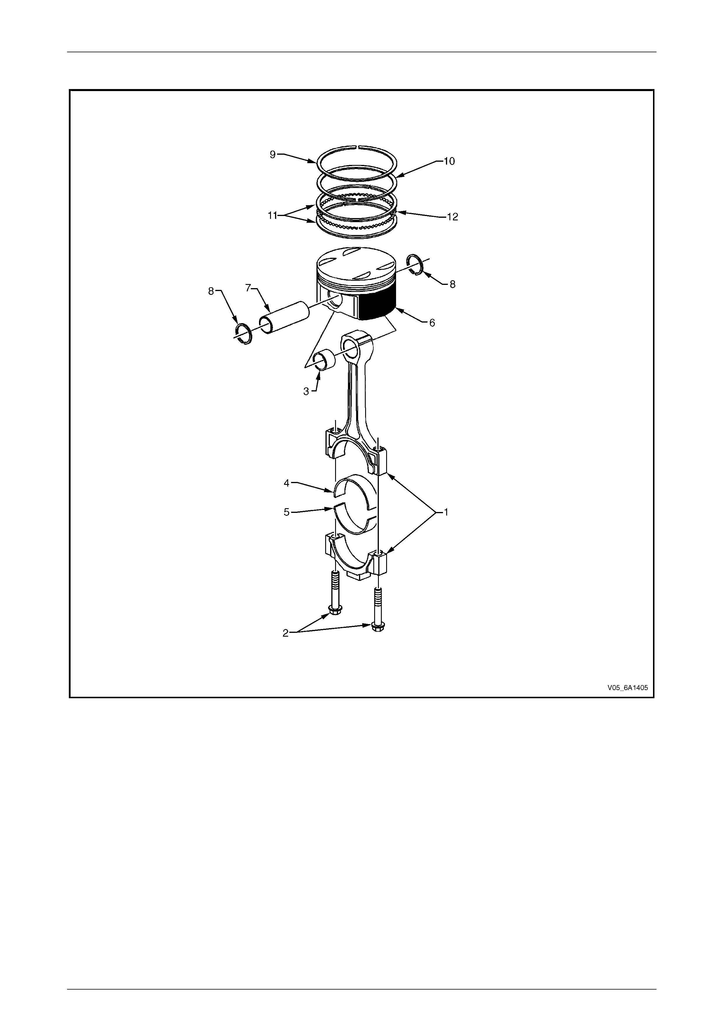
Pistons, Rings, Bearing and Connecting Rod
Figure 6A1 – 10
Legend
1 Connecting Rod
2 Connecting Rod Bolt
3 Connecting Rod Bush
4 Upper Connecting Rod Bearing
5 Lower Connecting Rod Bearing
6 Piston
7 Piston Pin
8 Piston Pin Retainer
9 Piston Upper Compression Ring
10 Piston Lower Compression Ring
11 Piston Oil Control Rail Ring
12 Piston Oil Control Ring Spacer
Engine Mechanical – V6 Page 6A1–19
Page 6A1–19
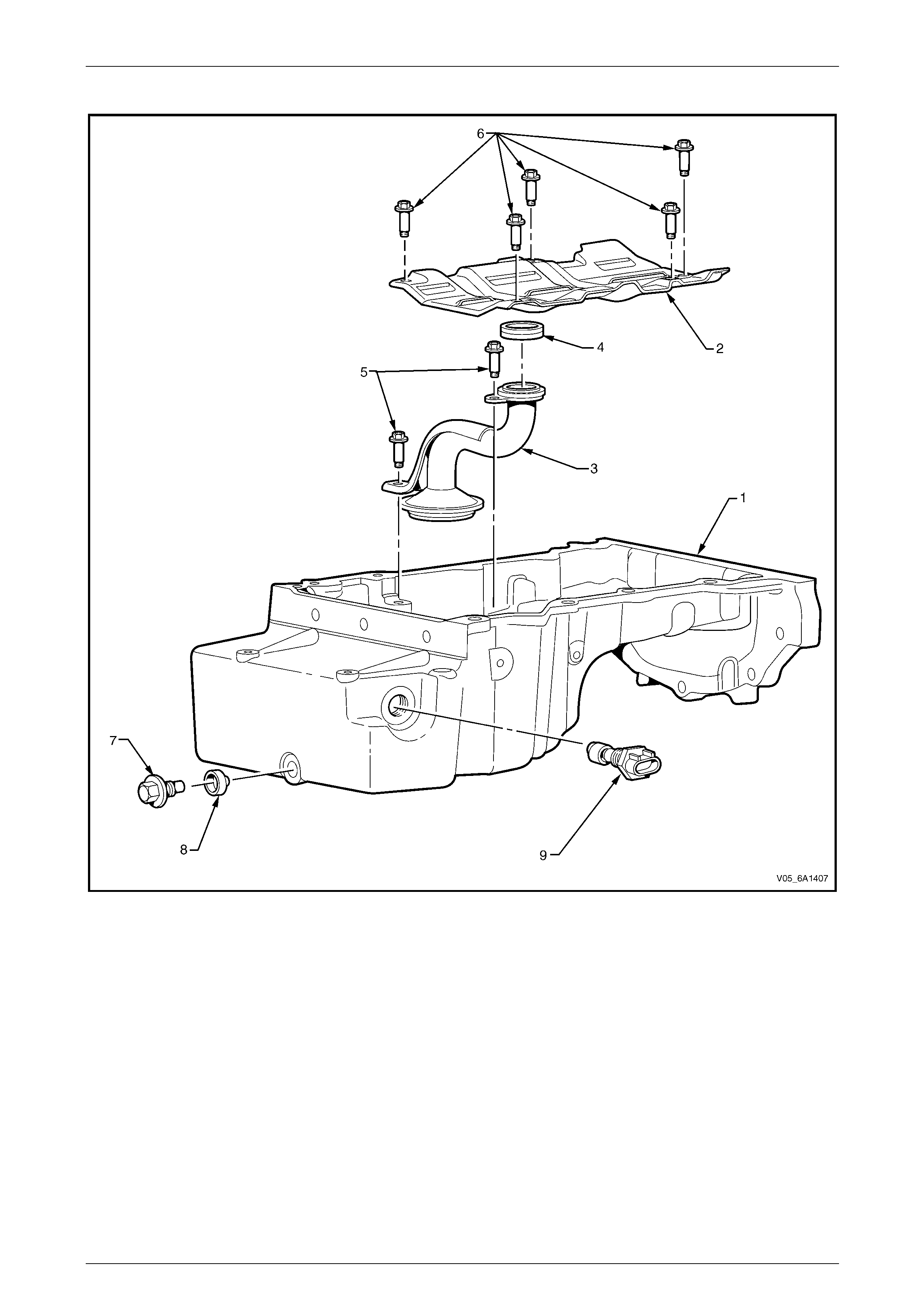
Oil Pan Assembly
Figure 6A1 – 11
Legend
1 Oil Pan
2 Crankshaft Oil Deflector
3 Oil Pump Suction Pipe
4 Oil Pump Suction Pipe Gasket
5 Oil Pump Suction Pipe Bolt
6 Crankshaft Oil Deflector Bolt
7 Oil Pan Drain Plug
8 Oil Pan Drain Plug Sleeve
9 Engine Oil Level Sensor
Engine Mechanical – V6 Page 6A1–20
Page 6A1–20
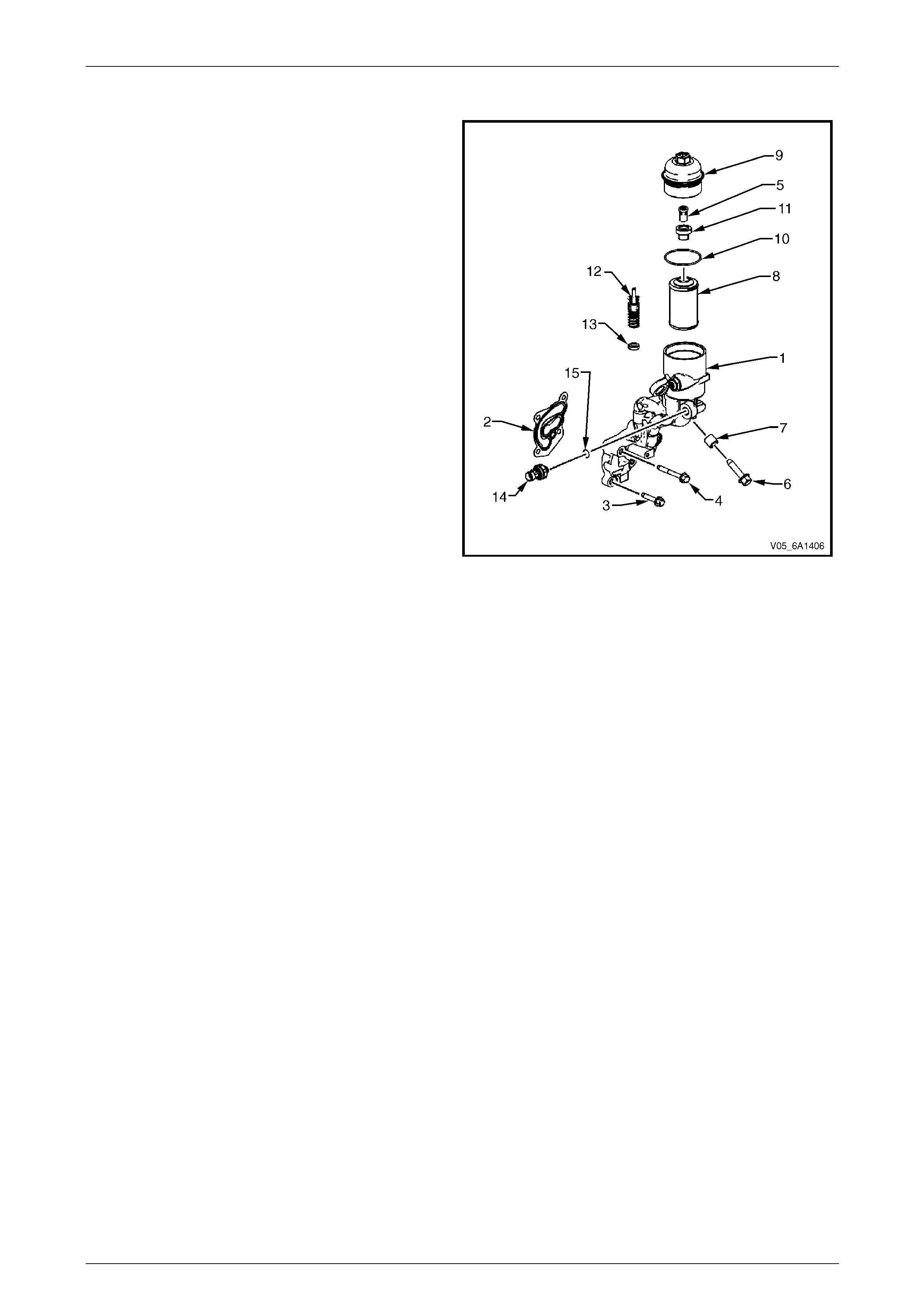
Oil Filter Assembly
Legend
1 Oil Filter Adapter
2 Oil Filter Adapter Gasket
3 Oil Filter Adapter Bolt, Short
4 Oil Filter Adapter Bolt, Long
5 Oil Filter Bypass Valve
6 Oil Filter Adapter Bolt, Large
7 Oil Filter Adapter Bolt Sleeve
8 Oil Filter
9 Oil Filter Cap
10 Oil Filter Cap O-ring
11 Oil Filter Bypass Valve Body
12 Drain Valve Assembly
13 Drain Valve Assembly Seal
14 Engine Oil Pressure Sensor
15 Engine Oil Pressure Sensor O-ring
Figure 6A1 – 12
Engine Mechanical – V6 Page 6A1–21
Page 6A1–21
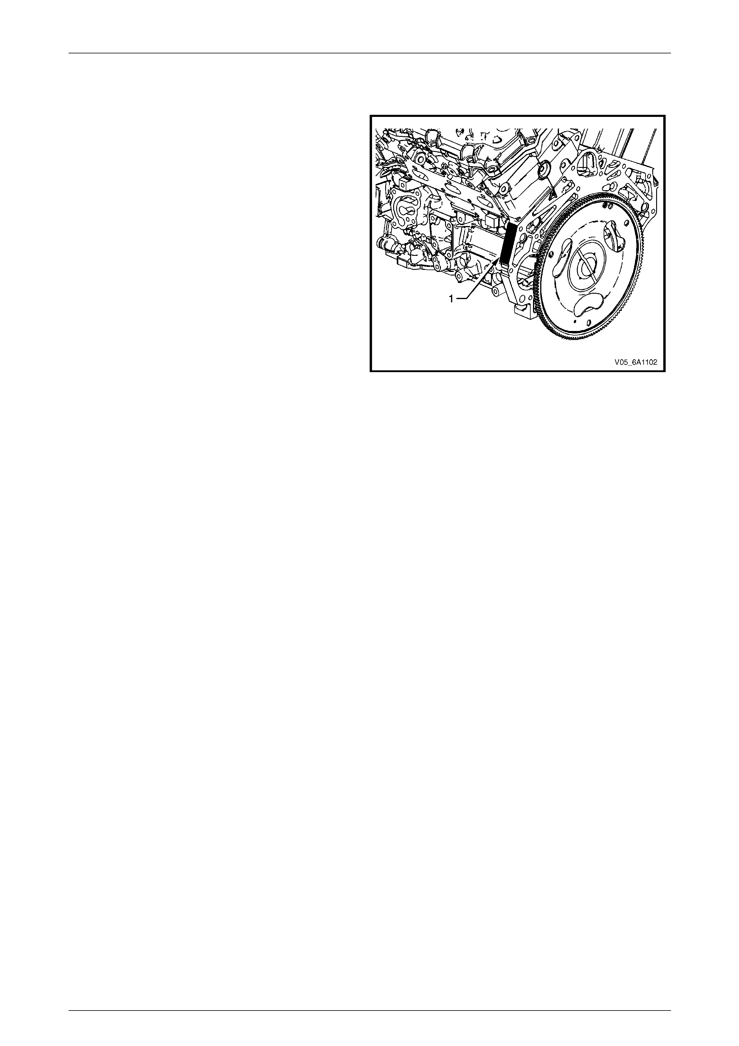
1.2 Engine Serial Number
The engine serial n umber is located on the machined pad
(1) at the left-hand rear of the cylinder block.
The following is a breakdown of the engine serial number,
using an example of 10 H7E H051230001:
• 10 = Component ID (i.e. 10 = Assembly)
• H7E = Engine Broadcast Code
• H = Assembly Plant Code
• 05 = Build Year
• 123 = Julian Date
• 0001 = Four Digit Daily S equence Number
Figure 6A1 – 13
Engine Mechanical – V6 Page 6A1–22
Page 6A1–22
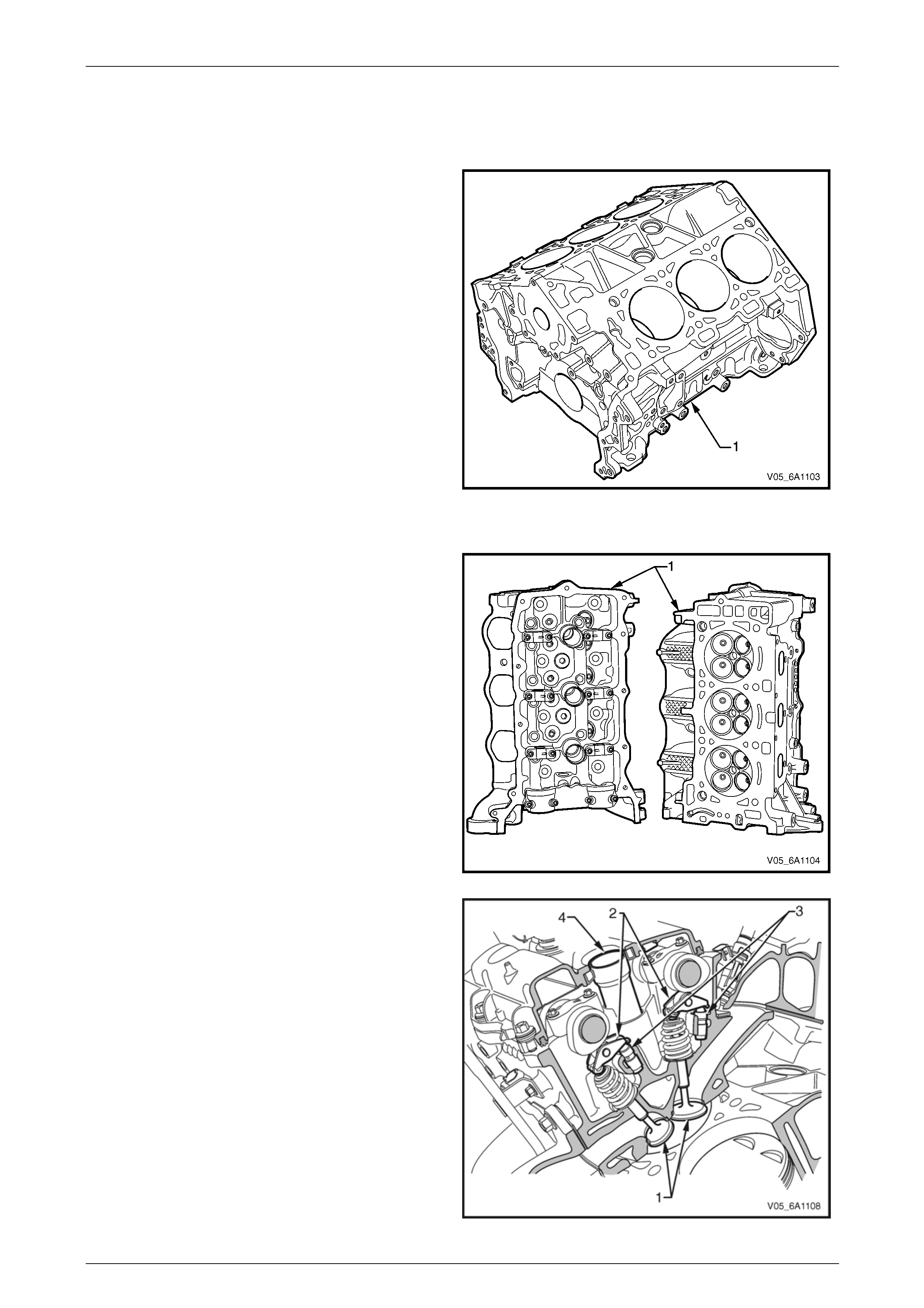
1.3 Engine Construction
Cylinder Block
The cylinder block (1) is constructed from aluminium alloy
with cast-in-place iron cylind er bore liners.
Each of the four copper-infiltrated sintered steel main
bearing caps are attached to the cylinder block by six bolts.
Along with two outer and t wo inner b olts, two side bolts are
used in the deep skirt block for increased bl ock stiffness.
The crankshaft thrust bearing is mounted in the third main
bearing cap.
To prevent aeration, oil return from the valve train and
cylinder heads is channel led away from the reciprocating
components through oil drai n back passages incorporated
into the cylinder heads and engine block. Pressure
actuated piston oil cooling jets are mounted between
opposing cylinders.
Figure 6A1 – 14
Cylinder Heads
The cylinder heads (1) are semi-permanent mould cast
aluminium with powdered metal valve seat inserts and
valve guides.
Figure 6A1 – 15
Each cylinder head contains four valves per cylinder. The
valves (1) are actuated by the rocker arms (2) that pivot on
stationary hydraulic lash a djusters (3), which are oil-fed to
maintain valve / rocker lash.
The separate exhaust and intake camshafts a r e supported
by four bearings machined into the cylinder head. The front
camshaft bearing cap is used as a thrust control surface for
each camshaft.
A tube (4) is pressed into each c ylinder he ad in three
places that shields each spark plug. An ignition coil
assembly is mounted directly on each spark plug, through
each spark plug tube.
Figure 6A1 – 16
Engine Mechanical – V6 Page 6A1–23
Page 6A1–23
Crankshaft
The crankshaft is a forged steel design with four main bearings. The number three main bearing controls crankshaft
thrust. A crankshaft position reluctor wheel is pressed onto the rear of the crankshaft, in front of the rear main journal.
The crankshaft is internally balanc ed with an integral oil pump drive machined into the nose in front of the front main
journal.
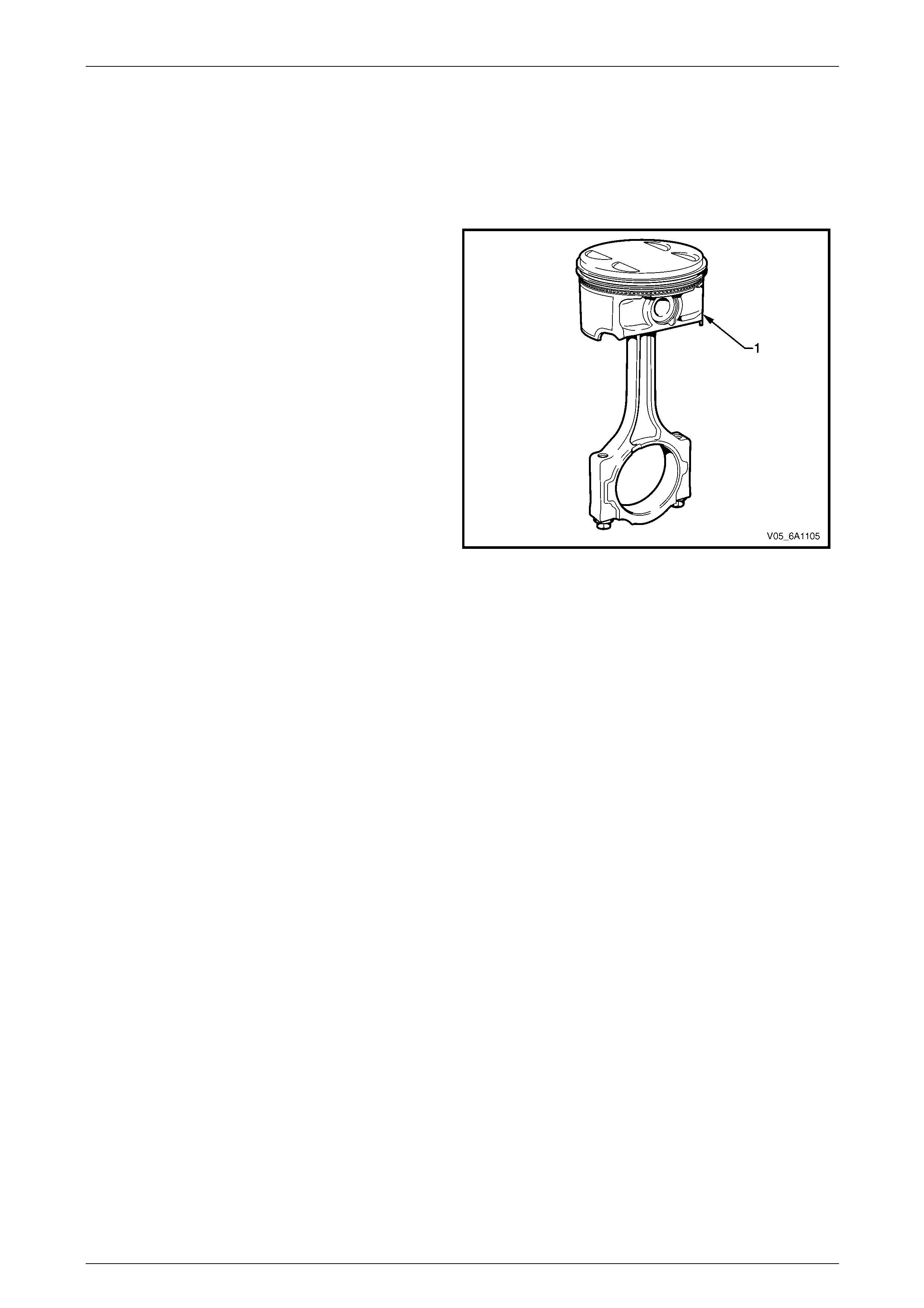
Pistons, Pins and Connecting Rods
The piston assembly (1) is fitted with two lo w tension
compression rings and one multi-pi ece oil control ring. The
top compression ring is plasma sprayed, while the second
compression ring is cast iron Napier.
The oil control ring incorp orates a steel expander and two
chrome plated steel rails.
The connecting rods are sinter forged steel and have full
floating piston pins. The piston pins are a sli p-fit type, into
the bronze bushed connecting rods. Round wire retainers
are used to retain the piston pin into the piston.
The cast aluminium pistons incorporate a polymer coated
skirt to reduce friction.
Figure 6A1 – 17
Camshaft Drive System
Three timing chains are fitted:
• primary (1),
• right-hand secondary (2), and
• left-hand secondary (3), refer to Figure 6A1 – 18.
The primary timing chain connects the crankshaft sprocket (4) with the left-hand and right-han d intermediate drive shaft
sprockets (5).
Each oil pressure fed intermediate sprocket drives the secondary timing chains, which subsequently drive the respective
cylinder head camshaft position actuators (6).
Two stationary timing chain guides (7) and movable timing chain shoes (8) control secondary timing chain backlash.
Each secondary timing chain shoe is under tension from an oil pressure hydraulically operated tensioner (9). To control
backlash on the primary chai n, two stationary timing chain guides (10) and an oil pressure hydraulically actuated
tensioner with built in shoe (11) are fitted.
The tensioners minimise timing chain noise and provide acc urate valve action by keeping slack out of the timing chains,
while continuously adjustin g for timing chain wear. The tensioners incorporate a plunger that adjusts outward with wear,
minimising backlash. The tensioners are equipped with oilin g jets to spray oil onto the timing components during engine
operation. Each tensioner is sealed to the head or block using a rubber coated steel gasket. The gasket traps an
adequate oil reserve to ensure qui et start-up.

Engine Mechanical – V6 Page 6A1–24
Page 6A1–24
Figure 6A1 – 18
Legend
1 Primary Timing Chain
2 Secondary Timing Chain, Right-hand
3 Secondary Timing Chain, Left-hand
4 Crankshaft Sprocket
5 Intermediate Driveshaft Sprocket
6 Camshaft Position Actuator
7 Secondary Timing Chain Guide
8 Secondary Timing Chain Shoe
9 Secondary Timing Chain Tensioner
10 Primary Timing Chain Guide
11 Primary Timing Chain Tensioner
Camshaft Position Actuator Control System
A variable camshaft timing system is fitted that allows
camshaft phasing changes within a range of 25 camshaft
degrees as engine operating conditions vary.
Camshaft phasing optimises engine performance and fuel
economy without compromising overall en gine response
and driveabilit y. Variable camshaft timing also contributes
to a reduction in exhaust emissions. T he need for an
exhaust gas recirculation (EGR) system is eliminate d as
exhaust and intake valve overlap is optimised.
A camshaft position actuator (1) is fitted at the front of each
camshaft that changes the camshaft lobe timing relative to
the camshaft drive sprocket.
For further information on the camshaft position actuator
control system refer to Section 6C1-1 Engine Management
– V6 – General Information.
Figure 6A1 – 19
Engine Mechanical – V6 Page 6A1–25
Page 6A1–25
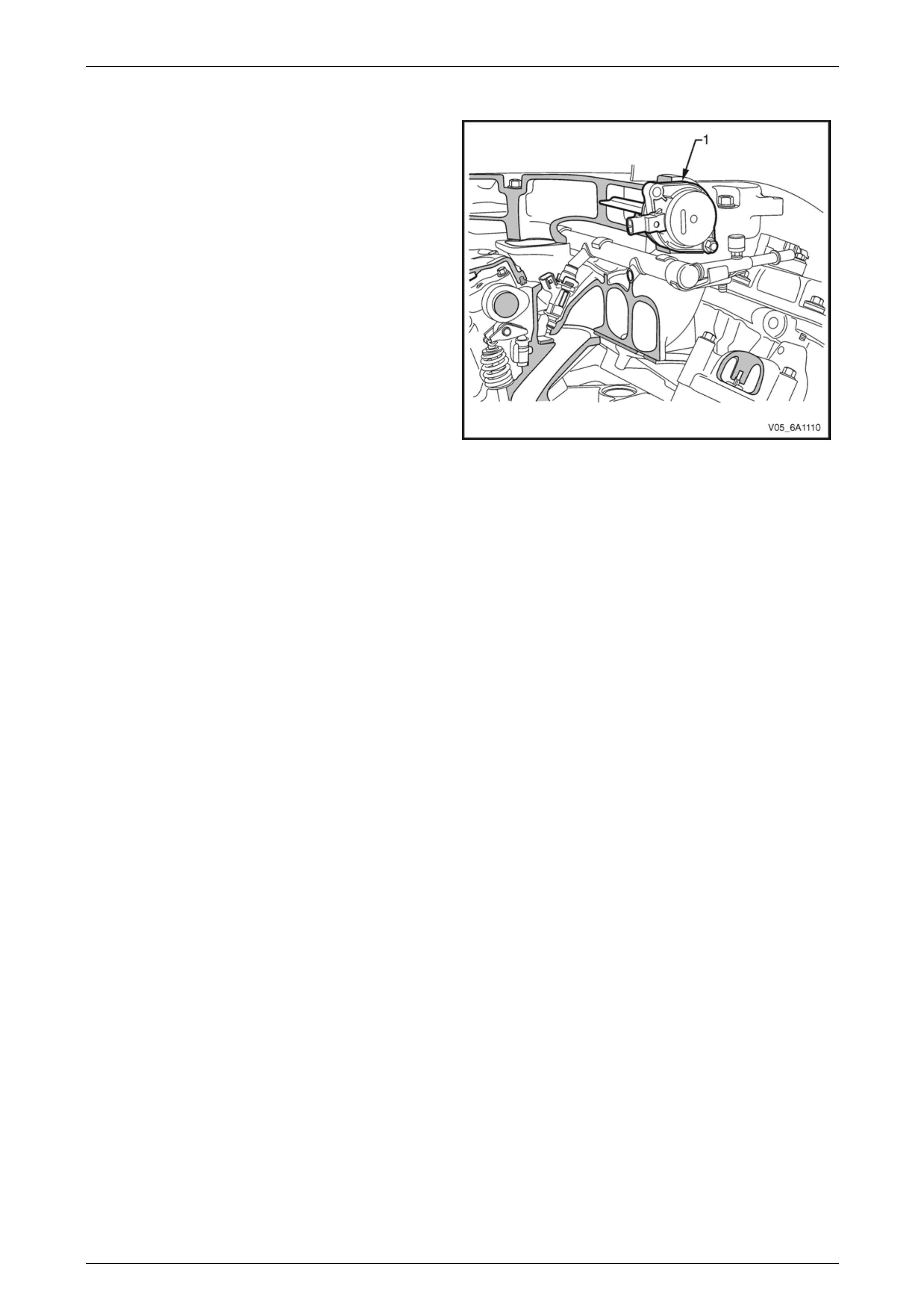
Intake Manifold
A dual-stage variable intake manifo ld is achieved through
the use of an intake manifold runner control (I MRC)
valve (1). The engine control module controlled IMRC alters
the length and volume of the intake manifold runners.
Varying the intake manifold takes adva ntag e of the natural
pulse / pressure waves occurring i n the man ifold that are
created by the process of air induction into the cylinders.
For further information on the intake manifold runner control
valve refer to Section 6C1-1 Engine Management – V6 –
General Information.
Figure 6A1 – 20

Engine Mechanical – V6 Page 6A1–26
Page 6A1–26
1.4 Engine Lubrication System
Lubrication Description
A structural diecast aluminium oil pan is fitted that incorpor ates an oil suction pipe, an oil deflector an d an oil level
sensor. The oil suction pipe is bolted into the oil pan and seals to the bottom of the cylinder block with a gasket. The oil
deflector is bolted to the upper portion of the oil pan and ensures oil suppl y is maintained under all conditions. The oil
level sensor is mounted through the bottom of the oil pan.
A crankshaft driven gerotor oil pump is mounted to the front of the cylinder block. The pump, which incorporates an
internal pressure-relief valve, draws oil from the oil suction tube through the lower passa ge in the cylinder block. Oil is
then directed through an upper passage to the left-hand side of the cylinder block where the oil filter adapter is mounted.
The oil filter adapter incorporates a top-access, cartridge style oil filter. The filter is accessed through a screw-on cap that
incorporates an oil bypass valve. T he oil filter adapter housing incorporates a drain back control va lve and a threaded oil
pressure sender. Oil flows through a lower passage within the oil filter adapter and through the oil filter cartridg e. F iltered
oil travels back through the upper passage of the adapter and into the engine block.
Oil is then directed up and across the front of the cylinder block, through several drilled passages. These front passages
feed oil to each cylinder head, the passa ge for the main bearings and piston oil jets, the right-hand and left-hand
secondary idler sprockets and to the primary timing chain tensioner.
Each cylinder head pass age directs oil into oiling circuits for the stationary hydraulic lash adjusters (SHLAs) and the
camshaft bearing journals. Oil is also directed through two passages, each with a spring-loaded check-ball valve, to the
chambers where the camshaft position actua tor solenoid valves are mounted. An additional pass age in the cylinder head
also directs oil to the secondary timing chain tensioner.
The oil passage that supplies oil to the main bearings also supplies oil to pressure actu ated piston cooling oil jets. Each
oil jet is mounted between opposing cylinder bores and directs oil to the two bores to provide extra cooling and control
piston temperatures.
From the front passages, oil is directed to the front of the block where the right-hand and left-hand intermediate drive
shaft sprockets and the primary timin g cha in tensioner are mounted. Each camshaft timing chain tensi oner relies on a
gasket to maintain an oil reserve after the engine is turned off. All camshaft timing chain tensioners incorporate a small
oil jet to supply an oil spray onto the camshaft timing chain components.
Oil returns to the oil pan, either through the camshaft timin g chai n area or through the drain back passa ges on the
outboard walls of the cylinder heads and cylinder block.

Engine Mechanical – V6 Page 6A1–27
Page 6A1–27
1.5 Service Notes
Cleanliness and Care
Throughout this Section, correct cleaning and protection of machined surfaces and friction areas is a part of the repair
procedure. This is considered standard workshop practice, even if not specifically stated.
When any internal engine part is serviced, care and cleanliness is extremely important.
When components are removed for service, they should be marked, organised or retained in a specific order for
reassembly.
At the time of installation, components should be installed in the same location and with the same mating surface as
when removed.
Any engine is a combination of many machined, honed, polished and lapped surfaces with tolerances that are measured
in thousandths of a millimetre. T hese surfaces shoul d be covered or protected to avoid component damage.
A liberal coating of clean engine oil should be applied to friction areas during assembly, as the lubrication will protect and
lubricate friction surfaces during the initial engine start-up.
Replacing Engine Gaskets
Re-Using Gaskets and Applying Sealants
• do not reuse any gasket unless specified,
• gaskets that can be reused will be id ent ified in the service procedure, and
• do not apply sealant to any gasket or sealing surface unless specified in the service inform ation.
Separating Components
• Use a rubber mallet to separate components.
• Bump the part sideways to loosen the components.
• Bumping should be done at bends or reinforced areas to prevent distortion of parts.
Cleaning Gasket Surfaces
• Where required, remove all gasket and sealing material from the part using a plastic or wood scraper.
• Care must be used to avoid gouging or scraping the sealing surfaces.
• Do not use any other method or technique to remove sealant or gasket material from a part.
• Do not use abrasive pads, sand paper, or power tools to clean the gasket surfaces as these methods of cleaning
can cause damage to the compon ent sealing surfaces. Abrasive pads also produce fine grit that the oil filter cannot
remove from the oil. This grit is abrasive and has been known to cause internal engine damage.
Assembling Components
• When assembling com ponents, use only the sealant specified or equivalent in the service procedure.
• Sealing surfaces should be clean and free of debris or oil.
• Specific components such as crankshaft oil seals or va lve stem oil seals may require lubrication during assembly.
• Components requiring lubrication will be identified in the service procedure.
• When applying sealant to a component, apply the amount specified in the service procedure.
• Do not allow the sealant to enter into any blind threaded holes as it may prevent the bolt from clamping correctly or
cause component damage when tightened.
• Only ever tighten bolts to the correct torque specification. Do not over-tighten.
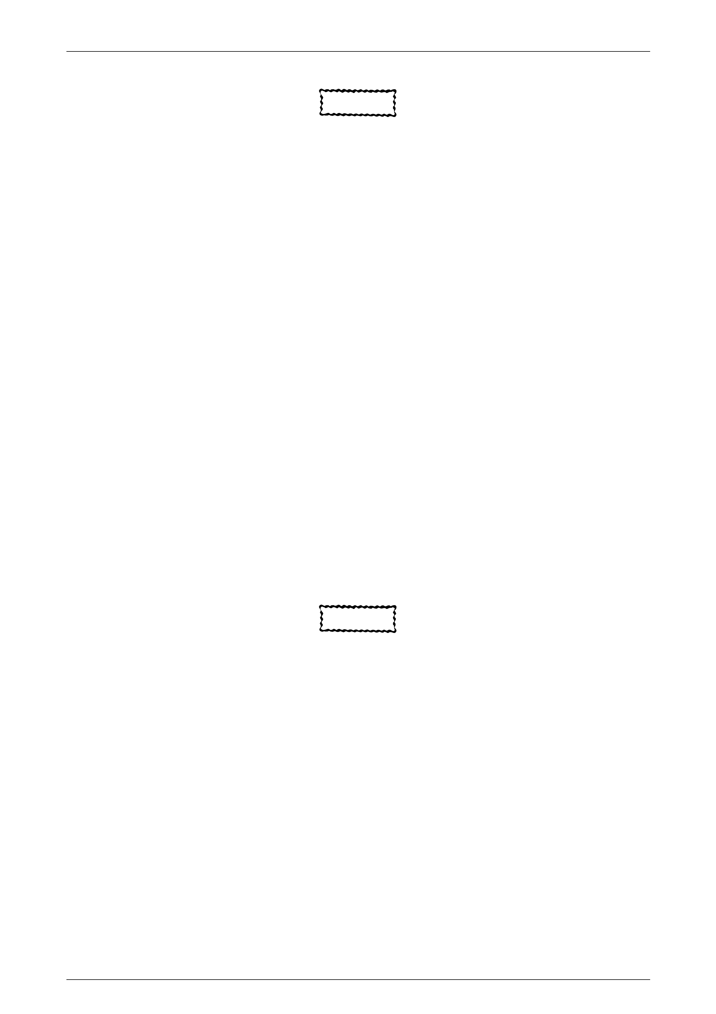
Engine Mechanical – V6 Page 6A1–28
Page 6A1–28
Use of Room Temperature Vulcanising and Anaerobic Sealer
CAUTION
A number of sealant types are commonly
used in engines. Examples are; room
temperature vulcanising (RTV) sealer,
anaerobic gasket eliminator sealer, and
anaerobic thread sealant and pipe joint
compound. The correct type of sealant and
amount must be used in the specified location
to prevent oil leaks. Do not interchange the
different types of sealers.
Room Temperature Vulcanising Sealer
• Room temperature vulcanising (RTV) sealant hardens when exposed to air. This type of sealer is used where two
non-rigid parts (such as the intake manifold and the engine block) are assembled together.
• Do not use RTV sealant in areas where extreme temperatures are experienced. These areas include the exhaust
manifold, head gasket, or other surfaces where a gasket eliminator is specified.
• Follow all safety recommendations and directions that are on the container.
• To remove the sealant or the gasket material, refer to Replacing Engine Gaskets in this Section.
• Apply RTV to a clean surface. Use a bead size as specified in the service procedure. Run the bead to the inside of
any bolt holes. Do not allow the sealer to enter any blind threaded holes, a s it may prevent the bolt from clamping
correctly or cause damage when the bolt is tightened.
• Assemble components while RTV is still wet (within 3 minutes). Do not wait for RTV to skin over.
• Tighten the bolts to the correct torque specification. Do not over-tighten.
Anaerobic Sealer
• Anaerobic gasket elimi nator or thread sealant, hardens in the absence of air. This type sealer is used where two
rigid parts (such as castings) are assembled together, where fasteners are subjected to vibration, or where the
holes are not blind. When two rigid parts are disassembled and no sealer or gasket is readily noticeable, the parts
were probably assembled using a gasket eliminator.
• Follow all safety recommendations and directions that are on the container.
• To remove the sealant or the gasket material, refer to Replacing Engine Gaskets in this Section.
• Apply a continuous bead of gasket eliminator to one flange or on the bolt/stud thread. All surfaces must be clean
and dry.
• Spread the sealer evenly to achieve a uniform coating on the sealing surface.
• Do not allow the sealer to enter any blind threaded holes as it may prevent the bolt from clamping correctly or
cause damage when tightened.
CAUTION
Anaerobic sealed joints that are partially
tightened and allowed to cure more than five
minutes may result in incorrect sh imming and
sealing of the joint.
• Tighten the bolts to the correct torque specification. Do not over-tighten.
• After correctly tightening the fasteners, remove the excess sealer from the outside of the joint.
Pipe Joint Compound
• Pipe joint compound is a pliable sealer that does not completely harden. This type of sealer is used where two non-
rigid parts (such as pressed steel and machined surfaces) are assembled together.
• Do not use pipe joint compound in areas where extreme temperatures are expected. These areas include the
exhaust manifold, head gasket, or other surfaces where gasket eliminator is specified.
• Follow all safety recommendations and directions that are on the container.
• To remove the sealant or the gasket material, refer to Replacing Engine Gaskets in this Section.
• Apply the pipe joint compou nd to a clean surface. Use a bead size or quantit y as specified in the procedure. Run
the bead to the inside of any bolt holes. Do not allow the sealer to enter any blind threaded holes as it may prevent
the bolt from clamping correctly or cause component damage when the bolt is tightened.
• Apply a continuous bead of pipe joint compound to one sealing surface. Sealing surfaces to be resealed must be
clean and dry.
• Tighten the bolts to the correct torque specification. Do not over-tighten.

Engine Mechanical – V6 Page 6A1–29
Page 6A1–29
Separating Parts
CAUTION
Many internal engine components will
develop specific wear patterns on their
friction surfaces. When disassembling the
engine, internal components must be
separated, marked and organised in a way to
ensure reinstallation in their original location
and position.
Separate, mark, or organise the following components:
• Piston and the piston pin.
• Piston to the specific cylinder bore.
• Piston rings to the specific piston.
• Connecting rod to the crankshaft journal.
• Connecting rod to the bearing cap.
• Crankshaft main and connecti ng rod bearings.
• Camshaft and rocker arms.
• Rocker arms and stationary hydraulic lash adjusters to cylinder head location.
• Valve to the valve guide.
• Valve spring and shim to the cylinder head location.
• Engine block main bearing cap location and direction.
• Oil pump drive and driven gears.
Tools and Equipment
Special tools are listed and illustrated throughout this Section with a complete listi ng at the end, refer to 7 Special Tools.
These tools (or their equivalents) are specially designed to quickly and safe ly accomplish the operations for which they
are intended. The use of these speci al too ls will a lso minimise possible damage to engine components. Some precision
measuring tools are required for inspection of certain critical components. A commercially available torque wrench and
torque angle wrench, Tool No. EN-7115 are required for the correct tightening of various fasteners.
To correctly service the engine assemb ly, the following items should be readily available:
• Approved eye protection and safety gloves.
• A clean, well-lit, work area.
• A suitable parts cleaning tank.
• A compressed air supply.
• Trays or storage containers to keep parts and fasteners organised.
• An adequate set of hand tools.
• Approved engine repair stan d.
• An approved engine lifting device that will adequately support the weight of the components.
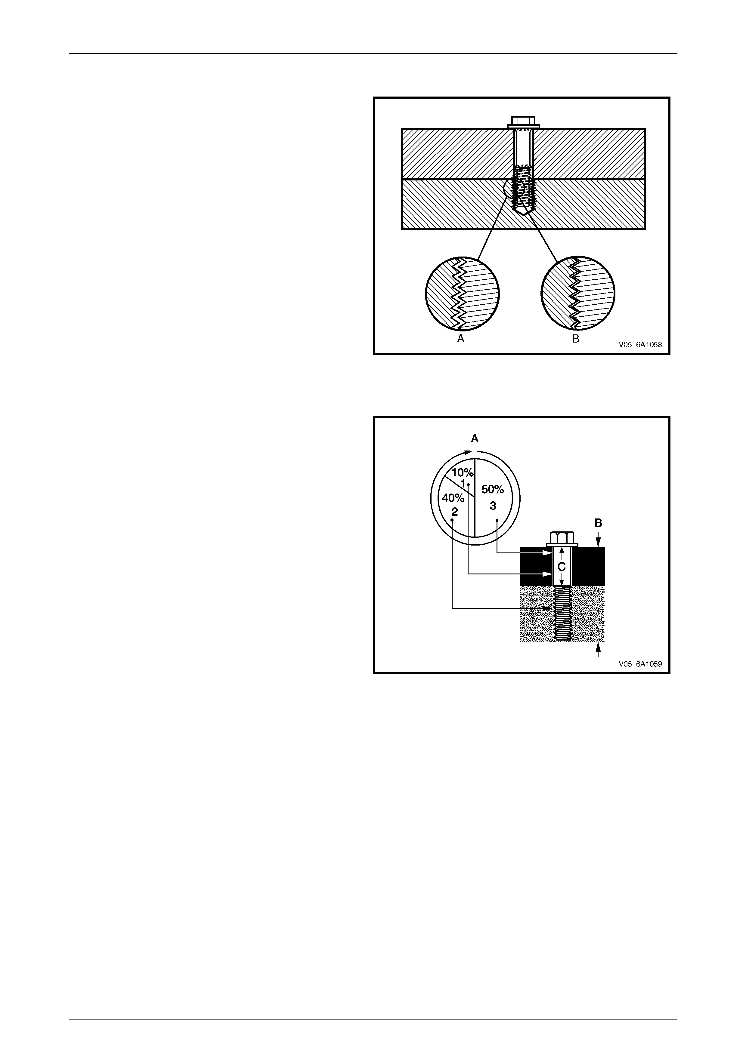
Engine Mechanical – V6 Page 6A1–30
Page 6A1–30
Fasteners
Fasteners are central to the reliable operation of an engine.
Whenever any bolt or any other threaded component is
removed, allow the engine to cool (inset A) before
attempting fastener removal.
Because of the greater thermal expansion of aluminium,
bolt threads will change dimension to a greater extent when
hot with this material (inset B) when compar ed to cast iron.
If a bolt or other threaded component is remo ved before the
engine is allowed to cool to at least 50° C, threads could be
pulled from the cylinder block or cylinder head.
Do not use impact tools to remove bolts during engine
disassembly. While this ma y be common practice with cast
iron engine components, use of these tools is more likely to
pull the aluminium threads in the cylinder block or head of
this engine.
Figure 6A1 – 21
Clamp Load
When torque is applied to a fastener, the fastener stretches
and the joint compresses. The force developed in the
fastener due to its stretch is called tension ( C), while the
force applied to the joint is called clamp load (B).
As shown, only a small portion of the applied torque (A) is
transferred to the clamp load (inset 1). Friction un der the
bolt head (inset 3) and in the t hrea ds (inset 2) absorbs
much of the applied torque (A). Typically, only 10% (inset 1)
of the torque is available to develop stretch (or tension) in
the fastener and clamp load in the joint.
Therefore, a slight variation in friction in the thread or under
the bolt head, results in a wide variation in the clamp load
applied to the joint.
Figure 6A1 – 22
Torque Angle and Torque to Yield Fasten ers
The torque angle method of applying torque to a fastener has been develo ped to overcome the effects of friction
variation in fastener applications.
The application of the torque angle method does not always mean the fastener has to be replaced after loosening. It is
only when the fastener has been an gle tightened to the extent the yield point has been exceeded, that the fastener must
be replaced.
Examples are the main bearing caps that are angle tightened but the bolts can be re-used, whereas the M11 cylinder
head bolts that are torque to yield fasteners, must be replaced after loosening.

Engine Mechanical – V6 Page 6A1–31
Page 6A1–31
2 Diagnosis
2.1 Engine Diagnosis
Begin engine mechanical system diagnosis by reviewing the disassembled views provided in 1.1 Engine Components
and 1.3 Engine Construction. Reviewing the description and operation information provided will assist in determining
whether the condition described by the customer is a fault or normal engine operation.

Engine Mechanical – V6 Page 6A1–32
Page 6A1–32
2.2 Symptoms
Strategy Based Diagnosis
1 Review the system operati ons to familiarise yourself with the system functions, refer to 1 General Information and
Section 6C1-1 Engine Management – V6 – General Information.
2 Perform an engine management Diagnostic System Check,
refer to Section 6C1-2 Engine Management – V6 – Diagnostics.
All diagnosis on a vehicle should follow a logical process. Strategy based d iagnosis is a uniform approach for repairing
all vehicle systems. The strategy based diagnostic flow chart may always be used to resolve a system problem. The
diagnostic flow chart is the place to start when repairs are required. For a detailed e x planation of strategy based
diagnosis and the flo w chart, refer to Section 6C1- 2 Engine Management – V6 – Diagnostics.
Visual / Physical Inspection
1 Inspect the vehicle for aftermarket accessories which may adverse ly affect engine operation.
2 Inspect the easily accessible or visible system components for obvious signs of damage or conditions that may
cause the symptom.
3 Check the engine lubrication system for the following:
• correct oil level,
• correct lubricant viscosity,
• correct oil filter application, and
• contaminated or burnt oil.
4 Confirm the exact operating conditions under which the fault occurs. Note factors such as:
• engine speed (r.p.m.),
• ambient temperature,
• engine temperature,
• engine warm-up time, and
• vehicle road speed.
5 Compare the engine sounds, if applicable, to a known good eng ine, and ensure you are not trying to diagnose a
normal operating condition.
Intermittent
For intermittent faults, test the vehicle under the same co nditions the customer reported in order to confirm whether the
system is operating correctly.

Engine Mechanical – V6 Page 6A1–33
Page 6A1–33
2.3 Engine Misfire without Internal Engine
Noises
Cause Correction
Abnormalities, severe cracking, bumps or missing areas in
the accessory drive belt.
Abnormalities in the accessory driv e system and/or
components may cause engine spee d variations that result
in a misfire diagnostic trouble code (DT C). A misfire code
may be present without an actual misfire condition.
Replace the accessory driv e belt, refer to 3.6 Accessory
Drive Belt.
Refer to Section 6C1-2 Engine Management – V6 –
Diagnostics to check for DTCs.
Worn, damaged or misaligned accessory drive components
and excessive pulley run-out may lead to a misfire DTC.
A misfire code may be present without an actual misfire
condition.
Inspect the components and repair or replace as required.
Refer to Section 6C1-2 Engine Management – V6 –
Diagnostics to check for DTCs.
Loose or incorrectly fitted flexplate or crankshaft bala ncer
assembly.
A misfire DTC may be present without an actual misfire
condition.
Repair or replace the flexplate or crankshaft balancer as
required, refer to 3.14 Crankshaft Balanc er Assembly or
4.3 Flexplate Assembly.
Refer to Section 6C1-2 Engine Management – V6 –
Diagnostics to check for DTCs
Restricted exhaust system.
A severe restriction in the exhaust flow can cause
significant loss of engine perfo rmance and may set a DTC.
Possible causes of restrictions in the e xhaust system
include collapsed/de nted pipes and blocked mufflers and/or
catalytic converters.
Repair or replace exhaust system compon ents as required,
refer to Section 8B Exhaust System.
Refer to Section 6C1-2 Engine Management – V6 –
Diagnostics to check for DTCs
Incorrectly installed or damag ed vacuum hoses. Repair or replace vacuum hoses as required.
Incorrect sealing bet ween the intake manifold and cylinder
heads, upper intake manifold and lower intake manifold,
throttle body and intake manifold.
Repair or replace the intake manifold, throttle body gaskets,
cylinder heads, throttle body as required.
Incorrectly installed or damag ed barometric
pressure(BARO) sensor and/or seal. The seal should not
be torn or damaged.
Repair or replace the BARO sensor and/or seal as
required, refer to Section 6C1-3 Engine Management – V6
– Service Operations.
Incorrectly installed or damaged EVAP purge solenoid
and/or O-ring seal. Repair or replace the EVAP purge solenoi d and/or se al as
required, refer to Section 6C1-3 Engine Management – V6
– Service Operations
Worn or loose stationary hydraulic lash adjusters (SHLA)
and/or rocker arms.
The SHLAs, rocker arms and roller bearings should be
intact and in the correct position.
Replace the SHLAs and/or rocker arms as required, refer to
3.22 Stationary Hydraulic Lash Adjuster or 3.21 Rocker
Arm.
Stuck valves.
Carbon build up on the valve stems can result in the valves
not closing correctly.
Repair or replace as required, refer to 3.23 Cylinder Head
Assembly.

Engine Mechanical – V6 Page 6A1–34
Page 6A1–34
Cause Correction
Excessively worn or misaligned timing chain/s. Replace the timing chain/s and components as required,
refer to 3.17 Timing Chains, Tensioners, Shoes and
Guides.
Worn camshaft lobes. Replace the camshaft/s and SHLAs as required, refer to
3.20 Camshaft or 3.22 Stationary Hydraulic Lash Adjuster.
Excessive oil pressure.
A lubrication system with excessive oil pressure may lead
to excessive lash adjuster pu mp-up and loss of
compression.
1 Perform an oil pressure test, refer to 3.2 Engine Oil.
2 Repair or replace the engine oil pump as re quired,
refer to 3.18 Oil Pump Assembly.
Faulty cylinder head gasket and/or cracking or other
damage to the cylinder head a nd cylinder block coolant
passages.
Coolant consumption may or may not cause the engine to
overheat.
1 Inspect the spark plugs for coolant saturation, refer to
Section 6C1-3 Engine Management – V6 – Service
Operations.
2 Inspect the cylinder heads, cylinder block and / or head
gaskets, refer to 3.23 Cylinder Head Assembly
and/or 4.7 Cylinder Block.
3 Repair or replace components as required.
Worn piston rings.
Oil consumption may or may not cause the engine to
misfire.
1 Inspect the spark plugs for oil deposits, refer to
Section 6C1-3 Engine Management V6 – Service
Information.
2 Check the cylinders for a loss of compression , refer to
2.15 Engine Compression Test.
3 Perform compression testing to identify the cause of
low compression.
4 Repair or replace components as required.
A damaged crankshaft reluctor wheel.
A damaged crankshaft reluctor wheel can result in different
symptoms depending on the severity and location of the
damage.
Systems with severe reluctor ring damage may exhibit
periodic loss of crankshaft position, stop deliv ering a signal,
and then re-sync the crankshaft position.
Systems with slight reluctor ring damage may exhibit no
loss of crankshaft position and no misfire may occur,
however, a DTC may set.
Replace the crankshaft as required, refer to 4.6 Crankshaft
and Main Bearings.
Refer to Section 6C1-2 Engine Management – V6 –
Diagnostics to check for DTCs

Engine Mechanical – V6 Page 6A1–35
Page 6A1–35
2.4 Engine Misfire with Abnormal Internal
Lower Engine Noises
Cause Correction
Abnormalities, severe cracking, bumps or missing areas in
the accessory drive belt.
Abnormalities in the accessory driv e system and/or
components may cause engine spee d variations that result
in a misfire diagnostic trouble code (DT C). A misfire code
may be present without an actual misfire condition.
Replace the accessory driv e belt, refer to 3.6 Accessory
Drive Belt.
Refer to Section 6C1-2 Engine Management – V6 –
Diagnostics to check for DTCs
Worn, damaged or misaligned accessory drive components
and excessive pulley run-out may lead to a misfire DTC.
A misfire code may be present without an actual misfire
condition.
Inspect the components and repair or replace as required.
Refer to Section 6C1-2 Engine Management – V6 –
Diagnostics to check for DTCs
Loose or Incorrectly fitted flexplate or crankshaft bala ncer
assembly.
A misfire code may be present without an actual misfire
condition.
Repair or replace the flexplate or crankshaft balancer as
required, refer to 3.14 Crankshaft Balanc er Assembly or
4.3 Flexplate Assembly.
Worn or broken piston rings.
Oil consumption may or may not cause an a ctual misfire. 1 Inspect the spark plugs for oil deposits, refer to
Section 6C1-3 Engine Management V6 – Service
Information.
2 Check the cylinders for a loss of compression , refer to
2.15 Engine Compression Test.
3 Perform compression testing to identify the cause of
low compression.
4 Repair or replace components as required.
Worn crankshaft thrust bearing.
Severely worn thrust surfaces on the crankshaft and/or
thrust bearing may permit fore and aft movement of the
crankshaft and create a DTC without an actual misfire
condition being present.
Replace the crankshaft and/or bearings as required, refer to
4.6 Crankshaft and Main Bearings.
Refer to Section 6C1-2 Engine Management – V6 –
Diagnostics to check for DTCs

Engine Mechanical – V6 Page 6A1–36
Page 6A1–36
2.5 Engine Misfire with Abnormal Valve
Train Noise
Cause Correction
Worn or loose stationary hydraulic lash adjusters (SHLA)
and/or valve rocker arms.
The SHLAs, rocker arm and roller bearings should be intact
and in the correct position.
Replace the SHLAs and/or rocker arms as required, refer to
3.22 Stationary Hydraulic Lash Adjuster or 3.21 Rocker
Arm.
Stuck valves.
Carbon build up on the valve stems can result in the valves
not closing correctly.
Repair or replace as required, refer to 3.23 Cylinder Head
Assembly.
Excessively worn or misaligned timing chain/s. Replace the timing chain/s and components as required,
refer to 3.17 Timing Chains, Tensioners, Shoes and
Guides.
Worn camshaft lobes. Replace the camshaft/s and SHLAs as required, refer to
3.20 Camshaft or 3.22 Stationary Hydraulic Lash Adjuster.
Sticking camshaft lash adjusters. Replace the lash adjusters as required, refer to 3.22
Stationary Hydraulic Lash Adjuster.

Engine Mechanical – V6 Page 6A1–37
Page 6A1–37
2.6 Engine Misfire with Coolant
Consumption
Cause Correction
Faulty cylinder head gasket and/or cracking or other
damage to the cylinder heads and cylinder block coolant
passages.
Coolant consumption may or may not cause the engine to
overheat.
1 Inspect the spark plugs for coolant saturation, refer to
Section 6C1-3 Engine Management – V6 – Service
Operations.
2 Inspect the cylinder heads, cylinder block and / or head
gaskets, refer to 3.23 Cylinder Head Assembly
and/or 4.7 Cylinder Block.
3 Repair or replace components as required.

Engine Mechanical – V6 Page 6A1–38
Page 6A1–38
2.7 Engine Misfire with Excessive Oil
Consumption
Cause Correction
Worn valves, valve guides and/or valve stem oil seals. 1 Inspect the spark plugs for coolant saturation, refer to
Section 6C1-3 Engine Management – V6 – Service
Operations.
2 Repair or replace components as required, refer to
3.23 Cylinder Head Assembly.
Worn or broken piston rings.
Oil consumption may or may not cause an a ctual misfire. 1 Inspect the spark plugs for oil deposits, refer to
Section 6C1-3 Engine Management – V6 – Service
Operations.
2 Check the cylinders for a loss of compression , refer to
2.15 Engine Compression Test.
3 Perform compression testing to identify the cause of
low compression.
4 Repair or replace components as required.

Engine Mechanical – V6 Page 6A1–39
Page 6A1–39
2.8 Engine Noise on Start-up, but only
Lasting a Few Seconds
NOTE
A cold piston knock, which disappears in
approximately 1.5 minutes from start up, should
be considered acceptable. A cold engine knock
usually disappears when the specific cylinder’s
secondary ignition circuit is grounded out during
diagnosis.
A light rattle/tapping noise may indicate a valve train/upper engine concern, while a low rumble/knocking may indicate a
crankshaft, piston or lower engine concern.
Cause Correction
Oil filter anti-drain back valve fault y. Replace the oil filter adaptor, refer to 3.4 Oil Filter Adaptor.
Incorrect oil viscosity. Drain the engine oil and replace with the correct viscosity
oil, refer to 3.2 Engine Oil.
High camshaft stationary hydraulic lash adjuster (SHLA)
leak down rate. Replace the SHLA as required, refer to 3.22 Stationary
Hydraulic Lash Adjuster.
Worn crankshaft thrust bearing. Inspect and replace the crankshaft and/or bearings as
required, refer to 4.6 Crankshaft and Main Beari ngs.
Damaged or faulty oil filter by-pass valve. 1 Inspect the oil filter by-pass valve for correct
operation.
2 Repair or replace the oil filter adaptor/by-p ass valve
as required.

Engine Mechanical – V6 Page 6A1–40
Page 6A1–40
2.9 Upper Engine Noise, Regardless of
Engine Speed
NOTE
A cold piston knock, which disappears in
approximately 1.5 minutes from start up, should
be considered acceptable. A cold engine knock
usually disappears when the specific cylinder’s
secondary ignition circuit is grounded out during
diagnosis.
A light rattle/tapping noise may indicate a valve train/upper engine concern, while a low rumble/knocking may indicate a
crankshaft, piston or lower engine concern.
Cause Correction
Low oil pressure. 1 Perform an oil pressure test, refer to 2.19 Engine Oil
Pressure Diagnosis.
2 Repair or replace the engine oil pump as re quired,
refer to 3.18 Oil Pump Assembly.
Worn or loose stationary hydraulic lash adjusters (SHLA)
and/or valve rocker arms.
The SHLAs, rocker arm and roller bearings should be intact
and in the correct position.
1 Clean, inspect and replace the camshaft lash
adjusters as required, refer to 3.22 Stationary
Hydraulic Lash Adjuster.
2 Replace the SHLAs and/or rocker arms as required,
refer to 3.22 Stationary Hydraulic Lash Adjuster or
3.21 Rocker Arm.
Incorrect lubrication to the stationary hydraulic lash
adjusters and valve rocker arm. Inspect the foll owing components and repair or replace as
required:
• valve rocker arms, refer to 3.21 Rocker Arm.
• stationary hydraulic lash a dj usters, refer to 3.22
Stationary Hydraulic Lash Adjuster.
• oil filter by-pass valve, refer to 3.4 Oil Filter Adaptor.
• oil pump and suction pipe, refer to 3.18 Oil Pump
Assembly.
• cylinder head oil galleries, refer to 3.23 Cylinder
Head Assembly.
• cylinder block oil galleries, ref er to 4.7 C ylinder
Block.
Broken Valve Spring. Replace the valve spring, refer to 3.23 Cylinder Head
Assembly.
Stretched or broken timing chain/s and/or da maged timing
chain sprocket teeth. Replace the timing chains or sprockets as required, refer to
3.17 Timing Chains, Tension ers, Shoes and Guides.
Worn or faulty timing chain ten sioner or guide. Replace the timing chains or sprockets as required, refer to
3.17 Timing Chains, Tension ers, Shoes and Guides.
Worn camshaft lobes. Replace the camshaft/s and SHLAs as required, refer to
3.20 Camshaft or 3.22 Stationary Hydraulic Lash Adjuster.
Worn valve guides and/or valve stems. Inspect and repair or replace valves a nd valve guides as
required, refer to 3.23 Cylinder Head Assembly.
Stuck valves.
Carbon on the valve stem or valve seat may cause the
valve to stay open.
Inspect and repair or replace valves a nd valve guides as
required, refer to 3.23 Cylinder Head Assembly.

Engine Mechanical – V6 Page 6A1–41
Page 6A1–41
2.10 Lower Engine Noise, Regardless of
Engine Speed
NOTE
A cold piston knock which disappears in
approximately 1.5 minutes from start up should
be considered acceptable. A cold engine knock
usually disappears when the specific cylinder’s
secondary ignition circuit is grounded out during
diagnosis.
A light rattle/tapping noise may indicate a valve train/upper engine concern, while a low rumble/knocking may indicate a
crankshaft, piston or lower engine concern.
Cause Correction
Low oil pressure. 1 Perform an oil pressure test, refer to 2.19 Engine Oil
Pressure Diagnosis.
2 Repair or replace the engine oil pump as re quired,
refer to 3.18 Oil Pump Assembly.
Worn accessory drive components.
Abnormalities such as severe cracking, bumps, stretching
or missing areas on an accessory drive belt and/or
misalignment of accessory drive system components.
Inspect the accessory drive system, repair or replace
components as required, refer to 3.6 Accessory Drive Belt.
Loose or damaged cra nkshaft balancer and pulley
assembly. Repair or replace the crankshaft balanc er and pulley
assembly as required, refer to 3.14 Crankshaft Balancer
Assembly.
Detonation or spark knock. Confirm the correct operation of the ignition system, refer to
Section 6C1-2 Engine Management – V6 – Diagnostics.
Loose torque converter bolts. Inspect and tighten the torque converter bolts to the correct
torque specification, refer to Section 7E4 Automatic
Transmission – 5L40E – On-vehicle Servicing.
Loose or damaged fle x plate. Repair or replace the flexplate as required, refer to 4.3
Flexplate Assembly.
Oil pump suction pipe loose, dama ged or restricted. Clean, inspect and repair/replace the oil pump suction pipe
as required, refer to 4.2 Oil Pan and Oil Pump Suction Pipe
Assembly.
Excessive piston-to-cylind er bore clearance. Inspect the piston and cylinder bore and repair/replace
components as required, refer to 4.5 Pistons, Pins, Rings,
Connecting Rods and Big-end Bearings and 4.7 Cylinder
Block.
Excessive connecting rod bearing clearance. Inspect the connecting rod, crankshaft and bearings an d
repair/replace components as required, refer to 4.5
Pistons, Pins, Rings, Connecting Rods an d Big-end
Bearings and 4.6 Crankshaft and Main Be arings.
Excessive piston pin to bore clearance. Inspect the pistons and pins and repair/replace components
as required, refer to 4.5 Pistons, Pins, Rings, Connecting
Rods and Big-end Bearings.
Excessive crankshaft main bearin g clearance. Inspect the crankshaft, cylinder block journals, main
bearings and main b earing caps and repair/replace
components as required, refer to 4.6 Crankshaft and Main
Bearings and 4.7 Cylinder Blo ck.
Incorrect piston, pin and connecting rod installation.
Pistons must be installed with the mark or dimple facing the
front of the engine. Piston pins must be centred in the
piston pin bore.
Confirm the pistons, pins and connecting rods are installed
correctly and repair if required, refer to 4.5 Pistons, Pins,
Rings, Connecting Rods an d Big-end Bearings.

Engine Mechanical – V6 Page 6A1–42
Page 6A1–42
2.11 Engine Noise Under Load
NOTE
A cold piston knock which disappears in
approximately 1.5 minutes from start up, should
be considered acceptable. A cold engine knock
usually disappears when the specific cylinder’s
secondary ignition circuit is grounded out during
diagnosis.
A light rattle/tapping noise may indicate a valve train/upper engine concern, while a low rumble/knocking may indicate a
crankshaft, piston or lower engine concern.
Cause Correction
Low oil pressure. 1 Perform an oil pressure test, refer to 2.19 Engine Oil
Pressure Diagnosis.
2 Repair or replace the engine oil pump as re quired,
refer to 3.18 Oil Pump Assembly.
Detonation or spark knock. Confirm the correct operation of the ignition system, refer to
Section 6C1-2 Engine Management – V6 – Diagnostics.
Loose torque converter bolts. Inspect and tighten the torque converter bolts to the correct
torque specification, refer to Section 7E4 Automatic
Transmission - 5L40E – On Vehicle Servicing
Cracked flexplate. Replace the flywheel/flex-plat e as requ ired, refer to 4.3
Flexplate Assembly.
Excessive connecting rod bearing clearance. Inspect the connecting rod, crankshaft and bearings an d
repair/replace components as required, refer to 4.5
Pistons, Pins, Rings, Connecting Rods an d Big-end
Bearings and 4.6 Crankshaft and Main Be arings.
Excessive crankshaft bearing clearance Inspect the crankshaft, cylinder block journals, main
bearings and main b earing caps and repair/replace
components as required, refer to 4.6 Crankshaft and Main
Bearings and 4.7 Cylinder Blo ck.

Engine Mechanical – V6 Page 6A1–43
Page 6A1–43
2.12 Engine Will Not Crank – Crankshaft Will
Not Rotate
Cause Correction
Seized accessory drive system compon ent. 1 Remove the accessory drive b elt, refer to 3.6
Accessory Drive Belt.
2 Rotate the crankshaft by hand at the balancer pulley
or flywheel.
3 Repair or replace accessory drive s ystem
components as required.
Hydraulically locked cylinder caused by:
• coolant in cylinder,
• oil in cylinder, or
• fuel in cylinder.
1 Remove the spark plugs and check for fluid, refer to
Section 6C1-3 Engine Management – V6 – Service
Operations.
2 Inspect for broken head gasket/s.
3 Inspect for cracked engine block or cylinder head.
4 Inspect for sticking fuel injector.
5 Repair or replace components as required.
Seized torque converter. 1 Remove the torque converter bolts, refer to Section
7E5 Automatic Transmission – 5L40E – U nit Repair.
2 Rotate the crankshaft by hand at the balancer pulley
or flywheel.
3 Repair or replace torque converter as required.
Material in cylinder bore, caused by:
• broken valve,
• broken piston or ring, or
• dirt or foreign matter entry during engine assembly
procedure.
1 Clean and inspect the cylinder for damaged
components and or foreign matter, refer to 4.7
Cylinder Block.
2 Repair or replace components as required.
Seized crankshaft or connecting rod bearings. Inspect and repair or replace crankshaft, connecting rod
and bearings as required, refer to 4.5 Pistons, Pins, Rings,
Connecting Rods and Big-end Bearings and 4.6
Crankshaft and Main Bearings .
Bent or broken connecting rod. Inspect and repair or replace conn ecting rod and bearings
as required, refer to 4.5 Pistons, Pins, Rings, Connecting
Rods and Big-end Bearings.
Bent or broken crankshaft. Inspect and repair or replace cranksh aft and bearings as
required, refer to 4.6 Crankshaft and Main Beari ngs.
Seized or broken camshaft. 1 Inspect and replace camshaft s as required, refer to
3.20 Camshaft.
2 Inspect camshaft journals and cam caps on c ylinder
head and repair or replace components as required,
refer to 3.23 Cylinder Head Assembl y.
Seized or broken camshaft timing components. 1 Inspect the crankshaft, idler, intake camshaft and
exhaust camshaft sprockets.
2 Inspect the timing chains.
3 Inspect the guides.
4 Inspect the tensioners.
5 Repair or replace components as required, refer to
3.17 Timing Chains, Tension ers, Shoes a nd Guides.
Seized or broken valve train c ompo nents. 1 Inspect the stationary hydraulic lash adjusters, refer
to 3.22 Stationary Hydraulic Lash Adjuster.
2 Inspect the rocker arms, refer to 3.21 Rocker Arm.
3 Inspect the Valves Refer to 3.23 Cylinder Head
Assembly.
4 Inspect the valve springs, refer to 3.23 Cylinder Head
Assembly.
5 Repair or replace components as required.

Engine Mechanical – V6 Page 6A1–44
Page 6A1–44
2.13 Coolant in Combustion Chamber
Definition
Excessive white smoke and/or coolant type odour emitted from the exhaust pipe may indicate coolant in the combustio n
chamber. Low coolant levels, an inoperative engine cooling fan or a faulty thermostat may lead to an over-temperature
condition which may cause in ternal engine component damage. A slower than normal cranking speed may indicate
coolant entering the combustion chamber.
1 Remove the spark plugs and inspect for spark plugs saturated by coolant and coolant in the cylinder bore.
2 Inspect by performing a cylinder leakage test, refer to 2.16 Cylinder Leakage Test. During this test, excessive air
bubbles in the coolant ma y indicate a faulty head gasket, cracked cylinder head or crack ed cylinder block.
3 Inspect by performing a cylinder compression test. Two cylinders side-by-side on the c ylinder block, with low
compression, may indicate a failed cylinder head gasket, refer to 2.15 Engine Compression Test.
Cause Correction
Cracked intake manifold or faulty gasket. Replace components as requ ired, refer to 3.11 Intake
Manifold Assembly – Complete.
Faulty cylinder head gasket. Replace the cylinder head gasket, refer to 3.23 Cylinder
Head Assembly.
Warped cylinder head. Repair or replace the cylinder heads as required, refer to
3.23 Cylinder Head Assembly.
Cracked cylinder liner or bloc k Repair or replace the cylinder block and components as
required, refer to 4.7 Cylinder Block.
Cylinder head or cylinder block porosity. Repair or replace the cylinder block or cylinder heads as
required, refer to 4.7 Cylinder Block or 3.23 Cylinder Head
Assembly.

Engine Mechanical – V6 Page 6A1–45
Page 6A1–45
2.14 Coolant in Engine Oil
Definition
Foamy or discoloured oil or an engine oil overfill condition may indicate coolant entering the engine crankcase. Low
coolant levels, an inoperative engine cooling fan or a faulty thermostat may lead to an over-temperature condition which
may result in engine component damage. Contaminated engine oil and oil filters must be replaced.
1 Inspect the oil for excessive foaming or an overfill condition. Oil diluted by coolant may not correctly lubricate the
crankshaft bearings, resulting in component damage,
refer to 2.10 Lower Engine Noise, Regardless of Engine Speed.
2 Perform a cylinder leakage test, refer to 2.16 Cylinder Leak age Test. During this procedure, excessive air bubbles
in the engine coolant ma y indicate a faulty gasket or damaged component.
3 Perform a cylinder compression test. T wo cylinders sid e-b y-side on the cylinder block, with lo w compress ion, may
indicate a failed cylinder head gasket, refer to 2.15 Engine Compression Test.
Cause Correction
Faulty cylinder head gasket. Replace the cylinder head gasket, refer to 3.23 Cylinder
Head Assembly.
Warped cylinder head. Repair or replace the cylinder heads as required, refer to
3.23 Cylinder Head Assembly.
Cracked cylinder liner or bloc k Repair or replace the cylinder block and components as
required, refer to 4.7 Cylinder Block.
Cylinder head, cylinder block or intake manifold porosity. Repair or replace the cylinder block, cylinder heads or
intake manifold components as required, refer to 4.7
Cylinder Block, 3.23 Cylinder Head Assembl y or 3.11
Intake Manifold Assembly – Complete.

Engine Mechanical – V6 Page 6A1–46
Page 6A1–46
2.15 Engine Compression Test
A compression pressure test of the engine cylind ers deter mines the condition of the rings, the valves and the head
gasket.
Preliminary Steps
1 Ensure the battery is fully charged.
2 Remove the spark plugs from all cylinders, refer to Section 6C1-3 En gine Management – V6 – Service Operations.
NOTE
DTCs will set when the fuel system or the i gnition
system is disabled and the engine is cranked.
Disregard DTCs that set under this condition.
3 Disable the fuel system by removing the fuel pump relay,
refer to Section 12O Fuses, Relays and Wiring Harnesses.
4 Start the engine to use any residual fuel from the fuel lines.
4 Disable the ignition coils by removing fuses 3 4 and 3 5, refer to Section 12O Fuses, Relays and Wiring Harnesses.
5 Using Tech 2, command the throttle plate to wide open throttle.
Engine Cylinder Compression Test
1 Install the compression tester to cylinder number 1.
NOTE
The engine may continue cranking for several
seconds once the key is released, refer to
Section 6D1-2 Starting System– V6 for further
information.
2 While observing the compression tester reading, turn the ignition to the START position for several seconds and
then allow the ignition to return to the ON position.
3 Record the highest compression reading obtained.
4 Repeat the engine compression test for each cylinder.
Test Result Evaluation
Normal engine compression pressure builds quickly and evenly to over 965 kPa. In addition, the lowest reading of an
engine cylinder should not be less than 70 percent of the highest reading. If any cylinder fails the compres s ion test,
adding 15 ml of engine oil to the suspected cylinder may help isol ate the following fault condition.
1 A fault condition in the piston rings will produce the following result:
• A low compression on the first engine c ycl e
• The compression tends to build-up with the succeeding engine rotation.
• The compression improves with the addition of engine oil.
2 A fault condition in an intake or exhaust valve will produce the following result:
• A low compression on the first engine c ycl e
• The compression does not build with the succeeding engine rotation.
• The compression does not improve with the addition of engine oil.
3 A fault condition in the cylinder head gasket will produce the following result:
• A low compression on the first engine c ycl e
• The compression does not build with the succeeding engine rotation.
• The compression does not improve with the addition of engine oil.
• The suspected cylinders are p ositio ned adjacent to each other.
• The engine oil may be contaminated with engine coolant.
• The engine coolant may be contaminate d with engine oil.
Once the fault has been identified, refer to the relevant servic e procedure and reinstall the removed compone nts.
Using Tech 2, clear DTCs.

Engine Mechanical – V6 Page 6A1–47
Page 6A1–47
2.16 Cylinder Leakage Test
A leakage test may be performed to measure cylinder/combustion chamber leakage. Hig h cylinder leakage may indicate
one or more of the following:
• worn or burnt valves,
• broken valve springs,
• stuck valve lifters,
• incorrect valve lash/adjustment,
• damaged piston,
• worn piston rings,
• worn or scored cylinder bore,
• damaged cylinder head g asket,
• cracked or damaged cylinder head, or
• cracked or damaged engine block.
1 Disconnect the battery ground negative cable.
2 Remove the spark plugs from all cylinders, refer to Section 6C1-3 En gine Management – V6 – Service Operations.
3 Rotate the crankshaft to place the piston in the cylinder being tested at top dead centre (TDC) of the compression
stroke.
4 Install a commercially available cylinder head leak down tester into the spark plug hole.
NOTE
If required, hold the crankshaft balancer bolt to
prevent the engine from rotating.
5 Apply shop air pressure to the cylinder head leak down tester and adjust accordi ng to the manufacturers
instructions.
6 Record the cylinder leakage value. Cylinder leakage that exceeds 25 perc ent is considered excessive and may
require component service. In excessive leakage situations, inspect for the following condit ions:
• air leakage sounds at the thrott le body or air inlet duct that may indicate a worn or burnt intake valve or a
broken valve spring,
• air leakage sounds at the exhaust system tailpipe that may indicate a worn or burnt exhaust valve or a broken
valve spring,
• air leakage sounds from the crankcase, oil level indicator tube, or oil fill tube that may indicate worn piston
rings, a damaged piston, a worn or scored cylinder bore, a damaged engin e block or a damaged cylinder
head, or
• air bubbles in the cooling system may indicate a damaged cylinder head or a damaged cylinder head gasket.
7 Perform the leakage test on the remaining cylinders and record the values.

Engine Mechanical – V6 Page 6A1–48
Page 6A1–48
2.17 Engine Oil Consumption Diagnosis
Definition
Excessive oil consum ption (not due to leaks) is the use of 3 litres or more of engine oil within 10,000 kilometres. Prior to
performing oil pressure testing, a preliminary inspection of t he vehicle should be performed. During the preliminary visual
inspection, the following likely causes of excessive oil usage should be investigated.
Cause Correction
External oil leaks. Refer to 2.18 Engine Oil Leak Diagnosis.
Incorrect oil level or reading of the oil level indicator. Check for the correct oil level, refer to 3.2 Engine Oil.
Incorrect oil viscosity. Replace the engine oil, using the recommended SAE grade
of engine oil, refer to 3.2 Engine Oil.
Continuous high-speed driving or severe usage. Service vehicle more frequently, refer to Section 0B
Lubrication and Service.
Crankcase ventilation system restricted or malfunctioning. Repair or replace crankcase ventilation system components
as required, refer to Section 6C1-3 Engine Management –
V6 – Service Operations.
Worn valve guides and or valve stems. Inspect and repair valves and valve gu ides as required,
refer to 3.23 Cylinder Head Assembl y.
Worn or damaged valve stem oil seal. Replace valve stem oil seals as required, refer to 3.23
Cylinder Head Assembly.
Piston rings broken, worn or not seated correctly. Allowing adequate time for the piston rings to seat correctly,
replace piston rings as required, refer to 4.5 Pistons, Pins,
Rings, Connecting Rods an d Big-end Bearings.
Piston rings incorrectly installed or not matched to cylinder
bore oversize. Replace piston rings as required, refer to 4.5 Pistons, Pins,
Rings, Connecting Rods an d Big-end Bearings.

Engine Mechanical – V6 Page 6A1–49
Page 6A1–49
2.18 Engine Oil Leak Diagnosis
Introduction
It is important to correctly identify the source of an engine oil leak. For example, a po wer steering fluid leak or spillage
during servicing can travel across the valley area of the engine and run-out the weep hole, which is located at the back of
the cylinder block. Failure to correctly identify the source of an engine oil leak can lead to unnecessary replacement of
engine components.
Most fluid leaks can be repaired by repairing or replacing the faulty component or reseali ng the gasket surface. However,
once a leak is identified it is important to determine and repair the cause as well as the leak itself.
Locating and Identifying the Leak
Inspect the leaking fluid and determin e whether it is engine oil, transmission fluid, power steering fluid, brake fluid or
some other fluid. If unsure of the source of the leaking lubricant, a quick check of fluid levels should indicate where the
fluid is coming from, as one or more fluid l eve l should be low.
Visual Inspection
Once the type of leaking fluid has been determined, a visual inspection of the affected system should be performed.
When performing the visual i nspection:
1 Remove the engine dress cover.
2 Bring the vehicle to the norma l operating temperature.
3 Park the vehicle over a large sheet of paper or other clean surface.
4 Leave the vehicle idlin g for 2-3 minutes, the n check for dripping fluid.
5 If required, identify the type of fluid leaking a nd the approximate location of the leak.
6 Visually inspect the suspected area. A small mirror may assist viewing areas that are difficult to see normally.
7 Check for leaks at all sealing surfaces and fittings.
8 Check for any cracked or damage d components.
9 If the leak cannot be located, completely clean the entire en gine and surrounding components, drive the vehicle at
normal operating temper ature for several kilometres and then repeat Steps 3 to 8.
10 If the leak still cannot be located, proceed with either the Powder Method or Black Light and Dye Method as
outlined below.
Powder Method
1 Completely clean the entire engine and surrounding components.
2 Apply an aerosol type powder (e.g. foot powder) to the suspected area.
3 Operate the vehicle at normal oper ating temperature and at varying speeds for several kilometres.
4 Identify the source of the leak from the discoloration of the po wder around the suspect components.
5 If required, use a small mirror to assist in viewing areas that are difficult to see normally.
6 Refer to Possible Causes for Engine Oil Leaks in this Section, and repair or replace components as required.
Black Light and Dye Method
A black light and die kit Tool No. J28428-E or a commercially available equivalent is available to technicia ns to aid in
engine oil leak diagnosis. When using a blac k light and die kit for the first time, it is recommended the technician read the
manufacturers instructions prior to using the kit.
1 Add the specified amount of dye, as per manufacturers instructions, into the engine or suspected source of the oil
leak.
2 Operate the vehicle at normal oper ating temperature and at varying speeds for several kilometres.
3 With the vehicle parked on a flat leve l surface, aim the black light at the suspected component/s. The dyed fluid will
appear as a yello w path leading to the oil leak source
4 Refer to Possible Causes for Engine Oil Leaks in this Section, and repair or replace components as required.
Possible Causes for Engine Oil Leaks
Common possible causes for engine oil leaks are:
• higher than recommended flui d levels,
• higher than recommended fluid pressures,
• blocked or faulty fluid filters or pressure relief valve,
• blocked or faulty engine ve ntilation system,
• incorrectly tightened or dam aged fasteners,
• cracked or porous components,
• incorrect gaskets or sealants used,
• incorrect gaskets or sealant installation,
• damaged or worn gaskets or seals, and
• damaged or worn sealing surfaces.

Engine Mechanical – V6 Page 6A1–50
Page 6A1–50
2.19 Engine Oil Pressure Diagnosis
If the engine oil pressure is below the specified value, inspect the engine and components for the follo wing:
• loose oil filter adaptor bolts,
• faulty oil filter adaptor seals,
• worn or faulty oil pump,
• loose oil pump bolts,
• loose, blocked or dama ge d oil pump suction pipe,
• faulty oil pump suction pipe seal,
• faulty oil pump pressure relief valve,
• faulty or incorrectly installed oil g allery plugs,
• excessive bearing cl earance in one of the following:
• connecting rods big end/s,
• crankshaft main journal/s,
• camshaft/s,
• camshaft sprocket/s, and
• cracked, porous or restricted oil galleries, or broken lash adjuster/s.
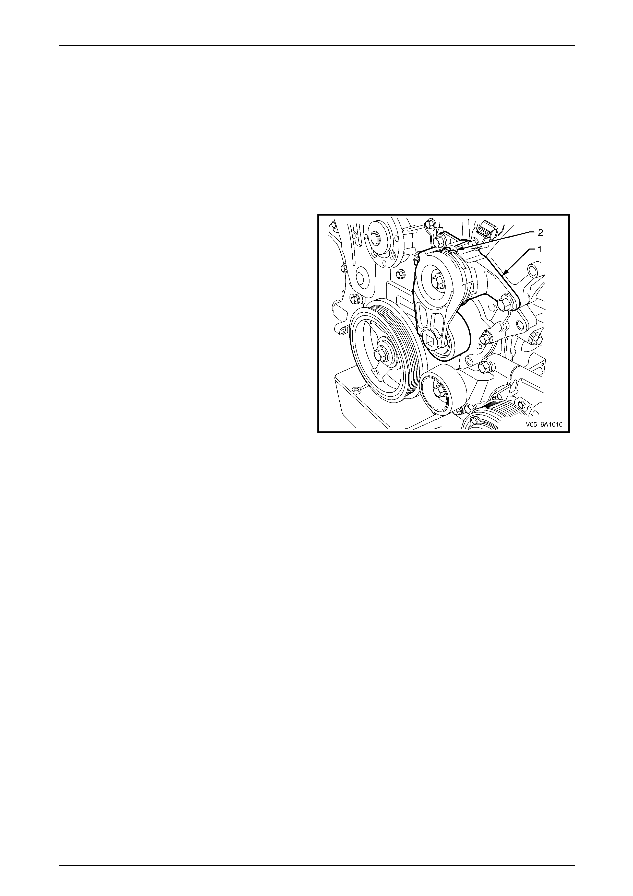
Engine Mechanical – V6 Page 6A1–51
Page 6A1–51
2.20 Accessory Drive Belt Diagnosis
Tension Check
NOTE
An accessory drive belt that squeaks when the
engine is started or stopp ed is considered normal
and has no effect on drive belt durability.
1 Start the engine and switch off the air-conditioning system. Allow engine to run until normal operating temperature
has been reached.
2 Turn the engine off and inspect the markings on the
drive belt tensioner to confirm the drive belt tension is
within the operating limits.
NOTE
The operating limits for acceptable drive belt
tension are when the dr ive belt tensi oner po i nter
(1) is aligned between the outer edge of the
minimum and maximum tension marks (2).
3 If the markings on the drive belt tensioner were
outside the acceptable operating limits, replace the
accessory drive belt, refer to
3.6 Accessory Drive Belt.
Figure 6A1 – 23
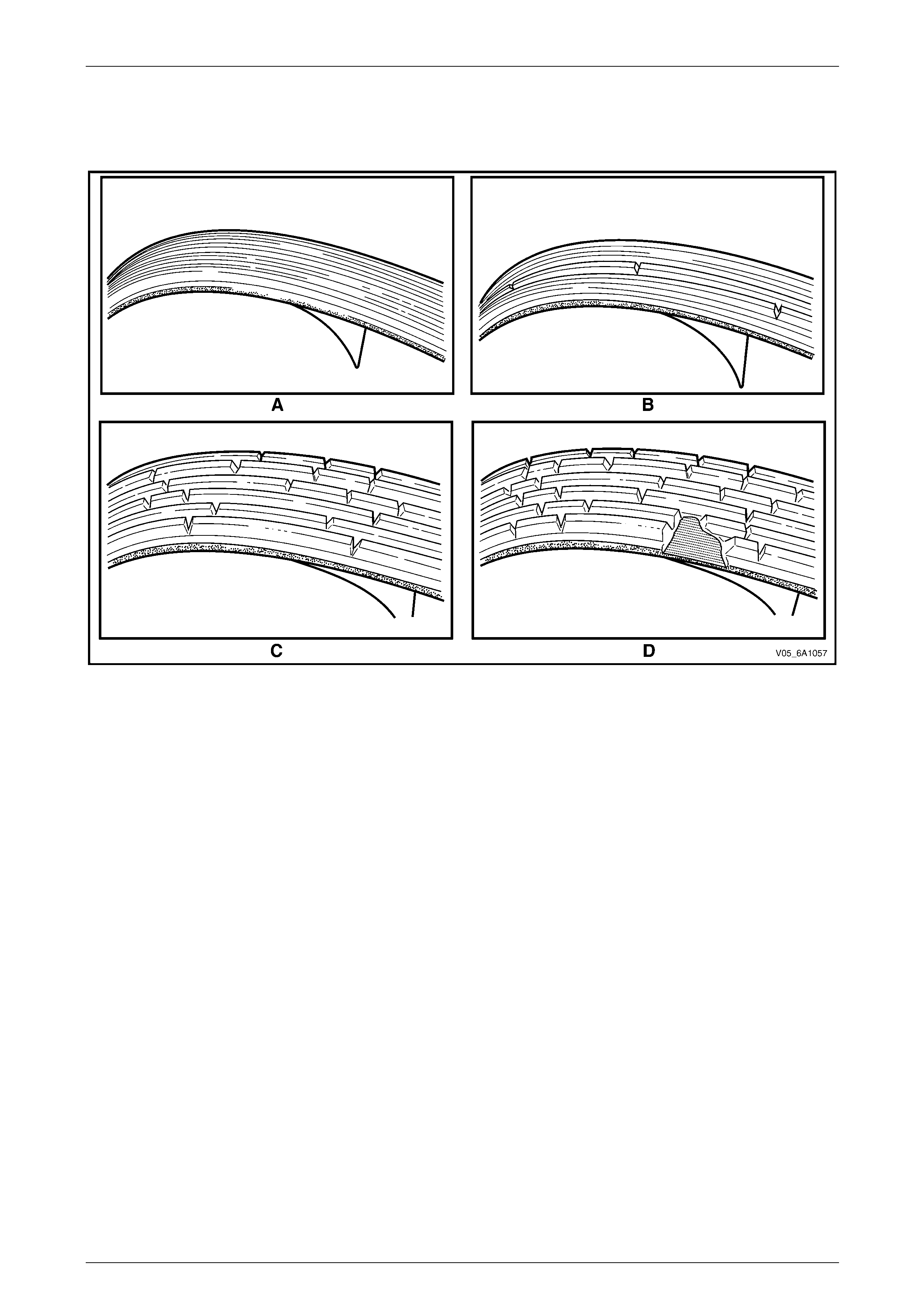
Engine Mechanical – V6 Page 6A1–52
Page 6A1–52
Inspect
Figure 6A1 – 24 illustrates the various stages of belt wear to aid in belt replacement decisions. Condition of the belt ribs
is best judged where the belt is bent over one of the larger accessory driv e system pulleys.
Figure 6A1 – 24
Legend
A New belt
B Moderately used belt – few cracks, some wear on ribs and in
grooves. replacement is not required
C Severely used belt – several cracks per 30 mm. Should be
replaced before chunking occurs.
D Failed belt – separation of rib material from the backing
(chunking). Replace belt immediately.

Engine Mechanical – V6 Page 6A1–53
Page 6A1–53
Drive Belt Chirp
Definition
Accessory drive belt chirping can be defined as a high-pitched noise that is heard once per revolution of the drive belt or
a pulley.
NOTE
Chirping during start-up in cold damp conditions
that abates once the engine reaches operating
temperature is considered normal.
Diagnostic Aids
The symptom may be intermittent due to moisture on the dr ive belts or pulleys. It may be necessary to spray a small
amount of water on the drive belt to duplic ate and confirm a customers concern. If spraying water onto the drive belt
system duplicates the symptom, cleaning the belt pulleys may be the solution.
A loose or incorrectly installed body component, suspension component or other item may be the cause of the noise.
Test Description
The numbers below refer to steps in the diagnostic table.
2 The noise may not be engine relate d. This step is to confirm the engine is making the noise. If the engine is not
making the noise, do not proceed further with this diagnostic procedure.
3 The noise may be an internal engine noise. Removing the drive belt and operating the engine briefly will confirm
whether or not the noise is related to the drive belt.
CAUTION
When running the engine with the accessory
drive belt removed, the coolant pump will not
be operating and the engine may overheat if
left unsupervised even for a short period.
NOTE
There may also be a number of DTCs set when
running the engine with the accessory drive belt
removed.
4 Inspect all drive pump pulleys for pilling.
NOTE
Pilling is the small balls ( pills) or strings of rubber
in the belt grooves caused by the acc umulati on of
rubber dust.
6 Misalignment of the accessory drive system pulleys may be caused by inco rrect mounting of an accessory drive
component (A/C compressor, generator etc.) or pulley. Misalignment may also be caused by incorrect installation of
a pulley during a previous repair. Test for a misaligned pulley using a straight edge in the pulley grooves across
two or three pulleys. If a misaligne d pulley is found, refer to the relevant component service information for the
correct installation and rem oval procedures.
10 Inspecting the fasteners can eliminate the possibility that an incorrect fastener has been in stalle d.
12 Inspecting the pulleys for bei ng bent should include inspecting for a dent or other damage that would prevent the
drive belt from not seating correctly in all of the pulley grooves or on the smooth surface when the back end of the
belt is used as the driving surface.
14 Replacing the drive belt when it is not damaged and there is no excessive pilling will only be a temporary repair.

Engine Mechanical – V6 Page 6A1–54
Page 6A1–54
Diagnostic Table
Step Action Yes No
1 Did you review the informatio n provi ded in 2.2 Symptoms, and
perform the required inspections. Go to Step 2 Go to 2.2
Symptoms
2 Confirm the customer complaint. Is there a chirping noise? Go to Step 3 Refer to Diagnostic
Aids in this Section
3 1 Remove the drive belt, refer to 3.6 Accessory Drive Belt.
2 Operate the engine for no more than 40 seconds.
Does the chirping noise still exist?
Accessory drive
system OK.
Go to 2.2
Symptoms, and
restart the diagnosis
of the noise Go to Step 4
4 Inspect for severe pilling, i.e. in excess of 33% of the belt groove
depth.
Do the belt grooves have pilli ng? Go to Step 5 Go to Step 6
5 Clean the drive belt pulle ys with a wire brush.
Are the belt pulleys clean? Go to Step 15 Go to Step 6
6 Inspect for misalignment of the pulleys.
Are the pulleys misalig ned? Go to Step 7 Go to Step 8
7 Replace or repair misaligned pulleys.
Did you complete the repair? Go to Step 15 —
8 Inspect for any bent or damaged accessory drive component
mounting brackets.
Did you find any bent or damaged brackets? Go to Step 9 Go to Step 10
9 Replace or repair any bent or damaged Brackets.
Did you complete the repairs? Go to Step 15 —
10 Inspect for missing, loose or incorrect fasteners.
Did you find any missing, lo ose or incorrect fasteners? Go to Step 11 Go to Step 12
11 Tighten any loose fasteners to the torque specification as provided in
provided in 6. Torque Wrench Specifications.
Replace any incorrect or missing fasteners.
Did you complete the repairs? Go to Step 15 —
12 Inspect for a bent pulley.
Did you find any bent pulleys? Go to Step 13 Go to Step 14
13 Replace bent pulleys as required.
Did you complete the repair? Go to Step 15 —
14 Replace the accessory driv e belt, refer to 3.6 Accessory Drive Belt.
Did you complete the repair? Go to Step 15 —
15 Reinstall the accessory drive belt and operate the system to confirm
the repair.
Did you correct the chirp noise? Accessory drive
system OK
Go to 2.2
Symptoms, and
restart the diagnosis

Engine Mechanical – V6 Page 6A1–55
Page 6A1–55
Drive Belt Squeal
Definition
Accessory drive belt squealing can be defined as a loud screeching n oise caused by a slipping drive belt. Belt squeal is
unusual in multi-rib belts. Drive belt squeal generally occurs when a heavy load is applied to the drive belt, such as an
air-conditioning compressor engagement, snapping the throttle, seized pulley or a faulty accessory drive component.
Diagnostic Aids
If the noise is intermittent, confirm the accessory drive components by varying their loads, making sure they are operated
to their maximum capacity. An overcharg ed A/C system, restrictions in the power steering pressure circuit or a faulty
generator or coolant pump are likely causes of accessory drive belt squeal.
A loose or incorrectly installed body component, suspension component or other item may be the cause of the noise.
Test Description
The numbers below refer to steps in the diagnostic table.
2 The noise may not be engine relate d. This step is to confirm the engine is making the noise. If the engine is not
making the noise, do not proceed further with this diagnostic procedure.
3 The noise may be an internal engine noise. Removing the drive belt and operating the engine briefly will confirm
whether or not the noise is related to the drive belt.
CAUTION
When running the engine with the accessory
drive belt removed, the coolant pump will not
be operating and the engine may overheat if
left unsupervised even for a short period.
NOTE
There may also be a number of DTCs set when
running the engine with the accessory drive belt
removed.
4 Confirms an accessory drive component does not have a seized bearing. With the belt removed, test the bearings
in the accessory drive comp onents spin free and smooth.
5 Confirms the drive belt tensioner is operating correctl y. If the drive belt tensioner is not operating correctly, drive
belt tension will not be maintained, resulting in a belt squealing no ise
6 Confirms the belt is not too long, which would prevent the tensioner from working as intended. Also, if an
excessively long belt has been fitted, it may also be routed incorrectly and may be turning an accessory drive
component in the wrong direction.
7 Misalignment of the pulle ys may be caused by one of the following:
• Incorrect mounting of an accessory drive component,
• Incorrect installation of an accessory drive pulley or,
• Bent or damaged pulley.
Test for a misaligned pulley using a straight edge in the pulley grooves acr oss 2 or 3 pulleys. If a misaligned pulley
is found, refer to the relevant component ser vice information for the correct installation and removal procedures.
8 This test is to confirm the pulleys are the corr ect diameter and/or width. Using a known good vehicle, compare the
pulley sizes.
Techline

Engine Mechanical – V6 Page 6A1–56
Page 6A1–56
Diagnostic Table
Step Action Yes No
1 Did you review the informatio n provi ded in 2.2 Symptoms, and
perform the required inspections. Go to Step 2 Go to 2.2
Symptoms
2 Confirm the customer complaint. Is there a squealing noise? Go to Step 3 Refer to Diagnostic
Aids in this Section
3 1 Remove the drive belt, refer to 3.6 Accessory Drive Belt.
2 Operate the engine for no more than 40 seconds.
Does the squealing noise still exist?
Accessory drive
system OK.
Go to 2.2
Symptoms, and
restart the diagnosis
of the noise Go to Step 4
4 Inspect the accessory drive components for a seized bearing and
general malfunctions.
Did you find and correct any seized bearings or general malfunctions
in the accessory drive system? Go to Step 9 Go to Step 5
5 Test the accessory drive belt tensioner for correct operati on, refer to
Drive Belt Tensioner Diagnosis.
Did you find and repair any problems with the tensioner? Go to Step 9 Go to Step 6
6 Inspect the accessory drive belt is the correct length, refer to 3.6
Accessory Drive Belt.
Did you find and repair any problems with the drive belt length? Go to Step 9 Go to Step 7
7 Inspect the accessory drive pulleys for misalignment.
Did you find and correct any misaligned accessor y drive pulleys? Go to Step 9 Go to Step 8
8 Check the accessory drive pulleys are the correct size.
Did you find and replace any incorrect pulleys? Go to Step 9 Refer to Diagnostic
Aids in this Section
9 Reinstall the accessory drive belt and operate the system to confirm
the repair.
Did you correct the squeal noise? Accessory drive
system OK
Go to 2.2
Symptoms, and
restart the diagnosis

Engine Mechanical – V6 Page 6A1–57
Page 6A1–57
Drive Belt Whine
Definition
Accessory drive belt whine can be defined as a high-pitched contin uous noise that is most likely to be caused by a failed
bearing in one of the accessory driv e components.
Diagnostic Aids
The drive belts themselves will not cause a whine. If the noise is intermittent, confirm the accessory drive components by
varying their loads, making sure they are ope rated to their m aximum ca pacity. An overcharged A/C system, restrictions
in the power steering pressure circuit or a faulty generator or coolant pump are likely causes of accessory drive belt
whine.
Test Description
The numbers below refer to steps in the diagnostic table.
3 The noise may be an internal engine noise. Removing the drive belt and operating the engine briefly will confirm
whether or not the noise is related to the drive belt.
CAUTION
When running the engine with the accessory
drive belt removed, the coolant pump will not
be operating and the engine may overheat if
left unsupervised even for a short period.
NOTE
There may also be a number of DTCs set when
running the engine with the accessory drive belt
removed.
4 The inspection of bearings should include the following accessory drive components:
• drive belt tensioners,
• drive belt idlers,
• generator,
• power steering pump,
• coolant pump, and
• A/C compressor.
The drive belt may need to be installed and the accessory drive components operated separately, at varying loads
to confirm the location of the faulty bearing, refer to the relevant Sections for compone nt inspection and repair
procedures.

Engine Mechanical – V6 Page 6A1–58
Page 6A1–58
Diagnostic Table
Step Action Yes No
1 Did you review the informatio n provi ded in 2.2 Symptoms, and
perform the required inspections. Go to Step 2 Go to 2.2
Symptoms
2 Confirm the customer complaint. Is there a whining noise? Go to Step 3 Refer to Diagnostic
Aids in this Section
3 1 Remove the drive belt, refer to 3.6 Accessory Drive Belt.
2 Operate the engine for no more than 40 seconds.
Does the whining noise still exist?
Accessory drive
system OK
Go to 2.2
Symptoms, and
restart the diagnosis Go to Step 4
4 Inspect the accessory drive components for a faulty or seized
bearings and gener al malfunctions.
Did you find and correct any faulty/seized bearings or general
malfunctions in the accessory drive system? Go to Step 5 Refer to Diagnostic
Aids in this Section
5 Reinstall the accessory drive belt and operate the system to confirm
the repair.
Did you correct the whine? Accessory drive
system OK
Go to 2.2
Symptoms, and
restart the diagnosis

Engine Mechanical – V6 Page 6A1–59
Page 6A1–59
Drive Belt Rumble
Definition
Accessory drive belt rumble can be d efin ed as a low pitch tapping, knocking or thumping noise heard at or just above
idle, once per rotation of the drive belt or a specific component. Drive belt rumble is generally caused by one of the
following:
• pilling or strings in the drive belt grooves,
• separation of the drive belt, o r
• a damaged or faulty drive belt.
NOTE
Pilling is the small balls ( pills) or strings of rubber
in the belt grooves caused by the acc umulati on of
rubber dust.
Diagnostic Aids
Vibration from the engine may cause a body component or other parts to emit a rumbling noise.
The drive belt may have a condition that cannot be seen or felt. Sometimes the replacement of the belt may be the only
way to confirm the belt is faulty
If the drive belt has been replaced and the diagnostic table completed, but the rumble is still present only when the drive
belt is installed, an accessory drive component such as the A/C compressor may be the cause. Varying the load to ea ch
accessory drive component in turn, should help isolate which component is causing the noise.
Test Description
The numbers below refer to steps in the diagnostic table.
2 Confirms the symptom exists at the time of diagnosis. Other vehicle components ma y be causing the noise.
3 Confirms the accessory drive belt is the cause of the noise. Drive belt rumbling is often confused with an internal
engine noise due to the simil arity in the description. Removing the drive belt and operating the engine briefly will
confirm whether or not the noise is related to the drive belt.
CAUTION
When running the engine with the accessory
drive belt removed, the coolant pump will not
be operating and the engine may overheat if
left unsupervised even for a short period.
NOTE
There may also be a number of DTCs set when
running the engine with the accessory drive belt
removed.
4 Inspecting the drive belt is to ensure that it is not causing the noise. Small cracks across the ribs of the drive belt
will not cause the noise and a r e not justification alone to replace the belt. Belt separation can be identified by the
ply of the belt separating and may be seen at the edge of the belt or felt as lumps under the belt.
5 Small amounts of pilling is a normal condition and is deemed acceptable. When the pilli ng is severe (33% of the
belt groove depth), the belt does not have a smooth surface to run on and should be replaced.

Engine Mechanical – V6 Page 6A1–60
Page 6A1–60
Diagnostic Table
Step Action Yes No
1 Did you review the informatio n provi ded in 2.2 Symptoms, and
perform the required inspections. Go to Step 2 Go to 2.2
Symptoms
2 Confirm the customer complaint. Is there a rumbling noise? Go to Step 3 Refer to Diagnostic
Aids in this Section
3 1 Remove the drive belt, refer to 3.6 Accessory Drive Belt.
2 Operate the engine for no more than 40 seconds.
Does the rumbling noise still exist?
Accessory drive
system OK
Go to 2.2
Symptoms, and
restart the diagnosis Go to Step 4
4 Inspect the accessory drive belt for damage, separ ation or sections of
missing ribs.
Did you find any damaged, se parated or missing ribs? Go to Step 7 Go to Step 5
5 Inspect the accessory drive belt for severe pil ling (exceeding 33% of
the belt groove depth).
Did you find sever pillin g? Go to Step 6 Go to Step 5
6 Clean the drive belt using a suitable wire brush and reinstall to the
engine, refer to 3.6 Accessory Drive Belt.
Did you complete the repairs? Go to Step 8 —
7 Install a new accessory drive belt, refer to 3.6 Accessory Drive Belt.
Did you replac e the accessory drive belt? Go to Step 8 —
8 If required, reinstall the accessor y drive belt and o perate the system to
confirm the repair.
Did you correct the rumbling noise? Accessory drive
system OK Refer to Diagnostic
Aids in this Section

Engine Mechanical – V6 Page 6A1–61
Page 6A1–61
Drive Belt Vibration
Definition
Accessory drive belt vibration can be d efined as a drive belt that jumps, shakes or rattles. Accessory drive belt vibr ation
is usually indicated b y one of the following:
• the vibration is engine speed related, or
• the vibration is sensitive to accessory drive system load.
Diagnostic Aids
The accessory drive components such as the A/C compressor or generator can have an affect on engine vibration.
To aid in locating which compone nt is causing the vibration, vary the load to each accessory drive component in turn and
note the effect it has on the vibration if any.
Test Description
The numbers below refer to steps in the diagnostic table.
2 Confirms the symptom exists at the time of diagnosis. Other vehicle components ma y be causing the noise.
3 Confirms the accessory drive belt is the cause of the noise. Drive belt rumbling is often confused with an internal
engine noise due to the simil arity in the description. Removing the drive belt and operating the engine briefly will
confirm whether or not the noise is related to the drive belt.
CAUTION
When running the engine with the accessory
drive belt removed, the coolant pump will not
be operating and the engine may overheat if
left unsupervised even for a short period.
NOTE
There may also be a number of DTCs set when
running the engine with the accessory drive belt
removed.
4 The drive belt may cause a vibration. Inspecting the drive belt is considerably easier while the drive belt is
removed.
6 Inspecting the fasteners can eliminate the possibility that an incorrect fastener has been installed.
8 This step should only be performed if the coolant pump is driven by the drive belt. Inspect the coolant pu mp for a
bent shaft. Also inspect the coolant pump bearings for smooth operation and excessive play. Compare the coolant
pump with a known good pump.
9 Accessory drive component brackets that are bent, cracked or loose ma y put extra strain on the accessory
component causing it to vibrate.

Engine Mechanical – V6 Page 6A1–62
Page 6A1–62
Diagnostic Table
Step Action Yes No
1 Did you review the informatio n provi ded in 2.2 Symptoms, and
perform the required inspections. Go to Step 2 Go to 2.2
Symptoms
2 Confirm the customer complaint. Is there a rumbling noise? Go to Step 3 Refer to Diagnostic
Aids in this Section
3 1 Remove the drive belt, refer to 3.6 Accessory Drive Belt.
2 Operate the engine for no more than 40 seconds.
Does the vibration noise still exist?
Accessory drive
system OK.
Go to 4.2
Symptoms, and
restart the diagnosis Go to Step 4
4 Inspect the accessory drive belt for damage, wear, debris b uild-up or
sections of missing ribs.
Did you find any damage, wear, debris bu ild-up or missing ribs? Go to Step 5 Go to Step 6
5 Install a new accessory drive belt, refer to 3.6 Accessory Drive Belt.
Did you replac e the accessory drive belt? Go to Step 10 —
6 Inspect for incorrect, loose, missing or damaged fasteners.
Did you find any incorrect, loo s e, missing or damaged fasteners? Go to Step 7 Go to Step 8
7 Tighten any loose fasteners to the correct torque specification, refer to
6 Torque Wrench Specifications.
Replace any incorrect or missing fasteners.
Did you complete the repairs? Go to Step 10 —
8 Inspect the coolant pump for a bent shaft, refer to Section 6B1 Engine
Cooling – V6.
Did you find and repair a bent coolant pump shaft? Go to Step 10 Go to Step 9
9 Inspect for bent, cracked or damaged accessory drive component
mounting brackets.
Did you find and repair any bent brackets? Go to Step 10 Refer to Diagnostic
Aids in this Section
10 If required, reinstall the accessor y drive belt and o perate the system to
confirm the repair.
Did you correct the vibration? Accessory drive
system OK Refer to Diagnostic
Aids in this Section

Engine Mechanical – V6 Page 6A1–63
Page 6A1–63
Drive Belt Falls Off
Definition
The drive belt falls off during normal operation or does not ride correctly on the accessory drive pull eys.
Diagnostic Aids
If the accessory drive belt repeatedl y falls off the drive pulleys, this is most likely due to pulley misalignment.
An extra load that is quickly applied and released by an accessory drive component (e.g. A/C compressor) may cause
the accessory drive belt to fall off. In this circumstance, confirm the fault by operating the accessory drive components in
turn, noting which one caused the belt to fall off.
Lack of drive belt tension may also cause the belt to fall off the pulle ys. Low drive belt tension could be caused by one of
the following:
• an incorrect drive belt length,
• a faulty drive belt tensioner, or
• a stretched or faulty drive belt.
Test Description
The numbers below refer to steps in the diagnostic table.
2 Confirms the condition of the drive belt. Damage may have occurred to the drive belt when it first fell off or it may
have been damaged which caused the belt to fall off.
4 Misalignment of the pulle ys may be caused by:
• the incorrect installation or mountin g of an accessory drive component,
• the incorrect installation of an accessory drive component pulley, or
• a damaged or bent accessory drive pu lley.
Test for a misaligned pulley using a suitable straight edge in the pulley grooves across two or more pulleys. If a
misaligned pulley is found, refer to the service information for the particular component, for the correct pulley
replacement procedures.
5 Inspecting the pulleys should include an inspection for dents or other dam age that would prevent the drive belt from
seating correctly in all of the pulley grooves or on the smooth surface of a pull ey when the back side of the belt is
used.
6 Accessory drive component mounting brackets that are bent will cause the drive belt to fall off.
7 Inspection of the fasteners can eliminate the possibil ity that an incorrect fastener was installed. Missing, loose or
incorrect fasteners may cause pulley misa lignment from the fasteners moving under load. Over-tightening of the
fasteners may cause deflection of mountin g brackets and result in misaligned accessory drive pulleys.

Engine Mechanical – V6 Page 6A1–64
Page 6A1–64
Diagnostic Table
Step Action Yes No
1 Did you review the informatio n provi ded in 2.2 Symptoms, and
perform the required inspections. Go to Step 2 Go to 2.2
Symptoms
2 Inspect for a damaged accessor y drive belt.
Did you find any damage on the drive belt? Go to Step 3 Go to Step 4
3 Install a new accessory drive belt, refer to 3.6 Accessory Drive Belt.
Does the drive belt continue to fall off? Go to Step 4 Go to Step 12
4 Inspect the accessory drive system pulle ys for misalignment
Did you find and repair any misaligned drive system pulleys? Go to Step 12 Go to Step 5
5 Inspect for a dented or cracked accessory drive system pulley.
Did you find and repair any dented or cracked drive system? Go to Step 12 Go to Step 6
6 Inspect for bent accessory drive component mounting brackets.
Did you find and repair any bent mounting brackets? Go to Step 12 Go to Step 7
7 Inspect for incorrect, loose, missing or damaged fasteners.
Did you find any incorrect, loo s e, missing or damaged fasteners? Go to Step 8 Go to Step 9
8 Tighten any loose fasteners to the correct torque specification, refer to
6 Torque Wrench Specifications.
Replace any incorrect or missing fasteners.
Does the drive belt continue to fall off? Go to Step 9 Go to Step 12
9 Test the accessory drive belt tensioner for correct operati on, refer to
Accessory Drive Belt Tensioner Dia gnosis in this Section.
Did you accessor y drive b elt tensioner operate correctly? Go to Step 11 Go to Step 10
10 Replace the drive belt tensioner, refer to 3.8 Accessory Drive Belt
Tensioner Assembly.
Does the drive belt continue to fall off? Go to Step 11 Go to Step 12
11 Inspect for a failed drive belt idler and drive belt tensioner bearings.
Did you find and repair any failed bearings? Go to Step 12 Refer to Diagnostic
Aids in this Section
12 If required, reinstall the accessor y drive belt and o perate the system to
confirm the repair.
Does the drive belt continue to fall off? Go to Step 2 Accessory drive
system OK

Engine Mechanical – V6 Page 6A1–65
Page 6A1–65
Drive Belt Excessive Wear
Definition
Excessive wear can be defined as wear at the outside ribs of the drive belt (frayed edges), usually caused by an
incorrectly installed driv e belt
Diagnostic Aids
Excessive wear of a drive belt is usually caused by an incorrect installation or an incorrect drive b elt fitted. Minor pu lley
misalignment will not cause excessive wear, but will cause the drive belt to fall off. Major pulley misalignment may cause
excessive wear, but would also result in the drive belt falling off.
Test Description
The numbers below refer to steps in the diagnostic table.
2 Confirms the drive belt is correctly installed onto all of the accessory drive system pulleys. Wear on the drive belt
may be caused by incorrectly positioning the drive belt by one or more grooves to a particular pulley.
3 The installation of the drive belt that is the incorrect width will cause wear on the drive belt. The drive belt ribs
should match all the grooves on all the pulle ys in the accessory drive system.
4 Confirms the drive belt is not contacting any parts of the engin e or bo dy while the engine is running. There should
be sufficient clearance when the accessory drive component loads varies. The drive belt should not come into
contact with any engine or body parts.
Diagnostic Table
Step Action Yes No
1 Did you review the informatio n provi ded in 2.2 Symptoms, and
perform the required inspections. Go to Step 2 Go to 2.2
Symptoms
2 Inspect the accessory drive belt for correct installation.
Is the drive belt installed correctly? Go to Step 5 Go to Step 3
3 Ensure that the drive belt is the correct one for the applicati on.
Is the correct drive belt installed? Go to Step 5 Go to Step 4
4 Is the drive belt contacting any engine or body components with the
engine running? Go to Step 6 Refer to Diagnostic
Aids in this Section
5 Install a new accessory drive belt, refer to 3.6 Accessory Drive Belt.
Did you replac e the accessory drive belt? Go to Step 6 —
6 If required, reinstall the accessor y drive belt and o perate the system to
confirm the repair.
Did you correct the excessive wear? Accessory drive
system OK Go to Step 2

Engine Mechanical – V6 Page 6A1–66
Page 6A1–66
Accessory Drive Belt Tensioner Diagnosis
Diagnostic Table
Step Action Yes No
1 1 Remove the accessory drive belt.
2 Inspect the drive belt tensioner pull ey.
Is the drive belt tensioner pulle y loose or misaligned? Go to Step 4 Go to Step 2
2 Rotate the drive belt tensioner.
Does the drive belt tensioner rotate freely, without any unusual
resistance or binding? Go to Step 3 Go to Step 4
3 1 Using a suitable torque wrench, measure the torque required to
lift the drive belt tensioner off the stop.
2 Using a known good tensioner, measure the torque required to
lift the drive belt tensioner off the stop.
Is the first torque reading within 10% of the second reading? Accessory drive belt
tensioner OK Go to Step 4
4 Replace the drive belt tensioner, refer to 3.8 Accessory Drive Belt
Tensioner Assembly.
Is the repair complete? Accessory drive belt
tensioner OK —

Engine Mechanical – V6 Page 6A1–67
Page 6A1–67
3 Minor Service Operations
ATTENTION
The V6 engine is a combination of numerous components, containing machined, honed, polished and lapped
surfaces manufactured on the latest, high technology production equipment. Many of the components
contain tolerances measured in thousandths of a millimetre. Consequently, when any engine component is to
be serviced, care and cleanlin ess are extremely important.
Prior to re-assembly of the engine, all components must be cleaned and inspected in accordance with the
relevant clean and inspect procedures throughout this Section, and replaced or repaired where required.
In addition to cleaning and inspecting components, a liberal coating of engine oil should be applied to friction
surfaces during assemb ly to protect and lubricate the surfaces on initial operation.
When performing any service operation, it should be understood that correct cleaning and protection of
machined surfaces and friction areas is part of the repair procedure. This is considered standard workshop
practice, even if not specifically stated.
ATTENTION
Torque values must be used as specified during reassembly to ensure correct retention of all components.
Through out this section, fastener torque wrench specifications may be accompanied with the following
identification marks:
■ Fasteners must b e rep laced after loosening.
Fasteners either have micro encapsulated sealant applied or incorporate a mechanical thread lock and
should only be re-used once. If in doubt, replacement is recommended.
If one of these identification marks is present alongside a fastener torque wrench specification, the
recommendation regarding that fastener must be adhered to.
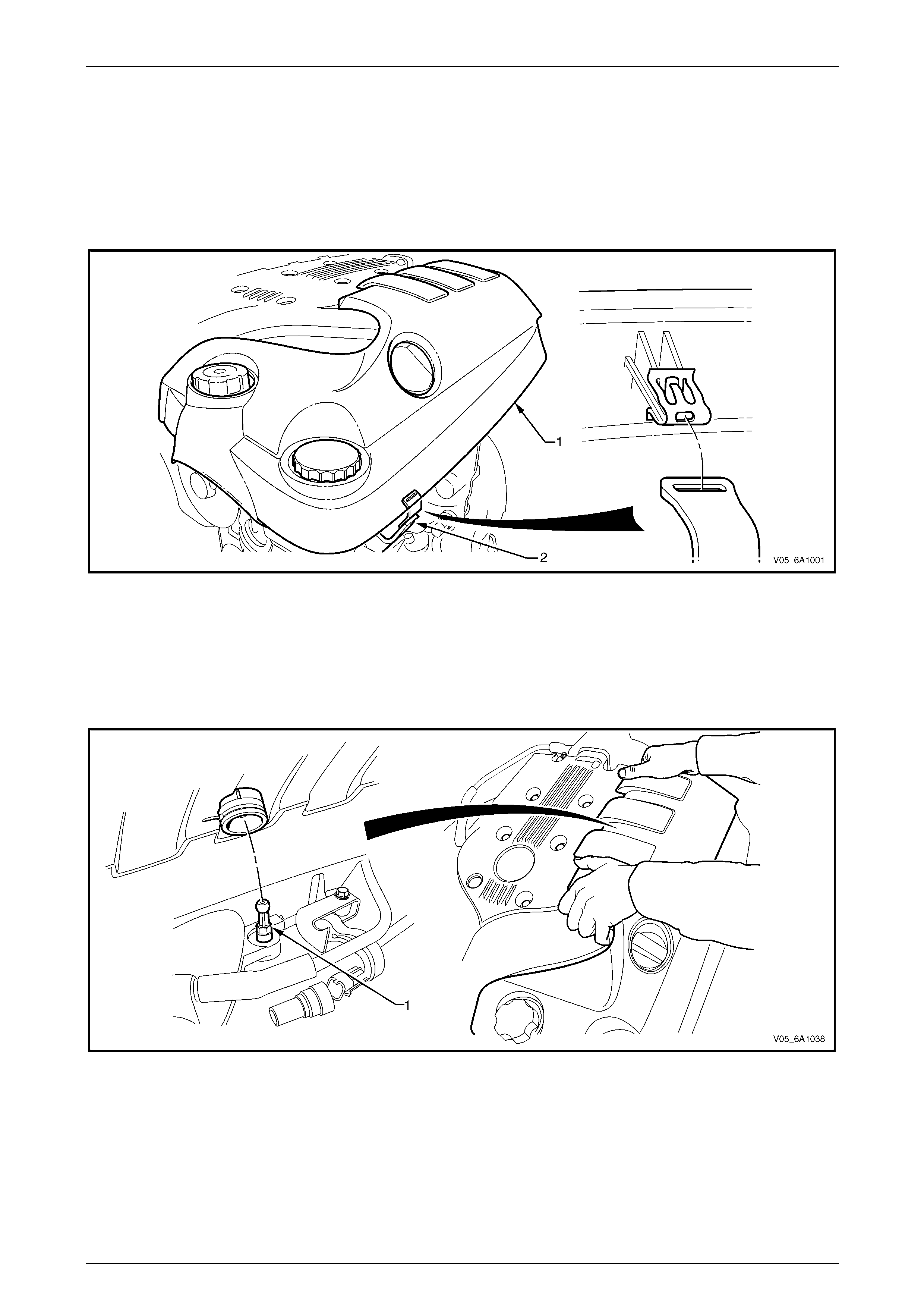
Engine Mechanical – V6 Page 6A1–68
Page 6A1–68
3.1 Engine Dress Cover
LT Section No. — 00–508
Remove
1 Remove the front suspension strut brace, refer to Section 1A1 Body.
2 For the left-hand engine dress cover (1), grasp the outer edge and prise the cover from the retainer (2), two places,
refer to Figure 6A1 – 25.
Figure 6A1 – 25
3 Either:
• For the left-hand engine dress cover, carefully lift the inner edge and unclip the cover from the ball stud (1),
one place.
• For the right-hand engine dress cover, carefully lift the inner and front edges and unclip the cover from the
ball stud (1), two places (left-hand shown, right-hand similar).
Refer to Figure 6A1 – 26.
Figure 6A1 – 26
4 Lift the cover up, unattaching the lug from the inlet manifold and remove the cover.
Reinstall
Reinstallation of the engine dress cover is the reverse of the removal procedure. Ensure the cover is secure after
installation.
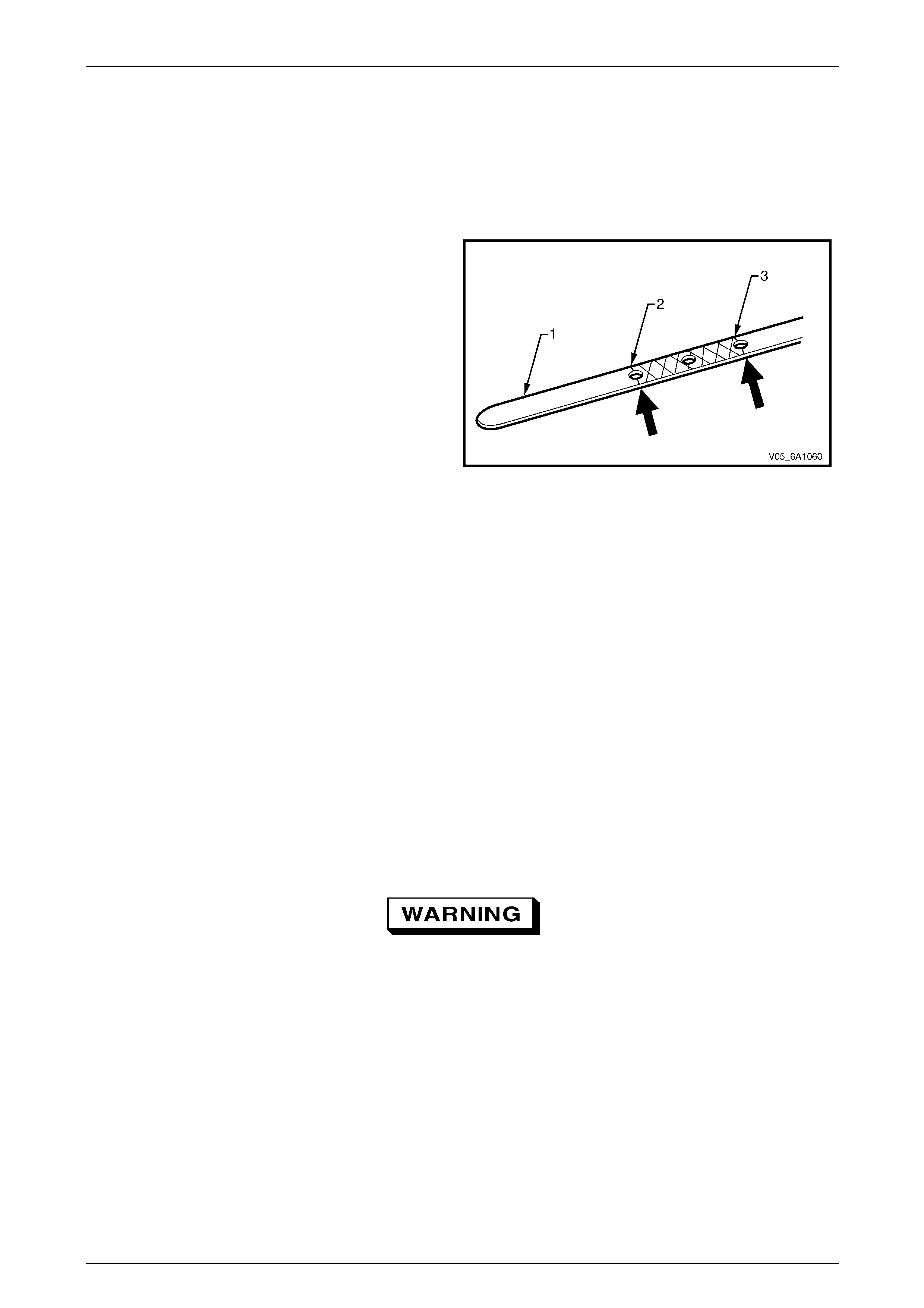
Engine Mechanical – V6 Page 6A1–69
Page 6A1–69
3.2 Engine Oil
Check
1 Run the engine to bring it to normal operating temperatur e.
2 Park the vehicle on a level surface. A vehicle that is not level will affect the accuracy of the level reading.
3 Stop the engine and wait 5 to 10 minutes to allow the oil to drain back into the oil pan.
4 Remove the oil level indicator (1) and wipe clean.
5 Insert the indicator, ensuring it is fully seated.
6 Slowly remove the indicator to avoid smearing. Hold it
horizontally or with lo wer end slightl y down to avoid
oil running along indicator.
7 Observe the oil level where it passes over the centre
line of the indicator.
8 If the level is lower than the Add mark (2), add
enough oil to the engine to reach the Upper mark (3).
Do not add too much oil as the reading s hould never
be above the Upper mark.
NOTE
When topping up the oil, allow approximately 5
to 10 minutes for the added oil to fully dra in into
the oil pan
Figure 6A1 – 27
Replace
NOTE
• Quicker and more complete draining will
occur if the engine oil is at normal operating
temperature. However, care must be taken to
avoid scalding from the hot oil.
• It recommended the oil filter be changed at
each engine oil change, refer to 3.3 Oil Filter.
1 Remove the oil fill cap.
2 To ensure complete draining of the oil pan, raise the front a nd rear of the vehicle to maintain a level attitude. If not
using a hoist, support the vehicle with safety stands, refer to Section 0A General Information.
3 Clean any foreign material from around the oil drain plug and place a suitable, clean drain tray under the engine.
The oil may be hot. Avoid contact with the oil.
Ensure that eyes and skin is p ro tected.
4 Remove the drain plug (1), taking care to avoid scalding from the hot oil. Allow the oil to drain.
5 Clean and inspect the drain plug threads. If damaged, replace the drain plug.
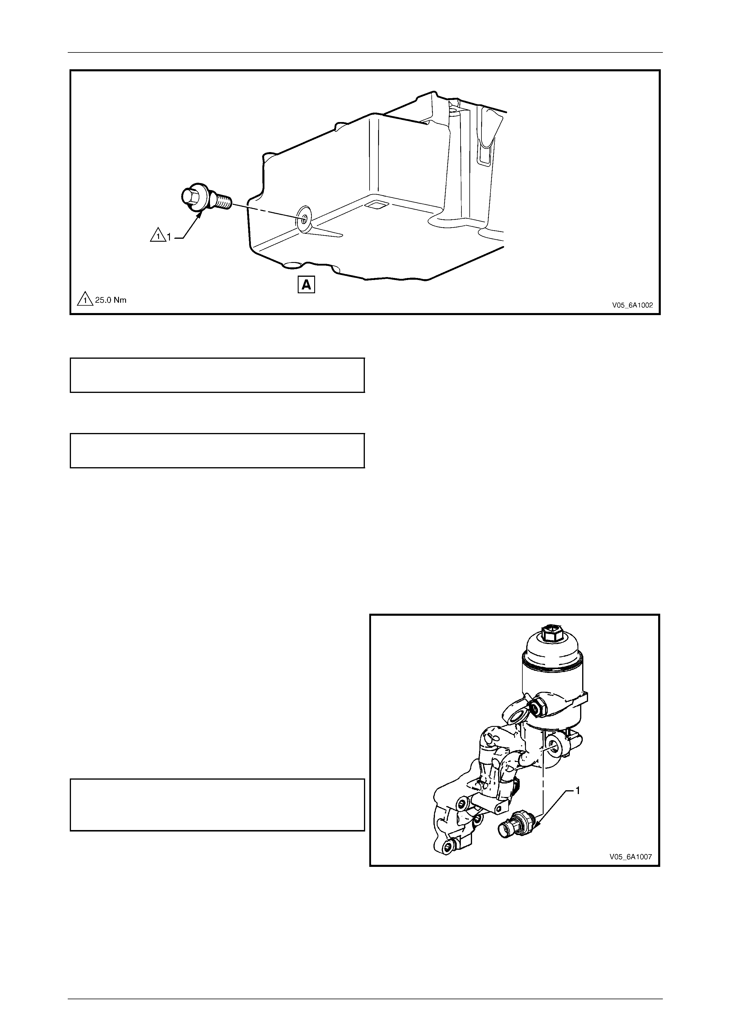
Engine Mechanical – V6 Page 6A1–70
Page 6A1–70
Figure 6A1 – 28
6 Once the oil has completely drained, reinstall the drain plug and tighten to the correct torque specification.
Oil pan drain plug
torque specification............................................25.0 Nm
7 Replace the oil filter, refer to 3.3 Oil Filter.
8 Lower the vehicle to the ground an d fill with the specified amount of SAE 5W30 lubricant.
Engine Oil Capacity:
With Oil Filter Change........................................6.5 litres
9 Install the oil fill cap.
10 Start the engine and check for leaks.
Pressure Check
1 Run the engine to bring it to normal operating temperatur e.
2 Park the vehicle on a level sur face. A vehicle not level will affect the accuracy of the level reading.
3 Stop the engine and wait 5 to 10 minutes to allow the oil to drain back into the oil pan.
4 Check the oil level and top up with the recommended engine oil as required, refer to Check, in this Section.
5 Remove the engine oil pressure sensor (1), refer to
Section 6C1-3 Engine Management – V6 – Service
Operations.
6 Install the oil pressure gauge adaptor, Tool No.
J36648-A into the oil pressure sender hole in the oil
filter housing.
7 Install a suitable oil pressure gau ge into the adaptor.
8 Start the engine.
9 Measure and record the pressure reading on the
gauge at idle and 2000 r.p.m. Compare the results
with the specification.
Minimum engine oil pressure
@ idle...................................................................69 kPa
@ 2000 r.p.m.....................................................138 kPa
10 If the engine oil pressure is not to specification, refer to
2.19 Engine Oil Pressure Diagnosis.
11 After completing the engine oil pressure chec k, stop
the engine and remove the oil pressure gauge. Figure 6A1 – 29
12 Reinstall the oil pressure sensor, refer to Section 6C1-3 Engine Management – V6 – Service Operatio ns.
13 Start the engine and check for leaks.
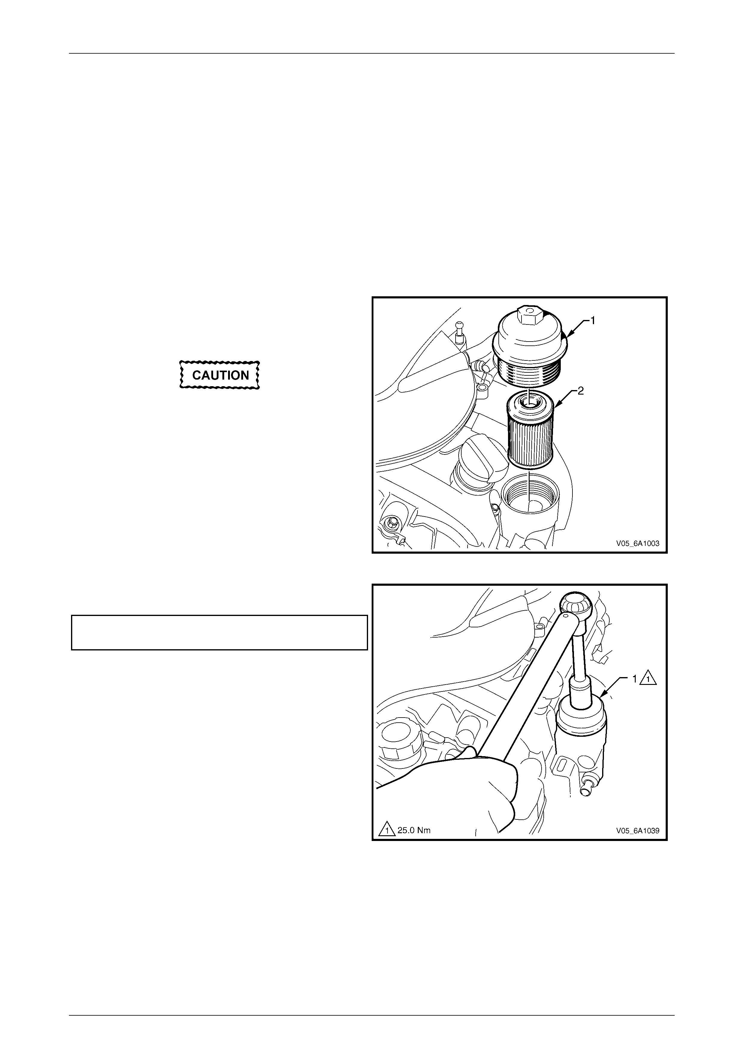
Engine Mechanical – V6 Page 6A1–71
Page 6A1–71
3.3 Oil Filter Cartridge
LT Section No. — 01–500
Replace
NOTE
• The oil filter cartridge should be replaced at
the correct time or distance intervals, refer to
Section 0B Lubrication and Se rvice .
• The oil filter cartridge shou ld also be replaced
whenever the engine oil is suspected to have
been contaminated by foreign material.
1 Remove the left-hand hand engine dress cover, refer to 3.1 Engine Dress Cover.
2 Remove the oil filter adaptor cap (1).
3 Remove and discard the oil filter cartridge (2).
4 Install the new oil filter cartridge.
Lubrication must be applied to the threads
of the oil filter cap prior to installation.
Failure to lubricate the oil filter cap threads
can hinder later remo val and cause possible
oil filter cap damage.
5 Lubricate the oil filter adaptor cap threads with clean
engine oil.
Figure 6A1 – 30
6 Install the oil filter adaptor cap (1) and tighten to the
specified torque.
Oil Filter Adaptor Cap Torque
Specification.......................................................25.0 Nm
Figure 6A1 – 31
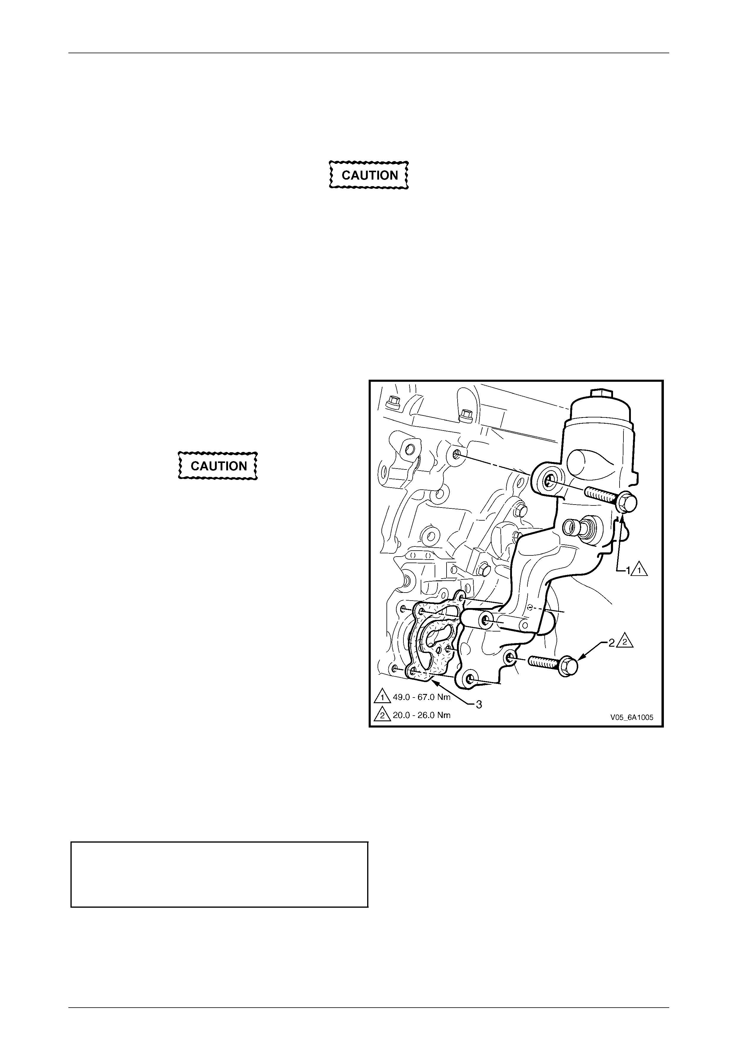
Engine Mechanical – V6 Page 6A1–72
Page 6A1–72
3.4 Oil Filter Adaptor
LT Section No. — 01–500
Remove
Disconnection of the battery affects certain
vehicle electronic systems, refer to
Section 00 Warnings, Caution and Notes
before disconnecting the battery.
1 Disconnect the battery negative terminal.
2 Remove the left-hand engine dress cover, Refer to 3.1 Engine Dress Cover.
3 Disconnect the wiring harness connector from the oil pressure sender.
4 Remove the power steering reservoir and pu mp brackets,
refer to 3.9 Power Steering Reservoir and Pump Brackets.
5 Remove the air-conditioner co mpressor but do not disconnect any hoses,
refer to Section 2B HVAC Climate Control (Manual A/C) – Remov al an d Installation.
6 Remove the upper (large) oil filter ada ptor attaching
bolt (1).
7 Remove the lower (small) oil filter attaching bolt (2),
four places.
Do not use a screwdriver or similar to prise
the oil filter adapter from the engine as
damage to the sealing surface may occur.
If required, use a rubber mallet to bump the
oil filter adapter to loosen the components
prior to separating. Bumping should be done
at bends, corners or reinforced areas to
prevent distortion of parts.
8 Remove the oil filter adaptor and discard the gasket
(3).
9 Clean the surfaces of the adaptor and cylinder block.
Figure 6A1 – 32
Reinstall
Reinstallation of the oil filter adaptor is the reverse of the removal procedure, noting the follo wing:
1 A new gasket must be used.
2 Loosely install the oil filter adaptor attaching bolts, then tighten all fasteners to the correct torque specification.
Oil filter adaptor upper attaching bolt
torque specification.................................49.0 – 67.0 Nm
Oil filter adaptor lower attaching bolt
torque specification...................................20.0- 26.0 Nm
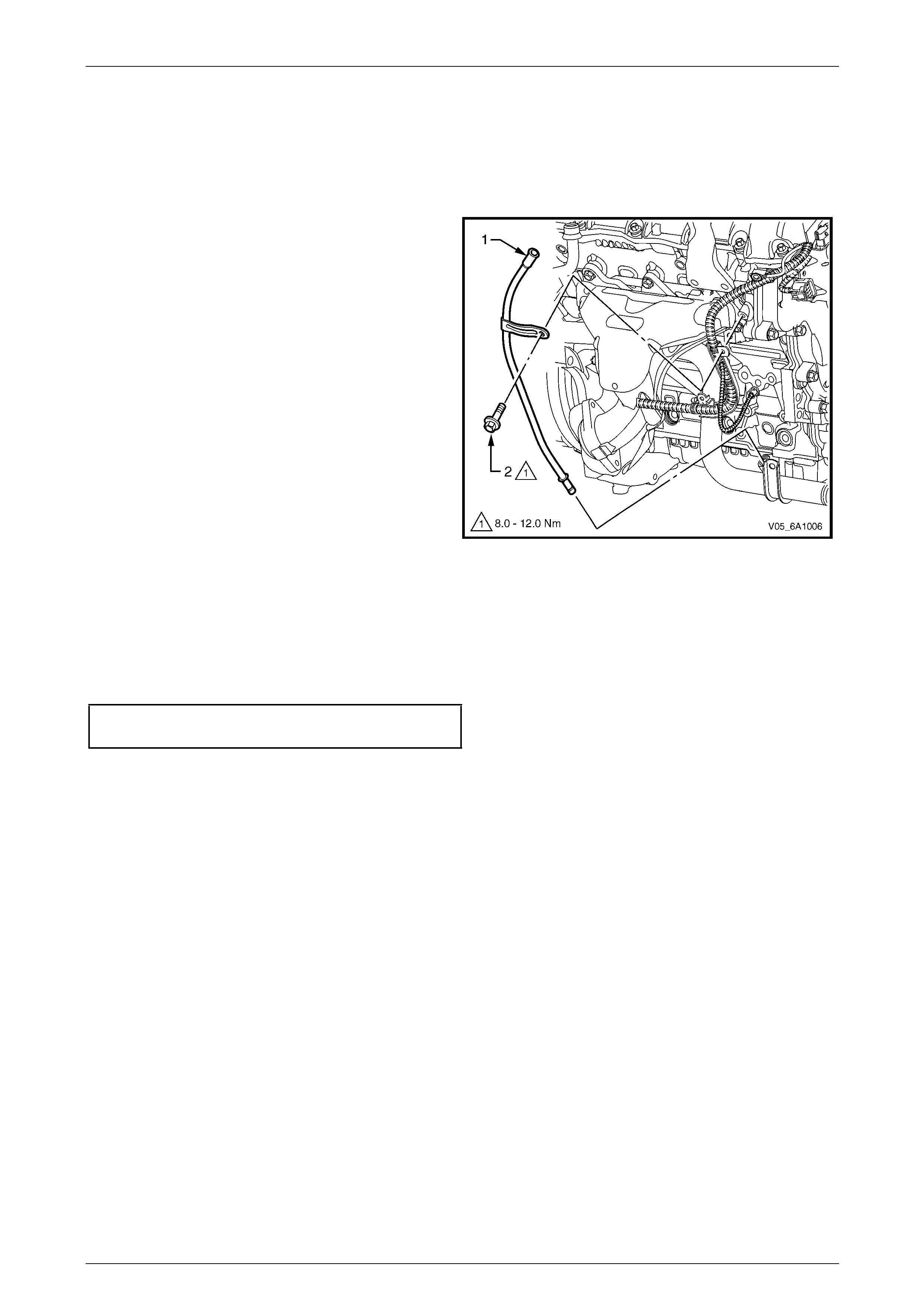
Engine Mechanical – V6 Page 6A1–73
Page 6A1–73
3.5 Oil Level Indicator Tube
LT Section No. — 00–580
Remove
1 Remove the oil level indicator from the oil level indicator tube.
2 Remove the bolt (2) attaching the oil level i nd icator
tube (1) and engine wiring harness retainin g bracket.
3 Withdraw the oil level indicator tube from the oil p an.
4 Remove and discard the o-ring at the bottom of the oil
level indicator tube.
Figure 6A1 – 33
Reinstall
Reinstallation of the oil level indicator tube is the reverse of the removal proced ure, noting the following:
1 Install a new oil level indicator o-ring.
2 Ensure the attaching bolt passes throug h the engine wiring harness retaining bracket.
3 Tighten bolt to the correct torque specification.
Oil level indicator tube attaching bolt
torque specification...................................8.0 – 12.0 Nm
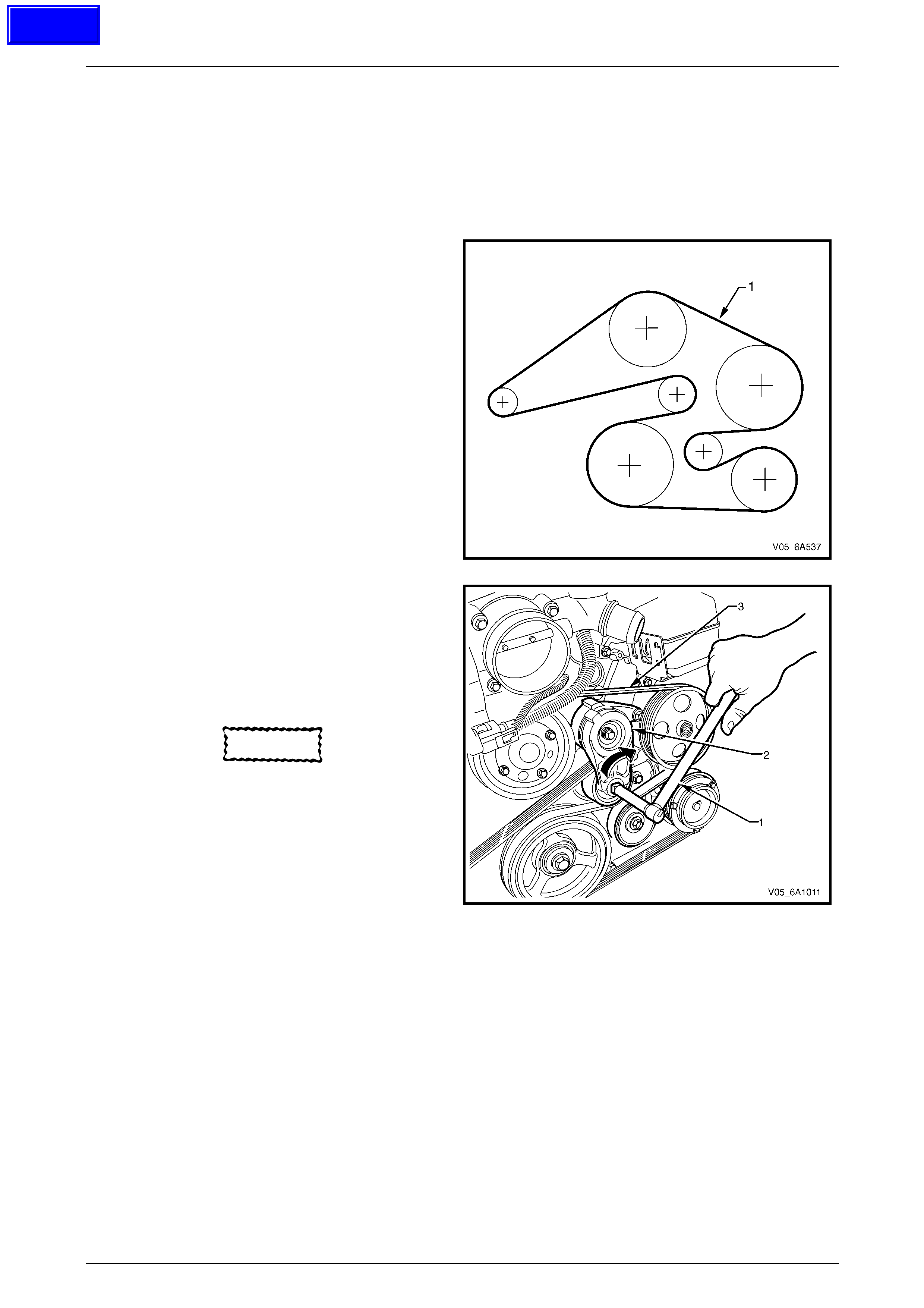
Engine Mechanical – V6 Page 6A1–74
Page 6A1–74
3.6 Accessory Drive Belt
LT Section No. — 01–003
Remove
1 Remove the air intake duct from between the air flow meter and the throttle body, refer to
Section 6C1-3 Engine Management – V6 – Service Operations.
2 Note the accessory drive belt (1) routing.
Figure 6A1 – 34
3 Using a suitable ½” drive socket bar (1), rotate the
drive belt tensioner (2) clockwise, to reduce belt
tension.
4 While holding the tensi on er in the reduced tension
position, remove the accessory drive belt (3).
NOTE
If required use an assistant to maintain the
tensioner in the required posi t ion.
CAUTION
If running the engine with the accessory
drive belt removed, the coolant pump will
not be operating and the engine may
overheat if left unsupervised even for a sho rt
period.
Figure 6A1 – 35
Reinstall
1 Install the drive belt over the A/C compressor, idler pulley, power steering pump, coolant pump, generator and
tensioner pulleys.
2 Using a suitable ½” drive socket bar (1), rotate the drive belt tensioner (2) clockwise, refer to Figure 6A1 – 35.
3 With an assistant holding the tensioner in the required position, feed the accessory drive belt (3) over the
crankshaft pulley.
4 Slowly release the drive belt tensioner mechanism.
NOTE
Ensure the drive belt ribs are correctly aligned
with the grooves in the accessor y drive pulleys or
damage to the drive belt and accessory drive
components and pulleys may occur.
5 Reinstall the air intake duct to the air flow meter and the throttle body,
refer to Section 6C1-3 Engine Management – V6 – Service Operations.
6 Run the engine to ensure correct operation.
Techline
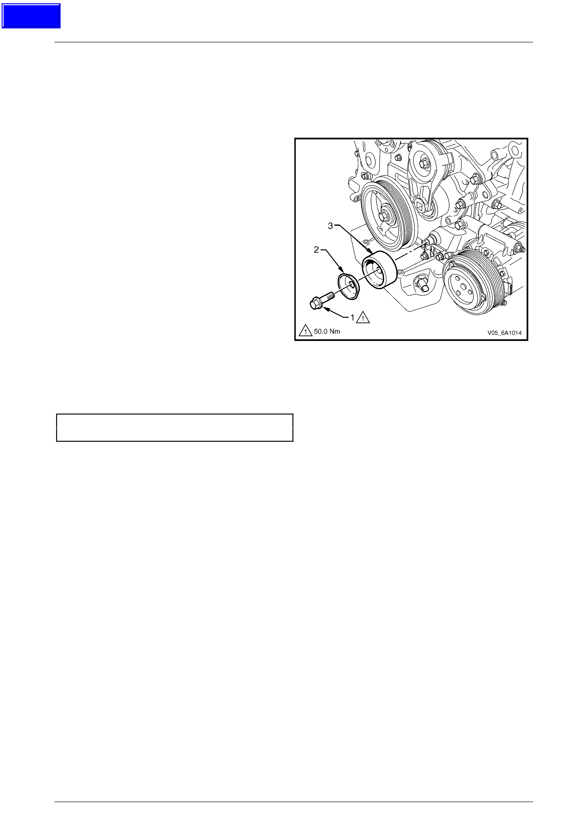
Engine Mechanical – V6 Page 6A1–75
Page 6A1–75
3.7 Accessory Drive Belt Idler Pulley
LT Section No. — 01–030
Remove
1 Remove the accessory drive belt, refer to 3.6 Accessory Drive Belt.
2 Remove the accessory drive belt idler pulley attaching
bolt (1).
3 Remove the dished washer (2) and accessory drive
belt idler pulley (3).
Figure 6A1 – 36
Reinstall
Reinstallation of the accessor y driv e belt idler pulley is the reverse of the removal procedure. Tighten the bolt to the
correct torque specification.
Accessory drive belt idler pulley
attaching bolt torque specification......................50.0 Nm
Techline
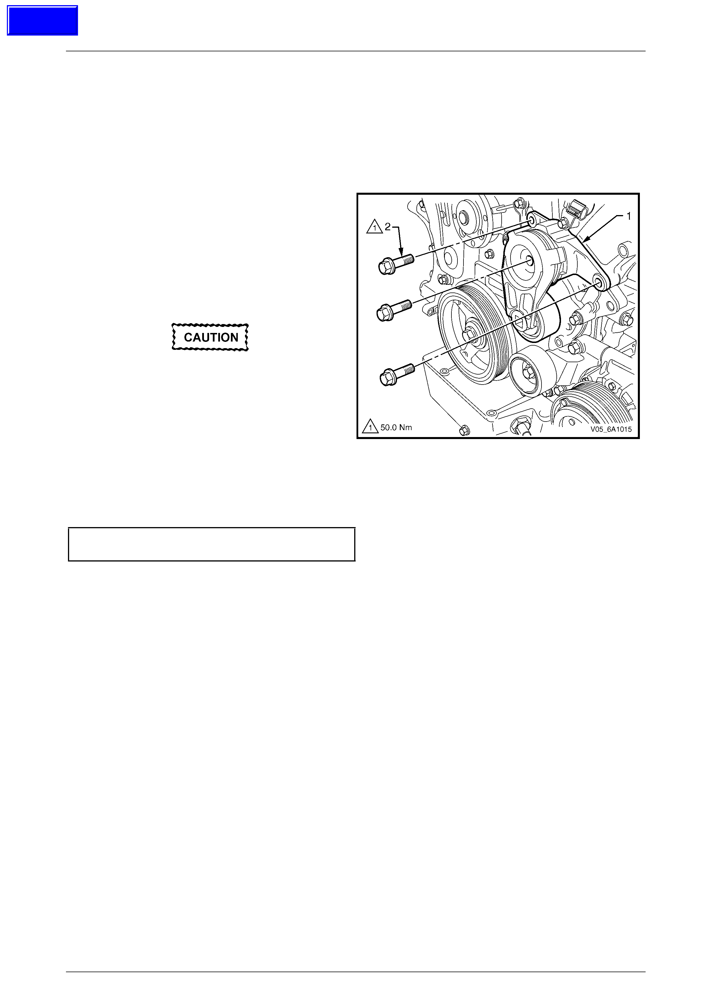
Engine Mechanical – V6 Page 6A1–76
Page 6A1–76
3.8 Accessory Drive Belt Tensioner
Assembly
LT Section No. — 01–030
Remove
1 Remove the accessory drive belt, refer to 3.6 Accessory Drive Belt.
2 Remove the three bolts (2) attaching accessory drive
belt tensioner assembly (1).
3 Remove the accessory drive belt tensioner assembly.
NOTE
The accessory drive belt tensioner pulley is not
serviced separately. If the pulley is found to be
faulty, the entire tensioner assembly must be
replaced.
Repairing a damaged accessory drive belt
pulley should not be attempted under any
circumstances.
Figure 6A1 – 37
Reinstall
Reinstallation of the accessor y driv e belt tensioner assembly is the reverse of the removal procedure. Tighten the bolts to
the correct torque specification.
Accessory drive belt tensioner
attaching bolt torque specification......................50.0 Nm
Techline
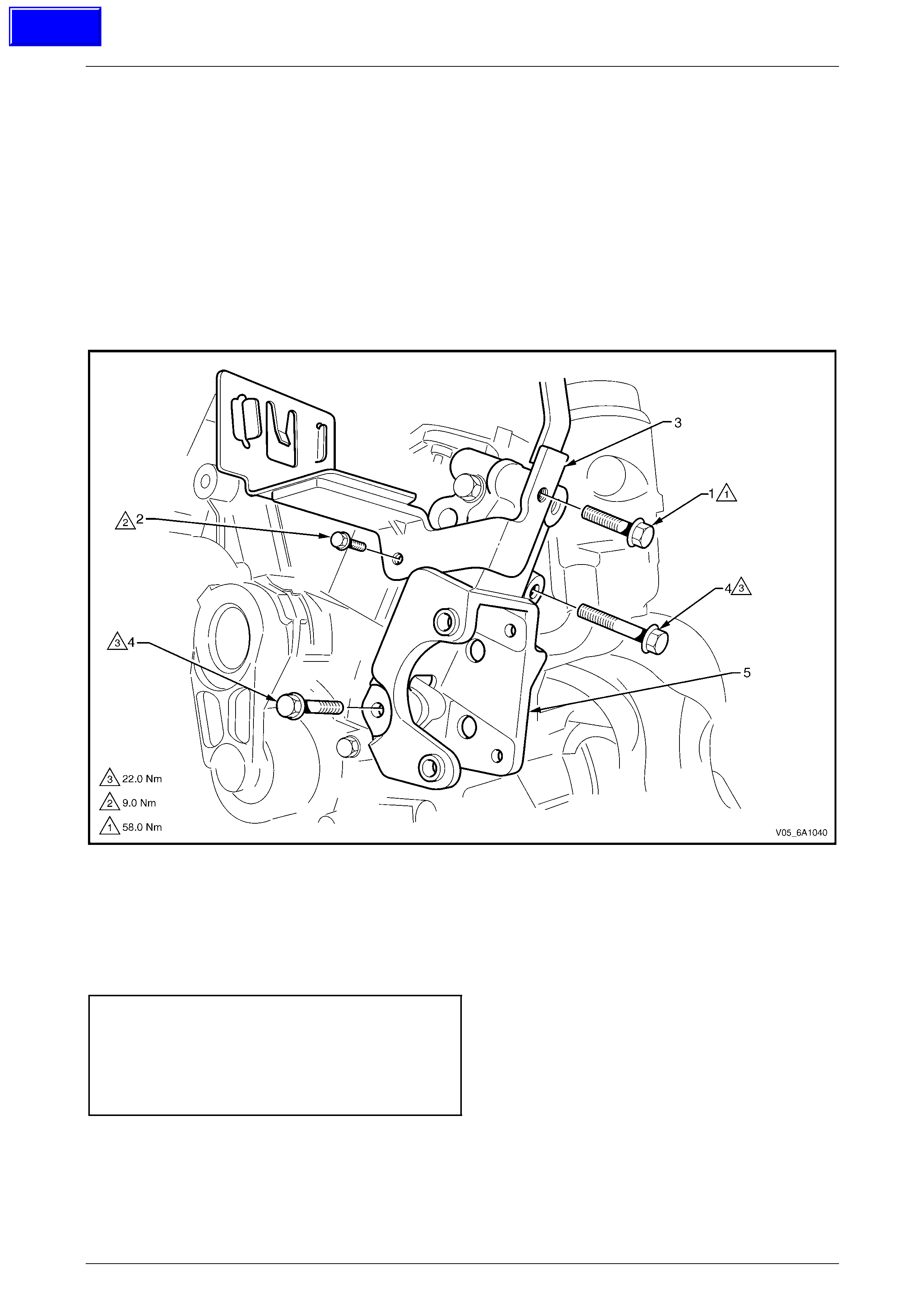
Engine Mechanical – V6 Page 6A1–77
Page 6A1–77
3.9 Power Steering Reservoir and Pump
Brackets
LT Section No. — XX–XXX
Remove
1 Remove the power steering pump and reservoir, refer to Section 9 Steering.
2 Remove the two screws (1 and 2) attaching the po wer steer ing reservoir bracket (3) to the cylinder head, refer to
Figure 6A1 – 38.
3 Remove the power steering reservoir bracket.
4 Remove the two screws (4) attaching the po wer steeri ng pump bracket (5) to the cylinder head.
5 Remove the power steering pump bracket.
Figure 6A1 – 38
Reinstall
Reinstallation of the power steering pump and reservoir brackets is the reverse of the removal procedure, noting the
following:
1 Hand start the bolts before tightening.
2 Tighten the bolts to the correct torque specification.
Power steering reservoir bracket
small attaching screw torque specification...........9.0 Nm
Power steering reservoir bracket
large attaching screw torque specification .........58.0 Nm
Power steering pump bracket
attaching screw torque specification..................22.0 Nm
Techline
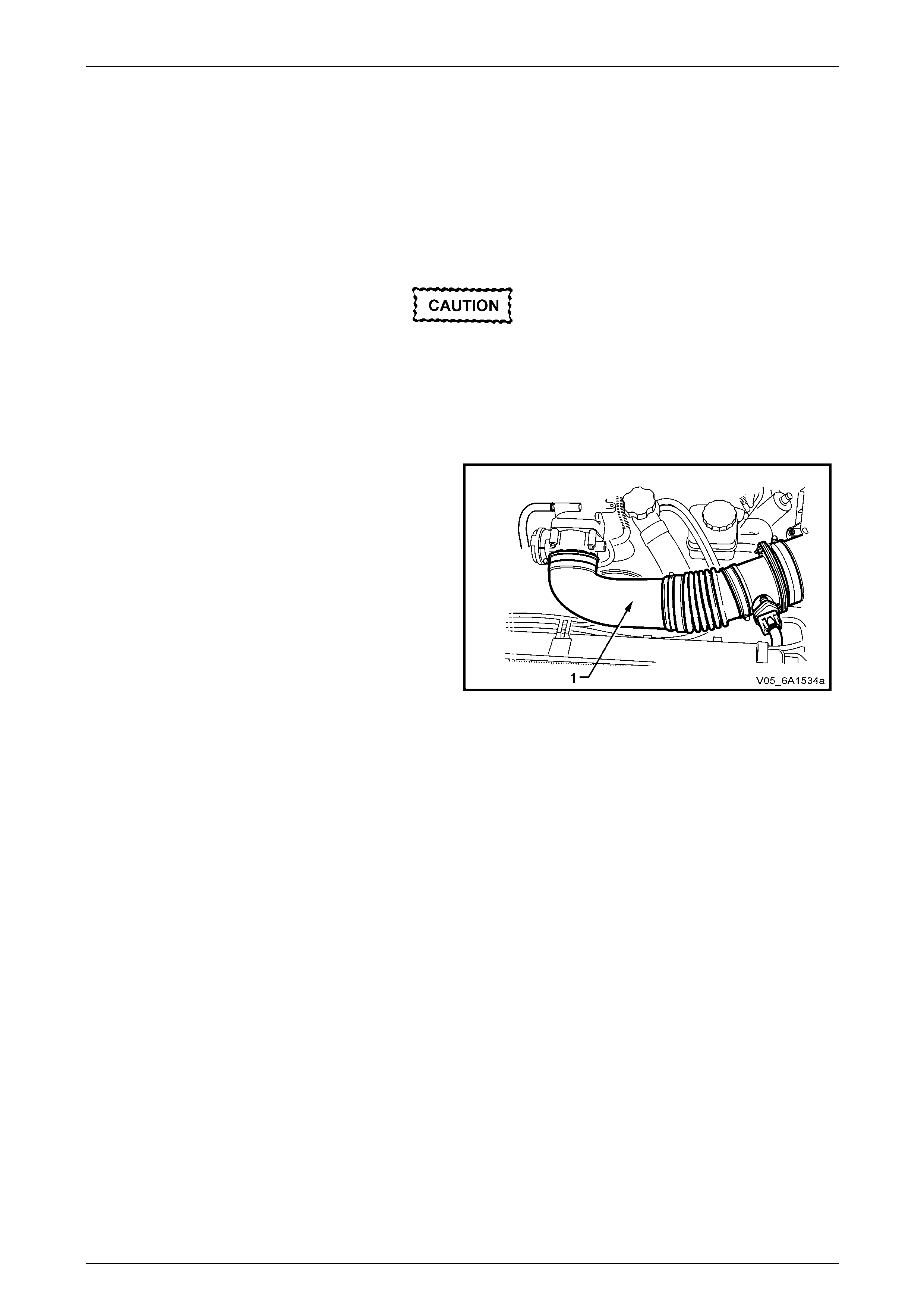
Engine Mechanical – V6 Page 6A1–78
Page 6A1–78
3.10 Upper Intake Manifold
The intake manifold comprises of an upper and lower section. Some service procedur es only require the removal of the
upper intake manifold (e.g. fuel injector/spark plug servicing), while other service procedures require the remova l of both
the upper and lower manifold as a complete assembly (e.g. cylinder head/s). If the complete assembly needs to be
removed, refer to 3.11 Intake Manifold Assembly – Complete.
LT Section No. — 00–375
Remove
Disconnection of the battery affects certain
vehicle electronic systems. Refer to
Section 00 Warnings, Caution and Notes
before disconnecting the battery.
1 Disconnect the battery negative terminal.
2 Remove the engine dress covers, refer to 3.1 Engine Dress Cover.
3 Remove the air intake duct (1), refer to Section 6C1-3
Engine Management V6 – Service Operations.
Figure 6A1 – 39
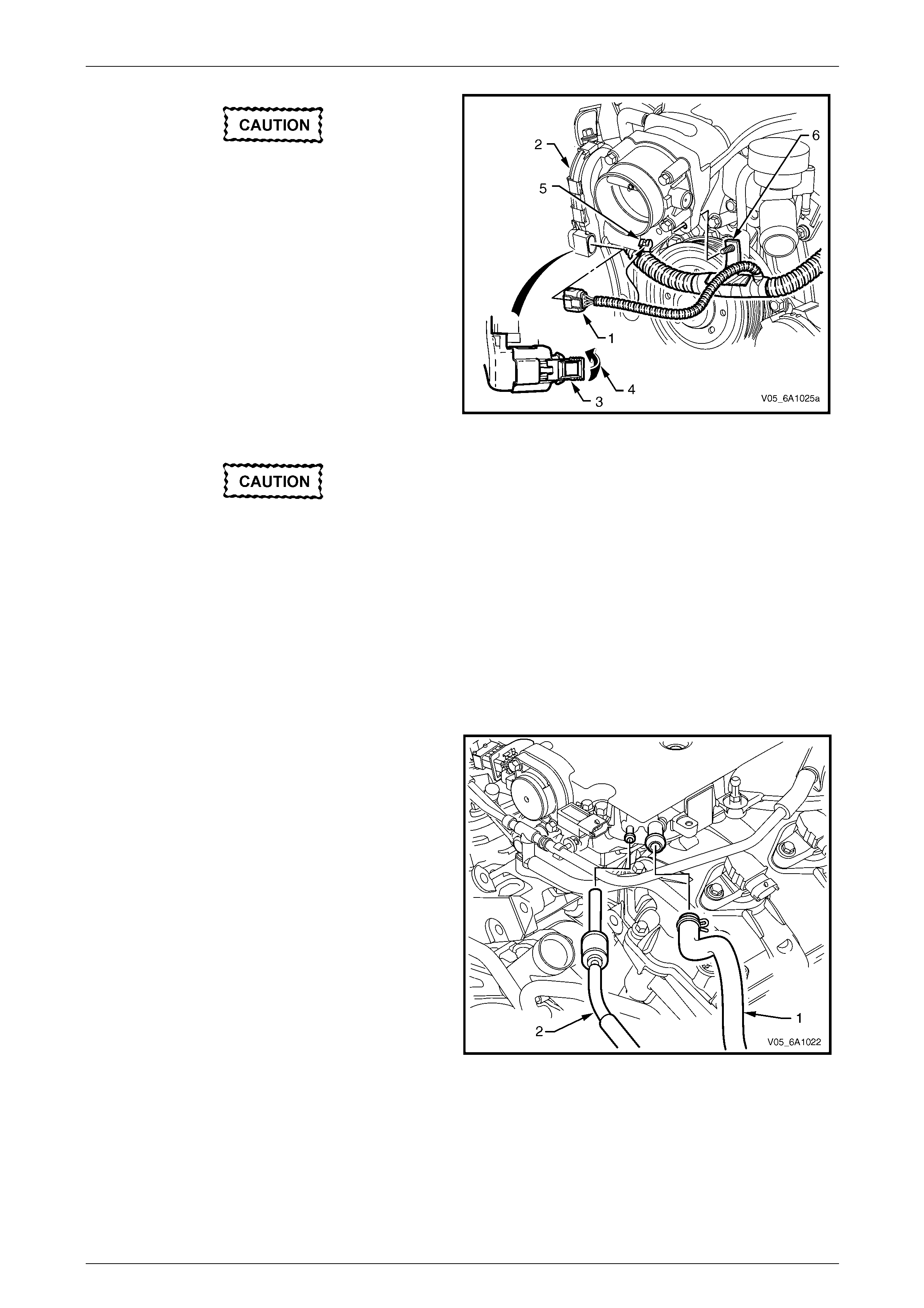
Engine Mechanical – V6 Page 6A1–79
Page 6A1–79
The following precautions must be followed
when disconnecting the throttle body wiring
connector:
• Do not use any mech an ical device such
as a screwdriver to disengage the
harness connector (1) from the throttle
body (2).
• When retracting the throttle wiring
connector lock (3), take care not to
disengage the lock from the connector.
• Do not pull on the connector wires.
4 Retract the throttle body wiring connector lock (3).
5 While pressing the connector latch in the direction of
the arrow (4), disconnect the throttle body wiring
connector.
6 Disconnect the throttle body conn ector wiring harness
from its retaining clip (5).
• Take care not to break the barbed
harness retain er pin (6) while remo ving
the harness retainer from the intake
manifold.
• Should the pin be broken, then it is
vital that a new harness retainer is
fitted to the wiring harness shield. If
not, the harness will foul the engine
drive belt.
7 Remove the main wiring harness retainer pi n (6) from
the intake manifold by pushing from the front to the
rear using a suitable piece of 5 mm steel rod (or an
Allen key).
Figure 6A1 – 40
8 Disconnect the following vacuum hoses from the
upper intake manifold:
a Brake booster hose (1).
b HVAC vacuum hose (2).
Figure 6A1 – 41
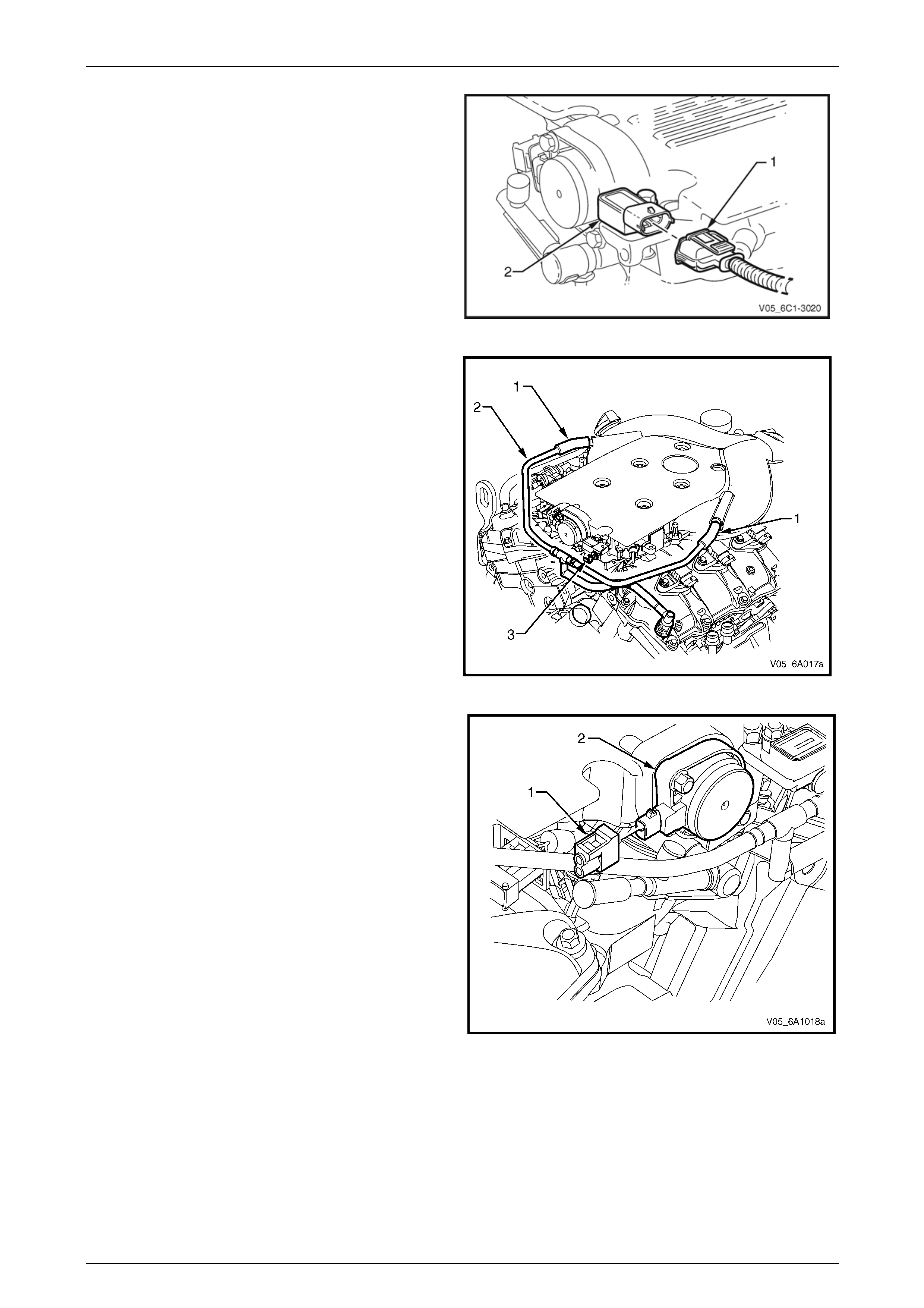
Engine Mechanical – V6 Page 6A1–80
Page 6A1–80
9 Disconnect the wiring harness connector (1) from the
barometric (BARO) pressure sensor (2).
Figure 6A1 – 42
10 Disconnect the PCV tube (1) from the upper intake
manifold assembly, on each side.
11 Disconnect the PCV tube assembly (2) from the
barometric pressure sensor mounting clip (3), by
pushing down on the tube at the ’T’ piece to dislodge.
12 Move the PCV tube assembly clear of the upper
intake manifold assembly.
Figure 6A1 – 43
13 Disconnect the wiring harness connector (1) from the
inlet manifold runner control (IMRC) soleno id (2).
Figure 6A1 – 44
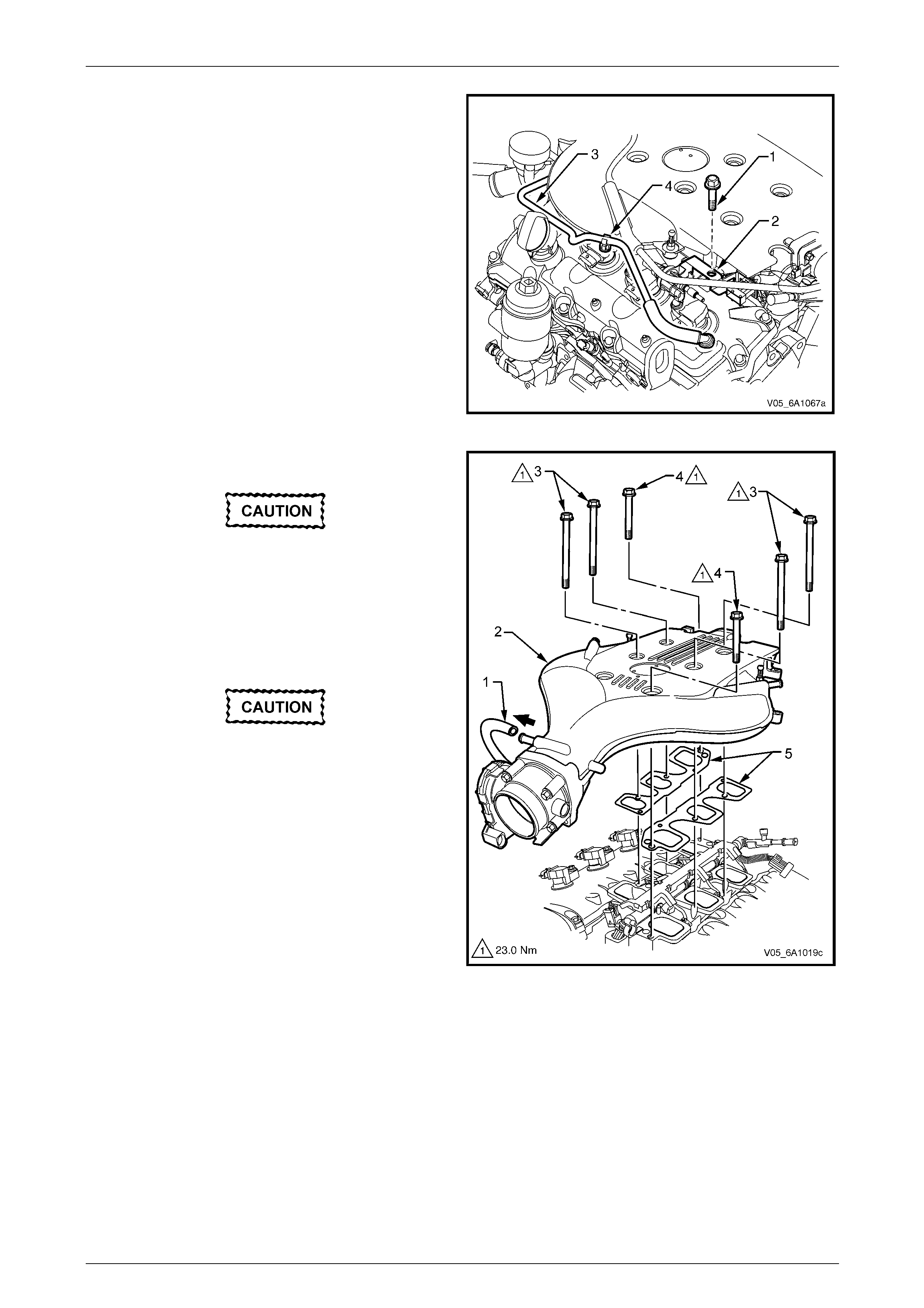
Engine Mechanical – V6 Page 6A1–81
Page 6A1–81
14 Remove the bolt (1) attaching the EVAP valve and the
fuel injector wiring harness connector mounting
bracket (2) to the upper intake manifold assembly.
15 Move the EVAP valve and the fuel injector wirin g
harness connector mounting bracket clear of the upper
intake manifold assembly.
16 Disconnect the PCV fresh air tube (3) from its upper
intake manifold mounting clip ( 4).
Figure 6A1 – 45
17 Disconnect the EVAP valve outlet tube (1) from the
intake manifold (2).
When the upper intake manifold is removed,
plug each of the lower intake runner
openings w ith lint free clot h, to stop th e entr y
of foreign material into the engine.
18 Remove the four long (3) (165 mm) and two short
bolts (4) (70 mm) attaching the upper intake
manifold (2) to the cylinder heads and lower intake
manifold.
Do not reuse the upper to lower intake
manifold gaskets (5).
19 Lift the upper intake manifold (2) clear from the lower
half and then remove the upper intake manifold from
the engine.
20 Remove and discard the upper to lower intake
manifold gaskets (5).
Figure 6A1 – 46
21 Remove the upper and lo wer intake manifold assembly from the engine.
22 Remove lower intake manifold to cylinder hea d gasket.
Disassemble
Remove the following from the upper intake manifold,
refer to Section 6C1-3 Engine Management – V6 – Service Operations:
• BARO sensor,
• IMRC solenoid, and
• throttle body assembly.
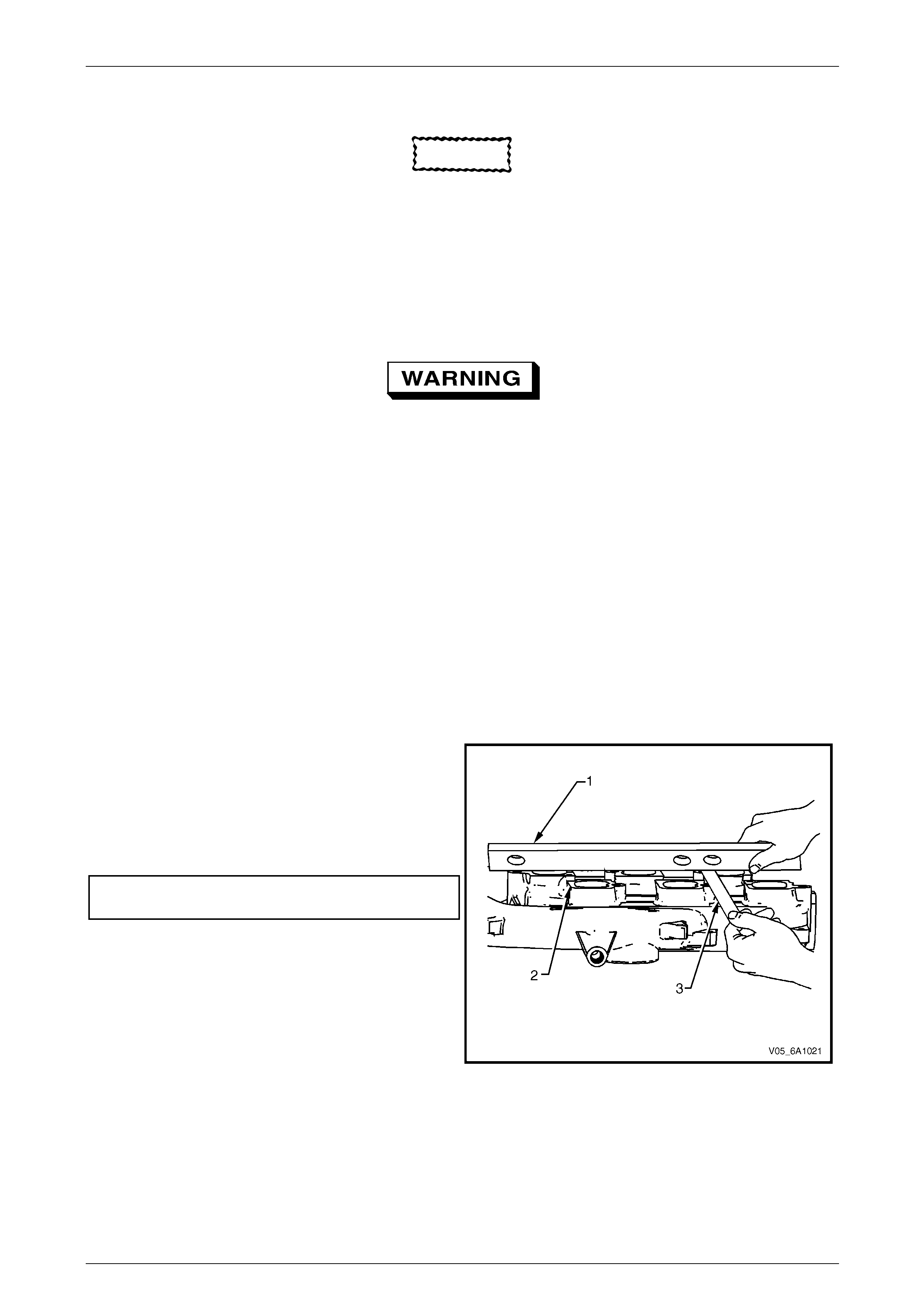
Engine Mechanical – V6 Page 6A1–82
Page 6A1–82
Clean
CAUTION
Due to the aluminium alloy construction of
the intake manifold, wire brushes and steel
scrapers must not be used during the
cleaning process, as damage to sealing
surfaces may occur. Use of a wooden or
plastic scraper is preferred.
1 Clean mating surfaces ensuring any gasket material is removed.
2 Clean the manifold using a suitable solvent
Safety glasses must be worn when using
compressed air.
3 Dry the timing components with compressed air.
Inspect
1 Inspect the intake manifold for the following fault conditions:
• Damaged sealing and mating surfaces.
• Damaged lower intake manifold gasket.
• Damage or excessive debris on the threaded and through holes.
• Cracks or damage to the intake manifold body.
NOTE
If the lower intake manifold is cracked or
damaged, it must be replaced. No welding or
patching of the intake manifold should be
performed.
2 Place a straight edge (1) across the upper intake
manifold sealing surface (2).
3 Using a feeler gauge (3), measure the clearance
between the manifold and the straight edge.
4 If the clearance between the upp er intake manifold
sealing surface and the straight edge exceeds the
specified maximum warpage, replace the manifold.
Upper manifold maximum
warpage............................................................ 0.05 mm
Figure 6A1 – 47
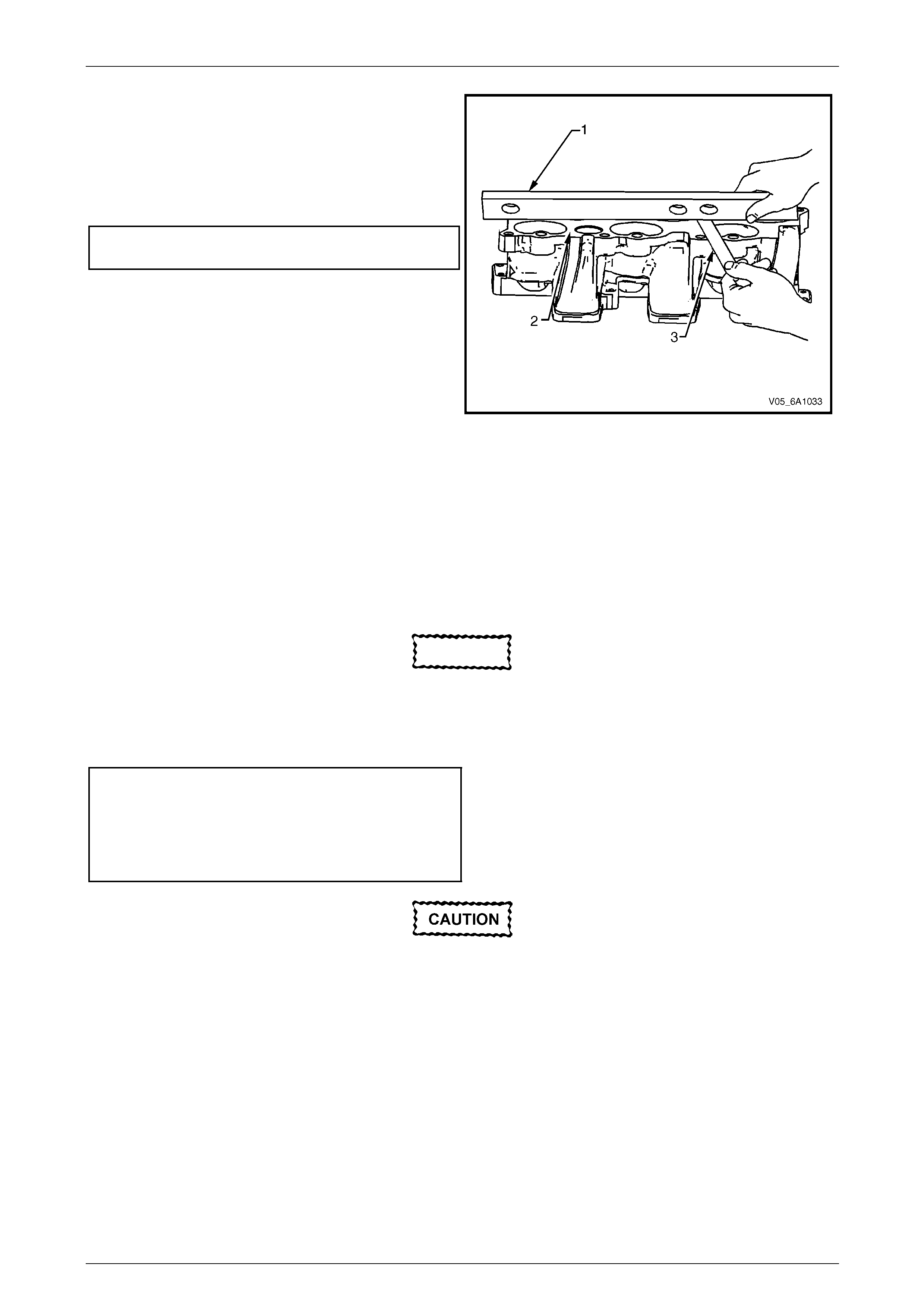
Engine Mechanical – V6 Page 6A1–83
Page 6A1–83
5 Place a straight edge (1) across the lo wer intake
manifold sealing surface (2).
6 Using a feeler gauge (3), measure the clearance
between the manifold and the straight edge.
7 If the clearance between the lower intake manifold
sealing surface and the straight edge exceeds the
specified maximum warpage, replace the manifold.
Lower manifold maximum
warpage............................................................ 0.05 mm
Figure 6A1 – 48
Reassemble
Reassembly of the upper manifold is the reve rse of the disassembly procedure .
Reinstall
Reinstallation of the upper intake manifold and the upper and lower intake manifold assembly is the reverse of the
removal procedure, noting the following:
1 Only new gaskets are to be fitted between the upp er and lower intake manifolds.
CAUTION
Tighten the intake manifold bolts in a circular
pattern starting at the centre bolt and moving
outward.
2 Ensure that all fasteners are tightened to the correct torque specification.
Upper intake manifold to lower
intake manifold attaching bolt
torque specification............................................23.0 Nm
Upper intake manifold to
cylinder head attaching bolt
torque specification............................................23.0 Nm
Incorrect wiring connector installation may
cause component malfunction or component
damage.
3 Ensure all wiring connectors are fully engaged and if applicable, locked in place.
4 Ensure all wiring harnesses are correctly routed and attached securely in their retaining clips.
5 Ensure that all hoses and pipes are routed correctly and that any retaining clips are correctl y installed.
6 Start and run the engine to check for correct operation.
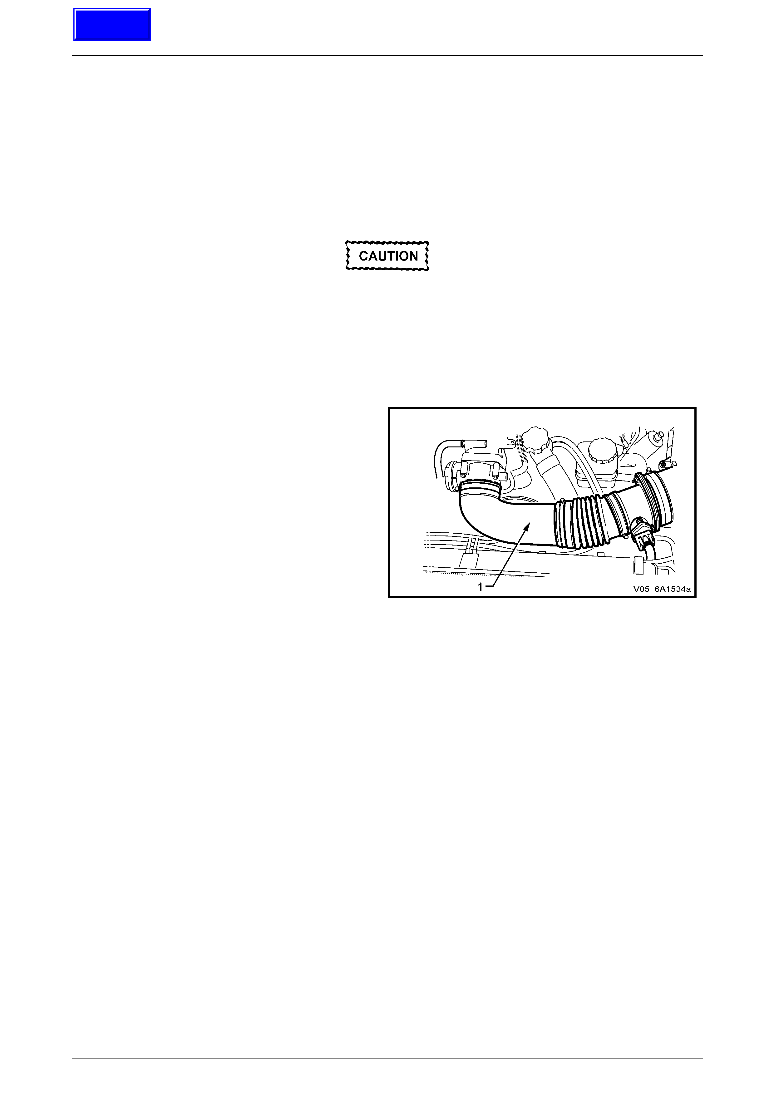
Engine Mechanical – V6 Page 6A1–84
Page 6A1–84
3.11 Intake Manifold Assembly – Complete
The intake manifold comprises of an upper and lower section. Some service procedur es only require the removal of the
upper intake manifold (e.g. fuel injector/spark plug servicing), while other service procedures require the remova l of both
the upper and lower manifold as a complete assembly (e.g. cylinder head/s). If only the upper intake manifold needs to
be removed, refer to 3.10 Upper Intake Manifold.
LT Section No. — 00–375
Remove
Disconnection of the battery affects certain
vehicle electronic systems. Refer to
Section 00 Warnings, Caution and Notes
before disconnecting the battery.
1 Depressurise the fuel system, refer to Section 8A1 Fuel Tank.
2 Disconnect the battery negative terminal.
3 Remove the engine dress covers, refer to 3.1 Engine Dress Cover.
4 Remove the air intake duct (1), refer to Section 6C1-3
Engine Management V6 – Service Operations.
Figure 6A1 – 49
Techline

Engine Mechanical – V6 Page 6A1–85
Page 6A1–85
The following precautions must be followed
when disconnecting the throttle body wiring
connector:
• Do not use any mech an ical device such
as a screwdriver to disengage the
harness connector (1) from the throttle
body (2).
• When retracting the throttle wiring
connector lock (3), take care not to
disengage the lock from the connector.
• Do not pull on the connector wires.
5 Retract the throttle body wiring connector lock (3).
6 While pressing the connector latch in the direction of
the arrow (4), disconnect the throttle body wiring
connector.
7 Disconnect the throttle body conn ector wiring harness
from its retaining clip (5).
• Take care not to break the barbed
harness retain er pin (6) while remo ving
the harness retainer from the intake
manifold.
• Should the pin be broken, then it is
vital that a new harness retainer is
fitted to the wiring harness shield. If
not, the harness will foul the engine
drive belt.
8 Remove the main wiring harness retainer pi n (6) from
the intake manifold by pushing from the front to the
rear using a suitable piece of 5 mm steel rod (or an
Allen key).
Figure 6A1 – 50
9 Disconnect the following vacuum hoses from the
upper intake manifold:
a Brake booster hose (1).
b HVAC vacuum hose (2).
Figure 6A1 – 51

Engine Mechanical – V6 Page 6A1–86
Page 6A1–86
10 Disconnect the wiring harness connector (1) from the
barometric (BARO) pressure sensor (2).
Figure 6A1 – 52
11 Disconnect the PCV tube (1) from the upper intake
manifold assembly, on each side.
12 Disconnect the PCV tube assembly (2) from the
barometric pressure sensor mounting clip (3), by
pushing down on the tube at the ’T’ piece to dislodge.
13 Move the PCV tube assembly clear of the upper
intake manifold assembly.
Figure 6A1 – 53
14 Disconnect the wiring harness connector (1) from the
inlet manifold runner control (IMRC) soleno id (2).
Figure 6A1 – 54
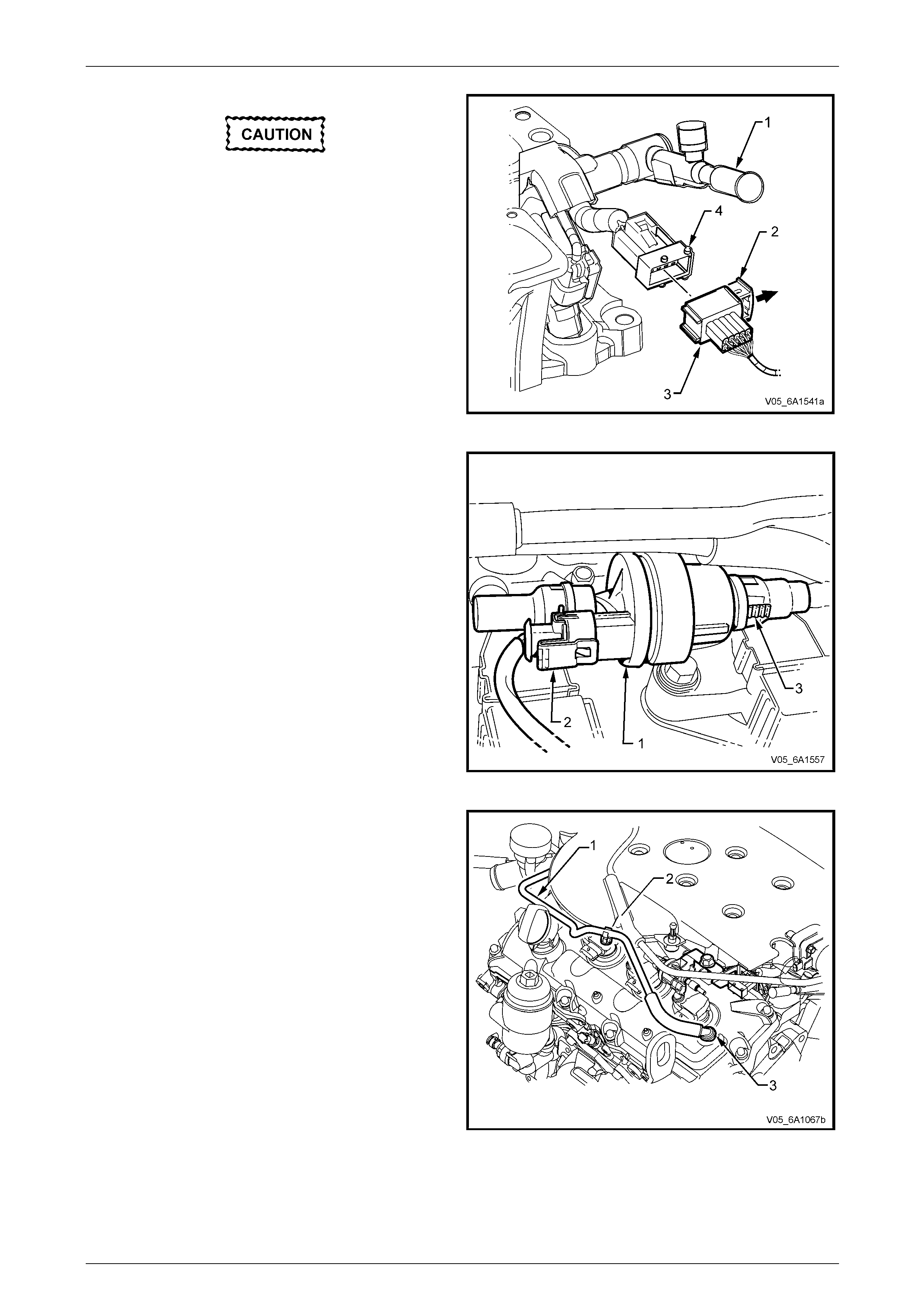
Engine Mechanical – V6 Page 6A1–87
Page 6A1–87
Plug the fuel feed hose opening after removal
to prevent dirt and other contaminants from
entering the fuel system.
15 Disconnect the fuel feed hose from the fuel rail (1).
Refer to Section 8A1 Fuel Tank for details of the
quick-connect fitting removal procedure.
16 Pull out the release bar (2) (broad arrow) of the fuel
injector harness wiring connector (3).
17 Disconnect the fuel injector harness wiring connector
from the fuel injector wiring harness (4).
Figure 6A1 – 55
18 Remove the wiring harness connector (2) from the
EVAP valve (1).
19 Disconnect the quick connect (3) from the rear of the
EVAP valve, as follows:
a Squeeze the two barbed lugs together, push the
quick connect into the valve, then pull out to
separate the connection.
b Plug both open ends to prevent the entry of
foreign matter.
Figure 6A1 – 56
20 Disconnect the PCV fresh air tube (1) from its upper
intake manifold mounting clip ( 2).
21 As required, pull the fresh air tube from the
grommet (3) in the left-hand side cam cover and
remove from the engine bay. Plug the gr ommet hole to
prevent dust and dirt entry.
Figure 6A1 – 57
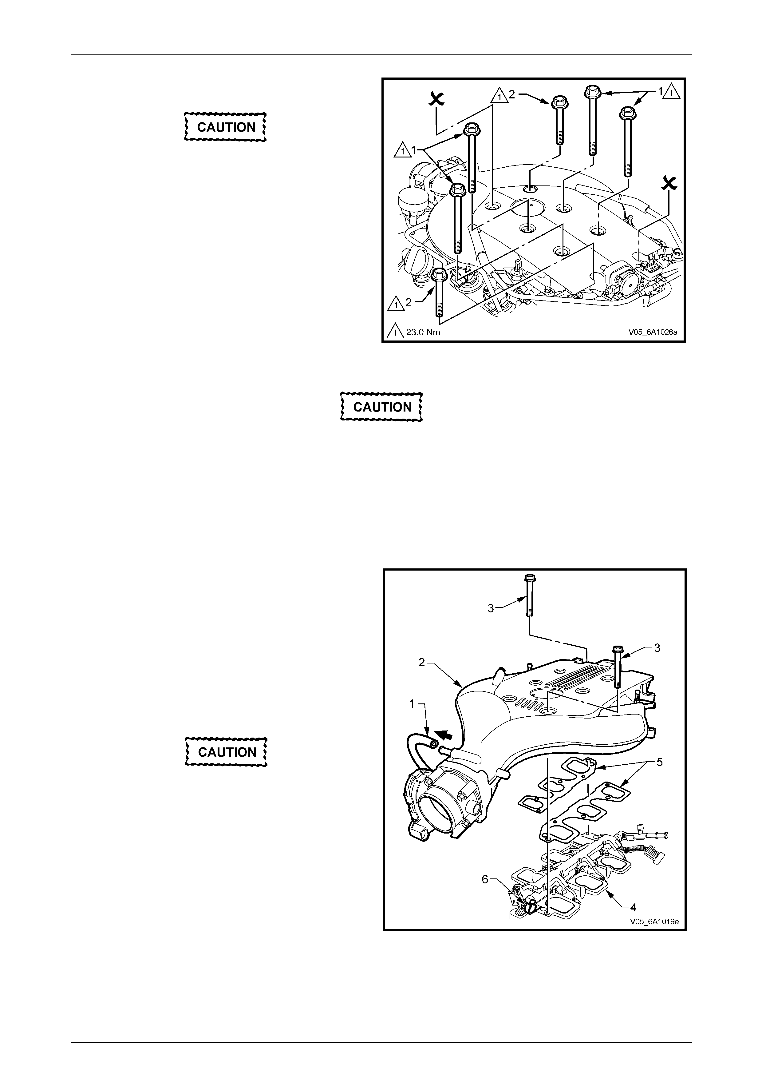
Engine Mechanical – V6 Page 6A1–88
Page 6A1–88
22 Remove the four long (1) bolts (165 mm) securing the
complete intake manifold to the cylinder heads.
Do not loosen nor remove the short bolts (8)
(70 mm) holding the upper intake manifold to
the lower. These bolts are at the front left
and rear right of the upper intake manifold.
23 Remove the two short (2) bolts (45 mm) securing the
lower intake manifold to the cylinder heads.
Figure 6A1 – 58
When the intake manifold is removed, plug
each of the cylinder head intake openings
with lint free cloth, to stop the entry of foreign
material into the intake ports.
24 Remove the upper and lo wer intake manifold assembly from the engine.
25 Remove lower intake manifold to cylinder hea d gasket.
Disassemble
1 Disconnect the EVAP hose (1) from the upper intake
manifold (2).
2 Remove the bolts (3) (70 mm) attaching the upper
intake manifold to the lower intake manifold (4).
NOTE
These bolts are located at the front left and rear
right of the upper intake manifold, as sho wn.
3 Remove the upper intake manifold from the lower
intake manifold.
Do not reuse the upper to lower intake
manifold gaskets (5).
4 Remove and discard the upper to lower intake
manifold gaskets.
5 Remove the EVAP hose from the retaining clip (6)
attached to the lower intake manifold.
6 Remove the following from the upper intake manifold,
refer to Section 6C1-3 Engine Management – V6 –
Service Operations:
• BARO sensor,
• IMRC solenoid, and
• throttle body assembly.
Figure 6A1 – 59
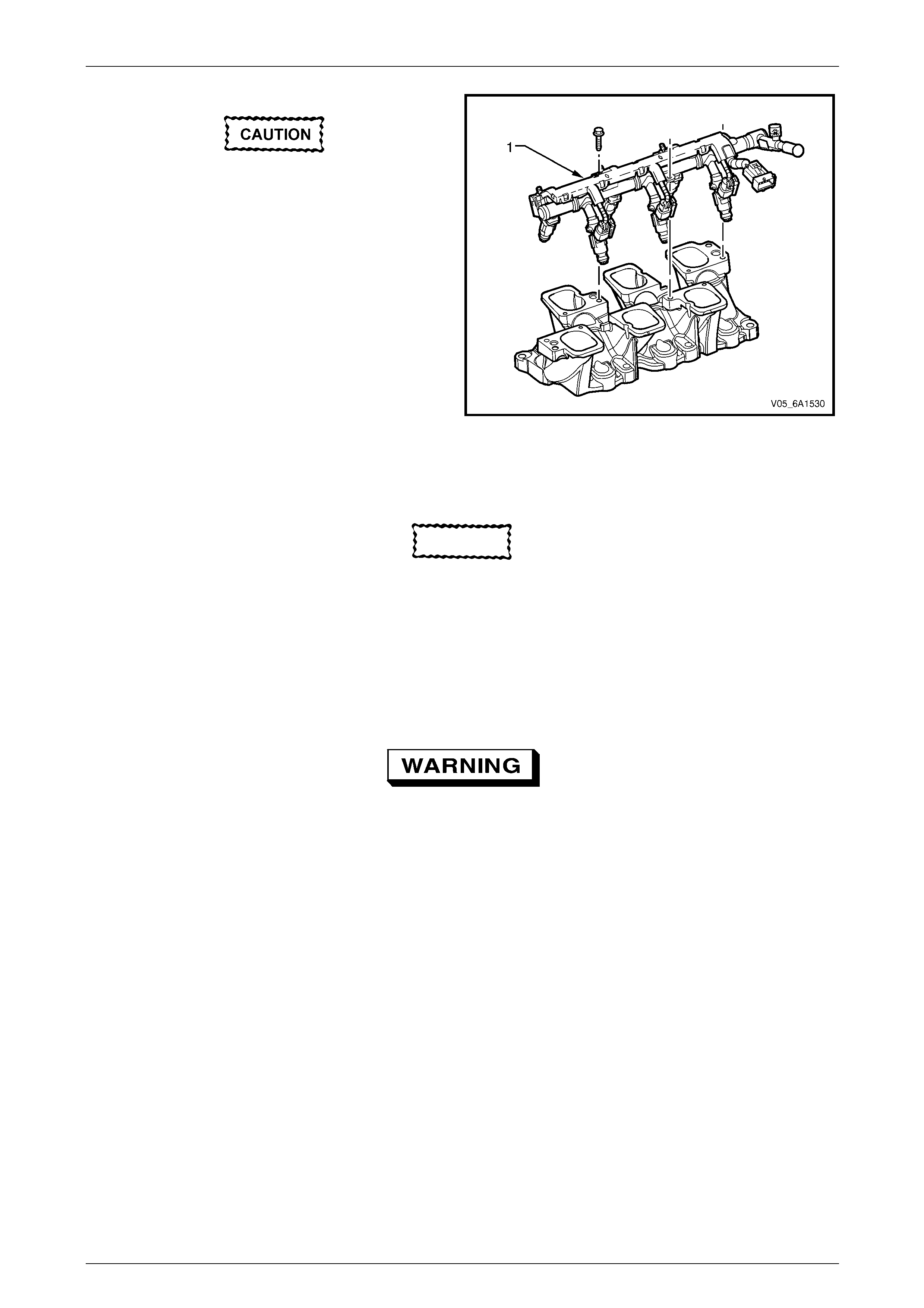
Engine Mechanical – V6 Page 6A1–89
Page 6A1–89
The following precautions must be followed
when removing the fuel rail and injector
assembly:
• Care must be taken when removing the
fuel rail and injector assembly to
prevent damage to the injector spray
tips and injector harness connector
terminals.
• Support the fuel rail and injector
assembly after removal.
• Plug all fuel line and manifold openings
after removal to prevent dirt and other
contaminants from entering the fuel
system.
7 Remove the fuel rail and injec t or assembly. Refer to
Section 6C1-3 Engine Management V6 – Service
Operations. Figure 6A1 – 60
Clean
CAUTION
Due to the aluminium alloy construction of
the intake manifold, wire brushes and steel
scrapers must not be used during the
cleaning process, as damage to sealing
surfaces may occur. Use of a wooden or
plastic scraper is preferred.
1 Clean mating surfaces ensuring any gasket material is removed.
2 Clean the manifold using a suitable solvent
Safety glasses must be worn when using
compressed air.
3 Dry the timing components with compressed air.
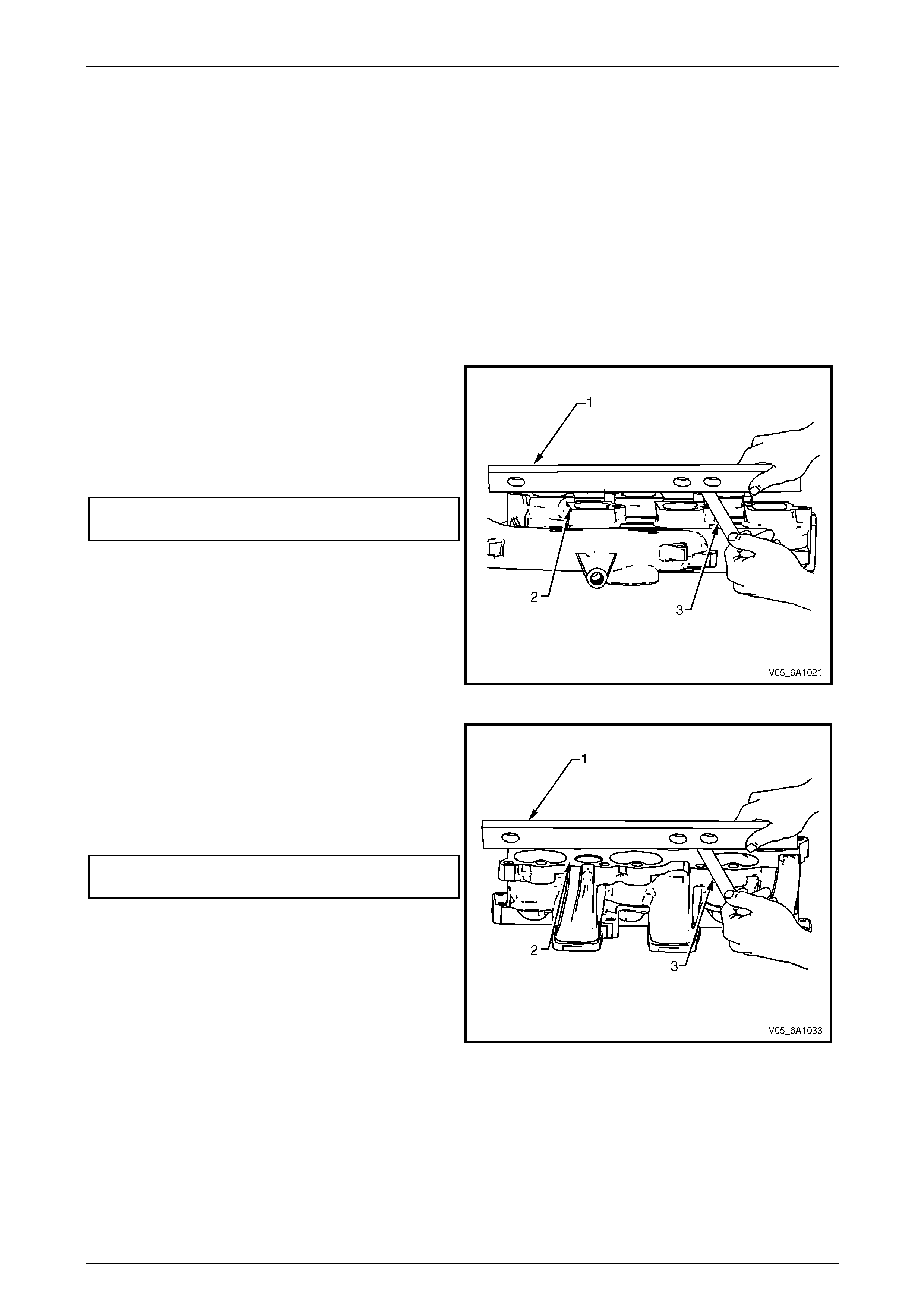
Engine Mechanical – V6 Page 6A1–90
Page 6A1–90
Inspect
1 Inspect the intake manifold for the following fault conditions:
• Damaged sealing and mating surfaces.
• Damaged lower intake manifold gasket.
• Damage or excessive debris on the threaded and through holes.
• Cracks or damage to the intake manifold body.
NOTE
If the lower intake manifold is cracked or
damaged, it must be replaced. No welding or
patching of the intake manifold should be
performed.
2 Place a straight edge (1) across the upper intake
manifold sealing surface (2).
3 Using a feeler gauge (3), measure the clearance
between the manifold and the straight edge.
4 If the clearance between the upp er intake manifold
sealing surface and the straight edge exceeds the
specified maximum warpage, replace the manifold.
Upper manifold maximum
warpage............................................................ 0.05 mm
Figure 6A1 – 61
5 Place a straight edge (1) across the lo wer intake
manifold sealing surface (2).
6 Using a feeler gauge (3), measure the clearance
between the manifold and the straight edge.
7 If the clearance between the lower intake manifold
sealing surface and the straight edge exceeds the
specified maximum warpage, replace the manifold.
Lower manifold maximum
warpage............................................................ 0.05 mm
Figure 6A1 – 62
Reassemble
Reassembly of the upper to lower intake manifold is the reverse of the disassembly procedure noting the following:
1 Ensure that both the manifolds have been cleaned and inspected.
2 Ensure that the warpage of the mating surfaces is within tolerances.
3 New upper to lower intake manifold gaskets must be used.
4 Do not tighten the intake manifold to lower intake manifold attaching bolt at this stage. The intake manifold
attaching bolts must be tightened at the specified sequence during the re installation procedure.
Engine Mechanical – V6 Page 6A1–91
Page 6A1–91
Reinstall
Reinstallation of the upper intake manifold and the upper and lower intake manifold assembly is the reverse of the
removal procedure, noting the following:
1 Install the EVAP hose to the clip attached to the lower intake manifold (refer to ‘5’ in Figure 6A1-63).
2 Only new gaskets are to be fitted between the upp er and lower intake manifolds.
3 If undamaged, the lower intake manifold to cyl inder head gasket may be re-used, however its replacement is
strongly recommended.
CAUTION
Tighten the intake manifold bolts in a circular
pattern starting at the centre bolt and moving
outward.
4 Ensure that all fasteners are tightened to the correct torque specification.
Upper intake manifold to lower intake
manifold attaching bolt torque specification ....... 23.0 Nm
Upper intake manifold to cylinder
head attaching bolt torque specification.............23.0 Nm
Lower intake manifold to cylinder
head attaching bolt torque specification.............23.0 Nm
Fuel injector wiring harness bracket
attaching bolt torque specification........................9.0 Nm
Incorrect wiring connector installation may
cause component malfunction or component
damage.
5 Ensure all wiring connectors are fully engaged and if applicable, locked in place.
6 Ensure all wiring harnesses are correctly routed and attached securely in their retaining clips.
7 Ensure that all hoses and pipes are routed correctly and that any retaining clips are correctl y installed.
8 After installation pull on any quick connect fittings to check that each is correctly installed.
9 Start and run the engine to check for correct operation.
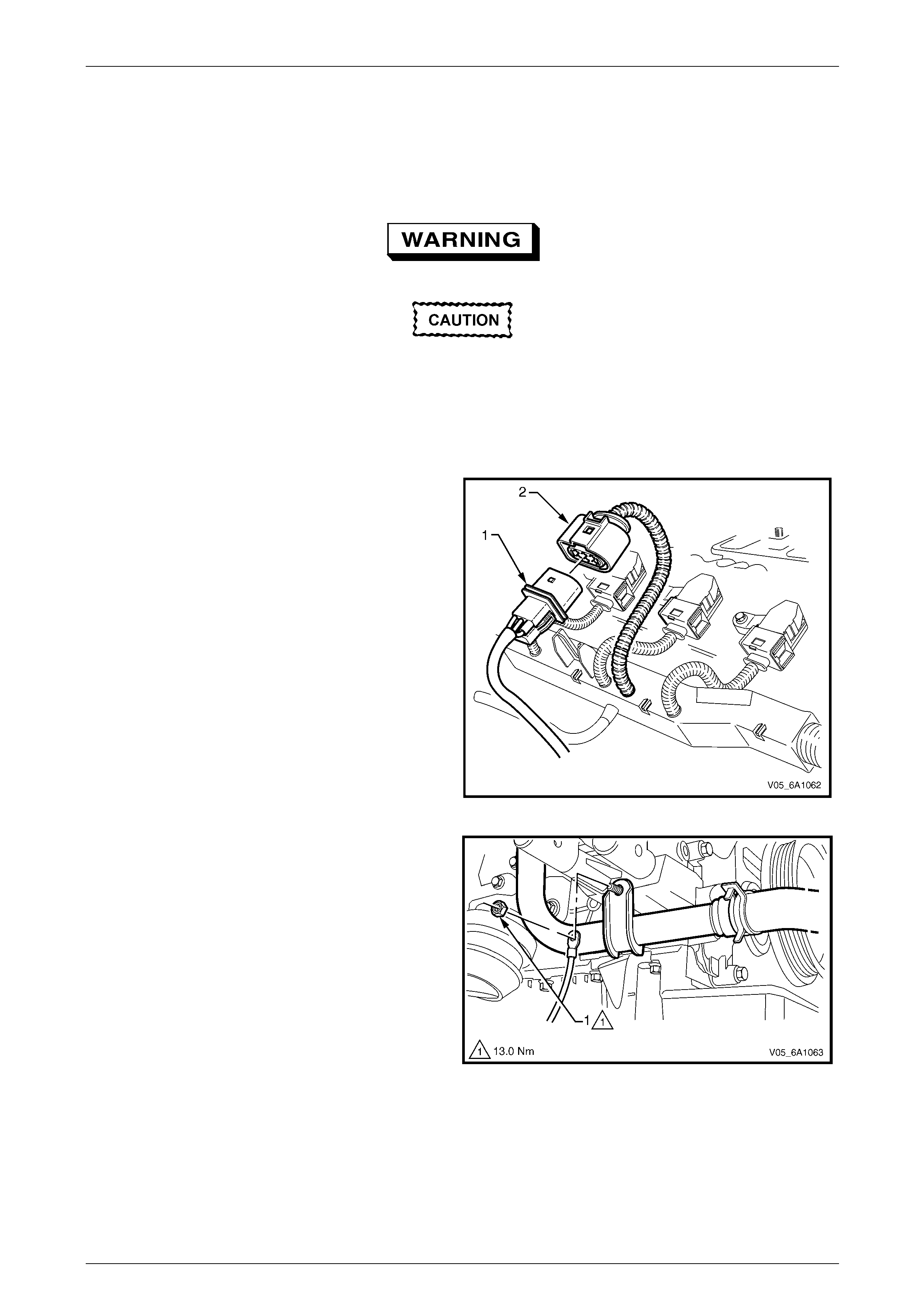
Engine Mechanical – V6 Page 6A1–92
Page 6A1–92
3.12 Exhaust Manifold Assembly
LT Section No. — 00–450
Remove
Allow the engine to cool before commencing.
Disconnection of the battery affects certain
vehicle electronic systems, refer to
Section 00 Warnings, Caution and Notes
before disconnecting the battery.
1 Disconnect the battery negative terminal.
2 Remove the engine dress cover, refer to 3.1 Engine Dress Cover.
3 Remove the oxygen sensor harness connector (1)
from the retaining bracket.
4 Disconnect the oxygen sensor wiring harness
connector from the engine wiring harness connector
(2).
5 Unclip the oxygen sensor wiring harness retaining clip
and move aside.
6 For the right-hand side:
a Remove the oil level indicator tube, refer to
3.5 Oil Level Indicator Tube.
b Remove the generator assembl y, refer to
Section 6D1 Charging System – V6.
Figure 6A1 – 63
c Remove the battery harness groun d cable
attaching nut (1) from the coolant pipe mounting
bracket.
7 Raise the front of the vehicle and place on stands,
refer to Section 0A General Information.
8 Working from under the vehicle, remove the two
exhaust manifold to exhaust pipe flange n uts, refer to
Section 8B Exhaust System.
Figure 6A1 – 64
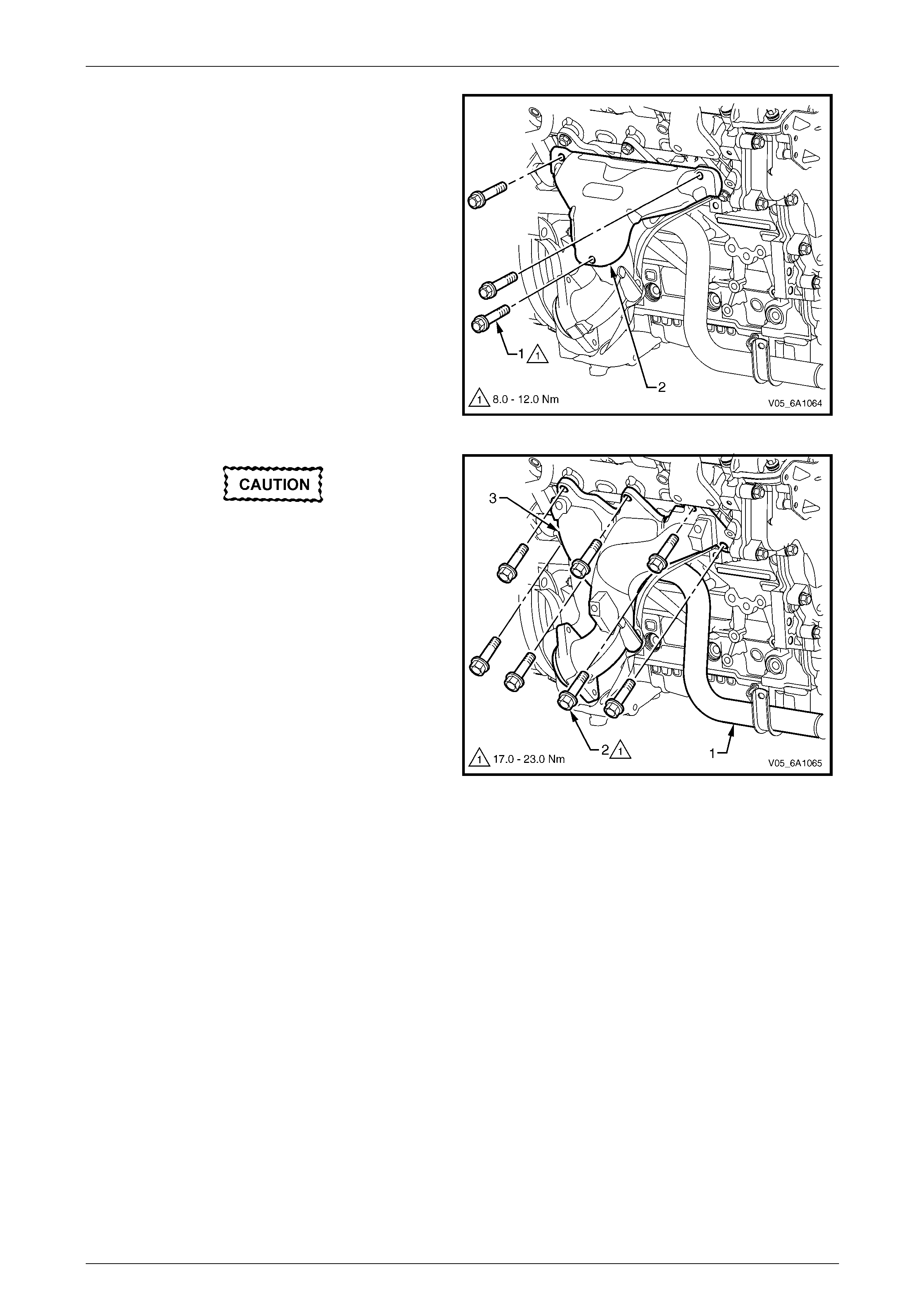
Engine Mechanical – V6 Page 6A1–93
Page 6A1–93
9 Remove the three bolts (1) attaching the exh aust
manifold outer heat shield (2) to the exhaust manifold.
Figure 6A1 – 65
Excessive movement of the coolant pipe
may cause damage to the pipe or cause a
coolant leak at the thermostat housing to
coolant pipe seal.
NOTE
To gain access to the lower rear exhaust
manifold attaching bolts (2), apply a slight
downward movement to the coolant inlet pipe
(1).
10 Progressively loosen the seven exhaust manifold
attaching bolts, working from the outside to the centre
and then remove the bolts.
11 Manoeuvre the exhaust manifold (3) toward the front
of the engine bay, then up between the front of the
engine and the radiator.
12 Remove and discard the exha ust manifol d to cylinder
head gasket.
Figure 6A1 – 66
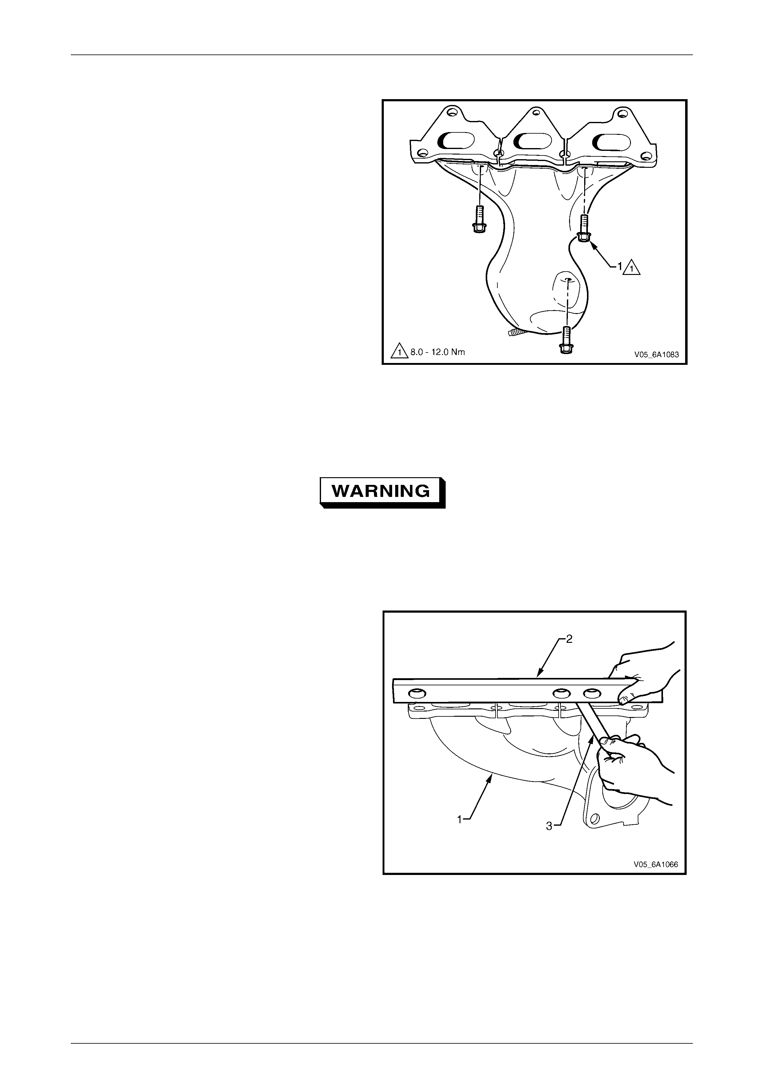
Engine Mechanical – V6 Page 6A1–94
Page 6A1–94
Disassemble
1 Remove the three bolts (1) attaching the exh aust
manifold inner heat shield to the exhaust manifold.
Figure 6A1 – 67
Clean
1 Using a suitable commerciall y available non-corrosive cleaning solvent and a soft bristled parts cleaning brush,
thoroughly clean the exhaust manifold.
Safety glasses must be worn when using
compressed air.
2 Dry the exhaust manifold using compressed air.
Inspect
Inspect the exhaust manifold (1) for the following:
• Damage to the threaded holes for the heat shield
mounting.
• Damage to the exhaust manifold mounting h oles.
• Damage to the threads of the exhaust manifold to
exhaust pipe flange studs.
• Damage to the gasket sealing surfaces.
• Using a straight edge (2) and feeler gauges (3), check
the cylinder head mounting face of the exha ust
manifold does not exceed the maximum distortion
specification of 0.25mm.
NOTE
If the surface flatness is not within
specifications, the exhaust manifold is warped
and must be replaced.
Figure 6A1 – 68

Engine Mechanical – V6 Page 6A1–95
Page 6A1–95
Reinstall
Reinstallation of the exhaust manifold assembly is the reverse of the removal procedure, noting the following:
1 Ensure the exhaust manifold, cylinder head and exhaust pipe flange surfaces are clean.
2 Position a new exhaust manifold gasket onto the exhaust manifold.
3 Apply a 5 mm bead of Loctite 272 threa d se alant (or equivalent) to the threads of the exhaust manifold attaching
bolts.
4 Install the bolts into the exhaust manifold. T his will prevent the gasket from falling off the manifold.
5 Manoeuvre the exhaust manifold into position and install the exhaust manifold attaching bolts.
6 From underneath the vehicle install the exhaust manifold to exhaust pipe flange nuts.
7 Tighten the exhaust manifold attaching bolts to the correct torque specification
NOTE
When tightening the exhaust manifold to cylinder
head attaching bolts, begin with the centre bolts,
then alternate from side to side to the outer bolts.
Exhaust manifold to cylinder hea d
attaching bolt torque specification...........17.0 – 23.0 Nm
8 Apply an anti seize compound such as Caltex Kopr-Kote (or equivalent) to the cleane d heat shield bolt threads.
Install the heat shield attaching bolts and tighten to the corre ct torque specification.
Exhaust manifold heat shield attaching
bolt torque specification............................8.0 – 12.0 Nm
9 For the right-hand side, install the battery harness ground cable attaching nut through the ground terminal and
lower coolant tube mounting lug, and tighten to the correct torque specification.
Battery harness ground terminal
attaching nut torque specification.......................13.0 Nm
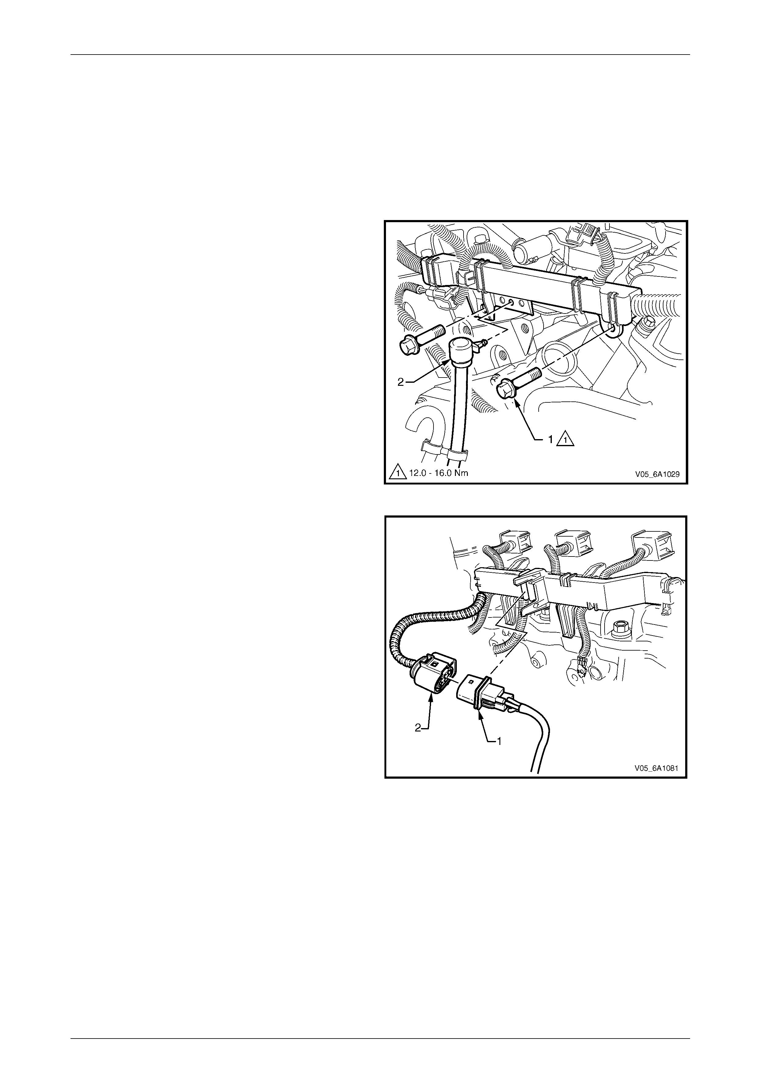
Engine Mechanical – V6 Page 6A1–96
Page 6A1–96
3.13 Camshaft Cover
LT Section No. — 00–025
Remove
1 Remove the upper intake manifold, refer to 3.10 Upper Intake Manifold.
2 For the left-hand side, remove the evaporative (EVAP) emission canister purge solenoid, refer to
Section 6C1-3 Engine Management – V6 – Service Operations.
3 Remove the two bolts (1) attaching the engin e wiring
harness former to the rear of the cylinder heads.
4 Unclip the transmission vent tube (2) from the engine
wiring harness.
Figure 6A1 – 69
5 Disconnect the oxygen sensor wiring harness
connector (1) from the engine wiring harness (2), left-
hand shown, right-hand simi lar.
Figure 6A1 – 70
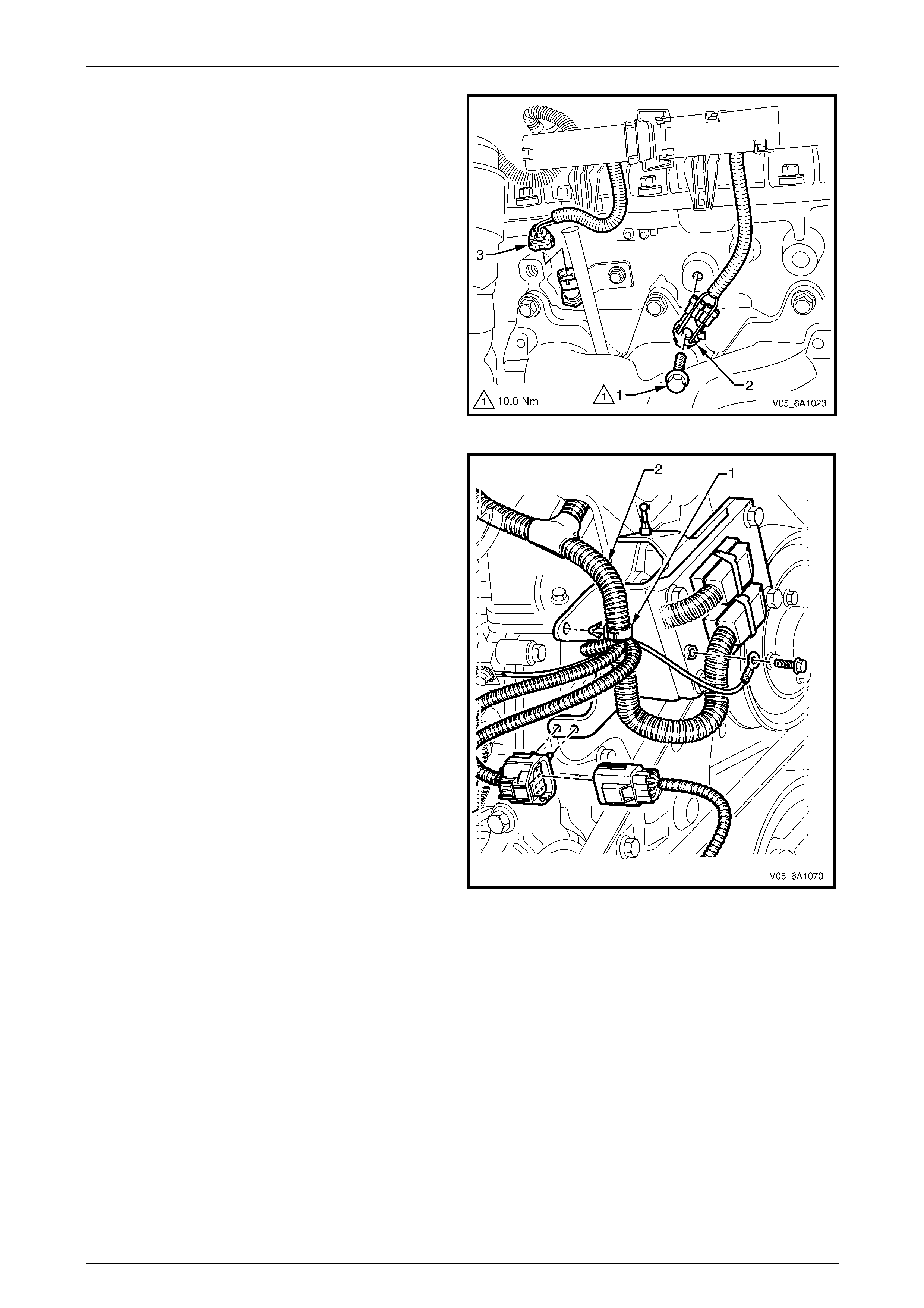
Engine Mechanical – V6 Page 6A1–97
Page 6A1–97
6 Remove the bolt (1) attaching the ground co nnector
(2) to the cylinder head.
7 Fro the left-hand side, disconnect the engine coolant
temperature (ECT) sensor wiring connector ( 3).
8 Unclip the engine wiring harness retaining lugs from
the side of the camshaft cover.
Figure 6A1 – 71
9 For the right-hand side, remove the engin e wiring
harness retaining clip (1) from the engine co ntrol
module (ECM) bracket (2).
Figure 6A1 – 72
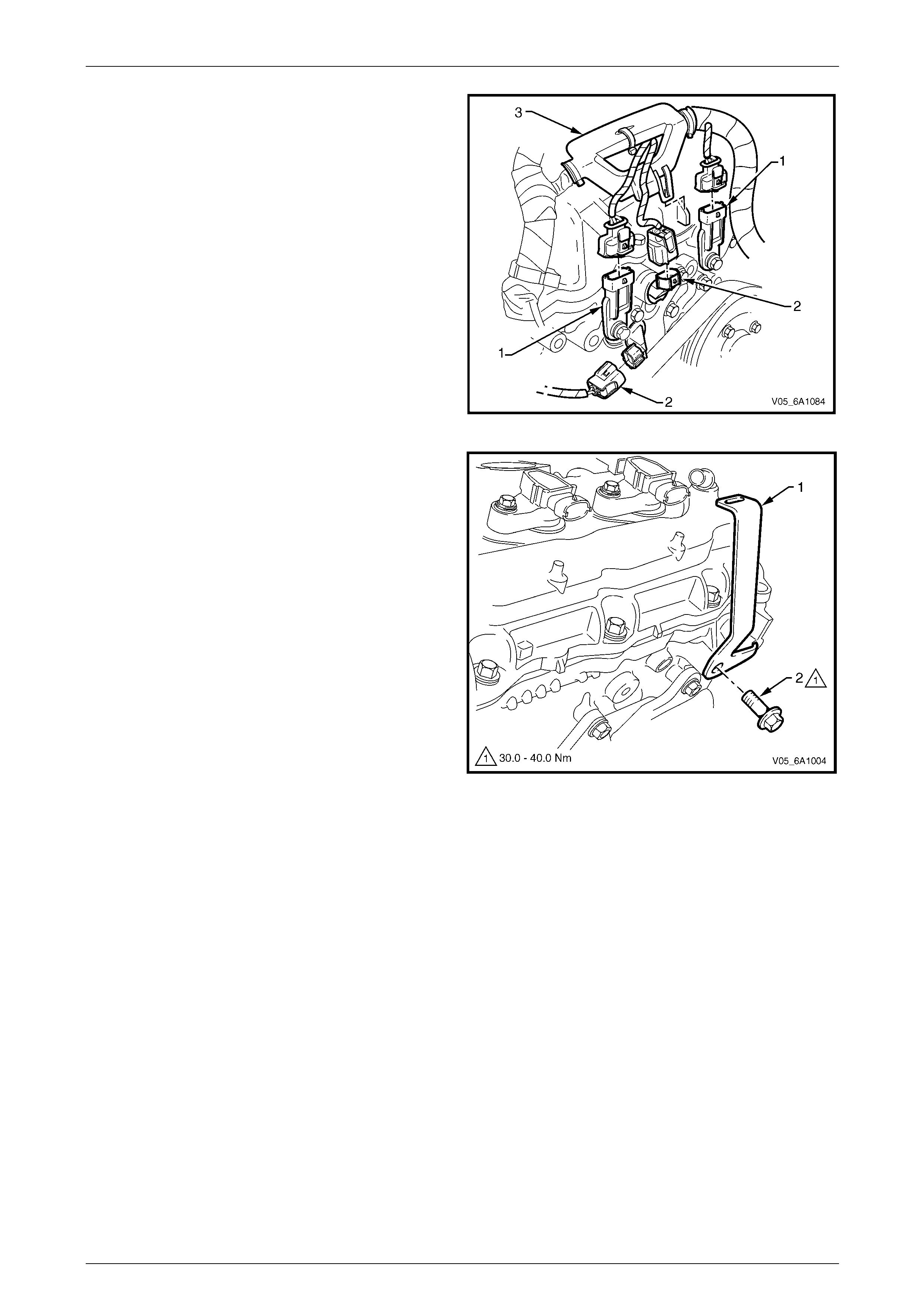
Engine Mechanical – V6 Page 6A1–98
Page 6A1–98
10 Disconnect the camshaft position (CMP) sensor wiring
connectors (1).
11 Disconnect the camshaft position (CMP) actuator
solenoid wiring connectors (2) .
12 Unclip the engine wiring harness retaining lug (3) from
the front of the camshaft cover.
13 Remove the ignition coil assemblies; refer to
Section 6C1-3 Engine Management – V6 – Service
Operations.
14 Move the engine wiring harness clear of the camshaft
cover.
Figure 6A1 – 73
15 For the left-hand side, remove the bolt (2) attaching
the engine dress cover bracket (1) to the c ylinder hea d
assembly.
Figure 6A1 – 74
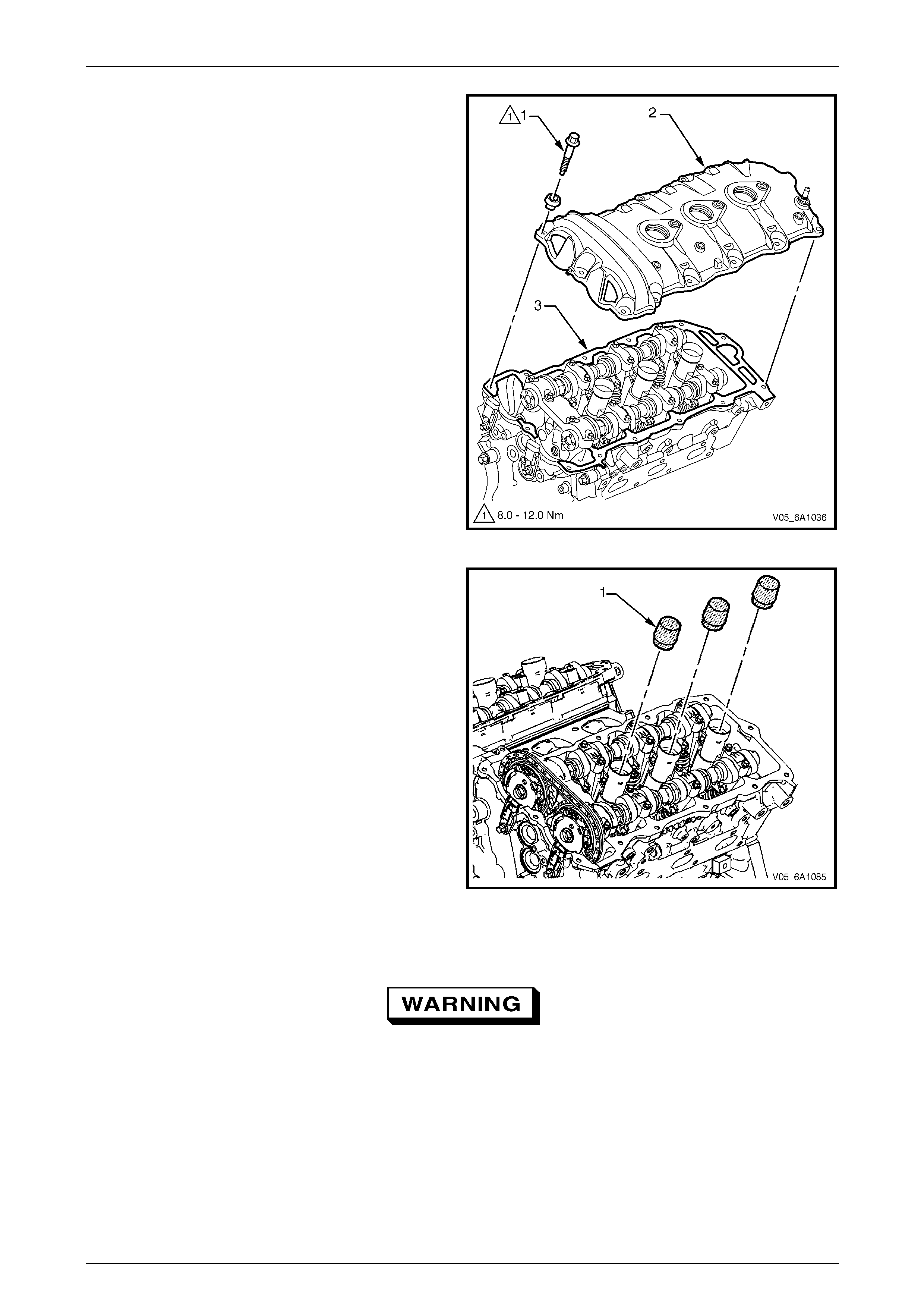
Engine Mechanical – V6 Page 6A1–99
Page 6A1–99
16 Remove the bolt (1), 13 places, attaching the camshaft
cover (2) to the cylinder head (3).
17 Remove the cover and discard the seal.
Figure 6A1 – 75
18 Install Tool No. EN-46101 (1) to the spark pl ug tubes
of the cylinder head to prevent entry of dirt into the
combustion chamber.
Figure 6A1 – 76
Clean and Inspect
Safety glasses must be worn when using
compressed air.
1 Clean the camshaft cover with suitable cl eaning solvent and blow dry with compressed air.
2 Inspect the cover for cracking and distortion.
3 Check the spark plug tube seals for damage.
4 If the camshaft cover is damaged in any way that will affect it’s performance to seal and stop the ingress of dirt,
replace the camshaft cover.
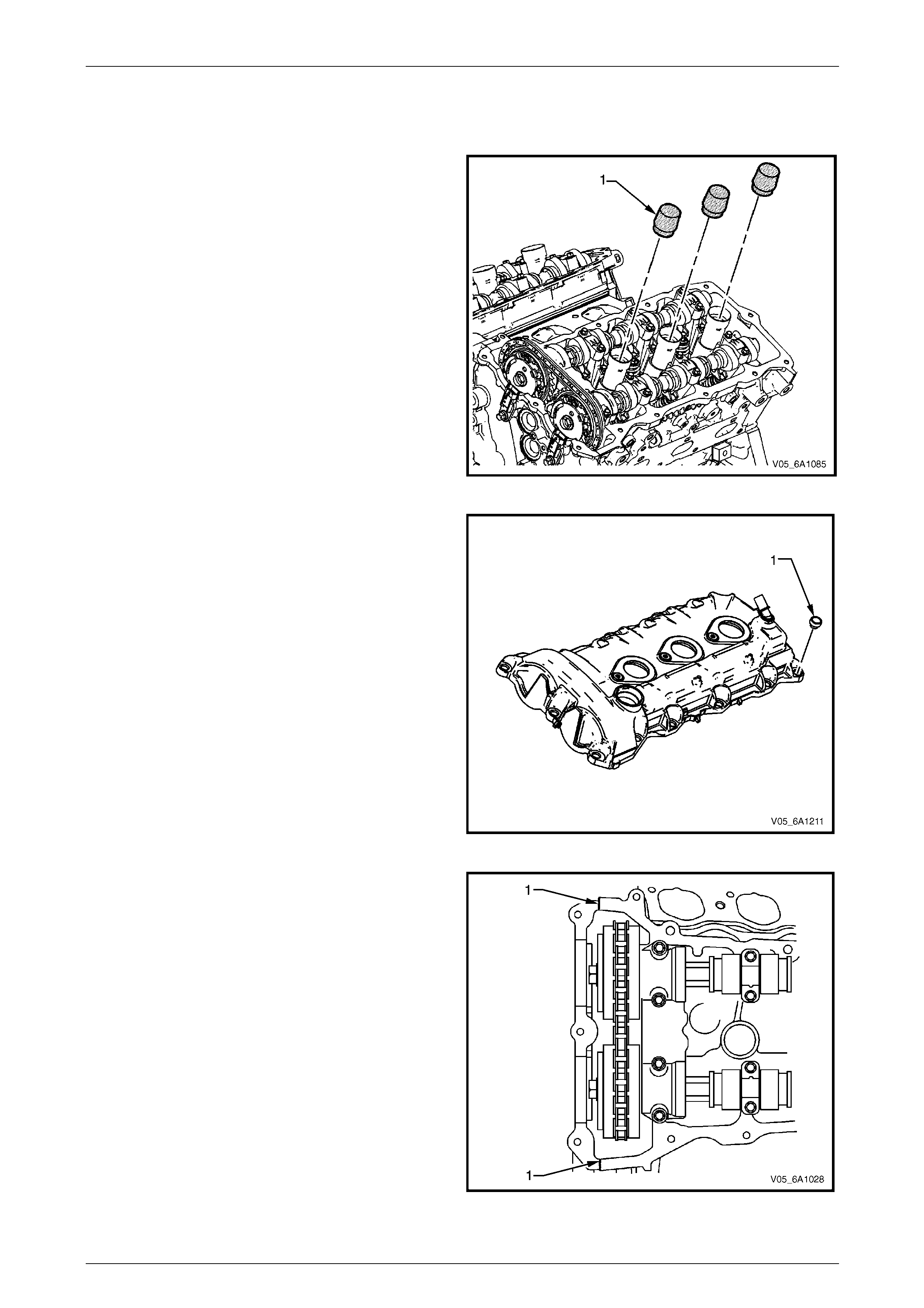
Engine Mechanical – V6 Page 6A1–100
Page 6A1–100
Reinstall
Reinstallation of the camshaft cover assembly is the reverse of the removal procedure, noting the following:
1 If not already fitted, install Tool No. EN-4610 1 (1) to
the spark plug tubes of the cylind er head.
Figure 6A1 – 77
2 Ensure that the grommet (1), 13 places, is correctly
seated in its hole.
3 Wipe the camshaft cover sealing surface o n the
cylinder head with a clean lint free cloth.
Figure 6A1 – 78
4 Ensure that a new seal is correctly fitted to the
camshaft cover. Place a 3 mm bead of RTV seal ant on
the join line of the engine front cover (1).
Figure 6A1 – 79
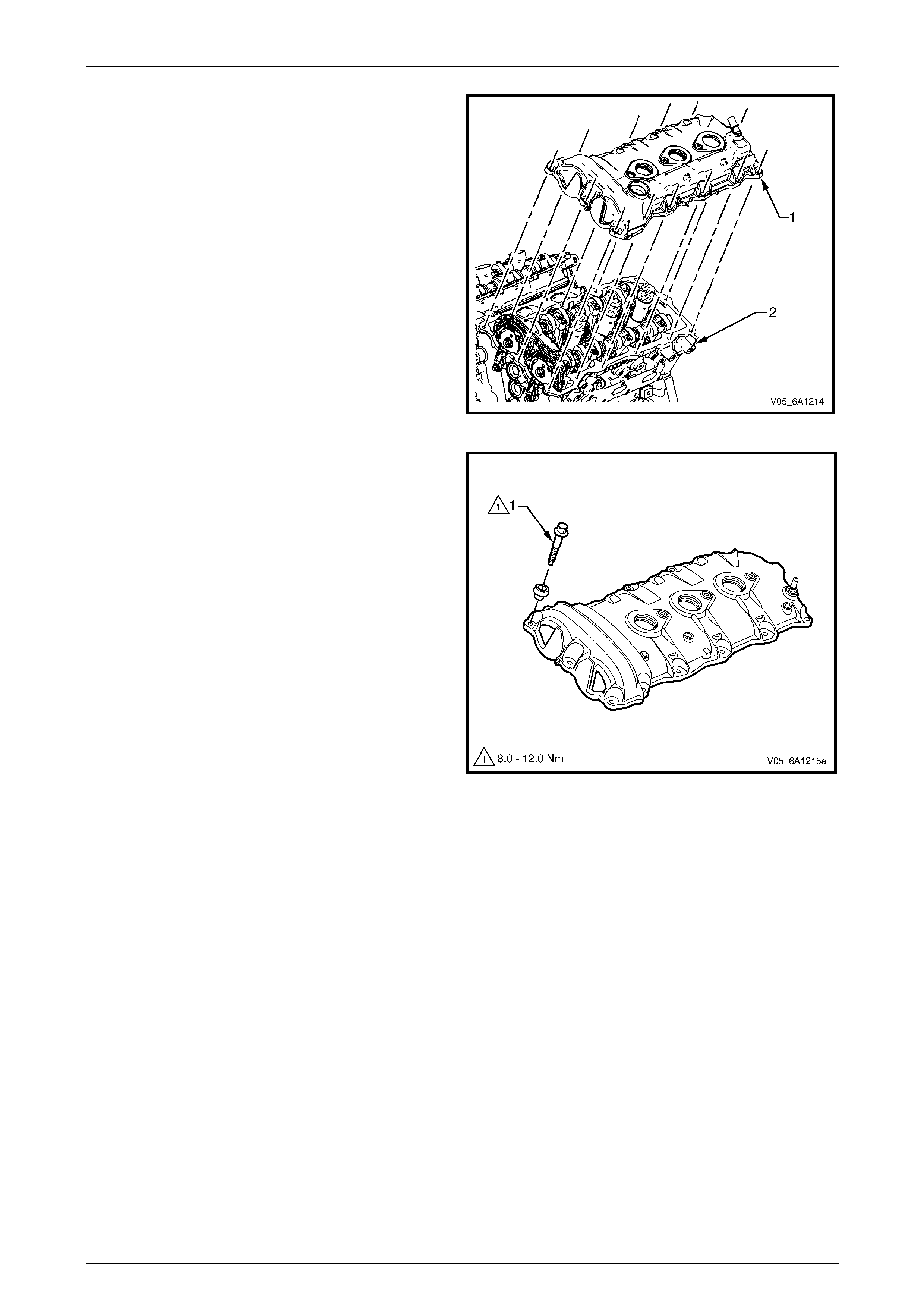
Engine Mechanical – V6 Page 6A1–101
Page 6A1–101
5 Place the camshaft cover (1) into position onto the
cylinder head (2).
Figure 6A1 – 80
6 Loosely install the camshaft cover bolt (1), 13 places.
Figure 6A1 – 81
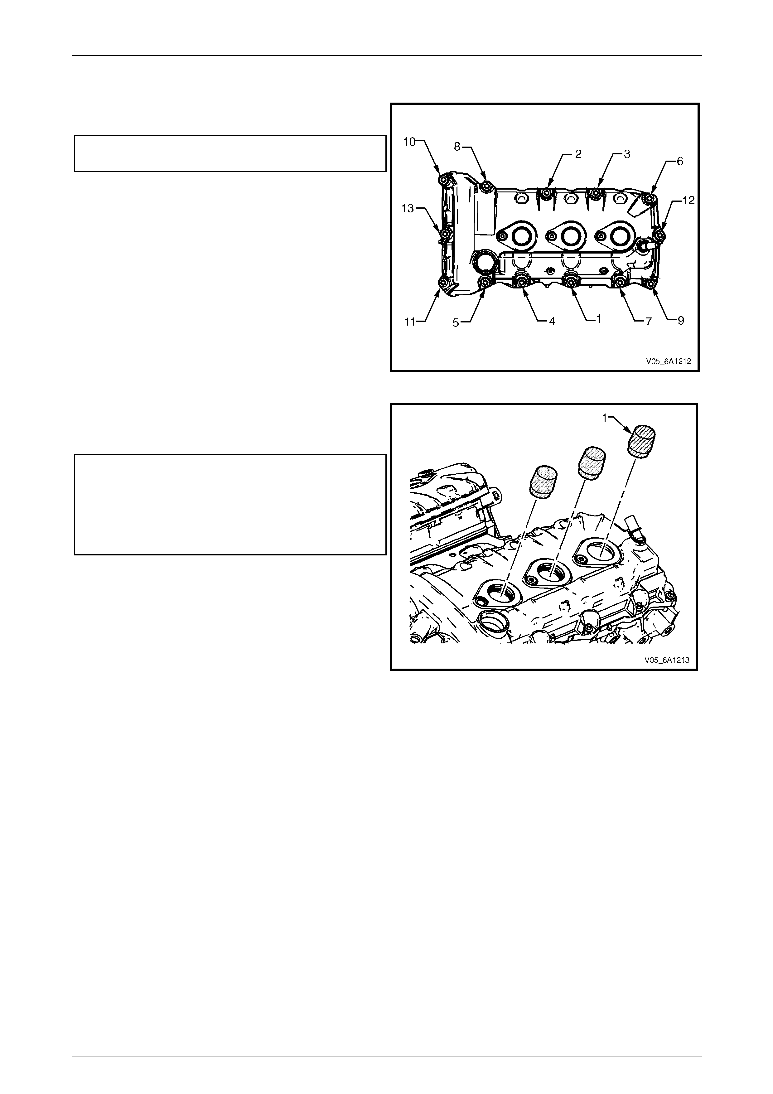
Engine Mechanical – V6 Page 6A1–102
Page 6A1–102
7 Tighten the camshaft cover bolts to the correct torque
specification, in the sequence shown.
Camshaft cover attaching bolt
torque specification...................................8.0 – 12.0 Nm
Figure 6A1 – 82
8 Remove Tool No. EN-46101 (1).
9 Tighten all remaining fasteners to the correct torque
specification.
Engine dress cover bracket attaching bo lt
torque specification................................30.0 – 40. 0 Nm
Engine ground connector bolt
torque specification............................................10.0 Nm
Engine wiring harness former attaching
bolt torque specification..........................12.0 – 16.0 Nm
Figure 6A1 – 83
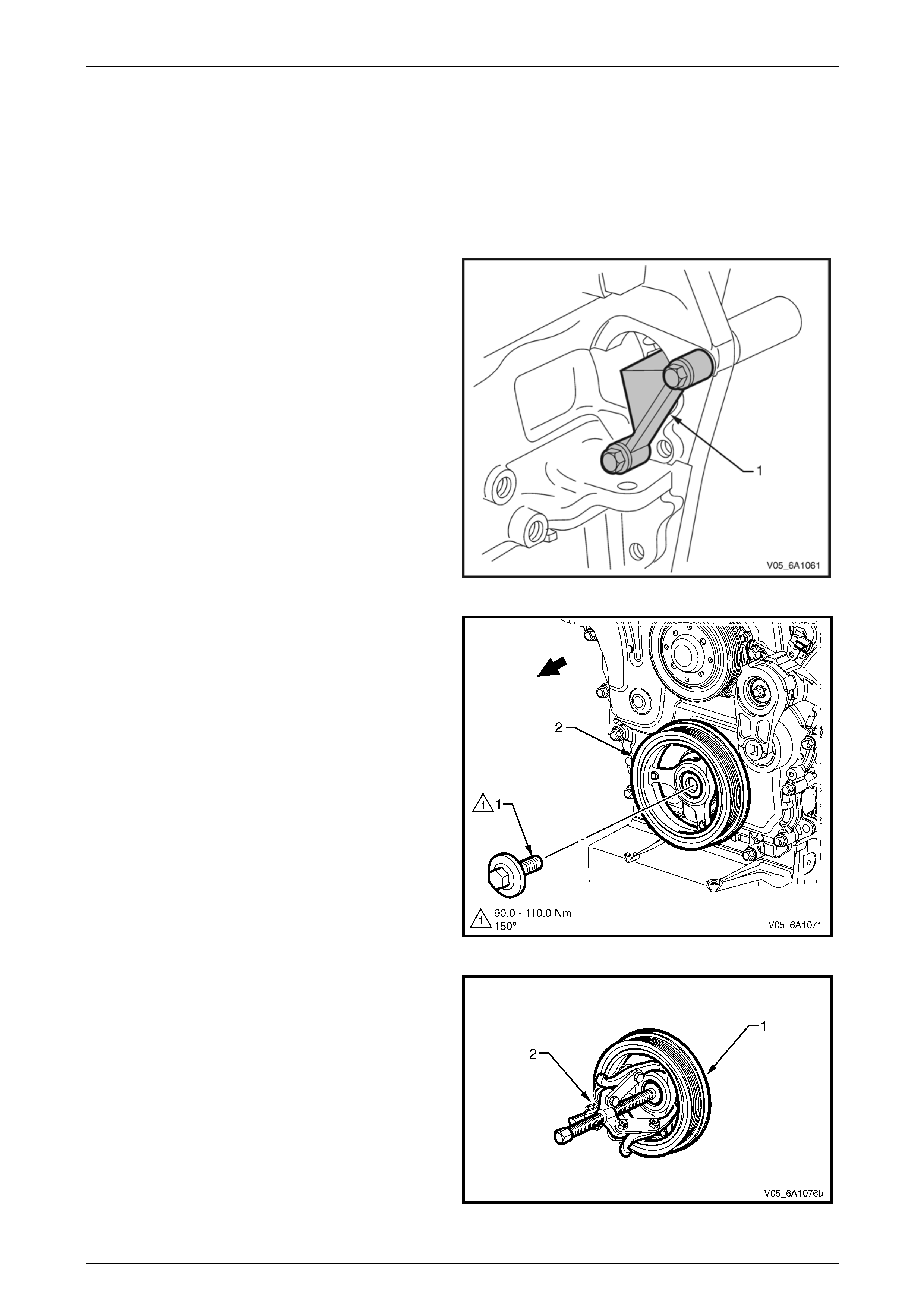
Engine Mechanical – V6 Page 6A1–103
Page 6A1–103
3.14 Crankshaft Balancer Assembly
LT Section No. — 00–540
Remove
1 Remove the accessory drive belt, refer to 3.6 Accessory Drive Belt.
2 Remove the starter motor, refer to Section 6D1-2 Starting System – V6.
3 Install Tool No. EN-46106 (1) into the starter motor
opening to stop the camshaft from rotating.
Figure 6A1 – 84
4 Remove the bolt (1) attaching the crankshaft bal ancer
assembly (2) to the crankshaft.
Figure 6A1 – 85
5 Remove the crankshaft balancer assembly (1) from
the crankshaft using three legged pull er, Tool No.
J-41816 (2) or equivalent.
Figure 6A1 – 86
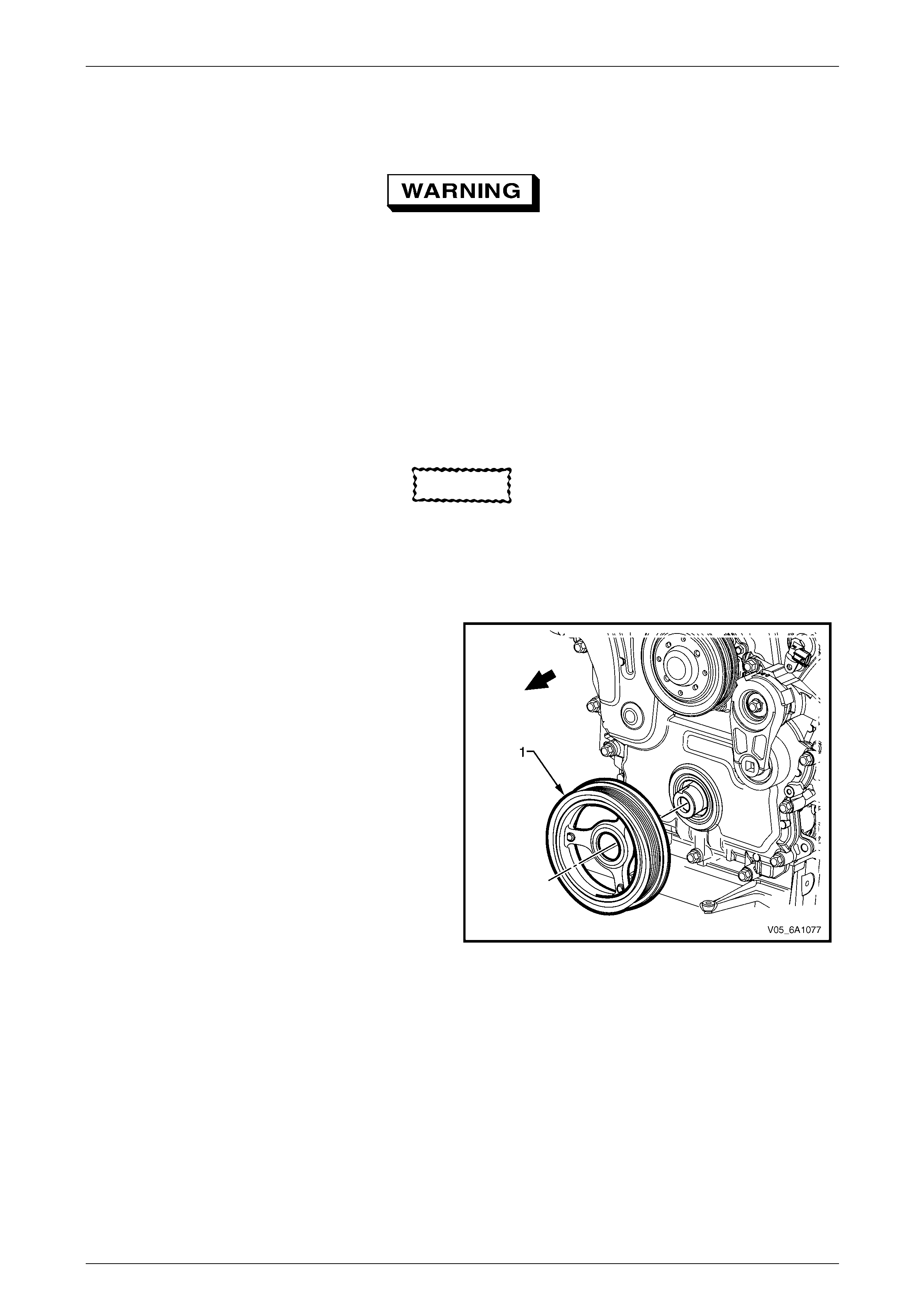
Engine Mechanical – V6 Page 6A1–104
Page 6A1–104
Clean and Inspect
1 Using a suitable non-corrosive cleaning solvent and a soft bristled parts cleaning brush, clean the crankshaft
balancer assembly.
Safety glasses must be worn when using
compressed air.
2 Dry the crankshaft balancer assembly using compressed air.
3 Inspect the crankshaft balancer assembly for the following fault conditions:
• Hub to crankshaft inner surface for wear or damage,
• Sealing surface for wear, grooving or scoring,
• Rubber ring between the hub and the pulley for wear, chunking and genera l deterioration, and
• Drive belt ribs of the pulley for damage.
Reinstall
CAUTION
Do not lubricate the crankshaft front oil seal
or crankshaft balancer sealing surfaces. The
crankshaft balancer must be installed onto a
dry seal.
1 Lubricate the crankshaft bala ncer assembly hub bore.
2 Partially install the cran kshaft balancer assembly onto
the crankshaft.
Figure 6A1 – 87
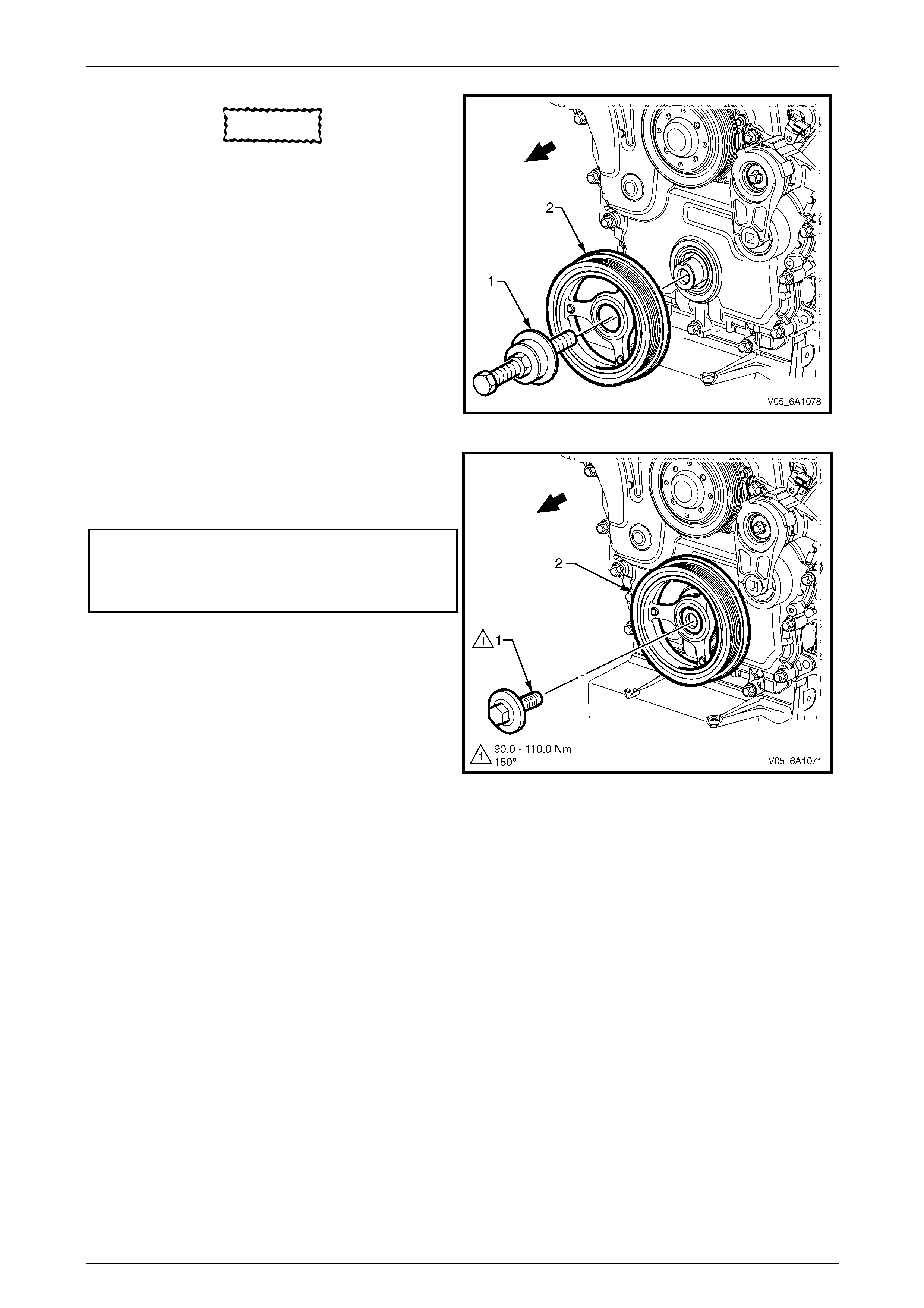
Engine Mechanical – V6 Page 6A1–105
Page 6A1–105
CAUTION
To prevent damage to the crankshaft
threads, fully install crankshaft balancer
installer, Tool No. J-41998-B (1) into the
crankshaft before pressing the pulley and
balancer assembly.
3 Using crankshaft balancer ins t aller, Tool No.
J-41998-B (1), fully install the crankshaft balancer
assembly into the crankshaft.
Figure 6A1 – 88
4 Apply Loctite 272 or equivalent to the thread of a new
crankshaft balancer assembly retaining bolt (1).
5 Install the crankshaft balancer assembly retainin g bolt
and tighten to the correct torque specification.
Crankshaft balancer retaining
bolt torque specification:
Stage 1 ............90.0 – 110.0 Nm
Stage 2 ...............................150°
Figure 6A1 – 89
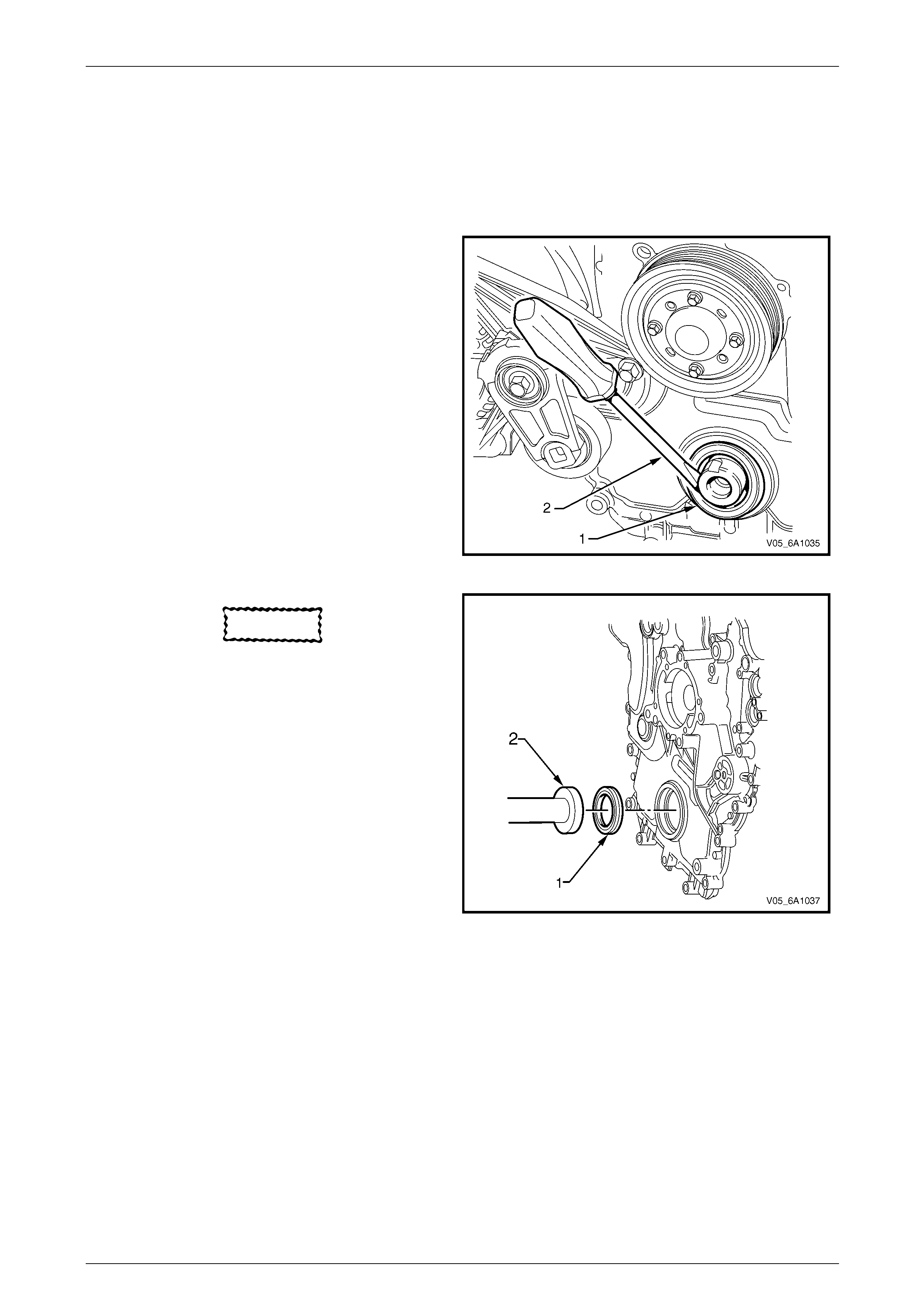
Engine Mechanical – V6 Page 6A1–106
Page 6A1–106
3.15 Crankshaft Front Seal
LT Section No. — 00–325
Replace
1 Remove the crankshaft balancer assembly, refer to 3.14 Crankshaft Balancer Assembly.
2 Using a flat bladed tool (2) or seal remover, Tool No.
E-308, carefully remove the cranksh aft front seal (1)
from the front cover.
Figure 6A1 – 90
CAUTION
Do not lubricate the crankshaft front oil seal
or crankshaft balan cer sealing surfaces. The
crankshaft balancer is installed into a dry
seal.
3 Using crankshaft front seal installer, T ool No. J-29184
(2) and a suitable hammer, install a new crankshaft
front seal (1) until fully seated against the front cover
housing.
4 Install the crankshaft balancer assembly, refer to
3.14 Crankshaft Balancer Assembly.
Figure 6A1 – 91
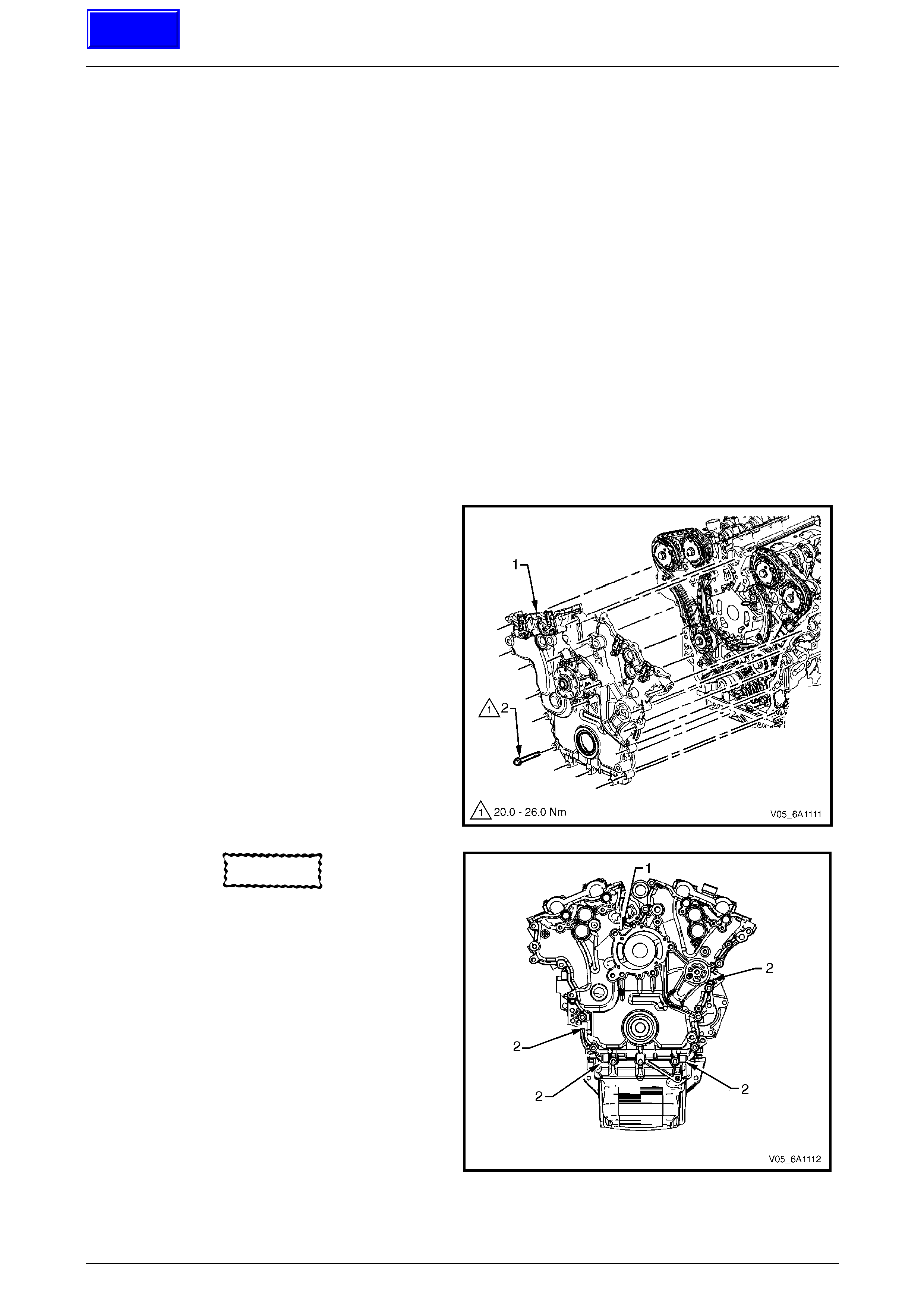
Engine Mechanical – V6 Page 6A1–107
Page 6A1–107
3.16 Front Cover Assembly
LT Section No. — 00–325
Remove
1 Drain the engine coolant, refer to Section 6B1 Engine Cooling – V6.
2 Remove the water outlet pipe and coola nt pump assembly, refer to Section 6B1 Engine Cooling – V6:
3 Remove the camshaft covers, refer to 3.13 Camshaft Cover.
4 Remove the crankshaft balancer assembly, refer to 3.14 Crankshaft Balancer Assembly.
5 Disconnect the purge vent hose from the water outlet pip e.
NOTE
Do not disconnect the power steering pipes or
drain the power steering fluid.
6 Remove the power steering pump reservoir mounting bracket,
refer to 3.9 Power Steering Reservoir and Pump Brackets.
7 Remove the air-conditioner compressor and mounting bracket as an assembly and move to one side to provide
access, refer to Section 2B HVAC Climate Control (Manual A/C) – Servicing and Diagnosis.
NOTE
Do not disconnect the A/C compressor pipes.
8 Remove the camshaft position sensors and camshaft position actuator solenoid valves, refer to
Section 6C1-3 Engine Management – V6 – Service Operations.
9 Remove the bolt (2), 22 places, attaching the front
cover assembly (1).
Figure 6A1 – 92
CAUTION
Only use the prise points and a bolt in the
jackscrew hole to remove the engine front
cover.
10 Loosely install a 10 x 1.5 mm bolt in the jackscre w
hole (1).
11 Using the prise points (2) located at the edge of the
front cover and the jackscrew, shear the RTV sealant.
Figure 6A1 – 93
Techline
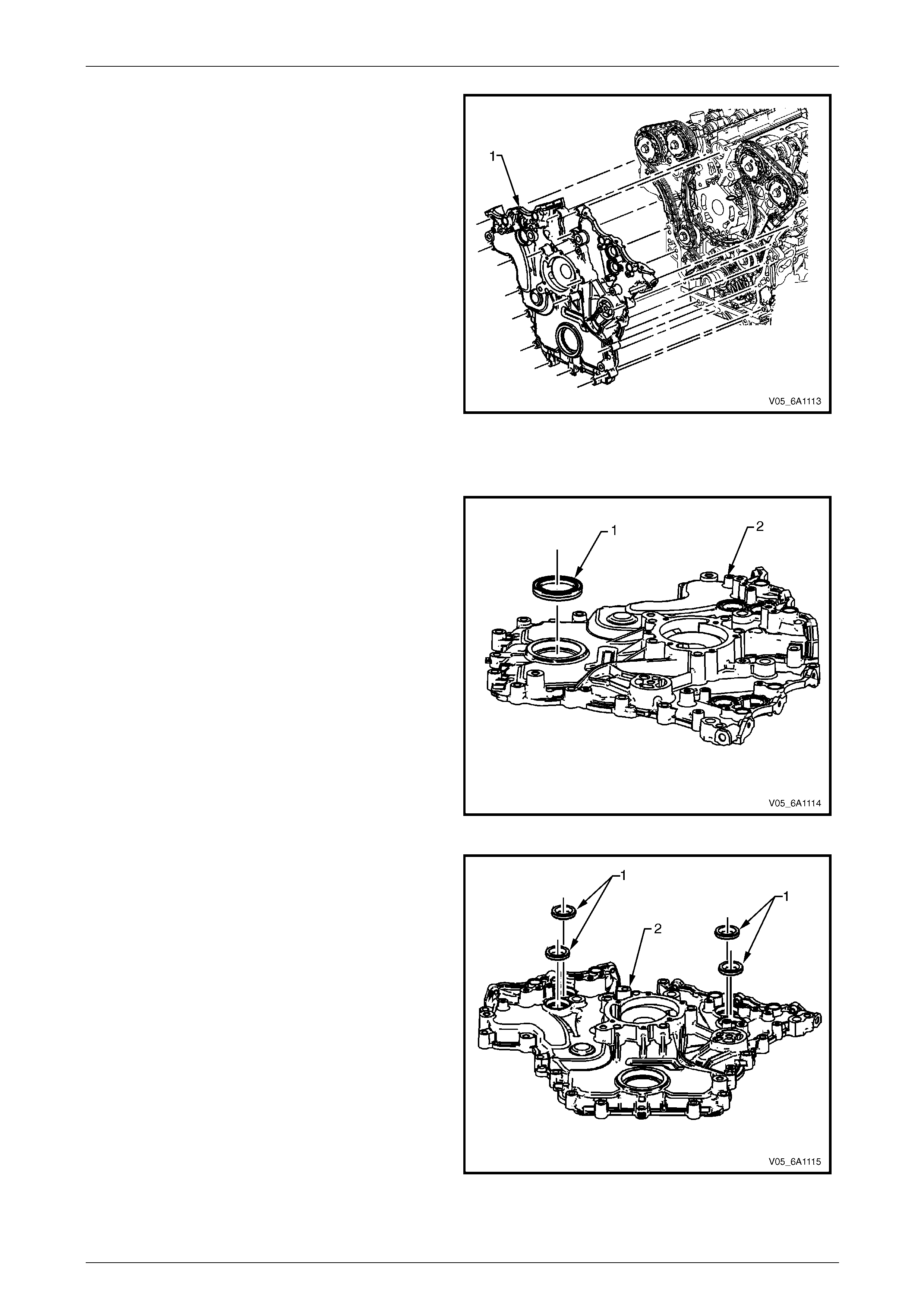
Engine Mechanical – V6 Page 6A1–108
Page 6A1–108
12 Remove the front cover assembly (1).
Figure 6A1 – 94
Disassemble
1 Remove the crankshaft front oil seal (1) from the
engine front cover (2) using a flat bladed tool or seal
remover, Tool No. E-308. Discard the seal.
Figure 6A1 – 95
2 Remove the camshaft position actuator valve oil
seals (1) from the engine front cover (2). Discard the
seals.
Figure 6A1 – 96
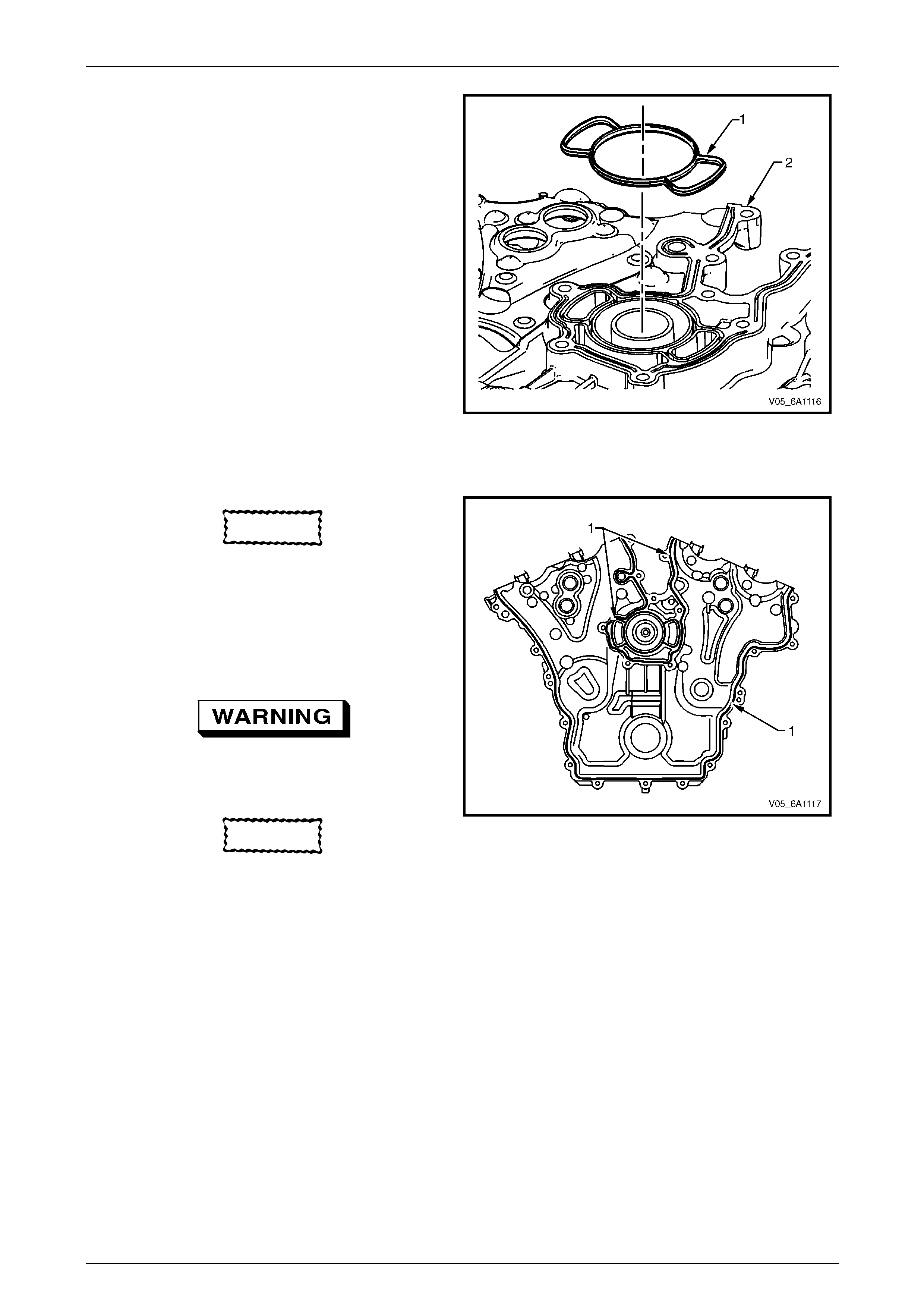
Engine Mechanical – V6 Page 6A1–109
Page 6A1–109
3 Remove the coolant pump seal (1) from the engine
front cover (2). Discard the seal.
Figure 6A1 – 97
Clean
CAUTION
Do not use a sharp or metal gasket scraper
to clean the sealing surface s.
1 Remove any RT V sealant (1) from the engine front
cover using a plastic or wood scraper.
2 Clean out any debris from the bolt holes.
3 Clean the front cover with a suitable cle an ing solvent.
Safety glasses must be worn when using
compressed air.
4 Dry the front cover with compressed air.
CAUTION
Insert a piece of cardboard between the front
of the oil pan and oil pump to prevent any
contaminants from falling into the oil pan.
Figure 6A1 – 98
5 Use compressed air to remove an y engine coolant from the engine co oling passages and from the top of the oil
pan oil deflector.
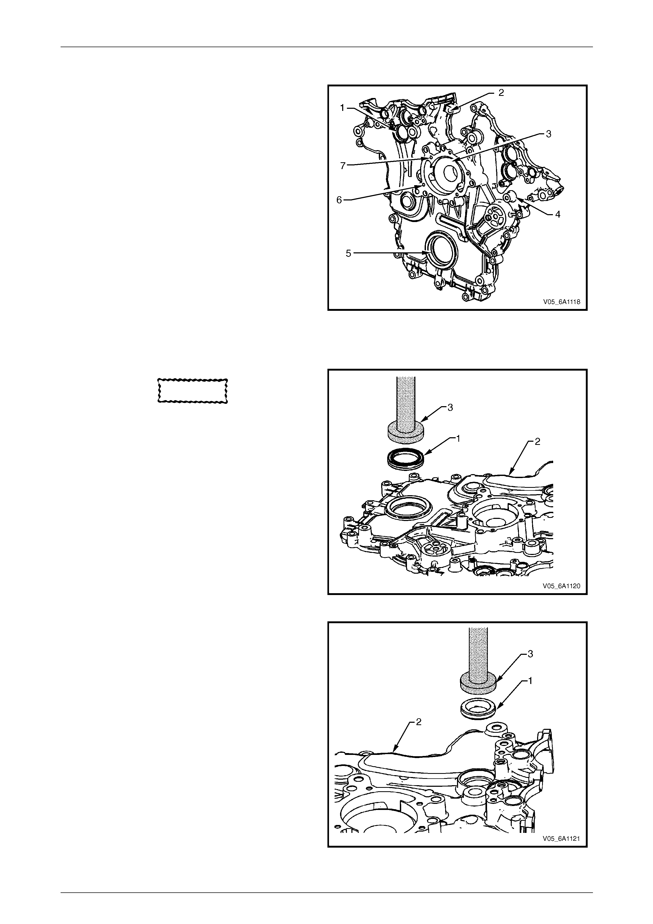
Engine Mechanical – V6 Page 6A1–110
Page 6A1–110
Inspect
1 Inspect both sides of the engine front cover for the
following conditions:
• damage to the camshaft position actuat or valve
oil seal bores (1),
• damage to the bolt holes (2),
• damage and/or corrosion to the engine coolant
passage (3),
• dents or damage to the exterior (4),
• damage to the crankshaft front oil seal bore ( 5),
• gouges or damage to the cool ant pump sealing
surfaces (6), and
• damage to the coolant pump bolt hole
threads (7).
2 Repair or replace the front cover as required.
Figure 6A1 – 99
Reassemble
CAUTION
Do not lubricate the crankshaft front oil seal
or crankshaft balancer sealing surfaces. The
crankshaft balancer is installed into a dry
seal.
1 Install a new crankshaft front oil seal (1) into the front
cover (2) using crankshaft front seal installer, Tool
No. J-29184 (3) and a suitable hammer.
Figure 6A1 – 100
2 Install a new camshaft position actuator valve oil se al
(1) into the front cover (2) using Tool No. EN-46103
(3) and a suitable hammer.
Figure 6A1 – 101
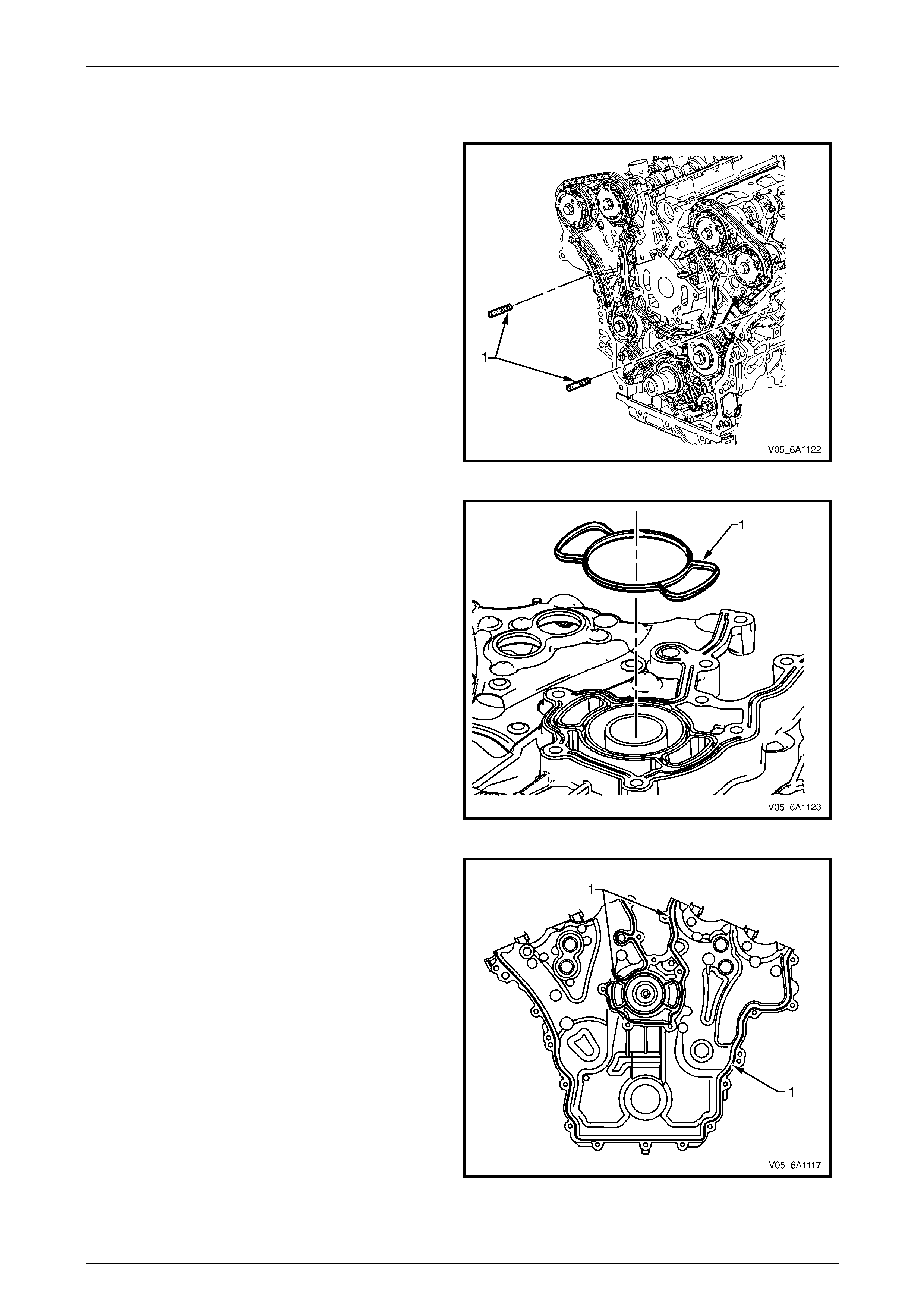
Engine Mechanical – V6 Page 6A1–111
Page 6A1–111
Reinstall
Reinstallation of the front cover is the reverse of the removal procedure, noting the following:
1 Install the guide pins, Tool No. EN-46109 (1) into the
engine block, two places.
Figure 6A1 – 102
2 Install a new engine front cover to cylinder block
seal (1).
Figure 6A1 – 103
3 Apply a 3 mm bead of RT V sealant (1) to the front
cover.
Figure 6A1 – 104
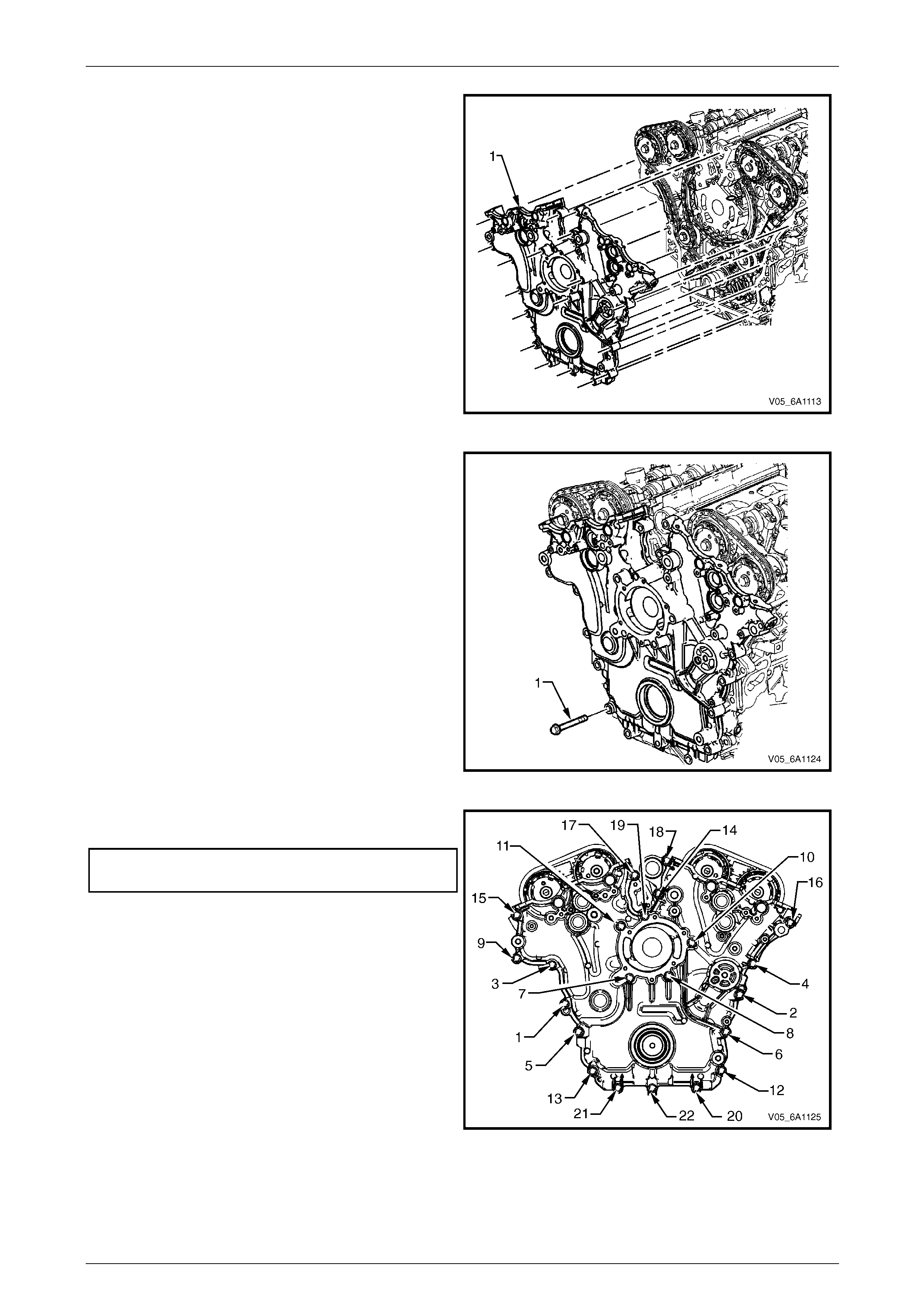
Engine Mechanical – V6 Page 6A1–112
Page 6A1–112
4 Place the front cover onto the special tools and slide
into position.
5 Remove the special tools from the cylinder block.
Figure 6A1 – 105
6 Hand start the front cover bolts (1).
Figure 6A1 – 106
7 Tighten the engine front cover bolts to the correct
torque specification, in the seque nce shown.
Engine front cover assembly attaching
bolt torque specification..........................20.0 – 26.0 Nm
8 Fill the cooling system, refer to
Section 6B1 Engine Co oling – V6.
9 Change the engine oil, refer to 3.2 Engine Oil.
Figure 6A1 – 107

Engine Mechanical – V6 Page 6A1–113
Page 6A1–113
3.17 Timing Chains, Tensioners, Shoes and
Guides
LT Section No. — 00–225
CAUTION
Setting the camshaft timing is required
whenever the camshaft drive system has
been disturbed and the relationship between
any chain and sprocket has been lost. Even
when only one sprocket is involved, multiple
crankshaft rotations will not produce
conditions where correct timing can be
confirmed. If required, follow the left-hand
secondary timing chain reinstallation
procedure to reset the camshaft timin g.
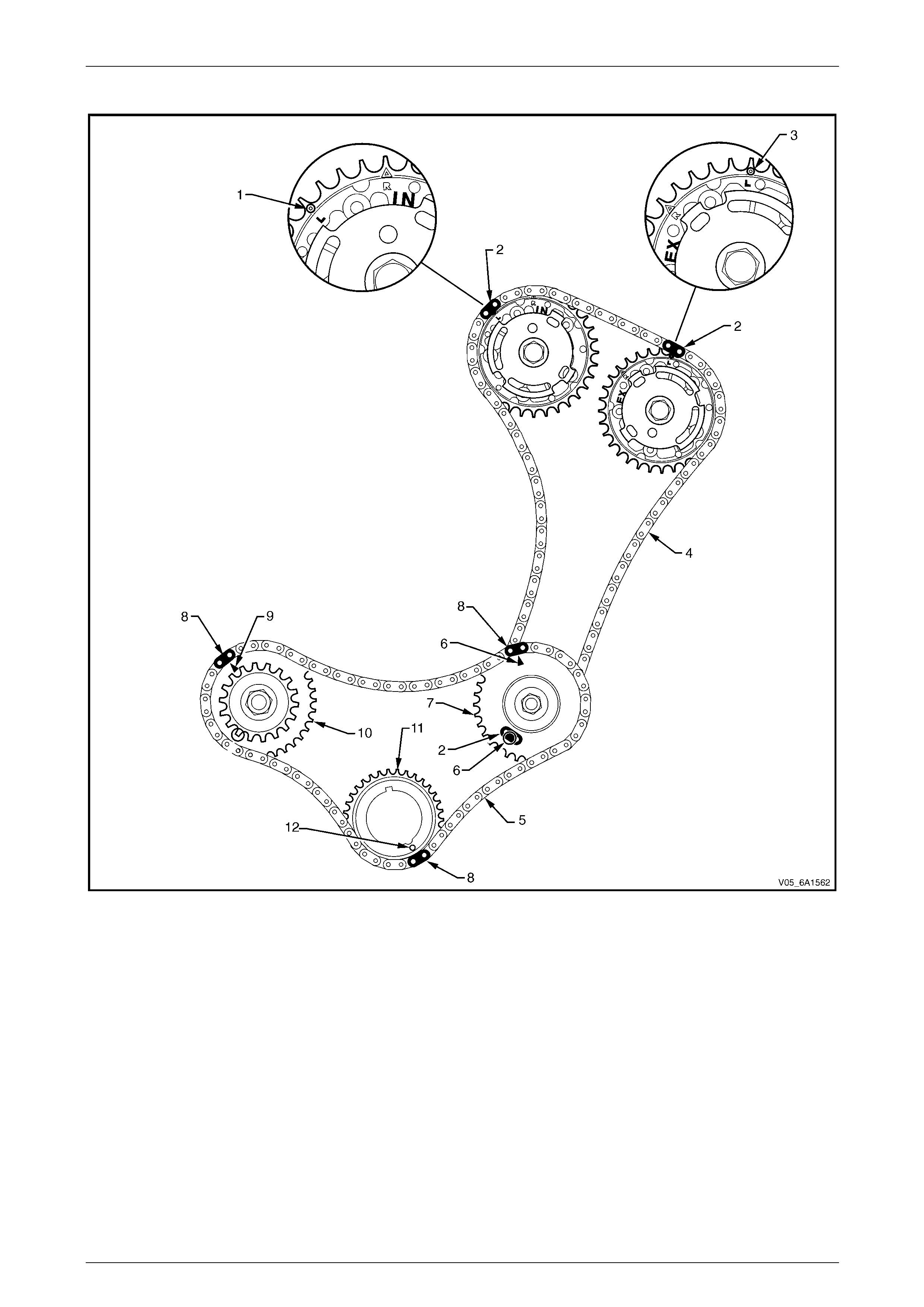
Engine Mechanical – V6 Page 6A1–114
Page 6A1–114
Primary and Left-hand Secondary Timing Chain Installation
Figure 6A1 – 108
Legend
1 Intake Camshaft Position (CMP) Actuator Timing Mark –
Left-hand
2 Secondary Timing Chain Bright Plated Link – Left-hand
3 Exhaust Camshaft Position (CMP) Actuator Timing Mark –
Left-hand
4 Secondary Timing Chain – Left-hand
5 Primary Timing Chain
6 Camshaft Intermediate Driveshaft Sprocket Timing Mark –
Left-hand
7 Camshaft Intermediate Driveshaft Sprocket – Left-hand
8 Primary Timing Chain Bright Plated Link
9 Camshaft Intermediate Driveshaft Sprocket Timing Mark –
Left-hand
10 Camshaft Intermediate Drive shaft Sprocket – Right-hand
11 Crankshaft Sprocket
12 Crankshaft Sprocket Timing Mark
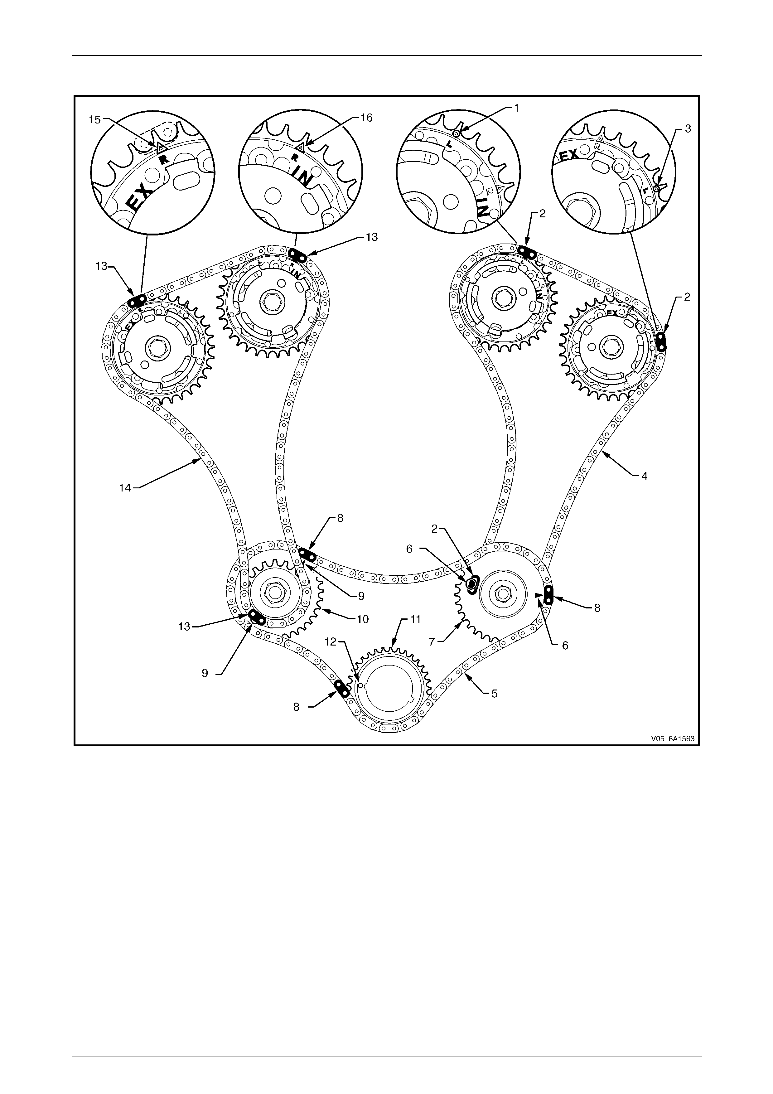
Engine Mechanical – V6 Page 6A1–115
Page 6A1–115
Right-hand Secondary Timing Chain Installation
Figure 6A1 – 109
Legend
1 Intake Camshaft Position (CMP) Actuator Timing Mark –
Left-hand
2 Secondary Timing Chain Bright Plated Link – Left-hand
3 Exhaust Camshaft Position (CMP) Actuator Timing Mark –
Left-hand
4 Secondary Timing Chain – Left-hand
5 Primary Timing chain
6 Camshaft Intermediate Drive Chain Sprocket Timing Mark –
Left-hand
7 Primary Camshaft Intermediate Drive Chain Sprocket – Left-
hand
8 Primary Timing Chain Bright Plated Link
9 Camshaft Intermediate Drive Chain Sprocket Timing Mark –
Left-hand
10 Camshaft Intermediate Drive Chain Sprocket – Right-hand
11 Crankshaft Sprocket
12 Crankshaft Sprocket Timing Mark
13 Secondary Timing chain Bright Plated Link – Right-hand
14 Camshaft Intermediate Drive Chain – Right-hand
15 Exhaust Camshaft Position (CMP) Actuator Timing Mark -
Right-side
16 Inlet Camshaft Position (CMP) Actuator Timing Mark - Right-
side
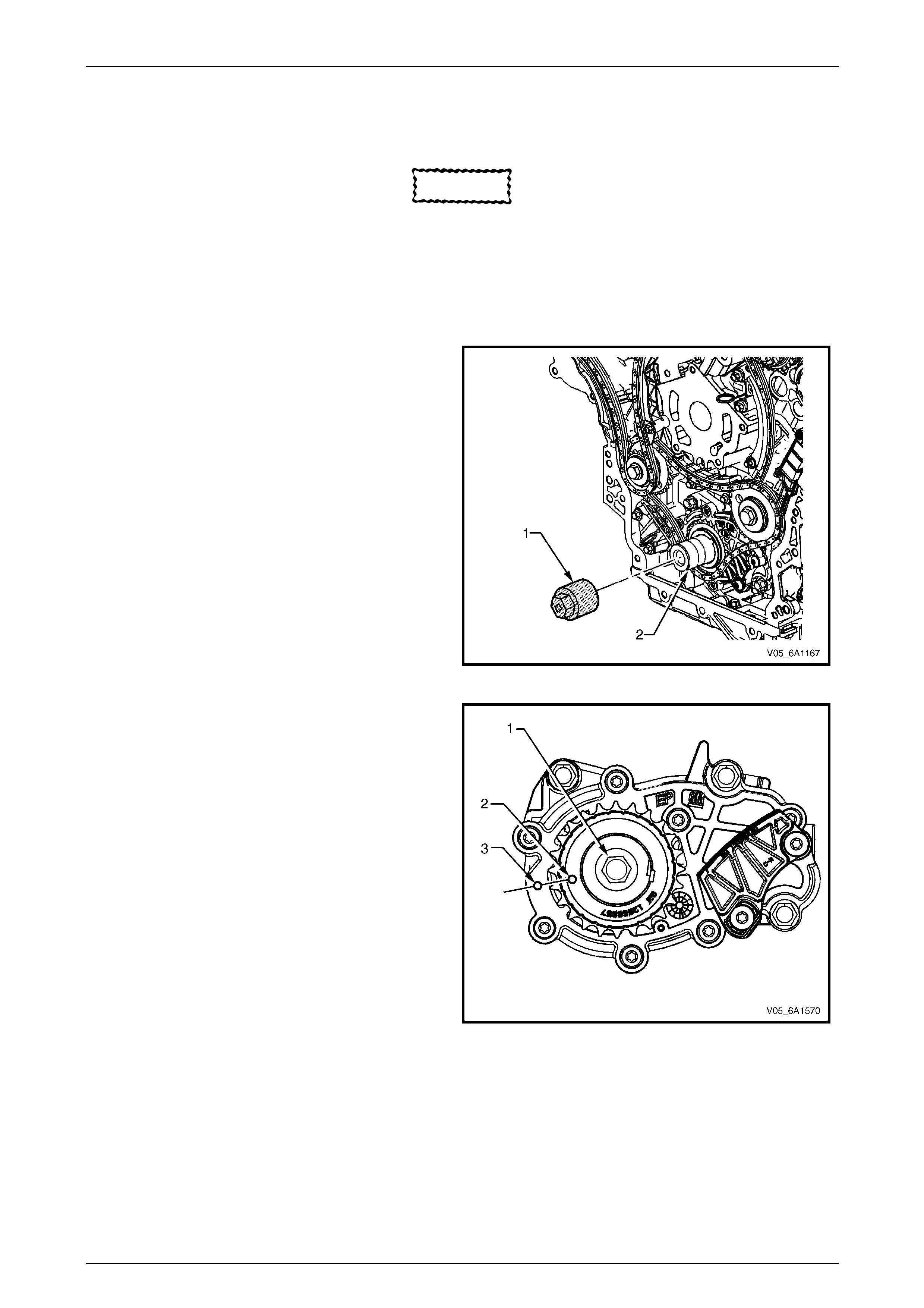
Engine Mechanical – V6 Page 6A1–116
Page 6A1–116
Remove
Right-hand Secondary Timing Chain
CAUTION
After remo ving the upper intake manifo ld, and
spark plugs, plug any openings to prevent dirt
and other contaminants from entering.
1 Remove the engine front cover assembly, refer to 3.16 Front Cover Assembly.
2 Remove the spark plugs to aid crankshaft/engine rotation,
refer to Section 6C1-3 Engine Mana gement – V6 – Service Operations.
3 Install Tool No. EN46111 (1) onto the crankshaft (2).
Figure 6A1 – 110
4 Using Tool No. EN46111 (1), rotate the crankshaft in
a clockwise direction until the cranksh aft sprocket
timing mark (2) is aligned with the indexing mark (3)
on the oil pump housing.
Figure 6A1 – 111
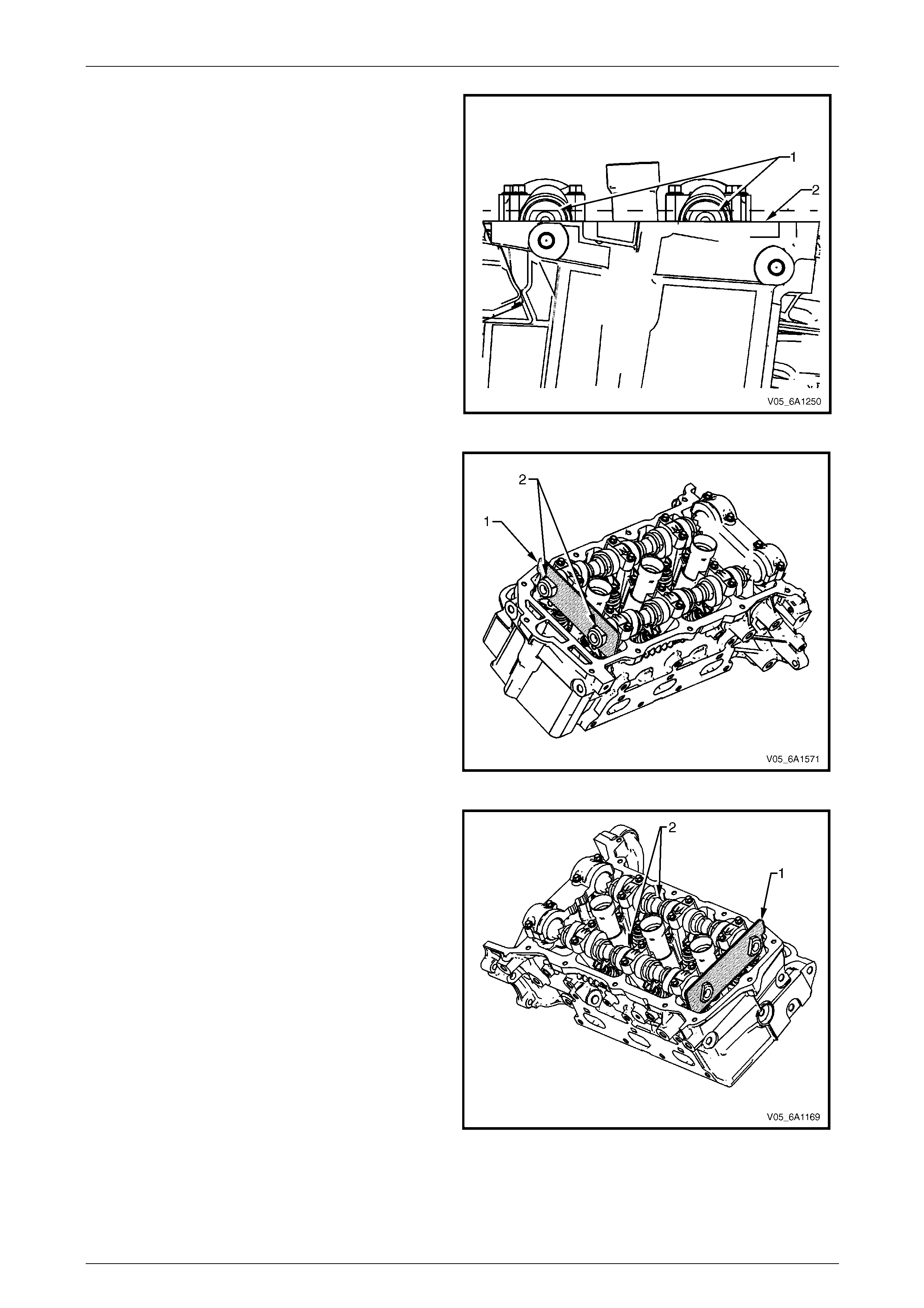
Engine Mechanical – V6 Page 6A1–117
Page 6A1–117
5 After aligning the crankshaft sprocket timing mark,
check that the camshaft flats (1) at the rear of the
right-hand cylinder head are parallel with the
camshaft cover rail (2).
6 If the camshaft flats are not as shown, rotate the
crankshaft 360 °.
Figure 6A1 – 112
7 Install Tool No. EN 46105-1 (1) onto the rear of the
right-hand cylinder head cams hafts (2).
Figure 6A1 – 113
8 Install Tool No. EN 46105-2 (1) onto the rear of the
left-hand cylinder head camshafts (2), and tool No
Figure 6A1 – 114
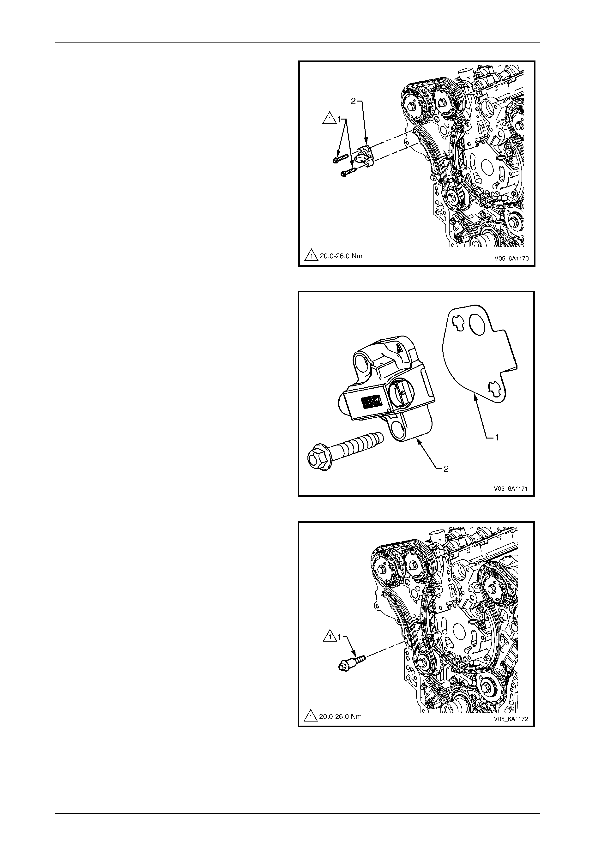
Engine Mechanical – V6 Page 6A1–118
Page 6A1–118
9 Remove the right-hand secondary timing chain
tensioner bolts (1) and remove the tensioner (2).
NOTE
Take care when removing the tensioner bolts.
The tensioner plunger is subjected to spring
tension and may spring apart during tensioner
removal.
Figure 6A1 – 115
10 Remove the tensioner gasket (1) from the tensioner
(2) and discard the gasket.
11 Inspect the tensioner mounting surface on the right-
hand cylinder head for burrs or an y defects that would
affect the sealing of a new tensioner gasket.
Figure 6A1 – 116
12 Remove the right-hand secondary timing chain shoe
bolt (1).
Figure 6A1 – 117
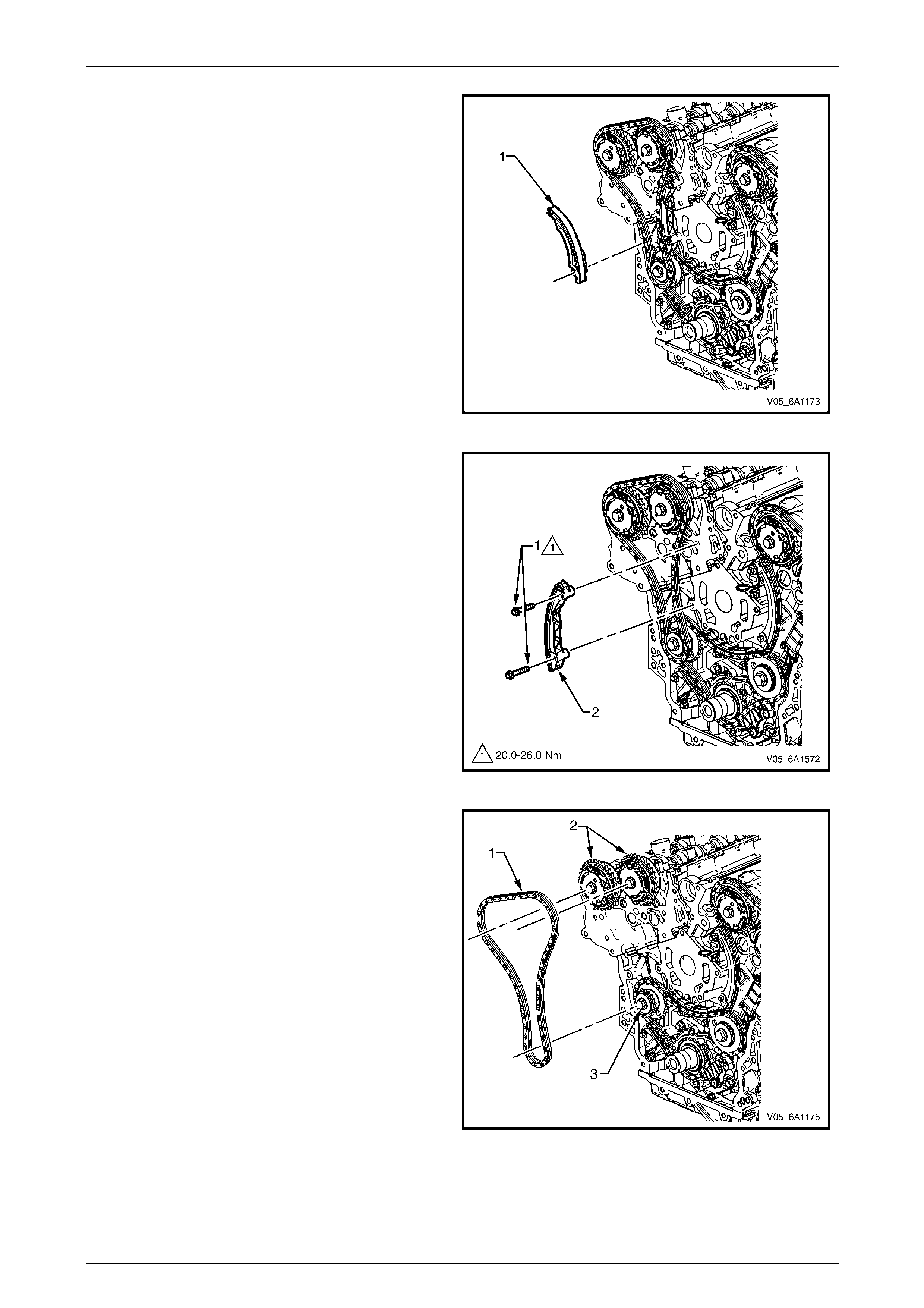
Engine Mechanical – V6 Page 6A1–119
Page 6A1–119
13 Remove the right-hand secondary timing chain shoe
(1).
Figure 6A1 – 118
14 Remove the two right-hand secondary timing chain
guide bolts (1) and remove the gui de (2).
Figure 6A1 – 119
15 Remove the right-hand secondary timing chain (1)
from the camshaft position actuators (2) and the
camshaft intermediate driveshaft sprocket (3).
Figure 6A1 – 120
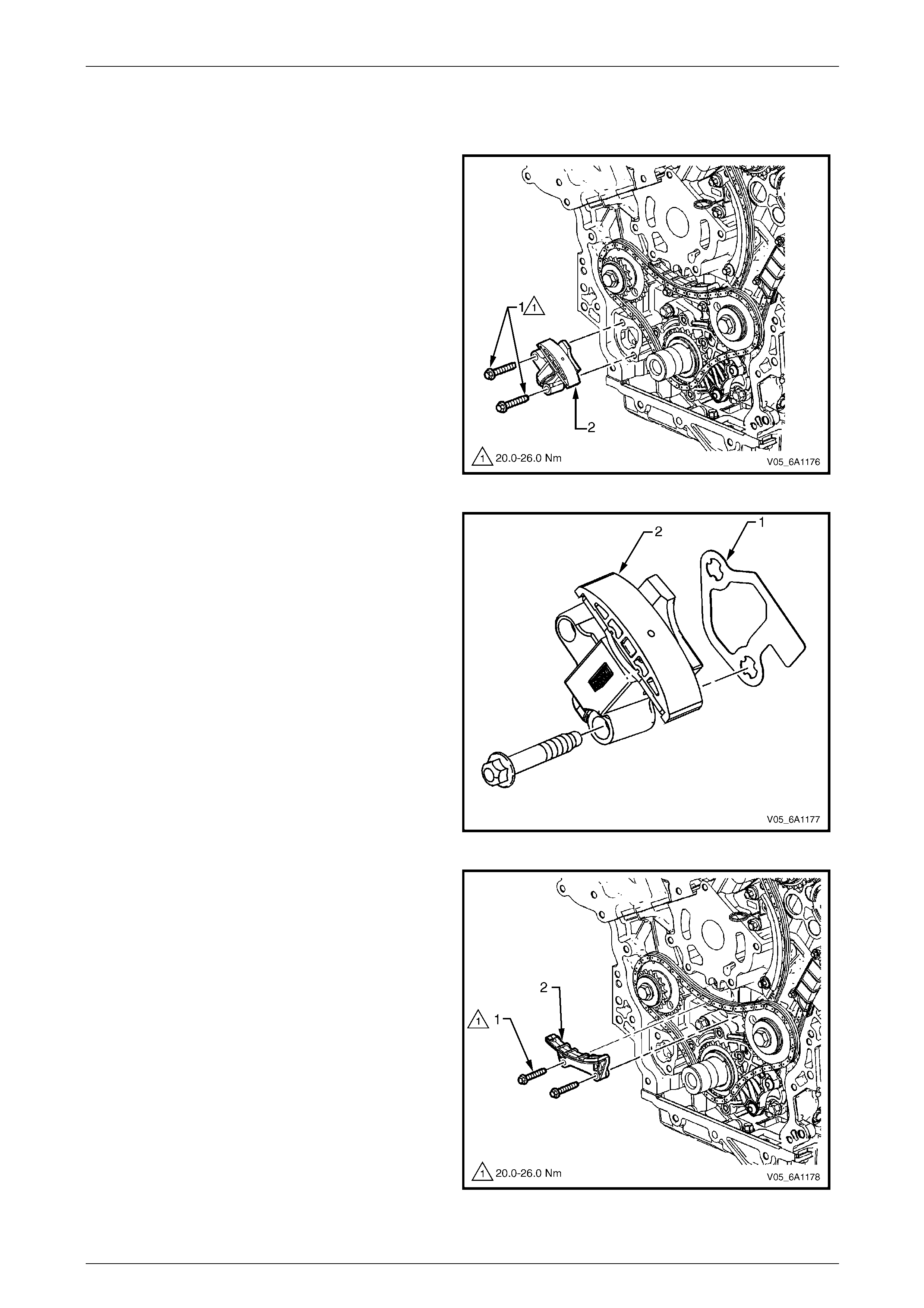
Engine Mechanical – V6 Page 6A1–120
Page 6A1–120
Primary Timing Chain
1 Remove the right-hand secondary timing chain, refer to Right-hand Secondary Timing Ch ain in this Section.
2 Remove the two primary timing chai n tensioner
bolts (1), and remove the tensioner (2).
NOTE
Take care when removing the tensioner bolts.
The tensioner plunger is subjected to spring
tension and may spring apart during tensioner
removal.
Figure 6A1 – 121
3 Remove the gasket (1) from the tensioner (2) and
discard the gasket.
4 Inspect the primary timing chain tensio ner mounting
surface on the engine block for burrs or any defects
that would affect the sealing of a new tensioner
gasket.
Figure 6A1 – 122
5 Remove the two primary timing chain upper guide
bolts (1) and remove the guide (2).
Figure 6A1 – 123
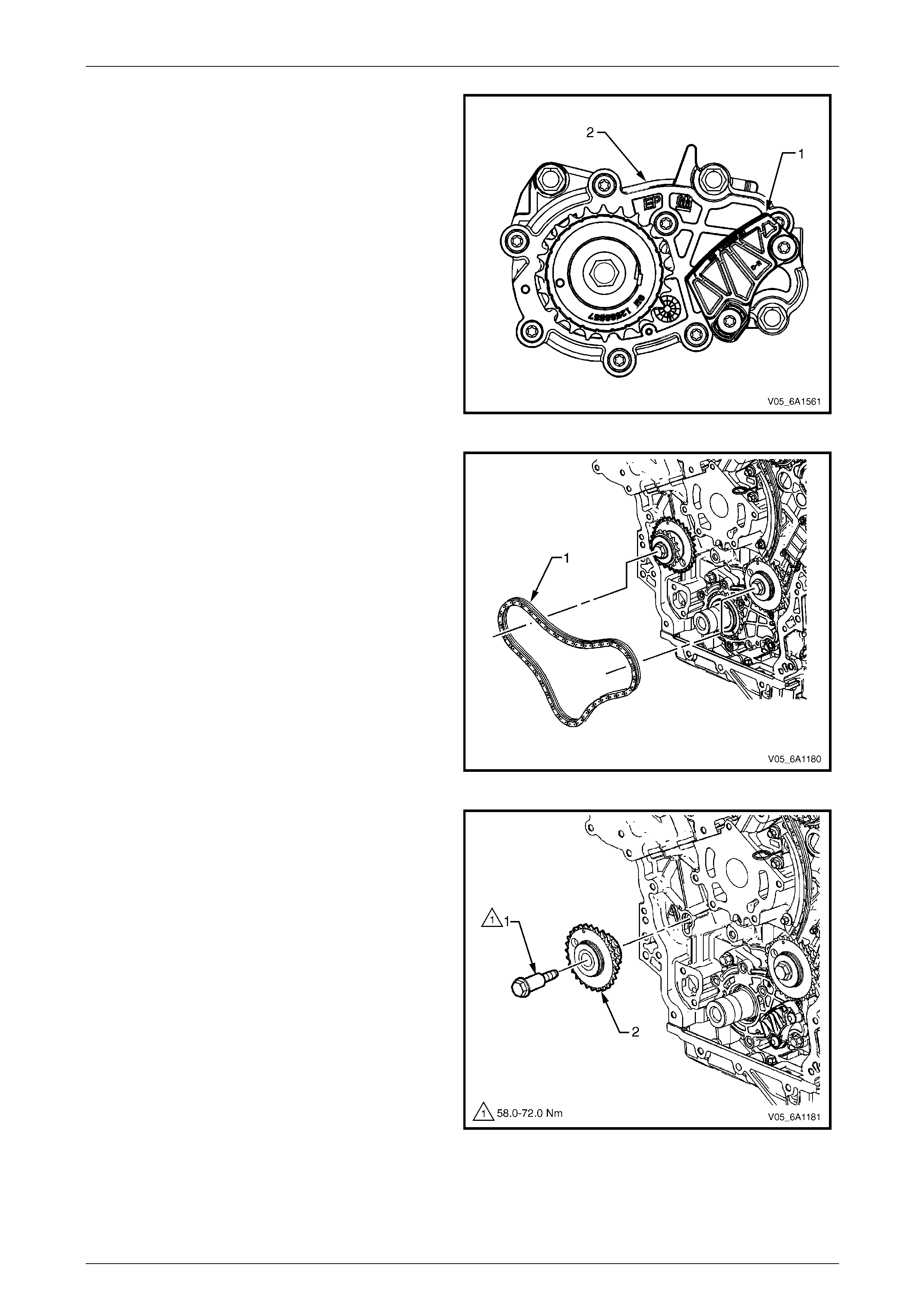
Engine Mechanical – V6 Page 6A1–121
Page 6A1–121
NOTE
Do not remove the primary timing chain lower
guide (1). The primary timing chain lower guide
is not serviced separately. If the primary timing
chain lower guide requires replacement, the oil
pump assembly (2) must be replaced.
Figure 6A1 – 124
6 Remove the primary timing chain (1).
NOTE
For ease of removal, r emove the chain from the
crankshaft sprocket, before attempting to
remove from the camshaft intermediate
driveshaft sprockets.
Figure 6A1 – 125
7 If required, remove the right-hand camshaft
intermediate driveshaft sprocket bolt (1) and remove
the sprocket (2).
Figure 6A1 – 126
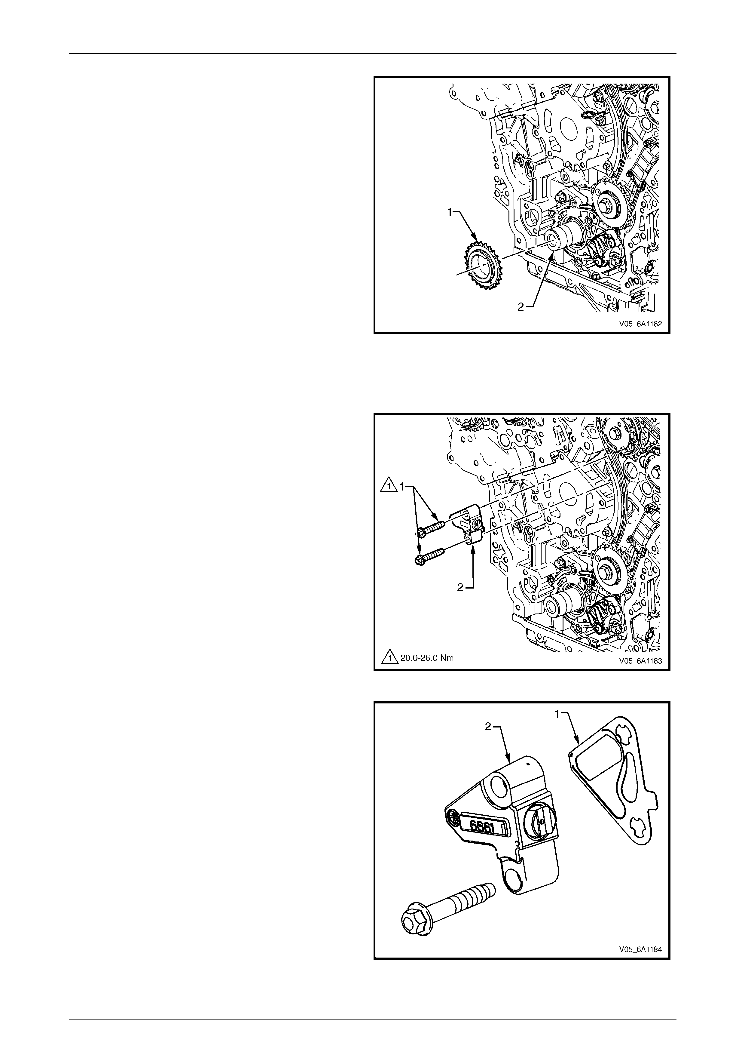
Engine Mechanical – V6 Page 6A1–122
Page 6A1–122
8 If required, remove the crankshaft sprocket (1) from
the crankshaft (2).
Figure 6A1 – 127
Left-hand Secondary Timing Chain
1 Remove the primary timing chain, refer to Primary Timing Chain in this Section.
2 Remove the two left-hand secondary timing chain
tensioner bolts (1) and remove the tensioner (2).
NOTE
Take care when removing the tensioner bolts.
The tensioner plunger is subjected to spring
tension and may spring apart during tensioner
removal.
Figure 6A1 – 128
3 Remove the gasket (1) from the tensioner (2) and
discard the gasket.
4 Inspect the tensioner mounting surface on the left-
hand cylinder head for burrs or an y defects that would
affect the sealing of a new tensioner gasket.
Figure 6A1 – 129
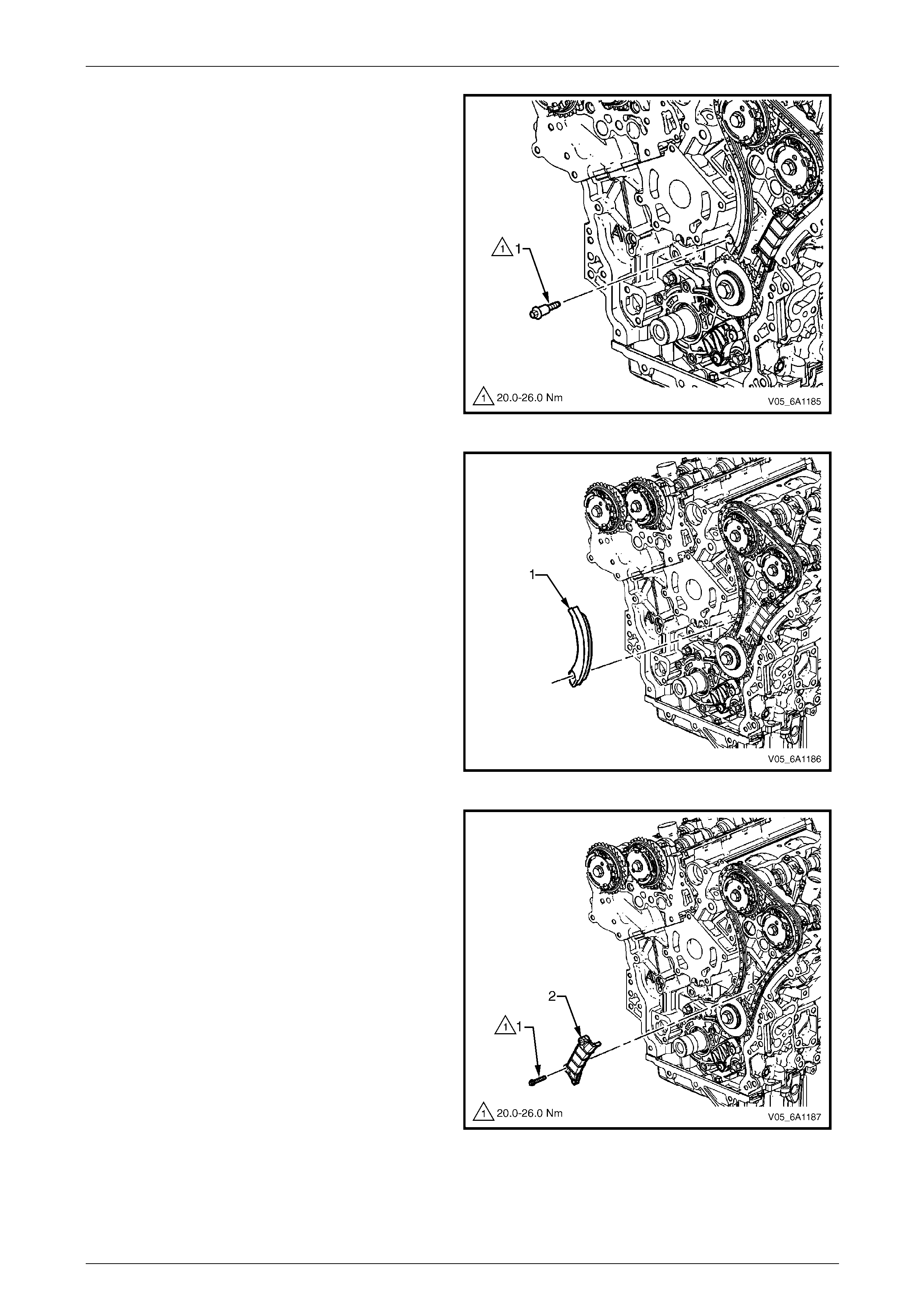
Engine Mechanical – V6 Page 6A1–123
Page 6A1–123
5 Remove the left-hand sec ondary timing chain shoe
bolt (1).
Figure 6A1 – 130
6 Remove the left-hand sec ondary timing chain
shoe (1).
Figure 6A1 – 131
7 Remove the left-hand secondary timing chain guide
bolt (1), two places, and remove the guide (2).
Figure 6A1 – 132
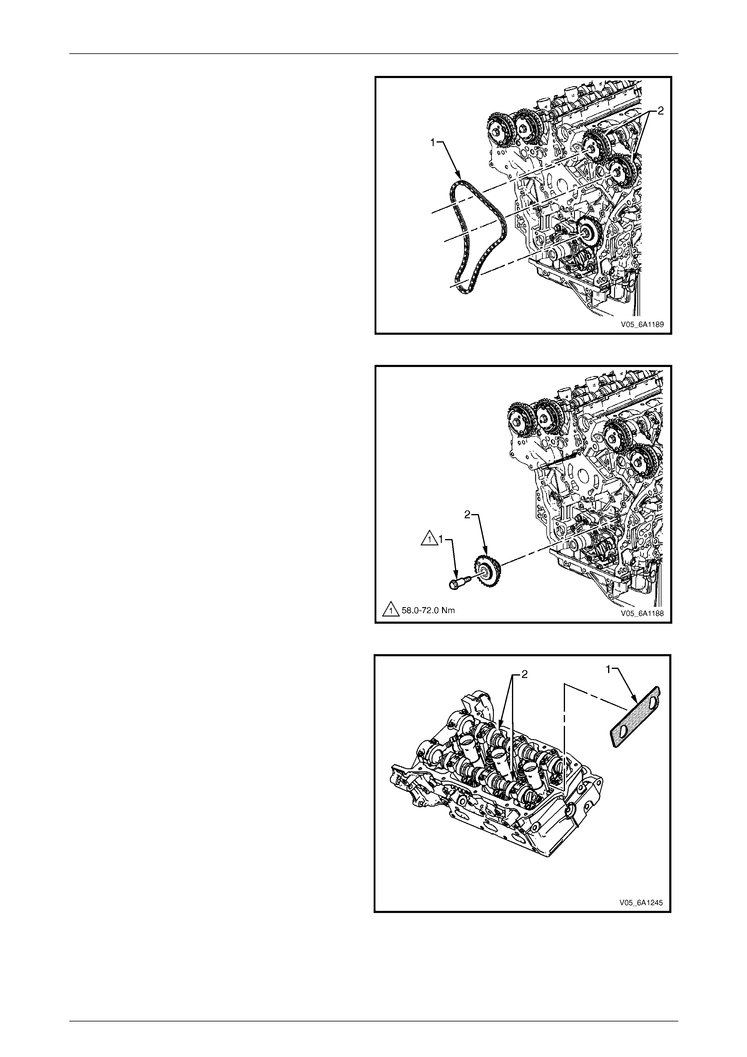
Engine Mechanical – V6 Page 6A1–124
Page 6A1–124
8 Remove the left-hand secondary timing chain (1) from
the camshaft position actuators (2) and the camshaft
intermediate driveshaft sprocket.
Figure 6A1 – 133
9 If required, remove the left-hand camshaft
intermediate driveshaft sprocket bolt (1) and remove
the sprocket (2).
Figure 6A1 – 134
10 Remove Tool No. EN 46105- 2 (1) from the left-hand
cylinder head camshafts (2).
Figure 6A1 – 135
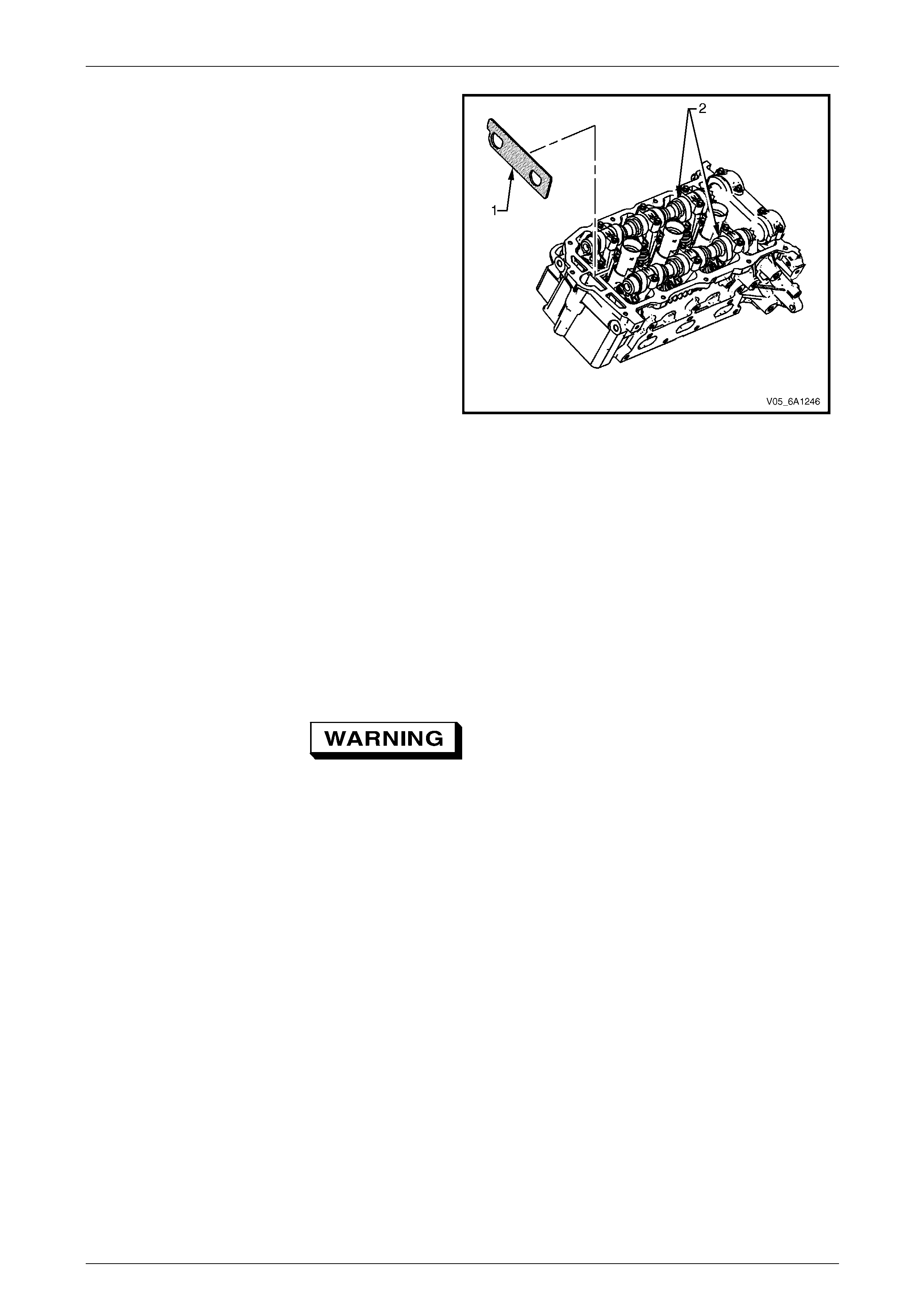
Engine Mechanical – V6 Page 6A1–125
Page 6A1–125
11 Remove Tool No. EN 46105- 1 (1) from the right-hand
cylinder head camshafts (2).
Figure 6A1 – 136
Clean
1 Clean all the following components with a suitable solvent:
• crankshaft sprocket,
• primary timing chain,
• primary timing chain guide,
• primary timing chain tensioner,
• secondary timing chains,
• secondary timing chain shoes,
• secondary timing chain guides,
• secondary timing chain tensioners, and
• bolts.
Safety glasses must be worn when using
compressed air.
2 Dry all the components with compressed air.
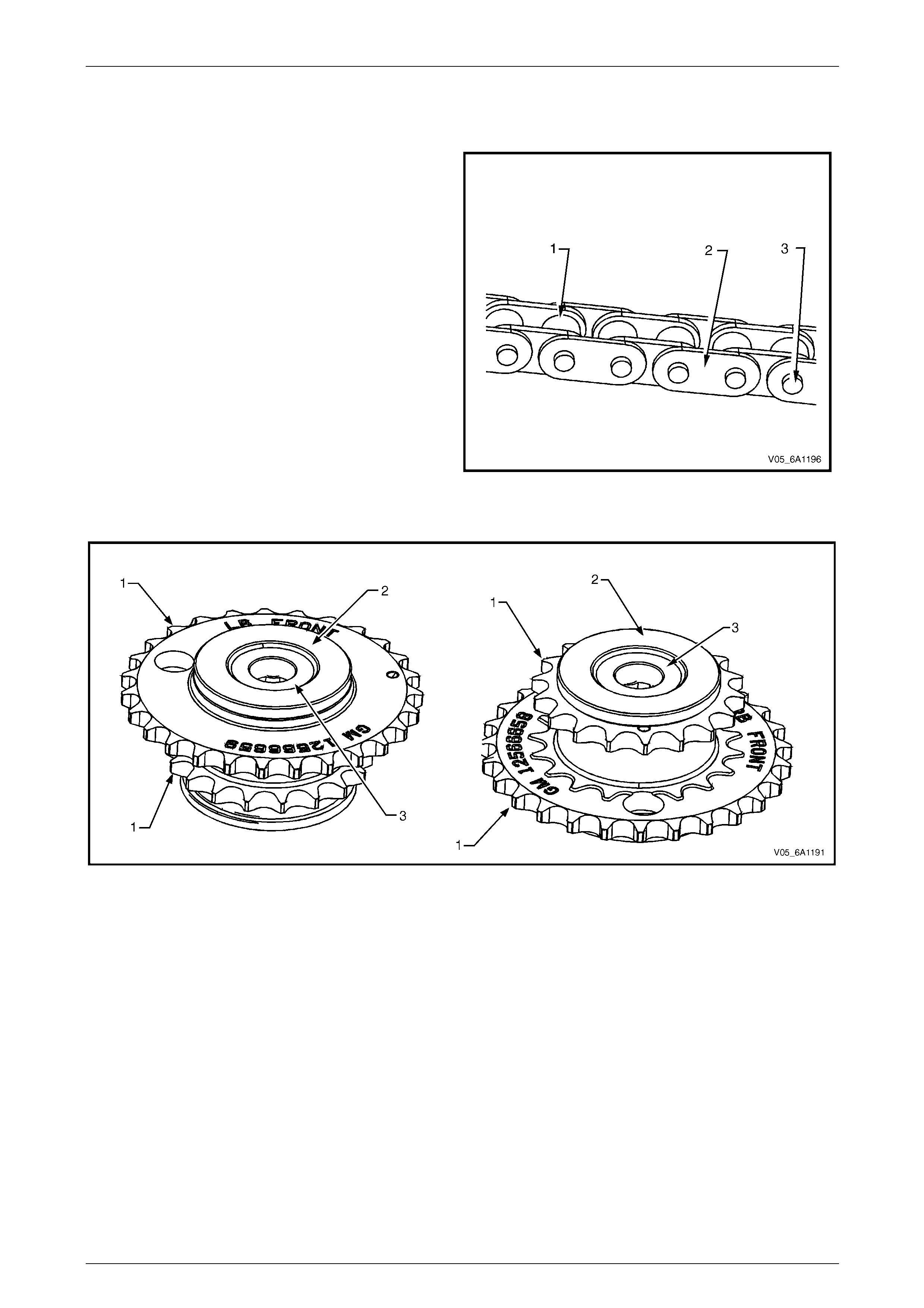
Engine Mechanical – V6 Page 6A1–126
Page 6A1–126
Inspect
Timing Chains
1 Inspect the primary and/or secondary timing chains
for the following:
• binding or worn rollers (1),
• loose links (2), and
• loose pins (3).
2 Replace a damage d timing chain as required.
Figure 6A1 – 137
Camshaft Intermediate Driveshaft Sprockets
Figure 6A1 – 138
1 Inspect the camshaft intermediate driveshaft sprockets for the following:
• Damage to the primary and secondary timing chain sprocket (1), refer to Figure 6A1 – 138.
• Damage to the hub bearing (2). Ensure the hub bearing spins freely. If the hub bearing wobbles, is noisy or
feels rough when rotated replace the camshaft intermediate sprocket, and
• Damage to the bolt flange seating / seali ng surface (3).
• Damage to the bearing hub-to-engine block sealing surface.
Inlet and Exhaust Camshaft Position Actu ator
Inspect the camshaft position actuator assemblies, refer to 3.19 Camshaft Position Actuator Assembly.
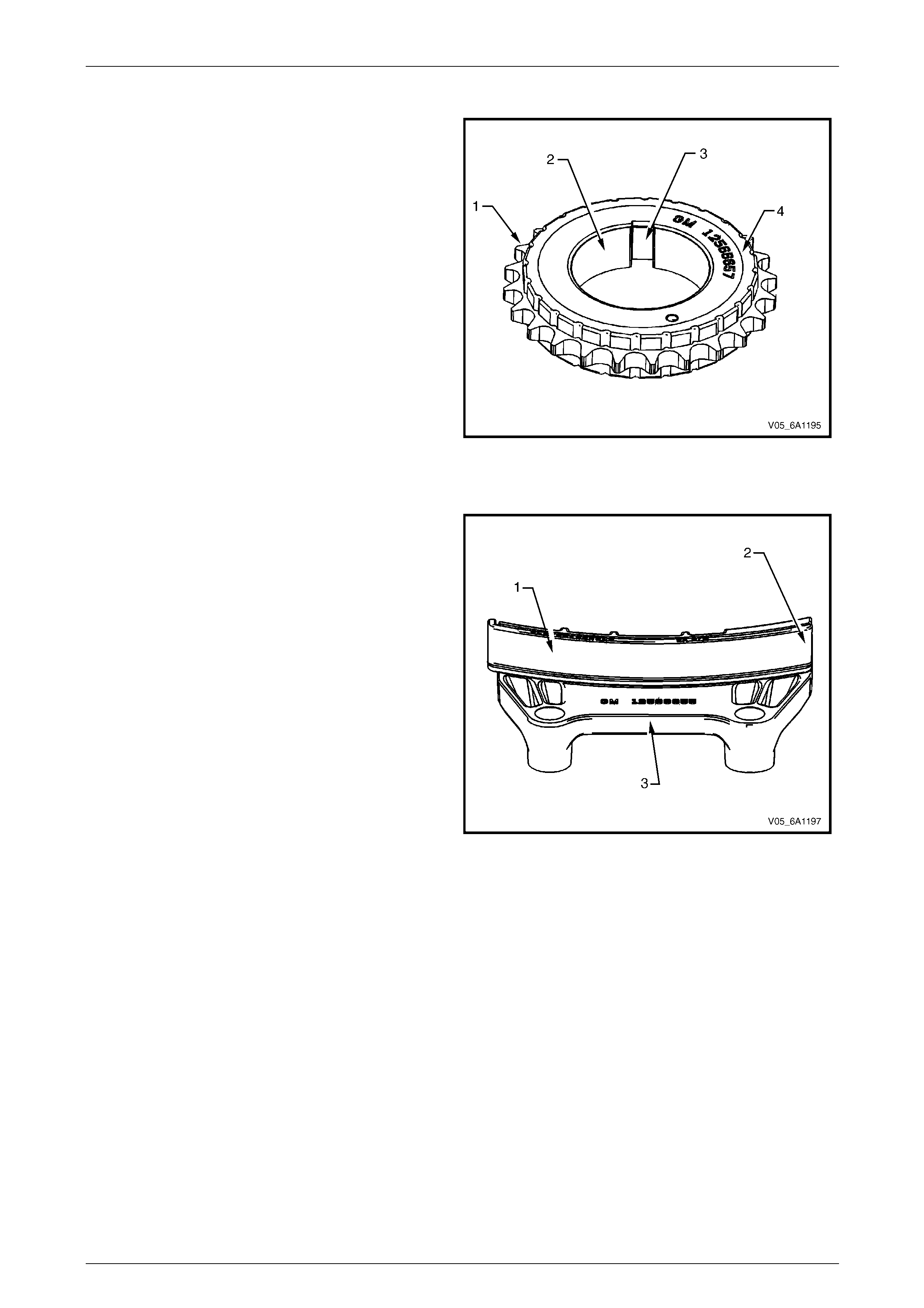
Engine Mechanical – V6 Page 6A1–127
Page 6A1–127
Crankshaft Sprocket
1 Inspect the crankshaft sprocket for the following:
• sprocket damage (1),
• bore damage (2),
• keyway damage (3), and
• damage to the cushion material (4).
2 Replace a damage d sprocket as required.
Figure 6A1 – 139
Primary Timing Chain Upper Guide
1 Inspect the primary timing chain upper guide for the
following:
• worn guide surface (1),
• cracked or broken guide surface (2), and
• cracked or damaged guide b ase (3).
2 Replace a damage d guide as required.
Figure 6A1 – 140
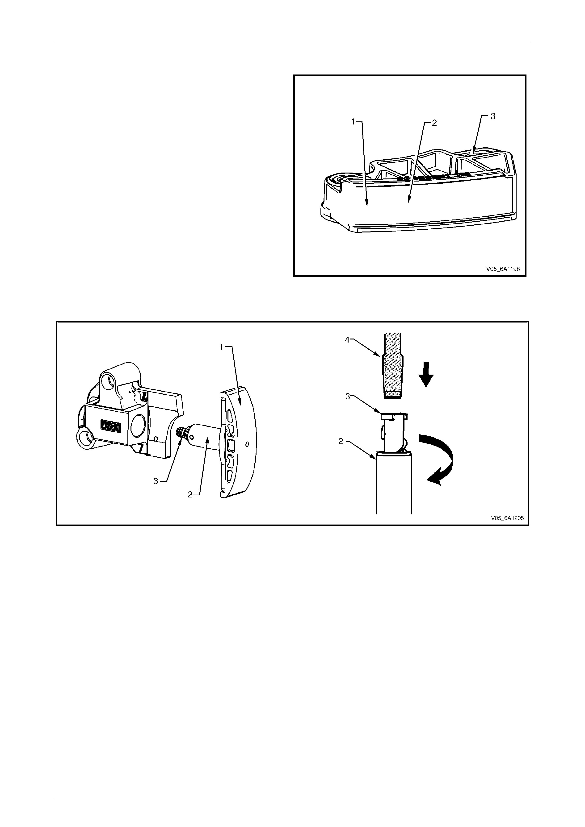
Engine Mechanical – V6 Page 6A1–128
Page 6A1–128
Primary Timing Chain Lower Guide
1 Inspect the primary timing chain lower guide for the
following:
• worn guide surface (1),
• cracked or broken guide surface (2), and
• cracked or damaged guide b ase (3).
NOTE
The primary timing chain lower guide is not
serviced separately and is part of the oil pump
assembly.
2 Replace the primar y timing chain lower guide by
replacing the oil pump assemb ly, refer to
3.18 Oil Pump Assembly.
Figure 6A1 – 141
Primary Timing Chain Tensioner
Figure 6A1 – 142
1 Inspect the primary timing chain tensioner for worn shoe surface (1), refer to Figure 6A1 – 142.
2 Inspect the tensioner for a locked or binding tensioner shaft (2). Reset the plunger (3) and ensure the ten s ioner
shaft moves freely in and out of the body of the tensi oner.
NOTE
To reset the tensioner, use a suitably sized flat
blade screwdriver or Tool N o. J 45027 (4) to wind
the plunger in a clockwise direction, into the
tensioner shaft.
3 Replace a damage d tensioner as required.
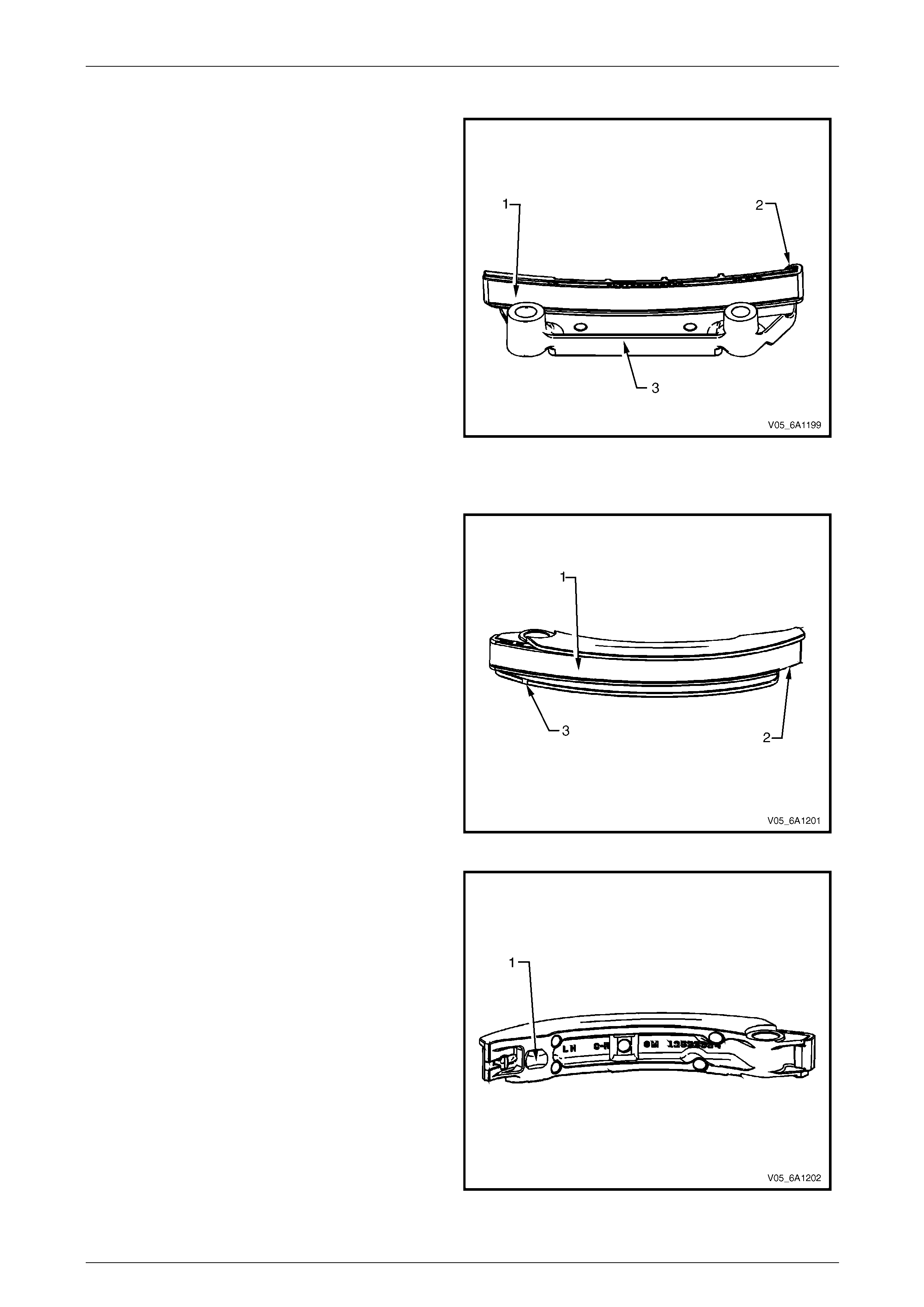
Engine Mechanical – V6 Page 6A1–129
Page 6A1–129
Left-hand Secondary Timing Chain G uide
1 Inspect the left-hand secondary timing chain guide for
the following:
• worn guide surface (1),
• cracked or broken guide surface (2), and
• cracked or damaged guide b ase (3).
2 Replace a damage d guide as required.
Figure 6A1 – 143
Left-hand Secondary Timing Chain Shoe
1 Inspect the front of the left-hand secondary timing
chain shoe for the following:
• worn shoe surface (1),
• cracked or broken shoe surface (2), and
• cracked or damaged shoe (3).
Figure 6A1 – 144
2 Inspect the back of the shoe for a damaged, worn or
missing timing chain tensioner contact pad (1).
3 Replace a damage d shoe as required.
Figure 6A1 – 145
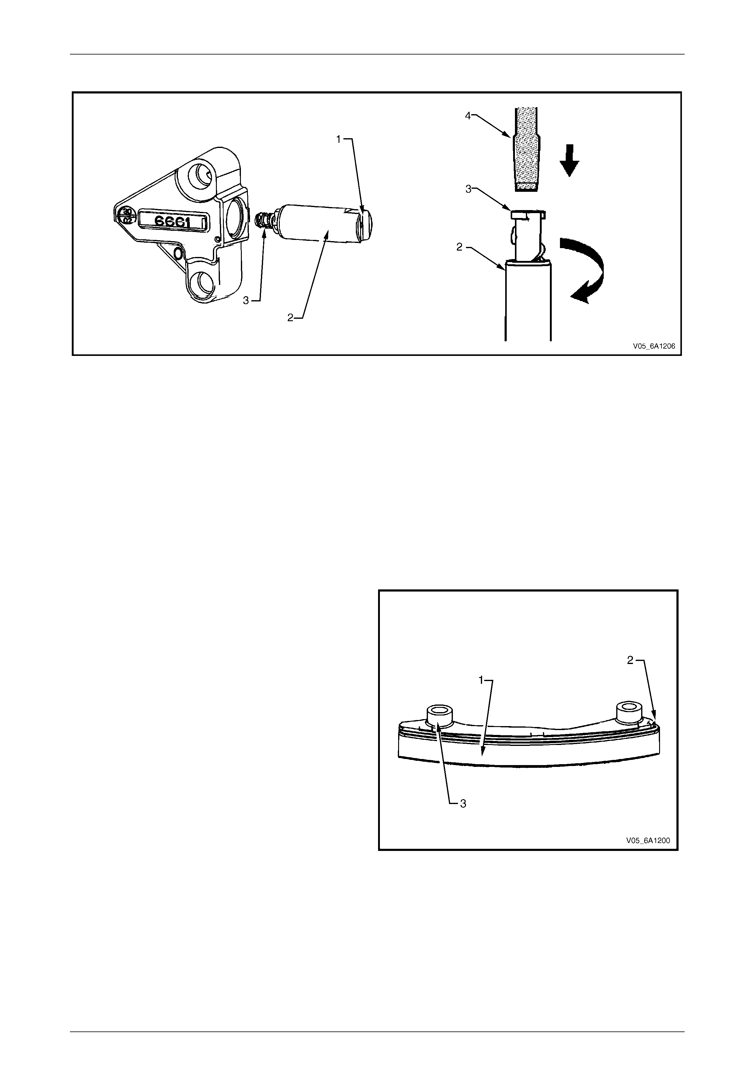
Engine Mechanical – V6 Page 6A1–130
Page 6A1–130
Left-hand Secondary Timing Chain Te nsioner
Figure 6A1 – 146
1 Inspect the left-hand secondary timing chain tensioner for damaged plunger-to-shoe contact surface (1), refer to
Figure 6A1 – 146.
2 Inspect the tensioner for locked or binding tensioner shaft (2). Reset the plunger (3) and ensure the tensioner shaft
moves freely in and out of the body of the ten s ioner.
NOTE
To reset the tensioner, use a suitably sized flat
blade screwdriver or Tool N o. J 45027 (4) to wind
the plunger in a clockwise direction, into the
tensioner shaft.
3 Replace a damage d tensioner as required.
Right-hand Secondary Timing Chain Guide
1 Inspect the right-hand secondary timing chain guide
for the following:
• worn guide surface (1),
• cracked or broken guide surface (2), and
• cracked or damaged guide b ase (3).
2 Replace a damage d guide as required.
Figure 6A1 – 147
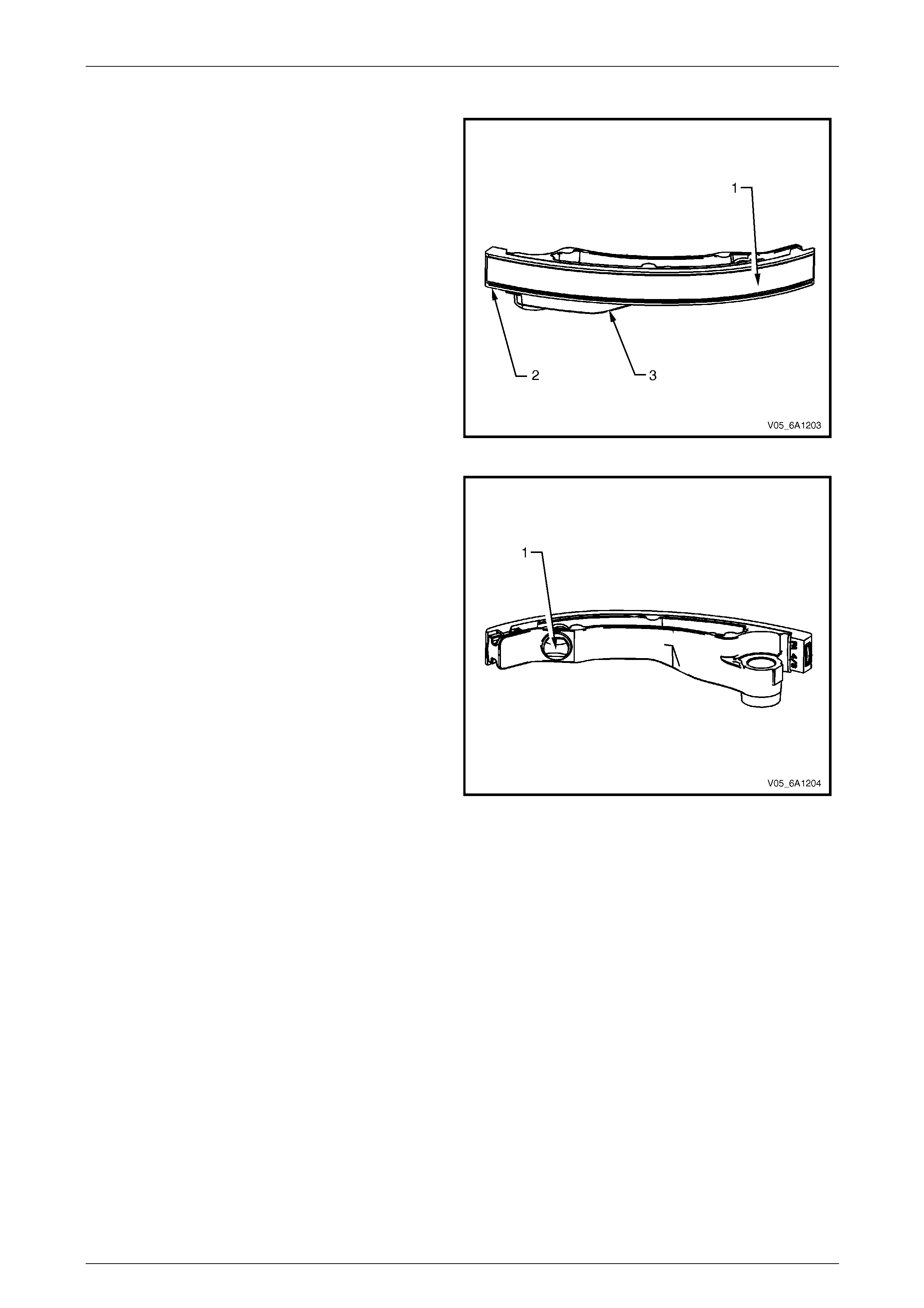
Engine Mechanical – V6 Page 6A1–131
Page 6A1–131
Right-hand Secondary Timing Chain Shoe
1 Inspect the front of the right-hand secondary timing
chain shoe for the following:
• worn shoe surface (1),
• cracked or broken shoe surface (2), and
• cracked or damaged shoe (3).
Figure 6A1 – 148
2 Inspect the back of the shoe for a damaged, worn or
missing timing chain tensioner contact pad (1).
3 Replace a damage d shoe as required.
Figure 6A1 – 149
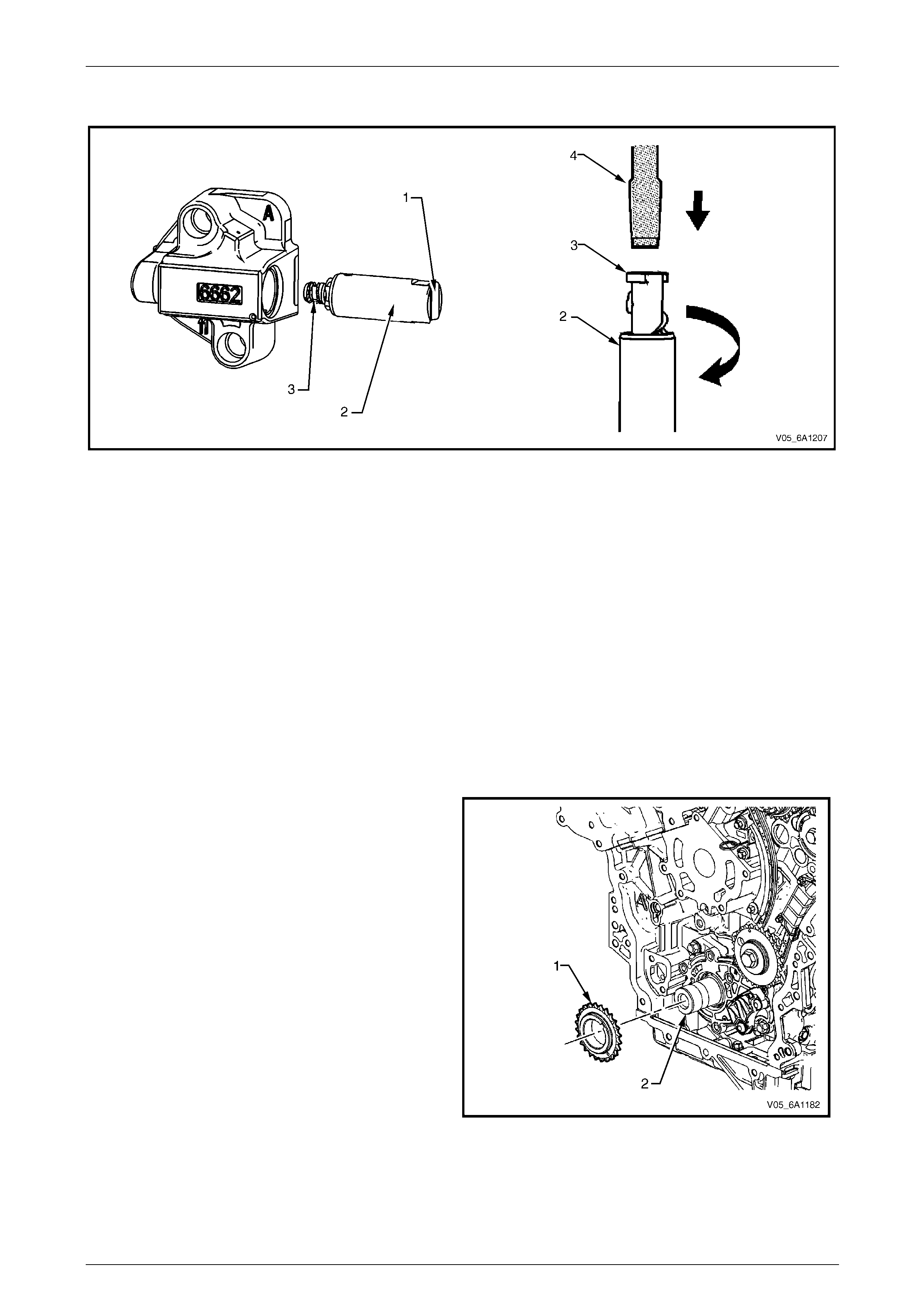
Engine Mechanical – V6 Page 6A1–132
Page 6A1–132
Right-hand Secondary Timing Chain Tensioner
Figure 6A1 – 150
1 Inspect the right-hand secondary timing cha in tensioner for damaged plunger-to-shoe contact surface (1), refer to
Figure 6A1 – 150.
NOTE
To reset the tensioner, use a suitably sized flat
blade screwdriver or Tool N o. J 45027 (4) to wind
the plunger in a clockwise direction, into the
tensioner shaft.
2 Inspect the tensioner for a locked or binding tensioner shaft (2). Reset the plunger (3) and ensure the ten s ioner
shaft moves freely in and out of the body of the tensi oner.
3 Replace a damage d tensioner as required.
Reinstall
Left-hand Secondary Timing Chain Components
1 Install the crankshaft sprocket (1) onto the
crankshaft (2) by aligning the keyway to the ke y on
the crankshaft.
2 Slide the crankshaft sprocket on the crankshaft until
the crankshaft sprocket contacts the step in the
crankshaft.
Figure 6A1 – 151
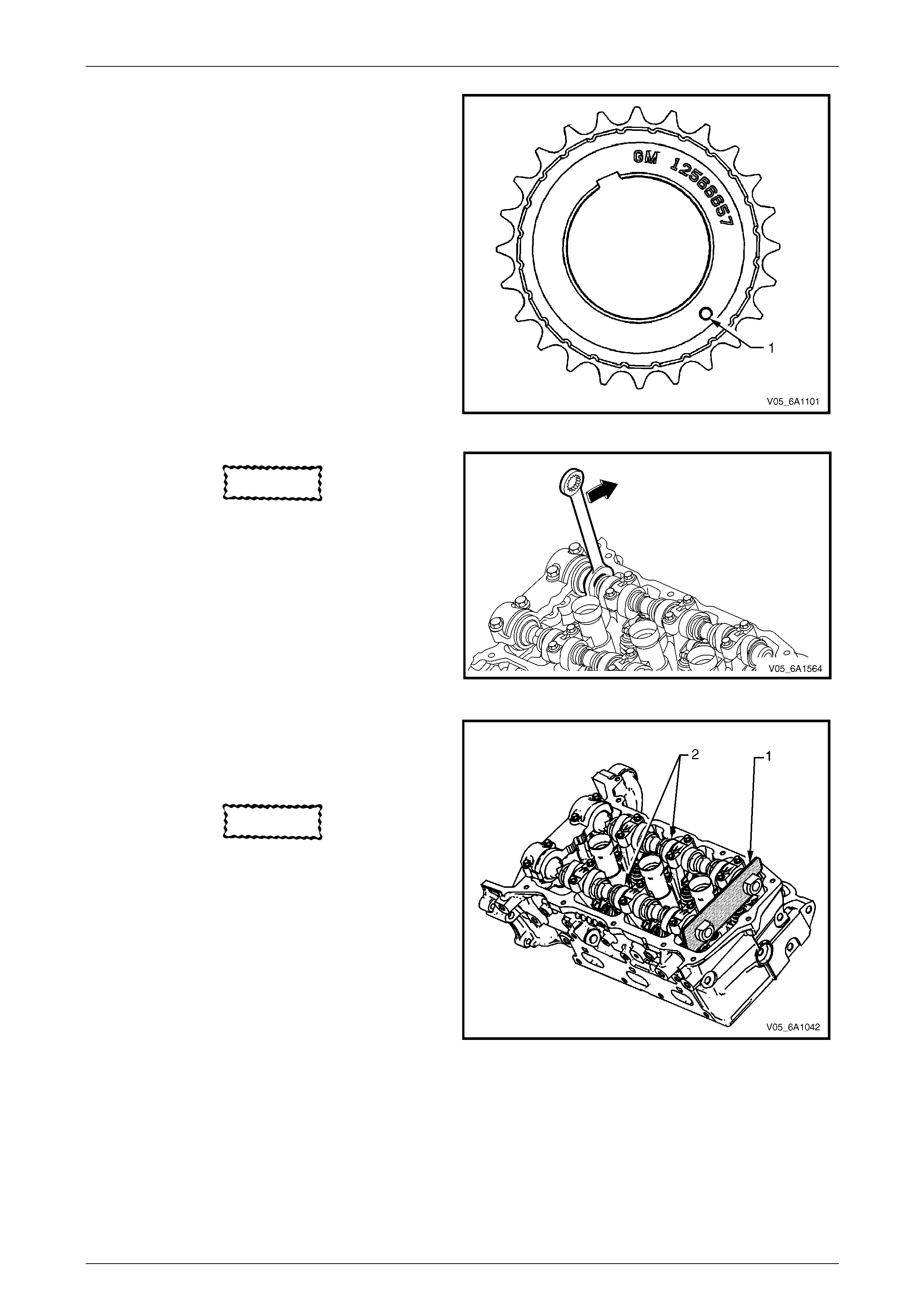
Engine Mechanical – V6 Page 6A1–133
Page 6A1–133
NOTE
Ensure that the crankshaft sprocket is installed
with the timing mark (1) visible.
Figure 6A1 – 152
CAUTION
In order to install Tool No. EN 46105 onto th e
camshafts, rotate the camshafts in an anti-
clockwise direction. There should be no
need to rotate the camshaft more than 45
degrees.
Figure 6A1 – 153
3 Install Tool No. EN 46105-1 (1) onto the rear of the
left-hand cylinder head camshafts (2), and Tool No.
EN 46105-2 onto the rear of the right-hand cylinder
head camshafts.
CAUTION
All camshafts must be locked in p l ace before
installation of any timing chains.
4 Ensure that Tool No. EN 46105 is fully seated onto
the camshafts.
Figure 6A1 – 154
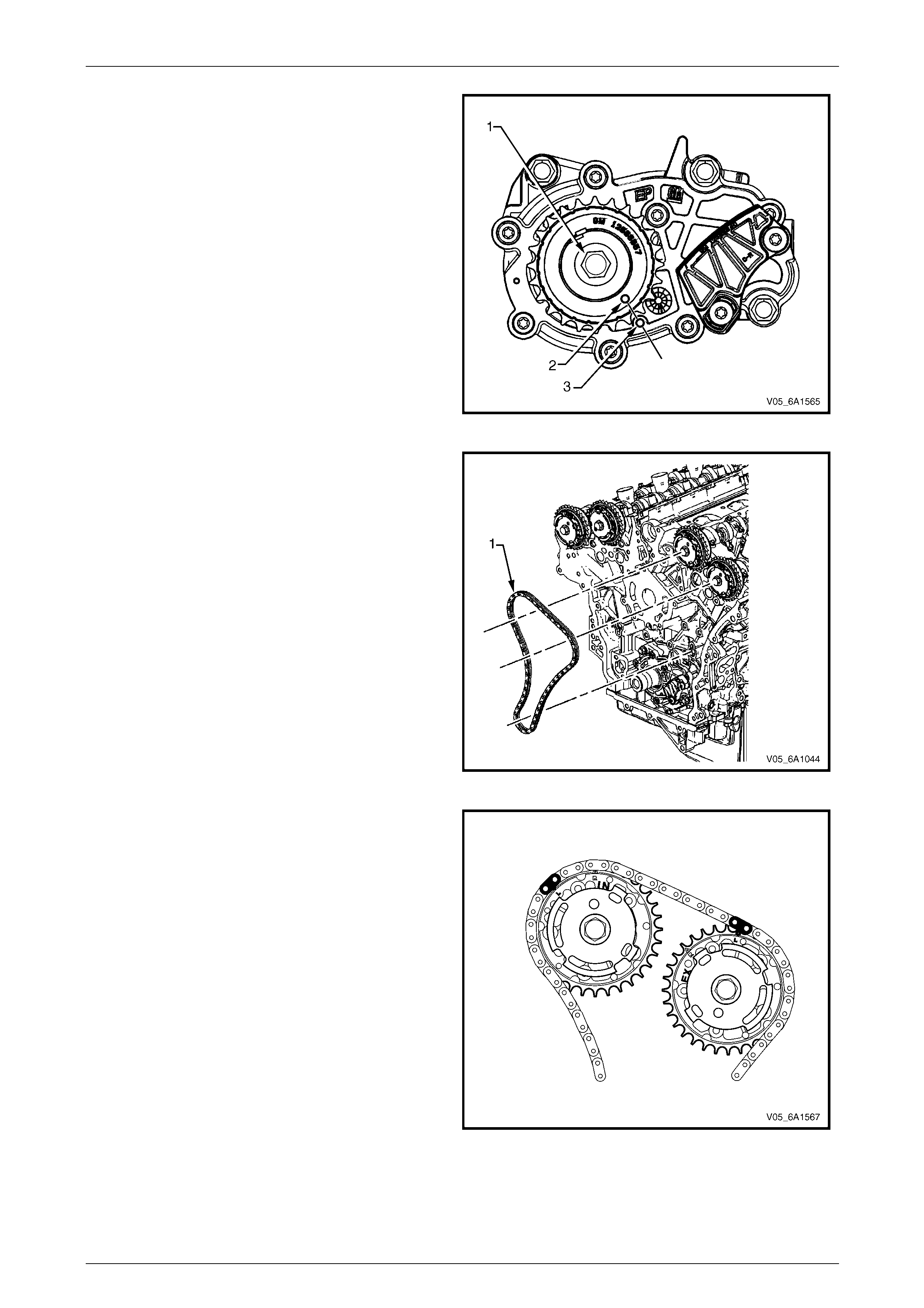
Engine Mechanical – V6 Page 6A1–134
Page 6A1–134
5 Using Tool No. EN46111 (1), rotate the crankshaft in
a clockwise direction until the cranksh aft sprocket
timing mark (2) is aligned with the indexing mark (3)
on the oil pump housing.
Figure 6A1 – 155
6 Install the left-hand secondary timing cha in (1)
aligning the chain in the following manner:
Figure 6A1 – 156
a Wrap the secondary timing chain around both
left-hand actuator drive sprockets.
b Ensure there are two bright lin ks located on top
of each of the camshaft actuator sprockets.
Figure 6A1 – 157
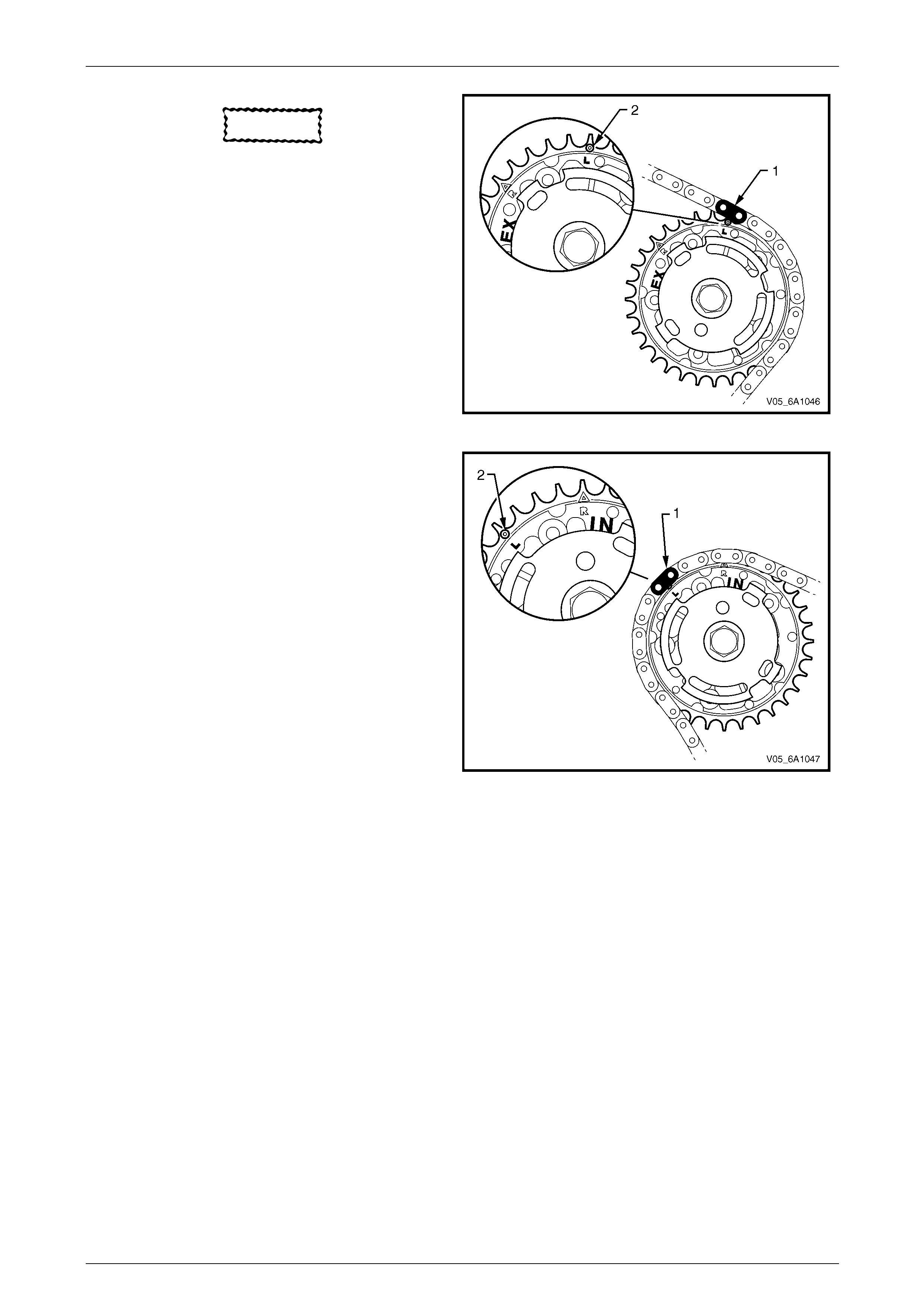
Engine Mechanical – V6 Page 6A1–135
Page 6A1–135
CAUTION
When aligning the left-hand secondary
timing chain to the camshaft actuator
sprockets, ensure the circular timing marks
on the sprocket are u sed, NOT the triangular
mark.
c Align the bright plated timing chain link (1) with
the left-hand exhaust camshaft position actuator
sprocket alignment circle mark (2).
Figure 6A1 – 158
d Align the bright plated timing chain link (1) with
the intake camshaft position actuator sprocket
alignment circle mark (2).
Figure 6A1 – 159
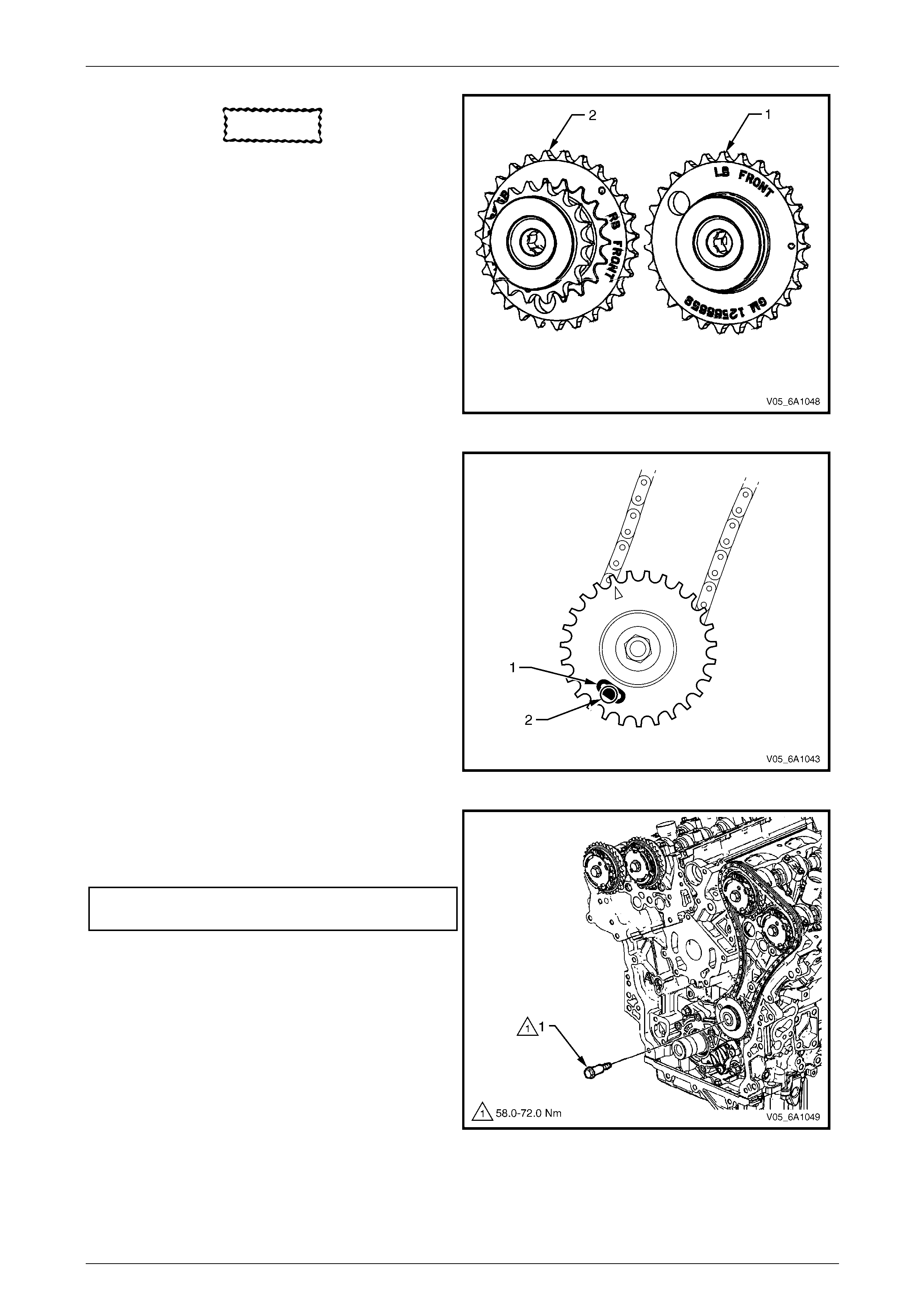
Engine Mechanical – V6 Page 6A1–136
Page 6A1–136
CAUTION
The left-hand camshaft intermediate
driveshaft sprocket (1) is marked with the
letters LB and ‘FRONT’, and the right-hand
sprocket (2) is marked with the letters RB
and 'FRONT' Ensure the correct sprocket is
used and the 'FRONT' text is facing fo rwards
when installed.
7 Ensure the left-hand camshaft intermediate driveshaft
sprocket is selected and orientated correctly.
Figure 6A1 – 160
8 Place the left-hand secondary timing chain around the
left-hand camshaft intermediate driveshaft inner
sprocket, with the bright plated timing chain link (1)
aligned with the access hole (2) in the outer sprocket.
Figure 6A1 – 161
9 Install the left-hand camshaft intermediate driveshaft
sprocket to the cylinder block.
10 Install the driveshaft sprocket bolt (1) and tighten to
the correct torque specification.
Camshaft intermediate driveshaft sprocket
attaching bolt torque specification...........58.0 – 72.0 Nm
Figure 6A1 – 162
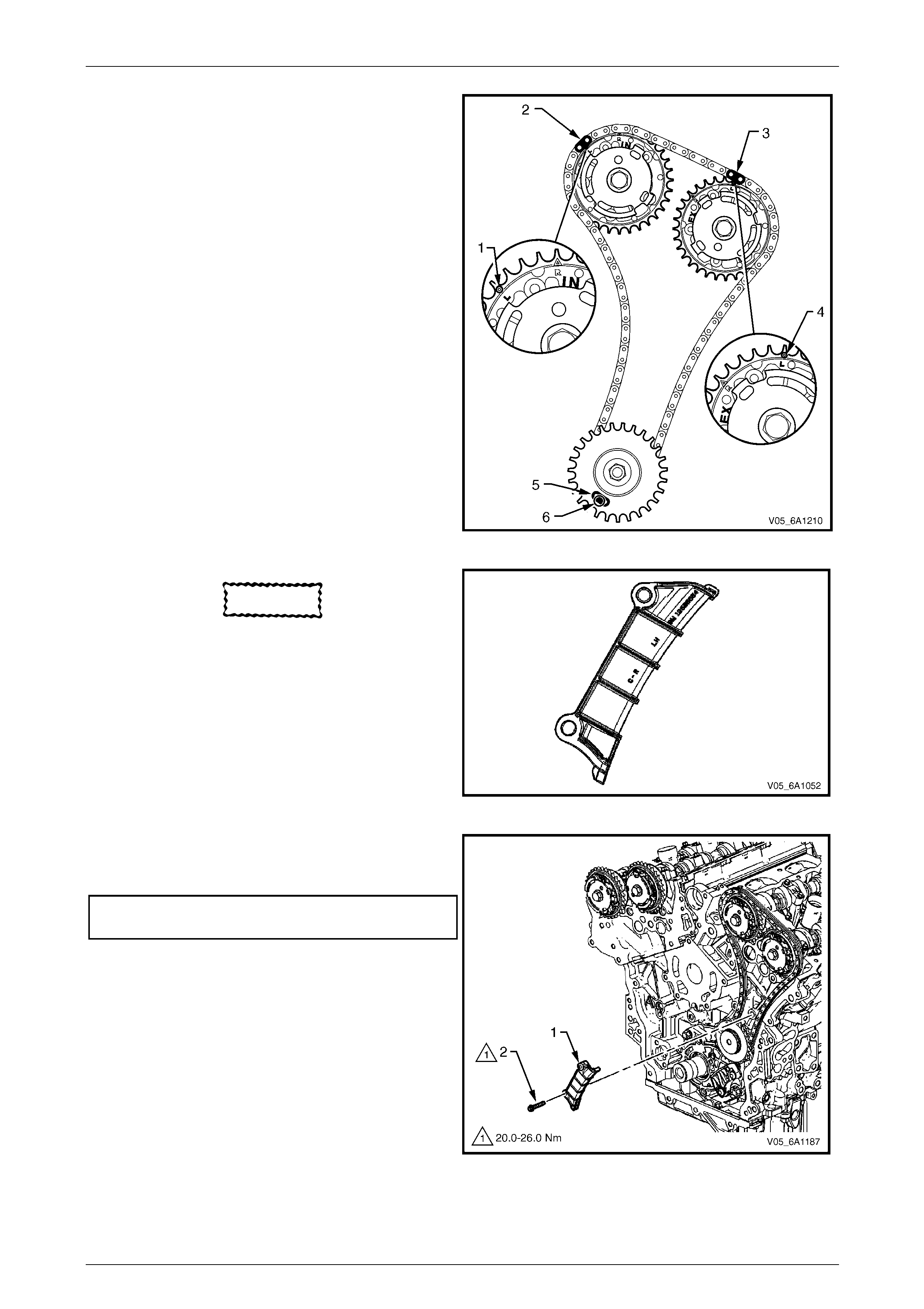
Engine Mechanical – V6 Page 6A1–137
Page 6A1–137
11 Verify the left-hand secondary timing chain timing
mark alignments (1 to 6)
Figure 6A1 – 163
CAUTION
The left-hand secondary timing chain guide
is marked with the letters LH. Ensure the
correct shoe is used when installing to the
left-hand side in this procedure and that the
letters ‘LH” are facing the fr o nt of the vehicle
when installed.
12 Ensure the left-hand secondary timin g chain guide is
selected and orientated correctly.
Figure 6A1 – 164
13 Install the left-hand secondary timing chain guide (1).
14 Install the secondary timing chain guide bolts (2) and
tighten to the correct torque specification.
Secondary timing cha in guide
attaching bolt torque specification...........20.0 – 26.0 Nm
Figure 6A1 – 165
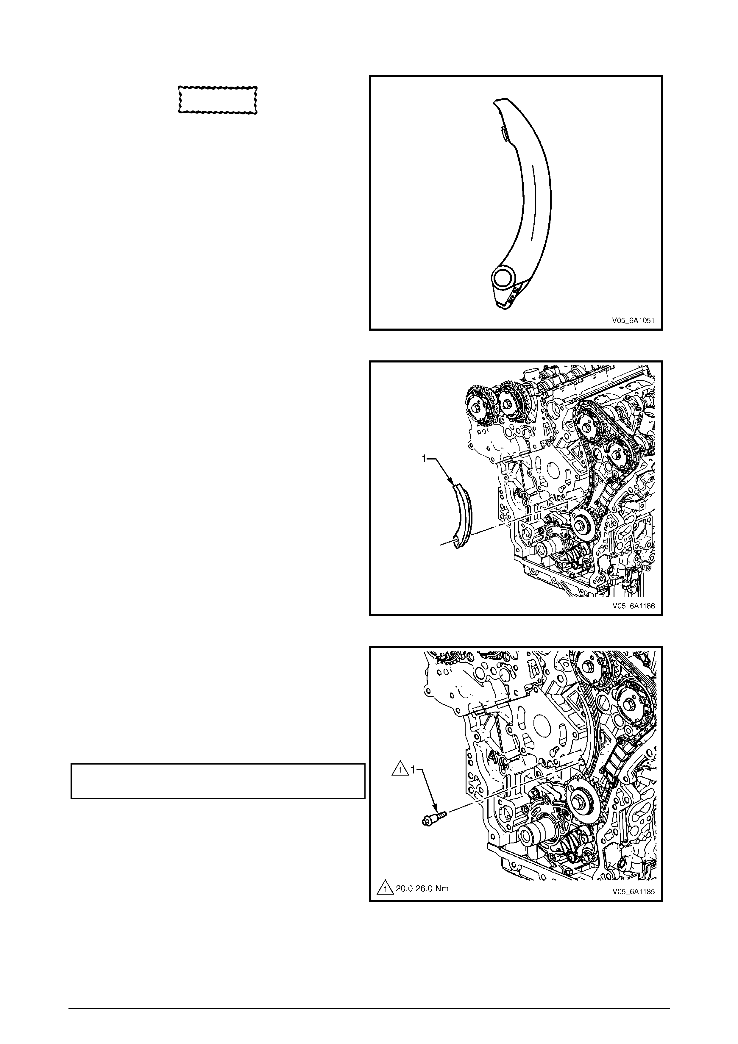
Engine Mechanical – V6 Page 6A1–138
Page 6A1–138
CAUTION
The left-hand secondary timing chain shoe
(2) is marked w ith the letters LH on the back
face of the timing chain shoe. Ensure the
correct shoe is used when installing to the
left-hand side.
15 Ensure the left-hand secondary timin g chain shoe is
selected and orientated correctly.
Figure 6A1 – 166
16 Install the left-hand secondary timing chain shoe (1).
Figure 6A1 – 167
17 Install the left-hand secondary timing chain shoe
bolt (1) and tighten to the correct torque specification.
NOTE
Ensure secondary timing chain shoe is clear of
the left-hand secondary timing chain tensioner
mounting pad, before tightening the attaching
bolt.
Secondary timing chain shoe attaching
bolt torque specification..........................20.0 – 26.0 Nm
Figure 6A1 – 168
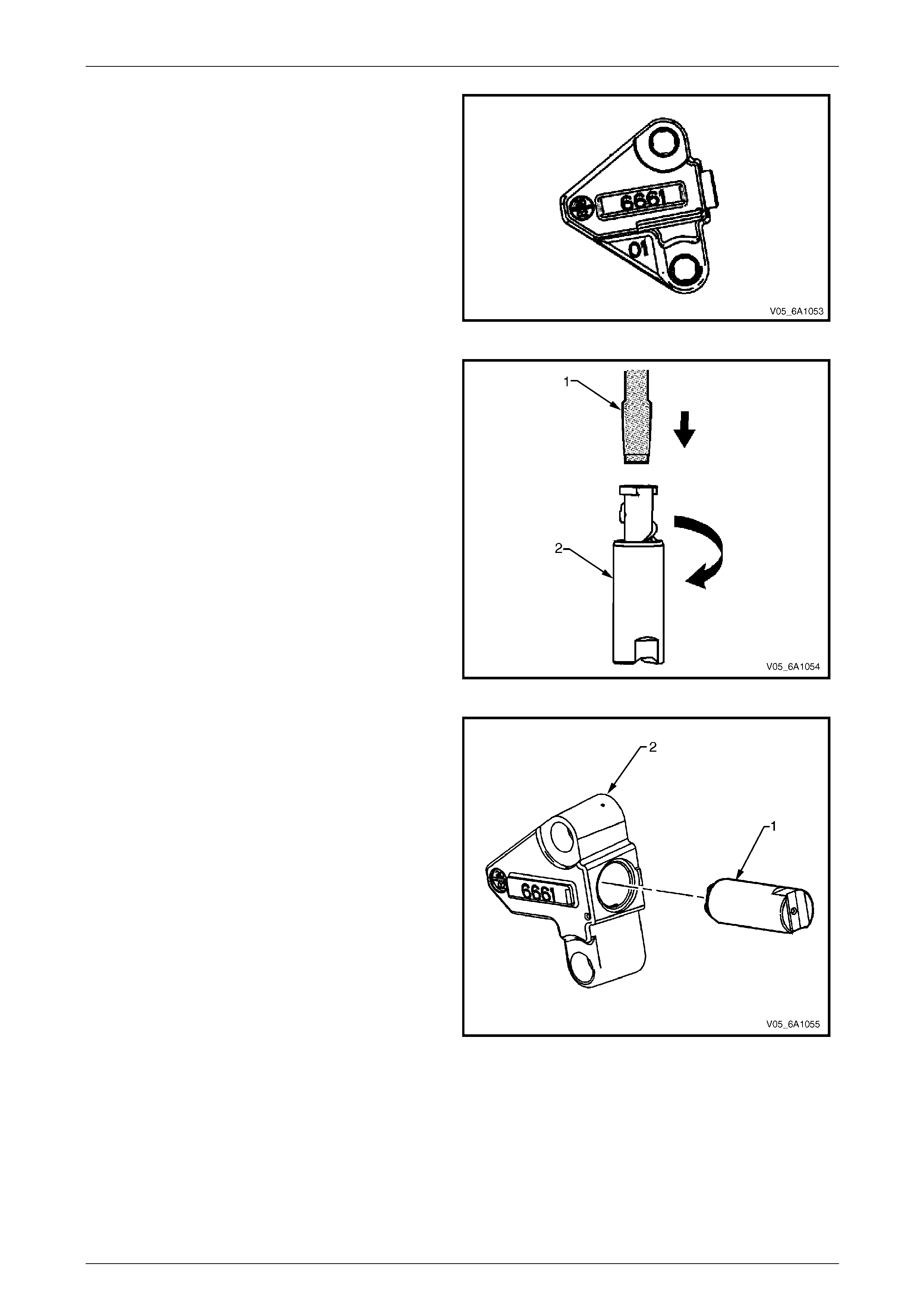
Engine Mechanical – V6 Page 6A1–139
Page 6A1–139
18 Ensure the left-hand secondary timin g cha in tensioner
is selected and orientated correctly.
Figure 6A1 – 169
19 Reset the left-hand secondary timing cha in tensioner.
NOTE
To reset the tensioner, use a suitably sized flat
blade screwdriver (1) or Tool No. J 45027 (4 ) to
wind the plunger in a clockwise direction, into
the tensioner shaft (2).
Figure 6A1 – 170
20 Install the tensioner shaft (1) into the left-han d
secondary timing chain tensioner body (2).
Figure 6A1 – 171
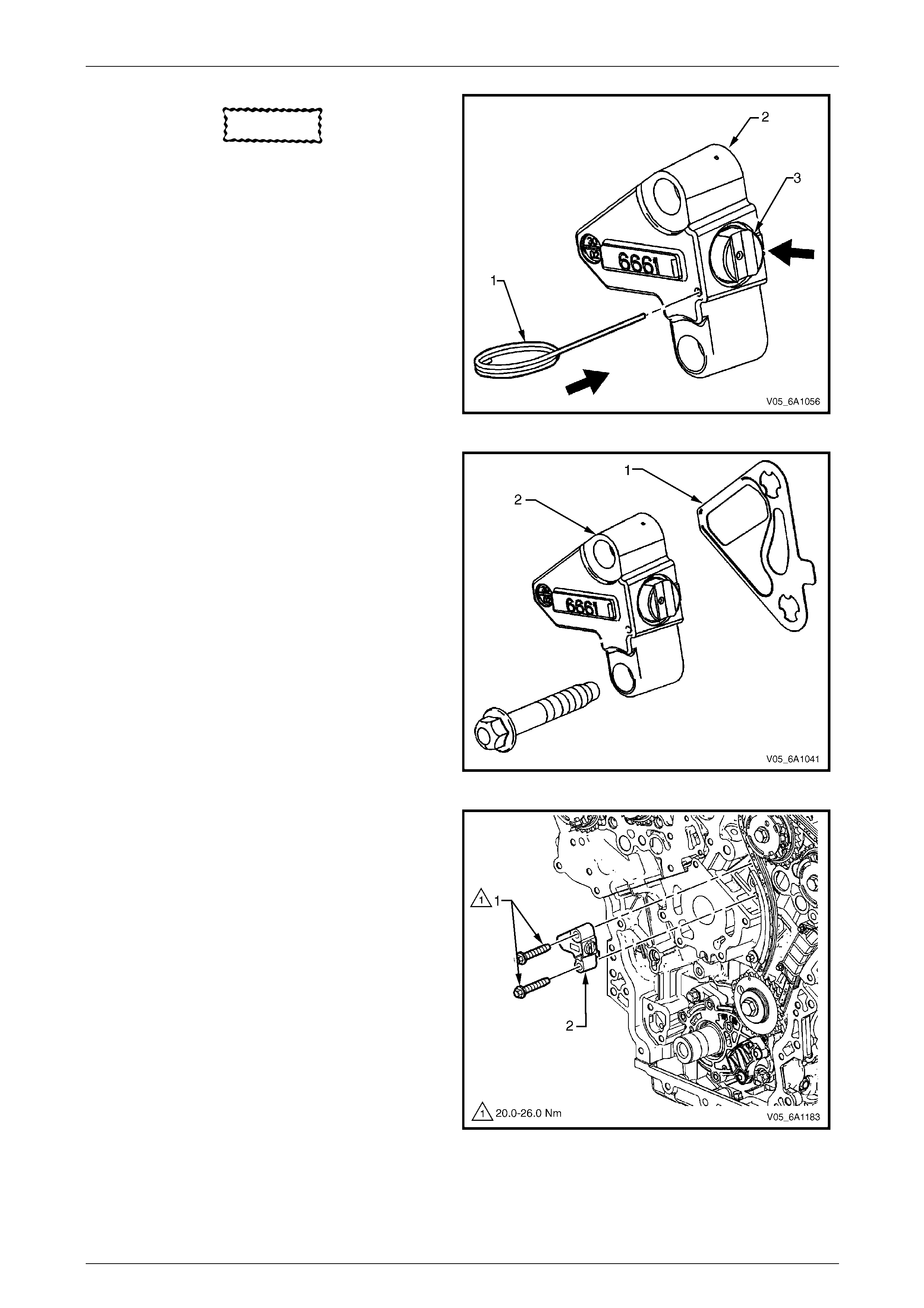
Engine Mechanical – V6 Page 6A1–140
Page 6A1–140
CAUTION
If Tool No. EN 46112 (1) is not inserted into
the tensioner body (2), the tensioner
shaft (3) will remain in the locked position
and no tension will be placed on the timing
chain, this will cause d ama ge to the engine.
21 Compress the tensioner shaft into the body and lock
the left-hand secondary timing chain tensioner by
inserting Tool No. EN 46112 i nto the access hole in
the side of the tensioner body.
22 Slowly release pressure on th e left-hand secondary
timing chain tensioner. The tensioner should remain
compressed.
Figure 6A1 – 172
23 Install a new left-hand secondar y timing chain
tensioner gasket (1) to the tensioner (2).
24 Install the left-hand secondary timing chain tensioner
bolts through tensioner and gasket.
25 Ensure the left-hand secondary timin g cha in tensioner
mounting surface on the left-hand cylinder head does
not have any burrs or defects that would affect the
sealing of the new gasket.
Figure 6A1 – 173
26 Place the left-hand secondary timing chain tensioner
(2) into position and loosely install the bolts (1) to the
cylinder head.
Figure 6A1 – 174
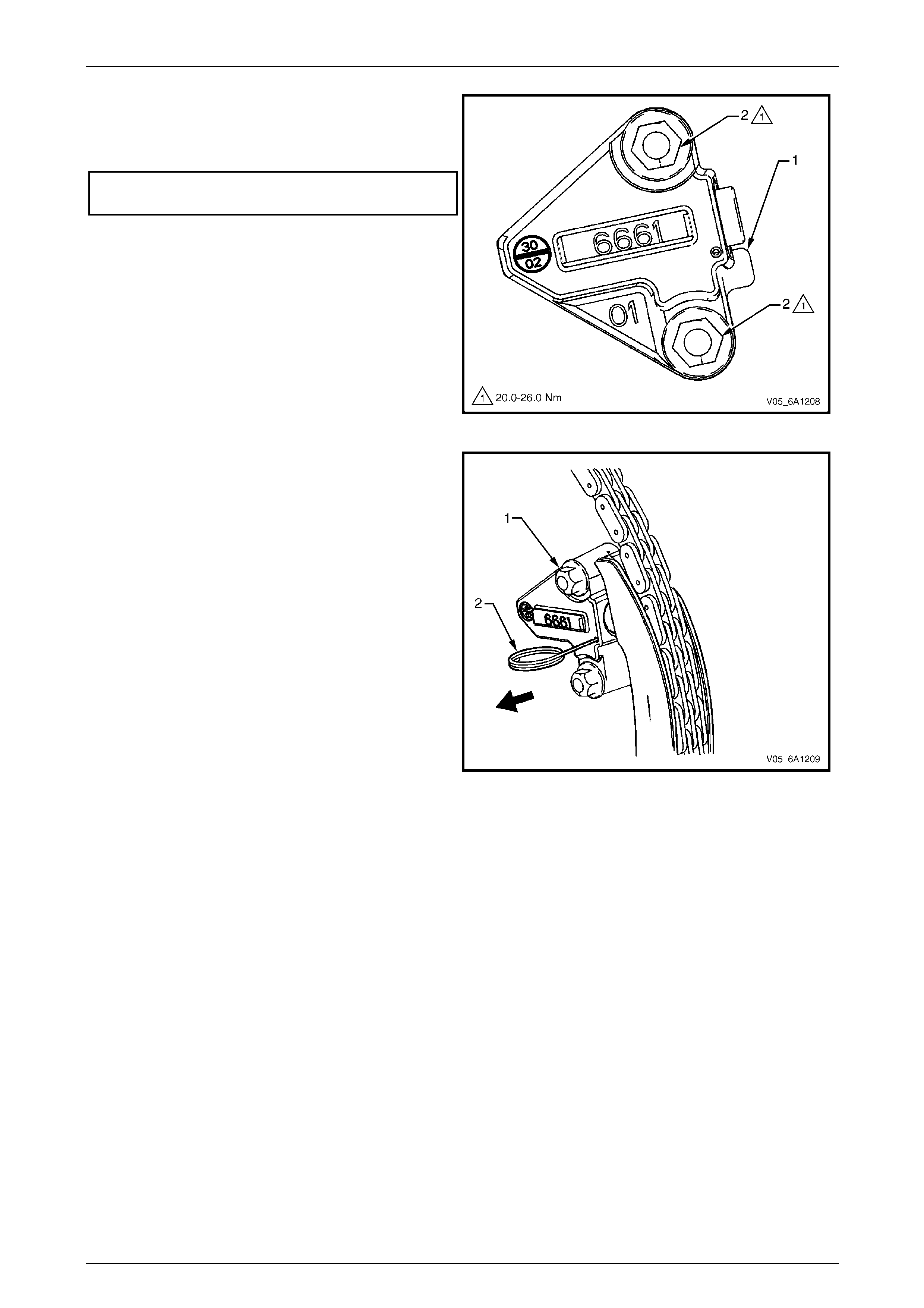
Engine Mechanical – V6 Page 6A1–141
Page 6A1–141
27 Verify the proper placement of the left-hand
secondary timing chain tensioner gasket tab (1).
28 Tighten the left-hand secondary timing chain
tensioner bolts (2) to the correct torque specification.
Secondary timing cha in tensioner
attaching bolt torque specification...........20.0 – 26.0 Nm
Figure 6A1 – 175
29 Release the left-hand secondary timing chain
tensioner (1) by pulling out Tools No. EN 46112 (2)
and unlocking the tensioner shaft.
Figure 6A1 – 176
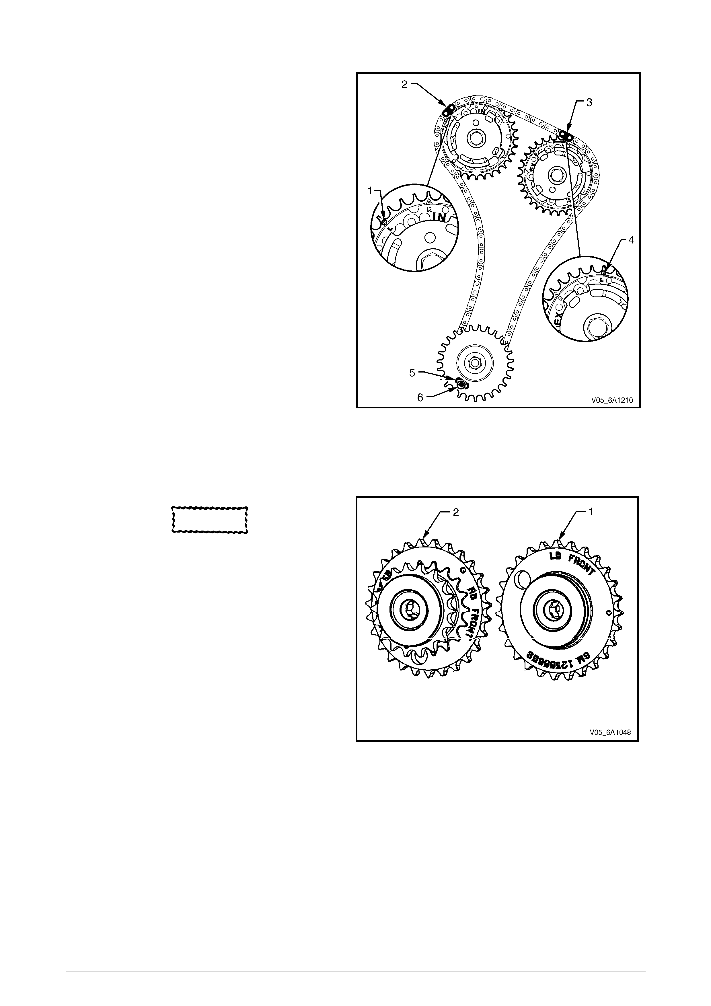
Engine Mechanical – V6 Page 6A1–142
Page 6A1–142
30 Verify the left-hand secondary timing chain timing
mark alignments (1 to 6).
Figure 6A1 – 177
Primary Timing Chain Components
1 If previously removed, install the left-hand secondary timing chain components,
refer to Left-hand Secondary Timing Chain Components in this Section.
CAUTION
The right-hand camshaft intermediate
driveshaft sprocket (2) is marked with the
letters RB and ‘FRONT’, and the left-hand
sprocket (1) is marked with the letters LB
and 'FRONT' Ensure the correct sprocket is
used and the FRONT text is facing forwards
when installed.
2 Ensure the right-hand camshaft intermediate
driveshaft sprocket is selected and orie ntated
correctly.
Figure 6A1 – 178
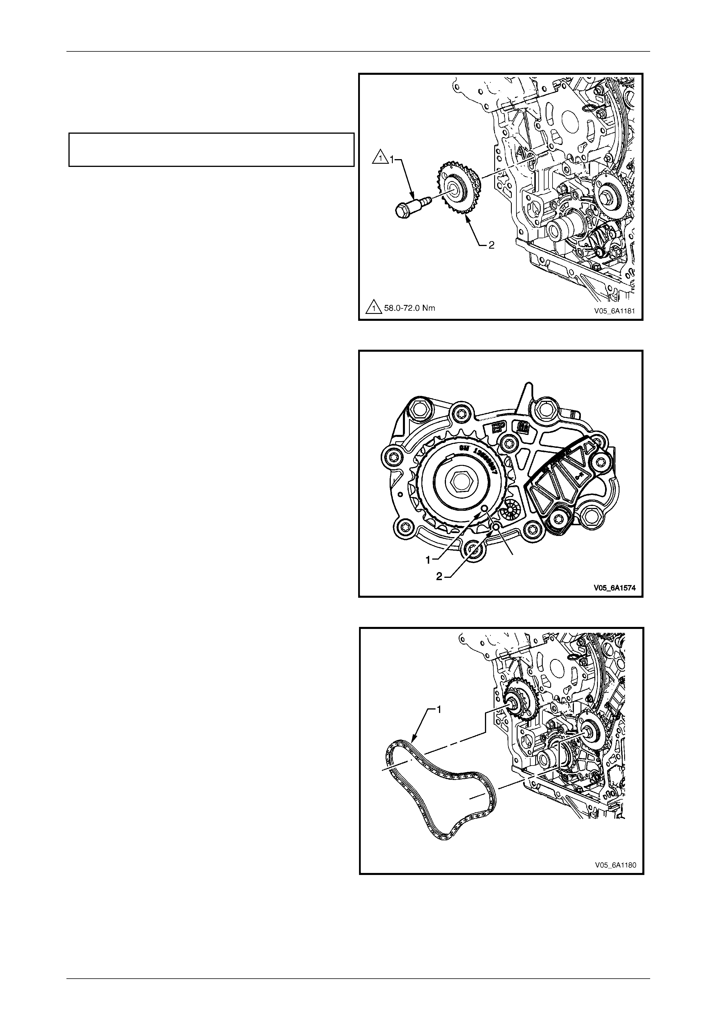
Engine Mechanical – V6 Page 6A1–143
Page 6A1–143
3 Install the right-hand camshaft intermediate driveshaft
sprocket (2).
4 Install the driveshaft sprocket bolt (1) and tighten to
the correct torque specification.
Camshaft intermediate driveshaft sprocket
attaching bolt torque specification...........58.0 – 72.0 Nm
Figure 6A1 – 179
5 Ensure that the crankshaft sprocket timing mark (1) is
aligned with the indexing mark (2) on the oil pump
housing.
Figure 6A1 – 180
6 Install the primary timing chain (1).
Figure 6A1 – 181
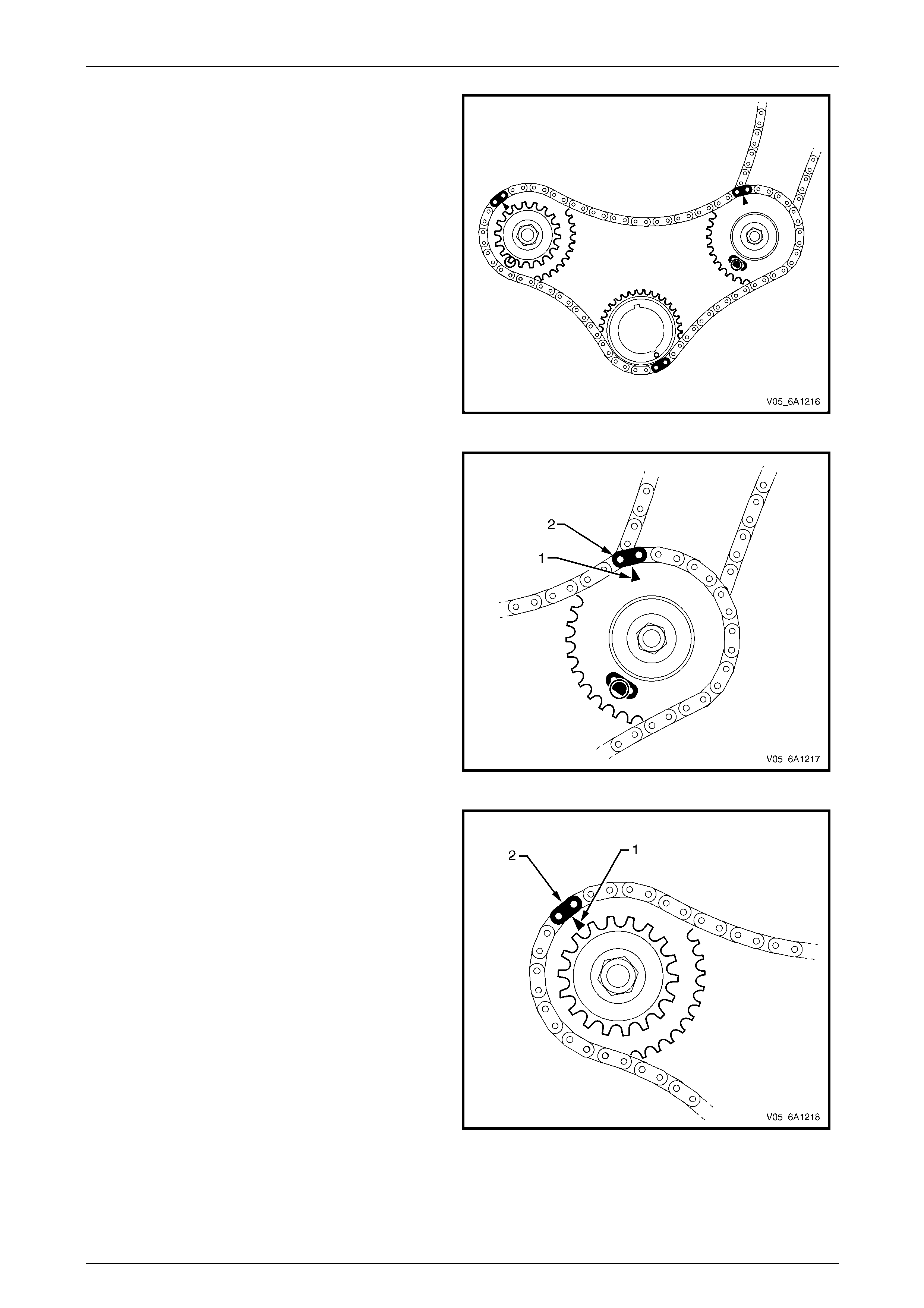
Engine Mechanical – V6 Page 6A1–144
Page 6A1–144
7 Wrap the primary timing chain around the large
sprockets of each camshaft intermediate driveshaft
sprocket and the crankshaft sprocket aligning the
brightened chain links as follows:
Figure 6A1 – 182
a The left-hand camshaft intermediate driveshaft
sprocket timing mark (1) will align with a bright
plated primary timing chain link (2).
Figure 6A1 – 183
b The right-hand camshaft intermediate driveshaft
sprocket timing mark (1) will align with a bright
plated primary timing chain link (2).
Figure 6A1 – 184
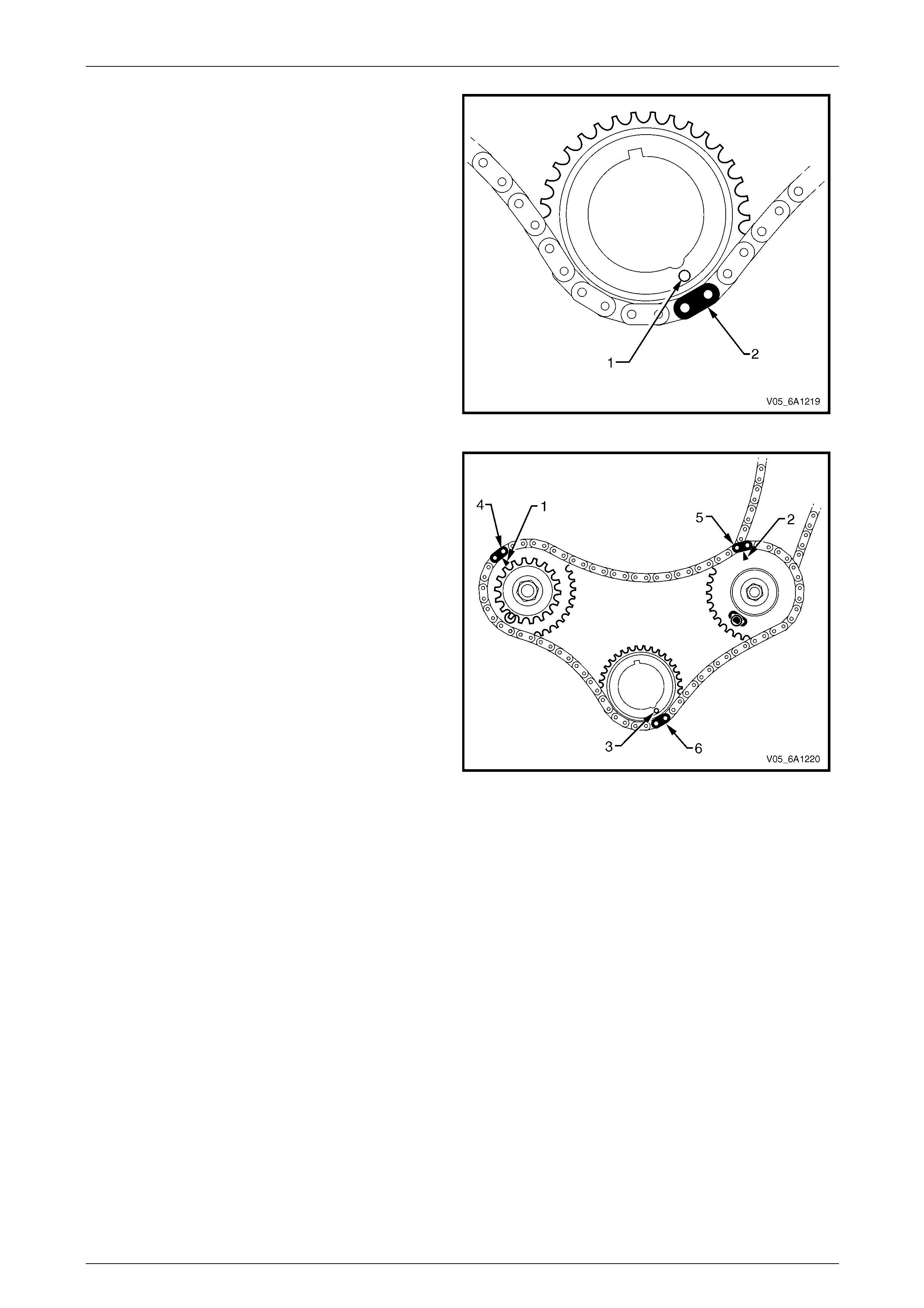
Engine Mechanical – V6 Page 6A1–145
Page 6A1–145
c The crankshaft sprocket timing mark (1) will
align with a bright plated timing chai n link (2).
Figure 6A1 – 185
8 Ensure all the timing marks (1, 2 and 3) are properly
aligned with the bright plated timing chain links (4, 5
and 6).
Figure 6A1 – 186
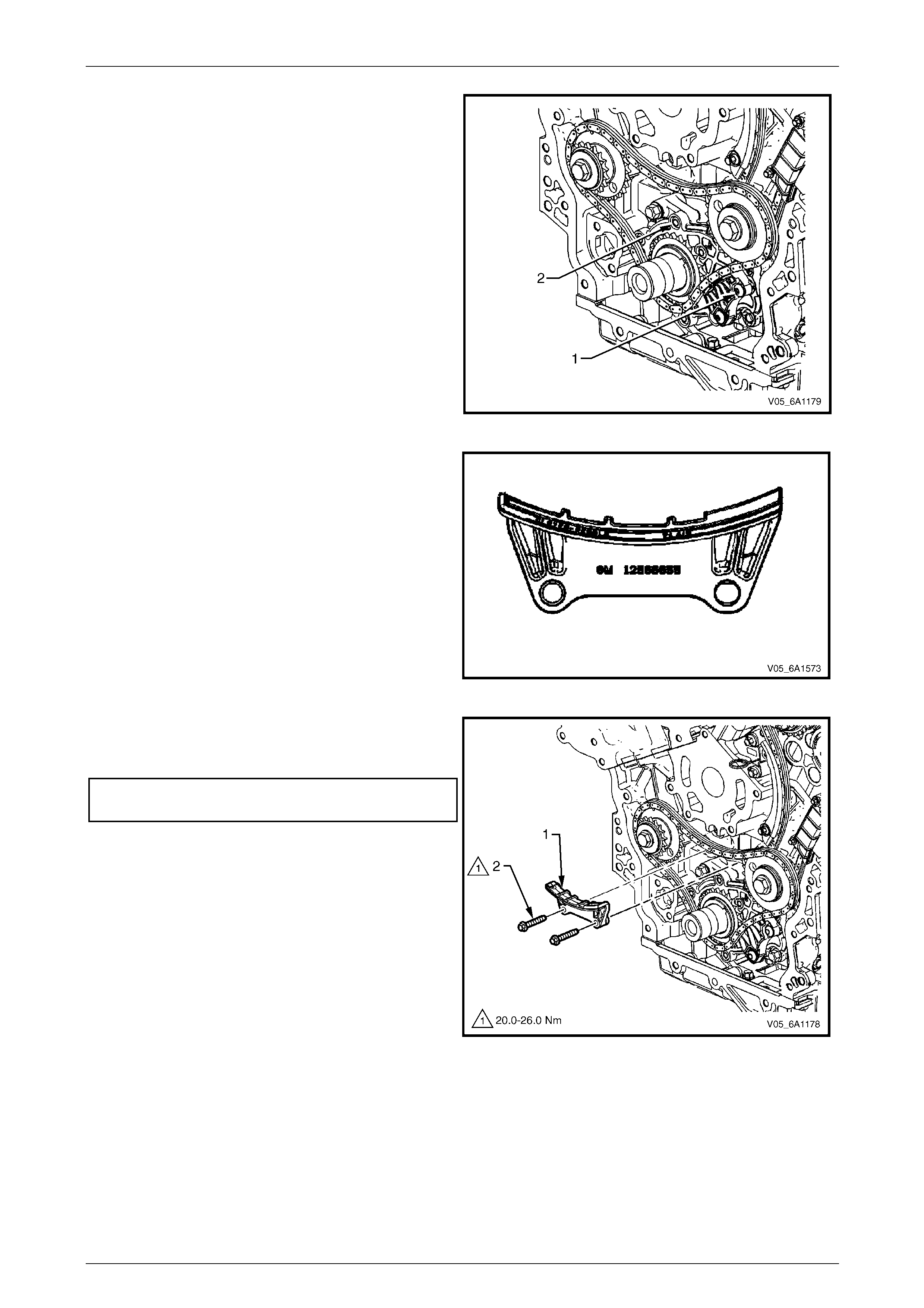
Engine Mechanical – V6 Page 6A1–146
Page 6A1–146
NOTE
Do not remove the primary timing chain lower
guide (1). The primary timing chain lower guide
is not serviced separately. If the primary timing
chain lower guide must be replaced, the oil
pump assembly (2) must be replaced.
Figure 6A1 – 187
9 Ensure the primary timing chain upper guide is
selected and orientated correctly.
Figure 6A1 – 188
10 Install the primary timing chain upp er guide (1).
11 Install the primary timing chain upper guide bolts (2)
and tighten to the correct torque specification.
Primary timing chain upper guide
attaching bolt torque specification...........20.0 – 26.0 Nm
Figure 6A1 – 189
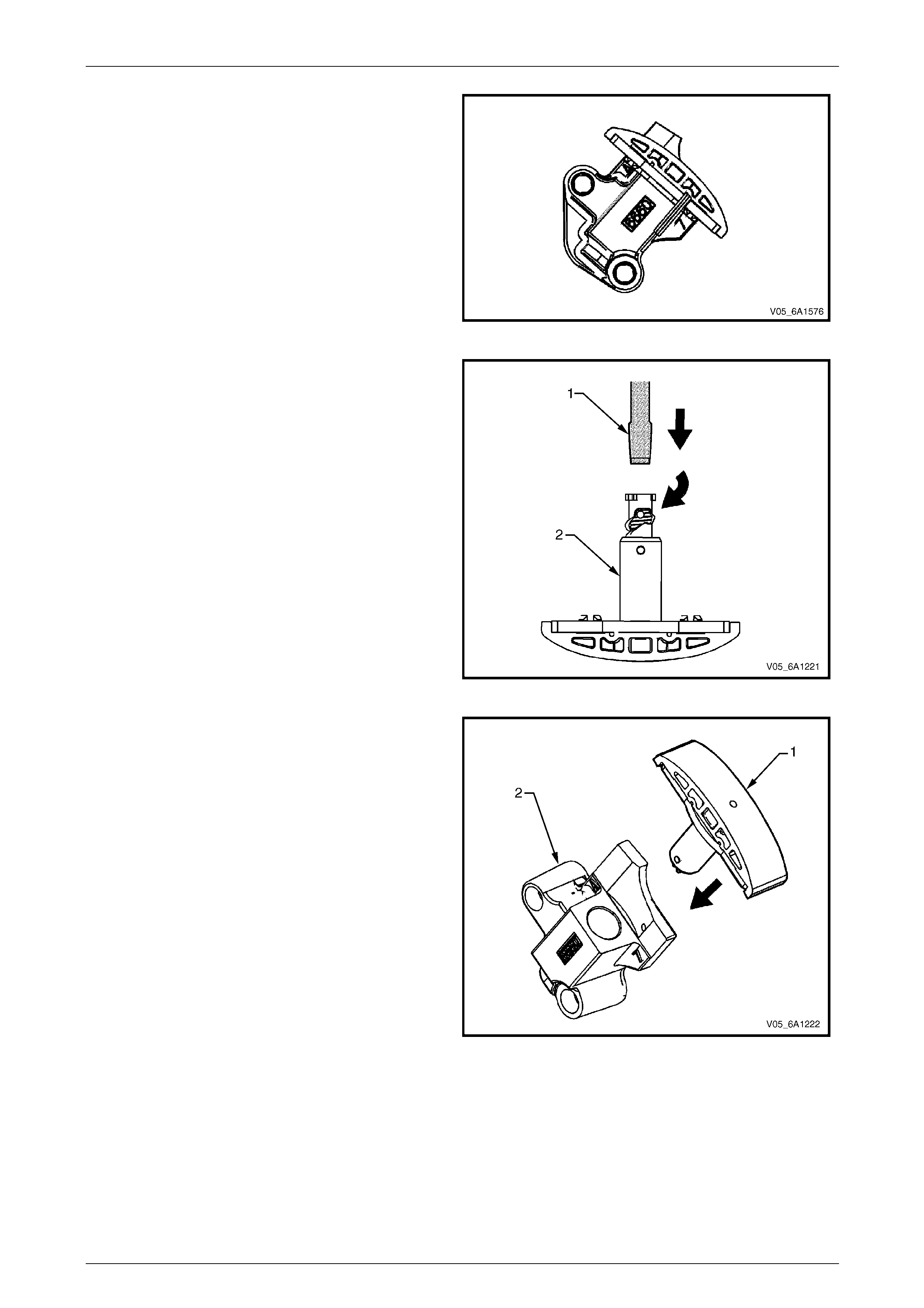
Engine Mechanical – V6 Page 6A1–147
Page 6A1–147
12 Ensure that the primary timing chain tensioner is
being installed.
Figure 6A1 – 190
13 Reset the primary timing chain tensioner.
NOTE
To reset the tensioner, use a suitably sized flat
blade screwdriver (1) or Tool No. J 45027 (4 ) to
wind the plunger in a clockwise direction, into
the tensioner shaft (2).
Figure 6A1 – 191
14 Install the tensioner shoe assembly (1) into the
primary timing chain tensioner body (2).
Figure 6A1 – 192
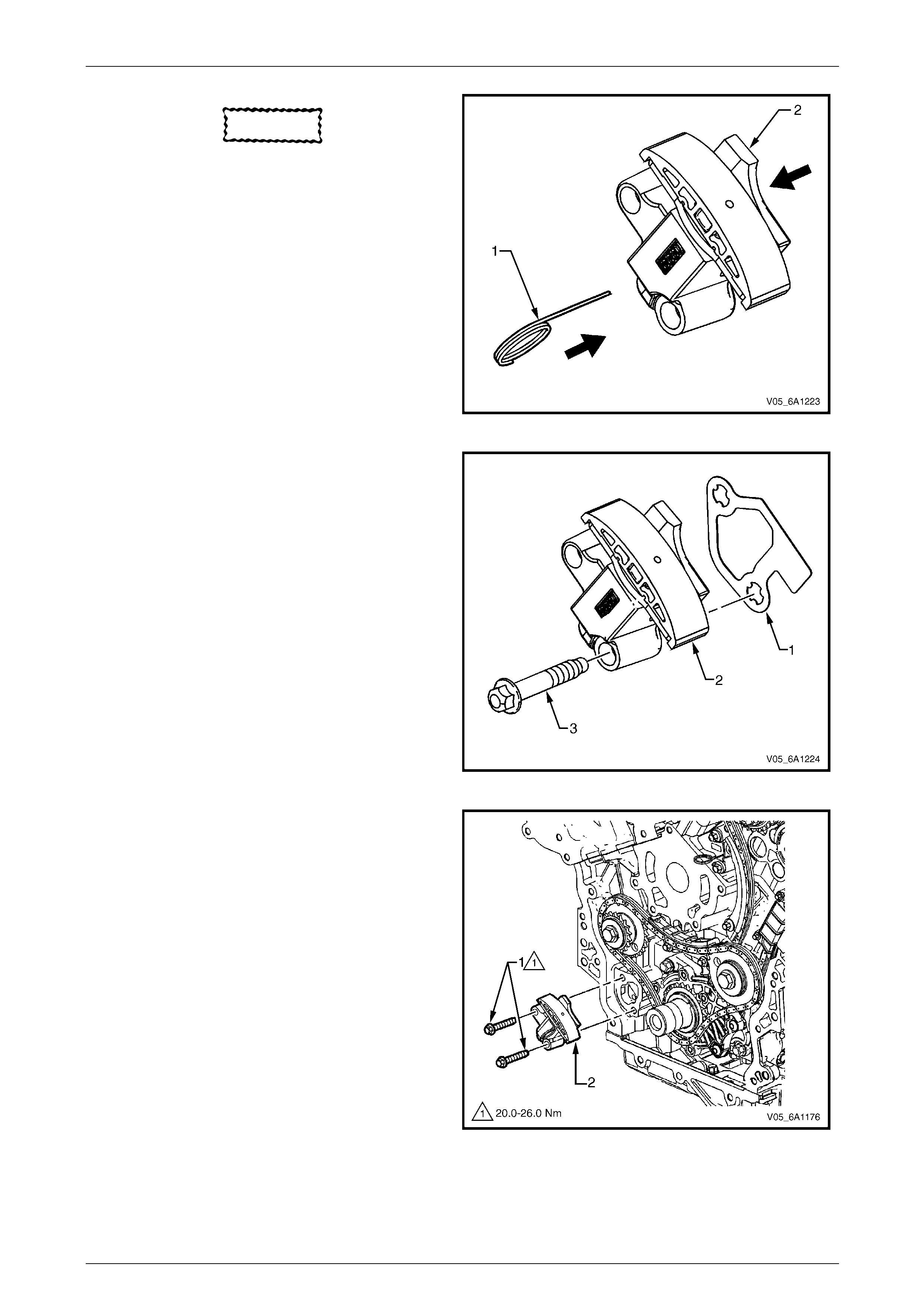
Engine Mechanical – V6 Page 6A1–148
Page 6A1–148
CAUTION
If Tool No. EN 46112 (1) is not inserted into
the tensioner body, the plunger will remain
in the locked position and no ten sion w ill be
placed on th e timing chain.
15 Compress the shoe assembly into the bod y (2) and
lock the primary timing chain tensioner by inserting
Tool No. EN 46112 into the access hole in the side of
the body.
16 Slowly release pressure on th e primary timing chain
tensioner. The primary timing chain tensioner should
remain compressed.
Figure 6A1 – 193
17 Install a new primary timing ch ain tensioner gasket (1)
to the tensioner (2).
18 Install the primary timing chain tensioner bolts (3)
through tensioner and gask et.
19 Ensure the primary timing chain tensioner mounting
surface on the engine block does not have any burrs
or defects that would affect the sealing of the new
gasket.
Figure 6A1 – 194
20 Place the primary timing chai n tensioner (2) into
position and loosely i nstall th e bolts (1) to the engine
block.
Figure 6A1 – 195
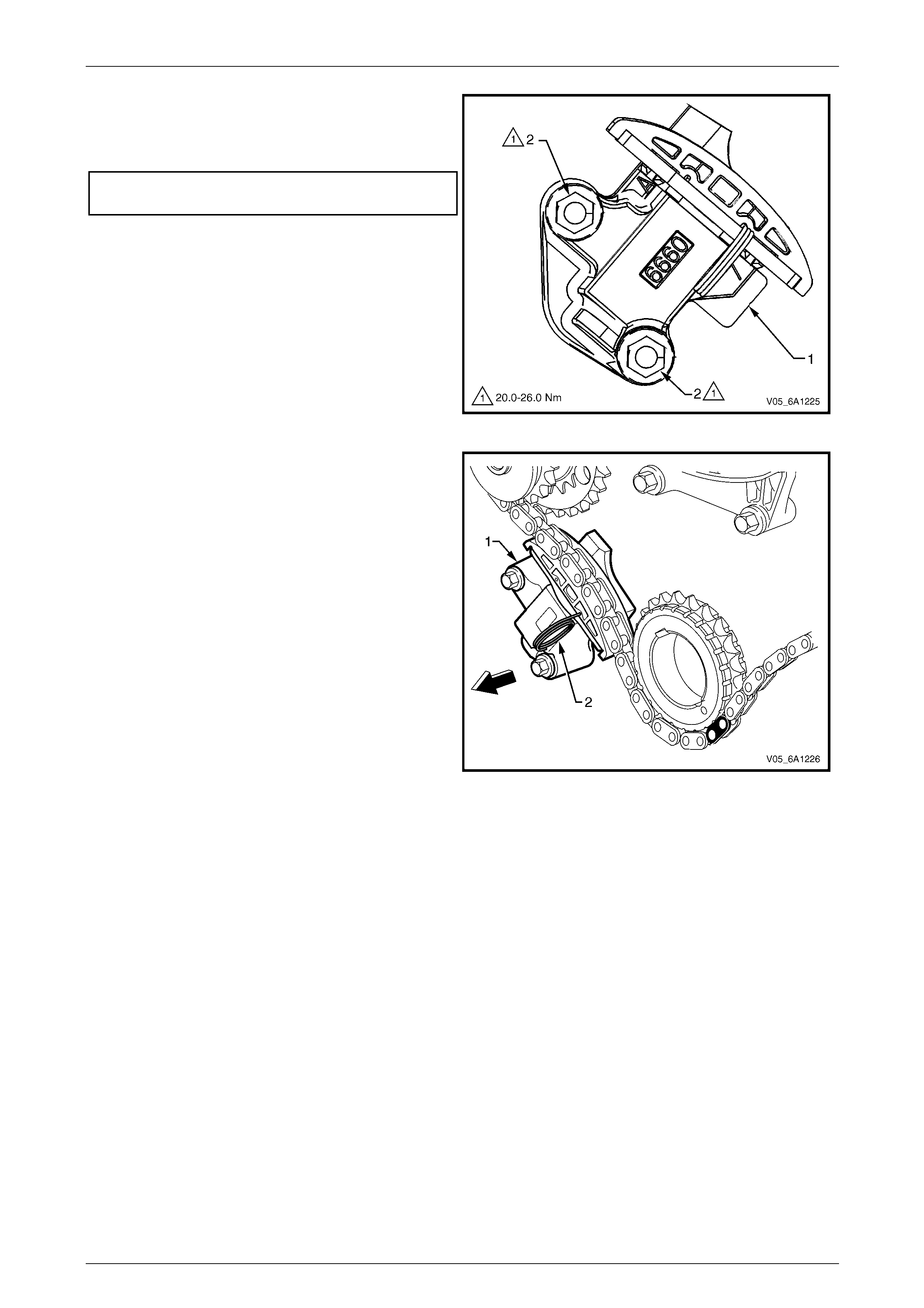
Engine Mechanical – V6 Page 6A1–149
Page 6A1–149
21 Verify the proper placement of the primary timing
chain tensioner gasket tab (1).
22 Tighten the primary timing chain tensioner bolts (2) to
the correct torque specification.
Primary timing chain tensioner
attaching bolt torque specification...........20.0 – 26.0 Nm
Figure 6A1 – 196
23 Release the primary timing chain tensioner (1) by
pulling out Tool No. EN 46112 (2) and unlocking the
tensioner shaft.
Figure 6A1 – 197
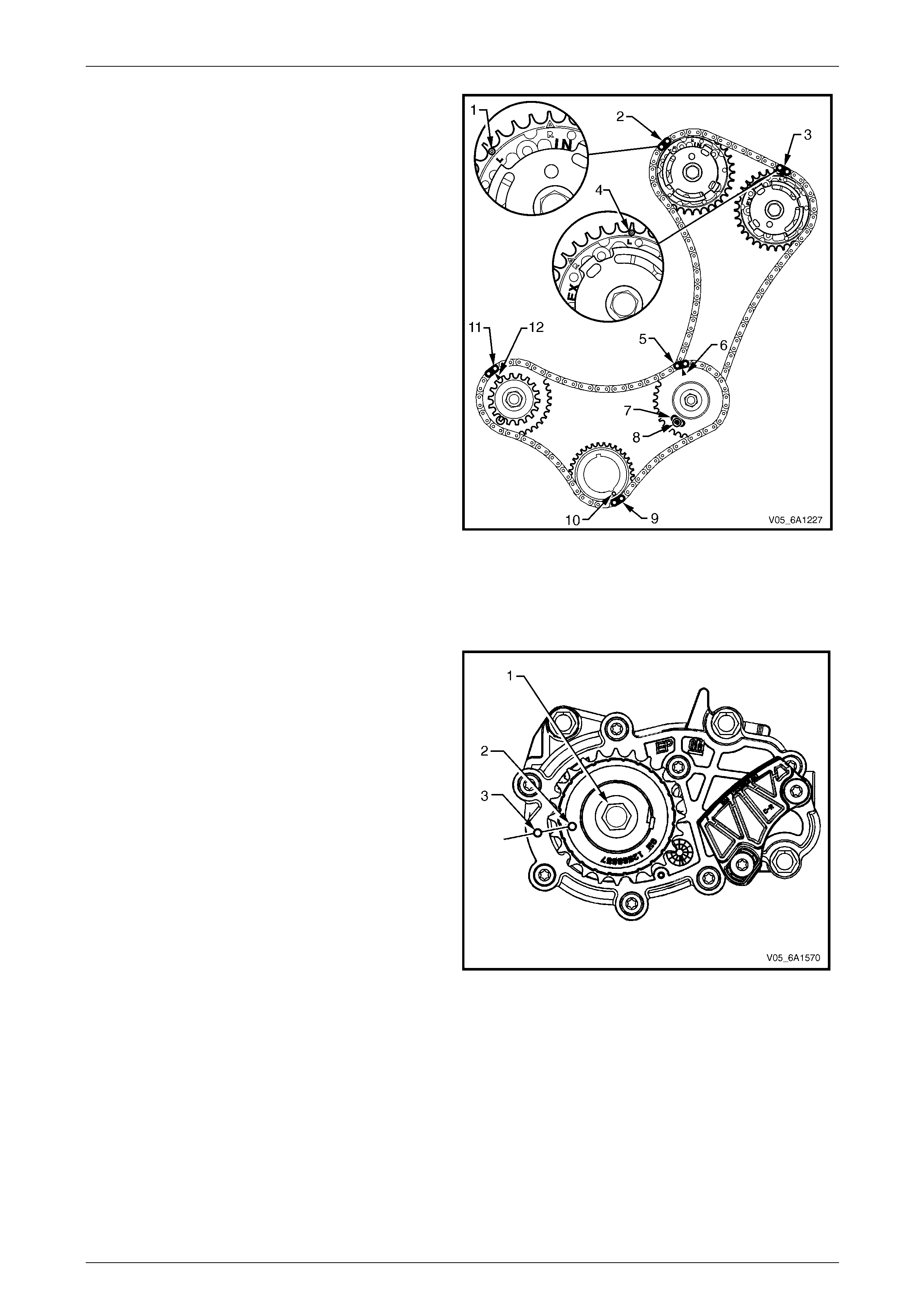
Engine Mechanical – V6 Page 6A1–150
Page 6A1–150
24 Verify the primary and left-hand secondary timing
chain timing mark alignments (1 to 12).
Figure 6A1 – 198
25 Remove Tool No. EN 46105 from the left-hand and right-hand cylinder head camshafts.
Right-hand Secondary Timing Chain Components
1 Install the primary timing chain compone nts, refer to Primary Timing Chain Components in this Section.
2 Using Tool No. EN46111 (1), rotate the crankshaft in
a clockwise direction until the cranksh aft sprocket
timing mark (2) is aligned with the indexing mark (3)
on the oil pump housing.
Figure 6A1 – 199
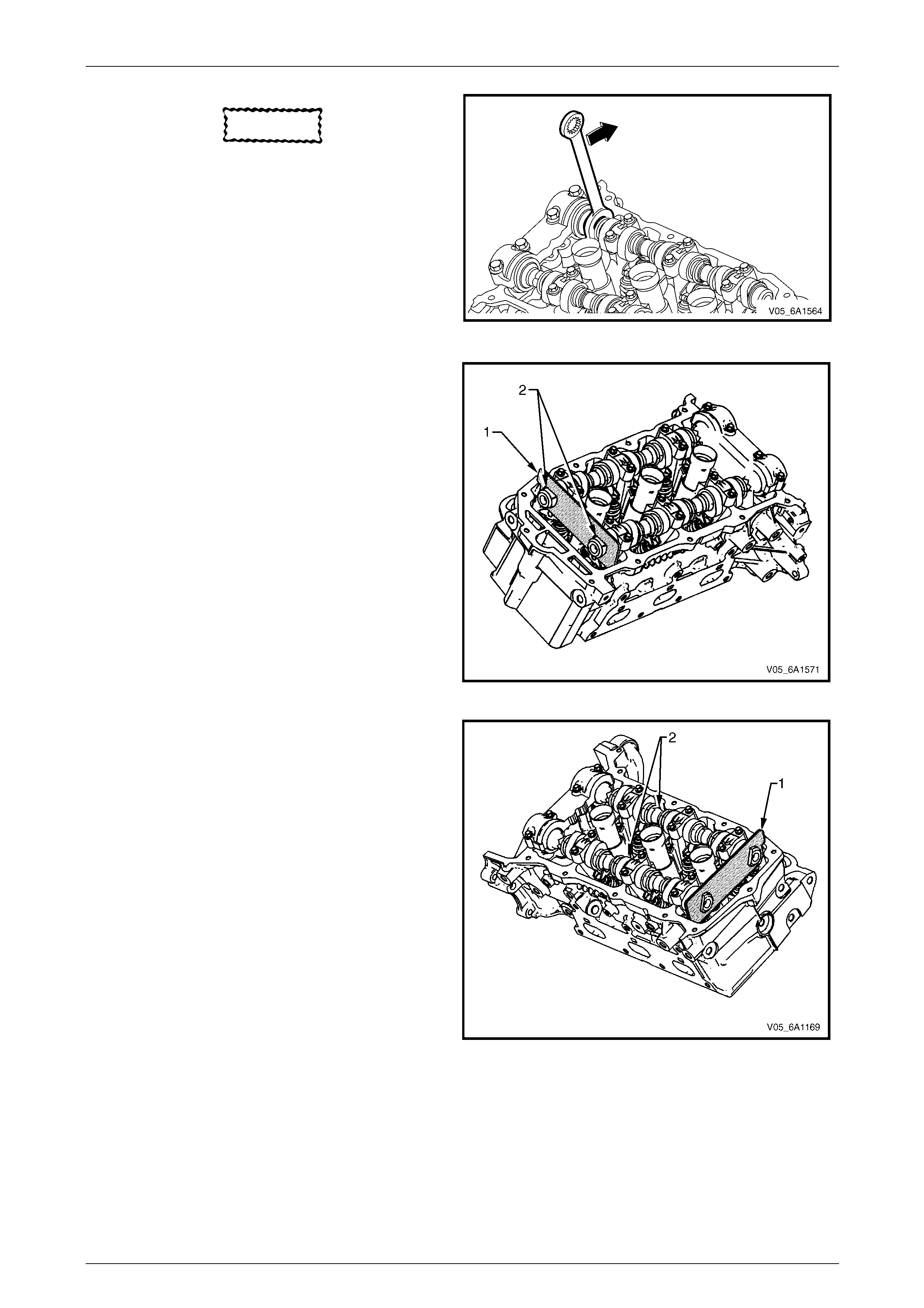
Engine Mechanical – V6 Page 6A1–151
Page 6A1–151
CAUTION
In order to install Tool No. EN 46105 onto th e
camshafts, rotate the camshafts. There
should be no need to rotate the camshaft
more than 45 degrees.
Figure 6A1 – 200
3 Install Tool No. EN 46105-1 (1) onto the rear of the
right-hand cylinder head cams hafts (2).
Figure 6A1 – 201
4 Install Tool No. EN 46105-2 (1) onto the rear of the
left-hand cylinder head camshafts (2).
Figure 6A1 – 202
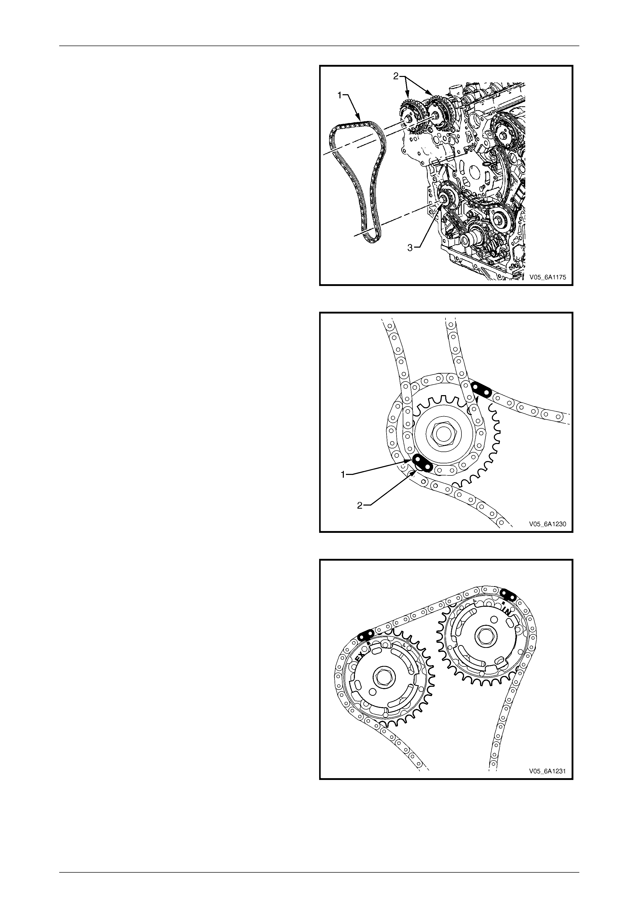
Engine Mechanical – V6 Page 6A1–152
Page 6A1–152
5 Install the right-hand secondary timing chain (1) onto
the camshaft actuators (2) and the right hand
camshaft intermediate driveshaft sprocket (3) ali gning
the chain in the following manner:
Figure 6A1 – 203
a Place the secondary timing chain around the
right-hand camshaft intermediate drives haft
outer sprocket, aligning the bright plated timin g
chain link (1) with the alignme nt access hole (2)
in the inner sprocket.
Figure 6A1 – 204
b Wrap the secondary timing chain around both
right-hand actuator drive sprockets.
Figure 6A1 – 205
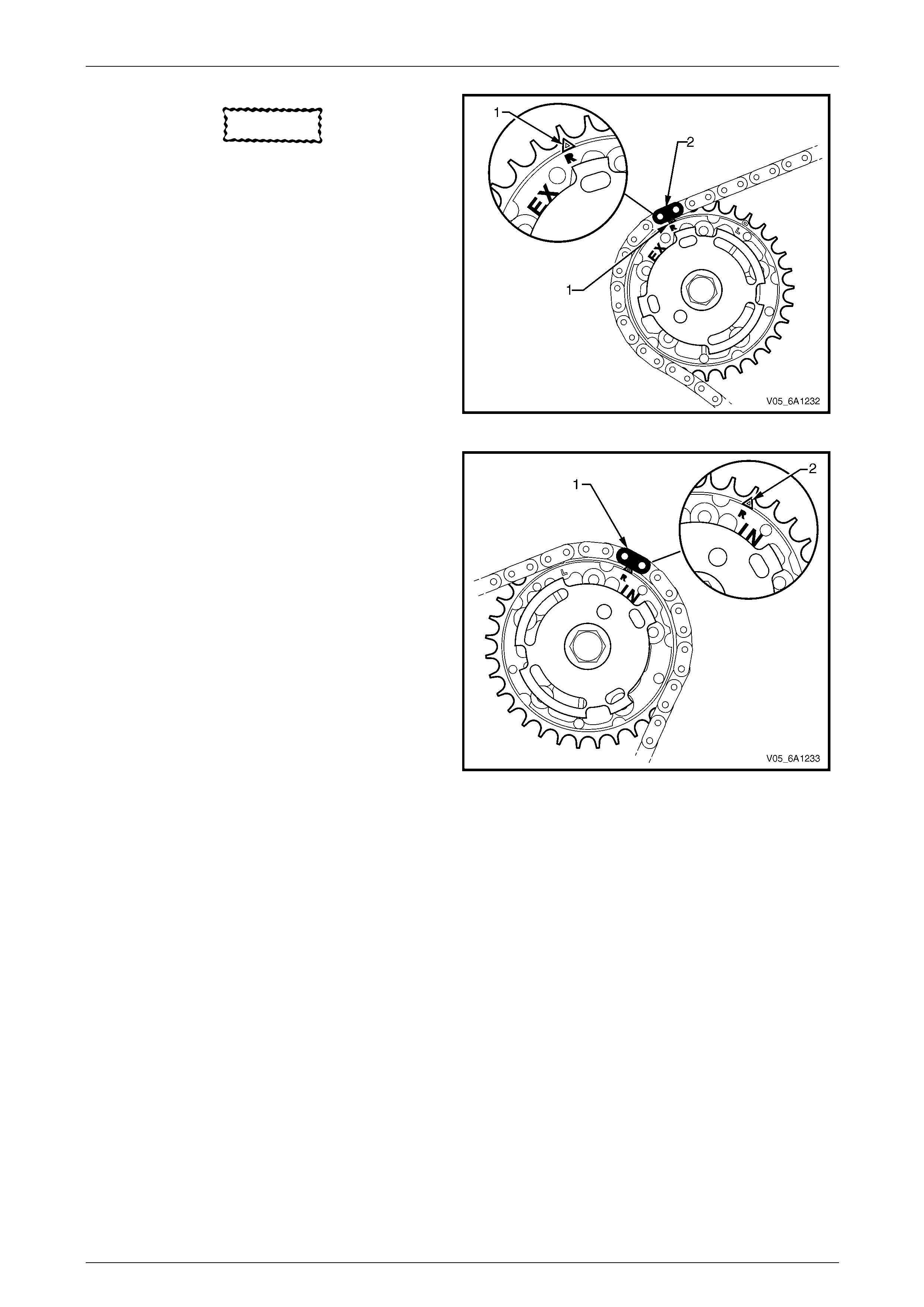
Engine Mechanical – V6 Page 6A1–153
Page 6A1–153
CAUTION
Ensure that when aligning the right-hand
secondary timing chain to the right-hand
camshaft actuator sprockets, that the
triangular timing marks (1) on the sprocket
are used, NOT the circular mark.
c Align the bright plated timing chain link (2) with
the exhaust actuator sprocket alignment triangle
mark.
Figure 6A1 – 206
d Align the bright plated timing chain link (1) with
the intake actuator sprocket alignment triangle
mark (2).
Figure 6A1 – 207
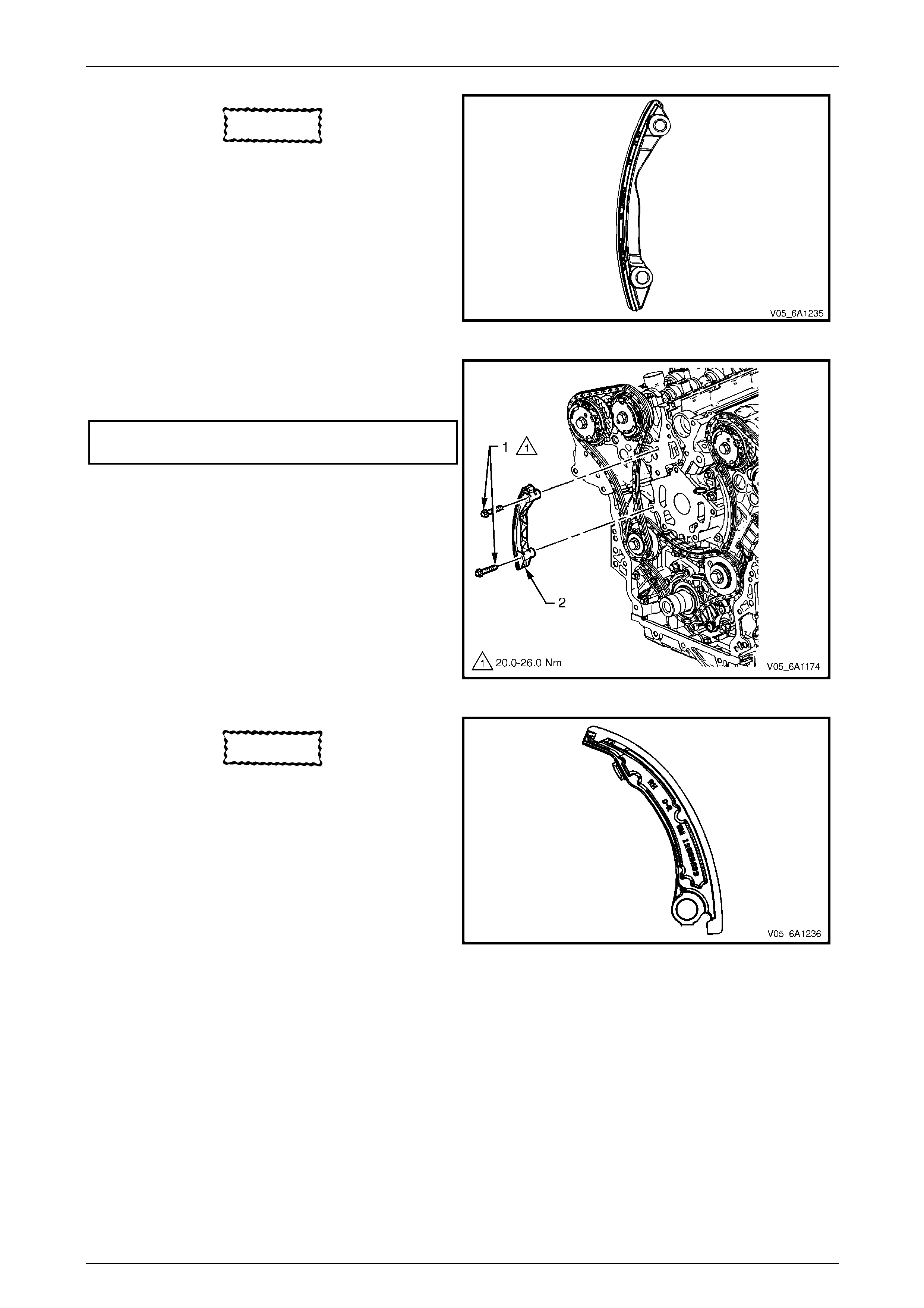
Engine Mechanical – V6 Page 6A1–154
Page 6A1–154
CAUTION
Ensure that the right-hand secondary timing
chain guide is used when installing to the
right-hand side in this procedure.
6 Ensure that the right-hand secondary timing chain
guide is selected and orientated correctly.
Figure 6A1 – 208
7 Position the chain guide (2).
8 Install the secondary timi ng chain guide bolts (1) and
tighten to the correct torque specification.
Secondary timing cha in guide
attaching bolt torque specification...........20.0 – 26.0 Nm
Figure 6A1 – 209
CAUTION
The right-hand secondary camshaft drive
shoe is marked with the letters ‘RH’. Ensure
that the right-hand drive shoe is used when
installing to the right-hand side in this
procedure and that the letters ‘RH” are
facing the front of the vehicle when installed.
9 Ensure the right-hand second ary timing chain shoe is
selected and orientated correctly.
Figure 6A1 – 210
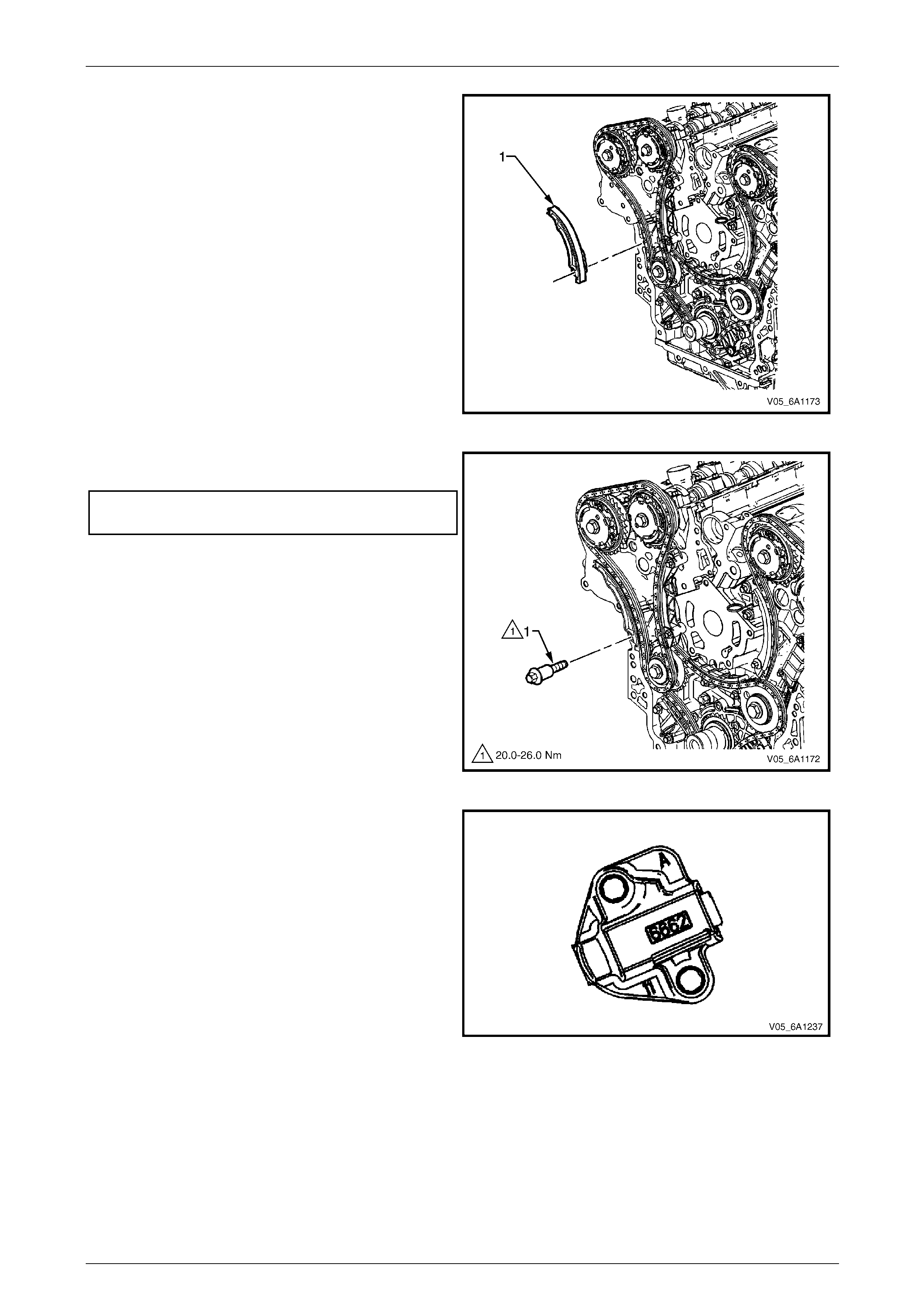
Engine Mechanical – V6 Page 6A1–155
Page 6A1–155
10 Position the right-hand secondar y timing cha in shoe
(1).
Figure 6A1 – 211
11 Install the secondary timi ng chain shoe bolt (1) and
tighten to the correct torque specification.
Secondary timing cha in shoe
attaching bolt torque specification...........20.0 – 26.0 Nm
Figure 6A1 – 212
12 Ensure the right-hand second ary timing chain
tensioner is selected and orientated correctl y.
Figure 6A1 – 213
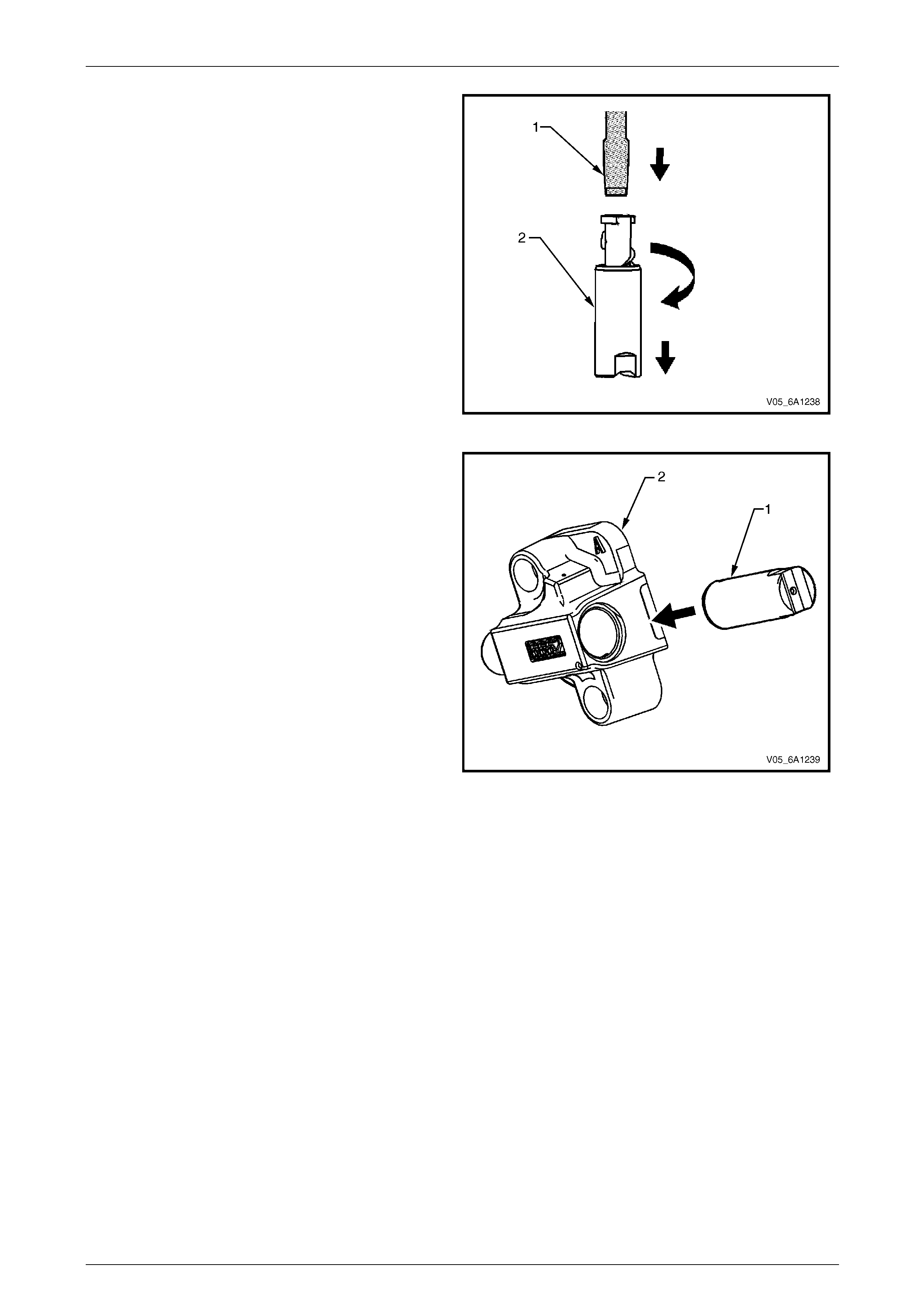
Engine Mechanical – V6 Page 6A1–156
Page 6A1–156
13 Reset the right-hand secondary timing chain
tensioner.
NOTE
To reset the tensioner, use a suitably sized flat
blade screwdriver (1) or Tool No. J 45027 to
wind the plunger in a clockwise direction, into
the tensioner shaft (2).
Figure 6A1 – 214
14 Install the tensioner shaft (1) into the right-hand
secondary timing chain tensioner body (2).
Figure 6A1 – 215
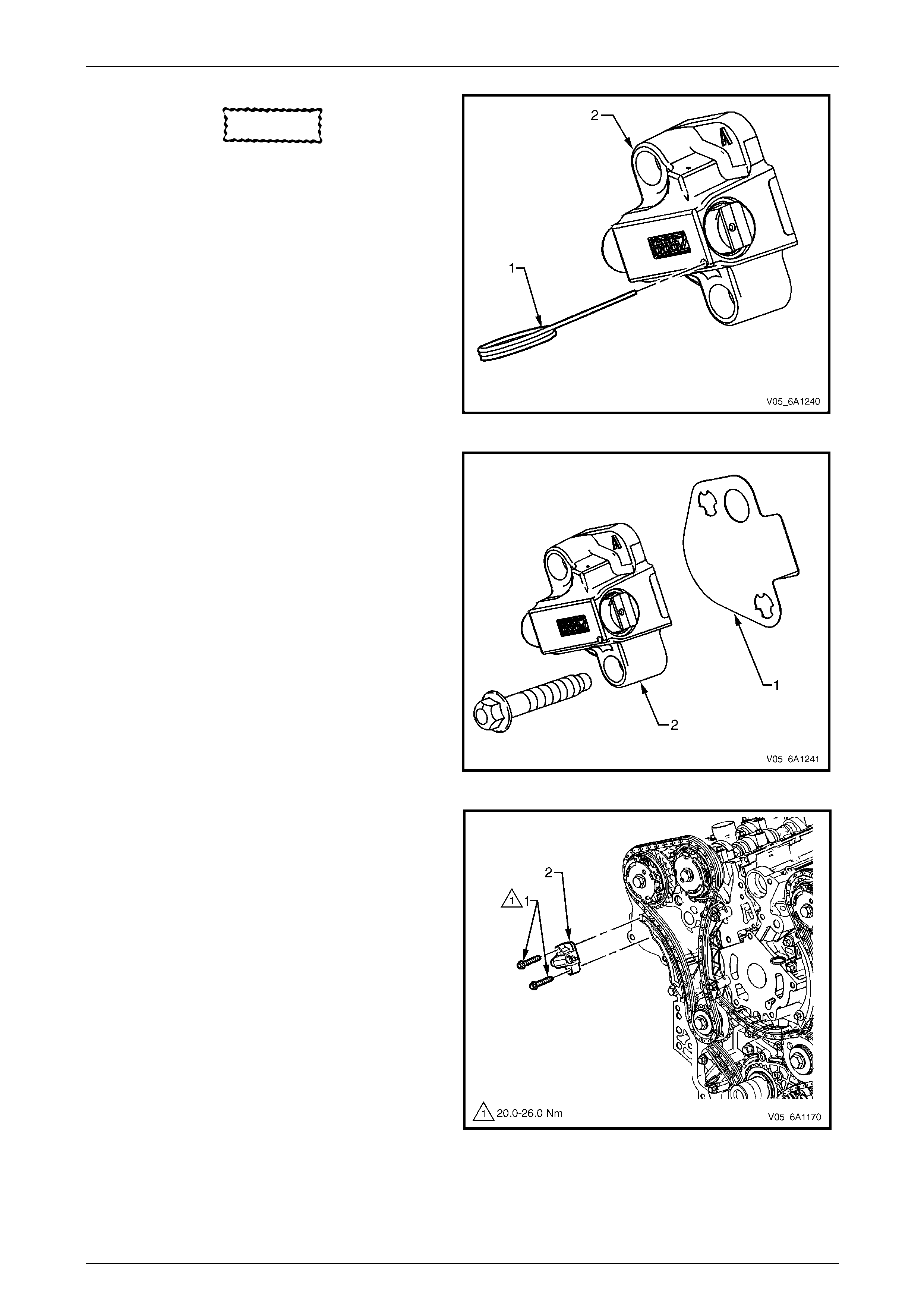
Engine Mechanical – V6 Page 6A1–157
Page 6A1–157
CAUTION
If Tool No. EN 46112 (1) is not inserted into
the tensioner body (2), the plunger will
remain in the locked position and no tension
will be placed on the timing chain, this will
cause damage to the engine.
15 Compress the tensioner shaft into the body and lock
the tensioner by inserting Tool No. EN 4611 2 into the
access hole in the side of the tensioner b od y .
16 Slowly release pressure on th e right-hand secondary
timing chain tensioner. The tensioner should remain
compressed.
Figure 6A1 – 216
17 Install a new right-hand sec ondary timing chain
tensioner gasket (1) to the tensioner (2).
18 Install the right-hand secondary timing chain
tensioner bolts (3) through the tensioner and gasket.
19 Ensure the right-hand second ary timing chain
tensioner mounting surface on the right-han d cylinder
head does not have any burrs or defects that would
affect the sealing of the new tensioner gasket.
Figure 6A1 – 217
20 Place the right-hand seco ndary timing chain tensioner
(2) into position and loosely install the bolts (1) to the
engine block.
Figure 6A1 – 218
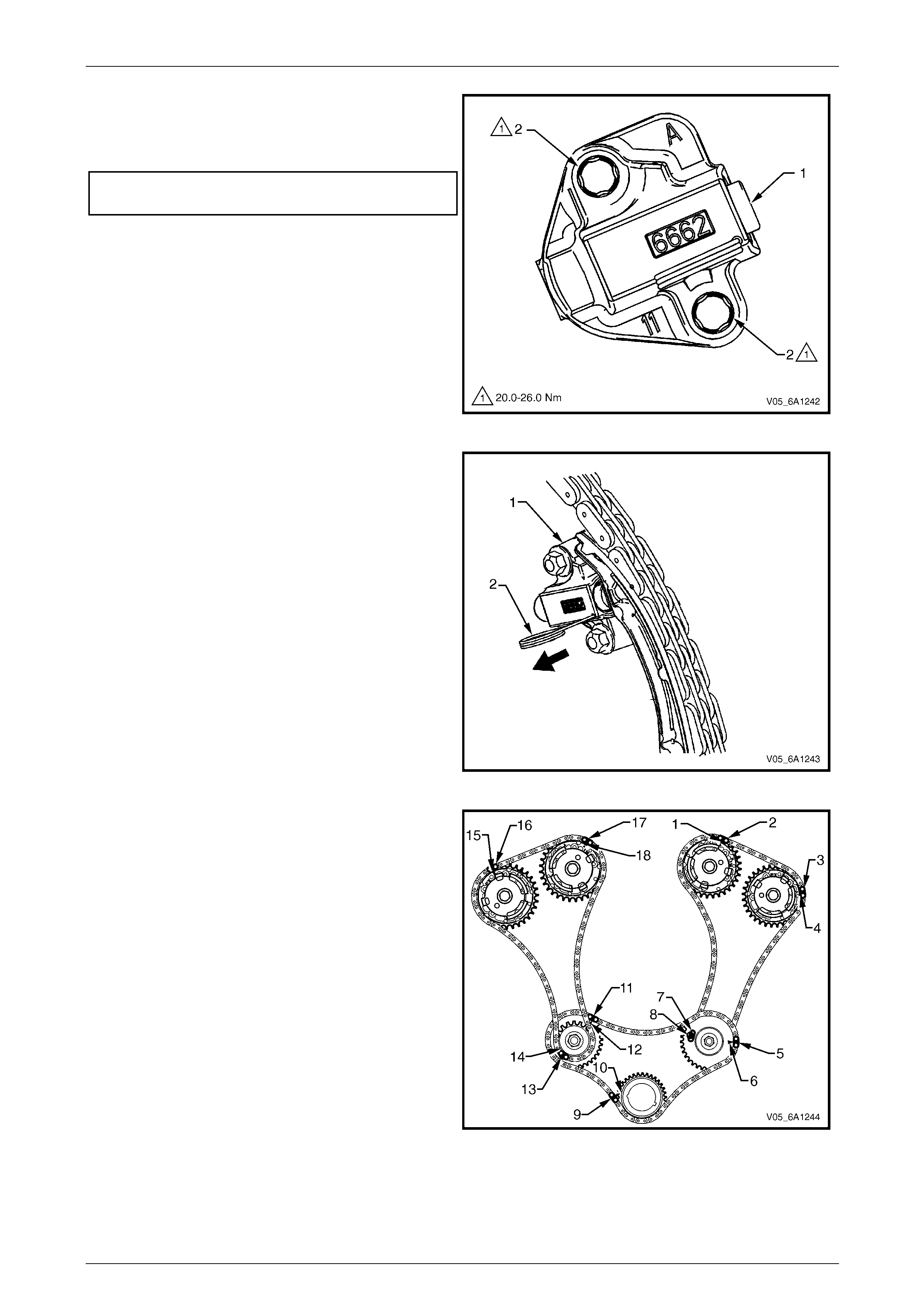
Engine Mechanical – V6 Page 6A1–158
Page 6A1–158
21 Verify the proper placement of the right-ha nd
secondary timing chain tensioner gasket tab (1).
22 Tighten the right-hand secon dary timing chain
tensioner bolts (2) to the correct torque specification.
Secondary timing cha in tensioner
attaching bolt torque specification...........20.0 – 26.0 Nm
Figure 6A1 – 219
23 Release the right-hand timing chain tensioner (1) by
pulling out Tool No. EN 46112 (2) and unlocking the
tensioner plunger.
Figure 6A1 – 220
24 Verify all primary and secondary timing chain timing
mark alignments (1 to 18).
25 Remove Tool No. EN 46105 and EN 46105-2 from
the left and right-hand cylinder head camshafts.
26 Reinstall the spark plugs. Refer to Section 6C1-3
Engine Management V6 – Service Operations.
27 Reinstall the engine front cov er assemb ly, refer to
3.16 Front Cover Assembly.
Figure 6A1 – 221
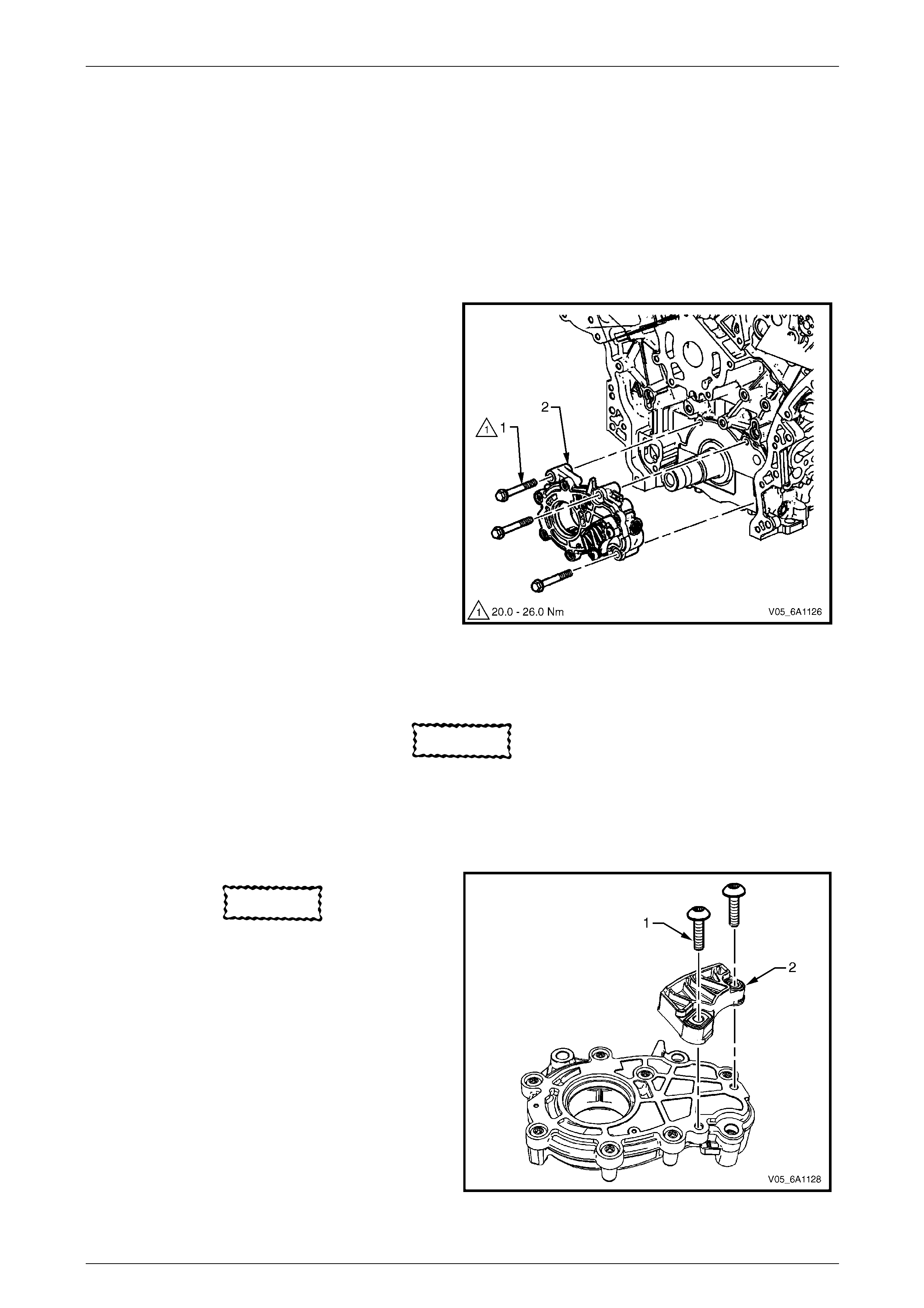
Engine Mechanical – V6 Page 6A1–159
Page 6A1–159
3.18 Oil Pump Assembly
LT Section No. — 01–500
Remove
NOTE
Do not remove the left-hand bank id ler sprocket.
1 Remove the primary timing chain and cra nkshaft sprocket,
refer to 3.17 Timing Chains, Tensioners, Sh oes and Guides.
2 Remove the three bolts (1) attaching the oil pump (2).
3 Remove the oil pump assembly.
Figure 6A1 – 222
Disassemble
CAUTION
There are no serviceable components within
the oil pump. Disassemble the pump only to
diagnose an oil related concern. A
disassembled oil p ump must not be reused : it
must be replaced.
CAUTION
The primary timing chain lower guide is not
serviced separately and is part of the oil
pump assembly. If it is removed from the
pump assembly, the guide and the pump
must be replaced.
1 Remove the two bolts (1) attaching the primary timing
chain lower guide (2) an d remove the guide.
Figure 6A1 – 223
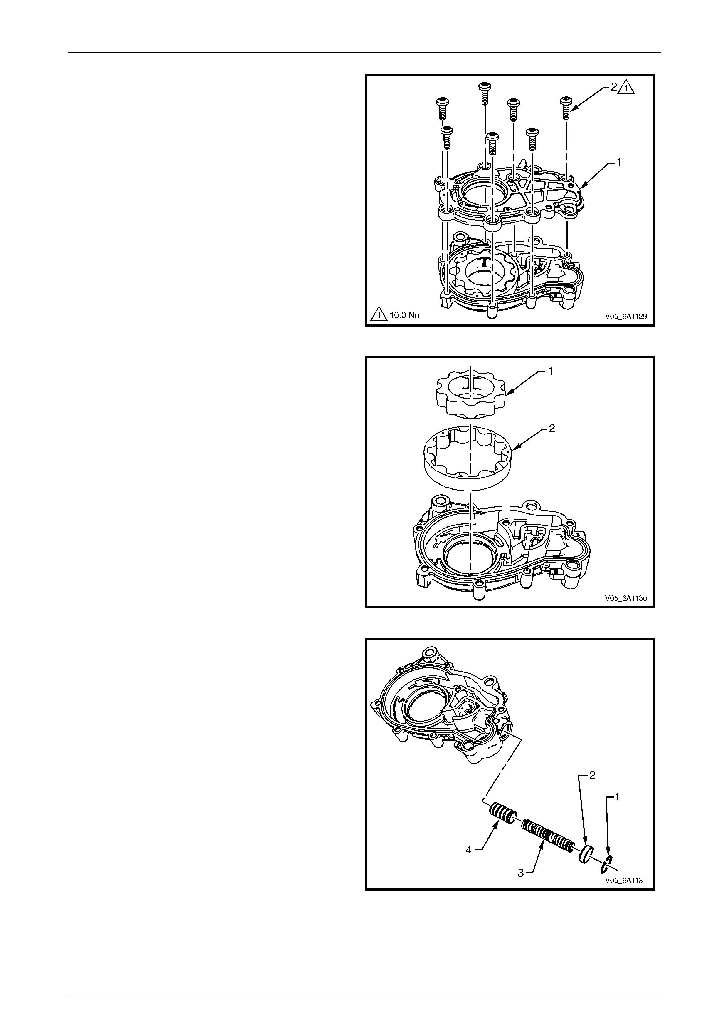
Engine Mechanical – V6 Page 6A1–160
Page 6A1–160
2 Remove the seven bolts (2) attaching the oi l pump
cover to the oil pump housing (1) and remove the
cover from the housing.
Figure 6A1 – 224
3 Remove the inner gerotor ring (1).
4 Remove the outer gerotor ring (2).
Figure 6A1 – 225
5 Remove the clip (1), retaining the oil re lief valve cap
(2).
6 Remove the cap, spring (3) and plunger (4) from the
oil pump housing.
Figure 6A1 – 226
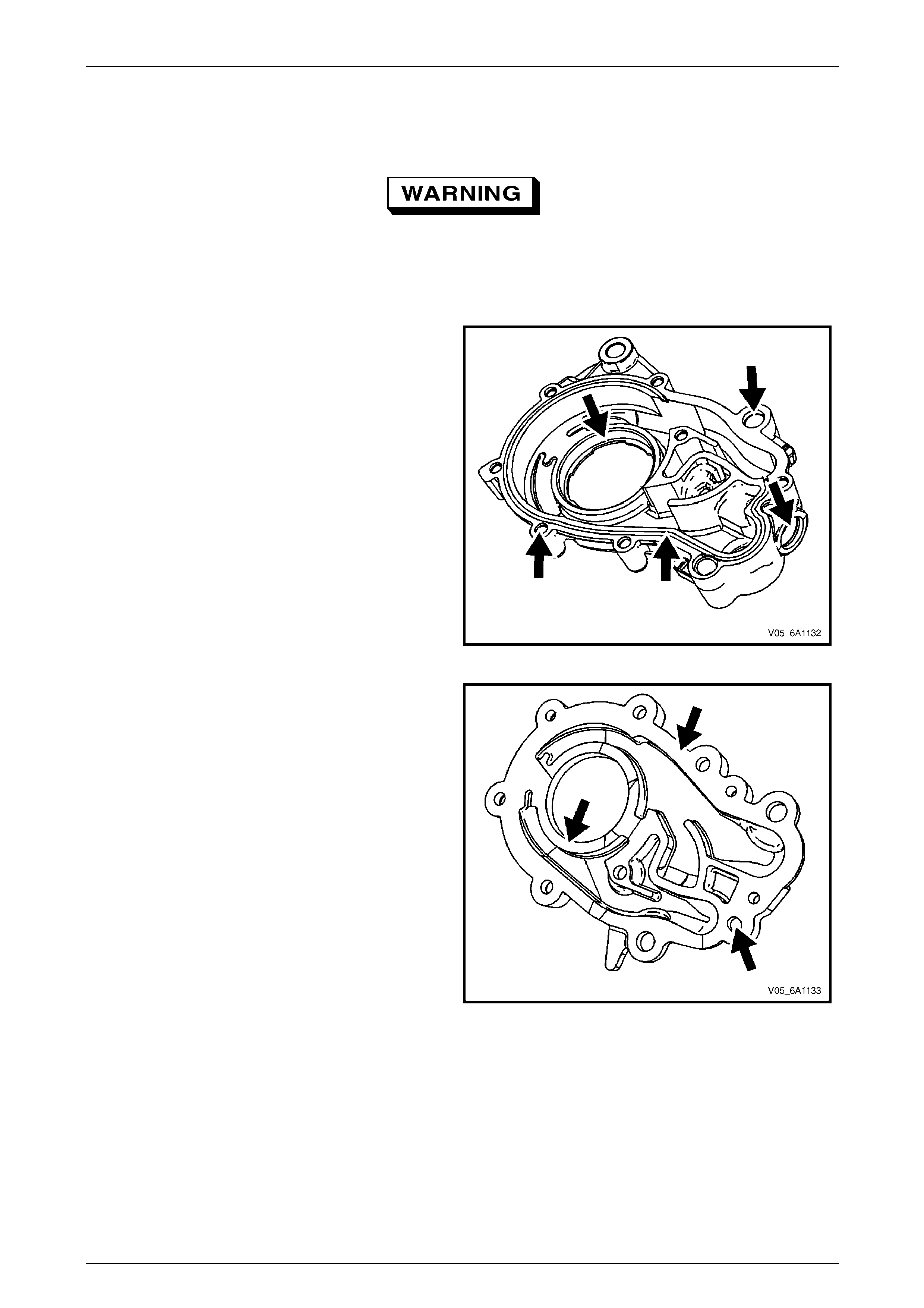
Engine Mechanical – V6 Page 6A1–161
Page 6A1–161
Clean
1 Clean the oil pump components with non-corrosive solvent.
Safety glasses must be worn when using
compressed air.
2 Dry the oil pump components with compressed air.
Inspect
1 Inspect the oil pump housing for damag e.
Figure 6A1 – 227
2 Inspect the oil pump cover for damage.
Figure 6A1 – 228
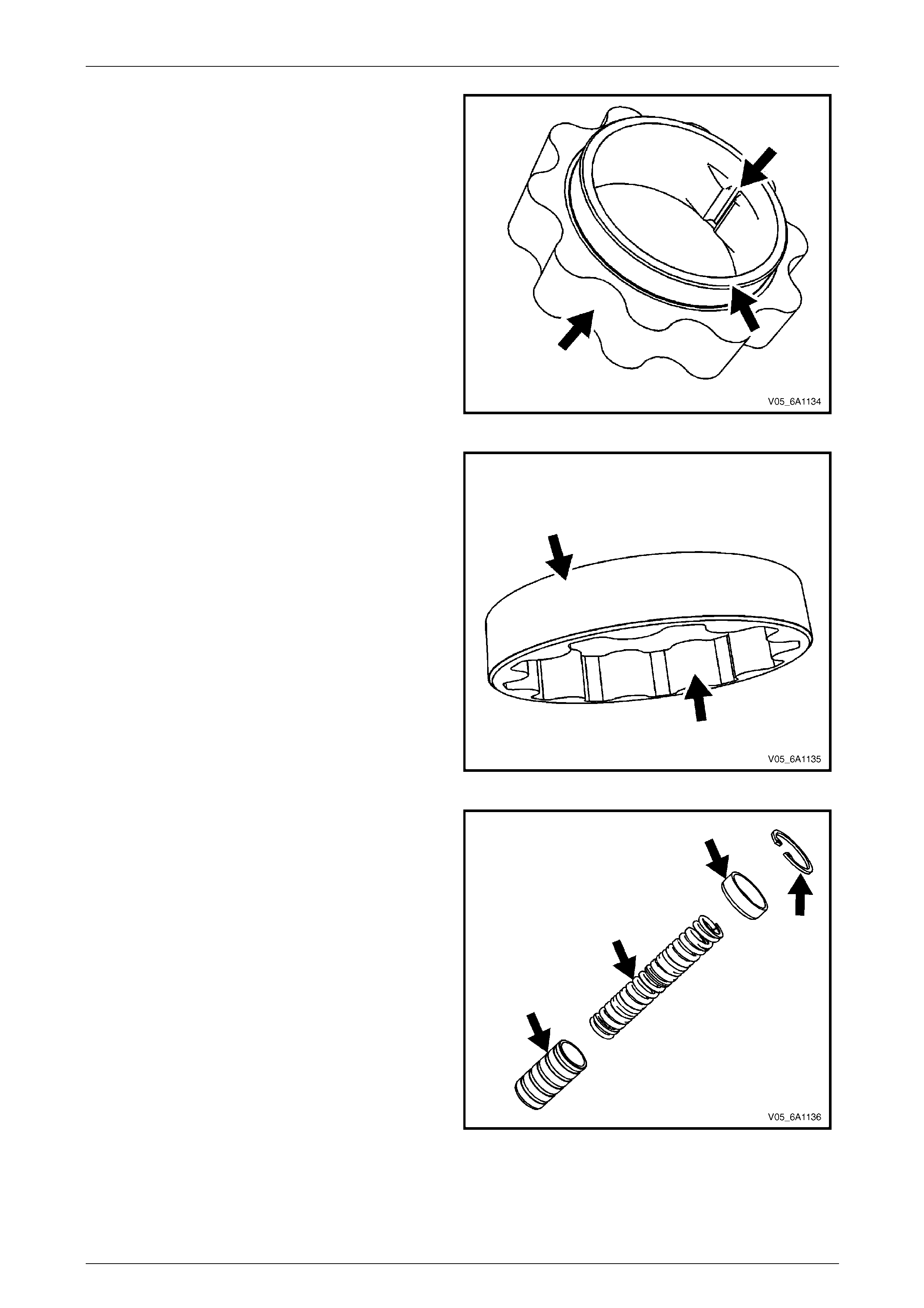
Engine Mechanical – V6 Page 6A1–162
Page 6A1–162
3 Inspect the inner drive gear for damage. If inner
surface damage is found, ensure the crankshaft is
also inspected.
Figure 6A1 – 229
4 Inspect the outer driven gear for damage.
Figure 6A1 – 230
5 Inspect the oil pump relief valve components for
debris or damage.
Figure 6A1 – 231
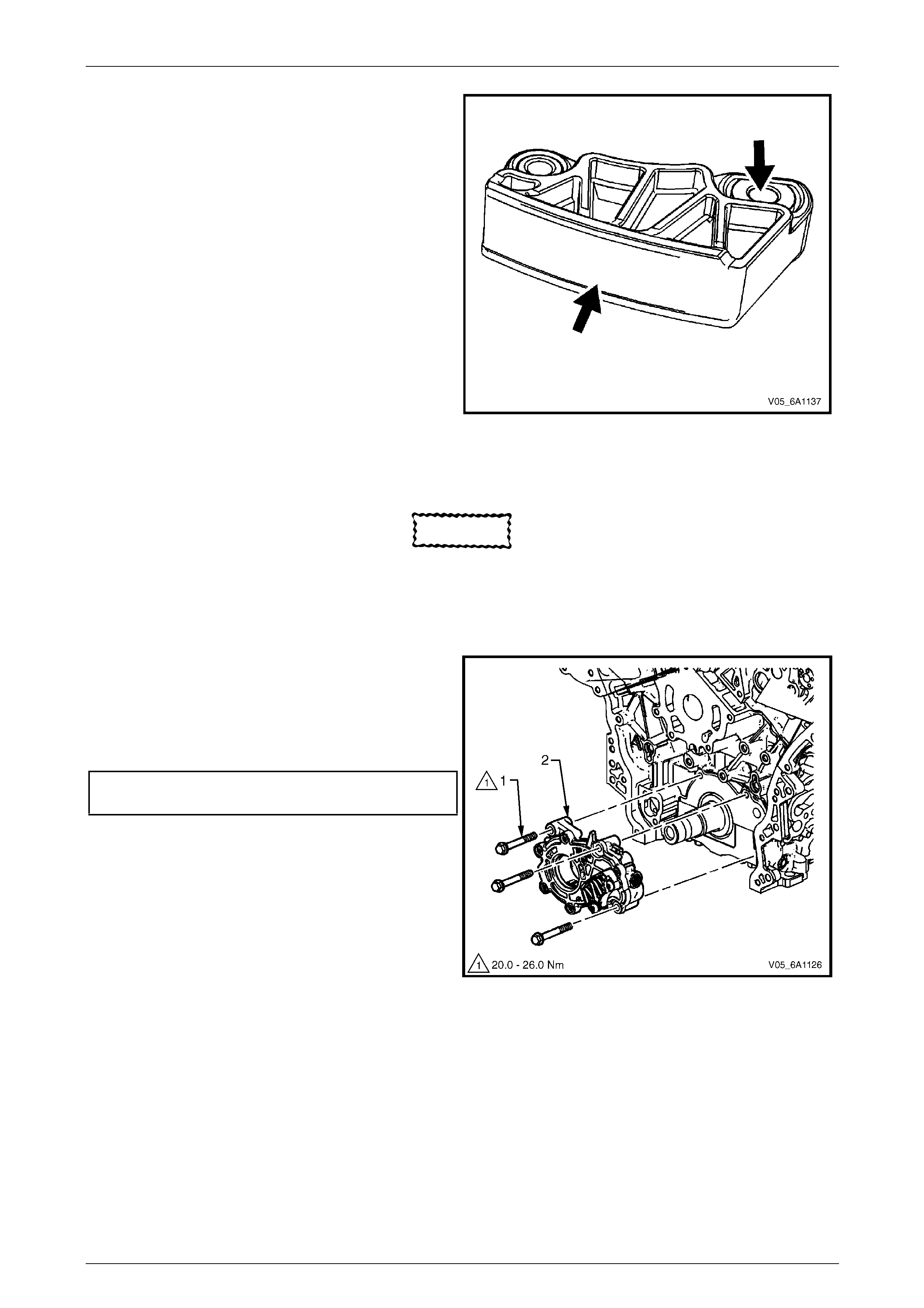
Engine Mechanical – V6 Page 6A1–163
Page 6A1–163
6 Inspect the primary camshaft chain lower guide for
damage. If replacement of the primary camshaft chain
lower guide is required, re place the entire oil pump
assembly as the primary camshaft chain lower guide
is not serviceable separately.
7 If debris or damage is present within the oil pump,
further inspection of all of the engine components is
required.
Figure 6A1 – 232
Reassemble
CAUTION
As there are no serviceable components
within the oil pump, a disassembled oil pump
must be replaced.
Reinstall
1 Align the oil pump gerotor with the crankshaft flats
and fit the oil pump assembly to the eng ine block.
2 Align the pump body (2) with the mounting holes in
the cylinder block.
3 Install the oil pump bolt (1), three places, and tighten
to the correct torque specification.
Oil pump attaching bolt torque
specification............................................20.0 – 26.0 Nm
4 Install the primary timing chain, refer to
3.17 Timing Chains, Tensioners, Shoes and Guides.
Figure 6A1 – 233
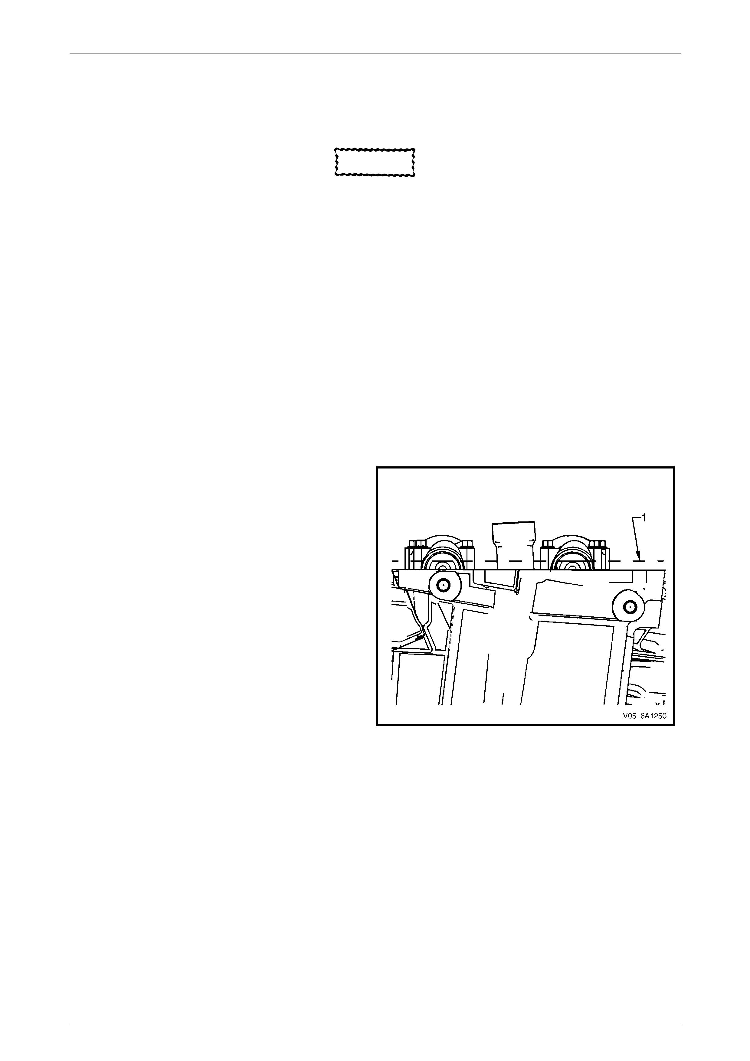
Engine Mechanical – V6 Page 6A1–164
Page 6A1–164
3.19 Camshaft Position Actuator Assembly
LT Section No. — 00–175
CAUTION
Setting the camshaft timing is required
whenever the camshaft drive system is
disturbed to ensure the relationship between
any chain and sprocket is no t lost. Even when
only one sprocket is involved, multiple
crankshaft rotations will not produce
conditions where correct timing can be
confirmed.
If required, follow the Left-hand Secondary
Camshaft Chain Components reinstallation
procedure to reset the camshaft timin g.
Remove
Right-hand Side
1 Remove the right-hand camshaft cover, refer to 3.13 Camshaft Cover.
2 Remove the camshaft position sensors, refer to Section 6C1-3 Engine Management – Service Information.
3 Remove the camshaft position actuator solenoids, refer to
Section 6C1-3 Engine Management – V6 – Service Operations.
4 Remove the crankshaft balancer assembly, refer to 3.14 Crankshaft Balancer Assembly.
5 Install the crankshaft rotation socket Tool No.
EN-46111 onto the crankshaft.
6 Rotate the crankshaft until the camshafts are in a
neutral low tension position. The camshaft flats will be
parallel with the camshaft cover rail (1).
Figure 6A1 – 234
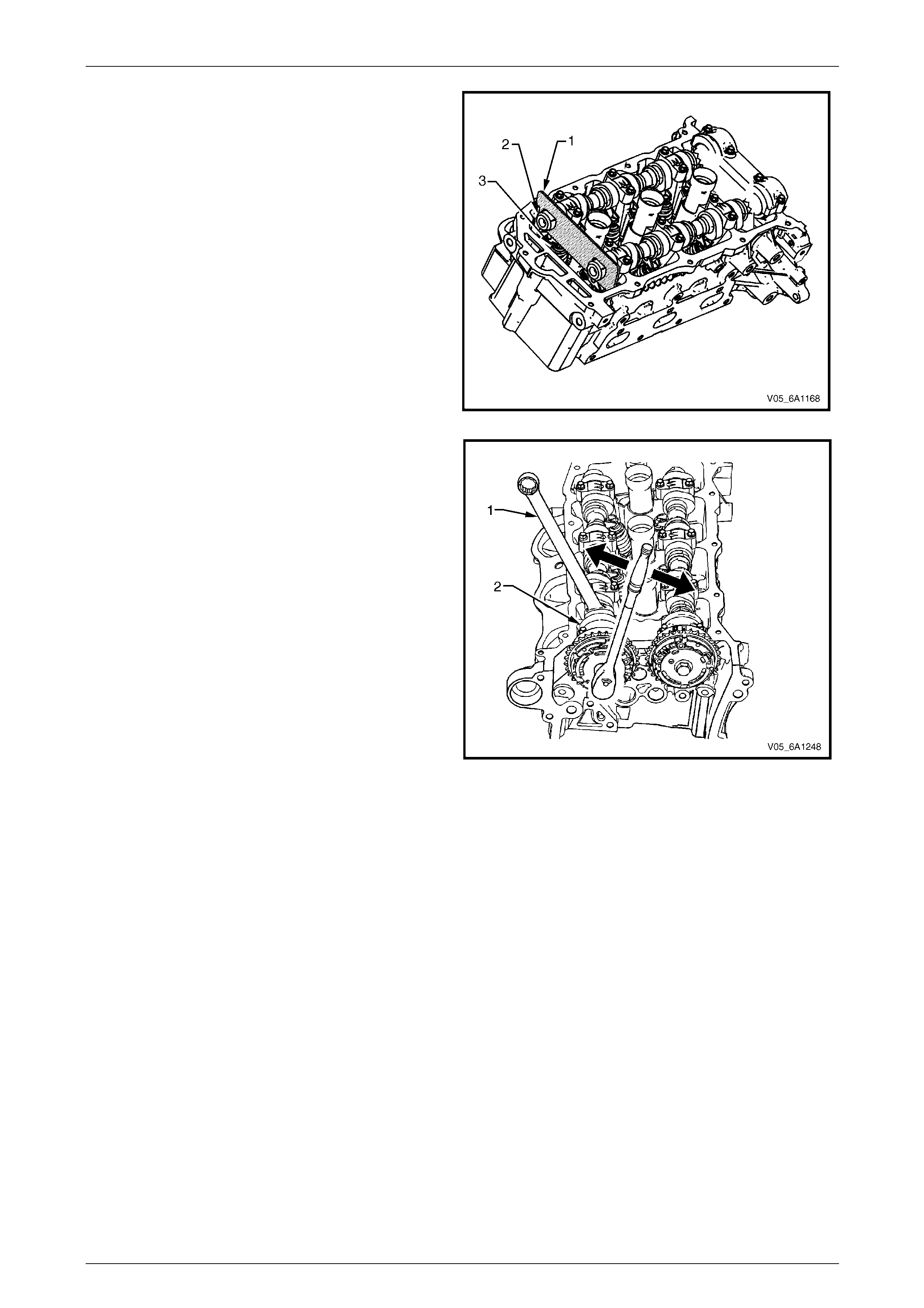
Engine Mechanical – V6 Page 6A1–165
Page 6A1–165
7 Install Tool No. EN-46105 – 1 (1) onto the rear of the
right-hand cylinder head (3) camshafts (2).
Figure 6A1 – 235
NOTE
Use an open-end spanner (1) at the camshaft
hex (2) to pre vent ca mshaft/eng ine rota tion.
NOTE
Do not remove the camshaft position actuator
bolt at this time.
8 Loosen the camshaft position actuator bolt.
NOTE
If you have already removed the camshaft
timing chain, proceed to Step 12.
Figure 6A1 – 236
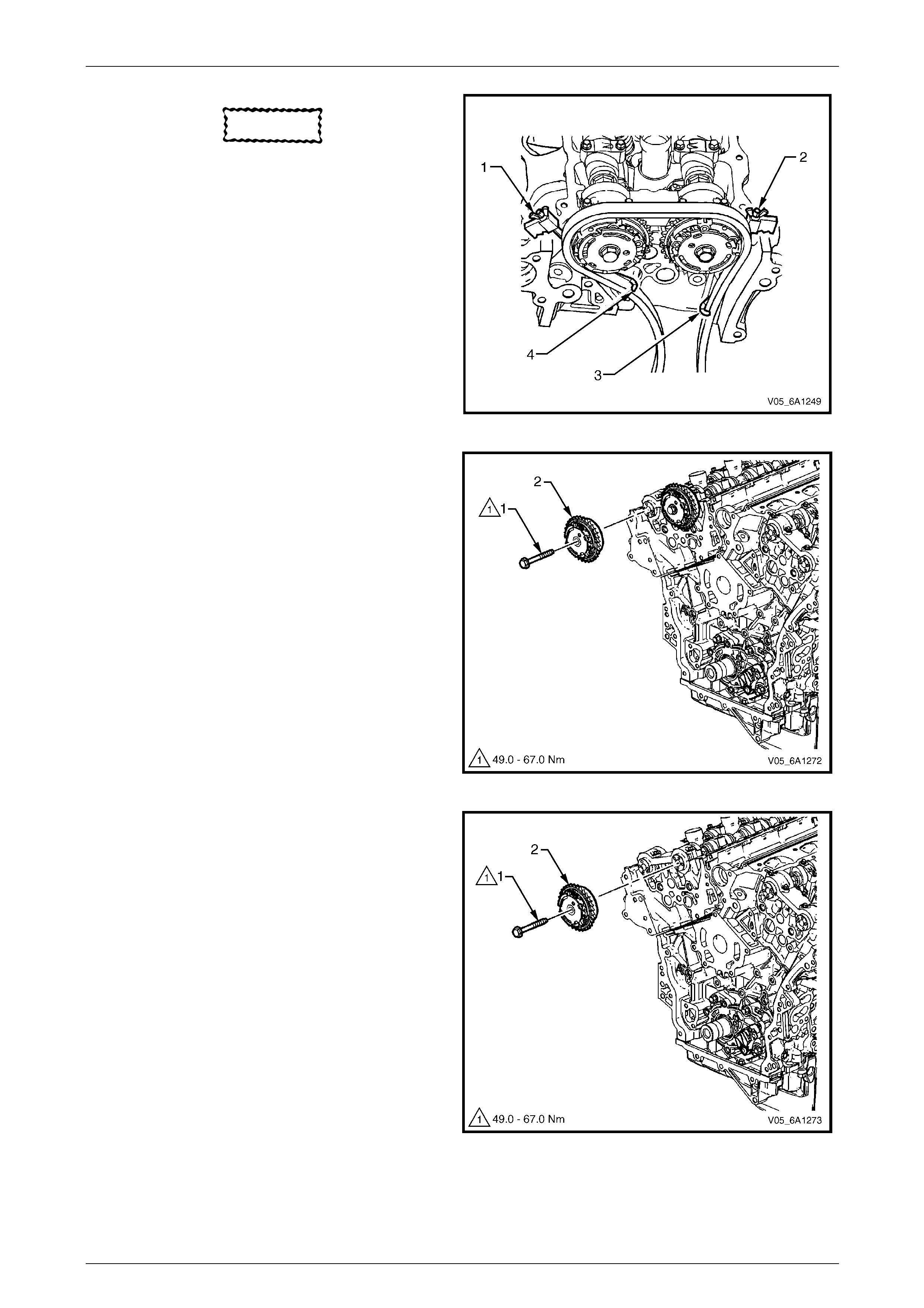
Engine Mechanical – V6 Page 6A1–166
Page 6A1–166
CAUTION
Ensure the tips of Tool No.
EN-46108 are fully engaged into the timing
chain and the wing nuts are tight and the
timing chain is taught.
9 Install Tool No. EN-46108 (1 and 2) to retain the
timing chain (3 and 4).
10 Firmly tighten the wing nuts of Tool No. EN-46108.
NOTE
Ensure the camshaft timing chain and the
camshaft position actuators are marked for
correct reassembly.
11 Mark the timing chain and the respective location on
both camshaft position actuators. Figure 6A1 – 237
12 Remove the bolt (1) attaching the right-han d exhaust
camshaft position actuator (2) and remove the
actuator.
Figure 6A1 – 238
13 Remove the bolt (1) attaching right-hand i nta ke
camshaft position actuator (2) and remove the
actuator.
Figure 6A1 – 239
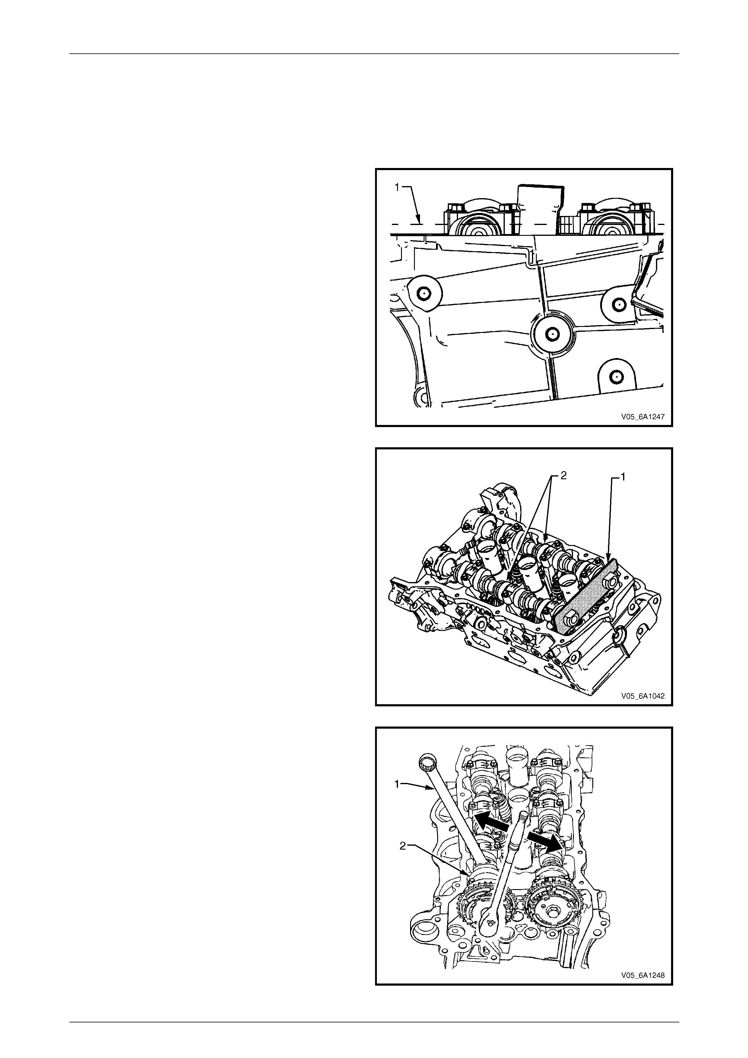
Engine Mechanical – V6 Page 6A1–167
Page 6A1–167
Left-hand Side
1 Remove the left-hand camshaft cover, refer to 3.13 Camshaft Cover.
2 Remove the camshaft position sensors, refer to Section 6C1-3 Engine Management – V6 – Service Operations.
3 Remove the camshaft position actuator solenoids, refer to
Section 6C1-3 Engine Management – V6 – Service Operations.
4 Remove the crankshaft balancer assembly, refer to 3.14 Crankshaft Balancer Assembly.
5 Install the crankshaft rotation socket Tool No.
EN-46111 onto the crankshaft.
6 Rotate the crankshaft until the camshafts are in a
neutral low tension position. The camshaft flats will be
parallel with the camshaft cover rail (1).
Figure 6A1 – 240
7 Install Tool No. EN-46105 – 1 (1) onto the rear of the
left-hand cylinder head camshafts (2).
Figure 6A1 – 241
NOTE
Use an open-end wrench (1) at the camshaft
hex (2) to pre vent ca mshaft/eng ine rota tion.
NOTE
Do not remove the camshaft position actuator
bolt at this time.
8 Loosen the camshaft position actuator bolt.
NOTE
If the camshaft timing chain h as been removed,
proceed to Step 12.
Figure 6A1 – 242
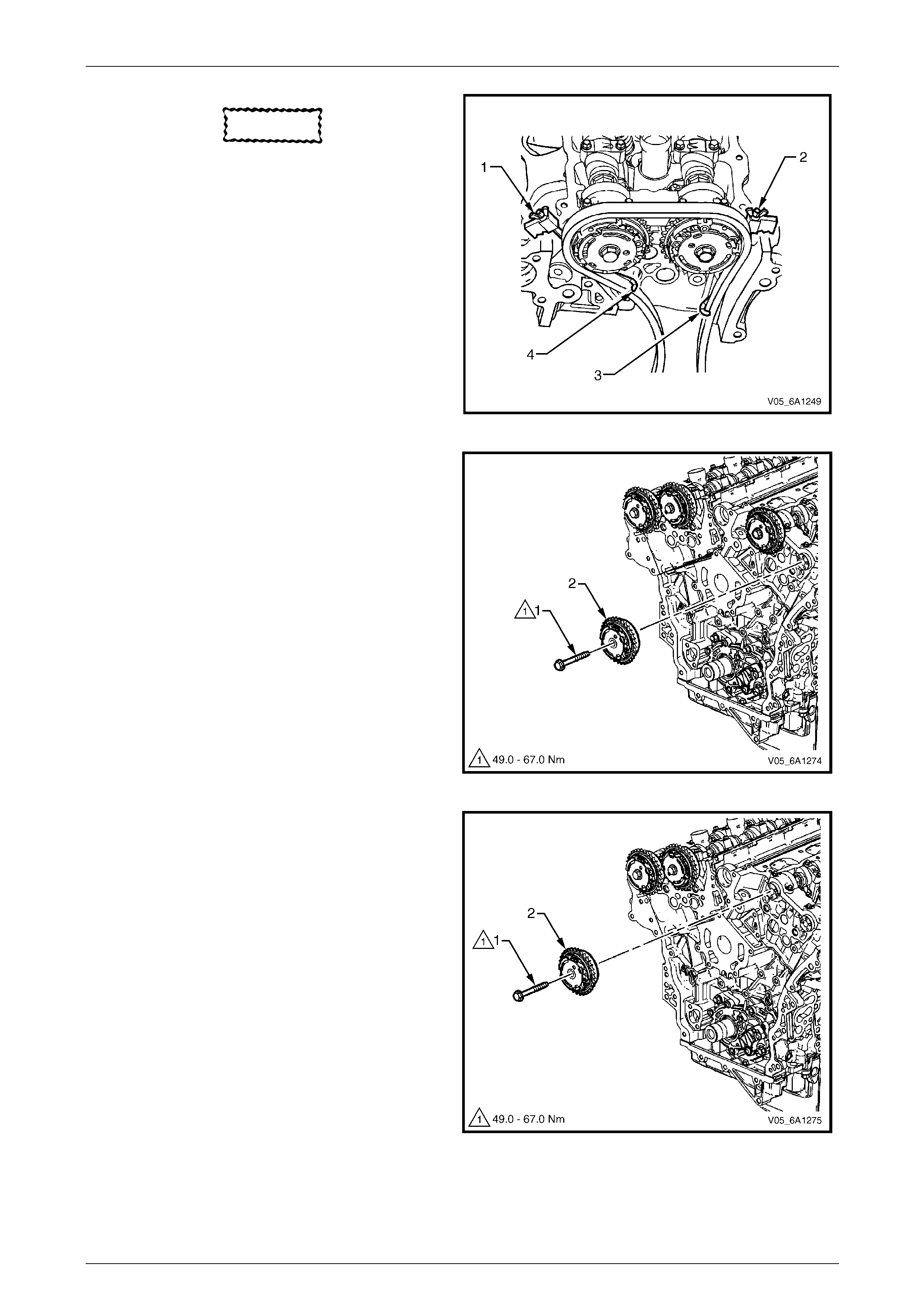
Engine Mechanical – V6 Page 6A1–168
Page 6A1–168
CAUTION
Ensure the tips of Tool No. EN-46108 are
fully engaged into the timing chain and the
wing nuts are tight and the timing chain is
taught.
9 Install Tool No. EN-46108 (1 and 2) to retain the
timing chain (3 and 4).
10 Firmly tighten the wing nuts of Tool No. EN-46108.
NOTE
Ensure the camshaft timing chain and the
camshaft position actuators are marked for
correct reassembly.
11 Mark the timing chain and the respective location on
both camshaft position actuators. Figure 6A1 – 243
12 Remove the bolt (1) attaching the left-hand e xhaust
camshaft position actuator (2) and remove the
actuator.
Figure 6A1 – 244
13 Remove the bolt (1) attaching left-hand intake
camshaft position actuator (2) and remove the
actuator.
Figure 6A1 – 245
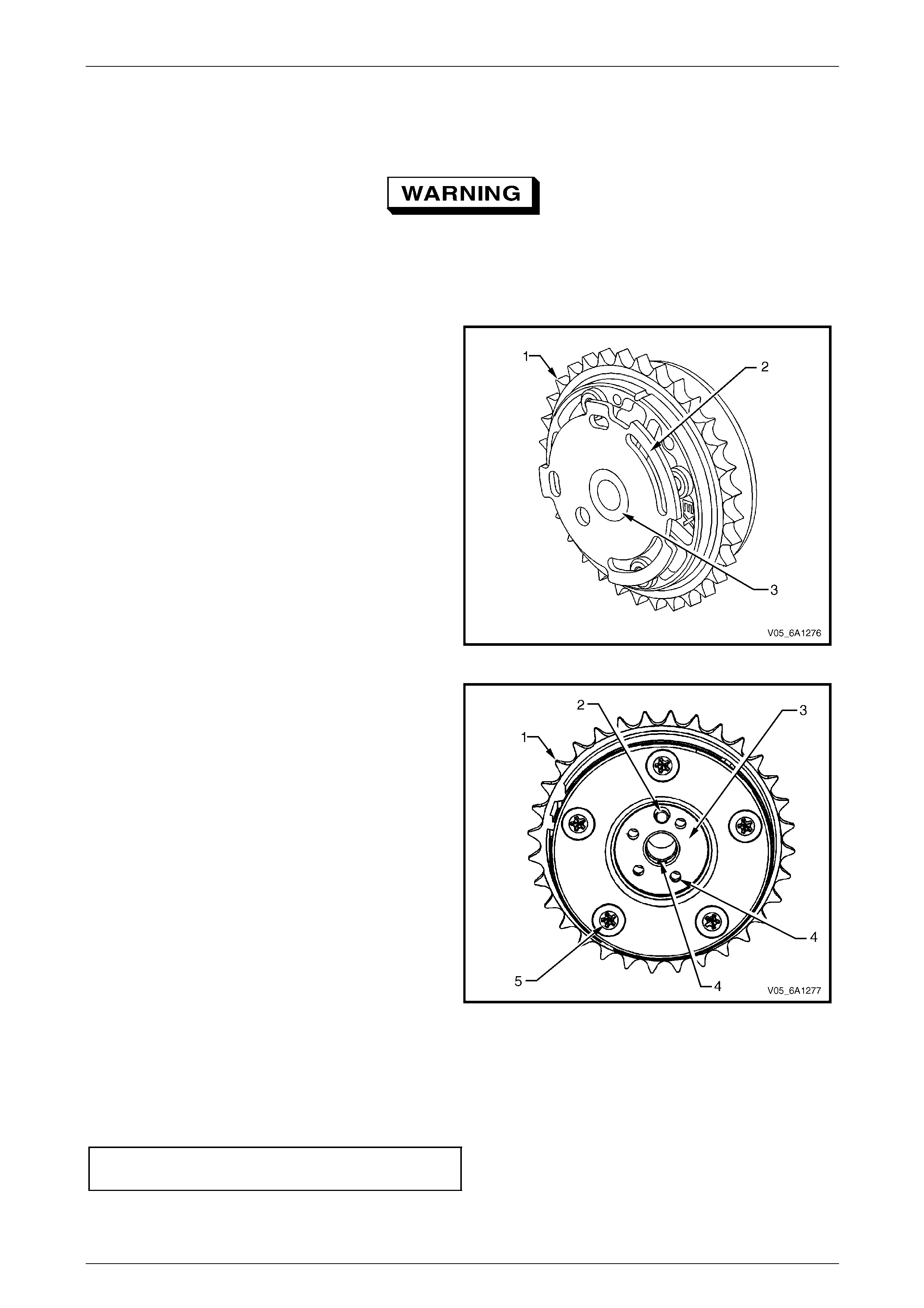
Engine Mechanical – V6 Page 6A1–169
Page 6A1–169
Clean
1 Clean the exterior of each camshaft position actuator with solvent.
Safety glasses must be worn when using
compressed air.
2 Dry the timing components with compressed air.
Inspect
1 Inspect the front of each camshaft position actuator
for the following:
• Sprocket damage (1),
• Reluctor/sensor wheel damage (2), and
• Camshaft position actuator bolt seating/sealing
inner hub flange damage (3).
Figure 6A1 – 246
2 Inspect the back of each camshaft position actuator
for the following:
• Sprocket damage (1),
• Camshaft locating pin damage (2),
• Camshaft seating/sealing inner hub flan ge
damage (3),
• Blockage to the oil passages (4), and
• Loose or missing housing bolts (5).
Figure 6A1 – 247
Reinstall
Reinstallation of the camshaft position actuators is the reverse of the removal procedur e, noting the following:
1 Align the actuators and timing chain with the marks made during removal.
2 Tighten the camshaft position actuator bolts to the correct torqu e specification.
Camshaft position actuator attaching
bolt torque specification..........................49.0 – 67.0 Nm
3 Remove the timing chain retention tools.
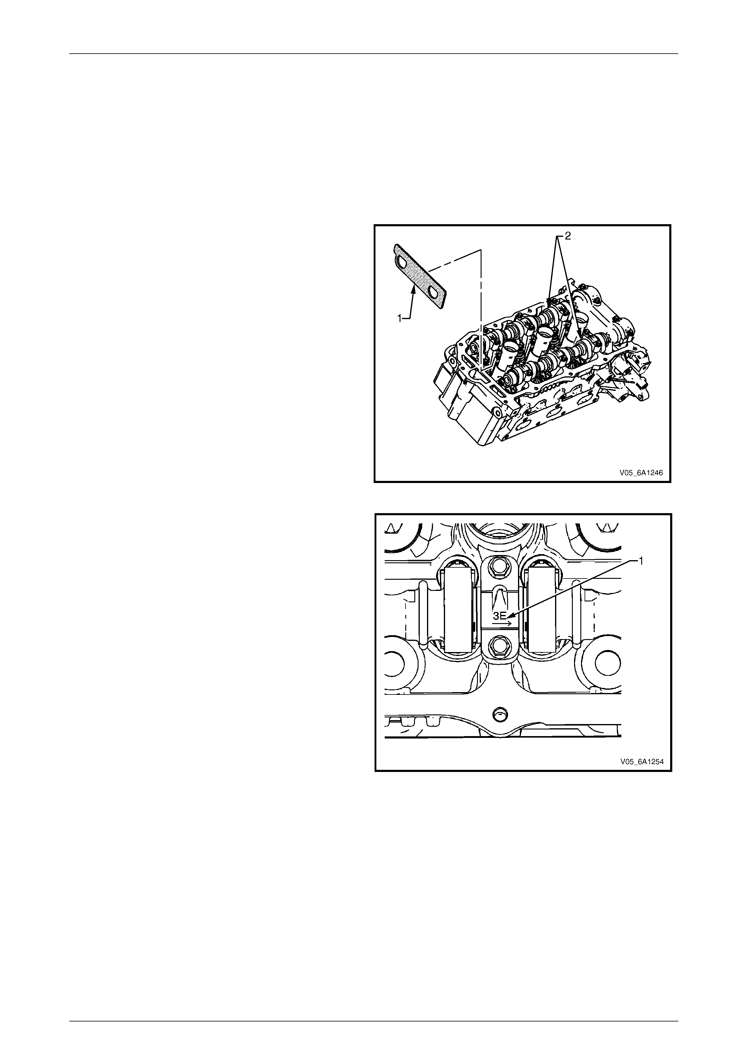
Engine Mechanical – V6 Page 6A1–170
Page 6A1–170
3.20 Camshaft
LT Section No. — 00–175
Remove
Right-hand Side
1 Remove the right-hand cylinder head camshaft position actuators, refer to
3.19 Camshaft Position Actuator Assembly.
2 Remove the Tool No. EN-46105 – 1 (1) from the right-
hand cylinder head camshafts (2).
NOTE
Tool No. EN-46105 was installed as part of the
right-hand cylinder head camshaft position
actuator removal procedure.
Figure 6A1 – 248
3 Observe the markings (1) on the bearing caps. Each
bearing cap is marked to identify its location. The
markings have the following meanings:
• The raised feature must always be oriented
toward the centre of the cylinder head.
• An I indicates the intake camshaft.
• An E indicates the exhaust camshaft.
• The number indicates the jour nal position from
the front of the engine.
Figure 6A1 – 249
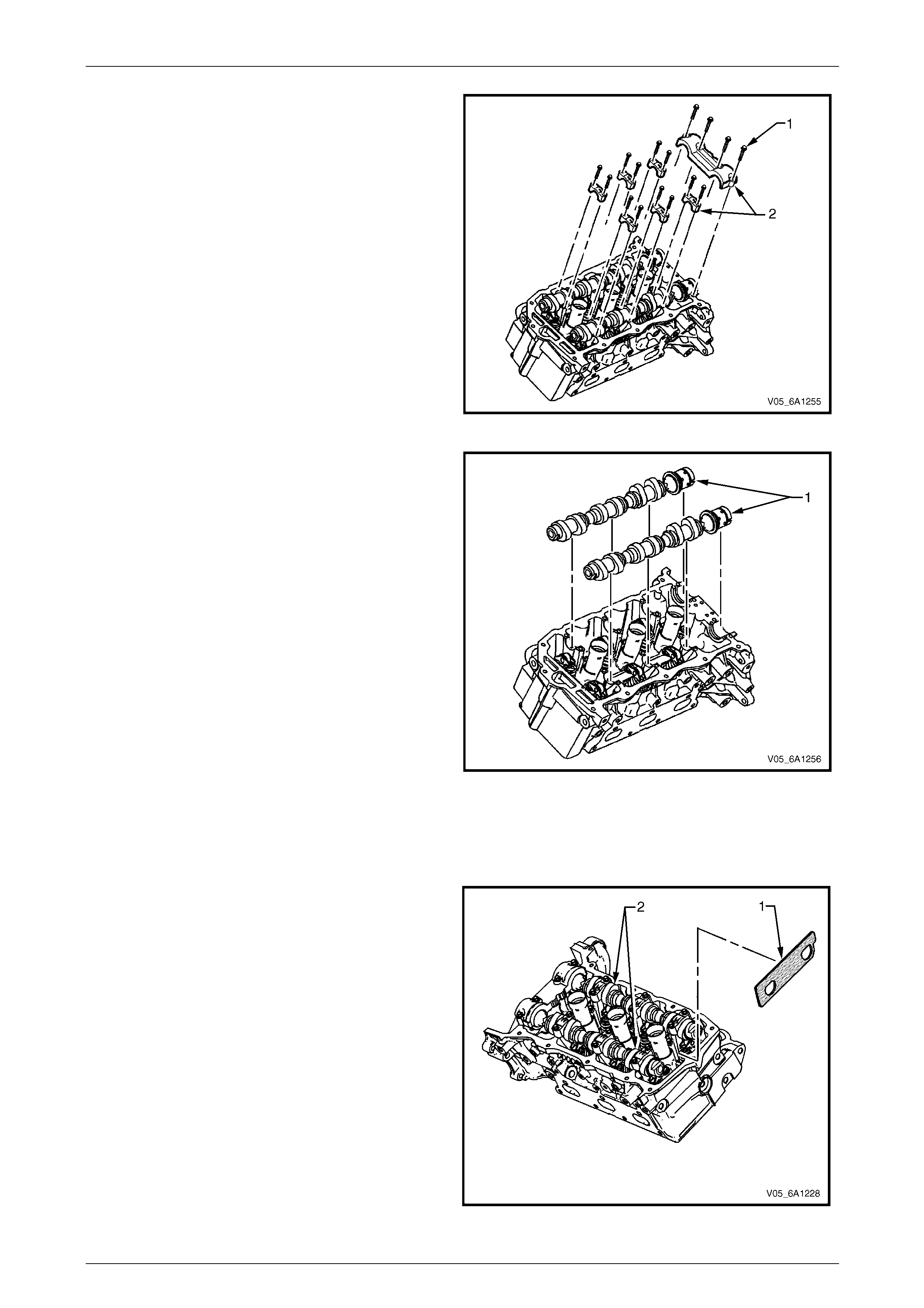
Engine Mechanical – V6 Page 6A1–171
Page 6A1–171
4 Remove the camshaft bearing cap bolts (1) and
caps (2).
Figure 6A1 – 250
5 Remove the camshafts (1).
Figure 6A1 – 251
Left-hand Side
1 Remove the left-hand cyl ind er head camshaft position actua t ors, refer to
3.19 Camshaft Position Actuator Assembly.
2 Remove Tool No. EN-46105 – 1 (1) from the left-hand
camshafts.
NOTE
Tool No. EN-46105 was installed as part of the
left-hand cylinder head camshaft position
actuator removal procedure.
Figure 6A1 – 252
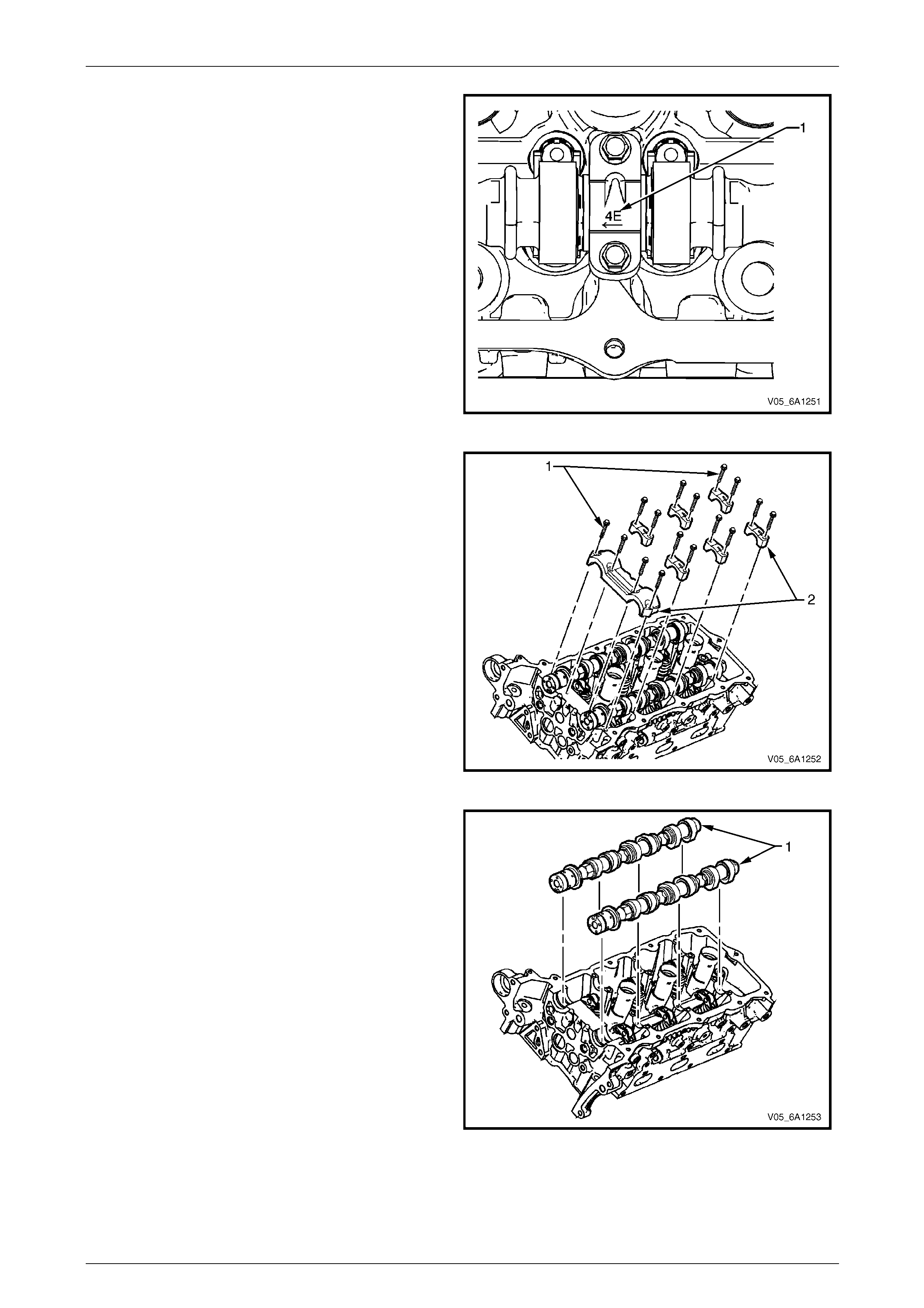
Engine Mechanical – V6 Page 6A1–172
Page 6A1–172
3 Observe the markings (1) on the bearing caps. Each
bearing cap is marked in orde r to identify its location.
The markings have the follo wing meanings:
• The raised feature must always be oriented
toward the centre of the cylinder head.
• An I indicates the intake camshaft.
• An E indicates the exhaust camshaft.
• The number indicates the jour nal position from
the front of the engine.
Figure 6A1 – 253
4 Remove the camshaft bearing cap bolts (1) and
caps (2).
Figure 6A1 – 254
5 Remove the camshafts (1).
Figure 6A1 – 255
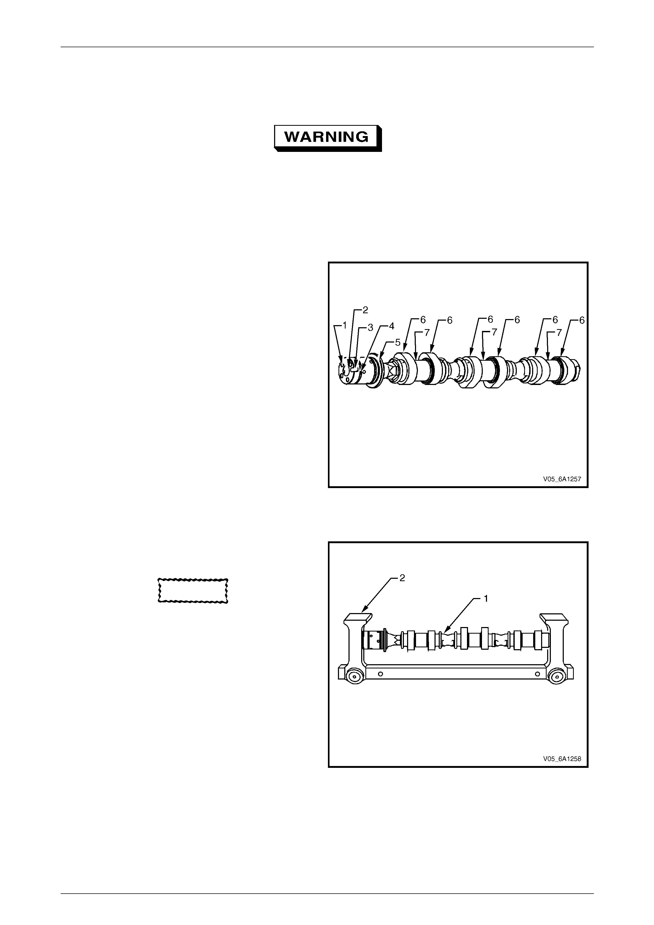
Engine Mechanical – V6 Page 6A1–173
Page 6A1–173
Clean
1 Clean the camshaft in solvent.
Safety glasses must be worn when using
compressed air.
2 Dry the camshaft with compressed air.
Inspect
Camshaft Visual Inspection
1 Inspect the camshaft oil feed holes (1) to the
camshaft position actuator for dirt, debris or blockage.
2 Inspect the threaded hole (2) for damage.
3 Inspect the camshaft position actuator locating
notch (3) for damage or wear.
4 Inspect the camshaft sealing grooves (4) for damage.
5 Inspect the camshaft thrust surface (5) for damage.
6 Inspect the camshaft lobes (6) and journals (7) for the
following conditions:
• Excessive scoring or pitting
• Discoloration from overheating
• Deformation from excessive wear, especially
the camshaft lobes
7 If any of the above conditions exist on the camshaft,
replace the camshaft.
Figure 6A1 – 256
Camshaft Measurement
1 With the camshaft (1) in a suitable fixture (2),
measure the camshaft for wear.
CAUTION
No machining of the camshaft is allowed.
NOTE
If the camshaft measures outside the specified
range, replace the camshaft.
2 For camshaft measurement the follo wing
specifications refer to 5 Specifications.
Figure 6A1 – 257
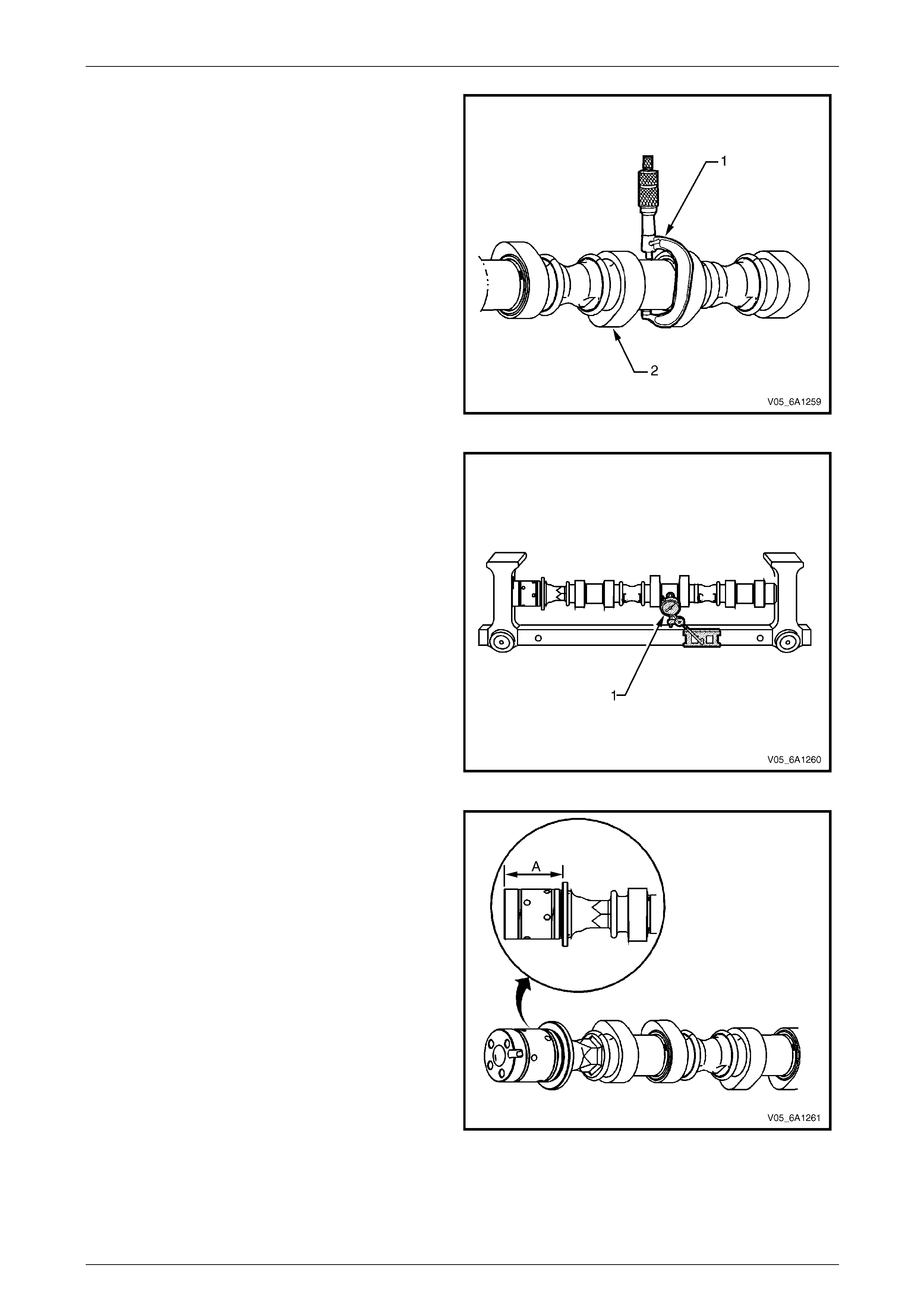
Engine Mechanical – V6 Page 6A1–174
Page 6A1–174
3 Measure the camshaft (2) journals for diamet er and
out-of-round using an outside micrometer (1).
Figure 6A1 – 258
4 Measure the camshaft runout using a d ial
indicator (1).
Figure 6A1 – 259
5 Measure the camshaft thrust width for wear using a
depth micrometer (A).
Figure 6A1 – 260
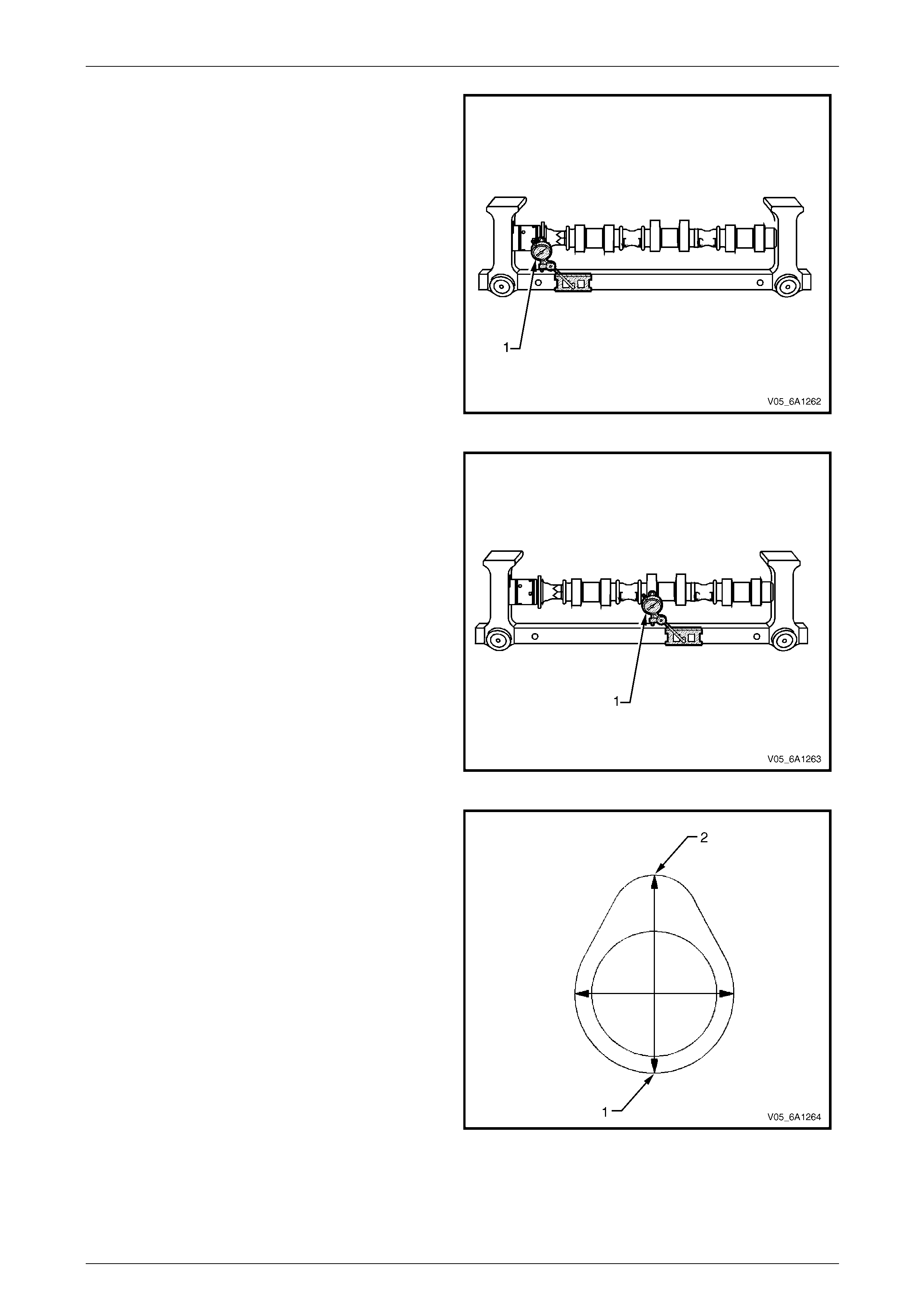
Engine Mechanical – V6 Page 6A1–175
Page 6A1–175
6 Measure the camshaft thrust wall surface for runout
using a dial indicator (1).
Figure 6A1 – 261
7 Measure the camshaft lobes for wear using a dial
indicator (1).
Figure 6A1 – 262
8 Place the dial indicator tip on the base circle (1) of the
camshaft lobe.
9 Set the dial indicator at zero.
10 Rotate the camshaft until the indicator tip is at the
highest point (2) on the lobe. This reading is the lift of
the camshaft lobe.
Figure 6A1 – 263
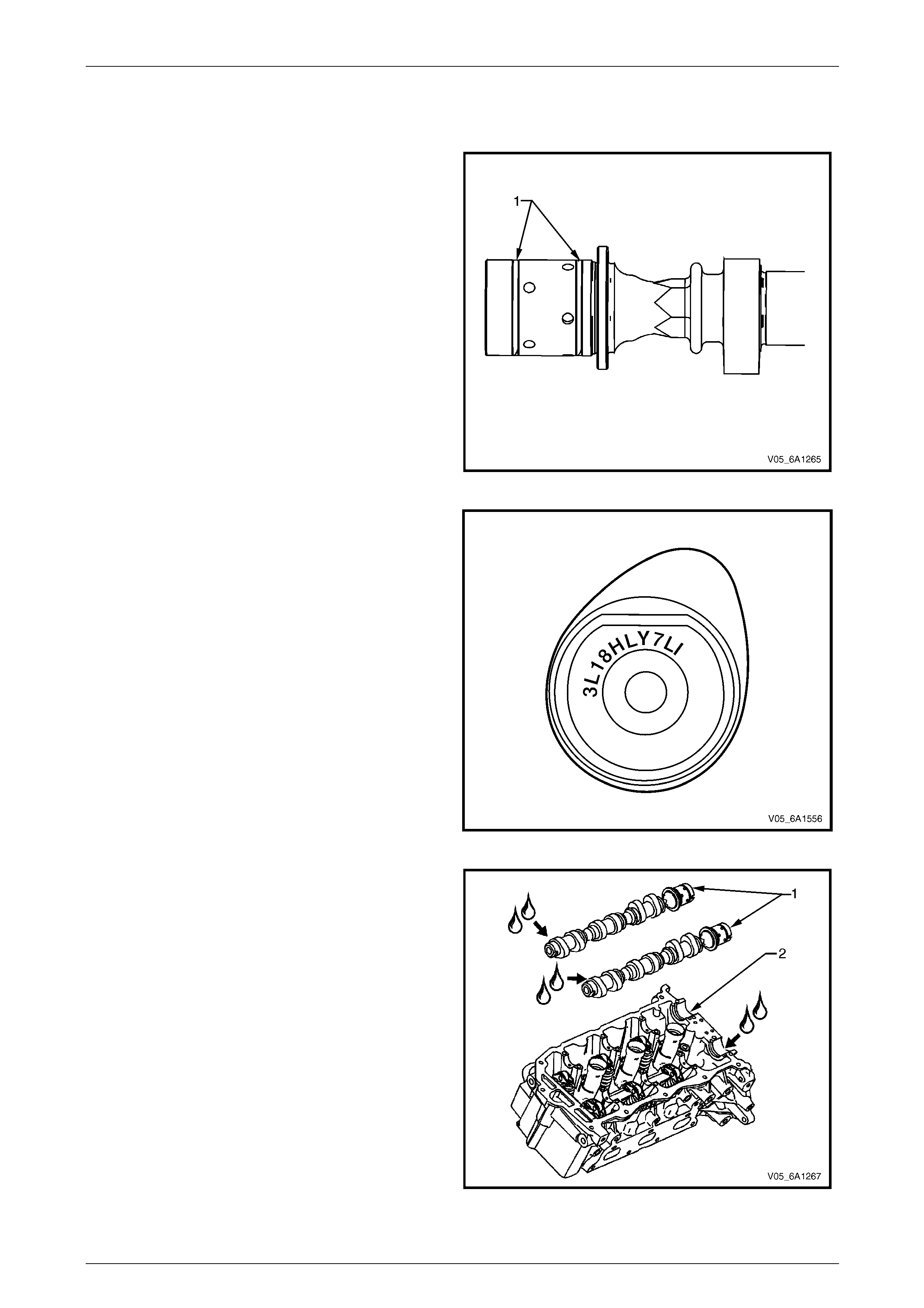
Engine Mechanical – V6 Page 6A1–176
Page 6A1–176
Reinstall
Right-hand Side
1 Ensure the camshaft sealing rings (1) are in place in
the camshaft grooves.
Figure 6A1 – 264
2 Select the correct camshaft for the particular
installation location. ID markings are on the rear end
of each camshaft. The ID markings are defined as
follows:
• The first five digits refer to the date and time of
production.
• Example = 3L18H.
• Digits six through nine refer to engine
production code.
• LY7 = Alloytec190 engine.
• The last two digits refer to position:
• LI = left-hand intake.
• LE = left-hand exhaust.
• RI = right-hand intake.
• RE = right-hand exhaust.
Figure 6A1 – 265
3 Apply a liberal amount of engine oil to the
camshaft (1) journals and the right-hand c ylin der
head camshaft carriers (2).
Figure 6A1 – 266
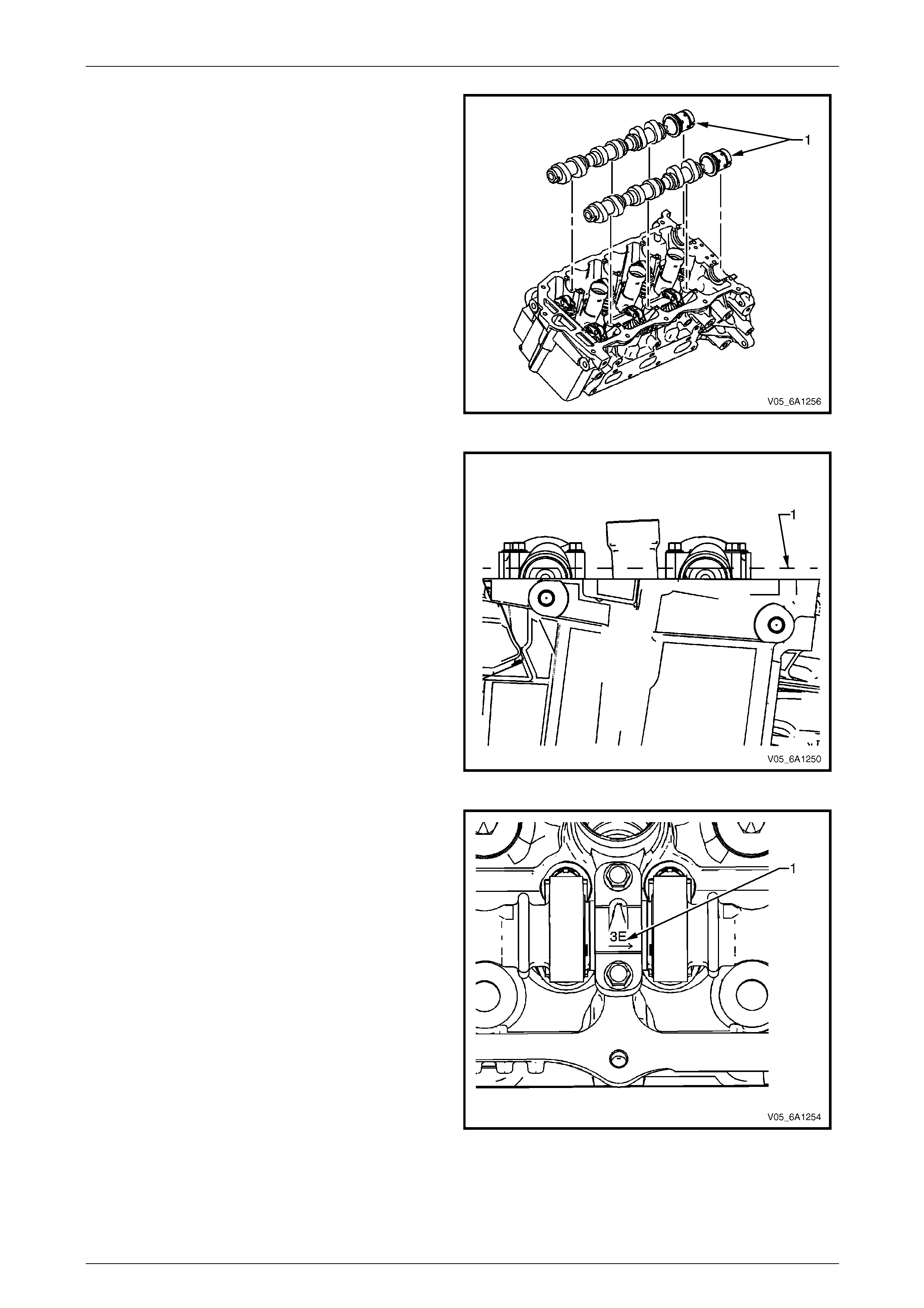
Engine Mechanical – V6 Page 6A1–177
Page 6A1–177
4 Position the camshafts (1) on the cylinder head and
assemble the camshaft actuators to the camshafts.
NOTE
Install the camshaft position actuator bolts but
do not tighten at this stage.
Figure 6A1 – 267
5 Ensure the camshaft lobes are in the neutra l position
with the flats on the back of the camshafts up and
parallel (1) with the right-hand cylinder head camshaft
cover rail.
6 Ensure the marks on the right-hand exhaust camshaft
position actuator and timing chain, made prior to the
disassemble operation are aligned.
7 Ensure the marks on the right-hand intak e camshaft
position actuator and timing chain, made prior to the
disassemble operation are aligned.
Figure 6A1 – 268
8 Observe the markings on the right-hand cylinder head
camshaft bearing caps. Each bear ing cap is
marked (1) to identify its location. The markings have
the following meanings:
• The raised feature must always be oriented
toward the centre of the cylinder head.
• The I indicates the intake camshaft.
• The E indicates the exhaust camshaft.
• The number 1, 3, 5 indicates the cylinder
position from the front of the engine.
9 Apply a liberal amount of engine oil to the camshaft
bearing caps.
Figure 6A1 – 269
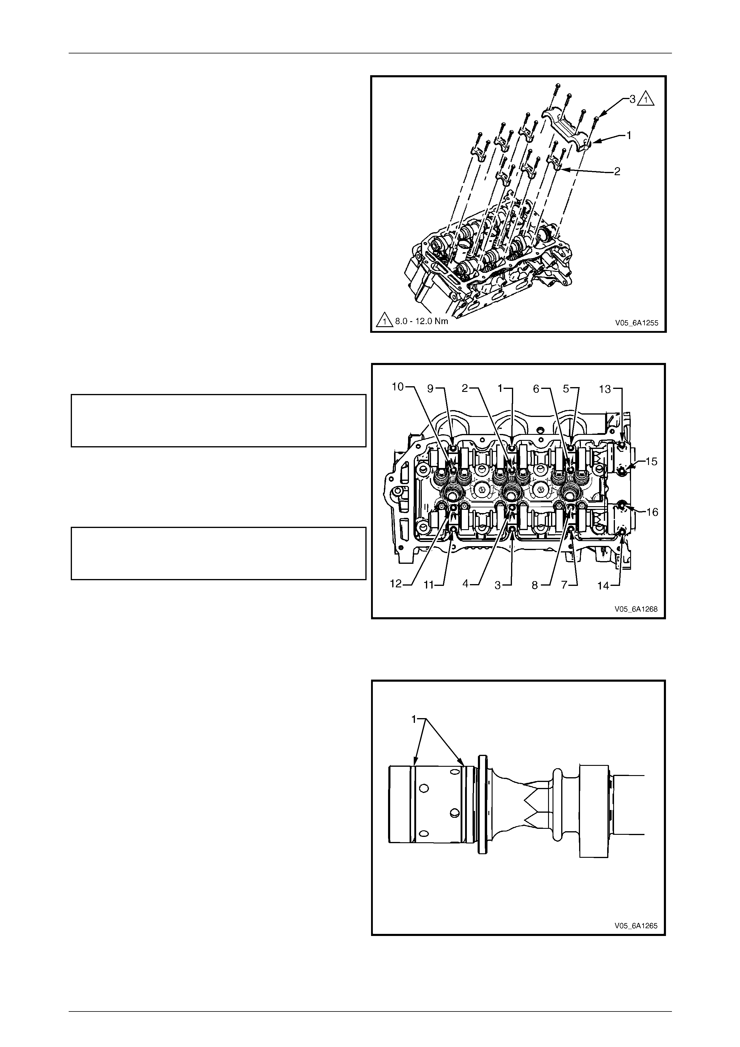
Engine Mechanical – V6 Page 6A1–178
Page 6A1–178
10 Install the camshaft bearing thrust cap (1) in the first
journal of the right-hand cyli nder head.
11 Install the remaining bearing caps (2) with their
orientation mark toward the centre of the cylinder
head.
12 Hand start all the camshaft bearing cap bolt s (3).
Figure 6A1 – 270
13 Tighten the camshaft bearing cap bolts to the correct
torque specification and i n the sequence shown.
Camshaft bearing cap attaching
bolt torque specification:
Stage 1: ....................................................8.0 – 12.0 Nm
14 Loosen the centre intake camshaft bearing cap bolts
1 and 2, and the centre exhaust camshaft bearing cap
bolts 3 and 4.
15 Retighten the centre camshaft bearing cap b olts 1, 2,
3 and 4 to the correct torque specification.
Camshaft bearing cap attaching
bolt torque specification:
Stage 2: ....................................................8.0 – 12.0 Nm
16 Install the right-hand cylinder hea d camshaft position
actuators, refer to
3.19 Camshaft Position Actuator Assembly. Figure 6A1 – 271
Left-hand Side (Bank 2)
1 Ensure the camshaft sealing rings (1) are in place in
the camshaft grooves.
Figure 6A1 – 272
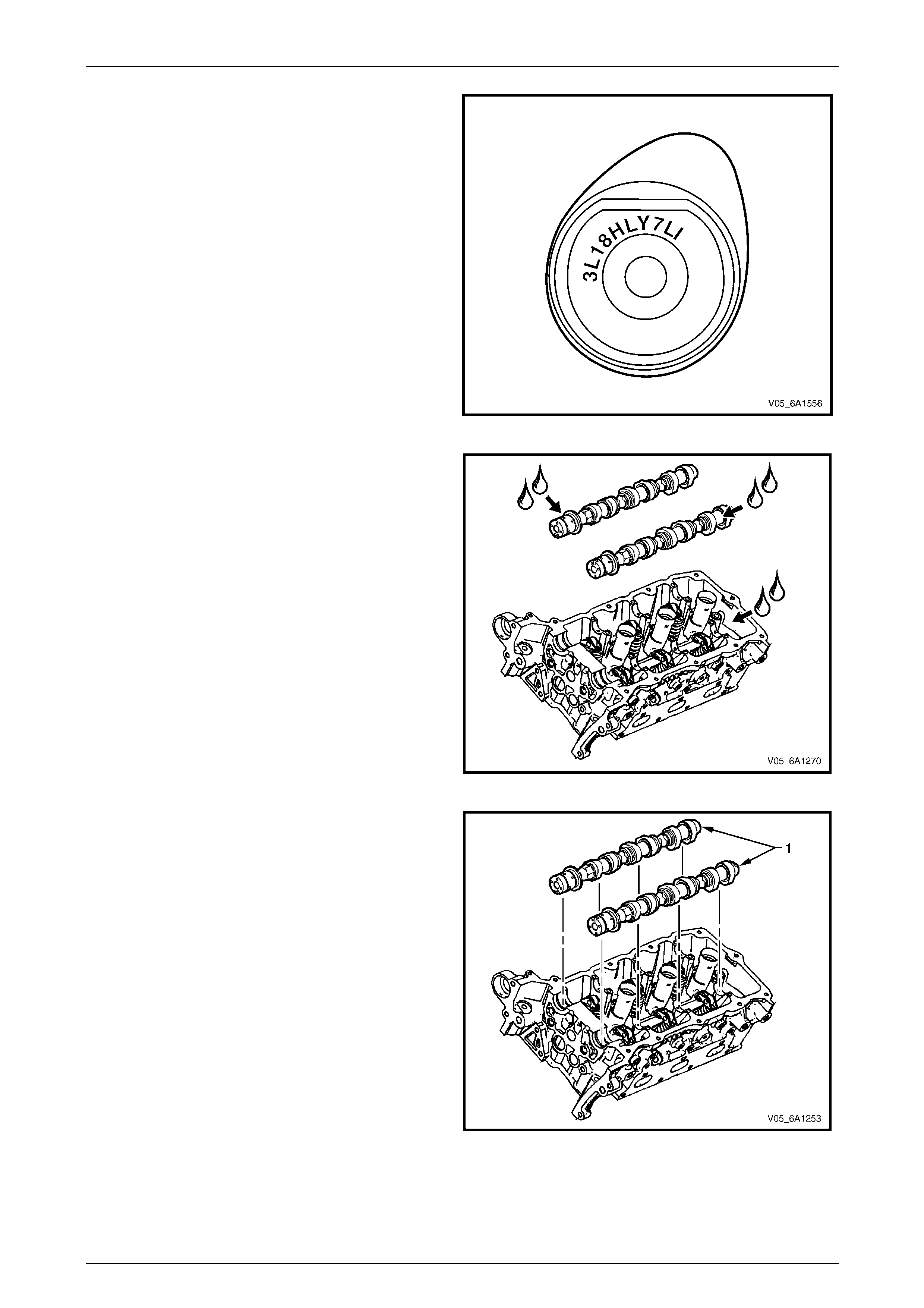
Engine Mechanical – V6 Page 6A1–179
Page 6A1–179
2 Select the correct camshaft for the particular
installation location. ID markings can be found on the
rear end of each camshaft. The ID markings are
defined as follows:
• The first five digits refer to the date and time of
production.
• Example = 3L18H.
• Digits six through nine refer to engine
production code.
• LY7 = Alloytec 190 eng ine.
• The last two digits refer to position:
• LI = left-hand intake.
• LE = left-hand exhaust.
• RI = right-hand intake.
• RE = right-hand exhaust.
Figure 6A1 – 273
3 Apply a liberal amount of engine oil to the camshaft
journals and the left-hand cylinder head camshaft
carriers.
Figure 6A1 – 274
4 Position the camshafts (1) on the cylinder head and
assemble the camshaft actuators to the camshafts.
NOTE
Install the camshaft position actuator bolts but
do not tighten at this stage.
Figure 6A1 – 275
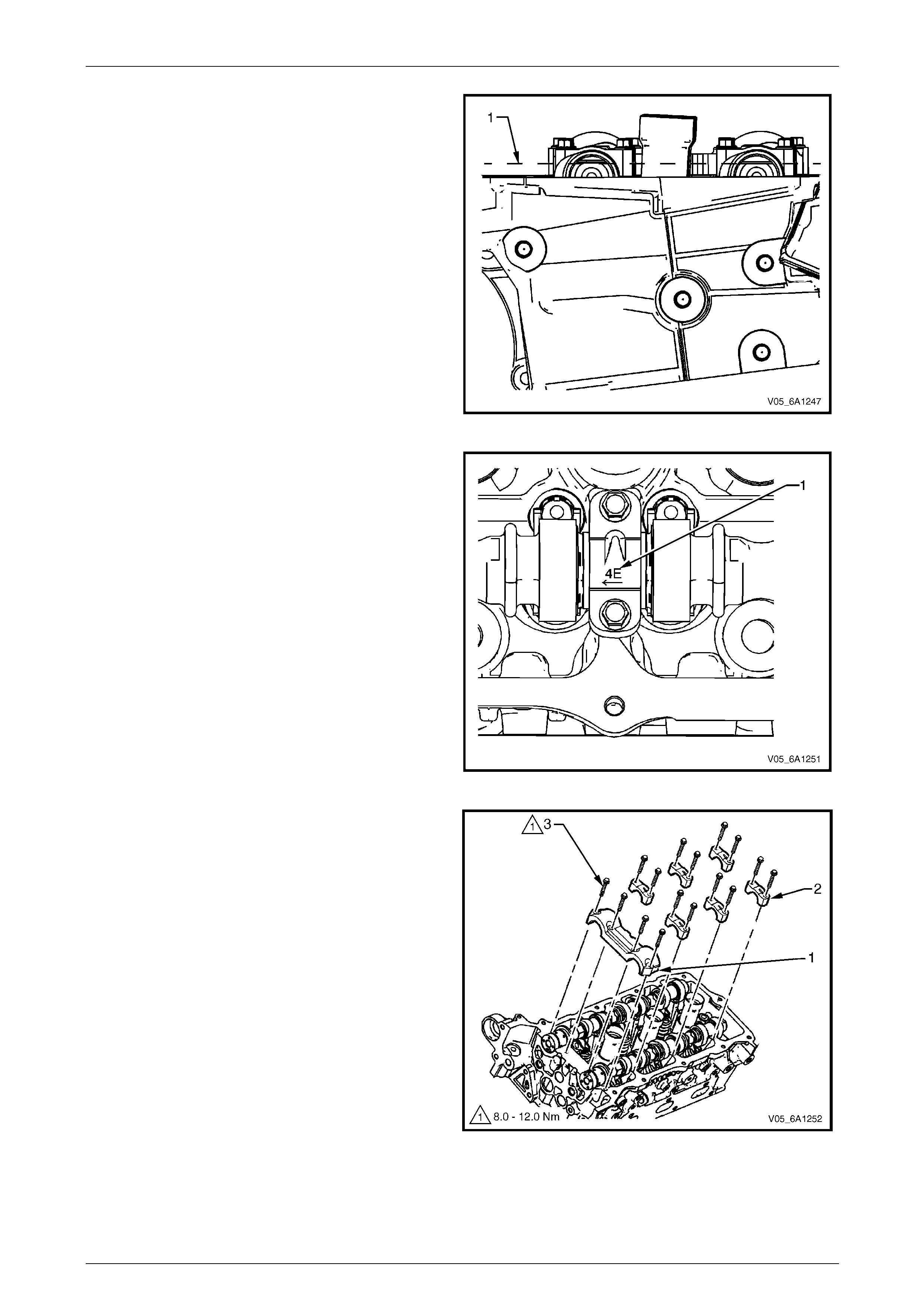
Engine Mechanical – V6 Page 6A1–180
Page 6A1–180
5 Ensure the camshaft lobes are in the neutra l position
with the flats on the back of the camshafts up and
parallel (1) with the left-hand cylind er head camshaft
cover rail.
6 Ensure the marks on the left-hand exhaust camshaft
position actuator and timing chain, made prior to the
disassemble operation are aligned.
7 Ensure the marks on the left-hand intake camshaft
position actuator and timing chain, made prior to the
disassemble operation are aligned.
Figure 6A1 – 276
8 Observe the markings on the left-hand cylinder head
camshaft bearing caps. Each bear ing cap is
marked (1) to identify its location. The markings have
the following meanings:
• The raised feature must always be oriented
toward the centre of the cylinder head.
• The I indicates the intake camshaft.
• The E indicates the exhaust camshaft.
• The number 2, 4, 6 indicates the cylinder
position from the front of the engine.
9 Apply a liberal amount of engine oil to the camshaft
bearing caps.
Figure 6A1 – 277
10 Install the camshaft bearing thrust cap (1) in the first
journal of the left-hand cylinder head.
11 Install the remaining bearing caps (2) with their
orientation mark toward the centre of the cylinder
head.
12 Hand start all the camshaft bearing cap bolt s (3).
Figure 6A1 – 278
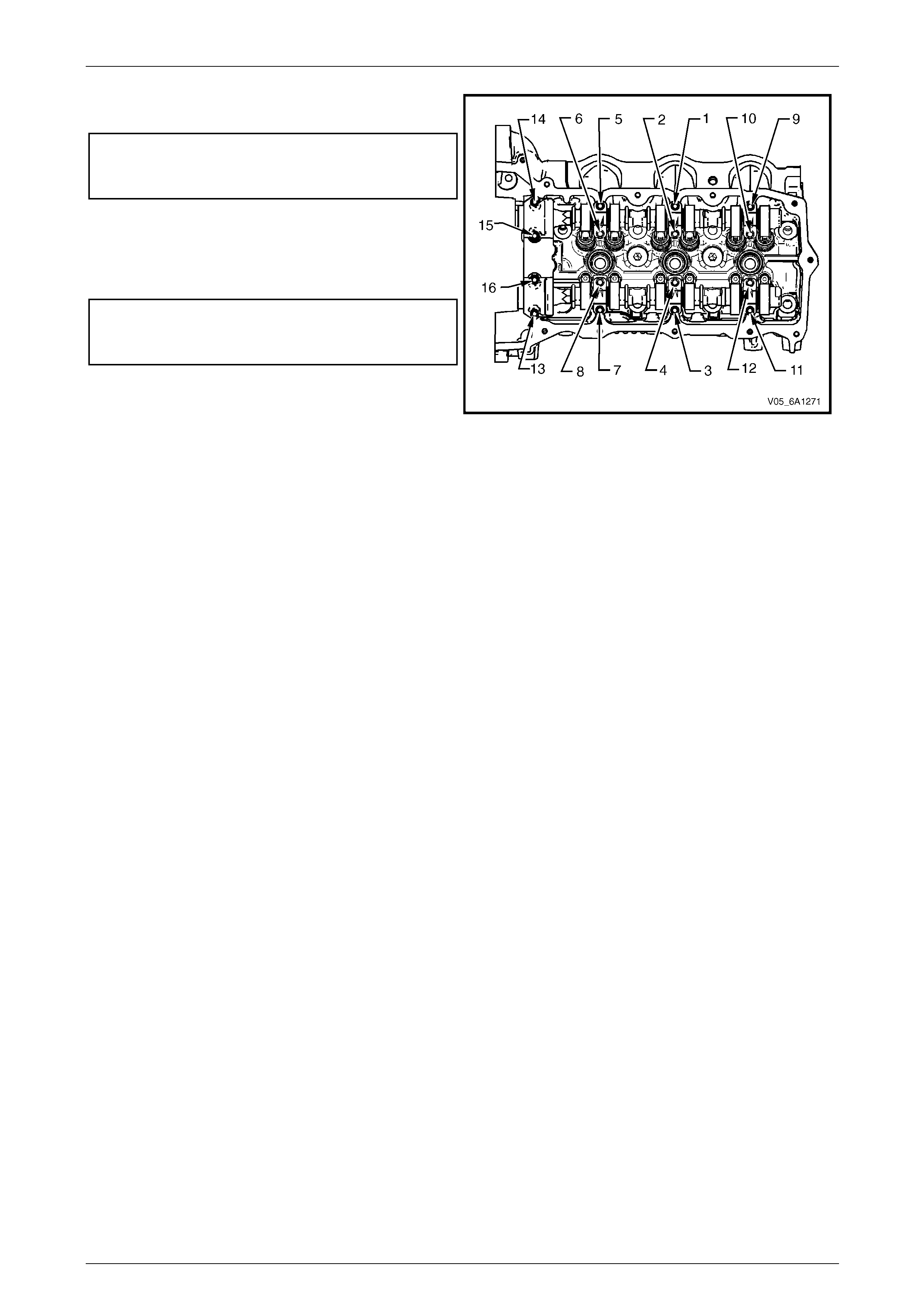
Engine Mechanical – V6 Page 6A1–181
Page 6A1–181
13 Tighten the camshaft bearing cap bolts to the correct
torque specification and i n the sequence shown.
Camshaft bearing cap
bolt torque specification:
Stage 1: ....................................................8.0 – 12.0 Nm
14 Loosen the centre intake camshaft bearing cap bolts
1, and 2, and the centre exhaust camshaft bearing
cap bolts 3 and 4.
15 Retighten the centre camshaft bearing cap b olts 1, 2,
3 and 4 to the correct torque specification.
Camshaft bearing cap
bolt torque specification:
Stage 2: ....................................................8.0 – 12.0 Nm
16 Install the left-hand cylinder head camsh aft positio n
actuators, refer to
3.19 Camshaft Position Actuator Assembly. Figure 6A1 – 279
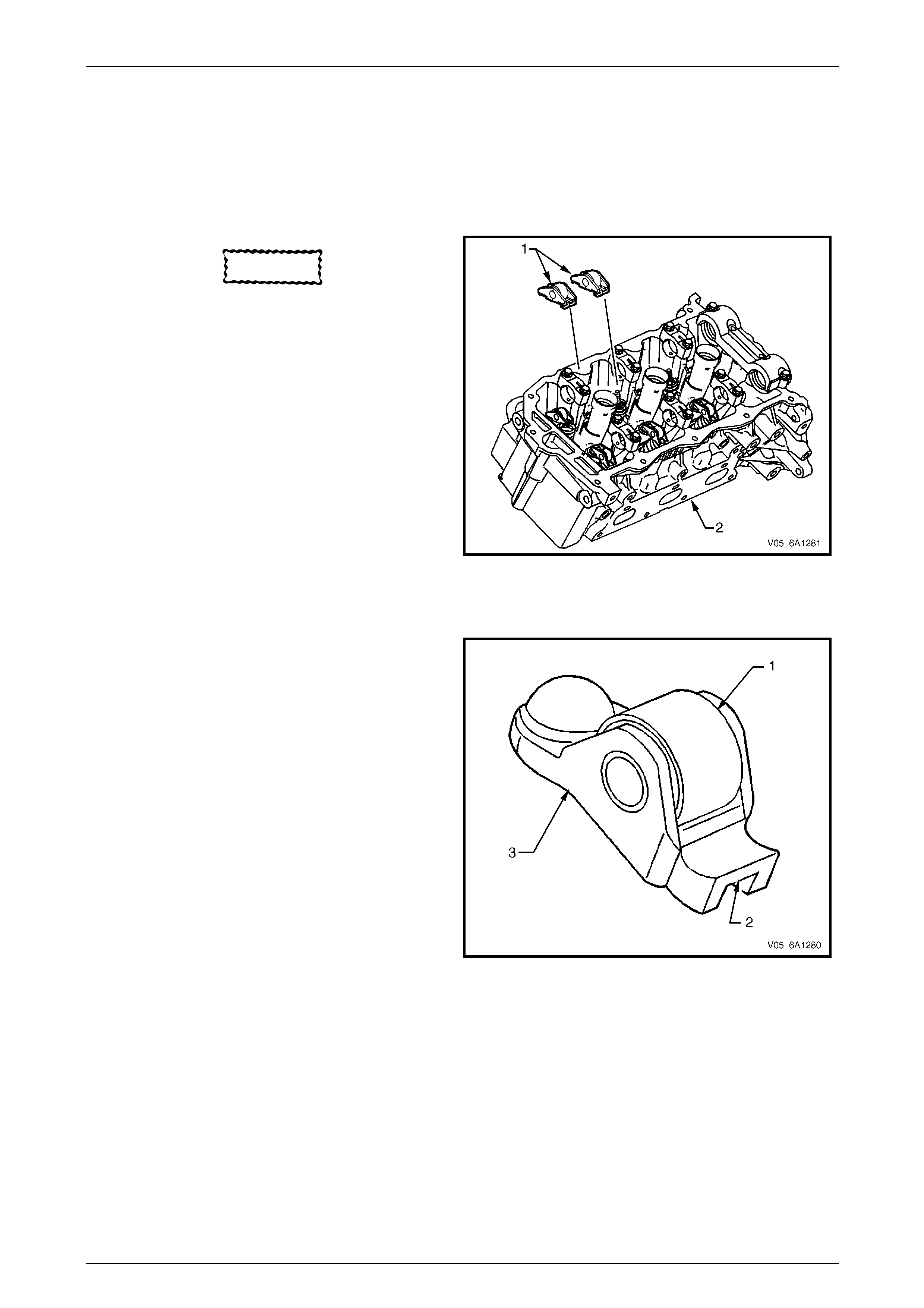
Engine Mechanical – V6 Page 6A1–182
Page 6A1–182
3.21 Rocker Arm
LT Section No. — 00–050
Remove
1 Remove the camshafts from the appropriate cylinder head, refer to 3.20 Camshaft.
CAUTION
If the rocker arms are being reused, they
must be reinstalled in their original location.
NOTE
Record the rocker arm positions during removal.
2 Remove the rocker arm (1) from the cylinder head (2).
Figure 6A1 – 280
Clean and Inspect
1 Inspect the rocker arm roller (1) for the following:
• flat spots,
• excessive scoring and pitting, and
• ensure the roller spins freely
2 Inspect the rocker arm valve tip area (2).
3 Inspect the rocker arm stationary hydraulic lash
adjuster (SHLA) pivot area (3).
4 Replace the rocker arm as required.
Figure 6A1 – 281
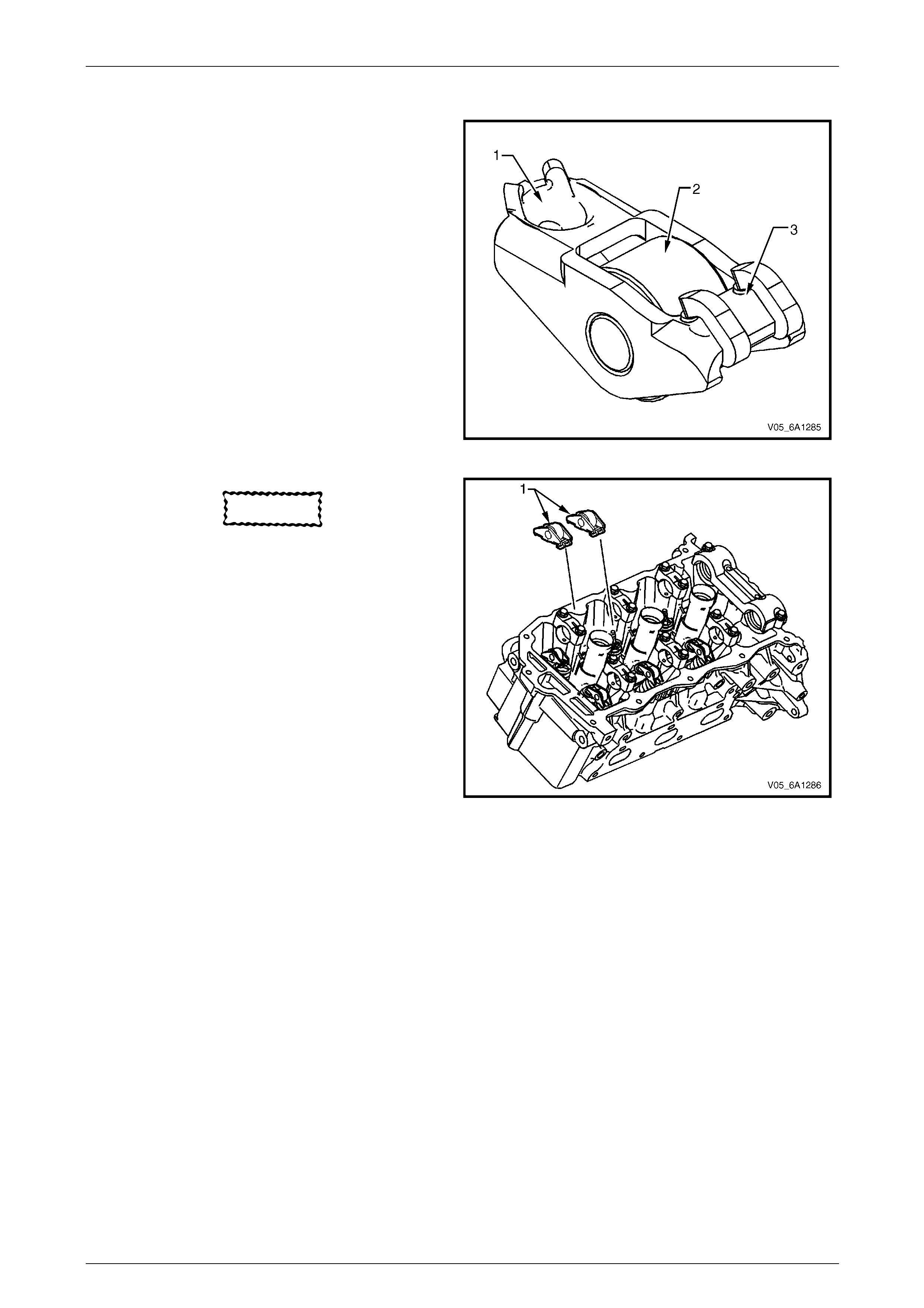
Engine Mechanical – V6 Page 6A1–183
Page 6A1–183
Reinstall
1 Apply a liberal amount of commercially available
camshaft / lifter prelube or equivalent to the pivot
pocket (1), roller (2) and valve slot (3) areas of the
camshaft followers.
Figure 6A1 – 282
CAUTION
• The rocker arm (1) must be positioned
squarely on the valve tip so the full width
of the roller will completely contact the
camshaft lobe.
• If the rocker arms are being reused, they
must be reinstalled in their original
location.
2 Place the rocker arm in position on the valve tip and
stationary hydraulic lash a djuster (SHLA). The
rounded head end of the arm seats on the SHLA
while the flat end seats on the valve tip.
3 Clean the camshaft journals and carriers with a clean,
lint-free cloth.
4 Reinstall the camshafts, refer to 3.20 Camshaft.
Figure 6A1 – 283
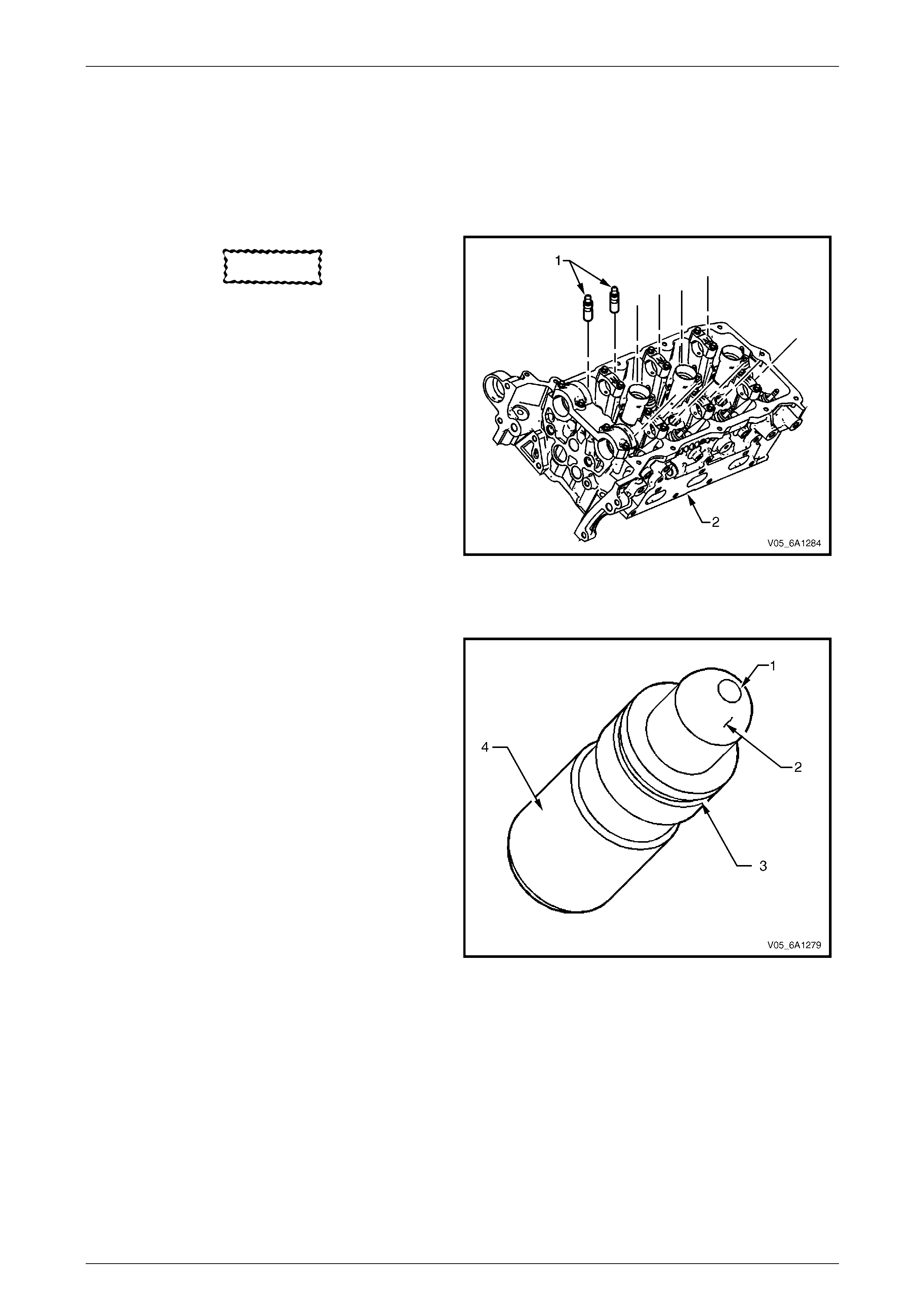
Engine Mechanical – V6 Page 6A1–184
Page 6A1–184
3.22 Stationary Hydraulic Lash Adjuster
LT Section No. — 00–050
Remove
1 Remove the rocker arms from the appropriate cylinder head, refer to 3.21 Rocker Arm.
CAUTION
• Do not stroke/cycle the stationary
hydraulic lash adjuster (1) plunger without
oil in the lower pressure chamber.
• Do not allow the station ary hydraulic la sh
adjuster to tip over, plunger down, after
the oil fill.
2 Remove the stationary hydraulic lash adjuster (SHLA)
from the cylinder head (2).
Figure 6A1 – 284
Clean and Inspect
1 Inspect the stationary hydraulic lash adjuster (SHLA)
in the following areas:
• a plugged oil passage (1),
• a scored or worn camshaft follower pivot
area (2),
• a damaged or broken retainer (3), and
• a severely scuffed or worn SHLA body (4).
2 Replace the SHLA as required.
Figure 6A1 – 285
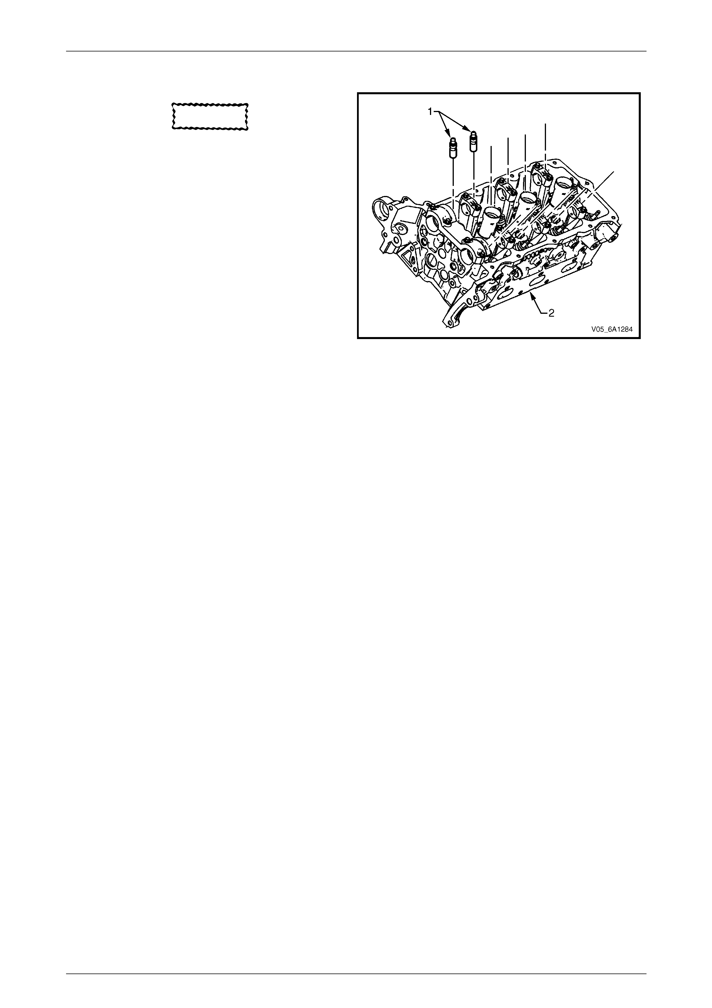
Engine Mechanical – V6 Page 6A1–185
Page 6A1–185
Reinstall
CAUTION
Ensure each lash adjuster (1) is filled with
clean engine oil and the adjuster does not
tip over, plunger down, before the
installation. The loss of oil in the adjuster
lower pressure chamber, or the dry
stroking/cycling of the adjuster plunger, will
allow air to enter the high pressure chambe r
of the valve lifter. Air in the high pressure
chamber of the adjuster may not be purged
causing cavitation and extensive engine
component damage.
1 Fill the stationary hydraulic lash adjuster (SHLA) with
clean engine oil. Take precautions to prevent
scratching the pivot sphere area of the SHLA.
2 Lubricate the SHLA bores in the cylinder head with
clean engine oil.
3 Install the SHLA in the cylinder head (2). Figure 6A1 – 286
4 Apply a liberal amount of commercially available camshaft/lifter prelube to the SHLA pivot spheres.
5 Install the rocker arms, refer to 3.21 Rocker Arm.
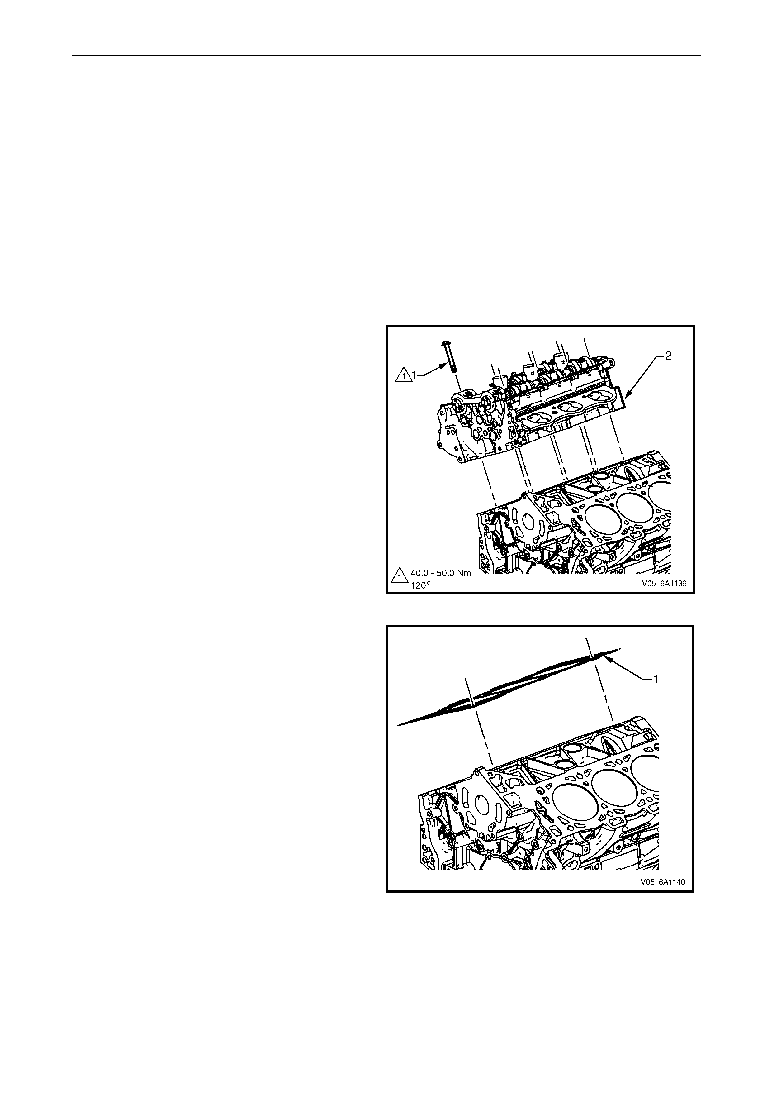
Engine Mechanical – V6 Page 6A1–186
Page 6A1–186
3.23 Cylinder Head Assembly
LT Section No. — 00–075
Remove
Right-hand Side (Bank 1) Cylinder Head
1 Remove the heater hoses and heater pipe assembly, refer to Section 6B1 Engine Cooling – V6.
2 Remove the intake manifold assembly, refer to 3.11 Intake Manifold Assembly – Complete.
3 Remove the exhaust manifold, refer to 3.12 Exhaust Manifold Assembly.
4 Remove engine harness grou nd terminal attaching bolts from the cylinder head,
refer to Section 12O Fuses, Relays and Wiring Harnesses.
5 Remove the right-hand side secondary timing chain, refer to 3.17 Timing Chains, Tensioners, Shoes and Guides.
6 Remove the camshaft position actuators, refer to 3.19 Camshaft Position Actuator Assembly.
7 Remove the cylinder head attaching bolt (1), eight
places.
NOTE
There is no bolt fitted to the hole in the rear of
the right-hand-hand cylinder head.
8 Remove the cylinder head.
Figure 6A1 – 287
9 Remove and discard the cyli nder head gasket (1).
Figure 6A1 – 288
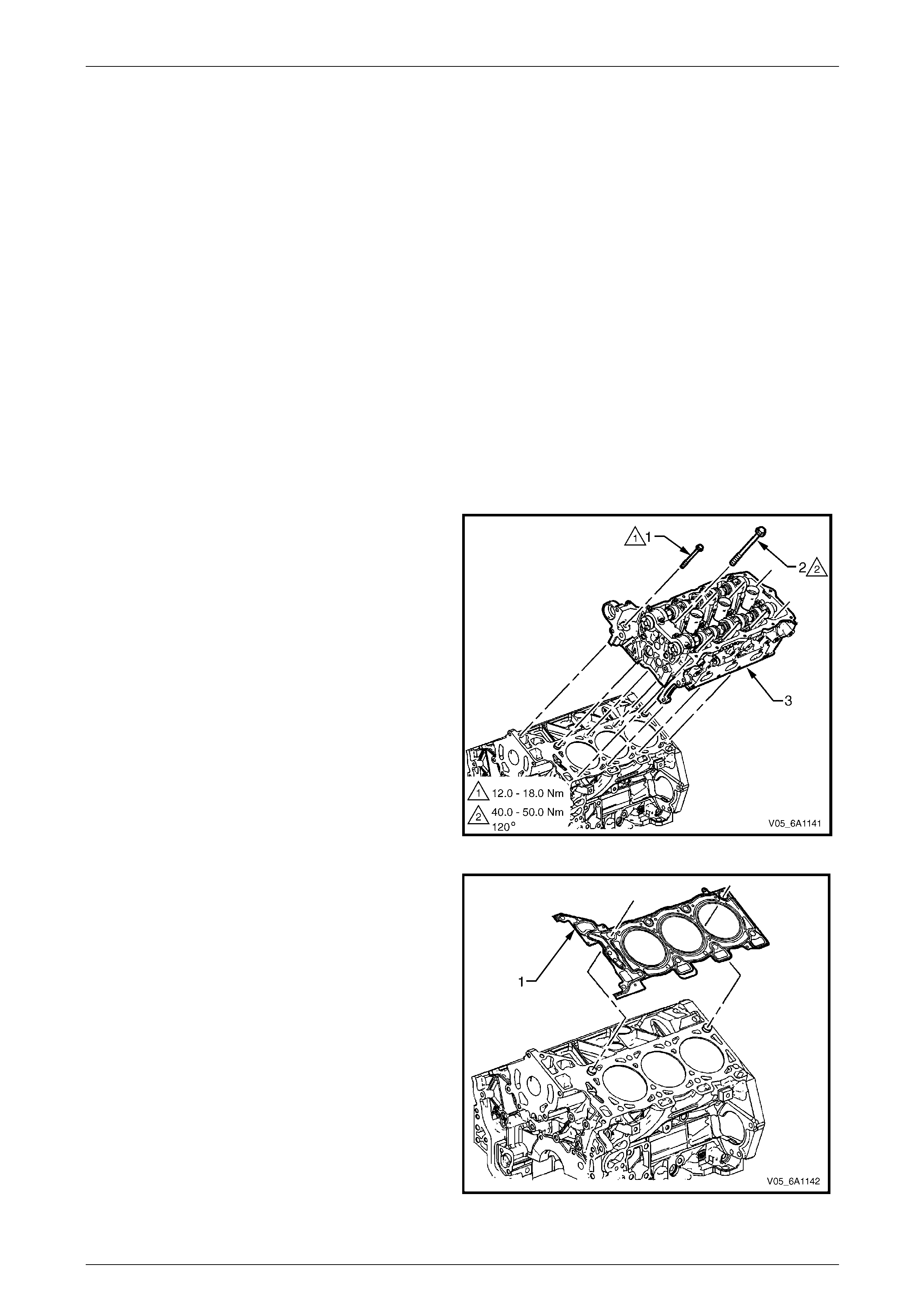
Engine Mechanical – V6 Page 6A1–187
Page 6A1–187
Left-hand Side (Bank 2) Cylinder Head
1 Remove the intake manifold assembly, refer to 3.11 Intake Manifold Assembly – Complete.
2 Remove the exhaust manifold, refer to 3.12 Exhaust Manifold Assembly.
3 Remove the power steering reservoir and pu mp mounting brackets, refer to
3.9 Power Steering Reservoir and Pump Brackets
NOTE
Do not disconnect the power steering pipes
and/or hoses.
4 Remove the oil filter adapter upper b olt.
NOTE
Do not remove the oil filter adapter.
5 Remove the engine coolant temperature (ECT) sensor,
refer to Section 6C1-3 Engine Management V6 – Service Information.
6 Remove engine harness grou nd terminal attaching bolt from cylinder head, refer to
Section 12O Fuses, Relays and Wiring Harnesses.
7 Remove the left-hand bank secondary timing chain, refer to 3.17 Timing Chains, Tensioners, Shoes and Guides.
8 Remove the camshaft position actuators, refer to 3.19 Camshaft Position Actuator Assembly.
9 Remove the front M8 (1) cylinder head attaching bolt,
two places.
10 Remove the cylinder head attaching bolt (2), eight
places.
11 Remove the cylinder head (3).
Figure 6A1 – 289
12 Remove and discard the cyli nder head gasket (1).
Figure 6A1 – 290
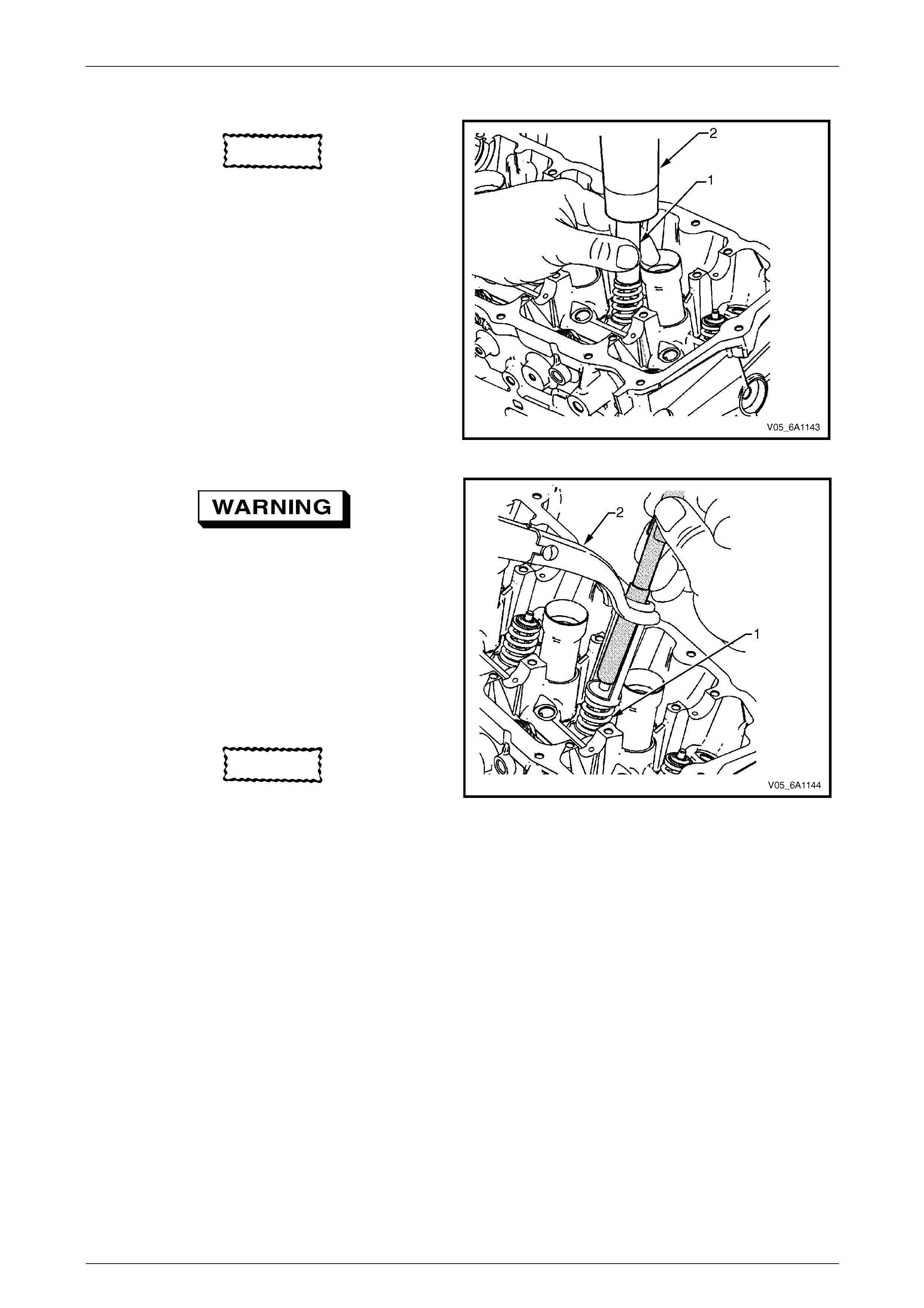
Engine Mechanical – V6 Page 6A1–188
Page 6A1–188
Disassemble
CAUTION
Ensure valve heads w ill not contact anyth ing
during the following step in order to avoid
bending or damage.
1 Using an appropriately sized deep socket (1) and a
plastic hammer (2), lightly tap on the valve spring
retainer to loosen the valve collets.
Figure 6A1 – 291
Compressed valve springs (1) have high
tension against the valve spring
compressor (2). Valve springs that are not
correctly compressed by, or are released
from the valve spring compressor can be
ejected from the valve spring compressor
with intense force. Use care when
compressing or releasing the valve spring
with the valve spring compressor and when
removing or installing the valve stem keys.
Failing to use care may cause personal
injury.
CAUTION
Do not compress the valve springs less than
24.0 mm. Contact between the valve spring
retainer and the valve stem oil seal can ca use
potential valve stem oil seal damage.
2 Compress the valve spring (1) using valve spring
compressor Tool No. J-8062 (2) and ada ptor Tool No.
EN-46119.
Figure 6A1 – 292
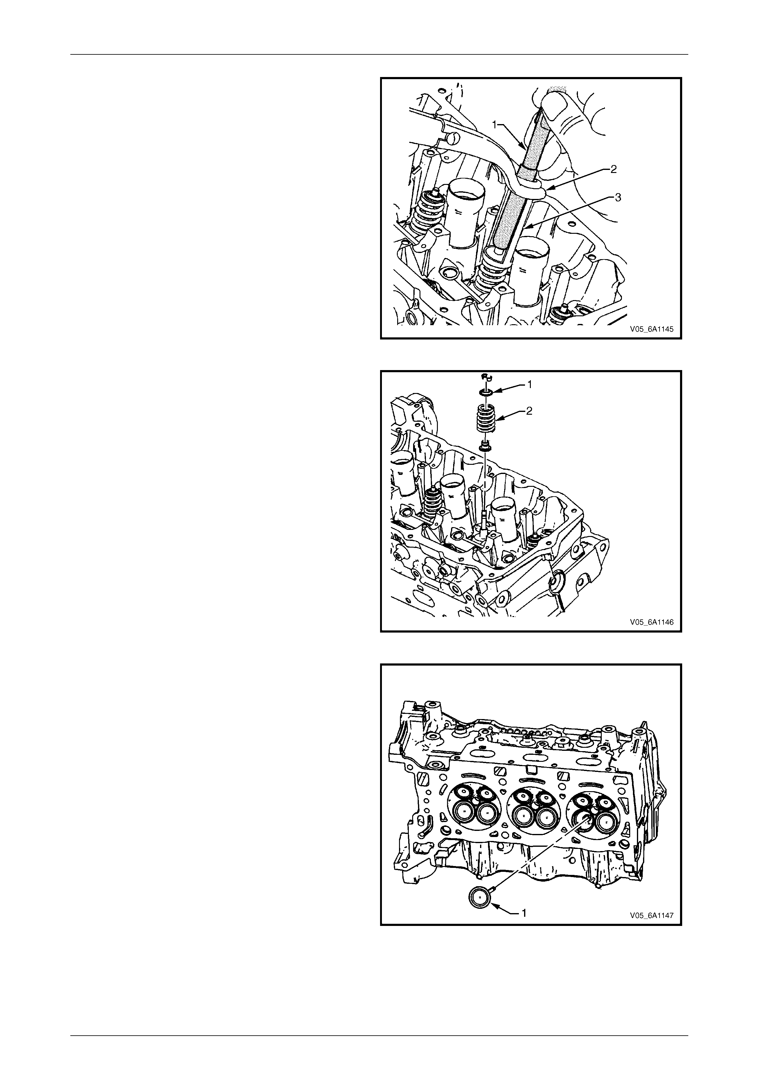
Engine Mechanical – V6 Page 6A1–189
Page 6A1–189
3 Remove the valve collets using Tool EN-46117 (1).
4 Remove the valve spring compressor (2) a nd the
adapter (3).
Figure 6A1 – 293
5 Remove the valve spring retainer (1).
6 Remove the valve spring (2).
Figure 6A1 – 294
7 Remove the valves (1).
Figure 6A1 – 295
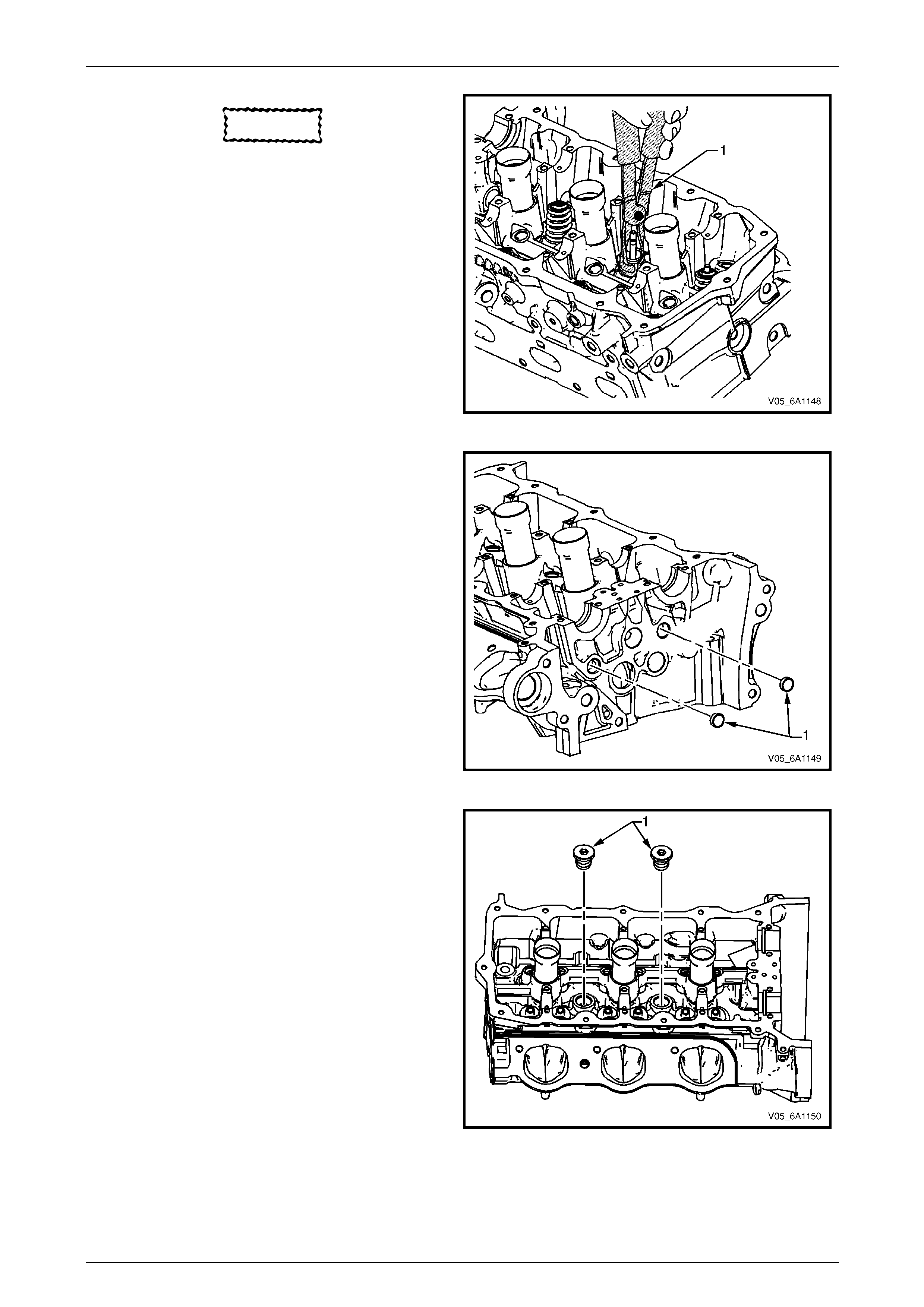
Engine Mechanical – V6 Page 6A1–190
Page 6A1–190
CAUTION
Never reuse a valve stem oil seal.
8 Remove the valve stem oil seal using Tool No.
EN-46116 and discard.
9 Repeat these procedures for the remaining valves.
Figure 6A1 – 296
10 Remove the cylinder head oil gallery expansi on
plugs (1).
Figure 6A1 – 297
11 Remove the cylinder head coola nt threaded plugs (1).
Figure 6A1 – 298
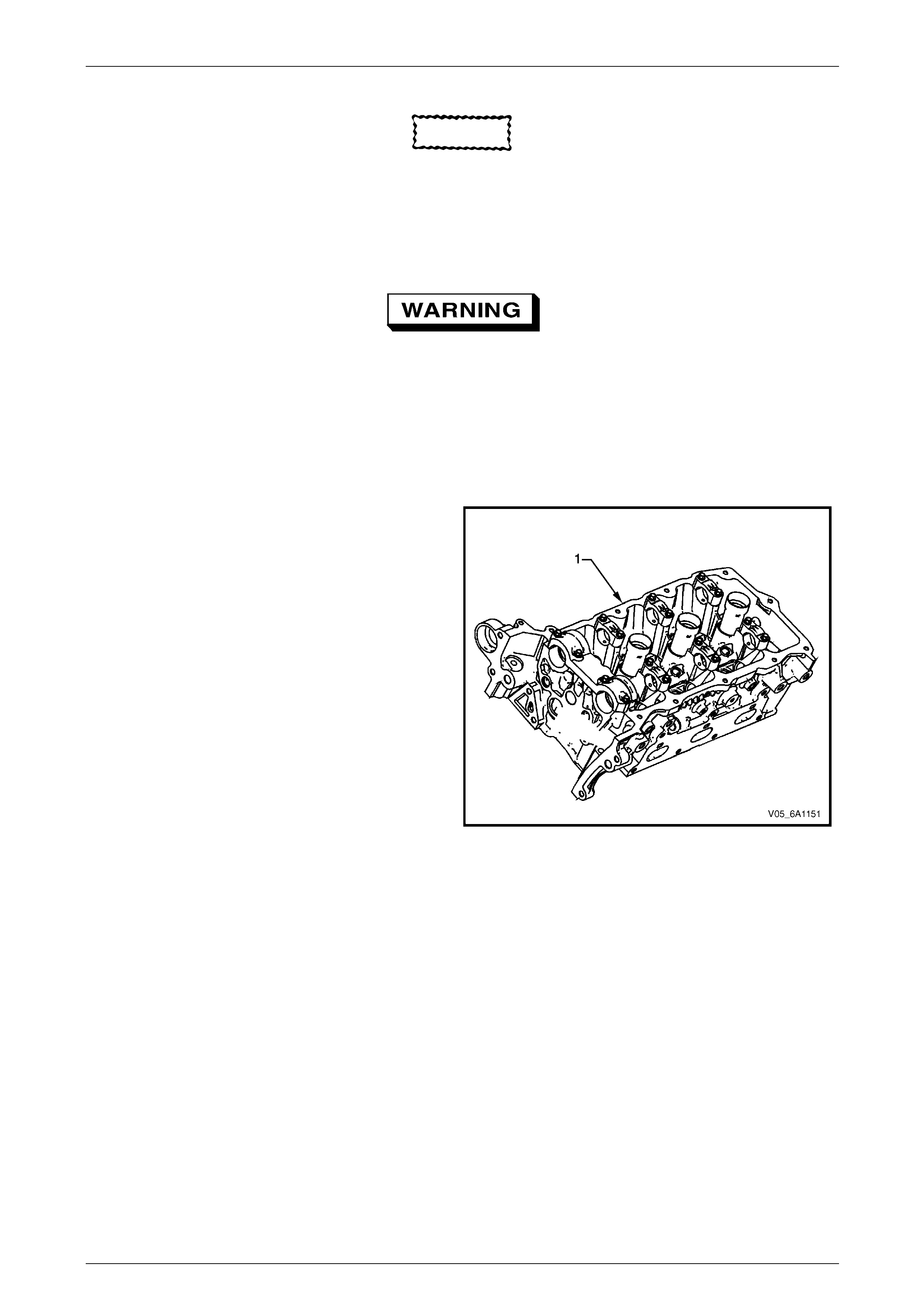
Engine Mechanical – V6 Page 6A1–191
Page 6A1–191
Clean
CAUTION
Due to the aluminium alloy construction of
the cylinder head, wire brushes and steel
scrapers must not be used during the
cleaning process, as damage to sealing
surfaces may occur. Use a wood or plastic
scraper as an alternative.
1 Remove any old thread seal ant, gasket material or sealant using commercially available plastic or wooden scraper.
2 Clean all cylinder head surfaces with non-corrosive solvent.
Safety glasses must be worn when using
compressed air.
3 Blow out all the oil galleries using compressed air.
4 Remove any carbon de posits from the combustion chambers.
5 Clean any debris or bui ld-up from the lifter pockets.
Inspect
Visual Inspection
1 Inspect the cylinder head (1) camshaft bearing
surfaces for the following conditions:
• excessive scoring or pitting,
• discoloration from overheating, and
• deformation from excessive wear.
2 If any of the above conditions exist on the camshaft
bearing surfaces, replace the cylinder head. Do not
machine the camshaft bearing journals.
Figure 6A1 – 299
3 Inspect the cylinder head for the follo wing:
• Cracks, damage or pitting in the combustion chambers.
• Debris in the oil galleries. continue to clean the galleri es until all debris is removed.
• Coolant leaks or damage to the deck face seali ng surface. if coolant leaks are present, measure the surface
warpage as described under Cylinder Head Measurement within this Section.
• Burrs or any defects that would degrade the sealing of a new secondary camshaft chain tensioner gasket.
• Damage to any gasket surfaces.
• Damage to any threaded bolt holes.
• Burnt or eroded areas in the combustion chamber.
• Cracks in the exhaust ports and combustion chambers.
• External cracks in the water passages.
• Restrictions in the intake or exhaust passages.
• Restrictions in the cooling system passages.
• Rusted, damaged or leaking core plugs.
4 If the cylinder head is cracked or damaged, it must be replaced. No welding or patching of the cylinder he ad is
recommended.
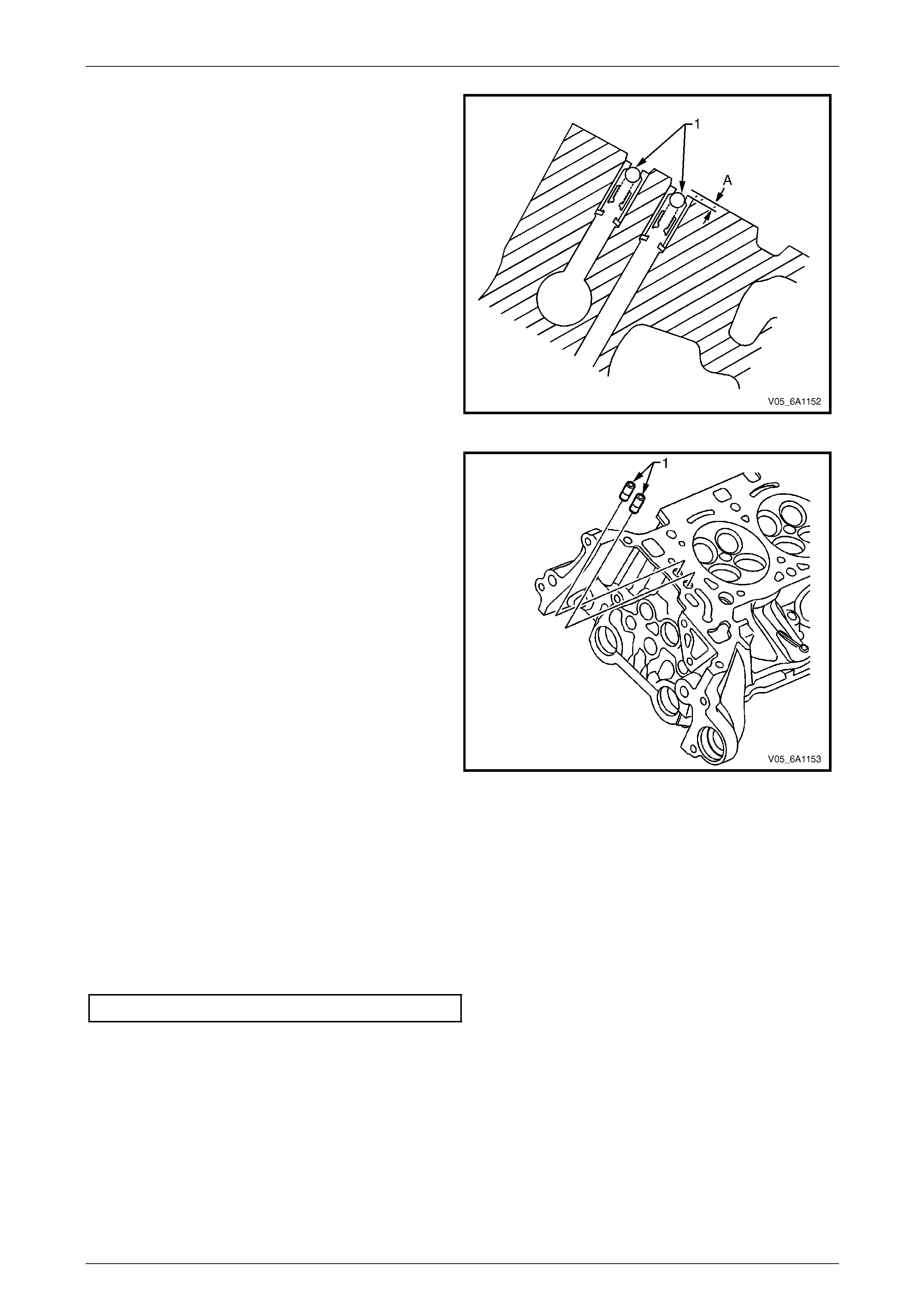
Engine Mechanical – V6 Page 6A1–192
Page 6A1–192
5 Inspect the camshaft position actuator oil feed check
valves (1) to ensure they are correctly positioned in
the cylinder head. T he camshaft position actuator oil
feed check valve should be flush to 2 mm below the
cylinder head deck surface (A).
Figure 6A1 – 300
6 Damaged, restricted or clogged check va lves (1) can
be replaced using the camshaft position actuator
check-ball remover/installer, Tool No. EN-46122.
Figure 6A1 – 301
Cylinder Head Measurement
NOTE
For all cylinder head and associated component
specifications, refer to 5 Specifications.
Camshaft Journal Clearance
1 Install the camshaft bearing cap in the c ylinder head without the camshaft.
2 Install the camshaft cap bolts and tighten to the correct torq ue specification
Camshaft bearing cap attaching bolt........8.0 – 12.0 Nm.
3 Measure the camshaft bearings using an inside micrometer.
4 Subtract the camshaft journal diameter from the camshaft beari ng diameter. This will provide the running
clearance. If the running clearance exceeds specifications and the camshaft journals are within specification,
replace the cylinder head.
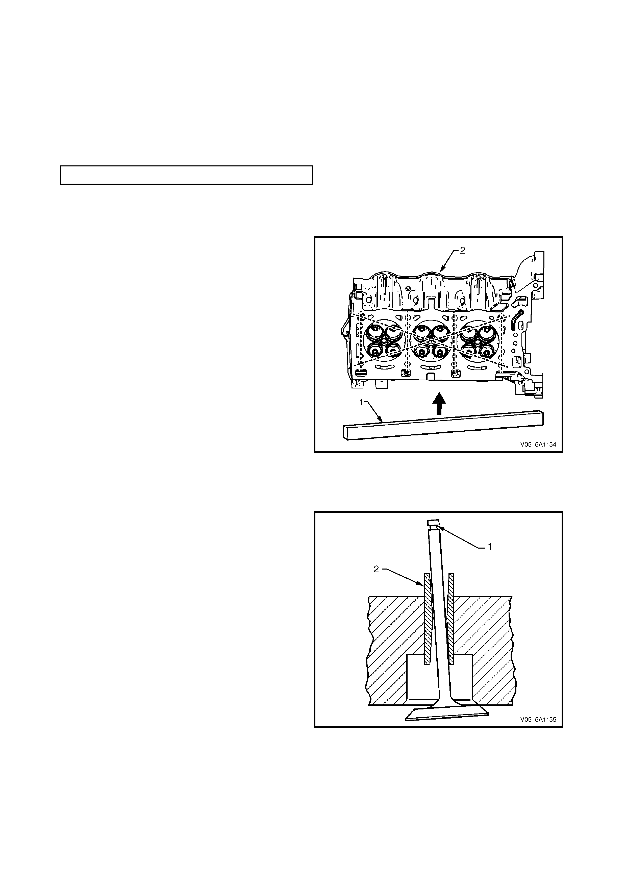
Engine Mechanical – V6 Page 6A1–193
Page 6A1–193
Camshaft Journal Alignment
1 Ensure the camshafts are serviceable, refer to 3.20 Camshaft for measuring procedures.
2 Inspect the cylinder head camshaft bearing surfaces for any imperfections or scratches that could inhibit correct
camshaft clearances. Repair minor imperfections or scratch es.
3 Install the camshafts in the cylinder head.
4 Install the camshaft bearing caps.
5 Install the camshaft cap bolts and tighten to the correct torq ue specification.
Camshaft bearing cap attaching bolt........8.0 – 12.0 Nm.
6 Ensure the camshafts spin freely in the cylinder head. If the camshaft does not run freely, replace the cylinder
head.
Deck Flatness Insp ection
1 Ensure the cylinder head decks are clean and free of
gasket material.
2 Inspect the surface for any imperfections or scratches
that could inhibit correct cylinder head gasket sealing.
3 Place a straight-edge (1) diagonally across the
cylinder head (2) deck face surface.
4 Measure the clearance between the straight-edge
and the cylinder head deck fa ce using a feeler gauge
at four points along the straight-edge.
5 If the warpage is less than 0.05 mm, the cylinder
head deck surface does not r equire resurfacing.
6 If the warpage is between 0.05±0.20 mm or any
imperfections or scratches that could inhibit correct
cylinder head gasket sealing are present, the cylinder
head deck surface requires resurfacin g.
7 If resurfacing is required the maximum amount that
can be removed is 0.25 mm.
8 If the cylinder head deck surface requires mo re than
0.25 mm material removal the head must be
replaced. Figure 6A1 – 302
Valve Guide Measurement
1 Measure the valve stem (1) to-guide (2) clearanc e.
Excessive valve stem-to-guide clearance may cause
excessive oil consumption and may also cause a
valve to break. Insufficient clearance will result in
noisy and sticky functioning of the valve and will
disturb the engine assembly smoothn ess.
2 Clamp a dial indicator to the cyl ind er head at the
camshaft cover rail.
3 Locate the dial indicator so the movement of the valv e
stem from side to side, crossways to the cylinder
head, will cause a direct movement of the in dicator
stem. The dial indicator stem must contact the side of
the valve stem just above the valve g uide.
4 Drop the valve head about 0.064 mm off the valve
seat.
5 Use light pressure when moving the valv e stem from
side to side to obtain a clearance reading, re fer to
5 Specifications.
• If the clearance for the valve is greater than
specified and a new standard diameter valve
stem will not bring the clearance within
specifications, the valve guide may be oversized
by 0.075 mm using the valve guide reamer, Tool
No. J 42096 or by 0.375 mm using the valve
guide reamer, Tool No. EN-46120. Two sizes of
oversized valve stems are availa ble for service.
Figure 6A1 – 303
• Valve guide wear at the bottom 10 mm of the valve guide is not significant enough to affect normal operation.
• If over sizing the guide does not bring the clearance within specifications, replace the cylinder head.
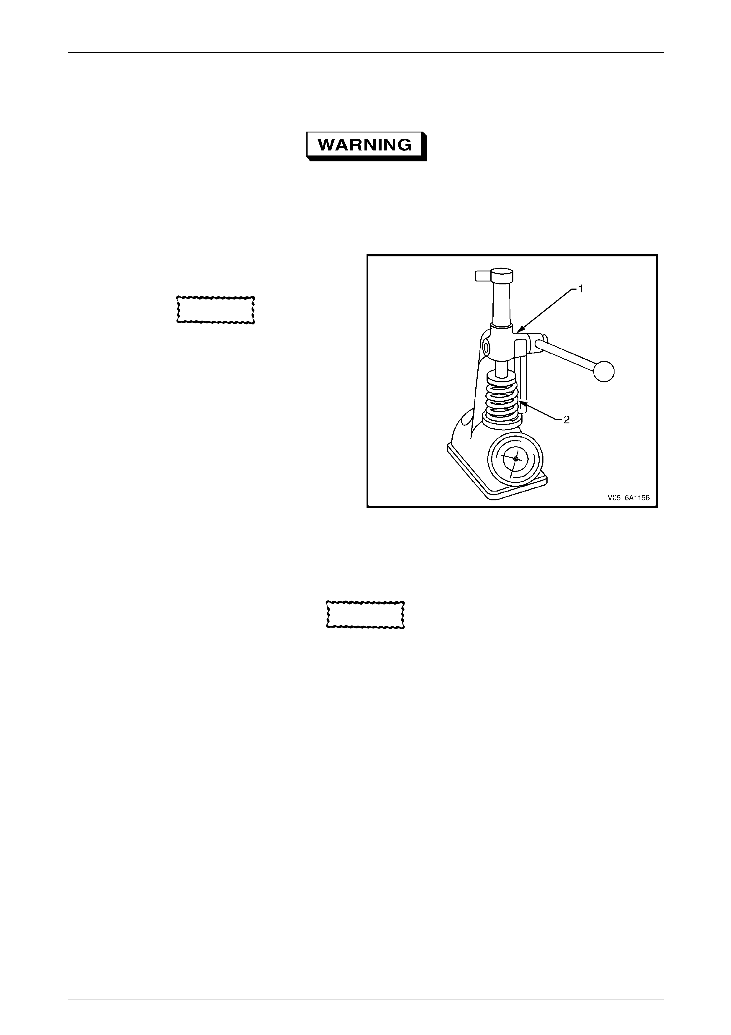
Engine Mechanical – V6 Page 6A1–194
Page 6A1–194
Valve Spring Inspection and Measurement
Inspection Procedure
1 Clean the valve springs in solvent.
Safety glasses must be worn when using
compressed air
2 Dry the valve springs with compressed air.
3 Inspect the valve springs for broken coils or coil ends.
Measurement Proced ure
1 Use a commercially available valve spring tester to
measure the valve spring tension, refer to
5 Specifications.
CAUTION
Do not use shims to increase spring load.
The use of shims can cause the valve spring
to bottom out before the camshaft lobe is at
peak lift.
2 If low valve spring load is found, replace the valve
springs.
Figure 6A1 – 304
Valve and Seat Grinding
Valve Cleaning Procedure
CAUTION
Do not use a wire brush on any part of the
valve stem. The valve stem is chrome plated
to provide enhanced wear characteristics.
Wire brushing the stem could remove the
chrome plating.
1 Use soft bristle brush to clean any carbon build-up from the valve head.
2 Thoroughly cle an the valve with solvent and wipe dry.
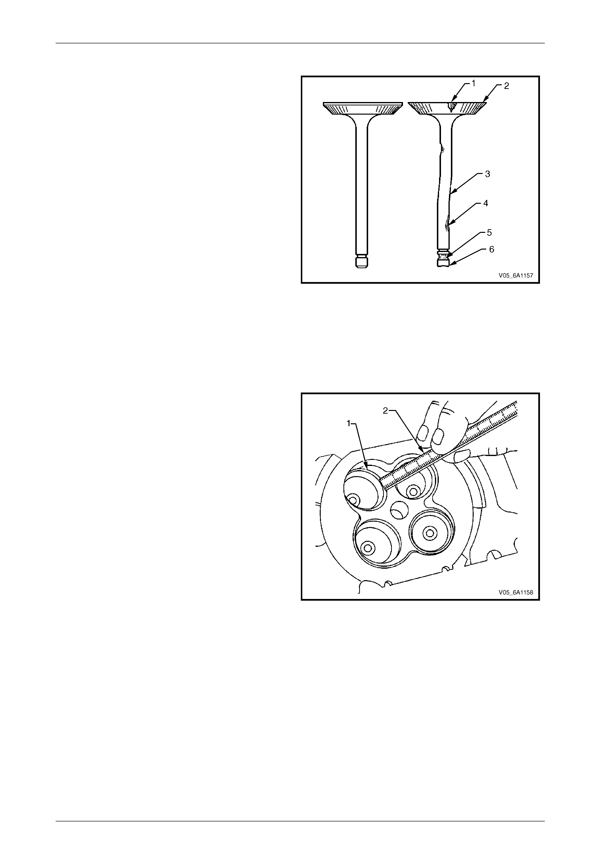
Engine Mechanical – V6 Page 6A1–195
Page 6A1–195
Valve Visual Inspection Procedu re
1 Inspect the valve for damage from the head to tip for
the following conditions:
• pitting in the valve seat area (1),
• lack of valve margin (2),
• bending in the valve stem (3),
• pitting or excessive wear in the stem (4),
• worn valve key grooves (5), and
• worn valve tip (6).
2 Replace the valve if any of these conditions exist.
Figure 6A1 – 305
Valve Measurement and Reconditioning Overview
Correct valve service is critical to engine performance. Therefore, all detailed measurement procedures must be followed
to identify components that are out of specification. If the measurement procedures reveal the valve or valve seat must
be reconditioned, it is critical to perform the measurement procedures after reconditio ning.
Valve Seat Width Measurem ent Procedure
1 Measure the valve seat (1) width in the c yli nder head
using a scale (2).
Figure 6A1 – 306
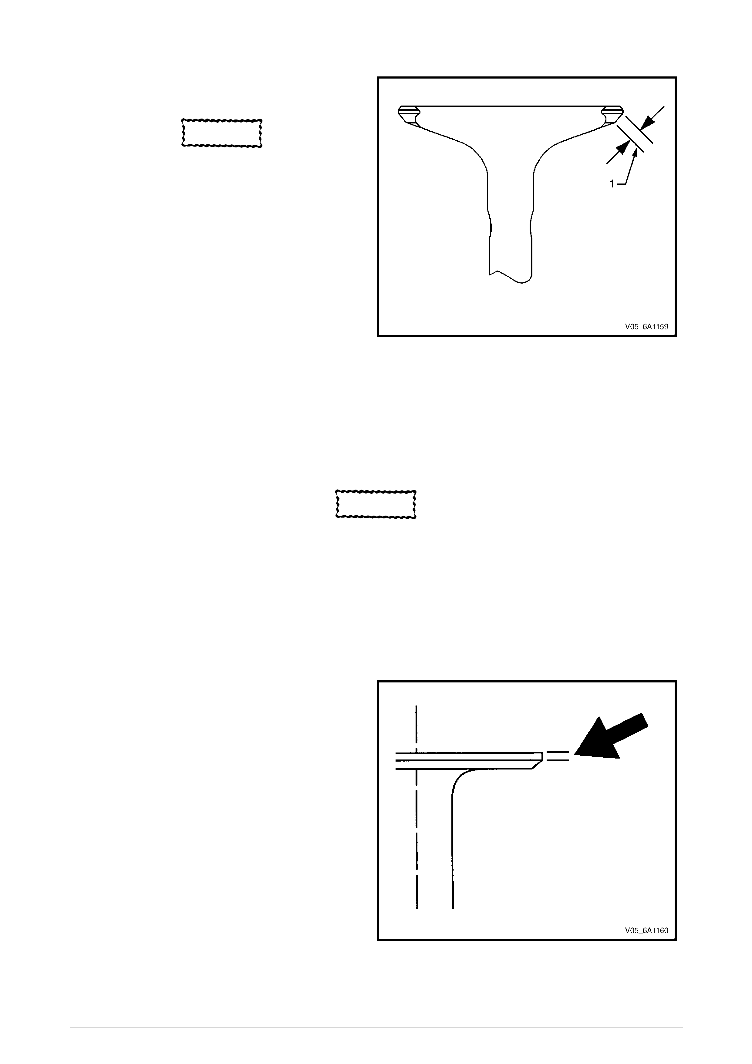
Engine Mechanical – V6 Page 6A1–196
Page 6A1–196
2 Measure the seat width on the valve face (1) using a
correct scale.
CAUTION
The seat contact area must be at least
0.5 mm from the outer diameter (margin) of
the valve. If the contact area is too close to
the margins, the seat must be reconditioned
to move the contact area away from the
margin.
3 Compare the measurements with the specifications,
refer to 5 Specifications.
4 If the seat widths are acceptable, check the valve
seat roundness, refer to Valve Seat Roundness
Measurement Procedure in this Section.
5 If the seat width is not acceptable, grind the valve
seat to bring the width back to specification. Correct
valve seat width is critical to providing the correct
amount of valve heat dissipation, refer to
Valve and Seat Reconditionin g Proced ure in this
Section.
Figure 6A1 – 307
Valve Seat Roundness Measurement Procedure
1 Measure the valve seat roundness using a dial indicator attached to a tapered pilot installed in the guide. The pilot
should have a slight bind when installed in the guide.
CAUTION
The correct size pilot must be used. Do not
use adjustable diameter pilots. Adjustable
pilots may damage the valve guides.
2 Compare your measurements with the specifications, refer to 5 Specifications.
3 If the valve seat exceeds the roundness specification, grind the valve and valve seat,
refer to Valve and Seat Reconditioning Procedure in this Section.
4 If new valves are being used, the valve seat roundness must be within 0.05 mm.
Valve Margin Measurement Procedure
1 Measure the valve margin using an appropriate scale.
2 Refer to 5 Specifications for minimum valve margin
and compare them to your measurements.
3 If the valve margins are beyond specification, replace
the valves.
4 If the valve margins are within specification a nd do
not require refacing, test the valve for seat
concentricity, refer to Valve-to-Seat Concentricity
Measurement Procedure in this Section.
Figure 6A1 – 308
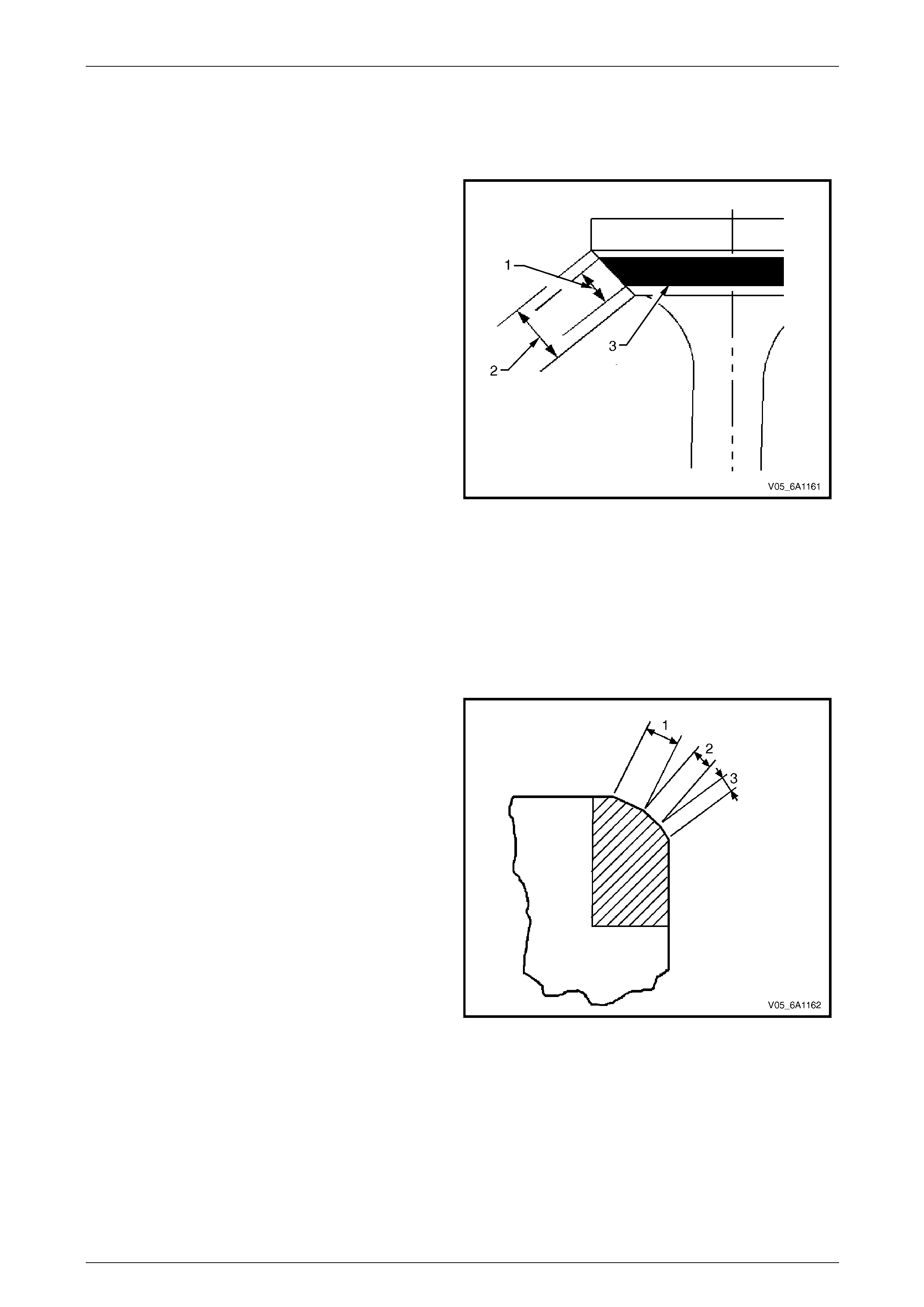
Engine Mechanical – V6 Page 6A1–197
Page 6A1–197
Valve-to-Seat Concentricity Measurement Pro cedu re
Checking the valve-to-seat concentric ity determines whether the valve and seat are sealing correctly.
Measure the valve face and the valve seat to ensure correct valve sealing.
1 Coat the valve face lightly with blue d ye ( 3).
2 Install the valve in the cylinder head.
3 Turn the valve against the seat with enough pressure
to wear off the dye.
4 Remove the valve from the cylinder hea d.
5 Inspect the valve face.
• If the valve face is concentric, providing a
correct seal, with the valve stem, a continuous
mark (1) will be made around the entire face (2).
NOTE
The wear mark must be at least 0.5 mm from
the margin of the valve. If the wear mark is too
close to the margin, the seat must be
reconditioned to move the contact area away
from the margin.
• If the face is not concentric with the stem, the
mark will not be continuous aroun d the valve
face. The valve should be refaced or replace d
and the seat must be reconditioned, refer to
Valve and Seat Reconditioning Procedure in
this Section.
Figure 6A1 – 309
Valve and Seat Reconditioning Procedure
If the valve seat width, roundness or concentricity are beyond specifications, grind the seats in order to ensure correct
heat dissipation and prevent the build up of carbon on the seats.
If valve seat reconditioning is required, reface the valve face, unless a ne w valve is used.
1 Grind the valve seats (2) to the correct angle
specification, refer to 5 Specifications.
2 Using the correct angle specification, gri nd and
relieve the valve seats (1) to correctly positio n the
valve seating surface (2) to the valve.
3 Using the correct angle specification, grind and
undercut the valve seats (3) to narrow the valve seat
widths to the specifications, refer to 5 Specifications.
4 If the original valve is being used, grind the valve to
the specifications, refer to 5 Specifications. Measure
the valve margin again after grindi ng, refer to
Valve Margin Measurement Procedure in this Section.
Replace the valve if the margin is out of spec ification.
New valves do not require grin ding.
5 When grinding the valves and seats, grind off as little
material as possible. Cutting valve seat results in
lowering the valve spring pressure.
6 Install the valve in the cylinder head.
Figure 6A1 – 310
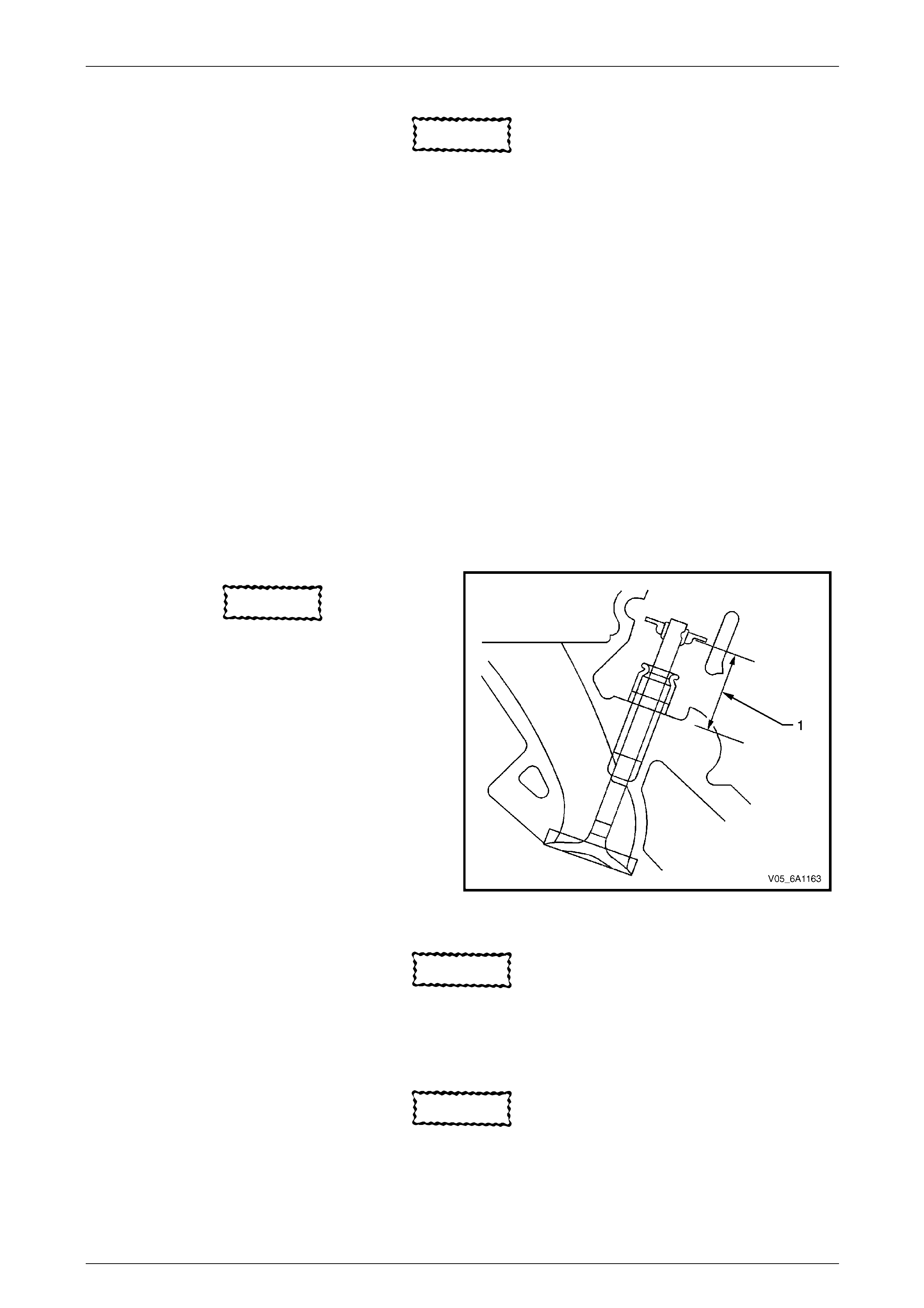
Engine Mechanical – V6 Page 6A1–198
Page 6A1–198
CAUTION
If using refaced valves, lap the valves into the
seats with a fine grinding compound. The
refacing and reseating operations should
leave the refinished su rfaces smooth and true
so that minimal lapping is required. Excessive
lapping will groove the valve face and prevent
a good seat when hot.
NOTE
Clean any remaining lapping compound from the
valve and seat with solvent and compressed air
prior to final assembly.
NOTE
If fitting new valves, do not lap the valves under
any condition.
7 After obtaining the correct valve seat width in the cylinder head, measure the valve stem height,
refer to Valve Stem Height Measurement Proced ure in this Section.
8 If the valve stem height is acceptable, test the seats for concentricity,
refer to Valve-to-Seat Concentricity Measurement Procedure in this Sectio n.
Valve Stem Height Measuremen t Procedure
CAUTION
To determine the valve stem height
measurement, measure from the valve
spring seat to the valve spring retainer.
1 Install the valve into the valve guide.
2 Ensure the valve is seated to the valve seat.
3 Install the valve stem oil seal.
4 Install the valve spring retainer and valve stem keys.
5 Measure the distance (1) betwee n the cylinder head
to the bottom of the valve spring retainer, refer to
5 Specifications.
6 If the maximum height specification is e xceede d, a
new valve should be installed and the va lve stem
height re-measured.
Figure 6A1 – 311
CAUTION
Do not grind the valve stem tip. The tip of the
valve is hardened and grinding the tip will
eliminate the hardened surface causing
premature wear and possible engine damage.
CAUTION
Do not use shims to adjust val ve stem heigh t.
The use of shims will cause the valve spring
to bottom out before the camshaft lobe is at
peak lift and engine damage cou l d result.
7 If the valve stem height still exceeds the maximum height specific ation, the cylinder head must be replaced.
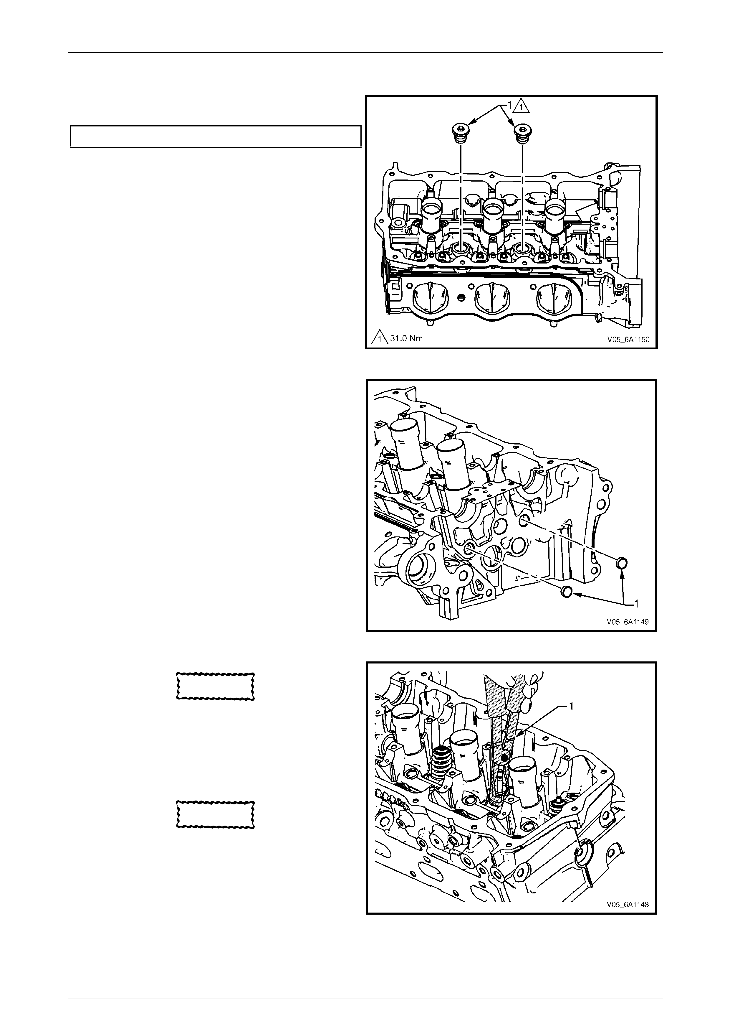
Engine Mechanical – V6 Page 6A1–199
Page 6A1–199
Assemble
1 Install the cylinder head coola nt threaded plugs (1)
and tighten to the correct torque specification.
Cylinder head threaded plug..............................31.0 Nm
Figure 6A1 – 312
2 Install the cylinder head oil gallery expansion
plugs (1).
Figure 6A1 – 313
CAUTION
Never reuse a valve stem oil seal. Always
use new seals w hen assembling the cylinder
head.
3 Fit the valve stem oil seals onto the guides using Tool
No. EN-46116 (1).
CAUTION
Force should only be applied to the valve
spring contact area o f the n ew valve stem oil
seal during installation.
4 Push and twist the valve stem oil seal into position on
the valve guide until the seal positively locks on the
guide using Tool No. EN-4 6116.
5 Lubricate the valve stem and valve guide ID with
clean engine oil.
Figure 6A1 – 314
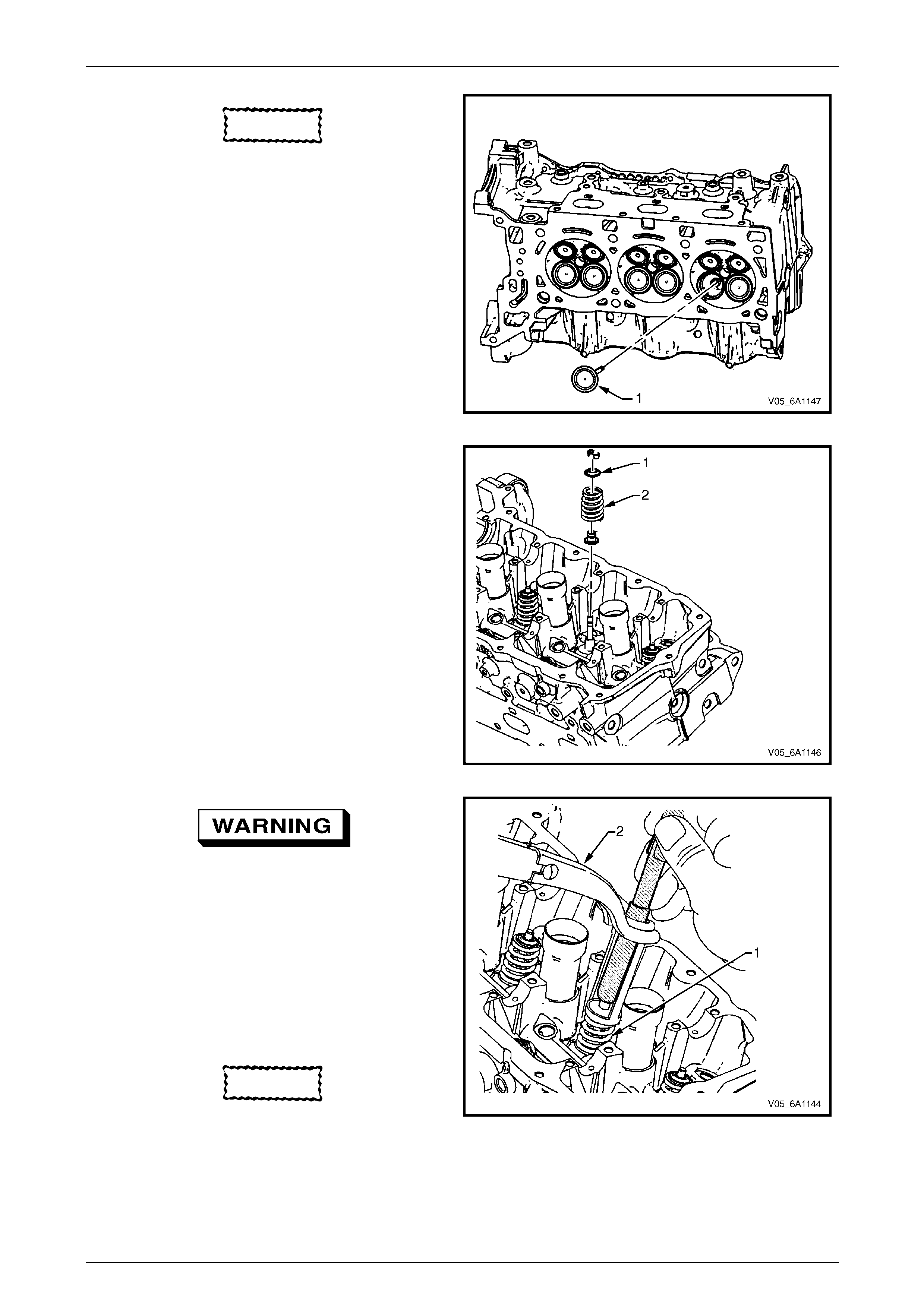
Engine Mechanical – V6 Page 6A1–200
Page 6A1–200
CAUTION
The valve stem oil seal must no t come loose
from the valve guide when the valve (1) is
installed.
7 Insert the valve into the valve guide until it bottoms on
the valve seat.
Figure 6A1 – 315
8 Position the valve spring (2) on the spring seat (1).
9 Place the valve spring retainer onto the valve spring.
Figure 6A1 – 316
Compressed valve springs (1) have high
tension against the valve spring
compressor (2). Valve springs that are not
correctly compressed by, or are released
from, the valve spring compressor can be
ejected from the valve spring compressor
with intense force. Use care when
compressing or releasing the valve spring
with the valve spring compressor and when
removing or installing the valve stem keys.
Failing to use care may cause personal
injury.
CAUTION
Do not compress the valve springs less than
24.0 mm. Contact between the valve spring
retainer and the valve stem oil seal can
cause potential valve stem oil seal damage.
10 Compress the valve spring using valve spring
compressor Tool No. J-8062 and adaptor Tool No.
EN-46119.
Figure 6A1 – 317
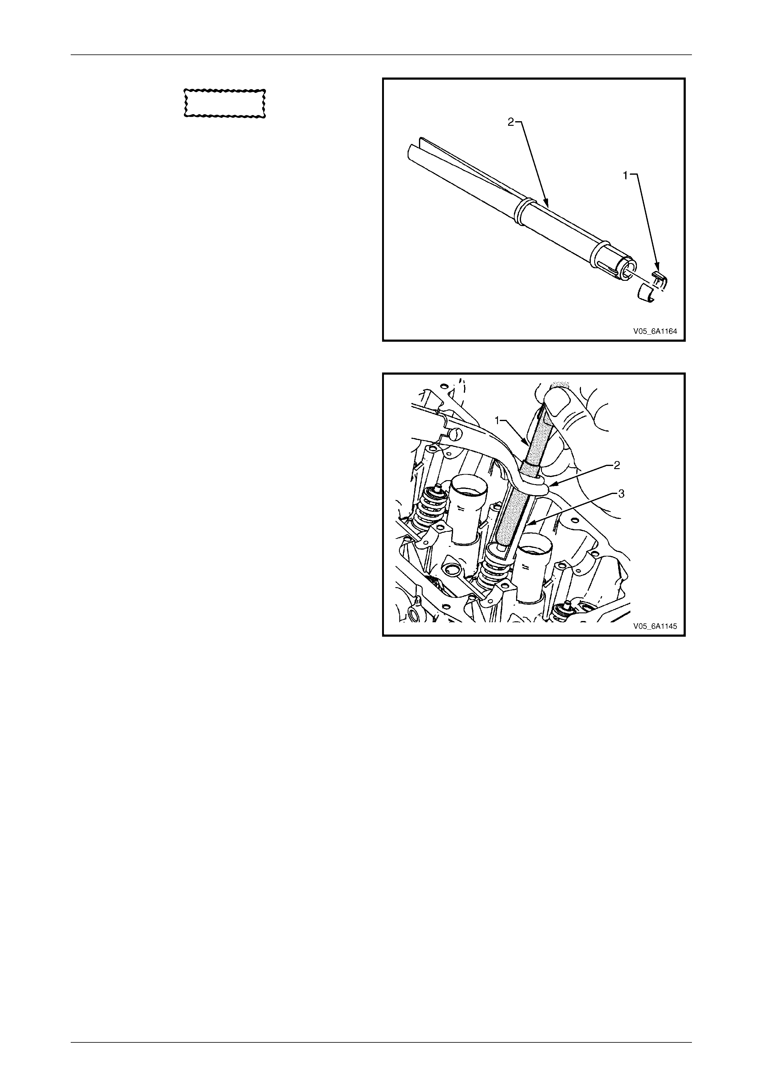
Engine Mechanical – V6 Page 6A1–201
Page 6A1–201
CAUTION
Ensure correct directional placement of
valve collets (1) in Tool No. EN-46117 (2).
The valve collets must be installed with the
tapered end towards the valve stem seal.
11 With the spring compressed, install the valve collets
into Tool No. EN 46117.
Figure 6A1 – 318
12 Place the collets into position by pushing the tool (1)
downward and releasin g tension on the valve spring
compressor (2).
13 Verify the valve collets are installed by placing a rag
over the valve tip and tapping wit h a dead-blow
hammer. The valve collets and the spring sh ould
remain in place.
Figure 6A1 – 319
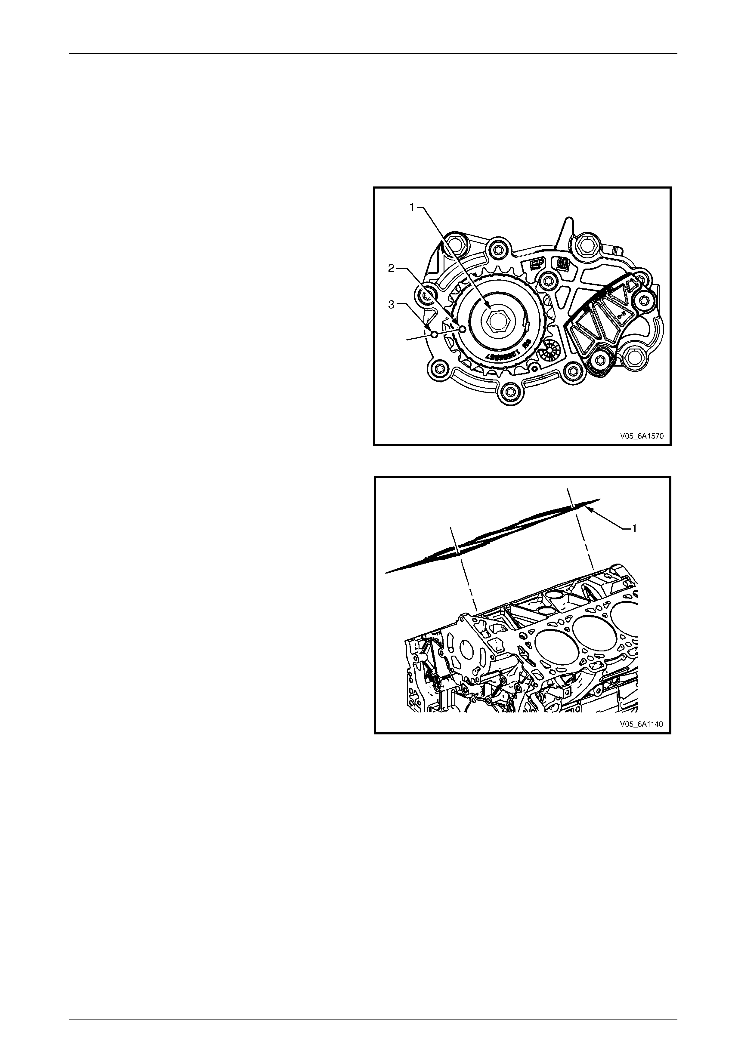
Engine Mechanical – V6 Page 6A1–202
Page 6A1–202
Reinstall
Right-hand Side (Bank 1) Cylinder Head
The reinstallation procedure for the right-hand side cylinder head assembly is the reverse of the removal procedure,
noting the following:
1 Ensure all fasteners are tightene d to the correct torque specification.
2 Using crankshaft rotation Tool No. EN-46 11 1 (1),
align the crankshaft sprocket timing mark (2) with the
indexing mark (3) on the oil pump housing.
Figure 6A1 – 320
3 Ensure the deck face is clean and the cylinder head
locating pins are securely mounted in the cylinder
block deck face.
4 Install a new right-hand cylinder head gasket (1)
using the deck face locating pins for retention.
Figure 6A1 – 321
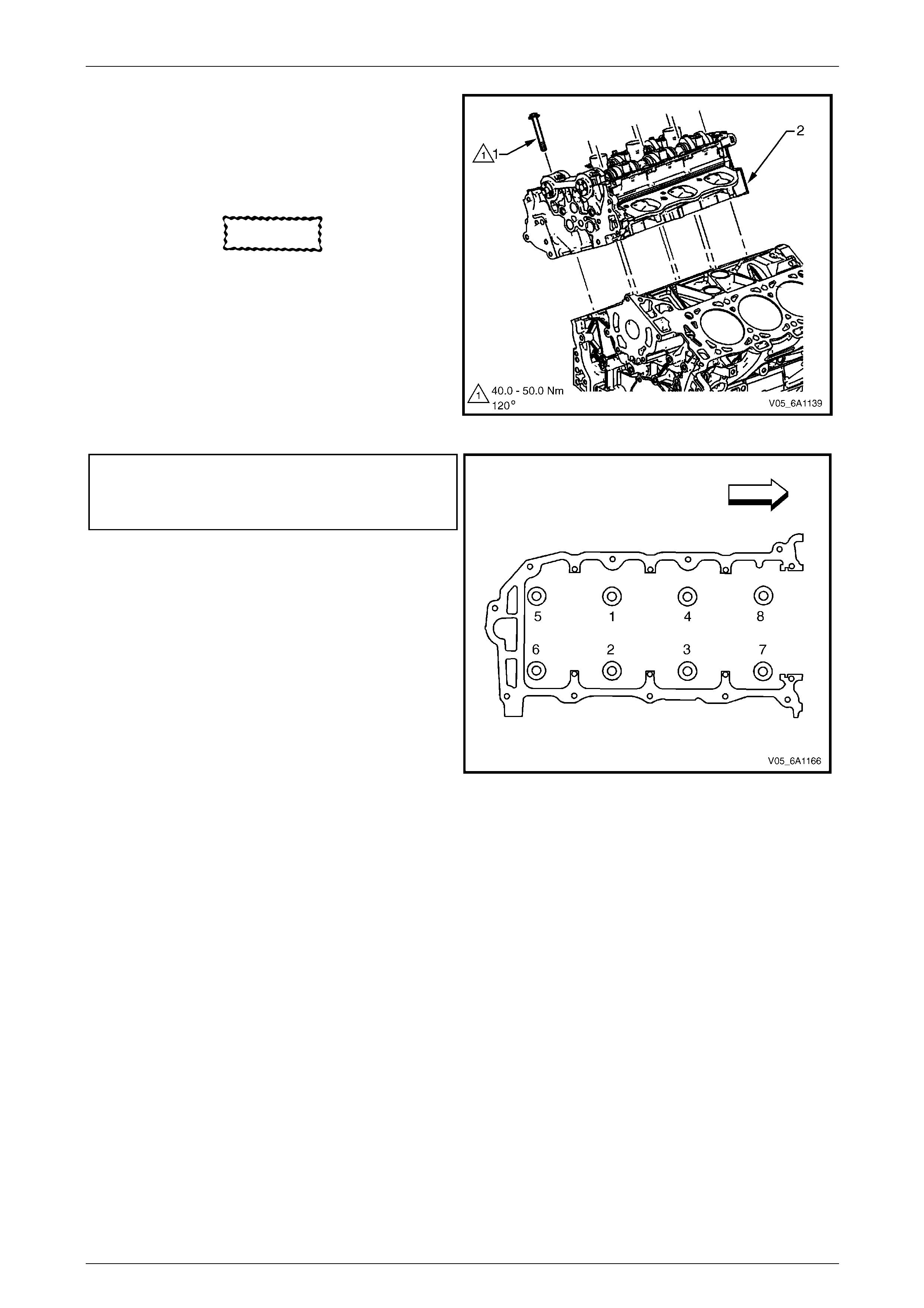
Engine Mechanical – V6 Page 6A1–203
Page 6A1–203
5 Align the cylinder head with the locating pins.
6 Place the cylinder head in position on the deck face.
NOTE
Do not allow oil on the cylinder head bolt
bosses.
CAUTION
Do not reuse the old M11 cylinder head bolts
(1 to 8 inclusive).
7 Install new M11 cylinder head bolt (1) eight places
and tighten in the sequence shown and to the correct
torque specification.
Figure 6A1 – 322
Cylinder head M11attaching bolt
torque specification:
Stage 1: .............40.0 – 50.0 Nm
Stage 2: ..............................120°
Figure 6A1 – 323
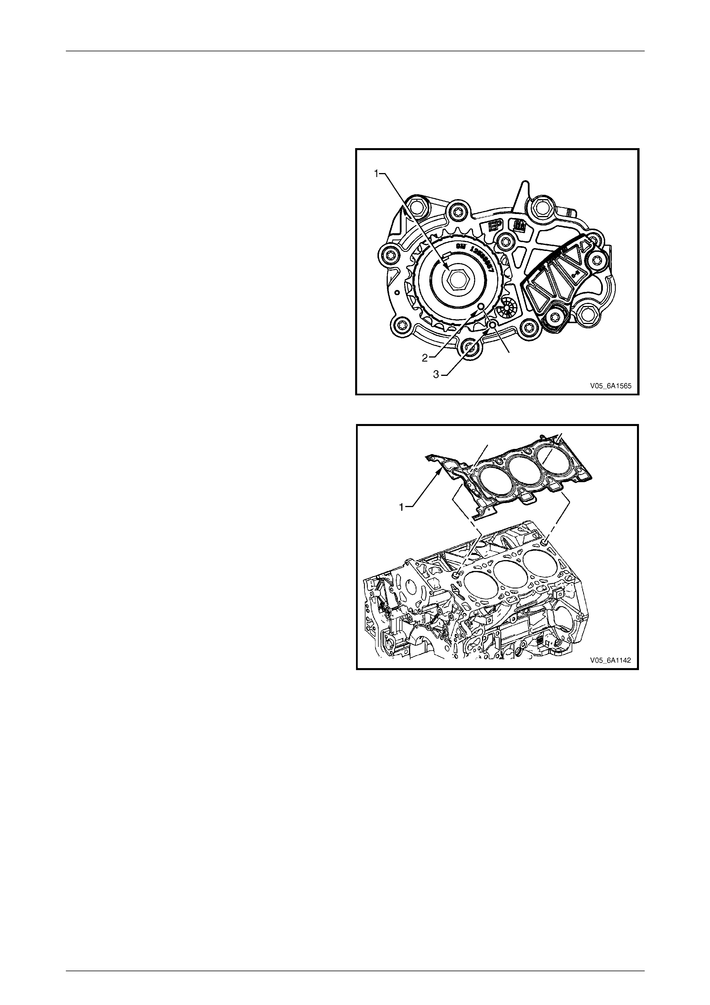
Engine Mechanical – V6 Page 6A1–204
Page 6A1–204
Left-hand Side (Bank 2) Cylinder Head
The reinstallation procedure for the left-hand side cylinder head ass embly is the reverse of the removal procedure, noting
the following:
1 Ensure all fasteners are tightene d to the correct torque specification.
2 Using crankshaft rotation Tool No. EN-46 11 1 (1),
align the crankshaft sprocket timing mark (2) with the
indexing mark (3) on the oil pump housing.
Figure 6A1 – 324
3 Ensure the deck face is clean and the cylinder head
locating pins are securely mounted in the cylinder
block deck face.
4 Install a new cylinder head gasket (1) using the deck
face locating pins for retention.
Figure 6A1 – 325
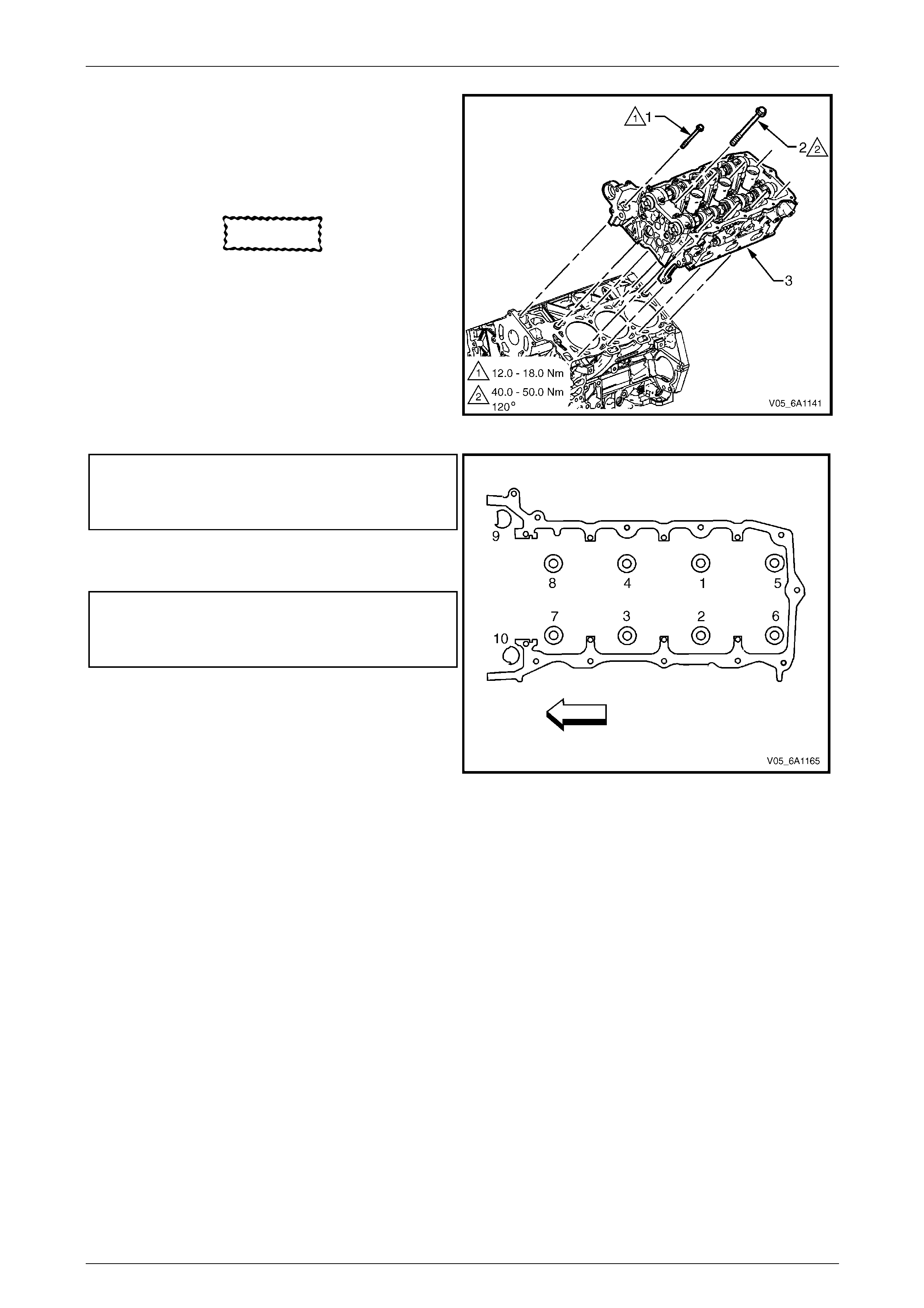
Engine Mechanical – V6 Page 6A1–205
Page 6A1–205
5 Align the cylinder head with the locating pins.
6 Place the cylinder head in position on the deck face.
NOTE
Do not allow oil on the cylinder head bolt
bosses.
CAUTION
Do not reuse the old M11 cylinder head bolts
(1 to 8 inclusive).
7 Install new M11 cylinder head bolt (1), eight places,
and tighten in the sequence shown and to the correct
torque specification.
Figure 6A1 – 326
Cylinder head M11attaching bolt
torque specification:
Stage 1: .............40.0 – 50.0 Nm
Stage 2: ..............................120°
8 Install the front M8 cylinder head bolt (2), two places,
and tighten in the sequence (9 and 10) and to the
correct torque.
M8 cylinder head bolt
torque specification
Stage 1: .............12.0 – 18.0 Nm
Stage 2: ................................60°
Figure 6A1 – 327
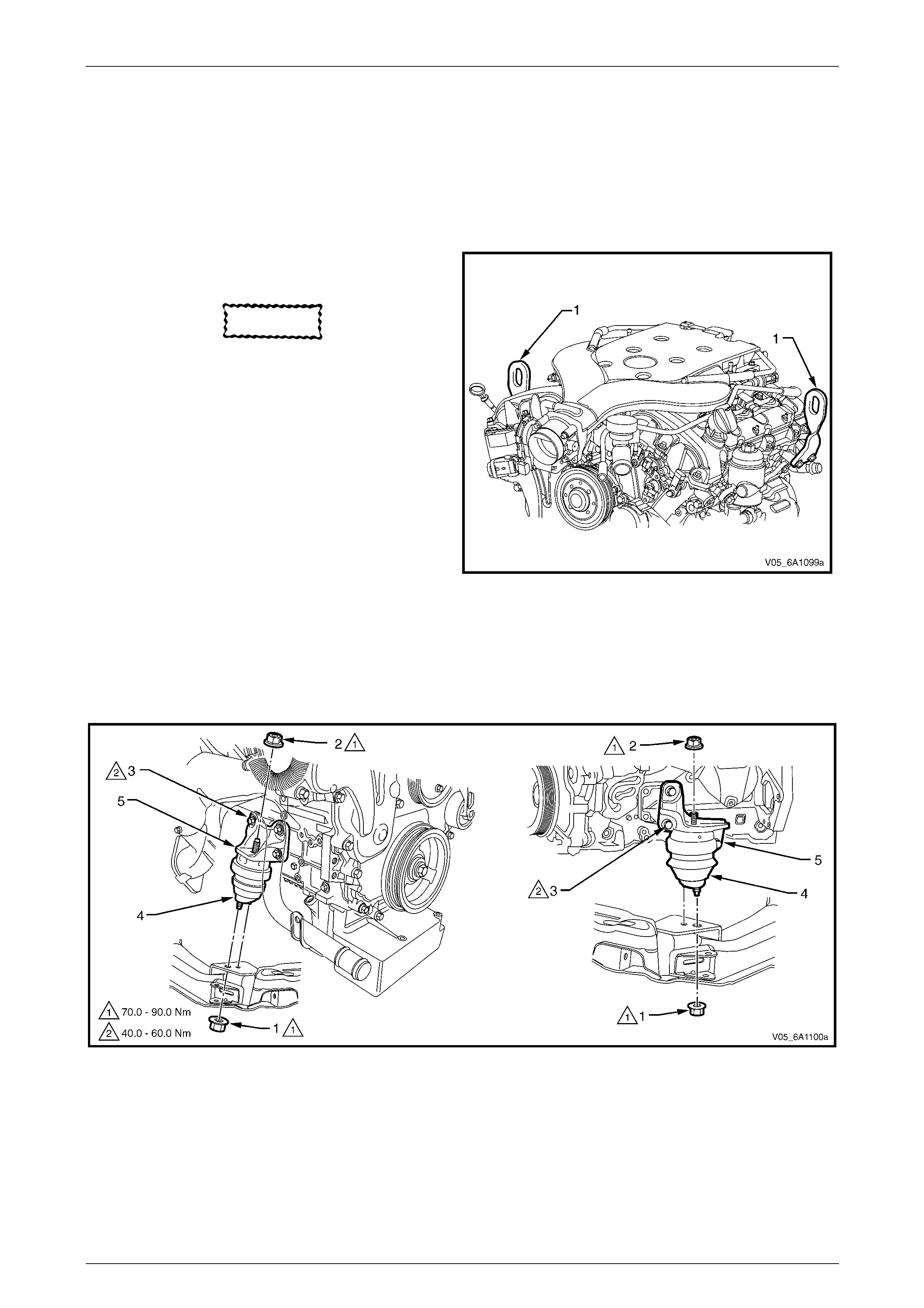
Engine Mechanical – V6 Page 6A1–206
Page 6A1–206
3.24 Engine Mounts and Brackets
LT Section No. — 00–475
Remove
1 Remove the exhaust manifold assembly from the side of the engine where the engine mount is to be removed,
refer to 3.12 Exhaust Manifold Assembly.
2 Fit the engine lift brackets, Tool No. EN-46114 (1) to
the cylinder heads.
CAUTION
Only lift the engine far enough to take the
weight off the engine mount, or damage to
the mount and lifting equipment failure may
occur.
3 Using an engine lifting crane, raise the side of the
engine where the mount is to be removed enough to
remove the weight from the engine mounts, and
create a slight tension in the lifting equipment.
Figure 6A1 – 328
4 Remove the nut (1) securing the engine mount (4) to the front crossmember, refer to Figure 6A1 – 329.
5 Remove the nut (2) securing the engine mount to the engine bracket (5).
6 Remove the bolts (3) securing the engi ne mo unt bracket to the cylinder block.
7 If required, raise the side of the engine where the mount is to be removed to provide adequate space.
8 Remove the engine mount and the engine mounting bracket from the vehicle.
Figure 6A1 – 329
Engine Mechanical – V6 Page 6A1–207
Page 6A1–207
Inspect
NOTE
Although the following procedure provides
information regarding on-vehicle engine mount
inspections, it is preferable to inspect the engine
mounts once removed from the vehicle.
1 Fit the engine lift brackets, Tool No. EN-46114 to the cylinder heads.
Only lift the engine enough to take the weight
off the engine mount, or damage to the mount
and lifting equipment failure may occur.
2 Using a commerciall y available engine lifting crane, have an assistant raise the engine far enough to remove the
weight on the engine mounts and create a slight tension in the rubber.
3 Observe the engine mount while raising the engine.
CAUTION
Before replacing engine mounts due to
suspected fluid loss, ensure the mount is the
source of the leak, and not the engine,
cooling system, etc.
4 Replace the engine mount if any of the following conditions are found:
• the hard rubber surface is covered with heat check cracks,
• the rubber is separated from the metal plate portion of the engine mount,
• the rubber is split through the centre of the engine mount, or
• the Glycol™ fluid is leaking from the engine mount.
5 Remove the engine lift brackets, T ool No. EN-46114 from the engine.
Reinstall
The reinstallation of the engine mounts an d brackets is the reverse of the removal procedure, noting the following:
1 Tighten all fasteners to the correct torque specification.
Engine mount bracket to
cylinder block attaching bolt
torque specification.................................40.0 – 60.0 Nm
Engine mount to bracket attaching nut
torque specification.................................70.0 – 90.0 Nm
Engine mount to frame attaching
nut torque specification...........................70.0 – 90.0 Nm

Engine Mechanical – V6 Page 6A1–208
Page 6A1–208
4 Major Service Operations
ATTENTION
The V6 engine is a combination of numerous components, containing machined, honed, polished and lapped
surfaces manufactured on the latest, high technology production equipment. Many of the components
contain tolerances measured in thousandths of a millimetre. Consequently, when any engine component is to
be serviced, care and cleanlin ess are extremely important.
Prior to re-assembly of the V6 engine, all components must be cleaned and inspected in accordance with the
relevant procedures throughout this section, and replaced or repaired where required.
In addition to cleaning and inspecting components, a liberal coating of engine oil should be applied to friction
surfaces during assemb ly to protect and lubricate the surfaces on initial operation.
When performing any service operation contained in this Section, it should be understood that correct
cleaning and protection of machined surfaces and friction areas is part of the repair procedure. This is
considered standard workshop practice, even if not specifically stated.
ATTENTION
Torque values must be used as specified during reassembly to ensure correct retention of all components.
Through out this section, fastener torque wrench specifications may be accompanied with the following
identification marks:
■ Fasteners must b e rep laced after loosening.
Fasteners either have micro encapsulated sealant applied or incorporate a mechanical thread lock and
should only be re-used once. If in doubt, replacement is recommended.
If one of these identification marks is present alongside a fastener torque wrench specification, the
recommendation regarding that fastener must be adhered to.
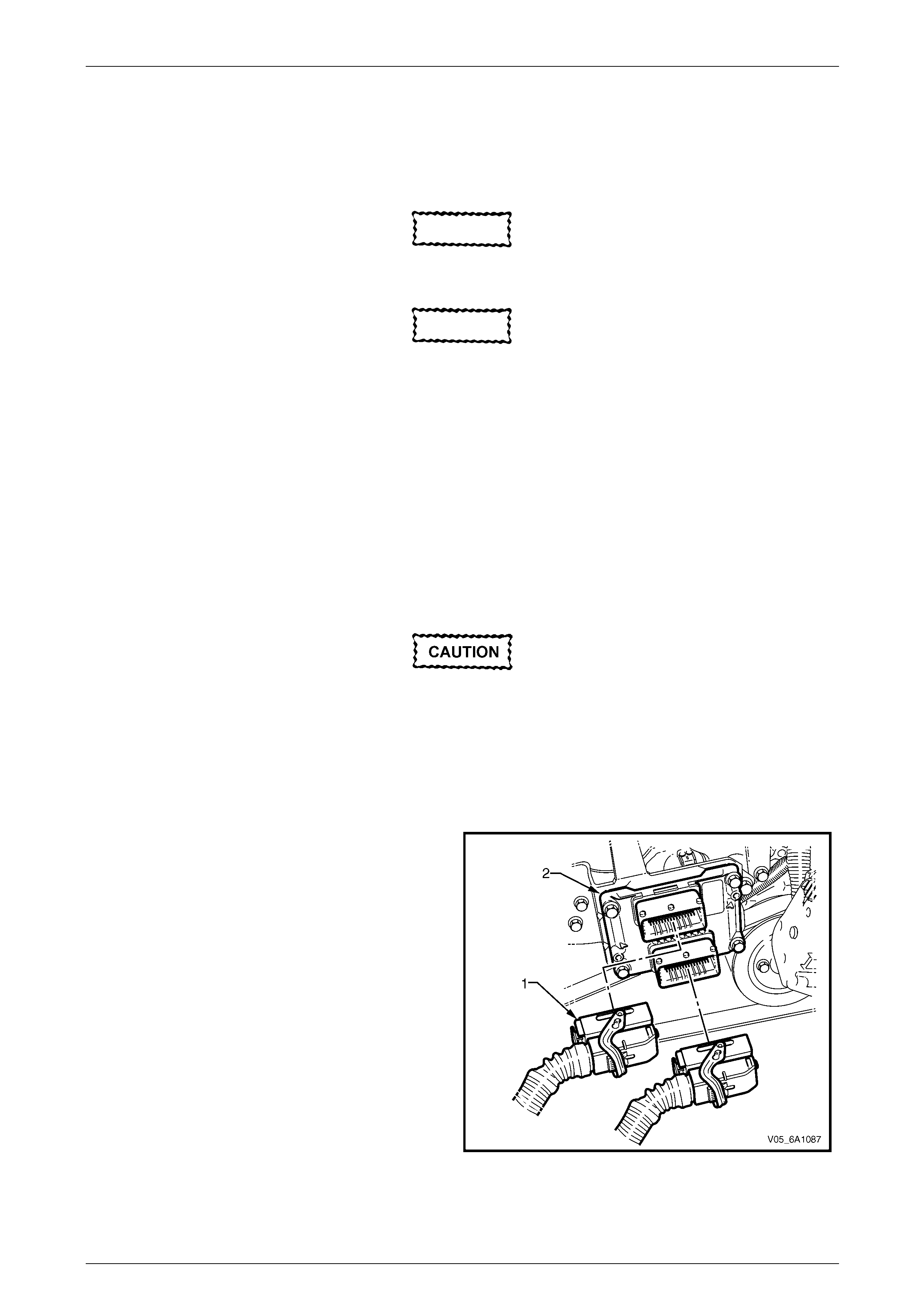
Engine Mechanical – V6 Page 6A1–209
Page 6A1–209
4.1 Engine Assembly
LT Section No. — 00–500
Remove
CAUTION
Allow the engine to cool to at least 50° C,
before attempting fastener removal.
CAUTION
Because of the greater thermal expansion of
aluminium, bolt threads will change
dimension to a greater exte nt when hot, when
compared to cast iron.
If a bolt or other threaded component is
removed before the engine is allowed to cool
to at least 50° C, threads could be pulled from
the cylinder block or cylinder head.
Do not use impact tools to remove bolts
during engine disassemb ly. While this may be
common practice with cast iron engine
components, use of these tools is likely to
pull the aluminium threads in the cylinder
block or head of this engine.
Disconnection of the battery affects certain
vehicle electronic systems, refer to
Section 00 Warnings, Caution and Notes
before disconnecting the battery.
1 Disconnect the battery negative terminal.
2 Remove the engine dress covers, refer to 3.1 Engine Dress Cover
3 Depressurise fuel system pressure, refer to Section 8A1 Fuel S ystem.
4 Disconnect the wiring harness connectors (1) from
the engine control module (ECM) (2).
5 From inside the vehicle, remove the left-hand body
hinge pillar trim assembly, refer to
Section 1A8 Headlining and Interior Trim.
Figure 6A1 – 330
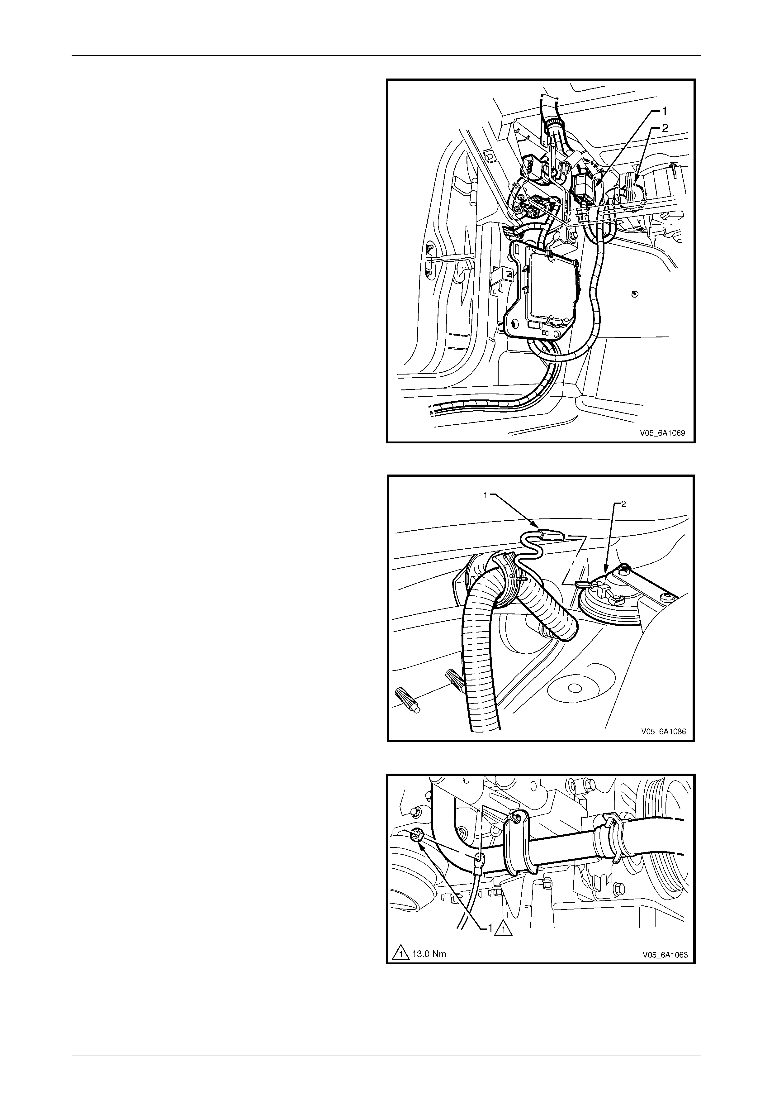
Engine Mechanical – V6 Page 6A1–210
Page 6A1–210
6 Disconnect the engine wiring harness con nector (1)
and disconnect the harness from the transmission
control module (TCM), refer to Section 7E4 Automatic
Transmission – 5L40E – On-vehicle Servicing.
7 Compress lugs on the engine harness plug (2) at the
dash panel and push the eng ine harness and
connectors through to the engine compartment.
Figure 6A1 – 331
8 Disconnect the wiring connector (1) from the anti-theft
horn (2).
9 Disconnect the engine harnes s from the dash panel
retaining clip and lay the engine harness on top of the
engine assembly.
10 Disconnect the fuel feed line and the ev aporative
canister hose, refer to Section 8A1 Fuel System.
11 Remove the air intake duct assembl y and the air
cleaner assembly, refer to Section 6C1-3 Engine
Management – V6 – Service Operations.
Figure 6A1 – 332
12 Remove the nut (1) attaching the battery grou nd
terminal to the generator mounting br acket.
13 Remove the nut attaching the automatic transmission
cooler pipes to the generator mounting bracket.
Figure 6A1 – 333
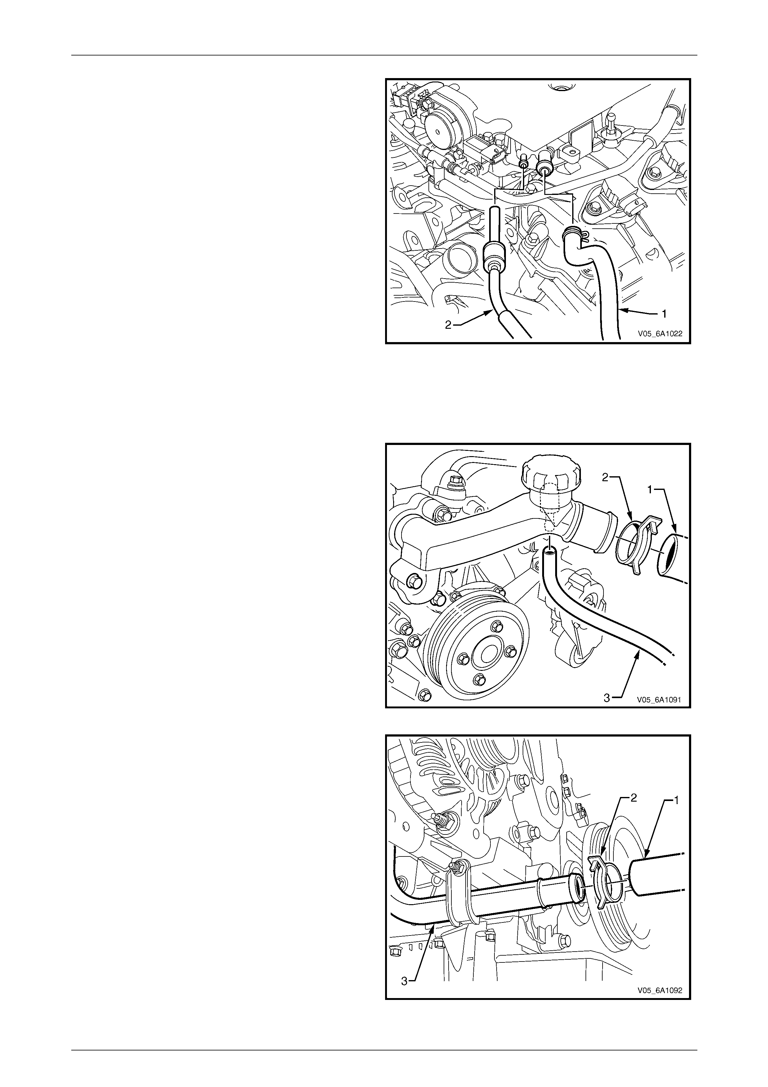
Engine Mechanical – V6 Page 6A1–211
Page 6A1–211
14 Disconnect the brake booster hose (1) and HVAC
vacuum hose (2) from the upper intake manif old
assembly.
15 Raise the vehicle and suppor t with safety stands,
refer to Section 0A General Information.
16 Drain the engine coolant from the radiator assembly,
refer to Section 6B1 Engine Cooling – V6.
17 Disconnect the pre catalytic converter oxyg en sensor
connectors and move the harness and retaining clips
clear of engine assembly, refer to Section 6C1-3
Engine Management – V6 – Service Operations.
18 Working from under the vehicle, disconnect the post
catalytic converter oxygen sensor connectors and
move the harness clear of engine and transmission
assembly, refer to Section 6C1-3 Engine
Management – V6 – Service Operations.
19 Remove the exhaust manifold to exhaust pipe flange
nuts and move exhaust pipes clear of the manifolds,
refer to Section 8B Exhaust System..
20 Remove the rear propeller shaft, refer to Section 4C1
Rear Propeller Shaft and Universal Joints.
21 Disconnect the gear lever control from the
transmission, refer to Section 7E4 Automatic
Transmission – 5L40E - On Vehicle Servicing.
Figure 6A1 – 334
22 Loosen the radiator hose clamp (2) and remove the
upper radiator hose (1). Remove the co olant overflow
hose (3) from the coolant outlet pipe.
Figure 6A1 – 335
23 Loosen the radiator hose clamp (2) and remove the
lower radiator hose (1) from the coolant inlet pipe (3).
24 Disconnect the heater hoses from the heat er pipes,
refer to Section 6B1 Engine Cooling – V6.
25 Remove the radiator assembly, refer to
Section 6B1 Engine Co oling – V6.
26 Remove the accessory drive belt, refer to
3.6 Accessory Drive Belt.
27 Remove the accessory drive belt idler pulley, refer to
3.7 Accessory Drive Belt Idler Pulley.
Figure 6A1 – 336
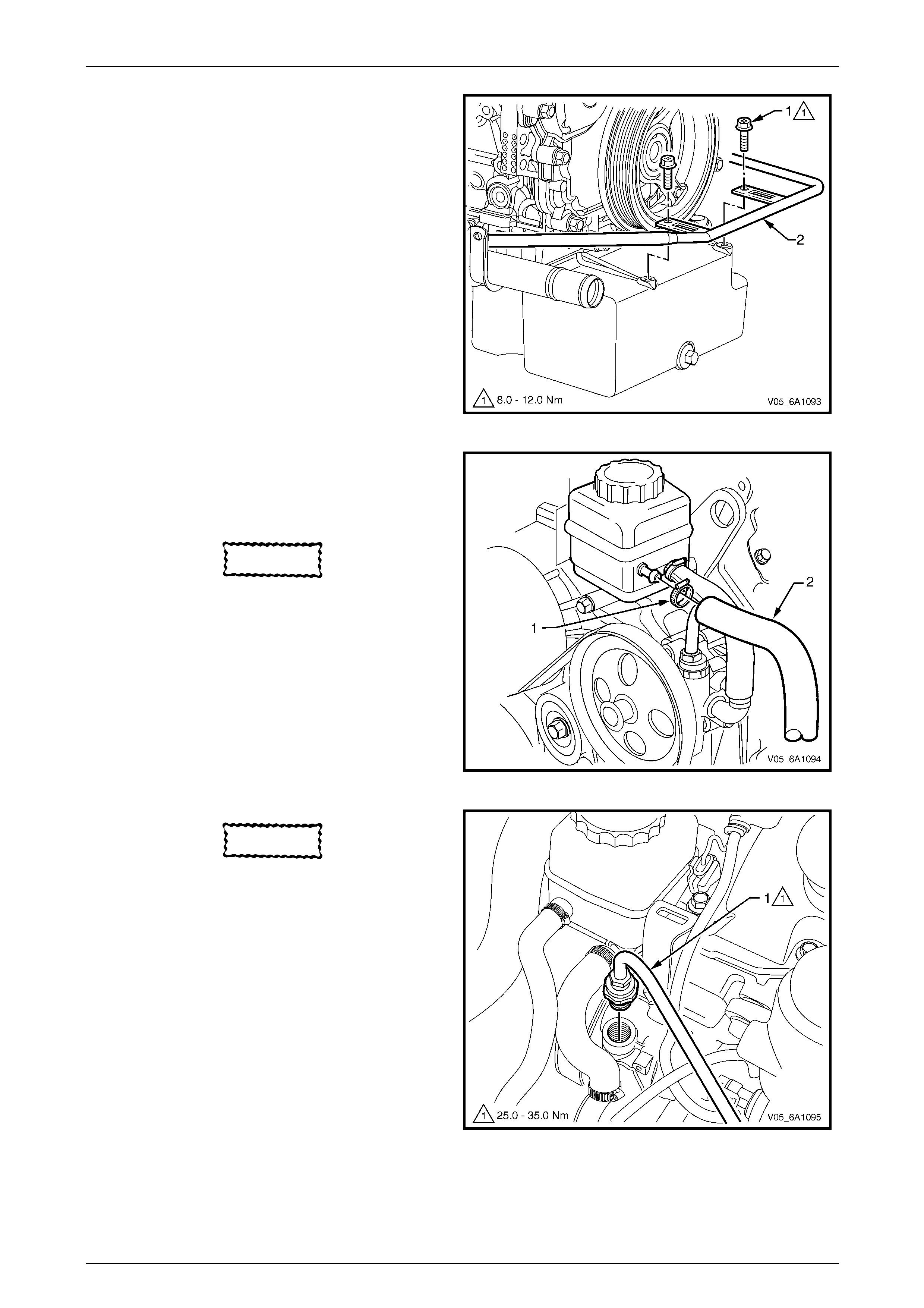
Engine Mechanical – V6 Page 6A1–212
Page 6A1–212
28 Remove the two bolts (1) attaching the power
steering high pressure line (2) to the oil pan.
Figure 6A1 – 337
29 Loosen the hose clamp (1) on the power steering
return hose (2) at the po wer steering reservoir end.
30 After placing a suitable contai ner under the reservoir,
remove the hose and drain the reservoir fluid.
CAUTION
Plug open hydraulic fittings, to prevent fluid
and/or dirt entry.
31 Secure the return hose to one side, clear of the
engine assembly.
Figure 6A1 – 338
CAUTION
Plug open hydraulic fittings, to prevent fluid
and/or dirt entry.
32 Remove the high pressure lin e flare nut (1) from the
power steering pump outlet fitting at the top of the
power steering pump.
NOTE
Use a backup spanner on the power steering
pump outlet fitting when loosening the flare nut.
Figure 6A1 – 339
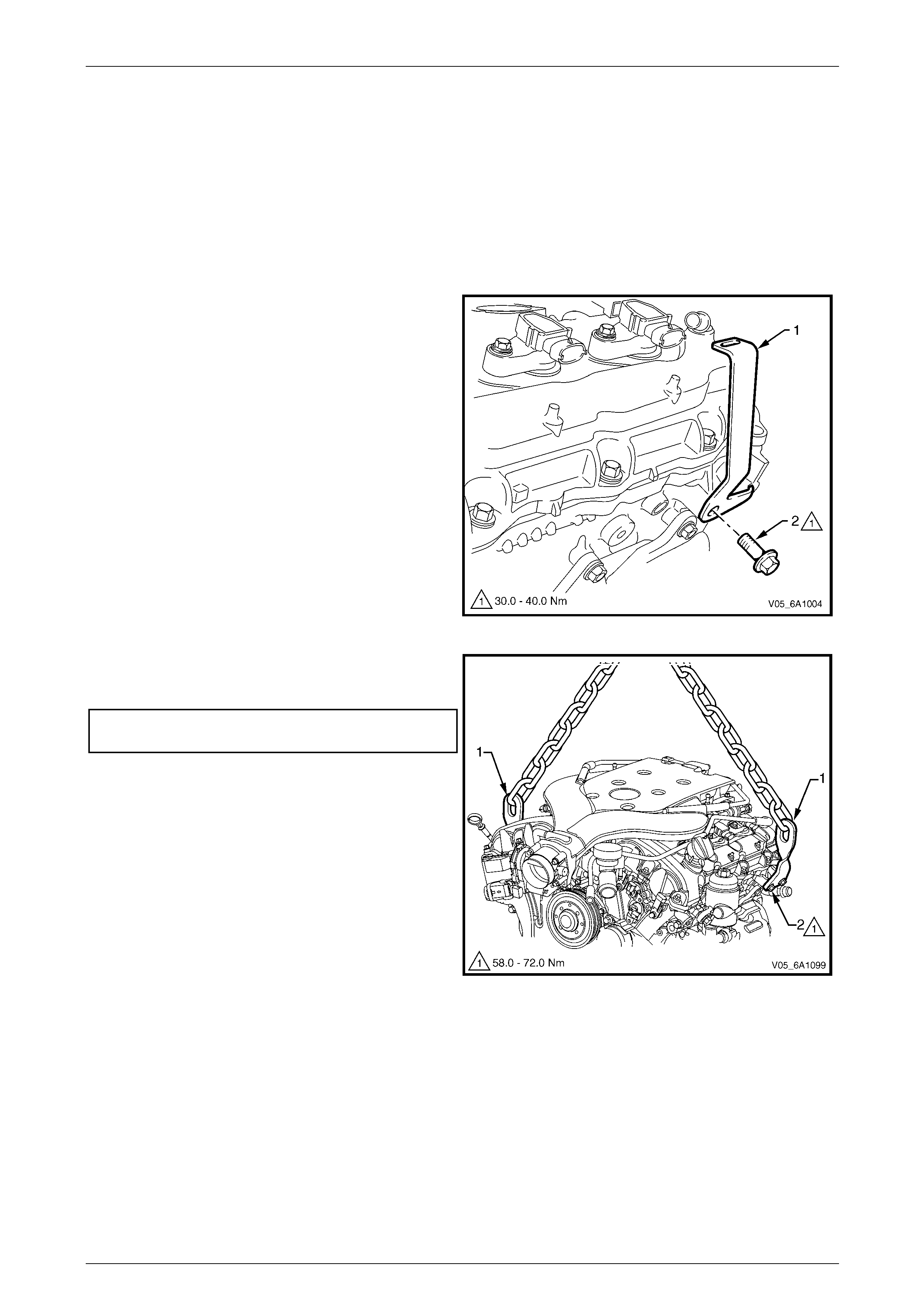
Engine Mechanical – V6 Page 6A1–213
Page 6A1–213
NOTE
Do not disconnect the refrigerant pipes from the
A/C compressor.
33 Remove the A/C compressor assembly and then move the compressor clear of the engine, refer to
Section 2C HVAC Climate Control (Man ual A/C) – Removal and Installation.
34 Disconnect the battery harness from the generator B+ terminal, refer to Section 6D1-1 Charging System – V6.
35 Disconnect the battery harness from the starter motor, refer to Section 6D1-2 Starting S ystem – V6.
36 Remove the oil level indicator tube, refer to 3.5 Oil Level Indicator Tube.
37 Remove the hood, refer to Section 1A4 Hood, Rear Compartment Lid, Liftgate and Endgate.
38 Remove the bolt (2) attaching engine dress cover
mounting bracket (1) to the rear of the bank 2 (left-
hand) cylinder head.
Figure 6A1 – 340
39 Attach the engine lift brackets, Tool No. EN-4 6114 (1)
and tighten the bolts to the correct torque
specification.
Engine lift bracket attaching bolt
torque specification.................................58.0 – 72.0 Nm
40 Attach a suitable lifting chain and hooks to the engine
lift brackets (1 and 2).
41 Using a suitable engine crane, raise the engine
slightly to take the slack out of the lifting chain.
Figure 6A1 – 341
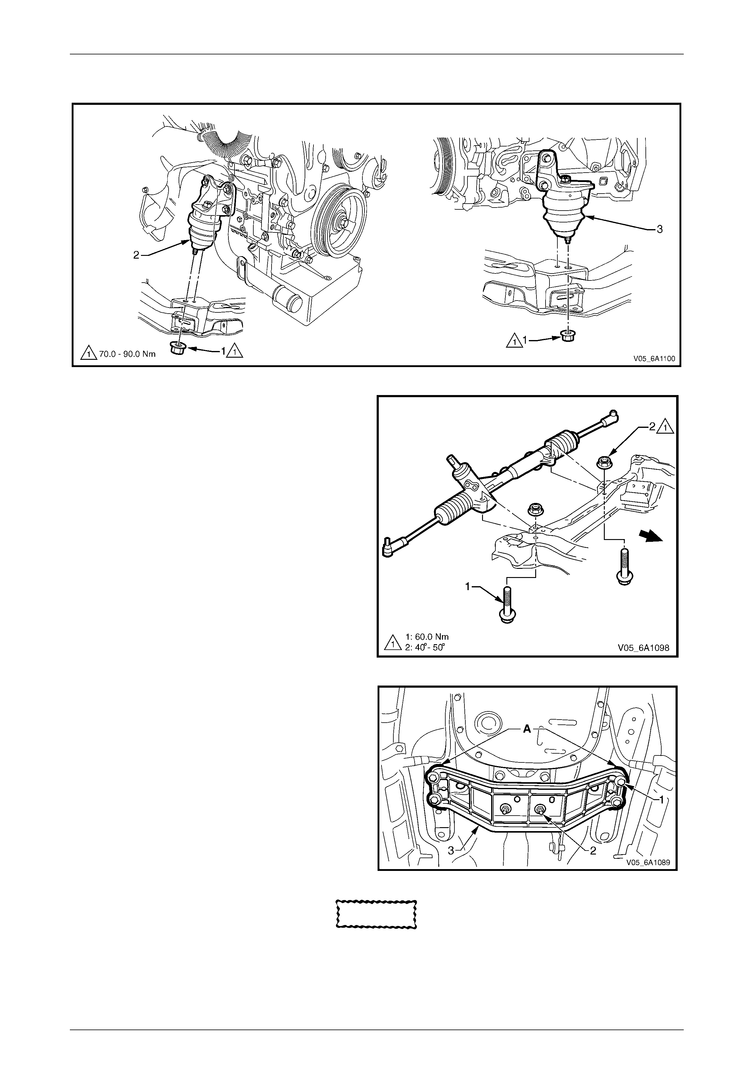
Engine Mechanical – V6 Page 6A1–214
Page 6A1–214
42 Remove the nut (1), one place each side, attaching the engine mount (2 – right-hand and 3 –- left-hand) to the front
suspension crossmember, refer to Figure 6A1 – 342.
Figure 6A1 – 342
43 Remove the steering gear housing to front
suspension crossmember mounting nuts (2) and
bolts (1).
44 Move the steering gear housing cle ar of the front
suspension crossmember by pulling it out towards the
rear of the vehicle. NOTE
Removal of the steering gear housing from the
crossmember is required to avoid obstructing
the engine oil pan during engine removal and
installation.
Figure 6A1 – 343
45 Mark the relationship of the engine rear crossmember
to the body (A), to assist with alignment duri ng
reassembly.
46 Remove the four bolts (1) attaching the engine rear
crossmember (3) to the frame.
47 Remove the rear mounting to rear crossmember
attaching nuts (2) and then remove the rear
crossmember from the vehicle.
48 Raise engine and transmission assembly with the
front tilted upward and a floor jack supporting the rear
of the transmission assembly.
Figure 6A1 – 344
CAUTION
Do not allow the engine to swing forward and
damage the air conditioning condenser
assembly.
49 Continue to lift and manoeuvr e the engine and transmission assembly clear of the engine compartment.

Engine Mechanical – V6 Page 6A1–215
Page 6A1–215
Disassemble
1 Remove the wiring harness conn ectors and ground connections from the engine and transmission assembly and
carefully set the wiring harness to one side, refer to Section 12O Fuses, Re lays and Wiring Harnesses.
2 Remove the engine control module (ECM) and mounting bracket,
refer to Section 6C1-3 Engine Management – V6 – Service Operations.
3 Separate the engine and transmission assembly,
refer to Section 7E4 Automatic Transmission – 5L40E – On Vehicle Servicing.
4 Mount the engine assembly on a suitab le engine stand.
5 Drain the engine oil into a suit able, clean container.
6 Remove the following components:
a Intake manifold assembly, refer to 3.11 Intake Manifold Assembly – Complete.
b Power steering reservoir and pump brackets, refer to 3.9 Power Steering Reservoir and Pump Brackets.
c Oil filter adaptor, refer to 3.4 Oil Filter Adaptor.
d Alternator and mounting brackets, refer to Section 6 D1-1 Charging System – V6.
e Engine coolant inlet pipe, refer to Section 6B1 Engine Cooling – V6.
f Heater pipe assembly, refer to Section 6B1 Engine Cooling – V6.
g Thermostat assembly, refer to Section 6B1 Engine Cooling – V6.
h Exhaust manifold assemblies, refer to 3.12 Exhaust Manifold Assem bly.
i Engine coolant outlet pipe, refer to Section 6B1 Engine Cooling – V6.
j Crankshaft position sensor, refer to Section 6C1-3 En gine Management – V6 – Service Operations.
k Knock sensors, refer to Section 6C1-3 Eng ine Management – V6 – Service Operations.
l Engine mounts and brackets, refer to 3.24 Engine Mounts and Brackets.
m Flexplate assemblies, refer to 4.3 Flexp late Assembly.
n Timing chains, tensioners, shoes, guid es & sprockets,
refer to 3.17 Timing Chains, Tensioners, Sh oes and Guides
o Cylinder head assemblies, refer to 3.23 Cylinder Head Assembly
p Oil pan assembly, refer to 4.2 Oil Pan and Oil Pump Suction Pipe Assembly.
q Piston and connecting rod assemblies,
refer to 4.5 Pistons, Pins, Rings, Connecting Rods and Big-end Bearings.
r Crankshaft assembly, refer to 4.6 Crankshaft and Main Bearings.
s Piston oil nozzles, refer 4.5 Pistons, Pins, Rings, Connecting Rods and Big-end Bearings.

Engine Mechanical – V6 Page 6A1–216
Page 6A1–216
Reassemble
Reassembly of the engine assembly is the reverse of the disassembly procedure.
Reinstall
Reinstallation of the engine assembly is the reverse to the removal procedure, noting the following:
1 Tighten the fasteners to the correct torque specification.
Engine ground connector bolt
torque specification............................................10.0 Nm
Power steering high pressure line
attaching bolt torque specification.............8.0 – 12.0 Nm
Power steering high pressure line
flare nut torque specification...................25.0 – 35.0 Nm
Engine dress cover bracket attaching
bolt torque specification..........................30.0 – 40.0 Nm
Engine mount to frame attaching bolt
torque specification.................................70.0 – 90.0 Nm
Steering gear housing mounti ng nut
torque specification:
Stage 1 .........................60.0 Nm
Stage 2 ....................... 40° – 50°
2 Use only the specified engine lubricant type and quantity. It is recommended that a fluorescent oil dye, such as that
contained in J 28481-B, be added to assist in any future oil leak diagnosis.
3 Fill the cooling system with the correct quantity and grade of coolant, refer to Section 6B1 Engine Cooling – V6.
4 Check transmission fluid level, replenishing as required, using the specified lubricant for the transmission fitted,
refer to Section 7E4 Automatic Transmission – 5L40E – On Vehicle Servicing.
5 Disable the ignition system, refer to Section 6C1-3 Engine Management – V6 – Service Operations.
6 Crank the engine several times. Listen for any unusual noises or evidence that parts are binding.
7 Enable the ignition system. Start the engine and listen for any unusual noises.
8 Check the vehicle oil pressur e gauge or warning indica tor and confirm the engine has acceptable oil pressure. If
required, install an oil pressure gauge and measure the en gine oil pressure,
refer to 2.19 Engine Oil Pressure Diagnosis.
9 Run the engine at about 1,000 r.p.m. until the engine has reached normal operating temperature.
10 Listen for any unusual noises.
11 Check for oil, fuel, coolant and exhaust leak s while the en gine is running, correcting as required.
12 Perform a final inspection for correct engin e oil and coolant levels.
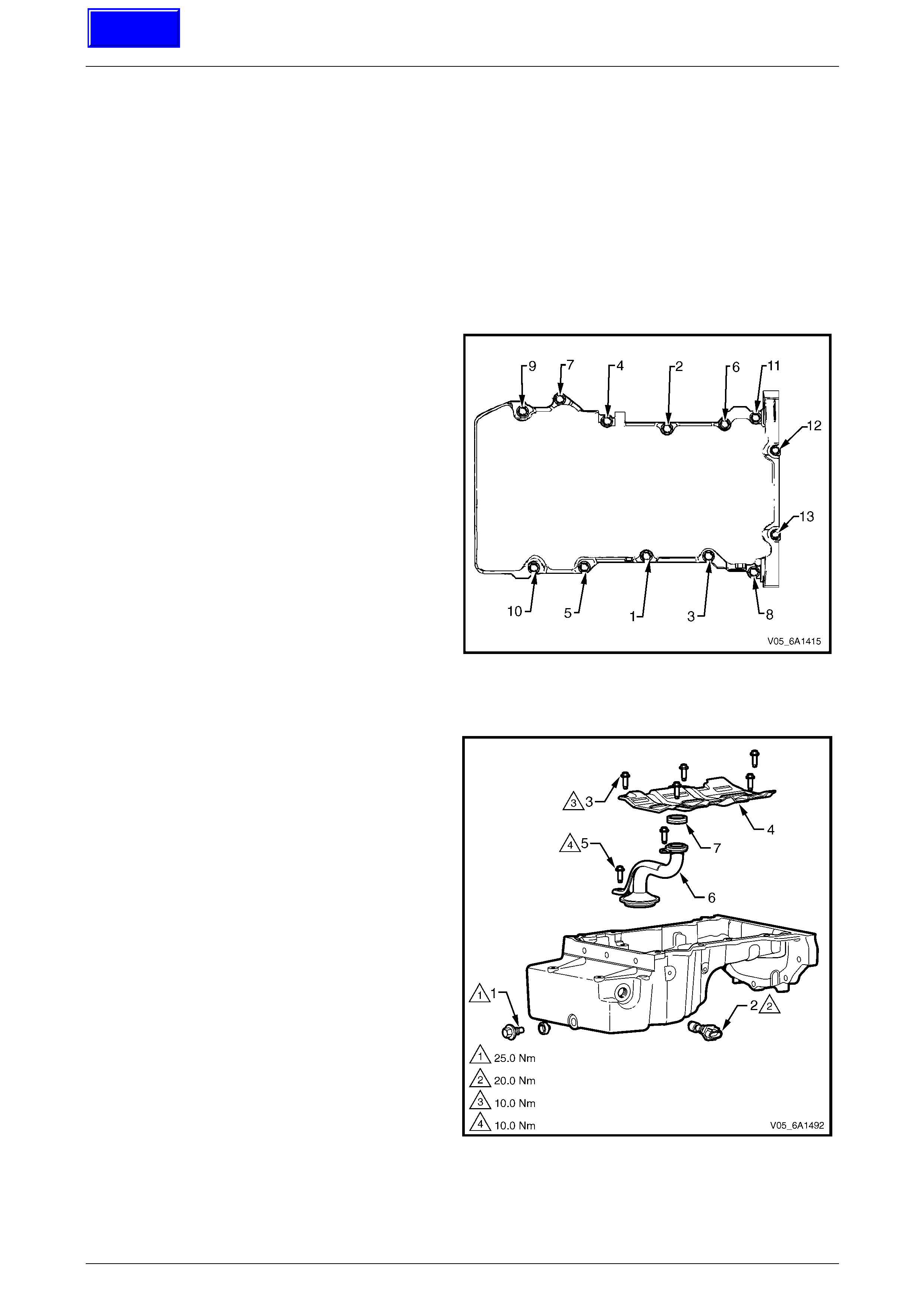
Engine Mechanical – V6 Page 6A1–217
Page 6A1–217
4.2 Oil Pan and Oil Pump Suction Pipe
Assembly
LT Section No. — 00–275
Remove
1 Remove the engine assembly from the vehicle, refer to 4.1 Engine Assembl y.
2 Separate the engine and transmission assemblies,
refer to Section 7E4 Automatic Transmission – 5L40E – On Vehicle Servicing.
3 Mount the engine assembly on a suitab le engine stand.
4 Remove the engine front cover, refer to 3.16 Front Cover Assembly.
5 Remove the two long bolts (12 and 13) attaching the
rear of the oil pan to the crankshaft rear oil s eal
housing.
6 Remove the eleven bolts (1 to 11) attaching the oil
pan to the cylinder block.
7 Using the shear points located at the edge of the oil
pan shear the RTV sealant.
8 Remove the oil pan from the cylinder bl ock.
Figure 6A1 – 345
Disassemble
Remove the following:
1 Oil pan drain plug (1) an d sleeve.
2 Oil level sensor (2).
3 Crankshaft oil deflector bolts (3) and remove the
deflector (4).
4 Oil pump suction pipe bolts (5) and the suction pipe
(6).
5 Oil pump suction pipe gasket (7) from the suction pipe
and discard.
Figure 6A1 – 346
Techline
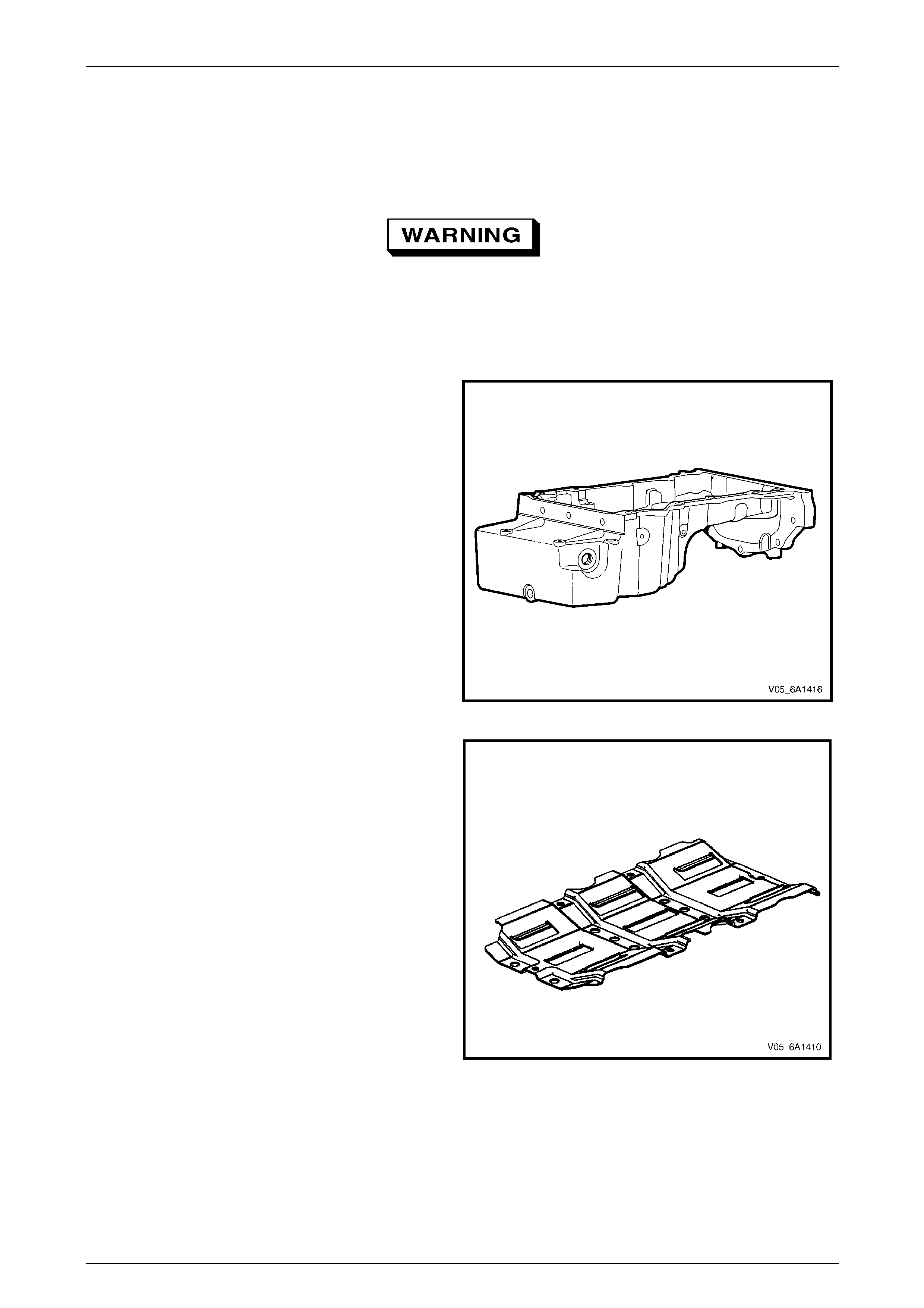
Engine Mechanical – V6 Page 6A1–218
Page 6A1–218
Clean
1 Remove any remaining thread sealant, gasket material or sealant using a commercially av ailable wooden or plastic
scraper.
2 Clean the oil pan and oil pan components in solvent.
3 Clean out debris from the bolt holes.
Safety glasses must be worn when using
compressed air.
4 Dry the oil pan and oil pan components with compressed air.
Inspect
1 Inspect the exterior of the oil pan for the following
conditions:
• Damage to the drain plug or dr ain plug hole,
• Damage to the transmission mounting boss es,
• Damage to the oil level sensor threads, and
• Dents or damage to the exterior.
2 Inspect the interior of the oil pan for the following
conditions:
• Gouges or damage to the oil pan sealing
surfaces,
• Damage to the crankshaft oil deflector,
• Damage to the bolt holes,
• Damage to the oil suction tube mounting
bosses, and
• Damage to the crankshaft oil deflector mounting
bosses. Figure 6A1 – 347
3 Inspect the oil pan scraper for damage.
4 Repair or replace the oil pan and/or oil pan
components as required.
Figure 6A1 – 348
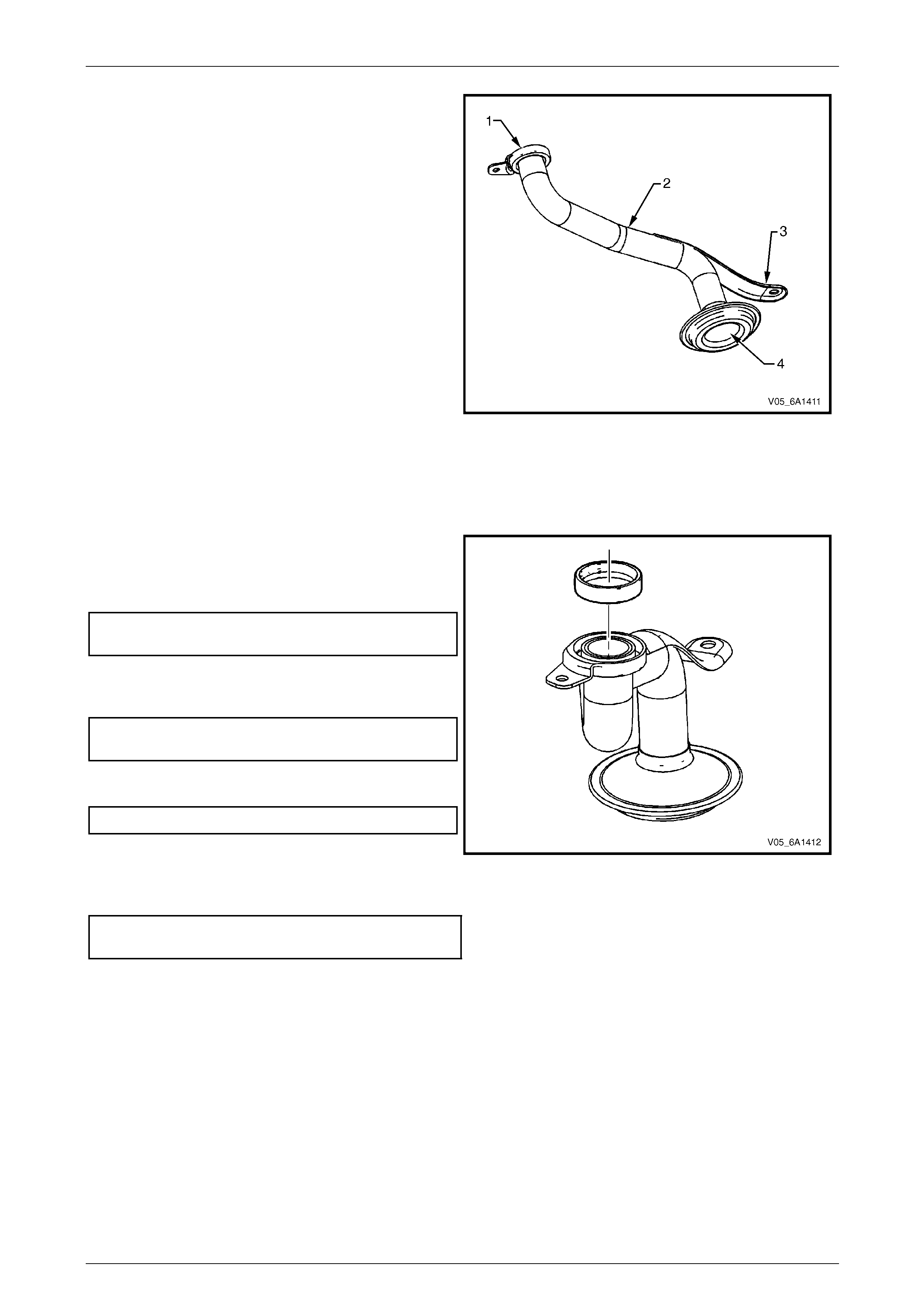
Engine Mechanical – V6 Page 6A1–219
Page 6A1–219
5 Inspect the following:
a The mounting face (1) of the oil pump suction
pipe for possible leakag e paths.
b The oil pump suction pipe tube (2) for cracks,
imperfections and/or damage.
c The oil pump pipe support bracket (3) for cracks
or damage.
d The oil pump screen (4) for blockage, foreign
material, tears, cracks and/or damage.
6 Repair or replace the oil pan and/or oil pan
components as required.
Figure 6A1 – 349
Reassemble
Reassembly of the oil pan and oil suction pipe assembly is the reverse of the disassembly procedure, noting the
following:
1 Install a new oil suction tube seal o nto the oil suction
tube.
2 Install the oil suction pipe and tighten the attaching
bolts to the correct torque specification.
Oil suction pipe attaching
bolt torque specification.....................................10.0 Nm
3 Install the crankshaft oil deflector into the oil pan
assembly and tighten the attaching bolts to the
correct torque specification.
Crankshaft oil deflector
attaching bolt torque specification......................10.0 Nm
4 Install the oil level sensor into the oil pan assembly
and tighten to the correct torque specification.
Oil level sensor torque specification...................20.0 Nm
Figure 6A1 – 350
5 Install the oil pan drain plug into the oil pan assembly and tighten to the correct torque specification.
Oil pan drain plug
torque specification............................................25.0 Nm
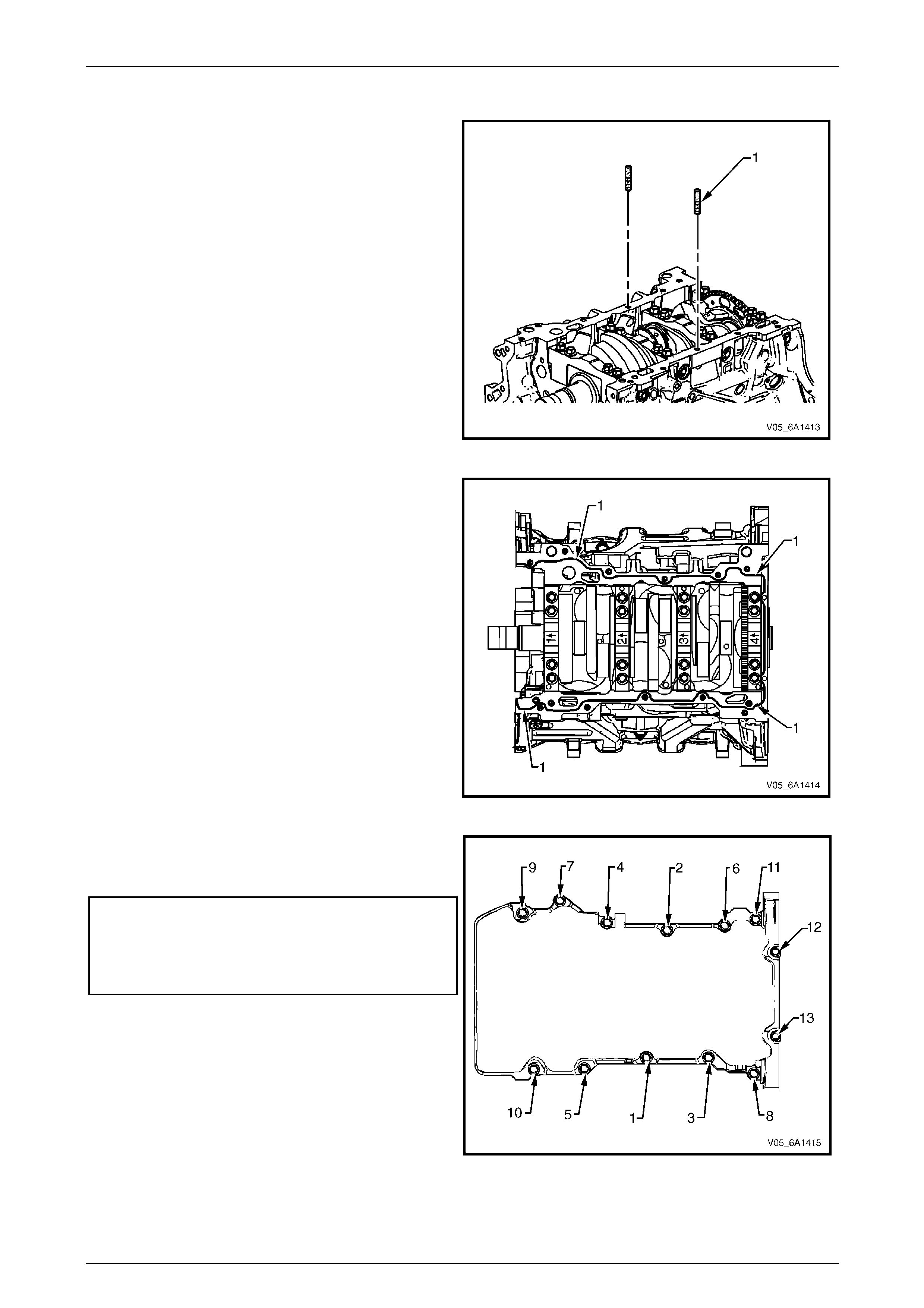
Engine Mechanical – V6 Page 6A1–220
Page 6A1–220
Reinstall
1 Install the guide pins, Tool No. EN-4610 9 (1) into the
oil pan rail bolt hole on each side of the engine block.
Figure 6A1 – 351
2 Place a 3mm bead (1) of RTV sealant on the cylinder
block pan rail and crankshaft rear oi l seal housing to
oil pan mating surfaces.
3 Position the oil pan onto the cylinder block.
4 Remove the guide pins, Tool No. EN-46109 from the
cylinder block.
Figure 6A1 – 352
5 Loosely install the oil pan bolts.
6 Tighten the oil pan attachin g bolts to the correct
torque specification and i n the sequence shown.
Oil pan to cylinder block attaching
bolt (1 – 11) torque specification.............20.0 – 26.0 Nm
Oil pan to crankshaft rear oil
seal housing attaching bolt (12 – 13)
torque specification...................................8.0 – 12.0 Nm
Figure 6A1 – 353
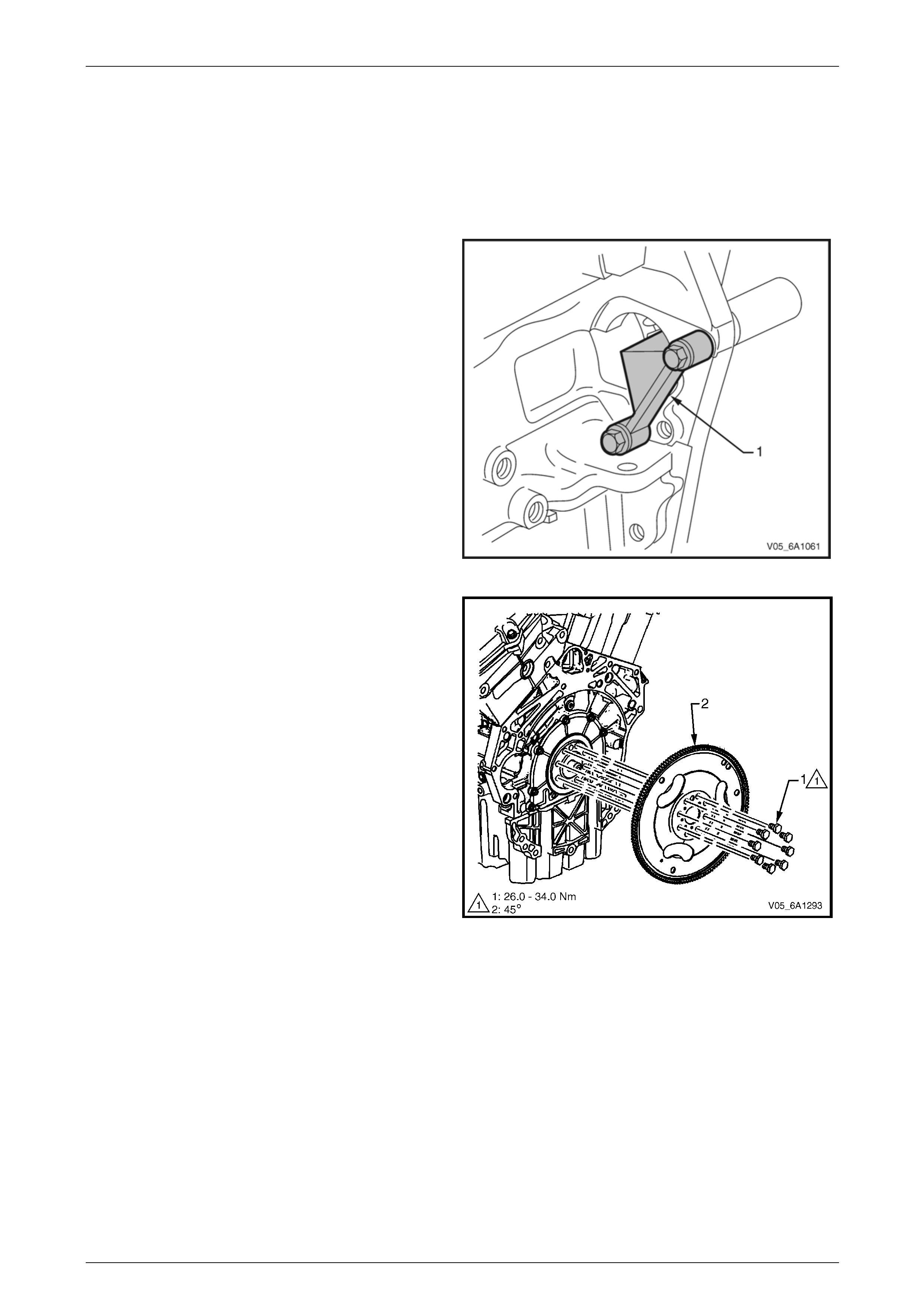
Engine Mechanical – V6 Page 6A1–221
Page 6A1–221
4.3 Flexplate Assembly
LT Section No. — 00–400
Remove
1 Remove the transmission, refer to Section 7E4 Automatic Transmission – 5L40E – On Vehicle Servicing.
2 Remove the starter motor, refer to Section 6D1-2 Starting System – V6.
3 Install the flexplate holding tool, T ool No. EN-46106
(1) into the starter motor mounting location.
Figure 6A1 – 354
4 Loosen the eight flexplate attaching bolts (1).
5 Remove the flexplate holding tool.
6 Using a suitable permanent marker or paint pen, mark
the flexplate assembly (2) to crankshaft relati onship.
7 Remove the eight flexplate attaching bolts and
discard.
8 Remove the flexplate assembly.
Figure 6A1 – 355
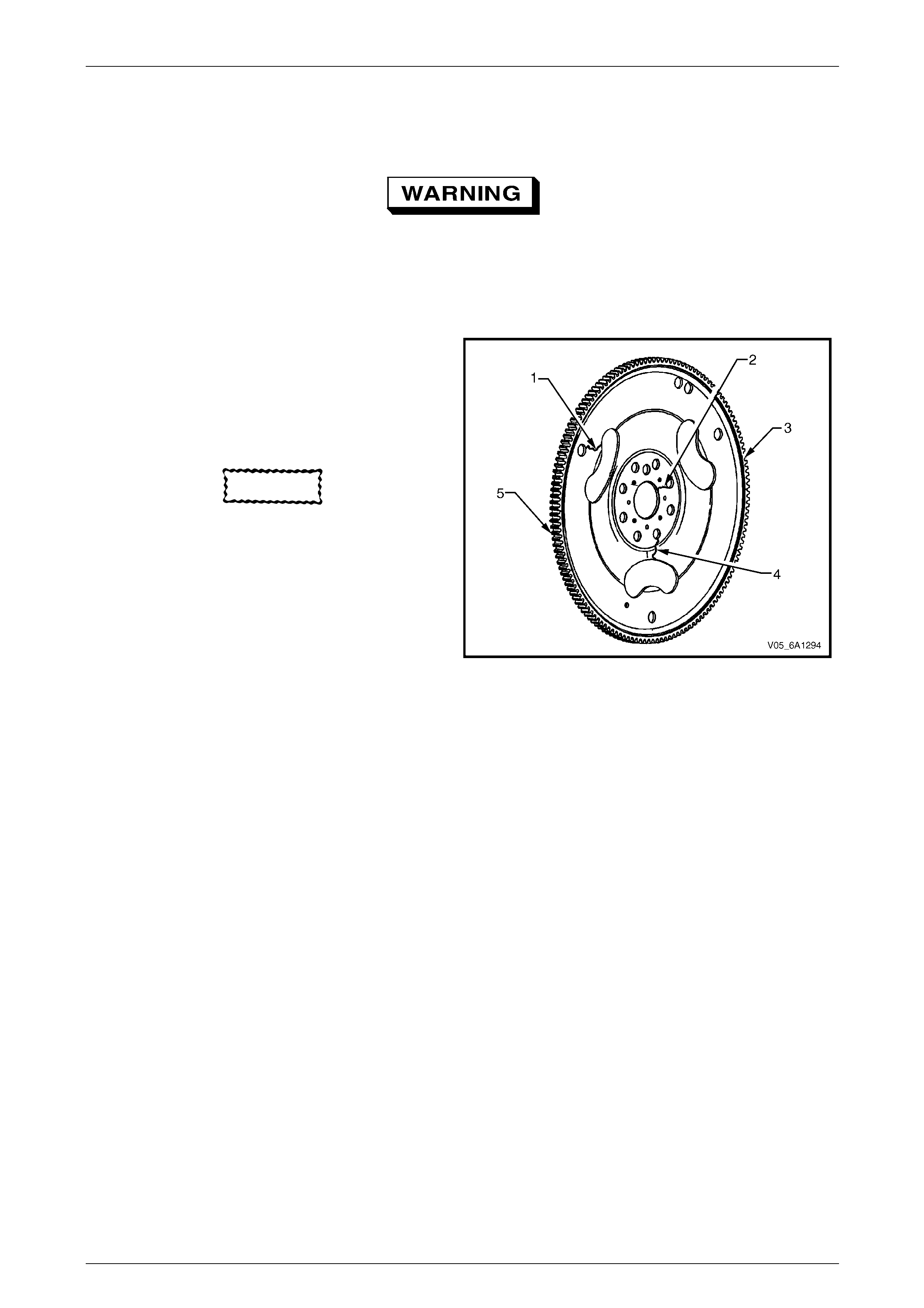
Engine Mechanical – V6 Page 6A1–222
Page 6A1–222
Clean
1 Clean the flexplate assembly in a suitable solvent.
Safety glasses must be worn when using
compressed air.
2 Dry the flexplate assembly with compressed air.
Inspect
1 Inspect the flexplate assembly for the follo wing
conditions:
• Stress cracks around the flexplate to torque
converter mounting bolt hole locations (1).
• Stress cracks around the flexplate to crankshaft
mounting bolt hole locations ( 2 and 4).
CAUTION
Do not repair the welded areas that retain
the ring gear to the flexplate. The flexplate
must be replaced.
• Cracks at welded areas that retain the ring gear
onto the flexplate (3).
• Damaged or missing ring gear teeth (5).
NOTE
The flexplate ring gear is not serviced
separately and cannot be repaired. If found to
be faulty or damaged, the flexplate assembly
must be replaced.
2 Replace the flexplate assembly as required.
Figure 6A1 – 356
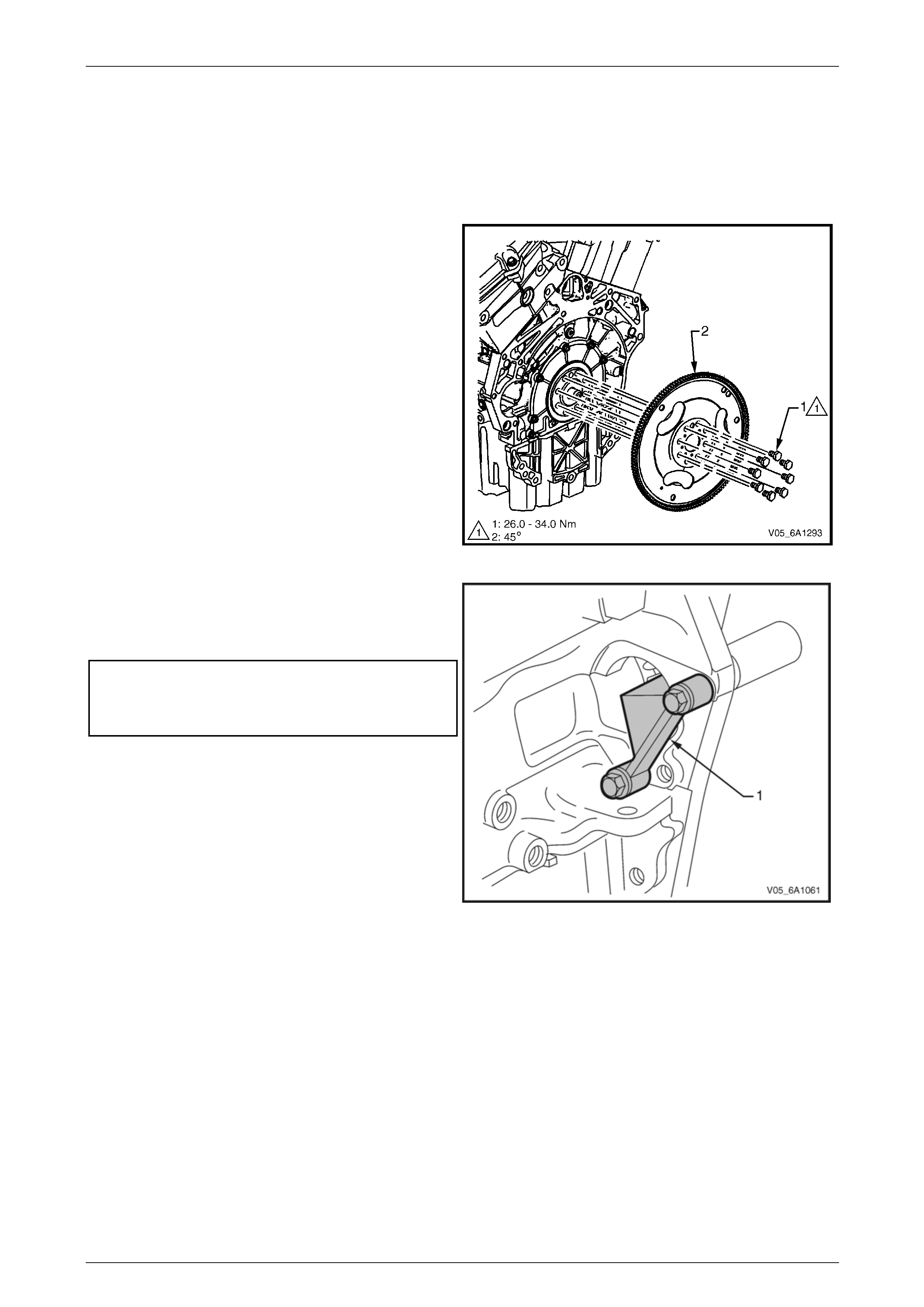
Engine Mechanical – V6 Page 6A1–223
Page 6A1–223
Reinstall
NOTE
The bolt holes are unevenly spaced to enable
flexplate fitment in the one position only.
1 Place the flexplate assembly (2) in position on the
crankshaft.
2 Install new flexplate attaching bolts (1) and hand
tighten.
Figure 6A1 – 357
3 Install the flexplate holding tool, T ool No. EN-46106
(1) into the starter motor mounting location.
4 Tighten the eight flexplate attaching bolts to the
correct torque specification.
Flexplate attaching bolt
torque specification:
Stage 1 ..............26.0 – 34.0 Nm
Stage 2 .................................45°
5 Remove the flexplate holding tool.
6 Install the starter motor, refer to
Section 6D1-2 Starting System – V6.
7 Install the transmission, refer to
Section 7E4 Automatic Transmission – 5L40E - On
Vehicle Servicing.
Figure 6A1 – 358
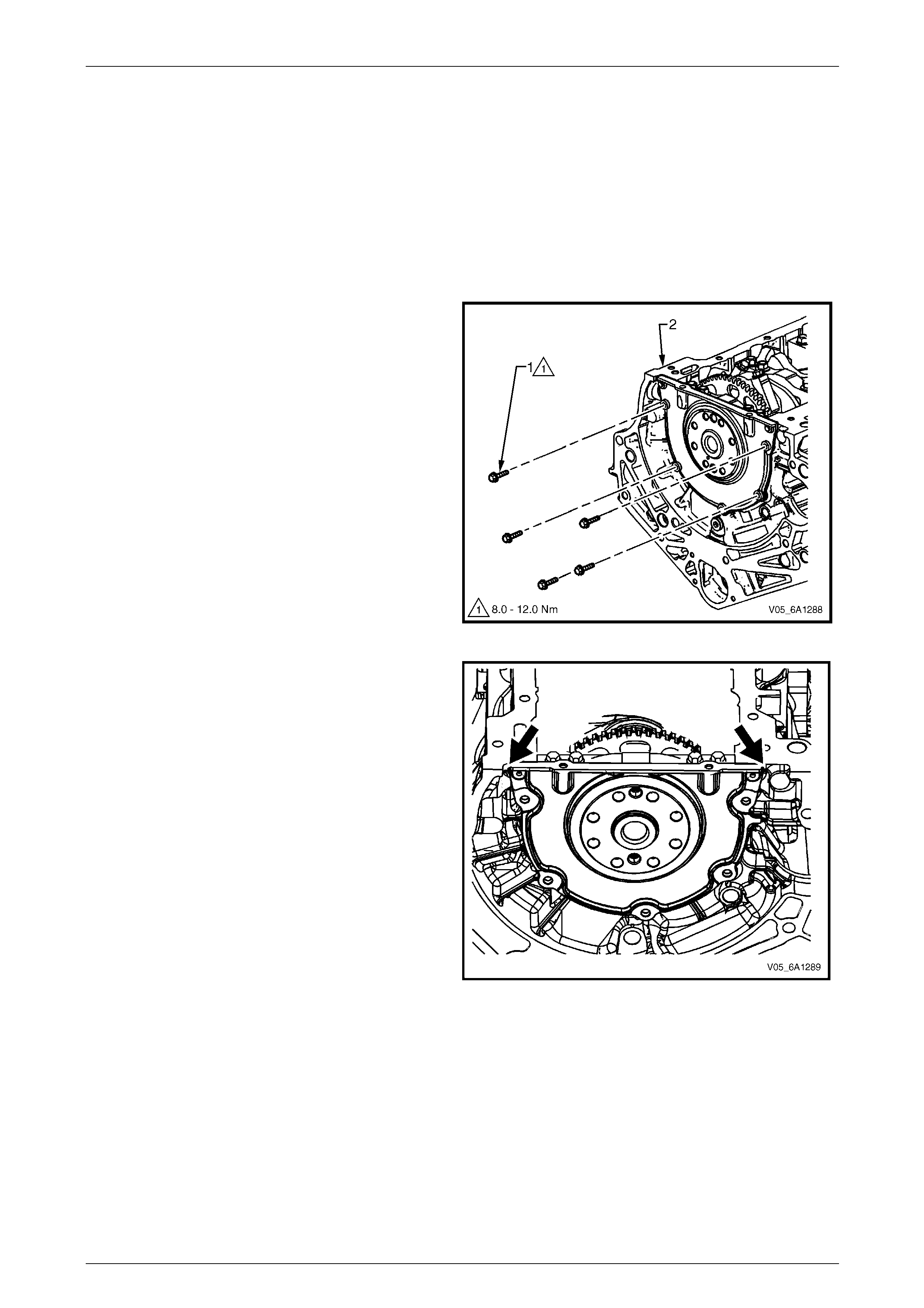
Engine Mechanical – V6 Page 6A1–224
Page 6A1–224
4.4 Crankshaft Rear Seal and Plate
Assembly
LT Section No. — 00–200
Remove
1 Remove the engine assembly, refer to 4.1 Engine Assemb ly.
2 Remove the flexplate assembly, refer to 4.3 Flexplate Assembly.
3 Remove the engine oil pan as sembly, refer to 4.2 Oil Pan and Oil Pump Suction Pipe Assembly.
4 Remove the five bolts (1) attaching the crankshaft
rear seal housing to the rear of the cylinder block (2).
Figure 6A1 – 359
5 Shear the RTV sealant using the pris e points located
at the edge of the crankshaft rear oil seal housing,
Figure 6A1 – 360
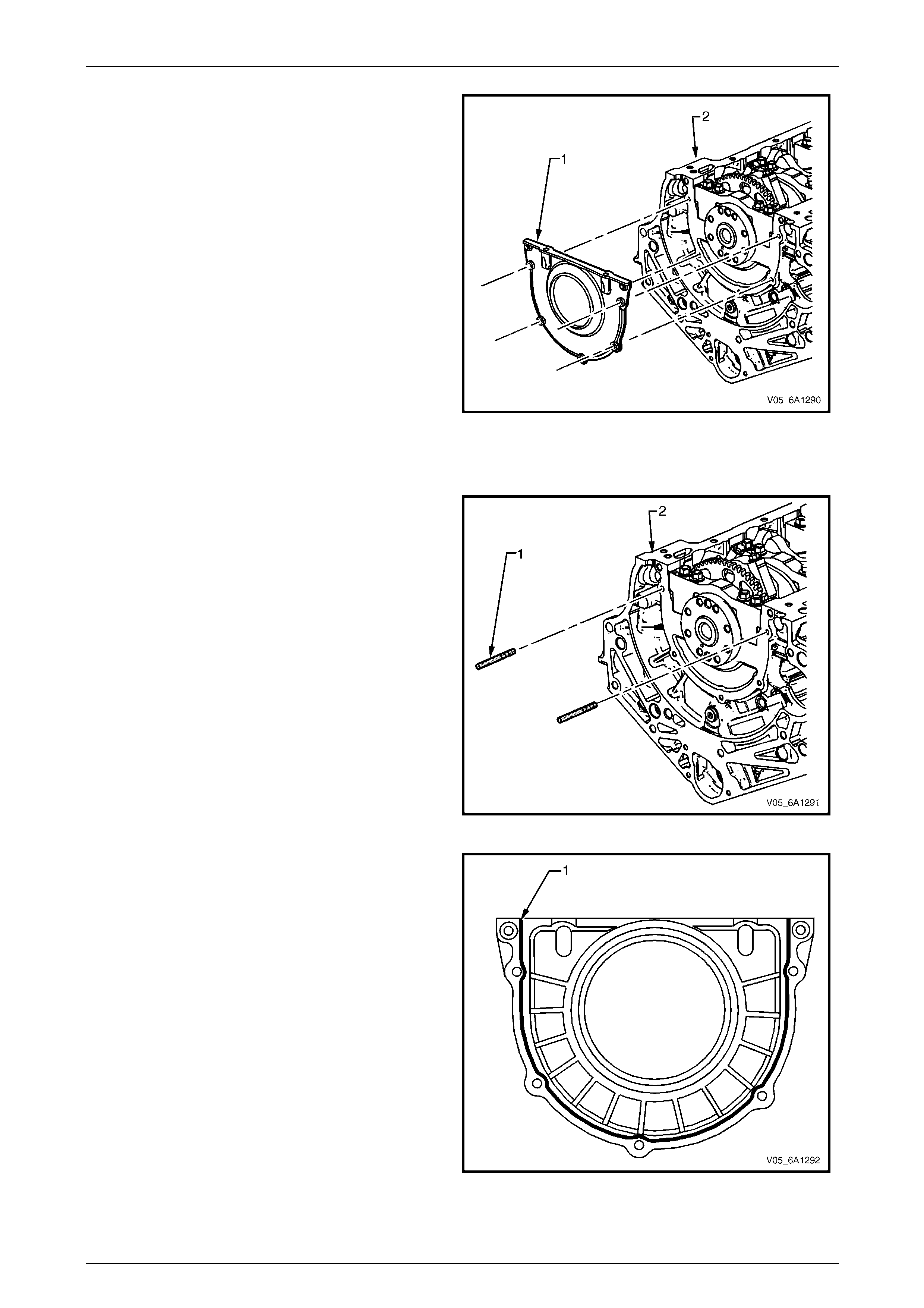
Engine Mechanical – V6 Page 6A1–225
Page 6A1–225
6 Remove the crankshaft rear oil seal housing (1) from
the cylinder block (2).
Figure 6A1 – 361
Reinstall
1 Install the guide pins, Tool No. EN-4610 9 (1) into the
two crankshaft rear oil seal housing bolt holes of the
cylinder block (2).
Figure 6A1 – 362
2 Apply a 3mm bead (1) of RTV sealant to the
crankshaft rear oil seal housing.
Figure 6A1 – 363
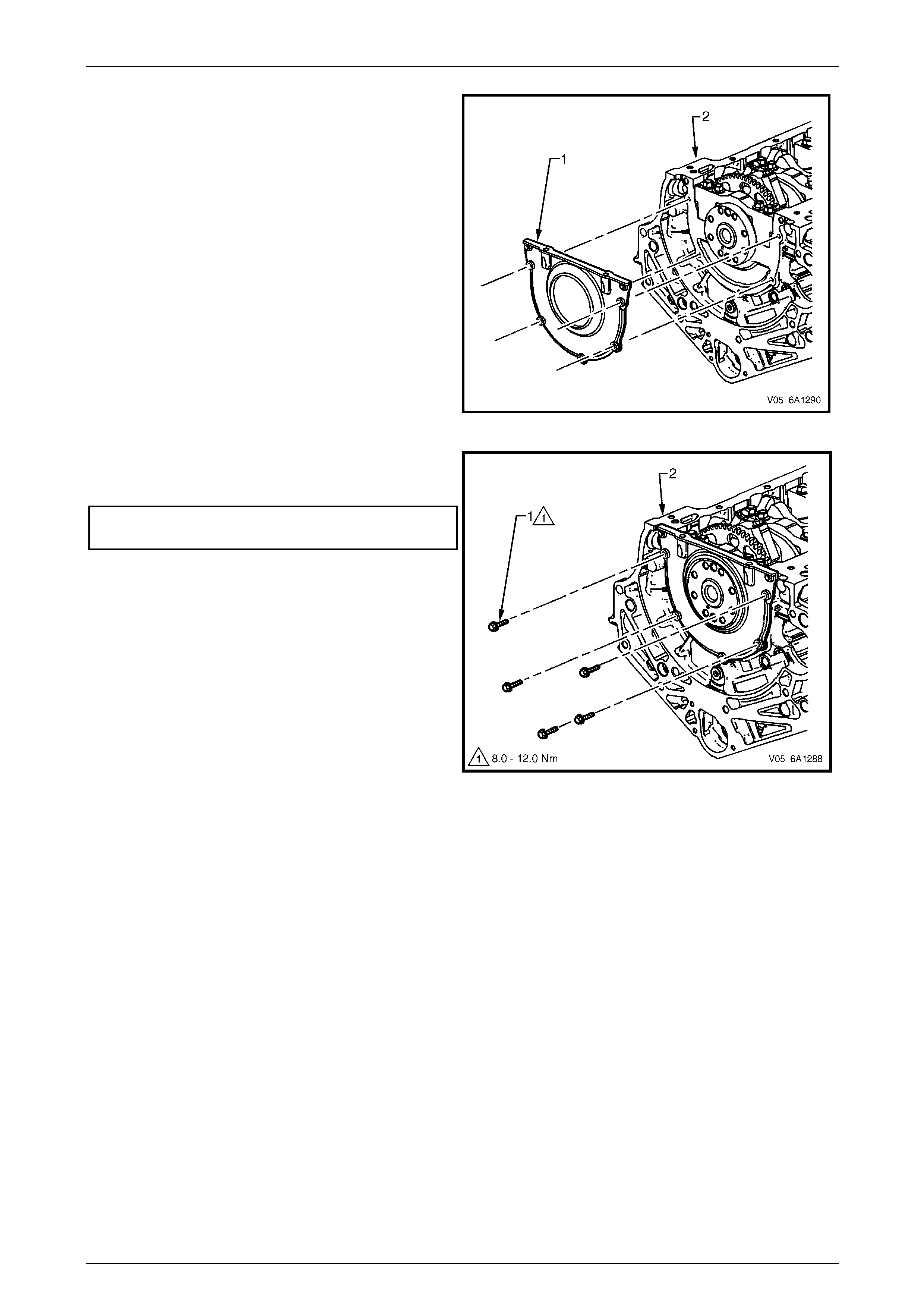
Engine Mechanical – V6 Page 6A1–226
Page 6A1–226
NOTE
Do not allow any engine oil onto the cylinder
block mating surface, where the crankshaft rear
oil seal housing is to be installed.
3 Install the crankshaft rear oil seal housing (1) to the
cylinder block (2).
NOTE
A seal-protector is provided with the new
crankshaft rear seal and housing assembly. Do
not remove the seal protector from the
crankshaft rear oil seal housing until the
crankshaft rear oil seal housing is fully in
position.
4 Remove the guide pins from the cylinder b lo ck.
Figure 6A1 – 364
5 Install the crankshaft rear oil seal housing attaching
bolts (1) to the cylinder block (2) and tighten to the
correct torque specification.
Crankshaft rear oil seal housing
attaching bolt torque specification.............8.0 – 12.0 Nm
Figure 6A1 – 365
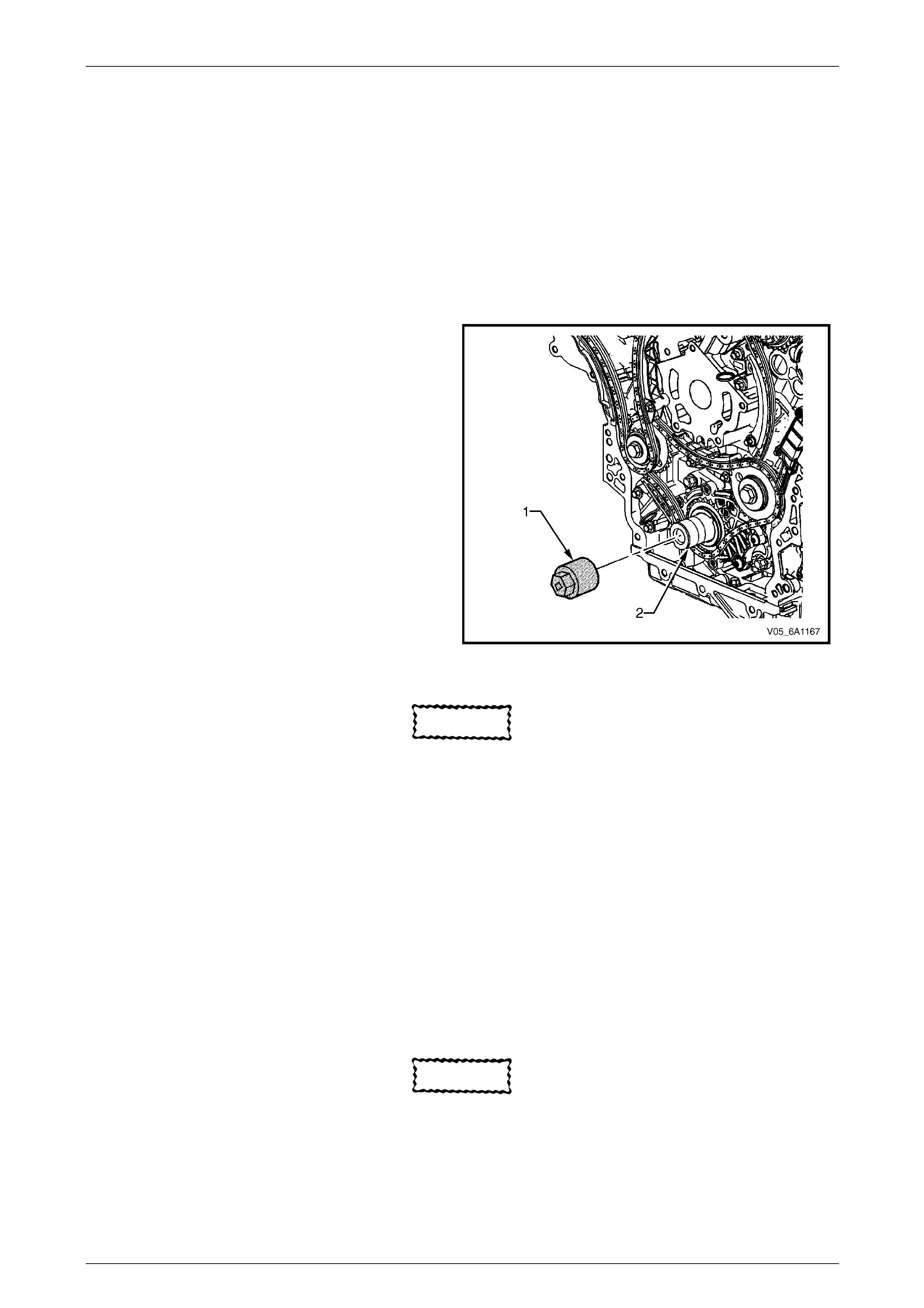
Engine Mechanical – V6 Page 6A1–227
Page 6A1–227
4.5 Pistons, Pins, Rings, Connecting Rods
and Big-end Bearings
LT Section No. — 00–550
Remove
1 Remove the engine assembly, refer to 4.1 Engine Assemb ly.
2 Remove both cylinder head assemblies, refer to 3.23 Cylinder Head Assembly.
3 Remove the oil pan assembly, refer to 4.2 Oil Pan and Oil Pump Suction Pipe Assembly.
4 Mark the top of the piston being removed to identify its specific bore.
5 Install Tool No. EN-46111 (1) onto the crankshaft (2).
6 Rotate the crankshaft until the piston being remove d
is at the bottom of its stroke; bottom dead centre
(BDC).
Figure 6A1 – 366
CAUTION
If the connecting rod bearings have been
used in a running engine, they must be
replaced with new connecting rod bearings
for reassembly.
7 Before removing the connecting rods, check the connecting rod side clearance using the following procedure:
a Tap the connecting rod to one end of the crankshaft journal with a dead blow or wooden hammer.
b Using feeler gauges, measure the clearance between the crankshaft counterweight and the connecting rod.
c The connecting rod side clear ance should not exceed specifications, refer to 5 Specifications.
d If the endplay exceeds the specified limits, measure the width of the crankpin end of the connecti ng rod,
refer to 5 Specifications.
e If the connecting rod width is significantly smaller than specified and severe wear is present on the side of the
connecting rod, replace the conn ecting rod.
f If the connecting rod width is within specifica t ion an d excessive scoring is present on the crankshaft journals,
replace the crankshaft.
CAUTION
Do not use a stamp, punch or any other
method that may distort or stress the
connecting rod and cap. Extensive engine
damage may result from a co nnectin g rod th at
is distorted or stressed.
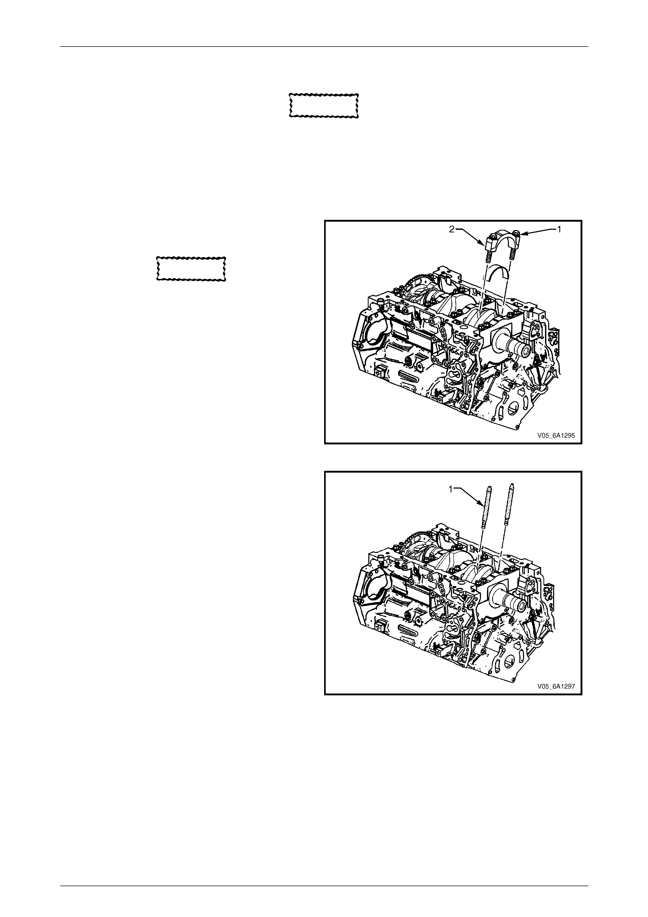
Engine Mechanical – V6 Page 6A1–228
Page 6A1–228
8 Mark the cylinder number on the connecting rod and the connecting rod cap with a paint stick or permanent marker.
CAUTION
Powdered metal connecting rods have rod
bolts which yield when tighten to the
specified torque. If the bolts are loosened or
removed they must be replaced. Rod bolts
that are not replaced will not torque to the
correct clamp load and can lead to serious
engine damage.
9 Remove the connecting rod bolts (1), loosening
progressively from side to side.
CAUTION
The connecting rod caps must remain with
the original connecting rod.
10 Remove the connecting rod cap (2).
Figure 6A1 – 367
11 Install connecting rod guide pin set, T ool No.
EN-46121 (1) to the connecting rod bolt holes.
Figure 6A1 – 368
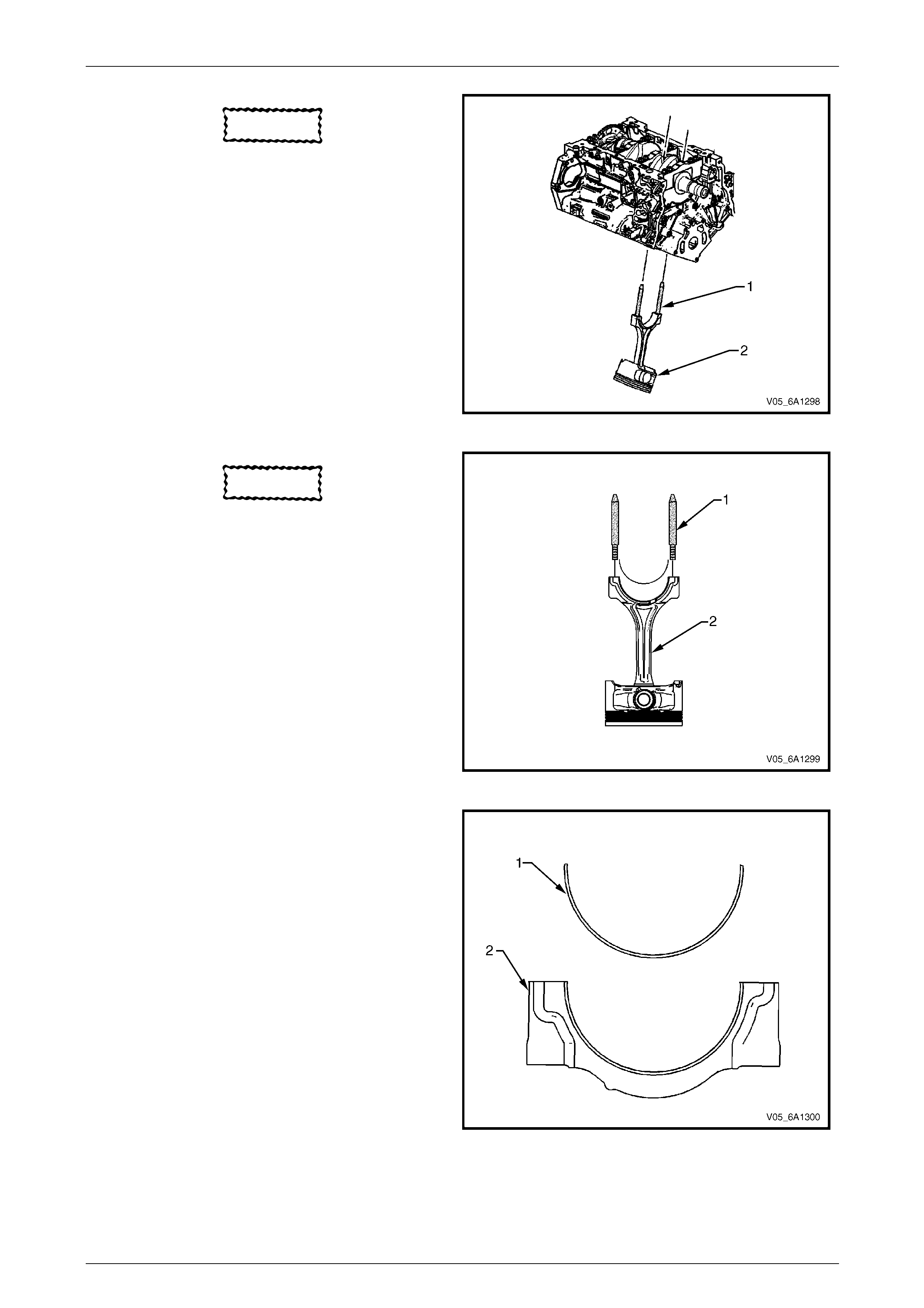
Engine Mechanical – V6 Page 6A1–229
Page 6A1–229
CAUTION
Do not damage the crankshaft journal,
cylinder wall and piston cooling jets when
removing the connecting rod and piston
assembly.
12 Using connecting rod gui de pin set, Tool No.
EN-46121 (1), push the connecting rod and piston
assembly (2) through the top of the cylinder.
Figure 6A1 – 369
CAUTION
When dismantled, ensure the connecting
rod, connecting rod cap, piston and
bearings are organised in their original
position and location. This will also aid
engine mechanical diagnosis.
13 Remove connecting rod guide pin set, Tool No.
EN-46121 (1) from the connecting rod bolt holes.
14 Remove the upper connecting rod bearing from the
connecting rod (2).
Figure 6A1 – 370
15 Remove the lower connecting rod bearing (1) from
the connecting rod cap (2).
Figure 6A1 – 371
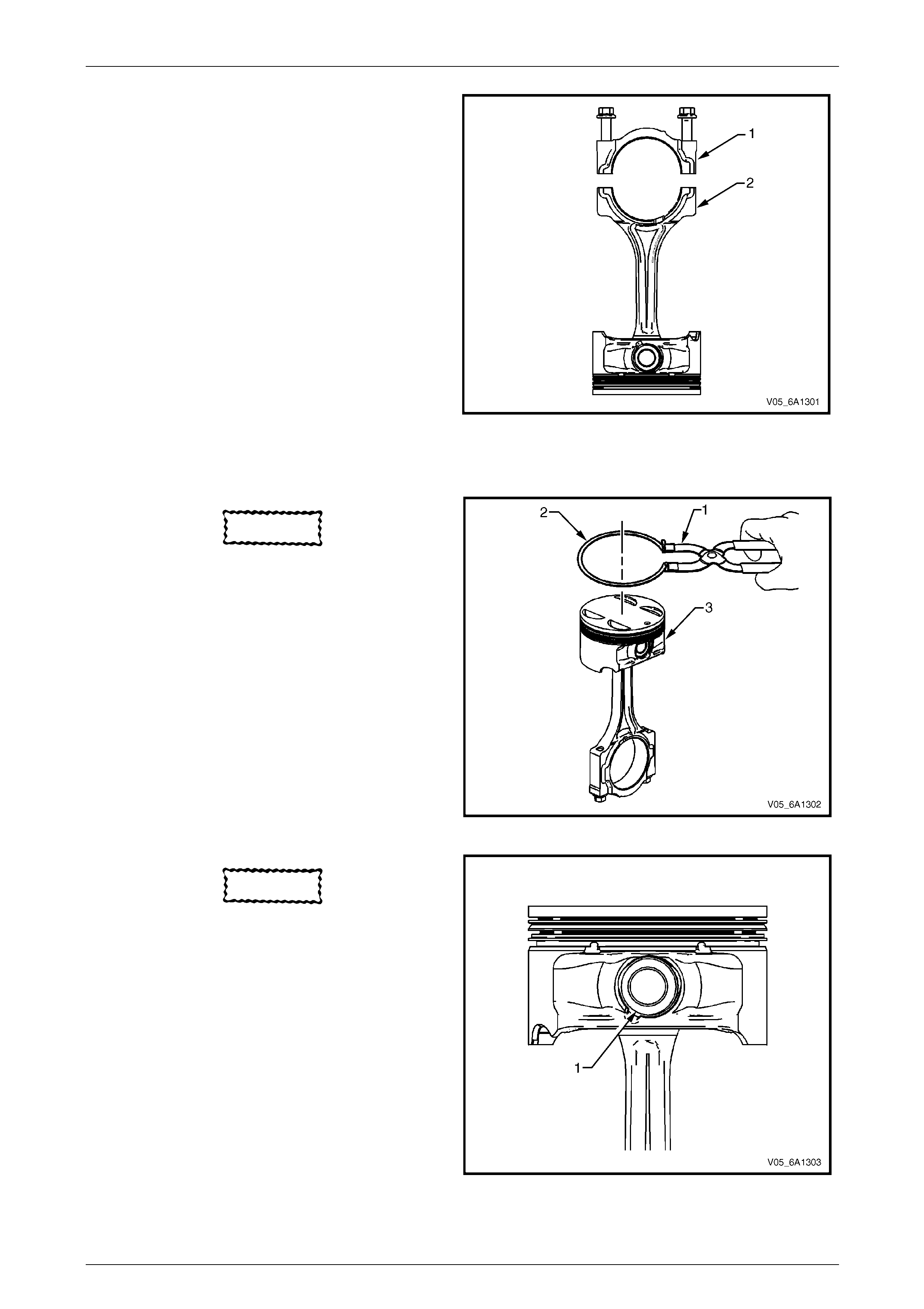
Engine Mechanical – V6 Page 6A1–230
Page 6A1–230
16 Reattach the connecting rod cap (1) to the connecting
rod (2) to prevent damage to their mating surfaces.
NOTE
The cap and rod are a matche d set and m ust be
kept together.
17 Repeat steps 4 to 16 for the remaining piston and
connecting rod assemblies.
Figure 6A1 – 372
Disassemble
CAUTION
A piston ring expander must be used to
remove and install the piston rings. Only
expand the rings far enough to fit over the
piston lands. If the rings are overexpanded,
the top ring will shatter and the others will
distort.
1 Remove the piston rings (2) using a piston ri ng
expander (1). Place each ring in a clean shop towel
for storage.
Figure 6A1 – 373
CAUTION
Do not reuse the piston pin retainers.
2 Remove the piston pin retainers b y using the removal
access notch (1) in the side of the piston. Discard the
piston pin retainers.
Figure 6A1 – 374
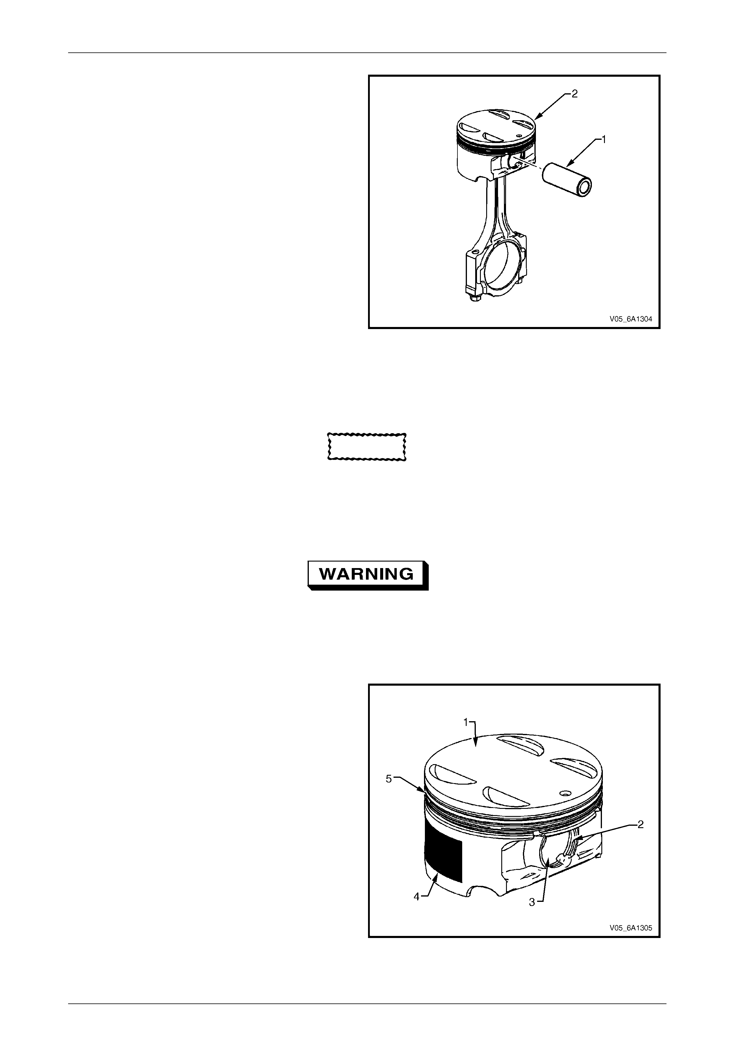
Engine Mechanical – V6 Page 6A1–231
Page 6A1–231
3 Slide the piston pin (1) out of the piston (2). The
piston will disconnect from the connecting rod.
Figure 6A1 – 375
Clean and Inspect
Piston Cleaning Procedure
CAUTION
Do not use a wire brush to clean any part of
the piston.
1 Clean the piston skirts and the pins with a suitable so lvent.
2 Clean the piston ring groov es wit h a gro ove cleaner. Ensure the oil ring holes and slots are clean.
Safety glasses must be worn when using
compressed air.
3 Dry the piston with compressed air.
Piston Inspection Procedure
1 Inspect the pistons for the following conditio ns:
• eroded areas at the top of the piston (1),
• piston pin retainer grooves for burrs (2),
• worn piston pin bores or worn piston pins (3),
• scuffed or damaged skirt coating (4),
• ring grooves for cracks, nicks or burrs that may
cause binding (5), and
• warped or worn ring lands.
2 Replace pistons that show any signs of damage or
excessive wear.
Figure 6A1 – 376

Engine Mechanical – V6 Page 6A1–232
Page 6A1–232
Piston Measurement
1 Measure piston width using the following procedure:
a Using an outside micrometer, measure the
width of the piston at 30 mm below the crown
top (1), at the thrust surfaces of the piston,
perpendicular to the piston pin centreli ne.
b Compare the measurement of the piston to its
original cylinder by subtracting the pisto n width
from the cylinder diameter.
c Check your measurements with specifications,
refer to 5 Specifications.
d If the clearance obtained through me asurement
is greater than the provided specifications a nd
the cylinder bores are within specification,
replace the piston.
Figure 6A1 – 377
2 Measure the piston pin bore t o piston pin (2)
clearances using the foll owing procedure:
a Piston pin bores and pi ns must be free of
varnish or scuffing.
b Use an outside micrometer (1) to measure the
piston pin in the piston contact areas.
Figure 6A1 – 378
3 Using an inside micrometer, measure the piston pin
bore (1). Compare the result with the piston pin
diameter and piston pin to piston pin bore clearanc e
listed in the specifications, refer to 5 Specifications.
4 If the clearance is excessive, determine which piece
is out of specification and replace as require d.
5 Replace the piston if any of its dimensions are out of
specification.
6 If the new piston does not meet clearance
specifications, the cylinder bl ock may need to be
oversized to 0.25 mm. There is only one size of
oversized pistons and rings available for service.
Figure 6A1 – 379
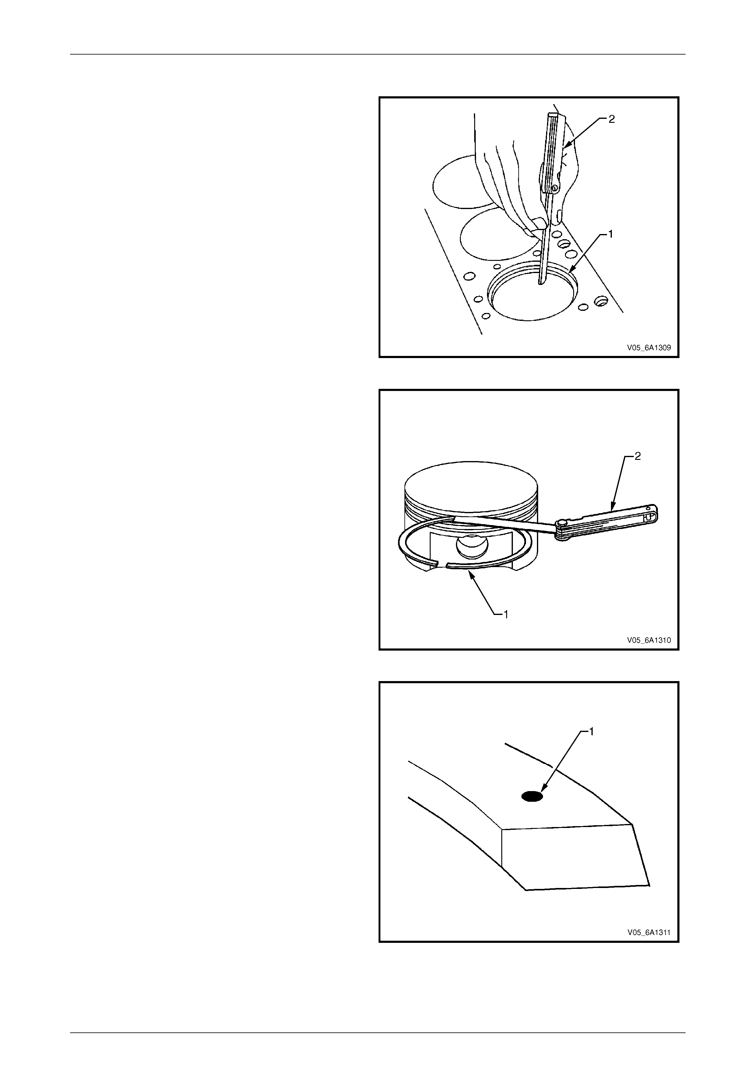
Engine Mechanical – V6 Page 6A1–233
Page 6A1–233
Piston Ring Measurement
1 Measure the piston ring end gap using the following
procedure:
a Place the piston ring (1) in the area of the bore
where the piston ring will travel, approximately
25 mm below the deck surface. Ensure the ring
is square with the cylinder bore b y position ing
the ring with the piston head.
b Measure the end gap of the piston rin g with
feeler gauges (2), refer to 5 Specifications.
c If the clearance exceeds the provided
specifications, the piston rings must be
replaced.
d Repeat the procedure for all piston rin gs.
Figure 6A1 – 380
2 Measure the piston ring side clearance using the
following procedure:
a Roll the piston ring (1) entirely aroun d the piston
ring groove. If any binding is caused by the ring
groove, dress the groove with a fine file. If any
binding is caused by a distorted piston ring,
replace the ring.
b With the piston ring on the pist on, use feeler
gauges (2) to check clearance at multiple
locations.
c Compare the measurements with piston ring
side clearance listed in the specificati ons,
refer to 5 Specifications.
d If the clearance is greater than specifications,
replace the piston rings.
Figure 6A1 – 381
3 There is a locating dimple (1) on the compression
rings. Install the compression rings with the dimple
facing up.
4 If the new ring does not reduce the clearance to the
correct specification, install a new piston.
5 If the new piston does not meet clearance
specifications, the cylinder bl ock may need to be
oversized to 0.25 mm. There is only one size of
oversized pistons and rings available for service.
Figure 6A1 – 382
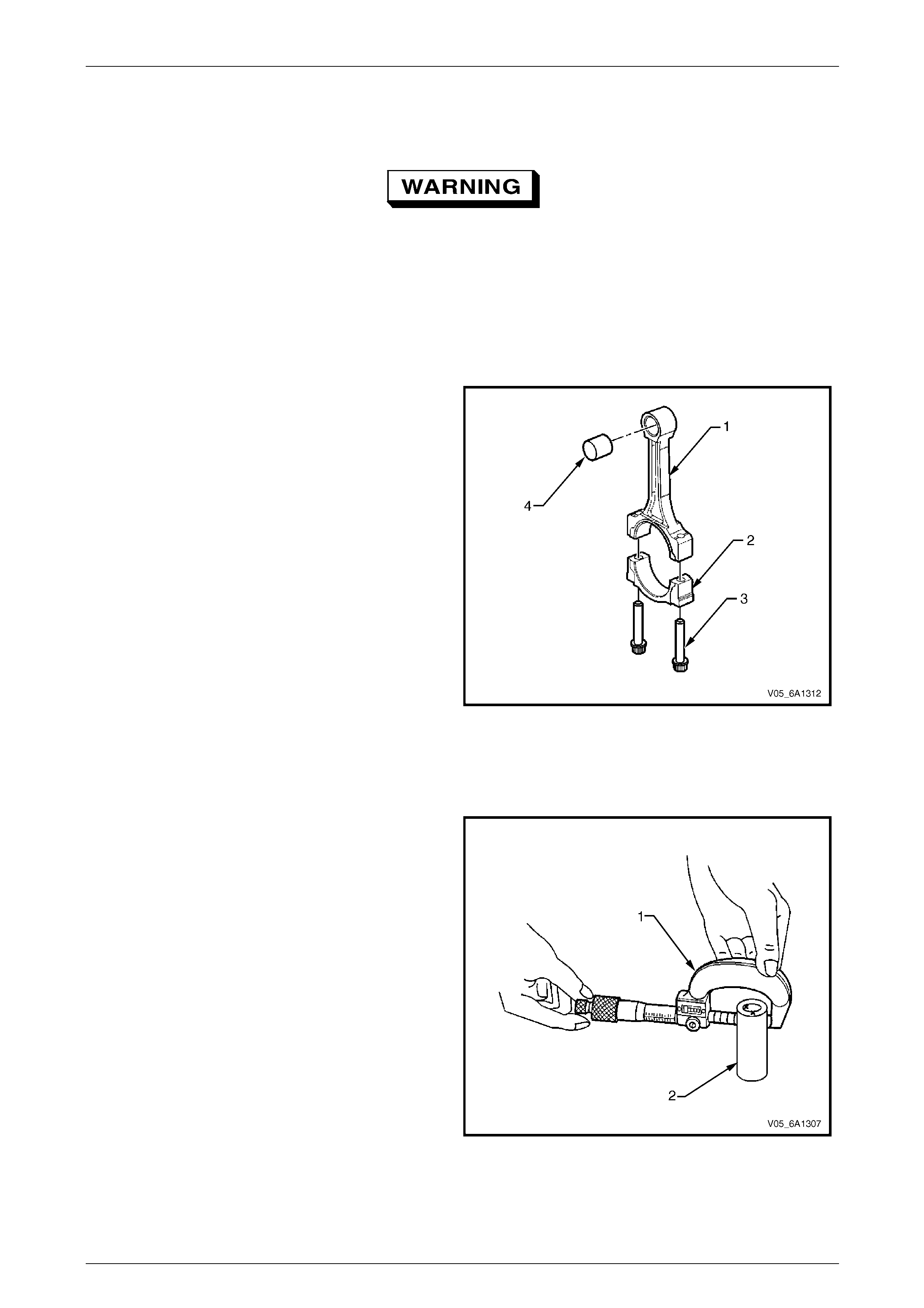
Engine Mechanical – V6 Page 6A1–234
Page 6A1–234
Connecting Rod Cleaning Procedure
1 Clean the connecting rods in solve nt.
Safety glasses must be worn when using
compressed air.
2 Dry the connecting rod using compressed air.
3 Remove the connecting rod cap an d clean the threads.
4 Remove the connecting rod b earing and discard. Never reuse a connecting rod be aring that has been used in a
running engine.
Connecting Rod Visual Inspection Procedure
1 Inspect the piston pin bushin g (4) for scoring or
damage.
2 Inspect the connecting rod beam (1) for twisting or
bending.
3 Inspect the rod cap (2) for any nicks or damage
caused by possible interference.
4 Inspect for scratches or abrasion on the rod beari ng
seating surface.
5 If the connecting rod bores contain minor scr atches or
abrasions, clean the bores in a circular direction with
a light emery paper.
6 Retain the original bolts (3) for preliminary assembly.
They must be replaced for final assembly.
Figure 6A1 – 383
Connecting Rod Measurement Proc edure
Piston Pin End
NOTE
Measurements of all components should be
taken with the components at normal room
temperature.
1 Using an outside micrometer (1), take t wo
measurements of the piston pin (2) in the are a of the
connecting rod contact.
Figure 6A1 – 384
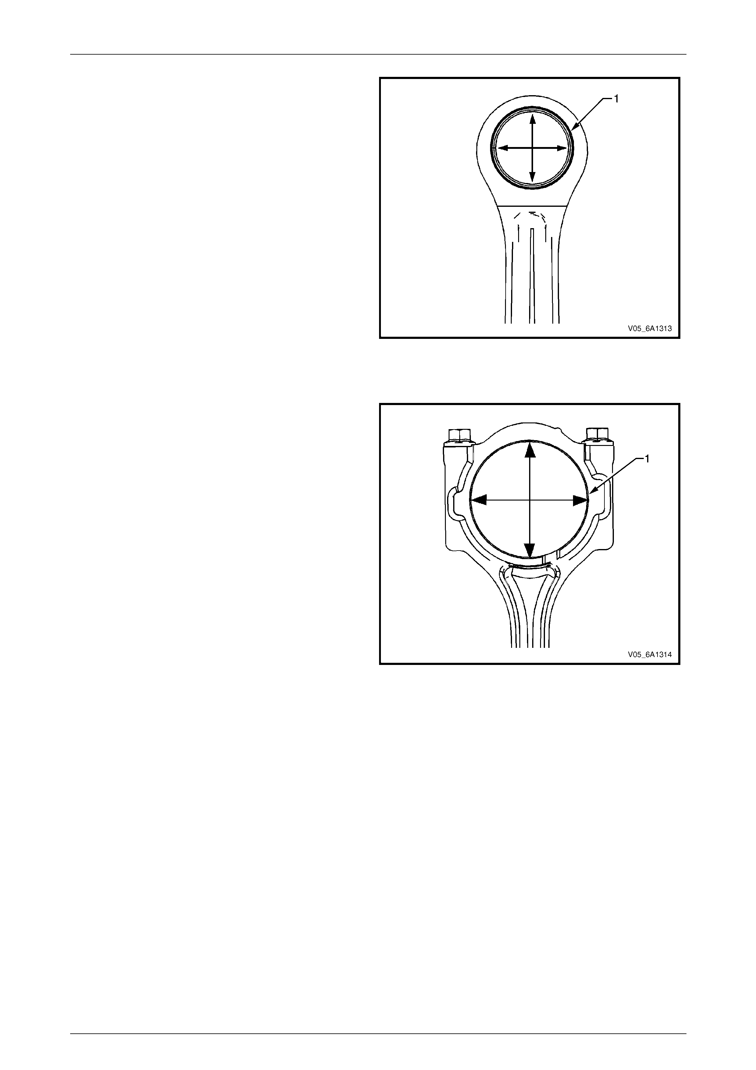
Engine Mechanical – V6 Page 6A1–235
Page 6A1–235
2 Using an inside micrometer, measure the connecting
rod piston pin bore (1).
3 Subtract the piston pin diameter from the piston pi n
bore.
4 Compare the clearance measurements listed in the
specifications, refer to 5 Specifications.
5 If the clearance is excessive, replace the piston pin. If
a new pin does not resolve the clear ance problem,
replace the connecting rod.
Figure 6A1 – 385
Crankshaft Bearing End
NOTE
Measurements of all components should be
taken with the components at normal room
temperature.
1 Using an inside micrometer, measure the connecting
rod crankshaft bearing bore (1).
2 Compare the bore measurements listed in the
specifications, refer to 5 Specifications.
3 Replace the connecting rod if the bore is out of
specification. Do not recondition the connecting rod.
Figure 6A1 – 386
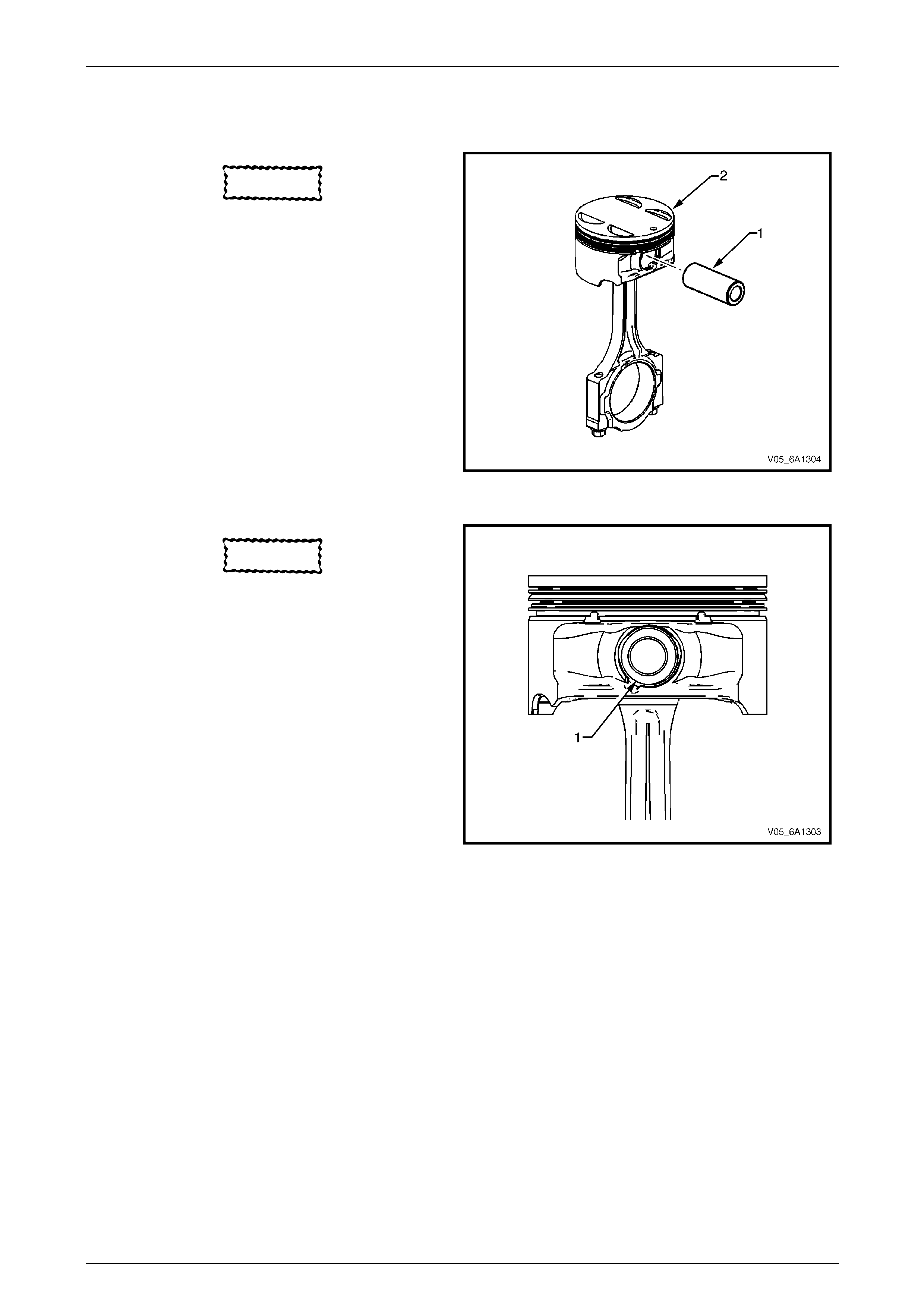
Engine Mechanical – V6 Page 6A1–236
Page 6A1–236
Reassemble
Piston and Piston Pin
CAUTION
The arrow located on top of the piston must
point toward the front of the engine.
NOTE
The connecting rod is non-directional and may
be assembled/reassembled to the piston in
either direction.
1 Lubricate the piston pin (1) bores in the pisto n (2) and
the connecting rod with clean engine oil.
2 Assemble the piston and piston pin to the connecting
rod. Correctly orient the piston when reusing a
marked connecting rod.
3 Align the piston pin bore with the connecting rod pin
bore.
4 Slide the piston pin into the piston and the connecting
rod. Figure 6A1 – 387
CAUTION
New piston pin retainers must be used.
Never reuse the piston pin retainers.
5 Install new piston pin retainers (1).
6 Ensure the piston pin retainers are fully seated in their
grooves.
7 Repeat steps 1 to 6 for the remaining pistons.
Figure 6A1 – 388
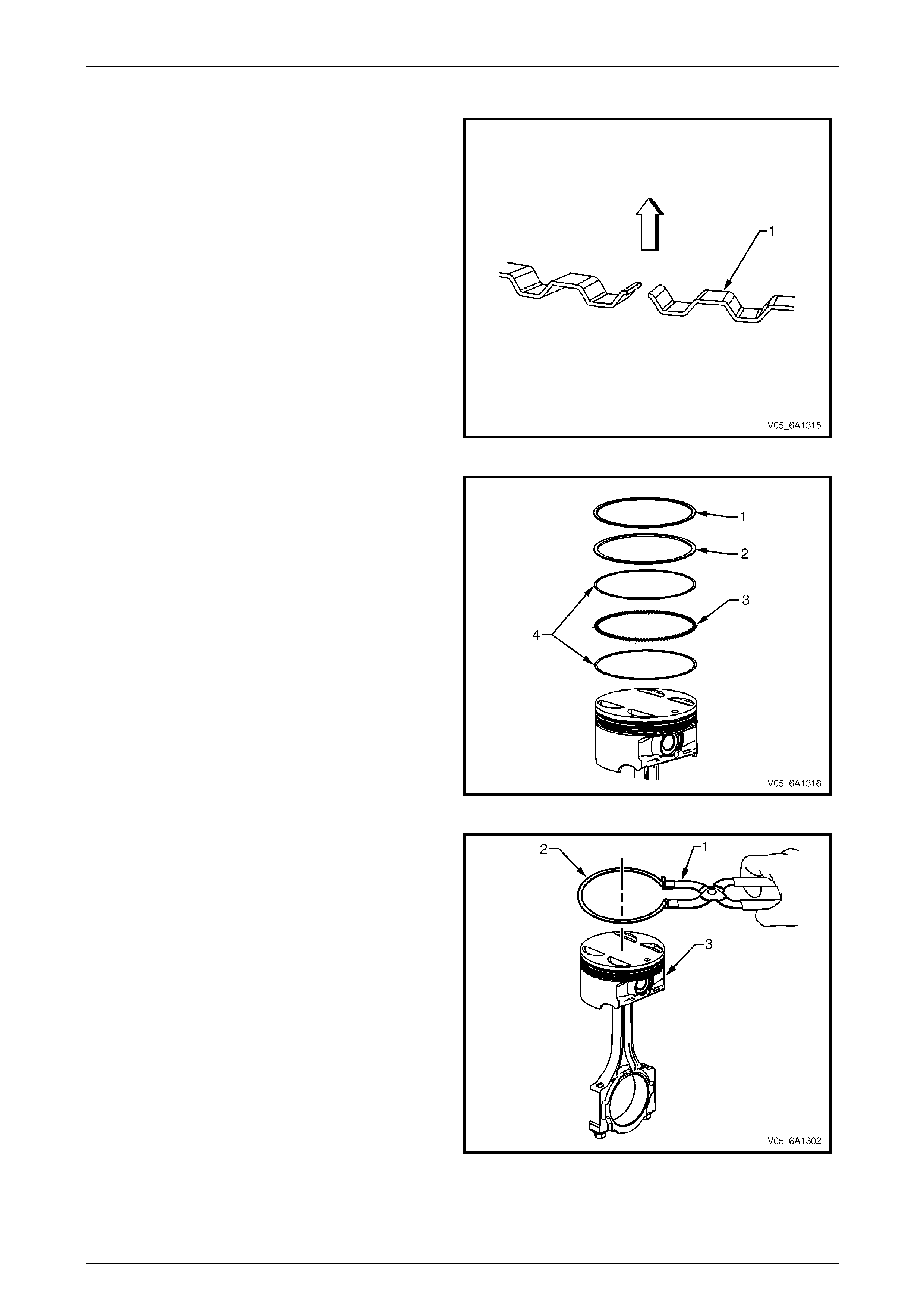
Engine Mechanical – V6 Page 6A1–237
Page 6A1–237
Piston Ring
1 Correctly orient the oil control ring ex pander (1)
before installation. The ends of the expander must be
facing toward the top of the piston.
Figure 6A1 – 389
2 Using a piston ring expander, install the oil control
ring assembly using the following procedure:
a Install the expander ring (3).
b Install the two oil scraper rings (4). Expand the
rings only enough to clear the piston diameter.
Over-expanding the piston rings will distort or
crack the rings.
3 Install the second (2) and top (1) piston rings as
follows.
Figure 6A1 – 390
4 Using the ring expander (1), install the second (2)
piston ring (2) onto the piston (3). Do not over-expand
the ring. Repeat for the top ring.
Figure 6A1 – 391
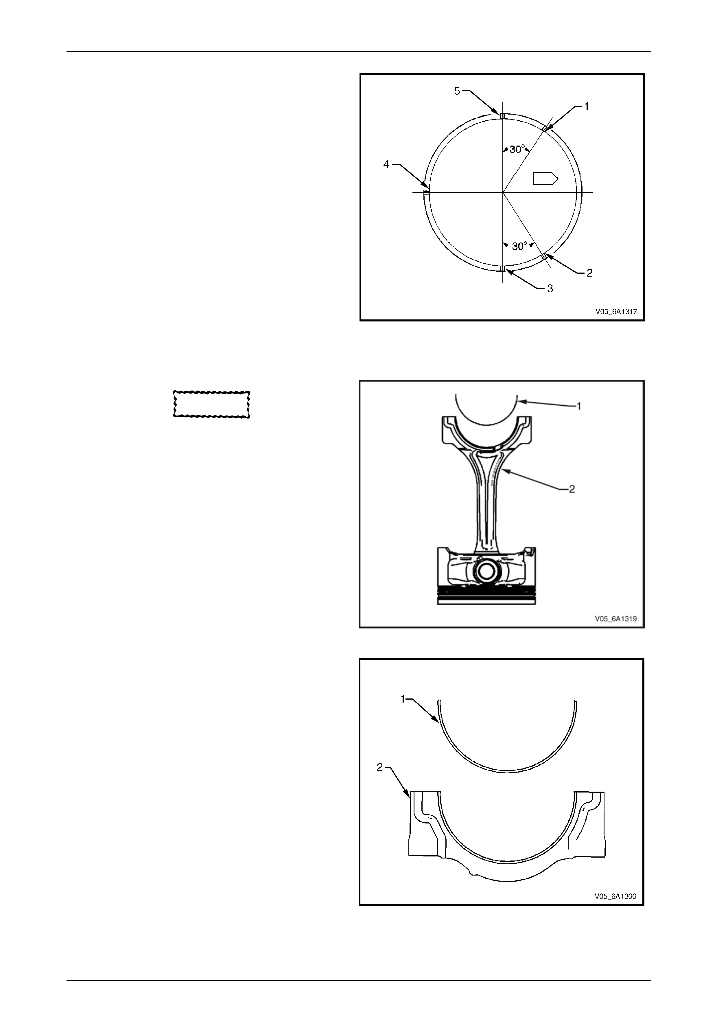
Engine Mechanical – V6 Page 6A1–238
Page 6A1–238
5 Once the rings are installed, set the ring gaps for the
oil control, second and top rin g as follows. Use the
piston location arrow for reference.
• Lower oil control ring position (1).
• Upper oil control ring position (2).
• Top ring position (3).
• Oil control ring expander positi on (4).
• Second ring position (5).
Figure 6A1 – 392
Connecting Rod Bearing
CAUTION
If the connecting rod bearings have been
used in a running engine, they must be
replaced with new connecting rod bearings
for reassembly.
1 Clean the connecting rod (2) and the co nnecting rod
cap bearing bore with a lint-free cloth.
2 Clean the oil from behind the connectin g rod bearing
halves.
3 Install a new upper connecting rod be aring (1) into
position. Roll the bearing into position so the lock tang
engages the alignment slot. The bearing mu st fit flush
in the connecting rod.
Figure 6A1 – 393
4 Install the lower connecting rod bear ing (1) into
position in the connecting rod cap (2).
5 Roll the bearing into positio n so the lock tang
engages the alignment slot. The bearing mu st fit flush
with the connecting rod cap.
Figure 6A1 – 394
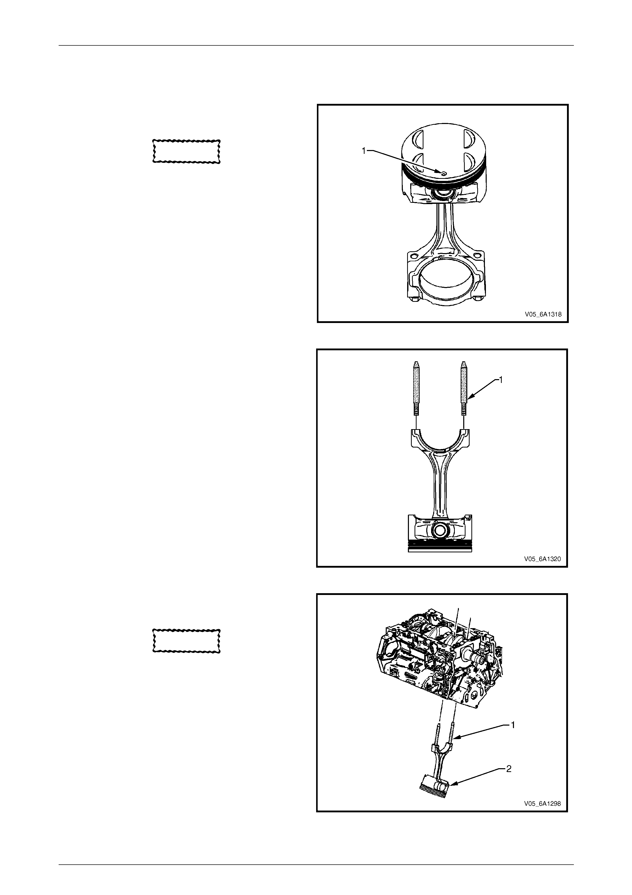
Engine Mechanical – V6 Page 6A1–239
Page 6A1–239
Reinstall
Piston Connecting Rod and Connecting Rod Bearing Installati on
1 Liberally lubricate the cylinder walls, piston rings and
piston skirts with engine oil.
CAUTION
The piston is directional and must be
installed in the engine block in the correct
direction. The locating arrow on the top of
each piston must be pointing toward the
front of the engine.
2 Select the correctly numbered piston/connecting rod
assembly for the cylinder. A dot (1) showing correct
piston orientation is located on the top of the piston.
Figure 6A1 – 395
3 Install connecting rod guide pin set, T ool No.
EN-46121 (1) into the connecting rod bolt holes.
Figure 6A1 – 396
4 Compress the piston rings using a commercially
available ring compressor.
CAUTION
Extreme care must be used when installing
the piston and connecting rod to ensure the
rod does not scrape or nick the cylinder
bore, oil jets, or crankshaft surfaces.
5 Using both hands from the top and bottom of the
cylinder, slowly guide the piston (2) and co nnecting
rod assembly into the cylinder. Do not allow the
connecting rod to contact the cylinder wall.
6 When the ring compressor contacts the deck surface,
gently tap the piston into the cylinder usi ng the handle
end of a dead-blow hammer. Guide the connecting
rod onto the crankshaft bearing journal using
connecting rod guide pin set, Tool No. EN-46121 (1)
while gently tapping the piston into the c ylinder with a
soft-blow hammer. Figure 6A1 – 397
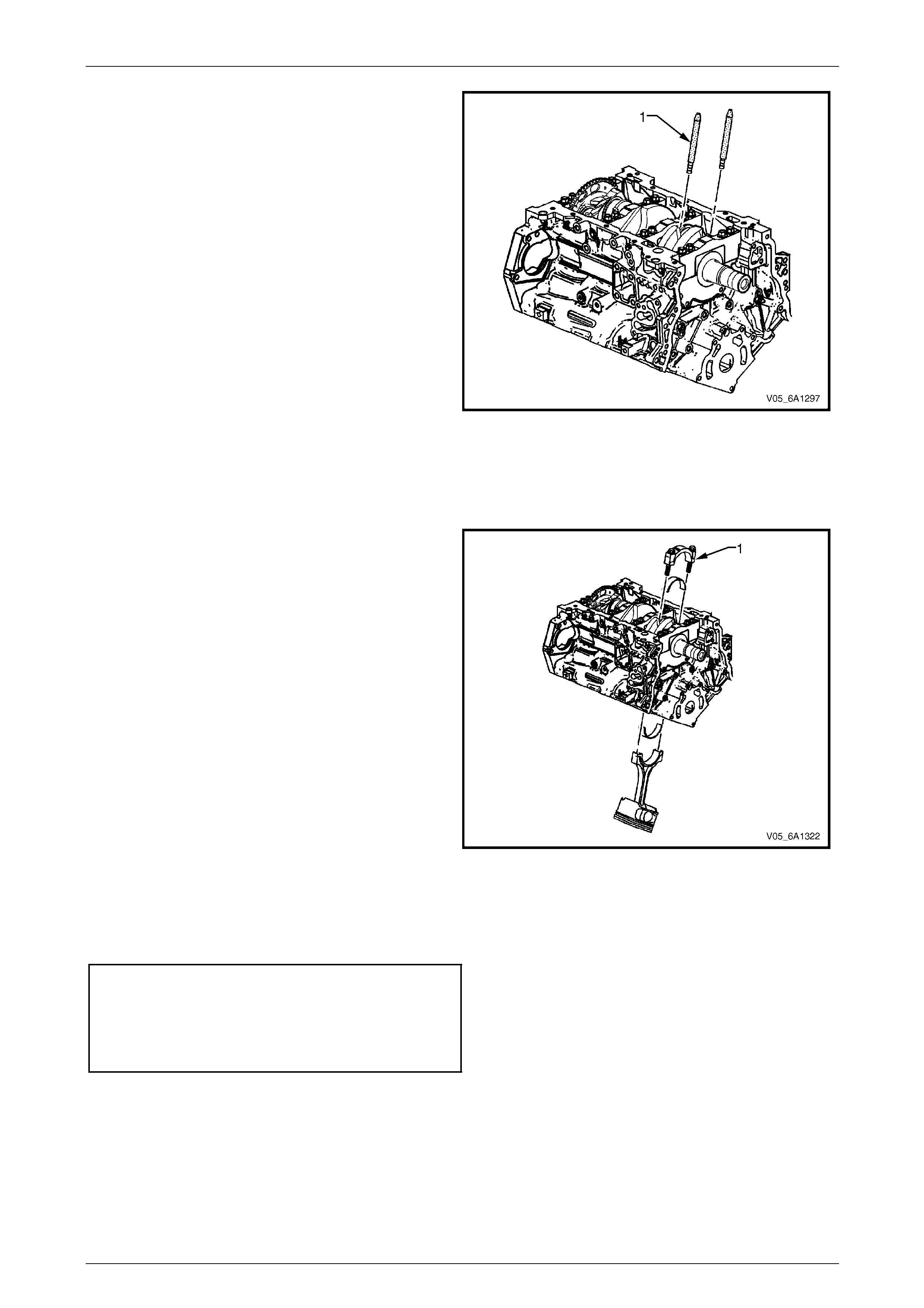
Engine Mechanical – V6 Page 6A1–240
Page 6A1–240
7 Remove connecting rod guide pin set, Tool No.
EN-46121 (1) from the connecting rod bolt holes.
Figure 6A1 – 398
Connecting Rod Bearing Clearance Measurement Procedure
NOTE
Before final assembly, check the clearance of the
new connecting rod bearings.
1 Place a length of fresh, room temperature plastic
gauging material all the way across the connecting
rod bearing journal.
2 Install the connecting rod bear ing into the connecting
rod cap.
3 Install the connecting rod end cap (1) on its original
connecting rod and ensure the bearing lock tangs are
aligned on the same side of the rod.
Figure 6A1 – 399
NOTE
Reuse the old connecting rod bolts only for
measuring the connecting rod bearing clearance.
4 Install the connecting rod cap bolts into the connecting rod cap and tighten to the correct torque specification using
torque angle wrench, Tool No . EN-7115.
Connecting rod cap attaching
bolt torque specification:
Stage 1 .........................30.0 Nm
Stage 2 ........ Loosen com pletely
Stage 3 .........................25.0 Nm
Stage 4 .................. 110 degrees
5 Allow the assembly to sit for at least 2 minutes.
6 Remove the connecting rod cap bolts and discard.
7 Remove the connecting rod cap.
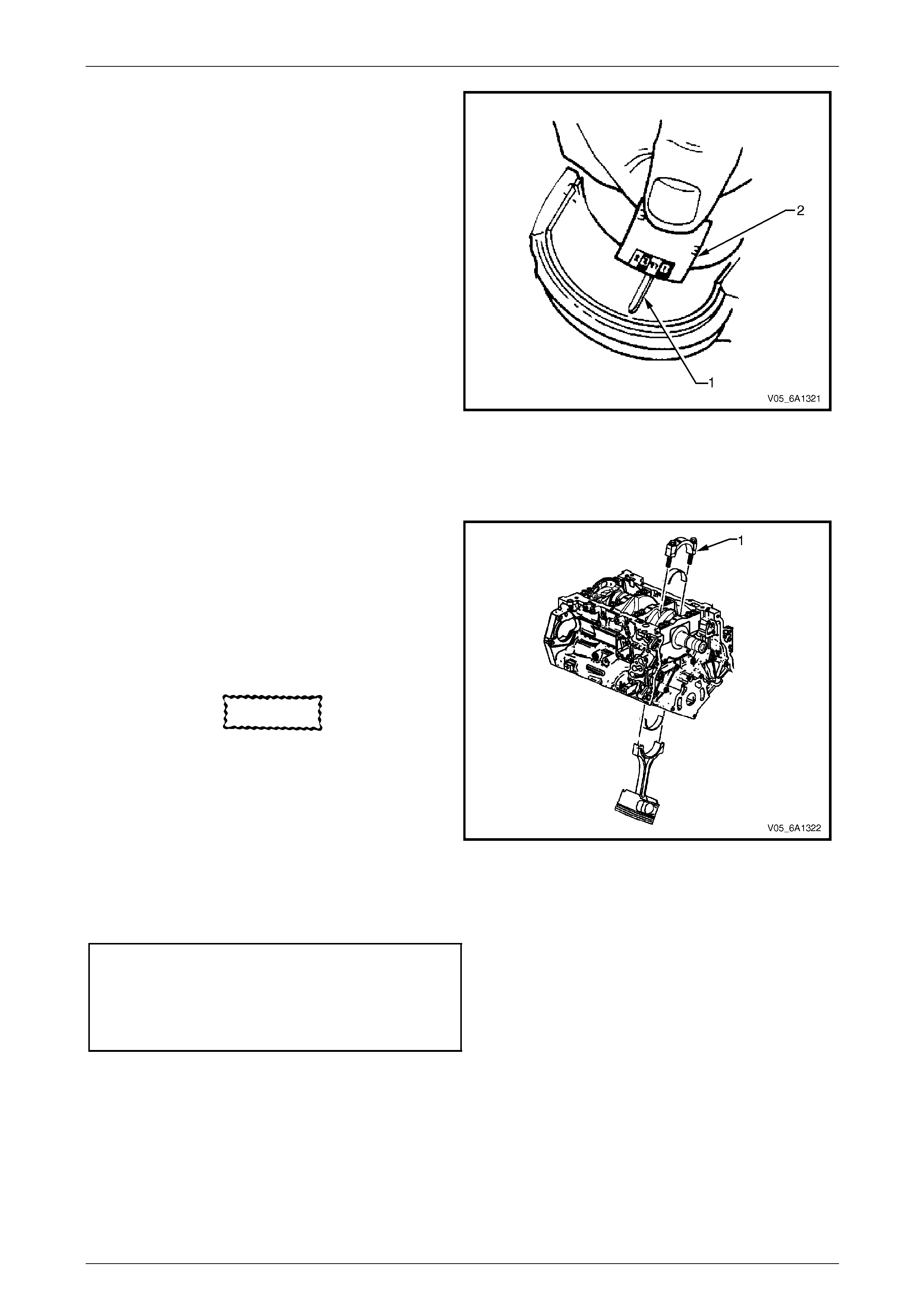
Engine Mechanical – V6 Page 6A1–241
Page 6A1–241
8 Determine the connecting rod bearing clearance by
comparing the width of the flattened plastic
gauging (1) material at its widest point with the
graduation on the gauging material container (2).
9 Compare the measurements with the specifications,
refer to 5 Specifications.
10 If the new bearings do not provide the correc t
crankshaft to connecting rod bear ing clearance,
inspect the following:
a Measure the crankshaft connecting rod journ als
for the correct specified size and ensure the
correct new bearings are being installed. If the
crankshaft connecting rod journals are
incorrectly sized, replace or regrind the
crankshaft. Crankshaft machining is permitted
and undersized bearings are available.
b Measure the connecting rod bearing bore
diameter to ensure correct size. The connecting
rod is not machineable and the connecting rod
must be replaced if out of specification.
11 Clean the plastic gauging material from the
connecting rod bearing journ als using a soft lint-free
cloth.
Figure 6A1 – 400
Connecting Rod Final Assembly Procedure
1 Carefully guide the connecting rod away from the
crankshaft connecting rod journal slightly to lubricate
the crankshaft connecting rod bearing jo urnal.
2 Apply a liberal amount of clean engine oil to the
crankshaft connecting rod bearing journal.
3 Guide the connecting rod to the crankshaft
connecting rod journal.
4 Install the connecting rod end cap (1) on its original
connecting rod and ensure the bearing lock tangs are
aligned on the same side of the rod.
CAUTION
• Do not lubricate the new connecting rod
bolts. The new bolts have a pre-applied
graphite lubricant. Applying lubricant to
the connecting rod bolts will effect the
clamp load when the connecting rod
bolts are tightened to the specified
torque. Incorrect clamp load can lead to
component failure and extensive engine
damage.
• Do not reuse the old connecting rod
bolts.
Figure 6A1 – 401
5 Install new connecting rod bolt s into the connecting rod cap and tighten to the correct torque specificatio n.
Connecting rod cap attaching bolt
torque specification:
Stage 1 .........................30.0 Nm
Stage 2 ........ Loosen com pletely
Stage 3 .........................25.0 Nm
Stage 4 .................. 110 degrees
NOTE
During and after installation, ensure each piston
is positioned correctly in the correct c ylinder. The
locating arrow on the top of each piston must be
pointing toward the front of the engine.
6 Repeat these procedures for the remaining piston/connecting rod assemblies.
7 Reinstall the oil pan and oil pump pick up assembly, refer to 4.2 Oil Pan and Oil Pump Suction Pipe Assembly.
8 Reinstall the cylinder heads, refer to 3.23 Cylinder Head Assembly.
9 Reinstall the engine ass embly, refer to 4.1 Engine Assembly.
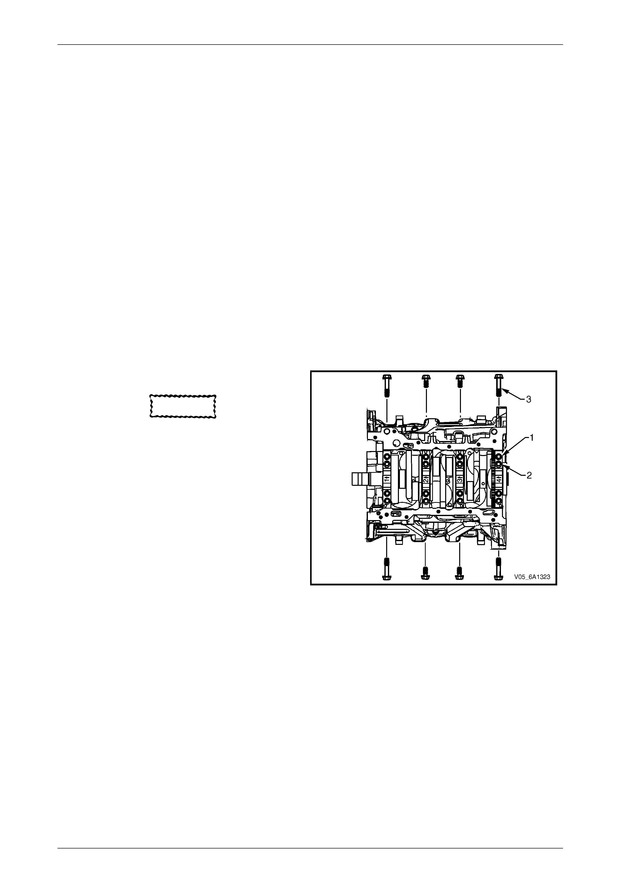
Engine Mechanical – V6 Page 6A1–242
Page 6A1–242
4.6 Crankshaft and Main Bearings
LT Section No. — 00–200
1 Remove the engine assembly, refer to 4.1 Engine Assemb ly.
2 Remove both cylinder head assemblies, refer to 3.23 Cylinder Head Assembly.
3 Remove the oil pan assembly, refer to 4.2 Oil Pan and Oil Pump Suction Pipe Assembly.
4 Remove the piston and connecting rod assemblies,
refer to 4.5 Pistons, Pins, Rings, Connecting Rods and Big-end Bearings.
5 Remove the oil pump assembly, refer to 3.18 Oil Pump Assembl y.
6 Remove the crankshaft rear oil seal and plate assembly, refer to 4.4 Crankshaft Rear Seal and Plate Assembly.
7 Remove the crankshaft position sensor, refer to Section 6C1-3 Engine Management – V6 – Service Operations.
Crankshaft End Play Measurement
1 Place a dial indicator at the end of the crankshaft nose.
2 Gently force the crankshaft towards the front and rear of the cylinder block with a lever while monitoring the
movement of the dial indicator.
3 The crankshaft endplay should not exceed specifications, refer to 5 Speci fications.
4 If the specifications are exceeded, inspect the thrust bearing thrust outer diameter and the crankshaft thrust wall for
wear and/or excessive runout. Compare the values with the specifications, refer to 5 Specifications.
5 Replace the thrust bearing or cranksh aft as required.
Remove
1 Remove the crankshaft bearing cap side b ol ts (3).
CAUTION
The crankshaft bearing cap outer bolts are
yield tightened during assembly and must
be replaced prior to reassembly. Crankshaft
bearing cap outer b olts that are not repla ced
will no t torque to the correct clamp load and
can lead to serious engine damage.
2 Remove the crankshaft bearing cap outer bolts (1).
3 Remove the crankshaft bearing cap inner bolts (2).
Figure 6A1 – 402
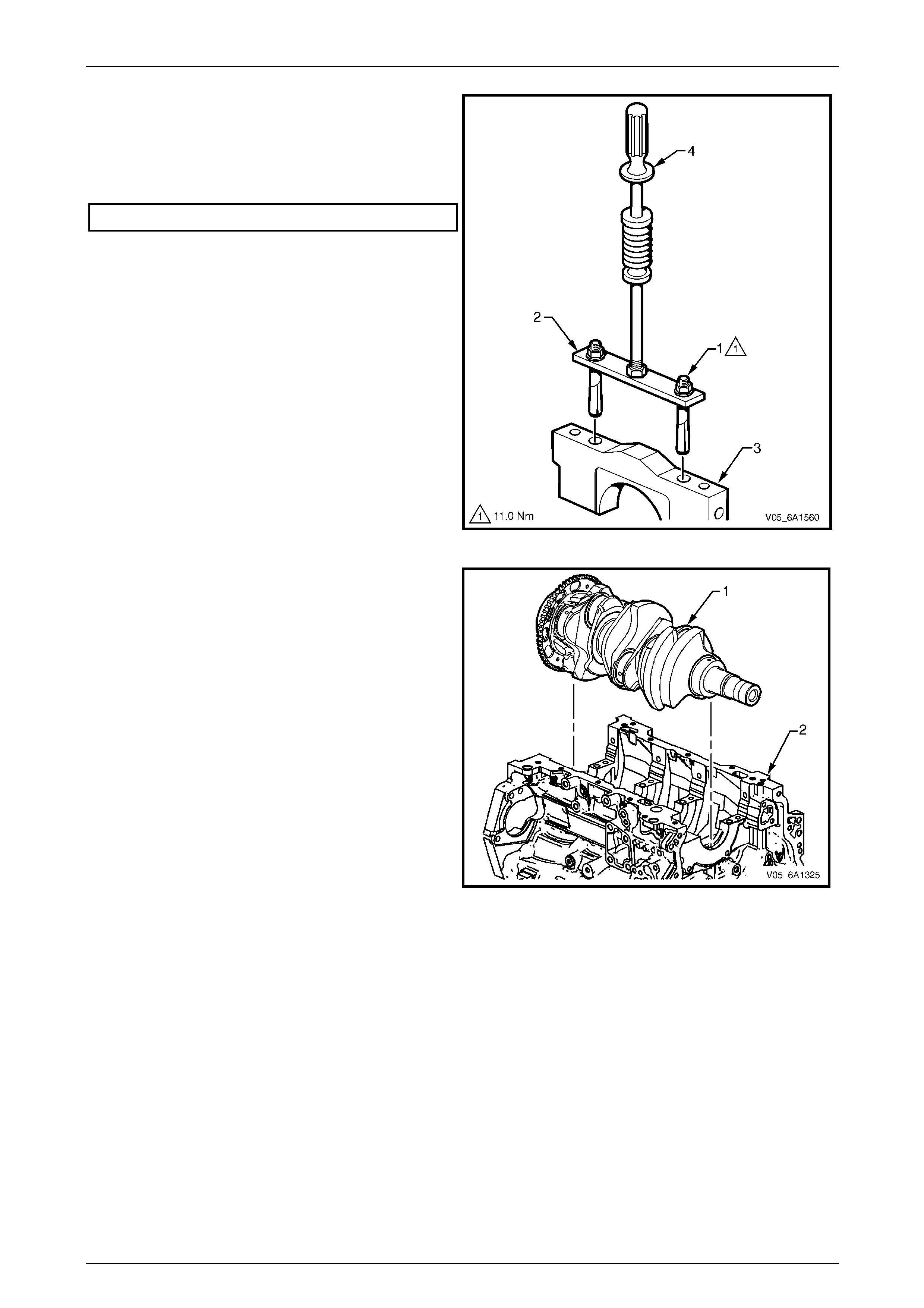
Engine Mechanical – V6 Page 6A1–243
Page 6A1–243
4 Loosen the nuts (1) of the crankshaft main bearing
cap remover, Tool No. J-41818 (2) to separate the
chamfered collets. Install the collets into the inner bolt
holes of the front main bearing cap (3).
5 Tighten the remover nuts to the correct torque
specification.
Crankshaft bearing cap remover nut.................11.0 Nm.
6 Install a slide hammer, Tool No. J-6125-1B (4) onto
the crankshaft bearing cap remover an d remove the
crankshaft bearing cap.
7 Repeat steps 9 to 14 for the remaining crankshaft
bearing caps.
Figure 6A1 – 403
8 Remove the crankshaft (1) from the engine block (2),
lifting evenly to avoid jammin g against the main thrust
bearing.
9 Place the crankshaft in a secure place.
Figure 6A1 – 404
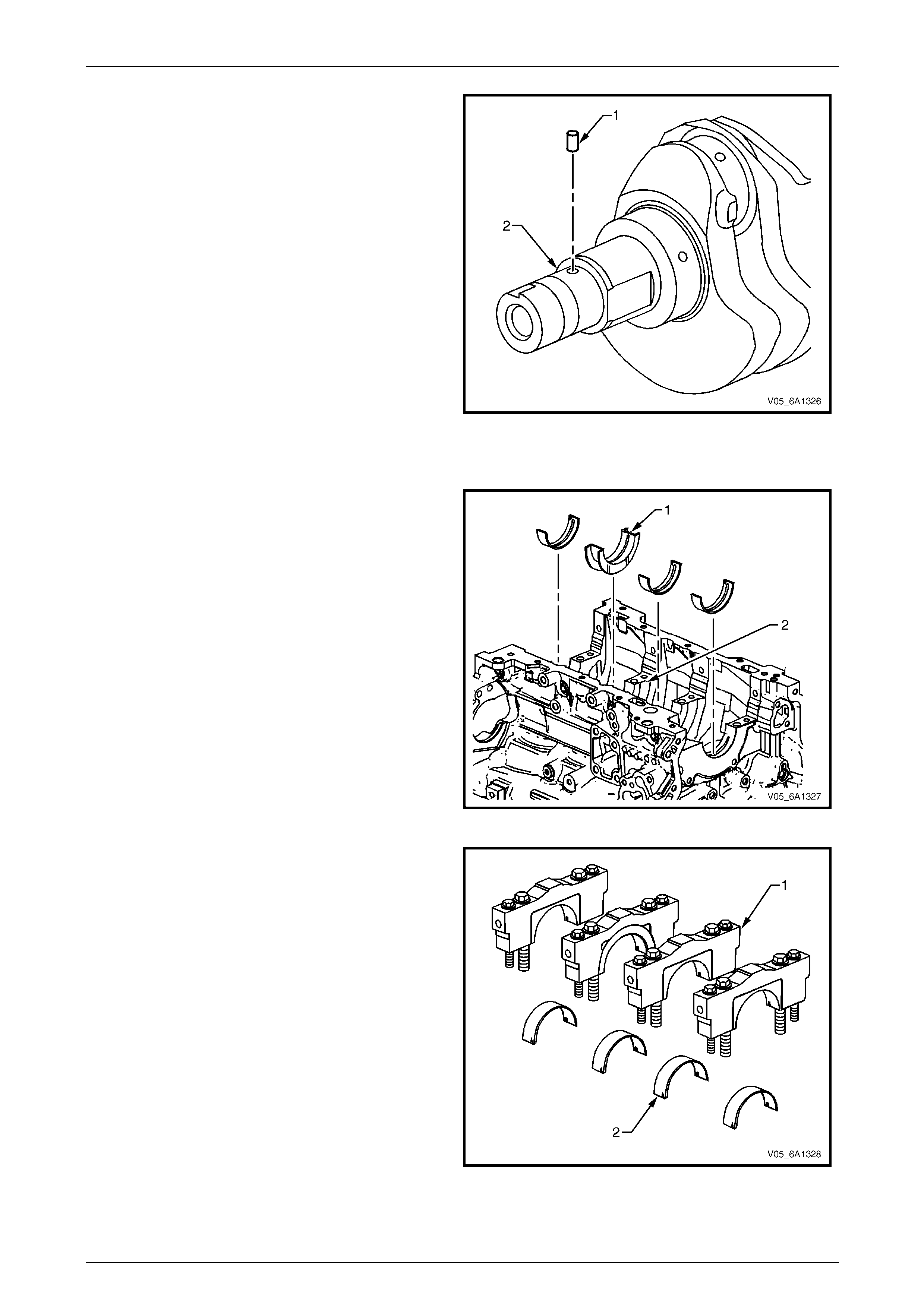
Engine Mechanical – V6 Page 6A1–244
Page 6A1–244
10 If required, remove the crankshaft sprocket drive
pin (1) from the crankshaft (2),
Figure 6A1 – 405
Crankshaft Bearing
1 Prepare a piece of cardboard or similar, numbered 1
– 4 for bearing identification.
NOTE
Main bearing journals are numbered from the
front of the engine.
2 Remove the crankshaft upper bearing halves from the
cylinder block. Note the position of the thrust
bearing (1) at the number 3 journal (2).
3 Place the crankshaft upper bearing halves on the
cardboard in the correct positions.
Figure 6A1 – 406
4 Remove the crankshaft lower bearing halves (2) from
the crankshaft bearing caps (1).
5 Place the crankshaft lower bearing halves in the
correct positions on the cardboard.
Figure 6A1 – 407
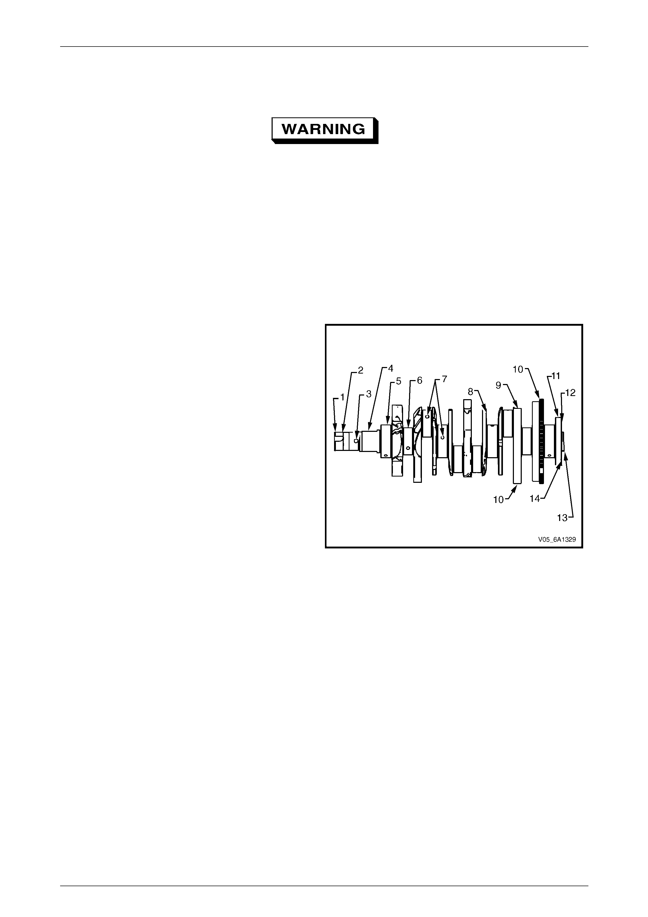
Engine Mechanical – V6 Page 6A1–245
Page 6A1–245
Clean and Inspect
Crankshaft and Main Bearing Cleaning
Safety glasses must be worn when using
compressed air.
Clean the following components in solve nt a nd then dry with compressed air:
• crankshaft bearings,
• connecting rod bearings,
• crankshaft journals,
• crankpin journals,
• crankshaft oil passages, and
• crankshaft threaded holes.
Crankshaft and Main Bearing Visual Inspec tion
1 Perform the following visual inspections:
• Inspect the crankshaft balancer bolt hole (1) for
thread damage.
• Inspect the crankshaft balancer mounting
area (2) for damage.
• Inspect the crankshaft sprocket pin hole (3) for
damage.
• Inspect the oil pump drive flats (4) for damag e.
• Inspect the crankshaft main journals (5) for
damage.
• Inspect the crankshaft connecting rod
journals (6) for damage.
• Inspect the crankshaft oil passages (7) for
obstructions.
• Inspect the crankshaft main bearing thrust wall
surfaces (8) for damage.
• Inspect the crankshaft counterweights (9) for
damage. Figure 6A1 – 408
• Inspect the crankshaft reluctor ring teeth (10) for damage.
• Inspect the crankshaft rear main oil seal surface (11) for damage.
• Inspect the crankshaft engine flexplate mounting surface (12) for damage.
• Inspect the crankshaft pilot hole (13) for damage.
• Inspect the crankshaft engine flywheel bolt holes (14) for thread damage.
2 Repair or replace the crankshaft as required.
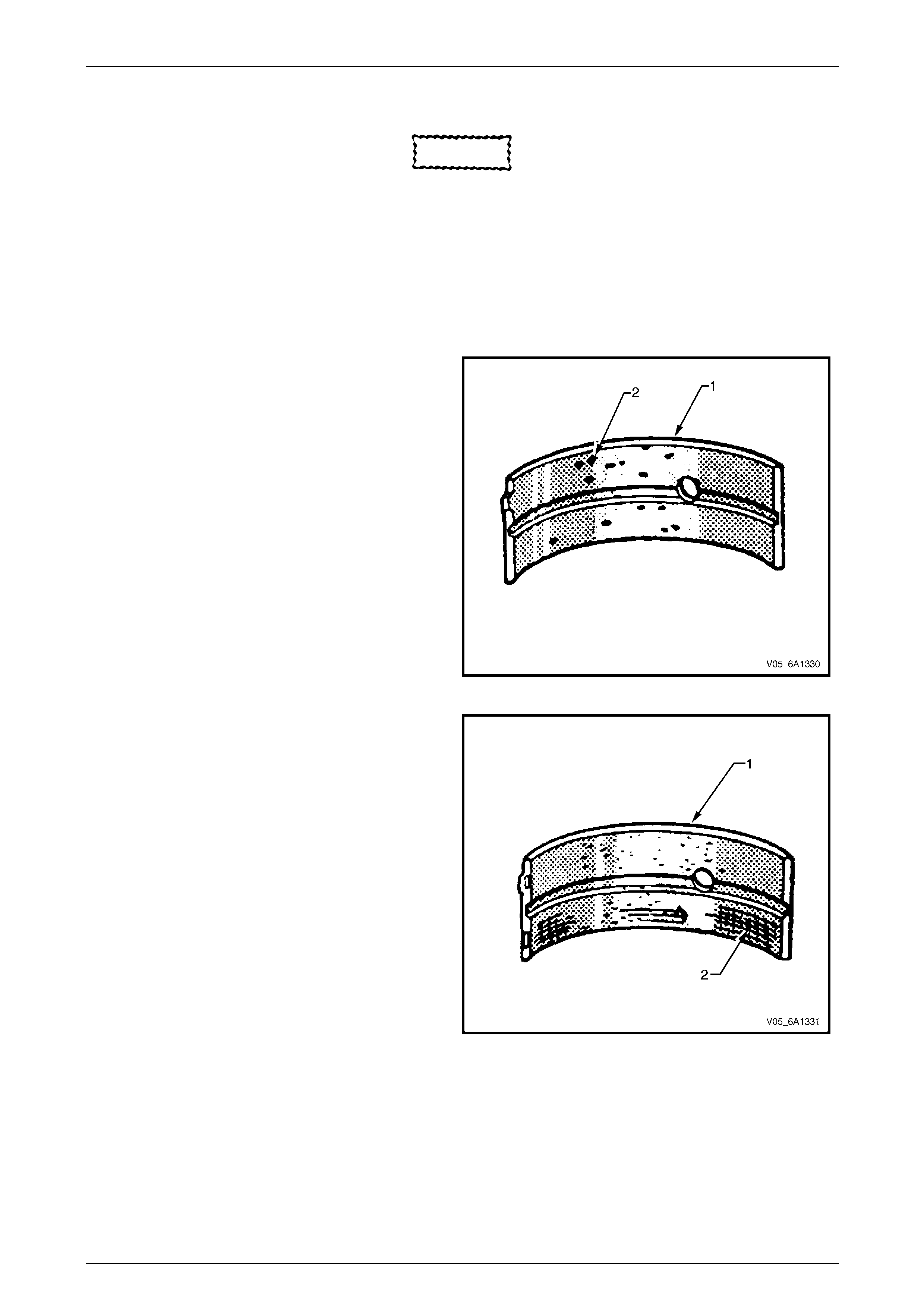
Engine Mechanical – V6 Page 6A1–246
Page 6A1–246
Crankshaft Main Bearing Inspection
CAUTION
All connecting rod and main journal bearings
that have been u sed in a running en gine must
be replaced. Never re-use the crankshaft or
connecting rod bearings.
NOTE
The following bearing wear conditions should be
used to diagnose engine operating conditions or
root cause of a condition.
1 Inspect for fatigue indicated by craters or pockets (2).
Flattened sections on the bearing halves (1) also
indicate fatigue.
Figure 6A1 – 409
2 Inspect for excessive scoring or discoloration (2) on
both front and back of the bearing halves (1).
3 Inspect the main bearings for dirt embedd ed into the
bearing material.
Figure 6A1 – 410
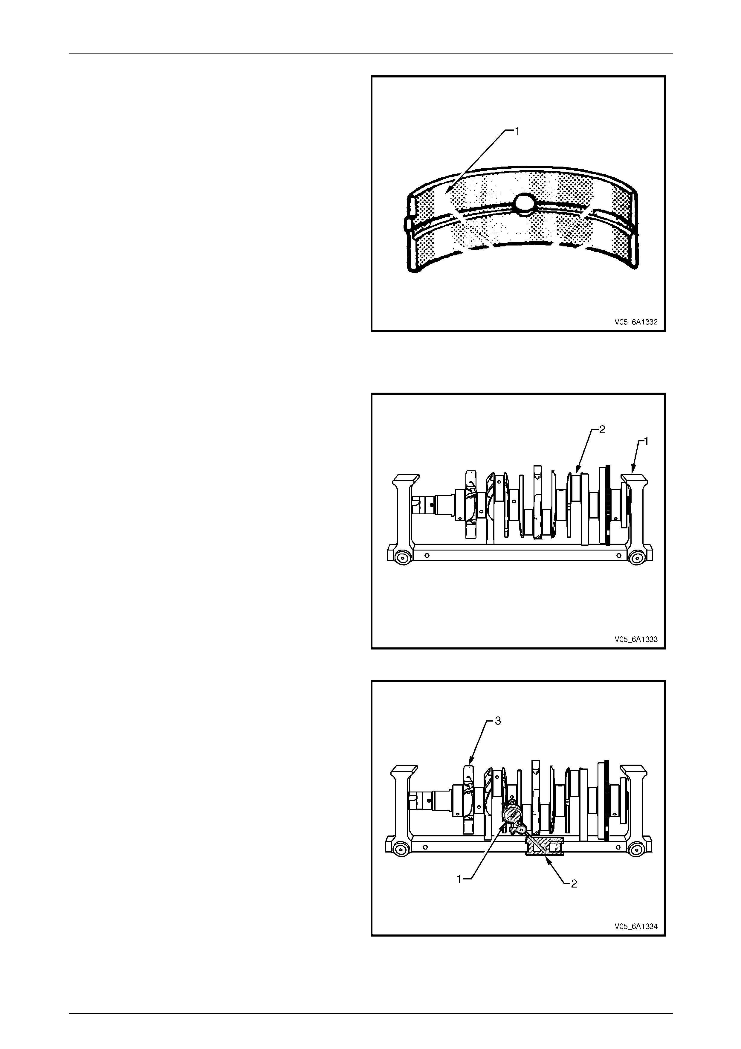
Engine Mechanical – V6 Page 6A1–247
Page 6A1–247
4 Inspect for incorrect seating indicated by bright,
polished sections (1).
Figure 6A1 – 411
Crankshaft Measuremen t
1 Using a suitable fixture (1), support the cra nkshaft (2).
Figure 6A1 – 412
2 Using a dial indicator (1) and magnetic base (2),
rotate the crankshaft (3) carefully by hand. Measure
the crankshaft main journals for runout and compare
with the engine specifications, refer to
5 Specifications.
Figure 6A1 – 413
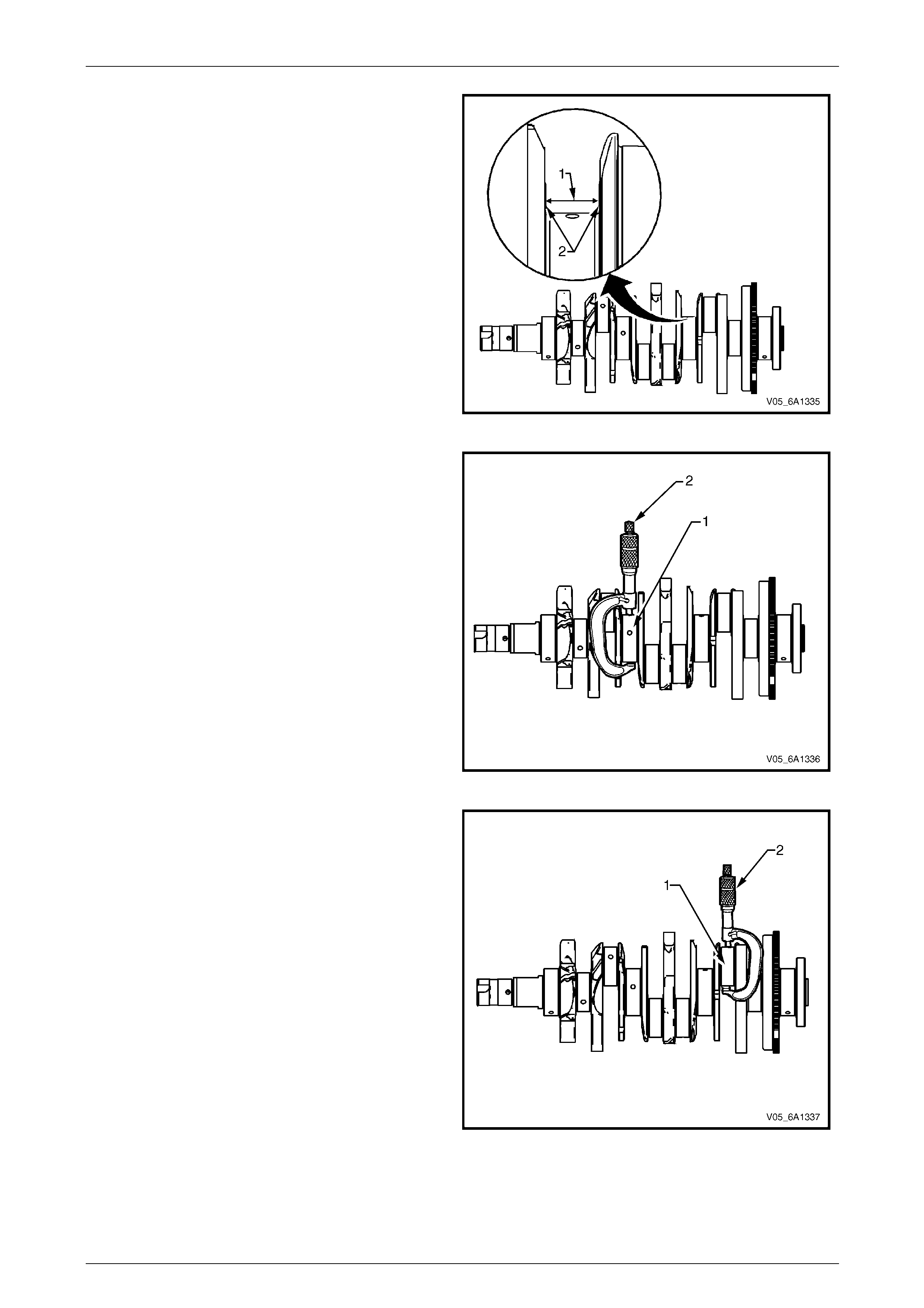
Engine Mechanical – V6 Page 6A1–248
Page 6A1–248
3 Measure the crankshaft thrust wall width (1) for wear
using an inside micrometer and compare with the
engine specifications, refer to 5 Specification s.
4 Measure the crankshaft thrust wall surface (2) for
runout using a dial indicator, mounted to a magnetic
stand and compare with the engine specifications,
refer to 5 Specifications.
5 If the crankshaft journals are damaged or worn
beyond specifications, the crankshaft may be ground
0.25 mm. There is only one size of oversized main
bearings availa ble for service.
Figure 6A1 – 414
6 Inspect the crankshaft main journals (1) for undersize,
using an outside micrometer (2).
Figure 6A1 – 415
7 Inspect the crankpins (1) for undersize using an
outside micrometer (2).
8 Compare your measurements with those listed in the
engine specifications, refer to 5 Specification s. If the
crankpin journals are worn beyond the specifications,
the crankshaft may be ground 0.25 mm. Only one
size of oversized connecting rod bearings available
for service.
Figure 6A1 – 416
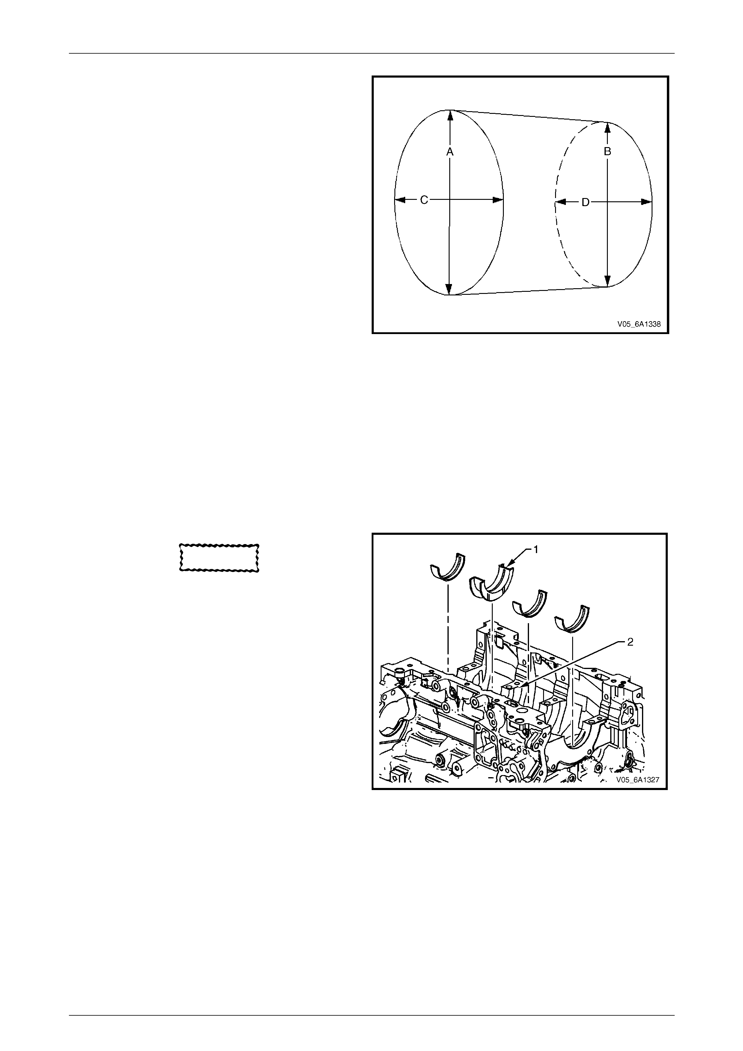
Engine Mechanical – V6 Page 6A1–249
Page 6A1–249
9 Measure the main bearing and crankpin journals for
out-of-round using the following procedure:
a Using an outside micrometer, measure the
journal at the extreme front and rear locations
on the journal. Call these points A and B.
b Measure the journal in two new locations
exactly 90 degrees from the first points. Call
these points C and D.
c Subtract A from C and B from D. The
differences will indicate jo urnal out-of-round.
d The out-of-round should not exc ee d 0.004 mm
maximum.
e If the journals are worn beyond the
specifications, the crankshaft may be ground
0.25 mm. There is only one size of oversized
crankshaft and connecting rod bear ings
available for service.
10 Measure the main bearing and crankpin journals for
taper using the following procedure:
a Using an outside micrometer, measure the
journal at the extreme front (A) and rear (B) of
the journal paralle l to the crankshaft centreline.
Figure 6A1 – 417
b Subtract the smallest from the largest measurement. The result will be the jour nal taper.
c If the main bearing journal taper exceeds 0.004 mm, replace the crankshaft.
d If the journals are worn beyond the specifications, the crankshaft may be ground 0.25 mm. There is only one
size of oversized crankshaft and connecting rod bearings available for service.
Reinstall
Crankshaft Bearing Installation Procedure
CAUTION
If the crankshaft bearings ha ve been used in
a running engine, replace them with new
crankshaft bearings for reassembly.
1 Clean the crankcase crank bore with a lint-free cloth.
2 Clean all the oil from the backside of new bearing
halves.
3 Install the new upper crankshaft bearings into
position. The thrust bearing (1) belongs in the number
3 journal(2). Ensure the upper bearing insert contains
the oil transfer hole and groove. Roll the bearing into
position so the lock tang engages the crank slot. The
bearing must fit flush with the upper crankcase.
Figure 6A1 – 418
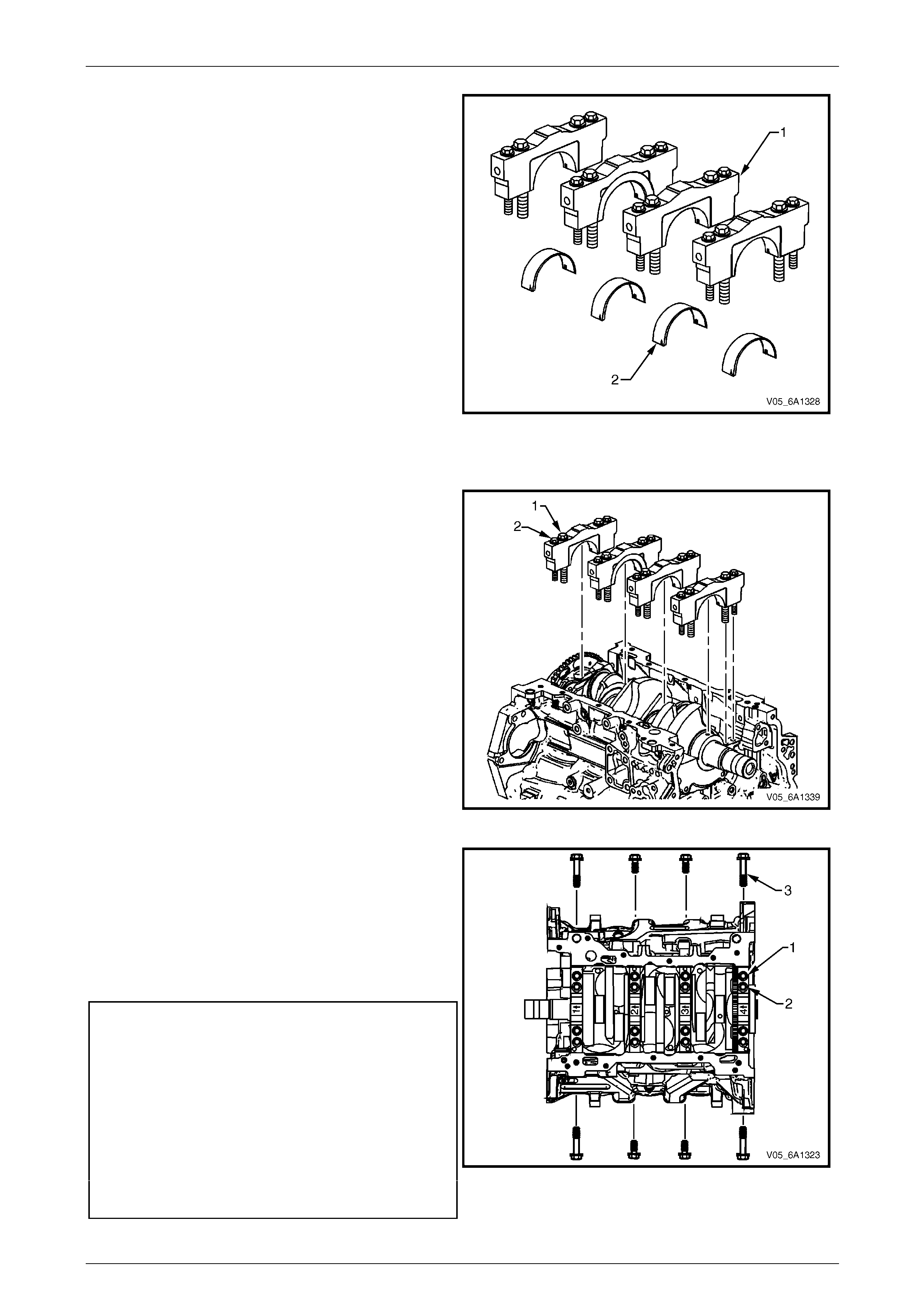
Engine Mechanical – V6 Page 6A1–250
Page 6A1–250
4 Install the new lower crankshaft bearings (2) into
position in the main bearing caps (1). The lower
crankshaft bearings are identified by no grooves or
holes. The bearings must fit flush with the crankshaft
bearing caps.
Figure 6A1 – 419
Crankshaft Main Bearing Clearance Measurement
1 Place a length of fresh, room temperature plastic
gauging material all the way across all the crankshaft
bearing journals.
2 Install the crankshaft main bearing caps.
3 Loosely install the original inner main cap bolts (1).
4 Loosely install the original outer main cap bolts (2).
Figure 6A1 – 420
5 Loosely install the original short/inner side main cap
bolts.
6 Loosely install the original long/outer side main cap
bolts (3).
7 Gently tap the crankshaft main bearing caps with a
soft-faced hammer to help seat the caps.
8 Tighten the main caps bolts to the correct torque
specification, and in the following sequence.
Crankshaft main bearing cap inboard
attaching bolt torque specificat ion:
Stage 1 .........................20.0 Nm
Stage 2 .................................80°
Crankshaft main bearing cap outboard
attaching bolt torque specificat ion:
Stage 1 .........................15.0 Nm
Stage 2 ...............................110°
Crankshaft main bearing cap side
attaching bolt torque specificat ion:
Stage 1 .........................30.0 Nm
Stage 2 .................................60° Figure 6A1 – 421
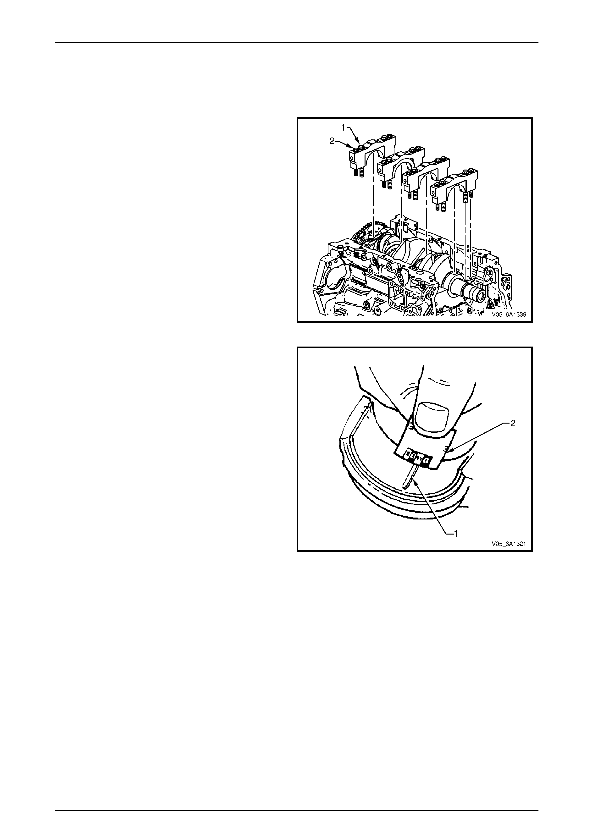
Engine Mechanical – V6 Page 6A1–251
Page 6A1–251
NOTE
Do not rotate the crankshaft.
9 Allow the assembly to sit for 2 minutes.
10 Remove the crankshaft bearing cap side b ol ts.
11 Remove the crankshaft bearing cap outer bolts (2).
12 Remove the crankshaft bearing cap inner bolts (1).
13 Install the crankshaft main bearing cap remover Tool
No. J-41818 as previously described and remove the
crankshaft bearing cap.
14 Repeat steps 10 to 13 for the remaining crankshaft
bearing caps.
Figure 6A1 – 422
15 Determine the crankshaft bearing clearance by
comparing the width of the flattened p lastic gauging
material (1) at its widest point with the graduation on
the gauging material scale (2).
16 Compare the measurements listed in the
specifications, refer to 5 Specifications. If the new
bearings do not provide the correct crankshaft to
bearing clearance, inspect the following:
a Measure the crankshaft journals for the correct
specified size and ensure new bearings are
being installed. If the crankshaft journals are
incorrectly sized, replace or regrind the
crankshaft. Crankshaft machining is permitted
and undersized bearings are available.
b Measure the engine block crankshaft bearing
bore diameter to ensure correct size. The
engine block crankshaft bearing bore is not
machineable and the bl ock must be replaced if
out of specification.
17 Clean the plastic gauging material from the crankshaft
bearing journals with a soft, lint-free cloth. Figure 6A1 – 423
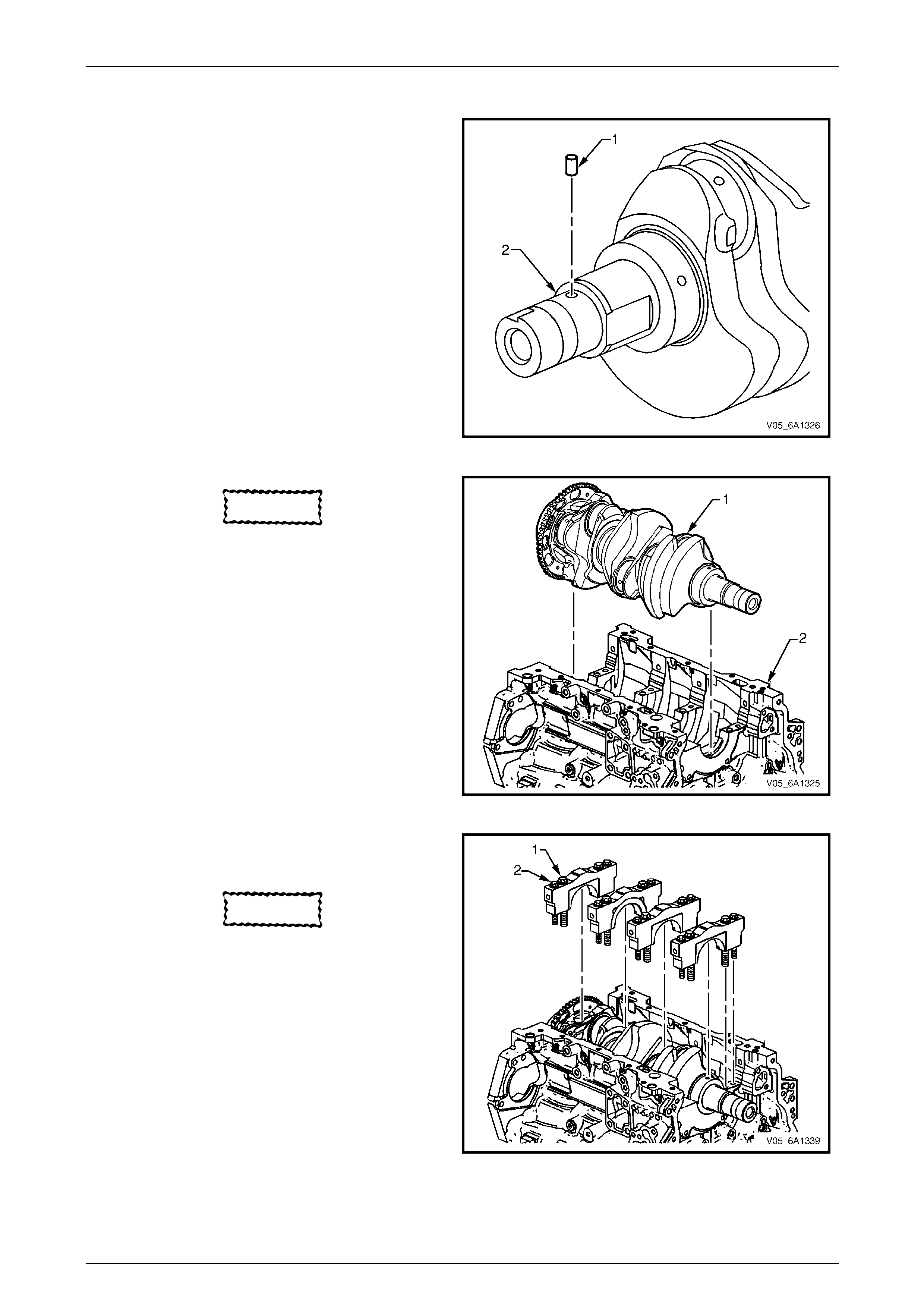
Engine Mechanical – V6 Page 6A1–252
Page 6A1–252
Crankshaft Final Installation Procedure
1 If removed, install the crankshaft sprocket dri v e
pin (1). Lightly tap the pin in place with a small soft
face, bronze/plastic, hammer until it bottoms in the
hole.
Figure 6A1 – 424
CAUTION
Ensure the crankshaft position sensor has
been removed from the cylinder block prior
to loading the crankshaft, as damage to the
sensor may occur.
2 Apply a liberal amount of clean engine oil to the upper
and lower bearing surfaces.
3 Gently lower the crankshaft (1) into position in the
cylinder block (2).
Figure 6A1 – 425
4 Install the crankshaft main bearing caps.
5 Loosely install the original inner main cap bolts (1).
CAUTION
The outer crankshaft bearing cap bolts (2)
are yield tightened during assembly and
must be replaced prior to reassembly. Outer
crankshaft bearing cap bolts that are not
replaced will n ot torque to the correct clamp
load and can lead to serio us engine damage.
6 Loosely install the new outer main bearing c ap
bolts (2).
7 Gently tap the crankshaft main bearing caps with a
soft-faced hammer to help seat the caps.
Figure 6A1 – 426
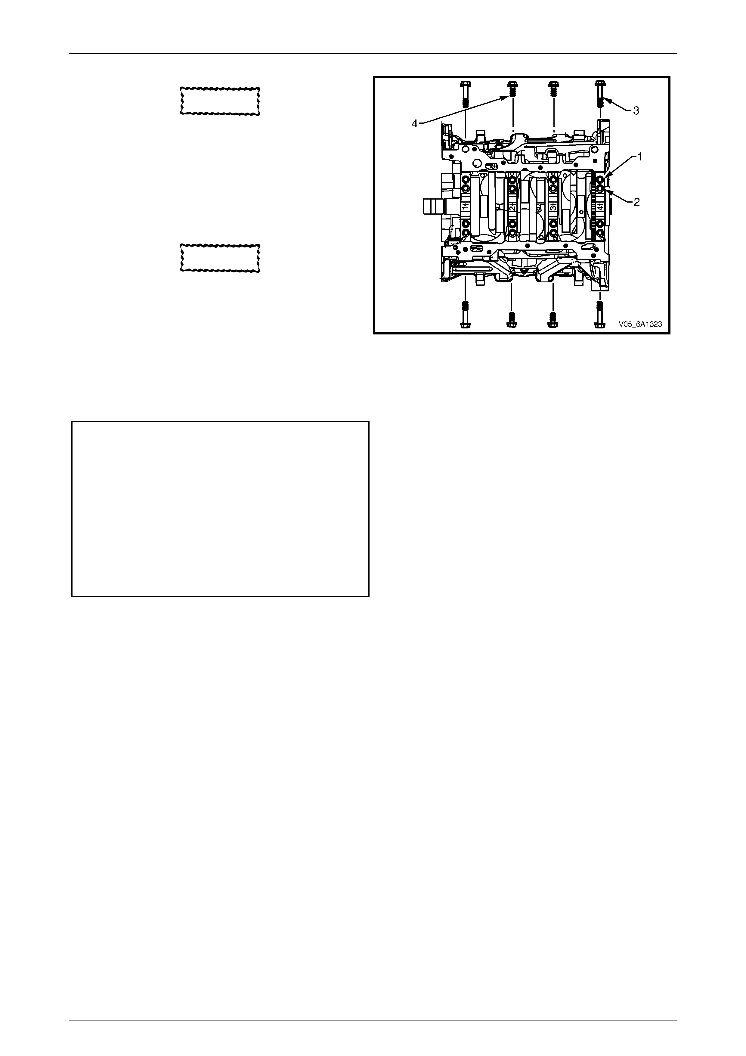
Engine Mechanical – V6 Page 6A1–253
Page 6A1–253
CAUTION
The short / inner side main cap bolts
originally have a sealant on the flange of the
bolt head. New bolts must be used. If new
bolts are not used, oil can leak from the
crankcase past the bolts.
8 Loosely install new short / inner side main cap
bolts (4).
CAUTION
The long / outer side main cap bolts
originally have a sealant on the flange of the
bolt head. New bolts must be used. If new
bolts are not used, oil can leak from the
crankcase past the bolts.
9 Loosely install the new long / outer side main cap
bolts (3).
10 Tighten the main caps bolts to the correct torque
specification, and in the following sequence.
Crankshaft main bearing cap in board
attaching bolt torque specificat ion:
Stage 1 .........................20.0 Nm
Stage 2 .................................80°
Crankshaft main bearing cap outb oard
attaching bolt torque specificat ion:
Stage 1 .........................15.0 Nm
Stage 2 ...............................110°
Crankshaft main bearing cap side
attaching bolt torque specificat ion:
Stage 1 .........................30.0 Nm
Stage 2 .................................60°
Figure 6A1 – 427
11 Ensure the crankshaft turns without binding or noise.
12 Install the remaining components in the reverse order to removal, refer to the appropriate Section.
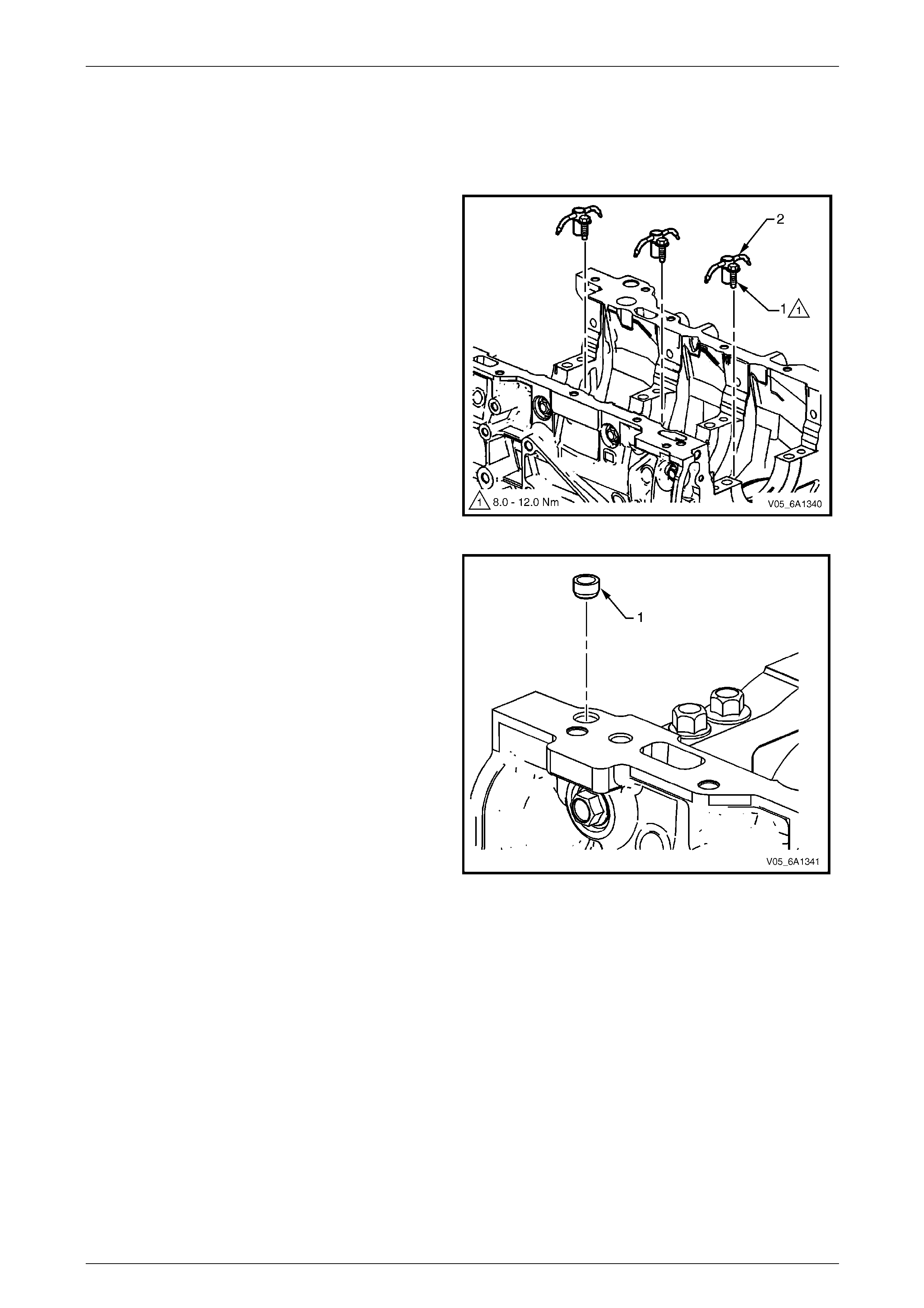
Engine Mechanical – V6 Page 6A1–254
Page 6A1–254
4.7 Cylinder Block
LT Section No. — 00–248
Disassemble
1 Remove oil jet bolt (1) attaching the oil jet (2), three
places.
Figure 6A1 – 428
2 Remove the right-hand front oil pan rail oil gallery
expansion plug (1).
Figure 6A1 – 429
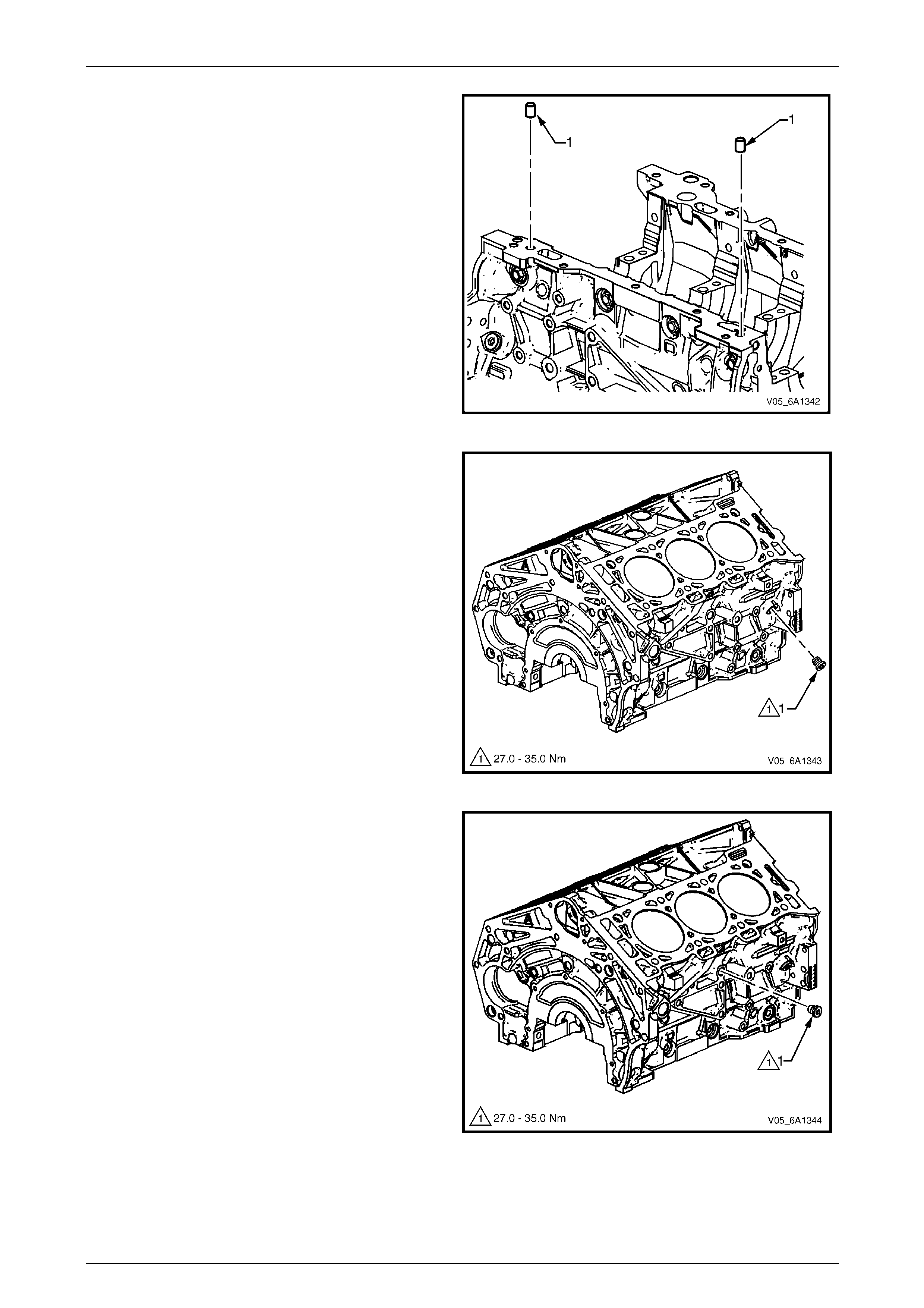
Engine Mechanical – V6 Page 6A1–255
Page 6A1–255
3 Remove the cylinder block-to- oil p an alignment
dowels (1).
Figure 6A1 – 430
4 Remove the right-hand side M14 oil gallery threaded
plug (1).
Figure 6A1 – 431
5 Remove the right-hand side M14 coola nt drain
threaded plug (1).
Figure 6A1 – 432
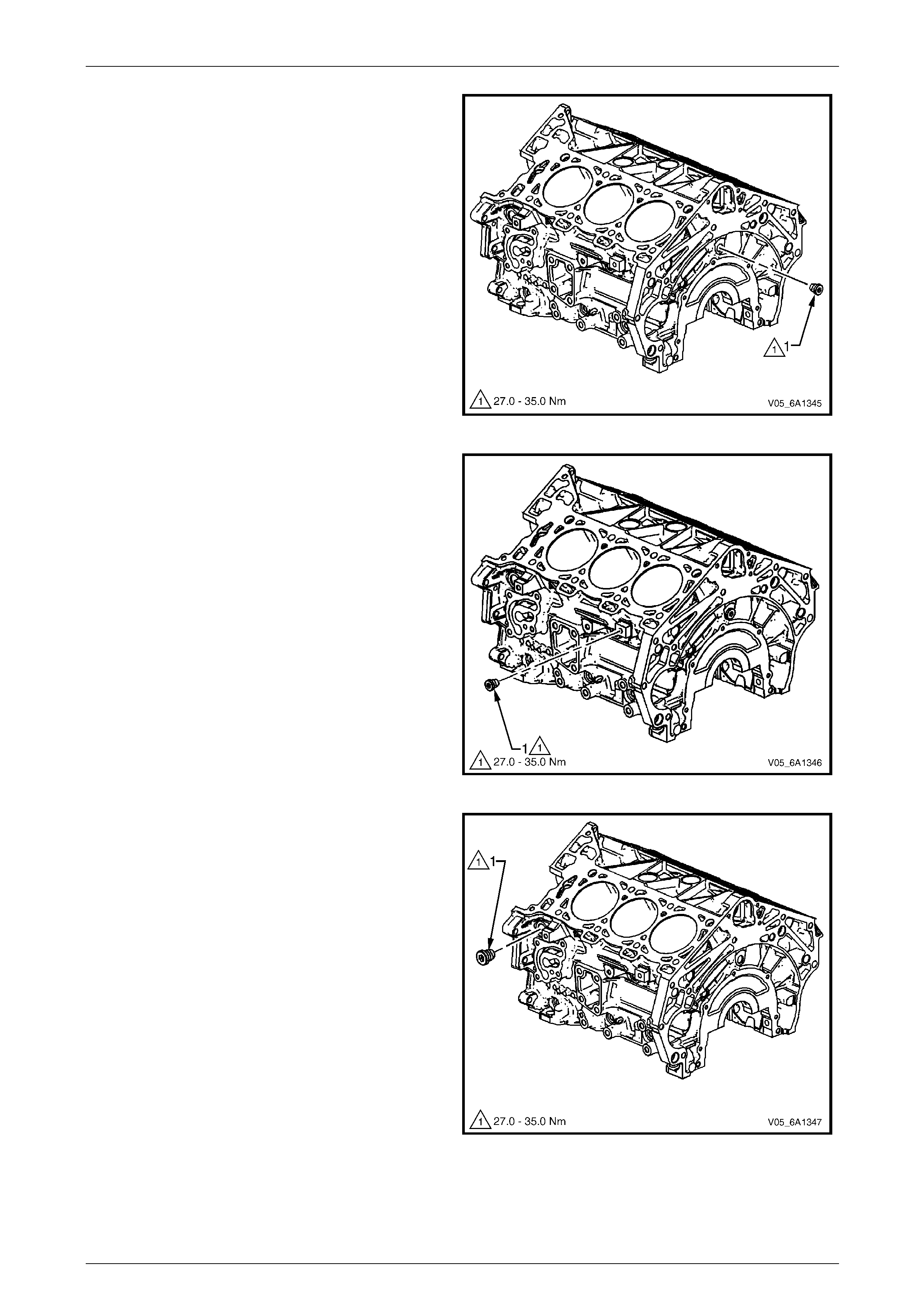
Engine Mechanical – V6 Page 6A1–256
Page 6A1–256
6 Remove the rear M14 oil galle ry threaded plug (1).
Figure 6A1 – 433
7 Remove the left-hand side M14 coolant drain
threaded plug (1).
Figure 6A1 – 434
8 Remove the left-hand si de M20 oil gallery threaded
plug (1).
Figure 6A1 – 435
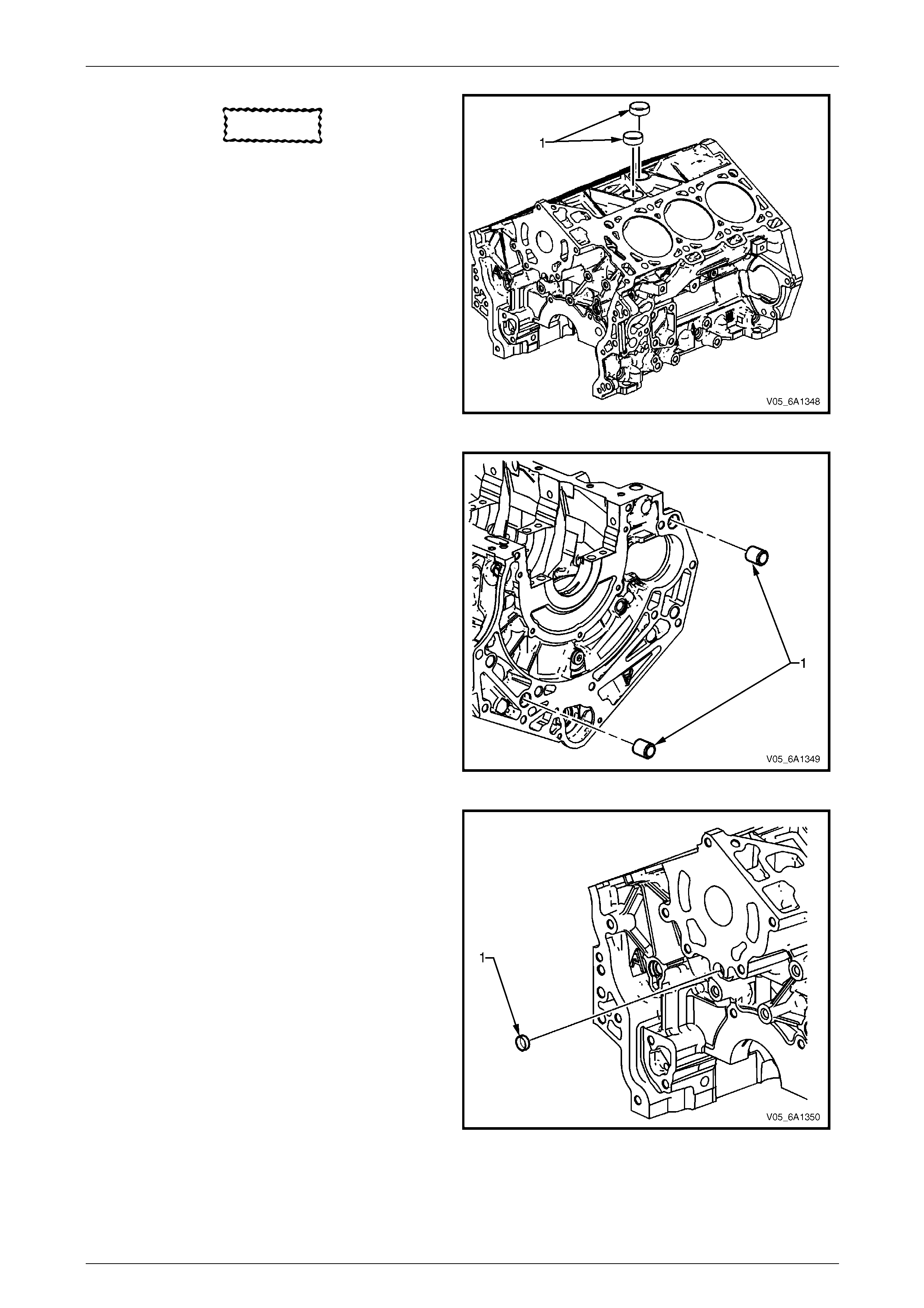
Engine Mechanical – V6 Page 6A1–257
Page 6A1–257
CAUTION
Do not force coolant expansion plugs
downwards during removal procedure as the
cylinder block will be damaged.
9 Remove the coolant expansion plu gs (1).
Figure 6A1 – 436
10 Remove the cylinder block-to- t ransmission alignment
dowels (1).
Figure 6A1 – 437
11 Remove the front oil gallery expansion plug (1).
Figure 6A1 – 438
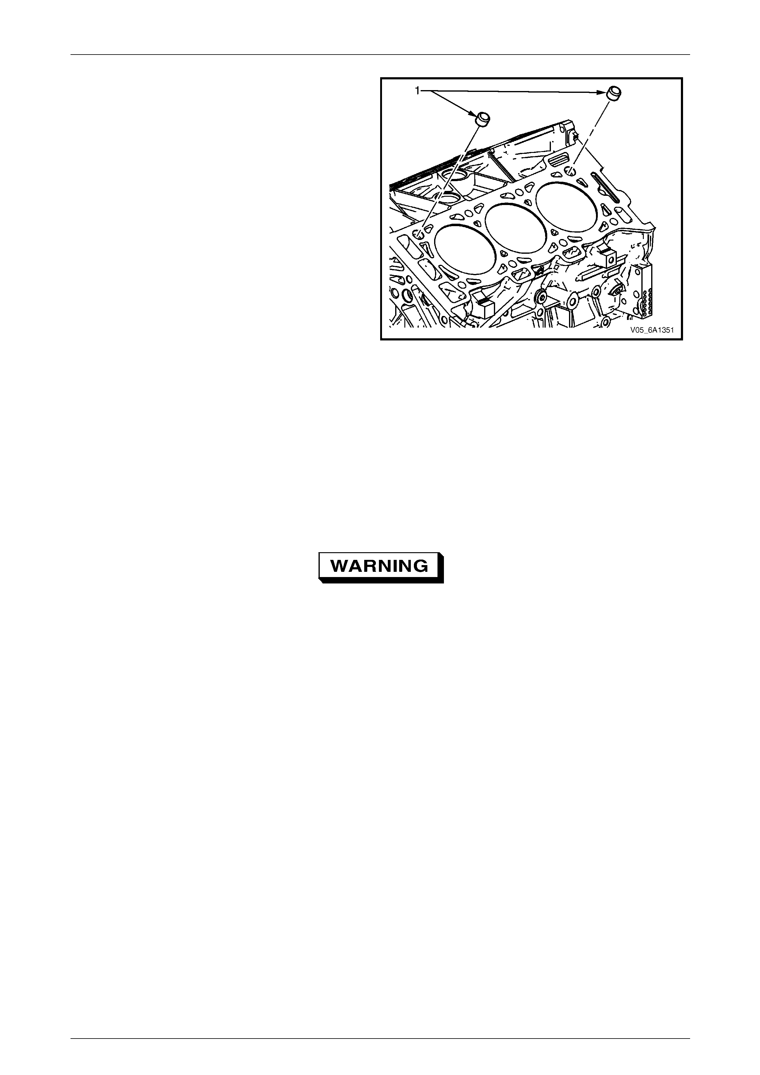
Engine Mechanical – V6 Page 6A1–258
Page 6A1–258
12 Remove the cylinder block-to- cylinder head alignment
dowels (1).
Figure 6A1 – 439
Clean
1 Remove all thread sealant, gasket material or sealant using a commercially availab le plastic or wood scraper.
2 Clean all the following areas with a suita ble solvent:
• sealing surfaces,
• cooling passages,
• oil passages, and
• bearing journals.
3 Clean all threaded and through holes with a suitable solvent.
Safety glasses must be worn when using
compressed air.
4 Dry the engine block with com presse d air.
Inspect
Visual Inspection
NOTE
The following procedure assu mes the engine has
been disassembled and cleaned, as described
above.
1 Inspect the crankshaft bearing journals for damag e or spun bearings. The crankshaft bearing j ournals are not
repairable and if damage is found, the cylinder block assembly must be replac ed.
2 Inspect the primary camshaft chain tensioner mounting surface on the engine b l ock for burrs or any defects that
would affect the sealing of the ne w primary camshaft chain tensioner gasket.
3 Inspect all sealing and mating surfaces for damage, repair or replace the cylinder block assembly if required.
4 Inspect all threaded and through holes for damage or excessive debris.
5 Inspect all bolts for damage, if damaged replace with new bolts only.
6 Inspect the cylinder walls for cracks or damage. The cylinder sleeves are not serviced separately, if the cylinders
are damaged the cylinder block assembly must be replaced.
7 Inspect the engine block for cracks. Do not repair any cracks. If cracks are found, the cylinder block assembly must
be replaced. Repair any d amaged threaded holes, refer to 4.9 Thread Repair Specifications.
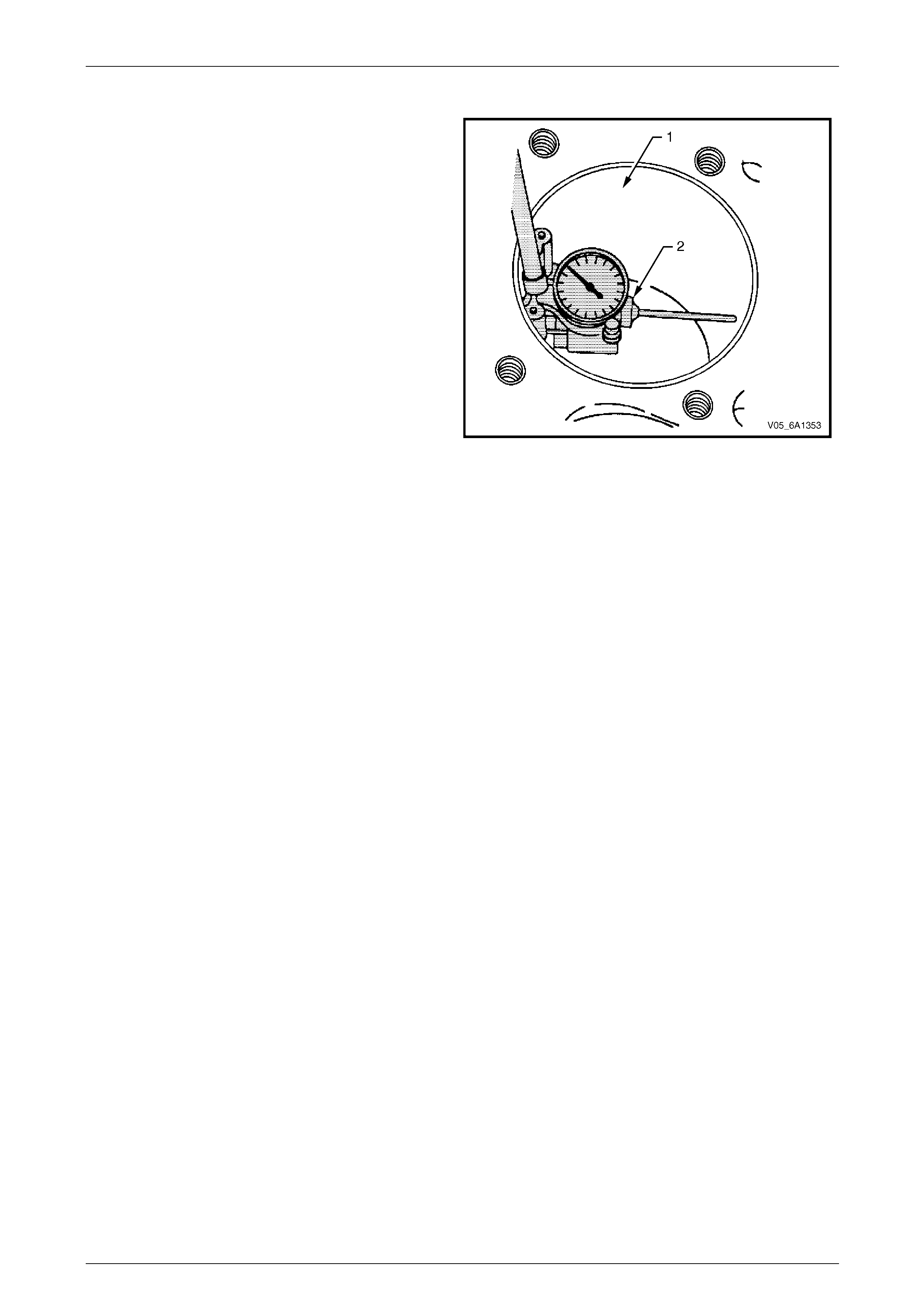
Engine Mechanical – V6 Page 6A1–259
Page 6A1–259
Measuring Cylinder Bore Diameter
1 Measure the cylinder bore diameter 37 mm from the
deck face (1) using a commercially available bore
gauge or Tool No. J-8087 (2).
2 Record the results and compa r e with the dimensions
listed in the specifications, refer to 5 Specifications.
NOTE
If the cylinder diameter exceeds the
specifications, the cylinder block may be
oversized to 0.25 mm. Only one size of
oversized pistons and rings are available for
service. If the cylinder bore diameter exceeds
specification by more than 0.25 mm, the
cylinder block must be replaced.
Figure 6A1 – 440
Measuring Cylinder Bore Taper
1 Measure the cylinder bore along the thrust surfaces, perpendicular to the crankshaft centreline, at 10 mm below the
deck surface and record the measurement.
2 Measure the cylinder bore along the thrust surfaces, perpendicular to the crankshaft centreline, at 100 mm below
the deck surface and record the measurement.
3 Calculate the difference between the two measurements. The result will be the c ylinder taper.
4 Compare the results with the dimensions listed in the specifications, refer to 5 Specifications.
NOTE
If the cylinder diameter exceeds the
specifications, the cylinder block may be
oversized to 0.25 mm. Only one size of oversized
pistons and rings are available for service. If the
cylinder bore diameter exceeds specification by
more than 0.25 mm, the cylinder block must be
replaced.
Measuring Cylinder Bore Out-of-Round
1 Measure both the thrust and n on-thrust cylinder diameter at 10 mm below the deck. Record your measurements.
2 Calculate the difference between the two measurements. The result will indicate out-of-round at the upper end of
the cylinder.
3 Measure both the thrust and n on-thrust cylinder diameter at 100 mm belo w the deck surface. Record your
measurements.
4 Calculate the difference between the two measurements. The result will in di cate out-of-round at the lower end of
the cylinder.
5 Compare your results with the dimensions listed in the specifications, refer to 5 Specifications.
NOTE
If the cylinder diameter exceeds the
specifications, the cylinder block may be
oversized to 0.25 mm. Only one size of oversized
pistons and rings are available for service. If the
cylinder bore diameter exceeds specification by
more than 0.25 mm, the cylinder block must be
replaced.
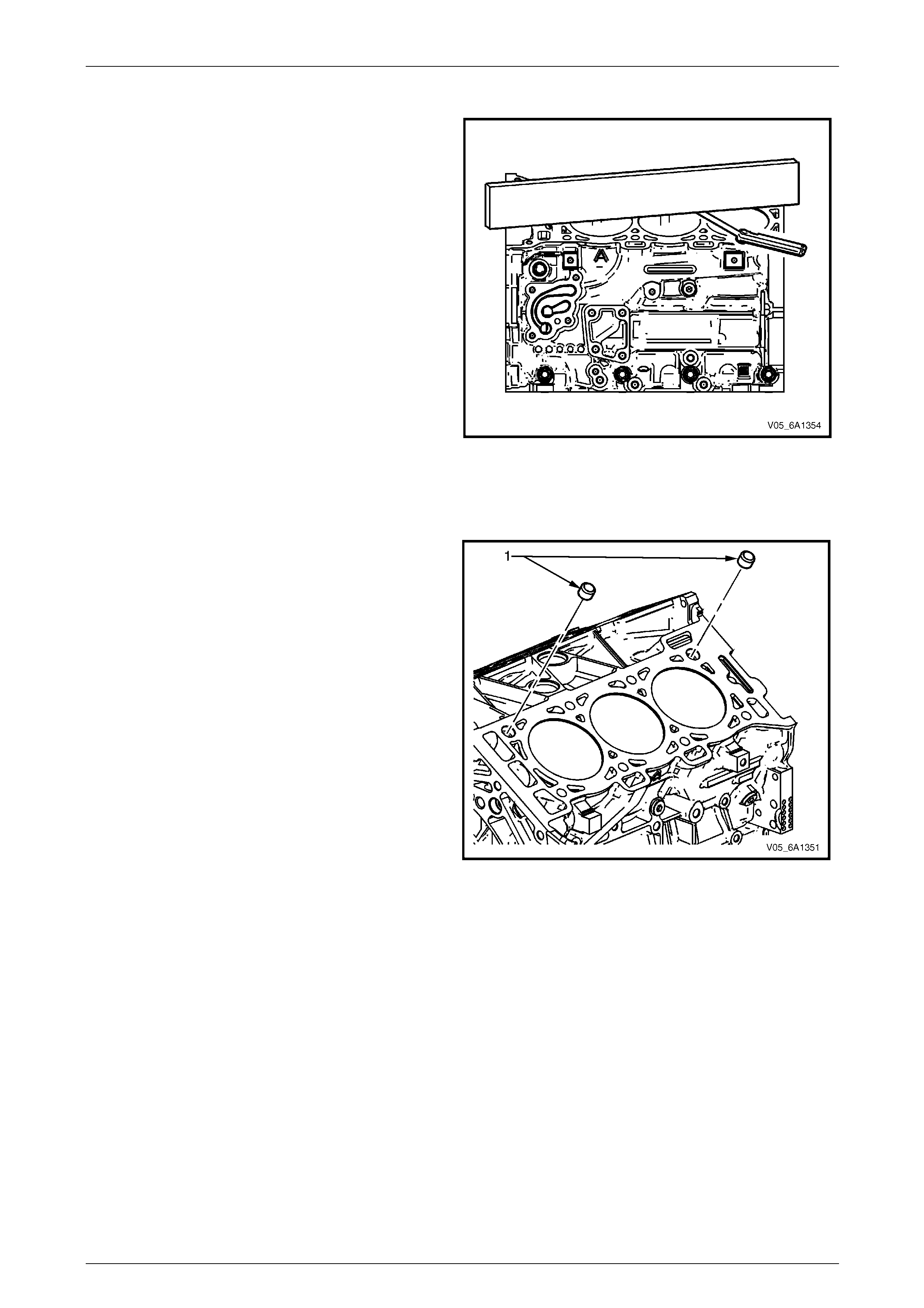
Engine Mechanical – V6 Page 6A1–260
Page 6A1–260
Deck Flatness Inspection
1 Ensure the engine block decks are clean and free of
gasket material.
2 Inspect the surface for any imperfections or scratches
that could inhibit correct cylinder head gasket sealing.
3 Place a straight-edge diagon ally across the cylinder
block deck face surface.
4 Measure the clearance between the straight-edge
and the cylinder block deck face usin g a feeler gauge
at 4 points along the straight-edge.
5 If the warpage is less than 0.05 mm, the cylinder
block deck surface does not require resurfac ing.
6 If the warpage is between 0.05 ±0.20 mm or any
imperfections or scratches that could inhibit correct
cylinder head gasket sealing are present, the cylinder
block deck surface requires resurfacing.
7 If resurfacing is required the maximum amount that
can be removed is 0.25 mm.
8 If the cylinder block deck surface requires more than
0.25 mm material removal the block must be
replaced. Figure 6A1 – 441
Reassemble
1 Install the cylinder block-to-c ylinder head alignment
dowels (1).
Figure 6A1 – 442
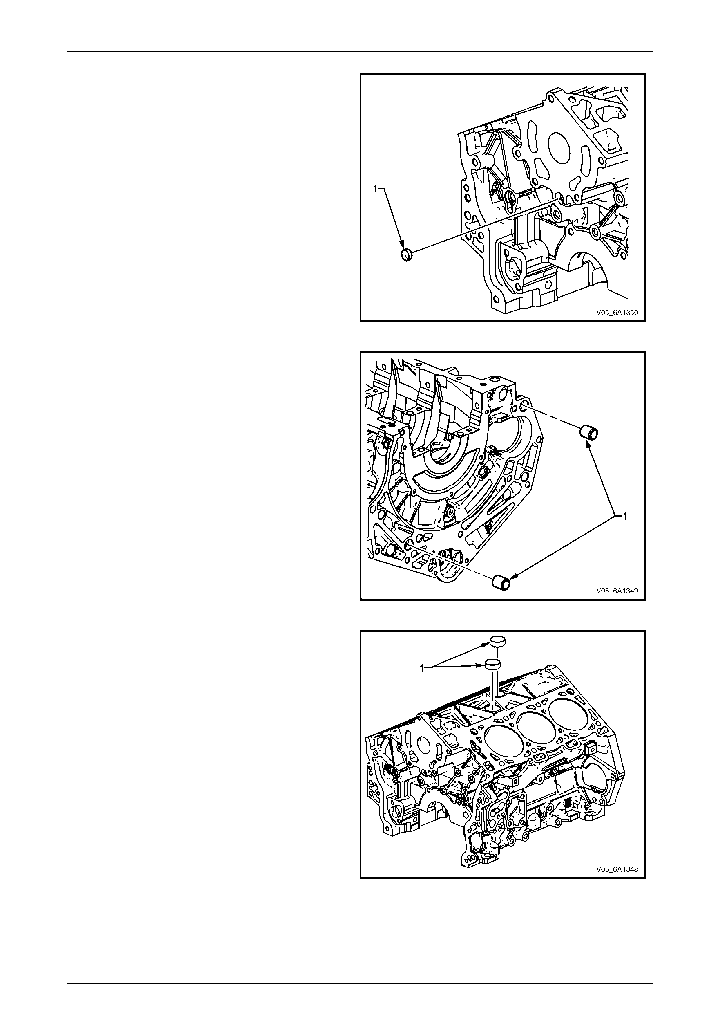
Engine Mechanical – V6 Page 6A1–261
Page 6A1–261
2 Install a new front oil gallery expansion plug (1).
Figure 6A1 – 443
3 Install the cylinder block-to-transmissio n alignment
dowels (1).
Figure 6A1 – 444
4 Place RTV sealant on ne w coolant expansion plugs
(1) and install the ne w coolant expansion plugs.
Figure 6A1 – 445
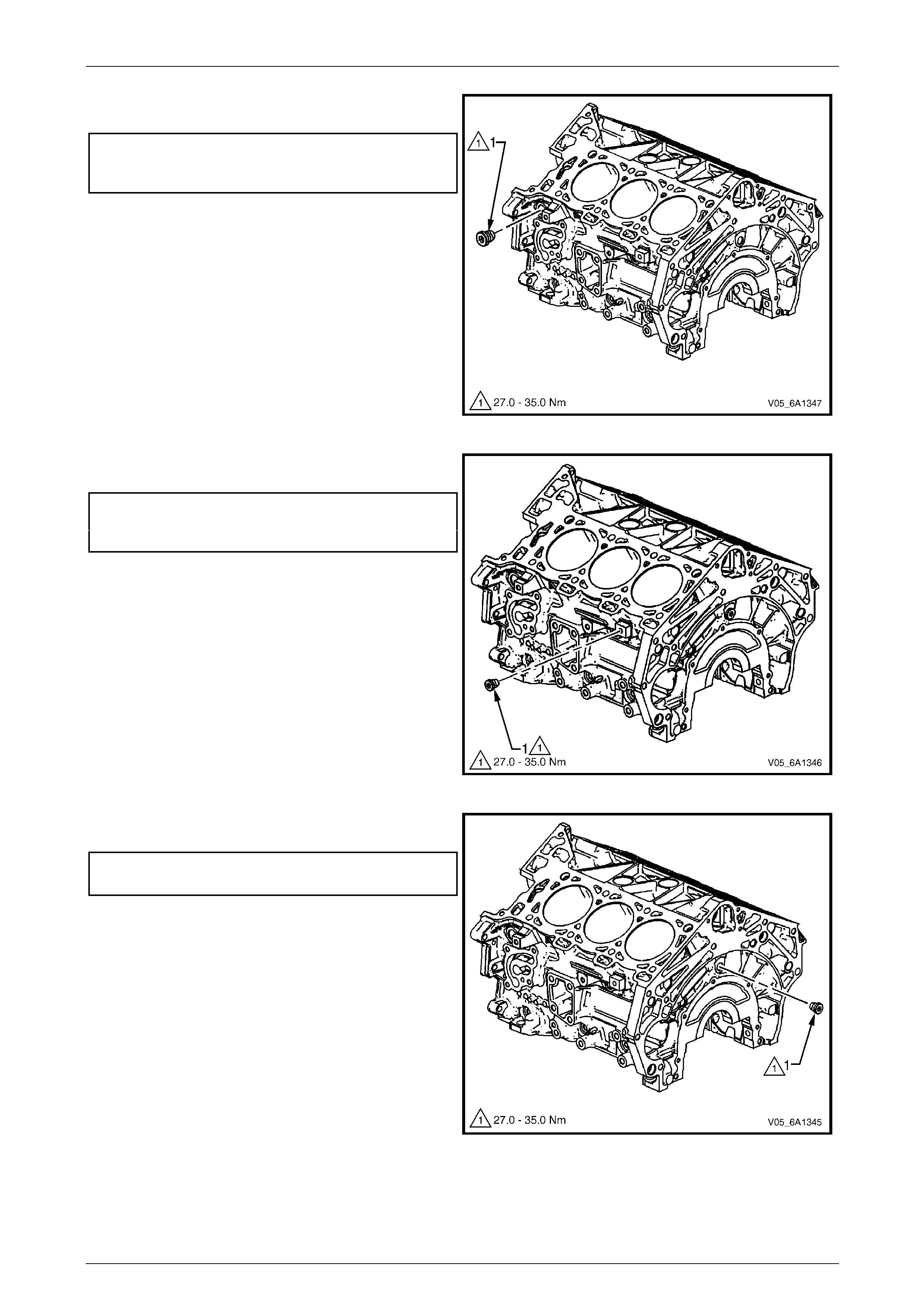
Engine Mechanical – V6 Page 6A1–262
Page 6A1–262
5 Install the left-hand side M20 oil gallery threaded plug
(1) and tighten to the correct torque specificat ion.
Left-hand side M20 cylinder bl ock
oil gallery threaded p lug
torque specification.................................27.0 – 35.0 Nm
Figure 6A1 – 446
6 Install the left-hand side M14 coolant drai n threaded
plug (1) and tighten to the correct torque spe c ification.
Left-hand side M14 cylinder bl ock
coolant drain threaded plu g
torque specification.................................27.0 – 35.0 Nm
Figure 6A1 – 447
7 Install the M14 rear oil galler y threaded plug (1) and
tighten to the correct torque specification.
M14 cylinder block rear oil gallery
threaded plug torque specification..........27.0 – 35.0 Nm
Figure 6A1 – 448
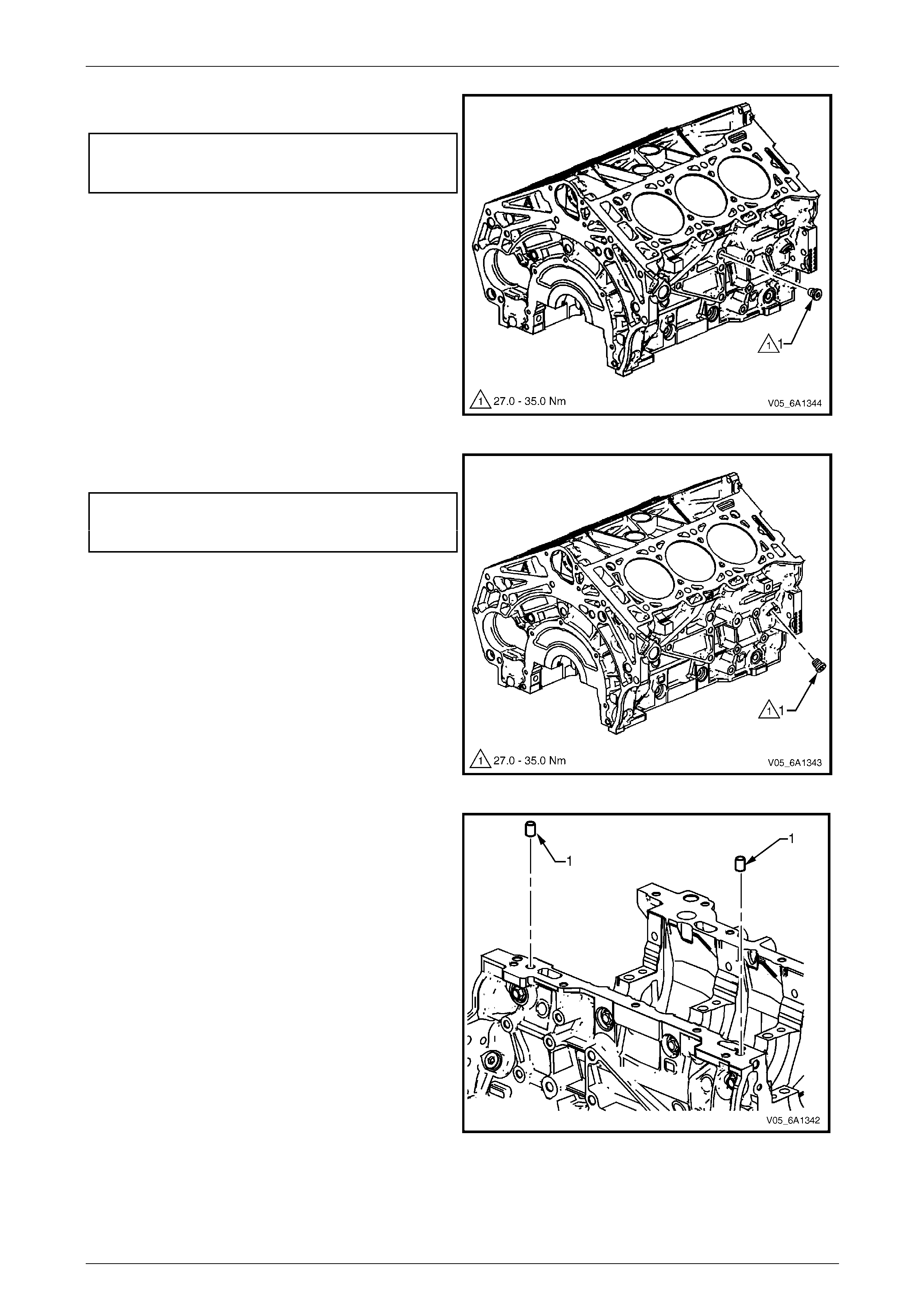
Engine Mechanical – V6 Page 6A1–263
Page 6A1–263
8 Install the right-hand side M14 coolant drain threaded
plug (1) and tighten to the correct torque spe c ification.
Right-hand side M14 cylinder block
coolant drain threaded plug
torque specification.................................27.0 – 35.0 Nm
Figure 6A1 – 449
9 Install the right-hand side M14 oil gall ery threaded
plug (1) and tighten to the correct torque spe c ification.
Right-hand side M14 cylinder block
oil gallery threaded plug
torque specification.................................27.0 – 35.0 Nm
Figure 6A1 – 450
10 Install the cylinder block-to-oil pan alignment
dowels (1).
Figure 6A1 – 451
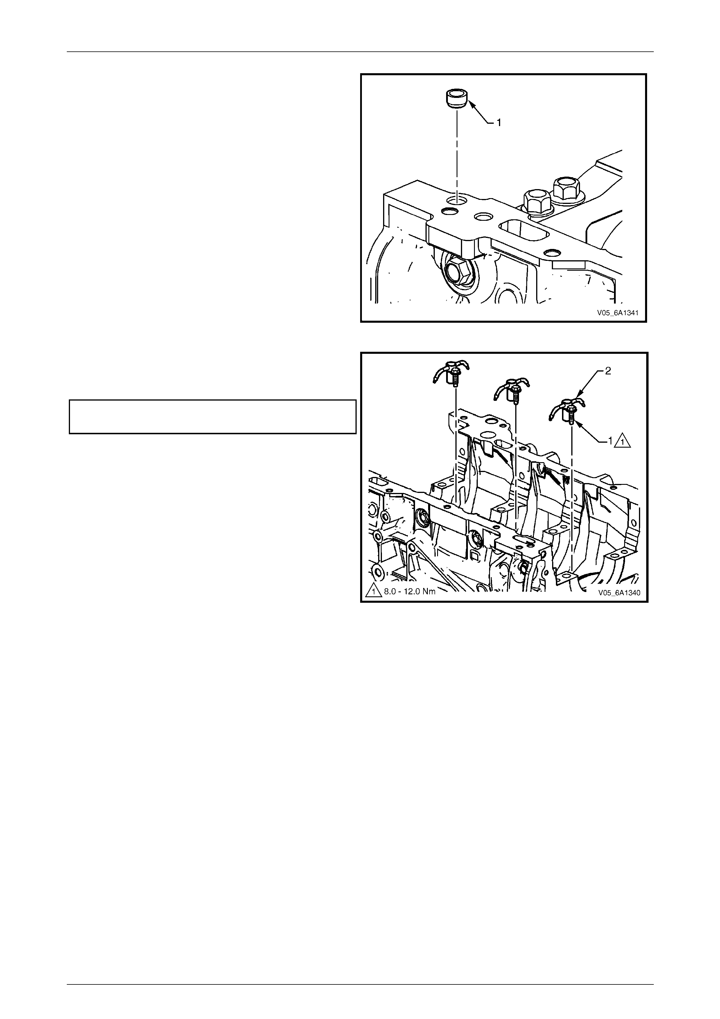
Engine Mechanical – V6 Page 6A1–264
Page 6A1–264
11 Install the new right-hand front oil pan rail o il gallery
expansion plug (1).
Figure 6A1 – 452
12 Install the oil jet (2), three places.
13 Install the oil jet attaching bolt (1), three places and
tighten to the correct torque specification.
Oil jet attaching bolt
torque specification...................................8.0 – 12.0 Nm
Figure 6A1 – 453
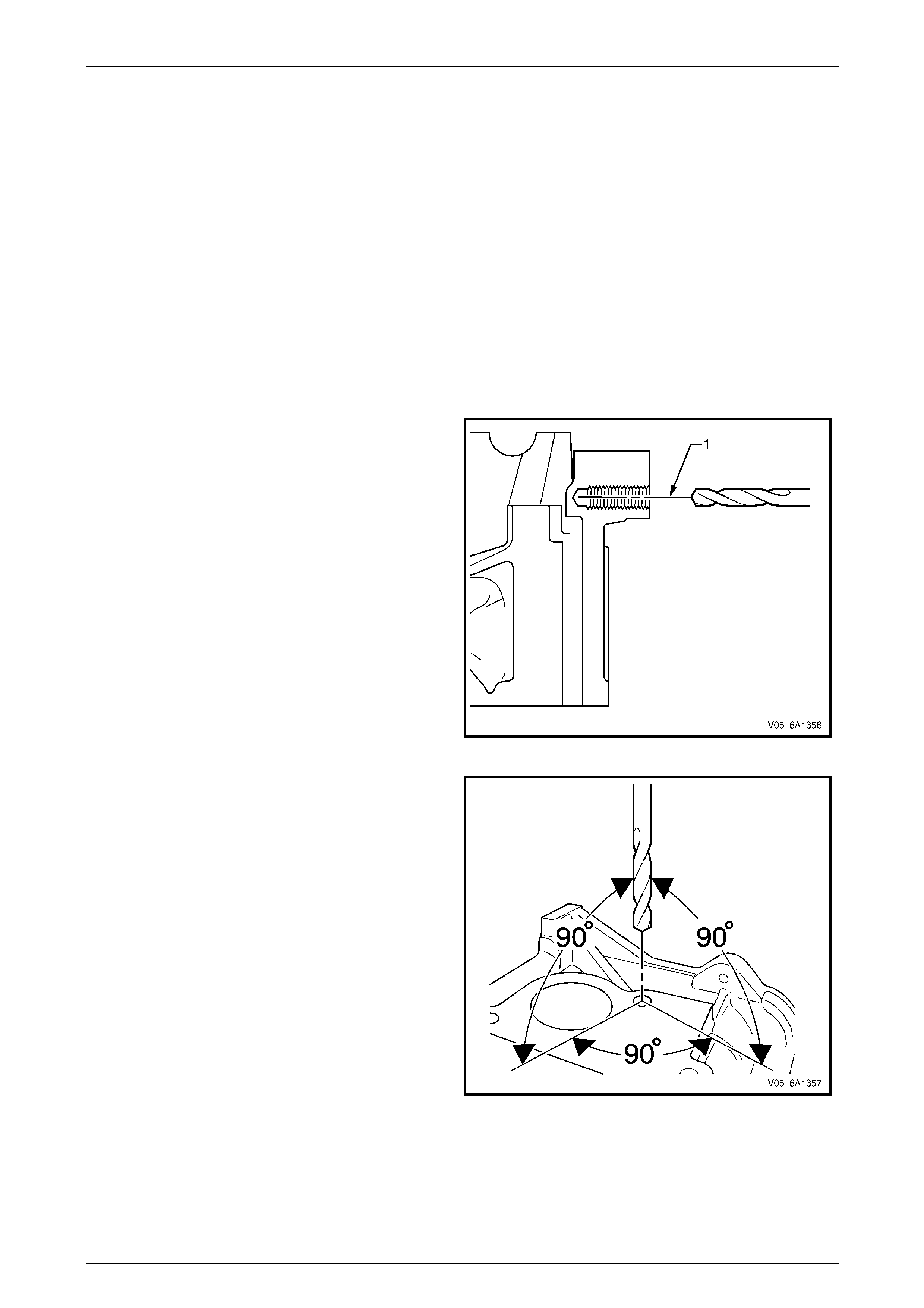
Engine Mechanical – V6 Page 6A1–265
Page 6A1–265
4.8 Thread Repairs
General Information
The thread repair process inv olves a so lid, thin walled, self-locking, carbon steel, bushing type insert. During the insert
installation process, the installation driver tool cold-rol ls the bottom intern al threads and expands the bottom external
threads of the insert into the base material. This action mechanically locks the insert into place.
This Section describes the recommended method of repairing threads in three specific areas of the engine.
• general thread repair,
• cylinder block main bearing cap bolt hole thread repair, and
• cylinder head bolt hole thread repa ir.
For detailed descriptions of all thread specifications used refer to 4.9 Thread Repair Specifications.
The drill-bit and counter-bore tool from the thread repair kit, Tool No. J-42385-700 and J-42385-2000 are designed for
use with either a suitable tap wrench or drill motor. Limited access and larger hole repair may process better using a ta p
wrench. An extension from T ool J 43965 may also be requ ired to drive the thread repair tooling dependent on access to
the hole being repaired. Use only a tap wrench when tapp ing the hole and during installation of the insert.
1 It is critical the drilling, counter boring and tapping of
the hole to be repaired follows the same centreline (1)
as the original hole.
Figure 6A1 – 454
2 During the drilling and tapp ing of the hole being
repaired, ensure the tooling is consistentl y machining
perpendicular to the surface of the base material.
Figure 6A1 – 455
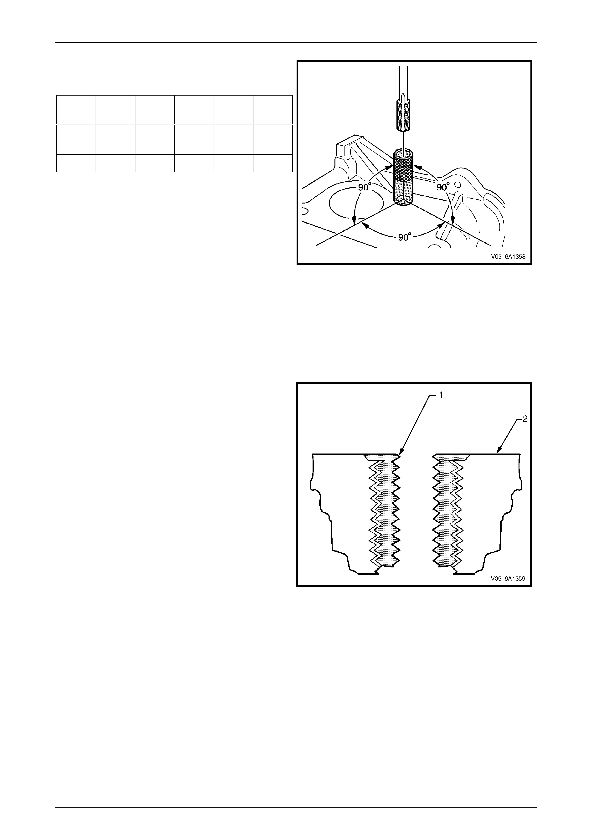
Engine Mechanical – V6 Page 6A1–266
Page 6A1–266
3 If the threaded hole being rep aired has a base
surface perpendicular to the hole centreline, tapping
guides are available to aid in tapping the hole.
Tap
Size Tap
Guide Tap
Size Tap
Guide Tap
Size Tap
Guide
- J 42385 - J 42385 - J 42385
6 x 1.0 729 10 x 1.5 731 14 x 1.5 736
8 x 1.25 730 12 x 1.5 732 20 x 1.5 737
Figure 6A1 – 456
General Thread Repair
NOTE
The use of a cutting t ype fluid such as W D 40® or
equivalent is recommended when performing the
drilling, counter boring and tapping procedures
When installed to the correct depth, the flange (1) of the
insert will be seated against the counter bor e of the
drilled/tapped hole and just b elow the surface (2) of the
base material.
Figure 6A1 – 457
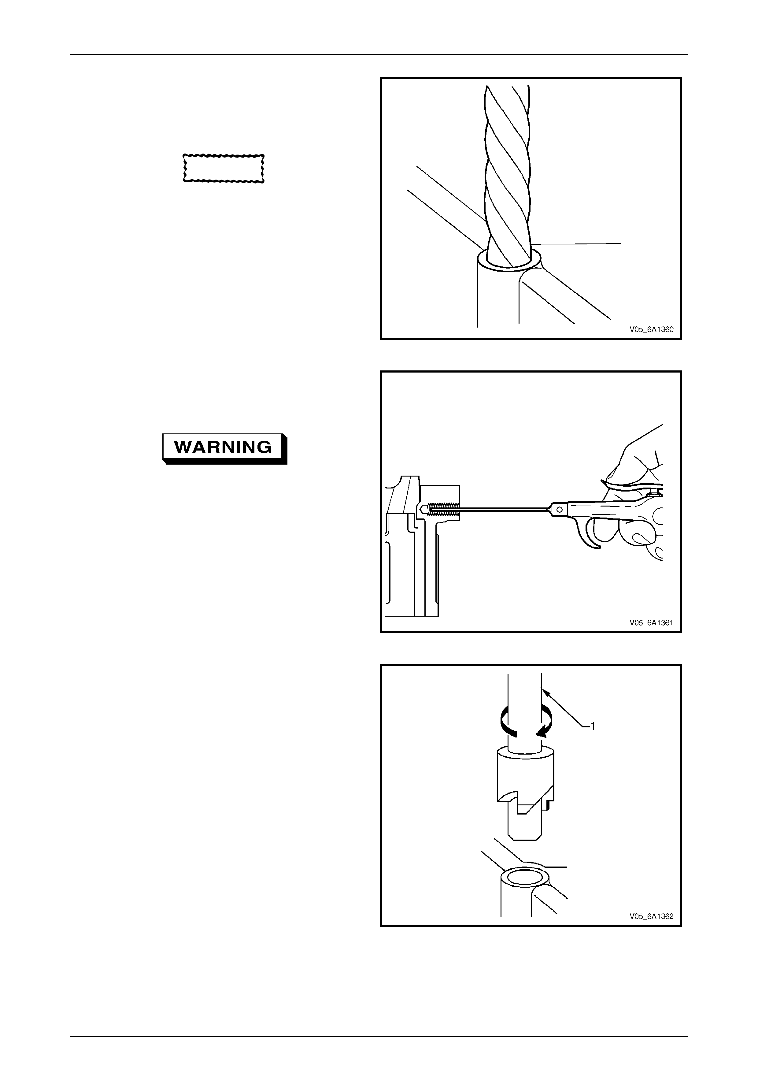
Engine Mechanical – V6 Page 6A1–267
Page 6A1–267
NOTE
During the drilling process, repeatedly remove
the drill and clean the swarf from the hole and
the flutes of the drill.
CAUTION
Do not drill any further than the original hole
depth.
1 Drill out the threads of the damaged hole to the
correct depth for the thread being repaire d:
• M6 inserts require a minimum drill depth of 15
mm.
• M8 inserts require a minimum drill depth of 20
mm.
• M10 inserts require a minimu m drill depth of
23.5 mm. Figure 6A1 – 458
NOTE
All swarf must be removed from the drilled hole
prior to tapping.
Safety glasses must be worn when using
compressed air.
2 Using compressed air, clean out an y s warf.
Figure 6A1 – 459
NOTE
A correctly counter bored hole will show a slight
burnishing on the surface of the base material
for 360 degrees around the drilled hole.
3 Counter bore the drilled ho le to the full depth
permitted by the tool (1).
Figure 6A1 – 460
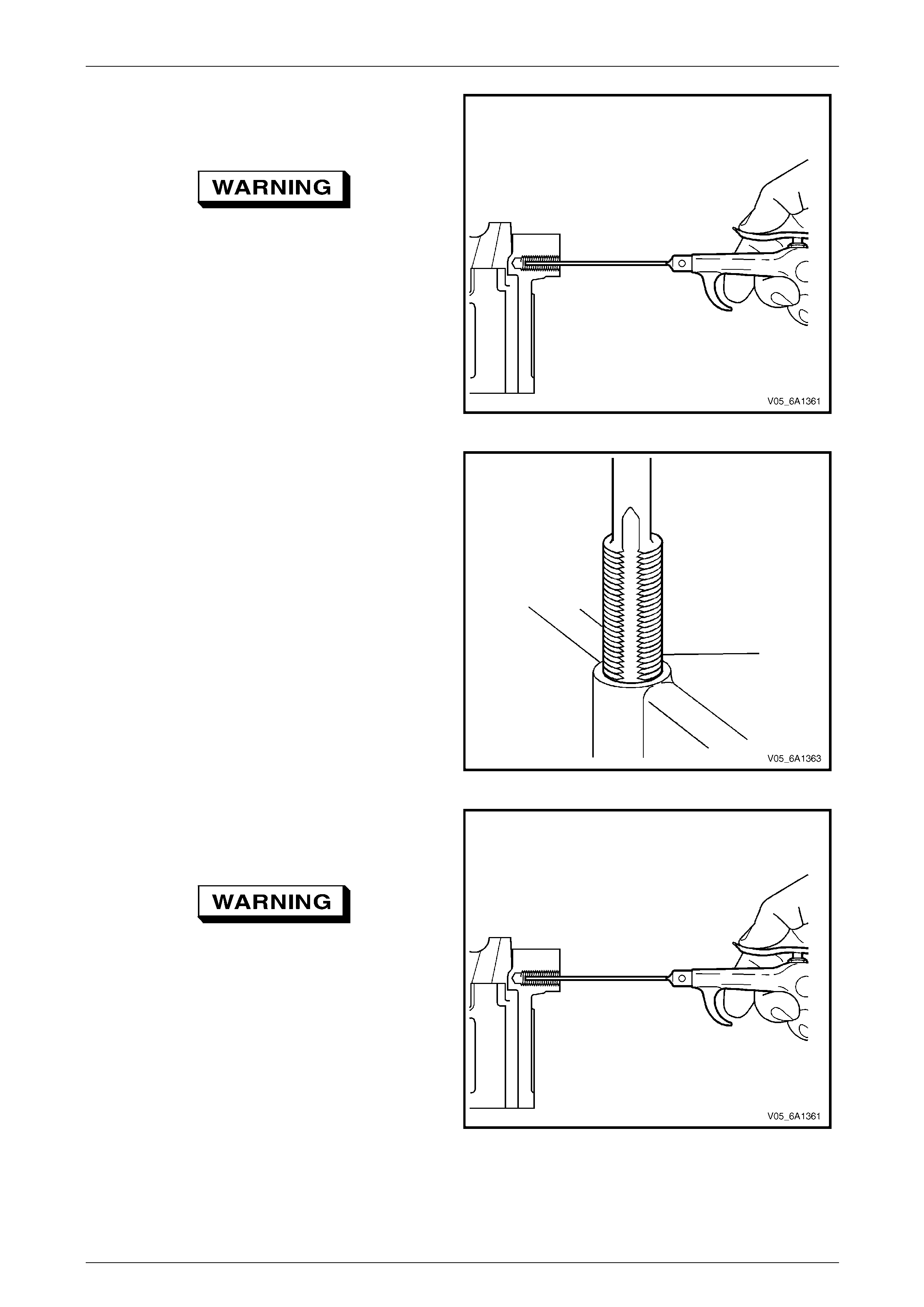
Engine Mechanical – V6 Page 6A1–268
Page 6A1–268
NOTE
All swarf must be removed from the drilled hole
prior to tapping.
Safety glasses must be worn when using
compressed air.
4 Using compressed air, clean out an y s warf.
Figure 6A1 – 461
NOTE
During the tapping process, repeatedly remove
the tap and clean the swarf from the hole and
the flutes of the tap.
NOTE
Ensure the tap has created full threads at least
to the depth equal to the insert length.
5 Using a suitable tapping wrench, tap the threads of
the drilled hole by hand only.
• M6 inserts require a minimum drill depth of 15
mm.
• M8 inserts require a minimum drill depth of 20
mm.
• M10 inserts require a minimu m drill depth of
23.5 mm.
Figure 6A1 – 462
NOTE
All swarf must be removed from the tapped hole
prior to insert installation.
Safety glasses must be worn when using
compressed air.
6 Using compressed air, clean out an y s warf.
Figure 6A1 – 463
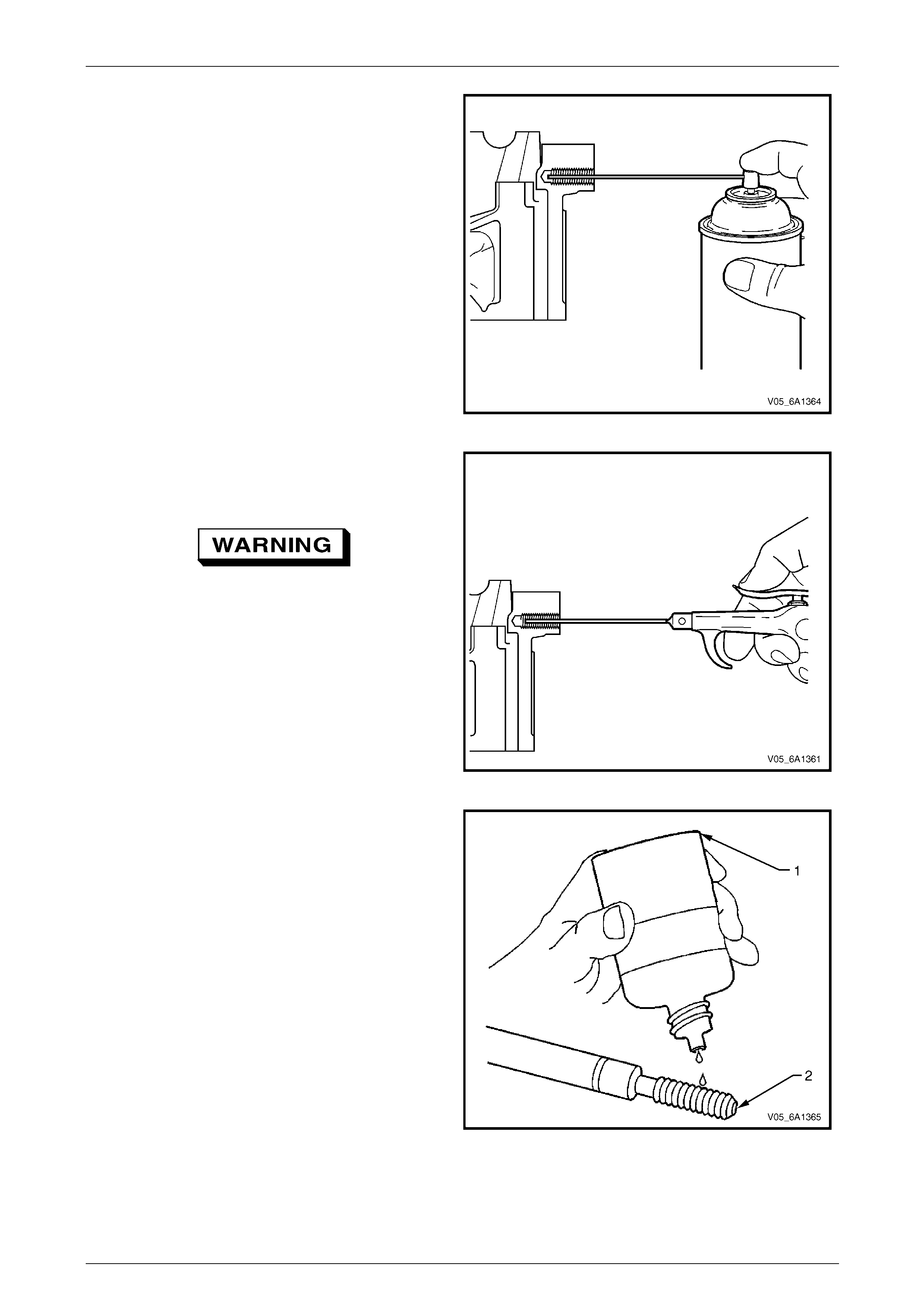
Engine Mechanical – V6 Page 6A1–269
Page 6A1–269
7 Spray a commercially available thread cleaner into
the tapped hole.
Figure 6A1 – 464
NOTE
All swarf must be removed from the tapped hole
prior to insert installation.
Safety glasses must be worn when using
compressed air.
8 Using compressed air, clean out an y s warf.
Figure 6A1 – 465
NOTE
Do not allow oil or other foreign material to
contact the outside diameter (OD) of the insert.
9 Lubricate the threads of the dr iver installation tool (2)
with the driver oil (1).
Figure 6A1 – 466
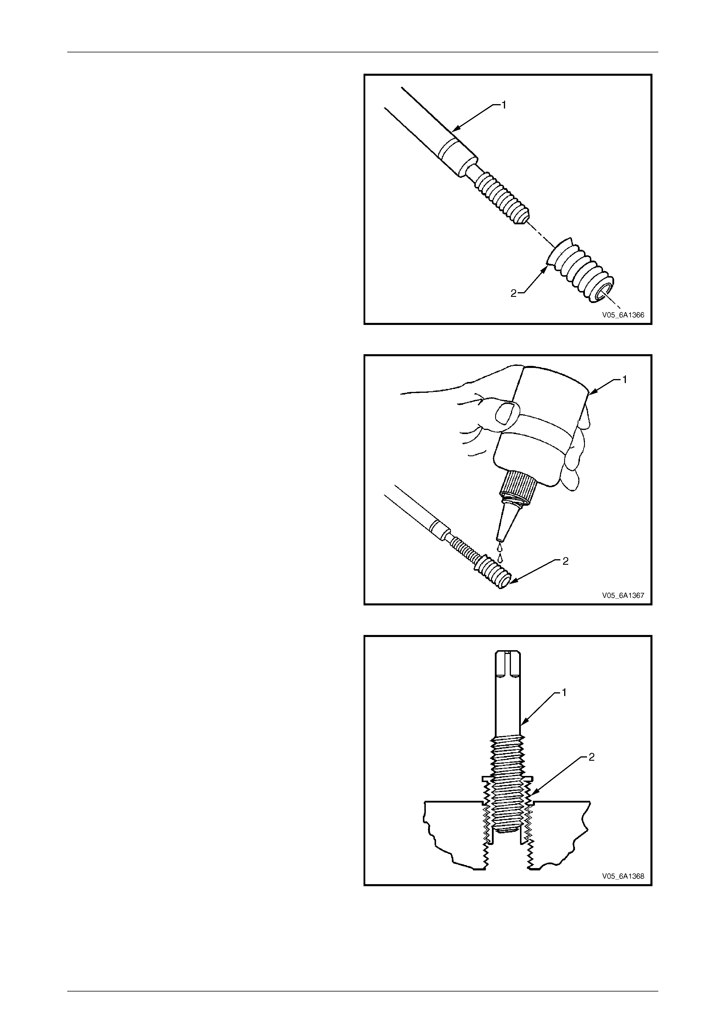
Engine Mechanical – V6 Page 6A1–270
Page 6A1–270
10 Install the insert (2) onto the driver installation tool (1).
Figure 6A1 – 467
11 Apply thread lock sealant (1) such as Loctite 277® or
equivalent to the insert OD threads (2).
Figure 6A1 – 468
12 Install the insert (2) into the tapped ho le by hand only.
Figure 6A1 – 469
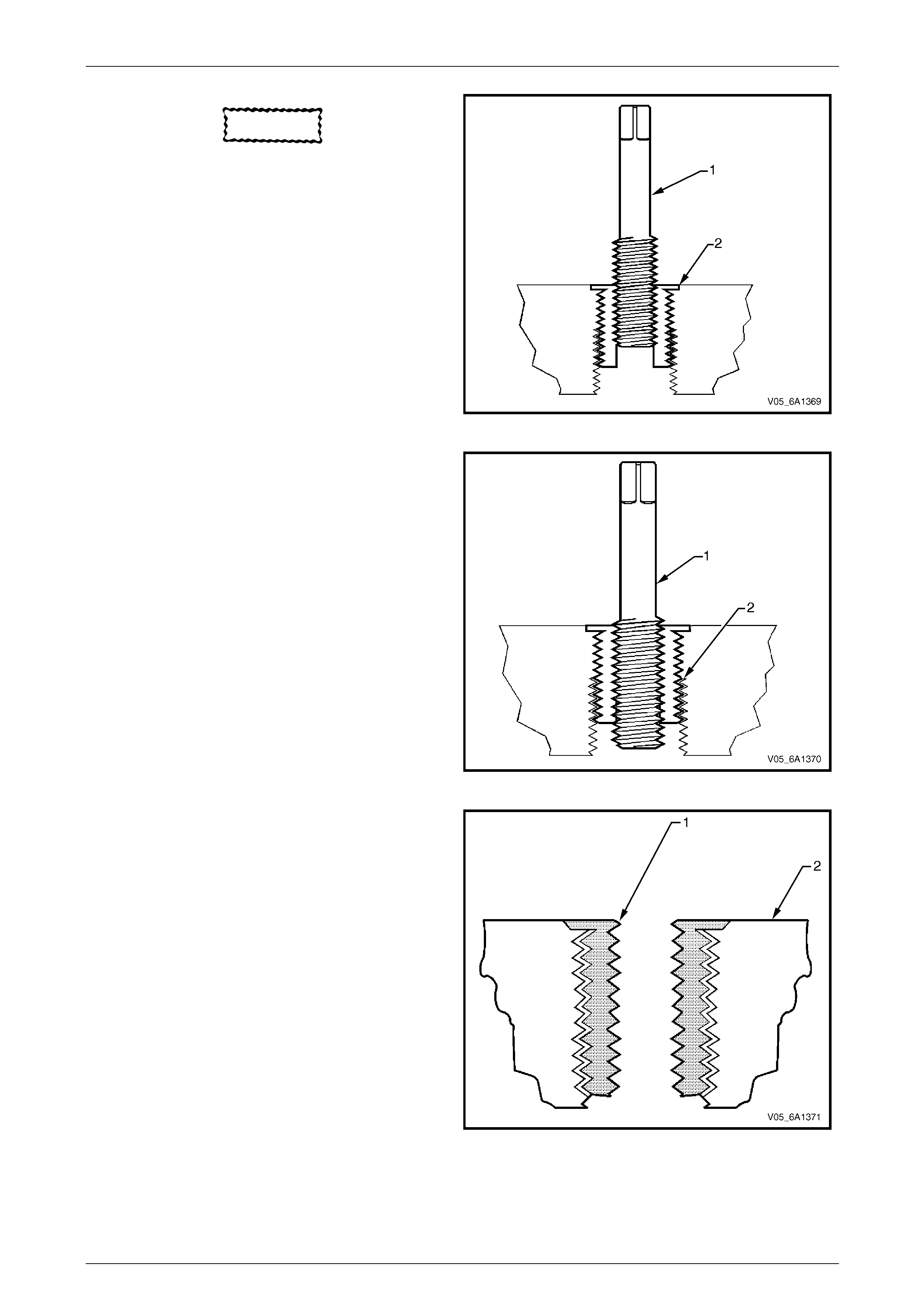
Engine Mechanical – V6 Page 6A1–271
Page 6A1–271
CAUTION
If the insert will not thread down until the
flange contacts the counter bore surface,
remove the insert immediately with a screw
extracting tool and inspect the tapped hole
for any remaining swarf and/or incorrect
tapping.
13 Install the insert until the flange (2) of the insert
contacts the counter bore surface.
Figure 6A1 – 470
NOTE
The driver installation tool will tighten up before
cutting completely through the insert. This is
acceptable. The threads at the bottom of the
insert are being formed and the insert is
mechanically locking the insert into the base
material threads.
14 Continue to rotate the driver installation tool (1)
through the insert (2)
15 Remove the driver installation tool.
Figure 6A1 – 471
16 Inspect the insert for correct installation into the
tapped hole. A correctly installed insert (1) will be
either flush or slightly below flush with the surface of
the base material (2).
Figure 6A1 – 472
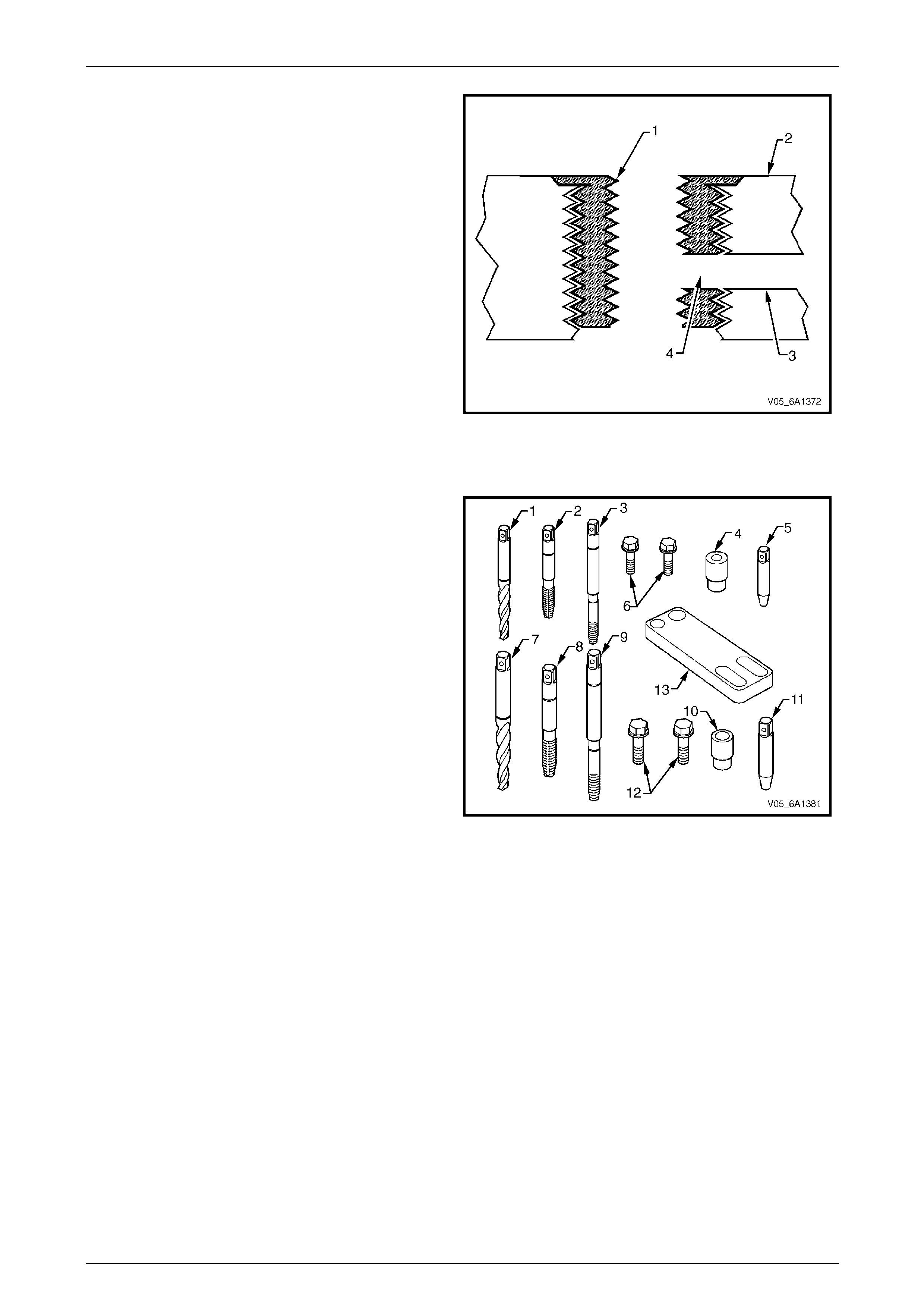
Engine Mechanical – V6 Page 6A1–272
Page 6A1–272
17 Any installed insert that restricts or blocks an oil or
engine coolant passage (3) will need to have the oil or
engine coolant passage drilled out (4) to the original
size of the oil or engine coola nt passag e. After drilling
the restriction or blockage, clean out an y swarf and
thread the installation dr iver tool through the insert
again to remove any burrs caused by the drilling of
the oil or engine coolant passage.
Figure 6A1 – 473
Main Bearing Cap Bolt Hole Thread Repair
The crankshaft main bearing bolt hole thread repair tools
are in Tool No. J 42385-2000 and J 42385-700 which
consist of the following:
• Drill (1) for outboard holes J 42385-702
• Tap (2) for outboard holes J 42385-703
• Installation driver (3) for outboard holes J 42 385-704
• Bushing (4) for outboard holes J 42385-726
• Alignment pin (5) for outboard holes J 42385-727
• Bolts (6) for outboard holes J 42385-728
• Drill (7) for inboard holes J 42385-72 0
• Tap (8) for inboard holes J 42385-721
• Installation driver (9) for inboard holes J 42385-722
• Bushing (10) J 42385-713
• Alignment pin (11) J 42385-308
• Bolts (12) J 42385-734
• Fixture plate (13) J 42385-712 Figure 6A1 – 474
NOTE
• Ensure the fixture plate is installed during the
machining and installation processes of the
insert.
• The use of a cutting type fluid such as
WD 40® or equivalent is recommended when
performing the drilling, counter boring and
tapping procedures.
• When installed to the correct depth, the fla nge
of the insert will be seated against the c ounter
bore of the drilled/tapped hol e.
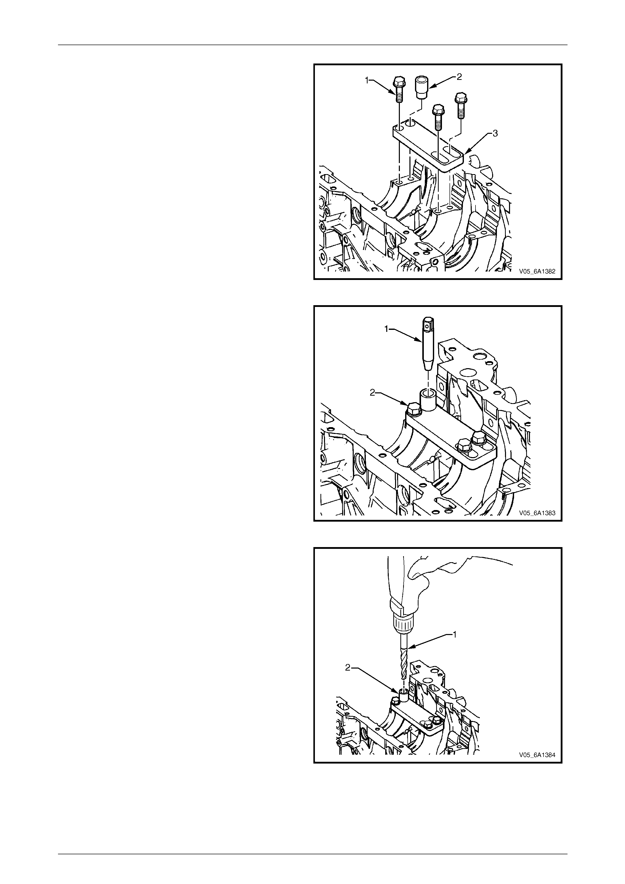
Engine Mechanical – V6 Page 6A1–273
Page 6A1–273
1 Position the fixture plate (3) with the bushing (2)
installed over the crankshaft main cap bolt hole to be
repaired.
2 Loosely install the fixture plate bolts (1) into the
remaining crankshaft main cap bolt holes.
Figure 6A1 – 475
3 Position the alignment pin (1) through the bushing
and into the crankshaft main cap bolt hol e.
4 With the alignment pin in the desired crankshaft main
cap bolt hole, tighten the fixture retain ing bolts (2).
5 Remove the alignment pin.
Figure 6A1 – 476
NOTE
During the drilling process, repeatedly remove
the drill and clean the swarf from the hole and
the flutes of the drill.
6 Drill the crankshaft main bolt hole until the mark (1)
on the drill aligns with the top of the drill bushing (2).
Figure 6A1 – 477
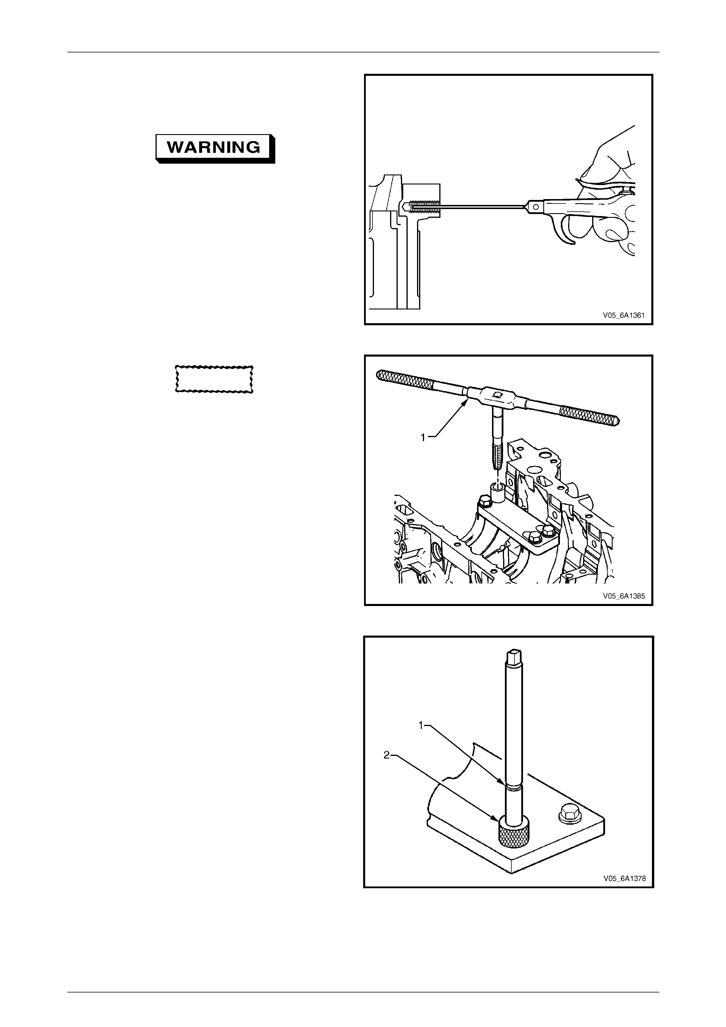
Engine Mechanical – V6 Page 6A1–274
Page 6A1–274
NOTE
All swarf must be removed from the drilled hole
prior to tapping.
Safety glasses must be worn when using
compressed air.
7 Using compressed air, clean out an y s warf.
Figure 6A1 – 478
CAUTION
Do not remove the fixture plate during the
machining and installation processes of the
insert.
NOTE
During the tapping process, repeatedly remove
the tap and clean the swarf from the hole and
the flutes of the tap.
NOTE
Ensure the tap has created full threads at least
to the depth equal to the insert length.
8 Using a suitable tapping wrench, tap the threads of
the drilled hole by hand only.
Figure 6A1 – 479
9 In order to tap the new threads for the insert to the
correct depth, rotate the tap into the crankshaft main
cap bolt hole until the mark (1) on the tap aligns with
the top of the drill bushing (2).
Figure 6A1 – 480

Engine Mechanical – V6 Page 6A1–275
Page 6A1–275
NOTE
All swarf must be removed from the tapped hole
prior to insert installation.
Safety glasses must be worn when using
compressed air.
10 Using compressed air, clean out an y s warf.
Figure 6A1 – 481
11 Spray a commercially available thread cleaner into
the tapped hole.
Figure 6A1 – 482
NOTE
All swarf must be removed from the tapped hole
prior to insert installation.
Safety glasses must be worn when using
compressed air.
12 Using compressed air, clean out an y s warf.
Figure 6A1 – 483

Engine Mechanical – V6 Page 6A1–276
Page 6A1–276
NOTE
Do not remove the fixture plate, ensure the
fixture plate is installed during the installation
process of the insert.
NOTE
Do not allow oil or other foreign material to
contact the outside diameter (OD) of the insert.
13 Lubricate the threads of the driver installation tool (2)
with the driver oil (1).
Figure 6A1 – 484
14 Install the insert (2) onto the driver installation tool (1).
Figure 6A1 – 485
15 Apply thread lock sealant (1) such as Loctite 277® or
equivalent to the insert OD threads (2).
Figure 6A1 – 486
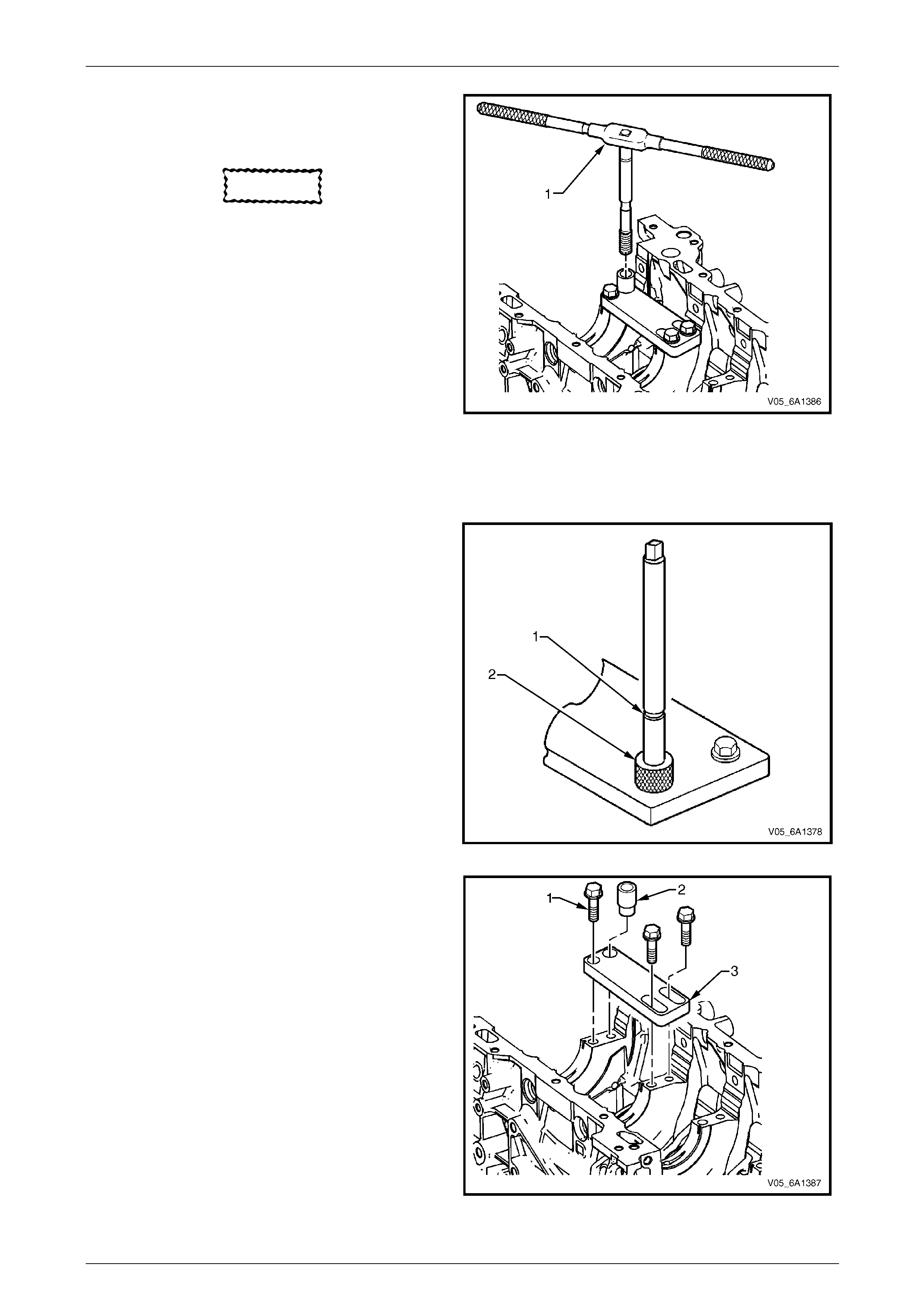
Engine Mechanical – V6 Page 6A1–277
Page 6A1–277
16 Install the insert and installation driver (1) to the
tapped hole by hand only.
17 Start the insert into the threaded hole.
CAUTION
If the insert will not thread down until the
flange contacts the counter-bored surface,
remove the insert immediately with a screw
extracting tool and inspect the tapped hole
for any remaining swarf and/or incorrectly
tapping.
18 Install the insert until the flange of the insert contacts
the counter-bored surface.
NOTE
The driver installation tool will tighten up before
cutting completely through the insert. This is
acceptable. The threads at the bottom of the
insert are being formed and the insert is
mechanically locking the insert into the base
material threads.
19 Continue to rotate the driver installation tool through
the insert.
Figure 6A1 – 487
20 Rotate the driver installation tool until the mark (1) on
the driver installation tool aligns with the top of the
drill bushing (2).
21 Inspect the insert for correct installation into the
tapped hole.
Figure 6A1 – 488
22 Remove the fixture plate bolts (1), bushing (2) and
fixture plate (3).
Figure 6A1 – 489
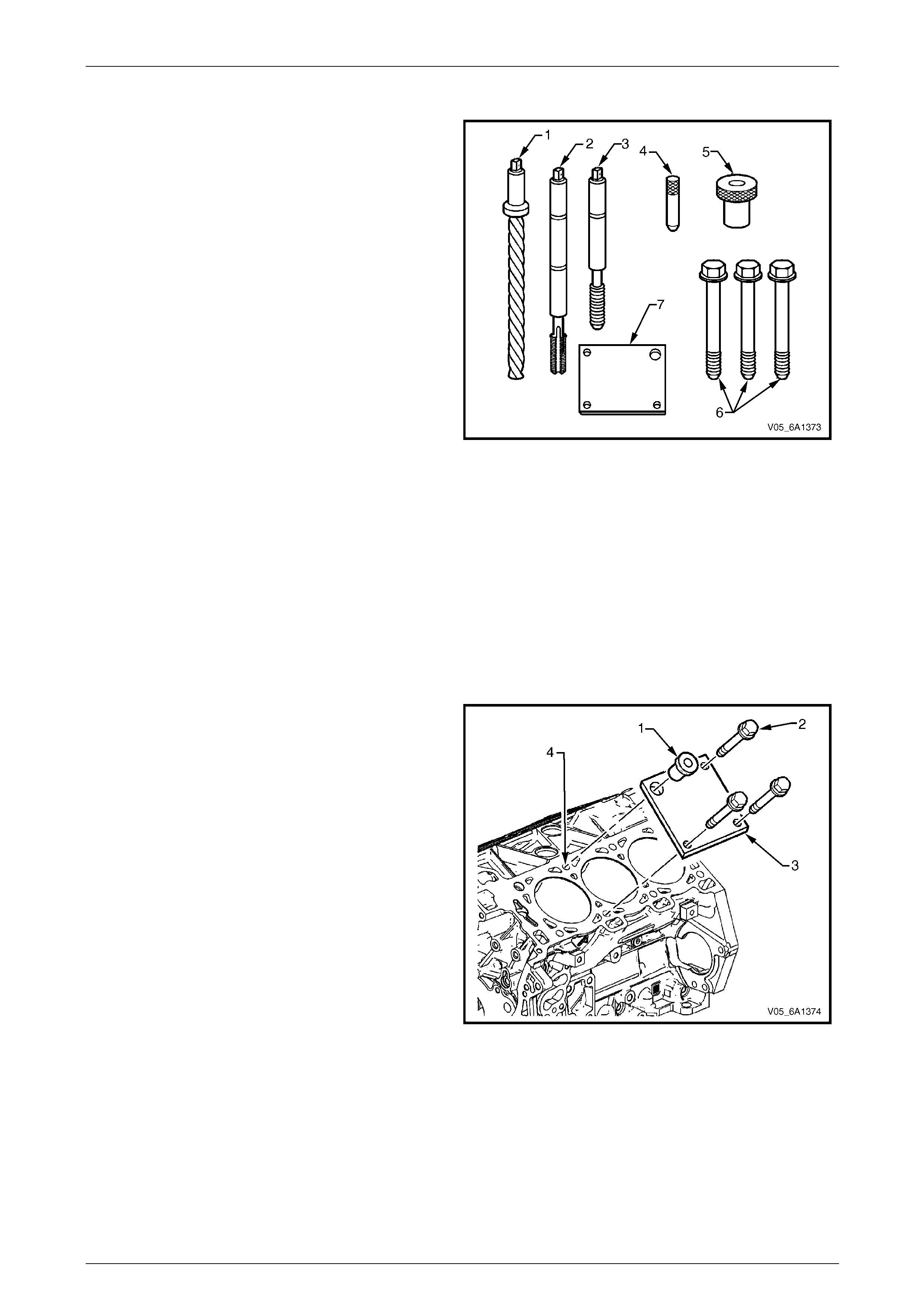
Engine Mechanical – V6 Page 6A1–278
Page 6A1–278
Cylinder Head Bolt Hole Thread Repair
The cylinder head bolt hole thread rep air to ols are in Tool
No. J 42385-2000 and J 42385-700 which consist of the
following:
• Drill (1) J 42385-723
• Tap (2) J 42385-724
• Installation driver (3) J 42385-725
• Alignment pin (4) J 42385-303
• Bushing (5) J 42385-302
• Bolts (6) J 42385-733
• Fixture plate (7) J 42385-401
Figure 6A1 – 490
NOTE
• Ensure the fixture plate is installed during the
machining and installation processes of the
insert.
• The use of a cutting type fluid such as
WD 40® or equivalent is recommended when
performing the drilling, counter boring and
tapping procedures.
• When installed to the correct depth, the fla nge
of the insert will be seated against the c ounter
bore of the drilled/tapped hol e.
1 Position the fixture plate (3) with the bushing (1)
installed over the cylinder head bolt hole to be
repaired (4).
2 Loosely install the fixture plate bolts (2) into the
remaining cylinder head b olt h oles.
Figure 6A1 – 491
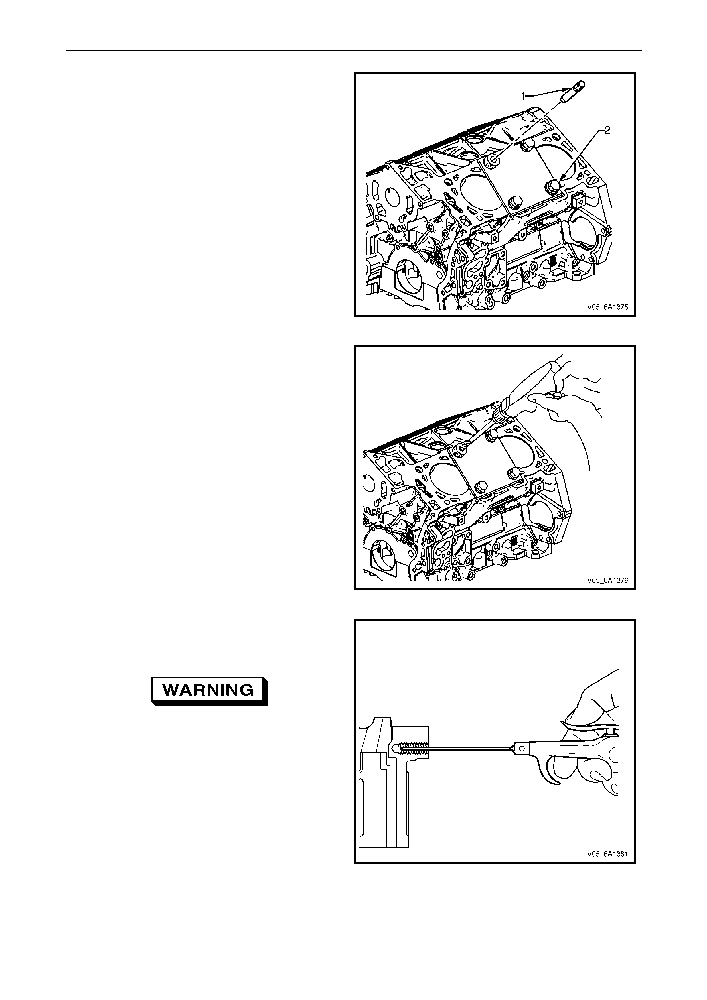
Engine Mechanical – V6 Page 6A1–279
Page 6A1–279
3 Position the alignment pin (1) through the bushing
and into the cylinder head bo lt hole.
4 With the alignment pin in the desire d cylinder head
bolt hole, tighten the fixture retaining bolts (2).
5 Remove the alignment pin.
Figure 6A1 – 492
NOTE
During the drilling process, repeatedly remove
the drill and clean swarf from the hole and the
flutes of the drill.
6 Drill the hole until the stop collar contacts the top of
the drill bushing.
Figure 6A1 – 493
NOTE
All swarf must be removed from the drilled hole
prior to tapping.
Safety glasses must be worn when using
compressed air.
7 Using compressed air, clean out an y s warf.
Figure 6A1 – 494
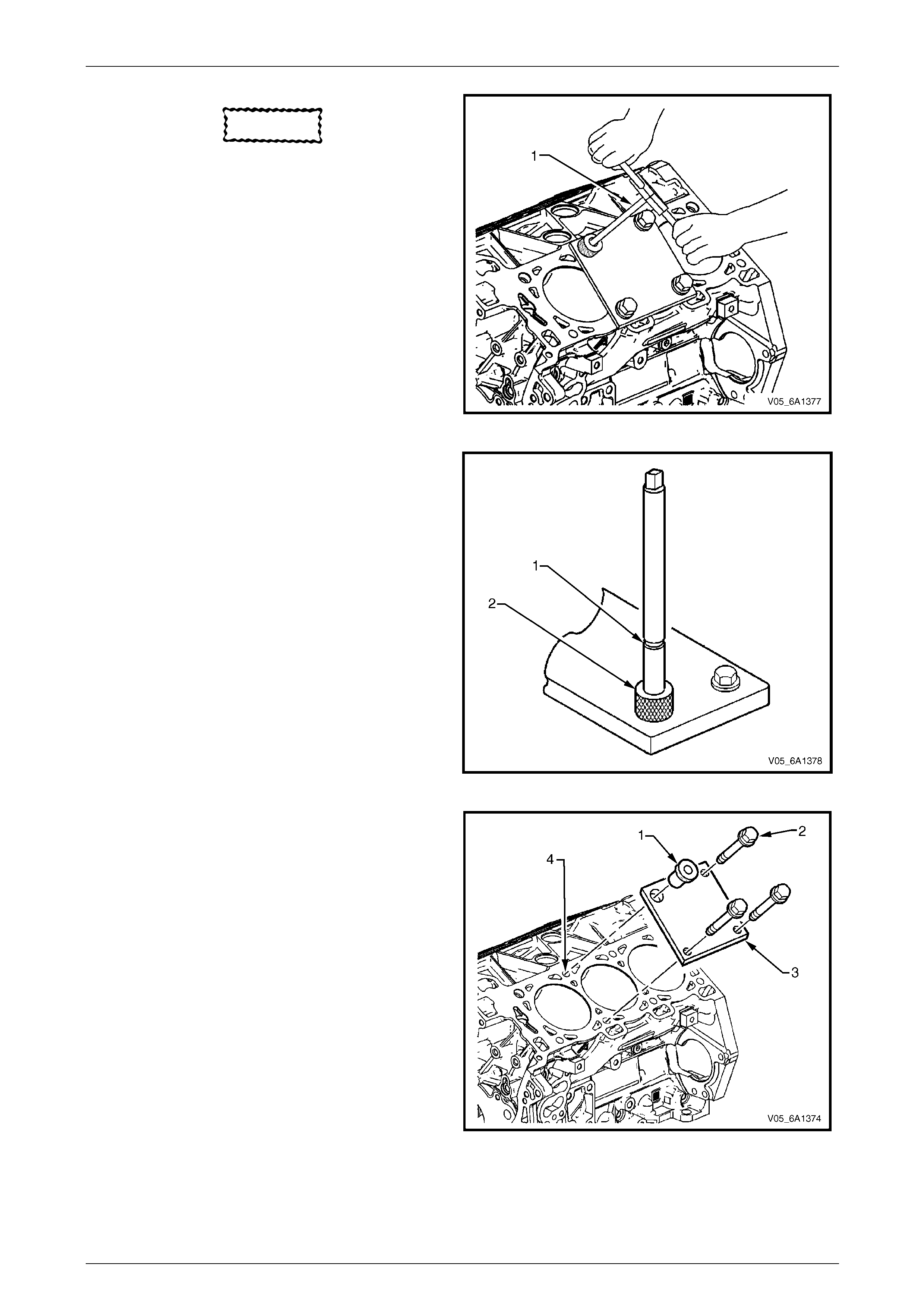
Engine Mechanical – V6 Page 6A1–280
Page 6A1–280
CAUTION
Do not remove the fixture plate during the
machining and installation processes of the
insert.
NOTE
During the tapping process, repeatedly remove
the tap and clean swarf from the hole and the
flutes of the tap.
NOTE
Ensure the tap has created full threads at least
to the depth equal to the insert length.
8 Using a suitable tapping wrench, tap the threads of
the drilled hole by hand only.
Figure 6A1 – 495
9 In order to tap the new threads for the insert to the
correct depth, rotate the tap into the cylinder head
bolt hole until the mark (1) on the tap aligns with the
top of the drill bushing (2).
Figure 6A1 – 496
NOTE
Remove the fixture plate prior to installing the
insert with the installer tool.
10 Remove the bushing (1) and fixture plate bolts (2)
from the cylinder block (4) and remove the fixture
plate (3).
Figure 6A1 – 497
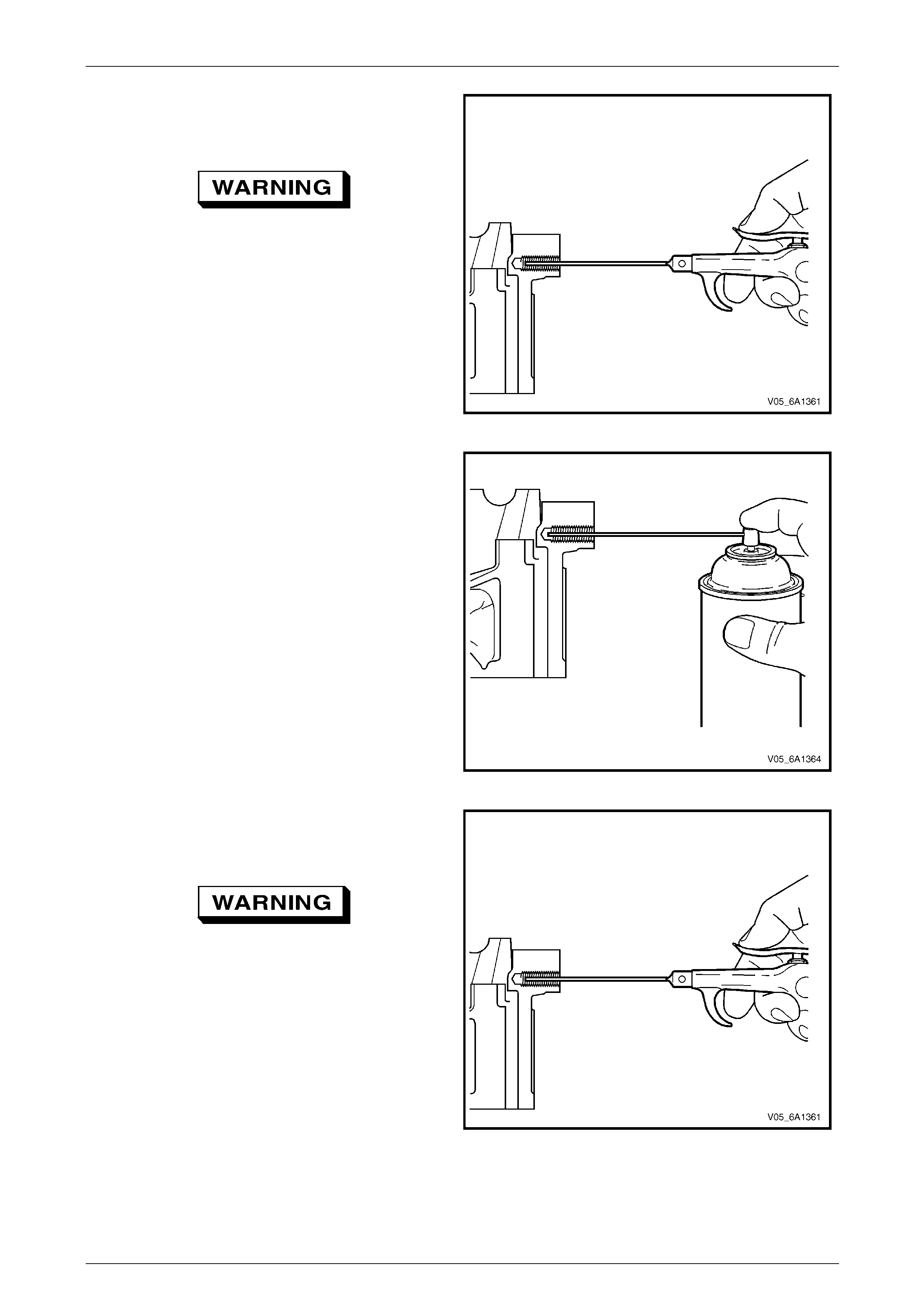
Engine Mechanical – V6 Page 6A1–281
Page 6A1–281
NOTE
All swarf must be removed from the tapped hole
prior to insert installation.
Safety glasses must be worn when using
compressed air.
11 Using compressed air, clean out an y s warf.
Figure 6A1 – 498
12 Spray a commercially available thread cleaner into
the tapped hole.
Figure 6A1 – 499
NOTE
All swarf must be removed from the tapped hole
prior to insert installation.
Safety glasses must be worn when using
compressed air.
13 Using compressed air, clean out an y s warf.
Figure 6A1 – 500
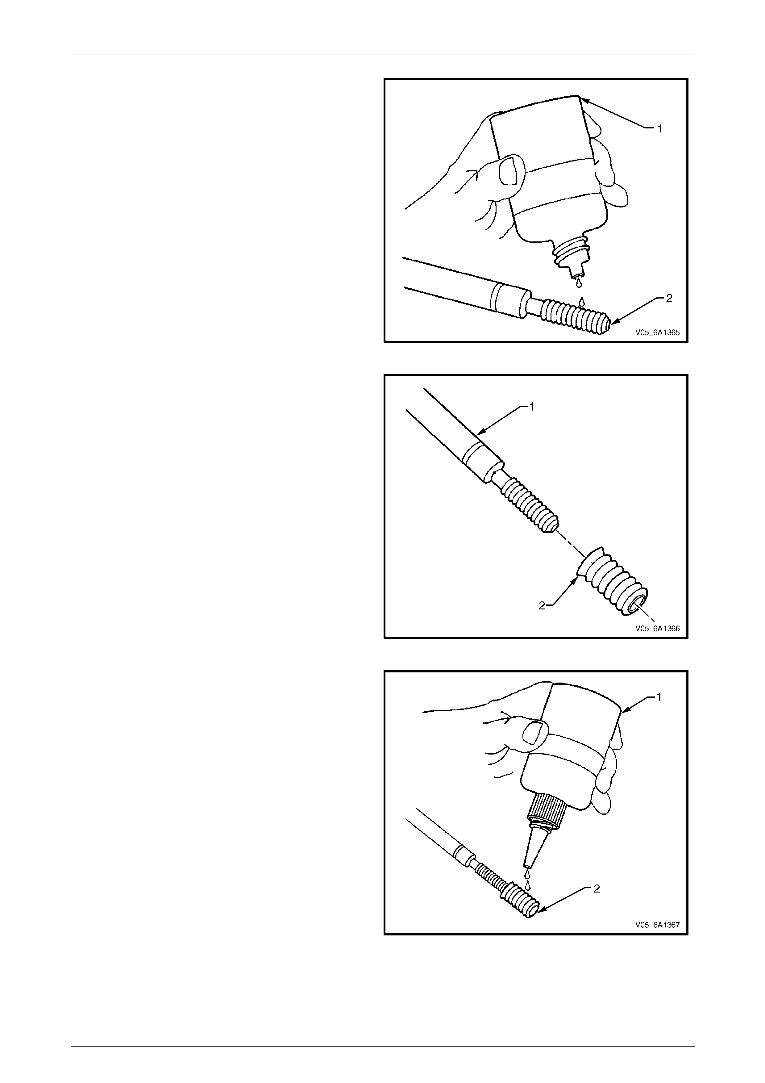
Engine Mechanical – V6 Page 6A1–282
Page 6A1–282
NOTE
Do not allow oil or other foreign material to
contact the outside diameter (OD) of the insert.
14 Lubricate the threads of the driver installation tool (2)
with the driver oil (1).
Figure 6A1 – 501
15 Install the insert (2) onto the driver installation tool (1).
Figure 6A1 – 502
16 Apply thread lock sealant (1) such as Loctite 277® or
equivalent to the insert OD threads (2).
Figure 6A1 – 503
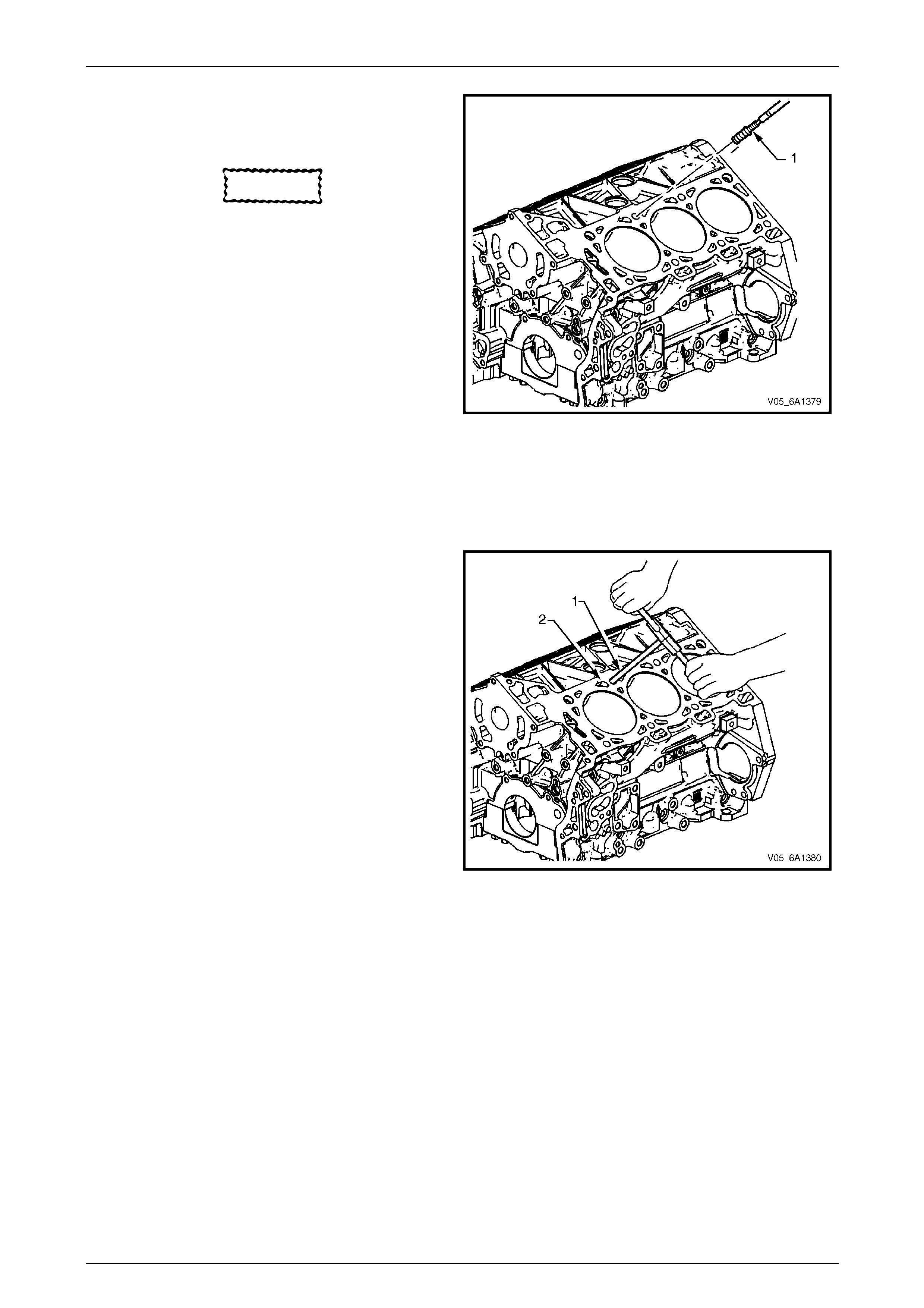
Engine Mechanical – V6 Page 6A1–283
Page 6A1–283
17 Install the insert and installation driver (1) into the
tapped hole by hand only.
18 Start the insert into the threaded hole.
CAUTION
If the insert will not thread down until the
flange contacts the counter-bored surface,
remove the insert immediately with a screw
extracting tool and inspect the tapped hole
for any remaining swarf and/or incorrect
tapping.
19 Install the insert until the flange of the insert contacts
the counter-bored surface.
NOTE
The driver installation tool will tighten up before
cutting completely through the insert. This is
acceptable. The threads at the bottom of the
insert are being formed and the insert is
mechanically locking the insert into the base
material threads.
20 Continue to rotate the driver installation tool through
the insert.
Figure 6A1 – 504
21 In order to completely form the new threads in the
insert, rotate the driver installation tool through the
insert until the mark on the driver installation tool (1)
aligns with the surface of the engine block deck (2).
22 Inspect the insert for correct installation into the
tapped hole.
Figure 6A1 – 505
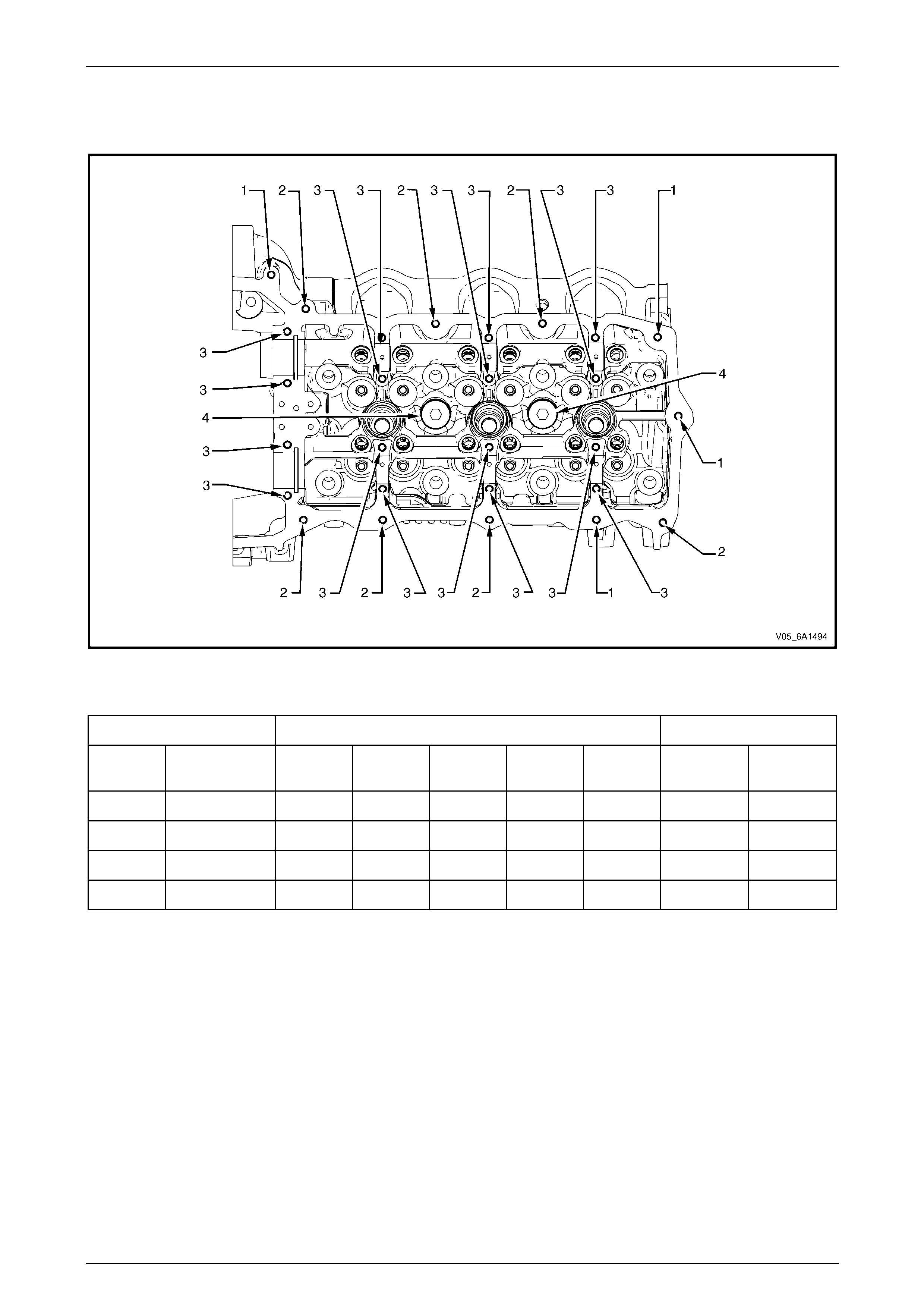
Engine Mechanical – V6 Page 6A1–284
Page 6A1–284
4.9 Thread Repair Specifications
Left-hand Cylinder Head Camshaft Cover Face
Figure 6A1 – 506
Legend
Hole Tool Number J 42385 Max. Depth in mm
Number Thread Size Drill Counter-
bore Tap Driver Insert Drill Tap
1 M6 x 1.0 201 202 203 204 205 22.5 18.0
2 M6 x 1.0 201 202 203 204 205 Thru Thru
3 M6 x 1.0 701 n/a 203 204 205 28.5 24.0
4 M20 x 1.5 715 716 717 718 719 25.0 17.0
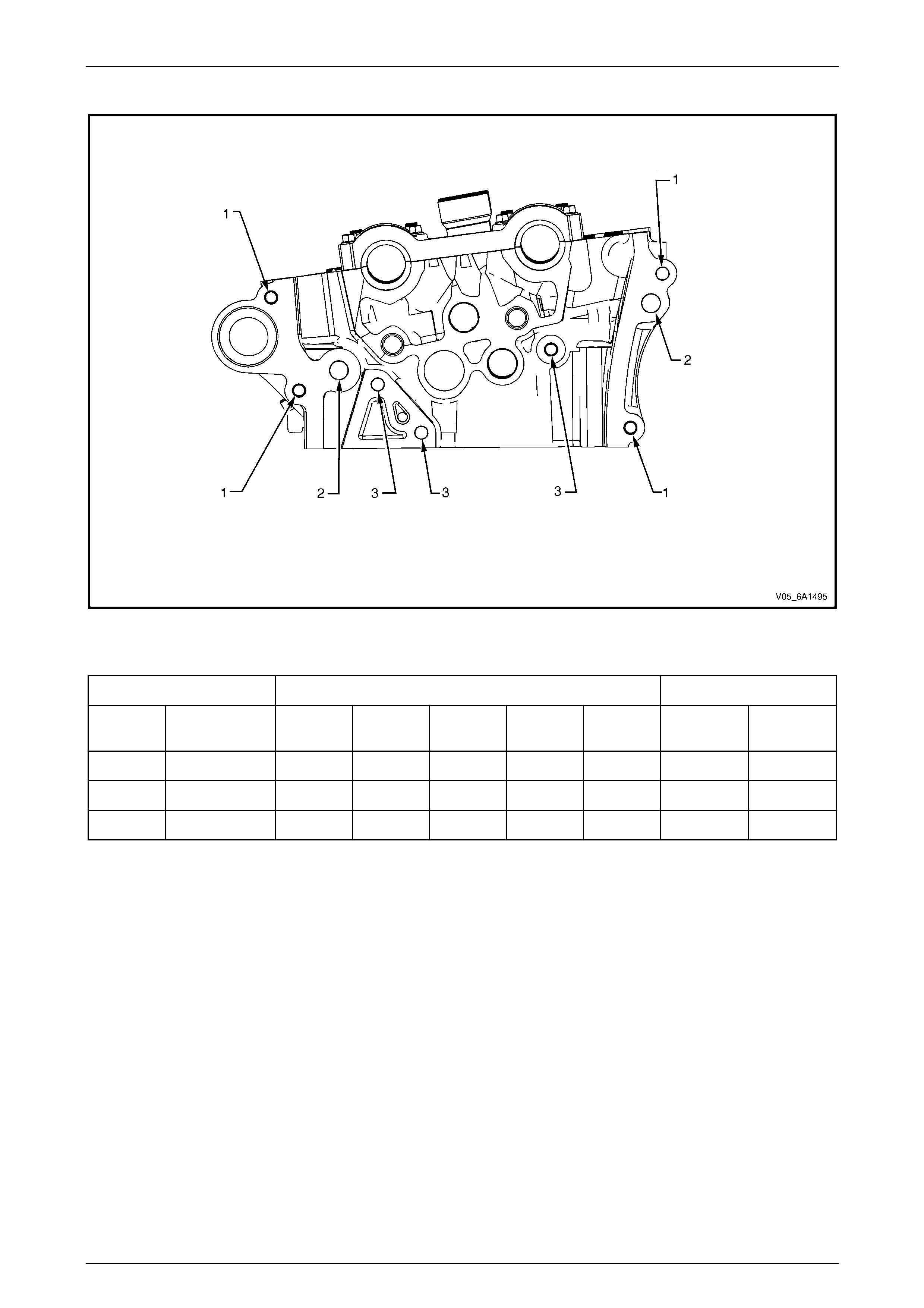
Engine Mechanical – V6 Page 6A1–285
Page 6A1–285
Left-hand Cylinder Head Front Face
Figure 6A1 – 507
Legend
Hole Tool Number J 42385 Max. Depth in mm
Number Thread Size Drill Counter-
bore Tap Driver Insert Drill Tap
1 M8 x 1.25 206 207 208 209 210 Thru Thru
2 M12 x 1.75 856 857 858 859 416 40.0 32.5
3 M8 x 1.25 206 207 208 209 210 22.5 18.0
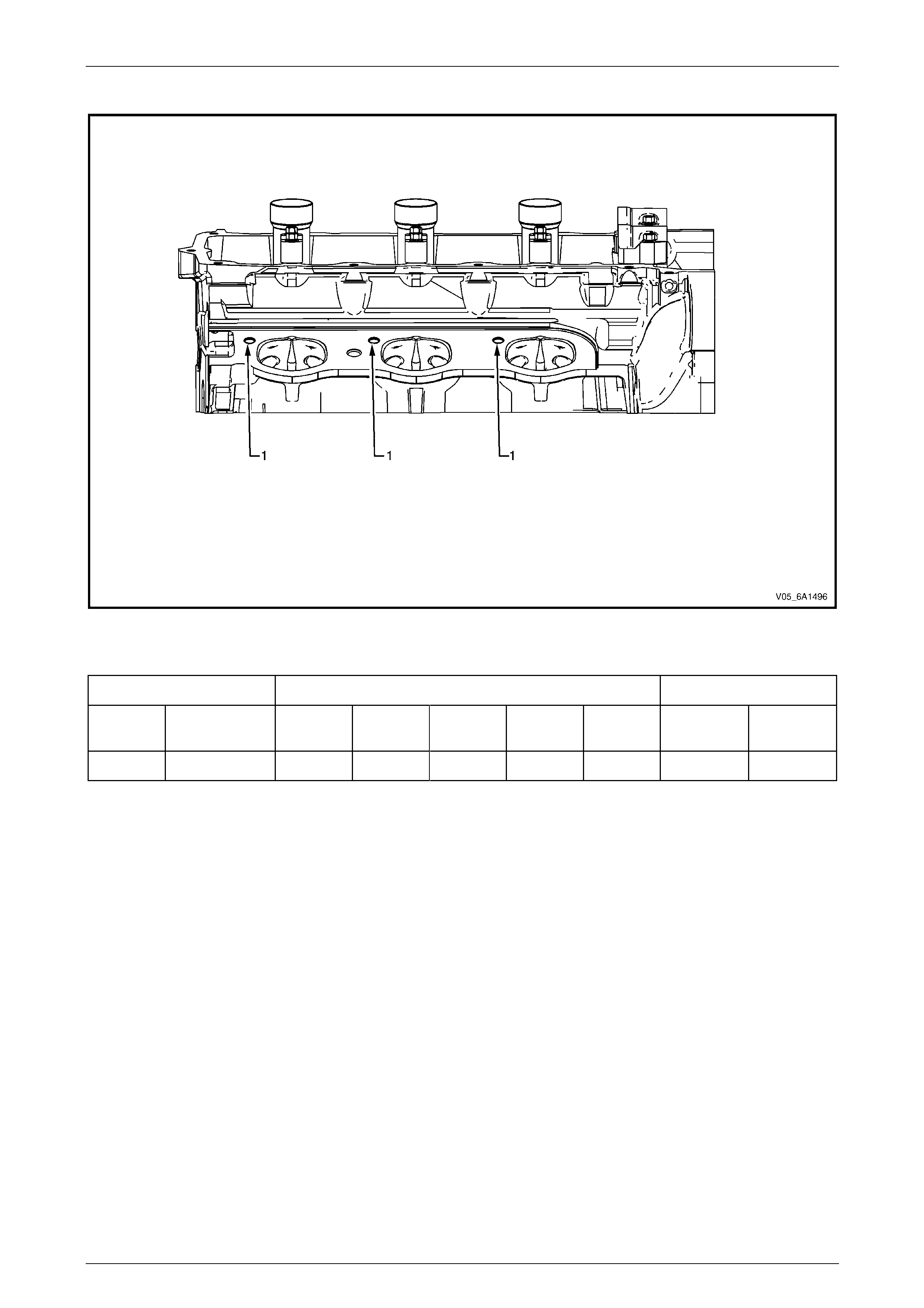
Engine Mechanical – V6 Page 6A1–286
Page 6A1–286
Left-hand Cylinder Head Intake Face
Figure 6A1 – 508
Legend
Hole Tool Number J 42385 Max. Depth in mm
Number Thread Size Drill Counter-
bore Tap Driver Insert Drill Tap
1 M8 x 1.25 206 207 208 209 210 28.5 23.0
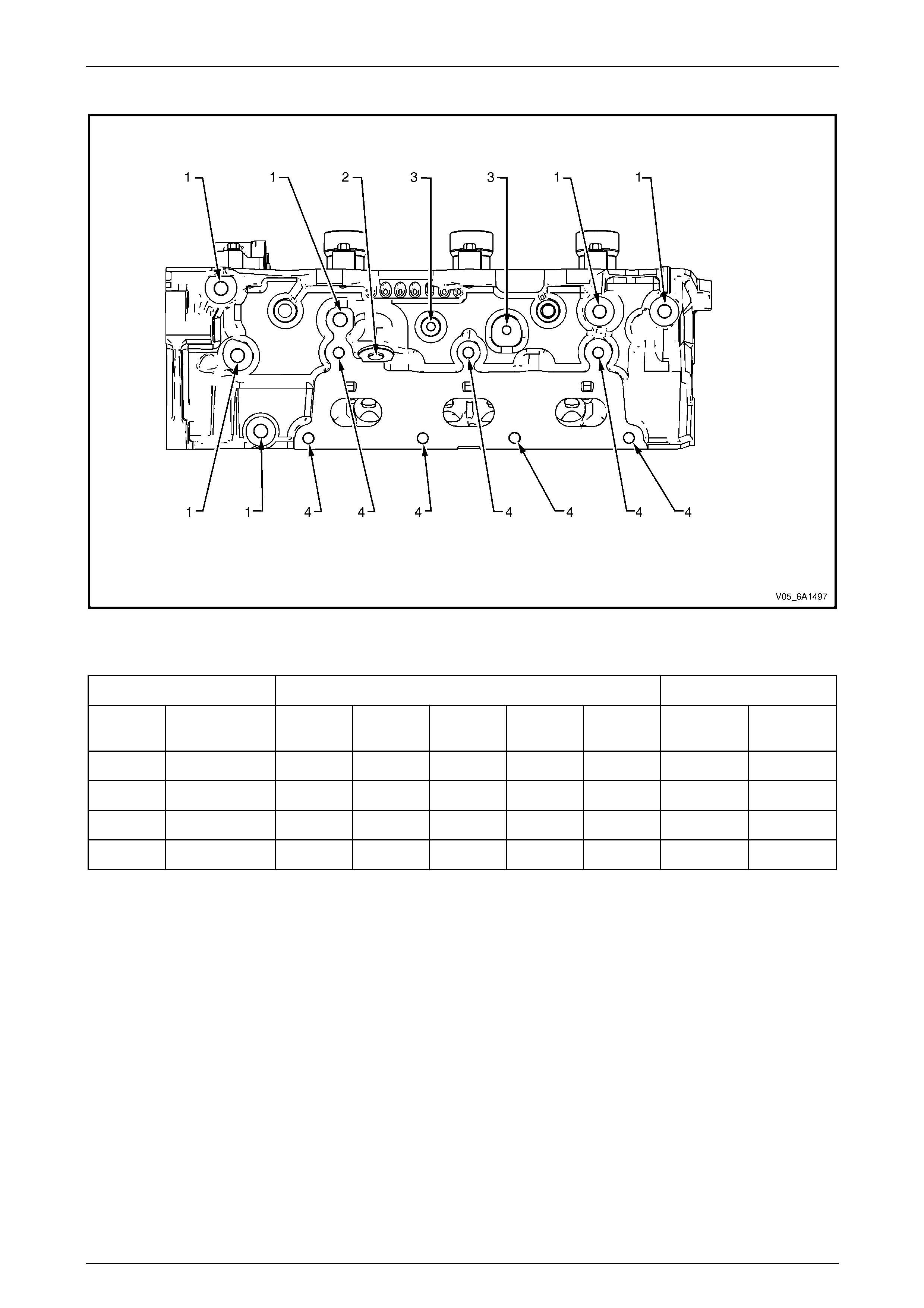
Engine Mechanical – V6 Page 6A1–287
Page 6A1–287
Left-hand Cylinder Head Exhaust Face
Figure 6A1 – 509
Legend
Hole Tool Number J 42385 Max. Depth in mm
Number Thread Size Drill Counter-
bore Tap Driver Insert Drill Tap
1 M10 x 1.5 211 212 213 214 215 33.5 27.0
2 M12 x 1.5 705 706 707 708 709 27.5 13.0
3 M6 x 1.0 201 202 203 204 205 22.5 18.0
4 M8 x 1.25 206 207 208 209 210 28.5 23.0
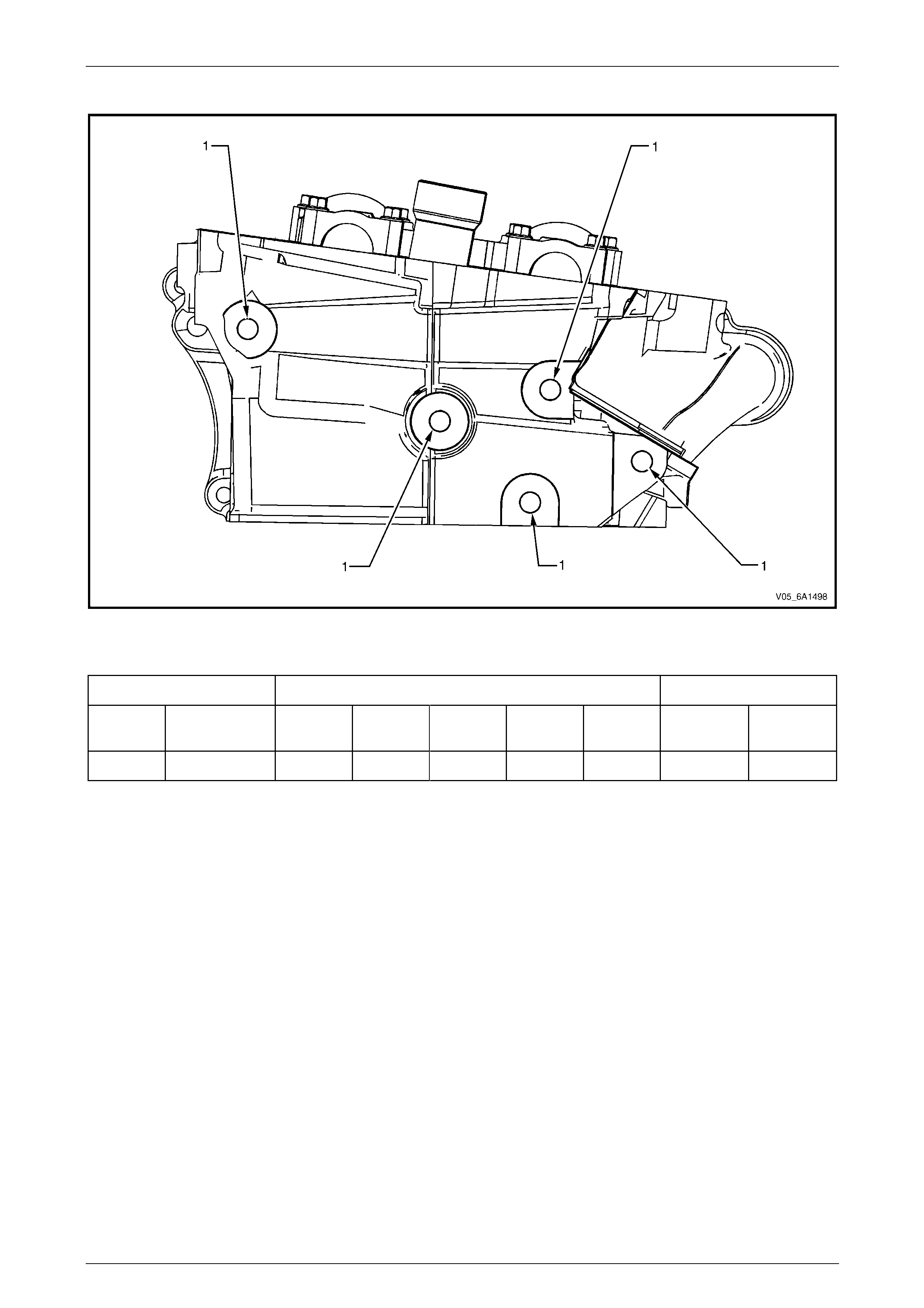
Engine Mechanical – V6 Page 6A1–288
Page 6A1–288
Left-hand Cylinder Head Rear Face
Figure 6A1 – 510
Legend
Hole Tool Number J 42385 Max. Depth in mm
Number Thread Size Drill Counter-
bore Tap Driver Insert Drill Tap
1 M10 x 1.5 211 212 213 214 215 33.5 27

Engine Mechanical – V6 Page 6A1–289
Page 6A1–289
Right-hand Cylinder Head Camshaft Cover Face
Figure 6A1 – 511
Legend
Hole Tool Number J 42385 Max. Depth in mm
Number Thread Size Drill Counter-
bore Tap Driver Insert Drill Tap
1 M6 x 1.0 201 202 203 204 205 Thru Thru
2 M6 x 1.0 701 n/a 203 204 205 28.5 24.0
3 M20 x 1.5 715 716 717 718 719 25.0 17.0
4 M6 x 1.0 201 202 203 204 205 22.5 18.0
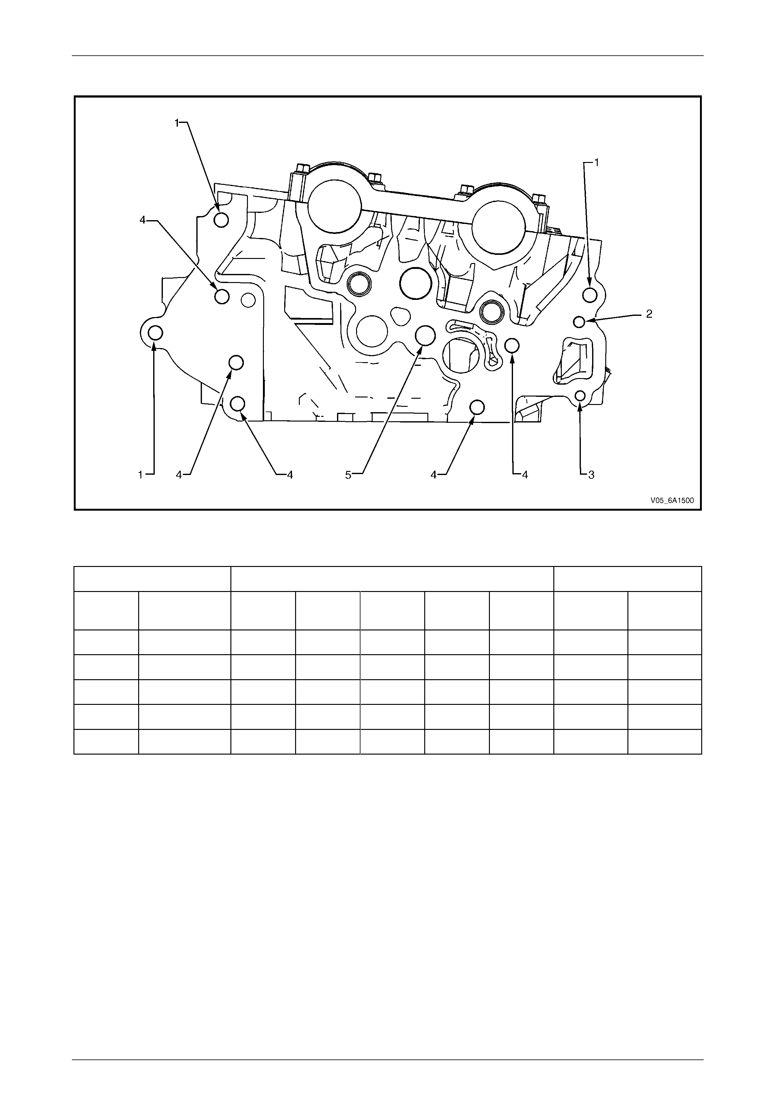
Engine Mechanical – V6 Page 6A1–290
Page 6A1–290
Right-hand Cylinder Head Front Face
Figure 6A1 – 512
Legend
Hole Tool Number J 42385 Max. Depth in mm
Number Thread Size Drill Counter-
bore Tap Driver Insert Drill Tap
1 M8 x 1.25 206 207 208 209 210 Thru Thru
2 M6 x 1.0 201 202 203 204 205 22.5 18.0
3 M6 x 1.0 201 202 203 204 205 Thru Thru
4 M8 x 1.25 206 207 208 209 210 28.5 23.0
5 M12 x 1.75 856 857 858 859 416 40.0 32.5
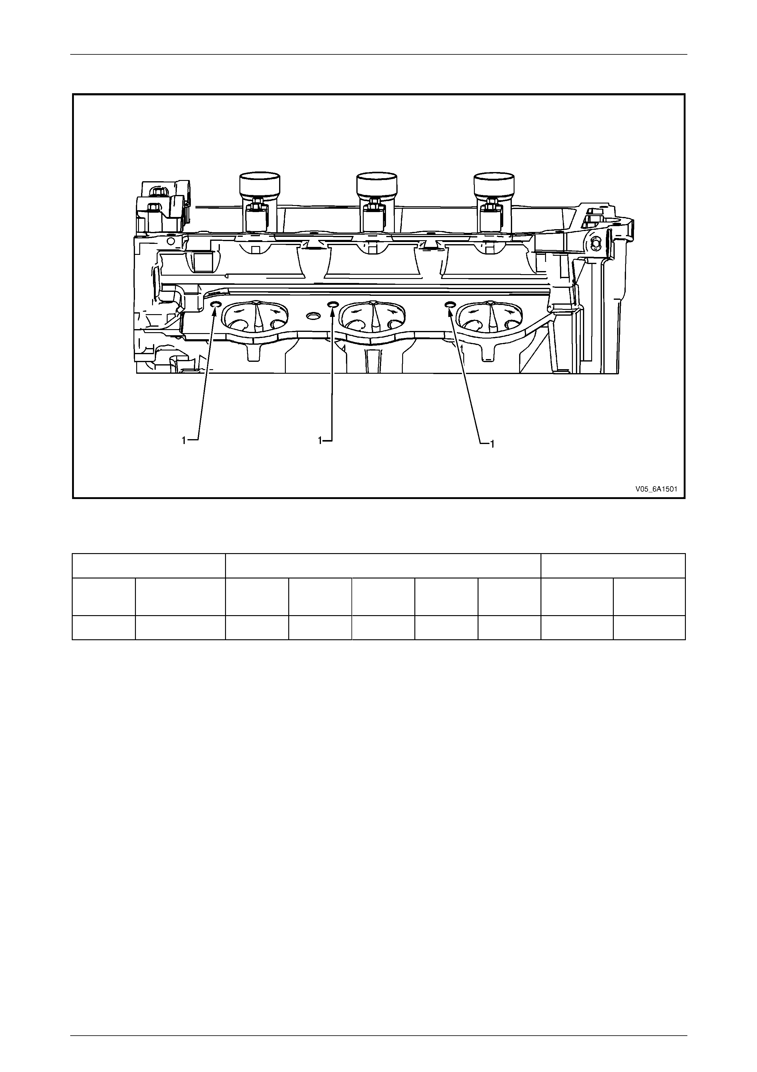
Engine Mechanical – V6 Page 6A1–291
Page 6A1–291
Right-hand Cylinder Head Intake Face
Figure 6A1 – 513
Legend
Hole Tool Number J 42385 Max. Depth in mm
Number Thread Size Drill Counter-
bore Tap Driver Insert Drill Tap
1 M8 x 1.25 206 207 208 209 210 28.5 23.0
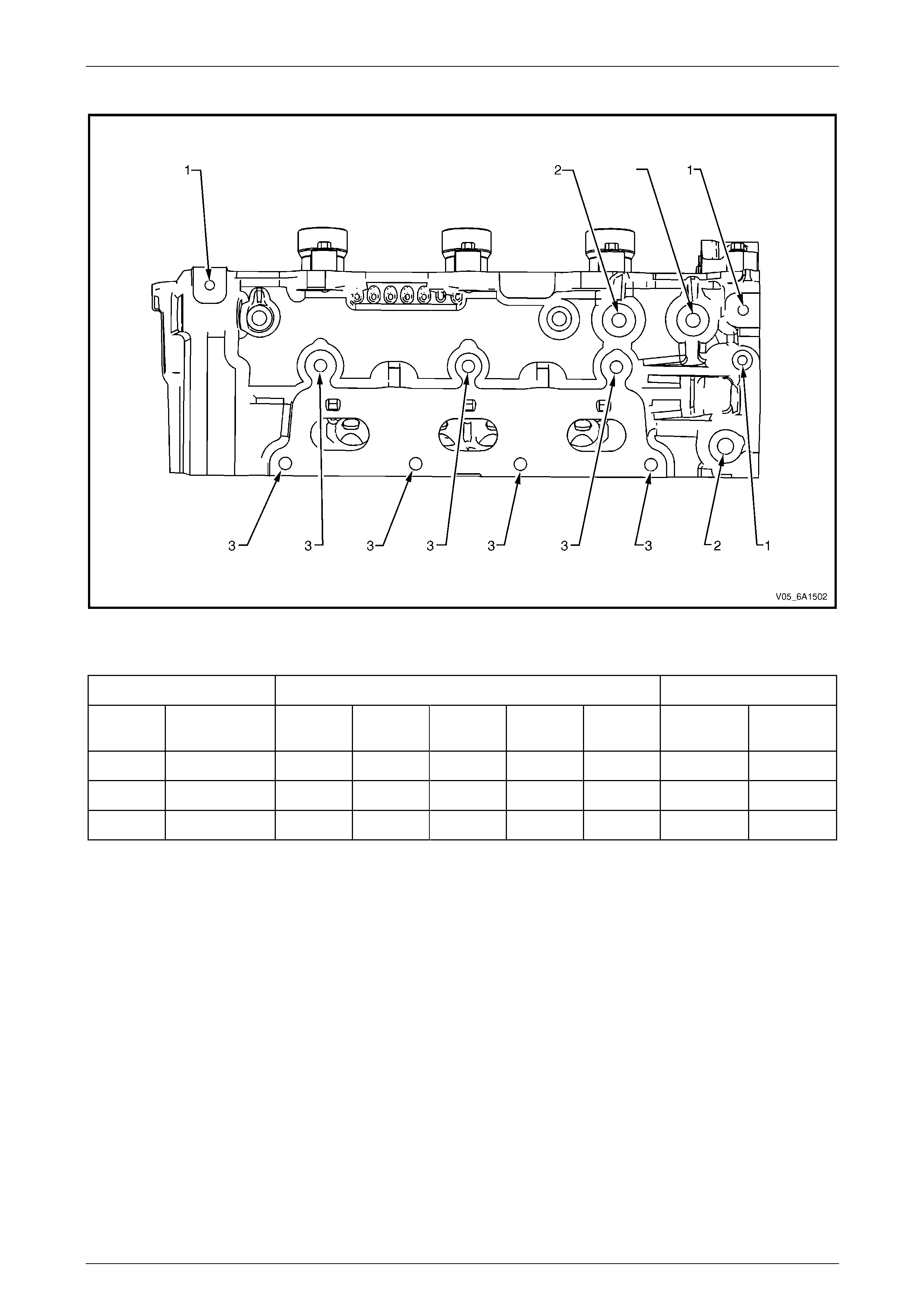
Engine Mechanical – V6 Page 6A1–292
Page 6A1–292
Right-hand Cylinder Head Exhaust Face
Figure 6A1 – 514
Legend
Hole Tool Number J 42385 Max. Depth in mm
Number Thread Size Drill Counter-
bore Tap Driver Insert Drill Tap
1 M6 x 1.0 201 202 203 204 205 22.5 18.0
2 M10 x 1.5 211 212 213 214 215 33.5 27.0
3 M8 x 1.25 206 207 208 209 210 28.5 23.0
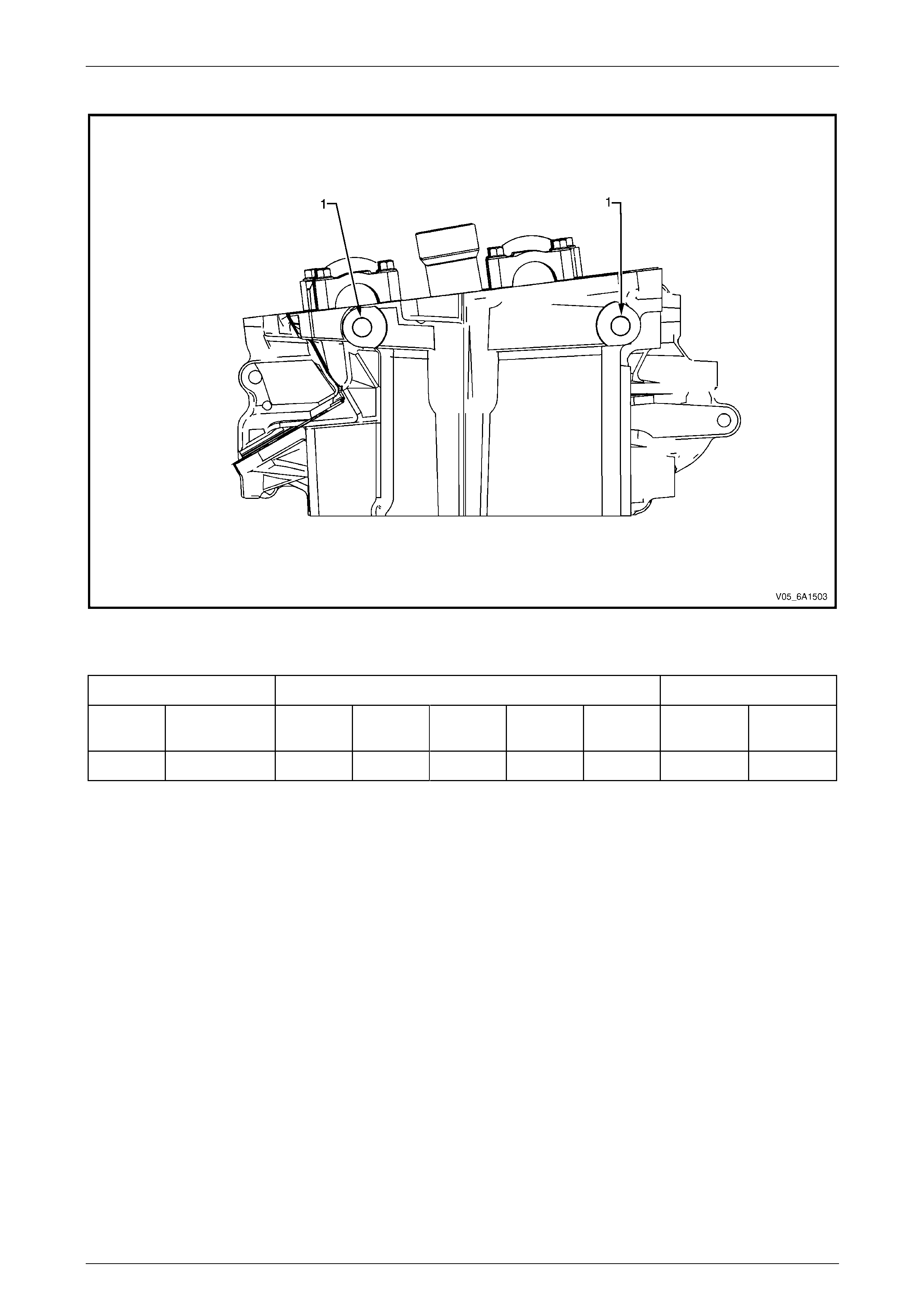
Engine Mechanical – V6 Page 6A1–293
Page 6A1–293
Right-hand Cylinder Head Rear Face
Figure 6A1 – 515
Legend
Hole Tool Number J 42385 Max. Depth in mm
Number Thread Size Drill Counter-
bore Tap Driver Insert Drill Tap
1 M10 x 1.5 211 212 213 214 215 33.5 27
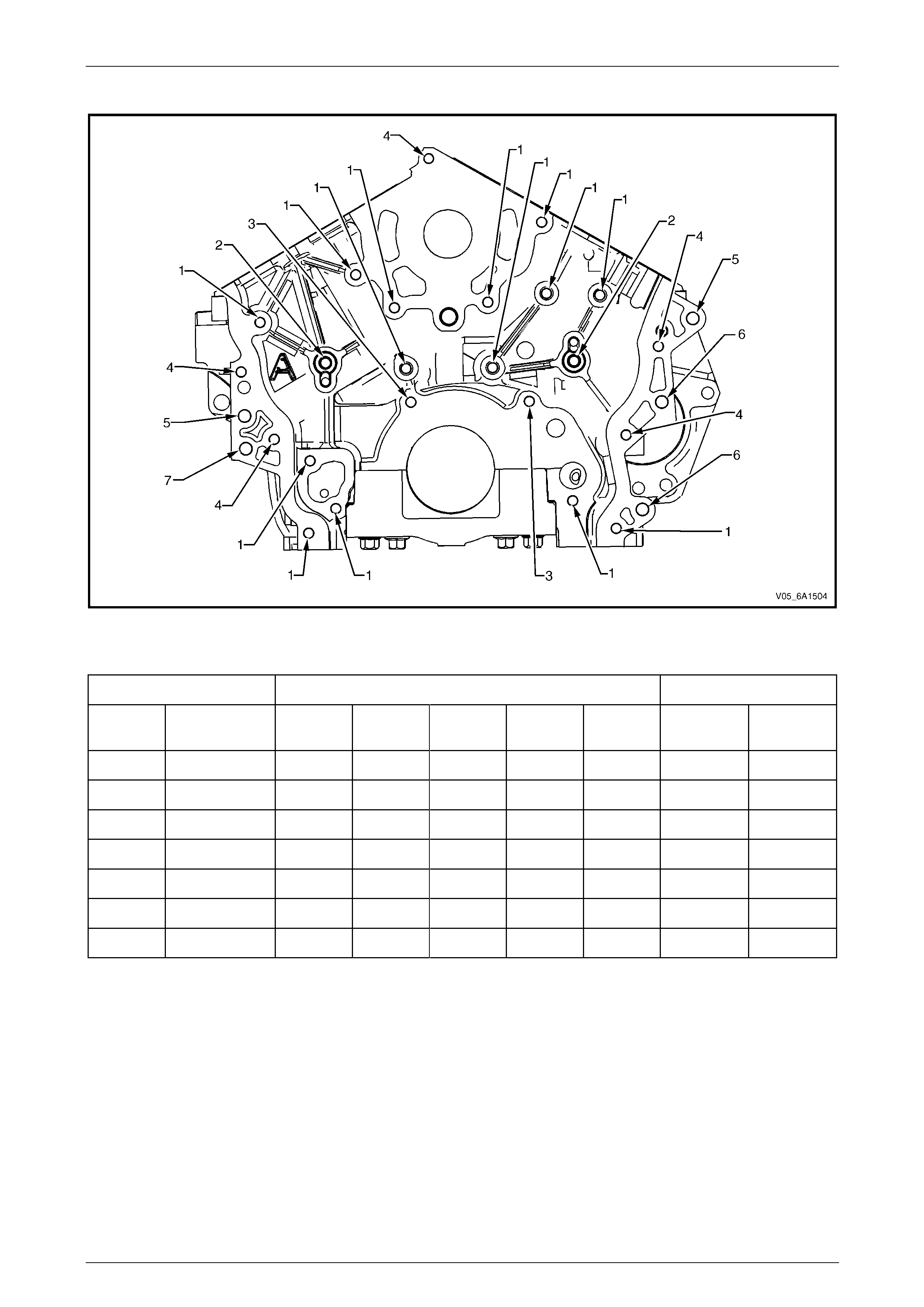
Engine Mechanical – V6 Page 6A1–294
Page 6A1–294
Engine Block Front
Figure 6A1 – 516
Legend
Hole Tool Number J 42385 Max. Depth in mm
Number Thread Size Drill Counter-
bore Tap Driver Insert Drill Tap
1 M8 x 1.25 206 207 208 209 210 28.5 23.0
2 M10 x 1.5 211 212 213 214 215 33.5 27.0
3 M8 x 1.25 207 207 208 209 210 Thru 23.0
4 M8 x 1.25 207 207 208 209 210 Thru Thru
5 M10 x 1.5 212 212 213 214 215 28.0 28.0
6 M10 x 1.5 212 212 213 214 215 Thru 20.0
7 M10 x 1.5 212 212 213 214 215 Thru 28.8
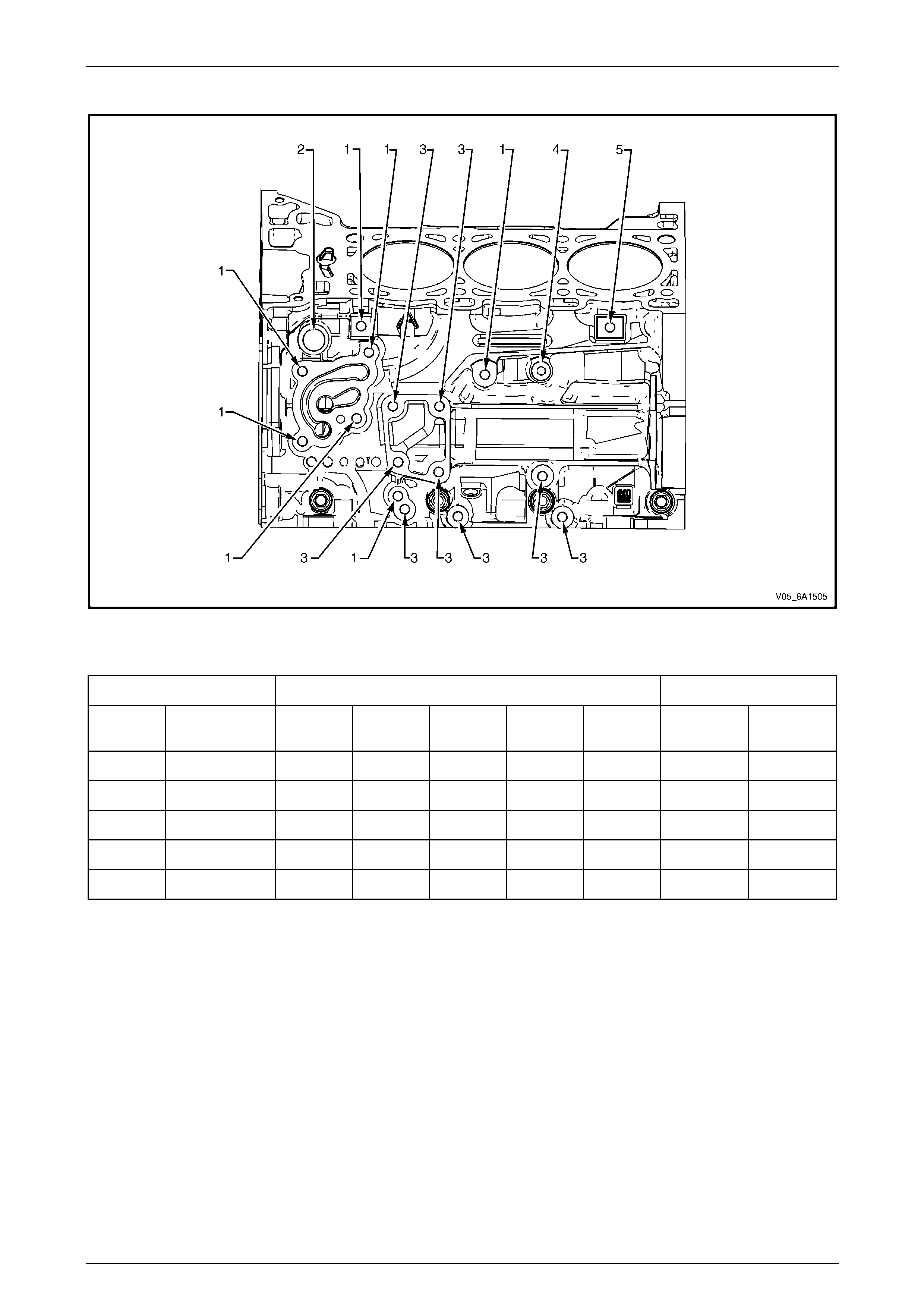
Engine Mechanical – V6 Page 6A1–295
Page 6A1–295
Engine Block Left-hand Side
Figure 6A1 – 517
Legend
Hole Tool Number J 42385 Max. Depth in mm
Number Thread Size Drill Counter-
bore Tap Driver Insert Drill Tap
1 M8 x 1.25 206 207 208 209 210 28.5 23.0
2 M20 x 1.5 715 716 717 718 719 30.0 20.0
3 M10 x 1.5 211 212 213 215 205 33.5 27.0
4 M14 x 1.5 409 410 411 735 719 Thru 15.0
5 M8 x 1.25 206 207 208 415 415 16.5 11.0
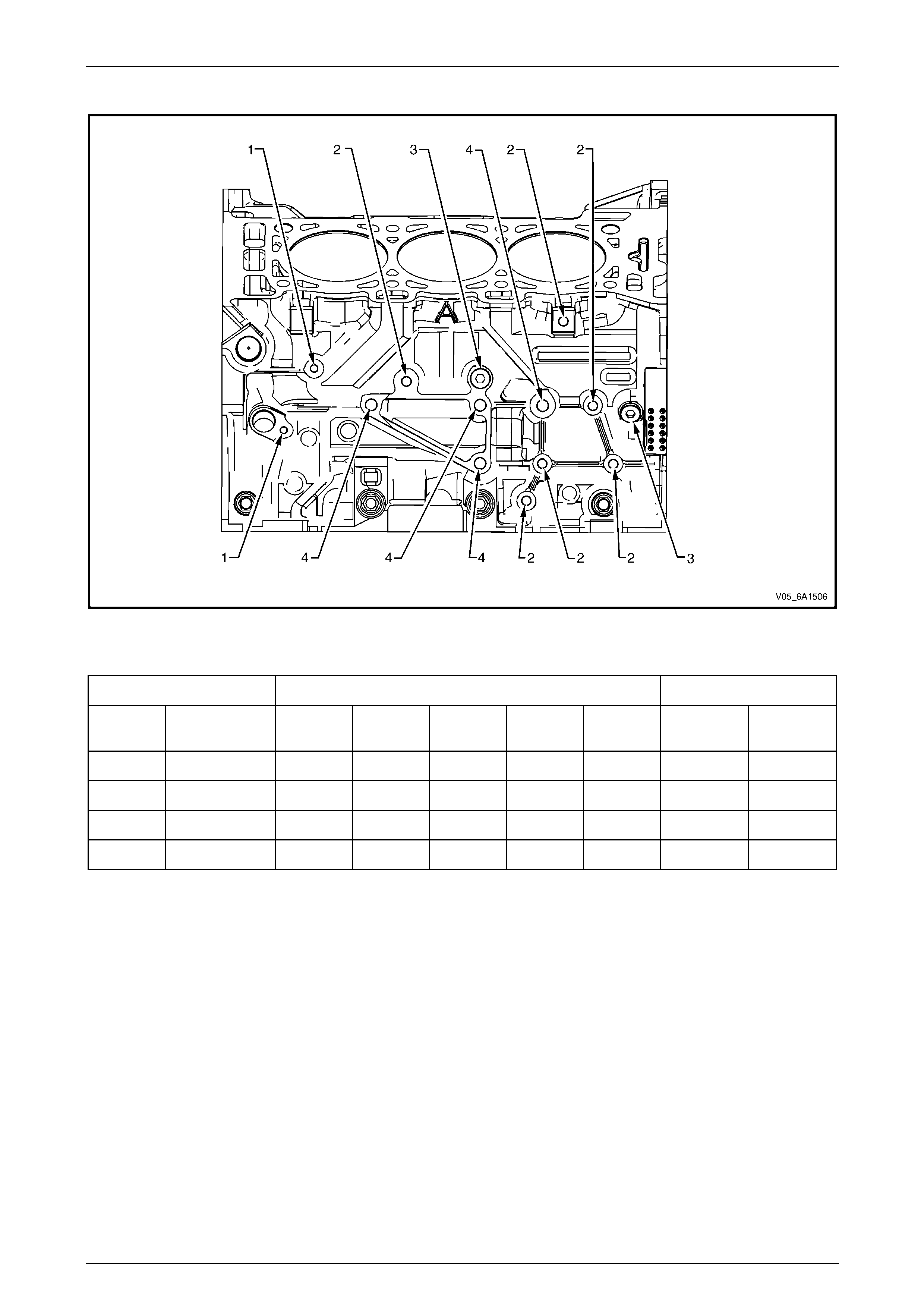
Engine Mechanical – V6 Page 6A1–296
Page 6A1–296
Engine Block Right-hand Side
Figure 6A1 – 518
Legend
Hole Tool Number J 42385 Max. Depth in mm
Number Thread Size Drill Counter-
bore Tap Driver Insert Drill Tap
1 M6 x 1.0 201 202 203 204 205 22.5 18.0
2 M8 x 1.25 206 207 208 209 210 28.5 23.0
3 M14 x 1.5 409 410 411 412 735 Thru 15.0
4 M10 x 1.5 211 212 213 214 215 33.5 27.0
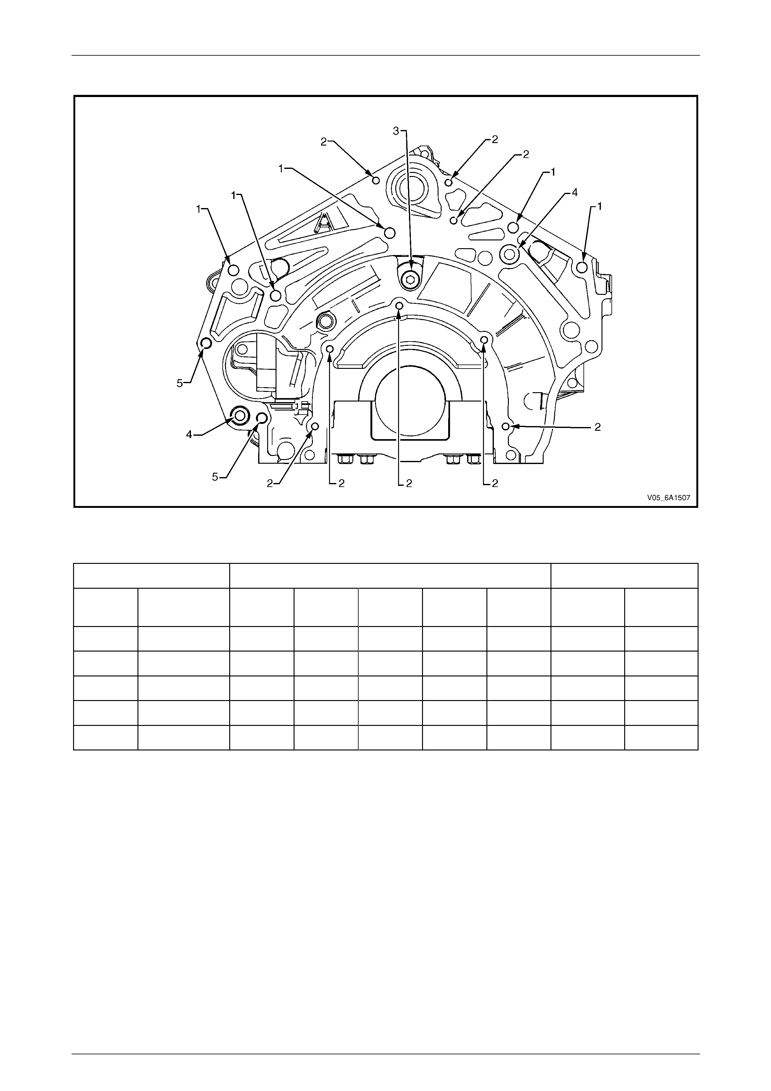
Engine Mechanical – V6 Page 6A1–297
Page 6A1–297
Engine Block Rear
Figure 6A1 – 519
Legend
Hole Tool Number J 42385 Max. Depth in mm
Number Thread Size Drill Counter-
bore Tap Driver Insert Drill Tap
1 M10 x 1.5 211 212 213 214 420 33.5 27.0
2 M6 x 1.0 201 202 203 204 205 22.5 18.0
3 M14 x 1.5 409 410 411 412 735 Thru 15.0
4 M10 x 1.5 211 212 213 214 216 39.5 33.0
5 M10 x 1.5 211 212 213 214 420 Thru Thru
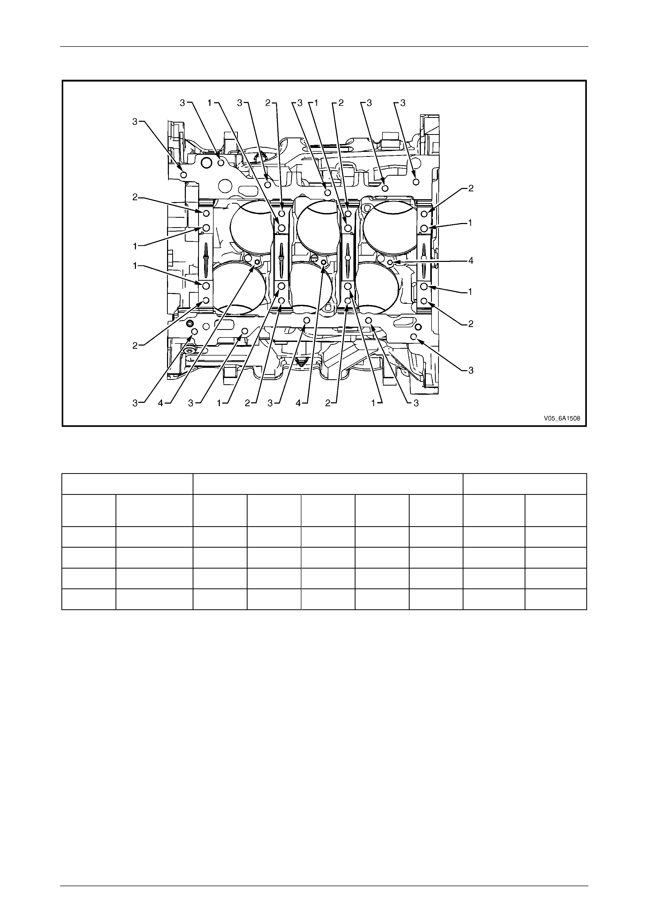
Engine Mechanical – V6 Page 6A1–298
Page 6A1–298
Engine Block Bottom
Figure 6A1 – 520
Legend
Hole Tool Number J 42385 Max. Depth in mm
Number Thread Size Drill Counter-
bore Tap Driver Insert Drill Tap
1 M10 x 2.0 720 n/a 721 722 104 56.0 49.0
2 M8 x 1.25 702 n/a 703 704 620 46.0 40.5
3 M8 x 1.25 206 207 208 209 210 28.5 23.0
4 M6 x 1.0 201 202 203 204 205 Thru Thru
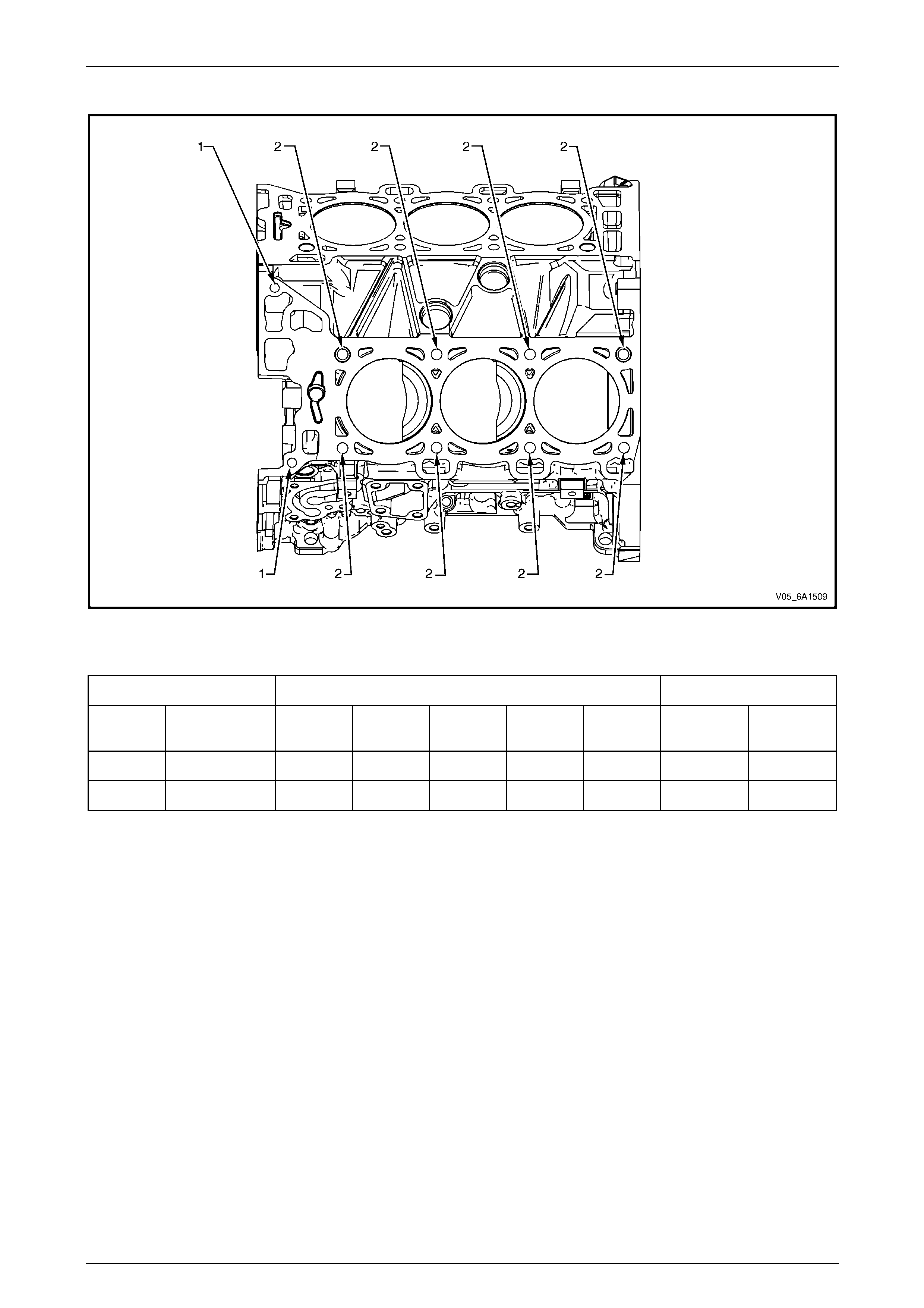
Engine Mechanical – V6 Page 6A1–299
Page 6A1–299
Engine Block Left-hand Deck Face
Figure 6A1 – 521
Legend
Hole Tool Number J 42385 Max. Depth in mm
Number Thread Size Drill Counter-
bore Tap Driver Insert Drill Tap
1 M8 x 1.25 206 207 208 209 210 28.5 23.0
2 M11 x 2.0 723 n/a 724 725 108 102.5 94.0
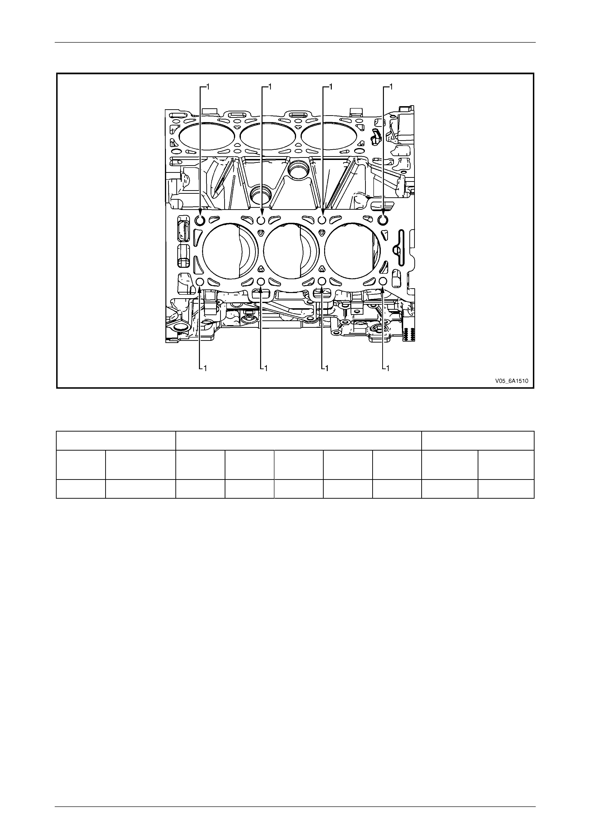
Engine Mechanical – V6 Page 6A1–300
Page 6A1–300
Engine Block Right-hand Deck Face
Figure 6A1 – 522
Legend
Hole Tool Number J 42385 Max. Depth in mm
Number Thread Size Drill Counter-
bore Tap Driver Insert Drill Tap
1 M11 x 2.0 723 n/a 724 725 108 102.5 94.0
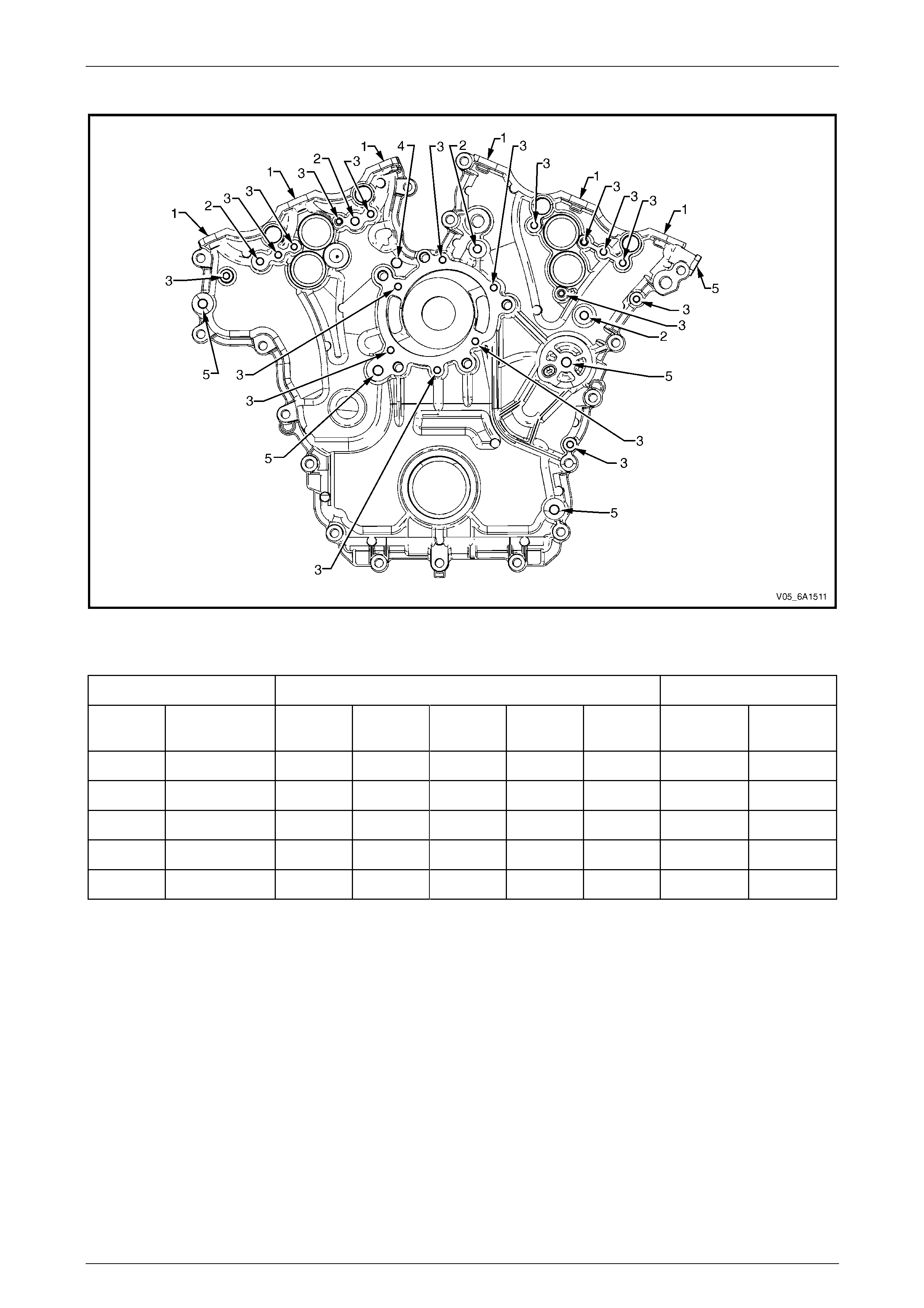
Engine Mechanical – V6 Page 6A1–301
Page 6A1–301
Engine Front Cover
Figure 6A1 – 523
Legend
Hole Tool Number J 42385 Max. Depth in mm
Number Thread Size Drill Counter-
bore Tap Driver Insert Drill Tap
1 M6 x 1.0 201 202 203 204 205 Thru Thru
2 M8 x 1.25 206 207 208 209 210 28.5 23.0
3 M6 x 1.0 201 202 203 204 205 21.5 18.0
4 M10 x 1.5 211 212 213 214 215 Thru Thru
5 M10 x 1.5 211 212 213 214 420 32.5 27.0
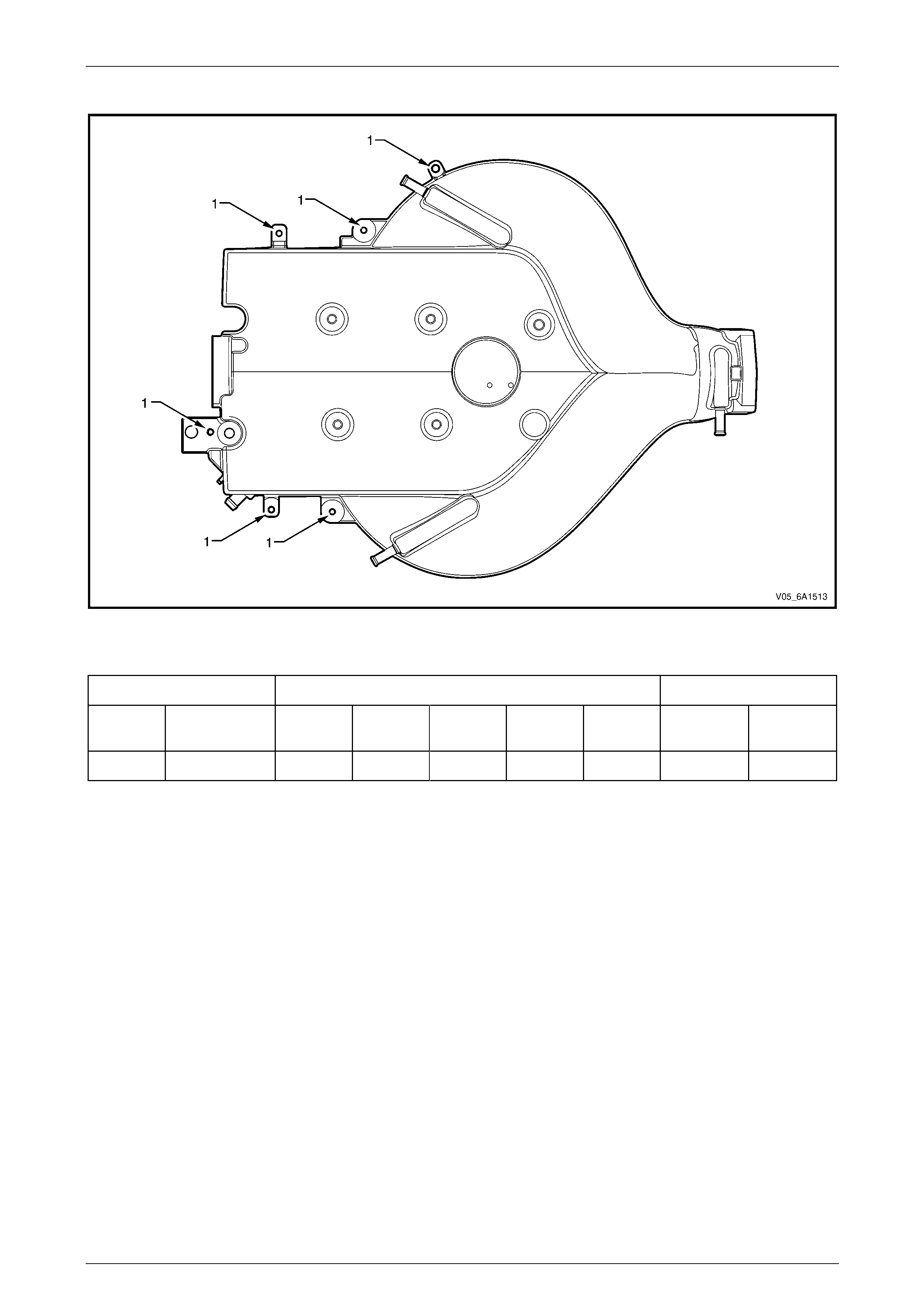
Engine Mechanical – V6 Page 6A1–302
Page 6A1–302
Upper Intake Manifold Top
Figure 6A1 – 524
Legend
Hole Tool Number J 42385 Max. Depth in mm
Number Thread Size Drill Counter-
bore Tap Driver Insert Drill Tap
1 M6 x 1.0 201 202 203 204 205 Thru Thru
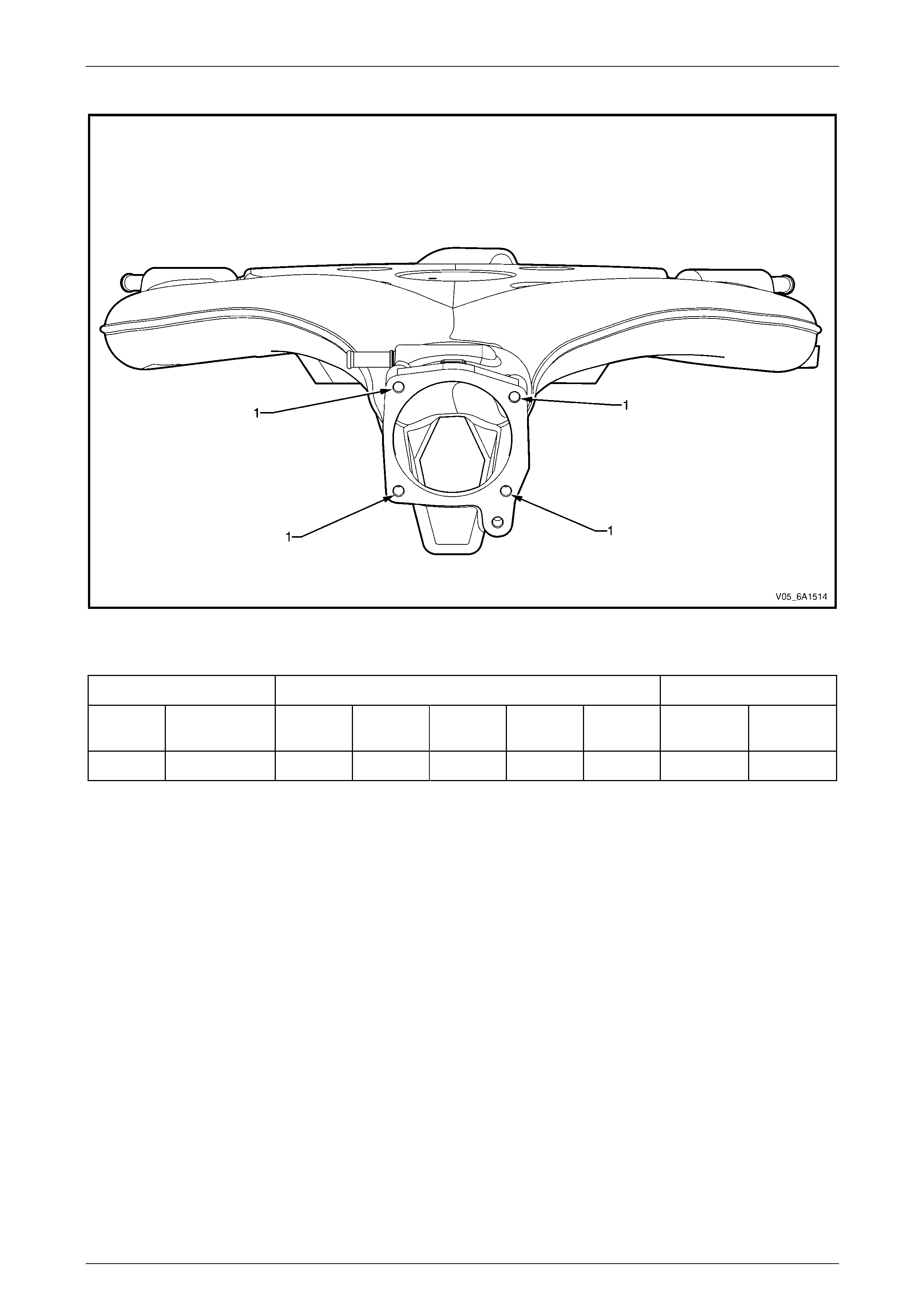
Engine Mechanical – V6 Page 6A1–303
Page 6A1–303
Upper Intake Manifold Front
Figure 6A1 – 525
Legend
Hole Tool Number J 42385 Max. Depth in mm
Number Thread Size Drill Counter-
bore Tap Driver Insert Drill Tap
1 M6 x 1.0 201 202 203 204 205 Thru Thru
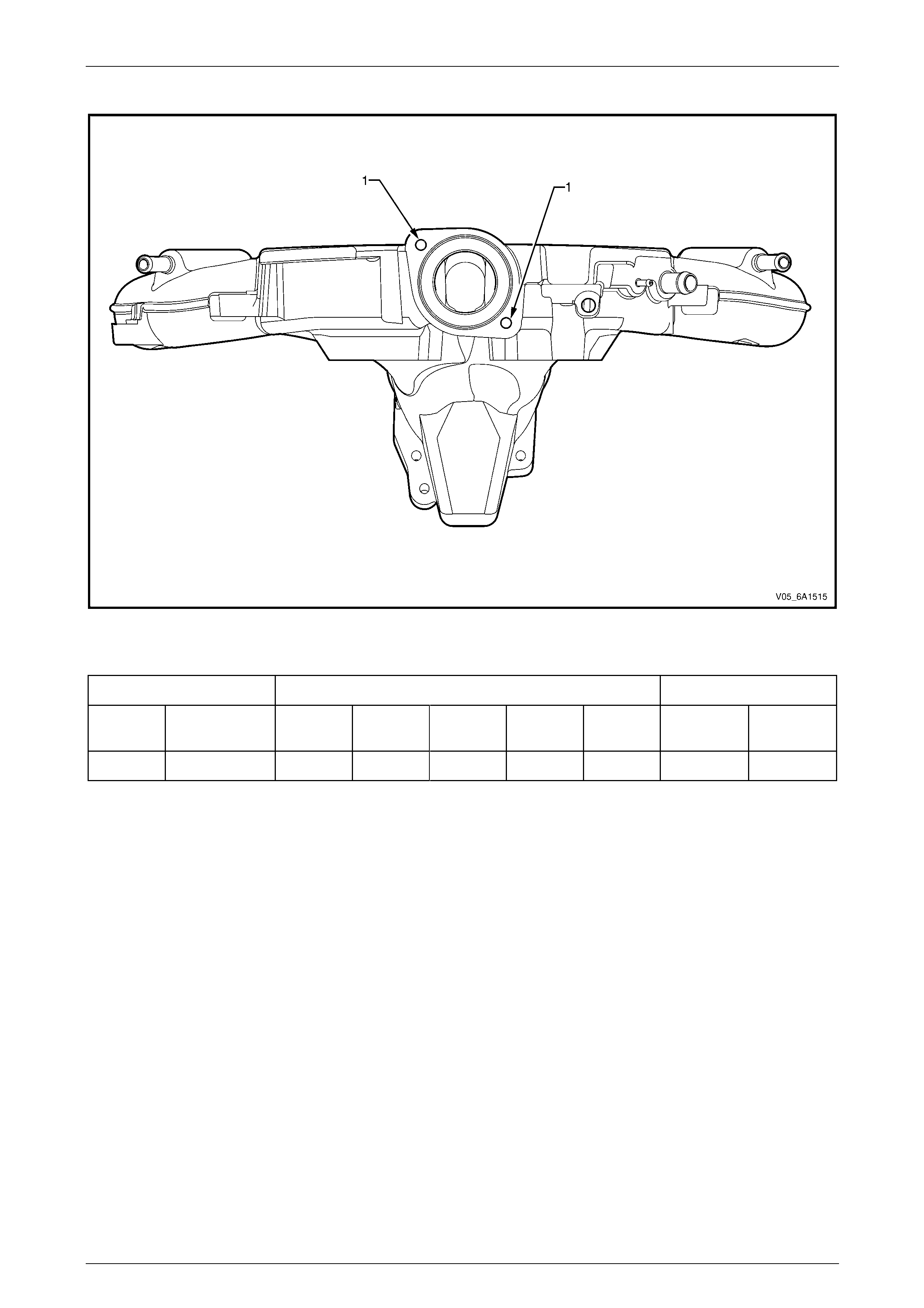
Engine Mechanical – V6 Page 6A1–304
Page 6A1–304
Upper Intake Manifold Rear
Figure 6A1 – 526
Legend
Hole Tool Number J 42385 Max. Depth in mm
Number Thread Size Drill Counter-
bore Tap Driver Insert Drill Tap
1 M6 x 1.0 201 202 203 204 205 Thru Thru
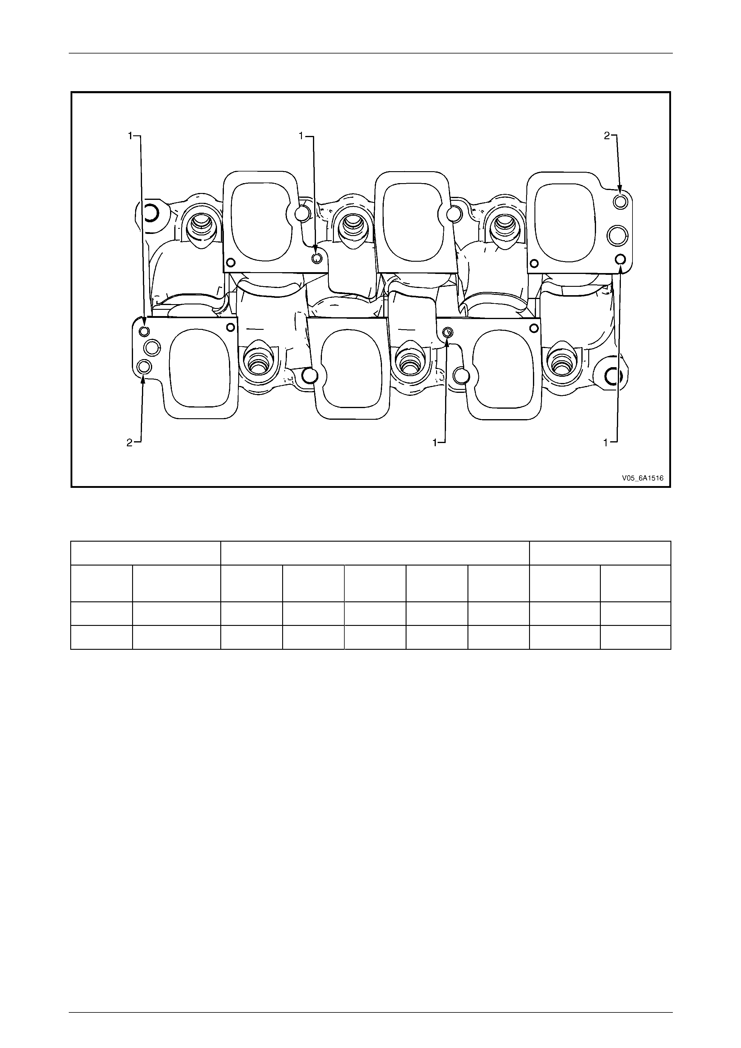
Engine Mechanical – V6 Page 6A1–305
Page 6A1–305
Lower Intake Manifold Top
Figure 6A1 – 527
Legend
Hole Tool Number J 42385 Max. Depth in mm
Number Thread Size Drill Counter-
bore Tap Driver Insert Drill Tap
1 M6 x 1.0 201 202 203 204 205 Thru Thru
2 M8 x 1.25 206 207 208 209 210 Thru Thru
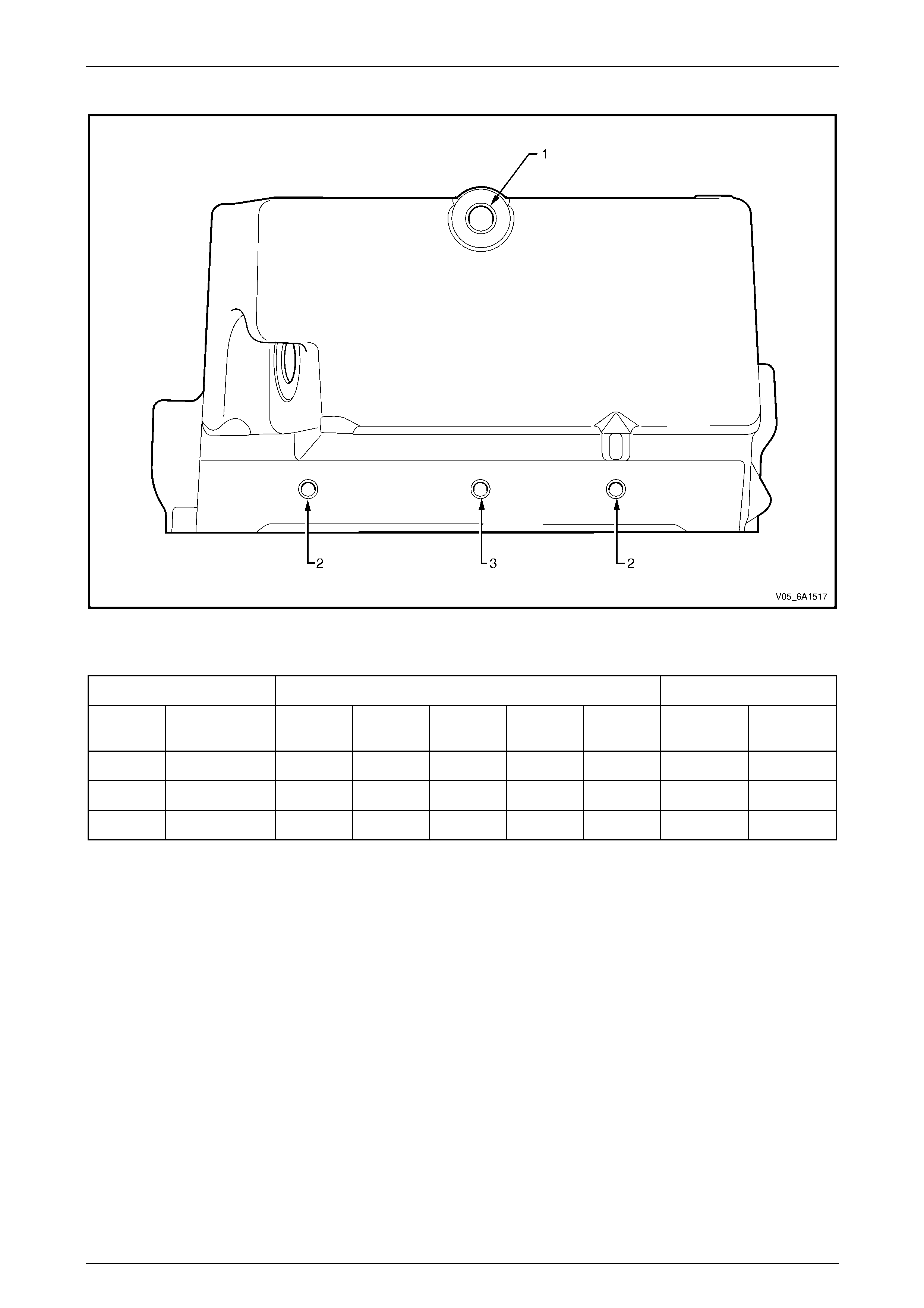
Engine Mechanical – V6 Page 6A1–306
Page 6A1–306
Oil Pan Front
Figure 6A1 – 528
Legend
Hole Tool Number J 42385 Max. Depth in mm
Number Thread Size Drill Counter-
bore Tap Driver Insert Drill Tap
1 M10 x 1.5 211 212 213 214 420 33.5 27.0
2 M8 x 1.25 206 207 208 209 210 28.5 23.0
3 M8 x 1.25 610 n/a 208 209 620 37.5 32.0
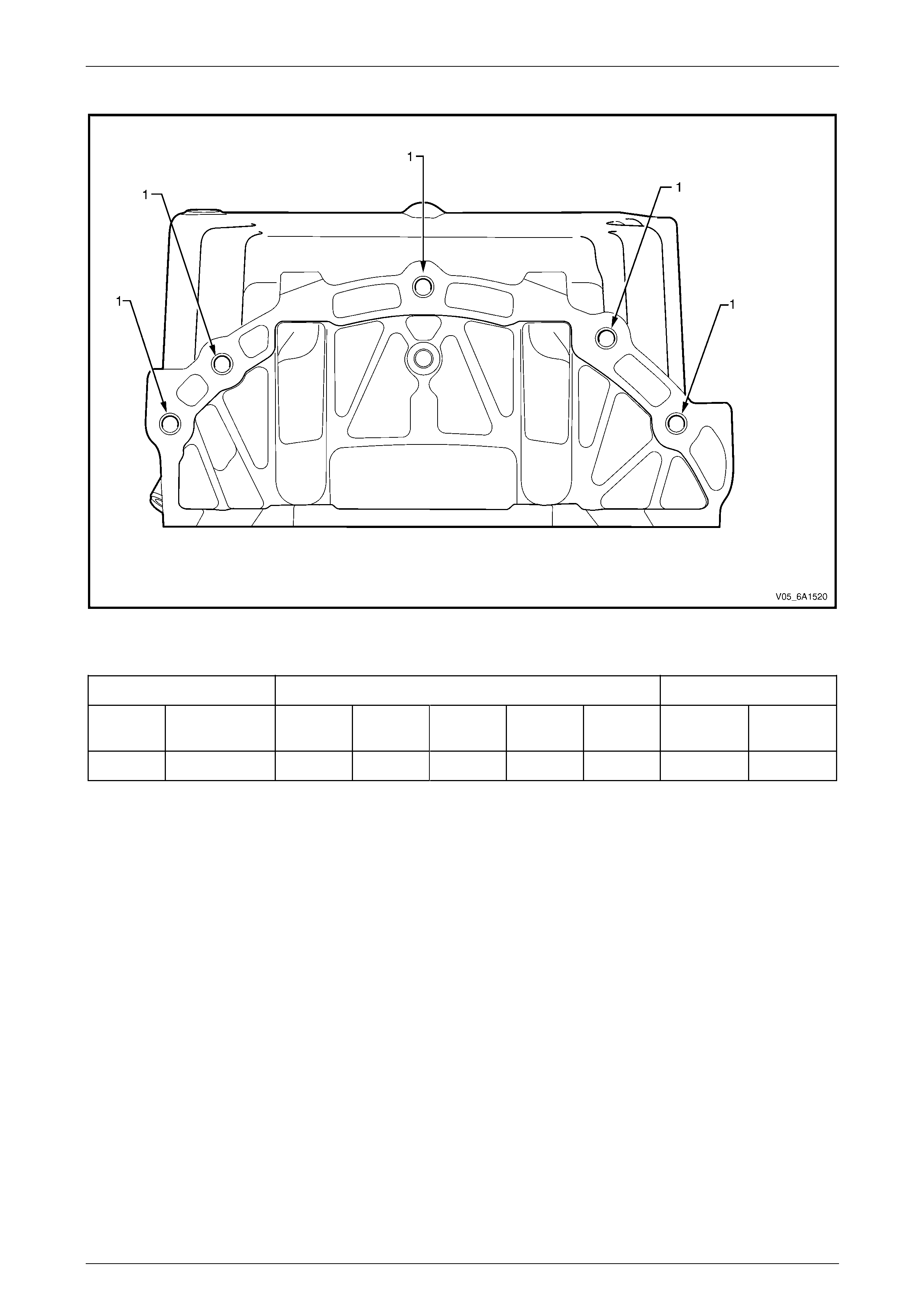
Engine Mechanical – V6 Page 6A1–307
Page 6A1–307
Oil Pan Rear
Figure 6A1 – 529
Legend
Hole Tool Number J 42385 Max. Depth in mm
Number Thread Size Drill Counter-
bore Tap Driver Insert Drill Tap
1 M10 x 1.5 211 212 213 214 215 Thru Thru
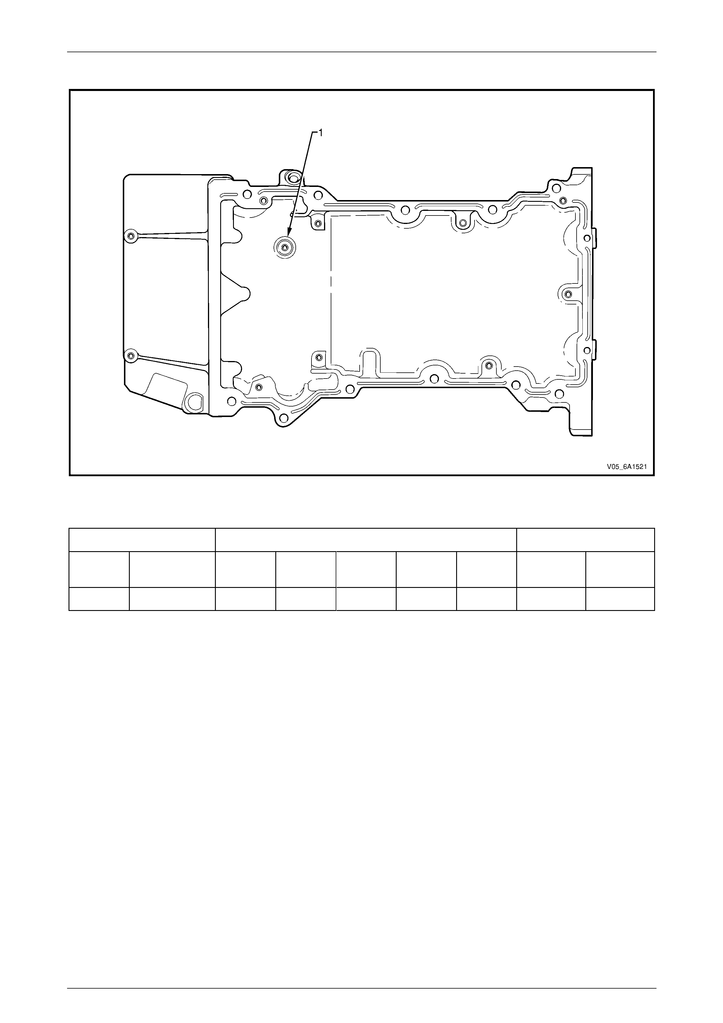
Engine Mechanical – V6 Page 6A1–308
Page 6A1–308
Oil Pan Bottom
Figure 6A1 – 530
Legend
Hole Tool Number J 42385 Max. Depth in mm
Number Thread Size Drill Counter-
bore Tap Driver Insert Drill Tap
1 M6 x 1.0 701 n/a 203 204 205 22.5 18.0

Engine Mechanical – V6 Page 6A1–309
Page 6A1–309
5 Specifications
General Engine Type ........................................................................................................................ V6
Bank Angle......................................................................................................................... 60°
Displacement.............................................................................................3.6 litre (3,565 cm3)
Bore...............................................................................................................................94 mm
Stroke.........................................................................................................................85.6 mm
Compression Ratio.........................................................................................................10.2:1
Cranking Speed at 40°C.............................................................................................80 r.p.m.
Spark Plug Gap ............................................................................................................1.1 mm
Firing Order ............................................................................................................1-2-3-4-5-6
Cylinder Block
Cylinder Bore Diameter ...........................................................................93.992 – 94.008 mm
Cylinder Out-of-Round – Production Maximum........................................................0.013 mm
Crankshaft Main bearing bore Diameter..................................................72.867 – 72.881 mm
Cylinder Head Deck Surface Flatness........................................................................0.05 mm
Crankshaft
Connecting Rod Journal Diameter...........................................................55.992 – 56.008 mm
Connecting Rod Journal Out-of-Round.....................................................................0.005 mm
Connecting Rod Journal Taper.................................................................................0.005 mm
Connecting Rod Journal Width (Production)...........................................................22.000 mm
Connecting Rod Journal Width (Service limit) .........................................21.920 – 22.080 mm
Crankshaft End Play....................................................................................0.100 – 0.330 mm
Crankshaft Main Bearing Clearance............................................................0.010 – 0.060 mm
Crankshaft Main Journal Diameter ..........................................................67.992 – 68.008 mm
Crankshaft Main Journal Out-of-Round....................................................................0.005 mm
Crankshaft Main Journal Taper ................................................................................0.005 mm
Crankshaft Main Journal Width, #2, 4 (Production) .......................................................24 mm
Crankshaft Main Journal Width, #2, 4 (Service) ......................................23.900 – 24.100 mm
Crankshaft Main Journal Width, #3 (Production) ....................................................24.400 mm
Crankshaft Main Journal Width, #3 (Service) ..........................................24.360 – 24.440 mm
Crankshaft Main Journal Thrust Wall Runout ..............................................0.000 – 0.040 mm
Crankshaft Main Journal Thrust Wall Square ..............................................0.000 – 0.010 mm
Crankshaft Rear Flange Runout...............................................................................0.025 mm
Crankshaft Reluctor Ring Runout - Maximum ..........................................................1.500 mm
Crankshaft Thrust Bearing Clearance..........................................................0.076 – 0.305 mm
Crankshaft Thrust Surface Runout ...........................................................................0.040 mm
Crankshaft Thrust Surface – Height Diameter........................................................95.000 mm
Connecting Rod
Connecting Rod Length - Bore Centre-to-Centre .................................................150.400 mm
Connecting Rod Bore Diameter - Bearing End........................................59.620 – 59.636 mm
Connecting Rod Bore Diameter - Pin End...............................................24.007 – 24.021 mm
Connecting Rod Width ........................................................................................... 21.775 mm
Connecting Rod Side Clearance..................................................................0.095 – 0.355 mm
Connecting Rod Bearing Clearance ............................................................0.010 – 0.070 mm

Engine Mechanical – V6 Page 6A1–310
Page 6A1–310
Piston Piston Diameter.......................................................................................93.956 – 93.974 mm
Piston Pin Bore Diameter ........................................................................24.005 – 24.009 mm
Piston Ring Groove Width - First (Top) Compression Ring .........................1.220 – 1.240 mm
Piston Ring Groove Width - Second Compression Ring..............................1.510 – 1.530 mm
Piston Ring Groove Width - Oil Control Ring...............................................2.510 – 2.530 mm
Piston to Bore Clearance.............................................................................0.026 – 0.052 mm
Piston Pin
Piston Pin Diameter..................................................................................23.997 - 24.000 mm
Piston Pin Length.....................................................................................60.600 – 61.100 mm
Piston Pin Clearance to Connecting Rod Bore.............................................0.007 – 0.024mm
Piston Pin Clearance to Piston Pin Bore.......................................................0.004 – 0.012mm
Piston Rings
Piston Ring to Groove Clearance:
• First (Top) Compression Ring...............................................................0.030 – 0.065 mm
• Second Compression Ring...................................................................0.015 – 0.060 mm
• Oil Control Ring....................................................................................0.030 – 0.170 mm
Piston Ring End Gap:
• First (Top) Compression Ring...............................................................0.150 – 0.300 mm
• Second Compression Ring...................................................................0.280 – 0.480 mm
• Oil Control Ring....................................................................................0.150 – 0.600 mm
Cylinder Head
Combustion Chamber Volume.................................................................................. 53.600 cc
Valve Guide Bore Diameter – Intake ...........................................................6.000 – 6.020 mm
Valve Guide Bore Diameter – Exhaust........................................................6.000 – 6.020 mm
Valve Guide Installed Height ...................................................................14.050 – 14.550 mm
Stationary Hydraulic Lash Adjuster (SHLA) Bore Diameter.....................12.008 – 12.030 mm
Valve Seat Angle – Seating Surface................................................................................... 45°
Valve Seat Angle – Relief Surface...................................................................................... 30°
Valve Seat Angle – Undercut Surface ................................................................................ 60°
Valve Seat Runout – Maximum ................................................................................0.050 mm
Valve Seat Width – Exhaust Seating Surface..............................................1.400 – 1.800 mm
Valve Seat Width – Exhaust Relief Surface.................................................0.700 – 0.900 mm
Valve Seat Width – Intake Seating Surface.................................................1.000 – 1.400 mm
Valve Seat Width – Intake Relief Surface....................................................0.500 – 0.700 mm
Engine Block Deck Surface Flatness..........................................................................0.05 mm
Exhaust Manifold Deck Surface Flatness...................................................................0.25 mm
Intake Manifold Deck Surface Flatness ......................................................................0.05 mm

Engine Mechanical – V6 Page 6A1–311
Page 6A1–311
Valve System
Face Angle .................................................................................................................... 44.25°
Face Runout.............................................................................................................0.038 mm
Valve Face Width – Exhaust.....................................................................................2.750 mm
Valve Face Width – Intake........................................................................................2.180 mm
Valve Head Diameter – Exhaust..............................................................30.470 – 30.730 mm
Valve Head Diameter – Intake.................................................................36.830 – 37.090 mm
Valve Installed Height..................................................................................35.26 – 36.69 mm
Valve Length – Exhaust..........................................................................................97.110 mm
Valve Length – Intake...........................................................................................101.230 mm
Valve Stem Diameter (standard)..................................................................5.955 – 5.975 mm
Valve Stem Diameter (oversize)..................................................................6.013 – 6.033 mm
Valve Stem to Guide Clearance...................................................................0.025 – 0.065 mm
Hydraulic Lash Adjuster Diameter ...........................................................11.986 – 12.000 mm
Hydraulic Lash Adjuster to Bore Clearance.................................................0.037 – 0.041 mm
Rocker Arm/Camshaft Follower Ratio.............................................................................1.68:1
Rocker Arm/Camshaft Follower Roller Diameter.....................................17.740 – 17.800 mm
Valve Spring Free Length........................................................................42.500 – 45.500 mm
Valve Spring Installed Height – Closed...................................................................35.000 mm
Valve Spring Installed Height – Open.....................................................................24.000 mm
Valve Spring Load – Closed................................................................................. 247 – 273 N
Valve Spring Load – Open.................................................................................... 598 – 662 N
Valve Spring Diameter – Inside Top........................................................12.200 – 12.700 mm
Valve Spring Diameter – Outside Top .....................................................18.000 – 20.500 mm
Valve Spring Diameter – Inside Bottom...................................................17.950 – 18.450 mm
Valve Spring Diameter – Outside Bottom...............................................................26.000 mm
Valve Spring Coil Thickness........................................................................3.250 – 3.900 mm
Valve Spring Total Number of Coils.....................................................................................7.1
Camshaft Camshaft Bearing Inside Diameter – Front Number 1.............................35.000 – 35.020 mm
Camshaft Bearing Inside Diameter – Middle & Rear Number 2 - 4..........27.000 – 27.020 mm
Camshaft End Play......................................................................................0.045 – 0.215 mm
Camshaft Journal Diameter – Front Number 1........................................34.936 – 34.960 mm
Camshaft Journal Diameter – Middle & Rear Number 2 - 4.....................26.936 – 26.960 mm
Camshaft Journal Out-of-round ................................................................................0.006 mm
Camshaft Journal to Bore Clearance...........................................................0.040 – 0.084 mm
Camshaft Runout – Front & Rear Number 1 and 4...................................................0.025 mm
Camshaft Runout – Middle Number 2 and 3.............................................................0.050 mm
Camshaft Lobe Duration – Exhaust (@ 0.150 mm Lift) .................................................... 238°
Camshaft Lobe Duration – Intake (@ 0.150 mm Lift) ....................................................... 237°
Camshaft Lobe Height – Exhaust.................................................................................6.6 mm
Camshaft Lobe Height – Intake ....................................................................................6.5 mm
Camshaft Lobe Overlap (@ 0.150 mm Lift).....................................................-5° (no overlap)
Valve Opens – Exhaust .........................................................................................229° BTDC
Valve Opens – Intake ...............................................................................................14° ATDC
Centre-line – Exhaust.............................................................................................111° BTDC
Centre-line – Intake ................................................................................................132° ATDC
Valve Closes – Exhaust..............................................................................................9° ATDC
Valve Closes – Intake ............................................................................................252° ATDC
Valve Lift – Exhaust....................................................................................................10.8 mm
Valve Lift – Intake.......................................................................................................10.8 mm

Engine Mechanical – V6 Page 6A1–312
Page 6A1–312
Oil Pump Type..............................................................................................................................Gerotor
Gear Diameter – Outer............................................................................87.095 – 87.175 mm
Gear Bore Depth......................................................................................15.565 – 15.600 mm
Gear Bore Diameter.................................................................................87.275 – 87.325 mm
Gear Thickness........................................................................................15.511 – 15.536 mm
Gear to Cover Clearance.............................................................................0.030 – 0.085 mm
Gear to Housing Clearance .........................................................................0.100 – 0.230 mm
Inner Gear Tip Clearance ............................................................................0.075 – 0.180 mm
Crankshaft Clearance to Housing................................................................0.040 – 0.130 mm
Inner Gerotor Hub Diameter ....................................................................53.310 – 53.335 mm
Housing Hub Diameter ............................................................................53.380 – 53.420 mm
Inner Gerotor Hub Clearance to Housing ....................................................0.045 – 0.110 mm
Lubrication System
Oil Type.................................................................................................................. SAE 5W30
Oil Capacity – with Filter...................................................................................................6.5 L
Oil Pressure – Minimum at idle......................................................................................69 kPa
Oil Pressure – Minimum at 2000 r.p.m. .......................................................................138 kPa
Piston Cooling Jet Valve Opening Pressure......................................................170 – 230 kPa

Engine Mechanical – V6 Page 6A1–313
Page 6A1–313
6 Torque Wrench Specifications
ATTENTION
Fasteners must be repl aced after loosening.
Fasteners either have micro encapsulated sealant applied or incorporate a mechanical thread lock and
should only be re-used once. If in doubt, replacement is recommended.
Oil Pan Drain Plug................................................................................25.0 Nm
Oil Filter Adaptor Cap...........................................................................25.0 Nm
Oil Filter Adaptor Upper Attaching Bolt......................................49.0 – 67.0 Nm
Oil Filter Adaptor Lower Attaching Bolt......................................20.0 – 26.0 Nm
Oil Level Indicator Tube Attaching Bolt........................................8.0 – 12.0 Nm
Accessory Drive Belt Idler Pulley Attaching Bolt...................................50.0 Nm
Accessory Drive Belt Tensioner Attaching Bolt ....................................50.0 Nm
Power Steering Reservoir Bracket Small Attaching Screw.....................9.0 Nm
Power Steering Reservoir Bracket Large Attaching Screw...................58.0 Nm
Power Steering Pump Bracket Attaching Screw...................................22.0 Nm
Upper Intake Manifold to Lower Intake Manifold Attaching Bolt ...........23.0 Nm
Upper Intake Manifold to Cylinder Head Attaching Bolt........................23.0 Nm
Lower Intake Manifold to Cylinder Head Attaching Bolt........................23.0 Nm
Fuel Injector Wiring Harness Bracket Attaching bolt ..............................9.0 Nm
Exhaust Manifold to Cylinder Head Attaching Bolt.....................17.0 - 23.0 Nm
Exhaust Manifold Heat Shield Attaching Bolt ...............................8.0 - 12.0 Nm
Battery Harness Ground Terminal Attaching Nut .................................13.0 Nm
Camshaft Cover Attaching Bolt ...................................................8.0 – 12.0 Nm
Engine Dress Cover Bracket Attaching Bolt..............................30.0 – 40.0 Nm
Engine Ground Connector Bolt.............................................................10.0 Nm
Engine Wiring Harness Former Attaching Bolt..........................12.0 – 16.0 Nm
Crankshaft Balancer Assembly Attaching Bolt:
Stage 1.....................................................................................90.0 –110.0 Nm
Stage 2.......................................................................................................150°
Engine Front Cover Assembly Attaching Bolt............................20.0 – 26.0 Nm
Camshaft Intermediate Driveshaft Sprocket Attaching Bolt.......58.0 – 72.0 Nm
Secondary Timing Chain Guide Attaching Bolt..........................20.0 – 26.0 Nm
Secondary Timing Chain Shoe Attaching Bolt...........................20.0 – 26.0 Nm
Secondary Timing Chain Tensioner Attaching Bolt ...................20.0 – 26.0 Nm
Primary Timing Chain Upper Guide Attaching Bolt....................20.0 – 26.0 Nm
Primary Timing Chain Tensioner Attaching Bolt........................20.0 – 26.0 Nm
Oil Pump Assembly Attaching Bolt............................................20.0 – 26.0 Nm
Camshaft Position Actuator Attaching Bolt................................49.0 – 67.0 Nm
Camshaft Bearing Cap Attaching Bolt.........................................8.0 – 12.0 Nm
Cylinder Head Threaded Plug..............................................................31.0 Nm
Cylinder Head M11 Attaching Bolt:
Stage 1......................................................................................40.0 – 50.0 Nm
Stage 2.......................................................................................................120°
Cylinder Head M8Attaching Bolt:
Stage 1......................................................................................12.0 – 18.0 Nm
Stage 2.........................................................................................................60°

Engine Mechanical – V6 Page 6A1–314
Page 6A1–314
Engine Mount Bracket to Cylinder Block Attaching Bolt ............40.0 – 60.0 Nm
Engine Mount to Bracket Attaching Nut.....................................70.0 – 90.0 Nm
Engine Mount to Frame Attaching Nut ......................................70.0 – 90.0 Nm
Engine Lift Bracket Attaching Bolt..........................................58.0 – 72.0.0 Nm
Power Steering High Pressure Line Attaching Bolt .....................8.0 – 12.0 Nm
Power Steering High Pressure Line Flare Nut...........................25.0 – 35.0 Nm
Steering Gear Housing Mounting Nut:
Stage 1.................................................................................................60.0 Nm
Stage 2................................................................................................40° – 50°
Oil Suction Pipe Attaching Bolt.............................................................10.0 Nm
Crankshaft Oil Deflector Attaching bolt.................................................10.0 Nm
Oil Level Sensor...................................................................................20.0 Nm
Oil Pan to Cylinder Block Attaching Bolt....................................20.0 – 26.0 Nm
Oil Pan to Crankshaft Rear Oil Seal Housing Attaching Bolt........8.0 - 12.0 Nm
Flexplate Attaching Bolt:
Stage 1......................................................................................26.0 – 34.0 Nm
Stage 2.........................................................................................................45°
Crankshaft Rear Oil Seal Housing Attaching Bolt........................8.0 – 12.0 Nm
Connecting Rod Cap Attaching Bolt:
Stage 1.................................................................................................30.0 Nm
Stage 2................................................................................Loosen Completely
Stage 3.................................................................................................25.0 Nm
Stage 4.......................................................................................................110°
Crankshaft Bearing Cap Remover Nut.................................................11.0 Nm
Crankshaft Main Bearing Cap Inboar d Attaching Bolt:
Stage 1.................................................................................................20.0 Nm
Stage 2.........................................................................................................80°
Crankshaft Main Bearing Cap Outboard Attaching Bolt:
Stage 1.................................................................................................15.0 Nm
Stage 2.......................................................................................................110°
Crankshaft main Bearing Cap Si de Attaching Bolt:
Stage 1.................................................................................................30.0 Nm
Stage 2.........................................................................................................60°
Cylinder Block Threaded Plug....................................................27.0 - 35.0 Nm
Oil Jet Attaching Bolt...................................................................8.0 – 12.0 Nm
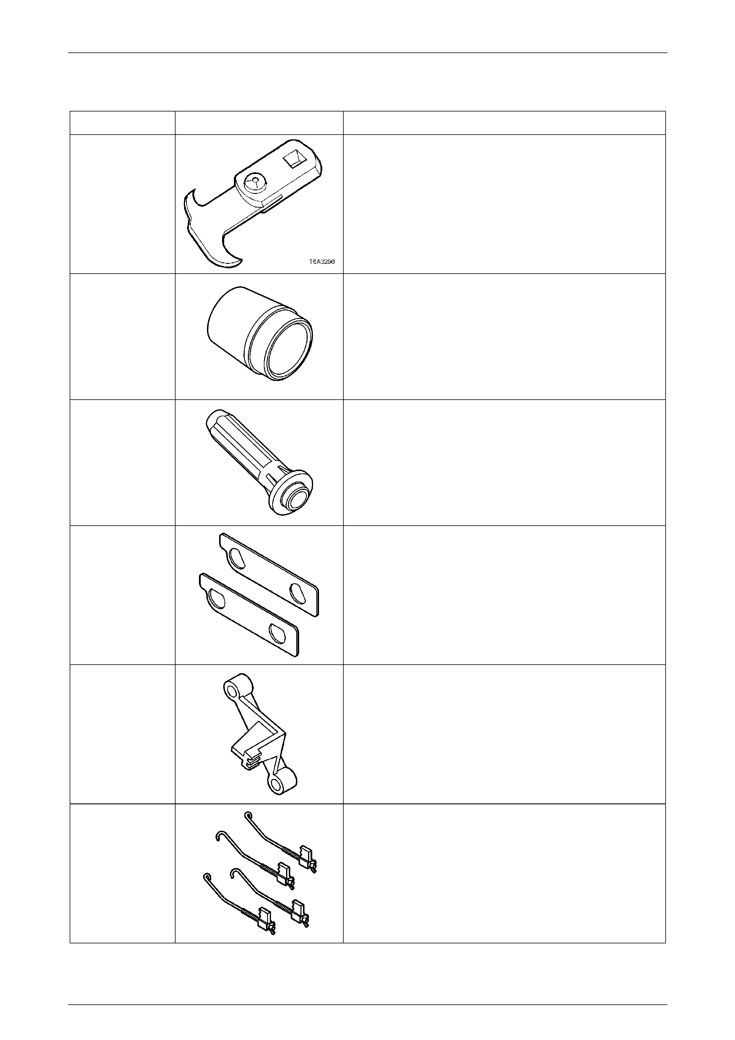
Engine Mechanical – V6 Page 6A1–315
Page 6A1–315
7 Special Tools
Tool Number Illustration Description
E-308
Seal Remover
Previously released.
EN-46101
Spark Plug Tube Seal Guide Set
Used to protect the spark plug lip seals when installing the
camshaft cover to the cylinder head.
EN-46103
Camshaft Actuator Valve Seal Installer
Used to install the camshaft actuator valve s eals into the front
cover.
EN-46105 –
1 and 2
Camshaft Locking Tool Set
Used to retain camshaft position during timin g chain or
camshaft actuator replacement.
EN-46106
Flexplate Holding Tool
Used to retain crankshaft position dur ing valve-train overhaul
and harmonic balancer removal.
EN-46108
Timing Chain Retention Tool Set
Used to retain timing chain tension d urin g camshaft and
actuator removal.
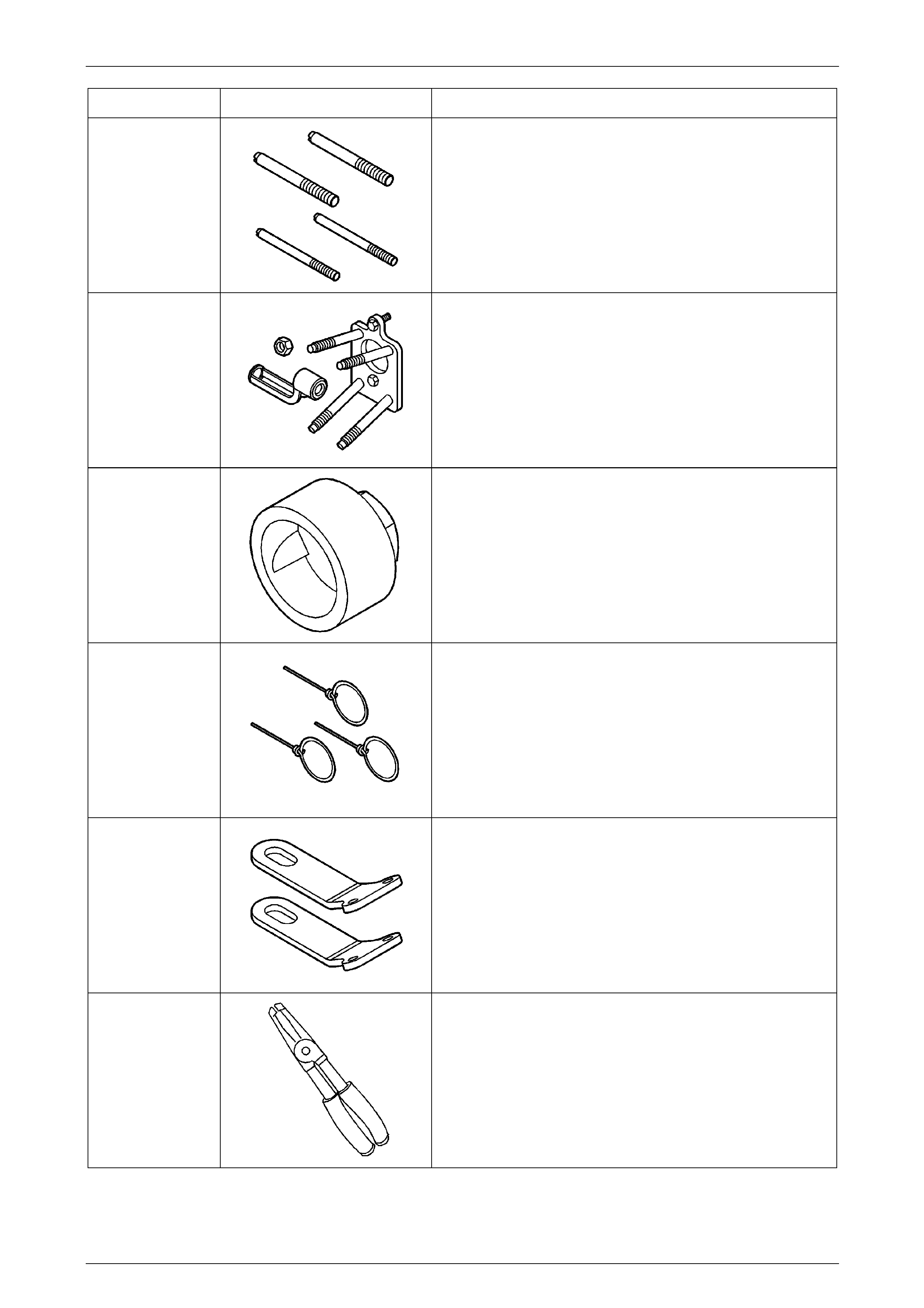
Engine Mechanical – V6 Page 6A1–316
Page 6A1–316
Tool Number Illustration Description
EN-46109
Engine Front Cover / Oil Pan / Crankshaft Rear Oil Seal
Housing Installation Guide Pins
Used to align the engine front cover/oil pan/crankshaft rear oil
seal housing during engin e assembly.
EN-46110
On-vehicle Valve Spring Compressor
Used to remove valve springs with the cylind er hea ds
assembled to the cylinder block.
EN-46111
Crankshaft Rotation Socket
Used to rotate the crankshaft during engi ne overhaul.
EN-46112
Timing Chain Tensioner Retraction Springs
Used to retain the timing chain tensioner plunger within the
tensioner bore during assem bly of timing chains to engine.
EN-46114
Engine Lift Brackets
Used in conjunction with commercial ly available lifting
equipment to lift engine.
EN-46116
Valve Stem Seal Remover / Installer
Used to remove/install the valve stem seals.
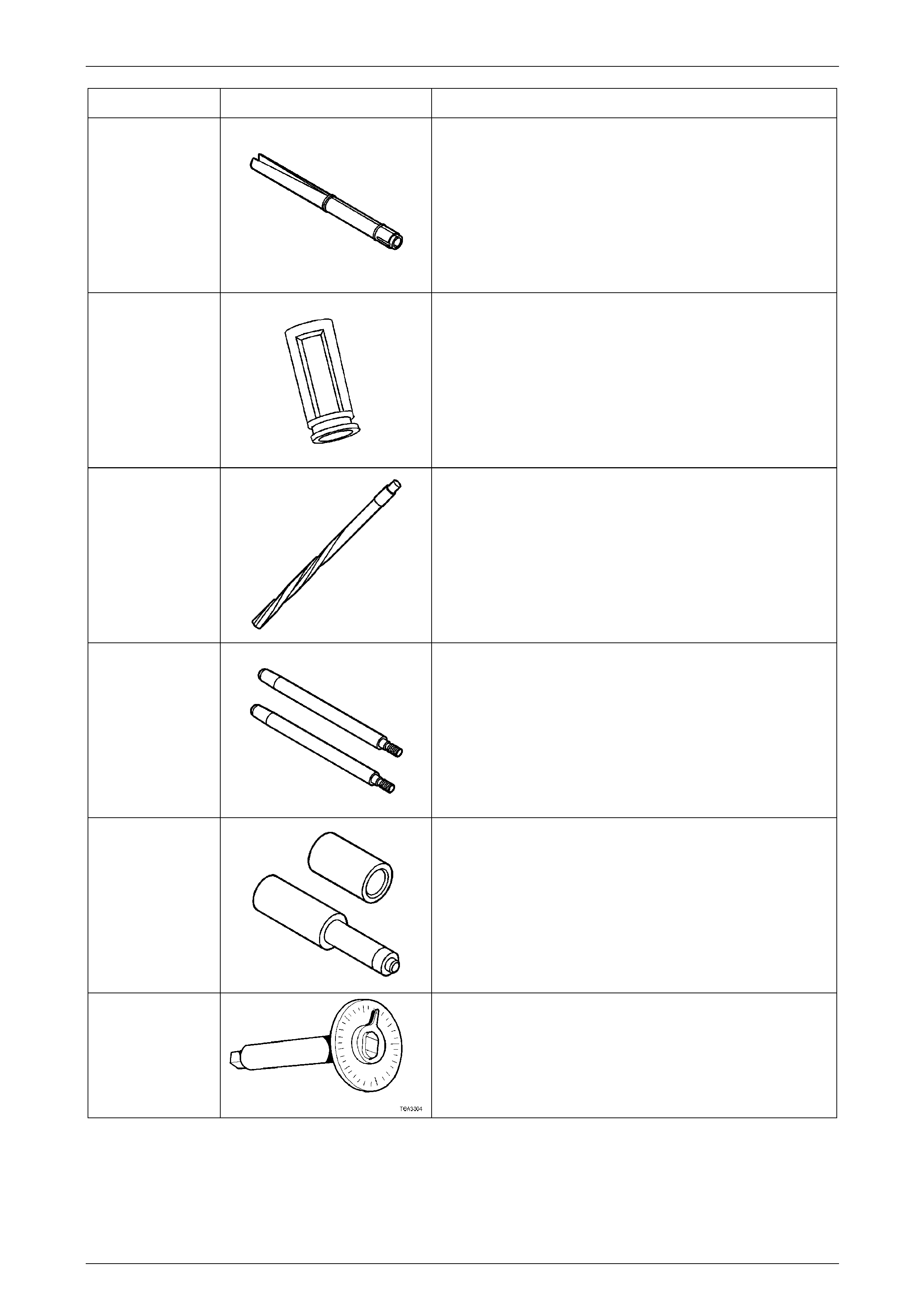
Engine Mechanical – V6 Page 6A1–317
Page 6A1–317
Tool Number Illustration Description
EN-46117
Valve Stem Key Remover / Installer
Used in conjunction with J-8062 or EN-46110 to remove and
reinstall the valve stem keys.
EN-46119
Off-vehicle Valve Spring Compressor Adaptor
Used in conjunction with J-8062 to remove v alve springs with
the engine disassembled.
EN-46120 and
J-42096
Valve Guide Reamer
Used to oversize valve guides prior to the installation of new
oversized valves.
EN-46121
Connecting Rod Guide Pin Set
Used to guide connecting rods onto the cran kshaft journals
and prevent damage to the cylinder bores, journal faces and
piston cooling jets during engine assembly procedures.
EN-46122
Oil Control Valve Check Ball Remover / Installer
EN-7115
Torque Angle Wrench
Used to accurately tighten fasteners when an angle torque is
required.
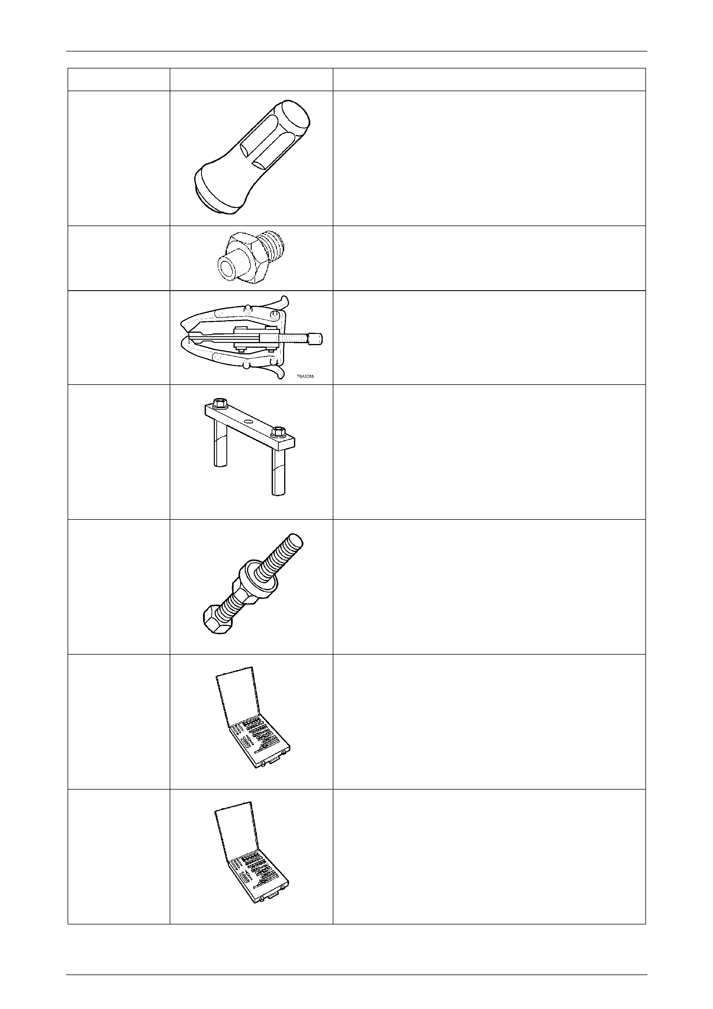
Engine Mechanical – V6 Page 6A1–318
Page 6A1–318
Tool Number Illustration Description
J-29184
Crankshaft Front Oil Seal Installer
J-36648-A
Oil Pressure Gauge Adaptor
J-41816
Three legged puller
J-41818
Main Bearing Cap Removal Tool
Used in conjunction with J-6125-1B to remove the main
bearing caps from the cylinder block during engine
disassembly proced ures.
J-41998-B
Crankshaft Balancer Installer
J-42385-2000
Thread Insert Kit
Used to repair damaged threa ds during engine overhaul.
J-42385-700
High Feature Thread Repair Kit
Used to repair damaged threa ds during engine overhaul.
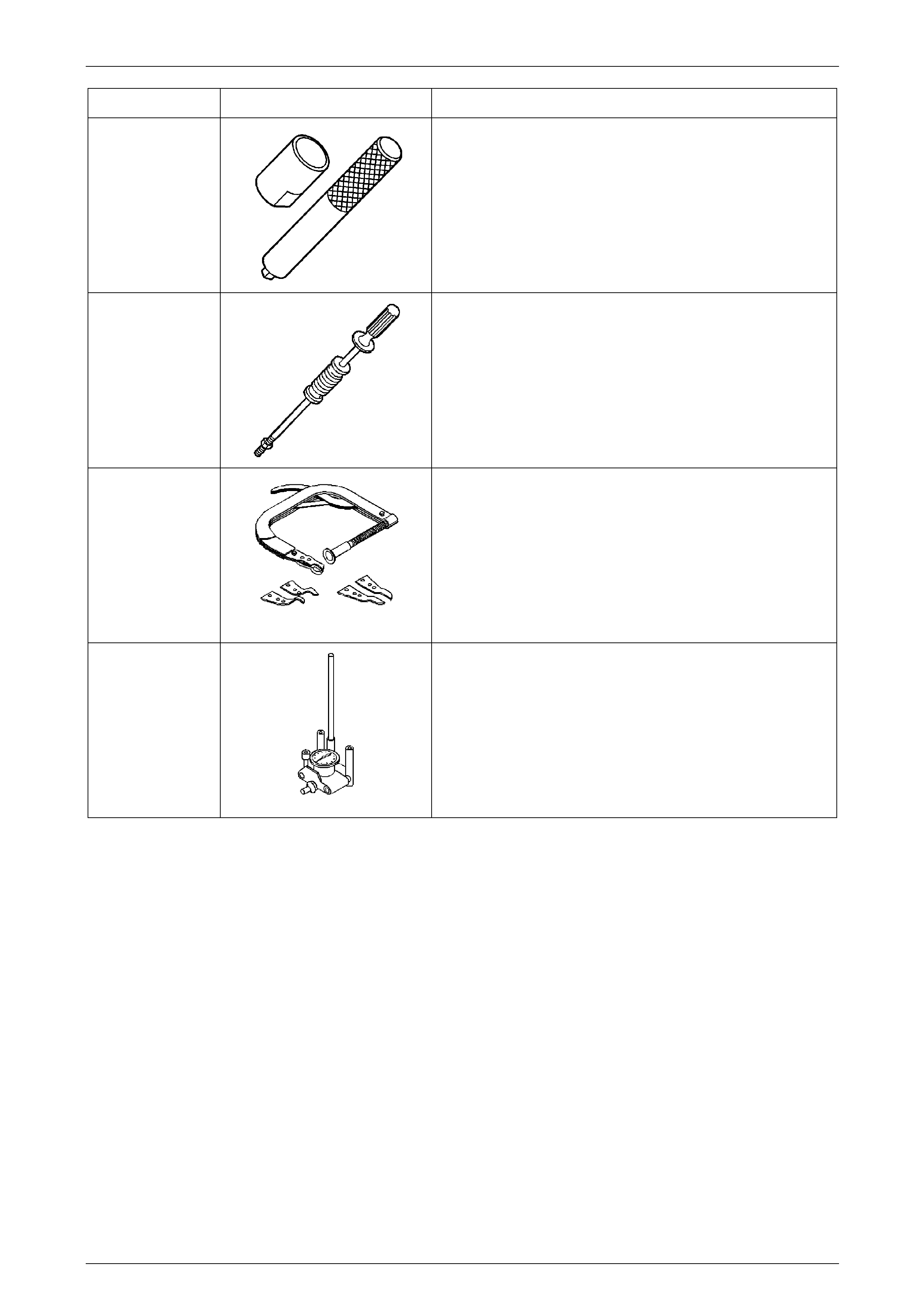
Engine Mechanical – V6 Page 6A1–319
Page 6A1–319
Tool Number Illustration Description
J-45027
Tensioner Tool
Used to reset the timing chain tensioner plunger.
J-6125-1B
Slide Hammer
Used in conjunction with J-41818 to remov e the main bearing
caps from the cylinder block during engi ne disassembly.
J-8062
Valve Spring Compressor
Used in conjunction with EN-4611 9 to remove valve springs
with the engine disassemble d.
J-8087
Cylinder Bore Gauge
Commercial equivalent als o a v ailable