SECTION 0B - LUBRICATION AND SERVICE
IMPORTANT
Before performing any Service Operation or other procedure described in this Section, refer to Section
00 CAUTIONS AND NOTES for correct workshop practices with regard to safety and/or property
damage.
1. GENERAL INFORMATION
This Section provides details of the lubricants recommended for V2 Series Models. Also included in this Section
are instructions on the time or distance intervals at which services should be carried out.
CAPACITIES CHART
LITRES (APPROXIMATE)
CAPACITIES 3.8 Litre V6 Supercharged 5.7 Litre GEN III V8
Engine Oil Pan Refill (Less oil filter) 4.5 5.2
Add for Oil Filter 0.3 0.3
Supercharger 0.12 -
Manual Transmission N/A 4.4
Automatic Transmission - Dry total 7.9 10.6
- Service refill 4.8 5
Cooling System 12 12
- Coolant Concentrate by volume HN2043 at 50% GM6277M at 50%
Brake Hydraulic System 0.616 0.616
Final Drive 1.6 1.6
Power Steering 0.70 0.80
Techline

2. ENGINE LUBRI CATION AND SERVICE
2.1 ENGINE OIL VISCOSITY AND CLASSIFICATION RECOMMENDATIONS
The grade of crankcase oil should be selected to give the best performance under the climatic and driving
conditions in the territory in which the vehicle is operated. When the crankcase is drained and refilled, the
crankcase oil should be selected, not on the basis of the existing temperature at the time of the change, but on
the ambient temperature range anticipated for the period during which the oil will be used.
For V2 Series Models , use 10W/30 ILSAC GF2 engine oil f or general use and high am bient temper atures in both
3.8 litre Supercharged V6 and 5.7 litre GEN III V8 engines. If this oil is unavailable, use SG, SH or SJ engine oil
with a viscosity of 20W/50 or 15W/40.
NOTE 1: Non-detergent and low quality oils are specifically not recommended.
NOTE 2: Only low phosphorous engine oils must be used. Just as lead can contaminate the ceramic monolith
inside the catalytic converter, s o can phosphorous . Most leading brands of engine oil now limit phosphor us levels
to safe limits.
NOTE 3: ‘Break-in’ oils, ‘tune-up’ compounds, ‘friction reducing’ compounds and other additives should not be
used unless recommended by Holden. Their use will only increase operating costs and may contaminate the
ceramic monolith inside the catalytic converter, rendering it unservicable.
2.2 CHECKING ENGINE OIL LEVEL
CHECK
1. Ensure engine is at normal operating
temperature (idle for 10 minutes or equivalent).
2. Park vehicle on level surf ace (as this will aff ect
the accuracy indicated on dipstick and this is a
critical requirement).
3. Do not check oil level for at least 10 minutes
after engine shut down to allow oil to drain back
into the oil pan.
4. Remove dipstick and wipe clean.
5. Install dipstick, ensuring that it is fully seated.
Slowly remove to avoid smearing, then hold
horizontally or with the lower end slightly down,
to avoid oil running along dipstick.
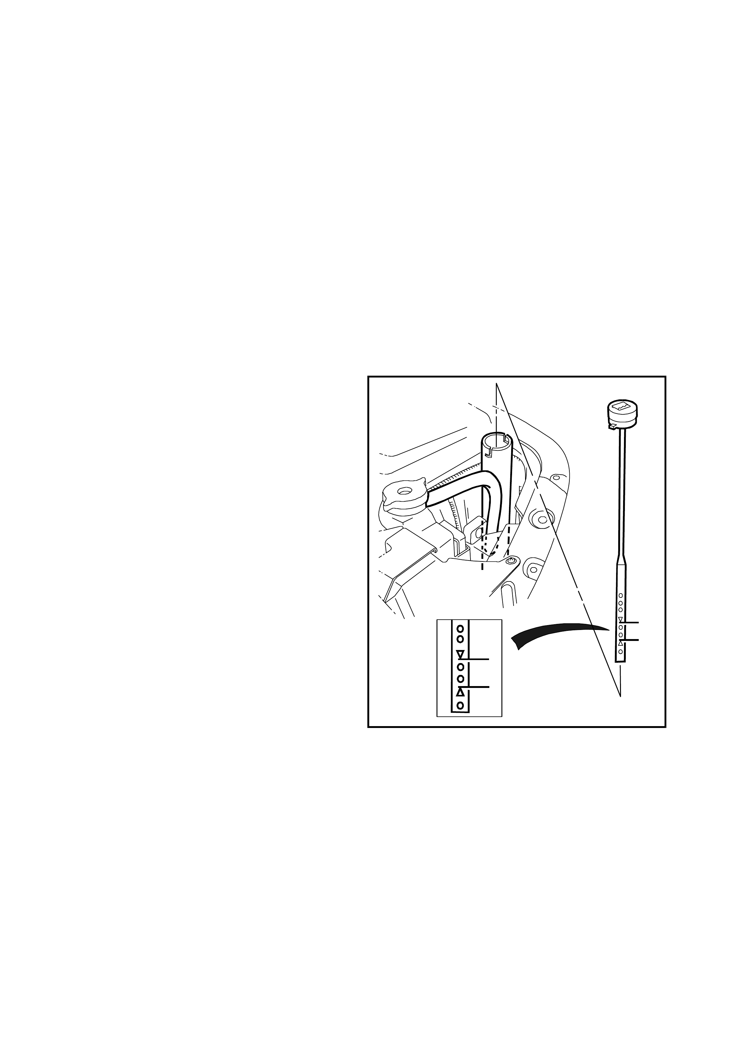
NOTE: Install V6 Supercharged engine dipstick
with the FULL/ADD marks facing towards centre
line of engine. This aspect is very important due to
the angle that the dipstick enters the oil in the oil
pan.
6. Observe the oil level where it passes over the
centre line of the dipstick.
If the engine oil level is below the ADD mark on
the dipstick, using the specified engine oil (refer
to 2.1 ENGINE OIL VISCOSITY AND
CLASSIFICATION RECOMMENDATIONS in
this Section), top up oil level until the oil
reaches the full mark;
FULL mark on V6 Supercharged engines.
Line after the hatched section on GEN III V8
engines.
7. When topping up the engine oil, allow
approximately 10 minutes for the oil added to
fully drain into the oil pan.
T20B003
Figure 0B-1 V6 Supercharged engine oil dipstick
V20B001
Figure 0B-2 GEN III V8 engine oil dipstick
2.3 ENGINE OIL - CHANGE
NOTE 1: Quicker and more complete draining will
occur if the engine oil is at operating temperature.
However, care must be taken to avoid scalding
from the hot oil.
NOTE 2: While all oil pans are alum inium , they are
fitted with steel thread inserts to increase durability
of the thread and to avoid thread tearing when the
drain plug is removed from a hot engine.
1. Raise the engine hood and remove the oil fill
cap.
2. Raise the vehicle front and support with safety
stands. Refer to Section 0A GENERAL
INFORMATION in this Service Information.
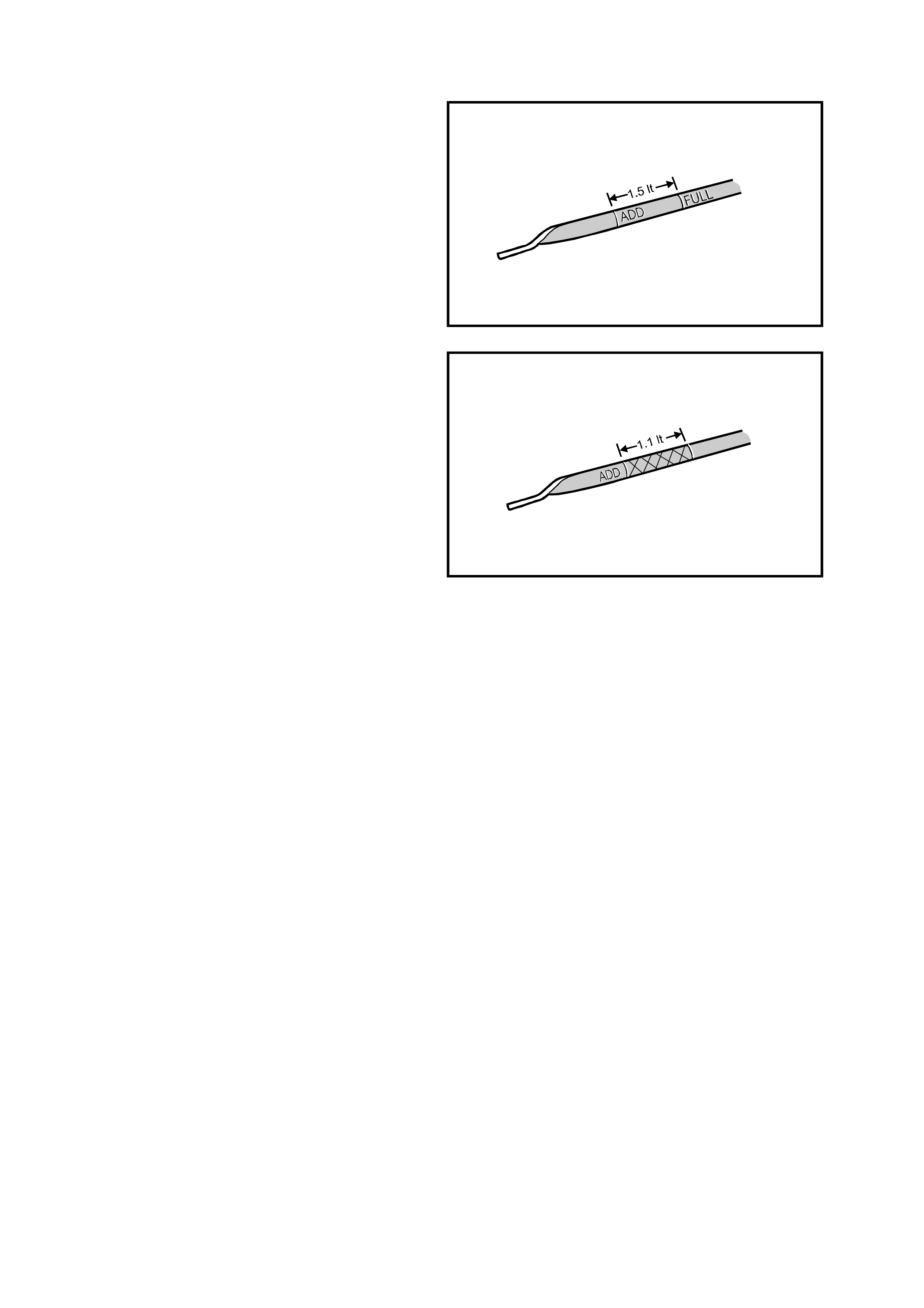
3. On vehicles with GEN III V8 engines, remove
the four oil pan under-tray securing bolts (2)
and remove under-tray (1).
4. Clean any foreign material from around the oil
pan drain plug.
5. Place an oil drain tray beneath the engine.
6. Us ing a suitable wrench rem ove the drain plug,
taking care to avoid sc alding with the hot waste
oil.
Figure 0B-3 GEN III V8 oil pan under-tray
7. W hen the oil has dr ained sufficiently, install the
drain plug, after inspecting and cleaning the
threads. The drain plug O-ring seal may be re-
used if not cut or damaged. Tighten the drain
plug to the correct torque specification.
8. On vehicles with GEN III V8 engines, reinstall
the oil pan under-t ray and tighten securing bolts
to the correct torque specification.
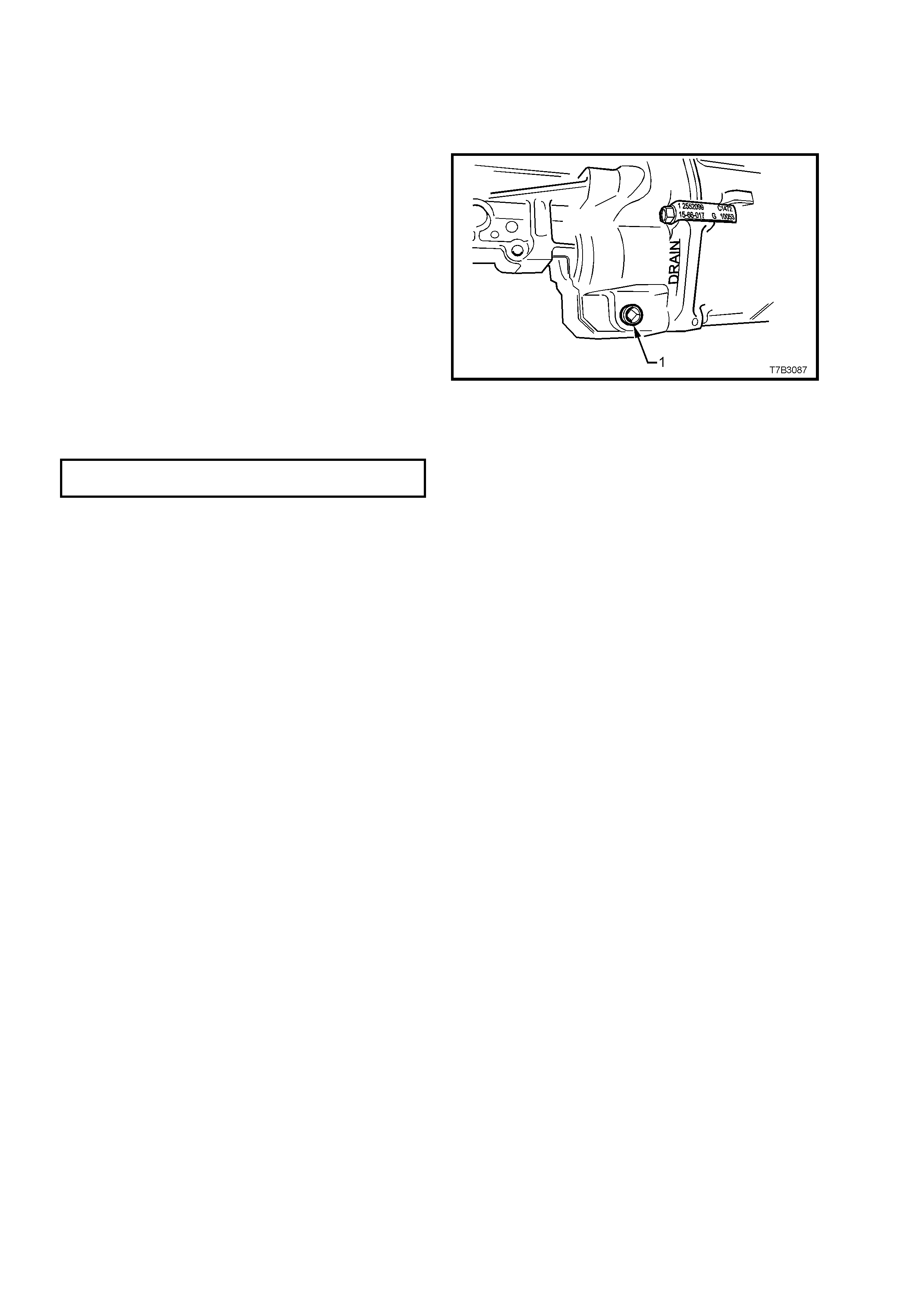
V6 ENGINE OIL PAN DRAIN PLUG
TORQUE SPECIFICATION 40 – 55 Nm
GEN III V8 ENGINE OIL
PAN DRAIN PLUG 25 Nm
TORQUE SPECIFICATION
OIL PAN UNDER TRAY SECURING BOLT
TORQUE SPECIFICATION 30 – 35 Nm
Figure 0B-4 V6 Engine oil pan drain plug
9. Lower the vehicle and fill the crankcase with the
specified engine oil, refer to
2.1 ENGINE OIL VISCOSITY AND
CLASSIFICATION RECOMMENDATIONS in
this Section.
10. Start the engine and check for oil leaks.
Figure 0B-5 GEN III V8 engine oil pan drain plug
2.4 ENGINE OIL FILTER
The full-flow oil filter, filters all the engine oil delivered by the oil pump. Accordingly, the oil filter should be replaced
at the time or distance intervals specified in 9.2 MAINTENANCE SCHEDULE in this Section (or the V2 Series
Owner’s Handbook) or whenever the engine oil is contaminated by foreign material and/or liquids.
Under prolonged dusty conditions, it is recommended that the oil filter be replaced more often.
NOTE: Whenever the oil f ilter is r eplac ed, an additional quantity of the recommended engine oil m us t be added to
fill the dry filter. Refer to the CAPACITIES CHART in this Section.
REPLACE
1. Raise the vehicle front and support with safety
stands. Refer to Section 0A GENERAL
INFORMATION in this Service Information.
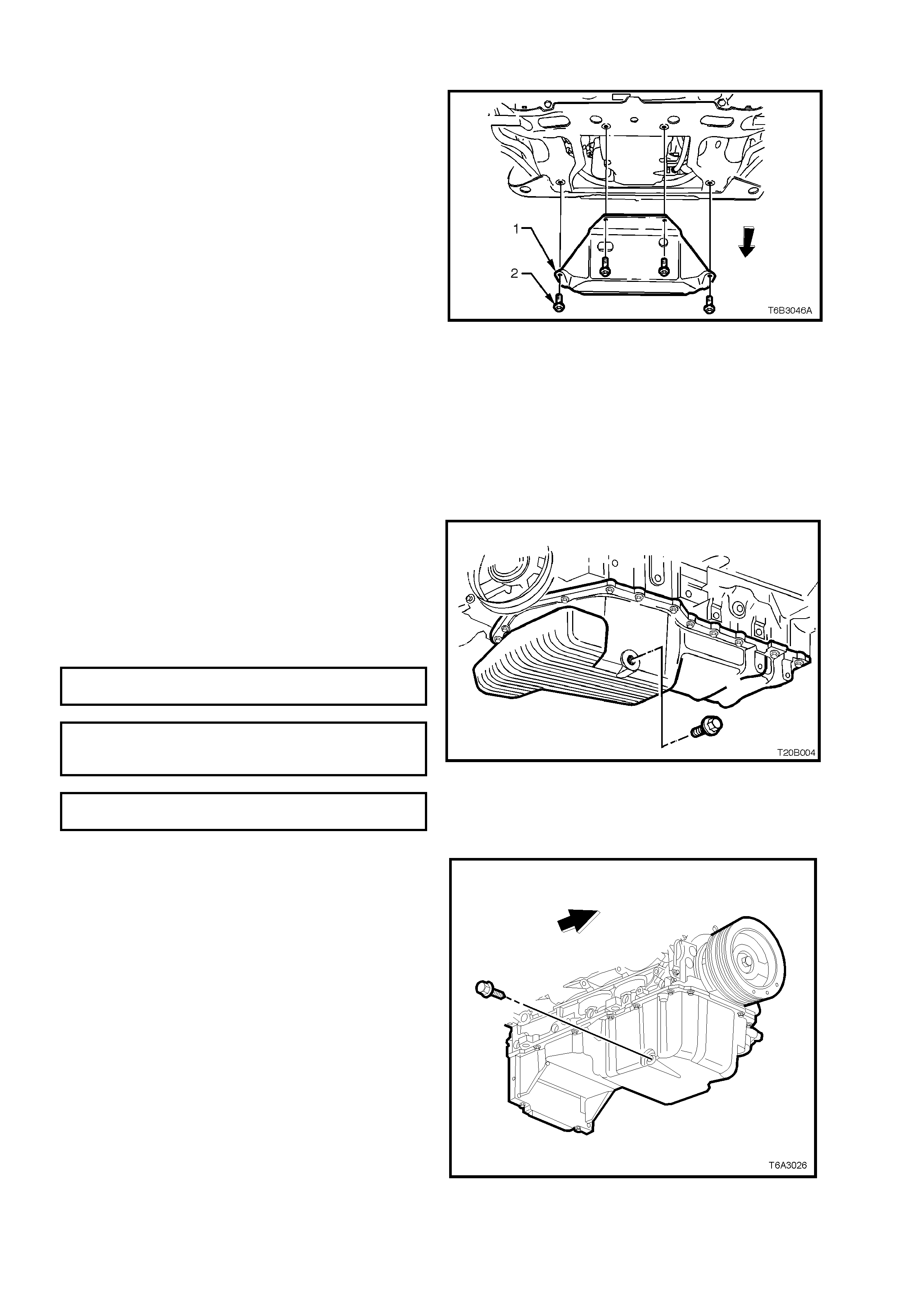
2. On vehicles with GEN III V8 engines, remove
the four oil pan under-tray securing bolts (2)
and remove under-tray (1).
Figure 0B-6 GEN III V8 oil pan under-tray
3. Place an oil drain tray beneath the engine and
remove the oil filter (1), using a commercially
available tool, taking care to avoid being
scalded with the hot waste oil.
4. After checking that the filter seal has not
adhered to the oil pan flange, inspect the oil
filter sealing surface for scratches or other
damage and check the oil filter adaptor threads
for damage.
NOTE: If necessary, refer to relevant Engine
Mechanical Sections in this Service Information for
information on how to remove and install the oil
filter adaptor.
5. Smear some new engine oil onto the new filter
seal, then install filter assembly to engine.
6. For V6 Supercharged engine screw filter into
place until the s eal contacts the m ating surf ace
of the adaptor and tighten a further 2/3 of a
turn.
For GEN III V8 engine; tighten oil filter to the
correct torque specification.
GEN III V8 ENGINE OIL FILTER
TORQUE SPECIFICATION 30 Nm
7. Clean any excess oil of filter and adaptor.
8. On vehicles with GEN III V8 engines, reinstall
the oil pan under-tray and tighten securing bolts
to the correct torque specification.
OIL PAN UNDER-TRAY SECURING BOLT
TORQUE SPECIFICATION 30 – 35 Nm
9. Lower the vehicle and check the oil level. Start
engine and check for leaks. Repair as
necessary.
NOTE: The oil level needs to be rechecked and oil
added as necessary, after running the engine, to
compensate for oil used to refill the oil filter. Refer
to 2.2 CHECKING ENGINE OIL LEVEL in this
Section for the recommended checking procedure.
Figure 0B-7 V6 engine oil filter
Figure 0B-8 GEN III V8 engine oil filter
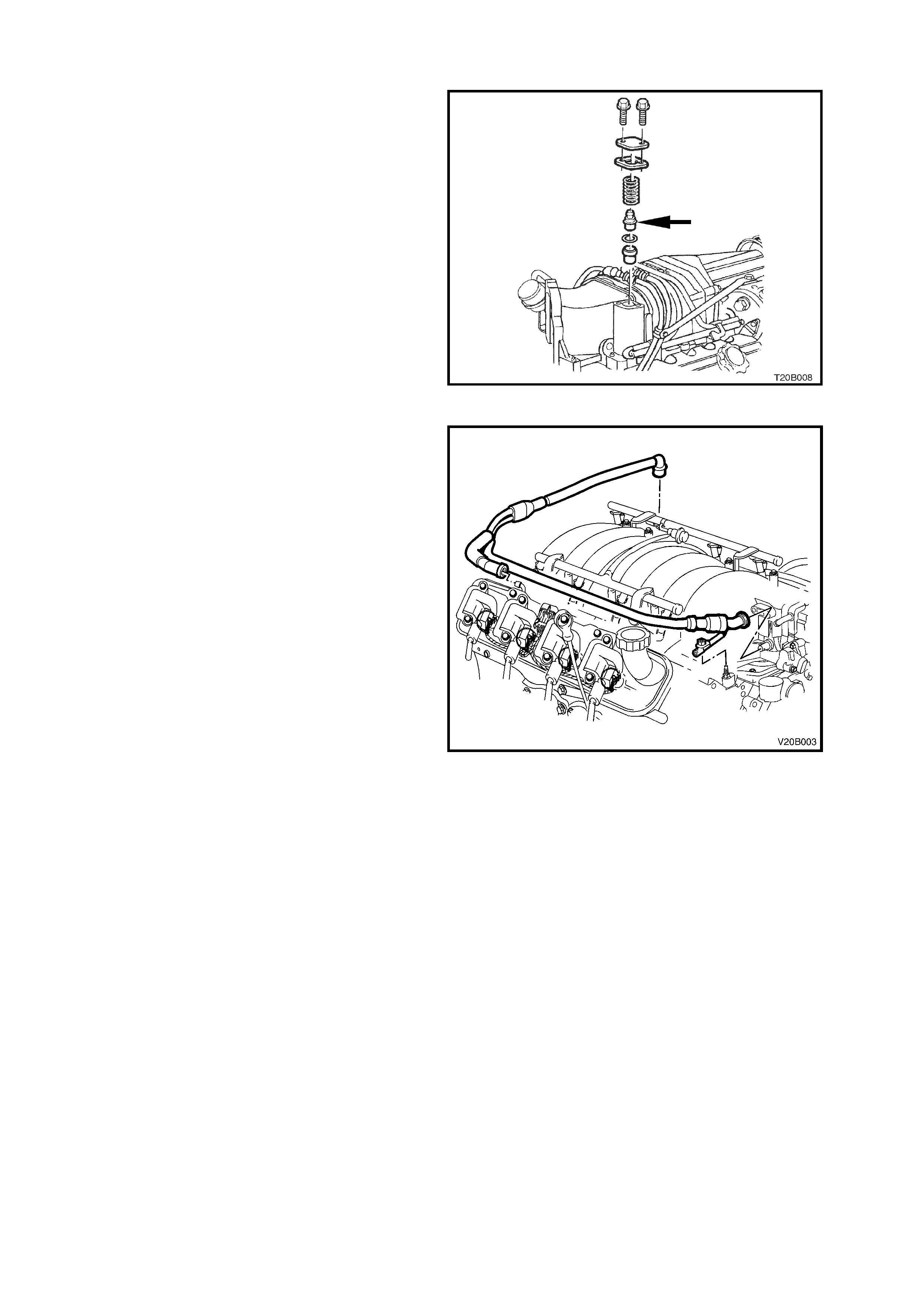
2.5 ENGINE VENTILATION SYSTEM
All V2 Series Model engine ventilation systems, use
a P.C.V. valve and utilise engine vacuum to draw
blow-by gases into the combustion chambers
where they are recycled through the combustion
process.
The location of the P.C.V. valve on a V6
Supercharged engine is in the LH rear of the
supercharger assembly, and GEN III engine it is
externally mounted between the valve cover and
the throttle body.
For service instructions covering the testing,
removal and installation procedures of the
P.C.V. valve, depending on the engine variant,
refer to Section 6E1 EMISSION CONTROL -
V6 ENGINE (V6 Supercharged engines) or
Section 6E3 EMISSION CONTROL - GEN III V8
ENGINE (GEN III V8 engine) in the VT Series II
Service Information.
Figure 0B-9 V6 Supercharged engine P.C.V. valve
Figure 0B-10 GEN III V8 engine P.C.V. valve
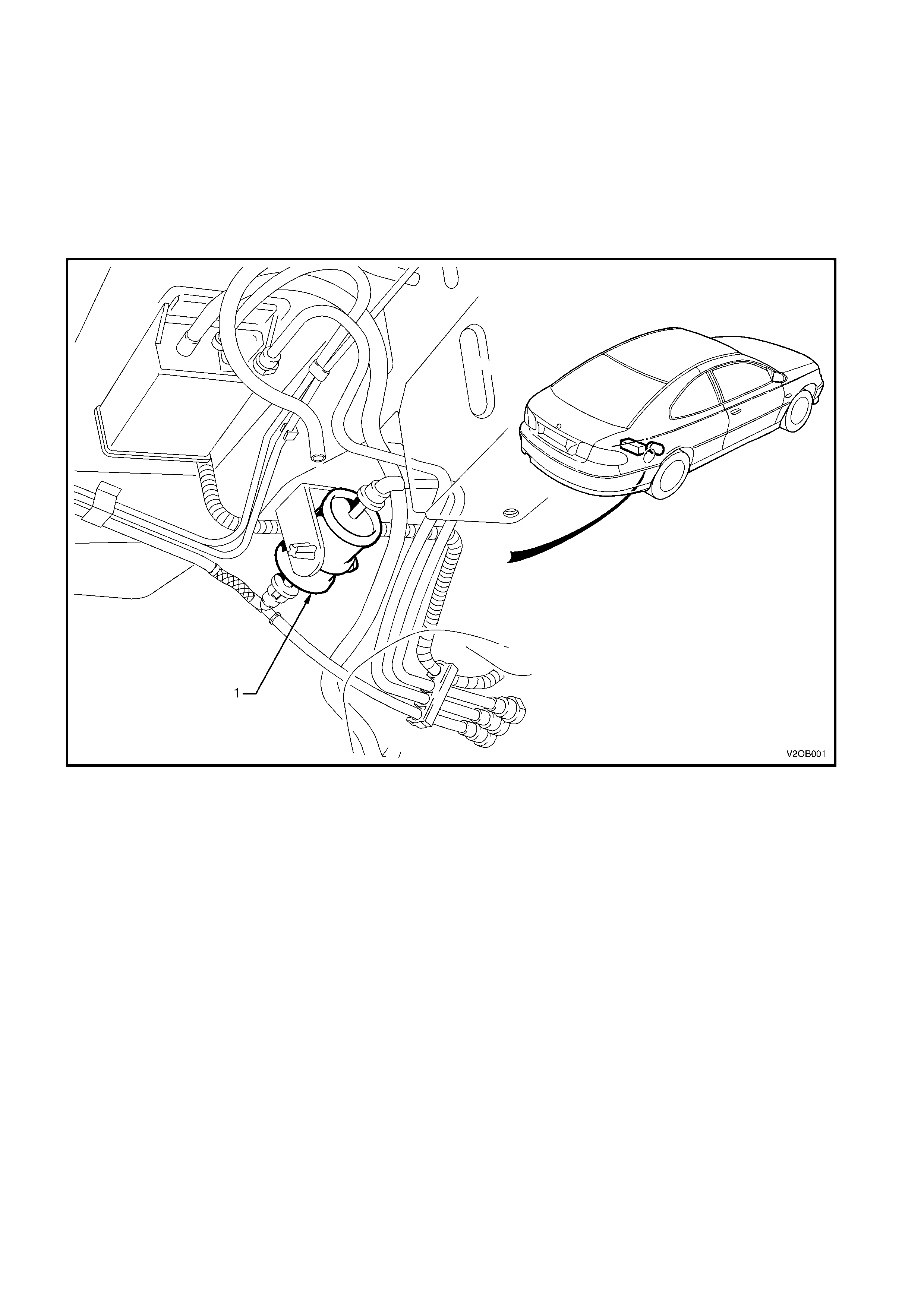
2.6 FUEL FILTER
The f uel f ilter is located on the pr es sur e s ide of the high pr es sur e fuel pum p and is attached to the floor pan
of the vehicle, behind the final drive assembly.
Refer to Fig. 0B-11 for fuel filter location.
The fuel filter (1) must be replaced at the time or distance intervals specified in 9.2 MAINTENANCE
SCHEDULE in this Section or in the V2 Series Owner’s Handbook.
For service instructions covering the removal and installation of the fuel filter, depending on the engine
variant, refer to Section 6C1 POWERTRAIN MANAGEMENT - V6 ENGINE (V6 Supercharged engine) or
Section 6C3 POWERTRAIN MANAGEMENT - GEN III V8 ENGINE in the VT Series Service Information.
Figure 0B-11
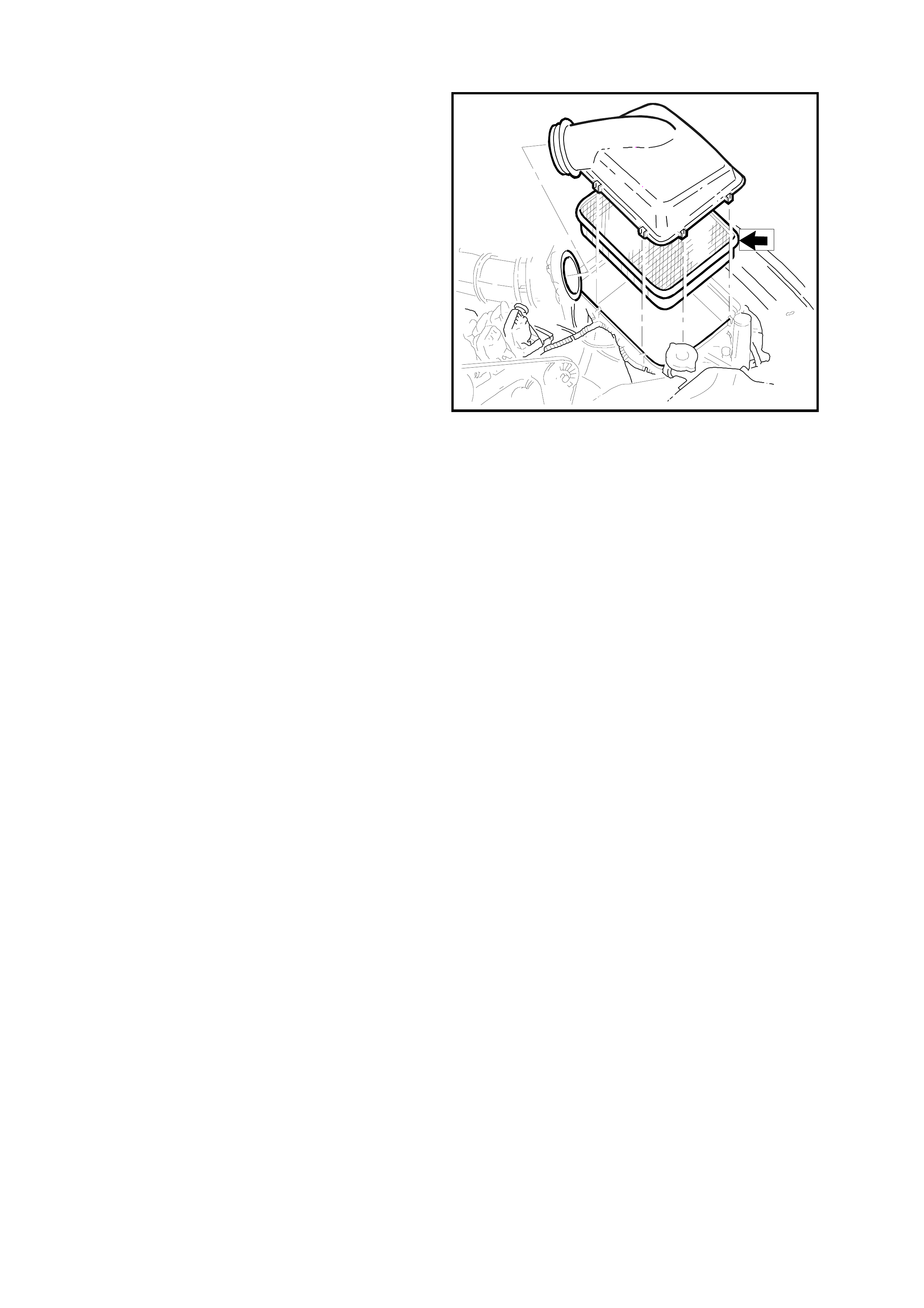
2.7 AIR CLEANER ELEMENT
The air cleaner elem ent m ay be partially cleaned of
dust by lightly tapping the element. It should not be
washed or oiled. The time or distance intervals at
which the element requires servicing depend on
vehicle operating conditions. Under dusty
conditions, the element should be checked for
restriction more often than for normal city
operation. Refer 9.2 MAINENANCE SCHEDULE in
this Section for additional information on when the
element should be serviced.
Fig. 0B-12 shows the location of the element for a
typical air cleaner assembly.
For service instructions covering the removal
and installation of the air cleaner element,
dependent on the engine type, refer to
Section 6C1 POWERTRAIN MANAGEMENT - V6
ENGINE (V6 Supercharged engine) or
Section 6C3 POWERTRAIN MANAGEMENT -
GEN III V8 ENGINE in the VX Series I Service
Information.
Figure 0B-12
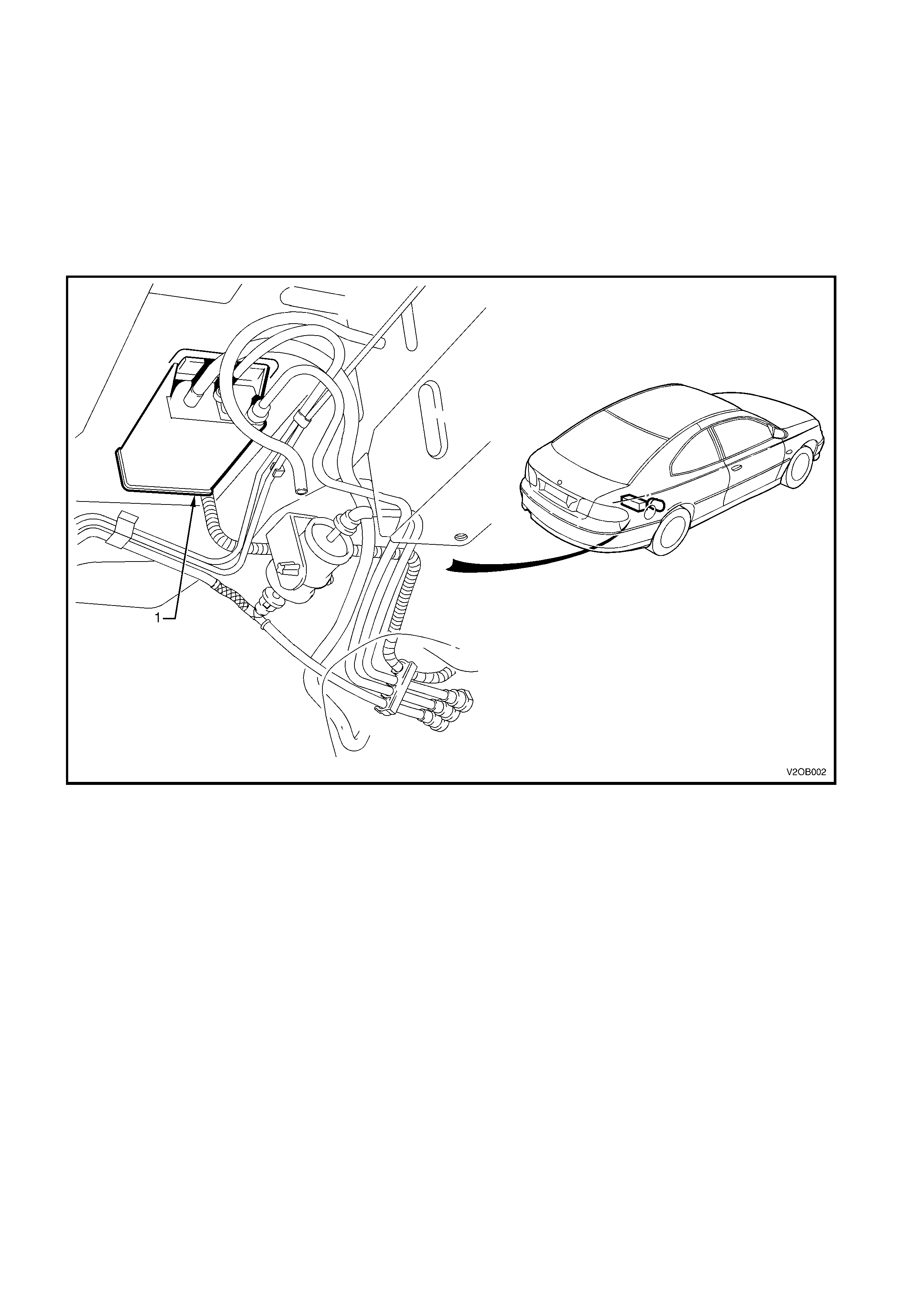
2.8 EVAPORATIVE EMISSION CONTROL CANISTER
The Evaporative Emission Control (EEC) canister is attached to the underbody on all V2 Series Models,
regardless of the engine configuration.
The canister should be serviced at the time or distance intervals specified in 9.2 MAINENANCE
SCHEDULE in this Section or in the V2 Series Owner’s Handbook.
The canister (1) location is shown in Fig. 0B-13.
For service instructions covering the testing, removal and reinstallation of the EEC canister, depending on
the engine variant, refer to Section 6E1 EMISSION CONTROL - V6 ENGINE (V6 and V6 Supercharged
engines) or Sect ion 6E3 EMISSION CONT RO L - GEN III V8 ENGINE (GEN III V8 engine) in the VT Series
II Service Information.
Figure 0B-13
2.9 COOLING SYSTEM
V6 SUPERCHARGED ENGINE
The cooling system is filled initially with a coolant mixture comprising 50% water and 50% inhibited ethylene
Glycol to Holden Specification HN2043.
CAUTION: Do not remove the radiator cap w hen the engine and radiator are hot. Scalding fluid and steam
can be blown out under pressure if the cap is removed.
The c ooling system is designed to us e f or mulated coolant ( a mixtur e of inhibited ethylene glycol and water), rather
than plain water. The coolant solution must be used year round.
Inhibited ethylene glycol conforming to Holden Specification HN2043 is named ‘New Formula Long Life All
Seasons Coolant’, and is available in the following quantities:
1 Litre, P/N 92140054*
5 Litre, P/N 92140057*
20 Litre, P/N 92140055*
* Always check with the latest Holden spare parts information for the correct part number before ordering parts.
NOTE: Do not m ix dif ferent types of anti-freeze or c orrosion inhibitors as they may be incom patible. If a different
type has been used in the cooling system, flush the system with clean water.
The water used for mixing with inhibited glycol c oncentrate mus t be of low dissolved salt content, pr eferably tank
water or demineralised water.
CHECK
Turn the coolant dipstick cap one eighth of a turn
anti-clockwise and slowly pull out the dipstick.
There ar e two triangles on the dipstick repr esenting
the Minimum ▲ and Maximum ▼ levels.
When the coolant is cold, the coolant level should
be at or above the Minimum ▲ triangle m ark on the
dipstick. After the engine has been driven and the
engine is at the normal operating temperature, the
level should be somewhere between the Minimum
▲ and Maximum ▼ triangles.
If the coolant level is correct, replace the dipstick
and turn the cap one eighth of a turn clockwise to
secure.
If the coolant level is low, add enough of a pre-
mixed coolant solution of water and a good quality
inhibited ethylene glycol (meeting Holden
specification HN2043) to bring the level up to the
proper mark.
When the level is correct, replace the dipstick and
turn the cap one eighth of a turn clockwise to
secure.
It is of the utmost importance to maintain the
correct concentration level of glycol in the cooling
system.
To ensure the specified glycol concentration is
maintained in the engine coolant, the coolant
concentration must be checked at the time or
distance intervals outlined in 9.2 MAINTENANCE
SCHEDULE in this Section or in the V2 Series
Owner’s Handbook.
Check coolant concentration as outlined in
Section 6B1-2 ENGINE COOLING - V6
SUPERCHARGED in the VT Series I Service
Information.
It is recom mended that the coolant be drained, the
system flushed and refilled with clean water and
radiator coolant at the tim e or distance intervals set
out in 9.2 MAINTENANCE SCHEDULE in this
Section or the V2 Series Owner’s Handbook.
T20B013
Figure 0B-14
Aluminium radiators should be protected at all times by a coolant that is specifically recommended for use with
aluminium. Aluminium radiators may be destroyed by the caustic solutions found in some cleaners or the
chemicals used in some antifreeze’s and inhibitors.
For cooling system filling instructions, refer to Section 6B1-2 ENGINE COOLING - V6 SUPERCHARGED in the
VT Series II Service Information.
GEN III V8 ENGINE
CAUTION: Do not remove coolant surge tank cap when the engine and radiator are hot. Scalding fluid and
steam can be blown out under pressure if the cap is removed.
The cooling system is designed to use a specific coolant (a mixture of DEX-COOL® coolant to GM Specif ication
6277M coolant additive and water), rather than plain water.
The use of this orange coloured coolant additive also raises the boiling point and increases the cooling system
efficiency. For this reason, it is of the utmost importance that the correct concentration level of DEX-COOL® is
maintained in the cooling system.
Addition of plain water into the cooling system when 'topping-up' may dilute the coolant mixture to a point where
the specific properties of DEX-COOL® become ineffective.
The coolant should comprise of a mixture 50% DEX-COOL® (GM Specification 6277M) with 50% clean, good
quality water.
NOTE: Do not mix different types of antifreeze or corrosion inhibitors as they may be incompatible. If a
different type has been used in the cooling system, flush the system with clean water, refer to
Section 6B3 ENGINE COOLING - GEN III V8 ENGINE in this Service Information.
The water used for mixing with DEX-COO L c oolant must be of low diss olved salt c ontent, pr ef erably tank water or
demineralised water.
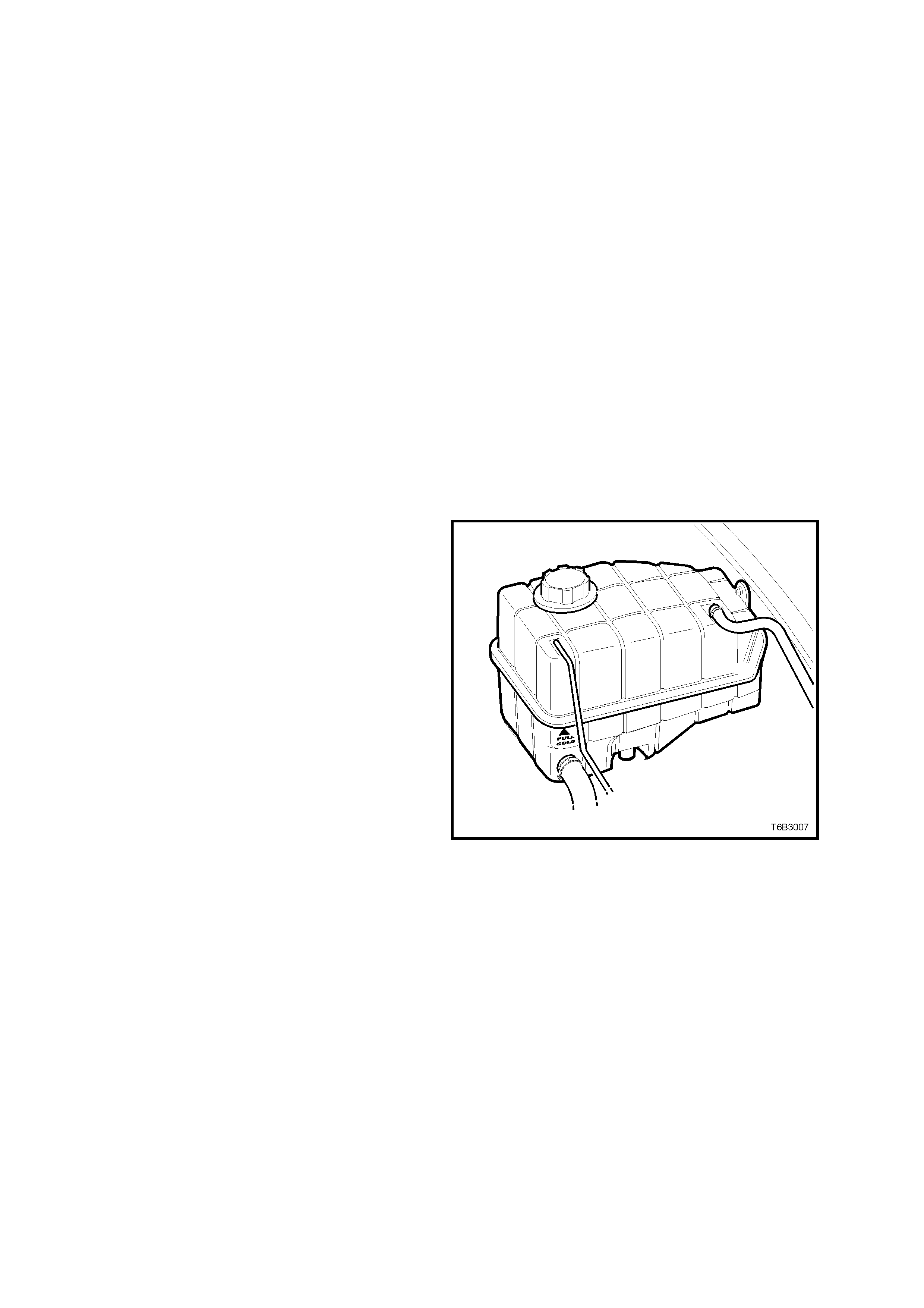
CHECK
The coolant level can be externally checked at the
coolant surge tank. With the engine cold, the
coolant level should be at the FU LL COLD m ark on
the front of the coolant surge tank.
Pre-mixed coolant (50% DEX-COOL® to GM
Specification 6277M with 50% clean, good quality
water) may be added as necessary to bring the
level shown on the coolant surge tank but only
when the engine is cold.
It is of the utmost importance to maintain the
correct concentration level of glycol in the cooling
system.
To ensure the specified glycol concentration is
maintained in the engine coolant, the coolant
concentration must be checked at the time or
distance intervals outlined in 9.2 MAINTENANCE
SCHEDULE in this Section or in the V2 Series
Owner’s Handbook.
Check coolant concentration as outlined in
Section 6B3 - ENGINE COOLING - GEN III V8
ENGINE in the VT Series II Service Information.
It is recom mended that the coolant be drained, the
system flushed and refilled with clean water and
radiator coolant at the tim e or distance intervals set
out in 9.2 MAINTENANCE SCHEDULE in this
Section or in the V2 Series Owner’s Handbook.
Figure 0B-15
Aluminium radiators should be protected at all times by a coolant that is specifically recommended for use with
aluminium. Aluminium radiators may be destroyed by the caustic solutions found in some cleaners or the
chemicals used in some antifreeze’s and inhibitors.
For cooling system filling ins truct ions, ref er to Section 6B3 - ENGINE CO OLING – G EN III V8 ENGINE in the VT
Series II Service Information.

3. MANUAL TRANSMI SSION LUBRICATION AND SERVICE
3.1 RECOMMENDED LUBRICANT
The recommended lubricant for the Tremec, Type T56, 6 speed manual transmission (production option
MM6) is fluid qualified to Dexron® III (to Holden specification HN2126).
3.2 CHECKING TRANSMISSION LUBRICANT LEVEL
The lubr icant level is to be c hec k ed at the time or distance intervals detailed in 9.2 MAINTENANCE SCHEDULE
in this Section or in the V2 Series Owner’s Handbook.
Important: This transmission is classified as
being a ‘Fill for Life’ transmission and periodic
checking of the lubricant level is not required.
The only time that fluid level checking would be
appropriate, would be af ter cor r ection of a fluid leak
from the transmission or if the transmission had
been removed from the vehicle.
1. Rais e the vehicle front and rear and support on
safety stands, ensur ing that the vehicle is level.
Refer to Section 0A GENERAL
INFORMATION in this Service Information, for
the location of jacking points.
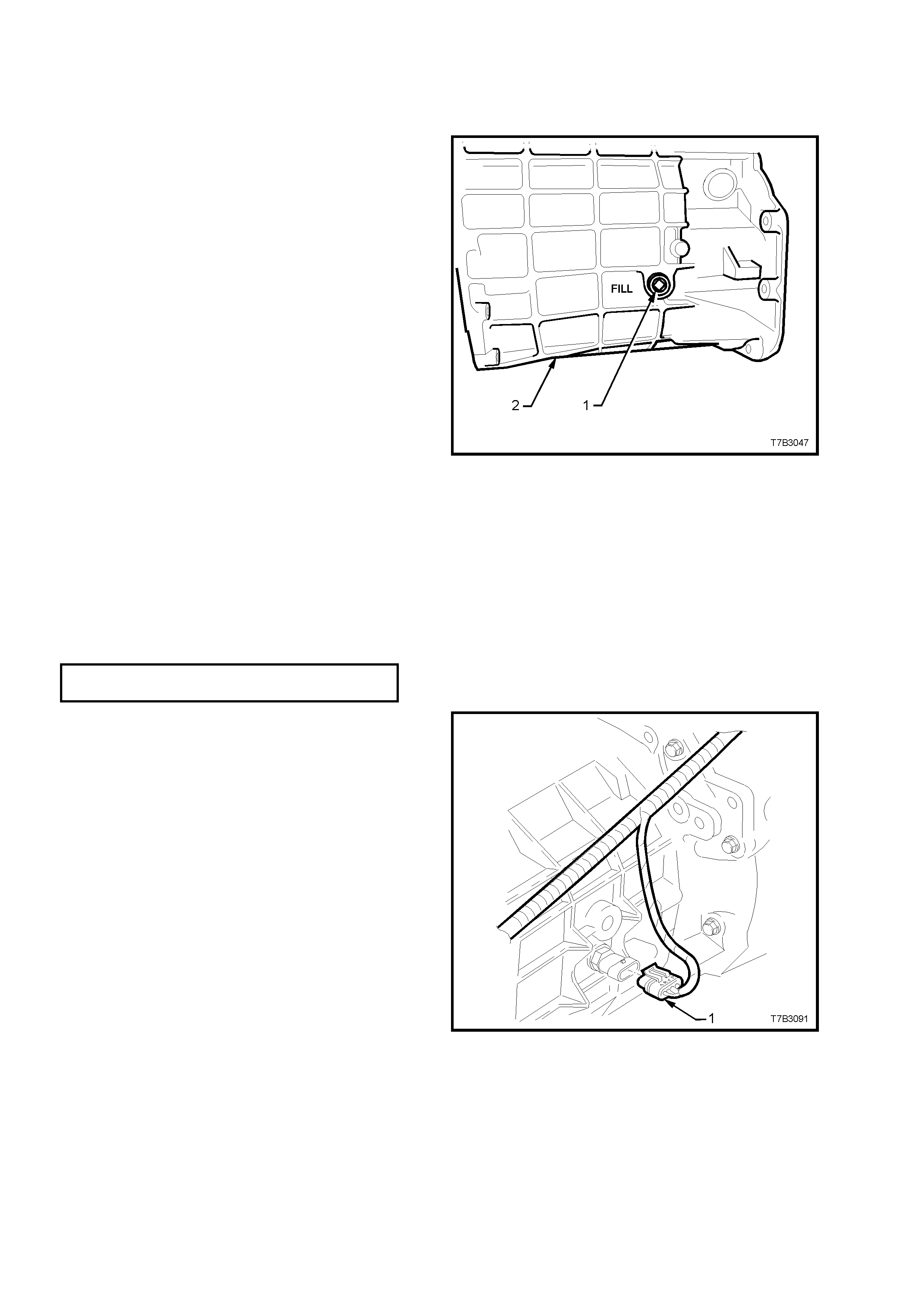
2. Place a drain tray beneath transmission and
remove transmission filler plug (1) from left
hand side of transmission case (2), using a 3/8”
drive socket bar.
NOTE: Depending on the severity of the loss, fluid
will probably flow from the filler plug hole, following
removal.
3. Allow excess fluid to drain until flow stops. If
required, top up fluid level until it does flow out.
Figure 0B-16
4. Clean the threads of the filler plug, apply
thread sealant such as Loctite 565 or
equivalent (GM P/N 12346004), then install
filler plug, tightening to the correct torque
specification. Do not apply Teflon thread tape
to the plug threads.
TRANSMISSION FILLER PLUG
TORQUE SPECIFICATION 20 – 34 Nm
5. Remove the back-up lamp switch as follows:
a. Remove wiring harness connector (1) from
switch, located on the right hand side of the
transmission case.
Figure 0B-17
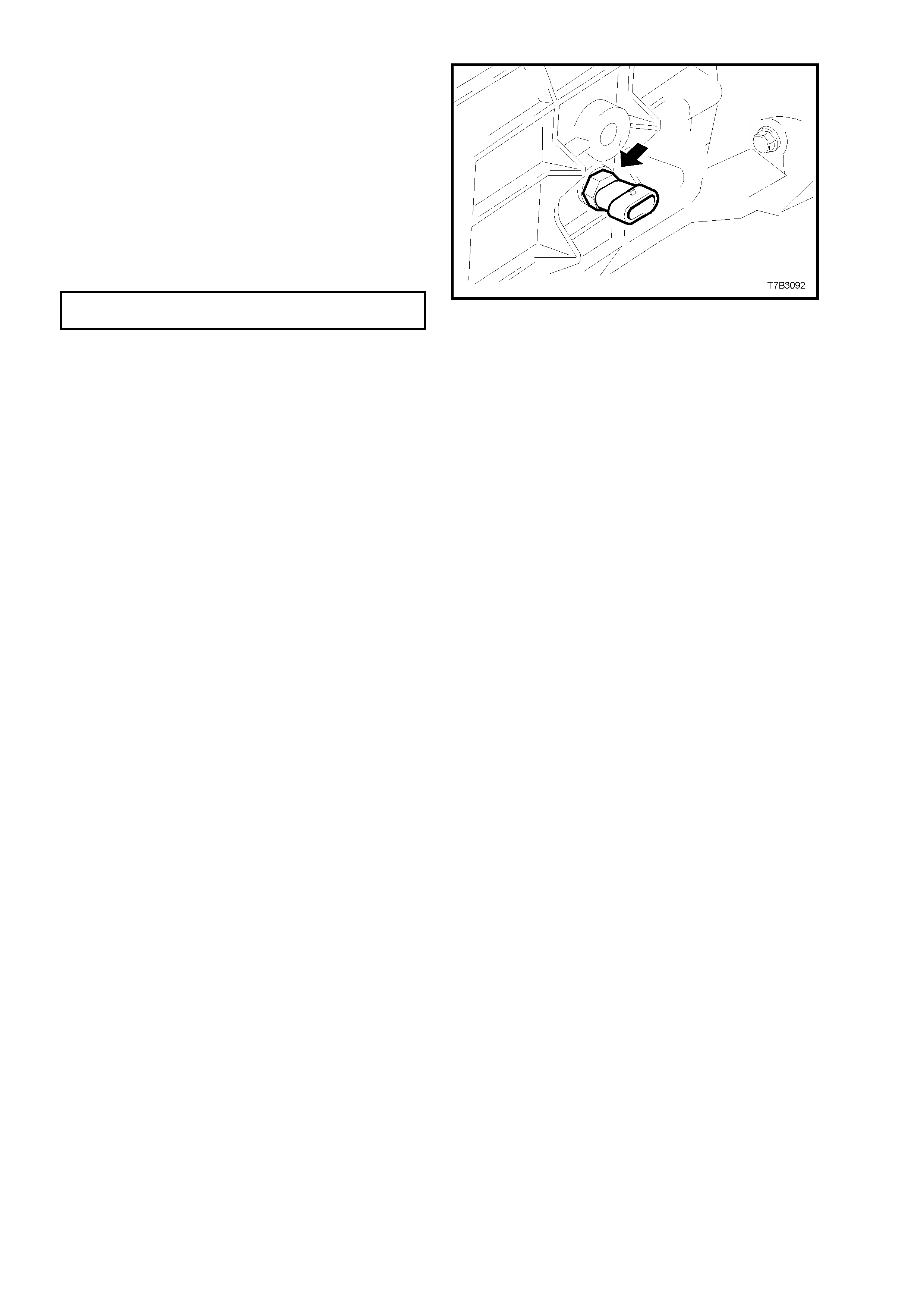
b. Loosen, then remove switch (arrow) from
the transmission case.
6. Using commercially available fluid dispensing
equipment, add a measured, 0.5 litres of the
recomm ended lubr ic ant to the trans miss ion, via
the back-up lamp switch threaded hole in the
transmission case.
7. Apply Loctite 565 or equivalent (GM P/N
12346004), to the cleaned threads of the back-
up lamp switch.
8. Install switch to transmission case and tighten
to the correct torque specification.
BACK-UP LAMP SWITCH
TORQUE SPECIFICATION 20 – 34Nm
9. Install wiring harness connector to switch.
10. Remove safety stands and lower vehicle to
ground.
11. Check back-up lamp operation.
Figure 0B-18
3.3 DRAINING AND REFILLING TRANSMISSION
Should a lubricant change be required, then the following procedure should be adopted.
NOTE: Periodic transmission lubricant changes are not necessary. However, the lubricant should be changed
when overhauling the transmission.
1. To drain transmiss ion, jac k up vehicle f ront and
rear and support on safety stands.
Refer to Section 0A GENERAL
INFORMATION in this Service Information, for
the location of jacking points.
2. Place a drain tray beneath transmission and
remove filler plug (refer to item 1 in
Figure 0B-16) and then the drain plug (1) from
the transmission extension housing using a
3/8” drive socket bar.
3. After draining, clean the threads of the drain
plug, apply thread sealant such as Loctite 565
or equivalent (GM P/N 12346004), then install,
tightening to the correct torque specification.
NOTE: Do not apply Teflon thread tape to the plug
threads.
TRANSMISSION DRAIN PLUG
TORQUE SPECIFICATION 20 – 34 Nm
4. Refill transmission to the correct level
with Dexronâ III transmission fluid (to
Holden specification HN2126) as outlined in
3.2 CHECKING TRANSMISSION LUBRICANT
LEVEL in this Section.
Figure 0B-19

4. AUTOM ATIC TRANSMISSI ON LUBRICATION AND SERVICE
4.1 RECOMMENDED FLUID
The automatic transmission for V2 Series Models requires fluid qualified to Dexron® III (to Holden specification
HN2126).
Techline
4.2 CHECKING TRANSMISSION FLUID LEVEL
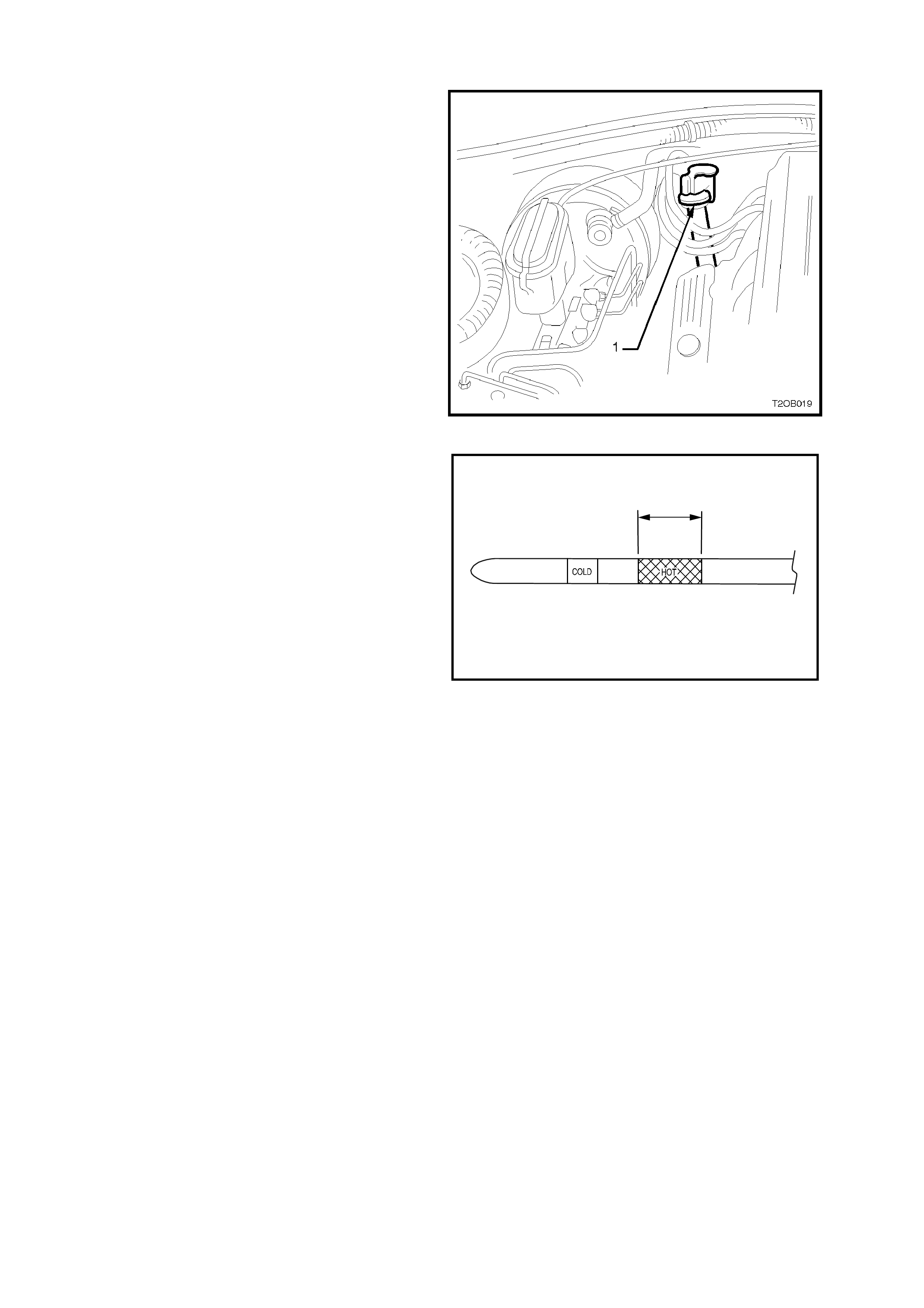
The transmission fluid level dipstick (1) is located
on the left hand side of the engine (if viewed from
the front of the vehicle), refer to Fig. 0B-20.
1. Bring transmission to normal operating
temper ature (82 to 94°C) (or drive vehic le for a
distance of 24 km).
NOTE: As temperature affects transmission fluid
levels, this operation must be carried out with the
transmission at normal operating temperature. If
the vehicle is not at normal operating temperature,
and the proper checking procedures are not
followed, the result could be a false reading of the
fluid level on the dipstick.
2. Park vehicle on level ground.
3. Place selector lever in ‘P’ (PARK) position.
4. Apply park brake.
5. Let engine idle for 3 minutes with accessories
(i.e. air conditioning) turned off.
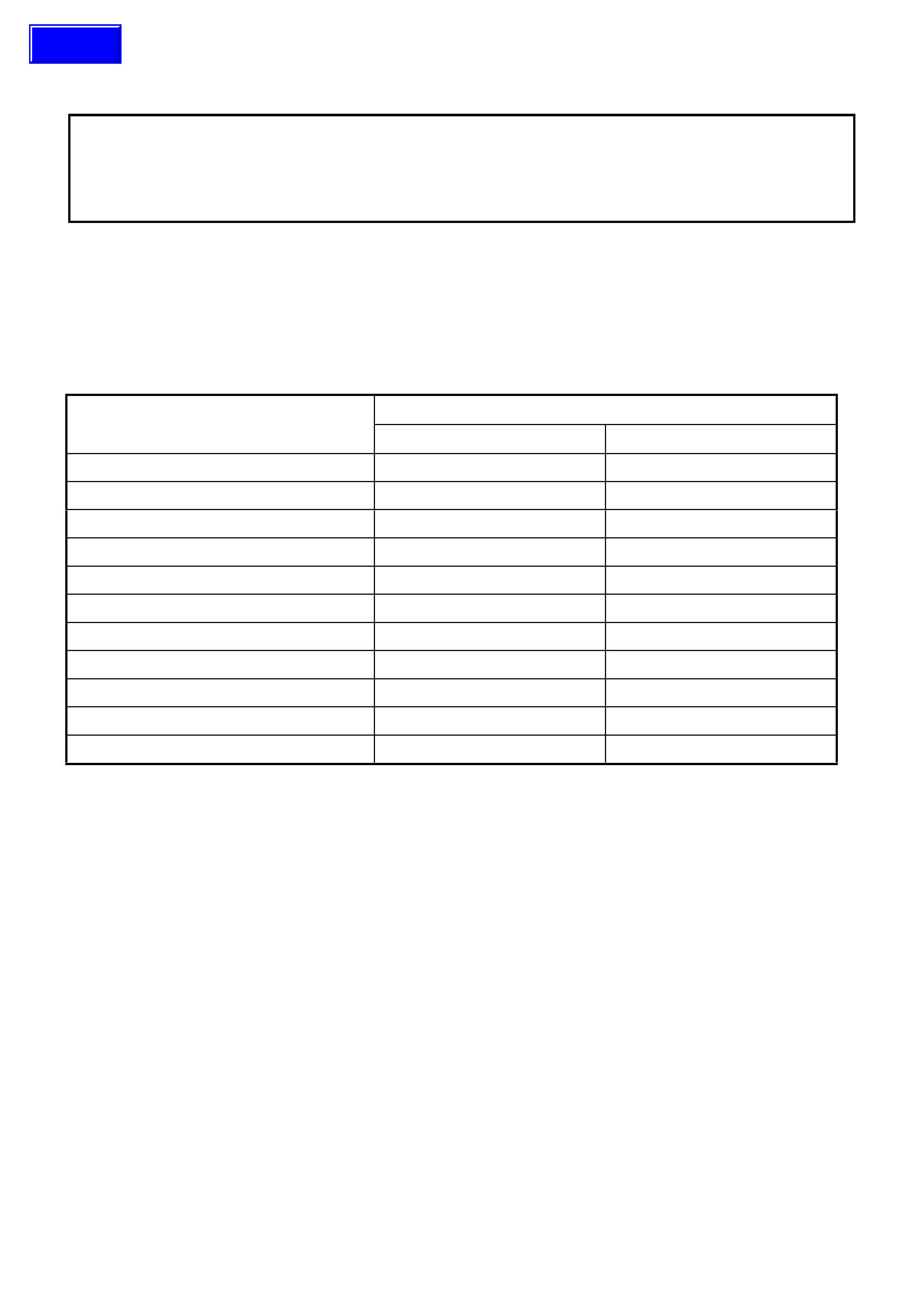
6. Lift the coloured dipstick locking lever, remove
dipstick and check fluid level.
The fluid level should be within the HOT
(hatched) area of the dipstick. If the level is
below this area, add only enough Dexron® III
fluid to bring the level into the HOT (hatched)
area of the dipstick.
NOTE 1: Inaccurate readings will result if the fluid
level is checked immediately after the vehicle has
been operating under any of the following
conditions:
• In high ambient temperatures above 32°C.
• At sustained high speeds
• In heavy city traffic during hot weather.
• Towing
• In commercial use (i.e. taxi)
If the vehicle has been operating under any of the
above conditions, switch of the engine and allow
the vehicle to cool for approximately 30 minutes,
then restart the vehicle and continue from step 2.
NOTE 2: The cold m arkings on the dipstick should
only be used as an indicator when initially filling the
transmission after the fluid has been completely
drained. The fluid should be rechecked when the
transmission is hot.
NOTE 3: Due to the shape of the filler tube, level
readings may be misleading. Look carefully for full
fluid ring on both sides of the dipstick. Recheck if
any doubt of fluid level exists.
NOTE 4: Also check the fluid for contamination,
discolouration or if it smells burnt. This gives an
indication that frictional materials within the
transmission may need replacement. Refer to
Section 7C3 - AUTOMATIC TRANSMISSION in
the VT Series II Service Information for additional
information.
Figure 0B-20
0.5 lt.
T20B006
Figure 0B-21

4.3 FLUID CHANGE
The transmission fluid and strainer should be changed at the time or distance intervals specified in
9.2 MAINTENANCE SCHEDULE in this Section or in the V2 Series Owner’s Handbook.
When changing the transmission fluid, refer to Section 7C1 AUTO TRANS. - GENERAL INFORMATION -
2.2 FLUID CHANGE AND FILTER REPLACEMENT the VT Series II Service Information.

5. BRAKE HYDRAULIC SYSTEM SERVICE
SAFETY AND CAUTIONARY NOTE FOR VEHICLES EQUIPPED WITH ABS/ETC:
Whenever any component that forms part of the ABS or ABS/ETC is disturbed during Service
Operations, it is vital that the complete ABS or ABS/ETC system is checked, using the procedure as
detailed in 4 DIAGNOSIS, ABS or ABS/ETC FUNCTION CHECK, in Section 12L ABS & ABS/ETC, in the
VT Series I (V6) or VT Series II (GEN III V8) Service Information.
5.1 RECOMMENDED FLUID
The recommended fluid for the V2 Series brake hydraulic system is heavy duty brake fluid to Holden’s
Specification HN1796.
5.2 BRAKE FLUID LEVEL CHECK
Check that the fluid level is between the MIN and
MAX level markings on the translucent reservoir
housing.
NOTE: If the fluid is between the markings, do not
rem ove r eser voir c ap, as brake fluid ex pos ed to the
atmosphere will quickly absorb moisture.
Should the addition of fluid be required, wipe clean
the sides of the reservoir cover, then unclip and
remove the reservoir cap. Top up fluid using heavy
duty brake fluid to Holden’s Specification HN1796.
T20B014
Figure 0B-22

5.3 BRAKE FLUID REPLACEMENT
The entire fluid content of the brake hydraulic system must be changed at the time or distance intervals
specified in 9.2 MAINTENANCE SCHEDULE in this Section or in the V2 Series Owner’s Handbook.
Due to the complexities of the brake f luid replacement procedure, refer to Section 5A BRAKES in this Service
Information, noting the following:
When bleeding brakes on vehicles with ABS or ABS/ETC, refer to Section 12L ABS & ABS/ETC in the
VT Series Service Information (V6 Supercharged engine) or VT Series II Service Information (GEN III V8
engine).

6. CLUTCH HYDRAULIC SYSTEM SERVICE
6.1 RECOMMENDED FLUID
The recommended fluid for the V2 Series clutch hydraulic system is heavy duty brake fluid to Holden’s
specification HN1796.
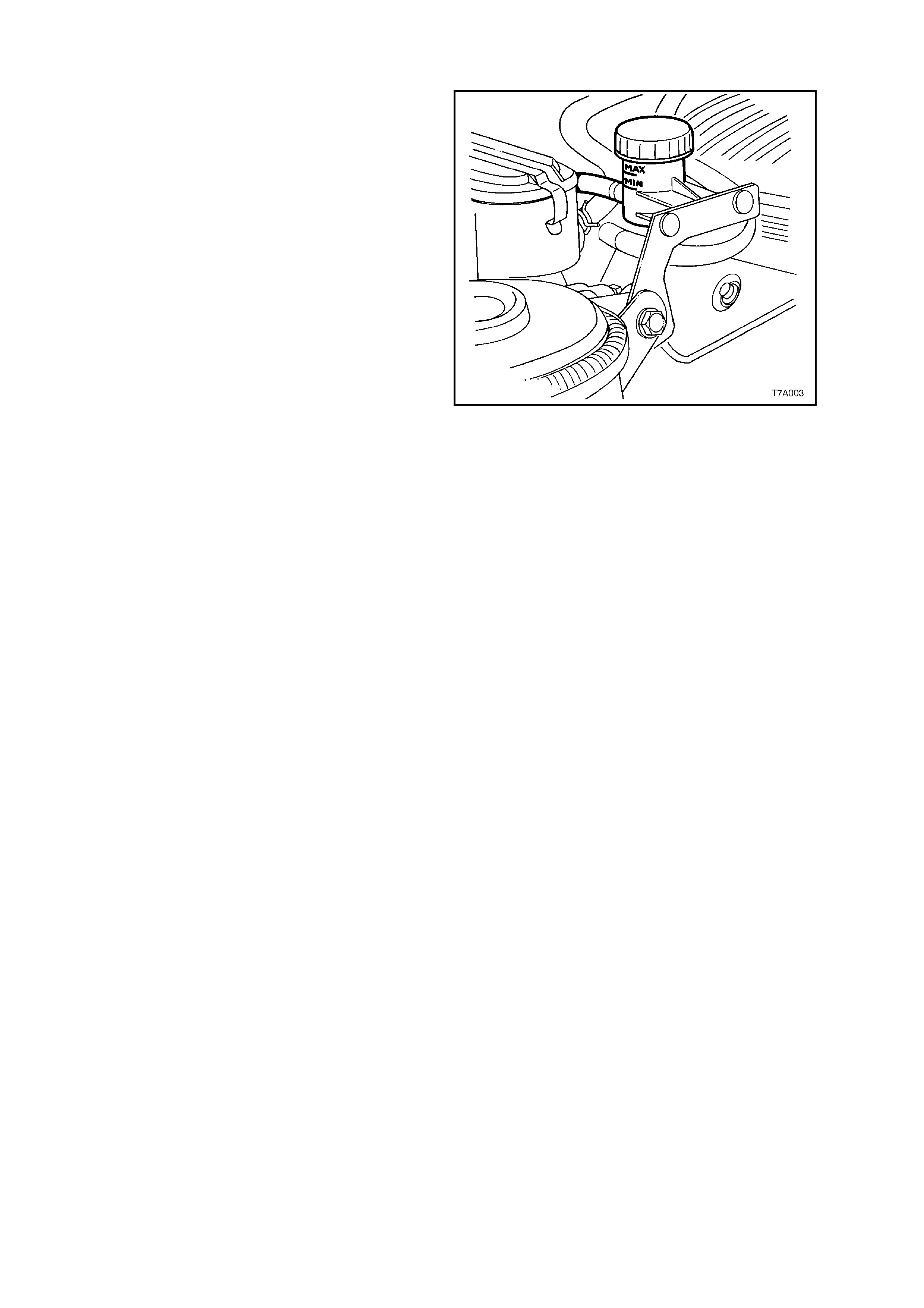
6.2 CLUTCH FLUID LEVEL CHECK
Check that the fluid level is between the two level
markings on the translucent reservoir housing.
NOTE: If the fluid is between the markings, do not
rem ove r eser voir c ap, as brake fluid ex pos ed to the
atmosphere will quickly absorb moisture.
Should the addition of fluid be required, wipe clean
the outer surface of the reservoir cap, then unscrew
and remove the reservoir cap. Top up fluid using
heavy duty brake fluid to Holden’s Specification
HN1796.
Figure 0B-23

6.3 CLUTCH FLUID REP LACEMENT
The entire fluid content of the clutch hydraulic system must be changed at the time or distance intervals
specified in 9.2 MAINTENANCE SCHEDULE in this Section or the V2 Series Owner’s Handbook.
To replace the clutch hydraulic fluid, refer to Section 7A CLUTCH in the VT Series II Service Information.
7. FINAL DRIVE LUBRICATION AND SERVICE
7.1 RECOMMENDED LUBRICANT
Refer to the following chart for recommended lubricant specifications and applications.
ENGINE/FINAL DRIVE
TYPE RECOMMENDED
LUBRICANT
V6 SUPERCHARGED
EXCLUDING LSD 1.6 Litres of Synthetic
Hypoid Gear Oil SAE
80W – 140
such as
Mobillube SHC ID
or
Castrol SAF – XA
ALL GEN III V8 AND V6
SUPERCHARGED
WITH LSD
1.5 Litres of Synthetic
Hypoid Gear Oil SAE
80W – 140
such as
Mobillube SHC ID
or
Castrol SAF – XA
and
0.1 Litres of Sturaco
7098 Oil Additive
7.2 CHECKING FINAL DRIVE LUBRICANT LEVEL
The final drive lubricant level should be checked at
the time or distance intervals specified in
9.2 MAINTENANCE SCHEDULE in this Section or
in the V2 Series Owner’s Handbook.
To check final drive level:
1. Ensure the vehicle is level.
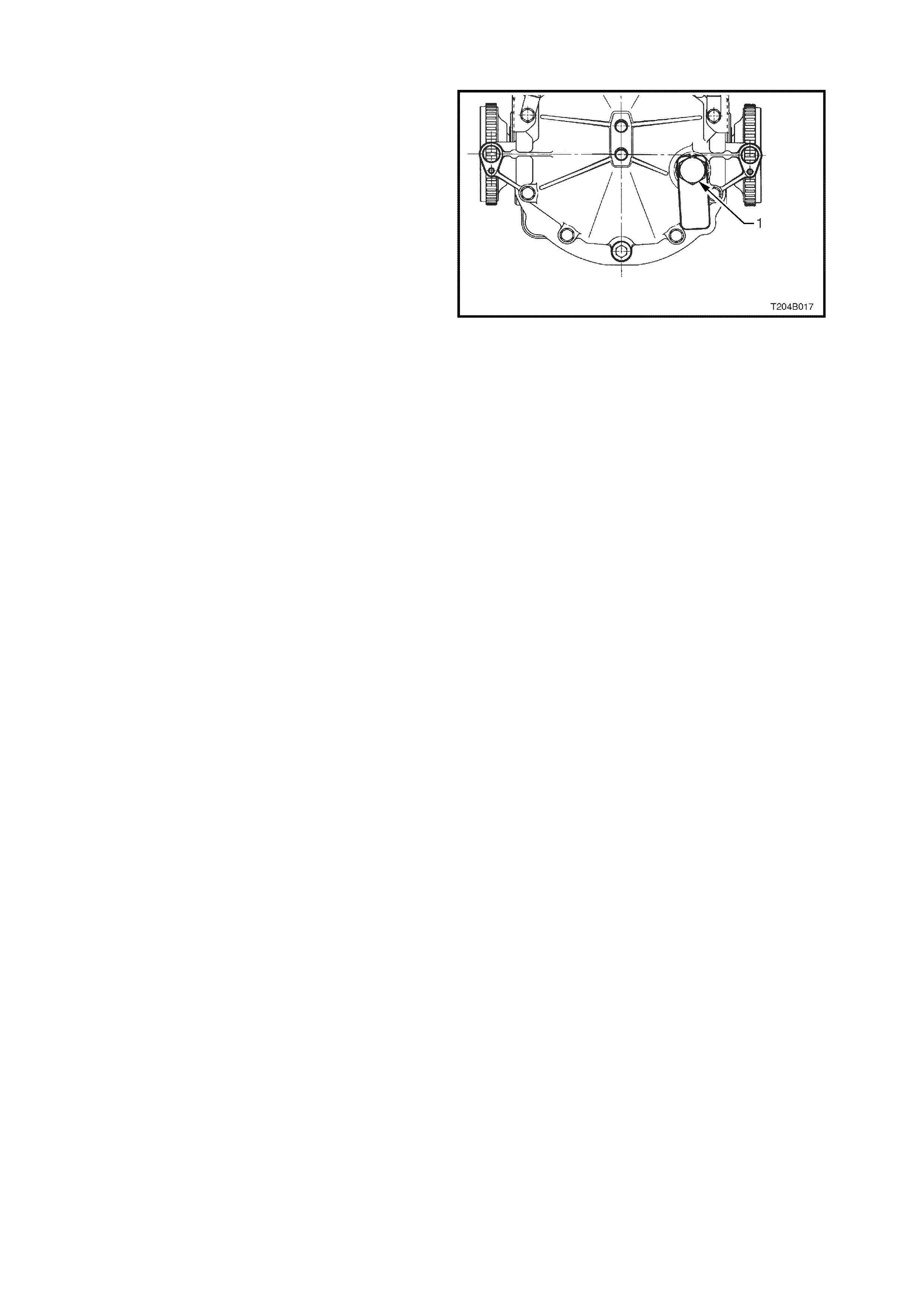
2. The final drive assembly is cold.
3. Clean the area around the filler plug (1).
4. Using a suitable socket and bar, remove the
filler plug.
5. The level is correct when the lubricant is at the
bottom of the filler plug hole.
6. Inspect filler plug for damage, if satisfactory,
refit into the final drive housing.
Figure 0B-24
7.3 PERIODIC SERVICING
Periodic draining of the final drive assembly is not
necessary.
Check for lubricant leaks at every service. If there
is evidence of leakage, repair leak and add
lubricant, if necessary, to the correct level.
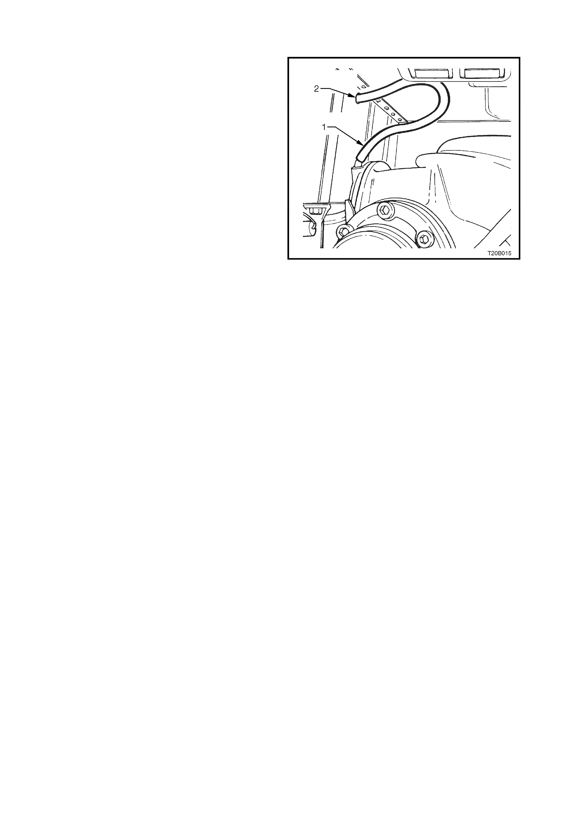
The final drive breather (1) should be checked
regularly to ensure that the hose is not kinked or
damaged.
The top end of the breather hose should be
inserted at least 25 m m into the vehicle underbody
crossmember hole (2).
Figure 0B-25

8. POWER STEERING
8.1 RECOMMENDED FLUID
The recommended fluid for the V2 Series power steering system is automatic transmission fluid, qualified to
Dexron ® III (to Holden specification HN2126).
8.2 CHECKING POWER STEERING FLUID LEVEL
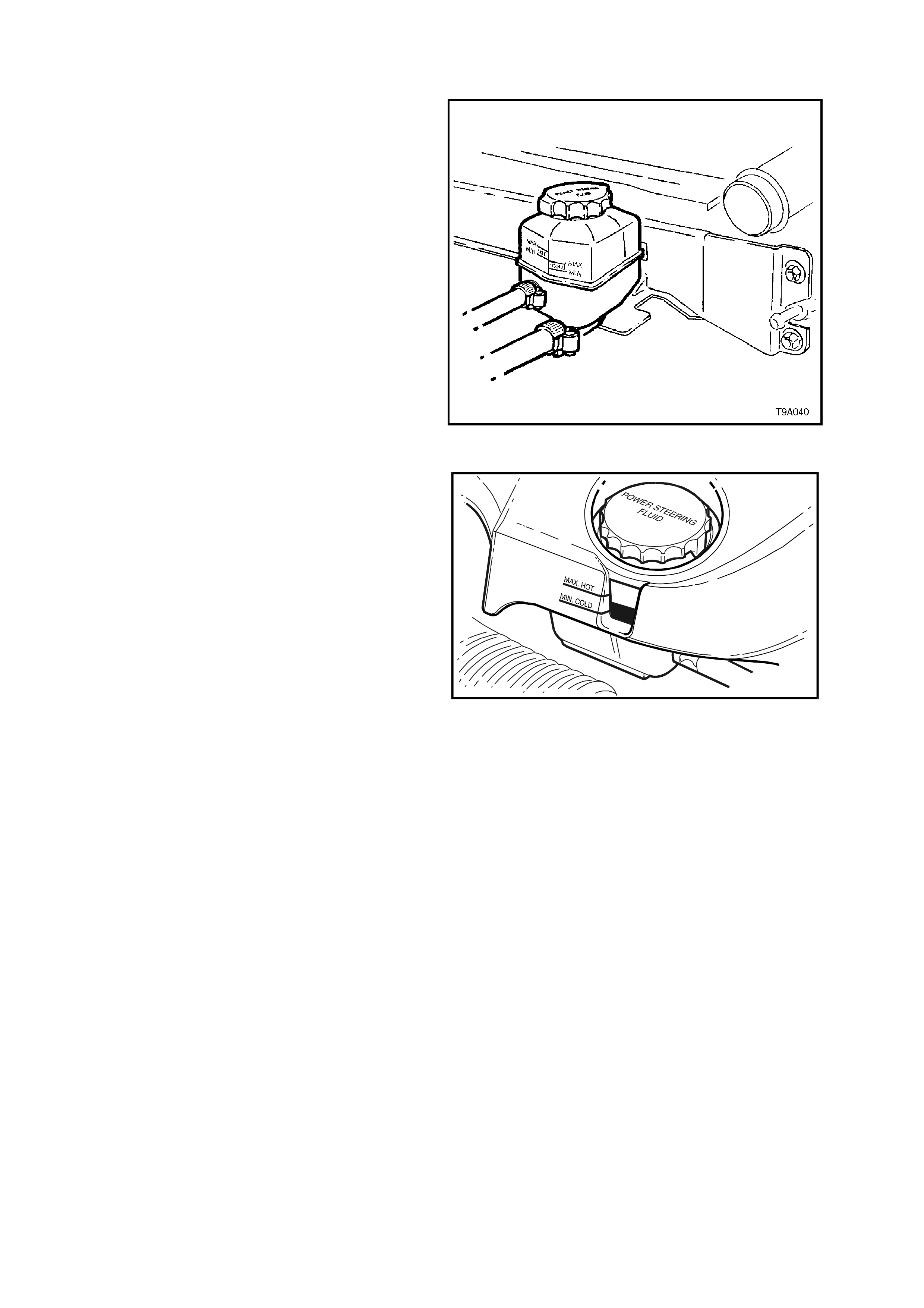
V6 SUPERCHARGED ENGINE
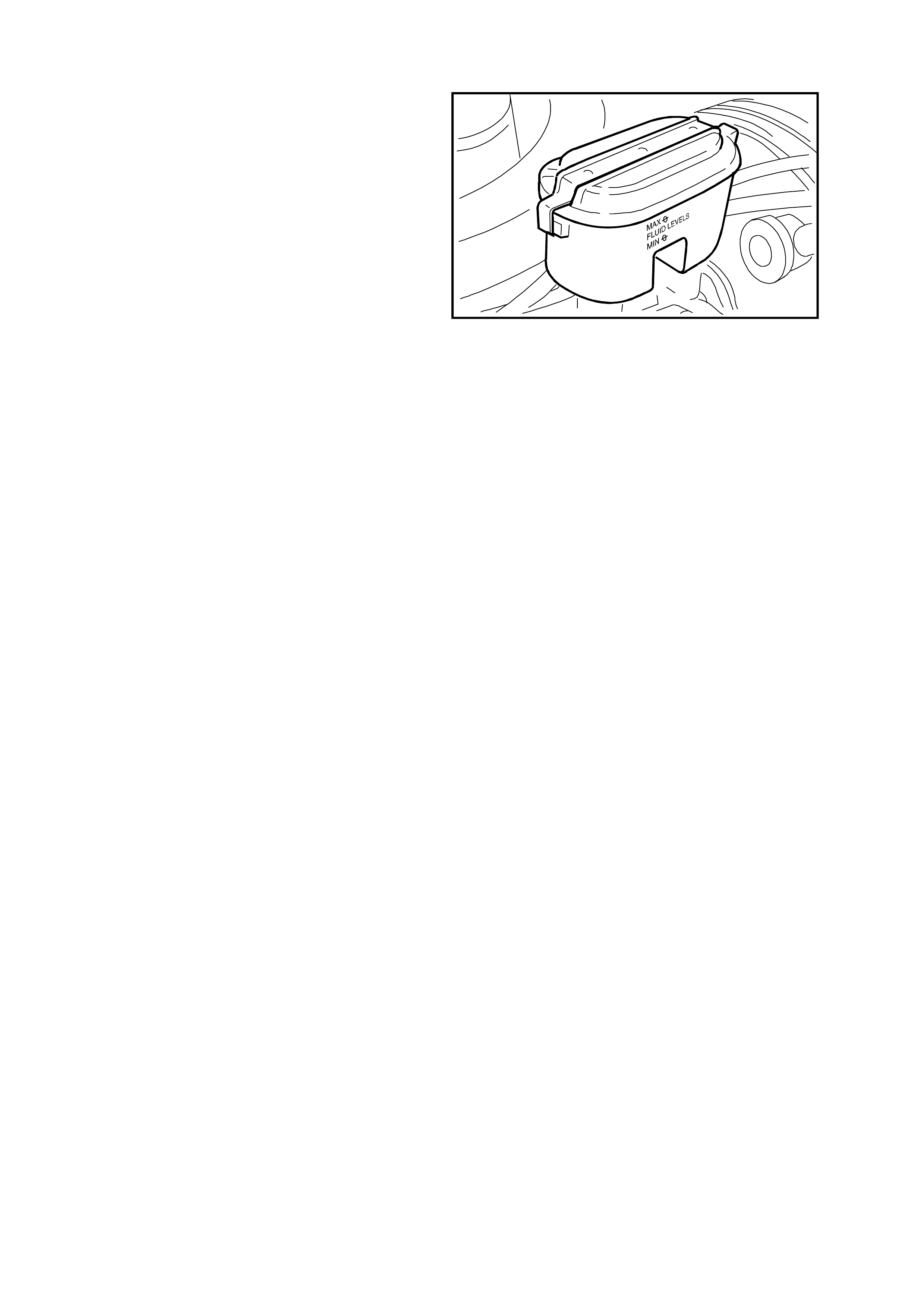
The power steering fluid level is checked by
viewing the fluid through the transparent plastic
side of the reservoir (refer Fig. 0B-26) which is
mounted to a bracket attached to the cooling fan
shroud.
If the f luid is cold, the level should be in the ‘COLD’
range. Similarly, if it is hot, the f luid should be in the
‘HOT’ range. If the fluid level is at the low side of
either range, fluid should be added to bring the f luid
to the correct level.
Figure 0B-26
GEN III V8 ENGINE
With t he en gin e dress co v er remov ed; the power
steering fluid level is checked in the same way as
the V6 Supercharged engine power s teering fluid is
checked, noting the following:
The power steering reservoir is mounted on the
front left hand side of the engine, above the power
steering pump.
With t he engine dress cov er installed; c heck the
power steering fluid level by viewing the fluid
through the cut away in the engine dress cover at
the front of the engine.
The fluid level should be in the range of ‘MIN
COLD’ and ‘MAX HOT’ depending on the
temperature of the fluid. If the fluid level is below
the MIN COLD mark, fluid s hould be added to bring
the fluid to the correct level.
T20B016
Figure 0B-27

8.3 PERIODIC SERVICING
Except under abnormal driving conditions (refer 9.1 ABNORMAL OPERATING CONDITIONS in this Section),
periodic draining of the power steering fluid is not necessary.
Check system for fluid leaks at every service. If there is evidence of leakage, repair leak and add fluid, if
necessary, to the correct level.
9. SERVICING
9.1 ABNORMAL OPERATING CONDITIONS
If the car is driven under any of the abnormal conditions listed below it is recommended that some items be
serviced more frequently than in the maintenance plan.
The extra services are only required while the car is driven under the abnormal conditions. If any of these
conditions are encountered on a one off basis, then any additional servicing should be for that time only. As a
guide, if the car is operated continually over a period of one m onth or 1000 km under the abnorm al conditions,
then additional servicing may be required.
ABNORMAL CONDITIONS
A When driving less than 10000 km in six months.
B Dust, dirt, loose road material.
C Muddy and wet areas.
D Cold weather (below 5°C) and when most trips are less than 5 km.
E Stop-start driving, excessive idling or low speed operation as experienced in inner city driving e.g. Door to
door delivery.
F Caravan or trailer towing.
G Extended heavy load high speed operation in temperatures above 35°C.
H When driving more than 250000 km per 5 years.
EXTRA SERVICES REQUIRED
SERVICE REQUIRED ABNORMAL CONDITION
Change engine oil @ 6 months A
Change auto trans fluid and strainer @ 4 years A
Change automatic transmission fluid and strainer @ 20000 km E F G
Inspect front suspension and steering for leaks, wear or damage @
5000 km B C
Replace engine oil filter @ 5000 km or 3 months (whichever comes
first) B
Change engine oil @ 5000 km or 3 months (whichever comes first) B D F G
Relace air cleaner element @ 20000 km B
Inspect and clean park brake linings @ 20000 km B C
Change differential oil @ 20000 km F G
Change brake fluid @ 1 year if 1600 kg (or higher) tow bar fitted * F
Change power steering fluid @ 50000 km F G
GEN III V8 only: change engine coolant H
Carbon canister: inspect @ 20000 km and change @ 80000 km B C
* Brake fluid deteriorates with time and should normally be replaced every two years. However, heavy duty
towing requires fresher fluid due to the higher demand on the brake system. Therefore, brake fluid should be
replaced each year if a 1600 kg (or higher) tow bar is fitted, so that the brake system can cope with the next
year’s towing requirements.
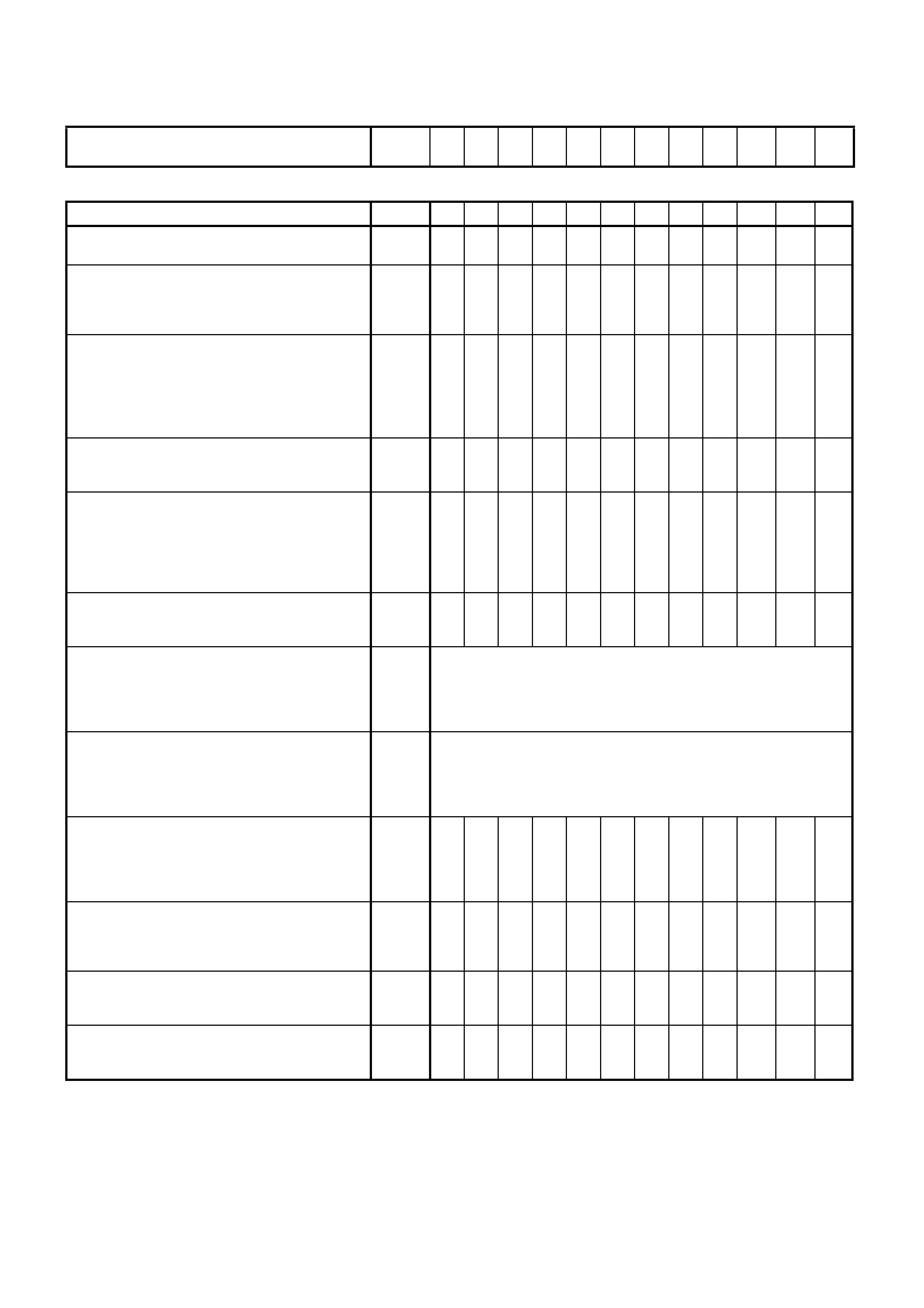
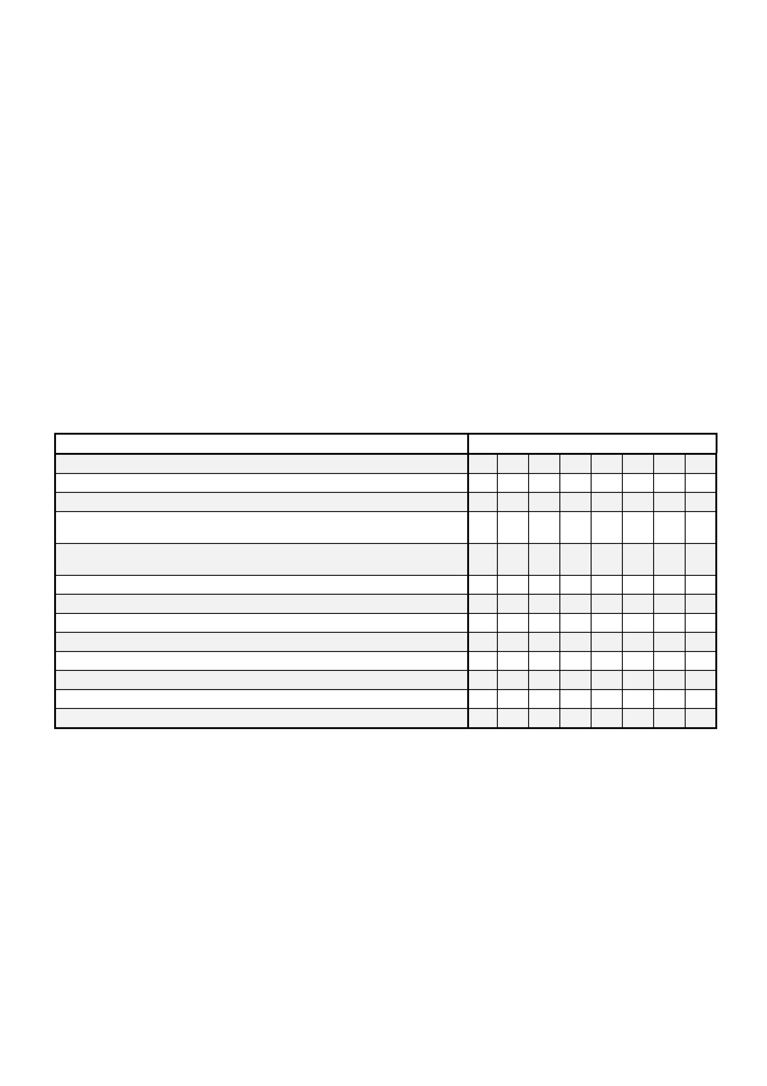
9.2 MAINTENANCE SCHEDULE
The f ollowing chart pr ovides the maintenanc e sc hedule, together with a refer enc e of where to find the necessar y
service information in the V2 Series Service Information.
Use odometer reading or years, whichever occurs
first. x 1000
km 1.5 10 20 30 40 50 60 70 80 90 100 110
UNDER HOOD
Extra
Change engine oil and engine oil filter (Refer this
Section). * X X X X X X X X X X X
Check fluid levels: brake, clutch, power steering,
autom atic transm issi on, washer (Refer this S ection,
& 12C WIPERS/WASHERS & INSTRUMENTS in
the VT S eri es Servic e I nformat i on).
X X X X X X X X X X X
Check coolant inhibitor % with tester and check
level (pressure test system if level is low). (Refer
Section 6B1 ENGINE COOLING -V6 ENGINE in
the VT Series Service Information or 6B3 ENGINE
COOLING - GEN II I V8 ENGINE in the VT Series II
Service Inform ation).
X X X X X X X X X X X
Check battery electrolyte and fluid level, if
applicable (Refer Section 12A BATTERY in the VT
Series S e rvi ce Information).
X X X X X X X X X X X X
Engine acc ess ory drive belt s, chec k length i ndicat or
and belt condition (Refer Section 6A1-1 ENGINE
MECHANICAL - V6 ENGINE in the VT Series
Service Information or 6A3-3 ENGINE
MECHANICAL - GEN III V8 ENGINE in VT Series II
Service Inform ation).
X X X X
Check for signs of deterioration and/or leaks from
engine, fluid reservoirs, air ducts, all hoses and
clamps.
X X X X X X X X X X X
(V6 Supercharged engine) Drain and refill cooling
system with recommended inhibitor, clean outside
of radiator and A/C condenser (Refer Section 6B1
ENGINE COOLING -V6 ENGINE in the VT Series
Service Inform ation).
Change every 2.5 years (regardless of km)
(GEN III V8 engine) Drain and refill cooling system
with recommended inhibitor, clean outside of
radiator and A/C condenser (Refer Section 6B3
ENGINE COOLI NG - GEN III V 8 ENGINE in the VT
Series II Service Information).
* Change every 5 years
Replace engine air cleaner element (Refer Section
6C1-3 POWERTRAIN MANAGEMENT - V6
ENGINE in the VT Series Service Information or
6C3-3 POWERTRAIN MANAGEMENT - GEN III V8
ENGINE i n the VT Series II S ervi ce Information).
* X X
(Supercharger) Check supercharger oil level (Refer
Section 6A1-2 ENGINE MECHANICAL - V6
SUPERCHARGED in the VT Series Service
Information).
X X
(V6 Supercharged engine) Replace spark plugs
(Refer Section 6D1-3 IGNITION SYSTEM - V6
ENGINE i n the VT Series Servic e I nformat i on)
X X
(GEN III V8 engine) Replace spark plugs (Refer
Section 6D3-3 IGNITION SYSTEM - GEN III V8
ENGINE i n t he VT Series II Service Information)
X
NOTE: All items marked with an asterisk in the ‘Extra’ column, require additional servicing under some driving
conditions. Refer to 9.1 ABNORMAL OPERATING CONDITIONS in this Section.
UNDER CAR
Use odometer reading or years, whichever occurs
first. x 1000
km 1.5 10 20 30 40 50 60 70 80 90 100 110
Extra
Replace fuel filter (Refer Section 6C1-3
POW ERT RAIN MANAGEMENT - V6 ENG in t he VT
Series Service Information or 6C3-3 POWERTRAIN
MANAGEMENT - GEN III V8 ENGINE in the VT
Series II Service Information).
X X
Check f i nal dri ve oi l l evel (Refer this Section). X X
Check f i nal dri ve and aut o trans for leaks. X X X X X X X X X X X X
Change auto trans fluid and strainer (Refer Section
7C-4 AUTOMATIC TRANSMISSION in the VT
Series S e rvi ce Information).
* X
Check manual trans mis sion for leak s. X X X X X X X X X X X
Change differential oil (Refer Section 4B FINAL
DRIVE & DRIVE SHAFTS in the VT Series Service
Information).
* Change not required under norm al dri ving conditions
Inspect front and rear disc pads for wear and disc
surface condition (Refer Section 5A STANDARD
BRAKES in the VT Series Service Information).
Rotate wheels (Refer Section 10 WHEELS &
TYRES i n t he VT Series S ervi ce Information).
X X X X X X X X X X
Check park brake linings and drums for wear (Refer
Section 5A STANDARD BRAKES in the VT Series I
Service Inform ation).
* X X
Inspect tyres for irregular wear or damage. Check
for damaged wheels. Check air pressures. (Refer
Section 10 WHEELS & TYRES in the VT Series
Service Inform ation)
X X X X X X X X X X X X
Drain, refill and bleed brake system, check brake
perform ance when road testing (Ref er t hi s Sect i on). * Change every 2 years (regardless of km) under normal dri vi ng
conditions
Drain, refill and bleed clutch system (Refer Section
7A CLUTCH - V6 in the VT Series Service
Inform ation or 7A1 CLUTCH - GEN I II V8 ENGINE
in the VT Series II Servic e I nformat i on.
Change every 2 years (regardless of km)
Check all brake and fuel lines and hoses for
conditi on, attachment and routi ng. X X X X X X X X X X X
Inspect front and rear suspension and steering
system for damaged, loose or missing parts, signs
of wear or lack of lubric ation. Inspect power steering
lines and hoses for condition, attachment and
routing, leaks, etc. Check condition of all rubber
boots and c overs.
* X X X X X X X X X X X
Inspect exhaust and adjacent underbody. Look for
damaged, missing or out-of-position parts, open
seam s, holes, or loose connections.
X X X X X X X X X X X
Inspect constant velocity joint for damage or torn
boot. X X X X X X X X X X
Clean and lubricate automatic transmission shift
linkage. X X X
Clean out air c ondi tioning drain tubes. X X
Check carbon canister for leaks or restrictions
(Refer Section 6E1 EMISSION CONTROL - V6
ENGINE in the VT Series Service Information or
6E3 E MISSION CONTROL - GEN II I V8 ENGINE i n
the VT S eri es II S ervi ce Information).
* X
X X
NOTE: All items marked with an asterisk in the ‘Extra’ column, require additional servicing under some driving
conditions. Refer to 9.1 ABNORMAL OPERATING CONDITIONS in this Section.
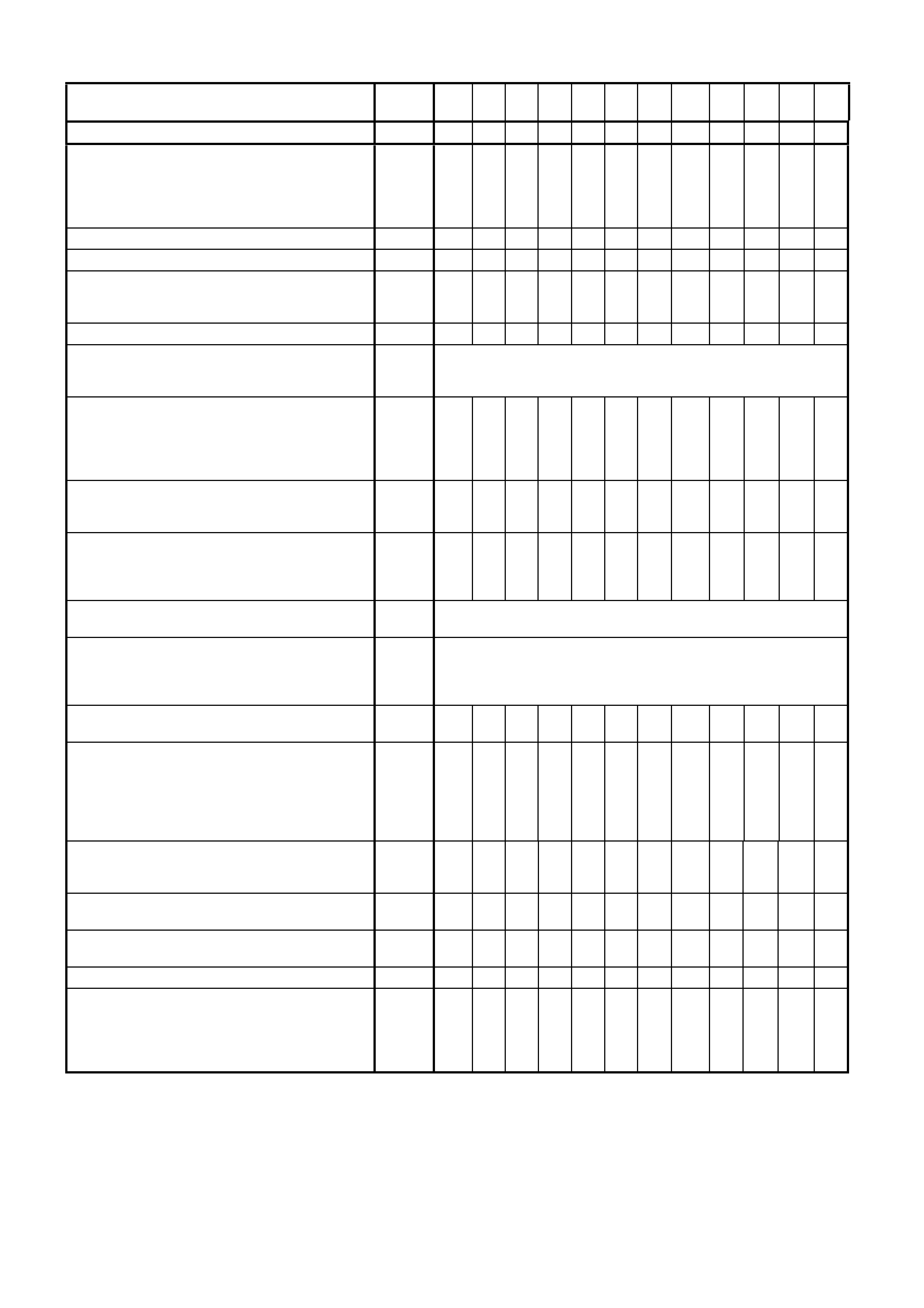
CAR INTERIOR
Use odometer reading or years, whichever occurs
first. x 1000
km 1.5 10 20 30 40 50 60 70 80 90 100 110
Extra
Check park brake operation. X X X X X X X X X X X
Inspect seat belts, check webbing condition, buckle
operation and retrac tor mec hani sm. X X X X X
CAR EXTERIOR
Check operat i on of all exterior lights. X X X X X X X X X X X X
Lubricate hood catch, door hinges, rear door links
only and lock cylinders . X X X X X
Check t ransmitter range of s ecurity sys tem. X X X X X X X X X X X
ROAD TEST
Check braking, steering, engine response and
transmission operation. Check operation of cruise
control. Check park pawl operation. Check A/C
perform ance. Check neutral start switch.
X X X X X X X X X X X X
NOTE: All items marked with an asterisk in the ‘Extra’ column, require additional servicing under some driving
conditions. Refer to 9.1 ABNORMAL OPERATING CONDITIONS in this Section.

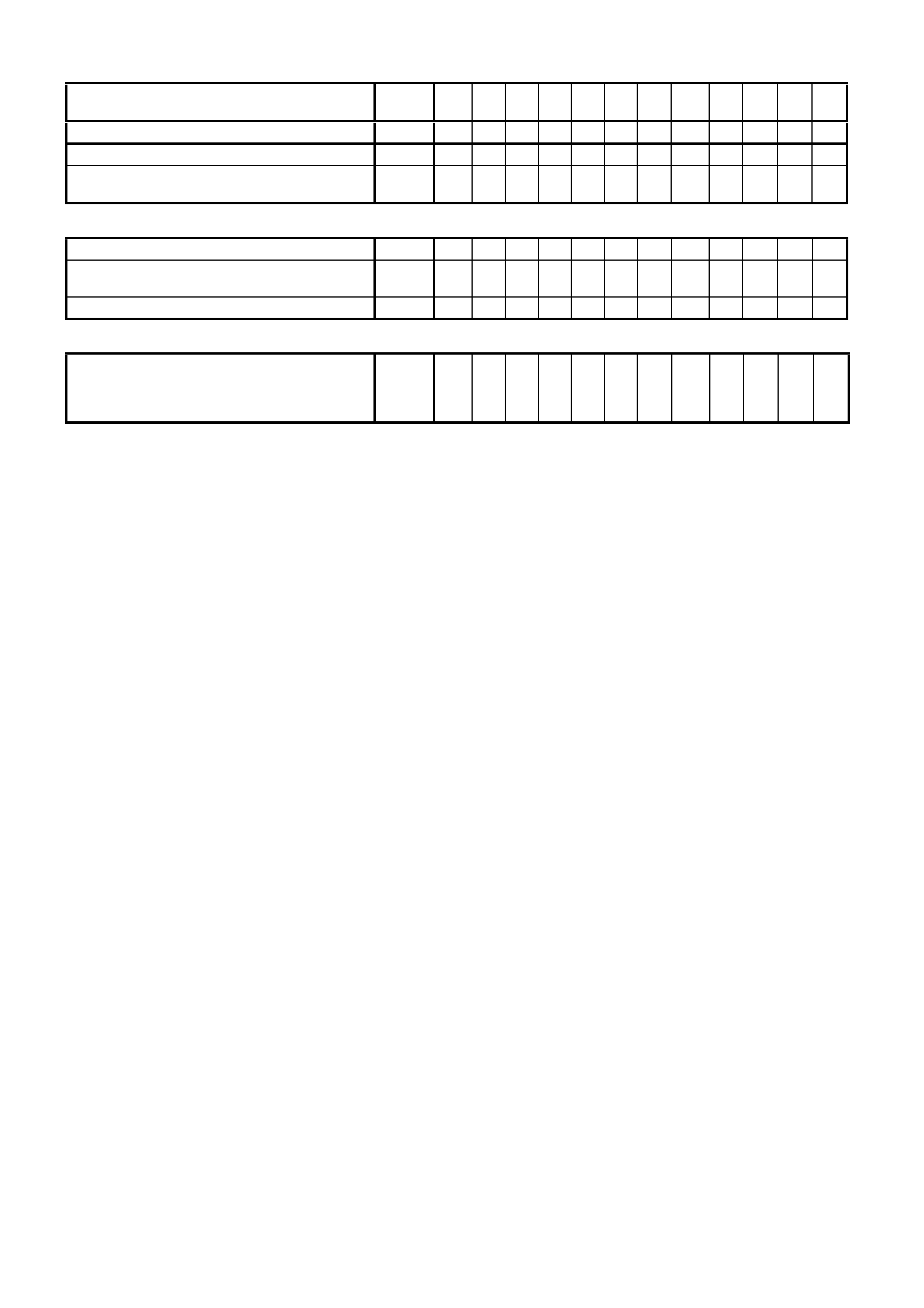
10. LUBRICANT RECOMM ENDATIONS
APPLICATION LUBRICANTS
Body - Door Lock Striker Bolts
Door Lock Fork Bolts
Instrument Compartment Lid Lock Tongue
Engine Hood Catch
Engine Hood Lock
Engine Hood Hinge
Door Hinge
Rear Compartment Lid Hinge
Rear Compartment Lid Lock Mechanism
Door Window Regulators
Door Window Guides and Cams
Front Seat Adjuster
Recliner Assembly - Front Seat
Window Regulator Friction Surfaces
Front Door Lock Cylinder
Ignition and Steering Lock Cylinder
Rear Compartment Lid Lock Cylinder
Instrument Panel Compartment Lock Cylinder
Starter Motor Drive Mechanism
Starter Motor Bearings
Park Brake Shoe Assemblies
Brake Adjusting Screw and Nut
Park Brake Shoe Actuator Pivots
Brake and Clutch Hydraulic System
Propeller Shaft Centre Constant Velocity Joint
Final Drive
Engine Oil:
All Models
Engine Supercharger
Bearing Face of Clutch Throw-Out Bearing, input
shaft splines and spigot - Tremec 6 speed manual
transmission (GEN III V8 Engine)
Clutch and Brake Pedal Pivots and Bushes
Accelerator Pedal Pivots
Manual Transmission:
GEN III V8 Engine
Automatic Transmission
Automatic Transmission Control Pivot Points
Steering Gear - (Hydraulic)
Windshield Wiper Pivot Points
Coolant Concentrate
V6 Supercharged engine
GEN III V8 engine
Solidoil
NLGI No. 1 Lithium Grease (with Zinc Oxide) meeting Holden
Specification HN1225
Lithium Based Grease Holden Specification Number HN1416
Powdered Graphite (applied through key aperture - do not oil)
Molybdenum Disulphide Grease to Holden Specification HN1271
Engine Oil at Overhaul
Special HT Grease to Holden Specification HN1227
Special HT Grease to Holden Specification HN1227
Molybdenum Disulphide Grease to Holden Specification HN1587
Heavy duty brake fluid to Holden Specification HN1796 (Part No.
92026651)
Molybdenum Disulphide Grease to Holden Specification HN1271
Synthetic Hypoid Gear Oil SAE 80W-140
such as Mobilube SHC ID or Castrol SAF-XA (or equivalent) and
friction modifying additive (Sturaco 7098)
10W-30 ILSAC GF2 Quality Engine Oil
(If unavailable,use SG, SH or SJ quality engine oil)
Supercharger Oil (Part No. 12345982)
Molybdenum disulphide grease to Holden Specification HN1271
Molybdenum Disulphide Grease to Holden Specification HN1271
Lithium Grease to Holden Specification HN1225
Dexron® III Automatic Transmission Fluid to Holden Specification
HN2126
Dexron® III Automatic Transmission Fluid to Holden Specification
HN2126
Molybdenum Disulphide Grease to Holden Specification HN1416
Dexron® III Automatic Transmission Fluid to Holden Specification
HN2126
Molybdenum Disulphide Grease to Holden Specification HN1271
Inhibited Glycol Coolant to Holden Specification HN2043 only,
at 50% by volume in water.
50% Dexcoolâ to GM Specification GM 6277M and 50% water.