
SECTION F – TRANSMISSION
CAUTION:
HSV vehicles are equipped with a Supplemental Restraint System (SRS). An SRS
consists of seat belt pre-tensioners (fitted to all front seats), and a driver’s-side air
bag or a driver’s-side air bag AND a passenger’s-side air bag. Refer to CAUTIONS,
Section 12M, before performing any service operation on or around SRS
components, the steering mechanism or wiring. Failure to follow the CAUTIONS
could result in personal injury or unnecessary SRS system repairs.
PURPOSE
The purpose of this bulletin is to provide inf orm ation on the transm ission ass emblies fitted to the HSV VT and HSV
VS m odels. This information is designed to supplement the information contained in the Holden VT and VS series
Service Manuals, and details are given where differences occur between the HSV models and standard Holden
models. A series of instruction drawings describe the design changes and indicate specific part numbers, fitting
instructions and relevant notes for vehicle servicing.
NOTE:
If specific technical data on a HSV model is not contained in this supplement, obtain data for that model from the
relevant Holden VT or VS series Service Manual Supplement. References are made throughout this section to
Holden Service Manuals, to assist in providing information for specific service operations.
CAUTION:
W hen hois ting (or j acking) HSV models , ensure that the lifting head of the hoist lifts on the chas sis before the arm
of the hoist contacts the side-skirt

1. TRANSMISSION - GENERAL INFORMATION
A range of m anual and autom atic transm iss ions are fitted to the HSV VT and HSV VS m odels. This range ex tends
from the standard Holden options (four-speed autom atic and five-speed manual), to HSV-designed automatic and
six-speed manual options fitted to HSV 5.7 litre m odels. Each of the HSV transm ission options has been s ubjected
to extensive testing and development to prove the operational reliability of the engine-transmission combination.
HSV models fitted with standard Holden transm iss ions are to be serviced in ac cordance with the Holden VT Series
Service Information CD, refer Section 7B2 MANUAL TRANSMISSION - V8 ENGINE. Clutch mechanisms
associated with these vehicles are also addressed in the Holden VT Series Service Information CD, refer
Section 7A CLUTCH. HSV models fitted with special-to-type transmissions, and associated clutches where
appropriate, are to be serviced in accordance with the procedures contained in this manual
The following table provides a summary of Standard (S) and Optional (O) transmissions fitted to HSV VT and VS
models.
TABLE F-1
MANUAL AUTOMATIC
MODEL GMH
290 BW
T56 GMH
8HBD HSV
8HJD HSV
8HSD
GTS 220 SEDAN S O
SENATOR
220 SEDAN OS
SENATOR 220
ESTATE S
CLUBSPORT S O
SENATOR
195 SEDAN OS
SENATOR 195
ESTATE S
MANTA S O
GRANGE 215 S
GRANGE 185 S
MALOO O S

2. CLUTCH
HSV CLUTCH
GENERAL DESCRIPTION
HSV VT models fitted with the BORG W ARNER T 56 manual trans mission, are equipped with a HSV design c lutch
and clutch operating system. A single, dry-disc-type clutch plate is used in these manual transmissions and the
clutch consists of two basic assemblies as follows:- (see Figure F-1)
the driven plate and facing assembly, and
the cover, pressure plate and diaphragm spring (clutch) assembly.
The driven plate and f acing as sem bly has a non-asbestos, conventional clutch f acing riveted to each s ide of waved
disc springs which provide axial cushioning during engagement. The disc springs are riveted to the circumference
of the hub assembly, which incorporates c oil springs for torsional c ushioning, and an internal s pline that m ounts the
assembly on the maindrive-gear clutch shaft which is externally splined
The cover, pressure plate and diaphragm spring assembly is mounted over the driven plate assembly and then
bolted to the flywheel. Retraction of the pressure plate by means of retracting springs and release of the driven
plate, is achieved when the diaphragm spring is operated.
On all models, the clutch assembly is totally enclosed in a 360 degree clutch housing which must be removed to
gain access to the clutch.
The c lutch is a “pull-type” design and incorporates light weight alloy com ponents which reduce the rotational m ass.
The clutch assembly connects to the standard Holden master cylinder and remote reservoir, see Figure F-2.
The clutch throw out bearing is always in contact with the diaphragm f ingers when correctly adjusted. It is actuated
by a clutch fork which is attached to a pivot stud in the clutch housing.
The c lutch dis engages drive to the tr ansmis sion input s haf t when hydraulic pressur e f r om the clutc h master c ylinder
(see Figure F -2) pushes the slave c ylinder pus h rod, this rotates the releas e fork about its pivot pulling the releas e
bearing against the clutc h cover assem bly spring lif ting the friction fac e and releasing the drive to the clutch driven
plate see Figure F-3. The raised hub of the driven plate faces toward the recess in the engine flywheel. Refer Figure
F-1. The engine is fitted with a unique bronze clutch shaft spigot bearing.
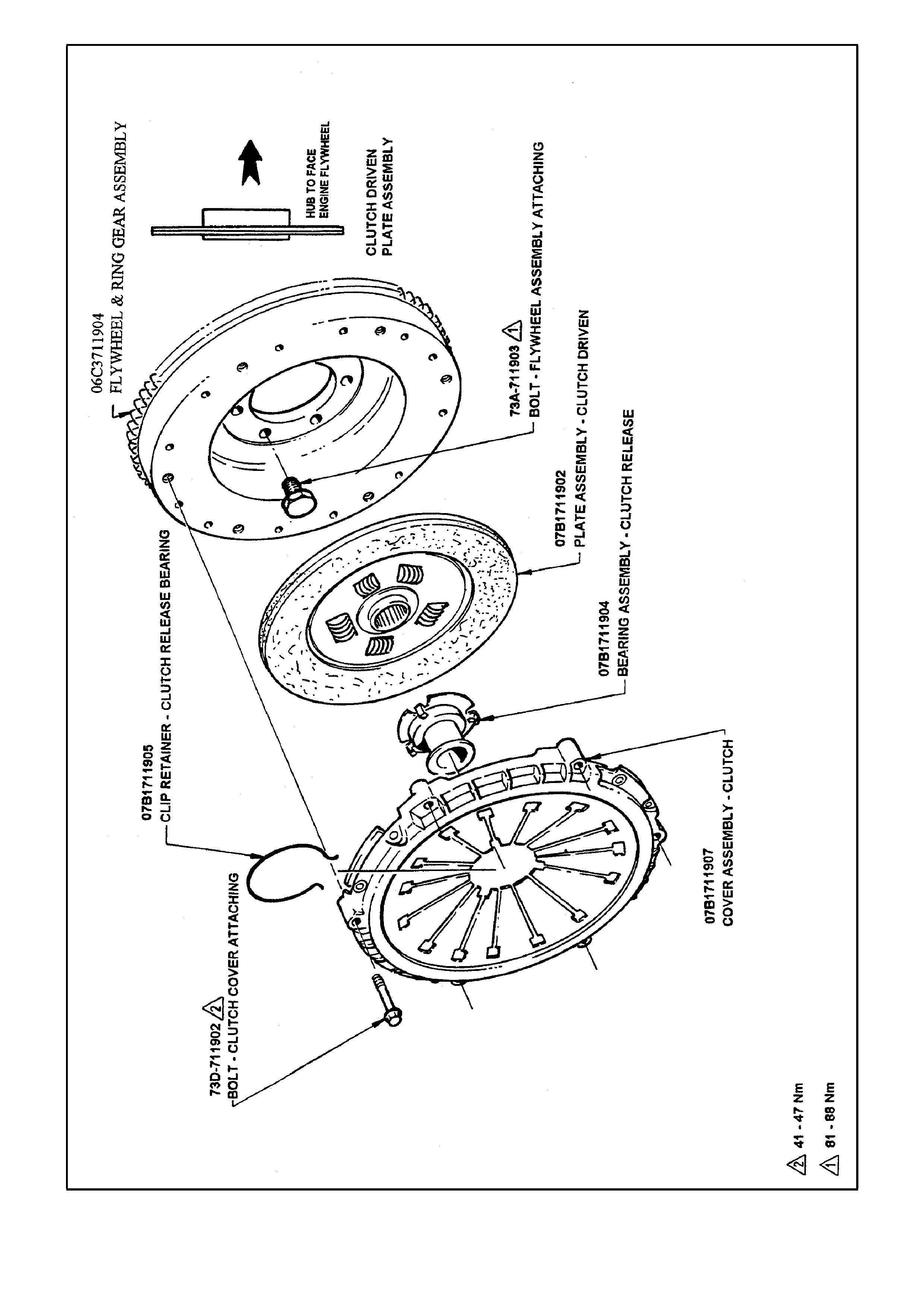
Figure F-1 - HSV Clutch Assembly
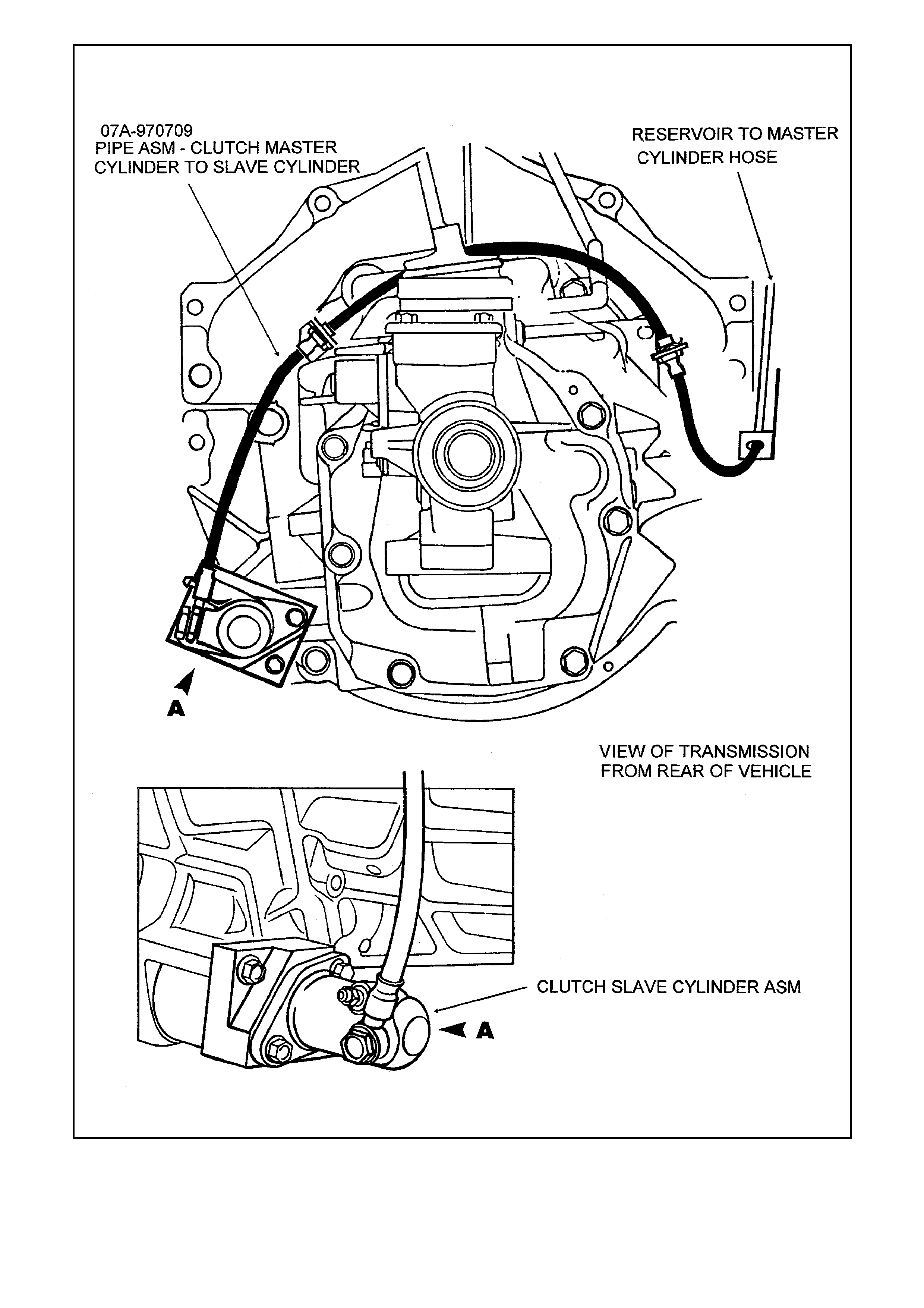
Figure F-2 - Clutch System
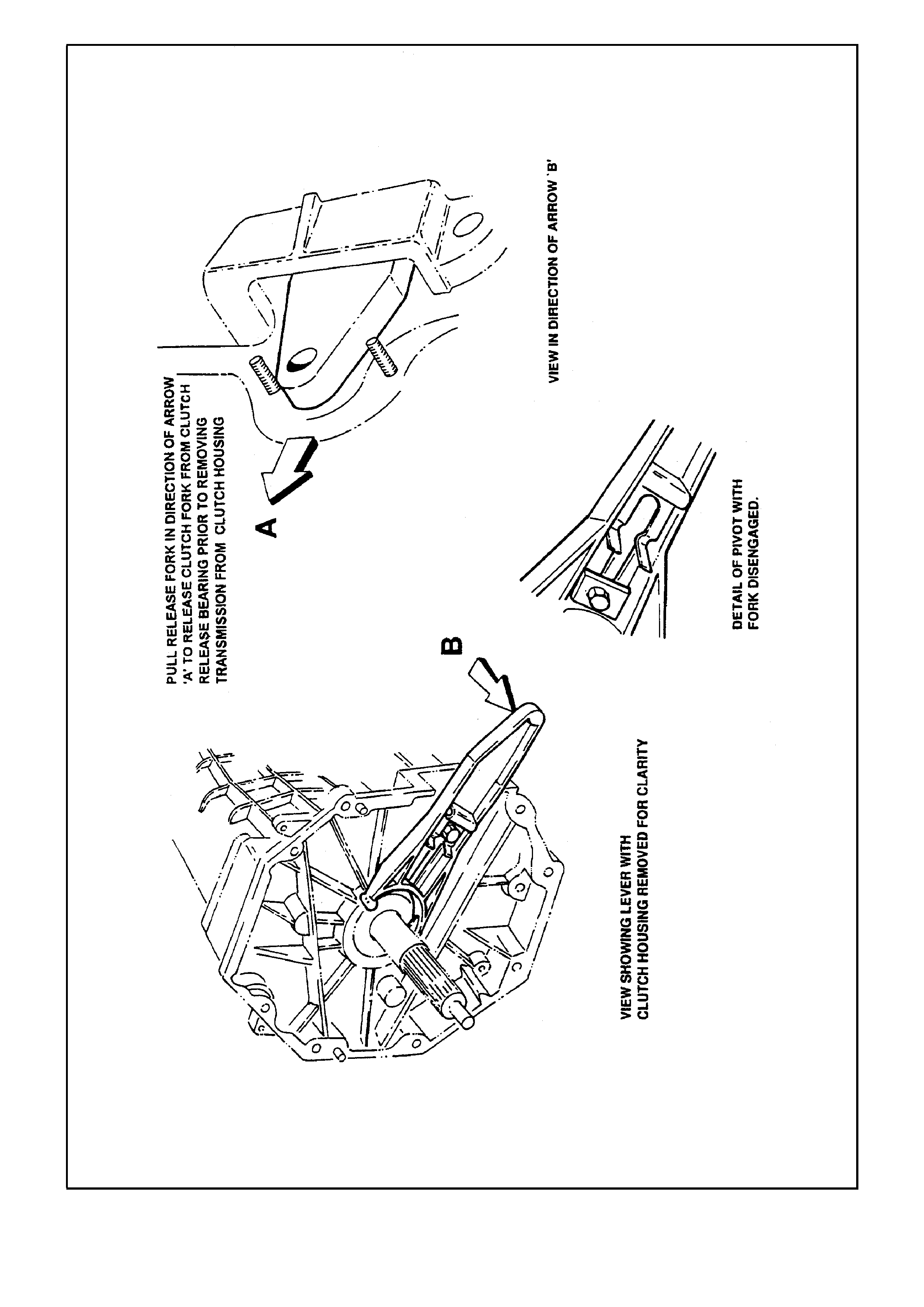
Figure F-3 - Clutch Fork Disengagement

SERVICE P ROCE DURES
CLUTCH REMOVAL AND INSTALLATION
1. Remove transmission assembly, refer TRANSMISSION REMOVAL in this section. With transmission
assembly removed, remove clutch housing dust cover attaching screws and remove dust cover.
2. Remove bolts attaching clutch housing to engine assembly.
3. Disengage clutch housing from dowel pins on rear face of the engine ass em bly by sliding rear wards and rotate
bell housing anti-clockwise to allow removal through transmission tunnel.
4. Insert a suitable clutch centering tool to support the clutch driven plate.
5. Loosen the 6 clutch c over attaching bolts in the diagonal sequenc e so as to releas e the clutc h cover clam ping
load evenly.
6. Remove the 6 clutch cover attaching bolts, clutch cover, centering tool and driven plate.
7. Installation of the clutch is the reverse of the removal procedure.

CLUTCH ADJUSTMENT
The HSV Clutch Assembly is a sealed hydraulic unit and no adjustments to the clutch system are provided.
Adjustment of the clutch pedal height is carried out by adjusting the master cylinder operating plunger: a bleed
screw is also provided on the clutch slave cylinder to bleed the hydraulic system. Although the clutch system is
unique to specific HSV models, service procedures and adjustment parameters are the same as the standard
Holden clutch. Theref ore, the clutch system is to be s erviced in accordance with procedur es detailed in the Holden
VT Series Service Information CD, refer Section 7A CLUTCH.


3. TRANSMISSION - MANUAL
BORG-WARNER T56
BORG-WARNER T56 manual transmissions are fitted to HSV VT models listed in Table F-1. This transmission
features synchromes h on all for ward gears and in r everse. T he selec tion of r everse gear is electr onically locked out
of engagement at any speed above a nominal vehicle forward speed of 10 to 15 kph or 2000 rpm engine speed.
Ratios: First 2.66:1
Second 1.78:1
Third 1.30:1
Fourth 1.00:1
Fifth 0.74:1
Sixth 0.50:1
Reverse 2.90:1
Design Maximum
Torque Rating: 615 Nm
Dry Weight: 56.7 kg

SERVICE OPERATIONS
The transmission oil must be changed in accordance with the owners’ handbook. Use Dexron IIIE transmission
fluid. The transmission lubrication capacity is 3.9 litres.
4. ELECTRICAL
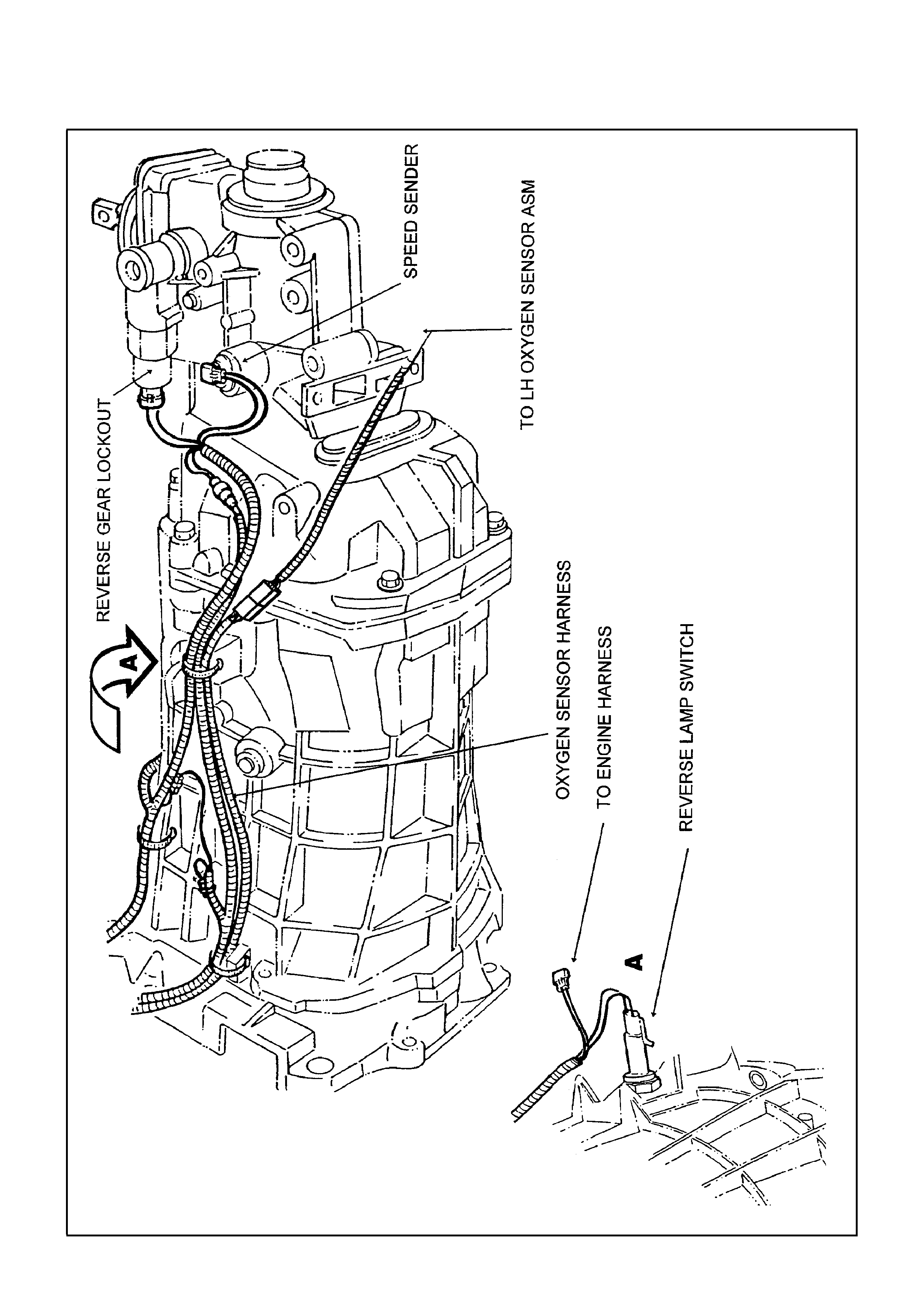
The transmission assembly is fitted with a specifically designed wiring harness for the speed sender, reversing
lamps and reverse lock out. Refer Figure F-4.
Figure F-4 - Wiring Harness Manual Transmission

5. OVERHAUL PROCEDURES
1. The Dealer will contact BTR Austr alia before carrying out “any” work on the transm ission. The Dealer s hall be
prepared with the following information:
Model and serial number of transmission.
Vehicle serial number, build date and registration number.
Kilometers covered.
Name of Dealership and contact name.
A detailed description of the fault.
2. Based on the above information BTR Australia will determine whether the transmission will be repaired by
exchange or by the Dealer.
If repair by exchange is appropriate, BTR Australia will advise the Dealer of the approximate arrival date of a
replacement transmission.
If repair by the Dealer is appropriate, BTR Australia will give approval to the Dealer to proceed with the repair
and any information possible to advise on how the repair should be conducted.
For either method of repair, BTR Australia will provide the Dealer with a repair approval number.
3. Where an exchange transm iss ion has been determ ined as the method of repair, BT R Australia shall des patch
the transmission.
4. Freight costs for shipping of replacement transmissions and return of warranty transmissions will be BTR
Engineering's responsibility.
NOTE:
Transmissions will be exchanged without clutch housings which have had unique HSV modifications.

TRANSMISSION REMOVAL AND INSTALLATION
CAUTION:
Whenever any component that forms a part of the ABS (if fitted), is disturbed during the following Service
Operations, it is vital that the complete ABS system is checked, using the procedures detailed in
ABS FUNCTIONAL CHECK, in the Holden VT Series Service Information CD.
TRANSMISSION REMOVAL
1. Disconnect battery earth lead.
2. Remove the console cover and the gearshift cover. See Figure F-5 following.
3. Remove the crosslink between the gear shift lever and the remote shifter.
4. Unscrew the gear shift lever from the link ball and remove the gear shift lever.
5. Undo air cleaner clips to free airbox upper part.
6. Raise vehicle front and rear and support on safety stands or use vehicle hoist.
7. Remove exhaust system rear of catalytic converters.
8. Remove the right and left hand exhaust connecting pipes and catalytic converters.
9. Remove 4 bolts attaching centre crossmember brace assembly, then remove brace from vehicle.
10. Disconnect wiring harness connections from back up lamp switch, reverse lock out solenoid, and speed sender
unit. Refer Figure F-4.
11. Secure all harnesses away from transmission to prevent possible damage during transmission removal
operations.
12. Remove handbrake cable at equaliser/rod connection.
13. Remove propeller shaf t, refer to the VT Series Service Inform ation CD, Sect ion 4C and inser t a suitable plug
in the transmission extension housing.
14. Place a suitable lifting jack beneath the transmission and support the weight of the transmission.
15. Remove engine rear crossmember to frame bolts and washers. Remove crossmember to rear mounting
attaching bolts and remove crossmember.
16. Gently partially lower transmission to allow access to transmission retaining bolts.
17. Unclip the two remaining clips for the hydraulic hose and remove hose from attaching brackets
18. Loosen and remove the 2 clutch slave cylinder attaching bolts and tie back the clutch slave cylinder assembly.
19. Loosen and remove the 2 nuts attaching the slave cylinder adaptor plate and remove the adaptor plate and
slide the adaptor housing off the retaining studs. Refer to Figure F-2
20. Disengage the clutch release fork from the clutch release bearing by pulling the fork away from the bear ing in a
radial direction. Refer Figure F-3.
21. Loosen and remove 6 remaining transmission to clutch housing retaining bolts and withdraw transmission
assembly. Take care not to damage clutch master cylinder to slave cylinder hydraulic tubing.
NOTE:
Keep the transm ission ass embly supported so that it will not tilt in relation to the engine until the input shaf t is clear
of the clutch plate and release bearing assembly. If the transmission is allowed to hang on the splines or release
bearing the clutch assembly w ill be damaged.
TRANSMISSION INSTALLATION.
The transmission installation is the reverse of the removal procedure. Attachment bolts which secure the bell
housing to the rear of the engine are to be torqued to the specifications detailed in the Holden VT Series Service
Information CD, refer Section 7B2 MANUAL TRANSMISSION - V8 ENGINE. Tor que s pecifications f or bolts which
attach the transmission to the Bell Housing and for all fasteners within the transmission are detailed in
Section 5.5 SPECIFICATIONS in this section.
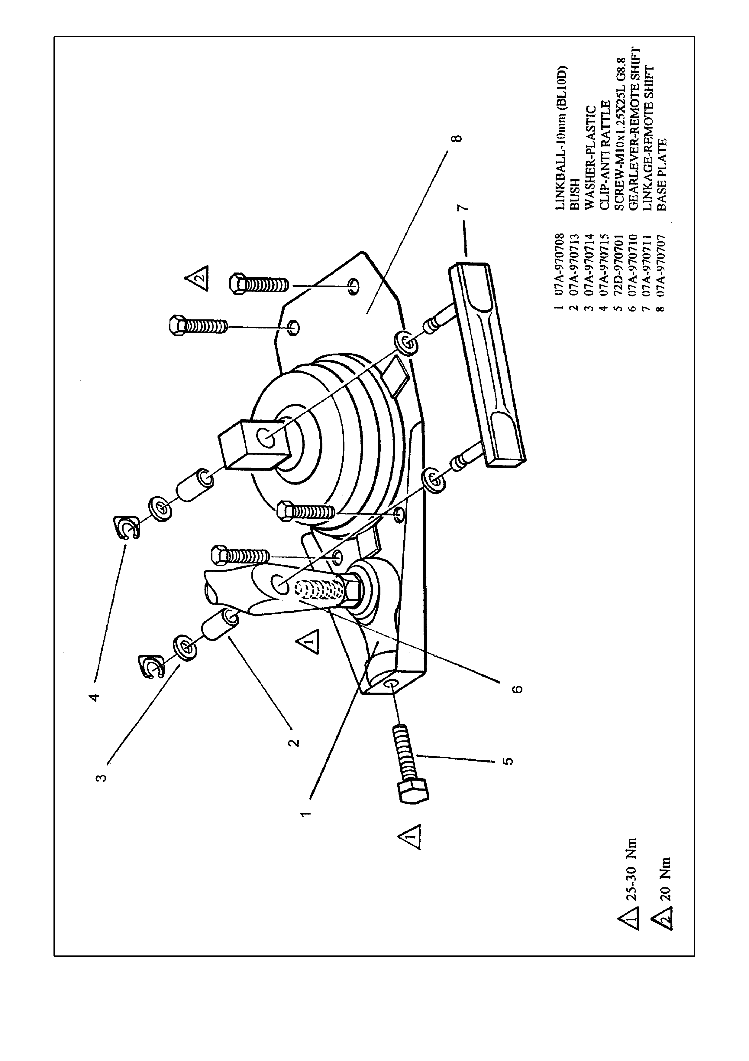
Figure F-5 - Wiring Harness Manual Transmission
UNIT DISASSEMBLY
NOTE:
W hen fasteners are removed, always reinstall them at the same location which they were removed. If a fastener
needs to be replaced, us e the corr ect part num ber fastener for that application. F asteners that are not reus ed, and
those requiring thread locking compound will be highlighted in the text. The correct torque valve must be used
when installing fasteners that require it. If the above conditions are not followed, damage to parts and/or the system
could result.
NOTE:
A complete disassembled view is shown in Figure 1.
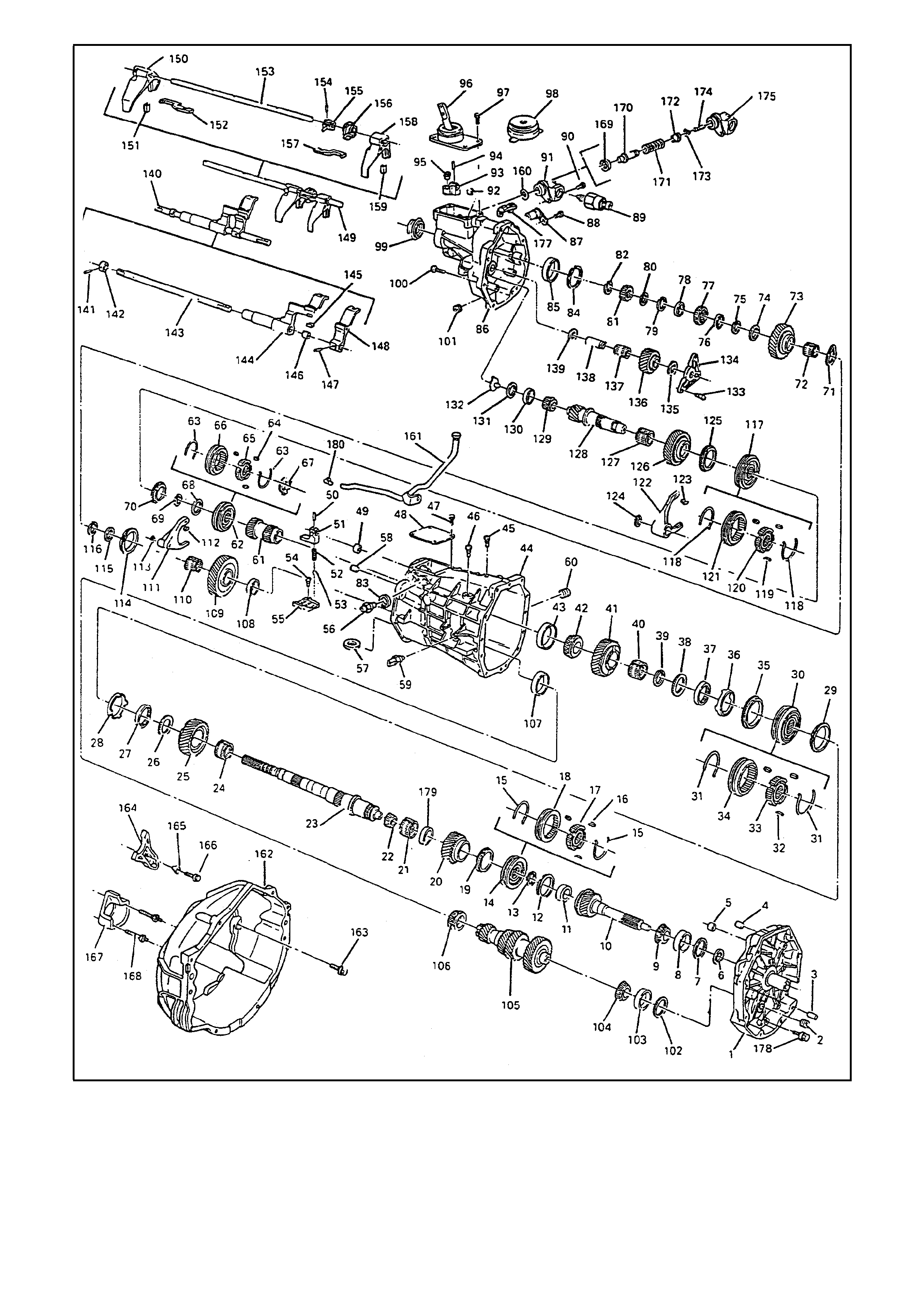
Figure 1 - Disassembled View

1. PLATE, TRANSMISSION ADAPTER
2. PLUG
3. PIN, DOWEL
4. PIN, DOWEL
5. BUSHING, SHIFT RAIL
6. SEAL, INPUT SHAFT
7. SHIM, INPUT SHAFT
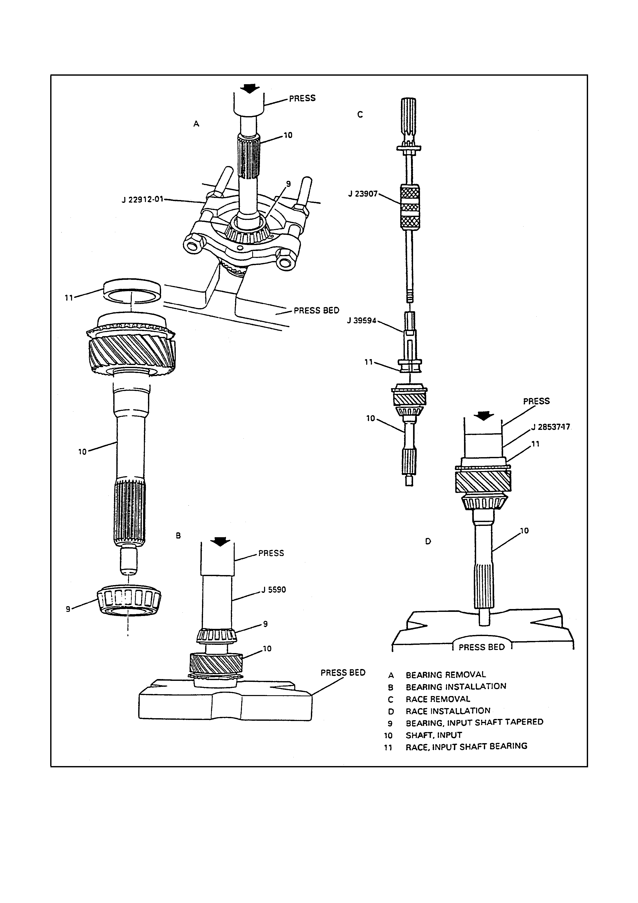
8. RACE, INPUT SHAFT BEARING
9. BEARING, INPUT SHAFT TAPERED
10. SHAFT, INPUT
11. RACE, INPUT SHAFT BEARING
12. RING, 4H GEAR BLOCKER
13. RING, SNAP
14. SYNCHRONIZER ASSEMBLY 3RD/4TH
15. SPRING, 3RD/4TH SYNCHRONIZER
16. KEY, 3RD/4TH SYNCHRONIZER
17. HUB, 3RD/4TH SYNCHRONIZER
18. SLEEVE, 3RD/4TH SYNCHRONIZER
19. RING, 3RD GEAR BLOCKER
20. GEAR, 3RD SPEED
21. BEARING, 3RD GEAR NEEDLE
22. BEARING, MAINSHAFT SMALL
TAPERED
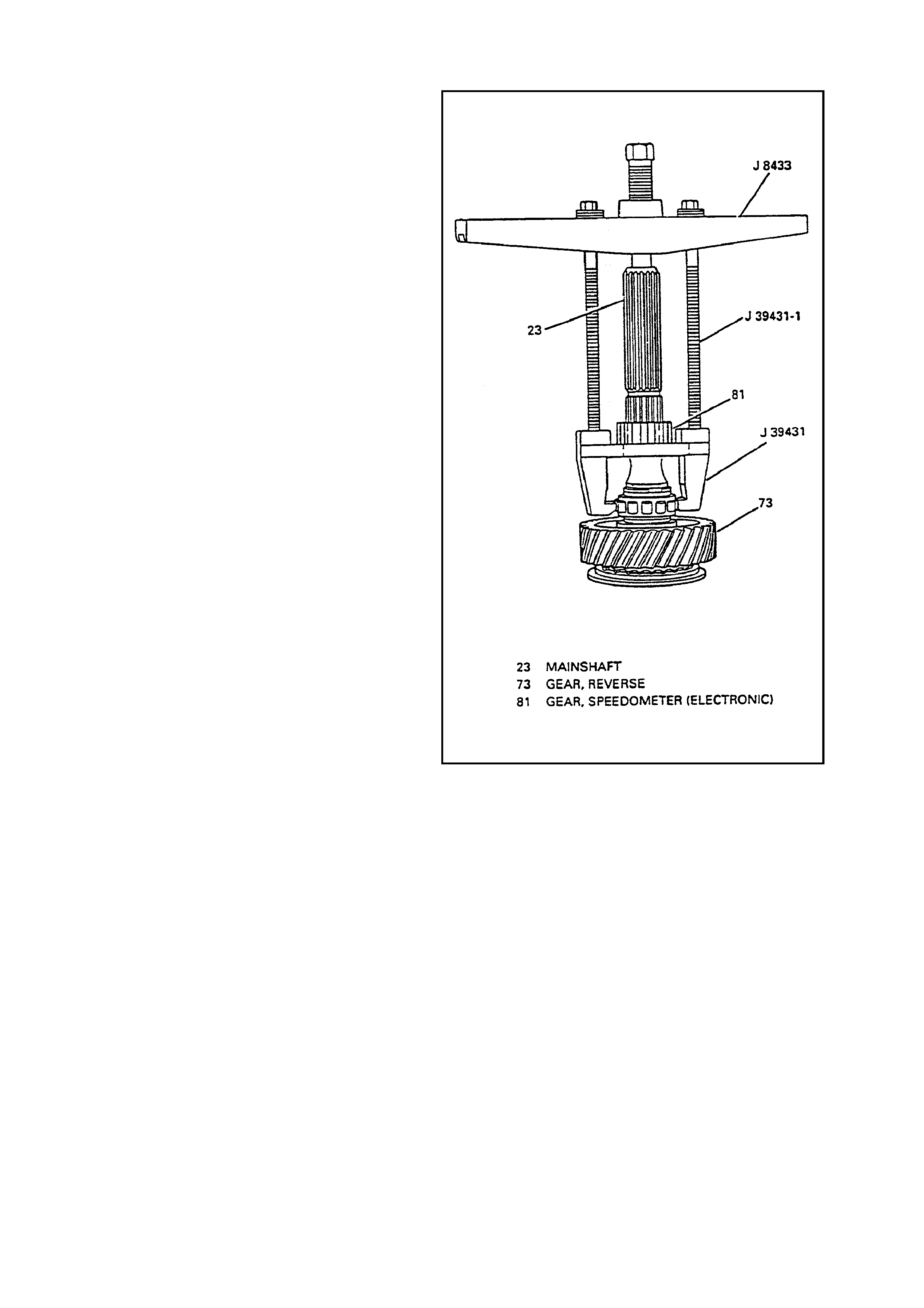
23. MAINSHAFT
24. BEARING, 2ND GEAR NEEDLE
25. GEAR, 2ND SPEED
26. WASHER, THRUST
27. CONE, INNER
28. CONE, FRICTION
29. RING, 2ND GEAR BLOCKER
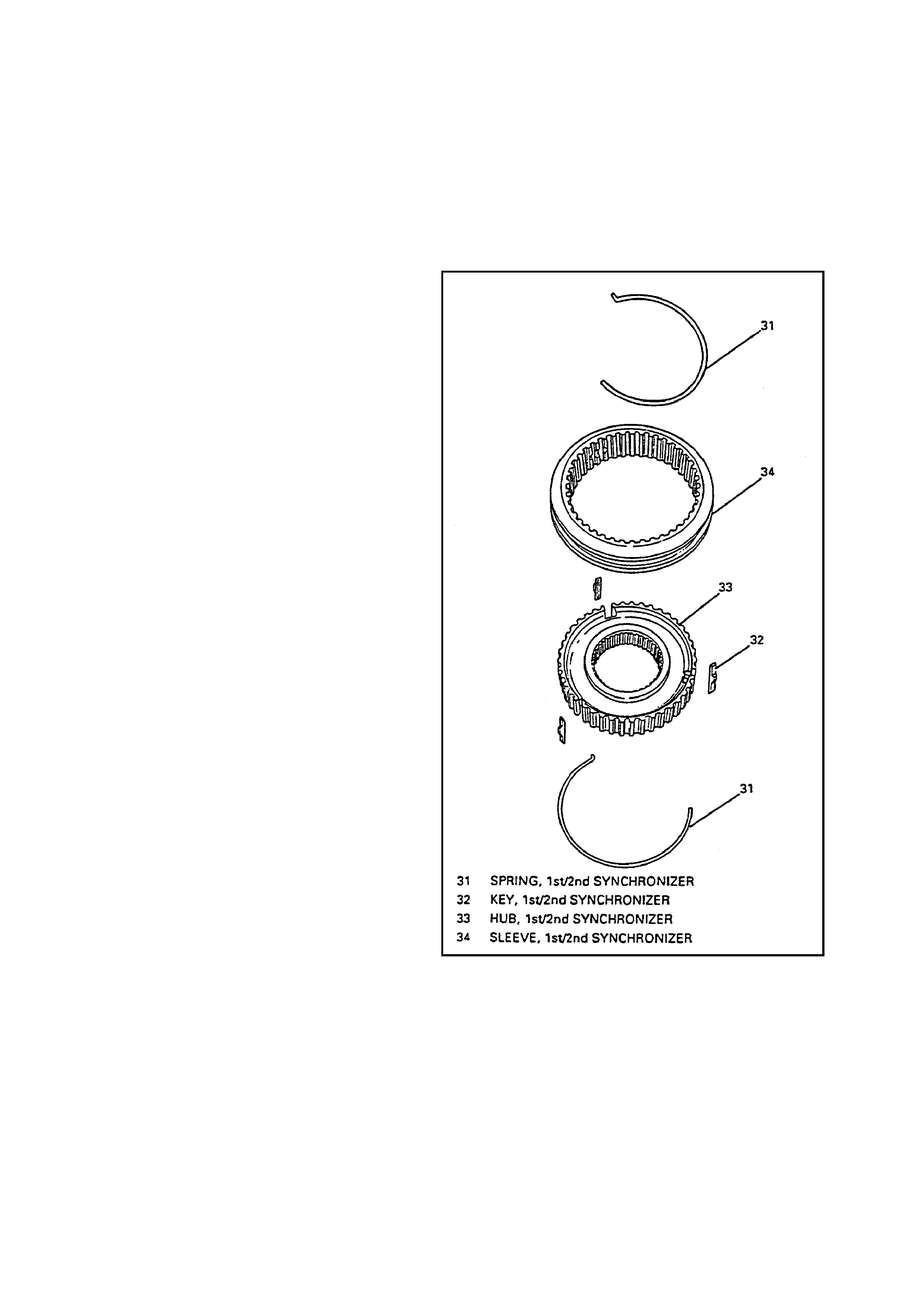
30. SYNCHRONIZER ASSEMBLY, 1ST/2ND
31. SPRING, 1ST/2ND SYNCHRONIZER
32. KEY, 1ST/2ND SYNCHRONIZER
33. HUB, 1ST/2ND SYNCHRONIZER
34. SLEEVE, 1ST/2ND SYNCHRONIZER
35. RING, 1ST GEAR BLOCKER
36. CONE, FRICTION
37. CONE, INNER
38. WASHER, THRUST
39. RING, SNAP
40. BEARING, 1ST GEAR NEEDLE
41. GEAR, 1ST SPEED
42. BEARING, MAINSHAFT LARGE
TAPERED
43. RACE, MAINSHAFT BEARING
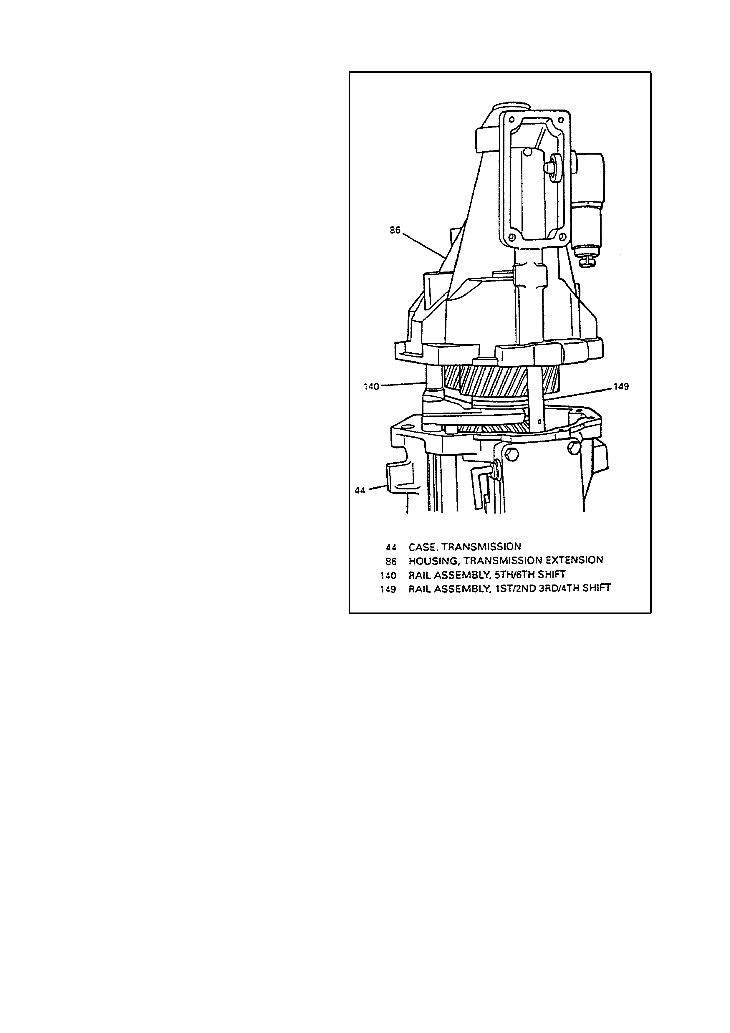
44. CASE, TRANSMISSION
45. BOLT, SHIFT LEVER GUIDE
46. BOLT, SHIFT LEVER GUIDE
47. BOLT, SHIFT DETENT COVER
48. COVER, SHIFT DETENT
49. BUSHING, SHIFT RAIL
50. PIN, FRONT OFFSET LEVER ROLL
51. LEVER, FRONT OFFSET
52. SPRING, SHIFT DETENT
53. BALL, SHIFT DETENT
54. BOLT, SHIFT GUIDEPLATE
55. PLATE, SHIFT GUIDE
56. DETENT ASSEMBLY, SHIFT
57. MAGNET
67. RETAINER, REVERSE
SYNCHRONIZER KEY
68. WASHER, THRUST
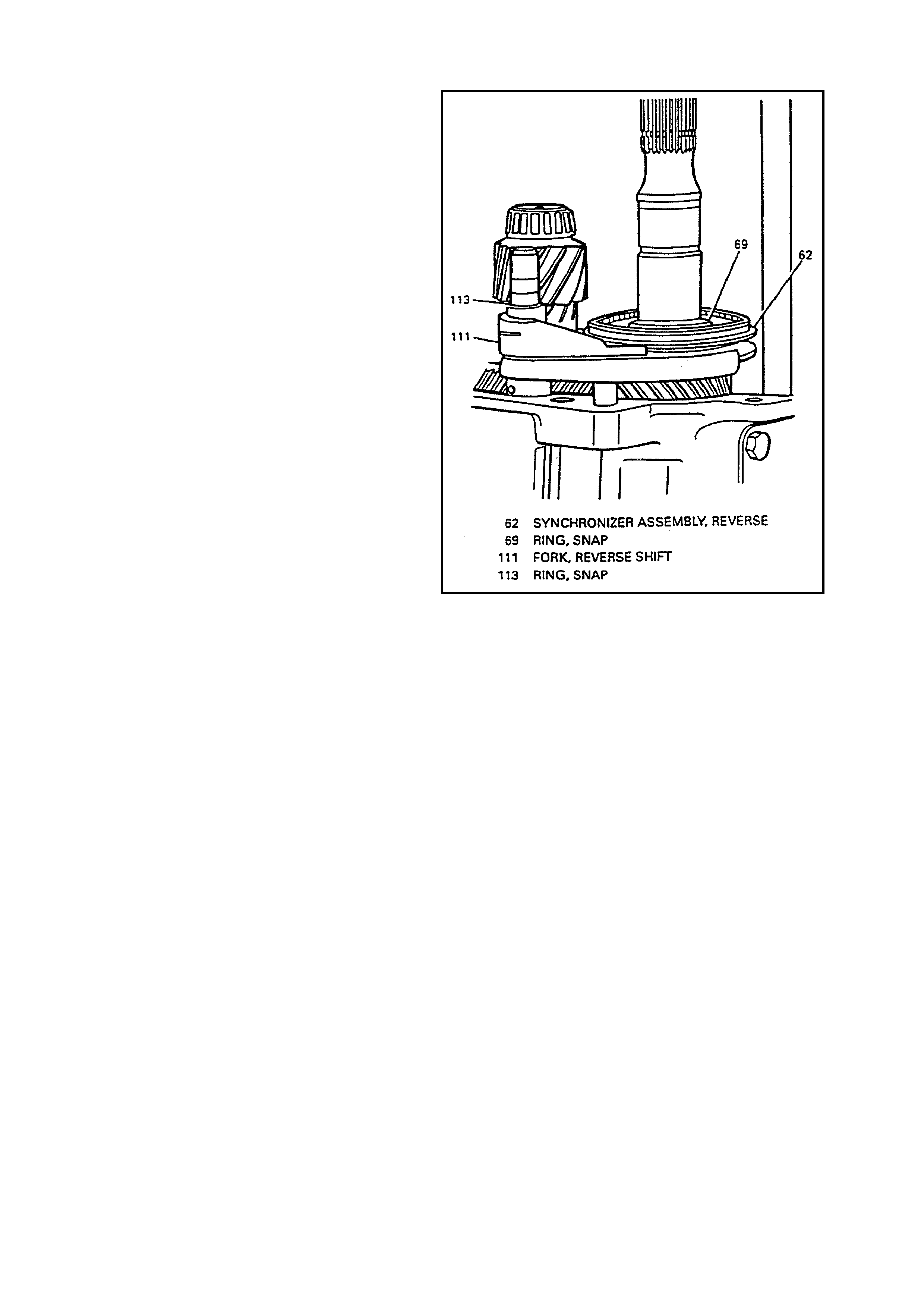
69. RING, SNAP
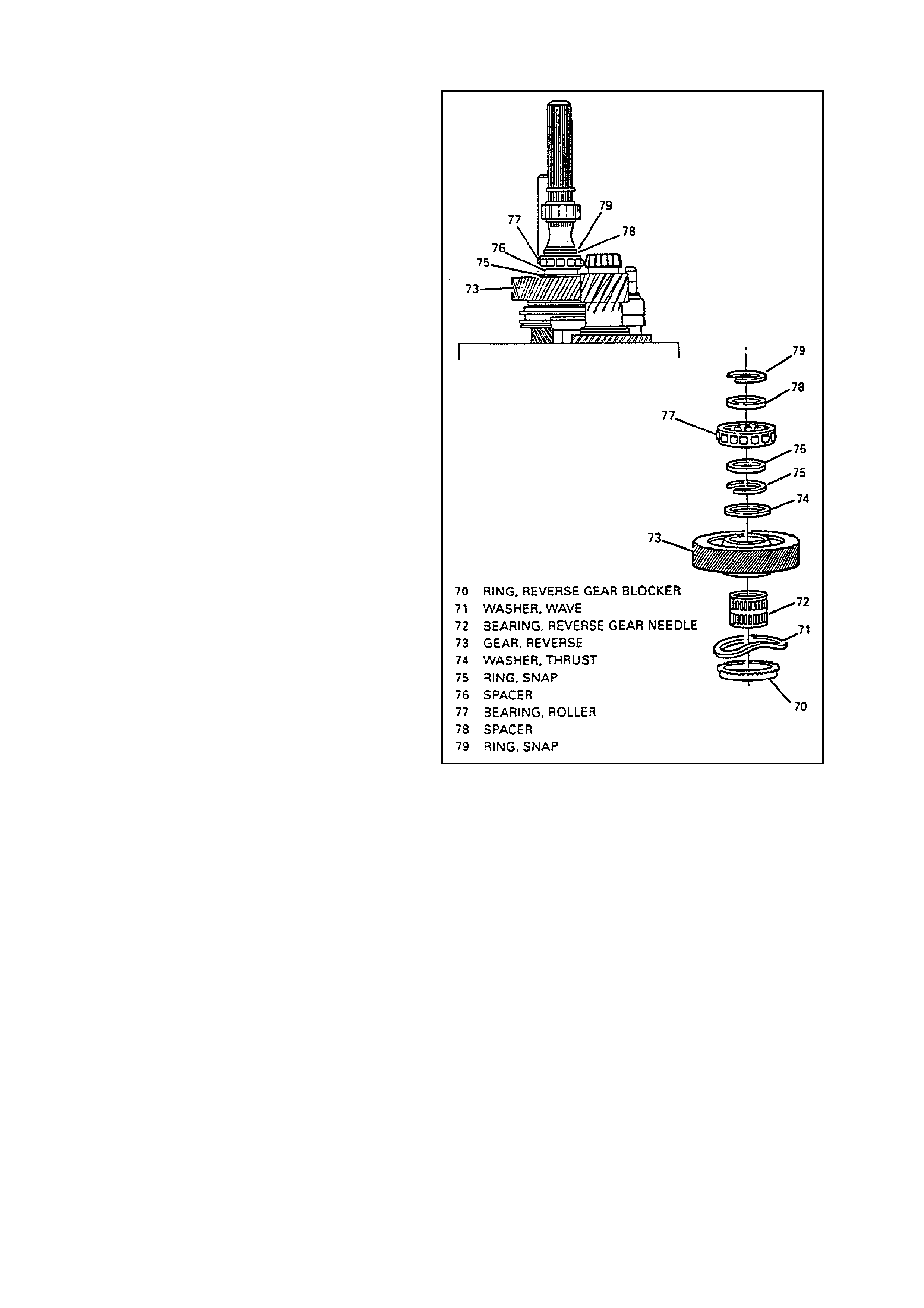
70. RING, REVERSE GEAR BLOCKER
71. WASHER, WAVE
72. BEARING, REVERSE GEAR
NEEDLE
73. GEAR, REVERSE]
74. WASHER, THRUST
75. RING, SNAP
76. SPACER
77. BEARING, REAR MAINSHAFT
78. SPACER
79. RING, SNAP
80. RING, SNAP
81. GEAR, SPEEDOMETER
(ELECTRONIC)
82. RING, SNAP
83. SPACER
84. RING, SNAP
85. RACE, MAINSHAFT BEARING
86. HOUSING, TRANSMISSION
EXTENSION
87. SENSOR, ELECTRONIC SPEED
88. BOLT, SPEED SENSOR
89. SOLENOID, REVERSE LOCKOUT
90. BOLT, REVERSE LOCKOUT
ASSEMBLY
91. BODY ASSEMBLY, REVERSE
LOCKOUT
92. BUSHING, SHIFT RAIL
93. LEVER, REAR OFFSET SHIFT
94. PIN, REAR OFFSET SHIFT LEVER
ROLL
95. CUP, ISOLATOR
96. SHIFTER ASSEMBLY
97. BOLT, SHIFTER ASSEMBLY
98. BOOT, SHIFTER
99. SEAL AND BOOT, REAR OUTPUT
100. BOLT, TRANSMISSION
EXTENSION HOUSING
101. PLUG, DRAIN
102. SHIM, COUNTERSHAFT
103. RACE, COUNTERSHAFT
TAPERED
104. BEARING, COUNTERSHAFT
TAPERED
105. COUNTERSHAFT
106. BEARING, COUNTERSHAFT
TAPERED
107. RACE, COUNTERSHAFT
BEARING
108. WASHER, THRUST
109. GEAR, 6TH DRIVE
110. BEARING, 6TH GEAR NEEDLE
111. FORK, REVERSE SHIFT
112. PAD, REVERSE SHIFT FORK
113. RING, SNAP
114. RING, 6TH GEAR BLOCKER
115. SPACER
116. RING, SNAP
126.GEAR, 5TH DRIVE
127.BEARING, 5TH GEAR NEEDLE
128.EXTENSION, COUNTERSHAFT
129.BEARING, COUNTERSHAFT
EXTENSION TAPERED
130.RACE, COUNTERSHAFT
EXTENSION BEARING
131.SHIM, COUNTERSHAFT
EXTENSION
132.FUNNEL, OIL
133.BOLT, REVERSE IDLER SHAFT
BRACKET
134.BRACKET, REVERSE IDLER
SHAFT
135.WASHER, REVERSE IDLER GEAR
THRUST
136.GEAR, REVERSE IDLER
137.BEARING, REVERSE IDLER GEAR
ROLLER
138.SHAFT, REVERSE IDLER GEAR
139.WASHER, REVERSE IDLER GEAR
THRUST
140.RAIL ASSEMBLY, 5TH/6TH SHIFT
141.PIN, ROLLER
142.COLLAR
143.RAIL, SHIFT
144.LEVER, 5TH/6TH SHIFT RAIL
145.PAD, 5TH/6TH SHIFT RAIL LEVER
146.BUSHING, 5TH/6TH SHIFT RAIL
LEVER
147.PIN, ROLL
148.LEVER, REVERSE SHIFT RAIL
149.RAIL ASSEMBLY, 1ST/2ND 3RD/4TH
SHIFT
150.FORK, 1ST/2ND SHIFT
151.PAD, 1ST/2ND SHIFT FORK
152.LINK, SHIFT
153.RAIL ASSEMBLY, 1ST/2ND 3RD/4TH
SHIFT
154.PIN, ROLL
155.PIN, SELECTOR
156.PLATE, INTERLOCK
157.LINK, SHIFT
158.FORK, 3RD/4TH SHIFT
159.PAD, 3RD/4TH SHIFT FORK
160.O-RING, REVERSE LOCKOUT
ASSEMBLY
161.TUBE, VENT
162.HOUSING, CLUTCH ADAPTER
163.BOLT, CLUTCH ADAPTER
HOUSING
164.FORK, CLUTCH
165.T-HANDLE, CLUTCH FORK PIVOT
166.BOLT, CLUTCH FORK PIVOT
167.HOUSING, CLUTCH ACTUATOR
ADAPTER
168.BOLT, CLUTCH ACTUATOR
ADAPTER HOUSING
169.RING, SNAP
170.PLUNGER, REVERSE LOCKOUT
171.SPRING, REVERSE LOCKOUT
OUTER
172.COLLAR, REVERSE LOCKOUT

58. PIN, DOWEL
59. SWITCH, BACK-UP LAMP
60. PLUG, FILL
61. GEAR, 5TH/6TH DRIVEN
62. SYNCHRONIZER ASSEMBLY,
REVERSE
63. SPRING, REVERSE SYNCHRONIZER
64. KEY, REVERSE SYNCHRONIZER
65. HUB, REVERSE SYNCHRONIZER
66. SLEEVE, REVERSE
SYNCHRONIZER
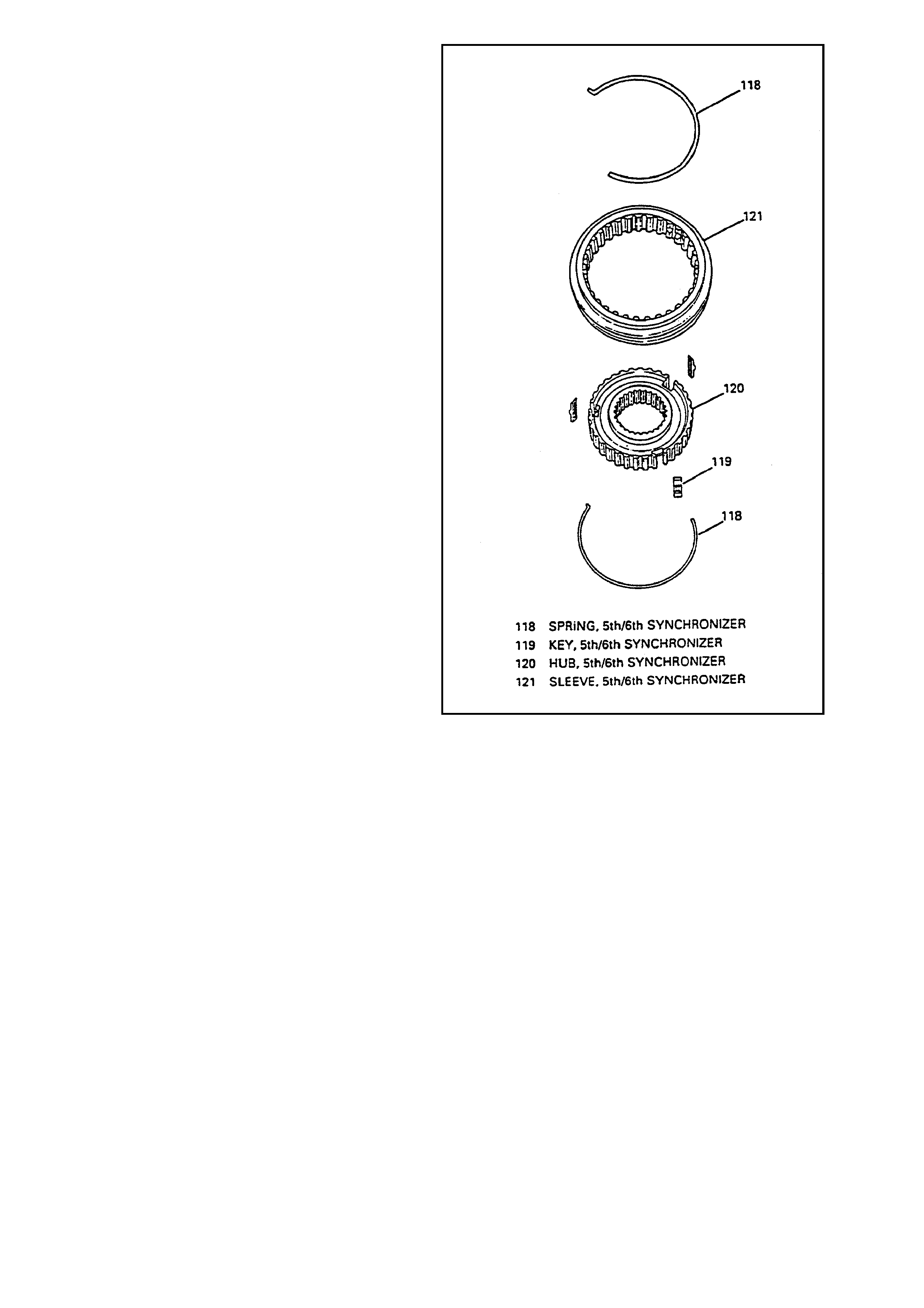
117. SYNCHRONIZER ASSEMBLY,
5TH/6TH
118. SPRING, 5TH/6TH SYNCHRONIZER
119. KEY, 5TH/6TH SYNCHRONIZER
120. HUB, 5TH/6TH SYNCHRONIZER
121. SLEEVE, 5TH/6TH SYNCHRONIZER
122. FORK, 5TH/6TH SHIFT
123. PAD, 5TH/6TH SHIFT FORK
124. RING, SNAP
125.RING, 5TH GEAR BLOCKER
173.RING, SNAP
174.SPRING, REVERSE LOCKOUT
INNER
175.BODY, REVERSE LOCKOUT
176.BODY, REVERSE LOCKOUT
177.BUMPER, TRANSMISSION
178.BOLT, TRANSMISSION ADAPTER
PLATE
179.SPACER
180.FITTING, VENT TUBE
Figure 2 – Dissassembled View - Legend
SHIFTER
REMOVE OR DISCONNECT
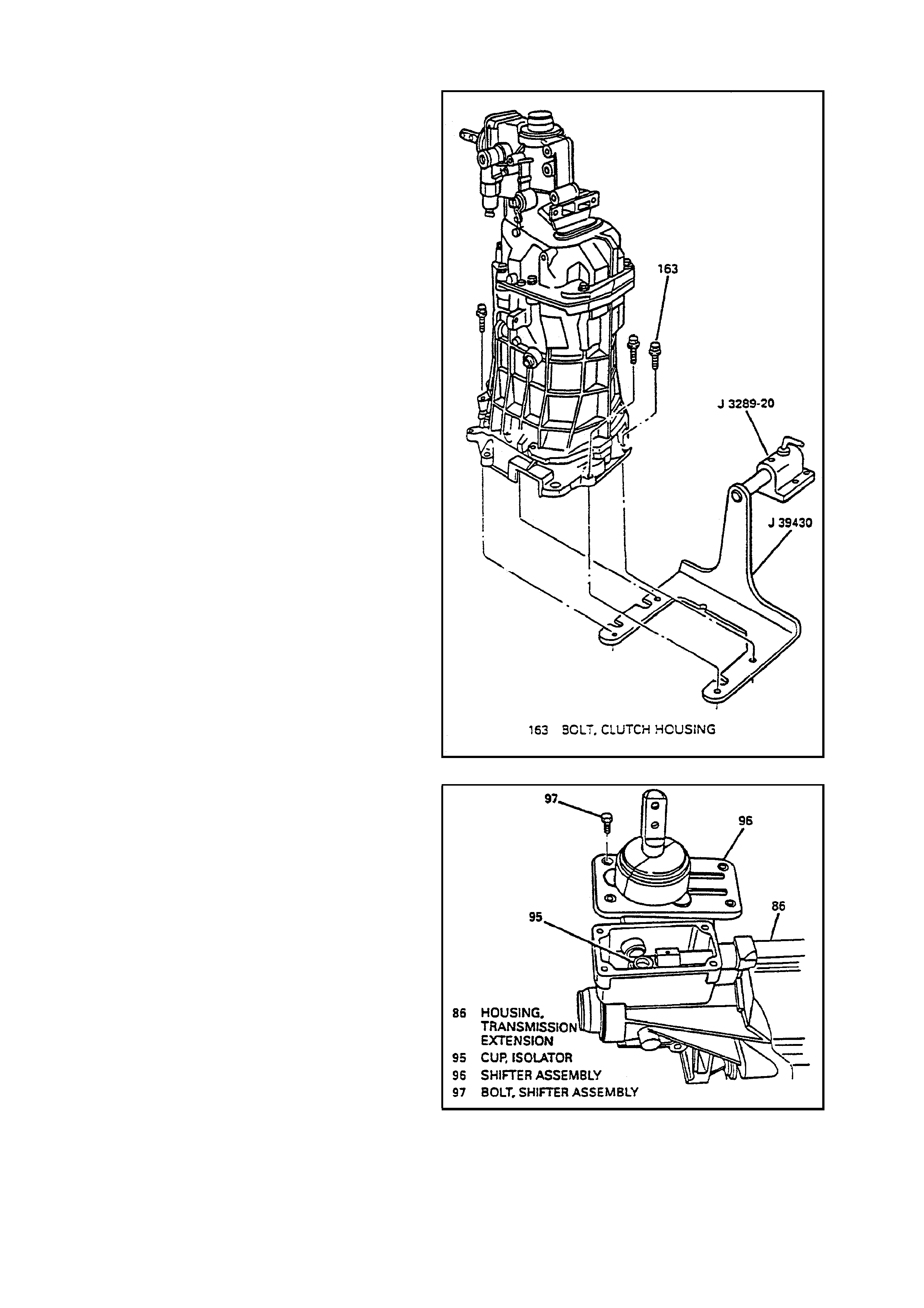
1. Vent tube (161).
2. Clutch housing bolts (163).
3. Clutch housing (162).
4. Clutch fork bolt (166).
5. Clutch fork (164) and T-handle (165).
6. Install transmission to J 39430 and J 3289-20.
Use bolts (163) to secure transmission to J
39430.
7. Rotate transmission in horizontal position,
shifter up.
8. Plug (101) and drain transmission fluid.
9. Put transmission in 3rd/4th neutral position.
10. Shifter bolts (97).
11. Shifter (96).
INSPECT
1. Isolator cup (95) for wear. Replace rear offset
shift lever (93) if wear is excessive or isolator
cup (95) is loose.
Figure 3 - Transmission Support Fixture
Figure 4 - Shifter
EXTENSION HOUSING
REMOVE OR DISCONNECT
1. Rear offset shift lever roll pin (94).
IMPORTANT
If isolator cup (95) is not f ully retained in rear of fset
lever with adhesive, replace rear offset lever
assembly (93).
2. Rear offset shift lever (93) and isolator cup
(95) assembly.
3. Extension housing bolts (100).
4. Extension housing (86).
With transmission in horizontal position, slide
extension housing (86) off shift rails (140 and
149).
Figure 5 - Extension Housing
SPEEDOMETER GEA R
REMOVE OR DISCONNECT
1. Rotate transmission in vertical position.
2. Sealing ring.
3. Speedometer gear snap ring (82).
4. Speedom eter gear (81) using J 8433, J 39431
and J 39431-1.
A. Set J 8433 onto nose of main shaft (23).
B. Slide J 39431 under speedometer gear.
C. Install bolts J 39431-1 to J 39431.
D. Speedometer gear (81) using J 8433, J 39431
and J 39431-1.
5. Speedometer gear snap ring (80).
Figure 6 - Speedometer Gear
REVERSE SPEED GEA R
REMOVE OR DISCONNECT
1. Roller bearing snap ring (79).
2. Spacer (78).
3. Roller bearing (77).
4. Spacer (76).
5. Snap ring (75).
6. Thrust washer (74).
7. Reverse speed gear (73).
8. Caged needle bearing (72).
9. Wave washer (71).
10. Blocker ring (70).
Figure 7 - Reverse Speed Gear
REVERSE SHIFT FORK
REMOVE OR DISCONNECT
1. Reverse synchronizer snap ring (69).
2. Reverse shift fork snap ring (113) and discard.
3. Revers e shift f ork (111) , s ynchronizer (62) and
thrust washer (68) at the same time.
Figure 8 - Reverse Shift Fork
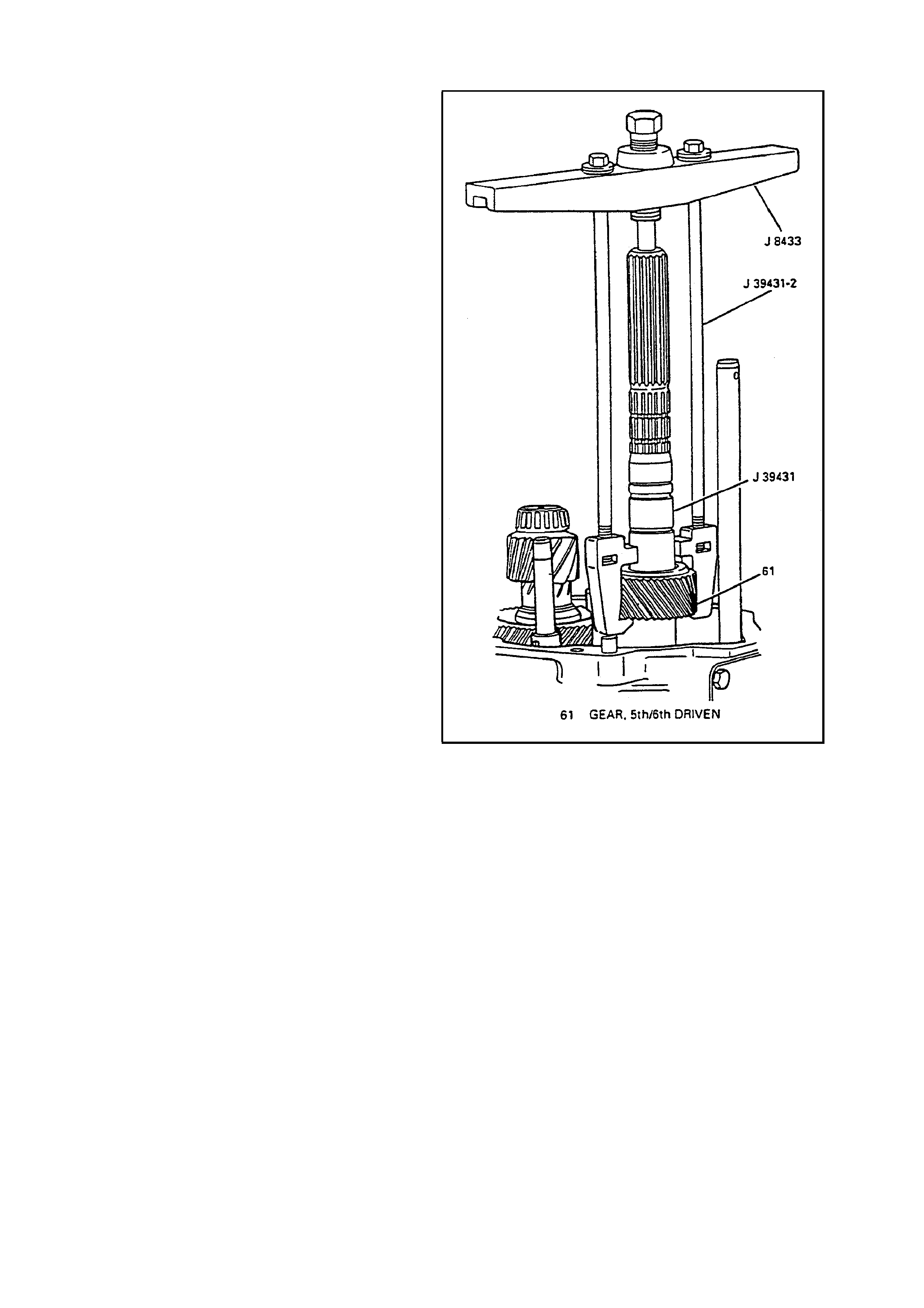
5TH/6TH DRIVEN GEAR
REMOVE OR DISCONNECT
1. 5
th
/6
th
driven gear (61) using J 8433, J 39431
and J 39431-2.
A. Set J 8433 onto nose of main shaft (23).
B. Slide J 39431 under 5th/6th driven gear.
C. Install bolts J 39431-2 to J 39431.
D. 5
th
/6
th
driven gear (61) using J 8433, J 39431
and J 39431-2.
Figure 9 - 5th/6th Driven Gear
COUNTERSHAFT EXTENSION ASSEMBLY
REMOVE OR DISCONNECT
1. 5th/6th shift fork snap ring (124).
2. Rotate transmission in horizontal position,
guide plate up.
3. Countershaft extension assembly with 5
th
/6
th
shift fork (122).
Figure 10 - Countershaft Extension Assembly
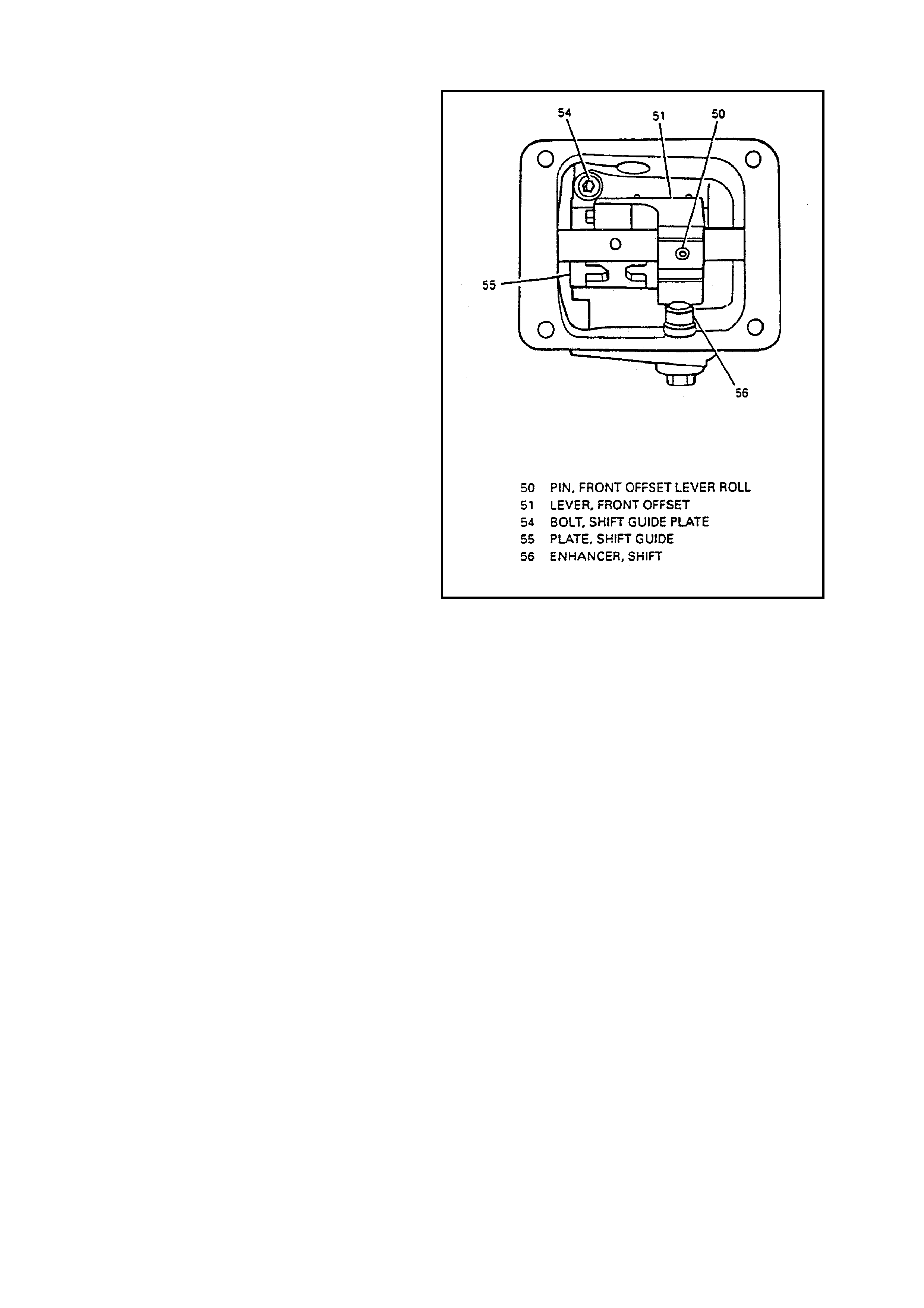
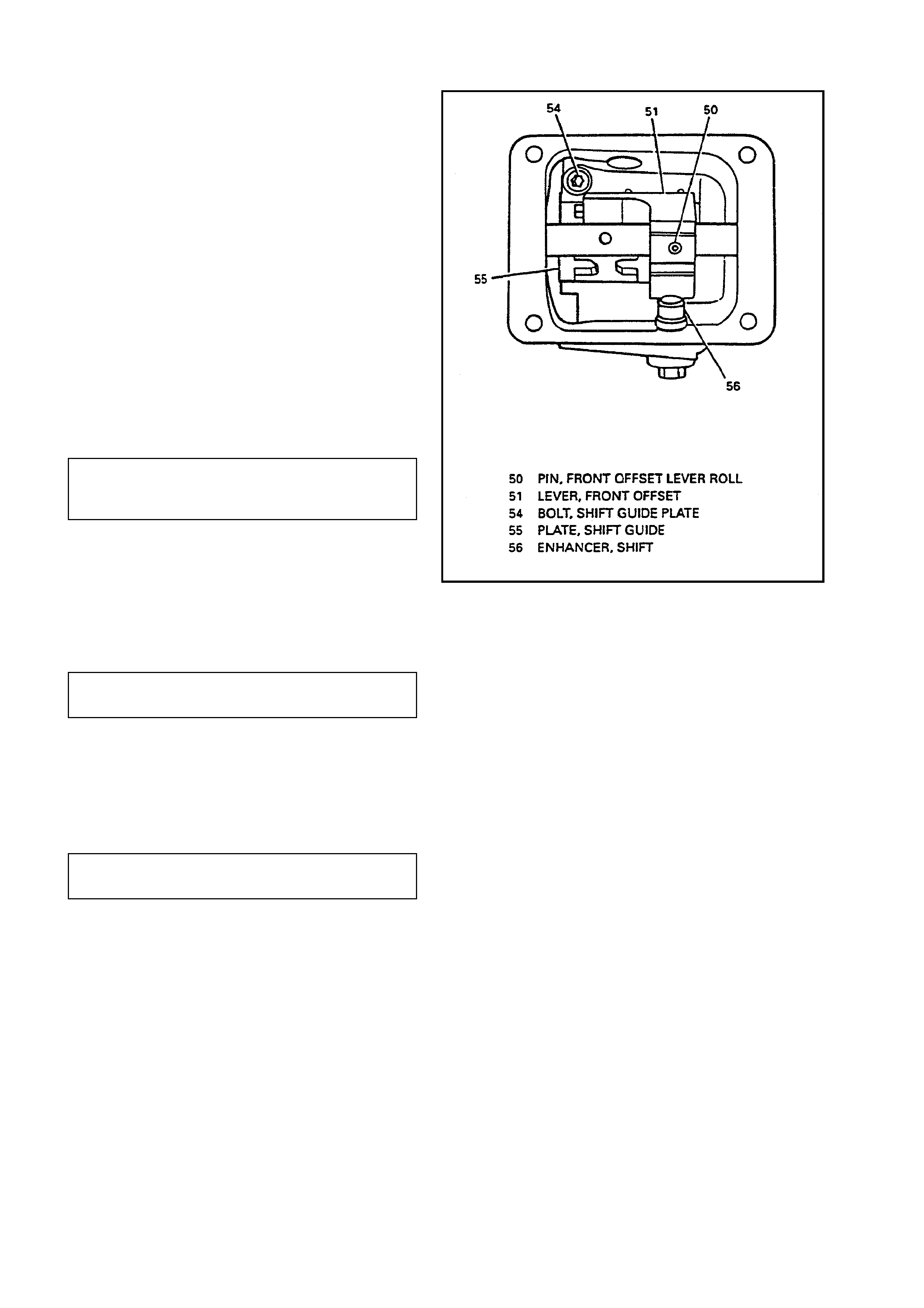
GUIDE PLATE
REMOVE OR DISCONNECT
1. Cover plate bolts (47).
2. Cover plate (48).
3. Shift detent assembly (56).
4. Front offset lever roll pin (50).
5. Shift guide plate bolts (54).
6. Guide plate (55) and front offset lever (51) at
the same time.
Hold guide plate (55) and front of fset lever (51)
together while sliding off shift rail (149) to
prevent spring release of detent ball (53) and
spring (52).
Rotate from offset lever (51) to clear case
while removing assembly.
DISASSEMBLE
A. Front offset lever (51).
B. Front offset lever roll pin (50).
C. Shift detent spring (52).
D. Shift detent ball (53).
E. Shift guide plate (55).
Figure 11 - Shift detent Assembly
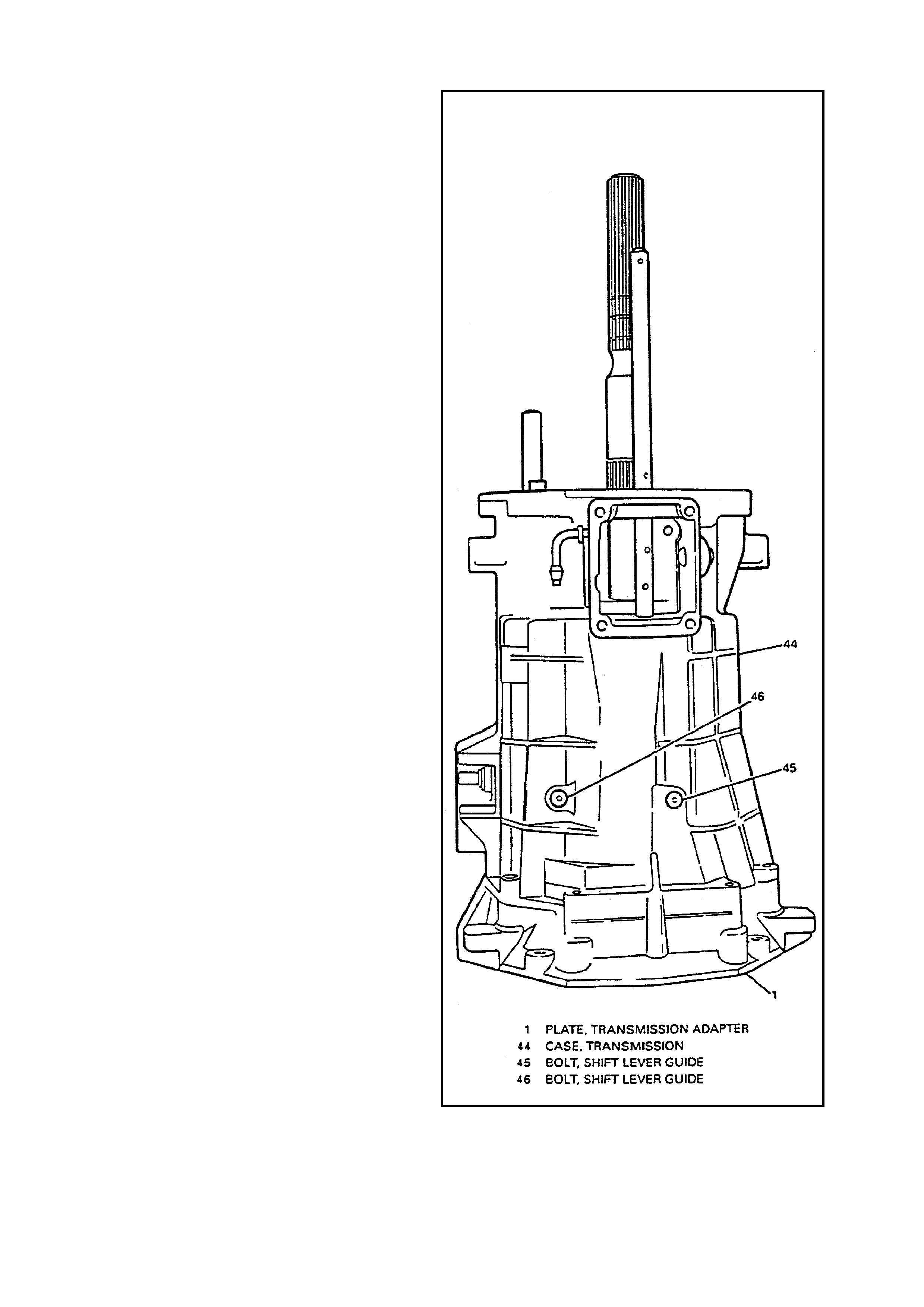
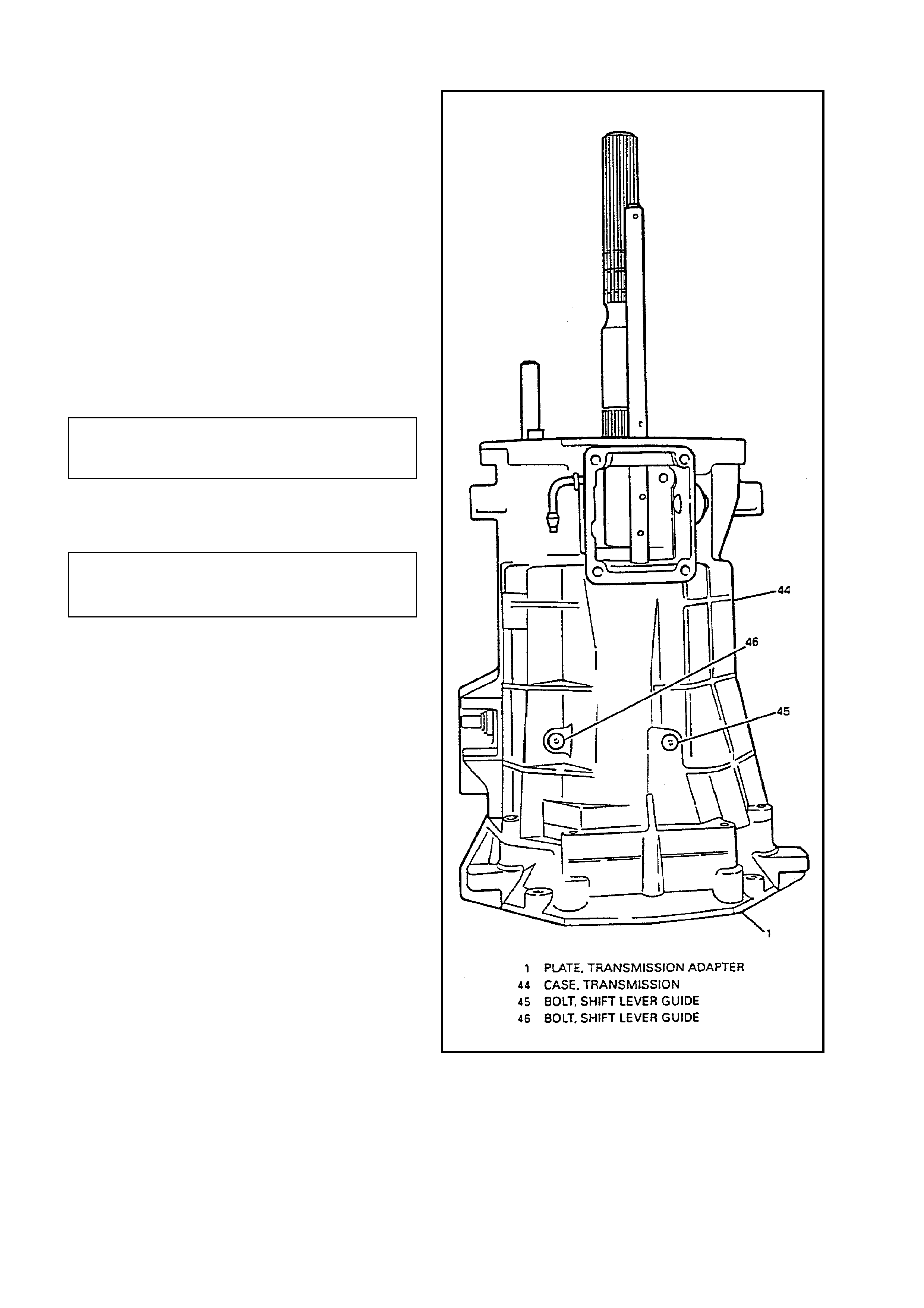
TRANSMISSION CASE
REMOVE OR DISCONNECT
1. 8 of the 10 adapter plate to transmission case
bolts (178).
2. Rotate transmission into vertical position.
3. Last 2 adapter plate to trans m ission cas e bolts
(178).
4. Shift lever guide bolts (45 and 46).
5. Magnets (57).
6. Transmission case (44).
Slide transmission case (44) up off of gear
clusters and shift rail components.
CLEAN
Shift lever guide bolt threads (45 and 46).
Case (44) and magnets (57) with solvent and
dry with compressed air.
Figure 12 - Transmission Case
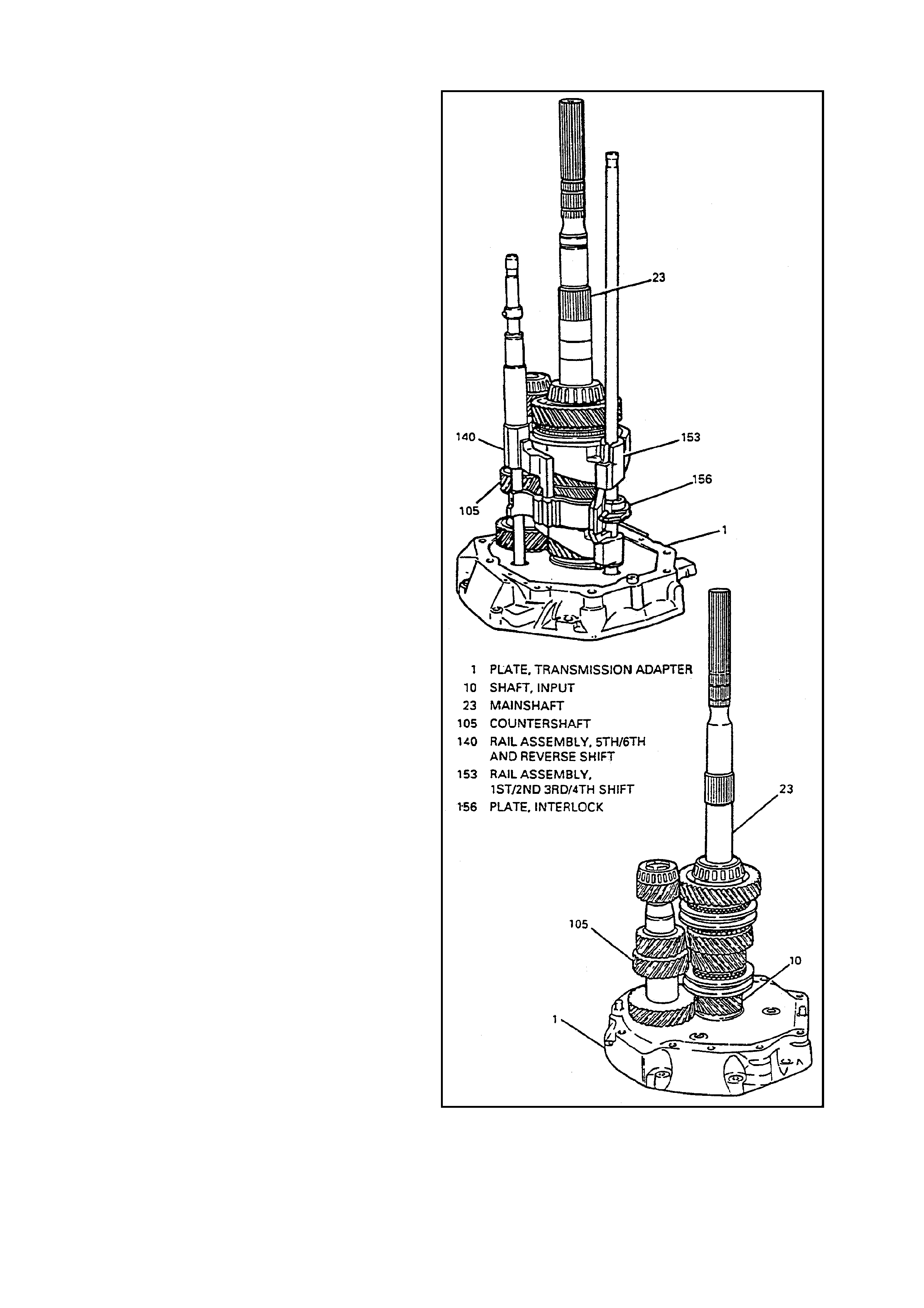
SHIFT RAIL ASSEMBLIES AND GEAR CLUSTERS
REMOVE OR DISCONNECT
1. Rotate 5
th
/6
th
and reverse shif t rail levers (140)
off shift interlock plate (156).
2. 5th/6th and reverse shift rail assembly (140).
3. Countershaft (105).
Lift up mainshaft (23) enough to remove
countershaft (105).
4. Mainshaft (23) and shift rail assembly (149).
Remove components as an assembly.
5. Shift rail assembly (149) from mainshaft (23).
6. 4th gear blocker ring (12).
7. Input shaft (10).
Figure 13 - Shift Rail Assemblies and
Gear Clusters
UNIT SUBASSEMBLY REPAIR AND INSPECTION
INPUT SHAFT
Figure 14 - Input Shaft

DISASSEMBLE
IMPORTANT:
Do not replace tapered bearing (9) or race (11) unless inspection shows bearing or race damage.
1. Input shaft tapered bearing (9) from input shaft (10) using J 22912-01 and hydraulic press.
2. Input shaft bearing race (11) using J 23907 and J 39594.
CLEAN
1. Input shaft components with solvent and dry with compressed air.
INSPECT
Input shaft components.
Shaft (10) and spline for excessive wear or cracks. Replace if these conditions exist.
Gear teeth for excessive wear, pitting, scoring, spalling or fractures.
Bearing (9) for roughness of rotation, burred or pitted conditions. Replace if these conditions exist.
If scuffed, nicked or scoring conditions cannot be reconditioned by hand with a soft stone or crocus cloth,
replace the component.
When replacing bearing (9) also replace bearing race (8).
When replacing bearing race (11) also replace bearing (22).
ASSEMBLE
1. New bearing race (11) to input shaft (10) using J 28537-17 hydraulic press.
2. New input shaft tapered bearing (9) to input shaft (10) using J 5590 and hydraulic press.
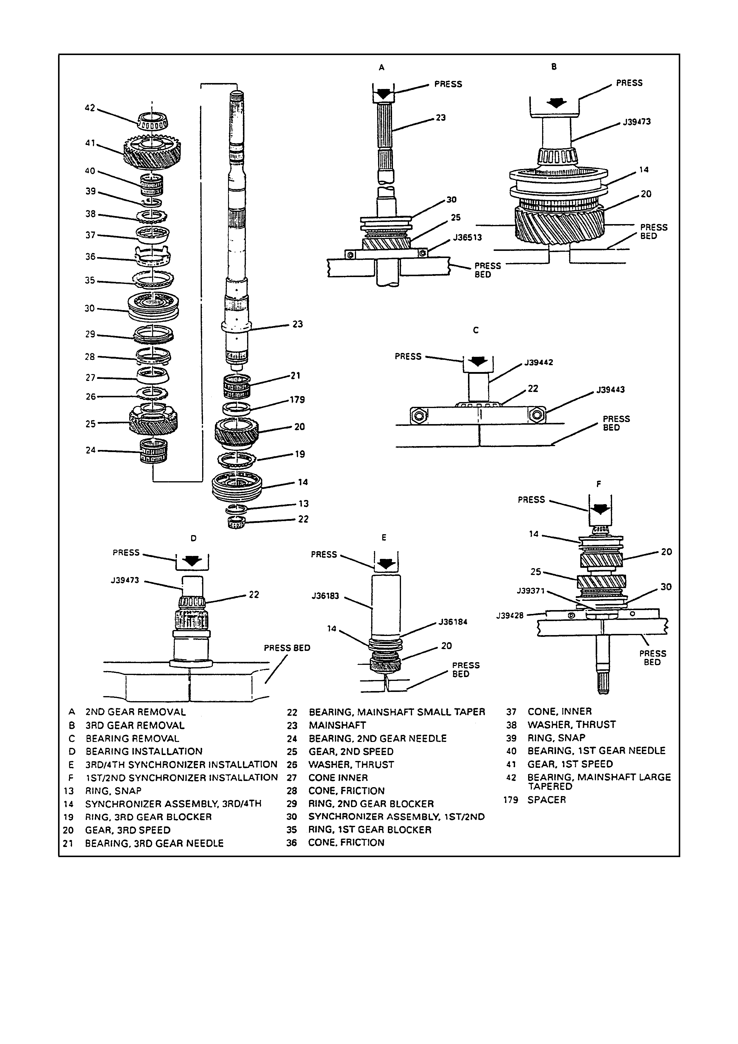
MAINSHAFT
Figure 15 - Mainshaft

DISASSEMBLE
IMPORTANT:
Identify and mark blocker rings. DO NOT MIX
1. Mainshaft large tapered bearing (42) and O-ring.
2. 1st sped gear (41).
3. 1st speed gear caged needle bearing (40).
4. Snap ring (39).
5. 1st speed gear blocker ring assembly.
A. Thrust washer (38).
B. Inner cone (37).
C. Friction cone (36).
D. Blocker ring (35).
6. 2nd speed gear (25) using J 36513 and hydraulic press.
1st/2nd synchronizer assembly (30), 2nd speed gear blocker ring (29), friction cone (28), 2nd speed gear inner
cone (27), and thrust washer (26), will press off with 2nd speed gear (25).
7. 2nd speed gear caged needle bearing (24).
8. 3rd/4th synchronizer snap ring (13).
9. 3rd speed gear (20) using J 39473, V-blocks and hydraulic press.
3rd /4th synchronizer ass embly assembly (14) and 3 rd speed gear blocker ring (19) will press off with 3rd speed
gear (20).
10. Spacer (179).
11. 3rd speed gear caged needle bearing (21).
IMPORTANT:
Do not replace tapered bearing (22) unless inspection shows bearing damage.
12. Mainshaft small tapered bearing (22) using J 39442, J 39443 and hydraulic press.
Discard small tapered bearing (22).
CLEAN
Mainshaft components with solvent and dry with compressed air.
INSPECT
Mainshaft components.
Shaft (23) and spline for excessive wear or cracks. Replace if these conditions exist.
Gear teeth (20, 25 and 41) for excessive wear, pitting , scoring, spalling or fractures.
Bearings (22 and 42) for roughness of rotation, burred or pitted conditions. Replace if these conditions exist.
Synchronizers (14 and 30). Refer to “Synchronizers” in this section.
When replacing bearings (22 and 42) also replace bearing races (11 or 43).
If scuffed, nicked, burred or scoring conditions cannot be reconditioned by hand with a soft stone or crocus
cloth, replace the component.
ASSEMBLE
1. New mainshaft small tapered bearing (22) using J 39473, V-blocks and hydraulic press.
2. 3rd speed gear caged needle bearing (21).
3. Spacer (179)
4. 3rd speed gear (20).
5. 3rd speed gear blocker ring (19).

IMPORTANT:
When pressing the 3rd/4th synchronizer assembly (14):
Start press operation. STOP before keys engage blocker ring slots.
Lift and rotate 3rd speed gear (20) to engage keys with blocker ring.
Continue to press until seated.
6. 3rd/4th synchronizer assembly (14) using J 36183, J 36184 and hydraulic press.
Install 3rd/4th synchronizer so ID groove on sleeve faces 3rd gear.
7. 3rd/4th synchronizer snap ring (13).
8. 2nd speed gear caged needle bearing (24).
9. 2nd speed gear (25).
10. Thrust washer (26).
11. 2nd speed gear inner cone (27).
12. Friction cone (28).
13. 2nd speed gear blocker ring (29).
IMPORTANT:
When pressing the 1st/2nd synchronizer assembly (30):
A. Start press operation. STOP before keys garage blocker ring slots.
B. Lift and rotate 2nd speed gear (25) to engage key s with blocker ring.
C. Continue to press until seated.
14. 1st/2nd synchronizer assembly (30) using J 39371, J 39428 and hydraulic press.
Install 1st/2nd synchronizer so ID groove on sleeve faces 1st gear.
15. 1st speed gear blocker ring assembly.
A. Blocker ring (35).
B. Friction cone (36).
C. Inner cone (37).
D. Thrust washer (38).
16. Snap ring (39).
17. 1st speed gear caged needle bearing (40).
18. 1st speed gear (41).
19. Mainshaft large tapered bearing (42) and O-Ring.
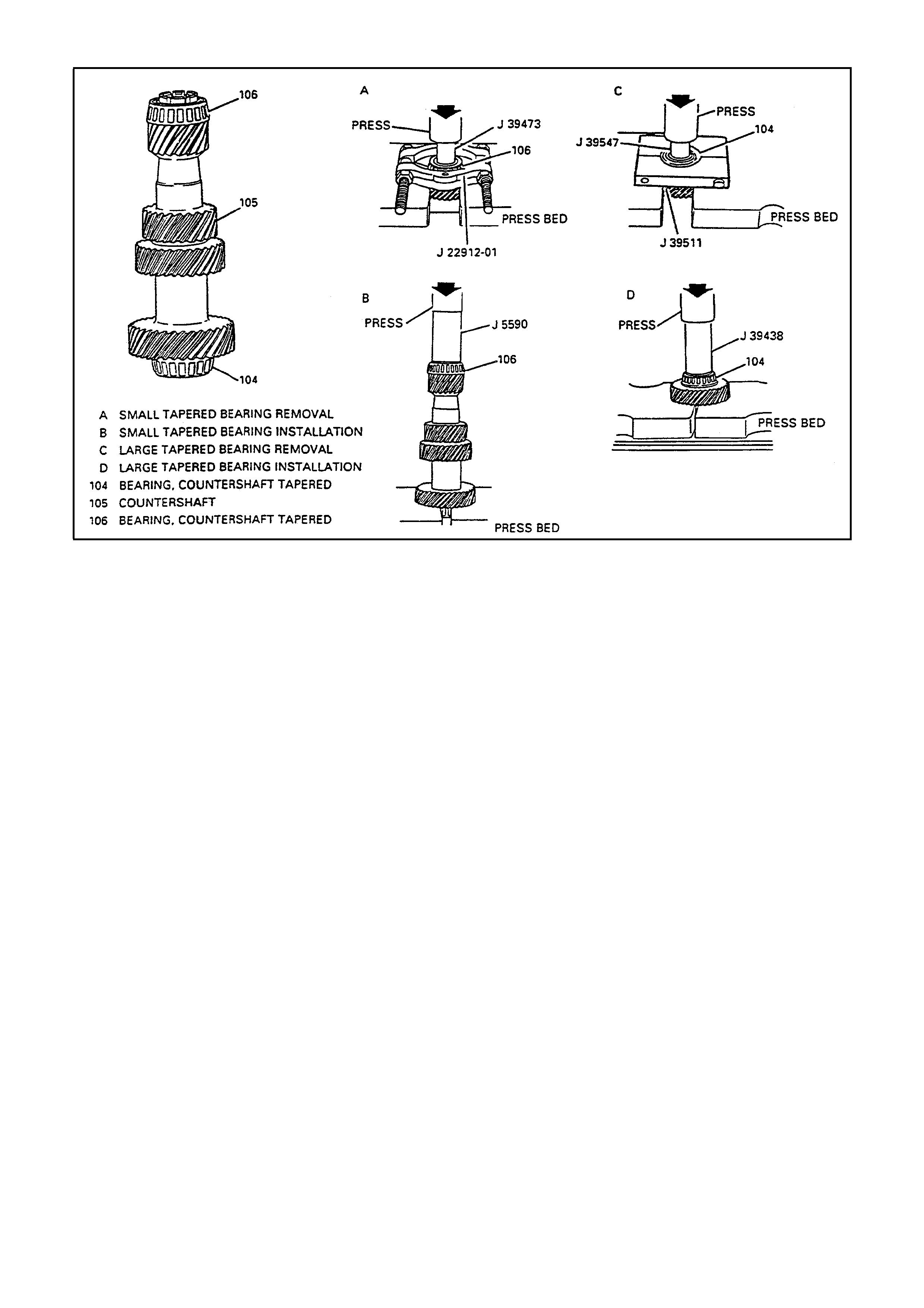
COUNTERSHAFT
Figure 16 - Countershaft

DISASSEMBLE
IMPORTANT:
Do not replace tapered bearings (104 and 106) unless inspection shows bearing damage.
1. Small tapered bearing (104) using J 22912-01, J39473 and hydraulic press.
Discard tapered bearing (104).
2. Large tapered bearing (106) using J 39511, J 39547 and hydraulic press.
Discard tapered bearing (106).
CLEAN
Countershaft with solvent and dry with compressed air.
INSPECT
Countershaft components.
Shaft (105) for excessive wear or cracks. Shaft if these conditions exist.
Gear teeth for excessive wear, pitting, scoring, spalling or fractures.
Bearings (104 and 106) for roughness of rotation, burred or pitted conditions. Replace if these conditions exist.
When replacing bearings (104 or 106) also replace bearing races (103 or 107).
If scuffed, nicked, burred or scoring conditions cannot be reconditioned by hand with a soft stone or crocus
cloth, replace the component.
ASSEMBLE
1. New large tapered bearing (106) using J 39438 and hydraulic press.
2. New small tapered bearing (104) using J 5590 and hydraulic press.
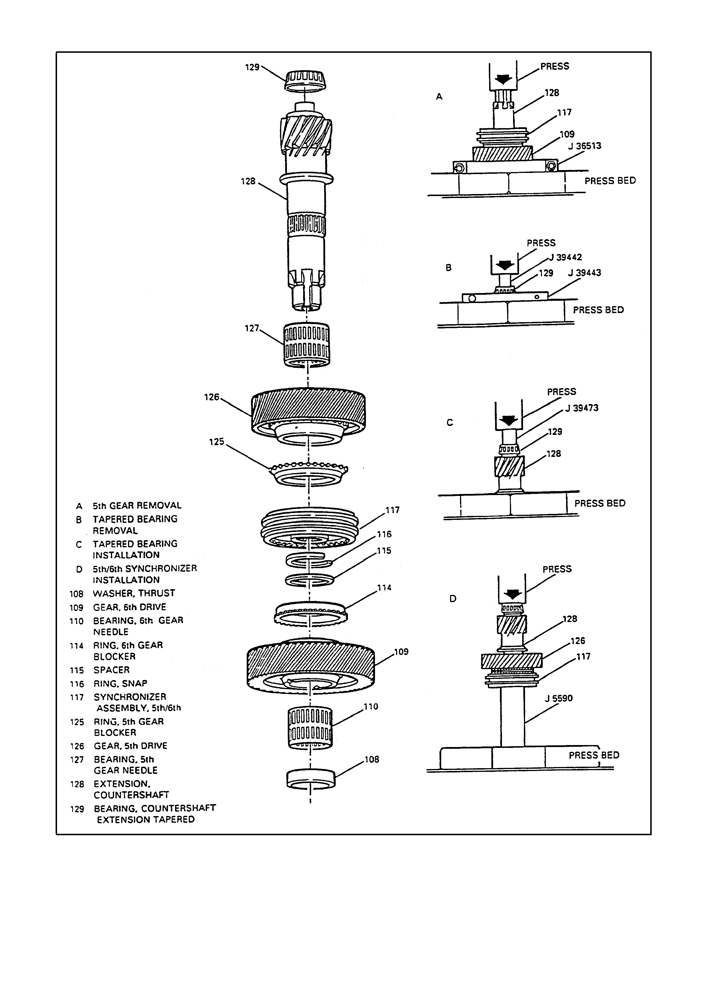
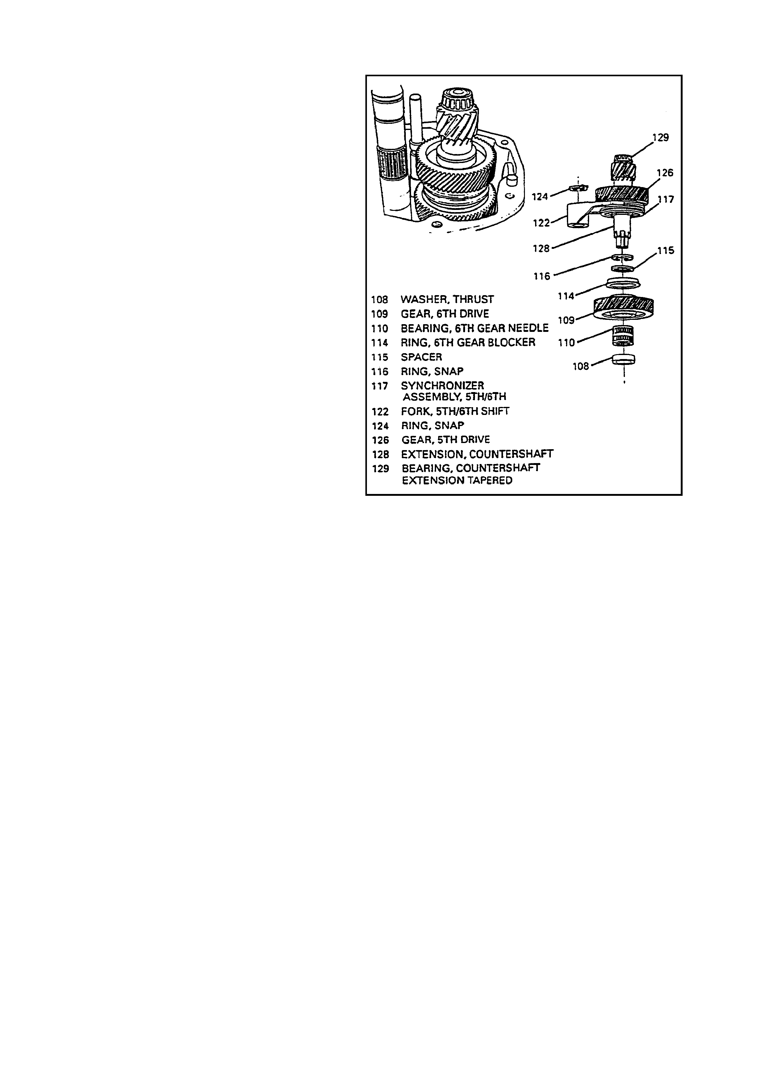
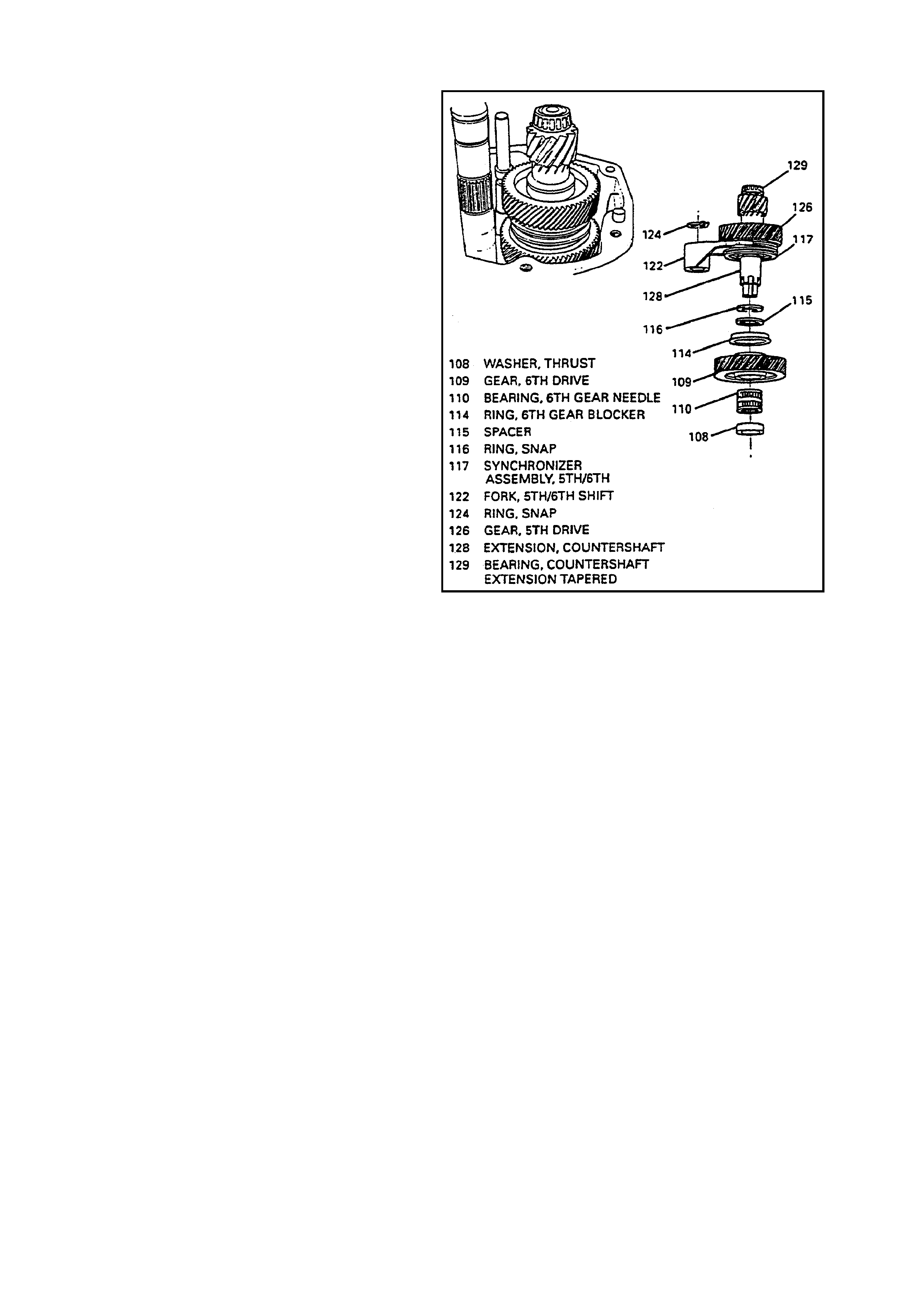
COUNTERSHAFT EXTENSION ASSEMBLY
Figure 17 - Countershaft Extension

DISASSEMBLE
1. 5th/6th shift fork (122).
2. Thrust washer (108).
3. 6h drive gear (109).
4. Caged needle bearing (110).
5. Spacer (115).
6. 6th drive gear blocker ring (114).
7. 5th/6th synchronizer snap ring (116) and discard.
8. 5th drive gear (126) using J 36513 and hydraulic press
5th/6th synchronizer assembly (117) and 5th drive gear blocker ring (125) will press off with 5th drive gear (126).
9. 5th drive gear caged needle bearing (127).
IMPORTANT:
Do not replace small tapered bearing (129) unless inspection shows bearing damage.
10. Small tapered bearing (129) using J 39442, J 39443 and hydraulic press.
CLEAN
Countershaft extension components with solvent and dry with compressed air.
INSPECT
Countershaft extension components.
Shaft (128) and spline for excessive wear or cracks. Replace if these conditions exist.
Gear teeth (109 and 126) for excessive wear, pitting, scoring, spalling or fractures.
Bearing (129) for roughness of rotation, burred or pitted condition. Replace if these conditions exist.
Synchronizer (117). Refer to “Synchronizers” in this section.
When replacing bearing (129) also replace bearing race (130).
If scuffed, nicked, burred or scoring conditions cannot be reconditioned by hand with a soft stone or crocus
cloth, replace the component.
ASSEMBLE
1. New small tapered bearing (129) using J 39473, V-blocks and hydraulic press.
2. 5th drive gear caged needle bearing (127).
3. 5th drive gear (126).
4. 5th drive gear blocker ring (125).
IMPORTANT:
When pressing the 5th/6th synchronizer assembly (117):
Start press operation. STOP before keys engage blocker ring slots.
Lift and rotate 5th drive gear (126) to engage keys with blocker ring.
Continue to press until seated.
5. 5th/6th synchronizer assembly (117) using J 5590 and hydraulic press.
Install 5th/6th synchronizer so ID groove on sleeve faces 5th gear.
6. New 5th/6th synchronizer snap ring (116).
7. 6th drive gear blocker ring (114).
8. 6th drive gear spacer (115).
9. 6th drive gear caged needle bearing (110).
10. 6th drive gear (109).
11. 6th drive gear thrust washer (108).
12. 5th/6th shift fork (122).
SYNCHRONIZERS
1ST/2ND , 3RD/4TH, 5TH/6TH SYNCHRONIZERS
IMPORTANT:
Synchronizers components are not
interchangeable. Keep synchronizer components
separate.
Synchronizer hubs and sleeves are a selected
assem bly and should be kept together as originally
assembled.
DISASSEMBLE
Refer to Figures 18, 19 and 20
1. Synchronizer spring (15), (31), (118) using a
small-bladed screwdriver.
2. Turn synchronizer assembly (14), (30), (117)
over.
3. Synchronizer spring (15), (31), (118), using a
small-bladed screwdriver.
4. Keys (16), (32), (119).
5. Synchronizer sleeve (18) , (34), (121) from hub
(17), (33), (120).
Figure 18 - 1st/2nd Synchronizer
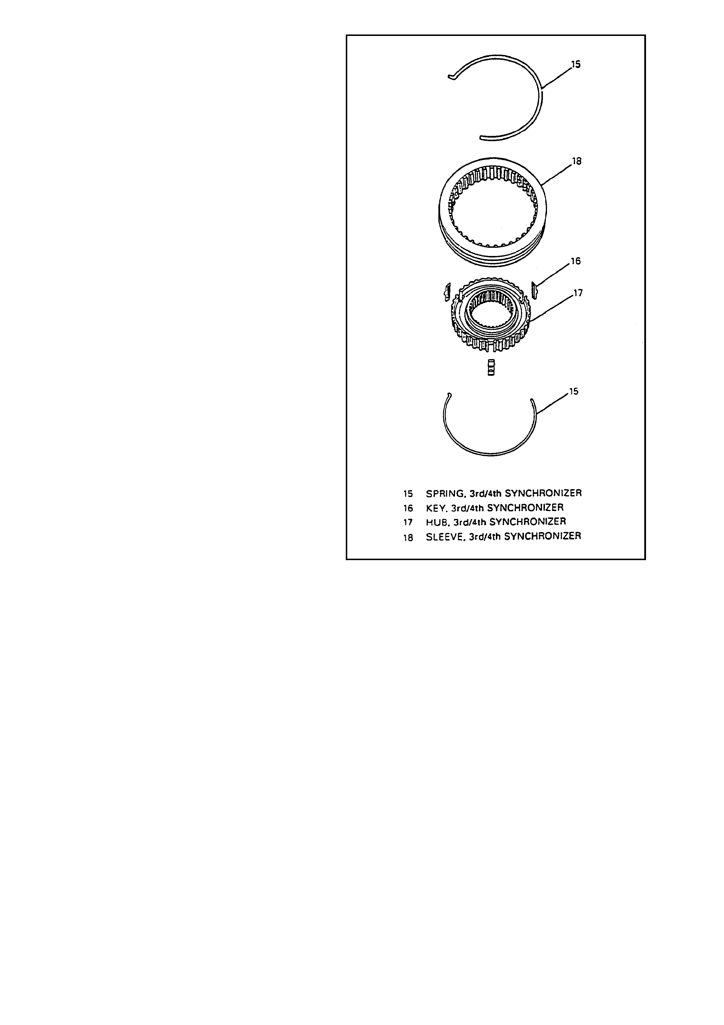
Figure 19 - 3rd/4th Synchronizer
CLEAN
Synchronizer components with solvent and dry with
compressed air.
INSPECT
Synchronizer components.
Teeth for wear, nicked, burred or broken teeth.
Replace hub and sleeve if excessive wear
exists.
Keys for wear or distortion. Replace if these
conditions exist.
Springs for distortion, cracks or wear. Replace
if these conditions exist.
If scuffed, nicked, or burred conditions cannot be
corrected by hand with a soft stone or crocus
cloth, replace the component.
ASSEMBLE
1. Synchronizer sleeve (18), (34), (121) to hub
(17), (33), (120).
Align key openings in hub (17), (33), (120) with
cuts in synchronizer sleeve (18), (34), (121).
2. Keys (16), (32), (119) with slots facing hub
(17), (33), (120).
3. Synchronizer spring (15), (31), (118) using a
small-bladed screwdriver.
Locate spring tang to one of the key slots
4. Turn synchronizer assembly (14), (30), (117)
over.
5. Synchronizer spring (15), (31), (118) using a
small-bladed screwdriver.
Locate spring tang on same key but wind in
opposite direction. Figure 20 - 5th/6th Synchronizer
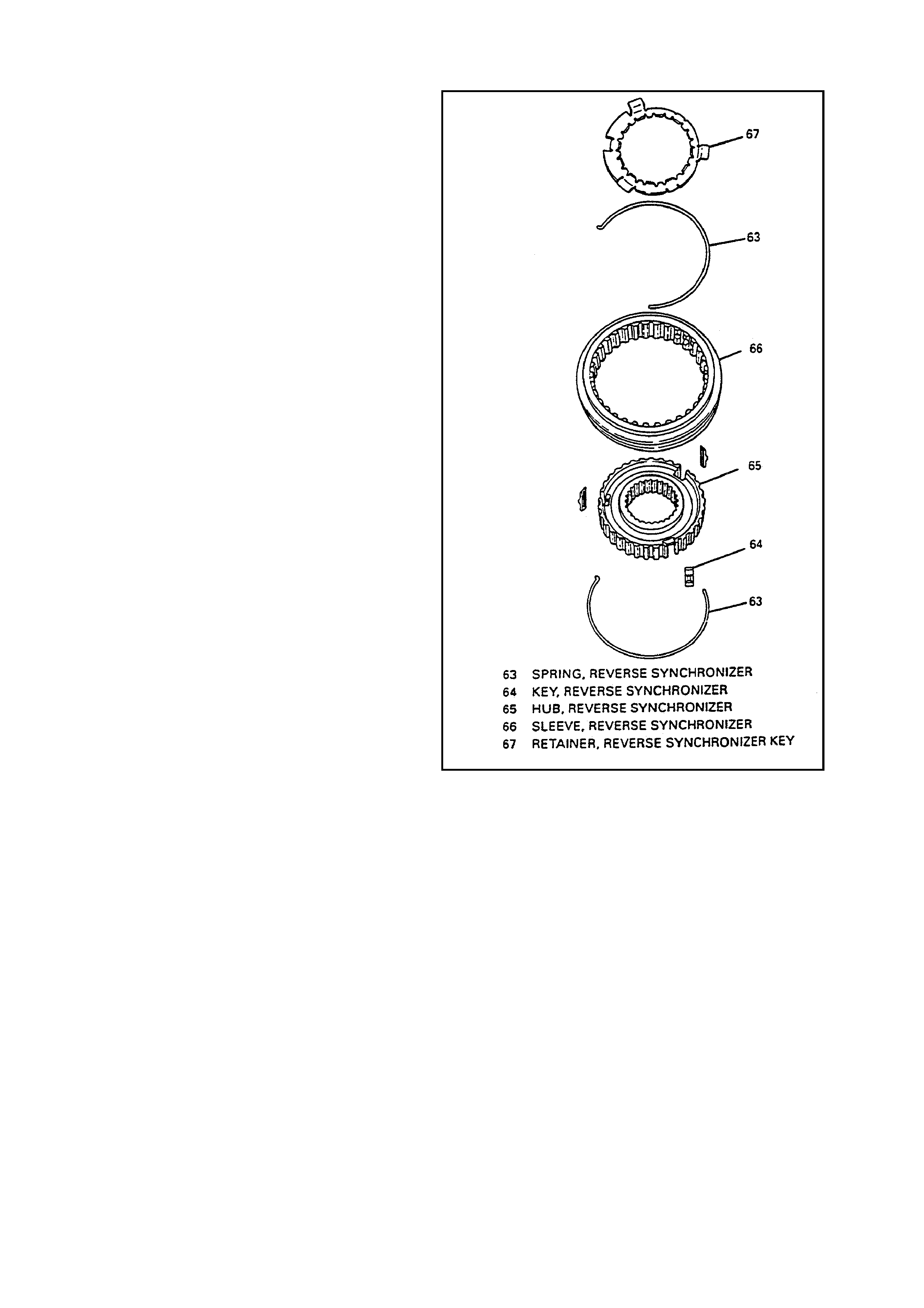
REVERSE SYNCHRONIZER
DISASSEMBLE
1. Synchronizer spring (63) using a small-bladed
screwdriver.
2. Synchronizer sleeve (66) from hub (65) by
pressing against inner hub (65).
3. Turn hub (65) over.
Keys (64) will slide out from hub (65).
4. Synchronizer key retainer (67) using a small-
bladed screwdriver through key slots of hub
(65) and discard retainer (67).
5. Synchronizer spring (63) using a small-bladed
screwdriver.
CLEAN
Synchronizer com ponents with solvent and dry with
compressed air.
INSPECT
Synchronizer components
Teeth for wear, nic k ed, burred or br oken teeth.
Replace hub and sleeve if excessive wear
exits.
Keys for wear or distortion. Replace if these
conditions exist.
Springs for distortion, crack s of wear. Replace
if these conditions exist.
Retainer for distortion. Replac e if this c ondition
exists.
If scuffed, nicked or burred conditions cannot be
correc ted by hand with a sof t stone or crocus cloth,
replace the component.
ASSEMBLE
1. Synchronizer sleeve (66) to hub (65).
Align key openings in hub (65) with cuts in
synchronizer sleeve (66).
2. Keys (64) with slots facing hub (65).
3. Synchronizer spring (63) using a small-bladed
screwdriver.
Locate spring tang to one of the key slots.
4. Turn synchronizer assembly (62) over.
5. Synchronizer spring (63) using a small0bladed
screwdriver.
Locate spring tang on same key but wind in
opposite direction.
6. New synchronizer key retainer (67).
Locate key retainer tangs over synchronizer
keys (64).
Figure 21 - Reverse Synchronizer
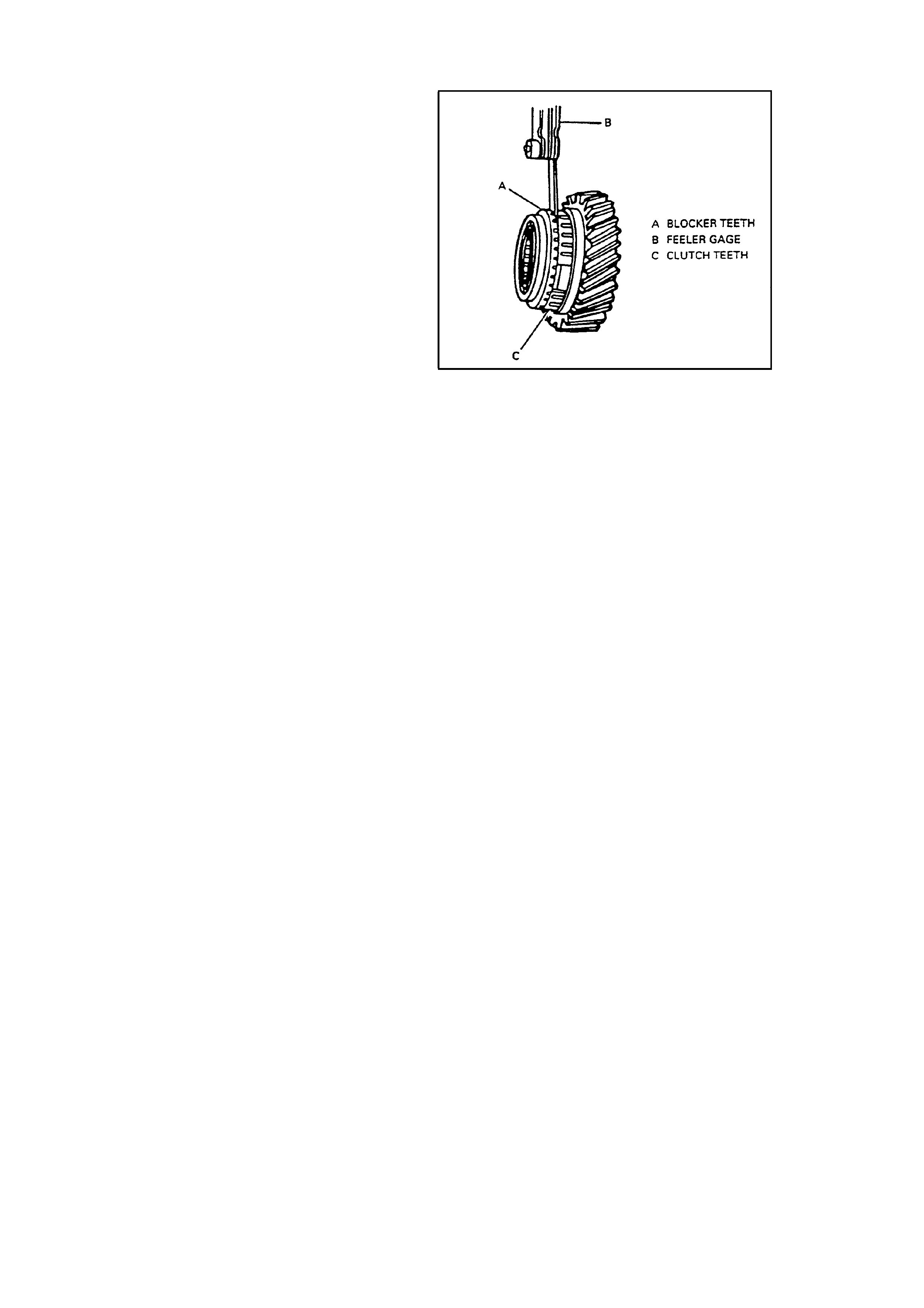
SYNCHRONIZER BLOCKER RING INSPECTION
INSPECT
1. Inspect the gear cones, clutch teeth and
blocker rings for excessive wear.
2. Inspect the synchronizer sleeve and gear
clutch teeth for evidence of gear clash or
cause of hop-out.
3. Measure the gap between the block er ring and
the speed gear. Mak e sure the c orrect block er
ring is measured with the correct gear and the
blocker ring is fully seated on the gear.
4. Replace blocker rings for 1s
t
, 2n
d
, 3r
d
, 4
th
, 5
th
and 6
th
gears of the wear gap is less than 0.38
mm (0.015 in.).
5. Replace the reverse blocker ring if the wear
gap is less than 0.75 mm (0.030 in.), when
measured without the wave washer (71) in
between the blocker ring and reverse gear. Figure 22 - Measuring Blocker Ring Wear
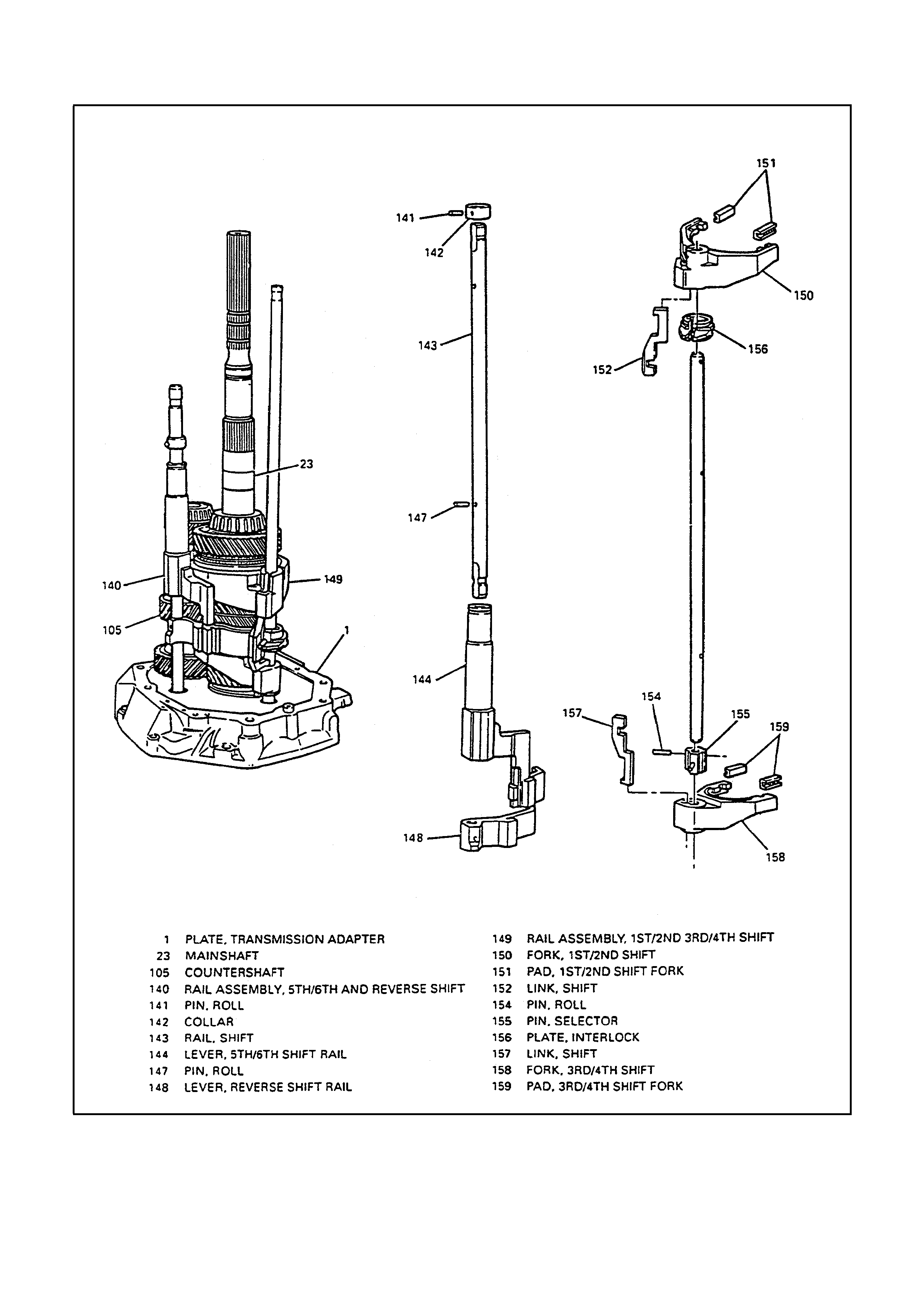
SHIFT RAIL AND FORK ASSEMBLIES
1ST/2ND, 3RD/4TH SHIFT RAIL A SSEMBLY
Figure 23 - Shift Rail And Fork Assemblies

DISASSEMBLE
1. Rotate selector pin (155) until opposite shift links (152 and 157).
2. 3rd/4th shift fork (158 with shift link (157) from rail (153).
3. 1st/2nd shift fork (150) with shift link (152) from rail (153).
4. Interlock plate (156) from rail (153).
5. Selector pin roll pin (154).
6. Selector pin (155).
CLEAN
Shift rail and fork assembly components with solvent and dry with compressed air.
INSPECT
Shift rail and fork assembly components.
Rail (153) for excessive wear or burrs. Replace if these conditions exist.
Shift forks (150 and 158) for excessive wear, fracture or distortion. Replace if these conditions exist.
Shift links (152 and 157) for excessive wear, fracture or distortion. Replace if these conditions exist.
Shift fork ny lon inserts (151 and 159) for excessive wear. Replace of this condition exists.
ASSEMBLE
1. Selector pin (155).
2. Selector pin roll pin (154).
3. Interlock plate (156) to rail (153).
4. 1st/2nd shift fork (150) with shift link (152) to rail (153).
5. 3rd/4th shift fork (158) with shift link (157) to rail (53).
6. Align selector pin (155) with slots in shifts links (152 and 157).

5TH/6TH, REVERSE SHIFT RAIL ASSEMBLY
DISASSEMBLE
Refer to Figure 23 above.
1. Collar roll pin (141).
2. Collar (142).
3. 5th/6th shift rail lever (144) from rail (143).
IMPORTANT:
Do not replace bushings (146) unless inspection shows bushing damage.
4. 5th/6th shift rail lever bushings (146) using J 23907 and J 36800.
5. Reverse shift rail lever roll pin (147).
6. Reverse shift rail lever (148) from rail (143).
CLEAN
Shift rail assembly components with solvent and dry with compressed air.
INSPECT
Shift rail assembly components.
Rail (143) for excessive wear or burrs. Replace if these conditions exist.
Shift rail levers (144 and 148) for excessive wear, fracture or distortion. Replace if these conditions exist.
Shift rail lever nylon insert for excessive wear. Replace if this condition exists.
Shift rail lever bushings (146) for excessive wear. Replace if this condition exists.
ASSEMBLE
1. Reverse shift rail lever (148) to rail (143).
Locate reverse shift rail lever (148) to roll pin hole at opposite end of rail (143) from snap ring groove.
Notched edge of reverse shift rail lever should face towards other roll pin hole.
2. Reverse shift rail lever roll pin (147).
3. 5th/6th shift rail lever bushings (146) using J 39437.
4. 5th/6th shift rail lever (144) to rail (143).
5. Collar (142).
6. Collar roll pin (141).
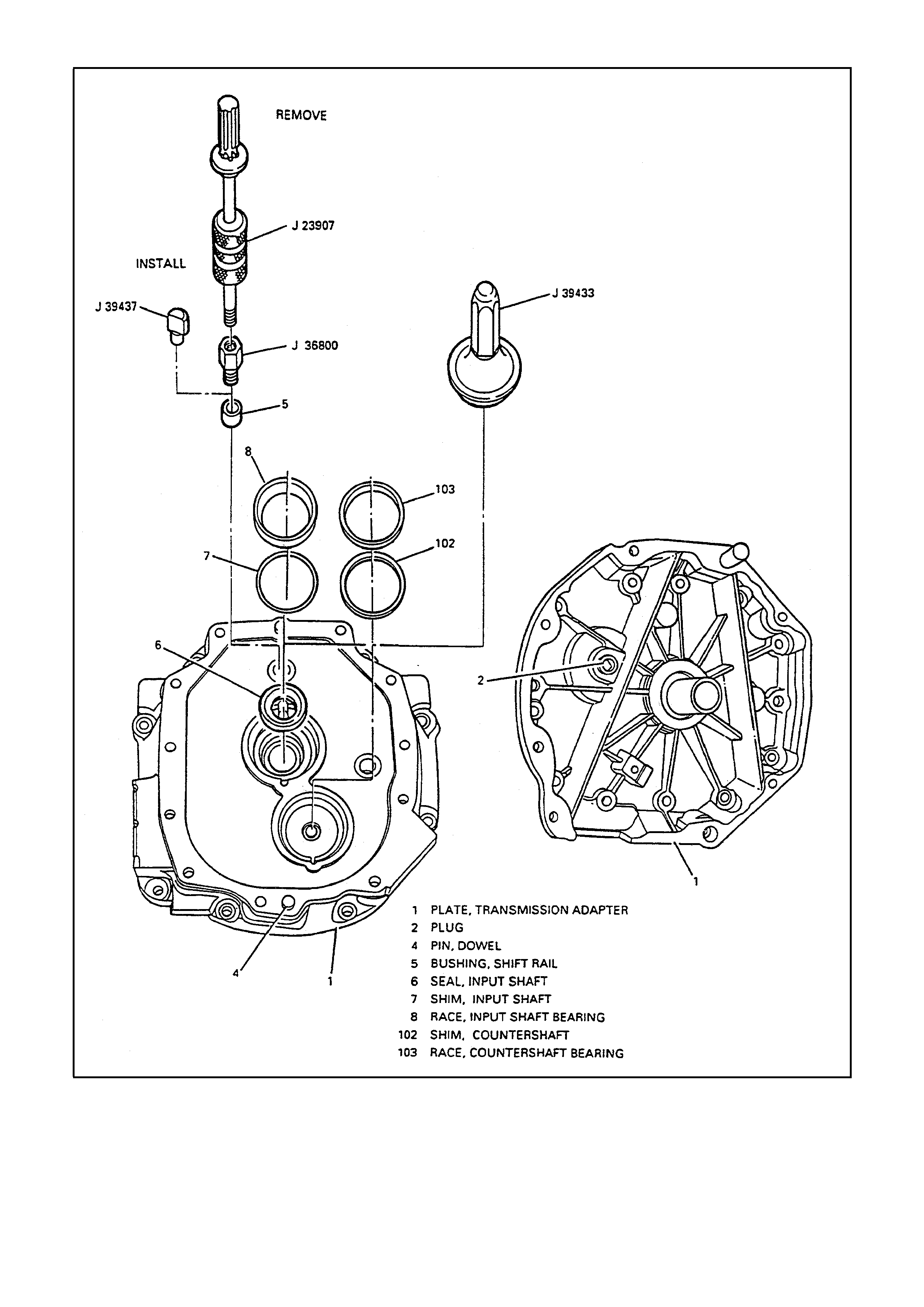
TRANSMISSION ADAPTER PLATE
Figure 24 - Transmission Adaptor Plate

DISASSEMBLE
1. Input shaft bearing race (8) and shim (7).
2. Countershaft bearing race (103) and shim (102).
3. Adapter plate plug (2).
4. Input shaft seal (6).
IMPORTANT:
Do not replace bushing (5) unless inspection shows bushing damage.
5. 1st/2nd, 3rd/4th shift rail bushing (5) using J 23907 and J 36800.
6. Dowel pins (3 and 4).
CLEAN
Adapter plate components with solvent and dry with compressed air.
INSPECT
Adapter plate components.
Bearing races (8 and 103) and bores for wear, scratches or grooves.
Bushing (5) for excessive wear or burrs. Replace if this condition exists.
Case for cracks, sealing surfaces for nicks, burrs or scratches. If case is cracked, it must be replaced.
If scratches, grooves or nicks cannot be removed by hand with a soft stone or crocus cloth, replace the
components.
ASSEMBLE
1. Dowel pins (3 and 4).
2. 1st/2nd, 3rd/4th shift rail bushing (5) using j 39437.
3. Input shaft seal (6) using J 39433.
IMPORTANT:
Do not install shims (102 and 7) until after performing “Shimming Procedures” later in this section.
4. Countershaft bearing race (103).
5. Input shaft bearing race (8).
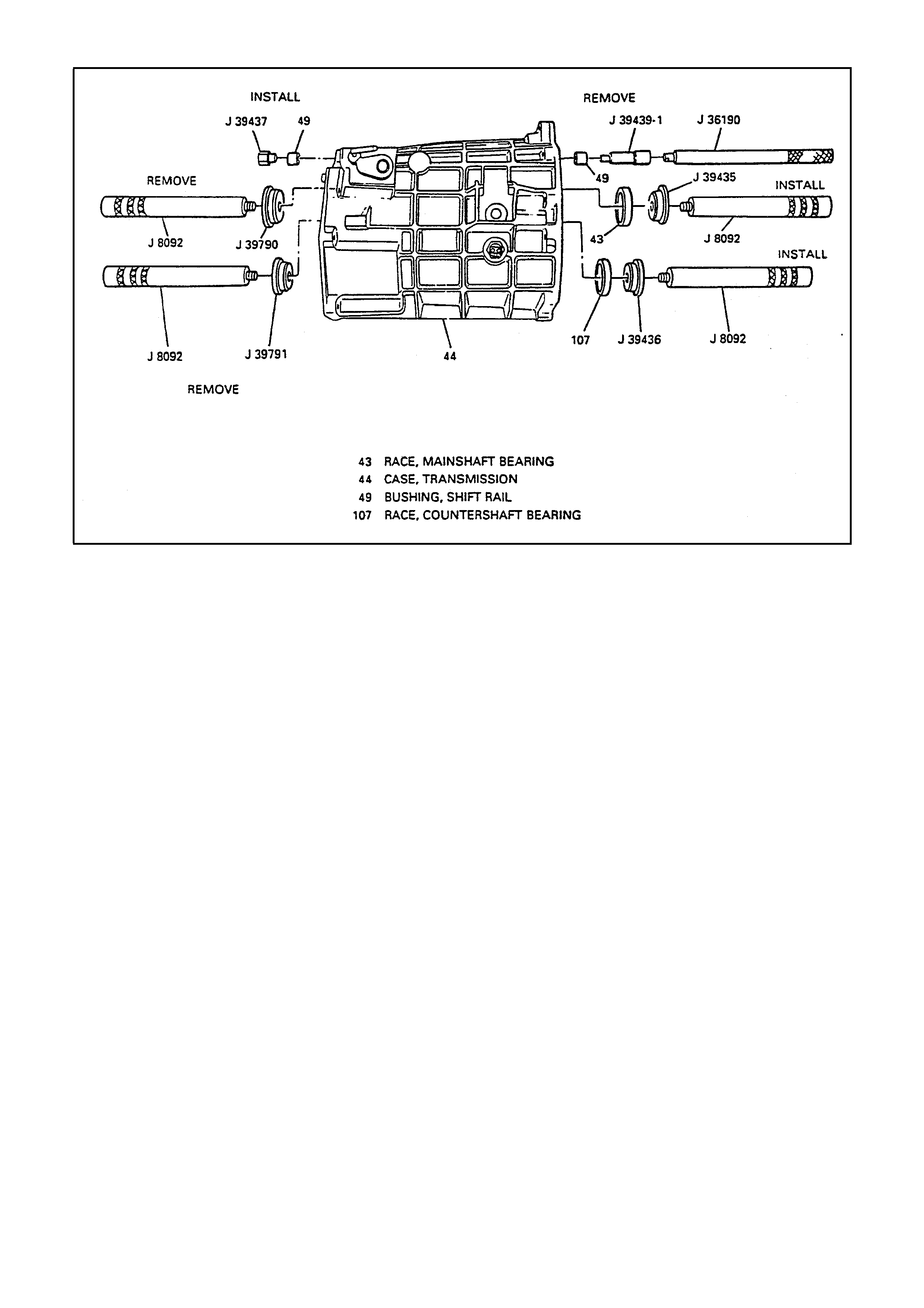
TRANSMISSION CASE
Figure 25 - Transmission Case
DISASSEMBLE
1. Fill plug (60).
2. Backup lamp switch (59).
3. Dowel Pins (58).
IMPORTANT:
Do not replace bearing races (107 and 43) unless inspection shows bearing race damage.
4. Countershaft bearing race (107) using J 8092 and J 39791.
5. Mainshaft bearing race (43) using J 8092 and J 39790.
6. 1st/2nd, 3rd/4th shift rail bushing (49) using J 36190 and J 39439.
CLEAN
Transmission case components with solvent and dry with compressed air.
INSPECT
Transmission case components.
Bearing races (43 and 107) and bores for wear, scratches or grooves.
Bushing (49) for excessive wear. Replace if this condition exists.
Case (44) for cracks , threaded openings f or damaged threads , sealing s urfaces f or nic ks, bur rs or sc r atches . If
case is cracked, it must be replaced.
If scratches, grooves or scoring cannot be removed by hand with a soft stone or crocus cloth, replace the
component.

ASSEMBLE
1. 1st/2nd, 3rd/4th shift rail bushing (49) using J 39437.
2. Mainshaft bearing race (43) using J 8092 and J 39435.
3. Countershaft bearing race (108) using J 8092 and J 39436.
4. Dowel pins (58).
5. Backup lamp switch (59).
BACKUP LAMP
SWITCH
TORQUE SPECIFICATION 27 Nm
6. Fill plug (60) with sealant GM p/n 1052080.
FILL PLUG
TORQUE SPECIFICATION 18
Nm
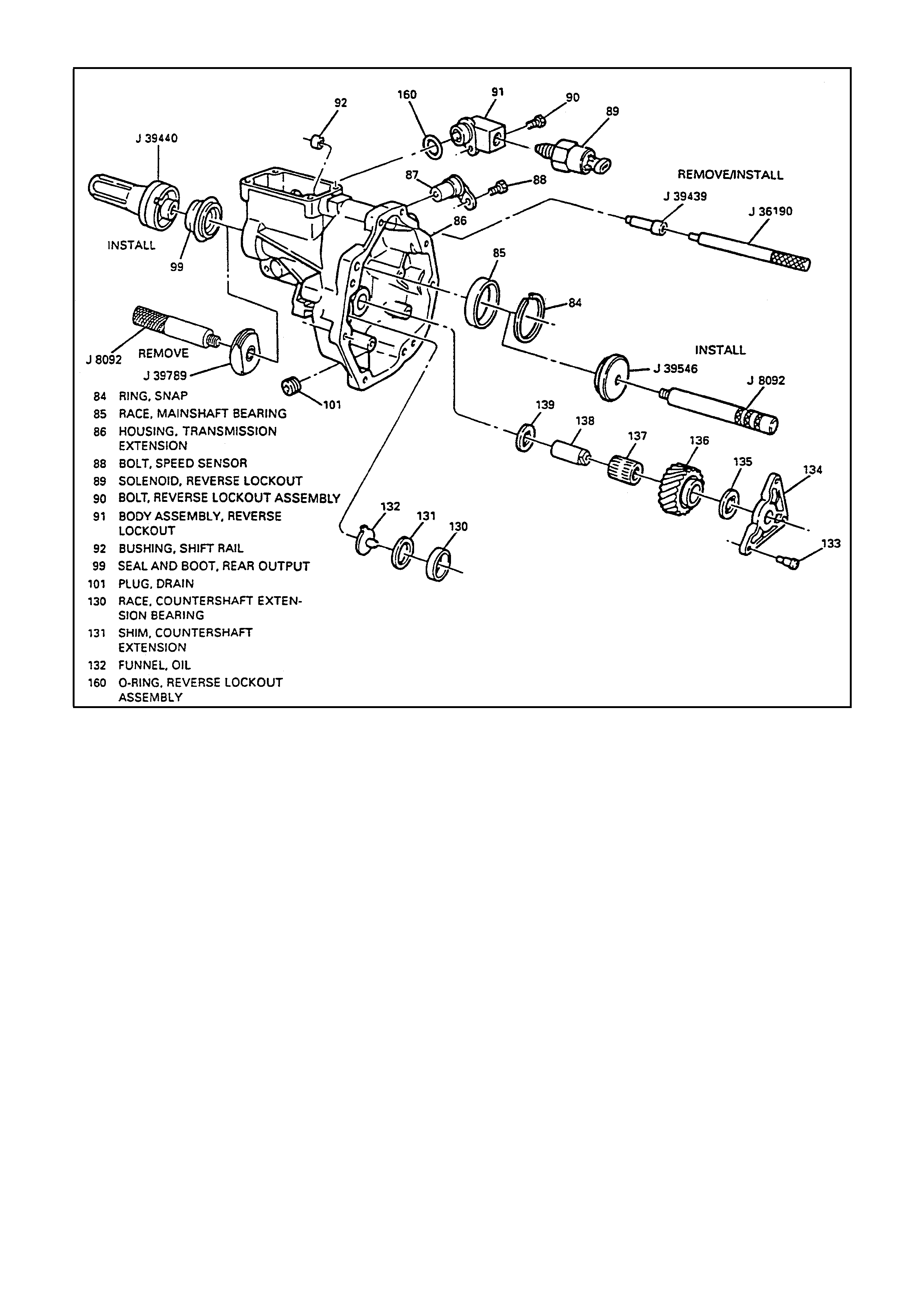
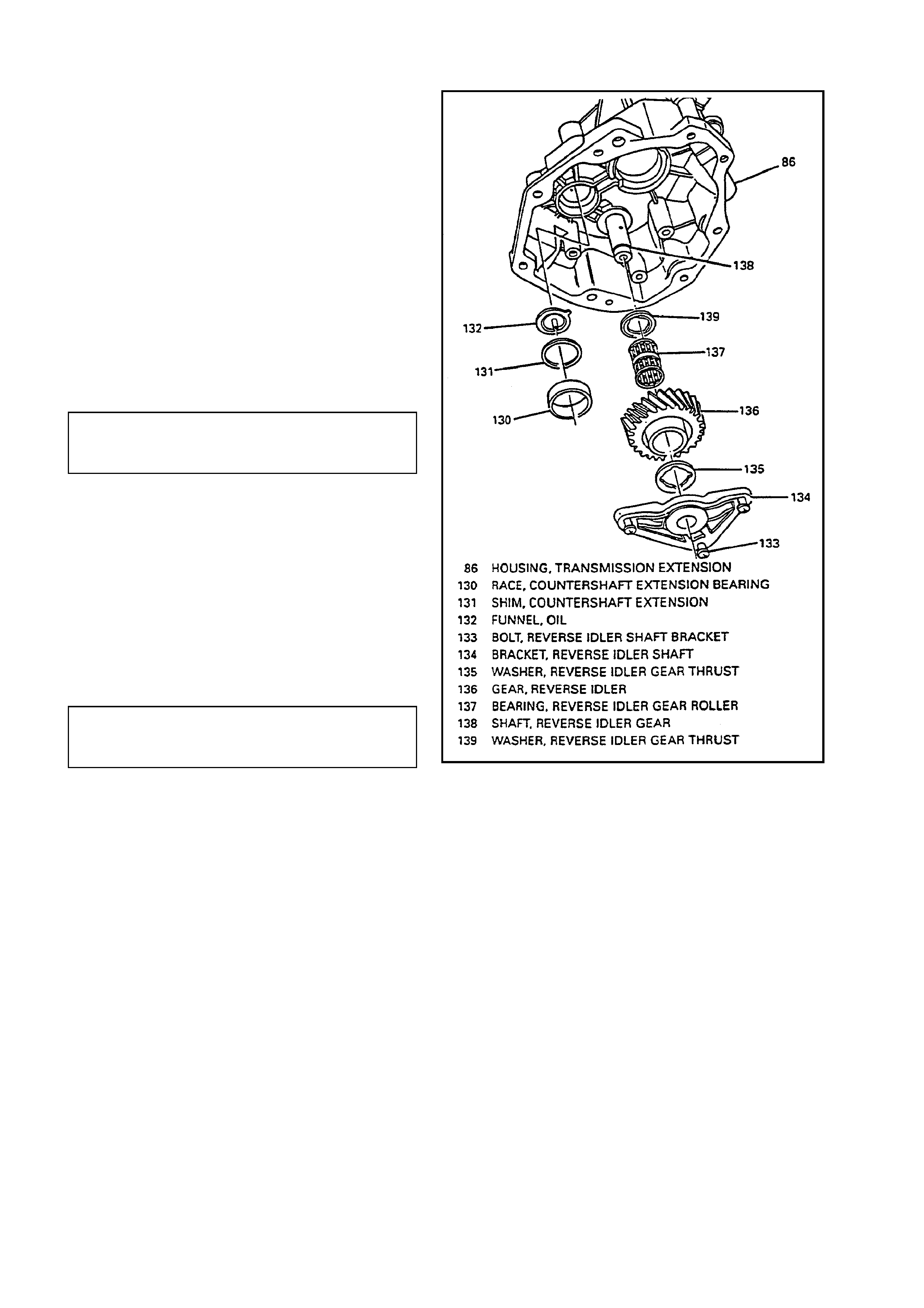
EXTENSION HOUSING
Figure 26 - Transmission Extension Housing
DISASSEMBLE
1. Reverse idler shaft bracket bolts (133).
2. Reverse idler shaft bracket (134).
3. Reverse idler gear thrust washer (135).
4. Reverse idler gear (136).
5. Roller bearing (137).
6. Thrust washer (139).
7. Reverse idler shaft (138).
8. Countershaft extension bearing race (130).
9. Shim (131).
10. Funnel (132).
11. Plug (101).
12. Reverse lockout assembly bolt (90).
CAUTION:
The re vers e loc k out as s embly us under spring pres s ur e. Exer c ise c aution when removing s nap ring (173) , as bodily
injury may result.

13. Reverse lockout assembly (91).
A. Reverse lockout solenoid (89) from reverse lockout body (175).
B. O-ring (160) from body (175).
C. Snap ring (169) from body (175).
D. Reverse lockout inner spring (174).
E. Compress reverse lockout plunger (170) and collar (172) in vise and remove snap ring (173).
F. Reverse lockout plunger (170).
G. Reverse lockout outer spring (171).
H. Reverse lockout collar (172).
14. Vehicle speed sensor bolt (88).
15. Vehicle speed sensor (87) and clamp.
O-ring seal from vehicle speed sensor (87).
16. Rear seal and boot (99).
Pry out seal and boot (99) with suitable tool.
17. Mainshaft bearing race snap ring (84).
IMPORTANT:
Do not replace bearing race (85) unless inspection shows bearing race damage.
18. Mainshaft bearing race (85) using J 8092 and J 39789.
IMPORTANT:
Do not replace bushing (92) unless inspection shows bushing damage.
19. Shift rail bushing (92) using J 36190 and J 39439.
CLEAN
Extension housing components with solvent and dry with compressed air.
INSPECT
Extension housing components.
Bearing races (85 and 130) and bores for wear, scratches or grooves.
Bushing (92) for excessive wear or burrs. Replace if this condition exists.
Case (86) for cracks, sealing surfaces for nicks, burrs or scratches. If case is cracked, it must be replaced.
If scratches, grooves or nicks cannot be removed by hand with a soft stone or crocus cloth, replace the component.
ASSEMBLE
1. Shift rail bushing (92) using J 36190 and J 39439.
2. Mainshaft bearing race (85) using J 8092 and J 39546.
3. Mainshaft bearing race snap ring ( 84).
4. Rear seal and boot (99) using J 39440.
Locate drain hole in rear seal and boot (99) down.
5. O-ring seal to vehicle speed sensor (87).
6. Vehicle speed sensor (87) and clamp.
7. Vehicle speed sensor bolt (88).
VEHICLE SPEED
SENSOR BOLT
TORQUE SPECIFICATION 10 Nm
CAUTION:
The re verse lockout as sembly is under spring pr essure. Exerc ise caution when installing snap ring (173), as bodily
injury may result.

8. Assemble reverse lockout body assembly.
A. Reverse lockout plunger (170).
B. Reverse lockout outer spring (171).
C. Reverse lockout collar (172).
D. Compress reverse lockout plunger (170), collar (172) and outer spring (171) in vise and install snap ring
(173).
E. Reverse lockout spring (174).
F. Install reverse lockout components in lockout body (175) and install snap ring (169).
G. Reverse lockout solenoid (89) to reverse lockout body assembly (91).
H. O-ring (160) to body assembly (91).
REVERSE LOCKOUT
SOLENOID (89)
TORQUE SPECIFICATION 40 Nm
10. Reverse lockout assembly.
11. Reverse lockout assembly bolt (90).
REVERSE LOCKOUT
ASSEMBLY BOLT (90)
TORQUE SPECIFICATION 18 Nm
12. Plug (101) with sealant GM p/n 1052080.
PLUG (101)
TORQUE SPECIFICATION 18
Nm
14. Countershaft extension bearing race (130).
IMPORTANT:
Do not install shim (131) until after performing
“Shimming Procedures” later in this section.
UNIT ASSEMBLY
SHIFT RAIL ASSEMBLIES AND GEAR CLUSTERS
INSTALL OR CONNECT
NOTE:
Lubricate all components as assembly progresses.
Use J 368250 Transmission Assembly Lube or
equivalent.
1. Selective shims (7 and 102). Refer to “Input
Shaft/Mainshaft and Countershaft” under
“Shimming Procedures” in this section.
2. Input shaft bearing race (8).
3. Countershaft bearing race (103).
4. Input shaft (10) and 4th gear blocker ring (12).
5. Shift rail assembly (149) to mainshaft
assembly.
6. Mainshaft assembly with shift rail assembly
(149).
7. Countershaft assembly.
A. Lift up mainshaft assembly enough to install
countershaft assembly.
B. Countershaft assembly.
C. Lift mainshaf t assembly enough to rotate input
shaft (10) to engage synchronizer keys (16)
with 4th gear blocker ring (12).
8. 5th/6th and reverse shift rail (140).
Align slots of shift rail levers with interlock plate
(156).
Figure 27 - Shift Rail Assemblies and
Gear Clusters
TRANSMISSION CASE
INSTALL OR CONNECT
NOTE:
Lubricate all components as assembly progresses.
Use J 36850 Transmission Assembly Lube.
1. Sealant GM p/n 12345739 at transmission
case to adapter plate mating surface.
2. Transmission case (44).
Slide transmission case (44) onto gear clusters
and shift rail components.
3. Shift lever guide bolts (45 and 46).
Apply anaerobic threadlocker GM p/n
12345382 to threads of shift lever guide bolts
(45 and 46).
Pull up on 5
th
/6
th
and reverse shift rail
assembly (140) enough to align the slot of the
shift interlockerplate (156) with guide bolt hole.
SHIFT LEVER GUIDE
BOLTS (45 AND 46) 27 Nm
TORGUE SPECIFICATION
4. Adapter plate to transmission case bolts (178).
ADAPTER PLATE TO
TRANSMISSION CASE BOLTS (178) 35 Nm
TORQUE SPECIFICATION.
Figure 28 - Transmission Case
GUIDE PLATE
ASSEMBLE
1. Shift detent ball (53) in neutral detent groove of
shift guide plate (55).
2. Shift detent spring (52) into front offset lever
(51).
3. Front offset lever (51) and spring (52) to shift
guide plate (55) and ball (53).
INSTALL OR CONNECT
1. Guide plate (55) and front offset lever (51) at
the same time.
A. Lubricate shift rail (153) using J 36850
Transmission Assembly Lube.
B. Compress guide plate (55) and front offset
lever (51) together while sliding onto shift rail
(149) to prevent spring release of inner
components.
2. Shift guide plate bolts (54).
SHIFT GUIDE PLATE
BOLTS (54) 22 Nm
TORQUE SPECIFICATION
3. Front offset lever roll pin (50).
4. Shift detent assembly (56).
Apply anaerobic threadlocker GM p/n
12345382 to threads of shift detent assembly
(56).
SHIFT DETENT ASSEMBLY (56) 34
TORQUE SPECIFICATION Nm
5. Cover plate (48).
Apply sealant GM p/n 12345739 to mating
surface of cover plate (48).
6. Cover plate bolts (47).
COVER PLATE BOLTS (47) 20
TORQUE SPECIFICATION Nm
Figure 29 - Shift Detent Assembly
COUNTERSHAFT EXTENSION ASSEMBLY
INSTALL OR CONNECT
1. Countershaft extension assembly and 5
th
/6
th
shift fork (122) with transmission in horizontal
position.
Ensure spines of countershaft extension (128)
engage splines of countershaft (105).
2. 5th/6th shift fork snap ring (124).
Figure 30 - Countershaft Extension Assembly
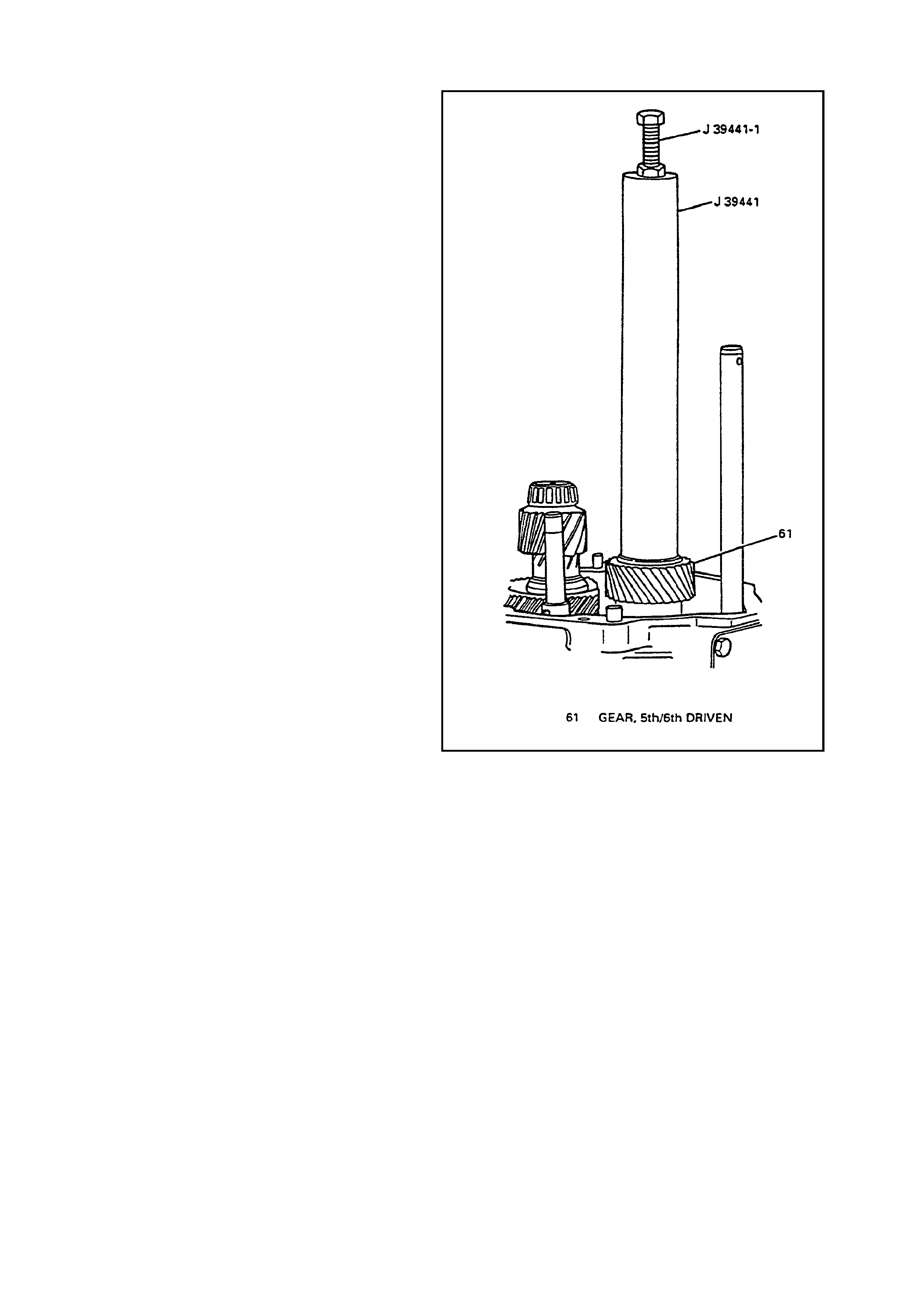
5TH/6TH DRIVEN GEAR
INSTALL CONNECT
1. 5
th
/6
th
driven gear (61) using J 39441 and J
39441-1.
Smaller OD gear down.
Engage splines of 5
th
/6
th
driven gear (61) to
shaft splines (23) before pressing gear onto
shaft.
Figure 31 - 5th/6th Driven Gear

REVERSE SHIFT FORK
INSTALL OR CONNECT
1. Reverse shift f ork (111) , synchronizer (62) and
thrust washer (68) at the same time.
2. New reverse shift fork snap ring (113).
3. Reverse synchronizer snap ring (69).
Figure 32 - Reverse Shift Fork
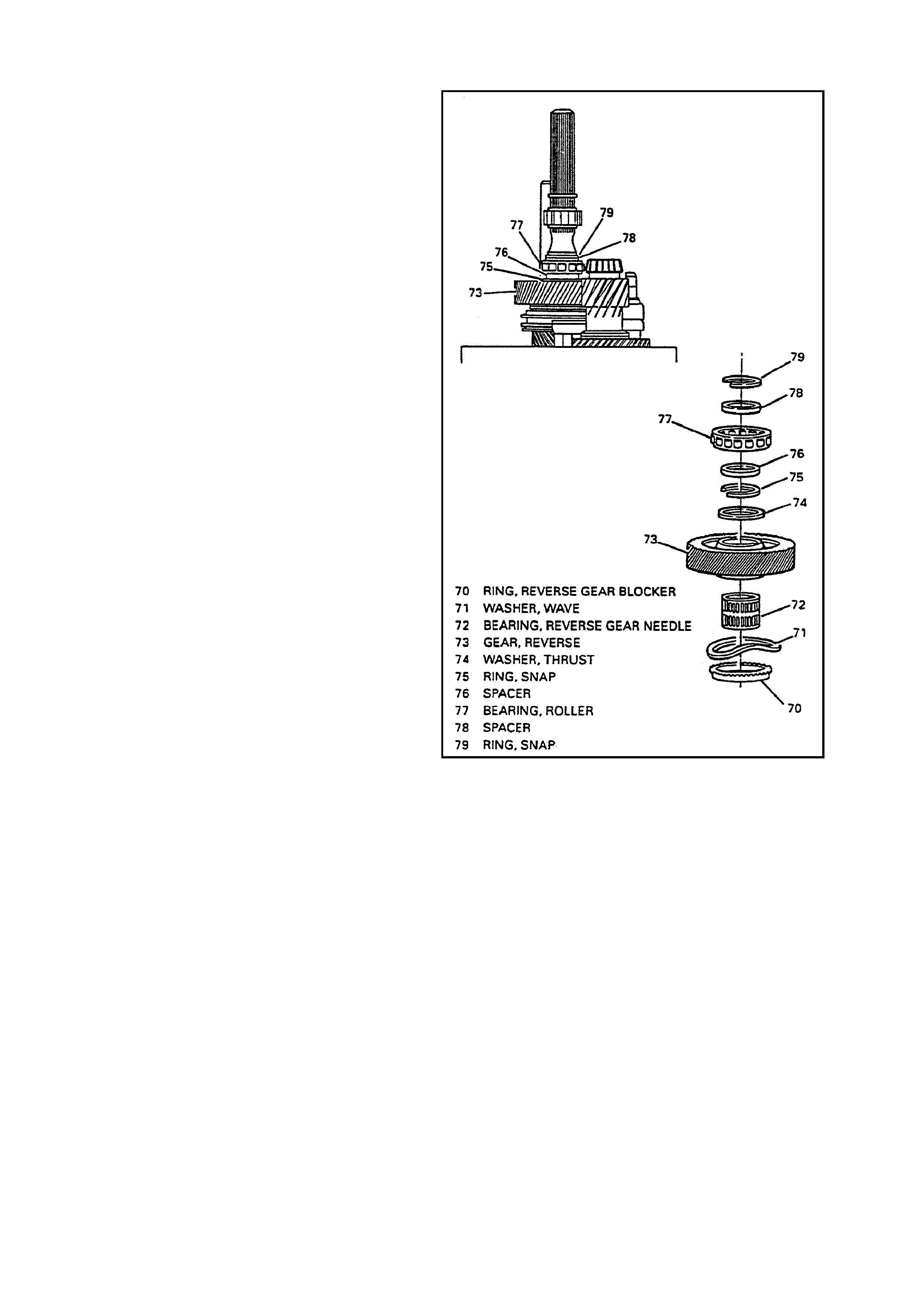
REVERSE SPEED GEA R
INSTALL OR CONNECT
1. Blocker ring (70).
2. Wave washer (71).
Install wave washer (71) so concave side
faces blocker ring.
3. Needle bearing (72).
4. Reverse speed gear (73).
5. Thrust washer (74).
6. Snap ring (75).
7. Spacer (76).
8. Roller bearing (77).
9. Spacer (78).
10. Roller bearing snap ring (79).
Figure 33 - Reverse Speed Gear
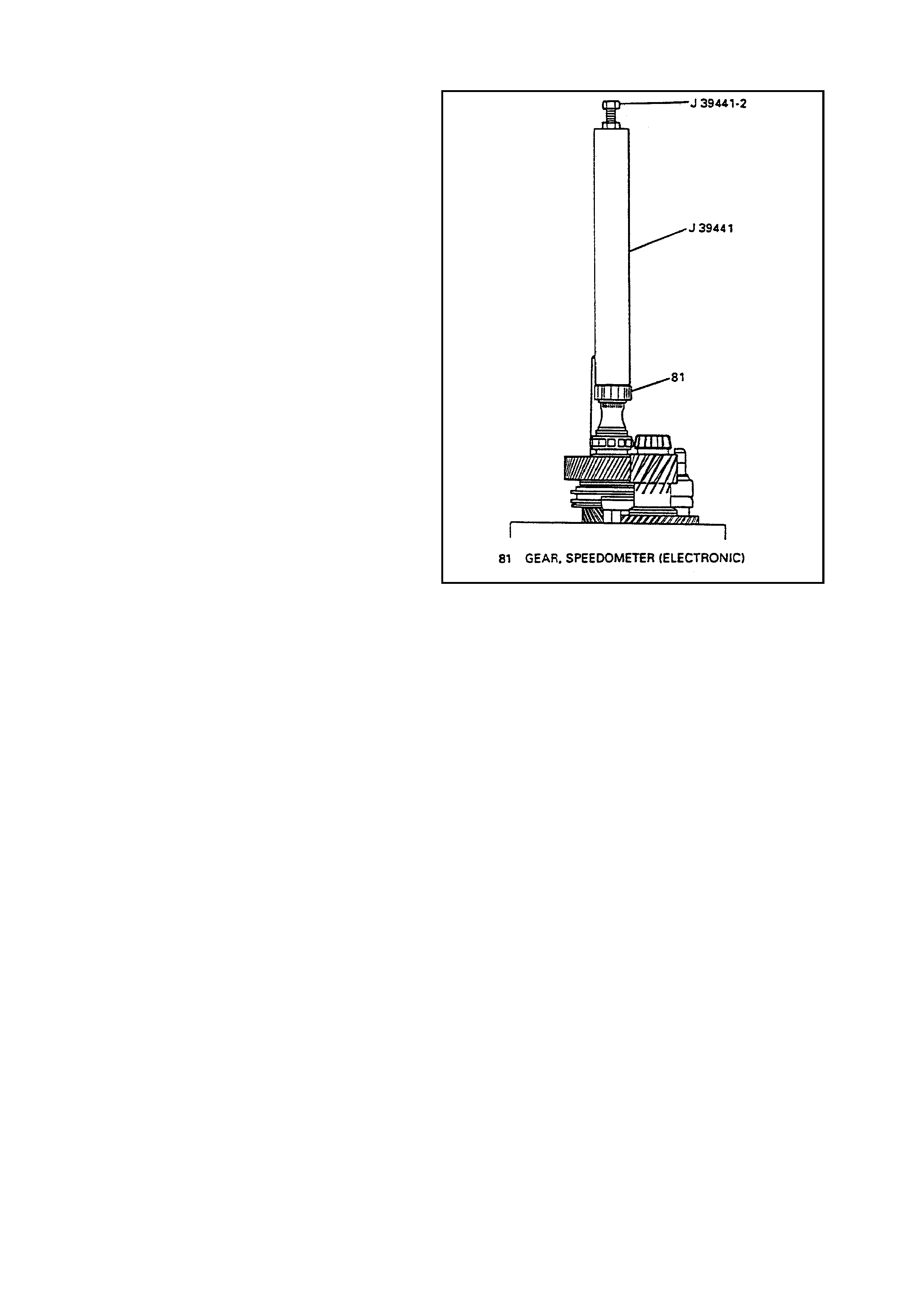
SPEEDOMETER GEA R
INSTALL OR CONNECT
1. Speedometer gear snap ring (80).
2. Speedometer gear (81) using J 39441 and J
39441-2.
3. Speedometer gear snap ring (82).
4. Sealing ring.
Figure 34 - Speedometer Gear
EXTENSION HOUSING
INSTALL OR CONNECT
1. Funnel (132).
2. Selective shim (131). Refer to “Countershaft
Extension” under “Shimming Procedures” in
this section.
3. Countershaft extension bearing race (130).
4. Reverse idler shaft (138).
5. Thrust washer (139).
6. Roller bearing (137).
7. Reverse idler gear (136).
8. Reverse idler gear thrust washer (135).
9. Reverse idler shaft bracket (134).
10. Reverse idler shaft bracket bolts (133).
Apply sealant GM p/n 12345382 to threads of
bolts (133).
REVERSE IDLER SHAFT
BRACKET BOLTS (133) 25 Nm
TORQUE SPECIFICATION
11. Extension housing (86).
Apply sealant GM p/n 12345739 at extension
housing to transmission case mating surface.
Align 5th/6th and reverse shift rail (140) with
extension housing bore.
12. Extension housing bolts (100) and
transmission bumper (177).
Apply sealant GM p/n 1052080 to threads of
bolts retaining transmission bumper.
EXTENSION HOUSING
BOLTS (100) 35 Nm
TORQUE SPECIFICATION
13. Rear offset lever (93) and isolator cup (95).
14. Rear offset shift lever roll pin (94).
Figure 35 - Speedometer Gear
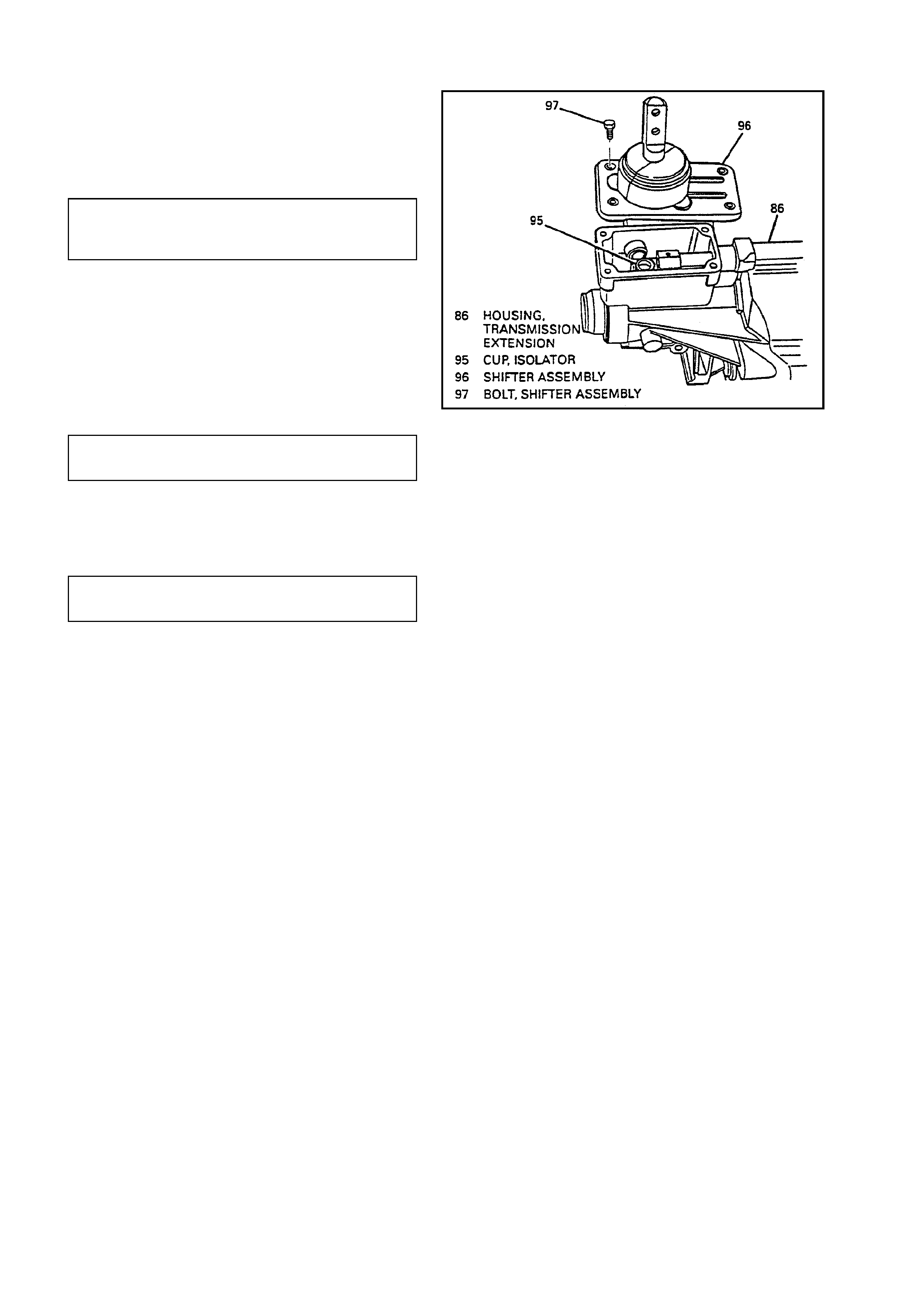
SHIFTER
INSTALL OR CONNECT
1. Shifter (96).
Apply sealant GM p/n 12345739 at extension
housing to shifter mating surface.
2. Bolts (97).
SHIFTER ASSEMBLY
RETAINING BOLTS (97) 20 Nm
TORQUE SPECIFICATION
3. Remove transmission from J 39430 and J
3289-20.
4. Clutch fork (164) and T-handle (165).
5. Clutch fork bolt (166).
Apply sealant GM p/n 12345382 to threads of
clutch fork bolt (166).
CLUTCH FORK BOLT (166) 25
TORQUE SPECIFICATION Nm
6. Clutch housing (162).
7. Clutch housing bolts (163).
CLUTCH HOUSING BOLTS (163) 35
TORQUE SPECIFICATION Nm
8. Vent tube (161).
Figure 36 - Shifter
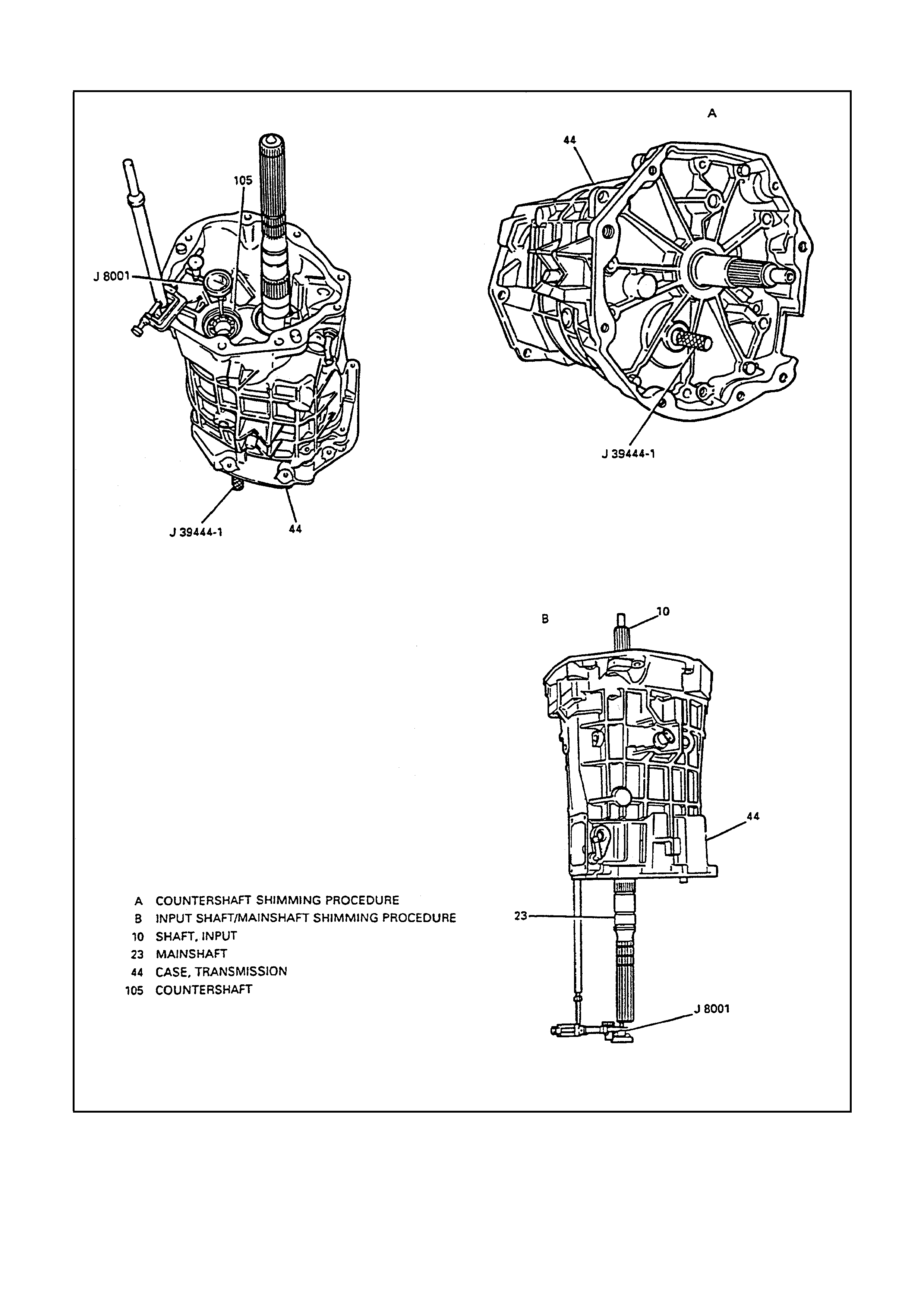
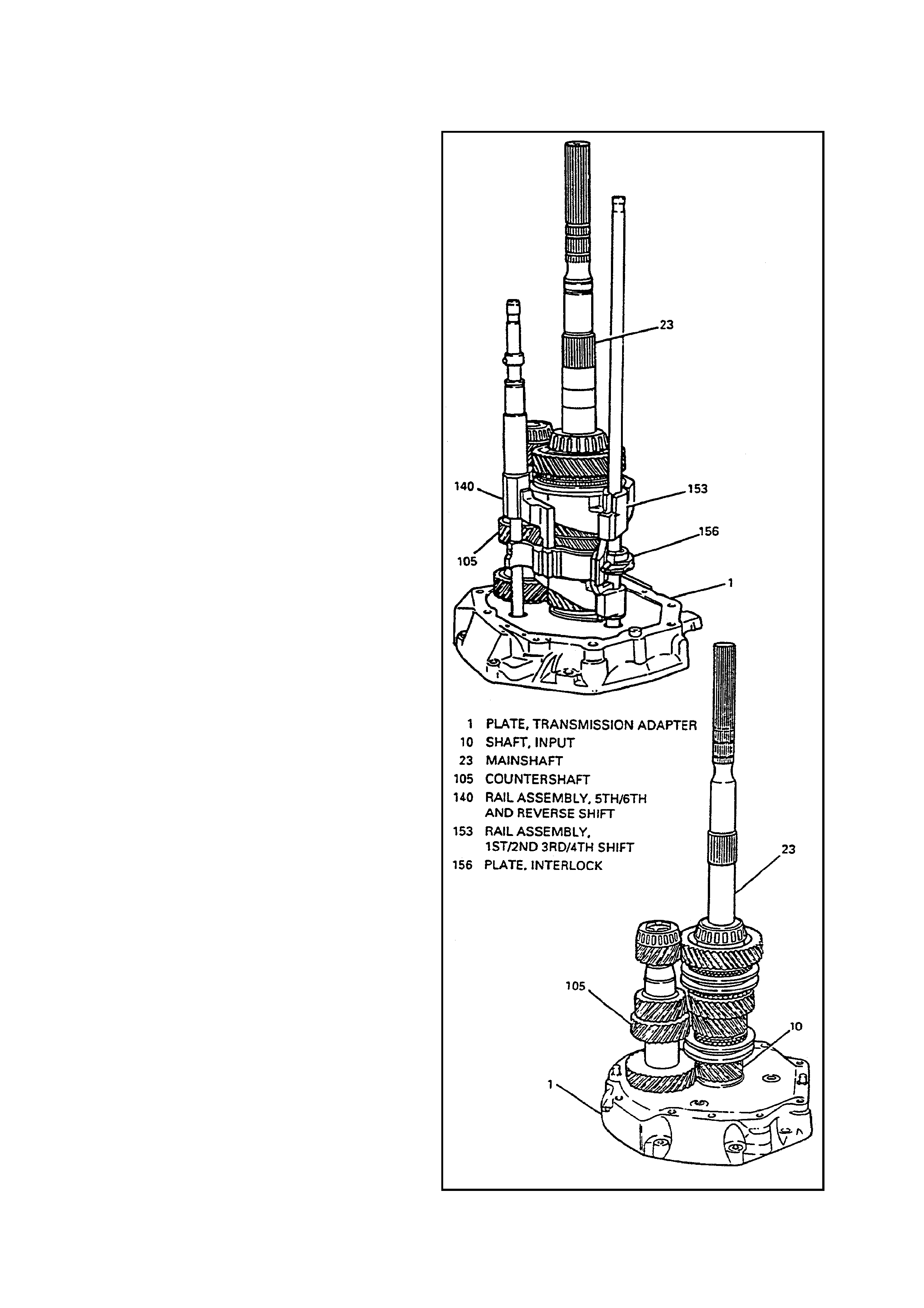
SHIMMING PROCEDURES
INPUT SHAFT/MAINSHAFT AND COUNTERSHAFT
Figure 37 - Input Shaft/Mainshaft and Countershaft

INSTALL OR CONNECT
1. Position transmission in vertical position.
2. Input shaft 910) to adapter plate (1).
3. Mainshaft (23) to input shaft (10).
4. Countershaft (105).
A. Lift up mainshaft (23) enough to install
countershaft (105).
B. Countershaft (105).
5. Transmission Case (44).
6. Adapter plate to transmission case bolts (178).
ADAPTER PLATE TO
TRANSMISSION CASE BOLTS (178) 35 Nm
TORQUE SPECIFICATION
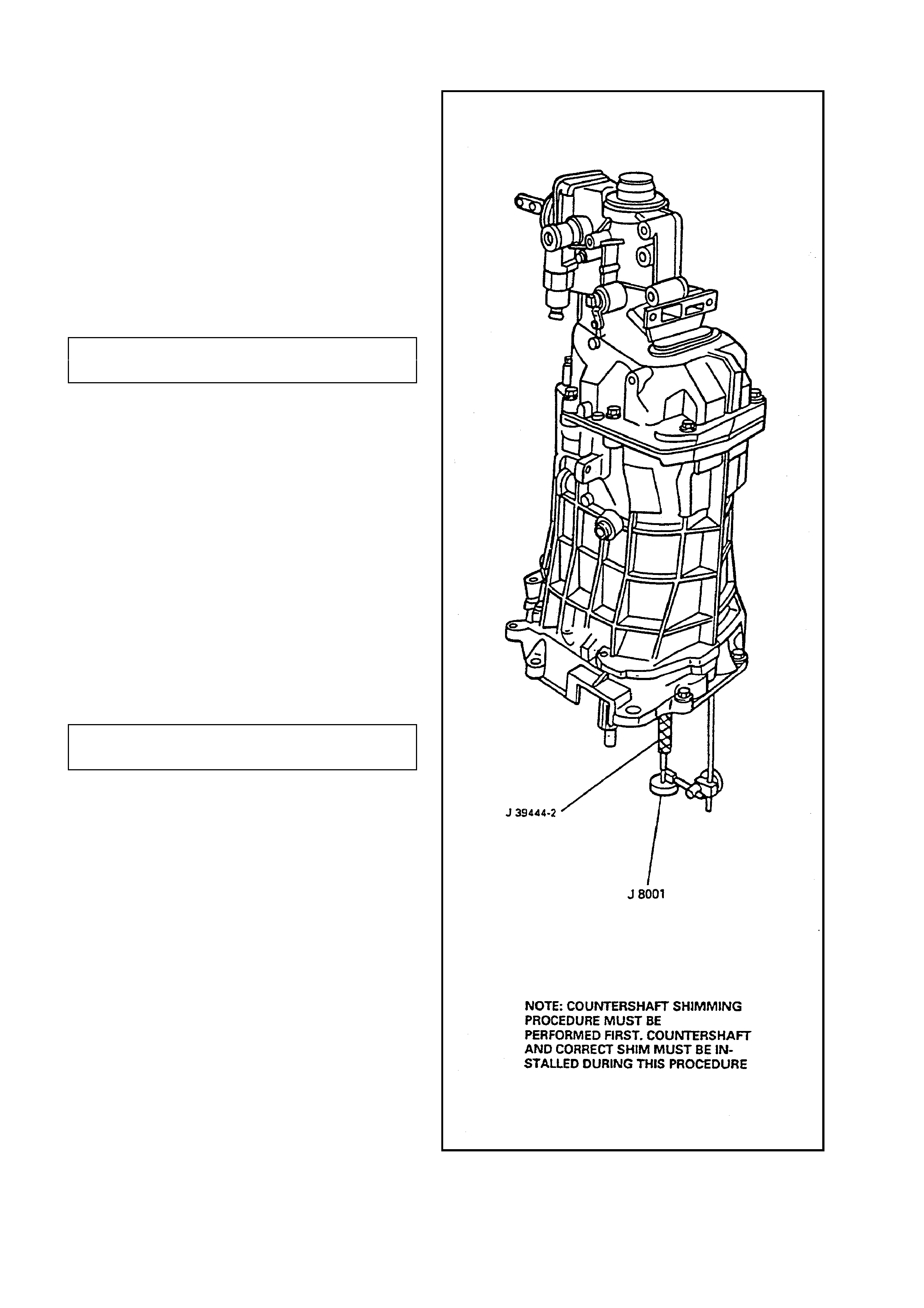
7. Place tip of J 8001 on end of mainshaft (23)
MEASURE
A. Input shaft/mainshaft end play by moving input shaft (10) up and down.
B. Select shim (6) to achieve 0.000 to 0.002 inch (0.00 to 0.05 mm ) preload.
8. Remove J 8001.
9. Place tip of J 8001 on end of countershaft (105).
10. J 39444-1 through adapter plate plug hole.
MEASURE
A. Countershaft end play using J 39444-1 to move countershaft (105) up and down.
B. Select shim (102) to achieve 0.000 to 0.002 inch (0.00 to 0.05 mm ) preload.
11. Remove J 39444-1 and J 9001.
REMOVE OR DISCONNECT
1. Adapter plate to transmission case bolts (167).
2. Transmission case (44).
3. Countershaft (105).
A. Lift up mainshaft (23) enough to remove countershaft (105).
B. Countershaft (105).
4. Mainshaft (23).
5. Input shaft (10) from adapter plate (1).
6. Input shaft bearing race (8).
7. Countershaft bearing race (103).
COUNTERSHAFT EXTENSION
INSTALL OR CONNECT
IMPORTANT:
This procedure cannot be performed accurately
until the “Countershaft Shimming Procedure” has
been completed and the transmission has been
assem bled to the point of ins talling the counters haft
extension.
1. Position transmission in horizontal position.
2. Countershaft extension (128) to countershaft
(105) making sure splines fully engage.
3. Extension housing (86).
4. Extension housing bolts (100).
EXTENSION HOUSING BOLTS (100) 35
TORQUE SPECIFICATION Nm
5. J 39444-2 through adapter plate plug hole and
screw J 39444-2 into countershaft extension.
7. J 8001 so tip is on end of J 39444-2.
MEASURE
A. Position transmission in vertical position.
B. Countershaft extension end play using J
39444-2 to move countershaft extension (128)
up and down).
C. Select shim (131) to achieve 0.002 to 0.005
inch (0.05 to 0.13mm) axial ply.
8. Remove J 8001 and J 39444-2.
9. Install adapter plate plug (2).
Apply sealant GM p/n 1052080 to plug threads
(2).
ADAPTER PLATE PLUG (2) 17
TORQUE SPECIFICATION Nm
REMOVE OR DISCONNECT
1. Extension housing bolts (100).
2. Extension housing (86).
3. Countershaft extension (128).
4. Countershaft extension bearing race (130).
Figure 38 - Countershaft Extension

SPECIFICATIONS
FASTENER TIGHTENING SPECIFICATIONS
NO.* DESCRIPTION TORQUE
2 Adapter Plate Plug 27 N.m
178 Adapter Plate to Transmission Case Bolts 35 N.m
59 Backup Lamp Switch 27 N.m
166 Clutch Fork Bolt 25 N.m
163 Clutch Housing to Adapter Plate Bolt 35 N.m
48 Cover Plate Bolts 20 N.m
101 Extension Housing Plug 27 N.m
100 Extension Housing to Transmission Case Bolts 35 N.m
133 Reverse Idler Shaft Bracket Bolts 25 N.m
90 Reverse Lockout Assembly Bolt 18 N.m
89 Reverse Lockout Solenoid 40 N.m
97 Shifter Bolts 20 N.m
56 Shift Detent Assembly 40 N.m
45, 46 Shift Lever Guide Bolts 27 N.m
54 Shift Guide Plate Bolts 22 N.m
60 Transmission Case Fill Plug 27 N.m
88 Vehicle Speed Sensor Bolt 10 N.m
* Disassembled Parts Illustration, Figure 1
SHIMING SPECIFICATIONS
SHIM NO.*
DESCRIPTION
SHIM TO ATTAIN
7 Input Shaft/Mainshaft Shim Preload of 0.0 - 0.002 inch
(0.0 to 0.05 mm)
102 Countershaft Shim Preload of 0.0 – 0.002 inch
(0.0 to 0.05 mm)
131 Countershaft Extension Shim Axial Play of 0.001 – 0.005 inch
(0.05 to 0.13 mm)
* Disassembled Parts Illustration, Figure 1
LUBRICANT SPECIFICATIONS
Lube Capacity (Approximate) 3.9 Litres
(After refill, fluid level must be checked as outlined under On-Vehicle Service in Section 7B).
Recommended Lube Dexron ®-IIE
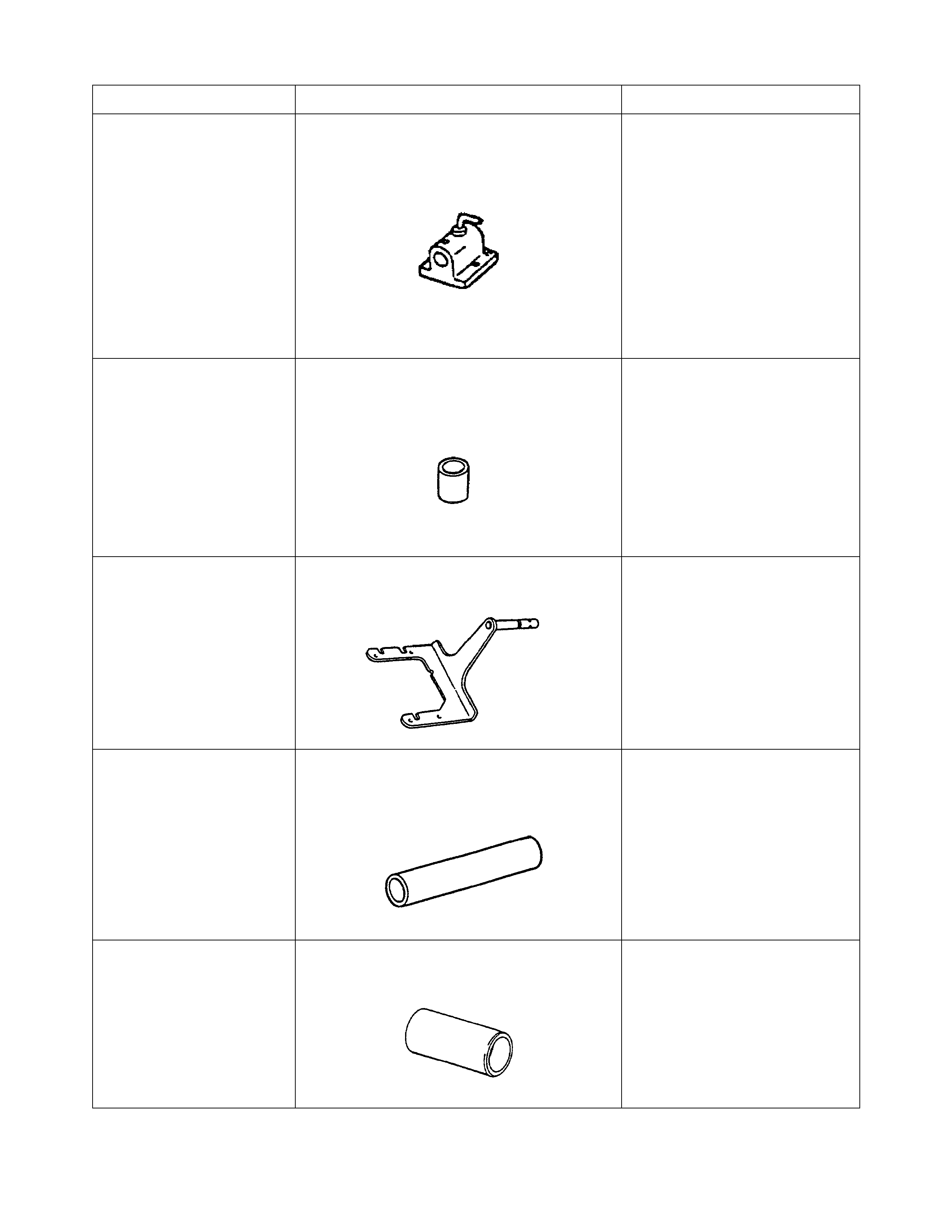
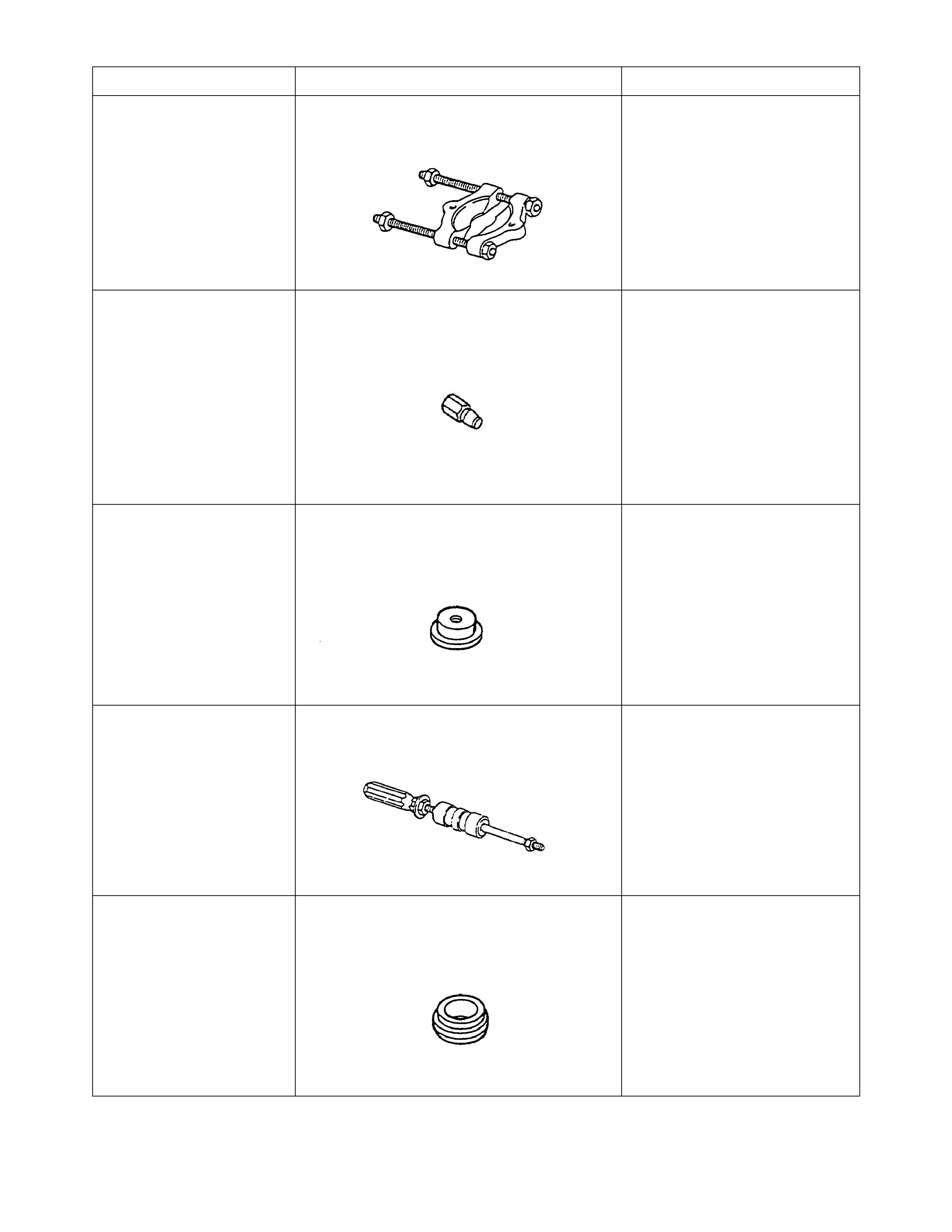
SPECIAL TOOLS
TOOL NO. REF IN TEXT TOOL DESCRIPTION COMMENTS
J3289-20
HOLDING FIXTURE
J2837-17 BAERING RACE INSTALLER
J39430 TRANSMISSION HOLDING FIXTURE
J5590 PRESS TUBE
J36183 PRESS TUBE
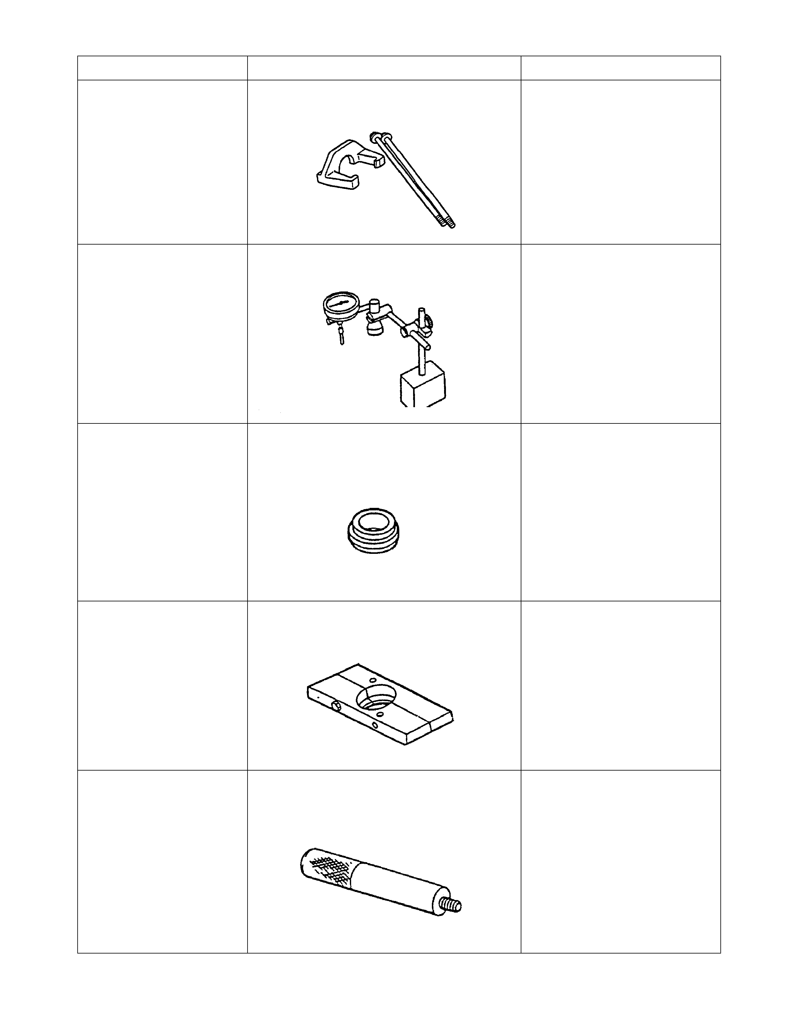
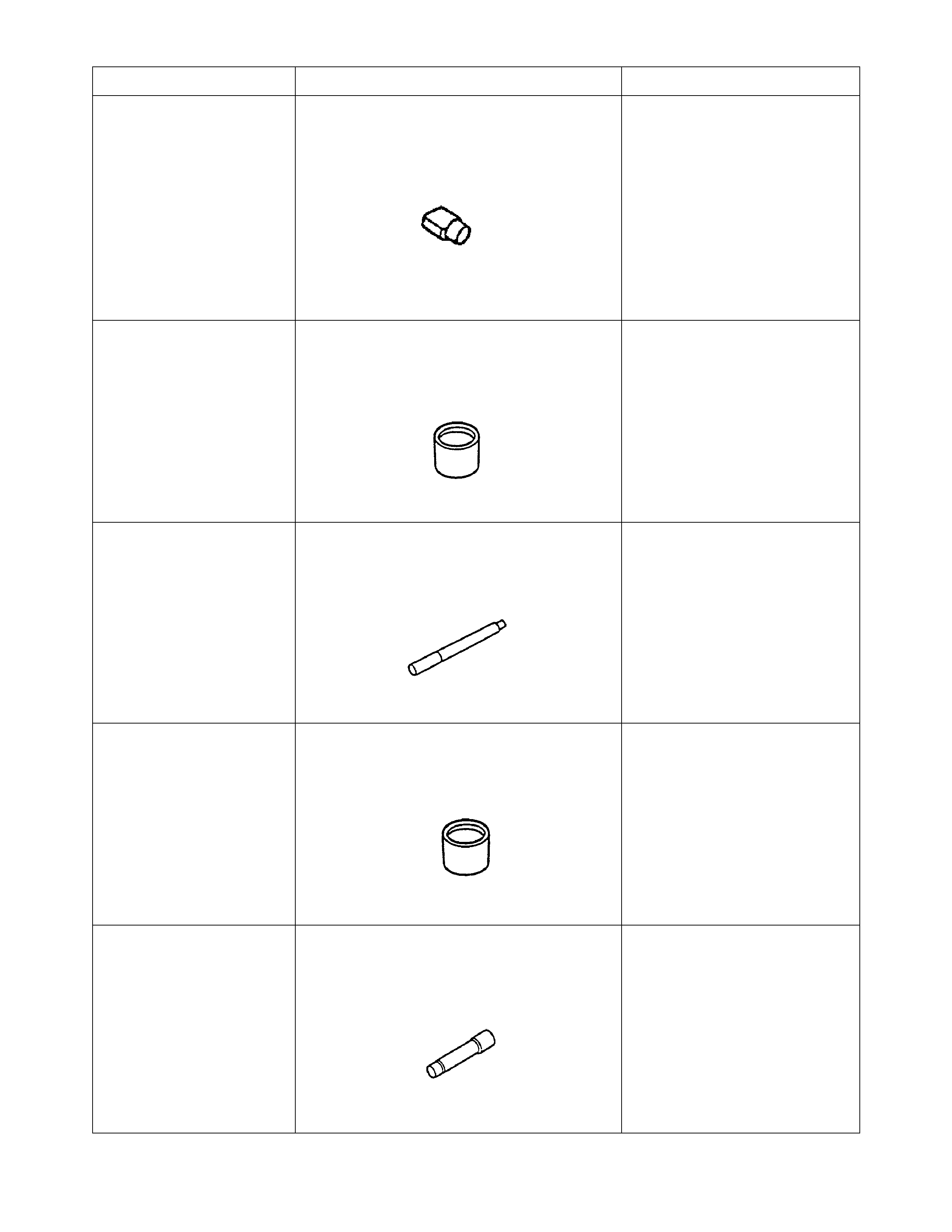
TOOL NO. REF IN TEXT TOOL DESCRIPTION COMMENTS
J39431,-1,-2 GEAR REMOVER AND BOLTS
J8001 DIAL INDICATOR SET
J36184 PRESS TUBE ADAPTER
J39428 SPLITE PLATE
J8092 UNIVERSAL DRIVE HANDLE
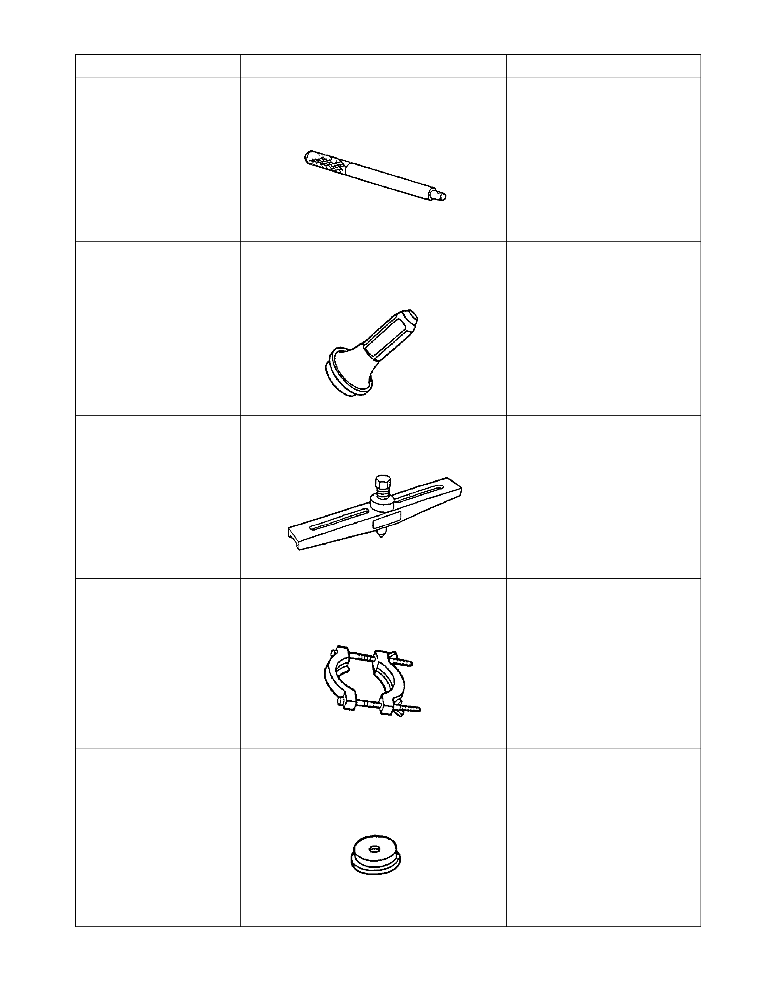
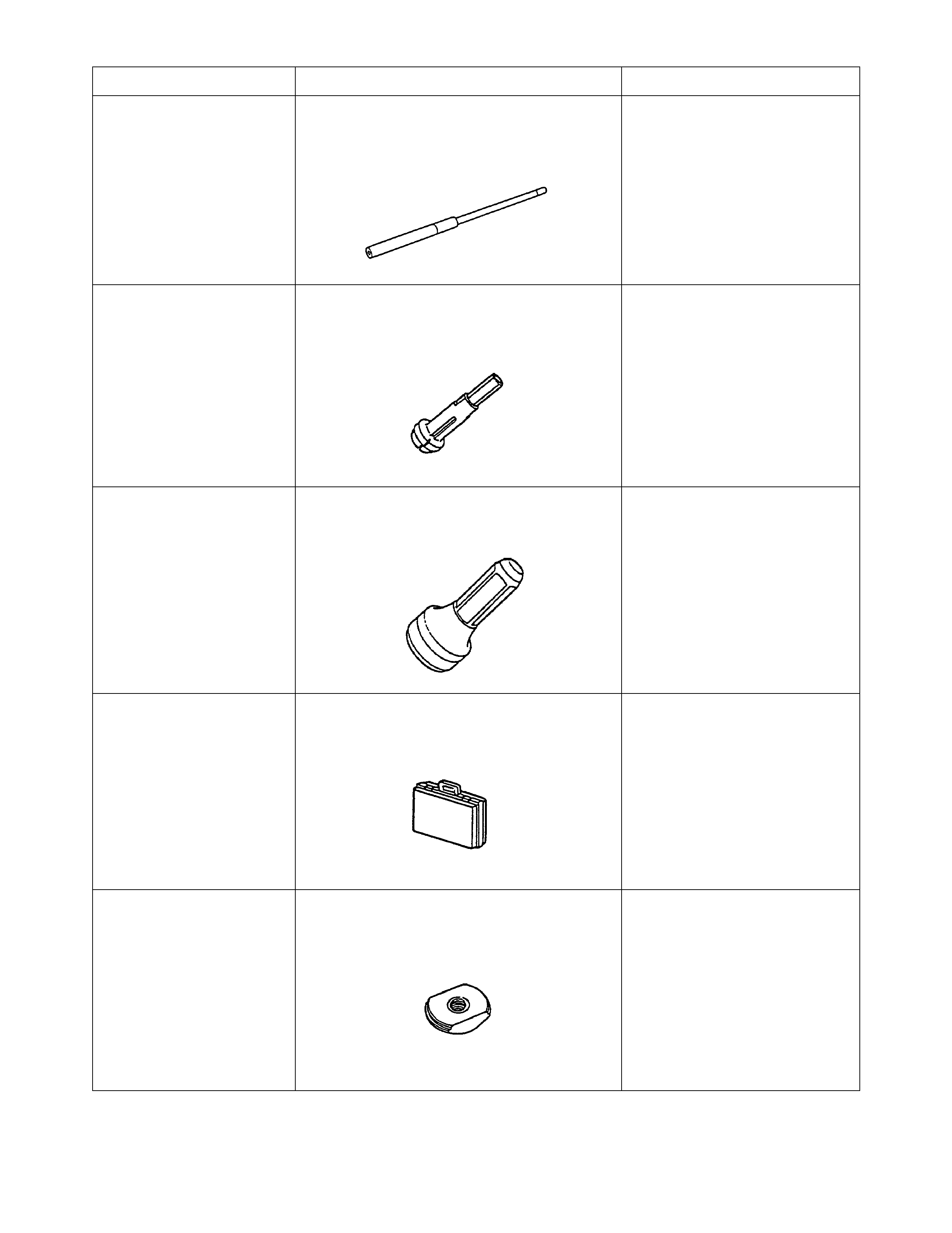
TOOL NO. REF IN TEXT TOOL DESCRIPTION COMMENTS
J36190 DRIVE HANDLE
J39433 SEAL INSTALLER
J8433 UNIVERSAL BRIDGE PULLER
J36513 SPLIT PLATE
J39436 BEARING RACE INSTALLER
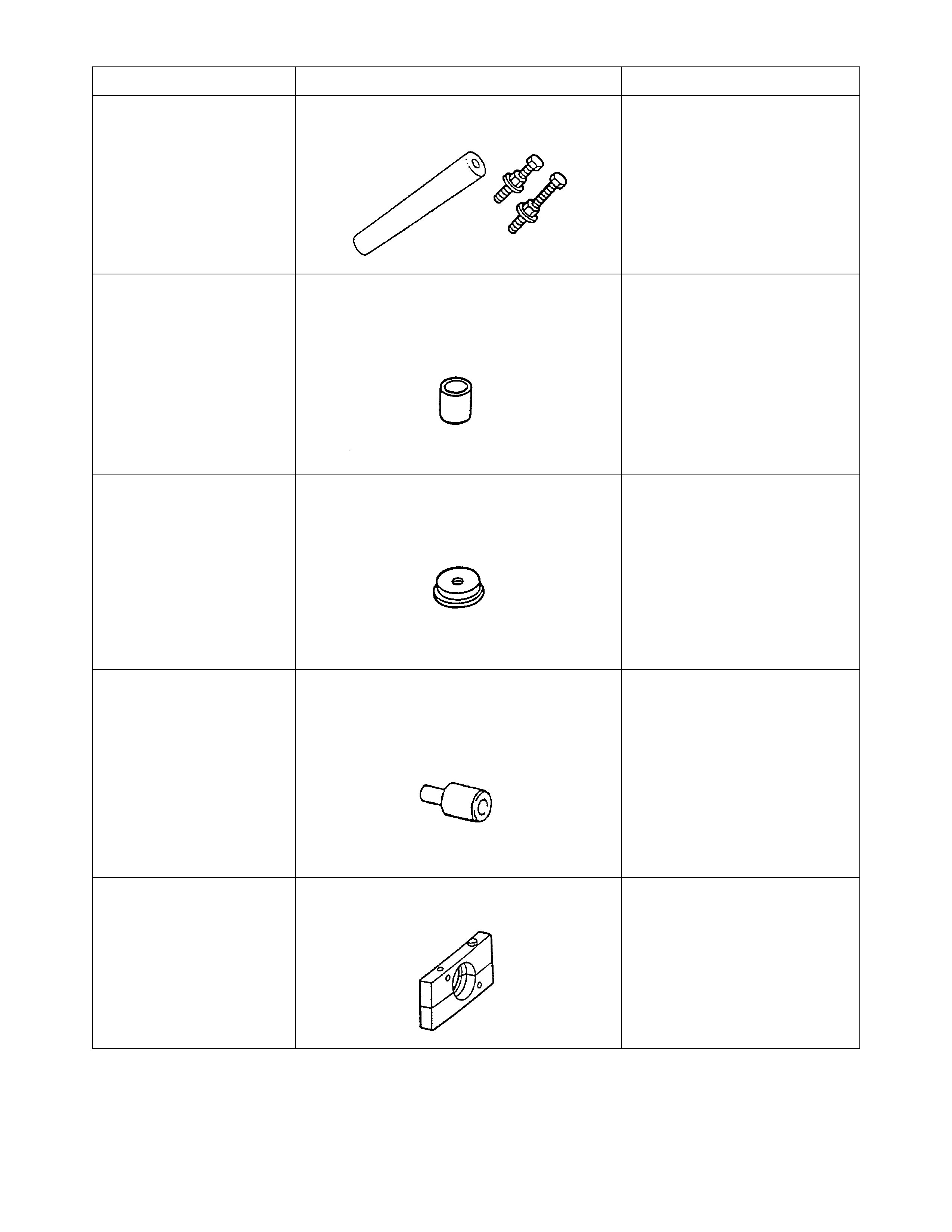
TOOL NO. REF IN TEXT TOOL DESCRIPTION COMMENTS
J22912-01 SPLIT PLATE
J36800 BUSHING REMOVER
J39436 BEARING RACE INSTALLER
J23907 SLIDE HAMMER
J39371 1ST/2ND SYNCHRONIZER INSTALLER
TOOL NO. REF IN TEXT TOOL DESCRIPTION COMMENTS
J39437 BUSHING INSTALLER
J39438 BEARING INSTALLER
J39444-1 COUNTERSHAFT END PLAY ROD
J39547 PRESS ADAPTER
J39439-1 BUSHING REMOVER/INSTALLER
TOOL NO. REF IN TEXT TOOL DESCRIPTION COMMENTS
J39444-2 COUNTERSHAFT EXTENSION END
PLAY ROD
J39594 BEARING RACE REMOVER
J39440 REAR SEAL AND BOOT INSTALLER
J39445 STORAGE CASE
J39789 BEARING RACE REMOVER
TOOL NO. REF IN TEXT TOOL DESCRIPTION COMMENTS
J39441,-1,-2 GEAR INSTALLER AND BOLTS
J39473 BEARING INSTALLER/ADAPTER
J39790 BEARING RACE REMOVER
J39442 PRESS ADAPTER
J39511 SPLIT PLATE
TOOL NO. REF IN TEXT TOOL DESCRIPTION COMMENTS
J39791 BEARING RACE REMOVER
J39443 SPLIT PLATE
J39546 BEARING RACE INSTALLER

6. HSV VT CLUBSPORT AND M ANTA SEDANS
HSV VT ClubSport and Manta 195i Sedans are fitted with a standard Holden manual transmission model 290.
Service operations for the model 290 transmission are detailed in the Holden VT Series Service Information CD,
refer Section 7B2 MANUAL TRANSMISSION - V8 ENGINE.


8. AUTOMATIC TRANSMISSION
GENERAL DESCRIPTION
The autom atic transm iss ions f itted to HSV VT m odels are developm ents of the standard Holden Hydra-matic 4L60-
E transmiss ion. As in all HSV developments , r eliability and effic iency have been impr oved as a r es ult of engineer ing
researc h, developm ent and extensive testing. In most cases, developm ent of the standard transm issions has been
necessitated by - and carried out in parallel with - the developm ent of HSV’s enhanc ed range of engines. T he result
is that all HSV VT and HSV VS have an engine-transmission combination designed to satisfy (and to exceed) the
operating specific ation of the vehicle. T he types of automatic tr ans miss ions us ed in the HSV VT and HSV VS ser ies
of vehicles listed in Table F-1, are explained in succ eeding paragraphs. Shift Patterns for each HSV transmis sion
have been included in this sec tion, see Figur es F -6 to F- 13, (r efer T RANSM ISSION SHIFT PAT TERN T ABLES) to
assist with the diagnosis and servicing of these transmissions.
HSV VT SENATOR 220I SEDAN AND ESTATE, AND GRANGE 215I SEDAN
The Automatic Transmission fitted to all Senator 220i models and 215i Grange Sedans, is the model 8HSD: this
transmission is also available as an optional fit in the GTS 220i Sedan.. The 8HSD transmission is electronically
controlled with 4 forward speeds and a reverse gear of the s ame r atios as the s tandard Holden VT V8 trans miss ion.
Service operations are the same as those described in the Holden VT Series Service Information CD:
Section 7C1 - GENERAL INFORMATION
Section 7C2 - ELECTRICAL DIAGNOSIS
Section 7C3 - HYDRAULIC DIAGNOSIS
Section 7C4 - ON VEHICLE SERVICING
Section 7C5 - UNIT REPAIR
However, specific HSV components have been incorporated in the transmission during manufacture and these
components MUST be replaced with genuine HSV components when specified.
SERVICE PARTS.
Specific HSV parts available for the servicing of the 220-215 kw transmissions are as follows;
HSV Part No Description
07B3970701 Converter Assembly - Torque
07B3970702 Plate control Valve Body Spacer
07B3970703 Valve Asm-control (with body & valve)
07B3970704 Piston Assembly 2-4 band Servo
07B3970705 Piston Assembly 2-4 band Servo
07B3970706 Piston Assembly 2-4 band Servo
POWERTRAIN CONTROL MODULE (PCM).
HSV transmissions fitted to 220 and 215 kw vehicles incorporate a specific PCM. This HSV PCM is calibrated to
recognise the higher torque of the engine, and to provide a specific s hift pattern for optimum control of the vehicle.
Refer to the table in the Service Operations section for the appropriate model in Section E - ENGINES of this
Supplement, for the identification and service numbers of the PCM fitted to these transmissions.

HSV VT SENATOR 195I SEDAN AND ESTATE
The Automatic Transmission fitted to all Senator 195i vehicles is the model 8HJD: this transmission is also available
as an optional fit to ClubSport and Manta 195i Sedans . This transmission is based on the Holden VT series
.transmission and service operations are the same as those described in the Holden VT Series Service
Information CD:
Section 7C1 - GENERAL INFORMATION
Section 7C2 - ELECTRICAL DIAGNOSIS
Section 7C3 - HYDRAULIC DIAGNOSIS
Section 7C4 - ON VEHICLE SERVICING
Section 7C5 - UNIT REPAIR
However, specific HSV components have been incorporated in the transmission during manufacture and these
components MUST be replaced with genuine HSV components when specified.
SERVICE PARTS.
Specific HSV parts available for the servicing of the 195 kw transmissions are as follows;
HSV Part No Description
07B3970101 Plate-Control valve Body spacer
07B3970102 Valve Asm- control (with body & valve)
POWERTRAIN CONTROL MODULE (PCM)
HSV transmissions fitted to 195 kw vehicles incorporate a specific PCM. This specific PCM is calibrated to
recognise the higher torque of the engine, and to provide a specific shift pattern for optimum control of the vehicle.
Refer to the table in the Service Operations section for the appropriate model in Section E - ENGINES of this
Supplement, for the identification and service numbers of the PCM fitted to these transmissions.

HSV GRANGE 185I AND MARLOO 185I
The automatic transmission fitted to HSV models Grange 185i and Maloo 185i is the standard Holden VT Hydra-
matic model 8HBD. Service operations for the model 8HBD transmission are detailed in the Holden VT Series
Service Information CD:
Section 7C1 - GENERAL INFORMATION
Section 7C2 - ELECTRICAL DIAGNOSIS
Section 7C3 - HYDRAULIC DIAGNOSIS
Section 7C4 - ON VEHICLE SERVICING
Section 7C5 - UNIT REPAIR

TRANSMISSION SHIFT PATTERN TABLES
The following illustrations show the transmission shift patten tables.
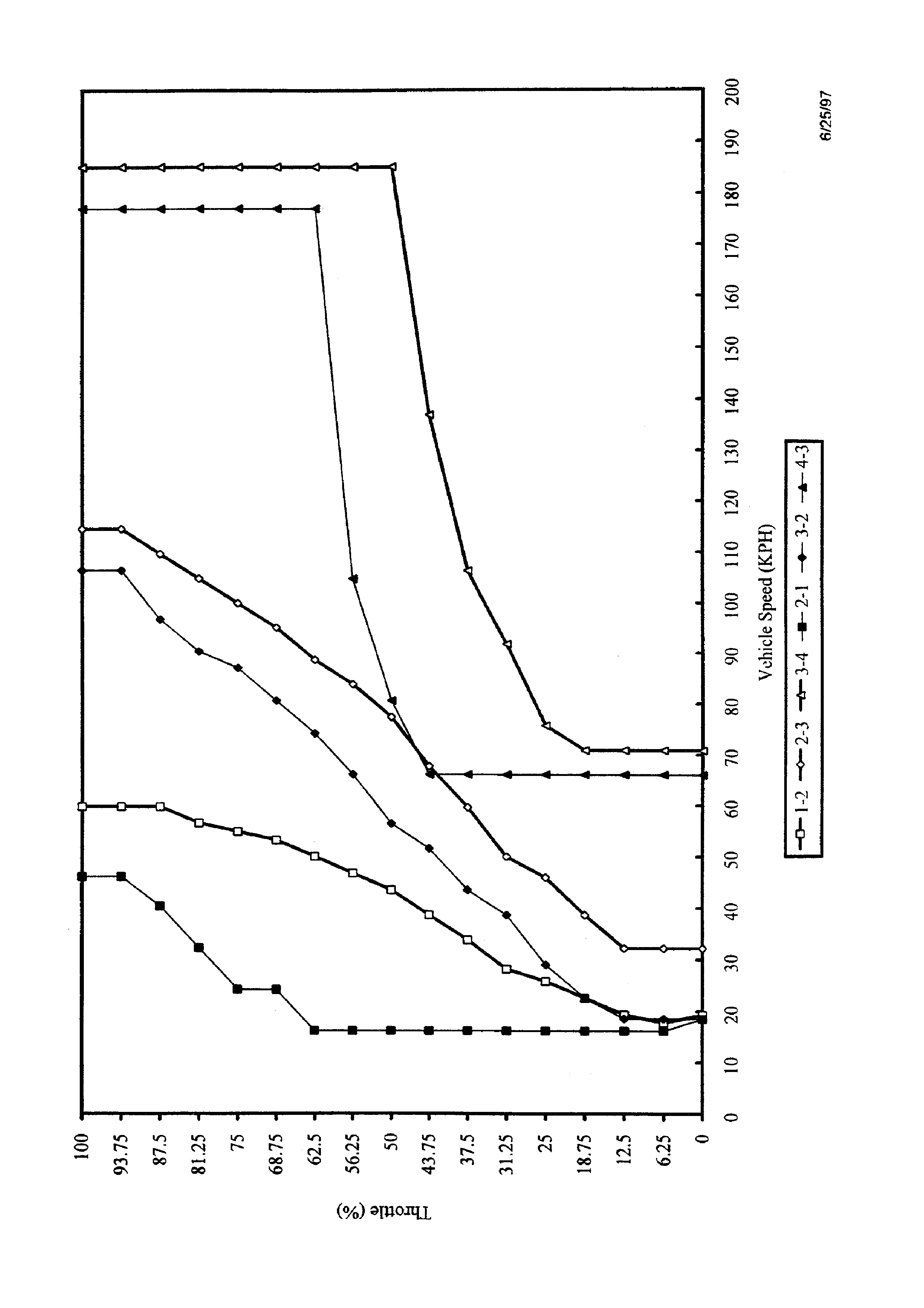
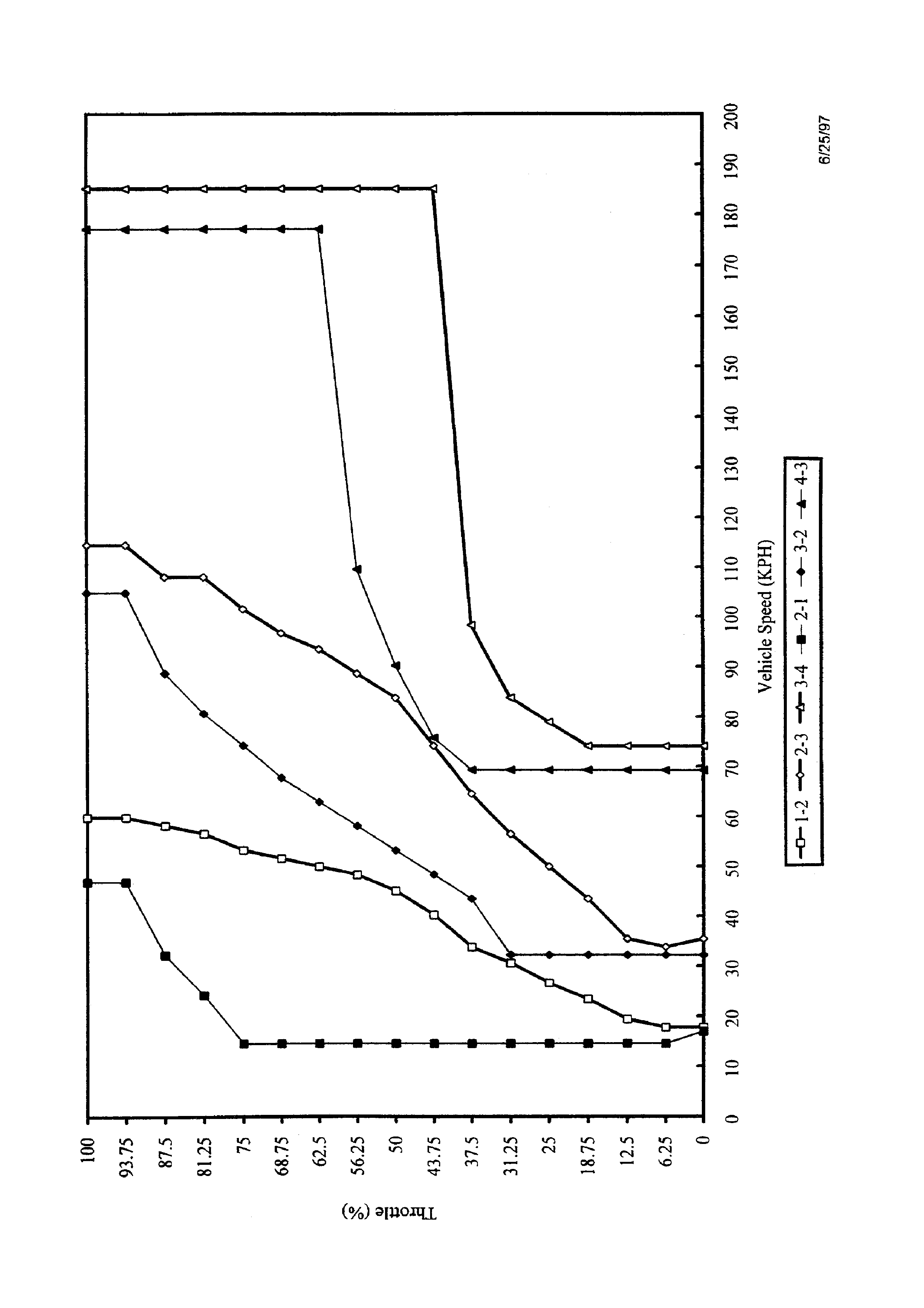
1998 HSV 198 KW V8-4L60E POWERTRAIN - NORMAL MODE SHIFT PATTERN
Figure F-6
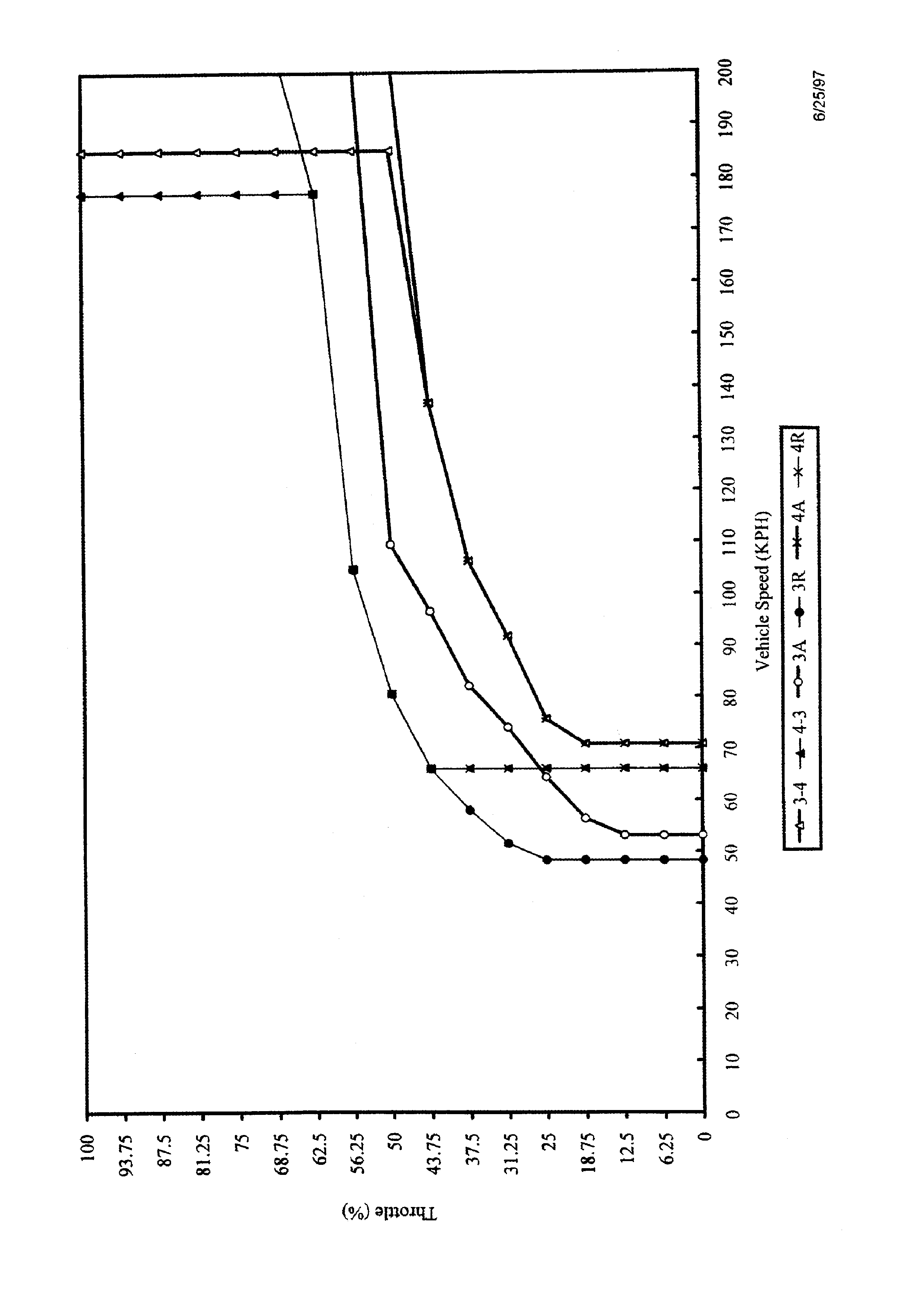
Figure F-7
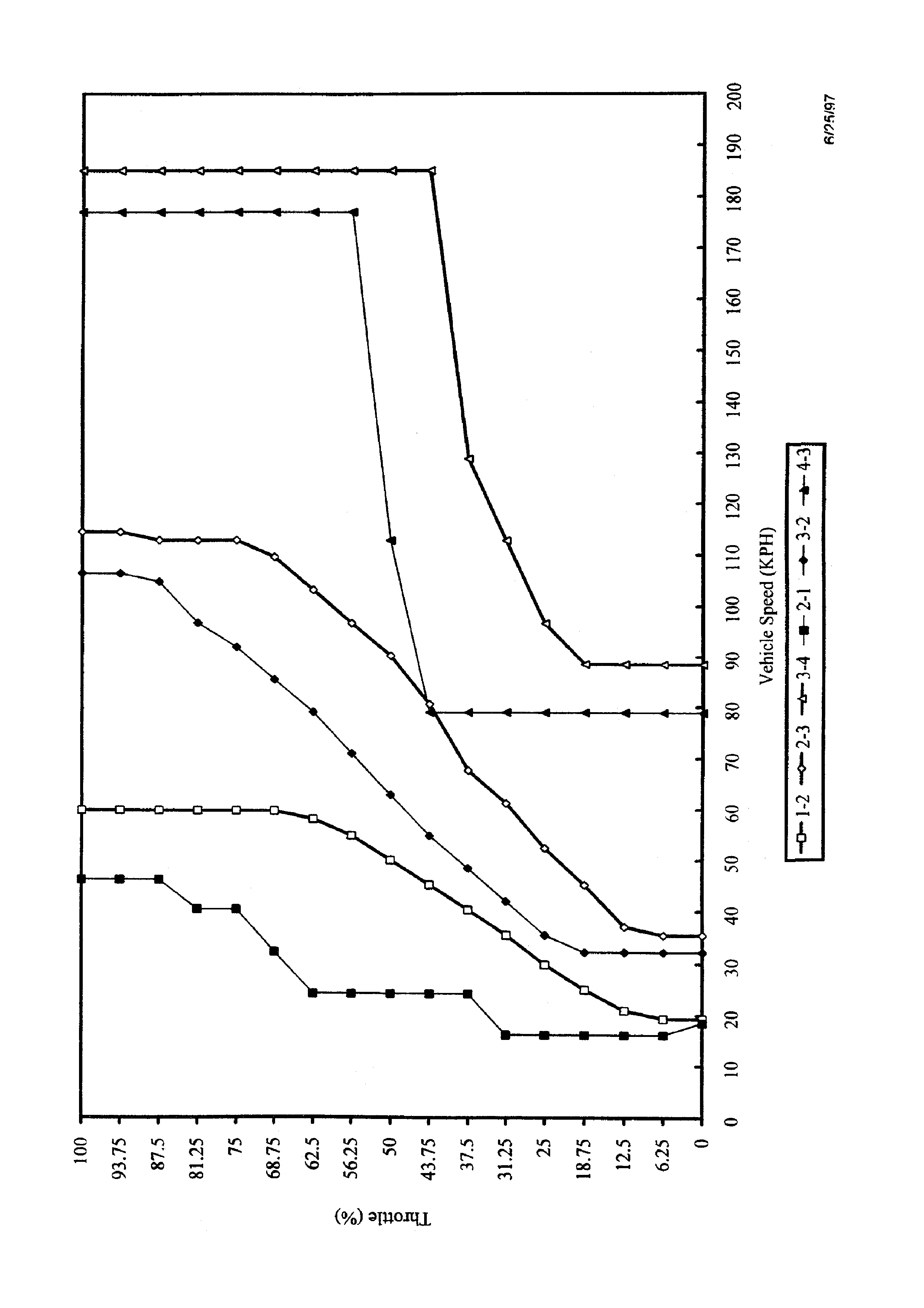
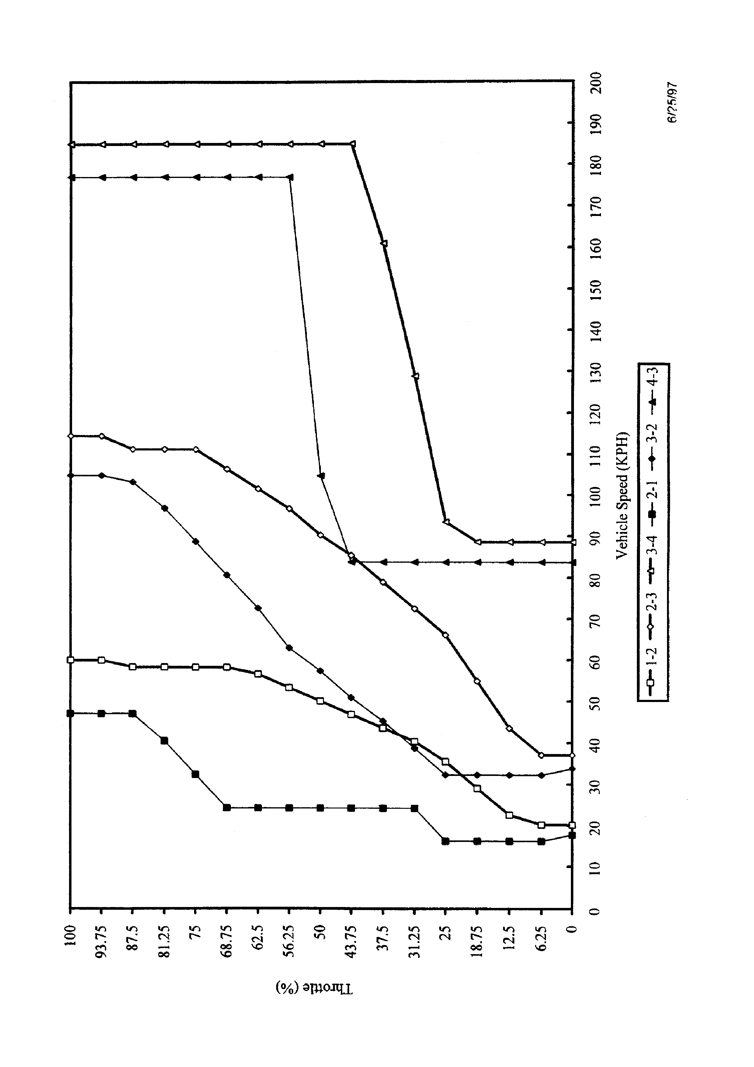
1998 HSV 198 KW V8-4L60E POWERTRAIN - POWER SHIFT MODE PATTERN
Figure F-8
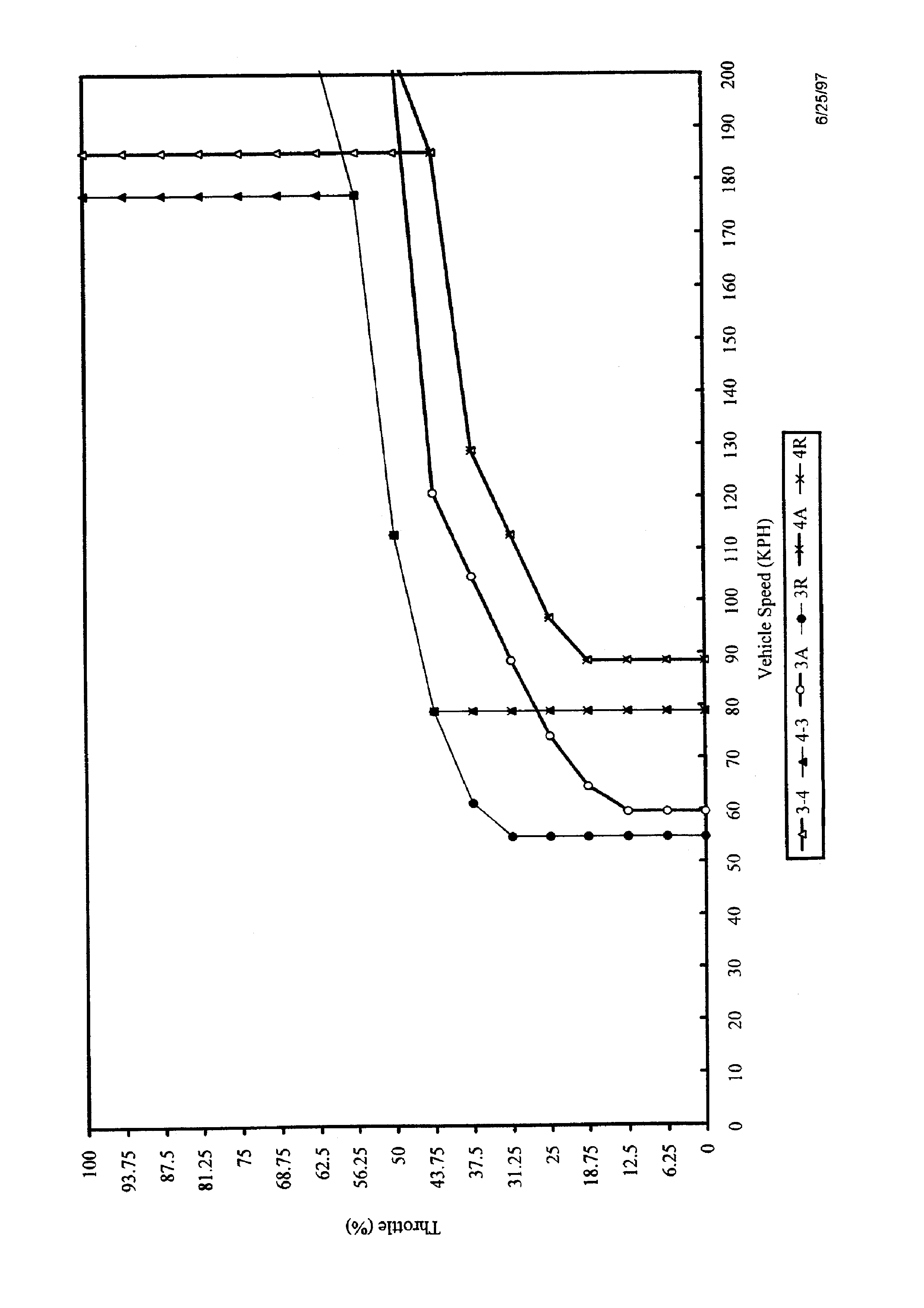
Figure F-9
1998 HSV 220 KW V8-4L60E POWERTRAIN - NORMAL SHIFT MODE PATTERN
Figure F-10
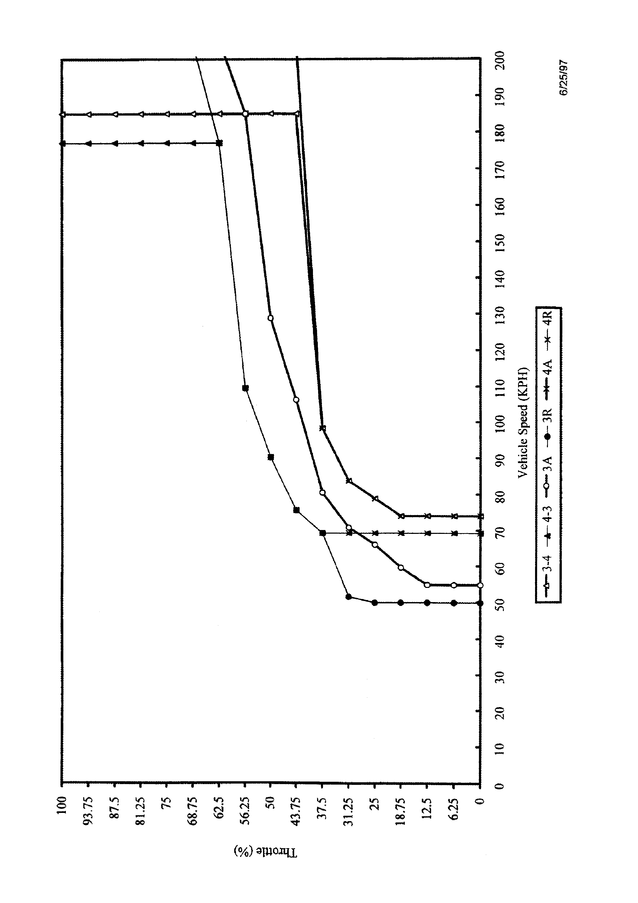
Figure F-11
1998 HSV 220 KW V8-4L60E POWERTRAIN - POWER SHIFT MODE PATTERN
Figure F-12
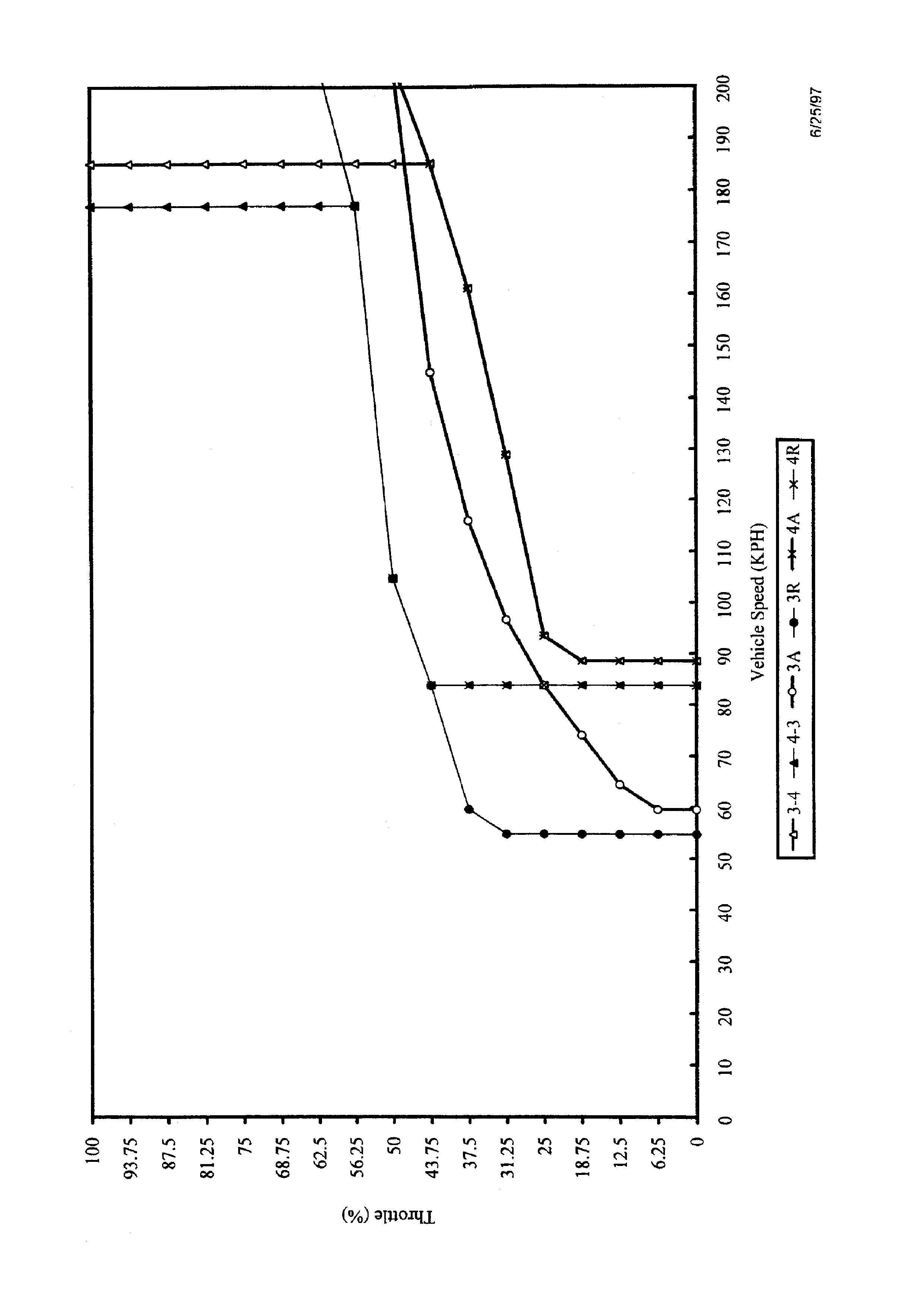
Figure F-13