SECTION 0B - LUBRICATION AND SERVICE
CAUTION:
This vehicle will be equipped with a Supplemental Restraint System (SRS). A SRS will
consist of either seat belt pre-tensio ners and a driver’s side air bag , or seat belt pre-
tensioners and a driver’s and front passenger’s side air bags. Refer to CAUTIONS,
Section 12M, before performing any service operation on or around SRS
components, the steering mechanism or wiring. Failure to follow the CAUTIONS
could result in SRS deplo yment, resulting in possible p ersonal injury or unnecessary
SRS system repairs.
CAUTION:
This vehicle may be equipped with LPG (Liquefied Petroleum Gas). In the interests of
safety, the LPG fuel system should be isolated by turning 'OFF' the manual service
valve and then draining the LPG serv ice lines, before any service w ork is carried out
on the vehicle. Refer to the LPG leaflet included with the Owner's Handbook for
details or LPG Section 2 for more specific servicing information.
1. GENERAL INFORMATION
This Section provides details of the lubricants recommended for VT Series Models. Instruction on the time or
distance intervals at which services should be carried out are contained in the Servicing chapter of the VT Series
Owner’s Handbook.
CAPACITIES CHART
LITRES
CAPACITIES (APPROXIMATE) V6 V6 Supercharged V8
Engine Oil Pan Refill (Less oil filter) 4.5 4.5 4.8
Add for Oil Filter 0.3 0.3 0.3
Supercharger -0.12 -
Manual Transmission 2.0 2.0 2.0
Automatic Transmission
- dry total 7.9 7.9 10.6
- service refill 4.8 4.8 5
Cooling System 12 12 12
* Coolant Concentrate -
HN 2043 at 50%
Brake Hydraulic System 0.616 0.616 0.616
Rear Axle 1.7 1.7 1.7
Power Steering 0.70 0.70 0.65
* For V6 and V8 engines
Techline
Techline
Techline
Techline

2. ENGINE LUBRI CATION AND SERVICE
2.1 ENGINE OIL VISCOSITY RECOMMENDATIONS
The grade of crankcase oil should be selected to give the best performance under the climatic and driving
conditions in the territory in which the vehicle is operated. When the crankcase is drained and refilled, the
crankcase oil should be selected, not on the basis of the existing temperature at the time of the change, but on the
ambient temperature range anticipated for the period during which the oil will be used. Use classification SG or SH
viscosity grade 20W/50 for general use and high ambient temperatures. For prolonged usage in snow areas, a
viscosity grade of 15W/40 may assist starting.
Techline

2.2 ENGINE OIL CLASSIFICATION RECOMMENDATIONS
Only engine oils classified as SG or SH quality are recommended for use with VT Series Models with 3.8 litre and
5.0 litre engines.
NOTE:
1. Non-detergent and low quality oils are specifically not recommended.
2. Only low phosphorous engine oils must be used. Just as lead can contaminate the ceramic monolith inside the
catalytic converter, so can phosphorous. Most leading brands of engine oil now limit phosphorus levels to
“safe” limits.
3. ‘Break-in’ oils, ‘tune-up’ compounds, ‘friction reducing’ compounds and other additives should not be used
unless recommended by Holden.
Their use will only increase operating costs and may contaminate the ceramic monolith inside the catalytic
converter, rendering it useless.
2.3 MAINTAINING OIL LEVEL
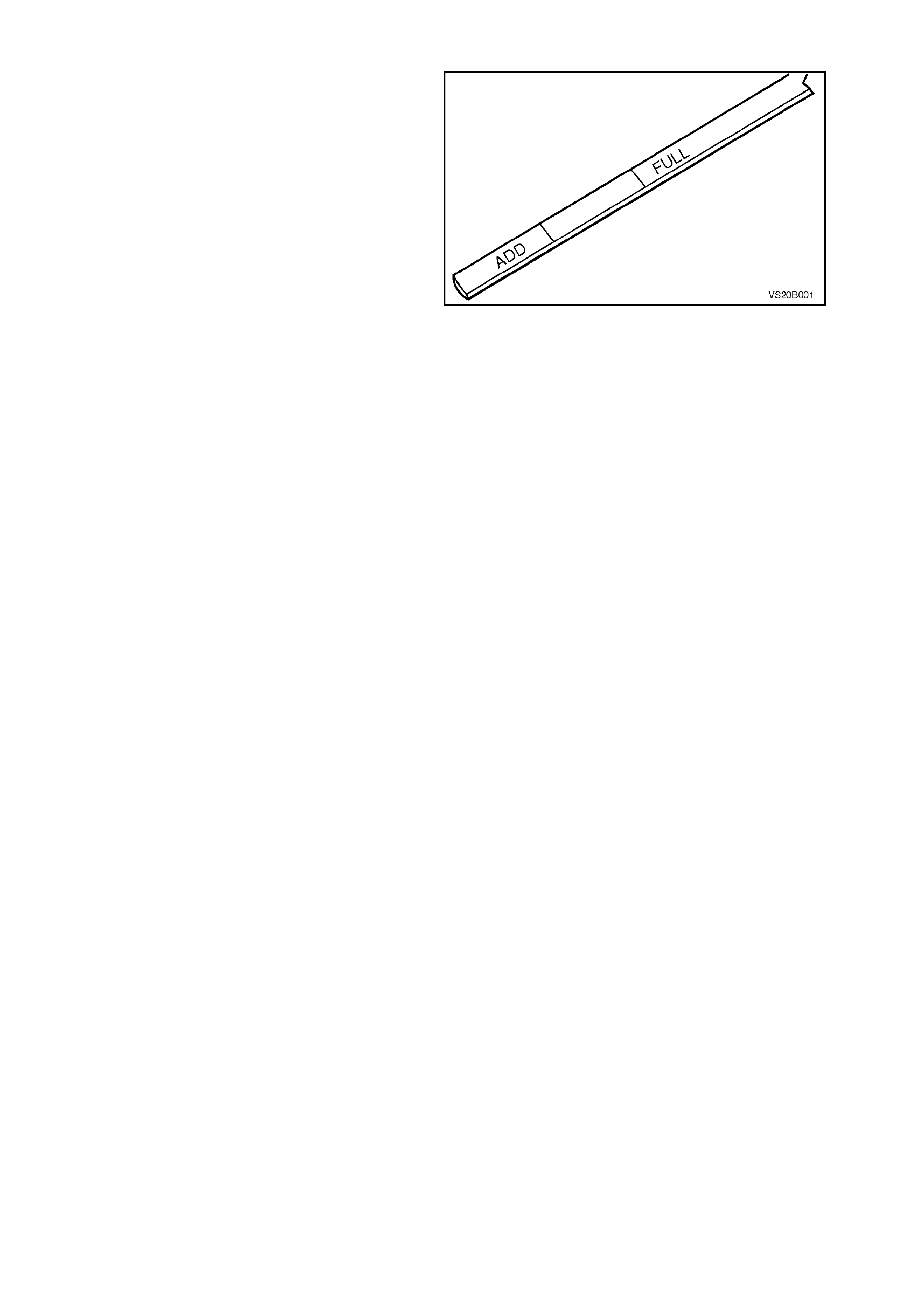
The oil level gauge is marked to indicate ‘FULL’
and ‘ADD’. The oil level should be maintained
between the two lines, neither going above the top
line nor under the lower line. Check the oil level
frequently and add oil when necessary. Always be
sure the oil pan is full before starting on a long
drive.
Before checking the oil level, the engine should be
at normal operating temperature. The vehicle
should be left stationary for several minutes after
the engine is turned off.
When draining the oil from the oil pan, it is
advisable to ensure that the engine is thoroughly
warmed up to normal operating temperature. The
benefit of draining is, to a large ex tent, los t, if the oil
is drained when the engine is cold, as some of the
suspended f oreign m aterial will cling to the sides of
the oil pan and will not drain out readily with the
cold, slow moving oil.
Figure 0B-1

2.4 OIL FILTER
The full-flow oil filter, filters all the engine oil
delivered by the oil pump. Accordingly, the oil filter
should be replaced at the tim e or distanc e intervals
specified in the VT Owner’s Handbook or whenever
the engine oil is contaminated by foreign material.
Under prolonged dusty conditions, it is
recommended that the oil filter be replaced more
often.
NOTE:
Whenever the oil filter is replaced, an additional
quantity of the recommended engine oil must be
added to fill the dry filter. Refer to the CAPACIT IES
Chart in 1. GENERAL INFORMATION in this
Section.
REPLACE
1. Place an oil drain tray beneath engine.
2. Using a suitable oil filter wrench, unscrew oil
filter, remove and discard.
3. Ensure seal is installed correctly in recess of
new filter.
4. Pour s om e clean engine oil into f ilter until level
remains at approximately 2 cm below top of
filter.
5. Smear some engine oil over filter seal. Screw
filter into place until seal contacts mating
surface of adaptor. Tighten filter through a
further 2/3 of a turn.
6. Clean any excess oil from filter and adaptor.
7. Check oil level. Start engine and check for oil
leaks. Repair as necessary.
NOTE:
The oil level must be rechecked and oil added as
necessar y, after running the engine, to compens ate
for oil used to refill the oil filter.
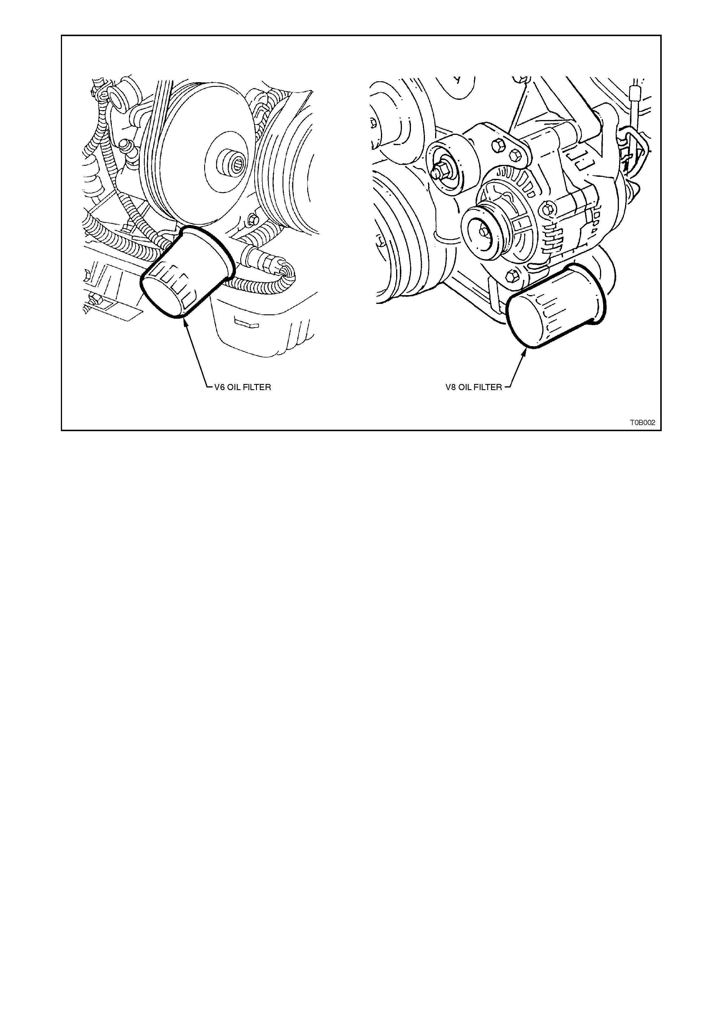
Figure 0B-2

2.5 OIL LEVEL CHECK
1. Engine must be at normal operating
temperature (idle for 10 minutes or
equivalent).
2 Park vehic le on level sur f ac e ( as this will aff e ct
the accuracy indicated on dipstick, this is a
critical requirement).
3. Do not check oil level for at least 10 minutes
after shut down to allow oil to drain back into
the oil pan.
4. Remove dipstick and wipe clean.
5. Reinstall dipstic k with FULL/ADD m ar ks fac ing
towards centre line of engine. This aspect is
very important due to the angle that the
dipstick enters the oil in the oil pan.
6. Ensure dipstick is fully seated and then slowly
rem ove to avoid sm ear ing. Hold horizontally or
with lower end slightly down to avoid oil
running along dipstick.
7. Observe the oil level where it passes over the
centre line of the dipstick.
8. When topping up the engine oil, allow
approximately 10 minutes for the oil added to
fully drain into the oil pan. Alternatively, add 50
ml of oil for each millimetre below the FULL
mark on the dipstick.

2.6 ENGINE VENTILATION SYSTEM
The engine ventilation system, uses a P.C.V. valve
and utilises engine vacuum to draw blow-by gasses
into the combustion chambers where they are
recycled through the combustion process.
Fig. 0B-3 shows the V6 P.C.V. valve which is
located in the inlet manifold for VT Series Models.
P.C.V. valves on V8 engines are located between
the valve cover and the throttle body.
The P.C.V. valve should be checked at the time or
distance intervals specified in the VT Series
Owner’s Handbook.
For service instructions covering the testing, and
the removal and reinstallation procedures of the
P.C.V. valve, refer to Section 6E1 EMISSION
CONTROL - V6 ENGINE or Section 6E2
EMISSION CONTROL - V8 ENGINE.
Figure 0B-3
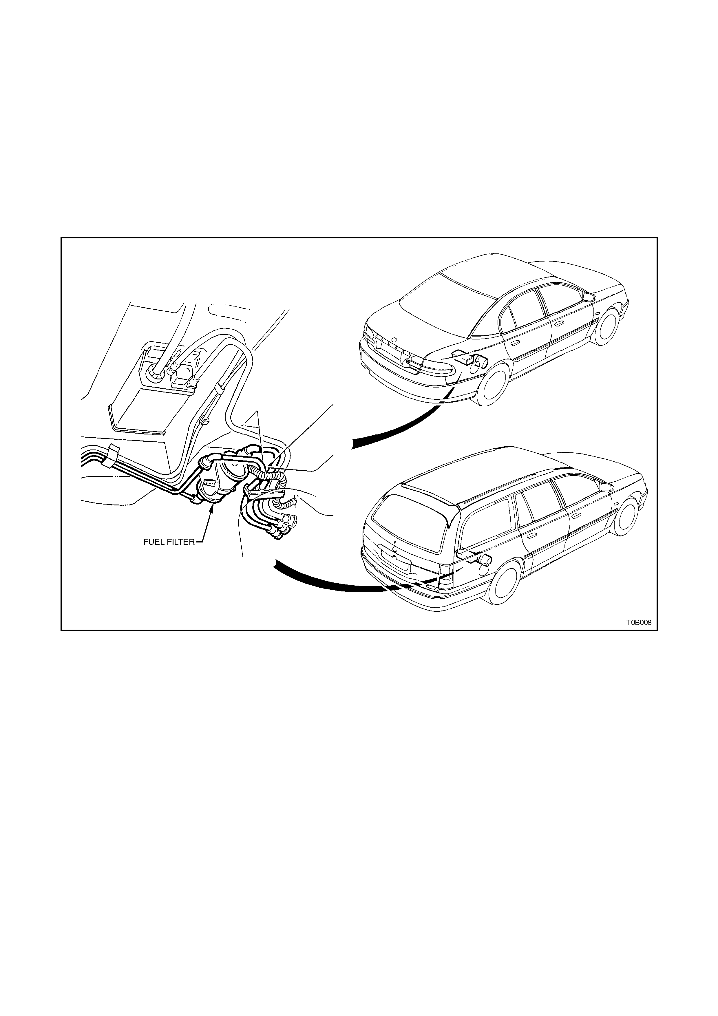
2.7 FUEL FILTER
The fuel filter is located on the pr essure side of the
high pressure fuel pum p and is attached to the f loor
pan of the vehicle, in front of the rear axle.
Refer to Fig. 0B-4 for filter locations.
The fuel filter must be replaced at the time or
distance intervals specified in the VT Series
Owner’s Handbook.
For service instructions covering the removal and
installation of the fuel filter, refer to Section 6C1
POWERTRAIN MANAGEMENT - V6 ENGINE or
Section 6C2 POWERTRAIN MANAGEMENT - V8
ENGINE.
Figure 0B-4
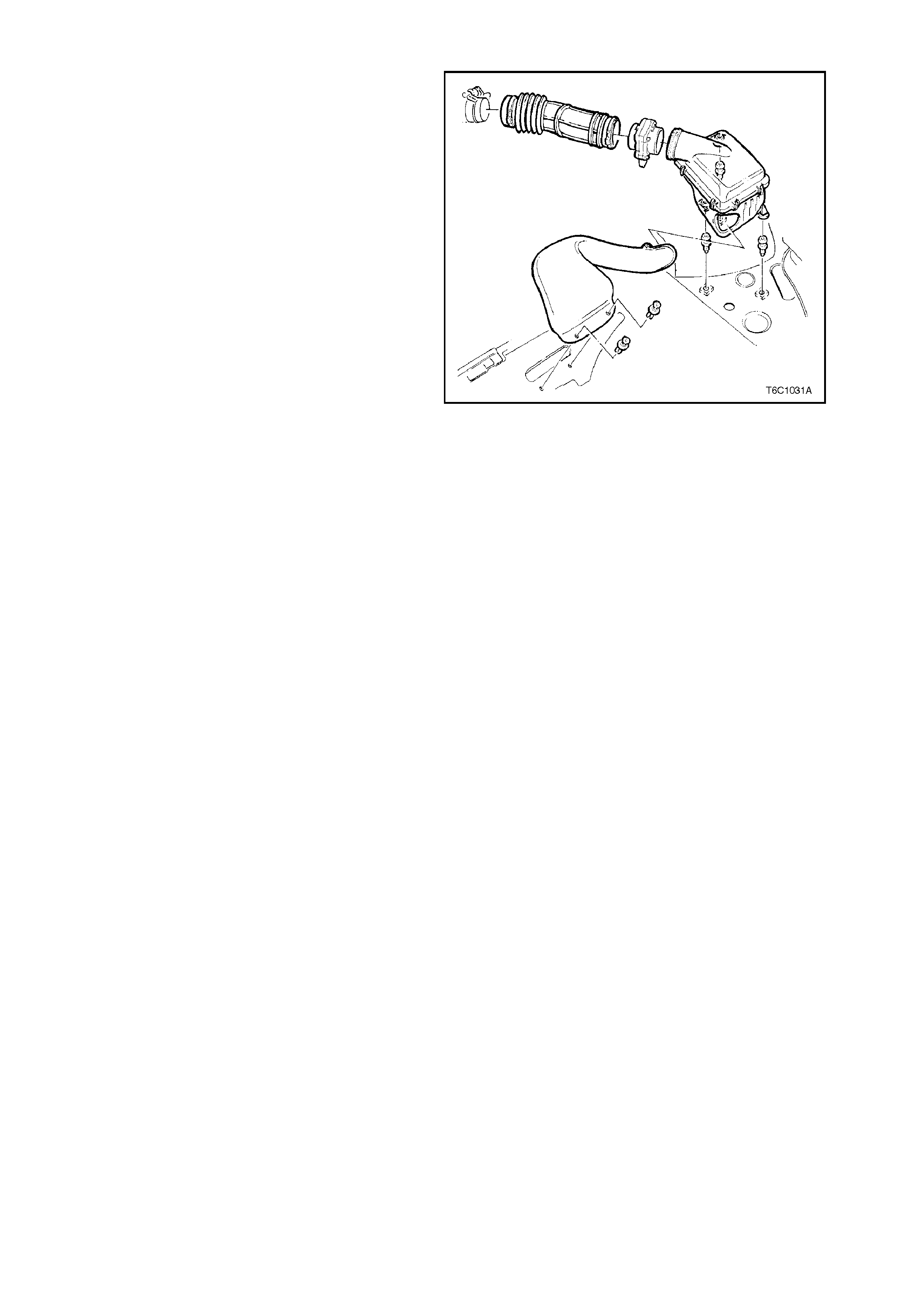
2.8 AIR FILTER
The air filter may be partially cleaned of dust by
lightly tapping the element. It should not be washed
or oiled. The time or distance intervals at which the
element requires servicing depend on vehicle
operating conditions. Under dusty conditions, the
element should be checked for restriction more
often than for normal city operation. Fig. 0B-5
shows a typical air cleaner assembly.
For service instructions covering the removal and
installation of the air cleaner element, refer to
Section 6C1 POWERTRAIN MANAGEMENT - V6
ENGINE or Section 6C2 POWERTRAIN
MANAGEMENT - V8 ENGINE.
Figure 0B-5
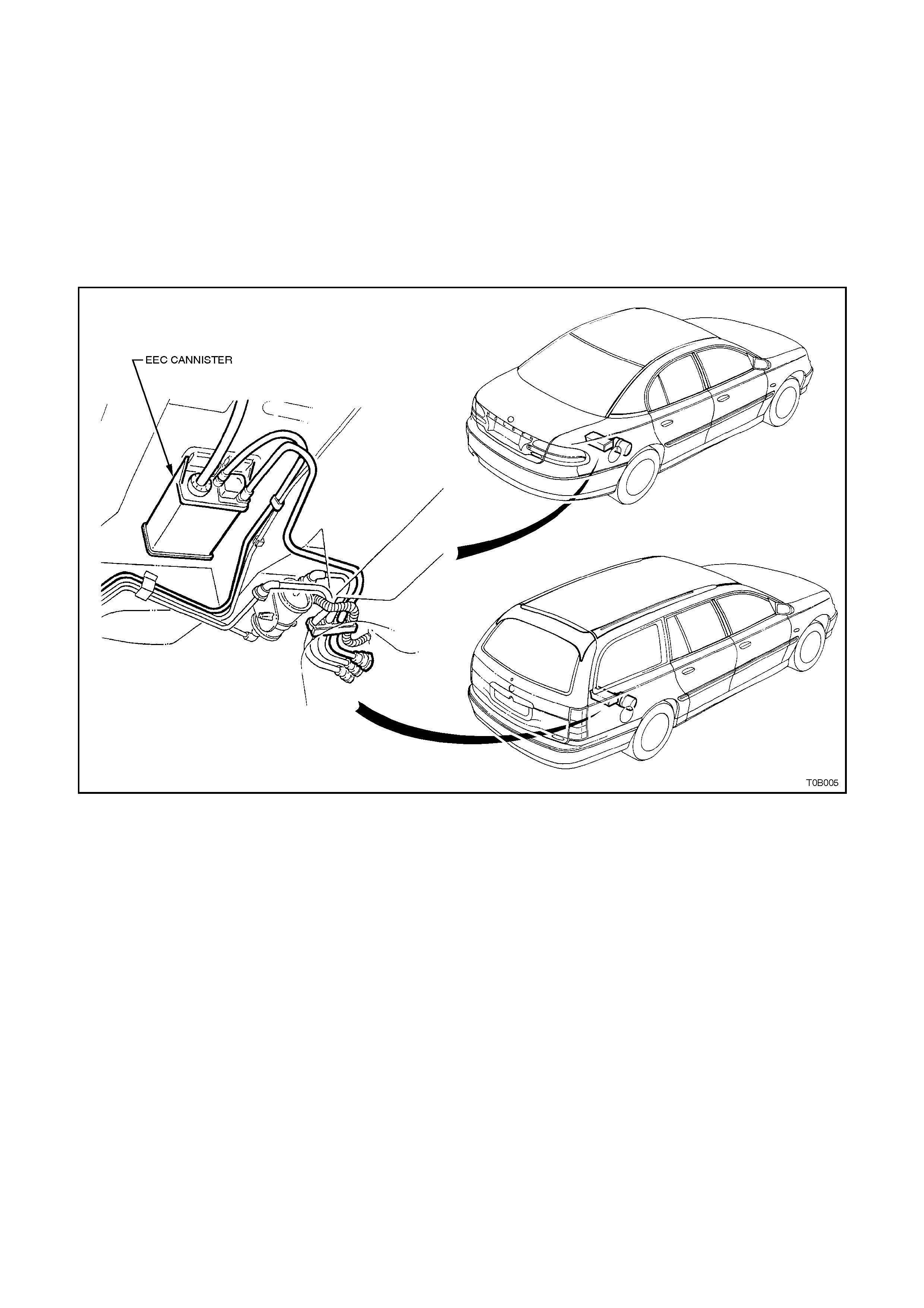
2.9 EVAPORATIVE EMISSION CONTROL CANISTER
The Evaporative Emission Control (EEC) canister
is attached to the underbody, refer to Fig. 0B-6.
The canister should be serviced at the time or
distance intervals specified in the VT Series
Owner’s Handbook.
For service instructions covering the testing, and
the removal and reinstallation of the EEC canister,
refer to Section 6E1 EMISSION CONTROL - V6
ENGINE or Section 6E2 EMISSION CONTROL -
V8 ENGINE.
Figure 0B-6
2.10 COOLING SYSTEM
The cooling system is filled initially with a coolant
mixture comprising 50% water and 50% inhibited
ethylene Glycol to Holden specification HN 2043.
CAUTION:
Do not remove the radiator cap when the
engine and radiator are hot. Scalding fluid and
steam can be blown out under pressure if the
cap is removed.
The cooling system is designed to use formulated
coolant (a mixture of inhibited ethylene glycol and
water), rather than plain water. The coolant solution
must be used year round.
Inhibited ethylene glycol conforming to Holden
Specification HN 2043 is named ‘New Formula
Long Life All Seasons Coolant’, and is available in
the following quantities:
1 Litre, P/N M40236
5 Litre, P/N M40307
20 Litre, P/N M40238
NOTE:
Do not mix different types of anti-freeze or
corros ion inhibitors as they may be inc ompatible. If
a different type has been used in the cooling
system, flush the system with clean water.
The water used for mixing with inhibited glycol
concentrate must be of low dissolved salt content,
preferably tank water or demineralised water.
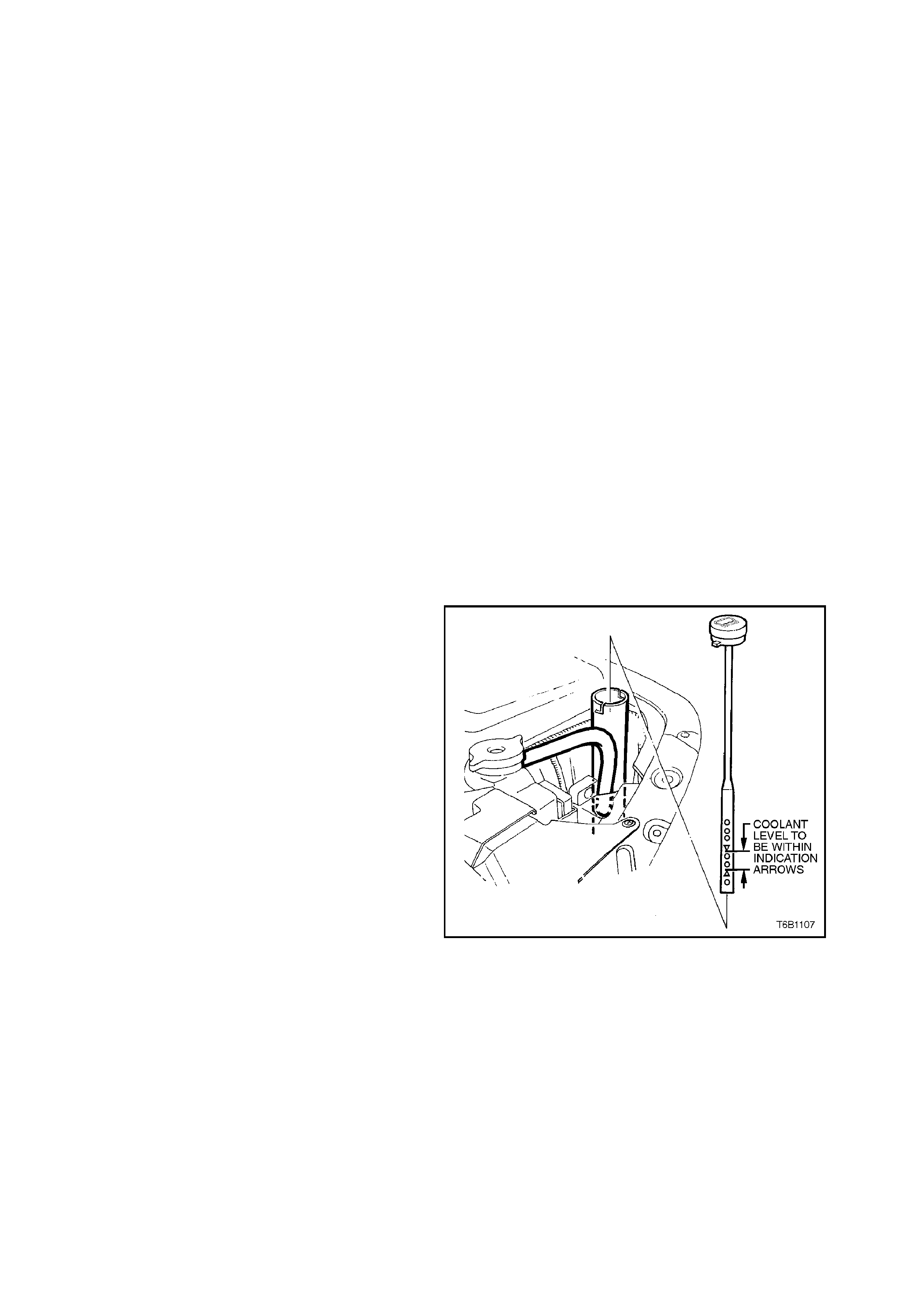
Check the ‘see through’ coolant recovery reservoir
as appropriate. The coolant should be between the
two indicator arrows on the recovery reservoir, refer
to Fig. 0B-7.
If the coolant level is low, remove the cap on the
recovery reservoir. Add enough of a pre-mixed
coolant solution of water and a good quality
inhibited ethylene glycol (meeting Holden
specification HN 2043) to bring the level up to the
proper mark. Put the cap back on the recovery
reservoir.
It is of the utmost importance to maintain the
correct concentration level of glycol in the cooling
system.
To ensure the specified glycol concentration is
maintained in the engine coolant, the coolant
concentration must be checked at the time or
distance intervals outlined in the VT Series Owner’s
Handbook. Figure 0B-7

Check coolant concentration as outlined in
Section 6B1-1 ENGINE COOLING - V6 ENGINE
or 6B1-2 ENGINE COOLING - V6
SUPERCHARGED or 6B2 ENGINE COOLING -
V8 ENGINE.
It is recom mended that the coolant be drained, the
system flushed and refilled with clean water and
radiator coolant at the time or distance inter vals set
out in the VT Series Owner’s Handbook.
Aluminium radiators should be protected at all
times by a coolant that is specifically recommended
for use with aluminium. Aluminium radiators may
be destroyed by the caustic solutions found in
some cleaners or the chemicals used in some
antifreeze’s and inhibitors.
For cooling system filling instructions, refer to
Section 6B1-1 ENGINE COOLING - V6 ENGINE,
or 6B1-2 ENGINE COOLING - V6
SUPERCHARGED or 6B2 ENGINE COOLING -
V8 ENGINE.

3. MANUAL TRANSMI SSION LUBRICATION AND SERVICE
3.1 RECOMMENDED LUBRICANT
The recommended lubricant for the manual transmission in VT Series Models is Castrol VMX 80W oil (to Holden
specification HN 1855).
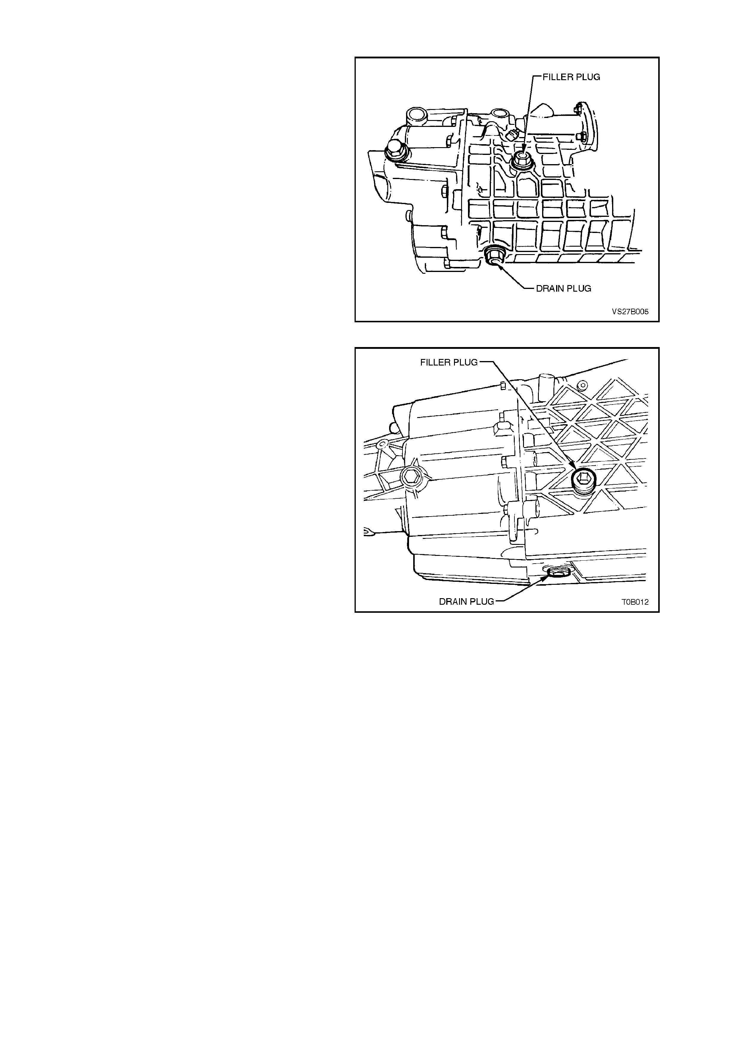
3.2 CHECKING TRANSMISSION LUBRICANT LEVEL
To check the transmission lubricant level, remove
the filler plug on the right hand side of the
transmission case, refer to Fig. 0B-8 for V6 and
Fig. 0B-9 for V8.
The level is correct when the lubricant is at the
bottom of the plug hole.
NOTE:
Ensure the vehicle is on level ground and that the
transmission is cold.
Figure 0B-8
Figure 0B-9

3.3 DRAINING AND REFILLING TRANSMISSION
To drain the transmission, remove the filler plug and then the drain plug, refer Fig. 0B-8 or Fig. 0B-9.
When the transmission has fully drained, refit drain plug and refill transmission to the required level with Castrol
VMX 80W oil (to Holden specification HN 1855) transmission fluid, as outlined in 3.2 CHECKING TRANSMISSION
LUBRICANT LEVEL in this Section.
The drain and filler plug threads should be sealed on reinstallation with Loctite 567 (Master Pipe Sealant with
Teflon), to Holden Specification HN1584 or equivalent. Under no circumstances is thread sealing tape to be used
on the drain or filler plug threads.
NOTE:
Periodic transmission lubricant changes are not necessary. The lubricant should be changed when overhauling the
transmission or when operating the vehicle under severe driving conditions (refer to the Owner’s Handbook).

4. AUTOM ATIC TRANSMISSION LUBRICATION AND SERVICE
4.1 RECOMME NDED FLUID
The automatic transmission for VT Series Models requires fluid qualified to Dexron® III (to Holden specification HN
2126).
4.2 CHECKING TRANSMISSION FLUID LEVEL
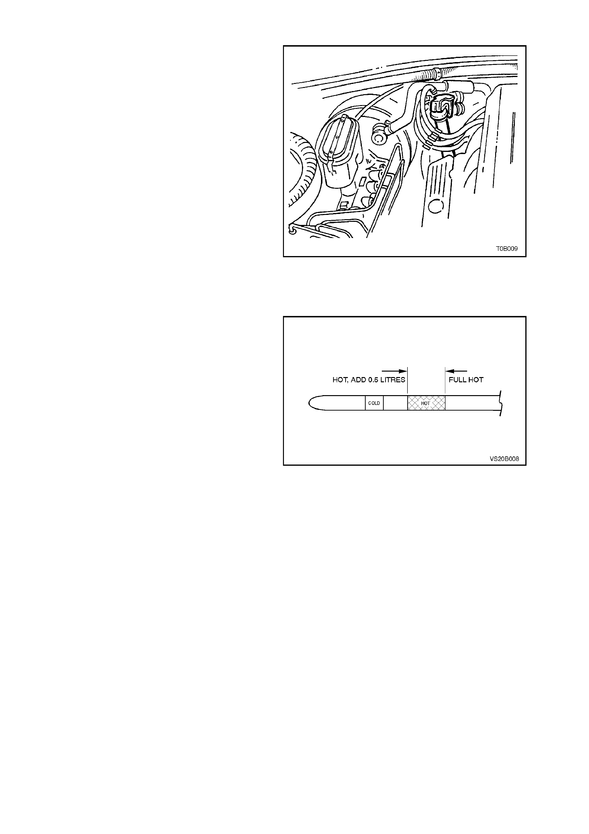
The transmission fluid level dipstick is located on
the right hand side of the engine, refer to Fig.0B-
10.
With transmission at operating temperature.
1. Place selector lever in ‘P’ (PARK) position.
2. Brakes applied.
3. Vehicle on level surface.
4. Start engine and let it idle.
5. W ith engine idling, remove dipstick and check
level, refer to Fig. 0B-11.
NOTE 1:
The cold markings on the dipstick should only be
used as an indicator when initially filling the
transmission after the fluid has been completely
drained. The fluid should be rechecked when the
transmission is hot.
NOTE 2:
Due to the shape of the filler tube, level readings
may be misleading. Look carefully for full fluid ring
on both sides of the dipstick. Recheck if any doubt
of fluid level occurs.
Figure 0B-10
6. Also check the fluid for contamination,
discolouration or if it smells burnt. This gives
an indication that frictional m aterials within the
transmission may need replacement.
Figure 0B-11


5. BRAKE HYDRAULIC SYSTEM SERVICE
SAFETY AND CAUTIONARY NOTE FOR VEHICLES EQUIPPED WITH
ABS/ETC:
Whenever any component that forms part of the ABS or ABS/ETC (if fitted), is
disturbed during Service Operations, it is vital that the complete ABS or ABS/ETC
system is checked, using the procedure as detailed in 4 DIAGNOSIS, ABS or
ABS/ETC FUNCTION CHECK, in Section 12L ABS & ABS/ETC.
5.1 RECOMME NDED FLUID
The recommended fluid for the VT Series brake hydraulic system is to Holden’s specification HN 1796.

5.2 BRAKE FLUID REPLACEMENT
The entire fluid content of the brake hydraulic system must be changed at the time or distance intervals specified in
the VT Series Owner’s Handbook.
There have been some major changes to the VT Series Model brake system, with the exception of bleeding brakes
on vehicles with ABS. Refer to Section 5A BRAKES for the recommended fluid changing procedure.
NOTE:
When bleeding brakes on vehicles with ABS, refer to Section 12L ABS & ABS/ETC.


6.2 CHECKING REAR AXLE LUBRICANT LEVEL
ENGINE & AXLE TYPE RECOMMENDED LUBRICANT
All V6 excluding
V6 Wagon with manual
Transmission &
V6 Supercharged
Vehicles
Mineral Hypoid Gear Oil, such as
AMPOL Gearlube SRD90, BP Limslip 90,
CALTEX Gear Oil LSD, CASTROL LSX90
MOBIL Lubrite LS90, SHELL XD90LS
VALVOLINE HP Gear Oil LS90
or equivalent lubricant to
Holden Specification HN 1561
All V8,
V6 Wagon
with Manual
Transmission &
V6 Supercharged
Vehicles
Synthetic Hypoid Gear Oil, such as
AMPOL Synthetic Gear Oil 80W/140
CALTEX Synstar GL 80W-140
CASTROL SAF-XA
MOBIL Mobilube SHC 80W-140 ID
VALVOLINE Synthetic Gear 75W-140
or equivalent lubricant to
Holden’s Specification HN 2040
The rear axle lubricant level should be checked at the
time or distance intervals specified in the VT Series
Owner’s Handbook.
To check Rear Axle level:
1. Ensure the vehicle is level.
2. The rear axle assembly is cold.
3. Clean the area around the filler plug.
4. Remove the filler plug, refer to Fig.0B-12.
5. The level is correct when the lubricant is at the
bottom of the filler plug hole.
6. Inspect filler plug for damage, if satisfactory, refit
into rear axle housing. Figure 0B-12
6.3 PERIODIC SERVICING
Periodic draining of the rear axle assembly is not
necessary.
Check for lubricant leaks at every service. If there
is evidence of leakage, repair leak and add
lubricant, if necessary, to the correct level.
The drain holes in each brake backing plate,
adjacent to the axle housing end flange, should be
checked periodically to ensure that the holes have
not become blocked with mud or sand.
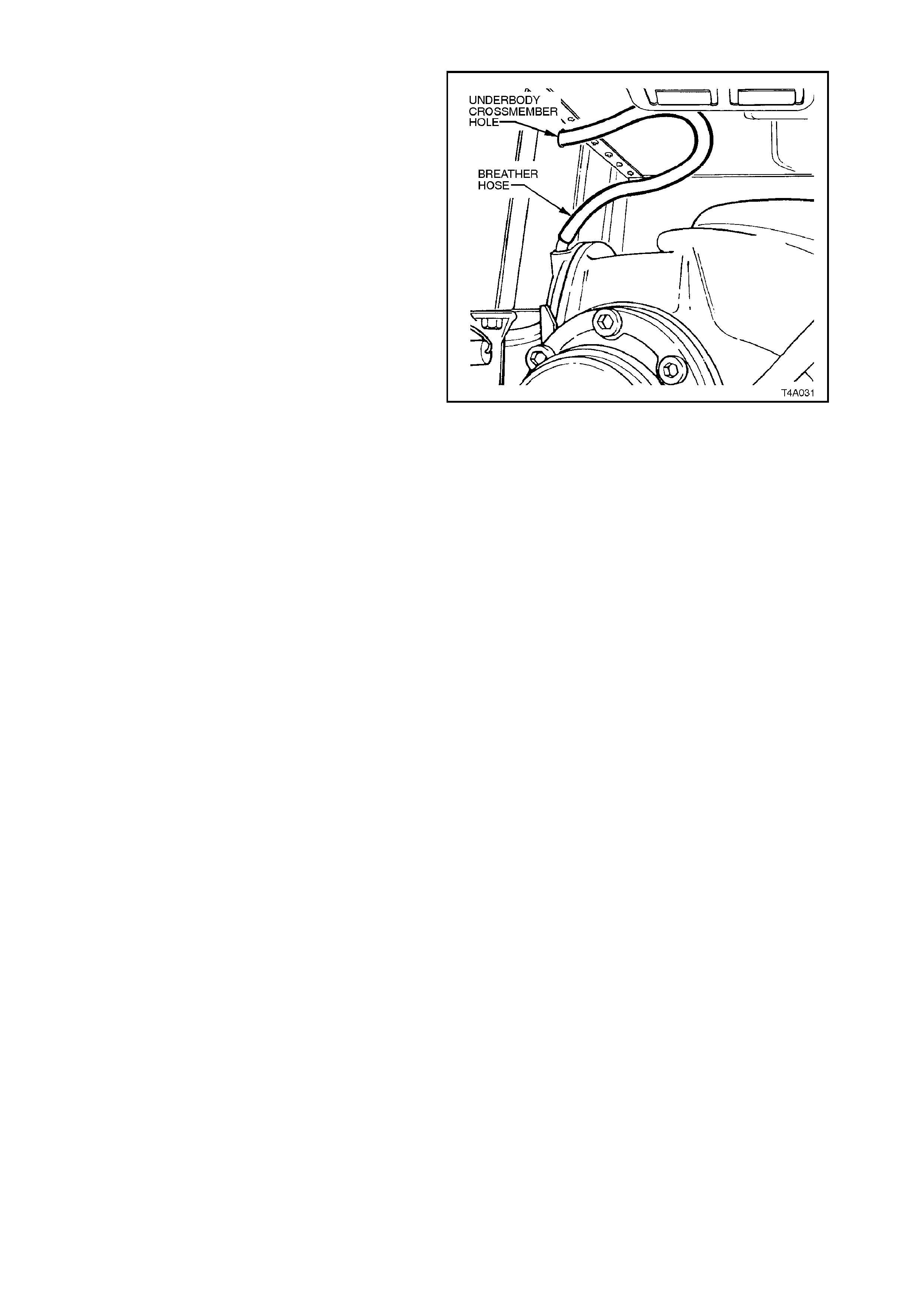
The I.R.S. rear axle breather should be checked
regularly to ensure that the hose is not kinked or
damaged.
Figure 0B-13

7. POWER STEERING
7.1 RECOMME NDED FLUID
The power steering system requires fluid equivalent to Dexron® III.
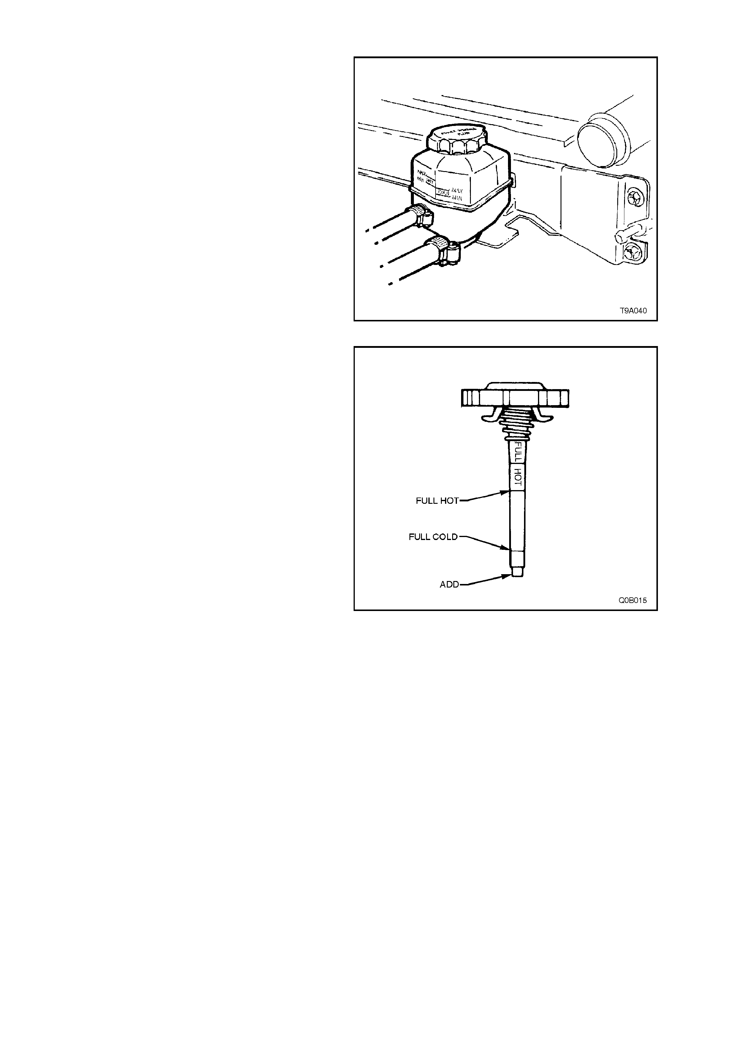
7.2 CHECKING POWER STEERING FLUID LEVEL
On vehicles with V6 engines, the power steering
fluid level is checked by viewing the fluid through
the transparent plas tic side of the r eservoir, ref er to
Fig. 0B-14.
If the fluid is cold, the level should be in the ‘COLD’
range. Sim ilar ly, if it is hot, the fluid s hould be in the
‘HOT’ range. If the fluid level is at the low side of
either range, f luid should be added to br ing the f luid
to the correct level.
Figure 0B-14
On V8 engines, the power steering fluid level is
checked using the dipstick, part of the filler cap on
the plastic reservoir, refer to Fig. 0B-15.
The fluid level should be somewhere between the
‘ADD’ and ‘FULL HOT’ indicator marks on the
dipstick , depending on the temperature of the fluid.
If power steering f luid is at or below the add mark ,
fluid should be added to bring the fluid to the
correct level.
Figure 0B-15

7.3 PERIODIC SERVICING
Periodic draining of the power steering fluid is not necessary.
Check system for fluid leaks at every service. If there is evidence of leakage, repair leak and add fluid, if necessary
to the correct level.
8. SERVICING
8.1 ABNORMAL OPERATING CONDITIONS
If the car is driven under any of the abnormal conditions listed below it is recommended that some items be
serviced more frequently than in the maintenance plan.
The extra services are only required while the car is driven under the abnormal conditions. If any of these
conditions are encountered on a one off basis, then any additional servicing should be for that time only. As a
guide, if the car is operated continually over a period of one month or 1000 km under the abnormal conditions, then
additional servicing may be required.
ABNORMAL CONDITIONS
A When driving less than 10,000 km in six months.
B Dust, dirt, loose road material.
C Muddy and wet areas.
D Cold weather (below 5°C) and when most trips are less than 5km.
EStop-start driving, excessive idling or low speed operation as experienced in inner city driving e.g. Taxi, door to
door delivery.
F Caravan or trailer towing.
G Extended heavy load high speed operation in temperatures above 35°C.
EXTRA SERVICES REQUIRED
SERVICE REQUIRED ABNORMAL CONDITION
Change engine oil @ 6 months A
Change auto trans fluid and strainer @ 4
years A
Change automatic transmission fluid and
strainer @ 20,000 km EFG
Inspect front suspension and steering for
leaks, wear or damage @ 5,000 km BC
Replace engine oil filter @ 5,000 km or 3
months (whichever comes first) B
Change engine oil @ 5,000 km or 3 months
(whichever comes first) BDFG
Relace air cleaner element @ 20,000 km B
Inspect and clean park brake linings @
20,000 km BC
Change differential oil @ 20,000 km F G
Change brake fluid @ 1 year if 1,600 kg (or
higher) tow bar fitted. *F
Change power steering fluid @ 50,000 km F G
* Brake fluid deteriorates with time and should normally be replaced every two years. However, heavy duty towing
requires fresher fluid due to the higher demand on the brake system. Therefore, brake fluid should be replaced
each year if a 1,600 kg (or higher) tow bar is fitted, so that the brake system can cope with the next year’s towing
requirements.
8.2 MAINTANENCE SCHEDULE
The following chart provides the maintenance schedule, together with a reference of where to find the necessary
service information for VT Series Models.
Use odometer reading or
years, whichever occurs
first.
x
1000
km 1.5102030405060708090100110
UNDER HOOD Extra
Change engine oil and
engine oil filter. (Refer this
Section).
*XXXXXXXXXXX
Check fluid levels: brake,
clutch, power steering,
auto trans, washer. (Refer
this Section, 7A CLUTCH,
& 12C WIPERS/
WASHERS &
INSTRUMENTS).
X XXXXXXXXXX
Check coolant inhibitor %
with tester and check level
(pressure test system if
level is low).
(Refer to Section 6B1
ENGINE COOLING -V6
ENGINE or 6B2 ENGINE
COOLING - V8 ENGINE).
X XXXXXXXXXX
Check battery electrolyte
and fluid level, if
applicable. (Refer Section
12A BATTERY).
XXXXXXXXXXXX
(V6) Engine accessory
drive belt, check length
indicator and belt
condition. (Refer Section
6A1-1 ENGINE
MECHANICAL - V6
ENGINE).
XXXX
(Supercharger) Check
supercharger belt
condition and length
indicator. (Refer Section
6A1-2 ENGINE
MECHANICAL - V6
SUPERCHARGED).
XXXX
(V8) check condition and
tension of all engine drive
belts using gauge. (Refer
Section 6A2-1 ENGINE
MECHANICAL - V8
ENGINE).
XXXXX
Check for signs of
deterioration and/or leaks
from engine, fluid
reservoirs, air ducts, all
hoses and clamps.
X XXXXXXXXXX
Drain and refill cooling
system with recommended
inhibitor, clean outside of
radiator and A/C
condenser. (Refer Section
6B1 ENGINE COOLING -
V6 ENGINE or 6B2
ENGINE COOLING - V8
ENGINE).
Change every 2.5 years (regardless of kms)
Replace engine air cleaner
element. (Refer Section
6C1-3 POWERTRAIN
MANAGEMENT - V6
ENGINE or 6C2-3
POWERTRAIN
MANAGEMENT - V8
ENGINE).
*XX
(Supercharger) Check
supercharger oil level.
(Refer Section 6A1-2
ENGINE MECHANICAL -
V6 SUPERCHARGED).
XX
Vacuum check for PCV
valve operation. (Refer
Section 6E1 EMISSION
CONTROL - V6 ENGINE
or 6E2 EMISSION
CONTROL - V8 ENGINE).
XX
Replace spark plugs.
(Refer Section 6D1-3
IGNITION SYSTEM - V6
ENGINE or 6D2-3
IGNITION SYSTEM - V8
ENGINE).
XX
(V8) check ignition timing.
(Refer Section 6D2-3
IGNITION SYSTEM - V8
ENGINE).
XX
NOTE:
All items marked with an asterisk in the ‘Extra’ column, require additional servicing under some driving conditions.
Refer to 8.1 ABNORMAL OPERA TING CONDITIONS in this Section.
UNDER CAR
Use odometer reading or
years, whichever occurs
first.
x
1000
km 1.5102030405060708090100110
Extra
Replace fuel filter.
(Refer Section 6C1-3
POWERTRAIN
MANAGEMENT - V6
ENG. or 6C2-3
POWERTRAIN
MANAGEMENT - V8
ENG.
XX
Check rear axle oil level.
(Refer this Section). XX
Check rear axle and auto
trans for leaks. XXXXXXXXXXXX
Change auto trans fluid
and strainer. (Refer
Section 7C4 AUTOMATIC
TRANSMISSION).
*X
Check manual
transmission oil level.
(Refer this Section).
XX
Check manual
transmission for leaks. X XXXXXXXXXX
Change differential oil.
(Refer Section 4B FINAL
DRIVE & DRIVE
SHAFTS).
*
Change not required under normal driving conditions
Inspect front and rear disc
pads for wear and disc
surface condition. (Refer
Section 5A STANDARD
BRAKES). Rotate wheels.
(Refer Section 10
WHEELS & TYRES).
XXXXXXXXXX
Check park brake linings
and drums for wear.
(Refer Section 5A
STANDARD BRAKES).
*XX
Inspect tyres for irregular
wear or damage. Check
for damaged wheels.
Check air pressures.
(Refer Section 10
WHEELS & TYRES).
XXXXXXXXXXXX
Drain, refill and bleed
brake system, check brake
performance when road
testing. (Refer this
Section).
*
Change every 2 years (regardless of kms) under normal
driving conditions
Drain, refill and bleed
clutch system. (Refer
Section 7A CLUTCH). Change every 2 years (regardless of kms)
Check all brake and fuel
lines and hoses for
condition, attachment and
routing.
X XXXXXXXXXX
Inspect front and rear
suspension and steering
system for damaged,
loose or missing parts,
signs of wear or lack of
lubrication. Inspect power
steering lines and hoses
for condition, attachment
and routing, leaks, etc.
Check condition of all
rubber boots and covers.
* X XXXXXXXXXX
Inspect exhaust and
adjacent underbody. Look
for damaged, missing or
out-of-position parts, open
seams, holes, or loose
connections.
X XXXXXXXXXX
Inspect constant velocity
joint for damage or torn
boot.
XXXXXXXXXX
Clean and lubricate
automatic transmission
shift linkage.
XXX
Clean out air conditioning
drain tubes. XX

Check carbon canister for
leaks or restrictions.
(Refer Section 6E1
EMISSION CONTROL -
V6 ENG.) or 6E2
EMISSION CONTROL -
V8 ENG.).
XXX
CAR INTERIOR
Check park brake
operation. XXXXXXXXXXX
Inspect seat belts, check
webbing condition, buckle
operation and retractor
mechanism.
XXXXX
CAR EXTERIOR
Check operation of all
exterior lights. XXXXXXXXXXXX
Lubricate hood catch, door
hinges, rear door links and
lock cylinders.
XXXXX
Check transmitter range of
security system. XXXXXXXXXXX
ROAD TEST
Check braking, steering,
engine response and
transmission operation.
Check operation of cruise
control. Check park pawl
operation. Check A/C
performance. Check
neutral start switch.
XXXXXXXXXXXX
NOTE:
All items marked with an asterisk in the ‘Extra’ column, require additional servicing under some driving conditions.
Refer to 8.1 ABNORMAL OPERA TING CONDITIONS in this Section.
9. LUBRICANT RECOMM E NDATIONS
APPLICATION LUBRICANTS
Body - Door Lock Striker Bolts
Door Lock Fork Bolts
Instrument Compartment Lid Lock Tongue
Solidoil
Engine Hood Catch
Engine Hood Lock
Engine Hood Hinge
Door Hinge and Rear Door Hold Opens
Rear Compartment Lid Hinge
Rear Compartment Lid Lock Mechanism
Door Window Regulators
Door Window Guides and Cams
Front Seat Adjuster
Recliner Assembly - Front Seat
NLGI No. 1 Lithium Grease (with Zinc Oxide)
meeting Holden Specification HN 1225
Window Regulator Friction Surfaces Lithium Based Grease Holden Specification
Number HN 1416
Front Door Lock Cylinder
Ignition and Steering Lock Cylinder
Rear Compartment Lid Lock Cylinder
Instrument Panel Compartment Lock
Cylinder
Powdered Graphite (applied through key
aperture - do NOT oil)
Starter Motor Drive Mechanism Molybdenum Disulphide Grease to Holden
Specification HN 1271
Starter Motor Bearings Engine Oil at Overhaul
Park Brake Shoe Assemblies Special HT Grease to Holden Specification
HN 1227
Brake Adjusting Screw and Nut Special HT Grease to Holden Specification
HN 1227
Park Brake Shoe Actuator Pivots Molybdenum Disulphide Grease to Holden’s
Specification HN 1587
Brake and Clutch Hydraulic System Fluid to Holden Specification HN 1796 (Part
No.92026651)
Propeller Shaft Centre Constant Velocity
Joint Molybdenum Disulphide Grease to Holden
Specification HN 1271
ABS Wheel Speed Sensor Dow Corning Molykote FB 180 High
temperature grease to Holden
Specification HN 2062
Universal Joints Lithium Grease to Holden Specification HN
1147
Rear Axle
V6 Naturally Aspirated
(except utility) Mineral Hypoid Gear Oil SAE 90. A.P.I. GL5.
To Holden Specification HN 1561
V6 Supercharged and V8
(all utility models) Synthetic Hypoid Gear Oil A.P.I. GL5 SAE
80W-140 (Mobilube SHC 80W-140 ID,
Castrol SAF-XA or equivalent to
Holden Specification HN 2040)
Engine Oil Pan SAE 15W-40, 20W-40 or 20W-50 SG or SH
Quality Engine Oil
Engine Supercharger Supercharger Oil (Part No. 12345982)
Clutch Throw-Out Bearing Lithium Grease to Holden Specification
HN 1147
APPLICATION LUBRICANTS
Clutch and Brake Pedal Pivots and Bushes Molybdenum Disulphide Grease to Holden
Specification HN 1271
Accelerator Pedal Pivots Lithium Grease to Holden Specification HN
1225
Manual Transmission Castrol VMX 80W oil to Holden Specification
HN 1855
Automatic Transmission Dexron® III Automatic Transmission Fluid to
Holden Specification HN 2126
Automatic Transmission Control Pivot
Points Molybdenum Disulphide Grease to Holden
Specification HN 1416
Steering Gear - Power (Mechanical)
(Hydraulic) EP Semi Fluid Lithium Base Type O Grease
Dexron® III Automatic Transmission Fluid to
Holden Specification HN 2126
Windshield Wiper Pivot Points Molybdenum Disulphide Grease to Holden
Specification HN 1271
Coolant Concentrate Inhibited Glycol Coolant to Holden
Specification HN 2043 only , at 50% by
Volume in water.
Check Link Housing NLGI No. 2 Lithium Complex Grease -
1.2g Applied to Housing
Check Link Arm NLGI No. 2 Polyurea Grease (Mineral Oil
Base) - 1.2g Applied to Arm