
SECTION 12L - ANTI-LOCK BRAKING &
ELECTRONIC TRACTION CONTROL
CAUTION:
This vehicle will be equipped with a Supplemental Restraint System (SRS). A SRS will
consist of either seat belt pre-tensioners and a driver's side air bag, or seat belt pre-
tensioners and a driver's and front passenger's side air bags. Refer to CAUTIONS,
Section 12M, before performing any service operation on, or around any SRS
components, the steering mechanism or wiring. Failure to follow the CAUTIONS
could result in SRS deployment, resulting in possible personal injury or unnecessary
SRS system repairs.
CAUTION:
This vehicle may be equipped with LPG (Liquefied Petroleum Gas). In the interests of
safety, the LPG fuel system should be isolated by turning 'OFF' the manual service
valve and then draining the LPG serv ice lines, before any service w ork is carried out
on the vehicle. Refer to the LPG leaflet included with the Owner's Handbook for
details or LPG Section 2 for more specific servicing information.
CAUTION:
Whenever any component that forms part of the ABS or ABS/ETC (if fitted), is
disturbed during Service Operations, it is vital that the complete ABS or ABS/ETC
system is checked, using the procedure as detailed in 4 DIAGNOSIS, ABS or
ABS/ETC FUNCTION CHECK, in this Section.
1. GENERAL INFORMATION
NOTE:
There are two systems in this Section; ABS and ABS/ETC. ABS is an Anti-locking Braking System only while the
ABS/ETC system is an Anti-locking Braking System (ABS) and an Electronic Traction Control system (ETC).
1.1 ANTI-LOCK BRAKING SYSTEM (ABS)
The purpose of the Anti-lock Braking System (ABS) is to prevent wheel lock-up during heavy braking conditions on
most road surfaces. A vehicle that is stopped without locking the wheels will normally stop in a shorter distance than
a vehicle with locked wheels, while maintaining directional stability and some steering capability. This allows the
driver to retain greater control of the vehicle during heavy braking.
Therefore, the object of an Anti-lock Braking System (ABS) is to provide drivers with:
1. Enhanced braking performance by reducing vehicle speed in the shortest distance possible on most road
surfaces.
2. Enhanced steering control by enabling the vehicle to move in a driver-controlled direction during braking
manoeuvres.
WHEEL SLIP
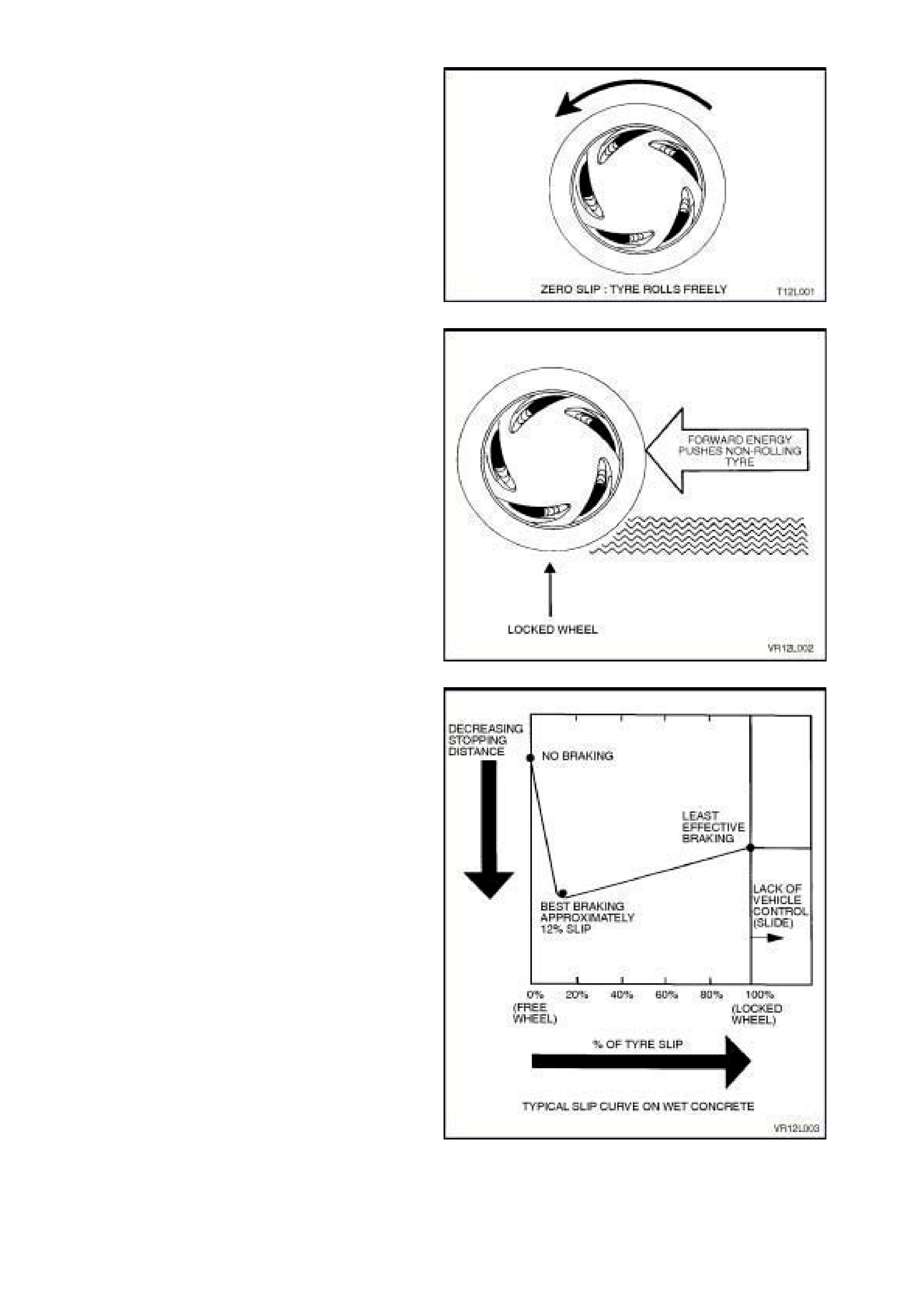
Maximum braking is achieved when wheel lock-up
is prevented. Maximum braking force is generated
when the tyre slip is approximately 12%.
Tyre slip can be anywhere between 0% and 100%.
1. 0% slip: The tyre freewheels (Fig. 12L-1).
2. 100% slip: Locked tyre (Fig. 12L-2).
Figure 12L-1
Figure 12L-2
At zero slip, a tyre rolls freely. At 100% slip, a tyre
locks up as the weight of the vehicle pushes the
non-rotating tyre along. At 100% slip, the brakes
stop the tyre but not the vehicle.
Figure 12L-3
The braking system needs tyre traction to function:
in operation, the brakes convert the vehicle's
forward motion into heat energy. The brakes
cannot generate stopping force unless the tyres
have traction. Tyre traction provides a counter
force for the brakes to work against.
The forces involved in stopping a vehicle are
extremely high. For example, stopping an 1800 kg
vehicle from 100 km/h requires the brakes to
generate approximately 8100 kilojoule (kJ) of
braking energy.
At 100% slip, the vehicle's f orward energy is turned
into braking energy between the tyre and the road
surface. However, the disadvantage here is that
the tyres against the road surface are a very poor
high temperature friction material when compared
to that of the brake pads. Brake pad material can
generate stopping f orce muc h more ef ficiently than
the road surface and a non-rotating tyre. The lack
of traction at 100% slip explains why locked wheels
produce long vehicle stopping distances.
Professional drivers carefully control lockup by
limiting brake pressure, but even they cannot
always prevent lock-up on wet roads or in other
reduced traction conditions. In theory, drivers must
limit brake applications just short of lock-up. In
practice, drivers rapidly pump the br akes to reduc e
lock-up. They apply, release, reapply and release
the brakes until the vehicle stops.
However, the mo st skilled driver s cannot pum p the
brakes rapidly or precisely enough for the best
brak ing under all conditions . Of c ourse, pumping of
the brake pedal applies and r eleases the brak es at
all four wheels at the s ame tim e. Ideally, automatic
individual control over the braking at each wheel
would enhance braking on most road surfaces.
This is precisely what ABS attempts to achieve.
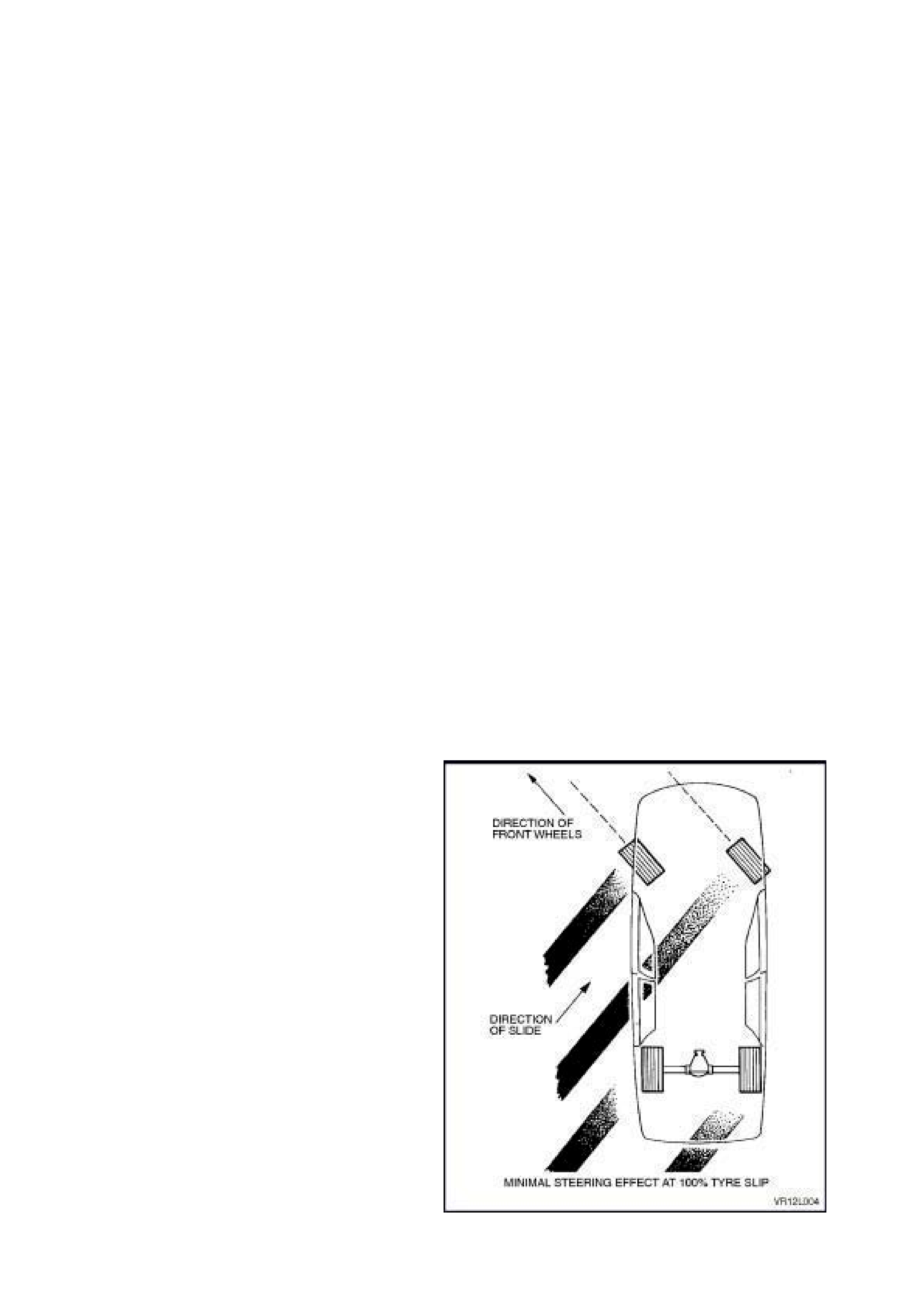
STEERING CONTROL
Steering control, like braking, also depends upon
tyre traction: a locked wheel/tyre in 100% slip
condition delivers poor braking and directional
control. Therefore, some tyre rotation is also
necessary for steering control.
Fig. 12L-4 of a sliding vehic le (100%) demons tr ates
the necessity of tyre traction. In this example, the
front tyre direction has minima l steering ef fect. T he
tyres must regain their traction before steering
control is restored to the vehicle.
Figure 12L-4
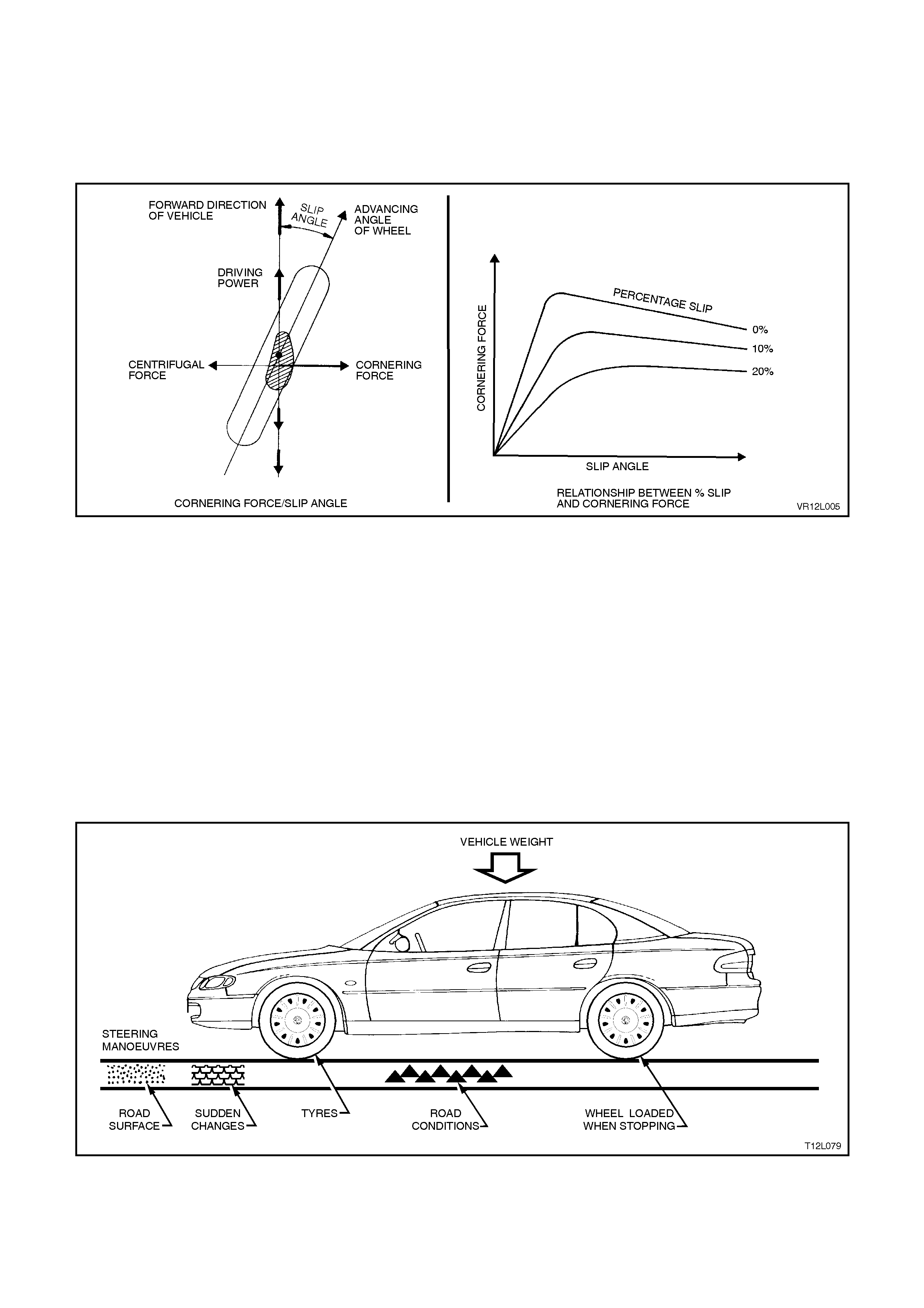
CORNERING FORCE
Centrifugal force inevitability acts on a vehicle that is turning a corner. A cornering force is needed to overcome the
centrifugal force so that the vehicle will stay on the road. The cornering force is produced when the wheel sideslip
occurs during turns (while the wheels are rotating). The following graph illustrates the relationship between the
percentage of slip, and the cornering force. When the wheel locks completely, the cornering force will then become
zero, that is, the force applied in the lateral direction no longer occurs.
Figure 12L-5
FACTORS AFFECTING BRAKING
During vehicle braking, several conditions and forces are at work. These include:
1. Road surface (dirt, gravel, bitumen).
2. Sudden changes in the road surface (oil, puddles, ice spots).
3. Road conditions (smooth, rough, wet, dry).
4. Vehicle weight.
5. Wheel loading when stopping.
6. Steering manoeuvres.
7. Tyres.
The advent of solid state electronics enables these factors to be monitored and allowed for during braking. Without
special electronics devices, the braking system could not account for these variables.
Figure 12L-6

1.2 ELECTRONIC TRACTION CONTROL (ETC)
Critical driving situations are not restricted to braking; they can also occur during standing start and moving
acceleration (especially on slippery gradients) and during cornering. These conditions can present drivers with more
than they can handle. The result: dangerous driving errors.
Electronic Traction Control (ETC) is designed to solve these problems. The primary purpose of ETC, an expanded
version of ABS, is to reduce the demands placed on the vehicle by the driver by maintaining vehicle stability and
steering response under acceleration (provided that the physical limits are not exceeded). ETC does this through
the use of ABS (brake intervention) and adapting the engine torque to levels corresponding to the traction available
at the road surface, before the situation becomes critical. By combining ETC and ABS, it is possible to obtain higher
levels of safety through dual purpose application of system components.
BASE SYSTEM
The ETC system must be capable of inhibiting wheelspin during initial or moving acceleration under the following
conditions:
• When the lane surface is slippery on one or both sides.
• As the vehicle enters an iced over road surface.
• During acceleration when cornering.
• When starting off on a gradient.
The ETC system must also intervene in the following situations:
• When a wheel spins (the same as when it locks), the lateral forces which it can transmit are limited; the vehicle
becomes unstable and the rear ‘fishtails’. ETC maintains vehicle stability for enhanced safety.
• Spin also leads to increased tyre tread wear and drivetrain stress, ie. rear axle. ETC avoids the drivetrain loads
that occur when a spinning wheel suddenly finds traction on a high adhesive surface.
• ETC must be ready to intervene automatically at all times. ETC employs the difference in slip rates at the drive
wheels to distinguish between cornering and acceleration slippage. The tyres do not drag in tight radius corners,
as can occur with a differential lock. Limited slip differentials can not always inhibit wheel spin resulting from
excess throttle applications. In contrast, ETC also regulates the engine output to ensure that the wheels retain
traction.
• The system responds to conditions in the physical threshold range by triggering a LOW TRAC warning lamp in
the instrument cluster to alert the driver.

2. GENERAL DESCRIPTI ON
There are two types of ABS fitted to VT Series Models, one with traction control ABS/ETC (production options JL9
and NW9) and one without traction control, ABS (production option JL9). ABS is fitted as standard equipment on
Berlina and SS models and is available as an option on all other models except Calais and Acclaim. ABS/ETC is
fitted to Acclaim and Calais models as standard equipment and is available as optional equipment on all other
models except for vehicles with V8 engines or LPG.
NOTE:
Holden will not build a vehicle with Electronic Traction Control (ETC) and LPG, as the systems are
incompatible. If a vehicle with ETC is to be fitted with an aftermarket LPG system, the ETC system must be
permanently disabled.
The only recommended way of disabling the ETC system is to disconnect terminal 27 from the ABS/ETC
Control Module connector YE98, circuit 1427, Black/White wire (actual torque). This is to be achieved by
withdrawing terminal 27 from connector YE98 and taping the wire back to the main wiring harness. This
will disable the ETC system while maintaining normal ABS operation.
If the ETC system is disabled, the TRAC OFF warning lamp in the instrument cluster will be permanently
illuminated when the ignition is on and Diagnostic Trouble Code 74 will be logged. At no time must the
‘TRAC OFF’ warning lamp be disconnected as it’s function is to advise the driver that this safety feature is
not available.
On all VT Series Models, the conventional portion (non-ABS) of the braking system comprises the conventional
heavy duty braking system, specific brake pipe harness and lines and a common master cylinder with the
conventional non-ABS braking system, but has a screw-in blanking plug installed into the lower of the two front
brake outlets. Each front wheel hub also includes the wheel speed sensor as part of the assembly. The rear wheel
speed sensors are toothed pulse rings attached to each of the inner axle flanges.
At road speeds above approximately 6 km/h, the ABS is designed to control brake fluid pressure so that the wheels
are prevented from locking-up during braking, irrespective of the road conditions and tyre grip. The system starts to
regulate when one wheel is detected to be decelerating faster than the other wheels, tending to lock. The vehicle
remains steerable, even in the event of panic braking, for instance on bends or when swerving to avoid an obstacle.
The ABS without traction control fitted to VT Series vehicles modulates braking pressure separately at each front
wheel, with the rear wheels sharing a single ABS modulated hydraulic circuit. This ABS is referred to as a three-
channel system as three separate hydraulic brake circuits are used to achieve anti-lock braking functions. The
ABS/ETC (ABS with electronic traction control) fitted to VT Series vehicles modulates braking pressure separately
at each front and rear wheel. The ABS/ETC is referred to as a four channel system as each of the four wheels have
a separate hydraulic brake circuits which are used to achieve anti-lock braking and traction control functions. The
term modulated refers to the ABS ability to 'Maintain', 'Reduce' or 'Increase' (Build-up) the hydraulic pressure in the
various brake circuits based on various inputs.
The TECH 2 diagnostic scan tool is programmed to assist with VT electrical diagnosis and problem solving,
including ABS and ABS/ETC.
TECH 2 connects to the ABS or ABS/ETC serial data communication information via the Data Link Connector
(DLC), attached to the instrument panel lower right hand trim, to the right of the steering column. For additional
information on DLC location and system diagnosis, refer to 4. ABS, ABS/ETC DIAGNOSIS in this Section. For
additional and more comprehensive information regarding TECH 2, refer to Section 0C TECH 2.
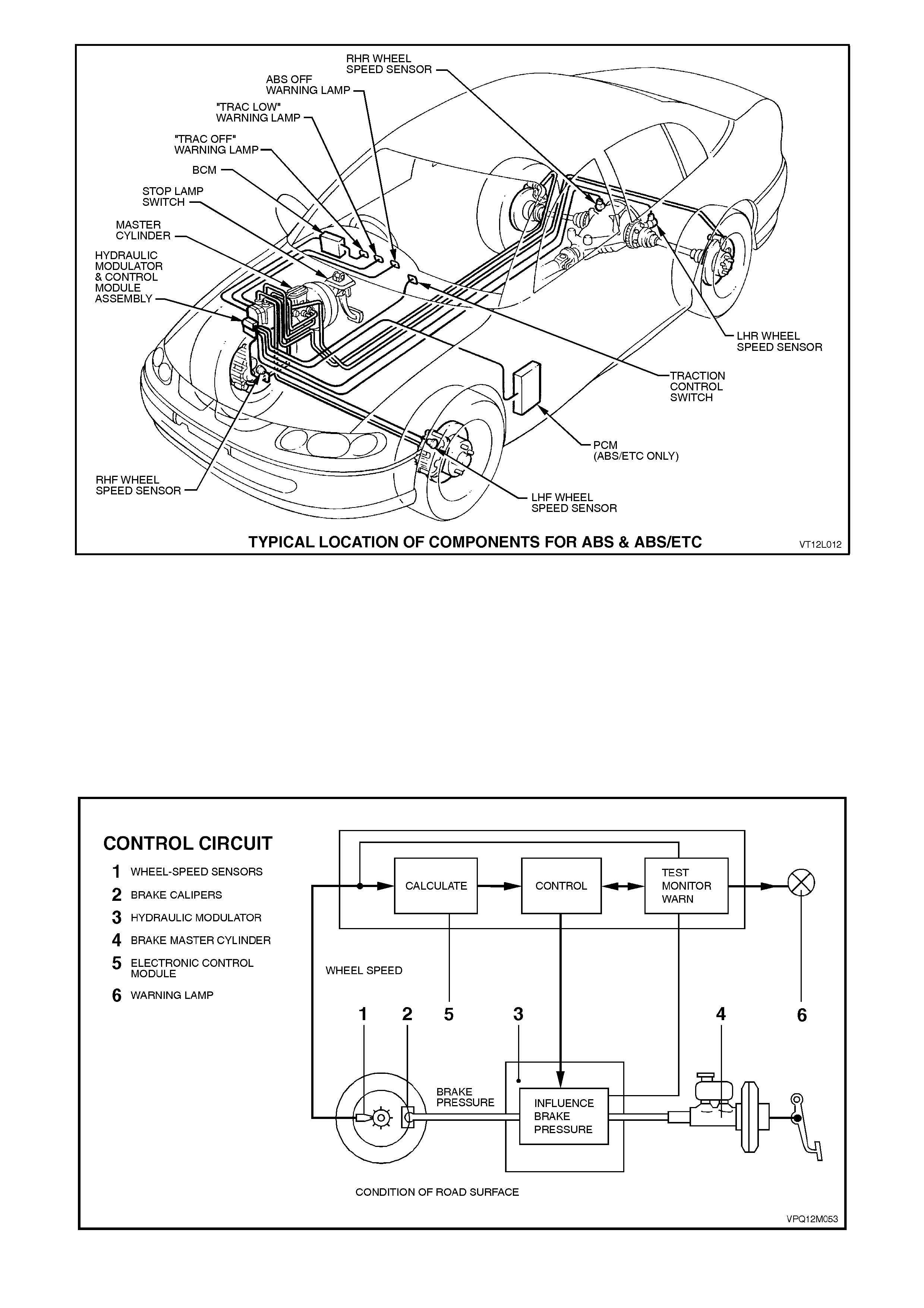
Figure 12L-7
2.1 ABS AND ABS/ETC SYSTEM OVERVIEW
BASIC OPERA TING PRINCIPLE
The rotational speed of each wheel is measured by inductive wheel speed sensors. When the brakes are applied,
the change in rotational speed is used by the processor in the ABS or ABS/ETC Control Module to determine the
deceleration, acceleration and slip of the wheels.
On vehicles with ABS, the front wheels are individually controlled with the rear wheels being controlled jointly (three
channel system). If one side of the road surface is slippery, the rear wheel braking on this surface determines the
braking pressure of both rear wheels. On vehicles with ABS/ETC, select low braking is still used, even thouigh it is a
four channel system.
Figure 12L-8

Three channel ABS
(refer Fig. 12L-9)
The braking force for each of the front wheels is regulated using individual inlet and outlet solenoid valves within the
Hydraulic Modulator, and the rear wheels are controlled by a common set of inlet and outlet solenoid valves within
the Hydraulic Modulator. Four sensors measure the individual speed of each wheel.
Figure 12L-9
Four channel ABS/ETC
(Refer Fig. 12L-10)
The braking force for each wheel (front and back) is regulated using individual inlet and outlet solenoid valves within
the hydraulic modulator. Four sensors measure the individual speed of each wheel.
Figure 12L-10
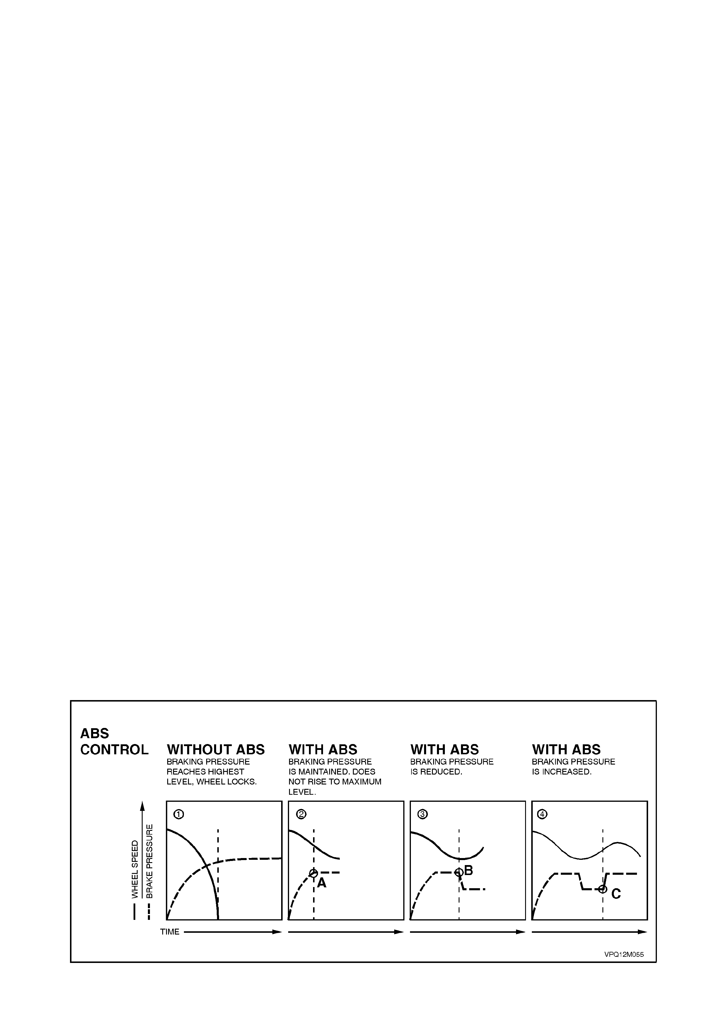
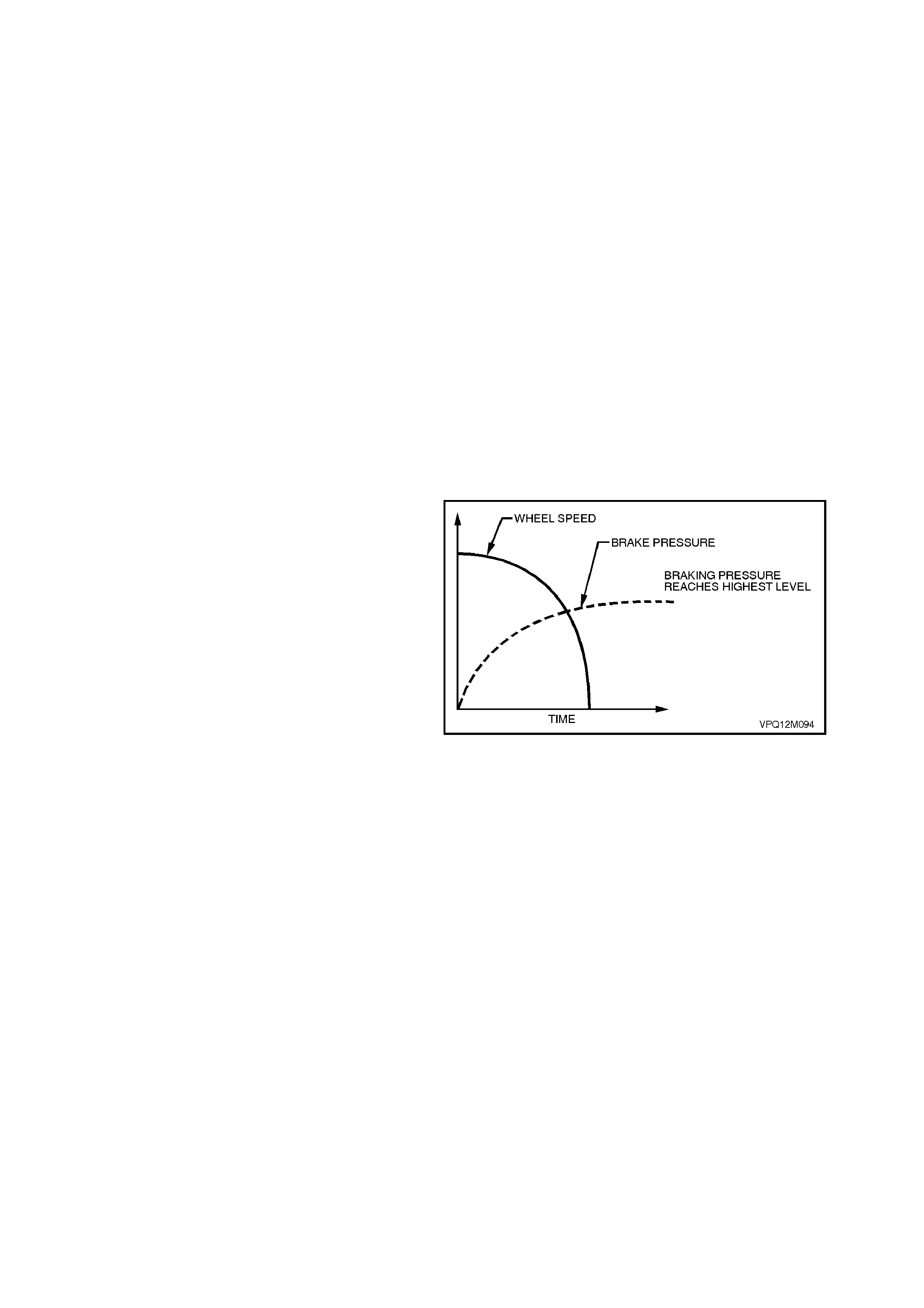
ABS CONTROL
Lock-up
(refer ➀ in Fig. 12L-12)
During full braking, the driver usually applies braking pressure to such an extent that the wheels lock-up. This
results in a loss of steering control, and the maximum possible braking effect is not attained. During ABS-controlled
full braking, the braking pressure is automatically adjusted to prevent wheel lock-up, regardless of brake pedal
force.
The processes involved are:
• maintaining pressure
• reducing pressure
• increasing (building-up) pressure.
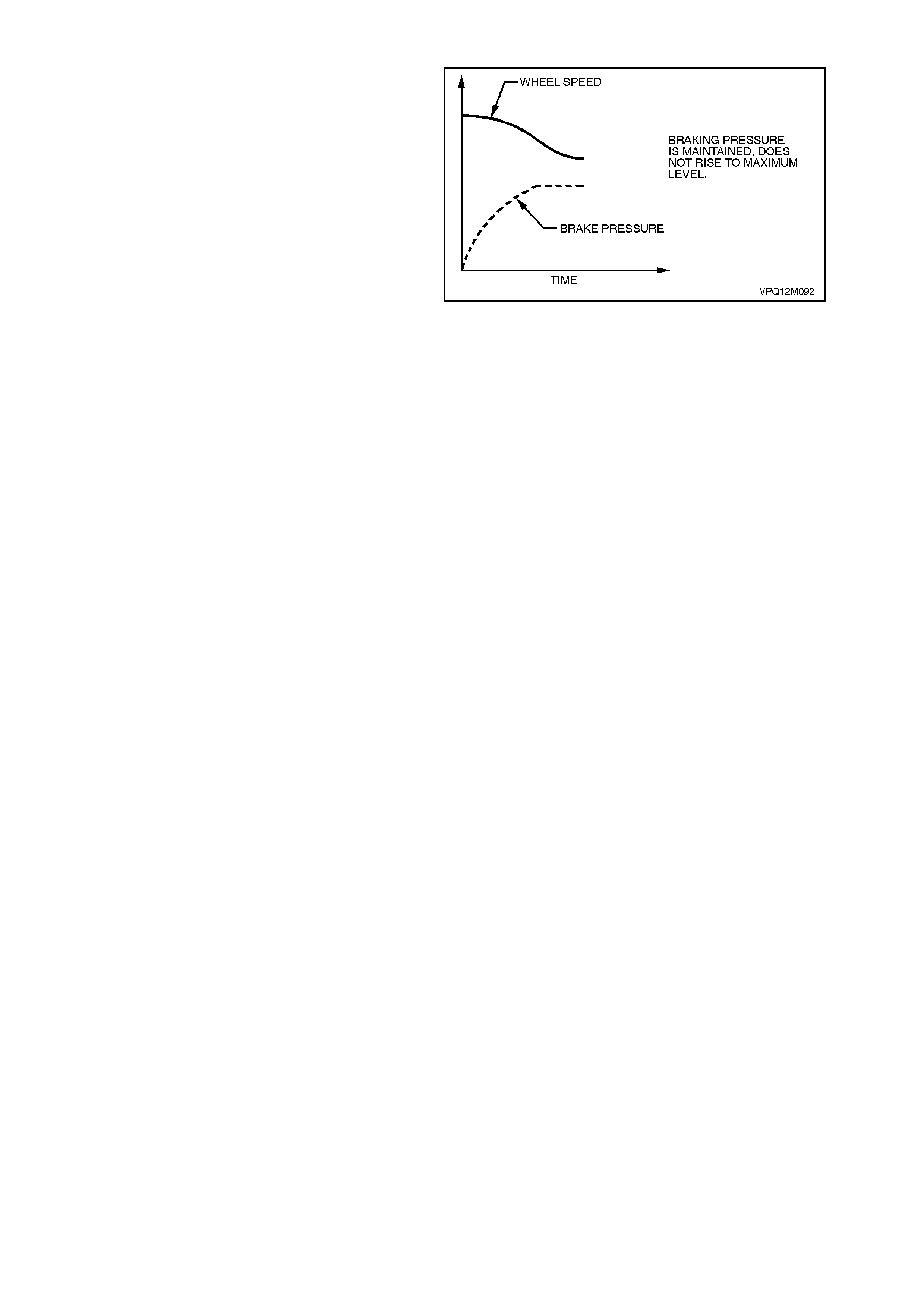
Maintaining Pressure
(refer ➁ in Fig. 12L-11)
If a wheel speed sensor signals severe wheel deceleration to the ABS Control Module, ie. the wheels are likely to
lock-up, the braking pressure at the wheel involved is initially maintained (kept constant) as opposed to being further
increased (point A).
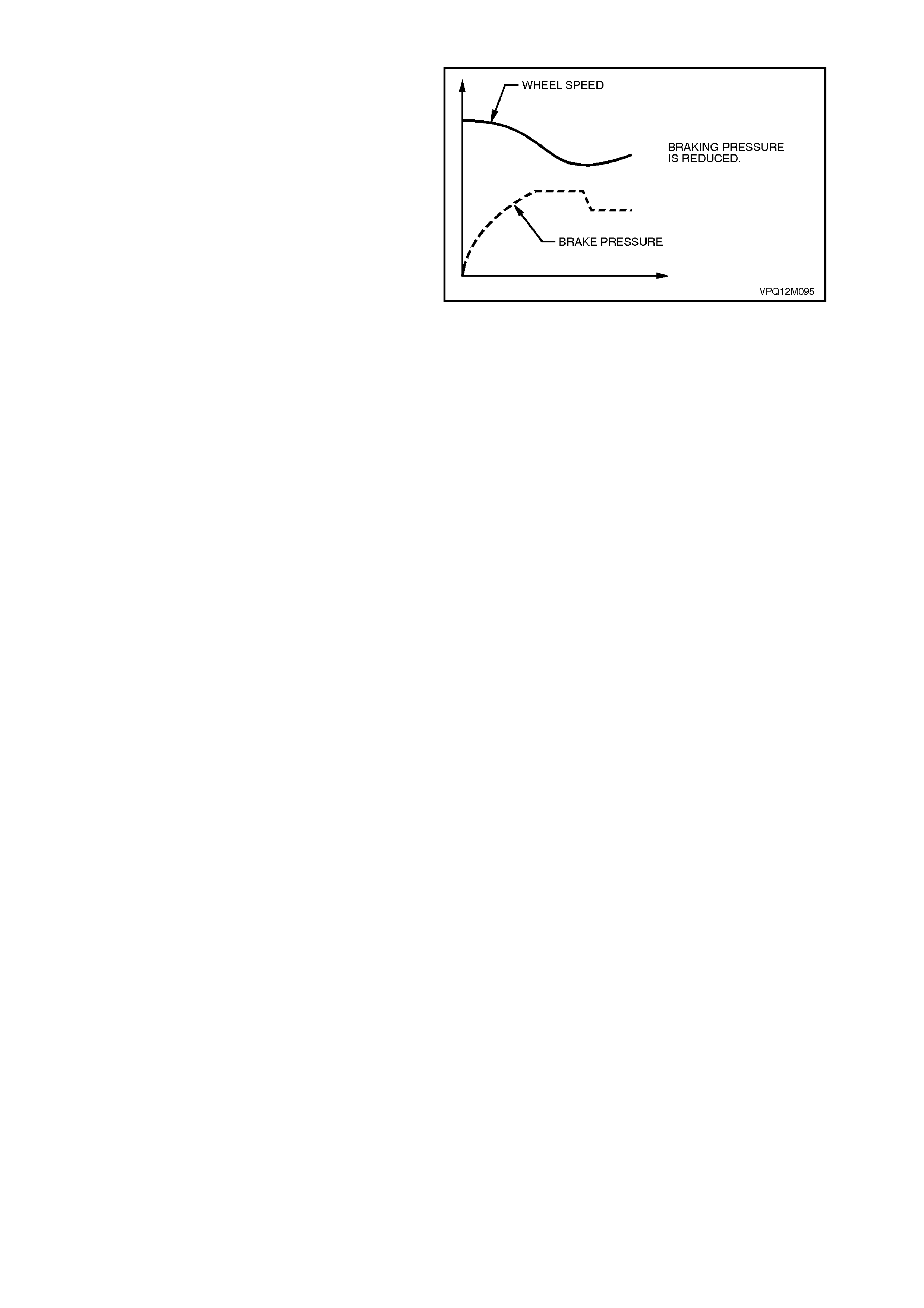
Reducing Pressure
(refer ➂ in Fig. 12L-11)
If the wheel still continues to decelerate rapidly, the pressure in the brake calliper circuit is reduced so that the wheel
is braked less heavily (point B).
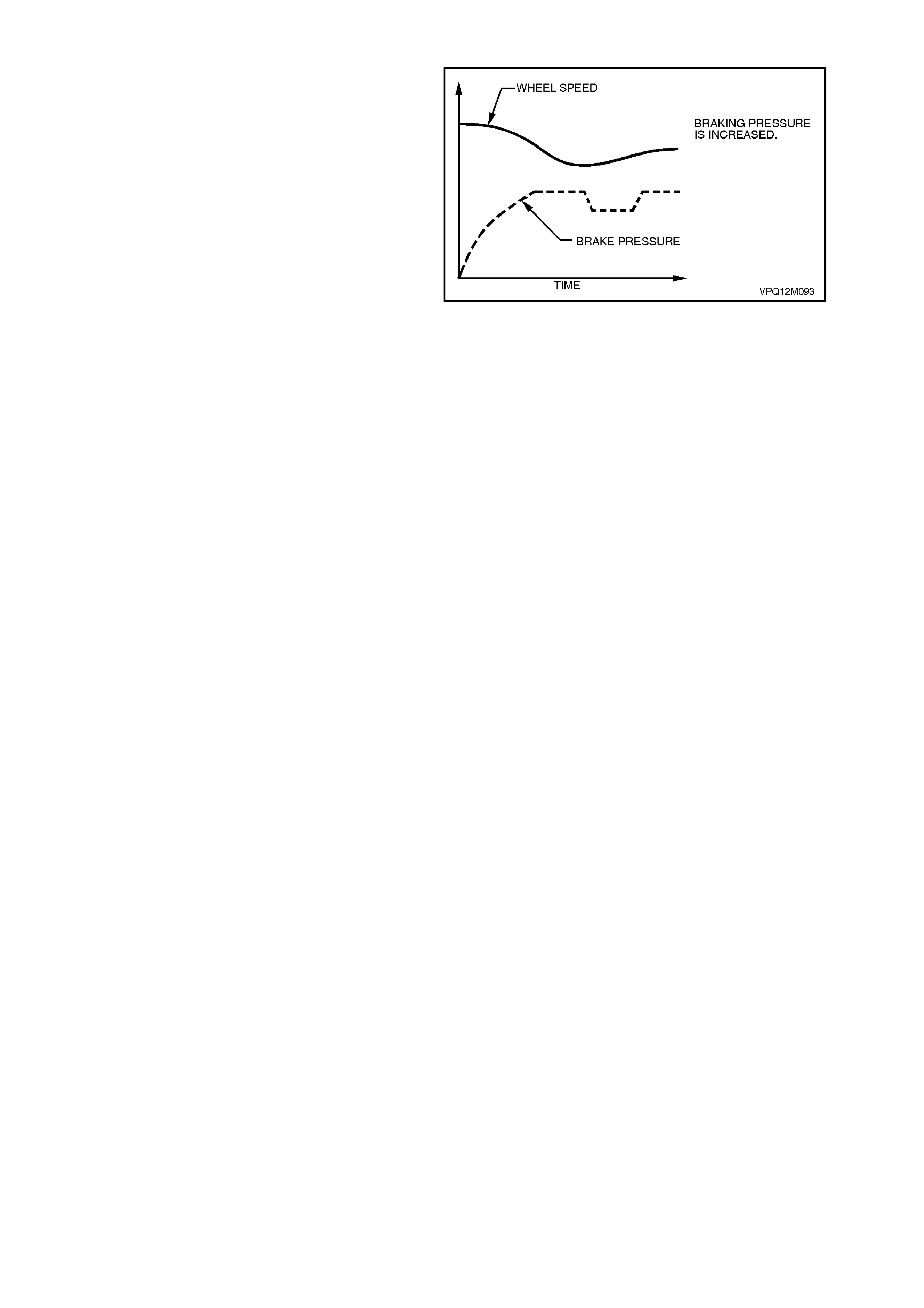
Increasing (Building-up) Pressure
(refer ➃ in Fig. 12L-11)
The wheel accelerates again as a result of the reduced braking pressure. Upon reaching a specific limit, the ABS or
ABS/ETC Control Module registers the fact that the wheel is now not being braked sufficiently. The formerly
reduced pressure is then increased, provided pedal pressure is maintained, so that the wheel is again decelerated
(point C). The control cycle begins again. There are approximately four to six control cycles per second, depending
on the state of the road surface. This rate is made possible by rapid electronic signal processing and the short
response times of the solenoid valves.
Self-Monitoring
At the start of a journey, the system automatically carries out an operational check in accordance with a stored
program in the ABS or ABS/ETC Control Module. The signals generated during a braking process are simulated
and the signals transmitted to the hydraulic modulator are checked for their correctness.
During the journey the system monitors itself by comparing the logical sequence of input and output signals with
memorised limit values, in addition to monitoring the voltage supply.
If a system defect is detected, the ABS switches itself off and the driver can still use the conventional, non ABS
controlled braking system. This changeover is indicated by the illumination of an ABS warning lamp in the
instrument cluster.
Performance
When full braking power is applied, the vehicle is optimally braked while retaining its full directional stability and
steerability. The ABS prevents wheel lock-up above a minimum speed of approximately 6 km/h, whether on ice or
on a dry road surface.
Figure 12L-11

2.2 NORMAL CONDITIONS DURING ANTI-LOCK BRAKING AND TRACTION CONTROL
INTERVENTION
During anti-lock braking, a series of rapid pulsations are felt through the brake pedal. These pulsations occur as
solenoid valves within the underhood Hydraulic Modulator Assembly change position to modulate brake hydraulic
pressure. Brake pedal pulsation continues until the vehicle is stopped or the ABS mode disengages.
The operation of the pump, also within the Hydraulic Modulator Assembly, is characterised by rapid brake pedal
pulsation that is accompanied by some electric motor and pump noise. Pump operation may be perceived during
regular vehicle operation or during initial ABS or ABS/ETC Control Module self-test. While these functions sometime
cause driver concern, they are normal functions of ABS operation.
During traction control, normal operation is less noticeable; the operation of the pump may still be heard together
with a power sag from the engine as the ABS/ETC Control Module requests the PCM to bring engine torque into a
specific range.
When the vehicle reaches approximately 6 km/h and provided the ABS or ABS/ETC Control Module does not sense
a stop lamp switch input, after initial engine start-up and driving away, the ABS or ABS/ETC Control Module tests
the solenoid valves and pump. This self test can be heard by the driver and is a normal operating function of the
ABS. If the ABS or ABS/ETC Control Module does sense a stop lamp switch input, the self test will not occur until
the vehicle is travelling at approximately 18 km/h.
Normal function of the ABS, TRAC OFF and LOW TRAC warning lamps in the instrument cluster are as follows:
ABS lamp: should illuminate when the ignition is switched on and will go out approximately two seconds later.
Should the lamp not go out, the ABS or ABS/ETC Control Module has detected a system fault.
TRAC OFF lamp: should illuminate when the ignition is switched on and will go out approximately five seconds later
(or two seconds latter with engine running). If the lamp does not go out, either the ABS/ETC Control Module has
detected a system fault, or the system has been manually switched off.
LOW TRAC lamp: should illuminate when the ignition is switched on and will go out approximately two seconds
later. This lamp will flash whenever the ETC system is engaged.
2.3 ABS AND ABS/ETC SYSTEM COMPONENTS
WHEEL SPEED SENSORS AND PULSE RINGS
Inductive wheel speed sensors are used to detect
the rotational speed of each wheel. There are
specif ic wheel sensor ass emblies f or front and rear
wheels.
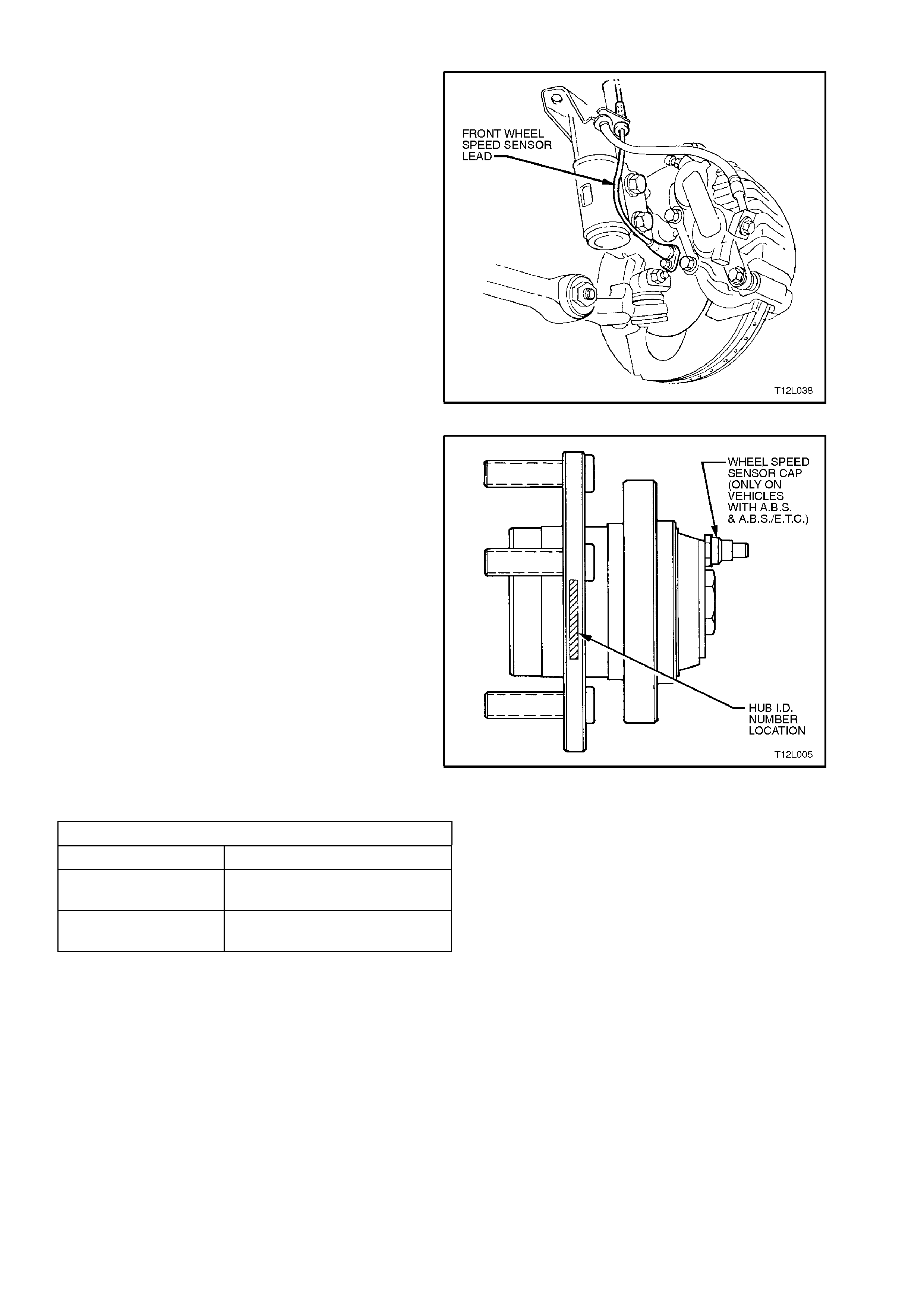
Front Wheel Speed Sensors
The f ront wheel speed sensors are incor porated as
part of the front suspension front wheel hub
assembly.
Figure 12L-12
There are three specific front wheel hub
assemblies available. For vehicles with ABS or
ABS/ETC there is a right and left, which
incorporates the wheel speed sensor and a 48
tooth magnet impulse r ing. For non ABS vehicles , a
common hub is used for both sides.
Identification of the front wheel hub assemblies is
by the assembly part number etched on the outer
surf ace of the hub wheel flange or by simply noting
whether a wheel speed sensor cap is fitted to the
hub, refer Fig.12L-13.
CAUTION:
During any service operation that requires the
replacement of the front hub assembly on a
vehicle equipped with ABS or ABS/ETC, ensure
that the correct replacement hub assembly is
installed, otherwise malfunctioning of the ABS
or ABS/ETC will occur. Figure 12L-13
FRONT WHEEL HUB IDENTIFICATION
VEHICLE TYPE HUB PART NUMBER
Vehicles without ABS
or ABS/ETC 92039932
Vehicles with ABS or
ABS/ETC 92046941 L/H
92046940 R/H
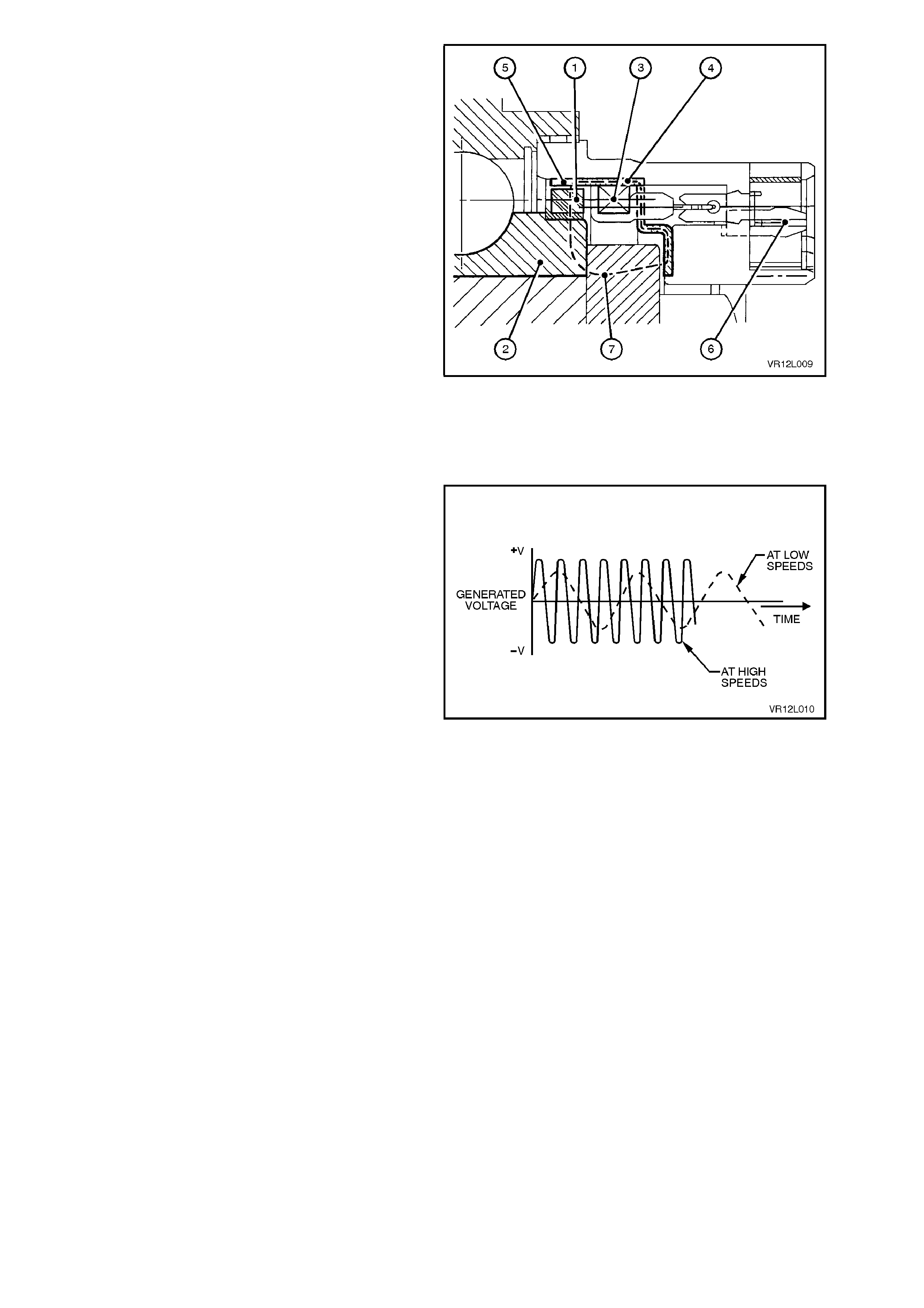
Fig. 12L-14 illustrates a sectioned view of the front
wheel sensor in the front hub assembly.
The components of the sensor are:
• magnetic impulse ring (1)
• coil (3)
• flux concentrator (4)
• coaxial connector (6)
The magnetic impuls e ring ( 1), attached to the fr ont
hub rotating member (2), is magnetised and
contains 48 individual magnets evenly spaced
around the ring.
On the flux concentrator (4) there are a
corresponding 48 evenly spaced teeth (5).
Magnetic flux (7), generated from the impulse ring
(1), is induced into the coil (3) via the flux
concentrator (4).
As the road wheel is rotated, the front hub inner
member and magnetic impulse ring rotate as one,
causing a variation of the magnetic flux generated
in the flux concentrator. This change in the
magnetic flux causes an alternating voltage to be
induced in the coil of the sensor.
Figure 12L-14
The frequency and amplitude of the induced
voltage are dependent on wheel RPM, the number
of turns of the coil, the magnetisation level of the
impulse ring and the number teeth of the flux
concentrator. Of all these factors, the only variable
is the wheel RPM, so the frequency and amplitude
of the output signal depend on the speed of wheel
rotation.
Figure 12L-15
NOTE:
Apart from wheel stud replacement, there are no
serviceable item s in the front wheel hub assembly.
With the unit being a 'sealed for life' assembly,
there are no requirements for wheel speed sensor
and/or bearing adjustments. Should a non-
standard condition develop, then the hub assem bly
must be replaced as complete unit.
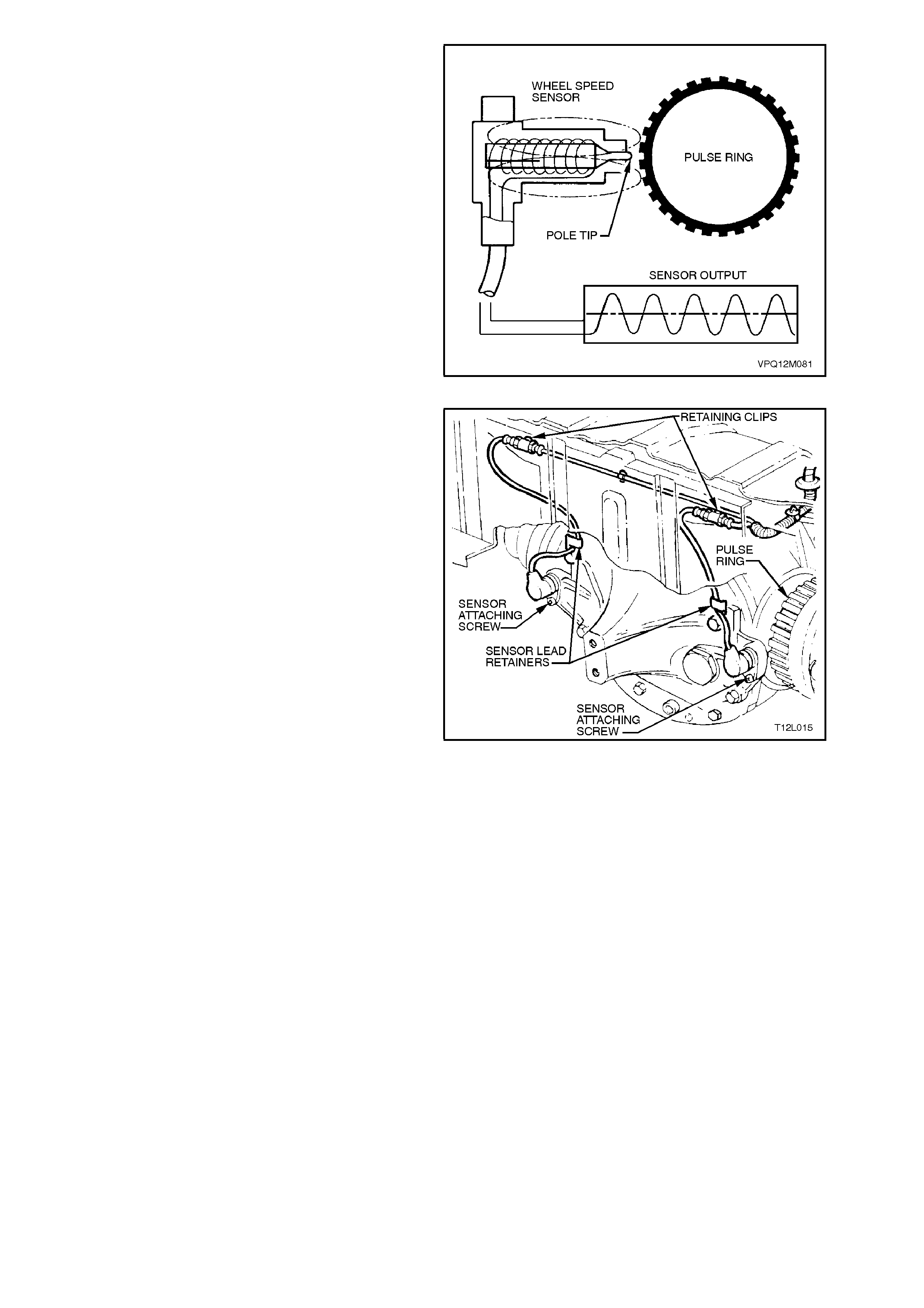
Rear Wheel Speed Sensors
The rear wheel speed sensor basically consists of
a magnetic core and a coil. The pole tip is
surrounded by a m agnetic f ield. As the wheel turns,
the teeth of the pulse ring cause changes in this
magnetic field. The magnetic flux thereby changes
and an alternating voltage is induced in the coil of
the wheel speed sensor.
The pole piece on the outer surface of the sensor is
of a plastic construction and therefore there is no
requirement to coat the outer surface with high
temperature grease when reinstalling sensor
assemblies (as on previous models).
The rear wheel speed sensors have a high voltage
output and therefore, there is no need to install
shim s between the sens or and its mating m ounting
bracket.
Figure 12L-16
The rear wheel speed sensors are located in a
bracket which is part of the final drive rear cover.
Each pulse ring is a toothed ring made of a ferrous
metal that rotates to allow the wheel speed sensor
to read the rotational speed of each rear wheel.
The rear wheel pulse rings are part of the final drive
inner axle flanges and are not serviced separately.
As the road wheels rotate, the wheel speed
sensors generate an AC electrical signal
proportional (in frequency and amplitude) to the
wheel speed. The ABS or ABS/ETC Control
Module uses wheel speed signals to determine
when anti-lock control or traction control is
required. Specifically, the module uses wheel
speed sensor signals to find out whether any of the
wheels are decelerating rapidly (locking) or
accelerating rapidly (slipping).
Figure 12L-17
The ABS and ABS/ETC systems are calibrated to
use tyres of a known rolling radius and pulse rings
with a specific number of teeth. The number of
teeth on the pulse rings correspond directly to tyre
size. If one of the tyres fitted to the vehic le is larger
or smaller (not to original equipment size) than the
remainder of the tyres on the vehicle, the ABS or
ABS/ETC Control Module will not modulate brake
system hydraulic pressure properly. Improper
system operation occurs because the wheel speed
signal from the off-size tyre makes the module
think that one wheel is ac celerating or decelerating
faster than the others.
NOTE:
IT IS IMPO RT ANT T HAT T HE VEHICLE O NLY BE
EQUIPPED WITH THE ORIGINAL EQUIPMENT
TYRE SIZE AS NOMINATED ON THE VEHICLES
TYRE PLACARD. CHANGING TYRE SIZE
COULD AFFECT SYSTEM FUNCTION.
ABS AND ABS/ETC CONTROL MODULE
The ABS or ABS/ETC Control Module evaluates
the signals from the wheel speed sensors and
computes the permissible wheel slip for optimum
braking and traction.
It regulates the necessary braking pressure in the
brake calipers by means of solenoid valves within
the Hydraulic Modulator assembly. The ABS or
ABS/ETC Control Module tests the system in
accordance with a defined program and monitors it
during driving.
The ABS/ETC Control Module also monitors both
front and rear wheel speeds through the wheel
speed sensors. If at any time during acceleration
the ABS/ETC m odule detec ts drive wheel slip, it will
request (on the Torque Request circuit) the
Powertrain Control Module (PCM) to bring excess
engine torque into a specific range. This is
accomplished via two high speed Pulse Width
Modulated (PWM) circuits between the ABS/ETC
Control Module and the PCM. The PCM will then
adjust spark firing and air/fuel ratio, altering boost
duty cycle (Supercharge engine only), and shutting
OFF up to five (5) injectors (if necessary), and
report the modified torque value (on the Torque
Achieved circuit) back to the ABS/ETC Control
Module. Simultaneously with engine torque
management, the ABS/ETC Control Module will
activate the ABS isolator valves, turn on the ABS
pump m otor and supply brake pressure to the over
spinning wheel/s.
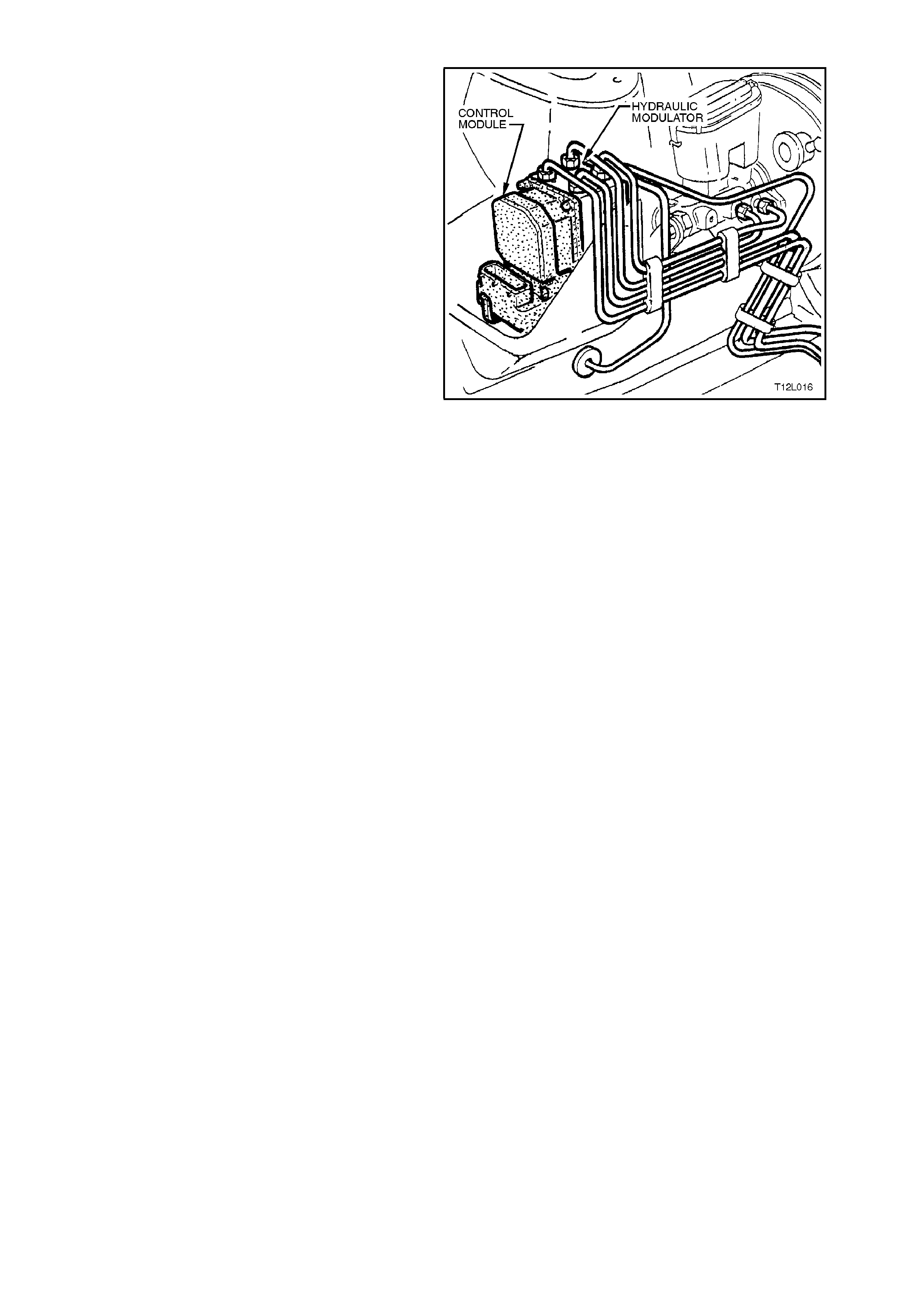
The ABS or ABS/ETC Control Module is integrated
with the hydraulic modulator and is located in the
engine compartment, forward of the master
cylinder.
There are different control modules used in VT
Series Model vehicles for ABS and ABS/ETC
systems. It is physically impossible to fit an ABS
Control Module to an ABS/ETC Hydraulic
Modulator or an ABS/ETC Control Module to a ABS
Hydraulic Modulator. However, if replacing either
an ABS or ABS/ETC Control Module, always refer
to the latest VT Series Model Parts Information for
the correct ABS Control Module part numbers.
Figure 12L-18
HYDRAULIC MODULATOR
The hydraulic m odulator f or the ABS c onsis ts of six
solenoid valves (three inlet and three outlet), two
accumulators, one for the front brake circuits and
the other for the rear brak e circuit and a brak e f luid
return pump.
The hydraulic modulator for ABS/ETC system
consists of ten solenoid valves (four inlet, four
outlet and two ETC solenoid valves), two
accumulators, one for the front brake circuits and
the other for the rear brak e circuit and a brak e f luid
return pump.
The solenoid valves are actuated by the ABS or
ABS/ETC Control Module. Depending on the
switching stage, they connect the wheel brake
calipers either with the brake master cylinder or
with the pump assembly, or disconnect the wheel
brake calliper from both the circuit and pump.
When pressure is reduced, the return pump
conveys the brake fluid flowing out of the wheel
brak e cylinder s back into the brak e mas ter cylinder
via the corresponding accumulator. The
accumulators serve to temporarily accommodate
the brake fluid 'surplus' which suddenly occurs
following a drop in pressure.
The hydraulic modulator is mounted in the engine
compartment, forward of the brake master cylinder.
Figure 12L-19
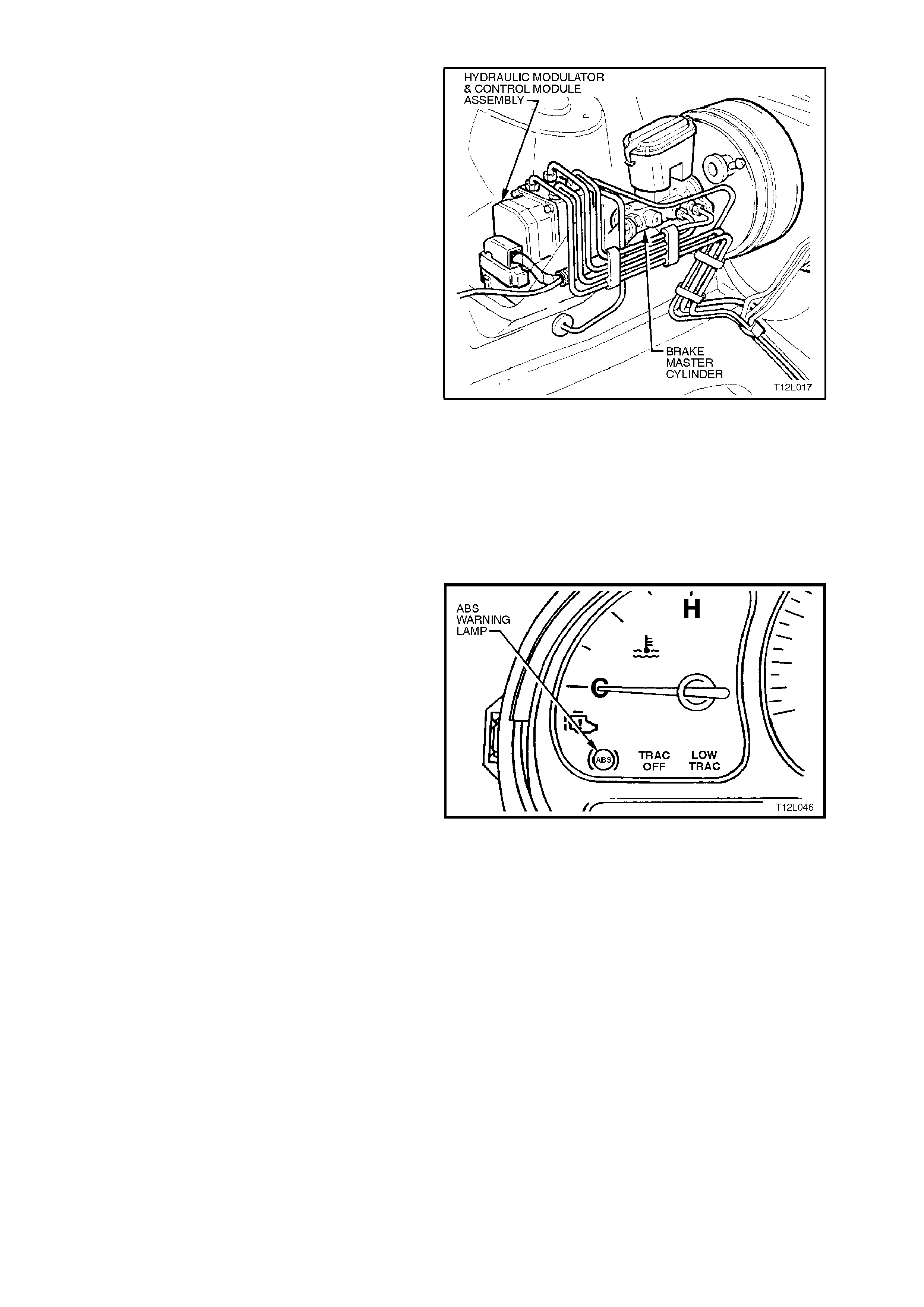
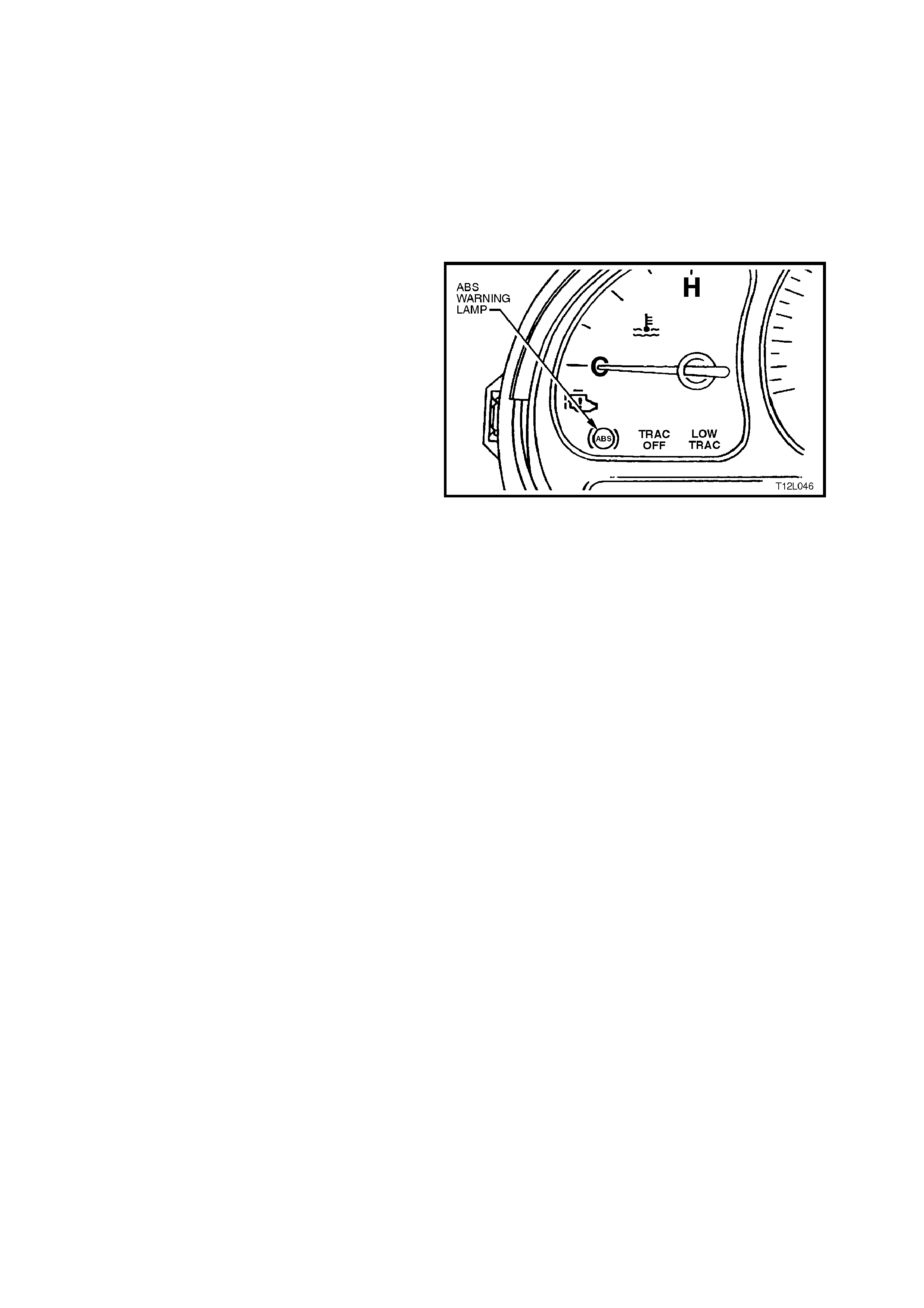
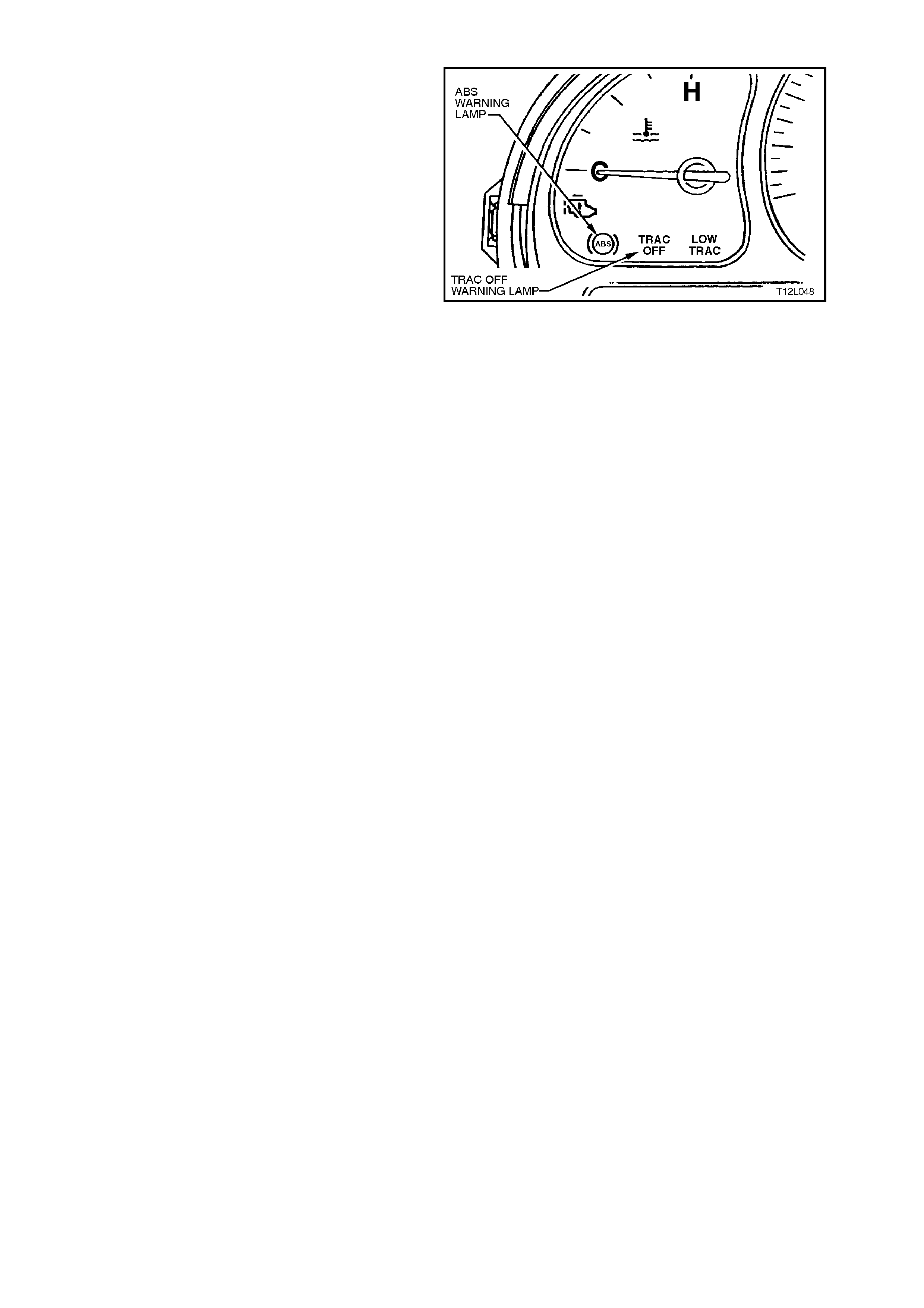
ABS WARNING LAMP
Located in the instrument cluster, the ABS warning
lamp is part of the driver warning system, refer to
Fig. 12L-20.
The ABS warning lamp is controlled by the ABS or
ABS/ETC Control Module. It is illuminated to warn
the driver that autom atic anti-loc k brak ing c apability
is totally inhibited. This does not affect the
operation of the vehicle's conventional braking
system.
The ABS warning lamp will illuminate when:
1. The ignition is turned on. The lamp will go out
after a stationary 'Self Check' is completed
(two to five seconds).
2. The ABS or ABS/ETC Control Module detects
an ABS electrical wiring or component
problem.
3. The ABS or ABS/ETC Control Module detects
a problem within itself.
These conditions are part of the ABS self-check.
4. When using TECH 2 in certain diagnostic
modes for ABS or ABS/ETC diagnosis, the
ABS or ABS/ETC is disabled by the ABS or
ABS/ETC Control Module while it is
communicating with TECH 2.
Should the ABS warning lamp lose power (from
fuse F13 ignition fuse) or the ABS Control Module
lose earth (terminals 19, 20 and 21), the ABS
warning lamp will not illuminate at any time.
Figure 12L-20
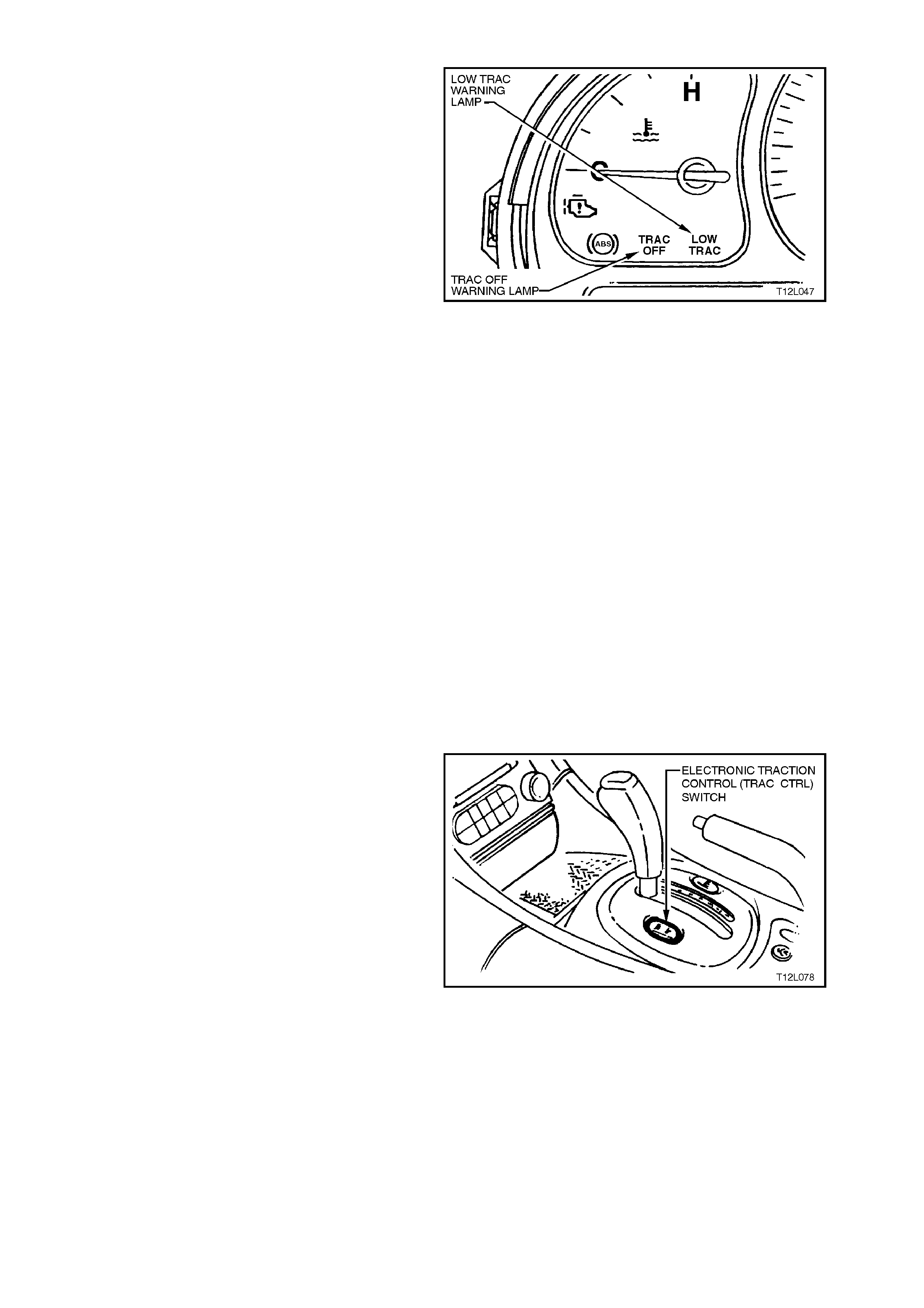
ELECTRONIC TRACTION CONTROL (ETC) WARNING LAMPS
There are two electronic traction control warning
lamps located in the instrument panel cluster;
TRAC OFF and LOW TRAC, refer to Fig. 12L-21.
The TRAC OFF warning lamp is controlled by the
ABS/ETC Control Module, via the serial data bus
circuit, and will illuminate to warn the dr iver that the
ETC system has been disabled.
The TRAC OFF warning lamp will illuminate when:
1. The ignition is turned on. The lamp will go out
after a stationary 'Self Check' is completed
(two to five seconds).
2. When the ETC system is manually switched
off, via the TRAC CTRL button.
3. The ABS/ET C Control Module detects an ET C
electrical wiring or component problem.
4. The ABS/ETC Control Module detects a
problem within itself.
5. When using TECH 2 in certain diagnostic
modes for ABS or ABS/ETC diagnosis, the
ABS and ETC systems are disabled by the
ABS/ETC Control Module while it is
communicating with the TECH 2.
Should the TRAC OFF or LOW TRAC warning
lamps lose power (from fuse F13 ignition fuse)
neither of these lamps will illuminate. Also, if the
ABS/ETC Control Module loses earth (terminals 19,
20 and 21), the LOW TRAC warning lamp will not
illuminate.
The LOW TRAC warning lam p is als o controlled by
the ABS/ETC Contr ol Module and will illum inate for
two seconds when the ignition is switched on and
then go out, or will flash when the ABS/ETC Control
Module is controlling wheel spin, indicating that the
vehicle is in a critical situation.
Figure 12L-21
ELECTRONIC TRACTION CONTROL (ETC) SWITCH
In certain circumstances (i.e. if the vehicle became
bogged and could be ‘rocked out’) it may be
necessary to disable the electronic traction control
system (ETC). This is achieved by pressing the
TRAC CTRL button, located near the transmission
selector, refer to Fig. 12L-22. If the traction control
system is switched off, the TRAC OFF lamp will
illuminate. T he system c an be switched on again by
either pressing the TRAC CTRL button again or
when the ignition is next cycled (off to on).
NOTE 1:
If the electronic traction control system is
commanded off, the ABS will still function normally.
NOTE 2:
If the T RAC CTRL button is depr ess ed and held f or
ten or m ore sec onds, the ABS/ET C Control Module
will see this as a short circuit and the ETC will be
permanently enabled until the ignition is switched
off and the engine restar ted. Additionally, the TRAC
OFF warning lam p (if illuminated) will be turned off
until the ignition is switched off and the engine
restarted.
Figure 12L-22
BRAKE MASTER CYLINDER
On VT Series Models, a common brake master
cylinder is used on vehicles with standard, ABS and
ABS/ETC brake systems. The only difference being
that the master cylinder used with ABS and
ABS/ETC systems has a screw-in blanking plug
installed and tightened into the lower of two front
brake outlets in the master cy linder.
Figure 12L-23
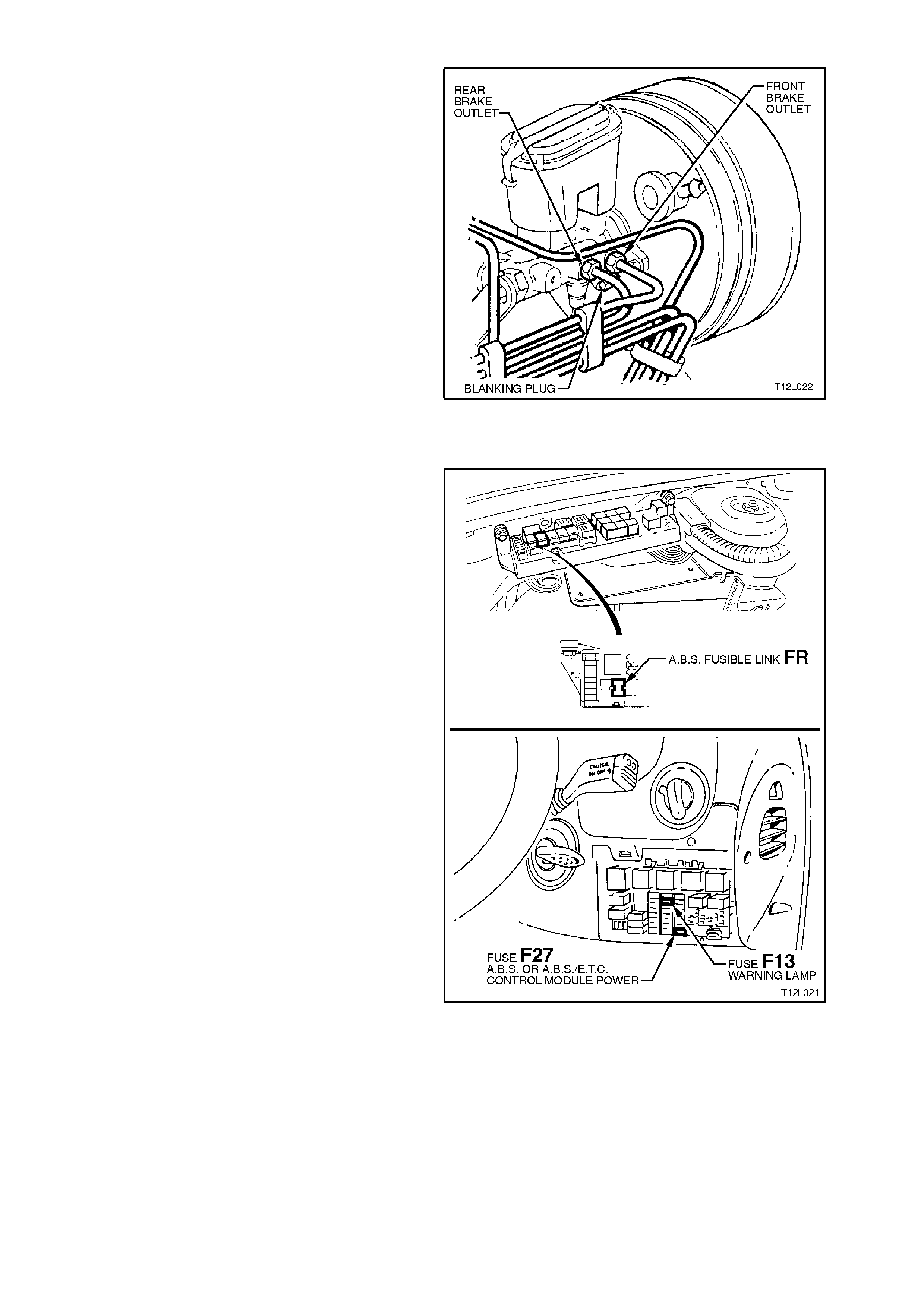
ABS & ETC FUSES
A separate ABS 60 amp fusible link, marked FR, is
incorporated in the engine compartment fusible link
housing.
Also, an additional 10 amp fuse is used for the ABS
and is located in the passenger compartment fuse
panel at fuse location No. 27.
The ABS, TRAC OFF & LOW TRAC warning
lamps are supplied voltage via F13 located in the
passenger compartment fuse panel.
Figure 12L-24
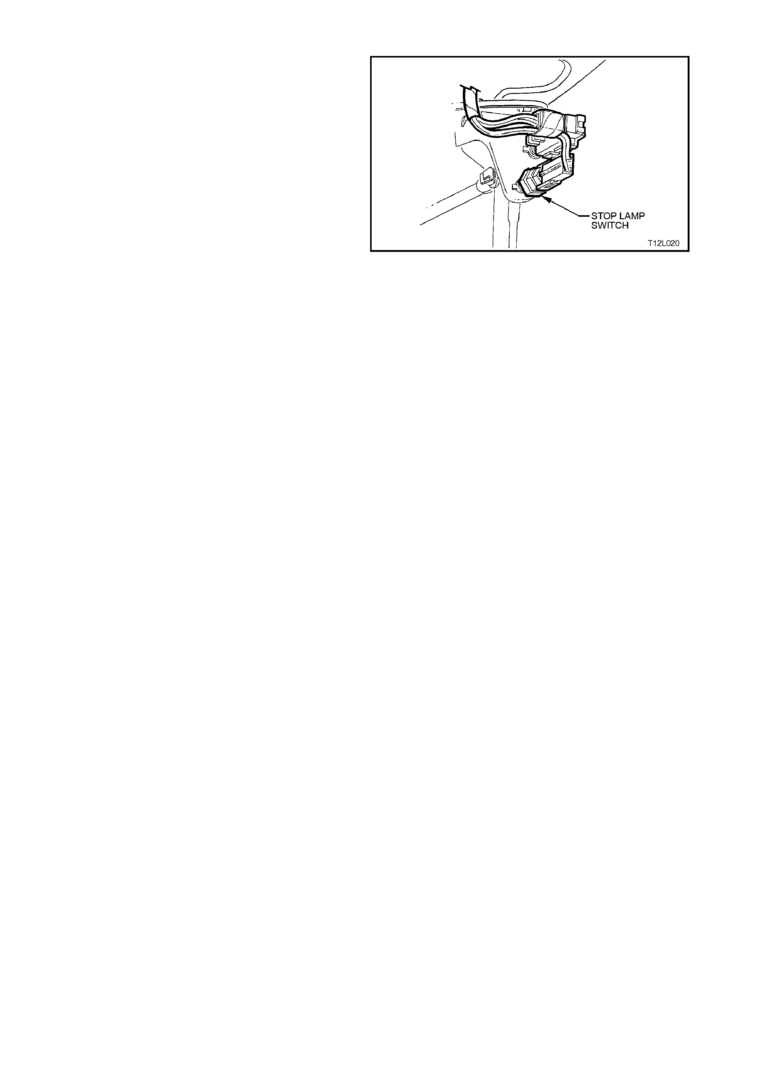
STOP LAMP SWITCH
The stop lamp switch, located in the brake pedal
support, provides a ‘brakes applied’ 12 volt input
signal to terminal 14 of the ABS Control Module.
Whenever the ABS or ABS/ETC Control Module
receives this signal the ABS control cycle will begin.
If the driver pum ps the brake pedal during the ABS
operation, the control cycle will be reset.
The stop lamp switch is a normally-open switch that
supplies battery voltage to the stop lamps and
terminal 14 of the ABS or ABS/ETC Control
Module, when closed, When the switch is open
(brakes not applied), terminal 14 of the ABS or
ABS/ETC Control Module is earthed through the
stop lamps, causing the voltage at terminal 14 to be
pulled low (less than 0.2 volts)
Also, if the ABS or ABS/ETC Control Module
senses a stop lamp switch input, the self test will
not occur until the vehicle is travelling at
approximately 18 km/h.
For all ser vice operations on the s top lamp s witch,
refer to Section 12B LIGHTING SYSTEM.
Figure 12L-25
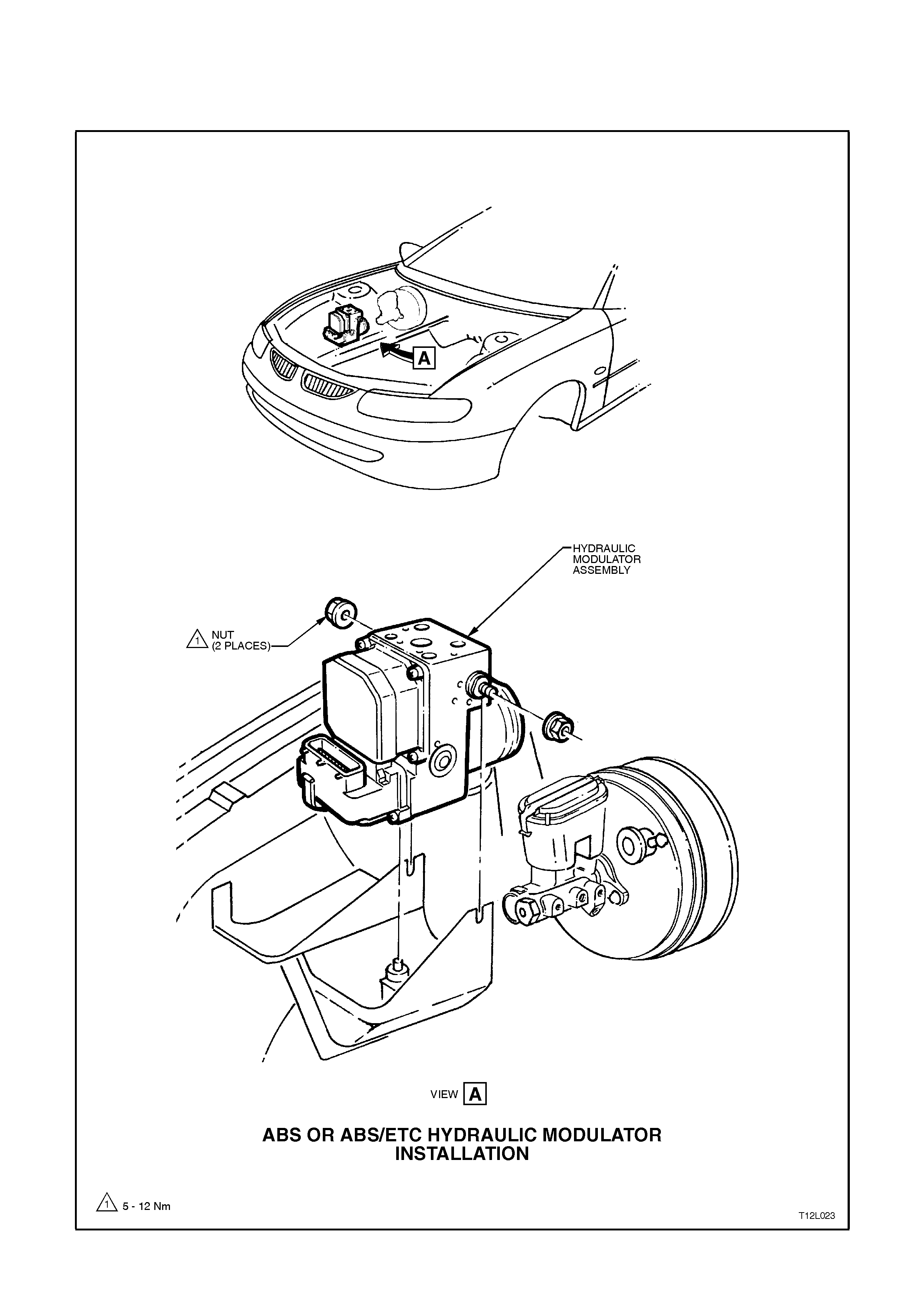
2.4 INSTALLATION POSITION OF ABS AND ABS/ETC COMPONENTS
The following figures illustrate the installed positions of the various ABS and ABS/ETC components.
ABS OR ABS/ETC HYDRAULIC MODULATOR INSTALLA TION
Figure 12L-26
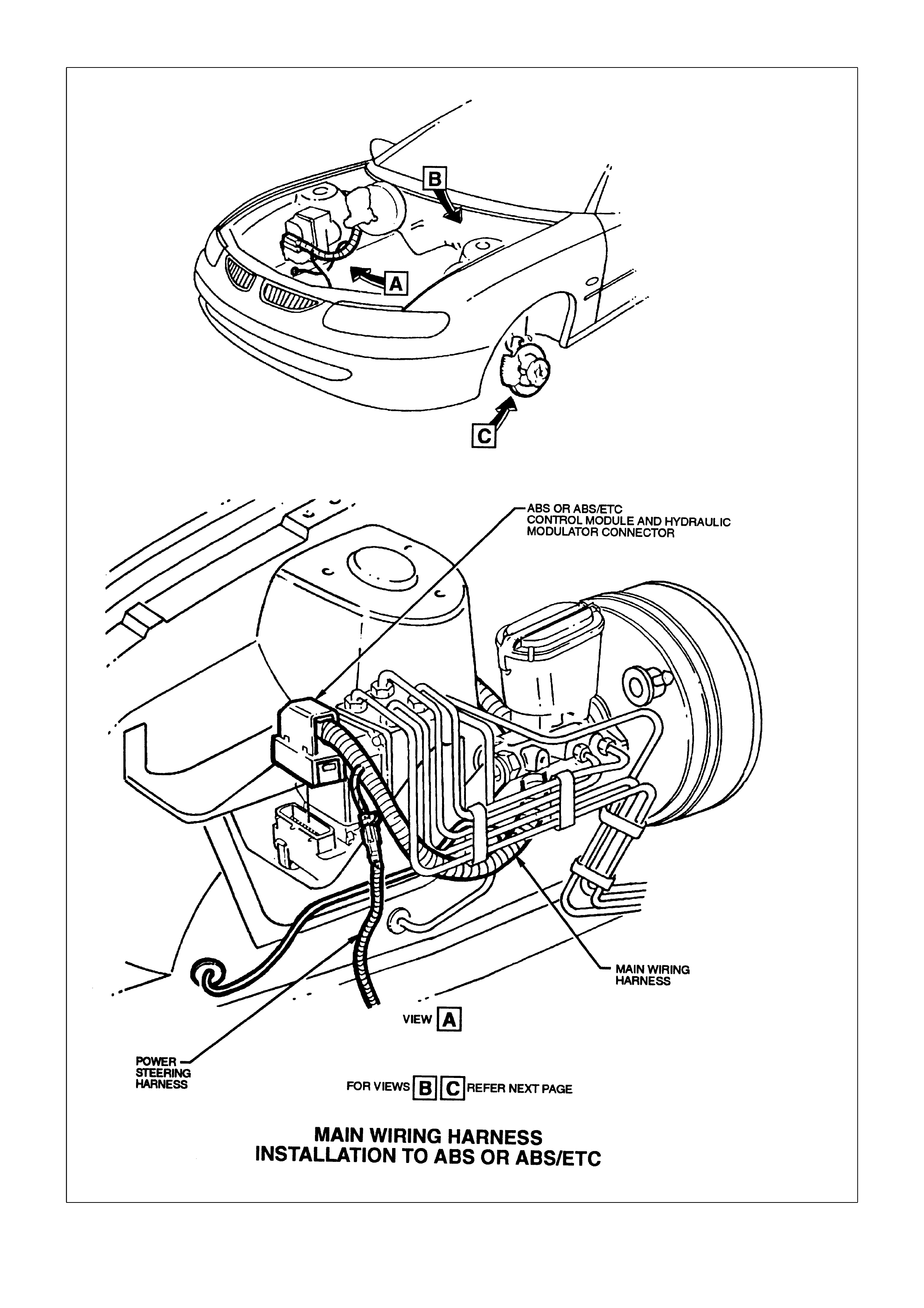
MAIN WIRING HARNESS INSTALLATION TO ABS OR ABS/ETC
Figure 12L-27
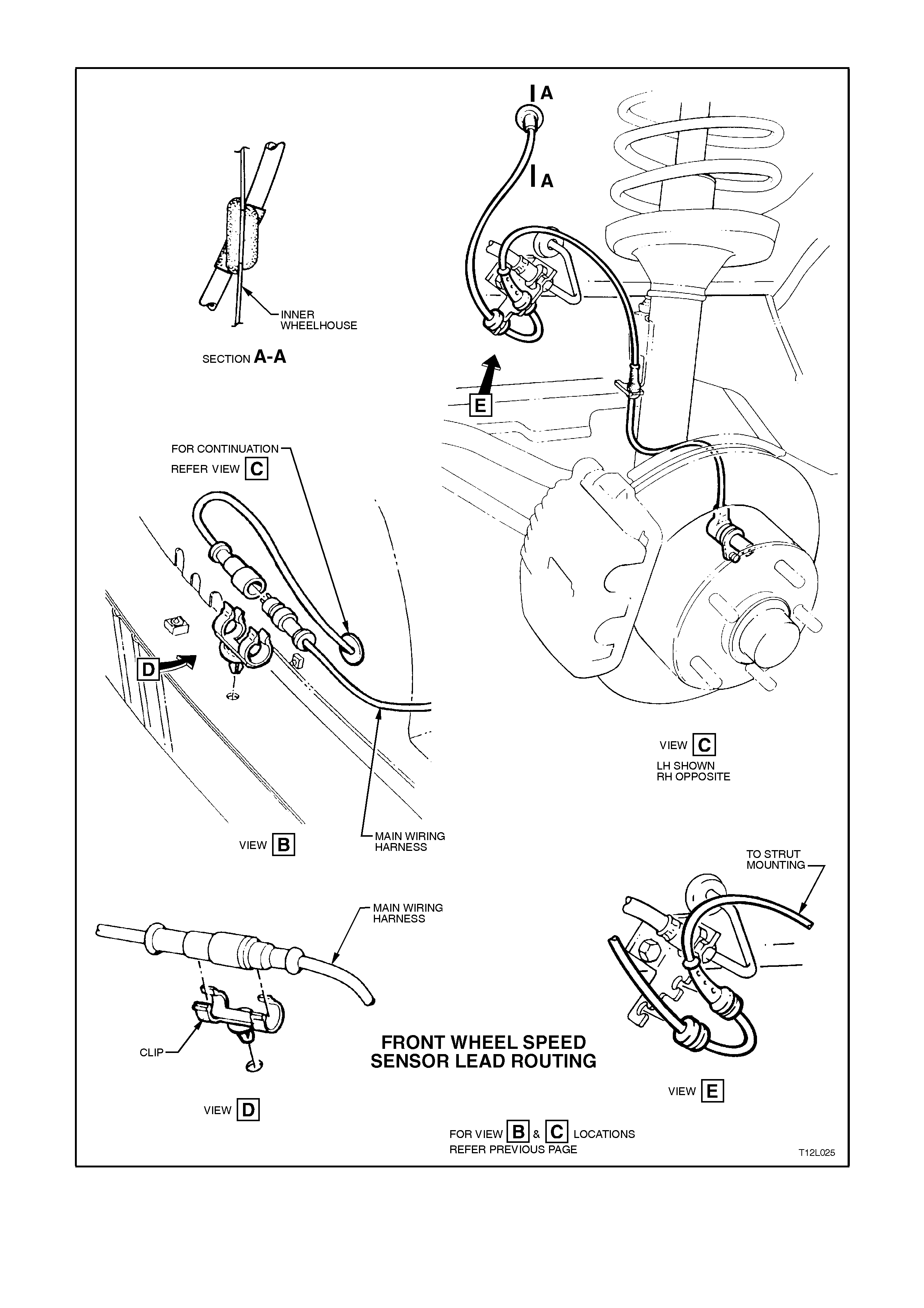
FRONT WHEEL SPEED SENSOR LEAD ROUTING
Figure 12L-28
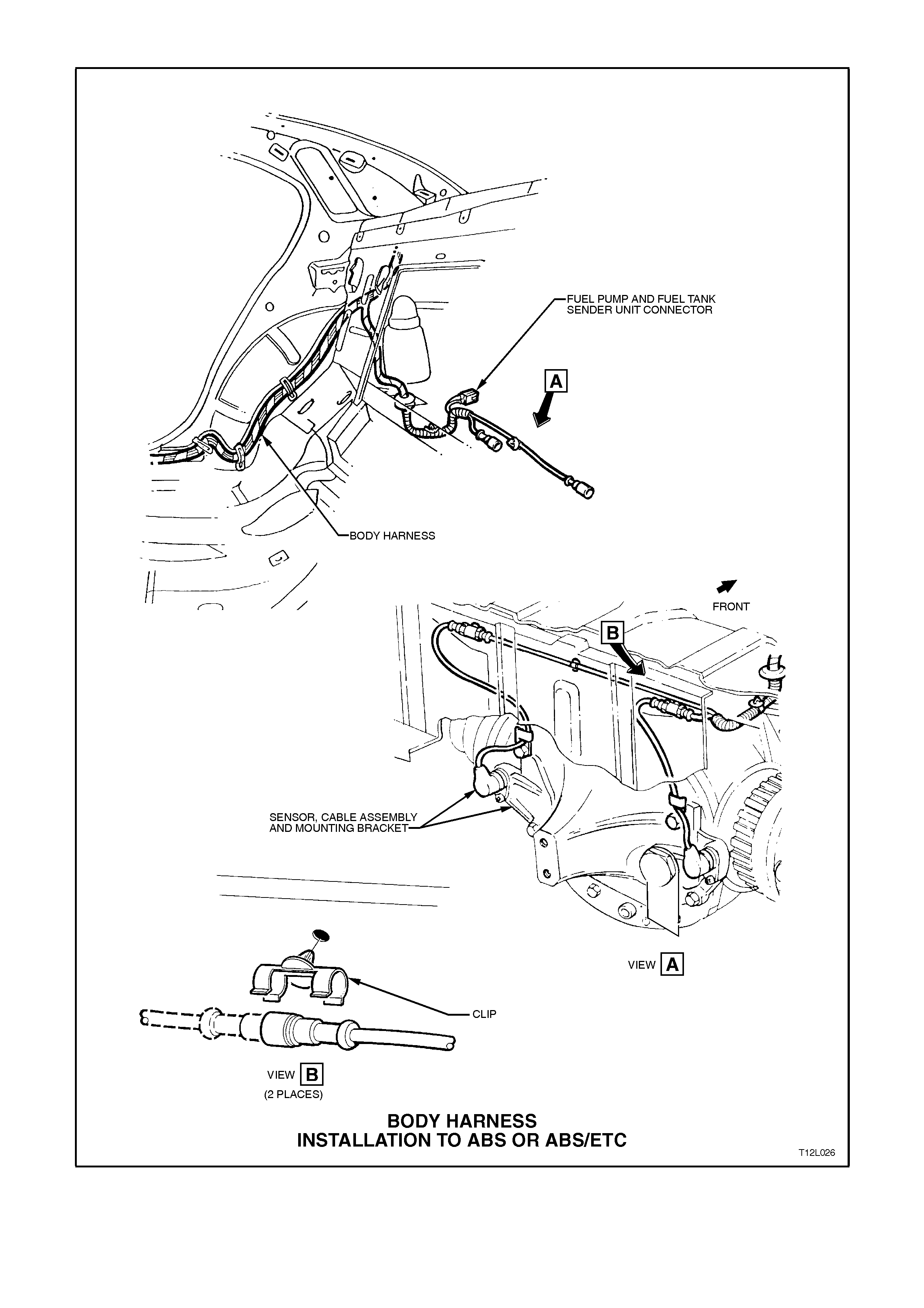
BODY HARNESS INSTALLATION TO ABS OR ABS/ETC
Figure 12L-29
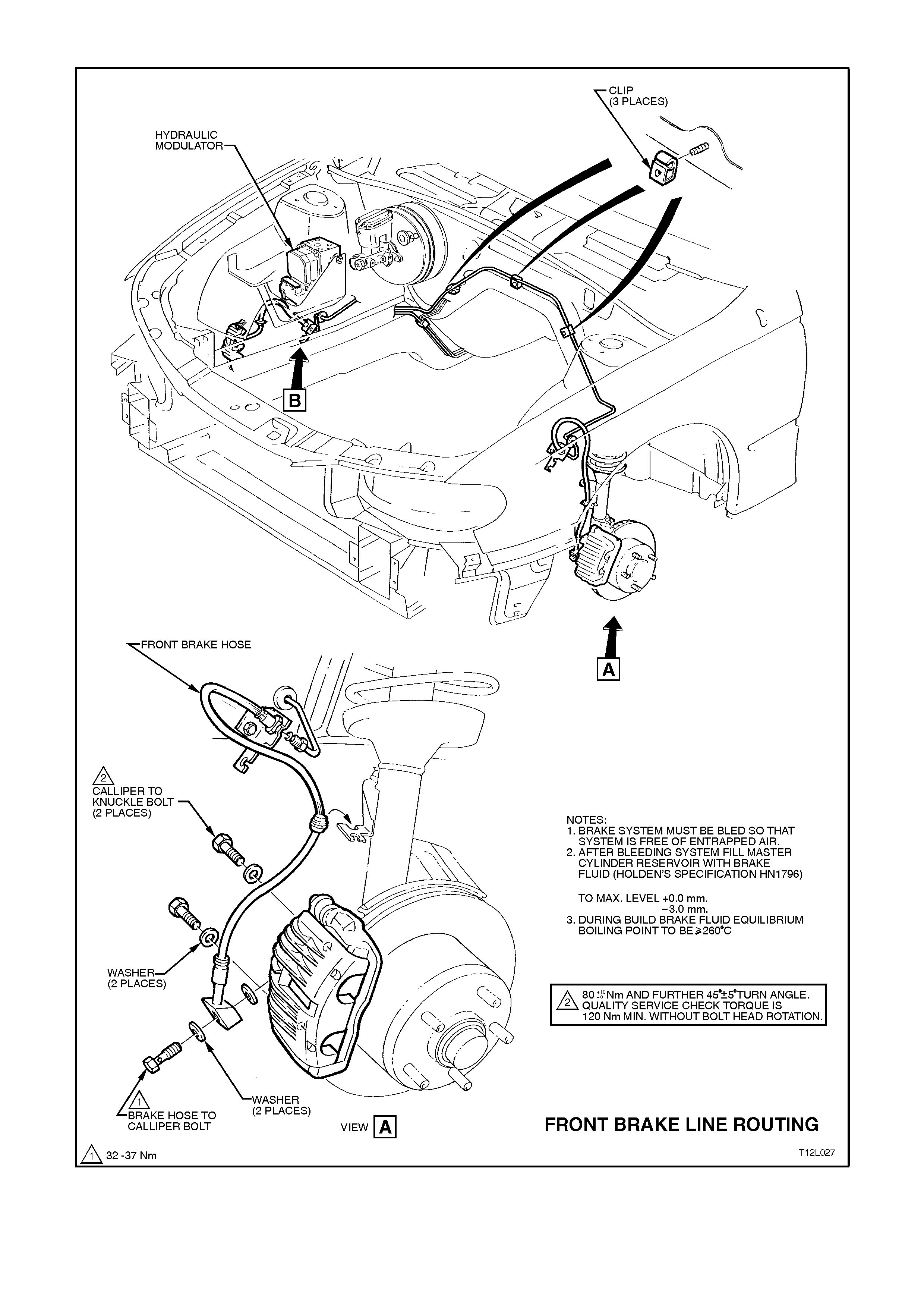
FRONT BRAKE LINE ROUTING
Figure 12L-30
Figure 12L-31

2.5 ABS PRINCIPLES OF OPERATION - EXCLUDING ABS/ETC
NON-ANTI-LOCK BRAKING
Under normal braking conditions, the anti-lock braking system functions much like a conventional braking system.
Brake fluid pressure is provided by the brake master cylinder and the power booster.
For non-anti-lock braking, hydraulic pressure is applied to the brake callipers without any intervention from the ABS.
At this time, the hydraulic modulator establishes an open two-way fluid path from the master cylinder to the brake
callipers. Non-anti-lock braking occurs when the wheel sensors do not detect wheel lock-up tendencies. However,
even though the ABS is passive during normal braking, the ABS Control Module is constantly monitoring for rapid
deceleration of any of the wheels and a signal from the brake switch (brakes applied input). Rapid wheel
deceleration during a braking operation could indicate wheel lock-up.
ANTI-LOCK BRAKING
When the ABS senses any tendency for wheel lock-up, it enters the anti-lock mode. During anti-lock braking, the
ABS modulates hydraulic pressure in the brake circuits to control wheel slip to 10 - 20%. For anti-lock braking, the
ABS Control Module controls current flow to the hydraulic modulator solenoid valves to control (by maintaining,
decreasing or increasing) hydraulic pressure in the brake circuits.
NOTE:
The hydraulic modulator cannot increase brake circuit hydraulic pressure above the pressure supplied by the brake
master cylinder.
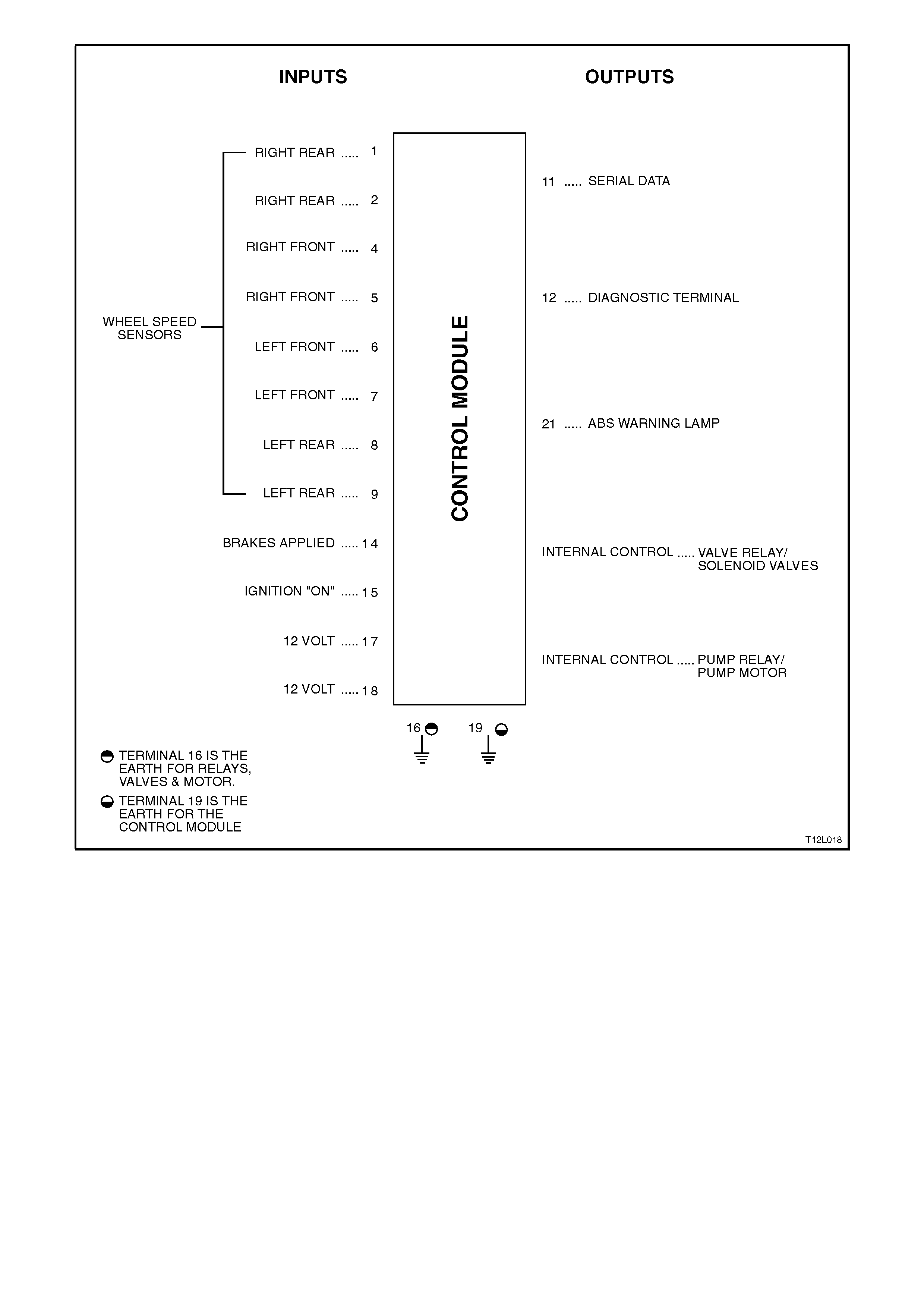
Figure 12L-32
ABS CONTROL MODULE OPERATION
Inputs
The following ABS components send signals to the ABS Control Module where they are evaluated in order for the
module to maintain and control wheel slip.
1. Ignition on input, (via fusible link FJ, ignition switch, fuse F27) - ABS Control Module terminal No. 15.
2. Wheel speed sensor inputs - ABS Control Module terminal No’s. LHF 6 and 7, RHF 4 and 5, LHR 8 and 9, and
RHR 1 and 2.
3. Brakes applied input (from brake lamp switch) - ABS Control Module terminal No. 14.
4. Battery voltage - ABS Control Module terminals 17 and 18.

Outputs
To control the anti-lock braking system, the ABS Control Module sends command signals to the following
components.
1. Valve relay/solenoid valves - internal control.
2. Pump relay/pump motor - internal control.
3. ABS warning lamp - ABS Control Module terminal No. 21.
4. Serial data - ABS Control Module terminal No. 11.
5. Self diagnostic 'Flash Code Actuation' - ABS Control Module terminal No. 12.
With the ignition switch in the ON position, battery voltage is applied to the ABS Control Module terminal No. 15 via
fuse F27. Battery voltage is applied to the pump motor relay and valve relay, via fusible link FR. Neither of the relays
will operate until they receive an earth from the ABS Control Module.
Also, battery voltage is supplied to the ABS warning lamp via fuse F13. The warning lamp will not illuminate until it is
earthed by the ABS Control Module. If the ABS module is not connected, terminals 19, 20 and 21 will be shorted
together with the connector and the ABS warning lamp will be illuminated.
Wheel speed sensors are located at each front wheel and at each final drive inner axle flange. When the vehicle
starts moving, all of the speed sensors create signals that are input to the ABS Control Module at terminals 1 and 2,
4 and 5, 6 and 7, 8 and 9. These signals are AC electrical pulses that are proportional (in frequency and amplitude)
to wheel rotational speed.
Once the vehicle has been started and driven over approximately 6 km/h, the Control Module performs an ABS self
test. The Control Module test cycles each solenoid valve and the return pump in the hydraulic modulator to check
component operation. The Control Module checks its own logic section and circuitry. If errors are detected during
this test, the Control Module earth’s terminal 21 and the ABS warning lamp is illuminated to warn the driver of a
problem with the system. The ABS Control Module remains deactivated until the next ignition switch OFF to ON
cycle when the process is repeated and the ABS warning lamp will be illuminated.
The ABS self test occurs once each ignition cy cle as follows:
1. After receiving an ignition 'ON' input, the Control Module earth’s and activates the valve relay.
2. When the vehicle reaches approximately 6 km/h, the Control Module tests the solenoid valves and the return
pump in the modulator. This test can usually be heard and/or felt by the driver.
3. If the pump or solenoid valves fail to operate, the ABS will be disabled and the ABS warning lamp will be
illuminated.
4. As soon as the ABS Control Module receives a signal from any of the wheel speed sensors, it checks wheel
speed sensor output. If any of the wheel speed sensor signals are not detected, or are incorrect, the ABS will
be disabled and the ABS warning lamp will be illuminated.
Once the vehicle is moving, the Control Module continuously monitors itself and the following components:
1. Solenoid valves.
2. Wheel speed sensors.
3. Wiring harness and relays.
4. Battery voltage.
If battery voltage drops below approximately 9 volts, the ABS will be disabled and the ABS warning lamp will be
illuminated.
During braking applications, if one or more wheels start to decelerate too quickly, the ABS is engaged and the
modulation process begins. Wheel speed information sent to the ABS Control Module is processed and the module
determines proper solenoid valve operation in the modulator. The modulator contains six solenoid valves; two for
each front wheel with the rear wheels both having two common solenoid valves.
HYDRAULIC MODULATOR OPERATION
The hydraulic modulator executes ABS Control Module commands using six solenoid valves that are located in the
hydraulic modulator assembly, are in series with the brake master cylinder and the brake circuits. The hydraulic
modulator solenoid valves are activated separately by the ABS Control Module corresponding to various ABS
control phases:
1. Non-ABS Braking
2. Maintaining Pressure
3. Reducing Pressure
4. Increasing (Building-up) Pressure
While the hydraulic modulator assembly contains six solenoid valves and a brake fluid return pump; for explanation
of the system operation, only two solenoid valves and one accumulator will be described. The operation is the same
for all three circuits.
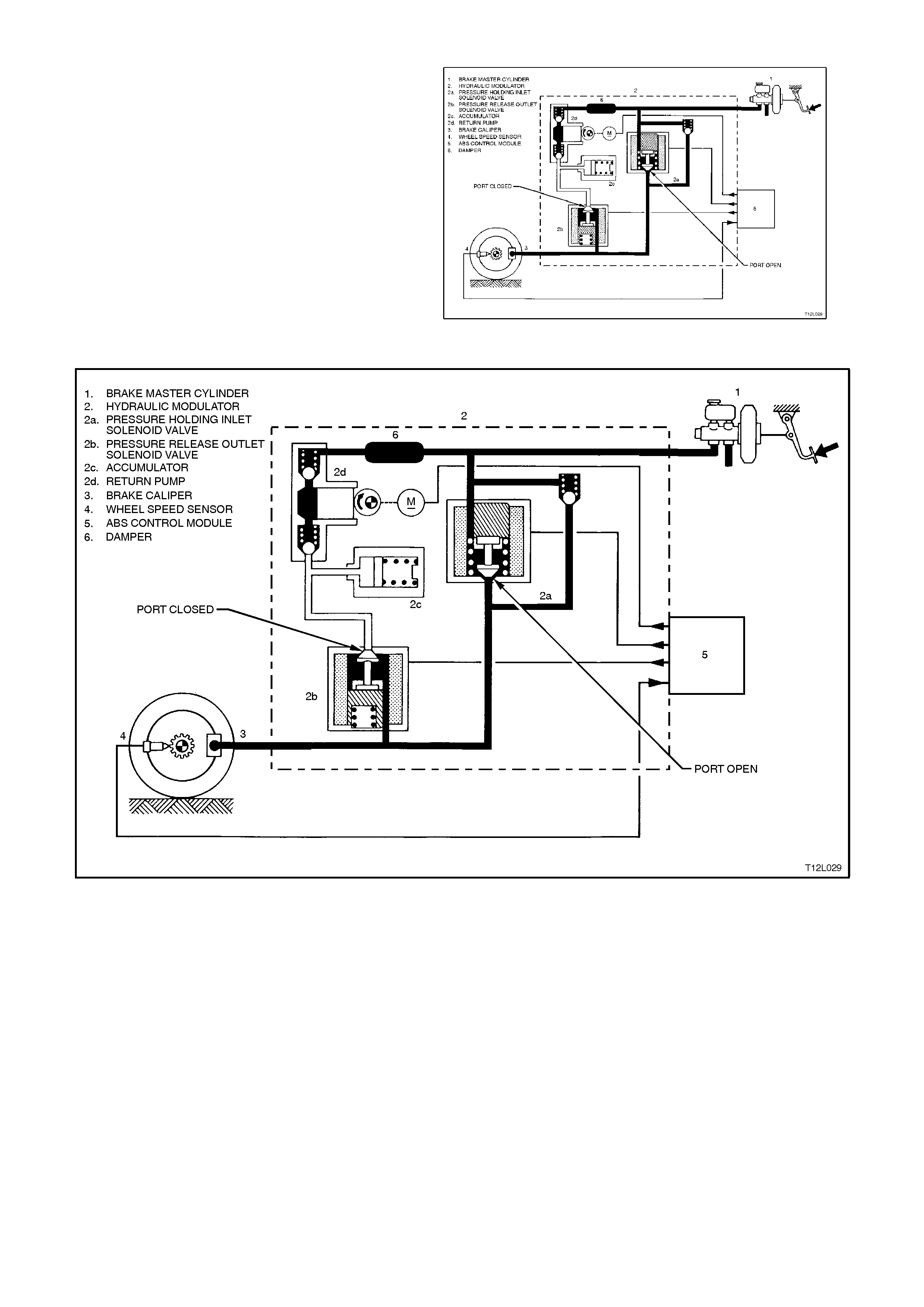
Non-ABS Braking
During this condition, the solenoid valves 2a and 2b
are not activated. Valve 2a [pressure holding (inlet)
solenoid valve] is open. This allows brake fluid to
flow in either direction between the brake master
cylinder and the brake calliper, providing for
conventional non-ABS braking. The solenoid valve
2b [pressure release (outlet) solenoid valve] is
closed, blocking off the passage to the accumulator
and the return pump.
The brake master cylinder (1) hydraulic pressure is
applied to the brake circuits (3). If the ABS Control
Module (5) does not detect any rapid wheel
deceleration, the ABS will remain passive at this
time. Figure 12L-33
Figure 12L-34
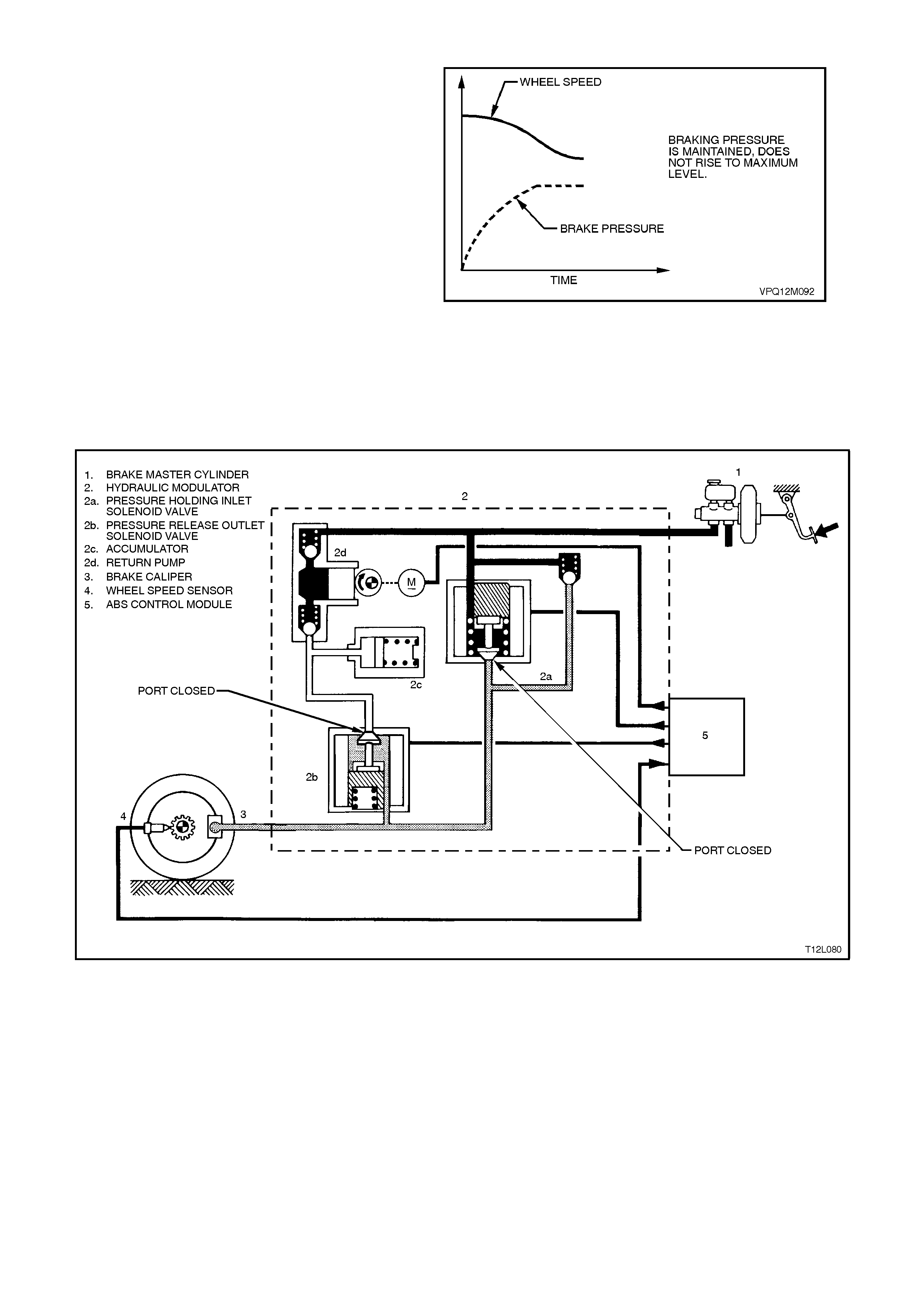
Maintaining Pressure
When the ABS Control Module detects excessive
wheel deceleration, based on the wheel speed
sensor (4) signal, it commands the pressure
holding (inlet) solenoid valve (2a) on, to maintain
brake circuit pressure. It does this by earthing the
respective circuit, therefore allowing a current flow
through the coil of solenoid valve 2a. This causes
the armature and valve to move downward,
isolating the brake circuit (3) from the master
cylinder.
Figure 12L-35
NOTE:
With the brake circuit isolated, brake circuit
pressure between the modulator and the brake
calliper circuit remains constant despite increased
master cylinder hydraulic pressure.
Figure 12L-36
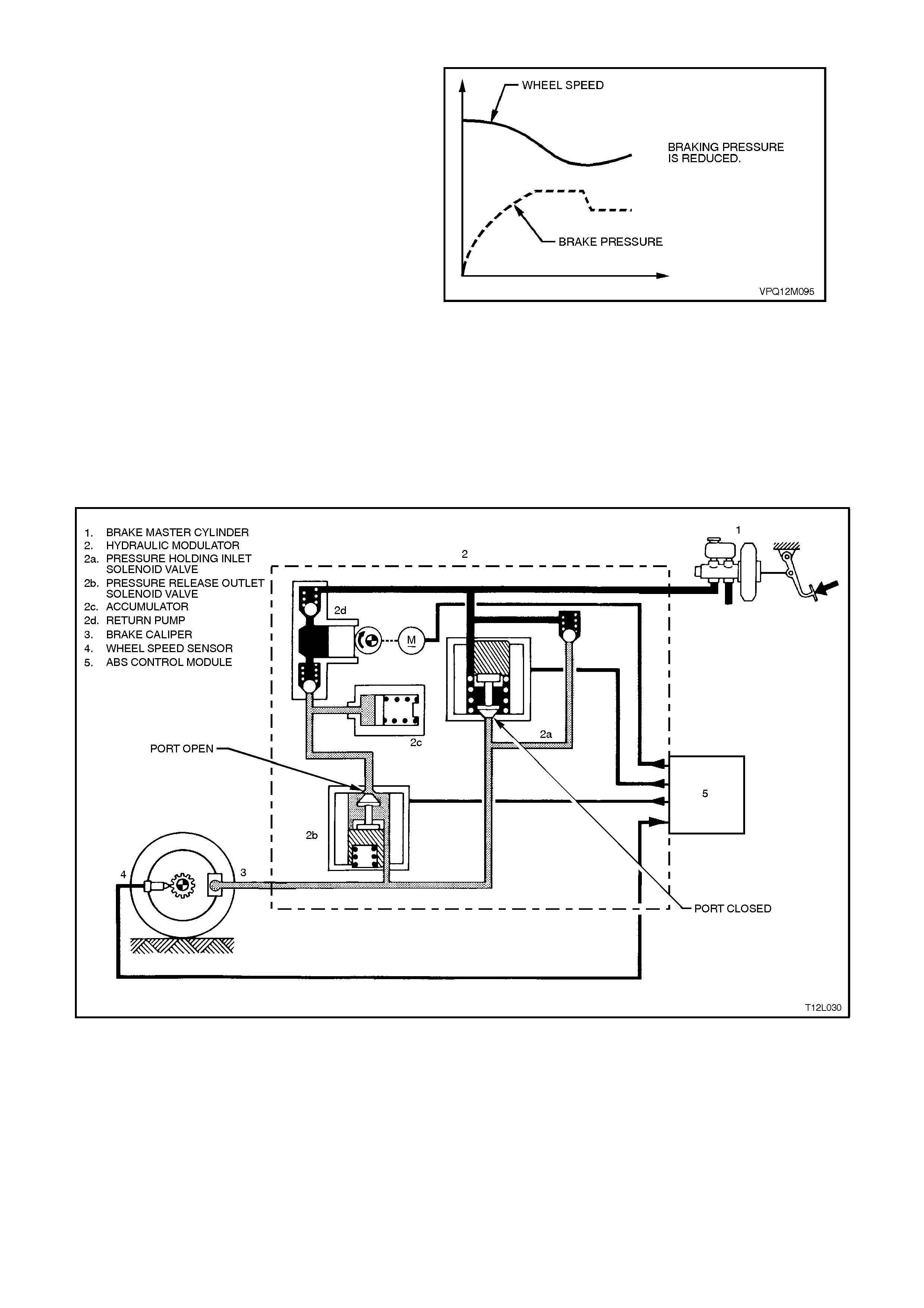
Reducing Pressure
If isolation of a brake circuit between the brake
master cylinder and the brake calliper does not
reduce the excessive wheel deceleration, the ABS
Control Module (5) commands the pressure
release (outlet) solenoid valve (2b) to reduce
hydraulic brake pressure in the brake circuit. During
this phase, the ABS Control Module earths the coil
of the solenoid valve 2b, allowing a current flow
through the coil windings. This causes the armature
and valve to move downward, opening a passage
from the brake circuit to the accumulator (2c) and
the return pump inlet (2d). At this stage, both
solenoid valves (2a and 2b) are activated
simultaneously. Figure 12L-37
NOTE:
At this time, the brake circuit is isolated from the
ma ster cylinder by the retur n pump valving and the
return pump is energised.
This action sends brake fluid from the brake
circuits back to the master cylinder against brake
pedal pressure. The return pump continues to
operate during the rest of the anti-lock cycle.
Figure 12L-38
Accumulators
During the 'Reducing Pressure' phase of ABS
modulation, the accumulators (2c) temporarily
store fluid from the brake circuits. Some road
conditions require the relief of a large volume of
fluid from the brake callipers. In such conditions,
the accumulator guar antees pr es sur e r eduction. As
soon as the solenoid valve (2b) moves to the
'Reduction Pressure' position, brake fluid from the
brake circuit flows into the accumulator. Thus,
before the return pump (2d) starts operation, the
accumulator allows an immediate pressure
reduction in the brake circuit. The front brake
circuits share a common accumulator. The rear
brake circuit uses a separate accumulator. The
accumulators are spring-loaded and designed to
operate at less than 1000 kPa.
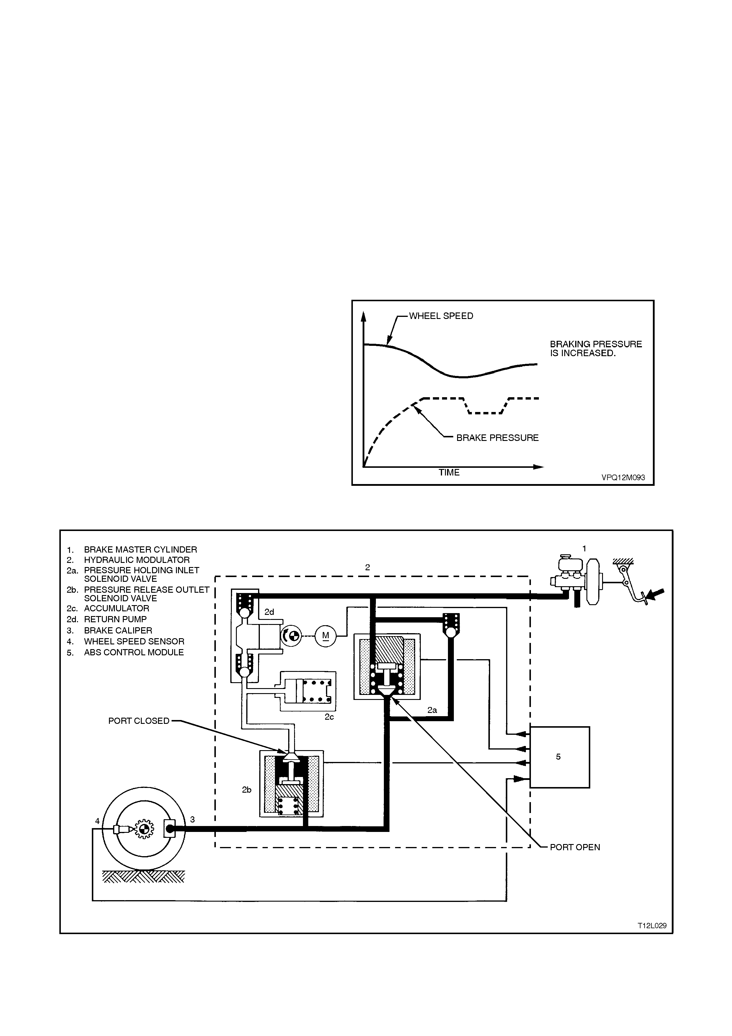
Increasing (Building-up) Pressure
The wheel accelerates again as a result of the
reduced braking pressure. Upon reaching a
specific lim it, the ABS Control Module registers the
fact that the wheel is now not being braked
sufficiently.
The ABS Control Module then de-energises both
solenoid valves and the formerly reduced pressure
is then increased so that the wheel is again
decelerated. The ABS control cycle begins again.
There are approximately 4 to 6 control cycles per
second, depending on the state of the road surface.
NOTE:
Circuit pressure cannot increase above master
cylinder pressure. Figure 12L-39
Figure 12L-40
MASTER CYLINDER OPERATION
The operation of the master cylinder assembly
used on vehicles with ABS is the same as the
assembly used on vehicles without ABS refer to
Section 5A STANDARD BRAKES for details.
OPERATION AND TESTING OF THE ABS WARNING LAMP
The following gives information about the
functioning and m alfunctioning of the ABS warning
lamp.
ABS Warning Lamp
W hen the ignition is s witched on, the warning lamp
illuminates for approximately 2 seconds. During this
period of time, the ABS Control Module perf orms a
check of the ABS system wiring.
On all vehicles with ABS, as soon as all four wheels
of the vehicle exceed a speed of approximately 6
km/h for the first time after starting, the ABS
system tests itself automatically (ABS 'Self-Test').
The ABS Control Module cycles each solenoid
valve and the return pump motor to check
component operation. The ABS Control Module
also checks its own circuitry.
This procedure is repeated every time the ignition is
switched OFF and the engine is started again. In
addition, the ABS constantly tests itself while the
vehicle is travelling.
The warning lamp is also used for self diagnosis
purposes.
Incorrect Warning Lamp Indications
1. Warning lamp does not illuminate after
switching ignition ON.
2. Warning lamp does not go out after
approximately 2 seconds.
3. Warning lamp illuminates when driving or
illuminates occasionally.
Illumination of the ABS warning lamp indicates to
the driver that the ABS is defective.
When the ABS warning lamp is activated, the
vehicle reverts to normal braking as in vehicles
without ABS fitted (eg. under emergency braking,
wheel/s may lock).
Occ asional illumination of the warning lamp may be
brought about through the battery being
insufficiently charged.
The lamp lights up only as long as there is a low
voltage, eg. after switching on electrical
components at idle.
The causes of trouble can be determined with the
assistance of the TECH 2 diagnostic scan tool.
Figure 12L-41

2.6 ABS/ETC PRINCIPLES OF OPERATION - EXCLUDING ABS
NON-ANTI-LOCK BRAKING / NON-TRACTION CONTROL
Under normal braking and driving conditions, the anti-lock braking system functions much like a conventional
braking system. Brake fluid pressure is provided by the brake master cylinder and the power booster.
For non-anti-lock braking, hydraulic pressure is applied to the brake callipers without any intervention from the ABS.
At this time, the hydraulic modulator establishes an open two-way fluid path from the master cylinder to the brake
callipers. Non-anti-lock braking occurs when the wheel sensors do not detect wheel lock-up tendencies. However,
even though the ABS is passive during normal braking, the ABS/ETC module is constantly monitoring for rapid
acceleration (wheel slip) and deceleration (wheel lock) of any of the wheels and a signal from the brake switch
(brakes applied input).
ANTI-LOCK BRAKING
When the ABS senses any tendency for wheel lock-up, it enters the anti-lock mode. During anti-lock braking, the
ABS modulates hydraulic pressure in the brake circuits to control wheel slip to 10 - 20%. For anti-lock braking, the
ABS Control Module controls current flow to the hydraulic modulator solenoid valves to control (by maintaining,
decreasing or increasing) hydraulic pressure in the brake circuits.
NOTE:
The hydraulic modulator cannot increase brake circuit hydraulic pressure above the pressure supplied by the brake
master cylinder during anti-lock braking.
ELECTRONIC TRACTION CONTROL
When the ABS/ETC Control Module senses spin from the drive wheels due to too much engine torque for the road
conditions, it enters the traction control mode.
The ABS/ETC module monitors both front and rear wheel speeds through the wheel speed sensors. If at any time
during acceleration the ABS/ETC module detects drive wheel slip, it will request [on the Torque Request (MMR)
circuit] the Powertrain Control Module (PCM) to bring engine torque into a specific range. This is accomplished via
two high speed Pulse Width Modulated (PWM) circuits between the ABS/ETC module and the PCM. The PCM will
then adjust spark firing and air/fuel ratio, altering boost duty cycle (Supercharged engine only), and shutting OFF up
to five (5) injectors (if necessary), and report the modified torque value [on the Torque Achieved (MMI) circuit] back
to the ABS/ETC module. Simultaneous with engine torque management, the ABS/ETC module will activate the ABS
isolation valves, turn on the ABS pump motor and supply brake pressure to the over spinning wheel(s).
The isolation valves isolate the front brake hydraulic circuits from the master cylinder and rear brake hydraulic
circuits. Once the rear brake hydraulic circuits are isolated, pressure can be applied to the rear wheels without
affecting any other brake hydraulic circuits. The ABS/ETC module opens the priming valve, allowing fluid to be
drawn from the master cylinder to the pump motor, turns on the ABS pump motor to apply pressure, begins cycling
the ABS assembly's inlet and outlet valves, and closes the switching valve, ensuring fluid is directed to the wheel
not back into the master cylinder.
The inlet and outlet valve cycling aids in obtaining maximum road surface traction in the same manner as the anti-
lock brake mode. The difference between Traction Control and Anti-Lock Brake mode is that brake fluid pressure is
increased to lesson wheel spin (Traction Control mode), rather than reduced to allow greater wheel spin (Anti-Lock
Brake mode).
If at any time during traction control mode, the brakes are manually applied, the brake switch signals the ABS/ETC
module to inhibit brake intervention and allow for manual braking (engine intervention can still occur if necessary).
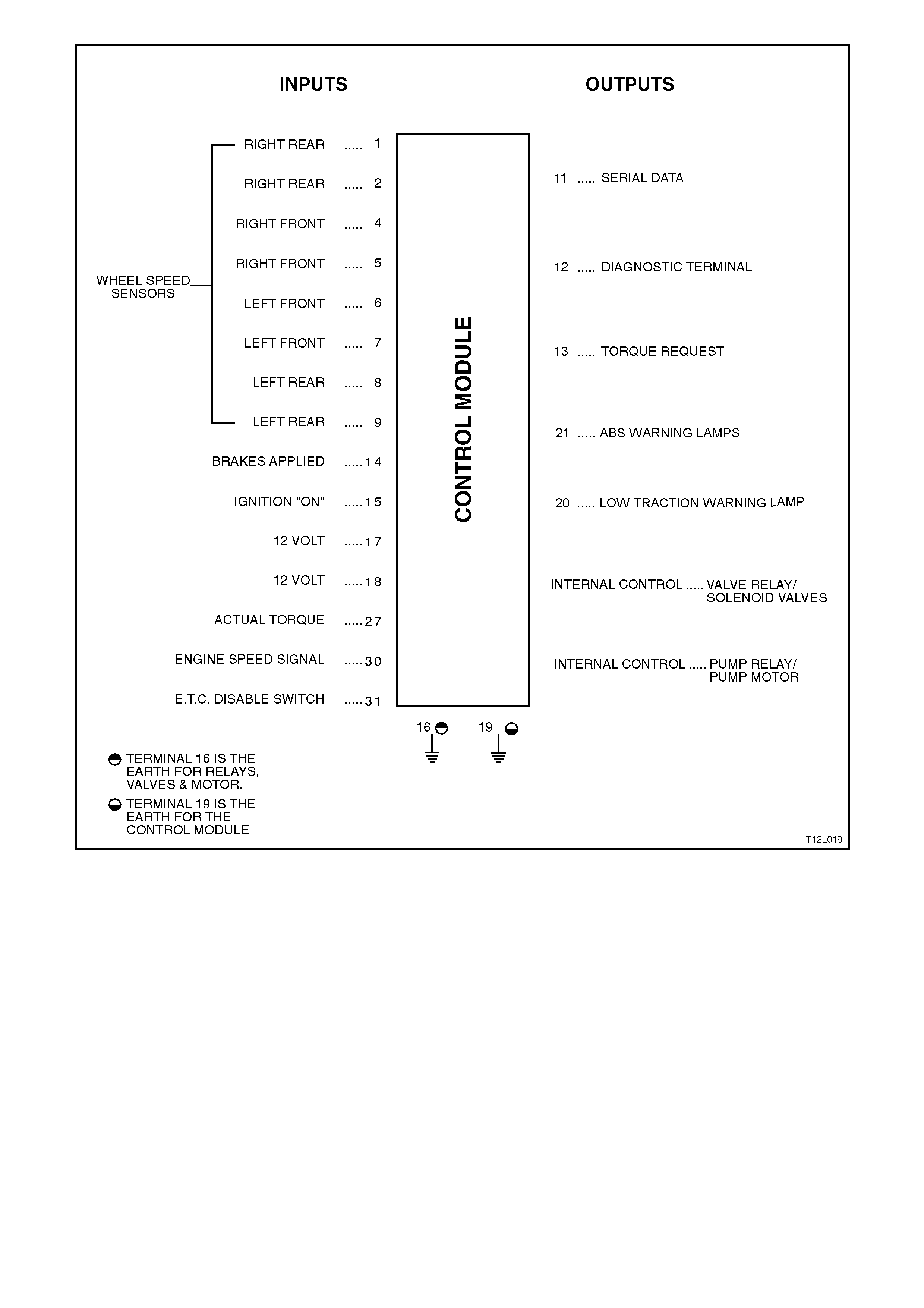
Figure 12L-42
ABS/ETC CONTROL MODULE OPERATION
Inputs
The following ABS/ETC components send signals to the ABS/ETC Control Module where they are evaluated in
order for the module to maintain and control wheel slip/spin.
1. Ignition on input, (via fusible link FJ, ignition switch, fuse F27) - ABS/ETC module terminal No. 15.
2. Wheel speed sensor inputs - ABS/ETC module terminal No's. LHF 6 and 7, RHF 4 and 5, LHR 8 and 9, and
RHR 1 and 2.
3. Brakes applied input (from brake lamp switch) - ABS/ETC module terminal No. 14.
4. Battery voltage - ABS/ETC module terminals 17 and 18.
5. Actual Torque (torque acknowledgment) - ABS/ETC module terminal 27.
6. Engine speed signal - ABS/ETC module terminal 30.
7. ETC disable switch (TRAC CTRL) - ABS/ETC module terminal 31.
Outputs
To control the anti-lock braking system and traction control system, the ABS/ETC Control Module sends command
signals to the following components.
1. Valve relay/solenoid valves - internal control.
2. Pump relay/pump motor - internal control.

3. Serial data - ABS/ETC module terminal No. 11.
4. Self diagnostic 'Flash Code Actuation' - ABS/ETC module terminal No. 12.
5. Torque requested - ABS/ETC module terminal No. 13
6. ETC warning lamp (TRAC OFF, LOW TRAC) - ABS/ETC module terminal 20.
7. ABS warning lamp - ABS/ETC module terminal No. 21.
With the ignition switch in the on position, battery voltage is applied to the ABS/ETC Control Module terminal No. 15
via fuse F27. Battery voltage is applied to the pump motor relay and valve relay, via fusible link FR. Neither of the
relays operate until they receive an earth from the ABS Control Module.
Also, battery voltage is supplied to the ABS and ETC warning lamps via fuse F13. The LOW TRAC and ABS
warning lamps will not illuminate until they are earthed by ABS/ETC Control Module. If the ABS/ETC Control Module
wiring harness connector YE98, is not connected to the Control Module, terminals 19, 20 and 21 are shorted
together by a shorting bar, and the LOW TRAC and ABS warning lamps will be illuminated. The TRAC OFF warning
lamp is defaulted to the ON position and is turned off via a serial data message from the ABS/ETC Control Module
when the ignition is turned on (provided the sy stem is OK).
Wheel speed sensors are located at each front wheel and at each final drive inner axle flange. When the vehicle
starts moving, all of the speed sensors create signals that are input to the ABS/ETC Control Module at terminals 1
and 2, 4 and 5, 6 and 7, 8 and 9. These signals are AC electrical pulses that are proportional (in frequency and
amplitude) to wheel rotational speed.
Once the vehicle has been started and driven over approximately 6 km/h, the Control Module performs an
ABS/ETC self test. The Control Module test cycles each solenoid valve and the return pump in the hydraulic
modulator to check component operation. The Control Module checks its own logic section and circuitry. If errors
are detected during this test, the Control Module earths terminal 20, illuminates the ABS warning lamp and also
sends a message, via the serial data circuit, commanding the TRAC OFF warning lamp to be illuminated. The ABS
and/or ETC warning lamp/s are illuminated to warn the driver of a problem with the system/s. The ABS/ETC Control
Module remains deactivated until the next ignition switch OFF to ON cycle when the process is repeated and the
ABS and/or TRAC OFF warning lamp/s will be illuminated.
The ABS self test occurs once each ignition cy cle as follows:
1. After receiving an ignition ‘ON’ input, the control module earth’s and activates the valve relay.
2. As soon as the ABS/ETC Control Module receives a signal from any of the wheel speed sensors, it checks
wheel speed sensor output. If any of the wheel speed sensor signals are not detected, or are incorrect, the
ABS/ETC system will be disabled and the warning lamps will be illuminated.
3. When the vehicle reaches approximately 6 km/h, the control module tests the solenoid valves and the return
pump in the modulator. If the Control Module recieves a brake lamp switch input below 6 km/h, the self-test will
not occur until the vehicle reaches a road speed of approximately 18 km/h.
4. If the pump or solenoid valves fail to operate, the ABS/ETC system will be disabled and the warning lamps will
be illuminated.
Once the vehicle is moving, the Control Module continuously monitors itself and the following components:
1. Solenoid valves.
2. Wheel speed sensors.
3. Wiring harness and relays.
4. Battery voltage.
If battery voltage drops below approximately 9 volts, the ABS/ETC will be disabled and the ABS and TRAC OFF
warning lamps will be illuminated, while the voltage remains below 9 volts.
During braking applications, if one or more wheels start to decelerate too quickly, the ABS is engaged and the
modulation process begins. Wheel speed information sent to the ABS/ETC Control Module is processed and the
module determines proper solenoid valve operation in the modulator. The modulator contains ten solenoid valves; a
priming and a switching relay, plus one inlet and one outlet valve for each wheel.
When wheel spin is detected and traction control mode begins, the ABS/ETC Control Module also engages ABS
through the modulation process. Additionally, the ABS/ETC Control Module simultaneously changes the engine
torque conditions through the use of engine torque management.
HYDRAULIC MODULATOR OPERATION
The hydraulic modulator executes ABS Control
Module commands using ten solenoid valves.
These solenoid valves, located in the hydraulic
modulator assembly. The hydraulic modulator
solenoid valves are activated separately by the
ABS/ETC Contro l Module corresponding to various
ABS or ETC control phases of :
1. Non-ABS Braking (ABS and ETC phases)
2. Maintaining Pressure (ABS phase)
3. Reducing Pressure (ABS phase)
4. Increasing (Building-up) Pressure (ABS
phase)
5. Normal condition (ABS and ETC phases -
brakes off)
6. Applying (ETC phase)
The hydraulic modulator assembly contains ten
solenoid valves and a brake fluid return pump;
however, for explanation of the operation only one
accumulator and four solenoid valves will be
described ( rear brak es). T he operation is the s ame
for all four circuits.
Non-ABS Braking (ABS and ETC phases)
During this condition, the inlet and outlet valves are
not activated. The inlet valve (pressure holding
solenoid valve) is open. This allows brake fluid to
flow in either direction between the brake master
cylinder and the brake calliper, providing for
conventional non-ABS braking. The outlet valve
[pressure release (outlet) solenoid valve] is closed,
blocking off the passage to the accumulator and
the return pump.
The brake master cylinder hydraulic pressure is
applied to the brake circuits (calliper). If the
ABS/ETC Control Module (not shown) does not
detect any rapid wheel deceleration, the ABS will
remain passive at this time.
Hydraulic modulator status:
LH inlet valve Open LH outlet valve Closed
RH inlet valve Open RH outlet valve Closed
Priming valve Closed Switching valve Open
Motor OFF
Figure 12L-43
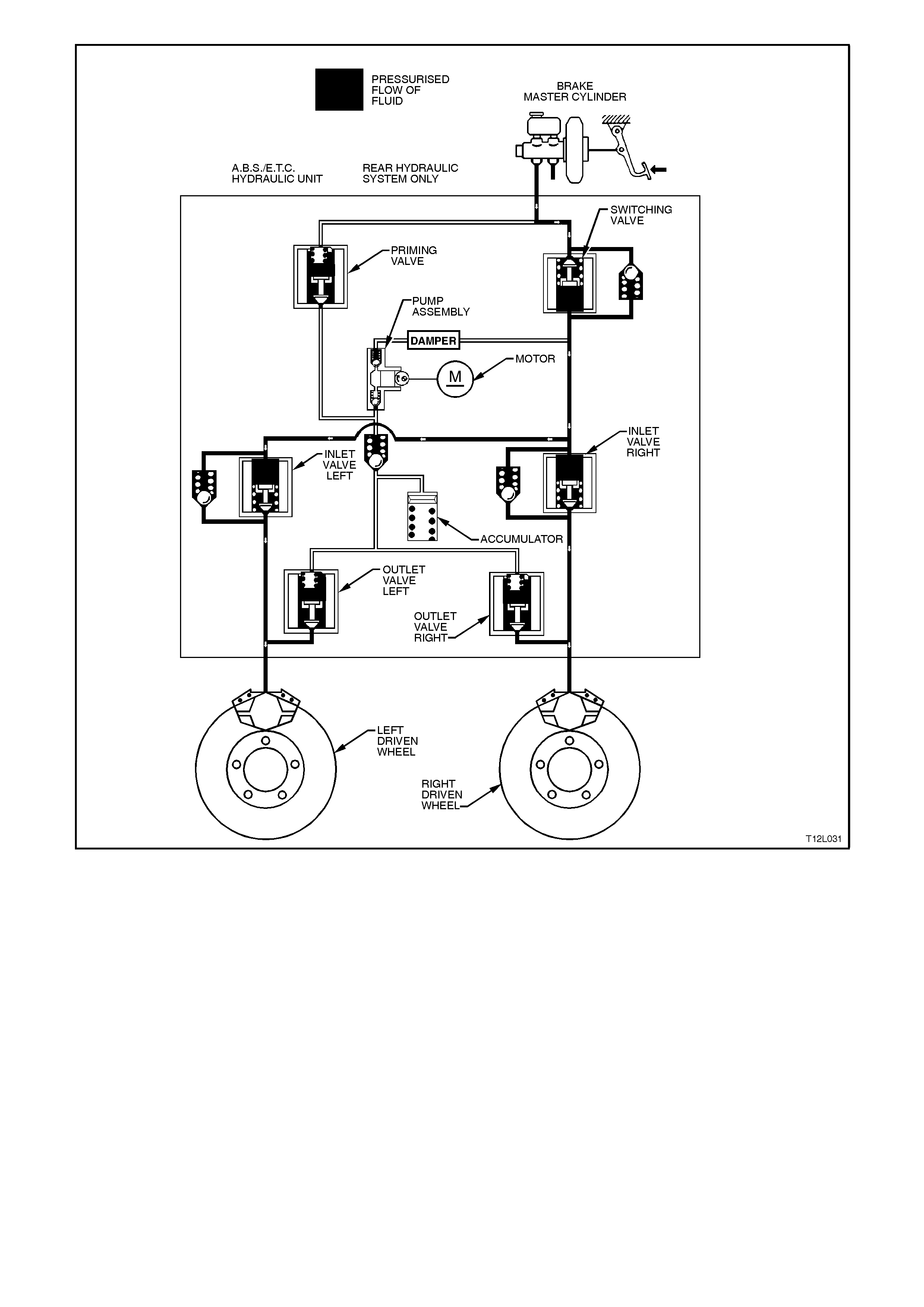
Figure 12L-44
Maintaining Pressure (ABS phase)
NOTE: The following diagram and explanation
assumes the right hand rear wheel is having a
tendency to lock.
When the ABS/ETC Control Module detects
excessive wheel deceleration (based on the wheel
speed sensor (not shown) s ignal), it com m ands the
right hand inlet valve (pressure holding solenoid
valve) to maintain brake circuit pressure. It does
this by earthing the respective circuit (RH in this
case), ther efore allowing a current f low through the
coil of inlet valve solenoid. This causes the
armature and valve to move downward, isolating
the brake circuit (calliper) from the master cylinder.
NOTE: W ith the brak e circuit isolated, brake circuit
pressure between the modulator and the brake
calliper circuit remains constant despite increased
master cylinder hydraulic pressure.
Hydraulic modulator status:
LH inlet valve Open LH outlet valve Closed
RH inlet valve Closed RH outlet valve Closed
Priming valve Closed Switching valve Open
Motor OFF
Figure 12L-45
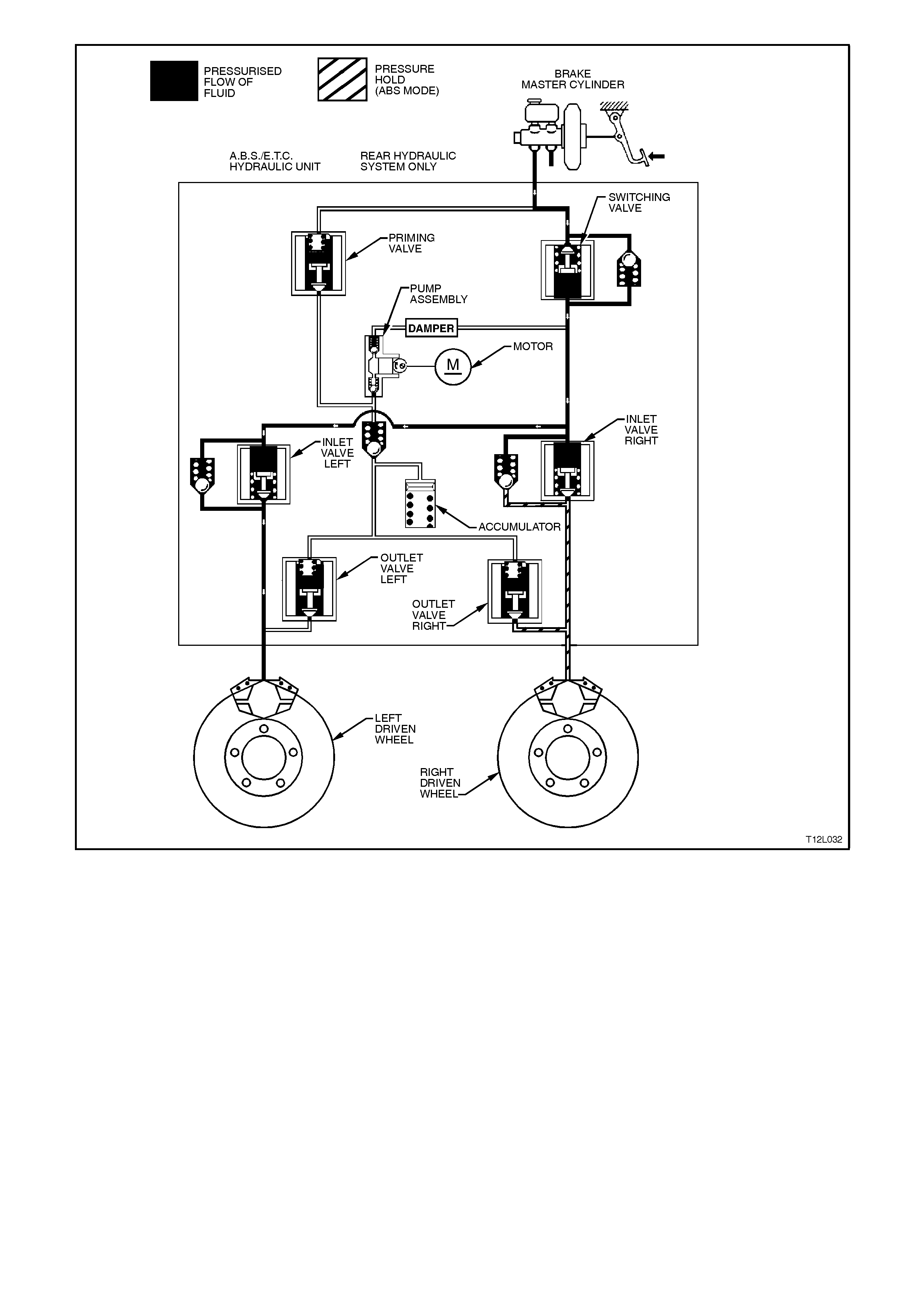
Figure 12L-46
Reducing Pressure (ABS phase)
NOTE:
The following diagram and explanation assumes
the right hand rear wheel is having a tendency to
lock.
If isolation of a brake circuit between the brake
master cylinder and the brake calliper does not
reduce the excessive wheel deceleration, the
ABS/ETC Control Module commands the outlet
valve (pressure release solenoid valve) open to
reduce hydraulic brak e press ure in the brak e circ uit
(RH outlet valve in this case). During this phase,
the ABS/ETC Control Module ear th's the coil of the
RH outlet valve, allowing a current flow through the
coil windings. This causes the armature and valve
to move downward, opening a passage from the
brake circuit to the accumulator and the pump
assem bly inlet. At this stage, both the RH inlet and
RH outlet valves are activated simultaneously.
NOTE:
At this time, the brake circuit is isolated from the
master cylinder by the return pum p valving and the
energised return pump.
This action sends brake fluid from the brake
circuits back to the master cylinder, against brake
pedal pressure. The return pump continues to
operate during the rem ainder of the anti-lock cycle.
This will increase the return flow from the brake
caliper, thus allowing the fluid released from the
caliper to be returned back to the master cylinder.
The pum p will continue to operate during the r est of
the anti-lock cycle.
Hydraulic modulator status:
LH inlet valve Open LH outlet valve Closed
RH inlet valve Closed RH outlet valve Open
Priming valve Closed Switching valve Open
Motor ON
NOTE:
Motor will remain operational until ABS mode is
exited.
Accumulators
During the 'Reducing Pressure' phase of ABS
modulation, the acc umulators ( 2c) temporar ily store
fluid from the brake circuits. Some road conditions
require the relief of a large volum e of fluid f rom the
brak e callipers . In such c onditions, the accum ulator
guarantees pressure reduction. As soon as the
solenoid valve (2b) moves to the 'Reduction
Pressur e' pos ition, brake f luid f rom the br ak e c irc uit
flows into the accum ulator. Thus, before the return
pump (2d) starts operation, the accum ulator allows
an immediate pressure reduction in the brake
circuit. The front brake circuits share a common
accumulator. The rear brake circuit uses a
separate accumulator. The accumulators are
spring-loaded and designed to operate at less than
1000 kPa.
Figure 12L-47
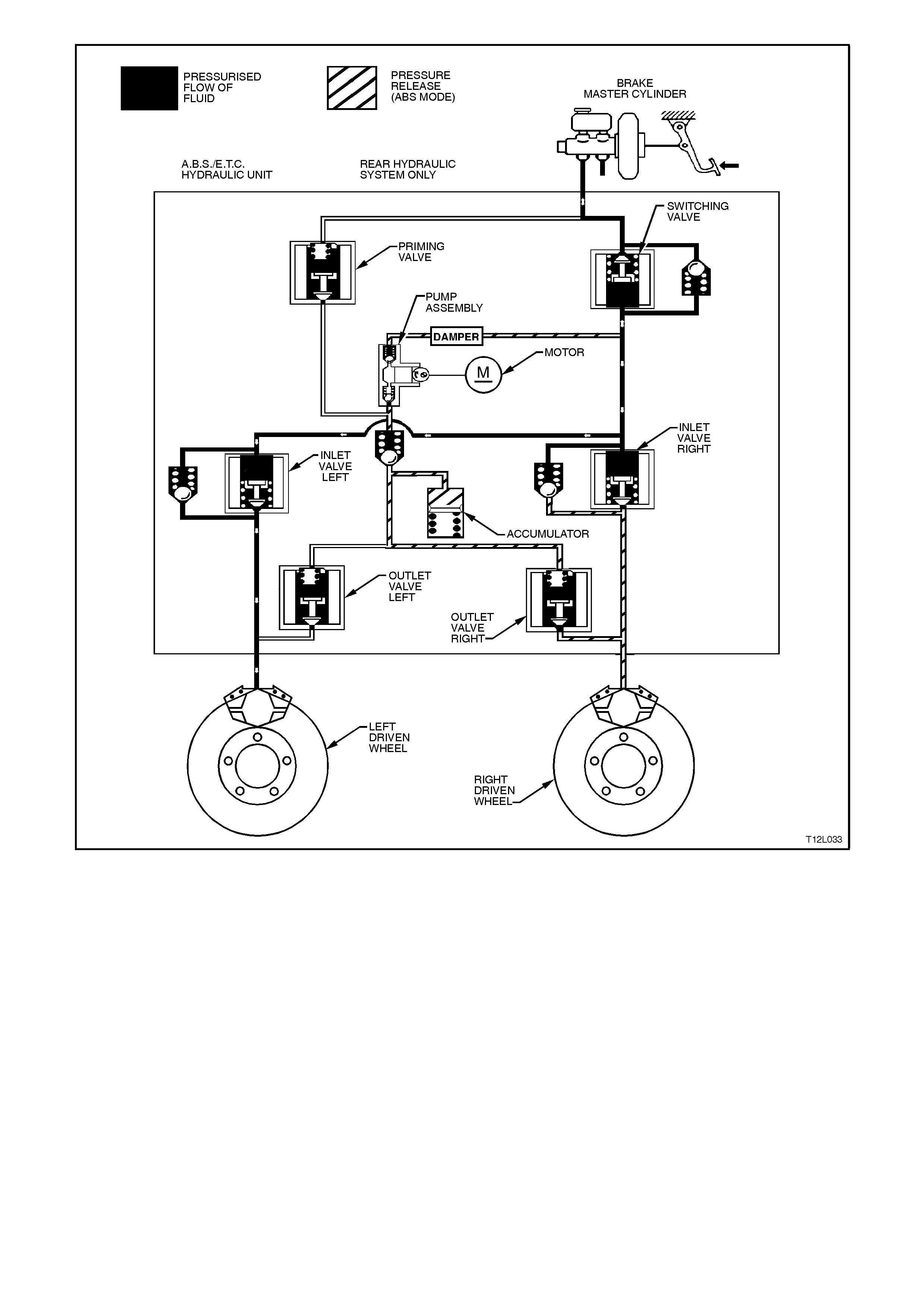
Figure 12L-48
Increasing (Building-up) Pressure (ABS phase)
NOTE: The following diagram and explanation
assumes the right hand rear wheel is having a
tendency to lock.
The wheel accelerates again as a result of the
reduced braking pressure. Upon reaching a
specific lim it, the ABS Control Module registers the
fact that the wheel is now not being braked
sufficiently.
The ABS Control Module then de-energises both
the RH inlet and RH outlet valves and the formerly
reduced pressure is then increased so that the
wheel is again decelerated. The ABS control cycle
begins again. There is approximately 4 - 6 control
cycles per second, depending on the state of the
road surface.
Hydraulic modulator status:
LH inlet valve Open LH outlet valve Closed
RH inlet valve Open RH outlet valve Closed
Priming valve Closed Switching valve Open
Motor ON
Figure 12L-49
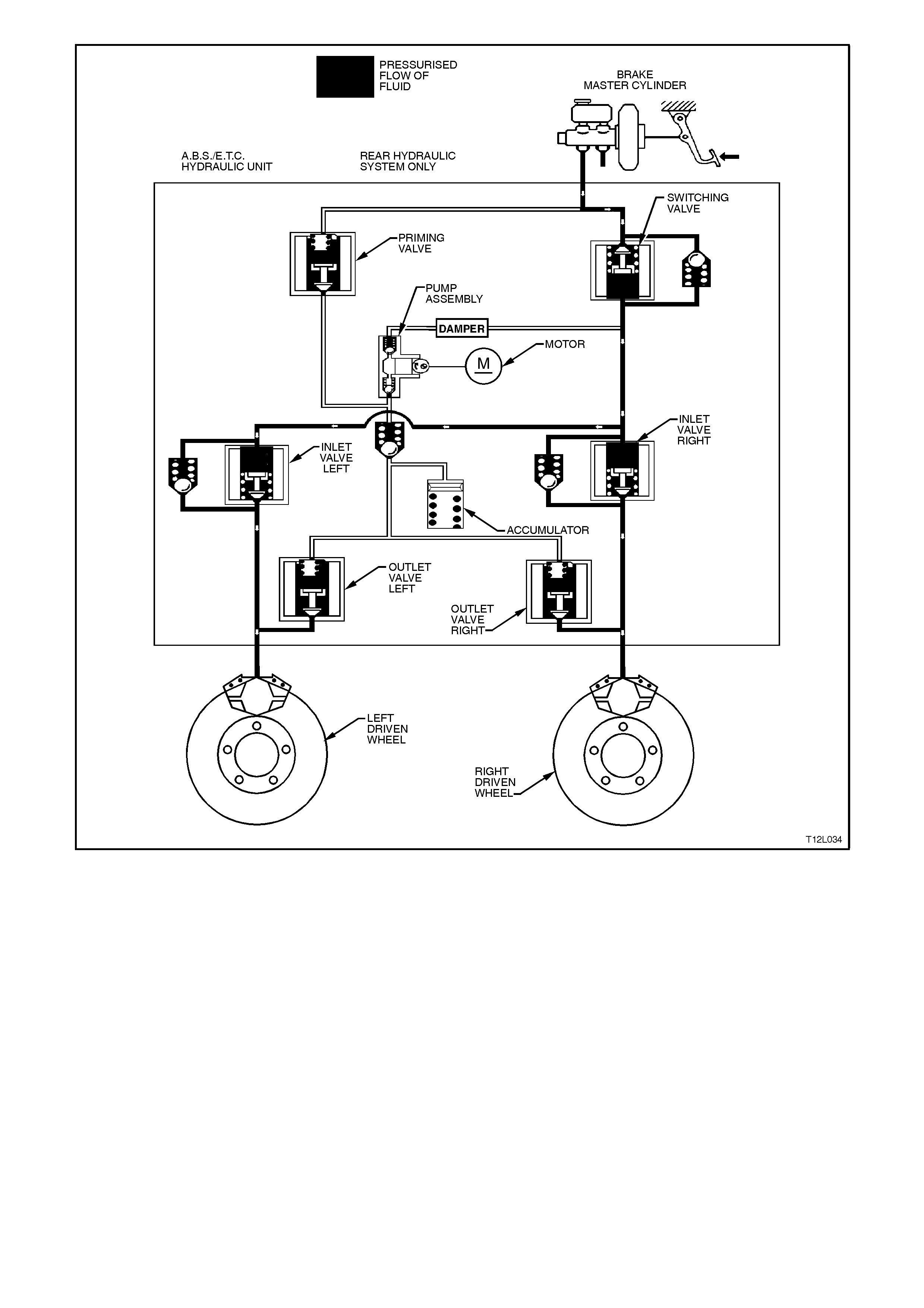
Figure 12L-50
ETC Normal condition (ABS and ETC phases)
In the normal condition, there is no brake
intervention. All the valves in the hydraulic
modulator are in their normal rest positions,
allowing for uninterrupted flow for normal braking.
The schematic shows no pressure in the system,
therefore no application of brakes.
Hydraulic modulator status:
LH inlet valve Open LH outlet valve Closed
RH inlet valve Open RH outlet valve Closed
Priming valve Closed Switching valve Open
Motor OFF
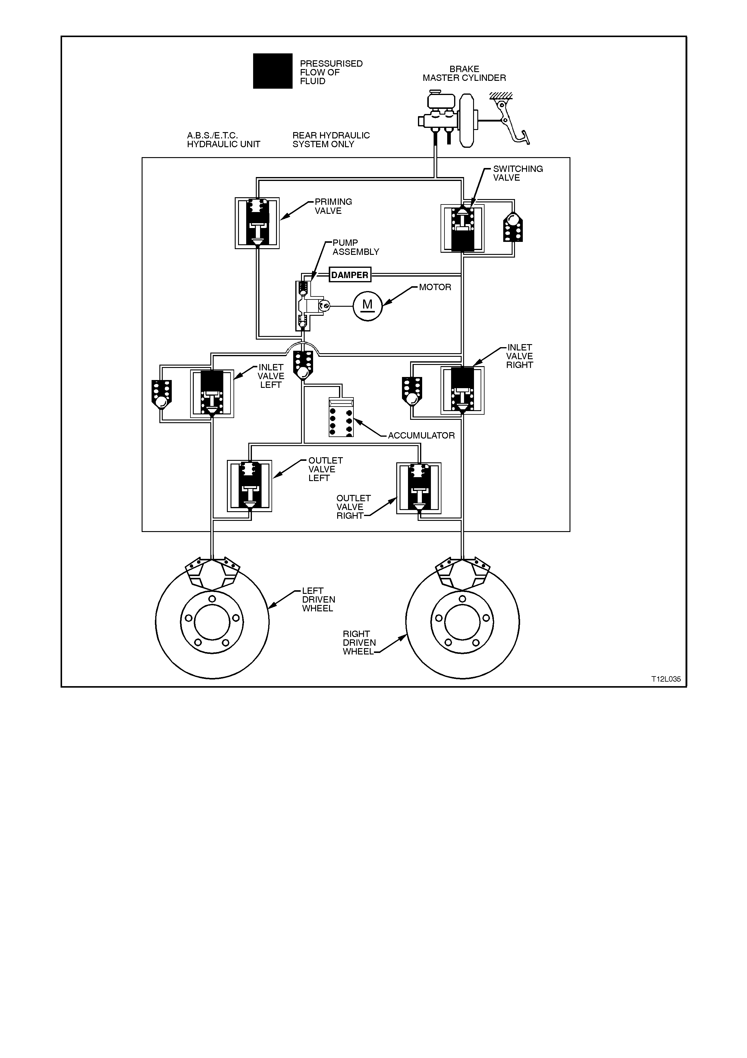
Figure 12L-51

ETC in operation (ETC phase)
NOTE:
The following diagram and explanation assumes
the right hand rear wheel is having a tendency to
spin.
Brake intervention
In the schematic below, the ABS/ETC Control
Module has detected that the right hand wheel is
about to enter into a situation where wheel slippage
is going to occur from exces s engine torque for the
road condition.
ABS/ETC Control Module commands the priming
valve open, allowing for fluid to be drawn from the
master cylinder by the pump assembly. The
switching valve is closed, ensuring fluid is directed
to the wheels and not back to the master cylinder.
With the right wheel tending to spin, the left inlet
valve closes, allowing the brak es to be applied only
to the right wheel. This will transfer the torque to
the left wheel. This operation can be applied 4 - 6
times a second and can function on either of the
driven wheels, or both.
Hydraulic modulator status:
LH inlet valve Closed LH outlet valve Closed
RH inlet valve Open RH outlet valve Closed
Priming valve Open Sw itching valve Closed
Motor On
Engine Torque management
Simultaneously to brake intervention, the ABS/ETC
Control Module communicates with the Powertrain
Control Module (PCM), requesting the PCM to
bring the engine torque into a specific range, by
sending a requested torque signal (MMR).
With the ignition on and the engine not running, the
ABS/ETC Contro l Module constantly sends a Puls e
W idth Modulated (PMW ) signal with a duty cycle of
93% to the PCM. The PCM responds with a PW M
signal with a duty cycle of 5%. W hen the engine is
started, the duty cycle of the torque
acknowledgment signal will increase to
approximately 30% at idle. When the ABS/ETC
Control Module determines that a reduction in
engine torque is required, the torque requested
signal will decrease fr om 93% ( no torque r eduction)
to 30% (maximum torque reduction) the PCM will
then reduce the engine torque to the required
amount by adjusting spark firing, air/fuel ratio,
altering boost duty cycle (supercharged engine
only) and shutting OFF up to five injectors (if
necessary). During traction control, the duty cycle
of the actual torque signal (MMI) should be similar
to and follow the duty cycle of the torque requested
(MMR) signal.
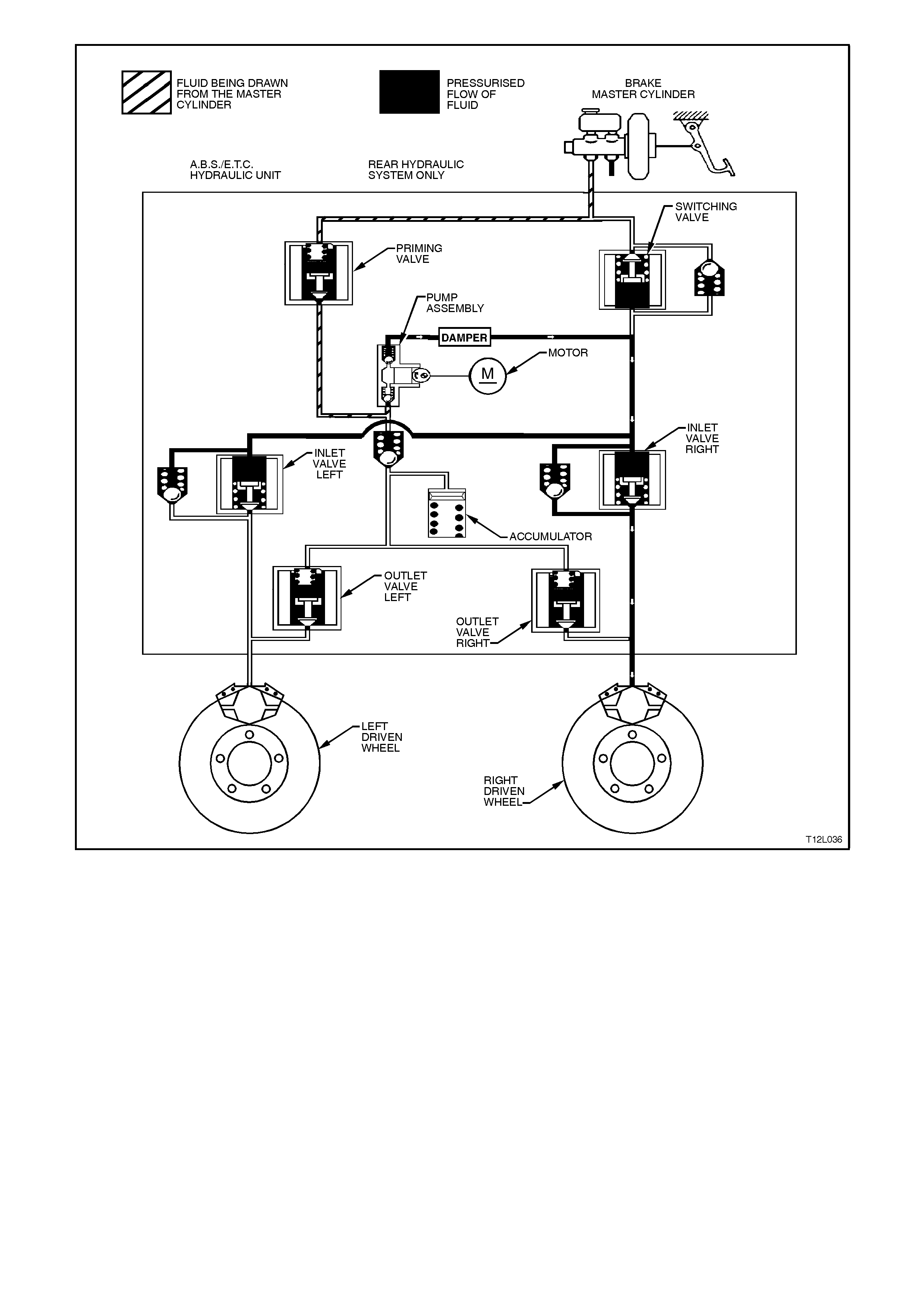
Figure 12L-52
MASTER CYLINDER OPERATION
The operation of the master cylinder assembly used on vehicles with ABS is the same as the assembly used on
vehicles without ABS, refer to Section 5A STANDARD BRAKES.
OPERATION AND TESTING OF THE ABS AND 'TRAC OFF' WARNING LAMPS
Should a vehicle equipped with ABS/ETC come into the workshop with one of the following customer complaints,
make sure of the circumstances before checking the complete ABS/ETC with the TECH 2 diagnostic scan tool.
1. Warning lamp(s) does not illuminate after switching the ignition on.
2. Warning lamp(s) does not go out after engine has started.
3. Warning lamp(s) illuminates again while driving or illuminates occasionally.
The following gives information about the functioning and malfunctioning of the ABS and TRAC OFF warning lamps.
ABS AND TRA C OFF WARNING LAMPS
W hen the ignition is switched on, the ABS warning
lamp illuminates for approximately two seconds
and the TRAC OFF warning lamp f or appr ox imately
five seconds (with engine running, TRAC OFF lamp
will illuminate for only two seconds also). During
this period of time, the ABS/ETC Control Module
performs a check of the ABS/ETC system wiring.
On all vehicles with ABS/ETC, as soon as all four
wheels of the vehicle exceed a speed of
approximately 6 km/h for the first time after starting,
the ABS/ETC system tests itself automatically
(ABS/ETC 'Self-Test'). The ABS/ETC Control
Module cycles each solenoid valve and the return
pump motor in the hydraulic modulator to check
component operation. The ABS/ETC Control
Module also checks its own circuitry.
This procedure is repeated every time the ignition is
switched OFF and the engine is started again. In
addition, the ABS/ETC system constantly tests
itself while the vehicle is travelling.
The warning lamp is also used for self diagnosis
purposes.
NOTE:
The TRAC OFF warning lamp will also illum inate if
the TRAC CTRL button has been pressed. The
TRAC OFF light will then stay illuminated until
either the ignition is switched off or the TRAC
CTRL button is pressed again.
Figure 12L-53

Incorrect Warning Lamp Indications (ABS and TRA C OFF)
1. Warning lamp(s) does not illuminate after switching ignition ON.
2. Warning lamp(s) does not go out after approximately 2 seconds.
3. Warning lamp(s) illuminates when driving or illuminates occasionally.
NOTE:
The TRAC OFF warning lamp will illuminate if the ETC system is manually switched off by the TRAC CTRL switch
located in the console and the LOW TRAC warning lamp will flash if the ETC system is functioning (in a wheel spin
situation). If either of these lights illuminate under these conditions, the system is functioning correctly.
Illumination of the ABS warning lamp indicates to the driver that the ABS is defective.
Illumination of the TRAC OFF warning lamp indicates to the driver that the ETC system is either manually disabled
or defective.
When the ABS warning lamp is activated, the vehicle reverts to normal braking as in vehicles without ABS fitted
(e.g. under emergency braking, wheel/s may lock).
When the TRAC OFF warning lamp is activated, the ABS still functions correctly.
Occasional illumination of the warning lamps may be brought about through the battery being insufficiently charged.
The lamp lights up only as long as there is a low voltage, e.g. after switching on electrical components at idle.
The causes of trouble can be determined with the assistance of the TECH 2 diagnostic scan tool.
LOW TRAC warning lamp
The LOW TRAC lamp is used to inform the driver that the vehicle is in a critical driving situation and that the ETC
system has been engaged to control wheel spin.

3. SERVICE OPERATIONS
3.1 SAFETY AN D PRECAUTIONAR Y M EASUR ES
The following information is general safety and precautionary measures that must be observed when servicing and
diagnosing the ABS or ABS/ETC system.
BEFORE TESTING FOR AN ABS OR ABS/ETC FAULT, ENSURE THAT CONVENTIONAL BRAKES ARE
WORKING CORRECTLY.
ABS and ABS/ETC are basically maintenance-free, however, when working on a vehicle with either of these
systems, the following points must be observed:
1. Whenever welding with electric welding equipment, disconnect wiring harness plug from the ABS or ABS/ETC
control module.
2. Whenever painting a vehicle using drying techniques that put the temperature above +85°C for more than one
hour, remove the ABS or ABS/ETC control module from the vehicle.
3. During any service operation that requires the replacement of the hydraulic modulator, the ABS or ABS/ETC
control module, wheel speed sensors, wiring harness, as well as after work procedures in which contact is
made with the various ABS and ETC assemblies (eg. accident repair), the complete ABS or ABS/ETC system
MUST be checked, refer to 4.4, ABS, ABS/ETC FUNCTIONAL CHECK in this Section. Make sure that the
brake lines, wheel speed sensor connections on the ABS control module, and the wheel speed sensor wiring
harness connections are assigned correctly (refer to ABS and ABS/ETC wiring diagram, in
Section 12P WIRING DIAGRAMS.
4. After any work is carried out on the brake system, the brake system must be bled and a high-pressure test
conducted. All junctions must be tested for leakage.
5. Be sure to properly tighten the battery cable terminals on the terminal posts of the battery.
6. Do not use a fast charger for starting the vehicle.
7. Never disconnect the battery from the vehicle electrical system while the engine is running.
8. Disconnect the battery from the vehicle electrical system before charging.
9. Make sure that all connectors of the wiring harness are seated correctly.
10. Never disconnect or connect the ABS or ABS/ETC control module wiring harness connector when the battery
is connected or the ignition is turned on.
11. Always use suitable wiring harness test leads (such as those in KM-609) when carrying out any test on the
ABS or ABS/ETC control module wiring harness connector to avoid terminal damage.
12. Always carefully note the routing, position, mounting and location of ABS or ABS/ETC wiring, connectors, clips,
brackets, etc. as ABS and ABS/ETC components are extremely sensitive to EMI (Electro-Magnetic
Interference). Proper mounting is critical when servicing ABS or ABS/ETC components.

13. Do not hang the suspension components by the wheel speed sensor cables; these cables are delicate.
14. Some components of the ABS or ABS/ETC are not serviced separately and must be replaced as assemblies.
15. For safety reasons, the hydraulic modulator and / or control module must never be repaired. Repair of either of
these two units is by replacement only. Apart from the brake line connections and the six screws securing the
control module to the hydraulic modulator, no screws at the hydraulic modulator may be loosened. Once they
are loosened, it is impossible to make the brake circuits leak-free ever again!
16. Special wiring repair procedures have been developed for use on the ABS and ABS/ETC due to the sensitive
nature of the circuitry. These specific procedures and instructions are detailed in Section 12P WIRING
DIAGRAMS. THE PROCEDURES DETAILED IN “SECTION 12P”, ARE THE ONLY RECOMMENDED AND
APPROVED ABS OR ABS/ETC WIRING REPAIR METHODS.
DANGER OF FATAL ACCIDENT
Caution when handling brake fluid
A. Even the slightest trace of mineral oil leads to failure of the brake system. Special care must be taken with
colourless or yellow-tinted brake fluid, since the danger of a mix-up is greatest with such fluid. If mineral oil is
found in the brake system or there is a suspicion of mineral oil being in the brake system, the complete brake
system must be thoroughly flushed out with the correct type of brake fluid (use fluid to Holden's Specification
HN1796). In addition to this, the master cylinder must be replaced.
B. Do not allow brake fluid to come in contact with paintwork of the vehicle, since the fluid attacks the paint.
C. Brake fluid is exceedingly hygroscopic; ie. absorbs moisture from the air, thus reducing its boiling point. For this
reason, brake fluid must be stored only in well-sealed storage containers.
NOTE:
As the operation time progresses, the boiling point of the brake fluid drops owing to the brake fluid permanently
absorbing moisture from the atmosphere. If the brakes are subjected to very severe loading, this can lead to
vapour-bubble formation in the brake sy stem.
Therefore, the brake fluid must be replaced at the time or distance intervals as specified in
Section 0B LUBRICATION AND SERVICE.
IMPORTANT:
ABS AND ABS/ETC ARE VEHICLE SAFETY SYSTEMS. WORK ON THESE SYSTEMS PRESUPPOSES
DETAILED SYSTEM KNOWLEDGE.
The above precautions are not exhaustive and are to be followed when working on an ABS or ABS/ETC equipped
vehicle. Become familiar with the ABS or ABS/ETC and how it may be interrelated to other components on the
vehicle when performing service work.
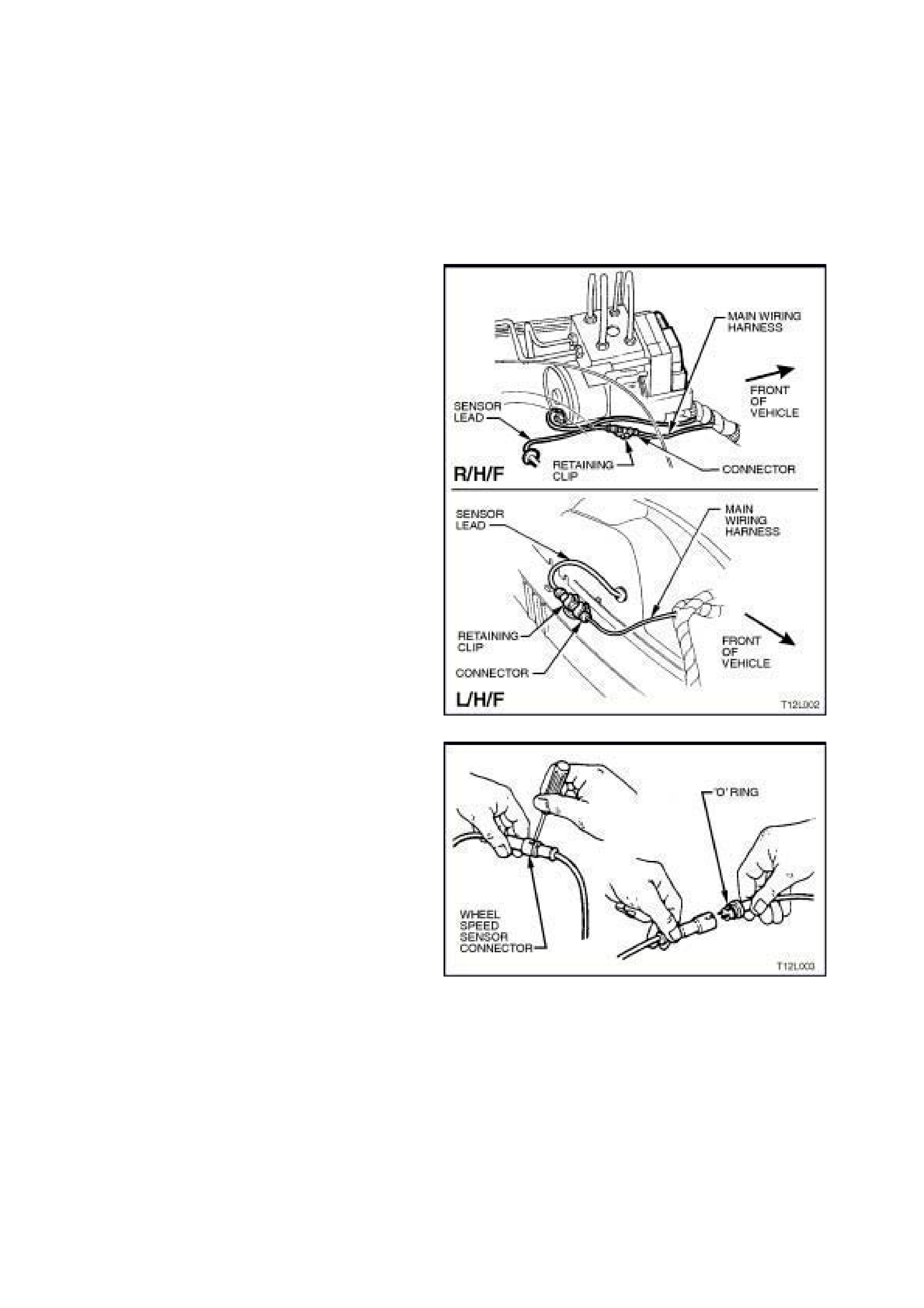
3.2 FRONT WHEEL SPEED SENSOR LEAD
REMOVE
1. Jack up front of vehicle and support on safety
stands. Observe jacking precautions as
outlined in Section 3 FRONT SUSPENSION.
2. Remove appropriate wheel cover (steel
wheels) or centre cap (alloy wheels).
3. Mark relationship of wheel to hub or brake
disc. Remove wheel attaching nuts and
remove wheel.
4. From engine compartment, pull appropriate
sensor connector from retaining clip at fender
inner panel.
Figure 12L-54
5. From engine compartment, disconnect
appropriate sensor harness connector from
main wiring harness connector by levering out
with a screwdriver.
Figure 12L-55
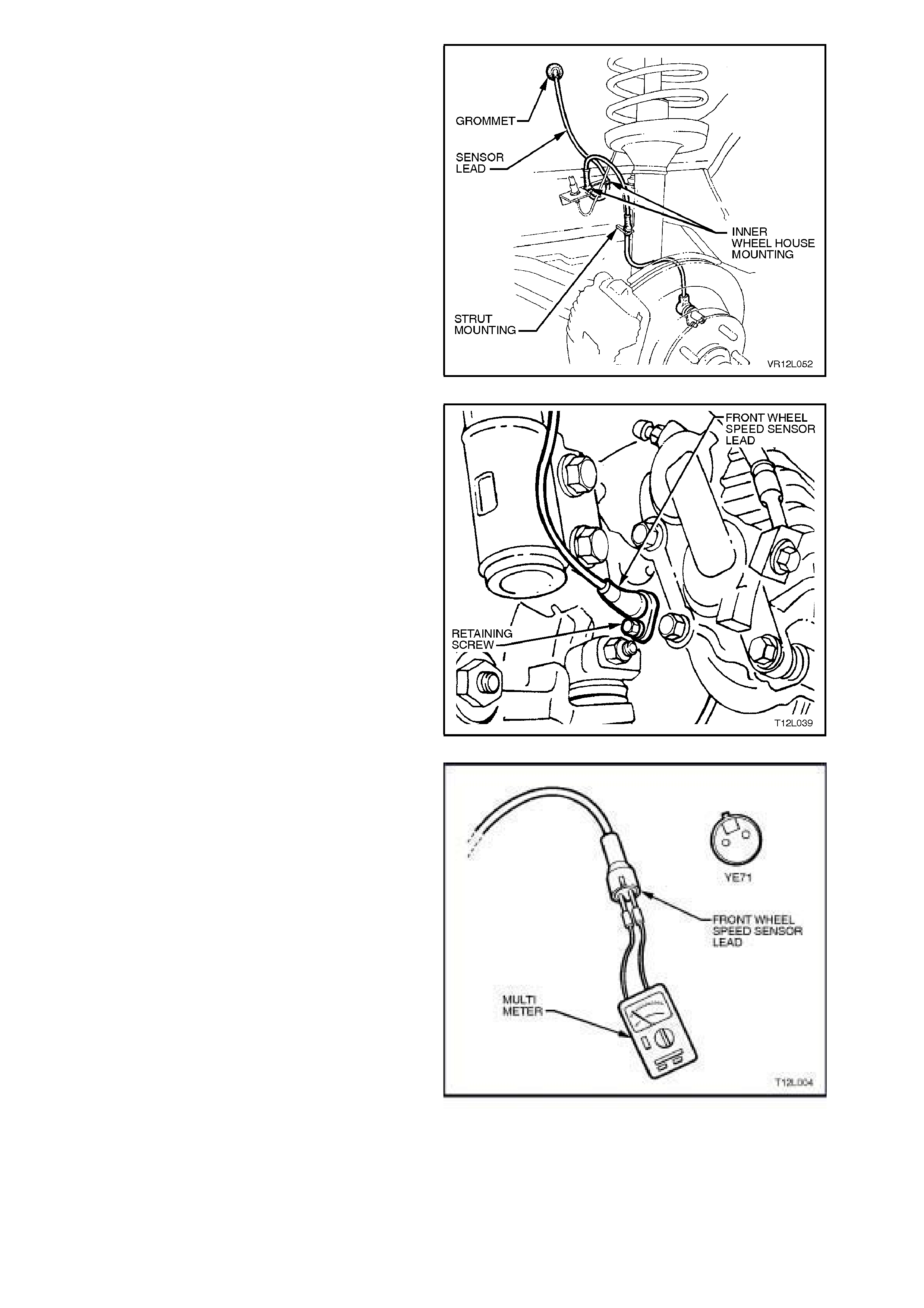
5. Push out sensor lead and fender inner panel
grommet in the inner wheelhouse.
6. Disconnect sensor lead from inner
wheelhouse mountings and front strut
mounting, taking note of lead routing.
Figure 12L-56
7. From behind steering knuckle, remove set
screw retaining wheel speed sensor lead to
steering knuckle using a 5 mm Allen key or
socket. Then, hold cable retaining bracket,
twist and gently pull on sensor lead connector
end to disconnect it from sensor. Take care
not to lose lead to steering k nuckle sealing 'O'
ring.
Figure 12L-57
TEST
With front wheel speed sensor lead disconnected,
connect an ohm m eter between the two terminals of
connector YE71, and check for continuity. W ith the
lead disconnected at both ends , there should be no
continuity between the terminals (open circuit).
NOTE:
Ensure that your skin is not contacting the
terminals of the sensor lead or multimeter leads
while checking res istance between the term inals as
your skin will serve as a conductor.
A good sensor lead will have a resistance value of
infinity (open circuit indication), between the
terminals. If you measure a resistance value other
than infinity, replace the lead assembly.
Figure 12L-58

REINSTALL
Installation of the front wheel sensor lead is the
reverse of removal procedures, noting the following
points:
1. Refit wheel speed sensor lead connector to
sensor and steering knuckle. Install lead
bracket retainer screw and tighten to the
correct torque specification.
SENSOR CABLE
RETAINER SCREW
TORQUE SPECIFICATION
6 - 14
Nm
2. Install sensor lead into inner wheelhouse
and front strut mountings, taking care that
lead routing is correct and not crossed up
with brake calliper hydraulic hose. For lead
routing, refer to Fig’s. 12L-28 and 12L-29 in
this Section.
3. Install the road wheel, aligning marks made
prior to removal, install attaching nuts.
4. Remove jack stands and lower vehicle.
5. Tighten road wheel attaching nuts to the
correct torque specification and refit wheel
cover/centre cap.
ROAD WHEEL ATTACHING NUT
TORQUE SPECIFICATION 110 - 140
Nm
6. After carrying out repairs, check ABS
operation, refer to 4.4 FUNCTIONAL CHECK
in this Section.
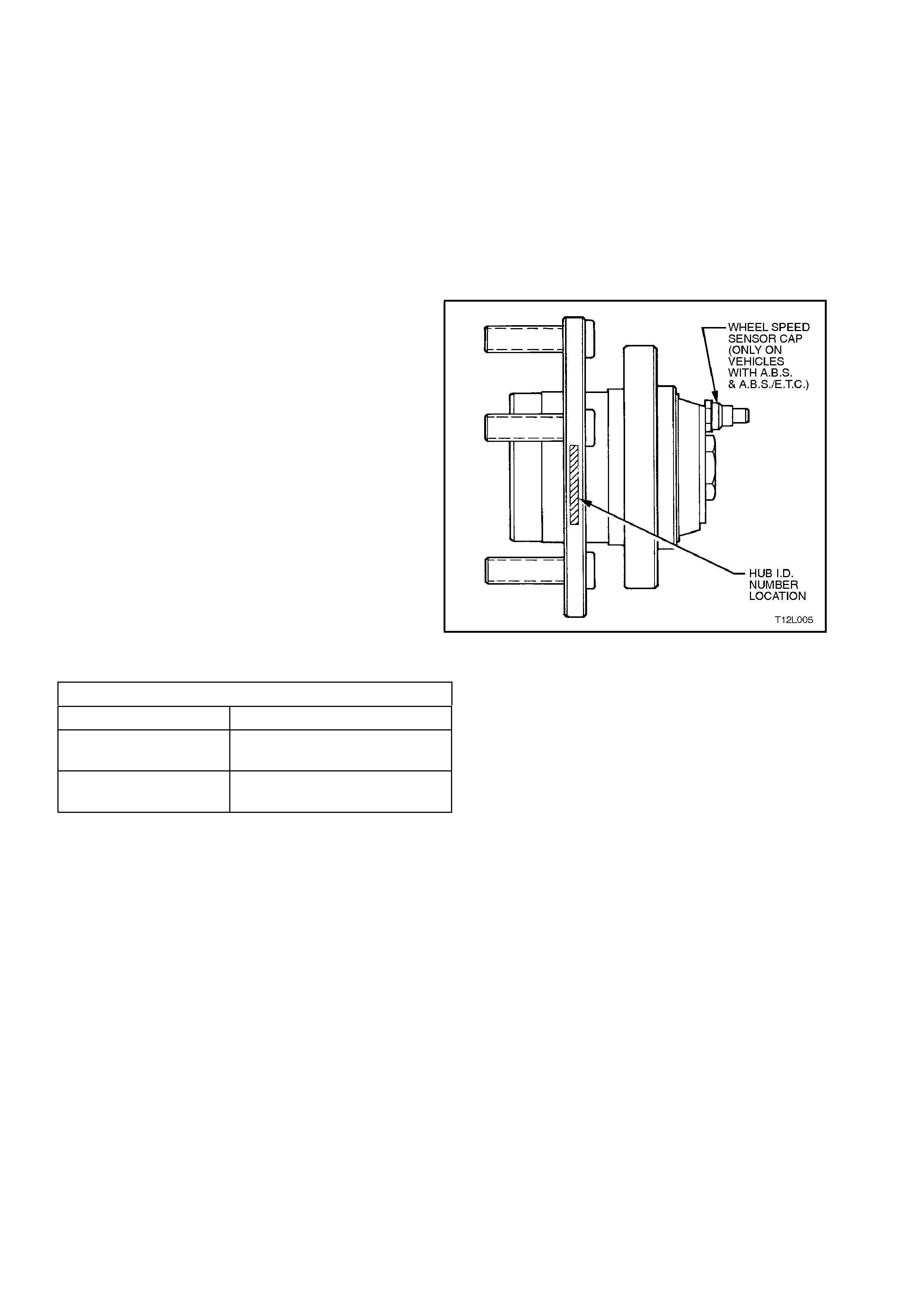
3.3 WHEEL SPEED SENSORS
FRONT WHEEL SPEED SENSOR
The f ront wheel speed sens ors ar e incor porated as
part of the front wheel hub assembly.
NOTE:
Apart from wheel stud replacement, there are no
serviceable item s in the front wheel hub assem bly.
With the unit being a 'sealed for life' assembly,
there are no requirements for wheel speed sensor
and/or bearing adjustments. Should a non-
standard condition develop, then the hub assem bly
must be replaced as a complete unit.
There are three specific front wheel hub
assemblies available. For vehicles with ABS and
ABS/ETC there is r ight and lef t, which inc orpor ates
the wheel speed sensor and a 48 tooth magnet
impuls e ring. For non ABS vehicles, a com m on hub
is used for both sides.
Identification of the front wheel hub assemblies is
by the assembly part number etched on the outer
surf ace of the hub wheel flange or by simply noting
whether a wheel speed sensor cap is fitted to the
hub, refer to Fig. 12L-59.
CAUTION:
During any service operation that requires the
replacement of the front hub assembly on a
vehicle equipped with ABS, ensure that the
correct replacement hub assembly is installed,
otherwise malfunctioning of the ABS will occur.
Figure 12L-59
FRONT WHEEL HUB IDENTIFICATION
VEHICLE TYPE HUB PART NUMBER
Vehicles without ABS
or ABS/ETC 92039932
Vehicles with ABS or
ABS/ETC 92046941 L/H
92046940 R/H
For front wheel hub checking procedures, other
than wheel speed sensor checking, refer to
Section 3 FRONT SUSPENSION.
REMOVE
1. Raise front of vehicle and support on safety
stands. Observe jacking precautions as
outlined in Section 3 FRONT SUSPENSION.
2. Remove wheel cover (steel wheels) or centre
cap (alloy wheels).
3. Mark relationship of wheel to hub or brake
disc. Remove wheel attaching nuts and
remove wheel.
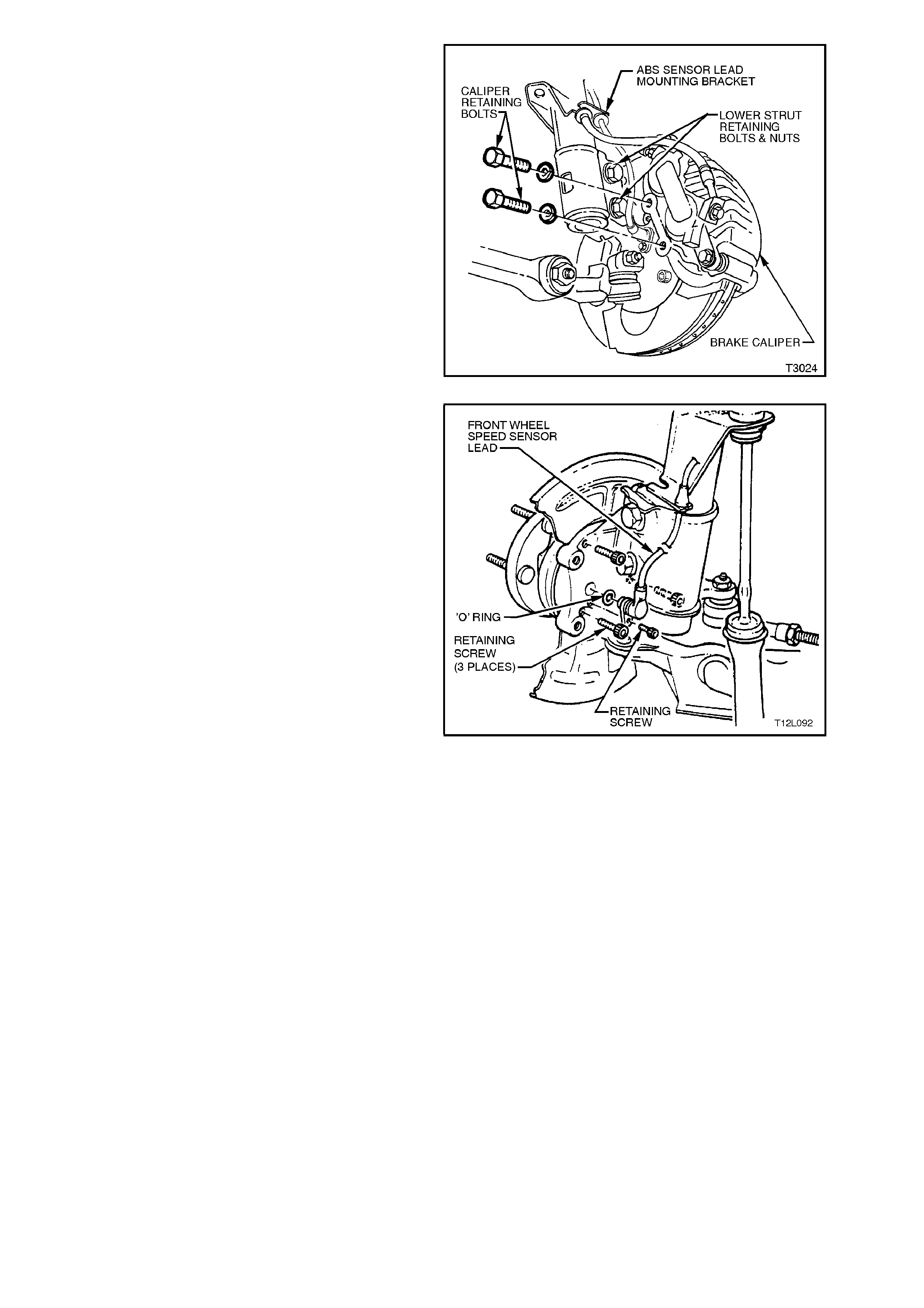
4. Remove brake calliper anchor plate retaining
bolts and washers, lift calliper assembly from
brak e disc. Position calliper in s uch a way that
no strain is placed on the brake hose. If
necessary, tie calliper to the suspension spring
with a piece of wire. DO NOT ALLOW
CALLIPER TO HANG BY BRAKE HOSE.
5. Remove brake disc from front wheel hub
assembly.
Figure 12L-60
6. From behind steering knuckle, remove set
screw retaining wheel speed sensor lead to
steering knuckle using a 5 mm Allen key or
socket. Then, holding cable retaining bracket,
twist and gently pull on sensor connector end
to disconnect it from sensor. Take care not to
lose lead to steering knuckle sealing O-ring.
7. Using a commercially available 10 mm Allen
key socket and a suitable socket bar, loosen,
each of the three bolts holding the hub to the
steering knuckle, DO NOT FULLY REMOVE.
Figure 12L-61
NOTE 1:
For the lower hub bolt, turn wheel outwards to
provide clearance between ball joint rivet and hub
bolt.
NOTE 2:
If the Allen key socket is too long to fit into front
upper hub bolt, then strut to s teering knuck le lower
nut will need to be removed and bolt withdrawn.
8. As the hub to knuckle interface has sealant
applied, it may be necessary to tap the
loosened bolts to break the seal. DO NOT
STRIKE THE HUB.
9. Remove the thr ee bolts and then the hub from
the steering knuckle.
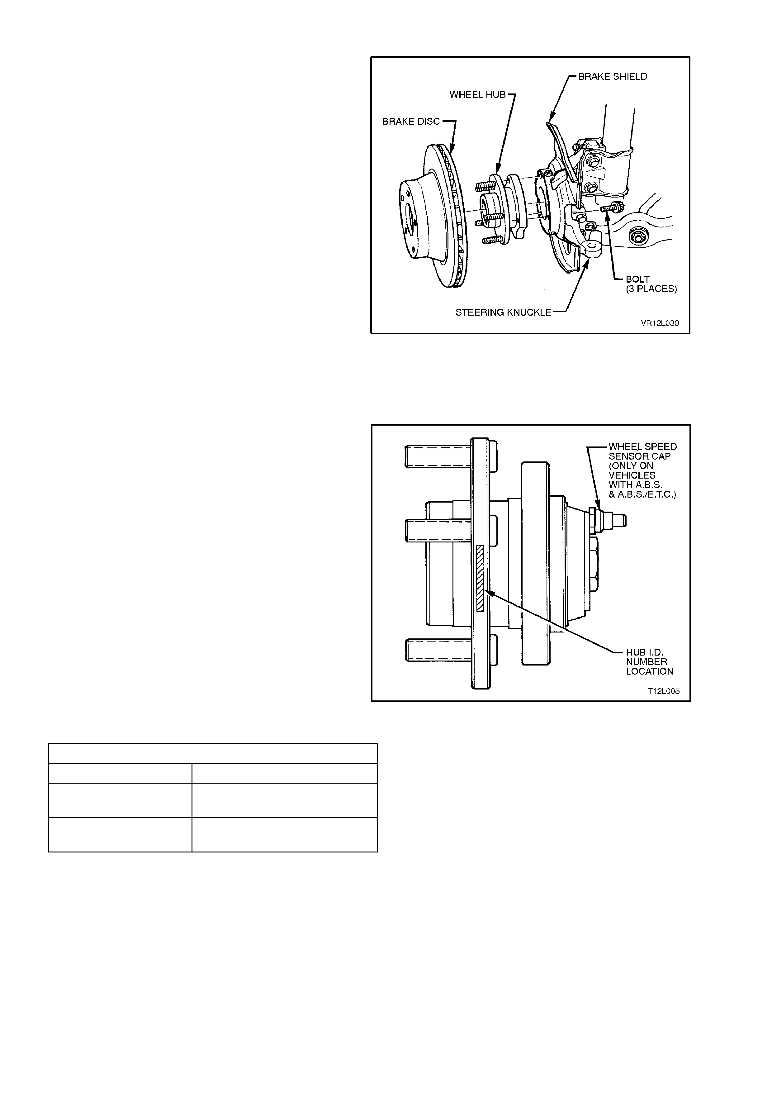
INSPECT
1. Check wheel studs to ensure threads are not
damaged, and that studs are pressed firmly
into the front wheel hub.
If one or more wheel studs require
replacement, refer to Section 3, FRONT
SUSPENSION.
2. Examine brake disc for scores or damage.
If either of these conditions exist, the brake
disc should be mac hined. Refer to Section 5A
STANDARD BRAKES.
3. Check for any dam age to the brak e shield that
may cause fouling of any rotating parts and if
suspect, the shield should be replaced. Refer
to Section 3, FRONT SUSPENSION.
Figure 12L-62
REINSTALL
Installation of the front wheel hub assembly is the
reverse of r emoval pr ocedur es , noting the f ollowing
points:
1. Before installing a new front wheel hub
assem bly, ensure that the correc t type is fitted.
Identification of the front wheel hub assemblies
is by the assembly part number etched on the
outer surface of the hub wheel flange or by
simply noting whether a wheel speed sensor
cap is fitted to the hub, refer Fig. to 12L-63.
Figure 12L-63
FRONT WHEEL HUB IDENTIFICATION
VEHICLE TYPE HUB PART NUMBER
Vehicles without ABS
or ABS/ETC 92039932
Vehicles with ABS or
ABS/ETC 92046941 L/H
92046940 R/H
2. Inspect mating surfaces of front wheel hub
and steering knuckle to make sure that they
are clean and free from burrs that could
prevent correct alignment of both parts, once
installed.
3. Prior to installation, it is vital that contact face
of hub is coated with Loctite 515 Master
Gasket or equivalent (Holden Specif ication HN
1581). Failing to use this sealant will cause
water to be drawn into the cavity in the
steering knuckle during the normal heating
and cooling cycle of vehicle operation.

4. Install front wheel hub to steering knuckle,
carefully aligning wheel speed sensor
connection on the hub with hole in steering
knuckle.
Install hub to steering knuckle attaching bolts
and tighten to the correct torque specification.
FRONT HUB TO STEERING
KNUCKLE TTACHING BOLT
TORQUE SPECIFICATION 100 - 115 Nm
NOTE:
The three hub attaching bolts are micro-
encapsulated with thread sealant and are not to be
re-used more than three times. If in any doubt to
how many times the bolts have be reused, then
install new bolts.
5. Refit wheel speed sensor lead connector to
sensor and steering knuckle. Install lead
bracket retainer screw and tighten to the
correct torque specification.
SENSOR CABLE
RETAINER SCREW
TORQUE SPECIFICATION 6 - 14 Nm
6. If removal of strut to steering knuckle support
arm lower bolt was necessary, the bolt and nut
must be replaced with new parts and tightened
to the correct torque specification.
STEERING KNUCKLE TO STRUT
ATTACHING BOLT & NUT
TORQUE SPECIFICATION
STAGE 1
STAGE 2
STAGE 3
85 Nm
100 Nm
then turn
through
85° - 95°
7. Reinstall brake disc and brake calliper.
Tighten calliper attaching bolts to the correct
torque specification.
BRAKE CALLIPER
ATTACHING BOLT
TORQUE SPECIFICATION
80 - 90 Nm
then turn
through
40° - 50°
8. Reinstall road wheel, aligning marks made
prior to removal and secure with attaching
nuts.
9. Remove jack stands and lower vehicle.
10. Tighten road wheel attaching nuts to the
correct torque specification.
ROAD WHEEL ATTACHING NUT
TORQUE SPECIFICATION 110 - 140
Nm
11. Refit wheel cover/centre cap.
12. After carrying out repairs, check ABS
operation, refer to 4.4 FUNCTIONAL CHECK
in this Section.
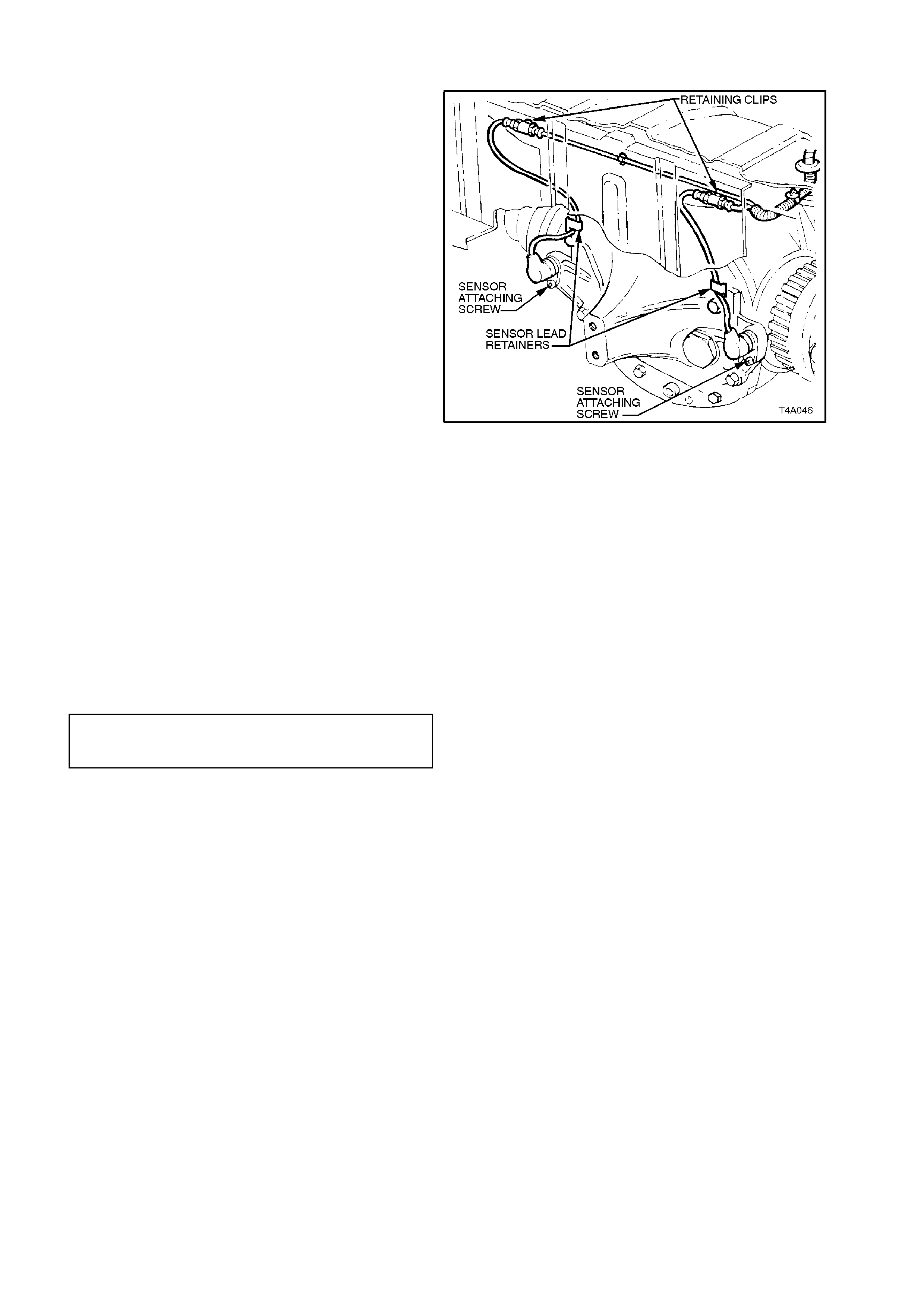
REAR WHEEL SPEED SENSOR
REMOVE
1. Using a floor jack under centre of differential
carrier, jack up rear of vehicle, then place
safety stands under trailing arms to support
weight of vehicle. Refer to Section 0A
GENERAL INFORMATION for location of
jacking points.
2. Pull appropriate sensor lead connector from
underbody retaining clip. Separate sensor
connector from body harness connector by
levering out with a screwdriver.
3. Using a screwdriver, carefully lever open
sensor lead retainer at final drive mounting
bracket.
4. Remove sensor from mounting bracket
attaching screw, pull out sensor.
Figure 12L-64
REINSTALL
1. Before reinstalling sensor, check sensor for
any signs of damage.
IMPORTANT:
A replacement wheel sensor must only be taken
out its packaging immediately before installing on
the vehicle.
2. Clean all traces of foreign matter from sensor
and mounting bracket mating hole.
3. Reinstall sensor into mounting bracket and
tighten attaching screw to the correct torque
specification.
WHEEL SPEED SENSOR
ATTACHING SCREW
TORQUE SPECIFICATION 6 - 14 Nm
4. Connect sensor lead connector to body
harness connector and secure to underbody
retaining clip.
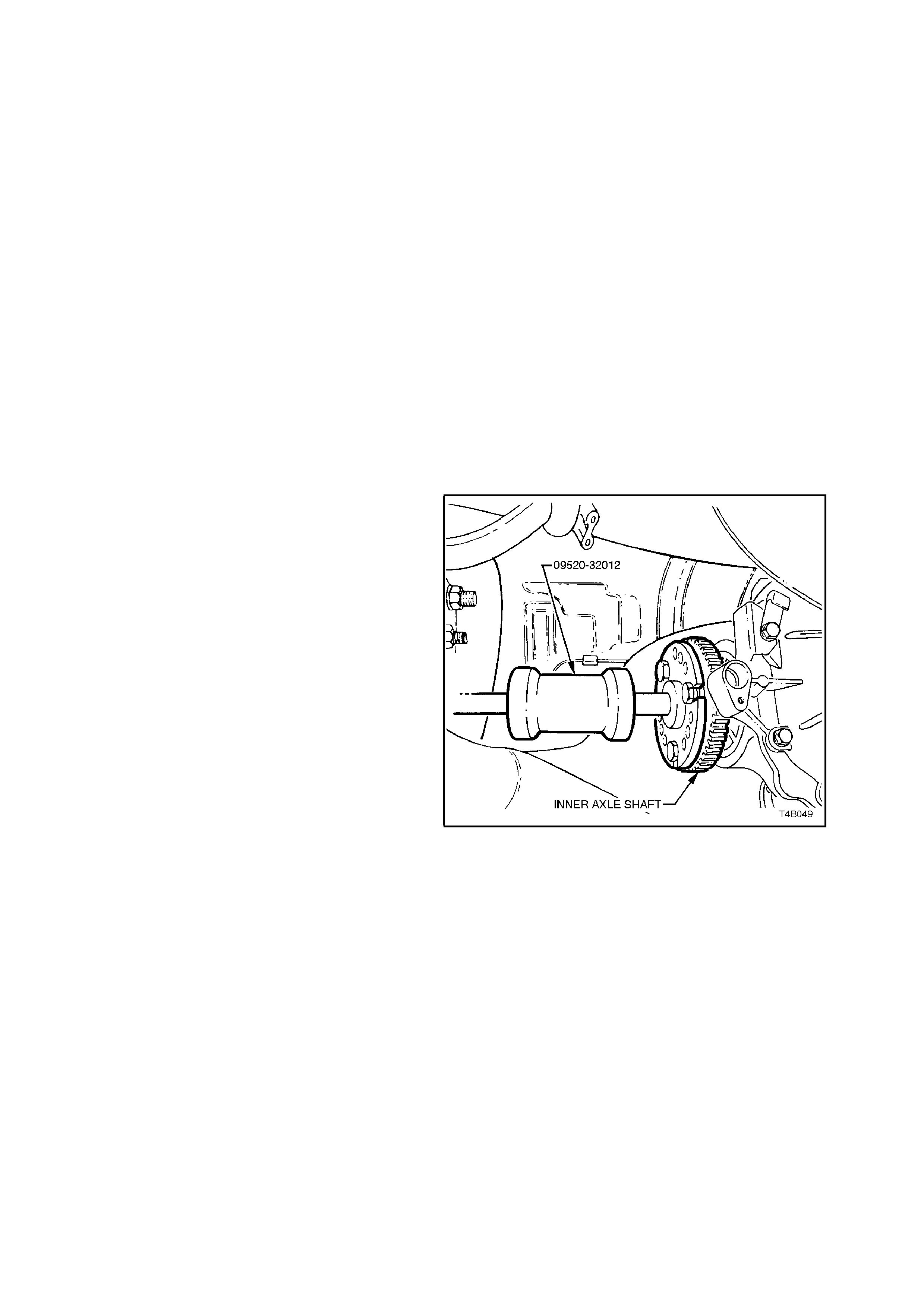
3.4 PULSE RINGS
NOTE:
The rear wheel pulse rings are part of the final
drive inner axle flanges and are a press fit onto
each of the rear axle shafts. Therefore, the
following service operation describes the
replacement procedures for the pulse ring and
inner axle shaft assembly.
REMOVE
1. Using a floor jack under centre of differential
carrier, jack up rear of vehicle and then place
safety stands under body rear jacking points.
Refer to Section 0A GENERAL
INFORMATION for location of jacking points.
2. Rem ove drive shaft f rom side of vehicle which
inner axle shaft is to be removed, refer to
Section 4B2 FINAL DRIVE AND DRIVE
SHAFTS.
NOTE:
During drive shaft removal, keep drive shaft
supported so that it does not hang on one end.
Drive shaft deflection should be kept to a minimum.
3. Remove inner axle shaft by installing a slide
hammer, Tool No 09520 - 32012 with three
suitable size bolts to axle shaft flange. Using
slide hammer to release axle shaft spring clip.
As the axle shaft is removed, a small amount
of lubricant may leak from differential carrier.
CAUTION:
If vehicle is fitted with LSD, do not rotate the
opposite axle shaft, as side gear and clutch
cone splines will become misaligned. Then the
axle shaft cannot be reinstalled without
removing differential, dismantling and
realigning gear and cone splines.
Figure 12L-65
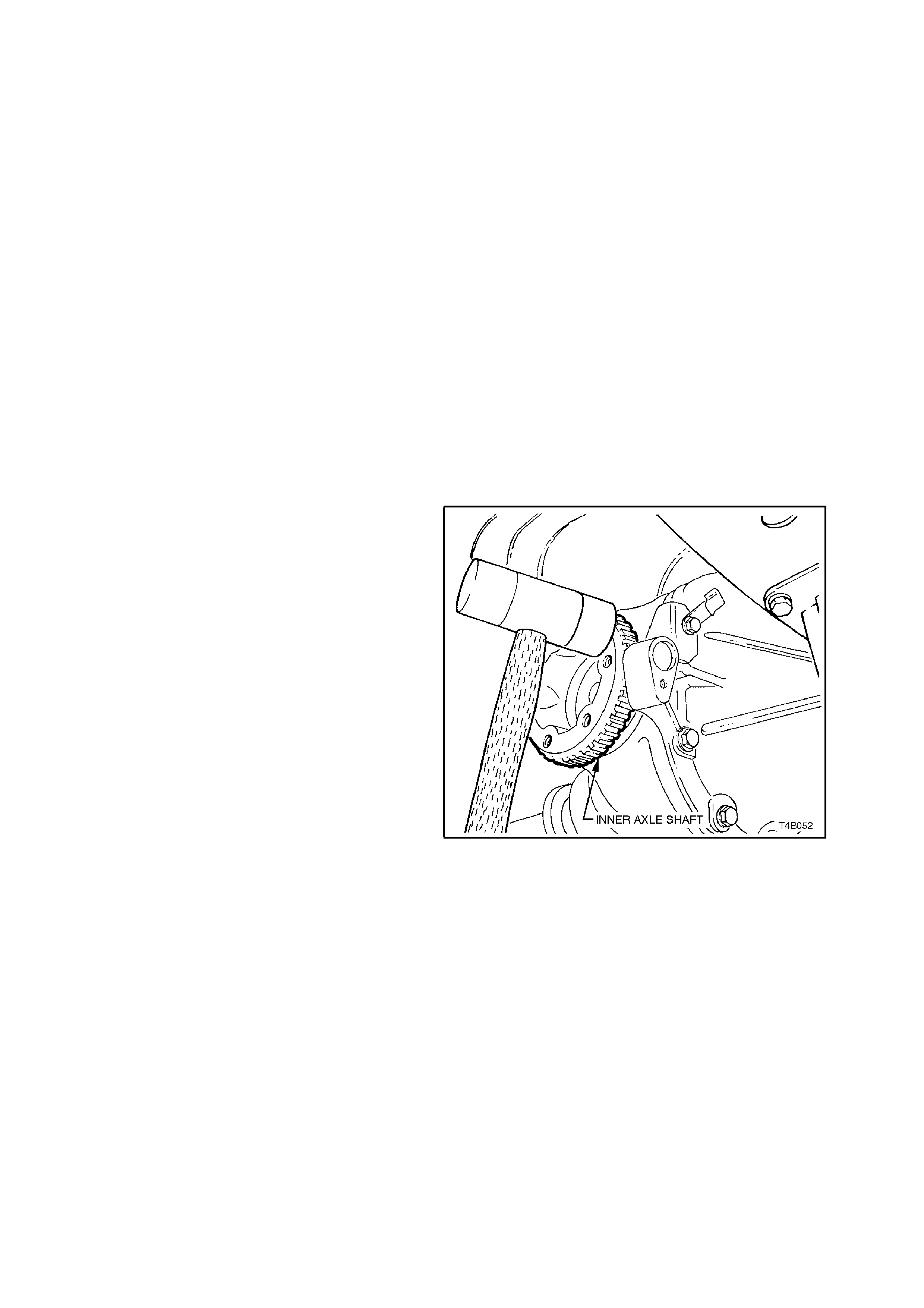
REINSTALL
1. Clean around seal bore and housing area to
make sure that no foreign matter enters axle
shaft needle bearing in the screw adjuster.
2. Before installing axle shaft, inspect seal
surface of shaft for any signs of damage.
NOTE 1:
The left hand inner axle shaft is shorter in length
than the right hand shaft.
NOTE 2:
Check spring clip in end of axle s haf t to ens ure that
it is not damaged and moves freely in groove.
Replace spring clip if necessary. Only expand the
ends of a new clip sufficiently to allow installation
into shaft groove.
3. Lubricate inner axle shaft seal lips with lithium
soap grease (Holden Specification HN 1147).
4. Install inner axle shaft, aligning splines with
clutch cone (if fitted with LSD) and side gear.
NOTE:
To avoid premature seal failure, ensure that axle
shaft splines or securing clip do not score or
damage the seal lips during installation.
5. Lightly hit on end of axle shaft with a soft faced
hammer to compress spring clip on shaft into
clutch cone and side gear splines. Fully
engage shaft until clip snaps into side gear
groove.
6. Reinstall drive shaft, refer to
Section 4B2 FINAL DRIVE AND DRIVE
SHAFTS.
7. Remove safety stands and lower vehicle.
8. Check and fill differential carrier to correct
level with specified lubricant. Refer to
Section 4B2 FINAL DRIVE AND DRIVE
SHAFTS.
9. After carrying out repairs, check ABS
operation, refer to 4.4 FUNCTIONAL CHECK
in this Section.
Figure 12L-66
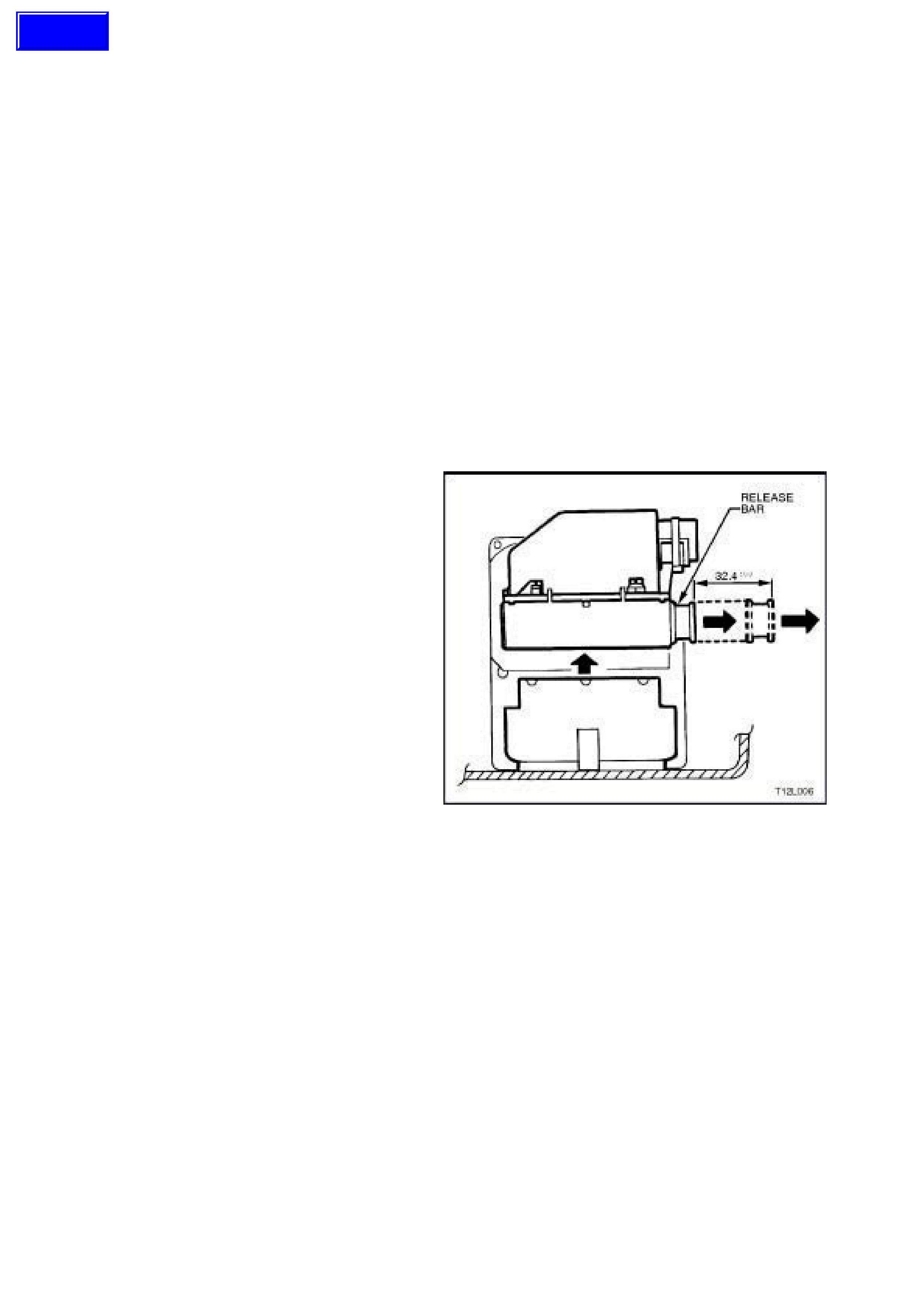
3.5 HYDRAULIC MODULATOR AND CONTROL MODULE ASSEMBLY
NOTE:
1. For safety reasons, the hydraulic modulator
and / or control module must never be
repaired. Repair of either of these two units is
by replacem ent only. Apart f rom the brake line
connections and the six screws securing the
control module to the hydraulic modulator, no
screws at the hydraulic modulator may be
loosened. Once they are loosened, it is
impossible to make the brake circuits leak-
free ever again!
Replacement hydraulic modulator assemblies are
supplied pre-filled with brake fluid. Do not remove
sealing plugs from modulator ports until ready to
install brake line connections.
NOTE:
2. Once replacement modulator has been fitted,
the sealing plugs must be fitted to original
modulator to prevent dirt and moisture entry.
REMOVE
1. Disconnect battery earth lead.
2. Pull out the release bar on the control
module’s wiring harness connector
(approximately 32.4 mm) and remove wiring
harness connector from control module, refer
to Fig. 12L-67.
NOTE:
The wiring harness connector will automatically lift
at the same time the release bar is withdrawn.
3. Fold back wiring harness connec tor and wiring
away f rom the hydraulic m odulator and control
module assembly.
Figure 12L-67
Techline
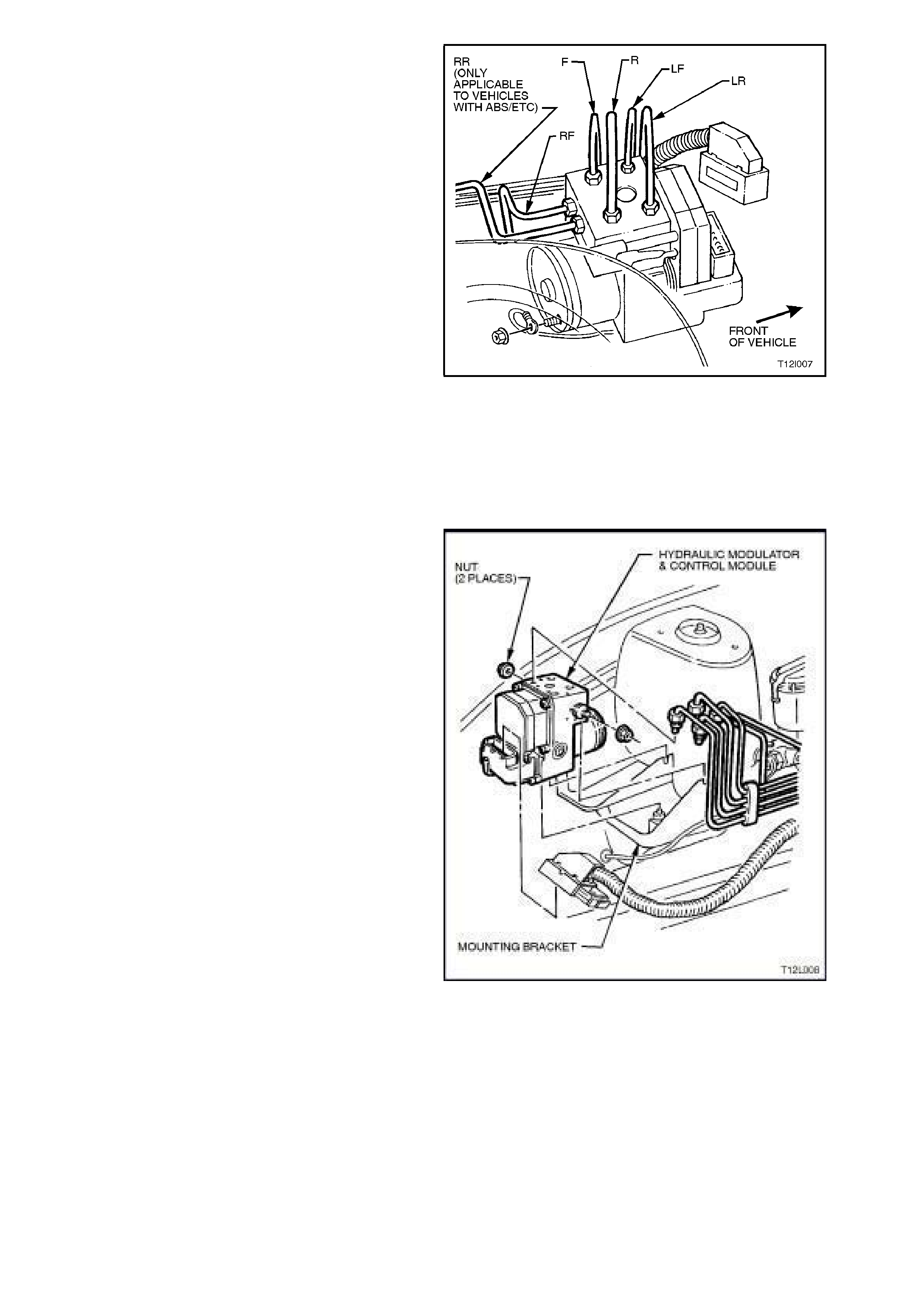
4. Place protective covers over vehicle exterior
panels to prevent paint damage from any
possible brake fluid spillage.
5. To aid in reassembly, tag all brake lines at
modulator. When tagging brake lines, make
sure the lines are marked in accordance with
the markings on the hydraulic modulator ports.
WARNING:
IF BRAKE LINES ARE INCORRECTLY FITTED
ON REASSEMBLY, WHEEL LOCK-UP WILL
OCCUR AND PERSONAL INJURY MAY
RESULT.
Markings on modulator, refer to Fig. 12L-68 are:
LF = Connection for brake line, front left.
LR = Connection for brake line, rear left and right
(ABS) or rear left only (ABS/ETC).
F = Front brake circuit from master cylinder.
R = Rear brake circuit from master cylinder.
RF = Connection for brake line, front right.
RR = Connection for brak e line, rear r ight (vehicles
with ETC only).
6. Place shop rags around and beneath
modulator and loosen and disconnect brake
lines from modulator.
Figure 12L-68
Immediately seal off brake lines and
connections with dummy plugs. If necessary,
gently push brake lines away from modulator
assembly ports, taking extreme care not to
damage or kink the brake lines in any way.
7. Loosen off or remove the two nuts securing
the hydraulic modulator and control module
assembly to the mounting bracket.
8. Lift hydraulic modulator and control module
assembly up and out of mounting bracket.
Figure 12L-69
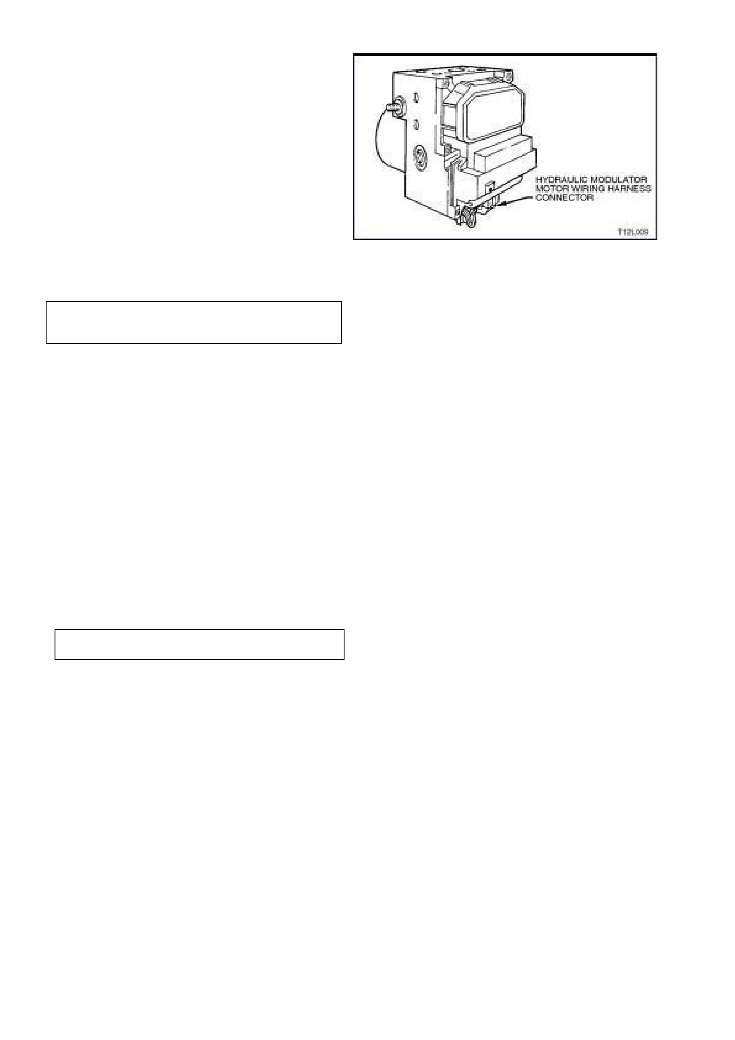
REINSTALL
Installation of the hydraulic modulator and control
module assembly is the reverse of removal
procedures noting the following points:
1. Before installing hydraulic modulator and
control module assembly, clean any traces of
brake fluid from within mounting bracket.
2. If necessary, transfer bumpers to mounting
studs on replacem ent hydraulic m odulator and
control module assembly.
3. Ensure the hydraulic modulator motor wiring
harness connector is connected to the control
module, refer to Fig. 12L-70.
4. Install hydraulic modulator and control m odule
into mounting bracket and tighten securing
nuts to the correct torque specification.
Figure 12L-70
HYDRAULIC MODULATOR AND
CONTROL MODULE SECURING NUT
TORQUE SPECIFICATION 5.0 - 12.0 Nm
5. Remove plugs from hydraulic modulator ports
and install brake lines, taking note to ensure
correct fitment of the correct brake line to the
correct port on the modulator. Use tags fitted
on removal to ensure correct fitment.
WARNING:
MAKE SURE BRAKE LINES ARE CORRECTLY
CONNECTED TO MODULATOR. IF BRAKE
LINES ARE INCORRECTLY FITTED, WHEEL
LOCK-UP WILL OCCUR AND PERSONAL
INJURY MAY RESULT.
THE ONLY TWO WAYS THIS CONDITION CAN
BE DETECTED ARE BY USING TECH 2 OR BY
DOING AN ABS STOP.
Tighten brake line connections to the correct
torque specification.
BRAKE LINE CONNECTION
TORQUE SPECIFICATION 8 - 11
Nm
NOTE:
If a replacement hydraulic modulator and control
module has been fitted, the sealing plugs must be
fitted to original unit to prevent dirt and moisture
entry.
5. Bleed brake system at all brake callipers and
test for leaks, refer to Section 5A
STANDARD BRAKES.
NOTE:
Use brake fluid to Holden Specification HN 1796
only.
6. After carrying all out repairs, check ABS or
ABS/ETC operation, refer to
4.4 FUNCTIONAL CHECK in this Section.

3.6 CONTROL MODULE
NOTE:
Remove the new control module from it’s protective
package only when it is ready to be fitted to the hydraulic
modulator.
REMOVE
1. Disconnect battery earth lead.
2. Remove hydraulic modulator and control
module assembly, refer to 3.5 HYDRAULIC
MODULATOR AND CONTROL MODULE
ASSEMBLY in this Section.
NOTE 1:
The hydraulic modulator and control module
assembly must be removed due to the specified
installation position of the control module (the
spring plate(s) will not seat corr ectly unless it is in a
horizontal position).
NOTE 2:
Ensure blanking plugs are fitted to the pipe
connections of the hydraulic modulator to avoid
excess drainage and contamination of the brake
fluid.
3. Disconnect hydraulic modulator motor wiring
harness connector from the control module
and press the motor wiring out of the retainer
on the control module, refer to Fig. 12L-71.
Figure 12L-71
4. Support the hydraulic modulator and control
module ass em bly so that the control m odule is
facing upwards, in a horizontal position.
5. Using a T-20H Torx bit, remove the 6 Torx
screws securing the control module to the
hydraulic modulator. Lift the control module
upwards and remove control module.
6. Remove spring plate(s).
7. Cover the valve body of the hydraulic
modulator to protect it from damage and from
any foreign materials entering the unit.
Figure 12L-72
Techline
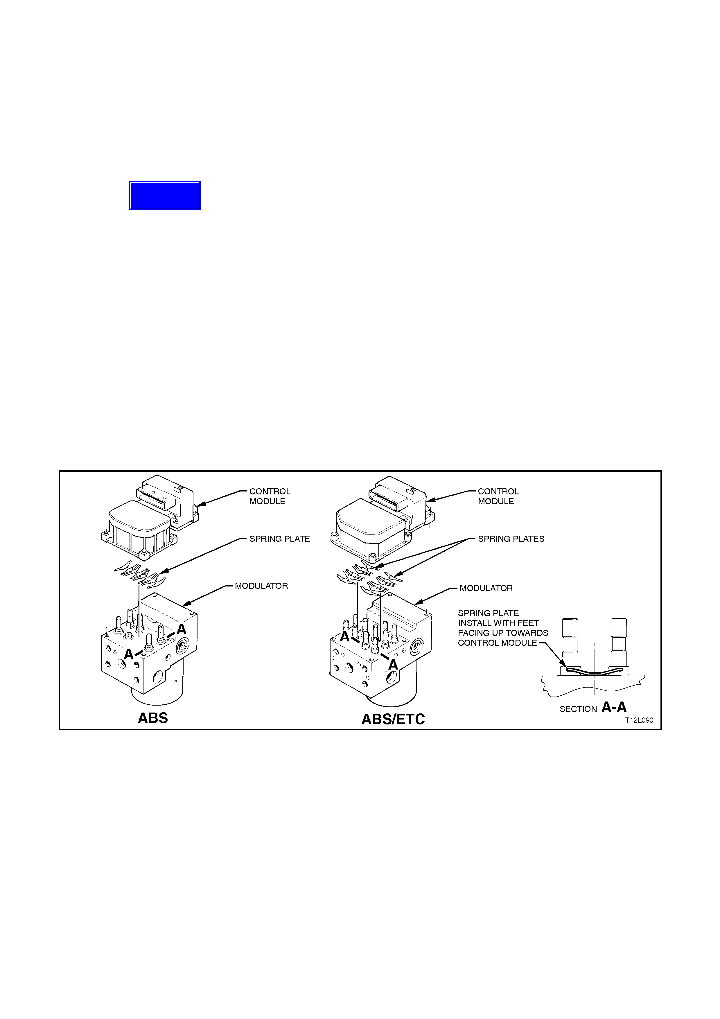
INSPECT
Inspect the sealing surface of the hydraulic
modulator for cleanliness or damage. If the sealing
surface is damaged, the surface cannot be
mec hanically reworked and therefore, the c om plete
hydraulic modulator and control module assembly
must be replaced.
NOTE:
The use of chemical solvents is not permitted for
cleaning.
REINSTALL
1. Before ins talling a new control m odule, ensure
that the correct type is fitted, always refer to
the latest spare parts information for the
correct ABS or ABS/ETC control module part
numbers.
2. Position the hydraulic modulator assembly so
that the control module face is facing upwards.
3. Insert the spring plate(s) with it’s feet facing
upwards (towards control module) to ensure
pretension and centering of the magnetic
coils, refer to Fig. 12L-73.
4. Remove the new control module from the
protective packaging and using the new
screws supplied, place screws in the new
control module and set the control module
into position.
Figure 12L-73
Techline
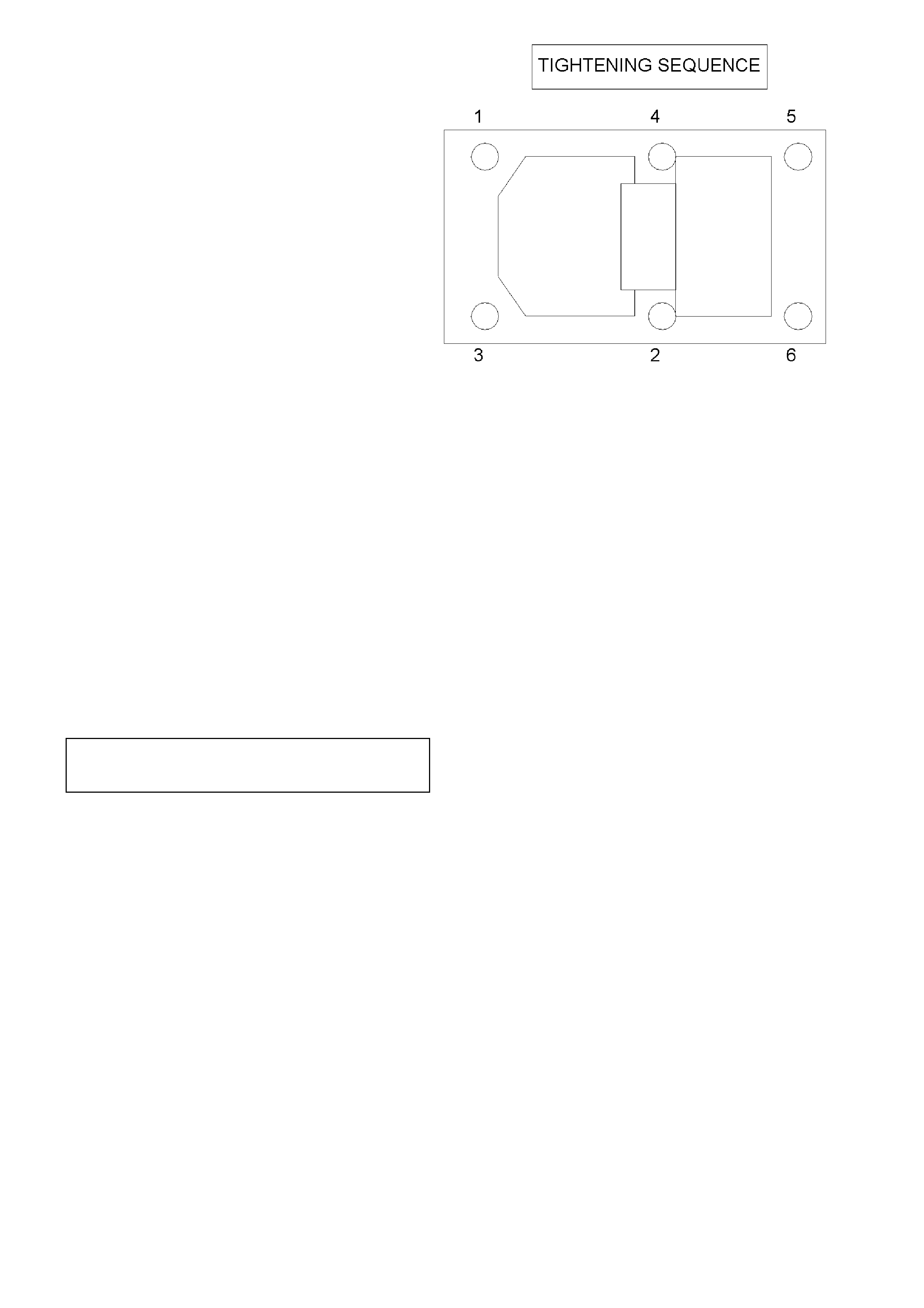
5. Tighten the six Torx screws securing the
control module to the hydraulic modulator in
the sequence shown in Fig. to 12L-74 and to
the recommended torque specification.
Figure 12L-74
6. Visually inspect hydraulic modulator and
control m odule as sem bly to ensure there is no
gap between control m odule and the hydraulic
modulator and to ensure Torx screws are
contacting control module correctly.
7. Connect the hydraulic modulator motor wiring
harness connector to the control module and
press the motor wiring into the retainer on the
control module.
8. Reinstall the hydraulic modulator and control
module assembly, refer to 3.5 HYDRAULIC
MODULATOR AND CONTROL MODULE
ASSEMBLY in this Section.
8. Reconnect battery earth lead.
5. After carrying out all repairs, check ABS or
ABS/ETC operation, refer to
4.4 FUNCTIONAL CHECK in this Section.
CONTROL MODULE TO HYDRAULIC
MODULATOR TORX SCREW
TORQUE SPECIFICATION 3 Nm

3.7 MASTER CYLINDER
REMOVE AND REINSTALL
Removal and installation instructions for the master cylinder on ABS equipped vehicles carry over from the
instructions described in Section 5A STANDARD BRAKES.
NOTE:
If installing a new master cylinder assembly to an ABS or ABS/ETC equipped vehicle, ensure that the screw in
blanking plug is installed and tightened into the lower of the two front brake outlets in the master cylinder.
OVERHAUL
Master cylinder overhaul instructions are the same as described in Section 5A STANDARD BRAKES.
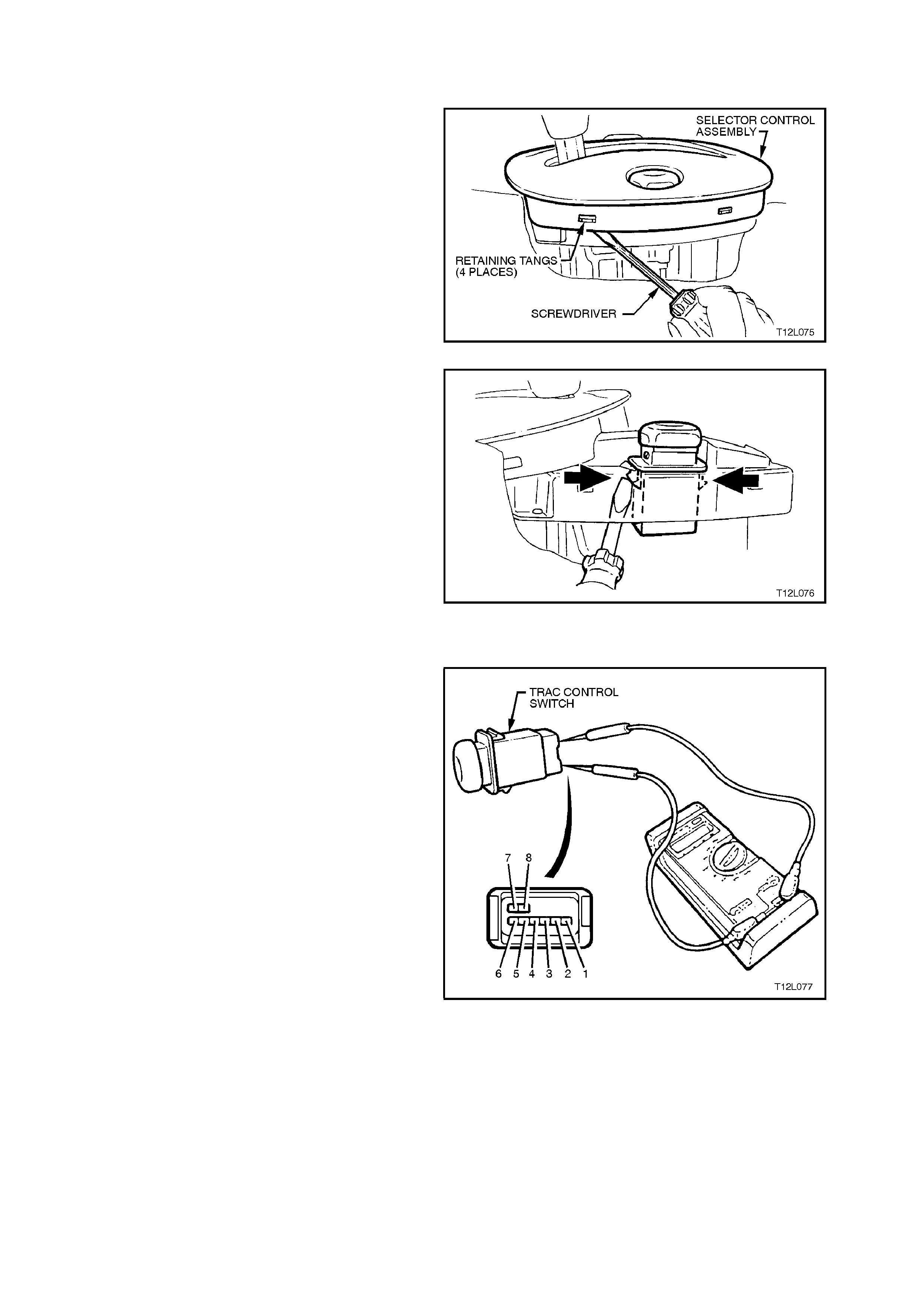
3.8 TRACTION CONTROL SWITCH (TRAC CTRL)
REMOVE
1. Remove centre console assembly, refer to
1A3 INSTRUMENT PANEL AND CONSOLE.
2. Pry shift indicator away from retaining tangs on
selector control assembly and move shift
indicator forward (move shift indicator as far
forward as possible with shift selector lever still
installed) to allow switch to be removed
upwards from selector control assembly.
Figure 12L-75
3. From under top of selector control assembly,
using a screw driver, push retaining tangs on
TRAC CTRL switch inward while pushing
switch up and remove.
4. Disconnect wiring harness connector and
remove.
Figure 12L-76
TEST
Using an ohmmeter connected to the TRAC CTRL
switch, check for continuity between the following
terminals with the switch held IN:
Ter. 1 and Ter. 2
Ter. 1 and Ter. 5
Ter. 2 and Ter. 5
If the ohmmeter indicates an open circuit, replace
the switch assembly.
REINSTALL
Installation of the traction control switch is the
reverse of the removal operation.
Figure 12L-77

4. ABS, ABS/ETC DIAGNOSIS
CAUTION:
Certain components in the Anti-lock Brake System and Electronic Traction Control system are not intended
to be serviced individually. Attempting to remove or disconnect certain system components, such as the
solenoid valves or pump motor from the hydraulic modulator, may result in personal injury and/or improper
system operation. Only those components with approved removal and reinstallation procedures described
3. SERVICE OPERATIONS in this Section should be serviced.
Before attempting any diagnostic work on the ABS, refer to and read the 'SAFETY AND PRECAUTIONARY
MEASURES' as described in 3. SERVICE OPERATIONS in this Section.
4.1 GENERAL DESCRIPTION
The following information is necessary when diagnosing any Anti-lock Braking System problem or failure,
specifically it should be used to diagnose conditions that may cause the illumination of the ABS or TRAC OFF
warning lamps in the instrument cluster.
Should conditions exist with the conventional (non ABS) portion of the braking system which cause the BRAKE
FAILURE warning lamp to illuminate (also in the instrument cluster), or there is some other obvious brake
mechanical problem, such as brake noise, brake pulsation (pedal or vehicle vibration during normal brake
application), brake pull or a parking brake problem, then these problems must be corrected before attempting to
rectify any suspected ABS or ABS/ETC problem. Refer to Section 5A STANDARD BRAKES for diagnosis and
repair of the conventional braking system.
Techline
Techline

4.2 BASIC KNOWLEDGE REQUIRED
Before attempting to diagnose the Anti-lock Brake System or Electronic Traction Control System, you must have a
good understanding of electrical system basics and the use of circuit testing tools. Without this basic knowledge it
will be difficult to use the diagnostic procedures detailed in this Section.
Some electrical basics, troubleshooting procedures and hints as well as the use of circuit testing tools are covered
in Section 12P WIRING DIAGRAMS.
Basic Electrical Circuits - You should understand the basic theory of electricity, series and parallel circuits, and
voltage drops across series resistors. You should know the meaning of voltage (volts), current (amps), and
resistance (ohms). You should understand what happens in a circuit with an open or shorted wire (shorted either to
voltage or earth). You should also be able to read and understand a wiring diagram.
Use of Circuit Testing Tools - You should know how to use a jumper lead to test circuits. You should be familiar with
the use of a high input impedance (10 Meg ohm) digital type multimeter such as tool No. J39200 or equivalent and
be able to measure voltage, current, and resistance. You should be familiar with the proper use of the Tech 2
Diagnostic Scan Tool.

4.3 VISUAL INSPECTION
When investigating any complaint of an ABS or ABS/ETC system problem or malfunction, start diagnosis with an
ABS, ABS/ETC visual inspection.
The ABS, ABS/ETC visual inspection is an examination of easily accessible components that could cause problems
with the system. The visual inspection procedure may quickly identify the cause and eliminate the need for
additional diagnosis.
If the complaint condition cannot be resolved by a visual check of the system components, then proceed to the
ABS, ABS/ETC Functional Check following on after the Visual Inspection Chart.
ABS, ABS/ETC VISUAL INSPECTION CHART
ITEM INSPECT FOR CORRECTIVE ACTION
GENERAL
Wheel and Tyres Recommended tyre and
wheel size fitted to vehicle Fit recommended size tyres and
wheels
BRAKE SYSTEM COMPONENTS
Master Cylinder Fluid
Reservoir Low fluid level Add fluid as required. Determine
cause of fluid loss and repair
Hydraulic Modulator External leaks If leakage is excessive, replace
modulator
Brake Booster and Master
Cylinder Correct installation and
assembly Reinstall or reposition components
correctly
Park Brake Mechanism Mechanism fully releasing Operate lever to verify release.
Adjust cable or repair release
mechanism as required
FUSES
ENGINE
COMPARTMENT
ABS Fusible Link FR Blown fusible link Replace fusible link. Inspect for
cause of failure
PASSENGER
COMPARTMENT
ABS Fuse F27 Blown fuse Replace fuse. Inspect for
Warning Lamp Fuse F13
(Ignition Circuit) cause of fuse failure
Stop Lamp Fuse F5
WIRING CONNECTIONS
ENGINE COMPARTMENT
ABS or ABS/ETC control
module Wiring Harness
Connector In all cases, inspect fo r:
Main Wiring Harness to
Front Wheel Speed
Sensor Connections Proper engagement.
Loose wires or terminals. Ensure proper engagement
Repair as required
Hydraulic modulator pump
motor wiring harness
connector
Corroded or broken
connections
PASSENGER
COMPARTMENT
Main Wiring Harness to
Body Harness Connectors
UNDER VEHICLE
Front Wheel Speed
Sensor Lead to Front
Wheel Hub Connections
Body Harness to Rear
Wheel Speed Sensor
Connections

4.4 ABS OR ABS/ETC FUNCTIONAL CHECK
If the source of the system problem or malfunction was not isolated during the ABS, ABS/ETC visual inspection,
carry out the following ABS, ABS/ETC functional check. Also, use the check to verify normal ABS or ABS/ETC
operation during diagnosis or after making any system repairs.
ABS OR ABS/ETC FUNCTIONAL CHECK CHART
STEP ACTION YES NO
1∙Has ABS, ABS/ETC Visual
Inspection been
performed?
Go to Step 2. Perform ABS,
ABS/ETC Visual
Inspection as per 4.3
in this Section before
proceeding.
2. ∙While observing the Brake
Failure warning lamp, turn
the ignition to the Bulb
Check position (engine
cranking position).
∙Does the Brake Failure
warning lamp illuminate?
Go to Step 3. Check warning lamp
circuit, re fer to
Section 12C.
3. ∙Turn ignition OFF.
∙Turn ignition ON whilst
observing ABS or ABS and
TRAC OFF warning lamp.
∙Do warning lamps
illuminate for approximately
3 seconds (5 seconds for
TRAC OFF lamp) then turn
OFF?
NOTE:
If engine is started, warning
lamps will illuminate for only 2
seconds
Go to Step 6. Go to Step 4.
4. ∙Install TECH 2 to DLC.
∙Select Chassis / ABS/ETC
and press CONFIRM.
∙Does TECH 2
communicate with the ABS
by displaying the System
Identification Information?
Go to Step 5. Refer to DTC 72 -
SERIAL DATA
FAULT Diagnosis in
this Section.
5. ∙With TECH 2 still
connected, select
Diagnostic Trouble Codes /
Read DTC’s.
∙Are any DTC's set?
Go to Step 6. Refer to Charts A1,
A2 (WARNING
LAMPS INOP) or
CHARTS C1, C2
(WARNING LAMPS
ILLUMINATED
CONTINUOUSLY) in
this Section.
6. ∙Select relevant DTC
Function Key.
∙Are the ignition cycles zero
(0)?
Refer to relevant
ABS or ABS/ETC
DTC chart in this
Section.
Refer to 4.5
INTERMITTENT
FAILURES in this
Section.

STEP ACTION YES NO
7. ∙Road test vehicle, ensuring
to achieve at least a speed
of 35 km/h.
∙Did the ABS warning lamp
turn on during the road test
?
Go to Step 5. Go to Step 8.
8. ∙During the road test, did the
vehicle exhibit any
symptoms or improper
operation that may be
mechanical in nature and/or
did the Brake Failure
warning lamp turn ON ?
Refer to Section 5A
BRAKES for
conventional braking
system repair
details.
Go to Step 9.
9. ∙Install TECH 2 to DLC and
turn ignition ON.
∙Check for any ABS History
DTC's.
∙Are any History DTC's
present (1 or more ignition
cycles)?
Refer to relevant
ABS or ABS/ETC
DTC diagnostic
chart in this Section.
Chart may be used
to identify and
isolate suspected
failures.
Also, refer to 4.5,
INTERMITTENT
FAILURES in this
Section for more
information on
isolating suspected
failures.
Clear all DTC's and
repeat this functional
check.
If a failure is still
suspected, refer to
4.5, INTER MITTENT
FAILURES in this
Section.
If not, system check
OK.
WHEN A LL DIAGNOSIS AND REPAIRS A RE COMPLETED, CLEAR ALL DTC's AND
VERIFY CORRECT OPERATION

4.5 INTERMITTENT FAILURES
As with most electronic systems, intermittent failures may be difficult to accurately diagnose. The following is a
method to try to isolate an intermittent failure, especially wheel speed circuit failures.
If the control module detects an ABS fault, the ABS warning lamp will illuminate during the ignition cycle in which the
fault was detected and a Diagnostic Trouble Code (DTC) will be logged in memory of the control module.
If an ETC fault occurs, either the TRAC OFF and /or ABS warning lamp will illuminate, if the fault is specific to the
ETC system, both the TRAC OFF and the ABS warning lamps will illuminate, if the fault is common to both systems.
If an intermittent problem occurs, the TRAC OFF and/or ABS warning lamp will go out (if the fault corrects itself)
after the ignition has been cycled off and on. Also stored in the control module memory, will be the history data of
the DTC at the time the fault occurred. This history data includes the number of Ignition Cycles since the DTC
occurred, if the Ignition Cycle is zero, then the DTC is Current, if the Ignition Cycles is greater than zero, then the
DTC is a history DTC. TECH 2 can be used to read ABS or ABS/ETC data;
1. If a system fault has been detected, record all current trouble codes and trouble code history information. Also,
if available, record any specific driving condition during which the problem or failure occurs. This information
can help in duplicating the condition.
2. Clear any trouble codes that are stored in the control module memory, refer 'CLEARING DTC's' in this Section.
3. Using the TECH 2 in Snapshot Mode while test-driving the vehicle, try to duplicate the condition in which the
problem or fault occurs. Refer to 4.7 TECH 2 Diagnostics in this Section for additional information on the use of
TECH 2.
NOTE:
IN CERTAIN DIAGNOSTIC MODES, THE ANTI-LOCK BRAKING SYSTEM IS DISABLED WHILE TECH 2 IS
COMMUNICATING WITH THE ABS OR ABS/ETC CONTROL MODULE.
If an intermittent condition is still undetected, or not related to the wheel speed circuitry, go to the appropriate
Diagnostic Trouble Code (DTC) or symptom chart in this Section. Follow through the Chart while moving or wiggling
the associated ABS or ABS/ETC wiring harnesses and connectors, and at the same time looking for intermittent
type failures in the circuitry.
Most intermittent problems are caused by faulty electrical connections or wiring. When an intermittent failure is
encountered, check suspect circuits for:
a. Poor mating of connector body halves or terminals not fully seated in the connector body (backed out).
b. Improperly formed or damaged terminals. If damaged, carefully reform terminals in a suspected circuit.
c. Poor terminal to wire connection. This requires removing the terminal from the connector body to inspect (refer
to Section 12P WIRING DIAGRAMS).
Also, due to the sensitivity of ABS or ABS/ETC components to Electro-Magnetic Interference (EMI), the following
checks should be performed if an intermittent malfunction is suspected:
a. Check for proper installation of wiring harnesses resulting from add-on options such as a C.B. radio or cellular
telephone etc.
b. Visually inspect wheel speed sensors and pulse rings for looseness, damage, foreign material accumulation
and proper mounting. Replace damaged components, remove any foreign material and/or properly attach all
components.
c. Check for proper routing of front wheel speed sensor wiring near spark plug leads. Refer to Section 6D1-3
(V6) or Section 6D2-3 (V8) for spark plug lead routing.
d. Measure resistance of spark plug leads (refer to Section 6D1-3 (V6) or Section 6D2-3 (V8) for details).
Replace any leads if not to specification.
e. While test driving vehicle, monitor wheel speeds using TECH 2. If any wheel speed drops or displays erratic
speed, refer to the appropriate wheel speed DTC chart in this Section.
If detected, ABS failures will disable the anti-lock brake function of an entire ignition cycle, even if the condition
clears itself before the ignition is switched off. However, the clearing of low voltage failure conditions during an
ignition cycle will allow ABS operation to resume.
If an ETC failure is detected, both the anti-lock braking and traction control functions will be disabled for an entire
ignition cycle, even if the condition clears itself before the ignition is switched off. However, the clearing of low
voltage failure conditions during an ignition cycle will allow ABS and ETC operation to resume.
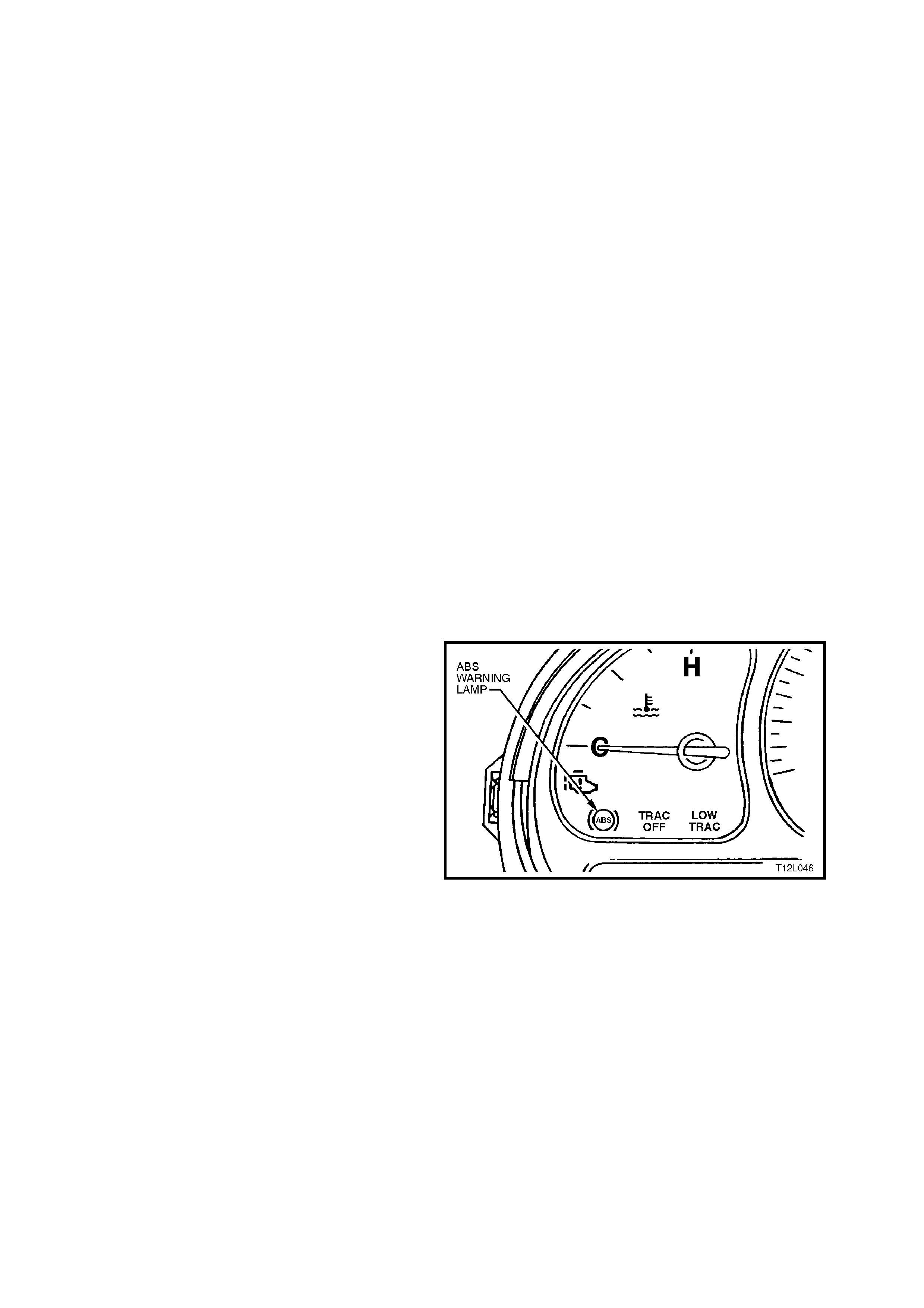
4.6 ABS & ABS/ETC SELF DIAGNOSTICS
DIAGNOSTIC TROUBLE CODES
The ABS and ABS/ETC control modules are
equipped with a self diagnostic capability that can
detect and isolate ABS and ABS/ETC problems or
failures . W hen a pr oblem or f ailure is detected, the
ABS or ABS/ETC control module sets a diagnostic
trouble code (DTC) that represents that particular
problem or failure. There are twenty one DTCs on
ABS and twenty nine on ABS/ETC systems that
may be set by the ABS or ABS/ETC control
module. Depending on the DTC set, either the
ABS, ETC or both ABS and ETC systems will be
disabled. If the ABS is disabled, it will allow for
conventional non ABS braking only and the ABS
warning lamp will be turned on. T he control module
has the capacity of storing three DTC’s.
NOTE:
W arning lamp will illuminate whilst f ault is active. If
a fault has occurr ed and is not active, the lamp will
not be illuminated and a fault code will be stored.
The control module performs an automatic test
once during each ignition cycle when the vehicle
reaches approximately 6 km/h (18km/h if the stop
lamp switch signal is received). The automatic test
cycles each solenoid valve and the pump motor to
check component operation. If any error is
detected during this test, the ABS or ABS/ETC
control module will set a DTC. This test may be
heard and felt while it is taking place and is a
normal mode of operation.
The ABS or ABS/ETC control module can display
the DTCs via the ABS warning lamp only when the
'Diagnostic Service Mode' has been entered.
Entering the diagnostic service mode is
accomplished by either earthing terminal 12 of the
Data Link Connector (DLC) using a test lead fitted
with suitable terminals and using ABS warning
lamp to flash system DTCs as described under
Flash Code Diagnostics Display in this Section or
by using Tech 2 (refer to
4.7 TECH 2 DIAGNOSTICS in this Section).
Figure 12L-78
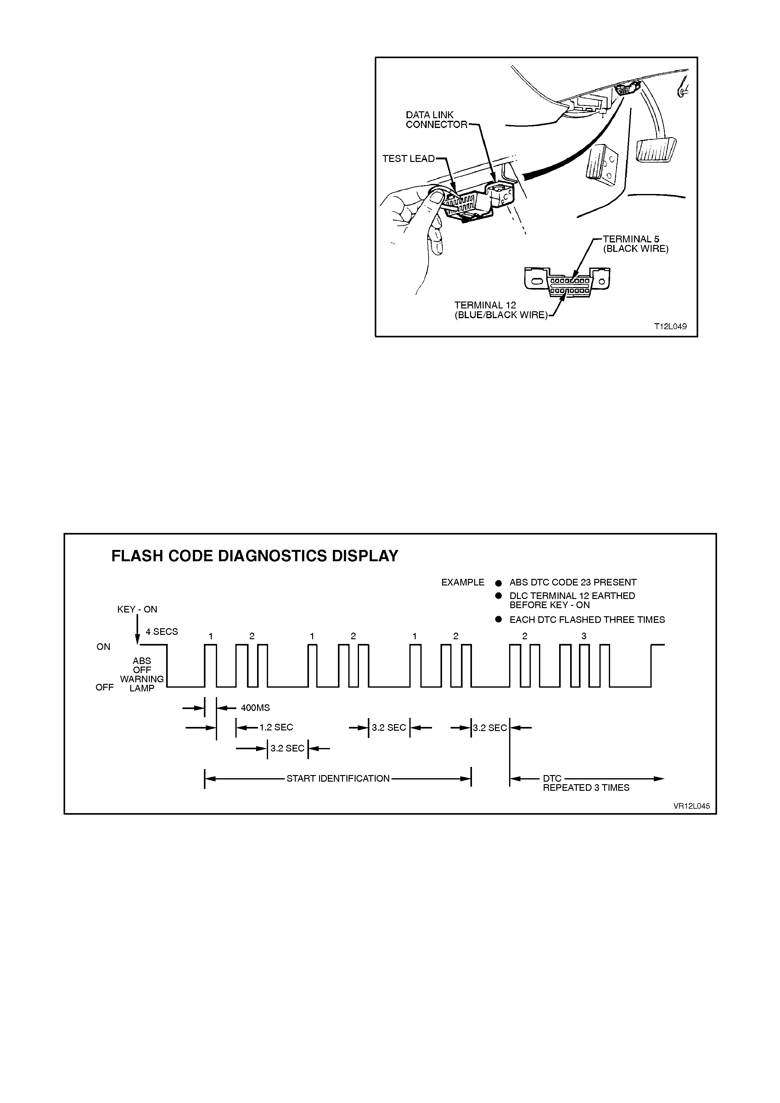
FLASH CODE DIAGNOSTICS DISPLAY
To enable the ABS warning lamp to flash system
DTCs, the vehicle must be stopped (vehicle speed
is less than 10 km/h), terminal 12 of the DLC
earthed (DLC terminal 5) using a test lead fitted
with suitable terminals and then the ignition turned
on. The flash code diagnostics will remain enabled
as long as terminal 12 is earthed, serial data line
communication has not been initiated or until any
wheel speed is greater than 10 km/h.
Approxim ately 3 seconds after earthing terminal 12
(ignition on) of the DLC, the ABS or ABS/ETC
control module will begin flashing the ABS warning
lamp.
The flash sequenc e will begin with DTC 12 to signal
the beginning of the f lash code display. DTC 12 will
flash three times. Each stored code will then be
displayed three times. After all codes have been
displayed, the sequence will repeat, starting with
DTC 12.
The following charts set out all the possible
diagnostic trouble codes.
NOTE:
Flash code diagnosis is not fully supported on
certain trouble codes involving the solenoid valves
or motor due to the valve relay inside the control
unit being disabled. Trouble codes 41, 42, 45, 46,
47, 48, 55, 56, 61 and 63 will prevent the ABS
warning lamp from turning off. These faults can
only be read through the DLC using TECH 2.
Figure 12L-79
Figure 12L-80

ABS DIAGNOSTIC TROUBLE CODES (EXCLUDING ABS/ETC)
DTC CODE DESCRIPTION
12 No Fault
21 Front Right Wheel Speed Sensor Incorrect Signal
23 Front Right Wheel Speed Sensor Short Circuit or Open
Circuit
25 Front Left Wheel Speed Sensor Incorrect Signal
27 Front Left Wheel Speed Sensor Short Circuit or Open Circuit
28 Wheel Speed Sensor Frequency Error
31 Rear Right Wheel Speed Sensor Incorrect Signal
33 Rear Right Wheel Speed Sensor Short Circuit or Open Circuit
35 Rear Left Wheel Speed Sensor Incorrect Signal
37 Rear Left Wheel Speed Sensor Short Circuit or Open Circuit
41 Front Right Inlet Valve Solenoid Fault
42 Front Right Outlet Valve Solenoid Fault
45 Front Left Inlet Valve Solenoid Fault
46 Front Left Outlet Valve Solenoid Fault
55 Rear Axle Inlet Valve Solenoid Fault
56 Rear Axle Outlet Valve Solenoid Fault
61 Pump Motor or Relay Fault
63 Valve Solenoid Relay Circuit Fault
67 Stop Lamp Switch Circuit Fault
71 Control Module Internal Fault
85 System Voltage Too Low

ABS/ETC DIAGNOSTIC TROUBLE CODES (EXCLUDING ABS)
DTC CODE DESCRIPTION
12 No Fault
21 Front Right Wheel Speed Sensor Incorrect Signal
23 Front Right Wheel Speed Sensor Short Circuit or Open
Circuit
25 Front Left Wheel Speed Sensor Incorrect Signal
27 Front Left Wheel Speed Sensor Short Circuit or Open Circuit
28 Wheel Speed Sensor Frequency Error
31 Rear Right Wheel Speed Sensor Incorrect Signal
33 Rear Right Wheel Speed Sensor Short Circuit or Open Circuit
35 Rear Left Wheel Speed Sensor Incorrect Signal
37 Rear Left Wheel Speed Sensor Short Circuit or Open Circuit
41 Front Right Inlet Valve Solenoid Fault
42 Front Right Outlet Valve Solenoid Fault
45 Front Left Inlet Valve Solenoid Fault
46 Front Left Outlet Valve Solenoid Fault
47 Priming Valve Solenoid Fault
48 Switching Valve Solenoid Fault
51 Rear Right Inlet Valve Solenoid Fault
52 Rear Right Outlet Valve Solenoid Fault
55 Rear Left Inlet Valve Solenoid Fault
56 Rear Left Outlet Valve Solenoid Fault
61 Pump Motor or Relay Fault
62 RPM Signal Fault
63 Valve Solenoid Relay Circuit Fault
67 Stop Lamp Switch Circuit Fault
71 Control Module Internal Fault
72 Serial Data Fault
73 Requested Torque Circuit Fault
74 Actual Torque Circuit Fault
78 Incorrect Option Coding
85 System Voltage Too Low
CLEARING DTCS
Any DTCs stored in the ABS or ABS/ETC control module's memory can be erased in one of three ways:
1. Diagnostic Request Line Procedure.
2. Tech 2 Clear Codes Selection.
3. Ignition Cycle Default.
These three methods are detailed as follows.
IMPORTANT:
Whichever method is used, be sure to verify proper system operation and absence of any DTCs when clearing
procedure is completed. The ABS or ABS/ETC control module will not permit DTC clearing until all of the codes
have been displayed. Also, DTCs cannot be cleared by unplugging the ABS or ABS/ETC control module,
disconnecting the battery cables, or turning the ignition OFF (except on an ignition cycle default).
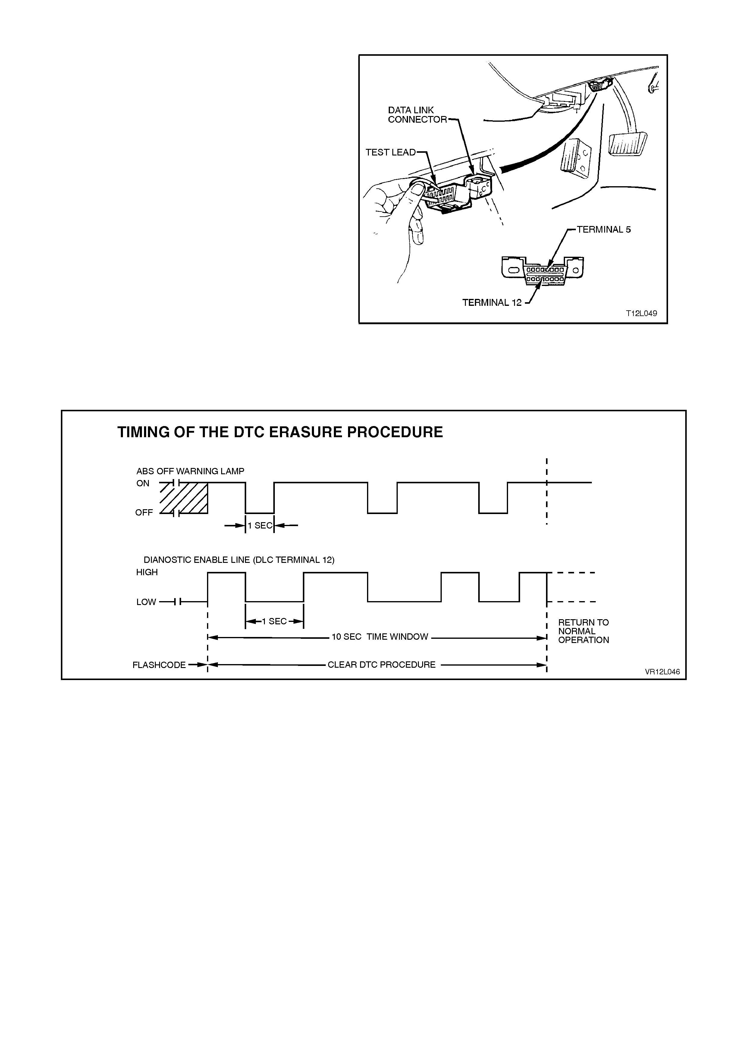
Diagnostic Reques t Line Procedure
To clear trouble codes via the DLC diagnostic
request line (terminal 12), go through the following
procedure.
1. Turn ignition OFF.
2. Connect a test lead fitted with suitable
terminals between DLC terminals 5 (black
wire) and 12 (blue/black wire).
3. Turn ignition on (this will enable Flash Code
Diagnostics Display) and allow all codes to be
displayed.
4. Disconnect one end of test lead from DLC for
approximately 1 second then reconnect for no
less than 1 second. Repeat this step at least 2
more times within 10 seconds, leaving test
lead connected to DLC upon completion of
final connection.
Observe flashing ABS warning lamp. Only DTC 12
should be flashed. If not, trouble codes have not
been properly cleared. Begin clearing code
procedure again at Step 1. If DTCs are cleared,
wait at least 15 seconds before turning ignition
'OFF'.
Figure 12L-81
Figure 12L-82
TECH 2 Clear Codes Procedure
Before clearing DTC’s, check and note any history
code data, as this information will also be cleared.
Select the appropriate menu, and select the Clear
Codes function. Verify that DTC’s have been
cleared by using the TECH 2 to read ABS or
ABS/ETC trouble codes. If any are present, either
the DTCs were not cleared, or an ABS or ABS/ETC
fault still exists.
Ignition Cycle Default
If the ignition is cycled 100-times without a
particular fault reappearing, that fault code will be
erased from the ABS or ABS/ETC control module
memory, and the ignition cycle counter inside the
control module will be reset to zero.
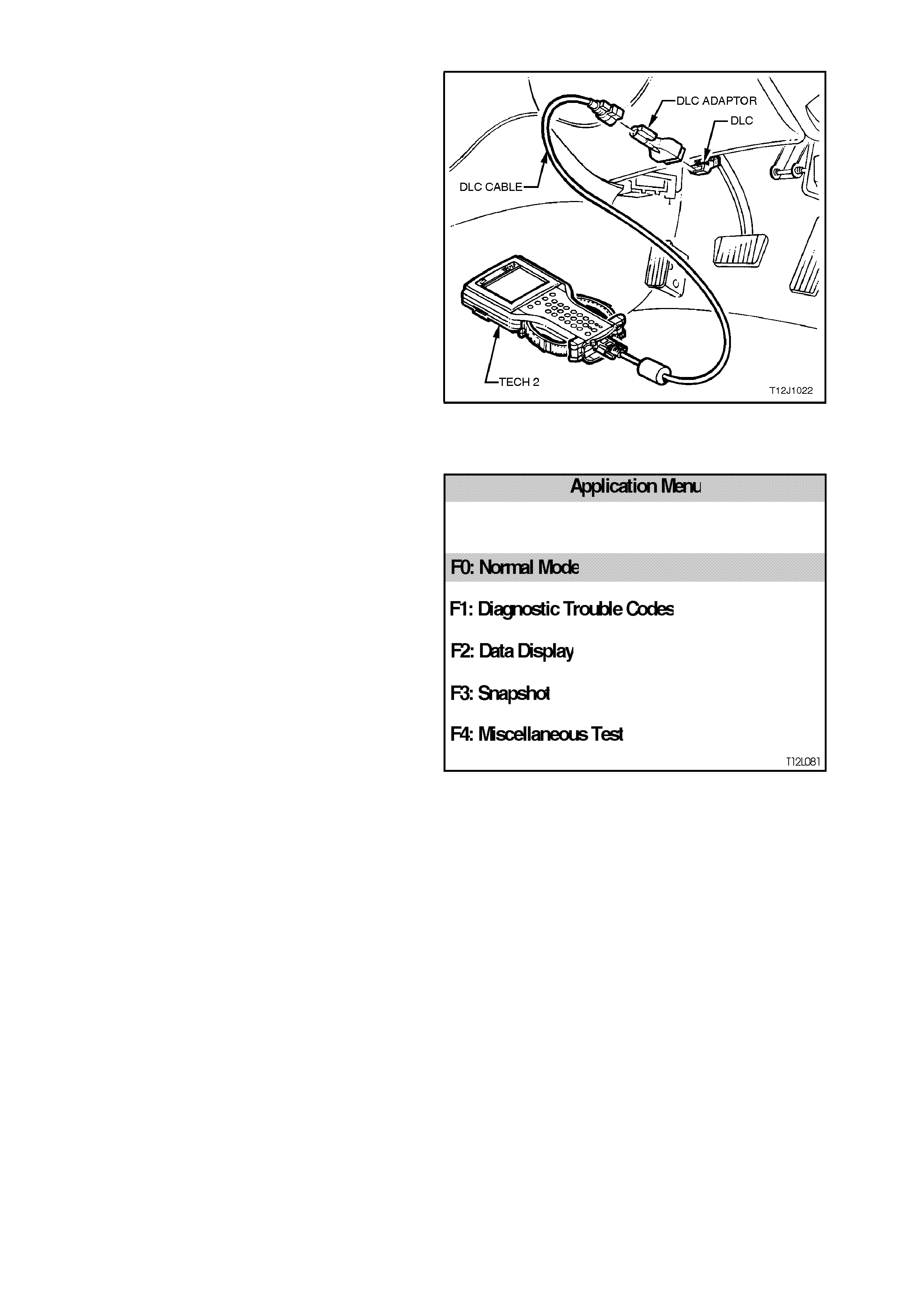
4.7 TECH 2 DIAGNOSTICS
IMPORTANT:
When using the TECH 2 in certain diagnostic
modes for ABS or ABS/ETC diagnosis, the Anti-
lock Brake System is disabled by the ABS or
ABS/ETC control module while it is
communicating with TECH 2. The ABS warning
lamp in the instrument cluster will be
illuminated, indicating only conventional (non
ABS) braking is possible.
TECH 2, with the appropriate software, cables and
adaptors, when connected to the Data Link
Connector (DLC) is capable of reading ABS or
ABS/ETC serial data. T he DLC is connected to the
instrument panel lower right hand trim, to the right
of the steering column.
For additional general information on connecting
and operating TECH 2, refer to
Section 0C TECH 2.
The T ECH 2 has f ive tes t modes f or diagnos ing the
Anti-lock Brake System and Electronic Traction
Control system. The five test modes are as follows:
Figure 12L-83
Mode F0: Normal Mode
In this mode, the Tech 2 monitors the constant
communication between control modules on the
serial data line. The information displayed on the
TECH 2 screen in this mode is what the ABS or
ABS/ETC control module is communicating to the
other modules via the serial data line.
Mode F1: Diagnostic Trouble Codes
In this mode, TECH 2 will display a DTC selection
list. When the appropriate function key is selected,
the TECH 2 will display a DT C Data List. The Data
List contains relevant information relating to the
DTC.
Mode F2: Data Display
In this test mode, the operator of Tech 2 has the
option of selecting an Active or Disabled data
stream that they can use to constantly monitor the
status of inputs and outputs of the ABS or
ABS/ETC system.
Mode F3: Snapshot
In this test mode, the Tech 2 captures ABS or
ABS/ETC data before and after a forced manual
trigger.
Mode F4: Miscellaneous Tests
In this test mode, the Tech 2 performs system
functional tests to assist in pr oblem isolation during
troubleshooting.
Each test mode has specific diagnosis capabilities
that depend upon various function key entries on
TECH 2.
Also, included in the MISCELLANEOUS TESTS is
a procedure for ABS or ABS/ETC brake bleeding.
Figure 12L-84
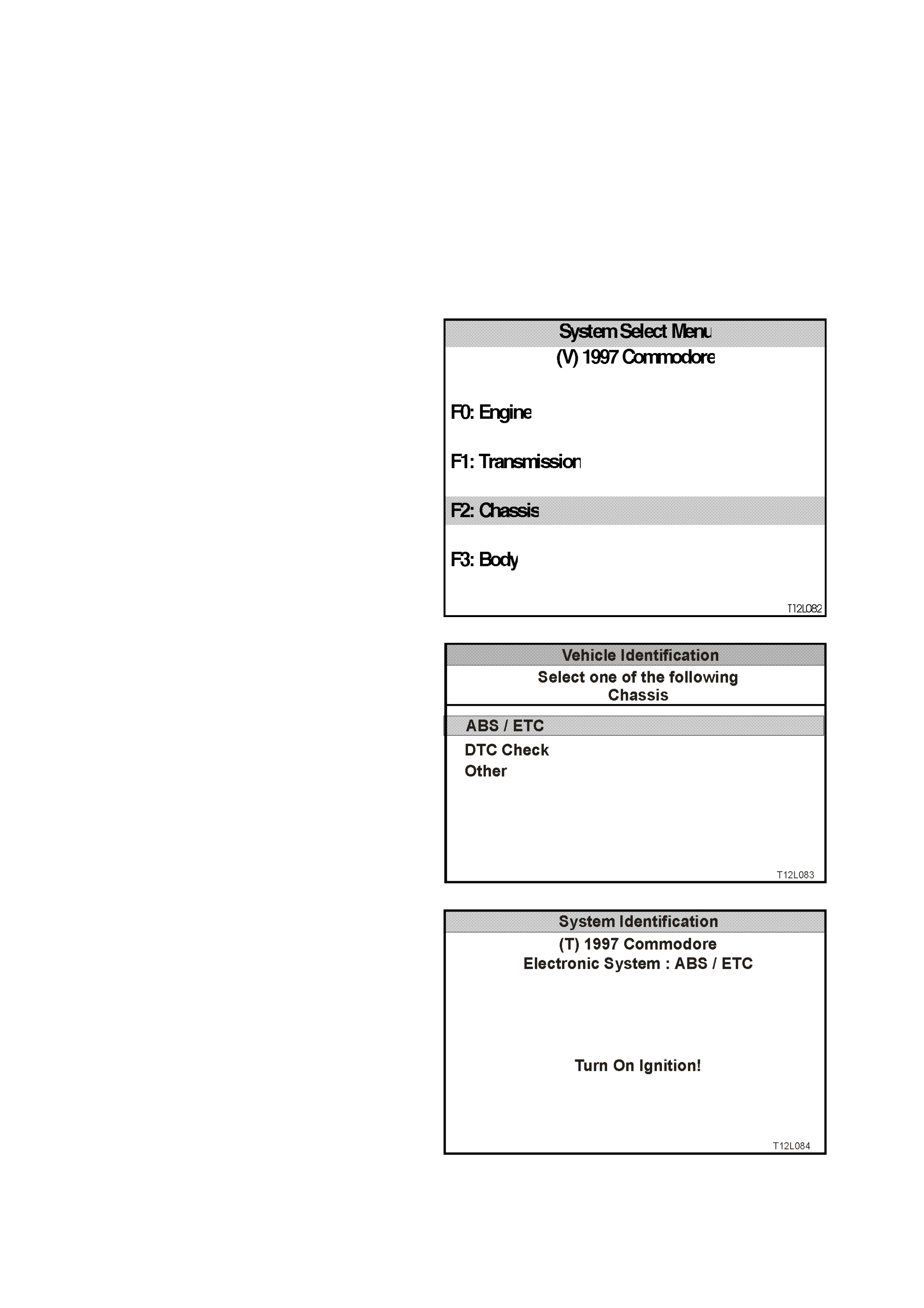
4.8 TECH 2 TEST MODES AND SCREEN DISPLAYS FOR ABS AND ETC DIAGNOSI S
WARNING:
When using TECH 2 for ABS and ABS/ETC
diagnosis, in certain diagnostic modes, the
system will be disabled.
As a prerequisite to this diagnostic section is for the
user to be familiar with the proper use of TECH 2,
the following illustrates only the major TECH 2
screen displays and provide a brief explanation of
their function for diagnosing the ABS or ABS/ETC
systems. If additional infor mation is r equired on the
operation of TECH 2, referenc e should be made to
either Section 0C TECH 2 or the TECH
OPERATORS MANUAL.
System Select Menu
With TECH 2 connected to the DLC and F0:
DIAGNOST ICS selected f rom the MAIN MENU, the
correct MODEL YEAR and VEHICLE TYPE must
be selected for access to the SYSTEM SELECT
MENU.
Select F2: CHASSIS and press enter to continue.
Figure 12L-85
Vehicle Identification Menu
Once F2: CHASSIS has been selected from the
select menu, the ABS/ETC systems can be
selected.
Select ABS/ETC.
Once ABS/ETC is selected, the ABS/ETC
Application menu will be displayed, via the System
Identification screens which will require action.
Note:
If DTC Check is selected, TECH 2 will display
information advising if any DTC’s are set by any
module. (If DTC’s are set from another module,
refer to the relevant Section). Figure 12L-86
System Identification
Turn the ignition ON (as requested) and press
CONFIRM soft key to continue.
Figure 12L-87
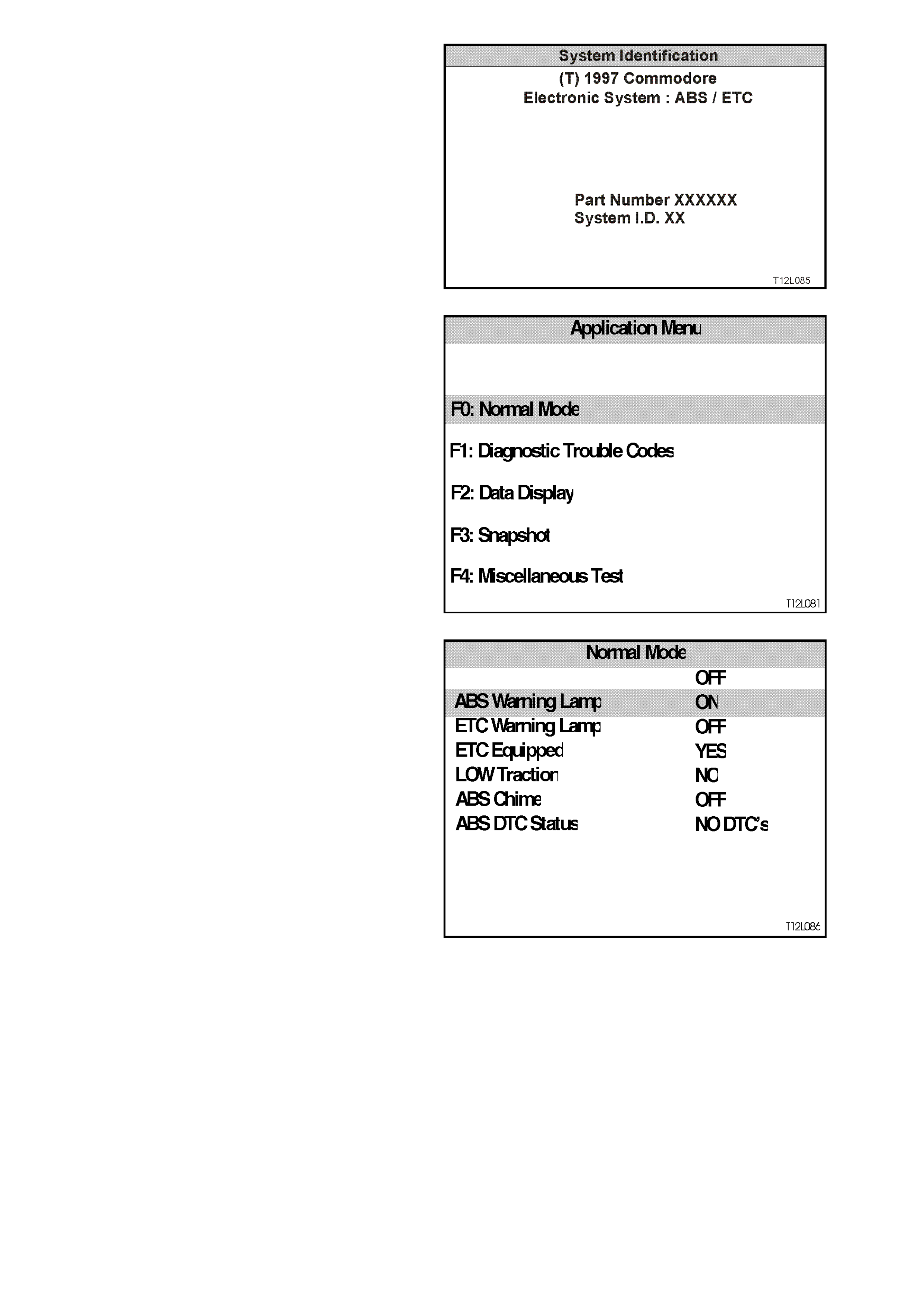
The SYSTEM IDENTIFICATION screen will then
display the control module par t num ber and s ystem
identification. Press the CONFIRM soft key to
continue to the ABS/ETC APPLICATION MENU.
Figure 12L-88
ABS/ETC Application Menu
The following functions will now be available:
F0: Normal Mode
F1: Diagnostic Trouble Codes
F2: Data display
F3: Snapshot
F4: Miscellaneous Tests
Figure 12L-89
F0: NORMAL MODE
In the F0: Normal Mode, information that the ABS
or ABS/ETC Control Module is communicating to
other control modules, via the serial data line, is
displayed.
For example: As displayed opposite, the ETC or
ABS/ETC W arning lamp status is ON. This means
the ABS or ABS/ETC control module is
communicating with the instrum ents requesting the
ABS OFF warning lamp to be illuminated.
Figure 12L-90

F1: DIAGNOSTIC TROUBLE CODES
If the F0: READ DT C’s is selected from this mode,
a listing of all (if any) DTC’s that have been set by
the ABS or ABS/ETC control module will be
displayed. To obtain further information about a
particular DT C, press the relevant f unction key and
a DTC data list will be displayed. From the
information provided in this data list, you can
determine when the DTC occurred and the
operating conditions of the system at the time.
For a listing of all DTC’s, refer to
4.6 ABS & ABS/ETC SELF DIAGNOSTICS in this
Section.
DTC’s can be cleared by simply selecting F1 Clear
DTC’s and pressing the ENTER key.
NOTE:
If any DTC’s are set, reference should be made to
the relevant diagnostic charts in this Section.
Figure 12L-91
F2: DATA DISPLAY
If the F2: DATA DISPLAY mode is selected, an
additional application menu will appear giving the
operator the option of selecting ABS or ABS/ETC
data while the system is either active or disabled.
F0: Active ABS/ETC
F1: ABS/ETC disabled
If the disabled data list is selected, the ABS
warning lamp will be illuminated and the s ystem will
become disabled.
While the two data lists offer similar information,
the active data list has the advantage of m onitoring
the ABS or ABS/ETC systems while they are
operational, aiding in the diagnosis of intermittent
faults.
When monitoring speed data, the TECH 2 screen
displays the signals being sent from the wheel
speed sensors to the control module. In F0: Active
ABS/ETC display mode, the vehicle can be driven
while the TECH 2 displays wheel speed data. At
this time, the readings may be compared with
vehicle speed to check proper operation. Wheel
speed signals can also be compared with each
other to determine whether they are within
specification.
If one wheel speed signal differs greatly from the
other signals, improper operation of that particular
sensor may be indicated. Intermittent wheel speed
signals can be detected in this m ode by look ing for
signals that vary for no apparent reason. This
variation can occur during vehicle operation and
can be captured during F3: SNAPSHOT test mode.
For additional information regarding the soft keys
while in the DATA DISPLAY mode, refer to
Section 0C TECH 2.
The table below lists each item contained in the
data stream for both active and disabled lists,
together with a brief description of their meanings.

ACTIVE ABS/ETC
DATA STREAM / SCREEN DISPLA Y DESCRIPTION
FR Wheel Speed (Front Right) Displays wheel speed sensor input (km/h) to
the control module.
FL Wheel Speed (Front Left)
RR Wheel Speed (Rear Right)
RL Wheel Speed (Rear Left)
Pump Motor Displays current status of pump motor - either
ON or OFF.
Pump Relay Displays current status of pump relay - either
ON or OFF.
Valve Relay Displays current status of valve relay - either
OPEN or CLOSED.
ETC Switch Displays current status of switch - will display
OPEN when switch is in the rest position and
CLOSED when held down (ETC Only).
Requested Torque Displays the amount of torque the ABS/ETC
control module is requesting the engine to
deliver (ETC Only).
Actual Torque Displays the calibrated torque (in Nm) that the
engine is delivering (ETC Only).
ABS/ETC DISABLED
DATA STREAM / SCREEN DISPLA Y DESCRIPTION
FR Wheel Speed (Front Right) Displays wheel speed sensor input (km/h) to
the control module.
FL Wheel Speed (Front Left)
RR Wheel Speed (Rear Right)
RL Wheel Speed (Rear Left)
Stop Lamp Switch Displays current status of switch - displays
OFF when switch is in the rest position and ON
when brake pedal is depressed.
Pump Monitor Will always display OFF as ABS and ETC are
disabled in this mode.
Valve Relay Displays current status of valve relay - either
OPEN or CLOSED.
NOTE:
If OPEN displays in this mode, there is a fault
in the valve relay circuit.
ETC Switch Displays current status of switch - displays
OPEN when switch is in the rest position and
CLOSED when held down (ETC Only).
Engine Speed Displays the current engine speed in RPM
(ETC Only).
Requested Torque Displays the amount of torque (in Nm) the
ABS/ETC control module is requesting the
engine to deliver (ETC Only).
Actual Torque Displays the calibrated torque (in Nm) that the
engine is delivering (ETC Only).
System ID Displays control module internal software
identification number.
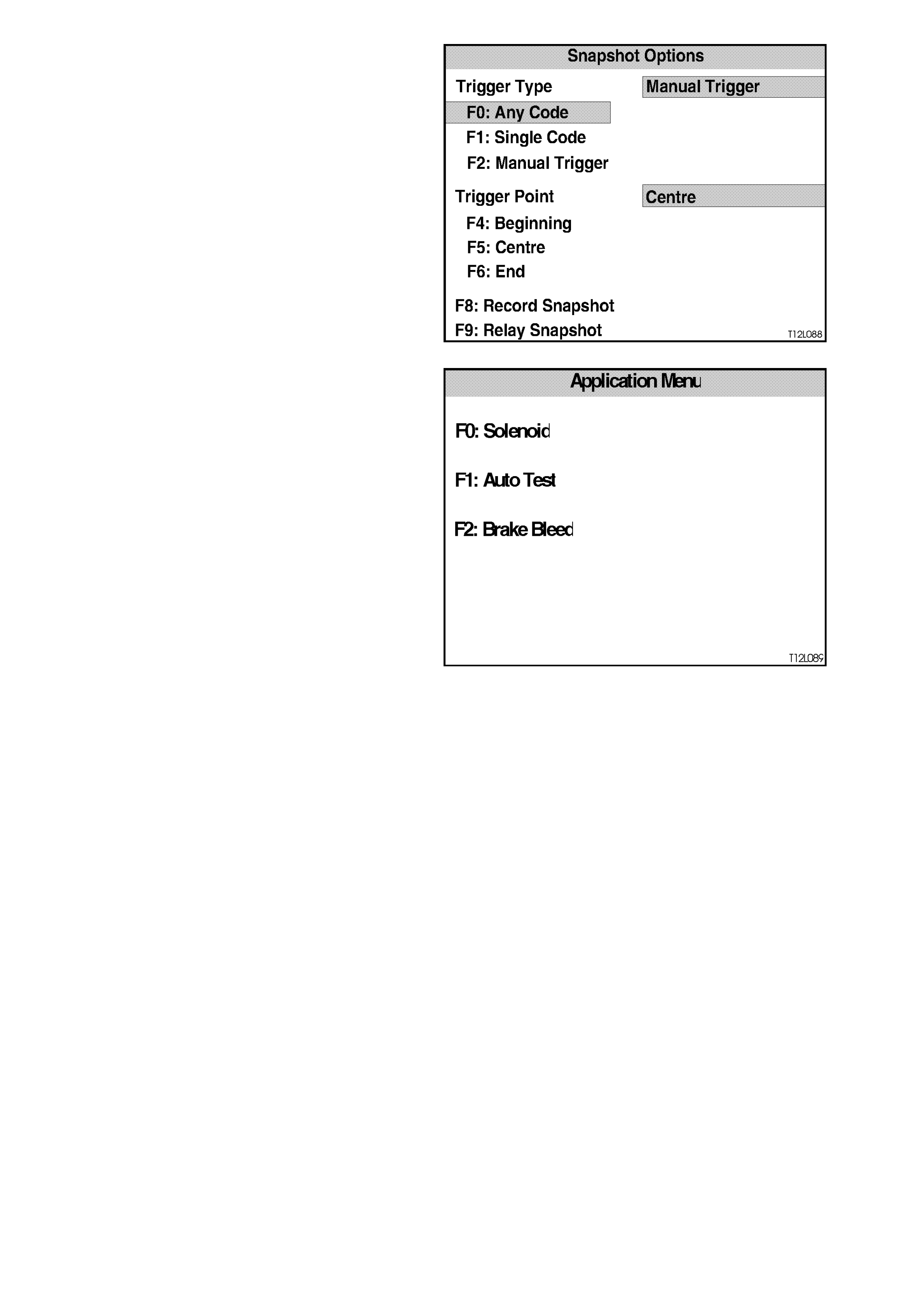
F3: SNAPSHOT
The snapshot mode will help to identify problems
caused by speed sensor signals that may cause
intermittent operation of the ABS or ABS/ETC
systems.
The SNAPSHOT mode captures data before and
after a forced manual trigger condition.
Figure 12L-92
F4: MISCELLANEOUS TESTS
In the Miscellaneous Tests mode, functional tests
are available on the ABS and ABS/ETC systems
that will help identify proper operation. In this m ode,
error conditions can be further identified by testing
and observing the test results.
Additionally, in this mode, the hydraulic modulator
can be bled (F2: BRAKE BLEED).
In the MISCELLANEOUS TESTS mode the
following tests can be performed:
F0: Solenoid
This test indicates whether spec ific s olenoid valves
in the hydraulic modulator release pressure to
assigned hydraulic wheel circuits and hold pr es sur e
in assigned hydraulic wheel circuits. Figure 12L-93
NOTE:
Use this procedure in conjunction with the
information displayed on the TECH 2 SCREEN
while in the F0: SOLENOID test mode.
The PRESSURE RELEASE part of the test
activates a selected hydraulic wheel circuit valve,
placing it in the pressure release position. Valve
action can then be verified by checking the
appropriate wheel for proper brake action.
The PRESSURE HOLD part of the test activates a
selected hydraulic wheel circuit valve, placing it in
the pressure hold position. Valve action can then be
verified by checking the appropriate wheel for
proper brake action.
These tests completely check each solenoid valve.
With an assistant, the pressure release and hold
tests can be verified as follows:
1. Ignition OFF.
2. Raise vehicle such that the wheels are at least
150 mm off the floor.
3. Install TECH 2 to the DLC.
4. Select Diagnostics / Chassis / ABS/ETC and
turn ignition on and confirm System
Identification information as instructed.
5. Select Miscellaneous Tests / Solenoids.
6. Select the relevant solenoid to be tested and
press ENTER.

7. Follow instructions on the TECH 2 display
screen while getting an assistant to try to spin
the road wheel being tested when requested by
TECH 2.
NOTE:
This test verifies correct operation of the hydraulic
functioning of the solenoid valves, Electrical
function is verif ied by the constant monitor ing of the
solenoid circuits by the control module during
normal operation of the system. If the control
module detects an electrical problem, such as an
open to ground of a solenoid circuit, a DTC will be
set and the system will be disabled.
F1: Auto Test
The AUTO Test is performed automatically by the
control module once during each ignition cycle
when the vehicle reaches approximately 6 km/h.
The TECH 2 will perform this test automatically
during the ABS TESTS mode. The AUTO Test
cycles each solenoid valve and the pump motor
briefly to check c om ponent operation. If any error is
detected during this tes t, the control m odule will set
a DTC and the ABS and or TRAC OFF warning
lamp will be illuminated. Perform the test as follows:
NOTE 1: Use this procedur e in conjunc tion with the
information displayed on the TECH 2 SCREEN
while in the F1: AUTO TEST, test mode.
NOTE 2: If there are any DTC’s set, they will have
to be cleared before this test can be performed.
Procedure
1. Turn ignition OFF.
2. Install TECH 2 to the DLC.
3. Select Diagnostics / Chassis / ABS/ETC and
turn ignition on and confirm System
Identification information as instructed.
4. Select Miscellaneous Tests / Auto Test and
press the CONTINUE soft key on TECH 2 to
start test (return pump will be heard running for
a short period).
5. Note any DTCs that are set when test is
completed.

F2: Brake Bleed
This test pr ompts the tec hnic ian to bleed the brake system . T he tes t is divided into two par ts ; a primar y bleed and a
secondary bleed. A prim ary bleed is a m anual bleed of eac h hydraulic cir cuit. Dur ing a s econdar y bleed, the ABS or
ABS/ETC control module activates the solenoid and pump motor so that any air in these components is expelled.
NOTE 1:
The AUTO TEST m ust be carried out prior to conducting the brake bleed procedure. If the automatic test has not
been conducted, carry out test as described under F1: AUTOMATIC TEST.
The brake bleed procedure is as follows:
1. Install brake bleeding equipment to vehicle as recommended in Section 5 BRAKES.
2. Turn ignition OFF.
3. Install TECH 2 to DLC.
4. Select Diagnostics / Chassis / ABS/ETC and turn ignition on and confirm System Identification information as
instructed.
5. Select Miscellaneous Tests / Brake Bleed and follow instructions on the TECH 2 display screen.
NOTE 2:
The T ECH 2 screen will display “RUN AUTO TEST PRIOR T O BRAKE BLEED. DONE ?” Select YES or NO. The
AUTOMATIC T EST must be c arr ied out prior to conduc ting the br ak e bleed pr oc edure. If the auto tes t has not been
conducted, select NO and carry out test as described under F1: AUTO TEST.
If the auto test has been completed, select YES and continue.
The procedure will begin with a manual bleed at the right hand rear brake calliper. Ensure a suitable size plastic
hose is installed over the bleed screw and that it leads into a container of brake fluid.
While following the bleed procedure, as per TECH 2 instructions, ensure that fluid is continuously fed into the
master cylinder.

4.9 DIAGNOSTIC CHARTS
INTRODUCTION
The following diagnostic charts are designed to provide fast and efficient fault location of the ABS or ABS/ETC
systems. Each diagnostic chart consists of: a ‘diagnostic chart’, connector body terminal assignments for
connectors relevant to that particular diagnostic chart, and pertinent information including Diagnostic Trouble Code
(DTC) setting parameters and circuit diagrams.
The following figures illustrate the terminal layout of the various connectors used in the system. This figure should
be used in conjunction with the diagnostic chart circuit diagrams when checking circuit faults if the connector
diagram is not included in the chart.
When carrying out wiring checks as directed to by the diagnostic charts, rather than probe terminals and connectors
with incorrect sized multimeter connections, use the adaptors contained in connector test adaptor kit KM-609. This
will prevent any possibility of spreading or damaging wiring harness terminals.
ON-VEHICLE SERVICE
When a diagnostic chart in this Section makes reference to removing/reinstalling or checking a component for
proper mounting or operation, refer to the appropriate service operation in this Section. After all diagnosis and
repairs are completed, road-test the vehicle to ensure proper ABS and ABS/ETC operation and the ABS and TRAC
OFF warning lamps do not come on, refer to 4.4 FUNCTIONAL CHECK in this Section. If the TECH 2 was used
for diagnosis, disconnect it from the DLC and turn the ignition OFF for at least 10 seconds before road testing. This
is necessary to reset the ABS or ABS/ETC control module as it is disabled during most TECH 2 diagnostic
procedures, and does not reset until serial data communication is stopped and ignition power is lost.
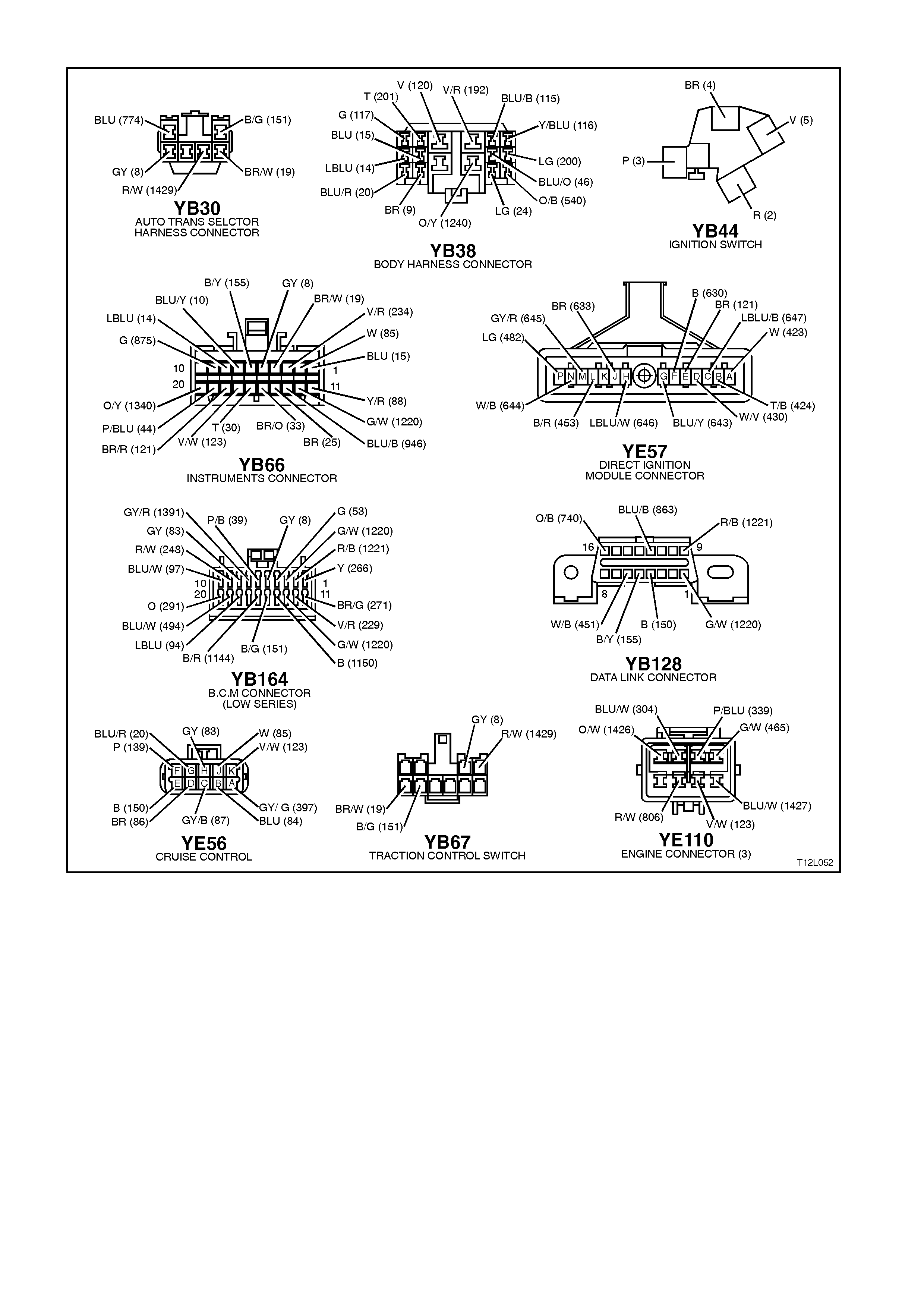
WIRING HARNESS CONNECTORS
Figure 12L-94
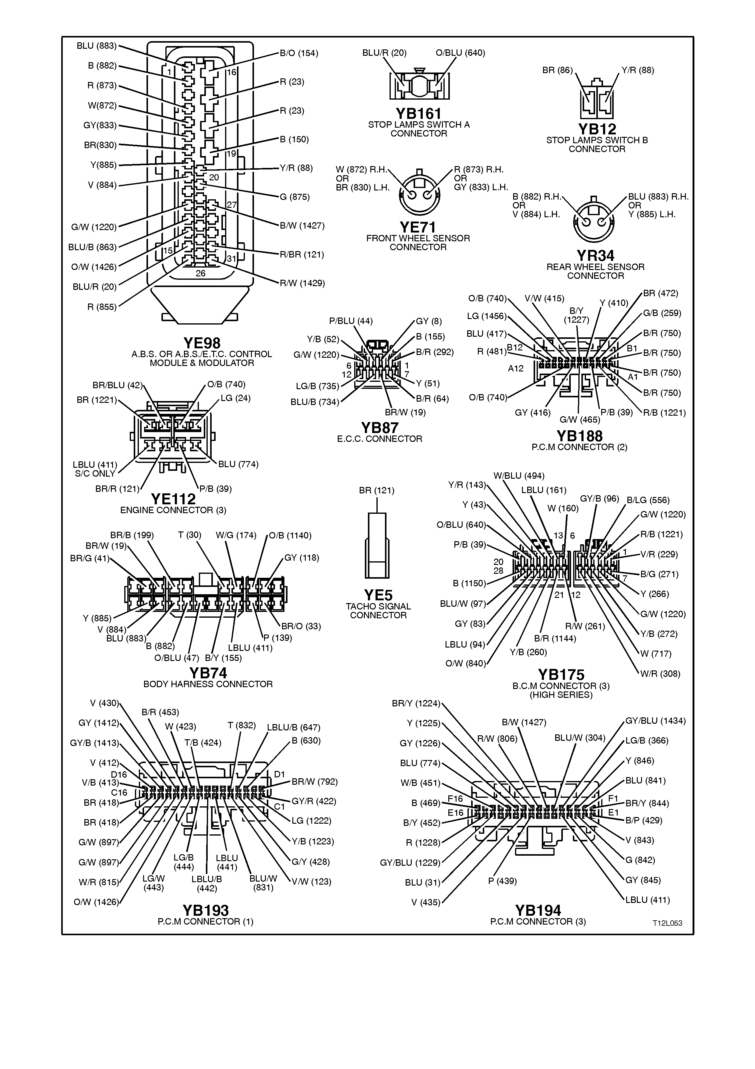
Figure 12L-95
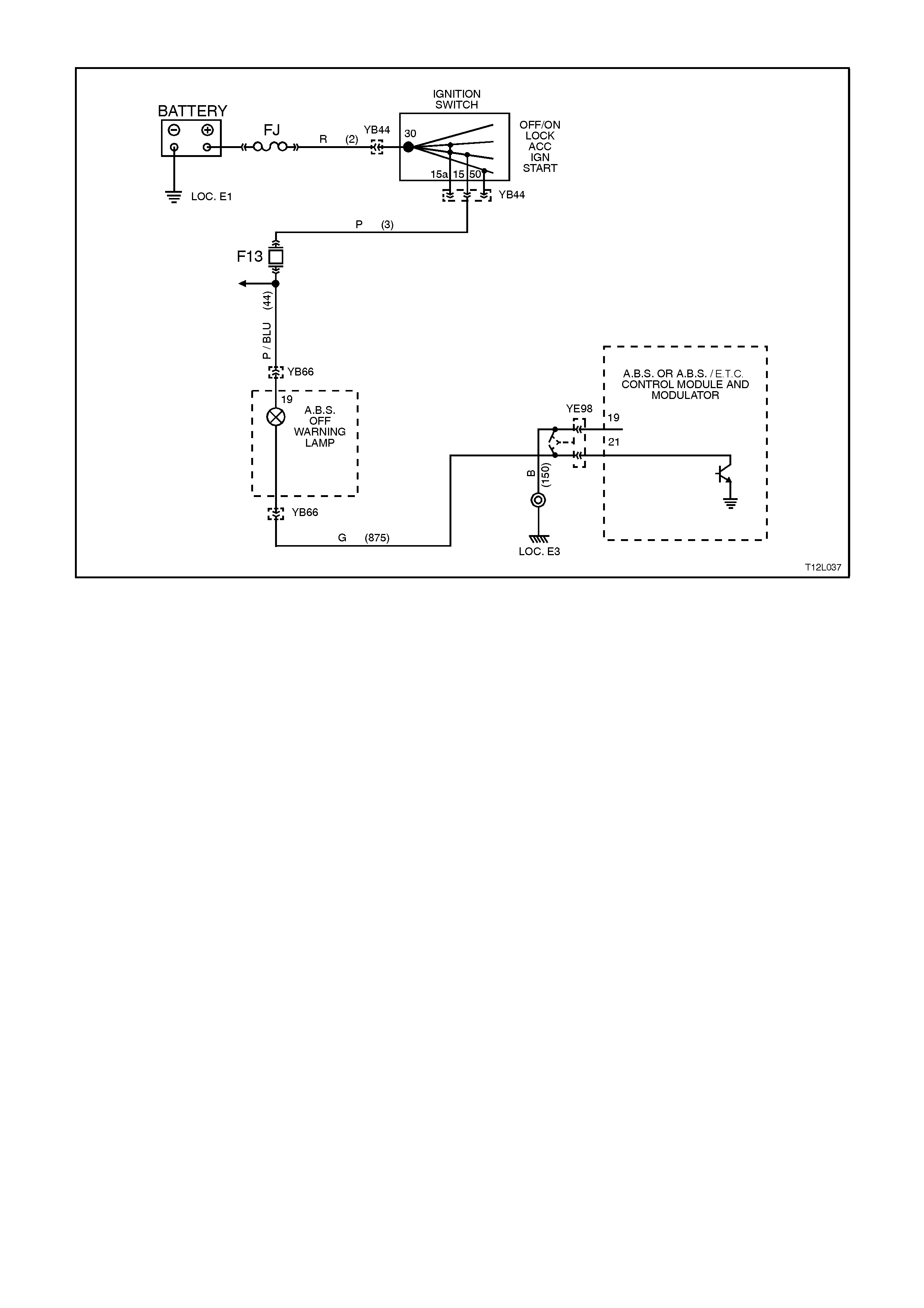
CHART A1 - ABS WARNING LAMP INOPERATIVE
Figure 12L-96
CIRCUIT DESCRIPTION:
Battery voltage is supplied to the ABS OFF warning lamp with the ignition switch in the IGN or START positions
through fuse F13 (located in the passenger compartment fuse panel).
The warning lamp can only be activated by the ABS or ABS/ETC control module internally by supplying earth to
terminal 21 or via shorting bar in the ABS or ABS/ETC control module connector YE98 when it is disconnected from
the control module.
TEST DESCRIPTION:
The numbers below refer to step numbers in diagnostic chart A1.
1. This test checks for any DTC's that may cause the ABS warning lamp to be inoperative.
2. This test verifies an inoperative warning lamp condition.
3. This test checks if fault is within control module.
4. This step determines if the warning lamp bulb or socket is defective.
5. This test checks for a faulty voltage supply to the warning lamp.
6. Checks circuit 875.
7. Checks the warning lamps earth circuit to the ABS or ABS/ETC control module.
NOTES ON DIAGNOSTIC CHART:
1. Refer to 4.7 TECH 2 DIAGNOSTICS in this Section for connecting and using TECH 2.
2. Refer to Section 12P WIRING DIAGRAMS for procedures on checking wiring faults.

STEP ACTION VALUE YES NO
1. ∙Install TECH 2 to
DLC and select
Diagnostics / Chassis
/ Diagnostic Trouble
Codes / Read DTC’s
(refer to NOTE 1
above).
∙Are any DTC's set ?
Repair conditions
which set DTC's,
recheck and verify
repair.
Go to Step 2.
2. ∙Disconnect TECH 2
from DLC.
∙Turn ignition on
whilst observing ABS
warning lamp.
∙Does warning lamp
illuminate for
approximately 2
seconds then turn
OFF ?
NOTE:
If battery voltage is below
9V, lamp may stay on.
No fault found.
Perform ABS or
ABS/ETC
functional check
as per 4.4 in this
Section.
Go to Step 3.
3. ∙Turn ignition OFF.
∙Disconnect ABS or
ABS/ETC control
module connector
YE98 from control
module.
∙Turn ignition ON.
∙Does ABS warning
lamp illuminate ?
Check control
module connector
YE98 terminals
for correct sizing
& condition. If all
OK, replace
control module.
Go to Step 4.
4. ∙Remove instrument
cluster, refer to
Section 12C
INSTRUMENTS,
WIPERS/WASHERS
AND HORN.
∙Remove ABS
warning lamp bulb
and socket from
instrument cluster
and check warning
lamp bulb condition.
∙Is bulb and socket
OK ?
Go to Step 5. Replace ABS
warning lamp bulb
and/or socket,
recheck and verify
repair.
5. ∙With instrument
cluster removed,
switch ignition on and
measure voltage
between connector
YB66, terminal 19,
circuit 44 (Pink/Blue
wire) and earth (refer
to NOTE 2 above).
∙Is voltage as
specified ?
Battery
+Go to Step 6. Check fusible link
FJ and fuse F13.
Check wiring
between ignition
switch and
instrument cluster
connector YB66.
Check ignition
switch contacts,
recheck and verify
repair.
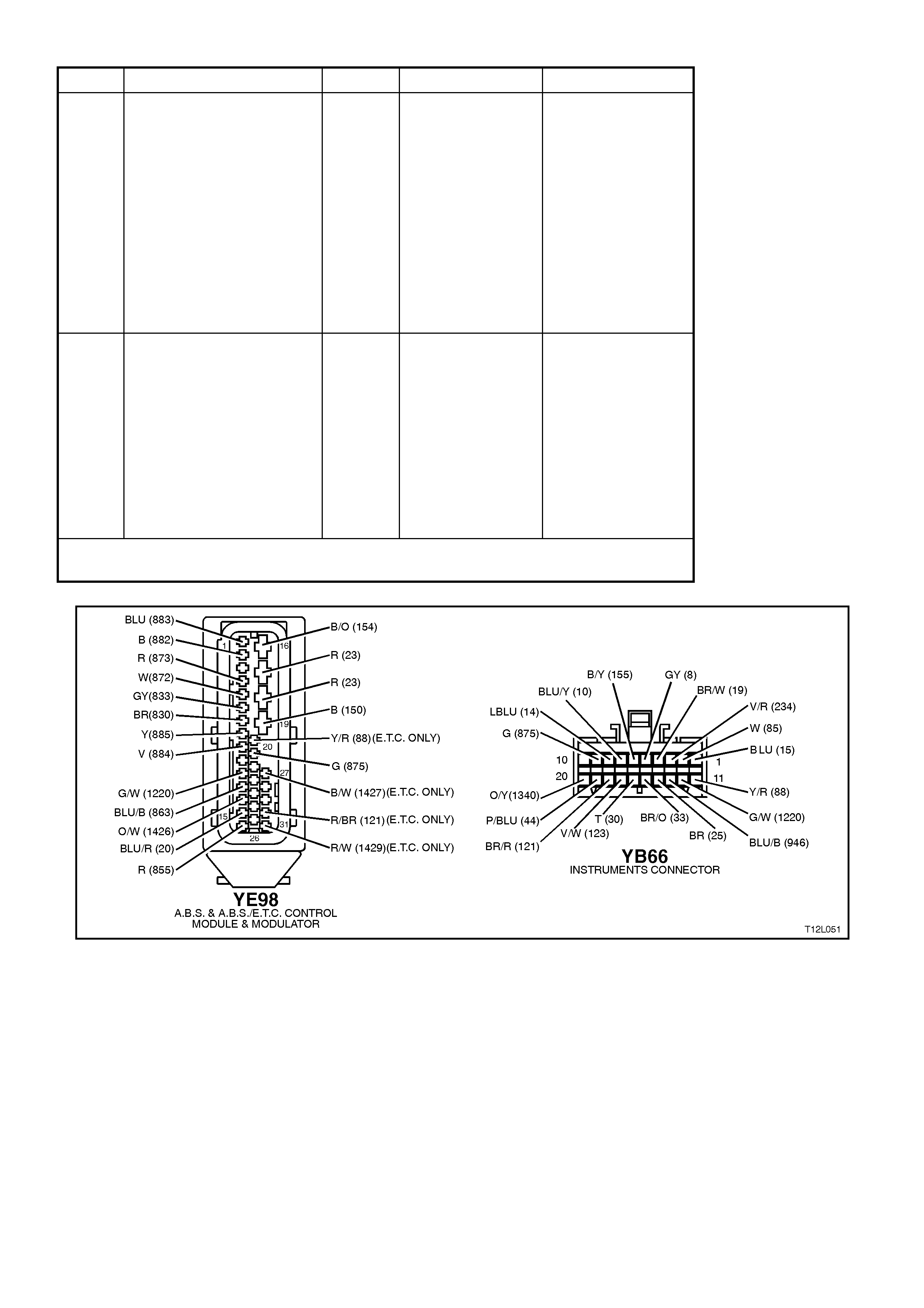
STEP ACTION VALUE YES NO
6. ∙Check for continuity
between instrument
cluster connector
YB66, terminal 9, and
ABS or ABS/ETC
control module
connector YE98,
terminal 21, circuit
875 (Green wire)
(refer NOTE 2
above).
∙Does continuity exist
?
Go to Step 7. Check and repair
open in circuit 875,
recheck and verify
repair.
7. ∙Check for continuity
between earth
location E3 (RH inner
fender) and ABS or
ABS/ETC control
module connector
YE98, terminal 19,
circuit 150 (Black
wire) (refer to
NOTE 2 above).
∙Earth ci rcuit OK ?
Replace
instrument
cluster, refer 12C
INSTRUMENTS,
WIPERS /
WASHERS AND
HORNS.
Repair circuit as
required, recheck
circuit to verify
repair.
WHEN A LL DIAGNOSIS AND REPA IRS ARE COMPLETED, CLEAR A LL DTC’S AND
VERIFY CORRECT OPERATION
Figure 12L-97
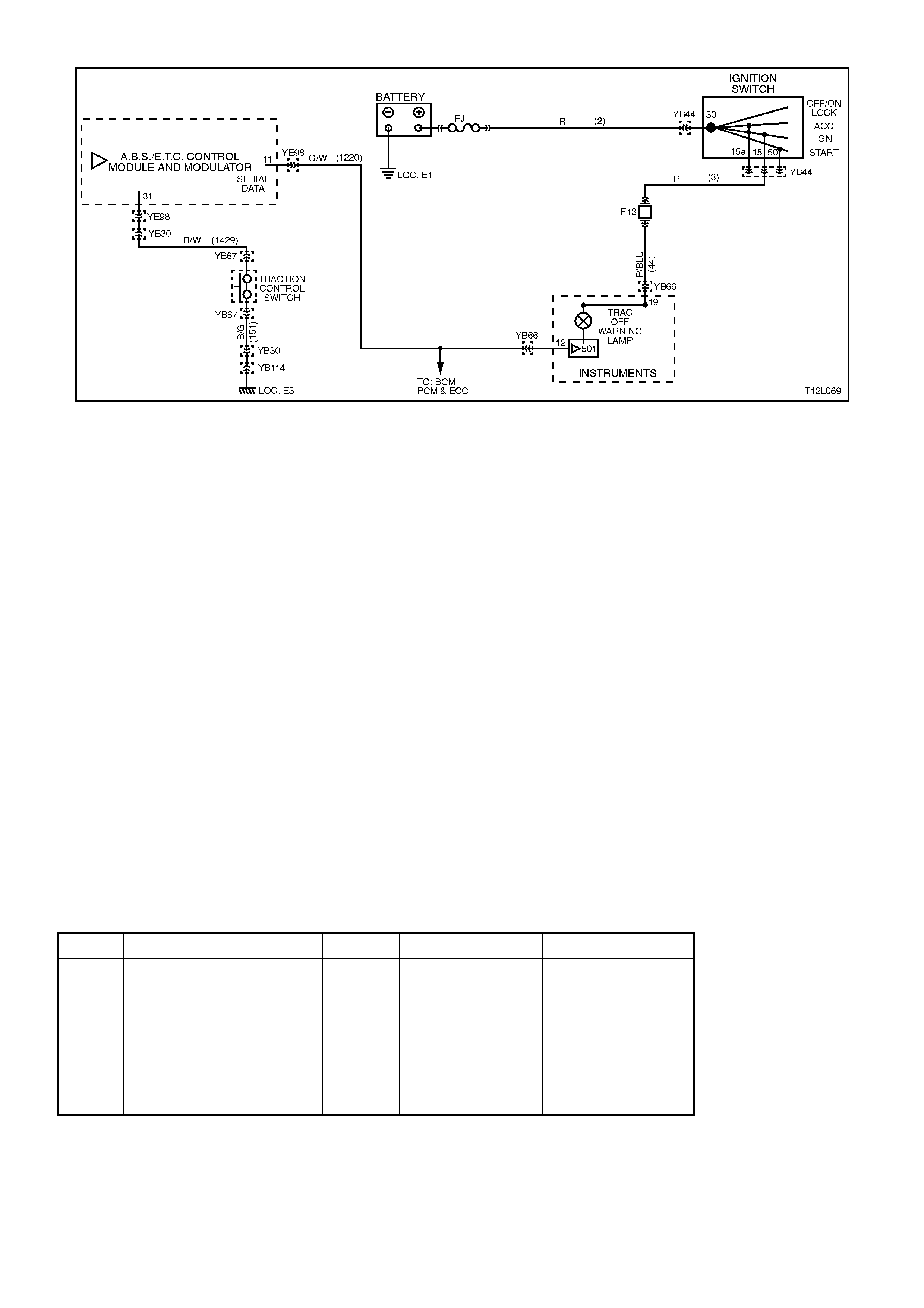
CHART A2 - TRAC OFF WARNING LAMP INOPERATIVE
Figure 12L-98
CIRCUIT DESCRIPTION:
Battery voltage is supplied to the TRAC OFF warning lamp with the ignition switch in the IGN or START positions
through fuse F13 (located in the passenger compartment fuse panel). The instrument cluster monitors circuit 1220
for a serial data message from the ABS/ETC control module. If the instrument cluster does not receive a serial data
message from the ABS/ETC control module, the instrument cluster will illuminate the TRAC OFF warning lamp.
The TRAC OFF warning lamp will be illuminated whenever the system is disabled, either manually through the
TRAC CTRL switch or due to a fault being logged in the control module, to alert the driver the ETC system has
been disabled.
TEST DESCRIPTION:
The numbers below refer to step numbers in diagnostic chart A2.
1. This test checks for any DTC's that may cause the TRAC OFF warning lamp to be inoperative.
2. This test determines if the ABS/ETC control module is faulty by using TECH 2 to drive the warning lamp on.
3. This is a simple test to determine if power is being supplied to the instrument cluster warning lamps (the TRAC
OFF and ABS warning lamps share a common power source).
4. This step determines if the warning lamp bulb or socket is defective.
5. This test checks for a faulty voltage supply to the warning lamp.
NOTES ON DIAGNOSTIC CHART:
1. Refer to 4.7, TECH 2 DIAGNOSTICS in this Section for connecting and using TECH 2.
2. Refer to Section 12P WIRING DIAGRAMS for procedures on checking wiring faults.
DIAGNOSTIC AIDS:
If the TRAC CTRL button is depressed and held for ten or more seconds (or there is a short to earth in circuit 1429),
the ABS/ETC control module will see this as a short circuit to earth and the ETC will be permanently enabled and
the TRAC OFF warning lamp turned off until the ignition is switched off and the engine restarted.
STEP ACTION VALUE YES NO
1. ∙Install TECH 2 to
DLC.
∙Select Diagnostics /
Chassis / Diagnostic
Trouble Codes /
Read DTC’s (refer to
NOTE 1 above).
∙Are any DTC’s set ?
Repair conditions
which set DTC’s,
recheck and verify
repair.
Go to Step 2

STEP ACTION VALUE YES NO
2. ∙With TECH 2 still
connected, exit
Chassis and select
Body / Instruments /
Miscellaneous Tests
/ Lamps / Traction
Control Off Lamp and
command TRAC
OFF warning lamp
on (refer to
NOTE 1 above).
∙Does TRAC OFF
warning lamp
illuminate ?
Replace
ABS/ETC control
module, refer to
3.6 CONTROL
MODULE in this
Section,
recheck circuit to
verify repair.
Go to Step 3.
3. ∙Disconnect TECH 2
from DLC.
∙Turn ignition on
whilst observing ABS
warning lamp.
∙Does ABS warning
lamp illuminate for
approximately 2
seconds then turn
OFF ?
Go to Step 4. Go to Step 5
4. ∙Remove instrument
cluster, refer to
Section 12C
INSTRUMENTS,
WIPERS/WASHERS
AND HORN
∙Remove TRAC OFF
warning lamp bulb
and socket from
instrument cluster
and check warning
lamp bulb condition.
∙Is bulb and socket
OK ?
Replace
instrument
cluster, refer to
Section 12C
INSTRUMENTS,
WIPERS /
WASHERS AND
HORNS.
Replace TRAC
OFF warning lamp
bulb and/or socket,
recheck and verify
repair.
5. ∙Remove instrument
cluster, refer to
Section 12C
INSTRUMENTS,
WIPERS/WASHERS
AND HORN.
∙Switch ignition on
and measure voltage
between connector
YB66, terminal 19,
circuit 44 (Pink/Blue
wire) and earth (refer
NOTE 2 above).
∙Is voltage as
specified ?
Battery
+No fault found.
Perform ABS or
ABS/ETC
functional check
as per 4.4 in this
Section.
Check fusible link
FJ and fuse F13.
Check wiring
between ignition
switch and
instrument cluster
connector YB66.
Check ignition
switch contacts,
recheck circuit to
verify repair.
WHEN A LL DIAGNOSIS AND REPA IRS ARE COMPLETED, CLEAR A LL DTC’S AND
VERIFY CORRECT OPERATION
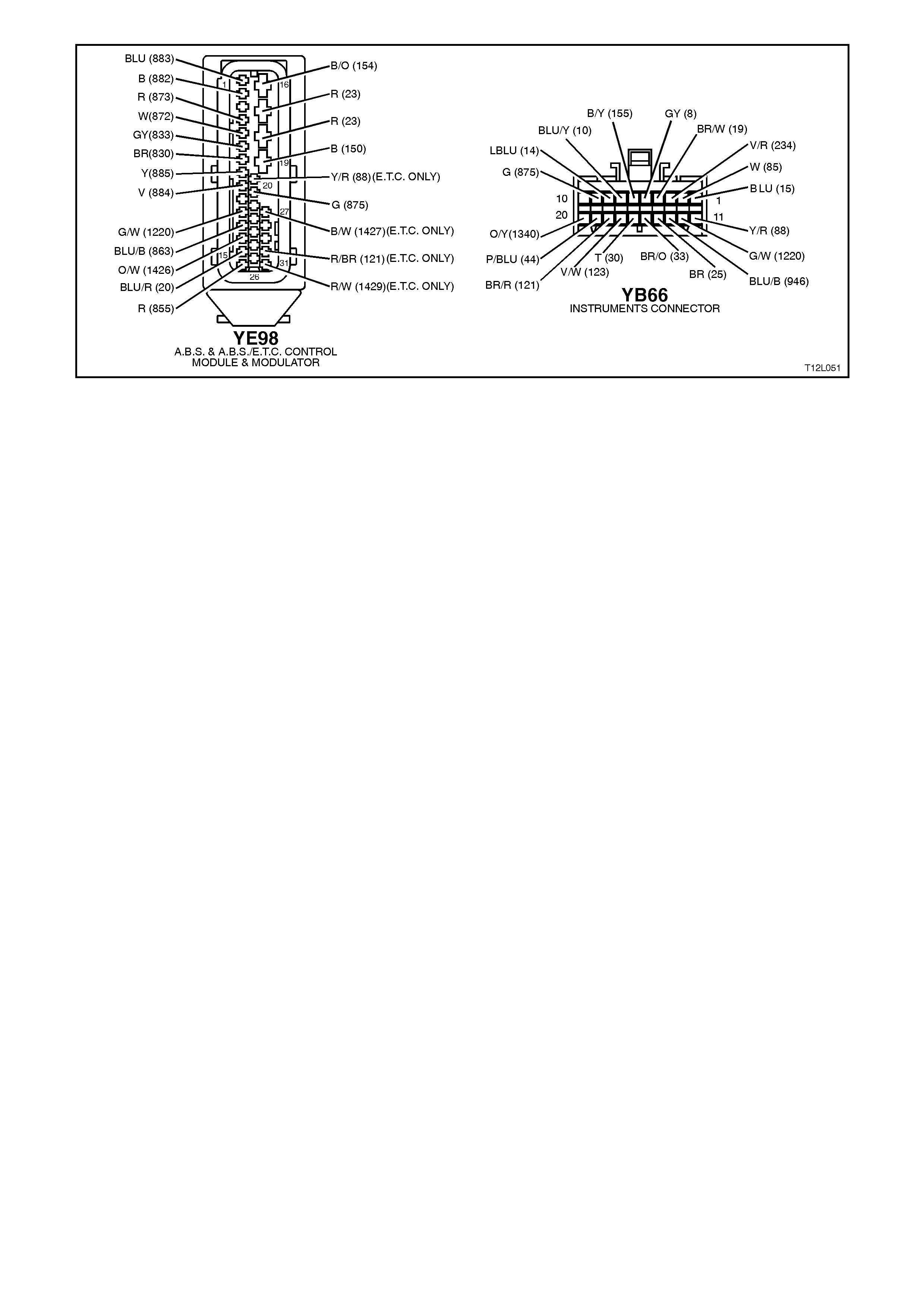
Figure 12L-99
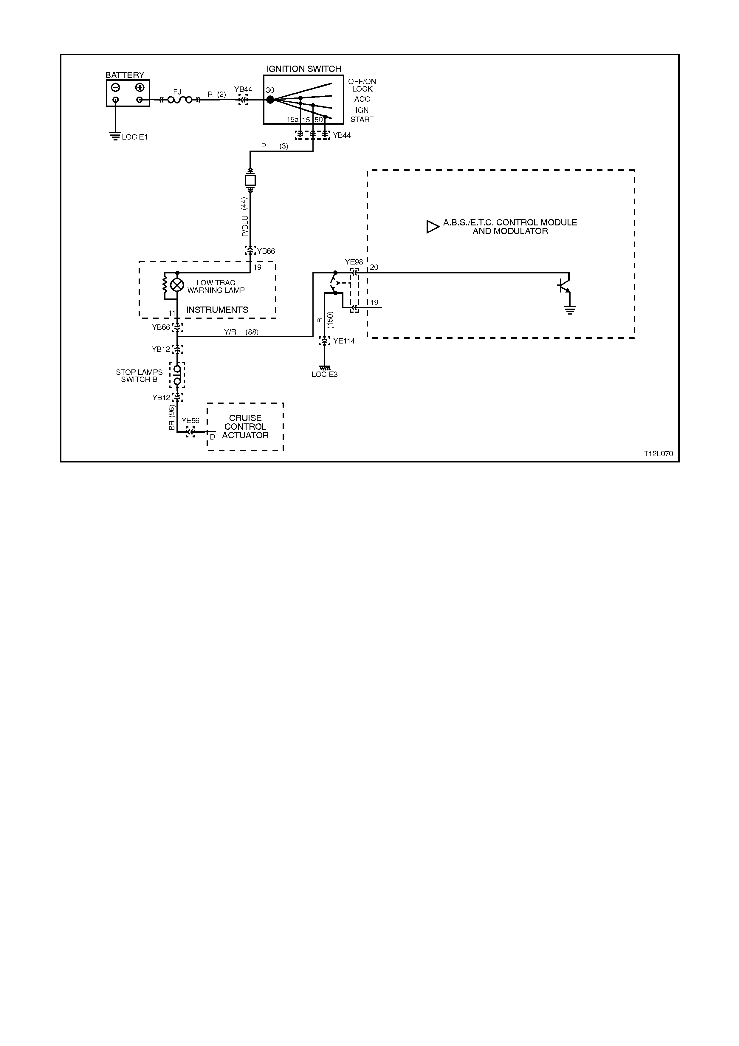
CHART A3 - LOW TRAC WARNING LAMP INOPERATIVE
Figure 12L-100
CIRCUIT DESCRIPTION:
Battery voltage is supplied to the LOW TRAC warning lamp with the ignition switch in the IGN or START positions
through fuse F13 (located in the passenger compartment fuse panel).
The warning lamp is activated by the ABS/ETC control module internally by supplying earth to terminal 20 when the
traction control system (ETC) is activated, or via a shorting bar in the ABS/ETC control module connector YE98
when it is disconnected from the control module.
TEST DESCRIPTION:
The numbers below refer to step numbers in diagnostic chart A3
1. This test checks for any DTC's that may cause the LOW TRAC warning lamp to be inoperative.
2. This test verifies an inoperative warning lamp condition.
3. This test checks if fault is within control module.
4. This step determines if the warning lamp bulb or socket is defective.
5. This test checks for a faulty voltage supply to the warning lamp.
6. Checks circuit 88.
7. Checks the warning lamps earth circuit to the ABS/ETC control module.
NOTES ON DIAGNOSTIC CHART:
1. Refer to 4.7 TECH 2 DIAGNOSTICS in this Section for connecting and using TECH 2.
2. Refer to Section 12P WIRING DIAGRAMS for procedures on checking wiring faults.

STEP ACTION VALUE YES NO
1. ∙Install TECH 2 to
DLC select
Diagnostics / Chassis
/ Diagnostic Trouble
Codes / Read DTC’s
(refer to NOTE 1
above).
∙Are any DTC's set ?
Repair conditions
which set DTC's,
recheck and verify
repair.
Go to Step 2.
2. ∙Disconnect TECH 2
from DLC.
∙Turn ignition on
whilst observing
LOW TRAC warning
lamp.
∙Does warning lamp
illuminate for
approximately 2
seconds then turn
OFF ?
No fault found.
Perform ABS or
ABS/ETC
functional check
as per 4.4 in this
Section.
Go to Step 3.
3. ∙Turn ignition OFF.
∙Disconnect ABS/ETC
control module
connector YE98 from
control module.
∙Turn ignition ON.
∙Does LOW TRAC
warning lamp
illuminate ?
Check ABS/ETC
control module
connector
terminal for
correct sizing &
condition. If all
OK, replace
control module.
Go to Step 4.
4. ∙Remove instrument
cluster, refer to
Section 12C
INSTRUMENTS,
WIPERS/WASHERS
AND HORN.
∙Remove LOW TRAC
warning lamp bulb
and socket from
instrument cluster
and check warning
lamp bulb condition.
∙Is bulb and socket
OK ?
Go to Step 5. Replace ABS
warning lamp bulb
and/or socket,
recheck and verify
repair.
5. ∙With instrument
cluster removed,
switch ignition on and
measure voltage
between connector
YB66, terminal 19,
circuit 44 (Pink/Blue
wire) and earth (refer
to NOTE 2 above).
∙Is voltage as
specified ?
Battery
+Go to Step 6. Check fusible link
FJ and fuse F13.
Check wiring
between ignition
switch and
instrument cluster
connector YB66.
Check ignition
switch contacts,
recheck circuit to
verify repair.
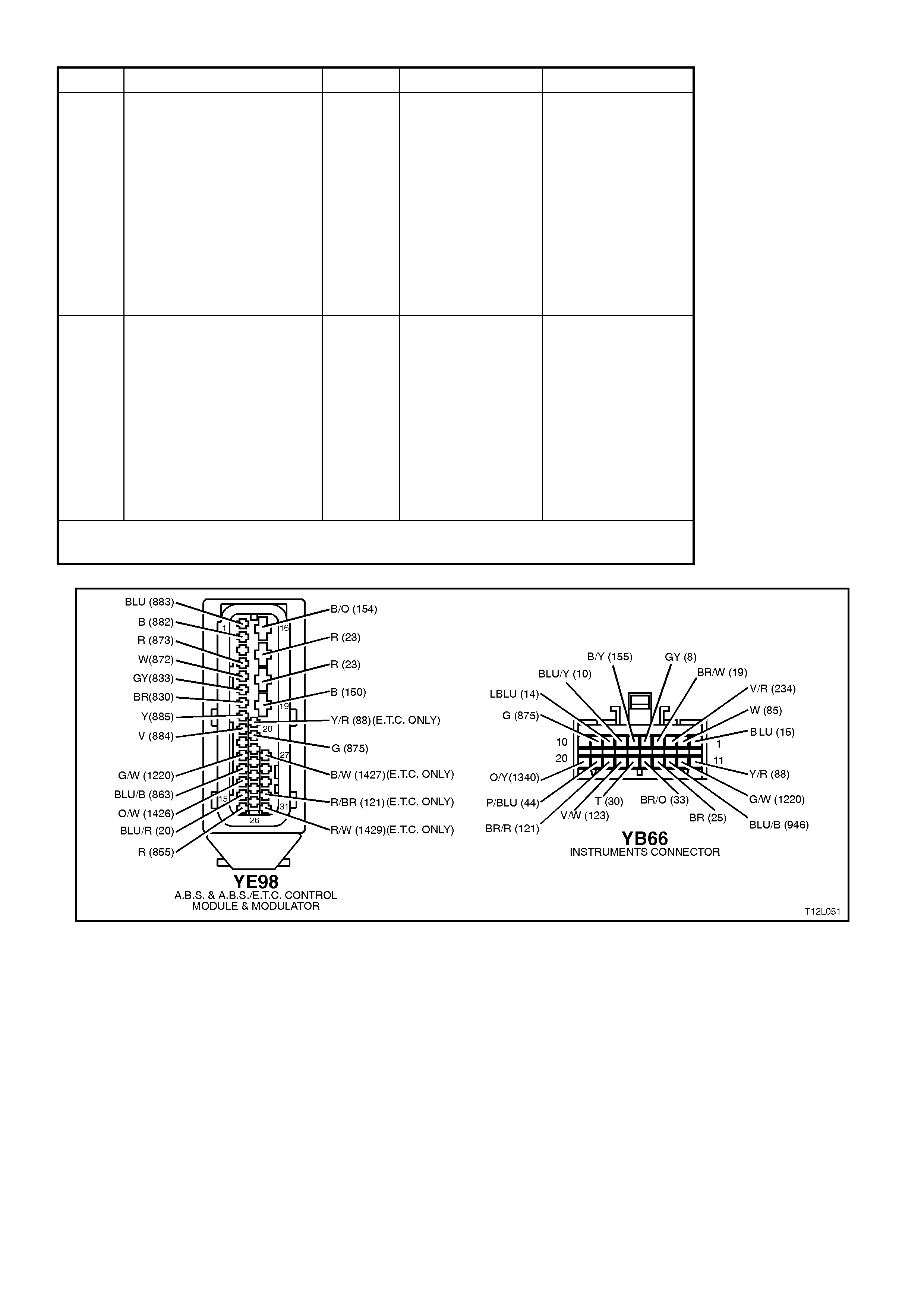
STEP ACTION VALUE YES NO
6. ∙Check for continuity
between instrument
cluster connector
YB66, terminal 11
and ABS/ETC control
module connector
YE98, terminal 20,
circuit 88 (Yellow/
Red wire) (refer to
NOTE 2 above).
∙Does continuity exist
?
Go to Step 7. Check and repair
open in circuit 88,
recheck and verify
repair.
7. ∙Check for continuity
between earth
location E3 (RH inner
fender) and
ABS/ETC control
module connector
YE98, terminal 19,
circuit 150 (Black
wire) (refer to
NOTE 2 above).
∙Earth ci rcuit OK ?
Replace
instrument
cluster, refer 12C
INSTRUMENTS,
WIPERS /
WASHERS AND
HORNS.
Repair circuit as
required, recheck
circuit to verify
repair.
WHEN A LL DIAGNOSIS AND REPA IRS ARE COMPLETED, CLEAR A LL DTC’S AND
VERIFY CORRECT OPERATION
Figure 12L-101
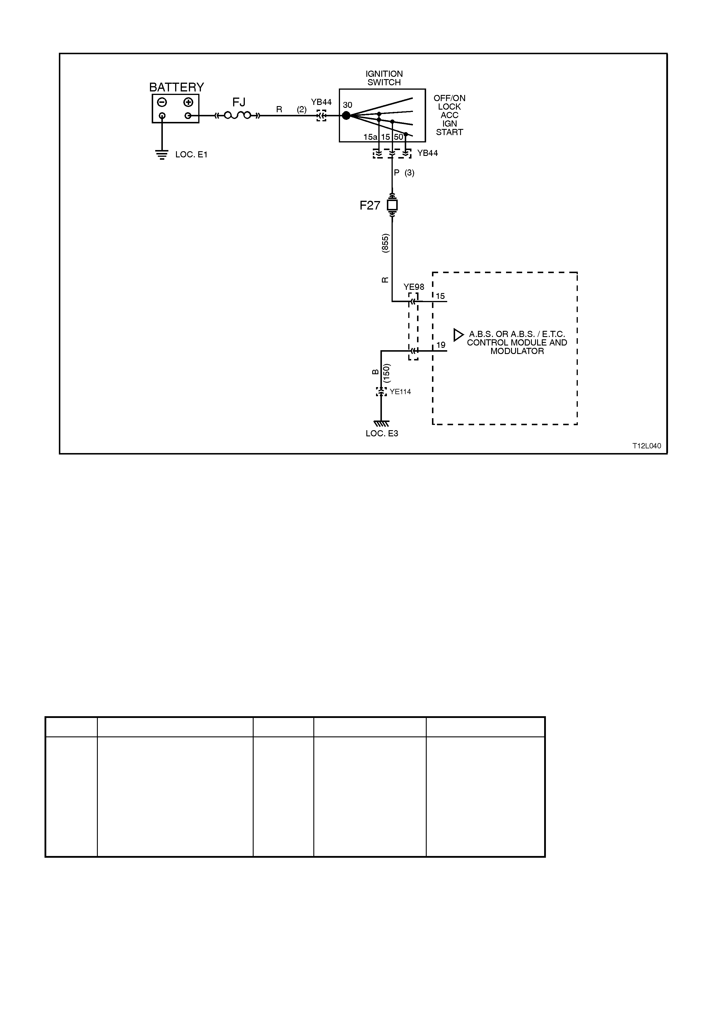
CHART B - POWER SUPPLY TO CONTROL MODULE (NO DTC'S STORED)
Figure 12L-102
CIRCUIT DESCRIPTION:
Battery voltage is supplied to the ABS or ABS/ETC control module terminal 15 with the ignition switch in the IGN or
START positions through fuse F27 (located in the passenger compartment fuse panel).
TEST DESCRIPTION:
The numbers below refer to the number/s in diagnostic chart B.
1. This test checks that there is sufficient battery voltage supply available.
2. This test checks the voltage supply to the ABS or ABS/ETC control module.
3. This test checks all fuses in the supply circuit.
4. This tests checks for other conditions that do not allow the correct voltage supply to the ABS or ABS/ETC
control module.
5. This test checks the earth connections to the ABS or ABS/ETC control module.
NOTES ON DIAGNOSTIC CHART:
1. Refer to Section 12P WIRING DIAGRAMS for procedures on checking wiring faults.
STEP ACTION VALUE YES NO
1. ∙Measure voltage
across battery
terminals (refer to
NOTE 1 above).
∙Is it voltage as
specified ?
10 - 16
Volts Go to Step 2. Check condition of
battery, refer to
Section 12A.
Check charging
system, refer to
Section 6D1-1 (V6)
or
Section 6D2-1 (V8)
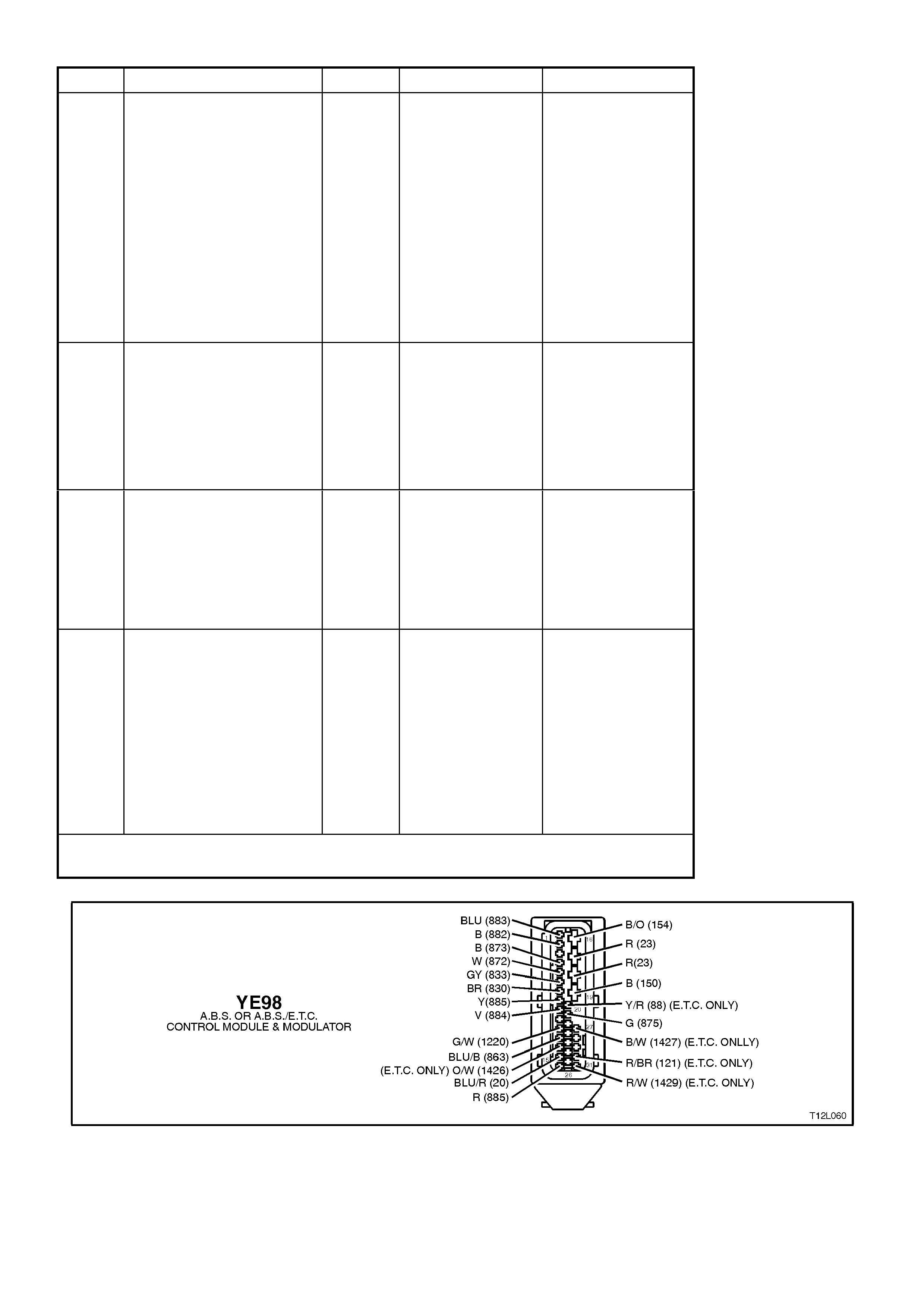
STEP ACTION VALUE YES NO
2. ∙Remove wiring
harness connector
YE98 from ABS or
ABS/ETC control
module.
∙Switch ignition ON.
∙Measure voltage at
connector YE98,
terminal 15, circuit
855 (Red wire) (refer
to NOTE 1 above).
∙Is voltage as
specified ?
Approx.
12 Volts Go to Step 5. Go to Step 3.
3. ∙Check fusible link FJ
and fuse F27.
∙Are fusible link and
fuse OK ?
Go to Step 4. Replace defective
fusible link FJ
and/or fuse F27.
Investigate cause
of blown link or
fuse, recheck
circuit to verify
repair.
4. ∙Check wiring in
circuits 2, 3 and 855
for open circuit (refer
to NOTE 1 above).
∙Check ignition switch
contacts.
∙Is all OK ?
Check ignition
switch connector
YB44 and control
module connector
YE98 terminals
for correct sizing
and condition.
Repair/replace
wiring or ignition
switch as
necessary, recheck
circuit to verify
repair.
5. ∙Check for continuity
between earth
location E3 (RH inner
fender) and ABS or
ABS/ETC control
module connector
YE98, terminal 19,
circuit 150 (Black
wire) (refer to
NOTE 1 above).
∙Earth ci rcuit OK ?
Check ABS or
ABS/ETC control
module connector
terminal for
correct sizing &
condition.
If all OK, replace
control module.
Repair circuit as
required, recheck
circuit to verify
repair.
WHEN A LL DIAGNOSIS AND REPA IRS ARE COMPLETED, CLEAR A LL DTC’S AND
VERIFY CORRECT OPERATION
Figure 12L-103
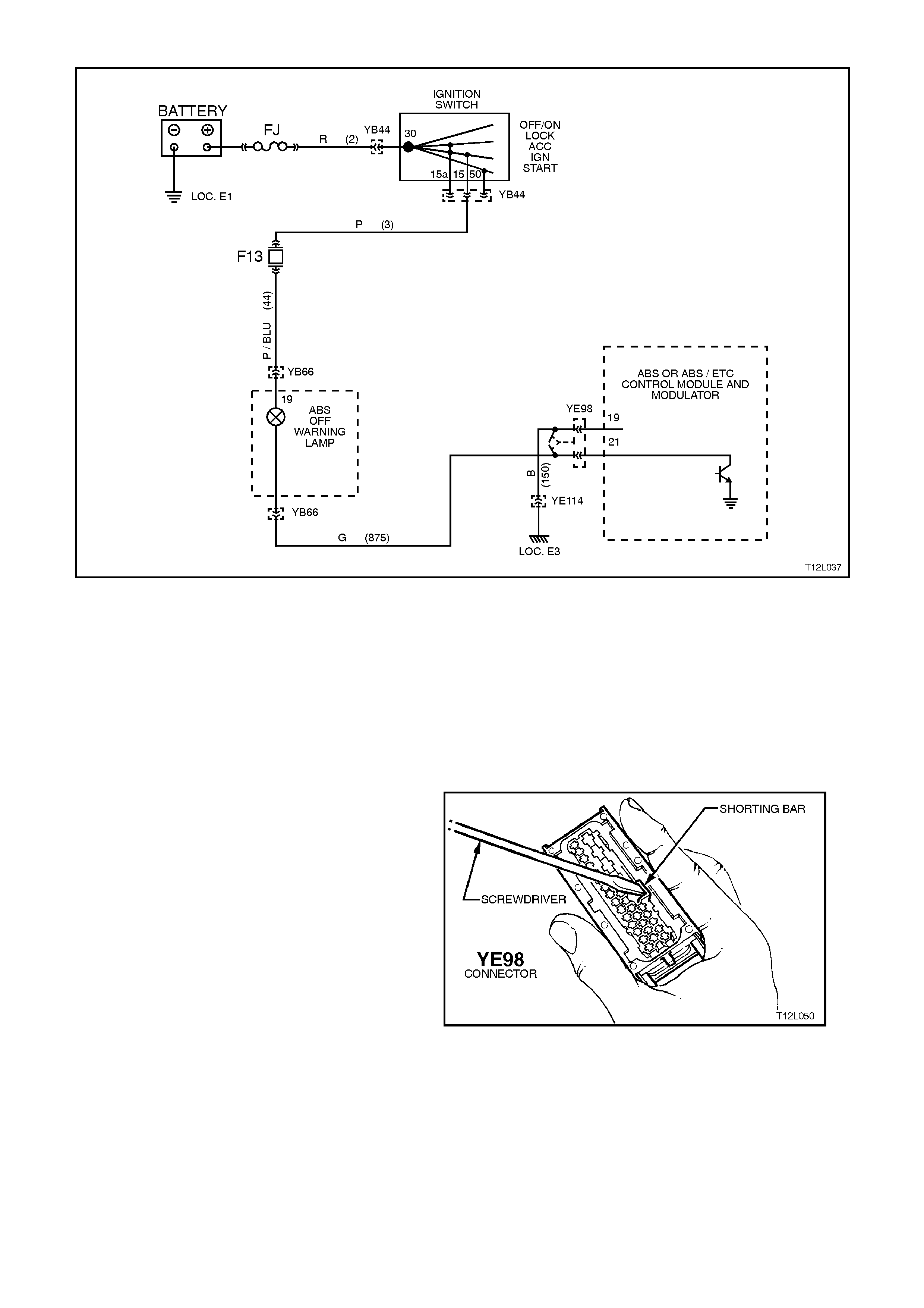
CHART C1 - ABS ‘OFF’ WARNING LAMP ILLUMINATED CONTINUOUSLY - (NO DTC'S STORED)
Figure 12L-104
CIRCUIT DESCRIPTION:
Battery voltage is supplied to the ABS O FF warning
lamp with the ignition switch in the IGN or START
positions through fuse F13 (located in the
passenger compartment fuse panel). The warning
lamp can only be activated by the ABS or ABS/ETC
control module internally by supplying earth to
terminal 21 or via the shorting bar in the ABS or
ABS/ETC control module connector YE98 when it
is disconnected from the control module.
TEST DESCRIPTION:
The numbers below refer to the Step numbers in
diagnostic chart C1.
1. Uses TECH 2 to check for logged DTC’s that
are causing the warning lamp to illuminate.
2. This test checks whether the fault is caused by
the ABS or ABS/ETC control module or a short
to earth on circuit 875 (Green wire).
3. This test checks for a short to earth in the
wiring between the warning lam p and the ABS
or ABS/ETC control module.
NOTES ON DIAGNOSTIC CHART:
1. Using a small screwdriver, hold shorting bar
away from terminals in connector YE98, refer
to Fig. 12L-105.
2. Refer to 4.7 TECH 2 DIAGNOSTICS in this
Section for connecting and using Tech 2.
3. Refer to Section 12P WIRING DIAGRAMS for
procedures on checking wiring faults.
Figure 12L-105
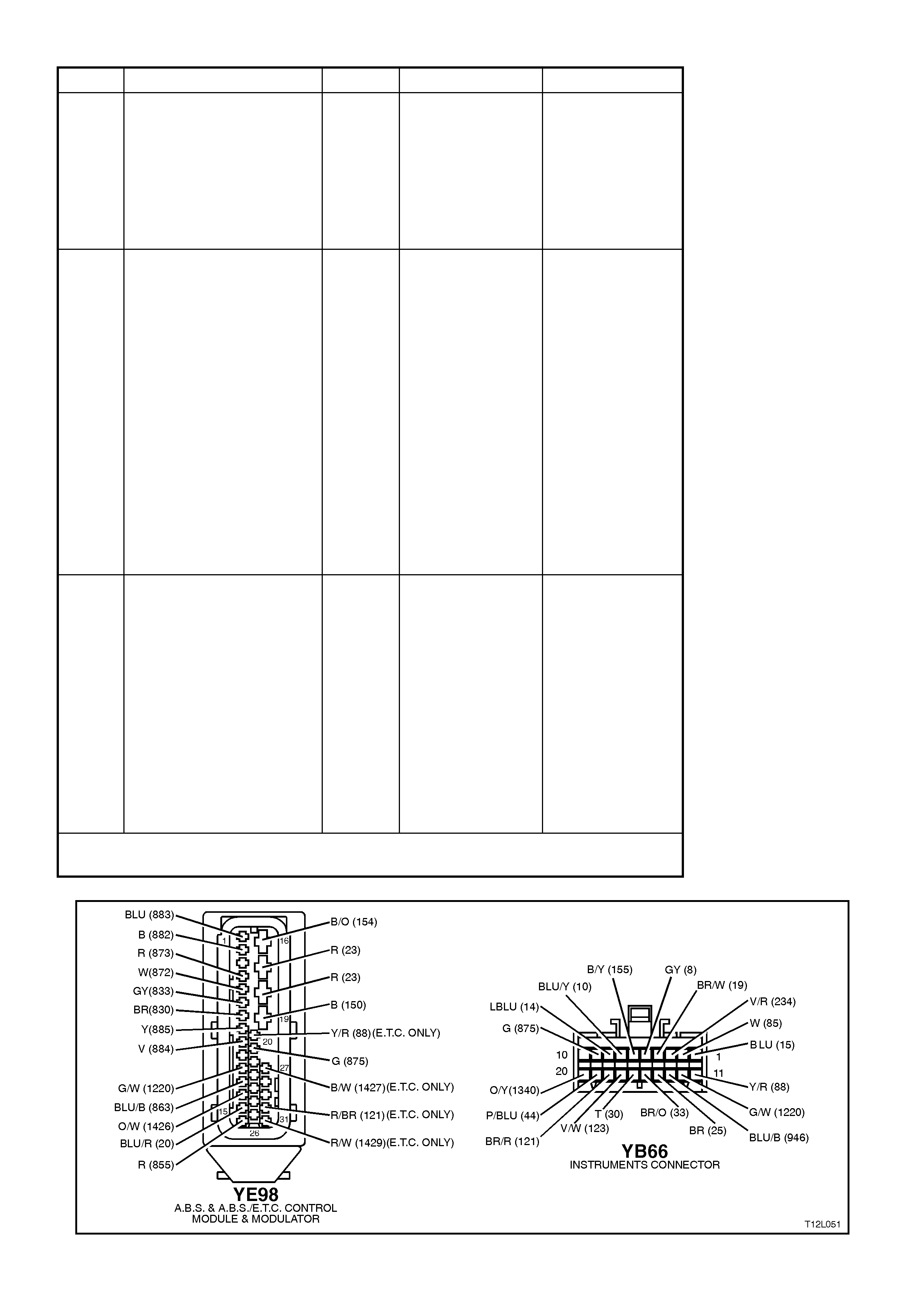
STEP ACTION VALUE YES NO
1. ∙Install TECH 2 to
DLC.
∙Select Diagnostics /
Chassis / Diagnostic
Trouble Codes /
Read DTC’s (refer to
NOTE 1 above).
∙Are any DTC's set?
Repair conditions
which set DTC's,
recheck and verify
repair.
Go to Step 2.
2. ∙Disconnect TECH 2
from DLC.
∙Remove wiring
harness connector
YE98 from ABS or
ABS/ETC control
module.
∙Hold shorting bar
away from terminals
20 and 21 in
connector YE98
(refer to
NOTE 2 above).
∙Switch ignition ON.
∙Is the warning lamp
constantly
illuminated?
Go to Step 3. Replace ABS or
ABS/ETC control
module, refer to
3.6 CONTROL
MODULE in this
Section, recheck
circuit to verify
repair.
3. ∙Check circuit 875
(Green wire) and the
warning lamp bulb
socket for short to
earth between the
ABS or ABS/ETC
control module
connector YE98,
terminal 21 (Green
wire) and connector
YB66, terminal 9
(Green wire) (refer to
NOTE 3 above).
∙Is all OK?
Replace
instrument
cluster, refer to
Section 12C
INSTRUMENTS,
WIPERS /
WASHERS AND
HORNS.
Repair circuit as
required, recheck
circuit to verify
repair.
WHEN A LL DIAGNOSIS AND REPA IRS ARE COMPLETED, CLEAR A LL DTC’S AND
VERIFY CORRECT OPERATION
Figure 12L-106
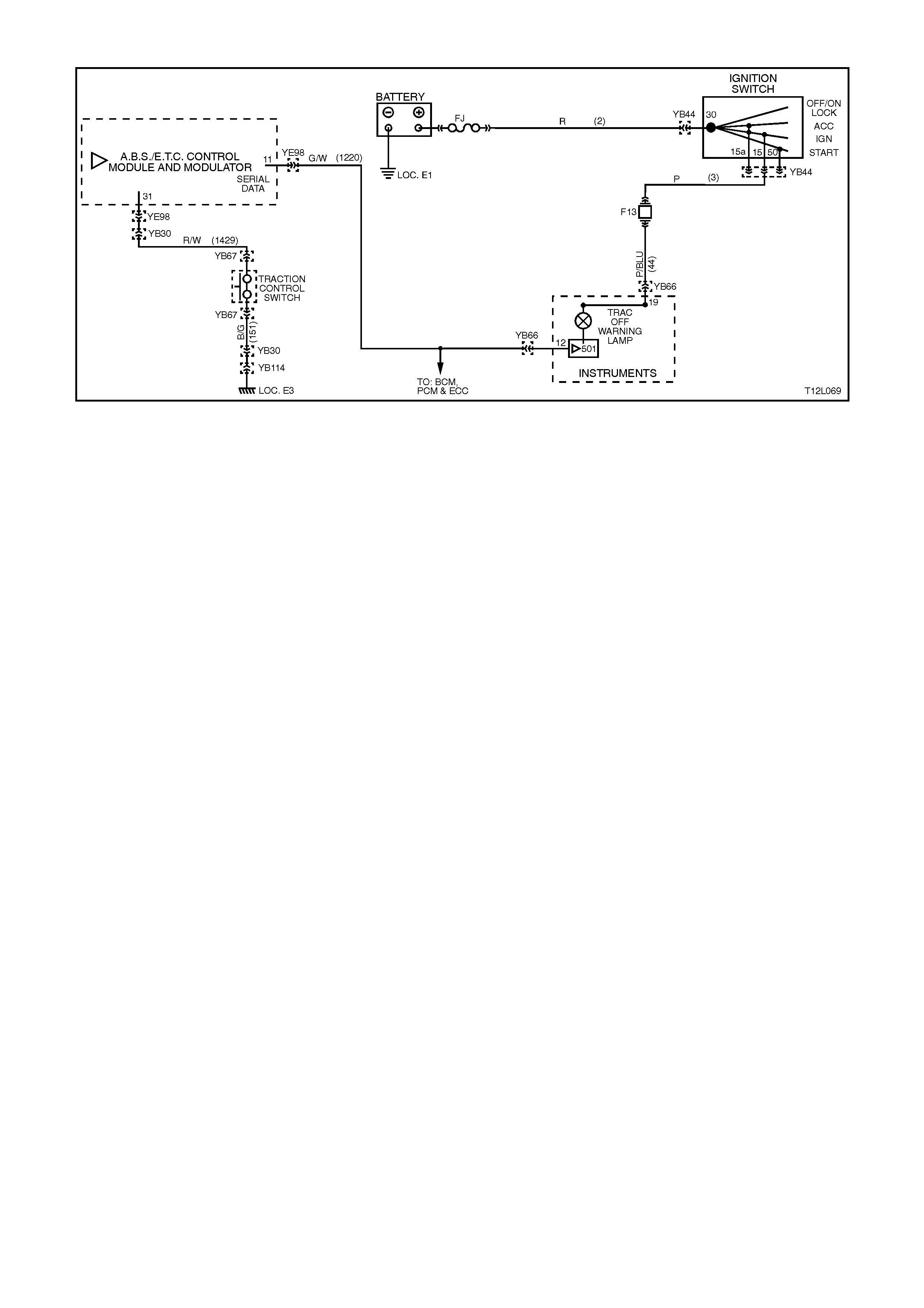
CHART C2 - TRAC OFF WARNING LAMP ILLUMINATED CONTINUOUSLY - (NO DTC'S STORED)
Figure 12L-107
CIRCUIT DESCRIPTION:
Battery voltage is supplied to the TRAC OFF warning lamp with the ignition switch in the 'IGN' or 'START' positions
through fuse F13 (located in the passenger compartment fuse panel). The warning lamp is activated by the
ABS/ETC control module sending a signal to the instrument cluster via the serial data bus. The warning lamp will be
illuminated whenever the system becomes disabled either because of a fault in the system or from being manually
turned off by the traction control (TRAC CTRL) switch, located near the transmission shift selector.
TEST DESCRIPTION:
The numbers below refer to the Step numbers in diagnostic chart C2.
1. Uses TECH 2 to check for logged DTC’s that are causing the warning lamp to illuminate.
2. Checks whether the fault is within the instrument cluster or ABS/ETC control module.
NOTES ON DIAGNOSTIC CHART:
Refer to 4.7 TECH 2 DIAGNOSTICS in this Section for connecting and using TECH 2.
DIAGNOSTIC AIDS:
If the TRAC CTRL button is depressed and held for ten or more seconds (or there is a short to earth in circuit 1429)
the ABS/ETC control module will see this as a short circuit to earth and the ETC will be permanently enabled and
the TRAC OFF warning lamp turned off until the ignition is switched off and the engine restarted.
Therefore, a short circuit in circuit 1429, including TRAC CTRL switch will not illuminate the warning lamp
continuously, however, it could hold the lamp on for tens seconds after the ignition is switched on.

STEP ACTION VALUE YES NO
1. ∙Install TECH 2 to
DLC.
∙Select Diagnostics /
Chassis / Diagnostic
Trouble Codes /
Read DTC’s (refer to
NOTE 1 above).
∙Are any DTC's set ?
Repair conditions
which set DTC's,
recheck and verify
repair.
Go to Step 2.
2. ∙With TECH 2 still
connected, exit
Chassis and select
Body / Instruments /
Miscellaneous Tests
/ Lamps / Traction
Control Off Lamp and
command TRAC
OFF warning lamp
off (refer to
NOTE 1 above).
∙Does TRAC OFF
warning lamp turn
off?
Replace
ABS/ETC control
module, refer to
3.6 CONTROL
MODULE in this
Section, recheck
circuit to verify
repair.
Replace instrument
cluster, refer to
Section 12C
INSTRUMENTS,
WIPERS /
WASHERS AND
HORNS.
WHEN A LL DIAGNOSIS AND REPA IRS ARE COMPLETED, CLEAR A LL DTC’S AND
VERIFY CORRECT OPERATION

CHART C3 - LOW TRAC WARNING LAMP ILLUMINATED CONTINUOUSLY - (NO DTC'S STORED)
Figure 12L-108
CIRCUIT DESCRIPTION:
Battery voltage is supplied to the LOW TRAC
warning lamp with the ignition switch in the IGN or
START positions through fuse F13 (located in the
passenger compartment fuse panel). The warning
lamp can only be activated by the ABS or ABS/ETC
control module internally by supplying earth to
terminal 20 or via the shorting bar in the ABS or
ABS/ETC control module connector YE98 when it
is disconnected from the control module. If the ABS
or ABS/ETC control module activates traction
control, it will send a signal to the cruise control
module via circuit 96 (Brown wire), requesting the
cruise control module to turn off.

TEST DESCRIPTION:
The numbers below refer to the Step numbers in
diagnostic chart C3.
1. Uses TECH 2 to check for logged DTC’s that
are causing the warning lamp to illuminate.
2. This test checks whether the fault is caused by
the ABS or ABS/ETC control module.
3. This test chec ks c irc uit 96, inc luding s top lamp
switch B.
4. This test checks for a short to earth in the
wiring between the warning lamp, ABS or
ABS/ETC control module and the stop lamp
switch connector.
NOTES ON DIAGNOSTIC CHART:
1. Using a small screwdriver, hold shorting bar
away from terminals in connector YE98, refer
Fig. 12L-109.
2. Refer to 4.7 TECH 2 DIAGNOSTICS in this
Section for connecting and using Tech 2.
3. Refer to Section 12P WIRING DIAGRAMS for
procedures on checking wiring faults.
Figure 12L-109
STEP ACTION VALUE YES NO
1. ∙Install TECH 2 to
DLC.
∙Select Diagnostics /
Chassis / Diagnostic
Trouble Codes /
Read DTC’s (refer to
NOTE 2 above).
∙Are any DTC's set ?
Repair conditions
which set DTC's,
recheck and verify
repair.
Go to Step 2.
2. ∙Disconnect TECH 2
from DLC.
∙Remove wiring
harness connector
YE98 from ABS or
ABS/ETC control
module.
∙Hold shorting bar
away from terminals
20 and 21 in
connector YE98
(refer to
NOTE 1 above).
∙Switch ignition ON.
∙Is the warning lamp
constantly illuminated
?
Go to Step 3. Replace ABS/ETC
control module,
refer to 3.6
CONTROL
MODULE in this
Section, recheck
circuit to verify
repair.
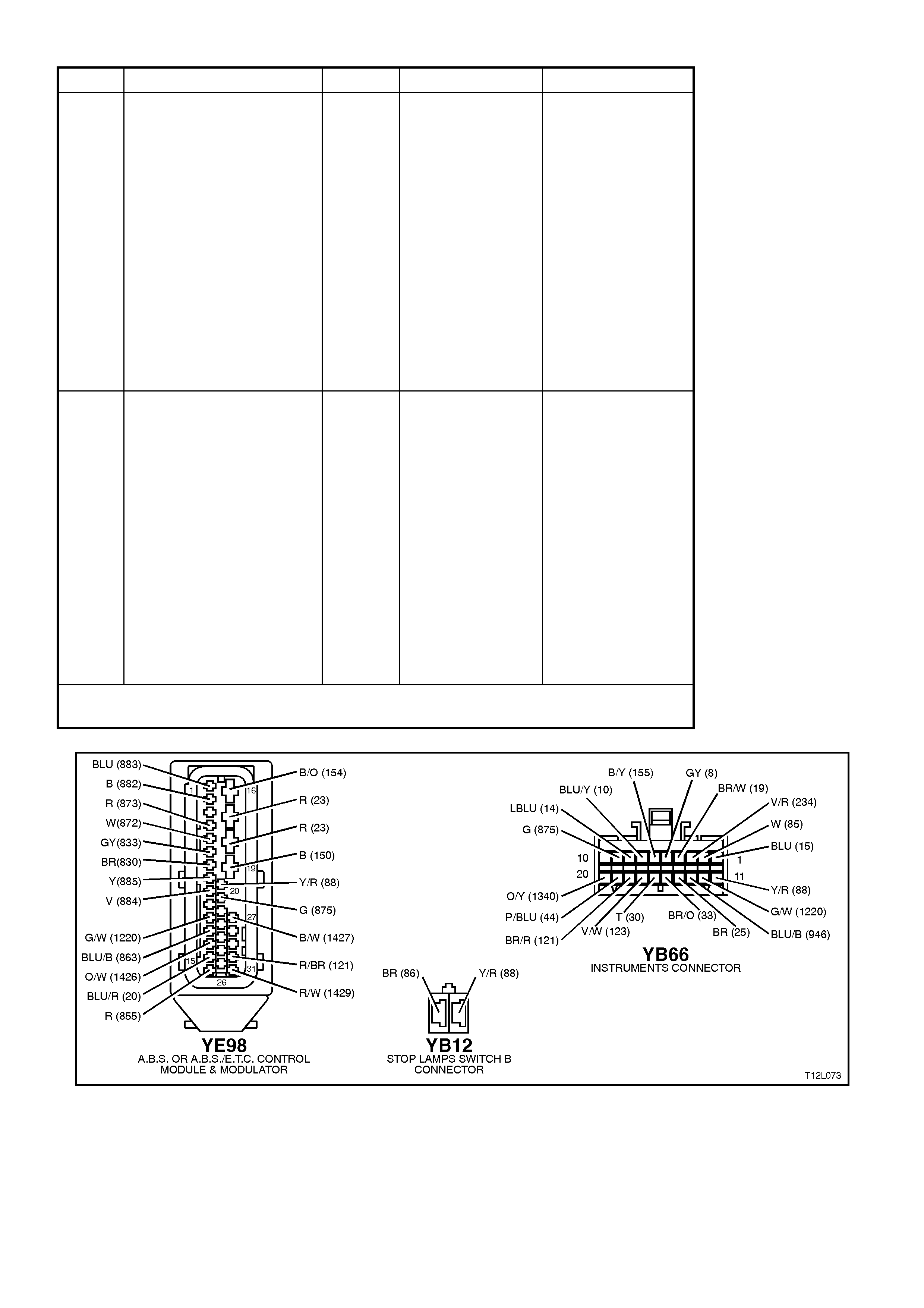
STEP ACTION VALUE YES NO
3. ∙With connector YE98
removed from the
control module and
the shorting bars held
away from terminals
20 and 21 in
connector YE98,
disconnect the stop
lamp switch
connector YB12
(refer NOTE 1
above).
∙Switch ignition ON.
∙Is the warning lamp
constantly illuminated
?
Go to Step 4. Check for short to
earth in circuit 96
and/or check and
adjust or repair
stop lamp swi tch B,
as necessary (refer
Section 12B
LIGHTING
SYSTEM for
information on stop
lamp switch).
4. ∙Check circuit 88
(Yellow/Red wire)
and the warning lamp
bulb socket for short
to earth between the
ABS or ABS/ETC
control module
connector YE98,
terminal 20,
connector YB66,
terminal 11 and
connector YB12
(Yellow/Red wire)
(refer NOTE 3
above).
∙Is all OK ?
Replace
instrument
cluster, refer to
Section 12C
INSTRUMENTS,
WIPERS /
WASHERS AND
HORNS.
Repair circuit as
required, recheck
circuit to verify
repair.
WHEN A LL DIAGNOSIS AND REPA IRS ARE COMPLETED, CLEAR A LL DTC’S AND
VERIFY CORRECT OPERATION
Figure 12L-110
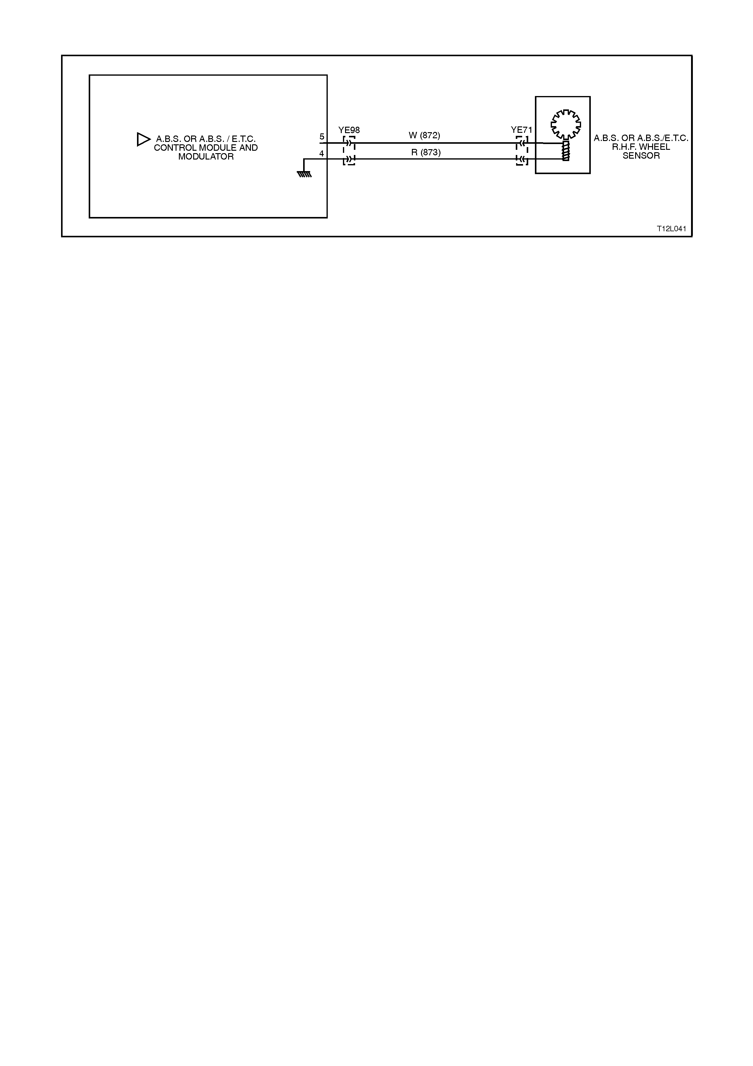
DTC 21 - FRONT RIGHT WHEEL SPEED SENSOR INCORRECT SIGNAL
Figure 12L-111
CIRCUIT DESCRIPTION:
The toothed pulse ring wheel inside the front hub assembly generates a voltage pulse as it moves past the wheel
speed sensor; each tooth - gap - tooth on the pulse ring generates these pulses.
The frequency of these pulses is used by the ABS or ABS/ETC control module to determine wheel speed.
DTC 21 will set if vehicle speed is approximately 12 km/h and the control module detects a low right hand front
wheel speed sensor output voltage.
If a failure is detected which causes DTC 21 to set, the ABS or ABS/ETC system is disabled and the control module
illuminates the ABS or ABS and TRAC OFF warning lamps for the remainder of the ignition cycle. If the failure is
intermittent, the control module will enable the system at the next ignition cycle and a history DTC 21 will be set.
TEST DESCRIPTION:
The numbers below refer to Step numbers in the diagnostic chart for DTC 21.
1. This test checks if there is a speed signal output from the sensor.
2. This test checks for connector or wiring problems which may cause an intermittent condition.
3. This test determines whether the DTC was set by an intermittent condition or a control module fault.
4. This check is a visual inspection of the speed sensor, wiring and the pulse ring.
5. If repairs are necessary, the speed sensor output must be rechecked to verify the repair.
6. This test checks for a voltage drop in the wheel speed sensor wiring which could cause lower than specified
sensor output voltage.
NOTES ON DIAGNOSTIC CHART
1. Refer to 4.7 TECH 2 DIAGNOSTICS in this Section for connecting and using Tech 2.
2. For all wiring checking procedures, refer to Section 12P WIRING DIAGRAMS.
DIAGNOSTIC AIDS
For additional information on testing the front wheel speed sensor, refer to 3.2 FRONT WHEEL SPEED SENSOR
LEAD in this Section.

STEP ACTION VALUE YES NO
1. ∙Jack up front of
vehicle and support
on safety stands.
∙Install Tech 2 to
DLC.
∙Select Diagnostics /
Chassis / ABS/ETC/
Data List / Active
ABS (refer to
NOTE 1 above).
∙Check right hand
front wheel speed
sensor output signal
by rotating wheel by
hand.
(Alternatively,
connect an
oscilloscope to the
wheel speed sensor
connector YE71,
between circuit 872
(White wire) and
circuit 873 (Red
wire), rotate right
hand front wheel by
hand and compare
oscilloscope patterns
with those shown
below. Repair as
necessary or go to
Step 2).
∙Does speed signal
change as wheel is
turned faster?
Go to Step 2. Go to Step 4.
2. ∙Visually inspect
sensor lead wiring
and connections.
∙Check wiring for
intermittent open or
short circuit (refer to
NOTE 2 above).
∙Is all OK ?
Go to Step 3. Repair fault with
sensor lead wiring
or connections,
recheck circuit to
verify repair.
3. ∙Clear all stored
DTC's (refer to
NOTE 1 above) and
road test vehicle .
∙Does DTC 21 set
again ?
Replace ABS or
ABS/ETC control
module, refer to
3.6 CONTROL
MODULE in this
Section, recheck
circuit to verify
repair.
Fault not present.
Check all system
wiring harness
connectors and
terminals, in
particular the ABS
or ABS/ETC
control module
connector
terminals.

STEP ACTION VALUE YES NO
4. ∙Visually inspect
sensor lead wiring,
mountings and
connections.
∙Is all OK ?
Go to Step 6. Go to Step 5.
5. ∙Make repairs as
necessary. Retest
speed sensor output.
∙Is output now OK ?
Go to Step 3. Go to Step 6.
6. ∙Check circuits 872
(White wire) and 873
(Red wire) for
continuity (refer to
NOTE 2 above).
∙Inspect Main Wiring
Harness to sensor
lead connector YE71
and sensor
connector at front
wheel hub assembly.
∙Are connectors and
wiring OK ?
Replace front hub
& WSS asm, refer
to 3.3 WHEEL
SPEED SENSOR
in this Section,
recheck circuit to
verify repair.
Repair wiring as
necessary, recheck
circuit to verify
repair.
WHEN A LL DIAGNOSIS AND REPA IRS ARE COMPLETED, CLEAR A LL DTC’S AND
VERIFY CORRECT OPERATION
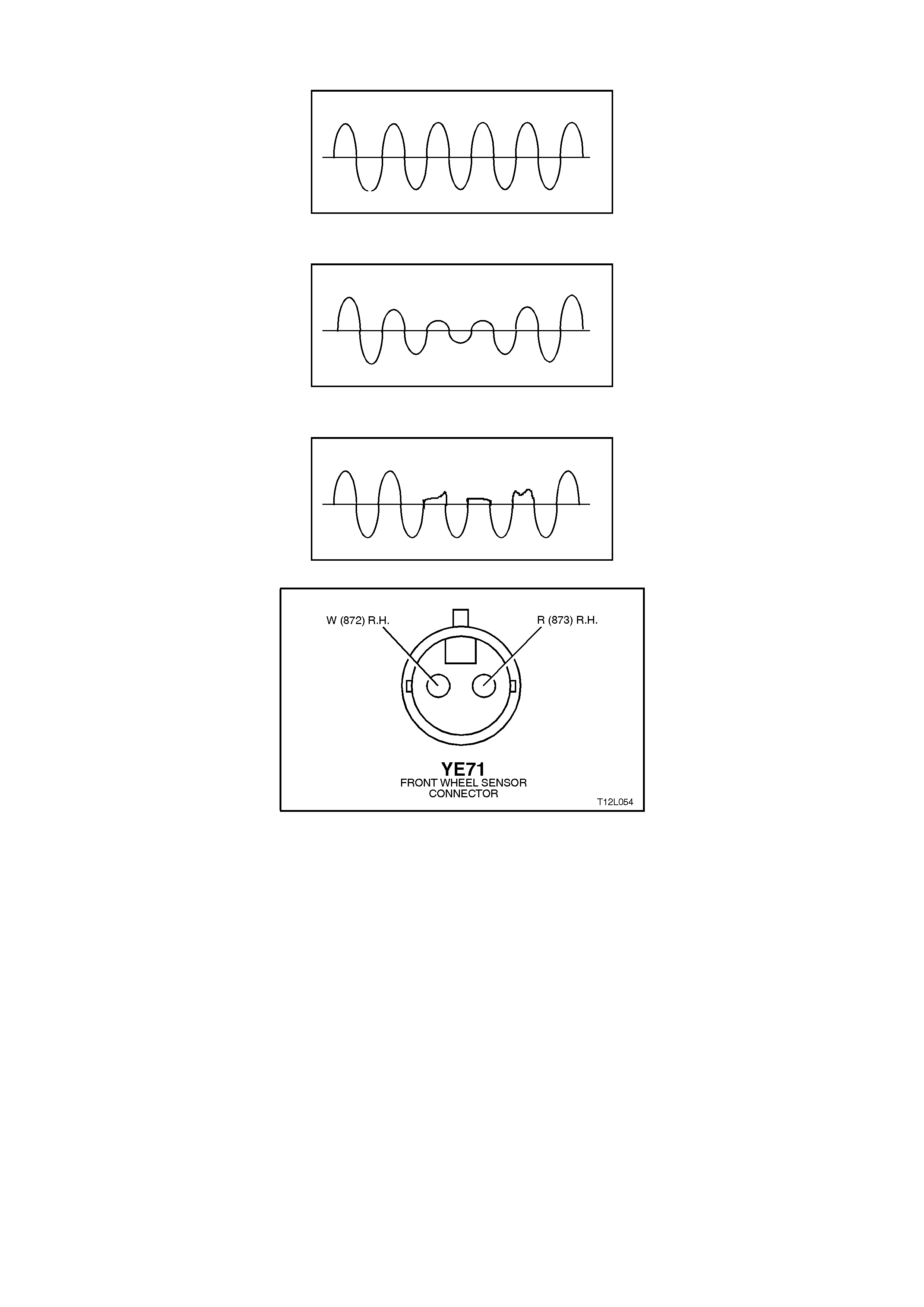
Oscilloscope patterns (simulated only)
Normal view
Possible increasing and decreasing distance between wheel speed sensor and pulse ring
Possible chipped or damaged teeth
Figure 12L-112
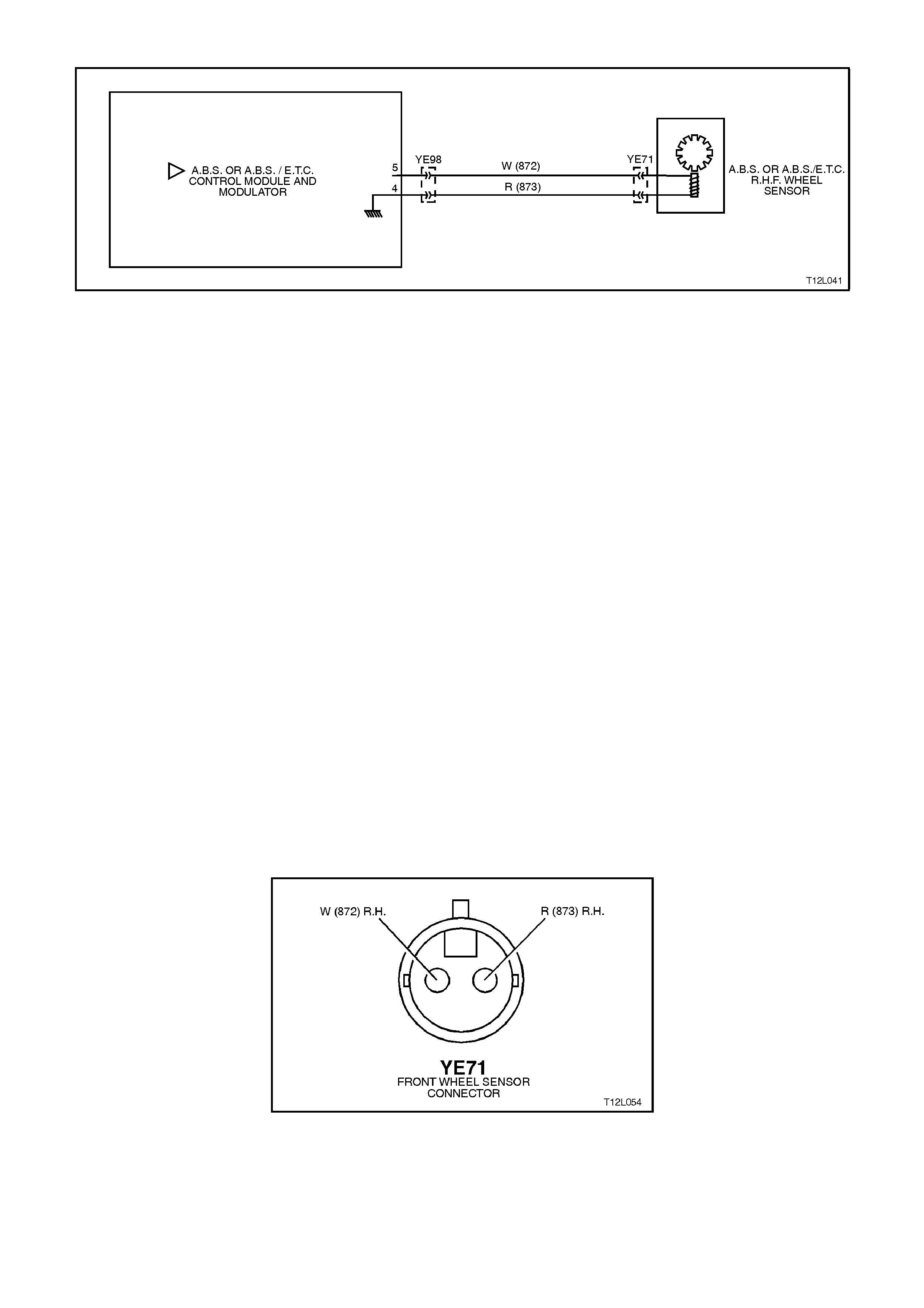
DTC 23 - FRONT RIGHT WHEEL SPEED SENSOR SHORT CIRCUIT OR OPEN CIRCUIT
Figure 12L-113
CIRCUIT DESCRIPTION:
The toothed pulse ring wheel inside the front hub assembly generates a voltage pulse as it moves past the wheel
speed sensor; each tooth - gap - tooth on the pulse ring generates these pulses.
The frequency of these pulses is used by the ABS or ABS/ETC control module to determine wheel speed.
DTC 23 will set when the ignition is switched on and the control module detects a continuity problem in circuits 872
and 873, or no wheel speed signal is generated by the sensor.
If a failure is detected which causes DTC 23 to set, the ABS or ABS/ETC system is disabled and the control module
illuminates the ABS or ABS and TRAC OFF warning lamps for the remainder of the ignition cycle. If the failure is
intermittent, the control module will enable the system at the next ignition cycle and a history DTC 23 will be set.
TEST DESCRIPTION:
The numbers below refer to Step numbers in the diagnostic chart for DTC 23.
1. Begin rectification of this DTC by visually inspecting right hand front wheel speed sensor wiring for a fault
condition.
2. This test is a usual check for connector or wiring problems which may cause an intermittent condition.
3. This test checks for correct resistance reading of the sensor coil.
4. This test checks for continuity of right hand front wheel speed sensor wiring.
5. This test checks for short circuit between wheel speed sensor wiring.
6. This test checks for open circuit in right hand front wheel speed sensor wiring.
7. This test checks for short to earth or B+ in circuits 872 and 873.
8. This test determines whether the DTC was set by an intermittent condition or a control module fault.
NOTES ON DIAGNOSTIC CHART:
1. Refer to 4.7 TECH 2 DIAGNOSTICS in this Section for connecting and using TECH 2.
2. For all wiring checking procedures, refer to Section 12P WIRING DIAGRAMS.
DIAGNOSTIC AIDS:
For additional information on testing the front wheel speed sensor, refer to 3.2 FRONT WHEEL SPEED SENSOR
LEAD in this Section.
Figure 12L-114
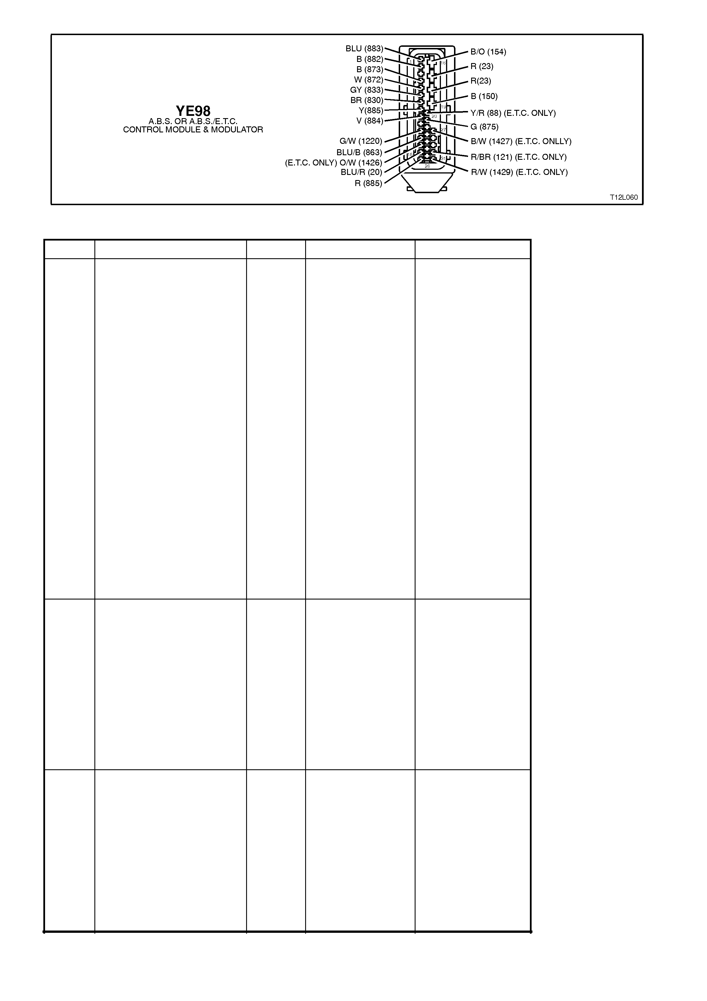
Figure 12L-115
STEP ACTION VALUE YES NO
1. ∙Ensure that right
hand front wheel
speed sensor lead is
not visibly damaged
and that it is properly
secured at all places.
∙If the sensor lead is
damaged or not
correctly mounted
and retained, replace
the lead and/or
properly install it.
∙Install TECH 2 to
DLC and select
Diagnostics / Chassis
/ ABS/ETC /
Diagnostic Trouble
Codes / Clear DTC’s
and clear all DTC's
(refer to NOTE 1
above).
∙Road test vehicle,
does DTC 23 set
again ?
Go to Step 3. Go to Step 2.
2. ∙Inspect all system
wiring and
connections that
could causes
intermittent faults.
Check all wiring is in
good condition,
terminals are clean
and tight and making
good contact (refer to
NOTE 2 above).
∙Is all OK ?
Fault not present.
Check all system
wiring harness
connectors and
terminals, in
particular the ABS
or ABS/ETC
control module
connector
terminals.
Make repairs as
necessary, recheck
circuit to verify
repair.
3. ∙Turn ignition OFF
∙Disconnect sensor
lead connector YE71
from Main Wiring
Harness connector.
∙Using digital
multimeter, measure
sensor and lead
resistance.
∙Is value as specified
?
1600 -
1800
Ohms
Go to Step 5. Go to Step 4.

STEP ACTION VALUE YES NO
4. ∙Remove sensor lead
and check continuity
of lead wiring.
∙Is continuity OK ?
Wheel speed
sensor faulty.
Replace front hub
assembly, refer to
3.3 in this Section,
recheck circuit to
verify repair.
Faulty lead.
Replace lead, refer
to 3.2 in this
Section, recheck
circuit to verify
repair.
5. ∙Disconnect the ABS
or ABS/ETC control
module connector
YE98.
∙With sensor lead
connector YE71 still
disconnected, check
continuity between
ABS or ABS/ETC
control module
connector YE98,
terminals 4 and 5
(refer to NOTE 2
above).
∙Does continuity exist
?
Eliminate short
circuit in wiring
between circuits
872 (White wire)
and 873 (Red
wire), recheck
circuit to verify
repair.
Go to Step 6
6. ∙Check circuits 872
(White wire) and 873
(Red wire) for open
circuit between
sensor connector
YE71 and ABS or
ABS/ETC control
module connector
YE98 (refer to
NOTE 2 above).
∙Is there continuity in
both circuits ?
Go to Step 7. Eliminate open
circuit in wiring,
recheck circuit to
verify repair.
7. ∙Check circuits 872
and 873 for short to
earth or B+ (refer to
NOTE 2 above).
∙Are both circuits OK
?
Go to Step 8. Eliminate short to
earth or B+ in
wiring, recheck
circuit to verify
repair.
8. ∙Install TECH 2 to
DLC and select
Diagnostics / Chassis
/ ABS/ETC /
Diagnostic Trouble
Codes / Clear DTC’s
and clear all DTC's
(refer to NOTE 1
above).
∙Road test vehicle.
∙Does DTC 23 set
again ?
Replace ABS or
ABS/ETC control
module, refer to
3.6 CONTROL
MODULE in this
Section, recheck
circuit to verify
repair.
Fault not present.
Check all system
wiring harness
connectors and
terminals, in
particular the ABS
or ABS/ETC
control module
connector
terminals.
WHEN A LL DIAGNOSIS AND REPA IRS ARE COMPLETED, CLEAR A LL DTC’S AND
VERIFY CORRECT OPERATION
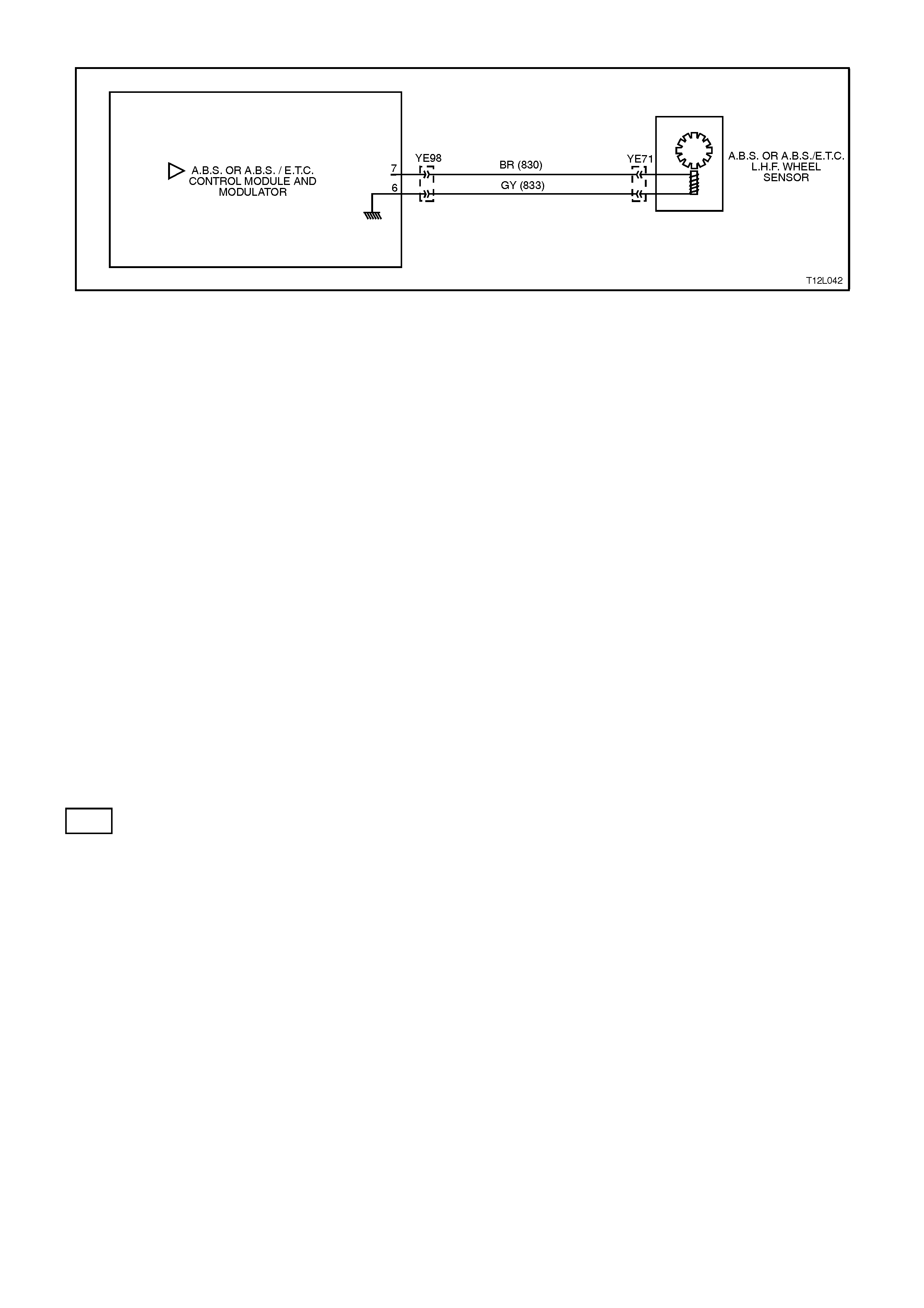
DTC 25 - FRONT LEFT WHEEL SPEED SENSOR INCORRECT SIGNAL
Figure 12L-116
CIRCUIT DESCRIPTION:
The toothed pulse ring wheel inside the front hub assembly generates a voltage pulse as it moves past the wheel
speed sensor; each tooth - gap - tooth on the pulse ring generates these pulses.
The frequency of these pulses is used by the ABS or ABS/ETC control module to determine wheel speed.
DTC 25 will set if vehicle speed is approximately 12 km/h and the control module detects a low left hand front wheel
speed sensor output voltage.
If a failure is detected which causes DTC 25 to set, the ABS or ABS/ETC system is disabled and the control module
illuminates the ABS, or ABS and TRAC OFF warning lamps for the remainder of the ignition cycle. If the failure is
intermittent, the control module will enable the system at the next ignition cycle and a history DTC 25 will be set.
TEST DESCRIPTION:
The numbers below refer to Step numbers in the diagnostic chart for DTC 25.
1. This test checks if there is a speed signal output from the sensor.
2. This test checks for connector or wiring problems which may cause an intermittent condition.
3. This test determines whether the DTC was set by an intermittent condition or a control module fault.
4. This check is a visual inspection of the speed sensor, wiring and the pulse ring.
5. If repairs are necessary, the speed sensor output must be rechecked to verify the repair.
6. This test checks for a voltage drop in the wheel speed sensor wiring which could cause lower than specified
sensor output voltage.
NOTES ON DIAGNOSTIC CHART:
1. Refer to 4.7 TECH 2 DIAGNOSTICS in this Section for connecting and using Tech 2.
2. For all wiring checking procedures, refer to Section 12P WIRING DIAGRAMS.
DIAGNOSTIC AIDS:
For additional information on testing the front wheel speed sensor, refer to 3.2 FRONT WHEEL SPEED SENSOR
LEAD in this Section.

STEP ACTION VALUE YES NO
1. ∙Jack up front of
vehicle and support
on safety stands.
∙Install Tech 2 to
DLC.
∙Select Diagnostics /
Chassis / ABS/ETC /
Data List / Active
ABS (refer to
NOTE 1 above).
∙Check left hand front
wheel speed sensor
output signal by
rotating wheel by
hand.
(Alternatively,
connect an
oscilloscope to the
wheel speed sensor
connector YE71,
between circuit 830
(Brown wire) and
circuit 833 (Grey
wire), rotate left hand
front wheel by hand
and compare
oscilloscope patterns
with those shown
below. Repair as
necessary or go to
Step 2).
∙Does speed signal
change as wheel is
turned faster?
Go to Step 2. Go to Step 4.
2. ∙Visually inspect
sensor lead wiring
and connections.
∙Check wiring for
intermittent open or
short circuit (refer to
NOTE 2 above).
∙Is all OK ?
Go to Step 3. Repair fault with
sensor lead wiring
or connections,
recheck circuit to
verify repair.
3. ∙Install TECH 2 to
DLC and select
Diagnostics / Chassis
/ ABS/ETC /
Diagnostic Trouble
Codes / Clear DTC’s
and clear all DTC's
(refer to NOTE 1
above).
∙Road test vehicle.
∙Does DTC 25 set
again ?
Replace ABS or
ABS/ETC control
module, refer to
3.6 CONTROL
MODULE in this
Section, recheck
circuit to verify
repair.
Fault not present.
Check all system
wiring harness
connectors and
terminals, in
particular the ABS
or ABS/ETC
control module
connector
terminals.
4. ∙Visually inspect
sensor lead wiring,
mountings and
connections.
∙Is all OK ?
Go to Step 6. Go to Step 5.
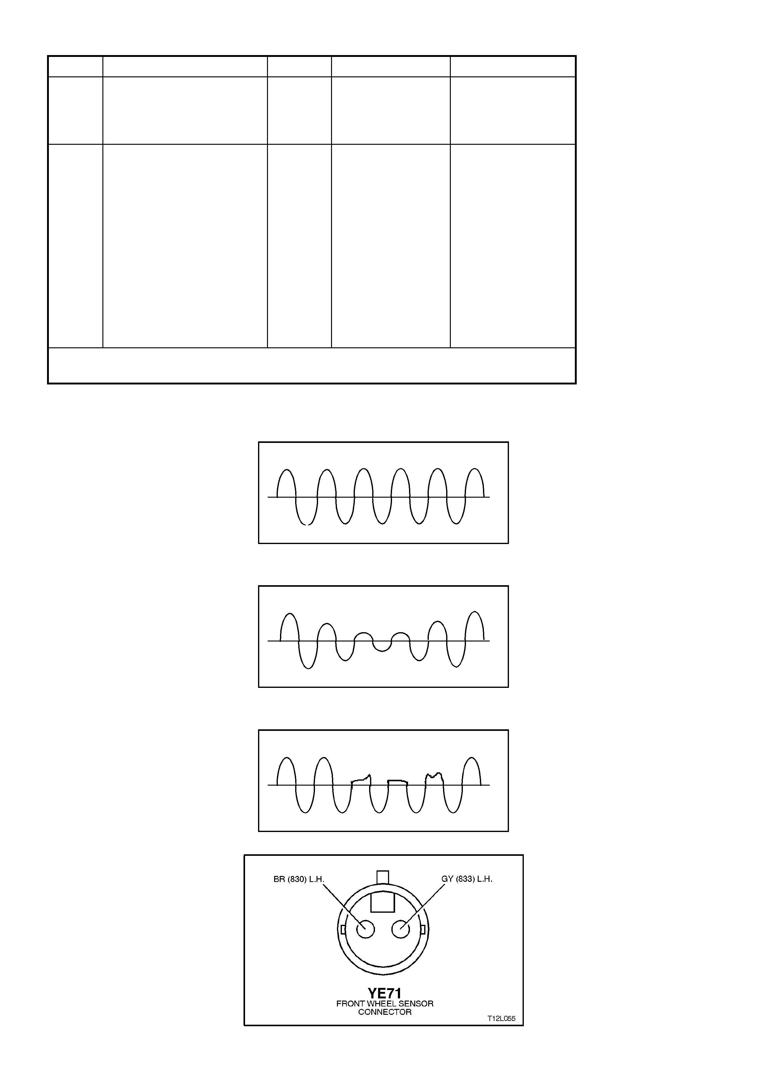
STEP ACTION VALUE YES NO
5. ∙Make repairs as
necessary. Retest
speed sensor output.
∙Is output now OK ?
Go to Step 3. Go to Step 6.
6. ∙Check circuits 830
(Brown wire) and 833
(Grey wire) for
continuity (refer to
NOTE 2 above).
∙Inspect Main Wiring
Harness to sensor
lead connector YE71
and sensor
connector at front
wheel hub assembly.
∙Are connectors and
wiring OK ?
Replace front hub
& WSS asm, refer
to 3.3 WHEEL
SPEED SENSOR
in this Section,
recheck circuit to
verify repair.
Repair wiring as
necessary, recheck
circuit to verify
repair.
WHEN A LL DIAGNOSIS AND REPA IRS ARE COMPLETED, CLEAR A LL DTC’S AND
VERIFY CORRECT OPERATION
Oscilloscope Patterns (simulated only)
Normal view
Possible increasing and decreasing distance between wheel speed sensor and pulse ring
Possible chipped or damaged teeth
Figure 12L-117
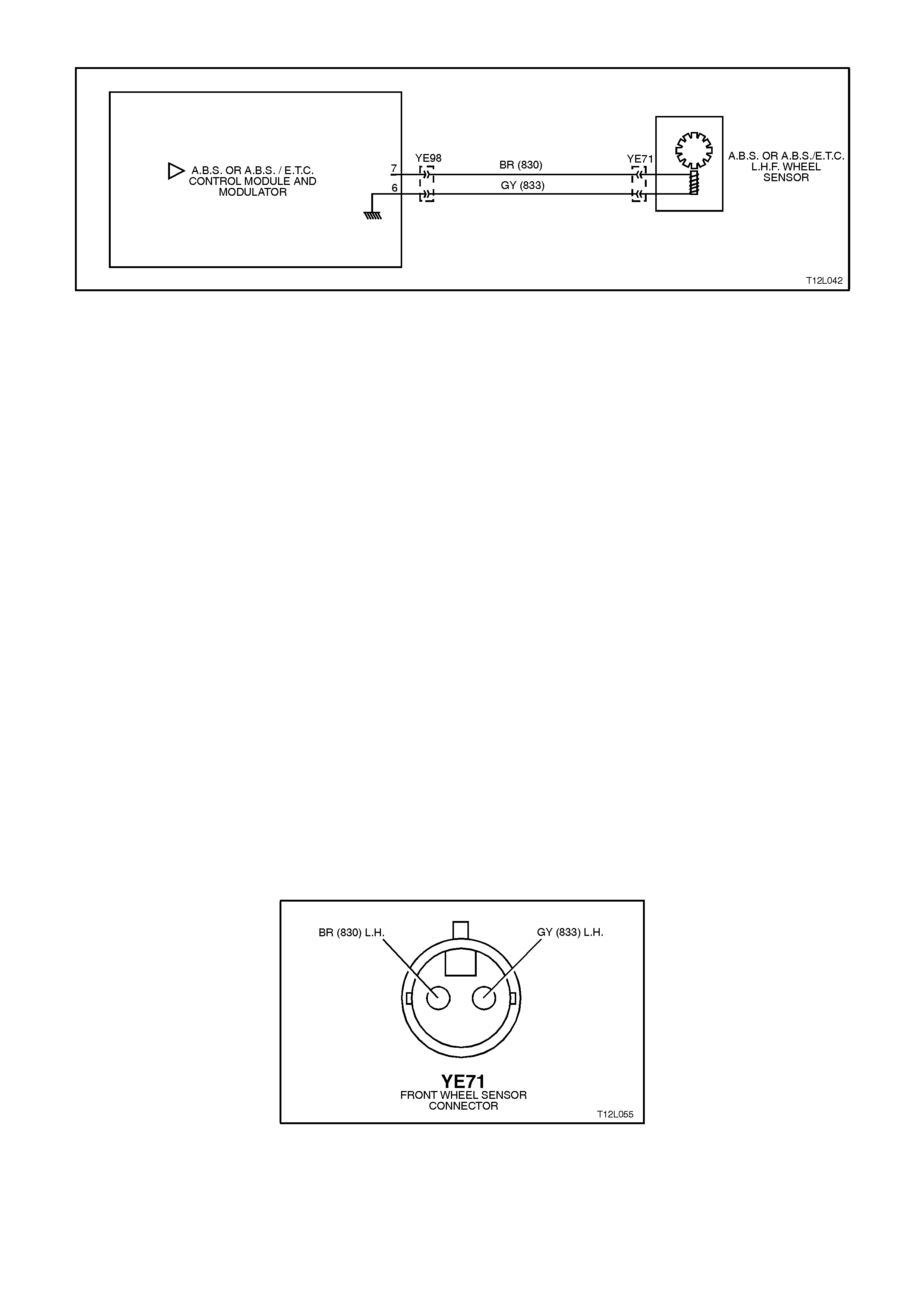
DTC 27 - FRONT LEFT WHEEL SPEED SENSOR SHORT CIRCUIT OR OPEN CIRCUIT
Figure 12L-118
CIRCUIT DESCRIPTION:
The toothed pulse ring wheel inside the front hub assembly generates a voltage pulse as it moves past the wheel
speed sensor; each tooth - gap - tooth on the pulse ring generates these pulses.
The frequency of these pulses is used by the ABS or ABS/ETC control module to determine wheel speed.
DTC 27 will set when the ignition is switched on and the control module detects a continuity problem in circuits 830
and 833, or no wheel speed signal is generated by the sensor.
If a failure is detected which causes DTC 27 to set, the ABS or ABS/ETC system is disabled and the control module
illuminates the ABS or ABS and TRAC OFF warning lamps for the remainder of the ignition cycle. If the failure is
intermittent, the control module will enable the system at the next ignition cycle and a history DTC 27 will be set.
TEST DESCRIPTION:
The numbers below refer to Step numbers in the diagnostic chart for DTC 27.
1. Begin rectification of this DTC by visually inspecting left hand front wheel speed sensor wiring for a fault
condition.
2. This test checks for connector or wiring problems which may cause an intermittent condition.
3. This test checks for correct resistance reading of the sensor coil.
4. This test checks for continuity of left hand front wheel speed sensor wiring.
5. This test checks for short circuit between wheel speed sensor wiring.
6. This test checks for open circuit in left hand front wheel speed sensor wiring.
7. This test checks for short to earth or B+ in circuits 830 and 833.
8. This test determines whether the DTC was set by an intermittent condition or a control module fault.
NOTES ON DIAGNOSTIC CHART:
1. Refer to 4.7 TECH 2 DIAGNOSTICS in this Section for connecting and using TECH 2.
2. For all wiring checking procedures, refer to Section 12P WIRING DIAGRAMS.
DIAGNOSTIC AIDS:
For additional information on testing the front wheel speed sensor, refer to 3.2 FRONT WHEEL SPEED SENSOR
LEAD in this Section.
Figure 12L-119
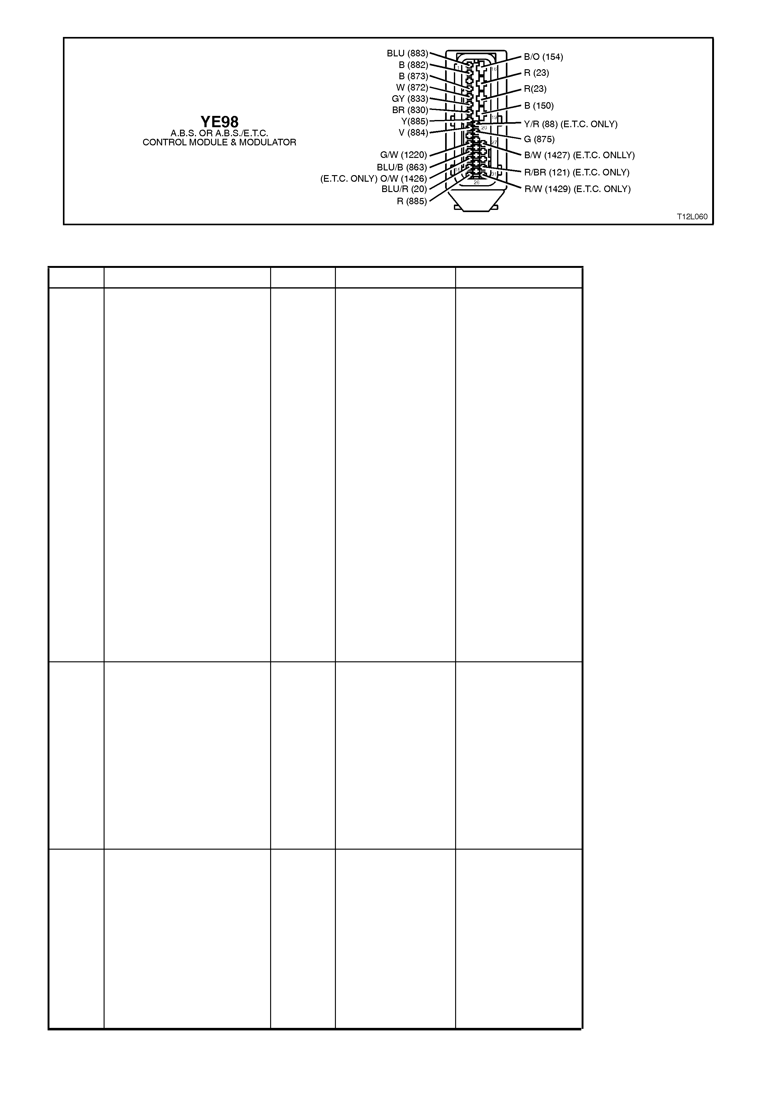
Figure 12L-120
STEP ACTION VALUE YES NO
1. ∙Ensure that left hand
front wheel speed
sensor lead is not
visibly damaged and
that it is properly
secured at all places.
∙If the sensor lead is
damaged or not
correctly mounted
and retained, replace
the lead and/or
properly install it.
∙Install TECH 2 to
DLC and select
Diagnostics / Chassis
/ ABS/ETC /
Diagnostic Trouble
Codes / Clear DTC’s
and clear all DTC's
(refer to NOTE 1
above).
∙Road test vehicle,
does DTC 27 set
again ?
Go to Step 3. Go to Step 2.
2. ∙Inspect all system
wiring and
connections that
could cause
intermittent faults.
Check all wiring is in
good condition,
terminals are clean
and tight and making
good contact (refer to
NOTE 2 above).
∙Is all OK ?
Fault not present.
Check all system
wiring harness
connectors and
terminals, in
particular the ABS
or ABS/ETC
control module
connector
terminals.
Make repairs as
necessary, recheck
circuit to verify
repair.
3. ∙Turn ignition OFF.
∙Disconnect sensor
lead connector YE71
from Main Wiring
Harness connector.
∙Using digital
multimeter, measure
sensor and lead
resistance.
∙Is value as specified
?
1600 -
1800
Ohms
Go to Step 5. Go to Step 4.

STEP ACTION VALUE YES NO
4. ∙Remove sensor lead
and check continuity
of lead wiring.
∙Is continuity OK ?
Wheel speed
sensor faulty.
Replace front hub
assembly, refer to
3.3 in this Section,
recheck circuit to
verify repair.
Faulty lead.
Replace lead, refer
to 3.2 in this
Section, recheck
circuit to verify
repair.
5. ∙Disconnect ABS or
ABS/ETC control
module connector
YE98.
∙With sensor lead
connector YE71 still
disconnected, check
continuity between
ABS or ABS/ETC
control module
connector YE98,
terminals 6 and 7
(refer NOTE 2
above).
∙Does continuity exist
?
Eliminate short
circuit in wiring
between circuits
872 (White wire)
and 873 (Red
wire), recheck
circuit to verify
repair.
Go to Step 6.
6. ∙Check circuits 830
(Brown wire) and 833
(Grey wire) for open
circuit between
sensor connector
YE71 and ABS or
ABS/ETC control
module connector
YE98 (refer
NOTE 2 above).
∙Is there continuity in
both circuits ?
Go to Step 7. Eliminate open
circuit in wiring,
recheck circuit to
verify repair.
7. ∙Check circuits 830
and 833 for short to
earth or B+ (refer to
NOTE 2 above).
∙Are both circuits OK
?
Go to Step 8. Eliminate short to
earth or B+ in
wiring, recheck
circuit to verify
repair.
8. ∙Install TECH 2 to
DLC and select
Diagnostics / Chassis
/ ABS/ETC /
Diagnostic Trouble
Codes / Clear DTC’s
and clear all DTC's
(refer to NOTE 1
above).
∙Road test vehicle.
∙Does DTC 27 set
again ?
Replace ABS or
ABS/ETC control
module, refer to
3.6 CONTROL
MODULE in this
Section, recheck
circuit to verify
repair.
Fault not present.
Check all system
wiring harness
connectors and
terminals, in
particular the ABS
or ABS/ETC
control module
connector
terminals.
WHEN A LL DIAGNOSIS AND REPA IRS ARE COMPLETED, CLEAR A LL DTC’S AND
VERIFY CORRECT OPERATION
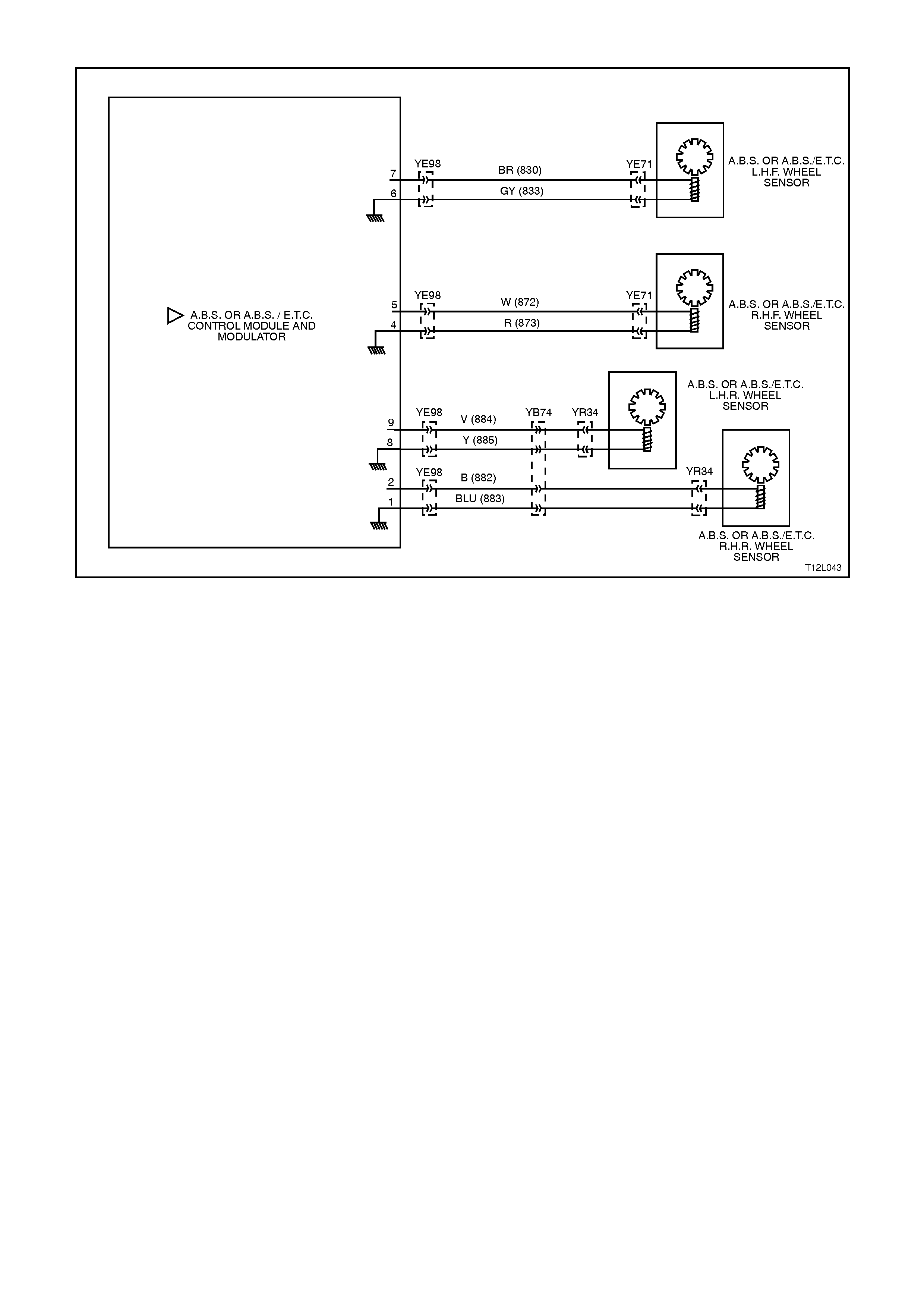
DTC 28 - WHEEL SPEED SENSOR FREQUENCY ERROR
Figure 12L-121
CIRCUIT DESCRIPTION:
The toothed pulse ring generates a voltage pulse as it moves past the wheel speed sensor. Each tooth - gap - tooth
on the pulse ring generates these pulses.
The frequency of these pulses is used by the ABS or ABS/ETC control module to determine wheel speed. The ABS
or ABS/ETC control module will calculate the wheel speed by the number of teeth on the pulse ring.
DTC 28 will set if an incorrect number of teeth or damaged teeth are present on a pulse ring. If the ABS or
ABS/ETC control module could define the specific wheel speed sensor causing the malfunction, the DTC
associated with the sensor (21, 25, 31 or 35) will be set instead of DTC 28.
If a failure is detected which causes DTC 28 to set, the ABS or ABS/ETC system is disabled and the control module
illuminates the ABS or ABS and TRAC OFF warning lamps for the remainder of the ignition cycle. If the failure is
intermittent, the control module will enable the system at the next ignition cycle and a history DTC 28 will be set.
NOTE:
If DTC 28 sets, the ABS or ABS/ETC control module does not or cannot determine which sensor assembly is at
fault. All the wheel speed sensors will need to be checked to determine which is setting the DTC.
TEST DESCRIPTION:
The numbers below refer to Step numbers in the diagnostic chart for DTC 28.
1. Begin rectification of this DTC by visually inspecting both front wheel speed sensors wiring for a fault condition.
2. This test checks for any front wheel speed sensor wiring or connector problem that could cause DTC 28 to set.
3. This test checks that rear sensors are correctly installed.
4. This test checks that the rear wheel pulse rings are correctly mounted.
5. This test checks for any rear wheel speed sensor wiring or connector problem that could cause DTC 28 to set.

STEP ACTION VALUE YES NO
FOR FRONT WHEEL SPEED SENSORS ONLY
1. ∙Visually inspect
sensor lead wiring
mountings and
connections.
∙Is all OK ?
Go to Step 2. Repair or replace
components as
necessary, recheck
circuit to verify
repair.
2. ∙Check system wiring
for faults between
ABS or ABS/ETC
control module
connector YE98 and
front wheel speed
sensor lead
connections at the
front wheel hub
connections, YE71,
as per steps 3 to 7 in
diagnostic charts
DTC 23 and/or DTC
27 in this Section.
∙Is all OK ?
Go to Step 3. Repair or replace
wiring as
necessary, recheck
circuit to verify
repair.
FOR REAR WHEEL SPEED SENSORS ONLY
3. ∙Check that the
sensors are correctly
mounted and that the
retaining bolt is
tightened to the
correct torque
specification.
∙Is all OK ?
Go to Step 4. Properly mount and
attach sensor,
recheck circuit to
verify repair.
4. ∙Check that pulse ring
is correctly mounted
to inner axle shaft
and is in line with
sensor.
∙Is all OK ?
Ensure that the
number of pulse
ring teeth
correspond to
specification (48),
and are not
damaged. If all
OK, go to Step 5.
Replace inner axle
shaft, refer to 3.4
PULSE RINGS in
this Section,
recheck circuit to
verify repair.
5. ∙Check system wiring
for faults between
ABS or ABS/ETC
control module
connector YE98 and
rear wheel speed
sensor lead
connectors YB34, as
per steps 3 to 6 in
diagnostic charts
DTC 33 and/or DTC
37 in this Section.
∙Is all OK ?
Check all system
wiring harness
connector
terminals, in
particular the ABS
or ABS/ETC
control module
connector
terminals.
Repair or replace
wiring as
necessary, recheck
circuit to verify
repair.
WHEN A LL DIAGNOSIS AND REPA IRS ARE COMPLETED, CLEAR A LL DTC’S AND
VERIFY CORRECT OPERATION
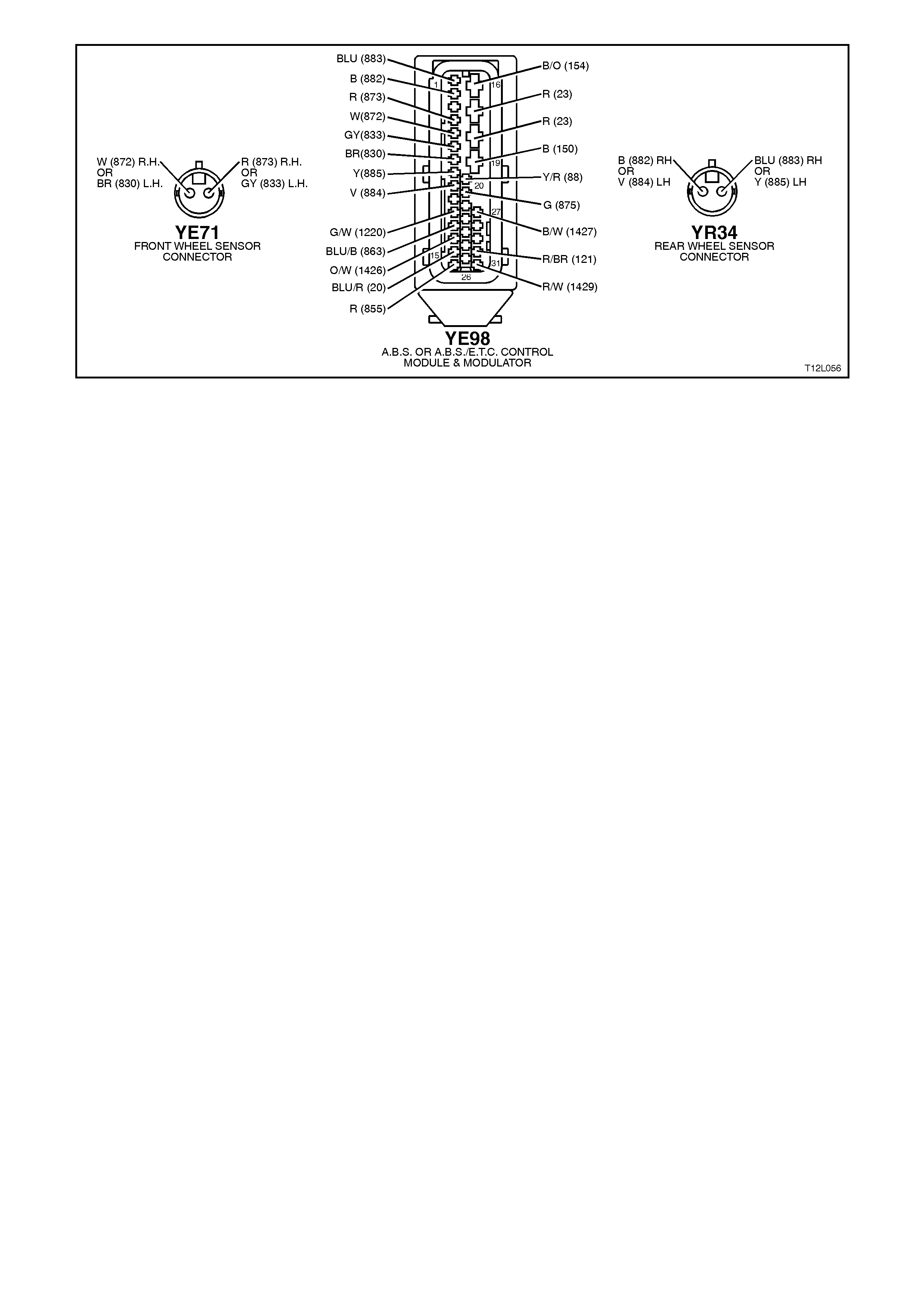
Figure 12L-122
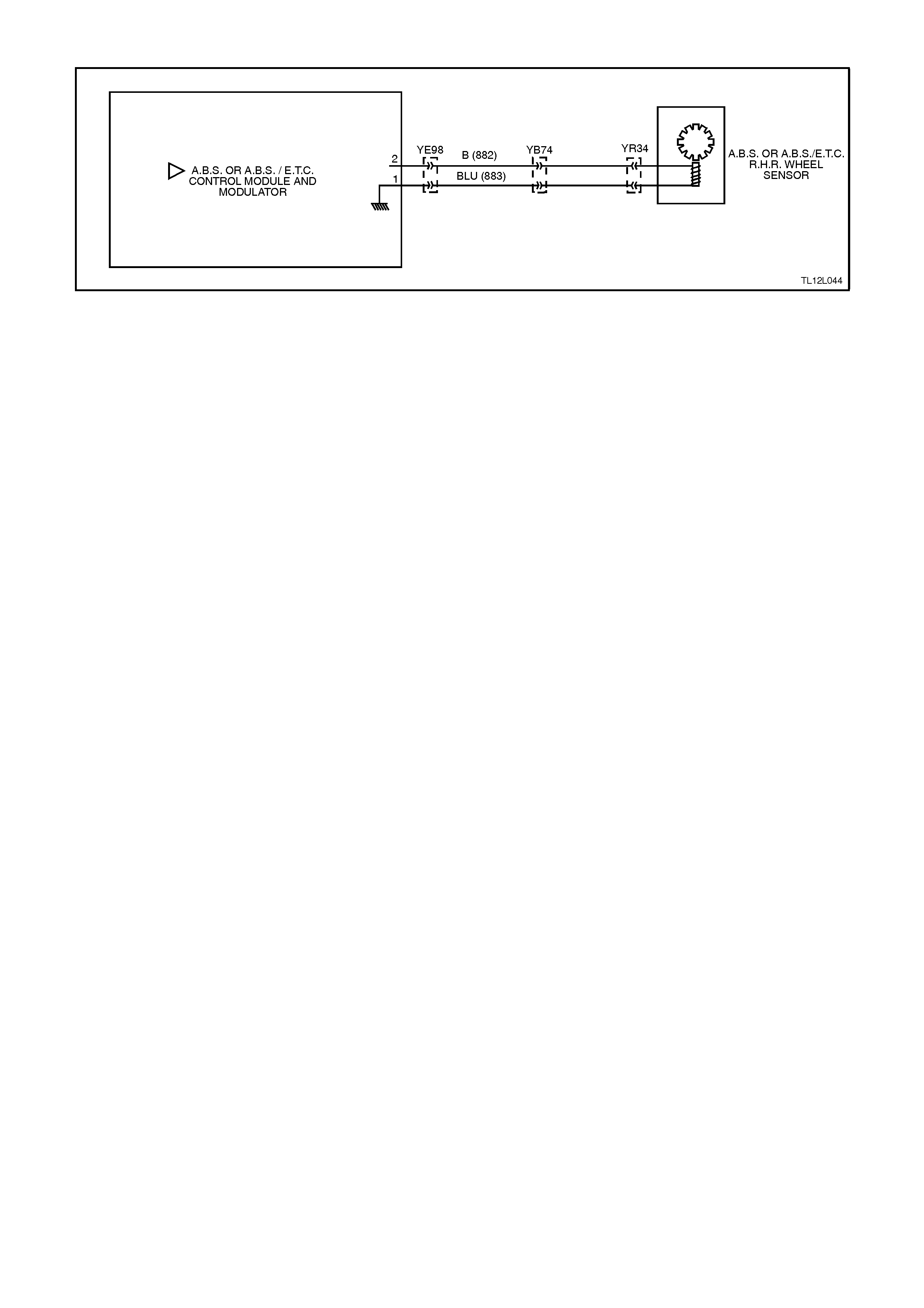
DTC 31 - REAR RIGHT WHEEL SPEED SENSOR INCORRECT SIGNAL
Figure 12L-123
CIRCUIT DESCRIPTION:
The toothed pulse ring wheel on the inner right rear axle flange generates a voltage pulse as it moves past the
wheel speed sensor; each tooth - gap - tooth on the pulse ring generates these pulses.
The frequency of these pulses is used by the ABS or ABS/ETC control module to determine wheel speed.
DTC 31 will set if vehicle speed is approximately 12 km/h and the control module detects a low right hand rear
wheel speed sensor output voltage.
If a failure is detected which causes DTC 31 to set, the ABS or ABS/ETC system is disabled and the control module
illuminates the ABS or ABS and TRAC OFF warning lamps for the remainder of the ignition cycle. If the failure is
intermittent, the control module will enable the system at the next ignition cycle and a history DTC 31 will be set.
TEST DESCRIPTION:
The numbers below refer to Step numbers in the diagnostic chart for DTC 31.
1. This test checks if there is a speed signal output from the sensor.
2. This test checks for connector or wiring problems which may cause an intermittent condition.
3. This test determines whether the DTC was set by an intermittent condition or a control module fault.
4. This check is a visual inspection of the speed sensor, wiring and the pulse ring.
5. If repairs are necessary, the speed sensor output must be rechecked to verify the repair.
6. This test checks for voltage drops in the wheel speed sensor wiring which could cause lower than specified
sensor output voltage.
NOTES ON DIAGNOSTIC CHART:
1. Refer to 4.7 TECH 2 DIAGNOSTICS in this Section for connecting and using TECH 2.
2. For all wiring checking procedures, refer to Section 12P WIRING DIAGRAMS.

STEP ACTION VALUE YES NO
1. ∙Jack up rear of
vehicle and support
on safety stands.
∙Install TECH 2 to
DLC (refer to
NOTE 1 above).
∙Select Diagnostics /
Chassis / ABS/ETC/
Data List / Active
ABS.
∙Check right hand
rear wheel speed
sensor output signal
by rotating wheel by
hand.
(Alternatively,
connect an
oscilloscope to the
wheel speed sensor
connector YR34,
between circuit 882
(Black w ire) and
circuit 883 (Blue
wire), rotate right
hand front wheel by
hand and compare
oscilloscope patterns
with those shown
below. Repair as
necessary or go to
Step 2).
∙Does speed signal
change as wheel is
turned faster?
Go to Step 2. Go to Step 4.
2. ∙Visually inspect
sensor lead wiring
and connections.
∙Check wiring for
intermittent open or
short circuit (refer to
NOTE 2 above).
∙Is all OK ?
Go to Step 3. Repair fault with
sensor lead wiring
or replace sensor,
recheck circuit to
verify repair.
3. ∙Install TECH 2 to
DLC and select
Diagnostics / Chassis
/ ABS/ETC /
Diagnostic Trouble
Codes / Clear DTC’s
and clear all DTC's
(refer to NOTE 1
above).
∙Road test vehicle.
∙Does DTC 31 set
again ?
Replace ABS or
ABS/ETC control
module, refer to
3.6 CONTROL
MODULE in this
Section, recheck
and verify repair.
Fault not present.
Check all system
wiring harness
connectors and
terminals, in
particular the ABS
or ABS/ETC
control module
connector
terminals.

STEP ACTION VALUE YES NO
4. ∙Visually inspect
sensor end for any
signs of damage
∙Check that the pulse
ring is secured to the
inner axle shaft and
is positioned in line
with the sensor.
∙Inspect pulse ring
teeth for any signs of
damage.
∙Is all OK ?
Go to Step 6. Go to Step 5.
5. ∙Make repairs as
necessary. Retest
speed sensor output.
∙Is output now OK ?
Go to Step 3. Go to Step 6.
6. ∙Check circuits 882
(Black wire) and 883
(Blue wire ) for
continuity (refer to
NOTE 2 above).
∙Inspect body harness
to sensor connector
YR34, body harness
to Main Wiring
Harness connector
YB74 and ABS or
ABS/ETC control
module connector
YE98.
∙Are connectors and
wiring OK ?
Replace rear
WSS asm, refer
to 3.3 WHEEL
SPEED
SENSORS in this
Section, recheck
circuit to verify
repair.
Repair wiring as
necessary, recheck
circuit to verify
repair.
WHEN A LL DIAGNOSIS AND REPA IRS ARE COMPLETED, CLEAR A LL DTC’S AND
VERIFY CORRECT OPERATION
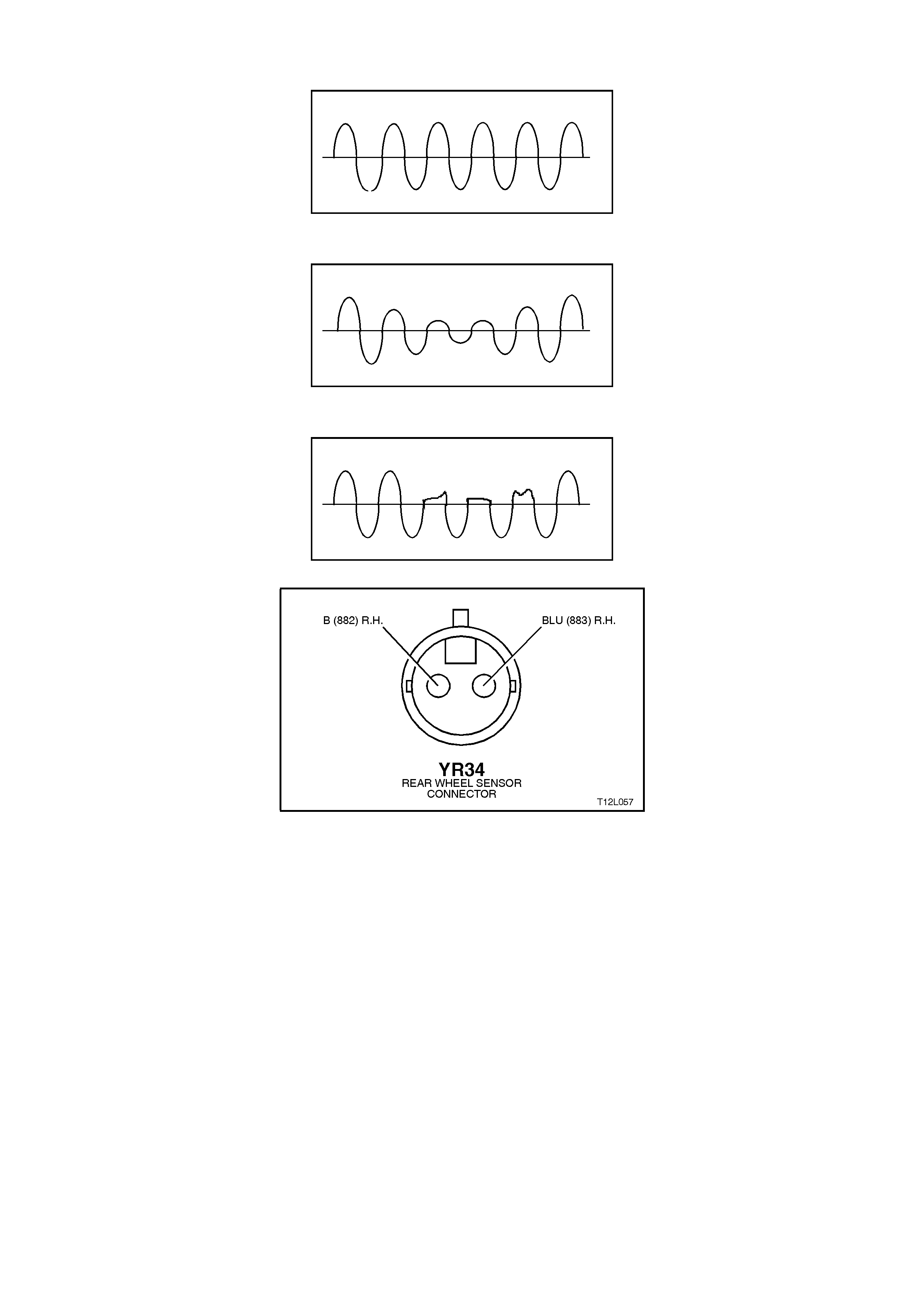
Oscilloscope Patterns (simulated only)
Normal view
Possible increasing and decreasing distance between wheel speed sensor and pulse ring
Possible chipped or damaged teeth
Figure 12L-124
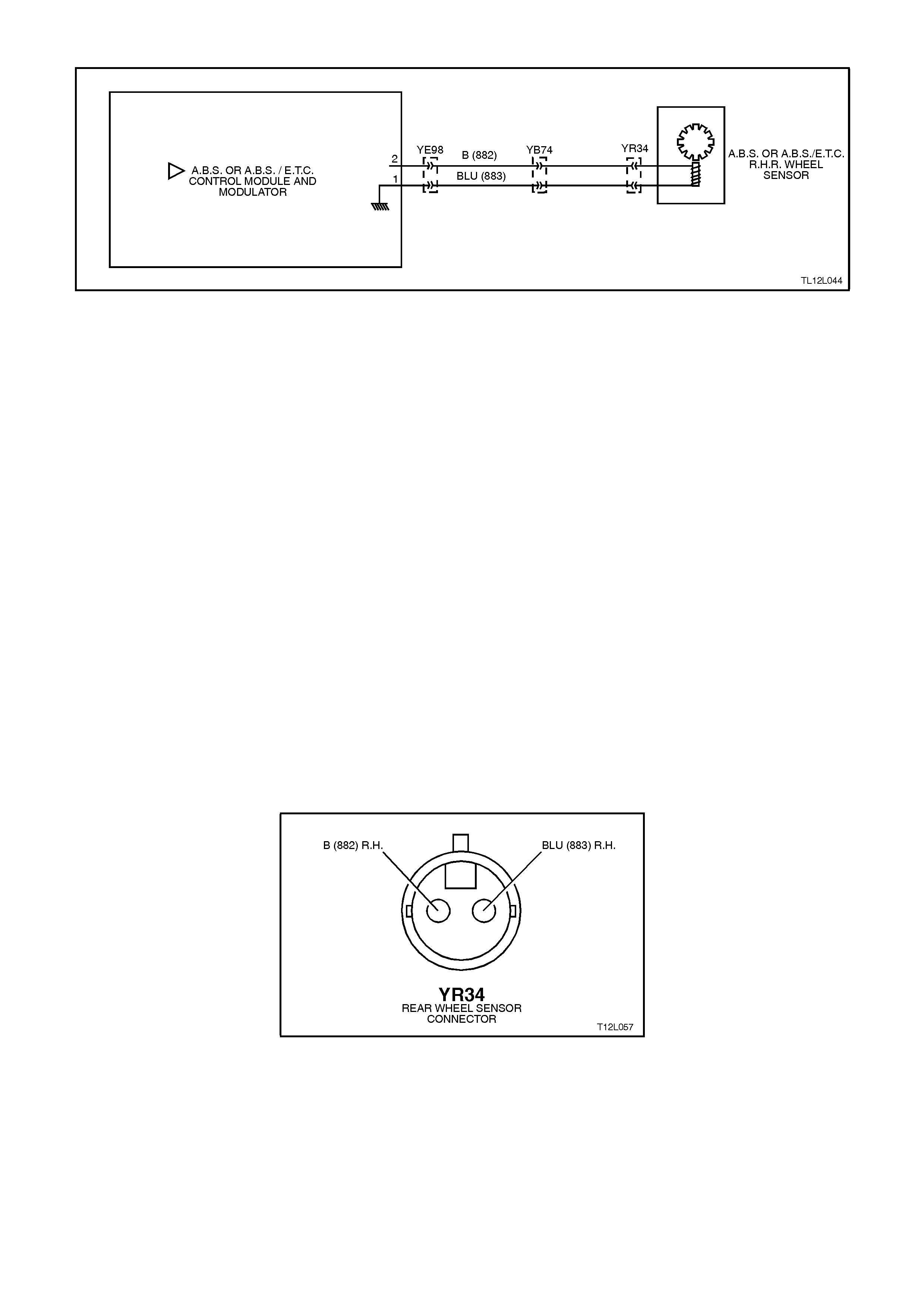
DTC 33 - REAR RIGHT WHEEL SPEED SENSOR SHORT CIRCUIT OR OPEN CIRCUIT
Figure 12L-125
CIRCUIT DESCRIPTION:
The toothed pulse ring wheel on the inner right rear axle flange generates a voltage pulse as it moves past the
wheel speed sensor; each tooth - gap - tooth on the pulse ring generates these pulses.
The frequency of these pulses is used by the ABS or ABS/ETC control module to determine wheel speed.
DTC 33 will set when the ignition is switched on and the control module detects a continuity problem in circuits 882
and 883, or no wheel speed signal is generated by the sensor.
If a failure is detected which causes DTC 33 to set, the ABS or ABS/ETC system is disabled and the control module
illuminates the ABS or ABS and TRAC OFF warning lamps for the remainder of the ignition cycle. If the failure is
intermittent, the control module will enable the system at the next ignition cycle and a history DTC 33 will be set.
TEST DESCRIPTION:
The numbers below refer to Step numbers in the diagnostic chart for DTC 33.
1. Begin rectification of this DTC by visually inspecting right hand rear wheel speed sensor wiring for a fault
condition.
2. This test is a usual check for connector or wiring problems which may cause an intermittent condition.
3. This test checks for correct resistance reading of the sensor coil.
4. This test checks for short circuit in right hand rear wheel speed sensor wiring.
5. This test checks for open circuit in right hand rear wheel speed sensor wiring.
6. This test checks for short to earth or B+ in circuits 882 and 883.
7. This test determines whether the DTC was set by an intermittent condition or a control module fault.
NOTES ON DIAGNOSTIC CHART:
1. Refer to 4.7 TECH 2 DIAGNOSTICS in this Section for connecting and using TECH 2.
2. For all wiring checking procedures, refer to Section 12P WIRING DIAGRAMS.
Figure 12L-126

Figure 12L-127
STEP ACTION VALUE YES NO
1. ∙Ensure that right
hand rear wheel
speed sensor lead is
not visibly damaged
and that it is properly
secured at all places.
∙If the sensor lead is
damaged or not
correctly mounted
and retained, replace
the lead and/or
properly install it.
∙Install TECH 2 to
DLC and select
Diagnostics / Chassis
/ ABS/ETC /
Diagnostic Trouble
Codes / Clear DTC’s
and clear all DTC's
(refer to NOTE 1
above).
∙Road test vehicle,
does DTC 33 set
again ?
Go to Step 3. Go to Step 2.
2. ∙Inspect all system
wiring and
connections that
could causes
intermittent faults.
Check all wiring is in
good condition,
terminals are clean
and tight and making
good contact (refer to
NOTE 2 above).
∙Is all OK ?
Fault not present.
Check all system
wiring harness
connectors and
terminals, in
particular the
modulator and
ABS or ABS/ETC
control module
connector
terminals.
Make repairs as
necessary, recheck
circuit to verify
repair.
3. ∙Turn ignition OFF.
∙Disconnect sensor
lead connector YR34
from body harness
connector.
∙Using digital
multimeter, measure
sensor and lead
resistance.
∙Is value as specified
?
1440 -
1760
Ohms
Go to Step 4. Replace rear WSS
asm, refer to 3.3
WHEEL SPEED
SENSORS in this
Section, recheck
circuit to verify
repair.

STEP ACTION VALUE YES NO
4. ∙Disconnect ABS or
ABS/ETC control
module connector
YB98.
∙With sensor lead
connector YR34 still
disconnected, check
continuity between
ABS or ABS/ETC
control module
connector YB98,
terminals 1 and 2
(refer to NOTE 2
above).
∙Does continuity exist
?
Eliminate short
circuit in wiring
between circuits
882 (Black wire)
and 883 (Blue
wire), recheck
circuit to verify
repair.
Go to Step 5.
5. ∙Check circuits 882
(Black wire) and 883
(Blue wire) for open
circuit between
sensor connector
YR34 and ABS
control module
connector YB98
(refer to NOTE 2
above).
∙Is there continuity in
both circuits ?
Go to Step 6. Eliminate open
circuit in wiring,
recheck circuit to
verify repair.
6. ∙Check circuits 882
and 883 for short to
earth or B+ (refer to
NOTE 2 above).
∙Are both circuits OK
?
Go to Step 7. Eliminate short to
earth or B+ in
wiring, recheck
circuit to verify
repair.
7. ∙Install TECH 2 to
DLC and select
Diagnostics / Chassis
/ ABS/ETC /
Diagnostic Trouble
Codes / Clear DTC’s
and clear all DTC's
(refer to NOTE 1
above).
∙Road test vehicle.
∙Does DTC 33 set
again ?
Replace ABS or
ABS/ETC control
module, refer to
3.6 CONTROL
MODULE in this
Section, recheck
and verify repair.
Fault not present.
Check all system
wiring harness
connectors and
terminals, in
particular the
modulator and ABS
or ABS/ETC
control module
connector
terminals.
WHEN A LL DIAGNOSIS AND REPA IRS ARE COMPLETED, CLEAR A LL DTC’S AND
VERIFY CORRECT OPERATION
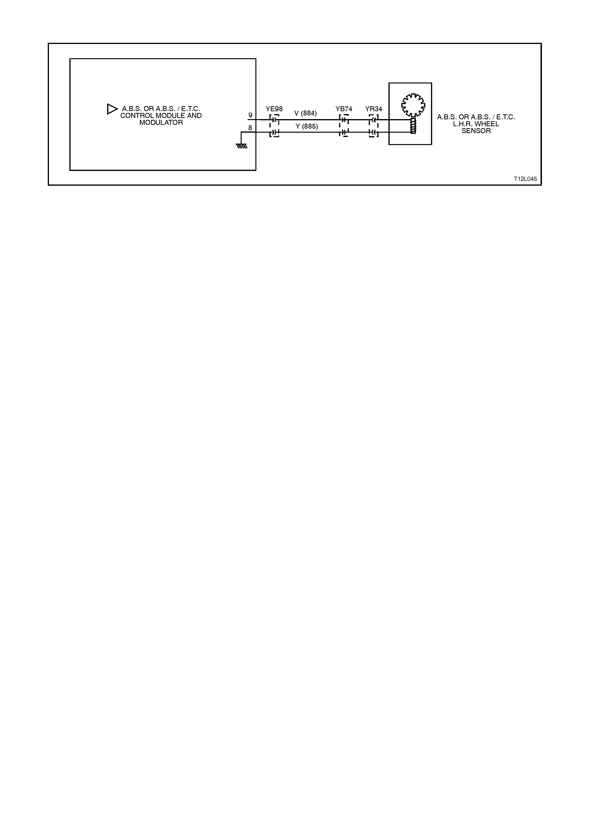
DTC 35 - REAR LEFT WHEEL SPEED SENSOR INCORRECT SIGNAL
Figure 12L-128
CIRCUIT DESCRIPTION:
The toothed pulse ring wheel on the inner left rear axle flange generates a voltage pulse as it moves past the wheel
speed sensor; each tooth - gap - tooth on the pulse ring generates these pulses.
The frequency of these pulses is used by the ABS or ABS/ETC control module to determine wheel speed.
DTC 35 will set if vehicle speed is approximately 12 km/h and the control module detects a low left hand rear wheel
speed sensor output voltage.
If a failure is detected which causes DTC 35 to set, the ABS or ABS/ETC system is disabled and the control module
illuminates the ABS, or ABS and TRAC OFF warning lamps for the remainder of the ignition cycle. If the failure is
intermittent, the control module will enable the system at the next ignition cycle and a history DTC 35 will be set.
TEST DESCRIPTION:
The numbers below refer to Step numbers in the diagnostic chart for DTC 35.
1. This test checks if there is a speed signal output from the sensor.
2. This test checks for connector or wiring problems which may cause an intermittent condition.
3. This test determines whether the DTC was set by an intermittent condition or a control module fault.
4. This check is a visual inspection of the speed sensor, wiring and the pulse ring.
5. If repairs are necessary, the speed sensor output must be rechecked to verify the repair.
6. This test checks for voltage drops in the wheel speed sensor wiring which could cause lower than specified
sensor output voltage.
NOTES ON DIAGNOSTIC CHART:
1. Refer to 4.7 TECH 2 DIAGNOSTICS in this Section for connecting and using TECH 2.
2. For all wiring checking procedures, refer to Section 12P WIRING DIAGRAMS.

STEP ACTION VALUE YES NO
1. ∙Jack up rear of
vehicle and support
on safety stands.
∙Install TECH 2 to
DLC and turn ignition
ON (refer to
NOTE 1 above).
∙Select Diagnostics /
Chassis / ABS/ETC/
Data List / Active
ABS.
∙Check left hand rear
wheel speed sensor
output signal by
rotating wheel by
hand.
(Alternatively,
connect an
oscilloscope to the
wheel speed sensor
connector YR34,
between circuit 884
(Violet wire ) and
circuit 885 (Yellow
wire), rotate left hand
front wheel by hand
and compare
oscilloscope patterns
with those shown
below. Repair as
necessary or go to
Step 2).
∙Does speed signal
change as wheel is
turned faster?
Go to Step 2. Go to Step 4.
2. ∙Visually inspect
sensor lead wiring
and connections.
∙Check wiring for
intermittent open or
short circuit (refer
NOTE 2 above).
∙Is all OK ?
Go to Step 3. Repair fault with
sensor lead wiring
or replace sensor,
recheck and verify
repair.
3. ∙Install TECH 2 to
DLC and select
Diagnostics / Chassis
/ ABS/ETC /
Diagnostic Trouble
Codes / Clear DTC’s
and clear all DTC's
(refer to NOTE 1
above).
∙Road test vehicle .
∙Does DTC 35 set
again ?
Replace ABS or
ABS/ETC control
module, refer to
3.6 CONTROL
MODULE in this
Section, recheck
and verify repair.
Fault not present.
Check all system
wiring harness
connectors and
terminals, in
particular the ABS
or ABS/ETC
control module
connector
terminals.

STEP ACTION VALUE YES NO
4. ∙Visually inspect
sensor end for any
signs of damage
∙Check that the pulse
ring is secured to the
inner axle shaft and
is positioned in line
with the sensor.
∙Inspect pulse ring
teeth for any signs of
damage.
∙Is all OK ?
Go to Step 6. Go to Step 5.
5. ∙Make repairs as
necessary. Retest
speed sensor output.
∙Is output now OK ?
Go to Step 3. Go to Step 6.
6. ∙Check circuits 884
(Violet wire) and 885
(Yellow wire) for
continuity (refer to
NOTE 2 above).
∙Inspect body harness
to sensor connector
YR34, body harness
to Main Wiring
Harness connector
YB74 and ABS or
ABS/ETC control
module connector
YE98.
∙Are connectors and
wiring OK ?
Replace rear
WSS asm, refer
to 3.3 WHEEL
SPEED
SENSORS in this
Section, recheck
and verify repair.
Repair wiring as
necessary, recheck
and verify repair.
WHEN A LL DIAGNOSIS AND REPA IRS ARE COMPLETED, CLEAR A LL DTC’S AND
VERIFY CORRECT OPERATION
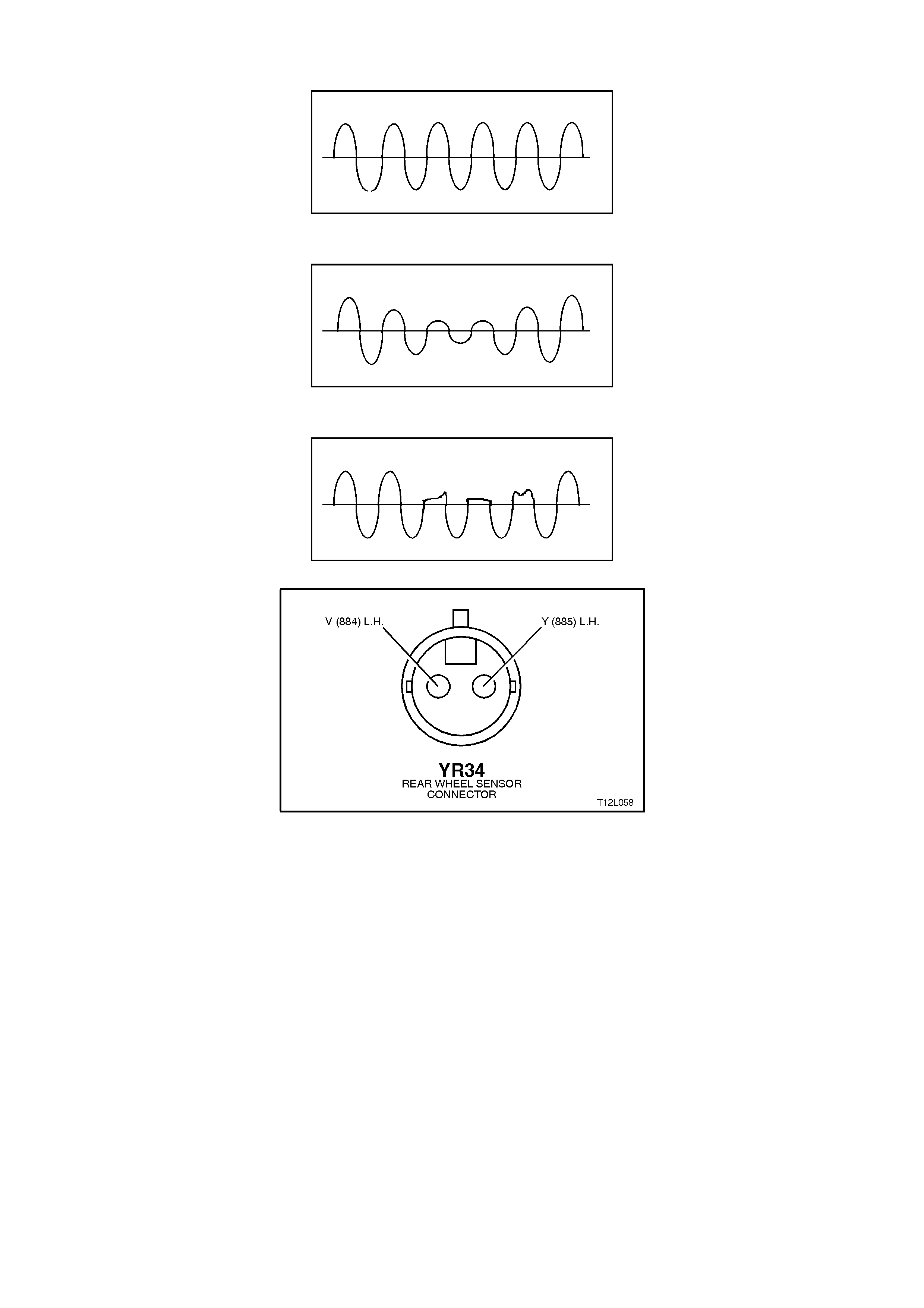
Oscilloscope Patter (simulated only)
Normal view
Possible increasing and decreasing distance between wheel speed sensor and pulse ring
Possible chipped or damaged teeth
Figure 12L-129
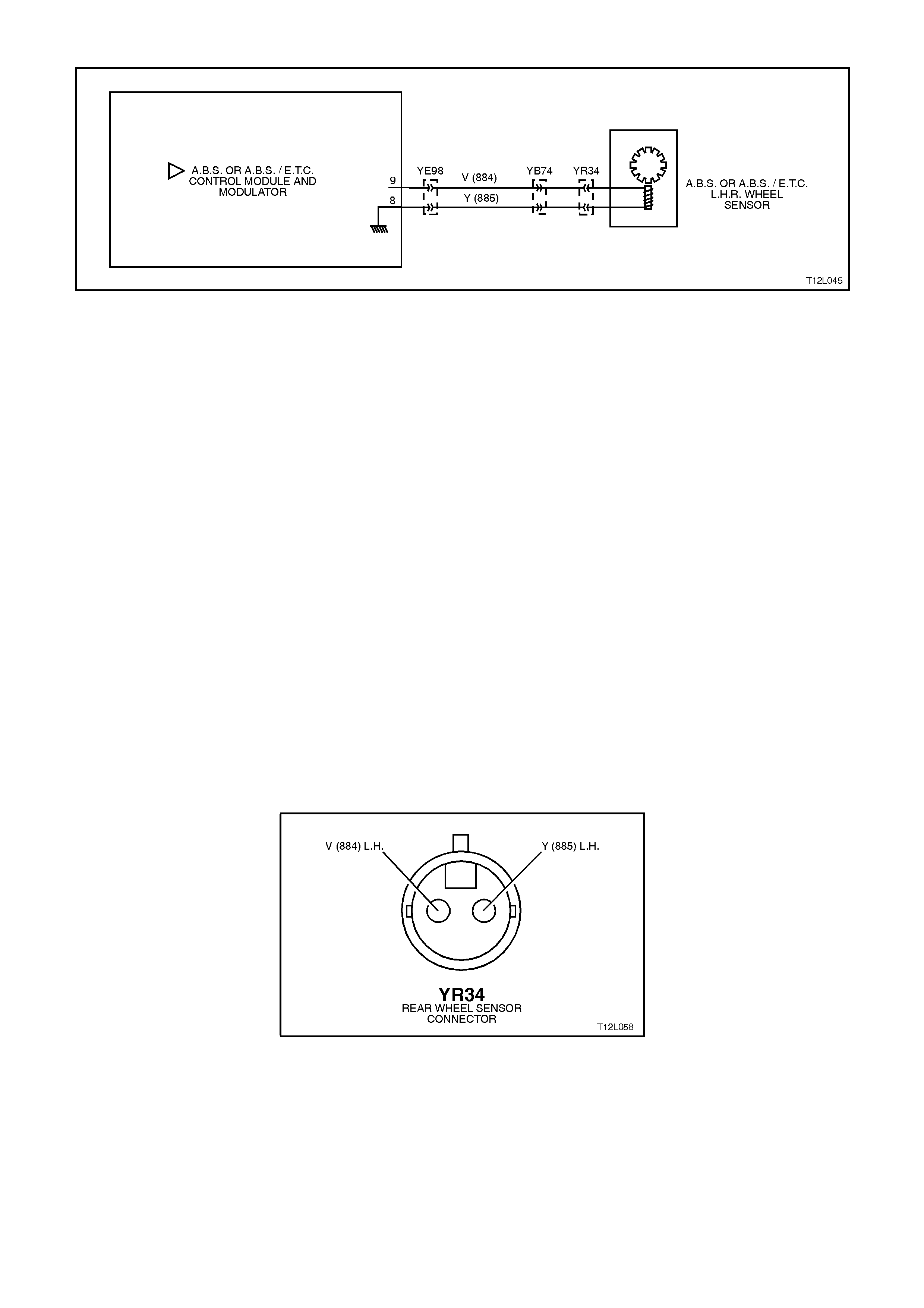
DTC 37 - REAR LEFT WHEEL SPEED SENSOR SHORT CIRCUIT OR OPEN CIRCUIT
Figure 12L-130
CIRCUIT DESCRIPTION:
The toothed pulse ring wheel on the inner left rear axle flange generates a voltage pulse as it moves past the wheel
speed sensor; each tooth - gap - tooth on the pulse ring generates these pulses.
The frequency of these pulses is used by the ABS or ABS/ETC control module to determine wheel speed.
DTC 37 will set when the ignition is switched on and the control module detects a continuity problem in circuits 884
and 885, or no wheel speed signal is generated by the sensor.
If a failure is detected which causes DTC 37 to set, the ABS or ABS/ETC system is disabled and the control module
illuminates the ABS, or ABS and TRAC OFF warning lamps for the remainder of the ignition cycle. If the failure is
intermittent, the control module will enable the system at the next ignition cycle and a history DTC 37 will be set.
TEST DESCRIPTION:
The numbers below refer to Step numbers in the diagnostic chart for DTC 37.
1. Begin rectification of this DTC by visually inspecting left hand rear wheel speed sensor wiring for a fault
condition.
2. This test is a usual check for connector or wiring problems which may cause an intermittent condition.
3. This test checks for correct resistance reading of the sensor coil.
4. This test checks for continuity of left hand rear wheel speed sensor wiring.
5. This test checks for open circuit in left hand rear wheel speed sensor wiring.
6. This test checks for short to earth or B+ in circuits 884 and 885.
7. This test determines whether the DTC was set by an intermittent condition or a control module fault.
NOTES ON DIAGNOSTIC CHART:
1. Refer to 4.7 TECH 2 DIAGNOSTICS in this Section for connecting and using TECH 2.
2. For all wiring checking procedures, refer to Section 12P WIRING DIAGRAMS.
Figure 12L-131

Figure 12L-132
STEP ACTION VALUE YES NO
1. ∙Ensure that left hand
rear wheel speed
sensor lead is not
visibly damaged and
that it is properly
secured at all places.
∙If the sensor lead is
damaged or not
correctly mounted
and retained, replace
the lead and/or
properly install it.
∙Install TECH 2 to
DLC and select
Diagnostics / Chassis
/ ABS/ETC /
Diagnostic Trouble
Codes / Clear DTC’s
and clear all DTC's
(refer to NOTE 1
above).
∙Road test vehicle,
does DTC 37 set
again ?
Go to Step 3. Go to Step 2.
2. ∙Inspect all system
wiring and
connections that
could causes
intermittent faults.
Check all wiring is in
good condition,
terminals are clean
and tight and making
good contact (refer
NOTE 2 above).
∙Is all OK ?
Fault not present.
Check all system
wiring harness
connectors and
terminals, in
particular the
modulator and
ABS or ABS/ETC
control module
connector
terminals.
Make repairs as
necessary and
recheck circuit to
verify repair.
3. ∙Turn ignition OFF.
∙Disconnect sensor
lead connector YR34
from body harness
connector.
∙Using digital
multimeter, measure
sensor and lead
resistance.
∙Is value as specified
?
1440 -
1760
Ohms
Go to Step 4. Replace rear WSS
asm, refer to 3.3
WHEEL SPEED
SENSORS in this
Section, recheck
circuit to verify
repair.

STEP ACTION VALUE YES NO
4. ∙Disconnect ABS
control module
connector YB98.
∙With sensor lead
connector YR34 still
disconnected, check
continuity between
ABS or ABS/ETC
control module
connector YB98,
terminals 8 and 9
(refer to NOTE 2
above).
∙Does continuity exist
?
Eliminate short
circuit in wiring
between circuits
884 (Violet wire)
and 885 (Yellow
wire), recheck
circuit to verify
repair.
Go to Step 5.
5. ∙Check circuits 884
(Violet wire) and 885
(Yellow wire) for
open circuit between
sensor connector
YR34 and ABS or
ABS/ETC control
module connector
YB98 (refer to
NOTE 2 above).
∙Is there continuity in
both circuits ?
Go to Step 6. Eliminate open
circuit in wiring,
recheck circuit to
verify repair.
6. ∙Check circuits 884
and 885 for short to
earth or B+ (refer
NOTE 2 above).
∙Are both circuits OK
?
Go to Step 7. Eliminate short to
earth or B+ in
wiring, recheck
circuit to verify
repair.
7. ∙Install TECH 2 to
DLC and select
Diagnostics / Chassis
/ ABS/ETC /
Diagnostic Trouble
Codes / Clear DTC’s
and clear all DTC's
(refer to NOTE 1
above).
∙Road test vehicle.
∙Does DTC 37 set
again ?
Replace ABS or
ABS/ETC control
module, refer to
3.6 CONTROL
MODULE in this
Section, recheck
and verify repair.
Fault not present.
Check all system
wiring harness
connectors and
terminals, in
particular the
modulator and ABS
or ABS/ETC
control module
connector
terminals.
WHEN A LL DIAGNOSIS AND REPA IRS ARE COMPLETED, CLEAR A LL DTC’S AND
VERIFY CORRECT OPERATION

DTC’S: 41, 42, 45, 46, 47, 48, 51, 52, 55 & 56 - SOLENOID VALVE CIRCUIT FAULTS
Figure 12L-133
The components relating to these DTC’s are all part of the hydraulic modulator assembly and share a common
earth and power supply.
DTC 41 Front Right Inlet Valve Solenoid Fault
DTC 42 Front Right Outlet Valve Solenoid Fault
DTC 45 Front Left Inlet Valve Solenoid Fault
DTC 46 Front left Outlet Valve Solenoid Fault
DTC 47 Priming Valve Solenoid Fault
(ABS/ETC Only)
DTC 48 Switching Valve Solenoid Fault
(ABS/ETC Only)
DTC 51 Rear Right Inlet Valve Solenoid Fault
(ABS/ETC Only)
DTC 52 Rear Right Outlet Valve Solenoid Fault
(ABS/ETC Only)
DTC 55 Rear Left Inlet Valve Solenoid Fault
(ABS/ETC Only)
or Rear Axle Inlet Solenoid Valve Fault
(ABS Only)
DTC 56 Rear Left Outlet Valve Solenoid Fault
(ABS/ETC Only)
or Rear Axle Outlet Valve Solenoid Fault
(ABS Only)

CIRCUIT DESCRIPTION:
The hydraulic modulator and control module assembly are supplied with constant power from the battery via fusible
link FR, and, when the ignition is switched ON, via fuse F27. The solenoid valves are activated by the control
module internally supplying earth via terminals 16 and 19
If the ABS or ABS/ETC control module senses a fault such as an open circuit or a short circuit in the wiring or
solenoid valve, the valve relay will be de-energised. The ABS, or ABS and TRAC OFF warning lamps will be
illuminated and the relevant DTC/S will be set.
If a failure is detected which causes DTC’s 41, 42, 45, 46, 47, 48, 51, 52, 55 or 56 to set, the ABS or ABS/ETC
system is disabled and the control module illuminates the ABS, or ABS and TRAC OFF warning lamps for the
remainder of the ignition cycle. If the failure is intermittent, the control module will enable the system at the next
ignition cycle and the relevant history DTC will be set.
TEST DESCRIPTION:
The numbers below refer to Step numbers in the following diagnostic chart.
1. This step determines if there is a common power or earth supply fault to the hydraulic modulator and control
module assembly.
2. This test uses TECH 2 to check for proper solenoid valve operation.
3. Checks for constant battery voltage to the control module at terminals 17 and 18.
4. Checks for battery voltage to the control module at terminal 15 when the ignition is switched on.
5. Checks for continuity in earth circuit 154
6. Checks for continuity in earth circuit 150.
NOTES ON DIAGNOSTIC CHART:
1. For all wiring checking procedures, refer to Section 12P WIRING DIAGRAMS.
2. Refer to 4.7, TECH 2 DIAGNOSTICS in this Section for connecting and using TECH 2.
STEP ACTION VALUE YES NO
1. ∙Install TECH 2 to
DLC and select
Diagnostics / Chassis
/ ABS/ETC /
Diagnostic Trouble
Codes / Read DTC’s
(refer to NOTE 2
above).
∙Is there more than
one DTC set ?
Go to Step 3 Go to Step 2
2. ∙With TECH 2
connected, select
Diagnostics / Chassis
/ ABS/ETC /
Miscellaneous Tests
/ Solenoids.
∙Depending on the
DTC set, conduct the
relevant solenoid test
(ie. if DTC 41 is set,
select Front Right
Solenoid Valve Test)
and conduct solenoid
test (refer to
NOTE 2 above)
∙Does test confirm
that relevant solenoid
is OK ?
Fault not present.
Check all system
wiring harness
connectors and
terminals, in
particular the ABS
or ABS/ETC
control module
connector
terminals.
Replace hydraulic
modulator asm,
refer to 3.5
HYDRAULIC
MODULATOR
AND CONTROL
MODULE
ASSEMBLY in this
Section.

STEP ACTION VALUE YES NO
3. ∙Turn ignition Off.
∙Disconnect control
module connector
YE98.
∙Check for voltage at
control module
connector YE98,
terminals 17 and
then 18, circuit 23
(Red wire) to earth
(refer to NOTE 1
above)
∙Is voltage as
specified at each
terminal ?
Approx.
12 Volts Go to Step 4. Check and repair
open or short in
circuit 23, recheck
and verify repair.
4. ∙Ignition On.
∙With control module
connector YE98 still
disconnected, check
for voltage between
terminal 15, circuit
885 (Red wire) and
earth (refer
NOTE 1 above).
∙Is voltage as
specified ?
Approx.
12 Volts Go to Step 5. Check and repair
open or short in
circuit 885
(including fuse
F27), recheck and
verify repair.
5. ∙With control module
connector YE98 still
disconnected, check
for continuity
between control
module connector
YE98, terminal 16,
circuit 154
(Black/Orange wire)
and earth location E2
(ABS bracket in
engine
compartment).
∙Does continuity exist
?
Go to Step 6. Check and repair
open in circuit 154,
recheck and verify
repair.
6. ∙With control module
connector YE98 still
disconnected, check
for continuity
between control
module connector
YE98, terminal 19,
circuit 150 (Black
wire) and earth
location E3.
∙Does continuity exist
?
Replace hydraulic
modulator asm,
refer to
3.5 HYDRAULIC
MODULATOR
AND CONTROL
MODULE ASM in
this Section.
Check and repair
open in circuit 150,
recheck and verify
repair.
WHEN A LL DIAGNOSIS AND REPA IRS ARE COMPLETED, CLEAR A LL DTC’S AND
VERIFY CORRECT OPERATION
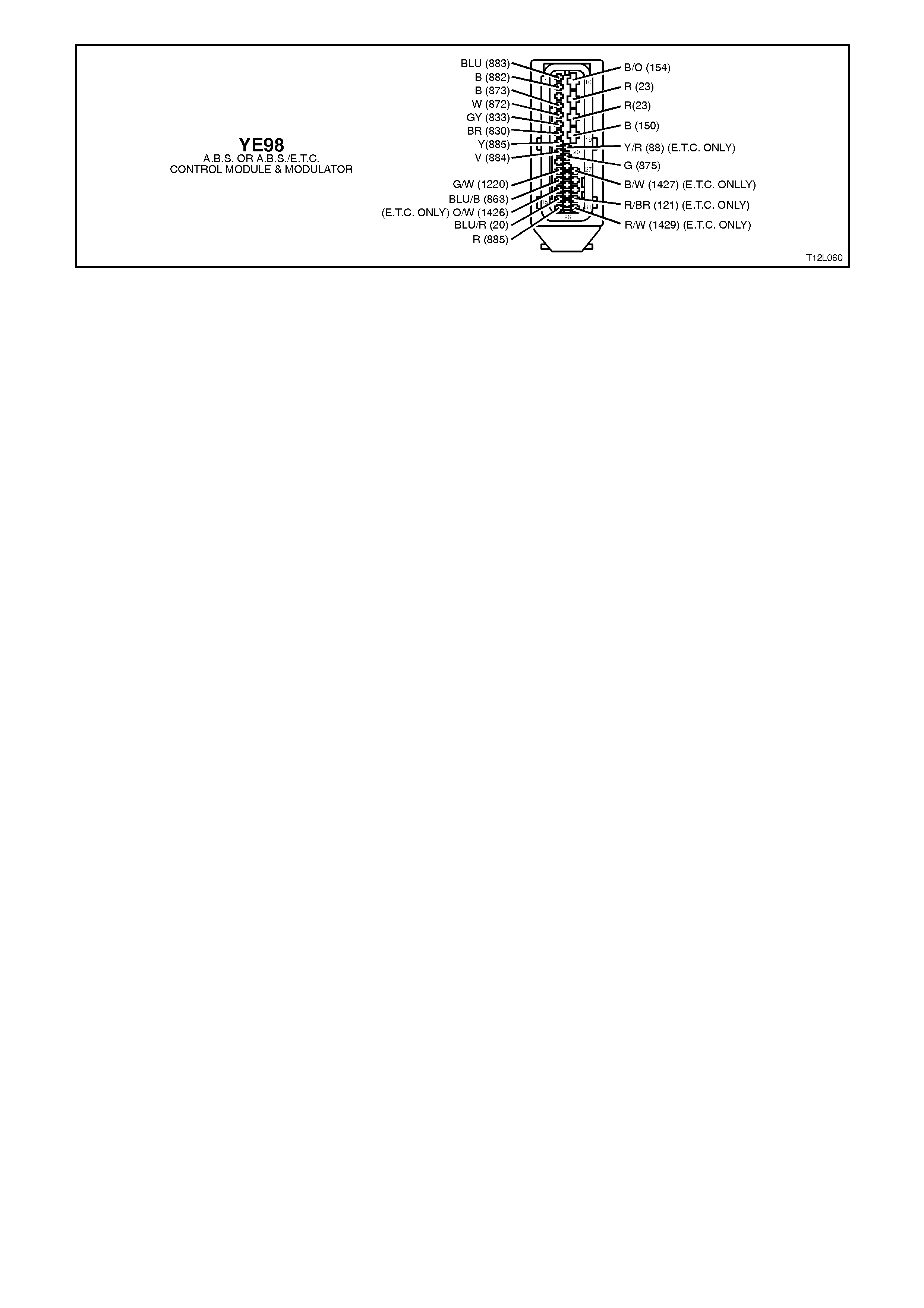
Figure 12L-134
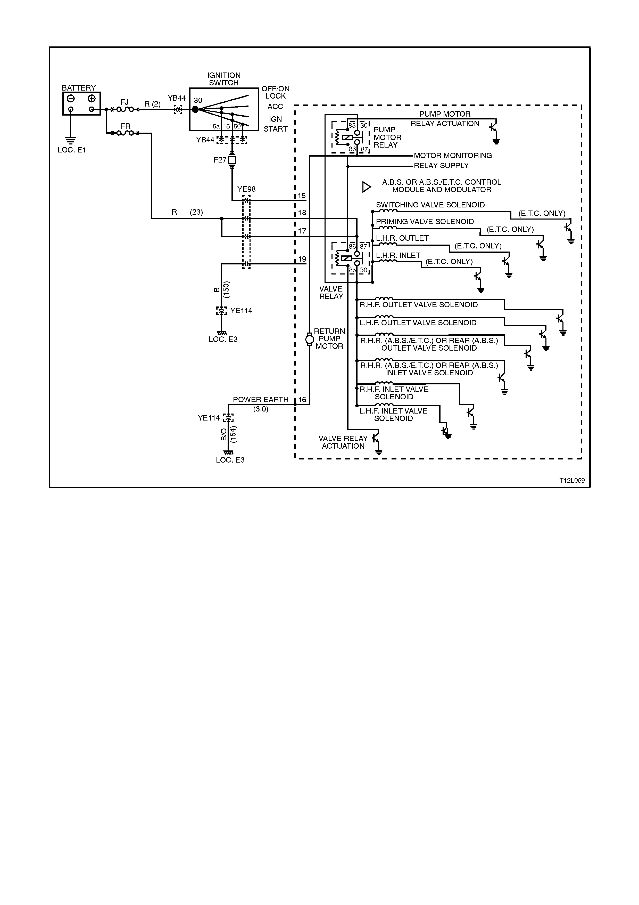
DTC 61 - PUMP MOTOR OR RELAY FAULT
Figure 12L-135
CIRCUIT DESCRIPTION:
When the pump motor relay is earthed by the ABS control module, it provides B+ to operate the modulators return
pump. Once the pump motor circuit is energised, a 'Pump On' signal is sent to the ABS or ABS/ETC control module
to verify pump motor operation.
DTC 61 will set if 12 volts is present at the pump motor without relay activation, or if battery voltage is not present at
the pump motor when the relay is activated.
If the ABS or ABS/ETC control module senses a fault such as an open circuit or a short circuit in the wiring or pump
motor, the pump relay will be de-energised. The ABS or ABS and TRAC OFF warning lamps will be illuminated and
the relevant DTC/S will be set.
If a failure is detected which causes DTC 61 to set, the ABS or ABS/ETC system is disabled and the control module
illuminates the ABS, or ABS and TRAC OFF warning lamps for the remainder of the ignition cycle. If the failure is
intermittent, the control module will enable the system at the next ignition cycle and the relevant history DTC will be
set.

TEST DESCRIPTION:
The numbers below refer to Step numbers in the diagnostic chart for DTC 61.
1. This step determines if there is a common power or earth supply fault to the hydraulic modulator and control
module assembly.
2. This test uses TECH 2 to check for proper pump operation.
3. Inspection of hy draulic modulator motor connector.
4. Checks for constant battery voltage to the control module at terminals 17 and 18.
5. Checks for battery voltage to the control module at terminal 15 when the ignition is switched on.
6. Checks for continuity in earth circuit 154
7. Checks for continuity in earth circuit 150.
NOTES ON DIAGNOSTIC CHART:
1. For all wiring checking procedures, refer to Section 12P WIRING DIAGRAMS.
2. Refer to 4.7 TECH 2 DIAGNOSTICS in this Section for connecting and using TECH 2.
STEP ACTION VALUE YES NO
1. ∙Install TECH 2 to
DLC and select
Diagnostics / Chassis
/ ABS/ETC /
Diagnostic Trouble
Codes / Read DTC’s
(refer to NOTE 2
above).
∙Is DTC 61 the only
DTC set ?
Go to Step 4. Go to Step 2.
2. ∙With TECH 2
connected,
Diagnostics /Chassis
/ABS/ETC /
Miscellaneous Tests
/ Auto Test and
conduct test (refer to
NOTE 2 above).
∙Does the pump
motor run ?
NOTE:
The pump motor should
be heard to run for
approximately 1 to 2
seconds while
conducting test
Fault not present.
Check all system
wiring harness
connectors and
terminals, in
particular the
modulator and
ABS or ABS/ETC
control module
connector
terminals.
Go to Step 3.
3. ∙Inspect the hydraulic
modulator pump
motor connector
(located at the front
of the modulator and
control module
assembly, under
control module
connector YE98) to
ensure it is firmly
connected.
∙Is connector OK ?
Replace hydraulic
modulator asm,
refer to 3.5
HYDRAULIC
MODULATOR
AND CONTROL
MODULE
ASSEMBLY in
this Section.
Ensure secure
connection,
recheck and verify
repair.

STEP ACTION VALUE YES NO
4. ∙Turn ignition OFF.
∙Disconnect control
module connector
YE98.
∙Check for voltage at
control module
connector YE98,
terminals 17 and
then 18, circuit 23
(Red wire) to earth
(refer NOTE 1
above).
∙Is voltage as
specified at each
terminal?
Approx.
12 Volts Go to Step 5. Check and repair
open or short in
circuit 23, recheck
and verify repair.
5. ∙Turn ignition On.
∙With control module
connector YE98 still
disconnected check
for voltage between
terminal 15, circuit
885 (Red wire) and
earth (refer to
NOTE 1 above).
∙Is voltage as
specified ?
Approx.
12 Volts Go to Step 6. Check and repair
open or short in
circuit 885
(including fuse
F27), recheck and
verify repair.
6. ∙Ignition OFF
∙With control module
connector YE98 still
disconnected, check
for continuity
between control
module connector
YE98, terminal 16,
circuit 154
(Black/Orange wire)
and earth location E2
(refer to NOTE 1
above).
∙Does continuity exist
?
Go to Step 7. Check and repair
open in circuit 154,
recheck and verify
repair.
7. ∙With control module
connector YE98 still
disconnected, check
for continuity
between control
module connector
YE98, terminal 19,
circuit 150 (Black
wire) and earth
location E3 (refer
NOTE 1 above).
∙Does continuity exist
?
Replace hydraulic
modulator asm,
refer to
3.5 HYDRAULIC
MODULATOR
AND CONTROL
MODULE
ASSEMBLY in
this Section.
Check and repair
open in circuit 150,
recheck and verify
repair.
WHEN A LL DIAGNOSIS AND REPA IRS ARE COMPLETED, CLEAR A LL DTC’S AND
VERIFY CORRECT OPERATION

Figure 12L-136

DTC 62 - RPM SIGNAL FAULT
Figure 12L-137
CIRCUIT DESCRIPTION:
The determine the requested torque request signal and prevent the engine stalling, the ABS/ETC control module
monitors the engine speed. An engine RPM signal is sent to terminal 30 of the ABS/ETC control module from the
Direct Ignition System (DIS) module. This signal has a fixed duty cycle and a frequency that w ill vary with changing
engine RPM.
DTC 62 will set if an RPM signal (engine speed signal) is not received by the ABS/ETC control module at terminal
30, provided the engine speed is greater than 480 RPM.
If the ABS/ETC control module senses this fault, only the ETC system will be disabled (ABS will operate normally),
the TRAC OFF warning lamp will be illuminated and the relevant DTC will be set. The TRAC OFF warning lamp will
remain illuminated for the remainder of the ignition cycle. If the failure is intermittent, the control module will enable
the system at the next ignition cycle and the relevant history DTC will be set.
TEST DESCRIPTION:
The numbers below refer to Step numbers in the diagnostic chart for DTC 62.
1. Checks for continuity in circuit 121.
NOTES ON DIAGNOSTIC CHART:
1. For all wiring checking procedures, refer to Section 12P WIRING DIAGRAMS.
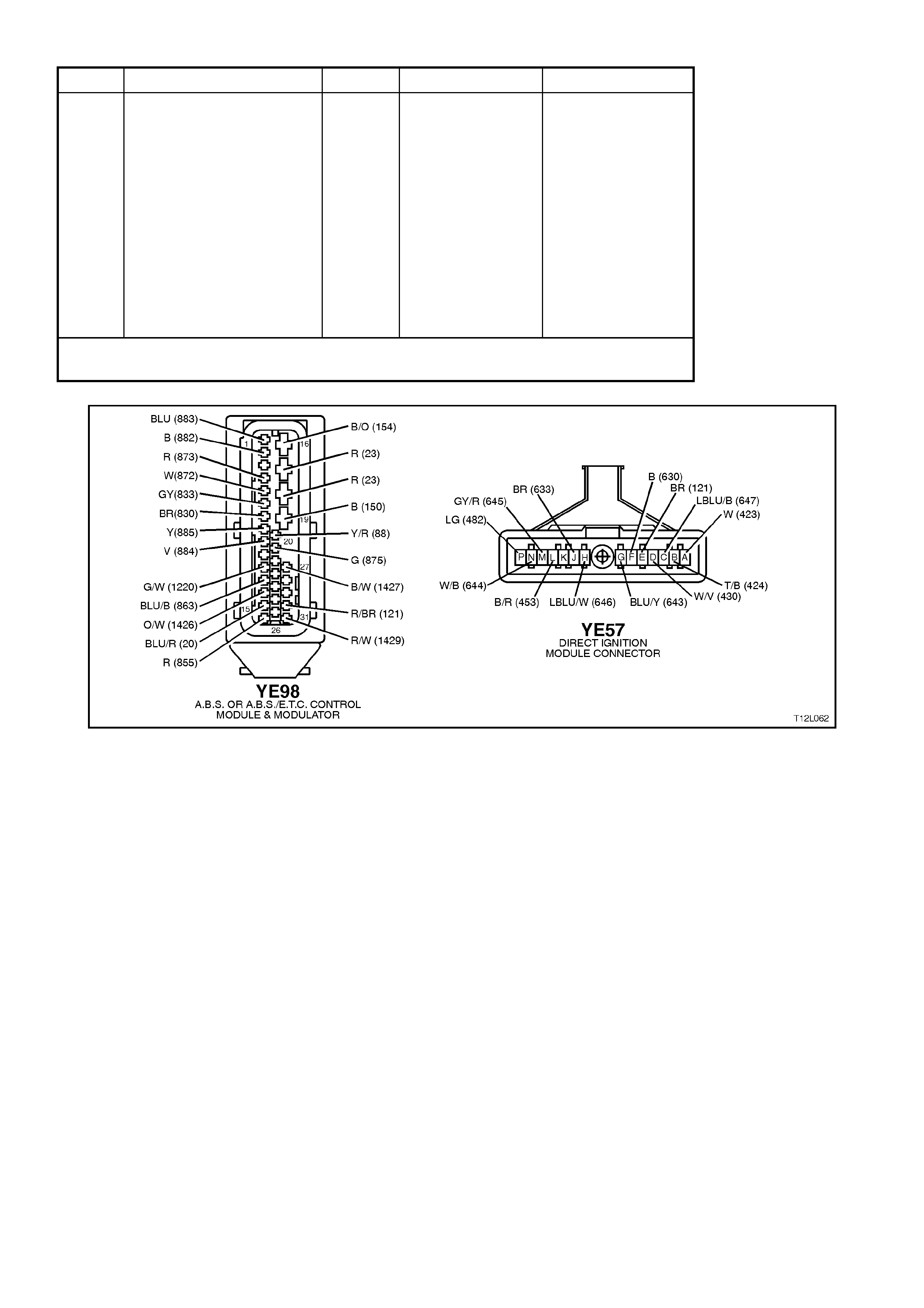
STEP ACTION VALUE YES NO
1. ∙Check continuity of
circuit 121 between
ABS/ETC control
module connector
YE98, terminal 30
and DIS module
connector YE57,
terminal E (Brown/
Red wire) (refer to
NOTE 1 above).
∙Does continuity
exist?
Replace
ABS/ETC control
module, refer to
3.6 CONTROL
MODULE in this
Section, recheck
and verify repair.
Check and repair
open in circuit 121.
Recheck and verify
repair.
WHEN A LL DIAGNOSIS AND REPA IRS ARE COMPLETED, CLEAR A LL DTC’S AND
VERIFY CORRECT OPERATION
Figure 12L-138

DTC 63 - VALVE SOLENOID RELAY CIRCUIT FAULT
Figure 12L-139
CIRCUIT DESCRIPTION:
When the ABS or ABS/ETC is active (ignition on), the valve relay provides voltage to actuate the six (ABS) or 10
(ABS/ETC) solenoid valves. However, the solenoid valves do not use this voltage unless the ABS or ABS/ETC
control module provides the earth for each solenoid.
DTC 63 will set if the valve relay voltage is low or if the relay supply line is at 12 volts when the ABS or ABS/ETC
control module is not requesting it to be: this would make the relay constantly energised.
Also, DTC 63 will set if the ABS or ABS/ETC control module detects if three or more of the solenoid valve circuits
between the valve relay terminal 30 and the control module are open circuited or shorted during the self test.
If a failure is detected which causes DTC 63 to set, the ABS or ABS/ETC system is disabled and the control module
illuminates the ABS or ABS and TRAC OFF warning lamps for the remainder of the ignition cycle. If the failure is
intermittent, the control module will enable the system at the next ignition cycle and a history DTC 63 will be set.
TEST DESCRIPTION:
The numbers below refer to Step numbers in the diagnostic chart for DTC 63.
1. This test uses TECH 2 to check valve relay operation.
2. Checks for constant battery voltage to the control module at terminals 17 and 18.
3. Checks for battery voltage to the control module at terminal 15 when the ignition is switched on.
4. Checks for continuity in earth circuit 154
5. Checks for continuity in earth circuit 150.
NOTES ON DIAGNOSTIC CHART:
1. For all wiring checking procedures, refer to Section 12P WIRING DIAGRAMS.
2. Refer to 4.7 TECH 2 DIAGNOSTICS in this Section for connecting and using TECH 2.

STEP ACTION VALUE YES NO
1. ∙Install TECH 2 to
DLC.
∙Select Diagnosis /
Chassis / ABS/ETC /
Miscellaneous Tests
/ Solenoid.
∙Conduct solenoid test
on any one of the
solenoid valves (refer
to NOTE 2 above).
∙Does test confirm
that solenoid valve
tested is OK ?
Fault not present.
Check all system
wiring harness
connectors and
terminals, in
particular the
modulator and
ABS or ABS/ETC
control module
connector
terminals.
Go to Step 2.
2. ∙Turn ignition OFF.
∙Back probe control
module connector
YE98, terminals 17
and then 18, circuit
23 (Red wire) with a
voltmeter to earth
(refer NOTE 1
above).
∙Is voltage as
specified at each
terminal ?
Approx.
12 Volts Go to Step 3. Check and repair
open or short in
circuit 23, recheck
and verify repair.
3. ∙Turn ignition ON.
∙Back probe control
module connector
YE98, terminal 15,
circuit 885 (Red wire)
with a voltmeter to
earth (refer to
NOTE 1 above)
∙Is voltage as
specified ?
Approx.
12 Volts Go to Step 4. Check and repair
open or short in
circuit 885
(including fuse
F27), recheck and
verify repair.
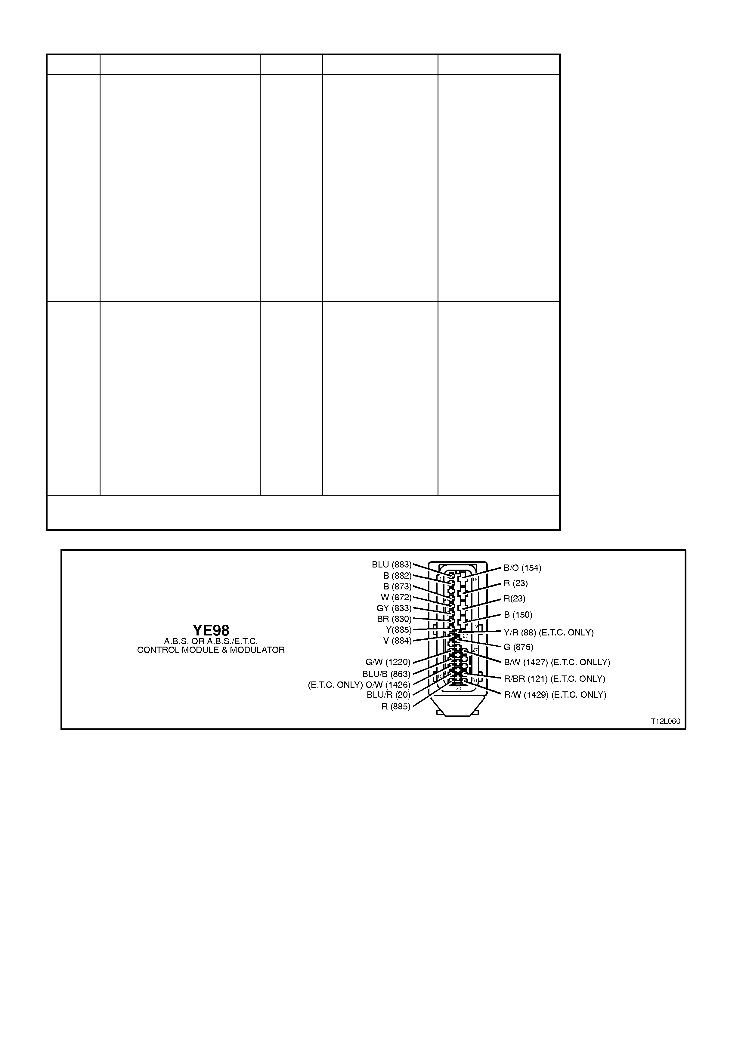
STEP ACTION VALUE YES NO
4. ∙Disconnect control
module connector
YE98.
∙Check for continuity
between control
module connector
YE98, terminal 16,
circuit 154
(Black/Orange wire)
and earth location E2
(ABS bracket in
engine
compartment).
∙Does continuity exist
?
Go to Step 5. Check and repair
open in circuit 154,
recheck and verify
repair.
5. ∙With control module
connector YE98 still
disconnected, check
for continuity
between control
module connector
YE98, terminal 19,
circuit 150 (Black
wire) and earth
location E3 (RH inner
fender).
∙Does continuity exist
?
Replace ABS or
ABS/ETC control
module, refer to
3.6 CONTROL
MODULE in this
Section, recheck
and verify repair.
Check and repair
open in circuit 150,
recheck and verify
repair.
WHEN A LL DIAGNOSIS AND REPA IRS ARE COMPLETED, CLEAR A LL DTC’S AND
VERIFY CORRECT OPERATION
Figure 12L-140
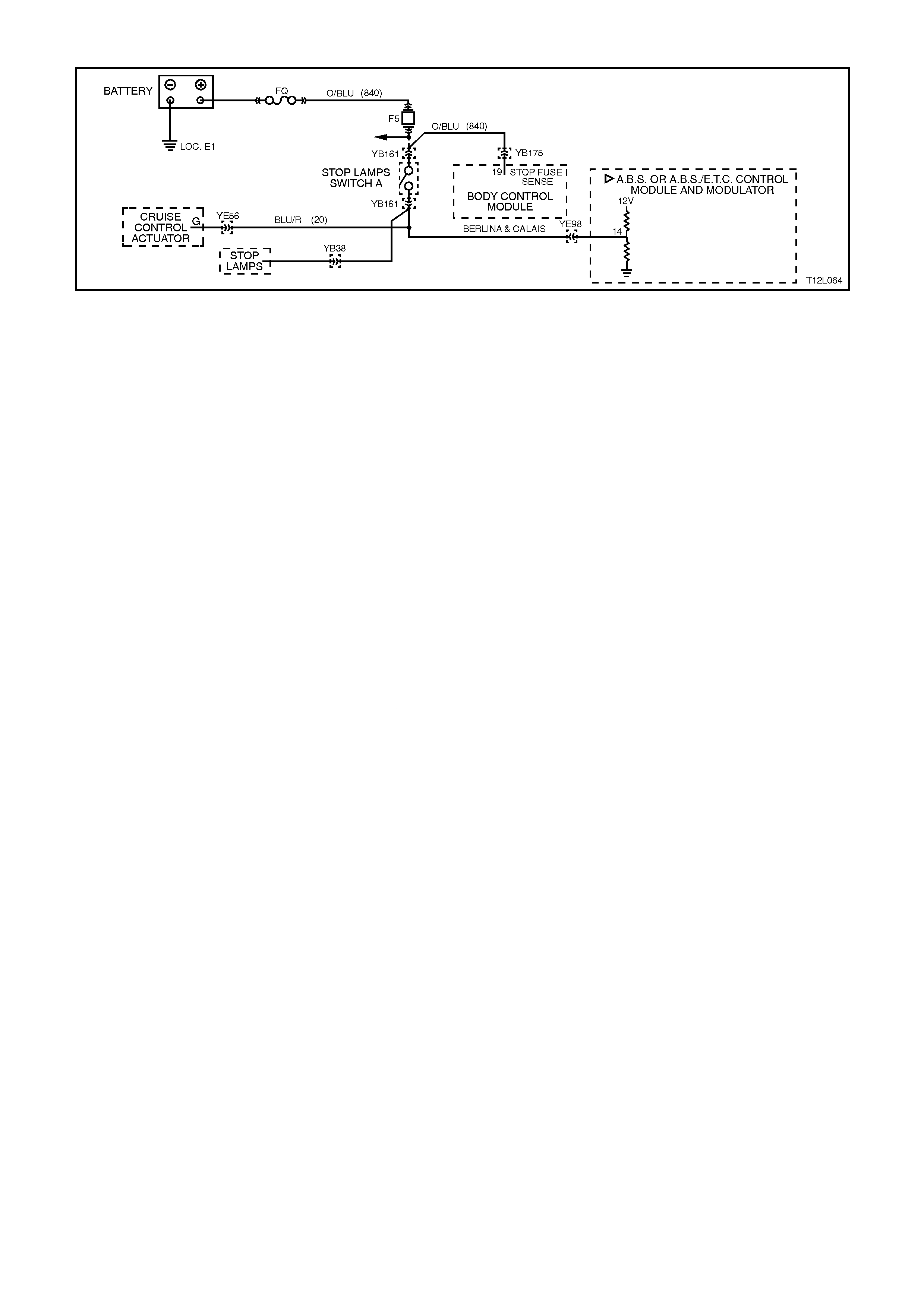
DTC 67 - STOP LAMP SWITCH CIRCUIT FAULT
Figure 12L-141
CIRCUIT DESCRIPTION:
The ABS or ABS/ETC control module monitors the stop lamp switch signal at terminal 14 to determine if the brakes
are being manually applied.
DTC 67 will set if the voltage monitored at terminal 14 goes out of range; between approximately 6 and 9 volts.
If the ABS or ABS/ETC control module senses this fault, the ABS will operate normally, however, it’s response time
will be marginally slower (approx 10 milliseconds) to react than if this input was available. The ETC systems brake
intervention will be disabled immediately, while the ETC engine intervention will become disabled after the
operation. The TRAC OFF warning lamp will be illuminated and the relevant DTC will be set. The TRAC OFF
warning lamp will remain illuminated for the remainder of the ignition cycle. If the failure is intermittent, the control
module will enable the system at the next ignition cycle and the relevant history DTC will be set.
TEST DESCRIPTION:
The numbers below refer to Step numbers in the diagnostic chart for DTC 67.
1. Checks for voltage at control module terminal 14 when brakes are applied.
2. Checks stop lamps to see if they illuminate when brakes applied.
3. Checks for continuity in 20.
4. Checks circuit 840 for power to stop lamp switch.
5. Checks stop lamp switch.
NOTES ON DIAGNOSTIC CHART:
1. For all wiring checking procedures, refer to Section 12P WIRING DIAGRAMS.

STEP ACTION VALUE YES NO
1. ∙Back probe control
module connector
YE98, terminal 14,
circuit 20 (Blue/Red
wire) with a voltmeter
to earth (refer to
NOTE 1 above).
∙Apply brakes (brake
switch closed).
∙Is voltage as
specified ?
B+ Volts Replace ABS or
ABS/ETC control
module, refer to
3.6 CONTROL
MODULE in this
Section, recheck
and verify repair.
Go to Step 2.
2. ∙Apply brakes and
check stop lamp
operation.
∙Do stop lamps
illuminate ?
Go to Step 3. Go to Step 4.
3. ∙Disconnect control
module connector
YE98 and stop lamp
switch A, connector
YB161.
∙Check for continuity
between control
module connector
YE98, terminal 14
and stop lamp switch
connector YB161,
circuit 20 (Blue/Red
wire) (refer to
NOTE 1 above).
∙Does continuity exist
?
Fault not present.
Check all system
wiring harness
connectors and
terminals, in
particular the
modulator and
ABS or ABS/ETC
control module
connector
terminals.
Check and repair
open in circuit 20,
recheck and verify
repair.
4. ∙Back probe stop
lamp switch
connector YB161,
circuit 840
(Orange/Blue wire)
with a voltmeter to
earth (refer to
NOTE 1 above).
∙Is voltage as
specified ?
B+ Volts Go to Step 5. Check and repair
open or short in
circuit 840
(including fuse F5),
recheck and verify
repair.
5. ∙Back probe stop
lamp switch A,
connector YB161,
circuit 20 (Blue/Red
wire) with a voltmeter
to earth (refer to
NOTE 1 above).
∙Apply brakes (brake
switch closed).
∙Is voltage as
specified ?
B+ Volts System OK. Check and adjust
or repair stop lamp
switch A, refer to
Section 12B
LIGHTING
SYSTEM.
WHEN A LL DIAGNOSIS AND REPA IRS ARE COMPLETED, CLEAR A LL DTC’S AND
VERIFY CORRECT OPERATION
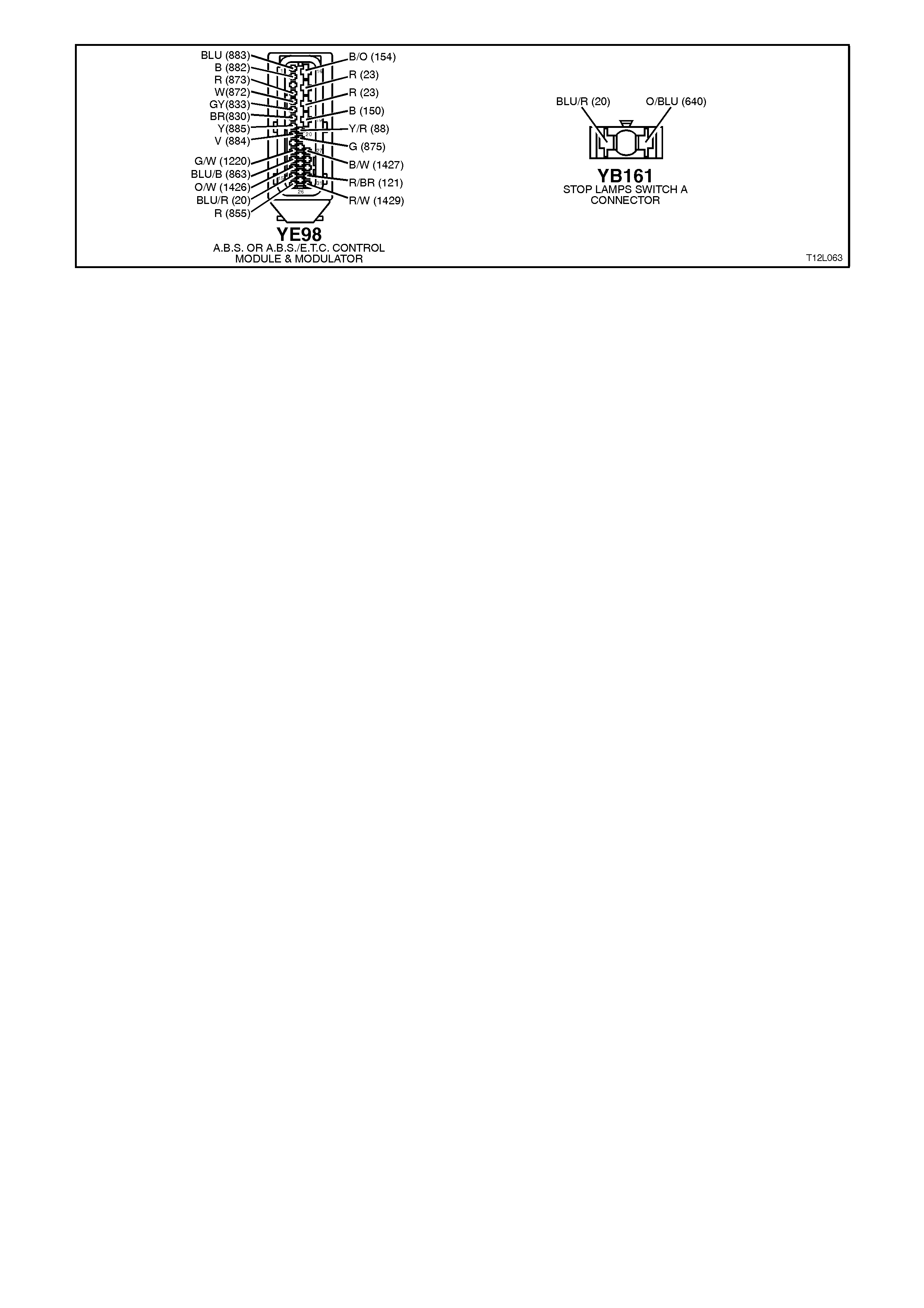
Figure 12L-142
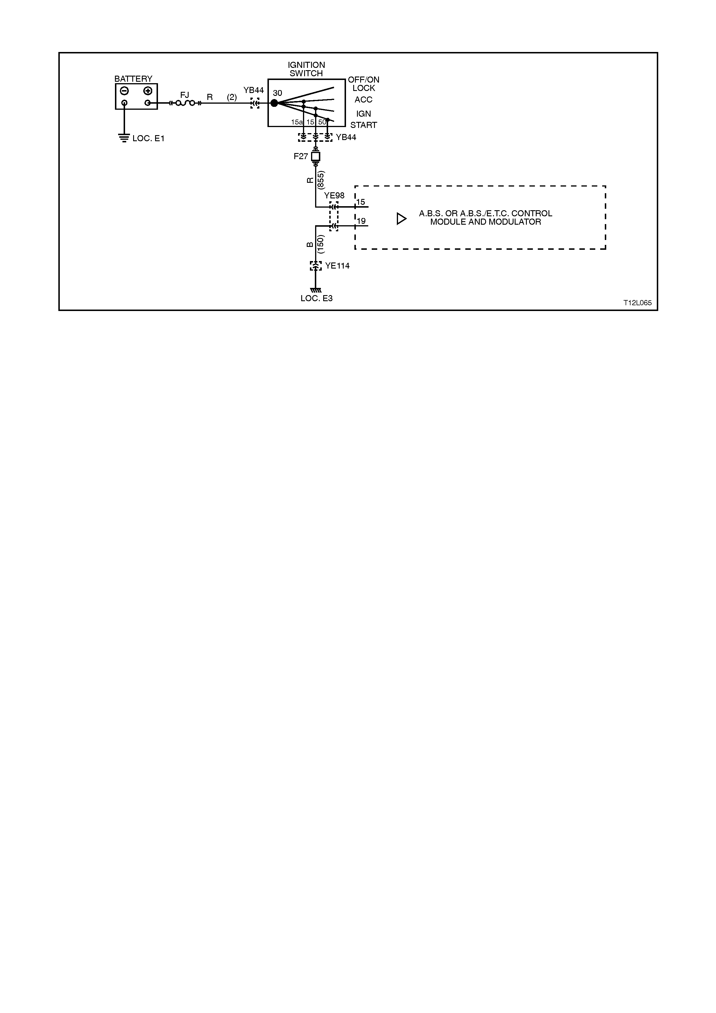
DTC 71 - CONTROL MODULE INTERNAL FAULT
Figure 12L-143
CIRCUIT DESCRIPTION:
The ABS or ABS/ETC control module performs various diagnostic checks on itself. If the control module detects an
internal fault, DTC 71 will be set.
If a failure is detected which causes DTC 71 to set, the ABS or ABS/ETC is disabled and the control module
illuminates the ABS or ABS and TRAC OFF warning lamps for the remainder of the ignition cycle. If the failure is
intermittent, the control module will enable the system at the next ignition cycle and a history DTC 71 will be set.
TEST DESCRIPTION:
The numbers below refer to Step numbers in the diagnostic chart for DTC 71.
1. This test checks for any additional system faults that may be causing DTC 71 to set.
2. Determines whether the DTC is set by an internal fault with the control module or by a faulty wiring connection.
3. This test checks the minimum supply voltage and integrity of the control module earth circuit.
4. This test checks for intermittent connections of the ABS control module connector and terminals to the module.
NOTES ON DIAGNOSTIC CHART:
1. Refer to 4.7 TECH 2 DIAGNOSTICS in this Section for connecting and using TECH 2.
DIAGNOSTIC AIDS:
If circuit 855 (Red wire) or circuit 150 (Black wire) are open circuited, TECH 2 screen will display "NO DATA
RECEIVED FROM ABS".

STEP ACTION VALUE YES NO
1. ∙Install TECH 2 to
DLC.
∙Select Diagnostics /
Chassis / Diagnostic
Trouble Codes /
Read DTC’s (refer
NOTE 1 above).
∙Are any other DTC's
set ?
Repair problems
causing other
DTC’s to set. Go
to Step 2.
Go to Step 2.
2. ∙With TECH 2
connected and
Diagnostic Trouble
Codes selected,
select Clear DTC’s
(refer to NOTE 2
above)
∙Road test vehicle.
∙Does DTC 71 set
again ?
Go to Step 3. Fault not present.
Check all system
wiring harness
connectors and
terminals, in
particular the
modulator and ABS
or ABS/ETC
control module
connector
terminals.
3. ∙Disconnect control
module connector
YE98.
∙Switch ignition ON
and measure voltage
between connector
YE98, terminals 15
and 19.
∙Is voltage as
specified ?
At least
10 Volts Go to Step 4. Check voltage
supply and earth
connections to ABS
or ABS/ETC
control module,
refer to CHART B -
POWER SUPPLY
TO CONTROL
MODULE in this
Section, recheck
circuit to verify
repair.
4. ∙Check ABS control
module connector
YE98 carefully to
ensure good
electrical connection
will all terminals and
that the connector is
properly retained
when connected.
∙Is all OK ?
Go to Step 5. Repair connector
and/or connector
retention, recheck
circuit to verify
repair.
5. ∙No fault found, Install
TECH 2 to DLC and
select Diagnostics /
Chassis / ABS/ETC /
Diagnostic Trouble
Codes / Clear DTC’s
and clear all DTC's
(refer NOTE 1
above).
∙Road test vehicle.
∙Does DTC 71 set
again ?
Replace ABS or
ABS/ETC control
module, refer to
3.6 CONTROL
MODULE in this
Section, recheck
and verify repair.
System OK.
WHEN A LL DIAGNOSIS AND REPA IRS ARE COMPLETED, CLEAR A LL DTC’S AND
VERIFY CORRECT OPERATION

Figure 12L-144
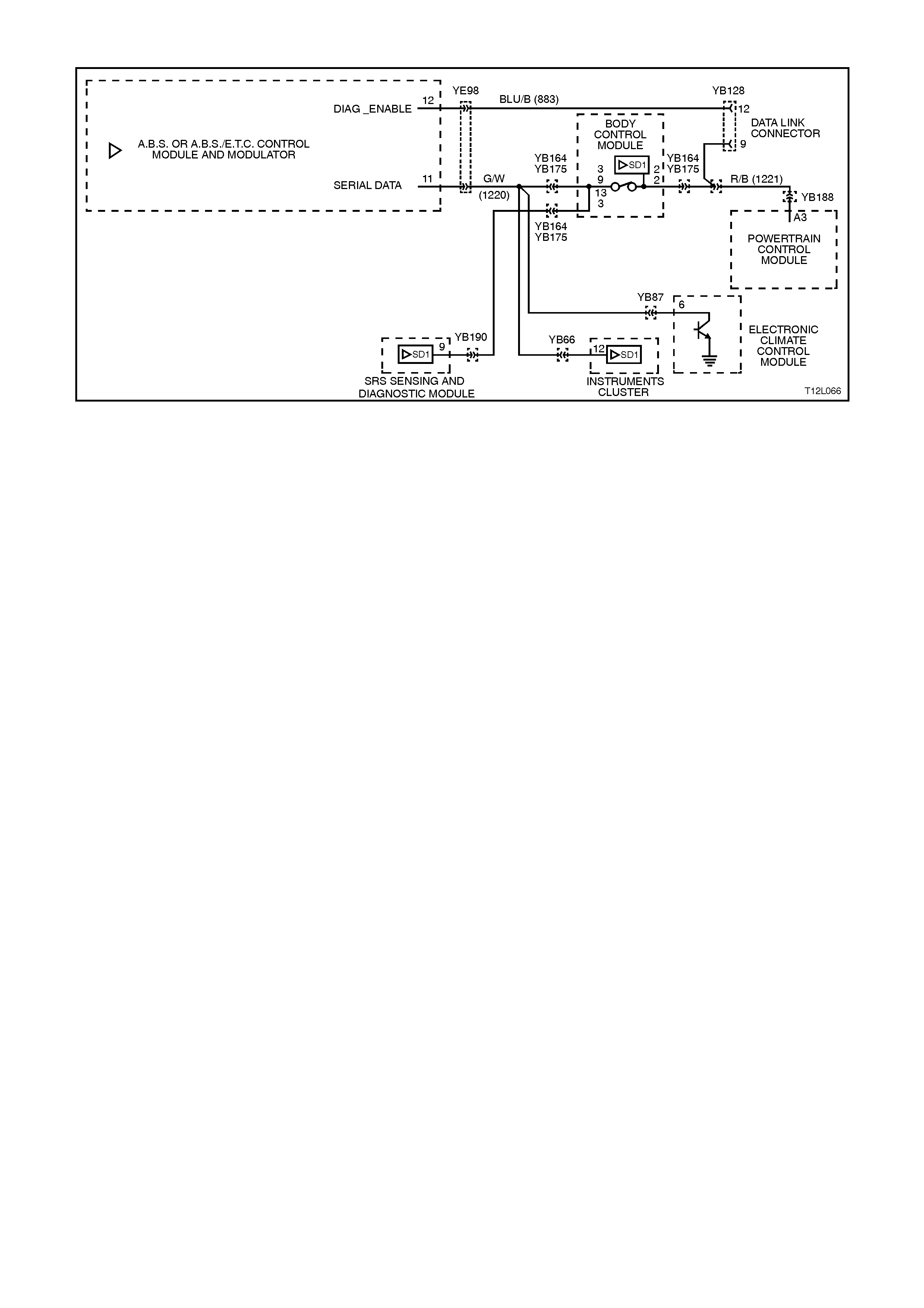
DTC 72 - SERIAL DATA FAULT
Figure 12L-145
CIRCUIT DESCRIPTION:
With the ignition ON, the ABS or ABS/ETC control module will be able to communicate with other control modules
via the serial data line, circuit 1220 (Green/White wire). If communication between the modules is disrupted due to a
short or open circuit, DTC 72 will be set.
If the ABS/ETC control module senses this fault, only the ETC system will be disabled (ABS operation will operate
normally), the TRAC OFF warning lamp will be illuminated and the relevant DTC will be set. The TRAC OFF
warning lamp will remain illuminated for the remainder of the ignition cycle. If the failure is intermittent, the control
module will enable the system at the next ignition cycle and the relevant history DTC will be set.
There are several other control modules that are connected to the serial data circuit (PCM, BCM, ABS/ETC, ECC,
SRS, and instrument cluster). Any of these control modules could cause a fault in the serial data line. This fault
could result in TECH 2 not being able to display serial data.
TEST DESCRIPTION:
The numbers below refer to Step numbers in the diagnostic chart for DTC 72.
1. This test determines if fault is current or not.
2. This test checks for connector or wiring problems which may cause an intermittent fault.
3. Determines if fault is in wiring or ABS/ETC control module.
4. Determines if fault is with BCM serial data communication (bus master).
5. Checks if fault is caused by other control modules that are communicating on the serial data line.
6. Checks circuit 1220 and determines if fault is in wiring or control module.
7. Checks for continuity in circuit 1220.
NOTES ON DIAGNOSTIC CHART:
1. For all wiring checking procedures, refer to Section 12P WIRING DIAGRAMS.
2. Refer to 4.7 TECH 2 DIAGNOSTICS in this Section for connecting and using TECH 2.
DIAGNOSTIC AIDS:
A fault with the serial data circuit could be caused by one or more of the several controllers connected to this serial
data circuit. Isolate the fault by disconnecting each controller one at a time until serial data communication is
restored.
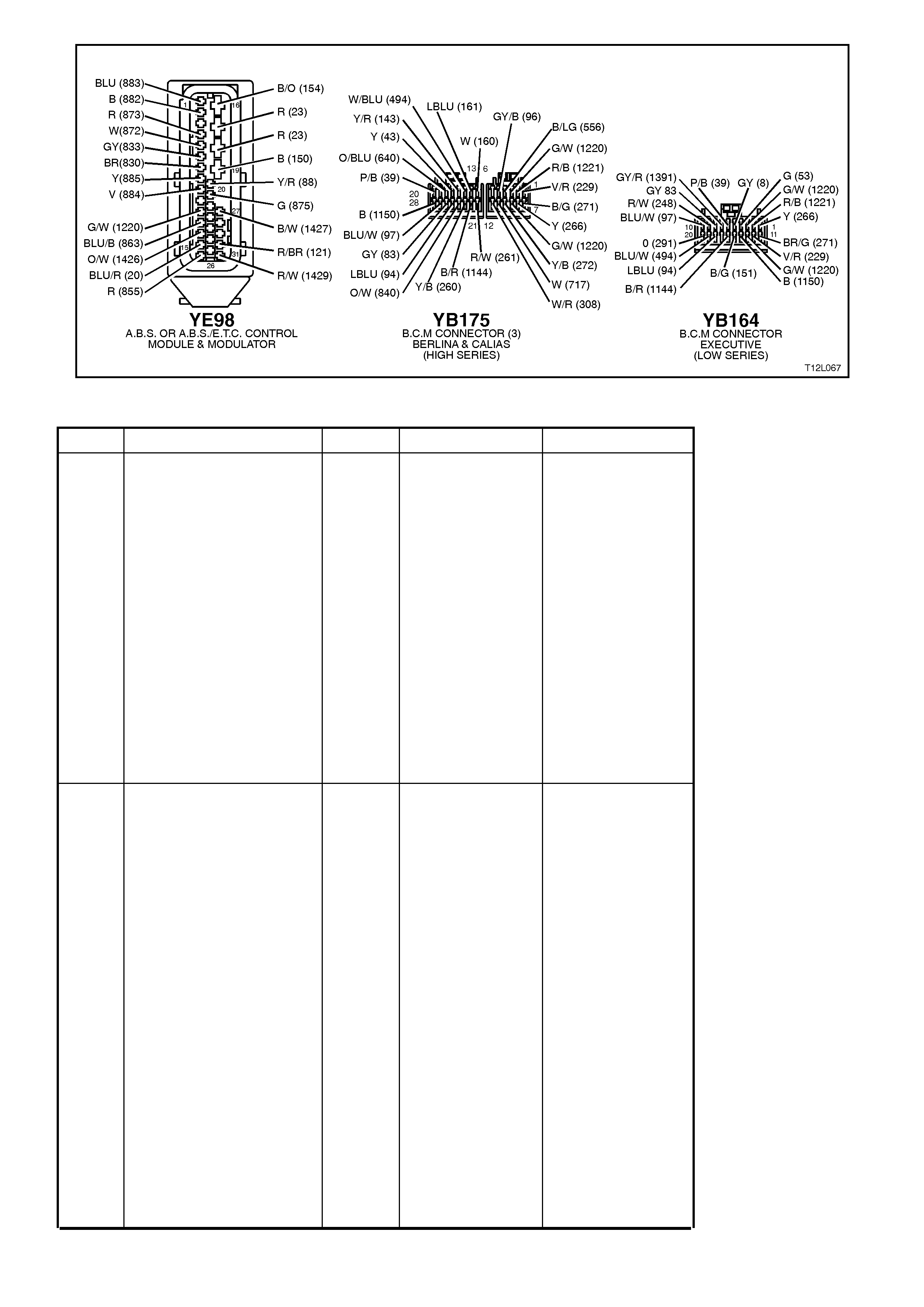
Figure 12L-146
STEP ACTION VALUE YES NO
1. ∙Install TECH 2 to
DLC.
∙Select Diagnostics /
Chassis / ABS/ETC /
Diagnostic Trouble
Codes / Clear DTC’s
and clear all DTC’s
(refer to NOTE 2
above).
∙Road test vehicle.
∙ Does DTC 72 set
again ?
NOTE:
Go to Step 4 if TECH 2
will not communicate with
the ABS/ETC control
module.
Go to Step 3. Go to Step 2.
2. ∙Inspect all system
wiring and
connections that
could cause
intermittent faults.
Check all wiring is in
good condition,
terminals are clean
and tight and making
good contact (refer
NOTE 1 above).
∙Is wiring OK ?
NOTE:
Other control modules
(SRS, Instruments, ECC,
BCM, PCM) that are
connected to the serial
data circuit could cause
DTC 72 to set, therefore,
check wiring and
connectors that could
cause intermittent faults at
these control modules
also.
Fault not present.
Check all system
wiring harness
connectors and
terminals, in
particular the
modulator and
ABS/ETC control
module connector
terminals.
Make repairs as
necessary, recheck
and verify repair.

STEP ACTION VALUE YES NO
3. · In step 1, was TEC H
2 able to
communicate with
the ABS/ETC c ont r ol
module (refer
NOTE 2 above)?
Go to Step 4. Replace ABS/ETC
cont ro l module, refer
to 3. 6 CON TROL
MODULE in this
Section, recheck
circuit to verify
repair.
4. · With TECH 2
connected, select
Diagnos tics / Body /
Body Control Module
and turn ignition on
as requested (refe r
NOTE 2 above) .
· Does TECH 2 display
BCM system
identification
information?
Go to Step 5. Refer to BCM Serial
Data Communication
diagnostics in
Section 12J-1 LOW
SERIES BC M
or
Section 12J-2 HIGH
SERIES BCM.
5. · U s ing TECH 2, check
for similar DTC’s
(Seria l Da ta faul t s)
that have been set by
other control
modules;
instrument s, SRS,
and ECC if applicable
to model variant
(refer NO TE 2
above).
· Ha ve simil a r DTC’s
been set by other
control modules ?
Go to Step 6. Go to Step 7.
6. · Check circuit 1220
for open, s hor t to
earth or short to
voltage between
BCM and individual
control modules
(refer NO TE 1
above).
· Is circ uit 1220 OK ?
NOTE:
Disconnect each controller
in circuit 1220 one at a
time to isolat e the fault in
the circuit or to identify
contr ol module causing
fault.
Replace faulty
m odule, refer to
relevant Section ,
recheck and verify
repair.
Make repairs as
necessary, recheck
and verify repair.

STEP ACTION VALUE YES NO
7. ∙Disconnect BCM
connector YB164
(Low Series BCM) or
YB175 (High Series
BCM) and ABS/ETC
control module
connector YE98.
∙Check for continuity
between BCM
connector YB164
terminal 3 or YB175
terminal 9 and
ABS/ETC control
module connector
YE98, terminal 11,
circuit 1220
(Green/White wire)
(refer to NOTE 1
above).
∙Does continuity exist
?
Replace
ABS/ETC control
module, refer to
3.6 CONTROL
MODULE in this
Section, recheck
circuit to verify
repair.
Check and repair
open in circuit 1220
between BCM and
ABS/ETC control
module, recheck
and verify repair.
WHEN A LL DIAGNOSIS AND REPA IRS ARE COMPLETED, CLEAR A LL DTC’S AND
VERIFY CORRECT OPERATION

DTC 73 - REQUESTED TORQUE CIRCUIT FAULT
Figure 12L-147
CIRCUIT DESCRIPTION:
With the ignition on, the ABS/ETC control module constantly sends a Pulse Width Modulated (PWM) signal AT 93%
with a frequency of 100Hz to the PCM via terminal 13, circuit 1426 (Orange/White wire). This is to indicate to the
PCM that the traction control system (ETC) is in a state of readiness. If the ABS/ETC control module requests
traction control, engine intervention, it signals the PCM to reduce engine torque by varying the duty cycle of this
pwm signal.
DTC 73 will set if this frequency output signal deviates outside a frequency specification (95 - 105 Hz) or if the signal
stops for more than 50 milliseconds.
If the ABS/ETC control module senses this fault, the ETC system will be disabled (ABS operation will operate
normally), the TRAC OFF warning lamp will be illuminated and DTC 73 will be set. The TRAC OFF warning lamp
will remain illuminated for the remainder of the ignition cycle. If the failure is intermittent, the control module will
enable the system at the next ignition cycle and the logged DTC will become history.
TEST DESCRIPTION:
The numbers below refer to Step numbers in the diagnostic chart for DTC 73.
1. Checks if ABS/ETC control module is sending signal to PCM.
2. Checks circuit 1426.
3. Checks if PCM is returning message to ABS/ETC control module.
4. Checks circuit 1427.
5. Determines if fault is within ABS/ETC control module or whether fault is intermittent.
NOTES ON DIAGNOSTIC CHART:
1. For all wiring checking procedures, refer to Section 12P, WIRING DIAGRAMS.
2. Refer to 4.7 TECH 2 DIAGNOSTICS in this Section for connecting and using TECH 2.
DIAGNOSTIC AIDS:
If DTC 74 (PCM / ETC INTERFACE FAULT (MMI - TORQUE ACKNOWLEDGMENT)) is logged as well as DTC 73,
always perform diagnostics for DTC 73 first.
When DTC’s 73 and 74 are logged by the ABS/ETC control module, the PCM will also log it’s own DTC’s; 91 and
95.

STEP ACTION VALUE YES NO
1. ∙Turn ignition ON.
∙Back probe
ABS/ETC control
module connector
YE98, terminal 13,
circuit 1426
(Orange/White wire)
with a digital
multimeter to earth
(refer NOTE 1
above).
∙Is value as specified
?
95 - 105
Hz
&
4.2 - 4.8
Volts
Go to Step 2. Replace ABS/ETC
control module,
refer to 3.6
CONTROL
MODULE in this
Section, recheck
circuit to verify
repair.
2. ∙Turn ignition ON
∙Back probe PCM
connector YB193,
terminal C11, circuit
1426 (Orange/White
wire) with a digital
multimeter to earth
(refer to NOTE 1
above).
∙Is value as specified
?
95 - 105
Hz &
4.2 - 4.8
Volts
Go to Step 3. Check and repair
open or short in
circuit 1426,
recheck and verify
repair.
3. ∙Turn ignition ON.
∙Back probe PCM
connector YB194,
terminal F7, circuit
1427 (Black/White
wire) with a digital
multimeter to earth
(refer NOTE 1
above).
∙Is value as specified
?
95 - 105
Hz &
0.1 - 1.0
Volts
Go to Step 4. Replace PCM,
refer to
Section 6C1
POWERTRAIN
MANAGEMENT -
V6 ENGINE
or
Section 6C2
POWERTRAIN
MANAGEMENT -
V8 ENGINE.
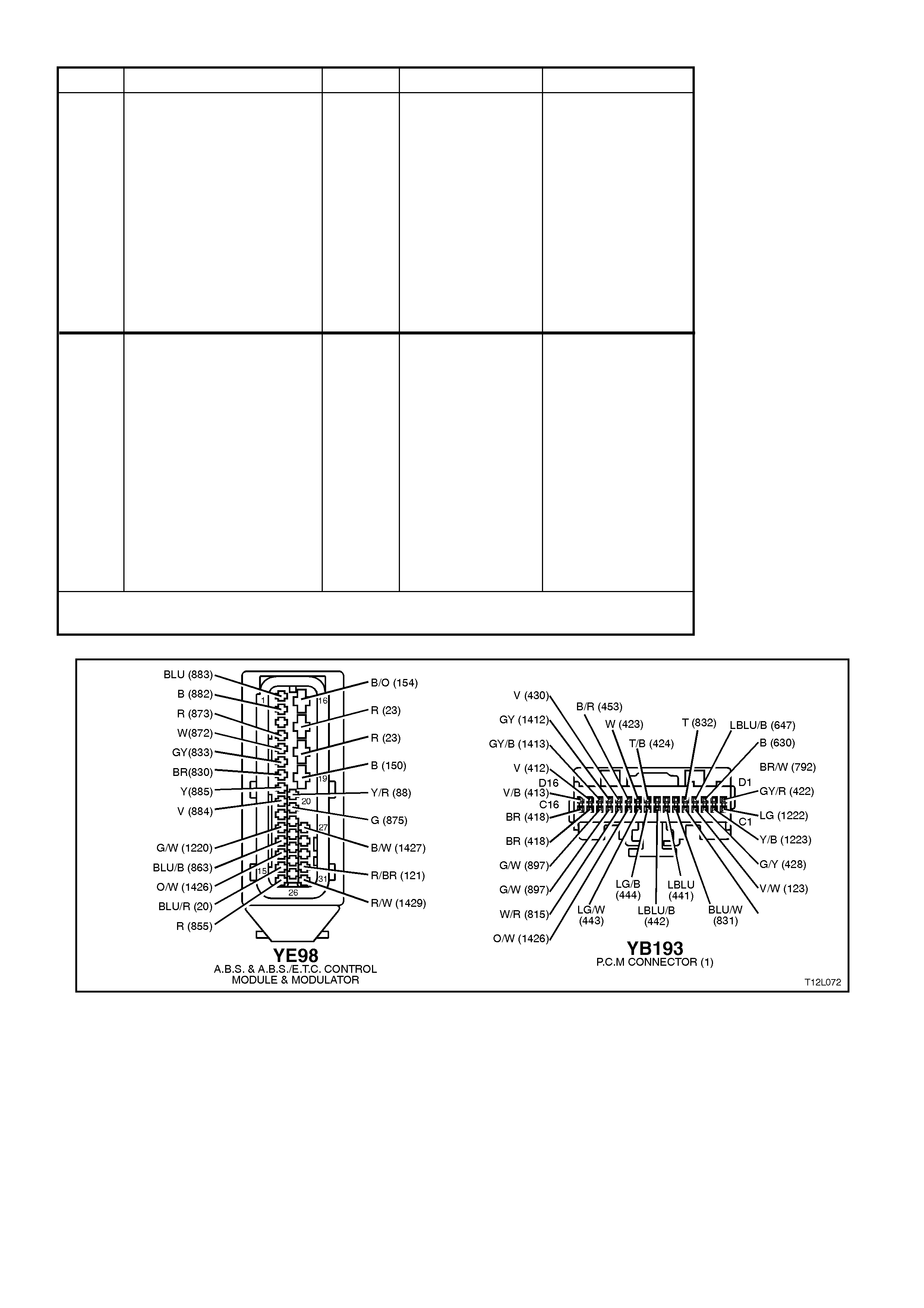
STEP ACTION VALUE YES NO
4. ∙Turn ignition ON.
∙Back probe
ABS/ETC control
module connector
YE98, terminal 27,
circuit 1427
(Black/White wire)
with a digital
multimeter to earth
(refer to NOTE 1
above).
∙Is value as specified
?
95 - 105
Hz &
0.1 - 1.0
Volts
Go to Step 5. Check and repair
open or short in
circuit 1427,
recheck and verify
repair.
5. ∙Install TECH 2 to
DLC
∙Select Diagnostics /
Chassis / ABS/ETC /
Diagnostic Trouble
Codes/ Clear DTC’s
and clear all DTC’s
(refer NOTE 2
above).
∙Road test vehicle.
∙ Does DTC 73 set
again ?
Replace
ABS/ETC control
module, refer to
3.6 CONTROL
MODULE in this
Section, recheck
circuit to verify
repair.
Fault not present.
Check all system
wiring harness
connectors and
terminals, in
particular the
modulator and
ABS/ETC control
module connector
terminals.
WHEN A LL DIAGNOSIS AND REPA IRS ARE COMPLETED, CLEAR A LL DTC’S AND
VERIFY CORRECT OPERATION
Figure 12L-148
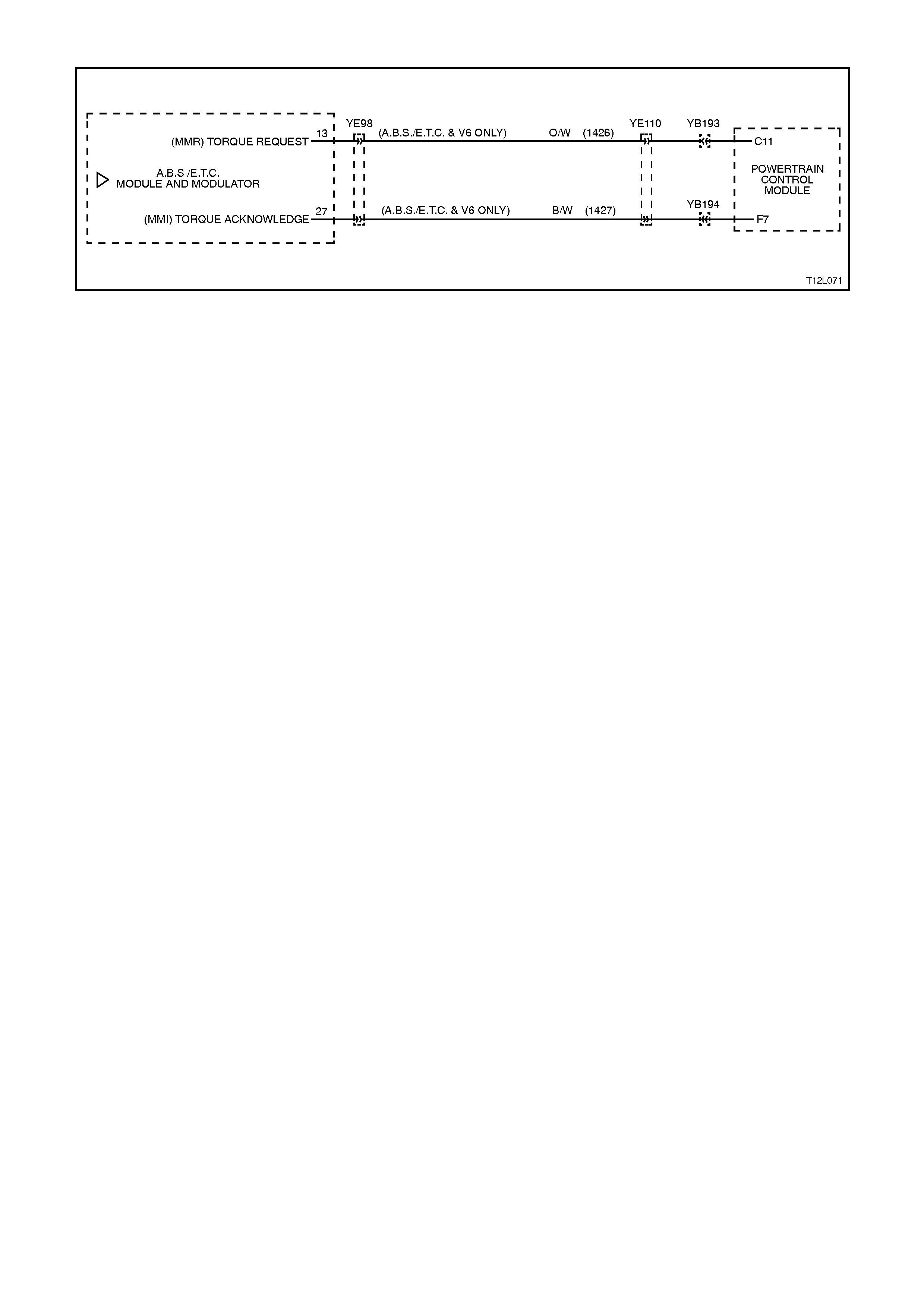
DTC 74 - ACTUAL TORQUE CIRCUIT FAULT
Figure 12L-149
CIRCUIT DESCRIPTION:
On receiving the request torque signal, the PCM will modify the output of the engine and then send an actual torque
signal to the ABS/ETC control module, via circuit 1427, this signal is a Pulse Width Modulated (PWM) signal with a
frequency of 100Hz. The duty cycle of the torque acknowledgment signal will vary depending on the torque
reduction achieved, ie. The actual torque of the engine.
Provided the engine speed is above 480 RPM, DTC 74 will set if this frequency deviates outside the frequency
specification (95 - 105 Hz) or if the signal stops for more than 100 milliseconds.
If the ABS/ETC control module senses this fault, the ETC system will be disabled (ABS operation will operate
normally), the TRAC OFF warning lamp will be illuminated and DTC 74 will be set. The TRAC OFF warning lamp
will remain illuminated for the remainder of the ignition cycle. If the failure is intermittent, the control module will
enable the system at the next ignition cycle and the relevant history DTC will be set.
TEST DESCRIPTION:
The numbers below refer to Step numbers in the diagnostic chart for DTC 74.
1. Checks if ABS/ETC control module is receiving a signal from the PCM.
2. Checks circuit 1427.
3. Checks if PCM is at fault and not sending message to ABS/ETC control module.
4. Checks circuit 1426.
5. Determines if fault is within ABS/ETC control module or whether fault is intermittent.
NOTES ON DIAGNOSTIC CHART:
1. For all wiring checking procedures, refer to Section 12P WIRING DIAGRAMS.
2. Refer to 4.7 TECH 2 DIAGNOSTICS in this Section for connecting and using TECH 2.
DIAGNOSTIC AIDS
If DTC 74 (PCM / ETC INTERFACE FAULT (MMI - TORQUE ACKNOWLEDGMENT)) is logged as well as DTC 73,
always perform diagnostics for DTC 73 first.
When DTC’s 73 and 74 are logged by the ABS/ETC control module, the PCM will also log it’s own DTC’s; 91 and
95.

STEP ACTION VALUE YES NO
1. ∙Turn ignition ON.
∙Back probe
ABS/ETC control
module connector
YE98, terminal 27,
circuit 1427
(Black/White wire)
with a digital
multimeter to earth
(refer to NOTE 1
above).
∙Is value as specified
?
95 - 105
Hz &
0.1 - 1.0
Volts
Go to Step 5. Go to Step 2.
2. ∙Turn ignition ON.
∙Back probe PCM
connector YB194,
terminal F7, circuit
1427 (Black/White
wire) with a digital
multimeter to earth
(refer to NOTE 1
above).
∙Is value as specified
?
95 - 105
Hz &
0.1 - 1.0
Volts
Check and repair
open or short in
circuit 1427,
recheck and verify
repair.
Go to Step 3.
3. ∙Turn ignition ON.
∙Back probe PCM
connector YB193,
terminal C11, circuit
1426 (Orange/White
wire) with a digital
multimeter to earth
(refer to NOTE 1
above).
∙Is value as specified
?
95 - 105
Hz &
4.2 - 4.8
Volts
Replace PCM,
refer to
Section 6C1
POWERTRAIN
MANAGEMENT -
V6 ENGINE
or
Section 6C2
POWERTRAIN
MANAGEMENT -
V8 ENGINE.
Go to Step 4.
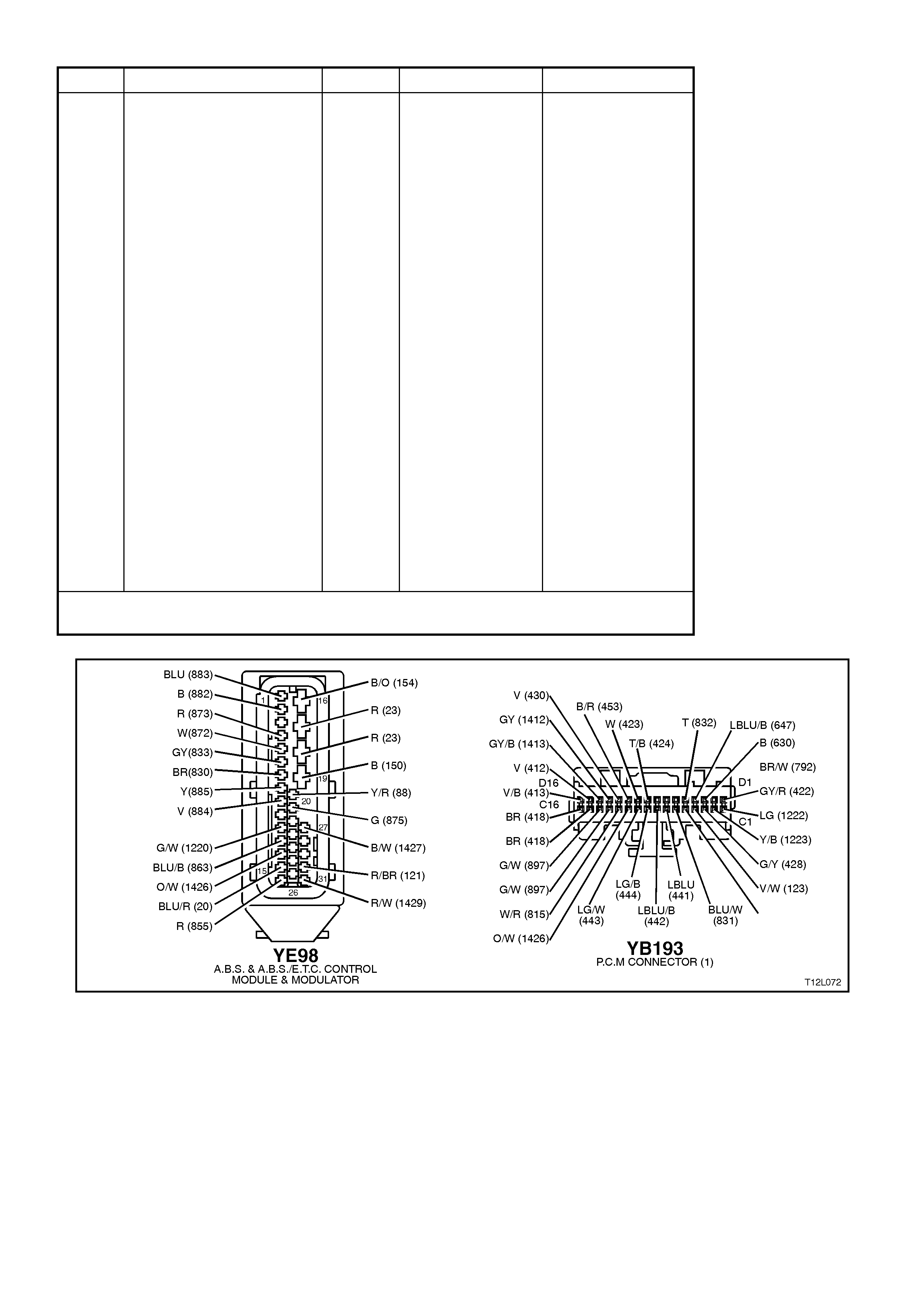
STEP ACTION VALUE YES NO
4. ∙Turn ignition ON.
∙Back probe
ABS/ETC control
module connector
YE98, terminal 13,
circuit 1426
(Orange/White wire)
with a digital
multimeter to earth
(refer to NOTE 1
above).
∙Is value as specified
?
95 - 105
Hz &
4.2 - 4.8
Volts
Check and repair
open or short in
circuit 1426,
recheck and verify
repair.
Replace ABS/ETC
control module,
refer to 3.6
CONTROL
MODULE in this
Section, recheck
circuit to verify
repair.
5. ∙Install TECH 2 to
DLC.
∙Select Diagnostics /
Chassis / ABS/ETC /
Diagnostic Trouble
Codes/ Clear DTC’s
and clear all DTC’s
(refer to NOTE 2
above).
∙Road test vehicle.
∙ Does DTC 74 set
again ?
Replace
ABS/ETC control
module, refer 3.6
CONTROL
MODULE in this
Section, recheck
circuit to verify
repair.
Fault not present.
Check all system
wiring harness
connectors and
terminals, in
particular the
modulator and
ABS/ETC control
module connector
terminals.
WHEN A LL DIAGNOSIS AND REPA IRS ARE COMPLETED, CLEAR A LL DTC’S AND
VERIFY CORRECT OPERATION
Figure 12L-150

DTC 78 - INCORRECT OPTION CODING
CIRCUIT DESCRIPTION:
This DTC relates to a difference in the interfacing of the ABS/ETC control module and other control modules and is
only applicable to the ABS/ETC system, not the ABS only sy stem.
Control modules are specifically designed for a particular optioned vehicle, ie. V6 or V6 supercharged. If any
module that communicates with the ABS/ETC control module are for an incorrect application, including the
ABS/ETC control module, DTC 78 will be set.
If the ABS/ETC control module senses this fault, only the ETC system will be disabled (ABS operation will operate
normally), the TRAC OFF warning lamp will be illuminated and the relevant DTC will be set. The TRAC OFF
warning lamp will remain illuminated for the remainder of the ignition cycle. If the failure is intermittent, the control
module will enable the system at the next ignition cycle and the relevant history DTC will be set.
TEST DESCRIPTION:
The numbers below refer to Step numbers in the diagnostic chart for DTC 78.
1. Physical check to determine if correct control modules are fitted to the vehicle.
2. Checks for other DTC’s logged that may cause DTC 78 to log.
Checks if fault is intermittent or in ABS/ETC control module.
NOTES ON DIAGNOSTIC CHART:
1. Refer to 4.7 TECH 2 DIAGNOSTICS in this Section for connecting and using TECH 2.
2. There are different control modules used in VT Series Model vehicles for ABS and ABS/ETC systems. It is
physically impossible to fit an ABS control module to an ABS/ETC hydraulic modulator or an ABS/ETC control
module to a ABS hydraulic modulator. However, if replacing either an ABS or ABS/ETC control module, always
refer to the latest VT Series Model Parts Information for the correct ABS control module part numbers.
STEP ACTION VALUE YES NO
1. ∙Are the correct
control modules that
communicate with
the ABS/ETC control
module, including the
ABS/ETC control
module installed in
the vehicle
(ABS/ETC and PCM)
(refer to NOTE 2
above) ?
Go to Step 2. Replace control
module with control
module that
matches vehicle
specifications,
recheck and verify
repair.
2. ∙Install TECH 2 to
DLC and check if
other system DTC's
are set (refer to
NOTE 1 above).
∙Are other codes
present ?
Repair problems
causing DTC to
set.
Go to Step 3.
3. ∙With TECH 2
connected, Select
Diagnostics / Chassis
/ ABS/ETC /
Diagnostic Trouble
Codes/ Clear DTC’s
and clear all DTC’s
(refer NOTE 1
above).
∙Road test vehicle.
∙Does DTC 78 set
again?
If correct control
modules are
installed in the
vehicle, replace
ABS/ETC control
module, refer to
3.6 CONTROL
MODULE in this
Section, recheck
circuit to verify
repair.
Fault not present.
Check all system
wiring harness
connectors and
terminals, in
particular the
modulator and
ABS/ETC control
module connector
terminals.
WHEN ALL DIAGNOSIS AND REPAIRS A RE COMPLETED, CLEAR ALL DTC’S AND
VERIFY CORRECT OPERATION
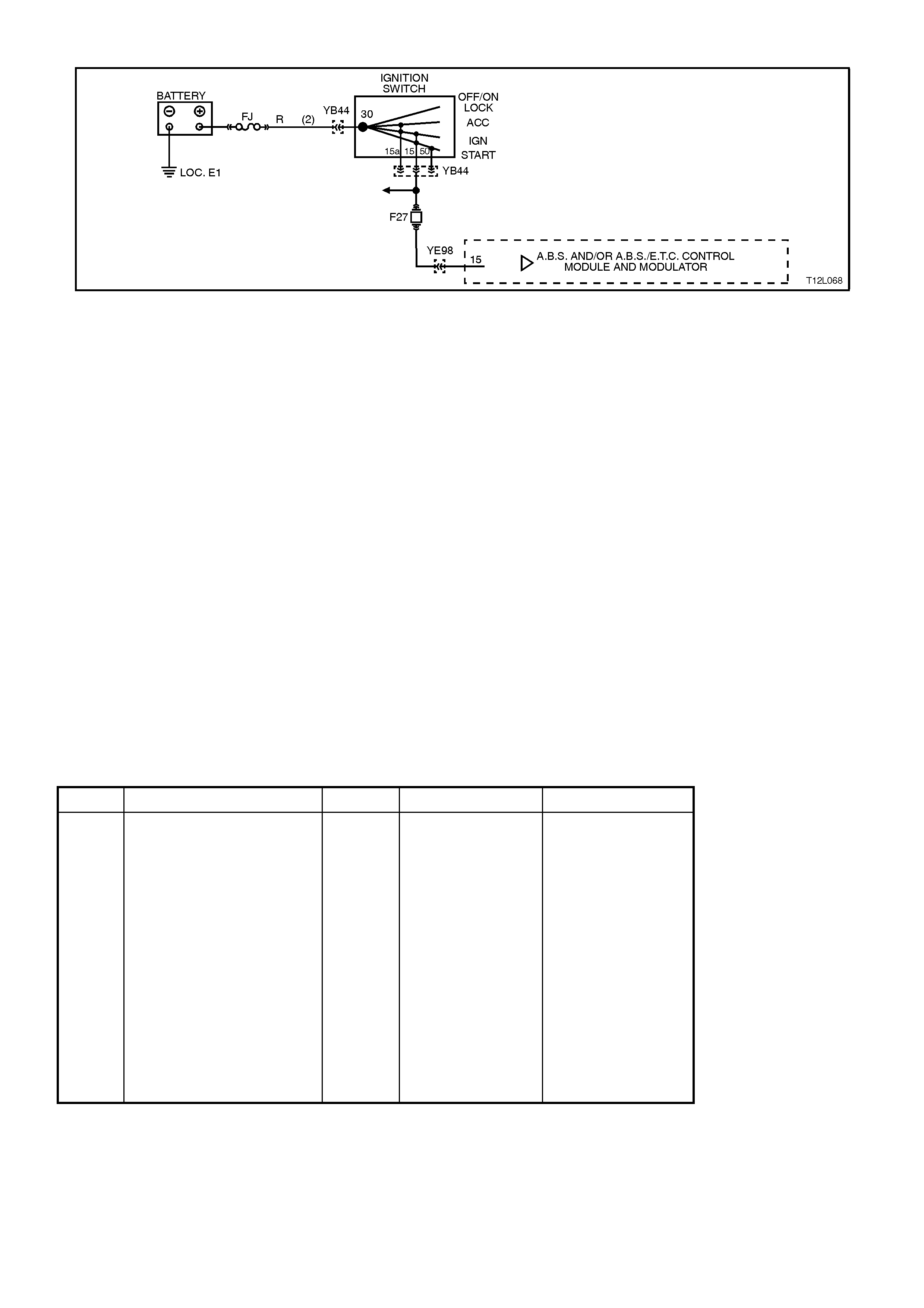
DTC 85 - SYSTEM VOLTAGE TOO LOW
Figure 12L-151
CIRCUIT DESCRIPTION:
The ABS or ABS/ETC control module is supplied with power to terminal 15, circuit 855 (Red wire) from the battery
via fuse F27 when the ignition is in the IGN or START positions.
DTC 85 will set if the ABS or ABS/ETC control module detects a voltage of 10 volts or less on terminal 15 when the
ignition is in the IGN or START positions.
If a failure is detected which causes DTC 85 to set, the ABS or ABS/ETC system is disabled and the control module
illuminates the ABS or ABS and TRAC OFF warning lamps for the remainder of the ignition cycle. If the failure is
intermittent, the control module will enable the system at the next ignition cycle and a history DTC 85 will be set.
TEST DESCRIPTION:
The numbers below refer to Step numbers in the diagnostic chart for DTC 85.
1. Uses TECH 2 to determine if the ABS or ABS/ETC control module is receiving normal battery voltage, above
10 volts.
2. Checks to see if the low voltage reading is due to the generator. If the voltage is below 10 volts, the ABS or
ABS/ETC control module is OK.
3. Checks for open in circuit 855.
4. Checks if low reading is due to faulty connection in circuit 855 or faulty ABS or ABS/ETC control module.
NOTES ON DIAGNOSTIC CHART:
1. For all wiring checking procedures, refer to Section 12P WIRING DIAGRAMS.
2. Refer to 4.7 TECH 2 DIAGNOSTICS in this Section for connecting and using TECH 2.
DIAGNOSTIC AIDS:
If DTC 85 sets when an accessory is operated, check for poor connections or excessive current draw.
STEP ACTION VALUE YES NO
1. ∙Install TECH 2 to
DLC
∙Select Diagnostics /
Body / Body Control
Module / Data List
and scroll to
BATTERY
VOLTAGE (refer to
NOTE 2 above).
∙Engine running (idle).
∙Is battery voltage
shown on TECH 2
above specified
value ?
10 Volts Fault not present.
If no additional
DTC’s were
stored, refer to
Diagnostic Aids
above.
Go to Step 2.
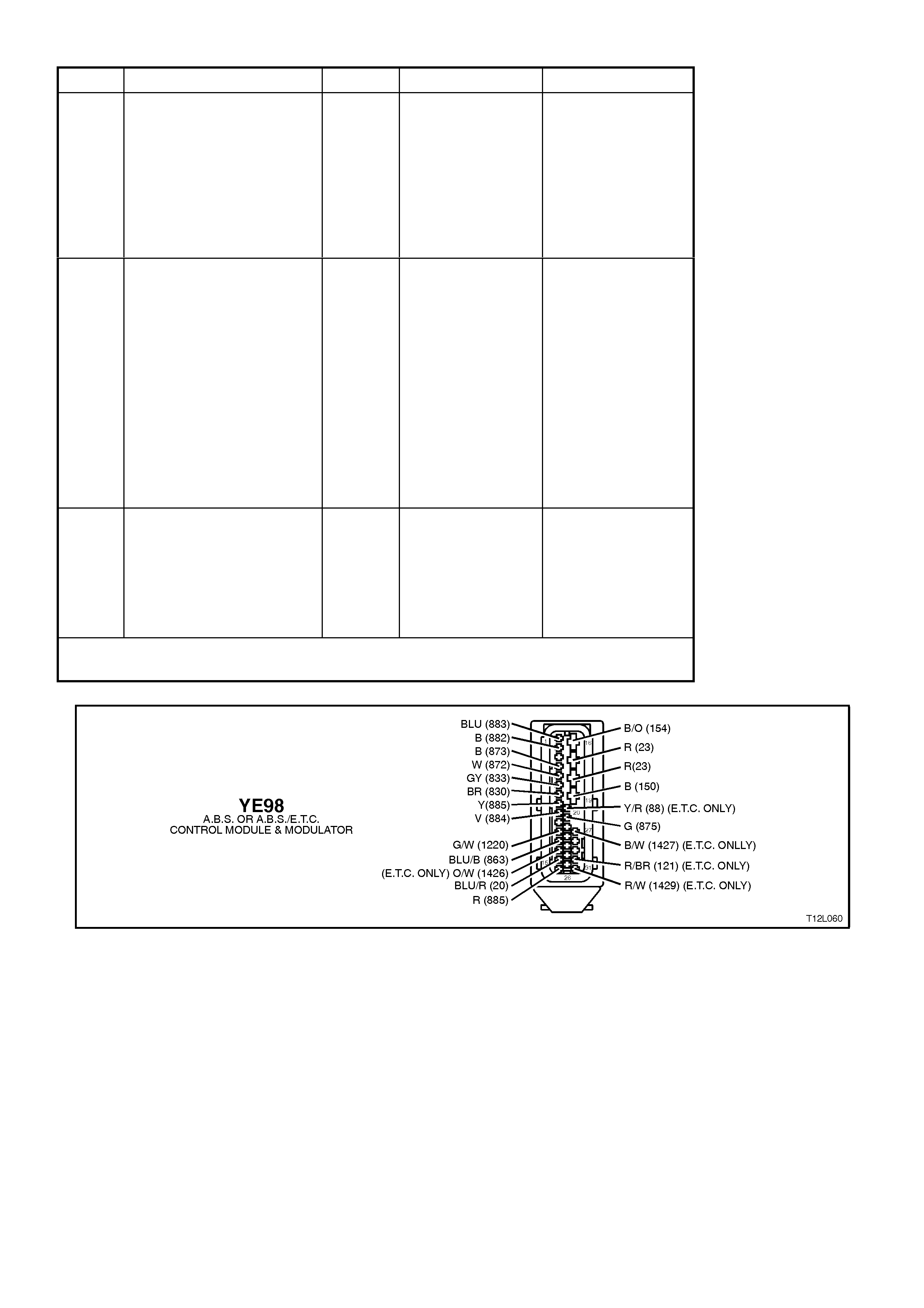
STEP ACTION VALUE YES NO
2. ∙Measure voltage
across battery
terminals.
∙Is voltage equal to or
above specified value
?
10 Volts Go to Step 3. Check generator
operation, refer to
Section 6D1-1,
CHARGING
SYSTEM - V6
ENGINE or Section
6D2-1 CHARGING
SYSTEM - V8
ENGINE.
3. ∙Ignition OFF.
∙Disconnect control
module connector
YE98.
∙Switch ignition ON
and measure voltage
between connector
YE98, terminals 15
and earth (refer to
NOTE 1 above).
∙Is voltage equal to or
above specified value
?
10 Volts Go to Step 4. Check and repair
open in circuit 855
(Red w ire)
(including fuse
F27), recheck and
verify repair.
4. ∙Check for faulty ABS
or ABS/ETC control
module connection
for circuit 855.
∙Was a fault found ?
Repair fault as
necessary,
recheck and verify
repair.
Replace ABS or
ABS/ETC control
module, refer to 3.6
CONTROL
MODULE in this
Section, recheck
and verify repair.
WHEN A LL DIAGNOSIS AND REPA IRS ARE COMPLETED, CLEAR A LL DTC’S AND
VERIFY CORRECT OPERATION
Figure 12L-152

5. SPECIFICATIONS
WHEEL SPEED SENSORS
Winding resistance at ambient temperature
Front wheels 1600 - 1800 Ohms
Rear wheels 1440 - 1760 Ohms
Wheel speed sensor air gap Non-adjustable
Wheel speed sensor pulse rings 48 teeth
Brake Fluid
Type Holden Specification
HN 1796
Control Module ABS and ABS/ETC control
modules are not interchangeable.
If replacing an ABS or ABS/ETC
control module, always refer to the
latest VT spare parts information.

6. TORQUE WRENCH SPECIFICATIONS
Nm
Brake line connections 8 - 11
Brake hose to calliper bolt 32 - 37
Brake master cylinder support bracket nut 5 - 12
Brake master cylinder support bracket bolt 15 - 20
Control module to hydraulic modulator 3
Front brake calliper attaching bolts 80 - 90 Nm, then
turn through
40° - 50°
Front wheel hub to steering knuckle attaching bolts 100 - 115
Front wheel speed sensor cable retainer screw 6 - 14
Hydraulic modulator and control module securing nut 5 - 12
Rear axle bearing outer retainer to axle housing
attaching nuts 40 - 50
Road wheel attaching nuts 110 - 140
Rear wheel speed sensor attaching screw 6 - 14
Steering knuckle to strut attaching bolt and nut Stage 1: 85
Stage 2: 100
Stage 3: then turn
through 85° - 95°
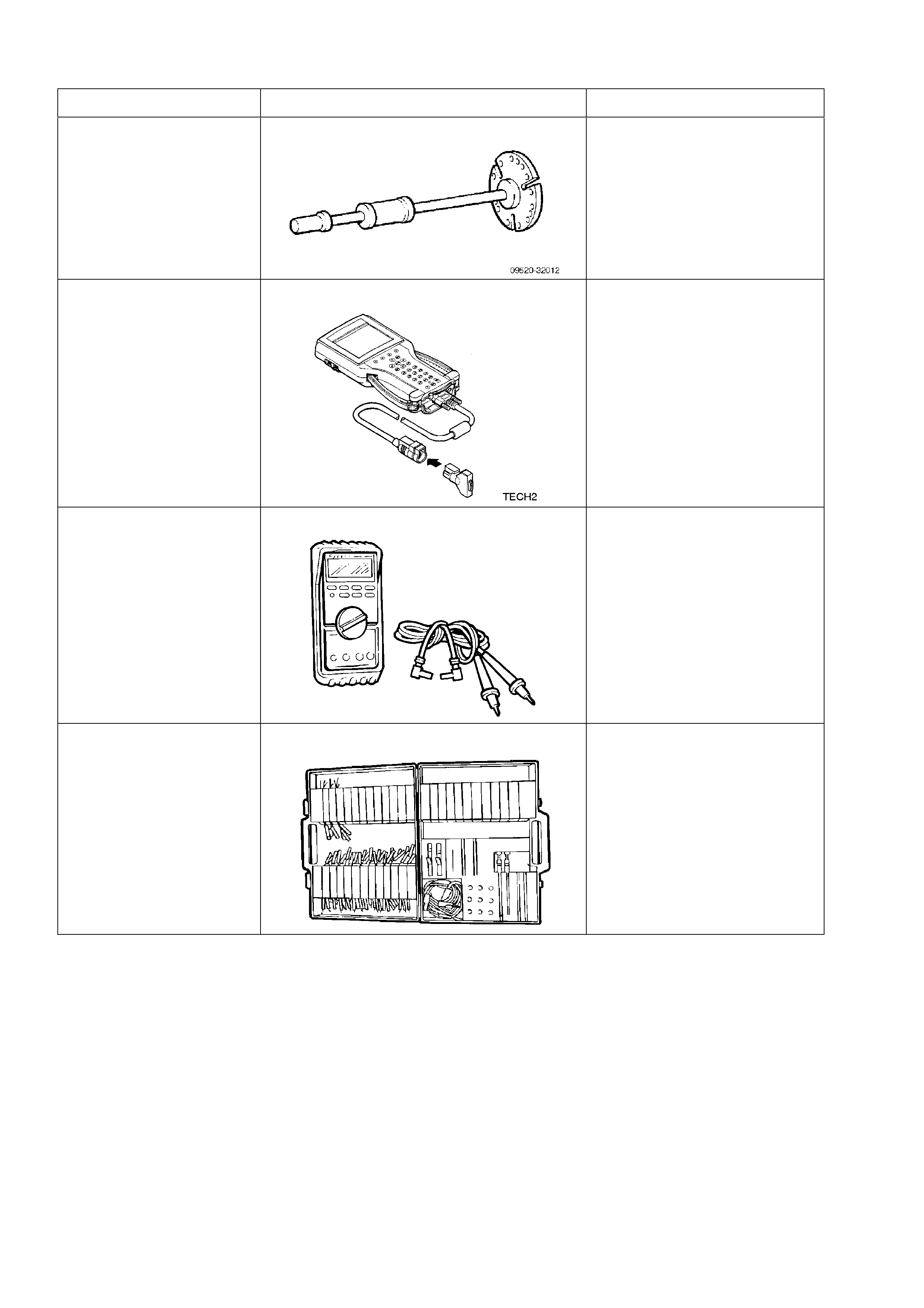
7. SPECIAL TOOLS
TOOL NO. REF IN TEXT TOOL DESCRIPTION COMMENTS
09520 - 32012 SLIDE HAMMER PREVIOUSLY RELEASED
FOR V AND J CARS.
USED FOR REMOVING INNER
AXLE SHAFT
TECH 2 DIAGNOSTIC SCAN TOOL PREVIOUSLY RELEASED
J39200 DIGITAL MULTIMETER TOOL NO. J39200
PREVIOUSLY RELEASED, OR
USE COMMERCIALLY
AVAILABLE EQUIVALENT.
MUST HAVE 10 MEG OHM
INPUT IMPEDANCE AND BE
CAPABLE OF READING
FREQUENCIES
KM-609 ELECTRONIC KIT USED IN CONJUNCTION
WITH A MULTIMETER FOR
MEASURING VOLTAGES AND
RESISTANCE’S WITHOUT
DAMAGING WIRING
HARNESS CONNECTORS