
SECTION 1A1 - BODY
CAUTION:
This vehicle is equipped with a Supplemental Restraint System (SRS). A SRS will
consist of either seat belt pre-tension ers and a driver’s side air bag, or seat belt pre-
tensioners and a driver’s and front passenger’s side air bags. Refer to CAUTIONS,
Section 12M, before performing any service operation on or around SRS
components, the steering mechanism or wiring. Failure to follow the CAUTIONS
could result in SRS d eployment, result ing in po ssible person al injury or unnecessary
SRS system repairs.
CAUTION:
This vehicle may be equipped with LPG (Liquefied Petroleum Gas). In the interests of
safety, the LPG fuel system should be isolated by turning 'OFF' the manual service
valve an d then draining the LPG service lines, bef ore any service work is carried out
on the vehicle. Refer to the LPG leaflet included with the Owner's Handbook for
details or LPG Section 2 for more specific servicing information.
1. GENERAL DESCRIPTI ON
The VT Series is a completely new vehicle design. All sheetmetal, interior trim, air conditioning, and lighting systems
have been redesigned. Bumper facias complement the new styling and accommodate below bumper engine cooling
entry. Head, turn signal and rear lamps are modified to suit design changes.
Techline

2. SERVICE OPERATIONS
2.1 PLASTIC COMPONENT LOCATIONS
Plastic components are used throughout the vehicle. To assist with the identification and composition of those
components refer to the following chart.
PLASTIC COMPONENT LOCATIONS
COMPONENT CODE PLASTIC TYPE
Radiator grille ABS Acrylonitrile Butadiene Styrene
Front Bumper Bar TPO Thermoplastic Olefin
Rear Bumper Bar TPO Thermoplastic Olefin
Air Baffle PP Polypropylene
Fender Liner TPO Thermoplastic Olefin
Front Turn Signal Lamp PMMA Polymethyl Methacrylate
Plenum Chamber Cover ASA Acrylate Styrene Acrylonitrile
Door Airbox PPE Polypropylene Ether
Coolant Reservoir V6 PP Polypropylene
Coolant Reservoir V8 PE Polyethylene
Cooling Fan Shroud PP Polypropylene
Instrument Panel Pad PU PVC/ASA Skin, Polyurethane Foam
Console ABS Acrylonitrile Butadiene Styrene
Shroud Lower Trim Assembly PP Polypropylene
Front Pillar Garnish PPE Polypropylene Ether
Centre Pillar - Upper Trim Assembly ABS Acrylonitrile Butadiene Styrene
Centre Pillar - Lower Trim Assembly ABS Acrylonitrile Butadiene Styrene
Quarter Window Inner Trim Assembly -
Sedan ABS Acrylonitrile Butadiene Styrene
Quarter Window Inner Trim Assembly -
Station Wagon ABS Acrylonitrile Butadiene Styrene
Rocker Panel Cover PP Polypropylene
Heater Case PP Polypropylene
Tailgate Upper Trim - Station Wagon ABS/PC Acrylonitrile Butadiene
Styrene/Poycarbonate
Tailgate Lower Trim - Station Wagon ABS/PC Acrylonitrile Butadiene Styrene/
Poycarbonate
Rear Tail lamp PMMA Polymethyl Methacrylate
Rear Compartment Lid Lamp Assembly ABS Acrylonitrile Butadiene Styrene
Licence Plate Lamp Assembly PC Poy carbonate
Wheel Covers ABS/PC Acrylonitrile Butadiene Styrene/
Poycarbonate
Body Side Mouldings PVC Polyvinylchloride (Vinyl)
Fuel Filler Door PPE/PA Polyphenylene/Polyamide
Glove Box ABS Acrylonitrile Butadiene Styrene
Centre Facia ABS Acrylonitrile Butadiene Styrene
Rocker Panel Skirts TPO Thermoplastic Olefin

2.2 BODY SHELL PARTS REPLACEMENT
When replacing or repairing a part or sub-assembly, care must be taken to ensure that correct alignment and
strength of unit as a whole is maintained. In some instances, major damage to the body or frame can be more
effectively and economically repaired by replacing a part or sub-assembly with a new one, rather than repairing the
damaged part.
Spot welding is used extensively for joining panels together, particularly around the flanged edges of dash panel,
windshield and back window openings, along edges of rocker panels and lower edge of the rear body.
When replacing a section that is normally attached by this method and spot-welding equipment is not available, or
the location of the parts restricts access, the part or assembly should be attached by the welding method known as
‘Plug Welding’, which is as follows:
1. Remove the damaged part by cutting through the spot welds between the panels with a thin-edged chisel or by
drilling the spot welds.
2. Drill 5 mm diameter holes in either the new or mating part to correspond with the spacing and location of the
original spot welds. Parts to be drilled are determined by accessibility for the following operations.
3. Clamp the new part in position and gas or arc weld the two parts together through each hole, finally dressing
off any high spots on exposed surfaces.
When replacing parts such as roof panels, rear quarter or rocker panels; where a butt or overlap weld is required,
the joint of the panels must be formed below the normal contour. This allows for filling over the join and eliminates
the possible reduction of sheet metal thickness following the necessary buffing or grinding of a normal welding
operation.
IMPORTANT:
Following replacement or repair of body components, it is essential that effective rust proofing techniques, as
outlined in the following paragraphs, be observed.

2.3 ANTI-CORROSIVE TREATMENT
Precoated and galvanised s teel is us ed extens ively for various body panels for inc reas ed c orr os ion protec tion of the
body. Body panels such as the door, tail gate and rear compartment lid outer panels are precoated on the inner
surface of the metal to improve corrosion protection. Other body structure members have complete double sided
galvanised protection.
In addition, a rust preventative mater ial is s pr ayed after paint application to areas s uc h as inter ior s ur f ac es of door s ,
etc.
Any repair or replacement of panels, assemblies, etc., that disturb this anti-corrosive treatment must be resealed
and should be included as part of the repair or replacement operation.
Anti-corrosive compounds used for repairs should be light bodied materials designed to penetrate between metal-
to-metal surfaces such as pinch weld flanges and integral panel attaching points.
All bare m etal s urfaces must be tr eated with m etal c onditioner and primed. These oper ations need to be c ar ried out
prior to the application of sealer s, waxes and s ound deadeners. Attac hing points of new replacem ent panels s hould
be resealed. The hemming flanges of replacement doors, tailgates and rear compartment lids will require resealing.
Open joins which require bridging of the sealer to close a gap should be sealed with a heavy bodied caulking
material. When colour application is required to restore repaired areas to original appearance, conventional
refinishing preparation, undercoat build-up and colour application techniques should be employed.
When deadeners are disturbed during damage repair, or a panel has been replaced, the deadener material must be
replaced with an equivalent material. The location and pattern for replacement material can be determined by
observing the original deadener application outlines.
IMPORTANT:
Follow label directions for materials selected.

2.4 WATER AND DUST LEAK DIAGNOSIS
Diagnosis of body leaks are complicated by the fact that the appearance of water at one point can be caused by
seepage through any one or more of m any possible locations . As an ex ample of this indirec t entr y, the caus e of wet
front floor coverings may be due to water entering past the door weatherstrip, through the door inner panel, between
the windshield and its adhesive compound or through any one of the joins in the floor panel, ventilator or dash
panels, therefore, point or points of water or dust entry must be established before effective resealing can be carried
out.
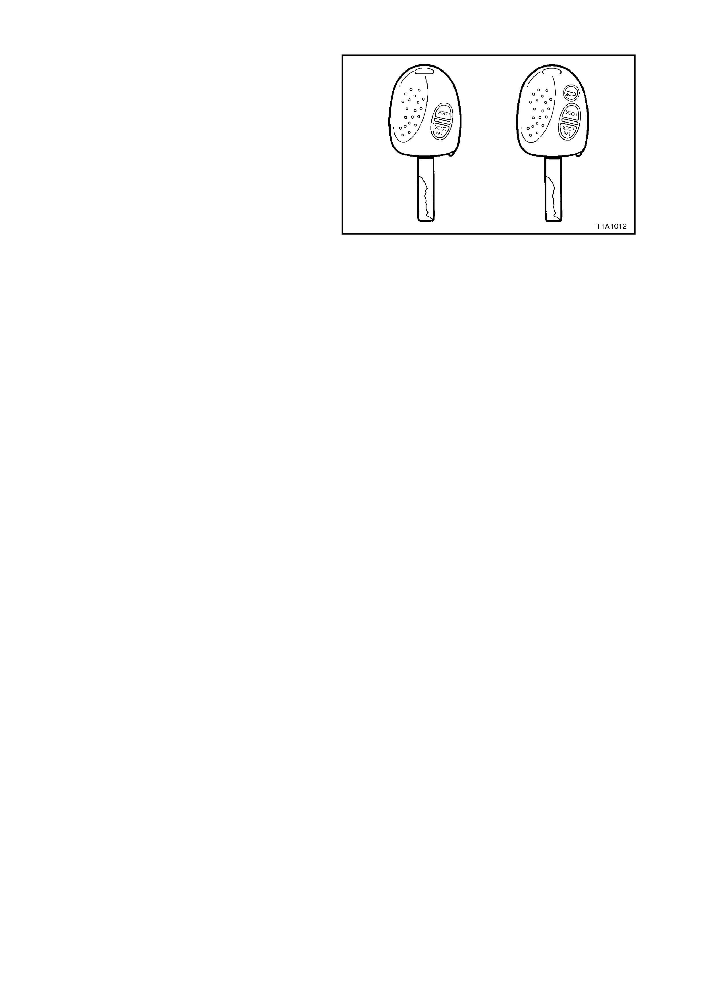
2.5 LOCK CYLINDE RS AND KEYS
A single key locking system is used on all VT
Series models. This key operates all locks on the
vehicle.
Two types of k eys are used which is dependant on
body style. The three button key is used on the
sedan while the two button is used on the wagon
body style.
The two button key features a lock and an unlock
button, while the three button key includes a boot
release button.
The key identification number is located on the
vehicle se curity card.
It is essential that this key number be available
should a replacement key be required. Figure 1A1-1

2.6 METAL REPLACEMENT PARTS REFINISHING
Metal service replacement parts (or assemblies) are painted with a black, ‘high-bake’ factory primer. For proper
adhesion of colour coats in service, the following refinish steps are necessary.
1. Clean part with a wax and grease removing solvent such as Prepsol.
2. Scuff-sand panel lightly with wet or dry number 400 paper and water. Avoid cut-throughs. Reclean part, then
apply sealer to entire part.
3. If factory primer coat has been cut through, apply metal conditioner to the exposed bare metal. Follow
directions on container label.
4. Apply primer-surfacer to entire part; allow to dry thoroughly before sanding.
5. Sand primer-surfacer using wet or dry number 400 paper and water. Do not sand sealer.
6. Re-clean part.
7. Apply colour coats to parts.
8. Follow direction on container label for drying time before compounding.
9. Compound part by hand or with power equipment.
10. Non-sealing polish may be applied after rub-out if desired. Waxes however, should NOT be applied until the
paint finish has aged for at least two months.

2.7 BODY LUBRICATION
The moving mechanical parts of the body which have metal to metal contact are lubricated at assembly.
Operating conditions, whether normal or otherwise, determ ine the effective lif e of the lubricant and for this reason,
lubrication in service is important. Equally important is the type of lubricant to be used and, for your guidance, we list
locations and recommended lubricants.
WARNING:
CARELESS OR EXCESSIVE APPLICATION OF BODY LUBRICANTS CAN RESULT IN STAINING OF PAINT
FINISH, INTERIOR TRIM OR DAMAGE TO CLOTHING. USE LUBRICANTS SPARINGLY AND REMOVE
ACCIDENTAL APPLICATION FROM PAINT FINISH IMMEDIATELY.
PARTS READILY ACCESSIBLE
Where practical, use lithium grease; otherwise use light oil.
Engine Hood Catch
Engine Hood Lock
Engine Hood Hinge
Door Hinge Sleeves and Check Links
Rear Compartment Lid Hinge
Rear Compartment Lid Lock Mechanism
Lock Cylinders
Apply Powdered Graphite through Key aperture (do not oil).
Ignition Lock Cylinder
Rear Compartment Lid Lock Cylinder
Door Lock Cylinder
Instrument Panel Compartment Lock Cylinder
Door Lock Striker Bolt/Fork Bolt
Use Solidoil or equivalent.
Door Lock Striker Bolt
Door Lock Fork Bolt
PARTS CONCEALED NECESSITATING DISASSEMBLY
Where practicable, use lithium grease, otherwise use light oil.
Door Window Regulator
Door Window Cams
Door Lock Mechanism
Door Lock Remote Control
Front Seat Adjuster
Driver’s Seat Height Adjuster

2.8 SHROUD LOWER TRIM ASSEMBLY
REMOVE
1. Remove the dash panel lower trim assembly and release the forward section of rocker panel cover.
2. Remove the upper retainer screw and the screw beneath the rocker panel cover securing the shroud lower trim
assembly to the rocker panel.
3. Pull the shroud lower trim assembly rearward from the retainer removing the assembly.
Figure 1A1-2
REINSTALL
Reverse removal operations.
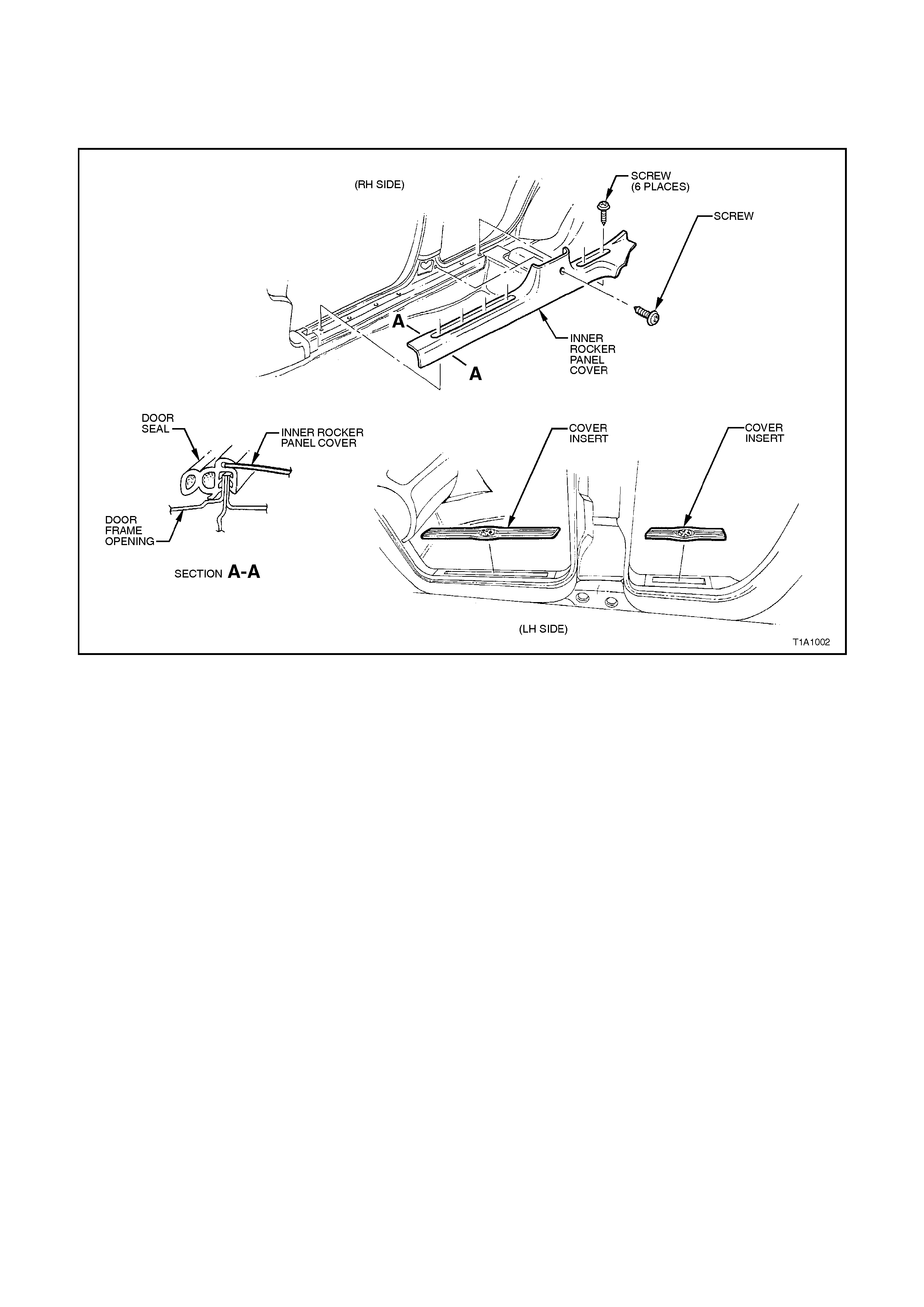
2.9 ROCKER P ANEL COVER
REMOVE
Remove rocker panel cover inserts and rocker panel cover retainer screws from rocker panel removing cover
assembly.
Figure 1A1-3
REINSTALL
Reverse removal operations.

2.10 FLOOR CARPET AND INSULATOR ASSEMBLY
REMOVE
CAUTION: It will be necessary to disable the
SRS (Air Bag) prior to this operation. Refer to
DISABLING THE SRS, Section 12M
SUPPLEMENTAL RE STRA I NT SYSTEM.
NOTE: Clean hands are esse ntia l when work ing on
the body interior trim.
1. Remove the rear seat cushion, refer to
2.18 REAR SEAT CUSHION AND BACK
ASSEMBLY – SEDAN or 2.23 REAR SEAT
CUSHION – WAGON in Section 1A7 – SEAT
AND SEAT BELT ASSEMBLIES.
2. Remove both front seats; refer to
2.1 FRONT BUCKET SEAT ASSEMBLIES in
Section 1A7 – SEAT AND SEAT BELT
ASSEMBLIES.
3. Remove the park brake lever cover by
grasping the cover firmly by hand and sliding
over the park brake lever, refer to
2.7 PARK BRAKE LEVER in Section 5A –
STANDARD BRAKES.
4. Remove front seat belt lower bolts, refer to
2.32 FRONT SEAT BELT RETRACTOR AND
HEIGHT ADJUSTER ASSEMBLY in Section
1A7 – SEAT AND SEAT BELT ASSEMBLIES.
5. Remove the instrument panel compartment;
refer to 1.2 INSTRUMENT PANEL
COMPARTMENT in Section 1A3 –
INSTRUMENT PANEL AND CONSO LE.
6. Remove the instrument panel cover RH lower
cover, refer to 1.1 INSTRUMENT PANEL
LOWER COVER – RIGHT SIDE in Section
1A3 – INSTRUMENT PANEL AND CONSOLE.
7. Remove the LH footwell closing panel, refer to
1.6 INSTRUMENT PANEL PAD ASSEMBLY
in Section 1A3 – INSTRUMENT PANEL AND
CONSOLE.
8. Remove the RH footwell upper closing panel,
refer to 1.6 INSTRUMENT PANEL PAD
ASSEMBLY in Section 1A3 – INSTRUMENT
PANEL AND CONSOLE.
9. Remove centre console and console side
extens ions, r ef er to 1.3 CENTRE CONSOLE in
Section 1A3 – INSTRUMENT PANEL AND
CONSOLE.
10. Remove both rocker panel trims; refer to
2.9 ROCKER PANEL TRIM in Section 1A1 –
BODY.
11. Remove both shroud lower trims; refer to
2.8 SHROUD LOWER TRIM ASSEMBLIES in
Section 1A1 – BODY.
12. Remove the two screws (1) securing the
footrest pad (2) to the footrest mounting
bracket (3).
13. Remove footrest pad.
Figure 1A1-4
14. Disconnect the SRS sensing and diagnostic module wiring harness from the module, refer to
2.7 SENSING AND DIAGNOSTIC MODULE (SDM) in Section 12M SUPPLEMENTAL RESTRAINT SYSTEM
(Version 6.2) or 2.4 SENSING AND DIAGNOSTIC MODULE (SDM) in Section 12M SUPPLEMENTAL
RESTRAINT SYSTEM (Vers ion 8.0 or 8.1)
15. For vehicles fitted with an automatic transmission, remove the selector control lever assembly; refer to
3.3 SELECTOR CONTROL LEVER ASSEMBLY in Section 7C4 – HYDRA-MATIC 4L60E AUTOMATIC
TRANSMISSION – ON VEHICLE SERVICING.
16. For vehicles fitted with manual transmission, remove the gearshift lever. For vehicles fitted with a V6 engine;
refer to 3.4 GEARSHIFT LEVER in Section 7 B1 MAN UAL TRANSMISSION – V6 ENGINE. For Vehicles f itted
with a V8 engine; refer to 3.4 GEARSHIFT LEVER in Section 7B2 MANUAL TRANSMISSION – V8 ENGINE.
17. Remove the instrument panel carrier to floor mounting bracket bolts; refer to 2.1 COCKPIT MODULE in Section
1E – COCKPIT MODULE.
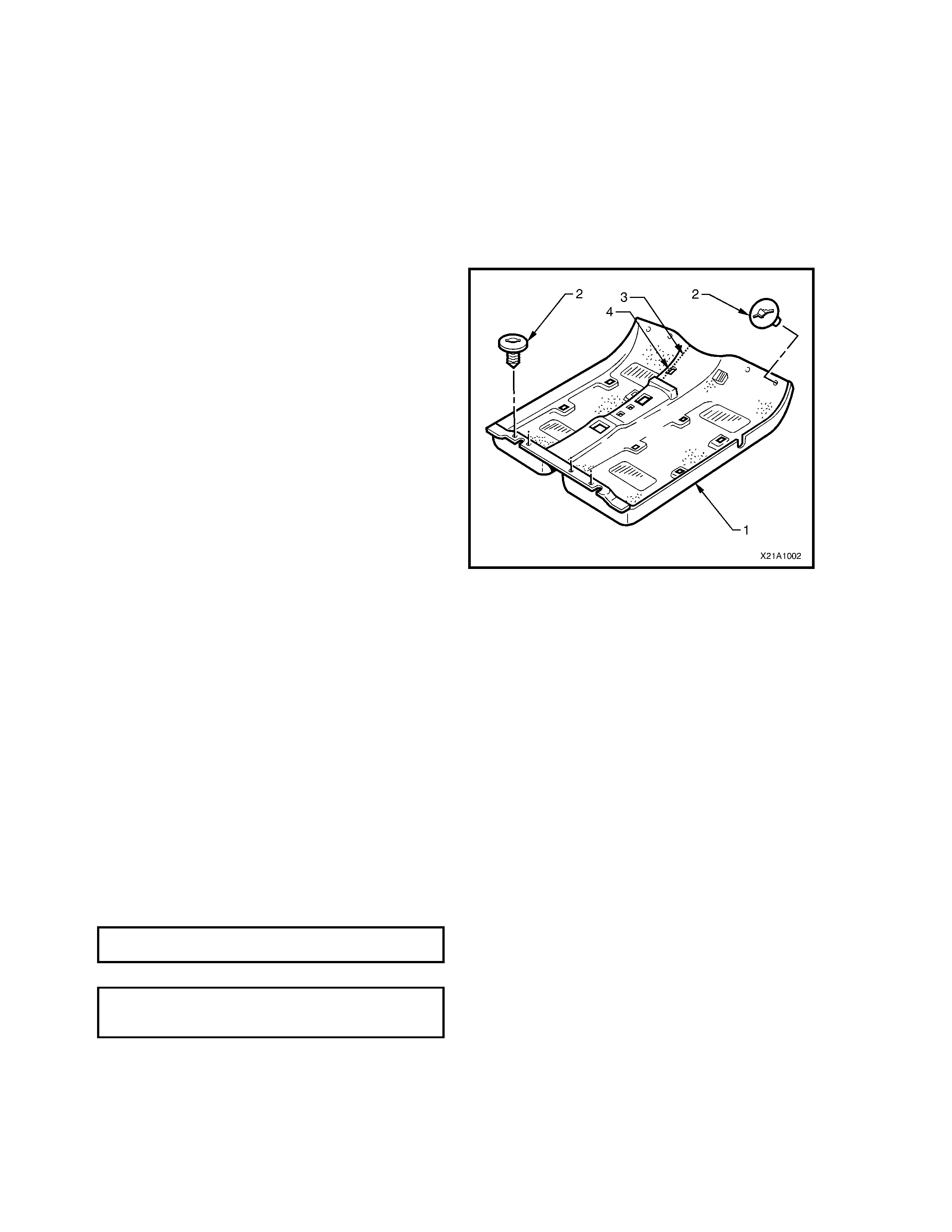
18. Remove t he eight car pet and insula tor ret aining
clips (2) from the carpet and insulator assembly
(1) by rotating the clips counter clockwise and
lifting clear of studs.
19. From inside the LH footwell, grasp the edge of
the hole in the floor carpet and insulator
asse mbly (4) around the evaporator dra in hose
and tear open the perforated line (3) by pulling
the carpet away from the transmission tunnel.
NOTE: To assist in the removal and reinstallation
of t he floor car pet assemb ly, it has been perfo rated
from the front edge, through the centre of the
evaporator drain cut out to the forward edge of the
radio support bracket cut out
20. Slide the remaining flap of carpet out from
under the heating, ventilation and air
conditioning (HVAC) unit and into the RH
footwell.
21. Carefully manoeuvre the floor carpet and
insulator assembly from vehicle.
Figure 1A1-5
REINSTALL
The reinstallation pr oced ur e for the floor c ar pet and
insulator assembly is the reverse of the removal
proce dure, noting the follo wing:
1. Cut alon g the perf orate d line in the floor car pet
that runs from the forward edge of the carpet,
through the evaporator drain cut-out to the
forward edge of the radio support bracket cut-
out prior to re installing.
2. Ensure that all cut-outs in the carpet are
correctly aligned and install the eight retainers
and front seat belt lower attaching bolts to
secure the carpet prior to reinstalling the seats
and cons ole.
3. Ensure all fasteners are tightened to the
correct torque specifications.
FOOTREST PAD ATTACHING SCREWS 2 – 5
TORQUE SPECIFICATION Nm
FRONT SEAT BELT LOWER
ATT ACHI NG BOLT 40 – 54 Nm
TORQUE SPECIFICATION
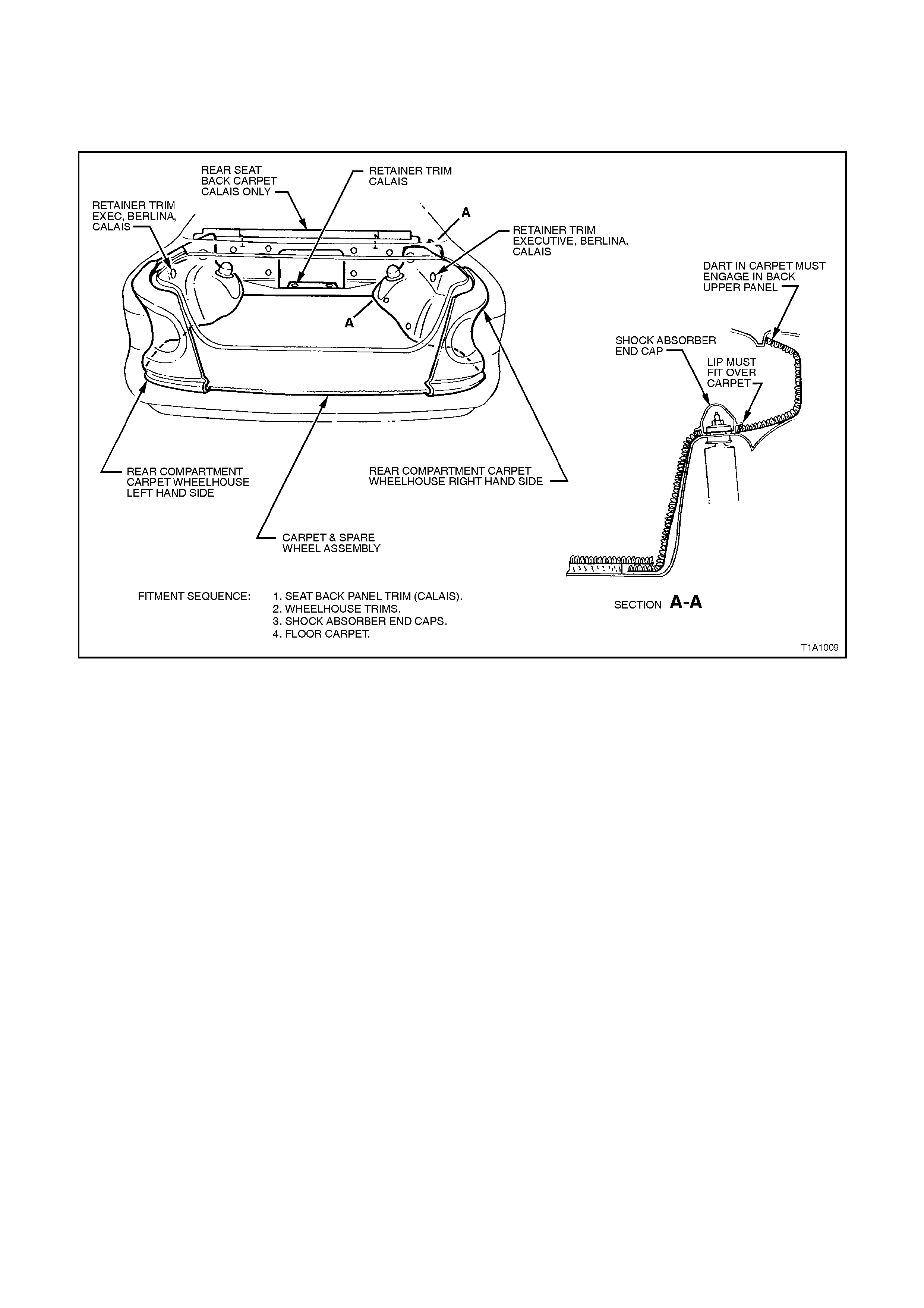
2.11 FLOOR COVERING ASSEMBLY- REAR COMPARTMENT- SEDAN
Removal and installation of the rear compartment carpet involves removal of the spare wheel cover and carpet
assembly. During installation locate the carpet edges and install the spare wheel cover.
The wheelhouse trim is held in place by retainers at the wheelhouse and at the rear compartment lid opening by the
rear crossmember trim.
Figure 1A1-5
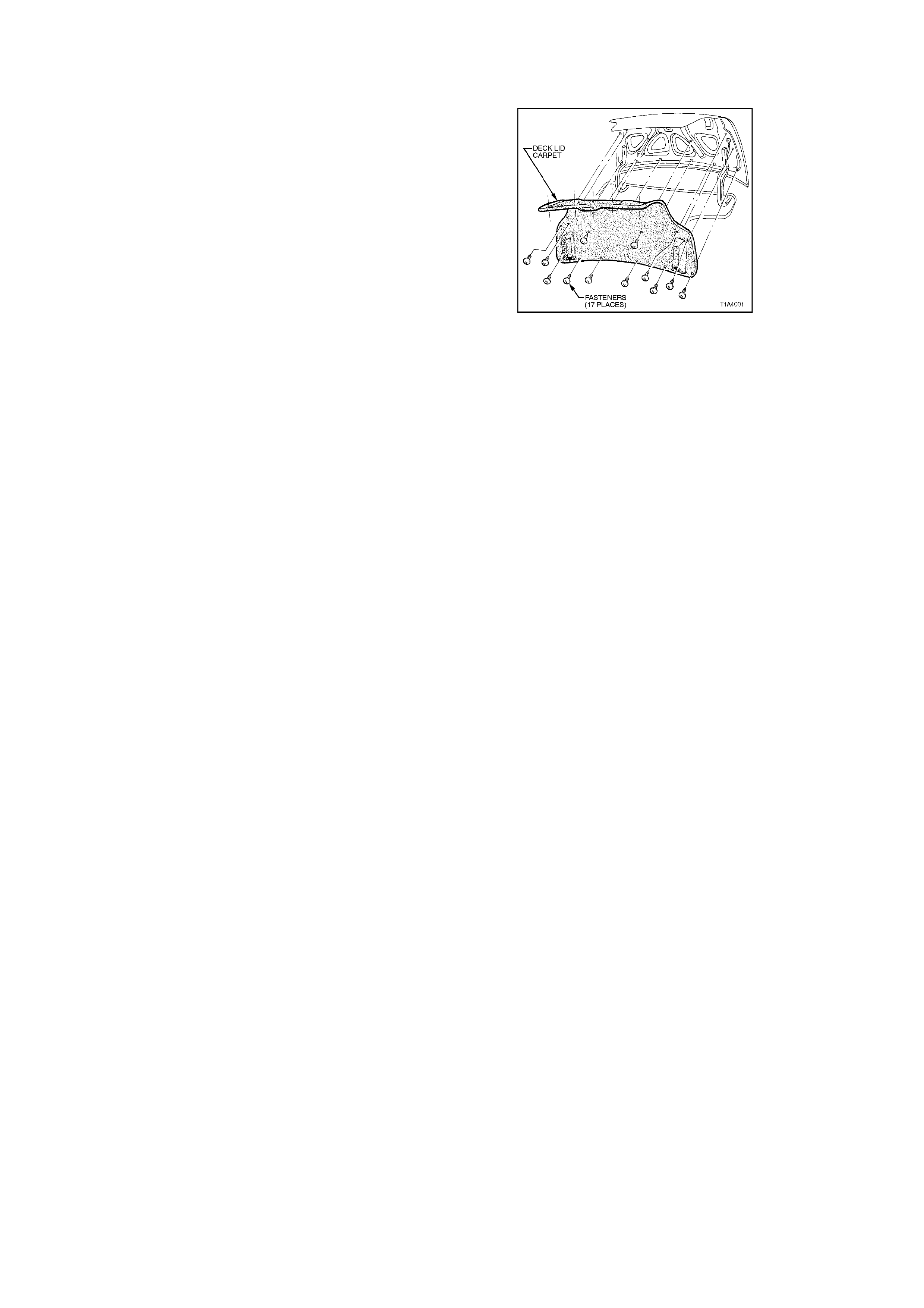
2.12 CARPET ASSEMBLY - REAR COMPARTMENT LID LINER
REMOVE
1. Remove the retainers securing the carpet
assembly to the rear compartment lid.
2. Move the carpet assembly from its position on
the rear compartment lid, open the hinge slots
at the base of the carpet assembly and
remove the carpet.
Figure 1A-6
REINSTALL
Reverse removal operations.
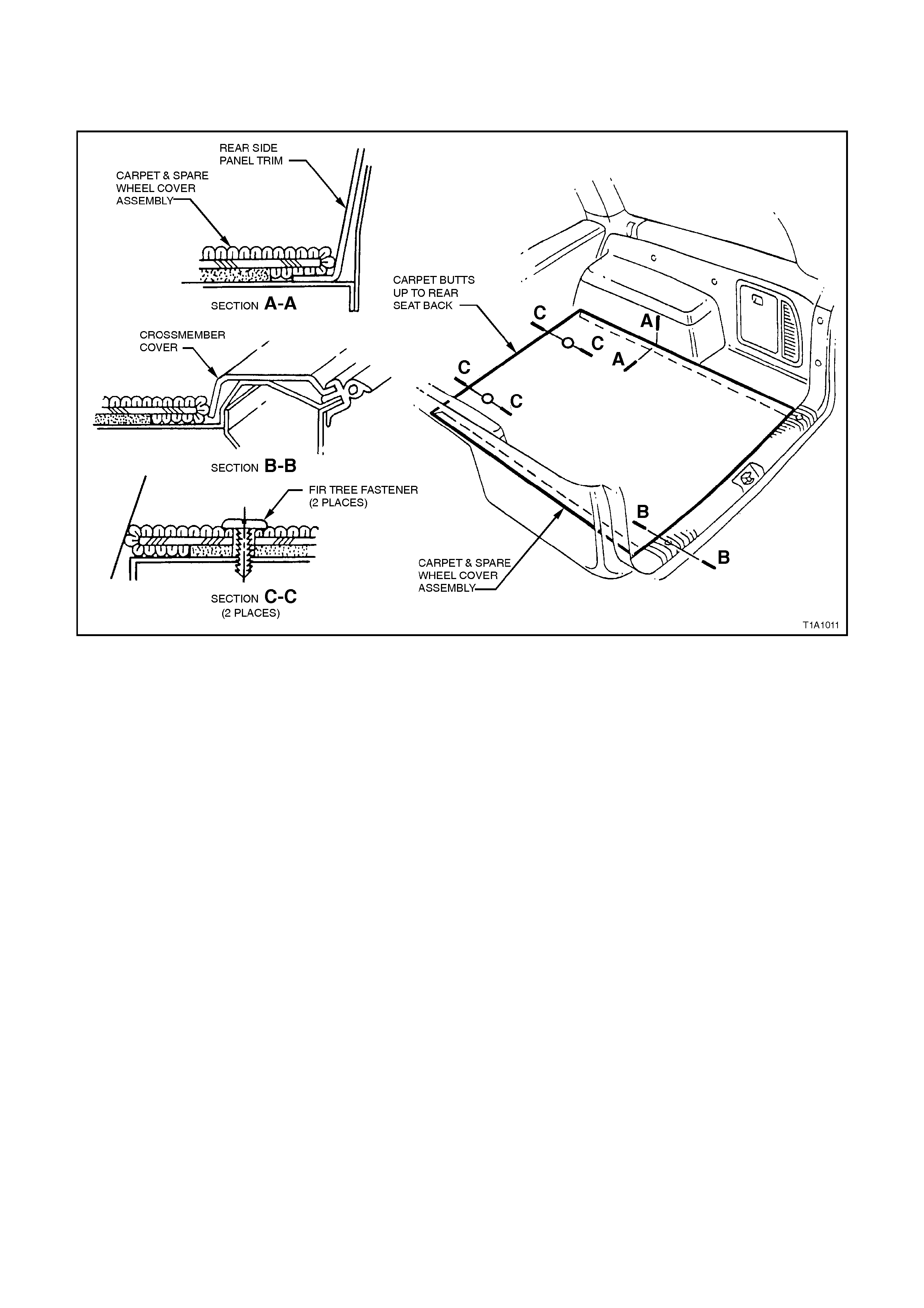
2.13 CARPET ASSEMBLY - LOAD COMPARTMENT - STATION WAGON
REMOVE
1. Remove the two Fir tree fasteners from load compartment area and lift the carpet from the vehicle.
Figure 1A1-7
REINSTALL
Reverse removal operations.

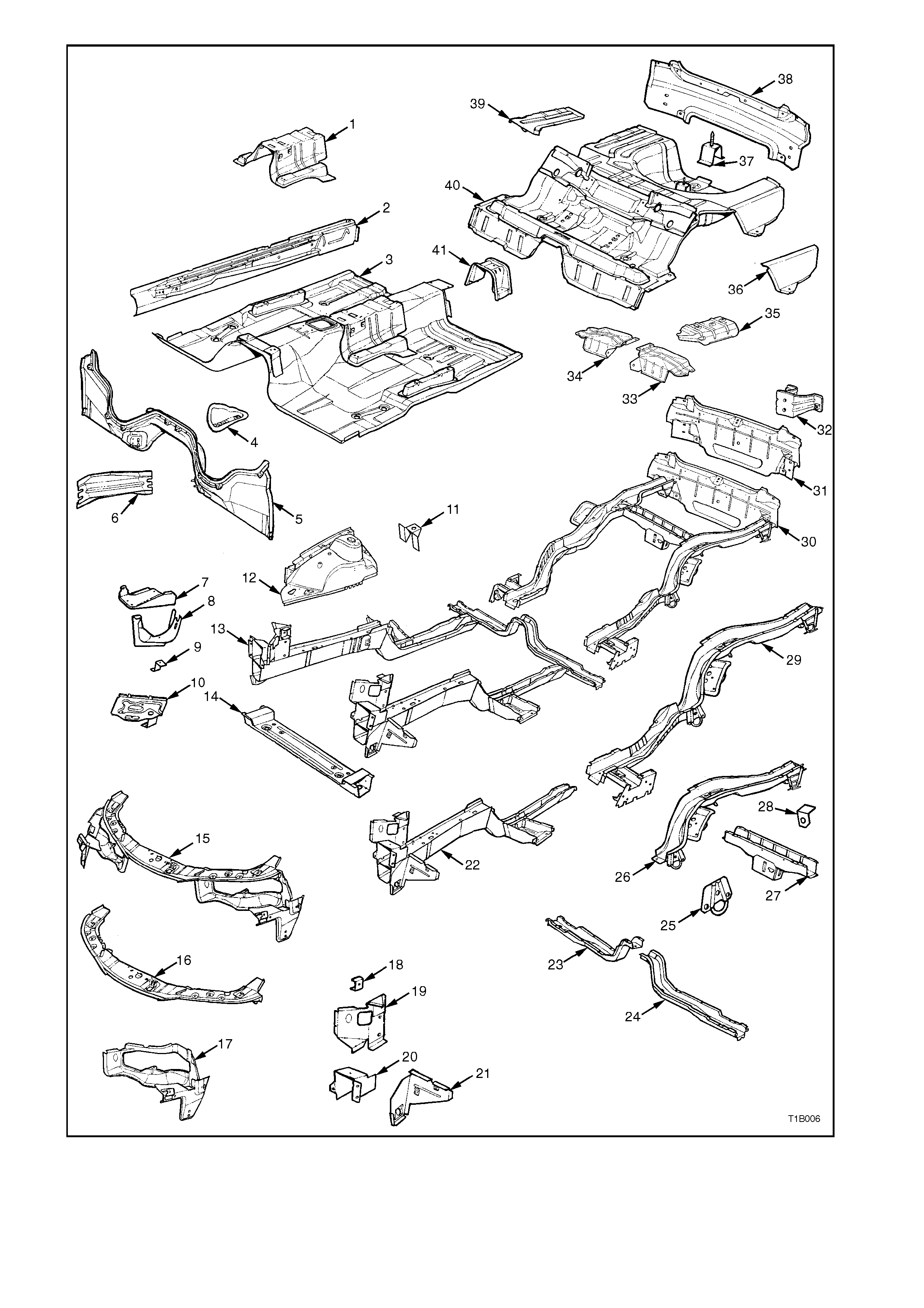
Figure 1A1-8

BODY SIDE - SEDAN
Listed below are assemblies and individual panels that are available for replacement.
The purpose of these illustrations is to provide the repairer with a better understanding of available replacement
panels.
1. Bracket - trim attachment.
2. Pillar - front body inner.
3. Brace - wheelhouse (front).
4. Fender panel (front).
5. Front fender liner.
6. Support - fender.
7. Angle - fender lower.
8. Frame assembly - door opening.
9. Angle - fender upper.
10. Support - front door check.
11. Support - rear door check.
12. Panel - rear quarter (side panel outer).
13. Liner - rear wheelhouse.
14. Gusset - side panel.
15. Insert assembly - tail lamp.
16. Cap - fuel filler.
17. Side panel assembly - inner.
18. Frame - side front roof.
19. Wheelhouse inner assembly.
20. Reinforcement - ‘A’ pillar upper.
21. Brace - upper wheelhouse.
22. Panel assembly - back upper.
23. Frame - roof rear.
24. Panel - roof.
25. Support - roof.
26. Rail - windshield header.
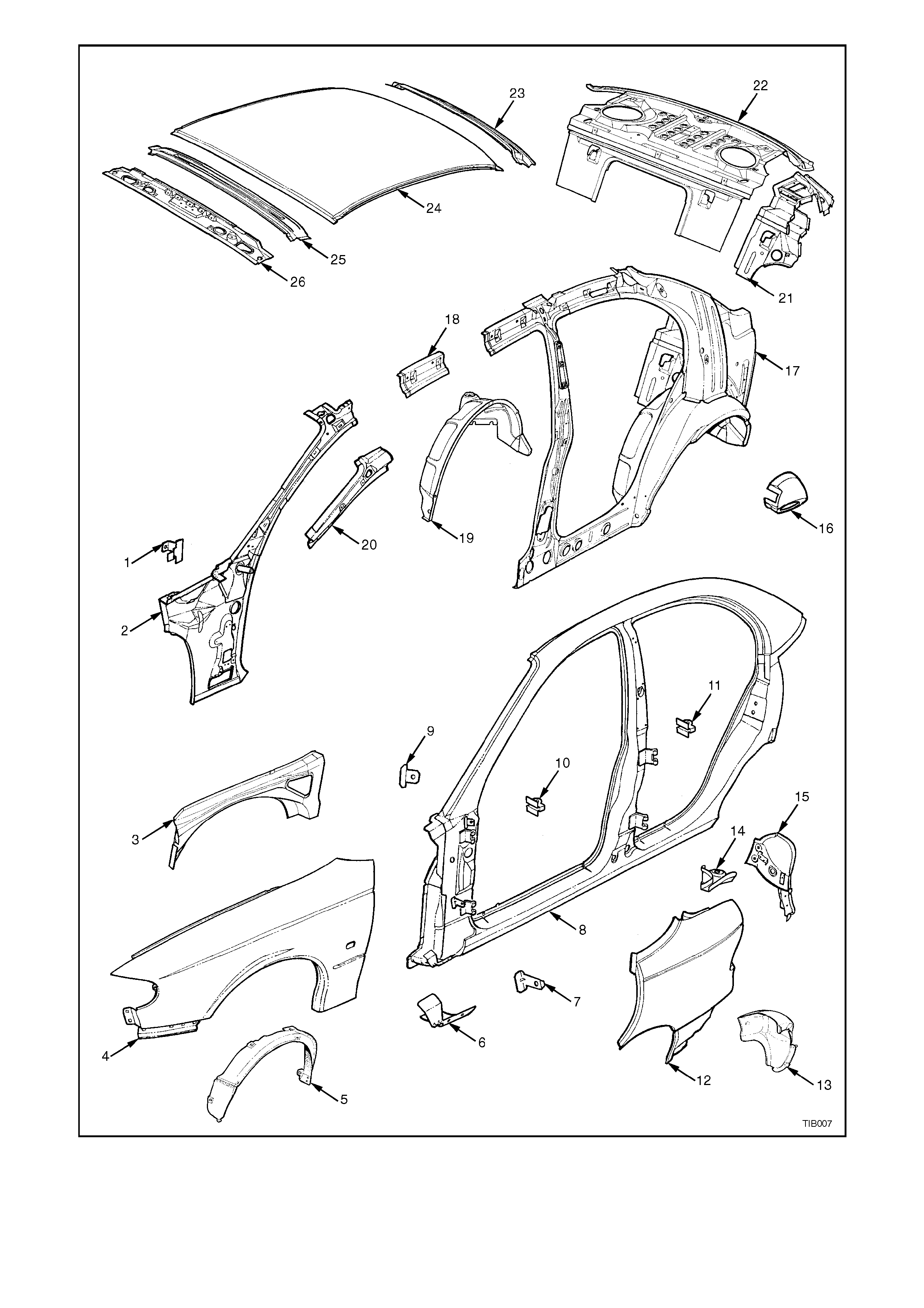
Figure 1A1-9

BODY SHELL - SEDAN
Listed below are assemblies and individual panels that are available for replacement.
The purpose of these illustrations is to provide the repairer with a better understanding of available replacement
panels.
1. Body shell.
2. Engine hood.
3. Hinge assembly - engine hood.
4. Door assembly - front (inner).
5. Panel assembly - front door outer.
6. 6. Panel assembly - rear door outer.
7. Door assembly - rear (inner).
8. Arm and bracket assembly - decklid hinge.
9. Decklid assembly - rear.
10. Dash panel assembly.
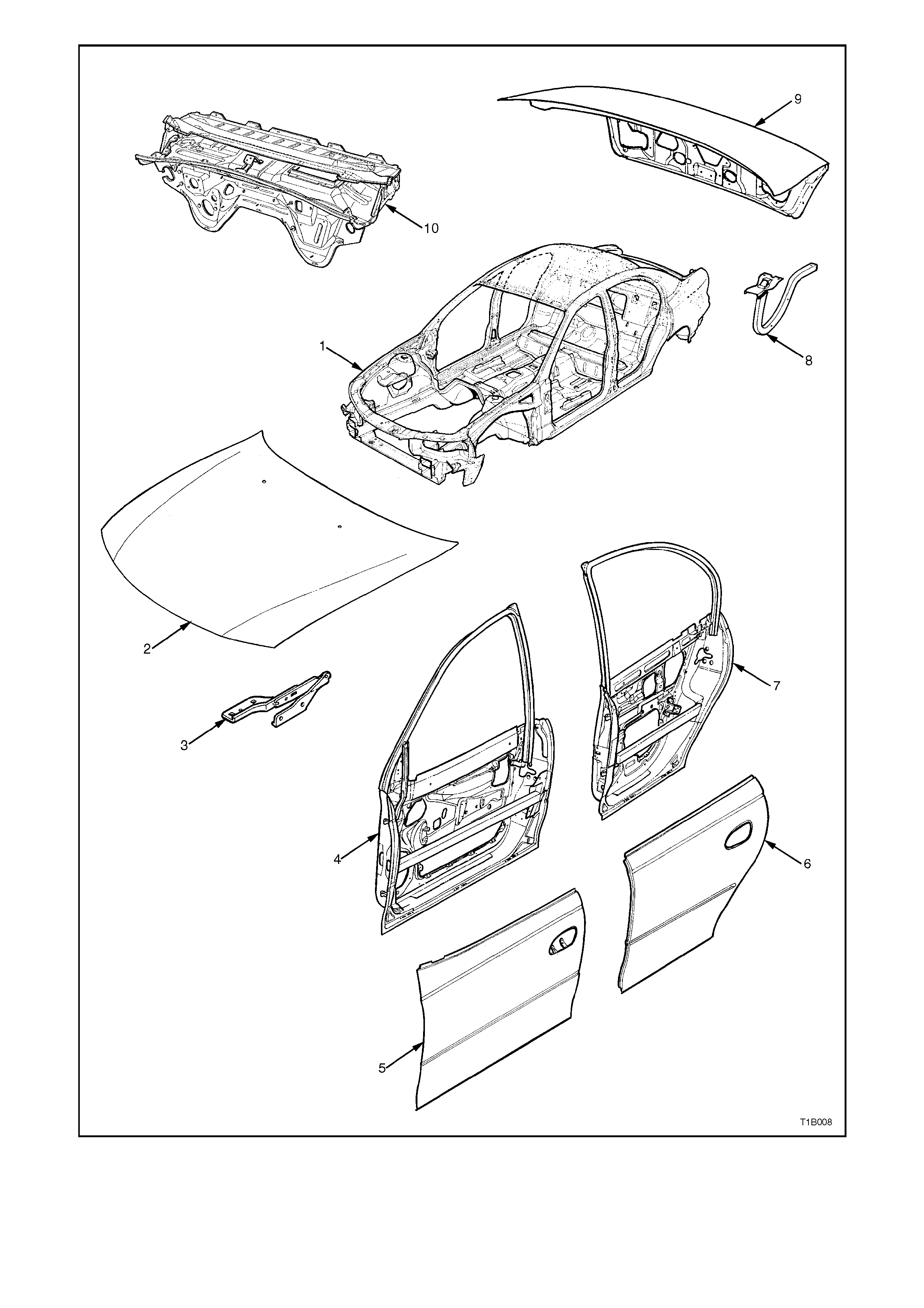
Figure 1A1-10

UNDER BODY - STATION WAGON
Listed below are assemblies and individual panels that are available for replacement.
The purpose of these illustrations is to provide the repairer with a better understanding of available replacement
panels.
1. Reinforcing assembly - inner seat attachment.
2. Reinforcing - floor panel side.
3. Floor assembly - front.
4. Mount assembly - power unit.
5. Extension assembly - floor panel front.
6. Brace - longitudinal to front floor.
7. Bracket - ABS modulator upper.
8. Bracket - ABS modulator lower.
9. Bracket - support modulator lower.
10. Tray assembly - battery.
11. Bracket assembly - anti-theft horn mounting.
12. Panel assembly - front fender skirt.
13. Frame work - under body front.
14. Cross member assembly - front (member
assembly - front lower).
15. Panel assembly - front.
16. Panel assembly - front.
17. Front panel - side.
18. Bracket - radiator support side.
19. Support - front panel side.
20. Bracket - bumper beam mounting
21. Console - front panel.
22. Longitudinal assembly (front)
23. Crossmember assembly (RH) center
24. Crossmember assembly (LH) center
25. Hook tie down rear
26. Extension assembly - longitudinal (rear)
27. Crossmember assembly - rear
28. Bracket assembly - brake hose
29. Longitudinal - complete
30. Frame work assembly - rear
31. Reinforcement assembly - back panel lower
32. Bumper beam mounting bracket assembly (rear)
33. Heat shield assembly - intermediate muffler (V6)
34. Heat shield assembly - intermediate muffler (V8)
35. Head shield - rear muffler
36. Web plate - rear
37. Stand assembly - spare wheel
38. Back panel assembly - lower
39. Web plate - rear
40. Floor assembly - rear
41. Reinforcement assembly - center bearing
42. Panel - rear floor rear (spare wheel cover)
43. Extension - back panel lower reinforcement
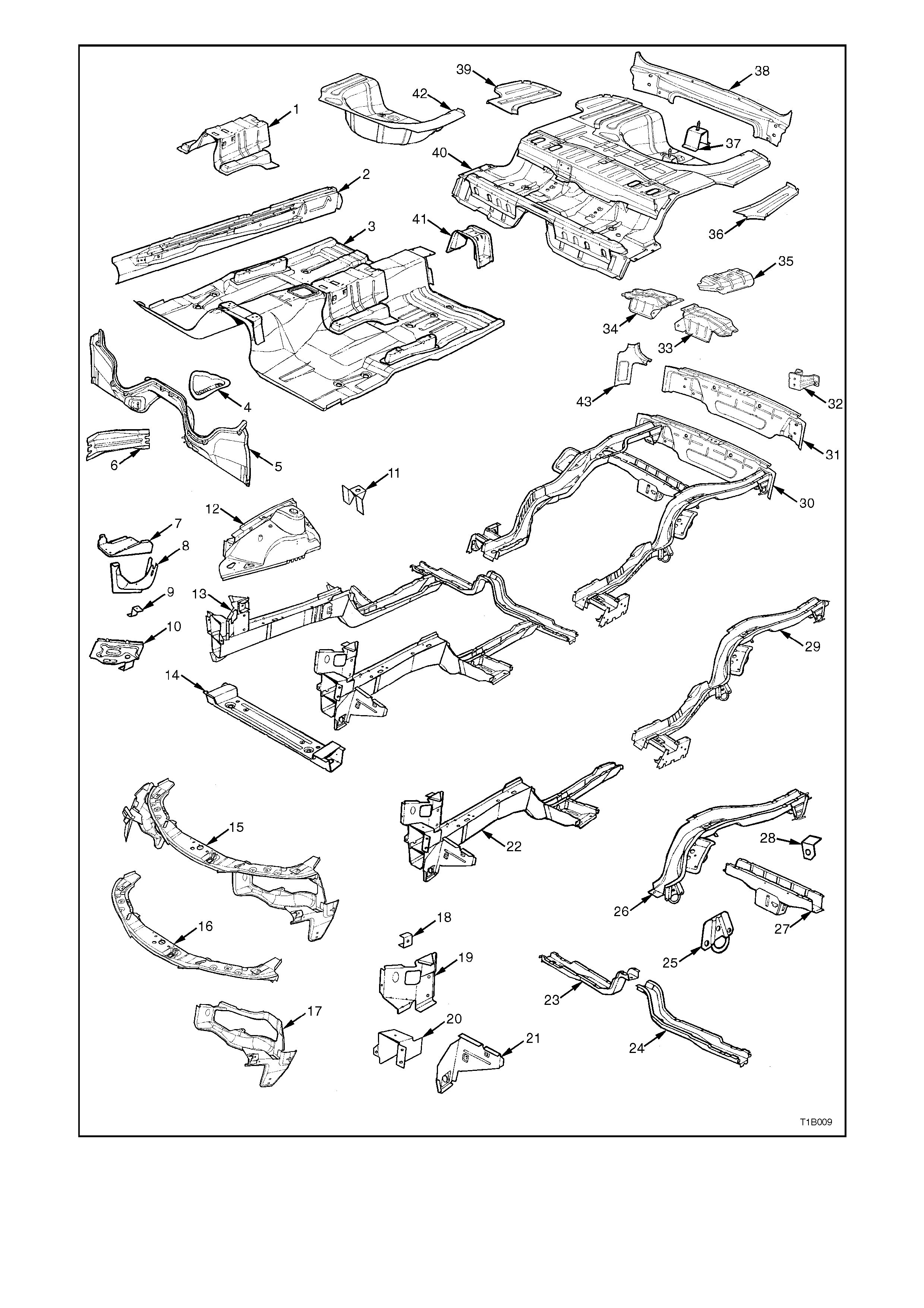
Figure 1A1-11

BODY SIDE - STATION WAGON
Listed below are assemblies and individual panels that are available for replacement.
The purpose of these illustrations is to provide the repairer with a better understanding of available replacement
panels.
1. Bracket - trim attachment.
2. Pillar - front body inner.
3. Brace - wheelhouse (front).
4. Fender panel (front).
5. Front fender liner.
6. Support - fender.
7. Angle - fender lower.
8. Frame assembly - door opening.
9. Angle - fender upper.
10. Support - front door check.
11. Support - rear door check.
12. Panel - rear quarter (side panel outer).
13. Liner - rear wheelhouse.
14. Gusset assembly - tail lamp.
15. Plate - closing, side outer.
16. Fuel filler cap.
17. Side panel assembly - inner.
18. Frame - side front roof.
19. Wheelhouse inner assembly.
20. Reinforcement - ‘A’ pillar upper.
21. Frame - roof rear.
22. Support - roof no. 4.
23. Support - roof no. 3.
24. Panel - roof.
25. Support - roof no. 2.
26. Support - roof no. 1.
27. Rail - windshield header.
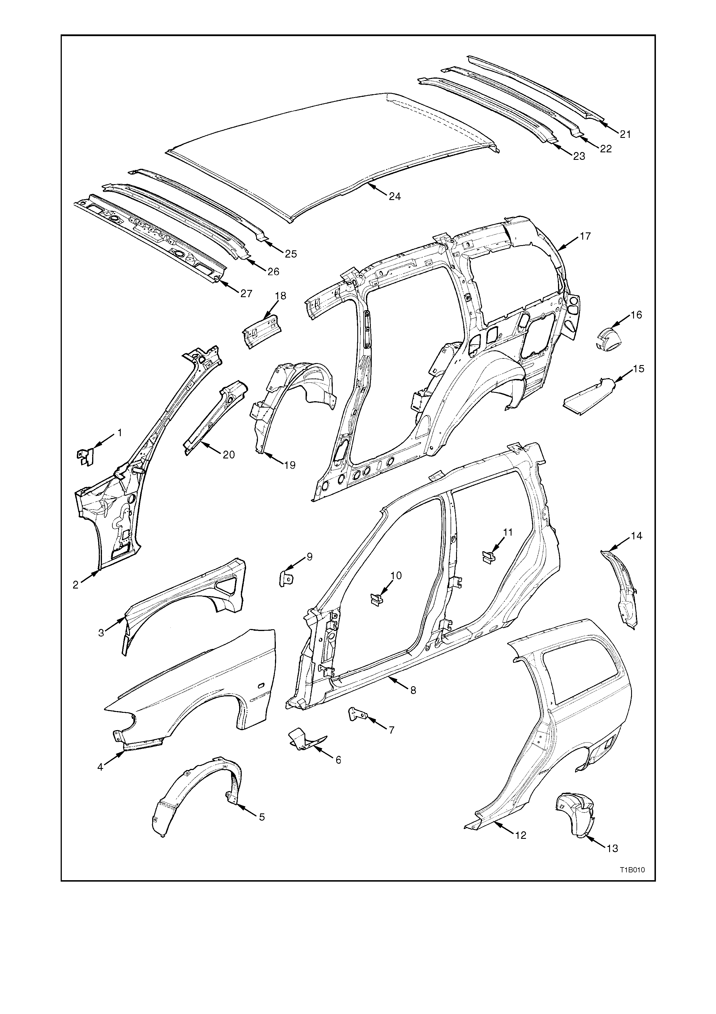
Figure 1A1-12

BODY SHELL - STATION WAGON
Listed below are assemblies and individual panels that are available for replacement.
The purpose of these illustrations is to provide the repairer with a better understanding of available replacement
panels.
1. Body shell.
2. Engine hood.
3. Hinge assembly - engine hood.
4. Door assembly - front (inner).
5. Panel assembly - front door outer.
6. Panel assembly - rear door outer.
7. Door assembly - rear (inner).
8. Panel - tailgate outer.
9. Panel assembly - rear end gate.
10. Dash panel assembly.
11. Deflector assembly - tailgate.
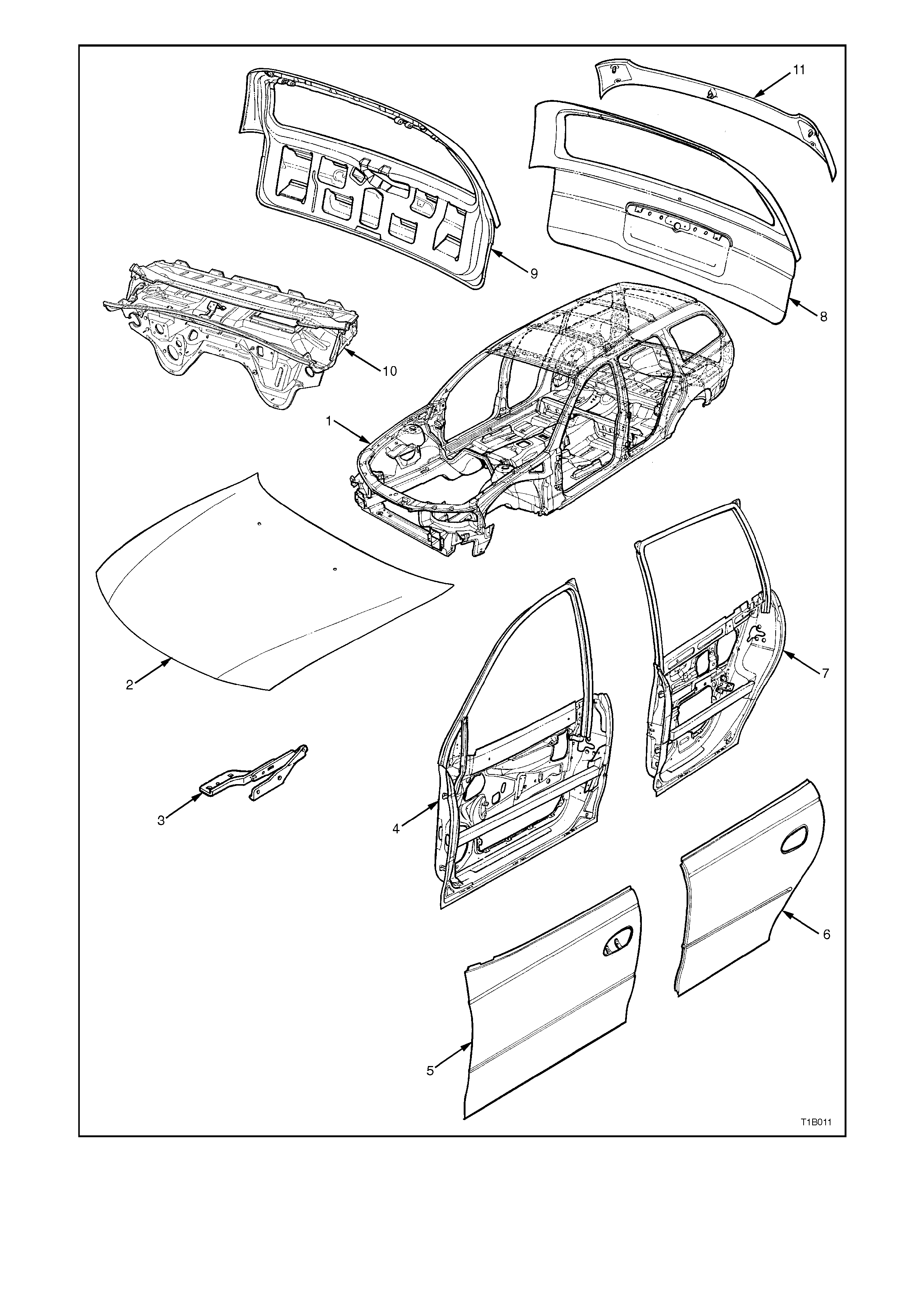
Figure 1A1-13