SECTION 3 - FRONT SUSPENSION
CAUTION:
This vehicle will be equipped with a Supplemental Restraint System (SRS). An SRS
will consist of either seat belt pre-tensioners and a driver's side air bag, or seat belt
pre-tensioners and a driver's and front passenger's side air bags. Refer to
CAUTIONS, Section 12M, before performing any service operation on or around any
SRS components, the steering mechanism or wiring. Failure to follow the CAUTIONS
could result in SRS deployment, resu lting in possible perso nal in jury or u nnecessary
SRS system repairs.
CAUTION:
This vehicle may be equipped with LPG (Liquefied Petroleum Gas). In the interests of
safety, the LPG fuel system should be isolated by turning ‘OFF’ the manual service
valve and then draining the L PG service lines, before any service w ork is carried out
on the vehicle. Refer to the LPG leaflet included with the Owner's Handbook for
details or LPG Section 2 for more specific servicing information.
CAUTION:
Whenever any component that forms part of the ABS or ABS/ETC (if fitted), is
disturbed during Service Operations, it is vital that the complete ABS or ABS/ETC
system is checked, using the procedure as detailed in 4. DIAGNOSIS, ABS or
ABS/ETC FUNCTION CHECK, in Section 12L ABS & ABS/ETC.
1. GENERAL DESCRIPTI ON
The front suspension fitted to all VT Series models operates on the MacPherson strut principle. The assembly
consists of the front crossmember, lower control arms, tension rods, stabiliser bar and strut assemblies (Refer to
Figure 3-2).
The crossmember is bolted to both longitudinal frame side members, while the inner pivots of the lower control
arms are rubber bushed and are attached to the crossmember by bolts and nuts. The outer end of each lower
control arm is connected to the knuckle on the strut assembly through a ball joint.
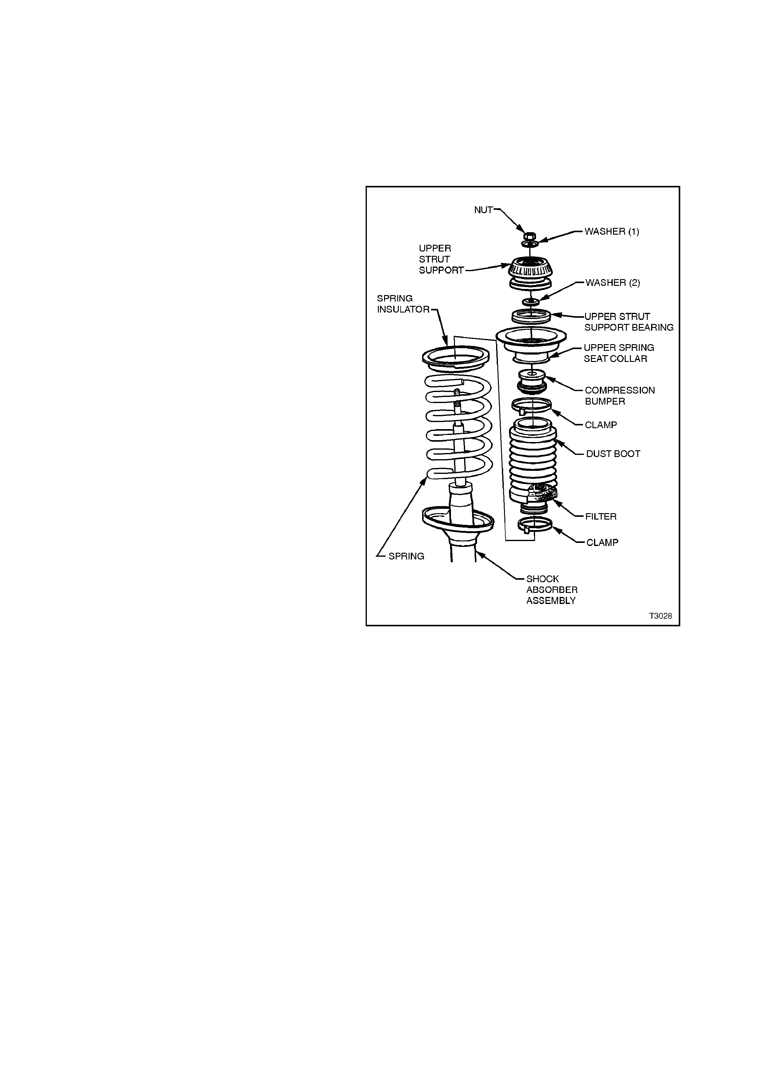
The strut assembly incorporates a hydraulic wet sleeve type damper inside the strut tube, a rubber dust boot with air
filter and compression rubber, a coil type suspension spring mounted between the strut housing and upper spring
seat collar, a bearing assembly and an upper strut support.
The strut assembly is located at the upper end to the body structure by an upper strut support and secured by a
self-locking nut and locating disc, while the lower end of the strut tube is fastened to the steering knuckle by two
bolts and nuts.
Positioning of the lower control arm assemblies is controlled by tension rods connecting the lower control arms to
the front suspension crossmember. The tension rods are mounted in a rubber bush at the lower control arm end
and a fluid filled damper at the other.
A stabiliser bar is mounted to the side members of the crossmember by two brackets and insulating rubbers, and
attached to each strut tube by a spacer stud, insulating bushes, retainers and attaching nuts.
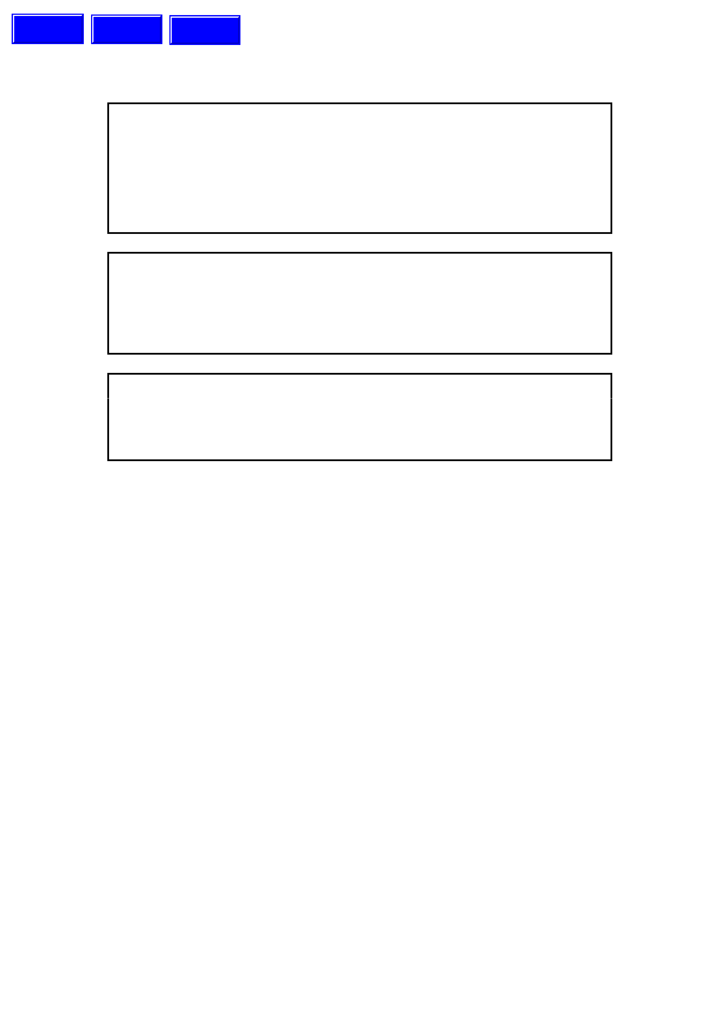
Production option FE2, SPORTS SUSPENSION PACK, is available as an option on all VT Series sedan models.
For identification information and specification details for the STANDARD or FE2 suspension types, refer to
6. SPECIFICATIONS in this Section.
Techline
Techline
Techline
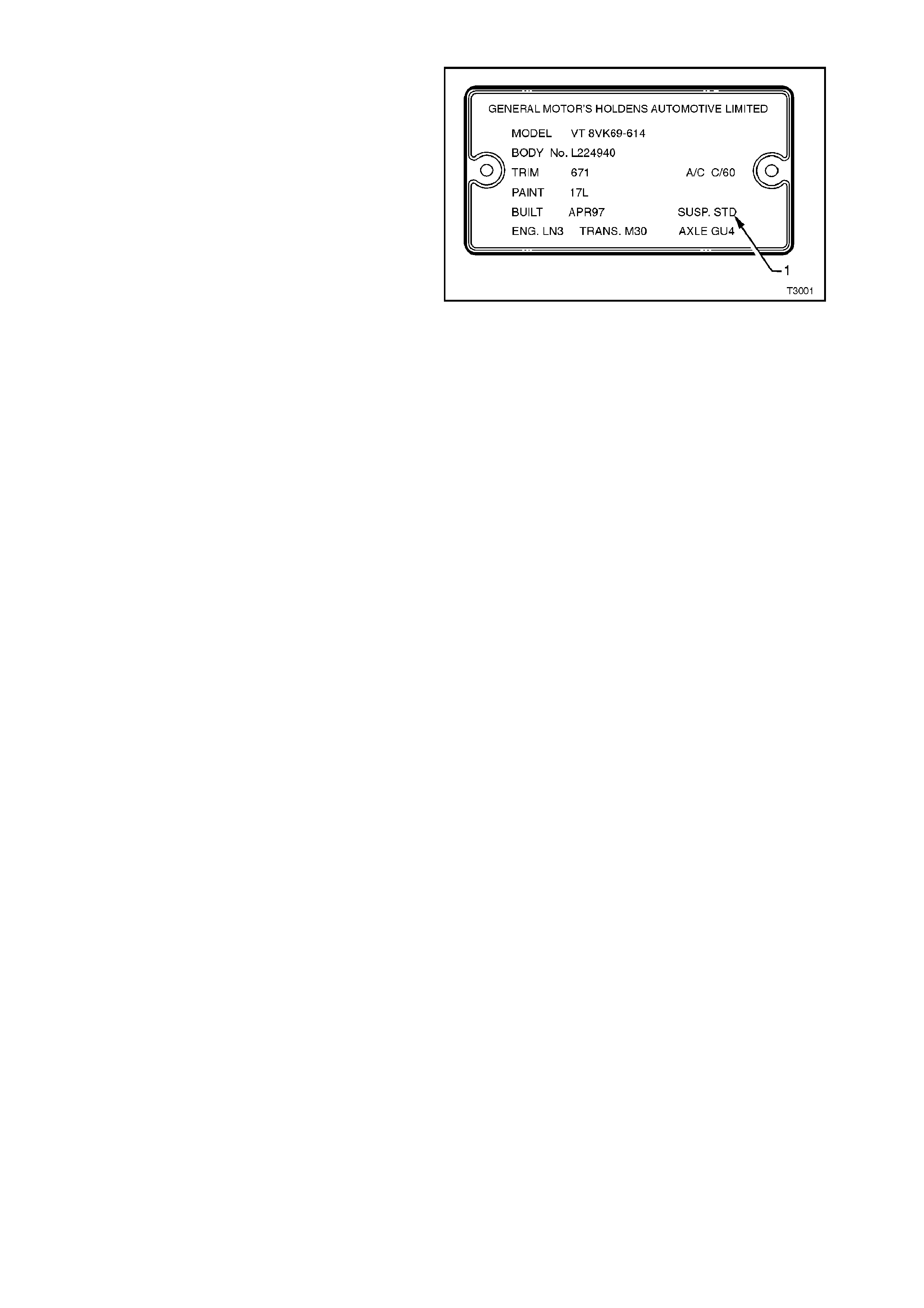
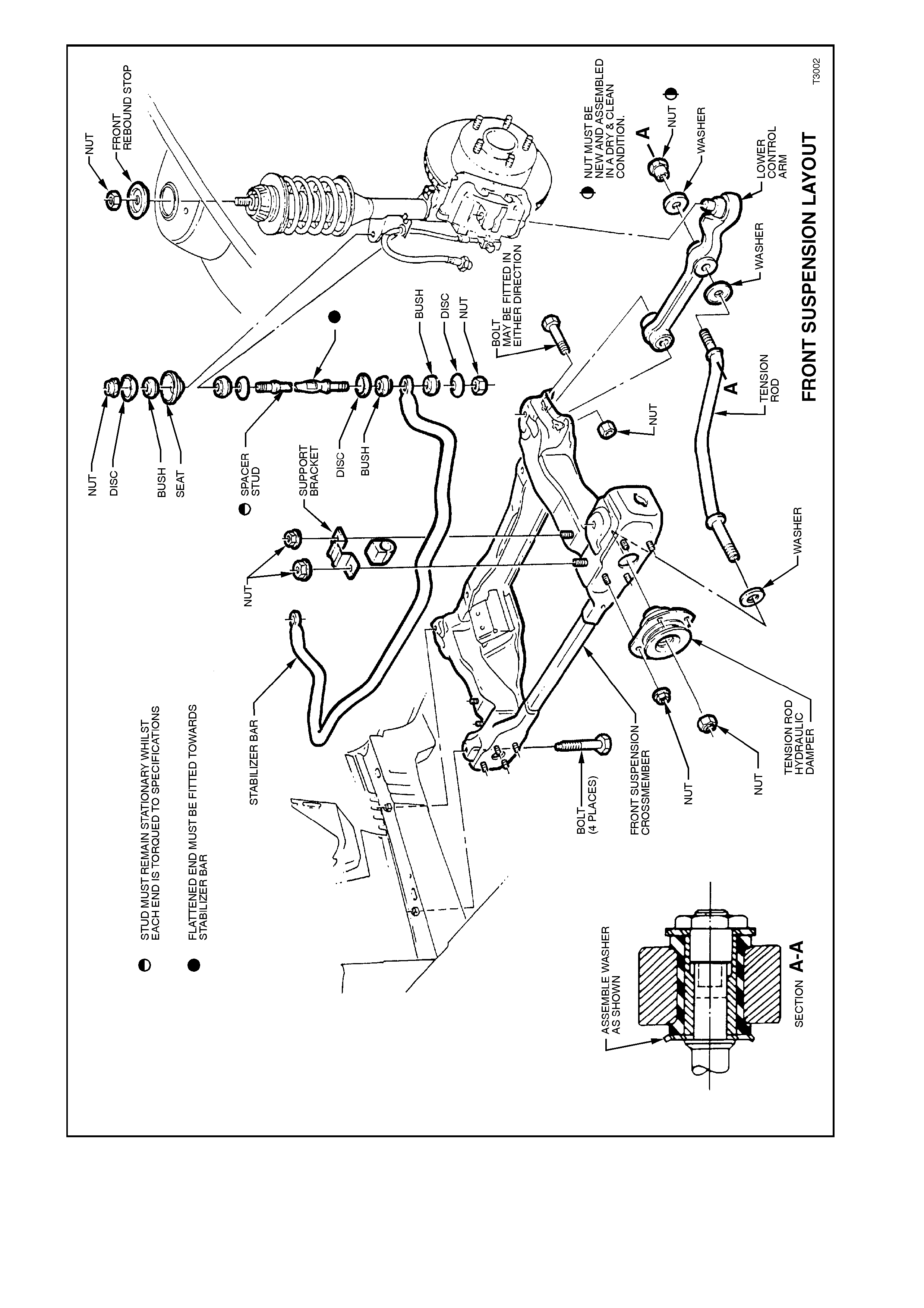
Figure 3-2
2. WHEEL ALIGNMENT
2.1 STEERING GEOMETRY
To achieve the desired handling characteristics of
a vehicle under various operating conditions,
modern steering geometry relates to both front and
rear suspension systems. It must also be realised
that the various, measurable angles that can be
checked while the vehicle is stationary, is no real
indication of the changes that occur in a dynamic
situation when the vehicle is required to have
directional stability during normal manoeuvres such
as straight ahead driving, cornering and braking.
Even though some of the following descriptions of
front wheel alignment angles are not normally
measurable and (in some instances) not
adjustable, each is an inherent part of the vehicle's
dynamic suspension tuning that has been
developed over an extended testing program.
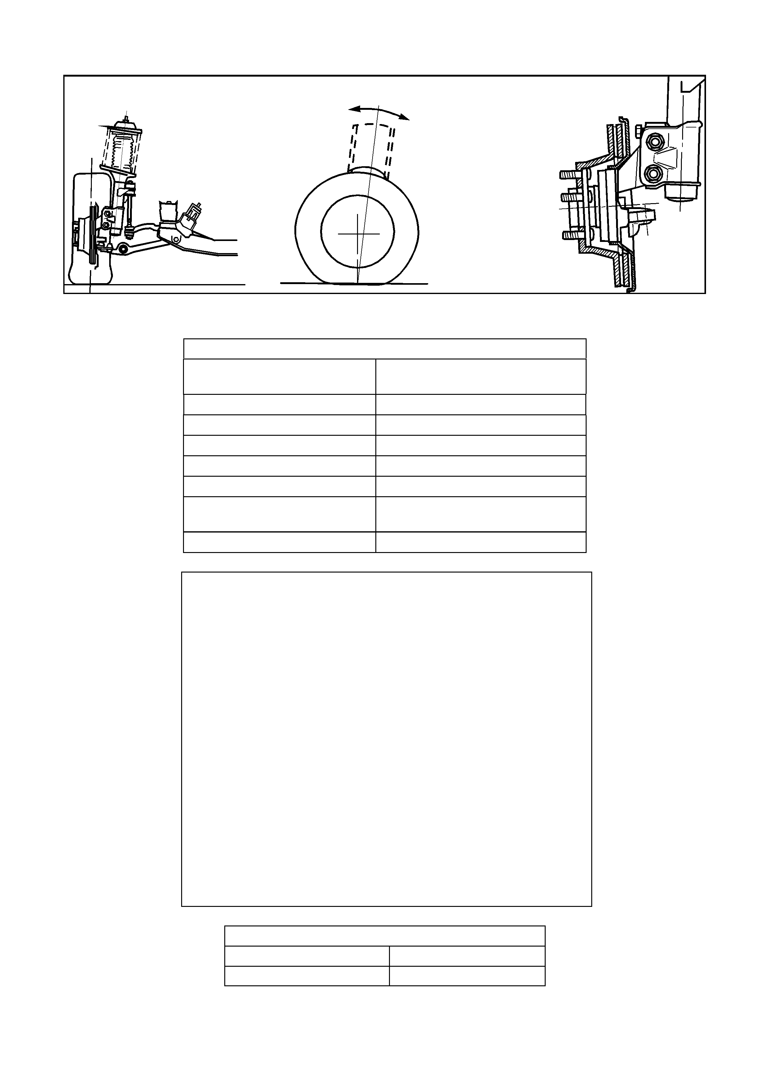
CASTER
It is usual to describe this front wheel alignment
angle as the tilting of the steering axis either
forward or backward from the vertical (when viewed
from the side of the vehicle). A backward tilt at the
top steering axis point is said be positive (+) and a
forward tilt is said to be negative (-). Measurement
is usually expressed as an angle in degrees and
minutes. Figure 3-3 shows the usual practice where
the vertical and steering axis centrelines both pass
through the wheel centre.
This results in a caster distance, which can be
described as being the distance in side view,
between the point where the steering axis contacts
the ground and the centre of the tyre’s footprint
contact.
Figure 3-3
The amount of caster angle will determine the
ability of the s teering to return to the straight ahead
position after a cornering manoeuvre. Too high an
angle though, can result in an excessive steering
effort with associated ‘wheel fight' and ‘kickback'.
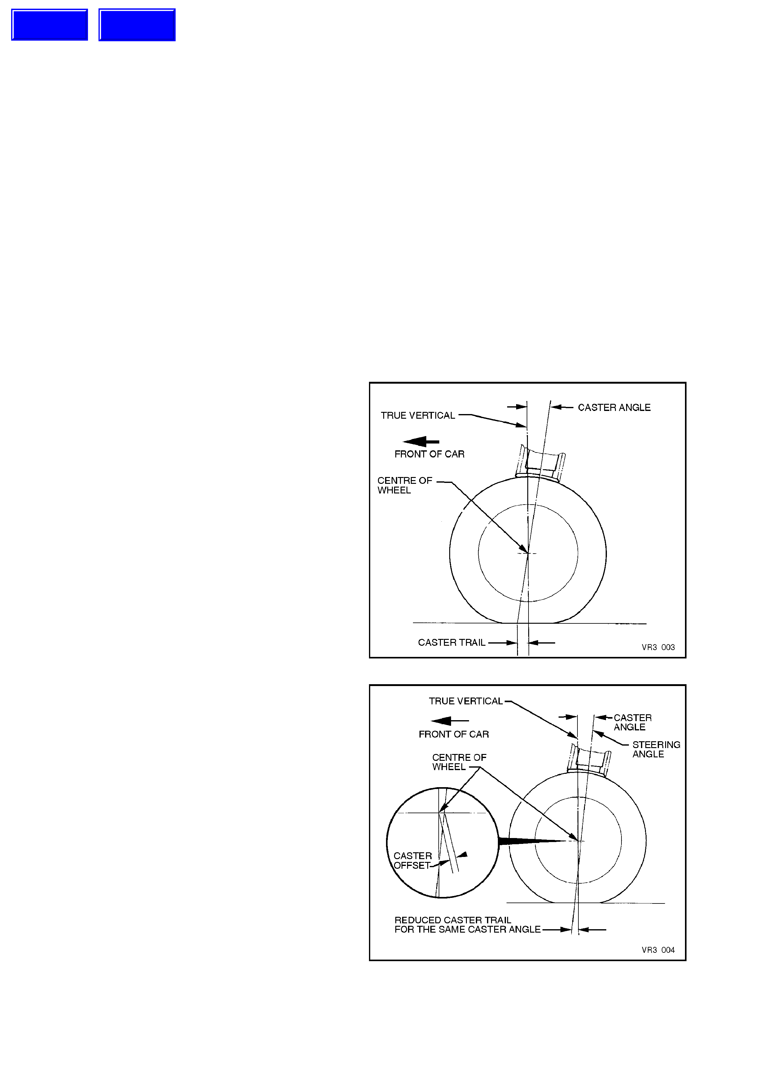
To optimise vehicle handling and control during
cornering and to maintain the benefits of positive
caster, VT Series vehicles have a 12 mm caster
offset incorporated into the suspension design.
This is achieved by moving the wheel spindle
centreline forward (in this instance, by 12 mm),
which will effectively reduce the caster distance by
that amount (see Figure 3-4). This action reduces
the undesirable effects of a high caster angle but
maintains the directional stability, increased front
axle lateral grip and steering feel that a high caster
angle normally provides.
Figure 3-4
Techline
Techline
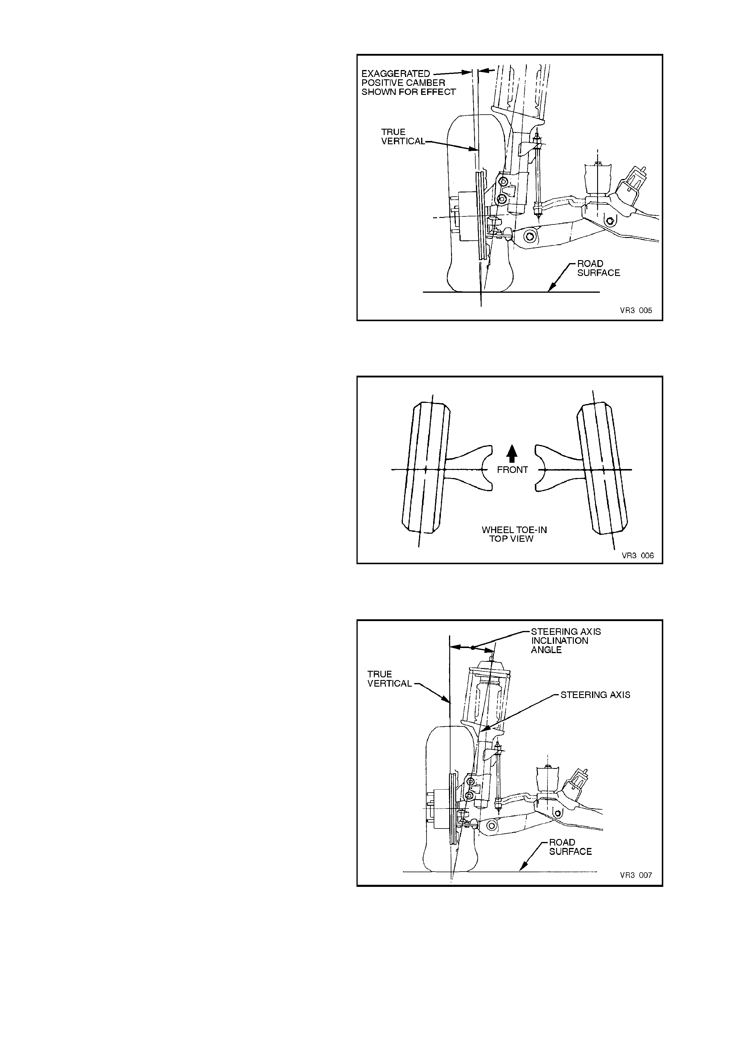
CAMBER
This angle is the tilting of the wheels from the
vertical when viewed from the front of the vehicle.
When the wheels tilt outward at the top, the camber
is said to be positive (+). When the wheels tilt
inward at the top, cam ber is said to be negative (-).
The amount of tilt is measured in degrees from
vertical and this m easurement is called the cam ber
angle.
While unequal camber may result in unstable
steering or wander, unequal and/or excessive
camber can also cause rapid tyre wear.
Figure 3-5
WHEEL TOE
Wheel Toe (see Figure 3-6), is the turning in (or
out) of the wheels when viewed from the overhead
position. The actual amount of toe is normally only
a few minutes of a degree. The purpose of a static
toe specification is to ensure parallel rolling of the
wheels, once the vehicle is in a dynamic state.
Excessive toe-in or toe-out may increase tyre wear.
With rear wheel drive vehicles, a slight amount of
toe-in, measured statically with the vehicle at rest,
is required to off-set the small deflections due to
rolling resistance and brake applications which tend
to turn the wheels outward.
Figure 3-6
STEERING AXIS INCLINATION
When viewed from the vehicle front, Steering Axis
Inclination can be described as being the angle
formed between the steering axis and the true
vertical (see Figure 3-7), where the steering axis is
the imaginary centreline through the upper strut
support bearing and the lower ball joint, both
components being the pivot points of the strut
assembly.
The Steering Axis Inclination angle is an important
factor in determining steering effort and directional
stability of the vehicle, by assisting caster in
keeping the front wheels in a central position.
Steering Axis Inclination also provides a self-
centring effect after cornering.
Figure 3-7
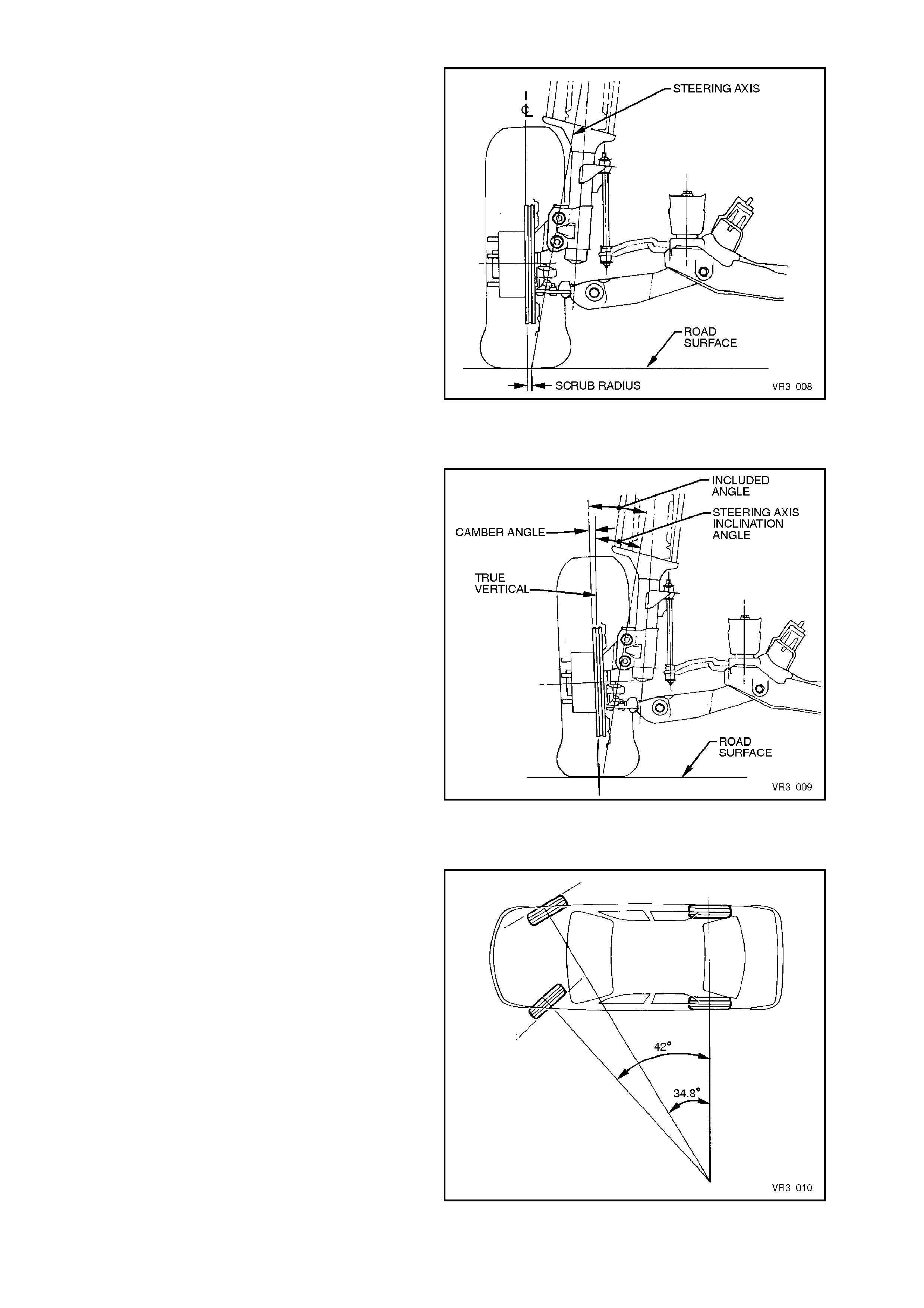
SCRUB RADIUS
This term refers to the distance that two imaginary
points are apart, at the road surface. These two
imaginary points are;
a. The intersection of the steering axis and
the road surface.
b. The centre of the tyre footprint on the road
surface.
As road wheel offset will affect scrub radius, in the
interests of vehicle handling and safety, non-
standard road wheels are not to be fitted to any
Holden vehicle.
With rear wheel drive vehicles, it is usual practice
to maintain a positive scrub radius (as shown in
Figure 3-8) to make the steering more responsive
and direct, thereby providing the driver with a more
positive sense of the tyre and road surface
interaction.
Figure 3-8
INCLUDED ANGLE
When both the Steering Axis Inclination angle and
Camber are combined, the resulting angle is
referred to as the Included Angle. This information
can be effectively used to determine if a component
is damaged or whether an adjustment is
responsible for an out-of-specification condition
occurring.
While Figure 3-9 shows a positive camber angle,
this has only been used to clarif y the term ‘Included
Angle'.
Figure 3-9
TOE-OUT ON TURNS
During cornering operations, a vehicle's road
wheels all turn about a common turning point,
causing the outer wheels to try and turn through a
greater radius than the inner. To overcome the
tendency for wheel slip under these conditions, the
outer wheel is commonly caused to toe-out, to
compensate for this increased turning circle.
The amount of toe-out during cornering, is
governed by the angle of the steering arms, which
are an inherent part of the steering knuckle.
Figure 3-10
2.2 WHE EL ALIGNMENT CHECKING AND ADJUSTMENT
PRELIMINARY INSPECTION
Before any attempt is made to check camber,
caster or toe-in, these preliminary checks should
be carried out.
1. Check tyre and tyre mountings. Always check
camber and toe-in at the mean run-out
position on the tyre or rim.
2. Check and adjust tyre pressures to
recommended values.
3. Front wheel bearing end float is to be chec k ed
to ensure it is within specification, as detailed
in 2.4 FRONT WHEEL BEARING HUB -
END FLOAT CHECKING PROCEDURE, in
this Section.
4. Lower control arm ball joints and inner bushes
should be checked for wear.
5. Check steering gear mounting bolts for
tightness and tie rod ball joints for wear.
6. The vehic le should be at c urb weight, f uel tank
full, without driver, passengers or luggage etc.
7. Check for improperly operating front struts or
rear shock absorbers.
8. Check for loose or missing stabiliser bar or
tension rod attachments.
9. Before checking the front wheel alignment,
refer to 4A REAR SUSPENSION for rear
wheel alignment details.
CASTER ADJUSTMENT
Only a nominal change in caster angle is
achievable and is limited to the addition (or
deletion) of a spacer washer to one of the tension
rods. The sole purpose of fitting this spacer is to
equalise caster angle from side to side, to within 0°
30'. Only one spacer washer is to be f itted and is to
be added to the side with the higher caster reading.
Figure 3-11
Techline
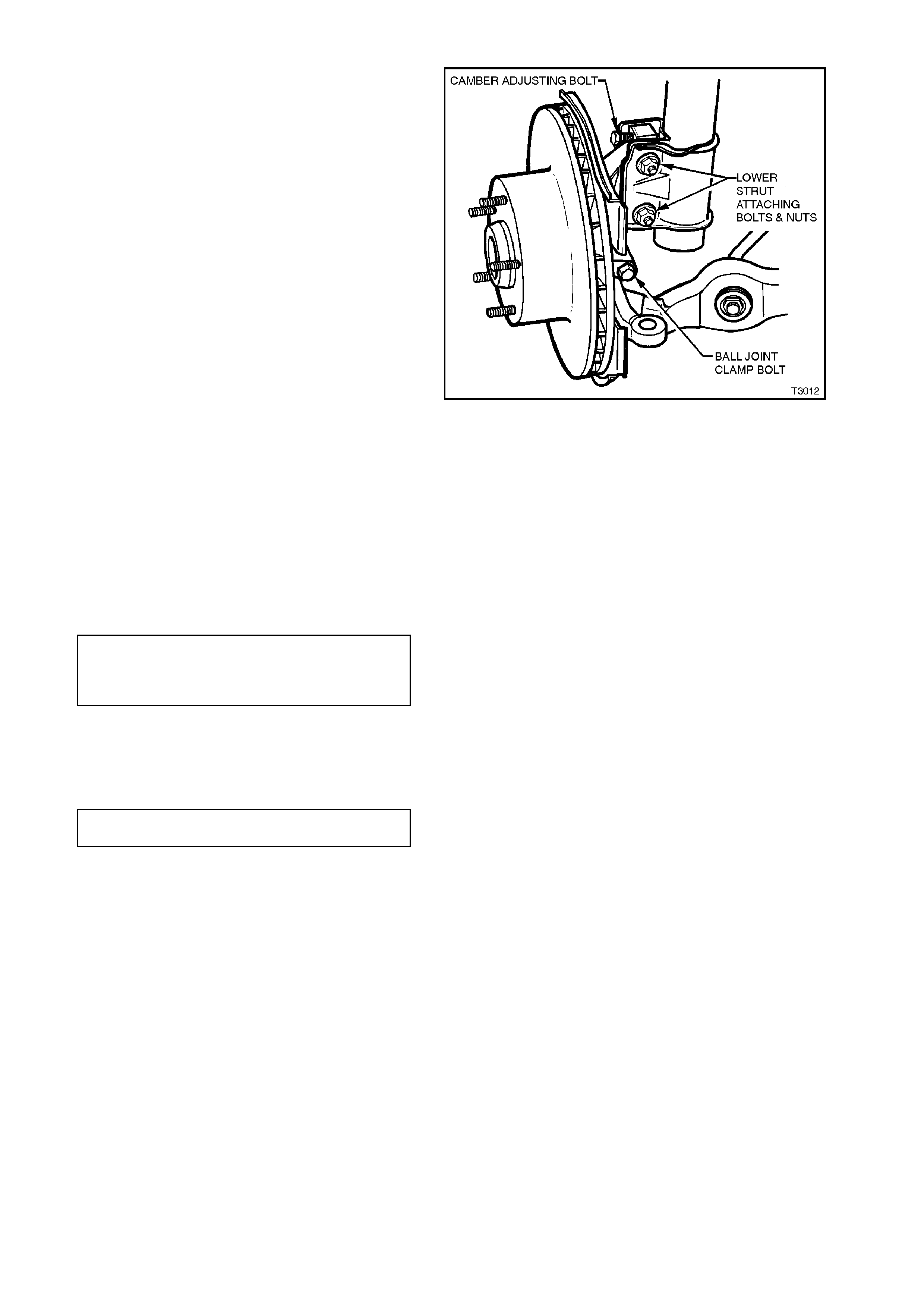
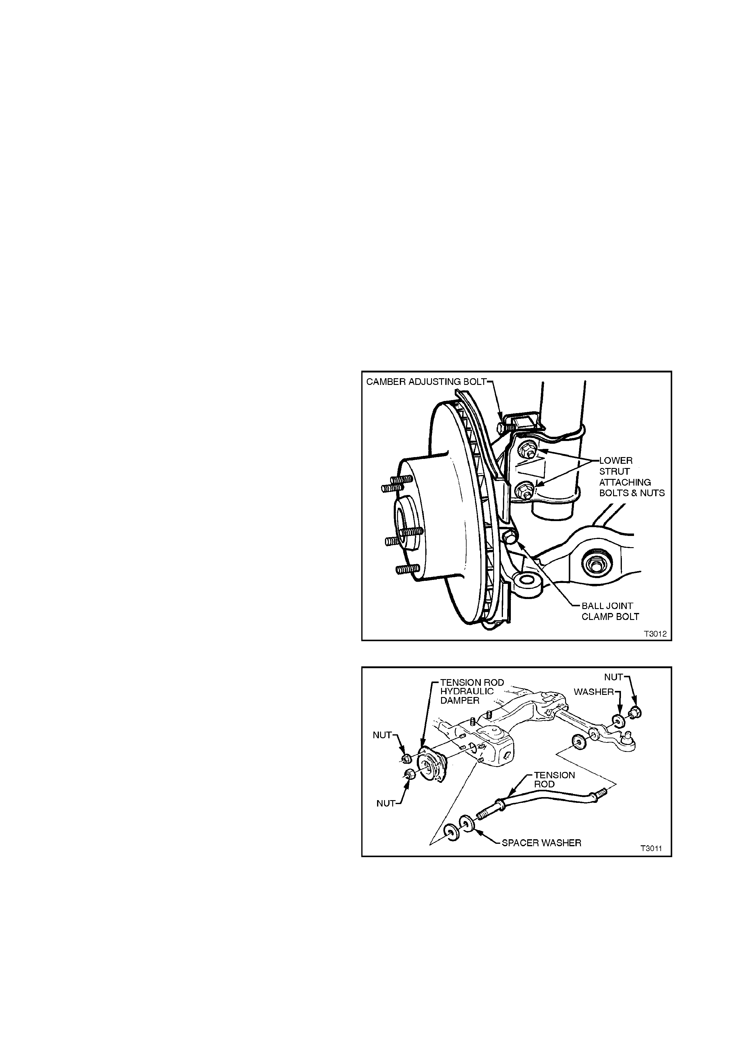
CAMBER ADJUSTMENT
1. Raise front of vehicle using a lifting jack under
front crossmember and support on safety
stands under front side members. Refer to
2.3 JACKING PRECAUTIONS in this Section
for details.
2. Remove wheel cover (steel wheels) or centre
cap (alloy wheels) and mark relationship of
wheel to hub or brake disc.
3. Remove wheel attaching nuts and remove
wheel.
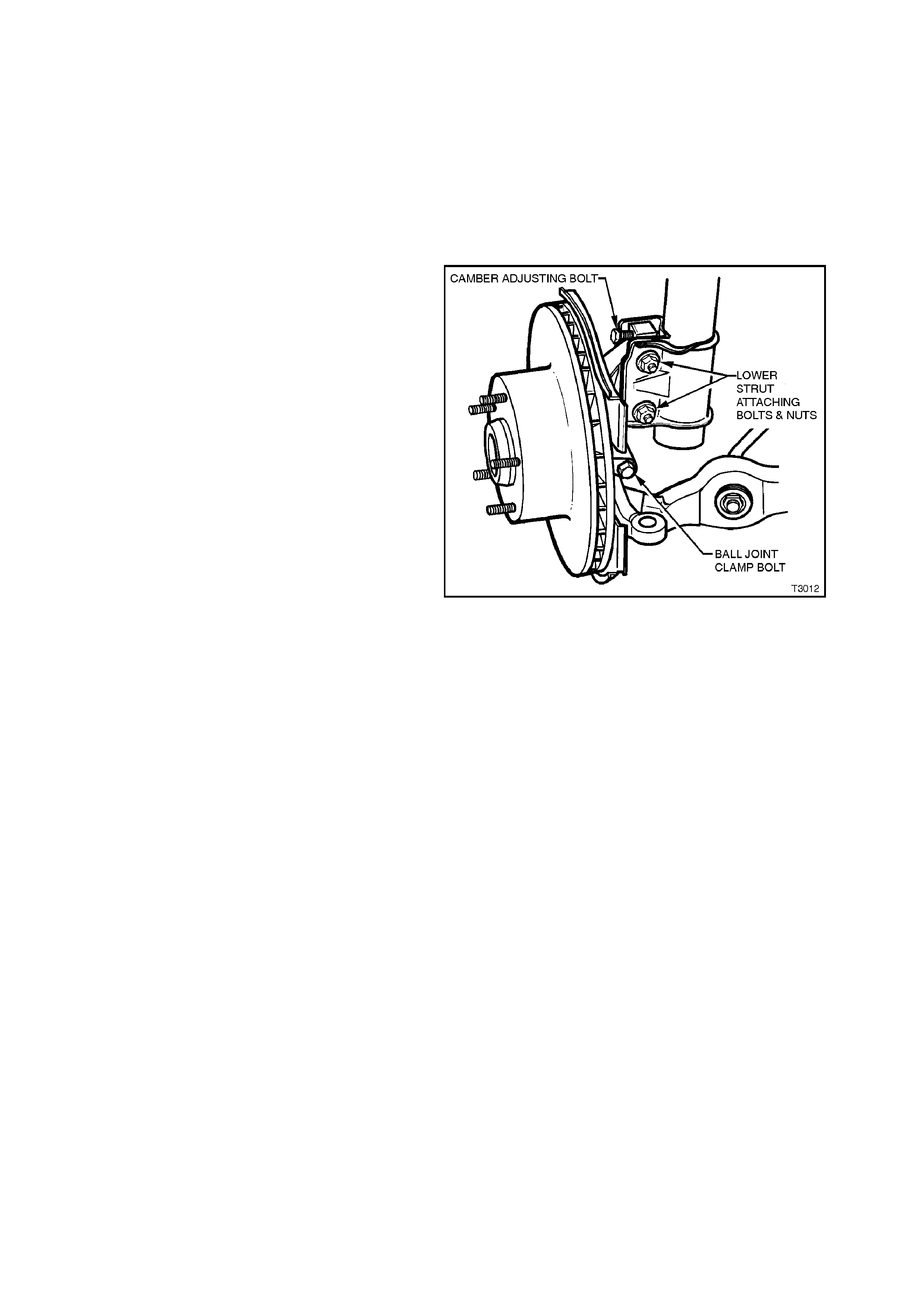
4. Loosen, remove and discard the two lower
strut attaching bolts and nuts (refer Figure 3-
12).
Reinstall NEW lower strut attaching bolts and
nuts but do not tighten until after the camber
has been adjusted to the recommended
specification.
5. Adjust camber by turning the camber adjusting
screw in the required direction. Clockwise to
reduce negative camber, anti-clockwise to
reduce positive camber.
NOTE:
The camber adjusting screw has thread sealant
applied in the form of micro-encapsulation and
does not require a lock nut.
Figure 3-12
6. Tighten both steering knuckle bolts and nuts
to the correct torque specification.
NOTE:
New bolts and nuts MUST be used!
STEERING KNUCKLE TO
STRUT ATTACHING
BOLTS & NUTS
TORQUE SPECIFICATION
Stage 1 85 Nm
Stage 2 100 Nm
Stage 3 Turn
through 90°
7. Install road wheels, aligning the marks made
prior to removal.
8. Remove jack stands and lower vehicle.
9. Tighten road wheel attaching nuts to correct
torque specifications.
ROAD WHEEL ATTACHING NUT
TORQUE SPECIFICATION 110 - 140
Nm
10. Refit wheel cover/centre cap.
11. Check the camber angle again to ensure that
it is within specification (refer to Figure 3-15).
TOE ADJUSTMENT
Toe of both front wheels, is checked with the
wheels in the straight ahead position.
Adjustm ent is achieved by winding the tie rods in or
out of the tie rod ends, thus increasing or
decreasing their length and thereby altering the toe-
in setting.
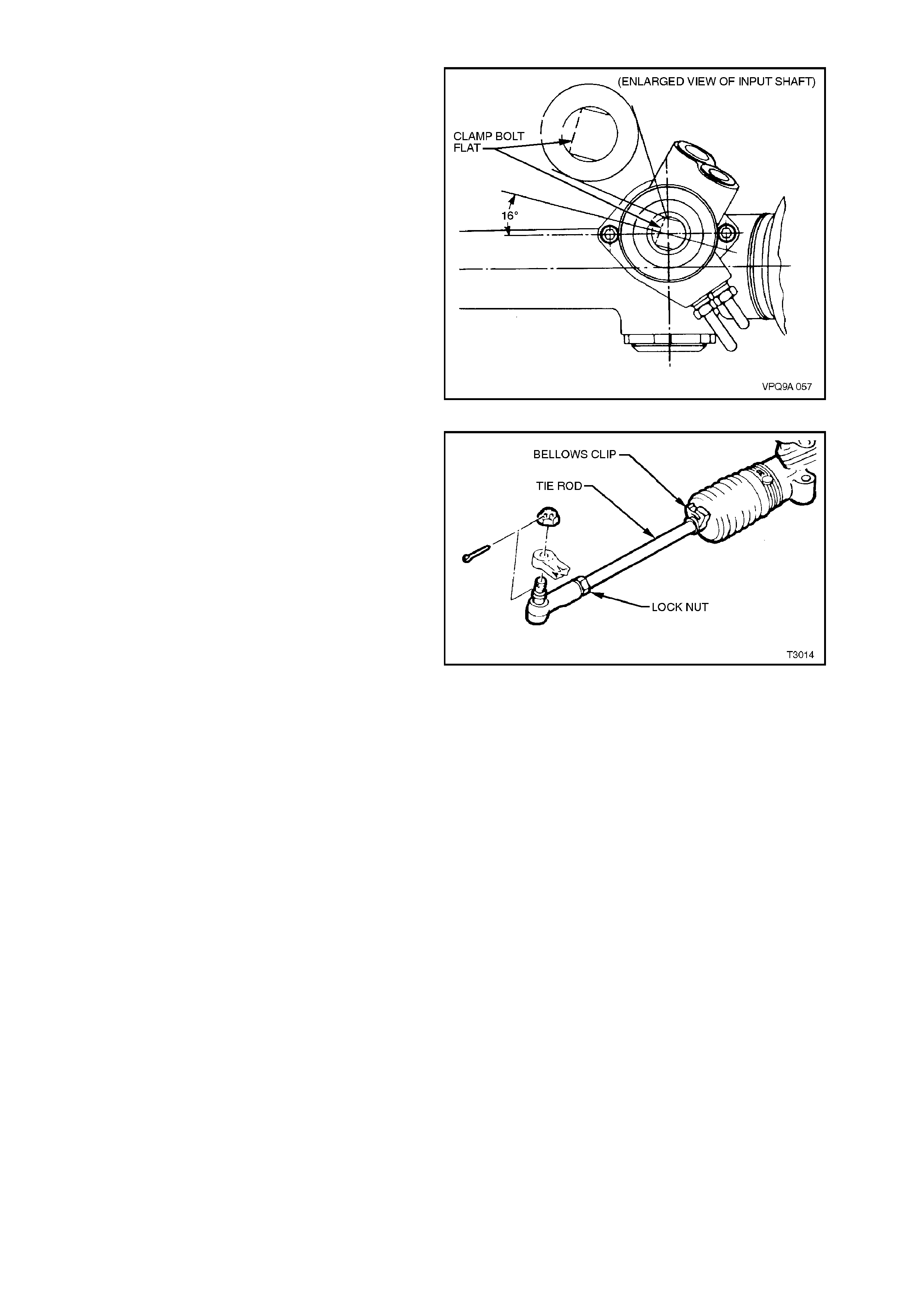
1. Set steering gear and wheels in straight ahead
position.
To check if steering gear is in straight ahead
position (on centre), refer to Figure 3-13.
Figure 3-13
2. Before adjusting tie rods, disconnect steering
gear outer bellows clips.
3. Loosen lock nut at end of each tie rod.
4. Turn each tie rod as required, until the correct
toe is obtained.
NOTE:
During toe adjustment, ensure that steering wheel
is held in the straight ahead position.
5. Tighten lock nuts, ensuring that tie rod ends
are in alignment with their ball studs, then
tighten outer bellows clips securely, making
sure that convolutions of the boots are not
distorted.
6. With steering gear in straight ahead position,
ensure that steering wheel is centralised. If
not, remove steering wheel (refer to
Section 9 STEERING and reposition.
Figure 3-14
WHEEL ALIGNMENT SPECIFICATIONS
Figure 3-15
FRONT WHEEL ALIGNMENT AT KERB WEIGHT
Wheel Alignment
Angle Specification
Camber (± 0° 12') – 0° 12'
Caster 7° 45' ± 1° 15'
Toe-in Degrees Total 0° 10’ ± 0° 10’
Degrees per Wheel 0° 5’ ± 0° 5’
Toe-out on Turns 1° 42’ @ 20° turn angle ± 1° 30’
Steering Axis Inclination Angle 12° 52’ ± 1° 30
Included Angle 12° 40’ ± 1° 30’
SERVICE INFORMATION
•The adjusting values for camber, caster and toe-in must remain
within the tolerances specified. The difference between left and
right must not exceed the following:
CASTER............. 0° 36’
CAMBER............ 0° 48’
TOE-IN............... 0° 10’
•The specifications listed are the nominal value, with acceptable
variance from this central point. Where possible, an attempt should
always be made to achieve the nominal settings when changing.
•Front wheel camber alters as a function of front suspension height.
•Camber adjusting bolt: After loosening both lower strut to steering
knuc kle bolts and nuts, adjust c amber by turning the adjusting bolt
clockwise to decrease negative camber and anti-clockwise to
increase negative camber. After adjustment, both bolts and nuts
MUST be replaced with new parts and tightened to the
recommended torque setting.
•The rear wheel alignment should be checked and corrected if
necessary (refer to Section 4 REAR SUSPENSION) before
checking front wheel alignment.
Fuel Mass (kg) with Full Tank
Vehicle Model All Models
All Models 56
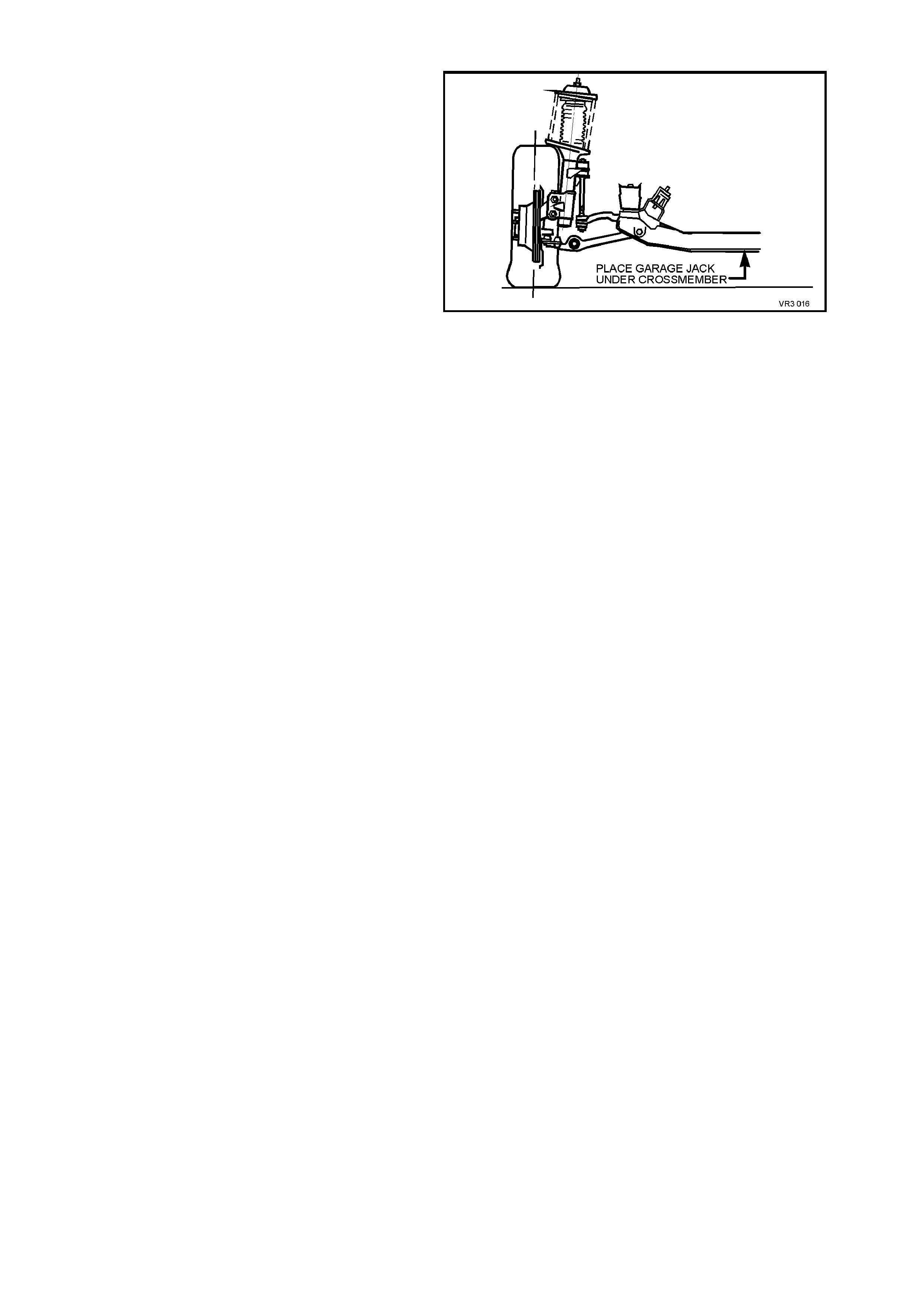
2.3 JACKING PRECAUTIONS
When raising the front of the vehicle with a jack,
the jack should be placed under the front
crossmember. THE WEIGHT OF THE VEHICLE
MUST NOT BE LIFTED UNDER THE LOWER
CONTROL ARMS.
When the vehicle is raised on the jack, it must be
firm ly supported on safety stands located under the
fram e side m em bers befor e any work is attem pted.
If a vehicle is not correctly supported by safety
stands, serious injury can result if the vehicle
should slip off the jack.
Figure 3-16
2.4 FRONT WHEEL BEARING HUB - END FLOAT CHECKING PROCEDURE
1. Raise front of vehicle and place on safety
stands. Observe jacking precautions as
detailed above.
2. Remove wheel covers (steel wheels) or centre
cap (alloy wheels).
3. Mark relationship of wheel hub to brake disc to
preserve on-vehicle wheel balancing. Remove
wheel attaching nuts and remove road wheel.
4. Temporarily reinstall three, reversed wheel
nuts with a flat washer under each nut, to
prevent damage to the nut thread.
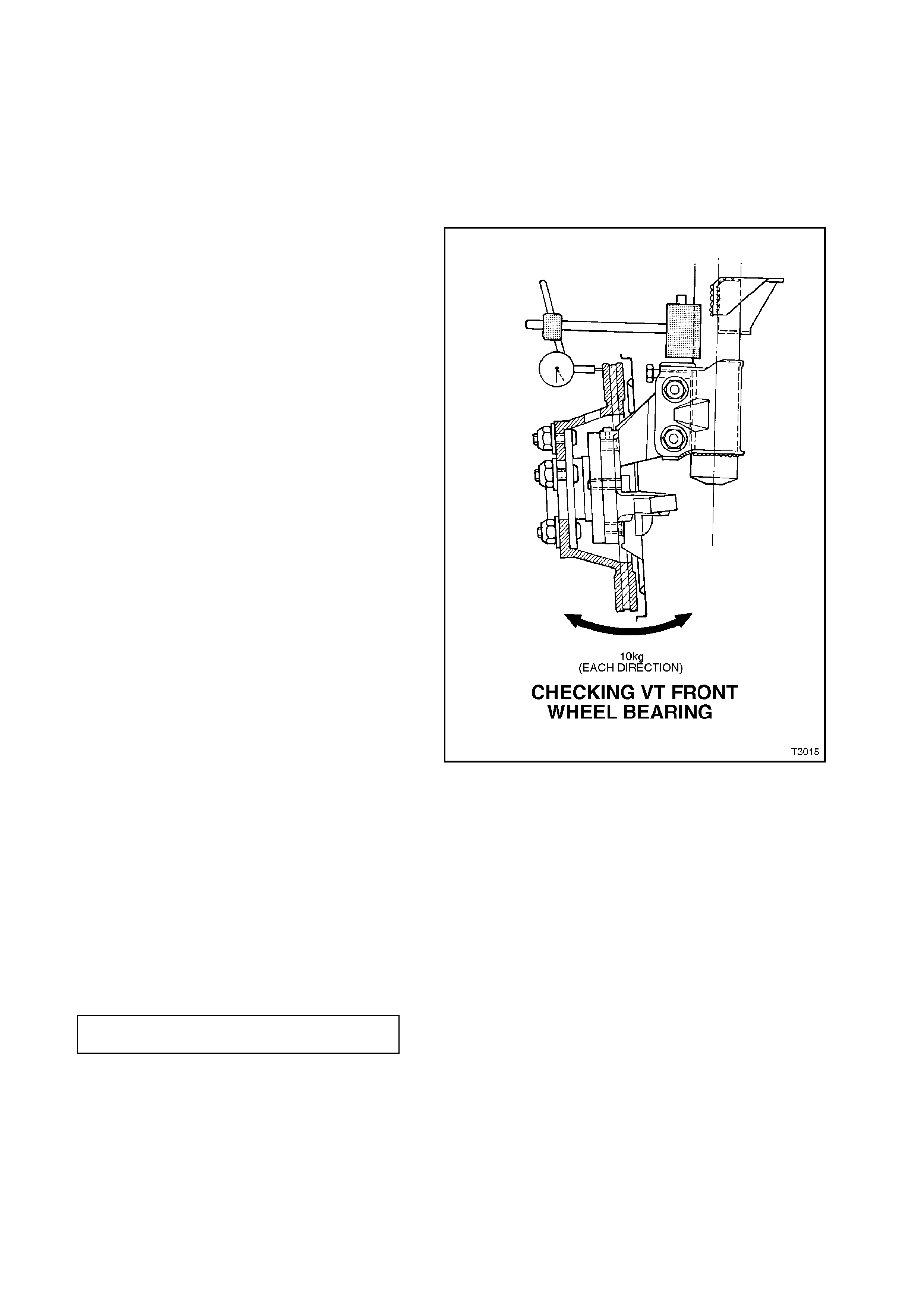
5. Mount a dial indicator to a suitable magnetic
stand and attach to the front strut tube.
Position the dial indicator pointer at the outer
diameter of the disc, as shown.
6. Apply an outward, 10 kg (22 lbf) force to the
outer brake disc diameter, in an opposite
position (180°) to the dial indicator. To
maintain consistency, a spring balance
capable of measuring this force, MUST be
used. With the force applied, zero the dial
indicator.
7. Apply an inward, 10 kg (22 lbf) force to the
outer brake disc diameter and note the dial
indicator reading.
8. The reading obtained is the angular movement
(NOT end float) and to determine the bearing’s
serviceability, compare the measured result
with the following specifications.
WHEEL BEARING ANGULAR ‘FLOAT’ SPECIFICATION
NEW BEARING 0.106 mm (0.0042”) Maximum
USED BEARING 0.213 mm (0.0085”) Maximum
9. Should this inspection show that the wheel
bearing assembly is outside the specified,
angular ‘float’ dimension, then the hub must be
replaced. Refer to operation
3.2 FRONT WHEEL HUB BRAKE DISC OR
BRAKE SHIELD, in this Section.
10. Remove the dial indicator and stand, and the
three wheel nuts and flat washers.
11. Reinstall road wheel, aligning marks made
prior to removal and secure with attaching
nuts.
12. Raise vehicle, remove safety stands and lower
vehicle to the ground. Tighten road wheel nuts
to the correct torque specification.
Figure 3-17
ROAD WHEEL ATTACHING NUT
TORQUE SPECIFICATION 110 - 140
Nm
13. Reinstall wheel cover/centre cap.

3. MI NOR SERVICE OPERATIONS
CAUTION:
Whenever any component that forms part of the ABS or ABS/ETC (if fitted), is
disturbed during Service Operations, it is vital that the complete ABS or ABS/ETC
system is checked, using the procedure as detailed in 4. DIAGNOSIS, ABS or
ABS/ETC FUNCTION CHECK, in Section 12L ABS & ABS/ETC.
3.1 SUSPENSION AND TRIM HEIGHT, CHECK
The suspension and trim height dimensions are
provided in 6 SPECIFICATIONS in this Section.
The dimensions are for a new vehicle built to
standard specification and only intended as a
guide when checking suspension and trim height
dimensions at normal curb weight. Normal curb
weight is defined as a vehicle with a full tank of
fuel, all fluids at the specified levels, spare tyre
included, tyre pressures as specified and no
passengers. Accumulated dirt, mileage, etc., must
also be taken into consideration when checking
vehicle heights.
The following procedure should be followed before
checking any suspension or trim height.
1. All checks must be carried out on a LEVEL
surface, after the vehicle's tyre pressures have
been checked and it has been confirmed that
the vehicle has not suffered accident damage.
2. On average, all VT Series vehicles will sit
approximately 4 mm lower at the right hand
side front, because of the vehicle's battery
weight.
3. Push vehicle up and down several times at the
front bumper bar with a decreasing force and
then gently remove hands, allowing vehicle to
settle on its own. Carry out vehicle front trim
and suspension height check.
4. Push vehicle up and down several times at the
rear bumper bar with a decreasing force and
then gently remove hands, allowing vehicle to
settle on its own. Carry out vehicle rear trim
and suspension height check.

As shown in the specification listing (refer to
6 SPECIFICATIO NS in this Section), there are two
diff erent dimensions that m ust be c hecked and the
location for the measurements to be taken is
critical to correctly establishing a standard vehicle
condition. When checking a vehicle's ride height,
the following tolerances must also be taken into
account, before any spring is replaced.
RIDE HEIGHT VARIATIONS FROM SPECIFICATION
FRONT TO REAR................................ ± 20 mm
SIDE TO SIDE..................................... ± 10 mm
NORMAL SPRING SETTLING ............ ± 5 mm
NOTE:
Ride height variation may also be due to any one or
a combination of the following:
-Spring seat location on the suspension/body.
-Incorrect springs; Check spring identification
against the table shown in
6 SPECIFICATIONS in this Section.
-Non-standard, additional vehicle weight, such
as a tow bar and/or LPG fitment.
-Any combination of the above.
CAUTION:
Good judgement must be exercised before
replacing a spring or springs from a vehicle
whose height is within the limits quoted. Even
should a vehicle's dimensions prove to be
slightly outside these tolerances, the vehicle
could well be in a serviceable condition.
Spring replacement under conditions of
excessive weight due to non standard fittings,
undercoating, road dirt, etc; will assist very
little in restoring the vehicle to its specified
height.
3.2 FRONT WHEE L HUB, BRAKE DISC OR BRAKE SHIELD
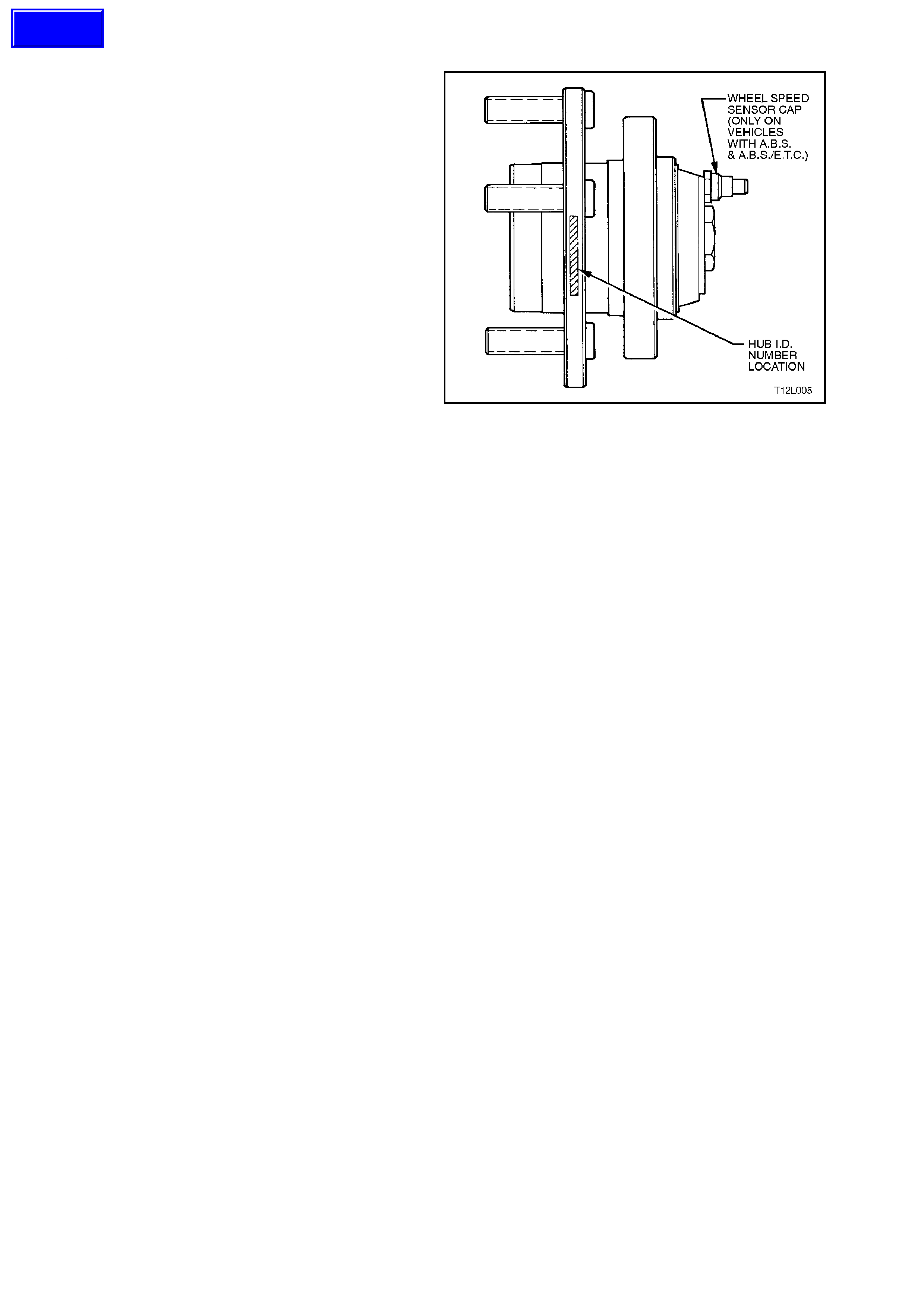
NOTE 1:
Apart from wheel stud replacement, there are no
serviceable item s in the front wheel hub assembly.
As the unit is a 'sealed for life' assembly, neither
bearing adjustment nor lubrication maintenance is
required. Should a non-standar d condition develop,
then the hub assembly must be replaced as a
complete unit.
NOTE 2:
If an ABS hub requires replacement, the correct
assembly must be fitted. If not, the ABS will
malfunction. Either the hub will have an ABS lead
connection or it will not.
NOTE 3:
While the f r ont wheel hub is des igned to have zero
axial free play or ‘end-float’, some angular
movement m ay be evident when a rocking force is
applied to the mounted wheel and tyre assembly.
Before a hub is replaced, refer to checking
procedure, detailed in Operation 2.4 in this Section
of the Service Manual.
.
Figure 3-18
Techline
REMOVE
1. Raise front of vehicle and support on safety
stands. Observe jacking precautions as
outlined in 2.3 JACKING PRECAUTIONS in
this Section.
2. Remove wheel cover (steel wheels) or centre
cap (alloy wheels).
3. Mark relationship of wheel to hub or brake
disc. Remove wheel attaching nuts and
remove wheel.
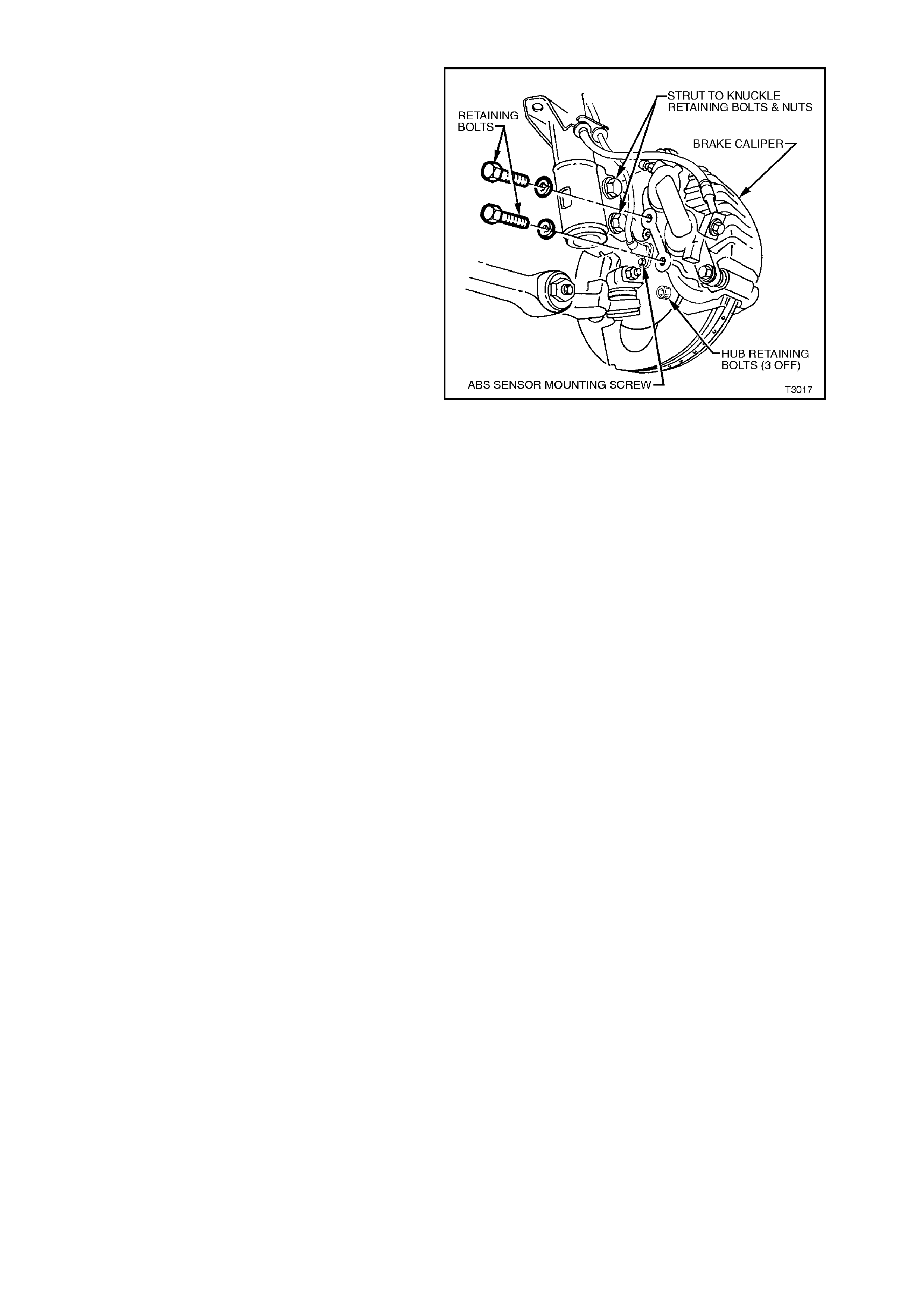
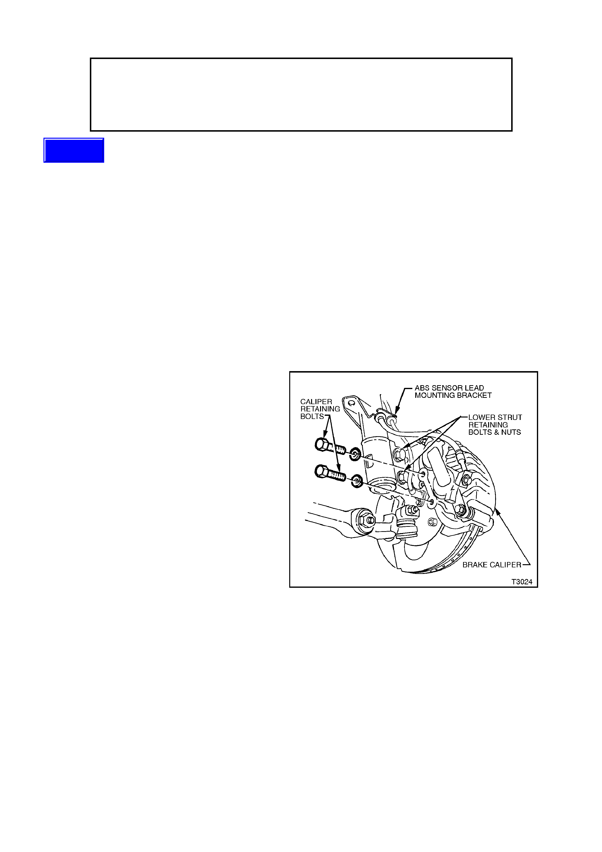
4. Remove brake caliper anchor plate retaining
bolts and washers, lift caliper assembly from
brake disc. Position caliper in such a way that
no strain is placed on the brake hose. If
necessar y, tie caliper to the suspens ion spring
with a piece of wire. THE CALIPER IS NOT
TO HANG BY BRAKE HOSE.
5. Remove brake disc from the wheel bearing
hub.
NOTE:
For vehicles equipped with ABS, disconnect the
wheel speed sensor connector from the steering
knuckle. To do this, use a 5 mm Allen key (or
socket), remove the set screw and then, holding
the cable retaining bracket, twist and gently pull on
the sensor c onnec tor end. Don't los e the s ealing O-
ring.
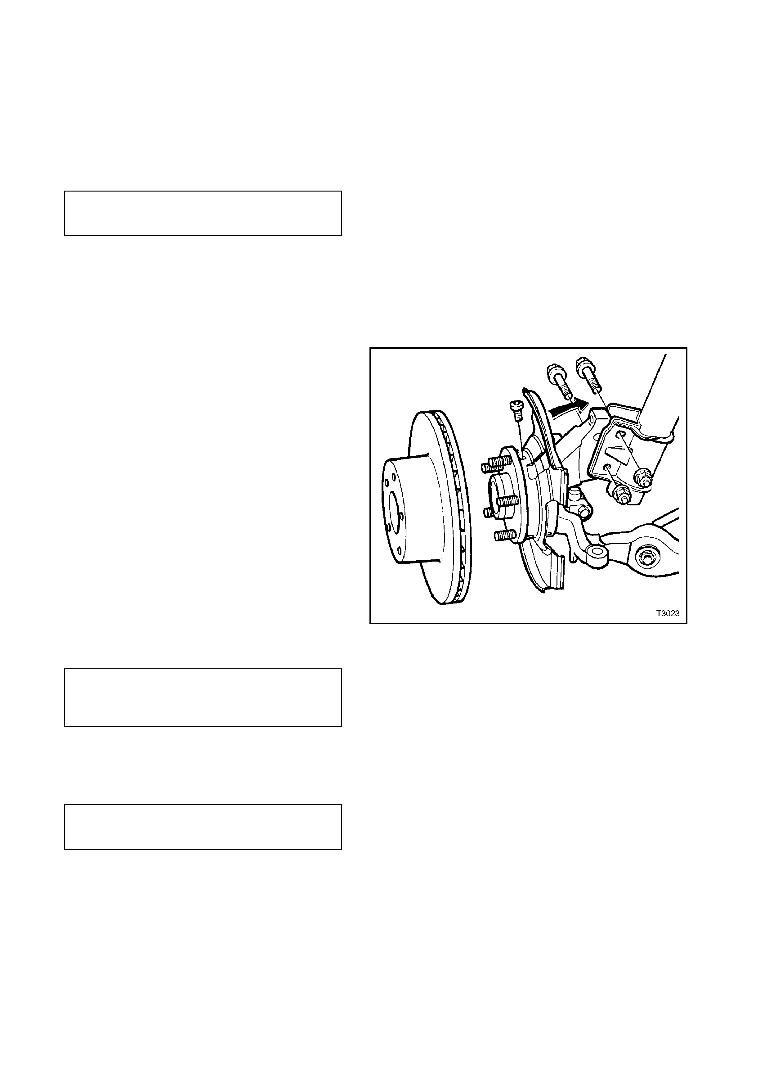
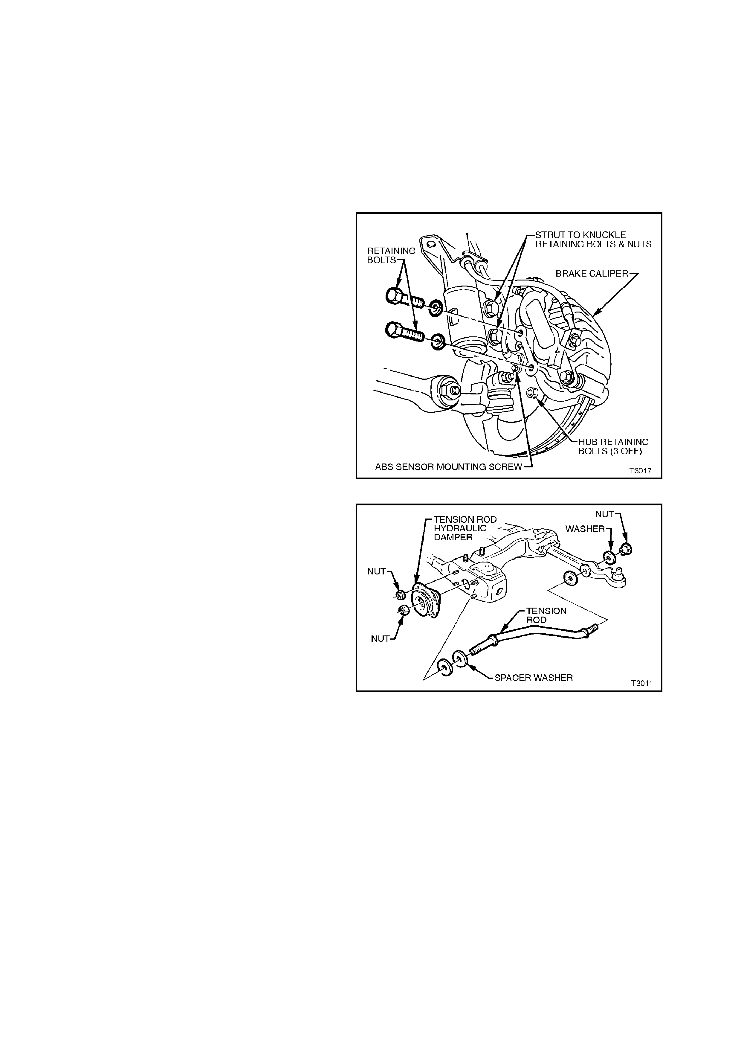
6. Using a commercially available 10 mm Allen
key socket and a suitable socket bar, loosen
each of the three bolts holding the hub to the
steering knuckle.
NOTE 1:
For the fr ont lower hub bolt, turn wheel outwards to
provide clearance between the ball joint rivet and
the hub bolt.
NOTE 2:
If the Allen key socket is too long to fit into the front,
upper hub bolt, then the lower strut to steering
knuckle nut will need to be removed and the bolt
withdrawn.
7. If the hub is a tight f it to the knuck le, it m ay be
necessary to loosen the three loosened bolts
and tap on the heads. DO NOT STRIKE THE
HUB.
Figure 3-19
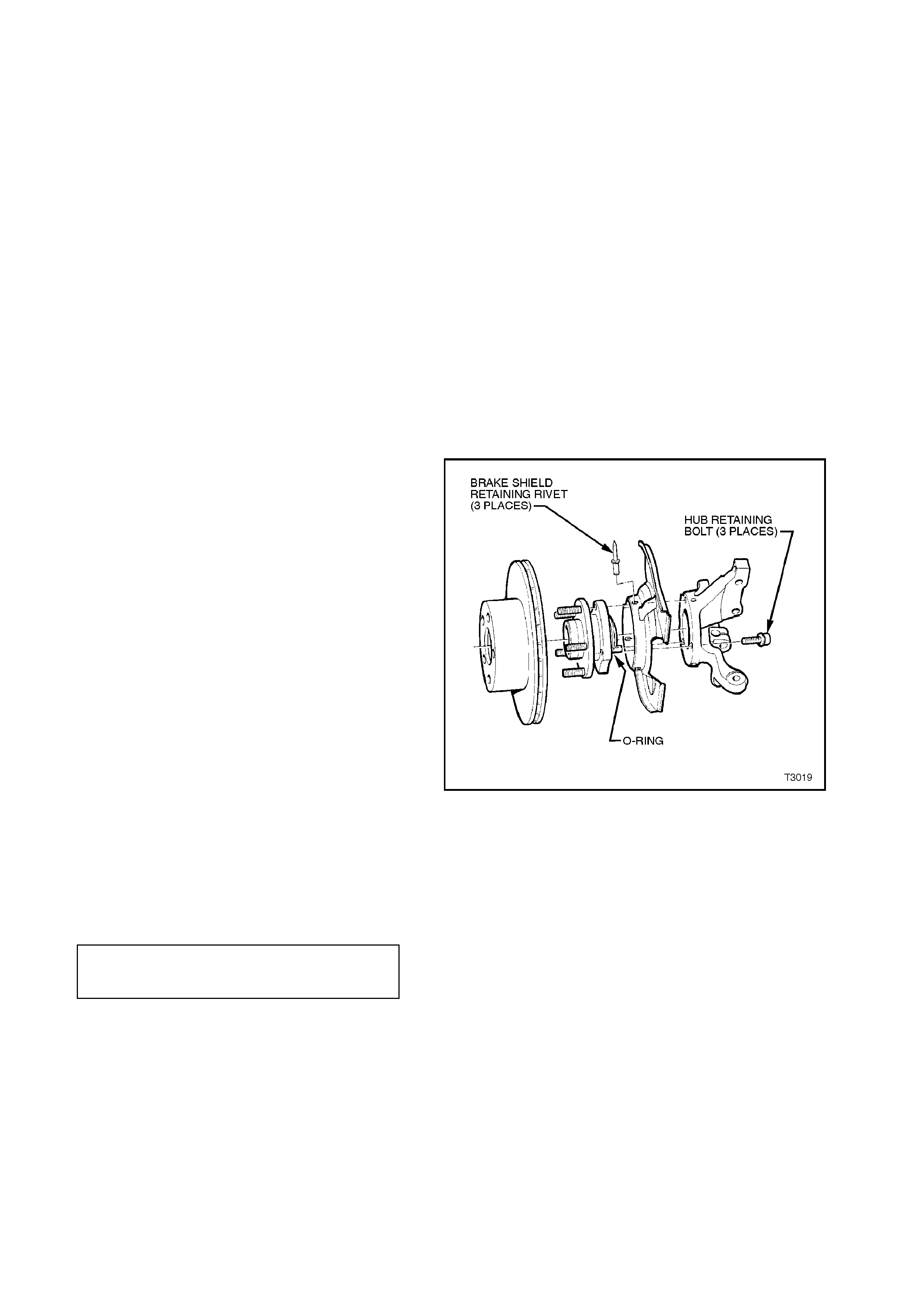
8. Remove the thr ee bolts and then the hub from
steering knuckle.
9. If removal of the brake shield is necessary,
drill the heads from the three rivets securing
the shield to the steering knuckle support.
10. After removal of the shield, carefully drill out
the remainder of the rivets, using a suitable
sized, sharp drill.
INSPECT
1. Check wheel studs to ensure threads are not
damaged, and that studs are pressed firmly
into the front wheel hub.
If one or more wheel studs require
replacement, refer to operation
3.3 FRONT HUB WHEEL STUD in this
Section, for details.
2. Examine brake disc for scores or damage.
If either of these conditions exist, the brake
disc should be machined. Refer to
Section 5A BRAKES for details.
3. Check for damage to the shield that may
cause fouling of any rotating parts and if
suspect, the shield should be replaced.
REINSTALL
Installation of the f ront wheel hub and brak e disc is
the reverse of removal procedures, except for the
following points:
All Models:
1. If the brake shield has been removed, install
three, common pop rivets, using a
commercially available pop rivet gun.
NOTE:
Install the fir st rivet in the brak e shield hole with the
round hole. This will ensure that the clearance to
brake caliper is correct.
2. Before installing the hub, inspect both mating
surf aces to mak e sure that they are clean and
free from burrs that could prevent correct
alignment of both parts, once installed.
3. Prior to installation, it is also vital that the
sealing O-ring located around the mounting
flange, is checked to ensure its serviceability.
Failing to adequately seal the hub to steering
knuc kle interf ace, will caus e water to be dr awn
into the cavity in the steering knuckle, during
the normal heating and cooling cycle of vehicle
operation.
Without ABS:
4a. Install the hub assembly to the steering
knuckle.
5a. Install the three attaching bolts and tighten to
the correct torque specification.
Figure 3-20
FRONT HUB TO STEERING
KNUCKLE ATTACHING BOLT
TORQUE SPECIFICATION 100 - 115 Nm
NOTE:
The three hub attaching bolts are micro-
encapsulated with thread sealant and are not to be
re-used m ore than thr ee times. If in doubt, the bolts
should be replaced.
With ABS:
4b. Carefully align the sensor connection on the
hub, with the hole in the steering knuckle, then
install the three hub attaching bolts and tighten
to the correct torque specification.
FRONT HUB TO STEERING
KNUCKLE ATTACHING
BOLT TORQUE SPECIFICATION 100 - 115 Nm
5b. Fit the wheel speed sensor connector, then
install the cable retaining bracket set screw
and tighten to specification.
SENSOR CABLE
RETAINING SCREW
TORQUE SPECIFICATION 6 - 14 Nm
All Models:
6. If removal of the lower strut to steering
knuckle bolt was necessary, the bolt and nut,
must be replaced with new parts and tightened
to the correct torque specification.
STEERING KNUCKLE
TO STRUT ATTACHING
BOLTS & NUTS
TORQUE SPECIFICATION
Stage 1 85 Nm
Stage 2 100 Nm
Stage 3 Turn
through 90°
7. Reinstall brake disc and brake caliper,
tightening attaching bolts to specification.
BRAKE CALIPER ANCHOR
PLATE RETAINING BOLTS
TORQUE SPECIFICATION
80 - 90 Nm
then turn through
40° - 50°
8. Reinstall road wheel, aligning the marks made
prior to removal and secure with the attaching
nuts.
9. Remove jack stands and lower vehicle.
10. Tighten road wheel attaching nuts to correct
torque specification.
ROAD WHEEL ATTACHING NUT
TORQUE SPECIFICATION 110 - 140
Nm
11. Refit wheel cover/centre cap.
3.3 FRONT WHE EL HUB STUDS
REPLACE
1. Raise front of vehicle and support on safety
stands. Observe jacking precautions as
outlined in 2.3 JACKING PRECAUTIONS in
this Section.
2. Remove wheel cover (steel wheels) or centre
cap (alloy wheels).
3. Mark relationship of wheel to hub and disc.
Remove wheel attaching nuts and remove
wheel.
4. Remove brake caliper anchor plate retaining
bolts and washers, lift caliper assembly from
brak e disc. Sus pend caliper on wire or hook to
avoid strain on the hose. DO NOT ALLOW
CALIPER TO HANG BY BRAKE HOSE.
5. Remove brake disc from hub.
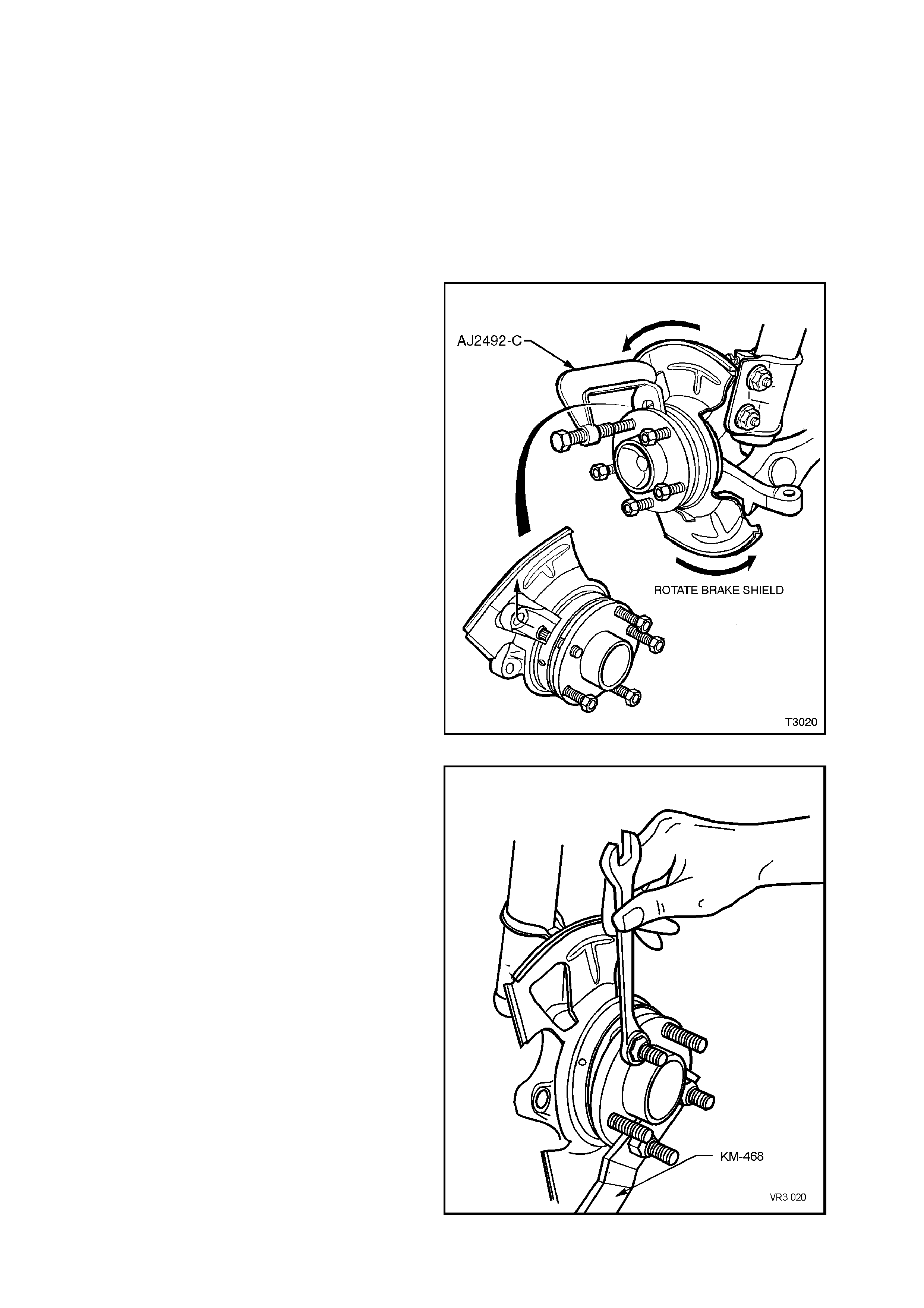
6. Using Tool No. AJ24292-C or equivalent,
press stud/s from the front hub after first
installing a wheel nut until the nut is flush with
the end of the stud.
NOTE 1:
To avoid the unnecessary removal of the micro-
encapsulated studs retaining the front hub to the
steering knuckle, it is recommended that wheel
stud/s replacement be carried out with the hub left
undisturbed.
NOTE 2:
To remove the stud/s, first drill out the three rivets
securing the brake shield to the steering knuckle.
Then rotate the shield and remove the wheel hub
stud by manipulating the head under the shield and
into the one recess in the steering knuckle, at
approximately the 11 o’clock position, as shown.
Figure 3-21
7. New studs can be installed as follows;
a. Install Tool No. KM468, using two revers ed
wheel nuts.
b. Install replacement stud by first
manipulating the stud under the disc brake
shield and into the wheel hub f lange. T hen,
after assembling a suitable sized flat
washer and reversed wheel nut onto the
replacement stud, hold Tool No. KM468
and tighten the wheel nut to draw the stud
into place.
c. Install any remaining studs in the same
manner. Remove Tool No. KM-468.
8. Using a suitable sized, sharp drill remove the
shanks of the three brake shield retaining
rivets. Then use common pop rivets and a
commercially available pop rivet gun to
reinstall the brake shield.
NOTE:
Install the fir st rivet in the brak e shield hole with the
round hole. This will ensure that the clearance to
brake caliper is correct.
9. Reinstall brak e disc and caliper, tightening the
caliper retaining bolts to the correct torque
specification. Figure 3-22

BRAKE CALIPER
ANCHOR PLATE
RETAINING BOLTS
TORQUE SPECIFICATION
80 - 90 Nm,
then turn
through
40° - 50°
10. Install the road wheel, aligning the marks
made prior to removal and secure with the
attaching nuts.
11. Remove jack stands and lower vehicle.
12. Tighten road wheel attaching nuts to correct
torque specification.
ROAD WHEEL ATTACHING NUT
TORQUE SPECIFICATION 110 - 140
Nm
13. Refit wheel cover/centre cap.
4. MAJOR SERVICE OPERATIONS
CAUTION:
Whenever any component that forms part of the ABS or ABS/ETC (if fitted), is
disturbed during Service Operations, it is vital that the complete ABS or ABS/ETC
system is checked, using the procedure as detailed in 4. DIAGNOSIS, ABS or
ABS/ETC FUNCTION CHECK, in Section 12L ABS & ABS/ETC.
4.1 FRONT STRUT ASSEMBLY
REMOVE
1. Raise front of vehicle and support on safety
stands. Observe jacking precautions as
outlined in 2.3 JACKING PRECAUTIONS in
this Section.
2. Remove wheel cover (steel wheels) or centre
cap (alloy wheels).
3. Mark relationship of wheel to hub or brake
disc. Remove road wheel attaching nuts and
remove wheel.
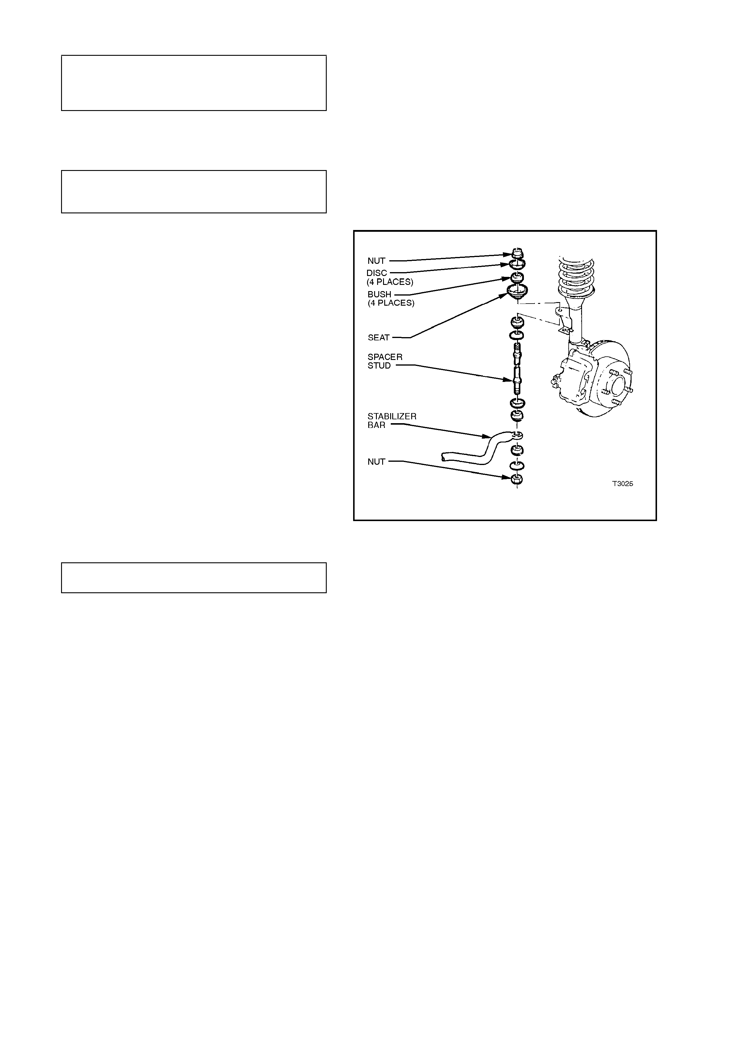
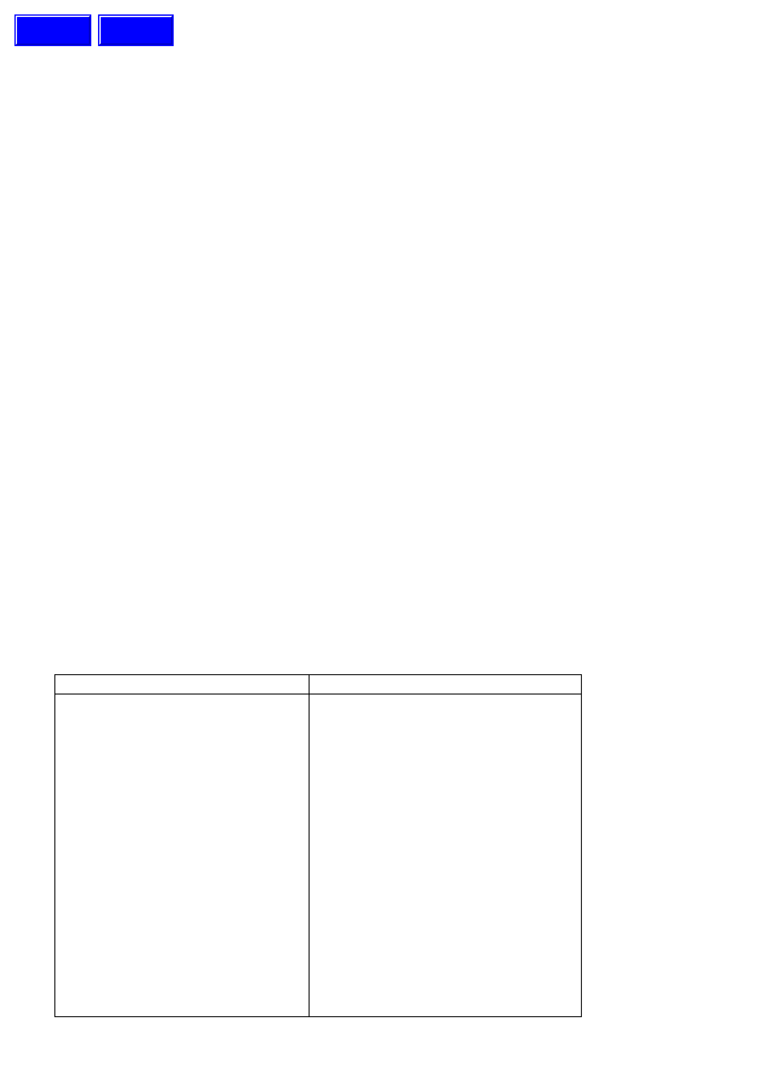
4. Position a suitable size open end spanner
over flat in stabiliser bar spacer stud, remove
upper nut, disc, bush and seat.
5. If the vehicle is fitted with ABS, disconnect the
wheel speed sensor cable by pulling the
insulator from the strut bracket.
6. Remove the brake caliper anchor plate
retaining bolts and washers, lift the caliper
assembly from the brake disc and support in
such a way that no strain is placed on the
brake hose. THE BRAKE CALIPER IS NOT
TO HANG BY THE BRAKE HOSE.
NOTE:
This step is necessary to provide access to the
lower strut mounting bolt and nut.
7. Remove brake hose from the strut housing
bracket by turning plastic sleeve on the hose
until flats on sleeve align with bracket opening.
8. Using a suitable f loor jac k f itted with a bloc k of
wood, position under the lower control arm,
just sufficient to support the weight.
9. W hile holding the strut rod shaft with a 10 mm
socket, remove the self-lock ing nut, using a 24
mm (15/16") ring spanner, then remove the
locating disc. DISCARD THE STRUT ROD
NUT.
10. Loosen, remove and DISCARD the two lower
strut to knuckle attaching bolts and nuts.
11. Pull the steering knuckle clear of the strut,
taking care not to place any strain on the ABS
Sensor cable (if fitted).
12. Carefully lower the strut from the tower,
manipulate the strut to remove the stabiliser
stud fr om the brack et on the str ut and rem ove
the assembly from the vehicle.
Figure 3-23
Techline
REINSTALL
NOTE:
In the interests of vehicle saf ety, it is important that
fastener s are r eplaced with new parts where stated
during the reinstallation process described here.
IMPORTANT:
The torque of the strut bearing retaining nut MUST
be checked for correct tightness BEFORE installing
the strut into the vehicle!
UPPER STRUT BEARING
RETAINING NUT
TORQUE SPECIFICATION 70 - 85 Nm
1. Manipulate the strut assembly so that the
stabiliser bar stud is located in the strut
bracket, then locate strut assembly into the
spring strut tower.
2. Af ter ins talling the locating disc , partially install
a NEW nut to the strut rod. Do not tighten at
this time.
3. Pivot the hub and steering knuckle
assemblies, sufficient to line up the bolt holes
in the steering knuckle and the lower end of
the strut assembly.
4. Install NEW retaining bolts and nuts, and
tighten in stages to the specified torque
values.
Figure 3-24
STEERING KNUCKLE TO
STRUT ATTACHING
BOLTS & NUTS
TORQUE SPECIFICATION
Stage 1 85 Nm
Stage 2 100 Nm
Stage 3 Turn
through 90°
5. While holding the strut rod f rom tur ning, with a
10 mm socket, tighten the upper strut rod
retaining nut to the correct torque
specification, using a 24 mm (15/16”) ring
spanner with a torque wrench attached.
UPPER STRUT LOCATING
PLATE RETAINING NUT
TORQUE SPECIFICATION 50 - 60 Nm
6. Install the brake hose to the strut bracket by
turning plastic sleeve on the hose until the flats
on the sleeve align with the bracket opening.
7. If removed, install the brake disc, then install
the brak e caliper , tightening the attac hing bolts
to specification.
BRAKE CALIPER
ANCHORPLATE
RETAINING BOLTS
TORQUE SPECIFICATION
80 - 90 Nm,
then turn through
40° - 50°
8. If the vehicle is fitted with ABS, fit the wheel
speed sensor connector, then install the cable
retaining bracket set screw and tighten to
specification.
SENSOR CABLE
RETAINING SCREW
TORQUE SPECIFICATION 6 - 14 Nm
9. Install stabiliser bar spacer stud nut after
ensuring that all components are assembled
as shown. While holding the spacer stud with
a suitable open end spanner, tighten the upper
retaining nut until the thread end.
NOTE:
Do not use power tools for this tightening operation,
otherwise thread damage will result.
10. Install road wheel, aligning the marks made
prior to removal.
11. Remove safety stands and lower vehicle.
12. Tighten road wheel attaching nuts to the
correct torque specification.
Figure 3-25
ROAD WHEEL ATTACHING NUT
TORQUE SPECIFICATION 110 - 140
Nm
13. Refit wheel cover/centre cap.
14. Bounce vehicle up and down several times to
settle suspension.
15. Check wheel alignment, as detailed in
2.2 WHEEL ALIGNMENT CHECKING AND
ADJUSTMENT in this Section.
4.2 UPPER STRUT SUPPORT BEARING AND MOUNT
REMOVE
1. Remove front strut as detailed in Operation
4.1 FRONT STRUT ASSEMBLY - REMOVE
in this Section.
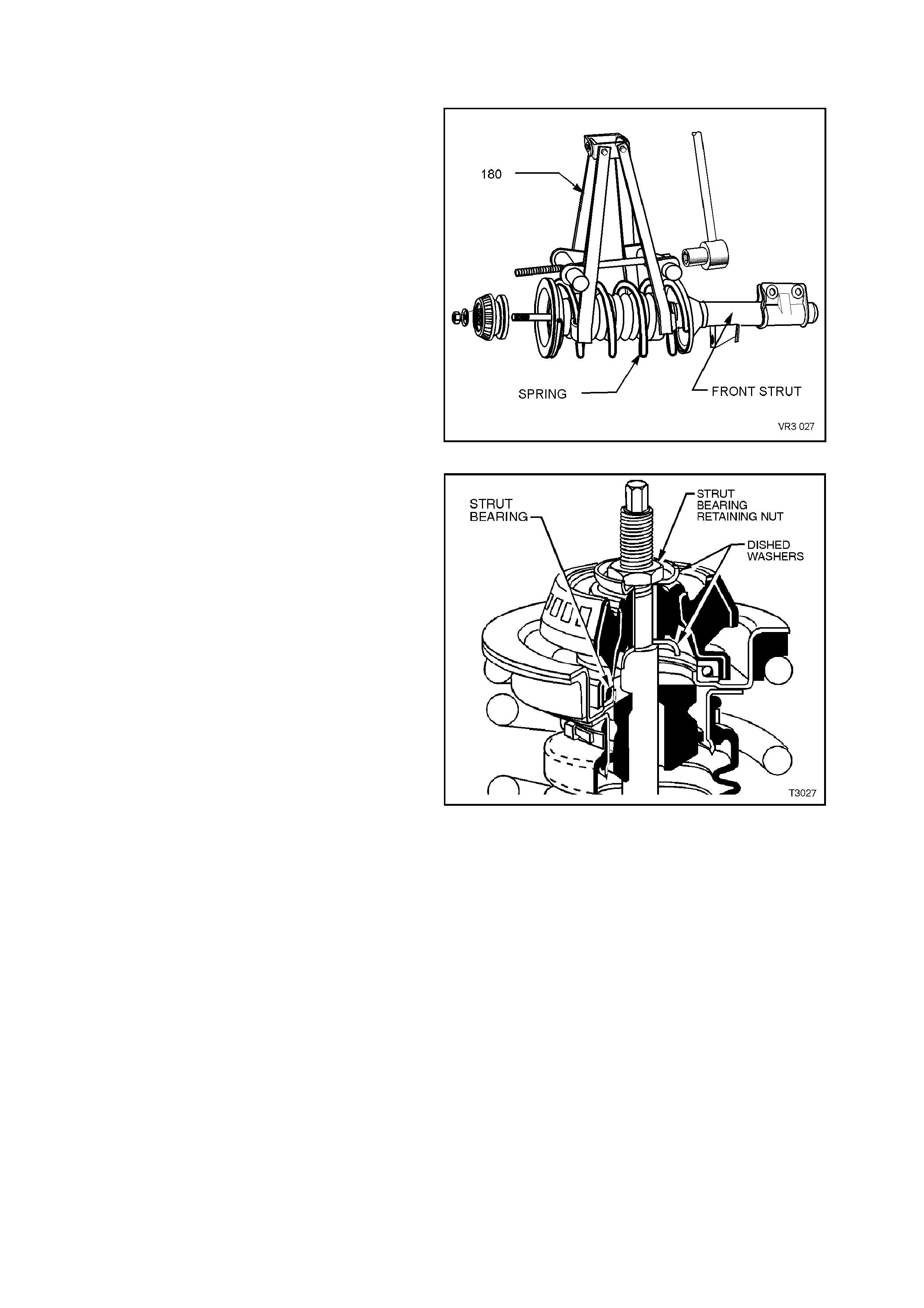
2. Fit Tool No. 180 as shown and compress the
spring until the upper support bearing has
clearance at the spring seat collar.
Figure 3-26
3. W hile holding the strut rod shaft with a 10 mm
sock et, remove the upper s trut bearing to str ut
rod retaining nut, using a 24 mm (15/16") ring
spanner.
4. Remove the strut mount and the two washers
(one each side of the mount).
NOTE:
The lower washer may be stuck to the lower edge
of the mount.
5. Remove the strut bearing from the upper
spring seat collar, taking particular note of
the bearing's orientation.
CAUTION:
Do not attempt to remove the retaining nut from
the strut rod shaft before compressing the
spring.
NOTE 1:
The upper suppor t bearing is self -lubricated and no
servicing requirements are necessary. If
considered to be faulty, the bearing is to be
replaced as an assembly.
NOTE 2:
Under no circums tanc es is the m ac hined s urface of
the piston rod section to be gripped directly on the
outer surface.
Figure 3-27

REINSTALL
1. Pull strut rod through upper spring seat to its
maximum length, then remove the strut rod
nut.
2. Install the upper bearing with the same
orientation as noted on rem oval. Norm ally, the
coloured or narrow, outer section, faces
towards the upper spring seat collar.
3. While holding the strut rod ex tended and, af ter
installing the first mount washer with the
dished shape facing downward (refer to Figure
3-27), install the upper strut mount over the
bearing and washer.
4. Install the second washer with the dished
shape facing upward (refer to Figure 3-27)
and install the retaining nut.
5. Using a 10 mm socket and a 24 mm (15/16")
ring spanner with a torque wrench attached,
tighten the nut to the correct torque
specification.
UPPER STRUT BEARING
RETAINING NUT
TORQUE SPECIFICATION 70 - 85 Nm
6. Release spring and remove compressor.
7. Reinstall front strut as detailed in
4.1 FRONT STRUT ASSEMBLY in this
Section.
4.3 FRONT SPRING
REMOVE
1. Remove front strut as per
4.1 FRONT STRUT ASSEMBLY in this
Section.
2. Remove upper strut mount, as detailed in
4.2 UPPER STRUT SUPPORT BEARING
AND MOUNT in this Section.
3. Remove the clamp securing the dust boot to
the upper spring seat collar and discard.
4. Remove upper spring seat collar, spring
insulator and compression bumper from the
top of the spring.
5. Remove spring from the strut and release the
spring compressor.
REINSTALL
NOTE:
If installing a replacement spring, ensure that the
spring is the corr ect type for the sus pens ion s ystem
fitted to the vehicle. Refer to 6 SPECIFICATIONS
in this Section for details.
1. Position spring on strut with straight projecting
end of spring correctly located in spring seat.
2. Install spring compressor Tool No. 180 and
compress spring.
3. Install upper spring ins ulator, s pring seat c ollar
and compression bumper so that the double
notch in upper flange of the spring seat collar
is assembled, facing inward. The spring
insulator has a step which locates in the
straight projecting end of spring.
4. Reinstall upper support plate as per
4.2 UPPER STRUT SUPPORT BEARING
AND MOUNT in this Section.
NOTE:
The lower washer (2) may be stuck to the lower
edge of the mount.
5. Fit the upper end of the dust boot over the
lower flange of the spring seat collar and
secure with a retaining clamp that has been
tightened until the boot rubber is firmly
secured.
6. Reinstall front strut as per
4.1 FRONT STRUT ASSEMBLY in this
Section.
Figure 3-28
4.4 FRONT STRUT UNIT
REPLACE
NOTE 1:
When replacing the front strut, ensure that the
replacement unit is the correct type for the
suspension system fitted to the vehicle. Refer to
6 SPECIFICATIONS in this Section for details.
NOTE 2:
As the strut assembly is a sealed component, no
overhaul procedures are possible and if found to be
unserviceable, then the complete strut must be
replaced.
1. Remove front strut assembly as detailed in
4.1 FRONT STRUT ASSEMBLY in this
Section.
2. Remove upper support plate as detailed in
4.2 UPPER STRUT SUPPORT BEARING
AND MOUNT in this Section.
3. Remove spring as detailed in
4.3 FRONT SPRING in this Section.
4. Remove lower boot retaining clamp and
discard. Slide dust boot and filter from the strut
assembly.
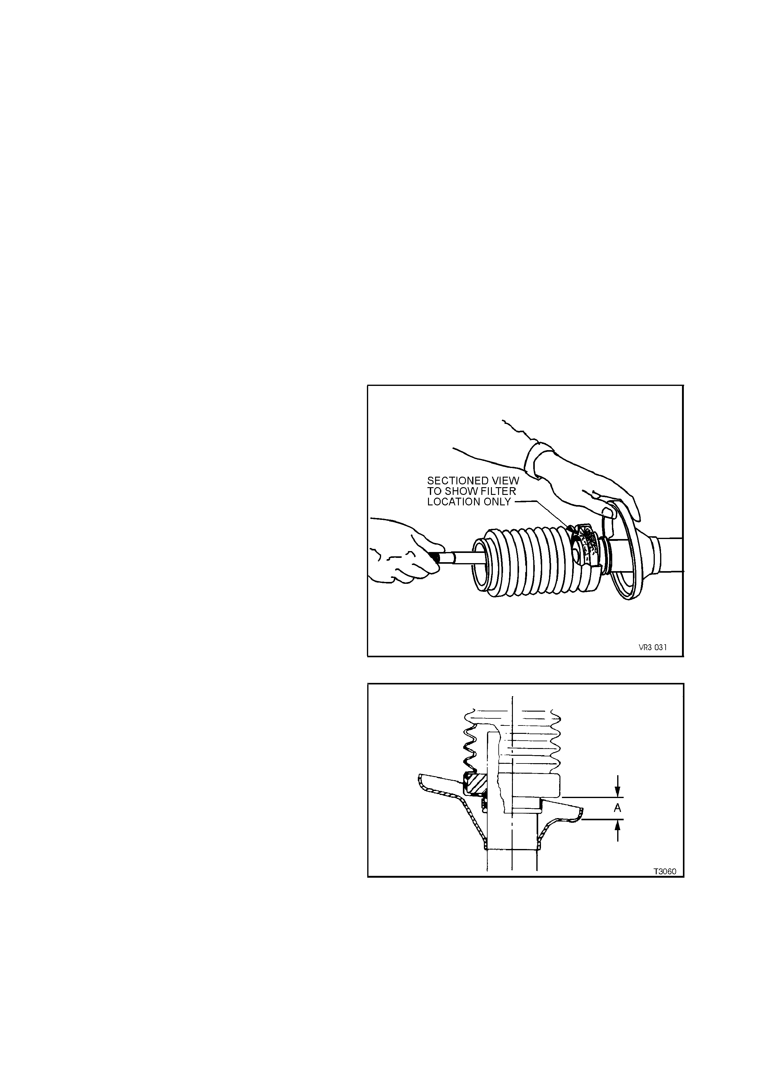
5. Pull strut rod fully up and, while supporting the
rod to stop it from slipping back into the strut,
install dust boot assembly over the strut tube,
ensuring that the filter remains seated in boot
assembly.
Figure 3-29
6. Ensure that bottom of dust boot is positioned
so that distance ‘A’ is from 30 - 35 mm.
7. Install retaining clamp and tighten until rubber
on dust boot is firmly secured.
8. Reinstall front spring as detailed in
4.3 FRONT SPRING in this Section.
9. Reinstall upper strut support assembly as
detailed in 4.2 UPPER STRUT SUPPORT
BEARING AND MOUNT in this Section.
10. Reinstall front strut assembly as detailed in
4.1 FRONT STRUT ASSEMBLY in this Section.
Figure 3-30
4.5 STEE RING KNUCKLE
REMOVE
1. Rem ove front br ak e disc, wheel hub assem bly
and brake shield, as detailed in
3.2 FRONT WHEEL HUB, BRAKE DISC OR
BRAKE SHIELD in this section.
2. Remove the split pin and nut from steering tie
rod ball joint stud and press stud out from
steering knuckle, using Tool No. 9A10.
3. Remove the ball joint clamp bolt and nut from
the steering knuckle and discard nut.
NOTE:
Because the nut is of a self-locking design, it m ust
be replaced, after removal.
4. Loosen, remove and discard the two lower
strut attaching bolts and nuts as shown.
5. If the steering knuckle is to be replaced,
remove the camber adjusting bolt from the
arm.
Figure 3-31

REINSTALL
Installation is the reverse of removal procedures
except for the following:
1. Install NEW lower strut to steering knuckle,
bolts and nuts but do not tighten fully at this
stage.
2. Install ball joint stud in steering knuckle and
install the clamp bolt and a NEW self-locking
nut, tightening to the correct torque
specification.
BALL JOINT CLAMP BOLT
TORQUE SPECIFICATION 70 Nm, then turn
through 30° - 40°
3. Install steering tie rod end ball joint stud to the
steering knuckle and tighten the castellated
attaching nut to the correct torque
specification. Install new split pin.
TIE ROD BALL JOINT STUD
CASTELLATED NUT
TORQUE SPECIFICATION 58 - 71 Nm
4. Install front brake disc, wheel hub assembly
and brake shield, as detailed in 3.2 FRONT
WHEEL HUB, BRAKE DISC OR BRAKE
SHIELD in this Section.
5. Temporarily install road wheel/s and lower
vehicle to the ground.
6. Bounce vehicle up and down several times to
settle suspension.
7. Check wheel alignment, as detailed in
2.2 WHEEL ALIGNMENT CHECKING AND
ADJUSTMENT in this Section.
8. Following wheel alignment operations, it will
be necessary to raise the vehicle and tighten
the NEW steering knuckle to strut bolts and
nuts to the correct torque specification.
STEERING KNUCKLE TO
STRUTATTACHING
BOLTS & NUTS
TORQUE SPECIFICATION
Stage 1 85 Nm
Stage 2 100 Nm
Stage 3 Turn
through 90°
9. After reinstalling the road wheel and aligning
the marks made prior to removal, install the
nuts, lower the vehicle to the ground and
tighten road wheel attaching nuts to the
correct torque specification.
ROAD WHEEL
ATTACHING NUT
TORQUE SPECIFICATION 110 - 140 Nm
10. Refit wheel cover/centre cap.
4.6 LOWE R CONTROL ARM
REMOVE
1. Raise front of vehicle and place safety stands
under side frame members. Observe jacking
precautions as outlined in
2.3 JACKING PRECAUTIONS in this Section.
2. Remove wheel cover (steel wheels) or centre
cap (alloy wheels).
3. Mark relationship of wheel to hub. Remove
road wheel attaching nuts and remove wheel.
4. Remove brake caliper anchor plate retaining
bolts and washers, lift caliper assembly from
brak e disc . Sus pend caliper on wire or hook to
avoid strain on the hose. THE CALIPER
MUST NOT HANG BY BRAKE HOSE.
5. Remove brake disc from hub.
6. Using a sharp drill, remove the rivet heads
retaining the disc brake shield and pull shield
toward hub to provide clearance for the ball
joint to be removed from the steering knuckle.
7. Remove the ball joint clamp bolt and nut from
the steering knuckle. Discard the nut.
NOTE:
Because the nut is of a self-locking design, it m ust
be replaced, after removal.
Figure 3-32
8. Remove tension rod to control arm attaching
nut and washer. Discard nut.
9. Loosen the tension rod front nut at the tension
rod bush assembly.
10. Remove the four nuts securing the tension
rod, front bus h assem bly to the cross mem ber,
then remove the tension rod from the lower
control arm, outer bush.
11. Remove control arm inner pivot bolt and nut.
Discard nut.
12. Remove control arm from the vehicle.
Figure 3-33

REINSTALL
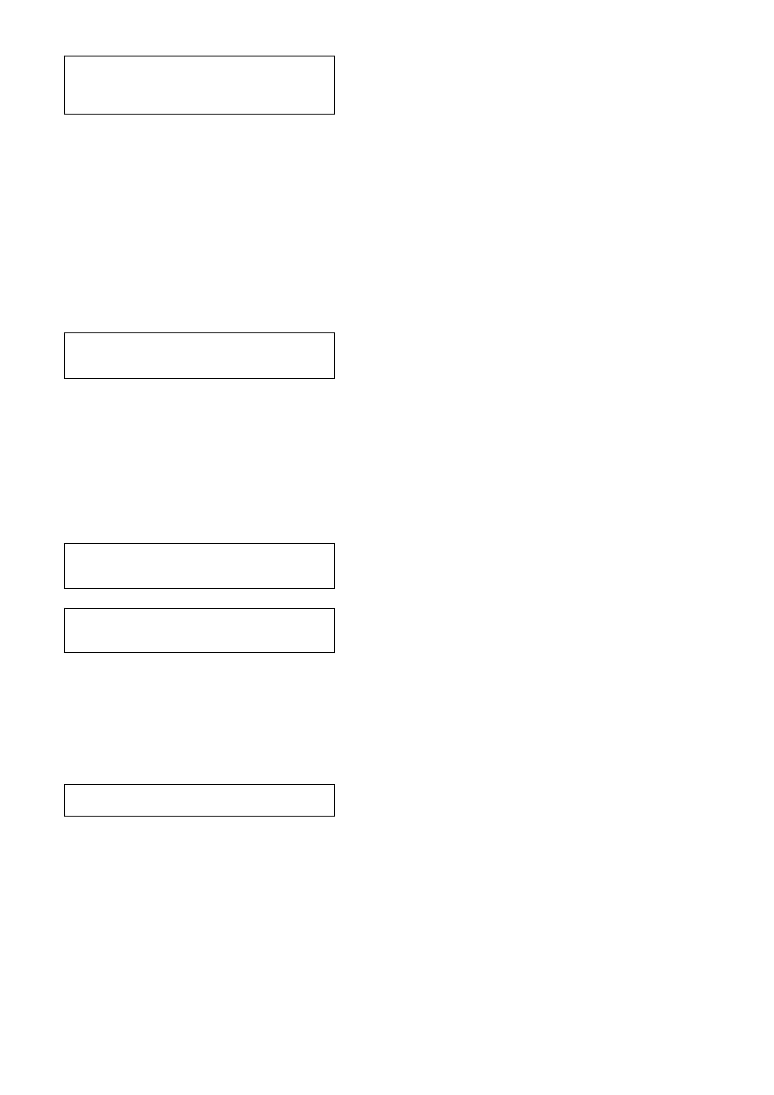
1. Install tension rod to control arm with convex
side of washer toward control arm bush, as
shown. Install tension rod to control arm
washer with a NEW attaching nut but do not
fully tighten at this stage.
2. Install tension rod, front bush assembly to the
crossmember, install the four retaining nuts
and tighten to the correct torque specification.
Figure 3-34
TENSION ROD BUSH TO
CROSSMEMBER OUTRIGGER
NUT TORQUE SPECIFICATION 20 - 26
Nm
NOTE:
Install a NEW tension rod nut but do not tighten at
this stage.
3. Install ball joint stud in steering knuckle and
install the clamp bolt and a NEW self-locking
nut, tightening to the correct torque
specification.
BALL JOINT CLAMP BOLT
TORQUE SPECIFICATION 70 Nm, then turn
through 30° - 40°
4. Using a suitable size drill, remove the brake
shield rivet shanks from the steering knuckle
support. Then reinstall the brake shield, using
common pop rivets and a commercially
available pop rivet gun.
NOTE:
Install the fir st rivet in the brak e shield hole with the
round hole. This will ensure that the clearance to
brake caliper is correct.
5. Reinstall brak e disc and caliper, tightening the
caliper retaining bolts to the correct torque
specification.
BRAKE CALIPER ANCHOR
PLATE RETAINING BOLTS
TORQUE SPECIFICATION
80 - 90 Nm,
then turn
through 40°-50°
6. Install road wheel, aligning marks made prior
to removal.
7. Remove safety stands and lower vehicle.
8. Bounce vehicle up and down several times to
settle suspension.

9. Tighten control arm inner pivot bolt to the
correct torque specifications.
LOWER CONTROL ARM
INNER PIVOT BOLT
TORQUE SPECIFICATION 95 - 110 Nm
10. Tighten the tension rod nuts, both at the lower
control arm and the tension rod hydraulic
damper, to the correct torque specifications.
TENSION ROD TO CONTROL
ARM ATTACHING NUT
TORQUE SPECIFICATION 95 - 110 Nm
TENSION ROD TO TENSION
ROD HYDRAULIC DAMPER
TORQUE SPECIFICATION 140 - 155 Nm
IMPORTANT:
The weight of the vehicle must be on all four
wheels before tightening the tension rod to
specification. Otherwise the tension rod hydraulic
damper be incorrectly preloaded, reducing the life
of the damper and affect ride and handling.
11. Tighten road wheel attaching nuts to the
correct torque specification.
ROAD WHEEL ATTACHING NUT
TORQUE SPECIFICATION 110 - 140
Nm
12. Refit wheel cover/ centre cap.
13. Check wheel alignment, as detailed in
2.2 WHEEL ALIGNMENT CHECKING AND
ADJUSTMENT in this Section.

4.7 LOWE R CONTROL ARM BALL JOINT
INSPECT
The following procedure should be used when
checking the ball joint for wear.
1. Jack up vehicle under crossmember.
2. Holding the road wheel at top and bottom,
check for play in the ball joint by rocking
wheel.
If any up or down movement of stud in ball
joint housing is detected, the control arm and
ball joint assembly must be replaced, as the
ball joint is not serviced separately.
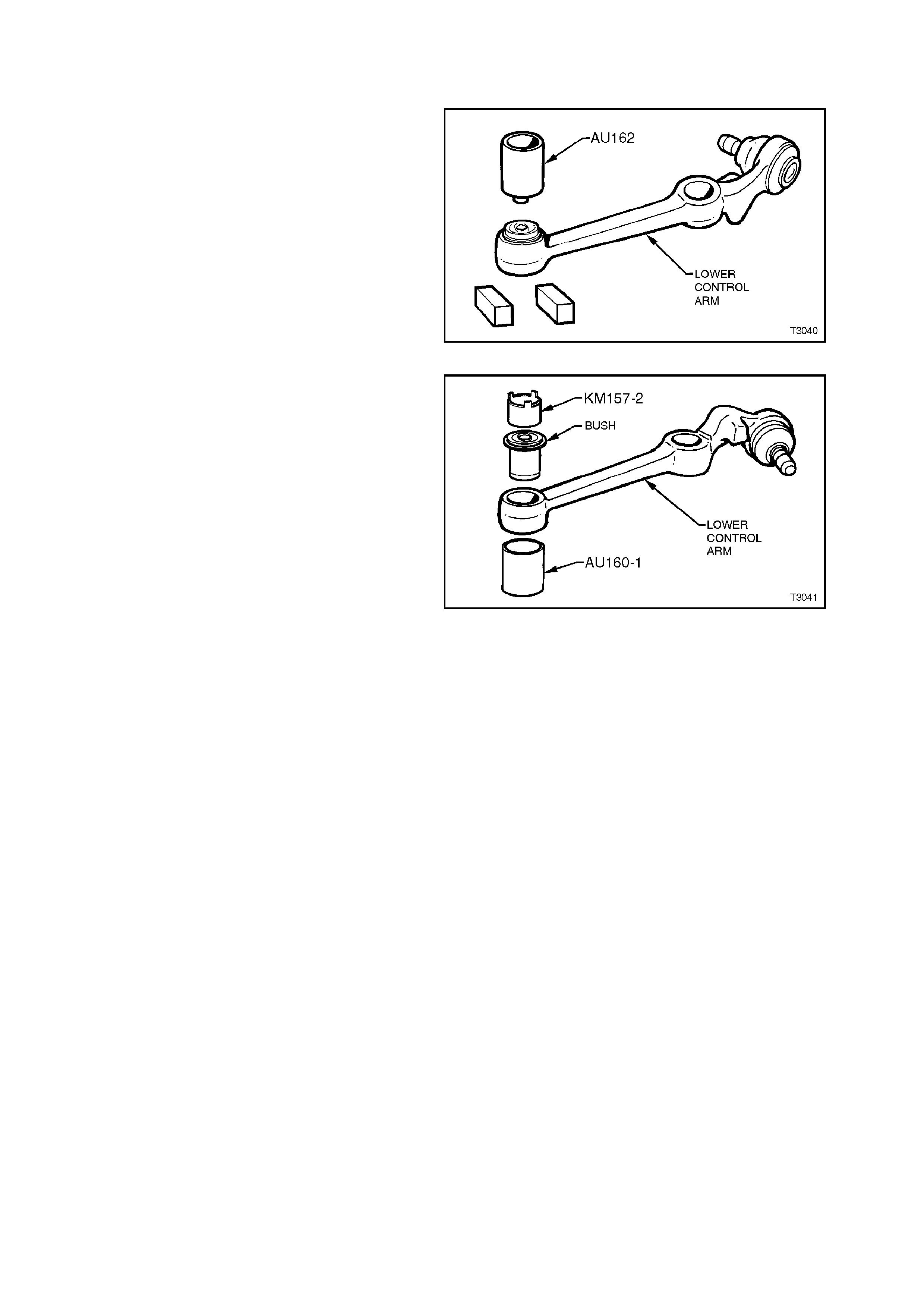
4.8 LOWER CONTROL ARM INNER PIVOT BUS H
REPLACE
1. Remove control arm as per
4.6 LOWER CONTROL ARM in this Section.
2. Support the lower control arm with two pieces
of square scrap and press the bush from the
arm, using Tool No. AU162.
Figure 3-35
3. Using Tool Nos. AU160-1 and KM157-2, install
new bush from front side of control arm, until
flange on outer sleeve is flush with control
arm.
NOTE 1:
The bush MUST be aligned correctly, as shown.
NOTE 2:
The bush may be lubricated with a soapy water
solution to ease the installation process.
NOTE 3:
Tool No KM157-2 is us ed in the rever s e direc tion to
some previous ‘V’ car models.
4. Reinstall control arm as detailed in
4.6 LOWER CONTROL ARM in this Section. Figure 3-36
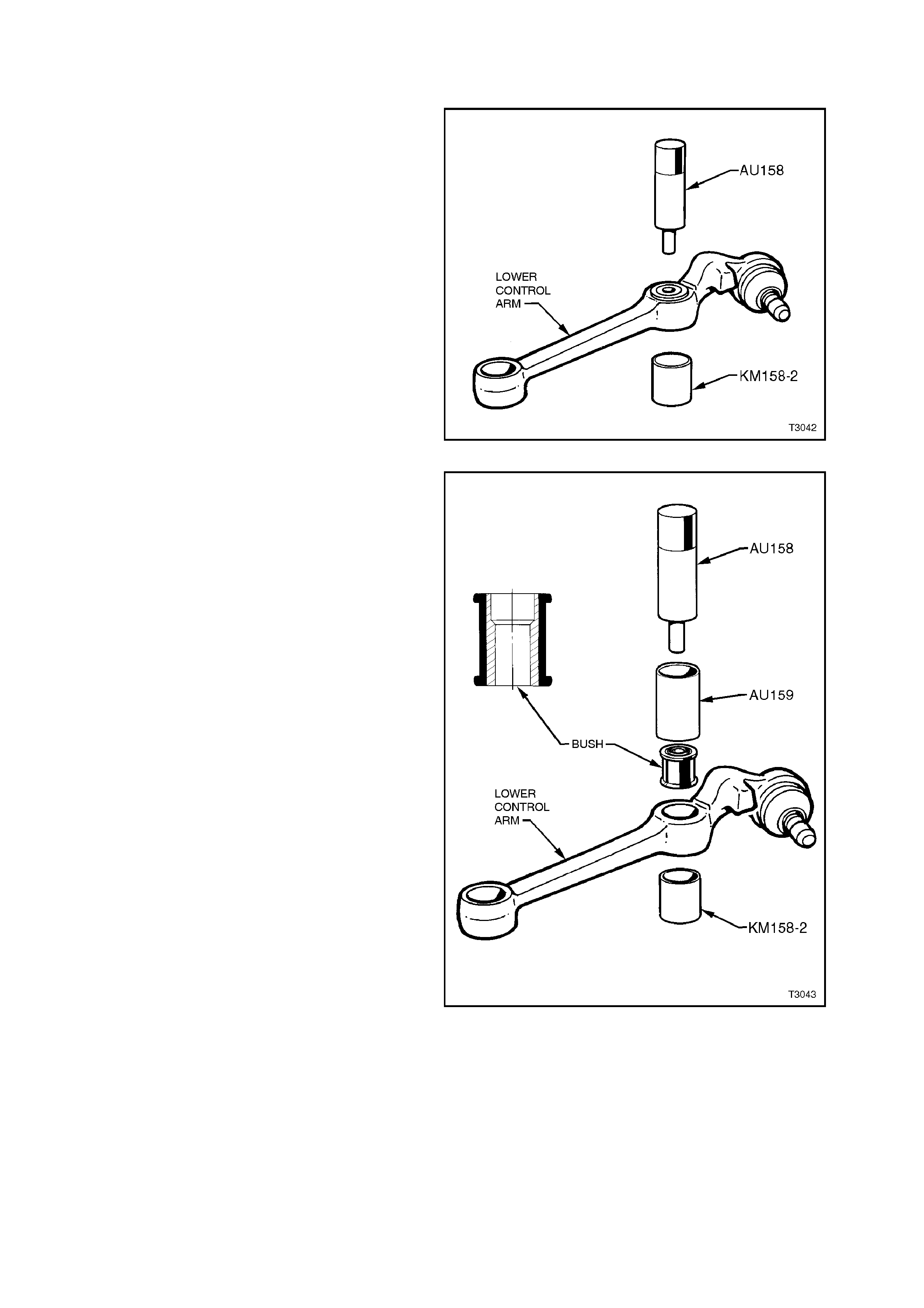
4.9 LOWER CONTROL ARM TENSION ROD BUSH
REPLACE
1. Remove control arm as per
4.6 LOWER CONTROL ARM in this Section.
2. Press out tension rod bush from control arm
using Tool No AU158 and KM158-2 as shown.
Figure 3-37
3. Press in a new tension rod bush using Tool
No’s AU158, AU159 and KM158-2 as shown.
To assist in installation, dip bush in a soapy
water solution. Install bush with larger
diameter of s tepped tens ion rod mounting hole
toward rear of control arm.
NOTE:
Press the bush in until it is centrally located in the
control arm.
4. Reinstall control arm as per
4.6 LOWER CONTROL ARM in this Section.
Figure 3-38
4.10 LOW ER CONTROL ARM TENSION ROD
REMOVE
1. Jack up front of vehicle and place safety
stands under side frame members. Observe
jacking precautions as outlined in
2.3 JACKING PRECAUTIONS in this Section.
2. Remove wheel cover (steel wheels) or centre
cap (alloy wheels).
3. Mark relationship of wheel to hub. Remove
road wheel attaching nuts and remove wheel.
4. Remove brake caliper anchor plate retaining
bolts and washers, lift caliper assembly from
brak e disc. Sus pend caliper on wire or hook to
avoid strain on the hose. DO NOT ALLOW
CALIPER TO HANG BY BRAKE HOSE.
5. Remove brake disc from hub.
6. Drill out the three rivets securing the brake
disc shield and pull shield toward hub to
provide clearance for the ball joint to be
removed from the steering knuckle.
7. Remove the ball joint clamp bolt and nut from
the steering knuckle. Discard the self-locking
nut.
Figure 3-39
8. Remove tension rod to control arm attaching
nut and washer. Discard the nut.
9. Remove four nuts attaching the tension rod
hydraulic damper assembly to the
crossmember outrigger.
10. Remove tension rod and tension rod damper
assembly from lower control arm and through
the crossmember outrigger.
11. Secure the tension rod in protected vice jaws,
then remove the tension rod to tension rod
damper assembly retaining nut. Discard the
nut.
12. Remove spacer washer (if fitted) from tension
rod. Figure 3-40
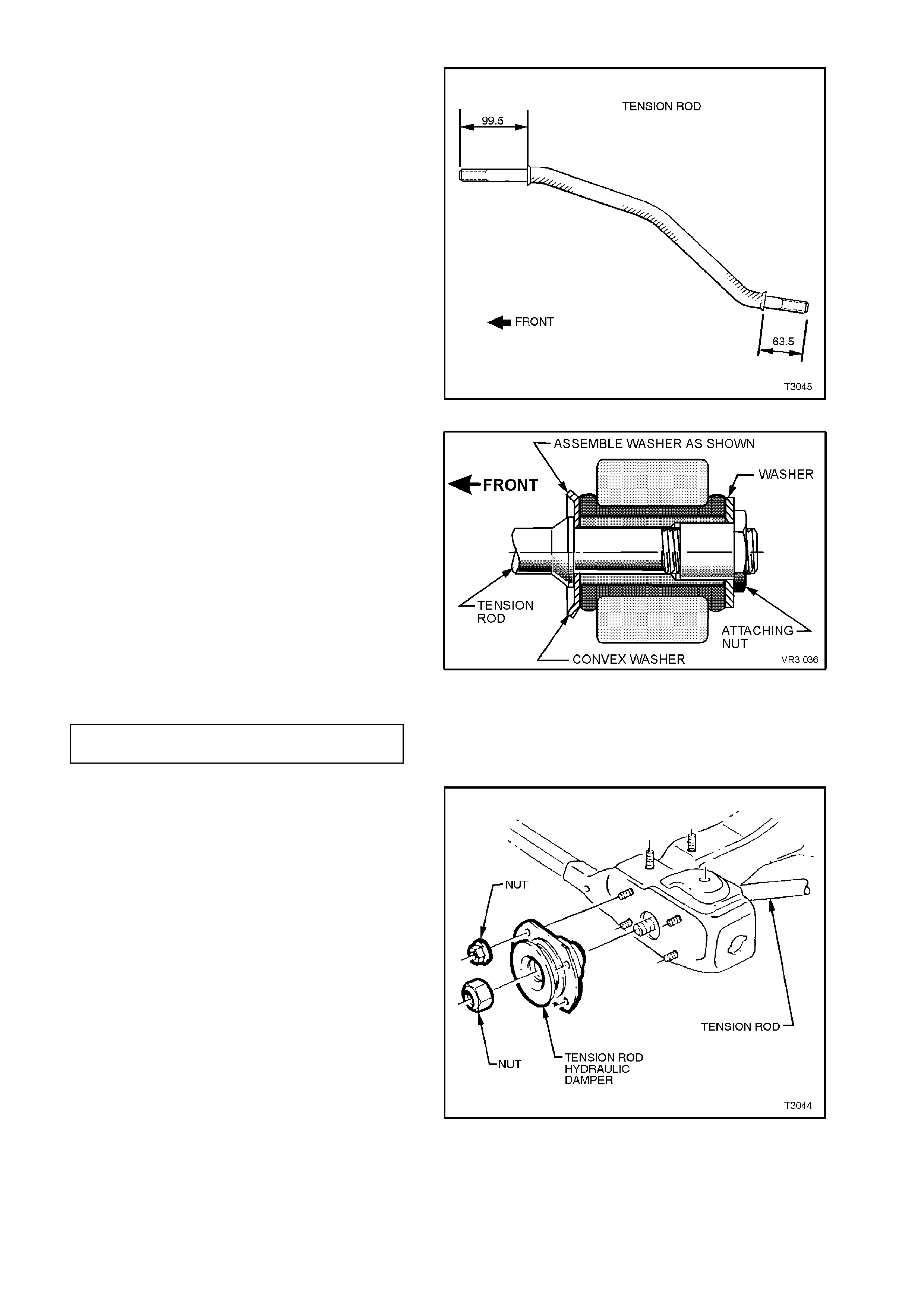
REINSTALL
1. Install flat inner washer to front end of tension
rod.
NOTE 1:
There may be m or e than one f lat spac er washer at
the inner side of the bush (See Figure 3-42). If
fitted, this second washer is only used to equalise
the caster angle from side to side and should be
reinstalled until Step 12 that follows.
NOTE 2:
The front end of the tension rod is identified by the
longer length of the shouldered ends, as shown.
Figure 3-41
2. Install tension rod into the hole in the
crossmember outrigger and then into the
control arm, with the washer installed as
shown. Loosely install tension rod to control
arm washer with a NEW attaching nut but do
not fully tighten at this stage.
3. Install ball joint stud in steering knuckle and
install the clamp bolt and a NEW nut,
tightening to the correct torque specification.
Figure 3-42
BALL JOINT CLAMP BOLT
TORQUE SPECIFICATION 70 Nm, then turn
through 30° - 40°
4. Install tension rod, hydraulic damper
assem bly, over the tension r od and install four
retaining nuts to the crossmember outrigger
studs. Tighten to the correct torque
specification.
Figure 3-43
TENSION ROD HYDRAULIC
DAMPER ASSEMBLY
ATTACHING
NUTS TORQUE SPECIFICATION 20 - 26 Nm
5. Install a NEW tension rod retaining nut but do
not fully tighten at this stage.
NOTE:
If fitted, ensure that the spacer washer is installed
over the tension rod before fitting the tension rod
damper.
6. Reinstall disc brake shield pop rivets. Refer
Operation 3.2 FRONT WHEEL HUB, BRAKE
DISC OR BRAKE SHIELD in this Section for
details.
7. Reinstall brake disc and brake caliper,
tightening attaching bolts to specification.
BRAKE CALIPER
ATTACHING BOLT
TORQUE SPECIFICATION
80 - 90 Nm,
then through
40° - 50°
8. Reinstall road wheel, aligning the marks made
prior to removal and secure with the attaching
nuts.
9. Remove safety stands and lower vehicle.
10. Bounce vehicle up and down several times to
settle suspension.
11. With the vehicle at curb position, tighten both
the tension rod to HYDRAULIC damper and
the tension rod to control arm attaching nuts to
the correct torque specifications.
TENSION ROD TO HYDRAULIC
DAMPER ATTACHING NUT
TORQUE SPECIFICATION 140 - 155
Nm
TENSION ROD TO CONTROL
ARM ATTACHING NUT
TORQUE SPECIFICATION 95 - 100 Nm
IMPORTANT:
The weight of the vehicle must be on all four
wheels before tightening the tension rod to
specification. Otherwise the fluid filled tension rod
bush will be incorrectly preloaded, reducing the life
of the bush and effect ride and handling.
12. Tighten road wheel attaching nuts to the
correct torque specification.
ROAD WHEEL ATTACHING NUT
TORQUE SPECIFICATION 110 - 140
Nm
13. Refit wheel cover/centre cap.
14. Check wheel alignment, as detailed in
2.2 WHEEL ALIGNMENT CHECKING AND
ADJUSTMENT in this Section.
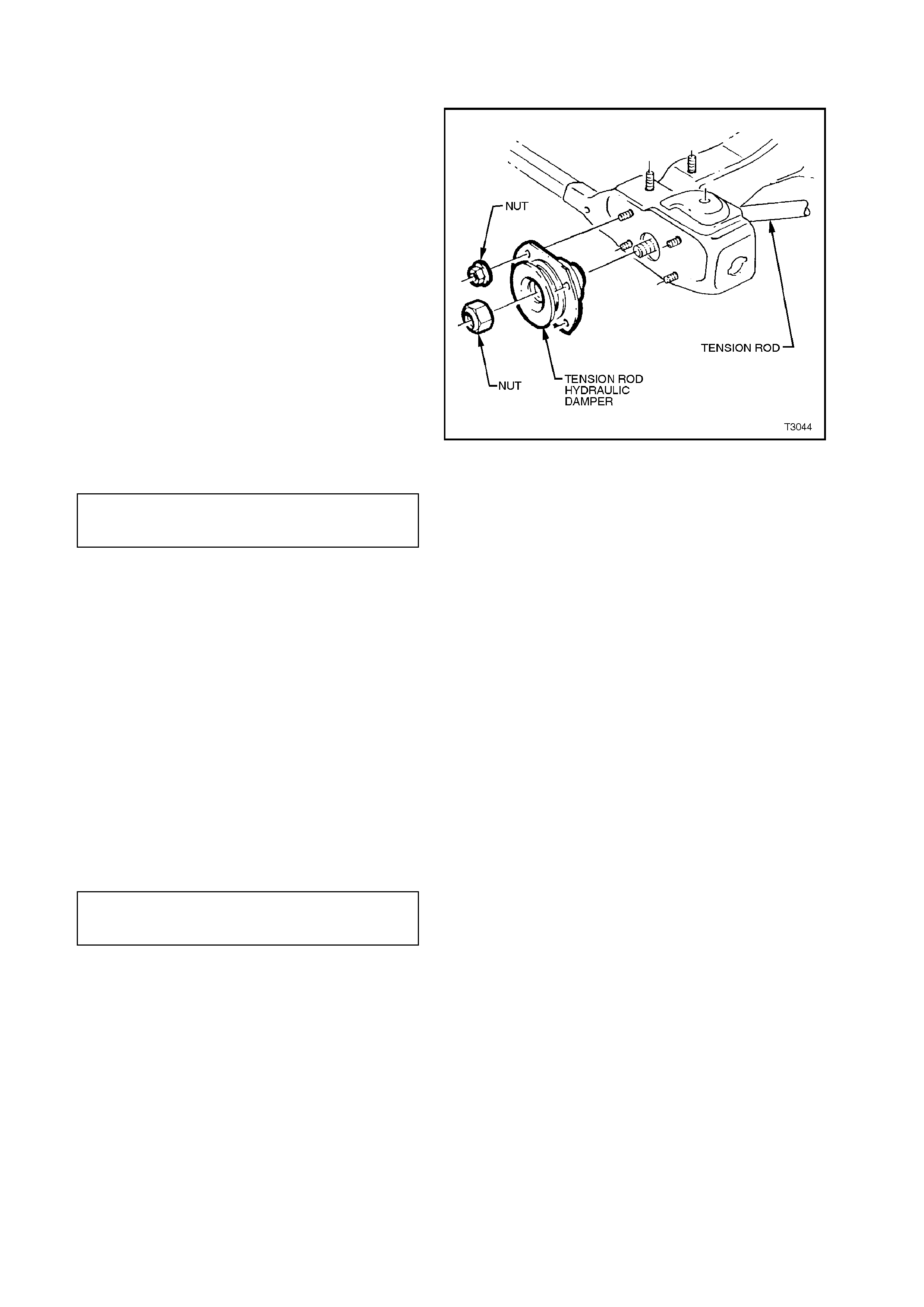
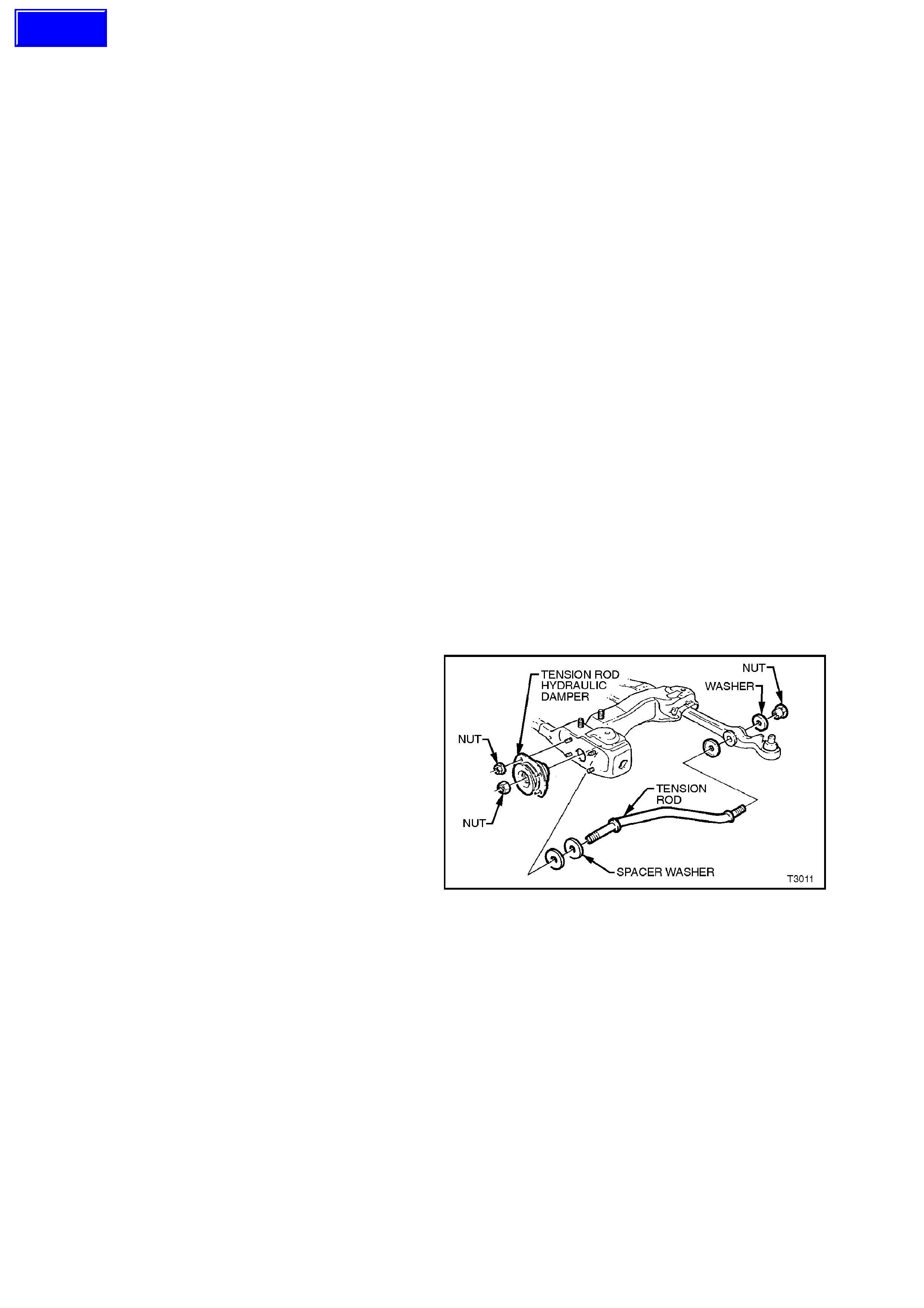
4.11 FRONT SUSPENSION TENSION ROD, HYDRAULIC DAMPER
REPLACE
1. Remove lower control arm tension rod, front
retaining nut and discard. Refer to
4.10 CONTROL ARM TENSION ROD in this
Section for more detail.
2. Remove the four nuts securing the tension
rod, hydraulic damper assembly to the
crossmember outrigger studs. Remove
damper from the vehicle.
3. Install tension rod, hydraulic damper
assembly, over the tension rod and reinstall
four retaining nuts to the crossmember
outrigger studs. Tighten to the correct torque
specification.
Figure 3-44
TENSION ROD HYDRAULIC
DAMPER ASSEMBLY ATTACHING
NUTS TORQUE SPECIFICATION 20 - 26 Nm
4. Install a NEW tension rod retaining nut but do
not fully tighten at this stage.
NOTE:
If fitted, ensure that the spacer washer is installed
over the tension rod before fitting the tension rod
damper.
5. Reinstall road wheel, aligning the mar ks m ade
prior to removal and secure with the attaching
nuts.
6. Remove safety stands and lower vehicle.
7. Bounce vehicle up and down several times to
settle suspension.
8. With the vehicle at curb position, tighten the
tension rod to hydraulic attaching nut to the
correct torque specification.
TENSION ROD TO HYDRAULIC
DAMPER ATTACHING NUT
NUTS TORQUE SPECIFICATION 140 - 155 Nm

IMPORTANT:
The weight of the vehicle must be on all four
wheels before tightening the tension rod to
specification. Otherwise the fluid filled tension rod
bush will be incorrectly preloaded, reducing the life
of the bush and effect ride and handling.
10. Tighten road wheel attaching nuts to the
correct torque specification.
ROAD WHEEL ATTACHING NUT
TORQUE SPECIFICATION 110 - 140
Nm
11. Refit wheel cover/centre cap.
12. Check wheel alignment, as detailed in
2.2 WHEEL ALIGNMENT CHECKING AND
ADJUSTMENT in this Section.
4.12 FRONT SUSPENSION CROSSMEMBER
CAUTION:
Before disturbing the front suspension crossmember mounting bolts, an alignment
procedure is required on installation and a special tool is required for this purpose. If
this tool is not available, then the crossmember cannot be correctly aligned and
steering abnormalities will result.
REMOVE
1. Jack up front of vehicle and place safety
stands under side frame members. Observe
jacking precautions as outlined in 2.3
JACKING PRECAUTIONS in this Section.
2. Remove wheel cover (steel wheels) or centre
cap (alloy wheels).
3. Mark relationship of wheel to hub. Remove
road wheel attaching nuts and remove wheel.
4. Remove brake caliper anchor plate retaining
bolts and washers, lift caliper assembly from
brak e disc. Sus pend caliper on wire or hook to
avoid strain on the hose. DO NOT ALLOW
CALIPER TO HANG BY BRAKE HOSE.
5. Remove brake disc from hub.
6. Drill out the three rivets securing the brake
disc shield and pull shield toward hub to
provide clearance for the ball joint to be
removed from the steering knuckle.
7. Remove the ball joint clamp bolt and nut from
the steering knuckle. Discard the self-locking
nut.
Figure 3-45
8. Using a suitable size open end spanner, hold
the stabiliser bar spacer stud and remove the
lower nut, washer and bush from both sides.
NOTE:
The illustration shows an exploded view of the
assembly, for convenience only.
Figure 3-46
Techline
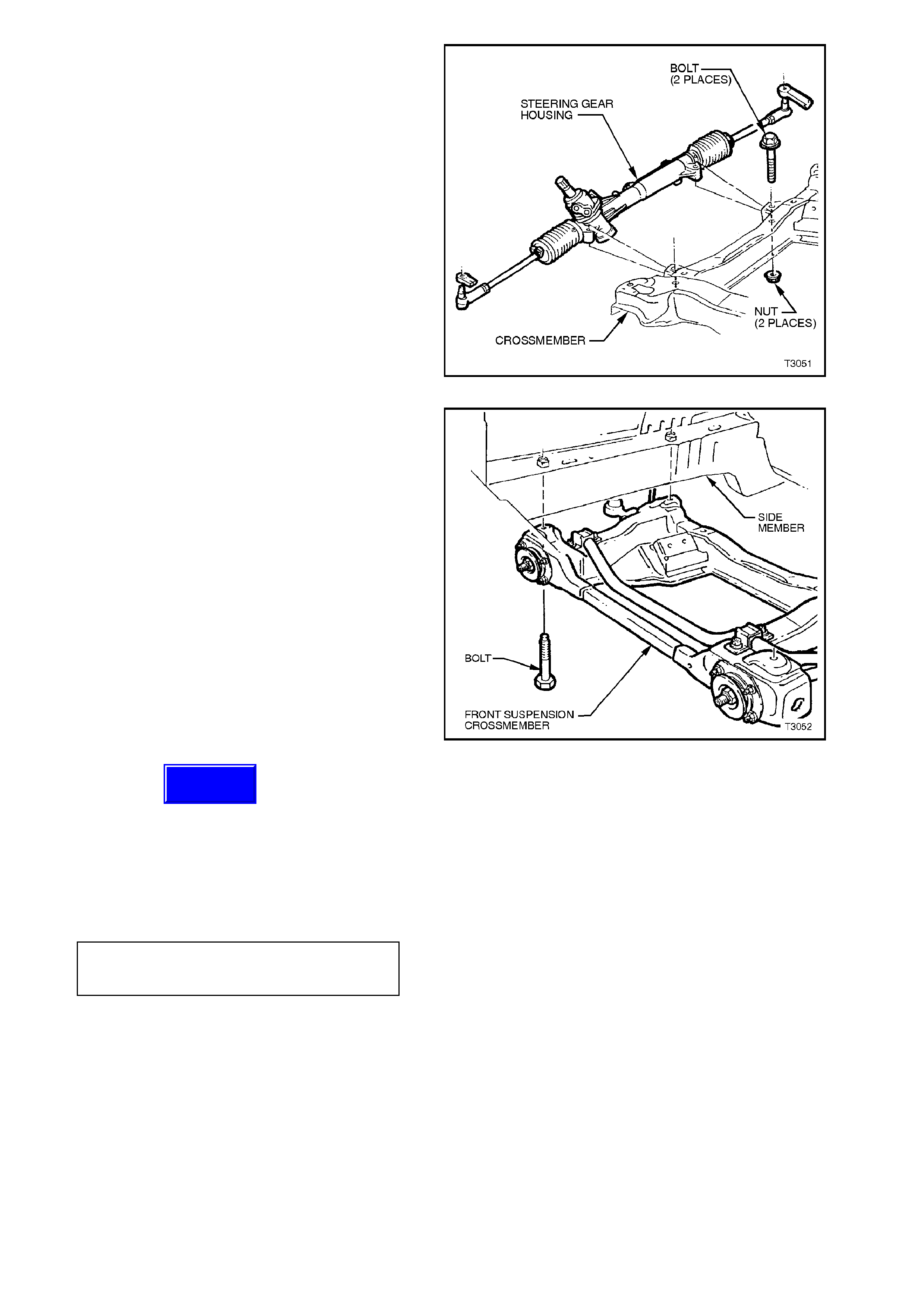
9. Remove steering gear housing to
crossmember mounting bolts, washers and
nuts. Remove steering gear housing from
crossmember mountings.
10. Mark hood hinge positions with felt tipped pen
and remove engine hood.
11. Support engine on a suitable lifting hook and
remove engine mounts to crossmember bolts
or nuts, refer to Section 6A1 ENGINE
MECHANICAL (V6) or Section 6A2 ENGINE
MECHANICAL (V8) for details.
NOTE:
On vehicles with V6 engine, it will be necessary to
loosen engine mounting to cylinder block attaching
bolts.
Figure 3-47
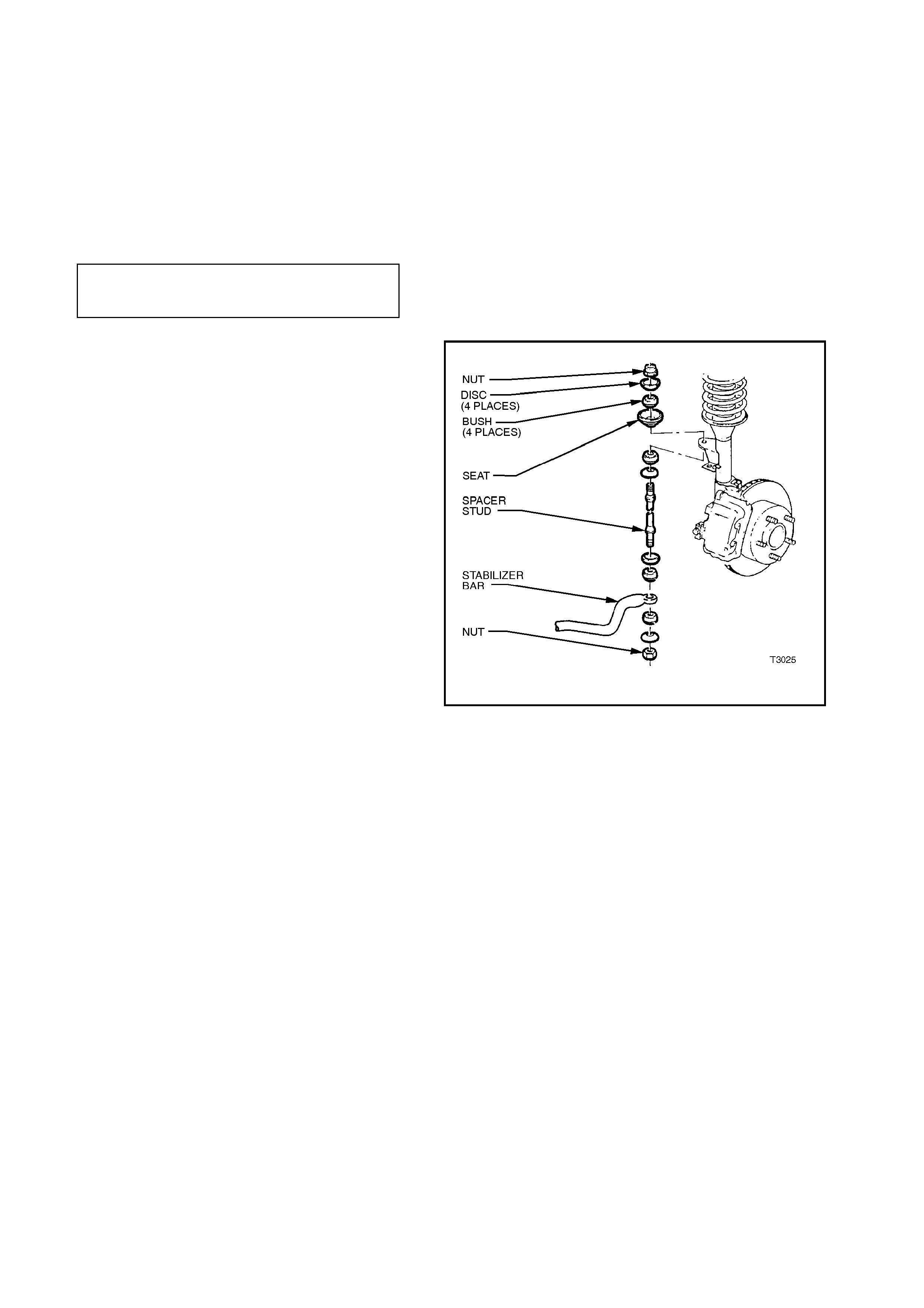
12. Support crossmember on a jack and remove
four bolts securing the crossmember to side
frame members.
NOTE:
If it is known that the same crossmember will be
reinstalled, then scribing alignment marks on the
side frame members before loosening the four
mounting bolts will greatly facilitate alignment
during reassembly.
13. Lower, then remove crossmember from
vehicle.
14. As required, remove the lower control arms,
tension rod hydraulic dampers, tension rods
and stabiliser bar from the crossmember.
Figure 3-48
REINSTALL
W hile the majority of the installation process is the
reverse of removal procedures, note the following
points:
1. Install the stabiliser bar insulating rubbers and
brackets to the crossmember, tightening
retaining nuts to the correct torque
specification.
STABILISER BAR SUPPORT
BRACKET RETAINING NUT
TORQUE SPECIFICATION 24 - 30 Nm
2. When installing the cr ossm ember , it MUST be
aligned correctly, by using the Special Tool
developed for that purpose. Refer to
Section 1A2 BODY DIMENSIONS for details
of the procedure and use of this tool.
CAUTION:
Failure to correctly align the crossmember to
the centreline of the vehicle will result in
steering abnormalities!
Techline

3. Tighten crossmember to side member
attaching bolts to the correct torque
specification.
CROSSMEMBER TO SIDE
MEMBER BOLT
TORQUE SPECIFICATION 120 - 125 Nm
4. Reinstall the two control arms to the
crossmember, installing the pivot bolts from
the rear to the front. Install NEW nuts but do
not fully tighten at this stage.
5. If the lower control arms were removed with
the crossmember, install the ball joint stud to
the steering knuckle and tighten a NEW bolt to
the correct torque specification.
BALL JOINT CLAMP BOLT
TORQUE SPECIFICATION 70 Nm, then turn
through 30° - 40°
6. Reinstall both tension rods, loosely installing
washers and NEW retaining nuts, as detailed
in 4.10 CONTROL ARM TENSION ROD in
this Section. Do not tighten at this time. The
tension rod hydraulic damper mounting nuts
however, can be tightened to the correct
torque specification.
TENSION ROD HYDRAULIC
DAMPER ASSEMBLY
ATTACHING NUTS
TORQUE SPECIFICATION 20 - 26 Nm
7. Refit steering gear housing to crossmember,
tighten mounting nuts to the correct torque
specification.
STEERING GEAR HOUSING
TO CROSSMEMBER
MOUNTING NUT
TORQUE SPECIFICATION
70 - 85 Nm
8. Reconnect engine mounts to crossmember,
refer to Section 6A1 ENGINE MECHANICAL
(V6) or Section 6A2 ENGINE MECHANICAL
(V8) for details.
9. Reinstall brak e disc and caliper, tightening the
caliper retaining bolts to the correct torque
specification.
BRAKE CALIPER ANCHOR
PLATE RETAINING BOLTS
TORQUE SPECIFICATION
80 - 90 Nm,
then turn through
40°-50°
10. Install road wheel, aligning marks made prior to
removal.
11. Refit engine hood.
12. Remove safety stands and lower vehicle.
13. Bounce vehicle up and down several times to
settle suspension.

14. Tighten lower control arm, inner pivot bolt nuts
to the correct torque specifications.
LOWER CONTROL ARM
INNER PIVOT BOLT NUTS
TORQUE SPECIFICATION 95 - 100 Nm
15. With the vehicle at curb position, tighten the
tension rod attaching nuts at the lower control
arm and the hydraulic damper, to the correct
torque specifications.
TENSION ROD TO CONTROL
ARM ATTACHING NUT
TORQUE SPECIFICATION 95 - 110 Nm
TENSION ROD
TO HYDRAULIC
DAMPER ATTACHING NUT
TORQUE SPECIFICATION
140 - 155
Nm
IMPORTANT:
The weight of the vehicle must be on all four
wheels before tightening the tension rod to
specification. If not, the fluid filled tension rod bush
will be ruptured, once the vehicle is put back into
service.
16. Check wheel alignment, as detailed in
2.2 WHEEL ALIGNMENT CHECKING AND
ADJUSTMENT in this Section.

4.13 STABILISER BAR
NOTE:
To remove the stabiliser bar completely from the vehicle, it will first be necessary to remove the crossmember.
Refer to Operation 4.12 FRONT SUSPENSION CROSSMEMBER in this Section.
Alternatively, the stabiliser bar insulators and mounting brackets, and/or the spacer stud, nuts, discs or bushes, can
all be replaced without removing the stabiliser bar from the vehicle.
REMOVE
1. Raise front of vehicle and support on safety stands. Observe jacking precautions as outlined in 2.3 JACKING
PRECAUTIONS in this Section.
2. After scribing crossmember alignment marks on the side frame members, remove the front suspension
crossmember mounting bolts, then lower enough to enable removal of the stabiliser bar from the vehicle.
3. Remove nuts securing support bracket to each side of the crossmember, then remove the stabiliser bar,
support brackets and insulators from the crossmember.
4. Remove the insulators from the stabiliser bar.
REINSTALL
1. Assem ble two insulators and s upport brackets
to stabiliser bar and bolt brackets to
crossmember outrigger.
NOTE:
The s lot in each insulator should face f orward, and
the rounded sections on the insulators should seat
in the mating recesses in the crossmember side
frame.
2. Tighten stabiliser bar support bracket bolts to
the correct torque specification.
STABILISER BAR SUPPORT
BRACKET RETAINING NUTS
TORQUE SPECIFICATION 24 - 30 Nm
3. Install stabiliser bar spacer stud nut after
ensuring that all components are assembled
as shown. While holding the spacer bar
spacer stud with a suitable sized spanner,
install the lower nut and tighten until the nut is
fully installed onto the threaded section of the
stud.
NOTE 1:
Do not use power operated tools for this operation
as thread damage will result
NOTE 2:
The illustration shows an exploded view of the
assembly, for convenience only.
4. Install front suspension crossmember, as
detailed in Operation
4.12 FRONT SUSPENSION
CROSSMEMBER in this Section.
5. Remove safety stands and lower vehicle.
Figure 3-49
5. DIAGNOSIS
GENERAL
When diagnosing suspected front suspension
problems, it should be remembered that steering,
wheels and tyres all have an effect on front end
performance (Refer to Section 9A STEERING or
Section 9B SPEED SENSITIVE POWER
STEERING and Section 10 WHEELS AND
TYRES for details).
STRUT DIAGNOSIS
1. Test by quickly pushing up and down on the
bumper bar at the front corner of the vehicle.
Compare the resistance to movement with a
similar vehicle having acceptable ride quality.
2. Inspect the struts for excessive fluid leakage.
ACCEPTANCE CRITERIA
A strut DOES NO T require r eplacem ent, if any or a
combination of the following are present:
• An oily build-up at the end of the piston rod, up
to 1 cm wide.
• Oily ‘sludge’ accum ulated f r om normal oper ating
conditions to 4 cm from the top of the strut body.
• Road grease, oil, sand and dust discolouration
on the body, does not constitute a leak ing strut.
If this condition is evident, the strut should be
wiped clean and checked at a later service.
NOTE:
Should one strut prove to be leaking and require
replacement, provided the remaining strut is
serviceable, it does not also need to be replaced.
5.1 DIAGNOSIS GUIDE
HARD OR HEAVY STEERING
SYMPTOM AND PROBABLE CAUSE REMEDY
1. Low or uneven tyre pressures 1. Inflate tyres to specified pressure for
specific load conditions. See tyre
placard attached to the vehicle
2. Steering gear or connections too tight
or misaligned 2. Adjust steering gear or replace
components as necessary.
See Section 9A.
3. Insufficient fluid in steering gear. 3. Check steering gear fluid level. Top up,
using only DEXRON III® fluid. Check
system for leaks. See Section 9A.
4. Excessive caster 4. Check front wheel alignment. Adjust as
necessary. See Operation 2.2, in this
Section.
5. Lower control arm/s and/or tension
rod/s bent. 5. Check alignment of control arms and
tension rods. Replace components as
necessary. See Operation 2.2, in this
Section.
6. Steering knuckle bent. 6. Replace steering knuckle. See Operation
4.5 in this Section.
7. Excessive toe-in. 7. Check and adjust wheel toe. See
Operation 2.2, in this Section.
Techline
Techline

EXCESSIVE PLAY OR LOOSENESS IN TEERING
SYMPTOM AND PROBABLE CAUSE REMEDY
1. Steering gear or connections loose or
worn. 1. Adjust steering gear or install new
components as required. See Section 9A.
2. Control arm ball joint loose or worn. 2. Replace ball joint assembly. See
Operation 4.7, in this Section.
3. Front wheel bearings worn. 3. Replace front hub assembly. See
Operation 3.2, in this Section.
4. Loose attachment of crossmember to
frame. 4. Check, align and tighten crossmember
attaching nuts. See Operation 4.12, in this
Section and Section for alignment
procedures.
ERRATIC STEERING ON APPLICATION OF BRAKES
SYMPTOM AND PROBABLE CAUSE REMEDY
1. Low or uneven tyre pressures. 1. Inflate tyres to specified pressure for
specific load conditions. See ty re placard
attached to the vehicle.
2. Excessive front brake disc runout. 2. Machine front discs. Refer to Section 5A.
3. Front brake pads contaminated with
lubricant. 3. Replace brake pads. Correct cause of
lubricant lleakage.
4. Insufficient or uneven caster. 4. Check front wheel alignment. See
Operation 2.2, in this Section.
5. Steering knuckle bent. 5. Replace steering knuckle. See Operation
4.5, in this Section.
6. Excessive play in steering gear. 6. Adjust steering gear or replace worn
components, See Section 9A.
VEHICLE PULLS TO ONE SIDE
SYMPTOM AND PROBABLE CAUSE REMEDY
1. Low or uneven tyre pressures. 1. Inflate tyres to specified pressure for
specific load conditions. See ty re placard
attached to the vehicle.
2. Rear wheels not tracking with front
wheels 2. Check alignment of rear wheels with front
wheels and correct as necessary. See
Section 4A, for details of rear wheel
alignment.
3. Front brake pads contaminated with
lubricant. 3. Replace brake pads. Correct cause of
lubricant leakage.
4. Toe-in incorrect. 4. Adjust toe-in to specification. See
Operation 2.2 in this Section.
5. Incorrect or uneven caster or camber. 5. Check wheel alignment. Adjust as
necessary. See Operation 2.2, in this
Section.
6. Rear axle assembly shifted. 6. Check attaching bolts for looseness and
control arm bushes for wear.
See Section 4A.
7. Steering knuckle bent.7. Replace steering knuckle. See Operation
4.5 in this Section.
FRONT OR REAR WHEEL TRAMP
SYMPTOM AND PROBABLE CAUSE REMEDY
1. Wheels and tyres out of balance. 1. Balance wheels and tyres. Also check for
eccentric or bulged tyres. Replace as
necessary. See Section 10.
2. Front struts or rear shock absorbers
operating incorrectly, leaking fluid or
inoperative.
2. Check operation and replace components
as necessary. See Operation 4.1 in this
Section or Section 4A.

ROAD SHOCKS
SYMPTOM AND PROBABLE CAUSE REMEDY
1. Incorrect tyre pressures. 1. Inflate tyres to specified pressure for
specific loadconditions. See ty re placard
attached to the vehicle.
2. Steering gear incorrectly adjusted. 2. Adjust steering gear. See Section 9A.
3. Front struts or rear shock absorbers
operating incorrectly or unevenly,
leaking fluid or inoperative.
3. Check operation and replace components
as necessary. See Operation 4.1 in this
section or Section 4A.
4. Compression or rebound rubbers
damaged or missing. 4. Replace missing or damaged parts. See
Operation 4.4 in this Section.
5. Unbalanced wheels. 5. Balance wheels as detailed in Section 10.
6. Incorrect wheel alignment.6. Check and adjust. See Operation 2.2 in
this Section.
SCUFFED TYRES
SYMPTOM AND PROBABLE CAUSE REMEDY
1. Toe-in incorrect. 1. Adjust toe-in. See Operation 2.2 in this
Section.
2. Tyres improperly inflated. 2. Inflate tyres to specified pressure for
specific load conditions. See ty re placard
attached to the vehicle.
3. Wheels or tyres out-of-true. 3. Check for wheel and tyre wobble. Check
that the wheels and tyres are correctly
mounted. Balance wheels and tyres.
See Section 10.
4. Control arm ball joint/s worn. 4. Replace worn components. See Operation
4.8 in this Section.
5. Uneven caster and camber. 5. Check wheel alignment. Adjust as
necessary. See Operation 2.2, in this
Section.
6. Lower control arm/s or tension rod/s. 6. Check alignment of control arm/s and
tension rod/s.Replace components as
necessary . See Operations 4.6 and 4.10
in this Section.
7. Steering knuckle bent.7. Replace steering knuckle. See Operation
4.5, in this Section.
CUPPED TYRES
SYMPTOM AND PROBABLE CAUSE REMEDY
1. Tyres improperly inflated. 1. Inflate tyres to specified pressure for
specific load conditions. See ty re placard
attached to the vehicle.
2. Wheels and tyres out-of-balance. 2. Balance wheels and tyres. Also check for
eccentric or bulged tyres. Replace as
necessary. See Section.
3. Dragging brakes. 3. Check for seizing of the brake calipers
and/or park brake mechanism. See
Section 5A.
4. Control arm ball joint/s and/or wheel
bearings worn. 4. Replace worn components. See Operation
4.7 or 3.2 in this Section.
5. Uneven caster. 5. Check wheel alignment. Adjust as
necessary. See Operation 2.2, in this
Section.
6. Steering knuckle bent 6. Replace steering knuckle. See Operation
4.5, in this Section.
FRONT WHEEL SHIMMY
SYMPTOM AND PROBABLE CAUSE REMEDY
1. Low or uneven tyre pressures. 1. Inflate tyres to specified pressure for
specific load conditions. See ty re placard
attached to the vehicle.
2. Steering connections incorrectly
adjusted or worn. 2. Adjust steering gear or install new
components as needed. See Section 9A.
3. Control arm ball joint/s and/or wheel
bearings worn. 3. Replace worn components. See Operation
4.7 or 3.2 in this Section.
4. Wheels and tyres out-of-balance. 4. Balance wheels and tyres. Also check for
eccentric or bulged tyres. Replace as
necessary. See Section 10.
5. Wheels or tyres out-of-true. 5. Check for wheel and tyre wobble. Check
that the wheels and tyres are correctly
mounted. Balance wheels and tyres.
See Section 10.
6. Incorrect or uneven caster or incorrect
toe-in setting. 6. Check and adjust. See Operation 2.2 in
this Section.
7. Steering knuckle bent. 7. Replace steering knuckle. See Operation
4.5, in this Section.
CAR WANDERS
SYMPTOM AND PROBABLE CAUSE REMEDY
1. Low or uneven tyre pressures. 1. Inflate tyres to specified pressure for
specific load conditions. See ty re placard
attached to the vehicle.
2. Steering connections loose or worn. 2. Adjust steering gear or install new
components as needed. See Section 9A.
3. Steering gear connections adjusted too
tight. 3. Test steering system for binding with front
wheels off the ground.
See Sections 9A or 9B.
4. Control arm ball joint/s worn. 4. Replace worn components. See Operation
4.7 in this Section.
5. Wheel toe settings outside
specifications. 5. Adjust toe-in. See Operation 2.2 in this
Section.
6. Incorrect or uneven caster. 6. Check wheel alignment. Adjust as
necessary. See Operation 2.2, in this
Section.
7. Steering knuckle bent. 7. Replace steering knuckle. See Operation
4.5 in this Section.
8. Rear axle shifted. 8. Check all attachment fasteners for
security, tightening to specification, as
required.
9. Loose attachment of sub-frame to side
rails 9. Check, align and tighten all fasteners to
specification. See Section 1A2 for
alignment procedures.
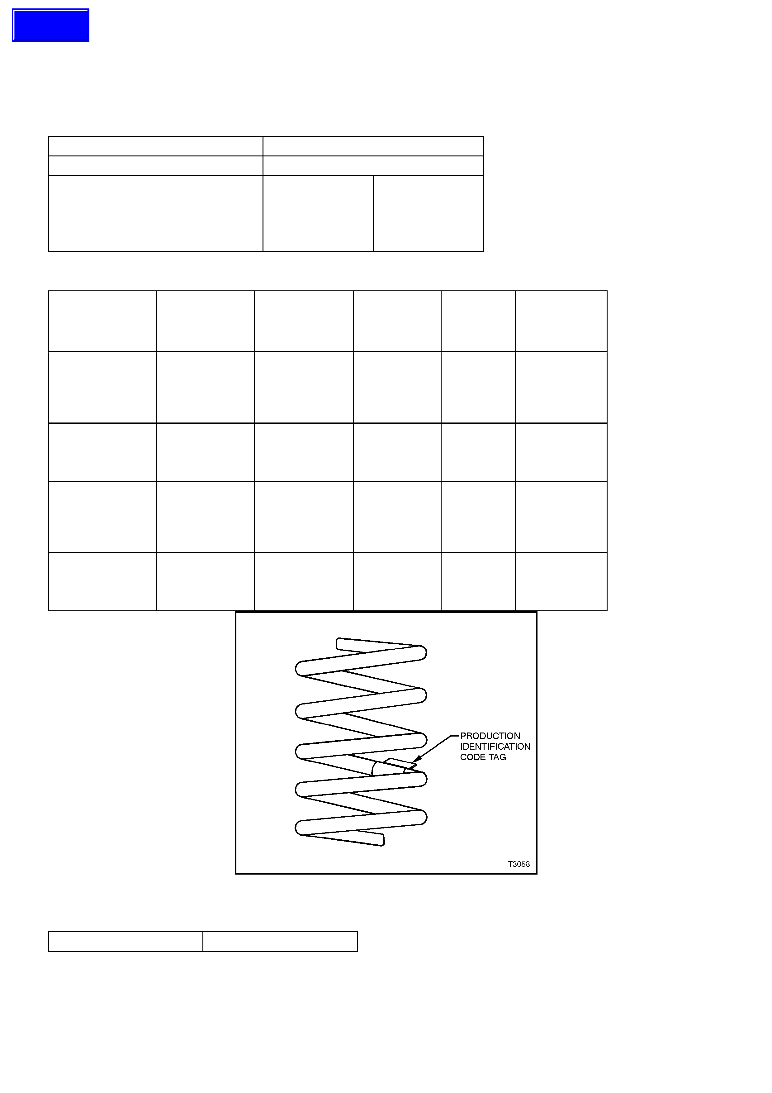
6. SPECIFICATIONS
SUSPENSION
Type MacPherson Wet Strut
Application All VT Models
Travel
Compression
(2/3compression of bumper)
Rebound
Standard
90 mm
110 mm
FE2
80 mm
120 mm
FRONT SPRING DETAILS
MODELS Approximate
Number COILS Approximate
FREE LENGTH
(mm)
INSIDE
DIAMETER
(mm)
PROD. I.D.
CODE
(Tag on
spring)
SPRING
TYPE & RATE
V6 ENGINE -
SEDAN &
S/WAGON
MODELS - STD.
SUSPENSION.
6.05 444 136 ± 1.5 HN VARIABLE
19 - 23 N/mm
V6 ENGINE -
SEDAN MODELS
- FE2
SUSPENSION.
5.25 341 136 ± 1.5 HJ VARIABLE
24 - 31 N/mm
V8 ENGINE -
SEDAN &
S/WAGON
MODELS - STD.
SUSPENSION.
6.12 376 136 ± 1.5 HS VARIABLE
24 - 31 N/mm
V8 ENGINE -
SEDAN MODELS
- FE2
SUSPENSION.
5.74 351 136 ± 1.5 HK VARIABLE
27 - 35 N/mm
Figure 3-50
STABILISER BAR (FRONT)
Type Decoupled
Techline
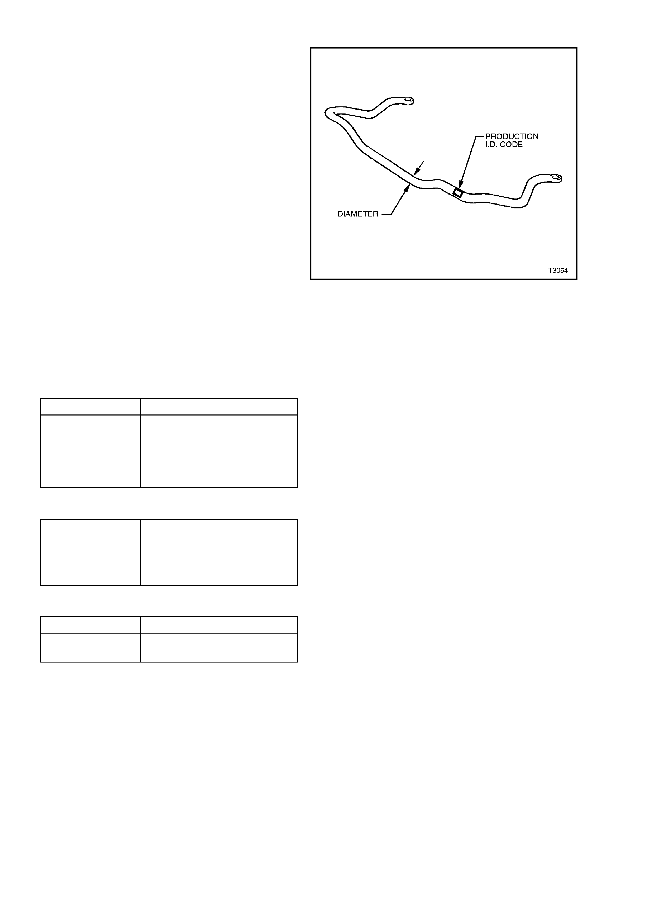
STABILISER BAR DETAILS
MODELS mm I.D. CODE
V6 ENGINE - SEDAN
MODELS -STANDARD
SUSPENSION 26.0 GE
V6 ENGINE - SEDAN
MODELS -FE2
SUSPENSION 26.0 GE
V6 ENGINE - S/WAGON
MODELS -STANDARD
SUSPENSION 26.0 GE
V8 ENGINE - SEDAN
MODELS -STANDARD
SUSPENSION 25.0 GF
V8 ENGINE - SEDAN
MODELS -FE2
SUSPENSION 25.0 GF
V8 ENGINE - S/WAGON
MODELS -STANDARD
SUSPENSION 25.0 GF
V6 and V6 S/C ENGINE
‘S’ MODELS 26.0 GE
V8 ENGINE - ‘SS’ MODELS 26.0 GE
Figure 3-51
SHOCK ABSORBER
Type Wet strut - non serviceable
Piston Diameter
Fluid Type
Capacity
30 mm
Hydraulic Fluid (Holden's
Specification HN1588) P/N
VS14444
350 ml
CONTROL ARM
Type Forged with rubber bushes for
attachment to front cross-
member and tension rod. Ball
joint is a press fit into the
lower control arm.
FRONT WHEEL BEARINGS
Type Double Row Ball Bearings
Lubricant Sealed for life - non-
adjustable
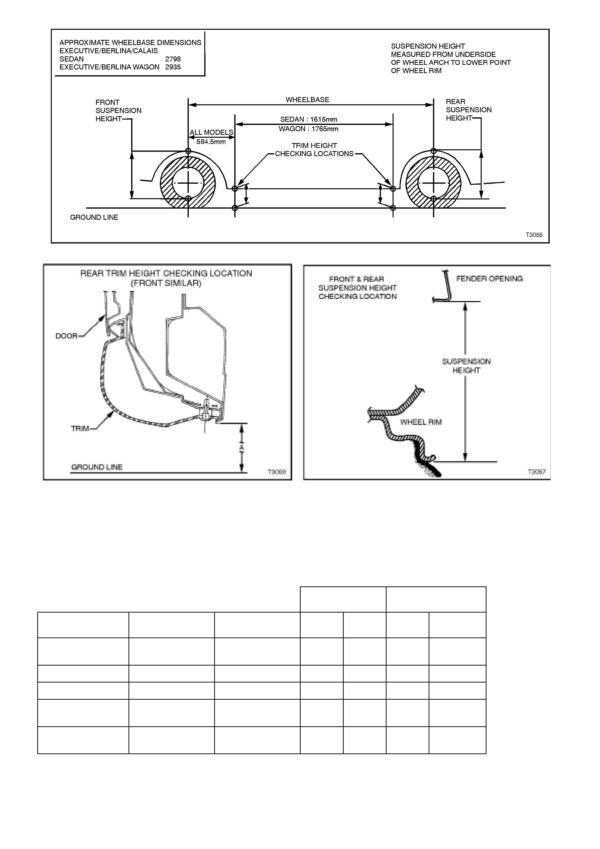
Figure 3-52
Figure 3-53 Figure 3-54
NOTE:
The following suspension/trim height dimensions are intended for reference and are intended to be a guide
only (refer to 3-1 SUSPENSION AND TRIM HEIGHT CHECK)
VT SERIES MODELS WITH V6 ENGINE AND STANDARD SUSPENSION
SUSPENSION
HEIGHT (MM) TRIM HEIGHT
(MM)
VEHICLE
DESCRIPTION TRANSMISSION
TYPE OPTIONS FRONT REAR FRONT REAR
EXECUTIVE
SEDAN MANUAL BASE 598 562 194 201
BERLINA SEDAN AUTOMATIC BASE 603 586 192 200
CALAIS SEDAN AUTOMATIC BASE 609 603 196 206
EXECUTIVE
STATION WAGON MANUAL BASE 603 573 196 212
BERLINA
STATION WAGON AUTOMATIC BASE 598 582 191 210

7. TORQUE WRENCH SPECIFICATIONS
Nm
! ! Steering knuckle to strut
attaching bolt Stage 1: 85
2: 100
3:
Then turn through 90°
♦ ♦ Front hub to steering knuckle
attaching bolt
100 - 115
Wheel speed sensor (ABS) cable
retaining screw 6 - 14
Brake caliper attaching bolt Stage 1: 80 - 90
2:
Then turn through 40°-
50°
Stabiliser bar spacer stud nut Hand tighten to end
of thread
Stabiliser bar support bracket
attaching nut 24 - 30
! ! Upper strut bearing retaining
nut 70 - 85
! ! Upper strut locating plate
retaining nut 50 - 60
! ! Ball joint clamp bolt Stage 1: 70
2:
Then turn through 30° -
40°
Tie rod ball joint stud castellated
nut 58 - 71
Control arm inner pivot bolt 95 - 110
! ! Tension rod to control arm
attaching nut 95 - 110
! ! Tension rod to hydraulic
damper retaining nut 140 - 155
Tension rod hydraulic damper
assembly attaching nut 20 - 26
Crossmember to side frame bolt 120 - 125
Steering gear housing to
crossmember mounting nut 70 - 85
Road wheel attaching nut 110 - 140
KEY
! !NEW bolts and/or nuts MUST be used in
these locations on reassembly!
♦ ♦These fasteners have micro-encapsulated
sealant applied and should be replaced after
being loosened more than three times. If in doubt,
replacement is recommended.
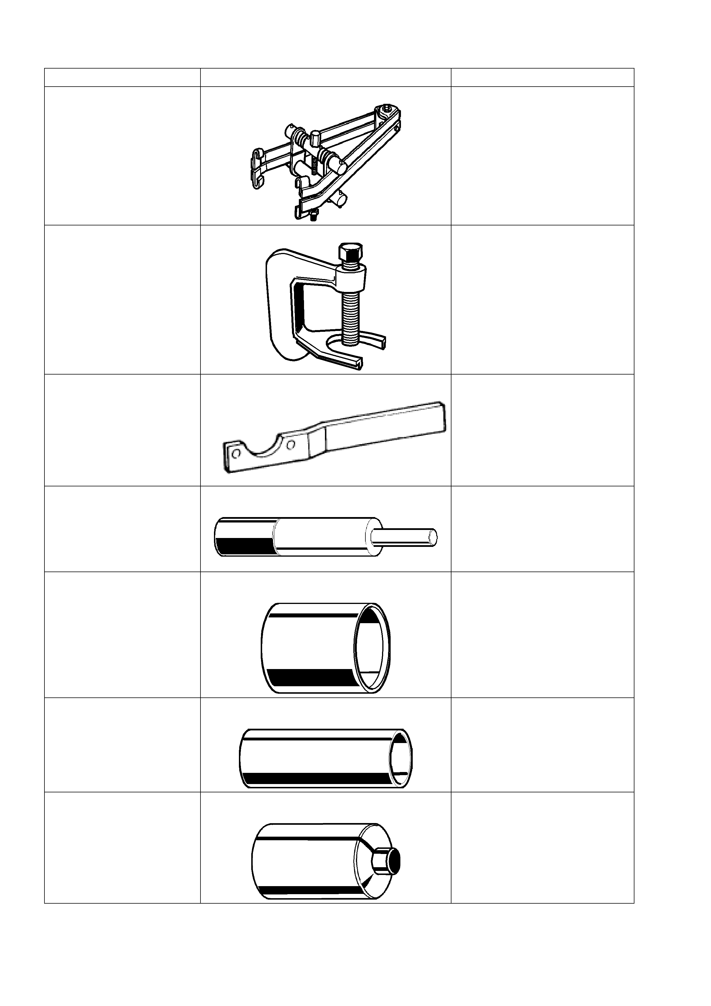
8. SPECIAL TOOLS
TOOL NO. REF IN TEXT TOOL DESCRIPTION COMMENTS
180 SPRING COMPRESSOR PREVIOUSLY RELEASED.
AJ24292-C PRESS TOOL PREVIOUSLY RELEASED
FOR "VQ" VEHICLES.
USED TO REMOVE WHEEL
STUDS FROM FRONT HUB.
KM468 HOLDING BAR PREVIOUSLY RELEASED
FOR 'J' CAR.
USED TO HOLD FRONT
WHEEL HUB FROM
ROTATING.
AU158 CONTROL ARM TENSION ROD BUSH
REMOVER AND INSTALLER MANDREL PREVIOUSLY RELEASED
FOR "V" CAR.
USED WITH KM158-2 FOR
REMOVING BUSH AND AU159
AND KM157-2 FOR
INSTALLING.
AU158-2 CONTROL ARM TENSION ROD BUSH
INSTALLING SUPPORT SLEEVE PREVIOUSLY RELEASED
FOR "V" CAR.
USED WITH AU158 AND
AU159.
AU159 CONTROL ARM TENSION ROD BUSH
REPLACER SLEEVE PREVIOUSLY RELEASED
FOR "V" CAR.
AU162 CONTROL ARM INNER PIVOT BUSH
REMOVAL MANDREL USED WITH AU160-1 AND
KM157-2.
PREVIOUSLY RELEASED
FOR "V" CAR..
KM157-2 CONTROL ARM BUSH INSTALLER PREVIOUSLY RELEASED
FOR "V" CAR.
USED WITH AU158 AND
AU159.
9A10 TIE ROD BALL JOINT REMOVER PREVIOUSLY RELEASED
FOR "V" CAR.
7A42 PRESS PLATES PREVIOUSLY RELEASED.
E7115 ANGLE WRENCH PREVIOUSLY RELEASED
FOR 'J' AND 'V' CARS.
USED TO TIGHTEN
COMPONENT FASTENERS
WHEN ANGLE TORQUE IS
REQUIRED.