SECTION 4A - REAR SUSPENSION
CAUTION:
This vehicle will be equipped with a Supplemental Restraint System (SRS). An SRS
will consist of either seat belt pre-tensioners and a driver's side air bag, or seat belt
pre-tensioners and a driver's and front passenger's side air bags. Refer to
CAUTIONS, Section 12M, before performing any service operation on or around any
SRS components, the steering mechanism or wiring. Failure to follow the CAUTIONS
could result in SRS deplo yment, resulting in possible p ersonal injury or unnecessary
SRS system repairs.
CAUTION:
This vehicle may be equipped with LPG (Liquefied Petroleum Gas). In the interests of
safety, the LPG fuel system should be isolated by turning ‘OFF’ the manual service
valve and then draining the LPG serv ice lines, before any service w ork is carried out
on the vehicle. Refer to the LPG leaflet included with the Owner's Handbook for
details or LPG Section 2 for more specific servicing information.
CAUTION:
Whenever any component that forms part of the ABS or ABS/ETC (if fitted), is
disturbed during Service Operations, it is vital that the complete ABS or ABS/ETC
system is checked, using the procedure as detailed in 4. DIAGNOSIS, ABS or
ABS/ETC FUNCTION CHECK, in Section 12L ABS & A BS/ETC.
1. GENERAL DESCRIPTI ON
Fitted as standard equipment on VT sedans and station wagon models, the independent rear suspension, is
equipped with variable rate minibloc coil rear springs and direct acting shock absorbers.
The rear suspension consists of a rear crossmember which is attached by large volume rubber bushes at each front
corner to the vehicle underbody. Rear location is provided by a rear mounting bolted to the differential carrier
assembly that is in turn, attached to the crossmember.
Two trailing arms are attached to the crossmember pivot points through rubber bushes. The trailing arms provide
attachment of the rear brake and trunnion assemblies, flanges and drive shaft outer (rear wheel) bearings.
A decoupled type stabiliser bar is attached to the top of the crossmember by two brackets and insulating bushes.
The outer ends of the stabiliser bar are attached to each trailing arm by a link via insulating bushes.
All VT applications have twin tube hydraulic shock absorbers that are double acting and are mounted between the
vehicle underbody and each trailing arm. The FE2 SPORTS SUSPENSION shock absorbers are twin tube, gas
pressurised units.
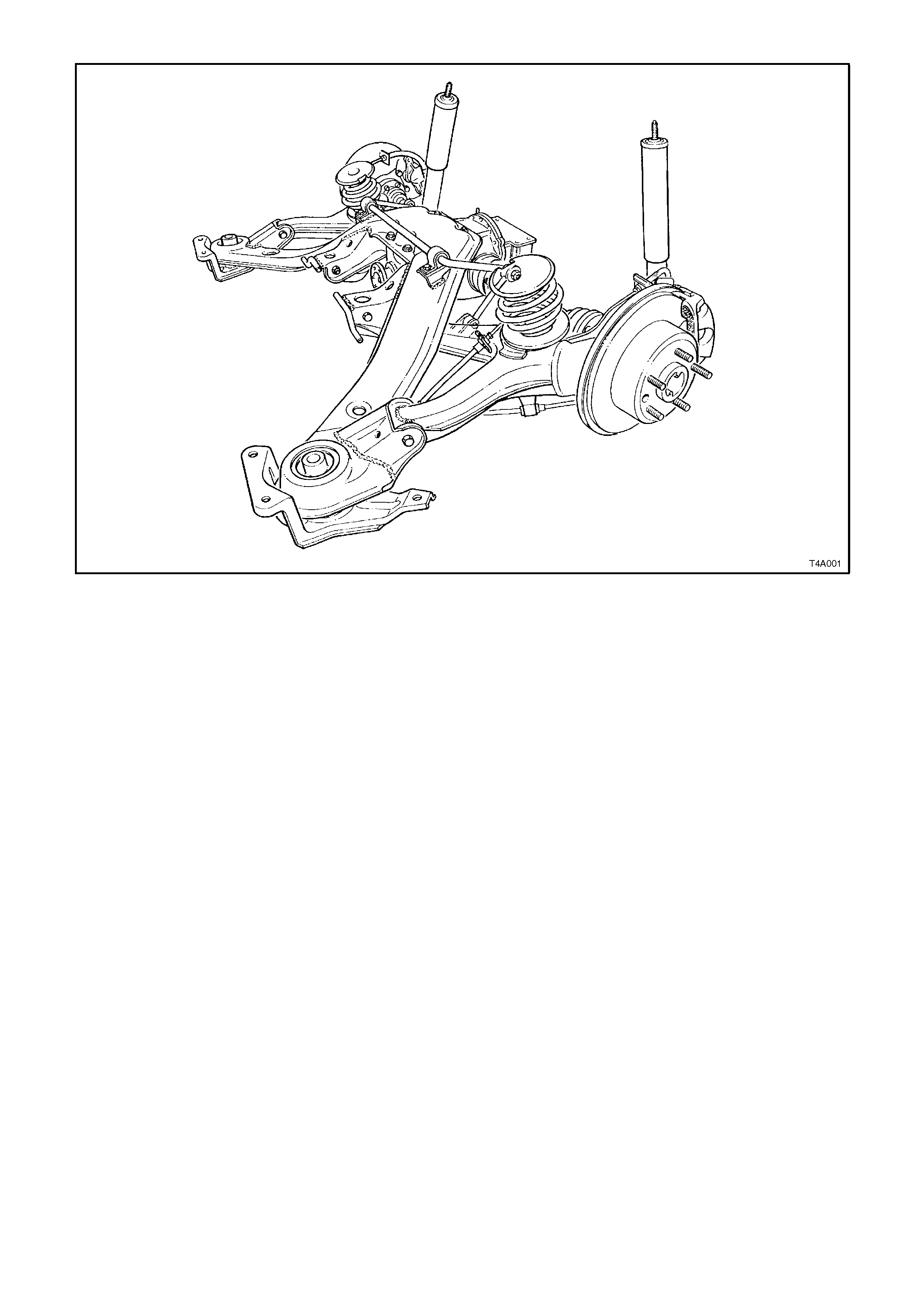
Figure 4A-1

2. SERVICE OPERATIONS
2.1 SERVICE NOTES
All rear suspension fasteners are important attaching parts because they affect the performance of vital
components and/or could result in major repair expense. Where specified in this Section, fasteners MUST be
replaced with ones of the same part number or with an equivalent part. Do not use a replacement part of inferior
quality or substitute design.
Torque values must be used as specified during reassembly to ensure proper retention of all rear suspension
components.

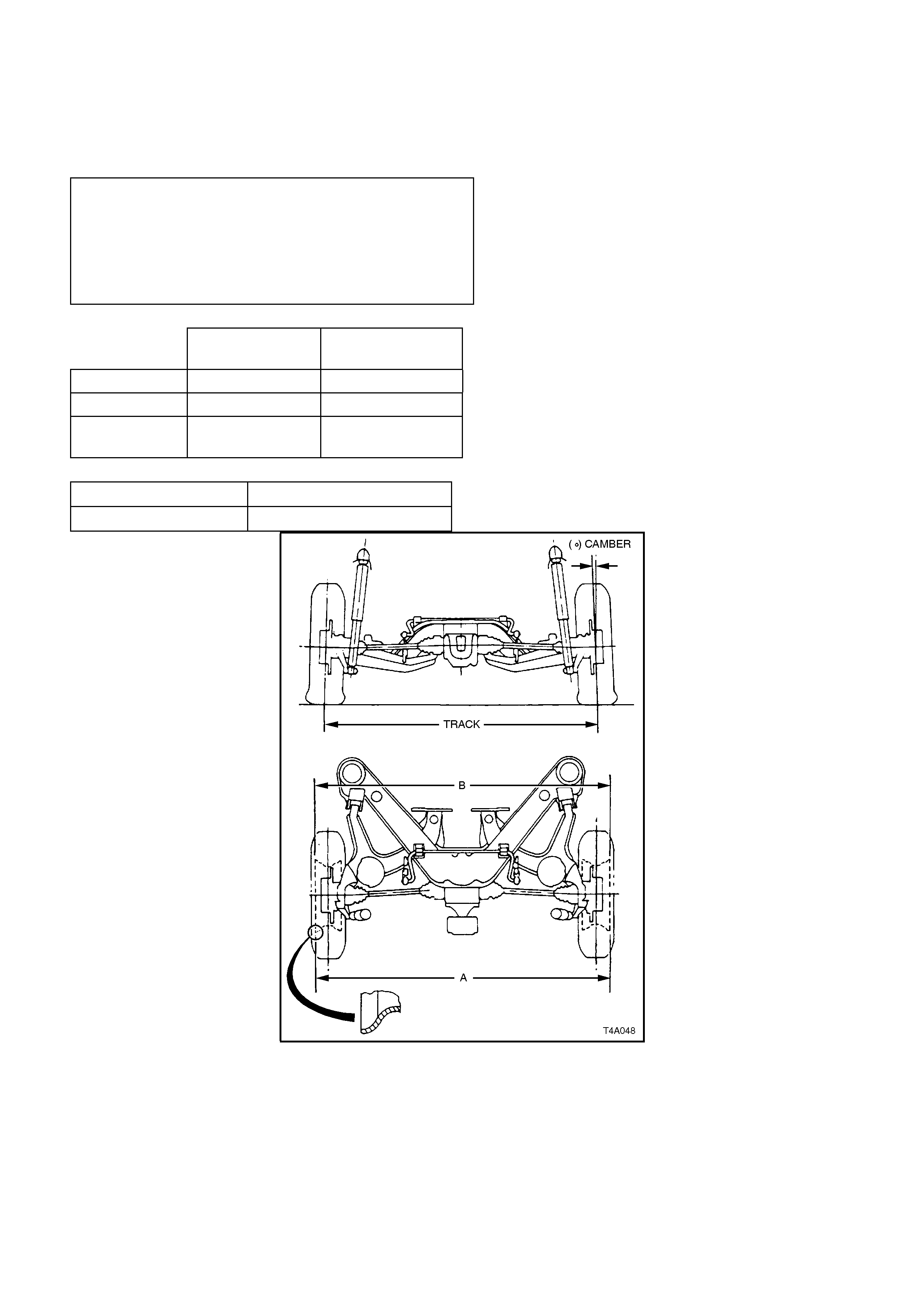
2.2 REAR WHEEL ALIGNMENT CHECKING
CAMBER AND TOE CHECK
The following conditions must be checked to
ensure accurate measurement of rear wheel
alignment.
1. Tread on rear tyres must be uniform and in a
roadworthy condition.
2. Tyre pressures must be equal on both sides
and to the correct pressure. Refer to the tyre
placard on the vehicle for correct tyre
pressures.
3. Wheel rim flange lateral run-out should be
checked and to specification, refer to
Section 10 WHEELS AND TYRES.
4. The vehicle m us t be at kerb height, i.e. vehic le
ready to drive with all fluids at recommended
levels, fuel tank full, without driver,
passengers or luggage.
5. Stabilise vehicle springs by bouncing rear of
vehicle several times.
This step is very important, particularly if
vehicle was raised before checking. In that
instance, the camber angle measured will be
excessive, because the trailing arms will not
have resumed their normal position.
NOTE 1:
Camber and wheel toe are not adjustable. If there
is any deviation from specification, the condition
and alignment of the crossmember, trailing arms
and bushes should be checked.
NOTE 2:
When checking wheel toe, if one side has
excessive toe-in and the opposite side has
excessive to e-out, this may be due to:
a. The trailing ar m attac hing nuts being tightened
when the vehicle was not at kerb height.
b. The rear cros sm em ber not correc tly aligned to
the vehicle centreline.
To correct such a condition, check the rear
crossmember alignment, as detailed in
Section 1A2 BODY DIMENSIONS. Following the
alignment procedure, tighten fastenings to the
following torque specifications.
NOTE:
Those fasteners marked ( ! ) must be replaced
after loosening.
REAR CROSSMEMBER FRONT
MOUNTING BOLT
TORQUE SPECIFICATION
125 Nm, plus
30° - 40°
turn angle
REAR CROSSMEMBER REAR
MOUNT TO UNDERBODY
ATTACHING BOLT (!)
TORQUE SPECIFICATION
30 - 40 Nm
TRAILING ARM TO REAR
CROSSMEMBER ATTACHING
NUT (!) TORQUE SPECIFICATION 95 - 105 Nm
IMPORTANT:
Alignment of the rear crossmember requires the use
of a special tool. Attempting the align the rear
crossmember without it will not prove to be
successful.
2.3 SUSPENSION AND TRIM HEIGHT, CHECK
For suspension and trim height dimensions, refer to Section 3 FRONT SUSPENSION.
REAR SUSPENSION ALIGNMENT
SPECIFICATIONS
SEDAN MODELS STANDARD
SUSPENSION FE2
SUSPENSION
REAR TRACK 1586 mm 1592 mm
CAMBER -1° 9' to -2° 6' -1° 27' to -2° 29'
TOE - Degrees
per Wheel -0° 14' to +0° 9' -0° 9' to +0° 14'
STATION WAGON MODELS
STANDARD
SUSPENSION FE2
SUSPENSION
REAR TRACK 1579 mm 1589 mm
CAMBER -1° 7' to -1° 44’ -1° 17' to -2° 14'
TOE - Degrees
per Wheel -0° 13' to +0° 10' -0° 5' to +0° 18'
VARIATION SIDE TO SIDE (ALL MODELS)
Camber 0° 35’ Max.
Wheel Toe 0° 20’ Max
Figure 4A-2
2.4 REAR SPRING/INSULATORS
REMOVE
1. Using a floor jack under centre of differential
carrier, jack up rear of vehicle and place
safety stands under body rear jacking points.
Refer to Section 0A GENERAL
INFORMATION for location of jacking points.
2. Remove wheel cover (steel wheels) or centre
cap (alloy wheels) fr om the vehicle s ide where
the spring is to be removed.
3. Mark relationship of wheel to mounting f lange.
Remove road wheel attaching nuts and
remove wheel.
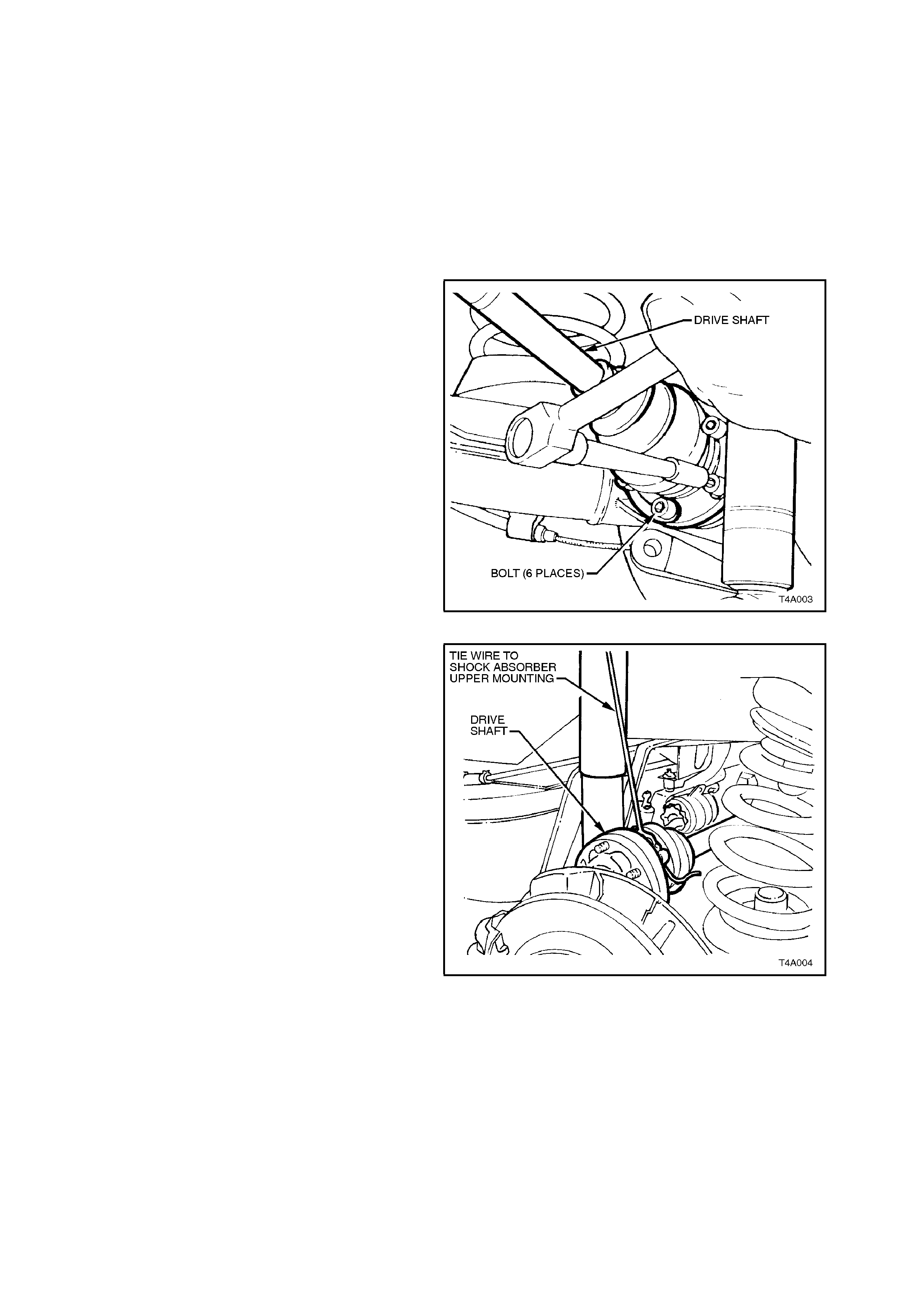
4. Using Tool No. KM468 to hold trunnion
assembly hub from rotating, loosen the six
drive shaft outer constant velocity joint to
trunnion flange attaching bolts with an 8 mm
Allen key socket.
Figure 4A-3
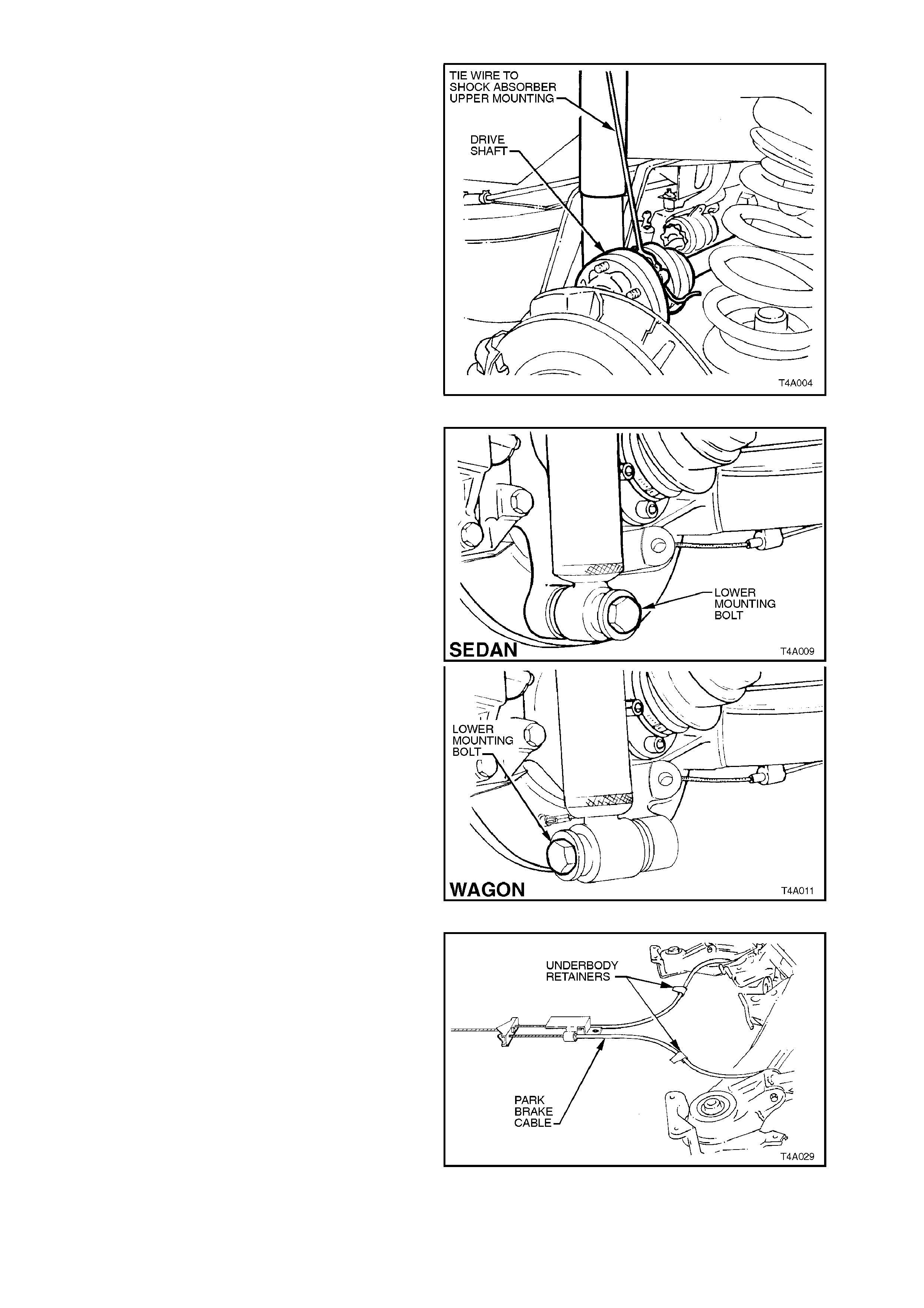
Disconnect drive shaft from flange and lift
upward. Keeping drive shaft vertical and, using
a piece of wire, tie up drive shaft to lower end
of shock absorber upper mounting.
NOTE:
Bruising to the inside of the drive shaft constant
velocity joint boots will occur if the trailing arm is
lowered any further. This will lead to premature
failure of the boot and eventual failure of the joint if
left unchecked.
For this reason, it is important that the constant
velocity joint is disconnected from the trunnion
flange before removing the shock absorber lower
mounting bolt.
Figure 4A-4
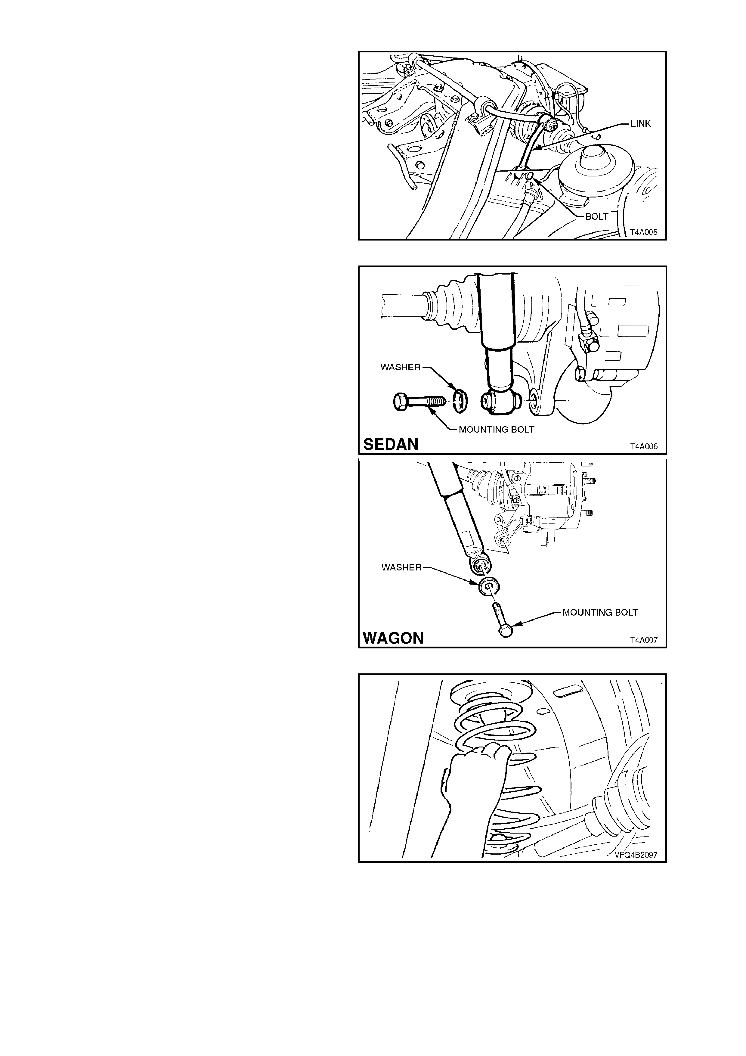
5. Remove stabiliser bar link to trailing arm
attaching bolt and nut from side of the vehicle
where the spring is being removed.
Figure 4A-5
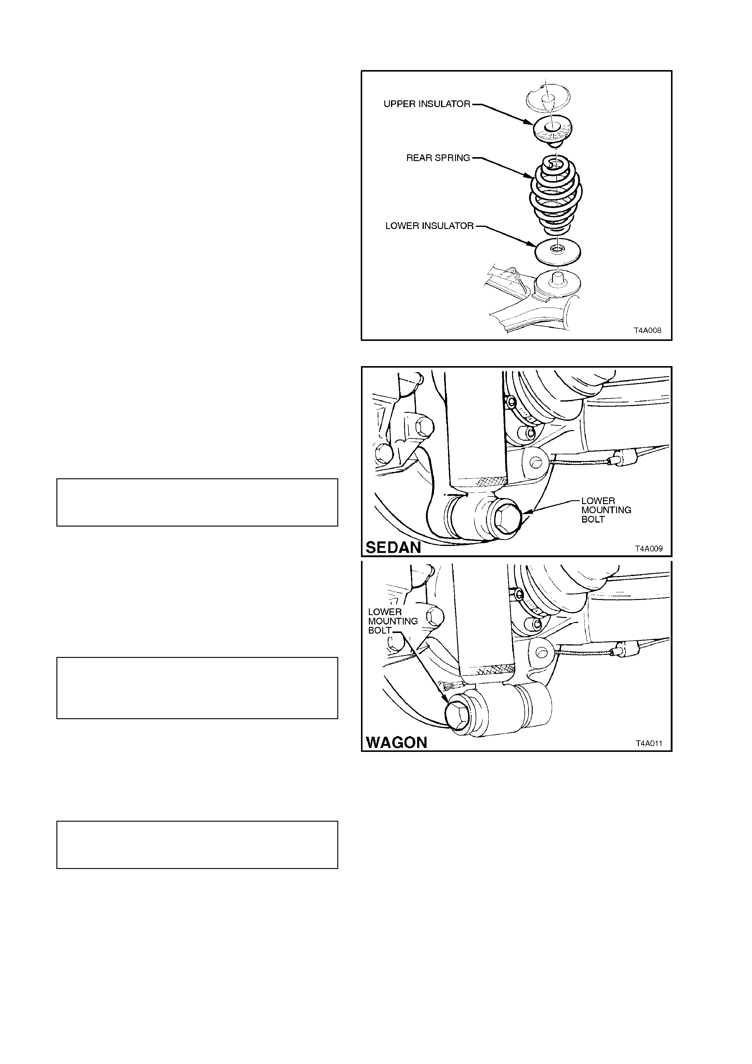
6. Position floor jack under trailing arm. Raise
jack slightly to take s pring load off tr ailing arm .
Disconnect rear shock absorber lower
mounting bolt from trailing arm, then pull the
lower end of shock absorber from trailing arm.
Figure 4A-6
7. Lower jack and remove rear spring and
insulators from vehicle underbody and trailing
arm.
NOTE 1:
It may be necessar y to push tr ailing arm downward
by hand to allow spring removal.
NOTE 2:
Ensure the rear brake hose is not pulled tight while
pushing down on trailing arm.
Figure 4A-7
REINSTALL
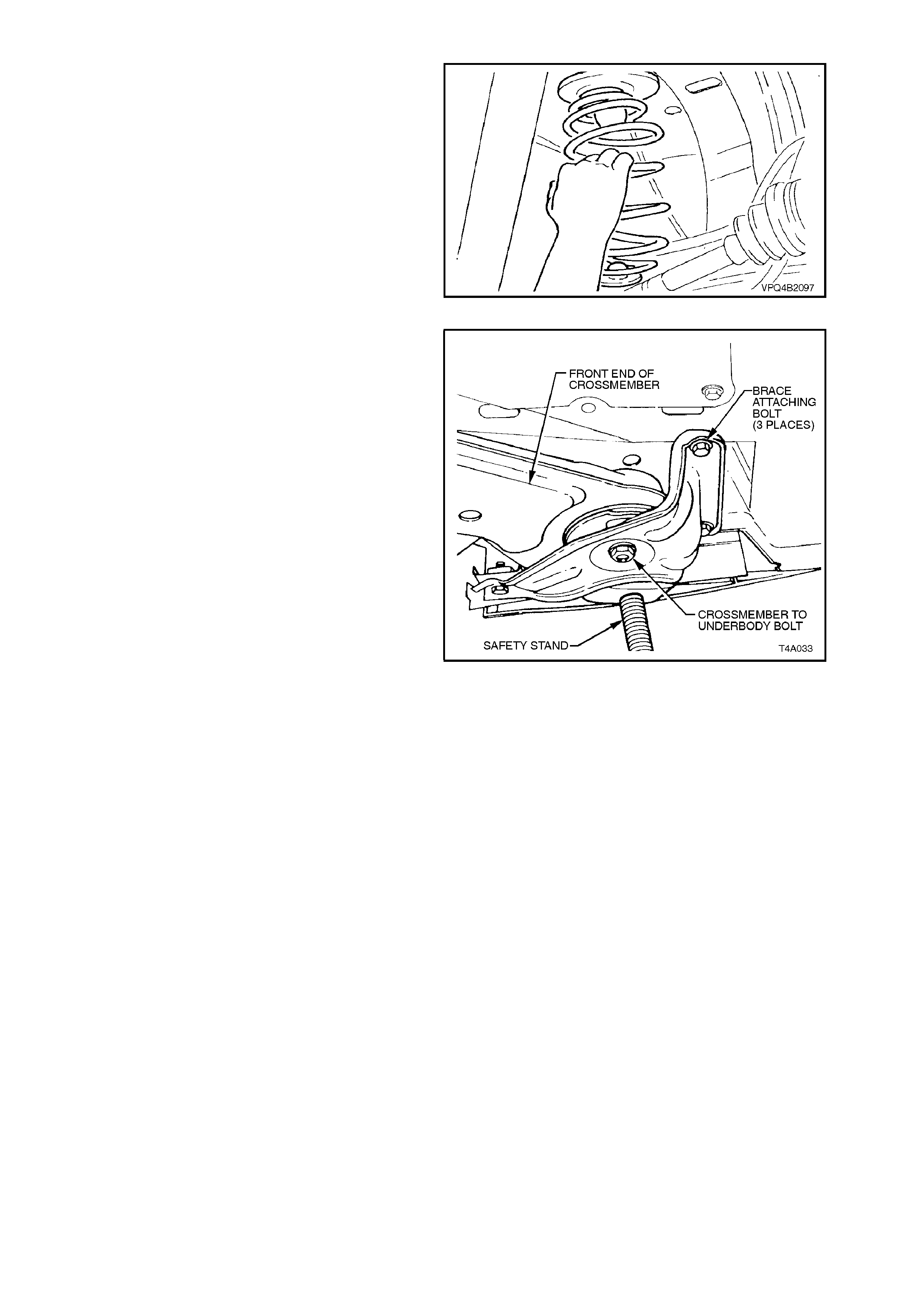
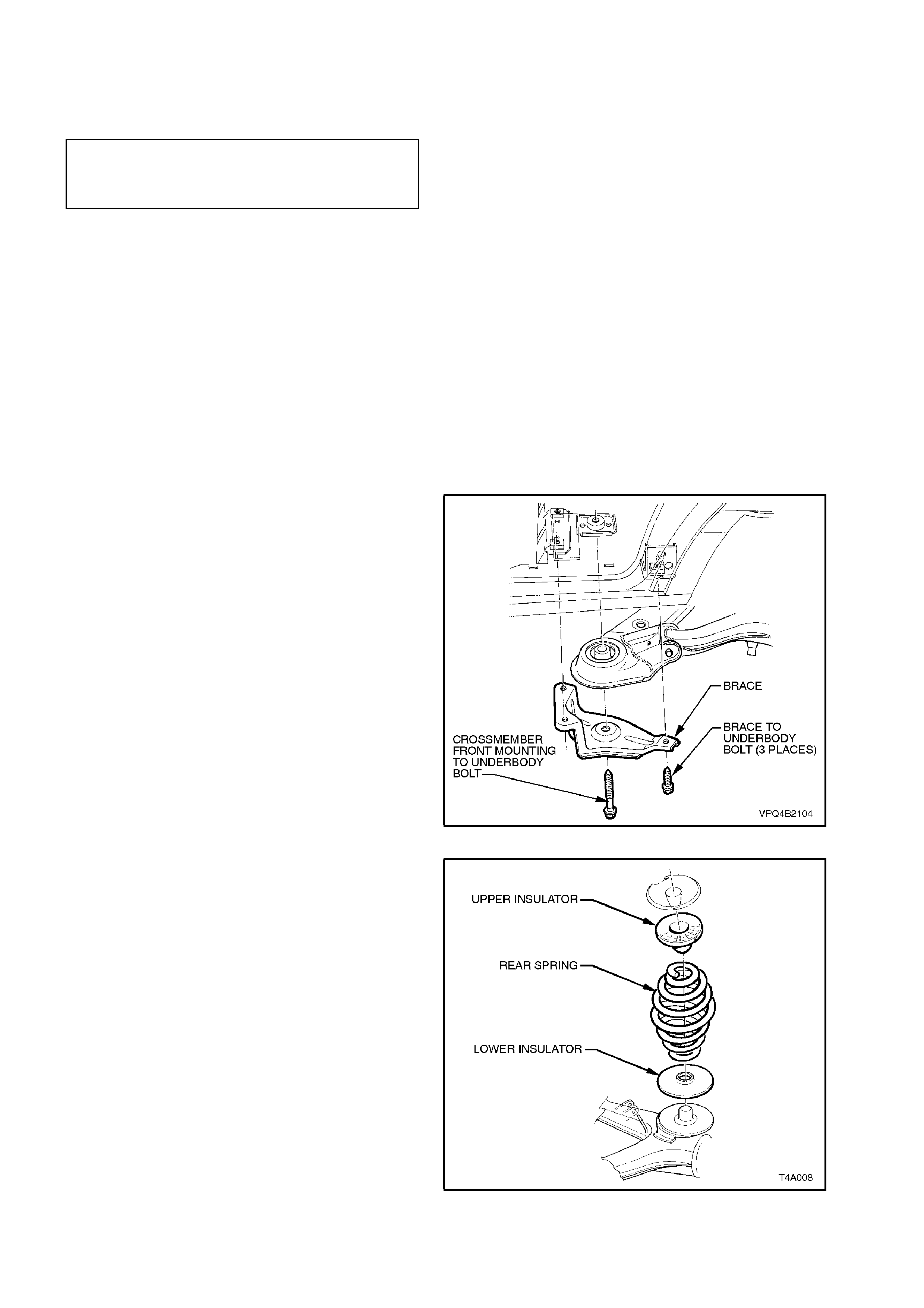
1. Install lower insulator onto trailing arm.
Assemble upper insulator onto spring, push
down on trailing arm and install spring and
upper insulator.
Figure 4A-8
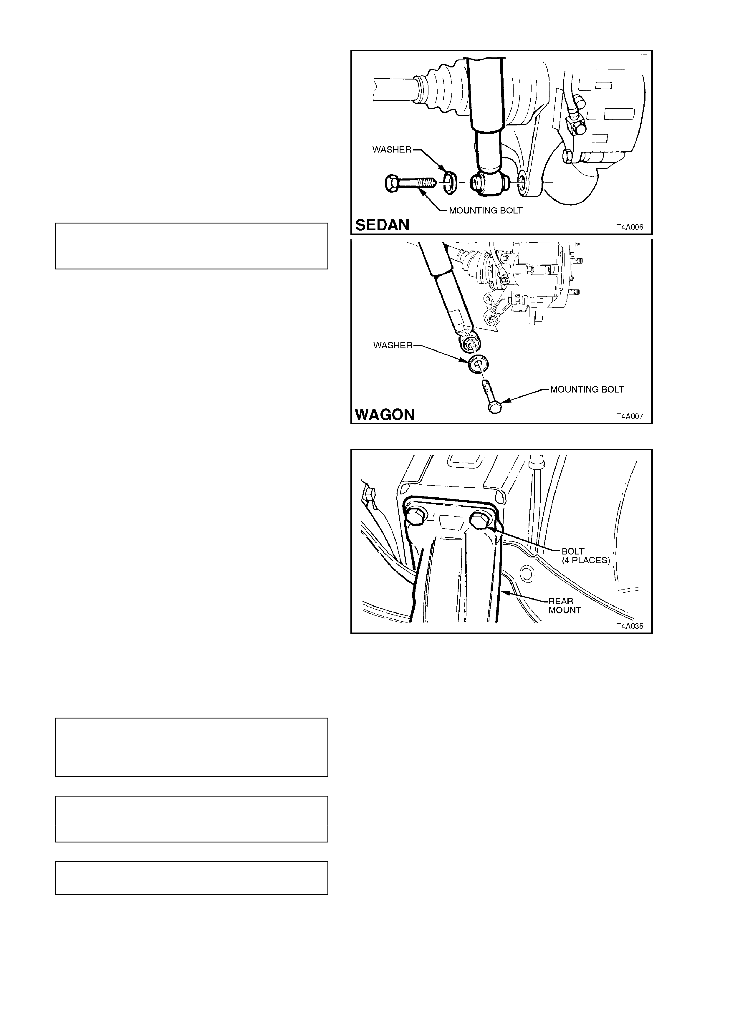
2. Position jack under trailing arm and raise far
enough to allow shock absorber lower
mounting bolt and washer to be installed.
Install washer and bolt to shock absorber
lower mount and into trailing arm. Tighten
bolt to the correct torque specification.
SHOCK ABSORBER LOWER
MOUNTING BOLT 105 - 125 Nm ■
TORQUE SPECIFICATION
3. Remove wire from drive shaft and shock
absorber upper mount. Lower drive shaft and
align drive shaft constant velocity joint to
trunnion flange attaching bolts with trunnion
flange holes. Tighten bolts to the correct
torque specification.
DRIVE SHAFT CONSTANT
VELOCITY JOINT TO TRUNNION 50 Nm, then
FLANGE ATTACHING BOLT 60° - 75°
TORQUE SPECIFICATION turn angle
4. Swing stabiliser bar link into position over
trailing arm bracket. Install attaching bolt and
nut, and tighten nut to the correct torque
specification.
STABILISER BAR LINK TO
TRAILING ARM ATTACHING NUT 18 - 26 Nm ■
TORQUE SPECIFICATION
Figure 4A-9

5. Install road wheel and tighten attaching nuts.
NOTE:
When installing the wheel, align the marks made
prior to removal.
6. Remove safety stands and lower vehicle.
7. Tighten road wheel attaching nuts to the
correct torque specification.
ROAD WHEEL ATTACHING NUT 110 - 140
TORQUE SPECIFICATION Nm
8. Refit wheel cover/centre cap.
IMPORTANT:
Those torque settings marked as ■ must only be
carried out with the weight of the vehicle on
the four wheels and at curb weight.
2.5 TRAILING ARM
CAUTION:
Whenever any component that forms part of
the ABS (if fitted) is disturbed during Service
Operations, it is vital that the complete ABS
system be checked, using the procedure as
detailed in DIAGNOSIS, ABS FUNCTION
CHECK, in Section 12L ABS & ABS/ETC.
NOTE:
For this operation, new trailing arm to
crossmember lock nuts, and if necessary, trunnion
flange to trunnion assembly collar nut and lock
plate, must be used on reassembly.
REMOVE
1. Using a floor jack under centre of differential
carrier, jack up rear of vehicle and place
safety stands under body rear jacking points.
Refer to Section 0A GENERAL
INFORMATION for location of jacking points.
2. Remove wheel cover (steel wheels) or centre
cap (alloy wheels) fr om the vehicle side where
the spring is to be removed.
3. Mark relationship of wheel to mounting f lange.
Remove road wheel attaching nuts and
remove wheel.
4. Loosen both stabiliser bar link, attaching bolts
and nuts, to reduce stress on the insulator
bush.
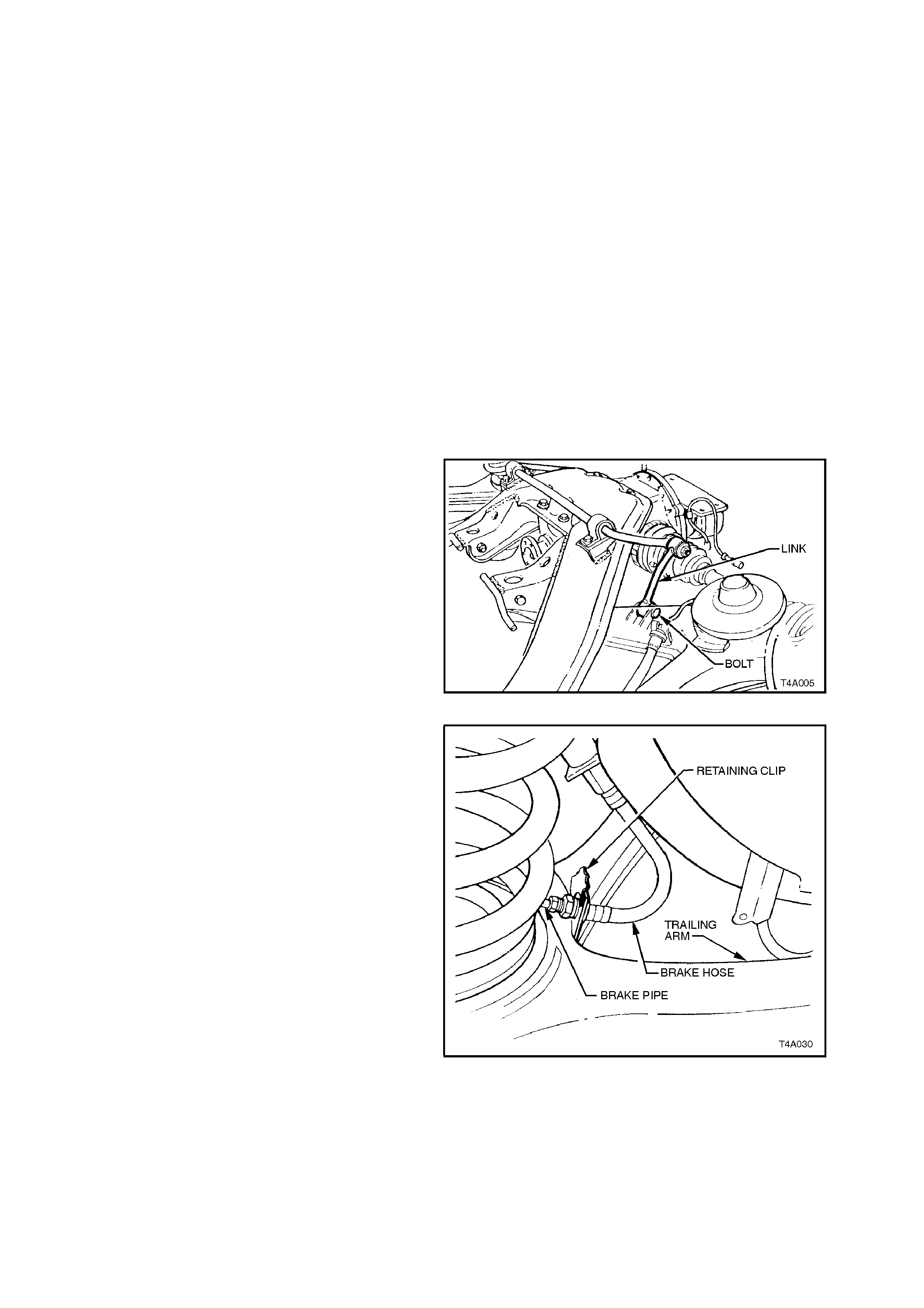
5. Remove the stabiliser link to trailing arm
attaching bolt and nut from side of vehicle
where the trailing arm is being removed.
Figure 4A-10
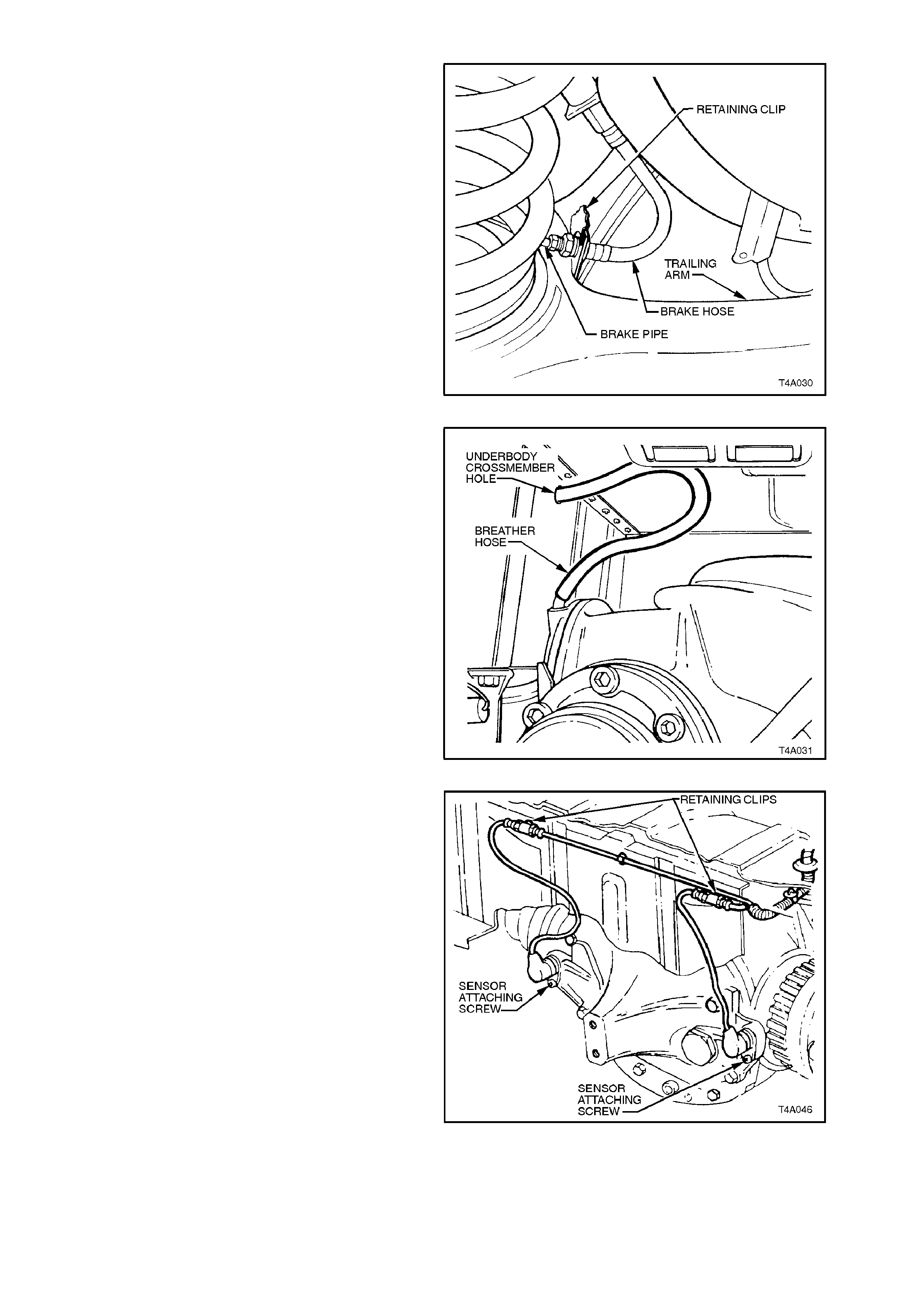
6. Remove rear brake hose retaining clip from
trailing arm to be removed. Pull brake pipe
and hose for ward f rom brac ket and disc onnec t
from trailing arm by lifting up brake pipe
through slot in bracket.
Figure 4A-11
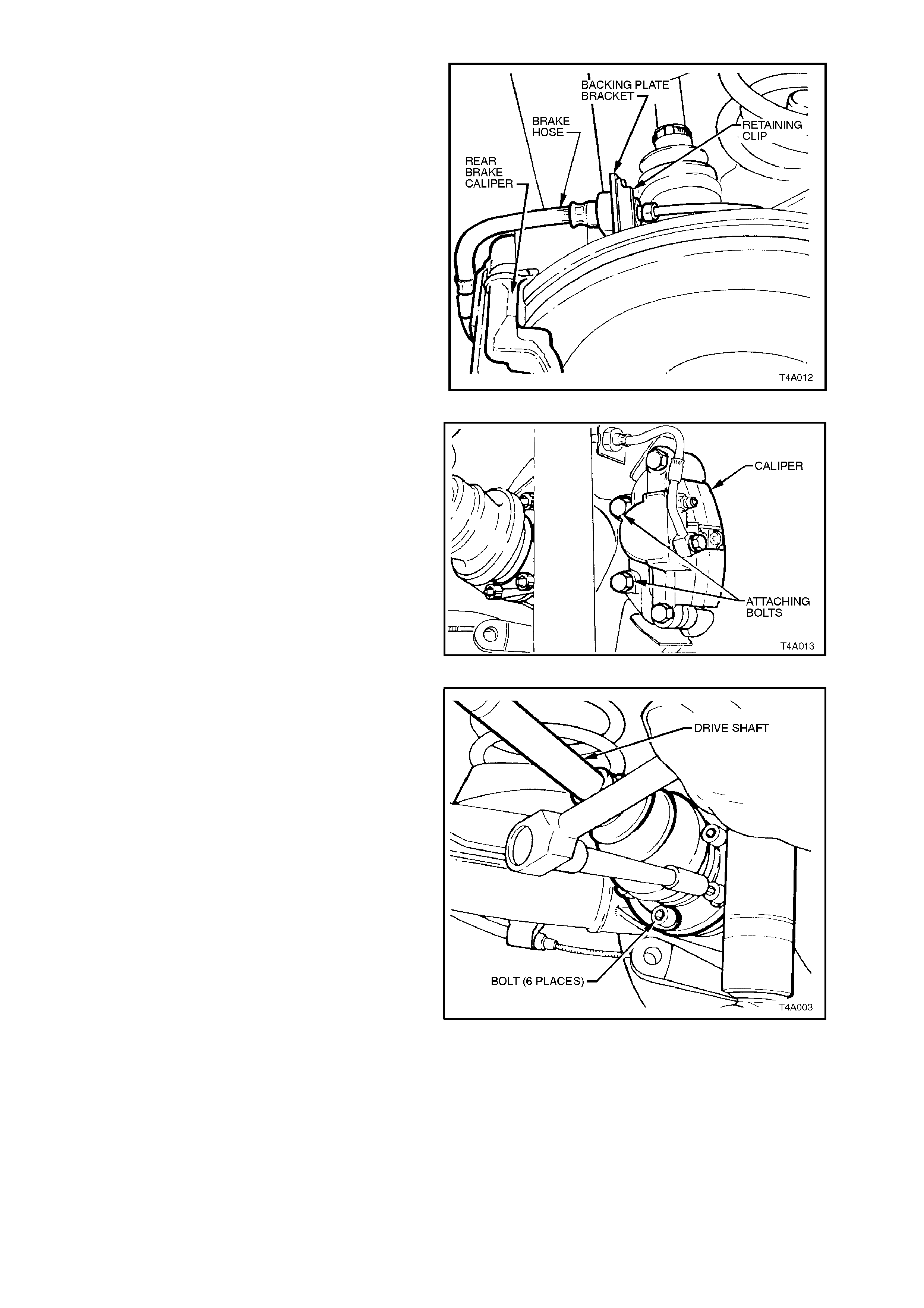
7. Remove brake hose retaining clip from brake
backing plate bracket. Disconnect rear caliper
brake hose from brake pipe and disconnect
pipe from backing plate bracket.
Plug open ends of brake pipe and hose to
prevent fluid loss and foreign matter entry.
Figure 4A-12
8. Remove brake caliper anchor plate to trailing
arm attaching bolts and remove caliper from
disc. Support the brake caliper with tie wire
secured to the vehicle underbody. THE
CALIPER IS NOT T O HANG BY THE BRAKE
HOSE.
Remove brake disc.
NOTE:
Should it be necessary to adjust the park brake
shoes to allow disc to be removed, refer to
Section 5A, STANDARD BRAKES for the
necessary procedure.
Figure 4A-13
9. Using Tool No. KM468 to hold trunnion
assembly hub from rotating, loosen the six
drive shaft outer constant velocity joint to
trunnion flange attaching bolts , using an 8 m m
Allen key socket and bar.
Figure 4A-14
Disconnect drive shaft from flange and lift
upward. Keeping drive shaft vertical and, using
a piece of wire, tie up drive shaft to lower end
of shock absorber upper mounting.
NOTE:
Bruising to the inside of the drive shaft constant
velocity joint boots will occur if the trailing arm is
lowered any further. This will lead to premature
failure of the boot and eventual failure of the j oint if
unchecked.
For this reason, it is important that the constant
velocity joint is disconnected from the trunnion
flange before removing the shock absorber lower
mounting bolt.
Figure 4A-15
10. Position floor jack under trailing arm. Raise
jack slightly to take s pring load off tr ailing arm .
Disconnect rear shock absorber lower
mounting bolt from trailing arm, then pull the
lower end of shock absorber from trailing arm.
Figure 4A-16
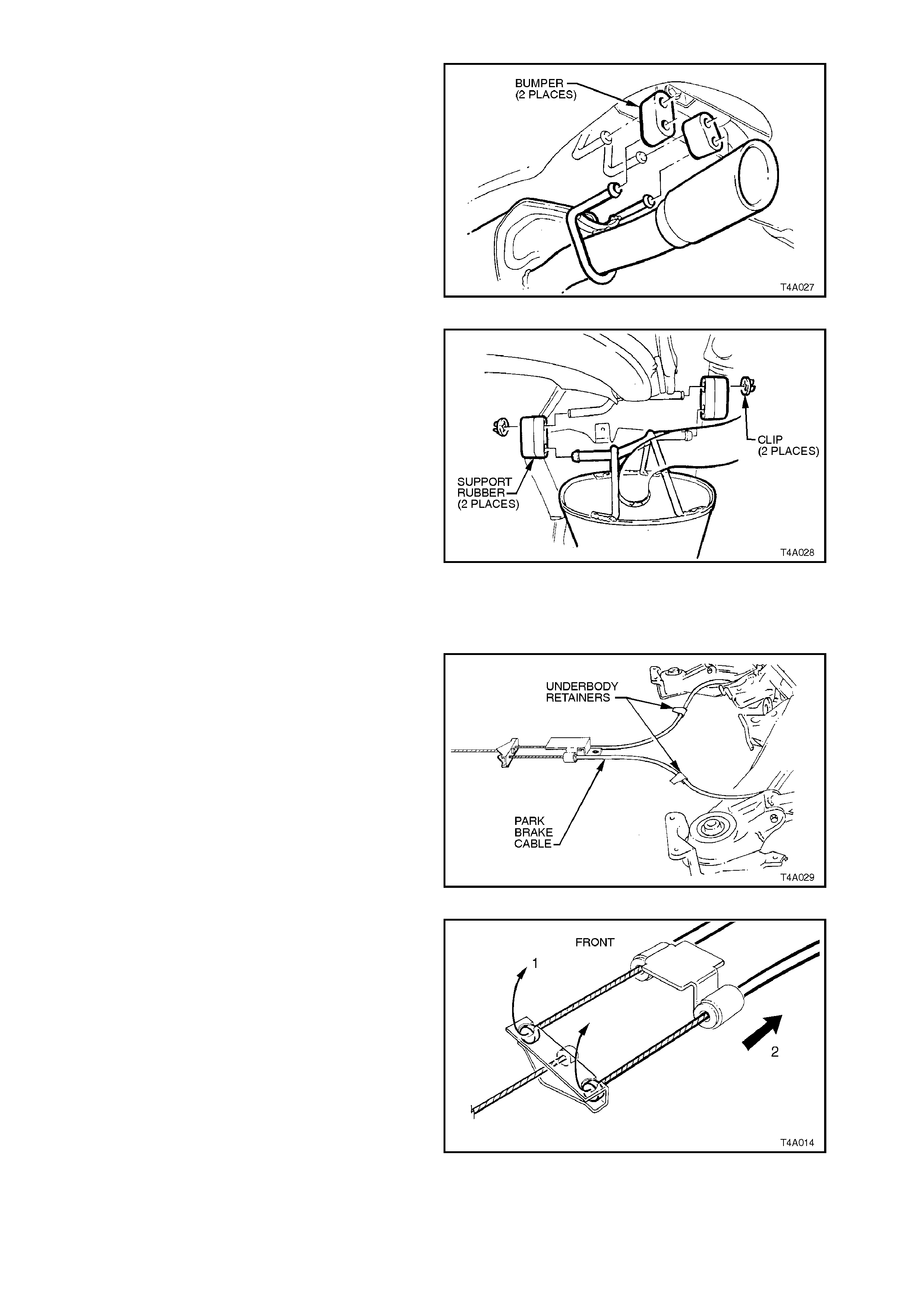
11. Set park brake in fully released position.
Release each of the underbody to park brake
cable retaining clips and free cables.
Figure 4A-17
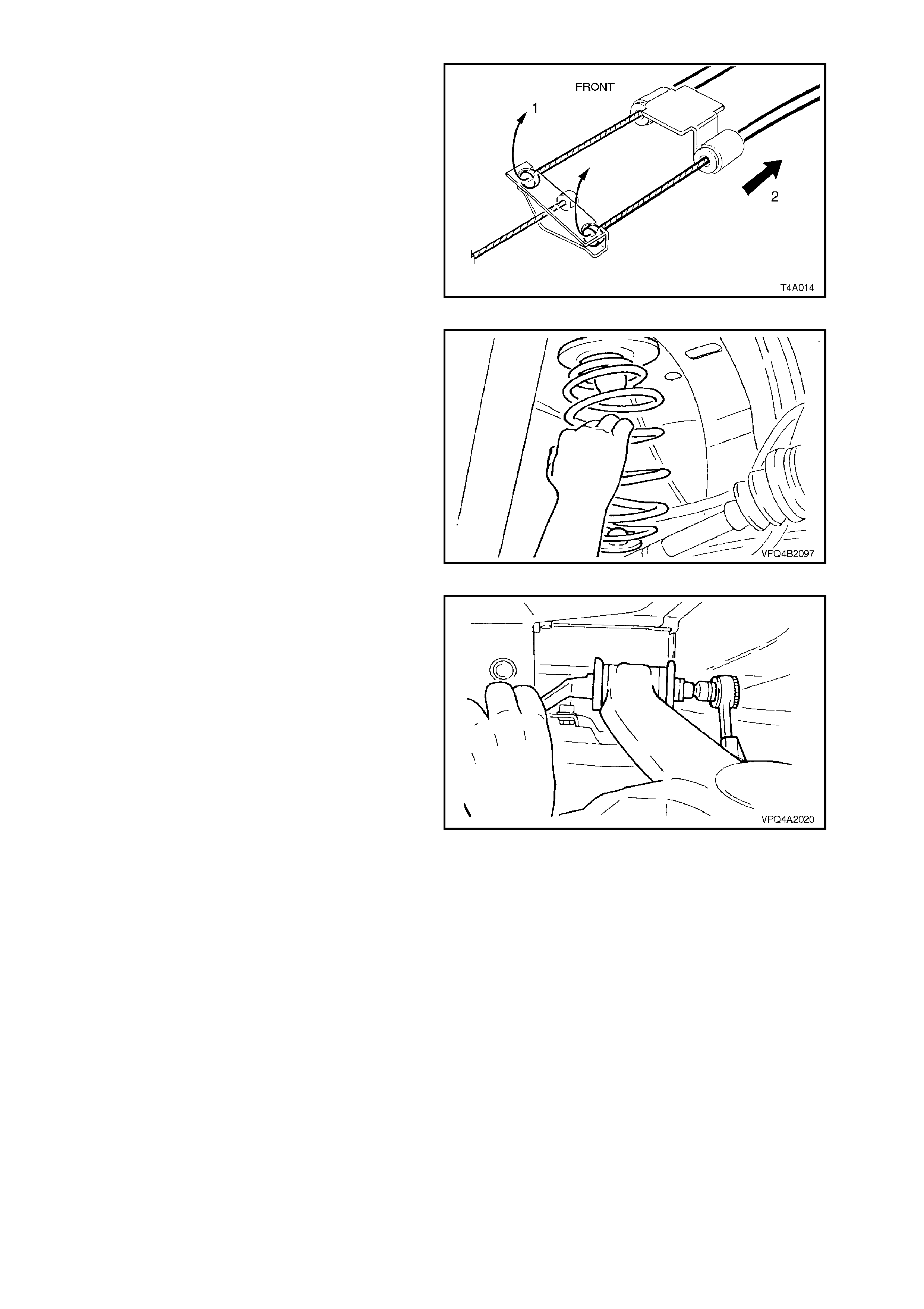
12. Remove park brake outer cable retaining
bracket bolt from the vehicle underbody.
13. Pull each park brake inner cable forward and
up, (1) out of the cable retainer. Pull the outer
cable rearward (2) to remove from the
underbody retainer.
Figure 4A-18
14. Lower jack and if necessary, push down on
trailing arm and remove rear spring and
insulators from vehicle underbody and trailing
arm.
Figure 4A-19
15. Loosen and remove trailing arm to rear
crossmember attaching bolts and nuts,
remove trailing arm and discard nuts.
Figure 4A-20
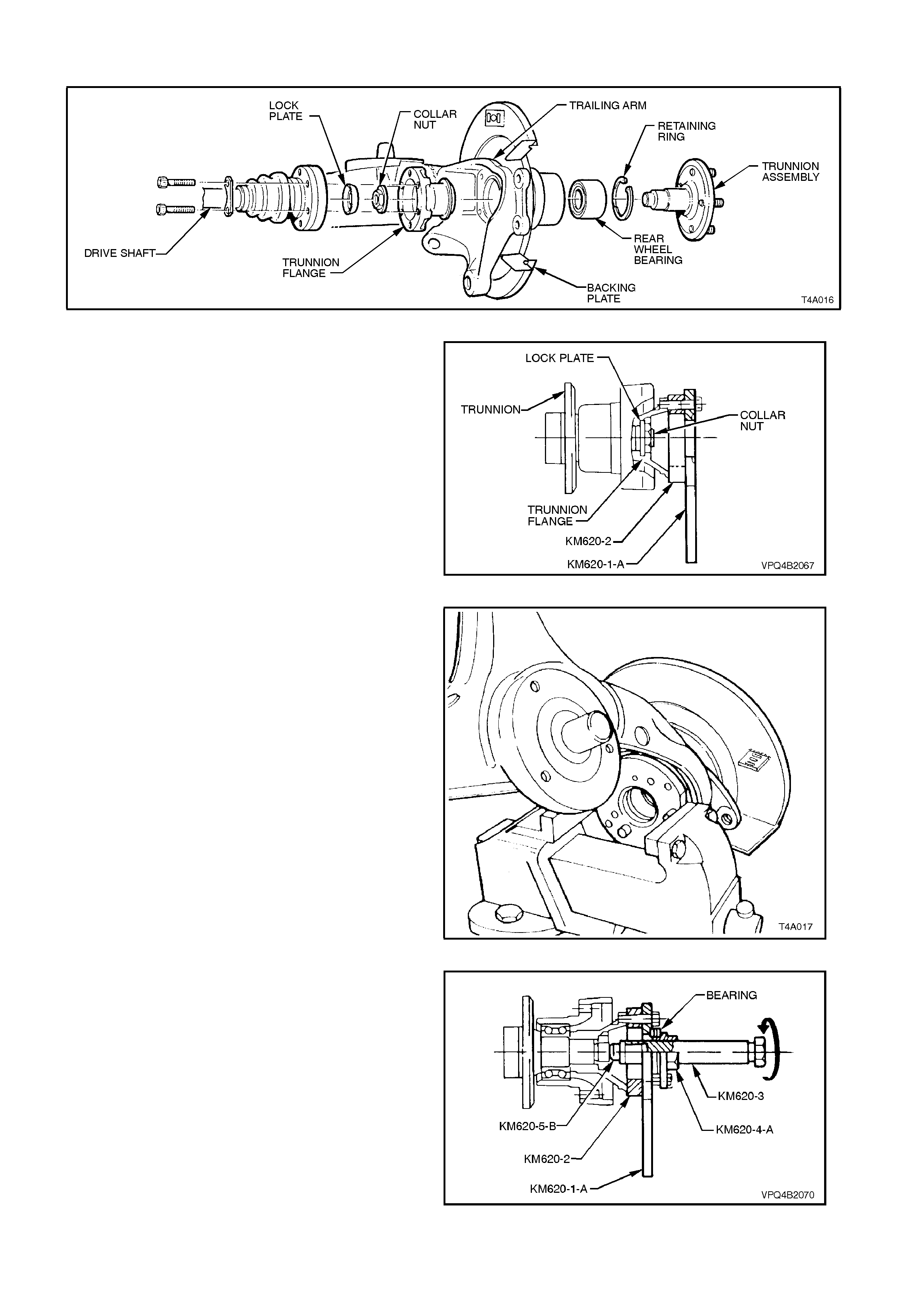
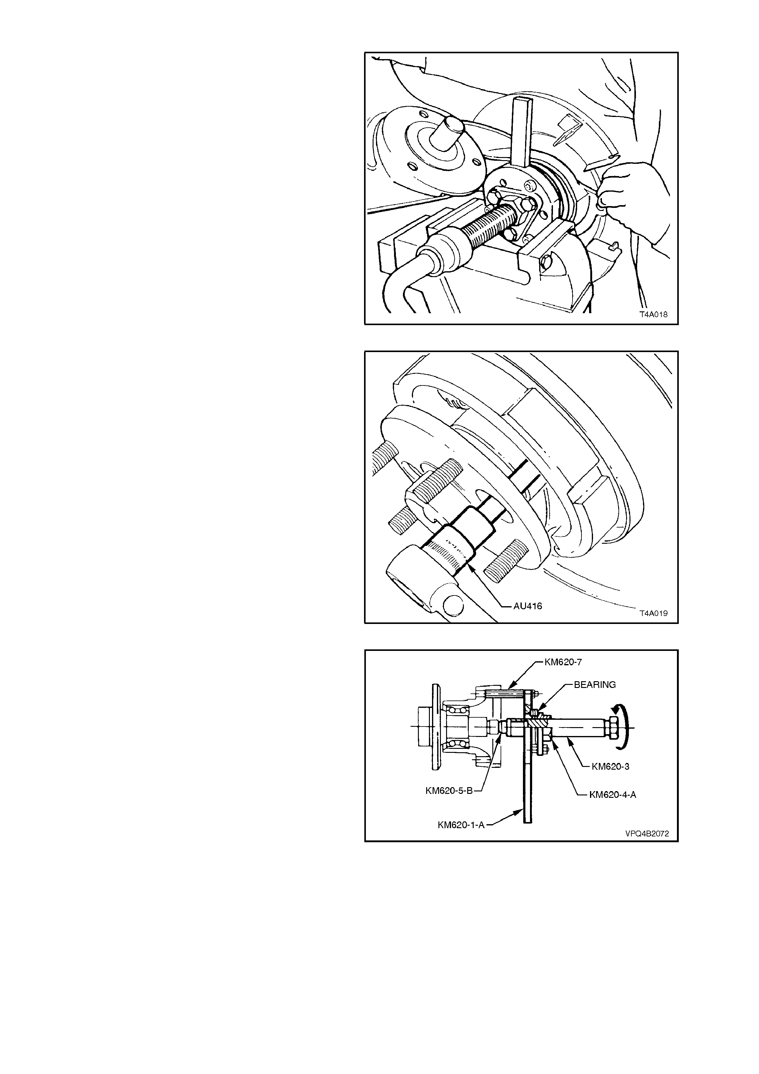
REPLACE TRUNNION ASSEMBLY, FLANGE OR BEARING
Figure 4A-21
IMPORTANT:
The rear wheel bearing should only be removed if it
is faulty, or the trunnion assembly is to be removed.
1. Secur e Tool Nos . KM620-1-A and KM620-2 to
trunnion flange with three drive shaft constant
velocity joint to trunnion flange attaching bolts.
NOTE:
Align holes marked ‘B' on KM620-1-A and KM620-2
with holes in trunnion flange before installing bolts.
Figure 4A-22
2. Mount assembly in a vice, gripping flats of
KM620-1-A. Loosen and remove trunnion
flange to trunnion as sem bly collar nut and lock
plate.
NOTE:
Discard the collar nut and lock plate when they
have been removed. They must be replaced with
new parts on reassembly.
Figure 4A-23
3. Apply grease to ball of Tool No. KM620-5-B.
Assemble KM620-3 to KM620-4-A and install
KM620-5-B to KM620-3. Install KM620-4-A to
KM620-1-A using three suitable bolts.
Secure the assembled tool and spacer ring,
Tool No. KM620-2, to the trunnion assembly,
using three drive shaft constant veloc ity joint to
trunnion flange attaching bolts
Figure 4A-24
W ith trailing arm assem bly m ounted in vice by
KM620-1-A, and having an assistant holding
and supporting weight of trailing arm
assembly, turn forcing screw KM620-3 to free
flange from trunnion assembly.
Separate components from flange once it has
been removed.
Figure 4A-25
4. Using Torx bit socket, Tool No. AU416,
remove brake backing plate to trailing arm,
two upper attaching bolts. Then remove the
two longer, hexagonal headed, lower bolts.
Figure 4A-26
5. Install KM620- 7 (t hree piec es ) to bac king plate
bolt holes, from the rear of backing plate.
Assemble KM620-1-A with KM620-4-A and
three suitable bolts, KM620-3 and KM620-5-B
to KM620-7. Install and tighten attaching nuts.
Figure 4A-27
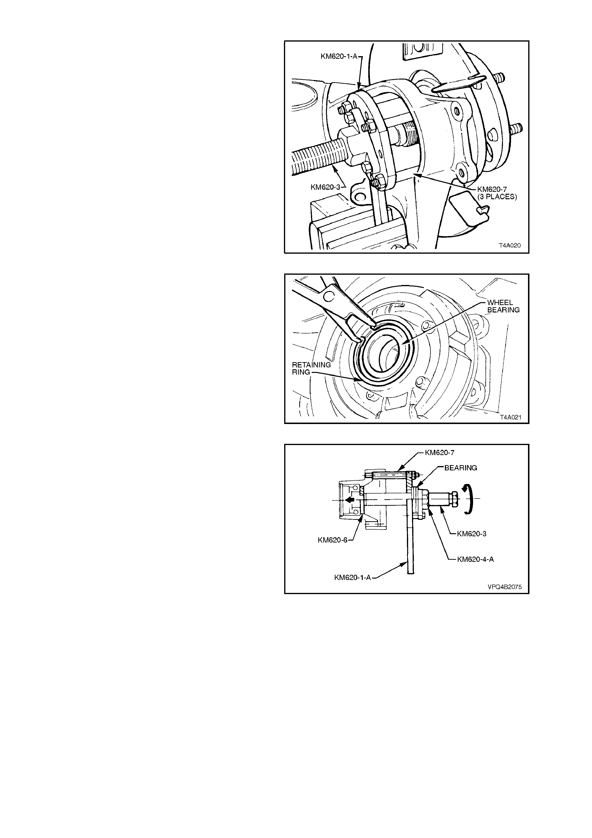
Mount assembly in vice by handle of KM620-1-
A. Turning the forcing screw KM620-3, press
trunnion assembly from rear wheel bearing.
Once trunnion has been removed, remove
nuts holding KM620-1-A assembly to KM620-
7. Remove KM620-1-A, and rem ove KM620- 5-
B from KM620-3.
Figure 4A-28
6. Remove wheel bearing retaining ring from
trailing arm.
Figure 4A-29
7. Install KM620-6 to rear of bearing. Install
KM620-A assembly and install attaching nuts.
With KM620-1-A mounted in vice, turn the
forc ing scr ew KM620-3 to press wheel bearing
from trailing arm.
8. Remove remaining backing plate to trailing
arm attaching bolt and anchor rear brake
bracket, remove backing plate.
Figure 4A-30
9. If installing a replacement trailing arm without
bushes, install new bushes. Refer to
2.6, TRAILING ARM BUSHES in this Section.
10. Ensure that bearing bore of trailing arm is
clean and free of any foreign matter.
11. Coat outside diameter of new wheel bearing
and bore of trailing arm with lubricant such as
Molybond HB50, or equivalent (to Holden's
Specification HN1326).
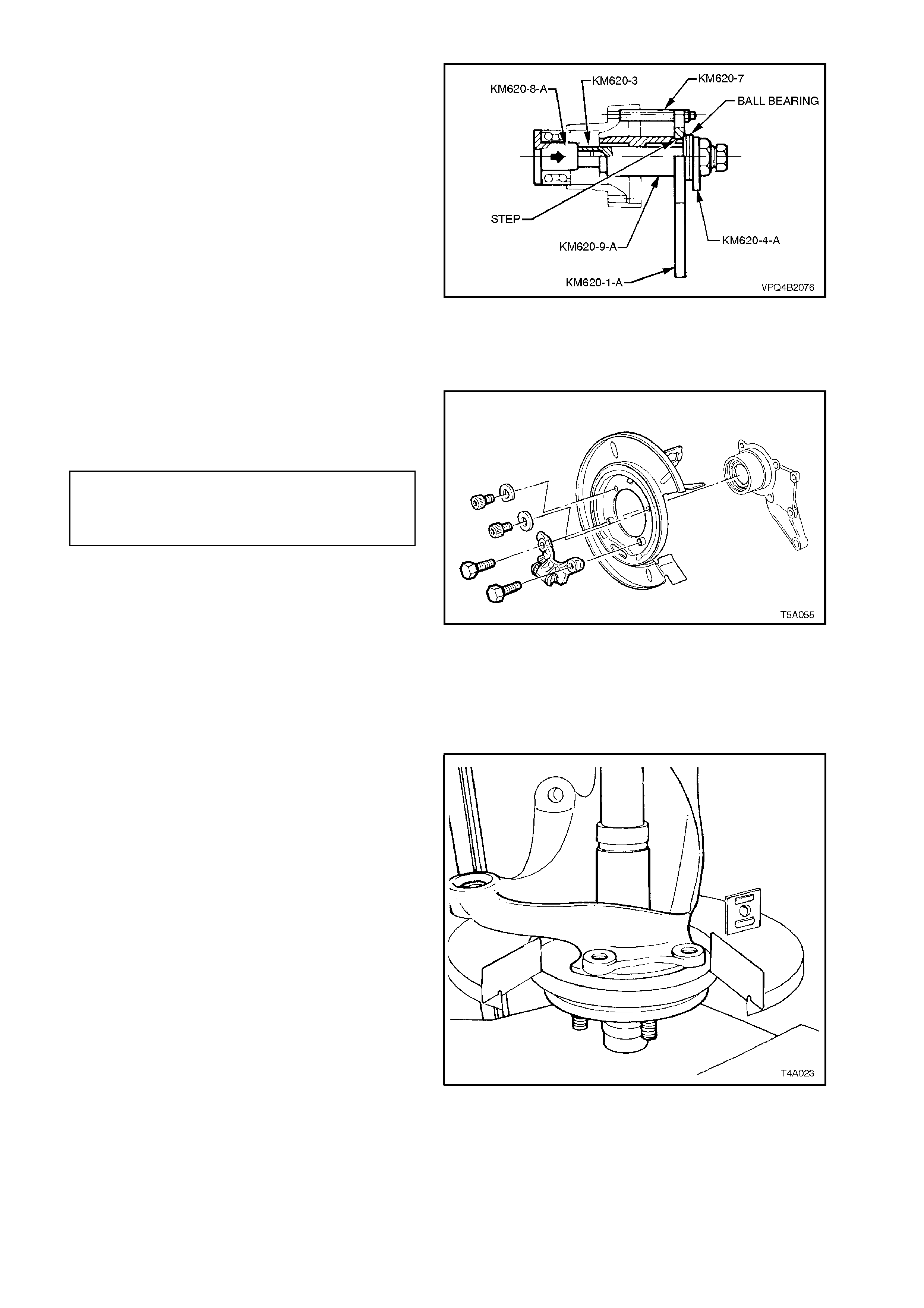
12. Remove KM620-4-A from KM620-1-A.
Assemble ball bearing race (part of KM620-A)
to KM620-4-A, install KM620-9-A over KM620-
3 and reinstall as s embly to KM620-1-A. Do not
install KM620-4-A to KM620-1-A attaching
bolts.
NOTE:
The s tepped end of sleeve KM620-9-A must locate
in the centre of KM620-1-A.
Install KM620-8-A to new bearing and install
into trailing arm , and scr ew threads of KM620-
8-A and KM620-3 together. While holding
KM620-3 from turning, rotating KM620-4-A to
draw bearing into position.
Remove KM620-8-A once bearing is fully
installed, and install retaining ring into trailing
arm, ensuring that it seated correctly.
Figure 4A-31
13 Install rear disc brake shield to trailing arm
bolts and tighten to the correct torque
specification.
REAR DISC BRAKE SHIELD
TO TRAILING ARM Upper: 70 - 80 Nm
ATTACHING BOLT Lower: 85 - 90 Nm
TORQUE SPECIFICATION
NOTE 1:
The two upper bolts have washers that are installed
with the cut-out surface facing around the trailing
arm hub outer surface.
NOTE 2:
Apply Loctitie 242 or equivalent (to Holden’s
Specification HN1256, Class 2, Type 1) to the
threads of the two longer, lower hexagon headed
bolts, before installation.
Figure 4A-32
15. Assemble trunnion assembly with raised
centre section of hub resting on a suitable
press tool and press plates. Ensure that
trunnion assembly hub studs do not contact
press plates.
Position trailing arm with wheel bearing onto
trunnion assem bly. Using Tool No. KM620- 9-A
and a suitable length and diam eter tube, pres s
wheel bearing onto trunnion assembly.
Figure 4A-33
16. Remove KM620-9-A and tube. Assemble
KM620-1-A and KM620-2 to trunnion flange
using three drive shaft attaching bolts.
Lubricate trunnion flange splines and trunnion
assembly threads with differential carrier
lubricant. Install trunnion flange onto trunnion
assembly.
17. With trunnion assembly supported on press
plates, as in step 16, press trunnion flange
onto trunnion assembly using Tool No.
KM620-9-A and a suitable tube.
18. Rem ove trailing arm assem bly f rom pr ess and
support assembly in a vice by the flats on
KM620-1-A. Install a new collar nut to trunnion
assembly and tighten to the correct torque
specification.
COLLAR NUT TO
TRUNNION ASSEMBLY 295 - 305 Nm
TORQUE SPECIFICATION Figure 4A-34
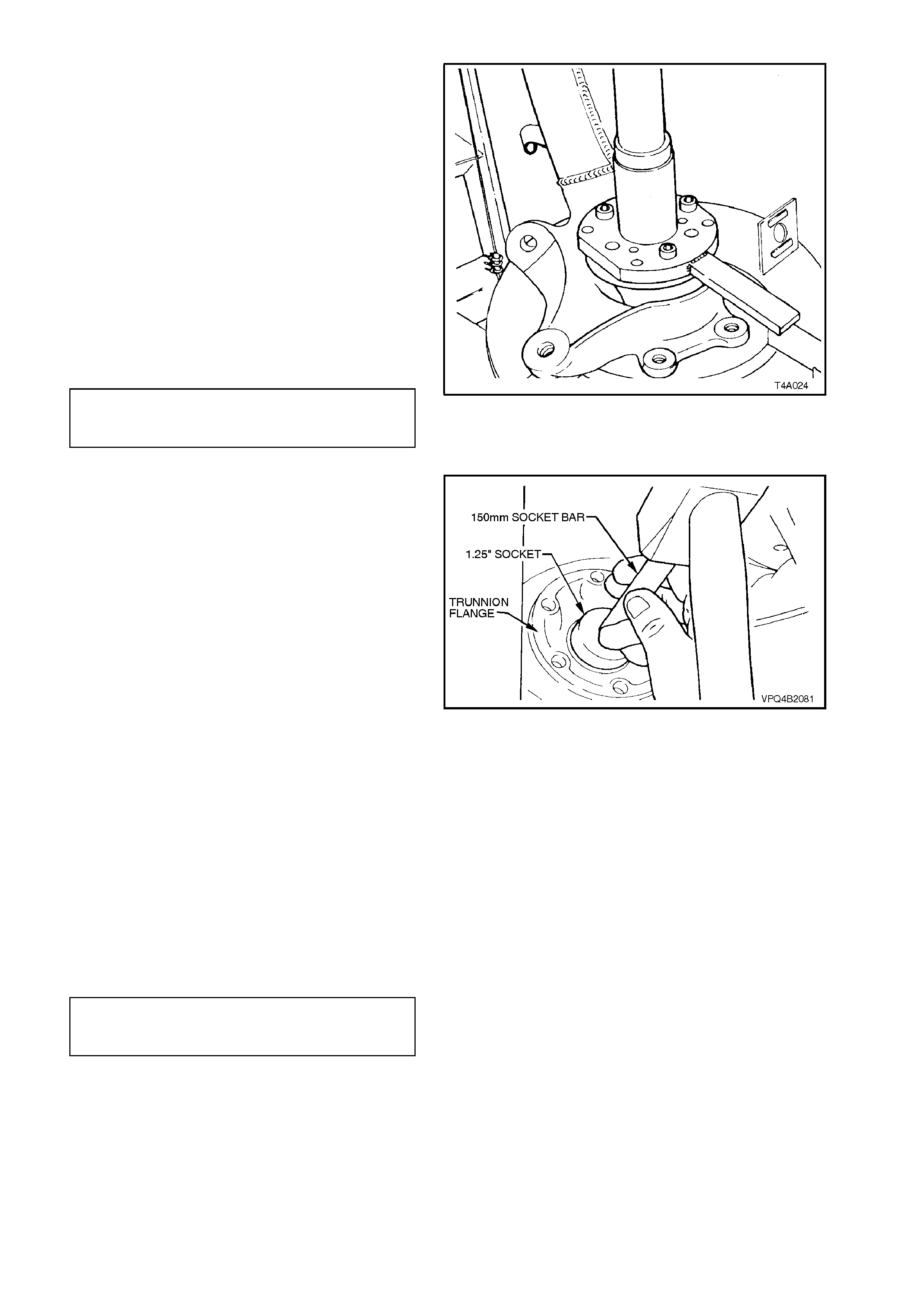
19. Remove assembly from vice and remove
KM620-1-A and KM620-2 from trunnion
flange. Using a 1 1/4 inch socket, 150 mm
sock et bar and ham me r, install new lock plate
over collar nut.
Figure 4A-35
REINSTALL
The remainder of the reinstallation of the trailing
arm is the reverse of removal procedure, with the
exception of the following steps:
1. Install trailing arm to rear crossmember, but
do not fully tighten attaching bolts at this
stage.
NOTE:
Always use new self-locking nuts.
2. Tighten brake caliper anchor plate-to-trailing
arm attaching bolts to the correct torque
specification.
BRAKE CALIPER ANCHOR PLATE
TO TRAILING ARM ATTACHING 70 - 100 Nm
BOLT TORQUE SPECIFICATION
3. Tighten shock absorber and stabiliser bar
attaching bolts and nuts to the correct torque
specifications.
NOTE:
Sedan and station wagon torque specifications are
the same.
SHOCK ABSORBER LOWER
MOUNTING BOLT 105 - 125 Nm ■
TORQUE SPECIFICATION
STABILISER BAR LINK TO
TRAILING ARM ATTACHING BOLT 18 - 26 Nm ■
TORQUE SPECIFICATION
4. T ighten drive s haf t outer cons tant veloc ity joint
to trunnion flange attaching bolts to the c orr ec t
torque specification.
DRIVE SHAFT CONSTANT 50 Nm, pl us
VELOCITY JOINT TO TRUNNION 60° - 75°
TORQUE SPECIFICATION turn angle
IMPORTANT:
Those torque settings marked as ■ must only be
carried out with the weight of the vehicle on the
four wheels and at curb weight.
5. Bleed rear brak es and chec k for leaks. F or the
recommended procedure, refer to Section
5A, BRAKES,.
6. Install road wheels and fit attaching nuts.
NOTE:
When installing the wheels, align the marks made
prior to removal.
7. Remove safety stands and lower vehicle.
8. Tighten road wheel attaching nuts to the
correct torque specification.
ROAD WHEEL ATTACHING NUT 110 - 140
TORQUE SPECIFICATION Nm
9. Refit wheel covers/centre caps.
10. With vehicle in kerb height position, tighten
trailing arm to crossmember attaching bolts to
the correct torque specification.
TRAILING ARM TO REAR
CROSSMEMBER ATTACHING NUT 95 - 105 Nm
TORQUE SPECIFICATION
2.6 TRAILING ARM BUSHES
REPLACE
1. Remove trailing arm, refer to
2.5 TRAILING ARM - REMOVE in this
Section.
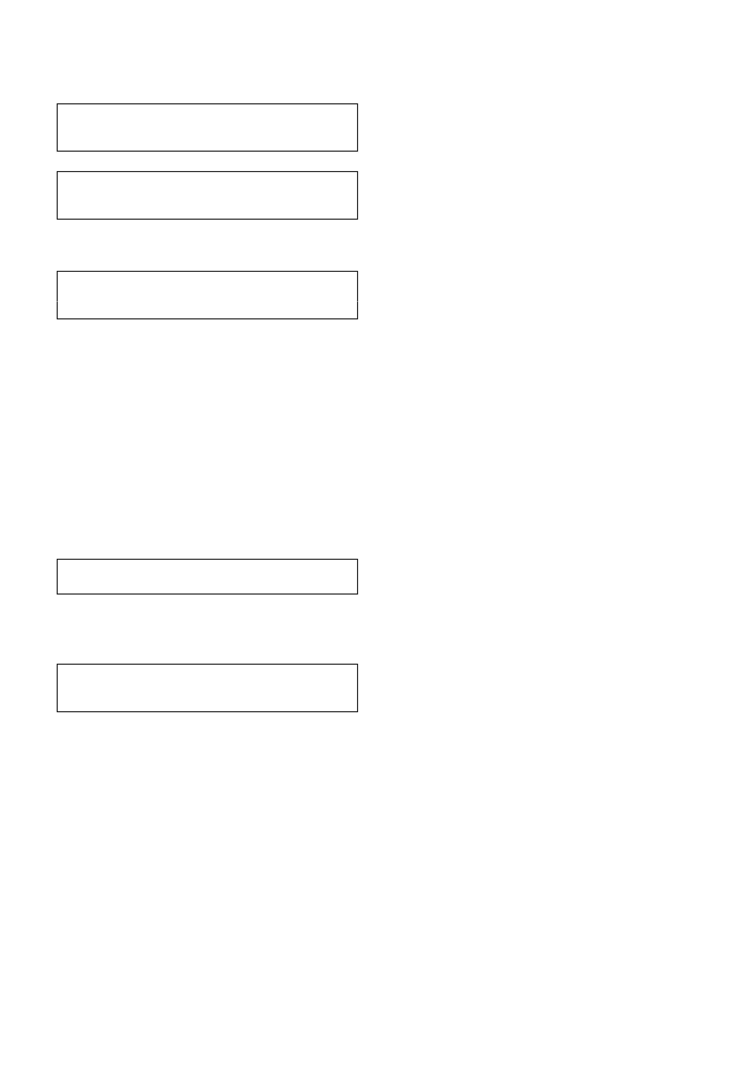
2. Cut inner flange section of bushes as shown.
Figure 4A-36
3. Press bushes from trailing arm using KM619-3
and KM619-4.
Figure 4A-37
4. Lightly coat outside surface of new bushes
with a soapy water solution. Pr ess new bushes
into trailing arm using KM619-1, KM619-2 and
KM619-4.
5. Reinstall trailing arm, refer to
2.5 TRAILING ARM in this Section.
Figure 4A-38
2.7 REAR CROSSMEMBER
CAUTION:
Whenever any component that forms part of
the ABS (if fitted) is disturbed during Service
Operations, it is vital that the complete ABS
system be checked, using the procedure as
detailed in # DIAGNOSIS, ABS FUNCTION
CHECK, in Section 12L ABS/Traction Control.
IMPORTANT:
Before disturbing the rear suspension
crossmember mounting bolts, an alignment
procedure is required on installation and a
special tool is required for this purpose. If this
tool is not available, then the crossmember
cannot be correctly aligned and steering and/or
handling abnormalities will result.
NOTE:
For this operation, new trailing arm-to-
crossmember lock nuts, rear crossmember rear
mount-to-vehicle underbody attaching bolts,
differential carrier-to-rear crossmember attaching
bolts and intermediate muffler support retainers
must be used on reassembly.
REMOVE
1. Using a floor jack under centre of differential
carrier, jack up rear of vehicle then place
safety stands under body rear jacking points.
Refer to Section 0A GENERAL
INFORMATION for location of jacking points.
2. Rem ove wheel covers (s teel wheels) or centre
caps (alloy wheels).
3. Mark relationship of wheels to mounting
flanges. Remove road wheel attaching nuts
and remove wheels.
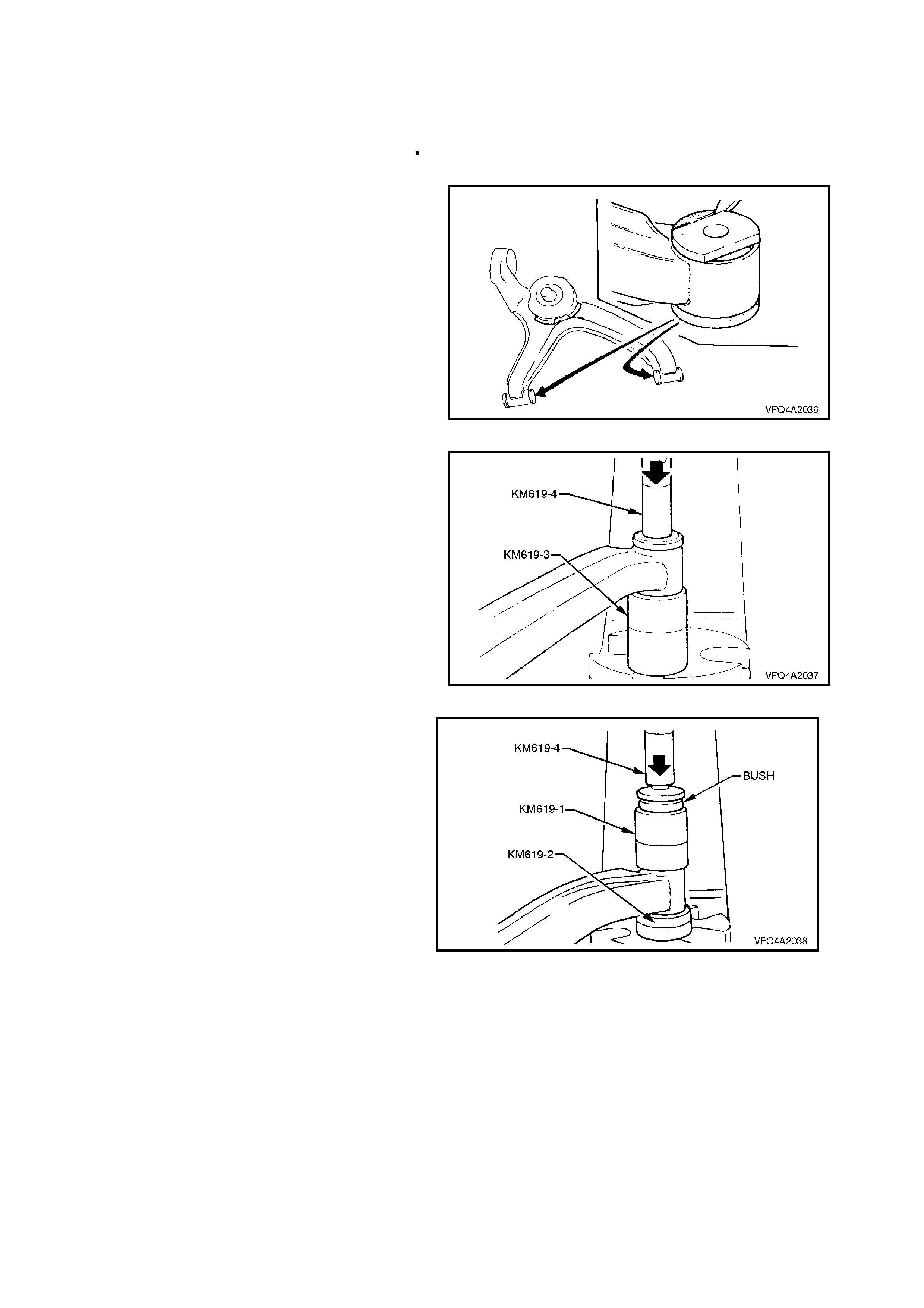
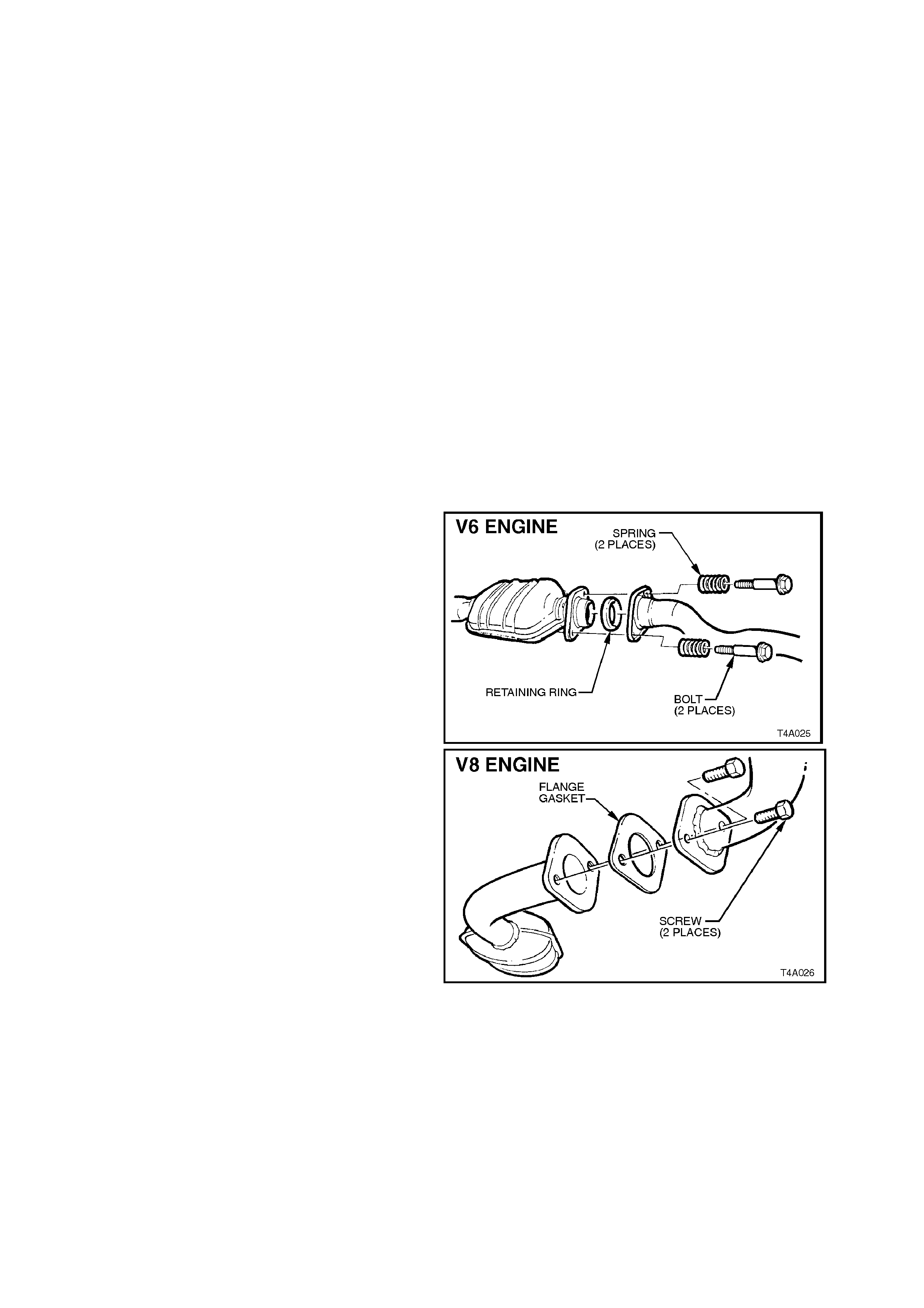
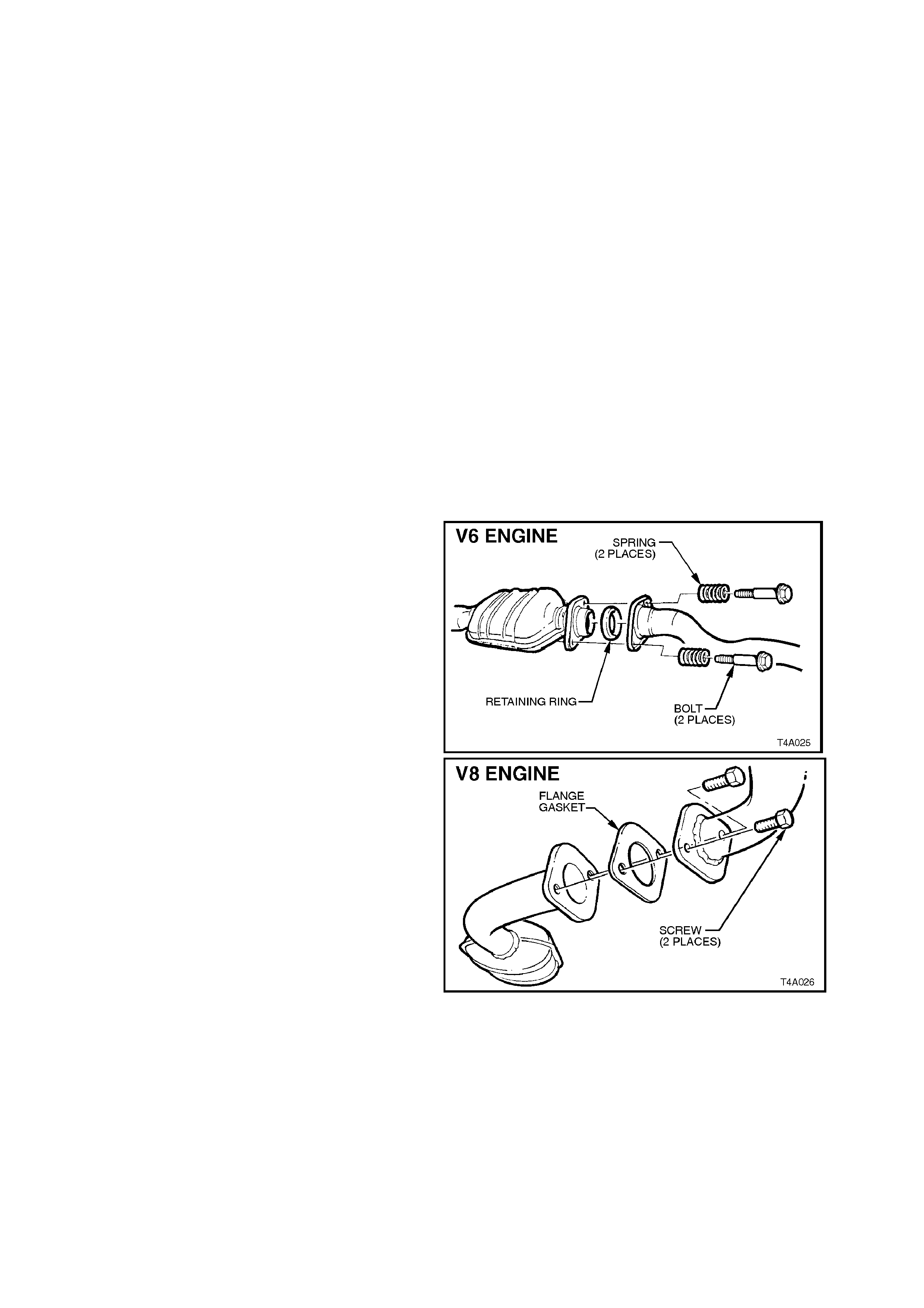
4. Disconnect exhaust system from rear of
catalytic converter (V6) or converters (V6
Supercharged and V8).
NOTE:
Only one side of the V6 Supercharged/V8
arrangement is shown.
Figure 4A-39
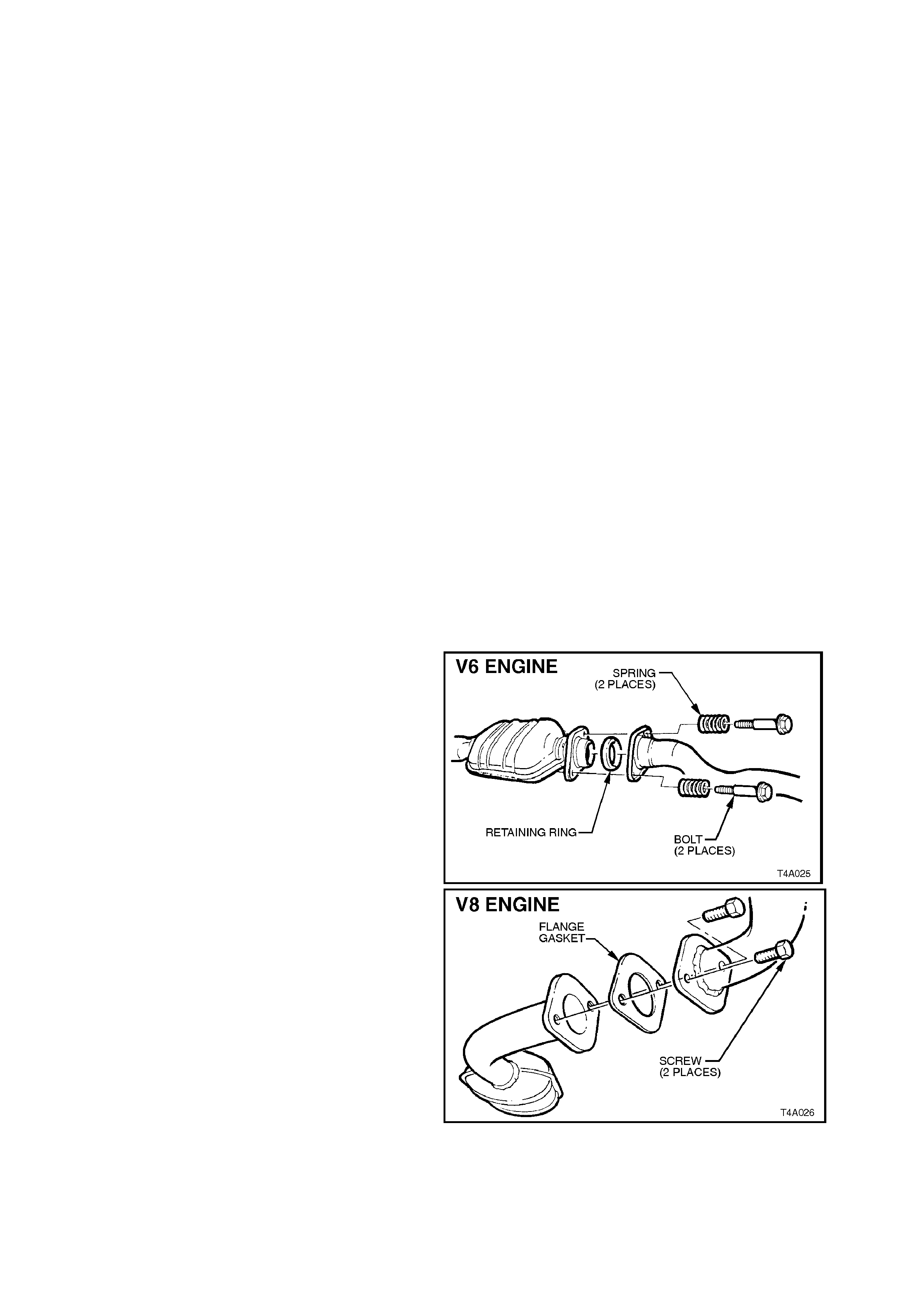
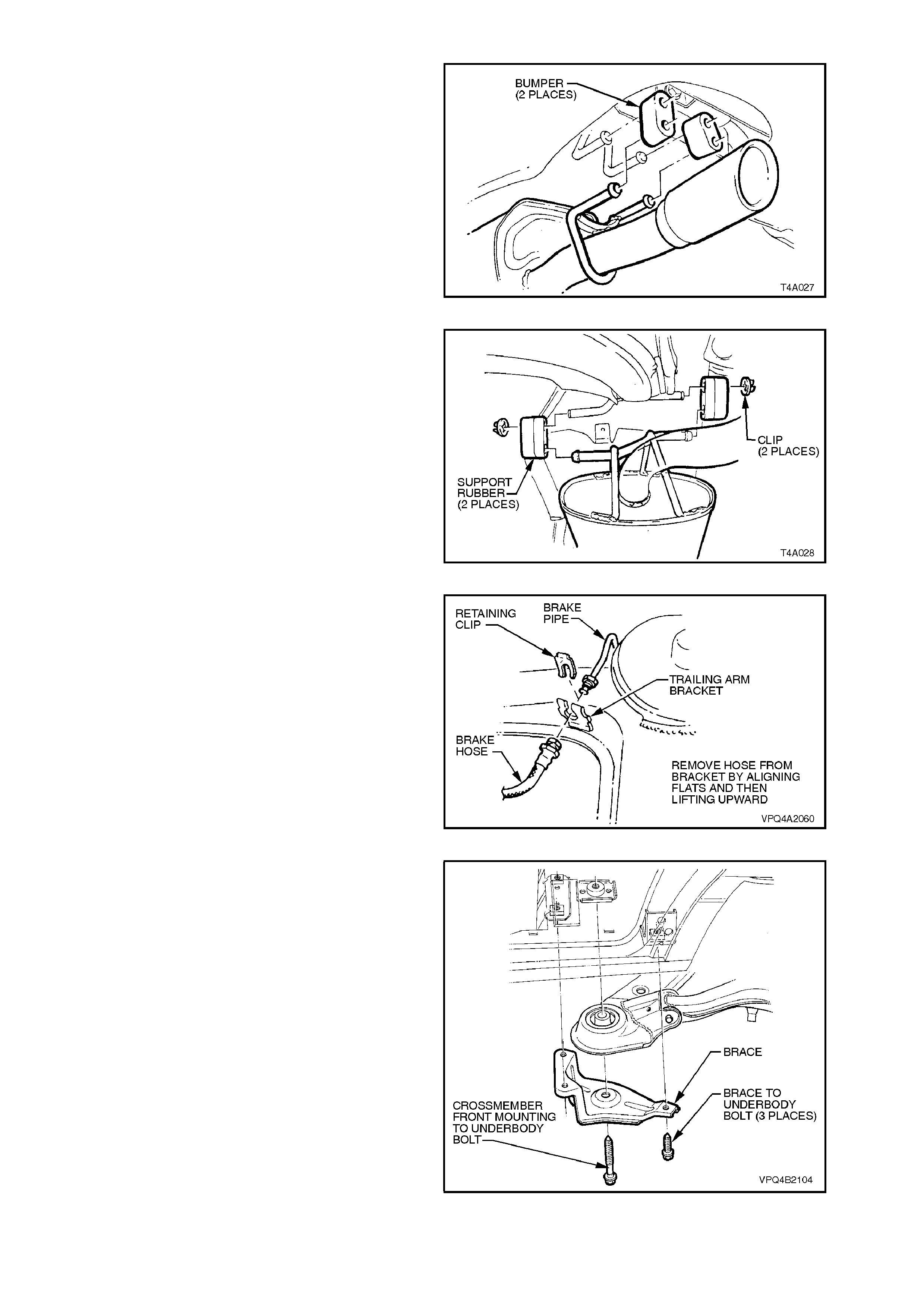
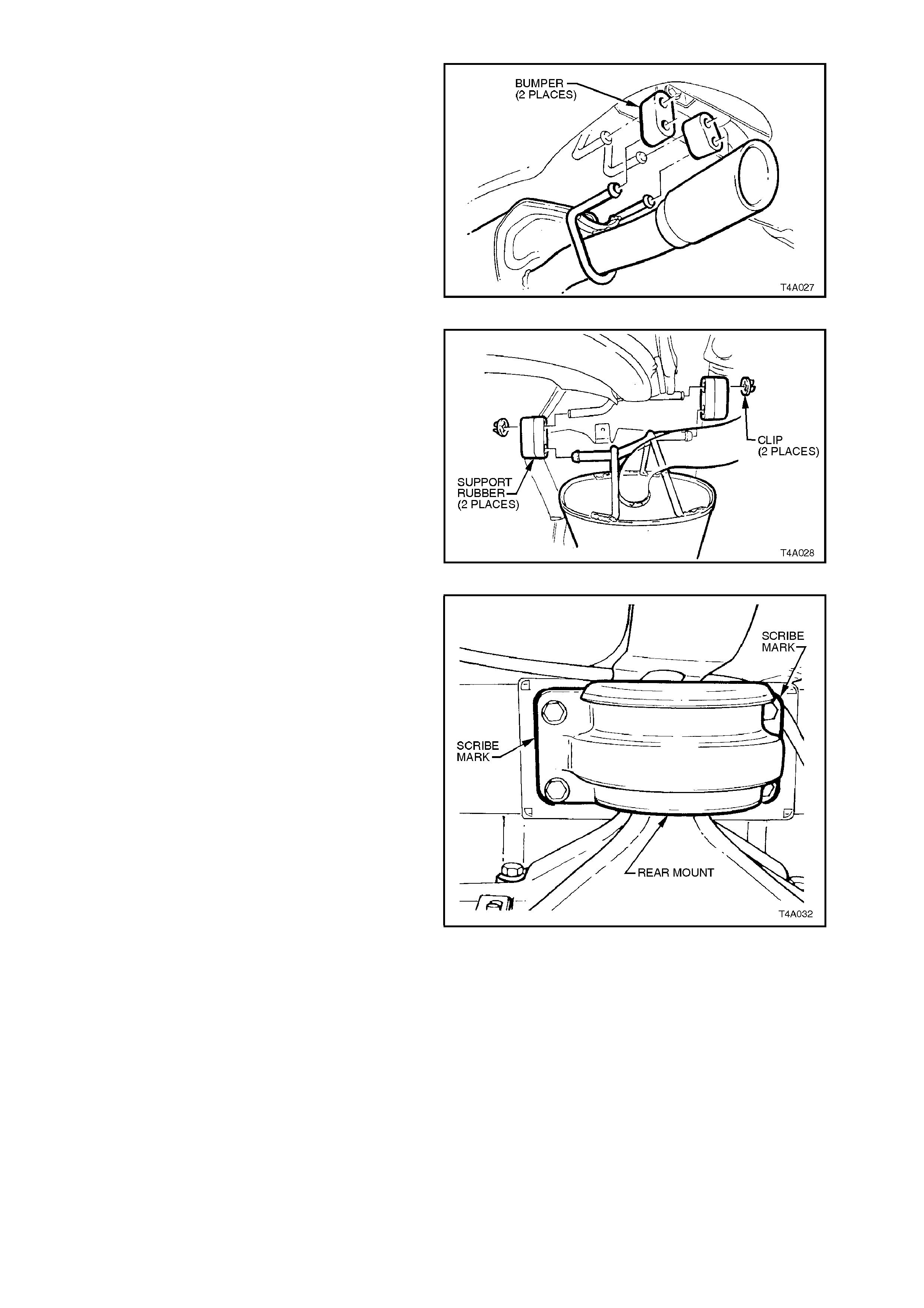
5. Remove the two retainers from the top posts
and discard. Disconnect exhaust system
support rings from the rear muffler assembly.
Both V6 and V8 arrangements are the same.
Figure 4A-40
6. Remove muffler support to rear crossmember
hanger retainers (2 places - V6, 4 places - V6
Supercharged and V8) and discard.
7. Support the intermediate section of exhaust
system and remove intermediate muffler
support rubbers. Remove intermediate and
rear sections of exhaust system from vehicle.
Figure 4A-41
8. Remove propeller shaft, refer to
Section 4C PROPELLER SHAFT AND
UNIVERSAL JOINTS.
9. Set park brake in fully released position.
Release each of the underbody to park brake
cable retaining clips and free cables.
Figure 4A-42
10. Remove park brake outer cable retaining
bracket bolt from the vehicle underbody.
11. Pull each park brake inner cable forward and
up (1), out of the cable retainer, then pull
rearward (2) to remove the cable from the
underbody bracket.
Figure 4A-43
12. Disconnect brake pipes from brake hoses at
trailing arm brackets and remove brake hose
retaining clips.
Plug ends of brake pipes to prevent fluid loss
and foreign matter entry.
Figure 4A-44
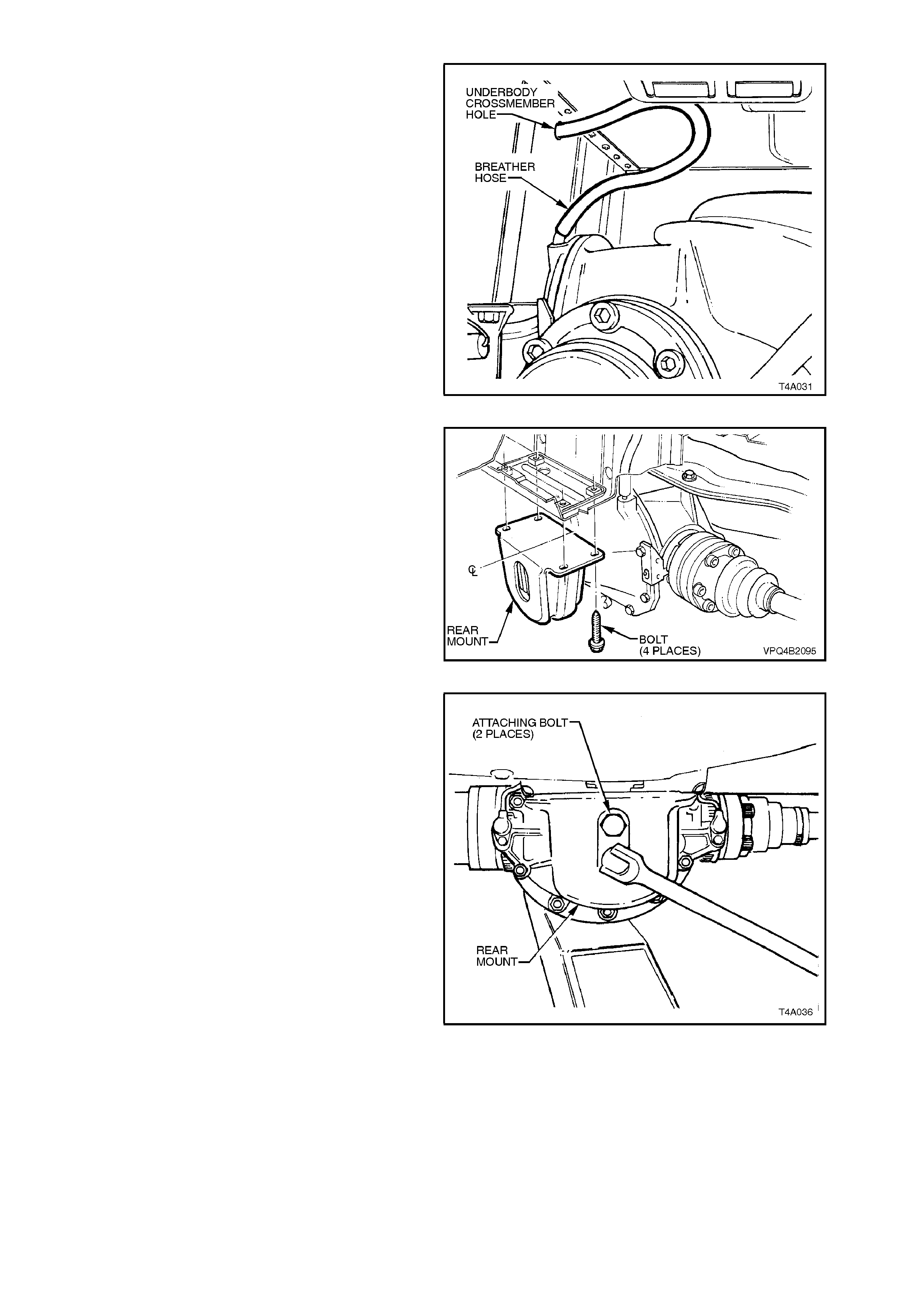
13. Pull out differential carrier breather hose from
vehicle underbody crossmember hole.
Figure 4A-45
14. If vehicle is fitted with ABS, pull both sensor
lead connectors from the underbody retaining
clips. Separate the sensor connectors from the
body harness connectors by levering out with
a screwdriver.
Figure 4A-46
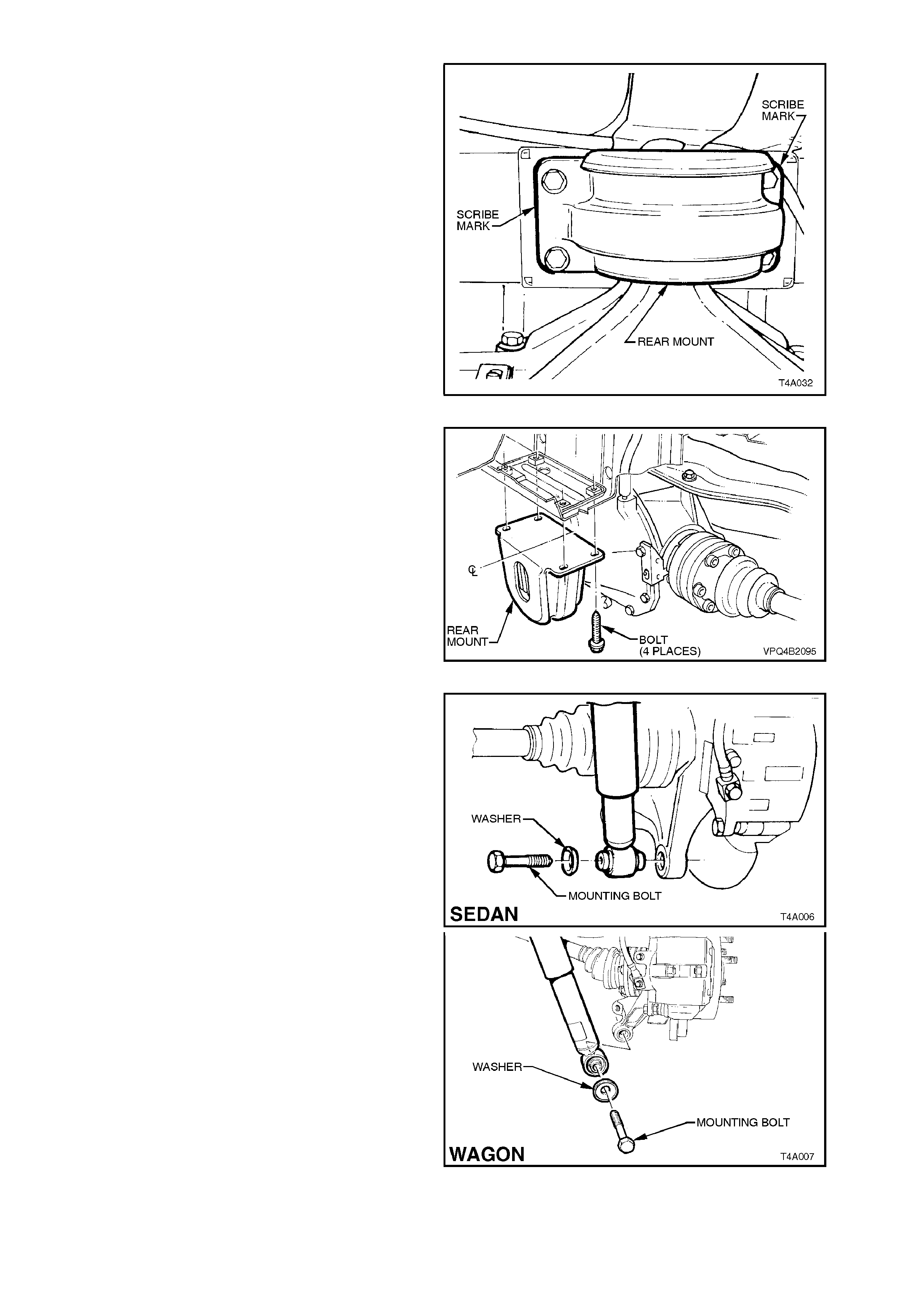
15. Using a scriber, mark rear mount to vehicle
under body location. This will aid in rear
crossmember alignment on installation.
16. Support weight of differential carrier with floor
jack.
Figure 4A-47
17. Remove rear mount to vehicle underbody
attaching bolts and discard. Lower differential
carrier and rear crossmember assembly by at
least 60 mm.
Figure 4A-48
18. Position a second floor jack under left and
right trailing arm s in turn and raise jac k slightly
to take spring load off trailing arm. Disconnect
rear shock absorber lower mounting bolts from
trailing arms and pull lower end of both shock
absorbers from trailing arms.
NOTE:
Bruising to the inside of the drive shaft constant
velocity joint boots will occur if the shock absorber
is disconnected from the trailing arm before the
rear of the differential carrier and crossmember
assembly has been lowered by at least 60 mm.
Bruising of the boot will lead to prem ature f ailure of
the boot and eventual failure of the joint if
unchecked.
Figure 4A-49
19. Remove rear springs and insulators from
vehicle underbody and trailing arms.
20. Raise differential carrier and rear
crossmember on floor jack until rear mount
contacts underbody.
Figure 4A-50
21. Remove brace to vehicle underbody attaching
bolts.
22. With the aid of an assistant, remove
crossmember to underbody bolts and braces.
23. With assistant supporting front end of rear
crossmember, lower assembly on jack and
remove from beneath vehicle.
Figure 4A-51
24. Remove differential carrier and crossmember
assembly from jack and support trailing arms,
drive shafts and differential carrier on wooden
blocks.
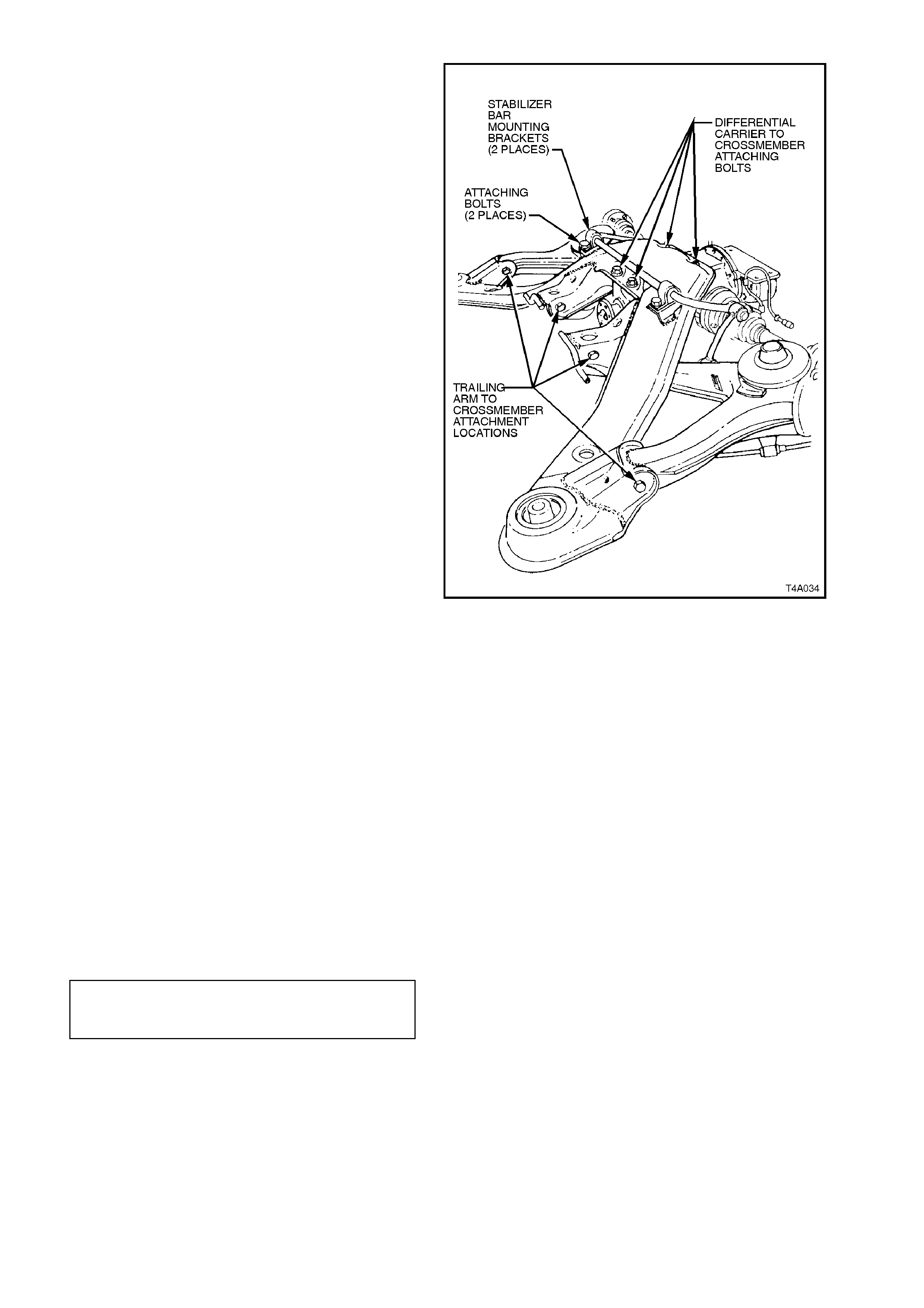
25. Remove stabiliser bar mounting bracket
attaching bolts.
Using a screwdriver, lever up brackets from
mounting points and remove brackets.
26. Remove differential carrier to crossmember
attaching bolts, discard bolts.
27. Remove trailing arm to crossmember
attaching bolts and nuts. Discard nuts, as new
ones must be used on reassembly. Disengage
trailing arms from crossmember.
28. Swing back stabiliser bar from crossmember,
and lift up and remove crossmember.
Figure 4A- 52
REINSTALL
Installation of rear crossmember is the reverse of
removal procedures, with the exception of the
following steps:
1. If replacing a crossmember that does not have
front bushes, press in new bushes using Tool
No’s. KM618-1 and KM618-2.
2. Install crossmember over differential carrier
and trailing arms.
Assemble trailing arms into crossmember
brackets and install attaching bolts and new
self-locking nuts.
Do not fully tighten nuts at this stage.
3. Align crossmember and differential carrier
mounting holes and install and tighten new
attaching bolts to the correct torque
specification.
DIFFERENTIAL CARRIER TO REAR 90 Nm, plus
CROSSMEMBER ATTACHING 30° - 45°
TORQUE SPECIFICATION turn angle
4. Position stabiliser bar onto cr ossmem ber, with
insulators located over crossmember
mounting points.
5. Engage brackets to mounting points and
install over insulators. Install and tighten
attaching bolts to the correct torque
specification.
STABILISER BAR MOUNTING
BRACKET TO CROSSMEMBER
ATTACHING BOLT
TORQUE SPECIFICATION 18 - 26 Nm
6. With the aid of two assistants, place the
differential carrier and rear crossmember
assembly onto floor jack.
7. Position assembly under vehicle and raise
assembly with the jack and, with the aid of an
assistant, guide the crossmember front
mounting points into location.
NOTE:
During this operation, ensure that trailing arms are
also supported on safety stands, to keep the drive
shafts as near to horizontal as is possible.
Failing to observe this aspect will result in bruising
to the insides of the constant velocity joint boots,
leading to boots splitting and eventually joint failure,
if left unchecked.
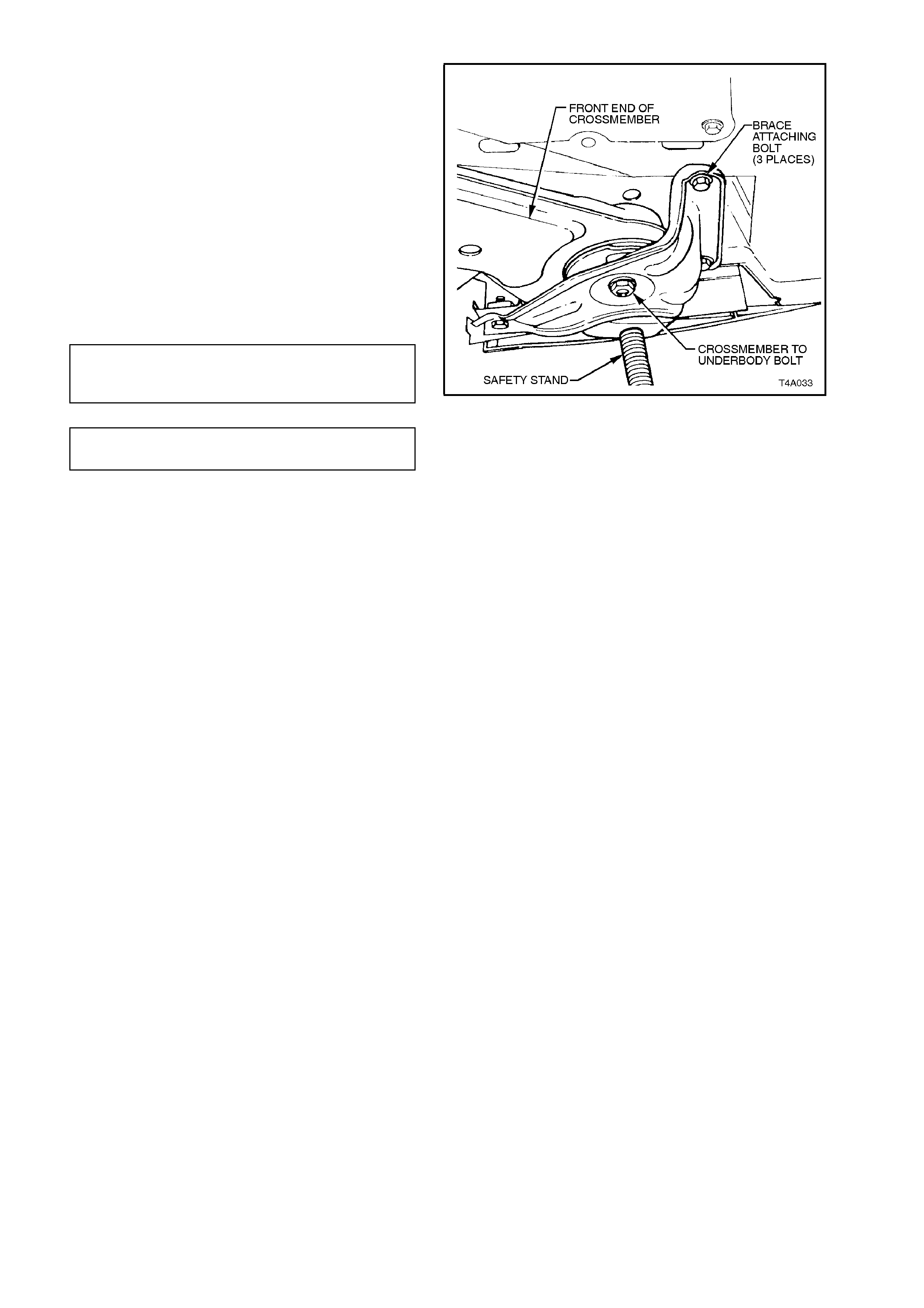
8. Install crossmember front mounting braces
and bolts but do not tighten bolts at this
stage.
Figure 4A-53
9. Lower differential carrier and rear
crossmember assembly on floor jack and
safety stands. Install rear springs and
insulators.
Figure 4A-54
10. After installing springs and insulators, use a
second floor jack to raise each trailing arm up
far enough to allow shock absorber lower
mounting be installed to trailing arms.
Install washers and bolts to shock absorber
lower mounts and tighten bolts to the correct
torque specification.
NOTE:
Sedan and station wagon torque specifications are
the same.
SHOCK ABSORBER LOWER
MOUNTING BOLT 105 - 125 Nm
TORQUE SPECIFICATION
Figure 4A-55
11. Raise assembly until rear mount contacts
vehicle underbody.
Align mount with marks on underbody, made
on disassembly, then loosely install new
attaching bolts but do not fully tighten at this
stage.
12. The rear crossmember MUST now be aligned
to the vehicle centreline, us ing the special tool
and procedure as detailed in Section 1A2
BODY DIMENSIONS.
CAUTION:
Failure to correctly align the rear crossmember
to the centreline of the vehicle will result in
steering abnormalities and uneven tyre wear!
13. Tighten all crossmember mounting fasteners
to the correct torque specification.
REAR MOUNT TO
VEHICLE UNDERBODY 30 Nm then
ATTACHING BOLT 60° turn angle
TORQUE SPECIFICATION
REAR CROSSMEMBER 125 Nm, plus
FRONT MOUNTING BOLT 30° - 40°
TORQUE SPECIFICATION turn angle
BRACE BOLT 60 -70
TORQUE SPECIFICATION Nm
14. Install differential carrier breather hose into
vehicle underbody crossmember hole. Ensure
that end of hose is pushed into hole
approximately 25 mm.
Figure 4A-56
15. If equipped with ABS, reconnect wheel sens or
wiring harness connectors.
16. Check park brake adjus tment and bleed brake
hydraulic system, refer to
Section 5A STANDARD BRAKES.
17. Reinstall ex haust system , by firs t installing the
front of the intermediate pipe to the catalytic
converter (V6 engine) or converters (V6
Supercharged and V8 engines). Use new
gaskets at the flanges on V6 Supercharged
and V8 converters.
18. While supporting the exhaust system, install
the exhaust hanger rubbers to the rear of the
intermediate muffler and secure with new
retainers.
19. Install rear muffler support rings to the rear of
the muffler.
20. Tighten intermediate exhaust pipe to catalytic
converter bolts to the correct torque
specification.
INTERMEDIATE EXHAUST PIPE TO All Engines
CATALYTIC CONVERTER BOLT 40 - 50
TORQUE SPECIFICATION Nm
21. Check exhaust clearances as detailed in
Section 8B EXHAUST SYSTEM.
22. Remove safety stands and lower vehicle.
23. Bounce the rear of the vehic le s everal times to
settle suspension then, with vehicle in kerb
height position, tighten trailing arm to
crossmember attaching nuts to the correct
torque specification.
TRAILING ARM TO CROSSMEMBER
ATTACHING NUT 95 - 105 Nm
TORQUE SPECIFICATION
24. Start vehicle and check for exhaust leaks.
Repair as necessary.
2.8 REAR CROSSMEMBER FRONT BUSHES
CAUTION:
Whenever any component that forms part of
the ABS (if fitted) is disturbed during Service
Operations, it is vital that the complete ABS
system be checked, using the procedure as
detailed in # DIAGNOSIS, ABS FUNCTION
CHECK, in Section 12L ABS/Traction Control.
IMPORTANT:
Before disturbing the rear suspension
crossmember, front mounting bolts, an alignment
procedure is required on installation and a special
tool is required for this purpose. If this tool is not
available, then the crossmember cannot be
correctly aligned and steering and/or handling
abnormalities will result.
REPLACE
1. Using a floor jack under centre of differential
carrier, jack up rear of vehicle then place
safety stands under body rear jacking points.
Refer to Section 0A GENERAL
INFORMATION for location of jacking points.
2. Disconnect exhaust system from rear of
catalytic converter (V6) or converters (V6
Supercharged and V8).
NOTE:
Only one side of the V6 Supercharged/V8
arrangement is shown.
Figure 4A-57
3. Remove the two retainers from the top posts
and discard. Disconnect exhaust system
support rings from rear hanger of rear muffler
assembly. Both V6 and V8 arrangements are
similar.
Figure 4A-58
4. Remove muffler support to rear crossmember
hanger retainers (2 places - V6, 4 places - V6
Supercharged and V8) and discard.
5. Support intermediate section of exhaust
system and rem ove supports from m uffler and
crossmember hangers. Remove intermediate
and rear sections of exhaust system from
vehicle.
Figure 4A-59
6. Remove brake hose retaining clips from
trailing arm and remove brake hoses from
brackets. Pull brake pipe and hoses forward
from brackets and disconnect from trailing
arms by lifting up brake pipes through slots in
brackets.
Figure 4A-60
7. With floor jack supporting differential carrier
and crossmember assembly, remove brace
and crossmember to vehicle underbody
attaching bolts from side on which bush is to
be replaced.
Figure 4A-61
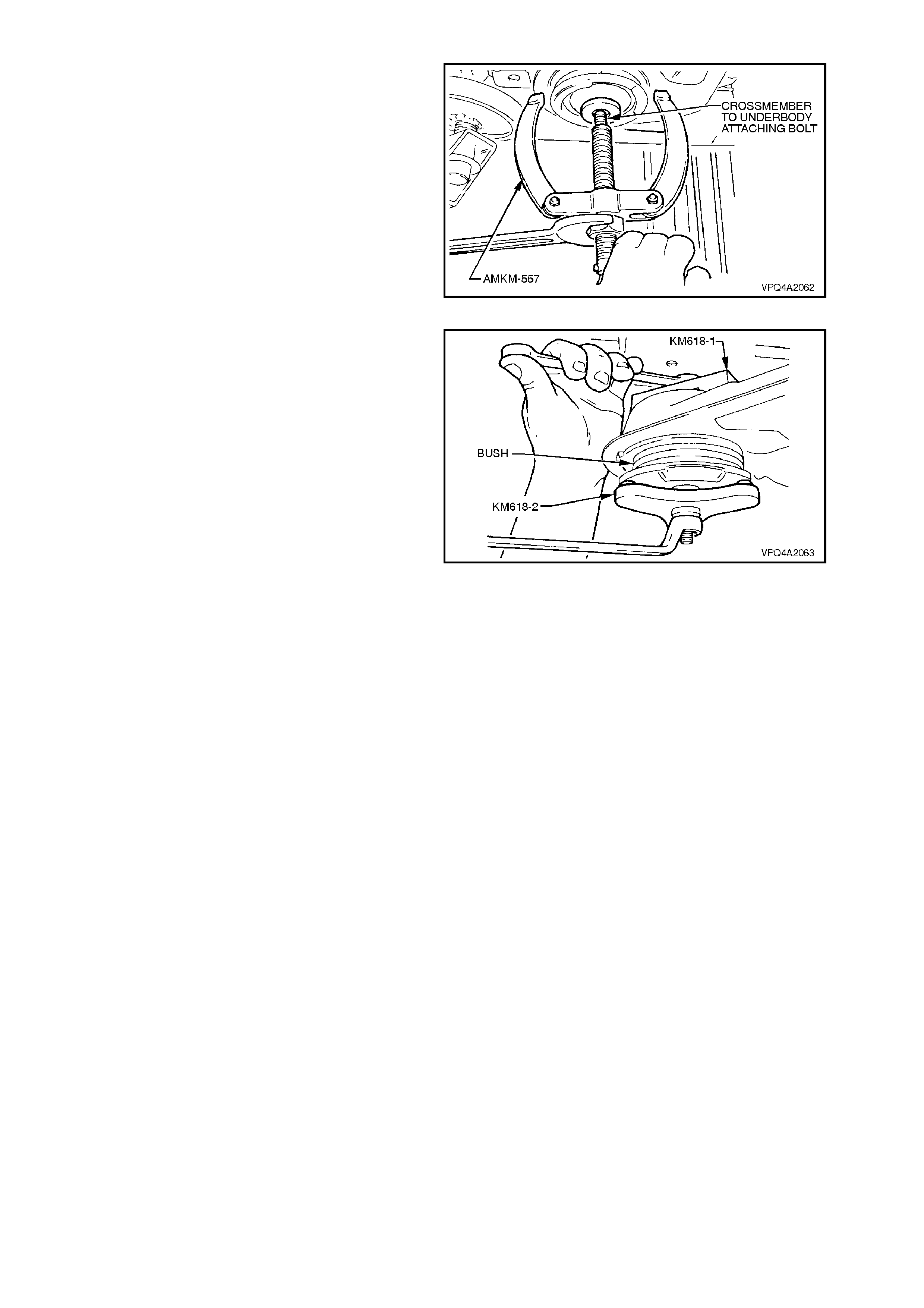
8. Lower jack slightly and allow crossmember to
rest on a safety stand, rear of front mounting.
Install bolt (part of Tool No. AMKM-557) from
above into bush. Using puller, Tool No.
AMKM-557, remove crossmember bush.
9. Remove AMKM-557 assembly and discard
bush.
Figure 4A-62
10. Draw in new bush into crossmember using
Tool No. KM618-1 and KM618-2.
Figure 4A-63
11. Raise up crossmember and install front
mounting brace and bolts but do not tighten
bolts at this stage.
12. The rear crossmember MUST now be aligned
to the vehicle centreline, us ing the special tool
and procedure, as detailed in
Section 1A2 BODY DIMENSIONS.
CAUTION:
Failure to correctly align the rear crossmember
to the centreline of the vehicle will result in
steering abnormalities and uneven wear!
13. Tighten bolts to the correct torque
specification.
REAR CROSSMEMBER FRONT 125 Nm, plus
MOUNTING BOLT 30° - 40°
TORQUE SPECIFICATION turn angle
BRACE BOLT 60 - 70
TORQUE SPECIFICATION Nm
14. Insert brake hoses into trailing arm brackets
and install retaining clips.
15. Reinstall exhaust system, by first installing the
front of the intermediate pipe to the catalytic
converter (V6 engine) or converters (V6
Supercharged and V8 engines). Use new
gaskets at the flanges on V6 Supercharged
and V8 converters.
16. While supporting the exhaust system, install
the exhaust hanger rubbers to the rear of the
intermediate muffler and secure with new
retainers.
17. Install rear muffler support rings to the rear of
the muffler.
18. Check exhaust clearances as detailed in
Section 8B EXHAUST SYSTEM.
19. Remove safety stands and lower vehicle.
20. Start vehicle and check for exhaust leaks,
repair as necessary.
Figure 4A-64
2.9 REAR CROSSMEMBER REAR MOUNT
CAUTION :
Whenever any component that forms part of
the ABS (if fitted) is disturbed during Service
Operations, it is vital that the complete ABS
system be checked, using the procedure as
detailed in DIAGNOSIS, ABS FUNCTION
CHECK, in Section 12L ABS/Traction Control.
IMPORTANT:
Before disturbing the crossmember rear
mounting bolts, an alignment procedure is
required on installation and a special tool is
required for this purpose. If this tool is not
available, then the crossmember cannot be
correctly aligned and steering and/or handling
abnormalities will result.
NOTE:
For this operation, new rear crossmember rear
mount to vehicle underbody attaching bolts and
rear mount to differential carrier rear cover
attaching bolts MUST be used on reassembly.
REMOVE
1. Using a floor jack under centre of differential
carrier, jack up rear of vehicle then place
safety stands under body rear jacking points.
Refer to Section 0A GENERAL
INFORMATION for location of jacking points.
2. Disconnect exhaust system from rear of
catalytic converter (V6) or converters (V6
Supercharged and V8).
NOTE:
Only one side of the V6 Supercharged/V8
arrangement is shown.
Figure 4A-65
3. Remove the two retainers from the top posts
and discard. Disconnect exhaust system
support rings from rear hanger of rear muffler
assembly. Both V6 and V8 arrangements are
the same.
Figure 4A-66
4. Remove muffler support to rear crossmember
hanger retainers (2 places - V6, 4 places - V6
Supercharged and V8) and discard.
5. Lift up intermediate section of exhaust system
and remove intermediate muffler support
rubbers. Remove intermediate and rear
sections of exhaust system from vehicle.
Figure 4A-67
6. Using a scriber, mark rear mount to vehicle
under body location. This will aid in rear
crossmember alignment on reinstallation.
7. Support weight of differential carrier with floor
jack.
Figure 4A-68
8. Pull differential carrier breather hose from
vehicle underbody crossmember hole.
Figure 4A-69
9. Support weight of differential carrier with floor
jack.
10. Remove rear mount to vehicle underbody
attaching bolts and discard.
11. Lower differential carrier and rear
crossmember assembly until rear mount to
differential carrier rear cover attaching bolts
becom e ac c ess ible below lower surf ac e of fuel
tank.
Figure 4A-70
12. Loosen and remove rear mount attaching
bolts, remove mount and discard attaching
bolts.
Figure 4A-71
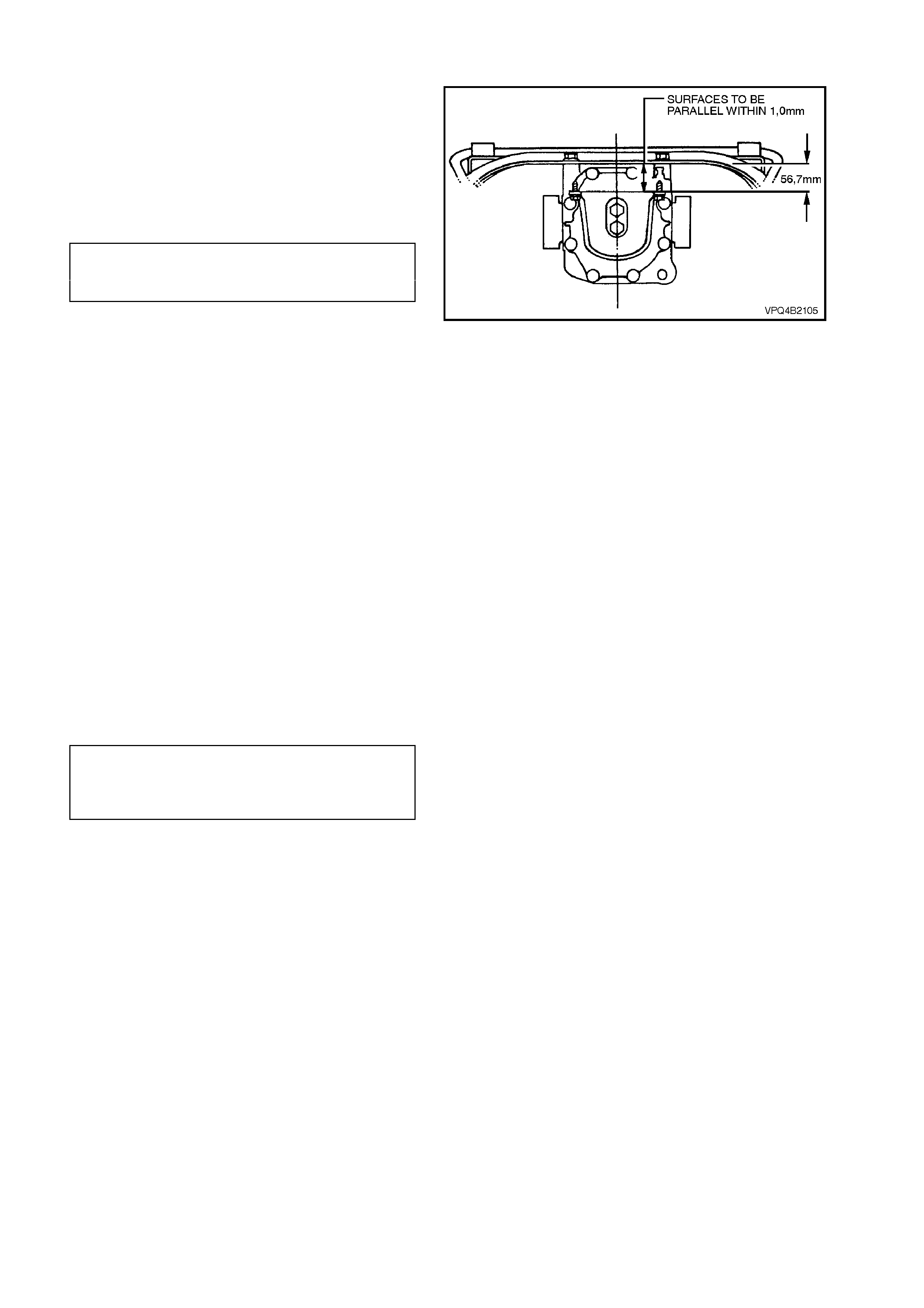
REINSTALL
1. Install rear mount and new attaching bolts to
differential carrier rear cover.
Tighten attaching bolts to the correct torque
specification, and at same time ensure that
mount does not twist (mount to vehicle
underbody mating surface should be parallel
to the rear crossmember, as shown).
REAR MOUNT TO REAR COVER
ATTACHING BOLT 85 - 105 Nm
TORQUE SPECIFICATION
NOTE:
Use a spirit level on rear mount to underbody
surface and top surface of crossm ember to ensure
that both surfaces are parallel.
2. Raise differential carrier and rear
crossmember assembly until rear mount
contacts vehicle underbody.
3. Align mount with marks on underbody, made
on disass embly and install new attaching bolts
but do not tighten at this stage.
4. The rear crossm ember MUST now be aligned
to the vehicle centreline, us ing the special tool
and procedure as detailed in
Section 1A2 BODY DIMENSIONS.
CAUTION:
Failure to correctly align the rear crossmember
to the centreline of the vehicle will result in
steering abnormalities and uneven tyre wear!
Figure 4A-72
5. Tighten rear crossmember, rear mount to
underbody bolts to the correct torque
specification.
REAR MOUNT TO
VEHICLE UNDERBODY 30 Nm the n
ATTACHING BOLT 60° turn angle
TORQUE SPECIFICATION
6. Install differential carrier breather hose into
vehicle underbody crossmember hole. Ensure
that end of hose is pushed into hole
approximately 25 mm.
7. Reinstall ex haust system , by firs t installing the
front of the intermediate pipe to the catalytic
converter (V6 engine) or converters (V6
Supercharged and V8 engines). Use new
gaskets at the flanges on V6 Supercharged
and V8 converters.
8. While supporting the exhaust system, install
the exhaust hanger rubbers to the rear of the
intermediate muffler and secure with new
retainers.
9. Install rear muffler support rings to the rear of
the muffler.

10. Tighten intermediate exhaust pipe to catalytic
converter bolts to the correct torque
specification.
INTERMEDIATE EXHAUST PIPE TO All Engines
CATALYTIC CONVERTER BOLT 40 - 50
TORQUE SPECIFICATION Nm
11. Check exhaust clearances as detailed in
Section 8B EXHAUST SYSTEM.
12. Remove safety stands and lower vehicle.
13. Start vehicle and check for exhaust leaks,
repair as necessary.
2.10 RE AR SHOCK ABSORBE RS AND/OR BUSHES
REMOVE
1. Using a floor jack under centre of differential
carrier, jack up rear of vehicle then place
safety stands under trailing arms to support
weight of vehicle.
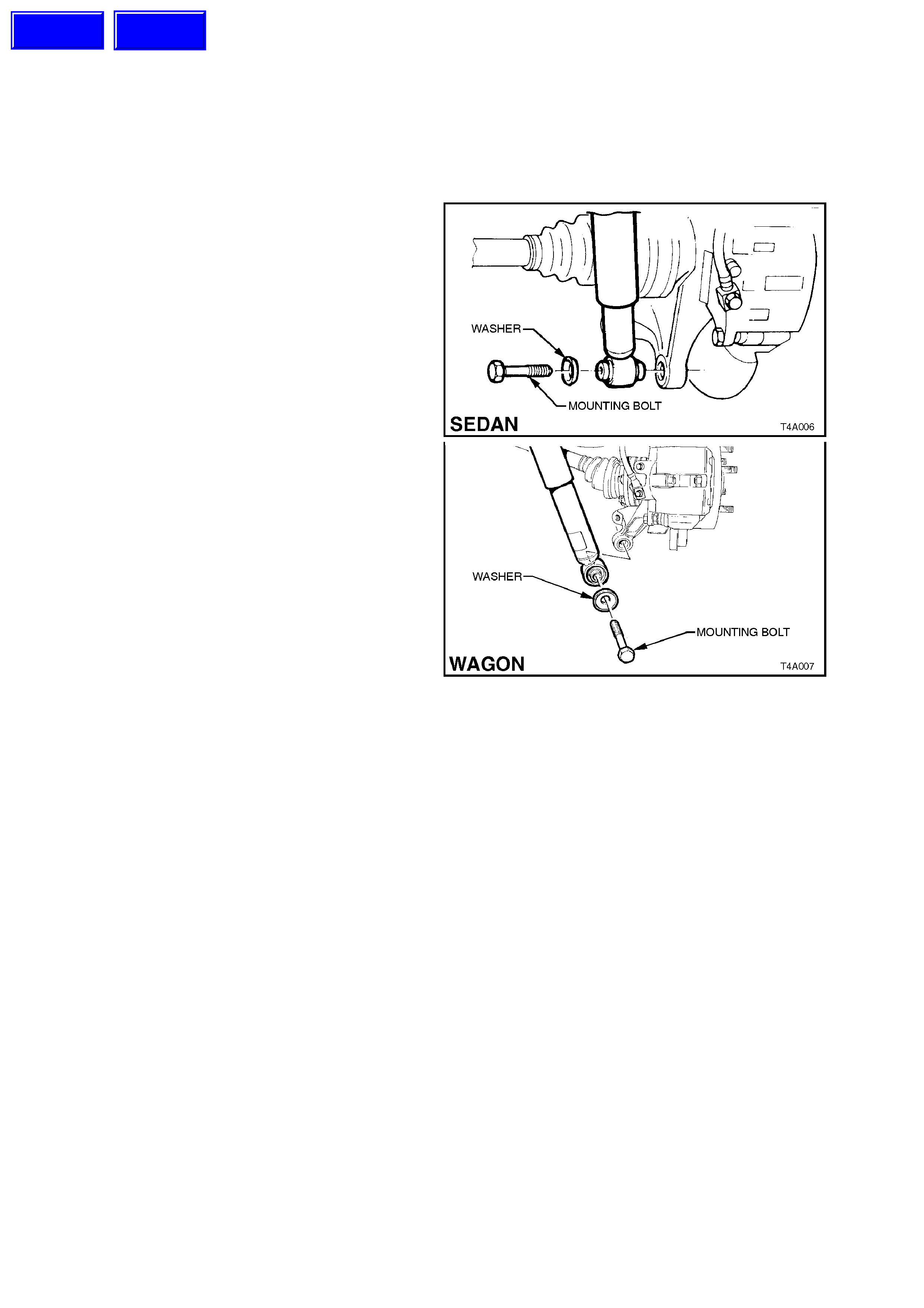
2. Loosen and remove shock absorber lower
mounting bolt and washer and remove shock
absorber from the lower mounting.
Figure 4A-73
Techline
Techline
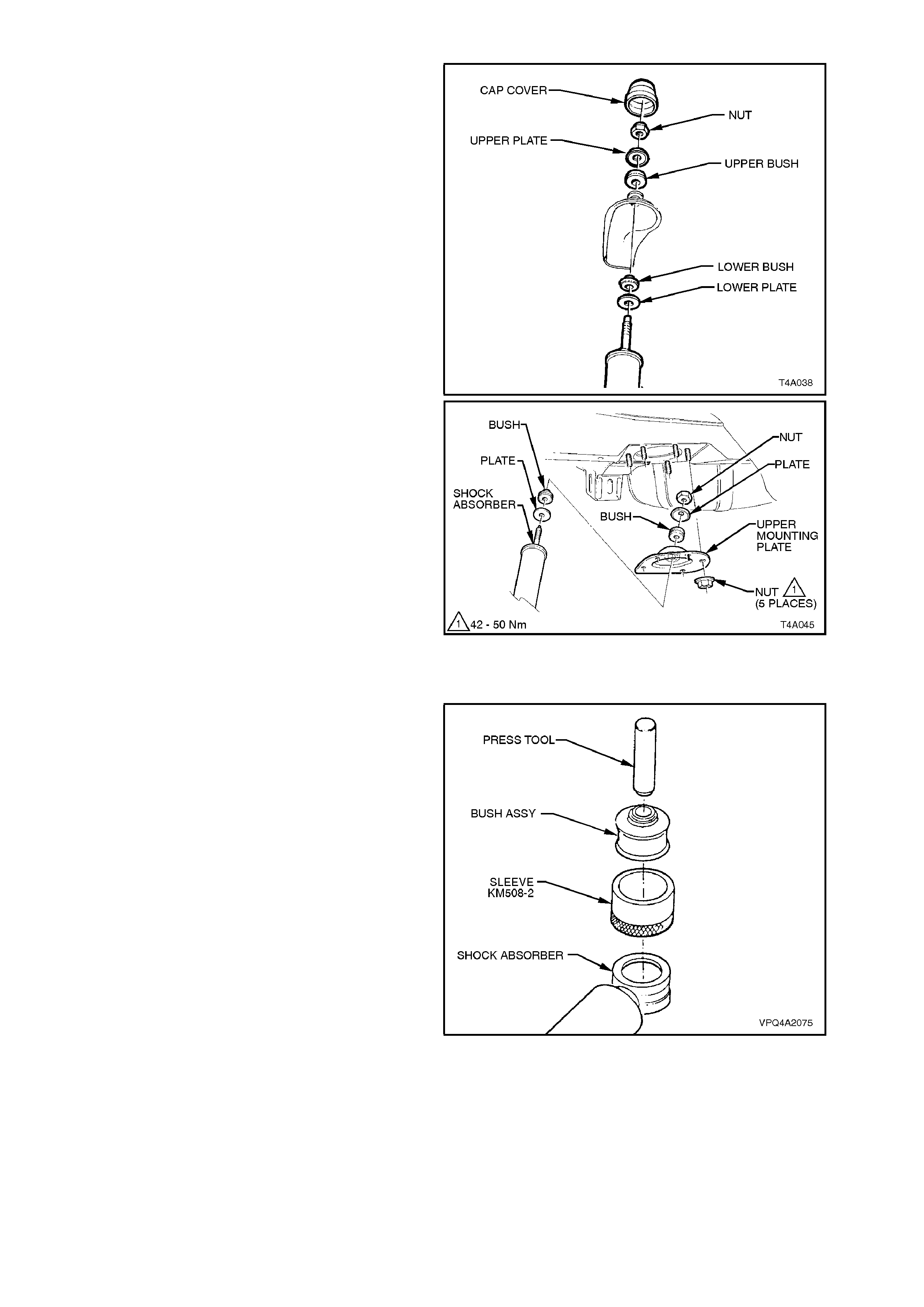
3. With sedan models, open rear compartment
lid and prise off shock absorber upper
mounting cap cover.
With station wagon models, remove the five
upper mounting plate retaining nuts.
4. Remove shock absorber upper mounting nut,
upper plate and bush. With station wagon
models, also remove the upper mounting
plate.
5. Remove upper m ounting lower bush and lower
plate from shock absorber.
Figure 4A-74
LOWER BUSH, REPLACE
1. To replace shock absorber lower bush:
a. With shock absorber lower mount
supported on suitable press plates, press
bush from mount.
b. Lubricate new bush with soapy water and
place in Sleeve, Tool No. KM508-2.
c. With shock absorber lower mount
supported on press plates, position
KM508-2 onto lower mount. Press new
bush into mount using fabricated press
tool. (For details of press tool, refer to
6. SPECIAL TOOLS at the end of this
Section).
Figure 4A-75
REINSTALL
1. Before installation, check shock absorber
action and inspect rubber bushes; replacing
as required. See 3. DIAGNOSIS in this
Section for testing details.
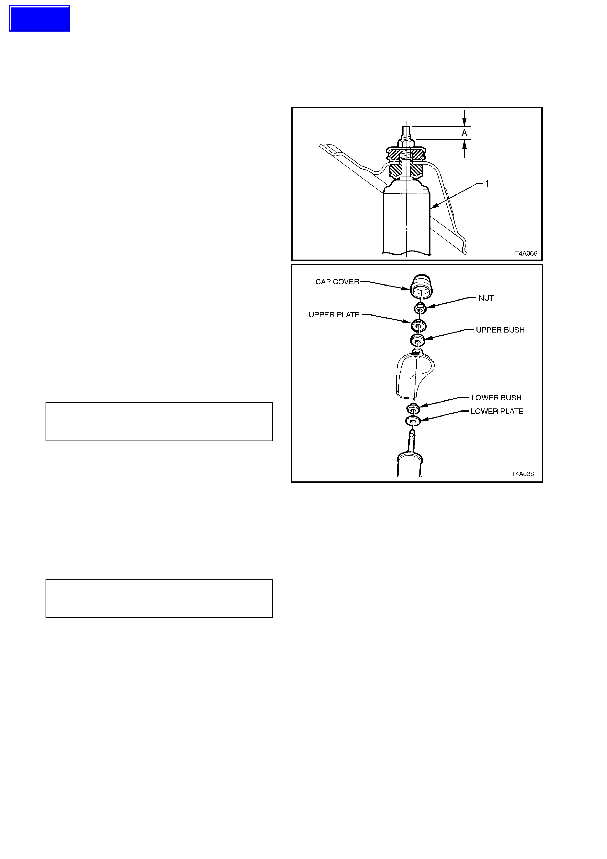
2. On all models, assemble upper mounting
lower plate and bush to the shock absorber
(1).
With station wagon models, also install the
upper mounting plate upper mounting upper
bush and plate.
3. On station wagon models, install the retaining
nut, tightening until the distance ‘A’, between
the top of the threaded shaft and the nut is
from 15.5 - 16.0 mm.
4. With sedan models, position shock absorber
into upper mounting hole. Install upper
mounting upper bush, upper plate and
mounting nut.
Hand tighten until the nut is fully installed onto
the threaded section of the shaft.
NOTE:
Do not use power operated tools for this operation,
as thread damage will result.
5. On station wagon models install the five
retaining plate nuts and tighten nuts to the
correct torque specification.
UPPER SHOCK ABSORBER Station Wagon
MOUNTING PLATE RETAINING Only
NUT TORQUE SPECIFICATION 42 - 50 Nm
6. Install upper mounting cap cover (sedan only).
7. Install s hock absor ber lower m ount into tr ailing
arm and install bolt but do not fully tighten at
this stage.
8. Lower vehicle to the ground, then bounce rear
of vehicle several times to settle suspension.
9. Tighten the shock absorber lower mounting
bolt to the correct torque specification.
SHOCK ABSORBER LOWER All
MOUNTING BOLT Models
TORQUE SPECIFICATION 105 - 125 Nm
Figure 4A-76
Techline
2.11 STABILISER BAR AND/OR MOUNTINGS
CAUTION:
Before disturbing the crossmember rear mount
to underbody bolts, an alignment procedure is
required on installation and a special tool is
required for this purpose. If this tool is not
available, then the crossmember cannot be
correctly aligned and steering and/or handling
abnormalities will result.
IMPORTANT:
For this operation, new rear crossmember rear
mount to vehicle underbody attaching bolts must
be used on reassembly.
REMOVE
1. Using a floor jack under centre of differential
carrier, jack up rear of vehicle then place
safety stands under body rear jacking points.
Refer to Section 0A GENERAL
INFORMATION for location of jacking points.
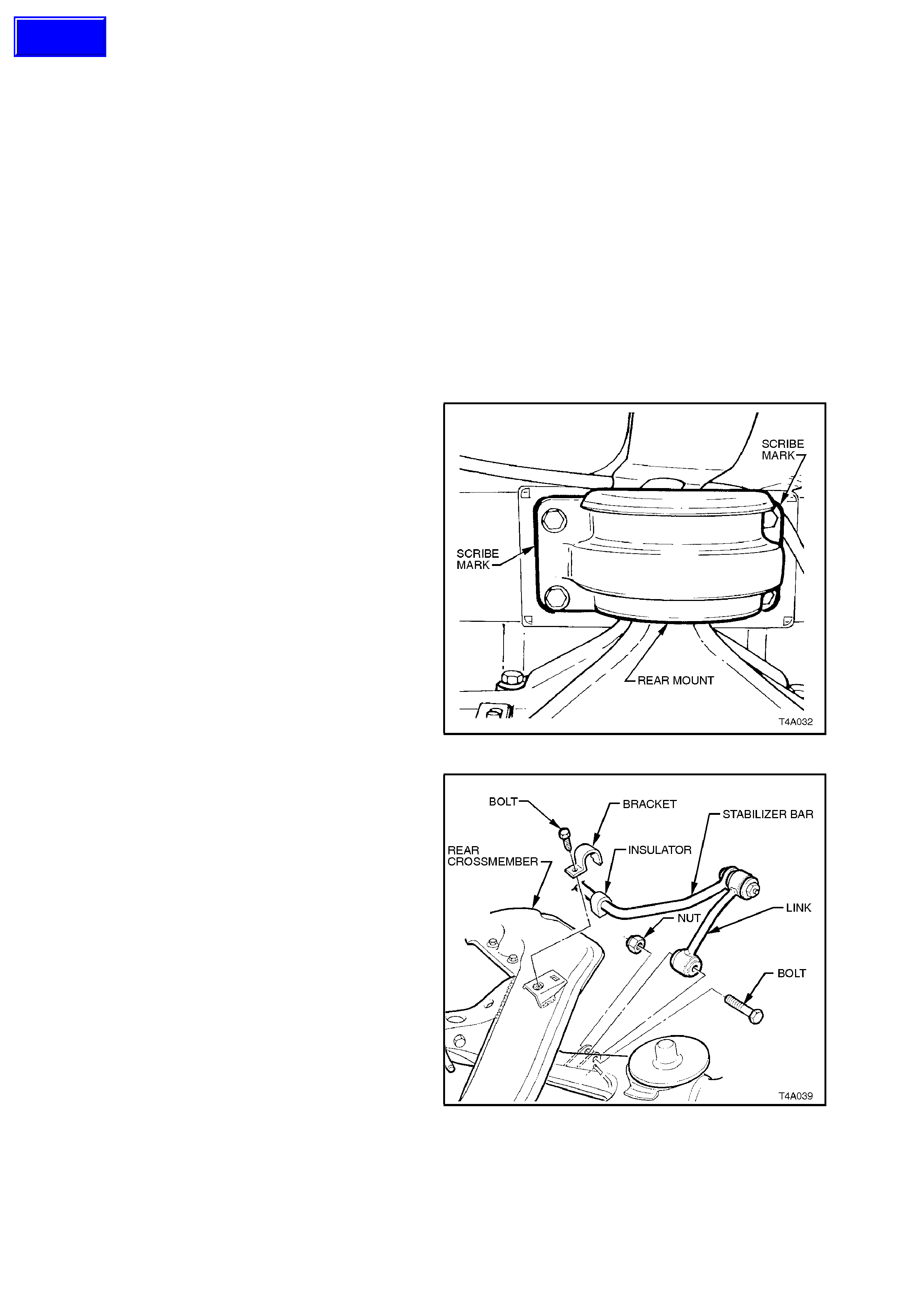
2. Using a scriber, mark rear mount to vehicle
under body location. This will aid in rear
crossmember alignment on installation.
3. Support weight of differential carrier with floor
jack.
4. Remove rear mount to vehicle underbody
attaching bolts and discard.
5. Lower differential carrier and rear
crossmember assembly sufficient to gain
access to stabiliser bar to crossmember
brackets.
NOTE:
Do not allow propeller shaft or left hand side drive
shaft to rest on exhaust system. Figure 4A-77
6. Remove both stabiliser bar link to trailing arm
attaching nuts and bolts.
Swing links clear of trailing arms.
7. Remove stabiliser bar to crossmember
bracket attaching bolts.
8. Using a screwdriver, lever up brackets from
crossmember and remove.
9. Remove stabiliser bar from vehicle.
10. Remove insulators from stabiliser bar.
11. Remove stabiliser bar to link mounting bolts
and nuts, to separate the links from the
stabiliser bar.
Figure 4A-78
Techline
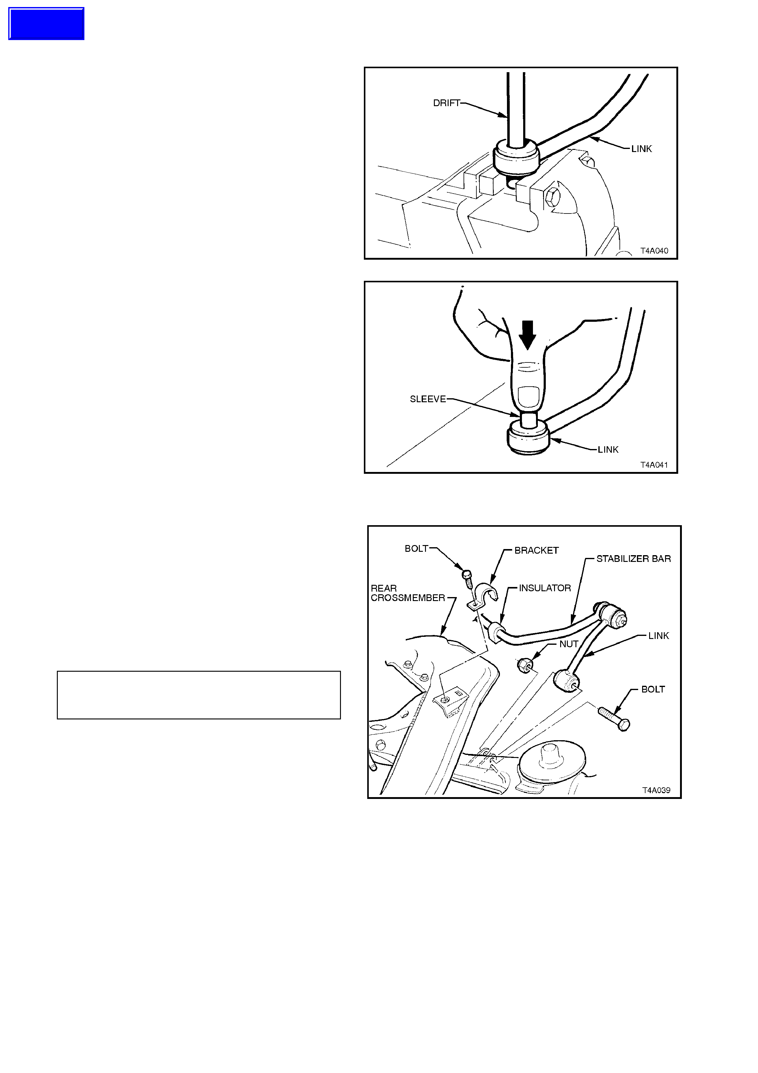
STABILISER BAR LINK BUSHES, REPLACE
NOTE:
The same procedure is used to replace both the
upper and lower bushes.
1. W hile s upporting link on pr ess plate E1312 (or
the open jaws of a vice as shown), use a
suitable drif t and rem ove the steel sleeve from
the centre of the bush. Then distort the
flanged edge of the bus h and rem ove from the
link.
Repeat procedure for remaining bush, as
required.
Figure 4A-79
2. T o ease ins tallation, apply petroleum jelly such
as Vaseline or equivalent, to bush/bushes,
then install into the eye of the link.
3. Apply a smear of petroleum jelly to the steel
inner s leeve, then insert into the bush until it is
centralised.
Figure 4A-80
REINSTALL
1. Loosely install the st abiliser bar link to stabiliser
bar bolts and nuts but do not f u lly tighten at this
stage.
2. Install insulators and brackets to stabiliser bar.
Position stabiliser bar onto crossmember,
engaging tangs of brackets with slots in
crossmember mounting points.
Install and tighten brack et attac hing bolts to the
correct torque specification.
STABILISER BAR MOUNTING
BRACKET TO CROSSMEMBER 18 - 26 Nm
BOLT TORQUE SPECIFICATION
3. Install links into position between trailing arm
brackets and loosely install attaching bolts and
nuts, but do not fully tighten at this stage.
Figure 4A-81
Techline
4. Raise differential carrier and rear
crossmember assembly until rear mount
contacts vehicle underbody.
5. Align mount with marks on underbody, made
on disassembly and install new attaching bolts
but do not tighten at this stage.
6. The rear crossmember MUST now be aligned
to the vehicle centreline, us ing the spec ial tool
and procedure as detailed in
Section 1A2 BODY DIMENSIONS.
CAUTION:
Failure to correctly align the rear crossmember
to the centreline of the vehicle will result in
steering abnormalities and uneven tyre wear!
7. Tighten rear crossmember, rear mount to
underbody bolts to the correct torque
specification.
REAR MOUNT
TO UNDERBODY 30 Nm the n
ATTACHING BOLT 60° turn angle
TORQUE SPECIFICATION
8. Lower vehicle, then bounce rear of vehicle
several times to settle suspension.
9. Tighten stabiliser bar link mounting bolts and
nuts to the correct torque specification.
STABILISER BAR LINK
ATTACHING BOLTS AND NUTS 18 - 26 Nm
TORQUE SPECIFICATION
3. DIAGNOSIS
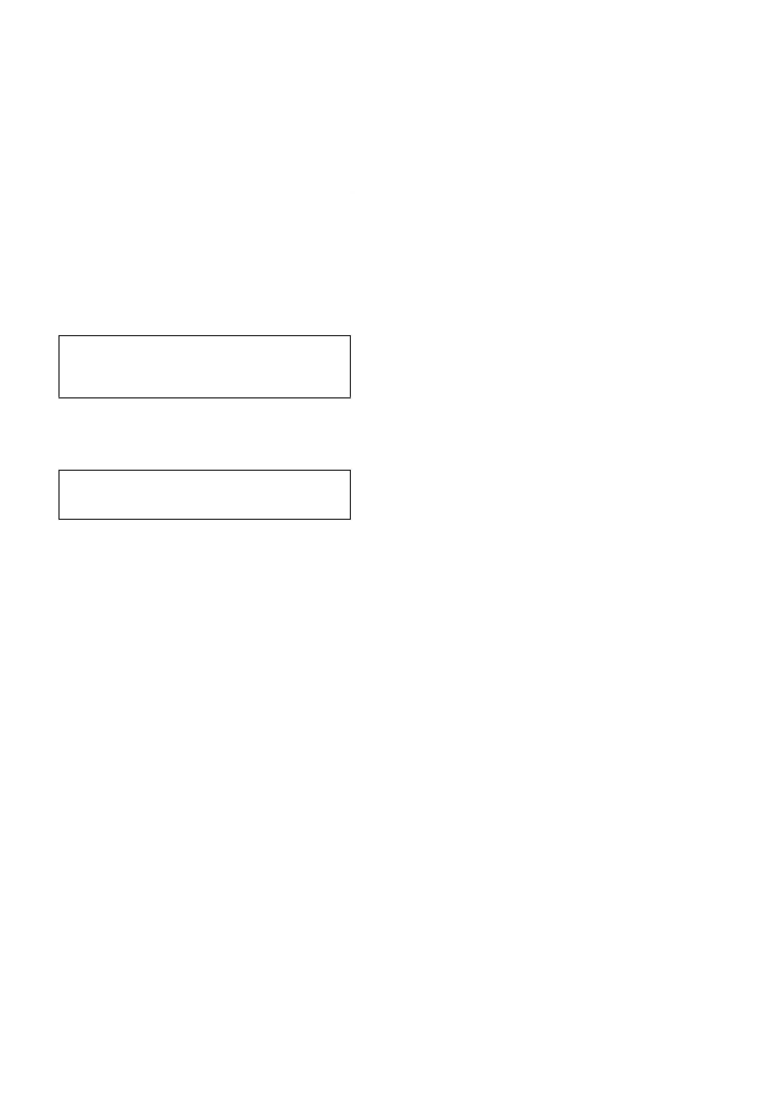
CHECKING AND TESTING SHOCK ABSORBERS
For a positive c heck of s hock absor ber operation it
is advisable to remove them from the vehicle.
However, before proceeding with the removal, it is
good practice to ensure that the noise causing
concern, is not coming from another source.
Check shock absorber mountings for tightness;
check rubber mounting bushes and replace if worn.
Test shock absorber action as follows:
IMPORTANT:
This test procedure is not for gas pressurised
shock absorbers.
1. Clam p shock absorber by its lower mount in a
vice, as shown.
2. Slowly pum p shock absorber up and down the
full stroke at least s ix times bef or e chec king its
resistance.
3. Pump shock absorber by hand at various rates
of speed and observe resistance.
When extending the shock absorber, the resistance
should be marginally greater than when collapsing
the unit. The resistance should be consistent
throughout both strokes and there should be no
‘slack' spots.
‘Slack' spots indicate either loss of oil - which is
usually visible on the outside - or the internal valves
not seating.
4. It is normal to detect a hissing noise (orifice
swish).
5. The following conditions are considered
abnormal and replacement is recommended;
a. A skip or lag at reversal near mid-stroke.
b. A seize (except at either extreme end of
travel).
c. A noise such as a grunt or squeal after
completing one full stroke in both
directions.
d. A clicking noise at fast reversal.
e. Fluid leakage. Refer to
LEAKAGE CRITERIA for guidelines.
Figure 4A-82
Techline

LEAKAGE CRITERIA
A shock absor ber DOES NOT requir e replacement
if any or a combination of the following are present:
An oily build-up at the end of the piston rod, up to 1
cm wide.
Oily ‘sludge’ accumulated from normal operating
conditions to 4 cm from the top of the shock
absorber body.
Road grease, oil, sand and dust discolouration on
the body, does not constitute a leaking shock
absorber. If this condition is evident, the shock
absorber should be wiped clean and checked at a
later service.
NOTE:
Should one shock absorber prove to be leaking
and require replacement, providing the remaining
shock absorber is serviceable, it does not also
need to be replaced.
4. SPECIFICATIONS
SUSPENSION
Type Independent semi-trailing arms
Travel
Compression (2/3 compression of bumper) Sedan, 85 mm. Station Wagon 98 mm
Rebound Sedan, 123 mm. Station Wagon, 111 mm.
Springs Minibloc'
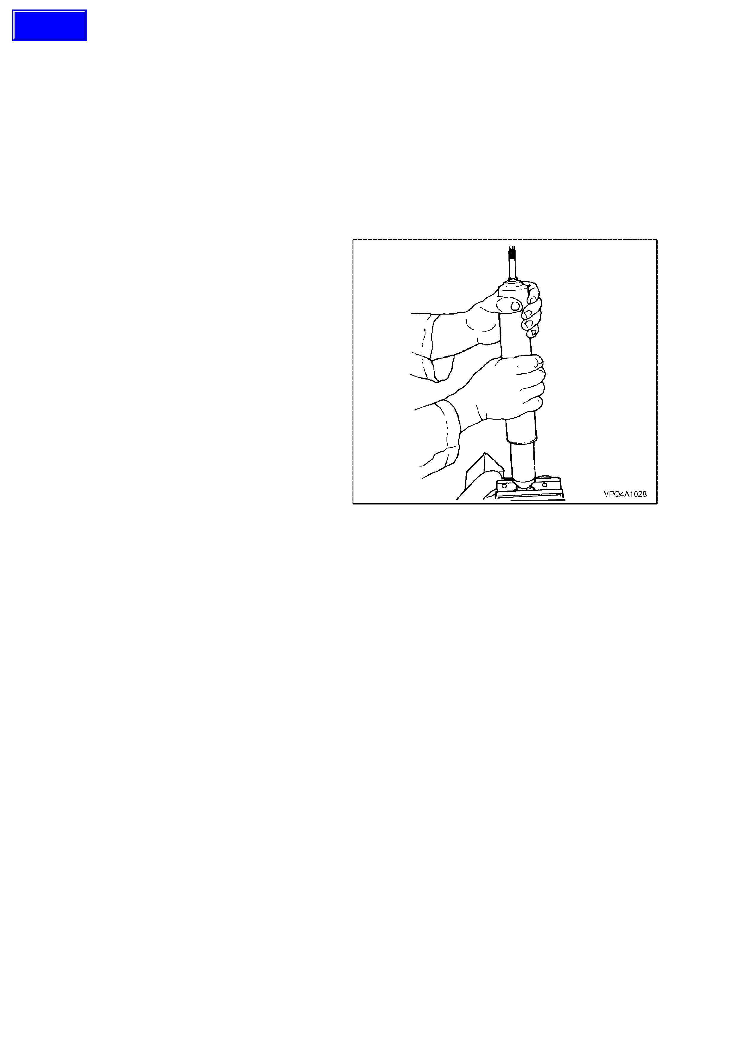
REAR SPRING DETAILS
MODEL TOTAL No.
COILS FREE
LENGTH
mm
OUTSIDE
DIAM.
mm
PROD. I.D.
CODE
(Tag on
spring)
SPRING
TYPE
AND
RATE
V6 & V8 ENGINE -
SEDAN MODELS -
STANDARD SUSPENSION
8 250 158 EJ VARIABLE
45.0/82.0
N/mm
V6 & V8 ENGINE -
SEDAN MODELS -
FE2 ‘SPORTS’ SUSPENSION
8 237 158 EM VARIABLE
45.0/90.0
N/mm
V6 & V8 ENGINE - STATION
WAGON MODELS -
STANDARD SUSPENSION
8 250 158 EK VARIABLE
51.0/90.0
N/mm
V6 ENGINE - STATION
WAGON MODELS -
FE2 ‘SPORTS’ SUSPENSION
8 258 158 EL VARIABLE
50.0/90.0
N/mm
Figure 4A-83
Techline
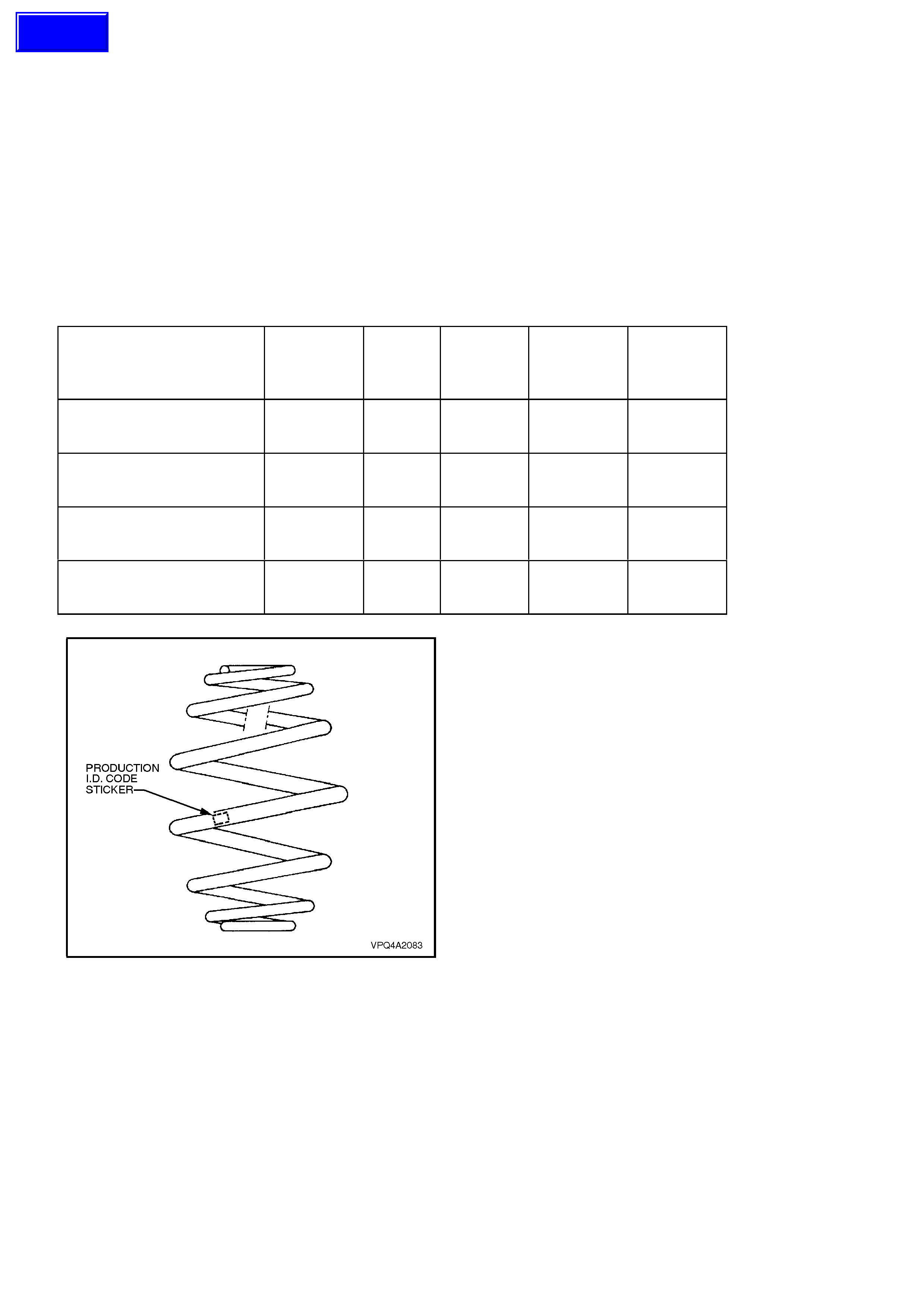
REAR SHOCK ABSORBER DETAILS
Type
VT Sedan and Station Wagon Models Twin tube hydraulic
VT Vehicles with FE2 suspension Twin tube hydraulic, gas pressurised
PROD. I.D. NOMINAL
MODEL LABEL EXTENDED
LENGTH
V6 or V8 ENGINE -
SEDAN MODELS -HG 670
STANDARD SUSPENSION
V6 or V8 ENGINE -
SEDAN MODELS -KF 670
FE2 ‘SPORTS’ SUSPENSION
V6 or V8 ENGINE -
STATION WAGON MODELS HE 670
STANDARD SUSPENSION
V6 ENGINE - STATION
WAGON MODELS -HJ 670
FE2 ‘SPORTS’ SUSPENSION Figure 4A-84
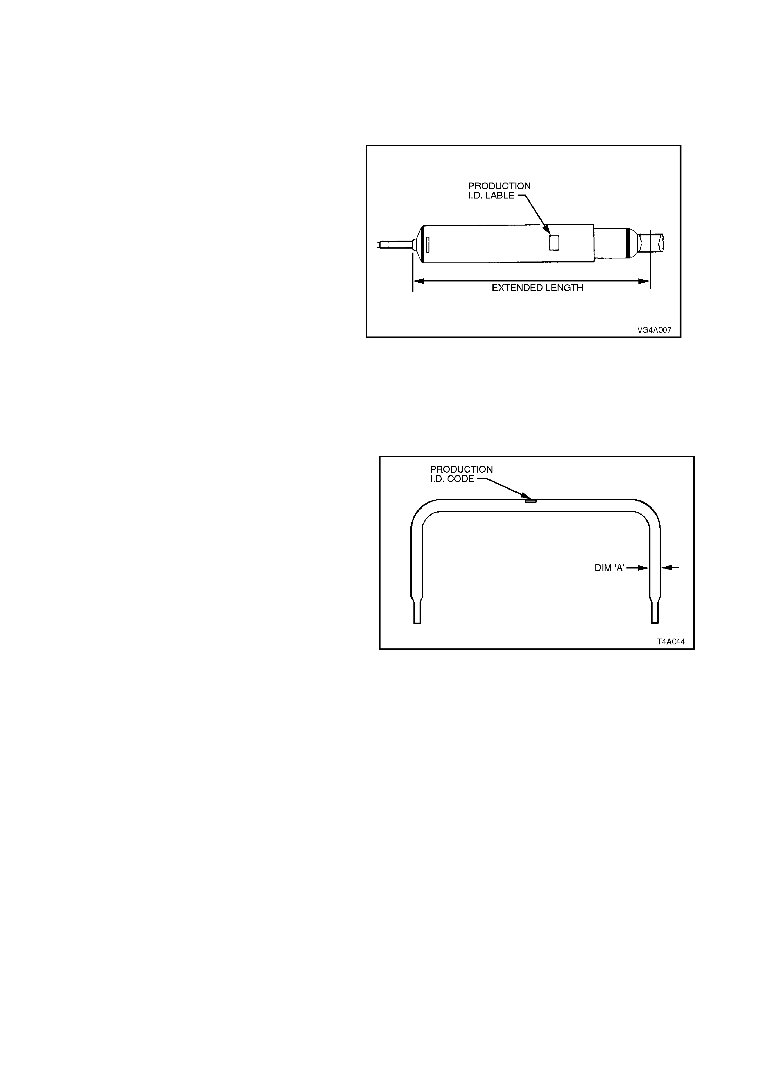
STABILISER BAR DETAILS
Type Linkless
MODEL Dim. “A” in PROD.
Fig 4A-85 I.D. CODE
V6 ENGINE - SEDAN & STATION
WAGON MODELS -15.0 mm FJ
STANDARD SUSPENSION
V8 ENGINE - SEDAN & STATION
WAGON MODELS -16.0 mm FK
STANDARD SUSPENSION
V6 ENGINE -
SEDAN MODELS 15.0 mm FJ
FE2 ‘SPORTS’ SUSPENSION
V8 ENGINE -
SEDAN MODELS 16.0 mm FK
FE2 ‘SPORTS’ SUSPENSION
V6 ENGINE - ‘S’ PACK
SEDAN MODELS -16.0 mm FK
FE2 ‘SPORTS’ SUSPENSION
V8 ENGINE - ‘SS’ PACK
SEDAN MODELS 17.0 mm FG
FE2 ‘SPORTS’ SUSPENSION
V6 ENGINE - STATION WAGON
MODELS 15.0 mm FJ
FE2 ‘SPORTS’ SUSPENSION
Figure 4A-85
REAR SUSPENSION: SERVICE ALIGNMENT
DATA
SEDAN MODELS STANDARD
SUSPENSION FE2
SUSPENSION
REAR TRACK 1586 mm 1592 mm
CAMBER -1° 9' to -2° 6' -1° 27' to -2° 29'
TOE (Degrees per
Wheel) -0° 14' to +0° 9' -0° 9' to +0° 14'
STATION WAGON MODELS
STANDARD
SUSPENSION FE2
SUSPENSION
REAR TRACK 1579 mm 1589 mm
CAMBER -1° 7' to -1° 44’ -1° 17' to -2° 14'
TOE (Degrees per
Wheel) -0° 13' to +0° 10' -0° 5' to +0° 18'
VARIATION SIDE TO SIDE (ALL MODELS)
Camber 0° 35’ Max.
Wheel Toe 0° 20’ Max
Dimensions shown are for a vehicle at curb height,
i.e. vehicle ready to drive with all fluids at the
recommended levels, the fuel tank full and without
driver, passenger/s or luggage.
Refer to Section 2.2 REAR WHEEL ALIGNMENT in
this Section, for specific details.

5. TORQUE WRENCH SPECIFICATIONS
Nm
Rear crossmember front mounting bolt 125, then
30° - 40° turn angle
♦ ♦
Crossmember rear mount to vehicle underbody
attaching bolt 30, then
60° turn angle
♦ ♦
Crossmember rear mount to differential carrier
rear cover attaching bolt 85 - 105
Brace bolt 60 - 70
♦ ♦
Trailing arm to rear crossmember attaching nut 95 - 105
Drive shaft constant velocity joint to trunnion
flange attaching bolt 50, then
60° - 75° turn angle
Road wheel attaching nut 110 - 140
Rear disc brake shield to trailing arm attaching
bolt 70 - 80
Brake caliper anchor plate to trailing arm. Upper bolt 70 - 100
Lower bolt 85 - 90
♦ ♦Collar nut to trunnion assembly 295 - 305
♦ ♦Differential carrier to rear crossmember
attaching bolt 90, then
30° - 45° turn angle
Stabiliser bar link to trailing arm attaching nut 18 - 26
Stabiliser bar mounting bracket to
crossmember attaching bolt 18 - 26
Intermediate exhaust pipe to cataly tic converter
attaching bolt 40 - 50
Shock absorber upper mounting nut:
- Sedan Hand tighten to end
of thread
- Station Wagon Shaft protrusion
above nut, from
15.5 - 16.0 mm.
Shock absorber upper mounting plate nut
(S/Wagon) 42 - 50
Shock absorber lower mounting bolt 105 - 125
♦ ♦New bolts and nuts must be used on reassembly
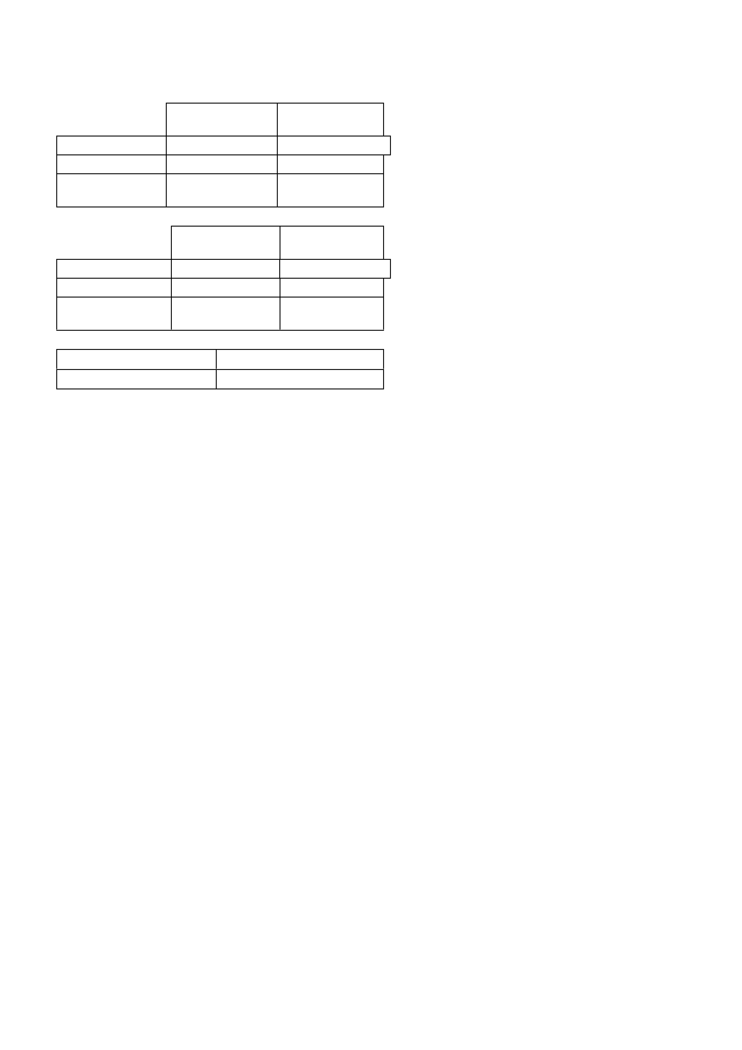
6. SPECIAL TOOLS
TOOL NO. REF IN TEXT TOOL DESCRIPTION COMMENTS
KM618 INSTALLER USED FOR INSTALLING NEW
BUSH INTO CROSSMEMBER
FRONT MOUNTING.
AMKM557 PULLER USED FOR REMOVING BUSH
FROM CROSSMEMBER
FRONT MOUNTING.
KM468 HOLDING BAR PREVIOUSLY RELEASED FOR
"J" CAR.
USED TO HOLD TRUNNION
ASSEMBLY HUB FROM
ROTATING.
KM619 REMOVER/INSTALLER USED TO PRESS BUSHES
FROM AND INTO TRAILING
ARMS.
E7115 ANGLE WRENCH PREVIOUSLY RELEASED FOR
"J" AND "V" CARS.
USED TO TIGHTEN VARIOUS
COMPONENTS WHERE A
TURN ANGLE IS SPECIFIED IN
ADDITION TO AN INITIAL
TORQUE SETTING.
AU385-4 REMOVER/INSTALLER PREVIOUSLY RELEASED FOR
V6 ENGINE.
USED TO REMOVE AND
INSTALL BUSHES INTO
STABILISER BAR.
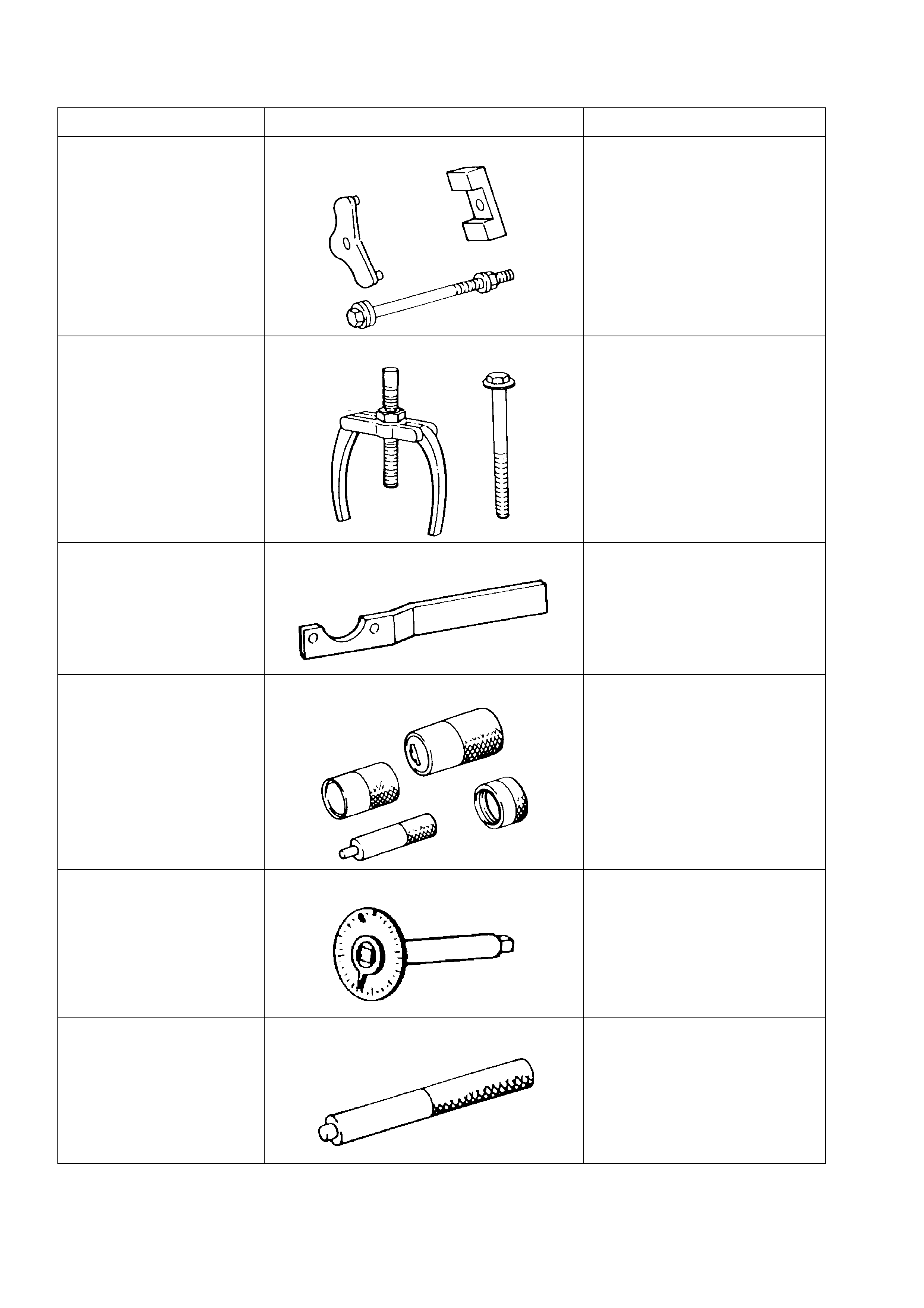
TOOL NO. REF IN TEXT TOOL DESCRIPTION COMMENTS
KM508-2 INSTALLING SLEEVE PREVIOUSLY RELEASED FOR
"J" CAR.
USED TO INSTALL NEW BUSH
IN SHOCK ABSORBER
LOWER MOUNT.
AU416 TORX BIT USED TO REMOVE AND
INSTALL BRAKE BACKING
PLATE TO TRAILING ARM
ATTACHING BOLTS.
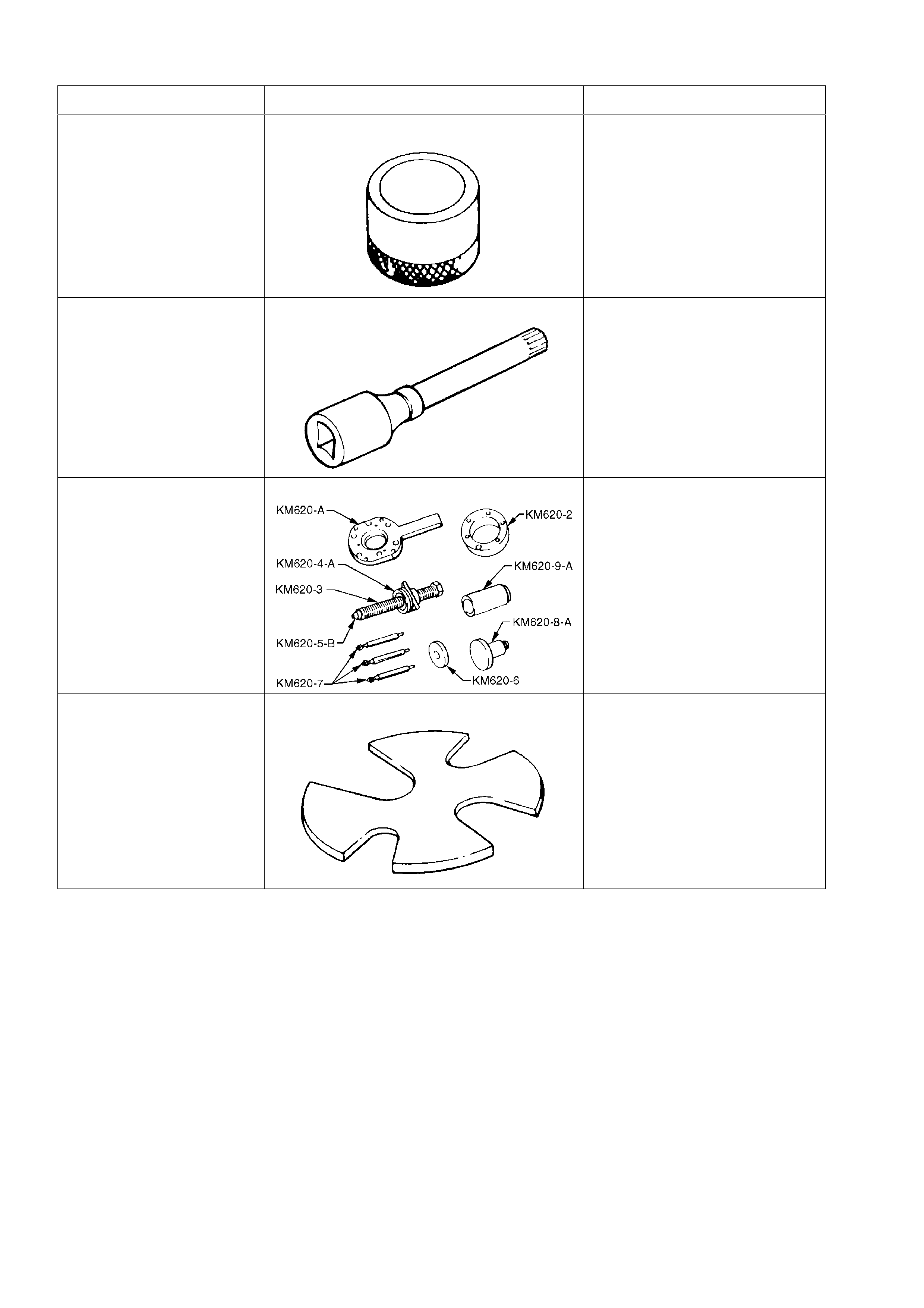
KM620-A REMOVER/INSTALLER USED TO REMOVE AND
INSTALL TRUNNION FLANGE,
REAR WHEEL BEARING AND
TRUNNION ASSEMBLY
E7110 PRESS PLATE PREVIOUSLY RELEASED.
USED FOR SUPPORTING
STABILISER BAR LINK WHILE
PRESSING OUT OR
INSTALLING BUSH.