
SECTION 7A1 - CLUTCH - GEN III V8 ENGINE
CAUTION:
This vehicle will be equipped with a Supplemental Restraint System (SRS). A SRS will consist of either
seat belt pre-tensioners and a driver's air bag, seat belt pre-tensioners and a driver's and front
passenger's air bags or seat belt pre-tensioners, driv er’s and front passenger’s air bag and left and righ t
hand side air bags. Refer to SAFETY PRECAUTIONS of the Service Information before performing any
service operation on, or around any SRS components, the steering mechanism or wiring. Failure to
follow the SAFETY PRECAUTIONS could result in SRS deployment, resulting in possible personal injury
or unnecessary SRS system repairs.
CAUTION:
Whenever any component that forms part of the ABS or ABS/ETC (if fitted), is disturbed during Service
Operations, it is vital that the complete ABS or ABS/ETC system is checked, using the procedure as
detailed in 4. DIAGNOSIS, ABS or ABS/ETC FUNCTION CHECK, in Section 12L ABS & ABS/ETC, (V6
Engine) or (GEN III V8 Engine) of this Service Information CD.
1. GENERAL INFORMATION
As the clutch and operating system for V6 engined vehicles remains unchanged since the start of VT Series
production, this Section will only detail the changes made to the clutc h and its operating s ystem as they apply to the
GEN III V8 engine when the manual transmission, production option MM6, is fitted.
For service operations relating to the clutch and operating system on V6 engined, VT Series vehicles, refer to
Section 7A CLUTCH of the VT Series I Service Information.
Techline
Techline
Techline
Techline
Techline
Techline
Techline
2. GENERAL DESCRIPTI ON
2.1 SELF-ADJUSTING CLUTCH PRESSURE PLATE
GEN III V8 ENGINE
By adopting a s elf - adjus ting f eatur e f or the clutc h pres s ure plate f itted to the G EN III V8 engine, sever al advantages
are achieved:
a. The clutch pedal loading is maintained at a consistent level throughout the life of the assembly, as the
diaphragm spring leverage over the pivot rings remains the same.
b. This also results in the fa ct that the clutch ‘take- up’ remains at a constant point, with the clutch pedal feel also
remaining constant.
c. No maintenance adjustments are required.
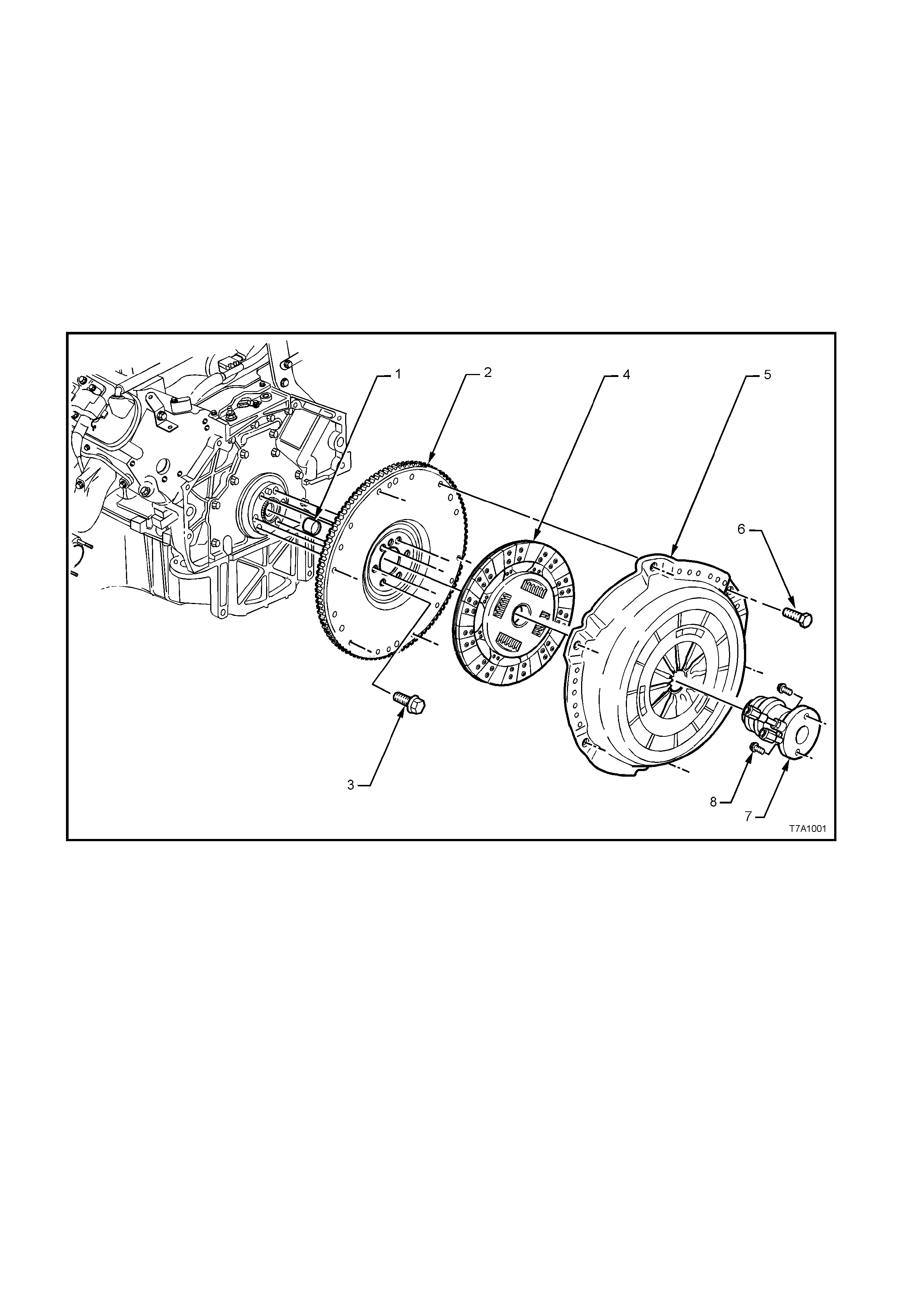
1. Bearing - Clutch Pilot
2. Flywheel – Engine
3. Bolt - Flywheel (6 places)
4. Plate - Clutch Driven
5. Plate - Clutch Pressure
6. Bolt - Pressure Plate (6 places)
7. Assembly - Clutch Slave
8. Bolt - Slave Cylinder (2 places)
Figure 7A1-1 - Clutch Components
2.2 CLUTCH CONTROL
Hydraulic actuation for the clutch has been retained f or the GEN III V8 engine application and uses s ome com mon
components with the V6 engined vehicle. For example, apart from the changed orientation of the outlet fitting, the
clutch master cylinder remains unchanged.
The clutch pedal is also common, except for those vehicles fitted with cruise control, when a small bracket is welded
to the pedal for clutch switch control.
Clutch control component changes that are unique for the GEN III V8 engine are:
• Hydraulic piping from the flexible hose to the clutch slave cylinder, routed across the top of the manual
transmission.
• An integrated clutch throwout bearing and concentric slave cylinder, mounted to the front of the transmission
adaptor plate.
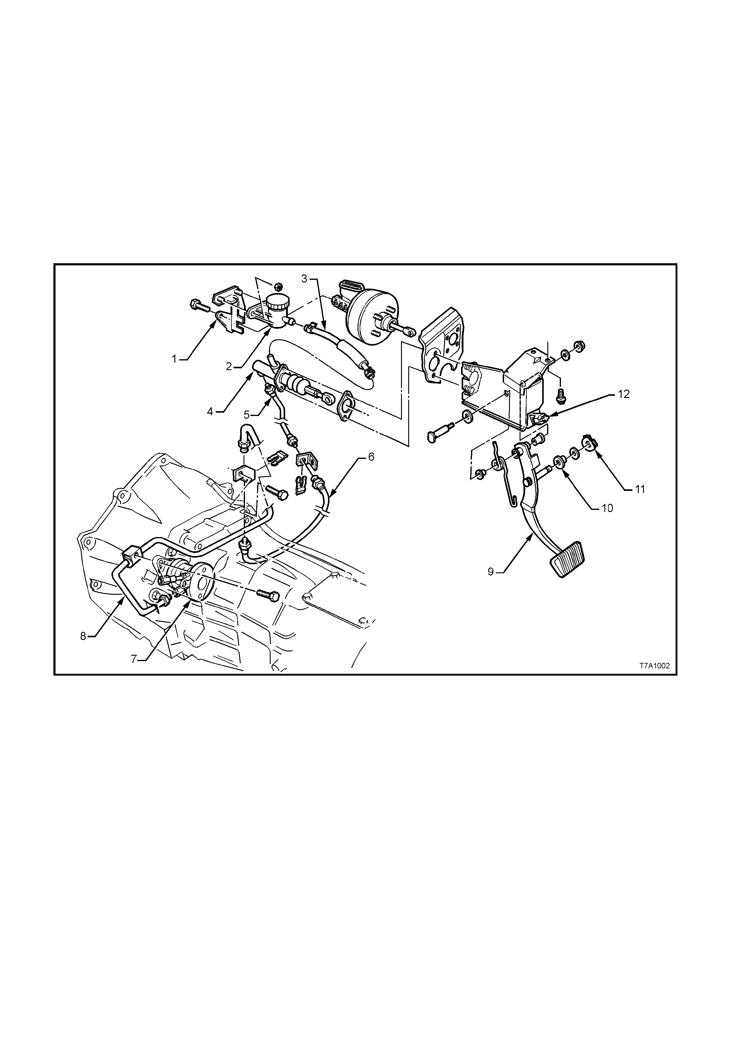
ARRANGEMENT
1. Bracket - Clutch Fluid Reservoir
2. Reservoir - Clutch Fluid
3. Hose - Reservoir to Master Cylinder
4. Master Cylinder
5. Pipe - Master Cylinder to Slave Cylinder
6. Hose - Master Cylinder Pipe to Slave Cylinder Pipe
7. Assembly - Slave Cylinder and Bearing
8. Pipe - Hose to Slave Cylinder
9. Pedal - Clutch
10. Bush - Master Cylinder Push Rod
11. Retainer - Push Rod Bush
12. Switch - Clutch (Cruise Control only)
Figure 7A1-2 Clutch Control Layout
OPERATION
Brak e fluid is f ed to the clutch m aster cylinder fr om
a remote reservoir mounted to a bracket, bolted to
the end of the brake m aster cylinder. A flexible line
connects the two components.
The master cylinder is attached to the firewall in the
engine compartment.
The clutch pedal is mounted in the clutch/brake
pedal support bracket, bolted to the dash panel.
The clutch master cylinder piston is connected to
the clutch pedal by an adjustable push rod, that is
bushed and retained by a spring clip.
No clutch adjustments are required. Although the
clutch master cylinder push rod does feature an
adjustment, it is only for production purposes and is
not to be tampered with, in service.
Stroking of the clutch throwout bearing is achieved
by using a concentr ic hydraulic clutch s lave cylinder
(2) mounted to the front of the transmission adaptor
plate housing.
Hydraulic connection to the master cylinder is by
steel piping from the master cylinder, flexible hose
to the transmission and steel pipe again from the
flexible hose to the slave cylinder (1) (Also see
Figure 7A1-2).
The slave cylinder is fitted with a bleed valve to
assist in removal of air from the hydraulic system.
Apart from the thr owout bearing ass em bly and load
spring, there are no other serviceable parts in the
slave cylinder and, if found to be faulty, the
assembly must be replaced.
NOTE: This actuation arrangem ent is unique to the
GEN III V8 engined vehicle. Figure 7A1-3
CLUTCH MASTER CYLINDER OPERATION
As the operation of the clutch mas ter cylinder fitted
to GEN III V8 engined vehicles is the same as for
all VT vehicles, refer to the description in
Section 7A CLUTCH, of the VT Series I Service
Information.
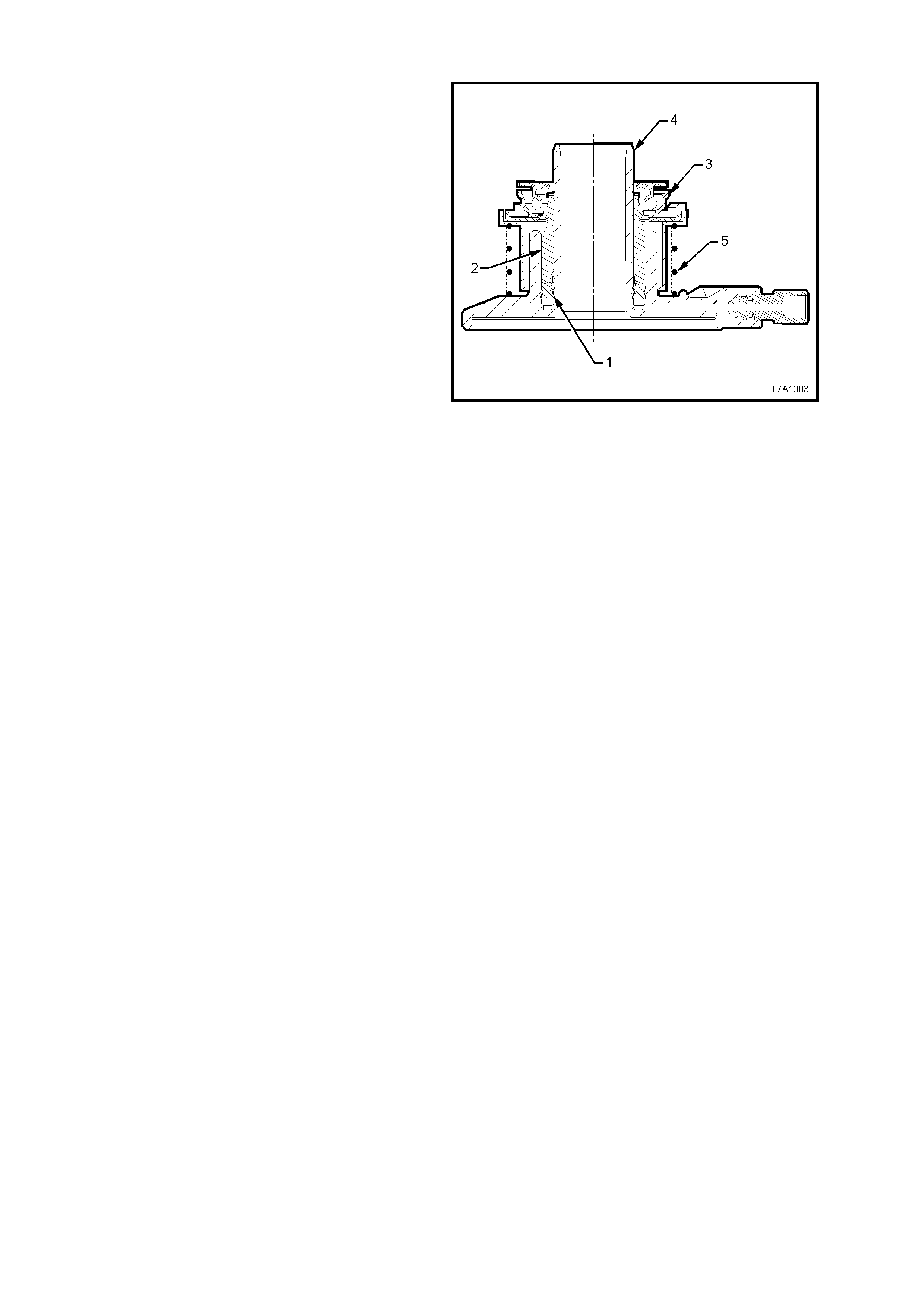
CLUTCH SLAVE CYLINDER OPERATION
When pressurised fluid from the clutch master
cylinder acts upon the seal (1), the seal moves,
stroking the sleeve (2) before it. As the throwout
bearing assembly (3) is attached to the sleeve (2),
the throwout bearing also moves with the sleeve, to
forc e the diaphragm f ingers of the pr es sur e plate to
move against its in-built spring force.
As the slave cylinder sleeve (2) continues to be
moved along the guide of the cylinder body (4), the
force applied to the pressure plate diaphragm
spring caus es the s pr ing to pivot, thus r eleasing the
applied force on the clutch driven plate, allowing it
to spin. When this situation occurs, the frictional
link between the engine flywheel and the
transmission input shaft is broken and gear
changing can then saf ely tak e place, without undue
stress being placed upon the transmission
synchromesh assemblies.
When the clutch pedal is released, the pressure
plate diaphragm spring force, moves the throwout
bearing (3) and slave cylinder sleeve (2), back
along the slave cylinder body guide (4), returning
displaced fluid back to the master cylinder
reservoir.
Coil spring (5) acts to maintain constant contact of
the throwout bearing with the pressure plate
diaphragm spring fingers, thereby reducing pedal
travel to begin initial movement by compensating
for any slight finger height variation in the
diaphragm spring.
As the clutch pressur e plate is self-adj usting, the ‘at
rest’ position of the throwout bearing and clutch
slave cylinder sleeve (2), remains relatively
constant throughout the life of the assembly,
compared to other clutch control systems.
Figure 7A1-4
3.2 CLUTCH HYDRAULIC SYSTEM, BLEED
The clutch hydraulic system m ust be bled whenever the hydraulic line has been disconnected, or when a leak has
allowed air to enter the system. Air trapped in the system can prevent full disengagement of the clutch.
During bleeding operations, the master cylinder reservoir must be kept at least half full with hydraulic brake fluid.
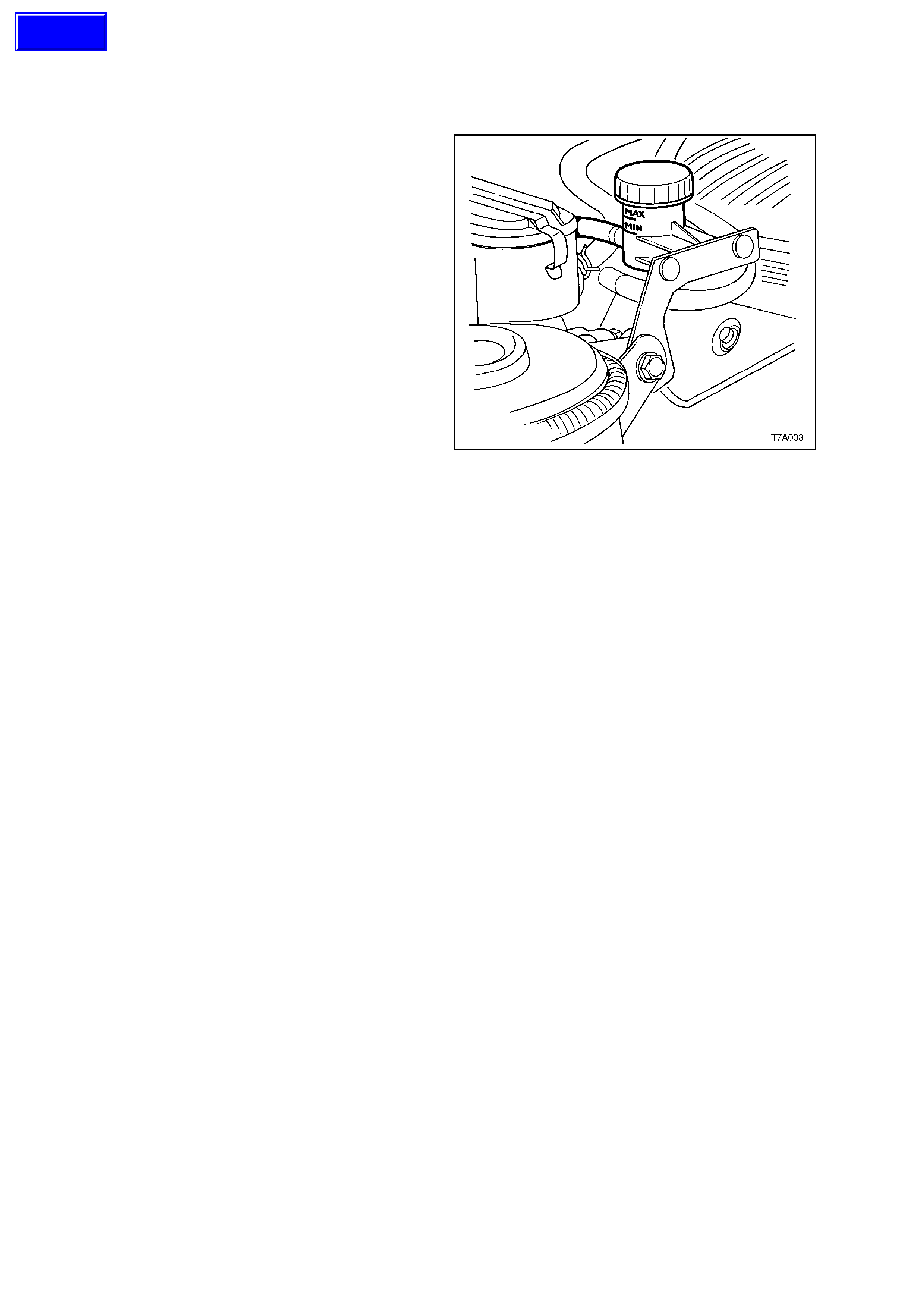
1. Carefully clean any dirt from around the fluid
reservoir cap.
2. Remove the filler cap and top up reservoir as
required, with heavy duty hydraulic brake fluid
to DOT 4+ (SAE J1704).
3. Using an 11 mm, 3/8 drive socket, short
extension and socket bar, loosen the slave
cylinder bleeder, located in the upper aperture
of the transmission adaptor plate/clutch
housing, on the left hand side.
4. Then, using just the socket and extension,
tighten the bleeder, using light finger force
only .
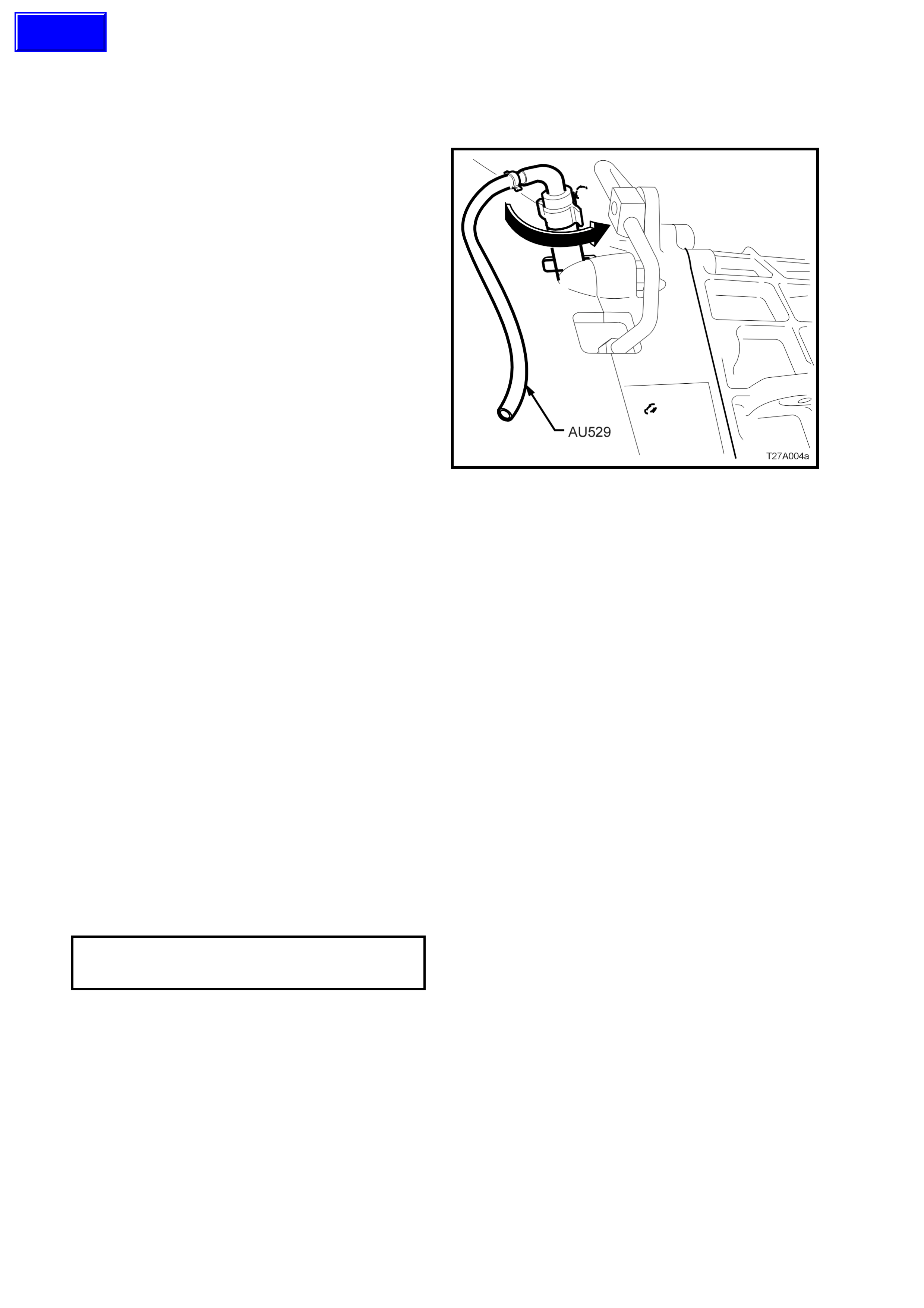
5. Insert the end of the rubber tube of Tool
AU529 over the end of the bleeder, positioned
at the 9 o’clock position.
6. W ith the other end of the bleeder tool inserted
into a clean glass c ontainer such as a jar , that
has been partially filled with new brake fluid,
open the bleeder 1/4 turn, using the rubber on
the bleeder tool to provide the required grip.
Ensure that the end of the hose always
remains submerged in the brake fluid during
bleeding operations.
7. Using an assistant, slowly depress the clutch
pedal by hand, one single time and, while
holding the pedal depressed, close the bleeder
using Tool AU529. O nc e the bleeder is c losed,
the clutch pedal can be slowly released.
Repeat this process until all bubbles cease to
appear at the end of the bleeder hose.
NOTE: Do not pump the clutch pedal repeatedly
during bleeding operations, as entrapped air will
cause the fluid to foam, making air removal
extremely difficult. Als o as the hydraulic steel piping
is routed over the top of the transmission housing,
air can be trapped in this section.
8. When all the air has been removed, close off
the bleeder and remove T ool AU 529. With the
clutch pedal still depressed, tighten the
bleeder screw to the correct torque
specification.
CLUTCH SLAVE CYLINDER
BLEEDER SCREW 15 - 20 Nm
TORQUE SPECIFICATION
9. Once all bleeding operations have been
completed, ensure that the fluid level in the
reservoir is correct.
Figure 7A1-6
NOTE: Alternative methods of bleeding would be to
use either a pressure bleeder, with a commercially
available res ervoir cap or use the vacuum m ethod,
with the assistance of a hand operated vacuum
pump such as Tool No. J23738-A (also
commercially available as a ‘MityVac’) and an
airtight, glass container.
Techline

3.4 CLUTCH S LAVE CYLINDER
REMOVE
1. Remove the transmission from the vehicle.
See 4.2 TRANSMISSION ASSEMBLY
Remove, in Section 7B3 MANUAL
TRANSMISSIO N - GEN III ENGINE, of the VT
Series I Service Information, for details.
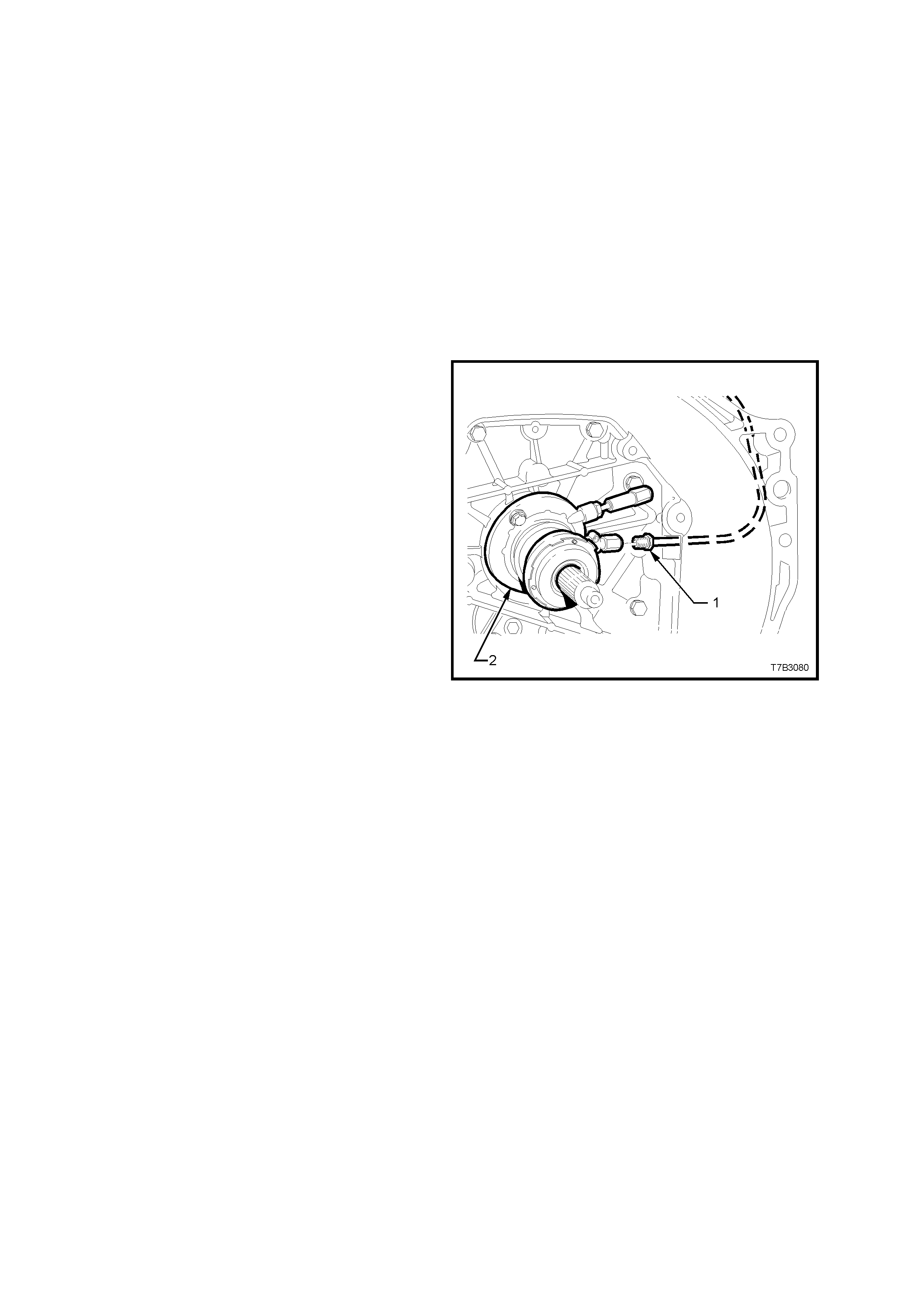
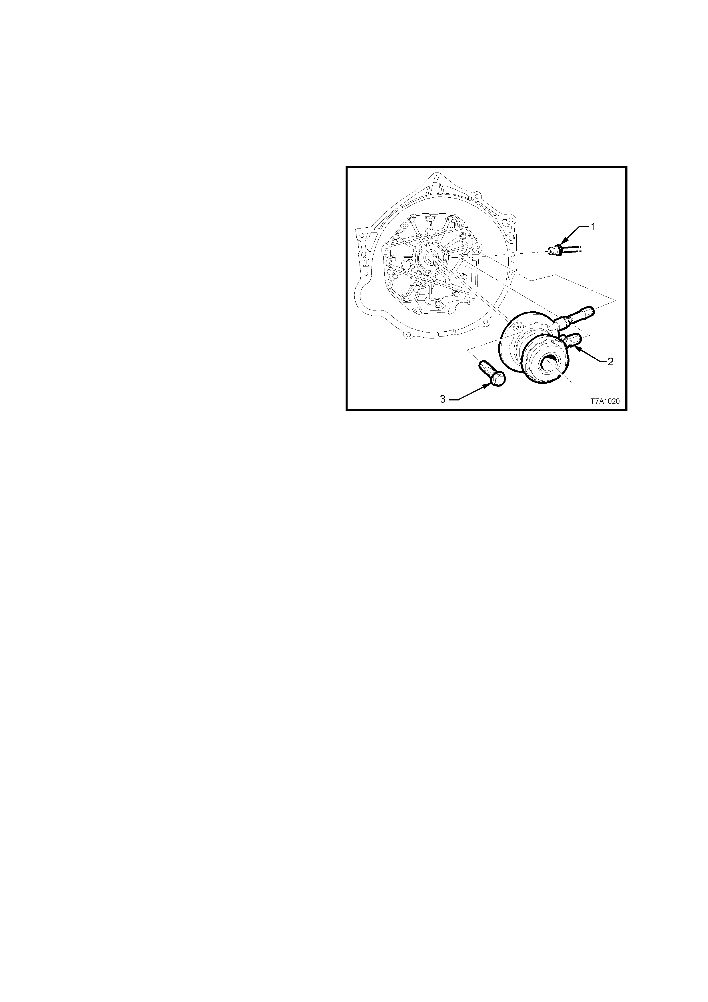
2. Unscrew the pipe fitting (1) from the clutch
slave cylinder (2).
3. Remove the two bolts (3) securing the clutch
slave cylinder assembly to the transmission
adaptor plate, then remove the slave cylinder.
DISASSEMBLE
If required, remove the throwout bearing. Refer
3.5 THROWOUT BEARING Replace, in this
Section. Apart from this bearing and the spring
behind it, there are no other serviceable par ts in the
clutch slave cylinder assembly.
CLEAN AND INSPECT
IMPORTANT: Do not wash hands in petrol or oil
before cleaning or handling clutch slave cylinder
parts. Always use a soap and water based hand
cleaning product.
1. Inspect the slave cylinder for any evidence of
fluid leakage. If found, replace the assembly.
2. Remove the bleeder screw and inspect the
slave cylinder threaded apertures for dam age,
re-claiming with thread inserts as required or
replace the assembly.
3. Check that the bleeder screw thread is
undamaged and that the drilled passage is
clear of debris.
4. Check the throwout bearing for any signs of
roughness or dryness by rotating the bearing
when a light load is applied. If either of these
conditions are evident, replace the clutch slave
cylinder assembly.
Figure 7A1-7

REINSTALL
Installation is the reverse of removal
operations except for the following points:
1. Install slave cylinder and the 2 retaining bolts,
then tighten the bolts to the correct torque
specification.
CLUTCH SLAVE CYLINDER BOLT
TORQUE SPECIFICATION 7.5 - 12.5 Nm
2. Install and tighten hydraulic pipe flare nut to
the slave cylinder, tightening to the correct
torque specification.
HYDRAULIC PIPE FLARE NUT TO
SLAVE CYLINDER 12 - 14 Nm
TORQUE SPECIFICATION
3. Reinstall the transmission. Refer to
4.2 TRANSMISSION ASSEMBLY Reinstall in
Section 7B3 MANUAL TRANSMISSION -
GEN III ENGINE, of the VT Series I Service
Information, for details.
4. Bleed the clutch hydraulic system, as detailed
in 3.2 CLUTCH HYDRAULIC SYSTEM,
BLEED, in this Section.
5. Following bleeding operations, check that the
hydraulic fluid level is correct, as detailed in
3.1 FLUID LEVEL CHECK, in this Section.
6. Road test the vehicle and check for correct
clutch and transmission operation.
3.5 CLUTCH THROWO UT BEARING
REPLACE
1. Remove the clutch slave cylinder assembly.
See 3.4 CLUTCH SLAVE CYLINDER
Remove, in this Section.
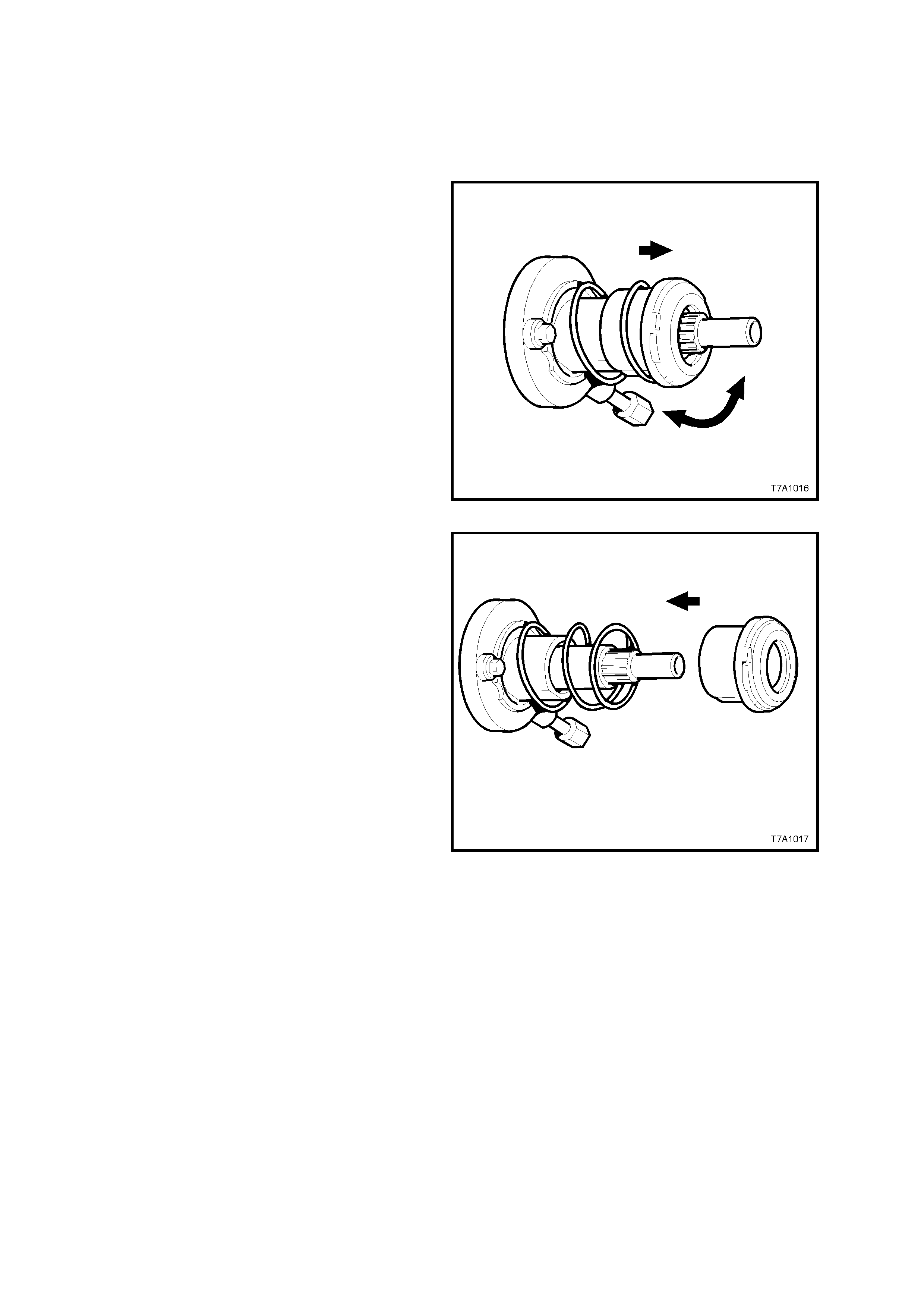
2. While holding the body of the slave cylinder
with one hand, grasp the throwout bearing with
the other and pull, while twisting the bearing
back and forth.
Figure 7A1-8
IMPORTANT: Do not use c leaners or c hemicals on
the bearing guide sleeve and do not apply any
grease to the sleeve.
3. Using a clean dry rag, wipe the exposed
portion of the bearing guide sleeve.
NOTE: DO NOT apply grease to the new clutch
throwout bearing as it has already been greased.
4. Install a new clutch throwout bearing to the
guide sleeve, by firmly pushing the new
bearing onto the sleeve, until it snaps into
place over the retaining tab.
5. Reinstall the clutch slave cylinder assembly.
Refer to 3.4 CLUTCH SLAVE CYLINDER,
Reinstall, in this Section.
Figure 7A1-9

3.7 CLUTCH PE DAL SWITCH
REMOVE
CAUTION: Disable the SRS (Air Bag). Refer to
'DISABLING THE SRS’, Section 12M, SRS of
this Service Information.
1. Disconnect the battery earth cable.
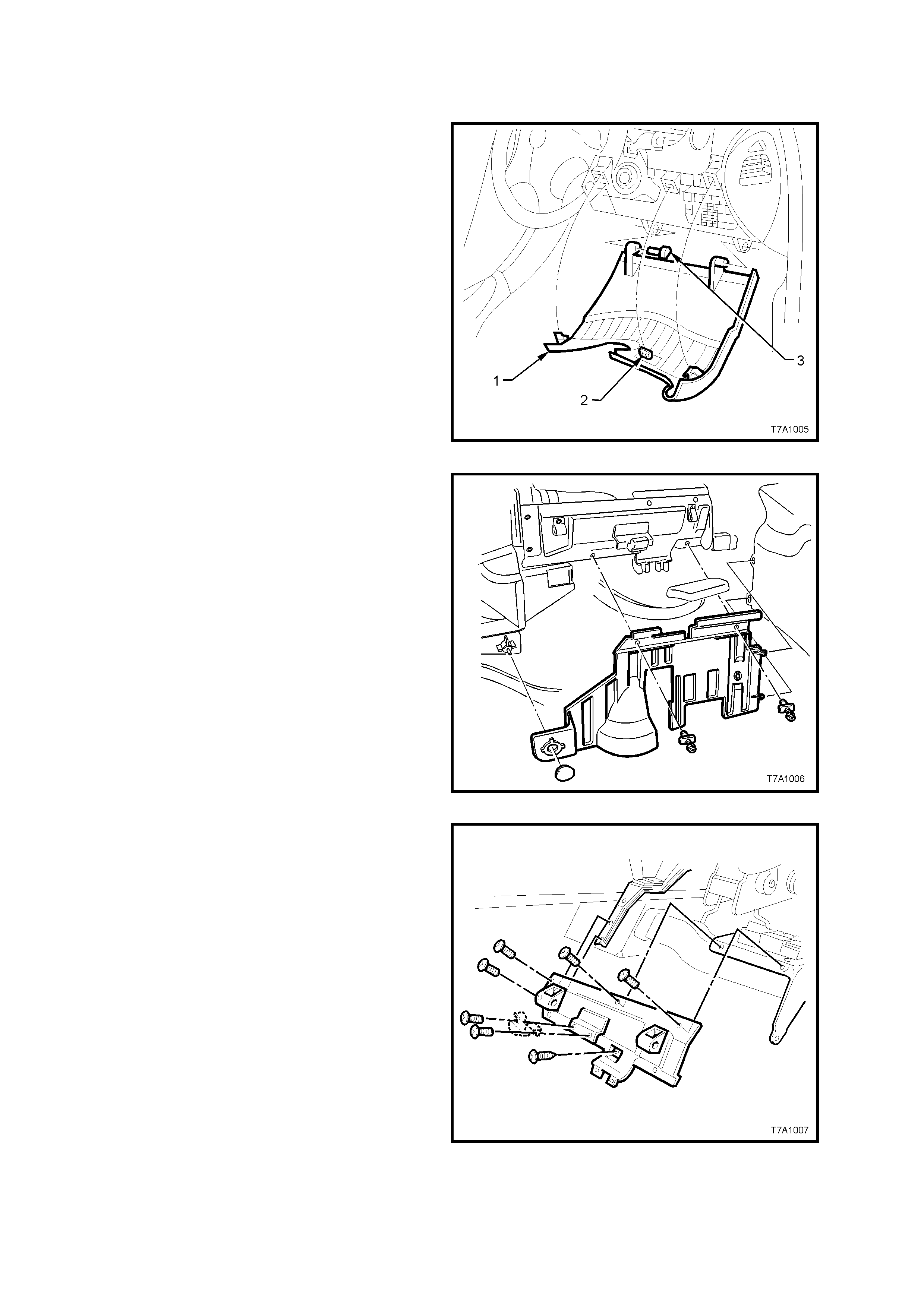
2. From inside the passenger compartment,
remove the lower the instrument panel, right
hand cover assembly 1), as follows;
Grasp the top edge of the cover (1) on each
side of the s teering column with the finger tips
and pull outwards, to fr ee the r etaining lugs ( 2)
from the clips.
Prise out the left hand hinge pin (3) with a
screwdriver or similar tool and remove.
Tilt the panel down on the left hand side and
disengage the right hand side hinge pin.
Figure 7A1-10
3. If fitted, remove the instrument panel lower
trim by removing the two fasteners and
retainer. Lower the panel sufficient to gain
access to the footwell illum ination lamp holder
(if f itted), then twist the lamp holder to rem ove
from the trim.
Figure 7A1-11
4. Remove screws attaching the fuse and Body
Control Module (BCM) panel to the dash
panel. Leaving the Data Link Connec tor (DLC)
attached to the panel, swing the panel to one
side and secure with tie wire or similar.
Figure 7A1-12

5. Remove the clutch switch wiring harness
connector (1), then remove the clutch switch
(2) by rotating counter -clock wise turn to free
the switch bayonet lugs.
Figure 7A1-13
REINSTALL
1. Install the switch and rotate turn clockwise
to lock the switch bayonet lugs, then reinstall
the wiring harness connector.
2. Reinstall all removed instrument panel
components in the reverse to removal
operations.
3. Road test vehicle to check clutch switch
operation. Refer to Section 12E CRUISE
CONTROL of the VT Series II Service
Information.
IMPORTANT: Enable the SRS (Air Bag). Refer to
'ENABLING THE SRS’, Section 12M, SRS of the
VT Series I Service Information.
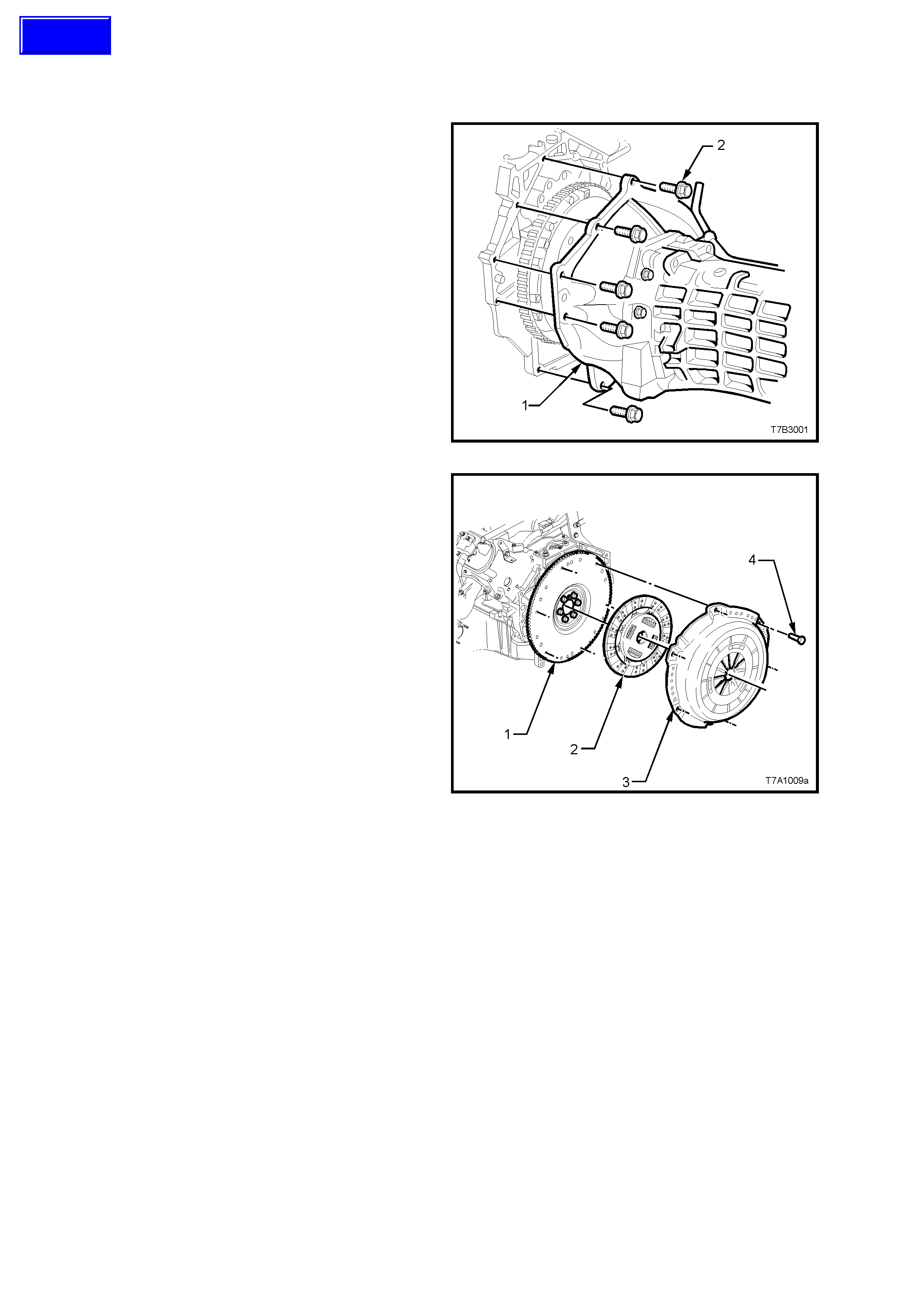
3.8 CLUTCH AND PRESSURE PLATES
REMOVE
1. Remove transmission assembly (1). Refer to
Section 7B3 MANUAL TRANSMISSION -
GEN III ENGINE of the VT Series II Service
Information.
Figure 7A1-14
2. Initially loosen all pressur e plate retaining bolts
(4), working from opposite sides, to avoid
distortion of the cover (3).
3. Continue loosening bolts from opposite sides,
until all are rem oved, then lift the c lutch driven
plate (2) and pressure plate (3) assemblies
from the flywheel (1).
NOTE: The two locating dowel pins in the flywheel
are set 170° apart, which means that marking the
pressure plate relationship to the flywheel is not
required.
Figure 7A1-15
Techline

INSPECT
1. Wipe pressure plate and flywheel surfaces
clean using a soft cloth dampened with a
suitable cleaning solvent (do not use
petroleum based products).
NOTE: Do not wash the pressure plate assembly -
blow dust out with compressed air.
2. With the two slave cylinder fluid apertures
firm ly plugged, clean the assem bly by blowing
off with compressed air. Do not use any
petroleum based products for cleaning.
NOTE: Do not attempt to clean the slave cylinder
and throwout bearing with any fluid solvents. Only
blow off with compressed air.
CAUTION: Wear safety glasses to avoid eye
injury and breathing apparatus with a suitable
filter for both of these cleaning operations.
3. Inspect input shaft spigot bush for wear. If
necessa ry, replace the bush as detailed in this
Section.
NOTE: Do not remove the bush unless inspection
reveals that replacement is required.
4. Inspect the slave cylinder for any evidence of
fluid leakage. If found, replace the assembly.
5. Remove the bleeder screw and inspect the
slave cylinder threaded apertures f or dam age,
re-claiming with thread inserts as required or
replace the assembly.
6. Check that the bleeder screw thread is
undamaged and that the drilled passage is
clear of debris.
7. Check the throwout bearing for any signs of
roughness or dryness by rotating the bearing
when a light load is applied. If either of these
conditions are evident, replace the clutch
slave cylinder assembly.
8. Inspect flywheel and clutch pressure plate
friction surfaces for burn marks scoring or
roughness. Slight roughness may be
smoothed with fine emery cloth.
Scoring of flywheel or pressure plate surfaces
will require replacement of the damaged
component/s.
9. Inspect clutch driven plate for lining wear or
other damage, such as oil or fluid
contamination.
NOTE: If oil or fluid is found on the clutch linings,
locate and correct the cause of the leak before
proceeding with any clutch repairs.
10. Bef ore installing the clutch driven plate, check
clutch hub for a free sliding fit on maindrive
gear clutch shaft splines.
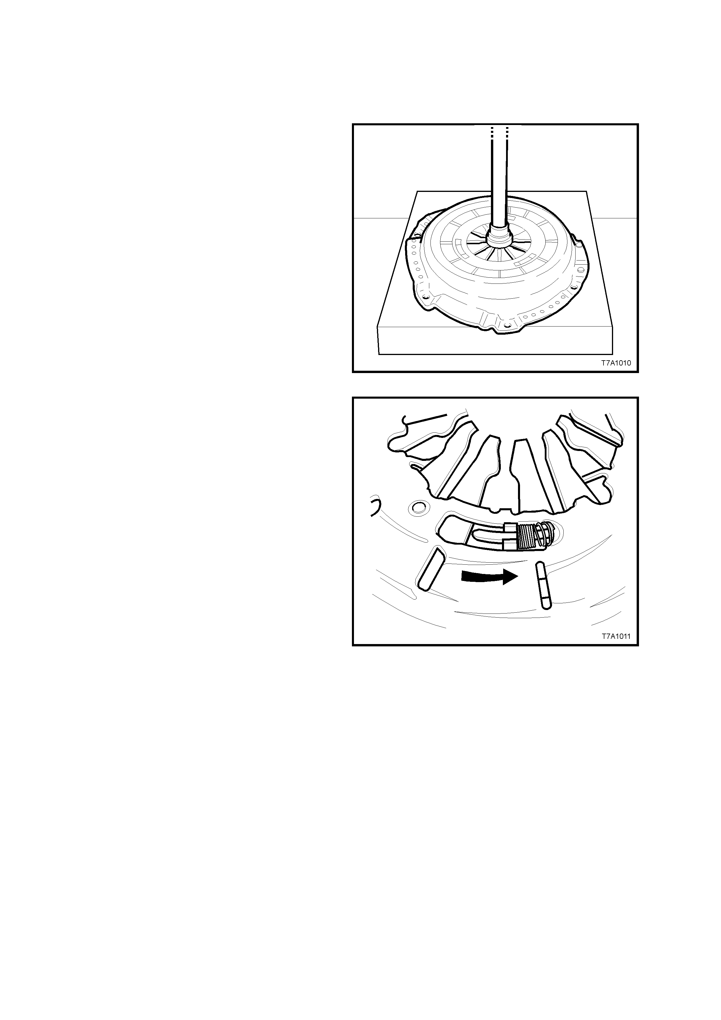
PRESSURE PLATE ADJUSTMENT
IMPORTANT: Prior to the installation of the
pressure plate, the self-adjusting feature must be
pre-set. If not carried out before installation, then
probable failure of the pressure plate will result.
1. Place the flat side of the clutch plate
downwards on flat press plates, then place the
pressure plate assembly over it.
2. Compress the pressure plate diaphragm
spring until tension is realised from the clutch
driven plate.
3. Hold two screwdrivers or other suitable tools,
placing them against 2 of the 3 stepped
adjusting ring tension spring stops , jus t in front
of the adjusting ring tension springs.
Figure 7A-16
4. Using the screwdrivers, rotate the stepped
adjusting ring, counter-clockwise (arrow), fully
compressing the tension springs.
5. While holding the tension springs in the fully
loaded position, release the force on the
diaphragm spring. This will then retain the
springs in the fully loaded position.
6. Remove the pressure plate and clutch driven
plate from the press.
Figure 7A-17
REINSTALL
1. Sparingly apply 10% molybdenum disulphide
grease, such as Molybond GA 10 (or
equivalent to Holden’s Specif ication HN 1271),
to the bearing face of the clutch throwout
bearing, input shaft splines and spigot.
2. W hile holding the clutch driven plate up to the
engine flywheel, insert a suitable clutch
centring tool (commercially available) into the
spigot bearing, through driven plate.
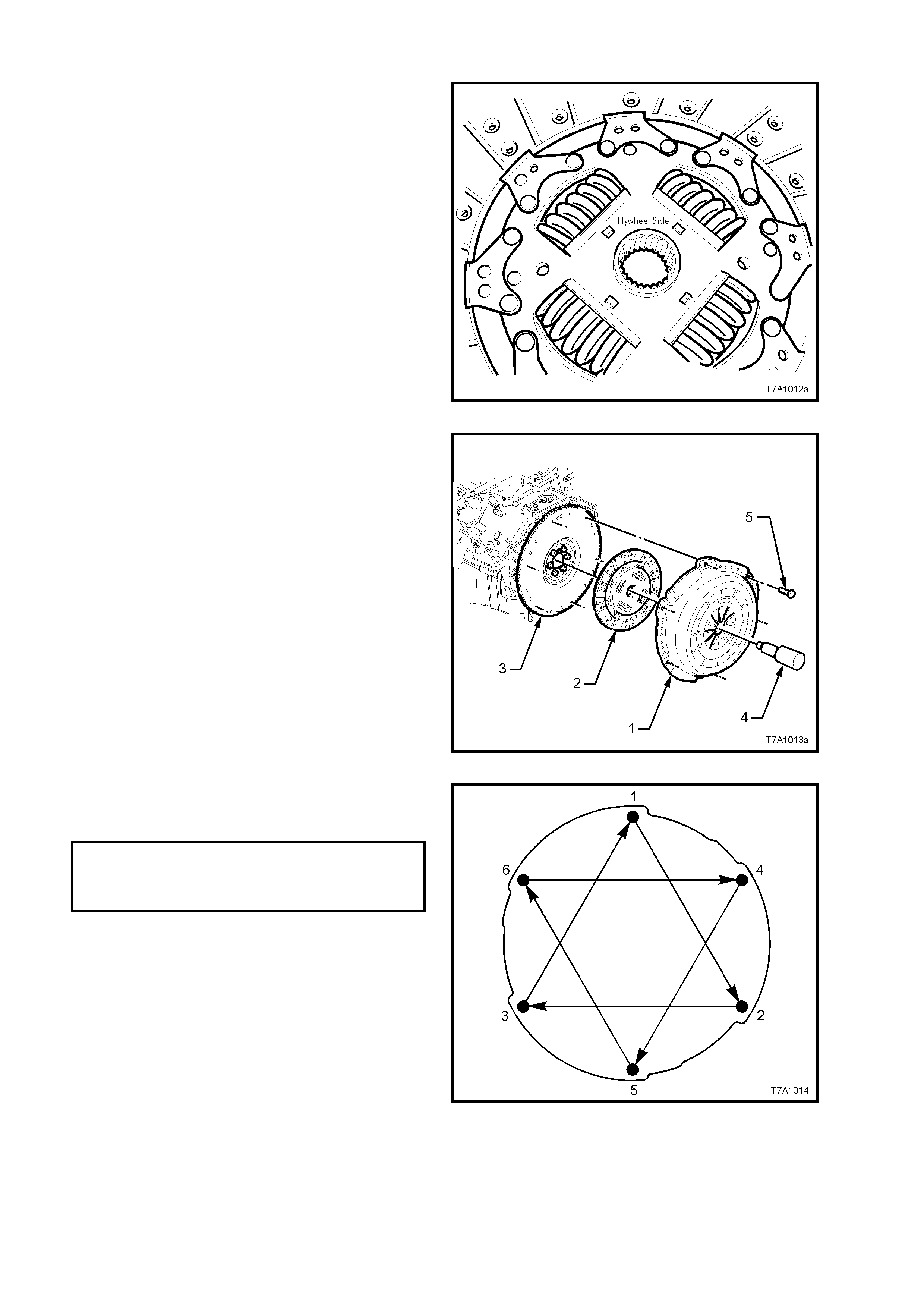
NOTE: The c lutch driven plate is installed with
the flat side of the hub, facing forward to the
flywheel. The word ‘Flywheel Side’ is also
stamped on the inner surface, as shown.
Figure 7A-18
3. Install the pressure plate assembly (1) over
the alignment tool (4) and clutch driven plate
(2), aligning the offset dowel pins in the
flywheel (3) with the mating holes in the
pressure plate cover (1).
4. Loosely install the 6, pressure plate to flywheel
bolts (5).
Figure 7A-19
5. Tighten the 6 pressure plate retaining bolts in
sequence and evenly over 4 stages until the
correct torque specification is reached.
CLUTCH PRESSURE Stage 1: 15 Nm
PLATE BOLT Stage 2: 35 Nm
TORQUE Stage 3: 55 Nm
SPECIFICATION Stage 4: 70 Nm
IMPORTANT: Tightening to the torque settings,
stages and in the sequence listed are all
necessary, to avoid permanent distortion of the
pressure plate cover.
Figure 7A-20

6. Reinstall the transmission assembly. Refer to
Section 7B3 MANUAL TRANSMISSION,
GEN III V8 ENGINE of the VT Series II
Service Information.
NOTE: When installing the transmission, do not
allow it to ‘hang’ on the maindrive gear splines, as
the clutch driven plate will be damaged.
7. Bleed the hydraulic clutch actuating system.
See 3.2 CLUTCH HYDRAULIC SYSTEM,
BLEED, in this Section.
8. Depress the clutch pedal several times to
allow the self-adjusting function of the
pressure plate to take effect.
9. Start engine, and check for exhaust leaks
before road testing the vehicle for satisfactory
clutch operation.
Figure 7A-21
3.9 ENGINE FLYWHEEL
NOTE: This operation is also included in the
engine mechanical items
3.5 ENGINE FLYWHEEL/FLEXPLATE in Section
6A3 ENGINE MECHANICAL - GEN III ENGINE, of
the VT Series II Service Information) but, as this
component forms an integral part of the clutch
assembly and the driveline, it has also been
included here.
REMOVE
1. Disconnect battery earth lead.
2. Remove the starter motor. Refer
Section 6D3-2 STARTING SYSTEM - GEN III
ENGINE of the VT Series II Service
Information.
3. Remove manual transmission and the clutch
assembly, refer to Section 7B3, MANUAL
TRANSMISSION - GEN III ENGINE of the VT
Series II Service Information and
3.8 CLUTCH AND PRESSURE PLATES in
this Section.
IMPORTANT: Note the position and direction of
the engine flywheel before removal. The flywheel
does not use a locating pin for alignment. Mark or
scribe the end of the crankshaft and the flywheel
before component removal. The engine flywheel
must be reinstalled to the original position and
direction.
The engine flywheel will not initially seat against the
crankshaft flange, but will be pulled onto the
crankshaft by the engine flywheel bolts. This
procedure requires a three stage tightening
process.
If replac ing the engine f lywheel, note the location of
any existing balance weights (relative to the
position of the flywheel locating hole). Install new
balance weights into the new flywheel (if
applicable). Flywheel balance weights must be
installed into the new flywheel in the same location
as the old flywheel. A properly installed balance
weight will be either flush or below flush with the
machined flywheel surface.
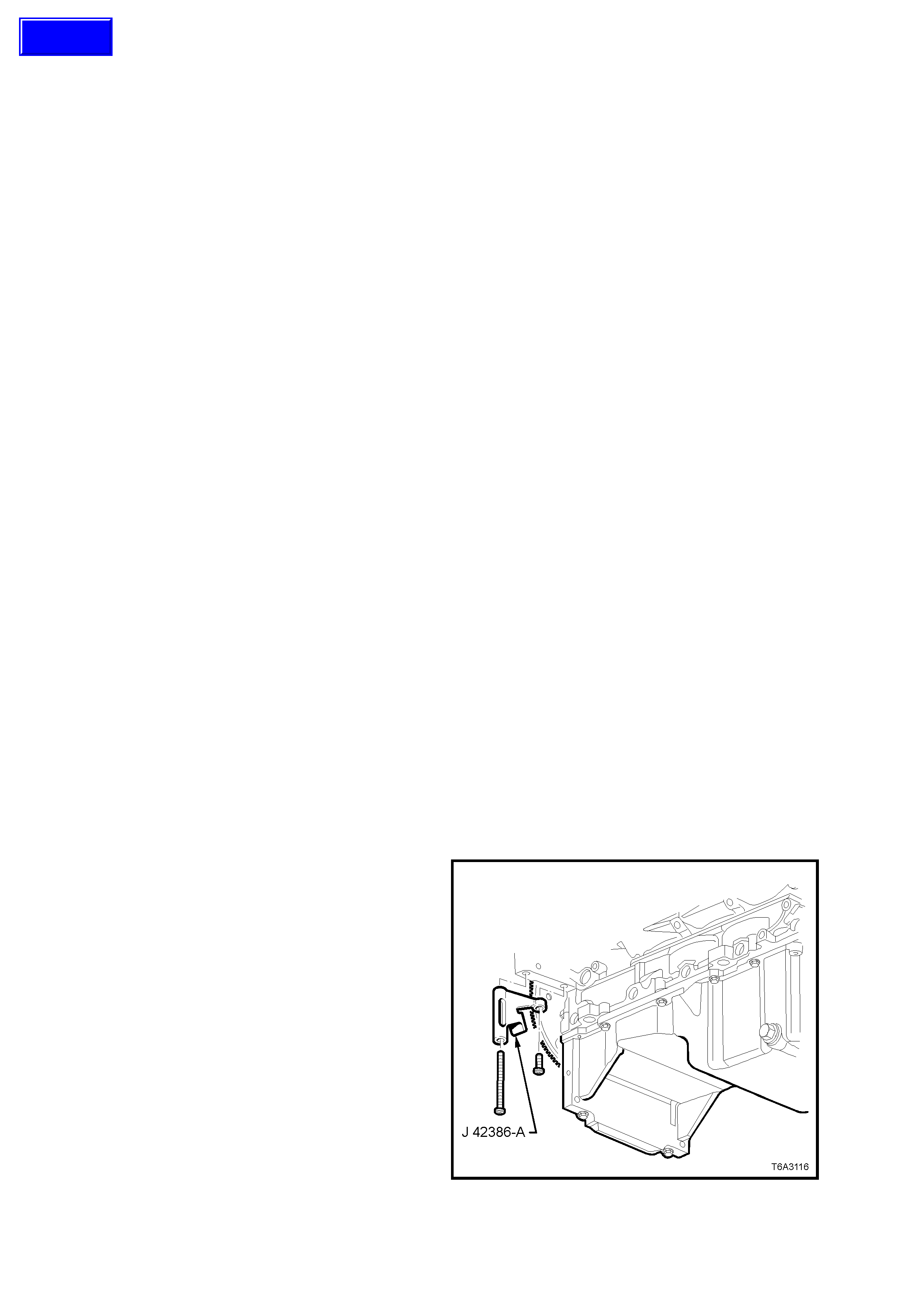
4. Install the ring gear holding Tool No. J 42386-
A, using the two starter motor bolts. Tighten
both bolts to 50 Nm.
NOTE: Ensure that the teeth of the holding tool
engage correctly with the ring gear teeth , before
tightening the fasteners.
Figure 7A1-22
Techline
5. Mark or scribe the end of the crankshaft and
the flywheel. Remove the engine flywheel
bolts, after loosening in an opposite sequence.
6. Remove the engine flywheel from the
crankshaft.
Figure 7A1-23
CLEAN AND INSPECT
1. Clean the flywheel in a suitable solvent and
blow dry with compressed air.
CAUTION: Wear safety glasses to avoid eye
injury.
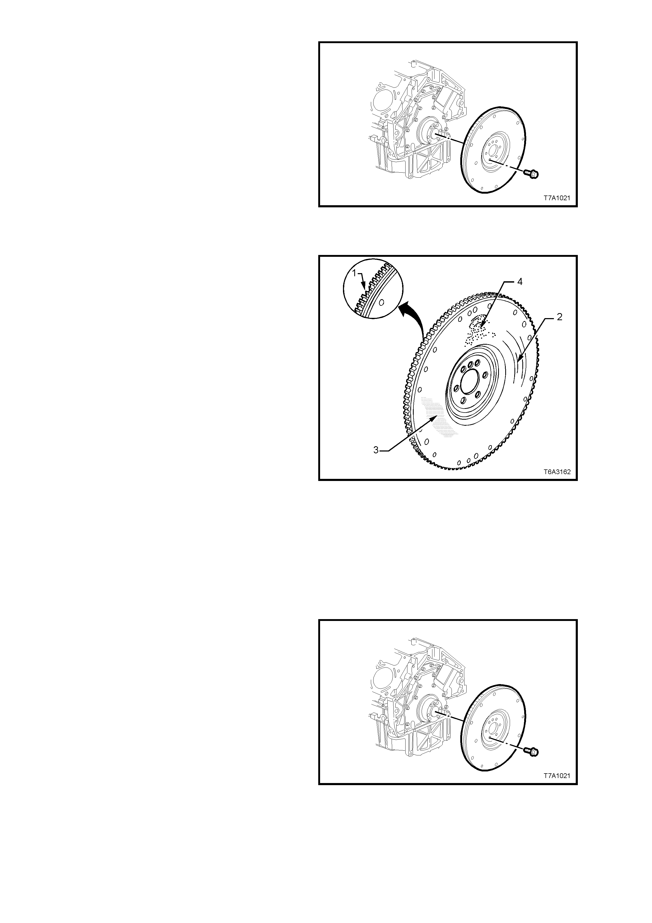
2. Inspect the flywheel for loose or improperly
installed balance weights (if applicable). A
correctly installed balance weight should be
either flush or below the m ac hined s urface of
the flywheel.
3. Inspect the flywheel for the following:
a. Pitted surfaces (1).
b. Grooves or scoring (2).
c. Rusted surface (3).
d. Damaged ring gear teeth (4).
e. Loose or incorrectly positioned ring
gear. The ring gear is an interference
fit onto the flywheel and should be
positioned completely against the
flange of the flywheel.
f. Missing, bent or damaged pressure
plate locating pins. The two locating
pins are pressed into the flywheel and
are spaced 170° apart.
Figure 7A1-24
REINSTALL
1. If replacing a flywheel;
a. Install any balance weights, as required.
b. Use the flywheel locating hole as
reference and scribe an alignment mark
corresponding to the one on the original
flywheel.
2. Install the flywheel, aligning the scribed marks
on the crankshaft and flywheel.
Figure 7A1-25
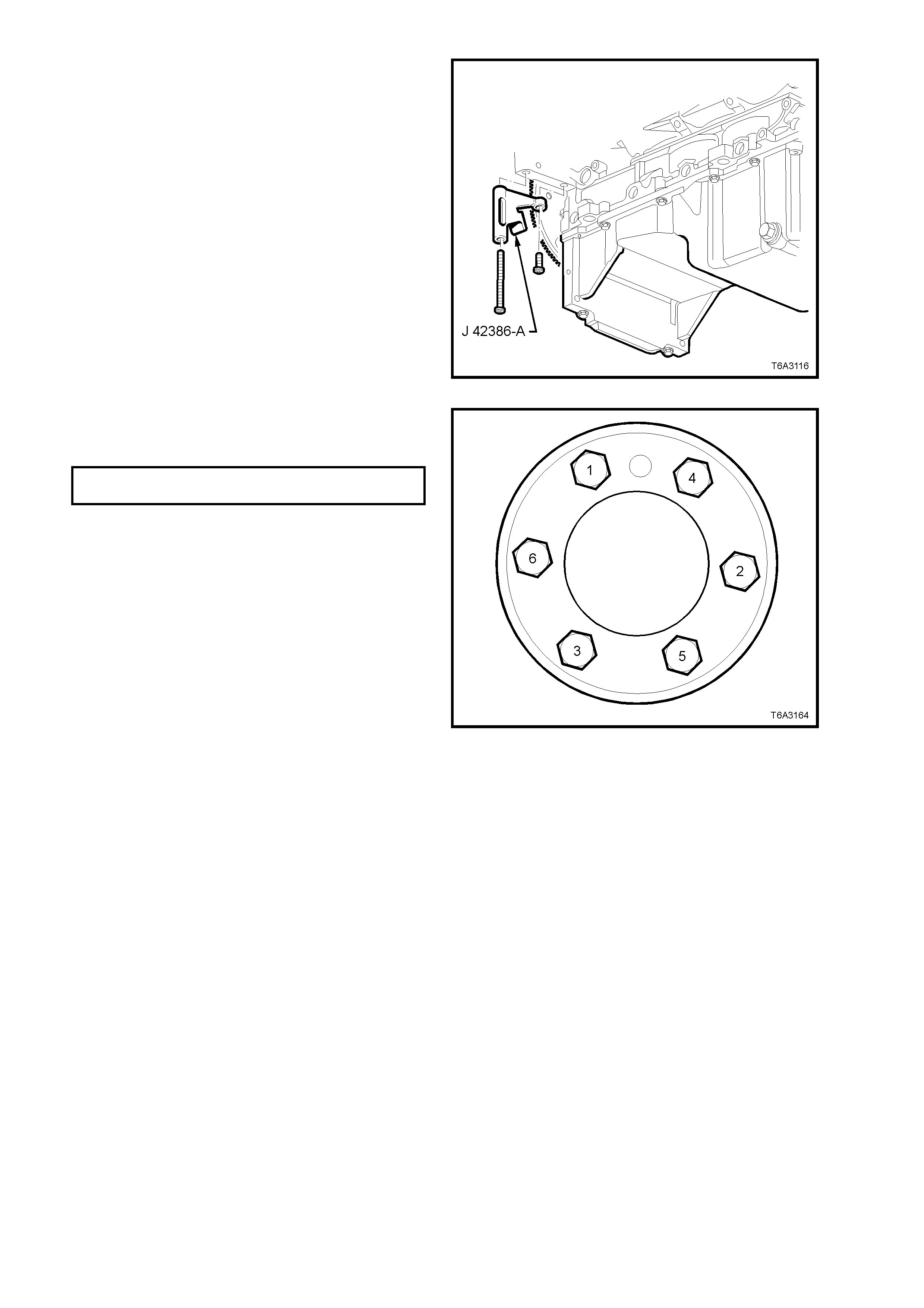
3. Loosely install NEW flywheel bolts, tightening
in the sequence shown in Figure 7A1-25, to an
initial torque specification of 20 Nm.
4. Reinstall the ring gear holding Tool No. J
42386-A, using the two starter motor bolts.
Tighten both bolts to 50 Nm.
NOTE: Ensure that the teeth of the holding tool
engage correctly with the ring gear teeth , before
tightening the fasteners.
Figure 7A1-26
5. Continue to tighten the flywheel bolts in the
sequence shown, in two additional stages and
to the correct torque specification.
FLYWHEEL BOLTS Stage 2: 50 Nm
TORQUE SPECIFICATION Stage 3: 100 Nm
Figure 7A1-27
6. Reinstall clutch assembly and manual
transmission, refer to 3.8 CLUTCH AND
PRESSURE PLATES in this Section and
Section 7B3, MANUAL TRANSMISSION -
GEN III ENGINE of the VT Series II Service
Information.
7. Reconnect battery earth lead.
8. Check starter motor operation and road test
vehicle to check transmission and clutch
operation.
3.10 RING GEAR
REPLACE
Automatic Transmission:
The ring gear is welded to the flexplate and is
serviced only as an assembly. Refer to
Section 6A3 ENGINE MECHANICAL, GEN III
ENGINE, of the VT Series II Service Information.
Manual Transmission:
1. Remove flywheel, refer to 3.9 ENGINE
FLYWHEEL, in this Section.
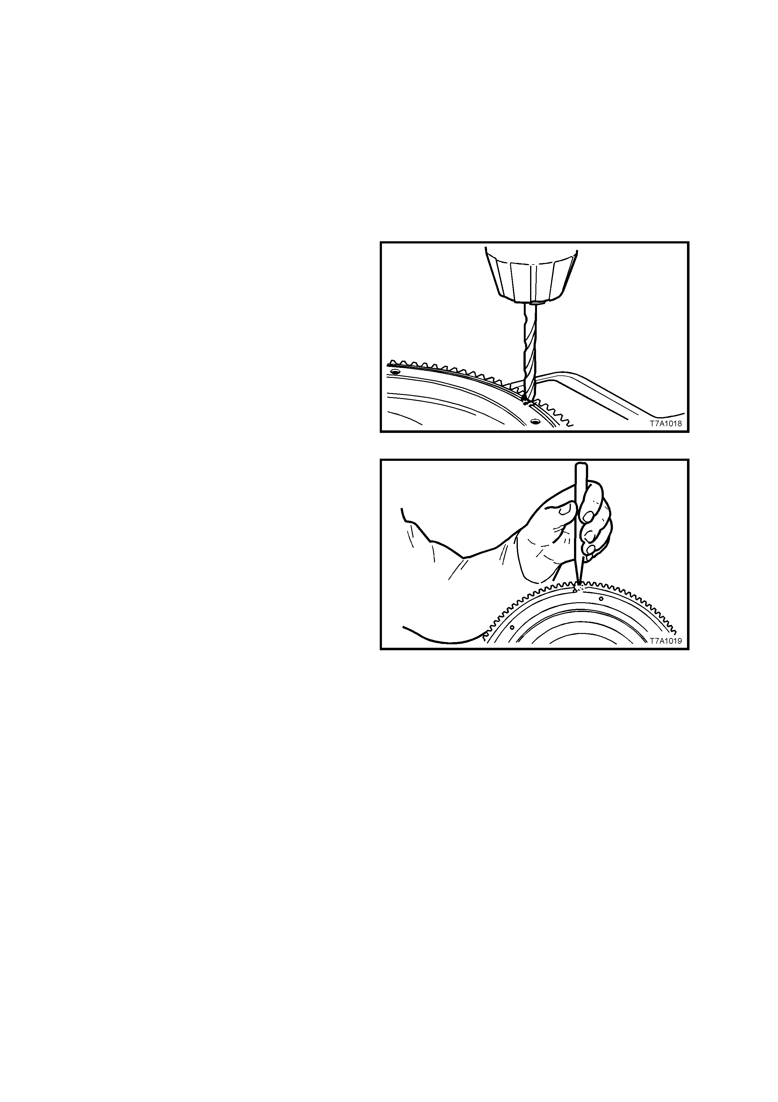
2. After marking with a centre punch and
hammer, drill an 8 mm diameter hole through
the ring gear, between two teeth.
Figure 7A1-28
3. Secure the flywheel in a vice fitted with soft
jaws, then use a sharp cold chisel and
hamm er to split the ring gear at the drill point.
Remove the ring gear from the flywheel.
Figure 7A1-29
4. Check that there are no burrs or foreign
material on the new ring gear and flywheel
mating surfaces. If present, burrs can be
removed with a fine mill file.
5. Heat and shrink the replacement ring gear,
using either one of the next two methods;
1.1 Heat the new ring gear, uniformly in an
oven to a temperature between 180 -
230° C. This temperature can be
achieved by using a thermal indicating
crayon such as Faber-Castell
Thermocrom 2815-200.
2.1 Polish several places on the ring gear
using emery cloth.
2.2 Use a hot plate or a slowly moving torch
to heat the ring gear until the polished
spots turn blue (approximately 300° C).
NOTE: Heating the ring gear above 427°
C will destroy the ring gear teeth heat
treatment.

6. Using protective gloves and two pairs of pliers,
quick ly place the ring gear against the f lywheel
shoulder. Allow the ring gear to cool until it
contracts and is firmly held in place.
7. Reinstall flywheel. Refer to
3.9 ENGINE FLYWHEEL, in this Section.
8. Reconnect battery earth lead and check
starter motor operation.
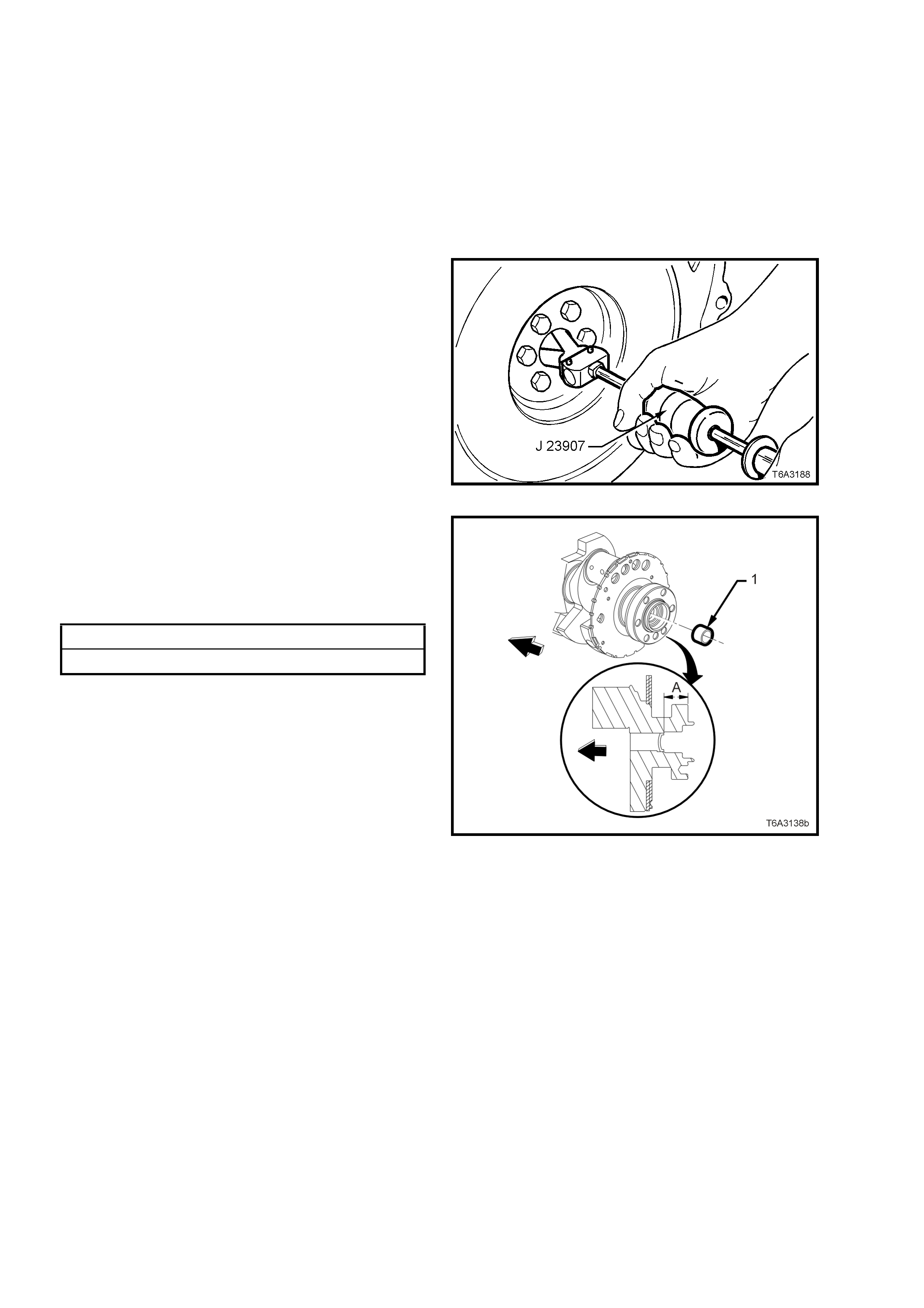
3.11 CRANKSHAFT SPIGOT BUSH
REPLACE
1. Disconnect battery earth lead.
2. Remove manual transmission and the clutch
assembly, refer to Section 7B3, MANUAL
TRANSMISSION - GEN III ENGINE of the VT
Series II Service Information and
3.8 CLUTCH AND PRESSURE PLATES in
this Section.
3. Using Tool J 23907, (also released as Tool
6A22-2 and slide hammer 7A28) or
commercial equivalent, remove the spigot
bush from the rear of the crankshaft.
Figure 7A1-30
4. Check that the rear crankshaft oil gallery plug
is not a loose fit, damaged or leaking.
5. If replacement is required, apply sealant such
as Loctite 242 or equivalent, to the sides of a
new plug and install to the correct depth.
Crankshaft Rear Oil gallery Plug Depth Specification
Distance ‘A’............................. 31.2 - 31.6 mm
Figure 7A1-31
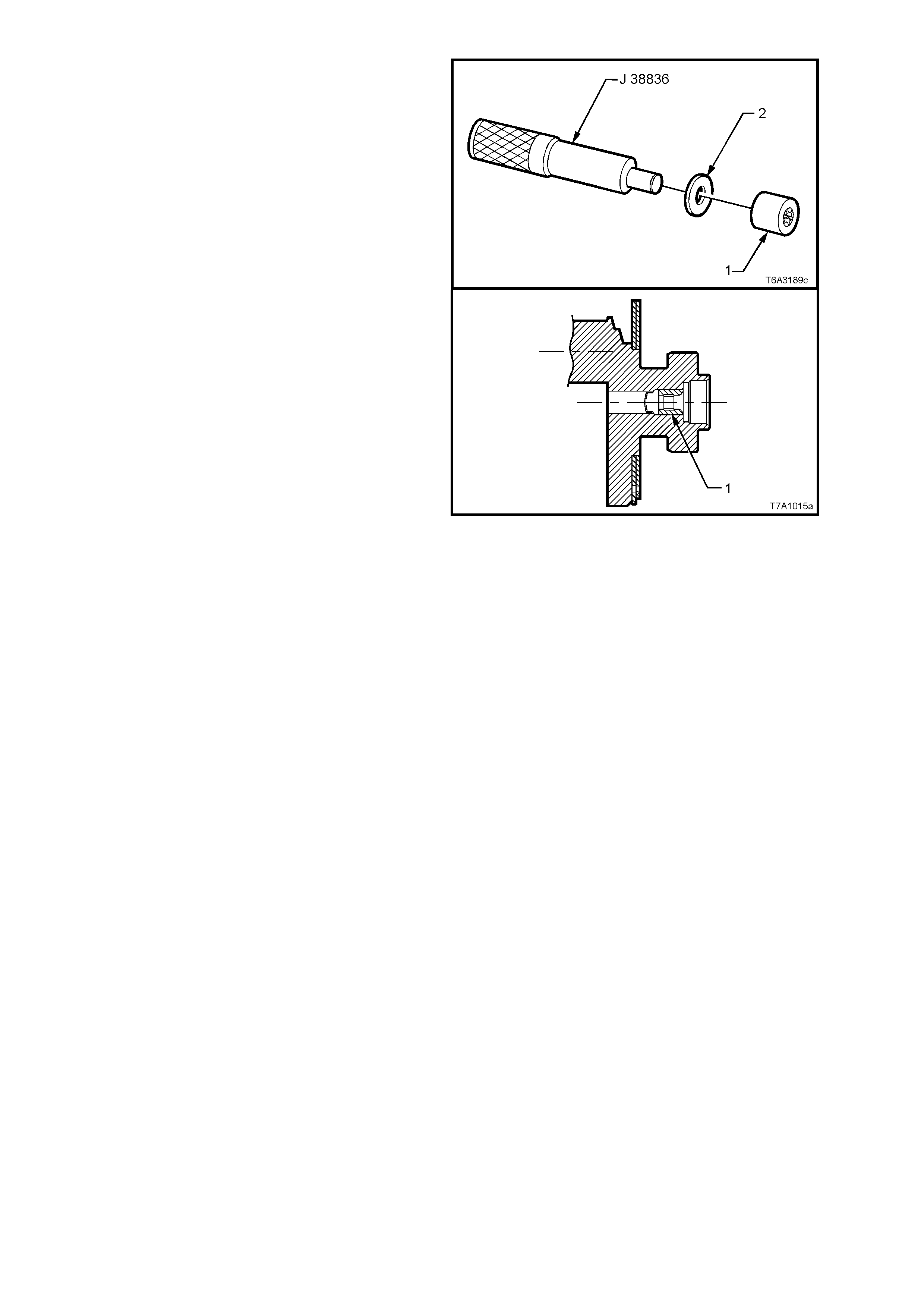
6. Using a suitable, stepped (or piloted ) driver
such as Tool J 38836 and flat washer (2),
install a replacement bush (1) to the rear of
the crankshaft, until flush with the crankshaft
counter-bore, as shown.
7. Lubricate the bearing with a small amount of
SAE 90 gear oil.
8. Reinstall clutch assembly and manual
transmission, refer to 3.8 CLUTCH AND
PRESSURE PLATES in this Section and
Section 7B3, MANUAL TRANSMISSION -
GEN III ENGINE of the VT Series II Service
Information.
9. Reinstall the starter motor. Refer
Section 6D3- 2 ST ARTING SY STEM - GEN III
ENGINE of the VT Series II Service
Information.
10. Reconnect battery earth lead.
11. Check starter motor operation and road test
vehicle to check transmission and clutch
operation.
Figure 7A1-32

4. DIAGNOSIS
CONDITION PROBABLE CAUSE CORRECTIVE ACTION
SLlPPING Worn or oil-soaked lining.
Driven plate sticking on transmission
input shaft splines.
Weak or broken diaphragm spring
Master or slave cylinder defective
Replace driven plate, correct oil leak.
Clean splines and appl
y
10%
mol
y
bdenum disulphide
g
rease to
Holden’s Specification HN 1271.
Replace pressure plate assembl
y
.
Refer Operation 3.8 Clutch and
Pressure Plates, in this Section.
Overhaul defective cylinder as outlined
under 3.3 Master Cylinder or 3.4 Clutch
Slave Cylinder, in this Section.
DRAG OR FAILURE TO RELEASE Air trapped in hydraulic system.
Leak In hydraulic system.
Clutch master or slave cylinder
defective.
Cracked or oil-soaked linings.
Excessive driven plate run-out or
distorted.
Driven plate sticking on splines.
Transmission input shaft spigot
partially seized in crankshaft spigot
bush.
Bleed system as outlined under 3.2
Clutch Hydraulic System Bleed, in this
Section.
Correct leak and bleed hydraulic
system.
Replace defective cylinder as outlined
under 3.3 Master Cylinder or 3.4 Clutch
Slave Cylinder, in this Section.
Replace driven plate. Refer Operation
3.8 Clutch and Pressure Plates, in this
Section.
Replace driven plate. Refer Operation
3.8 Clutch and Pressure Plates, in this
Section.
Clean and free splines and apply 10%
molybdenum disulphide grease to
Holden’s Specification HN 1271.
Remove clutch, Iubricate or replace
bush. Refer Operation 3.10 Crankshaft
Spigot Bush, in this Section.
GRAB OR CHATTER Oil on linings.
Worn transmission input shaft splines.
Rou
g
h, or
g
rooved, fl
y
wheel o
r
pressure plate.
Loose engine mountings.
Loose or worn universal joints or loose
rear universal joint flange.
Defective clutch driven plate.
Replace driven plate, correct oil leak.
Replace transmission input shaft. Refer
Section 7B3 TRANSMISSION of the
VT Series II Service Information.
Replace fl
y
wheel or replace both
fl
y
wheel and pressure plate. Refe
r
Operation 3.8 Clutch and Pressure
Plates or 3.9 En
g
ine Fl
y
wheel, in this
Section.
Ti
g
hten or replace mountin
g
s. Refe
r
Section 6A3 ENGINE MECHANICAL
GEN III V8 ENGINE of the VT Series II
Service Information.
Ti
g
hten or replace universal
j
oint/s
and/or flan
g
e. Refer 4C PROPELLER
SHAFT AND UNIVERSAL JOINTS of
the VT Series I Service Information.
Replace clutch driven plate. Refer
Operation 3.8 Clutch and Pressure
Plates, in this Section.
HARD OR STIFF CLUTCH ACTlON Clutch pedal bush seized or ti
g
ht on
pedal shaft.
Blockage in fluid hydraulic pipe.
Replace bushes as detailed in 3.6
Clutch Pedal in this Section.
Clean lines and bleed hydraulic
system. Refer 3.2 Clutch Hydraulic
System Bleed in this Section.
CLUTCH ENGAGEMENT TOO SLOW Blocka
g
e in fluid h
y
draulic pipe.
Clutch master or slave c
y
linde
r
defective.
Incorrect brake fluid used.
Clean lines and bleed h
y
draulic
s
y
stem. Refer 3.2 Clutch H
y
draulic
System Bleed in this Section.
Replace defective cylinder as outlined
under 3.3 Master Cylinder or 3.4 Clutch
Slave Cylinder, in this Section.
Flush and bleed hydraulic system.
Refer 3.2 Clutch Hydraulic System
Bleed in this Section.

5. SPECIFICATIONS
NOTE: Only those specifications relating specifically to this Section are quoted here. For all remaining
specifications, refer to Section 7A CLUTCH, of the VT Series I Service Information.
MASTER CYLINDER:
.................................................................................... All Engines
Type .................................................................................... Compensating port.
Bore Size............................................................................... 19.05 mm
Nominal Stroke...................................................................... 30 mm
CLUTCH SLAVE CYLINDER:
Type .................................................................................... Concentric hydraulic slave cylinder with side feed
....................................................................................and bleed ports
Bore Size............................................................................... I.D. 36 mm/O.D 47.6 mm (nominal)
Available Stroke .................................................................... 22.8 mm (nominal)
BRAKE FLUID:
Type .................................................................................... To Holden’s Specification HN 1796.
CLUTCH DRIVEN PLATE:
Type .................................................................................... Single plate dry disc.
Disc Facing:
Outside Diameter ............................................................... 297 mm
Inside Diameter.................................................................. 198 mm
Thickness of disc assembly with 10,000 N load applied.... 8.7 ± 0.35 mm
CLUTCH PRESSURE PLATE:
Type .................................................................................... Self-adjusting with a recessed nodular iron plate,
with a pressed steel cover plate and a multi-
fingered Belleville diaphragm spring.
CLUTCH THROWOUT BEARING:
Type .................................................................................... Ball race.
Lubrication............................................................................. Sealed with grease for life.
LUBRICANT:
Face of throwout bearing/transmission input shaft splines ... 10% Molybdenum Disulphide or equivalent to
Holden’s Specification HN 1271.

6. TORQUE WRENCH SPECIFI CATIONS
NOTE: Only those torque specifications referred to in this Section are quoted here. For all remaining torque
specifications, refer to Section 7A CLUTCH, of the VT Series I Service Information. Nm
Clutch pressure plate bolt to flywheel Stage 1........................................... 15
Stage 2........................................... 35
Stage 3........................................... 55
Stage 4........................................... 70
Clutch slave cylinder bleed screw .................................................................. 15 - 20
Clutch slave cylinder mounting bolt................................................................ 7.5 - 12.5
Flywheel to crankshaft mounting bolts Stage 1........................................... 20
Stage 2........................................... 50
Stage 3........................................... 100
Hydraulic pipe flare nut to slave cylinder and flexible hose............................ 12 - 14
Master cylinder hydraulic pipe to flexible hose flare nut................................. 12 - 14
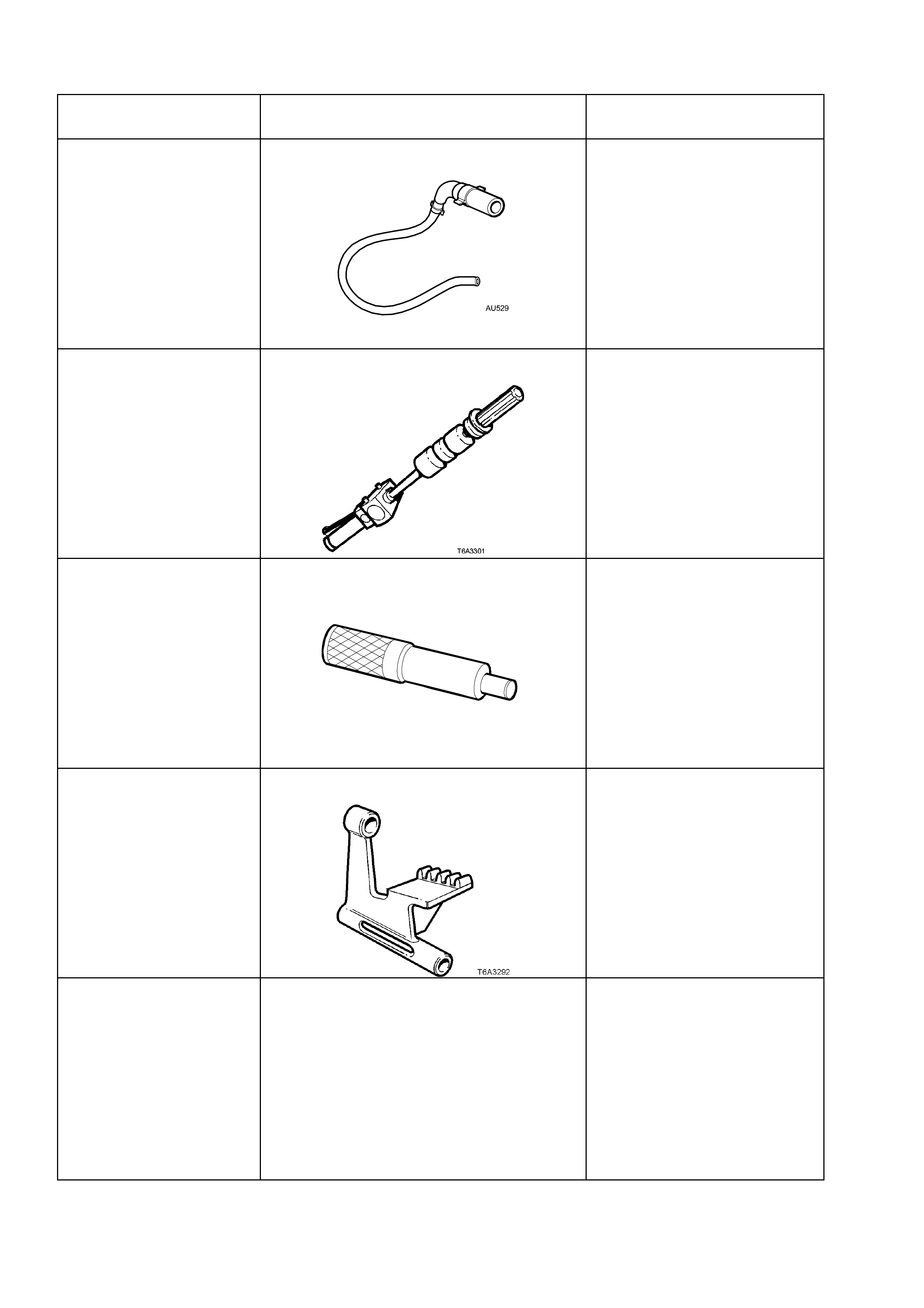
7. SPECIAL TOOLS
TOOL No. REFERENCE
IN TEXT TOOL DESCRIPTION COMMENTS
AU529 CLUTCH SLAVE CYLINDER BLEED TOOL New release.
Used to bleed air from the
Central Slave Cylinder (CSV)
fitted to the T56, 6 speed
manual transmission available
for the GEN III V8 engine.
J 23907 SLIDE HAMMER/BUSHING REMOVER Previously released.
Used to remove the crankshaft
spigot bush.
Also released as remover,
6A22-2 and slide hammer,
7A28.
J 38836 PILOTED DRIVER
T6A3 189b
New release.
Also used for the same
operation in Section 6A3,
Engine Mechanical GEN III, of
the VT Series II Service
Information.
J 42386-A RING GEAR HOLDING TOOL New release.
Also used for the same
operation in Section 6A3,
Engine Mechanical GEN III, of
the VT Series II Service
Information.
N/A CLUTCH CENTRING TOOL Commercially available.