
SECTION 12J-2 - HIGH SERIES BODY CONTROL
MODULE
CAUTION:
This vehicle will be equipped with a Supplemental Restraint System (SRS). A SRS will consist of either
seat belt pre-tensioners and a driver's air bag, seat belt pre-tensioners and a driver's and front
passenger's air bag s or seat belt pre- tensio ners, d riv er’s and fron t p asseng er’s air bag and lef t and rig ht
hand side air bags. Refer to SAFETY PRECAUTIONS, Section 12M Supplemental Restraint System of the
VT Series I Service Information before performing any service operation on, or around any SRS
components, the steering mechanism or wiring. Failure to follow the SAFETY PRECAUTIONS could
result in SRS deployment, resulting in possible personal injury or unnecessary SRS system repairs.
CAUTION:
This vehicle may be equipped with LPG (Liquefied Petroleum Gas). In the interests of safety, the LPG
fuel system should be isolated by turning 'OFF' the manual service valve and then draining the LPG
service lines, before any service work is carried out on the vehicle. Refer to the LPG leaflet included with
the Owner's Handbook for details or the appropriate Section of this Service Information CDfor more
specific servicing information.
1. GENERAL DESCRIPTI ON
A Body Control Module (BCM), both High and Low Series, com bine into one centr al m odule, the control or assist of
various vehicle electrical systems or features, rather than having individual modules for each system or feature.
High Series BCMs are fitted as standard equipment on all VT Series Berlina and Calais Models.
Two levels of High Series BCM’s have been released, a LUX level for Berlina Models and the HI level for Calais. If a
service operation or diagnostic procedure requires that a High Series BCM must be replaced, ensure that the
correct BCM level is reinstalled for the particular level of vehicle.
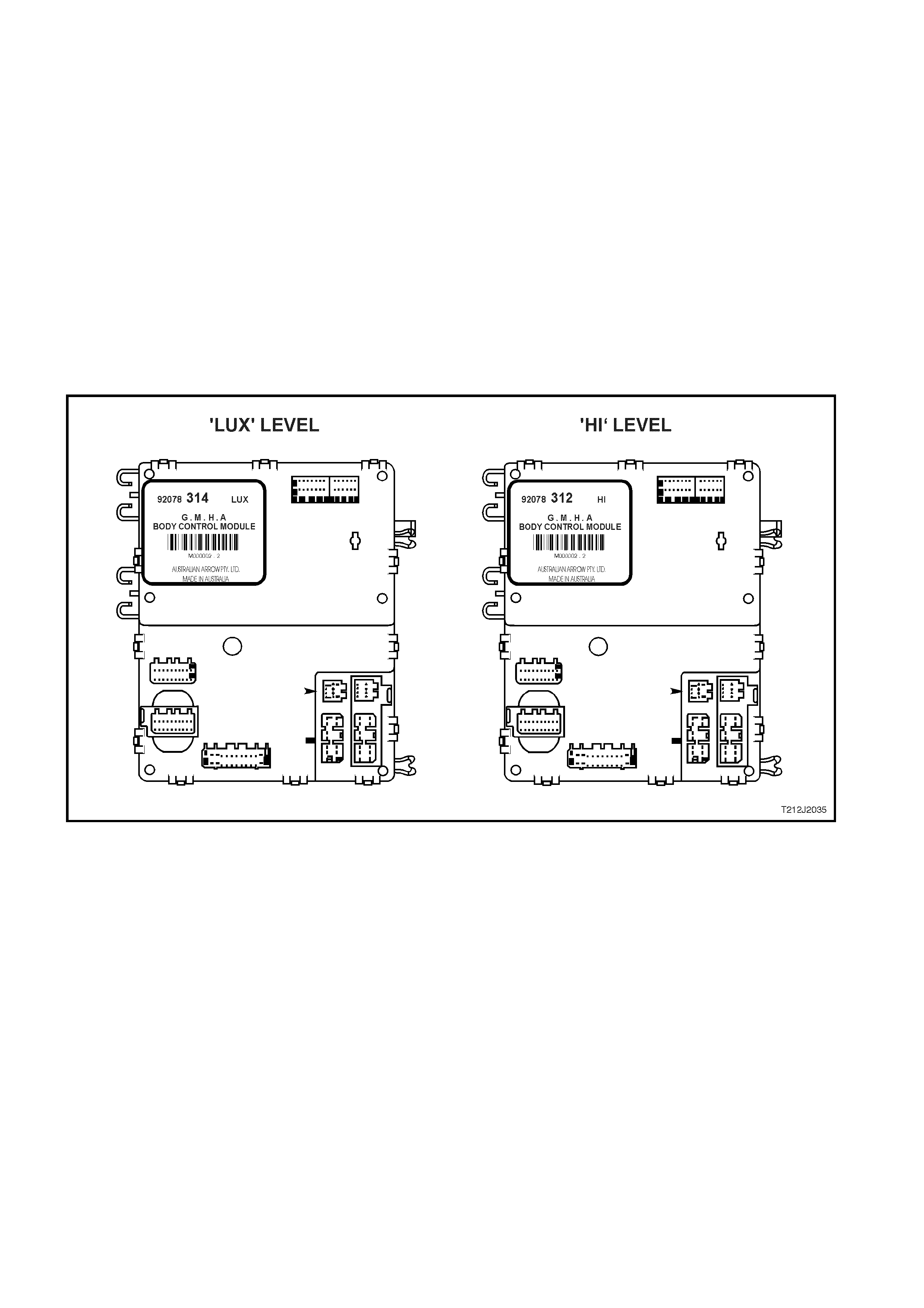
The High Series BCM is located beneath the instrument cluster, to the right of the steering column, refer to Fig.
12J-2-2. Fig. 12J-2-1 illustrates the identification details for the High Series BCM. External identification can be
made by referring to the last three digits of the BCM part number.
Information regarding Low Series BCMs, fitted to VT Series Executive and Acclaim Models, can be found in
Section 12J-1 LOW SERIES BODY CONTROL MODULE of the VT Series II Service Information.
With the introduction of VT Series II Models, comes various upgrade features (and changes) for the BCM. The
following list provides a summary of these new features, additional and more detailed information of an individual
features can be found within this Section.
• Remote deadlocking via remote key (two lock button presses within ten seconds).
• Battery saver feature; turns off all internal lam ps after one hour (default setting) of the ignition being switched
off.
NOTE: This f eatur e inc ludes a pr e-deliver y mode which sets the timer to a shor ter period of thr ee minutes until
the vehicle has travelled above 20km/h for a cumulative period of 30 minutes. After this period, the battery
saver timer sets to one hour.
• The standing current in the BCM has also been lowered from 18mA to 4mA.
• Key off courtesy lamp; courtesy lamp comes on for 30 seconds when the ignition is switched off.
• Disablement of the in-vehicle boot release button when security system armed.
• Approach illumination entry (high series BCM only); headlamps and/or park lamps are turned on for 30
seconds (dependant on headlamp switch position) when the vehicle is unlocked via the remote key.
• Deletion of 2 hour override. For the override feature to be deleted, both the BCM and the PCM had to be
changed. These changes were staggered in introduction;
BCMs were changed in July 1998.
V6 PCMs were changed in October 1998.
V8 PCMs were changed in December 1998.
• Serviceability of door lock microswitch (at VT start of production, microswitches were serviced as part of the
door handle assembly only).
Techline
Techline
Techline
Techline
Techline
Techline
Techline
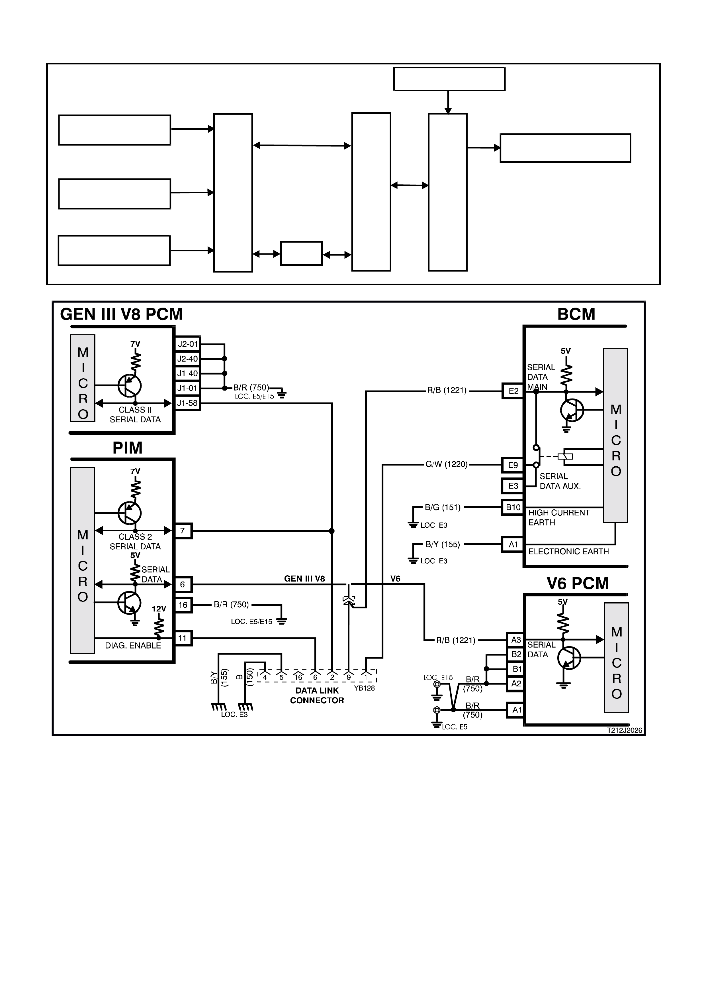
Also released f or VT Series II Models is the new GEN III V8 engine. T he Powertrain Control Module (PCM) f or this
engine uses what is referred to as ‘Class 2’ serial communication. All other control modules, including the BCM,
communicate serial data, in what is referred to as UART (Universal Asynchronous Receive and Transmit). The
‘Class 2’ communication is more sophisticated than UART, and as such, requires a Powertrain Interface Module
(PIM) to convert Class 2 communication into UART.
In sim ple terms, the G EN III V8 engine PCM comm unicates in a dif ferent language than the other c ontrol modules
and therefore requires the PIM to translate the PCM information into the same language as the other control
modules communicate in. Refer to 1.2 SERIAL DATA COMMUNICATION (BUS MASTER) for more information .
The PIM is located in the same location as a V6 PCM; behind the passenger side shroud lower trim assembly.
Specific software has been developed for use with the TECH 2 diagnostic scan tool to assist with various vehicle
electrical system fault finding, including the various BCM functions and controls.
The T ECH 2 connection f or the High Series BCM serial data com munic ation is via the Data Link Connec tor (DLC),
attached to the instrument panel lower right hand trim, to the left of the steering column, refer to Fig 12J-2-2.
This Section has been compiled to address these new features and changes only. For information that is not
covered in this Section, including General Description, Service Operations, Diagnosis and Special Service Tools,
refer to Section 12J-2 HIGH SERIES BODY CONTROL MODULE of the VT Series I Service Information.
Figure 12J-2-1 High Series BCM Identification

BODY CONTROL MODULE FEATURES
BCM FEATURE LEVEL 7 (BERLINA) LUX – 314 LEVEL 0 (CALAIS) HI - 312
Central door locking A A
Boot release with speed interlock A A
Power window system A A
Power antenna control A A
Dome lamp delay control A A
Rear lamp failure warning lamp control N/A A
Road speed dependent and variable
dwell wiper control - front AA
Intermittent and synchronised to front
rear wiper control with full wipe in
reverse gear (wagon only)
AN/A
Speed sensitive power steering N/A A
Instrument dimming control A A
Automatic lights OFF (variable) A A
Automatic lights ON - twilight sentinel N/A A
Engine disable A A
Alarm A A
Engine cooling low speed fan control A A
Priority key system N/A A
Cruise control interface A A
SRS (air bag) deployment vehicle
shutdown AA
Serial data interface A A
Battery saver mode A A
Approach illumination A A
N/A = NOT AVAILABLE A = AVAILABLE
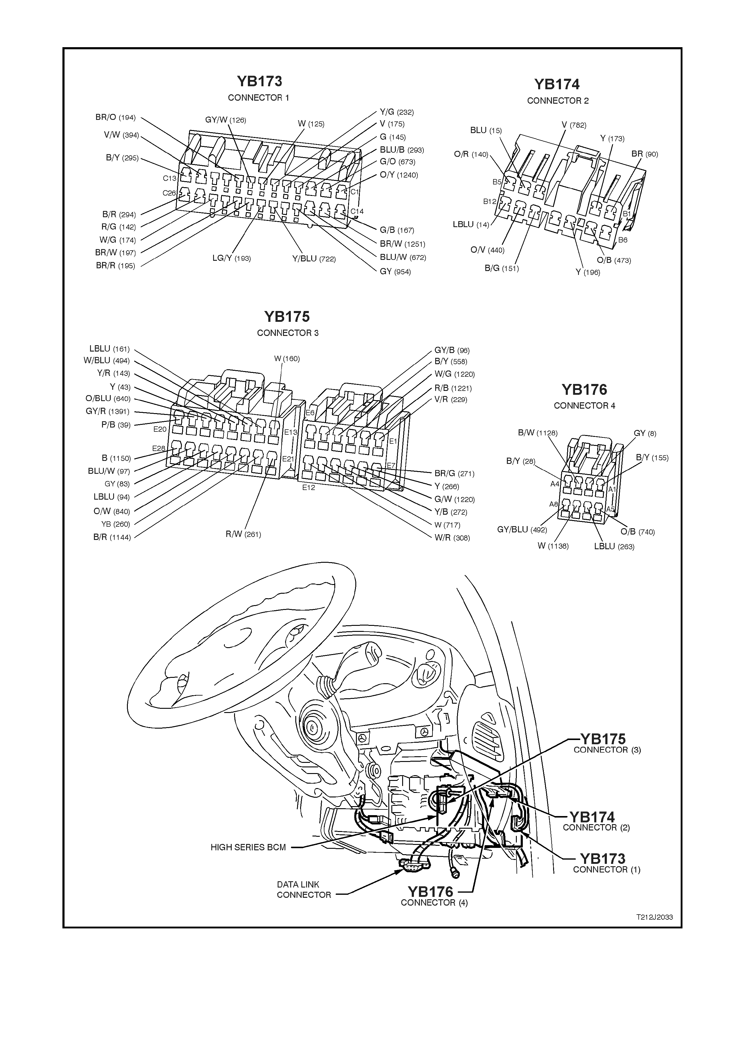
Figure 12J-2-2 BCM location and connector/terminal assignment

HIGH SERIES BCM TERMINAL IDENTIFICATION
YB176 CONNECTOR 4
PIN NO. DESCRIPTION CIRCUIT WIRE COLOUR CIRCUIT TYPE
A1 EARTH (ELECTRONIC) 155 B/Y E
A2 INSTRUMENT ILLUMINATION OUTPUT 8 GY O
A3 THEFT DETERRENT HORN OUTPUT 1128 B/W O
A4 HORN OUTPUT 28 B/Y 0
A5 BATTERY POSITIVE 740 O/B P
A6 THEFT DETERRENT LED OUTPUT 263 LBLU O
A7 INTERIOR ILLUMINATION OUTPUT 1138 W O
A8 REAR WI PER OUTPUT 492 GY/BLU O
YB174 CONNECTOR 2
PIN NO. DESCRIPTION CIRCUIT WIRE COLOUR CIRCUIT TYPE
B1 WI PER OUTPUT 90 BR O
B2 POWER WINDOW OUTPUT 173 Y O
B3 PRIORITY KEY ONE OUTPUT 782 V O
B4 RIGHT INDICATOR OUTPUT 15 BLU O
B5 INDICATOR POWER 140 O/R P
B6 NC
B7 LOW FAN SPEED OUTPUT 473 O/B O
B8 WIPER PARK INPUT 196 Y PD/O
B9 NC
B10 POWER EARTH 151 B/G E
B11 DOOR LOCK POWER 440 O/V P
B12 LEFT INDICATOR OUTPUT 14 LBLU O
YB173 CONNECTOR 1
PIN NO. DESCRIPTION CIRCUIT WIRE COLOUR CIRCUIT TYPE
C1 WINDOW POWER INPUT 1240 O/Y P
C2 WINDOW MOTOR OUTPUT 673 G/O O
C3 DRIVERS DOOR UNLOCK OUTPUT 293 BLU/B O
C4 ANTENNA DRIVE OUTPUT 145 G O
C5 DOME ON INPUT 175 V PD
C6 BOOT LAMP INPUT 162 Y/G PPU
C7 PASSENGER DOOR AJAR INPUT 125 W PPU
C8 DRIVERS DOOR AJAR INPUT 126 GY/W PPU
C9 PASSENGERS DOOR UNLOCK INPUT 194 BR/O PU
C10 NC
C11 NC
C12 DEADLOCK OUTPUT 394 V/W O
C13 ALL DOORS, LOCK OUTPUT 295 B/Y O
C14 WINDOW DOWN INPUT 167 G/B PD
C15 STOP/TAIL SENSE INPUT 1251 BR/W I
C16 WINDOW UP INPUT 672 BLU/W PD
C17 ANTENNA DIRECTION OUTPUT 954 GY O
C18 NC
C19 DOME - DOOR INPUT 722 Y/BLU PD
C20 UNLOCK INPUT 193 LG/Y PPU
C21 LOCK INPUT 195 BR/R PPU
C22 DEADLOCK REQUEST INPUT 197 BR/W PPU
C23 NC
C24 DOME LAMP OUTPUT 174 W/G O
C25 BOOT OUTPUT 142 R/G O
C26 PASSENGER DOOR UNLOCK OUTPUT 294 B/R O

YB175 CONNECTOR 3
PIN NO. DESCRIPTION CIRCUIT WIRE COLOUR CIRCUIT TYPE
E1 SLIP RING 229 V/R I/O
E2 SERIAL DATA INTERFACE MAIN BUS 1221 R/B I/O
E3 AIRBAG SERIAL DATA INTERFACE BUS 1220 W/G I/O
E4 POWER STEERING SOLENOID OUTPUT 558 B/Y O
E5 WIPER DWELL INPUT 96 GY/B PU
E6 NC
E7 RECEIVER EARTH 271 BR/G E
E8 RECEIVER DATA 266 Y I
E9 SERIAL DATA INTERFACE AUXILIARY BUS 1220 G/W I/O
E10 TWILIGHT INPUT (AMBIENT LIGHT SENSOR) 272 Y/B I
E11 INSTRUMENT DIMMER INPUT 717 W PU
E12 AUTO LIGHTS EARTH OUTPUT 308 W/R O
E13 ANTENNA DOWN INPUT 160 W PPU
E14 ANTENNA UP INPUT 161 LBLU PPU
E15 REAR WASHER INPUT 494 W/BLU PD
E16 RADIO ON INPUT 143 Y/R PD
E17 ACCESSORIES INPUT 43 Y PD, P
E18 STOP LAMP FUSE INPUT 640 O/BLU PD
E19 REAR WIPER INPUT 1391 GY/R PD
E20 IGNITION INPUT 39 P/B PD, P
E21 BONNET SWITCH INPUT 261 R/W PPU
E22 BOOT RELEASE INPUT 1144 B/R PPU
E23 BONNET SWITCH INPUT 260 Y/B PD
E24 PARK LAMP FUSE INPUT 840 O/W PD
E25 FRONT SCREEN WASH/WIPE INPUT 94 LBLU PU
E26 CRUISE CONTROL ON INPUT 83 GY PD
E27 FRONT INTERMITTENT AUTO WIPE INPUT 97 BLU/W PD
E28 LIGHTS OFF EARTH OUTPUT 1150 B O
GLOSSARY
E - Earth I/O - Input / Output O - Output PD - Pull down PU - Pull up
I - Input NC - No circuit P - Power PPU - Pulsed pull up
B - Black DKBLU - Dark blue LBLU - Light blue P - Pink V - Violet
BLU - Blue G - Green LG - Light green R - Red W - Wh ite
BR - Brown GY - Grey O - Orange T - Tan Y - Yellow

1.1 BATTERY SAVER MODE
The BCM Battery Saver Mode provides vehicle battery protection (through reduced current consumption). After a
programmed delay period (shut down timer) the BCM -:
1. De-activates the interior illumination relay which supplies battery voltage to all interior dome, ignition loc k, glove
and boot lamps, protecting the battery in the event of-:
A lamp mistakenly left on (ie. door open) or a faulty illumination circuit or component causing excess current
consumption.
2. De-activates the power window relay (separate from the normal power window off delay function).
3. Disables BCM inputs normally not required with the ignition in the ‘OFF’ position, to reduce its own current
consumption.
The battery saver delay period has a default value of one (1) hour, however can be set from 2 to 255 minutes via
TECH 2. The delay period (shut down timer) is initiated when the ignition is switched to the ‘OFF’ position.
Whilst in Battery Saver Mode, the BCM is ‘woken’ up when:
1. The bonnet, boot or any door is opened.
2. The BCM receives a valid RF key ‘LOCK’, ‘UNLOCK’ or ‘BOOT’ signal.
3. The Ignition is switched to the ‘ACC’ or ‘ON’ position.
4. The doors unlocked via the driver’s door microswitch.
5. The deadlock switch is activated.
6. TECH 2 is communicating with the BCM.
7. The headlamp switch is cycled from ‘OFF’ – ‘ON’ or ‘ON’ – ‘OFF’.
8. The rear compartment lock switch, located in the glove box, is activated.
9. When the alarm is activated.
PRE-DELIVERY MODE.
The BCM provides additional battery protection (pre-deliver y mode), where the battery saver delay period is set to a
shorter value, three (3) minutes. This value is estimated to be the equivalent period prior to customer delivery.
Pre-delivery mode is disabled once the vehicle has travelled for a total of thirty (30) minutes at speeds above 20
km/h.
Pre-delivery mode can be enabled and disabled via TECH 2.
1.2 SE RIAL DATA COMMUNICATION(BUS MASTER)
GENERAL INFORMATION
Various devices; system control modules of the vehicle, as well as TECH 2 communicate with each other. The
communication between control modules and com munication with the TECH 2 diagnostic scan tool is achieved on
the serial com munic ation lines using serial data. Serial data tr ansfers inf ormation in a linear f ashion - over a single
line, one bit at a time. The serial data line is referred to as the ‘data bus’.
Excluding the GEN III V8 PCM, all control modules communicating on the data bus communicate using UART
communication.
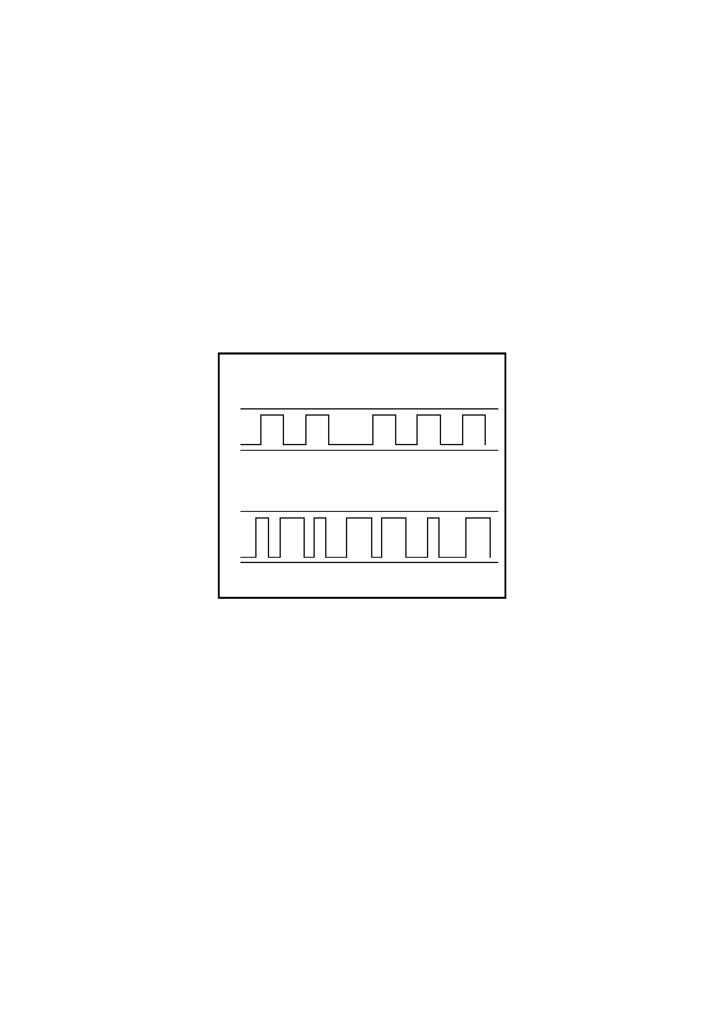
UART is a 5 volt data line that toggles the voltage to earth (0 volts ) at a fixed bit puls e width dur ing c om m unication.
UART trans m its data at the rate of 8.2 k ilobits per s econd ( 8192 bits /sec). In UART com m unications , when ther e is
no communication on the data line, the system voltage will be 5 volts.
The GEN III V8 PCM uses Class 2 com m unication. T his type of com m unication toggles the data line from 0 volts to
7 volts at a either a short or long pulse width at rate of 10.4 kilobits per second (average). In Class 2
communications, when there is no communication on the data line, the system voltage will be 0 volts.
As the ‘Class 2’ c omm unication is diff erent to UART (dif ferent languages), c omm unication between the modules is
incompatible, and as such, requires a Powertrain Interface Module (PIM) to convert Class 2 communication into
UART, and UART into Clas s 2 (a tr anslator ). Refer to ‘POWERT RAIN INTERFACE MO DULE (PIM)’ in this Sec tion
for additional information on this module.
TECH 2 is able to communicate with both UART and Class 2 control modules.
T212J1012
11
0
1
00
1
0
1
0
5V
0V
UART
CLASS 2
11 1
111
000 0
000
7V
0V
Figure 12J-2-3 Serial Data Digital Wave Form
On all VT Series Models, the BCM is the Bus Master of the serial data communication system. The BCM
periodically polls (surveys) each device on the data bus and requests status data.
The devices (control modules) the BCM polls are:
• Body Control Module (BCM).
• V6 and V6 supercharged engine Powertrain Control Module (PCM).
• Powertrain Interface Module (PIM), GEN III V8 engines only.
• Instrument cluster (INS).
• Antilock Brake/Electronic Traction Control System (ABS/ETC) module.
• Supplemental Restraint System (SRS) Sensing and Diagnostic Module (SDM).
• Electronic Climate Control (ECC) module.
• TECH 2 diagnostic scan tool.
The data provided by each device may be utilised by any device connected to the bus.
Each device has a unique response Message Identifier Word (MIW) for ease of identification.
The bus m aster (BCM) polls eac h device with a serial data mes sage which includes that devices MIW. The device
responds by putting a serial data m essage onto the bus which inc ludes its MIW and data, of which is r etrieved and
utilised by any device requiring it.
The BCM polls each device for a status update, once ever y 300 millis econds. T he ex ception to this being the PCM
(V6) and PIM (GEN III V8) which are polled twice every 300 milliseconds.

When the ignition switch is turned from the OFF position to the ON position, the BCM will communicate with the
PCM (via the PIM on vehicles with GEN III V8 engines) f or thef t deter rent pur poses . If the BCM does not r ec eive an
OK TO START message from the PCM within 0.5 seconds of ignition on, the auxiliary data bus is isolated via
switching from the BCM.
The isolation of the auxiliary data bus during this period eliminates the possibility of a device failure other than the
BCM, PCM or PIM (GEN III V8 only), causing a problem on the bus and inhibiting theft deterrent communications.
This period (short loop time) continues until the PCM responds with an acknowledgment or a maximum of five
seconds after which the BCM will switch to the standard polling sequence.
Following successful theft dterrent communications, the BCM begins sequential polling of devices on the bus and
normal system operation is established.
When the ignition switch is in the OFF position, the BCM continues to poll, allowing for TECH 2 communications
and external control of the bus prior to the ignition being switched on.
Powertrain Interface Module (PIM)
The PIM is a hardware and serial communications interface between the GEN III V8 PCM and the vehicles
electrical s ystem . The prim ary purpose of this module is to allow the GEN III PCM to interf ace (talk ) to the existing
communications bus (UART) operating in the vehicle. The PIM acts as a transparent bi-directional translation
device, which allows data to flow between the modules with varying communication protocols; Class 2 and UART.
When the ignition switch is turned from the OFF position to the ON position, and the PIM receives a poll from the
BCM, the PIM requests data from the GEN III PCM via its Class 2 interface and transfers this information to the
other control modules via the UART bus (Serial communications bus). The PIM also monitors responses from other
control modules on the UART bus and, using its Class 2 connection, transfers any information relevant to the GEN
III PCM as required.
T212J2031
Figure 12J-2-4 PIM location
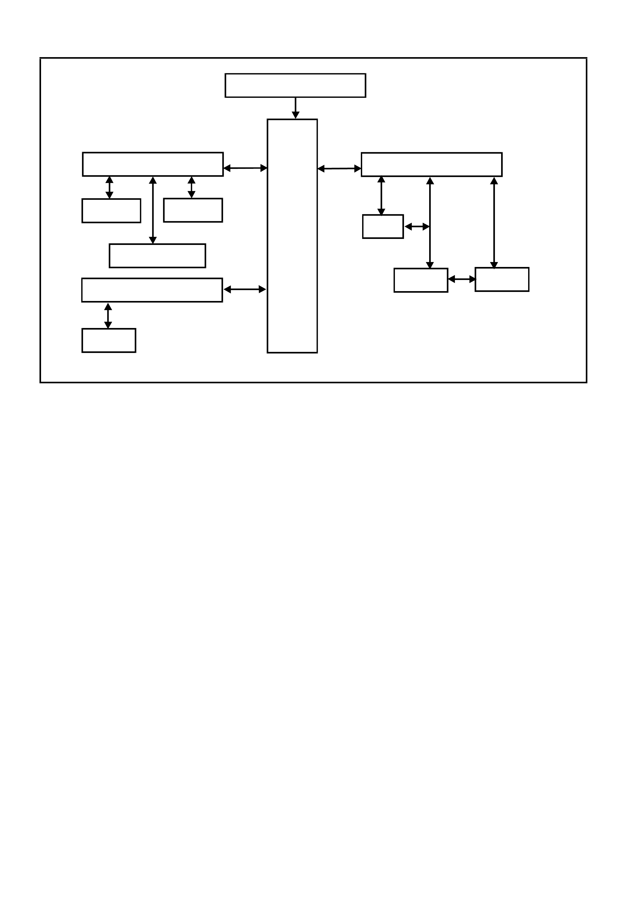
SYSTEM OVERVIEW - SERIAL COMMUNICATION
BATTERY POWER
BCM
SERIAL DATA MAIN
DLC
SERIAL DATA AUX
ABS/ETC ECC
INSTRUMENTS
SRS SERIAL DATA AUX
SRS
PCMPIM
GEN III V8
ENGINE V6 & V6 S/C
ENGINE
T212J2011
INPUTS / OUTPUTS
Serial Data Signal - Main
BCM terminal E2, serial data signal - main, refer Fig. 12J-2-6, is connected to the PCM (via PIM on vehicles with
GEN III V8 engines) and DLC via circuit 1221 (Red/Black wire). It is via this line that the BCM com municates with
the PCM and external devices connected to the DLC, at all times.
Serial Data Signal - Auxiliary
BCM term inal E9 and E3, serial data signal - auxiliary, refer to Fig. 12J -2-6, is connected to the instr ument c luster,
ABS/ETC and ECC modules via circuit 1220 (Green/White wire) and to the SRS module via circuit 1220
(White/Green wire). It is via this line (circ uit 1220) that the BCM com munic ates with these devices, af ter succes sful
theft deterrent c omm unications between the PCM and BCM (via the serial data - m ain line when the ignition switch
is turned from the OFF to ON position).
During theft deterrent communications, If the BCM does not receive an OK TO START message from the PCM
within 0.5 seconds of ignition on, the serial data - auxiliary line is isolated from the serial data - main line via
switching within the BCM. (This will continue for a five second period if there is still no acknowledgment from the
PCM, before it starts polling)
INPUTS
Ignition Switch ON Input Signal
The BCM uses this input signal to determine when the ignition switch is in the IGN or START position. When the
ignition switch is in the IGN or ST ART pos ition, battery voltage is applied to the BCM term inal E20 f rom the ignition
switch and fuse F14 via circuit 39 (Pink/Black wire), refer to Fig. 12J-2-5.
NOTE: The circuit diagr am s shown in this G eneral Desc ription Section ar e to aid in interpreting the oper ation of the
circuit and theref ore, only the m ain connectors and wiring colours ar e shown. For com plete circuits details, refer to
either the relevant diagnostic Section or Section 12P WIRING DIAGRAMS of the VT Series II Service Information.
M
I
C
R
O
BCM
T212J2013
BATTERY
FS
F31
A5
O/B (740 )
(1040)
BAT T ERY MAIN POWER
FJ
R ( 2)
F14
E20
P/ B (39)
IGNITION ON
15a 1550
30 ACC
IGN
START
IGNITION
SWITCH
P (3)
Figure 12J-2-5 Ignition switch ON input signal
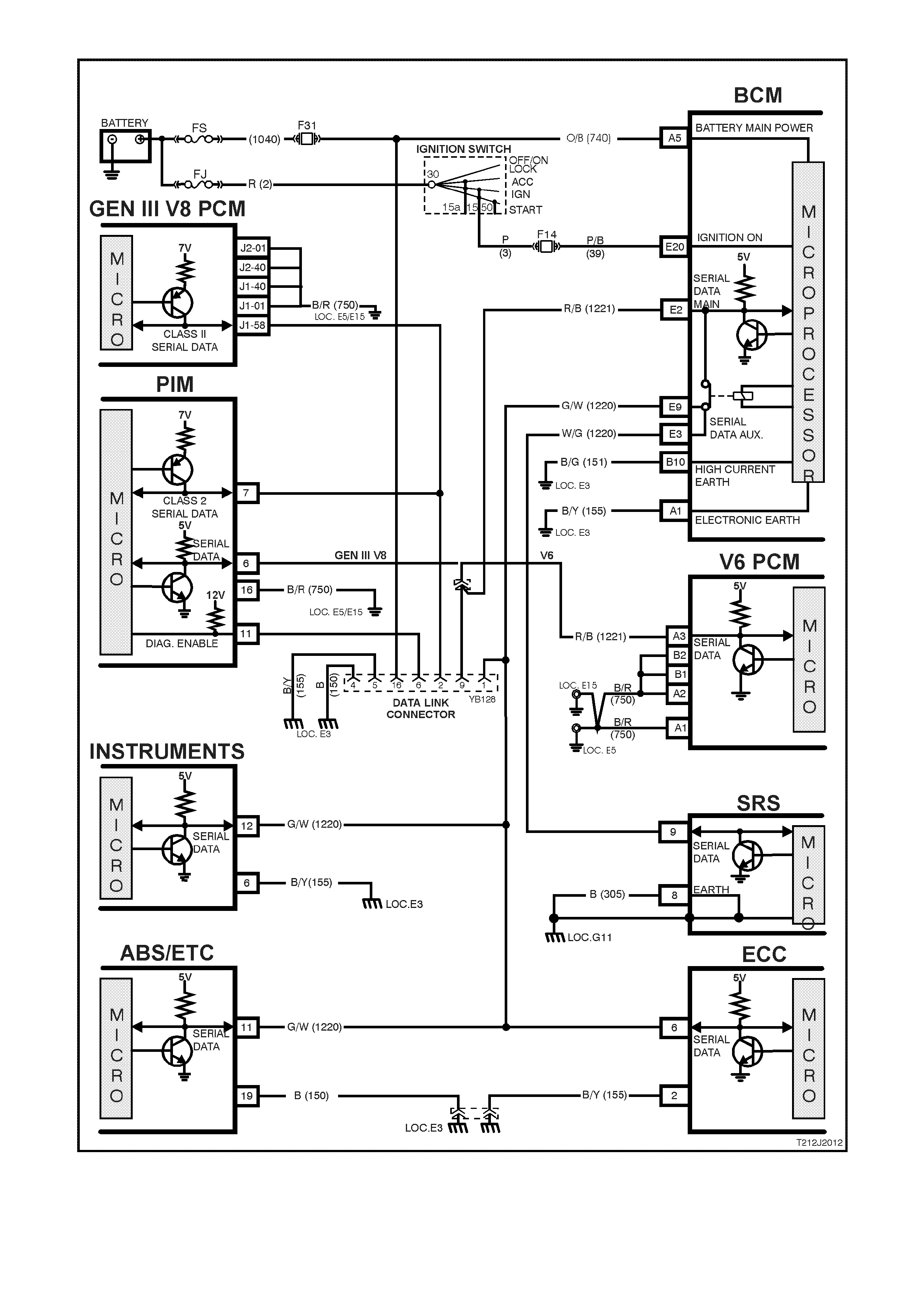
Figure 12J-2-6 Serial data communication circuit
1.3 CENTRAL DOOR LOCKING SYSTEM
GENERAL INFORMATION
On VT Series II Models, the centr al door lock ing system ess entially carries over f rom VT Series Models, noting the
following:
On VT Series II Models, it is possible to deadlock the doors via the remote coded key.
NOTE: Although the VT Series II central door locking system essentially carries over, if diagnosing a central door
locking circuit fault, reference to the wiring diagrams in Section 12P WIRING DIAGRAMS of the VT Series II
Service Information should be made.
For information details , including Gener al Information, Ser vice Oper ations and Diagnosis of the centr al door lock ing
systems that is not covered in this Section, refer to Section 12J-2 HIGH SERIES BODY CONTROL MODULE of
the VT Series I Service Information.
SYSTEM CHECK
The operation of the central door locking system is independent of the ignition being switched ON or OFF.
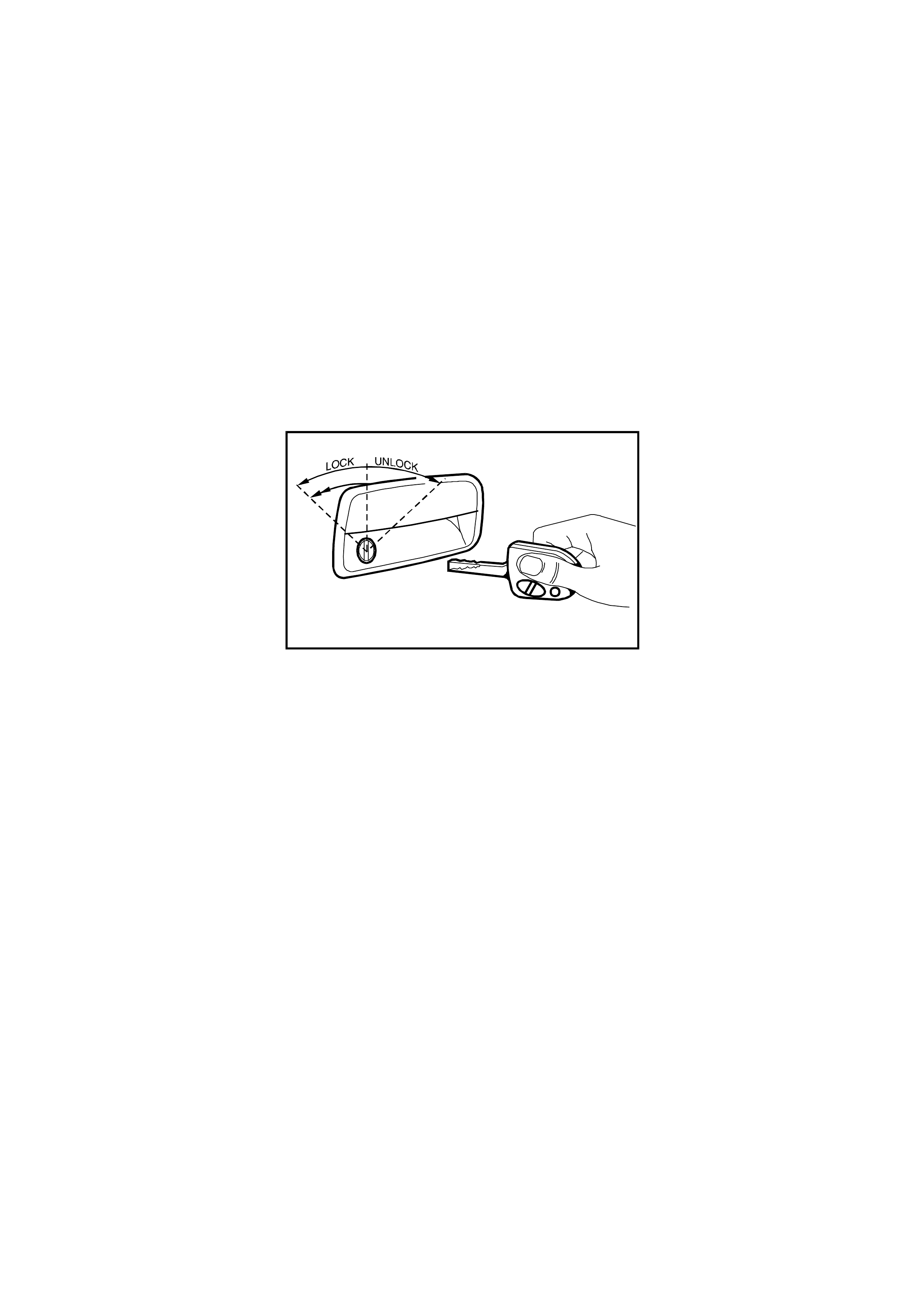
The figure below shows the key positions on the driver’s door for the various key locking functions.
Deadlock refers to the electrical means that can be activated to ensure vehicle security by inhibiting door lock
operation.
T212J1034
Figure 12J-2-7 Deadlocking with two sequential lock activation’s
Deadlock
The deadlocking feature applies to all four doors, but not to the luggage compartment lid or tailgate.
The deadlocking feature is engaged as follows:
• Two sequential lock activation’s of the door lock microswitch or
• Operating the ‘lock’ button on the remote coded key twice within 10 seconds.
The turn signal lamps turning on for three seconds indicate successful deadlocking via the remote coded key.
If the vehicle is already deadlocked, pressing the lock button on the remote coded key will cause the turn signal
lamps to turn on for three seconds, indicating that the vehicle is already deadlocked.
If the vehicle is locked (not deadlocked) pressing the lock button on the remote coded key 10 seconds after the
previous press, the doors will not deadlock and the turn signal lamps will flash briefly, indicating that the doors are
only lock ed. Pressing the loc k button again, within in a ten second period will caus e the doors to deadloc k and turn
the signal lamps will turn on for three seconds.
After the deadlocking feature device has been engaged, unlocking is possible at the driver’s door from outside, by:
• Inserting the key into the driver’s door lock cylinder and turning the key to the unlock position or
• Activating the un-lock button on the remote key unlocks the deadlocks on all doors, but only unlocks the
driver’s door (providing two stage unlocking is enabled).
To ensure access to the vehicle if the electrical system should fail (discharged battery), after the system has been
engaged, the driver’s door lock cylinder can be moved independently of the actuator and therefore allowing
unlocking of the driver’s door latch.
The rear com partment lid or tailgate can be lock ed/unlocked when the m echanical deadloc king featur e is actuated,
while leaving the doors secured.
NOTE: Deadlocking is not possible with the ignition in the ON position.
Remote Coded Key Check
Check that the remote coded key locks all doors when the rem ote coded key lock button is pressed, at a distance
within 4 metres from the driver’s side B pillar.
When the rem ote coded k ey unlock button is pr essed the driver 's side should unlock ( vehicles pr ogram m ed for two
stage unlock). Pressing the un-lock button again and all passenger doors (and tailgate on station wagon models)
should unlock.
On vehicles programmed for single stage unlock, the single press of the unlock button will unlock all doors and
tailgate on station wagon models.
If this test does not prove satisfactory, refer to 2.3 REMOTE CODED KEY in Section 12J-2 HIGH SERIES BODY
CONTROL MODULE of the VT Series I Service Information for a more detailed diagnosis before continuing with the
central locking system check.
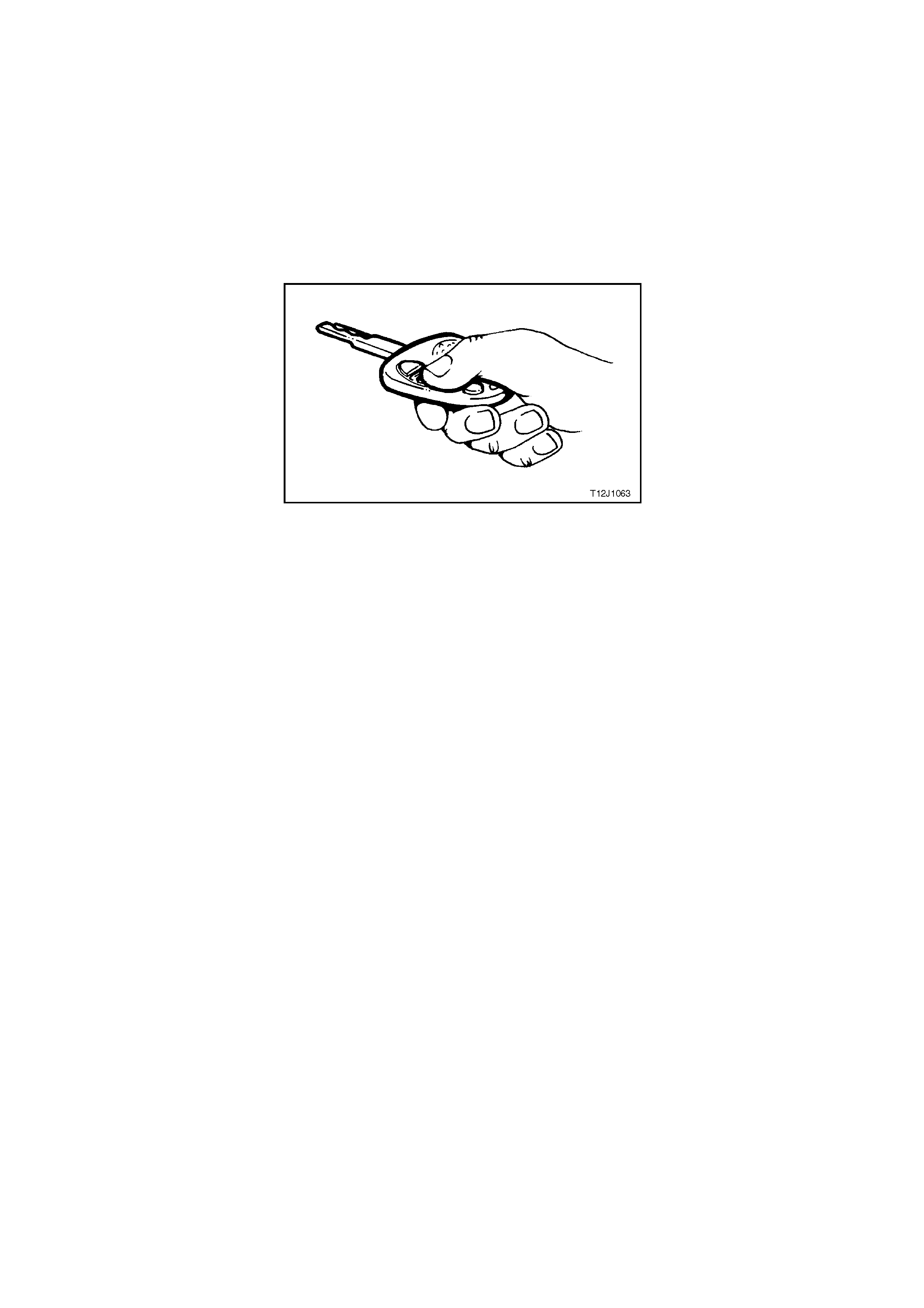
Figure 12J-2-8 Remote coded key
Checking the Deadlock Feature
Open all windows.
Close all doors.
Actuate the deadlock feature from the driver’s door with the key.
Check that all door lock buttons cannot be pulled up. They are electrically blocked.
NOTE: The door lock (snib) buttons can be pulled up slightly, but they will be under tension.
Overheating Prevention
In the event of m ultiple activation’s within a defined tim e period, the central door lock ing system will be deactivated
and remain inoperative for a def ined time period to prevent the door actuators from overheating. After a fixed tim e
delay, the system will re-activate and operate as normal.

1.4 THEFT DETERRENT SYSTEM
GENERAL INFORMATION
The theft deterrent system on VT Series Models uses a remote coded key to arm and disarm the system, and
where fitted, electric ally lock or unlock all doors and tailgate ( s tation wagon), or oper ate the boot unloc k m ec hanis m
(sedan models).
NOTE: The circuit diagr am s shown in this G eneral Desc ription Section ar e to aid in interpreting the oper ation of the
circuit and therefore, only the main connectors and wiring colours are shown. For complete circuit details, refer to
either the relevant diagnostic procedures in this Section or Section 12P WIRING DIAGRAMS of the VT Series II
Service Information.
SYSTEM OPERATION
When enabled, there are two modes of theft deterrent operation, armed and disarmed.
Armed
Once the theft deterrent system is enabled, it can be manually armed in one of two ways:
Actively, by pressing the lock button on the remote coded key or,
Passively, as the BCM will automatically arm 30 seconds after the ignition is turned off.
When the system is armed, the start relay (located in the engine compartment relay housing) and the engine
management system Powertrain Control Module (PCM) and on vehicles with GEN III V8 engines, Powertrain
Interface Module (PIM) are disabled, preventing the engine from being started.
Disarmed
With the system disarmed and the PCM/PIM enabled, the engine will be allowed to be started when the ignition
switch is turned to the run position.
The theft deterrent system can be disarmed in two ways:
1. Pressing the unlock button on the remote coded k ey. This unlocks the doors, turns the interior dom e lamp on
and fully disarms the system for 30 seconds or,
2. By insert ing the remote c oded key into the ignition switch key barrel and tur ning the ignition to the O N or RUN
position. This causes the BCM to read a security code serial data output from the remote coded key contact
pin via the remote coded key reader assembly.
NOTE 1: Both the V6 and V8 systems will allow upto one second crank if the code is invalid. In most cases this
results in the engine starting for a short period but dies after two – three seconds. (Under normal conditions, this
allows for f uel pr iming and reduc es s tart delays while the security mess age is being validated). Engine c r ank is then
disabled until the next ignition cycle (key off – on).
NOTE 2: Should the engine crank briefly when the ignition switch is turned to the START position (ie. due to mis-
aligned or a faulty remote coded key reader) then pressing the unlock button on the remote coded key will also
disarm the theft deterrent system.
Remote Coded Key (Refer to Fig. 12J-2-9)
The theft deterrent system uses a remote coded key to arm and disarm the system, and electrically lock or unlock
all doors and tailgate (station wagon), or operate the boot unlock mechanism (sedan models).
Its own internal battery powers the remote coded key. If its internal battery fails, the remote coded key reader can
power the remote coded key once the key is inserted into the ignition switch key barrel and turned to the IGN or
START position.
The radio frequency transmitted by the remote key is received by the BCM remote receiver, located in the
instrument panel, between the demist ducts.
When the theft deterrent system is armed by pressing the remote coded key lock button, the indicators will flash
once and the theft deterrent alert indicator LED will begin to flash. Disarming the system by pressing the unlock
button will cause the indicators to flash twice and the theft deterrent alert indicator LED will stop flashing.
NOTE: Passive arming of the system does not automatically operate the door locks or flash the indicators.
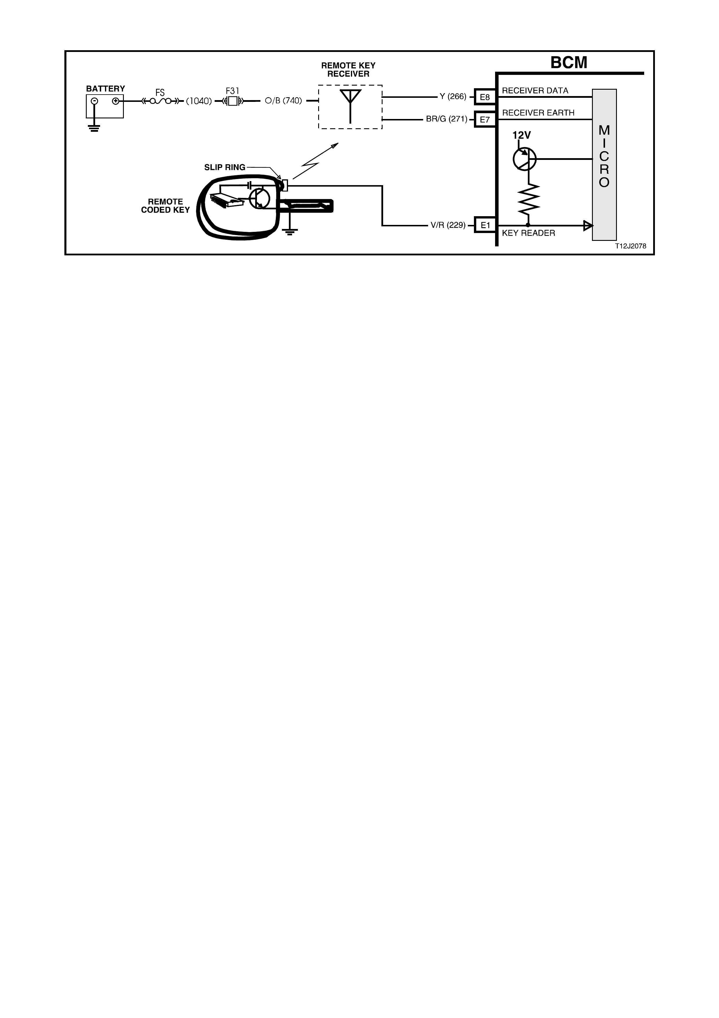
Figure 12J-2-9 Remote coded key circuit
Theft Deterrent Alert Indicator LED
The theft deterrent alert indicator LED is used to indicate the state of the system . A flashing LED indicates that the
system is arm ed and consequently the vehicle cannot be started. When the LED is turned of f, the BCM is disarm ed
and the engine can be started.
The theft deterrent LED is incorporated into the trip computer switch assembly in the instrument panel facia.
Operation (Refer to Fig. 12J-2-10)
V6 and V6 Supercharge d Engine
When the ignition switch is turned to the ON position, the BCM polls the PCM and sends an encrypted BCM/Key
security code (The security code is received via the BCM slip ring or remote receiver in the event of no slip ring
communication). The PCM compares the received security code with it’s stored security code and if the codes
match, the PCM will enable injector f uelling and continue engine crank ing. The PCM will return an OK TO ST ART
message, which tells the BCM to jump from SHORT LOOP mode to the LONG LOOP mode.
GEN III V8 Engine
When the ignition switch is turned to the ON position, the BCM polls the PIM and sends an encrypted BCM/Key
security code (The security code is received via the BCM slip ring or remote receiver in the event of no slip ring
communication). The PIM compares the received security code with it’s stored security code and if the codes
match, the PIM will continue enabling engine cranking and send a separate encrypted security code to the PCM.
The PCM compares this code with its stored security code and if the codes match, the PCM will enable injector
fuelling to continue. The PIM will return an OK TO START message, which tells the BCM to jump from SHORT
LOOP mode to the LONG LOOP mode.
NOTE: Regardless of the engine configuration, it is very important that the remote coded key reader is aligned
correc tly with the ignition lock assembly, or m isalignment with the rem ote coded key contact may occur r esulting in
intermittent or no engine cranking or starting.
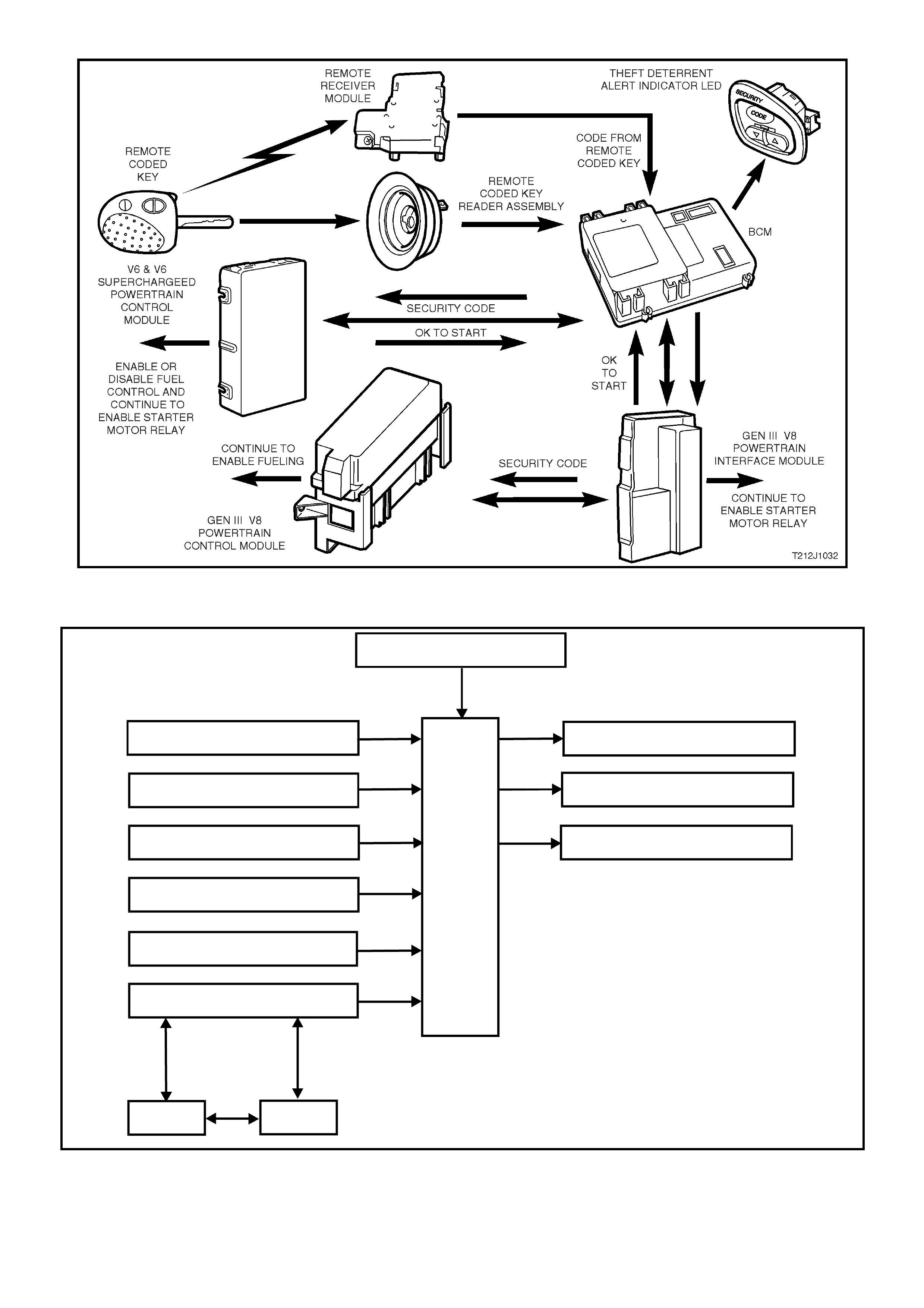
Figure 12J-2-10 Theft deterrent system
SYSTEM OVERVIEW - THEFT DETERRENT
BATTERY POW ER
LH TU RN SI GNAL
RH TURN SIGNAL
THEFT DETERRENT LED
BCM
TURN SIGNAL POWER
DRIVER’S DOOR OPEN
REMOTE RECEIVER
KEY RE AD ER
IGNITION SWITCH ON
T212J1024
SERIAL DATA
PCM
PIM
GEN III V8
ENGINE V6 & V6 S/C
ENGINE
CIRCUIT OPERATION (Refer to Fig. 12J-2-15)
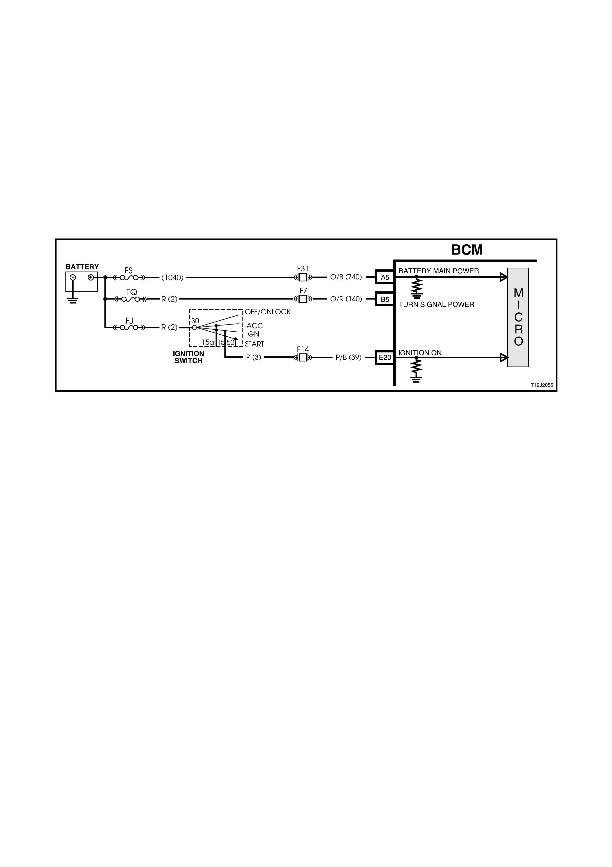
Battery Power (Refer to Fig. 12J-2-11)
Battery voltage is applied to the BCM microprocessor from terminal A5 at all times from fusible link FS and fuse F31
via circuit 740 (Orange/Black wire).
Indicators Power (Refer to Fig. 12J-2-11)
Battery voltage is applied to BCM terminal B5 at all times from fusible link FQ and fuse F7 via circuit 140
(Orange/Red wire).
Inputs
Ignition Switch ON Input Signal (Refer to Fig. 12J-2-11)
The BCM uses this input signal to determine when the ignition switch is in the IGN or START position. When the
ignition switch is in the IGN or ST ART pos ition, battery voltage is applied to the BCM term inal E20 f rom the ignition
switch and fuse F14 via circuit 39 (Pink/Black wire).
Figure 12J-2-11 Battery power, turn signal indicator power and ignition switch on input circuit
BCM and Powertrain Control Module Communication (Serial Data)
(Refer to Figs. 12J-2-12 and 12J-2-13)
V6 and V6 Supercharged Engine
When the ignition switch is turned to the ON pos ition, the BCM polls the PCM and sends a secur ity code. T he PCM
compares this code with it’s stored code and if they match, the PCM will enable fuel system control and continue
engine cranking.
The serial data from the remote coded key is applied to BCM terminal E1, circuit 229 (Violet/Red wire).
GEN III V8 Engine
W hen the ignition switch is turned to the ON position, the BCM polls the PIM and sends a security code. The PIM
compares this code with its stored code and if they match, the PIM continues engine enabling cranking and sends
the GEN III V8 PCM a security code. The GEN III V8 PCM compares this code with its stored code and, if they
match, the PCM will continue engine fuelling.
The serial data from the remote coded key is applied to BCM terminal E1, circuit 229 (Violet/Red wire).
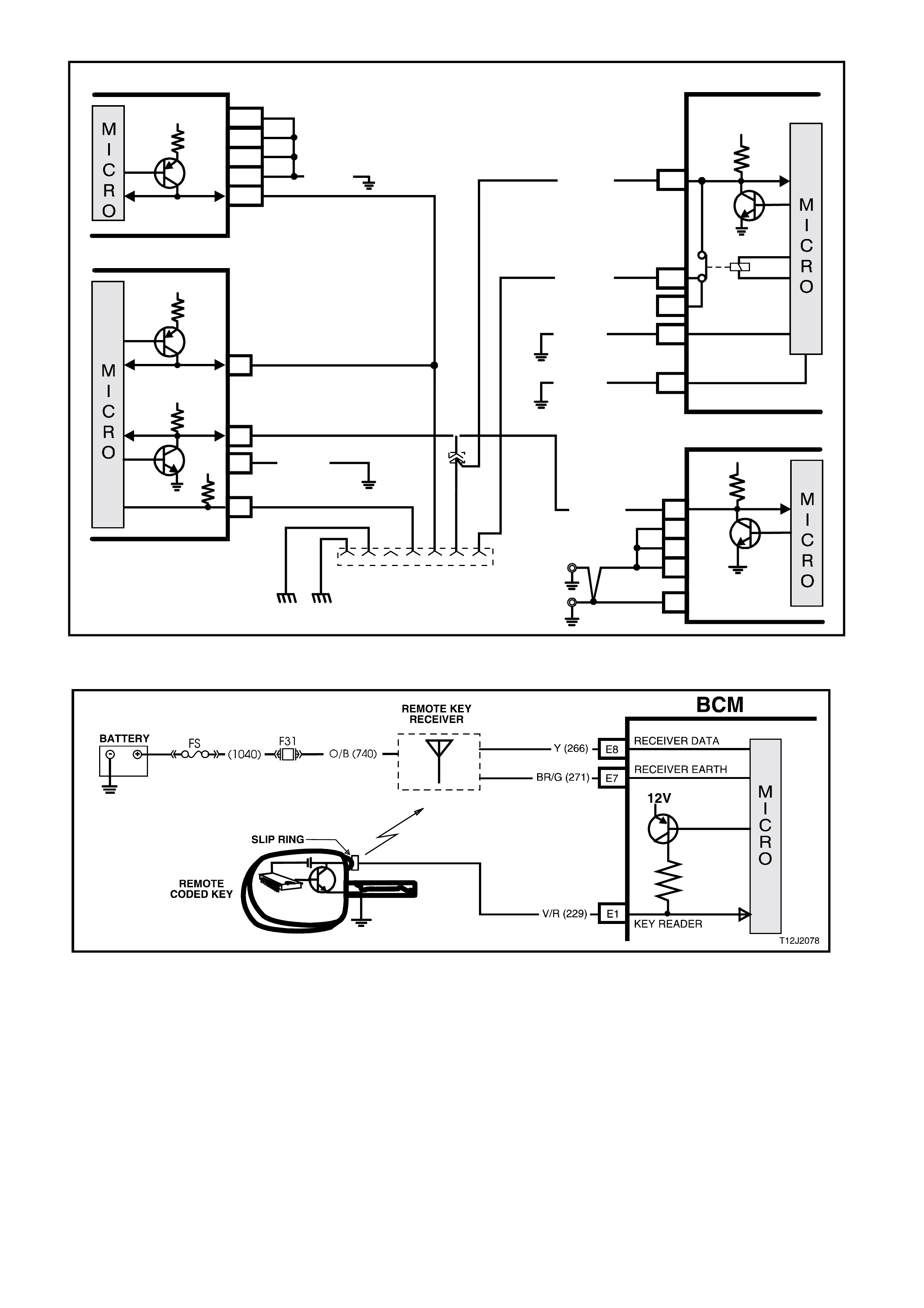
Figure 12J-2-12 Serial data circuit
Figure 12J-2-13 Remote coded key circuit
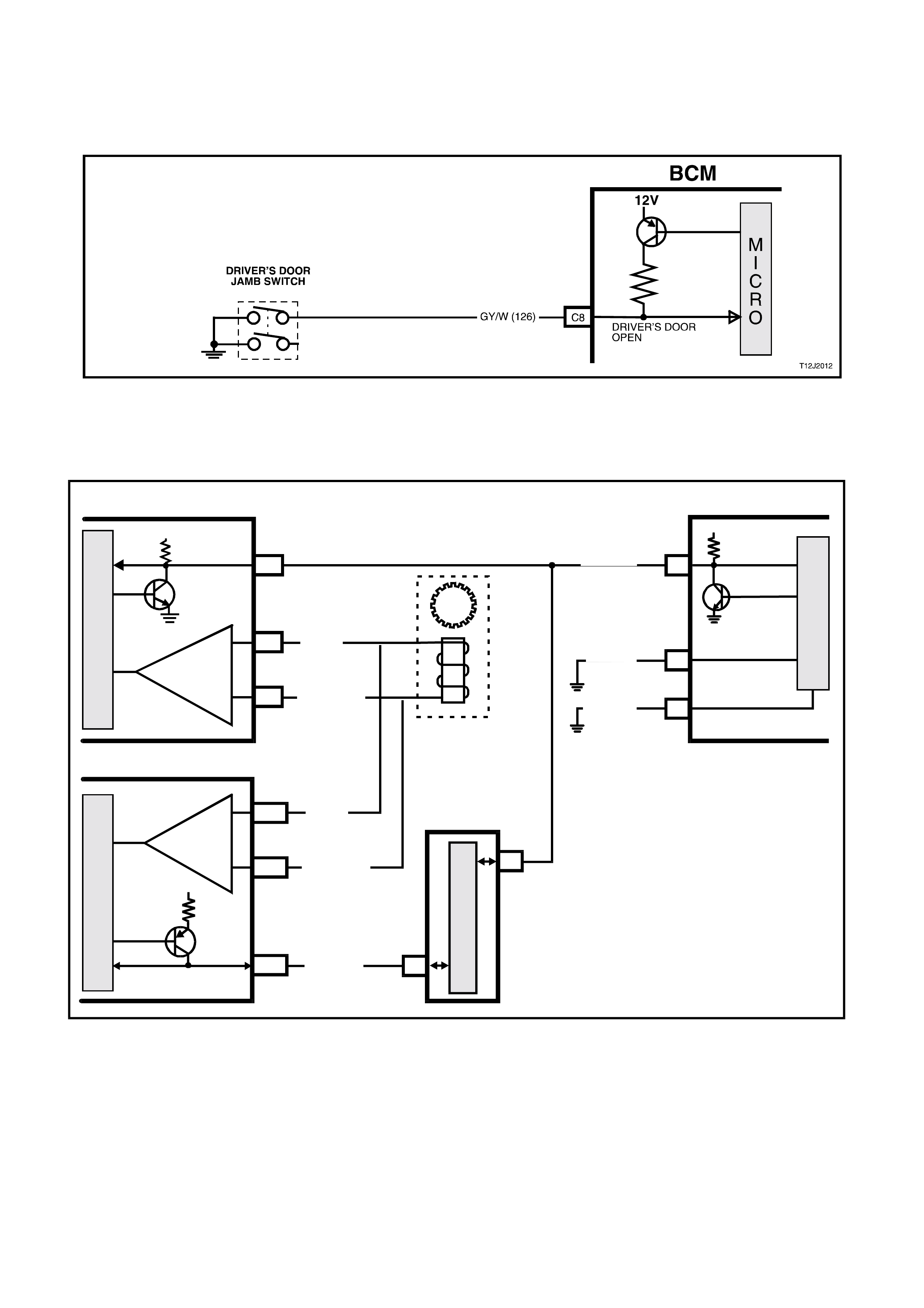
Driver's Door Jamb Switch (Refer to Fig. 12J-2-14)
The BCM uses this input signal to determine if the driver's front door is opened or closed. The BCM must sense that
the driver's door is closed before the theft deterrent system can be actively armed.
When the door is opened, the jamb switch earths terminal C8 via circuit 126 (Grey/White wire). This causes the
voltage at terminal C8 to be pulled low, less than 0.2 volt (driver's door open). This low voltage at terminal C8 is
seen by the BCM as the driver's door open input signal.
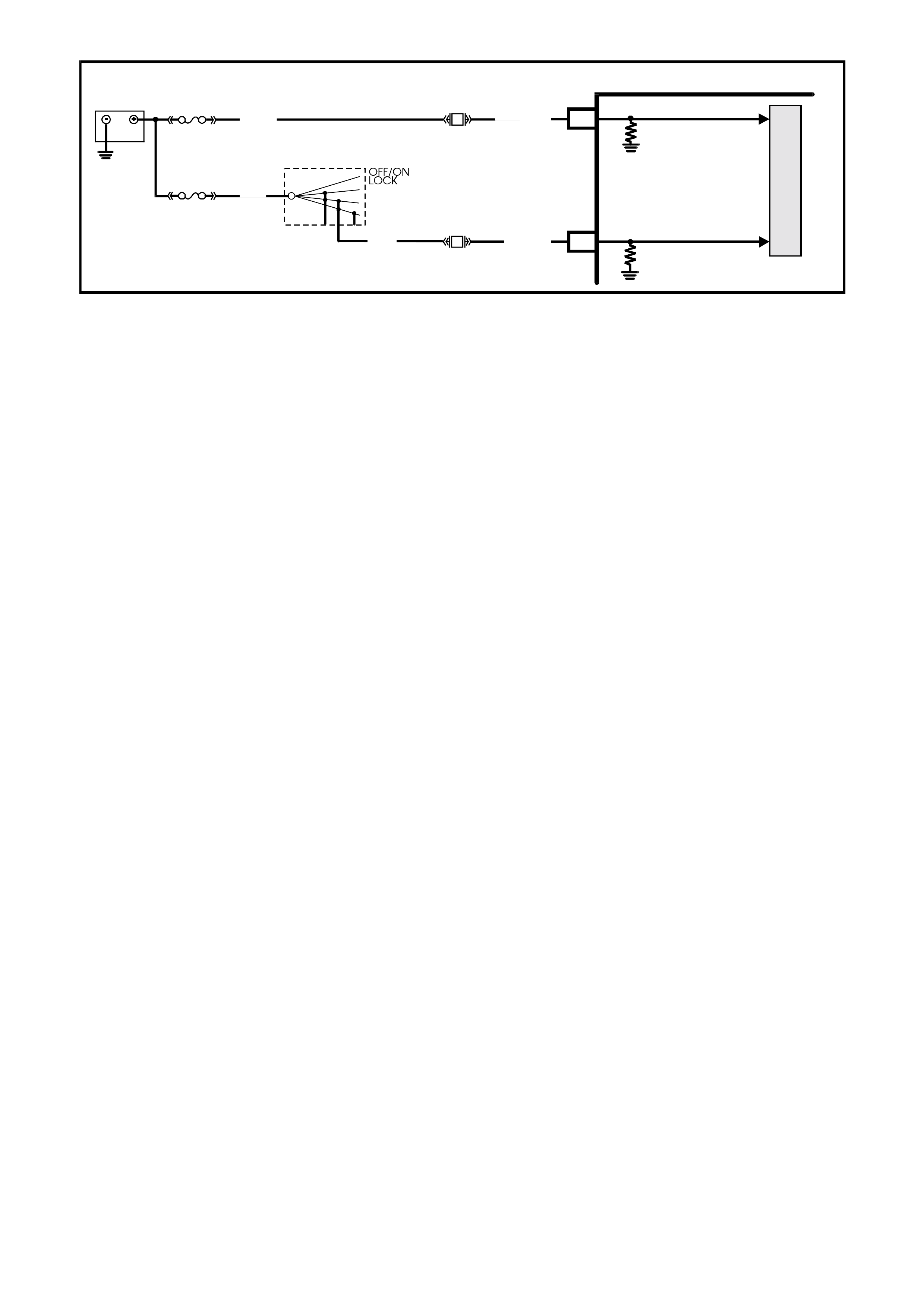
B/Y
(155)
B
(150)
LOC. E3
GEN III V8
YB128
642516 9 1
D ATA LINK
CONNECTOR
16
B/Y (155)
B/G (151)
LOC. E3
LOC. E3
R/B (1221)
G/W (1220)
B/R (750)
PIM
SERIAL
DATA
5V
7V
7V
12V
ELECTRONIC EARTH
HIGH CURRENT
EARTH
A1
B10
E2
E9
E3
SERIAL
DATA
MAIN
SERIAL
DATA AUX.
5V
6
11
7
DIAG. ENABLE
CLASS 2
SERIAL DATA
LOC. E5/E1 5
LOC. E5/E15
GEN III V8 PCM BCM
J1-58
J2-01
J2-40
J1-40
J1-01
CLASS II
SERIAL DATA
B/R (750)
T212J2026
R/B (1221)
LOC. E15
LOC. E5
V6 PCM
A3
B2
B1
A2
A1
SERIAL
DATA
5V
B/R
(750)
B/R
(750)
V
6
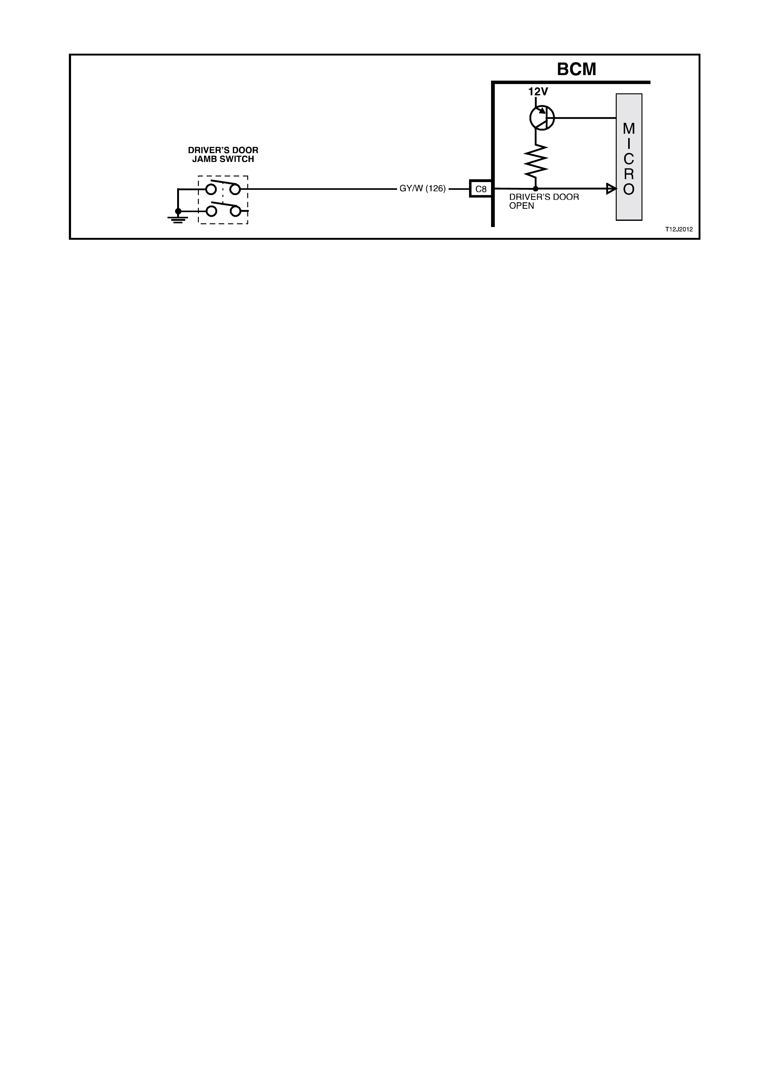
Figure 12J-2-14 Driver’s door jamb switch circuit
Outputs Refer to Fig. 12J-2-26
Left Hand Indicators
The BCM controls the operation of the left hand indicators by pulsing its internal indicator relay. This causes the
indicator relay contacts to close and open a number of times. This allows battery voltage from terminal B5 to be
applied internally to terminal B12, to the left hand indicator lamps via circuit 14 (Light Blue wire).
Right Hand Indicators
The BCM c ontrols the operation of the right hand indic ators in the s am e m anner as the lef t hand indicator s. Pulsing
of its internal indicator relay causes the indicator relay contacts to close and open a number of times. This allows
battery voltage from terminal B5 to be applied internally to terminal B4, to the right hand indicator lam ps via circuit
15 (Blue wire).
Theft Deterrent Alert Indicator LED
The theft deterrent alert indicator LED will continuously flash on and off whenever the system is armed. The BCM
controls the oper ation of the thef t deter rent aler t indicator LED by pulsing an internal switch on and off , which in tur n
switches the voltage applied to the theft deterrent alert indicator LED via terminal A6, circuit 263 (Light Blue wire).
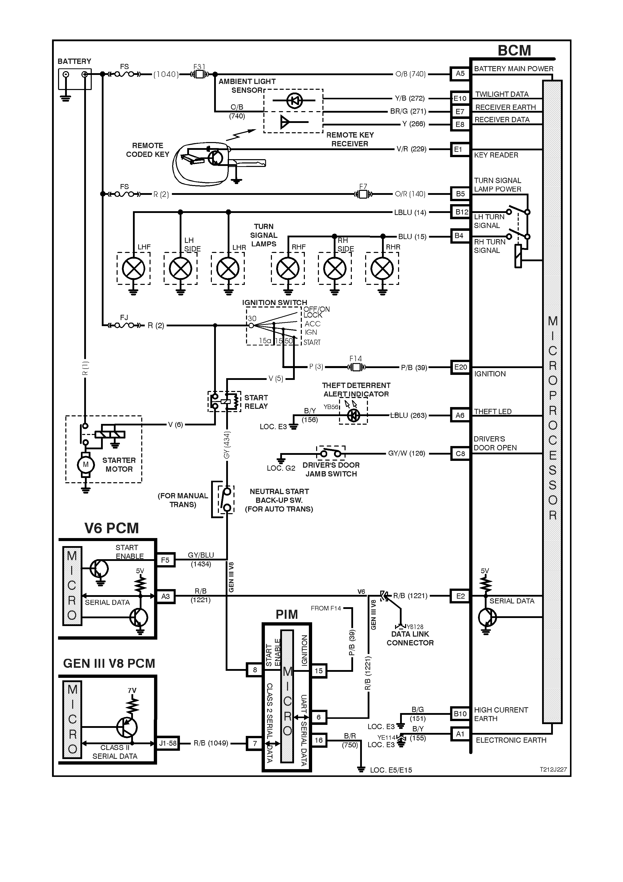
Figure 12J-2-15 Theft deterrent system circuit
1.5 ENTRY DETERRENT SYSTEM
GENERAL INFORMATION
On VT Series II Models, the entry deterrent system carries over from earlier VT Series Models, noting the following:
Comm unic ation between the PCM and the BCM on vehicles with GEN III V8 engines is via the Powertrain Interf ace
Module (PIM).
The rear compartment lock switch (boot release button) is disabled when the theft deterrent system is armed via the
remote code key, driver’s door microswitch, when deadlocked or when the vehicle is in battery saver mode.
The rear compartment lock switch is only enabled when the theft deterrent system is disarmed via the remote
coded key or remote key reader (valid security code).
If diagnosing a circuit fault with the entry deterrent system, reference to the wiring diagrams in
Section 12P WIRING DIAGRAMS of the VT Series II Service Information should be made.
For additional details, including General Description, Service Operations and Diagnosis of the entry deterrent
system that is not covered in this Section, refer to Sectio n 12J- 2 HIGH SERIES BODY CONTROL MO DULE of the
VT Series I Service Information.
SYSTEM OVERVIEW - ENTRY DETERRENT
BATTERY POWER
BCM
TURN SIGNAL POWER
IGNITION SWITCH ON
BONNET OPEN SWITCH HORN RELAY
LH TURN SIG NAL
RH TURN SIGNAL
BOOT SO LENOID D RIVE
THEFT DETERRENT LED
DOME LAMP
THEFT DETERRENT
HORN REL AY
BOOT LAMP SWITCH
KEY READ ER
DRIVER’S DOOR OPEN
PASSENGER’S DOOR OPEN
T212J2051
S ERIA L DATA
BOOT RELEASE
REMOTE RECEIVER
V EHI CLE SP EED
PCM
PIM
GEN III V8
ENGINE V6 & V6 S/C
ENGINE
1.6 POWER WINDOW SYSTEM
GENERAL INFORMATION
The BCM controls the following functions of the power window system:
1. Control of positive supply to all door window motors.
2. Automatic down of driver's door window (activated when the driver's power window switch DOWN button is
depressed for more than 0.4 seconds).
Once activated, the automatic down feature is cancelled within 100 ms (0.01 second) after:
a. The driver's power window switch UP button is depressed f ollowing which the window will move upward (if up
button is held) or:
b. The driver's power window switch DOW N button is depressed (the window will stop when the down button is
released).
3. With ignition on, power is supplied continuously to the window system.
4. W hen the ignition is switched off and no door has been opened, power is s upplied to the window system f or a
maximum of 60 minutes, provided the BCM has not entered battery saver mode. If battery saver mode is
active, power will be removed from the window system when the ignition is switched off.
5. In the event of any door being opened, power is supplied to the system for 45 s econds m aximum , tim ed from
when any door was opened. If during this period the power window switch is activated again, the 45 second
period will recommence from 0 seconds.
W hen the doors ar e remotely unlocked (by using the rem ote coded key), provided the vehicle is not in battery
saver m ode, power is s upplied to the system f or a 60 m inutes (If the vehicle is in battery saver m ode, power is
removed from the system). The delay is cancelled when the doors are locked by the remote coded key.
NOTE: The circuit diagr am s shown in this G eneral Desc ription Section ar e to aid in interpreting the oper ation of the
circuit and therefore, only the main connectors and wiring colours are shown. For complete circuit details, refer to
either the relevant diagnostic section or Section 12P WIRING DIAGRAMS of the VT Series II Service Information.
SYSTEM CHECK
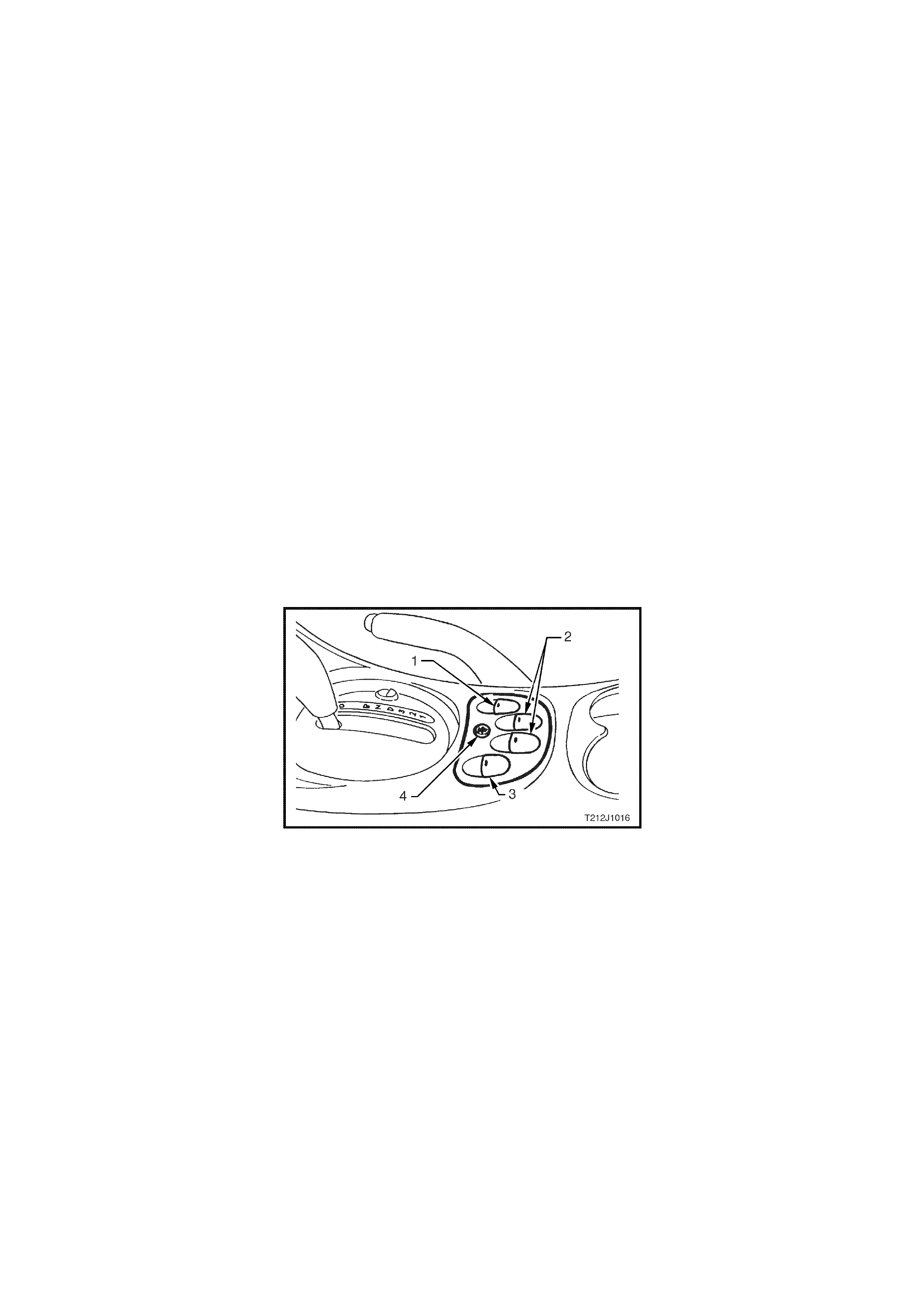
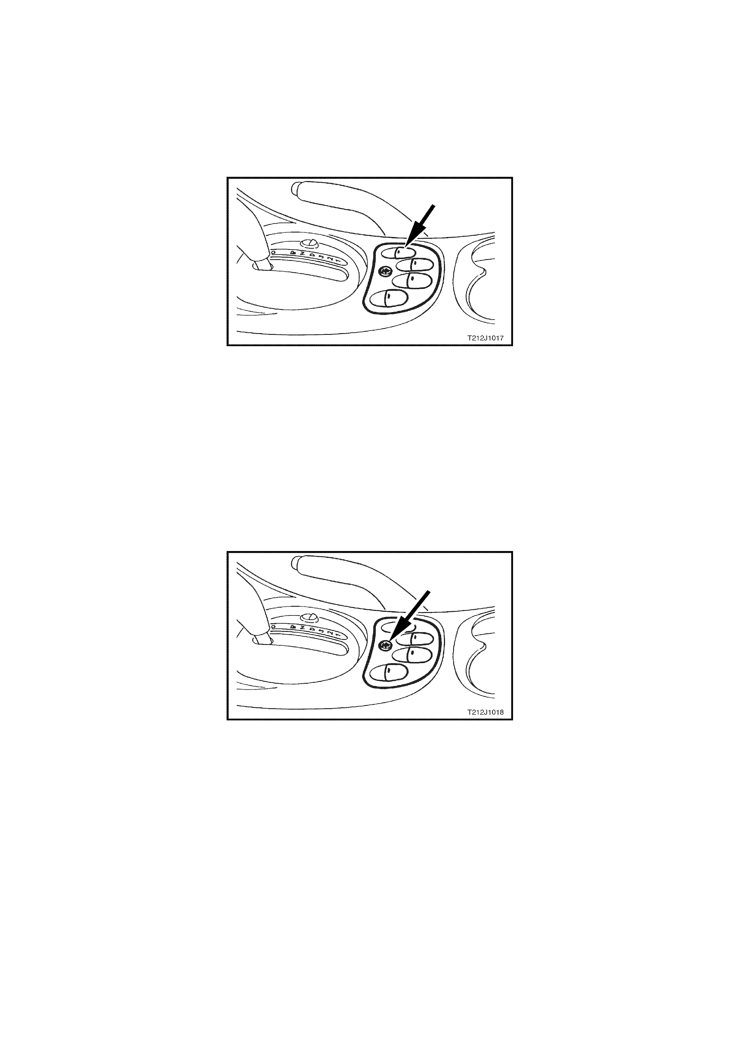
Figure 12J-2-16 Power w indow switch assembly
1. Drivers window switch.
2. Rear passenger window switches (left and
right hand).
3. Front passenger window switch.
4. Child safety switch.
Prerequisite Condition
The child safety switch must be switched OFF. This will be indicated by the green lights emitting diodes (LED) in
each of the rear door rocker switches being illuminated.
System Active
System active is indicated by the illumination of the lights in each of the rocker switches.
When the ignition switch is turned ON, all switches are active.
With the ignition switch turned OFF, all switches will remain active for 45 seconds after any door is opened.
With the ignition switch turned OFF, all switches will remain active for approximately 60 minutes, PROVIDED
THERE ARE NO OPEN DOORS.
System Inactive
Lights are not illuminated.
Automatic DOWN Operation of Driver’s Window
With the driver’s window in the fully UP position and the ignition switch turned to O N, pr ess the dr iver window switch
to the window DOWN position for more than 0.5 seconds and release.
The window will continue to lower automatically until the fully DOWN position is reached.
To interrupt this function, press the UP button momentarily.
Figure 12J-2-17 Driver’s power window switch
Child Safety Switch
W hen the child safety switch (override switch) is OFF, the rear windows can be opened or closed from the centre
console switch assembly or the rocker switches in each of the rear doors.
Check the operation of this feature, as per the following:
1. Switch ignition ON.
2. Check that the green LED in each of the rear door rocker switches is illuminated.
3. Open and close the rear door windows using the rocker switches in the rear doors.
4. Press the child saf ety switch button in the centre of the switch as sem bly in the console as shown in Fig. 12J- 2-
18.
5. Check that the green LED in each of the rear door rock er s witches extinguis hes and that the rear windows can
only be raised or lowered from the switch in the centre console.
Figure 12J-2-18 Child safety switch

SYSTEM OVERVIEW - POWER WINDOWS
BATTERY POWER
BCM
DRIVER’S WINDOW
DOWN SWITCH
IGNITION SWITCH ON
DRIVER’S WINDOW
MOTOR
T212J2001
POWER WINDOW
RELAY
DRIVER’S WINDOW
UP SWITCH
DRIVER’S DOOR
JAMB SWITCHES
PASSENGER DOO R
JAMB SWITCHES
REMOTE RECEIVER
WINDOW POWER
CIRCUIT OPERATION
A permanent magnet motor operates each of the power window mechanisms to raise or lower the window glass.
The direction in which the motor turns depends on the polarity of a voltage supplied to its terminals. The power
window switches, located in the centre console, or in the rear doors, control the polarity of the supply voltages.
The BCM has two main control functions in the power window system.
1. To control the operation of the power window relay and hence, power supply to the whole system.
2. To control the operation of the driver's side front window motor.
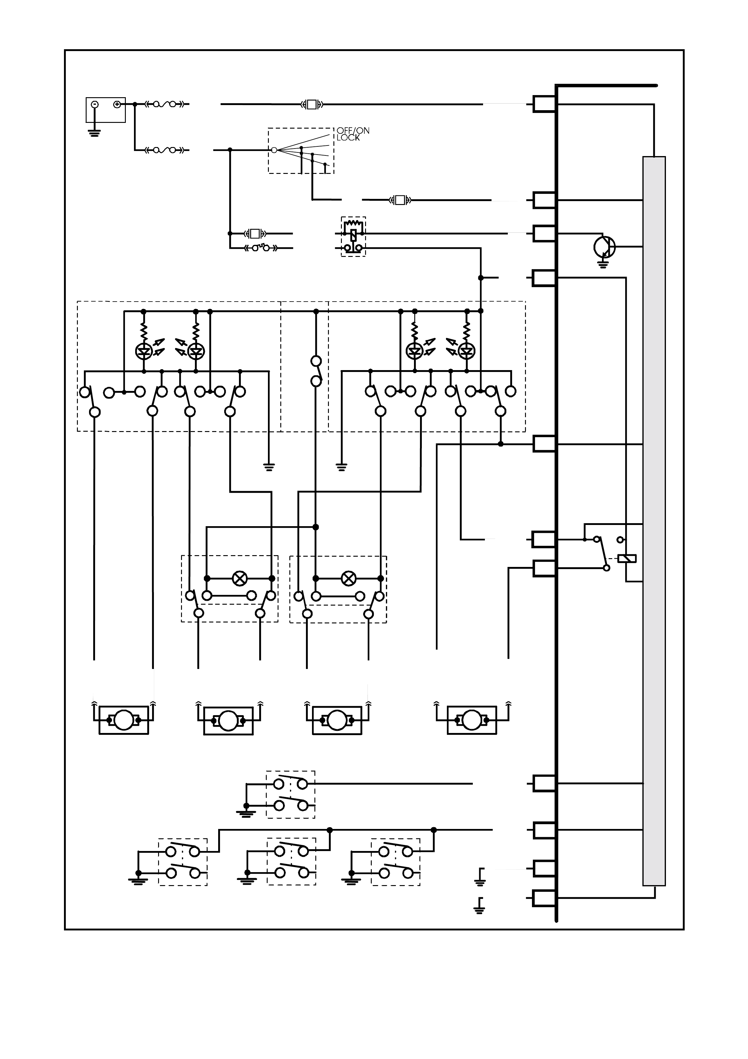
OPENING WINDOW - DRIVER'S DOOR (Refer to Figs. 12J-2-21 and 12J-2-22)
Ignition Switch ON Input Signal (Refer to Fig. 12J-2-19)
The BCM uses this input signal to determine when the ignition switch is in the IGN or START position. When the
ignition switch is in the IGN or ST ART pos ition, battery voltage is applied to the BCM term inal E20 f rom the ignition
switch and fuse F14 via circuit 39 (Pink/Black wire).
W hen the BCM receives an ignition ON input it energises the power windows relay (voltage supplied by fuse F20
circuit 440 Orange/Violet wire) by earthing the relay’s pull-in coil via circuit 173 (Yellow w ire) and BCM terminal B2.
With the relay coil energised, the relay contacts close and power via f usible link FJ and circuit br eak er F1 is applied
to the power window switches and each of the lights of the window switches (for rear door window switches, the
power window override switch in the front power window switch must be off). The opposite side of each light is
connected to earth, therefore the lights are illuminated (system active).
By depressing and releasing the driver's front window switch down button within 0.4 of a second (so as not to
engage the automatic down feature), this allows battery voltage from the power windows relay, circuit 1240
(Orange/Yellow wire), and the power window switch terminal 4, through to terminal 8 and then BCM terminal C14
(window down signal input), through the relay contacts and BCM term inal C2 to one side of the driver's s ide power
window motor on circuit 673 (Green/Orange wire).
The opposite side of the motor is connected to earth on circuit 672 Blue/White wire via power window switch
terminals 9 and 5 to circuit 156 (Black/Blue wire). This causes the motor armature to rotate, operating the window
regulator to lower the window.
As described under power windows general info rmation, the dr iver's window will automatically travel fully downward
provided the power window switch down button is depressed for more than 0.4 s econds. T he BCM micr oprocessor
senses the tim e the down button is depressed via term inal C14 and energises the internal relay so as to allow the
window to lower fully.
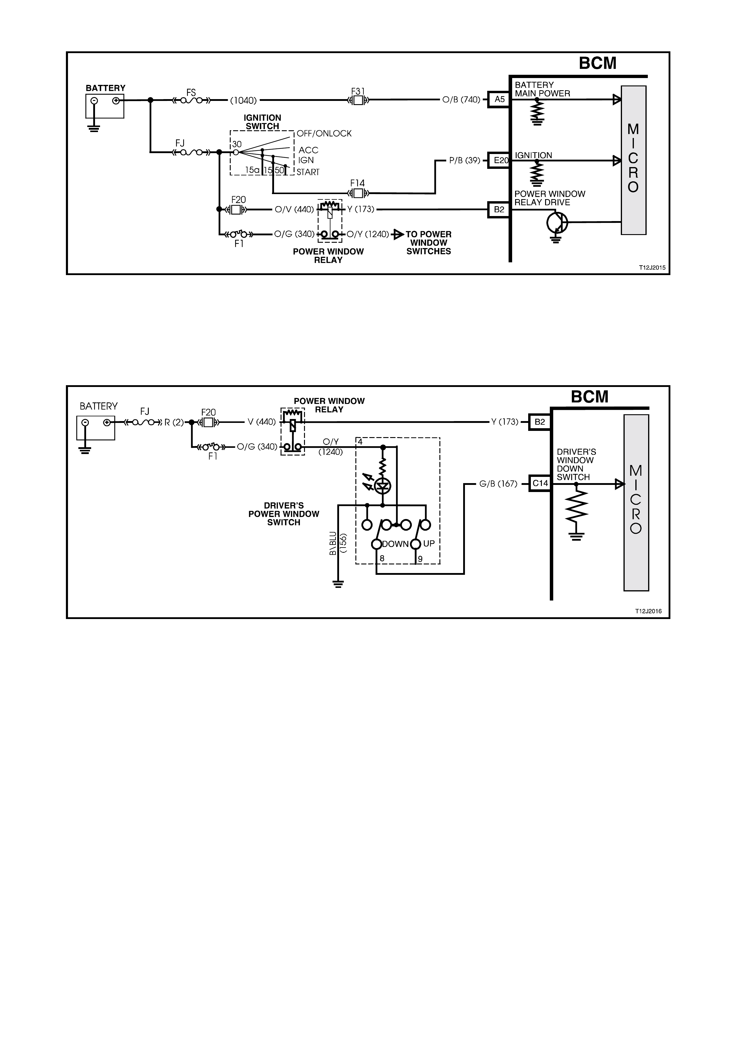
Figure 12J-2-19 Ignition switch on input signal
Driver's Front Window Down Switch Input Signal (REFER TO FIG. 12J-2-20)
W ith the driver's front window switch down button depressed, battery voltage from the power windows relay, circ uit
1240 Orange/Yellow wire, and the power window switch terminal 4, through to terminal 8 is applied to BCM ter minal
C14 (window down signal input).
Figure 12J-2-20 Driver’s front window down switch input circuit
W hen the BCM receives a driver's fr ont window down switch input signal it energis es an internal relay. This caus es
the relay contacts to changeover, allowing battery voltage from the power windows relay contacts, BCM terminal
C1, through the BCM internal relay contacts and BCM terminal C2 to one side of the driver's side power window
motor on circuit 673 (Green/Orange wire).
If the window is travelling downward and the down button is again depress ed, the BCM mic roprocess or senses this
(voltage again sensed at BCM term inal C14) and de-energises the internal relay, the contacts open and the m otor
stops.
Should the up button be mo mentarily depressed whilst the window is travelling downward, positive battery voltage is
applied to both sides of the motor armature and the motor stops. If the up button is continuously depressed whilst
the window is travelling downward, the window down function is cancelled. The window will then move upward as
described in the following text.

BATTERY
IGNITION SWITCH
FS
FJ
F31
A5
O/B (74 0)
(1040)
R (2)
F14
E20
B2
P/ B (39)
15a 15 50
30 ACC
IGN
START
F1
F20
O/V (440 )
O/G (340)
Y
(173)
P (3)
M
I
C
R
O
P
R
O
C
E
S
S
O
R
DRIVER'S
WINDOW
MOTOR
RHR WINDOW
MOTOR
LHR WINDOW
MOTOR
LHF W I NDOW
MOTOR
BATTERY MAIN POWER
LHF POWER
WIND OW SWIT CH DRIVER'S POWE R
WINDOW SWITCH
OVERRIDE
SWITCH
BCM
C14 WINDOW
EARTH
WINDOW
DOWN
C2
B/ G (151)
B10 HIGH CURRENT
EARTH
T212J2002
C1
IGNITION
POWER WINDOW
RELAY DRIVE
WINDOW
POWER
G/B (16 7 )
DRIVERS
WINDOW
UP SWITCH
113 325
UP DOWNDOWNUP
3
1
4
2
3
1
4
2
LHR
POWER
WINDOW
SWI T C H
RHR
POWER
WINDOW
SWITCH
BLU (671)
G (6 7 0 )
G (6 7 0 )
G (6 6 7 )
BLU (671)
BLU (666)
BLU/ W (672)
B/ BLU
(156)
B/ BLU
(156)
G/O (67 3 )
9
4
8
7
6
5
12 UPDOWN DOWN UP
C16
DRIVERS
WINDOW
DOWN
SWITCH
B/ Y (155)
ELECTRON IC EARTH
A1
W (125) C7
RHR DOOR
JAMB SWITCH LHF DO O R
JAMB SWITCH
LHR DOOR
JAMB SWITCH
PASS.
DOOR
SWITCH
DRIVER 'S DOOR
JAMB SWITCH
GY/W (126) C8 DRIVER'S
DOOR
OPEN
O/Y
(1240)
Figure 12J-2-21 Driver’s window manual down operation circuit

BATTERY
IGNITION SWITCH
FS
FJ
F31
A5
O/B (74 0)
(1040)
R (2)
F14
E20
B2
P/ B (39)
15a 15 50
30 ACC
IGN
START
F1
F20
O/V (440 )
O/G (340)
Y
(173)
P (3)
M
I
C
R
O
P
R
O
C
E
S
S
O
R
DRIVER'S
WINDOW
MOTOR
RHR WINDOW
MOTOR
LHR WINDOW
MOTOR
LHF W I NDOW
MOTOR
BATTERY MAIN POWER
LHF POWER
WIND OW SWIT CH DRIVER'S POWE R
WINDOW SWITCH
OVERRIDE
SWITCH
BCM
C14 WINDOW
EARTH
WINDOW
DOWN
C2
B/ G (151)
B10 HIGH CURRENT
EARTH
T212J2003
C1
IGNITION FUSE F10
POWER WINDOW
RELAY DRIVE
WINDOW
POWER
G/B (16 7 )
DRIVERS
WINDOW
UP SWITCH
113 325
UP DOWNDOWNUP
3
1
4
2
3
1
4
2
LHR
POWER
WINDOW
SWI T C H
RHR
POWER
WINDOW
SWITCH
BLU (671)
G (6 7 0 )
G (6 7 0 )
G (6 6 7 )
BLU (671)
BLU (666)
BLU/ W (672)
B/ BLU
(156)
B/ BLU
(156)
G/O (67 3 )
9
4
8
7
6
5
12 UPDOWN DOWN UP
C16
DRIVERS
WINDOW
DOWN
SWITCH
B/ Y (155)
ELECTRON IC EARTH
A1
W (125) C7
RHR DOOR
JAMB SWITCH LHF DO O R
JAMB SWITCH
LHR DOOR
JAMB SWITCH
PASS.
DOOR
SWITCH
DRIVER 'S DOOR
JAMB SWITCH
GY/W (126) C8 DRIVER'S
DOOR
OPEN
O/Y
(1240)
Figure 12J-2-22 Driver’s window automatic down operation circuit
CLOSING WINDOW (Refer to Fig. 12J-2-24)
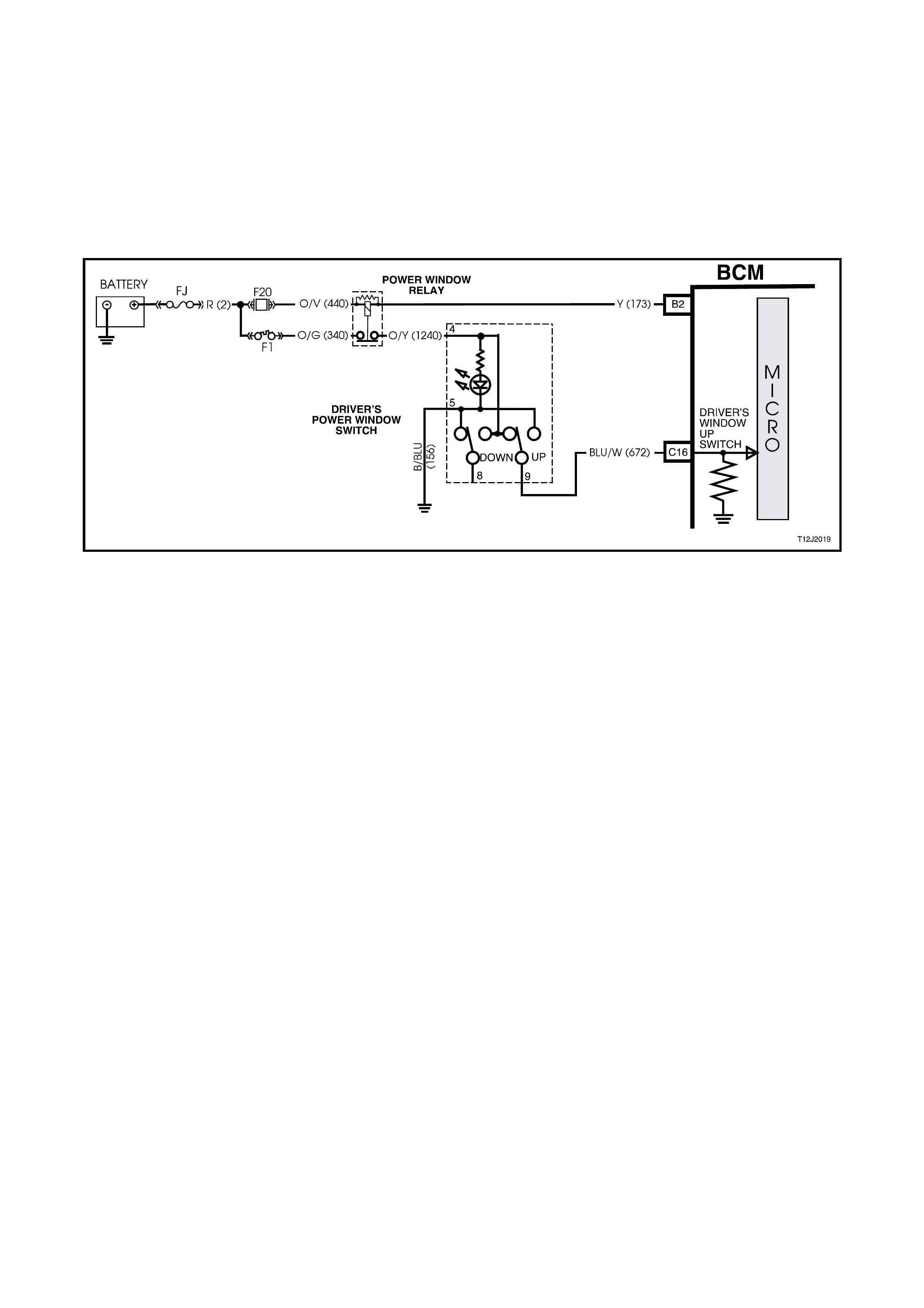
Driver's Front Window Up Switch Input Signal (REFER TO FIG. 12J-2-23)
By depressing and holding down driver's front window up button, battery voltage from the power windows relay
circuit 1240 (Orange/Yellow wire) is applied, via power window switch terminals 4 and 9, to the driver's side power
window motor circuit 672 (Blue/White wire).
The oppos ite side to the m otor cir cuit 673 (Gr een/Orange wire) is connected to ear th via BCM term inal C2, thr ough
the BCM internal relay contacts, BCM terminal C14 to switch terminals 8 and 5 to earth circuit 156 (Black/Blue wire).
This causes the m otor arm ature to rotate, operating the window regulator to raise the window as long as the power
window switch up button is depressed.
Figure 12J-2-23 Driver’s front window up switch input signal circuit
Window Operation - Passenger Doors
Power is supplied to all the power window switches fr om the power window relay (to the rear door switches pr ovided
the power window override switch is off). If the power window override switch is on, (contacts between terminals 4
and 12 are open) the power supply to the rear door power window switches is interrupted.
With the switch buttons at rest, all switch contacts are connected to earth circuit 156 (Black/Blue wire). By
depressing the appropr iate passenger's window switch down or up button, battery voltage from the power windows
relay, is applied to one side of the window m otor, via the depres sed switch c ontact. With the other s ide of the m otor
connected to earth, the motor armature will rotate, operating the window regulator to raise or lower the window as
long as the window switch button is depressed.
BATTERY
IGNITION SWITCH
FS
FJ
F31
A5
O/B (74 0)
(1040)
R (2)
F14
E20
B2
P/ B (39)
15a 15 50
30 ACC
IGN
START
F1
F20
O/V (440 )
O/G (340)
Y
(173)
P (3)
M
I
C
R
O
P
R
O
C
E
S
S
O
R
DRIVER'S
WINDOW
MOTOR
RHR WINDOW
MOTOR
LHR WINDOW
MOTOR
LHF W I NDOW
MOTOR
BATTERY MAIN POWER
LHF POWER
WIND OW SWIT CH DRIVER'S POWE R
WINDOW SWITCH
OVERRIDE
SWITCH
BCM
C14 WINDOW
EARTH
WINDOW
DOWN
C2
B/ G (151)
B10 HIGH CURRENT
EARTH
T212J2004
C1
IGNITION
POWER WINDOW
RELAY DRIVE
WINDOW
POWER
G/B (16 7 )
DRIVERS
WINDOW
UP SWITCH
113 325
UP DOWNDOWNUP
3
1
4
2
3
1
4
2
LHR
POWER
WINDOW
SWI T C H
RHR
POWER
WINDOW
SWITCH
BLU (671)
G (6 7 0 )
G (6 7 0 )
G (6 6 7 )
BLU (671)
BLU (666)
BLU/ W (672)
B/ BLU
(156)
B/ BLU
(156)
G/O (67 3 )
9
4
8
7
6
5
12 UPDOWN DOWN UP
C16
DRIVERS
WINDOW
DOWN
SWITCH
B/ Y (155)
ELECTRON IC EARTH
A1
W (125) C7
RHR DOOR
JAMB SWITCH LHF DO O R
JAMB SWITCH
LHR DOOR
JAMB SWITCH
PASS.
DOOR
SWITCH
DRIVER 'S DOOR
JAMB SWITCH
GY/W (126) C8 DRIVER'S
DOOR
OPEN
O/Y
(1240)
Figure 12J-2-24 Driver’s window manual up operation circuit

1.7 ENGINE COOLING FAN LOW SPEED CONTROL
GENERAL INFORMATION (Refer to Figs. 12J-2-25, 12J-2-26 and 12J-2-27)
VT Series II Models with V6 engines have two single speed electr ic engine cooling fans; a low speed f an and a high
speed fan. All other VT Series Models, r egardless of the engine c onfiguration (including G EN III V8), are equipped
with two, two speed electric cooling fans.
The engine cooling fan assemblies provide the primary means of moving air through the engine radiator. These
fans are placed between the radiator and the engine and have their own shroud. These fans configurations are
used on all vehicles even if not equipped with air conditioning. There is no fan in front of the A/C condenser.
The electric engine cooling fans are used to cool engine coolant flowing through the radiator, and if fitted, refrigerant
flowing through the A/C condenser.
On vehicles with V6 engines, the engine cooling fan m otors have two term inals ; one positive and one negative. T he
positive terminals are permanently connected to battery voltage. When the negative terminal is connected to
earthed through the low speed cooling fan relay, the low speed cooling fan will operate. When the negative term inal
is connected to earth via the high speed cooling fan relay, both cooling fans will operate.
On vehicles with either V6 supercharged or GEN III V8 engines , the engine cooling fan m otors have f our term inals,
two negative and two positive terminals. The two positive terminals are permanently connected to battery voltage.
When one of the negative terminals is earthed, both cooling fan motors will operate at low speed. When both
negative terminals are earthed, both cooling fans will operate at high speed.
Regardless of the engine configuration, the low speed cooling f an operation is enabled when the low speed engine
cooling fan micr o r elay (located in the engine com par tment relay housing, labelled Lo Fan) is ener gis ed by the Body
Control Module (BCM) via a request from the Powertrain Control Module (PCM). The PCM will request low speed
fan enable and disable via serial data communication to the BCM on circuit 1221 (Red/Black wire). After the PCM
requests a change in the state of the low speed relay (i.e. OFF to ON or ON to OFF), the BCM will send a serial
data response message back to the PCM confirming it received the message.
NOTE: On vehicles with GEN III V8 engines, serial data communication between the PCM and BCM is via the
Powertrain Interface Module (PIM).
The PCM determ ines when to enable the low speed fan relay based on inputs from the A/C reques t signal, Cooling
Temperature Sensor (CTS) and the Vehicle Speed Sensor (VSS).
For information regarding the engine cooling fan high speed control, refer to either Section 2A HEATING & AIR
CONDITIONING - DESCRIPTION & OPERATION, or, depending on the engine variation,
Section 6C1 POWERTRAIN MANAGEMENT - V6 ENGINE of the VT Series I Service Information
Section 6C3 POWERTRAIN MANAGEMENT - GEN III V8 ENGINE of the VT Series II Service Information.
NOTE: The circuit diagr am s shown in this G eneral Desc ription Section ar e to aid in interpreting the oper ation of the
circuit and therefore, only the main connectors and wiring colours are shown. For complete circuit details, refer to
either the relevant diagnostic section or Section 12P WIRING DIAGRAMS of the VT Series II Service Information.
SYSTEM OVERVIEW - ENGINE COOLING FAN, LOW SPEED CONTROL
BATTERY POWER
BCM
PCM
ENGINE COOLING FAN
LOW SPEED RELAY
T212J2052
VEHICLE SPEED
ENGINE COOLANT
TEMPERATURE
A/C REQUEST
PIM
GEN III V8
EN G INE
V6 & V6 S/C
ENG INE
S
E
R
I
A
L
D
A
T
A
Figure 12J-2-25 Main serial data communication circuit

CIRCUIT OPERATION
V6 ENGINE (refer Fig. 12J-2-26)
The engine cooling low speed fan relay is energised by the BCM earthing terminal B7, circuit 473 (Orange/Brown
wire). This causes the relay contacts to switch over from 30-87A to 30-87 and circuit 157 (Black/Pink wire) is
earthed through the relay and to the low speed fan terminal on circuit 533 (Blue/Yellow wire). Battery voltage is
supplied to the other low speed fan terminal via circuit 208 (Yellow wire).
V6 SUPERCHARGED & GEN III V8 ENGINES (refer Fig. 12J-2-27)
The engine cooling low speed fan relay is energised by the BCM earthing terminal B7, circuit 473 (Orange/Brown
wire). This causes the relay contacts to switch over from 30-87A to 30-87 and circuit 157 (Black/Pink wire) is
earthed through the relay and to the low speed fan term inal on circuit 533 (Blue/Yellow wire). T he other low speed
fan terminal is connected to battery voltage via circuit 204 (Orange wire).
LOW SPEED FAN OPERATION
The low speed cooling fan relay will be turned ON when:
•Air conditioning request indicated (YES) and the vehicle speed is less than 30 km/h or
•Air conditioning pressure is greater than 1500 kPa or
•Coolant temperature is greater than 104°C (V6 and V6 supercharged) / 98°C (GEN III V8) or
•Vehicles with V6 and V6 supercharged engines; an engine coolant temperature sensor failure is detected by
the PCM, refer to Section 6C1 POWERTRAIN MANAGEMENT - V6 ENGINE for additional information.
Vehicles with GEN III V8 engines; when a coolant tem perature sens or failure in conjunction with an Intake Air
Temperature (IAT) sensor failure is detected by the PCM, refer to Section 6C3 POWERTRAIN
MANAGEMENT - GEN III V8 ENGINE for additional information.
•When the ignition switch is turned from ON to OFF and the engine coolant temperature is above 117°C (V6
and V6 superchar ged) / 113°C (GEN III V8). T he BCM will continue to energise the low speed engine cooling
fan micro relay for four minutes.
The PCM will request the BCM to switch off the low speed cooling fan relay when the following conditions have
been met:
•Air conditioning request not indicated (NO) and the coolant temperature is less than 99°C (V6 and V6
supercharged) / 95°C (GEN III V8) or
•Air conditioning reques t indic ated (YES) with press ure les s than 1170 kPa, vehic le speed gr eater than 50 km /h
and coolant temperature less than 99°C (V6 and V6 supercharged) / 98°C (GEN III V8).
NOTE: On vehicles with GEN III V8 engines, the low speed cooling fan run on time has a minimum default
value of 30 seconds.
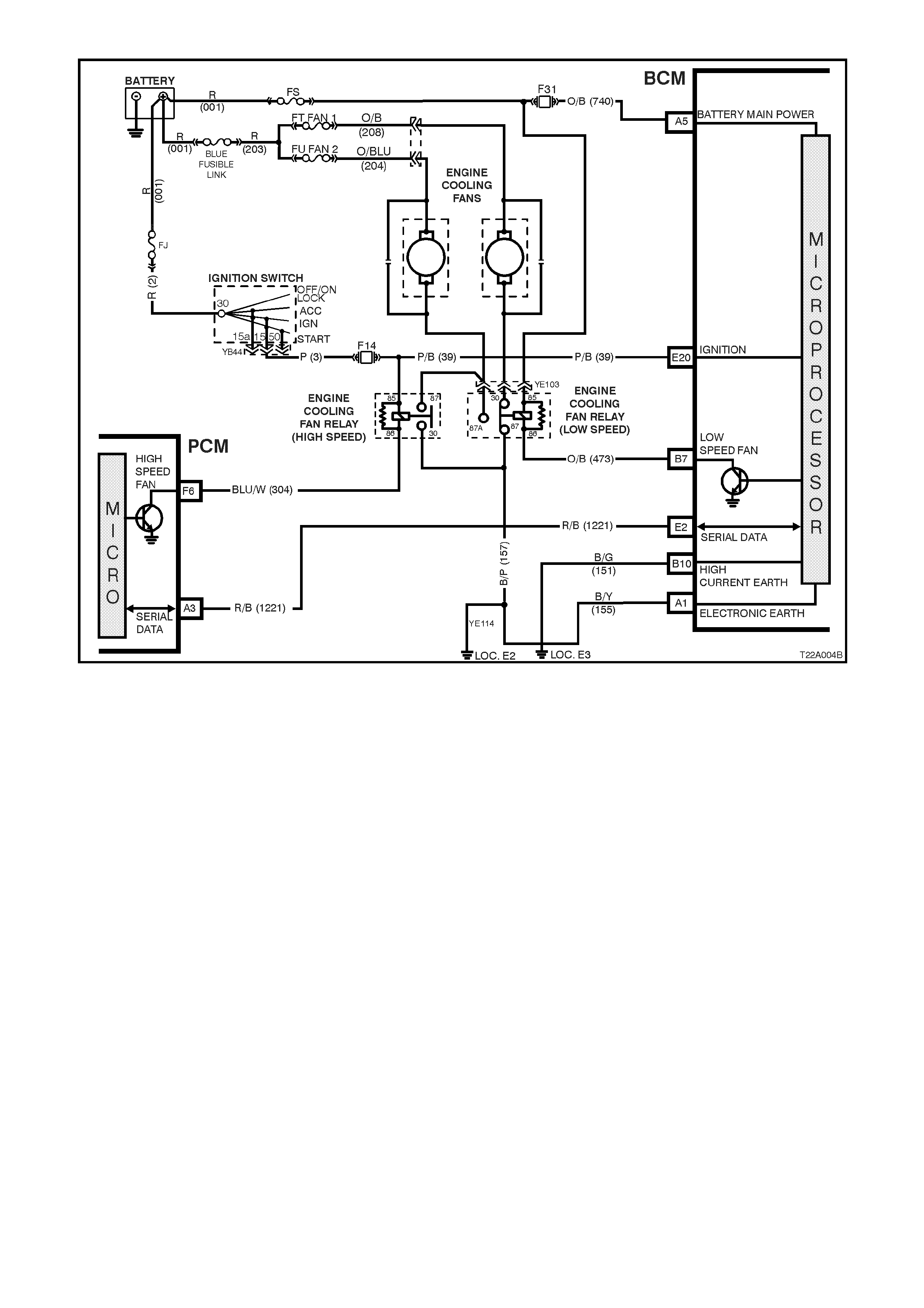
Figure 12J-2-26 V6 engine - cooling fan low speed control
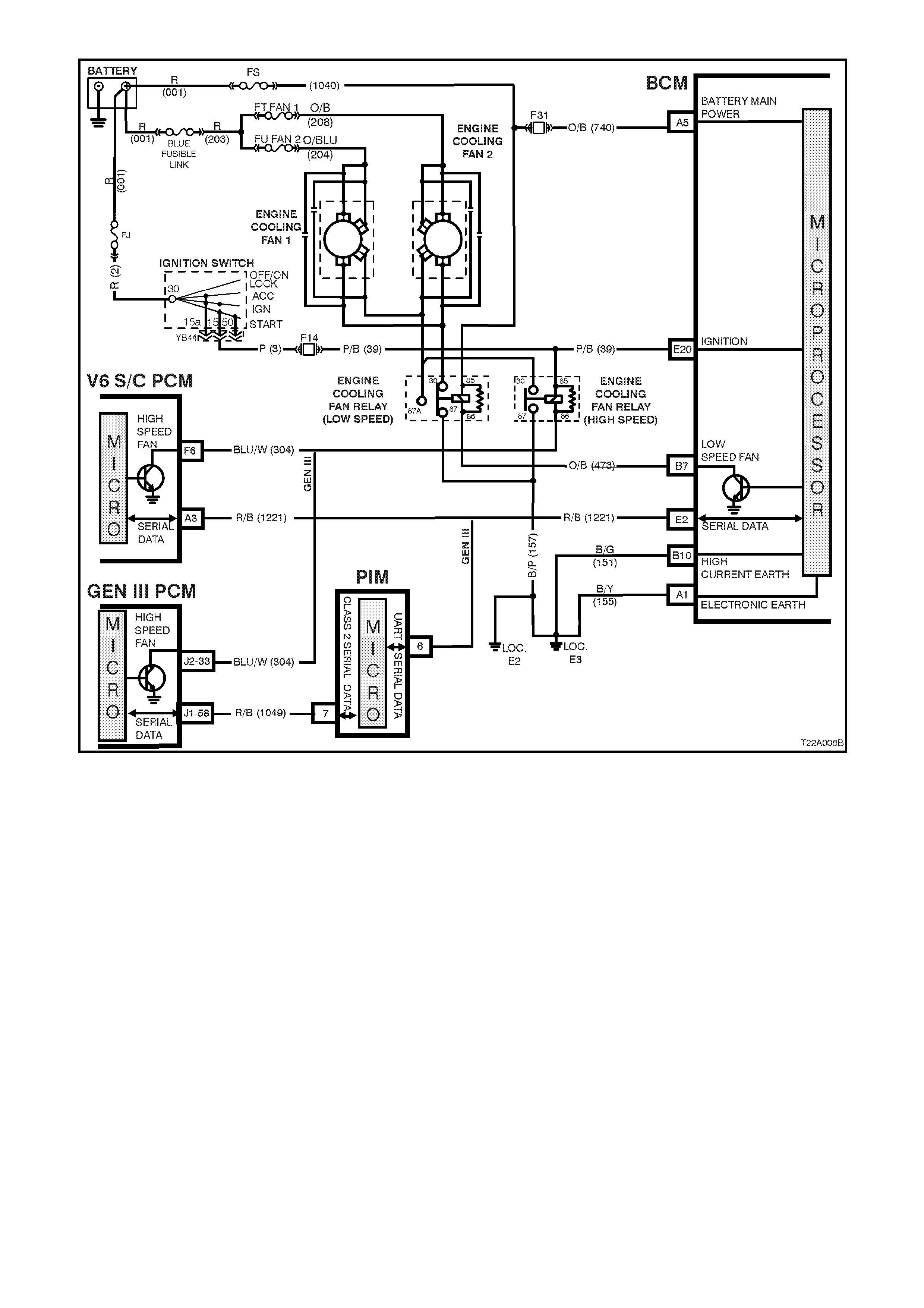
Figure 12J-2-27 V6 supercharged and GEN III engine - cooling fan low speed control

1.8 AUTOMATIC LIGHTS OFF (WITHOUT TWILIGHT SENTINEL)
GENERAL INFORMATION
The autom atic light control (lights off ) feature is designed to automatic ally switch the headlam ps and park ing lam ps
off when the driver leaves the vehicle.
NOTE: Sinc e this system is safety related, it is m andatory that in the event of a s ystem failure, the def ault status of
the BCM light control outputs ar e in the ON s tate when the ignition switch is in the IGN pos ition. T his will give dir ect
control of the lights to the headlamp switch.
The sequence of events required to switch the lights off automatically are as follows:
1. The vehicle road speed input to the BCM indicates speed is les s than 10 k ilometr es per hour and there has not
been a sudden loss of speed (ignition being switched off with the vehicle travelling above 10 km/h).
2. The BCM senses that the ignition switch is turned from ON to OFF and remains in the off position.
3. The headlamp switch has not been turned on after the ignition switch was turned off.
4. The BCM senses the driver's door has been opened or that it is already open.
W hen the ignition switch is turned back to IGN position, the lights will turn back on to the position selected by the
headlamp switch and the mode of headlamps operation (ie. high or low beam or fog lam ps [if fitted]) determ ined by
the position of the relevant switches.
Turning the headlamp switch off deactivates the automatic lights system.
There is a delay period before the automatic lights off featur e deactivates the vehic le lights. T his tim e period c an be
set by the driver using the following procedure.
1. Turn ignition switch to the IGN position, switch parking lamps on and close the driver's door.
2. Hold the headlamp switch instrument cluster illumination switch control lever in the down position continuously.
3. Turn the ignition switch to the ACC position.
4. Open the driver's door.
This initiates the start of the time delay period.
5. Wait the required delay time period and release the illumination switch control lever.
6. Turn the ignition switch to the OFF position
This sets the time delay period and switches off the parking lamps.
The delay period adjustment is only possible whilst road speed input to the BCM is zero. A maximum of 180
seconds applies to the time delay period and the default setting is 0 seconds. The time delay period resets to
default value whenever the battery or fuse F31 is disconnected from the vehicle.
This time delay is also dependent on the priority key system . The tim e delay period can be set f or the priority 1
and priority 2 keys. The time delay is recalled when the unlock button on the remote is pressed and is
dependent on whether priority 1 or priority 2 key is used.
NOTE: The circuit diagr am s shown in this G eneral Desc ription Section ar e to aid in interpreting the oper ation of the
circuit and theref ore, only the m ain connectors and wiring colours ar e shown. For com plete circuits details, refer to
either the relevant diagnostic section or Section 12P WIRING DIAGRAMS of the VT Series II Service Information.
SYSTEM OVERVIEW - AUTOMATIC LIGHTS OFF
BCM
BATTERY POWER
IGNITION SWITCH ON
INST RUM ENT D I MMI NG /
PARK LAMP SWITCH
DRIVER’S DOOR JAMB SW ITCH
T212J2053
HEADLAMP RELAY
PARKING LAMP RELAY
SERIAL DATA
VEHICLE SPEED
PCM
PIM
GEN III V8
ENGINE V6 & V6 S/C
ENGINE
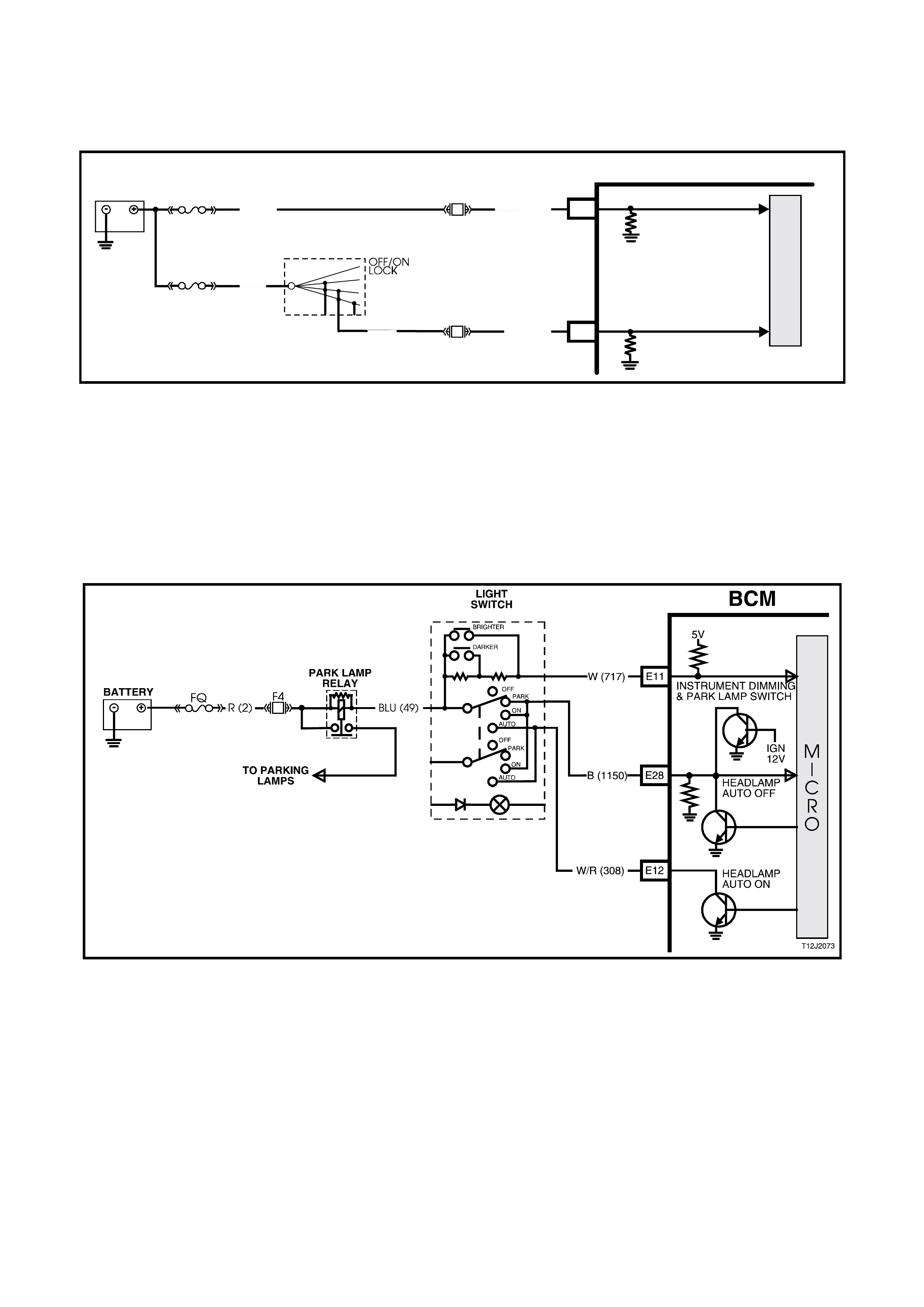
CIRCUIT OPERATION
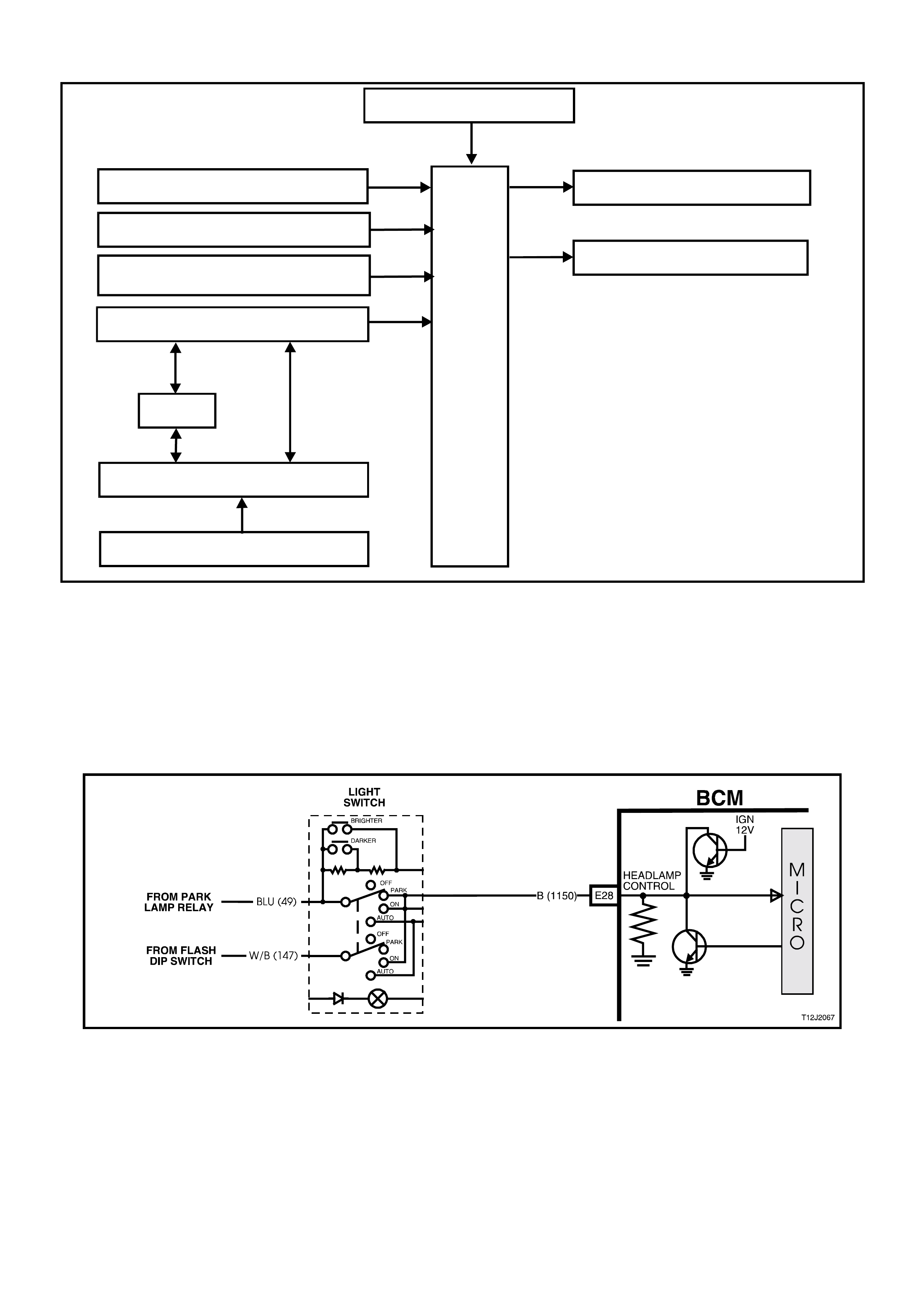
Headlamp Control Input Signal (Refer to Fig. 12J-2-28)
The BCM m onitor s the voltage on term inal E28 to determine the pos ition of the headlam p and park ing lam p switch.
W hen the headlam ps or parking lam p are on, the voltage at BCM term inal E28 will be less than 0.2 volt. W hen the
automatic headlamps OFF system has turned the lights off, the voltage at terminal E28 will be 12 volts. If the
headlamp s witch is turned of f, the voltage at term inal E28 will be less than 0.2 volt. T he BCM s ees this low voltage
at terminal E28 as a change in status of the headlamp switch and will turn the automatic lights system off. The lights
will then turn back on when a change in position of the switch occurs.
Figure 12J-2-28 Headlamp control input signal
Driver’s Door Open Input Signal (Refer to Fig. 12J-2-29)
W hen the dr iver’s door is opened, BCM ter minal C8 is connected to earth via circuit 126 (G rey/White wire) and the
driver's door jamb switch. This causes the voltage at terminal C8 to pulled low, less than 0.2 volt (driver's door
open). This low voltage at terminal C8 is seen by the BCM as the driver's door open input signal.
Figure 12J-2-29 Driver’s door open input signal
Vehicle Speed Signal (Refer to Fig. 12J-2-30)
The BCM, terminal E2, receives vehicle speed information from the PCM/PIM via the serial communications bus,
circuit 1221 (Red/Black wire).
Figure 12J-2-30 Vehicle speed signal
BCM
R/B (1221) E2 SERIAL DATA
5V
B/G (151)
B10
B/Y (151)
A1
HIGH
CURRENT EARTH
T212J2038
ELECTRONIC EARTH
M
I
C
R
O
BLU/W (831)
BLU/W (831)
T (832)
V6
GEN III
GEN III
V6
T (832)
INTEGRATED
CIRCUIT
INTEGRATED
CIRCUIT
M
I
C
R
O
M
I
C
R
O
V6 PCM
GEN III V8 PCM
SERIAL DATA
5V
A3
C6
D5
VEHICLE
SPEED
SENSOR
R/B (1049)J1-58
J2-21
J2-20
CLASS II
SERIAL DATA
7V
PIM
6
7
M
I
C
R
O
CLASS 2 SERIAL DATA
UART SERIAL DATA
Ignition Switch ON Input Signal (Refer to Fig. 12J-2-31)
The BCM uses this input signal to determine when the ignition switch is in the IGN or START position. W hen the
ignition switch is in the IGN or START position, battery voltage is applied to the BCM terminal E20 f rom the ignition
switch and fuse F14 via circuit 39 (Pink/Black wire).
M
I
C
R
O
BCM
T212J2013
BATTERY
FS
F31
A5
O/B (740 )
(1040)
BAT T ERY MAIN POWER
FJ
R ( 2)
F14
E20
P/ B (39)
IGNITION ON
15a 1550
30 ACC
IGN
START
IGNITION
SWITCH
P (3)
Figure 12J-2-31 Ignition switch on input signal
Instrument Illumination Dimmer Switch Input (Refer To Fig. 12J-2-32)
W hen the illumination switch lever is in the down position (DIM-), BCM terminal E11 is connected to earth via the
headlamp s witch and the 2.7 kilohm resistor in the switch as sembly. This causes the voltage at BCM terminal E11
to go from above 5 volts to approximately 1.3 volts. This voltage at BCM terminal E11 is seen by the BCM as the
input signal that determines the delay period for the automatic lights off feature for the period that the voltage is
present.
NOTE: This circuit will only work while the headlamp switch is in the PARK or ON positions and the ignition switch is
in the ACC or IGN positions.
Figure 12J-2-32 Instrument illumination dimming switch input

Power Supplies (Refer to Fig. 12J-2-33)
Battery voltage is applied to the low, high beam and fog lamps (if fitted) relays from fusible link FQ, circuit 2 (Red
wire) and fuses F30 and F29.
Battery voltage is applied to the parking lamps re lay from f us ible link FQ c irc uit 2 ( Red wire) and f us e F 4, cir cuit 840
(Orange/White wire).
The BCM controls the operation of the exterior light circuits by enabling its internal control circuit, which provides the
earth circuit for the relays.
High Beam Relay Earth Circuit (Refer to Fig. 12J-2-33)
The earth circuit for the high beam headlamp relay is via circuit 10, (Blue/Yellow wire), through the headlamp and
turn signal control (flash/dip) switch assembly, circuit 147 (White/Black wire), headlamp switch contacts to BCM
terminal E28, circuit 1150 (Black wire) and then to earth through internal switching.
Low Beam Relay Earth Circuit (Refer to Fig. 12J-2-33)
The earth circuit for the low beam headlamp relay is via 103 (White wire), through the headlamp and turn signal
control (f lash/dip) switch ass em bly, circuit 147 (White/Black wire), headlam p switch contrac ts to BCM term inal E28,
circuit 1150 (Black wire) and then to earth through internal switching.
Parking Lamps Relay Earth Circuit (Refer to Fig. 12J-2-33)
The earth circuit for the parking lamps relay is via the closed parking lamps contacts in the headlamp switch,
through BCM terminal E28, circuit 1150 (Black wire) and then to earth through internal switching.
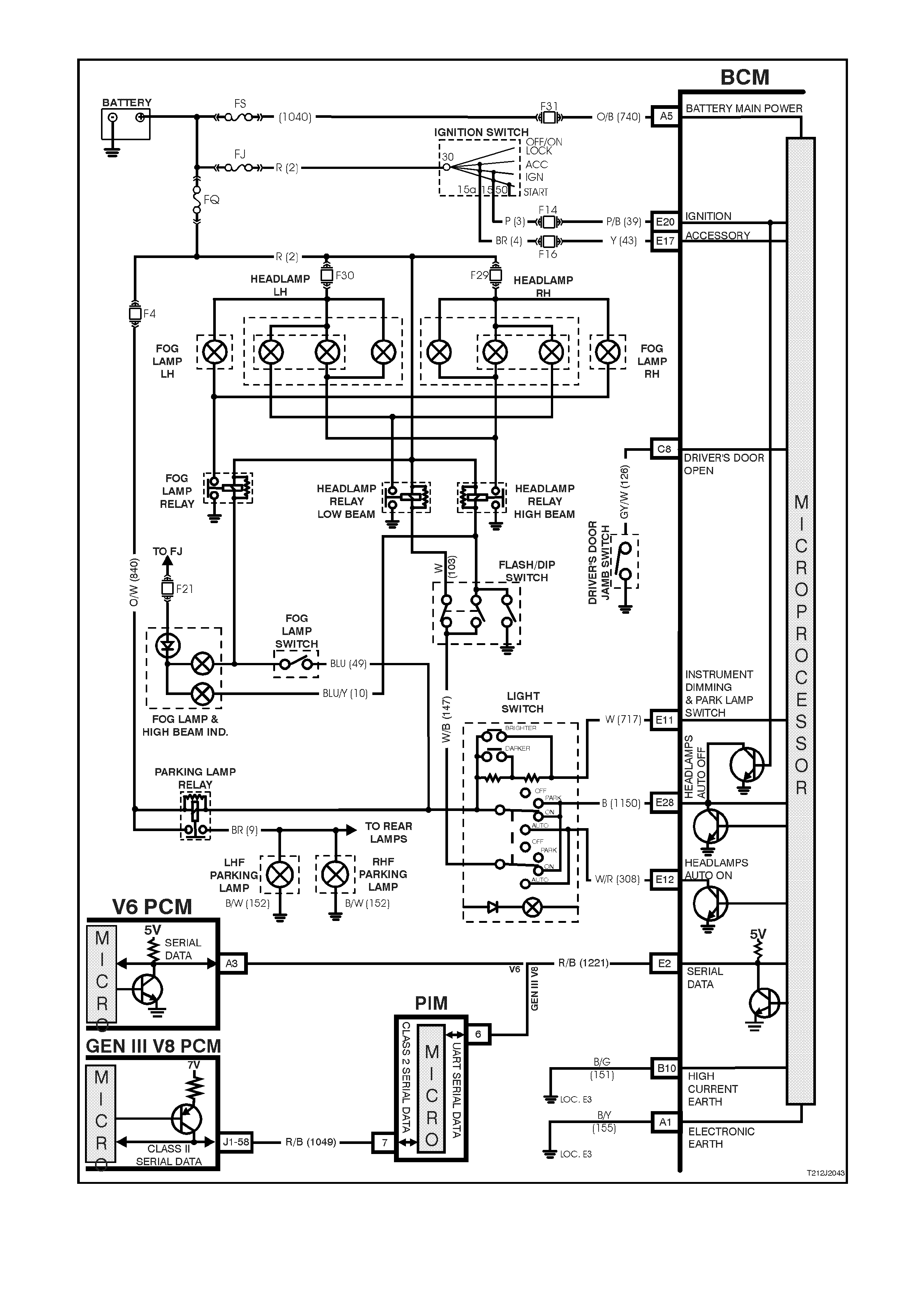
Figure 12J-2-33 Automatic lights off control circuit
1.9 AUTOMATIC LIGHT CONTROL -LIGHTS ON AND
OFF / APPROACH ILLUMINATION (WITH TWILIGHT SENTINEL)
GENERAL INFORMATION
NOTE: The circuit diagr am s shown in this G eneral Desc ription Section ar e to aid in interpreting the oper ation of the
circuit and theref ore, only the m ain connectors and wiring colours ar e shown. For com plete circuits details, refer to
either the relevant diagnostic section or Section 12P WIRING DIAGRAMS of the VT Series II Service Information.
Automatic lights ON and OFF (High Series BCM only)
The autom atic light control (lights on and of f) f eature (with twilight sentinel) turns the vehicle headlamps on and off,
depending on the outside light level. This feature will work only while the headlamp switch is in the Auto position and
the ignition on. The lights will operate as normal in other switch positions.
The operation of the headlamps when the ignition is switched off and the headlam p switch in the Auto position will
be the same as the Auto lights off operation.
A sensor is m ounted in the instr um ent panel pad of the vehic le to monitor the am ount of light in f ront of the vehicle.
The BCM monitors the output of this sensor and determ ines when the light levels are low enough to turn them on.
TECH 2 can be used to select several different ON/OFF light levels to suit the customer preferences.
Approach illumination (High Series BCM)
The approach illumination feature turns the vehicle head and/or park lamps (dependant on headlamp switch
position) on for 30 seconds when the doors are unlocked with the remote coded key.
This provides additional c ustom er secur ity when approaching the vehic le at night. T he lights will tur n of f again if the
vehicle is locked with the remote coded key within 30 seconds of the approach illumination being activated.
When the approach feature is activated, subs equent operation of the remote coded key unlock button will reactivate
the lights to remain on for a further 30 seconds.
The approach illumination feature only operates during dark conditions. The BCM monitors the output of the sun
sensor and determines when the light levels are low enough to enable the approach illumination feature.
The lights resume to normal operation when the ignition is switched to the on position.
TECH 2 has the capability to enable and disable the approach illumination feature.
SYSTEM OVERVIEW - AUTOMATIC LIGHTS ON / APPROACH ILLUMINATION
BATTERY POWER
BCM
HEADLAMP RELAY
PARK LAMP RELAY
REMOTE RECEIVER
LIGHT SENSOR
(SUN SENSOR)
T212J2009
IGNITION SWITCH ON
CIRCUIT OPERATION (Refer to Fig. 12J-2-36)
Light Sensor Control / Remote coded key Input (REFER TO FIG. 12J-2-34)
The light sensor produces a voltage proportional to the amount of ambient light. This voltage can vary between 0
and 5 volts depending on the am ount of light. The BCM determines the light value from the voltage on terminal E10,
circuit 272 (Yellow/Black wire). The BCM reads this input to determine the light level. TECH 2 should be used to
measure the performance of the light sensor.
The BCM monitors the input at terminal E8, circuit 266 (Yellow wire) to determine when the un-lock button on the
remote coded key has been pressed.
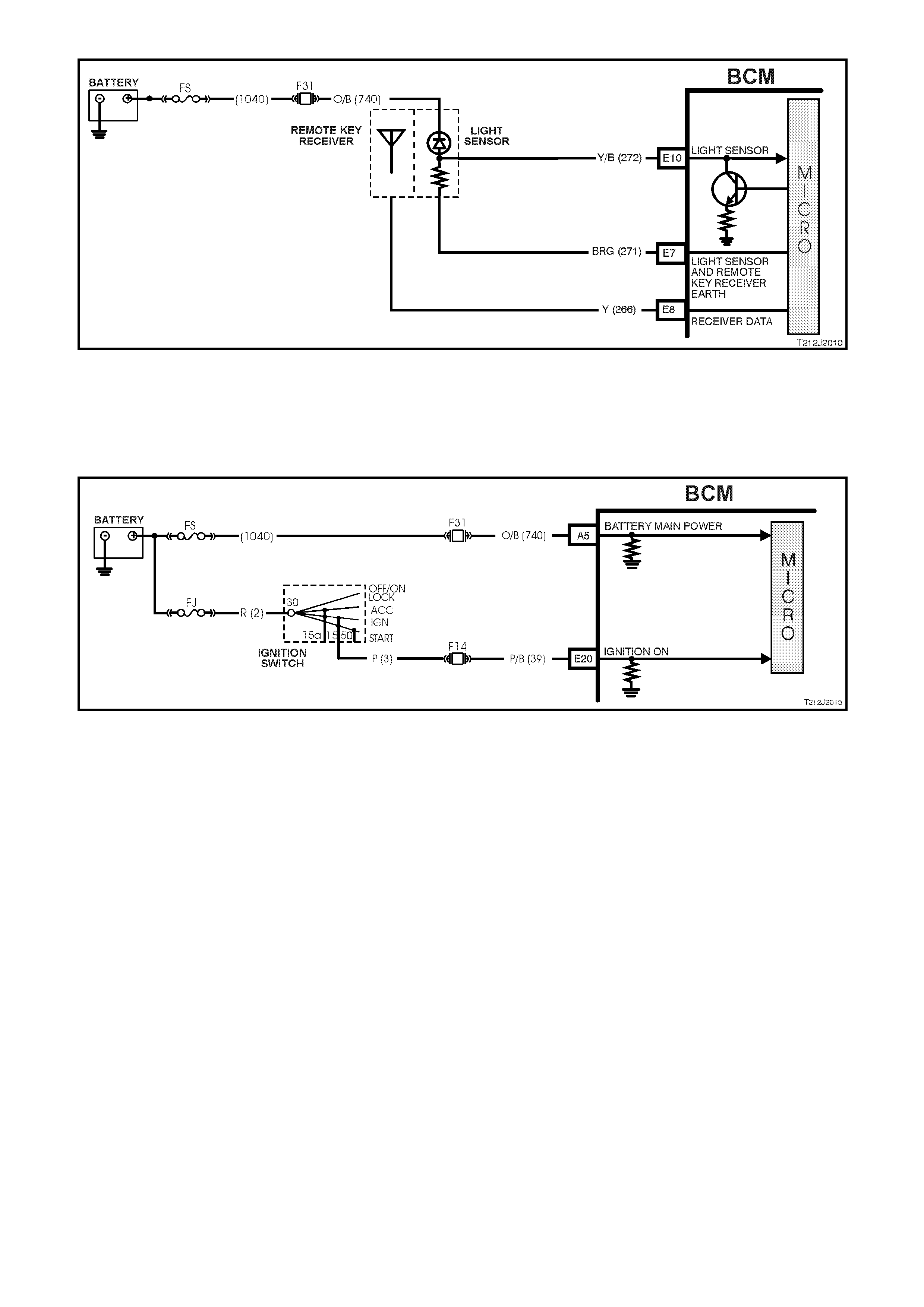
Figure 12J-2-34 Light sensor control and remote coded key input
Ignition Switch ON Input Signal (Refer to Fig. 12J-2-35)
The BCM uses this input signal to determ ine when the ignition switch is the ON or OF F position. W hen the ignition
switch is in the IGN or START position, battery voltage is applied to the BCM terminal E20 from the ignition switch
and fuse F14 via circuit 39 (Pink/Black wire).
Figure 12J-2-35 Ignition switch on input signalPower Supplies (Refer to Fig. 12J-2-36)
Battery voltage is applied to the low and high beam relays from fusible link FQ, circuit 2 (Red wire) and fuses F30
and F29. Battery voltage is applied to the parking lam ps relay from fus ible link F Q, cir cuit 2 (Red wire) and f use F4,
circuit 840 (Orange/White wire). The BCM controls the operation of the exterior lights by switching its internal
control circuits, which provide the earth circuits for the relays, on or off. If the ambient light level is low, or the
approach illumination has been activated, the BCM will energise the control circuits, turning the lights on. If the
ambient light level is high, the BCM will de-energise the control circuit, turning the lights off.
High Beam Relay Earth Circuit (Refer to Fig. 12J-2-36)
The earth circuit for the high beam headlamp relay is via circuit 10 (Blue/Yellow wire), through the headlamp and
turn signal control switch as sem bly, circuit 147 ( W hite/Blac k wire), headlam p switch contac ts to BCM term inal E12,
circuit 308 (W hite/Red wire) or terminal E11, circuit 717 (W hite wire) and then to earth through the internal control
circuit.
Low Beam Relay Earth Circuit (Refer to Fig. 12J-2-36)
The earth circuit for the low beam headlamp relay is via circuit 103 (W hite wire), through the headlamp and turn
signal control switch assembly, circuit 147 (White/Black wire), headlamp switch contacts to BCM terminal E12,
circuit 308 (W hite/Red wire) or terminal E11, circuit 717 (W hite wire) and then to earth through the internal control
circuit.
Parking lamps Relay Earth Circuit (Refer To Fig. 12J-2-36)
The earth circuit for the parking lamps relay is via circuit 49 (Blue wire), the closed parking lamp contacts in the
headlamp switch, through the BCM terminal E12, circuit 308 (White/Red wire) or terminal E11, circuit 717 (White
wire) and then to earth through the internal control circuit.
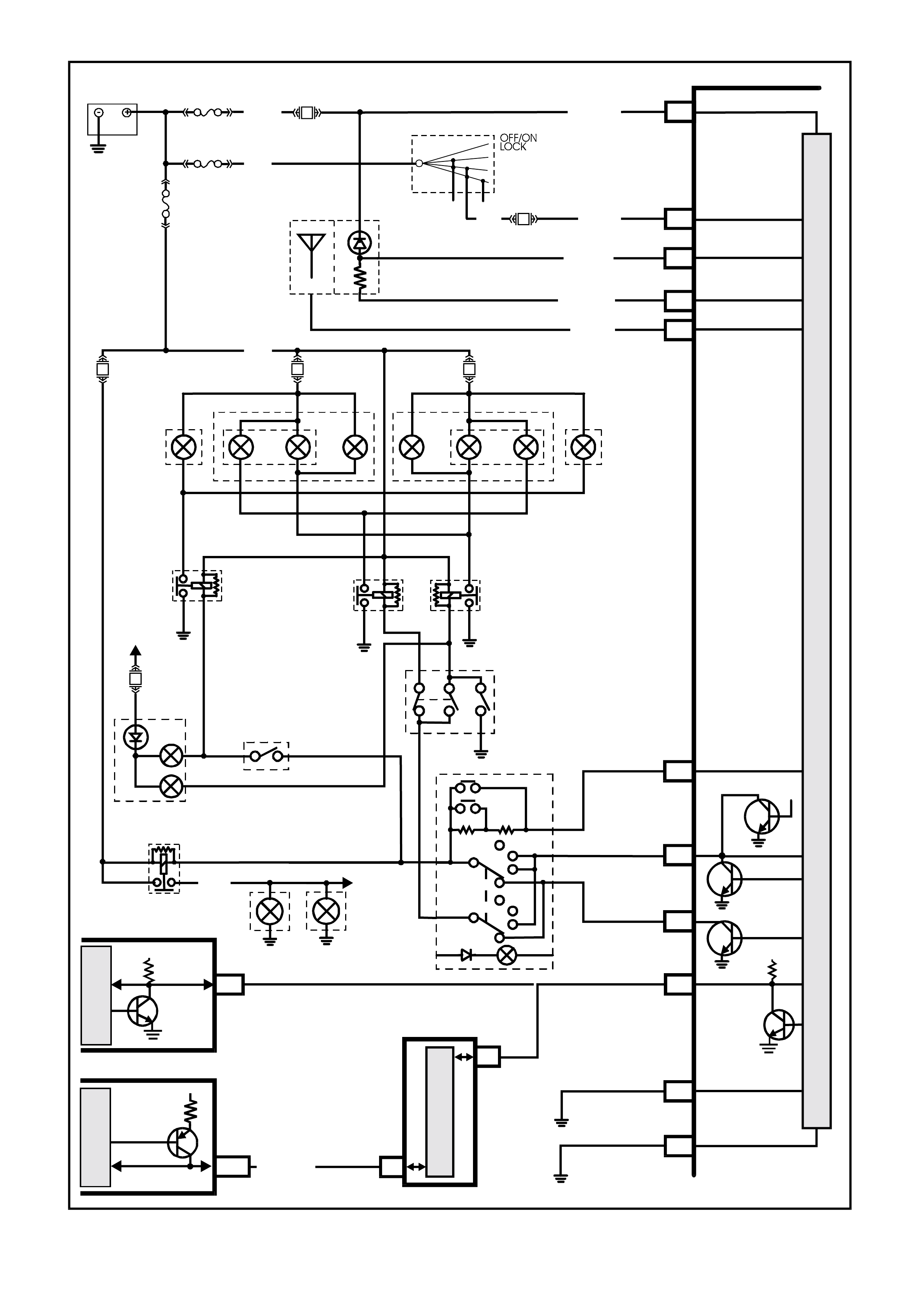
Figure 12J-2-36 Automatic lights ON and OFF / approach illumination circuit
BATTERY
FS
(1040)
BCM
B/G
(151)
B10 HIGH
CURRENT
EARTH
F31
E2
R/B
(1221) SERIAL
DATA
5V
T212J2029
B/Y
(155)
ELECTRONIC
EARTH
A1
FJ
R (2)
OFF
DARKER
BRIGHTER
PARK
ON
AUTO
OFF
PARK
ON
AUTO
F21
M
I
C
R
O
P
R
O
C
E
S
S
O
R
FLASH/DIP
SWITCH
FOG
LAMP
SWITCH
TO FJ
INSTRUMENT
DIMMING
& PARK L AMP
SWITCH
IGN
F OG LAMP &
HIGH BEAM IND.
BLU/Y
(10)
BLU
(49)
REAR
PARKING
LAMPS
TO REAR
LAMPS
PARKING LAMP
RELAY
BR (9)
LIGHT
SWITCH
HEADLAMPS
AUTO OFF
E28
E12
E11
B
(1150)
FQ
F30
F4 F29
HEADLAMP
RELAY
HIGH B EAM
HEADLAMP
RELAY
LOW BEAM
FOG
LAMP
RELAY
FOG
LAMP
LH
FOG
LAMP
RH
HEADLAMP
RH
HEADLAMP
LH
R (2)
W
(717)
LIGHT SENSOR
LIGHT SENSOR
AN REMOTE KEY
RECEIVER EARTH
RECEIVER DATA
E10
E7
E8
Y/B (272)
REMOTE KEY
RECEIVER
LIGHT
SENSOR
BR /G (271)
Y (260)
W/R
(308)
LOC. E3
LOC. E3
LOC. E3
LOC. E3
IGNITION SWITCH
15a
30
BAT TERY MAIN POWER
A5
O/B (740)
IGNITION
F14
E20
P/B (39)
15 50
A
CC
IGN
START
P (3)
LOC. E3
LOC. E3
V6
GEN III V8
R/B (1049)J1-58
CLASS II
SERIAL DATA
GEN III V8 PCM
7V
SERIAL
DATA
5V
V
6 PCM
A3
M
I
C
R
O
M
I
C
R
O
PIM
6
7
M
I
C
R
O
CLASS2SERIALDATA
UART SERIAL DATA
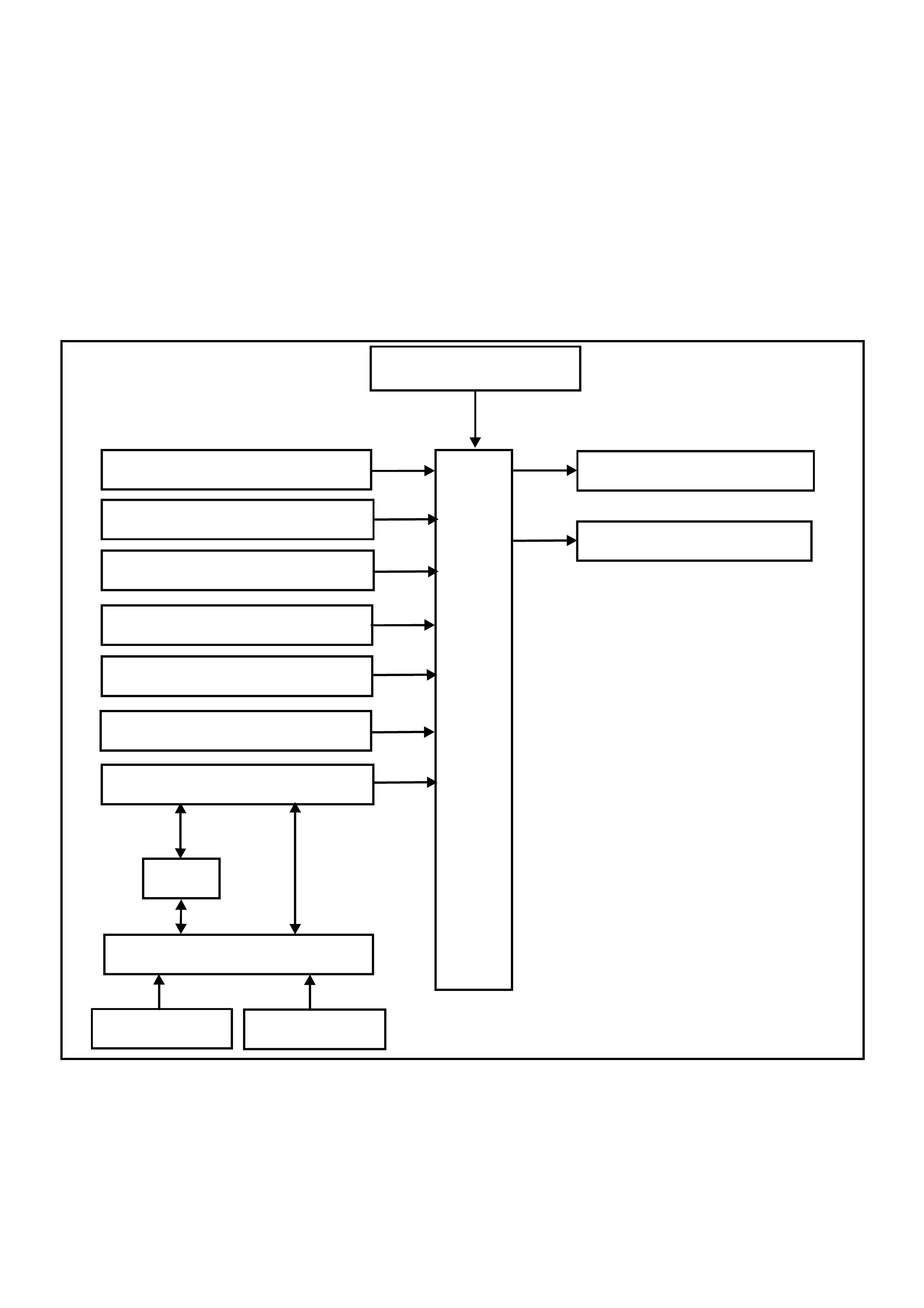
1.10 ROAD SPEED DEPENDENT VARIABLE DWELL WIPER SYSTEM
GENERAL INFORMATION
On VT Series II Models, the road s peed dependent variable dwell wiper s ystem car ries over from ear lier VT Series
Models, noting the following:
Comm unic ation between the PCM and the BCM on vehicles with GEN III V8 engines is via the Powertrain Interf ace
Module (PIM).
If diagnosing a circuit fault with the road speed dependent variable dwell wiper system, reference to the wiring
diagrams in Section 12P WIRING DIAGRAMS of the VT Series II Service Information should be made.
For additional details, including General Description, Service Operations and Diagnosis of the road speed
dependent variable dwell wiper system that is not covered in this Section, refer to Section 12J-2 HIGH SERIES
BODY CONTROL MODULE of the VT Series I Service Information.
SYSTEM OVERVIEW - ROAD SPEED DEPENDENT VARIABLE DWELL WIPERS
BATTERY POWER
BCM
REAR WIPER SWITCH
REAR WASHER SWITCH
WIPER MOTOR PARK SWITCH
WIPER INTERMITTENT SWITCH
WIPER DWELL SWITCH
T212J2048
SERIAL DATA
WIPER MOTOR LOW SPEED
REAR WIPER MOTOR
FRONT WASHER SWITCH
VEHICLE SPEED
REVERSE GEAR
PCM
PIM
GEN III V8
ENGINE V6 & V6 S/C
ENGINE
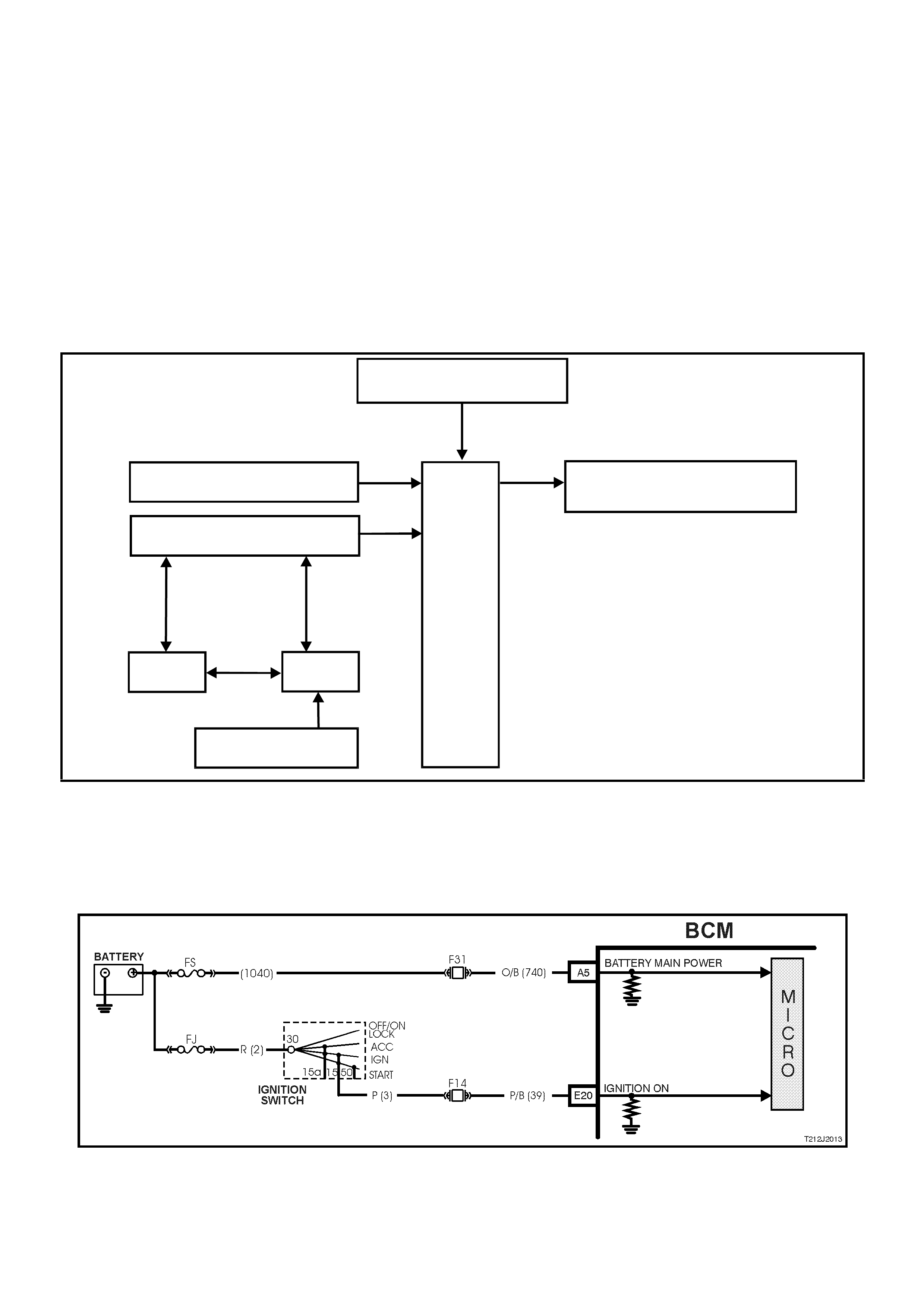
1.11 SPEED SENSITIVE POWER STEERING
GENERAL INFORMATION
This control system of the BCM varies the am ount of power ass istance given to the steering of the vehicle in order
to allow high boost at low speed or parking and low boost at high speeds for better centre steering performance.
The body control module contains a curve of speed versus boost (or control solenoid current) stored in memory.
The power steer ing boost is adjusted by accurately controlling the current flowing in the boost solenoid attached to
the steering gear valve housing. If the BCM detects a system malfunction the BCM will gradually change to a default
boost value at a predetermined rate.
NOTE: The circ uit diagram s shown in this General Des cription Sec tion are to aid in interpr eting the operation of the
circuit and theref ore, only the m ain connectors and wiring colours ar e shown. For com plete circuits details , refer to
either the relevant diagnostic s ect ion or the Wir ing Diagr ams in Section 12P WIRING DIAGRAMS of the VT Series
II Service Information.
SYSTEM OVERVIEW - SPEED SENSITIVE POWER STEERING
BATTERY POWER
POWER STEE RI NG
SOLENOID
BCM
IGNITION SWITCH ON
T212J2016
SERI AL DATA
VEHI CLE SPEED
PCM
PIM
GEN III V8
ENGINE V6 & V6 S/C
ENGINE
CIRCUIT OPERATION
Ignition Switch ON Input Signal (Refer to Fig. 12J-2-37)
The BCM uses this input signal to determine when the ignition switch is in the IGN or START position. W hen the
ignition switch is in the IGN or START position, battery voltage is applied to the BCM terminal E20 f rom the ignition
switch and fuse F14 via circuit 39 (Pink/Black wire).
Figure 12J-2-37 Ignition switch on input signal
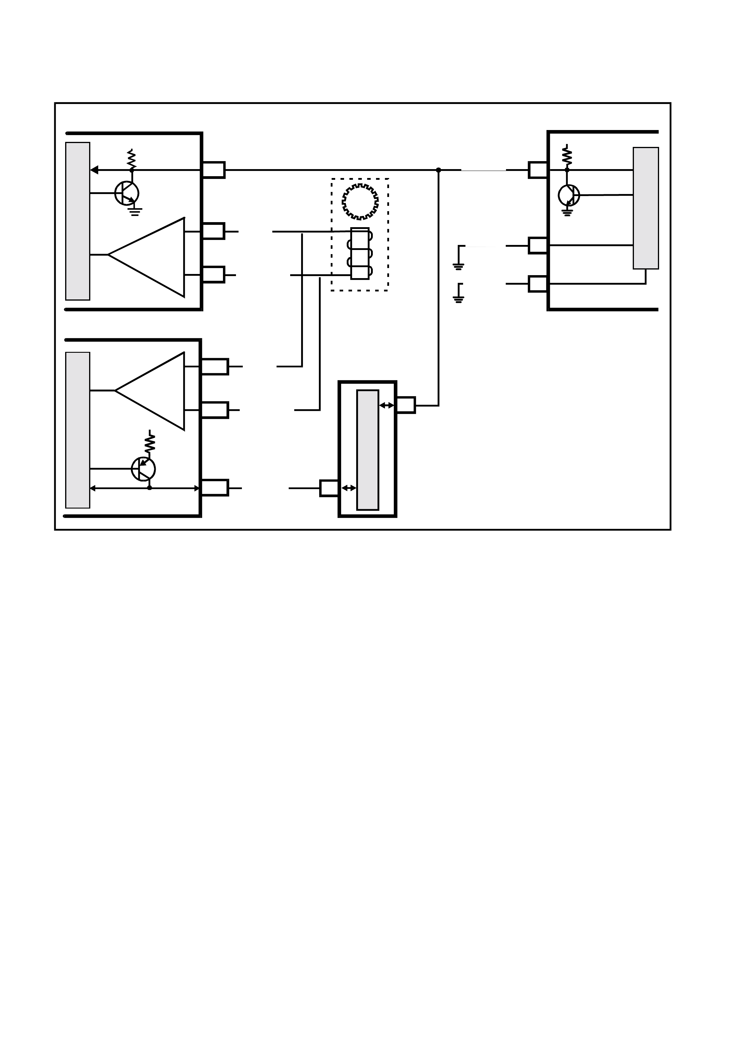
Vehicle Speed Input Signal (Refer to Fig.12J-2-38)
The BCM, terminal E2, receives vehicle speed information from the PCM/PIM via the serial communications bus,
circuit 1221 (Red/Black wire).
Figure 12J-2-38 Vehicle speed input signal
Power Steering Solenoid (Refer to Fig.12J-2-39)
Battery voltage is applied to the power steering solenoid from the ignition switch, circuit 3 (Pink wire), through fuse
F15, circuit 139 (Pink wire), with the opposite end of the solenoid winding connected to BCM terminal E4, circuit 556
(Black/Light Green wire).
The BCM then controls the operation of the power steering solenoid by applying a pulse width modulated signal to
an internal switch, this earth’s the power steering solenoid.
BCM
R/B (1221) E2 SERIAL DATA
5V
B/G (151)
B10
B/Y (151)
A1
HIGH
CURRENT EARTH
T212J2038
ELECTRONIC EARTH
M
I
C
R
O
BLU/W (831)
BLU/W (831)
T (832)
V6
GEN III
GEN III
V6
T (832)
INTEGRATED
CIRCUIT
INTEGRATED
CIRCUIT
M
I
C
R
O
M
I
C
R
O
V6 PCM
GEN III V8 PCM
SERIAL DATA
5V
A3
C6
D5
VEHICLE
SPEED
SENSOR
R/B (1049)J1-58
J2-21
J2-20
CLASS II
SERIAL DATA
7V
PIM
6
7
M
I
C
R
O
CLASS 2 SERIAL DATA
UART SERIAL DATA
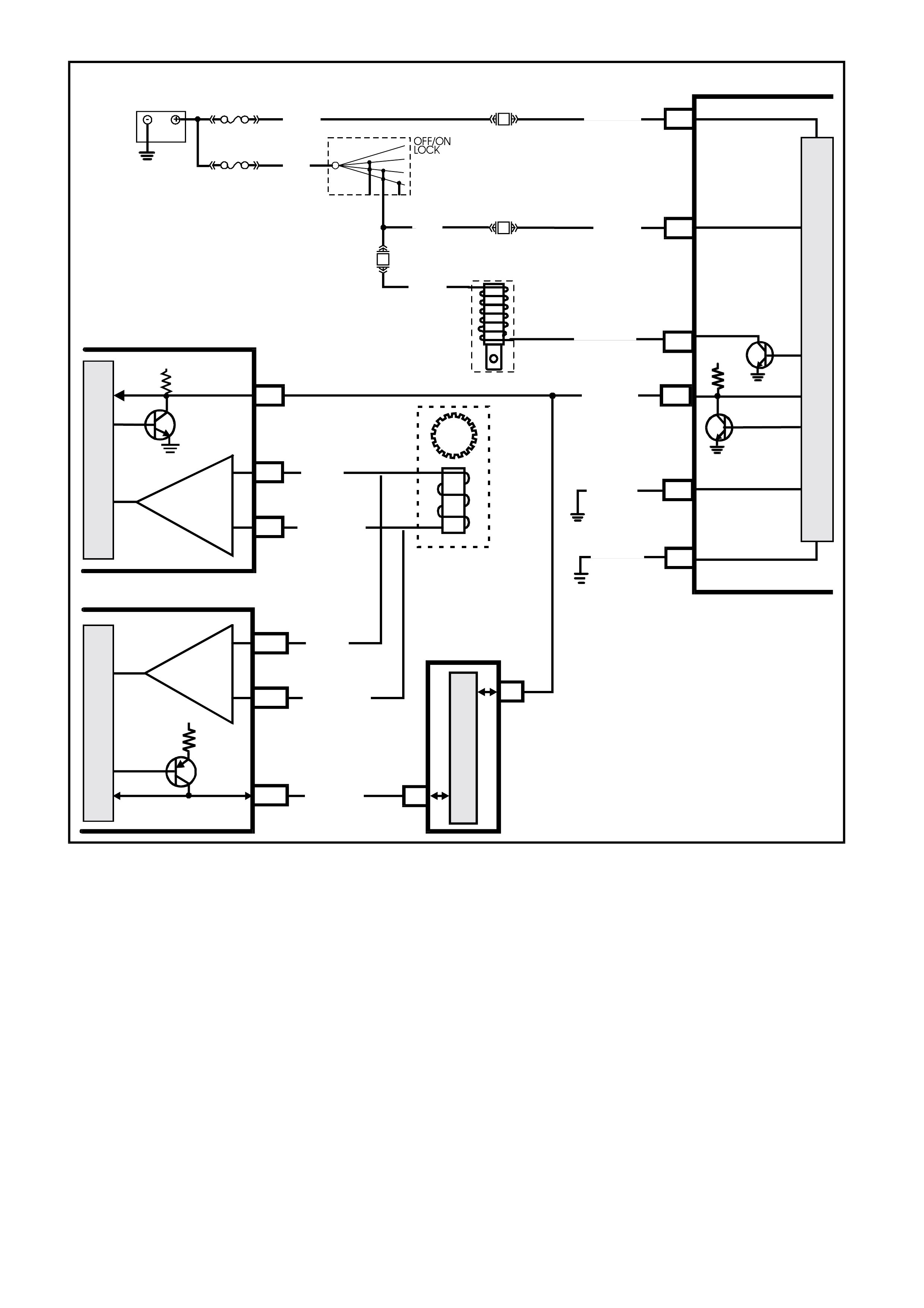
Figure 12J-2-39 Speed sensitive power steering
BCM
SERIAL DATA
5V
HIGH
CURRENT EARTH
T212J2039
ELECTRONIC EARTH
M
I
C
R
O
F15
IGNITION
BAT TERY MAIN POWE R
P (139)
POWER
STEERING
DRIVE
POWER
STEERING
SOLENOID
R/B (1221) E2
B/G (151)
B10
B/Y (151)
A1
BLU/W (831)
BLU/W (831)
T (832)
V6
GEN III
GEN III
V6
T (832)
INTEGRATED
CIRCUIT
INTEGRATED
CIRCUIT
M
I
C
R
O
M
I
C
R
O
V
6 PCM
GEN III V8 PCM
SERIAL DATA
5V
A3
C6
D5
VEHICLE
SPEED
SENSOR
R/B (1049)
J1-58
J2-21
J2-20
CLASS II
SERIAL DATA
7V
PIM
6
7
M
I
C
R
O
CLASS 2 SER IAL DATA
UART SERIAL DATA
E4
B/ LG (556)
BATTERY
FS
F31
A5
O/B (740)
(1040)
FJ
R (2)
F14
E20
P/B (39)
15a 15 50
30 ACC
IGN
START
IGNITION
SWITCH
P (3)
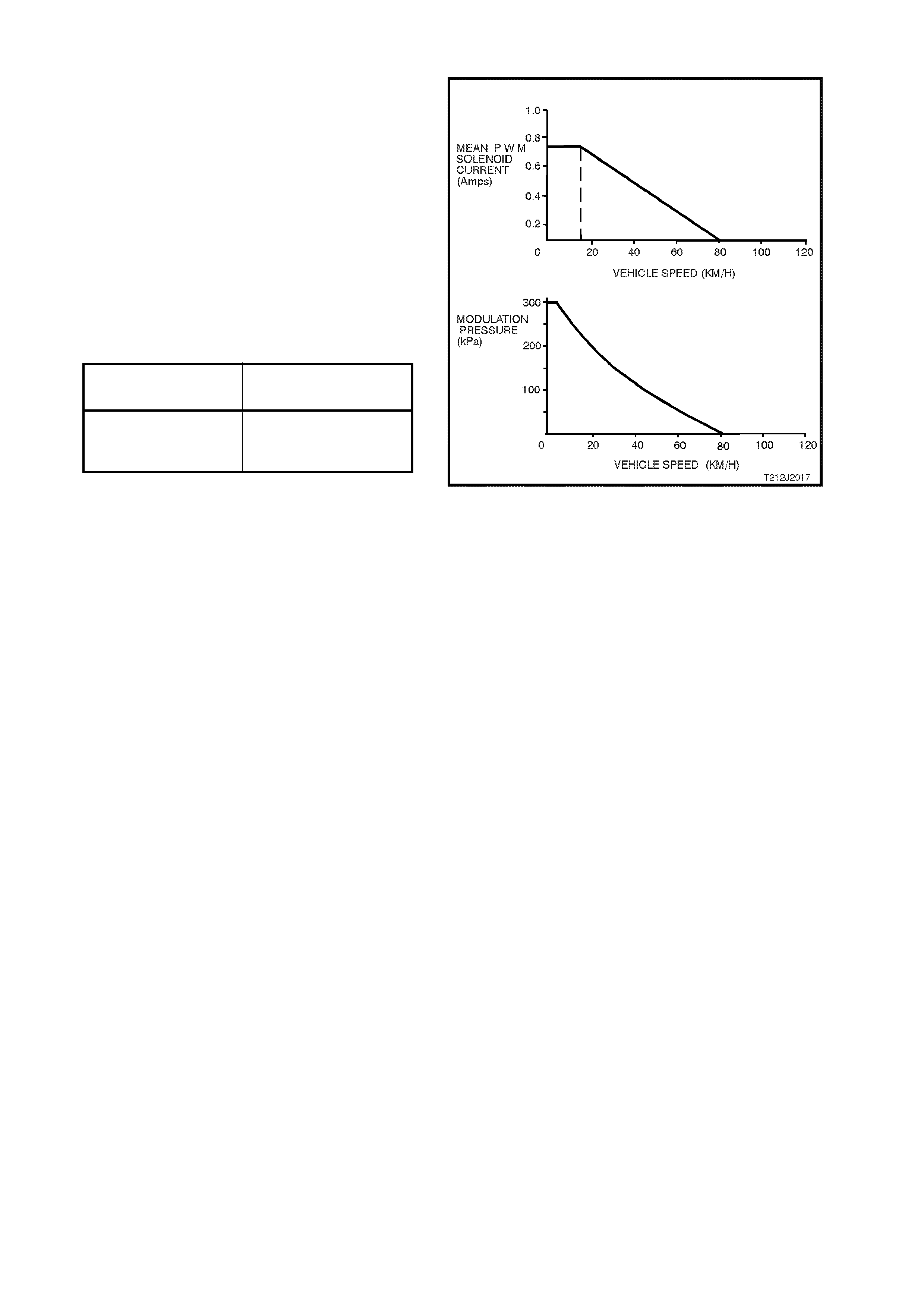
SOLENOID VALVE OPERATION
The BCM controls the operation of the boost
solenoid by supplying a Pulse Width Modulated
(PWM) signal to the solenoid that varies
proportionally with vehicle road speed. The signal is
modulated at a frequency of 167 Hz. As shown by
the typical diagrams in the illustration opposite,
both the average PWM solenoid current and the
modulated pressure are relatively similar. Further,
maximum modulation pressure is only applied
during parking and up to a low speed of a few
km/h.
Reference to the following table and the illustration
opposite shows the relative P.W .M. c urrent flow for
respective road speeds.
CURRENT (Amp.) ROAD SPEED
(km/h)
0.75 0 - 12
0.45 40
0.0 80+
General Curve CharacteristicsT212J2017
By changing the pulse width (time ON) of the signal
sent to the solenoid, the amount of assistance
delivered by the power steering can be varied.
When maximum assistance is required (low vehicle
speed), the BCM increases the signal duty cycle ON
time (lengthening the pulse width of the signal) to
approximately 50%. This will cause a current of
approximately 750 mA of flow through the solenoid.
As vehicle speed increases, the BCM progressively
decreases the as sis tanc e by decreasing the duty cycle
ON time (shortening the pulse width of the signal)
thereby decreasing the solenoid current until zero
current flow is achieved. At this point minimum
assistance will be delivered by the power steering
system.
W hen activated, the power steering solenoid receives
a Pulse Width Modulated (PWM) cur rent f low from the
BCM that varies proportionally with vehicle road
speed.
From this point, the modulated pressure falls
progressively until, at approximately 80 km/h,
modulated pressure decreases to a minimum. It is at
this time also, that the solenoid receives no further
current pulses from the BCM.
Figure 12J-2-40 shows a typical speed sensitive
power steering pulse width modulated current flow.
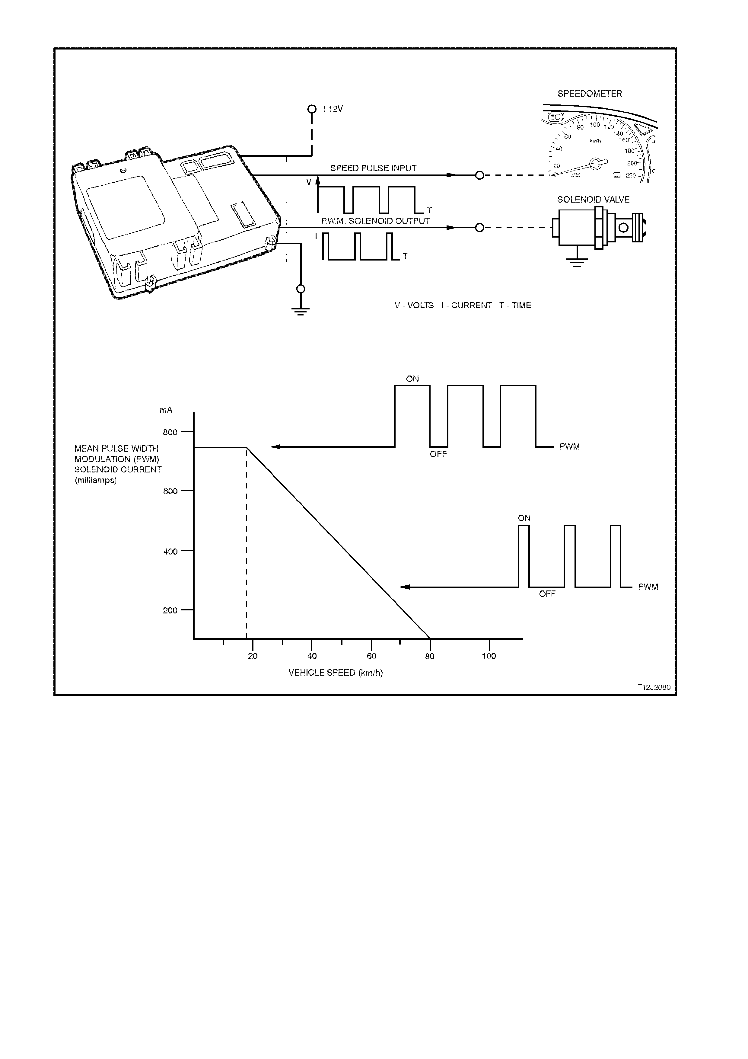
Figure 12J-2-40 Speed sensitive power steering pulse width modulated current flow (Typical)
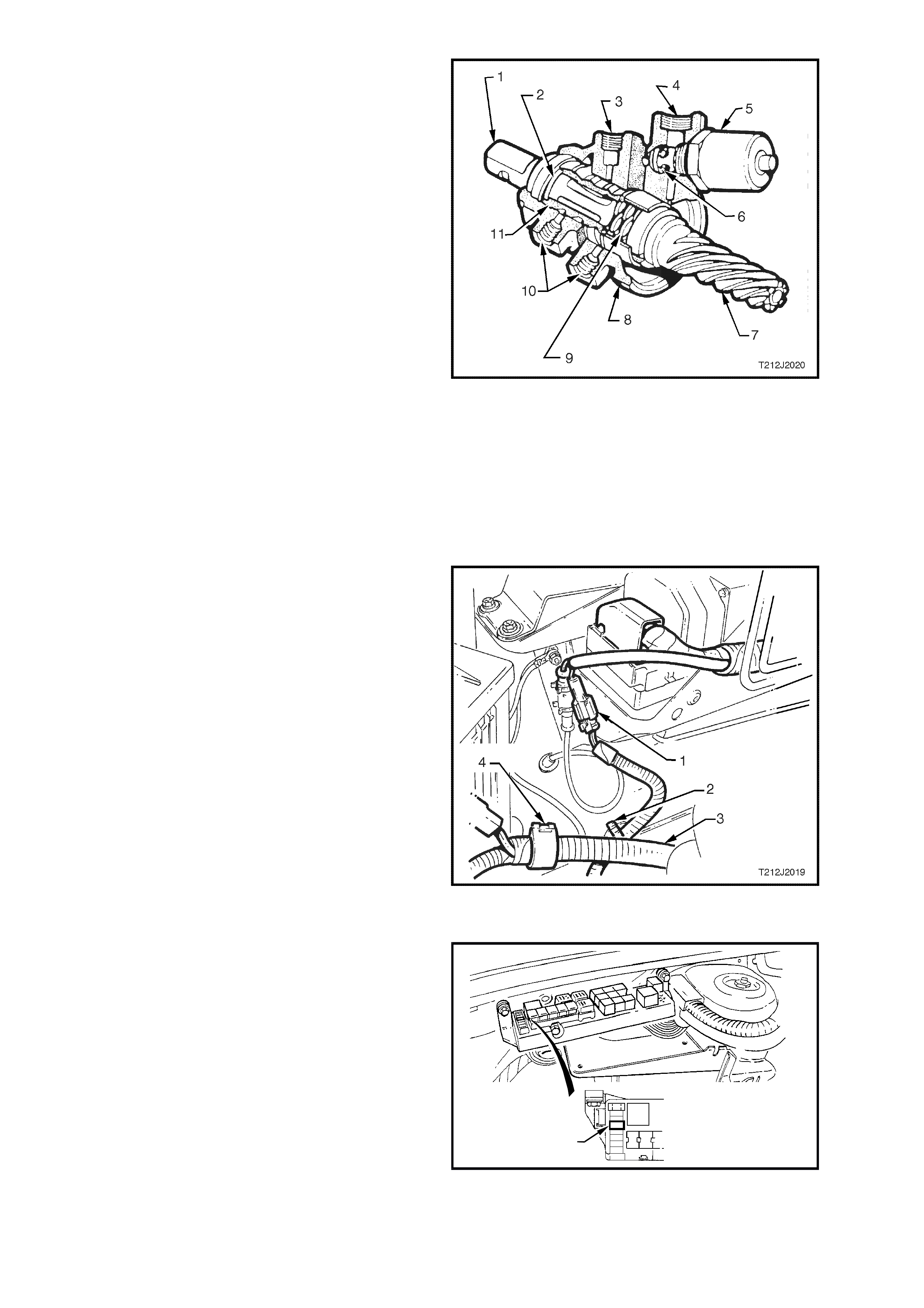
The figure opposite illustrates a sectioned view
through the power s teering gear valve hous ing. T he
steering gear boost solenoid operates an internal
'flapper' valve, loc ated in the fluid return side of the
valve housing. The operation of the 'flapper' valve
causes changes in hydraulic pressure and allows
progressive movement of the steering gear valve
housing outer sleeve along the inner shaft valve
member. This movement of the outer sleeve
causes the change in steering gear boost
characteristics.
The most accurate method of testing the speed
sensitive power steering electrical system is by
using TECH 2.
The BCM has a spec ial des ign f eature inc or porated
so that when an open or short circuit is detected in
the drive circuits to the power steering solenoid, ie.
circuits 139 and 556, the BCM will automatically
switch the drive circuits accordingly.
1. Input shaft 7. Pinion
2 Damper seal 8. Housing
3. Inlet (from pump) 9. Reaction spring
4. Return (to pump) 10.Outlets to rack piston
5. Solenoid 11.Outer sleeve
6. Flapper valve
Figure 12J-2-41 Power steering gear
In the event of an interm ittent open circuit due to a
faulty connection, the BCM microprocessor may
need to be reset before carrying out testing.
When carrying out any testing on the system,
ensure that the ignition is switched off, otherwise if
a connection is broken anywhere in the circuit
(disconnecting power steering solenoid connector
from the main wiring harness connector YB63) the
control system in the BCM will turn power off to the
boost solenoid.
NOTE: Even changing multimeter range selection
while connected to solenoid circuitry, with ignition
on, can cause the system to default to low boost.
1. Power steering solenoid wiring
harness connector.
2. Retaining clip.
3. Battery harness.
4. Retaining clip.
Figure 12J-2-42 Power steering solenoid connector
To reset the complete BCM memory, switch
ignition off, remove fuse F31 from engine
compartment relay housing, then refit after
approximately one second.
When resetting of the BCM m icr oproces sor occ urs,
a clicking sound may be heard from within the BCM
if the dome lamp relay is active.
POWER STEERING PUMPS
On vehicles f itted with High Series BCM, the power
steering pumps fitted ARE NOT the Droop Flow
type pumps as fitted to vehicles with Low Series
BCM. The difference in pumps is that the Non
Droop Flow type pumps do not incorporate the
metering needle valve in the pump outlet fitting.
Therefore, if replacing a power steering pump,
ensure the correct type is fitted.
T212J2018
F31
Figure 12J-2-43 Fuse F31 location

1.12 DOME LAMP DELAY CONTROL
GENERAL INFORMATION
NOTE: The circ uit diagram s shown in this General Des cription Sec tion are to aid in interpr eting the operation of the
circuit and theref ore, only the m ain connectors and wiring colours ar e shown. For com plete circuits details , refer to
either the relevant diagnostic section or Section 12P WIRING DIAGRAMS of the VT Series II Service Information.
The interior lighting is controlled by the BCM or by the dome lam p switch (incorporated with the dome and reading
lamps cluster). The interior lighting is activated when any door is opened, unlocked with the remote coded key,
when the ignition is switched from IGN to OFF (provided the feature is ac tivated and conditions are dark ), or when
the dome lamp switch is operated.
In addition, as part of the battery saver function, the BCM controls internal, dome, ignition lock surround, glove
compartment and door lamps. The BCM controls battery voltage to these circuits via the interior illumination relay.
There is a delay period before the batter y saver func tion of the BCM deactivates the inter ior illumination relay. T he
delay default tim e is set to one hour, however, c an be reprogramm ed with TECH 2 from between 2 - 255 minutes.
The delay period (shut down timer) is initiated when the ignition is switched to the OFF positions.
Whilst in battery saver mode, the BCM will reactivate the interior illumination relay when:
1. When the bonnet, boot or any door is opened.
2. The BCM receives a valid remote receiver.
3. When the ignition is switched to the ON or ACC positions.
4. Doors are unlocked via the driver’s door microswitch.
5. TECH 2 is connected to the DLC and communicating with the BCM.
6. The headlamp switch is cycled from OFF to ON or ON to OFF.
7. The deadlock switch is activated.
8. When the alarm is activated.
9. When the boot release switch is pressed.
The various modes of dome lamp delay control operation are as follows:
Operation with door opening:
The interior lighting is activated when any door is open. After all doors have been closed, the lamp/s remains
activated for an additional 30 seconds.
However, if the ignition is switched on, the delay time is cancelled and the lamp/s go off immediately.
Operation with dome lamp switch:
The dom e lam p switch is a three pos ition switch with; doors, OFF and O N positions which turns the interior lighting
on when closed. If the interior lighting has been activated by some other BCM control system or action, the dome
lamp switch will turn the interior lighting off when it is switched from ON to OFF (with the sole exception of dome
light flash when the theft deterrent system is triggered). This means that the switch can curtail any delay time
initiated as well as switch the lighting of f whilst a door is open. The BCM als o monitor s the position of the door s and
controls the dome lamp accordingly.
Operation with central locking:
Provided the dome lamp switch is in the doors position, the interior lighting is switched on upon central door
unlocking for 30 seconds. If the ignition is turned on during this delay, the interior lighting will be switch off
immediately. Interior lighting is also switched off upon central door locking or deadlocking.
If any of the passenger doors are open while the doors are locked, the interior lighting will remain on. The lighting
will turn off immediately only when that particular door is closed, or if the BCM has entered battery saver mode.
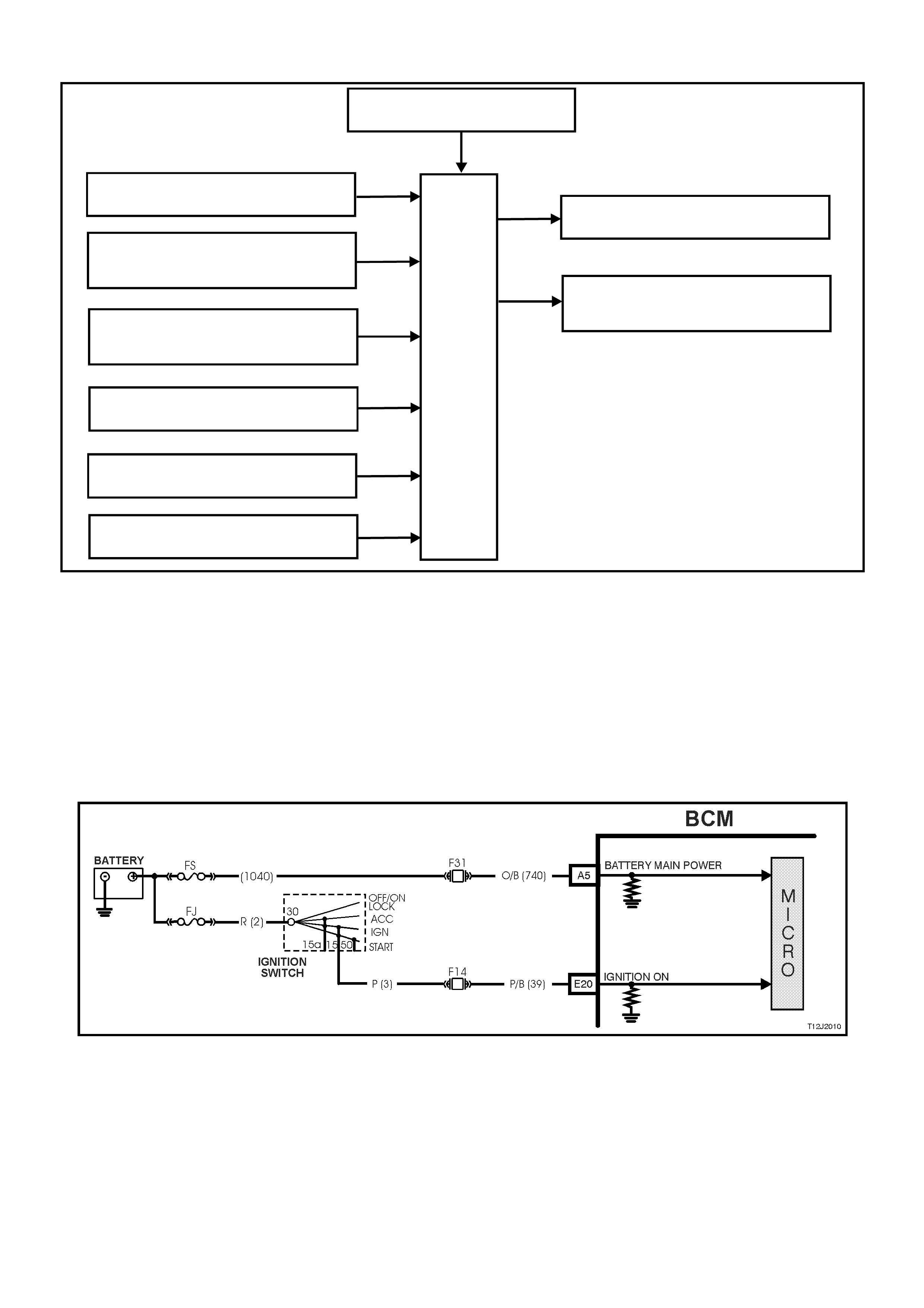
SYSTEM OVERVIEW - DOME LA MP DELAY
BATTERY POWER
BCM
DOME LAMP
INTERIOR ILLUMINATION
RELAY
PASSENGER DO OR
JAMB SWITCH
DRIVER’S DOOR JAMB
SWITCH
T212J2008
IGNITION SWITCH ON
DOME LAMP ON SWITCH
DOME LAMP DOOR SWITCH
REMOTE RECEIVER
CIRCUIT OPERATION (Refer to Fig. 12J-2-49)
Battery voltage is applied to all interior lights via fuse F6, circuit 1140 (Orange wire), the interior illumination relay,
controlled by the BCM (battery saver mode), and circuit 1145 (Orange/Black wire). The opposite side of the dome
lamps are connected to earth via circuit 174 (White/Green wire) and BCM terminal C24. The BCM controls the
operation of the dome lamps connected to this earth circuit by energising its internal dome lamp relay, this causes
the relay contacts to close completing the circuit to earth.
Ignition Switch ON Input Signal (Refer to Fig. 12J-2-44)
The BCM uses this input signal to determine when the ignition switch is in the IGN or START position. W hen the
ignition switch is in the IGN or START position, battery voltage is applied to the BCM terminal E20 f rom the ignition
switch and fuse F14 via circuit 39 (Pink/Black wire).
Figure 12J-2-44 Ignition switch on input signal
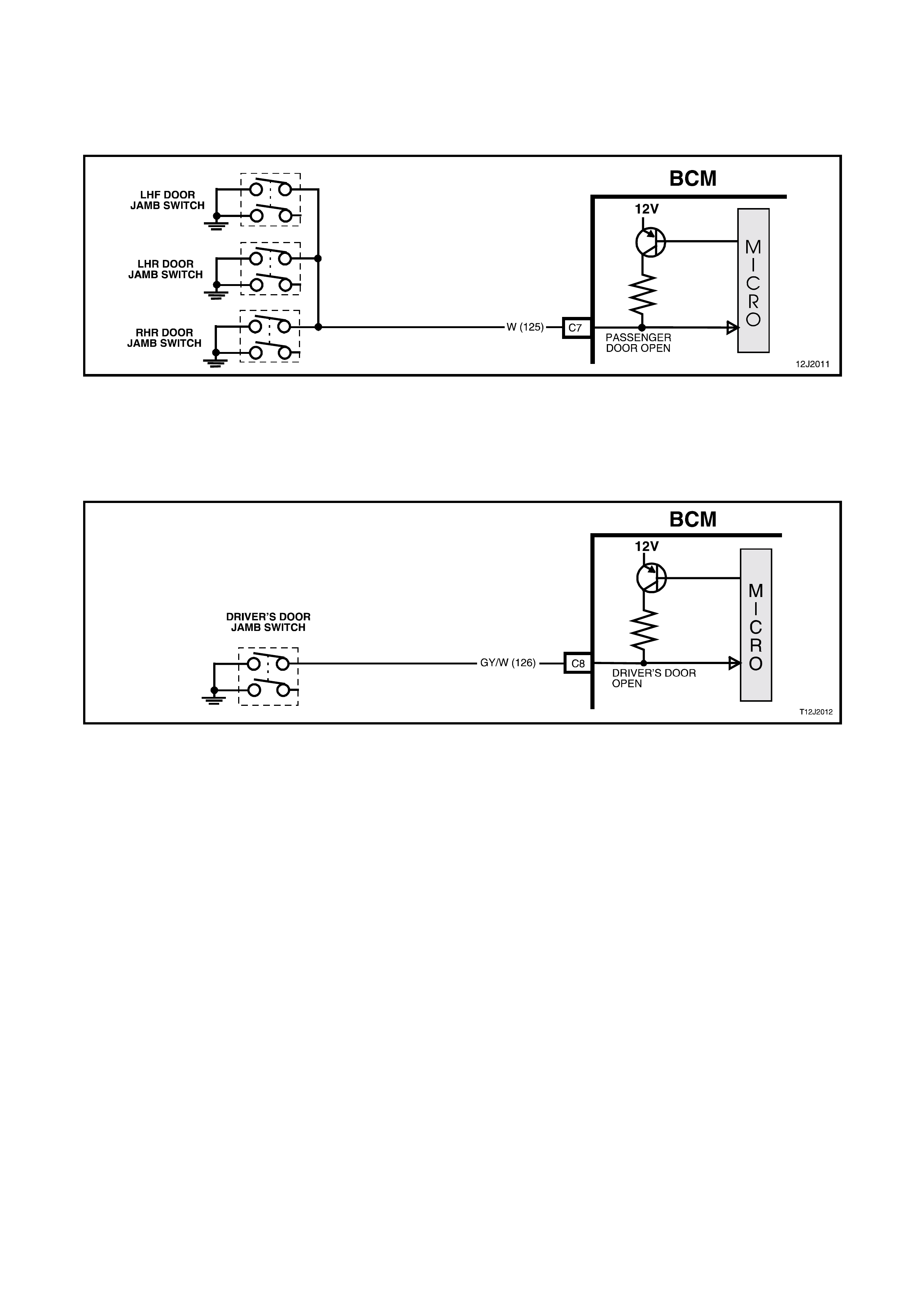
Passenger Door Open Input Signal (Refer To Fig. 12J-2-45)
When any passenger door is opened, BCM terminal C7 is connected to earth via circuit 125 (W hite wire) and the
passenger door jam b switch. This causes the voltage at term inal C7 to be pulled low, less than 0.2 volt (passenger
door open). This low voltage at terminal C7 is seen by the BCM as the passenger door open input signal.
Figure 12J-2-45 Passenger door open input signal
Driver’s Door Open Input Signal (Refer to Fig. 12J-2-46)
W hen the dr iver’s door is opened, BCM ter minal C8 is connected to earth via circuit 126 (G rey/White wire) and the
driver’s door jamb switch. This causes the voltage at terminal C8 to be pulled low, less than 0.2 volt (driver's door
open). This low voltage at terminal C8 is seen by the BCM as the driver's door input signal.
Figure 12J-2-46 Driver’s door open input signal
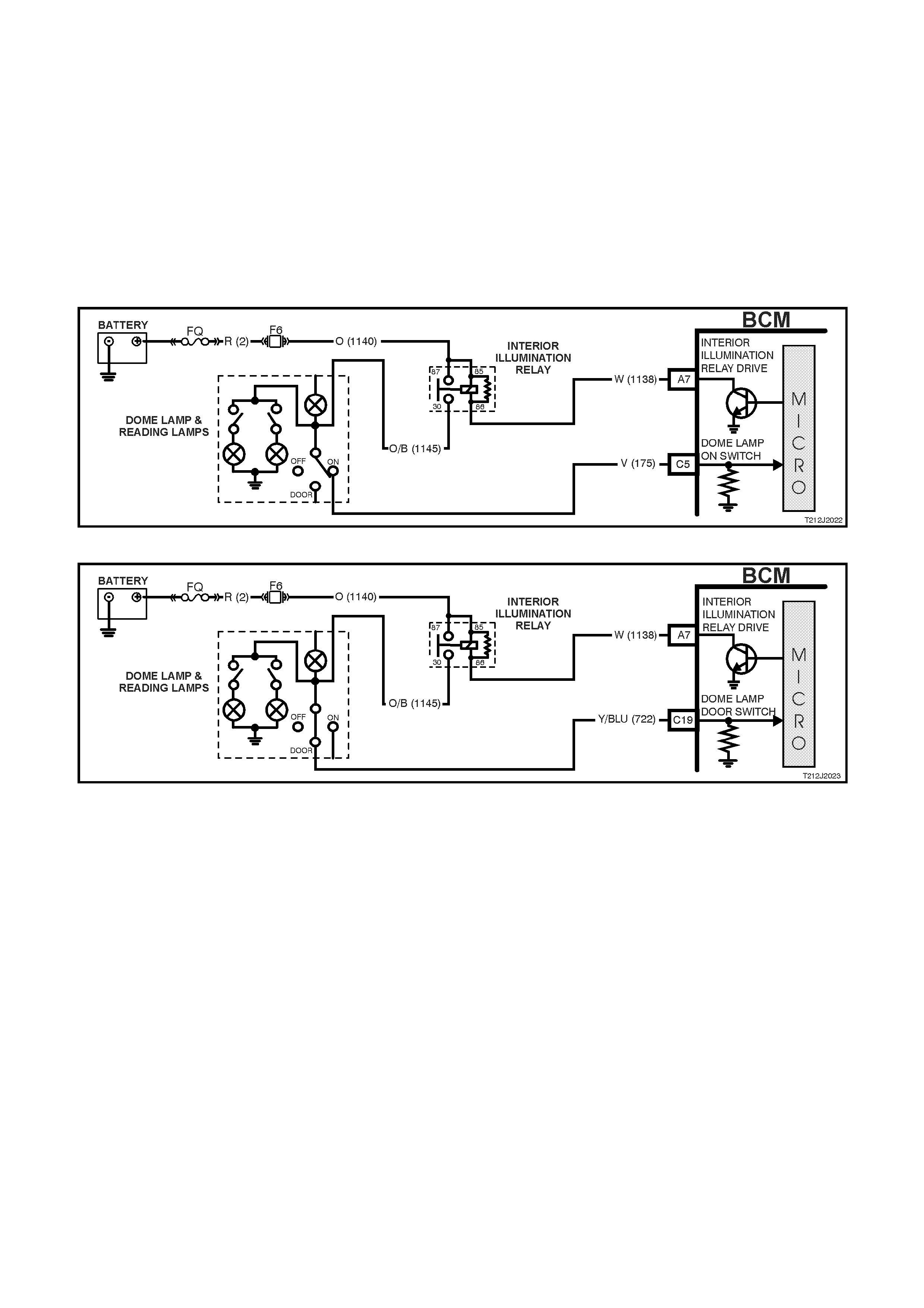
Dome Lamp Switch Input Signal
Dome ON (Refer to Fig. 12J-2-47)
W hen the dome lam p switch is in the ON position, battery voltage is applied to BCM terminal C5 from fuse F6 via
circuit 1140 (Orange wire), interior illumination relay, circuit 1145 (Orange/Black wire), dom e lamp switch contacts,
and circuit 175 (violet wire). This voltage at BCM term inal C5 is seen by the BCM as the dome lam p switch on input
signal.
Dome DOOR (Refer to Fig. 12J-2-48)
When the dom e lamp switch is s witched to the DOO R pos ition, battery voltage is applied to BCM terminal C19 from
fuse F6 via circuit 1140 (Orange wire), interior illumination relay, circuit 1145 (Orange/Black wire), dome lamp
switch contacts, and circuit 722 (Yellow/Blue wire). This voltage at BCM terminal C19 is seen by the BCM as the
dome lamp switch DOOR input signal.
Figure 12J-2-47 Dome lamp on switch input
Figure 12J-2-48 Dome lamp door switch input
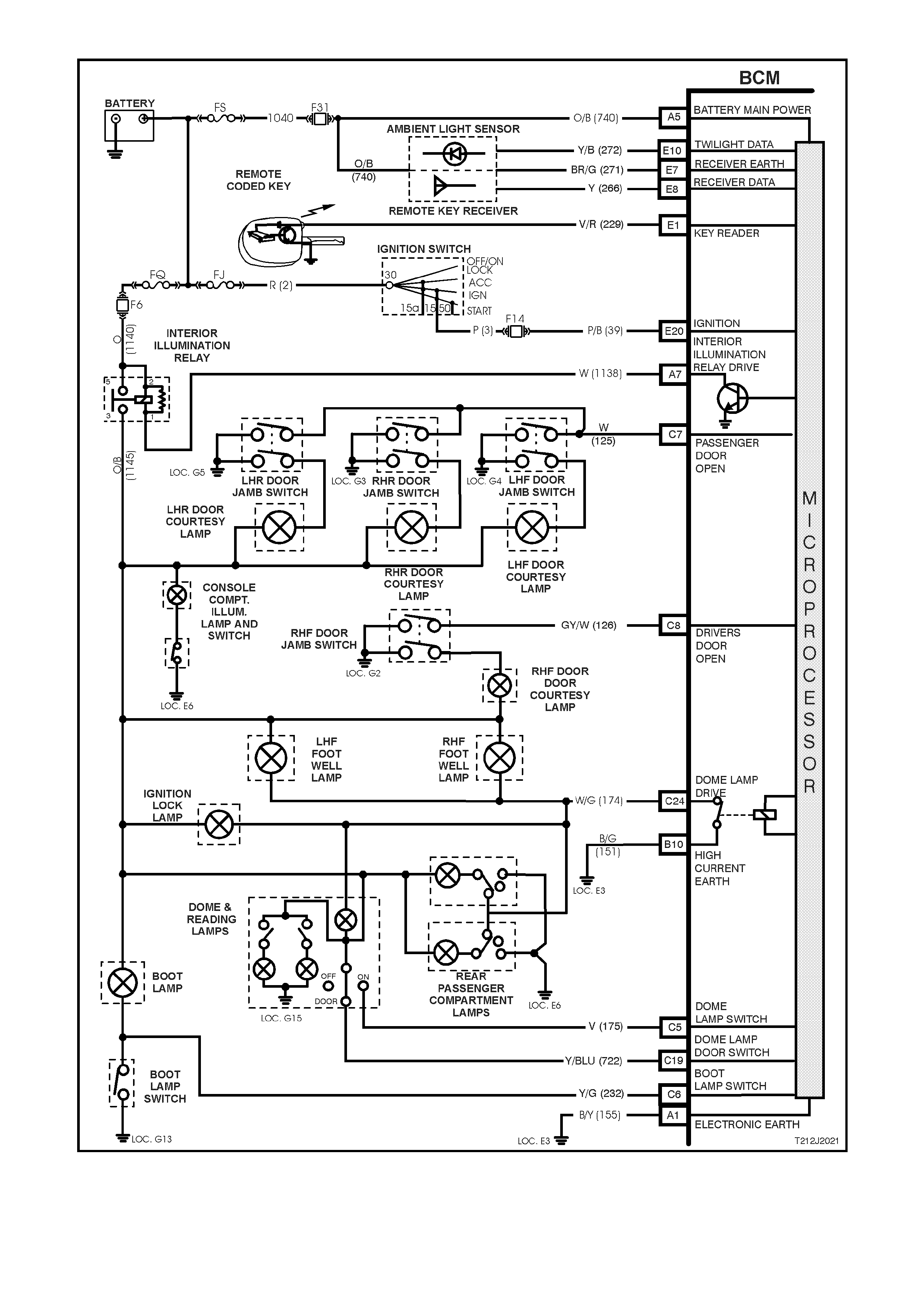
Figure 12J-2-49 Dome lamp delay control circuit
1.13 INSTRUME NT DIMMING CONTROL
GENERAL INFORMATION
The instrument dimming control allows for illumination level adjustment of the instrument dial faces, dash and
centre console illumination, as well as display windows of the trip computer, climate control and radio. The
illumination level is adjusted by m oving the spring loaded control lever on the headlamp switch. T he lever operates
two momentary contact switches within the headlamp switch. The dimm er drives to full load when both the ignition
is on and the parking lamps are switched off to give maximum illumination intensity. W hen the parking lamps are
switched on, the dimmer will operate according to the level previously set and provide the voltage variation
compensation required to maintain the same brightness, irrespective of the ignition switch position.
The instrument illumination intensity is also dependent on the priority key system. Instrument illumination intensity
can be set for priority 1 and 2 keys. The intensity is recalled when the unlock button or the rem ote key is pressed,
and is dependent on whether priority 1 or 2 key is used.
To decrease dash illumination intensity, the switch control lever must be held down for the required time for the
BCM to decrease instrument cluster and trip computer illumination intensity. To increase illumination intensity, the
switch control lever must be held up for the required time for the BCM to increase the illumination intensity. The
illumination switches are only active while the ignition switch is in the ACC or IGN positions.
NOTE: The circ uit diagram s shown in this General Des cription Sec tion are to aid in interpr eting the operation of the
circuit and therefore, only the main connectors and wiring colours are shown. For complete circuit details, refer to
either the relevant diagnostic section or Section 12P WIRING DIAGRAMS of the VT Series II Service Information.
SYSTEM OVERVIEW - INSTRUMENT DIMMING CONTROL
BATTERY POWER
BCM
INSTRUM ENT ILLUMINATION
IGNITION SWITCH
ACC ESSORY SWITCH
T212J2005
DIMMING CONTROL SWITCH
PA RKING LAMP S WI TCH
CIRCUIT OPERATION (Refer to Fig. 12J-2-53)
The BCM controls the operation of the instrument illumination dimming by controlling the current flow through the
instrum ent illumination circ uit. This is achieved by turning the instrum ent illumination earth c ircuit on and off . As the
on time increases , so to does the current flowing through the circ uit. As this pulse width m odulated current f low (on
time) increases, the instrument illumination intensity will also increase.
Battery voltage is applied to the trip computer display illumination from the ignition switch, via fuse F13, circuit 3
(Pink wire) and circuit 44 (Pink/Blue wire). The earth circuit is via circuit 8 (Grey wire) through the BCM terminal A2.
Battery voltage is applied to the instrument cluster illumination lights, radio illumination and climate control
illumination from the park lamp relay to fuse F11, circuit 19 (Brown/White wire). The earth circuit is via circuit 8
(Grey wire) through the BCM terminal A2.
NOTE: The instrument cluster, radio, climate control and trip computer illumination lights are the only illumination
lights that are variable in intens ity, this control is carried out by the BCM. All other s witch or dash illumination lights
are not controlled via the BCM and therefore, all these lights are directly connected to earth.
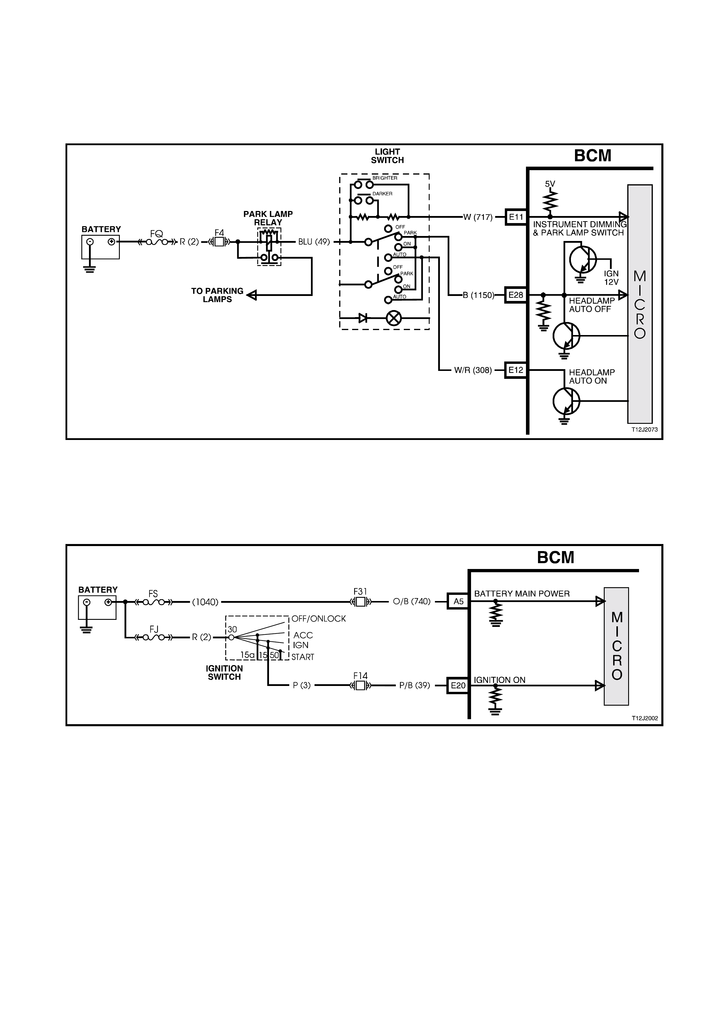
Parking Lamps Switch Input Signal (REFER TO FIG. 12J-2-50)
W hen the par king lam ps are turned on, the par k lam p relay is earthed through cir cuit 49 ( Blue wire), the park lamp
switch contacts, circuit 1150 (Black wire), BCM terminal E28 and to earth via an internal switch. This places a
voltage at BCM terminal E11, approximately 2.5 volts (resistor dividing network dimmer resistors 5.4 kΩ and BCM
internal resistor) . This enables the BCM to determ ine that the parking lam ps are turned on and inter nal switching is
activated to turn on the instrument illumination lamps.
Figure 12J-2-50 Park lamp switch input signal
Ignition Switch 'ON' Input Signal (Refer To Fig. 12J-2-51)
W hen the ignition s witch is in the IGN or ST ART pos ition, battery voltage is applied to BCM term inal E20 via circuit
39 (Pink/Black wire). This causes the voltage at terminal E20 to go from less than 0.2 volts (ignition OFF) to 12 volts
(ignition IGN or START). The voltage at terminal E20 is seen by the BCM as the ignition ON input signal.
Figure 12J-2-51 Ignition switch on input signal
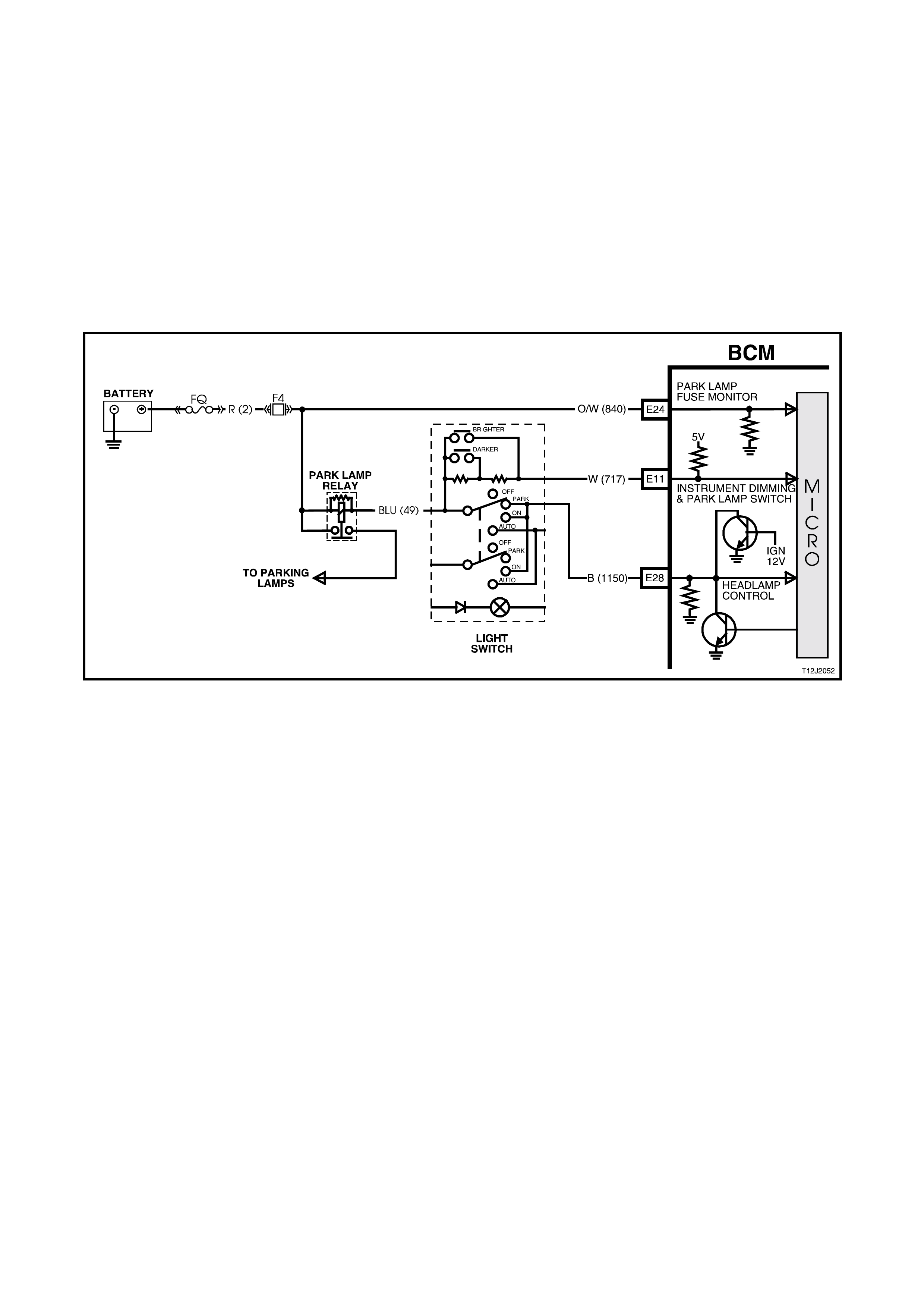
Illumination Dimmer Control Input Signal (Refer To Fig. 12J-2-52)
BCM terminal E11 is connected to earth when the headlamp switch is in the park position, through the dimmer
control line via two 2.7 kohm series resistors in the spring loaded instrument illumination control lever on the
headlamp switch, the headlamp park ing lamp switch contacts circuit 1150 (Black wire), BCM terminal E28 to earth
via an internal switch.
With the ignition switch in the ACC or IGN positions and the headlamp switch in the OFF position, the voltage at
BCM terminal E11 is approximately 8.0 volts. With the headlamp switch in the PARK position, the voltage at the
BCM terminal will be 2.5 volts. This enables the BCM to determine that the parking lamps are turned on and internal
switching is activated to tur n on the instrum ent illumination lam ps . When the BCM detec ts the lam ps are turned off ,
the instrument dimming output is set to full brightness for the trip computer illumination.
W ith the ignition s witch in the ACC or IGN positions and the headlam p switch c ontrol lever is held up (DIM +), both
resistor s are shorted and the voltage at BCM term inal E11 should be approximately 0.2 volts. W hen the headlam p
switch control lever is held down (DIM -) , one of the two ser ies resis tors is shorted and the voltage at BCM term inal
E11 should be approximately 1.5 volts.
Figure 12J-2-52 Illumination dimmer control input signal
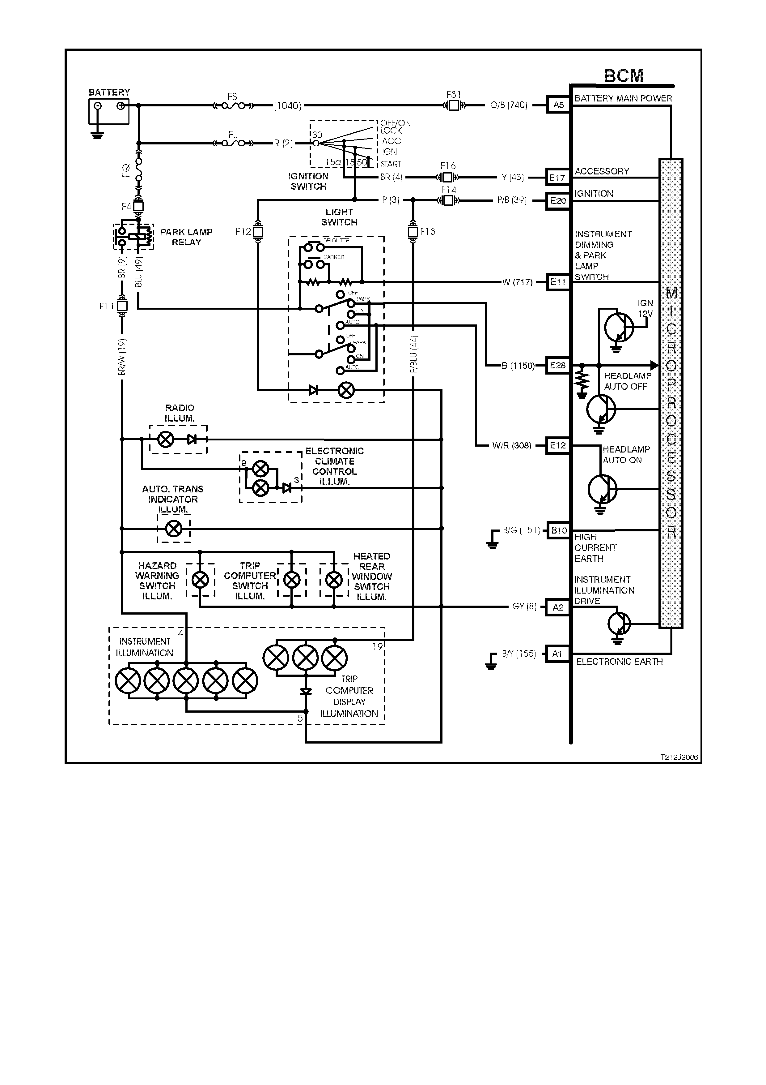
Figure 12J-2-53 Instrument Dimming circuit
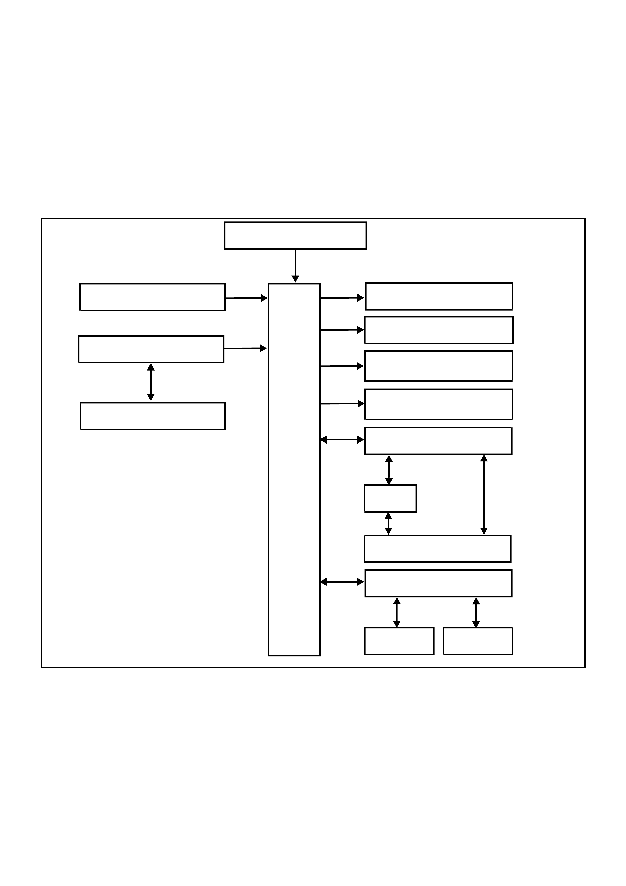
1.14 PRIORITY KEY SYSTEM
GENERAL INFORMATION
On VT Series II Models, the priority key system carries over from earlier VT Series Models, noting the following:
Comm unic ation between the PCM and the BCM on vehicles with GEN III V8 engines is via the Powertr ain Interfac e
Module (PIM).
If diagnosing a circuit fault with the priority key system, reference to the wiring diagrams in
Section 12P WIRING DIAGRAMS of the VT Series II Service Information should be made.
For additional details, including General Description, Service Operations and Diagnosis of the priority key system
that is not covered in this Section, refer to Section 12J-2 HIGH SERIES BODY CONTROL MODULE of the VT
Series I Service Information.
SYSTEM OVERVIEW - PRIORITY KEY
BATTERY POWER
BCM
DOOR LOCK POWER
T212J2050
SERIAL DATA AUX
ECC INSTRUMENTS
SERIAL DATA MAIN
PCM
PIM
GEN III V8
ENGINE V6 & V6 S/C
ENGINE
REMOTE KEY RECEIVE R
REMOTE CODE D KEY
PRIORITY ONE
ANTENNA DRIVE
INSTRUMENT
ILLUMINATION
AUTOMATIC LIGHTS
OFF EARTH
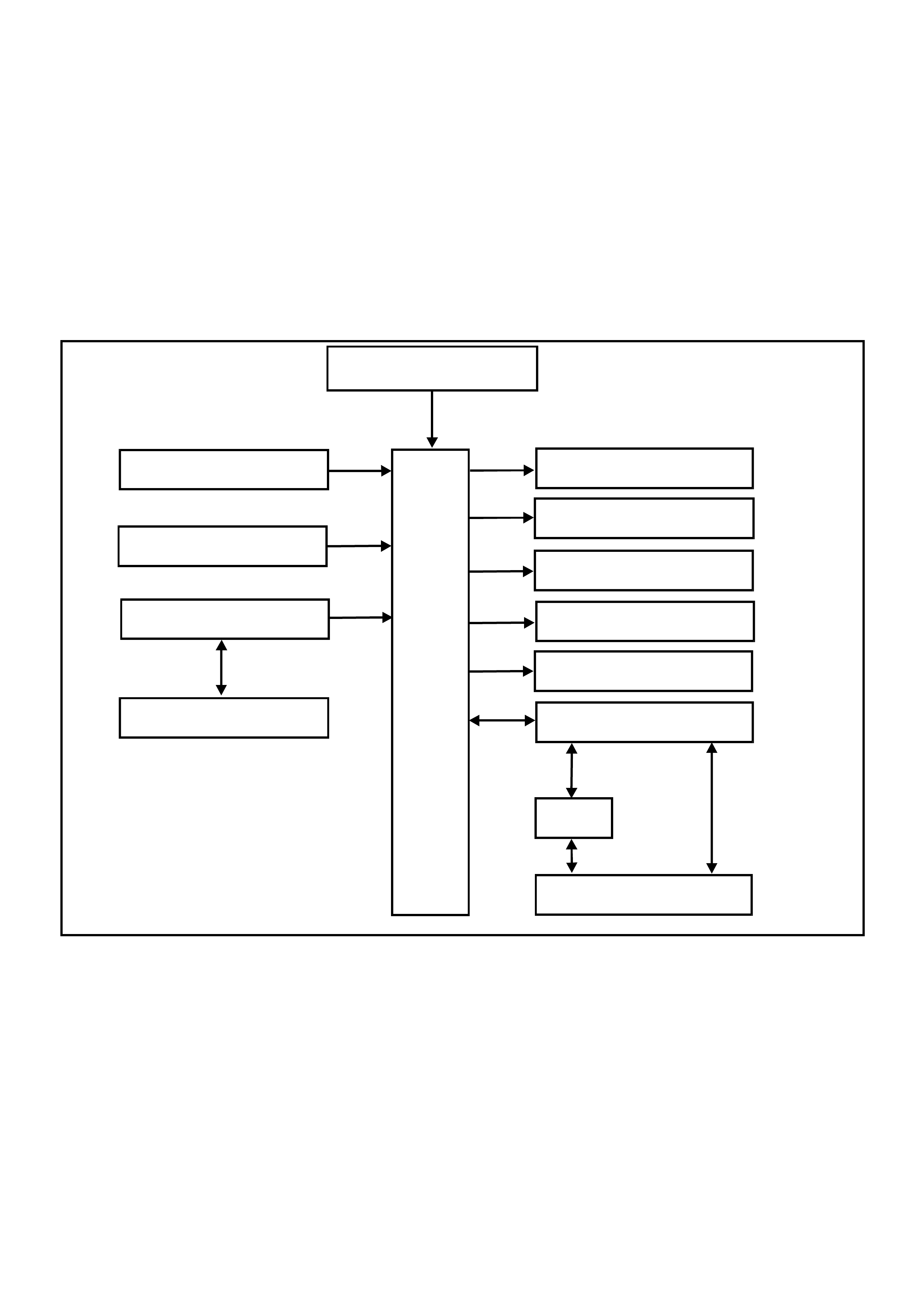
1.15 SRS DEPLOYMENT VEHICLE SHUTDOWN
GENERAL INFORMATION
On VT Series II Models, SRS deployment vehicle shutdown carries over from earlier VT Series Models, noting the
following:
Comm unic ation between the PCM and the BCM on vehicles with GEN III V8 engines is via the Powertr ain Interfac e
Module (PIM).
If diagnosing a circuit fault with SRS deployment vehicle shutdown, reference to the wiring diagrams in
Section 12P WIRING DIAGRAMS of the VT Series II Service Information should be made.
For additional details, including General Description, Service Operations and Diagnosis of the SRS deployment
vehicle shutdown feature that is not covered in this Section, refer to Section 12J-2 HIGH SERIES BODY
CONTROL MODULE of the VT Series I Service Information.
SYSTEM OVERVIEW - SRS VEHICLE SHUTDOWN
BATTERY POWER
BCM
DOOR LOCK POWER
IGNITION SWITCH ON
T212J2049
SERIAL DATA MAIN
PCM
PIM
GEN III V8
ENGINE V6 & V6 S/C
ENGINE
SRS SERIAL DATA AUX
SDM
DOME LAMP
DOOR UNLOCK
DOOR DEADLOCK
ALL D OOR S LOCK DRI V E
DRIVER’S DOOR UNLOCK

2. SERVICE OPERATIONS
2.1 HIGH SERIES BCM
REMOVE & REINSTALL
The procedure for removing and reinstalling the BCM is as detailed in Section 12J-2 HIGH SERIES BODY
CONTROL MODULE of the VT Series I Service Information, noting the following.
If the BCM is r eplaced, the new BCM m ust be sec urity linked to the PCM and, on vehicles with GEN III V8 engines,
the PIM as per the following procedure. If this procedure is not perf ormed, the vehicle will not crank (for m ore than
one second).
BCM LINK TO PCM/PIM
Connect TECH 2 to DLC and select the following:
Diagnostics / (X) 1999 / VT COMMODORE / BODY / BODY CONTROL MODULE / SECURITY / BCM LINK TO
PCM/PIM / select applicable engine and follow TECH instructions.
NOTE: On vehicles with a GEN III V8 engine it will be necessary to obtain TIS approval during the linking
procedure. When instructed to obtain TIS approval by TECH 2, use the following procedure:
1. Disconnect TECH 2 from the vehicle.
2. Using the RS232 connector lead and T ECH 2 power lead, connect T ECH 2 to a Personal Com puter (PC) with
TIS installed (refer Section 0C TECH 2 of the VT Series II Service Information).
3. Turn the TECH 2 unit on so that the TECH 2 screen displays ‘TECH 2’
4. Open TIS and select NEW SESSION / TECHLINE / ENABLING PROGRAMMING and follow the instructions
given by TIS (PC screen).
5. When TIS displays ENABLING PROGRAMMING SUCCESSFUL, press OK.
6. Disconnect TECH 2 from the PC and reconnect TECH 2 to the vehicles DLC.
7. On TECH 2, select Diagnostics / (X) 1999 / VT COMMODORE / BODY / BODY CONTROL MODULE /
SECURITY / BCM LINK TO PCM/PIM / select applicable engine and follow TECH 2 instructions again.
For additional information regarding TECH 2 and TECH 2 test modes (including this linking procedure), refer to
3 TECH 2 DIAGNOSIS FOR BCM in this Section.
Techline

2.2 DOOR LOCK MICROSW ITCHES
Door lock microswitches are now serviced separately on VT Series Models. For the removal and reinstallation
procedure, refer to Section 1A5 FRONT AND REAR DOOR A SSEMBLIES of the VT Series II Service Information.
The procedure for testing the microswitches remains unchanged from that published in
Section 12J-2 HIGH SERIES BODY CONTROL MODULE of the VT Series I Service Information.

2.3 VEHICLE SPEED SENSOR
MANUAL TRANSMISSION
For vehicle speed sensor removal, testing and reinstallation instructions, refer to the RELEVANT POWERTRAIN
MANAGEMENT SECTION in this Service Information CD:
Section 6C1 POWERTRAIN MANAGEMENT - V6 ENGINE of the VT Series I Service Information.
Section 6C2 POWERTRAIN MANAGEMENT - V8 ENGINE of the VT Series I Service Information.
Section 6C3 POWERTRAIN MANAGEMENT - GEN III V8 ENGINE of the VT Series II Service Information.
AUTOMATIC TRANSMISSION
For vehicle speed sensor removal, testing and reinstallation instructions, refer the relevant POWERTRAIN
MANAGEMENT SECTION in this Service Information CD:
Section 6C1 POWERTRAIN MANAGEMENT - V6 ENGINE of the VT Series I Service Information.
Section 6C2 POWERTRAIN MANAGEMENT - V8 ENGINE of the VT Series I Service Information.
Section 6C3 POWERTRAIN MANAGEMENT - GEN III V8 ENGINE of the VT Series II Service Information.

3. TECH 2 DIAGNOSIS FOR BCM
3.1 BASIC KNOWLEDGE REQUIRED
Before attem pting to diagnose the c ontrol or assist of the various vehicle electrical s ystem s controlled by the BCM,
you must have a good understanding of electrical system basics and the use of circuit testing tools. Without this
basic knowledge it will be difficult to use the diagnostic procedures detailed in this Section.
Some elec trical basics, troubleshooting procedures and hints as well as the use of cir cuit testing tools are cover ed
in Section 12P WIRING DIAGRAMS of the VT Series I Service Information.
Basic Electrical Circuits - You should understand the basic theory of electricity, series and parallel circuits, and
voltage drops across series resistors. You should know the meaning of voltage (volts), current (amps), and
resistanc e (ohms). You should understand what happens in a circuit with an open or shorted wire (s horted either to
voltage or earth). You should also be able to read and understand a wiring diagram.
Use of Circuit Testing Tools - You should know how to use a jumper lead to test circuits. You should be familiar with
the use of a high input im pedance ( 10 Meg ohm) digital type m ultimeter such as tool No. J39200 or equivalent and
be able to measure voltage, current, and resistance. You should be familiar with the proper use of the TECH 2
Diagnostic Scan Tool.
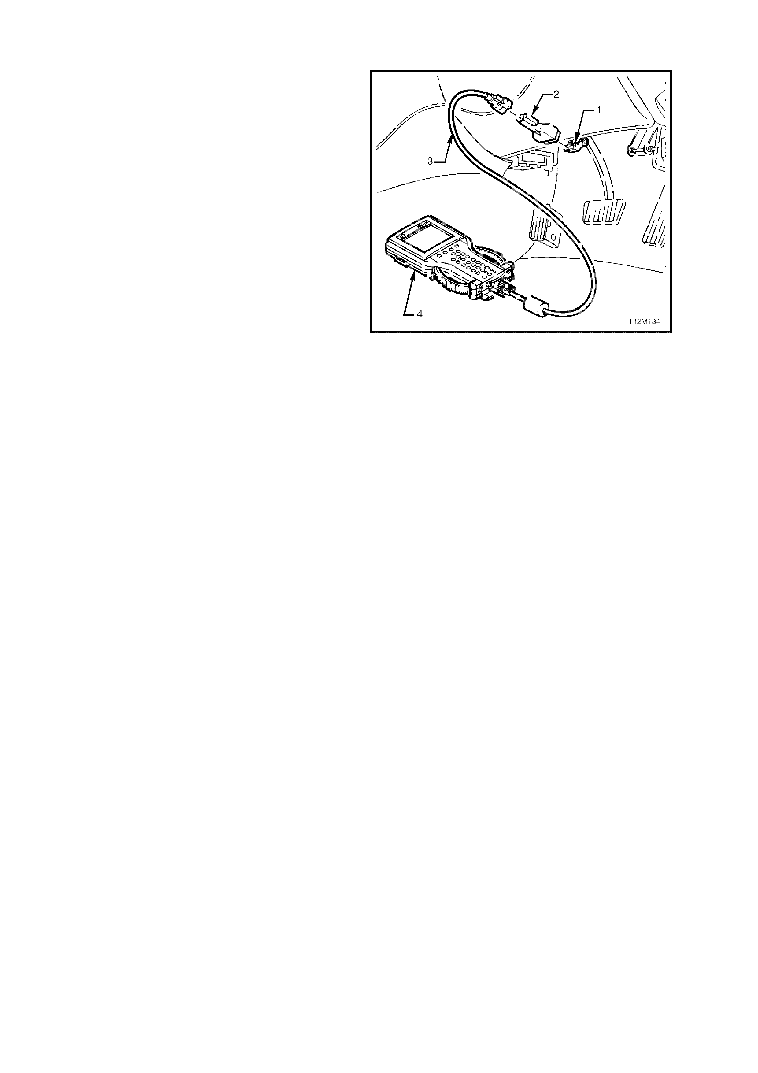
3.2 CONNECTING TE CH 2
TECH 2, with the appropriate software, cables and
adaptors, when connected to the Data Link
Connector (DLC) is capable of reading BCM serial
data. The DLC is connected to the instrument panel
lower right hand trim, to the right of the steering
column.
For additional general information on connecting
and operating TECH 2, refer to
Section 0C TECH 2 of the VT Series I Service
Information.
1. DLC
2. DLC ADAPTOR
3. DLC CABLE
4. TECH 2
Figure 12J-2-55

TECH 2 has seven test modes for diagnosing the
BCM. The seven test modes are as follows:
Mode F0: Normal Mode
In this mode, the Tech 2 monitors the
communication between control modules on the
serial data line. The information displayed on the
TECH 2 screen in this mode is what the BCM is
communicating to the other modules via the serial
data line.
Mode F1: Diagnostic Trouble Codes
In this test mode, curr ent Diagnostic T r ouble Codes
(DTCs) stored in the control m odules mem ory may
be displayed or cleared.
Additionally, in this mode, entry deterrent alarm
codes, stored in the control modules memory can
be displayed and cleared. The pur pose of the entry
deterrent alarm codes is to identify which device
triggered the alarm; i.e. bonnet alarm triggered.
Mode F2: Data Display
In this test mode, TECH 2 displays the status of
inputs and outputs of the BCM.
Mode F3: Snapshot
In this test mode, Tech 2 captures BCM data
before and after a forced manual trigger.
Mode F4: Miscellaneous Tests
In this test mode, Tech 2 performs various
functional tests to assist in pr oblem isolation during
trouble shooting.
Mode F5: Program
In this test mode, Tech 2 allows the programming
of various features by turning the feature OFF or
ON, or adjusting settings (ie. Twilight sentinel
sensitivity).
Mode F6: Security
In this test m ode, T ech 2 pr ovides the user with the
capability of: linking the BCM to the PIM (GEN III
V8 only) and to the PCM, reading security
information (ie. Radio pin numbers), and
programming security features (ie. keys).
Figure 12J-2-56
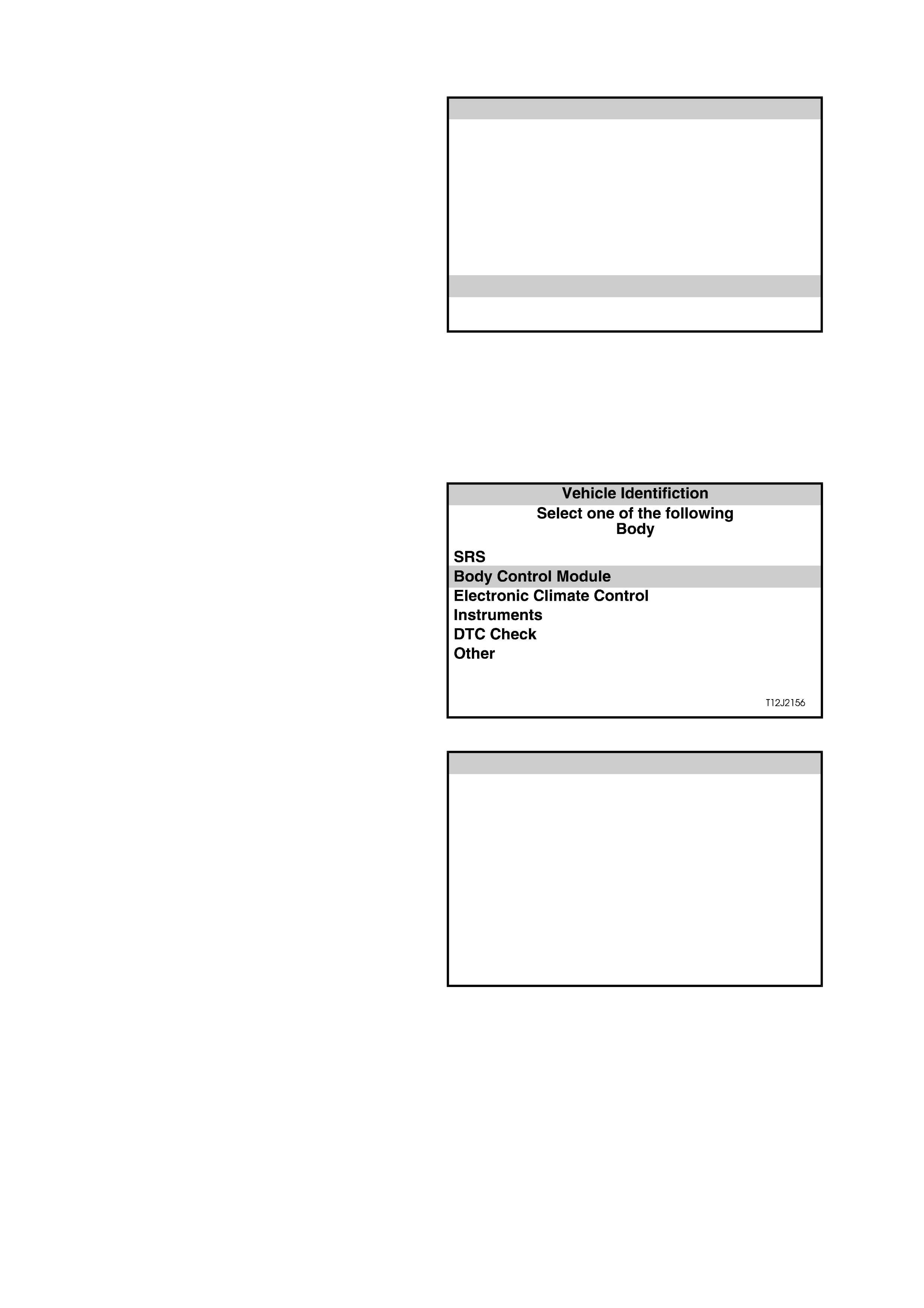
3.3 TECH 2 TEST MODES AND DISPLAYS FOR BCM DIAGNOSIS
As a prerequisite to this diagnostic s ec tion is f or the
user to be familiar with the proper use of TECH 2.
The following pages illustrate only the major TECH
2 screen dis plays and provide a brief ex planation of
their function for diagnosing the BCM. If additional
inform ation is required on the operation of T ECH 2,
reference should be made to either
Section 0C T ECH 2 in this Service Inform ation CD
or the TECH 2 OPERATORS MANUAL.
System Select Menu
W ith TECH 2 c onnected to the DLC and turned on,
F0: DIAGNOSTICS selected from the MAIN
MENU, the appropriate MODEL YEAR and
VEHICLE TYPE must be selected for access to the
SYSTEM SELECT MENU.
Select F3: BODY.
This mode contains all functions to test, diagnose,
monitor and program the vehicles body systems
including the BCM as well as providing the
opportunity to check all DTCs that may be set in the
vehicle.
System S elect Menu
(X) 1999 Commodore
F0: Engine
F1: Transmission
F2: Chassis
F3: Body
T212J2014
Figure 12J-2-57
Body Application Menu
Once F3: BO DY has been selec ted from the s elect
menu, BCM can be selected.
Select Body Control Module and press enter to
continue.
NOTE: If information regarding DTCs set for the
vehicle is required, select DTC CHECK and press
enter to continue. To return to the BCM mode
option from the DTC CHECK mode option screen
display, simply press the EXIT key on TECH 2.
Once the BCM has been selec ted and entered, the
following two SYSTEM IDENTIFICATION screens
will appear which require action. Figure 12J-2-58
System Identification
Turn the ignition ON (as requested) and press
CONFIRM soft key to continue.
System Iden tification
(X) 1999 Commodore
El ectr o ni c Sy s tem : Bo dy Co nt ro l M o du le
Turn On Ignition!
T212j2015
Figure 12J-2-59
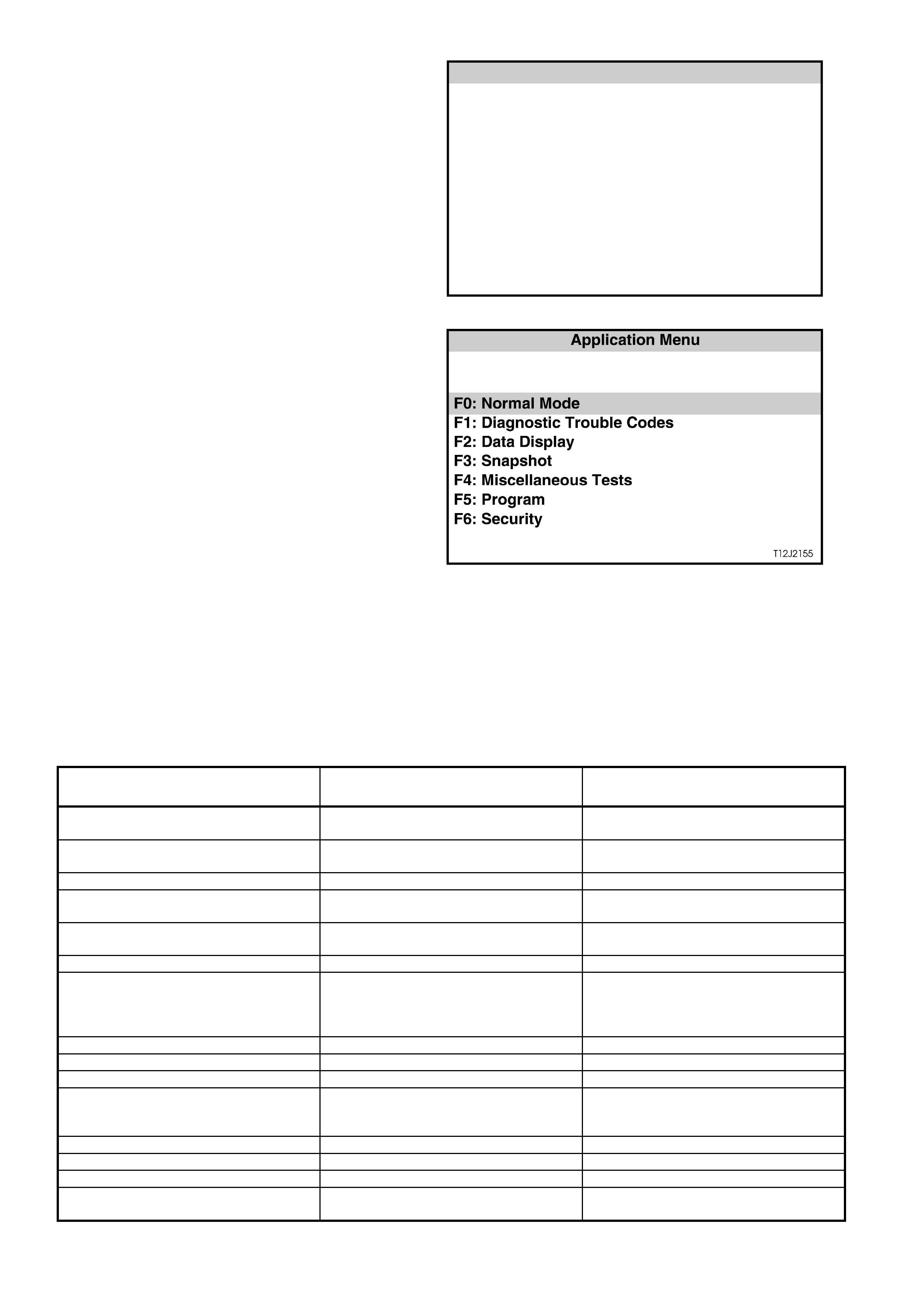
The SYSTEM IDENTIFICATION screen will then
display the control module level and type. Press the
CONFIRM soft key to continue to the BCM
APPLICATION MENU.
• VT Series II Calais should display: Type 1,
Level High.
• VT Series II Berlina Models should display:
Type 1, Level LUX
System Iden tification
(X) 1999 Commodore
El ectr o ni c Sy s tem : Bo dy Co nt ro l Module
BCM Leve l: Hig h
BCM Type:1
T212J2045
Figure 12J-2-60
Application Menu
The following functions will now be available:
F0: Normal Mode
F1: Diagnostic Trouble Codes
F2: Data display
F3: Snapshot
F4: Miscellaneous Tests
F5: Program
F6: Security
Figure 12J-2-61
F0: NORMAL MODE
In the F0: Normal Mode, information that the BCM
is communicating to other control modules, via the
serial data line, is displayed.
The table below lists each item in the Normal
Mode, together with a brief description of its
meaning.
DATA STREAM / SCREEN
DISPLAY DESCRIPTION EXPECTED READING
Ignition Status Displays current state of ignition switch
as sensed by the BCM. On 12 volts / Off 0 volts
Ignition Off Time Displays the length of time since the
ignition was last switched off. XX minutes
Instrument Lamps Displays instrument illumination level. 0 % / 100 %
Lights On Displays current status of headlamp
switch. Yes / No
Ambient Light Level Displays the ambient light level from
the sun load sensor / remote receiver. Between 0 and 254
Boot Status Displays boot switch status. Open / Closed
Rear Lamp Status Displays rear lamp circuit status
(including bulb condition). If a fault is
detected in the circuit, Service Request
will be displayed.
Okay / Service Request
Front Wiper Status Displays front wiper drive status. On / Off
Front Auto Wiper Status This feature is unavailable at present. Off
Cruise Control Input Signal Displays status of cruise control. On / Off
A/C Request (Air Conditioning) This feature is not applicable to high
series vehicles (with ECC), therefore,
will always display OFF.
On / Off
BCM Lower Fan Drive Displays low speed fan drive status. On / Off
BCM Chime (Body Control Module) Displays status of BCM chime. On / Off
Key User Displays priority key in use. 1 / 2
BCM DTC Status Display will advise if any BCM DTCs
are set. No DTCs / DTCs Set

F1: DIAGNOSTIC TROUBLE CODES
The following functions will be available in this
mode:
Read Current DT C Inf or mation - a lis ting of all ( if
any) current DTCs that have been set by the
BCM will be displayed. A short description of
what the DTC is, is also displayed in this mode.
Read Alarm Code Information - a description of
stored alarm codes (if any) w ill be displayed.
Clear DTC Information - simply select CLEAR
CODES, press the ENTER button on TECH 2
and confir m the action as instructed by T ECH 2.
Performing this function will also alarm codes.
The following chart sets out all the possible BCM
DTCs as indicated by TECH 2.
Refer to the relevant diagnostic chart in this
Section when attempting rectification of a
system problem or failure.
Figure 12J-2-62

BCM DIAGNOSTIC TROUBLE CODES
DTC CODE DESCRIPTION REFER
1Output overload - sets if the BCM output
protection circuitry detects an output driver
overload. This will cause all BCM output drives to
be set to the inactive state. The BCM will then
attempt to drive all outputs approximately every
10ms, thus causing all active BCM output drives to
repeatedly switch from an active to an inactive
state until the fault condition is remedied.
NOTE: The BCM is unable to identify which output
is being overloaded.
This DTC can be set by any one of the BCM outputs being
shorted to battery positive, therefore, if DTC 1 is set, refer
to section relevant to driver complaint (if any).
For a listing of all BCM outputs, refer to the HIGH SERIES
BCM TERMINAL IDENTIFICATION chart in 1 GENERAL
DESCRIPTION in this Section.
NOTE: DTC 1 can also be set by electrical transients,
therefore, if DTC 1 is set and there are no noticeable
problems with the vehicle, clear DTC and check function
of BCM outputs. if DTC does not reset and BCM outputs
are functioning correctly, disregard DTC 1.
2Slip Ring Failure -sets if the number of failed slip
ring reads exceeds a programmable percentage of
all slip ring reads (approximately 18 failed slip ring
reads out of 100 good slip ring reads).
4.4 THEFT DETERRENT, in this Section to rectify
problem.
3Power steering Open Circuit - sets when the
feedback from the BCM commanded power
steering current is less than the desired value by
more than 25% of the minimum achievable
current.
4.8 SPEED SENSITIVE POWER STEERING, in this
Section to rectify this problem.
4Power Steering Short Circuit - sets whenever the
power steering current feedback circuit detects a
current in excess of that commanded by the BCM.
4.8 SPEED SENSITIVE POWER STEERING, in this
Section to rectify this problem.
5Tail Lamp Failure - sets when the BCM detects a
tail lamp failure that turns the rear light failure
warning lamp ON in the instrument cluster.
4.12 REAR LAMP FAILURE WARNING SYSTEM, in this
Section to rectify the problem.
6Stop Lamp Failure - sets when the BCM detects a
stop lamp fail that turns the rear light failure
warning lamp ON in the instrument cluster.
4.12 REAR LAMP FAILURE WARNING SYSTEM, in this
Section to rectify the problem.
7PCM Data Lost - sets when the BCM does not
receive responses from the PCM (via PIM on a
vehicle with a GEN III V8 engine) or receives
incorrectly formatted responses from the PCM
within three seconds of normal serial data bus
activity.
The three second time out period is reset
whenever the following conditions occur:
• Ignition switched from OFF to ON.
• A good PCM poll response is received from
the PCM/PIM.
• A key has been programmed.
• BCM has just been reset.
4.2 SERIAL DATA COMMUNICATION, in this Section to
rectify problem.
8PCM Vehicle Speed Data Unstable - sets if the
BCM receives two consecutive road speed
updates from the PCM/PIM with a magnitude
difference of 30 km/h.
4.8 SPEED SENSITIVE POWER STEERING (steps 10 &
11), in this Section to rectify problem.
17 Serial Data Bus Fault - sets if the BCM cannot
detect six consecutive messages on the serial
data bus. This trouble code indicates either a short
circuit on the bus or if two or more modules send a
message at the same time.
4.2 SERIAL DATA COMMUNICATION, in this Section to
rectify problem.
BCM ENTRY DETERRENT ALARM CODES
AC CODE DESCRIPTION REFER
1Bonnet alar m triggered If an alarm code is triggered, it does not indicated a
2Boot alarm tr iggered problem with the entry deterrent system, rather it simply
3Passenger’s door alarm triggered acts as a guide to indicate which alarm trigger (i.e. bonnet
4Driver’s door ala rm triggered switch) is triggering the alarm system.
5Ignition alarm triggered

F2: DATA DISPLAY
In this test mode, TECH 2 checks if the BCM is actually receiving an input or inputs from the appropriate sensor/s or
actuator/s f or the system being diagnosed, eg. for power antenna m ast adjustm ent, check that the radio on, power
antenna up or down switch inputs are being received.
If the sensor/s or actuator/s input/s are not being received, then c arry out the relevant system diagnos is as defined
in this Section.
If the sens or/s or actuator /s input/s ar e being rec eived, go to the appr opriate F 4: BCM T EST mode to c ommand the
BCM via TECH 2 to operate the system output.
Should the system output or actuator not function correctly, conduct relevant system diagnosis as defined in this
Section. If system wiring and output actuator are OK, replace BCM.
A description explaining the display and, where applicable, affected terminals is included in the charts below.
NOTE: When the TECH 2 is communicating with the BCM, it also determines what type of BCM is fitted to the
vehicle and therefore only the relevant data list and functional tests will be displayed.
Data List
SCREEN DISPLAY DESCRIPTION TERMINAL
AFFECTED
BCM LEVEL Displays what level of BCM is fitted to the vehicle.
The screen should display LUX on Berlina Models and HIGH on Calais.
If fuse F31 or circuits 740 and/or 1040 are open circuited, communication with
the BCM will not be possible. If these circuits are OK, refer to 4.2 SERIAL DATA
COMMUNICATION in this Section.
-
BCM TYPE Displays what type of BCM is fitted to the vehicle.
The screen will display the type of BCM fitted to the vehicle (Both VT and VT
Series II Berlina and Calais Models will display ‘TYPE 1’).
If fuse F31 or circuits 740 and/or 1040 are open circuited, communication with
the BCM will not be possible. If these circuits are OK, refer to 4.2 SERIAL DATA
COMMUNICATION, in this Sec t ion.
-
BATTERY VOLTAGE Displays battery voltage input to BCM.
If fuse F31 or circuits 740 and/or 1040 are open circuited, communication with
the BCM will not be possible.
A5
VEHICLE SPEED Displays vehicle speed input to BCM via the main SDI (circuit 1221).
If vehicle speed cannot be displayed, refer to 4.11 ROAD SPEED DEPENDENT
VARIABLE WIPER SYSTEM diagnosis, Steps 50 and 54 in Section 12J-2 HIGH
SERIES BODY CONTROL MODULE, of the VT Series I Service Information.
E2
SLIP RING ENABLED Screen display may flash from NO to YES briefly when BCM receives a correct
key reading. If BCM does not receive a correct key reading, screen will flash
between NO YES continuously until a correct reading is achieved.
If screen does not change as described, refer to 4.4 THEFT DETERRENT in this
Section.
E1
IGNITION SWITCH Displays current state of ignition switch as sensed by the BCM.
Will display ON with ignition switch in IGN or START positions and OFF in ACC
or OFF positions.
If screen display doesn’t change as described, check circuitry between ignition
switch and BCM, and ignition switch contacts. If circuit and switch are OK, BCM
is faulty.
E20

SCREEN DISPLAY DESCRIPTION TERMINAL
AFFECTED
ACCESSORY SWITCH Displays current state of accessory switch as sensed by the BCM.
Will display ON with ignition switch in ACC or IGN positions and OFF in START
or OFF positions.
If screen display doesn’t change as described, check circuitry between ignition
switch and BCM, and ignition switch contacts. If circuit and switch are OK, BCM
is faulty.
E17
CENTRAL LOCKING Displays the current state of the BCM internal central door locking relays.
When locking the central door locking system, either remotely or by turning the
RH door key switch, the screen display changes to ALL LOCK. If the RH door
key switch is activated a second time or the remote coded key lock button is
pressed a second time, the screen will display DEADLOCKED.
When unlocking the system by turning the RHF door key switch, the screen
display changes from ALL LOCKED or DEADLOCKED to ALL UNLOCK.
Unlocking remotely, the screen display changes from ALL LOCKED or
DEADLOCKED to DRIVER UNLOCK on first press (If vehicle is programmed
with two stage unlocking) and second button press, the screen displays ALL
UNLOCK.
If screen display does not change as described, refer to 4.3 CENTRAL DOOR
LOCKING and carry out FUNCTIONAL CHECK - CENTRAL DOOR LOCKING.
-
DRIVER’S DOOR
UNLOCK SWITCH Displays RHF door lock actuator key switch input to BCM.
With doors locked, screen displays OFF, unlocking the driver’s door or all doors,
screen will change to ON.
If the circuit from BCM terminal C20 is open circuited, the passenger’s doors
cannot be unlocked by the RHF door lock key switch.
C20
PASSENGER’S DOOR
UNLOCK SWITCH Displays passenger door lock actuator switch inputs to the BCM.
With doors locked, screen displays OFF, unlocking the passenger doors, screen
changes to ON.
If the circuit from BCM terminal C9 is open circuited, the passenger doors cannot
be unlocked. The screen display will also remain unchanged.
C9
LOCK SWITCH
STATUS Displays the front doors lock actuator inputs to the BCM.
When doors are locked, by activating either of the front door lock actuators
(snib), screen displays ON. When doors are unlocked, screen displays OFF.
If circuit is open, doors can not be locked from the front door lock actuators
(snib), but system can be locked remotely.
If screen display does not change as described, refer to 4.3 CENTRAL DOOR
LOCKING and carry out FUNCTIONAL CHECK – CENTRAL DOOR LOCKING in
this Section.
C21
DEADLOCK SWITCH Displays RHF door lock microswitch input to BCM.
With RHF door lock in the unlocked and locked position, screen displays OFF.
Display will change to DEADLOCK when the door lock is turned to the deadlock
position either via the remote coded key lock button being pressed twice within
10 seconds, or when the driver’s door lock cylinder is turned to the deadlock
position (two sequential locks).
If circuit 197 is open circuited, doors cannot be locked or deadlocked by turning
the RHF door lock cylinder. However, doors can be locked or deadlocked
remotely.
If screen display does not change as described, refer to 4.3 CENTRAL DOOR
LOCKING and carry out FUNCTIONAL CHECK - CENTRAL DOOR LOCKING,
in this Section.
C22
ILLUMINATION
SWITCH POSITION Displays instrument dimmer slide control input to BCM.
With the ignition OFF, parking lamps OFF and dimming switch control lever at
the rest position, screen displays OFF.
With the ignition and park lamps on and the control lever held up, screen
displays UP. With switch control lever held down, screen displays DOWN.
If circuit 717 between BCM terminal E11 and headlamp switch is open circuited,
the screen will not change and screen display will remain OFF.
If screen displays are not as described, refer to 4.10 INSTRUMENT DIMMING
CONTROL in this Section.
E11

SCREEN DISPLAY DESCRIPTION TERMINAL
AFFECTED
ILLUMINATION
VOLTAGE Displays instrument dimmer slide control input voltage to BCM.
With the parking lamps ON and dimming switch control lever at the rest position,
screen displays approximately 3.5 volts. (Displays approximately 5 volts when
lamps are OFF)
With the control lever held in the up position, screen displays 0.2 volts. With the
switch control lever in the down position, the screen displays 2.2 volts.
If screen displays are not as described, refer to 4.10 INSTRUMENT DIMMING
CONTROL in this Section.
E11
INSTRUMENT LAMPS With ignition OFF and parking or headlamps OFF, screen displays 100%,
irrespective of switch control lever position. With ignition ON and parking lamps
off, screen displays 100%, irrespective of switch control lever position as the trip
computer display in the instrument cluster is illuminated.
With the ignition ON, Parking lamps ON and switch control lever in the up
position, the percentage of instrument cluster illumination intensity will increase
to 100% (if not already at 100%).
Holding switch control lever down, screen will gradually decrease to
approximately 35%.
If circuit 717 between BCM terminal E11 and headlamp switch is open circuited,
the screen will not change and screen display will remain OFF.
If screen displays are not as described, refer to 4.10 INSTRUMENT DIMMING
CONTROL in this Section.
E11
DOME SWITCH Displays dome lamp switch input to BCM.
With dome lamp switch in off, screen displays OFF, changes to ON when switch
is turned ON, and changes to DOOR when switch is turned to the door position.
If circuit 174 between the BCM, terminal C24 and the interior lighting is open
circuited, the interior lighting will not come on.
If screen display does not change as described, refer to 4.9 DOME LAMP
DELAY CONTROL in this Section.
C24
DOME LAMP DRIVE Display changes from OFF to ON as dome lamp is turned ON or when the
remote coded key UNLOCK button is depressed. Display goes OFF when the
ignition is turned ON. This check confirms if the BCM internal circuitry is
operating (a relay within the BCM will be heard to click as the drive is turned on).
If circuit 174 between the BCM, terminal C24 and the interior lighting is open
circuited, the interior lighting will not come on.
If screen display does not change as described, refer to 4.9 DOME LAMP
DELAY CONTROL in this Section.
C24
LIGHTS OFF DELAY Displays programmed automatic headlamps delay period, if set (will display
0 sec. If not set). Refer to 1.8 AUTOMATIC LIGHTS OFF (WITHOUT TW ILIGHT
SENTINEL) in this Section.
If delay period will not set, refer to 4.6 AUTOMATIC LIGHTS OFF (WITHOUT
TWILIGHT SENTINEL) in this Section.
-
HEADLAMP SWITCH Displays status of switch during auto off period only.
Display changes from OFF to ON as headlamps auto off period is in progress.
This check confirms that the BCM internal switching is operating. Display goes to
OFF when the headlamp auto off is cancelled.
If screen does not change as described, refer to 4.6 AUTOMATIC LIGHTS OFF
(WITHOUT TWILIGHT SENTINEL) in this Section.
E12, E28
HEADLAMP DRIVE With the ignition turned on, screen displays ON, turning the ignition off, the
screen will still display ON. Turn headlamps on, scroll ignition from on to off and
open the driver’s door, screen will change from ON to OFF and headlights will go
out.
If screen does not change as described, refer to 4.6 AUTOMATIC LIGHTS OFF
(WITHOUT TWILIGHT SENTINEL) in this Section.
E28
AMBIENT LIGHT
SENSOR Displays ambient light level input to BCM.
When ambient light sensor (sun sensor / remote receiver module) is covered
(dark), display will show approximately 0 volts. With bright light (sun light or for
testing purposes, a torch), display will be up to 5 volts.
If screen does not change as described, to 4.6 AUTOMATIC LIGHTS OFF
(WITHOUT TWILIGHT SENTINEL) in this Section.
E10

SCREEN DISPLAY DESCRIPTION TERMINAL
AFFECTED
TWILIGHT LEVEL Displays the programmed level of sensitivity - may be set between 0 and 7 (4 is
the default setting in production).
If screen display is not as described, refer to 4.7 AUTOMATIC LIGHT CONTROL
– LIGHTS ON AND OFF / APPROACH ILLUMINATION (WITH TWILIGHT
SENTINEL) in this Section.
-
TWILIGHT SENTINEL Will display ON when BCM determines lights should be turned on, regardless of
headlamp position.
If screen does not change as described, refer to 4.7 AUTOMATIC LIGHT
CONTROL – LIGHTS ON AND OFF / APPROACH ILLUMINATION (WITH
TWILIGHT SENTINEL) in this Section.
E7, E10
DRIVERS DOOR Displays the driver’s door jamb switch input to the BCM.
When the driver’s door is open, the screen display should be OPEN, and when
the door is closed, the screen should display CLOSED.
If screen does not change as described, refer to 4.4 THEFT DETERRENT in this
Section.
C8
PASSENGER DOORS Displays the passenger’s door jamb switch input to the BCM.
When the passenger’s door is open, the screen display should be OPEN, and
when the door is closed, the screen should display CLOSED.
If screen does not change as described, refer to 4.18 ENTRY DETERRENT in
this Section.
C7
STOP LAMP SWITCH Displays stop lamp switch input to BCM.
When brake pedal is depressed and the ignition is on, screen display changes
from OFF to ON.
If screen does not change as described, refer to Section 12L ABS & ABS/ETC
diagnostics of the VT Series I Service Information.
E18
STOP LAMP BULB
CONDITION With ignition ON and brake pedal depressed, screen should display OKAY. If
screen displays FAILED, check stop lamp bulbs, wiring between stop lamp
switch and rear lamp connectors, and between rear lamp connectors and BCM.
NOTE: If at any time the BCM has been reset, a rear lamp failure warning
system bulb relearn procedure must be performed (refer to 1.14 REAR LIGHT
FAILURE WARNING SYSTEM in Section 12J-2 HIGH SERIES BODY
CONTROL MODULE, of the VT Series I Service Information).
C15
STOP LAMP FUSE Displays stop lamp fuse F5 input to BCM.
Screen should display Okay. If screen displays FAILED, check fuse F5, wiring
between fuse F5 and battery, and between fuse F5 and BCM.
E18
PARK LAMP FUSE Displays parking lamp fuse F4 input to BCM.
Screen should display Okay. If screen displays FAILED, check fuse F4, wiring
between fuse F4 and battery, and fuse F4 and the BCM.
E24
PARK LAMP SWITCH Displays parking lamps switch input to BCM.
When the parking lamps are switched on, screen display changes from OFF to
ON.
If screen does not change as described, check headlamp switch contacts or
open circuit in wiring to BCM terminal E11, refer to Section 12B LIGHTING
SYSTEM of the VT Series I Service Information.
E11
PARK LAMP BULB
CONDITION With ignition ON and parking lamps on, screen should display Okay. If screen
displays FAILED, check rear parking lamp bulbs, wiring between headlamp
switch and rear lamp connectors, and between rear lamp connectors and BCM.
NOTE: If at any time the BCM has been reset, a rear lamp failure warning
system bulb relearn procedure must be performed (refer to 1.14 REAR LIGHT
FAILURE WARNING SYSTEM in Section 12J-2 HIGH SERIES BODY
CONTROL MODULE, of the VT Series I Service Information).
E11, E28
BULB FAILED
WARNING LAMP Checks BCM internal switching for illuminating the rear lamps failure warning
lamp. The warning lamp will illuminate whenever a fault is detected.
If lamp does not work, refer to Section 12C INSTRUMENTS,
WIPERS/WASHERS & HORN of the VT Series I Service Information.
If screen display does not change as described, the BCM is faulty.
E9

SCREEN DISPLAY DESCRIPTION TERMINAL
AFFECTED
LAMP CIRCUIT
CURRENT STATUS Will display OK if the BCM current flow is within specifications. If current flow is
higher than specified, TECH 2 screen will display TOO HIGH. In this case, check
for installation of incorrect wattage rear lamp bulbs, or causes of high current
flow to rear lamps, ie. Rear lamps shorted to together or shorted to earth.
-
STOP LAMP
CURRENT Displays current flow from rear lamps as detected by the BCM.
With ignition off, parking lamps off and brake pedal released, displays
approximately 0.0 A.
With ignition off, parking lamps on and brake pedal depressed, displays
approximately 0.3 A.
With ignition on, parking lamps on and brake pedal depressed, displays
approximately 1.0 A.
C15
PARK LAMP
CURRENT Displays current flow from rear lamps as detected by the BCM.
With ignition off, parking lamps off and brake pedal released, displays
approximately 0.0 A.
With ignition on, parking lamps on, displays approximately 3.1 A.
With ignition on, parking lamps on and brake pedal depressed, displays
approximately 4.9 A.
With ignition on, parking lamps off and brake pedal depressed, displays
approximately 4.9A.
C15
FRONT WASHER
PUMP SWITCH Displays front washer pump switch input to BCM.
With ignition on and the washer pump switch activated, screen display changes
from OFF to ON.
If circuit 94, between the BCM and the wiper/washer switch is open circuited, the
wipe after wash function will not operate.
If screen display does not change, check circuit 94 between BCM terminal E25
and wiper/washer switch (including wiper/washer switch contacts), refer Section
12C INSTRUMENTS, WIPER/WASHER & HORN of the VT Series I Service
Information.
E25
WIPER PARK SWITCH Displays input to BCM.
With wipers in the park position, screen displays ON. With wipers operating,
display will change to OFF and momentarily go to ON as wipers operate through
the park region.
If circuit 196, between the BCM and the wiper motor is open circuited, the screen
will display ON all the time and wipers will not park when turned off.
If screen display remains ON with wipers operating, check for open circuit
between BCM terminal B8 and wiper motor, carry out checks of wiper motor,
refer Section 12C INSTRUMENTS, WIPER/WASHER & HORN of the VT Series
I Service Information.
B8
FRONT WIPER
INTERMITTENT
SWITCH
Displays wiper/washer switch intermittent switch contacts input to BCM.
With ignition on and wiper/washer switch set to the intermittent position, screen
display changes to ON.
If circuit 97, between the BCM and the wiper/washer switch is open circuited,
there will be no intermittent wiper function.
If screen display does not change, check circuit 97 between BCM terminal E27
and wiper/washer switch (including wiper/washer switch contacts), refer Section
12C INSTRUMENTS, WIPER/WASHER & HORN of the VT Series I Service
Information.
E27
INTERMITTENT
WIPER VOLTAGE Displays intermittent wiper potentiometer setting input to BCM.
Displays between 0.9 and 3.9 volts depending on potentiometer setting.
If screen does not change when potentiometer is adjusted, refer to Section 12C
INSTRUMENTS, WIPERS/WASHERS & HORN of the VT Series I Service
Information.
E5
INTERMITTENT
WIPER DRIVE With wipers operating in the intermittent mode, screen displays ON. With wipers
in the parked position, and in 1st or 2nd speed, screen displays OFF.
If screen displays are not as described, refer to 4.14 ROAD SPEED
DEMENDENT VARIABLE DWELL WIPER SYSTEM in this Section.
-

SCREEN DISPLAY DESCRIPTION TERMINAL
AFFECTED
FRONT WIPER
DWELL TIME Displays wiper/washer switch dwell control adjustment at BCM.
With vehicle stationary, display will change from approximately 5.0 SEC
(seconds) at fastest setting to approximately 25 SEC (seconds) at its slowest
setting as dwell control switch is adjusted from one extreme to the other.
If screen display doesn’t change, or displays 5.0 SEC continuously, check circuit
96, between BCM terminal E5 and wiper/washer switch (including wiper/washer
dwell control adjustment contacts, refer Section 12C INSTRUMENTS,
WIPER/WASHER & HORN of the VT Series I Service Information.
E5
REAR WASH PUMP
SWITCH Displays rear washer pump switch input to BCM.
With ignition on and the washer pump switch activated, screen display changes
from OFF to ON (this applies to wagon only, on sedan models, the screen will
always display OFF).
If circuit 494, between the BCM and the wiper/washer switch is open circuited,
the wipe after wash function will not operate.
If screen display does not change, check circuit 494 between BCM terminal E15
and wiper/washer switch (including wiper/washer switch contacts), refer to
Section 12C INSTRUMENTS, WIPER/WASHER & HORN of the VT Series I
Service Information.
E15
REAR WIPER SWITCH Displays rear wiper switch input to BCM.
With ignition on and the rear wiper switch in the on position, screen will change
from OFF to ON (this applies to wagon only, on sedan models, the screen will
always display OFF).
Refer to 4.14 ROAD SPEED DEMENDENT VARIABLE DWELL WIPER
SYSTEM in this Section.
E19
POWER WINDOW
SWITCH Displays input to BCM.
With power windows enabled, screen displays OFF. With driver’s window switch
down button activated, screen displays DOWN. With driver’s window switch up
button activated, screen displays UP.
If screen does not display DOW N when the down button is activated and the
window automatic down function does not work, check for open circuit between
BCM terminal C14 and the driver’s side power window switch.
C14 (Down)
C16 (Up)
WINDOW AUTO
DOWN DRIVE Screen display changes from OFF to ON when the driver’s side power window
switch automatic down button is activated and functioning. Will also display ON
when down button is activated, but with automatic down feature not functioning.
If the driver’s side power window operates normally except for the automatic
down feature, and all system inputs are determined to be OK, then BCM is
faulty.
-
POWER WINDOW
RELAY Displays the power window relay status as determined by the BCM internal
circuitry. The relay is enabled by the BCM earthing circuit 173.
With the power window switch enabled (lights in power switch illuminated),
screen displays ENABLED. With the system OFF, screen displays DISABLED.
If the screen displays ENABLED but the lights in the power window switch do not
illuminate, check for open in wiring to BCM terminal B2.
If screen displays are not as described, refer to 4.20 POWER WINDOW
SYSTEM in this Section.
B2
CRUISE CONTROL
INPUT SIGNAL Displays the cruise control on/off switch input status to the BCM.
With ignition on, each activation of the cruise on/off switch will toggle the screen
display to the next state, ie. OFF to ON or ON to OFF.
If the screen display changes as described, but the cruise control CRUISE lamp
in the instrument cluster does not illum i nate, refer to 4.11 CRUISE CONTROL in
this Section.
If screen display does not change, refer to Section 12E CRUISE CONTROL the
VT Series I Service Information (V6) or the VT Series II Service Information
(GEN III V8) in this Service Information CD.
E26

SCREEN DISPLAY DESCRIPTION TERMINAL
AFFECTED
BONNET OPEN
SWITCH Displays bonnet switch input to BCM.
With bonnet closed (bonnet switch contacts open circuit), screen displays
OPEN. With bonnet open (switch contacts close and the circuit is connected to
earth) screen will display CLOSED.
If circuit 260 is open circuited, the screen display will remain OPEN.
If screen does not change as described, refer to 4.18 ENTRY DETERRENT in
this Section.
E23
BOOT RELEASE
SWITCH Displays boot release switch input to BCM.
With the boot release switch (located in glove compartment) in the rest position,
screen displays OFF. With switch held in, switch displays ON.
If screen does not change as described, refer to 4.18 ENTRY DETERRENT in
this Section.
E22
BOOT LAMP SWITCH Displays rear compartment (boot) lamp switch input to the BCM.
With rear compartment lid closed (rear compartment lamp switch contacts
open), screen displays OPEN. With the rear compartment lid open (the switch
contacts close and the circuit is connected to earth), screen will display
CLOSED.
If circuit 162 is open circuited, the screen display will remain OPEN.
If screen does not change as described, refer to 4.18 ENTRY DETERRENT in
this Section.
C6
BOOT SOLENOID
DRIVE Provided the vehicle speed is less than 15 km/h, depressing the boot release
button on the remote coded key will cause the screen display to change from
CLOSED to OPEN as the BCM internal relay is activated.
If screen does not change or boot release does not operate, refer to 4.18
ENTRY DETERRENT in this Sec t ion.
-
RADIO STATUS Displays radio ON/OFF status input to BCM.
The radio on signal is required to enable the antenna mast to extend.
With the radio turned off, screen displays OFF. With radio on and the ignition in
the ACC or IGN positions, screen displays ON.
If screen does not change as described, check circuit 143 between BCM and
radio.
E16
POWER ANTENNA Displays BCM output state of BCM internal switch.
If circuit 954 is open circuited from the BCM, the antenna mast will not extend.
With the radio off, the power antenna screen displays OFF. With ignition in the
ON or ACC position, and radio on, screen will display AUTO UP. When antenna
mast finishes extending, screen displays OFF.
At this position (mast extended), switch the radio off and as the mast retracts,
screen will display AUTO DOWN.
If screen does not change as described, refer to 4.13 POWER ANTENNA
CONTROL in this Section.
C17
ANTENNA SWITCH
POSITION Displays antenna switch input to BCM.
With switches in the rest position, screen displays OFF. With radio on and
ignition on, if up switch is depressed, screen will display UP SWITCH, if down
switch is depressed, screen will display DOW N SWITCH.
If screen does not change as described, refer to 4.13 POWER ANTENNA
CONTROL in this Section.
E13, E14
OVERRIDE STATUS This screen displays that status of the theft deterrent systems override function.
NOTE: The 2 hour override function was deleted from the BCM in July 1998,
therefore, the screen display should always display SECURITY ON.
-
SECURITY LED Displays current state of the BCM theft deterrent system LED driver condition. If
the LED is flashing, ie. system armed, the screen will pulse between ON and
OFF.
NOTE: TECH 2 and security LED are synchronised.
This checks that the BCM is turning on and off the voltage supply.
If TECH 2 screen display does not change, the BCM is faulty.
If TECH 2 screen display does change, but the LED does not flash, check for
open or short in wiring from BCM to LED.
A6

SCREEN DISPLAY DESCRIPTION TERMINAL
AFFECTED
INDICATORS When the BCM activates the indicators via it’s internal relay, the screen display
alternates between ON and OFF as the indicators flash.
This checks that the BCM is pulsing its internal relay, thereby supplying voltage
from BCM terminal B5 to terminals B4 and B12. If screen display does not
change as described, BCM is faulty.
If screen display does change as described, but the indicators do not flash,
check for open circuit in wiring from BCM output terminals B4 and B12 or input
to BCM terminal B5. (Refer to 4.4 THEFT DETERRENT diagnosis in this
Section).
B4, B5, B12
PASSIVE MODE With the theft deterrent system in passive arm state, screen displays should be
ON (theft deterrent LED flashing). -
ALARM MODE With the theft deterrent system enabled (theft deterrent LED flashing), and the
system disarmed, screen displays DISARMED. Press the LOCK button on the
remote coded key (doors closed) and centrally lock all doors, the display should
change to ARMED.
-
ALARM With the system armed and not triggered, the screen displays INACTIVE. When
the system is triggered, the screen display changes to TRIGGERED. -
THEFT DETERRENT
HORN When the system is disarmed, or armed and not triggered, the screen displays
OFF. When the system is triggered, the screen changes to ON. This action
checks if the BCM is switching ON or OFF it’s internal driver, enabling terminals
A3 and A4 to be earthed (sounding horns).
A3, A4
REMOTE BOOT
SIGNAL Screen display changes to OPEN then OFF when the boot release button on the
remote coded key is depressed.
If the screen displays INVALID KEY continuously when the boot release button
on the remote coded key is depressed, and the BCM does not operate, that
particular remote coded key is not coded to the BCM (refer to 4.17 REMOTE
RECIVER / KEY in this Section).
NOTE: Due to the fact that the screen changes when the remote coded key is
depressed, is confirmation that there is an RF output from the remote coded key
and that it is recognised by the BCM either as correct or invalid.
-
REMOTE DOOR
SIGNAL Screen display changes to UNLOCK then OFF when remote coded key unlock
button is depressed. Changes to LOCK to OFF when lock button is depressed.
If the screen displays INVALID KEY continuously when the remote coded key is
depressed, and the BCM does not operate, that particular remote coded key is
not coded to the BCM (refer to 4.17 REMOTE RECIVER / KEY in this Section).
NOTE: Due to the fact that the screen changes when the remote coded key is
depressed, is confirmation that there is an RF output from the remote coded key
and that it is recognised by the BCM either as correct or invalid.
-
REMOTE KEY USER Depressing a button on the remote coded key enables the BCM to read the
key’s security code information. If the remote coded key has been programmed
to the BCM, the screen displays the remote coded key user number that has
been assigned to it during the programming process.
A BCM can have up to 31 different remote coded keys programmed into it.
-
KEY PRIORITY
SIGNAL Depressing the UNLOCK button on the remote coded key enables the BCM to
read the key’s security information. If the remote coded key has been
programmed to the BCM, the screen will display the remote coded key’s priority
number that it has been assigned.
NOTE: There can be only one priority one key, all other keys are priority two.
-
RADIO PRIORITY
DRIVE Display BCM output to radio.
With ignition switch in the off position, screen displays 0, with ignition switch in
the ACC or IGN positions, screen will display either 1 or 2 depending on which
key was inserted into the ignition (priority key 1 or 2).
If screen displays are not as described, refer to 4.15 PRIORITY KEY SYSTEM in
this Section.
B3

SCREEN DISPLAY DESCRIPTION TERMINAL
AFFECTED
SERIAL DATA BUS
ISOLATION Displays serial data bus isolation internal switch status.
During normal operations (ignition on, cranking or engine running) the serial data
bus isolation switch will be closed and screen displays NORMAL. If engine will
not start within 0.5 seconds of being cranked, the serial data bus isolation switch
will open (isolating auxiliary serial data bus) for a maximum period of five
seconds, during this time, screen display will change to DATA CUTOFF
If screen displays are not as described, refer to 4.2 SERIAL DATA
COMMUNICATION in this Section.
-
LOW FAN DRIVE This checks the BCM’s ability to turn on it’s internal driver to earth, thus enabling
the engine cooling low speed fan.
With the low speed fan not operating, screen displays OFF. With fan operating,
screen displays ON.
B7
DTC STATUS Display will advise if any BCM DTCs are set.
Screen will display No DTCs if there are no DTCs, or DTCs Set if there are any
BCM DTCs se t.
-
Power Steering
SCREEN DISPLAY DESCRIPTION TERMINAL
AFFECTED
VEHICLE SPEED Displays vehicle speed input to BCM via the main SDI (circuit 1221). E2
If vehicle speed cannot be displayed, refer to 4.8 SPEED SENSITIVE POWER
STEERING diagnosis in this Section.
DESIRED PS
CURRENT (POWER
STEERING)
With ignition ON, TECH 2 displays BCM current flow control of power steering
solenoid.
With rear of vehicle supported on safety stands, drive vehicle and current flow
indication on TECH 2 will gradually reduce to approx. 0 mA at a vehicle speed of
80 km/h.
If power steering current does not change, refer to 4.8 SPEED SENSITIVE
POWER STEERING Diagnosis in this Section.
E4
DTC STATUS Display will advise if any BCM DTCs are set.
Screen will display No DTCs if there are no DTCs, or DTCs Set if there are any
BCM DTCs se t.
-
Part Number
SCREEN DISPLAY DESCRIPTION TERMINAL
AFFECTED
PART NUMBER With the theft deterrent system disarmed, TECH 2 displays the last two digits of
the Holden part number for the BCM fitted to the vehicle (ie. 14).
This information can be checked against the part number label attached to the
BCM case, refer Fig. 12J-2-1 in this Section.
F3: SNAPSHOT
In this mode, TECH 2 captures data before and after a forced manual trigger.
The purpose of the SNAPSHOT test mode is to help isolate an intermittent or transient problem by storing BCM
data parameters just before and just after a problem occurs.

F4: MISCELLANEOUS TESTS
In this test mode, Tech 2 performs various functional tests to assist in problem isolation during trouble shooting.
If a vehicle component is commanded by TECH 2 to operate and the TECH 2 screen display changes as per this
com mand, yet the com ponent does not operate, check for a f aulty circuit between the BCM and the com ponent (ie.
If low speed cooling f an is com m anded ON, TECH 2 sc reen displays LOW SPEED CO OLING FAN ON yet the low
speed cooling fan is physically not ON, then check cooling fan wiring between the BCM and the low speed cooling
fan, including cooling fan, for open or short circuit).
To operate any of the m iscellaneous tes ts, sim ply select the appr opriate functional tes t from the m iscellaneous test
application menu and follow the instructions as per TECH 2.
When the Miscellaneous Tests option is selected, the following options will become available.
NOTE: Additional application menu screens will be displayed for Lamps, Wiper Tests, and Security Systems.
• Lamps: If lamps are selected, an additional application menu will be displayed offering additional functional
tests of the vehicle’s lighting system.
• Dome: In this mode, TECH 2 commands the BCM to switch on and off the interior lighting.
If the interior lighting does not operate, refer to 4.9 DOME LAMP DELAY CONTROL diagnosis in this
Section.
• Lamp Delay Drive: In this mode with the ignition OFF and the headlamps and park lamps turned ON,
TECH 2 commands the BCM to switch OFF and ON the vehicle park lamps and headlamps.
If lamps do not switch off when commanded, refer to
4.6 AUTOMATIC LIGHTS OFF (WITHOUT TWILIGH T SENTINEL) diagnosis in this Section
• Indicators: In this mode, TECH 2 commands the BCM to switch ON and OFF the turn signal indicator
lamps, including the warning lamps in the instrument cluster.
If the turn signal lamps do not operate when commanded by TECH 2, refer to 4.4 THEFT DETERRENT
diagnosis in this Section.
• Bulb Fail Lamp: In this mode and with ignition switched ON, TECH 2 commands the BCM to switch on
and off rear light failure warning light in the instrument cluster.
If the lamp in the instrument cluster will not turn ON, refer to
4.12 REAR LAMP FAILURE WARNING SYSTEM diagnosis in this Section.
• Illumination: In this m ode, TECH 2 comm ands the BCM to brighten or dim the instr um ent cluster and trip
computer illumination lamps.
If the instrument cluster and trip c omputer illumination lamps intens ity does not change when c ommanded
by TECH 2, refer to 4.10 INSTRUMENT DIMMING CONTROL diagnosis in this Section.
NOTE: if the ignition is OFF and the park lamps are ON, only the instrument cluster lamps will be affected.
If the ignition is ON and the park lamps are ON, both the instrument cluster and trip computer will be
affected.
• Tw ilight Sentinel: In this m ode, with the ignition on and the headlam p switch in the Auto position, TECH
2 commands the BCM to turn the headlamps on and off.
If lamps do not switch off or on when commanded, refer to
4.7 AUTOMATIOC LIGHT CONTROL – lights on and off / approach illumination (with twilight sentinel)
diagnosis in this Section.
• Low Fan: In this mode, TECH 2 commands the BCM to switch ON and then OFF, (will switch OFF
automatic ally after a short period provided the PCM is not com manding the low f an on) the engine c ooling low
speed fan relay.
If the engine cooling low speed fans do not operate in this mode, refer to 4.5 ENGINE COOLING FAN LOW
SPEED CONTROL diagnosis in this Section.
• Data Bus Isolator: In this mode, the BCM data bus isolator switch can be opened or closed.
To chec k if the data bus is olator is oper ating, while commanding the data bus is olator open with T ECH 2, st art
engine and monitor the trip computers “instant fuel consumption” display while varying the engine speed. When
the data bus isolator switch is opened, the trip computers instant fuel consumption display will not update.
If the data bus isolator will not change state, refer to 4.2 SERIAL DATA COMMUNICATION diagnosis, in this
Section.
NOTE: The Data Bus Isolator will only be held open for 5 seconds.
• Central Locking: In this mode, TECH 2 commands the BCM to operate all door lock actuators.
If door locks do not operate, refer to 4.3 CENTRAL DOOR LOCKING diagnosis in this Section.

• Wiper T ests: If W ipers are selected, an additional application m enu will be displayed offering extra functional
tests of the vehicles wiper system.
• Front Wipers: In this mode, the front windshield wipers can be driven ON and OFF.
• Rear Wipers: In this mode, the rear screen wipers can be driven ON and OFF.
If the wipers to not operate when commanded by TECH 2, refer to 4.14 ROAD SPEED DEPENDENT
VARIABLE DWELL WIPER SYSTEM in this Section.
• Window Down: In this mode, the driver’s window can be driven down.
NOTE: Before entering and conducting this test, ensure that driver's side power window is fully up.
If the power window auto down function does not operate when commanded by TECH 2, refer to
4.20 POWER WINDOW SYSTEM diagnosis in this Section.
• Antenna: In this mode, TECH 2 commands the BCM to raise or lower the antenna.
If the antenna mast does not operate, refer to 4.13 POWER ANTENNA CONTROL diagnosis in this Section.
• Horn: In this mode, the horn can be switched ON.
If the vehicles horns do not sound when commanded by TECH 2, refer to 4.18 ENTRY DETERRENT diagnosis
in this Section.
• Powe r Steering: In this tes t, TECH 2 com m ands the BCM to vary the current flow thr ough the power s teering
solenoid, thereby varying the amount of power steering assist.
For this test, start the engine and allow to idle.
With engine idling, rock steering wheel from side to side while pressing the INCREASE or DECREASE soft
keys (alternatively, press and hold the left arrow key and then press and hold the right arrow key) on TECH 2 to
command changes in power steering assistance.
As changes are made to the c omm anded current f low, a noticeable differ ence in the eff ort to rock the steering
wheel should be felt.
If during tes t, the ef f or t requir ed to roc k the steer ing wheel from s ide to side does not c hange, and there ar e no
faults detected by the BCM, (no BCM DTCs set), carry out steering gear checks as per Section 9B, SPEED
SENSITIVE POWER STEERING of the VT Series I Service Information.
• Power Window Relay: In this mode, TECH 2 commands the BCM to turn off the power window relay.
If the power relay is disabled, the power window will not function. If power windows still f unction while disabled,
refer to 4.20 POWER WINDOW SYSTEM diagnosis in this Section.
• Illumination Drive Relay: In this mode, TECH 2 commands the illumination drive relay on or off.
If the interior lamps do not turn on when this relay is commanded on, refer to 4.9 DOME LAMP DELAY
CONTROL diagnosis in this Section.
• Security System: If the security system mode is selected, an additional application menu will be displayed
offering additional functional tests of the vehicles security system.
• Security LED: In this mode, TECH 2 commands the BCM to turn the theft deterrent alert indicator LED
ON and OFF.
If the theft deterrent LED does not operate in this mode, refer to 4.4 THEFT DETERRENT diagnosis in
this Section.
• Boot Release: In this mode, TECH 2 commands the BCM to activate the sedan rear compartment lock
actuator.
If the boot release does not work in this mode, refer to 4.19 BOOT RELEAS E diagnosis in this Section.
• Theft Horn: In this mode, the theft deterrent horns can be switched ON.
If the vehicles theft deterrent horns do not sound when commanded by TECH 2, refer to
4.18 ENTREY DETERRENT diagnosis in this Section.
• Key Priority: In this mode, the priority key status can be switched from priority one to priority two or
priority two to priority one.
• If the priority mode does not change status when commanded by TECH 2, refer to
4.15 PRIORITY KEY SYSTEM diagnosis in this Section.

F5: PROGRAM
In this test mode, TECH 2 allows the programming of various features by turning the feature OFF or ON, or
adjusting settings to suit individual owner requests.
To operate any of the programming features, simply select the appropriate function to be changed from the
Program Application Menu and follow the instructions as per TECH 2.
When the Program option is selected, the following choices will become available.
• Rear Wiper Control: In this m ode, the r ear wiper intermittent contr ol c an be disabled. By disabling this f eature,
it will change the rear wiper continuously sweeping the tailgate screen when the rear intermittent wiper is
activated and reverse gear is selected to continuously sweeping the tailgate screen when the front wiper is
activated and reverse gear is selected.
• Antenna Height Memory: In this mode, the antenna height memory can be switched off, resulting in the
antenna mask fully extending each time the radio is switched on.
• Two Stage Unlocking: In this mode, the two stage door unlock feature (one press of remote coded key unlock
button will unlock the driver’s door only, a second press will open all doors) can be disabled, thus enabling
single stage unlock (one press of remote coded key unlock button will unlock all doors).
• Set Key to Priority: In this mode, the priority key in the ignition switch can be set to become priority one.
• Tw ilight Sentinel: In this mode, the sensitivity of the twilight sentinel c an be adjusted from 0 to 7. All vehicles
will have the twilight sentinel set to a default value of 4. If the driver requests the lights to com e on latter (when
it is darker), the sensitivity of the twilight sentinel should be adjusted down (towards 0). If the driver requests
the lights to come on earlier (when it is lighter), the sensitivity of the twilight sentinel should be adjusted up
(towards 7).
• Battery Saver Shutdown Mode: In this mode the battery saver shutdown mode time can be changed to
switch on after 2 minutes to 255 minutes. Outside pre-delivery mode, the default time is one hour.
• Ignition Off Courtesy Lamp: In this mode the ignition off courtesy lamp can be disabled.
• Pre-delivery Mode: Pre-delivery mode is a function of the battery saver feature allowing the vehicle to enter
battery saver mode after only three minutes. Pre-delivery mode can be enabled or disabled in this mode.
• Approach illumination: In this mode, approach illumination can be disabled.
F6: SECURITY
In this test mode, Tech 2 provides the user with the capability of: linking the PCM and or PIM (GEN III V8) to the
BCM, reading security information (ie. radio pin numbers), and programming security features (ie. keys).
NOTE: A precondition to all security features is: the theft deter rent system must be disarmed and the ignition m ust
be switched ON with a programmed remote coded key.
When the Security option is selected, the following choices will become available.
• BCM Link to PCM/PIM: If the BCM is replaced, the new BCM must be linked to the PCM otherwise, the
vehicle will not crank. Likewise, if the PCM and or PIM (GEN III V8) is replaced, the new PCM/PIM must be
security linked to the BCM.
By selecting this mode, after the new BCM, PCM or PIM has been installed, TECH 2 will security link these
components. Refer to 2.1 LOW SERIES BCM in this Section for complete details of this procedure.
• Security Information: If this mode is selected, the following vehicle security information is displayed.
• Radio PIN
• Mechanical Key Number
• Glove Box Key
• Program: Programming features are only available to Authorised Holden Dealers. Consult separate literature
for further details.

4. DIAGNOSIS
4.1 PREREQUISITES TO DIAGNOSIS AND TROUBLESHOOTING
NOTE: The diagnostic procedures in this section are applicable to VT Series II Models only. When diagnosing a
BCM feature on an earlier VT Series Model, or for diagnostic procedures not detailed in this Section, refer to
Section 12J-2 HIGH SERIES BODY CONTROL MODULE of the VT Series I Service Information.
PRELIMINARY SYSTEM REQUIREMENTS
The prerequisites before proceeding with system checks are:
• Ensure no moisture is present in the wiring harness connections in either A-pillar.
• Ensure that sound earth connections are available for all functioning components, particularly at the body earth
connection (fender panel inner stud, adjacent to the battery).
• Ensure the battery is in good condition and adequately charged (above 11.5 volts) before carrying out any
electrical checks.
SAFETY REQUIREMENTS
Disconnect the battery when carrying out work which involves the risk of an electrical short circuit.
Do not touch mechanical components during function checks, to avoid the risk of a hand being caught in the
mechanism.
CHECKING EQUIPMENT
TECH 2 scan tool.
A digital multimeter, with a minimum 10 Megohm impedance MUST be used when undertaking any electrical
checks on these systems.
Exercise care when taking readings from wiring harness connectors. It is preferred that the back probing method
with individual connectors is employed wherever possible, to avoid terminal damage and subsequent connection
failure.
When carrying out wiring checks as directed to by the diagnostic char ts, r ather than pr obe ter minals and c onnector s
with incorrect sized multimeter connections, use the adaptors contained in suitable connector test adaptor k it such
as KM-609. This will prevent any possibility of spreading or damaging wiring harness terminals.
IMPORTANT:
• ENSURE THAT THE IGNITION IS TURNED OFF AND THE BATTERY EARTH LEAD IS DISCONNECTED
BEFORE ANY TEST THAT REQUIRES DISCONNECTION OR RECONNECTION OF ANY OF THE BCM
CONNECTORS.
• When checking the complete system, the exact order of the test steps should be observed.
• If the required nominal value is not achieved in any stage, then the problem must be rectified before
proceeding further.
• Unless the multimeter being used has an auto ranging function, check that the correct range, as specified, is
selected before the test is carried out.
• It will be necessary to lower the BCM down to gain access to BCM wiring harness connectors, refer to 2.2
HIGH SERIES BCM in Section 12J-2 HIGH SERIES BODY CONTROL MODULE of the VT Series I Service
Information.
• Testing of the various systems will involve gaining access to specific wiring harness connectors. For the
location of these connectors, refer to Section 12N FUSES AND WIRING HARNESSES of the VT Series II
Service Information.

KEY READER CIRCUIT DIAGNOSIS
INTERMITTENT OPERATION
Preliminary Checks
• Check for loose key shaft.
• Check for correct screws.
• Correct length of remote key shaft. (Check shaft against a known good key).
• Remove the key shaft, clean the earth contact, key shaft and reinstall the key shaft. If screws won’t retain
or if the screw threads are deformed, then replace the screws.
STEP ACTION YES NO
1. • Is the case cracked along the weld line, or are there
visible gaps (at the sides only)? Refer to Figure 12J-2-
62A. Replace Key. Go to step 2.
2. • Are any of the buttons collapsed , depressed or
damaged?
Replace Key. Go to step 3.
3. • With the Theft Deterrent LED flashing, insert the remote
key into the ignition switch and slowly turn to the ‘ON’
position.
• Does the Theft Deterrent LED stop flashing?
Go to step 4. Go to step 6.
4. • With the Theft Deterrent LED off, turn the remote key to
the ‘START’ position.
• Does the vehicle start? Go to step 5
Refer to 4.4
Theft Deterrent
diagnosis in
this Section.
5 • Does the customer complain that occasionally the
Traction Control Light remains ‘ON’ or Theft Deterrent
LED continues to flash at a quicker rate after starting? Go to step 7. Go to step 6.
6. • Connect a multimeter between a known good earth and
one of the reader slip rings.
• Apply a thick tape over the remote key contact pin and
insert into the ignition switch.
• Is there on the slip ring 4 - 6V AC constantly w hen the
remote key is turned to the ‘ON’ position?
• At end of test, remove tape from the remote key.
Go to step 7. Go to step 8.
7. • Check integrity of ignition barrel earth by-:
Visually inspecting earth strap on ignition lock
housing.
Checking tightness of earth strap.
Checking for continuity to known good earth.
• Is ignition barrel earth OK?
Vehicle built
prior to
15/8/01,
Go to Step 10.
Vehicle built
after 15/8/01
Go to Step 11.
Repair or
replace faulty
components.
Recheck circuit
to verify repair.
8. • With a multimeter check for continuity between BCM and
remote key reader.
• Is there continuity? Go to step 9.
Repair open
circuit.
Recheck circuit
to verify repair.
9. • Disconnect appropriate BCM connector (Refer to Wiring
Diagrams)
• With the ignition switch in the ‘OFF’ position check for a
short to B+/Earth on the slip ring.
• Is there a short?
Repair short
circuit.
Recheck
circuit to verify
repair.
Call Australian
Arrow on
03 9785 0792
10. • Align Key reader
- Remove key reader and align the locating rib on the
Reader with the ignition barrel.
• Does the vehicle start?
Verify repair.
Return vehicle
to customer
and monitor.
Go to step 11.

STEP ACTION YES NO
11. • Check for a slip ring contact as per following procedure -:
- Remove starter relay from the engine bay to prevent
the vehicle from cranking.
- Disconnect Remote key reader connector by access
from under steering column cover.
- Ensure the Theft Deterrent LED is flashing, and
slowly turn key and hold in crank position.
- While holding in crank position, reconnect the reader
connector.
- Does the Theft Deterrent LED switch off (has key
been read)?
- Remove ignition key, rotate it 180 degrees, insert into
the ignition switch and check contact with the
second slip ring with the same method.
• Did the or Theft Deterrent LED stop flashing in both first
and second slip ring tests?
Call Australian
Arrow on
03 9785 0792 Go to step 12.
12. • Check for worn or relaxed key reader contacts as per
following procedure -:
- With or Theft Deterrent LED flashing, turn key to
Accessories position.
- Apply outward pre-load to key, by pulling on key
gently away from reader.
- While monitoring or Theft Deterrent LED, quickly turn
key from Accessory to crank position.
- Visually inspect for the key contact pin making
contact with the slip ring.,
- Remove ignition key, rotate it 180 degrees, insert into
the ignition switch and check contact with the second
slip ring with the same method.
• Did the Theft Deterrent LED stop flashing?
Vehicle built
prior to May
98, Replace
Remote Key.
Vehicle built
post May 98,
Call Australian
Arrow on 03
9785 0792
Replace with
full circle slip
ring assembly.
REMOTE OPERATION
Diagnostic Aids:
Prior to fur ther diagnosis, technicians should be aware of the following system functions:
• There is a 2 second delay on the remote boot release
• The central locking system will time-out as a result of multiple activation of the lock or unlock remote
buttons.
• Loss of rolling code synchronisation can be rectified by cycling the key in ignition.
• Metal objects such as other keys on the key ring or key tags can effect range if folded over the
remote key head.
• If the reported problem is specific to one area, radio or TV towers can effect key range and
performance.
• Damaged key casing may cause moisture ingress resulting in premature key failure.
STEP ACTION YES NO
1. • Is the case cracked along the weld line, or are there
visible gaps (at the sides only)? Refer to Figure
12J-2-62A. Replace Key. Go to step 2.
2. • Are any of the buttons collapsed , depressed or
damaged? Replace Key. Go to step 3.
3. • With all doors closed and unlocked, insert the remote into
the driver’s door lock barrel and turn anti-clockwise.
• Do all doors lock? Go to step 5. Go to step 4.

STEP ACTION YES NO
4. • Does the Dome lamp remain on with the ignition in the
‘ON’ position and all the doors closed? Inspect door
jamb switches
or circuit for
short to earth.
Refer to 4.3
Central Door
Locking
diagnosis in this
Section.
5 • With all doors closed and unlocked, operate the
DOOR/LOCK button on the remote key within 4 metres of
the driver’s side ‘B’ pillar.
• Do all doors lock?
Go to step 6. Go to step 7.
6. • Vehicles with remote boot operation,
- Operate the BOOT button on the remote key for at
least 2 seconds within 2 metres of the rear of the
vehicle.
• Does the boot solenoid activate?
Refer diagnostic
aids above then
Go to step 10. Go to step 8
7. • Does the remote key operate intermittently while
tapping it? Replace Key. Go to step 8.
8. • Connect TECH 2 to the DLC.
• Proceed to the BCM Data List mode and select REMOTE
DOOR and REMOTE BOOT signals.
• Operate the UNLOCK/LOCK/BOOT button on the remote
key.
• Does the Screen Display change to show either
‘UNLOCK’ or ‘LOCK’ or ‘OPEN’?
For Door
unlocking
problems, call
Australian
Arrow on
03 9785 0792.
For boot release
problems refer
to 4.19 Boot
Release
diagnosis in this
Section.
Go to Step 9.
9. • Connect TECH 2 to the DLC of another fully functional
VT/WH vehicle.
• Proceed to the BCM Data List mode and select REMOTE
DOOR and REMOTE BOOT signals.
• Operate the UNLOCK/LOCK/BOOT button on the remote
key.
• Does the Screen Display change to show ‘INVALID
KEY’?
Go to Step 10. Replace Remote
Key .
10. • Test receiver/sunsensor
- Confirm normal 4 metre remote range is achievable
with passenger compartment cool.
- Use a 150 Watt lamp applied to the remote receiver
for 5 minutes maximum.
Recheck remote range – is it less than 4 metres from the
drivers side door when hot but more than 4 metres range
when cold?
Replace
receiver or
sunsensor
Call Australian
Arrow Customer
Service on
03 785 0792
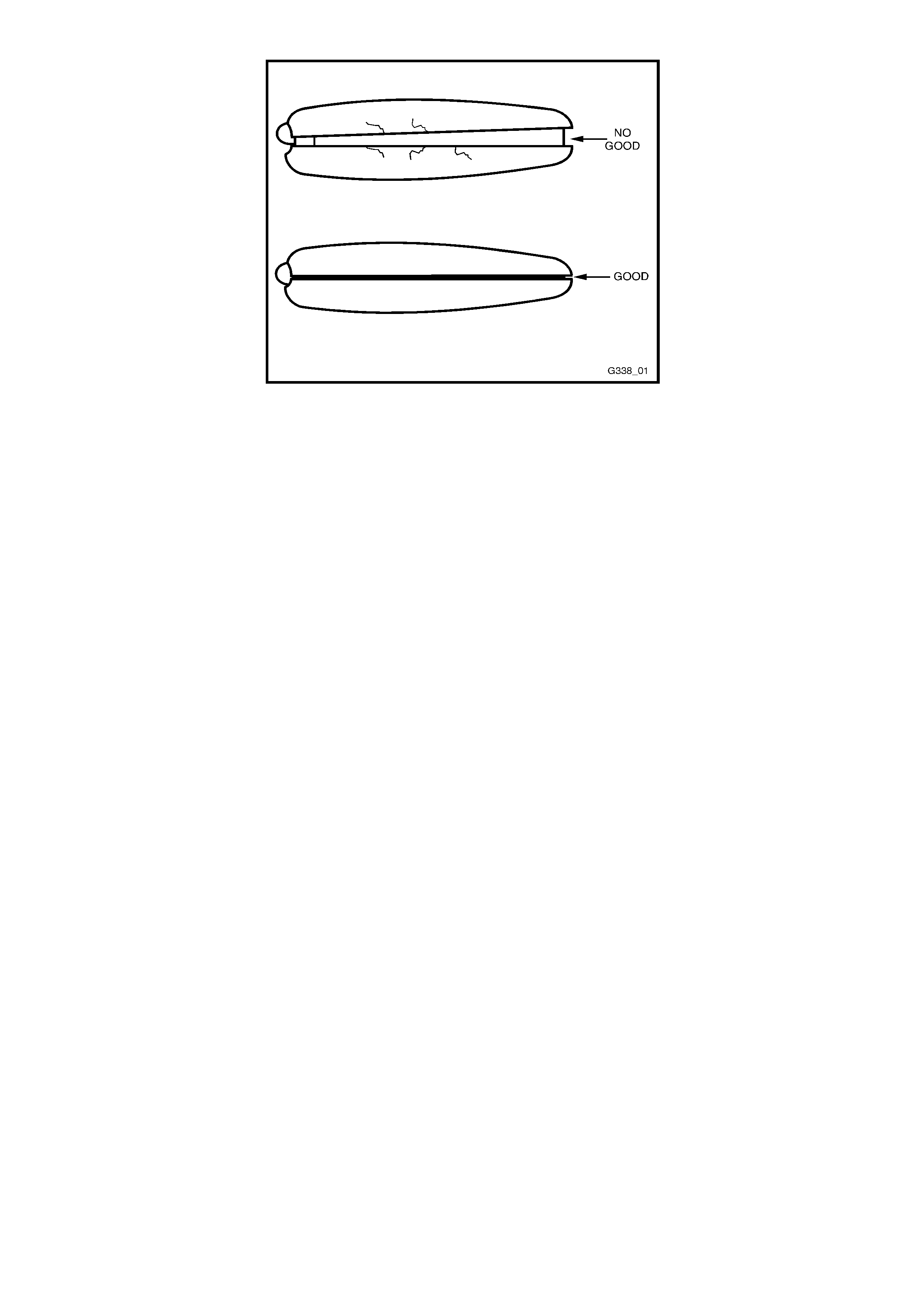
Figure 12J-2-62A
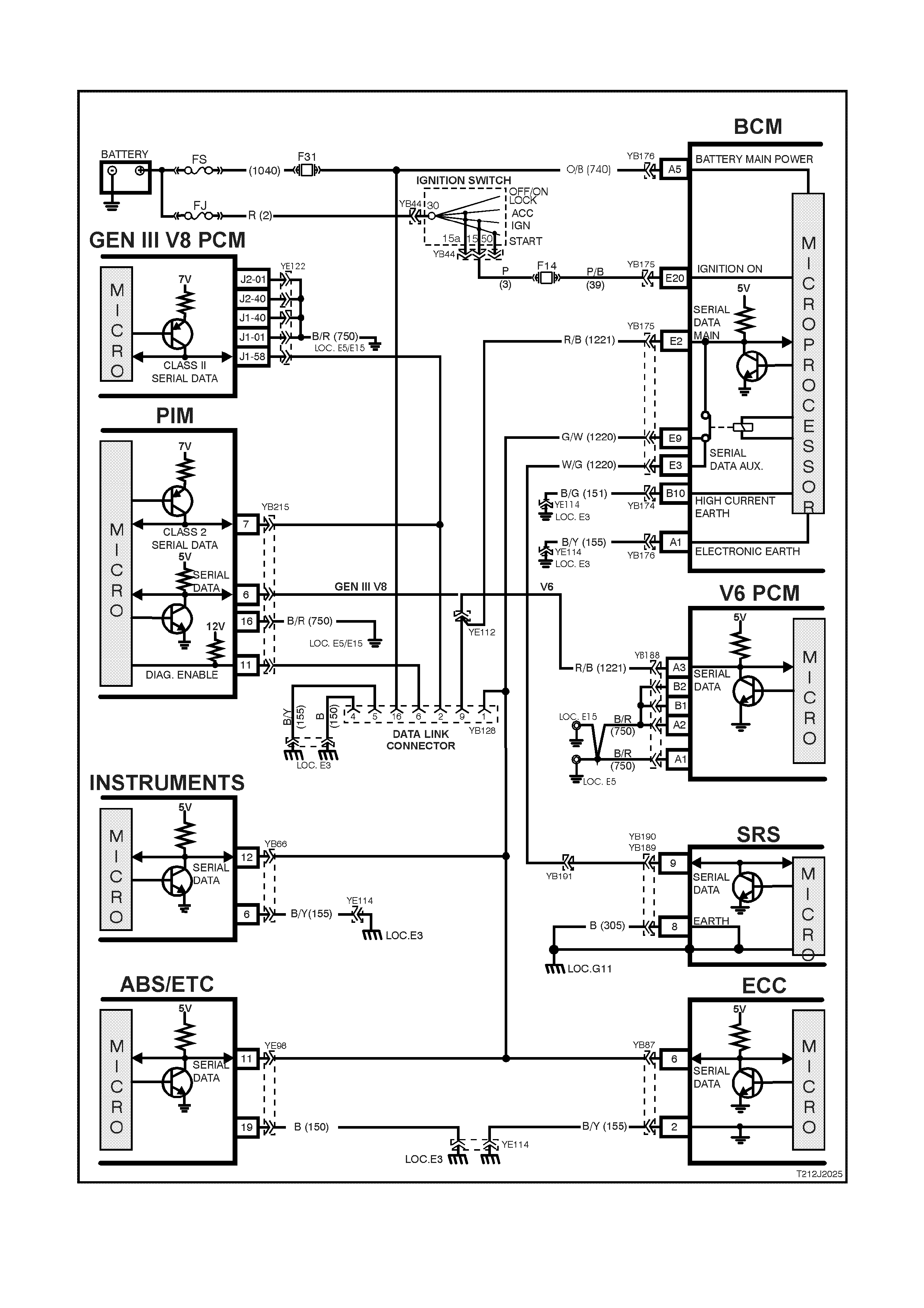
4.2 SERIAL DATA COMMUNICATION
Figure 12J-2-63

GENERAL INFORMATION
The VT Series Model uses a bus master communication system where the BCM is the bus master.
The BCM periodically polls (surveys) each device on the bus and requests status data.
NOTE: The GEN III PCM communicates using a Class 2 communication protocol, all other control modules
communicate using UART. Due to these two different communication protocols, a Powertrain Interface Module
(PIM) is required to convert the Class 2 data into UART. For additional information on Class 2 and UART
communication protocols and the PIM, refer to 1.2 SERIAL DATA COMMUNICATION (BUS MASTER) in this
Section.
The devices connected to the bus are:
• Body Control Module (BCM).
• V6 and V6 supercharged engine Powertrain Control Module (PCM).
• GEN III V8 engine Powertrain Control Module (PCM) via the Powertrain Interface Module (PIM).
• Instrument cluster (INS).
• Antilock Brake System / Electronic Traction Control (ABS/ETC) module.
• Supplemental Restraint System (SRS) Sensing and Diagnostic Module (SDM).
• Electronic Climate Control (ECC) module.
• External diagnostic scan tool (TECH 2).
The data provided by each device may be utilised by any device connected to the bus.
Each device has a unique response “Message Identifier Word” (MIW) for ease of identification.
The bus m aster (BCM) polls each device with a serial data m essage which includes that devic es MIW . The devic e
responds by putting a serial data m essage back onto the bus. T he devices m essage includes its MIW and data, of
which is retrieved and utilised by any device on the bus requiring it.
The BCM polls each device for a status update, once ever y 300 m illiseconds. The exception to this being the PCM
(V6) and PIM (GEN III V8) which are polled twice every 300 milliseconds.
When the ignition switch is turned from the OFF position to the ON position, the BCM will communicate with the
PCM (via the PIM on vehicles with GEN III V8 engines) f or thef t deter rent pur poses . If the BCM does not r eceive an
OK TO START message from the PCM within 0.5 seconds of ignition on, the auxiliary data bus is isolated via
switching from the BCM.
The isolation of the auxiliary data bus during this period eliminates the possibility of a device failure other than the
BCM, PCM or PIM (GEN III V8 only), causing a problem on the bus and inhibiting antitheft communications.
This period (short loop time) continues until the PCM responds with an acknowledgment or a maximum of five
seconds after which the BCM will switch to the standard polling sequence.
Following succes sful theft deterr ent comm unications, the BCM begins sequential polling of devices on the bus and
normal system operation is established.
When the ignition switch is in the OFF position, the BCM continues to poll, allowing for TECH 2 communications
and external control of the bus prior to the ignition being switched on.
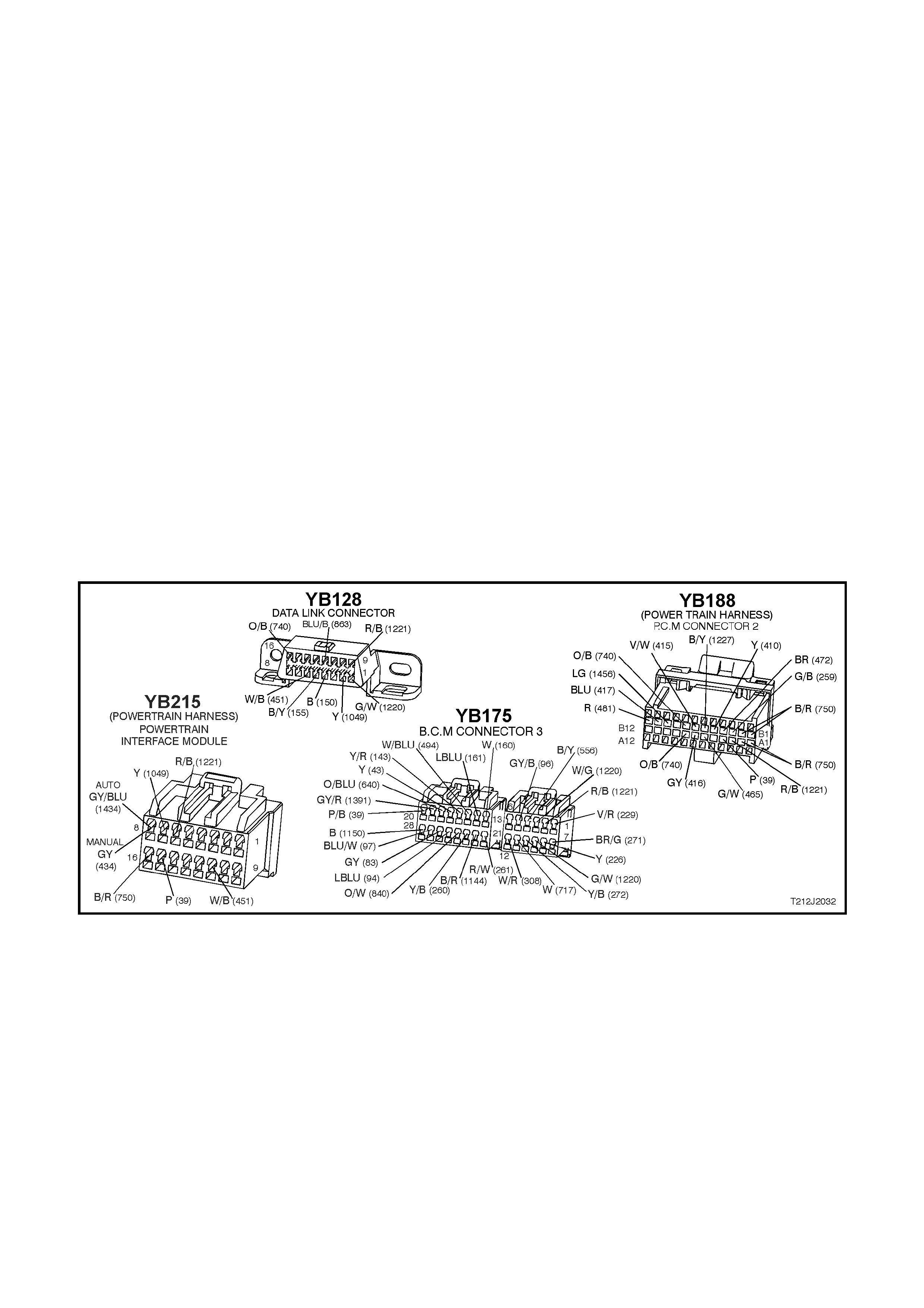
Test Description
The numbers below refer to step numbers on the facing pages diagnostic chart.
1. Ensures TECH 2 is functioning correctly.
2. Checks if TECH 2 can communicate with the BCM.
3. Checks if TECH 2 can communicate with the V6 or V6 supercharged PCM (vehicles with V6 or V6
supercharged engines).
4. Checks if TECH 2 can communicate with the PIM (vehicles with GEN III V8 engines).
5. Checks if TECH 2 can communicate with the GEN III V8 PCM (vehicles with GEN III V8 engines).
6. Checks if TECH 2 can communicate with all the devices (SRS, ABS/ETC, INS, ECC) on the auxiliary serial
data line.
7. Checks continuity of circuit 1221 between the BCM and the DLC.
8. Check s if no BCM com m unication is c aused by contr ol module interf erence connec ted to the m ain or auxiliary
serial data line.
9. Checks if no BCM communication is caused by a short to battery + or earth on the main and auxiliary serial
data lines.
10. Check s continuity of circuit 1221 between the BCM and PCM, and if there is a problem with the PCM (vehicles
with V6 and V6 supercharged engines).
11. Checks continuity of circuit 1221 between the BCM and PIM (vehicles with GEN III V8 engines).
12. Continuation of Step 6; determines if TECH 2 can communicate with at least one of the devices (SRS,
ABS/ETC, INS) on the auxiliary serial data line.
13. Check s to establish whether lost communic ation between m odules on the auxiliar y serial data line and TECH 2
is due to an open in circuit 1220 or the module itself.
14. Check s to establish whether loss of com munic ation on the auxiliary serial data line is due to an open in circuit
1220 or the BCM.
Figure 12J-2-64

SERIAL DATA COMMUNICATION
STEP ACTION VALUE YES NO
1. • Connect TECH 2 to DLC.
• Turn ignition ON.
• Push power button on TECH 2.
• Does TECH 2 power up (screen will illuminate
display TECH 2)?
Go to Step 2. Go to TECH 2
diagnosis, refer
to Section 0C
TECH 2 in this
Service
Information CD.
2. • With TECH 2 still connected and ignition ON, select
Diagnostics / Body / Body Control Module.
• Does TECH 2 display BCM system identification
information (BCM level and type)?
Go to Step 3 –
vehicles with V6
or V6
supercharged
engines.
Go to Step 4 -
vehicles with
GEN III V8
engines
Go to Step 7.
3. • With TECH 2 still connected, ignition ON, exit
BODY and select Diagnostics / Engine / Engine
Type (ie V6, V6 Supercharged).
• Does TECH 2 display PCM system identification
information (ie. prom identification)?
Go to Step 6. Go to Step 10.
4. • With TECH 2 still connected, ignition ON, exit
BODY Control Module and select Powertrain
Interface Module (PIM)
• Can TECH 2 communicate with the PIM?
Go to Step 5. Go to Step 11.
5. • With TECH 2 still connected, ignition ON, exit
BODY and select Diagnostics / Engine / Engine
Type (ie V8 GEN III).
• Does TECH 2 display GEN III V8 PCM system
identification information (ie. prom identification)?
Go to Step 6 Go to PCM
diagnostics in
Section 6C3
POWERTRAIN
MANAGEMENT -
GEN III V8
ENGINE of the
VT Series II
Service
Information.
6. • With TECH 2 still connected, ignition ON, exit
Engine Diagnostics and select Body / DTC Check /
DTC Check.
• Can TECH 2 communicate with all control modules
fitted to the vehicle (if NO DATA is displayed next
to a control module, then there is no
communication between TECH 2 and that control
module)?
NOTE: If vehicle is not equipped with a particular
feature, ie. ABS/ETC, No Data will be displayed next to
this module in the TECH 2 display.
System OK. Go to Step 12.
7. • Turn ignition OFF.
• Back probe DLC connector YB128, terminal 9,
circuit 1221 (Red/Black wire) and BCM connector
YB175, terminal E2, circuit 1221 (Red/Black wire)
with an Ohmmeter.
• Is value as specified?
Below 1 ohm Go to Step 8. Check and repair
open in circuit
1221 between
DLC and BCM.
Recheck and
verify repair.
8. • Disconnect control modules on auxiliary serial data
line (ABS, ABS/ETC, SRS, ECC, INS) and the PCM
(V6 & V6 Supercharged engine) or PIM (GEN III V8
engine) on the main serial data line one at a time,
checking each time if TECH 2 can communicate
with the BCM (refer to Step 2).
• Does communication between the BCM and TECH
2 resume after disconnecting any of the control
modules?
Go to suspect
control module
diagnosis in the
relevant Section
in this Service
Information CD.
Go to Step 9.

STEP ACTION VALUE YES NO
9. • Disconnect all control modules; ABS, ABS/ETC,
SRS, INS, PCM, PIM (GEN III only) and BCM.
• Check integrity (i.e. short to battery +, short to
earth) of circuits 1221 (Red/Black wire) and circuit
1220 (Green/White – White/Green wire).
• Are circuits 1221 and 1220 OK?
Replace BCM,
refer to 12J-2
HIGH SERIES
BCM of the VT
Series I Service
Information.
Recheck and
verify repair.
Repair circuits
1221 or 1220 as
necessary.
Recheck and
verify repair.
10. • Turn ignition OFF.
• Back probe BCM connector YB175, terminal E2,
circuit 1221 (Red/Black wire) and PCM connector
YB188, terminal A3, circuit 1221 (Red/Black wire)
with an Ohmmeter.
• Is value as specified?
Below 1 ohm Go to PCM
diagnostics in
Section 6C1
POWERTRAIN
MANAGEMENT -
V6 ENGINE of
the VT Series I
Service
Information.
Check and repair
open in circuit
1221 between
PCM and BCM.
11. • Turn ignition OFF.
• Back probe BCM connector YB175, terminal E2,
circuit 1221 (Red/Black wire) and PIM connector
YB215, terminal 6, circuit 1221 (Red/Black wire)
with an Ohmmeter.
• Is value as specified?
Below 1 ohm Go to 4.4 THEFT
DETERRENT
diagnostics in
this Section.
Check and repair
open in circuit
1221 between
PIM and BCM.
12. • In Step 6, was TECH 2 able to communicate with at
least one of the control modules on the auxiliary
serial data line (ABS, ABS/ETC, INS, ECC, SRS)?
NOTE: TECH 2 will display No Data next to a control
module that it can not communicate with in the DTC
Check mode.
Go to Step 13. Go to Step 14.
13. • Check continuity between BCM and suspect control
module in circuit 1220 (Green/White – White/Green
wire).
• Does continuity exist?
Go to suspect
control module
diagnosis in the
relevant Section
in this Service
Information CD.
Repair open in
circuit 1220
between suspect
control module
and the BCM.
Recheck and
verify repair.
14. • Check continuity between BCM and all control
modules on the auxiliary serial data line.
• Does continuity exist?
Replace BCM,
refer to 12J-2
HIGH SERIES
BCM of the VT
Series I Service
Information.
Recheck and
verify repair.
Repair open in
circuit 1220.
Recheck and
verify repair.

4.3 CENTRAL DOOR LOCKING
GENERAL INFORMATION
The diagnostic procedure for central door locking system remains unchanged from the procedure detailed in
Section 12J-2 HIGH SERIES BODY CONTROL MODULE of the VT Series I Service Information, noting the
following:
On VT Series II Models, it is possible to deadlock the doors via the remote coded key.
W hen diagnosing a central door locking circuit fault on a VT Series II vehicle, reference to the wiring diagrams in
Section 12P WIRING DIAGRAMS of the VT Series II Service Information should be made.
Due to the addition of the deadlock ing feature via the r em ote coded k ey, the central door lock ing System Check , as
detailed in the VT Series I Service Information has been updated and republished to include this feature.
In part A of the central door locking diagnostic procedures - “Unlocking doors, driver’s door lock microswitch”, on
page 12J-2-128, in the VT Series I Service Information, there are three errors:
Step 2 - If the answer to Step 2 is NO, go to Step 12.
Step 3 - if the answer to Step 3 is YES, replace the BCM.
Step 3 - if the answer to Step 3 is NO, go to Step 16
SYSTEM CHECK
The operation of the central door locking system is independent of the ignition being switched ON or OFF.
Deadlock refers to the electrical means that can be activated to ensure vehicle security by inhibiting door lock
operation.
Central Locking and Unlocking
Operation of this system can be effected as follows;
1. Driver’s door, outside key and inside locking (snib) button (locking and unlocking).
2. Left hand front passenger door inside locking (snib) button (locking and unlocking)
3. Rear passenger doors inside locking (snib) button (only unlocking is possible).
Deadlock
The deadlocking feature applies to all four doors, but not to the luggage compartment lid or tailgate.
The deadlocking feature is engaged as follows:
• Two sequential lock activation’s of the door lock microswitch or
• Operating the ‘lock’ button on the remote coded key twice within 10 seconds.
Successful deadlocking via the remote coded key is indicated by the turn signal lamps turning on for three seconds.
If the vehicle is already deadlocked, pressing the lock button on the remote coded key will cause the turn signal
lamps to turn on for three seconds, indicating that the vehicle is already deadlocked.
If the vehicle is locked (not deadlocked) pressing the lock button on the remote coded key 10 seconds after the
previous press, the doors will not deadlock and the turn signal lamps will flash briefly, indicating that the doors are
only lock ed. Pressing the lock button again, within in a 10 second period will cause the doors to deadlock and turn
the signal lamps will turn on for three seconds.
After the deadlocking feature device has been engaged, unlocking is possible at the driver’s door from outside, by
inserting the key into the driver’s door lock cylinder and turning the key to the unlock position or activating the unlock
button on the rem ote key unlocks the deadloc ks on all door s, but only unlocks the dr iver ’s door ( providing two stage
unlocking is enabled).
To ensure access to the vehicle if the electrical system should f ail (discharged battery), after the system has been
engaged, the driver’s door lock cylinder can be moved independently of the actuator and therefore allowing
unlocking of the driver’s door latch.
The rear com partment lid or tailgate can be lock ed/unlocked when the m echanical deadloc king featur e is ac tuated,
while leaving the doors secured.
NOTE: Deadlocking is not possible with the ignition in the ON position.
Overheating Prevention
In the event of m ultiple activation’s within a defined tim e period, the central door loc king system will be deactivated
and remain inoperative for a defined tim e period to prevent the door actuators from overheating. After a fixed time
delay, the system will re-activate and operate as normal.
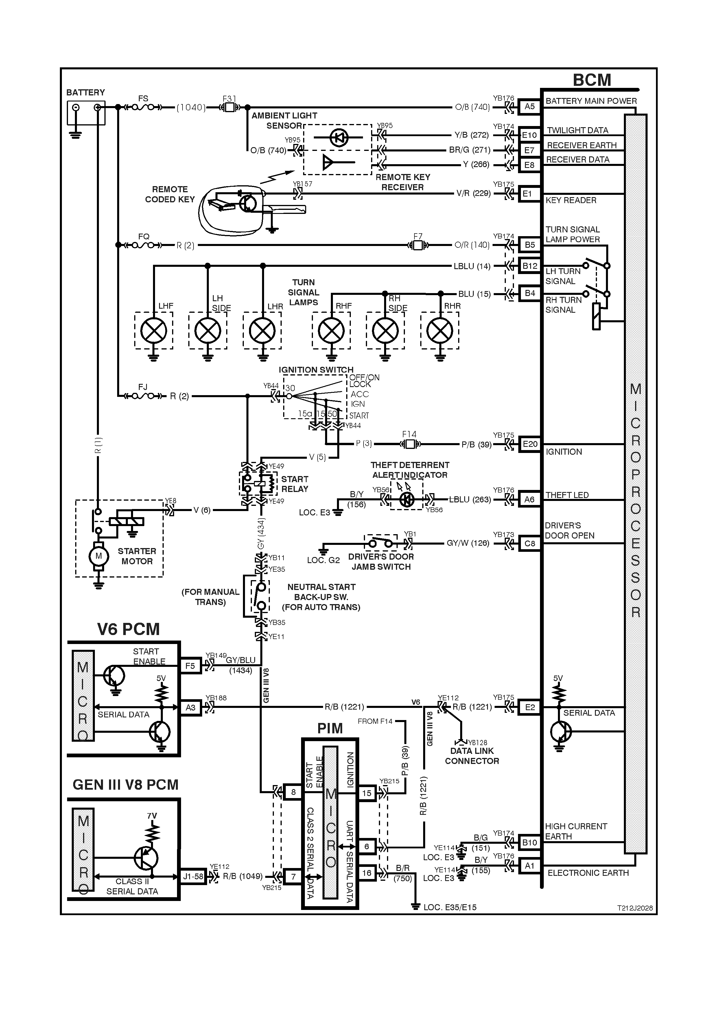
4.4 THEFT DETERRENT
Figure 12J-2-65

CIRCUIT DESCRIPTION
The theft deterrent system can be armed by pressing the lock button on the remote coded key when the driver’s
door is closed or pass ive ly arm ed autom aticall y by the BC M 3 0 secon ds af ter the ignit ion is s witch ed of f. W hen the
system is armed, the Powertrain Control Module (PCM)(V6 and V6 supercharged engine) or Powertrain Interface
Module (PIM)(GEN III V8 engine) prevents the engine from starting.
The theft deterrent system can be disarmed in two ways:-
1. By pressing the unlock button on the remote coded key. This will unlock doors, turn the interior light on and
disarm the system for 30 seconds.
2. By inserting the rem ote coded key into the ignition switc h cylinder and turning the ignition to t he ON position.
This caus es the BC M t o read a s ec ur it y code s erial da ta o utp ut f r om the rem ote c oded key contac t pin , v ia the
remote coded key reader assembly.
Should th e system not d isar m (thef t deter r ent L ED of f ) when the ign iti on switch is tu rne d to the O N pos i tion (ie. due
to a mis aligne d or fault y rem ote cod ed k ey reader or f ault y rem ote coded k ey), t hen pres s the unlock button on t he
remote key to disarm the theft deterrent system.
The remote coded key is powered by it’s own internal battery. If the battery fails, the remote coded key can be
powered b y the rem ote coded k ey reader onc e the k ey is insert ed into th e ignition cyl inder an d turned t o either the
ON or START positions.
When pressing the lock button on the remote coded key to arm the system, the indicators will flash once and the
theft deterrent alert indicator (LED) will begin to flash.
W hen pressing the unlock button on the rem ote coded k ey to disarm the s yst em, the in dicators will flas h twice a nd
the theft deterrent alert indicator (LED) will go out.
On vehic les with V6 and V6 superc harged eng ines, whe n the igniti on switc h is turned to the ON positio n, the BC M
polls the PCM and s en ds an enc rypted BCM/ Key security cod e (The se cur ity code is r eceived vi a th e B CM s l ip ring
or rem ote receiver in the event of no slip ri ng communic ation). T he PCM com pares the rec eived s ecurit y code with
it’s stored sec urity code and if the c od es matc h, the P CM wil l enable inj ec tor f ue ll ing and c ont inu e e n g ine c r anking.
The PCM will return an OK TO START message, which tells the BCM to jump from SHORT LOOP mode to the
LONG LOOP mode.
On vehicles with GEN III V8 engin es, when the ign ition switch is turned to the ON position, t he BCM polls the PIM
and sends an encrypted BCM/Key security code (The security code is received via the BCM slip ring or remote
receiver in the event of no slip r ing comm unication). T he PIM com pares the received securit y c ode wit h it’s stored
security code and if the codes match, the PIM will continue engine cranking and send a separate encrypted
security code to the PCM. T he PCM compares this code with its stored securit y cod e and if the codes m atch, the
PCM will enable inj ector fuelling to co ntinue. The PI M will return an OK TO START m essage, which tells the BCM
to jump from SHORT LOOP mode to the LONG LOOP mode.
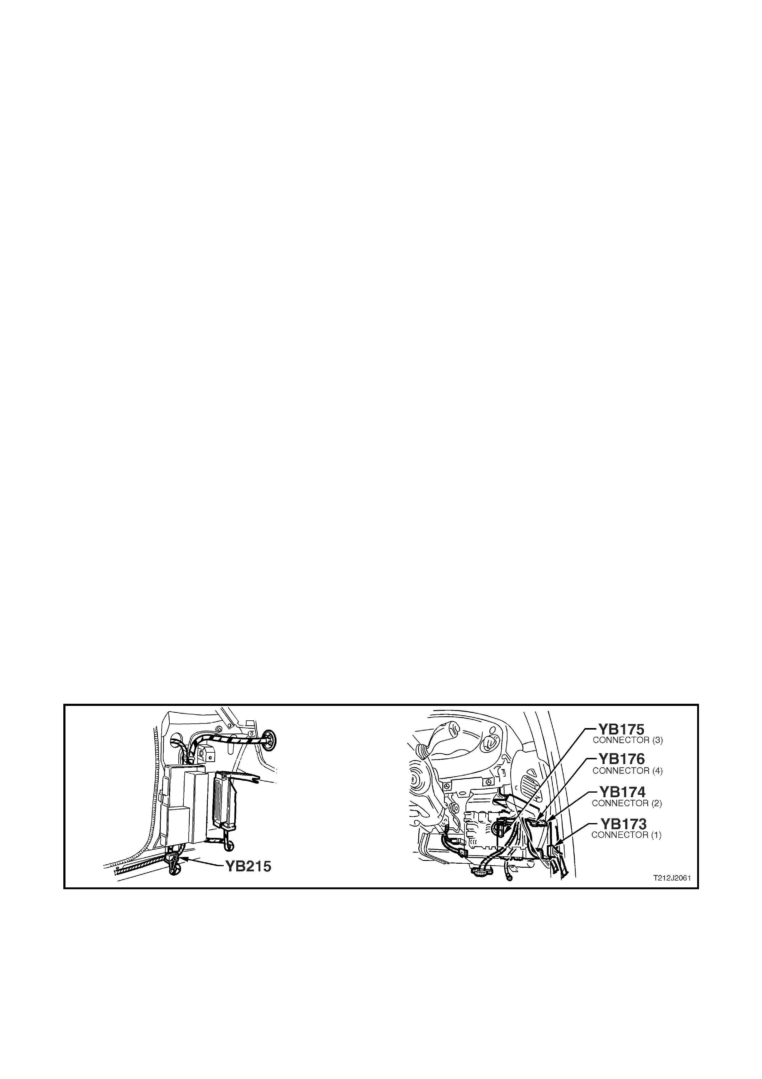
Test Description
The numbers below refer to step numbers on the facing pages diagnostic chart.
1-10 Functional check of system.
11. Checks if doors are not locking due to central door locking system or remote receiver/remote key.
12. Re-synchronisation of remote key rolling code in event of rolling code misalignment.
14. Uses TECH 2 to operate indicators (establish whether problem is with the BCM or other external problem).
15. Checks turn signal input at input to BCM.
16. Checks turn signal output at output of BCM when commanded by TECH 2.
17. Uses T ECH 2 to operate the theft deter rent LED (est ablish whether pro blem is with the BCM or other ex ternal
problem).
18. Checks for theft deterrent LED output drive form the BCM when commanded by TECH 2.
19 Checks circuit 263 for short to earth, causing LED to be inoperative.
20. Checks circuit 263.
21. Checks circuit 156 for open to establish if circuit is faulty or theft deterrent LED is faulty.
22. Checks if problem is confined to the key reader or remote serial data transfer.
23. Checks for poor remote coded key shaft earth contact.
24 Checks for poor contact of remote coded key pin with remote coded key reader.
25. By using second ‘good’ key, determines if problem is with remote key.
26. Checks for BCM signal at remote key reader.
27. Checks ignition switch/cylinder earth.
28. Uses TECH 2 to check IGNITION ON signal at microprocessor of BCM.
29. Checks circuit 229 for open to establish if circuit is faulty or BCM is faulty.
30. Checks circuit 229 for short to earth.
31. Checks ignition ON signal at input to BCM.
32. Uses T ECH 2 to check for PASSIVE MODE OFF signal at microprocessor of BCM to establish if fault is with
the BCM or PCM.
33. Continuation of functional check for vehicles with GEN III V8 engines.
34. Uses T ECH 2 to check for PASSIVE MODE OFF signal at microprocessor of BCM to establish if fault is with
the BCM or PCM.
35. Using TECH 2, checks for communication with the PIM.
36. Uses TECH 2 to check for THEFT STATUS start signal at the microprocessor of the PIM.
37. Uses TECH 2 to drive the starter relay to determine if the fault is with the PIM or starter circuits.
38. Checks for ignition on (power feed) at the input to the PIM.
39. Checks circuit 750.
40. Checks circuit 1221.
41. Uses TECH 2 to check starter relay drive of PIM.
Figure 12J-2-65

Figure 12J-2-66
THEFT DETERRENT
STEP ACTION VALUE YES NO
1. • Close and lock all doors.
• Operate remote key UNLOCK button within 4
meters of the driver’s side B pillar.
• Does the driver’s door unlock (2 stage unlocking
programmed) or all doors unlock (single stage
unlocking progra mmed)?
Go to Step 2. Go to Step 11.
2. • In Step 1, did all indicator lights flash twice (both
left-hand and right-hand sides)? Go to Step 3. Go to Step 13.
3. • In Step 1, did the dome lamp illuminate? Go to Step 4. Go to dome
lamp delay
diagnosis, refer
to 4.9 DOME
LAMP DELAY
CONTROL in
this Section.
4. • In Step 1, did the theft deterrent LED go out
immediately and begin flashing 30 seconds latter. Go to Step 5. Go to Step 17.
5. • Close all doors.
• Arm theft deterrent system by operating the LOCK
button on the remote coded key within 4 metres of
the driver’s side B pillar.
• Did all doors lock?
Go to Step 6. Go to central
door locking
diagnosis, refer
to 4.3 CENTRAL
DOOR
LOCKING in this
Section.
6. • In Step 5, did the dome lamp go out immediately
upon activating the lock button? Go to Step 7. Go to dome
lamp delay
diagnosis, refer
4.9 DOME
LAMP DELAY
CONTROL in
this Section.
7. • In Step 5, did all indicator lights flash once (both
left-hand and right-hand sides)? Go to Step 8. Replace BCM,
refer to 12J-2
HIGH SERIES
BCM in the VT
Series I Service
Information.
Recheck and
verify repair.
8. • Is the theft deterrent LED flashing? Go to Step 9. Replace BCM,
refer to 12J-2
HIGH SERIES
BCM in the VT
Series I Service
Information.
Recheck and
verify repair.

STEP ACTION VALUE YES NO
9. • Unlock vehicle with remote key and wait for theft
deterrent system to passively arm (theft deterrent
LED flashing).
• With vehicle passively armed, insert the ignition key
into ignition switch and turn to the ON position.
• Does the theft deterrent LED extinguish?
Go to Step 10. Go to Step 22.
10. • Turn the ignition key to the START position.
• Does the vehicle crank and start? System OK.
Go to Step 32 -
vehicles with V6
or V6
supercharged
engines.
Go to Step 33 -
vehicles with
GEN III V8
engines
11. • Insert ignition key into driver’s door lock cylinder
and operate door unlock microswitch (turn key to
unlock position).
• Do all doors unlock?
NOTE: Alarm will sound.
Go to Step 12. Go to central
door locking
diagnosis, refer
to 4.3 CENTRAL
DOOR
LOCKING in this
Section.
12. • Insert ignition key into ignition switch and cy cle from
OFF - ON - OFF.
• Remove key and lock doors with driver’s door lock
cylinder switch.
• Operate UNLOCK button on remote key within 4
metres of driver’s door B pillar.
• Does the driver’s door unlock (2 stage unlocking
programmed) or all doors unlock (single stage
unlocking programmed)?
Go to Step 2. Go to remote
receiver
diagnosis, refer
Section 12J-2
HIGH SERIES
BODY
CONTROL
MODULE of the
VT Series I
Service
Information.
13. • In Step 2, did at least one side of vehicle’s
indicators flash twice (either left-hand or right-hand
side)?
Go to Step 16. Go to Step 14
14. • Driver’s door closed.
• Connect TECH 2 to DLC.
• Select BODY / BODY CONTROL MODULE /
MISCELLANEOUS TESTS / LAMPS /
INDICATORS.
• Conduct test as instructed by TECH 2.
• Do all indicator lights illuminate?
Go to central door
locking diagnosis,
refer to 4.3
CENTRAL DOOR
LOCKING in this
Section.
Go to Step 15.
15. • Back probe BCM connector YB174, terminal B5,
circuit 140 (Orange/Red wire) with a Voltmeter to
earth.
• Is voltage as specified?
Approx.
12 volts Go to Step 16. Check and
repair open in
circuit 140
(including fuse
F7). Recheck
and verify repair.
16. • Back probe BCM connector YB174, terminal B4
and B12, circuits 14 and 15 (Light Blue wire and
Blue wire respectively) with a Voltmeter to earth.
• Repeat INDICATOR ILLUMINATION test as per
Step 14.
• Is voltage as specified?
Approx.
12 volts Check and repair
circuits 14 (LH
indicator) and/or
15 (RH indicator).
Recheck and
verify repair.
Replace BCM,
refer to 12J-2
HIGH SERIES
BCM of the VT
Series I Service
Information.
Recheck and
verify repair.
17. • Connect TECH 2 to DLC.
• Select BODY / BODY CONTROL MODULE /
MISCELLANEOUS TESTS / SECURITY SYSTEM /
SECURITY LED.
• Conduct test as instructed by TECH 2.
• Does theft deterrent LED illuminate?
Replace BCM,
refer to 12J-2
HIGH SERIES
BCM of the VT
Series I Service
Information.
Recheck and
verify repair.
Go to Step 18
18. • Back probe BCM connector YB176, terminal A6,
circuit 263 (Light Blue wire) with a Voltmeter to
earth
• Repeat SECURITY LED test as per Step 17.
• Are voltages as specified?
Approx. 5
volts - LED
on
Approx. 0
volts LED off
Go to Step 20. Go to Step 19
19. • Disconnect BCM connector YB176.
• Back probe BCM connector YB176, terminal A6,
circuit 263 (Light Blue wire) with an Ohmmeter to
earth.
• Is value as specified?
Below 1 ohm Check and repair
short in circuit
263. Recheck and
verify repair.
Replace BCM,
refer to 12J-2
HIGH SERIES
BCM of the VT
Series I Service
Information.
Recheck and
verify repair.

STEP ACTION VALUE YES NO
20. • Disconnect theft deterrent LED connector YB56.
• Back probe theft deterrent LED connector YB56,
circuit 263 (Light Blue wire) with a Voltmeter to
earth
• Repeat SECURITY LED test as per Step 17.
• Is voltage as specified?
Approx.
12 volts Go to Step 21. Check and repair
open in circuit
263. Recheck and
verify repair.
21. • Back probe theft deterrent LED connector YB56,
circuit 156 (Blue / Yellow wire) with a Ohmmeter to
earth.
• Is value as specified?
Below 1 ohm Replace theft
deterrent LED,
refer 12C
INSTRUMENTS
, WIPERS /
WASHER &
HORN of the VT
Series I Service
Information.
Repair open in
circuit 156.
Recheck and
verify repair.
22. • With the ignition key in the ON position, operate the
unlock button on the remote coded key.
• Does the theft deterrent LED go out?
Go to Step 23. Go to remote
receiver
diagnosis, refer
Section 12J-2
HIGH SERIES
BODY CONTROL
MODULE of the
VT Series I
Service
Information.
23. • Remove remote key, key shaft.
• Clean earth contact (shaft earth).
• Reinstall key shaft and tighten screws to the correct
torque specification (0.7 - 0.9 Nm).
• With system passively armed (theft deterrent LED
flashing), insert key into ignition switch and turn key
to the ON position.
• Does the theft deterrent LED go out?
Go to Step 10. Go to Step 24.
24. • Turn ignition key to the ON position.
• Visually check to see if remote coded key contact
pin is making good contact with remote key reader
(slip ring).
• Is remote coded key contact pin making good
contact?
Go to Step 25. Check and repair
as necessary:
remote key reader
(slip ring),
alignment of
remote key reader
(refer step 12),
length of key shaft
and remote key
contact pin.
25. • Check function of second remote key.
• Is second key OK? Replace suspect
key. Go to Step 26.
26. • Isolate remote coded key contact pin (use a thick
piece of paper to cover contact pin) .
• Insert key into ignition switch and turn key to the
ON position.
• Measure voltage at the remote coded key reader
(slip ring) to a sound earth.
• Is voltage as specified?
Fluctuates
between 4 - 6
volts - AC
Go to Step 27. Go to Step 28.
27. • Check ignition switch earth using an Ohmmeter
connected between the ignition switch housing a
sound earth point.
• Is value as specified?
Below
100 ohms Replace BCM,
refer to 12J-2
HIGH SERIES
BCM of the VT
Series I Service
Information.
Recheck and
verify repair.
Check and repair
open or poor earth
connect ion at
ignition sw itch /
cylinder, Recheck
and verify repair.
28. • Connect TECH 2 to DLC.
• Select BODY / BODY CONTROL MODULE / DATA
DISPLAY / DATA LIST.
• Turn ignition ON as instructed by TECH 2.
• Scroll to IGNITION SWITCH.
• Does screen display IGNITION SWITCH ON?
Go to Step 29. Go to Step 31.

STEP ACTION VALUE YES NO
29. • Back probe BCM connector YB175, terminal E1,
circuit 229 (Violet/Red wire) with a Voltmeter to
earth.
• With remote coded key contact pin isolated
(covered with thick paper), insert ignition key into
ignition sw itch and turn igni tion switch to the ON
position.
• Is voltage as specified?
Fluctuates
between 4 - 6
volts - AC
Check and
repair open in
circuit 229 or
remote key
reader. Recheck
and verify repair.
Go to Step 30.
30. • Check circuit 229 (Violet/Red wire) for short to
earth.
• Is circuit 229 OK?
Check and
repair short in
circuit 229.
Recheck and
verify repair.
Replace BCM,
refer to 12J-2
HIGH SERIES
BCM of the VT
Series I Service
Information.
Recheck and
verify repair.
31. • Back probe BCM connector YB175, terminal E20,
circuit 39 (Pink/Black wire) with a Voltmeter to
earth.
• Turn ignition ON.
• Is voltage as specified?
Approx.
12 volts Replace BCM,
refer to 12J-2
HIGH SERIES
BCM of the VT
Series I Service
Information.
Recheck and
verify repair.
Check and repair
open in circuit 39
(including fuse
F14). Recheck
and verify repair.
32. • Connect TECH 2 to DLC.
• Select BODY / BODY CONTROL MODULE / DATA
DISPLAY / DATA LIST / DATA LIST.
• Scroll to PASSIVE MODE.
• With system disarmed (theft deterrent LED off),
does the screen display PASSIVE MODE OFF?
Go to PCM
diagnostics in
Section 6C1
POWERTRAIN
MANAGEMENT
- V6 ENGINE of
the VT Series I
Service
Information.
Replace BCM,
refer to 12J-2
HIGH SERIES
BCM of the VT
Series I Service
Information.
Recheck and
verify repair.
33. • Turn the ignition to the START position.
• Does the engine crank and continue to crank after 1
second?
Go to PCM
diagnostics in
Section 6C3
POWERTRAIN
MANAGEMENT
- GEN III V8
ENG of the VT
Series II Service
Information.
Go to Step 34.
34. • Connect TECH 2 to the DLC.
• Turn ignition ON.
• Select BODY / BODY CONTROL MODULE / DATA
DISPLAY and scroll to PASSIVE MODE.
• With the theft deterrent system disarmed (theft
deterrent LED off) does the screen display Passive
Mode OFF?
Go to Step 35. Replace BCM,
refer to 12J-2
LOW SERIES
BCM of the VT
Series I Service
Information.
Recheck and
verify repair.
35. • With TECH 2 still connected and ignition ON, exit
Body Control Module and select BODY /
POWERTRAIN INTERFACE MODULE (PIM).
• Can TECH 2 communicate with the PIM (i.e.
display software version number)?
Go to Step 36. Go to Step 38.
36. • Ensure the BCM has been linked to the PIM (Refer
to BCM linking procedure in the Service Operations
of this Section).
• With TECH 2 still connected and ignition ON select
BODY / POWERTRAIN INTERFACE MODULE /
DATA LIST. Scroll to STARTER RELAY, FUEL
DISABLE TIMEOUT, and FUEL DISABLE CYCLE
IGNITION.
• Does screen display OFF for each of these items?
Go to Step 37. Replace PIM,
refer Section 6C3
POWERTRAIN
MANAGEMENT -
GEN III V8 ENG
of the VT Series II
Service
Information.
37. • With TECH 2 connected and ignition ON, select
BODY / POWERTRAIN INTERFACE MODULE /
MISCELLANEOUS TESTS / STARTER RELAY.
• Turn and hold the ignition switch in the START
position.
• Conduct starter relay test as instructed by TECH 2.
• Does the engine crank?
Replace PIM,
refer Section
6C3
POWERTRAIN
MANAGEMENT
- GEN III V8
ENG of the VT
Series II Service
Information.
Go to Step 41.

STEP ACTION VALUE YES NO
38. • Back probe PIM connector YB215, terminal 15,
circuit 39 (Pink wire) with a Voltmeter to earth.
• Turn ignition ON.
• Is voltage as specified?
12 volts Go to Step 39. Check and
repair open in
circuit 39.
Recheck and
verify repair.
39. • Turn ignition OFF.
• Back probe PIM connector YB215, terminal 16,
circuit 750 (Black/Red wire) with an Ohmmeter to
earth.
• Is value as specified?
Below 1 ohm Go to Step 40. Check and
repair open in
circuit 750.
Recheck and
verify repair.
40. • Back probe BCM connector YB175, terminal E2,
circuit 1221 (Red/Black wire) and PIM connector
YB215, terminal 6, circuit 1221 (Red/Black wire)
with an Ohmmeter.
• Is value as specified?
Below 1 ohm Replace PIM,
refer Section 6C3
POWERTRAIN
MANAGEMENT -
GEN III V8 ENG
of the VT Series II
Service
Information.
Check and
repair open in
circuit 1221
between PIM
and BCM.
Recheck and
verify repair.
41. • Back probe PIM connector YB215, terminal 8,
circuit 1434 (Grey/Blue wire) with a Voltmeter to
earth.
• Connect TECH 2 to the DLC and select BODY /
POWERTRAIN INTERFACE MODULE /
MISCELLANEOUS TESTS / STARTER RELAY.
• Turn and hold the ignition switch in the START
position.
• Conduct starter relay test as instructed by TECH 2.
• Is value as specified?
Below 1 volt Check the starter
circuits, including
fuse F10, circuits
1434, 434, 5, 6, 1,
starter relay,
neutral safety
switch and starter
motor. Refer to
the appropriate
sections in this
Service
Information CD
Replace PIM,
refer Section
6C3
POWERTRAIN
MANAGEMENT
- GEN III V8
ENG of the VT
Series II Service
Information.
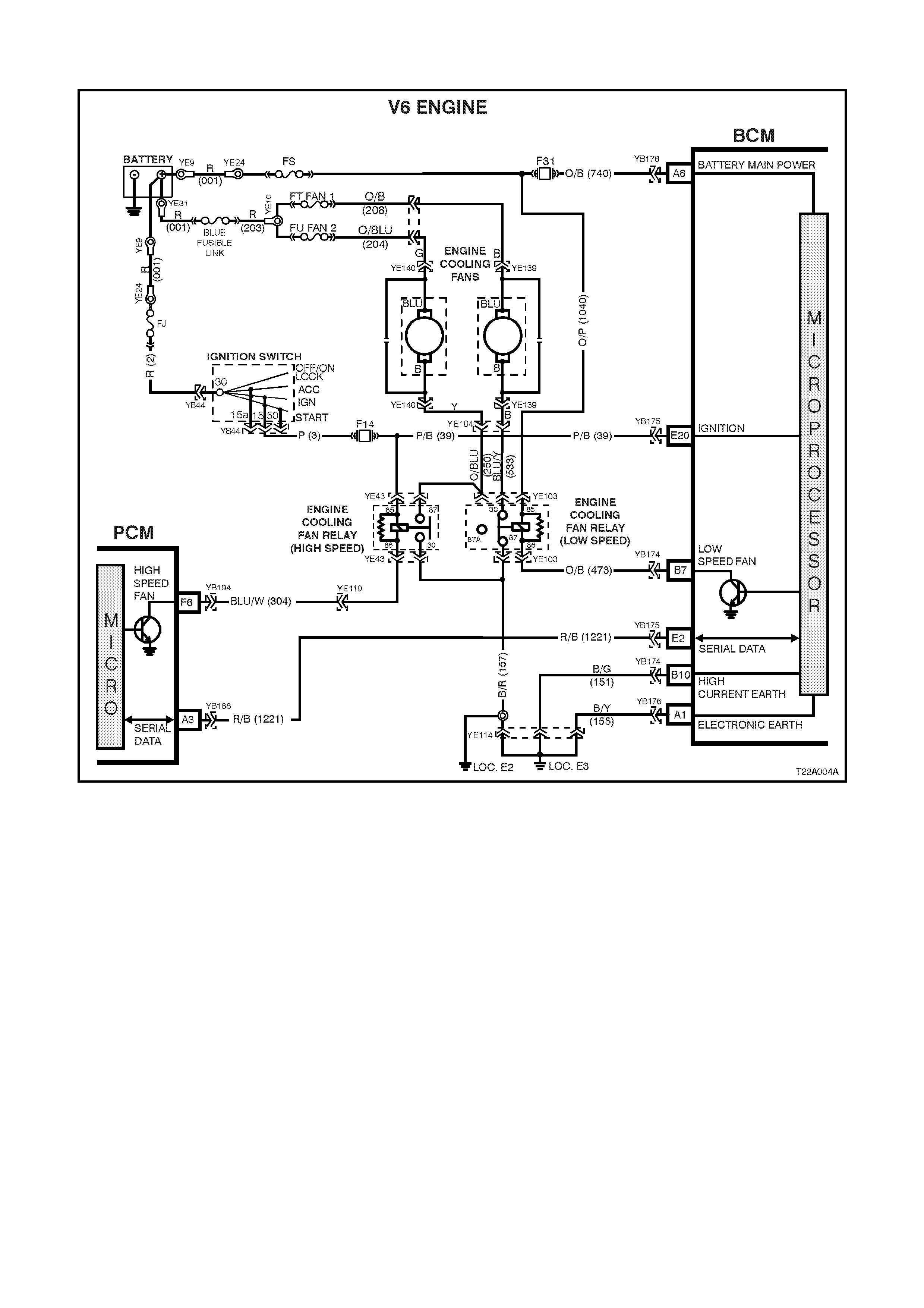
4.5 ENGINE COOLING FAN LOW SPEED CONTROL
Figure 12J-2-68
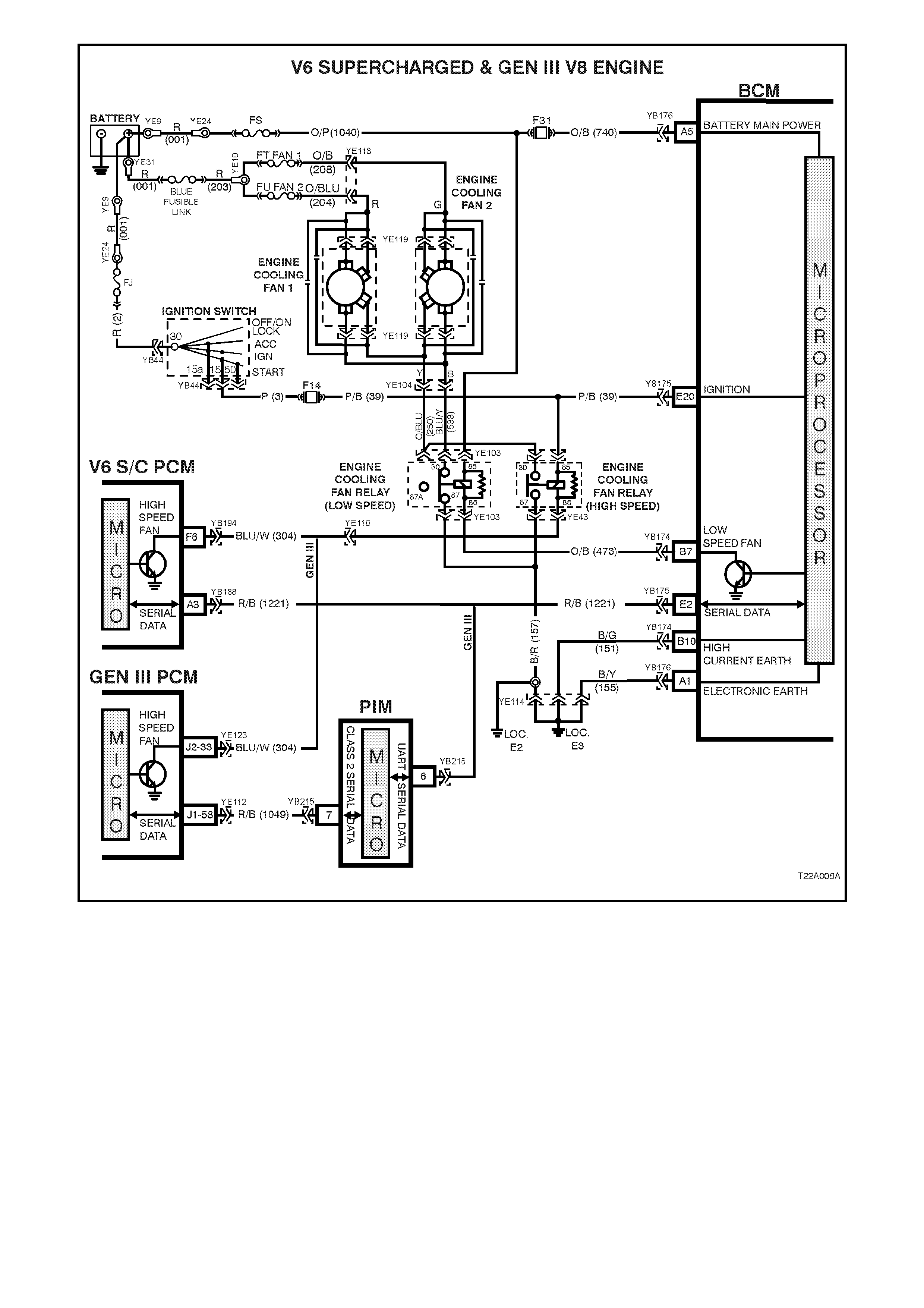
Figure 12J-2-69
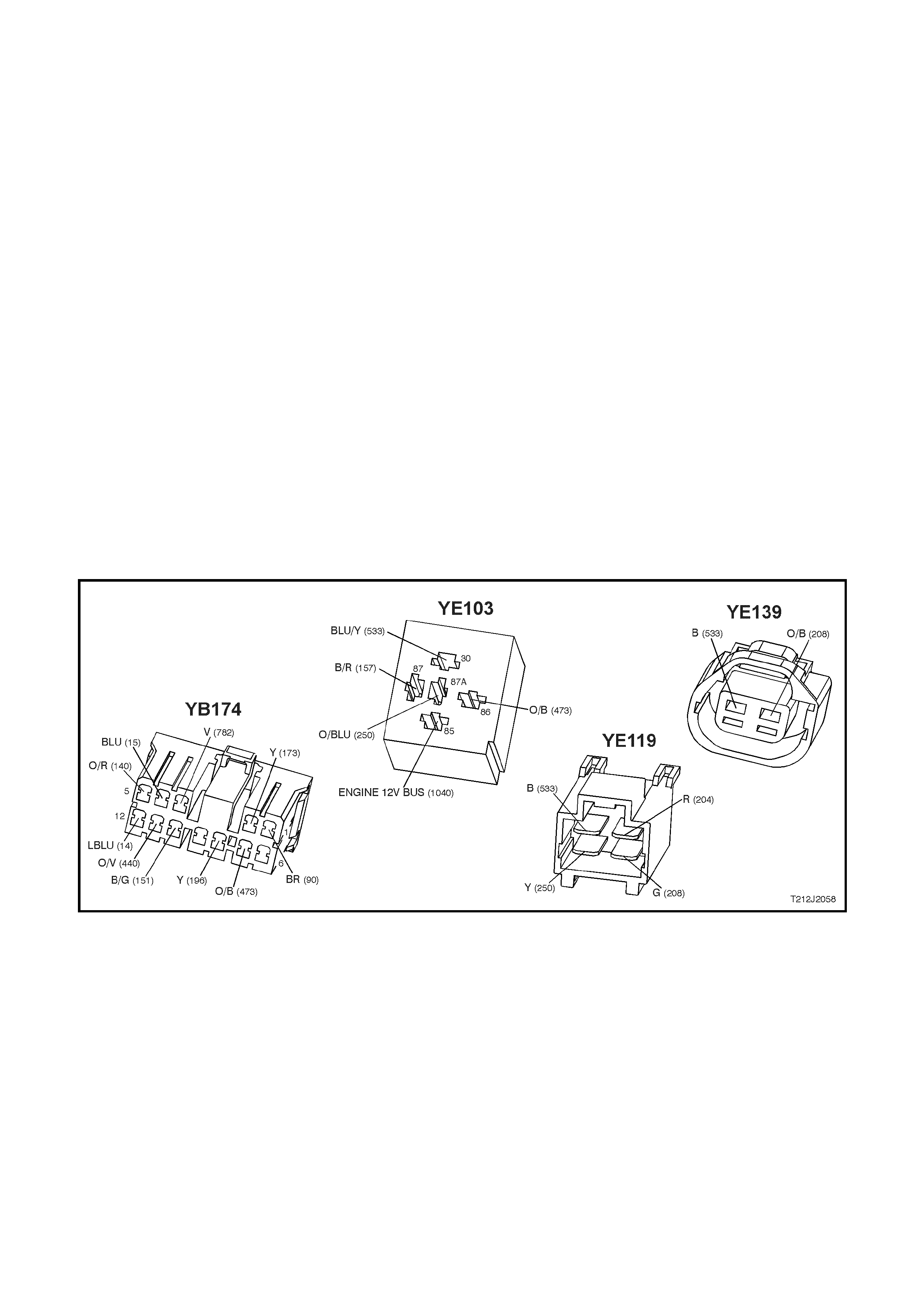
CIRCUIT DESCRIPTION
Regardless of the eng ine c onfig urati on, the l ow s peed coo ling f an o peratio n is e nable d wh en the low sp eed eng ine
cooling fan micro relay (located in the engine compartment relay housing, labelled Lo Fan) is energised by the
Body Control Module (BCM) via a request from the Powertrain Control Module (PCM). The PCM will request low
speed fan enable and disable via serial data communication to the BCM on circuit 1221 (Red/Black wire).
The PCM determ ines when to enabl e the low speed fan r ela y based on inputs from the A/C r eques t signa l, Cool ing
Temperature Sensor (CTS) and the Vehicle Speed Sensor (VSS).
W hen the ignition switc h is turned from ON to O FF and the eng ine coo lant tem perature is above 117°C (V6 or V6
supercharged engine) / 113°C (GEN III V8 engine). The BCM will continue to energise the low speed engine
cooling fan micro relay for four minutes.
NOTE: On veh icles with GE N III V8 e ngine, the lo w speed c ooling fan r un on tim e has a m inim um def ault value of
30 seconds.
Test Description
The numbers below refer to step numbers in the following diagnostic chart.
1. Functional check of low speed cooling fan operation.
2. Uses TECH 2 to command the BCM to turn the low speed fan on.
3. Checks for battery voltage supply to engine cooling fan motor.
4. Checks low speed fan drive signal at output of BCM when.
5. Checks circuit 473.
6. Checks circuit 1040.
7. Checks circuit 157.
8. Checks engine cooling low speed fan motor for power.
7. Checks circuit 533 and engine low speed cooling fan relay.
Figure 12J-2-70
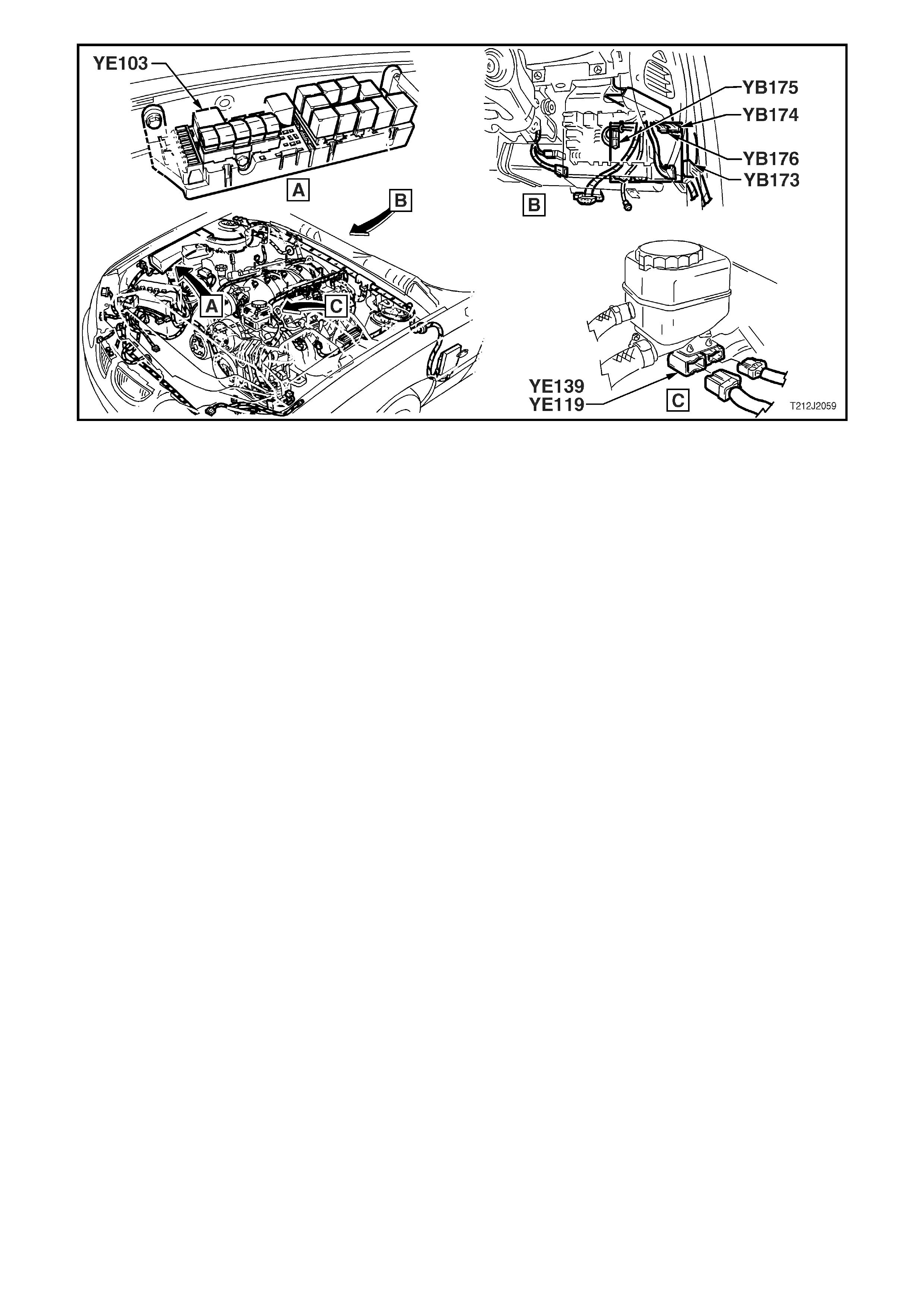
Figure 12J-2-71

ENGINE COOLING FAN LOW SPEED CONTROL
STEP ACTION VALUE YES NO
1. • With the engine coolant temperature greater than
104°C (V6 or V6 supercharged engine) or 98°C
(GEN III V8 engine) is the low speed fan enabled?
System OK. Go to Step 2.
2. • Connect TECH 2 to the DLC.
• Select BODY / BODY CONTROL MODULE /
MISCELLANEOUS TESTS / LOW FAN.
• Conduct test as instructed by TECH 2 and enable
the low speed fan.
• Is the low speed fan enabled?
Go to PCM /
Temperature
sensor diagnosis
in Section 6C1
POWERTRAIN
MANAGEMENT
– V6 ENGINE in
the VT Series I
Service
Information or
6C3
POWERTRAIN
MANAGEMENT
– GEN III V8
ENG in the VT
Series II Service
Information.
Go to Step 3.
3. • Back probe engine cooling fan motor connector
YE139 circuit 208 (Black wire) on vehicles with V6
engines or connector YE119, circuit 208 (Green
wire) on vehicles with V6 supercharged or GEN III
V8 engines with a Voltmeter to earth.
• Is voltage as specified?
12 volts Go to Step 4. Check and repair
open in circuit
208. Recheck
and verify repair.
4. • Back probe BCM connector YB174, terminal B7,
circuit 473 (Orange/Black wire) with a jumper lead
to earth.
• Does low speed fan turn on?
0 volts Replace BCM,
refer to 12J-2
HIGH SERIES
BCM of the VT
Series I Service
Information.
Recheck and
verify repair.
Go to Step 5.
5. • Back probe engine cooling fan low speed relay
connect or YE103, ter minal 86, circuit 473
(Orange/Black wire) with a jumper lead to earth.
• Does low speed fan turn on?
0 volts Check and repair
open in circuit
473. Recheck
and verify repair.
Go to Step 6.
6. • Back probe engine cooling fan low speed relay
connect or YE103, ter minal 85, circuit 1040
(Orange/Pink wire) with a Voltmeter to earth.
• Is voltage as specified?
12 volts Go to Step 7. Check and repair
open in circuit
1040. Recheck
and verify repair.
7. • Back probe engine cooling fan low speed relay
connect or YE103, ter minal 87, circuit 157
(Black/Red wire) with an Ohmmeter to earth.
• Is value as specified?
Below 1 ohm Go to Step 8. Check and repair
open in circuit
157. Recheck
and verify repair.
8. • Back probe engine cooling fan motor connector
YE139 (V6) or YE119 (V6 supercharged and GEN
III V8), circuit 533 (Black wire) with a test light
connected to battery +.
• Connect TECH 2 to the DLC.
• Select BODY / BODY CONTROL MODULE /
MISCELLANEOUS TESTS / LOW FAN.
• Conduct test as instructed by TECH 2 and enable
the low speed fan.
• Does test lamp illuminate?
Replace engi ne
cooling fan
motor, refer to
either Section
6B1 ENGINE
COOLING - V6
ENGINE in the
VT Series I
Service
Information or
6B3 ENGINE
COOLING - GEN
III V8 ENGINE in
the VT Series II
Service
Information.
Recheck circuit
to verify repair.
Go to Step 9.
9. • With TECH 2 still connected, back probe engine
cooling fan low speed relay connector YE103,
terminal 30, circuit 533 (Blue/Yellow wire) with a
test light connected to battery +.
• Repeat TECH 2 LOW SPEED FAN test as again.
• Does test lamp illuminate?
Repair open in
circuit 533.
Recheck circuit
to verify repair .
Replace engine
cooling low
speed fan relay.
Recheck and
verify repair.
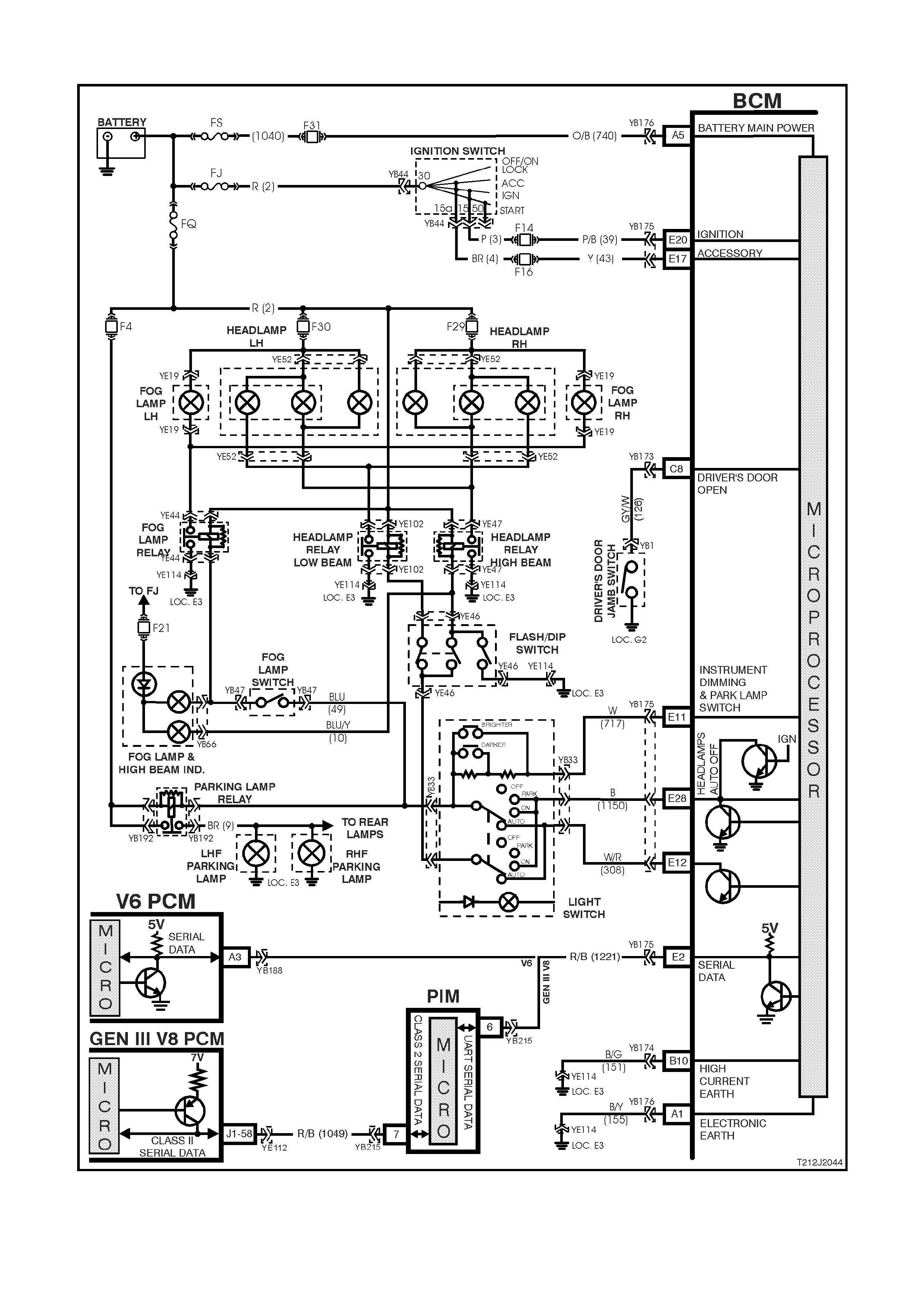
4.6 AUTOM ATIC LIGHTS OFF (WITHOUT TWILIGHT SENTINEL)
Figure 12J-2-72
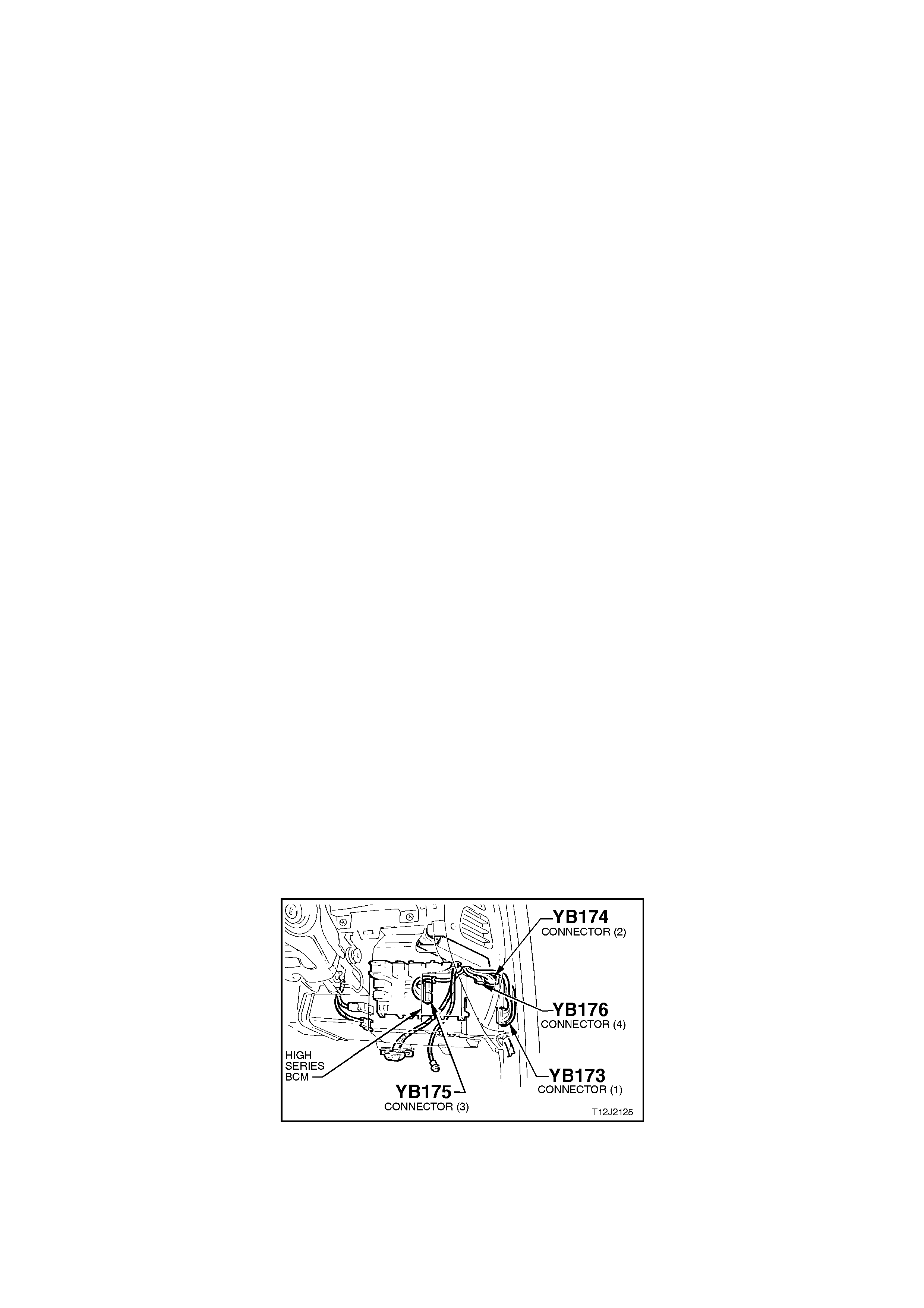
CIRCUIT DESCRIPTION
The autom atic light contr ol (lights of f ) featur e is desi gned to automatic all y switch the head lam ps and p ark ing lam ps
off when the driver leaves the vehicle.
NOTE: Since this system is saf ety relate d, it is mandatory that in the event of a s ystem f ailure, the def ault s tatus of
the BCM light c o ntr o l ou tputs ar e i n th e o n s tate when th e i gn iti on s w itch is in t he 'IG N' pos it io n. This will give dir ect
control of the lights to the headlamp switch.
The sequence of events required to switch the lights off automatically is as follows:
1. The vehicle road speed input to the BCM indicates speed is less than 10 kilometres per hour and there has
not been a sudden loss of speed (ignition being switched off with the vehicle travelling above 10 km/h).
2. The BCM senses that the ignition switch is turned from ON to OFF and remains in the off position.
3. The headlamps switch has not been turned on after the ignition switch was turned off.
4. The BCM senses the driver's door has been opened or that it is already open.
W hen the ignition switc h is turned bac k to 'IGN' pos ition, the li ghts will turn back on to the position sel ected by the
headlam p switch and the m ode of headlam ps operation (ie. h igh or low beam or fog light [if fitted]) determ ined by
the position of the relevant switches.
Turning the headlamp switch off deactivates the automatic lights system.
A delay period before the automatic lights off feature deactivates the vehicle lights can be set by following a set
procedure (refer to 1.8 AUTOMATIC LIGHT CONTROL / AUTOMATIC LIGHTS OFF (WITHOUT TWILIGHT
SENTINEL) in this Section for more information about this feature).
NOTE: This time delay is also dependent on the priority key system. The time delay period can be set for the
priority 1 and priority 2 keys. The time delay is recalled when the unlock button on the remote is pressed and is
dependent on whether priority 1 or priority 2 key is used.
Test Description
The numbers below refer to step numbers in the following diagnostic chart.
1-9. Functional check of automatic light control system.
10. Functional check of fail safe.
11. Test to establish whether problem is due to no output drive from BCM or circuit problem beyond BCM.
12. Checks circuit 1150.
13. Uses TECH 2 to check for DRIVER’S DOOR OPEN signal at microprocessor of BCM.
14. Uses TECH 2 to check IGNITION signal at microprocessor of BCM.
15. Checks for correct ignition signal at input to BCM.
16. Checks DRIVER’S DOOR OPEN signal at input to BCM.
17. Checks circuit 126 and driver’s door jamb switch.
18. Checks for false output drive from BCM or short circuit in lamp circuits.
19. Uses TECH 2 to check ILLUMINATION DIM- signal at microprocessor of BCM.
20. Checks ILLUMINATION DIM- signal at input to BCM.
21. Uses TECH 2 to check ACC signal at microprocessor of BCM.
22. Checks circuit 717 and headlamp switch assembly.
23. Checks for ACC signal at input to BCM.
Figure 12J-2-73

Figure 12J-2-74
AUTOMATIC LIGHTS OFF (WITHOUT TWILIG HT SENTINEL)
STEP ACTION VALUE YES NO
1. • Remove and reinstall fuse F31 (to reset the
automatic lights off time delay period to 0 seconds).
• Turn ignition OFF.
• Turn headlamp switch from the OFF to PARK
LAMPS position.
• Do the park lamps turn ON?
Go to Step 2. Go to Step 9.
2. • With ignition OFF, turn headlamp switch from the
PARK LAMPS to HEADLAMPS position.
• Do the headlamps turn ON?
Go to Step 3. Check and repair
headlamp switch,
fault in wiring
harness to
headlamp relays
& circuits
including fuses &
relays. Recheck
and verify repair.
3. • Turn ignition ON and close driver’s door.
• Turn headlamp switch to the HEADLAMP position.
• Turn ignition OFF.
• Open the driver’s door.
• Do the headlamps turn off?
Go to Step 4. Go to Step 13.
4. • From Step 3. (ignition OFF, driver’s door open,
headlamp switch in the HEADLAMP position and
headlights off), turn Ignition ON.
• Do headlamps turn back ON?
Go to Step 5. Replace BCM,
refer to 12J-2
HIGH SERIES
BCM of the VT
Series I Service
Information.
Recheck and
verify repair.
5. • Turn ignition from ON to OFF.
• Open driver’s door (headlamps OFF).
• Turn headlamp switch from HEADLAMPS to OFF
to HEADLAMPS.
• Do headlamps turn ON (system override)?
Go to Step 6. Replace BCM,
refer to 12J-2
HIGH SERIES
BCM of the VT
Series I Service
Information.
Recheck and
verify repair.
6. • Turn ignition ON.
• Turn headlamp switch to the HEADLAMP position
and close the driver’s door.
• Hold the illumination level switch in the down
position (DIM -).
• Turn ignition to the ACC position.
• Open driver’s door (initiate time delay period).
• Do headlamps remain ON (illumination level switch
held down)?
Go to Step 7. Go to Step 19.

STEP ACTION VALUE YES NO
7. • With illumination level switch held down from Step
6, wait the requested time delay and release switch.
• Do headlamps turn OFF?
Go to Step 8. Go to instrument
illumination
diagnosis, refer
to 4.10
INSTRUMENT
DIMMING
CONTROL in
this Section.
8. • Close driver’s door.
• Turn ignition ON (headlamps ON).
• Turn ignition OFF.
• Open driver’s door.
• Do headlamps turn OFF (after time delay period as
set in Step 6 and 7)?
System OK. Replace BCM,
refer to 12J-2
HIGH SERIES
BCM of the VT
Series I Service
Information.
Recheck and
verify repair.
9. • Turn ignition OFF.
• Turn headlamp switch to HEADLAMPS position.
• Do headlamps turn ON?
Check and verify
headlamp switch
and park lamp
circuits. Recheck
and verify repair.
Go to Step 10.
10. • Turn headlamp switch to PARK LAMP position.
• Turn ignition ON.
• Do park lamps turn ON?
Replace BCM,
refer to 12J-2
HIGH SERIES
BCM of the VT
Series I Service
Information.
Recheck and
verify repair.
Go to Step 11.
11. • Remove BCM connector YB175 and back probe
harness end of connector, terminal E28, circuit
1150 (Black wire) with a jumper lead and connect to
a sound earth.
• Turn headlamp switch to the PARK LAMP position.
• Do park lamps turn ON?
Replace BCM,
refer to 12J-2
HIGH SERIES
BCM of the VT
Series I Service
Information.
Recheck and
verify repair.
Go to Step 12.
12. • Reconnect BCM connector YB175.
• Back probe BCM connector YB175, terminal E28,
circuit 1150 (Black wire) and headlamp switch
connector YB33, circuit 1150 (Black wire) with an
Ohmmeter.
• Is value as specified?
Below 1 ohm Check and repair
headlamp switch
assembly, fault in
wiring harness to
head & park lamp
relays and/or park
lamps (inc. fuses,
head & park lamp
relay). Recheck
and verify repair.
Check and
repair open in
circuit 1150.
Recheck and
verify repair.
13. • Connect TECH 2 to DLC.
• Select BODY / BODY CONTROL MODULE / DATA
DISPLAY / DATA LIST.
• Scroll to DRIVERS DOOR display and open the
driver’s door.
• Does screen display DRIVERS DOOR OPEN?
Go to Step 14. Go to Step 16.
14. • With TECH 2 still connected and DATA DISPLAY
selected, scroll to IGNITION SWITCH display.
• With ignition OFF, does screen display IGNITION
SWITCH ON?
Go to Step 15. Go to Step 18.
15. • Turn ignition OFF.
• Back probe BCM connector YB175, terminal E20,
circuit 39 (Pink/Black wire) with a Voltmeter to
earth.
• Is voltage as specified?
0 volts Replace BCM,
refer to 12J-2
HIGH SERIES
BCM of the VT
Series I Service
Information.
Recheck and
verify repair.
Check and
repair fault in
wiring
(particularly
short to Battery
+) in circuit 39 or
faulty ignition
switch. Recheck
and verify repair.

STEP ACTION VALUE YES NO
16. • Open driver’s door.
• Back probe BCM connector YB173, terminal C8,
circuit 126 (Grey/White wire) with a Voltmeter to
earth.
• Is voltage as specified?
Below 0.5
volts Replace BCM,
refer to 12J-2
HIGH SERIES
BCM of the VT
Series I Service
Information.
Recheck and
verify repair.
Go to Step 17.
17. • Disconnect BCM connector YB173 and back probe
harness end of terminal C8, circuit 126 (Grey/White
wire) and driver’s door jamb switch connector YB1,
circuit 126 (Grey/White wire) with an Ohmmeter.
• Is value as specified?
Below 1 ohm Replace driver’s
door jamb switch,
refer to 12J-2
HIGH SERIES
BCM of the VT
Series I Service
Information.
Recheck and
verify repair.
Check and
repair open in
circuit 126.
Recheck and
verify repair.
18. • Disconnect BCM connector YB175.
• Turn headlamp switch to HEADLAMP position.
• Do headlamps switch OFF?
Replace BCM,
refer to 12J-2
HIGH SERIES
BCM of the VT
Series I Service
Information.
Recheck and
verify repair.
Check and
repair short to
earth in wiring to
relays and/or
earth end of
headlamps,
faulty relays
(beyond BCM
terminal E28).
Recheck and
verify repair.
19. • Connect TECH 2 to DLC.
• Select BODY / BODY CONTROL MODULE / DATA
DISPLAY / DATA LIST.
• Turn the headlamp switch to HEADLAMP position.
• Turn the ignition switch to the ACC position.
• Scroll to ILLUMINATION SWITCH POSITION
display.
• Activate DIM - control on the illumination switch.
• Does screen display ILLUMINATION SWITCH
POSITION down?
Replace BCM,
refer to 12J-2
HIGH SERIES
BCM of the VT
Series I Service
Information.
Recheck and
verify repair.
Go to Step 20.
20. • With headlamp switch still in HEADLAMP position,
back probe BCM connector YB175, terminal E11,
circuit 717 (White wire) with a Voltmeter to earth.
• Turn ignition to the ACC position.
• Hold the illumination control switch in the DIM -
position.
• Is voltage as specified?
Approx. 1.6
volts Replace BCM,
refer to 12J-2
HIGH SERIES
BCM of the VT
Series I Service
Information.
Recheck and
verify repair.
Go to Step 21.
21. • Connect TECH 2 to DLC.
• Select BODY / BODY CONTROL MODULE / DATA
DISPLAY / DATA LIST.
• Turn ignition to the ACC position.
• Scroll to ACCESSORY SWITCH display.
• Does screen display Accessory Switch ON?
Go to Step 22. Go to Step 23.
22. • Check integrity of circuit 717 (White wire).
• Is circuit 717 OK? Below 1 ohm Replace
headlamp switch,
refer to 12B
LIGHTING
SYSTEM of the
VT Series I
Service
Information.
Check and
repair circuit 717
as necessary.
Recheck and
verify repair.
23. • Turn the ignition switch to the ACC position.
• Back probe BCM connector YB175, terminal E17,
circuit 43 (Yellow wire) with a Voltmeter to earth.
• Is voltage as specified?
12 volts Replace BCM,
refer to 12J-2
HIGH SERIES
BCM of the VT
Series I Service
Information.
Recheck and
verify repair.
Repair fault in
circuit 43
(including fuse
F16). Recheck
and
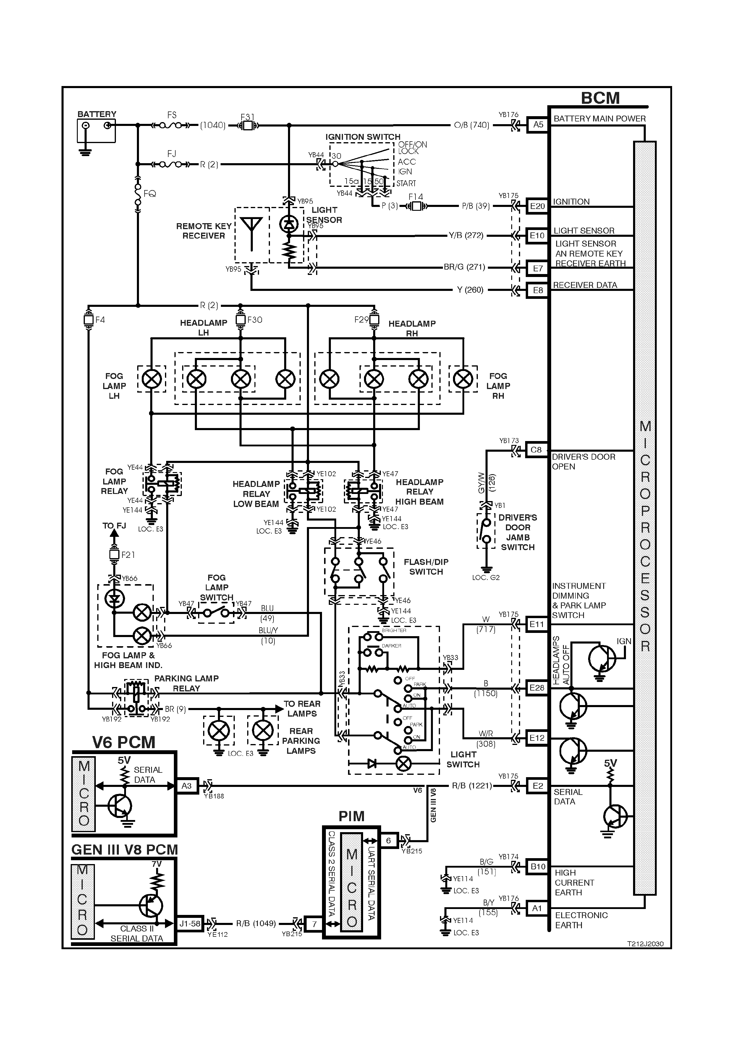
4.7 AUTOM ATIC LIGHT CONTROL - LIGHTS ON AND OFF / APPROACH ILLUMINATION
(WITH TWILIGHT SENTINEL)
Figure 12J-2-75

CIRCUIT DESCRIPTION
A utomatic lights ON and OFF (High Series BCM only)
The automatic light control, lights on and off feature with twilight sentinel, turns the vehicle headlights on and off,
depend ing on the outside light leve l. This f eature will onl y work while t he headlam p switch is in the AUTO position
and the ignition switched ON. The lights will operate as normal in other switch positions.
The light sensor is part of the sun sensor / remote receiver module and is located in the instrument panel pad of the
vehicle betwee n the demist ducts. T he light s ensor is us ed t o monitor th e amount of l igh t in front of the ve hic l e. T he
BCM monitors the outp ut of this sensor via c ircuit 272 (term inal E10) and determ ines when the l ight levels are low
enough to turn the lights on.
TECH 2 can be used to select several different ON/OFF light levels to suit the customer preferences. The
automatic lights off featur e works as per norm al (automatic lights of f witho ut twilig ht sentin el) durin g autom atic light
control (including auto lights off delay period).
A pproach illumination (Lux and High Series BCM)
The approach illumination feature turns the vehicle head and/or park lamps on (depended on headlamp switch
position) for 30 seconds when the doors are unlocked with the remote coded key.
This provi des ad dit io na l c ust omer s ecu rit y when appr oaching t he ve hic l e at ni ght. T he li ghts wil l turn off again if the
vehicle is locked with the remote coded key within 30 seconds of the approach illumination being activated.
When the approach feature is activated, subsequent operation of the remote coded key unlock button will
reactivate the lights to remain on for a further 30 seconds.
The approach illumination feature only operates during dark conditions. The BCM monitors the output of the sun
sensor and determines when the light levels are low enough to enable the approach illumination feature.
The lights resume to normal operation when the ignition is switched to the on position.
TECH 2 has the capability to enable and disable the approach illumination feature.
Diagnostic Aids
If a driver complains of the headlamps coming on to early (during daylight), or to late (well after dusk), the
sensitivity of the twilight can be programmed using TECH 2.
By adjusting the sensitivity down (below the default value of 4) the headlamps will turn on latter.
By adjusting the sensitivity up (above the default value of 4) the headlamps will switch on earlier.
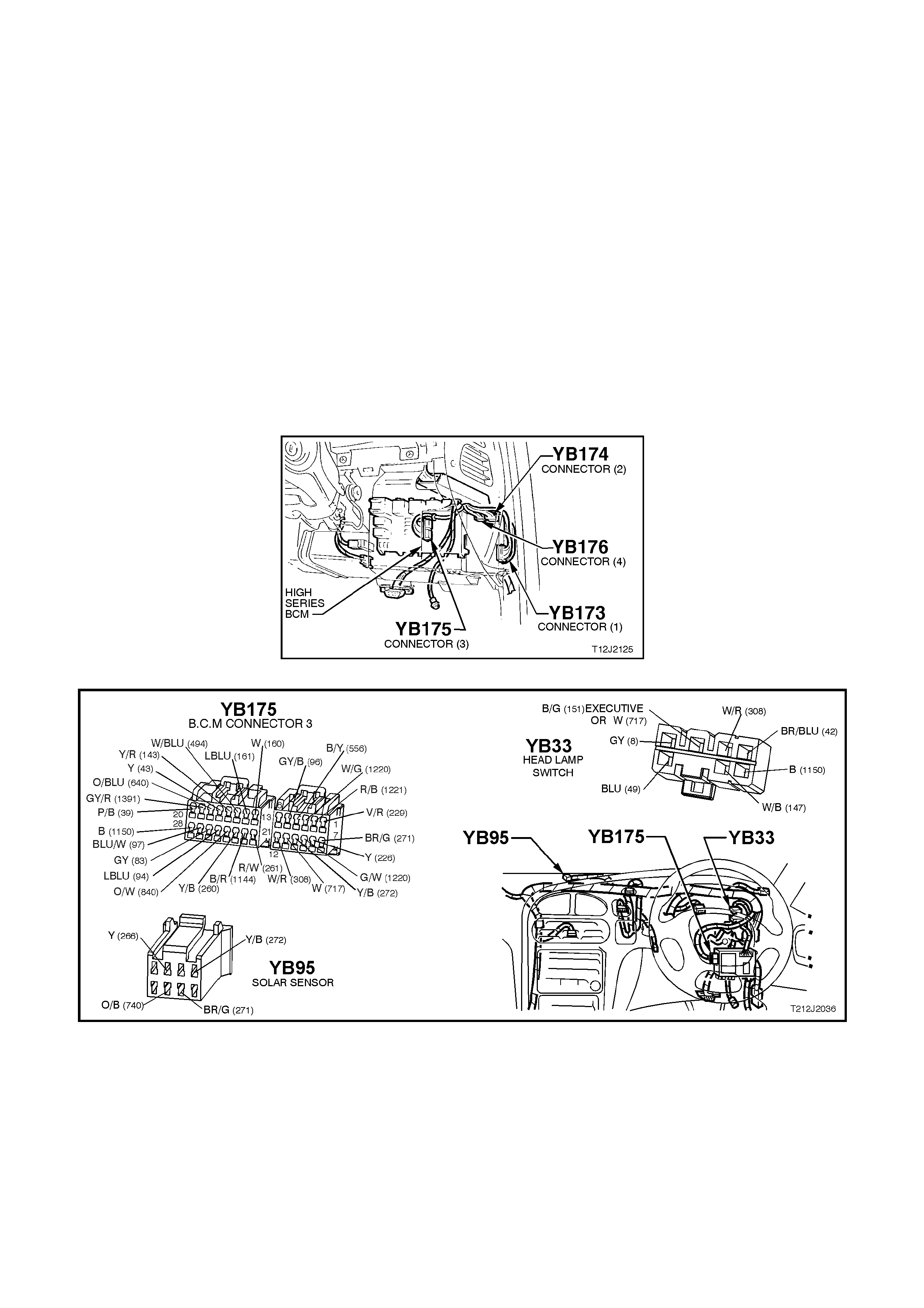
Test Description
The numbers below refer to step numbers in the following diagnostic chart.
1-5. Functional check of automatic light control system.
6. Us es TECH 2 to oper ate head lights in t he AUT O position t o establ ish wheth er problem is with input or ou tput
of BCM.
7. Checks for power and earth to sun sensor / remote receiver module.
8. Uses TECH 2 to check LIGHT SENSOR LEVEL signal at microprocessor of BCM.
9. Checks for BCM output drive of AUTO LIGHTS ON.
10. Checks circuit 308.
11. Checks for battery voltage supply at sun sensor/remote receiver module (circuit 740).
12. Checks circuit 271.
13. Checks LIGHT SENSOR LEVEL signal at input to BCM.
14. Checks and defines fault of circuit 272.
15. Uses T ECH 2 to turn head lights off in th e AUTO position to esta blish whether problem is with output or input
of BCM.
16. Checks LIGHT SENSOR LEVEL signal at input to BCM.
17. Tests for false output drive from BCM or short circuit in wiring.
Figure 12J-2-76
Figure 12J-2-77

AUTOMATIC LIGHT CONTROL - AUTOMATIC LIGHTS ON AND OFF / APPROACH ILLUMINATION
STEP ACTION VALUE YES NO
1. • Turn ignition ON.
• Turn headlamp switch to AUTO position.
• Cover the sun sensor/remote receiver module
assembly.
• Do the headlamps turn ON?
Go to Step 2. Go to Step 5.
2. • With ignition still ON and headlamp switch in AUTO
position, uncover the sun sensor/remote receiver
module.
• Shine a torch on the sun sensor/remote receiver
module.
• Do the headlamps switch OFF?
Go to Step 3. Go to Step 15.
3. • Does the automatic lights off feature (including
delay time) operate with the light switch in the
AUTO position when the ignition is switched off and
the driver’s door is open?
Go to Step 4. Go to automatic
lights off
diagnosis, refer
to 4.6
AUTOMATIC
LIGHTS OFF
(WITHOUT
TWILIGHT
SENTINEL) in
this Section.
4. • Ensure Approach Illumination feature is enabled
(can be enabled and disabled using TECH 2; select
BODY/BODY CONTROL MODULE
PROGRAM/APPROACH ILLUMINATION).
• Turn headlamp switch to the headlamp ON
position.
• Cover the sun sensor/remote receiver module
assembly.
• Turn the ignition ON then OFF.
• Open then close the driver’s door (auto lights off).
• With the headlamps off (if an auto lights off time
delay has been set, headlamps may take up to 3
minutes), lock the doors using the lock button on
the remote coded key.
• Unlock the doors using the unlock button on the
remote coded key.
• Do the headlamps come on and remain on for 30
seconds?
System OK. Replace BCM,
refer to 12J-2
HIGH SERIES
BCM of the VT
Series I Service
Information.
Recheck and
verify repair.
5. • Do lights operate normally in the PARK and
HEADLAMP positions? Go to Step 6. Go to automatic
lights off
diagnosis, refer
to 4.6
AUTOMATIC
LIGHTS OFF
(WITHOUT
TWILIGHT
SENTINEL) in
this Section.
6. • Connect TECH 2 to DLC.
• Select BODY / BODY CONTROL MODULE /
MISCELLANEOUS TESTS / LAMPS / TWILIGHT
SENTINEL.
• Turn headlamp switch to AUTO position.
• Conduct test as instructed by TECH 2.
• Do headlamps turn ON?
Go to Step 7. Go to Step 9.
7. • Check operation of the remote coded key receiver
by locking and unlocking doors using remote coded
key LOCK and UNLOCK button.
• Does remote coded key receiver operate?
Go to Step 8. Go to Step 11.

STEP ACTION VALUE YES NO
8. • Connect TECH 2 to DLC.
• Select BODY / BODY CONTROL MODULE / DATA
DISPLAY/DATA LIST.
• Scroll to AMBIENT LIGHT SENSOR display.
• Cover and uncover the sun sensor/remote receiver
module assembly.
• Does the AMBIENT LIGHT SENSOR screen
display value vary as the sensor is covered and
uncovered (should be approximately 0V when
covered)?
Replace BCM,
refer to 12J-2
HIGH SERIES
BCM of the VT
Series I Service
Information.
Recheck and
verify repair.
Go to Step 13.
9. • Back probe BCM connector YB175, terminal E12,
circuit 308 (White/Red wire) with a jumper lead to
earth.
• Turn headlamp switch to AUTO position.
• Do lights come on?
0 volt Replace BCM,
refer to 12J-2
HIGH SERIES
BCM of the VT
Series I Service
Information.
Recheck and
verify repair.
Go to Step 10.
10. • Back probe BCM connector YB175, terminal E12,
circuit 308 (White/Red wire) and light switch
connector YB33, circuit 308, (White/Red wire) with
an Ohmmeter and check for continuity.
• Does continuity exist?
Replace light
switch, refer to
Section 12B
LIGHTING
SYSTEM of the
VT Series I
Service
Information.
Check and repair
open in circuit
308. Recheck
and verify repair.
11. • Back probe sun sensor/remote receiver module
connector YB95, circuit 740 (Orange/Black wire)
with a Voltmeter to earth.
• Is voltage as specified?
12 volts Go to Step 12. Check and repair
open in circuit
740. Recheck
and verify repair.
12. • Check integrity (including terminal retention) of
circuit 271 (Brown/Green wire).
• Is circuit 271 OK?
Go to Step 8. Check and repair
circuit 271 as
necessary.
Recheck and
verify repair.
13. • Disconnect BCM connector YB175.
• Check voltage at BCM connector YB175, terminal
E10, circuit 272 (Yellow/Black wire) with a
Voltmeter to earth.
• Turn ignition ON.
• Cover the sun sensor/remote receiver module
assembly.
• Is voltage as specified?
Less than
0.5 volts Replace BCM,
refer to 12J-2
HIGH SERIES
BCM of the VT
Series I Service
Information.
Recheck and
verify repair.
Go to Step 14.

STEP ACTION VALUE YES NO
14. • Check integrity of circuit 272 (Yellow/Black wire).
• Is circuit 272 OK? Replace sun
sensor/ remote
receiver module ,
refer to 12J-2
HIGH SERIES
BCM of the VT
Series I Service
Information.
Recheck and
verify repair.
Check and repair
circuit 272 as
necessary.
Recheck and
verify repair.
15. • Connect TECH 2 to DLC.
• Select BODY / BODY CONTROL MODULE /
MISCELLANEOUS TEST / LAMPS / TWILIGHT
SENTINEL.
• Turn ignition ON.
• Turn light switch to AUTO position.
• Conduct test as instructed by TECH 2 and
command lights off.
• Do lights turn off when commanded?
Go to Step 16. Go to Step 17.
16. • Back probe BCM connector YB175, terminal E10,
circuit 272 (Yellow/Black wire) with a Voltmeter to
earth.
• Turn ignition ON.
• Shine a torch on the sun sensor/remote module.
• Is voltage as specified?
5 volts Replace BCM,
refer to 12J-2
HIGH SERIES
BCM of the VT
Series I Service
Information.
Recheck and
verify repair.
Replace sun
sensor/ remote
receiver module ,
refer to 12J-2
HIGH SERIES
BCM of the VT
Series I Service
Information.
Recheck and
verify repair.
17. • Turn light switch to AUTO position.
• Disconnect BCM connector YB175.
• Do headlamps turn off?
Replace BCM,
refer to 12J-2
HIGH SERIES
BCM of the VT
Series I Service
Information.
Recheck and
verify repair.
Check and repair
short as
necessary in
wiring to relays
and/or earth end
of lamps or faulty
relays (beyond
BCM terminal
E12). Recheck
and verify repair.
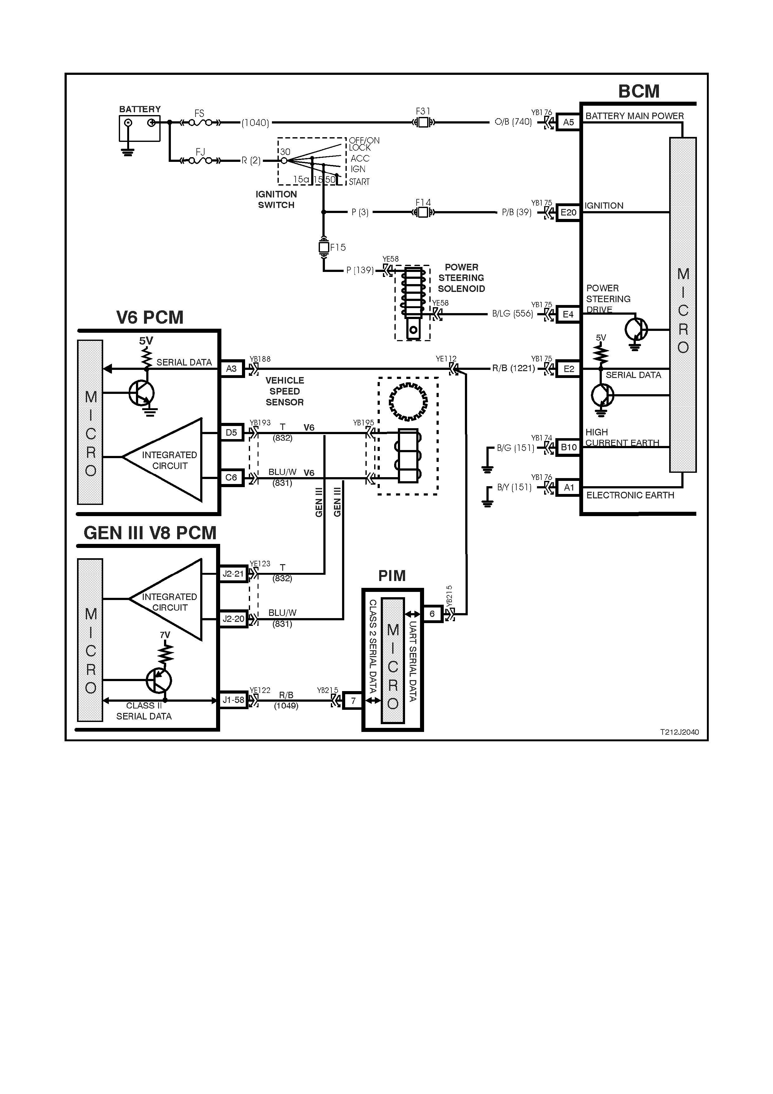
4.8 SPEED SENSITIVE POWER STEERING
Figure 12J-2-78
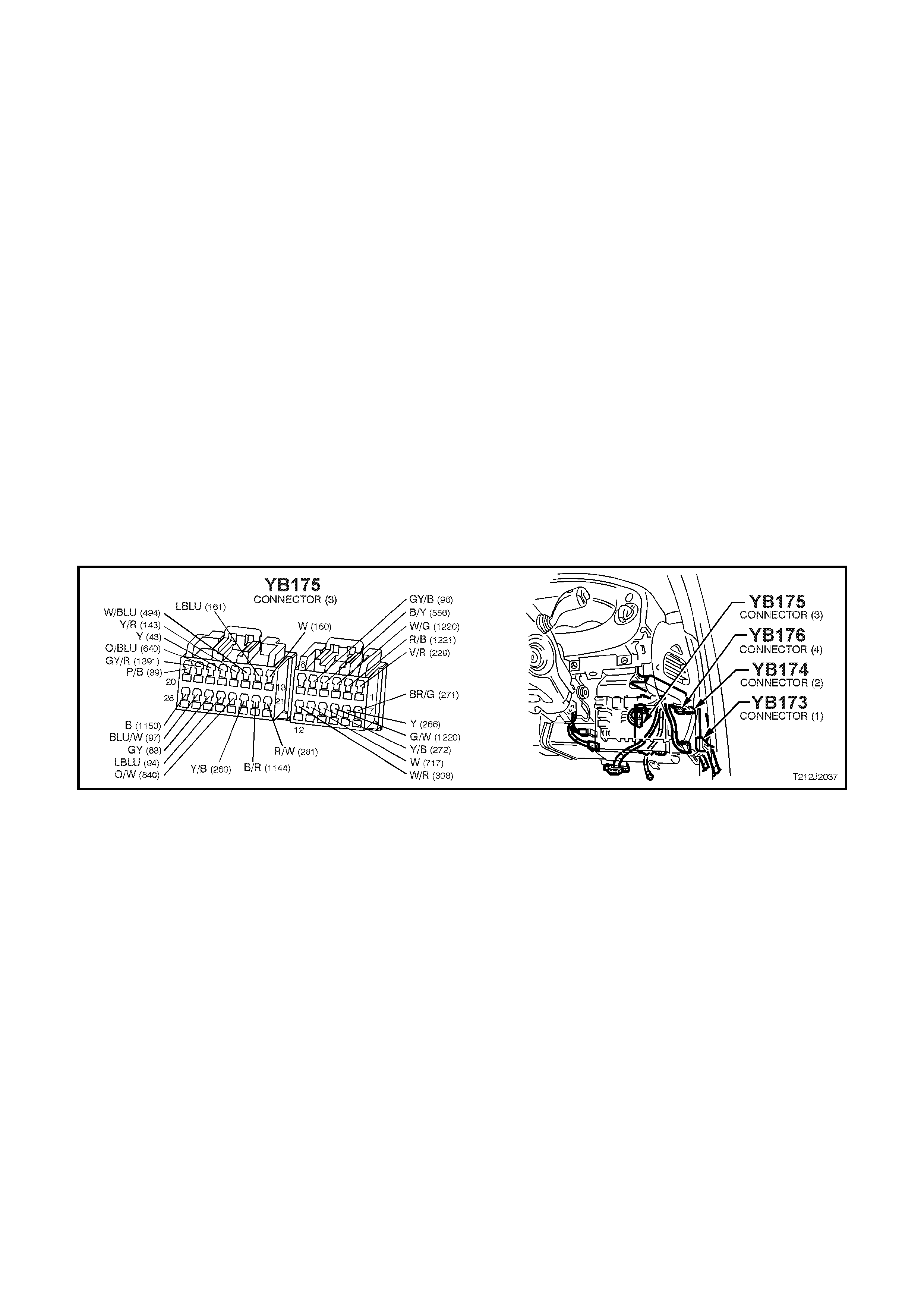
CIRCUIT DESCRIPTION
The c ontrol system of the BCM varies the am ount of power ass istance given to the steeri ng of the vehicle in order
to allow high boost at lo w speed or parking and lo w bo os t at hi gh s pe eds for bett er on centr e s t eering per f ormance.
The BCM contains a curve of speed versus boost (or control solenoid current) stored in memory.
The power steer ing boost is adj usted b y accuratel y controlling t he curre nt flowing in the boost solen oid attached to
the steering gear valve housing.
In the event of any of the following faults, the system will default to no power steering boost: power failure, open
circuits on either side of the power steering solenoid (DTC 3), short circuit to earth on the power steering side of the
solenoid (DTC 3), and short circuit to battery voltage on the BCM side of the solenoid (DTC 4).
In the even t of a s hort circ uit t o earth o n the BC M si de of th e sol enoid (DT C 3) , the s ystem will go to m or e tha n f ull
boost until condition stops and then will default to no boost.
If an y of thes e faults are intermittent, c ycling the ignition from OFF to ON will return the system to norm al until the
fault re-o ccurs.
In the event of road speed information loss, the system will default to minimum boost.
Test Description
The numbers below refer to step numbers in the following diagnostic chart.
5. Checks circuit 139 (including fuse F15).
6. Checks power steering solenoid.
7. Checks circuit 556.
8. Checks BCM for power steering output drive.
9. Checks for serial data communications.
10. Checks for vehicle speed data at the microprocessor of BCM.
11. Checks for vehicle speed data at the microprocessor of BCM.
Figure 12J-2-79

SPEED SEN SITIVE POW ER ST EERING
STEP ACTION VALUE YES NO
1. • Start engine and allow to idle.
• Is there any power steering boost? Go to Step 2. Go to Step 5.
2. • Accelerating vehicle from rest and note power
steering boo st.
• Does power steering boost reduce?
Go to Step 3. Go to Step 9.
3. • Is speed sensitive power steering operation
erratic, requiring ignition to be cycled from OFF to
ON to return system to normal (DTC 3 set)?
Check for
intermittent short
to earth or open
in circuits 556
and 139 and
repair as
necessary.
Recheck and
verify repair.
Go to Step 4.
4. • Is speed sensitive power steering operation
erratic, requiring ignition to be cycled from OFF to
ON to return system to normal (DTC 4 set)?
Check for
intermittent short
to battery
voltage in circuit
556 and repair
as necessary.
Recheck and
verify repair.
System OK.
5. • Back probe power steering solenoid connector
YE58, circuit 139 (Pink wire) with a Voltmeter to
earth.
• Turn ignition ON.
• Is voltage as specified?
12 volts Go to Step 6. Check and repair
fault in circuit 139
(including fuse
F15) Recheck and
verify repair.
6. • Disconnect power steering solenoid connector
YE58.
• Back probe power steering solenoid connector
terminals (solenoid side) with an Ohmmeter.
• Is reading as specified?
7.5 to 8.5
ohms @ 20°CGo to Step 7. Replace power
steering sol eno id,
refer to Section 9B
SPEED
SENSITIVE
POWER
STEERING of the
VT Series I
Service
Information.
7. • Back probe BCM connector YB175, terminal E4,
circuit 556 (Black/Light Green wire) and power
steering solenoid connector YE58 circuit 556
(Black/Light Green wire) with an Ohmmeter.
• Is reading as specified?
Below 1 ohm Go to Step 8. Repair open in
circuit 556.
Recheck circuit to
verify repair.

STEP ACTION VALUE YES NO
8. • Disconnect power steering solenoid connector
YE58 and using appropriate jumper leads from
KM-609, reconnect circuit 139 and connect an
ammeter in series in circuit 556.
• Turn ignition ON.
• Connect TECH 2 to DLC.
• Select BODY / BODY CONTROL MODULE /
MISCELLANEOUS TESTS / POWER STEERING.
• Conduct test as instructed by TECH 2.
• Does value displayed by ammeter vary as the
level of assist is varied?
Go to
DIAGNOSIS in
Sections 9A
STEERING
and 9B SPEED
SENSITIVE
POWER
STEERING of
the VT Series I
Service
Information.
Replace BCM, refer
to 12J-2 HIGH
SERIES BCM of the
VT Series I Service
Information. Recheck
and verify repair.
9. • Connect TECH 2 to DLC.
• Select BODY / BODY CONTROL MODULE.
• Is the SYSTEM IDENTIFICATION screen
displayed in the TECH 2 display?
Go to Step 10. Go to serial data
communications
diagnosis, refer to
4.2 SERIAL DATA
COMMUNICATION.
in this Section.
10. • With TECH 2 still connected and ignition ON, exit
BODY selection and select ENGINE / DATA
DISPLAY.
• Scroll to VEHICLE SPEED.
• Road test vehicle.
• Does screen display the actual vehicle speed as
the vehicle speed varies?
Go to Step 11. Go to PCM
DIAGNOSIS in either
6C1 POWERTRAIN
MANAGEMENT - V6
ENGINE in the VT
Series I Service
Information or 6C3
POWERTRAIN
MANAGEMENT -
GEN III V8 ENGINE
in the VT Series II
Service Information.
11. • With TECH still connected and ignition ON, exit
ENGINE selection and select BODY / BODY
CONTROL MODULE / DATA DISPLAY.
• Scroll to VEHICLE SPEED.
• Road test vehicle.
• Does screen display the actual vehicle speed as
the vehicle speed varies?
Go to Step 8. Replace BCM, refer
to 12J-2 HIGH
SERIES BCM of the
VT Series I Service
Information. Recheck
and verify repair.
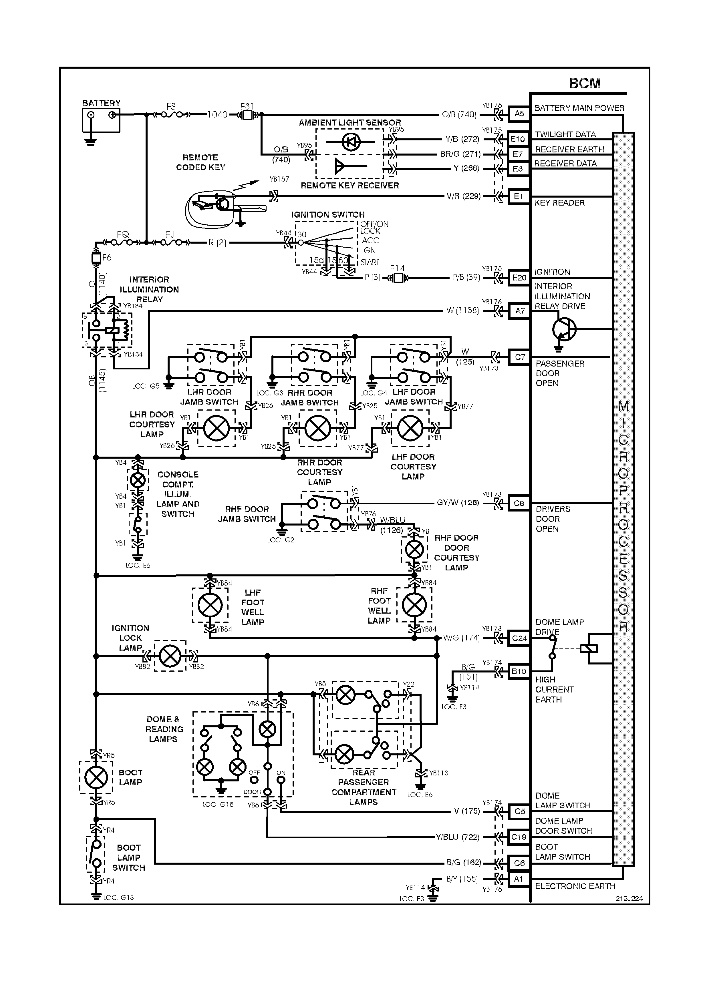
4.9 DOME LAMP DELAY CONTROL
Figure 12J-2-80

CIRCUIT DESCRIPTION
The interi or lightin g is co ntrolled b y the BCM or by the dom e lam p switch (incor porat ed with the dome and readi ng
lamps cluster). The interior lighting is activated when any door is opened, unlocked with the remote coded key,
when the ig nition is switched f r om IGN to O FF (pr ovi ded the f eatur e is en abled or the c ond iti ons are dark), or when
the dome lamp switch is operated.
In addition, as part of the battery saver function, the BCM controls internal, dome, ignition lock surround, glove
compartment and door lamps. The BCM controls battery voltage to these circuits via the interior illumination relay.
There is a dela y period b efore the batter y saver func tion of the BCM deact ivates t he interior illum ination rela y. The
delay defaul t tim e is set to one hour, howe ver, can b e reprogram med with TECH 2 f rom between 2 - 255 minutes .
The delay period is initiated when the ignition is switched to the OFF position.
Whilst in battery saver mode, the BCM will reactivate the interior illumination relay when:
1. When the bonnet, boot or any door is opened.
2. The BCM receives a valid remote receiver.
3. When the ignition is switched to the ON or ACC positions.
4. Doors are unlocked via the driver’s door microswitch.
5. TECH 2 is connected to the DLC and communicating with the BCM.
6. The headlamp switch is cycled from OFF to ON or ON to OFF.
7. The deadlock switch is activated.
8. When the alarm is activated.
9. When the boot release button is pressed.
The interior lighting is activated when any door is open. After all doors have been closed, the lamp will remain
activated for an additional 30 seconds.
The BCM monitors the DOORS and ON positions and controls the dome lamp accordingly.
If the interior light ing has been acti va ted b y a BCM contr o l system ac tion, the dome lamp switch will tur n t he interior
lighting off when it is switched from the DOOR to the OFF position. This means that the switch can curtail any delay
time indicated as well as switch the lighting off whilst a door is open. The exception to this is if the theft deterrent
system has been triggered. In this case, even with the switch in the OFF position, the dome lamp will flash.
The interior lighting is switched on upon central door unlocking for 30 seconds. If the ignition is turned on during
this period, the interior lighting will be switched off immediately. Interior lighting is also switched off upon central
door locking, except if the dome lamp switch is turned on or if a door remains open.
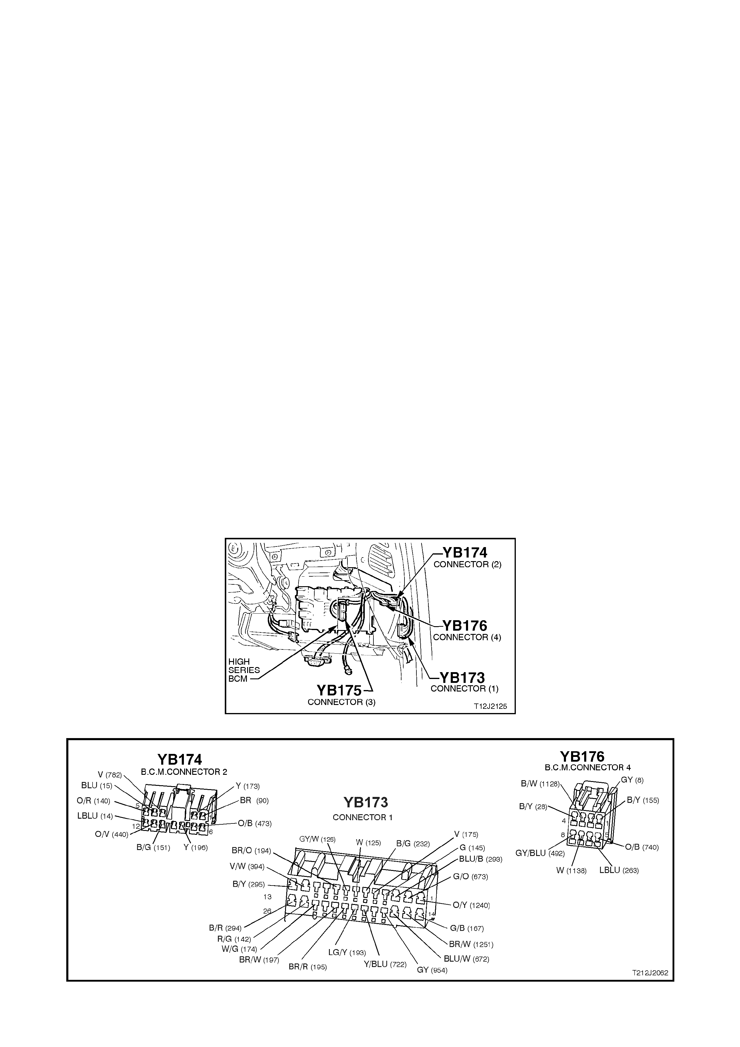
Test Description
The numbers below refer to step numbers in the following diagnostic chart.
1-7. Functional check of dome lamp system.
9. Uses TECH 2 to check for DOME LAMP SWITCH DOOR signal at microprocessor of BCM.
10. Checks dome lamp globe and fuse F6.
11. Uses TECH 2 to drive dome lamp.
12. Checks dome lamp DOOR signal at input of BCM.
13. Checks dome lamp drive output from BCM using TECH 2.
14. Checks circuit 174.
15. Checks circuit 1140 and dome lamp and switch assembly.
16. Checks circuit 722 and dome lamp and switch assembly.
17. Checks BCM for false output drive, circuit 174 and dome lamp and switch assembly.
18. Uses T ECH 2 to ch ec k for DO ME L AMP SWITCH ON signa l at micropr oces s or of BCM in t he ev ent of a f als e
signal causing the dome lamp to come on.
19. Checks driver’s door jamb signal at input of BCM.
Checks circuit 126.
Checks driver’s door jamb switch.
Checks passenger door jamb signal at input of BCM.
Checks passenger door jamb switch.
24. Uses TECH 2 to check for DOME LAMP SWITCH ON signal at microprocessor of BCM.
25. Checks for DOME LAMP SWITCH ON signal at input to BCM.
26. Checks circuit 175 and dome lamp and switch assembly.
27. Checks ignition signal at input of BCM.
28. Checks circuit 1140.
29. Checks circuit 1145.
30. Checks interior illumination relay.
31. Checks circuit 1138 / relay drive from BCM.
Figure 12J-2-81
Figure 12J-1-82

DOME LAMP DELAY
STEP ACTION VALUE YES NO
1. • Dome lamp switch in DOOR position.
• All doors locked.
• Unlock doors with remote key.
• Does dome lamp turn on?
Go to Step 2. Go to Step 8.
2. • Dome lamp switch in DOOR position.
• Dome lamp on (doors open).
• Close doors and lock with remote key.
• Does dome lamp turn off immediately?
Go to Step 3. Go to Step 17.
3. • Dome lamp switch in DOOR position.
• Doors closed but unlocked ( dom e lamp off).
• Open driver’s door.
• Does dome lamp illuminate?
Go to Step 4. Go to Step 20.
4. • Dome lamp switch in DOOR position.
• Doors closed but unlocked ( dom e lamp off).
• Open any passenger door.
• Does dome lamp illuminate?
Go to Step 5. Go to Step 22.
5. • Dome lamp switch in DOOR position.
• Doors closed (dome lamp off).
• Turn dome lamp switch to ON position.
• Does dome lamp turn on?
Go to Step 6. Go to Step 24.
6. • Dome lamp switch in DOOR position.
• With doors closed, lock then unlock doors with
remote key.
• Within 30 seconds, turn ignition to the ON position.
• Does the dome lamp turn off immediately?
Go to Step 7. Go to Step 27.
7. • With the ignition OFF (courtesy lamp function
enabled via TECH 2), all doors closed and the
dome lamp switch in the DOOR position, turn the
ignition ON.
• Turn the ignition OFF.
• Does the dome lamp turn on?
System OK Replace BCM,
refer to 12J-2
HIGH SERIES
BCM of the VT
Series I Service
Information.
Recheck and
verify repair.
8. • Switch the dome lamp switch to the ON position.
• Does the dome lamp illuminate? Go to Step 9. Go to Step 10.
9. • Connect TECH 2 to DLC.
• Select BODY / BODY CONTROL MODULE / DATA
DISPLAY.
• Scroll to DOME SWITCH.
• Does screen display DOME SWITCH DOOR?
Replace BCM,
refer to 12J-2
HIGH SERIES
BCM of the VT
Series I Service
Information.
Recheck and
verify repair.
Go to Step 12.

STEP ACTION VALUE YES NO
10. • Check dome lamp globe and fuse F6.
• Are globe and fuse OK? Go to Step 11. Replace globe
and/or fuse F6.
Recheck and
verify repair.
11. • Connect TECH 2 to DLC.
• Select BODY / BODY CONTROL MODULE /
MISCELLANEOUS TESTS / LAMPS / DOME.
• Conduct test as instructed by TECH 2 and
command dome lamp on.
• Does the dome lamp illuminate
Go to Step 9. Go to Step 13.
12. • Dome lamp switch in DOOR position.
• Back probe BCM connector YB173, terminal C19
circuit 722 (Yellow/Blue wire) with a Voltmeter to
earth.
• Is voltage as specified?
12 volts Replace BCM,
refer to 12J-2
HIGH SERIES
BCM of the VT
Series I Service
Information.
Recheck and
verify repair.
Go to Step 16.
13. • Disconnect BCM connector YB173 and back probe
terminal C24 with an Ohmmeter to earth.
• Repeat DOME LAMP test (Step 10).
• Is reading as specified?
Below 1 ohm Go to Step 14. Replace BCM,
refer to 12J-2
HIGH SERIES
BCM of the VT
Series I Service
Information.
Recheck and
verify repair.
14. • Remove the interior illumination relay.
• Reconnect BCM connector YB173 and back probe
terminal C24, circuit 174 (White/Green wire) and
dome lamp and switch assembly connector YB6,
circuit 174 (White/Green wire) with an Ohmmeter.
• Is reading as specified?
Below 1 ohm Go to Step 15. Repair open in
circuit 174.
Recheck and
verify repair.
15. • Reinstall interior illumination relay.
• Ignition ON
• Back probe dome lamp and switch assembly
connector YB6, circuit 1145 (Orange/Black wire)
with a Voltmeter to earth.
• Is voltage as specified?
12 volts Replace dome
lamp and switch
assembly, refer
12B LIGHTING
SYSTEM of the
VT Series I
Service
Information.
Recheck and
verify repair.
Go to Step 28.
16. • Dome lamp switch in DOOR position.
• Back probe dome lamp and switch assembly
connector YB6, circuit 722 (Yellow/Blue wire) with a
Voltmeter to earth.
• Is voltage as specified?
12 volts Repair open in
circuit 722.
Recheck and
verify repair.
Replace dome
lamp and switch
assembly, refer
12B LIGHTING
SYSTEM of the
VT Series I
Service
Information
Recheck and
verify repair.
17. • Dome lamp switch in DOOR position.
• Disconnect BCM connector YB173.
• Does dome lamp turn off?
Go to Step 18. Check and repair
either short in
circuit 174 or
faulty dome lamp
and switch
assembly.
Recheck and
verify repair.
18. • Re-connect BCM connector YB173.
• Dome lamp switch in DOOR position.
• Connect TECH 2 to DLC.
• Select BODY / BODY CONTROL MODULE / DATA
DISPLAY.
• Scroll to DOME SWITCH.
• Does screen display DOME SWITCH ON?
Go to Step 19. Replace BCM,
refer to 12J-2
HIGH SERIES
BCM of the VT
Series I Service
Information.
Recheck and
verify repair.

STEP ACTION VALUE YES NO
19. • Dome lamp switch in DOOR position.
• Back probe BCM connector YB173, terminal C5,
circuit 175 (Violet wire) with a Voltmeter to earth.
• Is voltage as specified?
12 volts Check and repair
circuit 175 for
short to B+ or
replace dome
lamp and switch
assembly, refer
12B LIGHTING
SYSTEM of the
VT Series I
Service
Information.
Recheck and
verify repair.
Replace BCM,
refer to 12J-2
HIGH SERIES
BCM of the VT
Series I Service
Information.
Recheck and
verify repair.
20. • Driver’s door open.
• Dome lamp switch in DOOR position.
• Back probe BCM connector YB173, terminal C8,
circuit 126 (White/Blue wire) with a Voltmeter to
earth.
• Is voltage as specified?
Below 0.5
volts Replace BCM,
refer to 12J-2
HIGH SERIES
BCM of the VT
Series I Service
Information.
Recheck and
verify repair.
Go to Step 21.
21. • Back probe BCM connector YB173, terminal C8,
circuit 126 (Grey/White wire) and driver’s door jamb
switch connector YB1, circuit 1126 (White/Blue
wire) with an Ohmmeter.
• Is reading as specified?
Below 1 ohm Replace driver’s
door jamb switch,
refer to 12J-2
HIGH SERIES
BCM of the VT
Series I Service
Information.
Recheck and
verify repair.
Repair open in
circuit 1126.
Recheck and
verify repair.
22. • Back probe BCM connector YB173, terminal C7,
circuit 125 (White wire) with a Voltmeter to earth.
• Open and close each passenger door.
• Is voltage as specified when opening each of the
passenger doors?
Below 0.5
volts Replace BCM,
refer to 12J-2
HIGH SERIES
BCM of the VT
Series I Service
Information.
Recheck and
verify repair.
Go to Step 23.
23. • While performing test in Step 22, was voltage as
specified at least one of the passenger doors? Check and repair
either open in
relevant
passenger door
jamb circuit or
faulty door jamb
switch.
Repair open in
circuit 125.
Recheck and
verify repair.
24. • Dome lamp switch in ON position.
• Connect TECH 2 to DLC.
• Select BODY / BODY CONTROL MODULE / DATA
DISPLAY.
• Scroll to DOME SWITCH.
• Does screen display DOME SWITCH ON?
Replace BCM,
refer to 12J-2
HIGH SERIES
BCM of the VT
Series I Service
Information.
Recheck and
verify repair.
Go to Step 25.
25. • Dome lamp switch in ON position.
• Back probe BCM connector YB173, terminal C5,
circuit 175 (Violet wire) with a Voltmeter to earth.
• Is voltage as specified?
12 volts Replace BCM,
refer to 12J-2
HIGH SERIES
BCM of the VT
Series I Service
Information.
Recheck and
verify repair.
Go to Step 26.

STEP ACTION VALUE YES NO
26. • Dome lamp switch in ON position.
• Back probe dome lamp and switch assembly
connector YB6, circuit 175 (Violet wire) with a
Voltmeter to earth.
• Is voltage as specified?
12 volts Repair open in
circuit 175.
Recheck and
verify repair.
Replace dome
lamp and switch
assembly, refer
12B LIGHTING
SYSTEM of the
VT Series I
Service
Information.
Recheck and
verify repair.
27. • Back probe BCM connector YB175 terminal E20,
circuit 39 (Pink/Black wire) with a Voltmeter to
earth.
• Turn ignition ON.
• Is voltage as specified?
12 volts Replace BCM,
refer to 12J-2
HIGH SERIES
BCM of the VT
Series I Service
Information.
Recheck and
verify repair.
Check and repair
open in circuit 39
(including fuse
F14). Recheck
and verify repair.
28. • Back probe the interior illumination relay connector
YB134 terminals 2 and 5, circuit 1140 (Orange
wire) with a voltmeter to earth.
• Turn ignition ON.
• Is voltage as specified?
12 volts Go to Step 29. Check and repair
fault in circuit
1140. Recheck
and verify repair.
29. • Back probe the interior illumination relay connector
YB134 terminals 3, circuit 1145 (Orange/Black wire)
with a voltmeter to earth.
• Turn ignition ON.
• Is voltage as specified?
12 volts Repair open in
circuit 1145.
Recheck and
verify repair
Go to Step 30.
30. • Dome lamp switch in ON position.
• Back probe interior illumination relay connector
YB134, terminal 1, circuit 1138 (White wire) with a
jumper lead connected to earth.
• Turn ignition ON.
• Does the dome lamp turn ON?
Go to Step 31 Replace interior
illumination relay.
Recheck and
verify repair.
31. • Back probe BCM connector YB176 terminal A7,
circuit 1138 (White wire) with a jumper lead
connected to earth.
• Turn ignition ON.
• Does the dome lamp turn ON?
Go to Step 27. Check and repair
open in circuit
1138. Recheck
and verify repair.
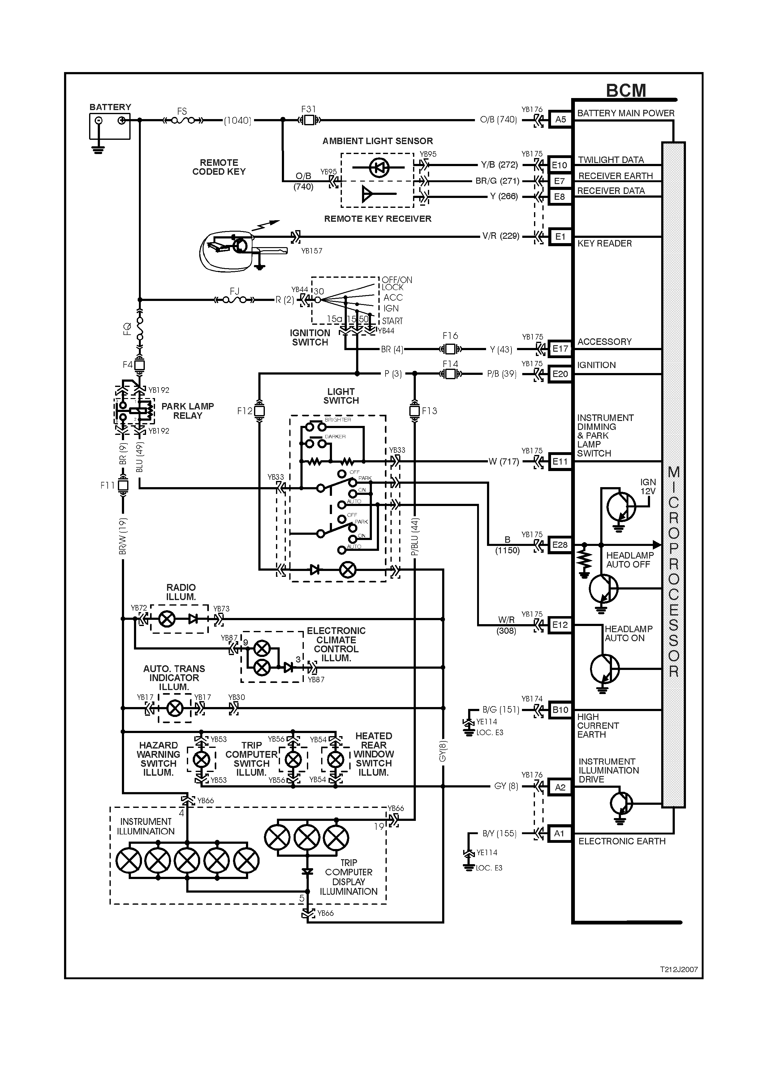
4.10 INSTRUMENT DIMMING CONTROL
Figure 12J-2-83

CIRCUIT DESCRIPTION
The BCM controls the illumination level of the instrument dial faces, all dash and centre console illumination and
display windows of the trip computer, Electronic Climate Control (ECC) and radio.
The illuminatio n level is adjusted by two momentary contac t switches , l oc ated in the he ad lamp s witch as s embly, f or
ram ping the illumination inte ns ity up and down.
The dimmer drives to full load when both the ignition is on and the park lamps are off. This gives maximum
brightness to the trip computer, ECC and radio windows. When the park lamps are switched on, the dimmer
operates according to the level previously set (is also dependant on which remote coded key was used; priority one
or priority two).
The dimmer control inputs are resistor encoded onto the one input line (including the park lamps input). A ‘bright’
input will occur when ther e is 0 ohms refer ence to the park lamp control output (DIM + activated) a nd a ‘dim ’ input
will occur when there is 2.7 kohms reference to the park lamp control output (DIM - activated). This line is at 5.4
kohms at rest point. The system default is full load when th e line is o pen cir cuit. The default dim mer intensit y is full
load, and will default to this if the battery is disconnected from the vehicle.
NOTE: Illumination switches are only active whilst the ignition switch is in the ACC or IGN positions.
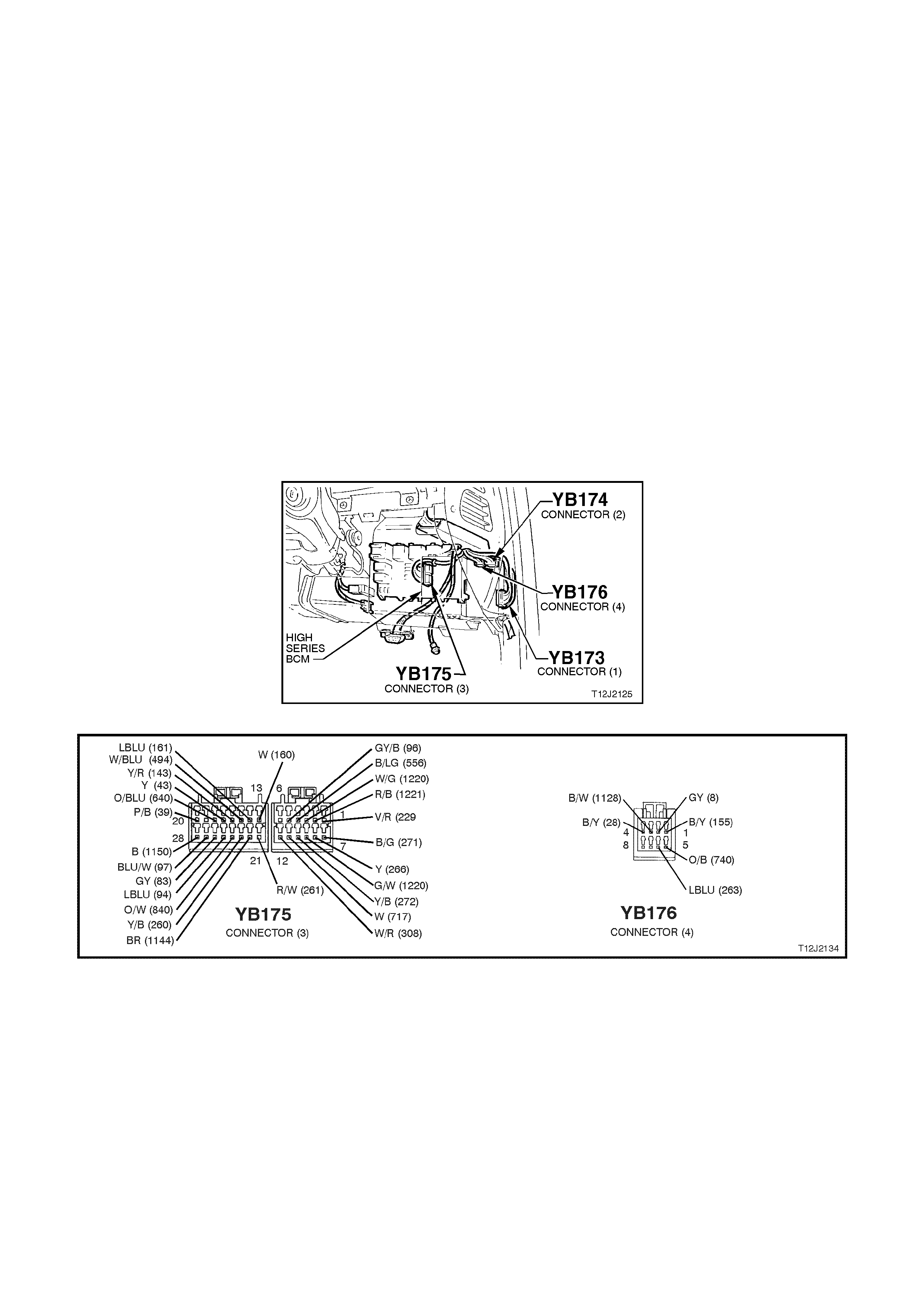
Test Description
The numbers below refer to step numbers in the following diagnostic chart.
6. Uses TECH 2 to check for IGNITION signal at microprocessor of BCM.
7. Checks circuit 44, including fuse F13.
8. Check illumination output drive from BCM.
9. Checks circuit 8.
10. Checks for IGNITION signal at input of BCM.
11. Checks parking lamp circuit.
12. Checks circuit 19, including fuse 11.
Uses TECH 2 to check for park lamp switch signal at microprocessor of BCM.
14. Uses TECH 2 to check for Dim + switch signal at microprocessor of BCM.
15. Uses TECH 2 to check for Dim - switch signal at microprocessor of BCM.
16. Uses TECH 2 to vary illumination level
17. Checks for park lamp switch signal at input to BCM.
18. Checks circuit 717.
19. Checks light switch (illumination resistors).
20. Checks for Dim + signal at input of BCM.
21. Checks for Dim - signal at input of BCM.
22. Checks for short in circuit 8 or BCM that is causing illumination level not to vary.
Figure 12J-1-84
Figure 12J-1-85

INSTRUMENT DIMMING
STEP ACTION VALUE YES NO
1. • Turn ignition ON.
• Does trip computer illuminate? Go to Step 2. Go to Step 6.
2. • Turn ignition ON.
• Light switch in PARK position.
• Is instrument panel illuminated?
Go to Step 3. Go to Step 11.
3. • Ignition ON.
• Light switch in PARK position.
• Activate DIM + button located in the light switch
assembly.
• Does instrument panel illumination ramp up to
full?
Go to Step 4. Go to Step 13.
4. • Turn ignition ON.
• Light switch in PARK position.
• Activate the DIM - button located in the light
switch assembly.
• Does instrument panel illumination fade fully?
Go to Step 5. Go to Step 13.
5. • When operating Priority One and Priority Two
keys, is the illumination level as set previously? System OK. Go to priority key
system
diagnosis, refer
to 4.15
PRIORITY KEY
SYSTEM in this
Section.
6. • Connect TECH 2 to DLC.
• Turn ignition ON.
• Select BODY / BODY CONTROL MODULE /
DATA DISPLAY and scroll to IGNITION SWITCH.
• Does screen display IGNITION SWITCH ON?
Go to Step 7. Go to Step 10.
7. • Turn ignition ON.
• Back probe instrument panel cluster connector
YB66, circuit 44 (Pink/Blue wire) with a Voltmeter
to earth.
• Is voltage as specified?
12 volts Go to Step 8. Check and repair
fault in circuit 44
(including fuse
F13). Recheck
and verify repair.
8. • Turn ignition ON.
• Back probe BCM connector YB176, terminal A2,
circuit 8 (Grey wire) with a jumper lead to earth.
• Does trip computer illuminate fully?
Replace BCM,
refer to 12J-2
HIGH SERIES
BCM of the VT
Series I Service
Information.
Recheck and
verify repair.
Go to Step 9.
9. • Turn ignition ON.
• Back probe instrument panel cluster connector
YB66, circuit 8 (Grey wire) with a jumper lead to
earth.
• Does trip computer illuminate fully?
Repair open in
circuit 8.
Recheck and
verify repair.
Go to
Instruments
diagnosis in
Section 12C
INSTRUMENTS,
WIPERS /
WASHERS AND
HORNS of the
VT Series II
Service
Information.
10. • Turn ignition ON.
• Back probe BCM connector YB175, terminal E20,
circuit 39 (Pink/Black wire) with a Voltmeter to
earth.
• Is voltage as specified?
12 volts Replace BCM,
refer to 12J-2
HIGH SERIES
BCM of the VT
Series I Service
Information.
Recheck and
verify repair.
Check and repair
fault in circuit 39
(including fuse
F13). Recheck
and verify repair.
11. • Light switch in PARK position.
• Back probe parking lamp relay connector YB192,
terminal 5, circuit 9 (Brown wire with Voltmeter to
earth.
• Is voltage as specified?
12 volts Go to Step 12. Go to automatic
lights off
diagnosis, refer
4.6 AUTOMATIC
LIGHTS OFF
(WITHOUT
TWILIGHT
SENTINEL in this
Section.

STEP ACTION VALUE YES NO
12. • Light switch in PARK position.
• Back probe instrument panel cluster connector
YB66, circuit 19 (Brown/White wire) with a
Voltmeter to earth.
• Is voltage as specified?
12 volts Go to Instrument
diagnostics in
Section 12C
INSTRUMENTS,
WIPERS /
WASHERS AND
HORNS of the
VT Series II
Service
Information.
Check and repair
fault in circuit 19
(including fuse
F11). Recheck
and verify repair.
13. • Turn ignition ON.
• Turn headlamp switch to the PARK position.
• Illumination switch OFF (centre position).
• Connect TECH 2 to DLC.
• Select BODY / BODY CONTROL MODULE /
DATA LIST and scroll to PARK LAMP SWITCH.
• Does screen display PARK LAMP SWITCH ON?
Go to Step 14. Go to Step 17
14. • Turn ignition ON.
• Turn headlamp switch to the PARK position.
• With TECH 2 connected, and DATA DISPLAY
selected, scroll to ILLUMINATION SWITCH
POSITION.
• Activate the DIM + button.
• Does screen display INSTRUMENT SWITCH
POSITION UP?
Go to Step 15. Go to Step 20.
15. • Turn ignition ON.
• Turn headlamp switch to the PARK position.
• With TECH 2 connected, and DATA DISPLAY
selected, scroll to ILLUMINATION SWITCH
POSITION.
• Activate the DIM - button.
• Does screen display INSTRUMENT SWITCH
POSITION DOWN?
Go to Step 16. Go to Step 21.
16. • Turn ignition ON.
• Turn headlamp switch to the PARK position.
• With TECH 2 connected, exit DATA DISPLAY
and select MISCELLANEOUS TESTS / LAMPS /
ILLUMINATION.
• Conduct test and vary illumination level up/down.
• Does illumination level vary?
Replace BCM,
refer to 12J-2
HIGH SERIES
BCM of the VT
Series I Service
Information.
Recheck and
verify repair.
Go to Step 22.
17. • Turn ignition ON.
• Turn headlamp switch to the PARK position.
• Turn illumination switch OFF (centre position).
• Back probe BCM connector YB175, terminal E11,
circuit 717 (White wire) with a Voltmeter to earth.
• Is voltage as specified?
Approx. 2.6 -
3.4 volts Replace BCM,
refer to 12J-2
HIGH SERIES
BCM of the VT
Series I Service
Information.
Recheck and
verify repair.
Go to Step 18.

STEP ACTION VALUE YES NO
18. • Check integrity of circuit 717 (White wire).
• Is circuit 717 OK? Go to Step 19. Repair circuit 717
as necessary.
Recheck and
verify repair.
19. • Disconnect headlamp switch connector YB33 and
back probe switch terminals (switch end), circuits
49 )Blue wire) and 717 (White wire) with an
Ohmmeter.
• Is value as specified?
Approx. 5.4
kohms Replace BCM,
refer to 12J-2
HIGH SERIES
BCM of the VT
Series I Service
Information.
Recheck and
verify repair.
Replace light
switch assembly,
refer to Section
12B LIGHTING
SYSTEM of the
VT Series I
Service
Information.
20. • Turn ignition ON.
• Turn headlamp switch to the PARK position.
• Back probe BCM connector YB175, terminal E11,
circuit 717 (White wire) with a Voltmeter to earth.
• Activate DIM + button.
• Is value as specified?
Less than 0.5
volts Replace BCM,
refer to 12J-2
HIGH SERIES
BCM of the VT
Series I Service
Information.
Recheck and
verify repair.
Replace light
switch assembly,
refer Section 12B
LIGHTING
SYSTEM of the
VT Series I
Service
Information.
21. • Turn ignition ON.
• Turn headlamp switch to the PARK position.
• Back probe BCM connector YB175, terminal E11,
circuit 717 (White wire) with a Voltmeter to earth.
• Activate DIM - button.
• Is voltage as specified?
Approx. 1.8
volts Replace BCM,
refer to 12J-2
HIGH SERIES
BCM of the VT
Series I Service
Information.
Recheck and
verify repair.
Replace light
switch assembly,
refer to Section
12B LIGHTING
SYSTEM of the
VT Series I
Service
Information.
22. • Turn ignition ON.
• Turn headlamp switch to the PARK position.
• Disconnect BCM connector YB176.
• Does instrument illumination go out?
Replace BCM,
refer to 12J-2
HIGH SERIES
BCM of the VT
Series I Service
Information.
Recheck and
verify repair.
Check and repair
short in circuit 8
(Grey wire).
Recheck and
verify repair.

4.11 CRUISE CONTROL INTERFACE
The cruise control interface diagnostic procedure remains unchanged from the procedure detailed in
Section 12J-2 HIGH SERIES BODY CONTROL MODULE, of the VT Series I Service Information, noting the
following:
When diagnosing a circuit fault in the cruise control interface on a VT Series II vehicle, reference to the wiring
diagrams in Section 12P WIRING DIAGRAMS of the VT Series II Service Information should be made.

4.12 REAR LAMP F AILURE WARNING SYSTEM
The rear lamp failure warning system diagnostic procedure remains unchanged from the procedure detailed in
Section 12J-2 HIGH SERIES BODY CONTROL MODULE of the VT Series I Service Information, noting the
following:
When diagnosing a circuit fault in the rear lam p failure warning system on a VT Series II ve hicle, reference to the
wiring diagrams in Section 12P WIRING DIAGRAMS of the VT Series II Service Information should be made.

4.13 POWER ANTENNA CONTROL
The power antenna control diagnostic procedure remains unchanged from the procedure detailed in
Section 12J-2 HIGH SERIES BODY CONTROL MODULE of the VT Series I Service Information, noting the
following:
When diagnosing a circuit fault in the power antenna control system on a VT Series II vehicle, reference to the
wiring diagrams in Section 12P WIRING DIAGRAMS of the VT Series II Service Information should be made.

4.14 ROAD SPEED DEPENDENT VARI ABLE DWELL WIPER SYSTEM
The road speed dependent variable dwell wiper system diagnostic procedure remains unchanged from the
procedure detailed in Section 12J-2 HIGH SERIES BODY CONTROL MODULE of the VT Series I Service
Inform ation, not ing the fol lowi n g:
If referred to Powertrain Management (PCM) diagnostics and the vehicle is equipped with a GEN III V8 engine,
reference to Section 6C3 POWERTRAIN MANAGEMENT - GEN III V8 ENGINE of the VT Series II Service
Information should be made.
W hen diagnos ing a circuit fault in the ro ad speed depend ent variab le dwell wiper system on a VT Series I I vehicle,
reference to the wiring diagrams in Section 12P WIRING DIAGRAMS of the VT Series II Service Information
should be made.

4.15 PRIORITY KEY SYSTEM
The priority key system diagnostic procedure remains unchanged from the procedure detailed in
Section 12J-2 HIGH SERIES BODY CONTROL MODULE of the VT Series I Service Information, noting the
following:
If referred to instruments diagnostics refer to the diagnostic procedures in Section 12C INSTRUMENTS,
WIPER S/W ASHERS AND HORNS of the VT Series II Service Information.
W hen diagnosing a circuit fau lt for prior ity ke y system on a VT Series II vehic le, ref erence to the wirin g dia gram s in
Section 12P WIRING DIAGRAMS of the VT Series II Service Information should be made.

4.16 SRS DEPLOYMENT VEHICLE SHUTDOWN
The SRS deployment vehicle shutdown diagnostic procedure remains unchanged from the procedure detailed in
Section 12J-2 HIGH SERIES BODY CONTROL MODULE of the VT Series I Service Information, noting the
following:
If referred to serial data communications diagnostics refer to 4.2 SERI AL DATA COMMUNICAT ION in this Section.
When diagnosing a circuit fault for SRS deployment vehicle shutdown on a VT Series II vehicle, reference to the
wiring diagrams in Section 12P WIRING DIAGRAMS of the VT Series II Service Information should be made.

4.17 REMOTE RECEIVER/KEY
The remote receiver/key diagnostic procedure remains unchanged from the procedure detailed in
Section 12J-2 HIGH SERIES BODY CONTROL MODULE of the VT Series I Service Information, noting the
following:
If referred to theft deterrent diagnosis and the vehicle is a VT Series II, reference to 4.4 THEFT DETERRENT in
this Section should be made, not to the VT Series I Service Information.
W hen diagnosi ng a faulty rem ote receiver/k ey circuit on a VT Series II vehicle, refer ence to the wiring diagram s in
Section 12P WIRING DIAGRAMS of the VT Series II Service Information should be made.
Techline

4.18 ENTRY DE TERRENT
The entry deterrent system diagnostic procedure remains unchanged from the procedures detailed in
Section 12J-2 HIGH SERIES BODY CONTROL MODULE of the VT Series I Service Information, noting the
following:
The rear com partment loc k switch ( located in t he glov e com partment) is disable d when the vehicl e speed is abo ve
15 km /h, theft deterren t system is arm ed via the r emote cod ed k ey, driv er’s do or m icros witch or deadlock , or if the
vehicle is in battery saver mode.
The rear compartment lock switch is only enabled when the theft deterrent system is disarmed via the remote
coded key or remote key reader (valid security code).
When diagnosing the an entry deterrent system circuit fault on a VT Series II Model, reference to the wiring
diagrams in Section 12P WIRING DIAGRAMS of the VT Series II Service Information should be made.

4.19 BOOT RELEASE
The boot release system diagnostic procedure remains unchanged from the procedure detailed in
Section 12J-2 HIGH SERIES BODY CONTROL MODULE of the VT Series I Service Information, noting the
following:
The rear com partment loc k switch ( located in t he glov e com partment) is disable d when the vehicl e speed is abo ve
15 km/h, theft deterrent system is armed via the remote coded key, or driver’s door microswitch or deadlock.
The rear compartment lock switch is only enabled when the theft deterrent system is disarmed via the remote
coded key or remote key reader (valid security code).
When diagnosing a boot release system circuit fault on a VT Series II Model, reference to the wiring diagrams in
Section 12P WIRING DIAGRAMS of the VT Series II Service Information should be made.
Techline
Techline

4.20 POWER WIN D OW SY STEM
The diagnostic procedure for power windows remains unchanged from the procedure detailed in
Section 12J-2 HIGH SERIES BODY CONTROL MODULE of the VT Series I Service Information, noting the
following:
When the ignition is switched off and no door has been opened, power is supplied to the window system for a
maximum of 60 minutes, provided the BCM has not entered battery saver mode. If battery saver mode is active,
power will be removed from the window system when the ignition is switched off.
When the doors are remotely unlocked (using the remote coded key), provided the vehicle is not in battery saver
mode, po wer is suppl ied to the s ystem f or a 60 minutes (If the vehicle is in batter y sa ver mode, power is r emoved
from the system). The delay is cancelled when the doors are locked by the remote coded key.
When diagnosing a power window circuit fault on a VT Series II vehicle, reference to the wiring diagrams in
Section 12P WIRING DIAGRAMS of the VT Series II Service Information should be made.