
SECTION 6A1 - ENGINE MECHANICAL -
V6 ENGINE
CAUTION:
This vehicle will be equipped with a Supplemental Restraint System (SRS). A SRS will consist of either
seat belt pre-tensioners and a driver's air bag, seat belt pre-tensioners and a driver's and front
passenger's air bag s or seat belt pre- tensio ners, d riv er’s and fron t p asseng er’s air bag and lef t and rig ht
hand side air bags. Refer to SAFETY PRECAUTIONS, Section 12M Supplemental Restraint System of
this Service Information CD before performing any service operation on, or around any SRS
components, the steering mechanism or wiring. Failure to follow the SAFETY PRECAUTIONS could
result in SRS deployment, resulting in possible personal injury or unnecessary SRS system repairs.
CAUTION:
This vehicle may be equipped with LPG (Liquefied Petroleum Gas). In the interests of safety, the LPG
fuel system should be isolated by turning 'OFF' the manual service valve and then draining the LPG
service lines, before any service work is carried out on the vehicle. Refer to the LPG leaflet included with
the Owner's Handbook for details or the appropriate Sections of this Service Information CD for more
specific servicing information.
1. GENERAL INFORMATION
Since the VT Series Information was first published, there have been several changes to the V6 and V6
Supercharged engines. The information contained in this Section provides a summary of these changes, together
with any relevant Service Operations and Specifications.
Information, including General Description, Service Operations, Engine Mechanical Diagnosis, Specifications
and Special T ools, that is not cover ed in this Section, ref er to Section 6A1-1 Engine M echanical - V6 Engine and
6A1-2 Engine Mechanical - V6 SUPERCHARGED of the VT Series I Service Information.
Techline
Techline
Techline
Techline

SUMMARY OF CHANGES
1. A new oil specification for V6 and V6 Supercharged engines; 10W /30 SJ GF2 has been introduced. This new
oil comes from a new generation of oils and, exc luding vehicles fitted with LPG, c an be used on all 3.8 litre V6
engines.
NOTE: On vehicles fitted with LPG, engine oil to Holden Specification HN2314 must be used. At time of
publication, products approved to this specification are: BP Vanellus Multigrade C3 15W/40 SH/CG4, Mobil
Delvac MX 15W/40 SH/CG4 and Mobil Super LPG oil 15W/40 SJ/CE4.
2. To provide better inlet valve sealing during engine r un in, the inlet valve seat angle has been revised f rom 45°
to 46°. This revision applies to engines built after engine number VH754438 (V6) and VS754757 (V6
Supercharged).
3. To provide better exhaust valve sealing during engine run in, the exhaust valve seat angle has been revised
from 45° to 46°. This revision applies to engines built after engine num ber VH765076 (V6) and VS765144 (V6
Supercharged).
4. To commonise V6 engines world wide, the cylinder heads on V6 Supercharged engines have a reduced
diameter on the machined valve spring seat spigot. This modification was introduced from engine number
VS767692.
5. From engine number VH756061 (V6) and VS756061 (V6 Supercharged) the V6 engine oil pan seal was
replaced with a carrier type gask et, com prising of a 1.5m m thick alum inium carr ier with a double lip bonded to
its edge. Coinciding with this change, the seal groove in the oil pan is deleted and micro encapsulated oil pan
retaining bolts are introduced.
NOTE 1: The carrier type gasket must not be used on a ‘grooved’ type oil pan.
NOTE 2: The carrier type gasket must not be re-used once the engine has been started, or if the Permatex
has cured.
6. The O-ring type seal between the upper and lower inlet manifolds on V6 naturally aspirated engines was
replaced by a gasket type seal, commencing from engine number VH923160. Coinciding with this change
comes the deletion of the seal grooves in the upper inlet manifold and a revised torque wrench specification
(from 10 – 14 Nm) for the upper to lower inlet manifold retaining bolts.
UPPER TO LOWER INLET MANIFOLD
RETAINING BOLT 15 – 20 Nm
TORQUE SPECIFICATION
Provided both the new gasket AND upper inlet manifold are used, the new parts will service back to earlier
build engines.
7. At the sam e time as the inlet m anifold gask et fitment, the O -ring seal between the throttle body and the upper
inlet manifold was also changed to a gasket type. The torque specification for the throttle body retaining nuts
remains unchanged.
8. To be introduced at an anticipated tim ing of early February 2000, the rear main oil seal c arrier housing gask et
material is to be changed. A non-stick coating will be added to the beaded side of the gasket, allowing the
gasket to move independently from the cylinder block. Visibly the new gasket can be identified by a slight
pinkish tinge to the beaded side.
Should replacem ent be required, both the revis ed gask et AND the rear m ain oil s eal carrier housing MUST be
fitted.
The new parts will service back to earlier build engines but the two parts MUST also be fitted.

2. SERVICE OPERATIONS
2.1 OIL PAN AND SEAL
REMOVE
1. Disconnect battery earth lead.
2. Remove engine mounting nuts, refer to 2.23
ENGINE MOUNTS in Section 6A1 ENGINE
MECHANICAL - V6 of the VT Ser ies I Service
Information.
3. Raise the engine 40mm.
4. Fit a 40mm spacer under the left and right
hand engine mounts to support the engine.
NOTE: On vehicles with a V6 Supercharged
engine, it is necessary to:
a. Remove the front suspension
cross mem ber, refer to Section 3 FRONT
SUSPENSION of the VT Series I Service
Information.
b. Use safety stands, located under the
front engine m ounts, to st eady the engine
assembly.
T6A1288A
40 mm
Figure 6A1-1
5. Drain oil from oil pan.
6. Remove engine beaming brace, refer to 2.24
BEAMING BRACE in Section 6A1 ENGINE
MECHANICAL - V6 ENGINE of this Service
Information CD.
7. Remove battery harness and (if fitted)
automatic transmission oil cooler line retainer
attaching screw from the front of the engine,
refer Fig. 6A1-26A1-.
8. Remove the oil pan retaining bolts and
remove the oil pan and gasket, discard old
gasket.
Figure 6A1-2
Techline
REINSTALL
1. Thoroughly clean mating surface of oil pan, front cover, rear oil seal housing and cylinder block.
On mating threads in the front cover, rear oil seal housing and cylinder block - solvent clean to remove all
traces of oil.
Ensure all oil pan retaining bolt threads are clean and free from dirt or residue.
IMPORTANT: Ensure old sealant etc. is removed from the oil pan.
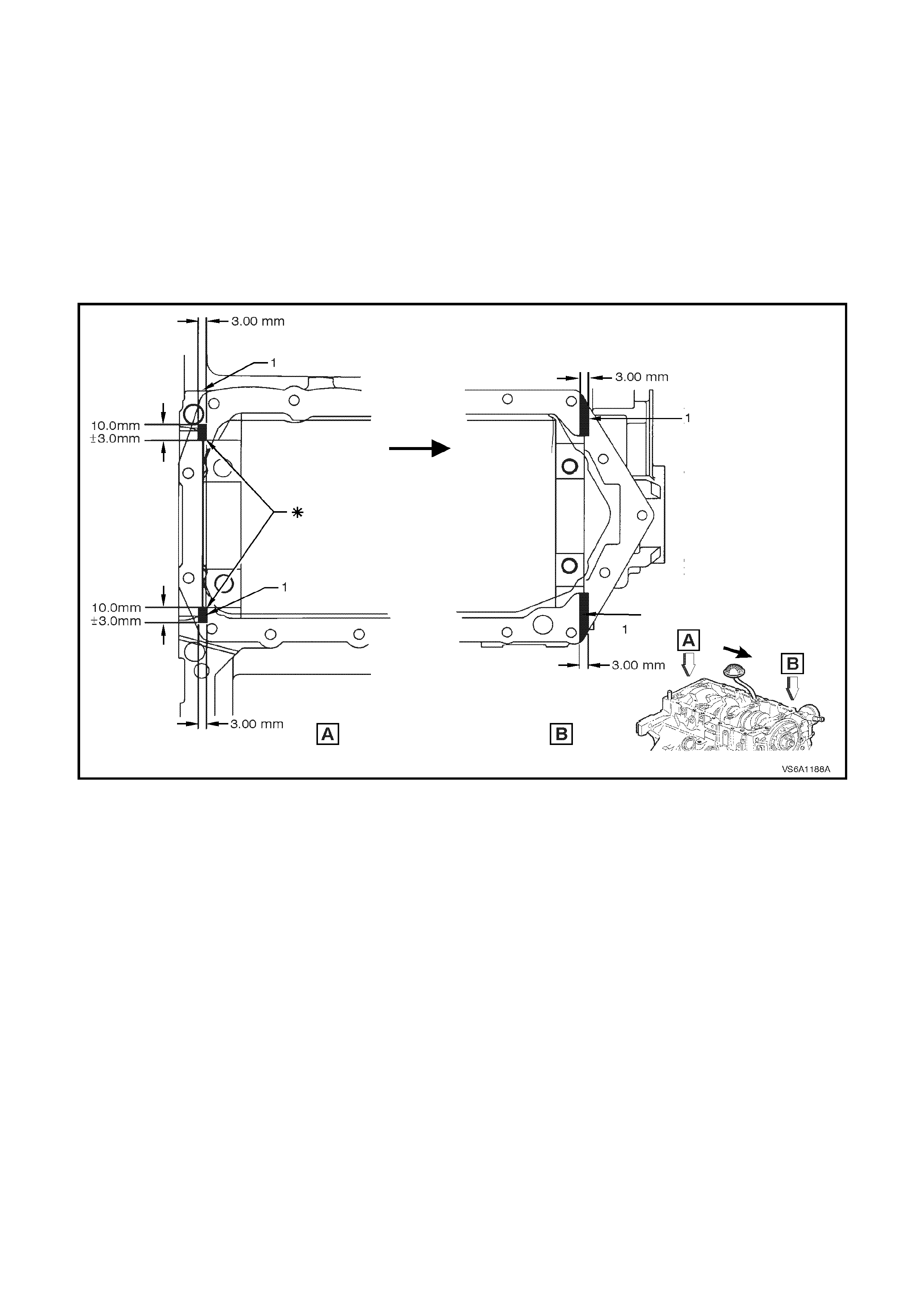
2. Apply Perm atex “ T he Right Stuff ’, as a bead 10m m wide and 3m m thick to the cylinder block in the ar ea of the
rear oil seal housing and front cover joints (1), refer Fig. 6A1-3.
NOTE: Do not apply exces sive sealer. Thic k ness of s ealer can be c ontrolled by first applying a 1mm thick adhesive
tape onto block, using a scraper, fill to specified thickness, then remove tape.
NOTE: When applying sealer at ∗ in Fig. 6A1-3, Stop short of the edge to avoid filling this corner.
Figure 6A1-2
3. Install oil pan and gasket to cylinder block
using temporary guide pins to prevent
smearing sealant.
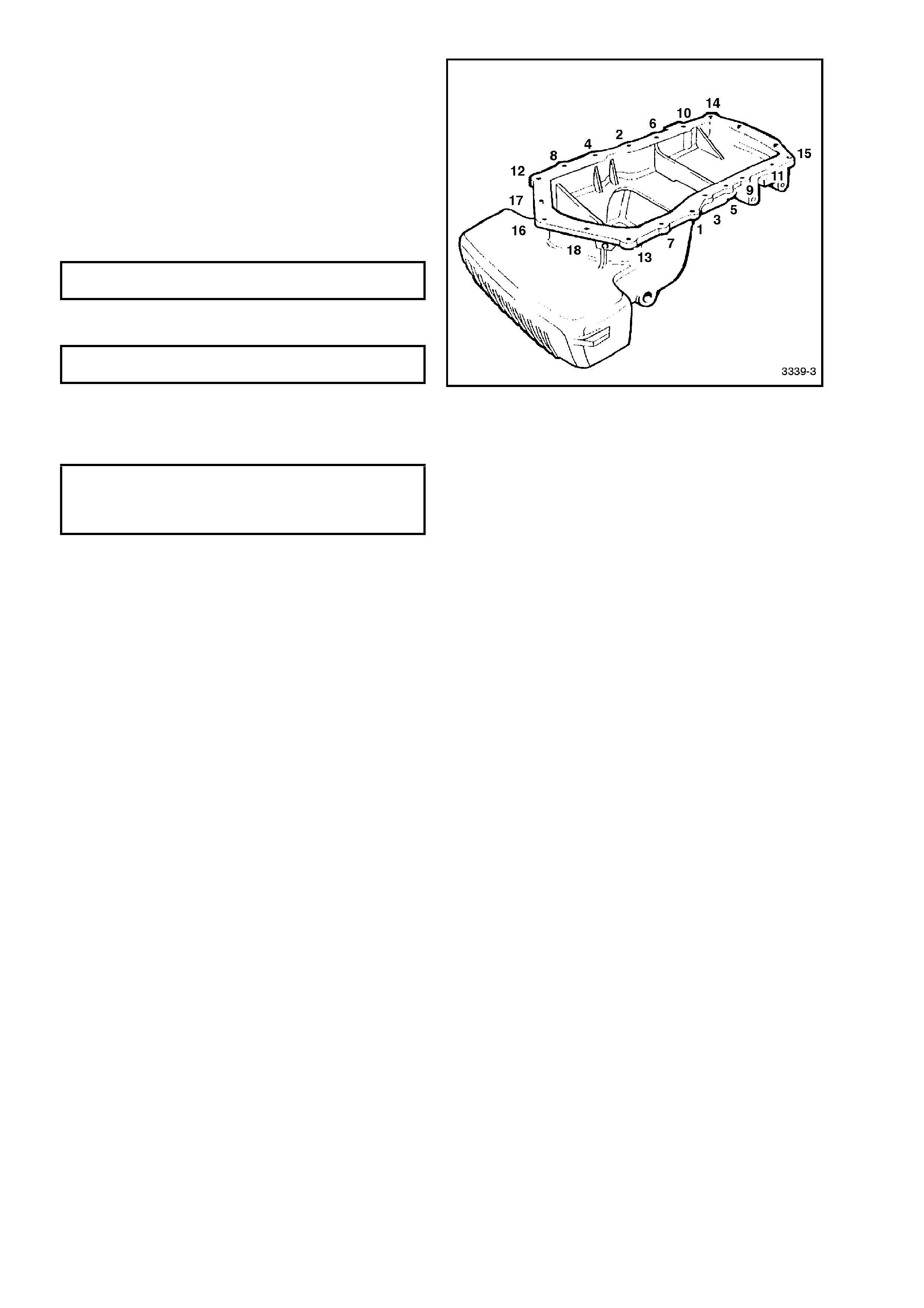
4. Install oil pan retaining bolts and tighten to the
correct torque specification in the sequence
shown in Fig.
NOTE 1: Coat threads of oil pan retaining bolts with
Loctite 243 sealant or equivalent.
NOTE 2: Oil pan must be tightened within 5
minutes of sealant application.
OIL PAN RETAINING BOLT 12 - 16
TORQUE SPECIFICATION Nm
5. Ensure oil pan drain plug is tightened to the
correct torque specification.
OIL PAN DRAIN PLUG 40 - 50
TORQUE SPECIFICATION Nm
6. Install battery harness and (if fitted) automatic
transmission oil cooler line retainer attaching
screws and tighten to the correct torque
specification.
BATTERY HARNESS AND OIL
COOLER LINE RETAINER TO OIL 3 - 5
PAN ATTACHING SCREW Nm
TORQUE SPECIFICATION
Figure 6A1-3
7. Reinstall beaming brace, refer to 2.24
BEAMING BRACE in Section 6A1 ENGINE
MECHANICAL - V6 of the VT Series I Service
Information.
8. Rem ove spacer bloc ks f rom engine mount and
lower engine. Reinstall engine mount nuts,
refer to 2.23 ENGINE MOUNTS in Section
6A1 ENGINE MECHANICAL - V6 ENGINE of
the VT Series I Service Information.
On vehicles with a V6 Supercharged engine,
reinstall the front suspension crossmember,
refer to Section 3 FRONT SUSPENSION of
the VT Series I Service Information.
9. Using 10W/30 SJ GF2 engine oil, refill oil pan
to the correct level, refer to Section 0B
LUBRICATION AND SERVICE of the VT
Series I Service Information.
10 Start engine and check for oil leaks. Repair as
required.