
SECTI ON 6C 3-1 - GENERAL INFORMATI ON -
GEN III V8 ENGINE
CAUTION:
This vehicle will be equipped with a Supplemental Restraint System (SRS). A SRS will consist of either
seat belt pre-tensioners and a driver's air bag, seat belt pre-tensioners and a driver's and front
passenger's air bags or seat belt pre-tensioners, driver’s and front passenger’s air bag and left and right
hand side air bags. Refer to SAFETY PRECAUTIONS, Section 12M Supplemental Restraint System of the
VT Series II Service Information before performing any service operation on, or around any SRS
components, the steering mechanism or wiring. Failure to follow the SAFETY PRECAUTIONS could result
in SRS deployment, resulting in possible personal injury or unnecessary SRS system repairs.
1. GENERAL DESCRIPTION
The engine used in this vehicle uses an Powertrain Control Module (PCM) to control exhaust emissions while
maintaining excellent driveability and fuel economy. The PCM maintains a desired air/fuel ratio at precisely
14.7 to 1. To maintain a 14.7 to 1 air fuel ratio the PCM m onitors the output signal from two oxygen sensors. The
PCM will either add or subtract fuel pulses based on the oxygen sensors output signal. This method of feed back
fuel control is called CLOSED LOOP.
In addition to fuel cont rol, the PCM also c ontrols the f ollowing systems.
• The ignition dwell
• The ignition timing
• The idle speed
• The engine elec tric cooling fan
• The fuel pump
• The instrument panel Check Powertr ain Lamp (CPL)
• The A / C compress or clu t c h
• The automatic transmission functions
The PCM also interfaces with other vehicle control modules, such as the Powertrain Interface Module (PIM), trip
com put er an d Body Contro l Module ( BC M). Th e f ollowing diagr am con tains a list of the vario us op era ting c ondit ions
sensed by the PCM, and the various systems controlled. Details of basic operation, diagnosis, and service are
covered in this Section.
The PCM has a built-in diagnostic system that identifies operational problems and alerts the driver by illuminating
the Check Powertrain Lamp (CPL) on the instrument panel. If the lamp illuminates while driving, it does not mean
that the engine should be stopped imm ediately, but the cause of the lam p illuminating should be checked as soon
as is reas onably possible. Th e PCM h as built in bac k-u p system s t hat in all but the m os t severe fa ults will allow the
vehicle to operate in a near normal manner un til repair s can be made.
Below the instrument panel is a Data Link Connector (DLC) which is used by the assembly plant for a computer
check-out of the powertrain management system. The DLC is also used in service to help diagnose the system.
Refer to Section 6C3 -2 , DIAGNOSIS in this Section for further details.
Techline
Techline
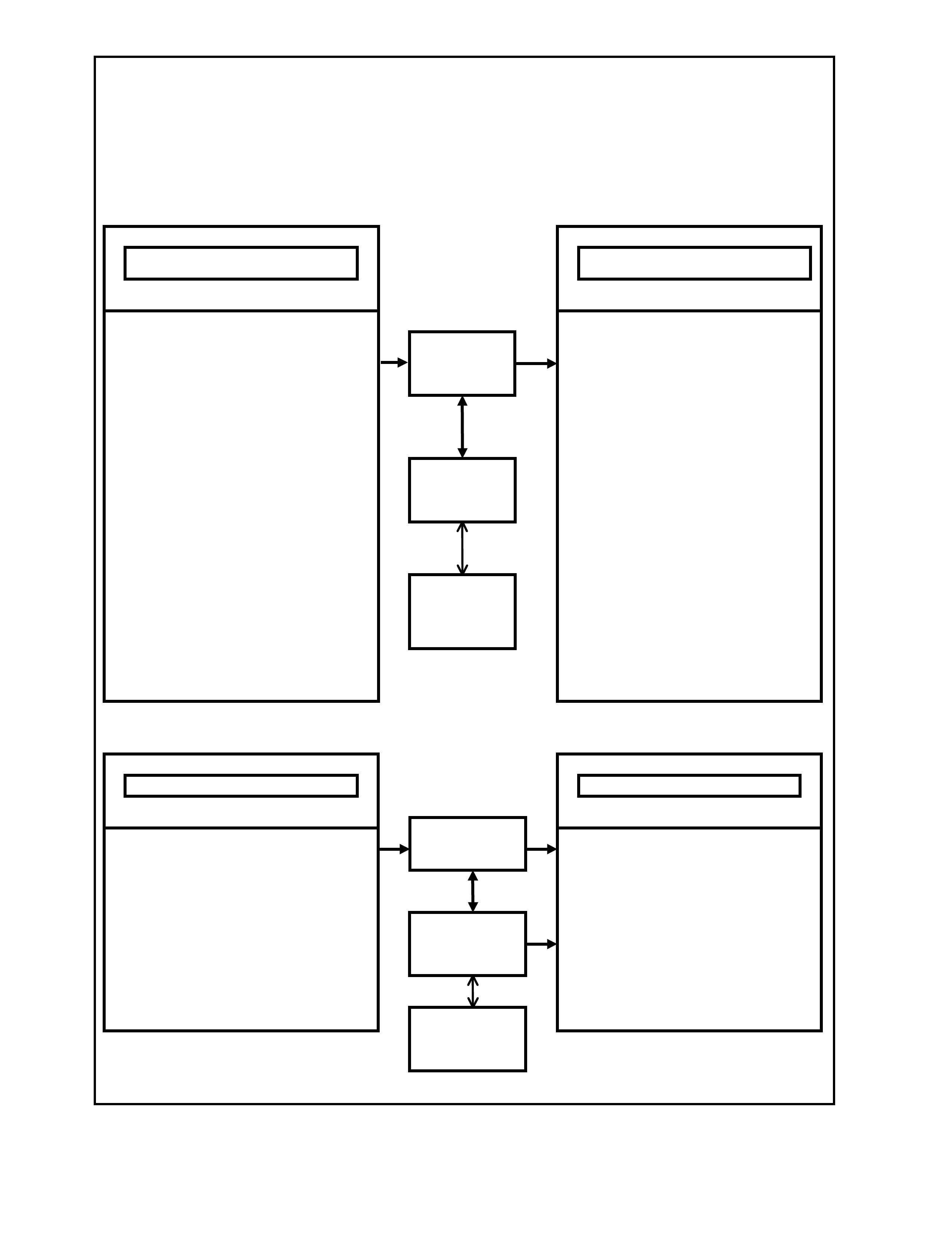
Not e:
Some parameters may travel through one or more controllers for input or output controls.
ENGINE CONTROLS
TRANSMISSION CONTROLS
PCM Operating Conditions Sensed and Systems Controlled
• A/C Pressur e Sensor
• A/C Request "ON" or "OFF"
• Battery Voltage
• Camshaft Po sitio n (CMP)
• Crankshaft Position (CKP)
• DLC Da ta Stream Input
• Engine Coolant Level Switch
• Engine Coolant Temperature (ECT)
• Engine Cooling Fan Response
• Engine Knock (KS)
• Engine Speed (RPM)
• Exhaust Gas Oxygen Cont ent
• Intake A ir T emp era ture (IAT)
• Mass Air Flow (MAF)
• Manifold Abs olute Pre ssure (MAP)
• Oil Pressure Sensor
• Spark Retard Signal
• Stop Lamp Switch
• Thrott l e Positio n ( TP)
• Transmission Gear Position
• Th eft D et errent Signal
• Vehic l e Speed (VSS)
POWERTRAIN
CONTROL
MODULE (P CM)
• Air Conditioning Compressor Clutch
• Canister Purge Solenoid
• Diagnostics
• - Check Powertrain Lamp (CPL)
• - DLC Data Stream Output
• - Field Service Mode
• El ectric Engi n e Cooling Fa n
• Electron i c Spark Con t ro l (ESC)
• Electron ic Spark Timing (EST)
• Fuel C ontrol
- Fuel Injectors
- Fuel Pump
• Idle A ir Cont rol
• Torque Management
OPERATING PA RAMETERS SENSED SYS TEMS CONT RO L L E D
• Battery Voltage
• Economy/ Power Switch
• Engine Speed (Engine RPM)
• Engine Coolant Temperature (ECT)
• Stop Lamp Switch
• Throttle Position (TP Sensor)
• Transmission Fluid Temperature (TFT)
• Transmission Gear Position
• Vehicle Spee d Sensor (VSS)
• Transmission Fluid Pressure (TFP)
• Switch Assembly
• TCC Enable Solenoid
• 3-2 Shift Solenoid
• 1-2 Shift Solenoid
• 2-3 Shift Solenoid
• Diagnostics
• - Check Powertrain Lamp (CPL)
• - DLC Data Stream Out pu t
• - Field Service Mode
POWERTRAIN
CONTROL
MODULE (P CM)
OPERATING PA RAMETERS SENSED SYSTEM CONTROLLED
POWERTRAIN
INTERFACE
MODULE (P IM)
POWERTRAIN
INTERFACE
MODULE (PIM)
BODY
CONTROL
MODULE (B CM)
BODY
CONTROL
MODULE (BCM)
T26C3001
1
2
3
4
5
6
7
9
10
11
12
13
14
151617 18
19
20 21
21
23
23
22
24
25
26
27
28
29
30
AB
C
D
F
E
8
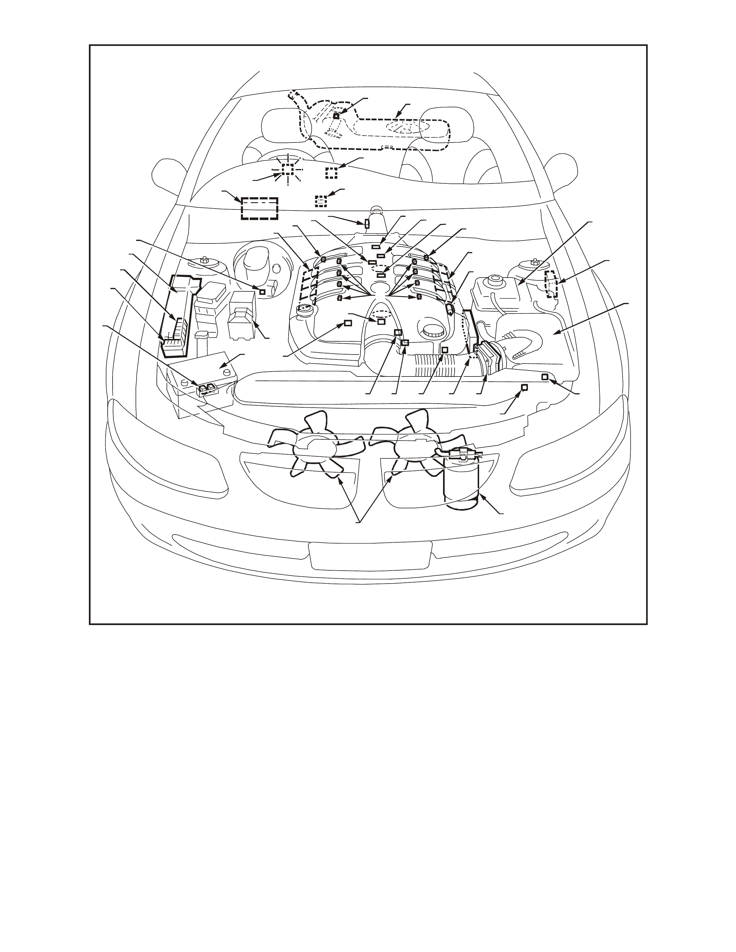
Componen t Lo cations View GEN III V8 Engi ne
1. Engi ne Compar t m ent Fusi ble Link Housing
2. Battery Harness Fusible Link Housing
3. Engi ne Compartment Rel ay Housing
4. Engi ne Compartment Rel ay Housing
5. Fuel Pressure Regulator (in Fuel Tank)
6. A/C Accumulator Tank
7. Brake Hydraulic Failure Switch
8. Fuel Injectors (8)
9. Idle Air Control (IAC) Valve
10. Check Powertrain Lamp (CPL)
11. Ignition Coil/Module Right Bank
12. Ignition Coil/Module Left Bank
13. Engine Fa ns (2)
14. Canis ter Purge Solenoid
15. Mass Air Flow (MAF) Sensor
16. Engine Coolant Temperature (ECT) Sensor
17. Throttle P osition (TP ) Se nsor
18. Intak e Ai r Temperature (IAT) Sensor
19. Vehicle Speed Sensor (VSS)
20. Camshaft Position (CMP) Sensor
21. Heated Oxygen (HO2S) Sensor (2)
22. Crankshaft Position (CKP) Sensor
23. Knock Sensors (KS) (2)
24. ECC In - Car Air Temperature Sensor
25. A/C Refrigerant Pressure Transducer
26. Powertrain Control Module (PCM)
27. Powertrain Interface Module (PIM) - Inside
vehicle behind left kick panel
28. Diagnostic Link Connector (DLC)
29. Oil Pressure Sensor
30. Manifold Absolute Pressure (MAP) Sensor
A Battery
B ABS
C BCM
D Fuel Tank
E Surge Tank (With Low Coolant Level Switch)
F Air Cleaner
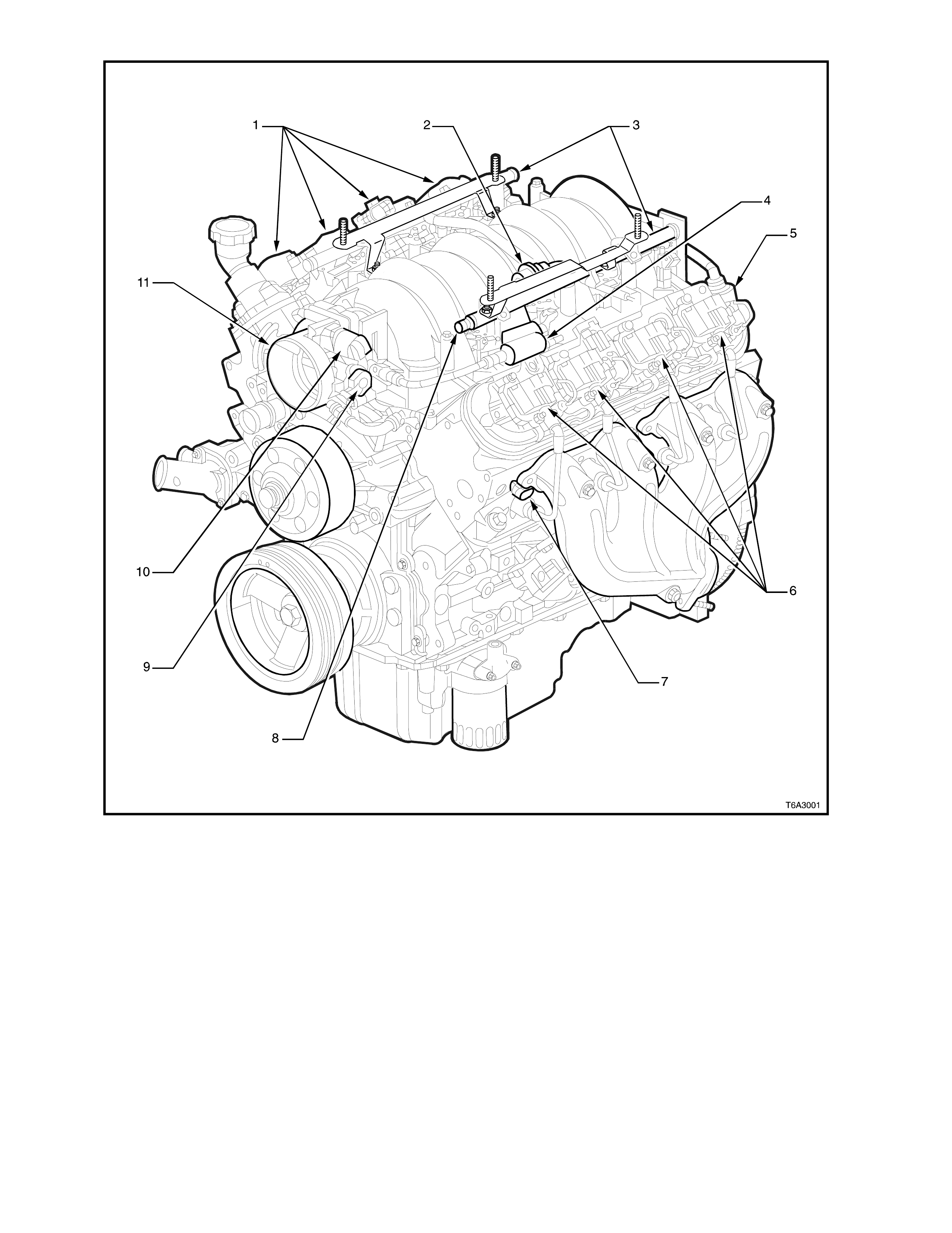
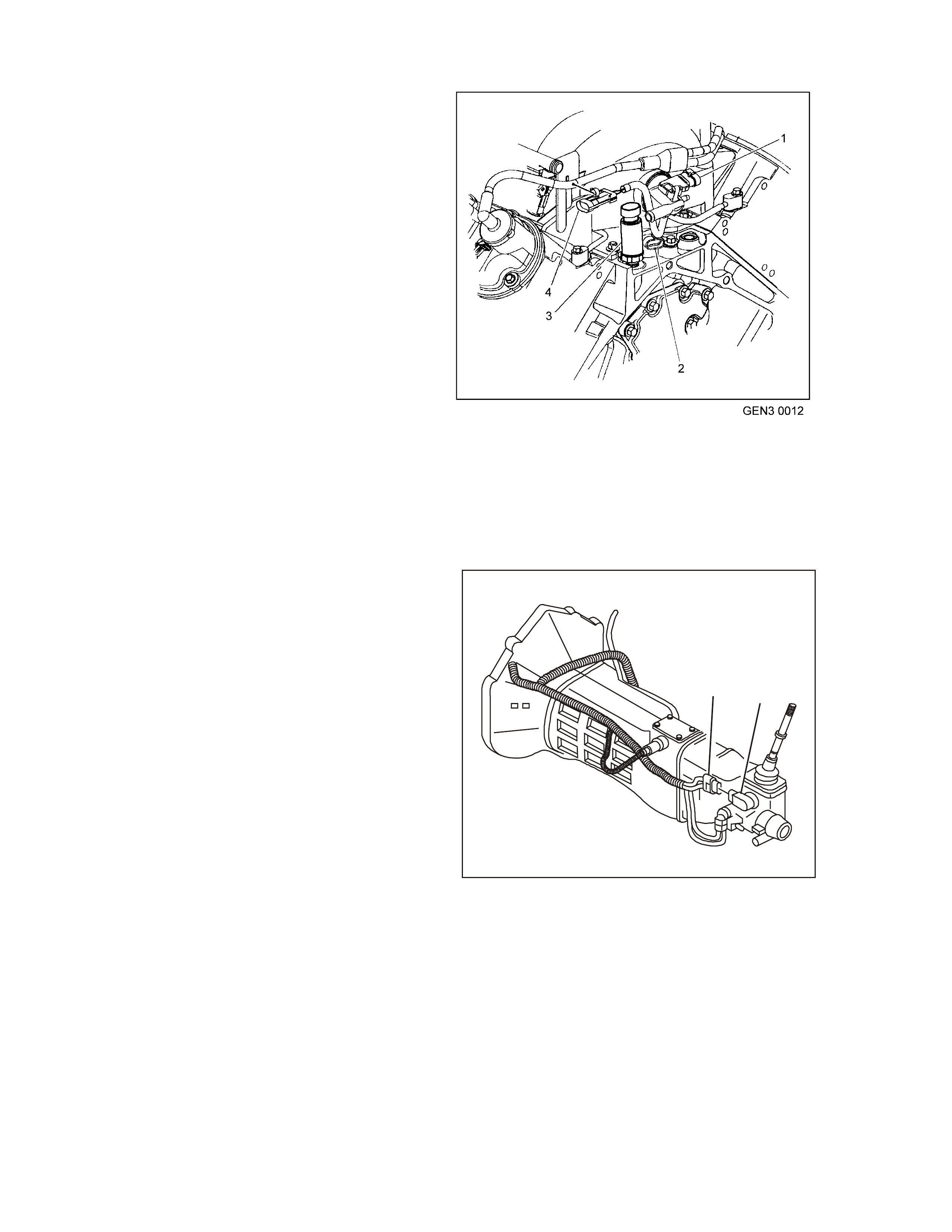
GEN III V8 Engine View Left-Hand Side
1. Right -Hand Ignition Coils/Mod ul es
2. Fuel Pu l se Dampe ner
3. Fuel Rail with Injectors
4. Evaporative Canister Purge Solenoid
5. Crankcase Vent
6. Left-Hand Ignition Coils/Modules
7. Engine Coolant Temperature (ECT) Sensor
8. Fuel Pr essure Gauge Test Co nnector
9. Throttle Position (TP) Sensor
10. Idle Air Control (IAC) Valve
11. Throttle Body
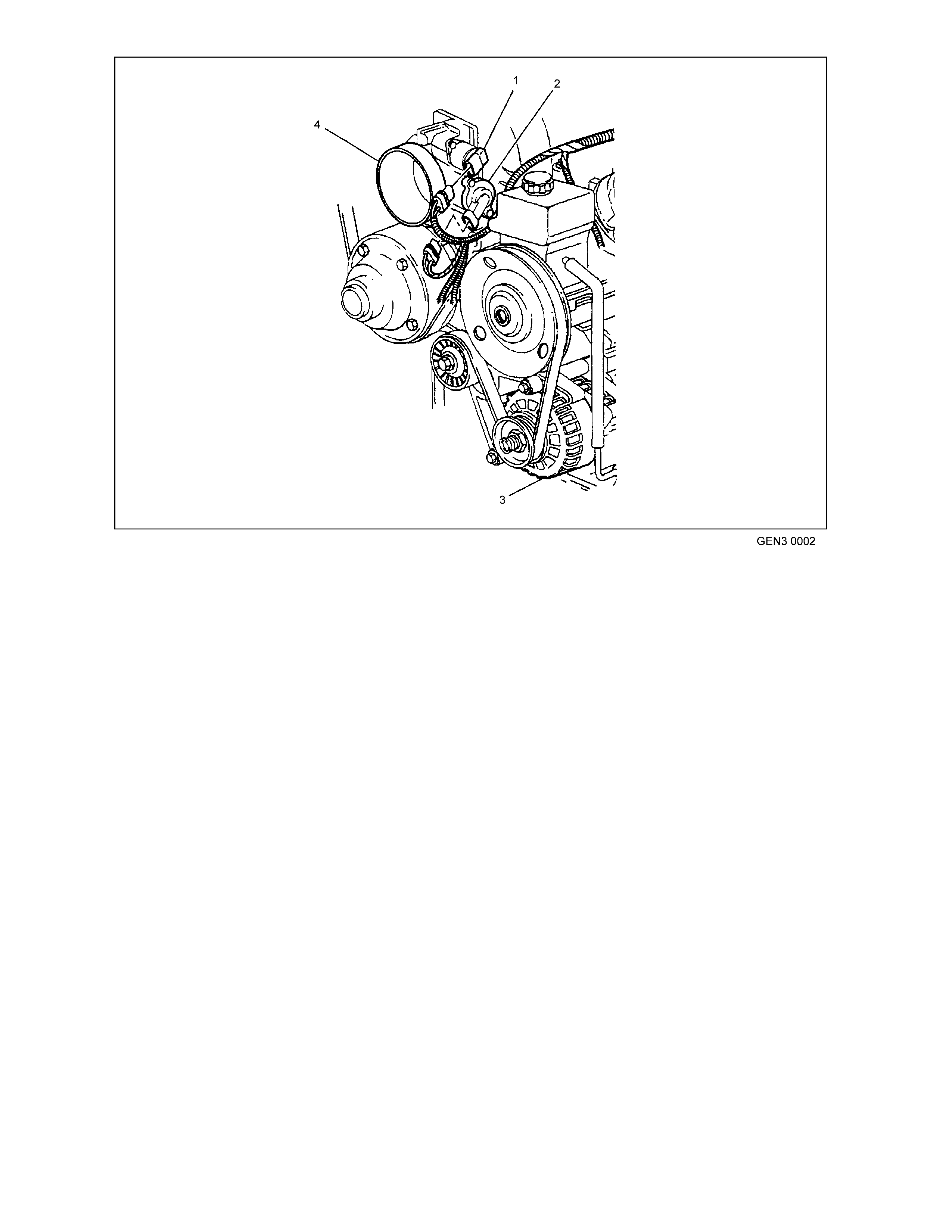
GEN III V8 Engine Front View
1. Idle Air Contro l (IAC) Valve
2. Throttle Position (TP) Sensor
3. Generator
4. Throttle Body
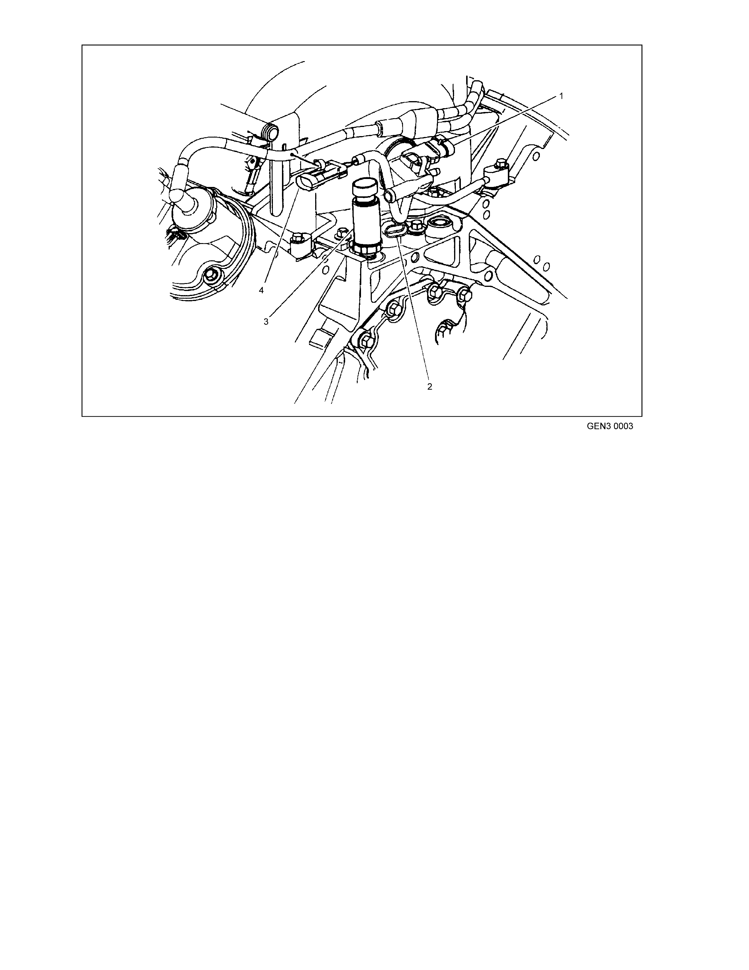
GEN III V8 Engine Rear View
1. Manifold Absolute Pressure (MAP) Sensor
2. Cams haft Posi tion (CMP) Sensor
3. Oil Pressure Sensor
4. Connector to Knock Sensor Jumper Harness
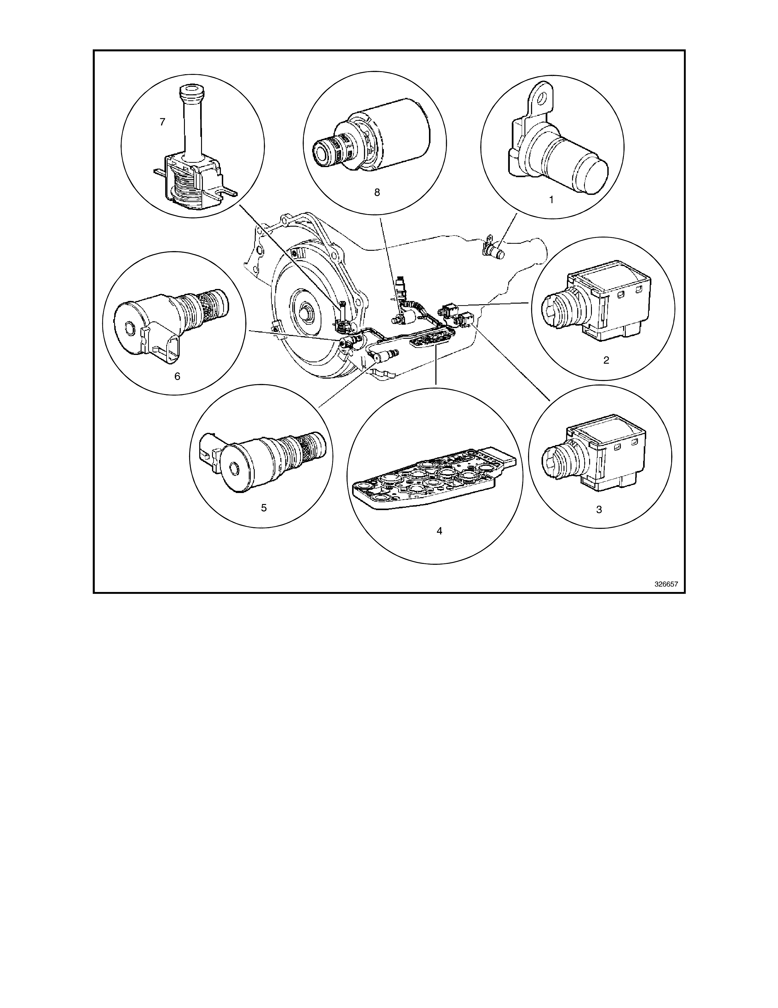
Au to m atic Tran s m iss i o n Internal Electr on ic Co m po n en t Lo ca tions
1. Vehicle Speed Sensor (VSS)
2. Shift So l enoid B (SS) Valve
3. Shift So l enoid A (SS) Valve
4. Autom atic Tra nsmission Fluid Pres sure (TFP) Manual Valve Position Switch
5. Shift Solenoid (SS) Valve Assembly
6. To rque Converter Clutch Pulse Width Modulation (TCC PWM) Solenoid Valve
7. Torque Converter Clu tch (TCC) Solenoid Val ve
8. Pressure Control Solenoid (PCS) Valve
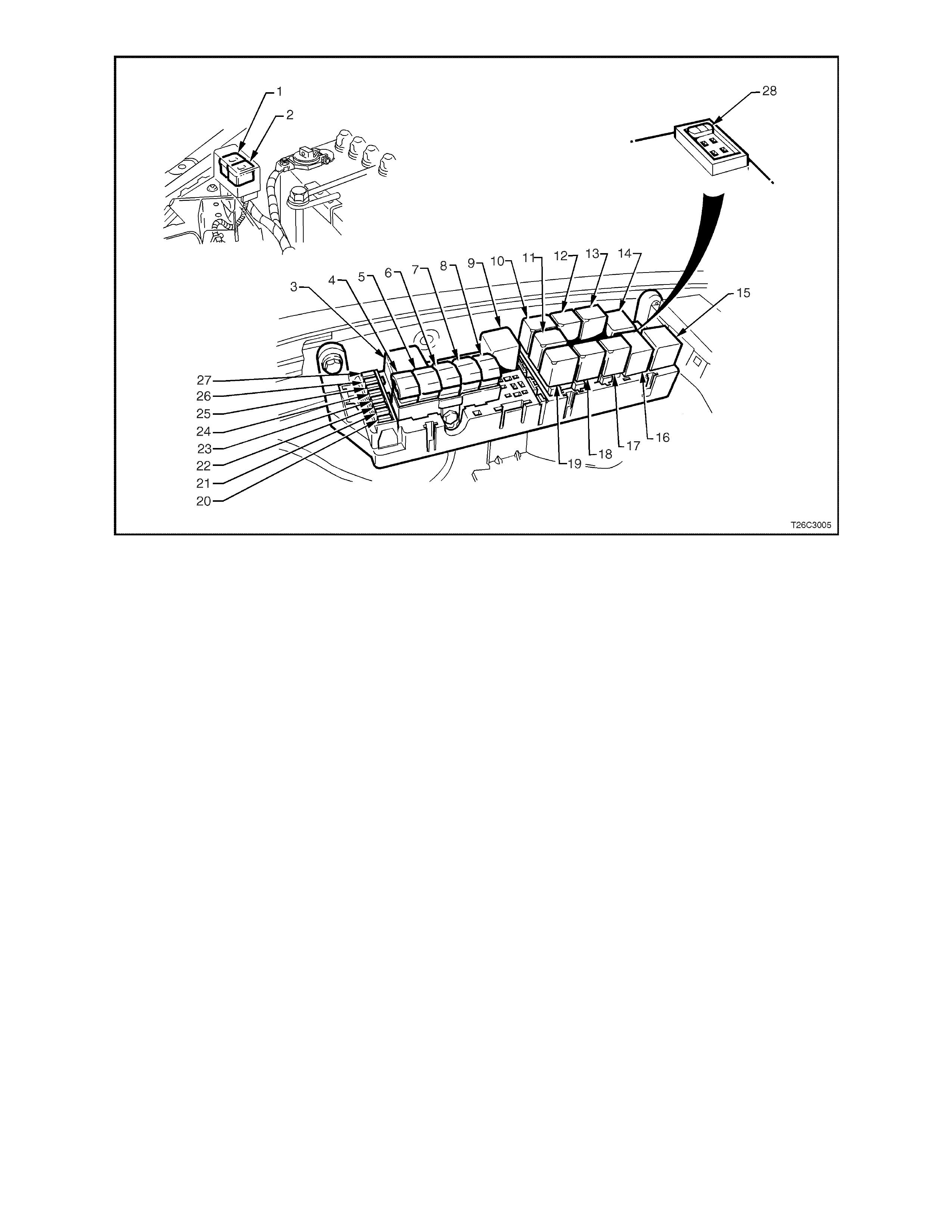
Engine Compa rt m ent Fuse/Re l ay Panel
1. Fan 1 Fusible Link FU 15. Start Relay
2. Fan 2 Fusible Link FT 16. Headlamp High Beam Relay
3. Engine Fan Relay (Low Speed) 17. Fuel Pump Relay
4. Lighting Fusible Link FQ 18. Front Wiper Relay
5. ABS Fusible Link FR 19. Headlamp Low Beam Relay
6. Engine Fusible Link FS 20. Injectors / Ignition Fuse F35
7. Main Fusible Link FJ 21. Injectors / Ignition Fuse F34
8. Blower Fusible Link FY 22. Engine Sensors Fuse F33
9. Engine Cont. (EF I) Rel ay 23. Automatic Transmission Fuse F32
10. Horn Relay 24. Engine Control / BCM Fuse F31
11. A/C Relay 25. LH Headl am p Fuse F30
12. Theft Horn Relay 26. RH Headlamp Fu se F29
13. Fog Lamp Relay 27. Fuel Pump Fuse F28
14. Engine Fan Relay (High Speed) 28. Throttle Relaxer Control Module Fuse F36
1.1 POWERTRAIN CONTROL MODULE (PCM)
The Powert ra in Con tr ol Module (P CM), is loc ated in
the engine compartment. The PCM is the control
centr e of the vehicle. It controls the following:
• Fuel metering system.
• Transmission shifting.
• Igni tion timing.
• Knock Sensor (KS) .
• Evaporative Emission Control System (EECS)
Purge.
• Cooling fan.
• A/C system.
• Che c k P owe rtrain L amp (CPL).
• Theft Deterrent (Injector control).
The PCM constantly monitors the information from
various sensors, and controls the systems that
affect vehicle performance. The PCM also
performs diagnostic function of the system. It can
recognise operational problems. The PCM also
alerts the driver through the Check Powertrain
Lamp (CPL) via the Class II serial data
communication line to the Powertrain Interface
Module (PIM). This is where the PIM converts the
Class II serial data communication to Universally
Asynchronous Receiving/T ransmitting (UART).
This UART serial data communication is then sent
from the PIM to the Body Control Module (BCM)
then from the BCM to t he Inst ru ment Panel Clu st er.
When the PCM detects a malfunction, it stores a
Diagnos tic Trouble Code (DTC ) .
GEN3 0004
1
2
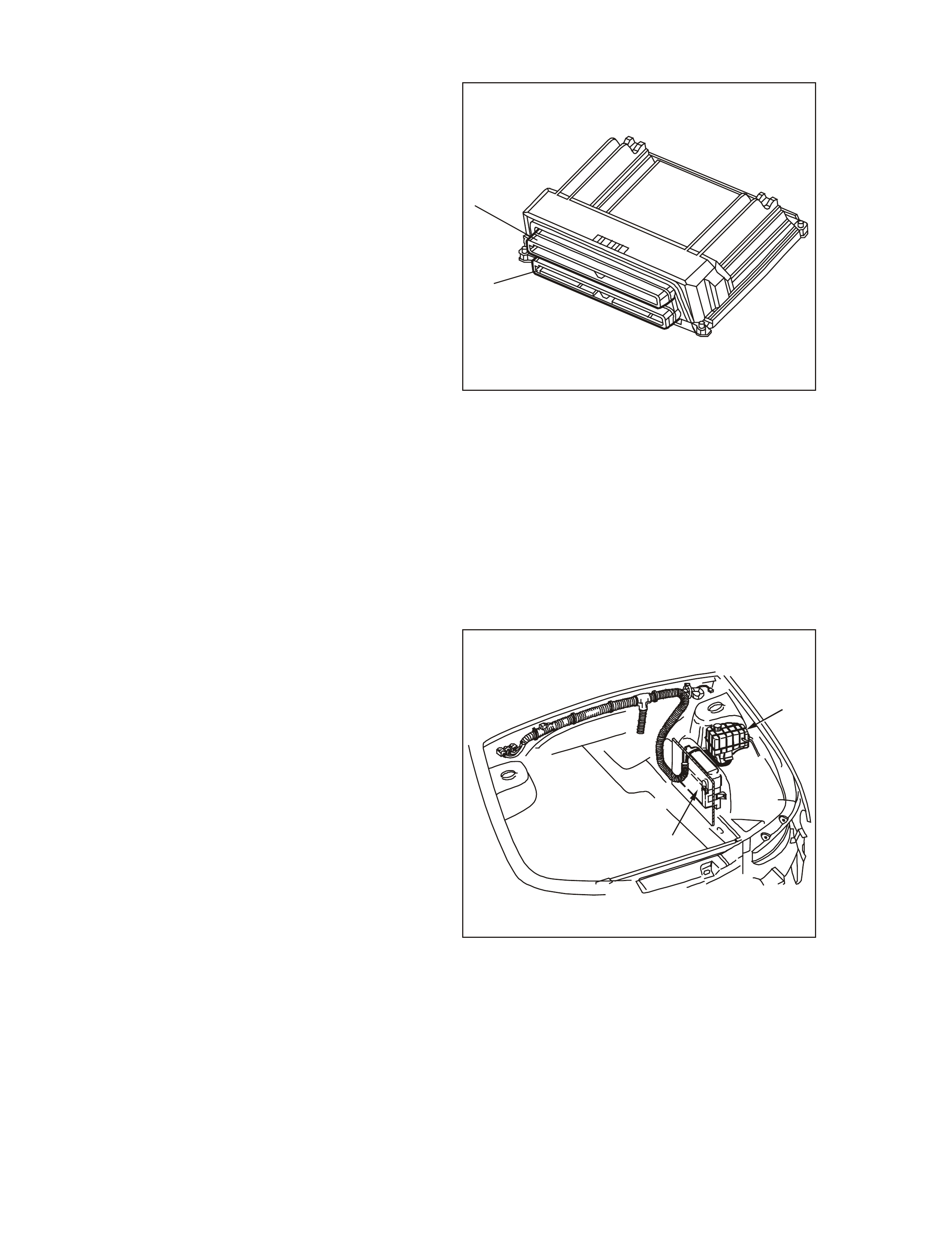
Pow ertrain Control Module
1. Connector J1 BLUE
2. Connector J2 RED
A stored DTC, will identify the problem areas. This
will aid the technician in making repairs.
The PCM supplies either 5.0 or 12.0 volts to power
various sensors or switches. This is done through
resis tance in the PCM. The r esistance is s o h igh in
value that a test lamp will not illuminate when
connected to the circuit. In some cases, even an
ordinary shop voltmeter will not give an accurate
reading because its resistance is too low.
Ther efore , a digit al mu ltimeter DMM ( J 3920 0) with
at lea st 10 m egaohm s input im pedance is required
to ensure accurate voltage readings.
The PCM controls output circuits such as the
injec tors , IAC, cooling fan r elays , etc. by controlling
the earth or the power feed circuits through
transistors or a device called an Output Driver
Module (ODM).
GEN3 0005
1
2
Pow ertrain Control Module
1. Coolant Surge T ank
2. Powertrain Control Module (PCM)
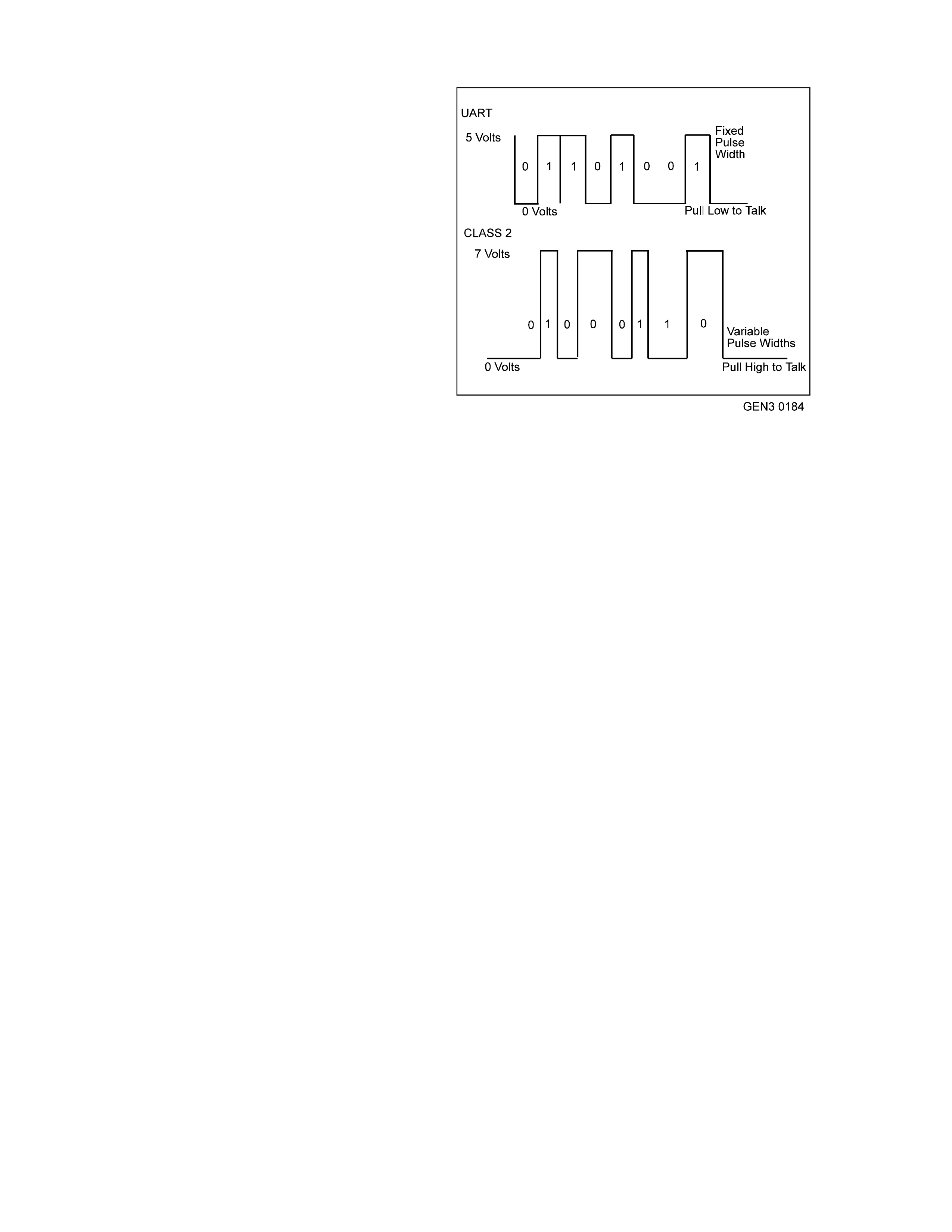
SERIAL DATA COMMUNICATIONS
Serial data is a series of rapidly changing voltage
signals pulsed from high to low. These signals are
typically 5 volts (UART), 7 volts (Class II ) , and 12 or
0 volts (high or low) and are transmitted through a
wire often referr ed to as the Serial Data Cir c uit.
Today’s automotive regulations require that all
automobile manufacturers establish a common
communications system. Class II communication
was selected as the automotive communication
standard.
The GEN III V8 Engine on-vehicle controllers
communicate with both types of se r ial data:
• Universal Asynchronous Receive and Transm it
(UART)
• Class II
UART serial data has been used for many years
(since the beginning of computer control systems
on GM vehicles). With UART serial data,
controlle rs com m unicate o n a single wire by pulling
the voltage on the data circuit low to create
m essages . As a re sult, when c om munic ation is not
occurring, the signal voltage on the data circuit
rem ains high (usually 5 volts).
Class II serial data takes the signal voltage low
when communication is not occurring. Class II
communication differs from UART in 2 main ways.
1. High is 7 volts.
Serial Data Voltage Signal s
2. The signal uses several pulse widths,
compar ed to UART’s fix ed pulse width.
With a variable pulse width, Class II comm unication
saves switching time in its messages. Class II only
needs to lengthe n the voltage duration and anot her
bit can be sent. Class II supports the transmission
of 10,400 bits per second, compared to UART at
8,192 bits per second. This allows Class II
communication between controllers to be more
complex and quicker.
The most significant result of this Class II
communication is that it provides scan tool
m anufact urers with the ca pability of acc essin g data
fr om any make or model vehicle.
For the PCM Class II communication to interface
between all the other vehicle system controllers, a
Powertrain Inter fac e Module ( PIM) has been adde d
as a com munic ation tr anslator fo r UART and Class
II. For further information on the PIM, refer to
Section 1.2 Powertrain Interface Module (PIM ) in
this Sec tion.

THE DIAGNOSTIC EXECUT IVE
The Diagnostic Executive is a unique segment of
the PCM software which is designed to coordinate
and prioritise the diagnostic procedures as well as
define the protocol for recording and displaying
their results. The main responsibilities of the
Diagnos tic Executive are:
• Monitoring the Diagnostic Test Enabling
Conditions
• Requesting the Check Powertrain Lamp (CPL).
• Recording Pending, Current, and History
DTC(s)
• Storing and Erasing Freeze Frame Data
• Monitoring and Recording Test Status
information.
PCM PROGRAMMING
The PCM for this vehicle application does not
contain a removable PROM, instead it uses an
EEPROM (Flash Memory) which is non rem ovable.
From the f actory, the PCM is progr amm ed with the
proper calibrations for vehicle operation. In the
event that the PCM is replaced, or an updated
calibration is required to correct a vehicle's
operating condition, the new PCM or the new
calibration will require the use of the Tech 2 scan
tool for down loading to the EEPROM (Flash
Memory). Down loading is accomplished through
the vehicle Data Link Connector (DLC) using the
Tech 2 scan tool.
The service replacement PCM EEPROM (Flash
Memory) will not be programmed. DTC P0601 and
P0602 indicates the Flash Memory is not
program med or has m alfunc tioned.
Refer to Section 6 C3-3 SERVICE OPERATIONS –
GEN III V8 Engine in this Section for this service
program ming procedure.
PCM / PIM/BC M SECURITY LINK
Once the PCM, PIM or BCM has been replaced,
the new module(s) must be security linked to each
other . If the pr ocedure is not perf orm ed, th e engin e
will not crank or run.
This linking procedure is found under the BODY
CONTROL MODULE of TECH 2 and has to be
performed as follow s:
Connect TECH 2 to DLC and select:
Diagnostic / (X) 1999 / VT Commodore / Body /
Body Control Module / Security / BCM Link to
PCM/PIM.
The procedu re ”BCM Link to PCM/PIM” will first ask
to select the installed engine. If Gen III V8 is
selected a TIS program approval is required.
Connect TECH 2 to TIS terminal and select
”Pro gr am Approve”.
GEN3 0005
1
2
Powertrain Control Module Location
1. Coolant Surge Tank
2. Powertrain Co ntrol Module (PCM)
After returning to the vehicle select again the link ing
procedure. Now first BCM and PIM are linked and
afterwards the PCM – PIM linking is performed
automatically.
For additional information regarding TECH 2 and
TECH 2 test modes (including this linking
procedure), refer to TECH 2 DIAGNOSIS FOR
BCM in Section 12J-1 LOW SERIES BCM or
Section 12J-2 HIGH SERIES BCM in the VT
Series II Service Information.

PCM MEMORY FUNCTIONS
The following list contain the two types of memory
wi th in th e PCM.
• RAM
• EEPROM (Flash Memory)
RAM
Random Access Memory (RAM) is the
microprocessor scratch pad. The processor can
write into, or read from this memory as needed.
This memory is volatile and needs a constant
supply of B+ voltage to be retained. If the B+
voltage is lost, the memory is lost.
EEPROM (Flash Memory)
A new Service Programming System (SPS) has
been inco rporated with th is Gen III PCM. This SPS
enables technicians to directly update the data
stored in the Powertrain Control Module (PCM).
The part of the PCM which contains the specific
calibration data for a particular vehicle and engine
combination is commonly refered to as the
EEPROM. EEPROM is an acronym for Electrically
Erasable Programmable Read Only Memory. In
eff ect, the dat a in the mem ory m atches the PCM to
the vehicle to provide optimum performance,
driveability, and emissions control.
Sometimes EEPROM data is updated to modify
engine operations. For example, the EEPROM
calibration data may be changed to adjust ignition
timing in order to eliminate a potential detonation
condition or improve idle quality. Before the SPS
was implemented, the procedure for updating
EEPROM data was to simply replace the PCM
EEPROM unit.
The relative ease of changing engine data has led
to inc reased use of af term ark et EPROMs des igned
to enhance performance. Unfortunately, such HOT
EEPROMs often cause engine emissions to
exceed regulated standards. In such instances,
installation of an aftermarket EEPROM is
considered tampering. Governing bodies ruled that
emission-related control modules must be tamper
resistant. These tamper-resistant EEPROMs are
soldered in place as an integral part of the PCM.
Updating the EEPROM data is accomplished
through flash programming.
Flash programming refers to the SPS used to
transfer (or download) PCM data from a computer
terminal and compact disk-read only memory (CD-
ROM) to the vehicle’s PCM. The system is
design ed so that the veh icle verificatio n p roc ed ure s
are required to eliminate EEPROM tampering that
could inc r ease engine emission levels.
There are three main flash programming
techniques listed below:
1. Direct Programming
This is where the vehicle’s Data Link Connector
(DLC) is connected directly to a computer
terminal. On screen directions are then
followed for downloading.

2. Remote Programming
Reprogramming information is downloaded
fr om a computer t er minal to a Tec h 2 scan tool.
The Tech 2 scan tool is then connected to the
vehicle’s Data Link Connector (DLC). On
screen directions are then followed for
downloading.
3. Off-Board Programming
The off-board programming method is used
when a reprogrammable PCM must be
programmed separate from the vehicle. For
example, an independent repair facility may
find it necessary to replace a faulty PCM. On
flash programming equipped vehicles, the
replacement PCM must be programmed with
data for the specific Vehicle Identification
Number (VIN) or the vehicle may not operate
properly.
1.2 POWERTRAIN INTERFACE MODULE (PIM)
The Powertrain Interface Module (PIM), is located
at the left ’A’ pillar behind the kick panel. The PIM
acts as a communication translator between the
PCM and other onboard controllers that use a
different serial data protocol. The GEN III PCM
uses the new Class II serial data to communicate,
while other controllers on the vehicle are designed
to transmit serial data via the conventional
Universal Asynchronous Receive Transm it (UART)
protocol. Since these two types of serial data are
not compatible, a translator or PIM is required to
transmit data in either direction between the PCM
and other controllers. The PIM will interpret the
serial data inform ation and translate UART to Class
II or Class II to UART to support the appropriate
vehicle controller operation. The PIM is the serial
data communication translator for vehicle
operations. It interprets and supplies the following
information in the proper direction for operation of:
• A/C Request.
• Che c k P owe rtrain L amp (CPL).
• Starter Motor Control.
• Theft Deterrent (Starter Motor Cont rol).
• Oil Warning Lamp.
• Power/Ec onom y Lamp.
• Low Co olant La mp.
• Gear Indica to r Lamps.
• Cooling Fan Relay (Low Speed).
A PIM malfunction may affect vehic le operation and
may interrupt starter motor operation. For PIM
diagnosis refer to Section 6C3-2A –
DIAGNOSTICS TABLES – GEN III V8 Engine of
this Ser v ice Inf ormation CD for PIM DTC diagnosis.
There are four (4) PIM DTCs that will set. Each of
thes e DTCs have corr esponding diagnostic tables.
The f our (4) DTCs that will set are:
• DTC B2002: Low Speed Fan No BCM
Response
• DTC B2006: No Serial Data From PCM
• DTC B2007: Starter Relay Voltage High
• DTC B2009: EEPROM Checksum Error
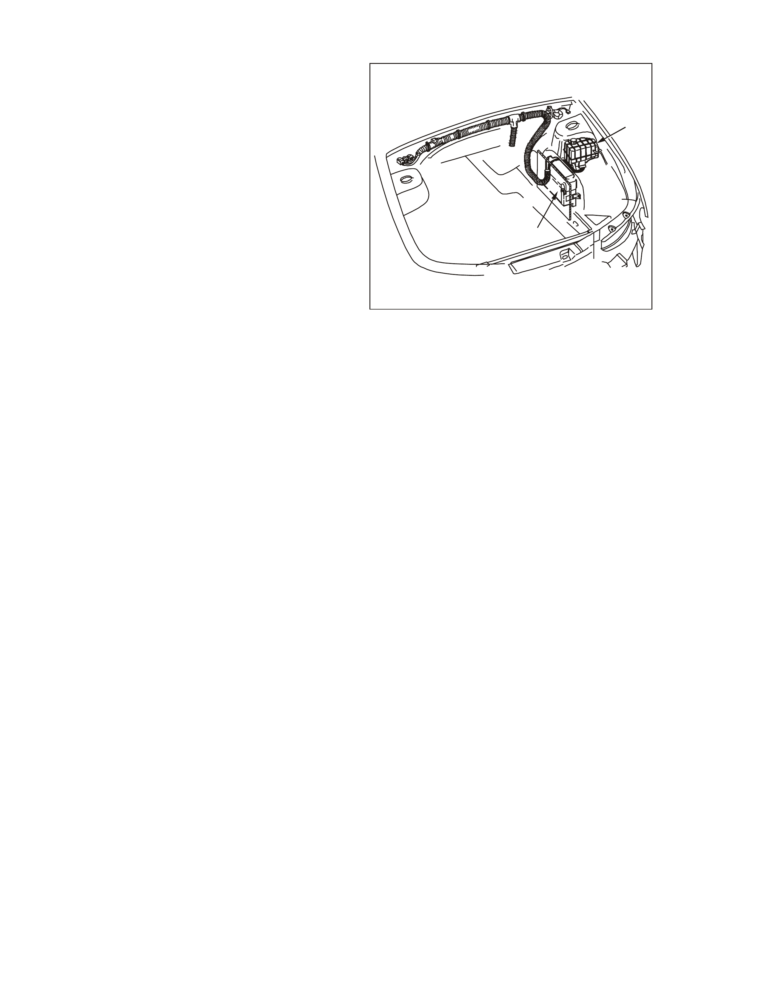
GEN3 0007
Powertrain Interface Module (PIM) Location
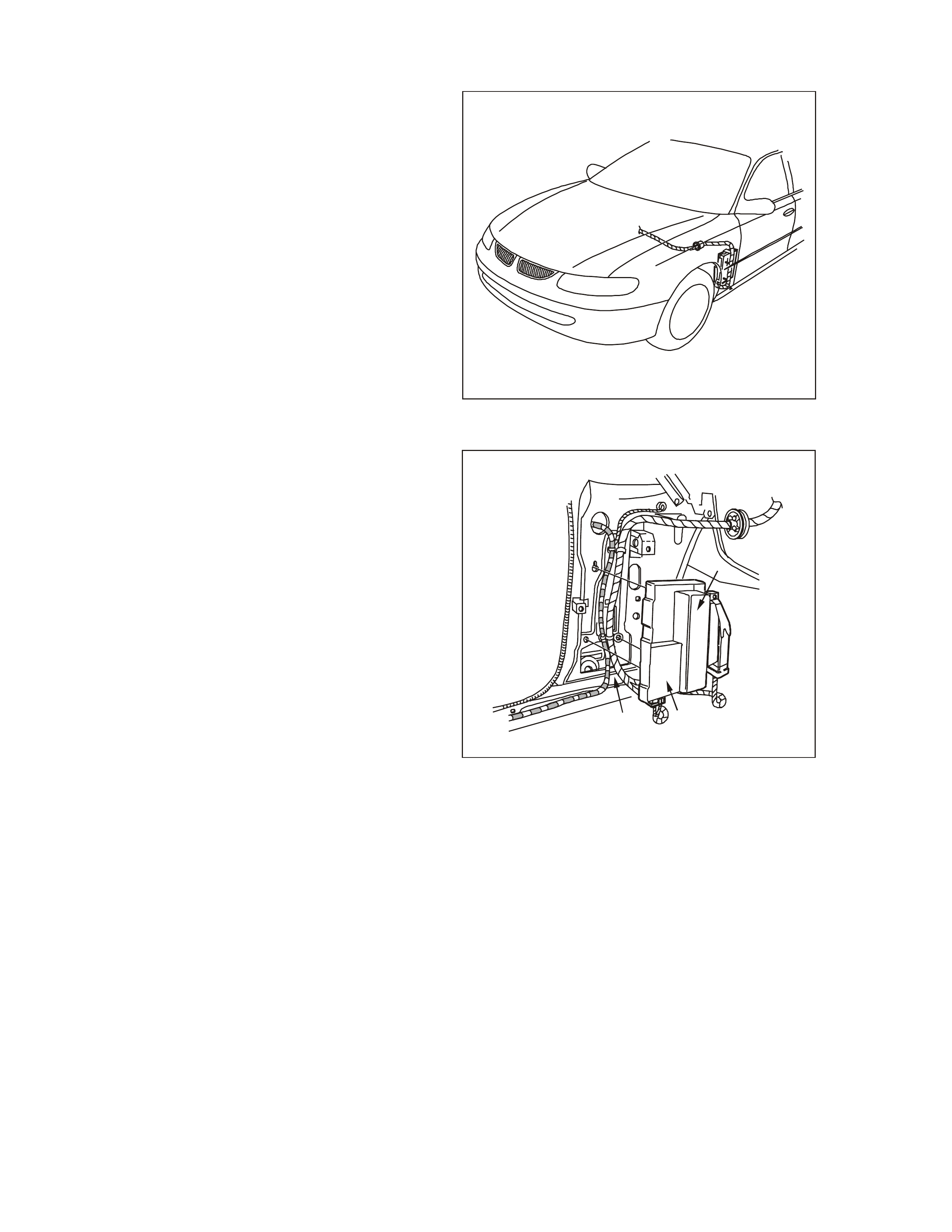
GEN3 0006
1
32
Powertrain Interface Module (PIM)
1. Throttl e Re laxer Control Mod ule
2. Power train Interface Module
3. Left ‘A’ pillar

There are twenty other PIM DTCs that may set
along with a PCM DTC. If any of the following PIM
DTC s ar e s et, dia gnose the on e or more PCM DTC
first, then clear all PCM and PIM DTC and retest:
• DTC B2017: No Throttle Position Sensor
(TPS) Information
• DTC B2018: No A/C Clutch Information
• DTC B2019: No Engine Speed Information
• DTC B2020: No Vehicle Speed Information
• DTC B2021: N o Commanded Gear
Information
• DTC B2022: No Transmission Type
• DTC B2023: No Low Speed Fan Run On
Information
• DTC B2024: No Low Speed Fan Request
Information
• DTC B2025: No Engin e Coolant Temp
(ECT) Information
• DTC B2026: No Fuel Flow Rate Information
• DTC B2027: No Fuel Used Counter
Information
• DTC B2028: No A/C Pressure Information
• DTC B2029: No PRNDL Inf or ma tion
• DTC B2030: No Engine Oil Information
• DTC B2031: No O il Pressure Information
• DTC B2032: N o Shift Information
• DTC B2033: No Check Powertrain Lamp
(CPL) Information
• DTC B2034: No Low Coolant Level
Information
• DTC B2035: No Barometric Pressure
Information
• DTC B2036: No PCM Informat ion
Thes e additio nal PIM DT C s m ay set if a f ault exis t s
with a r elated s ensor or with the Class II serial dat a
circu it. In either c ase, the PCM will also identify this
fault and set a PCM DTC. All information for these
PIM DT Cs is supplied fr om the PCM to the PIM on
the Class II serial data circuit. If there is a problem
with the Class II serial data circuit, the PIM will not
receive this information and set a DTC B2006 and
or one or more of the ot her twenty PIM DTCs.
The Powertrain OBD System Check will identify a
problem with the ser ial data c irc uit or other circuits,
and direct the technician in the proper direction for
diagnosis. There are no PIM DTC tables
asso ciated with thes e twenty PIM DTCs, so always
diagnos e the PCM fir st.
1.3 ENGINE INFORMATION SENSORS AND SIGNALS
ENGINE COOLANT T EMPERATURE (ECT) SENSOR
The Engine Coolant Temperature (ECT) sensor is
a ther mis tor (a r esistor which changes value base d
on temperature) mounted in the left cylinder head.
Low coolant temperature produces a high
resistance (100,000 ohms at -38°C) while high
temperature causes low resistance (70 ohms at
130°C).
The PCM supplies a 5.0 volt signal to the engine
coolant temperature sensor through a resistor in
the PCM and measures the voltage. The voltage
will be high when the engine is cold. The voltage
will be low when the engine is hot. The PCM
calculates the engine coolant temperature by
measuring the voltage. The engine coolant
temperature affects most systems the PCM
controls.
The Tech 2 scan tool displays engine coolant
temperature in degrees. When the engine starts
the engin e cool ant tem peratur e should rise s teadily
to about 90°C then stabilise when thermostat
opens. The engine coolant temperature and intake
air t em peratur e s hould be clos e to e ach other if the
engine has not been run for several hours
(overnigh t). T he following D TCs set when t he PCM
detects a malfunction in the engine coolant
temperature sensor circuit:
• DTC P0117: ECT Sensor Circuit Low
Voltage.
• DTC P0118: ECT Sensor Circuit High
Voltage.
• DTC P0125: ECT Excessive Time to Closed
Loop Fuel Control.
• DTC P1114: ECT Sensor CKT Intermittent
Low Voltage.
• DTC P1115: ECT Sensor CKT Intermittent
High Voltage.
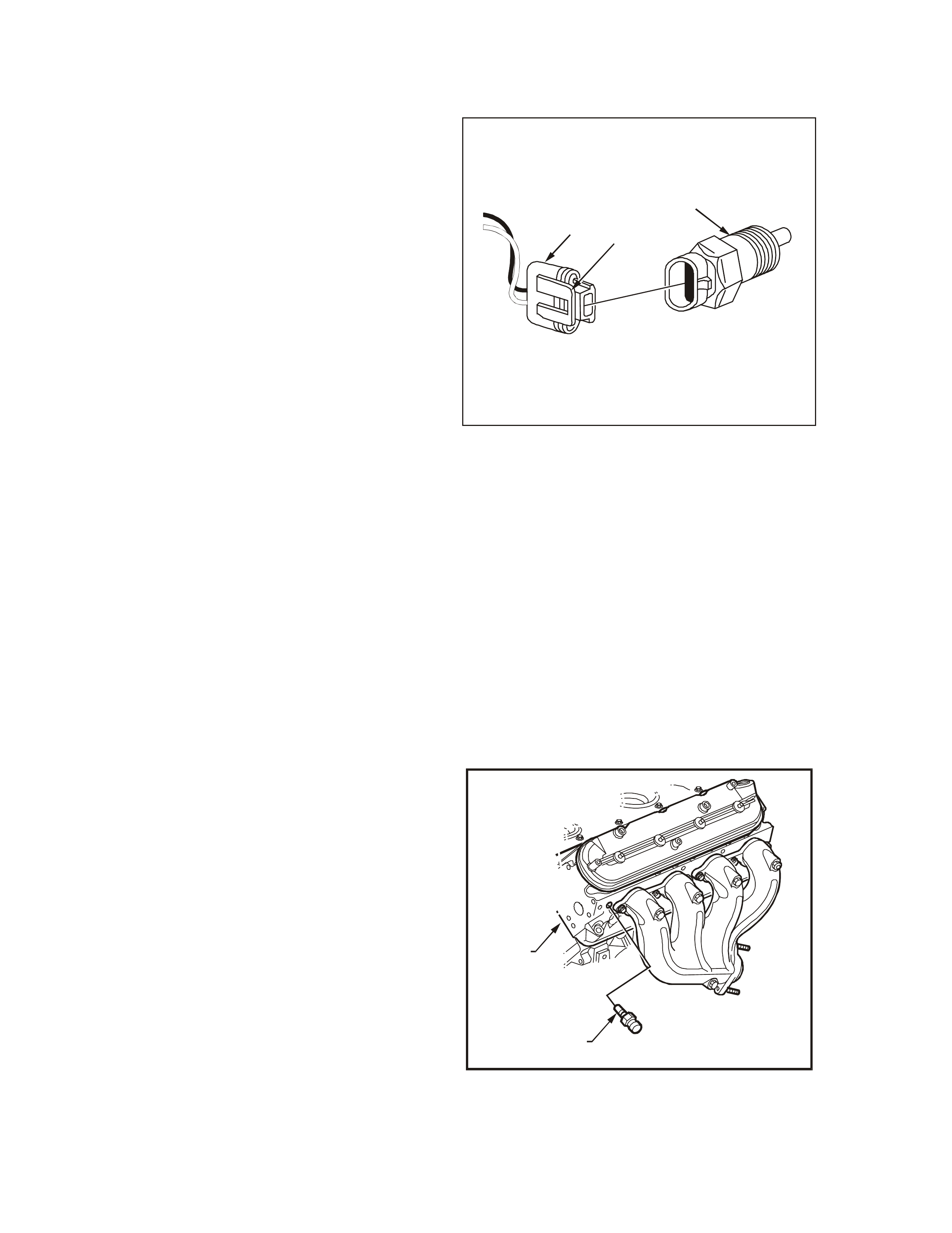
GEN3 0008
12
3
Engine Coolant Temperature (ECT) Sensor
1. ECT Electrical Connector
2. Connector Tab
3. Engine Coolant Tem perature (ECT ) Sensor
Section 6C3-4 SPECIFICATIONS – GEN III V8
Engine of this Service Information CDcontains a
table to chec k for sensor resistanc e values rela tive
to temperature.
T6B3047
1
2
Engine Coolant Temperature (ECT) Sensor
Location
1. ECT Sensor
2. Left Cylinder Head
ENGINE COOLANT LEVEL SWITCH
The engine coolant level switch is used to inform
the PCM when the coolant level is at a calibrated
low level.
When the engine coolant is at normal operating
level, the engine coolant level switch float inside the
surge tank will rise and close the sensor contacts
pulling the PCM supplies buffered B+ low.
When the coolant level is low, the engine coolant
level switch will remove the earth signal, causing
the PCM o utput B+ signal to go high. T he PCM will
then send a serial data message to the instrument
panel cluster instructing the instrument panel
cluster to turn ON the Lo w Co o l an t Warning La mp.
For diagnosis of the engine coolant level switch,
refer to Section 6C3-2C FUNCTIONAL CHECKS
– GEN III V8 Engine in this Section.
The engine coolant level switch is located in the
coolant surge tank . T he engine coolan t level switch
is serviceable only by replacing the surge tank.
Refer to Section 6B3 ENGINE COOLING of the
VT Series II Service Information, for surge tank
replacement.
GEN3 0153
2
1
Engine Coolant Level Switch Location
1. Engine Coolant Level Switc h Ele c trical Connector
2. Power train Control Mod ule (PCM)
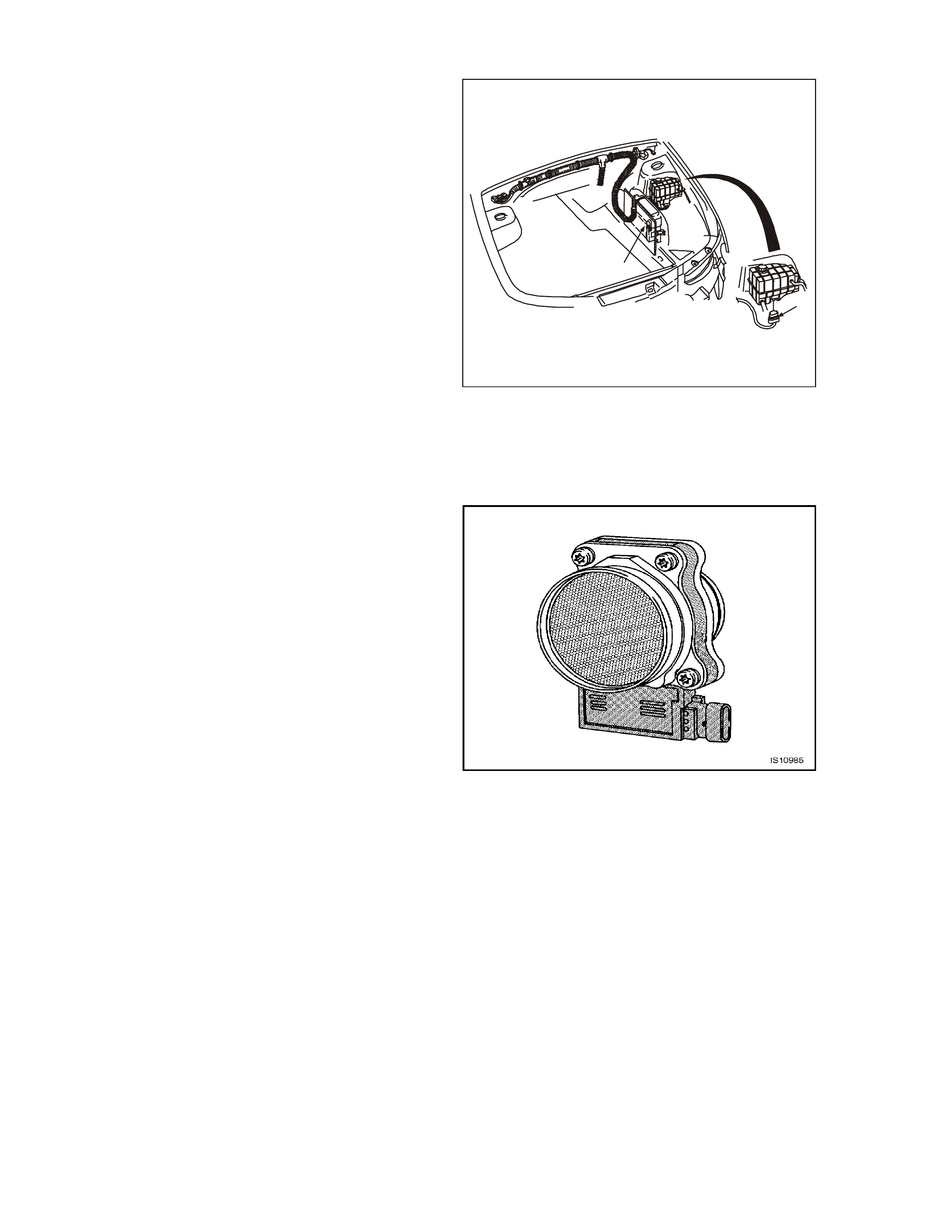
MASS AIR FLOW (MAF) SENSOR
The Mass Air Flow (MAF) sensor measures the
amount of air which passes through it. The PCM
uses this information to determine the operating
condition of the engine in order to control the fuel
delivery. A large quantity of air indicates
acceleration. A small quantity of air indicates
decele ration or idle.
The Tech 2 scan tool reads the MAF value and
displays it in grams per second (g/s). The MAF
sensor displays between 6 g/s and 9 g/s at idle on
a fully warmed up engine. The MAF sensor values
should change quickly on acceleration, but the MAF
sens or values sho uld re m a in relat ively st able at any
given RPM. When the PCM detects a malfunction
with the MAF senso r, the PCM will switch to Speed
Density for fuel control.
The following DT Cs are se t when the PCM detec ts
a m alfunction in the MAF sens or circu it:
• DTC P0101: Mass Air Flow System
Performance.
• DTC P0102: MAF Sensor Circu it Low
Frequency.
• DTC P0103: MAF Sensor Circuit High
Frequency.
Mas s Air Fl ow (MAF) Se nsor
Three sensing elements are used in this system.
One senses the amb i ent air tem perature. T he other
two sensing elem ents are heat sensing elem ents.
The ambient air temperature sensor is mounted in
the lower half of the sens or housing.
The two heater sensing elements are heated to a
calculated temperature that is significantly above
the ambient air temperature. The two heater
sensing elements are connected electrically in
parallel and mounted directly in the air f low stream
of the sensor hous ing. One se nsor is in the top and
the other sensor is in the bottom of the sensor
housing. This is done so that the air meter is less
sensitive to upstream ducting configurations that
could skew the flow of air through the housing.
As the air passes over the heater sensing
elements, the elements begin to cool. By
measuring the amount of voltage required to
maintain the heater sensing elements at the
calculated temperature above ambient, the
incoming air flow rate can be calculated.
After the Mass Air Flow sensor has developed a
signal related to the mass air flow rate, the MAF
sensor then sends the signal to the PCM. In order
to pr eserve the a ccuracy of the voltage s ignal from
the mass air flow sensor, the voltage is converted
to a frequency signal then sent to the PCM.
GEN3 0010
1
2
Sensing E l em e nts
1. Heater Sensing Elements
2. Ambient Temperature Sensor
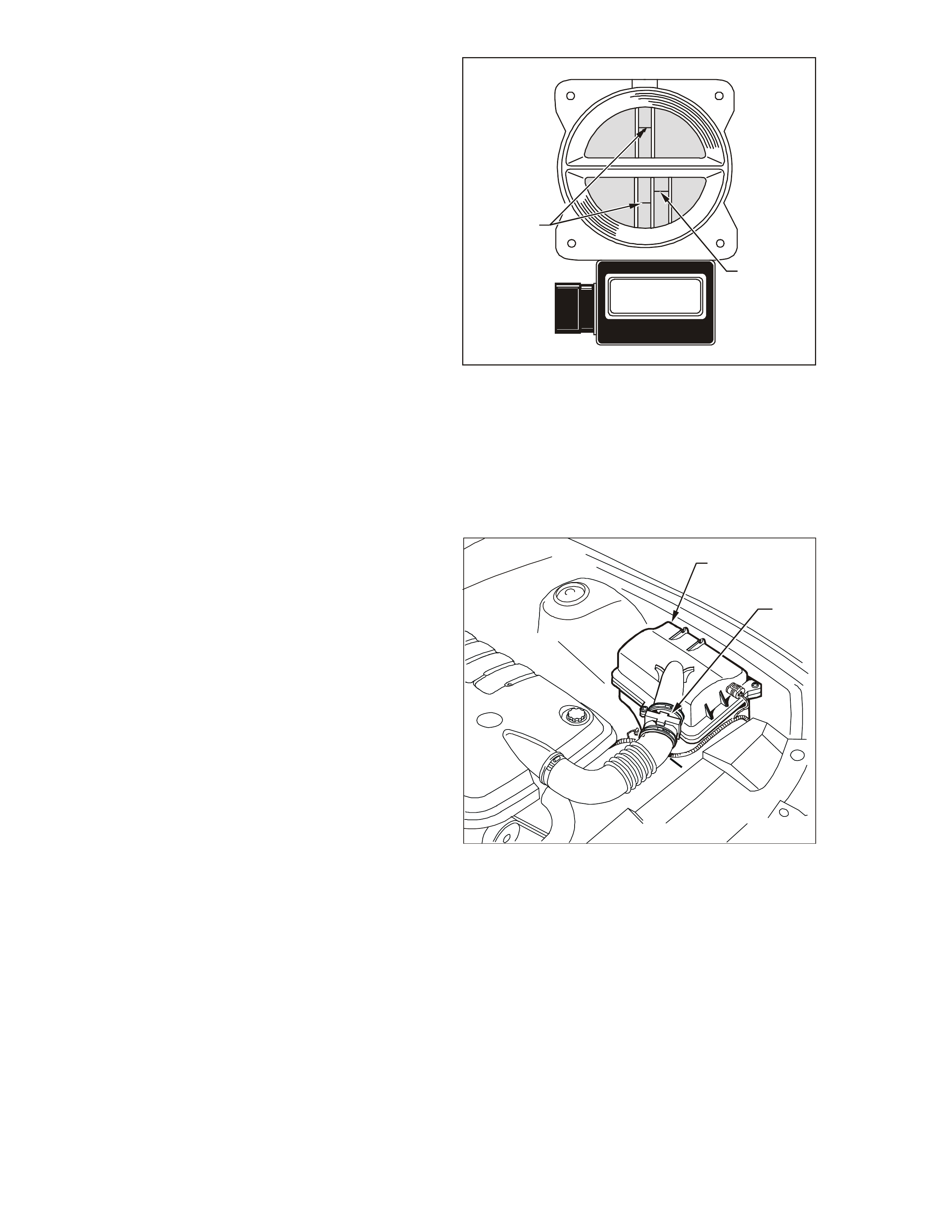
T26C3002
2
1
MAF Sensor Location1. Air Cleane r Housing
2. Mass Air Flow (MAF) Senso r
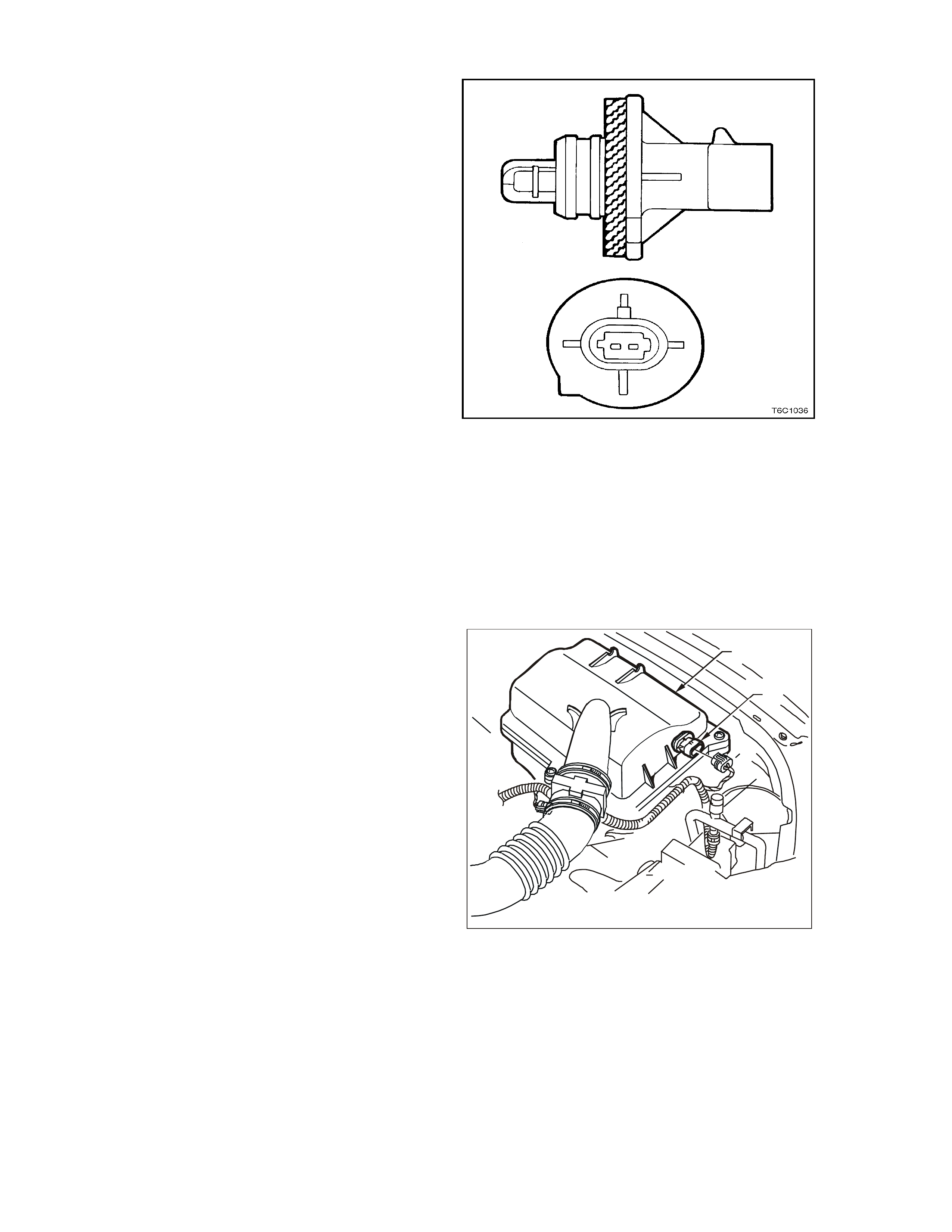
INTAKE AI R TEMPERATURE (I AT) SENSOR
The Intake Air Temperature (IAT) sensor is a
thermistor which changes value based on the
temperature of air entering the engine. Low
temperature produces a high resistance (100,000
ohms at -38°C/-39°F). A high temperature causes
low resistance (70 ohms at 130°C/266°F). The
PCM supplies a 5.0 volt signal to the sensor
through a resistor in the PCM and measures the
voltage. T h e voltage will b e high when the inc om ing
air is cold, and low when the air is hot. The PCM
calculates the incoming air temperature by
m easuring the IAT voltage. T he IAT sensor signal is
used to adjust spark timing according to incoming
air density.
The Tech 2 scan tool displays temperature of the
air entering the engine, which should read close to
ambient air temperature when engine is cold. The
temperature should rise as underhood temperature
increases. If the engine has not been run for
several hours (overnight) the IAT sensor
temperature and engine coolant temperature sho uld
read close to each other. The following DTCs are
set if the PCM detects a malfunction in the IAT
sens or circuit:
• DTC P0112: IAT Sensor Circuit Low Voltage.
• DTC P0113: IAT Sensor Circuit High Voltage.
• DTC P1111: IAT Sens or C KT I nter m it te nt Hi gh
Voltage.
• DTC P1112: IAT Sensor CKT Intermittent Low
Voltage.
Intake Air Temperature (IAT) Sensor
T26C3004
2
1
IAT Sensor Loc ation
1. Air Cle aner Housin g
2. Intake Air Temperature (IAT) Sensor
3. A/C Re frigerant Pres sure Tr ansducer
MANIFOLD ABSOLUTE PRESSURE (M AP) SENSOR
The Manifold Absolute Pressure (MAP) sensor
responds to changes in the intake manifold
pressure. The pressure changes as a result of
engine load and speed. The map sensor converts
this to a voltage output.
A closed throttle on engine coast down produces a
relatively low MAP output voltage. A wide open
throttle produces a high MAP output voltage. This
high output voltage is produced because the
pressure inside the m anifold is the same as outside
the manifold. The MAP is inversely proportional to
what is measured on a vacuum gauge. The MAP
sens or is used for the following:
• Altitude determ i nation.
• Ignition timing control.
• Speed density fuel management default.
Manifold Absolute Pressure (MAP) Sensor Location
1. Manifold Abso lute Pressure (MAP) Sensor
2. Camshaft Position (CMP) Sensor
3. Oil Pressure Sensor
4. Connector to Knock Sensor Jumper Harness
SPEED DENSITY SYSTEM
Three specific data sensors provide the PCM with
the basic information for the fuel management
portion of its operation. That is three specific
signals to the PCM esta blish the en gine speed and
air density factor s. Th e engine s peed signal come s
from the ignition system. The PCM uses this
information to determine engine speed (RPM). Air
density is der ived from IAT and MAP sensor input s.
The IAT sensor measures the air temperature that
is entering the engine. The IAT signal works in
conjunction with the MAP sensor to determine air
density. As the intake manifold also increases and
additional f u el is req uire d. This inf o rmation from the
IAT and MAP sensors is used by the PCM to
control injector pulse width.
The Speed Density system is only needed when
there is a Mas s Air Flow ( MAF) s ens or m alf un ction.
If the PCM detects a malfunction with the MAF
sens or circuit, the PC M will default to speed density
fuel management.
When the PCM detects a malfunction in the MAP
sensor circuit, DTC P0107: MAP Sensor Circuit
Low Voltage or DTC P0108: MAP Sensor Circuit
High Volta ge will set.
Manifold Absolute Pressure (MAP) Sensor Location1.
Manifo ld Absolute Pressure (MAP) Sensor
2. MAP Sensor Harness Connector
HEAT ED OXYGEN SENSORS (HO2S)
The Heated Oxygen Sensors are mounted in the
exhau st syst em where t hey can mo nitor he oxygen
content of the exhaust gas stream. The oxygen
present in t he exhaust gas reac ts with the s ensor to
produce a voltage ou tput.
This voltage should constantly fluctuate from
approximately 100mV (high oxygen content - lean
mixture) to 900 mV (low oxygen content - rich
m ixtur e) . T he hea te d oxygen senso r vo ltage ca n be
monitored with a scan tool. The PCM calculates
what fuel mixture command to give to the injectors
(lean mixture - low HO2S voltage = rich com mand,
rich m ix ture - high HO2S volt age = lean com mand )
by monitoring the voltage output of the oxygen
sensors.
These oxygen sensors ar e mounted in the exhaust
pipes and are referred to as Bank 1 Sensor 1 (left
exhaust pipe) Bank 2 Sensor 1 (right exhaust pipe).
The PCM sets the following DTCs when the PCM
detec ts an HO2S signal circuit that is low:
• DTC P0131: Bank 1 Sensor 1 HO2S.
• DTC P0151: Bank 2 Sensor 1 HO2S.
The PCM sets the following DTCs when the PCM
detec ts an HO2S signal circuit that is high:
• DTC P0132: Bank 1 Sensor 1 HO2S.
• DTC P0152: Bank 2 Sensor 1 HO2S.
The PCM sets the following DTCs when the PCM
detects no HO2S activity:
• DTC P0134: Bank 1 Sensor 1 HO2S.
• DTC P0154: Bank 2 Sensor 1 HO2S.
A fault in the heat ed oxygen se nsor heater elem ent
or its ignition feed o r earth results in an increa se in
time to Closed Loop fuel control. This may cause
increased emissions, especially at start-up. The
following DTCs are set when the PCM detects a
malfunction in the HO2S heater circui ts:
• DTC P0135: Bank 1 Sensor 1 HO2S heater.
• DTC P0155: Bank 2 Sensor 1 HO2S heater.
RESPONSE TIME
The PCM also has the ability to detect HO2S
response, switching, transition time, and incorrect
ratio voltage problems. The PCM stor es a DTC that
indicates degraded HO2S performance if a HO2S
response switching , transition time , or ratio pr oblem
is detected.
OXYGEN SENSOR CONT AMINANTS
Carbon
Carbon or soot deposits result from an extremely
rich air-fuel mixture. Carbon does not harm an O2
sensor. Deposits can be burned off in the vehicle
by running the engine at least part throttle for two
minutes.
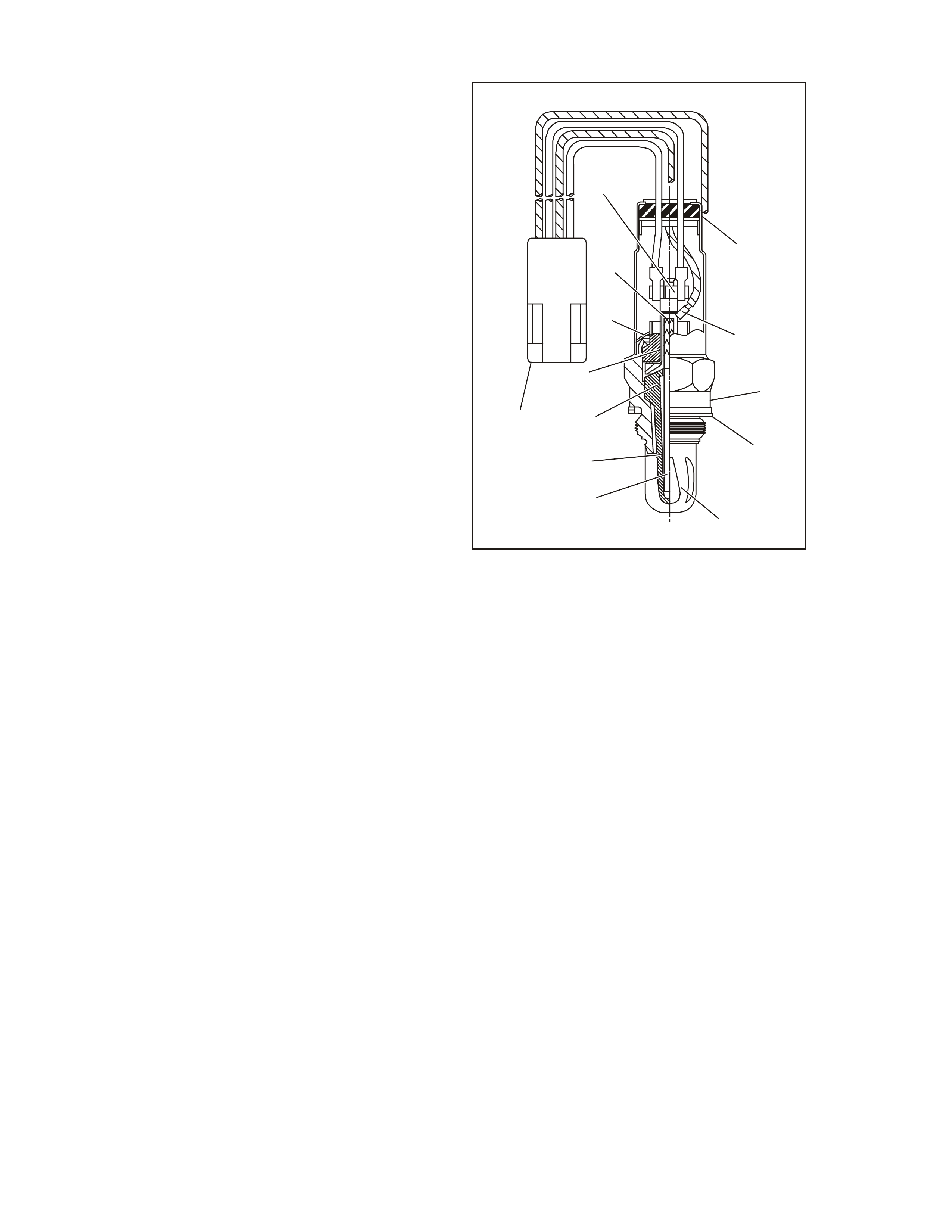
GEN3 0013
2
3
4
13
12
11
1
5
6
7
8
9
10
Heated Oxyg en Sensor (HO2S) Cut away
1. Four Wire In-Line Connector
2. Heater Termination
3. Water Shield Assembly
4. Sensor Lead
5. Flat Seat Shell
6. Seat Gasket
7. Out er Electrode an d Pr otective Co ating
8. Rod Heater
9. Inner Electrode
10. Zirconia Element
11. Insulator
12. Clip Ring
13. Gripper

Silica
Certain RTV silicone gasket materials give off
vapours that may contaminate the oxygen sensor.
The sand like particles from the RTV silica embed
them selves in t he oxygen se nsor elem ent and plug
the sur face. T his will result in a lazy oxygen sensor
respo nse tim e. T he sens or will also have a whitis h
appearance.
Silica co ntam ination c an also be ca used by silicone
in the f ue l. Car eless f ue l handling pr a ctice s with th e
transport containers can result in unacceptable
concentrations of silicone in the fuel at the fuel
pump.
There is also a possibility of silica contamination
caused when installing vacuum hoses or fittings.
Do not use silicone sealers on the gaskets or the
exhaust joints.
Lead
Lead glazing of the oxygen sensor can occ ur when
leaded fuel is burned.
Other Substances
Oil deposits will ultimately prevent oxygen sensor
operation. The O2 sensor will have a dark brown
appearance. Causes of high oil consumption
should be c hec k e d. The a dditives in ethylene glycol
can also affect the oxygen sensor performance.
This produces a whitish appearance. If antifreeze
enter s the exhaus t s ys tem , you will likely encounter
other, more obvious, symptoms of cooling system
trouble.
Multiple Faul ts
If you encounter multiple or repeat oxygen sensor
faults on the s ame vehicle, consider contamination.
Leaded fuel, silica contamination from uncured,
low-grade (non approved) RTV sealant, and high oil
cons umpt ion are possible.
A problem in the either oxygen sensor circuits or
fuel system should set a DTC( s).
THROTTL E POSITION (TP) SENSOR
The Throttle Position (TP) sensor is a
potentiometer. The TP sensor is connected to the
throttle shaft on the throttle body. The PCM
calculates throttle position by monitoring the
voltage on the signal line. The TP sensor signal
changes as the throttle valve angle is changed
(accelerator pedal moved). The TP sensor signal
voltage is low at a closed throttle position. The TP
sens or signal voltage inc r eases as the throttle valve
opens so that at Wide Open Throttle (WOT), the
output voltage should be above 4.0 volts.
The PCM calculates fuel delivery based on throttle
valve angle (driver demand). A broken or loose TP
sensor may cause intermittent bursts of fuel from
an injector. This may cause an unstable idle
becau se the PCM detect s the thrott le is moving.
The following DT Cs are se t when the PCM detec ts
a malfunction with the TP sensor circuits:
• DTC P0121: TP Sensor Circuit Insufficient
Activity.
• DTC P0122: TP Sensor Circuit Low Voltage.
• DTC P0123: TP Sensor Circuit High Voltage.
• DTC P1121: TP Sensor CKT Intermittent
High Voltage.
• DT C P112 2: T P Sens or CKT Inte rmitt ent Low
Voltage.
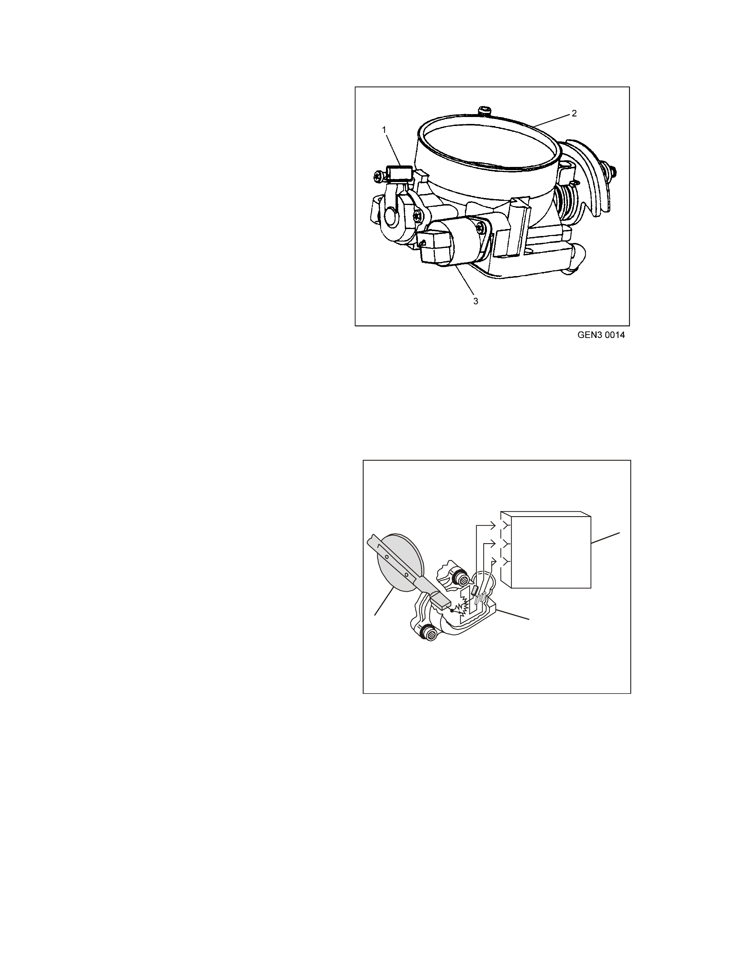
Throttle Position (TP) Sensor1. TP Sensor
2. Throttle Body
3. IAC Valve
GEN3 0015
C
B
A
21
3
TP Sensor - Typ i cal
1. TP Sensor
2. Throttle Plate
3. Power train Control Mod ule (PCM)
KNOCK SENSORS (KS)
A Knock Sensor (KS) system is used in order to
control engine spark knock. The KS system is
designed to retard spark t i ming up to 20° in order to
reduce spark knock in the engine. This allows the
engine to use m axim um spark ad vance to improve
driveability and fuel economy.
The knock sensor system is used to detect engine
detonation. The knock sensors produce an AC
voltage which is s ent t o the PCM. The PC M r etard s
the spark timing based on signals from the KS
sensors. The amount of AC voltage produced by
the sensors is determined by the amount of knock.
This AC signal voltage t o the PCM is proc essed by
a Signal Noise Enhancement Filter (SNEF) module.
The SNEF module is used to determine if the AC
signal coming in is noise or detonation. This SNEF
m odule is part o f the PC M and ca nnot be re placed.
The PCM then adjusts t he ignition tim ing to reduce
the spark advance. How much the timing is
retarded is based upon the amount of time knock
that is detected and is limited to a maximum value
of 20° degrees. After the detonation stops, the
timing will gradually return to its calibrated value of
spark advance.
Knock (KS) Sensor
The Knock Sensor system will only retard timing
after the f ollowing conditions are met:
• The engine run time is greater than 20
seconds.
• The engine speed is greater than 16 50 RPM.
• The engine coolant temperature is greater
than 70°C (158°F).
• The MAP is less than 60 kPa.
The Tech 2 scan tool has several positions for
diagnos ing the KS circuit:
• Knock Retard indicates the amount of spark
the PCM is removing from the IC spark
advance in response to the signal from the
Knock Sensors.
• Spark indicates the amount of spark advance
being commanded by the PCM on the IC
circuit.
DTC P0325 indicates an internal PCM malfunction
related to the KS system. DTCs P0327 and P0332
indicate that a Knock Sensor or Knock Sensor
circuit is malfunctioning. If these DTCs are set,
ref er to applicable DTC table.
Knock Sensor Location
1. Fr ont Knock Sensor
2. Rear Knock Se nsor
3. Left Cylinder Head

PARK, REVERSE, NEUTRAL, DRIVE, LOW (PRNDL) SWITCH
The transmission PRNDL module is a multi-signal
switch which sends a signal to the PCM to indicate
gear selection. The PCM will then determine the
signal from the PRNDL module and send a
command via serial data communication to the
instrument panel clust er to turn ON the correct gear
indicator lamp for the gear that is be ing selected.
The PRNDL module uses four discrete circuits to
pull four PCM voltag es low in various co mbinations
to indicate each gear range. The voltage level of
the circuits is represented as CLOSED = earthed,
and OPEN = open cir c uit. Th e fou r st ates displa yed
represents decoder P, A, B, and C inputs.
The Tech 2 scan tool will display all four circuits
(P, A, B, C ) and the ap pro pria te open and clos ed to
represent the gear selected. If the gear selected
does not match the OPEN/ CLOSED state as
displayed in the table on the scan tool, or the
instrument panel cluster gear lamp (if fitted) does
not light up for the gear selected, there is a fault in
the PR NDL select c irc uit or in the Instru m ent Panel
(IP) cluster.
The PRNDL operation indicates to the PCM what
gear the shift selec tor is in. Th is inf ormatio n is used
for the IAC valve operat i on.
Important: Idle quality will be af fect ed if the vehicle
is driven with the PRNDL switch disconnected.
Having the switch disconnected may also cause a
VSS DTC to set.
For additional details of the PRNDL switch location
and adjustment, refer to Se ct ion 7C 4 AUTOMA TIC
TRANSMISSION, On-Vehicle Servicing of the VT
Series II Service Information.
A/C REQUEST SIGNAL
When received, this signal tells the PCM that the
driver want s t he air condit ioning to operat e. On non
ECC equipped vehicles the signal originates at the
instrument panel A/C s witch, but must pass thr ough
the BCM, which sends a serial communications
message to the PIM, which in turn passes the
switch state on to the PCM.
If the vehicle is equipped with Electronic Climate
Control, this A/ C re quest signa l comes dir ec tly from
the ECC module via a serial message to the PIM
which then passes the request to the PCM. The
PCM uses th is signal to - adjust the Idle Air Control
(IAC) po sition to com pe nsat e for the additional load
placed on the engine by the air conditioning
compressor, and then - energises the A/C control
relay, to operate the A/C compressor.
TRANSMISSION RANGE / PRNDL SWITCH VALID
INPUT COMBINATIONS
GEAR
POSITION
SELECTED
SCAN TOOL PRNDL DISP L A Y
(P, A, B, C)
P A B C
PARK (P) CLOSED CLOSED OPEN OPEN
REVERSE (R) OPEN CLOSED CLOSED OPEN
NEUT RA L (N) CLOSED OPEN CLOSED OPEN
DRIVE 4 (D) OPEN OPEN CLOSED C LOSED
DRIVE (3) CLOSED CLOSED CLOSED CLOSED
DRIVE 2 (2) OPEN CLOSED OPEN CLOSED
DRIVE 1 (1) CLOSED OPEN OPEN CLOSED
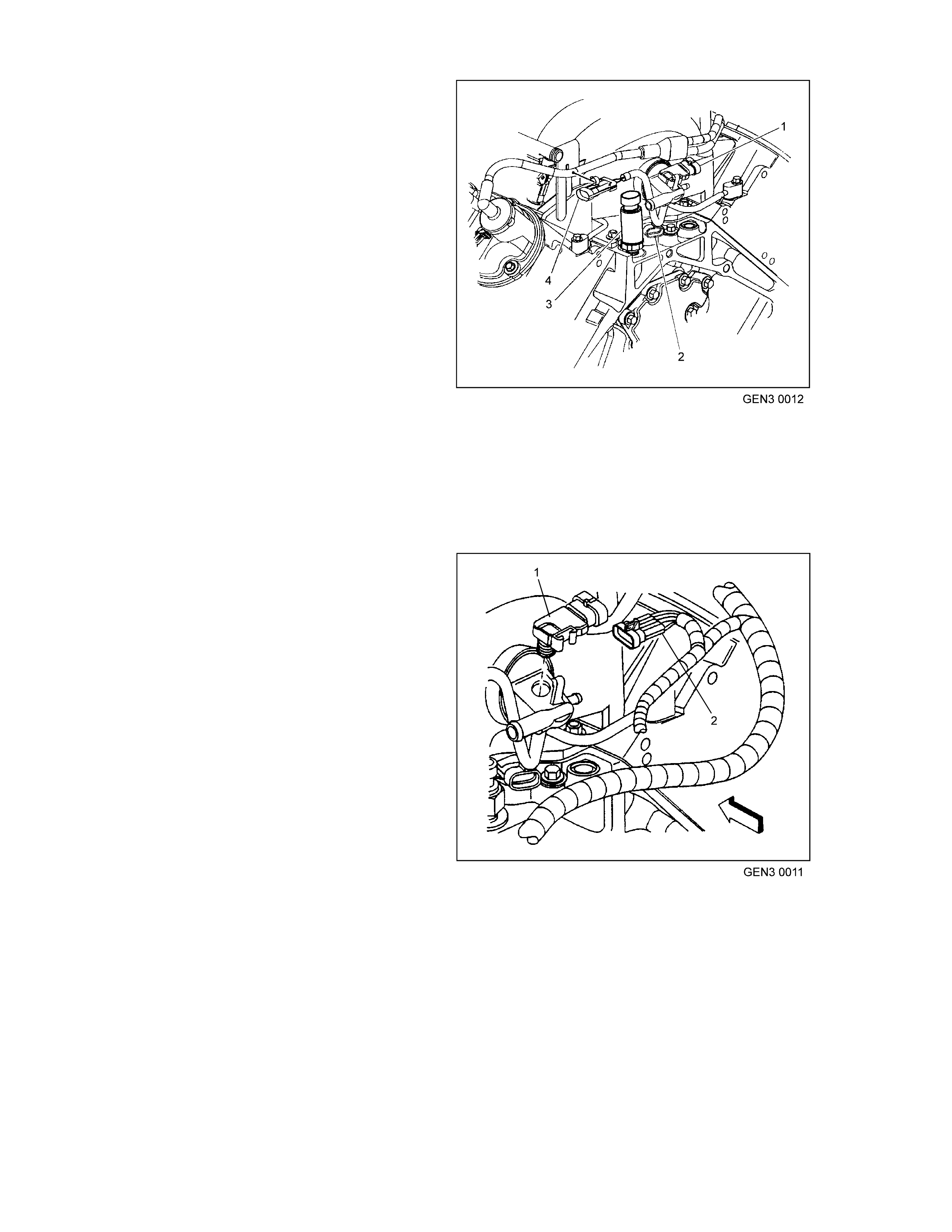
A/C REFRIGERANT PRESSURE TRANSDUCER
This signal is used by the PCM in order to enable
the cooling fans when the A/C compressor head
pressure reaches a predetermined value. DTC
P0530 sets if a fault is present in the A/C
refrigerant pressure sensor circuit.
The PCM disables the A/C compres s or clutc h when
the PCM sets an A/C system DT C. Refer to the A/C
Refrigerant Pressure Transducer Circuit Diagnosis
in Section 6C3-2C FUNCTIONAL CHECKS –
GEN III V8 Engine of this Service Inform ation CD, if
the A/C Refrigerant Pressure Transducer is faulty.
T26C3004
1
A/C Refrigerant Pressure Transducer Location
1. A/C Re friger ant Pressure Transducer
VEHICLE SPEED SENSOR (VSS)
The Vehicle Speed Sensor (VSS) is a pulse
counter type input that informs the PCM how fast
the vehicle is traveling. The VSS system uses an
inductive sensor mounted in the tail housing of the
transmission and a toothed reluctor wheel on the
tailshaft. The teeth of the reluctor wheel alternately
interfere with the magnetic field of the sensor
creating an induced voltage pulse as the reluctor
rotates. Each brake in the field sends a pulse to the
PCM.
For automatic transmission equipped vehicles 40
pulses per tailshaft revolution are generated. This
results in 100196 pulses per mile (62260 PPK)
input to the PCM.
For manual transmission equipped vehicles 17
pulses per tailshaft revolution is generated. This
results in 47992 pulses pe r mile (29820 PPK) input
to the PCM.
For both transmissions the output is 10020 pulses
per m ile (6226 PPK). A f ault with th e spe ed sensor
will cause DTC P0608 to set.
The PCM uses the signal from the vehicle speed
sens or to determine the following:
• The vehicle spe ed.
• The control sh ift points .
• Calc ulate transmission slip.
• The engine fueling modes.
• Chime Module.
IMPORTANT: The automatic transmission VSS
resistance should be 1470-2220 ohms when
measured at 20°C (68°F). Output voltage of the
VSS varies with s peed fr om a minim um of 0.5 volts
AC at 10 0 RPM to m ore than 100 volt s AC at 8000
RPM.
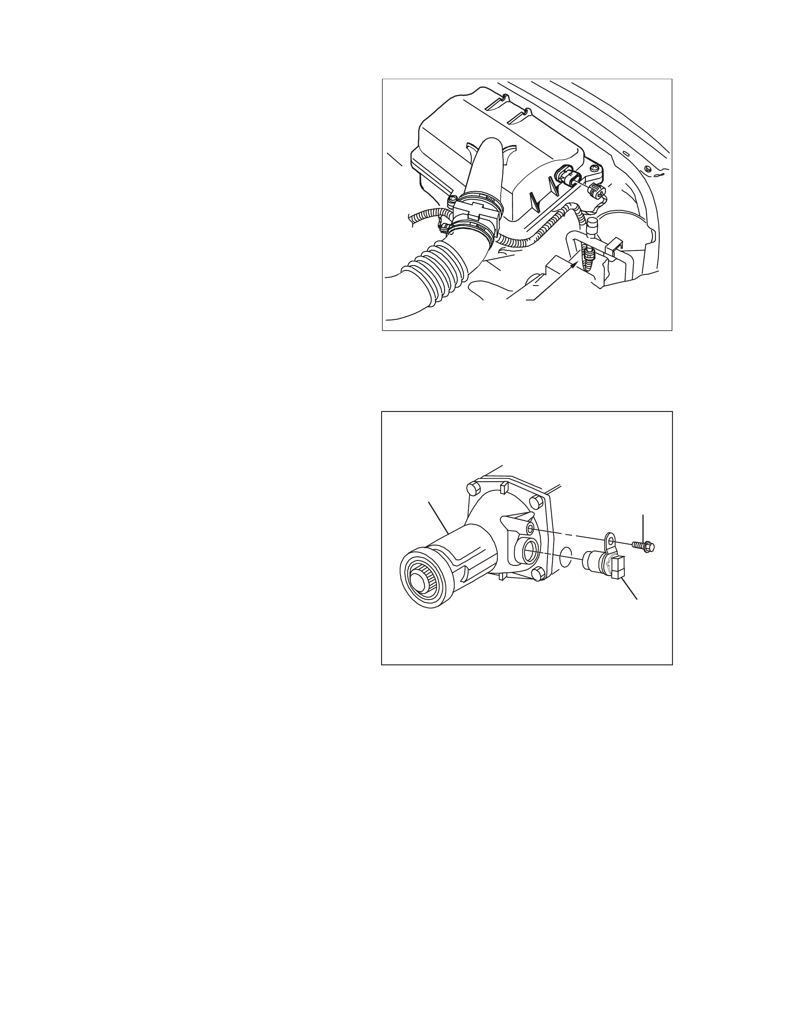
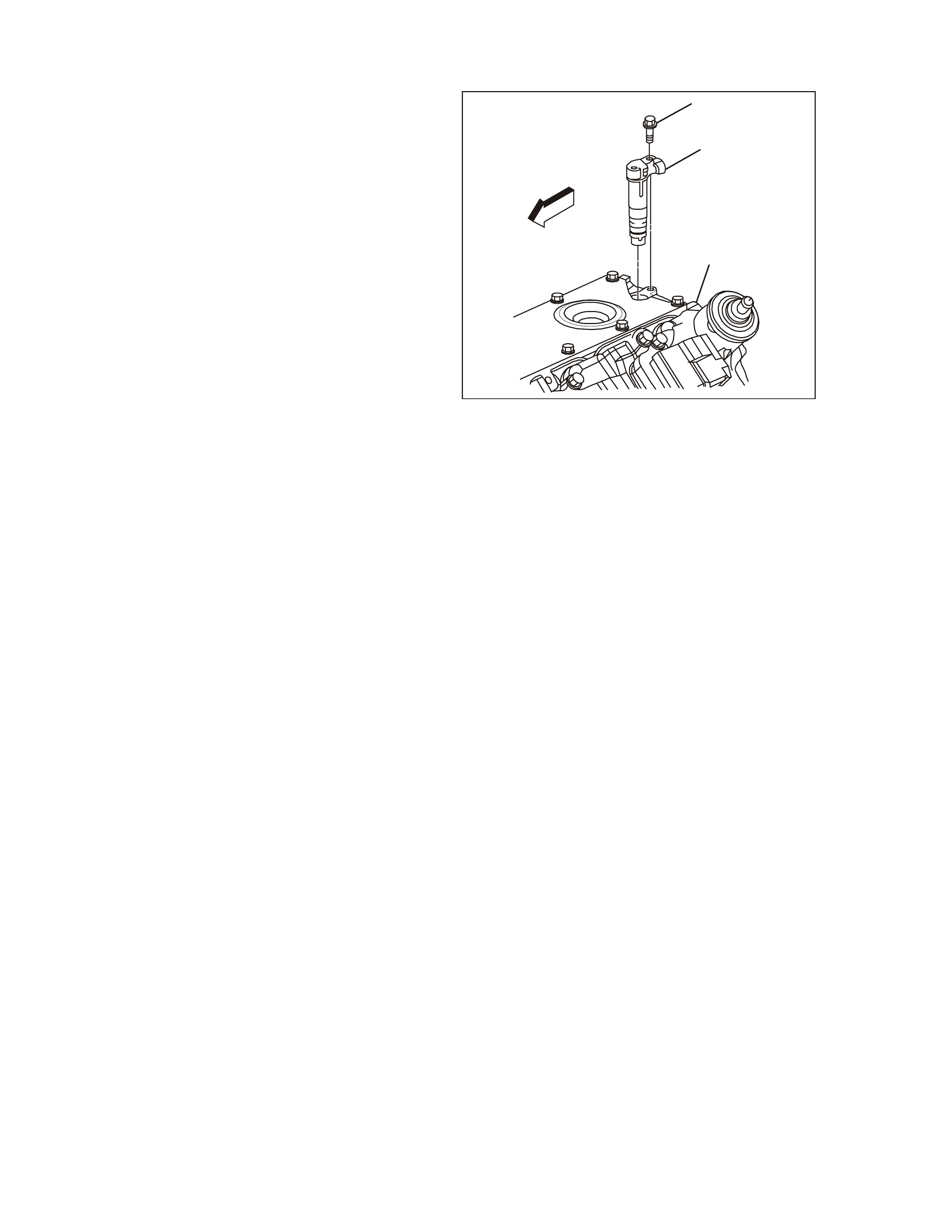
GEN3 0019
12
3
Vehicle Speed Sensor (VSS)
1. Automatic Transmission Tail Housing
2. Vehicle Speed Sensor (VSS) Reta ining Bolt
3. Vehicle Speed Sensor (VSS)
A Diagnostic Trouble Code will set if a fault exists
in the Vehicle Speed Sensor circuit.
For automatic transmission: as the vehicle is
acce lerated, the PCM will shift the transm ission into
second gear at approximately 50 km/h. If the
vehicle speed signal is not present while in second
gear, a DTC will set .
The PCM will substitute a default value for the
vehicle speed if the fault occurred in fourth gear. If
the f ault occurred in park , neutral, or f irst gear, the
PCM will allow 1-2 shifts to occur. If a DTC is set,
then the PCM will default into third gear. If the
conditions for a DTC no longer exist, then normal
operation will r esume after the next ignition cycle.
For manual transmission: as the vehicle is
accelerated in any forward gear from a closed
throttle, and no vehicle speed is indicated to the
PCM, a DTC will set.
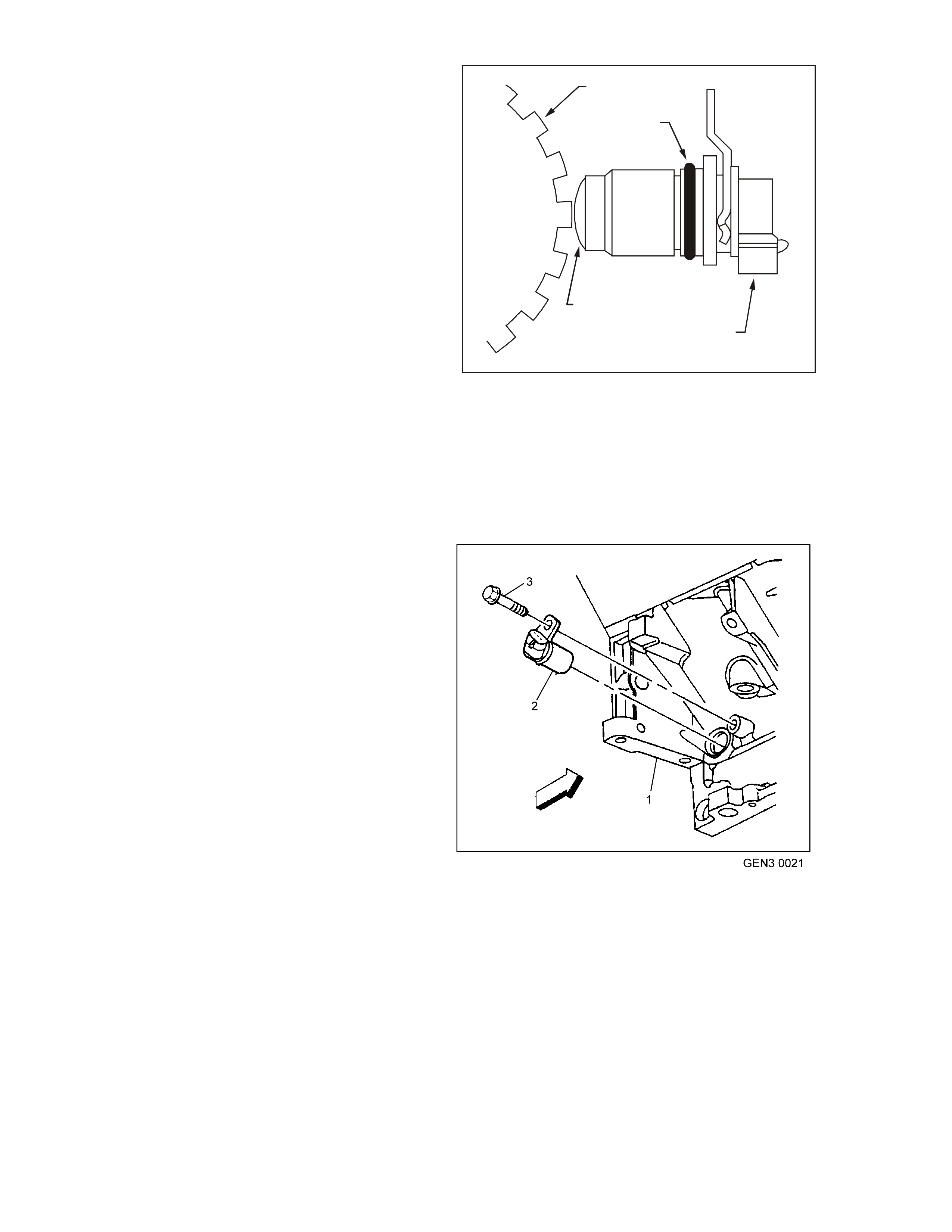
GEN3 0020
1
2
4
3
Vehicle Speed Sensor To Reluctor Wheel
1. Reluctor Wheel (Rotor)
2. O-Ring
3. Electrical Connector
4. Magnetic Pickup
CRANKSHAFT POSITION (CKP) SENSOR
The Crank sh af t Position (CKP) senso r provides the
PCM with crankshaft speed and crankshaft
position.
The PCM monitors the CKP sensor signal circuit
for m alfun ctions. The PCM sets a DTC P0335 or a
DTC P0336 when the CKP sensor is out of the
normal operating range.
Crankshaft Position Sensor (CKP) Location
1. Starter Mounting Pad on Engine Block
2. CKP Sensor
3. CKP Mounting Bolt
CA MSHAFT POSITION (CMP) SENSOR
The Camshaft Position (CMP) sensor is mounted
through the top of the engine b lock at the rear of the
valley cover and works in conjunction with a 1X
reluctor wheel on the camshaft. The reluctor wheel
is inside t he engine, imme diately in fron t of the rear
cam bearing. The PCM provides a 12 volt power
supply to the CMP sensor as well as a earth and a
signal circ uit.
The PCM uses the camshaft position sensor in
order to determine whether a cylinder is on a firing
or exhaust stroke. The reluctor wheel interrupts a
magnetic field produced by a magnet within the
CMP sensor as the camshaft rotates. The CMP
sensor’s internal circuitry detects this and produces
a signal which the PCM reads. The PCM uses this
1X signal in combination with the Crankshaft
Position s ens or 24 X s ignal in or der to det er mine the
Crankshaft Position and stroke. This diagnostic for
the Camshaft Position sensor checks for Camshaft
Position sensor signal. The PCM also monitors the
CMP sensor signal circuit for malfunctions. The
following DTCs set when the PCM detects a CMP
sens or that is out of the normal operating r ange:
• DTC P0341: Camshaft Position ( CMP)
Sens o r Cir cu i t P e rfor mance .
• DTC P0342: Camshaft Position ( CMP)
Sensor Circuit Low Voltage.
• DTC P0343: Camshaft Position ( CMP)
Sensor Circuit High Voltage.
GEN3 0022
1
2
3
Camshaft Posi tion Senso r (CMP) Location
1. CMP Mounting Bolt
2. CMP Sensor
3. Top Rear of Engine Block
BATTERY VOLTAGE
The PCM continually monitors battery voltage.
When the battery voltage is low, the ignition system
may deliver a weak spark and the injector
mechanical movement takes longer to open the
injector.
The Powert rain Control Module will compensate by:
1. Increasing the ignition coil dwell time if the
batte r y voltage is les s than 12 volts.
2. Increasing the engine idle RPM if battery
voltage drops below 10 volts.
3. Increasing the injector pulse width if the
battery voltage drops below 10 volts.
On vehicles equipped with automatic transmission,
Diagnostic Trouble Code (DTC) P0563 will set
when the ignition is ON and PCM voltage is more
than 17 volts for about 5 seconds.
Diagnostic Trouble Code (DTC) P0562 will set
when the ignition is ON and PCM voltage is less
than 5 volts f or about 5 s econds.
TRANSMISSION ECONOMY/POWER SWITCH
The Economy/Power switch is used to modify
upshifts and shift t imes. The driver can select either
Economy or Power mode with the switch (1)
located on the centre console. A third mode,
Cruise, is available via a switch located on the
indicat or stalk (where fitt ed).
Two green indicator lamps of 1.2 watts at 12 volts
are located in the instrument cluster and display
POW E R or CRUISE when illumina ted to inform the
driver of the mode that is en abled.
The PCM provides a voltage signal of about 12
volts, and monitors the status of this circuit. In the
Econom y position, the switch is open and the PCM
voltage status signal remains high, about 12 volts.
The PCM does not allow shift point changes in the
Economy mode. When the transmission switch is
pressed to the Power position the switch is
momentarily closed and the PCM voltage status
signal is mom entarily pulled low, to about 0.5 volts.
The PCM senses this voltage momentary voltage
drop and enables Power mode (alternate shift
pattern tab les to be utilised).
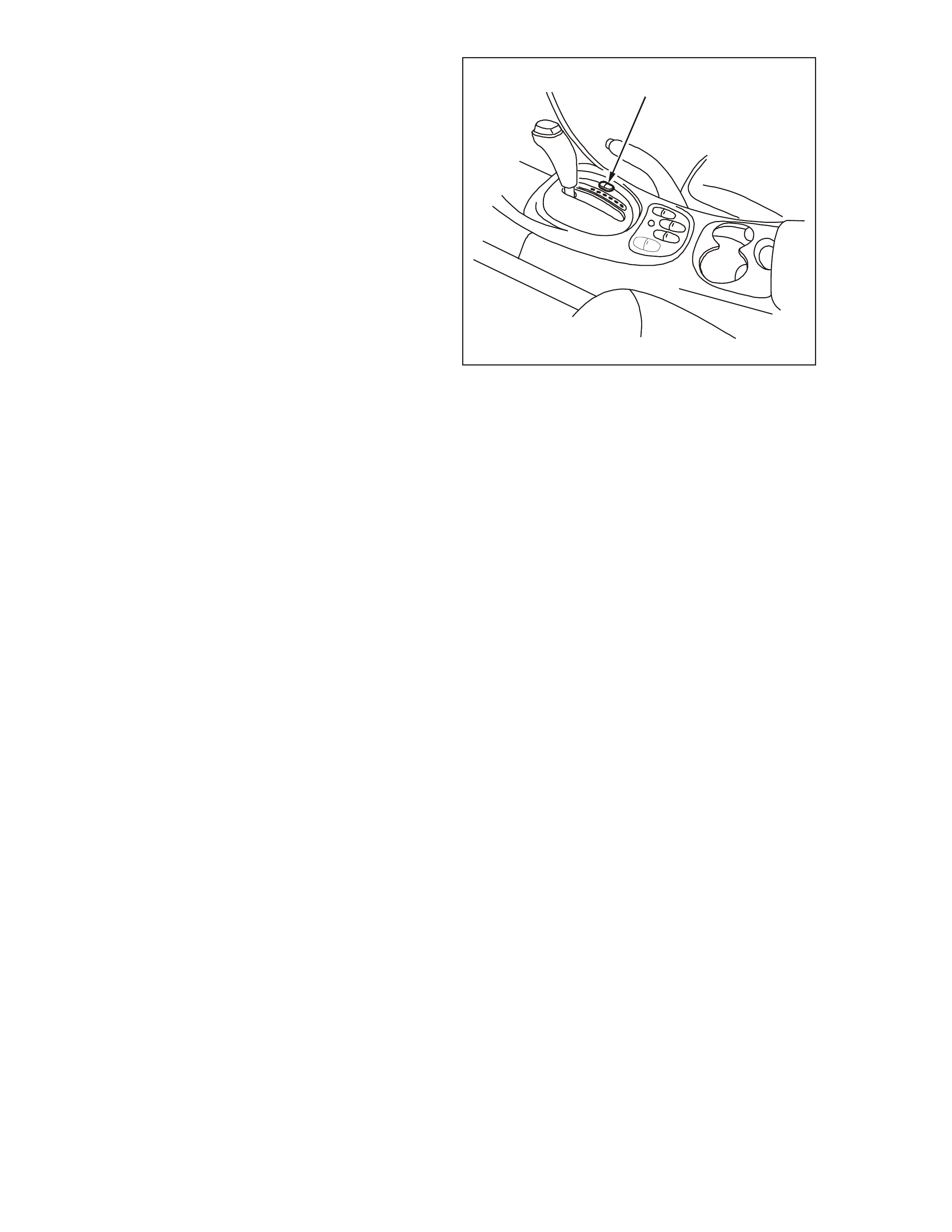
GEN3 0154
1
Transmission Econ omy/Power Switch
1. Automatic Tr ansmission Economy/Power Switch
In the Power mode, the Torque Converter Clutch
(TCC) can be applied in 3rd and 4th gears. When
the TCC is applied in 3rd gear it will stay applied
until the normal 4th gear upshift criteria is met.
When the 3-4 upshift occurs, the TCC will be
released momentarily. Also, in the Power mode
while in D gear select position, the PCM will delay
the 1-2 and 2-3 shift while under light throttle. The
shift patterns will be the sam e in the Economy and
Power m odes if the Th rottle Pos ition (TP) sensor is
between 80% - 100%. The Power mode should be
used when towing, as applying the TCC in 3rd and
4th gear reduces slippage in the TCC and thus
reduces heat build up.
In Cruise mode operation, when the driver ac tivates
the cruise control, the POWER lamp and Power
mode will turn OFF (if vehicle was in power mode)
and a CRUISE lamp will illuminate on the
instr ument panel. T he tr ansmis sio n shif t patter n will
switch to cruise shift pattern. W hen in cruise mode
the PCM will m odify the trans miss ion calibration so
that transmission shift activity is reduced.
W hen the key is turned ON, the PCM shift mode is
set to the last mode that was previously selected
(Economy/Power). The cruise control is set to OFF
at every key ON cycle.
For replacement of the Economy/Power switch,
refer to Section 7C4 AUTOMATIC
TRANSMISSION On Vehicle Service of the VT
Series I Service In formation.

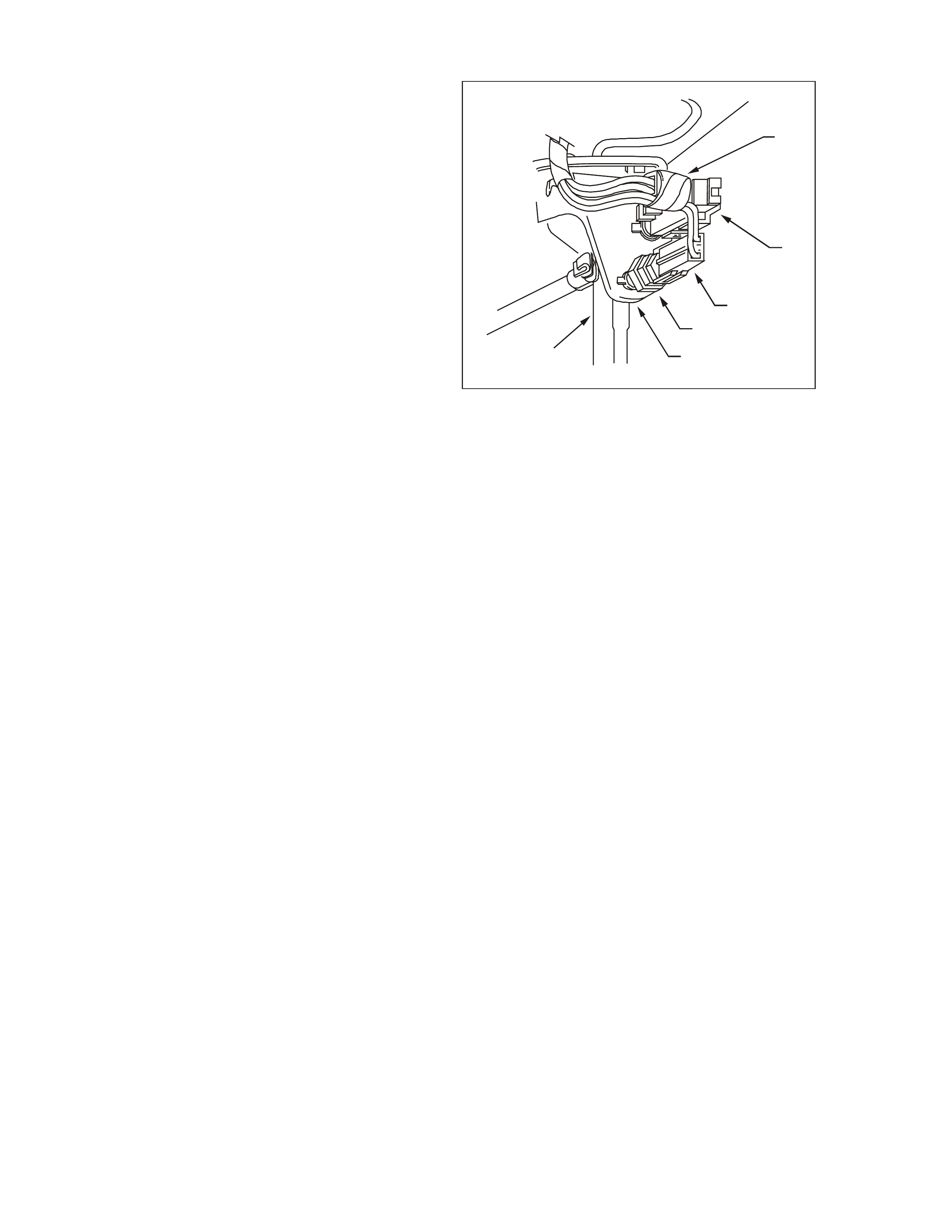
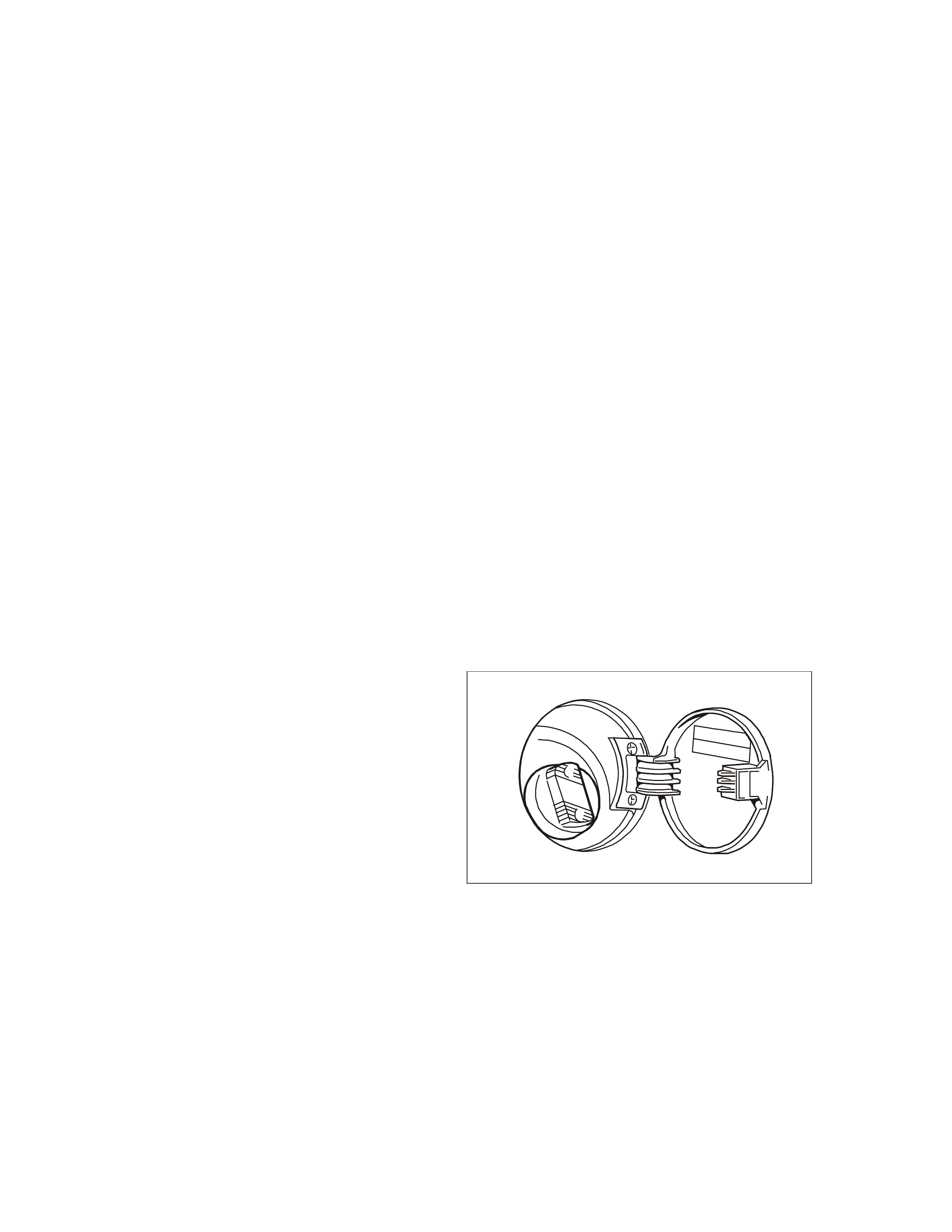
THEFT DETERRENT SYSTEM
The thef t deter rent system on VT Series Models uses a remote coded key to arm and disar m the system , as well as
electrically lock or unlock all doors and tailgate (station wagon), or operate the boot unlock mechanism (sedan
models).
The th eft deter rent alert indicat or LED is used to indicate the state of the system . A flashing LED indicates that the
system is ar m ed and cons equen tly the vehicle cannot be s tart ed. When the LED is turned off , the BCM is disarm ed
and the engine can be started. The theft deterrent LED is incorporated into the trip computer module in the
instrument panel fa cia.
W hen the GEN III V8 ignition switch is turned to the ON position, the BCM polls the PIM and sends an encrypted
BCM/Key security code (The security code is received via the BCM slip ring or remote receiver in the event of no
slip ring communication). The PIM compares the received security code with its stored security code and if the
codes match, the PIM will continue engine cranking and send a separate encrypted security code on the Class II
serial data circuit to the PCM. The PCM compares this code with its stored security code and if the codes match,
the PC M will enable injection of fue l to continue. The PIM will return an O K TO ST ART messag e on the UART serial
data c ir cuit, which t ells the BCM to jump from SHORT LOOP mode to the LONG LOOP mode.
NOTE 1: Regardless of the engine configuration, it is very important that the remote coded key reader is aligned
correctly with the ignition lock assembly. Misalignment with the remote coded key contact may occur resulting in
intermitt ent or no engine c r anking or starting.
NOTE 2: Should the engine crank briefly when the ignition switch is turned to the START position (ie. due to
m isaligned or a fault y remo te code d key reader) then pr essing t he unlock butto n on the r emot e coded k ey will also
disarm the theft deterrent system.
Refer to Section 12J-1 LOW SERIES BODY CONTROL MODULE or 12J-2 HIGH SERIES BODY CONTROL
MODULE in the VT Series II Service Inform ation for further information and diagnosis.
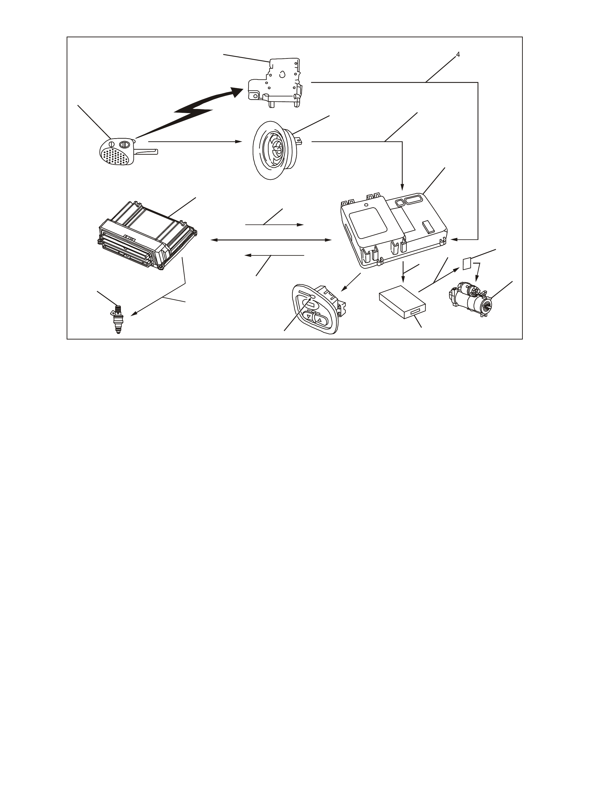
GEN 3 0024
14
13
12
15
16
1
17
2
35
6
11 97
8
10
Theft Deterrent Sy stem
1. Remote Coded Key
2. Remote Receiver Module
3. R emote Coded K ey Reader Asse m bly
4. Signal from Remote Receiver Modul e t o BCM
5. Signal from Key Reader to BCM
6. Body Control Module (BCM)
7. Starter Relay
8. Starter Motor
9. Signal from PIM to Start Relay
10. Powertrain Interface Module (PIM)
11. Signal from BCM to PIM for Starter
12. Theft Deterrent Alert Indicator LED Control
13. OK to Start from BCM
14. Is It OK To Start Request from PCM
15. Signal from PCM for Injector Control
16. Fuel Injectors (8)
17. Powertrain Control Module (PCM)
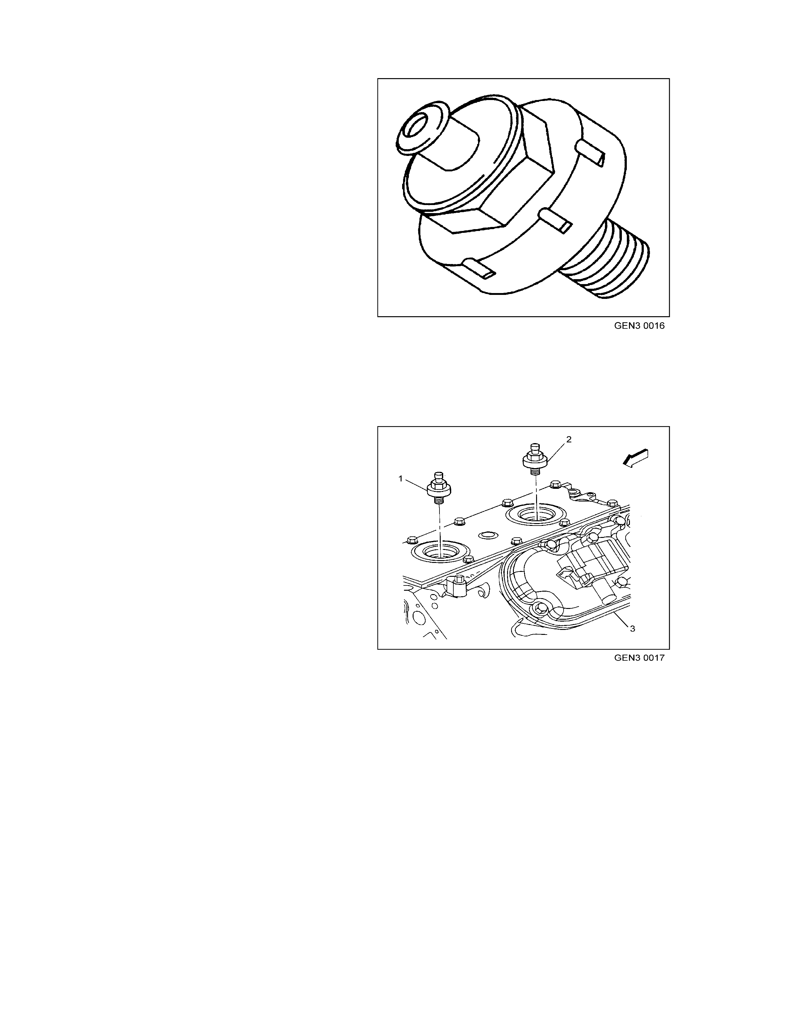
OIL PRESSURE SENSOR
The engine oil pressure sensor is a resistor which
changes value based on pressure and is mounted
to the rear left top of the engine.
The PCM su pplie s a 5 volt signal to the oil pres sur e
sensor through a resistor in the PCM and
measures the voltage on the signal circuit. By
measuring the voltage, the PCM calculates the
engine oil pressure and determines when to turn
ON the low oil warning lamp .
If t he low oil warning lamp st ays ON all the tim e, or
does not illuminate, more than likely there is a
problem with the instrument panel cluster or the
bulb. Using the Tech 2 scan tool to control the low
oil warning lamp will determine its operation.
When the PCM detects a malfunction in the oil
pressure sensor circuit, the following DTCs will set:
• DTC P0522: Engine Oil Pressure Circ uit
Low Voltage
• DTC P0523: Engine Oil Pressure Circ uit
High Voltage
Oil Pressure Sensor
1. Manifold Abso lute Pressure (MAP) Sensor
2. Camshaft Position (CMP) Sensor
3. Oil Pressure Sensor
4. Connector to Knock Sensor Jumper Harness
MANUAL TRANSMISSION REVERSE LOCKOUT SOLENOID
When the key is ON the PCM supplies an earth
signal to the reverse lockout solenoid, allowing
shifting into reverse. When the reverse lockout
solenoid is energised, the driver can shift the
transmission into reverse. The PCM enables the
reverse lockout solenoid whenever the vehicle
speed is below 3 km/h. When the vehicle speed is
above 5 km/h, the PCM will de-energise the
solenoid, which pr events t he driver from shifting the
transm ission into reverse.
GEN3 0147
21
Reverse Lockout Sol enoid
1. Reverse Lockout Solenoid
2. Reverse Lockout Harness Conn ector
BRA KE PEDAL SWITCHES
There are two electrical switches mounted on the
brake pedal support br acket.
Stop Lamp Switch
The stop lamp switch (4) is a normally open switch
that supplies B+ from fuse F5 to the rear brake
lamps when the brake pedal is depressed. It also
supplies 12 volts to the cruise control actuator and
a brake applied 12 volt input signal to terminal 14 of
the ABS or ABS/ETC control mod ule.
If the ABS or ABS/ETC control module does not
receive this sign al at star t up, t he ABS or ABS/ETC
self test will begin when vehicle speed is
approx imately 6k m/h. Should th e bra k es b e applied
before this initial ABS or ABS/ETC cycle, the self
test will not occur until the vehicle speed is
approximatel y 18 km/h.
Should the brake switch signal be received at any
time during Traction Control mode, the ABS/ETC
control module will inhibit Traction Control and
allow for manual braking. Engine torque
m anagem ent m ay still occ ur if necessary.
This stop lamp switch 12 volt signal is also used to
signal the cr uise c ontrol m odule to disengag e when
the brake pedal is depressed. For all service
operations on the stop lamp switch, refer to
Section 12B LIGHTING SYSTEMS of the VT
Series II Service Information.
Cruise Control Release Switch
The cruise electrical release switch (2) is a
normally closed switch, and supplies a 12 volt
signal from the Low Traction Lamp (through a
resistor adjacent to the Low Traction Lamp) to the
PCM, Cruise Control Actuator, and the ABS or
ABS/ETC module. When the brake pedal is
depressed, the 12 volt supply signal is removed
fr om th e PC M and the Cruise Control Actuator.
When the PCM determines that this 12 volt signal
has been removed, the PCM will disengage the
automatic transmission Torque Converter Clutch
(TCC) until this 12 volt signal is re-established to
the PCM. Also, the cruise control actuator will
deactivate the cruise control operation (the cruise
set speed will be retained in memory). Once the
brake pedal is released, the cruise set speed can
be re-established by selecting the cruise resume
switch.
GEN3 0181
1
2
3
4
5
6
Stop Lamp Switch Location
1. Cruise Electrical Re lease Switch Connector
2. Cruise Elect rical Release Switch
3. Stop Lamp Electrical Connector
4. Stop Lamp Switch
5. Brake Peda l Supp or t B r ac ket
6. Brake Pe da l A rm Asse mbly

Also, associated on this cruise electrical release
switch (2) circuit is the ABS/ETC module Low
Traction Lamp control. The ABS or ABS/ETC
module will supply an earth signal to the Low
Traction Lamp when traction control is being
requested. When the PCM receives this earth
signal the PCM will inhibit TCC operation and
activate the engine torque management operation.
The cruise control will also deact iva te operation.
If there is a problem with the circuit between the
Low Traction Lamp and the PCM, DTC P0719 or
P0724 will set.
Both switches are used to signal the cruise control
m odule s o th at if one sho uld f ail, the sec ond switc h
will still generate a signal to the cruise control
module to disengage the cruise control operation.
For all service operations on the cruise electrical
release switch, Refer to Section 12E CRUISE
CONTROL of the VT Series II Service Information.
1.4 FUEL CONTROL SYSTEM
SYSTEM OVERVIEW
An electric fuel pump, located in the fuel tank with
the fuel sender assembly, pumps fuel through an
in-line f uel f ilter t o the fu el rail a ssem bly. The pum p
provides fuel at a pressure greater than is needed
by the inject or s. The fuel pr es su re re gulator, pa rt of
the fuel sender assembly, keeps fuel available to
the injectors at a regulated pressure. A separate
pipe ret ur ns unused fuel to the fuel tank.
COMPONENTS
Fuel Tank Vent Valve
The f uel ta nk vent valve is loc ated in the r ear of the
vehicle near the fuel tank. The fuel tank vent valve
is a pressure/vacuum relief valve. When the fuel
tank pressure exceeds a specified pressure, the
valve opens allowing the tank pr essur e to bleed off.
When the fuel tank is in a vacuum condition, the
vent valve opens when the vacuum is within a
spec ified rang e allowing fresh air to be pulled in.
Fuel Tank
The fuel tank is constructed from a special plastic
and is located under the rear compartment floor. It
is secured to the vehicle by three metal straps that
attach to the fram e.
Fuel Tank Filler Pipe
The fuel tank filler pipe has a built-in resistor and
deflector in order to prevent refueling with leaded
fuel.
Fuel Filler Ca p
NOTE: If a fuel filler ca p requires replac ement , use
only a fuel filler cap of the s ame type. Failure to use
the correct fuel filler cap can result in a serious
m alfunc tion of the fuel and evaporative systems.
The fuel filler cap incorporates a torque-limiting
device which prevents the cap from being over
tightene d. T o ins tall the cap, t urn the cap clock wise
until you hear three audible clicks. This indicates
that the cap is correctly torqued and fully seated.
Fuel Filler Cap
Fuel Sender Assembly
The fuel sender assembly, mounted inside the fuel
tank, is att ached t o th e top of t he fu el tank . The f uel
sender assembly consists of the following major
components:
• The fuel level sensor
• The fuel pump
• The fuel pressure regulator
• The fuel pump strainer
NOTE: The only serviceable part of the fuel sender
assembly is the fuel lever sensor. All other
components require replacement of the complete
fuel sender assem bly.
Fuel Pump
The fuel pump attaches to the fuel sender
asse m bly inside the f uel ta nk an d is an elec t ric high
pressure gear rotor pump. The fuel pump provides
fuel t o the fuel r ail as sem bly at a sp ecified flow and
pressure. Excess fuel returns to the fuel tank by the
return pipe.
The fuel pump delivers a constant flow of fuel to the
engine even during low fuel conditions and
aggres sive vehicle m anoeuvres. T he PCM controls
the electric fuel pump operation through a fuel
pump relay. The fuel pump flex pipe has a quick-
connect f itting . T he fu el r eturn hose a ttaches to the
fuel pressure regulator. The fuel pump flex pipe
acts to dampen the fuel pulses and noise
generated by the fuel pump.
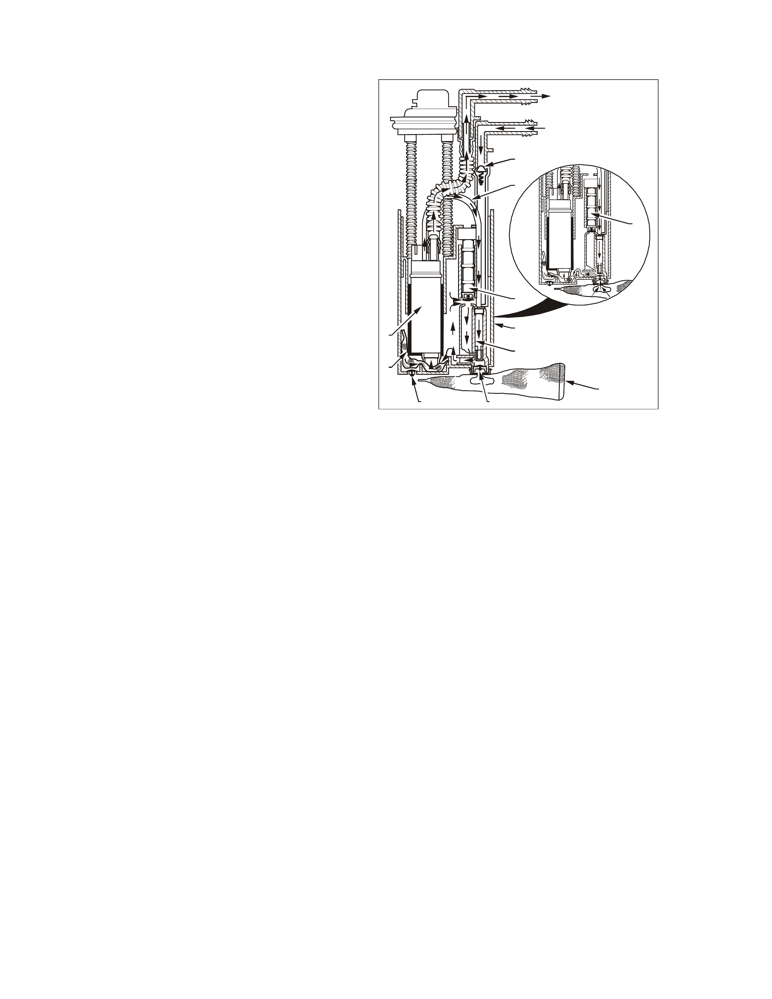
T26C3007
T8A1001
10
3A
2
9
6
4
8
51
3B
7
A
Fuel Se nder Assembly
1. Primary Umbrella Valve
2. Reservoir
3. Floating J e t Pump (“a” High Fuel / “b” Low Fuel)
4. Internal Filter Screen
5. Secondary Umbr ella Valve
6. Gerotor Fuel Pum p
7. Diverter Pipe
8. External Filter Screen
9. Jet Pump Filter Screen
10. Pressure Re lief Valve
Fuel Pres s ur e Re gula tor Assembly
The fuel pressure regulator is a part of the fuel
sender assem bly fuel r eturn pipe . It is a diaphragm
operated relief valve. A soft ware bias com p ensat es
the injector on-time because the fuel pressure
regulator is not referenced to manifold vacuum.
The fuel injector pulse width varies with the signal
fr om the MAP s ensor . Wit h the ignitio n ON and the
engine OFF, system fuel pressure at the pressure
test connection should be 380- 440 kPa ( 55-62 psi).
If the pressure is too low, poor performance could
result. If the pressure is too high, excessive odor
and a Diagnostic Trouble Code (DTC) P0132,
P0152, P0172, or P0175 may result. Refer to Fuel
System Diagnosis in Section 6C3-2A
DIAGNOSTIC TABLES – GEN III V8 Engines of
this Service Information CD for information on
diagnos ing fuel pr essure conditions.
Fuel Pump Stra ine r
The f uel pum p s trainer attac hes to the lower end of
the fuel pump and the lower end of the fuel return
pipe. The fuel pump strainer is made of woven
plast ic. T h e funct ions of t he fu el pump s trainer is to
filter contaminant s and to wick fuel.
The fuel pump strainer is self-cleaning and
normally requires no maintenance. Fuel stoppage
at this point ind icates tha t the fuel tank contains an
abnormal amount of sediment or water. Clean the
fuel tank and replace fuel sender assembly.
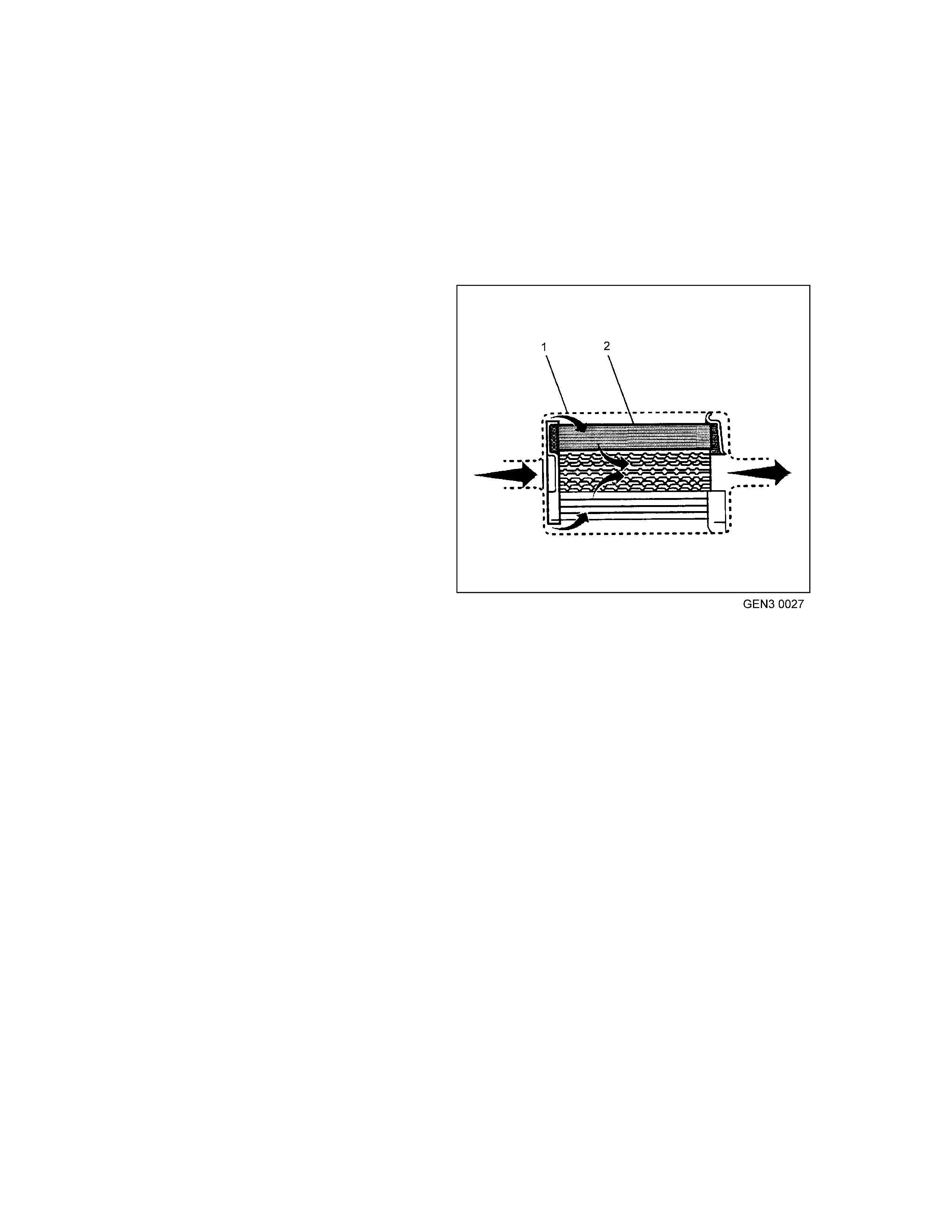
In-Line Fuel Filter
The fuel f eed pipe has a steel filter installed ahead
of the fuel injection system. The paper filter
element (2) traps particles in the fuel that may
damage the injection system. The filter housing (1)
is made to withstand maximum fuel system
pressure, exposure to fuel additives, and changes
in temperature. The inlet fitting is a quick-
disconnect and a the outlet is a threaded fitting
which is sealed with an O-ring. The fuel filter is to
be changed at prescribed service intervals, refer to
Section OB, Lubrication & Service of the VT
Series II Service Information. A restricted fuel filter
shou l d be replac ed.
Fuel Feed and Return Pipes
The fu el fee d pipe car ries f uel f rom the f uel tank to
the fuel rail assembly. The fuel return pipe carries
fuel from the T -connector located on the outlet side
of t he fuel f ilter back to t he fu el ta nk . The fu el pipes
cons ist of three sections:
• The rear fue l pipe assemblies are located from
the top of the fuel tank to the chassis fuel
pipes. The rear fuel pipes are constructed of
nylon.
• The chassis fuel pipes are located under the
vehicle and connect the rear fuel pipes to the
engine compartment connecting fuel pipe.
These pipes are constructed of steel.
• The engine compartment connecting fuel pipe
connects the chassis fuel pipe to the engine
fuel rail. T his fu el pi pe is constructed of nylon.
In-line Fuel Filter
1. Fuel Filter Housing
2. Paper Filter Element
Nylon Fuel Pipes
CAUTION: In order to Reduce the Risk of Fire
and Personal Injury:
• If nylon fuel pipes are nicked, scratched or
damaged during installation, Do Not
attempt to repair the sections of the nylon
fuel pipes. Replace them.
• When installing new fuel pipes, Do Not
hammer directly on the fuel harness body
clips as it may damage the nylon pipes
resulting in a pos sible l eak.
• Always cover nylon vapour pipes with a
wet towel before using a torch near them.
Also, never expose the vehicle to
temperatures higher than 115°C (239°F) for
more than one hour, or more than 90°C
(194°F) for any extended period.
• Before connec ting fuel pipe fittings, alw ays
apply a few drops of clean engine oil to the
male pipe ends. This will ensure proper
reconnection and prevent a possible fuel
leak. During normal operation, the O-rings
located in the female connector will swell
and may prevent proper reconnection if not
lubricated.
Nylon fuel pipes are designed to perform the sam e
job as the steel or flexible fuel pipes or hoses that
they replace. Nylon pipes are constructed to
withstand maximum fuel system pressure,
exposure to fuel additives, and changes in
temperature. There are three sizes of nylon pipes
used: 3/8” ID for the fuel feed, 5/16” ID for the fuel
return, and 1/2" ID for the vent
Heat resistant rubber hose and/or corrugated
plastic con duit pro tect the section s of the pipes that
are exposed to chafing, high temperature or
vibration.
NOTE: Nylon fuel pipes are som ewhat flexible and
can be formed around gradual turns under the
vehicle. Howeve r, if nylon f uel pipes a re forc ed into
sharp be nds, the pipes will kin k and restric t the fuel
flow. Also, once exposed to fuel, nylon pipes may
become stiffer and are more likely to kink if bent
too far. Take special care when working on a
vehicle with nylon fuel pipes.
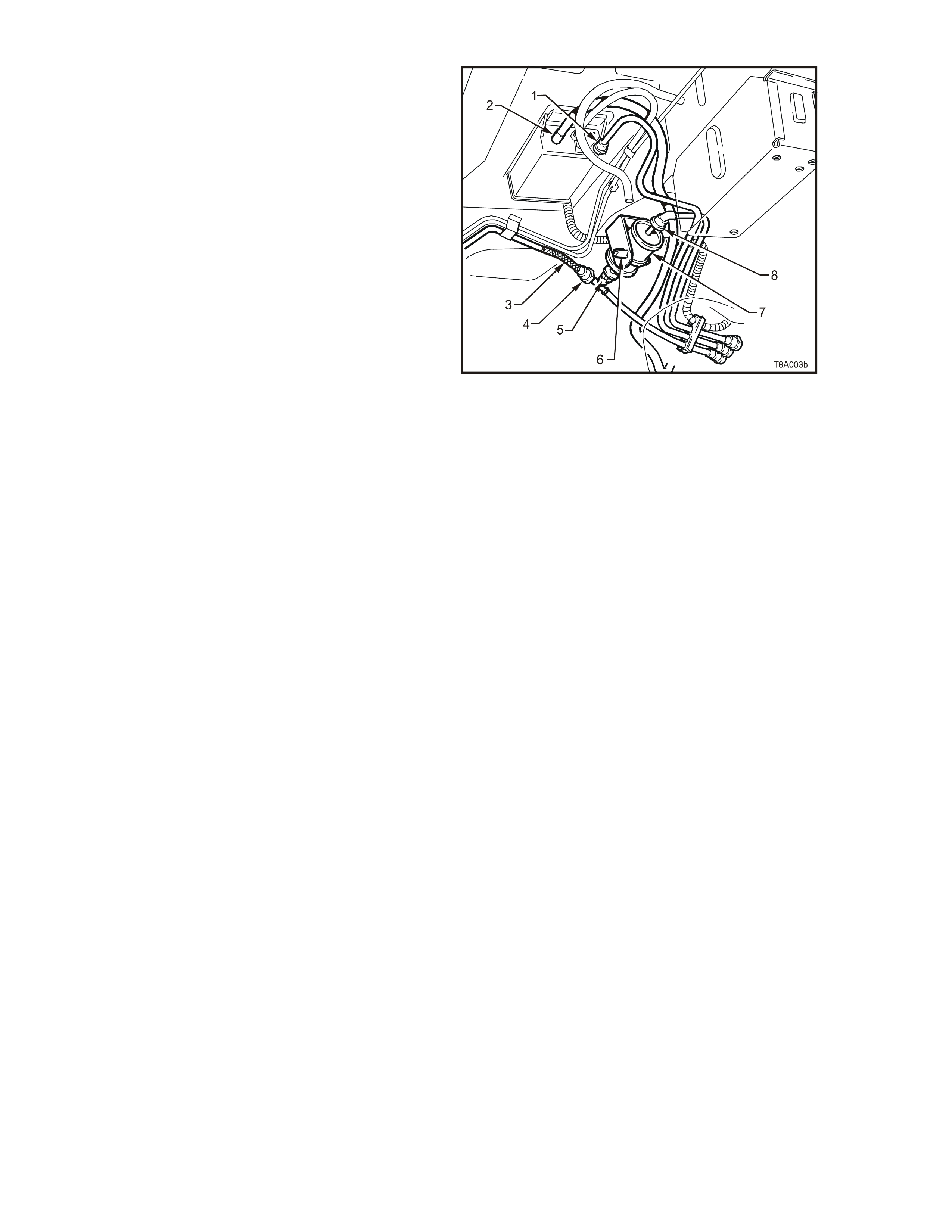
Fuel Filte r Locati on View
1. Q uick Connect, F uel Tank Vapour Line to Caniste r
2. Hos e, Filler Neck Breather
3. Flexible Line, Fuel Feed to Engine
4. Quick Connect, Fuel Feed Line
5. Q uick Connect, F uel Filter T-piece
6. Ret aining Tangs, Fuel Filter Strap
7. Filter, Fuel
8. Quick Connect, Fuel Fee d Line fro m Fue l Tank

Quick-Connect Fittings
Quick -co nnect f ittings provide a sim plif ied m eans of installing and conn ecting f uel system com ponents . The fit tings
cons ist of a unique female connector and a compatible male pipe end. O-rings, located inside the f emale c onnecto r ,
provide the fuel s eal. Integral locking tabs or fingers hold the f ittings toge ther.
Fuel Pipe O-Rings
O-r ings s ea l the thr eade d c on nec tio ns in the f uel system and are mad e of sp ec ial m a ter ial. Ser vice the O -r ing s eals
with the correct servic e part.
Evapo rativ e Pipes and Hoses
The evaporative pipes extend from the fuel sender assembly and the evaporative canister vent solenoid to the
evaporative canister. The evaporative purge pipe extends from the evaporative canister to the evaporative purge
valve in the engine compartment. The rear pipes and the engine compartment pipe are constructed of nylon. The
chas sis evapora tive purge pipe is constructed of steel.
FUEL MET ERING MO DES OF O PERATION
Modes Of Ope ration
The PCM looks at voltages from several sensors to determine how much fuel to give the engine. The fuel is
delivered under one of several conditions called modes. The PCM controls all modes.
Starting Mode
Wit h the ign ition s witch in the O N po sition (b ef ore en gaging the st arter ), t he PCM ene rgis es the fuel pum p relay f or
two seconds, allowing the fuel pump to build system pressure. The PCM first checks speed density, then switches
to t he Mass Air Flow (MAF) sensor. T he PCM als o uses th e Engine Coolant T em perature (E CT), T hrottle Posit ion
(TP) , and Manif old Absolute Pres sure (MAP) sensors to dete rmine the proper air/fue l ra tio f or star ting. This ranges
from 9.7:1 to 14.7:1 depending on coolant temperature. The PCM controls the amount of fuel delivered in the
star ting mo de by changing the pulse width of the injectors. This is done by pulsin g the injectors for very short times.
Clear Flood Mode
If t he engine floods, clear the engine by press ing the accele rator pedal down all the way. The PCM then pu lses the
injec tor s at an air/ f uel ratio of 2 0: 1. T he PC M ho lds this inj e ctor r ate a s long as the thr ot tle stays wide open an d the
engine speed is below 300 RPM. If the throttle position becomes less than 80 percent, the PCM returns to the
starting mo de.
Run Mode
The r un m ode has two conditions called Open Loop, and Close d Loop. When th e engine is firs t sta rted, and engine
speed is above a predet ermined RPM, the system begins O pen Loop opera tion. The PCM ignores t he signal fr om
the Hea ted O xygen Senso r (HO 2S) and c alculates the air /f uel rat io based on inputs f rom the ECT , MAF, MAP, and
TP sensors. The sy stem stays in Open Loop until meeting the following conditions:
• Both HO 2S have varying voltage output, showing that they are hot enoug h to operate prope rly. (T his depends
on te mperature.)
• The Engine Collan t Temperature (ECT) s ensor is above a specified temperatur e.
• A spec ific amount of time has elapsed after starting the engine.
Specific values for the above conditions exist for each different engine, and are stored in the Electrically Erasable
Programmable Read Only Memory (EEPROM). The system begins closed loop operation after reaching these
values. In Closed Loop, the PCM calculates the air/fuel ratio (injector on-time) based on the signal from various
sensors, but mainly the HO 2S. T his allows th e air /fuel r atio to stay very close to 14.7:1.

Acceleration Mode
W he n the drive r presse s on the ac celerator pedal, air flow into the cylinder s increases rapidly, while fuel flow tends
to lag behind. To prevent possible hesitation, the PCM increases the pulse width to the injectors to provide extra
fuel ac celerat ion. The PCM det erm ines the am ount of fuel requir ed based on throttle pos ition, coola nt tempe ratur e,
m anifold air pr essure, mass air flow and engine speed.
Decele r ation Mode
When the driver releases the accelerator pedal, air flow into the engine is reduced. The PCM looks at the
corresponding changes in throttle position, manifold air pressure and mass air flow. The PCM shuts OFF fuel
com pletely if the decelerat ion is very rapid, or f or long p eriods (such as long c losed throttle c oast- down). T he fuels
shuts O FF in order to protect the warm-up three-way catalytic converters .
Battery Voltage Correct ion Mode
When battery voltage is low, the PCM compensates for the weak spark delivered by the ignition system in the
following ways:
• Inc r easing th e amoun t of fuel delivered.
• Increasing the idle RPM.
• Increasing ignit ion dwell time .
Fuel Cut OFF Mode
To prevent possible engine damage from over-speed, the PCM cuts off fuel from the injectors when the engine
speed is above approximately 6200 RPM. Also, see Rapid Deceleration in Deceleration Mode.
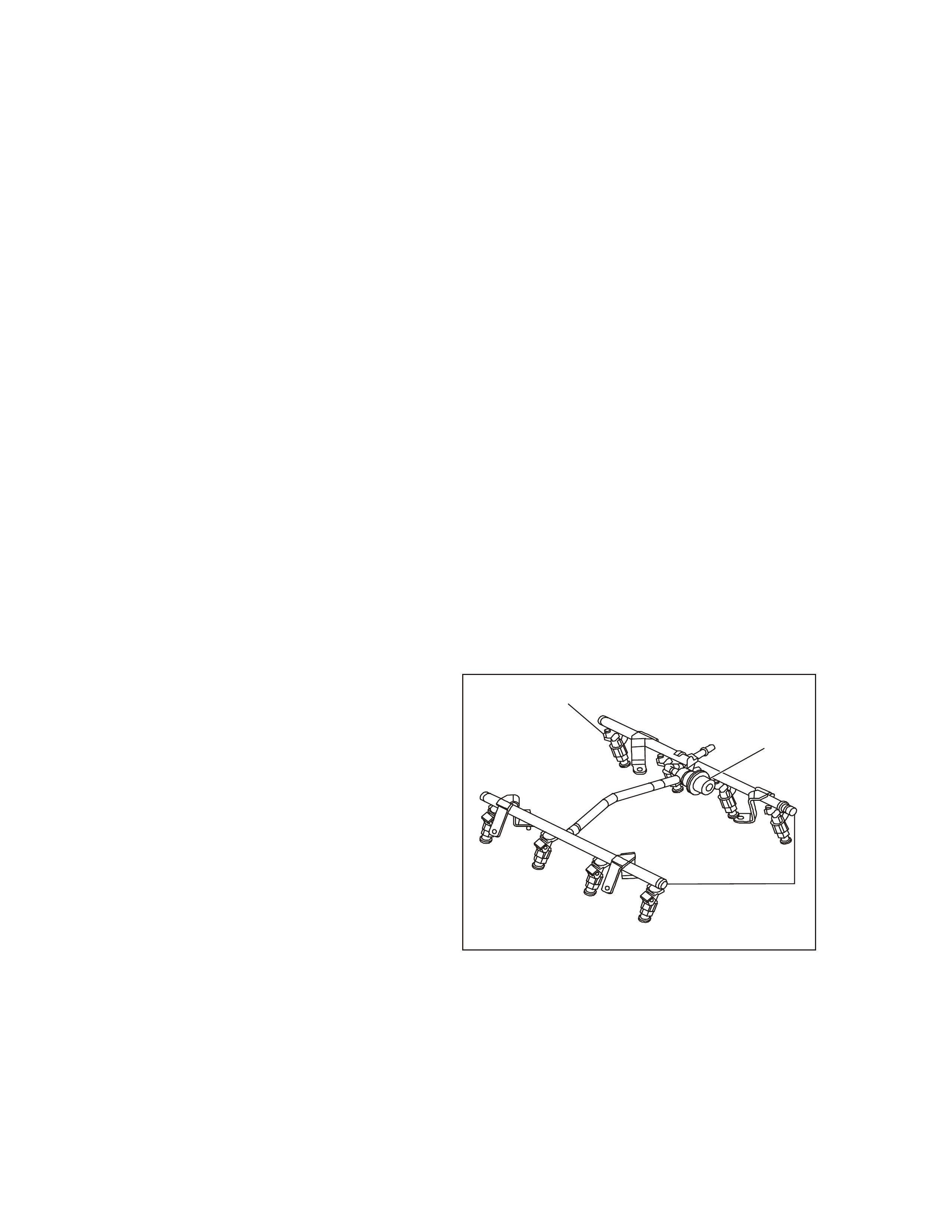
FUEL METERING SYSTEM COMPONENT DESCRIPTION
The fuel m ete ring s ystems c onsist s of the following
parts:
• The fuel supply components(fuel tank, pump,
pipes).
• The fuel pump elec trical circuit.
• The fuel rail.
• The fuel injectors.
• The fuel pr essur e regulat or.
• The throttle body.
• The Idle Air Contro l (IAC) valve.
• The Throttle Position Sensor.
System Overview
An electric fuel pump, located in the fuel tank with
the fuel sender assembly, supplies fuel through an
in-line fuel filter at a pressure greater than is
needed by the injectors. The fuel pressure
regulator, part of the fuel sender assembly, keeps
fuel available to the injectors at a regulated
pressure. A separate pipe returns unused fuel to
the fuel tank.
Fuel Pump Electrical Circuit
When the ignition switch is in the ON position
(before engaging the starter), the PCM energises
the fuel pump relay for two seconds, causing the
fuel pump to pre ss ur is e the f u el system . If the PCM
does not receive ignition reference pulses (engine
cranking or running) within two seconds, it shuts
OFF the f uel pump relay, c ausing the fuel pum p to
stop.
Fuel Rail Assembly
The fuel rail as sembly attaches to the en gine intak e
m anifold and performs the following functions:
• It positions the injectors (1) in the intake
manifold.
• It distr ibutes fuel evenly to the injectors.
• It integrates the fuel pulse dampener into the
fuel me tering system.
GEN3 0029
1
2
3
Fuel Rail Assembly
1. Fuel Injector
2. Fuel Pulse Dampener
3. Fuel Rail
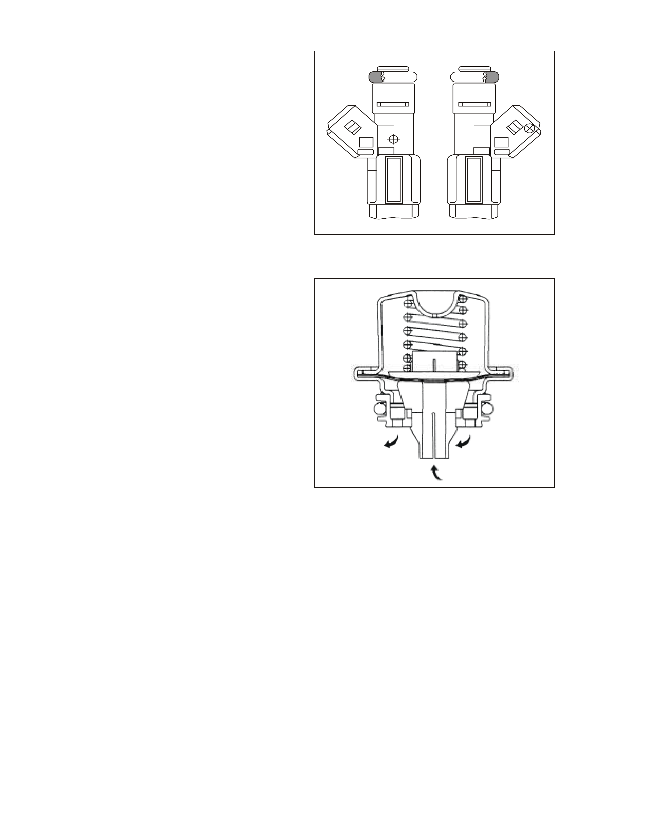
Fuel Injec tors
The top-feed fuel injector assembly is a solenoid
operated device, controlled by the PCM, that
m eters p ressu rised f uel to a single en gine cylinder.
The PCM energises the injector solenoid, which
opens a ball valve, allowing fuel to flow past the ball
valve, and through a recessed flow director plat e.
The director plate has multiple machine holes that
control the fuel flow, generating a conical spray
pattern of finely atomised fuel at the injector tip.
Fuel is directed at the intake valve, causing it to
become further atomised and vaporised before
enter ing the co mbustio n cha mber . An injec to r st uc k
partly open can cause a loss of pressure after
engine shutdown. Consequently, long cranking
tim es would be notic ed on som e engines.
GEN3 0030
Fuel Inje ctor
Fuel Puls e Da mpe ner
The fu el puls e dam pener att aches inside a housing
on the f uel rail as sem bly. The fue l pulse dam pener
is diaphr agm operate d, with f uel pum p pres sure o n
one s ide and spr ing pre ssur e of th e other side. T he
function of the dampener is to reduce fuel
pulsat ion.
GEN 3 00 31
Fuel Pul se Dampener
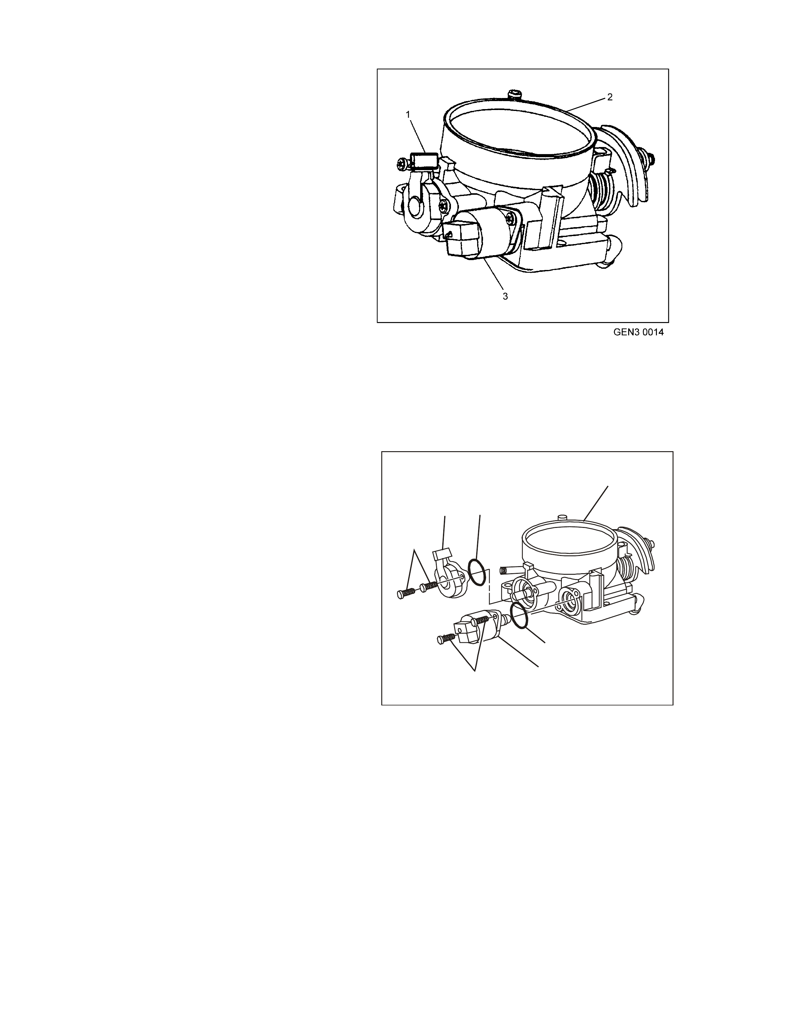
Accelerator C ontrol s
The accelerator control system is cable operated.
Two different type of accelerator control cable
systems are used, one where Electronic Traction
Control (ETC) is fitted and the other without ETC.
Therefore use the specific cable for each
application. Cable adjustment is provided on the
throttle cable, refer to Section 6C3-3 SERVIE
OPERATIONS – G EN III V8 Engine of this Servic e
Information CD.
Throttle Body Assembly
The throttle body assembly attaches to the intake
manifold and controls air flow into the engine,
there by c ontrolling engine output . The dr iver opens
the throttle valve within the throttle body through the
acce lerator c ontrols. During engine idle, t he throttle
valves are almost closed. A fixed air bypass orifice
and the Idle Air Control (IAC) valve (3) control the
air f low.
Engine c oolant f lows thr ough a coolant cavity in the
bottom of the throttle body and prevents throttle
valve icing during cool weather operation. The
throt tle body also provid es the locati on for mount in g
the Throttle Position (TP) sensor ( 1).
Throttle Body Assembl y
1. TP Sensor
2. Throttle Body Assembly
3. IAC Valve
Throttle Position (TP) Sensor
The T hr ot tle Position ( TP) s ens or is m o unted to th e
throttle shaft on the throttle body. The T P sensor is
a potentio m e ter which is s upp lied a 5 volt reference
and an earth circuit from the PCM. The signal
circuit connects from a sliding contact in the TP
sensor to the PCM. This allows the PCM to
measure the voltage from the TP sensor. As the
throttle is depressed, the output of the TP sensor
changes. At a closed throttle position, the outp ut of
the T P sen sor is be low 1.25V. As t he throttle valve
opens, the output increases. At a wide-open
throttle, the TP sensor output voltage should be
greater than 4 volts.
Speed Density System Description
Three specific data sensors provide the PCM with
the basic information for the fuel management
portion of its operation. That is, three specific
signals to the PCM esta blish the en gine speed and
air density factor s. Th e engine s peed signal come s
fr om the ignition system .
The PCM us es this infor mation to determine eng ine
speed (RPM). Air density is derived from IAT and
MAP sensor inputs. The IAT sensor measures the
air tem per ature that is enter ing the eng ine. Th e IAT
signal works in conjunction with the MAP sensor to
determine air density. As the intake manifold also
increases and additional fuel is required. This
inform ation f rom the IAT an d MAP sensors is used
by the PCM to control injector pulse width.
The speed density system is used to :
1. Monitor Mass Air Flow (MAF) sensor operation
(to determine if there is a MAF sensor
malfunction).
2. T ake over f ueling manage m e nt oper atio n when
there is a Mass Air Flow (MAF) sensor
malfunction.
GEN3 0032
1
2
3
4
5
67
Throttle Position ( T P) Se nsor
1. Throttle Body
2. IAC Valve O-Ring
3. IAC Valve
4. IAC Valve Attaching Screws
5. TP Sensor Attaching Screws
6. TP Sensor
7. TP Sensor Seal

Short Term Fuel Trim Description
The short term fuel trim is a PCM erasable memory register. The neutral value for the short term fuel trim is 0%.
Any deviation from 0% indicates the short term fuel trim is changing the injector pulse width. The amount of pulse
width c hange de pends on how far the short term fuel trim valu e is from 0%. The short term fu el trim is rich when the
scan tool indicates -99%.
The short fuel trim is lean when the scan tool indicates 99%. The short term fuel trim changes the pulse width by
varying the Closed Loop factor of the base pulse width e quation.
As the PCM monitors the oxygen sensors input it, is constantly varying the short term fuel trim vale. The value is
updated very quickly, therefore, the shor t ter m fuel trim only corrects for short te rm mixture tre nds. T he corr ection of
long ter m mixture tren ds is the f unction of long term fuel trim.
When the PCM determines t hat the Short Term Fuel T r im is ou t of the operating range, the following DTCs will s et:
• DTC P0171: Bank 1 Too Lean
• DTC P0172: Bank 1 Too Rich
• DTC P0174: Bank 2 Too Lean
• DTC P0175: Bank 2 Too Rich
Long Term Fuel Trim Description
The long term fuel trim is a matrix of cells arranged by RPM and MAP. Each cell of the long term fuel trim is a
register like t he s hor t t erm f u el tr im . As the engin e ope rat ing c ondition s ch ang e, the PCM will switch fr om c ell to ce ll
to determine what long term fuel trim factor to use in the base pulse width equation.
While in any given cell, the PC M also m onitors the short term fuel t rim . If the shor t term f uel trim is f ar enoug h from
0%, the PCM will change the long term fuel trim value. On ce the long term fuel trim value is chan ged, it shou ld force
the short term fuel trim back toward 0%. If the mixture is still not correct (as judged by the HO2S), the short term
fuel trim will continue to have a large deviation from the ideal 0%.
In this case, the long term fuel trim value will continue to change until the short term fuel trim becomes balanced.
Both the short term fuel trim and long term fuel trim have limits which vary by calibration. Both the short term fuel
trim and long term fuel trim have limits that var y by calibration. If the mixt ur e is so far out of range that the long term
fuel trim reaches th e lim it of control withou t correcting the condition, the shor t term f uel trim will also go to its lim its
of control in the same direction. If the mixture is still not corrected by both short term fuel trim and long term fuel
trim at their extreme values, a Fuel T rim Diagnost ic Trou ble Code (DTC) will likely result .
When the PCM determines t hat the Long Term Fuel Trim is out of the operating ra nge, the following DTC s will s et:
• DTC P0171: Bank 1 Too Lean
• DTC P0172: Bank 1 Too Rich
• DTC P0174: Bank 2 Too Lean
• DTC P0175: Bank 2 Too Rich
Under the conditions of power enrichment, the PCM sets the short term fuel trim to 0% and freezes it there until
power en richment is no longer in effe ct. This is done so the Closed Loop factor and the long term fuel trim will not
try to correct for the com man ded richness of power enrichment.
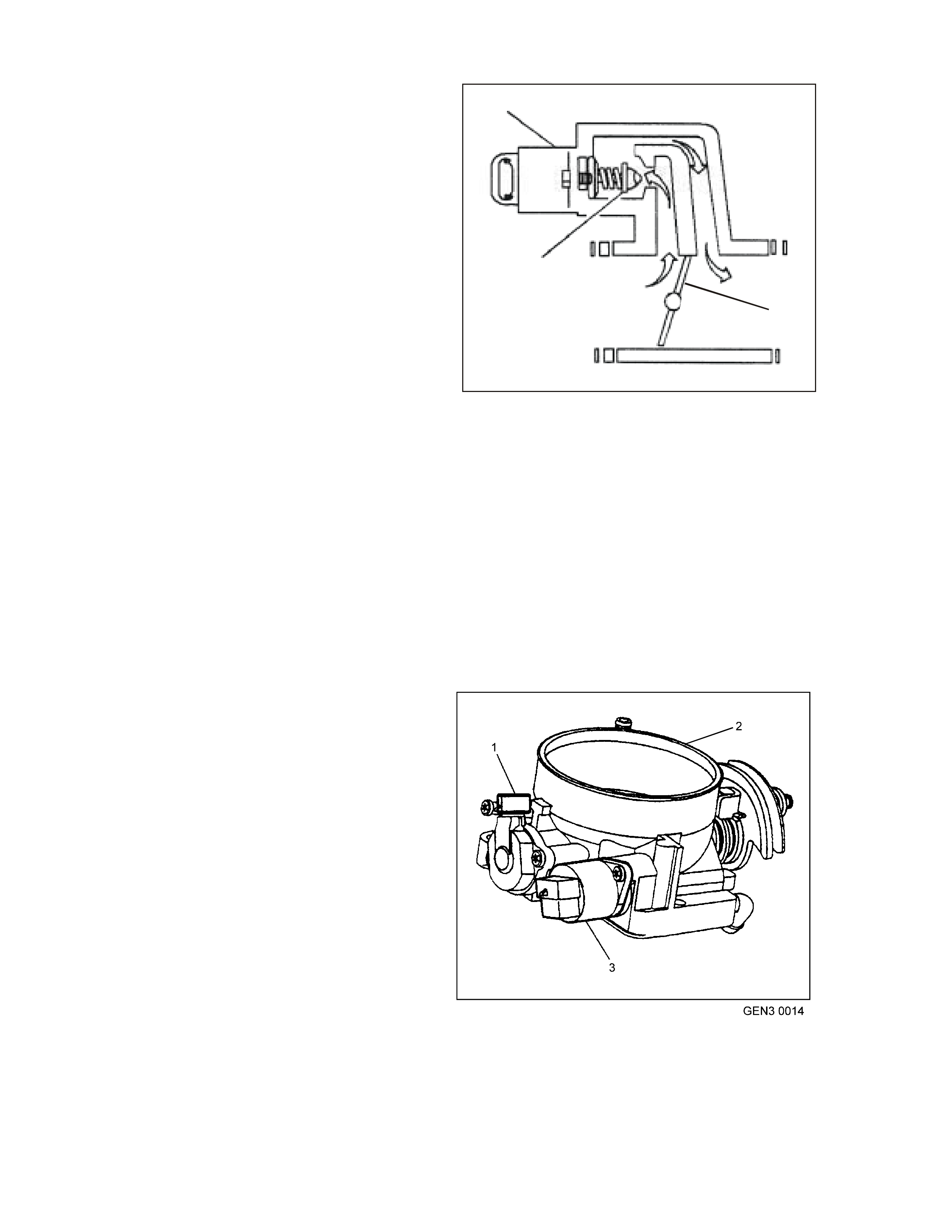
1.5 IDLE AIR CONTROL (IAC) VALVE
The purpose of the Idel Air Control IAC valve is to
control engine idle speed, while preventing stalls
due to changes in engine load. The IAC valve,
mounted in the throttle body, controls a portion of
the bypass air . An orifice loc ated in th e throt tle body
also supplies a constant amount of bypass air.
By moving a conical valve, known as a pintle, in
towards the seat ( to decre ase air f low); or out away
from the seat (to increase air flow), a controlled
amount of air can be bypassed. If engine speed is
too low, more air is bypassed to increase RPM. If
engine speed is too high, less air is bypassed to
decrease RPM.
The PCM moves the IAC valve in small steps,
called counts. These can be measured and
displayed by a Tech 2 scan tool, which plugs into
the Data Link Connector (DLC). The PCM
calculates the proper position of the IAC valve
during idle, based on battery voltage, coolant
temperature, engine load, and engine RPM. If the
RPM drops below specification and the throttle
valve is closed, the PCM senses a near stall
condition and calculates a new valve position in
order to prevent stalling.
• Engine idle speed is a func tion of total air flo w
into the engine. Idle speed is based on IAC
valve pintle position + crankcase ventilation
valve flow + throttle valve opening + bypass
orifice air flow + calibrated vacuum loss
thr ough accessories.
• Controlled idle speed is programmed into the
PCM, which determines the correct IAC valve
pintle position to maintain the desired idle
speed for all engine operating conditions and
loads.
GEN3 0033
1
3
2
Idle Air Cont rol (IAC) Valve Air Flow
1. IAC Valve
2. Throttle Plate
3. IAC Valve Pintle
• The minim um idle air rate is set at the factory
with a stop screw. This setting allows enough
air flow by the throttle valve to cause the IAC
valve pintle to be positioned a calibrated
number of steps (counts), from the seat,
durin g controlled idle operation.
IDLE AIR VALVE POSITION RESET
If the IAC valve is disconnected and reconnected
with the engine running, the idle speed may be
wrong. If this occurs, reset the IAC valve by
depressing the accelerator pedal slightly, start and
run the engine for five seconds, then turn the
ignition OFF for ten seconds.
IAC Valve Location
1. TP Sensor
2. Throttle Body
3. IAC Valve

1.6 ELECTRONIC IGNITION SYSTEM
IGNITION SYSTEM OVERVIEW
The electronic ignition system controls fuel combustion by providing a spark to ignite the compressed air/fuel
mixture at the correct time. To provide optimum engine performance, fuel economy, and control of exhaust
emissions, the PCM controls the spark advance of the ignition system. The Electronic ignition system has the
following advantages over a mechanical distributor system:
• No moving parts.
• Les s maintenanc e.
• Remote mounting capability.
• No mechanical load on the engine.
• More coi l cool down time be t w e en firing events.
• Elim ination of mec hanical timing adju s tments.
• Incr eased available ignition coil satur at ion time .
The ele ctr on ic ignit ion s ystem d oes not us e the co nventi onal dis t ribu to r a nd c oil. The ignitio n system co ns ists of the
following components/circuits:
• Eight ignition coils/modules
• Eight Ignition Control (IC) circuits
• Camshaft Position (CMP) sensor
• 1X Camshaft reluctor wheel
• Cranksh aft P os ition (CKP) se ns or
• 24X Crankshaft reluctor wheel
• Related connecti ng wire s
• Powertrain C ontrol Module (PCM)
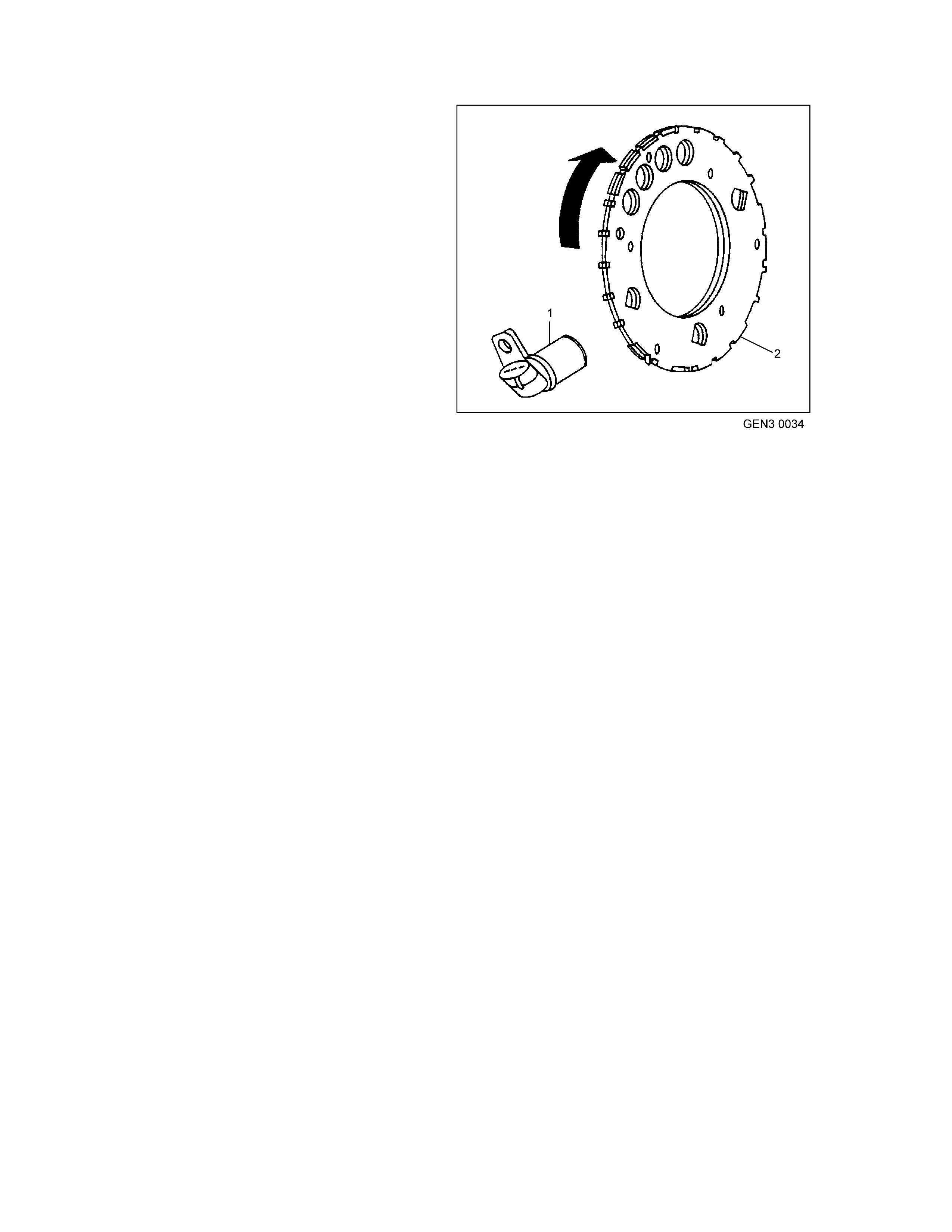
COMPONENTS
Crankshaft Position Sensor (CKP) and Reluctor Wheel
The Crankshaft Position (CKP) sensor is located in
the right r ear of the engine, behind the s tarter and is
a dual m agnet o re sis tive type sens or . T his sens or is
not speed dependent. The dual micro switches
monitor both notches of the reluctor wheel for
greater accuracy. The CKP sensor works in-
conjunction with a 24X reluctor wheel.
The reluctor wheel is mounted on the rear of the
crankshaft. The 24X reluctor wheels use two
different width notches that are 15 degrees apart.
This pulse width encoded pattern allows cylinder
position identification within 90 degrees of
crankshaft rotation. In some cases, cylinder
identification can be located in 45 degrees of
crankshaft rotation. This reluctor wheel also has
dual track notches that are 180 degrees out of
phase. The dual track design allows for quicker
starts and accuracy.
The PCM also receives a 4X signal from the
crankshaf t pos it ion se nso r. T h e PCM u tilis es the 4X
signal for the following:
• Misfire
• Tachometer output
• Spark control
• Fuel Control
• Certain diagnostics
The CKP signal m ust be available for the engine to
start. The CMP signal is not needed to start and
operate the engine. T he PCM can determine when
a particular cylinder is on either a firing or exhaust
stroke by the 24X signal. The CMP sensor is to
determine what stroke the engine is on. The
system will attempt to synchronise and look for an
increa se in the MAF s ignal. An increase in the MAF
signal indicates the engine has started. If the PCM
does not detect an increase in the MAF signal, a
re-sync will occur to the opposite cam position. A
slightly longer cranking time may be a symptom of
this condition.
Crankshaft Positi on Sensor and Rel uctor Wheel
1. CKP Sensor
2. Reluctor Wheel
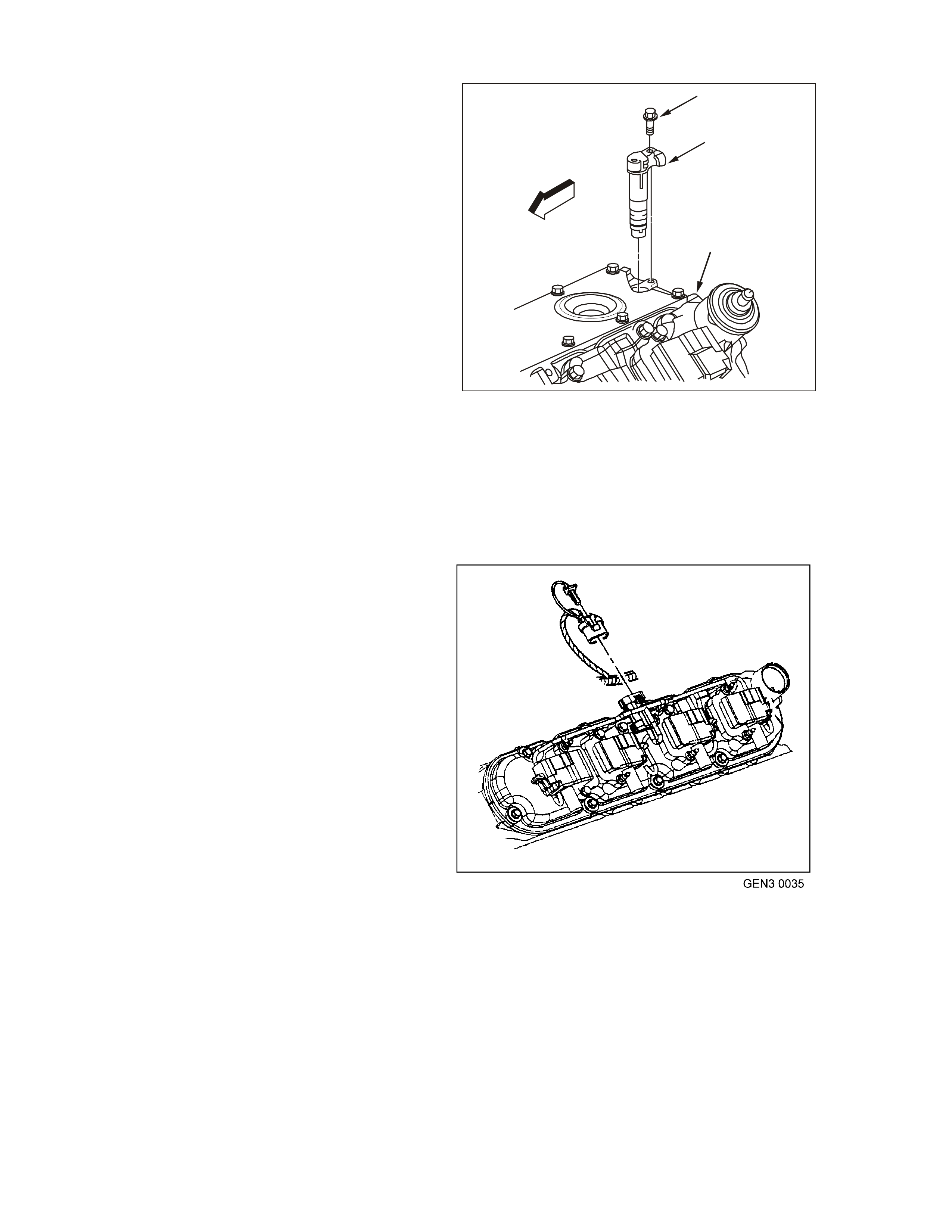
Camshaft Position Sensor (CMP)
The Camshaft Position (CMP) sensor is mounted
through the top of the engine block at the rear of
the valley cover. The CMP sensor works in-
conjunction with a 1X reluctor wheel. The reluctor
wheel is located at the rear of the camshaft. The
CMP sensor is used to determine whether a
cylinder is on the firing or the exhaust stroke. As
the cam s ha f t rot ates , t he relu ctor wheel interr u pts a
magnetic field produced by a magnet within the
sensor. The CMP sensor internal circuitry detects
this and produces a signal which is used by the
PCM. The PCM uses this signal in combination
with the CKP 24X signal to det ermine to crank shaft
posit ion and stroke.
The CKP signal m ust be available for the engine to
start. The CMP signal is not needed to start and
operate the engine. T he PCM can determine when
a particular cylinder is on either a firing or exhaust
stroke by the 24X signal. The CMP sensor is to
determine what stroke the engine is on. The
system will attempt to synchronise and look for an
increa se in the MAF s ignal. An increase in the MAF
signal indicates the engine has started. If the PCM
does not detect an increase in the MAF signal, a
re-sync will occur to the opposite cam position. A
slightly longer cranking time may be a symptom of
this condition.
GEN3 0022
1
2
3
Camshaft Position (CMP) Sens or
1. CMP Mou nting Bolt
2. CMP Sensor
3. Top Rear of Engine Block
Ignition Coils/ Module
The ignition system on this engine features a
m ultiple coil ignition and is k nown as coil near plug.
The secondary ignition wires are short compared
with a distributor ignition system wire. Eight ignition
coils/m odules are individually mounted above each
cylinder on the rocker covers and fire sequentially.
There is an Ignition Control (IC) circuit for each
ignition coil/module. The eight ignition control
circuits are connected to the PCM. All timing
decisions are made by the PCM, which triggers
each co il/module individually.
The ignition coil/ modules are supplied with the
following circuits:
• Ignition feed circuit
• Ignition control circuit
• Earth circuit
• Reference low circuit
Ignition Coils/Module Location
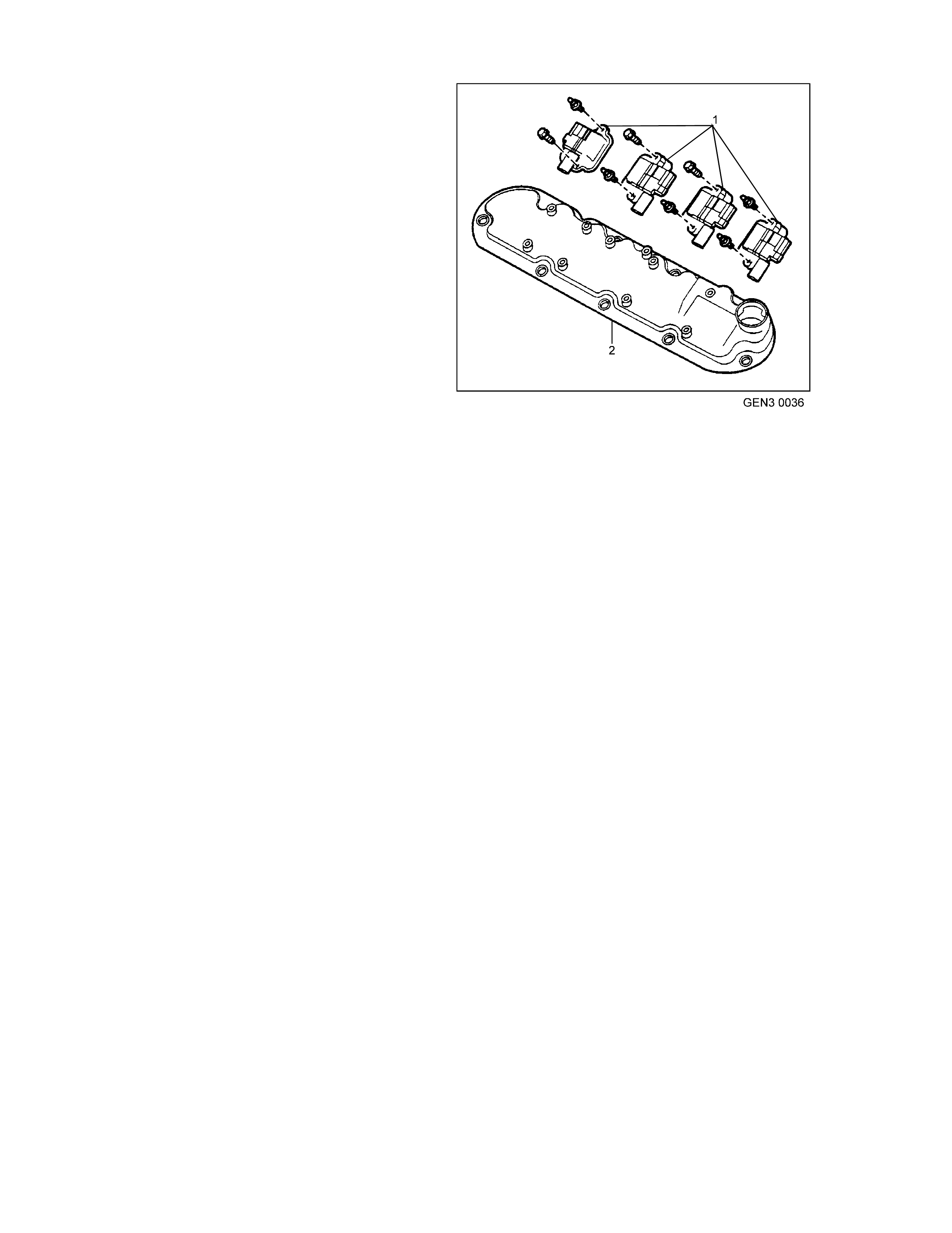
Ignition Coils
The ignition feed circuits are fused separately for
each bank of the engine. Th e two f uses also supply
the injectors for that bank of the engine. Each
coil/module is serviced separat ely.
This system puts out very high ignition energy for
plug firing. Because the ignition wires are shorter,
less energy is lost to ignition wire resistance. Also,
since the f iring is sequen tial, each coil has f ar m ore
tim e to s aturate as oppos ed to the t hree in a waste
spark arrangement. Furthermore, no energy is lost
to the resistance of a waste spark sy stem.
CIRCUITS AFFECTING IGNITION CONTROL
To properly control ignition timing, the PCM relies
on the following informa tion:
• Engine load ( manifold pressure or vacuum )
• Atmospher ic ( barometric) pressure
• Engine temper ature
• Intake air t empe rature
• Cranksh aft posit i on
• Engine s peed (RPM)
The Ignition Control (IC) system consists of the
following components:
• Ignition coil/modules
• 24X crankshaft position sensor
• Powertrain C ontrol Module (PCM)
• All connect ing wir es
Ignition Coils/Modules
1. Ignition Coils/Modules
2. Engine Valve Cover
The Ignition Control utilises the following to control
spark timing functions:
• 24X signal: The 24X crankshaft position
sensor sends a signal to the PCM. The PCM
uses this signal to determine crankshaft
position. The PCM also utilises this signal to
trigger th e fuel injectors.
• Ignition Control (IC) circuits: The PCM uses
these circuits to trigger the ignition
coil/modules. The PCM uses the crankshaft
reference signal to calculate the amount of
spark advance need ed.

NOTEWORTHY IGNITION INFORMATION
Ther e are import ant c on side rat ion s to point o ut when s er vic ing the ignit ion s ystem . The f ollowing inf or m a tion will list
some of these, to help technician in servicing the ign ition system.
• Th e ignition coil’s se condar y voltage outp ut capa bility is very high - m ore than 40,000 volts. Avoid body contact
with ignition hig h voltage secondary c ompon ents when the engine is running, or personal injury may result.
• Th e 24X cr ank sha ft p osition sens or is the m ost critic al part of the ignition system . If the sens or is dam ag ed so
that pulses are not generated, the engine will not start.
• Crankshaft position sensor clearance is very important. The sensor must not contact the rotating interrupter
ring at any time, or sensor damage will result. If the interrupter ring is bent, the interrupter ring blades will
destroy the sensor.
• Ignition timing is not adjusta ble. There are no timing marks on the crankshaft balancer or timing chain cover.
• Be care fu l not t o dam ag e th e sec on dar y ignition wires or bo ots when serv icing the ignition system. Rota te each
boot to dis lodge it f r om t he pl ug or c oil t ower bef o re pullin g it fr om eith er a spark plug or the ignition coil. Never
pierc e a sec ondar y ignition wire or boot f or any testing purpose s! Futu re problem s will occur if pin points or tes t
lights are pushed through the insulating fo r testing.
POWERTRAIN CONTROL MODULE (PCM )
The PCM is respons ible for maintaining correc t spark and fue l injection timing for all d riving conditions. To pro vide
optimum driveability and emissions, the PCM monitors input signals from the following components in calculating
Ignition Control (I C) spark timing:
• Engine Coolant Temp er ature (ECT) sensor
• Intake Air Temperature (IAT) sensor
• Mass Air Flow (MAF) sensor
• Automatic Transmission R ange inputs from the T r ansmission Range switch
• Throttle Position (TP) sensor
• Vehicle Speed Sensor (VSS)
RESULTS OF INCORRECT OPERATION
An ignition control circuit that is open, earthed, or short circuited will set an ignition control circuit DTC. If a fault
occu rs in the IC output circuit when the eng ine is running, the engine will experienc e a mis fir e. DT Cs P0351-P0358
will set when a m alfun ction is dete cted with an Ignit ion Co ntrol cir cui t. When an Ignit ion c ontrol DT C s ets , th e PCM
will disabled the injector for the appropriate cylinder.
The PCM uses information from the engine coolant temperature sensor in addition to RPM to calculate spark
advance values as follows:
• High RPM = m ore advance
• Cold engine = more advance
• Low RPM = less advance
• Hot engine = less advance
Therefore, detonation could be caused by high resistance in the engine coolant temperature sensor circuit. Poor
performance could be caused by low resistance in the engine coolant temperature sensor circuit.
If the e ngine c rank s b ut will not run o r im m ediately sta lls, Engine Crank s But Will Not Run diagnost ic table m us t be
used to determine if the failure is in the ignition system or the fuel system. If DTC P0341, P0342, P0343, P0335,
P0336 is set, the appropriate diagnostic trouble code table must be used for diagnosis.

1.7 CRANKCASE VENTILATION SYSTEM
A closed crankcase ventilation system is used to
provide a more complete scavenging of crankcase
vapours . F re sh air f ro m t he thr o ttle bod y is supplied
to the crankcase, mixed with blow-by gases and
then passed through a crankcase ventilation valve
into the intake manifold.
The primary control is through the crankcase
ventilation valve which meters the flow at a rate
depending on manifold vacuum. To maintain idle
quality, the crankcase ventilation valve restricts the
flow when intake manifold vacuum is high. If
abnormal operating conditions arise, the system is
designed to allow excessive amounts of blow-by
gases to back flow through th e cr ank case vent tube
into the engine air inlet to be consumed by normal
combustion.
The engine ventilation system was developed to
minimise oil consumption and ensure that oil
ingestion could not occur during high speed
cornering manoeuvres. Filtered fresh air is routed
from up stream of the throttle blade to the front of
the right rocker cover via a form ed rubber hose.
To reduce the potential of oil pullover into the
throt tle bor e area due to back flow of t he ventilat ion
system, the fitting in the right side rocker cover is
located between a shield from the rocker arms.
Blow-by gases are routed from the rear of both
rock er cover s, th rough m oulde d nylon lines to a tee
fitt ing located o n the centr eline of th e engin e at th e
rear of the intake manifold. From there, a single
nylon line carries the gases through an externally
mounted, horizontal PCV valve and enters the
intake manifold behind the throttle body.
The dual draw system was developed to meet
vehicle m anoeuvre requirements. During sustained
m ax im u m later al acc ele rat ions , the outb oar d roc k e r
cover may fill with oil. The dual draw system
pass ively switches , allowing the PCV valve to draw
on the rocker cover with the least resistance. This
results in the system drawing on the air filled, or
inboard rocker cover and eliminates oil pullover due
to drawing on th e oil-fil led outboard rocke r co v e r.
T20B009
Crankcase Ventilation System Routing
1. PCV Valve
2. Throttle Body
3. Fresh air
4. Return air
2
3
1 4
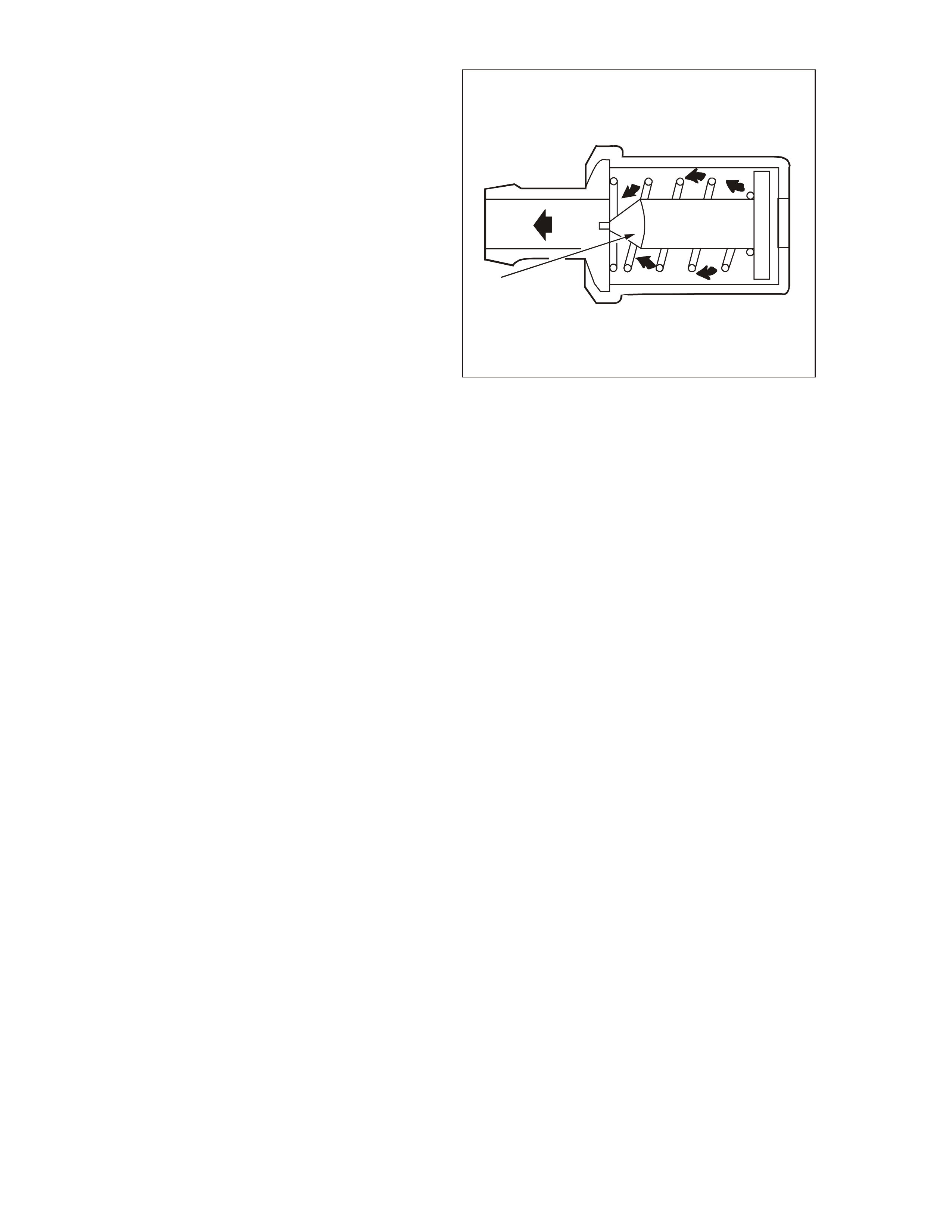
RESULTS OF INCORRECT OPERATION
A plugged PCV valve or hose may cause:
• Rough idle.
• Stalling or slow idle speed.
• Oil leaks.
• Sludge in engine.
A leaking valve or hose would cause:
• Rough idle.
• Stalling.
• High idle s peed.
For re placement of the PCV and related crank case
hoses, refer to Section 6E3 Emission Control -
GEN III V8 Engine of the VT Series II Service
Information.
GEN3 0038
1
PCV Cutawa y
1. Check Valve
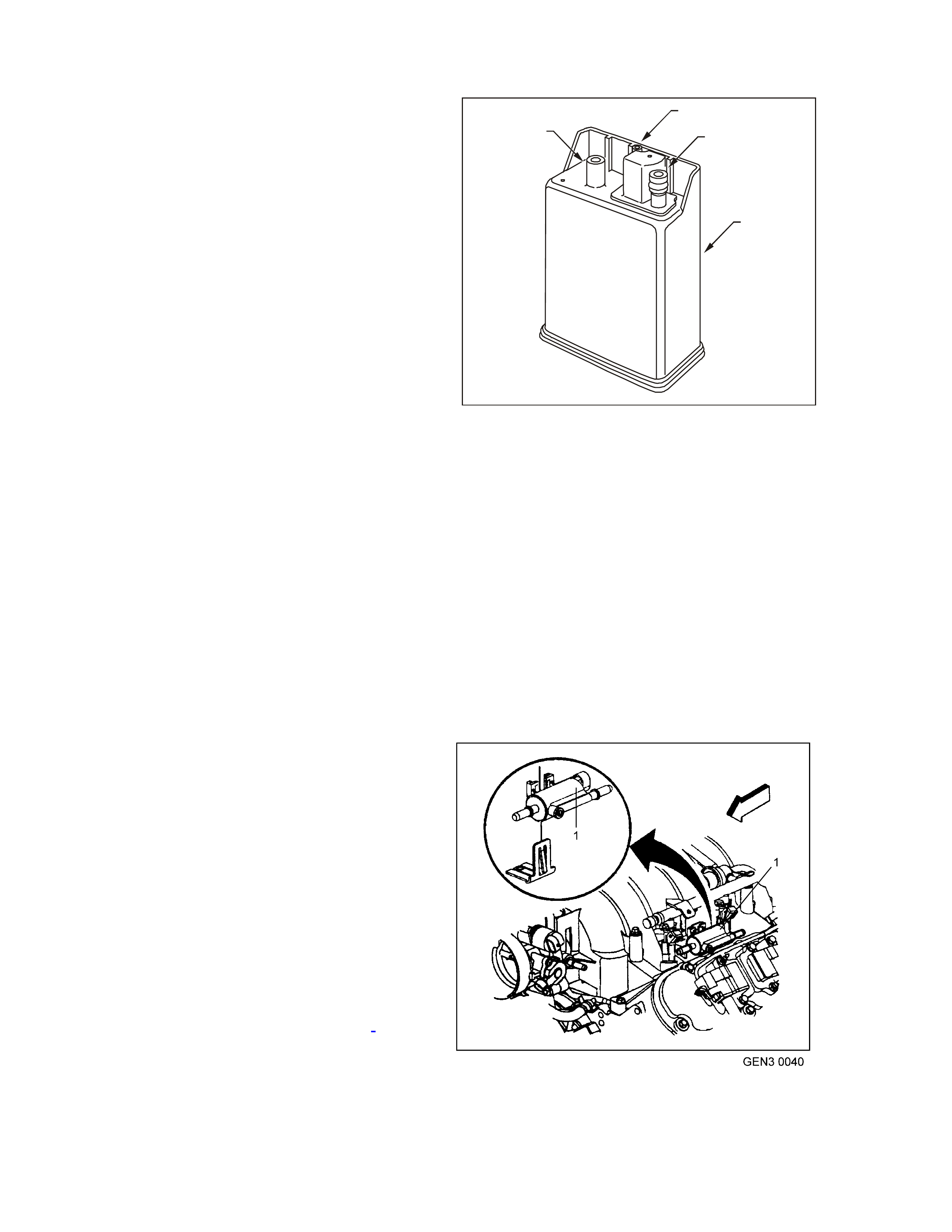
1.8 EVAPORATIVE EMISSION
The Evaporative Emission Control System (EECS)
used on this vehicle is the charcoal canister
storage met hod. T his m ethod tran sfers f uel vapour
fr om the f uel t ank to an activat ed carb on (c harcoa l)
storage device (canister located under the rear of
the veh icle) to hold t he vapour s when the vehic le is
not oper ating. W hen the engine is running, the fuel
vapour is purged from the c arbon element by intake
air flow and consumed in the normal combustion
process.
The EECS purge solenoid valve allows manifold
vacuum to purge the canister. The Powertrain
Control Module (PCM) supplies an earth signal to
energise the EECS purge solenoid valve (purge
ON). The EECS purge solenoid control is Pulse
Width Modulated (PWM) or turned ON and OFF
several times a second.
The PCM controlled PWM output is commanded
when the appr opriate conditions have been met:
• Engine coolant temperature is below 30°C at
cold st art up.
• Engine has been running longer than 2
minutes.
or
• Engine coolant temperature is above 30°C at
warm star t up.
• Engine has been running longer than 30
seconds.
• Engine is not in Decel Fuel Cutoff Mode.
• Throttle opening is less than 96%.
• Engine is in Closed Loop mode or Open Loop
mode.
A higher purge rate is used under conditions that
are likely to produce large amounts of vapour,
when the fo llowing conditions have been met:
GEN3 0039
1
2
3
4
Fuel Vapour Canister
1. Air Vent Port
2. Canis ter Purge Port
3. Vapour From Fuel Tank Po rt
4. Vapour Canister
• Intake Air Temperature (IAT) is above 50 °C.
or
• Engine Coolant Temperature (ECT) is above
100°C.
• Engine has been running for more than 15
minutes.
EECS purge PWM duty cycle varies according to
operating conditions determined by mass air flow,
fuel trim and intake air temperature. The EECS
purge will be re-enabled when TP angle decreases
below 96%.
The canister ( loca ted u nder the re ar of the vehicle)
cannot be repaired, and is serviced only as an
assembly. Periodically check the canister at the
time or distance intervals specified in
Section OB LUBRICATION & SERVICE of the VT
Series II Service Information or the Owner’s
Handbook.
Canister Purge Solenoid Location
1. Evaporative Purge Solenoid
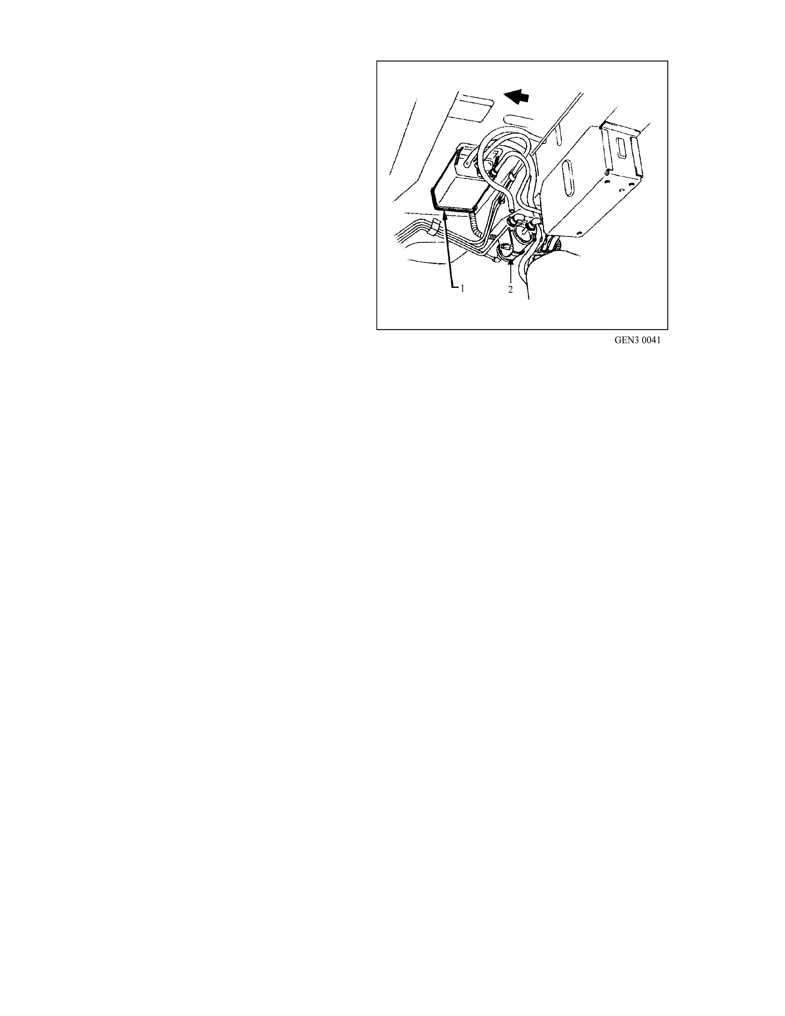
The fuel vapour canister is mounted in a bracket
underneath the vehic l e, located by the fuel filter.
This canister is a three port design. Fuel vapour is
absor bed by the c harc oal within the canist er. Whe n
the engine is running at idle speed and above idle,
air is drawn into the canister through the air vent
port (atmospheric port) at the top of the canister
assembly. The air mixes with the fuel vapour and
the mixture is drawn int o the in take manifold via the
canister purge line.
The Up perm ost port on t he canis ter is con trolled by
a PCM controlled canister purge solenoid. The
canister purge solenoid controls the manifold
vacuum signal from the throttle body. The port
below the canister purge port is the vapour inlet
from the fuel tank. The fresh air inlet port (air vent
port) on the canister is open to the atmospher e via
a hose t hat vents und er the vehicl e.
RESULTS OF INCORRECT OPERATION
• Poor idle, stalling and poor driveability can be
cause d by:
- Inoperative canister purge solenoid
- Damaged canister.
- Hoses split, cracked and/or not connected
to the
proper tubes.
- Throttle body and canister hoses
interchanged on the purge solenoid
connections.
NOTE: The canister connection is marked with
CAN.
• Evidence of fuel los s or fuel vapour odour can
be caused by:
Canister Location
1. Evaporati ve Canister ( Under Vehicle by Fuel T ank)
2. Fuel Filter
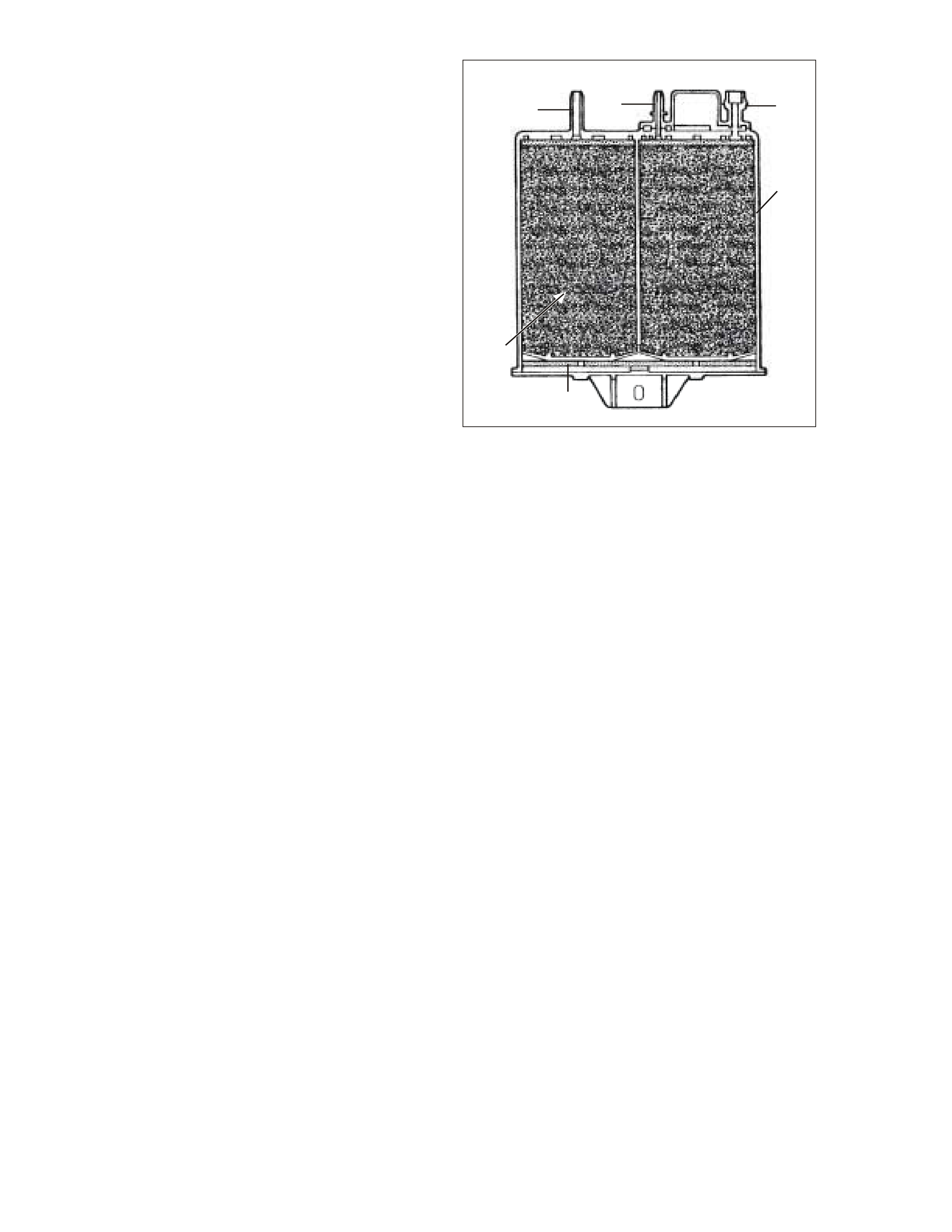
- Liquid fuel leaking fr om f uel lines.
- Cr acked or damaged c anister.
- Disconnected, incorrectly routed, kinked,
deteriorated or damaged vapour hoses, or
control hoses.
If th e solenoid is s tuck open, or the co ntrol cir cuit is
shorted to earth, the canister will purge to the
intake manifold all the time. This can allow extra
fuel at idle or during warm-up, which can cause
rough or unstable idle or a rich fuel operation.
If the canister purge solenoid is always closed, the
canister can become over loaded with fuel,
resulting in fuel odour.
A failure in the canister purge solenoid or circuit
may result in DTC P0443.
GEN 03 0042
123
4
6
5
Sectioned View of Canister
1. Air Vent Por t
2. Canister Purge Port
3. Vapour From Fuel Tank Port
4. Evaporative Canister
5. Volume Compensator
6. Charcoal Bed
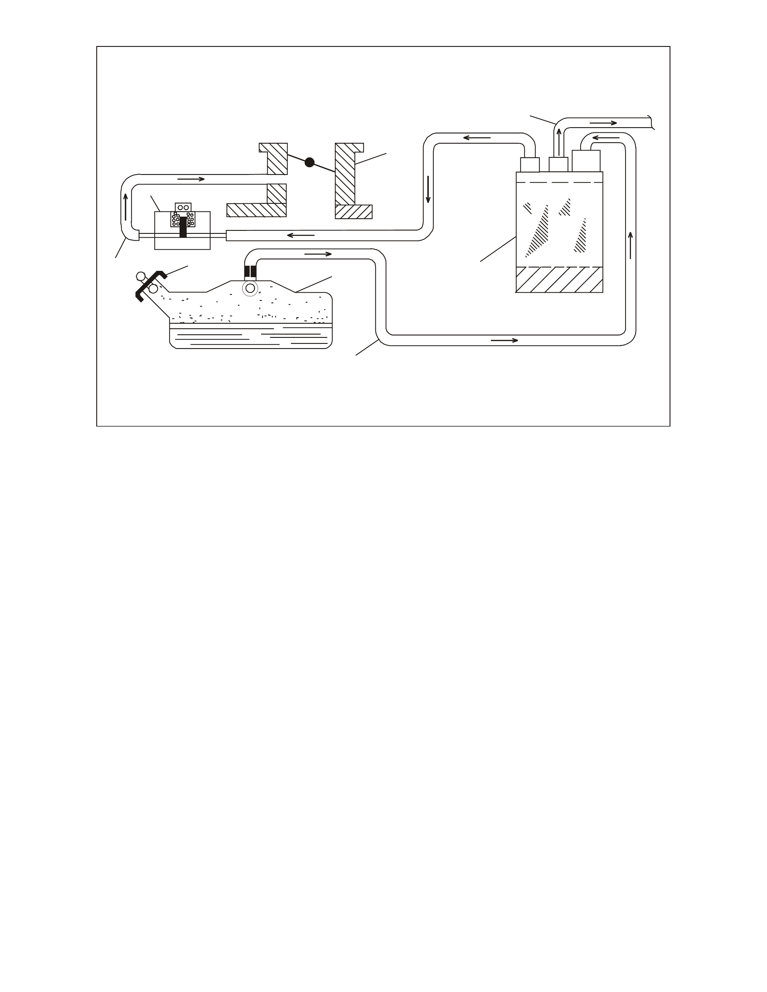
GEN 3 0043
7
8
65
1
3
2
4
Typical Evaporative Emission Control Schematic
1. Throttle Body
2. Atmospheric Port Hose
3. Evaporative Emission Canister
4. Fuel Vapour Hose
5. Fuel Tank
6. Pressure/Vacuum Vented Fuel Filler Cap
7. Evaporative Purge Hose
8. Canister P ur ge Solenoid (Norm ally Close d)
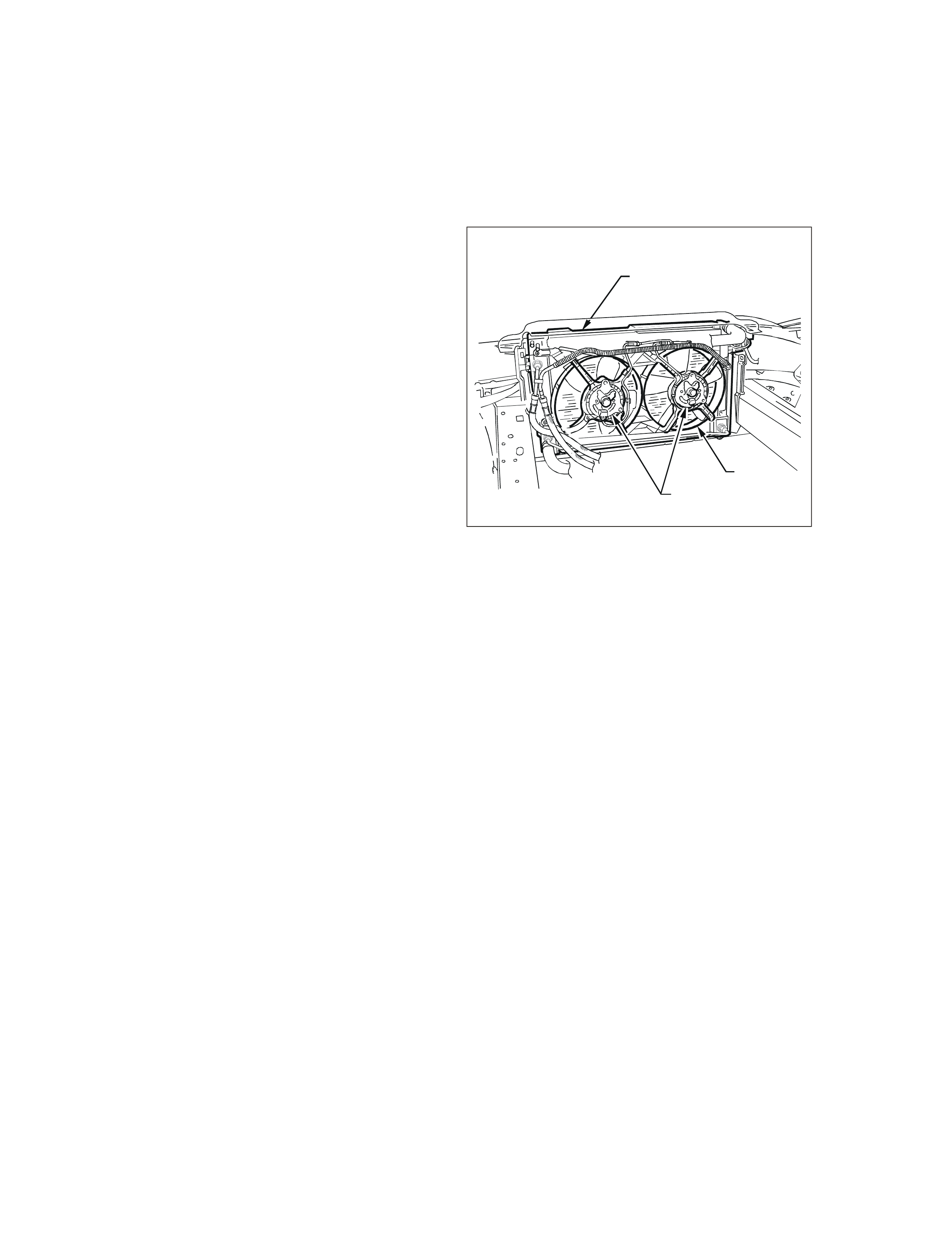
1.9 ELECTRI C COOLING FANS
The GEN III engine has two, two speed electric
engine cooling fan assemblies that provide the
primary means of moving air through the engine
radiator. The cooling fans are used to cool engine
coolant flowing through the radiator and the
refrigerant flowing through the A/C condenser (if
fitted).
Each engine cooling fan motor has four terminals;
two negative and two positive. The two negative
terminals are the relay controlled circuits for fan
operation. The two positive terminals are the direct
power feed from a fusible link to the fan motors.
When an earth signal is applied to one of the
negative t erminals, the f an m oto r will operat e at low
speed. When an earth signal is applied to both
negative terminals, both fans will operate at high
speed.
The engine cooling fan high speed and low speed
relays are used to control the earth signal to the
electric motors.
The high speed relay is controlled by the PCM,
which cont rols the eart h path for the engine cooling
fan high speed relay.
The low speed of the electric fan is controlled by
the PC M through a spec ial Data Com m unication t o
the BCM. The BCM controls the earth path for the
engine cooling fan low speed relay.
The PCM determines operation of the two, two
speed engine cooling fans based on A/C request,
engine coolant temperature, A/C Refrigerant
Pressure Transducer, and vehicle speed signal
inputs.
There are also four (4) suppression capacitors
incorporated into the fan motor wiring circuits.
These suppression capacitors help eliminate fan
motor noise through the radio speakers. If these
capacitors are open, then noise will be present
through the radio speakers. If shorted to earth, the
fan motors could continuously run, or the fuse or
fusible link could fail.
For replacement of the cooling fan motor, refer to
Section 6B3 ENGINE COOLING of the VT Series
II Service Information.
T6B3001
1
23
Engine Cool in g Fan Assembly
1. Top of Radiator
2. Cooling Fan Mot ors
3. Cooling Fan Shroud
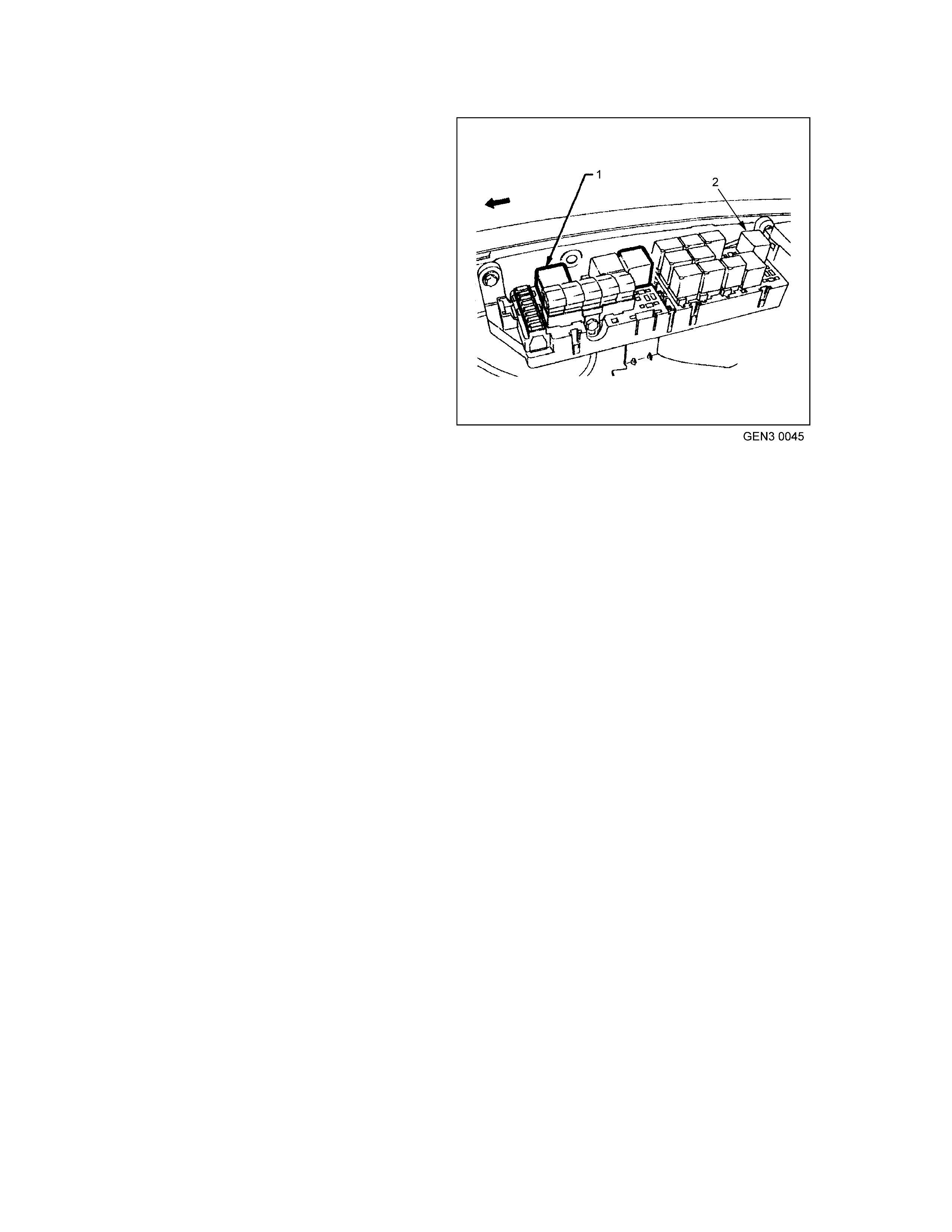
ENGINE COOLING FAN LOW SPEED
The engine cooling fan low speed relay is
energis ed by the BCM. Th e PCM det ermine s when
to enable the low speed fan based on inputs from
the BCM serial data, Engine Coolant Temperature
(ECT) sensor and the Vehicle Speed Sensor
(VSS).
The cooling fan low speed relay will be turned ON
when:
• The A/C requ est indicated ( YES) and either
• the vehicle speed is less than 30 km/h
or
• A/C pr essure is greater than 1500 kPa
or
• The coolant tem perature is greater than 98°C.
• If the coolant temperature is greater than
113°C when the ignition is switched OFF, the
relay is ener gised for up to approximately four
minutes.
• If an engine coolant temperature sensor fault
is detected, such as DTC P0117, P0118,
P1114, P1115.
The cooling f an low speed relay will be turned OFF
when any of the following conditions have been
met:
• The A/C requ est is not indicated (NO)
• The A/C request is indicated (YES) and the
vehicle speed is greater than 50 km/h, A/C
pressure is less than 1170 kPa, and coolant
temperature less than 98°C.
NOTE: T he low speed c ooling fan has a minim um,
run on time of 30 seconds.
Engine Fa n Low Speed Relay Locati on
1. Engine Fan Low Speed Relay
2. Engine Fan High Speed Relay

ENGINE COOLING FAN HIGH SPEED
The engine cooling fan high speed relay is
controlled by the PCM based on input from the
Engine Coolant Temperature (ECT) sensor.
The PCM will only turn ON the engine cooling fan
high speed relay fan if the engine cooling fan low
speed relay has been ON for 2 seconds and the
following co nditions are s atisfied:
• An Engine Coolant Temperature sensor fault
is detected such as DTC P0117, P0118,
P1114, P1115.
• Coolant temperature greater than 108°C.
The engine cooling fan high speed relay can also
be enabled by the A/C Refrigerant Pressure
Transducer. When the A/C Refrigerant Pressure
transducer determines the A/C system pressure is
too high (greater than 2400 kPa) and this will
instruct the PCM to enable the high speed fan.
If th e low speed fan was O FF when th e criteria was
met to turn the high speed fan ON, the high speed
fan will come ON 5 seconds aft er the low speed f an
is turned ON.
If both the engine cooling fan relays are ON, the
PCM will turn OFF the high speed re lay when:
• The engine coolant temperature is less than
102°C.
• A/C request not indicated (NO ).
• A/C r eques t indica ted ( YES) and A/C pres sur e
is less than 1900 kPa.
NOTE: The high speed coo ling fan has a minimu m,
run on time of 30 seconds.
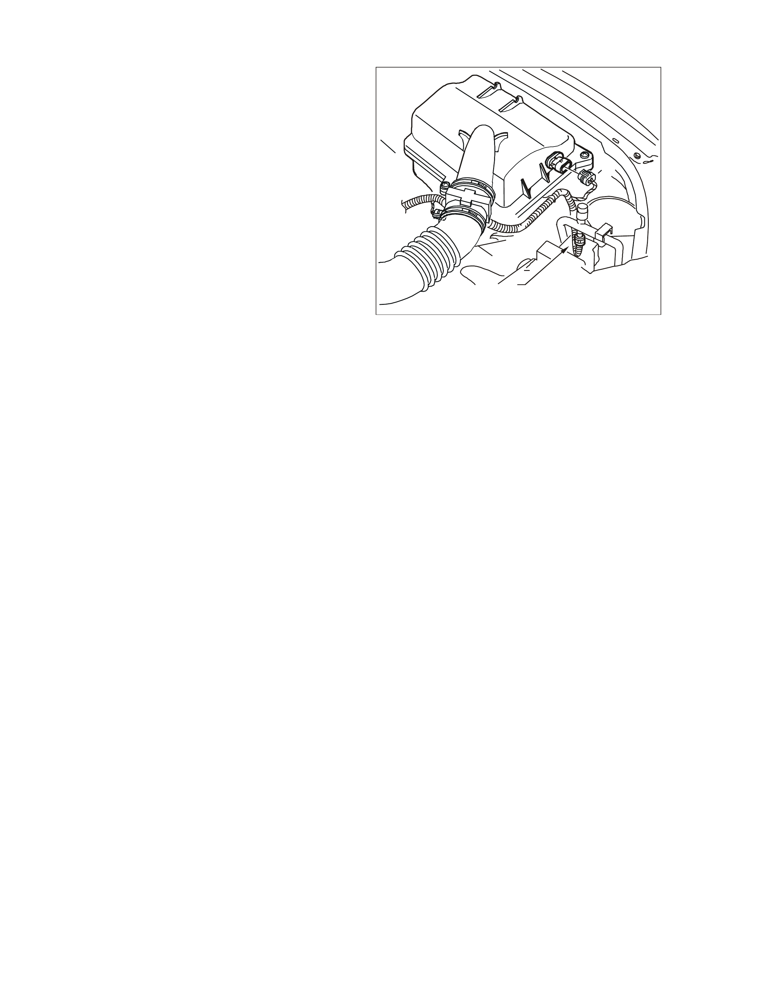
1.10 A/C CLUTCH CONTROL
This vehicle uses two types of A/C clutch controls;
one with standard A/C and the other uses an
Electronic Climate Control (ECC) module.
ECC SYSTEM
With the ECC system, when the A/C is requested
the electronic climate control module will supply a
signal to the BCM. T he BCM will then send a serial
data request to the PCM. W hen the PCM receives
the serial data request on PCM terminal J1-58, it
indicates that air conditioning has been requested
and approximately 1/2 second after the PCM
receives this signal, it will energise the A/C control
relay. This serial data signal to the PCM is also
used to a djus t the idle sp eed bef ore tu rning O N the
A/C compressor relay. If this signal is not available
to the PCM, t he A/C compress or will be inoperative.
The BCM also supplies the earth signal from BCM
terminal 7 to the low speed cooling fan relay.
This A/C system also incorporates an A/C
Refrigerant Pressure Transducer. The A/C
Refrigerant Pressure Transducer signal indicates
high side refrigerant pressure to the PCM. The
PCM uses this information to adjust the idle air
control valve to compensate for the higher engine
loads present with high A/C refrigerant pressures.
A fault in the A/C Refrigerant Pressure T ransducer
signal will cause DTC P0530 t o set.
The PCM will not energise the A/C control relay if
any of the following conditions are present:
• High coolant temperature
• Low A /C sy stem pressure
• High A/C system pressure
• Wide open thrott l e
• High engine RPM
T26C3004
1
A/C Refrigerant Pressure Transducer Location
1. A/C Re frigerant Pres sure Tr ansducer
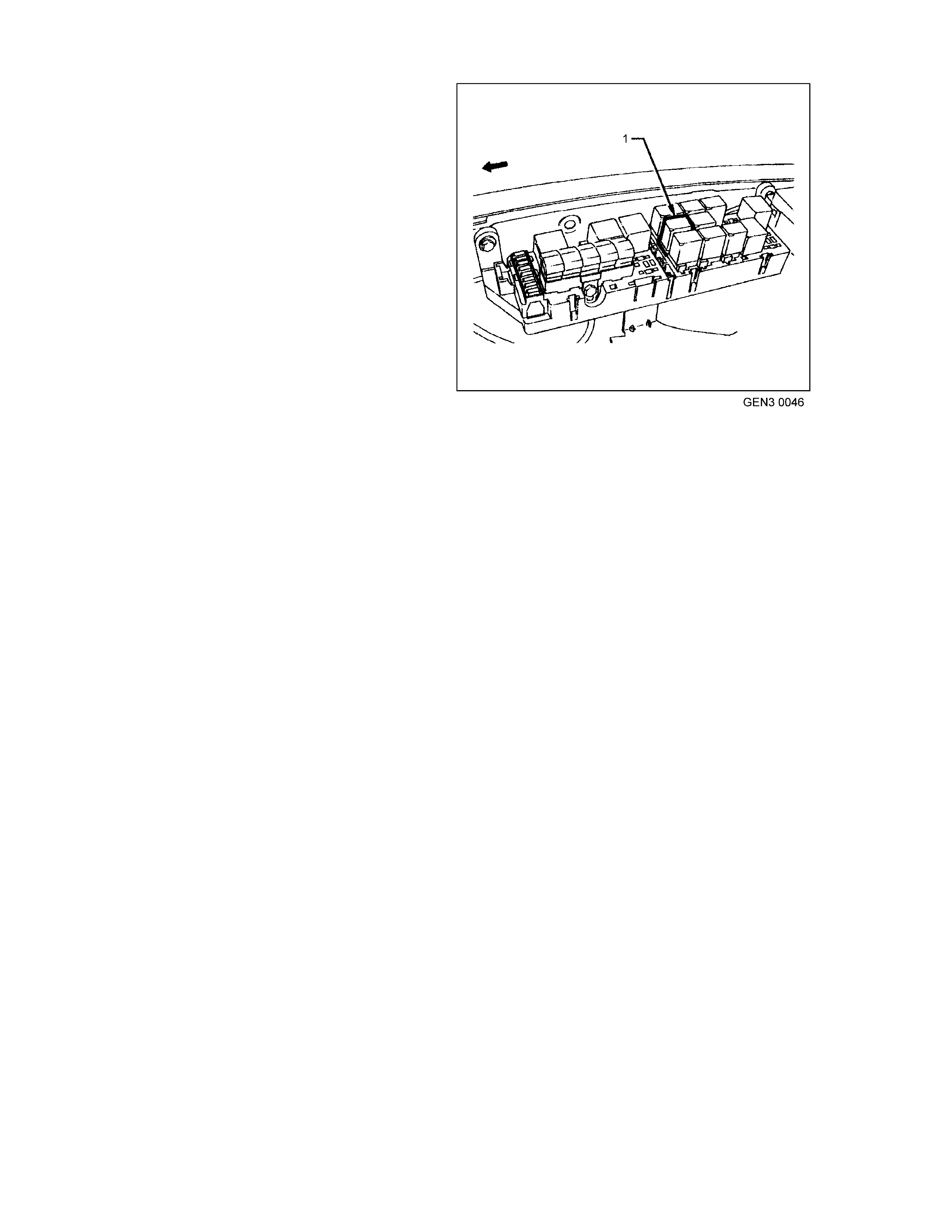
STANDARD A/C SYSTEM
On vehicles equipped with non-ECC systems the
power flow is different. With the blower fan
switche d O N, a nd the air c ond itioning swit ch ed ON,
switched ignition voltage is supplied from fuse F13
through the A/C master switch, and then to the
BCM. T he BCM will t hen s upply a serial data signal
to the PCM requesting A/C. If the BCM does not
receive a earth signal from the blower switch to
BCM terminal 3, the BCM will not supply the serial
data request for A/C. Once the PCM receives this
serial data signal, the PCM will energise the A/C
com press or re lay. T he BCM also supplies the earth
signal from BCM terminal 7 to the low speed
cooling fan relay.
This serial data signal to the PCM is also used to
adjust the idle speed before turning ON the A/C
compressor relay. If this signal is not available to
the PCM, the A/C compr essor will be inoperative.
This system, like on the ECC system also
incorporates an A/C Refrigerant Pressure
Transducer. The A/C Refrigerant Pressure
Transducer signal indicates high side refrigerant
pressure to the PCM. The PCM uses this
information to adjust the idle air control valve to
compensate for the higher engine loads present
with high A/C refrigerant pressures. A fault in the
A/C Refrigerant Pressure Transducer signal will
caus e DTC P0530 to set.
A/C Relay L ocation
1. A/C Relay
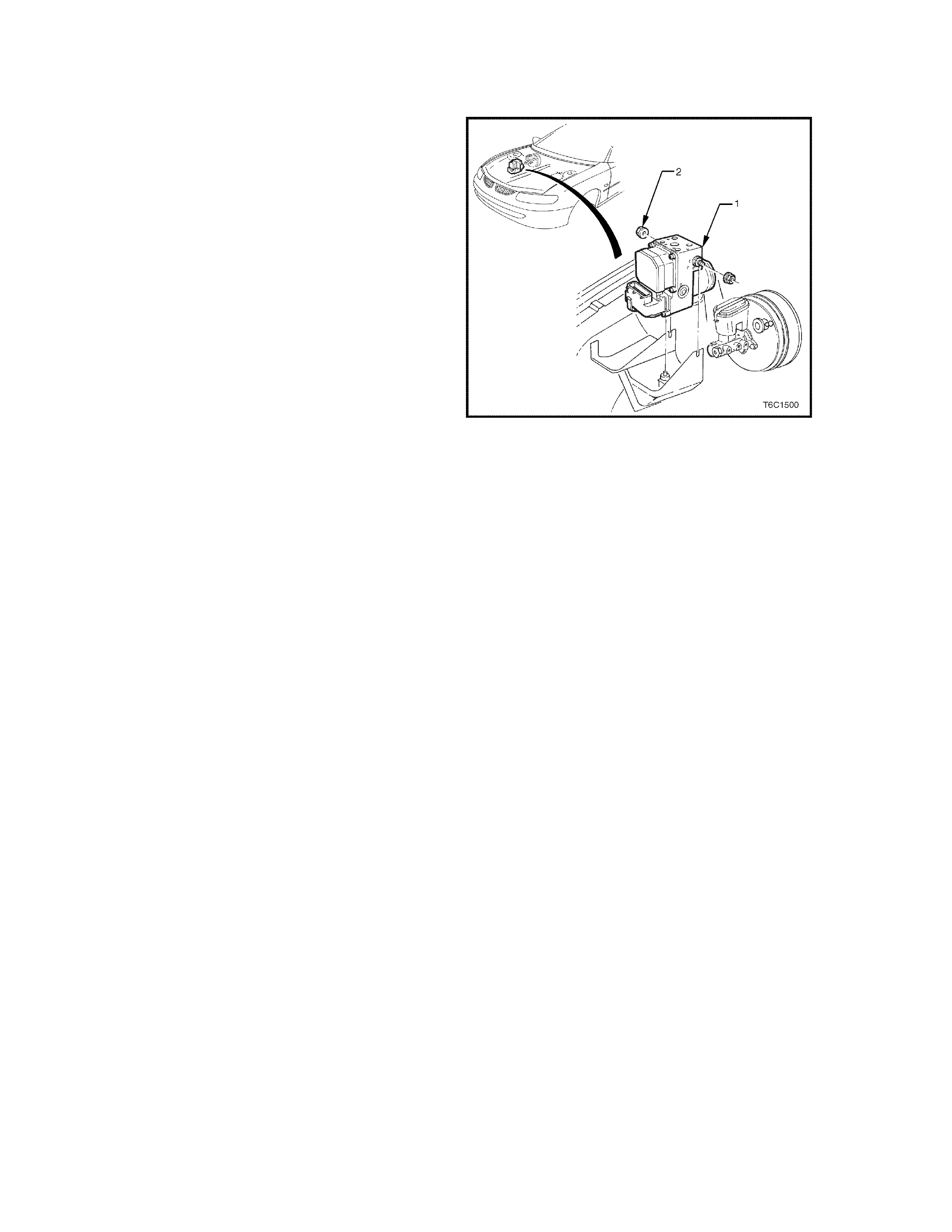
1.11 ELECTRONIC TRACTION CONTROL
PURPOSE
The Electronic Traction Control (ETC) system is
designed to maintain traction and reduce wheel
over- spin at the drive wheels on slippery surfaces
during acceleration. This system is designed to
operate at all vehicle speeds and reduces wheel
slip by use of the engine torque management
system, throttle relaxer control module and anti-
lock brake (ABS) system.
The ABS/ET C module m onitors both front and rea r
wheel speeds through the wheel speed sensors. If
at any time during acceleration the ABS/ETC
module detects drive wheel slip, it will request the
Powertrain Control Module (PCM) to bring excess
engine torque into a specific range, refer to
Section 12L ABS & ABS/ETC of the VT Series II
Serv i c e In format i on .
If the ABS/ETC cont inues to detect the rear wheels
are rotating faster than the front it will request the
throt tle relax er c ont ro l module to r edu ce t he thr o ttle
angle. The last measure taken to control the rear
wheels is for the ABS/ETC module to apply the rear
brakes, thus reducing torque to the r e ar wheels.
Once the rear wheels begin to rotate at the same
speed as the front wheels, the system will return full
control to the driver. During traction control mode, if
the brake is applied to only one drive wheel, most
of the torq ue fr om the engine will be dir ecte d to th e
other drive wheel which will improve the traction of
the vehicle .
ABS/ETC Module Loc at io n
1. ABS/ETC Hydraulic Modulator
2. Nut (2 Places) 5.0 - 12.0 Nm
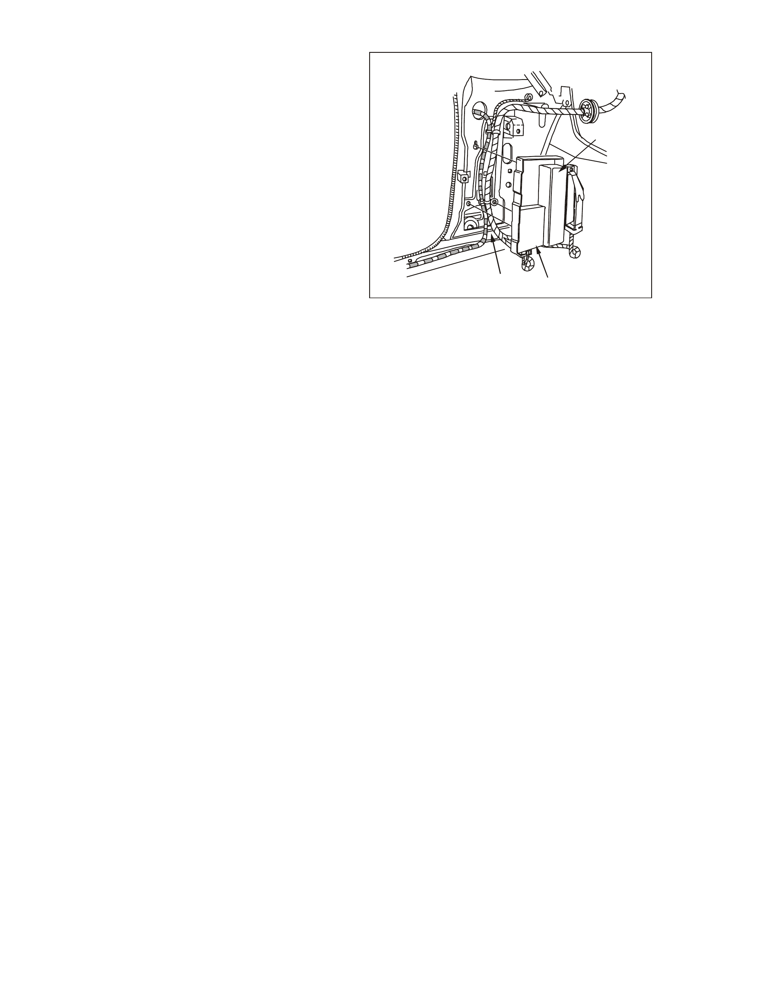
The trac tion c ontrol b raking is accom plis hed by the
ABS/ETC module closing the isolation valves,
turning on the ABS pump motor and supplying
brake pres sure to the over spinning wheel(s ) .
The isolation valves isolate the front brake
hydraulic circuits from the m aster cylinder and rear
brake hydraulic circuits. Once the rear brake
hydraulic circuits are isolated, pressure can be
applied to the rear wheels without affecting any
other brake hydraulic circuits. The ABS/ETC
module turns on the ABS pump motor to apply
pressure, and begins cycling the ABS assembly's
inlet and outlet valves.
The inlet and outlet valve cycling aids in obtaining
maximum road surface traction in the same
manner as the anti-lock brake mode. The
difference between electronic traction control and
anti-lock br ake m ode is that brake fluid pres sure is
increased to lessen wheel spin (traction control
mode), rather then reduced to allow greater wheel
spin (anti-lock brake mode).
If at any time during traction control mode, the
brakes are manually applied, the brake switch
signals the ABS/ETC module to disable traction
contr ol mode and allow manu al br aking.
If there is a malfunction between the ABS/ETC
module and the PCM, DTC will set. If there is a
m alfunctio n between the ABS/ETC m odule a nd the
throttle relaxer control module, refer to
Section 12L ABS & ABS/ETC of the VT Series II
Serv i c e In format i on .
For further description on the Anti-Lock Brake
(ABS) system, Electronic Traction Control (ETC)
system and Throttle Relaxer Control Module
operation and DTC diagnosis, refer to
Section 12L ABS & ABS/ETC of the VT Series II
Serv i c e In format i on .
GEN3 0006
1
32
Throttle Relaxer Control Module
1. Throttle Re l ax e r Co nt ro l M od ule
2. Powertrain Inter fac e Module
3. Left F r ont Kick Pa nel
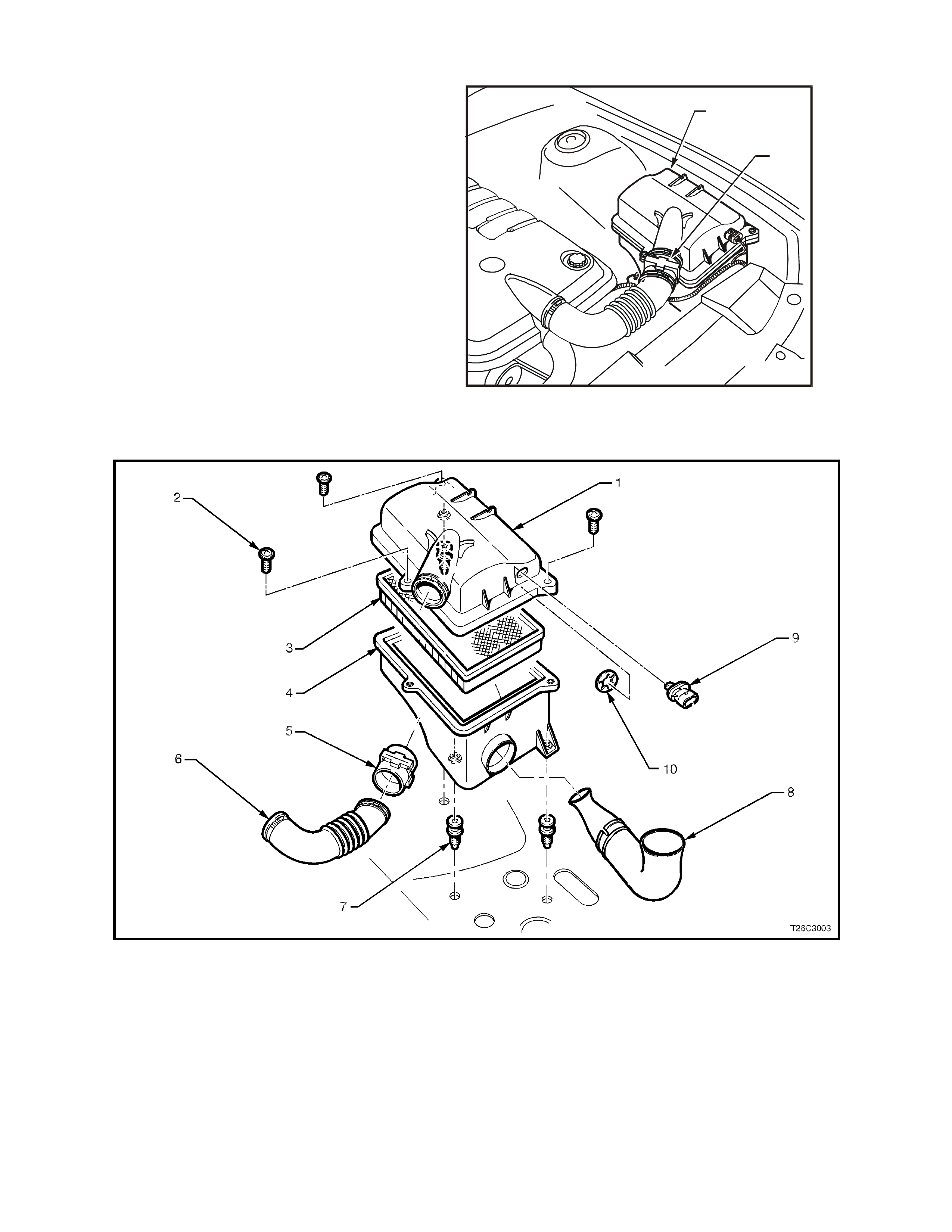
1.12 AIR INTAKE SYSTEM
The air intak e system draws out side air th rough th e
front of the air cleaner assembly and filter element
of the forward mounted air cleaner. The air is then
route d th rou gh the MAF sens or and in to the t hro tt le
body to the intak e m anif old. T he air is then direct ed
into the intake manifold runners, through the
cylinder heads and int o the cylinders.
If the Mass Air Flow (MAF) sensor is installed
backwards, the system will run rich. An arrow
marked on the plastic portion of the sensor
indicates correct air flow direction. The arrow must
point towar d the engine.
T26C3002
2
1
Air Cleane r Location
1. Air C leaner Housing
2. Mass Air Flow (MAF) Sensor
Air Cleaner Housing Assembly
1. Air Cleane r Ho usi n g U pp er Body
2. Air Cleaner Housing Top Cover Retaining
Screws (3)
3. Air Cleaner Filter
4. Air Cleane r Ho usi n g Lower Body
5. Mass Air Flow (M AF) Sensor
6. Air Intake to Throttle Body
7. Air Cleaner Housing Retaining Screws (3)
8. Air Inlet to Air Cleaner Housing Duct
9. Intake Air Temperature (IAT) Sensor
10. Intake Air Temperature (IAT) Sensor Clip
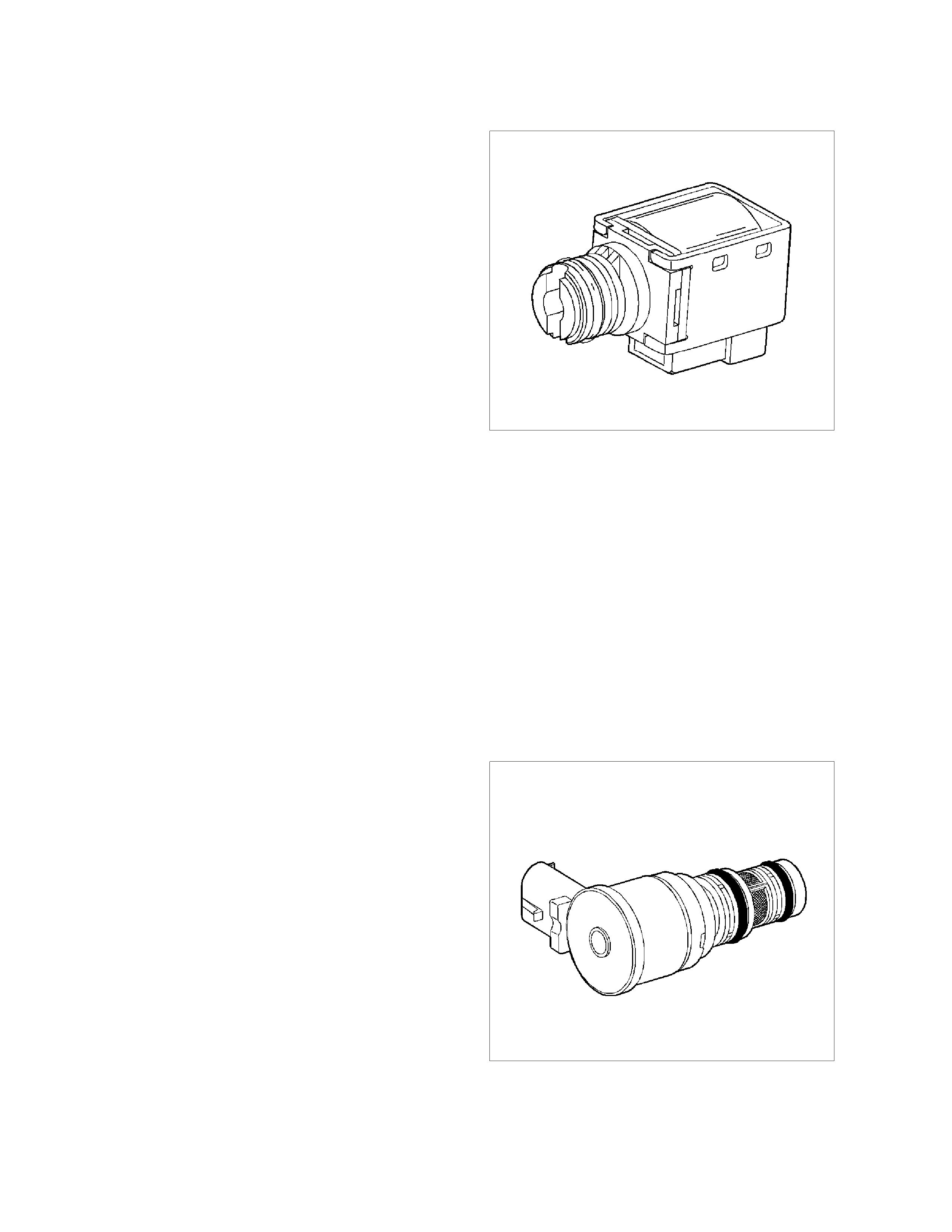
1.13 AUTOMATIC TRANSMISSION SENSORS & SIGNALS
1-2 (A) AND 2-3 (B) SHIFT SOLENOID VALVES
IMPORTANT: The shift solenoid valve resistance
should measure 19-24 ohms minimum when
measured at 20°C (68°F). The shift solenoid current
flow should not exceed 0.75 amps. The shift solenoid
should energise at a voltage of 7.5 volts or more
(measured across the terminals). The shift solenoid
should de-energise when the voltage is one volt or
less.
If both solenoid s lose power, only third gear engages.
The 1-2 and 2-3 shift solenoid valves (also called A
and B solenoids) are identical devices that control the
m oveme nt of t he 1-2 and 2- 3 shift valve s (the 3- 4 s hift
valve is n ot dir ectly controlled by a sh ift solenoid) . T he
solenoids are normally open exhaust valves that work
in four combinations to shift the transmission into
differen t ge a rs.
The PCM energises each solenoid by grounding the
solenoid through an internal quad driver. This sends
current through the coil winding in the solenoid and
m oves the internal plunger ou t of the exhau st position .
When ON, the solenoid redirects fluid to move a shift
valve.
IMPORTANT: The manual valve can hydraulically
override the shift solenoids. Only in D4 do the shift
solenoid states totally determine what gear the
tra nsmissio n is in. In the other m anual valve positions ,
the transmission shifts hydraulically and the shift
solenoid states CATCH UP when the throttle position
and the vehicle speed fall into the correct ranges.
Diagnostic trouble codes P0753 and P0758 indicate
shift solenoid circuit voltage faults.
The PCM-controlled shift solenoids eliminate the need
for throttle valve and governor pressures to control
shift valve operat ion.
8885
3-2 SHIFT SOLENOID VALVE ASSEMBLY
IMPORTANT: The 3-2 shift solenoid valve assembly
resistance should be a minimum of 20-24 ohms at
20°C (68°F).
The 3-2 shift solenoid valve assembly is an ON/OFF
solenoid that is used in order to improve the 3-2
downshift. The solenoid regulates the release of the 3-
4 clut ch and the 2-4 band apply.
If a voltage fault is detected in the 3-2 shift solenoid
circuit, diagnostic trouble co de P0785 will set.
325350
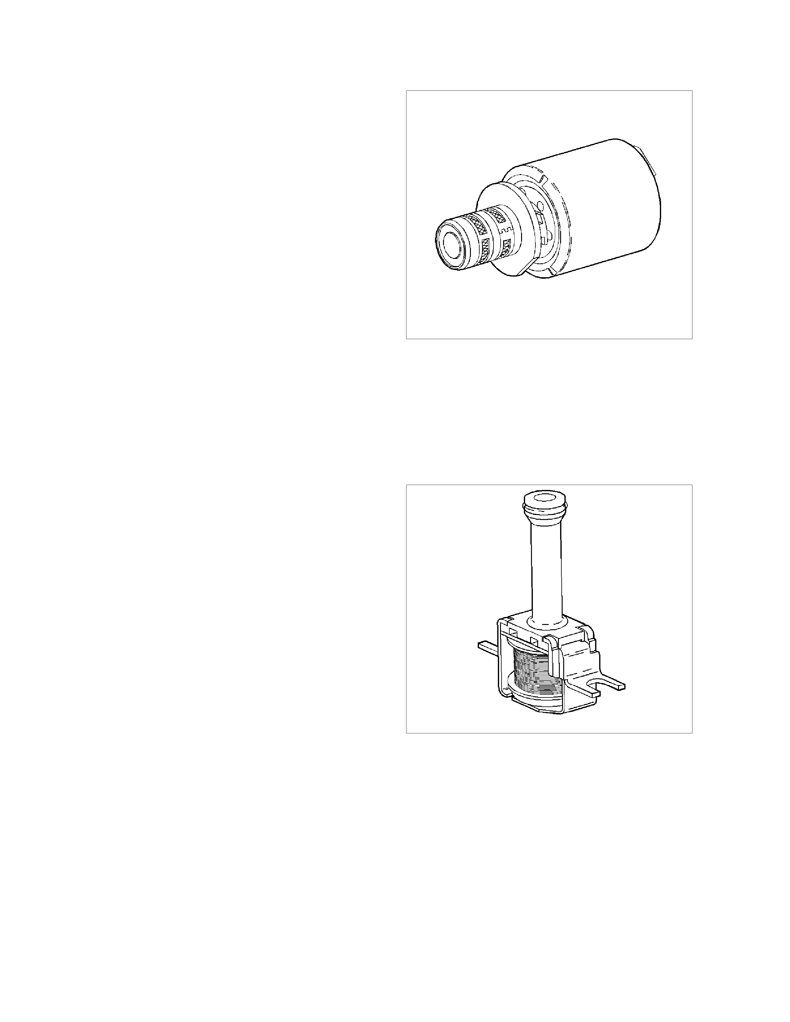
TRANSMISSION PRESSURE CONTROL SOLENOI D
IMPORTANT: Transmission pressure control solenoid
resistance should measure 3-5 ohms when measured
at 20°C (68°F).
The transmission pressure control solenoid is an
electronic pressure regulator that controls pressure
bas ed on the c urrent flow throug h its coil winding . The
magnetic field produced by the coil moves the
solenoid's internal valve which varies pressure to the
pressure regulator valve.
The PCM controls the pressure control solenoid by
comm an ding c urr ent between 10 0 and 1100 m illiamps .
Th is changes th e duty cycle of the so lenoid, which can
rang e between 5 per cent and 95 per cent ( typically less
than 60 percent). 1100 milliamps corresponds to
minimum line pressure, and 100 milliamps
corresponds to m aximum line pressure If the solenoid
loses power, the transmission defaults to maximum
line pressure.
The PCM commands the line pressure values, using
inputs such as the throttle position sensor. The
pres su re c ont ro l solen oid ta k e s the plac e of the throttle
valve or the vacuum modulator that was used on the
past model transmissions.
If the duty cycle drops below 5 percent or rises above
95 per cent, DT C P0748 will set.
325352
TORQUE CONVER TER CLU TCH SOLE N OID V ALVE
IMPORTANT: Th e TCC solenoid r esistanc e should be
21-2 6 ohm s m inimum when m easu red at 20°C (68°F).
If a fault is detected in the TCC solenoid circuit, code
P0740 will set.
The torque converter clutch solenoid valve is a
normally open exhaust valve that is used to control
torque converter clutch apply and release. When
grounded (energised) by the PCM, the TCC solenoid
valve stops converter signal oil from exhausting. This
causes converter signal oil pressure to increase and
shifts the TCC solenoid valve into the apply position.
Th e brake switc h is an input to the PCM, and the PCM
directly controls the TCC apply based on the brake
switch status.
8882
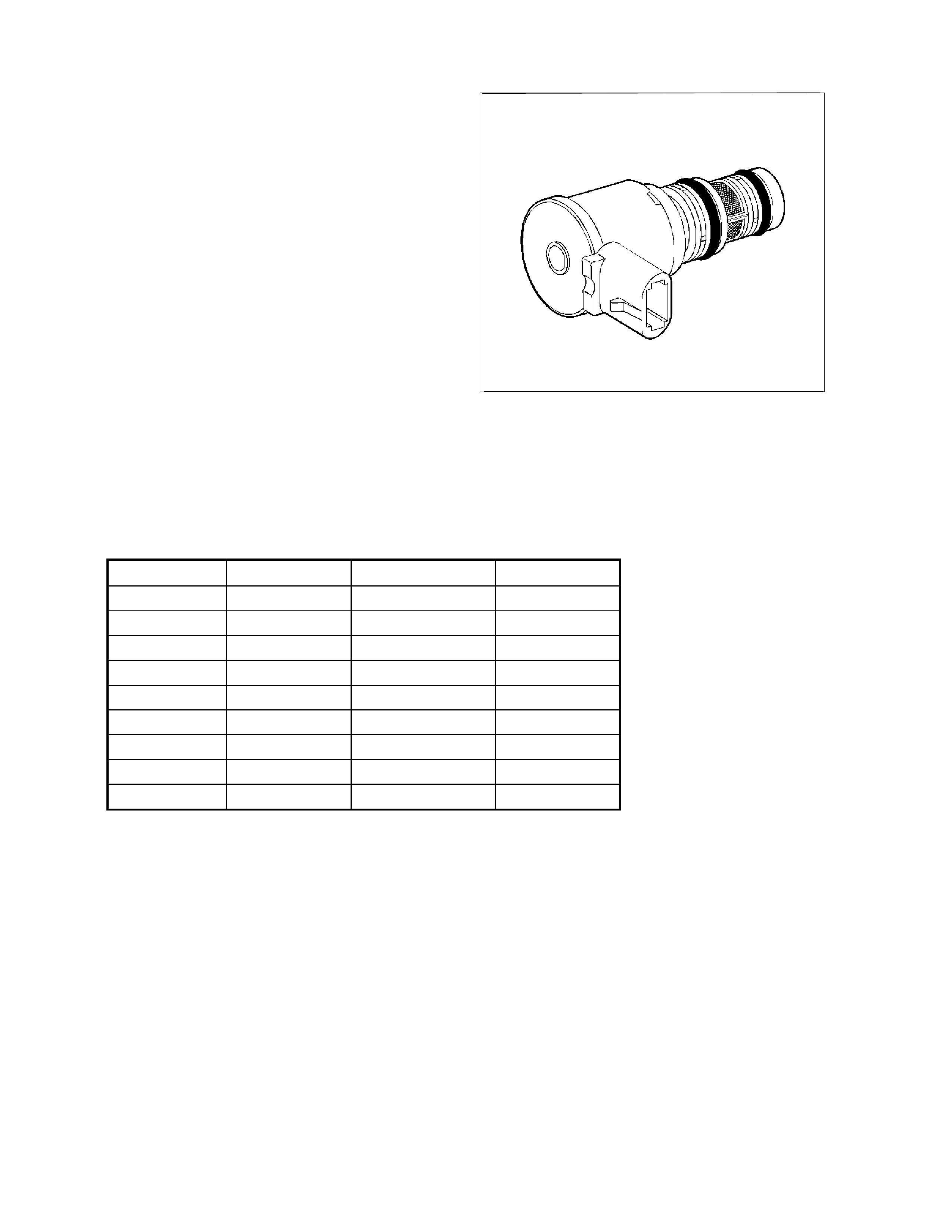
TORQUE CONVERTER CLUTCH PWM SOLENOID VALVE
IMPORTANT: TC C PWM solen oid valve resista nce
should be 10-11 ohms when measured at 20°C
(68°F), and 13-15 ohms when measured at 100°C
(212°F).
The torque converter clutch PWM solenoid valve
controls the fluid acting on the converter clutch
valve, which then controls the TCC apply and
release. This solenoid is attached to the control
valve body assembly within the transmission.
The TCC PWM solenoid valve provides smooth
engagement of the torque converter clutch by
operating on a negative duty cycle a variable
percent of ON time.
If a fault is detected in the TCC PWM circuit, code
P1860 will set.
325355
TRANSMISSION FLUID PRESSURE (TFP) MANUAL VALVE POSITION SWITCH
IMPORTANT: Seven valid combinations and two
invalid combinations are available from the TFP
manual valve position switch. Refer to the TFP
Manual Valve Position Switch Logic table below for
valid/invalid combinations for range signal circuits
A, B and C.
Gear Positi on Range Sig nal A Range Signa l B Range Signal C
Park Open 12 V Closed 0 V Open 12 V
Reverse Closed 0 V Closed 0 V Open 12 V
Neutral Open 12 V Closed 0 V Open 12 V
D Open 12 V Closed 0 V Closed 0 V
3 Op en 12 V Open 12 V Closed 0 V
2 Open 12 V Open 12 V Open 12 V
1 Closed 0 V Open 12 V Open 12 V
Invalid Closed 0 V Open 12 V Closed 0 V
Invalid Closed 0 V Closed 0 V Closed 0 V
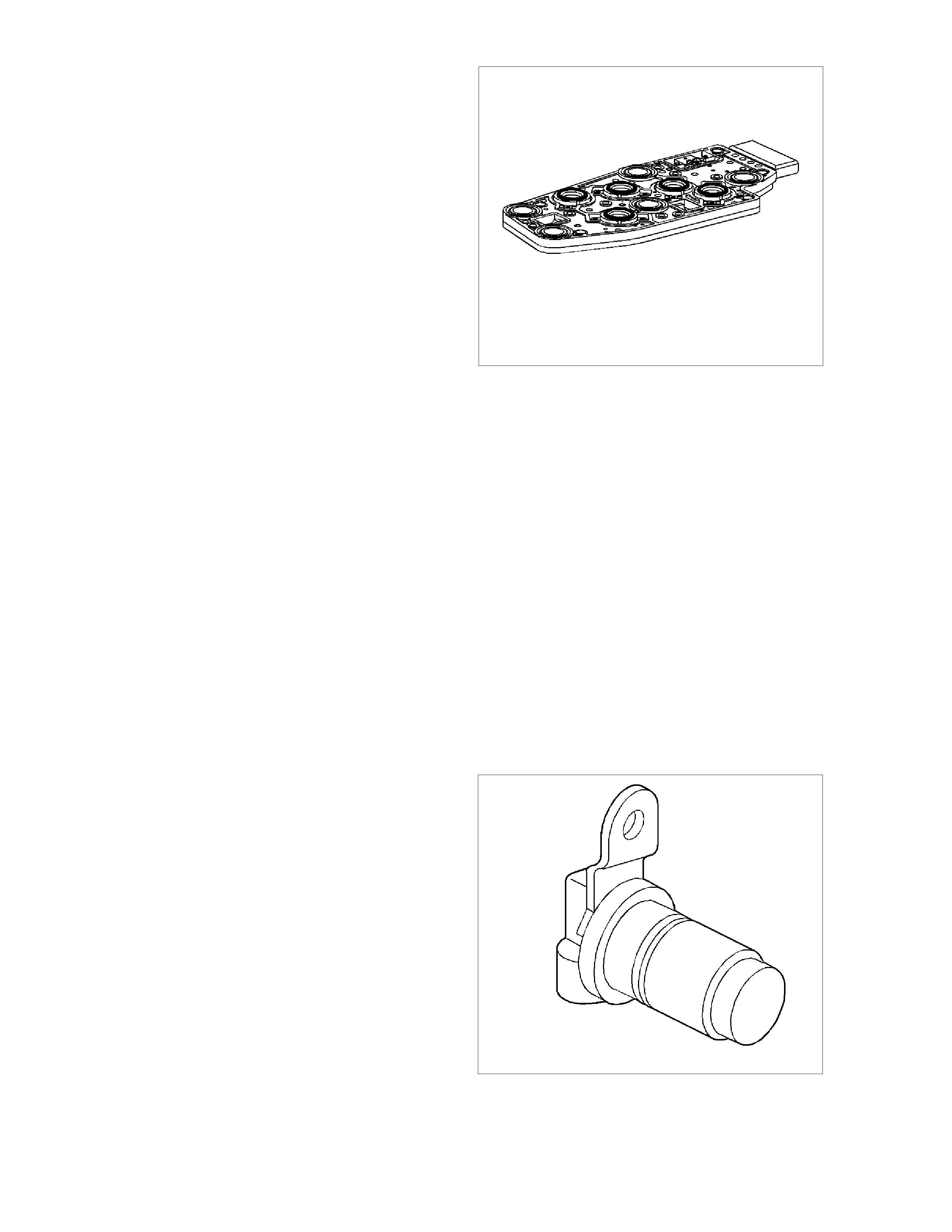
The Transmission Fluid Pressure (TFP) manual
valve position switch is a set of five pressure
switches on the control valve body that sense
whether fluid pressure is present in five different
valve body passages. The combination of which
switches are open and closed is used by the PCM
in order to determine actual m anual valve position.
The TFP manual valve position switch, however,
cannot distinguish between PARK and NEUTRAL
because the monitored valve body pressures are
identical in both cases.
The switch es are wir ed to provide thr ee signal lines
that are monitored by the PCM. These inputs are
used to help co ntrol line press ure, tor que converter
clutch apply and shift solenoid valve operation.
Voltage at each of the signal lines is either zero or
12 volts.
In order to monitor the TFP manual valve position
switch operation, the PCM compares the actual
voltage combination of the switches to a TFP
com bination tab le stored in its mem ory. If the PCM
sees one of two illegal voltage combinations, a
DTC P1810 will result. A DTC P1810 indicates a
short circuit condition in either the range signal A or
the ra nge signal C circuits.
The TFP manual valve position switch signal
voltage can be measured from each pin-to-ground
and compared to the combination table. On the
automatic transmission wiring harness assembly,
pin N is rang e sig nal A, pin R is range signal B, and
pin P is range signal C. With th e A/T wiring harness
assembly connected and the engine running, a
voltage measurement of these three lines will
indicate a high reading (near 12 volts) when a
circ uit is open, and a low r eading (zero volt s) when
the c ircuit is switched to ground.
8889
The transm issio n fluid tem perature (TFT ) s ensor is
part of the TFP manual valve position switch
assembly.
VEHICLE SPEED SENSOR
IMPORTANT: The sensor resistance is model
dependent and varies with speed from a minimum
of 0.5 volts AC at 100 RPM to mor e than 1 00 volts
AC at 8000 RPM.
The vehicle speed sensor (or transmission output
speed sensor) controls shift points and calculates
the TCC slip. The speed sens or contains a coil that
gives off a continuous magnetic field. A rotor
rotates past the sensor and the rotor teeth break
the m agnetic field. Each break in the field sends a
pulse to the VSSB (Vehicle Speed Sensor Buffer).
The VSSB sends two signals to the PCM. T he first
is a 2002 pulse per mile (PPM) signal that is used
by the engine. The second is the
transmission/transfer case 40 pulse per revolution
(PPR) signal that is used in order to control the
transmission.
The vehicle speed sensor is located on the
transmission extension housing. Trans Output
Speed = Transfer Case Speed.
DTC P0502 will set if a fault exists in the vehicle
speed sensor circuit 40 PPR line.
62801

AUTOMATIC TRANSMISSION FLUID TEMPERAT URE SENSOR
The Automatic Transmission Fluid Temperature
(TF T ) s ens or is pa rt o f th e Auto m at ic T r ansmis sion
Fluid Pressure (TFP) manual valve position switch
assembly. This sensor helps control torque
converter clutch apply and shift quality. The TFT
sensor is a resistor, or thermistor, which changes
value based on temperature. At low temperatures
the r esistance is high, and at high temperatu r es the
resistance is low.
The PCM sends a 5 volt signal to the TFT sensor
and the PCM measures the voltage drop in the
circuit. You will measure a high voltage when the
transmission is cold and a low voltage when the
transmission is hot. Refer to the Temperature vs
Resistance table in Section 6C3-4 Specifications
of this Service Information CD.
If th e TFT sensor cir cuit has a f ault, DT C P0712 or
P0713 is set. A DTC P0712 ind icates a sho rt circ uit
condition, while a DTC P0713 indicates an open
circuit condition. DTC P0218 is set if the
transm ission is oper ating at a high tem peratur e for
a period of time.
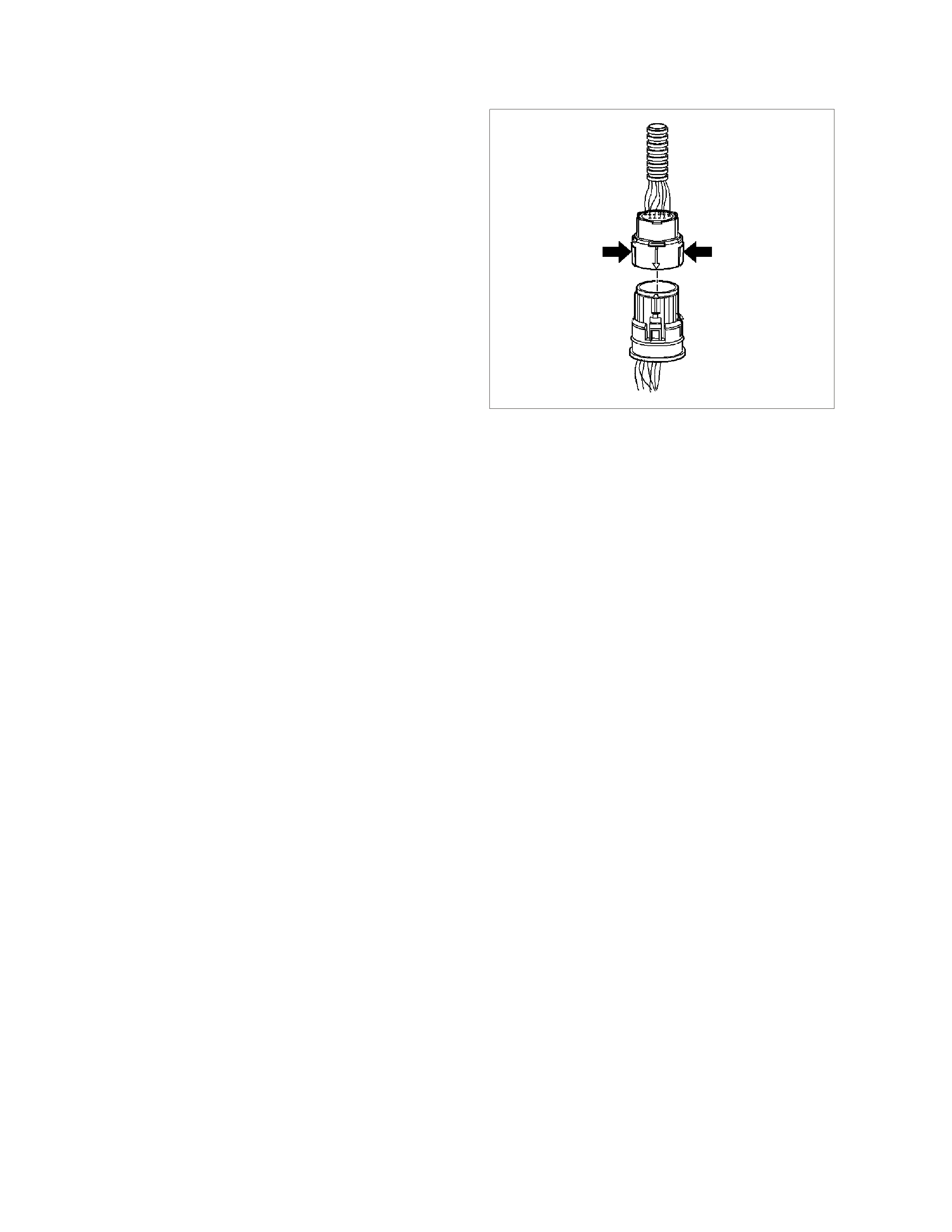
ELECTRICA L CONNECTOR
The transmission electrical connector is an important
part of the transmission operating system. Any
interference with the electrical connection can cause
the transmission to set Diagnostic Trouble Codes
(DTCs) or affect proper operation.
The following items can affect the electrical
connection:
• Bent pins in the connector from rough handling
during co nnection and disconnection.
• Wires backing away from the pins or coming
uncrimped (in either the internal or the external
wiring har ness) .
• Dirt contamination entering the connector when
disconnected.
• Pins in the internal wiring conne ctor back ing out of
the connector or pushed out of the connector
during reconnec tion.
• Excessive transmission fluid leaking into the
connector, wicking up into the external wiring
harness and degr ading the wire insulation.
• Moisture intrusion in the connector.
• Low pin retention in the external connector from
excessive connection and disconnection of the
wiring connector assembly.
• Pin corrosion from cont amination.
• Damaged connector assembly.
13265
Remember the following points:
• In or der to r em ove the co nnector , squee ze the two
tabs toward ea ch other and pull st raight up without
pulling by the wires.
• Limit twisting or wiggling the connector during
removal. Bent pins can occur.
• Do not pry the connector off with a screwdriver or
other tool.
• Visually inspect the seals to ensure that they are
not damaged du ring handling.
• In order to reinstall the external wiring connector,
first align the pins by lining up the arrows on each
half of the connector. Push the connector straight
down into the transmission without twisting or
angling the m ating parts.
• The connector should click into place with a
positive feel and/o r noise.
IMPORTANT: Whenever the transmission external
wiring connector is disconnected from the internal
harness and the engine is operating, DTCs will set.
Clear these DTCs after reconnecting the external
connector.

1.14 ABBREVIATIONS AND GLOSSARY OF TERMS
Abbreviations used in this Service Information CD are listed below in alphabetical order with an explanation of the
abbreviation.
POWERTRAIN MANAGEMENT
AC - ALTERNATING CURRENT - A current whose polarity is constantly chang ing between positive and negative.
A/C - AIR CONDITIONING
A/F - AIR/FUEL (A/F RATIO)
AN ALOG SIGNAL - An electrical signal that varies in voltage within a given param eter.
BAROMETRIC PRESSURE - Atmospheric pr essure. May be called BARO, or barometric absolute pressure.
BATTERY - Stores chemical energy and converts the chemical energy into electrical energy. This provides DC
current for the vehicle’s electrical systems.
CAT. CONV - CATALYTIC CONVERTER - A muffler-shaped device fitted in the exhaust system, between the
engine and the m uf fler . The purpo se of the cat alytic con verte r is to c hem ically conver t eng ine pro ducing gases into
environmentally safe gases. HC, CO, and NOx emitted by the engine, are converted to water vapour, carbon
dioxide, and nitrogen.
CHECK POWERTRAIN LA MP (CPL) - A W arning indic ator loc ated on the instr ument panel, and controlled by the
PCM. The lamp is illuminated by the PCM when it detects a fault in the engine management system, or when the
ignition is ON with the engine not runnin g (bulb che ck).
CKT - CIRCUIT
CLOSED LOOP - A fuel cont rol m ode of ope ration that us es the signal f rom the ex haus t oxygen sens or, in order to
control the air/fuel ratio pr ecisely at a 14.7 to 1 ratio. This allows maxi mum efficienc y of the catalytic converter.
CO - CARBON MONOXIDE - One of the pollutants found in the engine exhaust.
DIAGNOSTIC TROUBLE CODE - The PC M can det ect f aults in t he engine mana geme nt system . If a fault occur s,
the PCM m ay turn on the Ch eck Power train Lam p (CPL) and a four digit code num ber will set. A diagnos tic trouble
code can be read with the Tech 2 scan tool. This DTC will indicate the area of the fault.
DIAGNOSTIC TEST ENABLE TERMINAL - A terminal in the Data Link Connector(DLC) that is earthed to get a
Diagnos tic Tr ouble Code.
DIGITAL SIGNAL - An electrical signal t hat is either ON or OFF .
DLC - DATA LINK CONNECTOR - Used at the assembly plant to evaluate the engine management system. For
service to flash the Check Powertrain Lamp (CPL), use of Tech 2 scan tool and performing other system checks.
DLC DATA STREAM - An output from the PCM, initiated by the Tech 2 scan tool. This output is a digital signal,
used by assembly plant test equipment and the Tech 2 scan tool. This signal is transmitted from the PCM to the
Dat a Link Connector(DLC).
DMM (10 Meg Ohm) - MULTIMETER - A mult ipurpos e m eter t hat ha s cap ability of m eas uring Voltag e, Am ps , and
Ohms.
DRIVER - An elect r onic device, usua lly a power transistor, that op erates like an electr ical switch turning a circ uit ON
and OFF.
DUTY CYCLE - The tim e, in perce ntage, that a circuit is ON versus OF F .
FIELD SERVICE MODE - A PCM mode of operation that is used during service. It is operational when the engine is
running and the DLC diagnostic te st enable ter minal is earthe d.
ENGINE COO LAN T TEM PERATUR E (ECT ) SENSOR - A sens or that sense s the engine coo lant temp erature and
sends that information to the powertrain control module.
EECS - EVAPORATIVE EM ISSIONS CONT ROL SYST EM - Used t o prevent petrol vapo urs from the fuel tank from
enter ing into the atmosphere. The vap ours are stor ed in a canister, located under th e vehicle. The caniste r contains
an act ivat ed char coal element. The petrol vapour s are pur ged fro m the caniste r into the manif old to be burned in the
engine.
EMI OR ELECT RICAL NO ISE - An unwanted sign al int erf er ing with ano th er ne ede d signal. Comm on ex ample s are
an electric razor's effect on a te levision, or AM rad io r eception while dr iving under high voltage power lines.
EPROM - ERASABLE PROGRAMMABLE READ ONLY MEMORY - Type of Read Only Memory (ROM) that can
be erased with ultra vio let light and rep rogrammed.
ESD - ELECTROSTATIC DISCHARGE - The discharge of static electricity, which has built up on an insulated
material.
EEPROM - ELECTRICALLY ERASABLE PROGRAMMABLE READ ONLY MEMORY - T ype of rea d o nly memo ry
(RO M) th at c an be electr ically program m ed, eras ed and re progra mme d using a sc an to ol. Also refe rre d to as F lash
Memory.

FIELD SERVICE MODE - A PCM mode of operation that is used during service. The field service mode is
operat ional when the engine is r unning and the DLC diagnost ic test enable terminal is earthed.
FUSE - A thin metal strip which melts through when excessive current flows through it, creating an open circuit,
protecting a circuit from damage.
HC - HYDROCARBONS (HC) - Any unburnt fuel leaving th e engine fr om inco mplet e combustion.
IAC VALVE - IDLE AIR CONTROL VALVE - Installed on the throttle body unit and controlled by the PCM to
regulate idle air flow, and thus idle RPM.
IAT SENSOR - INTAKE AIR TEMPERATURE SENSOR - A sensor that enses intake manifold incoming air
temperature, and sends the information to the PCM.
IDEAL M IXTURE - The air/fuel ratio which pr ovides the best pe rform ance , while m aintaining max imum c onversion
of exhaust emissions, typically 14.7 to 1 on petr ol engines.
IGN - IGNITION
INPUTS - Information from sensors (MAF, TPS, etc.) and switches (A/C request, etc.) used by the PCM to
determine how to control its outputs.
INTERMITTENT - An electrical signal that occurs now and then; not continuously. In electrical circuits, refers to
occa sional open, short, or earth in a circuit.
IPC - INS TRU MENT PANEL CLUSTER
LOW - A voltage les s t han a s pec if ic t hr es hold. Ope rat es t he s ame as an e art h and m a y, or m ay not, be conn ect ed
to chassis earth.
MAF - MASS AIR FLOW SENSOR - A device tha t monitor s t he amount of air f low coming in th e eng ine intake. T he
MAF sens or sends a signal to the PC M.
N.C. - NORMALLY CLOSED - Switch contac ts that are closed, when they are in the normal operating position.
N.O. - NORMALLY OPEN - Switch contacts that are normally open when in the normal operating position.
NOx - NITROGEN OXIDE - One of the pollutants found in spark ignition engine exhaust. The are formed from
normal combustion and increase in severity with combustion temperatures.
OXYGEN SEN SOR - T he exh aust gas oxygen sens or is locat ed in the exhaus t m anif old. T he O2 s ensor mea sur es
the oxygen in the ex haust m anif old af ter the c om bust ion pr ocess . T he O2 sens or produce s a sm all elect rical signa l
based on the amount of oxygen in the exhaust gas.
OPEN LOOP - The PCM control of the fuel control system witho ut the use of the oxygen sensor information.
OUTPUT - Functions, typic ally include solenoids and relays, that are controlled by the PCM.
PIM - POWERT RAIN INT ERFACE MODU LE - The PI M acts as a com m unica tion tr anslator between the PCM and
other onboar d c ontrolle rs t hat use a dif fe rent serial data prot ocol. T he GEN III V8 PCM uses the new Class II serial
data t o c om mun icate, while o th er cont rolle rs on the vehic le ar e desig ned to tran smit seria l data via the convent iona l
Universal Asynchronous Receive Transmit (UART) protocol. Since these two types of serial data are not
compatible, a translator or PIM is required to tr ansm it data in either direct ion between the PCM and ot her controller.
PCM - POWERTRAIN CONTROL MODULE - A metal cased box containing electronic circuitry which electrically
monitors and controls the transmission system and emission systems on the engine management system. It also
turns ON the Ch eck Power train Lamp (C PL) when a malfunction occurs in the system.
PCV - POSITI VE CRANKCASE VENTIL ATI ON - Method of rebur ning crankcase f umes , ra ther than pass ing them
directly into the atmosphere.
PROM - PROGRAMMABLE READ ONLY MEMORY - An electronic term used to describe the engine calibration
unit. A plug-in memory unit that instr ucts the PCM how to operate for a particular vehicle.
PULSE WIDTH MODULATED (PWM) - A digital sign al turned O N and OF F for a p ercentage of available o n-plus-
off cycle tim e. A signal that is 30% ON and 70 % OFF would be c alled a 30% ON PWM signal.
QUAD DRIVER - A transistor in the PCM, capable of operating four separate outputs. Outputs can be either ON-
OFF or pulse width modulate d.
RAM - RA NDOM A CCESS MEMORY - Is the m icr oproce ssor s "s cratc h pad". T he proc esso r can write int o, or read
from t his mem ory as neede d. This mem ory is volatile and needs a constan t supply of volta ge to be retained. If the
voltage is lost or removed, this memory is lost.
SERIAL DATA - Serial data is a series of rapidly changing voltage signals pulsed from high to low. These signals
are typically 5 volts (UART), 7 volts (Class II), and 12 or 0 volts (high or low) and are transmitted through a wire
often referred to as the Serial Data Circuit.
SFI - SEQUENTIAL FUEL INJECTION - Method of inj ecting f uel into the eng ine. Places a fuel inje ctor at each inlet
port of a cylinder head, directly in front of the intake valve, mount ed in the intak e manifold.
SOLENOID - An electromagnetic coil which creates a magnetic field when current flows through it and causes a
plunger or ball to m ove.
SWITCH - Opens and closes circuits , thereb y controlling current flow.
TCC - TORQUE CONVERTER CLUTCH - A PCM c ont rolled sole noid in an aut om at ic tr ans miss ion which pos itively
couples the transmission input shaft to the engine.

TECH 2 SCAN TOOL - The Tech 2 scan tool is a hand held computer designed to aid in diagnosis and repair of
automotive systems with electronic controls/interfaces. The Tech 2 scan tool connects to the vehicle’s Data Link
Connector (DLC ).
TP SENSOR - THROTTLE POSITION - A sensor that sends a signal to the PCM. The PCM can determine from
this signal the current throttle position, and th e rate of throttle opening / closing.
VACUUM, M ANIFOLD - A vacuum source from below the thrott le plate.
VACUUM, PORTED - Vacuum source from a small port in the throttle body. With the throttle closed, there is no
vacuum, because the port is on the air c leaner side of the throttle blade, and is exposed to engine vacuum only after
the throttle is open.
VSS - VEHICLE SPEED SENSOR - A perm anen t m agnet type senso r which produ ces an AC voltag e which is sent
to the PCM to determine vehicle speed.
UART - UNIVERSAL ASYNCHRONOUS RECEIVE AND TRANSMIT - A method of communicating between
electr onic devices.WOT - WIDE OPE N TH ROTTLE - A throttle position opening greater than 80%.
AUTOMATIC TRANSMIS SION
AT - Automatic Transmission
BUMP - A sudden and forceful app ly of a clut ch or a band.
CHUGGLE - A bucking or jerking. This c ondition m ay be most noticeable when the converte r clutch is engaged. It is
sim ilar to the feel of towing a trailer.
DC - Direc t Current
DELAYED - A condition wher e a shift is expected but does not occur fo r a perio d of time. This could be descr ibed
as a clutch or band engagement that does not occur as quickly as expected during a part or wide open throttle
application, or during manual downshifting to a lower range. This term is also defined as LATE or EXTENDED.
DOUBLE BUMP (DOUBLE FEEL) - T wo sudden and f orcef ul applications of a clutc h or a band when downshifting
during a zero throttle c oastdown.
DRIVE LINK NOI SE - A whine or gr owl that in creases or f ades with vehicle speed, and is m ost not iceable u nder a
light throttle acceleration. It may also be noticeable in PARK or NEUTRAL operating ranges with the vehicle
stationary.
EARLY - A condition where the shift occurs before the vehicle has reached proper speed. This condition tends to
labour t he engine aft er the upsh ift.
END BUMP - A firm er feel at the end of a shift than at the start of the shift. This is also defined as END FEEL or
SLIP BUMP.
ENGINE BR AKING - A con dition where the engine is used to slow the vehicle on clos ed throttle or low gear.
ETC - Electronic Traction Control
FINAL DRIVE NOISE - A hum r elated to vehicle sp eed which is most notice able under a light throttle acceleration.
FIRM - A notice ably quick apply of a clu tch or band that is co nsidered nor mal with a m edium to heavy throttle. T his
apply should not be confused with HAR SH or ROUGH.
FLARE - A quic k increase in engine RPM along with a mom entary loss o f torque. This most generally occur s during
a shift . This condition is also defined as SLIPPING.
FULL THROTTLE DETENT DOWNSHIFT - A quick apply of the accelerator pedal to its full travel, forcing a
downshift.
HARSH (ROUGH) - A more noticeable apply of a clutch or band than FIRM. This condition is considered
undesirable at any thrott le position.
HEAVY THROTTLE - Approximately 3/4 of accelerator pedal travel (75% throttle position).
HUNTING - A repeating quick series of upshifts and downshifts that causes a noticeable change in engine RPM,
such as a 4- 3-4 shif t pattern . This c ondition is also defined as BUSYNESS.
INI TIAL FEEL - A distinctly firmer feel at the start of a shift than at the finish of the shift.
LATE - A shift that occurs when the engine RPM is higher than no rmal for a given amou nt of thr ottle.
LIGHT THROTTLE - Approxim ately 1/4 of accelerator pedal travel (25% throttle position).
MEDIUM THROTTLE - Approximately 1/2 of accelerator pedal travel (50% throttle position).
MI NIMUM THR O TTL E - The least amount of throttle opening required for an upshift.
OBD - On Board Diag nostic
OSS - Output (Shaft) Speed Sensor
PC - Pressu r e Control
PLANETARY GEAR NOISE - A whine rela ted to vehic le spee d, which is m ost noticea ble in FIRST ge ar, SECO ND
gear, FOURTH gear or REVERSE. The condition m ay become less noticeable, or go away, after an upshift.
PM - Per manent Magnet

PUMP NOISE - A high pitched whine that increases in intensity with engine RPM. This condition may also be
noticeable in all operating ranges with the vehicle stationary or moving.
RPM - Revolutions Per Minute
SHIFT CONDITION DEFINITIONS
SHUDDER - A repea ting jer king cond ition sim ilar to CH UGGLE but m ore s evere and rapid . This co ndition m ay be
m ost notic eable during certain ranges of vehic l e speed.
SLIPPING - A noticeable incre ase in engine RPM withou t a vehicle speed incr ease. A slip usually occurs during or
after initial clut ch or band app ly.
SOFT - A slow, almost unnotice able clutch or band apply with very little shift feel.
SS - Shift Solenoid
SURGE - A repeating engine related conditio n of acceleration and deceleration that is less int ense than CHUGGLE.
TAP - Transmissio n Adaptive Pressure
TFP - Transm ission Fluid Pres sure
TFT - Transmission Fl uid Tempera ture
TIE-UP - A con dition wher e two opposing clutch an d/or ban ds ar e attem pt ing to apply at the sam e tim e caus ing the
engine to labour with a noticeable loss of engine RPM.
TORQUE CONVERTER NOISE - A whine usually noticed when a vehicle is stopped, and the transmission is in
DRIVE or REVERSE. The noise will incr ease with engine RPM.
TV - Throttl e V al v e
WIDE OPEN THROTTLE (WOT) - Full travel of the accelerat or pedal (100% throt tle position).
ZERO THROTTLE COASTDOWN - A full release of the accelerator pedal while the vehicle is in motion and in
Drive range.