
SECTION 6C3-2A - DIAGNOSTIC TABLES
CAUTION:
This vehicle will be equipped with a Supplemental Restraint System (SRS). A SRS will consist of either
seat belt pre-tensioners and a driver's air bag, seat belt pre-tensioners and a driver's and front
passenger's air b ags o r seat b elt p re-t ension ers, driv er’s an d f ron t p asseng er’s air bag and left and righ t
hand side air bags. Refer to SAFETY PRECAUTIONS, Section 12M Supplemental Restraint System of the
VT Series II Service Information before performing any service operation on, or around any SRS
components, the steering mechanism or wiring. Failure to follow the SAFETY PRECAUTIONS could
result in SRS deployment, resulting in possible personal injury or unnecessary SRS system repairs.
NOTICE:
When performing any of these Diagnostic Tables, make certain that the drive wheels are blocked and the
parking brake is firmly set.
Techline
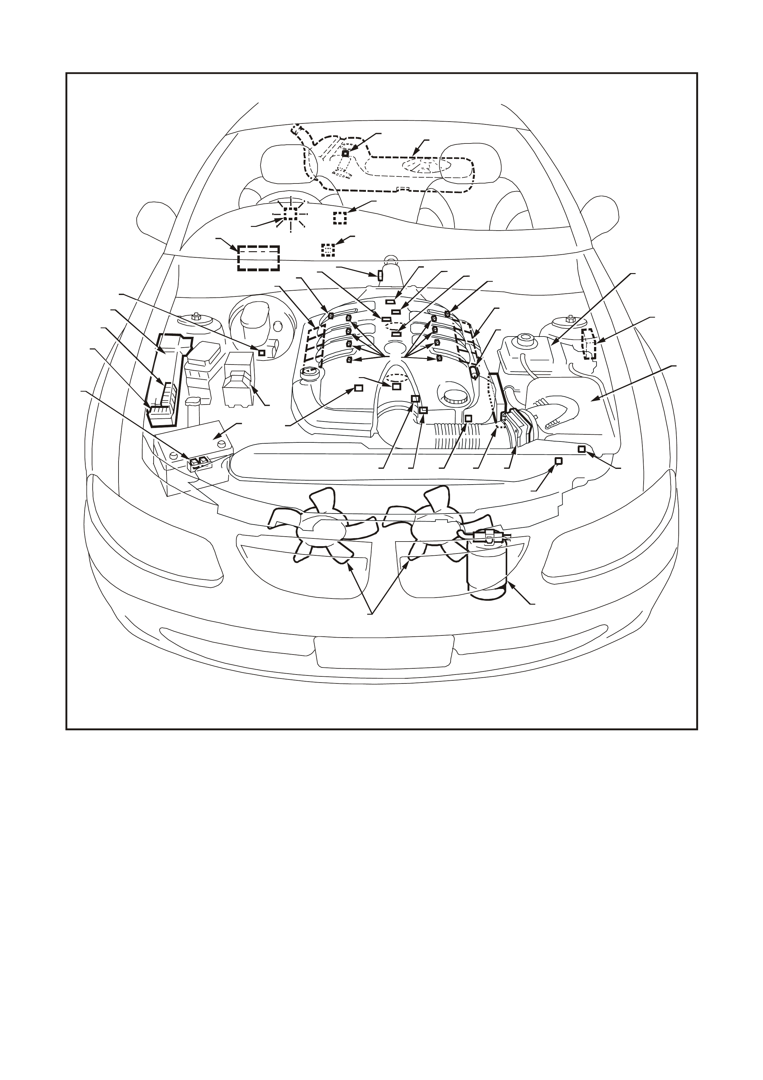
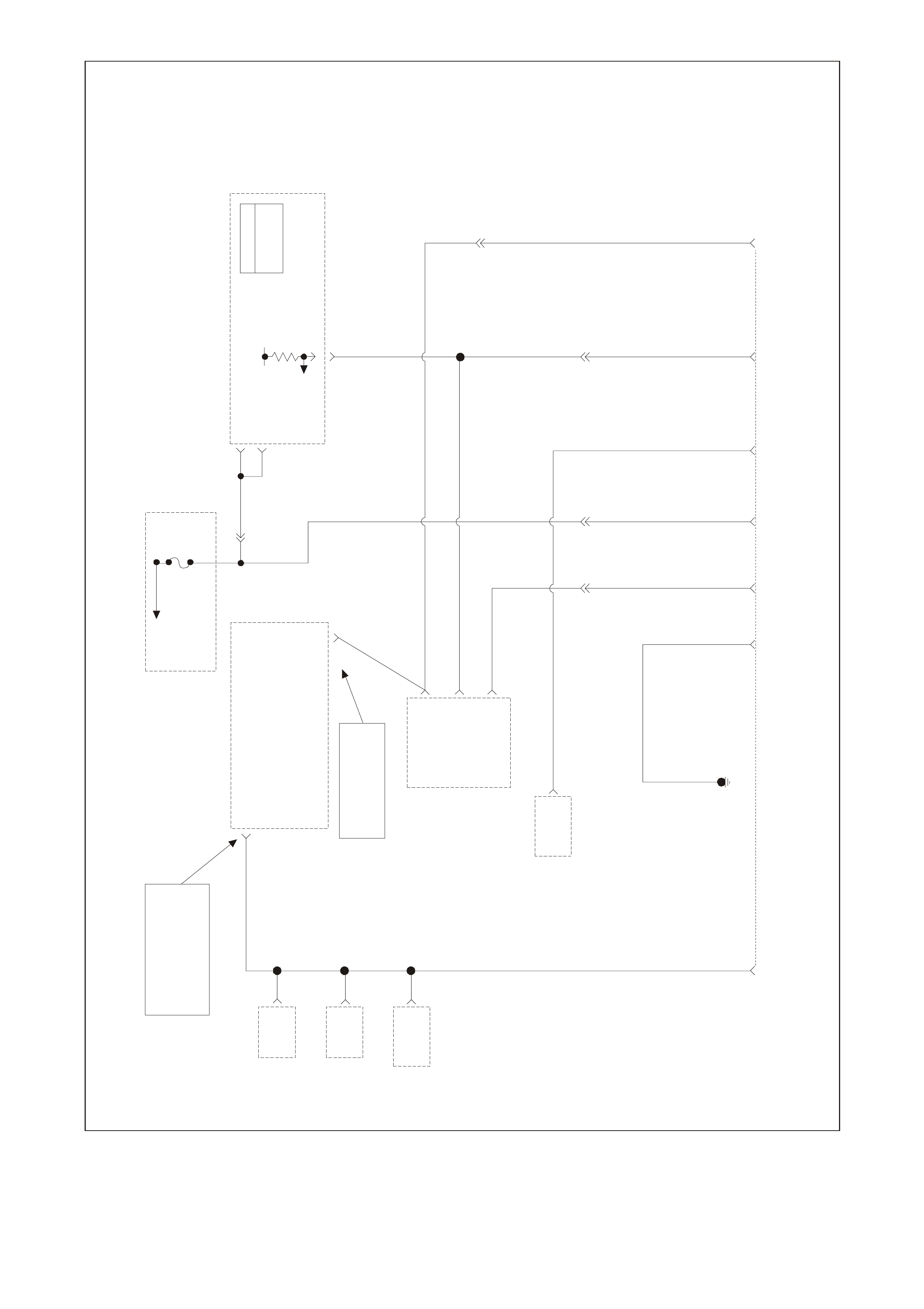
SYSTEM COMPONENT LOCATIONS
T26C3001
1
2
3
4
5
6
7
9
10
11
12
13
14
151617 18
19
20 21
21
23
23
22
24
25
26
27
28
29
30
AB
C
D
F
E
8
1. Engine Compartment Fusible Link
Housing 13. Engine Fans (2) 25. A/C Refrigerant Pressure
Transducer
2. Battery Harness Fusible Link
Housing 14. Canister Purge Solenoid 26. Powertrain Control Module
(PCM)
3. Engine Compartment Relay
Housing 15. Mass Air Flow (MAF) Sensor 27. Powertrain Interface Module
(PIM)
4. Engine Compartment Relay
Housing 16. Engine Coolant Temperature (ECT)
Sensor 28. Diagnostic Link Connector (DLC)
5. Fuel Pressure Regulator - In fuel
tank 17. Throttle Position (TP) Sensor 29. Oil Pressure Sensor
6. A/C Accumulator Tank 18. Intake Air Temperature (IAT)
Sensor 30. Manifold Absolute Pressure
(MAP) Sensor
7. Brake Hydraulic Failure Switch 19. Vehicle Speed Sensor (VSS) (A) Battery
8. Fuel Injectors (8) 20. Camshaft Position (CMP) Sensor (B) ABS
9. Idle Air Control (IAC) Valve 21. Heated Oxygen (HO2S) Sensor (2) (C) BCM
10. Check Powertrain Lamp (CPL) 22. Crankshaft Position (CKP) Sensor (D) Fuel Tank
11. Ignition Coil/Module Right Bank 23. Knock (KS) Sensors (2) (E) Surge Tank
12. Ignition Coil/Module Left Bank 24. ECC In-Car Air Temperature Sensor (F) Air Cleaner
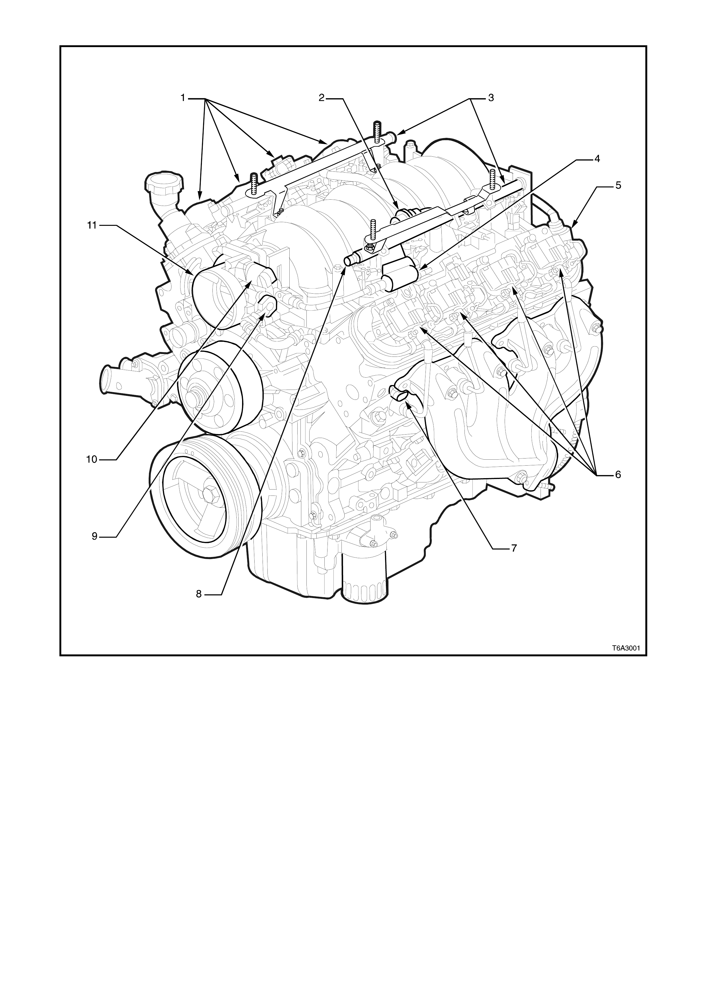
GEN. III V8 Engine View LH
1. Right Hand Ignition Coils/Modules 7. Engine Coolant Temperature (ECT) Sensor
2. Fuel Pulse Dampener 8. Fuel Pressure Gauge Test Connector
3. Fuel Rail with Injectors 9. Throttle Position (TP) Sensor
4. EVAP Canister Purge Solenoid 10. Idle Air Control (IAC) Valve
5. Crankcase Vent 11. Throttle Body
6. Left Hand Ignition Coils/Modules
GEN3 0002
4
12
3
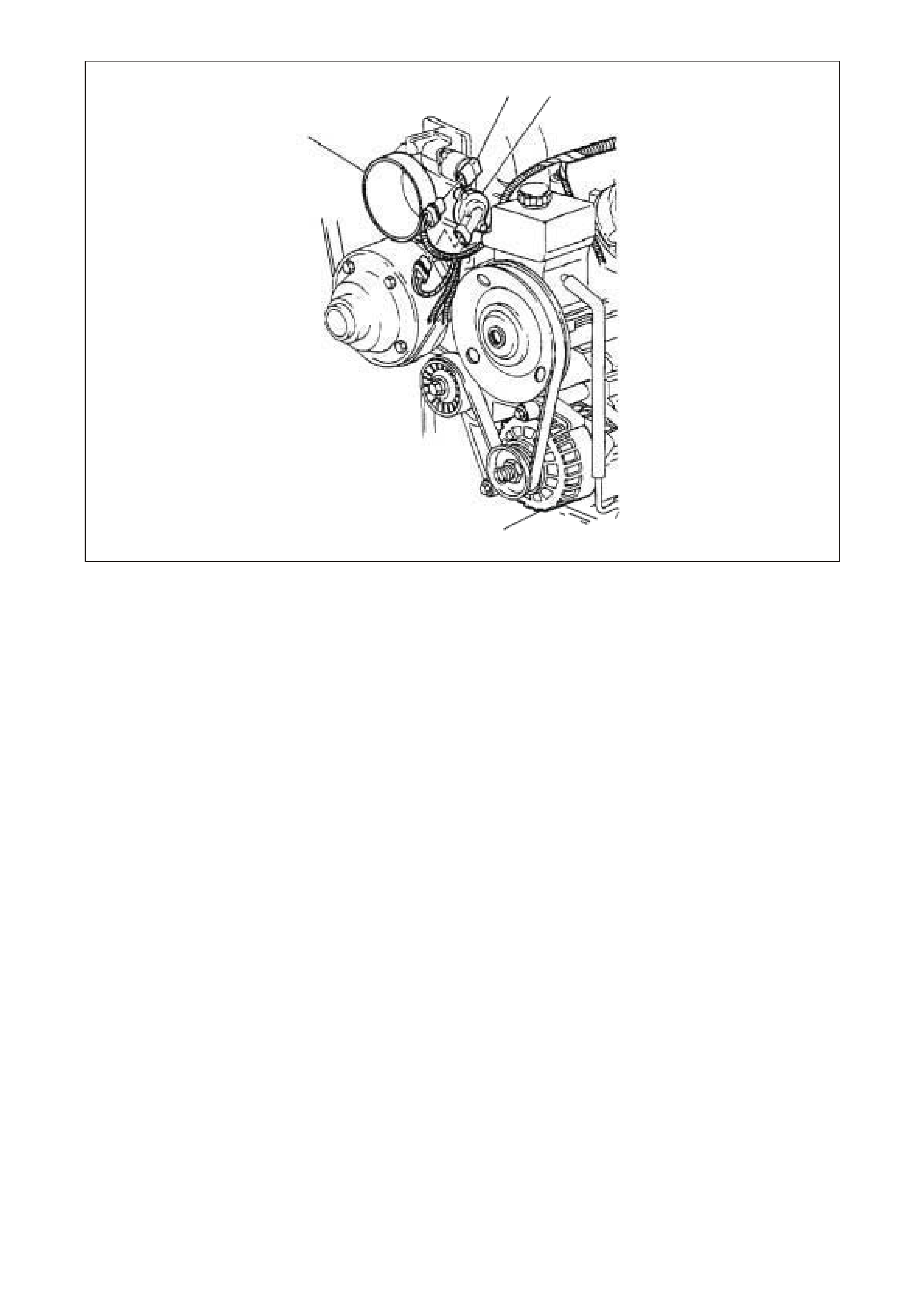
GEN. III V8 Front of Engine View
1. Idle Air Control (IAC) Valve 3. Generator
2. Throttle Position (TP) Sensor 4. Throttle Body

GEN. III V8 Rear of Engine View
1. Manifold Absolute Pressure (MAP) Sensor 3. Oil Pressure Sensor
2. Camshaft Position (CMP) Sensor 4. Connector to Knock Sensor Jumper Harness
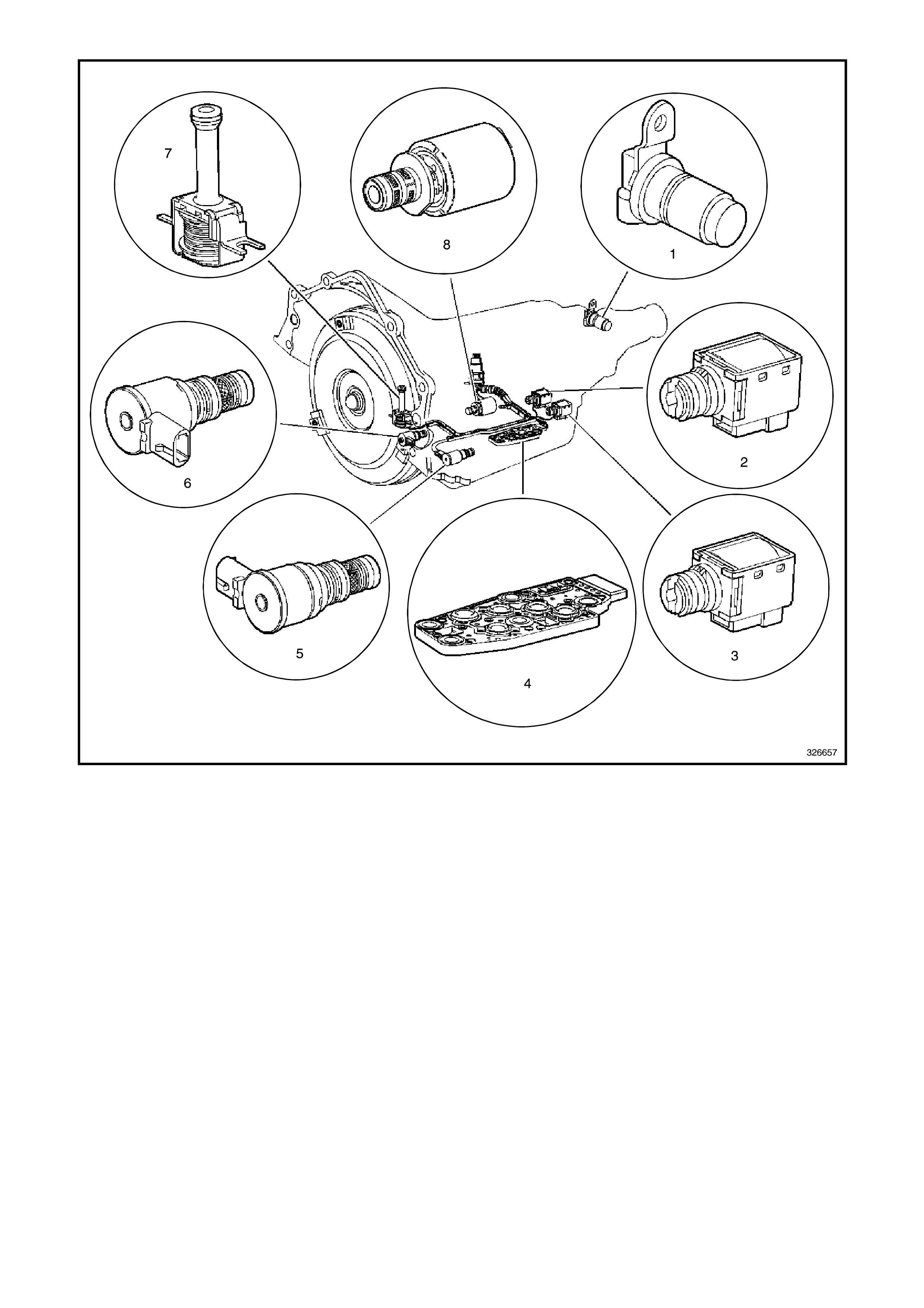
Automatic Transmission Internal Electronic Component Locations
1. Vehicle Speed Sensor 5. Shift Solenoid (SS) Valve Assembly
2. Shift Solenoid B (SS) Valve 6. Torque Converter Clutch Pulse Width Modulation (TCC
PWM) Solenoid Valve
3. Shift Solenoid A (SS) Valve 7. Torque Converter Clutch (TCC) Solenoid Valve
4. Automatic Transmission Fluid Pressure (TFP) Manual
Valve Position Switch 8. Pressure Control Solenoid (PCS) Valve
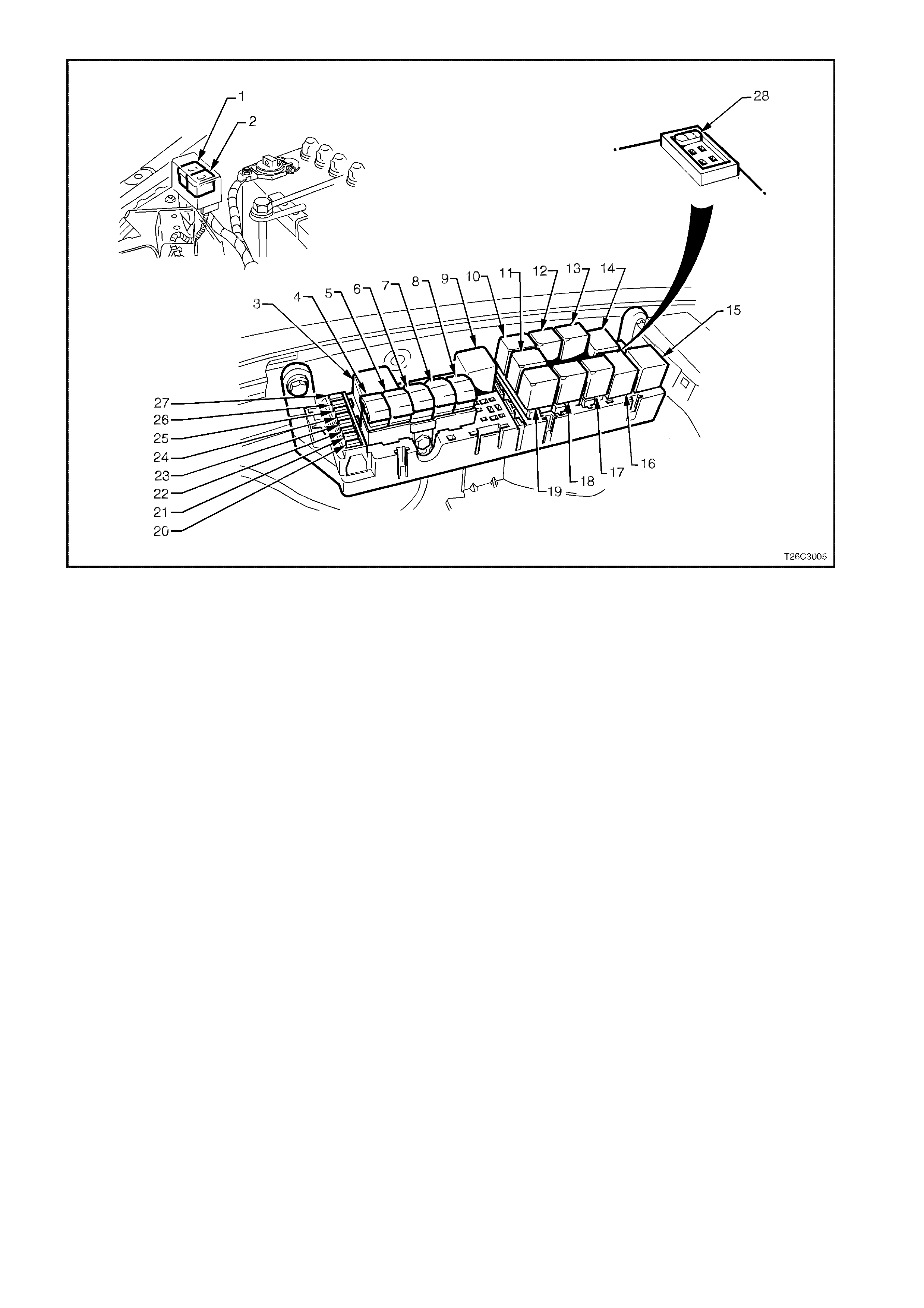
Engine Compartment Fuse/Relay Panel
1. Fan 1 Fusible Link FU 15. Start Relay
2. Fan 2 Fusible Link FT 16. Headlamp High Beam Relay
3. Engine Fan Relay (Low Speed) 17. Fuel Pump Relay
4. Lighting Fusible Link FQ 18. Front Wiper Relay
5. ABS Fusible Link FR 19. Headlamp Low Beam Relay
6. Engine Fusible Link FS 20. Injectors/Ignition Fuse F35
7. Main Fusible Link FJ 21. Injectors/Ignition Fuse F34
8. Blower Fusible Link FY 22. Engine Sensors Fuse F33
9. Engine Cont. (EFI) Relay 23. Automatic Transmission Fuse F32
10. Horn Relay 24. Engine Control/BCM Fuse F31
11. A/C Relay 25. LH Headlamp Fuse F30
12. Theft Horn Relay 26. RH Headlamp Fuse F29
13. Fog Lamp Relay 27. Fuel Pump Fuse F28
14. Engine Fan Relay (High Speed) 28. Throttle Relaxer Control Module Fuse F36
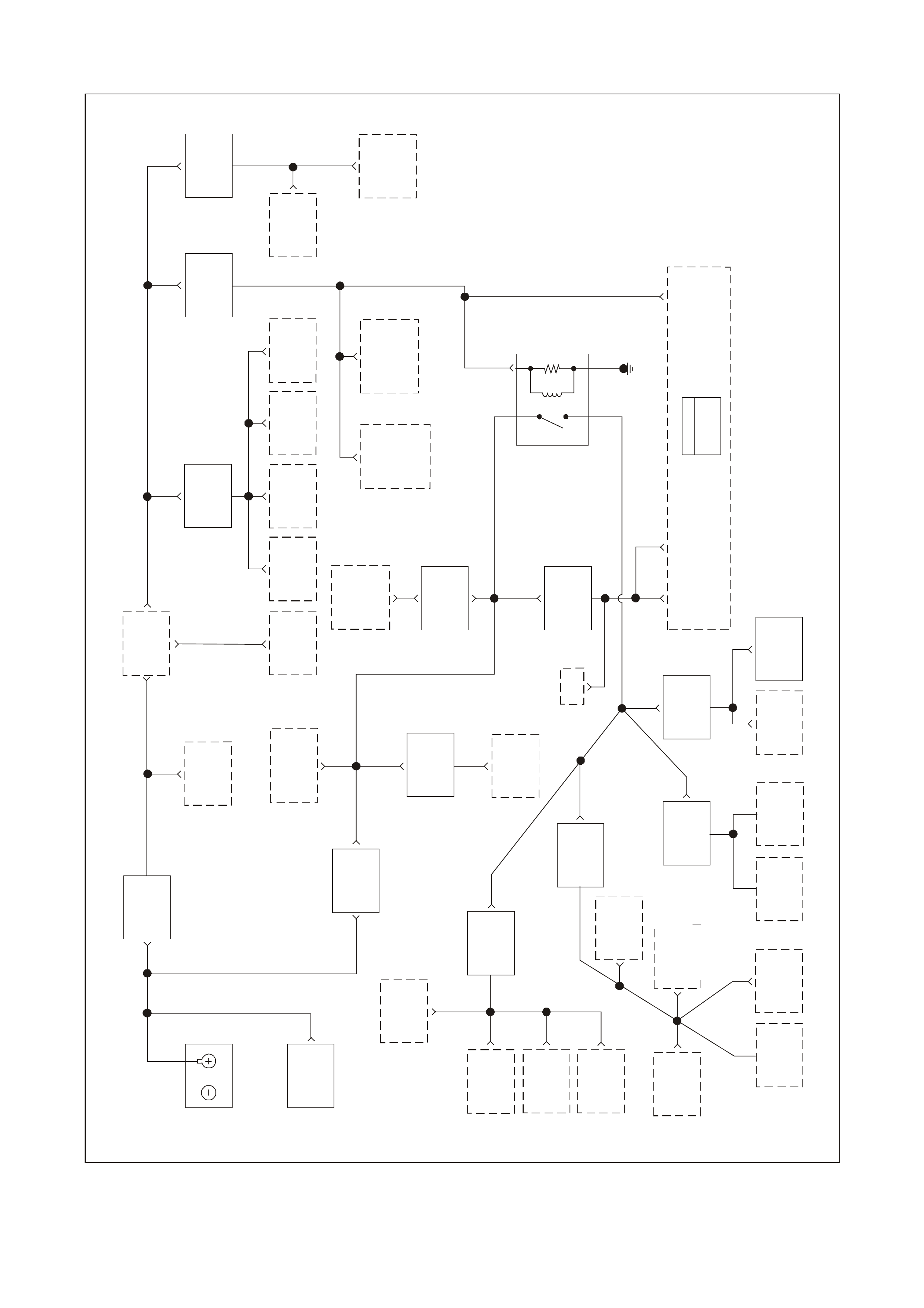
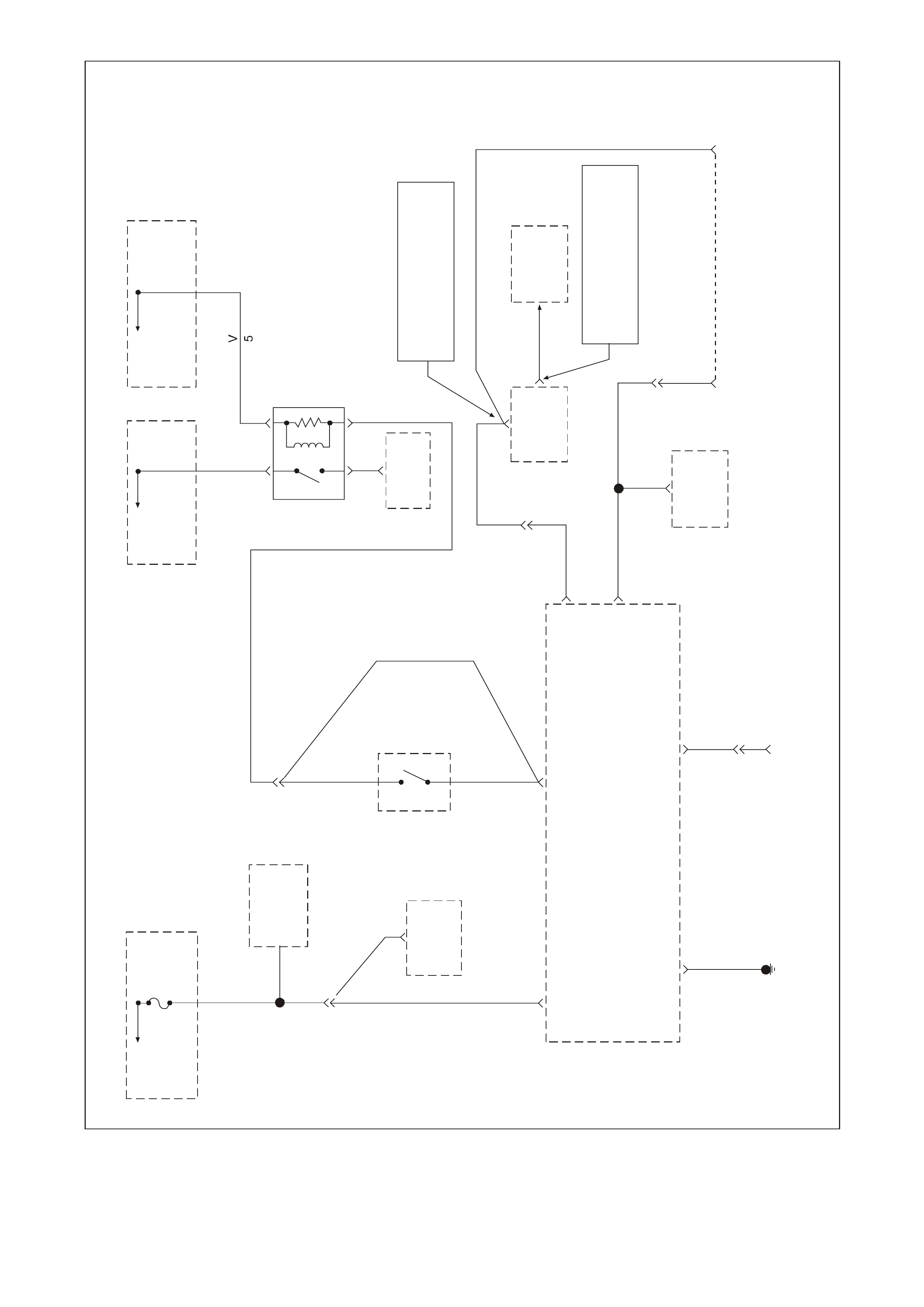
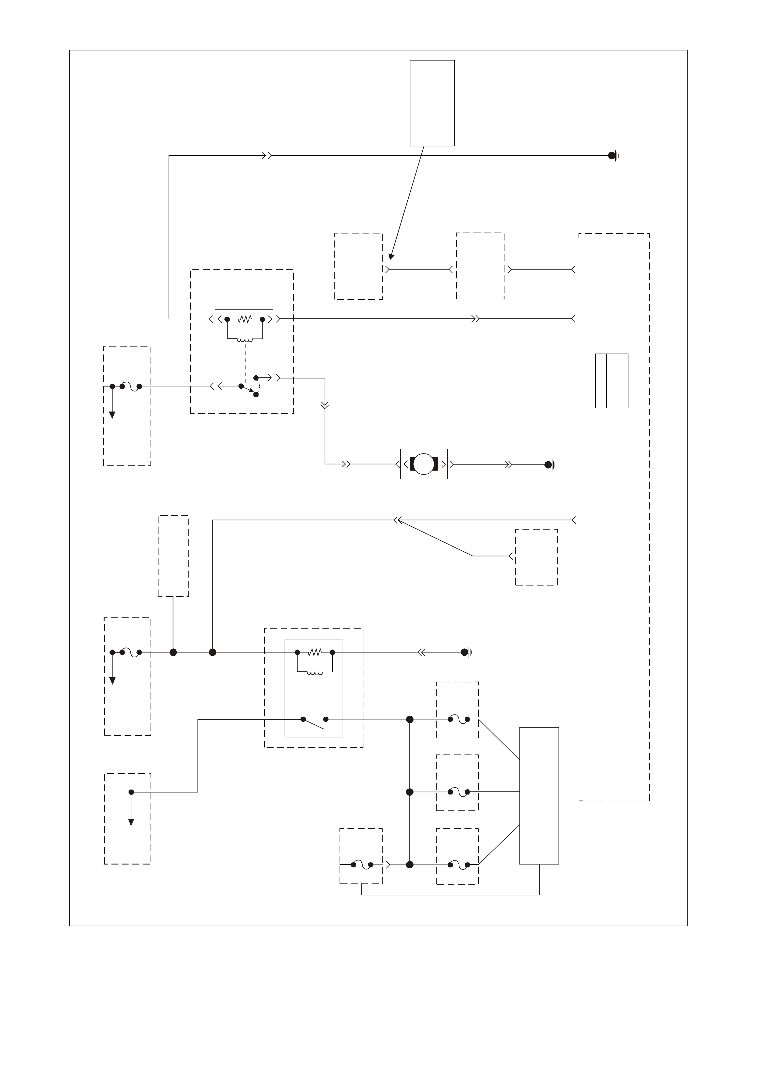
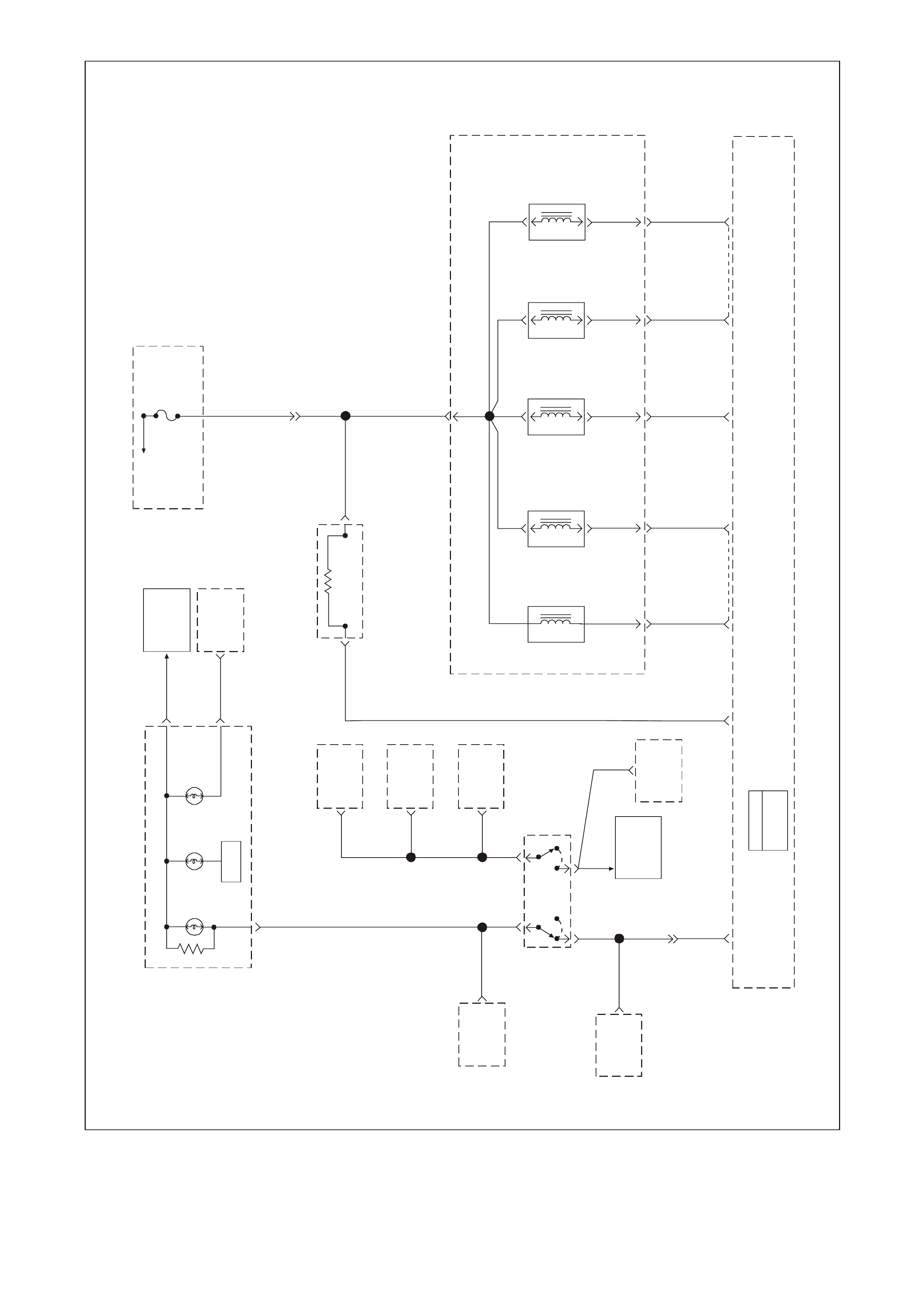
PCM WIRING DIAGRAMS
GEN3 0052
Battery
See
Part 2
MAF
Sensor
Oxygen
Sensor
Heaters
Canister
Purge
Solenoid
3-2
Solenoid
Shift 1-2
Solenoid
Shift
2-3
Solenoid
TCC
Enable
Solenoid
TCC PWN
Solenoid
Fuse
F33
A/C
Relay
Fusible
Link FJ
Start
Relay
Cooling
Fan Relay
Low Speed
Fusible
Link FS
Fuse
F28
Fuel
Pump
Relay
Fuse
F34
Ignition
Module
2, 4, 6, 8 Injector
2, 4, 6, 8
Fuse
F32
Ignition
Module
1, 3, 5, 7 Injector
1, 3, 5, 7
Fuse
F35
DLC
Battery
Feed
PCM
J1 = BLUE
J2 = RED
Fuse
F31
Start
Relay IP
Cluster
Throttle
Relaxer
Control
Module
ECC
Module Blower
Relay A/C
Master
Switch
Powertrain
Interface
Module
(PIM)
Cooling
Fan Relay
High Speed
Fuse
F36
Ignition
Switch
Fuse
F13 Fuse
F14 Fuse
F27
ABS/ETC
Module 15
1
Throttle
Relaxer
Control
Module
19 J1
Ignition
Positive
Voltage
Powertrain
Control
Module
(PCM)
Engine
Earth
86
85
30
87
EFI
(Engin e Con t.)
Relay
15 85
51, 24
85
30
85
3
16
20 57 J1
C
D
A
2, 3
Powertra in Controls Schematics (Fused Power Circuits Pa rt 1)
GEN3 0053
Battery
See
Pa r t 1
Blue
Fusible
Link Wire
Fusible
Link FQ Fuse
F5
Fusible
Link FR ABS/ETC
Module
17
18
Body Control
Module
(BCM)
18
Stop
Lamp
Switch
Fusible
Li n k F T
Fusible
Link FU
Cooling
Fan Motor
#2
Cooling
Fa n Motor
#1
Cruise
Control
Actuator
Rear
Stop
Lamps
ABS/ETC
Module
G
14
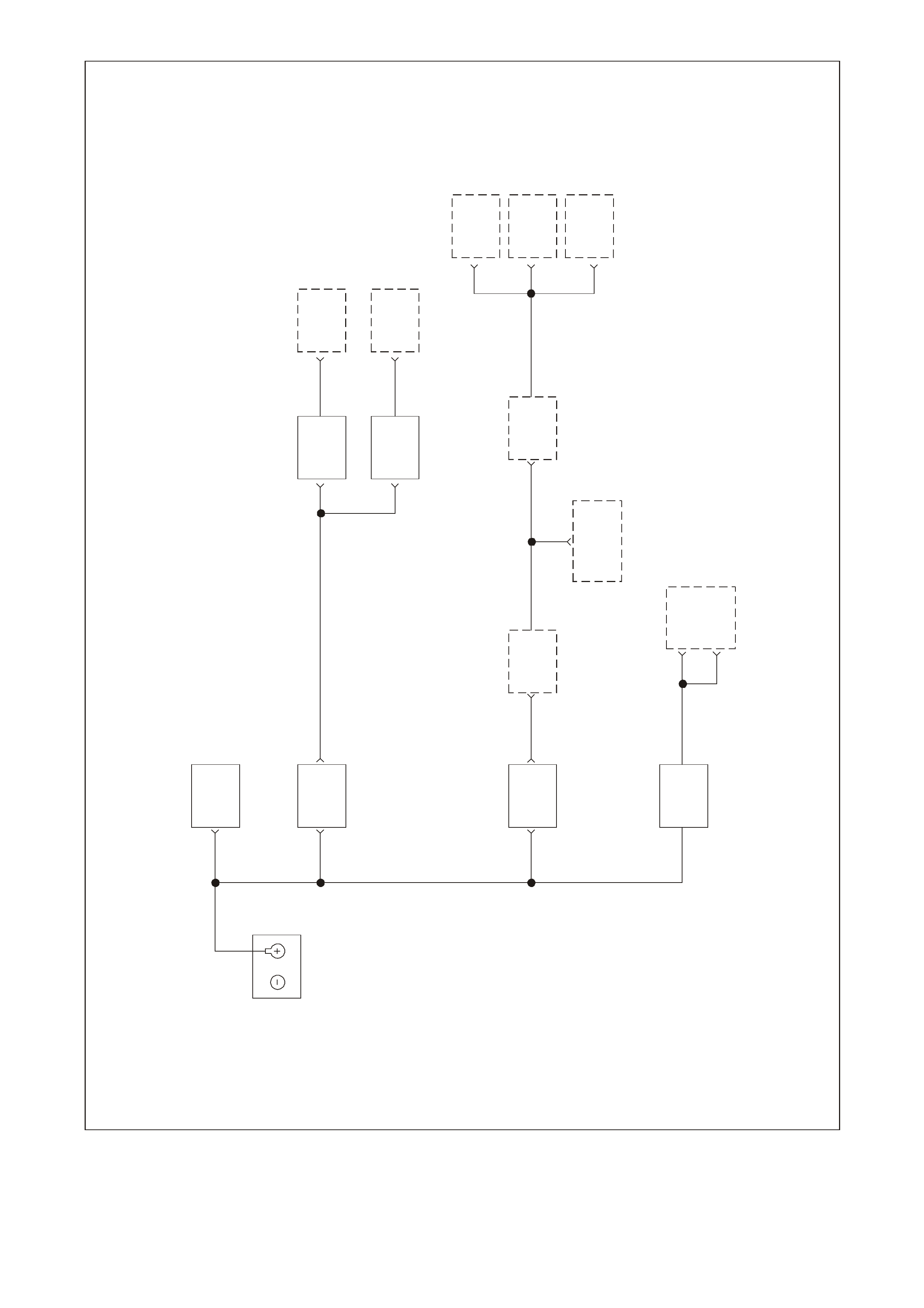
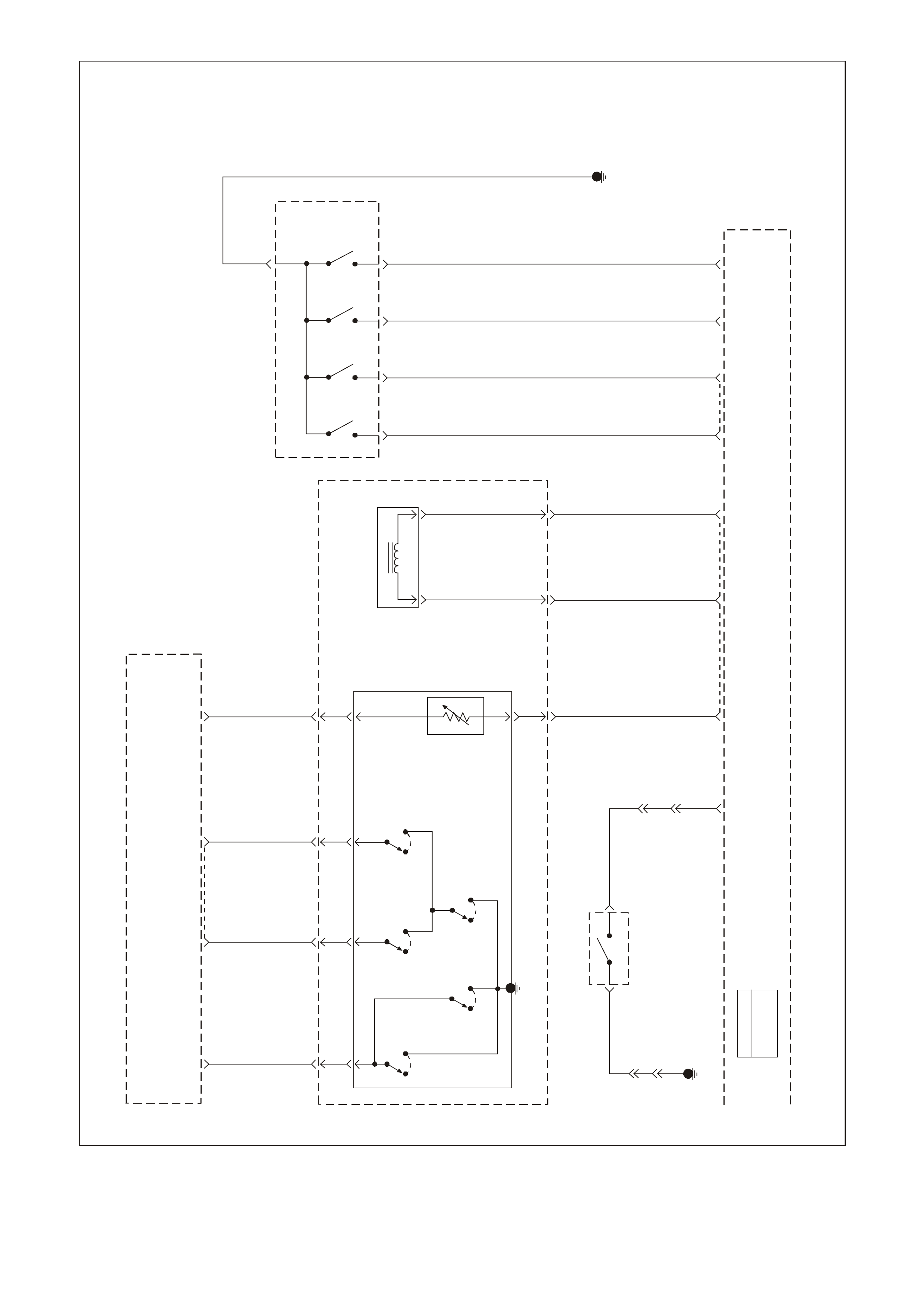
Powertra in Control Sc hematics (Fused Power Circuits Pa rt 2 )
GEN3 0054
To
Fusible
Link
FS
Fuse
F31
To
Ignition
Switch Fuse
F14
Refer to
Wiring
Schematic
Part 1
O/B 740 P/B 39
O740 P39
O740
20 57 19 58 J1
P39
YE112
Battery
Feed Ignition
Positive
Voltage
Battery
Feed
B/R 750 B/R 750 B/R 750 B/R 750
B/R 750
750
B/R
Engine Earth
L ocation E5 / E15
Oxyg e n Sens or
Heaters
CC
Serial
Data
(Class 2)
PCM
J1 = BL UE
J2 = RED
Powertrain
Control
Module
(PCM)
Y1049 YE110
291
Data Link
Connector
(DLC)
R/B 1221
1049
Y
7
R/B
1221 YE112 2
6Ser ial Data
(UART)
Serial Data
(UART)
Se ria l D ata
(C la ss 2)
Powertrain
Interface
Module
(PIM)
Ignition
Voltage
15
Fuse
F13
ECC
Module 6
P/BLU 44
19
Gear Indicator Lamps
(Option)
SDI
Low
Coolant
Lamp
SDI
Power
Economy
Lamp
Check
Powertrain
Malfunction
Indicator
Lamp (MIL)
SDI
Oil
Warning
Lamp
Instrument Panel C lu s te r
G/W 1220
12
B/Y
155
9
G/W 1220
G/W 1220
Serial Data
(UART)
ABS/ECT
Module
11
Body
Control
Module
(BCM)
NOTE
BCM Terminals
9 YB175 High Series
3 YB164 Low Series
NOTE
YB17 5 High Series
YB164 Low Series
01 40 J1 01 40 J2
6
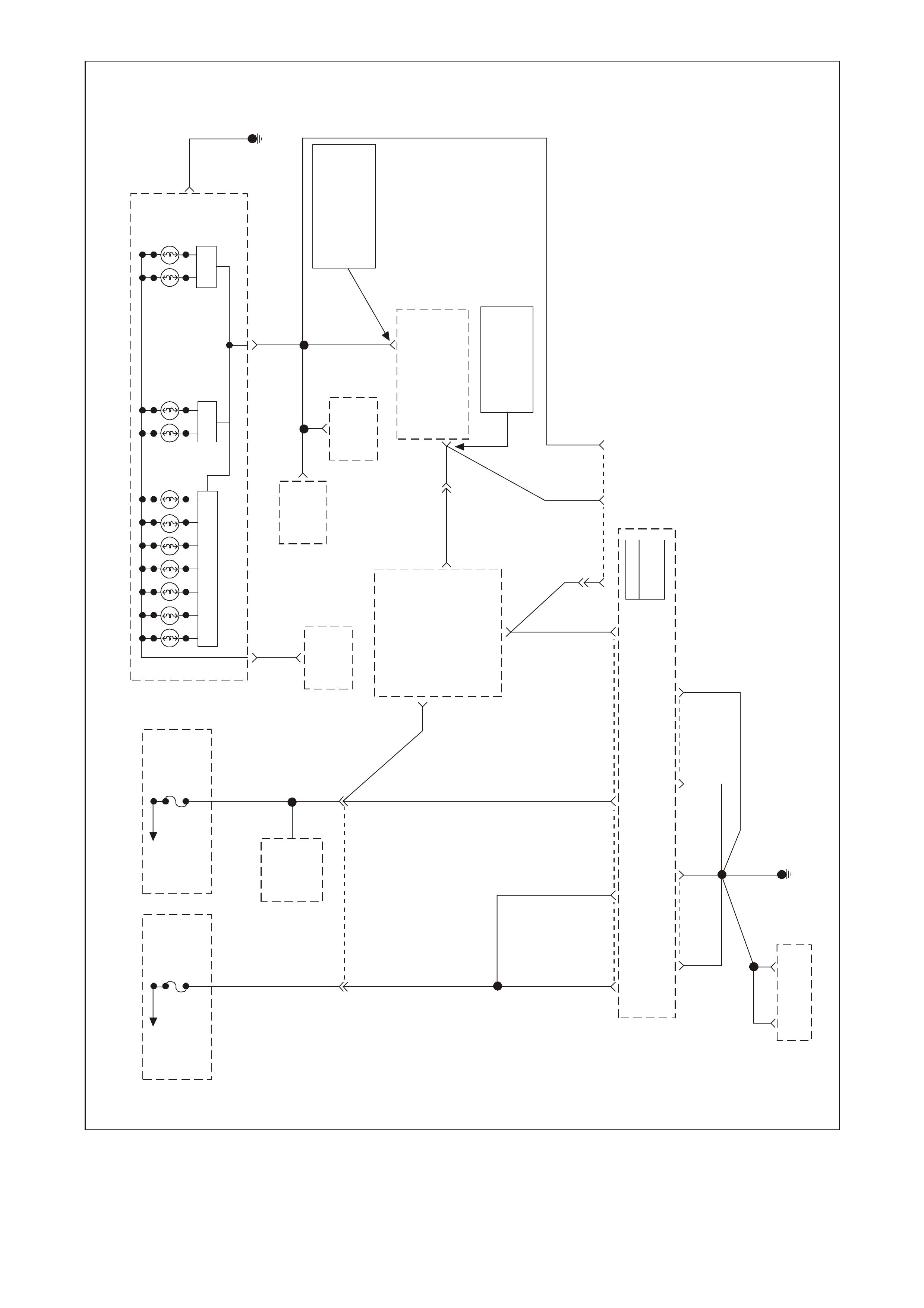
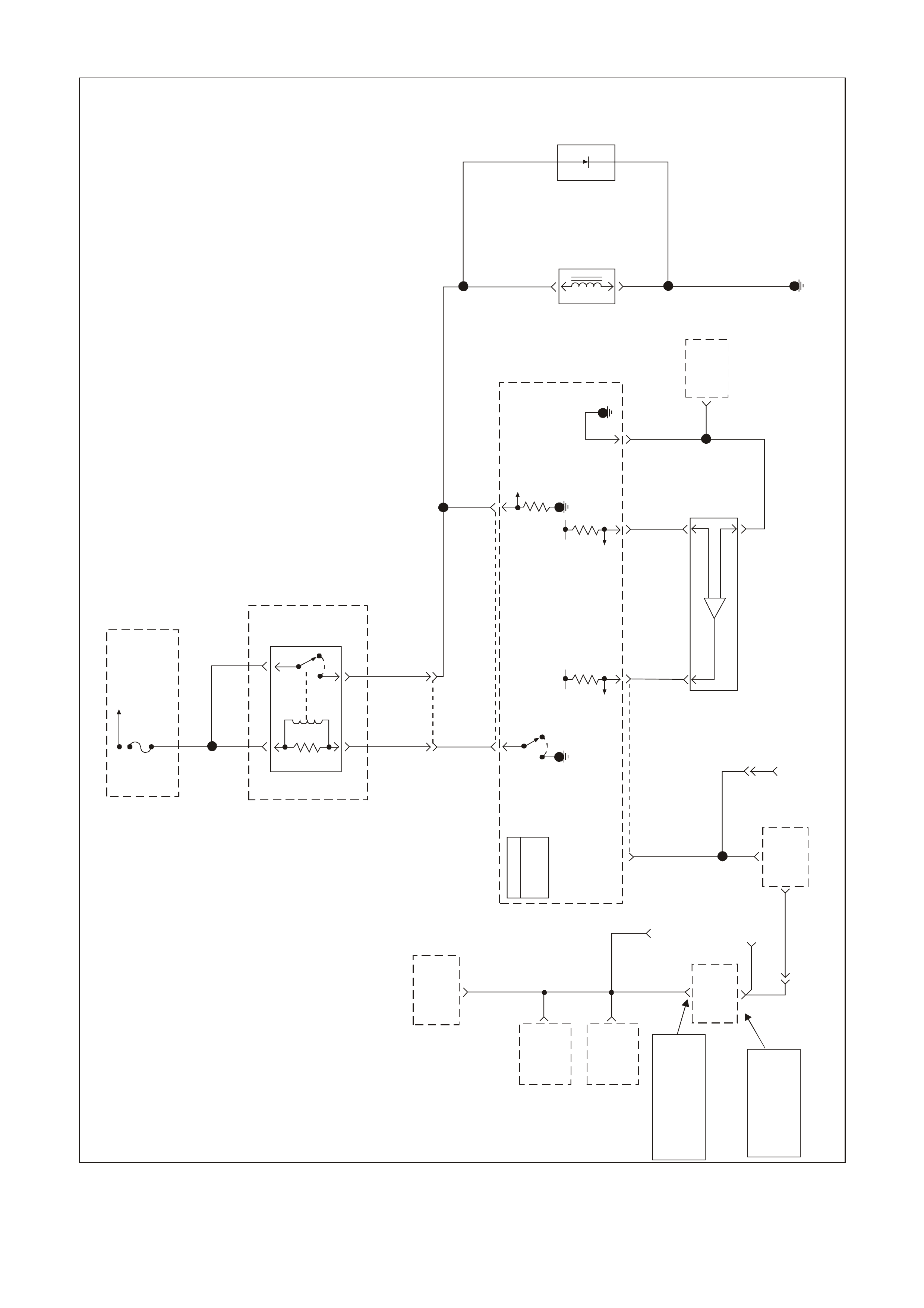
Powertrain Control Schematics (Power, Earth and CPL)
GEN3 0055
PCM
J1 = BL UE
J2 = R E D
NOTE
BC M Termin al
9 Y B 175 H ig h Se ries
3 YB164 Low Series
Body
Earth 56 16 212 9
B/Y 155 B/Y 155 BLU/B 863
R/B 1221
YE112
Data Link
Connector
(DLC)
Y1049
YE110
58 J1
Y1049
7V
Serial D a ta
(C l as s I I)
Fuse
F31
Fusible
Link FS
O/B 740
R/B
1221 Y
1049
YE111
YE112
W/B 451
BLU/B
863
6
7
11
R/B 1221
2
Serial Data
UART
Serial Data
UART
Se r i a l Data
UART
Se r i a l Data
(C la ss I I )
Diagnostic Test
Enable
Powertrain
Interface
Module
(PIM)
NOTE
YB175 H ig h S e r i e s
YB164 Lo w Seri es
9
Body
Control
Module
(BCM)
12
Diagnostic
Enable
ABS/ETC
Module
1
G/W 1220
IP
Cluster
ECC
Module
ABS/ETC
Module
6
11
G/W
1220
20
57
J1
Powertrain
Control
Module
(PCM)
Battery
Feed
O
740
Powertrain Control Schematics (Data Link Connector (DLC) )
GEN3 0056
To
Ignition
Switch Fuse
F14
Refer to
Wiring
Schematic
Part 1
YE112
Powertrain
Control
Module
(PCM)
P/B 39
P39
Ignition
Positive
Voltage
P39
19 J1
15 8
Ignition
Input Start Rel ay
Control
GY/BLU 1434
GY
434
Se ria l D at a
(UART)
Se ria l D at a
(C la ss I I )
Earth
Diagnostic
"TEST"
Enable
16 11
B/R 750 W/B 451
YE111
Engine Earth
Location E Data Link
Connector
(DLC)
6
Powertrain
Interface
Module
(PIM) 6
7
GY/BLU 1434
Neutral
Start
Switch
(Auto Only)
G
YE111
GY 434
Manual
Transmission
GY
434
R/B
1221
Fusible
Link
FJ
To
Ignition
Switch
R2
30 85
87 86
Start
Relay
To Starter
Solenoid NOTE
YB175 High Series BCM
YB164 Low Series BCM
R/B 1221 2
R/B
1221
YE112 Serial Data
(UART)
9R/B
1221
To
Vehicle
Bus
NOTE
"9" YB17 5 Hi gh Series
"3" YB164 Low Series
Body Control
Module (BCM)
R/B 1221
9Data Link
Connector
(DLC)
2
Y1049
YE110
Y1049
58 C1
Y
1049
Serial Data
(C l as s II)
Powertrain
Control Module
(PCM)
E
Powertrain Control Schematics (Powertrain Interface Module (PIM) and Start Relay)
GEN3 0057
PCM
J1 = BLUE
J2 = RED
Powertrain
Control
Module
(PCM)
J227
Ignition
Control
7
68
Ignition
Control
5
69
Ignition
Control
3
26
Ignition
Control
1
60
Reference
Low
Fuse
F35
To EFI
(Engine Cont.)
Relay
To Injectors
1, 3, 5, 7
YE111
482
LG 971W973
BLU 958BR 975G977
Y
BC
E
FH G
B
C
D
Ignition
Coil/
Module
1
Ignition
Feed Ignition
Control
Signal
Reference
Low
Earth
A
Spark
Plug
B
C
D
Ignition
Coil/
Module
3
Ignition
Feed Ignition
Control
Signal
Reference
Low
Earth
A
Spark
Plug
C
D
B
Ignition
Coil/
Module
5
Ignition
Feed Ignition
Control
Signal
Reference
Low
Earth
A
Spark
Plug
C
D
B
Ignition
Coil/
Module
7
Ignition
Feed Ignition
Control
Signal
Reference
Low
Earth
A
Spark
Plug
A
750
B/R YE125
Engine Ear th
Location E5/E15
YE125
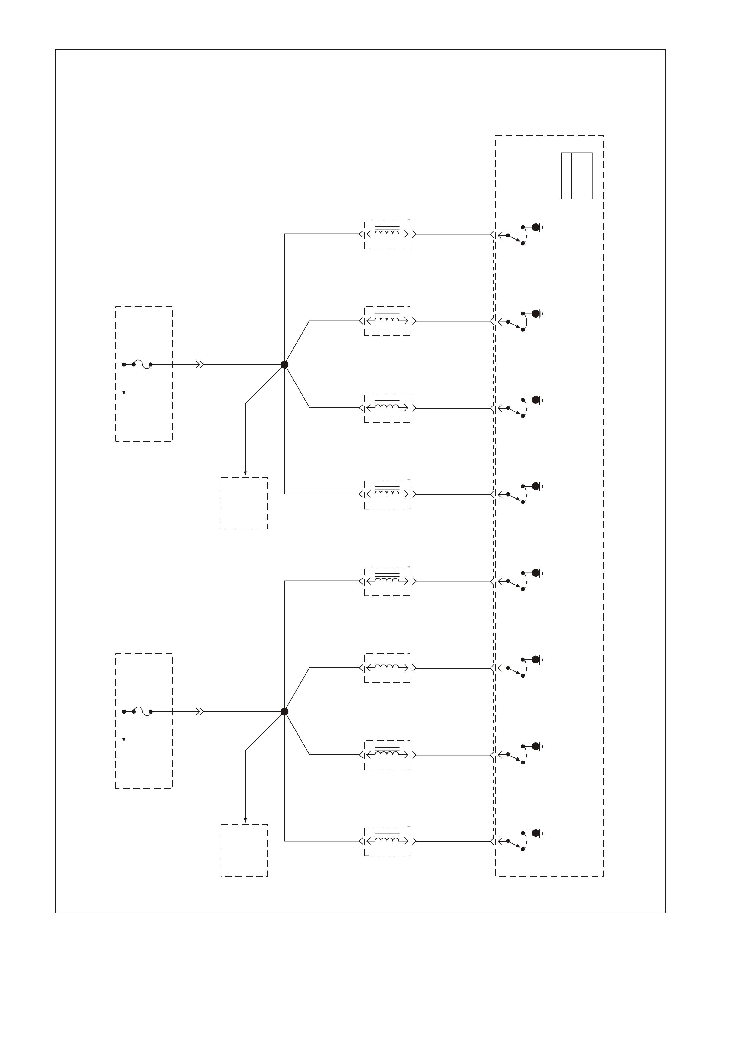
Powertrain Control Schematics (Left Bank Ignition Coil/Modules)
GEN3 0058
PCM
J1 = BLUE
J2 = RED
Powertrain
Control
Module
(PCM)
J266
Ignition
Control
8
28
Ignition
Control
6
29
Ignition
Control
4
67
Ignition
Control
2
61
Reference
Low
Fuse
F34
To EFI
(Engine Cont.)
Relay
To Injectors
2, 4, 6, 8
YE111
481
R972Y/B 974
W959V976LG 978
LBLU
GF
E
CH B
B
C
D
Ignition
Coil/
Module
2
Ignition
Feed Ignition
Control
Signal
Reference
Low
Earth
A
Spark
Plug
B
C
D
Ignition
Coil/
Module
4
Ignition
Feed Ignition
Control
Signal
Reference
Low
Earth
A
Spark
Plug
C
D
B
Ignition
Coil/
Module
6
Ignition
Feed Ignition
Control
Signal
Reference
Low
Earth
A
Spark
Plug
C
D
B
Ignition
Coil/
Module
8
Ignition
Feed Ignition
Control
Signal
Reference
Low
Earth
A
Spark
Plug
A
750
B/R YE124
Engine Ear th
Location E5/E15
YE124
Powertrain Control Schematics (Right Bank Ignition Coil/Modules)
GEN3 0059
To
Fusible
Link
FS
To
Ignition
Switch Fuse
F14
Refer To Wiring
Schematic Part 1
P/B
39
To
Fusible
Link
FS
Fuse
F28
31
Fuel
Pump
Relay
52
B/W 152
YE114
G/W
O
465
240
Body
Control
Module
(BCM)
Theft
Deterrent
Output
Signal
R/B 1221
2
6Powertrain
Interface
Module
(PIM)
Theft
Deterrent
Starter
Disable
7
Y1049
58 J1 Powertrain
Control
Module
(PCM) Engine Earth
Location E3
Fuel
Pump
Relay
Control
Theft
Deterrent
Fuel
Disable
(Se r ia l D ata )
09 J2
YE110
B/BLU 156
PCM
J1 = BLUE
J2 = RED
Engine Earth
Location E7
YR32
Fuel
Pump
Motor
M
V120
YR32
V
120 YB39
Ignition
Positive
19 J1
Ignition
Positive
Powertrain
Interface
Module
(PIM)
P/B 39
15
P39
YE112
Engine Earth
YE114
B/W 152O/Y 479
Fuse
F35
Fuse
F34
30 86
87 85 EFI
(Engine Cont.)
Relay
P/B 3912V Bus 10 40
12V Bus 1040
Fuse
F33
Fuse
F32
Refer To:
Engine Controls Schematics
(Fuse Power Circui ts Part 1)
NOTE:
YB17 5 Hig h Seri es
YB 1 6 4 Low Se r i e s
Powertrain Control Schematics (Fuel System and EFI Relay)
GEN3 0060
Fuse
F34
YE111
R481
To Ignition
Coils
2, 4, 6, 8 R
481
To EFI
(Engine
Cont.) Relay Fuse
F35
YE111
LG 482
To Ignition
Coils
1, 3, 5 , 7
R481
Fuel
Injector
2
G842
A
B
04
Fuel
Inje c tor 2
Driver
R481
Fuel
Injector
4
BR/Y 844
A
B
44
Fuel
Inject or 4
Driver
R481
Fuel
Injector
6
Y846
A
B
37
Fuel
Inje c tor 6
Driver
R481
Fuel
Injector
8
LG 848
A
B
77
Fuel
Injector 8
Driver
LG 482
Fuel
Injector
1
BLU 841
A
B
36
Fuel
Inj e c t or 1
Driver
LG 482
Fuel
Injector
3
V843
A
B
03
Fuel
Injector 3
Driver
LG 482
Fuel
Injector
5
GY 845
A
B
76
Fuel
In jector 5
Driver
LG 482
Fuel
Injector
7
P/B 847
A
B
43
Fuel
Injector 7
Driver
J1
PCM
J1 = BLUE
J2 = RED
Powertrain
Control
Module
(PCM)
To EFI
(Engine
Cont.) Relay
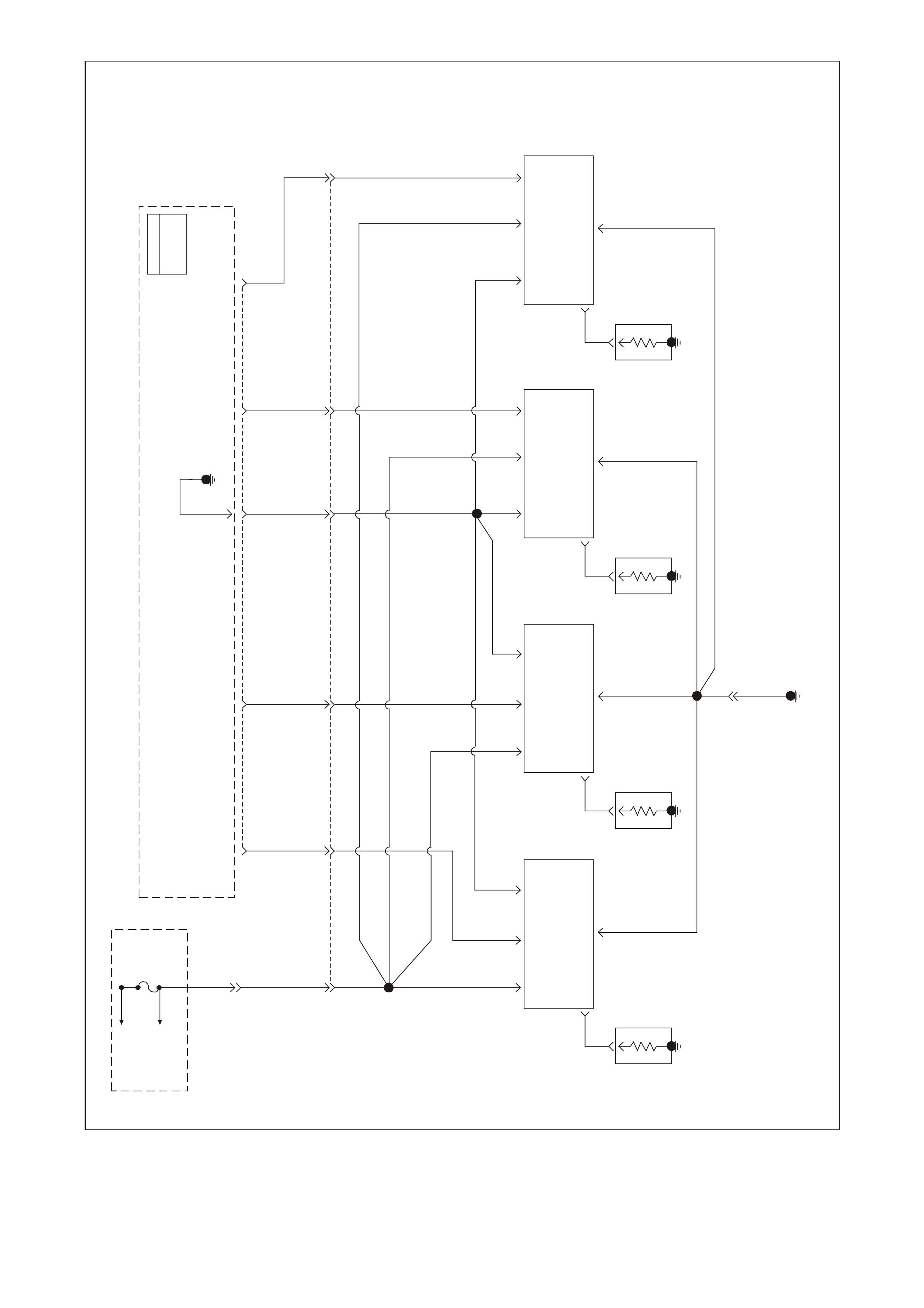
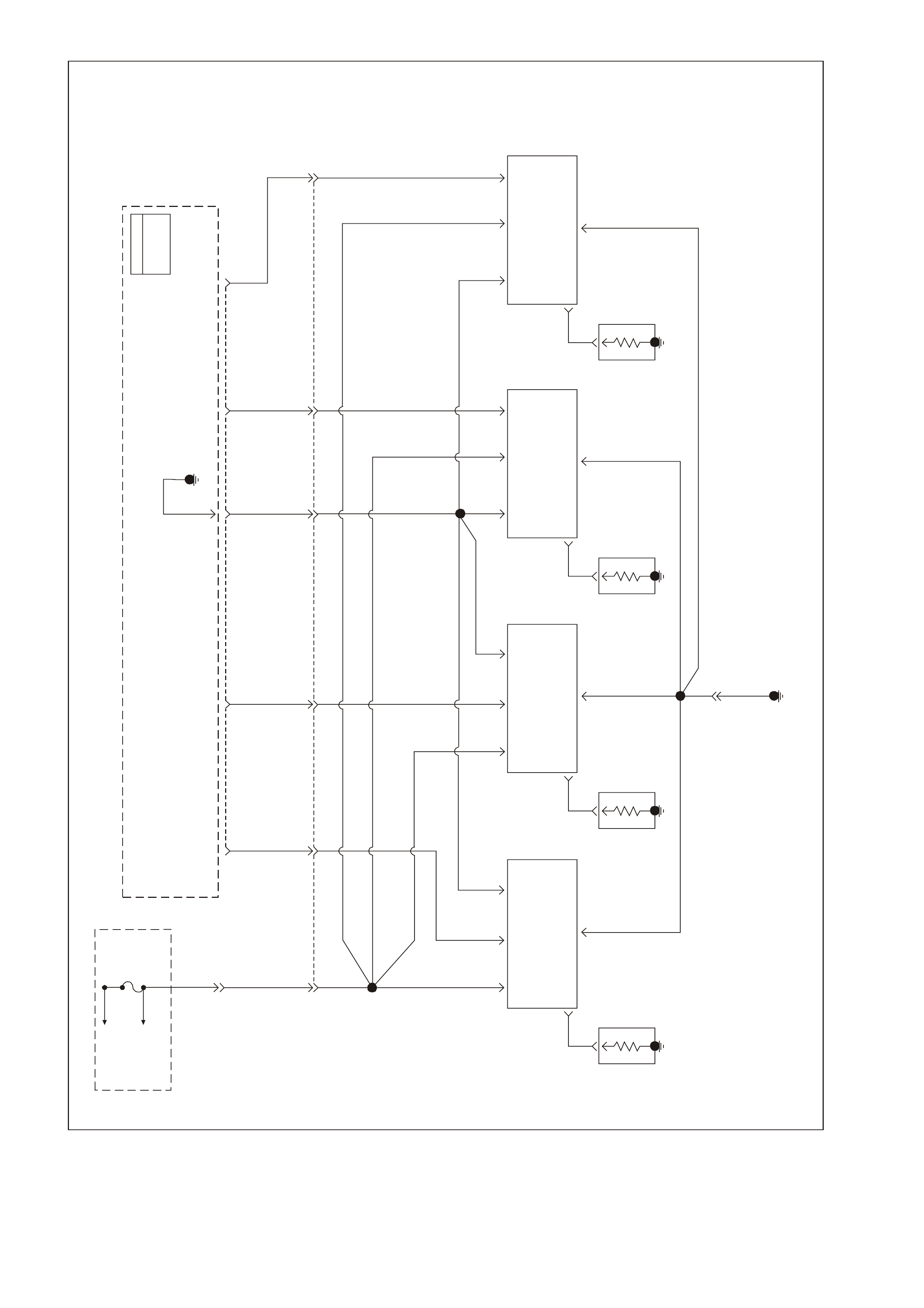
Powertrain Control Schematics (Injector Circuits)
GEN3 0061
PCM
J1 = BL U E
J2 = RE D
Powertrain
Control
Module
(PCM)
Tachometer
Input
Instrument Cluster
18
BR/R 121
Tach
Input 30 YE112
ABS/ETC
Module
BR 121
10 J2
Tachometer
Output CKP Sensor
Signal I nput
Reference
Low
12 21 02 J1
12VIgnition
Feed
KS
Signal
61 73 39 J2
12V
Ignition
Feed
CMP Sensor
Signal Input
Reference
Low
J1
51
BLU 815
BLU 815
Front
Knock
Sensor
(KS)
KS
Signal
11
LBLU 826
LBLU 826
Rear
Knock
Sensor
(KS)
J1
Hall Sensor
Trigger Circuit
Am pl if ie r and
Voltag e R eg
Electronics
Camshaft
Position
(CMP)
Sensor
29
1K
47g
4700pf
Power
Gnd
BAC
R/W 632 W/B 631
BR 633
ABC
BLU 643 LBLU/W 646
LBLU/B 647
Magnetic
Pickup Crankshaft
Position
(CKP)
Sensor
Puls e Shape r
And Voltage
Reg Electronics
Output Power
Gnd
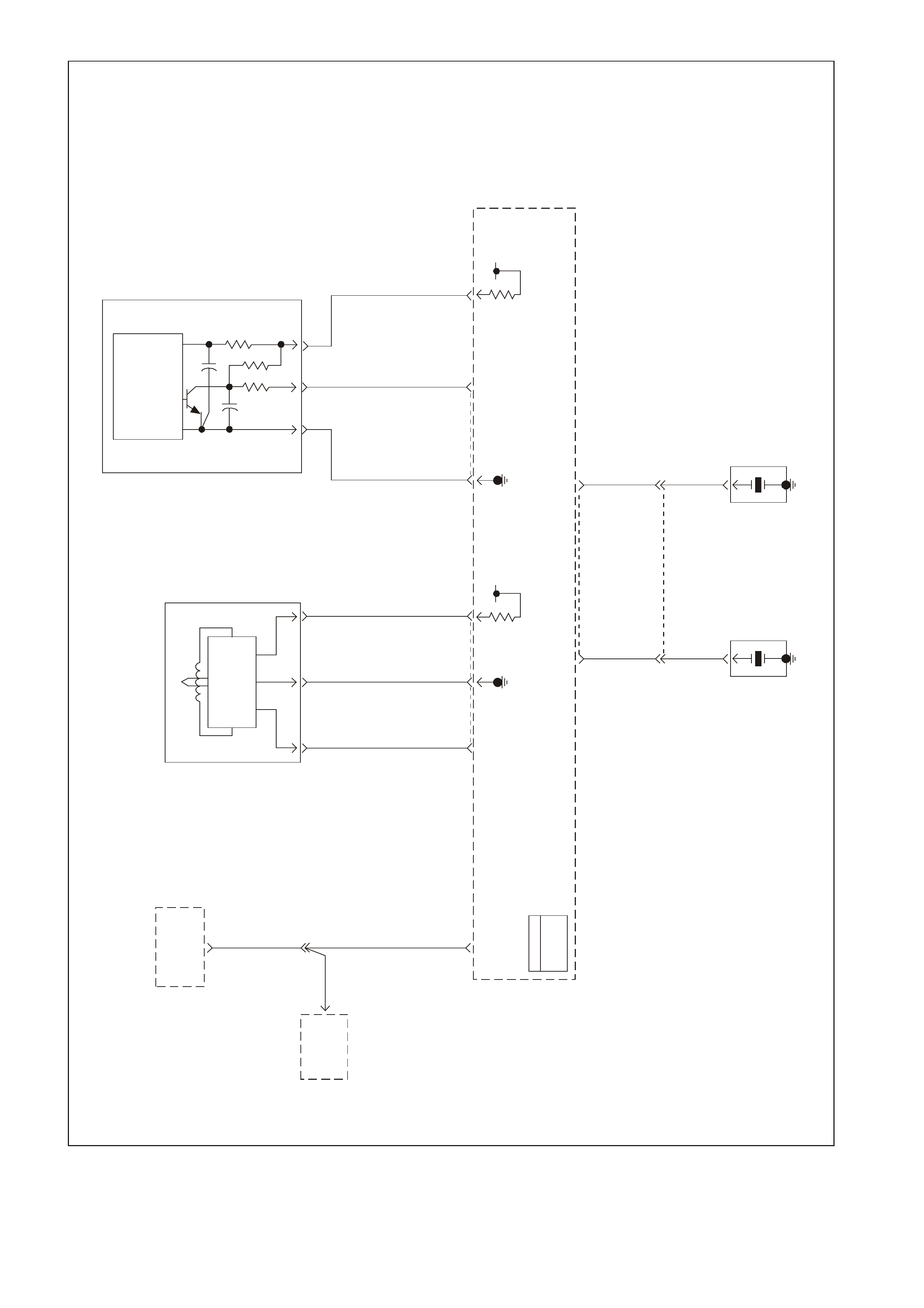
Powertrain Control Schematics (Engine Speed Output, CKP, CMP, and KS Sensors)
GEN 3 00 62
PCM
J1 = BLUE
J2 = RED
Powertrain
Control
Module
(PCM)
To
EFI (Engine
Con t. ) Re lay Fuse
F33
Powertrain
Control
Module
(PCM)
5V 5V 5V 5V 5V
ECT
Sensor
Signal
TP Sensor
5V
Reference
IAT
Sensor
Signal
MAP
5V
Reference
MAF
Sensor
Signal
Oxygen
Sensor
Heaters
Throttle
Relaxer
Control
Module
Intake
Air
Temperature
(AIT)
Sensor
Engine
Coolant
Temperature
(ECT)
Sensor
Throttle
Position
(TP)
Sensor
Coolant
Level
Switch
Engine
Earth
Ignition
Power MAF
Sensor
Signal
Mass Air
Flow (MAF)
Sensor
Manifold
Absolute
Pressure
(MAP)
Sensor
To
A/C
Pressure
Sensor
MAP
Sensor
Signal MAP
Sensor
Earth
IAT
Sensor
Earth
TP
Sensor
Signal Sensor
Earth ECT
Sensor
Earth
Coolant
Level
Switch
Input
Engine
Earth
P439
YE111
P439
C
D
A
31 J2 48 J1 25 J2 08 74 J1
Y410
B
A
B/R 750
G69
30 J1
GY/B 455
80 J1
B/Y 452
60
BLU 417
24 J2
G/O 469
57 J2
B421
32 J2
B/R 750
B/R 750
B
LG 432
BA
CG/O 469
A
B
B/Y 452
BLU 417
BC
40
43
GY 416
GY 416
A
GY
416
41
BR 472
V/W 414
BR/W 792
A
54 J1
Throttle
Relaxer
Control
Module
J1
J1
Powertrain Control Schematics (Information Sensors)
GEN 3 00 63
To EFI
(Engine
Cont.) Relay Fuse
F33
YE111
P439
Bank #1
Lef t Front
HO2S
High HO2S
Low
Bank #2
Right Front
HO2S
Low HO2S
High
PCM
J1 = BLUE
J2 = RED
Powertrain
Control
Module
(PCM)
P439
B/R 750
B/R 750
Engine
Earth
D
C
Bank 2 Sensor 1
Heated O xygen
Sens or (HO2 S)
BA
GY/B 1413 GY 1412
26 66 J169 29
ABD
CBan k 1 Sens or 1
Heated Oxygen
Sens or (HO2S)
BLU/B 413P439 V412
B/R 750
Powertrain Control Schematics (Heated Oxygen Sensors)
GEN3 0064
PCM
J1 = BLUE
J2 = RED
EVAP
Canister
Purge
Valve
Control
To
EFI (Engine
Cont.) Relay Fuse
F33
P439
YE111
Evaporative
Emission
(EVAP)
Canister
Purge
Valve
A
B
G/Y 428
34
LBLU/B 442 LG/W 443
LBLU 441 LG/B 444
DCB
A
IAC
Coil A
High
79
IAC
Coil A
Low
78
IAC
Coil B
Low
77
IAC
Coil B
High
76 J2 Powertrain
Control
Module
(PCM)
M
Stepper
Motor
Coil
ACoil
B
Id le Ai r
Control
(IAC)
Valve
Powertrain Control Schematics (EVAP and IAC)
GEN3 0065
PCM
J1 = BLUE
J2 = RED
V/W 123
V/W 123
GY/B 1687
GY/B 1687
V/W 123
Powertrain
Control
Module
(PCM)
ABS/ETC
Module
ETC
Spark
Retard
Signal
VSS
Input
Cruise
Control
Module VSS
Input
Instrument
Cluster
BLU/W 831 T 832
Vehicle Speed
Sens or ( VS S)
BA
20 J221
VSS
High VSS
Low
ETC
Retard
Signal
VSS
Output
50
53 J2
28
YE129
YE110
YE110
YB195
Powertraiin Control Schematics (ETC Retard Signal, VSS Output and VSS Signal)
GEN3 0067
PCM
J1 = BL UE
J2 = RED
Powertrain
Control
Module
(PCM)
YE112
CA
Y1049
BLU/Y 334
58 J107 J1 58 J2
R/B 1221
B
G335
G/W
1220
R/B 1221
BR/W 331
Serial
Data
(Class 2)
Sensor
Earth
Sensor
Signal
Sensor
5V
Reference
Y
1049
To
Fuse
F13 Oil
Warning
Lamp
SDI
Instrument Panel Cluster
12
To
Vehicle
Bus
Serial Data
(UART)
Body Control
Module
(BCM)
2
6
Serial Data
(UART)
Serial Data
(Class 2)
Powertrain
Interface
Module
(PIM)
792 DLC
Connector
63 J1
Oil Pressure
Sensor
NOTE
YB164 Low Se r ie s
YB175 Hi gh Seri es
NOTE
"3" YB164 Low Series
"9" YB175 High Series
Powertrain Control Schematics (Oil Pressure Sensor)
GEN3 0068
Instrument
Panel
Cluster
Low
Traction ETC
Off
Warning
Lamp
ABS
Off
Warning
Lamp
SDI
11 9
19 P/BLU
44
G
875 21
14
To
Fuse
F13
ABS/ETC
Module
Y/R 88
BLU/R 20
ABS/ETC
Module
Rear
Stop
Lamps
Cruise
Control
Actuator
6
Y838
BLU/R 20
ABS/ETC
Module
B-A Stop Lam p
Switches (A-B)
(Open wi th brak e
pedal depressed)
88
Y/R
20
86
BR
D
Cruise
Control
Actuator
BR 86
YE129
To
Fuse
F5 Body
Control
Module
33 J1
O/BLU 640
YB17518
TCC/ Cru is e Brake
Switch
PCM
J1 = BLUE
J2 = RED
44 J2 42 02 J2 79 J1 47 48 J2
Powertrain
Control
Module (PCM)
TCC SOL
Valve
Control
TCC PWM SOL
Valve
Control
3-2 SS
Valve Assembly
Control
2-3 SS
Valve
Control
1-2 SS
Valve
Control
Reverse
Lock-Out
Control
TU S B A
GY/R 422 BR 418 G/W 897 Y/B 1223 LG 1222
B422 T418 W897 Y1223 LG 1222
R339
Torque
Converter
Clutch
Solenoid
(TCC SOL)
Valve
Torque
Converter
Clutch Pulse
Width
Modulation
Solenoid
(TCC PWM SOL)
Valve
3-2 S hift
Solenoid
(3-2 SS)
Valve
Assembly
2-3 Shift
Solenoid
(2-3 SS)
Valve
1-2 Shift
Solenoid
(1-2 S S)
Valve
Automatic
Transmission
A
B
A
B
A
B
A
B
A
B
E
P/BLU 339
P/BLU 339
YE110
P/BLU
339
AB
M an u al Tra n smi ssion
Revers e Lo ck Out So l e n oid
To
EFI (Engine
Cont.) Relay Fuse
F32
Powertrain Engine Control Schematics (Transmission)
GEN 3 00 69
BR/Y 1224
PCM
J1 = B L UE
J2 = RED
Engine Earth
Engine Earth
Powertrain
Contr o l Mo dul e
(PCM)
Powertrain
Control Module
(PCM)
Transmission
Range A
Input
P1224
63 J2
N
C
Y1225
Transmission
Ra ng e B
Input
DKBLU 1225
17
R
E
GY 1226
Transmission
Range C
Input
O1226
18 J1
P
D
B/Y 1227
TFT
Sensor
Signal
BR 1227
51 J2
L
A
Automatic
Transmission
Pressure
Control Solenoid
(PC SOL.) Valve
PRNDL
Switch
SW A
REV
Switch
LO
Switch D2
Switch
D3
Switch D4
Switch
Transmission
Fluid
Temperature
(TFT)
Sensor
Automatic
Transmission
Fluid Pressure
(TFP) Manual
Valve Position
Switch
LBLU 1229 V 1228
GY 1230
B
GY/BLU 1229 R 1228B/W 1230
MD
C
53 08 06J1 J2 32 72 J1 62 J2 34 J1
PRNDL
APRNDL
BPRNDL
CPRNDL
P
Y772
GY 773BLU/W 771
W776
B/R 750
SW B SW C SW P
ADBC
71 J1
Sensor
Earth PC SOL.
Valve Low PC SOL.
Valve High
Economy/Power
Swit c h Inp ut
Signal
YB30
YE112
YB30
YE114
Economy/Power
Switch
B/G BLU
151 774
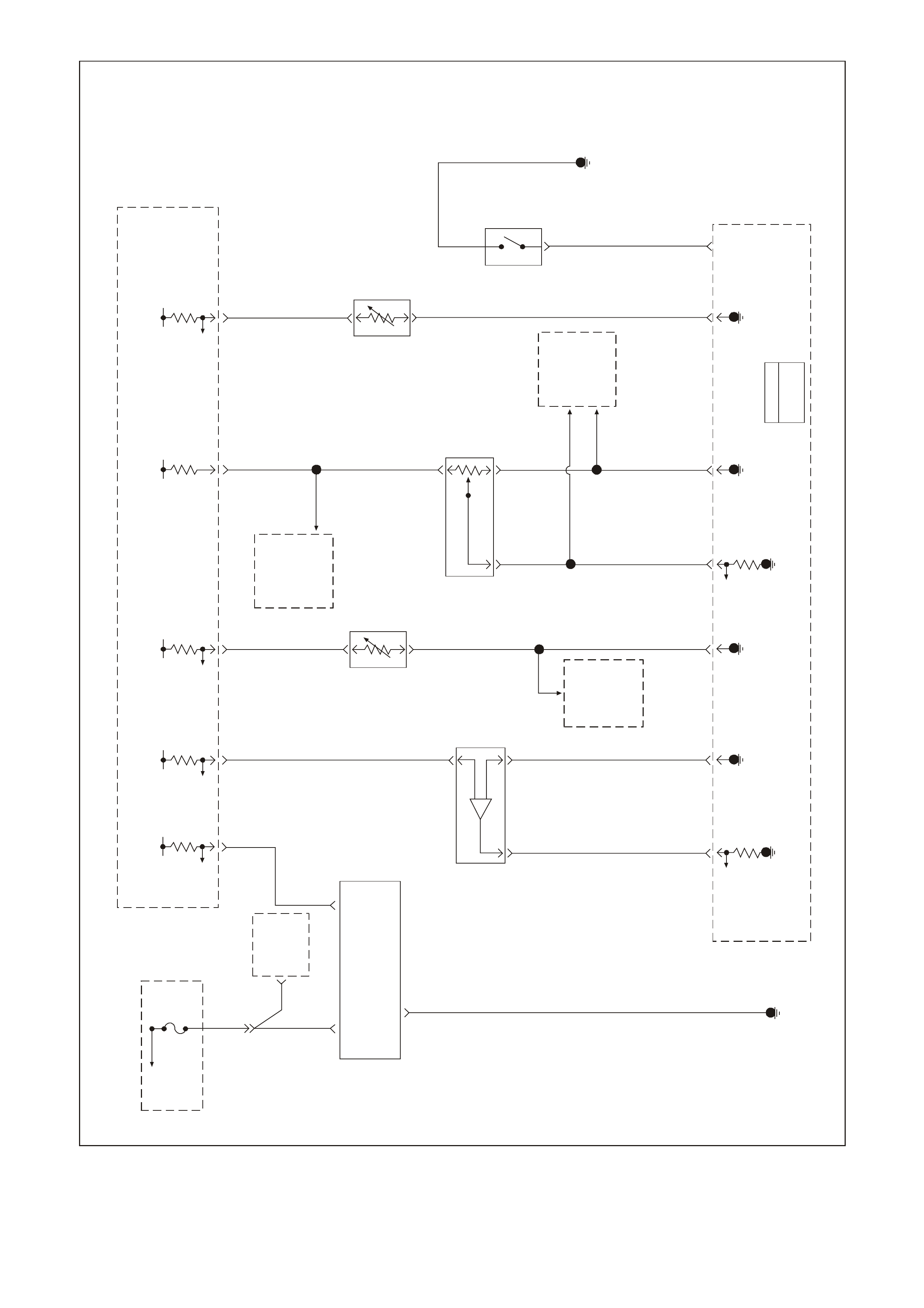
Powertrain Control Schematics (Transmission)
To
EFI (Engine
Cont.) Rel ay
GEN 3 00 70
A/C
Diode
Fuse
F33
P439
P439
A/C
COMP
Relay
15
23
G59
LG/B 366
YE111
LG/B 366
43 18 J2
G
59
A/C
Clutch
Status
A/C Refrigerant
Pre ssure Sensor
Earth
A
B
A/C
Compressor
Clutch
Powertrain
Control
Module
(PCM)
Engine
Earth
B/R 750
A/C
Refrigerant
Pressure
Sensor
IAT
Sensor
G/O 469V/W 415G/B 259
A/C Refrigerant
Pressure Sensor
5V R e f e r ence
A/C Refrigerant
Pressure Sensor
Signal
5V
57 J245 J1
14 J258 J1
Y1049 CB
A
Y
1049
YE110
PIM 2Data Link
Connector
(DLC)
7
6
R/B
1221
YE112
DLC
92
BCM
1
G/W 1220
IP
Cluster 12
11
ABS/ETC
Module
HVAC
A/C
Control
6
A/C
Clutch
Relay
Control
Se r ial Data
(Cla ss 2)
PCM
J1 = BLUE
J2 = RED
A
NOTE
"3" YB164 Low Series
" 9" Y B175 Hi g h S er i es
NOTE
YB164 Low Series
YB175 High Series
Powertrain Control Schematics (A/C System)
GEN3 0071
Refer to Wiring
Schematic
Part 1
Engine Cooling
Fan R e lay
High Sp eed
P/B
39
Fuse
F14
To
Ignition
Switch
To
Fusible
Link FS
To
Fusible
Link FU
To
Fusible
Link FT O/B 208
YE118
208
R204
O/BLU 204
Y
250
O/BLU
250
YE104
Supression
Capacitors
12V Bus 1040
B/R 157
O/BLU
250
Engine
Earth
O/BLU 250
85
30
86
87
O/BLU 250
12V Bus 1040
BLU/W 304
YE110
B/R 157
85 87
86 30 87A
Engine Cooling
Fan Relay
Low Speed
B533
YE104 O/B 473
O/B 473
BLU/Y
533
NOTE
YB17 4 Hi g h S eries
YB16 3 Lo w Series
Engine
Cooling
Fan Relay
Low Speed
Control
Powertrain
Control
Module
(PCM)
Engine Cooling
Fa n R ela y
High Speed
Control
J233
Cooling
Fan
2
Cooling
Fan
1
Serial Data
(Class II)
Body Control
Module (BCM)
Serial Data
(UART)
7
R/B
1221 6
2Se r i a l Data
(Class II)
Serial Data
(UART) Y
104958
7J1
Powertrain Interf ac e
Modul e (PIM)
G
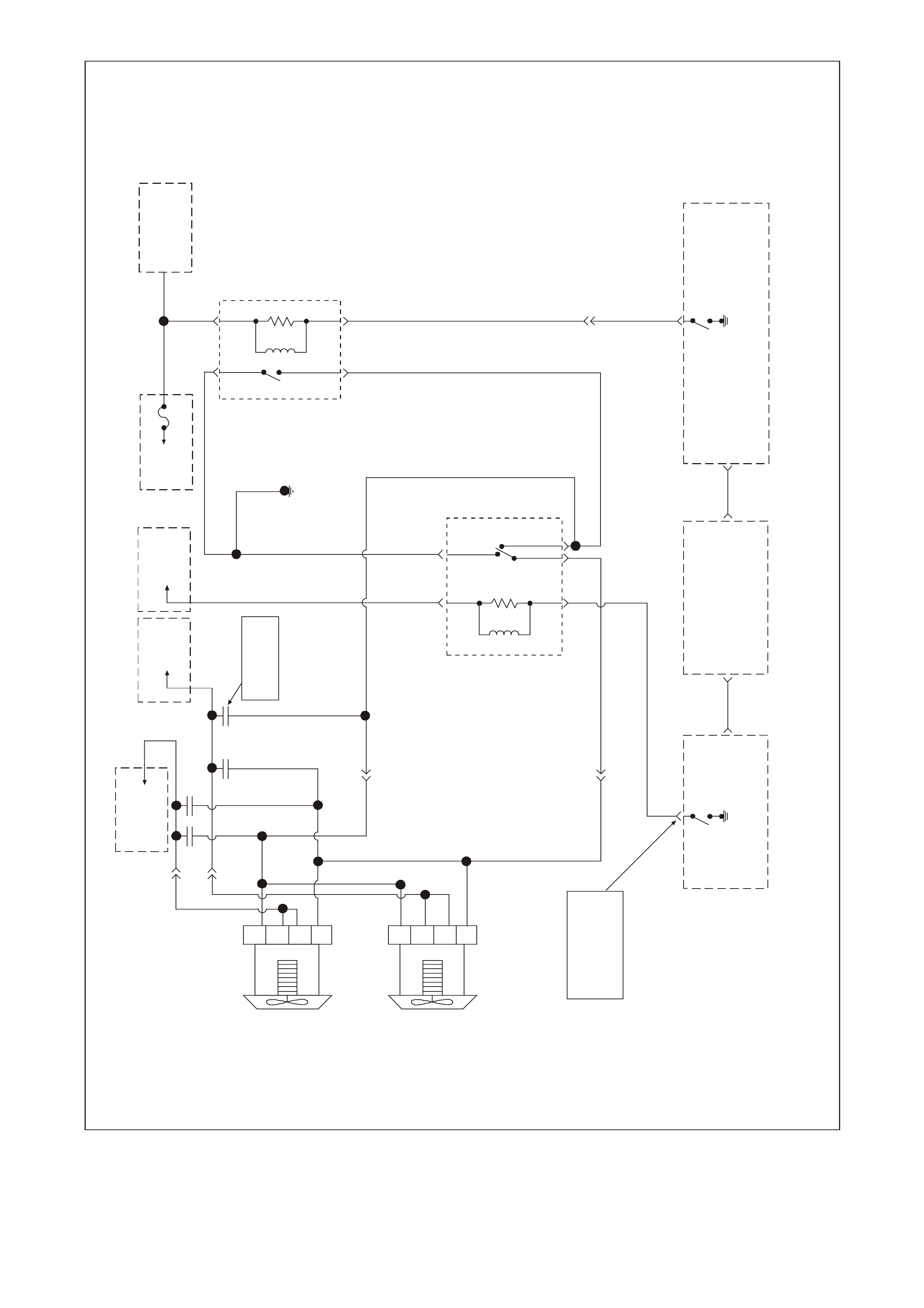
Powertrain Control Schematics (Engine Cooling Fans)
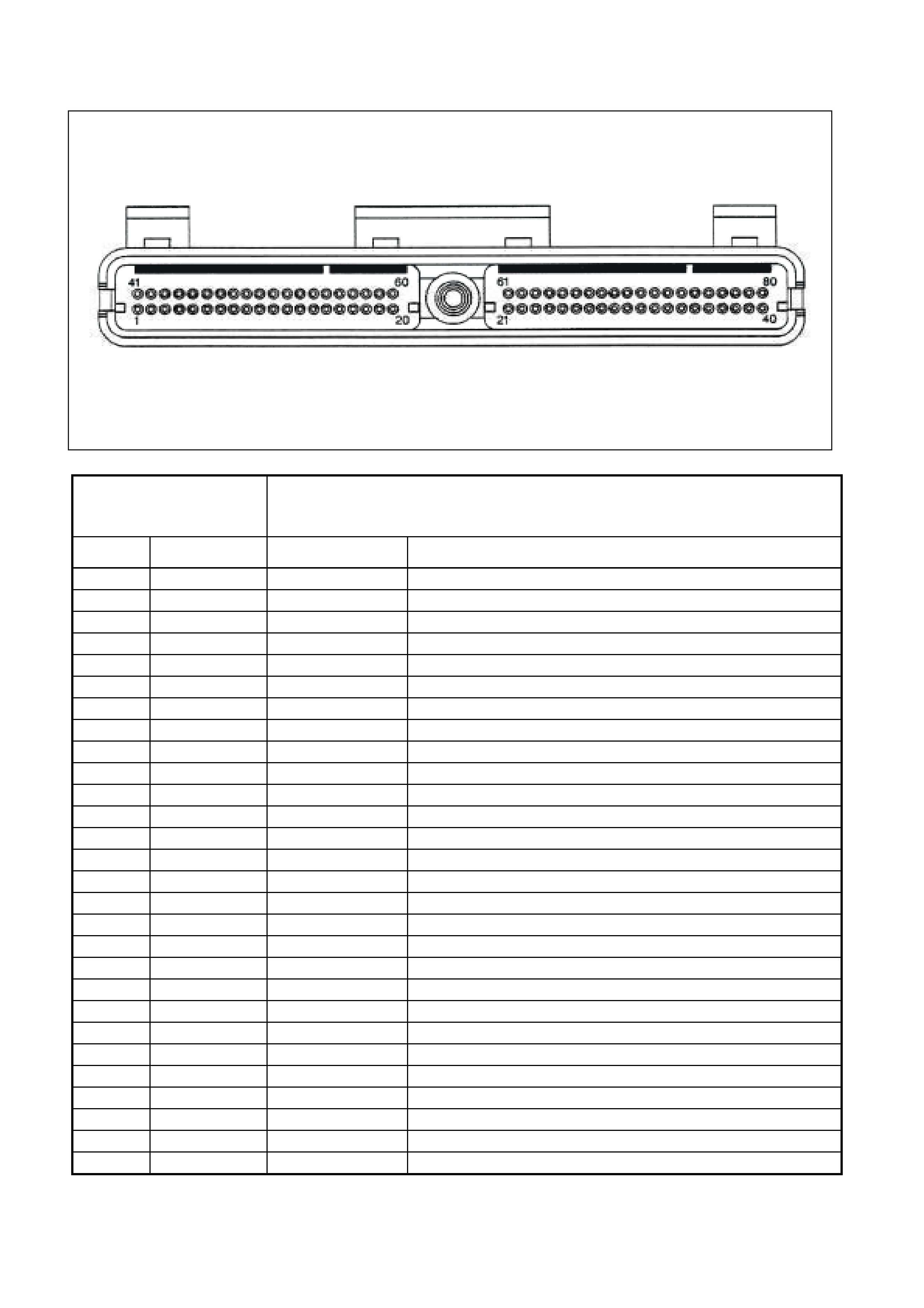
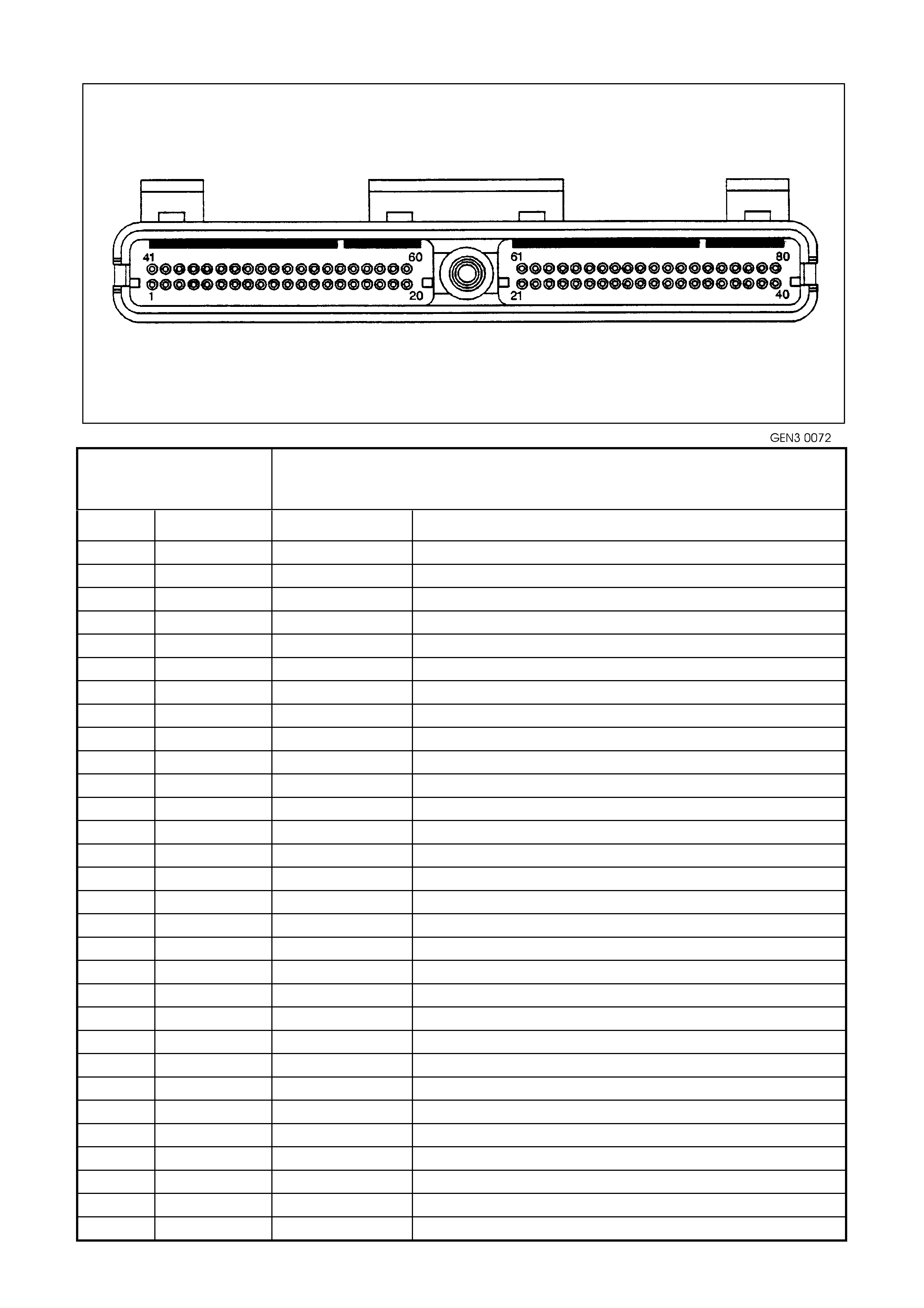
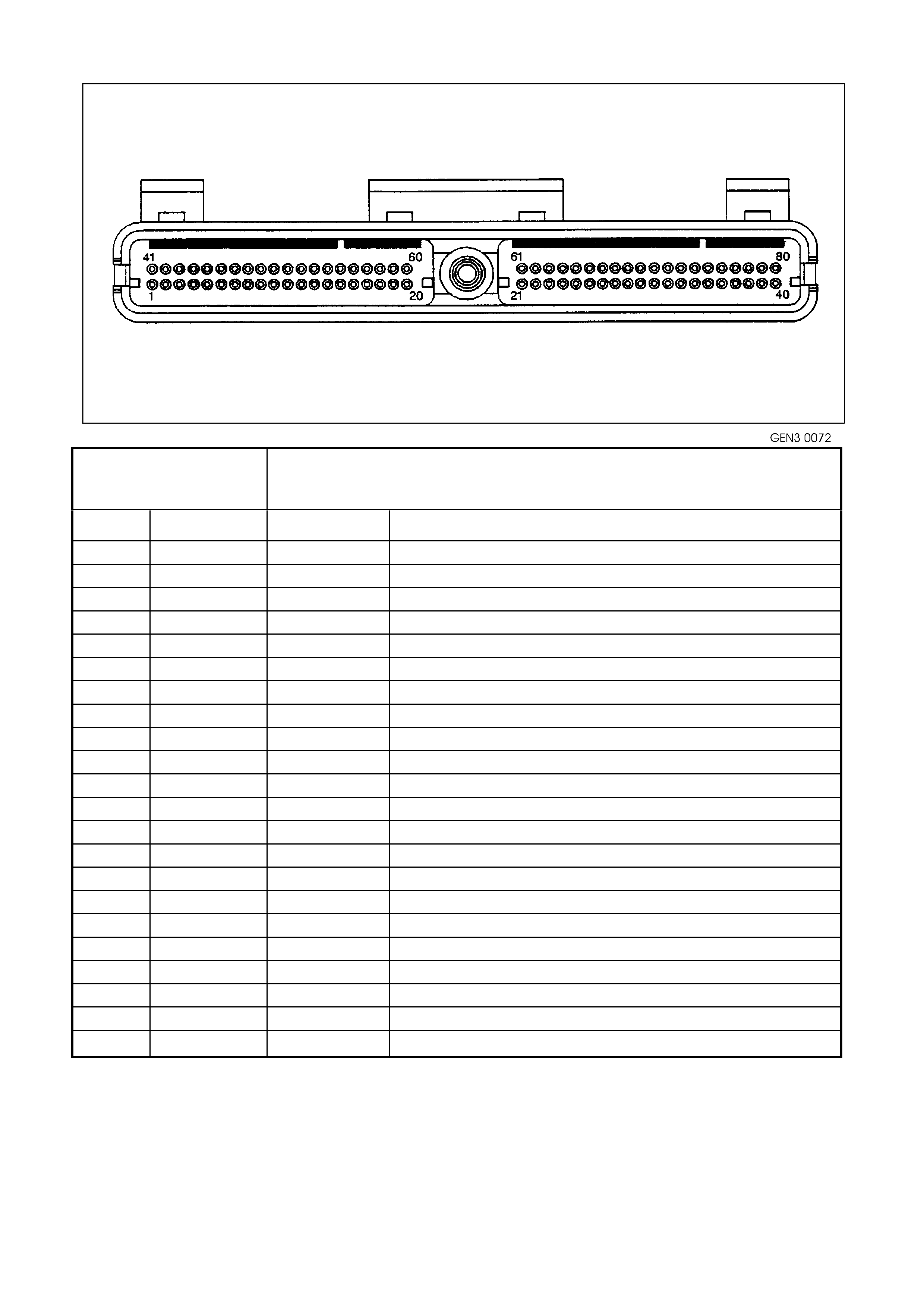
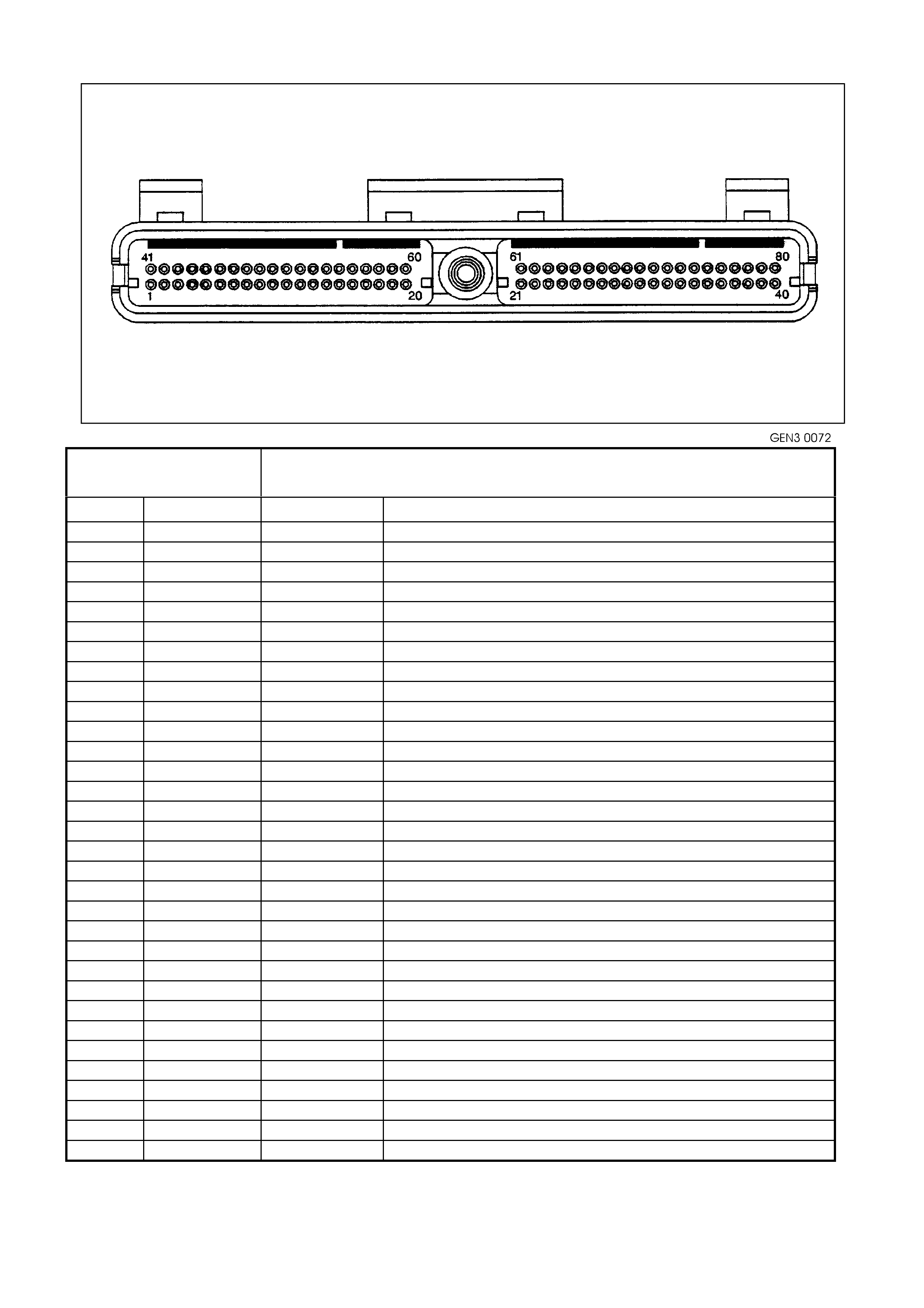
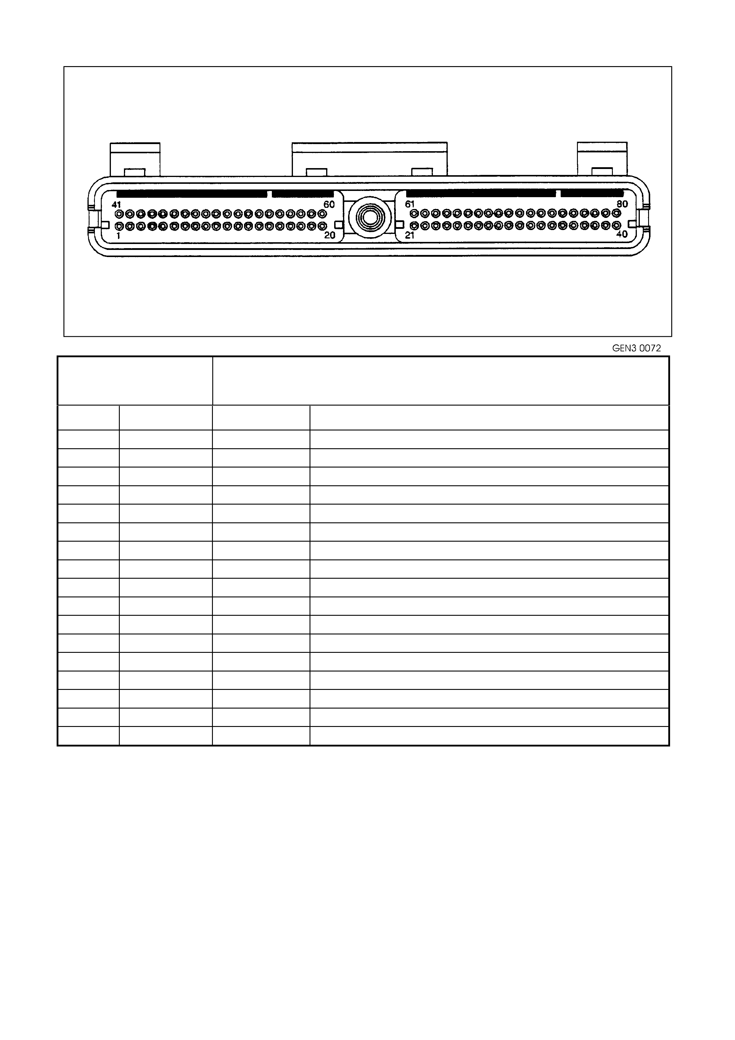
PCM CONNECTOR END VIEWS
PCM CONNECTOR J1 (BLUE)
GEN3 0072
Connector Part
Information
• PCM Connector YE122 J1 (Blue)
• 80 Pin Connector
Pin Wire Color Circuit No. Function
1 Brown/Red 750 System Earth
2 LT Blue/White 646 Crankshaft Position Sensor Ignition Voltage Feed
3 Violet 843 Fuel Injector #3 Driver
4 Green 842 Fuel Injector #2 Driver
5 Not Used - -
6 Not Used - -
7 Blue/Yellow 334 Oil Pressure Sensor 5 Volt Reference
8 Grey 416 Throttle Position Sensor 5 Volt Reference
9 Not Used - -
10 Not Used - -
11 LBLU 826 Rear Knock Sensor Input Signal
12 Blue 643 Crankshaft Position Sensor Input Signal
13 Not Used - -
14 Not Used - -
15 Not Used - -
16 Not Used - -
17 Yellow 1225 Transmission Range B Input
18 Grey 1226 Transmission Range C Input
19 Pink 39 Ignition Positive Voltage
20 Orange 740 Battery Feed
21 LT Blue/Black 647 Crankshaft Position Sensor Reference Low
22 Not Used - -
23 Not Used - -
24 Not Used - -
25 Not Used - -
26 Grey/Black 1413 Bank 2 Sensor 1Heated Oxygen Sensor Signal Low
27 Not Used - -
28 Not Used - -
PCM CONNECTOR J1 (BLUE) CONTINUED
Connector Part
Information
• PCM Connector YE122 J1 (Blue)
• 80 Pin Connector
Pin Wire Color Circui t No. Function
29 Blue/Black 413 Bank 1 Sensor 1 Heated Oxygen Sensor Signal Low
30 Green 69 Engine Coolant Level switch Input Signal
31 Not Used - -
32 Blue/White 771 PRNDL A
33 Brown 86 Torque Converter Clutch/Cruise Brake Switch Input Signal
34 White 776 PRNDL P
35 Not Used - -
36 Blue 841 Fuel Injector #1 Driver
37 Yellow 846 Fuel Injector #6 Driver
38 Not Used - -
39 Not Used - -
40 Brown/Red 750 System Earth
41 Not Used - -
42 Not Used - -
43 Pink/Black 847 Fuel Injector #7 Driver
44 Brown/Yellow 844 Fuel Injector #4 Driver
45 Violet/White 415 A/C Refrigerant Pressure Transducer 5 Volt Reference
46 Not Used - -
47 Not Used - -
48 Violet/White 414 Manifold Absolute Pressure Sensor 5 Volt Reference
49 Not Used - -
50 Not Used - -
51 Blue 815 Front Knock Sensor Input Signal
52 Not Used - -
53 Black/White 1230 Transmission Fluid Temperature Sensor Earth
54 Black 421 Manifold Absolute Pressure Sensor Earth
55 Not Used - -
56 Not Used - -
57 Orange 740 Battery Feed
58 Yellow 1049 Serial Data (Class II)
PCM CONNECTOR J1 (BLUE) CONTINUED
Connector Part
Information
• PCM Connector YE122 J1 (Blue)
• 80 Pin Connector
Pin Wire Color Circuit No. Function
59 Not Used - -
60 Black/Yellow 452 Throttle Position Sensor Earth
61 Red/White 632 Camshaft Position Sensor Reference Low
62 Not Used - -
63 Green 335 Oil Pressure Sensor Earth
64 Not Used - -
65 Not Used - -
66 Grey 1412 Bank 2 Sensor 1 Heated Oxygen Sensor Signal High
67 Not Used - -
68 Not Used - -
69 Violet 412 Bank 1 Sensor 1 Heated Oxygen Sensor Signal High
70 Not Used - -
71 Blue 774 Economy/Power Switch Input
72 Yellow 772 PRNDL B
73 Brown 633 Camshaft Position Sensor Input Signal
74 Yellow 410 Engine Coolant Temperature Sensor Signal
75 Not Used - -
76 Grey 845 Fuel Injector #5 Driver
77 LT Green 848 Fuel Injector #8 Driver
78 Not Used - -
79 Green/White 897 3-2 Shift Solenoid Control
80 Grey/Black 455 Engine Coolant Temperature Sensor Earth
PCM CONNECTOR J2 (RED)
Connector Part
Information • PCM Connector YE123 J2 (Red)
• 80 Pin Connector
Pin Wire Color Circuit No. Function
1 Brown/Red 750 System Earth
2 Brown 418 Torque Converter Clutch Pulse Width Modulation Solenoid Control
3 Not Used - -
4 Not Used - -
5 Not Used - -
6 Red 1228 Pressure Control Solenoid Signal High
7 Not Used - -
8 Grey/Blue 1229 Pressure Control Solenoid Signal Low
9 Green/White 465 Fuel Pump Relay Control
10 Brown 121 Tachometer Output Signal
11 Not Used - -
12 Not Used - -
13 Not Used - -
14 Green/Black 259 A/C Refrigerant Pressure Transducer Input Signal
15 Not Used - -
16 Not Used - -
17 Not Used - -
18 Green 59 A/C Clutch Status
19 Not Used - -
20 Tan 832 Vehicle Speed Sensor Signal Low
21 Blue/White 831 Vehicle Speed Sensor Signal High
22 Not Used - -
23 Not Used - -
24 Blue 417 Throttle Position Sensor Input Signal
25 Brown 472 Intake Air Temperature Sensor Signal
26 White 971 Ignition Coil/Module Control #1
27 Yellow 977 Ignition Coil/Module Control #7
28 LT Green 976 Ignition Coil/Module Control #6
29 White 974 Ignition Coil/Module Control #4
30 Not Used - -
31 Brown/White 792 Mass Air Flow Sensor Signal
32 LT Green 432 Manifold Absolute Pressure Sensor Input Signal

PCM CONNECTOR J2 (RED) CONTINUED
Connector Part
Information • PCM Connector YE123 J2 (Red)
• 80 Pin Connector
Pin Wire Color Circuit No. Function
33 Blue/White 304 Engine Cooling Fan Relay High Speed Control
34 Green/Yellow 428 Evaporative Emission Canister Purge Solenoid Control
35 Not Used - -
36 Not Used - -
37 Not Used - -
38 Not Used - -
39 White/Black 631 Camshaft Sensor Ignition Voltage Feed
40 Brown/Red 750 System Earth
41 Not Used - -
42 Grey/Red 422 Torque Converter Clutch Solenoid Control
43 LT Green/Black 366 A/C Clutch Relay Control
44 Yellow 838 Manual Transmission Reverse Lock-Out Control
45 Not Used - -
46 Not Used - -
47 Yellow/Black 1223 2-3 Shift Solenoid Control
48 LT Green 1222 1-2 Shift Solenoid Control
49 Not Used - -
50 Violet/White 123 Vehicle Speed Sensor Output Signal
51 Black/Yellow 1227 Transmission Fluid Temperature Sensor Input Signal
52 Not Used - -
53 Grey/Black 1687 Electronic Traction Control Retard Signal
54 Not Used - -
55 Not Used - -
56 Not Used - -
57 Green/Orange 469 Intake Air Temperature / A/C Refrigerant Pressure Transducer Earth
58 Brown/White 331 Oil Pressure Sensor Input Signal
59 Not Used - -
60 Brown 958 Ignition Reference Low
61 Violet 959 Ignition Reference Low
62 Grey 773 PRNDL C
63 Brown/Yellow 1224 Transmission Range A Input
PCM CONNECTOR J2 (RED) CONTINUED
Connector Part
Information
• PCM Connector YE123 J2 (Red)
• 80 Pin Connector
Pin Wire Color Circuit No. Function
64 Not Used - -
65 Not Used - -
66 LT Blue 978 Ignition Coil/Module Control #8
67 Yellow/Black 972 Ignition Coil/Module Control #2
68 Green 975 Ignition Coil/Module Control #5
69 Blue 973 Ignition Coil/Module Control #3
70 Not Used - -
71 Not Used - -
72 Not Used - -
73 Not Used - -
74 Not Used - -
75 Not Used - -
76 LT Green/White 443 Idle Air Control Valve Coil B High
77 LT Green/Black 444 Idle Air Control Valve Coil B Low
78 LT Blue/Black 442 Idle Air Control Valve Coil A Low
79 LT Blue 441 Idle Air Control Valve Coil A High
80 Not Used - -

PCM CONNECTOR TERMINAL DEFINITIONS
PCM CONNECTOR J1 (BLUE)
1 - SYSTEM EARTH - This terminal should have zero volts. This circuit is connected directly to the engine earth.
2 - CRANKSHAFT POSITION SENSOR IGNITION VOLTAGE FEED - This voltage should be always be B+
anytime the ignition is ON. It is a regulated voltage output from the PCM, and supplies B+ to the CKP sensor.
3 - FUEL INJECTOR #3 DRIVER - W ith the engine OFF and the ignition ON, the voltage should be B+. W ith the
engine running at idle, the charging s ystem increas es the battery voltage slightly, so this voltage will increas e. W ith
higher engine RPM or more engine load, the resulting increase in injector pulse frequency or injector pulse width will
cause this voltage to become slightly less.
4 - FUEL INJECTOR #2 DRIVER - W ith the engine OFF and the ignition ON, the voltage should be B+. W ith the
engine running at idle, the charging s ystem increas es the battery voltage slightly, so this voltage will increas e. W ith
higher engine RPM or more engine load, the resulting increase in injector pulse frequency or injector pulse width will
cause this voltage to become slightly less.
5 - NOT USED
6 - NOT USED
7 - OIL PRESSURE SENSOR 5V REFERENCE - This voltage should always be 5 volts whenever the ignition is
ON. The reference voltage is a regulated voltage from the PCM, and supplies 5 volts to the oil pressure sensor.
8 - THROTTLE POSITION SENSOR 5 VOLT REFERENCE - T his voltage should always be 5 volts whenever the
ignition is ON. The reference voltage is a regulated voltage from the PCM, and supplies 5 volts to the TP sensor.
9 - NOT USED
10 - NOT USED
11 - REAR KNOCK SENSOR INPUT SIGNAL - The knock sensor detects when detonation is occurring in the
combustion chambers. W hen detected, the PCM will reduce the amount of spark advance being delivered on the
EST output circuits to the ignition COIL/MODULES.
12 - CRANKSHAFT POSITIO N SENSOR INPUT SIG NAL - This ter m inal c ould be called the tec h input. It provides
the PCM with RPM and crankshaft position information. The PCM uses this signal to control fuel injection, and
spark timing.
13 - NOT USED
14 - NOT USED
15 - NOT USED
16 - NOT USED
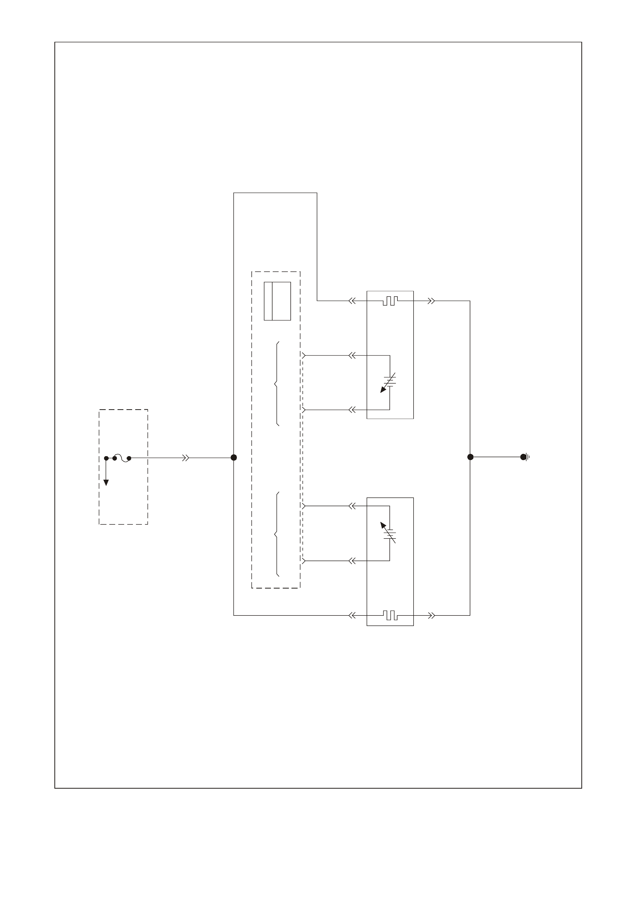
17 - TRANSMISSION RANGE B INPUT - The PCM sends out a buffered B+ signal to the pressure switch
assembly., located in the automatic transmission valve body. The B+ signal must pass through either a normally
open or normally closed switch to reach earth. When the switches are closed, the signal should be near 0 volts. The
PCM monitors the status of these signals to determine which gear servo is actually receiving hydraulic apply
pressure.
18 - TRANSMISSION RANGE C INPUT - The PCM sends out a buffered B+ signal to the pressure switch
assembly, located in the automatic transmission valve body. The B+ signal must pass through either a normally
open or normally closed switch to reach earth. When the switches are closed, the signal should be near 0 volts. The
PCM monitors the status of these signals to determine which gear servo is actually receiving hydraulic apply
pressure.
19 - IGNITION POSITIVE VOLTAGE - This is the wak e up signal to the PCM from the ignition switch. It is not the
power supply to the PCM, it only tells the PCM that the ignition switch is ON. The voltage should equal the battery
voltage when the key is in either the RUN, or CRANK position.
20 - BATTERY FEED - This s upplies the PCM with full time B+ volts . This c irc uit s tays hot even when the ignition is
turned OFF. The battery voltage feed circuit receives it's voltage from fuse F31.
21 - CRANKSHAFT POSITION SENSOR REFERENCE LOW - This terminal should always be zero volts. It is
connected from the PCM to the CKP sensor and provides the earth signal needed for the sensor to operate.
22 - NOT USED
23 - NOT USED
24 - NOT USED
25 - NOT USED
26 - BANK 2 SENSOR 1 HEATED OXYGEN SENSOR SIGNAL LOW - This terminal should have zero volts. It is
connected f rom the PCM to the HO2S. T his term inal earth's the PCM circuitry for the HO2S voltage m onitor inside
the PCM.
27 - NOT USED
28 - NOT USED

29 - BANK 1 SENSOR 1 HEATED OXYGEN SENSOR SIGNAL LOW - This terminal should have zero volts. It is
connected f rom the PCM to the HO2S. T his term inal earth's the PCM circuitry for the HO2S voltage m onitor inside
the PCM.
30 - ENGINE COOLANT LEVEL SWITCH INPUT SIGNAL - This terminal indicates to the PCM when the coolant
level is low. W hen the PCM receives this signal from the Engine Coolant Level switch, the PCM will turn ON a low
coolant warning lamp on the instrument panel.
31 - NOT USED
32 - PRNDL A - This circuit along with the circuits on PCM connector pins J1 34, 72 & J2 62 indicate to the PCM
what transm ission gear the driver has selected. The PCM will then send a com mand via the serial data line to the
instrument panel cluster (smart cluster) to indicate to the driver what gear has been selected.
33 - TORQUE CONVERTER CLUTCH/CRUISE BRAKE SWITCH INPUT SIGNAL - This signal indicates to the
PCM when the driver has depressed the brake pedal. The PCM will then disengage the TCC and or cruise if
activated. This circuit also indicates to the PCM and cruise control actuator when the ABS/ETC module is
requesting the Low Traction lamp ON.
34 - PRNDL P - This circuit along with the circuits on PCM connector pins J1 32, 72 & J2 62 indicate to the PCM
what transmission gear the driver has selected. The PCM will then send a command via the serial data line to the
instrument panel cluster (smart cluster) to indicate to the driver what gear has been selected.
35 - NOT USED
36 - FUEL INJECTOR #1 DRIVER - W ith the engine OFF and the ignition ON, the voltage should be B+. W ith the
engine running at idle, the charging system increases battery voltage slightly, so this voltage will increase. With
higher engine RPM or more engine load, the resulting increase in injector pulse frequency or injector pulse width will
cause this voltage to become slightly less.
37 - FUEL INJECTOR #6 DRIVER - W ith the engine OFF and the ignition ON, the voltage should be B+. W ith the
engine running at idle, the charging system increases battery voltage slightly, so this voltage will increase. With
higher engine RPM or more engine load, the resulting increase in injector pulse frequency or injector pulse width will
cause this voltage to become slightly less.
38 - NOT USED
39 - NOT USED
40 - SYSTEM EARTH - This terminal should have zero volts. This circuit is connected directly to the engine earth.
41 - NOT USED
42 - NOT USED
43 - FUEL INJECTOR #7 DRIVER - W ith the engine OFF and the ignition ON, the voltage should be B+. W ith the
engine running at idle, the charging s ystem increas es the battery voltage slightly, so this voltage will increas e. W ith
higher engine RPM or more engine load, the resulting increase in injector pulse frequency or injector pulse width will
cause this voltage to become slightly less.
44 - FUEL INJECTOR #4 DRIVER - W ith the engine OFF and the ignition ON, the voltage should be B+. W ith the
engine running at idle, the charging s ystem increas es the battery voltage slightly, so this voltage will increas e. W ith
higher engine RPM or more engine load, the resulting increase in injector pulse frequency or injector pulse width will
cause this voltage to become slightly less.
45 - A/C REFRIGERANT PRESSURE TRANSDUCER 5 VOLT REFERENCE - This voltage should always be 5
volts anytime the ignition is ON. It is a regulated voltage output from the PCM, and supplies 5 volts to the A/C
Pressure Sensor.
46 - NOT USED
47 - NOT USED
48 - M ANIFOLD ABSOLUTE PRESSURE SENSO R 5 VOLT REFERENCE - This voltage s hould always be 5 volts
anytime the ignition is ON. It is a regulated voltage output from the PCM, and supplies 5 volts to the map Sensor.
49 - NOT USED
50 - NOT USED
51 - FRONT KNOCK SENSOR - The knock sensor detects when detonation is occurring in the combustion
chambers. W hen detected, the PCM will reduce the amount of spark advance being delivered on the EST output
circuits to the ignition COIL/MODULES.
52 - NOT USED
53 - TRANSMISSION FLUID TEMPERATURE SENSOR EARTH - This terminal should be zero volts. It is
connected through the PCM circuitry to engine earth.
54 - MANIFOLD ABSOLUTE PRESSURE SENSOR EARTH - This terminal should have zero volts. This circuit is
connected directly to the earth through the PCM.
55 - NOT USED
56 - NOT USED

57 - BATTERY FEED - This s upplies the PCM with full time B+ volts . This c irc uit s tays hot even when the ignition is
turned off. The battery voltage feed circuit receives it's voltage fuse F31.
58 - SERIAL DATA (CLASS II) -This is a dedicated line for the Tech 2 scan tool communication. The circuit
connects the PCM, PIM, ABS/ETC, and BCM. T he Tech 2 s c an tool can talk to each of these modules by sending a
message to a controller and asking only it to respond. The communication carried on Class II data streams are
prioritised. The normal voltage on this line is 0 volts, but when the Tech 2 scan tool is connected, the voltage will
about 7 volts indicating communication.
59 - NOT USED
60 - THROTTLE POSITION SENSOR EARTH - This terminal should have zero volts. This circuit is connected
directly to the earth through the PCM.
61 - CAMSHAFT POSITION SENSOR REFERENCE LOW - This terminal should always be zero volts. It is
connected from the PCM to the CMP sensor and provided the earth signal needed for the sensor to operate.
62 - NOT USED
63 - OIL PRESSURE SENSOR EARTH - This terminal should always be zero volts. It is connected from the PCM
to the oil pressure sensor and provides the earth signal needed for the sensor to operate.
64 - NOT USED
65 - NOT USED
66 - BANK 2 SENSO R 1 OXY GEN SENSOR SIG NAL HIGH - With the ignition ON and the engine not running, the
voltage should be 350 - 450 millivolts (0.350 0.450 volts). This is the PCM supplied HO2S circuit bias voltage. When
the HO2S is hot, and the engine is r unning, the voltage should be rapidly changing, somewhere between 10 - 1000
millivolts (0.010 - 1000 volts).
67 - NOT USED
68 - NOT USED
69 - BANK 1 SENSOR 1 HEATED OXYGEN SENSOR SIGNAL HIGH - With the ignition ON and the engine not
running, the voltage should be 350 - 450 millivolts (0.350 0.450 volts). This is the PCM supplied HO2S circuit bias
voltage. When the HO2S is hot, and the engine is running, the voltage should be rapidly changing, somewhere
between 10 - 1000 millivolts (0.010 - 1000 volts).
70 - NOT USED
71 - ECONOM Y/POWER SWITCH INPUT - T he PCM sends a signal of about 12 volts, and monitors the status of
this circuit. In the ECONOMY position the switch is open, the PCM voltage status signal remains high - about 12
volts, and the PCM does not allow shift point changes. When the transmission switch is pressed to the POWER
position the switch is momentarily closed and the PCM voltage status signal is momentarily pulled low. The PCM
senses the momentary voltage signal drop and enables power mode shifting only if other criteria are met. These
criteria include throttle position and engine speed.
72 - PRNDL B - This circuit along with the circuits on PCM connector pins J1 32, 34 & J2 62 indicate to the PCM
what transm ission gear the driver has selected. The PCM will then send a com mand via the serial data line to the
instrument panel cluster (smart cluster) to indicate to the driver what gear has been selected.
73 - CAMSHAFT POSITION SENSOR INPUT SIGNAL - This signal indicates to the PCM when number 1 cylinder
is on the compression stroke.
74 - ENGINE COOLANT TEMPERATURE SENSOR SIGNAL - The PCM sends a 5 volt signal voltage to the
Engine Coolant Temperature sensor, which is a temperature variable resistor called thermistor. The sensor, being
also connected to earth, will alter the voltage according to engine coolant temperature. As the engine coolant
temper ature incr eases, the voltage s een on term inal C1 74 decr eases. At 0 degrees C engine coolant tem perature,
the voltage will be above 4 volts. At normal operating temperature the voltage will be less than 2 volts. The PCM
uses this signal for fueling.
75 - NOT USED
76 - FUEL INJECTOR #5 DRIVER - W ith the engine OFF and the ignition ON, the voltage should be B+. W ith the
engine running at idle, the charging s ystem increas es the battery voltage slightly, so this voltage will increas e. W ith
higher engine RPM or more engine load, the resulting increase in injector pulse frequency or injector pulse width will
cause this voltage to become slightly less.
77 - FUEL INJECTOR #8 DRIVER - W ith the engine OFF and the ignition ON, the voltage should be B+. W ith the
engine running at idle, the charging s ystem increas es the battery voltage slightly, so this voltage will increas e. W ith
higher engine RPM or more engine load, the resulting increase in injector pulse frequency or injector pulse width will
cause this voltage to become slightly less.
78 - NOT USED
79 - 3-2 SHIFT SOLENOID CONTROL- The 3- 2 s hif t s olenoid is a normally closed, pulse width modulated solenoid
used to control the 3-2 downshift. The PCM operates the 3-2 shift solenoid at a frequency of 50 Hz (cycles per
second). The solenoid is constantly fed B+ and the PCM controls the length of time the path to earth for the
electrical circuit is closed.

80 - ENGINE COOLANT TEMPERATURE SENSOR EARTH - T his terminal should have zero volts. T his circuit is
connected directly to the earth through the PCM.
PCM CONNECTOR J2 (RED)
1 - SYSTEM EARTH - This terminal should have zero volts. This circuit is connected directly to the engine earth.
2 - T ORQUE CONVERTER CLUTCH PULSE W IDTH M ODULATION SOLENOID CONTROL - T he PCM uses the
pulse width m odulation (PW M) T CC apply solenoid to smoothly engage the torque converter clutch, after the TCC
ENABLE solenoid is energised. By varying the duty cycle pulse width modulation, the PCM can slowly engage the
torque converter clutch, allowing very smooth TCC engagement.
3 - NOT USED
4 - NOT USED
5 - NOT USED
6 - PRESSURE CONTROL SOLENOID HIGH - T he duty cycle, and am ount of c ur rent f low to the T FP, is c ontrolled
by the PCM. T his c irc uit is the B+ s upply line from the PCM to the T FP. T he duty cycle and amper age are controlled
by the PCM.
7 - NOT USED
8 - PRESSURE CONTROL SOLENOID LOW - The 4L60-E automatic transmission uses an electrical solenoid to
control hydraulic pressure inside the transmission. This electrical solenoid allows the PCM to control line pressure,
similar to other automatic transmissions that use a throttle valve cable or vacuum modulator. The duty cycle, and
amount of cur rent f low to the PCS, are both controlled by the PCM. By m onitoring this line, the PCM can deter m ine
if the commanded amperage has gone to the PCS and returned to the PCM.
9 - FUEL PUMP (FP) RELAY CONTROL - Turning the ignition ON causes the PCM to energise (+12V) the Fuel
Pump Relay. If no crankshaft reference input pulses are received, the PCM turns OFF the relay. As soon as the
PCM receives crankshaft reference input pulses, the PCM will turn the Fuel Pump Relay on again.
10 - TACHOMETER OUTPUT SIGNAL - This signal is used to operate the tachometer located in the instrument
panel cluster. The PCM determines then signal based off of the CKP sensor.
11 - NOT USED
12 - NOT USED
13 - NOT USED
14 - A/C REFRIGERANT PRESSURE TRANSDUCER INPUT SIGNAL - The signal that is sent from the pressure
sensor to the PCM indicates to the PCM what the A/C pressure is. Depending on the A/C pressure, this signal will
indicate to the PCM if A/C pressure is too LOW or too HIGH.
15 - NOT USED
16 - NOT USED
17 - NOT USED
18 - A/C CLUTCH ST ATUS - T his c ircuit is a f eed bac k signal to the PCM indicating that the A/C c om press or relay
has s upplied the signal to the com pressor c lutch. The PCM uses this circuit to determ ine if there is a f ault with the
A/C compressor relay.
19 - NOT USED
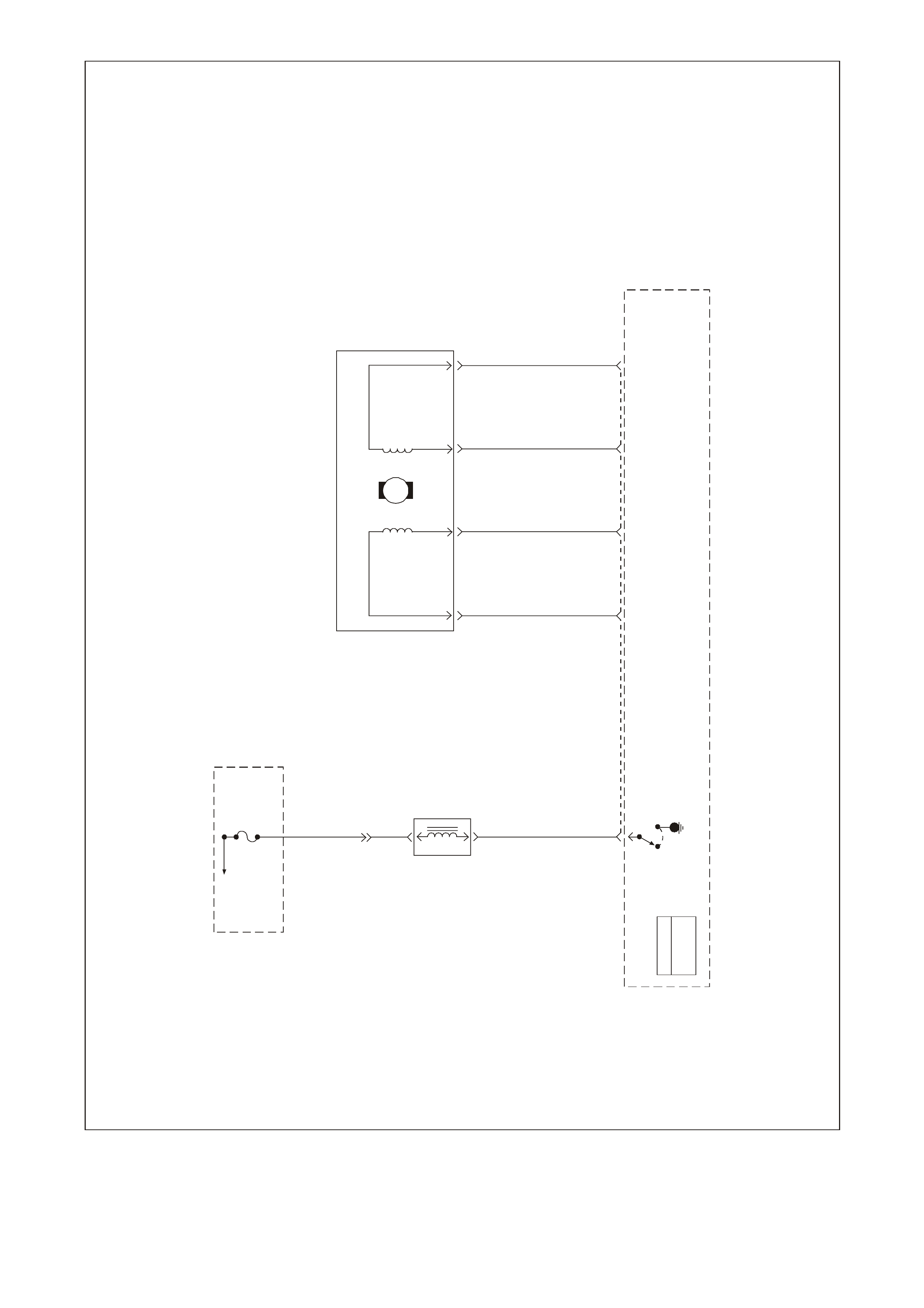
20 - VEHICLE SPEED SENSOR SIGNAL LOW - The transm ission has an output shaft speed sensor used by the
PCM to calculate vehicle speed, and to help determine various transmission shifting functions. It is a magnetic
inductive sensor that generates an AC voltage signal sent to the PCM. If measured with the digital AC multimeter,
no voltage will appear until the output shaft begins turning.
21 - VEHICLE SPEED SENSOR SIGNAL HIGH - The transm ission has an output shaft speed sensor used by the
PCM to calculate vehicle speed, and to help determine various automatic transmission shifting functions. It is a
magnetic inductive sensor that generates an AC voltage signal sent to the PCM. If measured with the digital AC
multimeter, no voltage will appear until the output shaft begins turning.
22 - NOT USED
23 - NOT USED
24 - THROTTLE POSITION SENSOR INPUT SIGNAL - The TP sensor input voltage, which follows actual throttle
changes, is variable from 0 to 5 volts. Typically the voltage is less than 1 volt at idle, and 4 to 5 volts at wide-open
throttle.
25 - INTAKE AIR TEMPERATURE SENSOR SIGNAL - The PCM sends a 5 volt signal voltage to the IAT sensor,
which is a temper ature - variable - r esistor c alled a therm istor. The s ensor is also connec ted to earth, and will alter
the signal voltage ac cor ding to inc oming air temper ature. As the air temper ature inc r eases , the voltage s een on this
term inal decreas es. At 0 degrees C, the voltage will be above 4 volts. At norm al operating temperature (10 degrees
C to 80 degrees C) the voltage will be less than 4 volts.

26 - IGNITION COIL/MODULE CONTROL #1 - This terminal is what triggers the ignition system coil/module for
cylinder #1. This terminal is connected from the PCM to the #1 ignition coil/module connector terminal G.
27 - IGNITION COIL/MODULE CONTROL #7 - This terminal is what triggers the ignition system coil/module for
cylinder #1. This terminal is connected from the PCM to the #7 ignition coil/module connector terminal B.
28 - IGNITION COIL/MODULE CONTROL #6 - This terminal is what triggers the ignition system coil/module for
cylinder #1. This terminal is connected from the PCM to the #6 ignition coil/module connector terminal F.
29 - IGNITION COIL/MODULE CONTROL #4 - This terminal is what triggers the ignition system coil/module for
cylinder #1. This terminal is connected from the PCM to the #4 ignition coil/module connector terminal C.
30 - NOT USED
31 - MASS AIR FLOW SENSOR SIGN AL - The PCM supplies a 5-volt signal voltage to the mass air flow sensor on
this c ircuit. The m ass air f low sensor pulses the 5-volt signal to ear th. Thes e earth pulses occur at a very fast rate -
from less than 500 per second (500 Hz) with no airflow through the sensor, to upwards of many thousands of pulses
per second at high air f low rates s uc h as during ac c eleration. If meas ur ed, the voltage seen will be between 0.5 and
4.5 volts, depending on air flow through the sensor.
32 - MANIFOLD ABSOLUTE PRESSURE SENSOR INPUT SIGNAL - The voltage seen will vary with intake
manifold pressure. With the ignition ON but the engine not running (High manifold pressure), the voltage will be
above 4 volts . At this time the s ens or ac tually is meas ur ing the barometr ic pr es su re, s o this voltage will change with
both barometric pressure and altitude changes. W hen the engine is running at idle, the manifold pressure is quite
low because of engine vacuum, and the voltage will also be low, 1 to 2 volts. The voltage is variable, mostly from
engine vacuum changes, but can also change with barometric pressure or altitude changes. This input is typically
called the engine load input.
33 - ENGINE COOLING FAN RELAY HIGH SPEED CONTROL - This terminal will have battery voltage until the
PCM energises the high speed cooling fan relay by supplying the earth; then it will be close to zero. The input that
causes the PCM to ener gise the high speed fan relay is the engine coolant temper ature sensor. The PCM will also
energise the high speed fan relay in the Diagnostic Mode - i.e., ignition ON, engine stopped, and DLC diagnostic
test enable terminal earthed. (The Body Control Module operates the cooling fan low speed relay).
PCM Connector J2 (Red) Continued
34 - EVAPORATIVE EMISSION CANISTER PURGE SOLENOID CONTROL - The PCM operates a normally
closed solenoid valve, which controls vacuum to purge the evaporative emissions storage canister of stored fuel
vapours. The PCM turns ON the pulse width modulated control of the purge solenoid, to control purging of the
stored vapours . If the PCM is not energising the pur ge solenoid, the voltage m easur ed at this term inal s hould equal
battery voltage. If the PCM is controlling the solenoid, the measured voltage will be between battery voltage and
0.50 volts.
35 - NOT USED
36 - NOT USED
37 - NOT USED
38 - NOT USED
39 - CAM SHAFT SENSO R IGNITIO N VOLTAGE FEED - This voltage should be always be B+ anytim e the ignition
is ON. It is a regulated voltage output from the PCM, and supplies B+ to the CMP sensor.
40 - SYSTEM EARTH - This terminal should have zero volts. This circuit is connected directly to the engine earth.
41 - NOT USED
42 - TORQUE CONVERT ER CLUTCH SOLENOID CONTROL - T he PCM is used to either open or provide a path
to earth for the torque converter s olenoid. W hen the PCM provides a path to earth, the TCC solenoid is considered
ON and voltage should be near 0 volts . The PCM uses both the T CC enable solenoid and the TCC PW M solenoid
to control the torque converter clutch.
43 - A/C CLUTCH RELAY CONTROL - When the A/C is requested, the BCM will communicate to the PCM through
the PIM via the serial data line, requesting A/C. The PCM supplies the earth path on this terminal to energise the
A/C control relay. The voltage will be less than 1 volt when the PCM energises the relay. When the PCM does
energise the A/C control relay, the voltage w ill be more than 0.1, but less than 1 volt.
44 - MANUAL TRANSMISSION REVERSE LOCK-OUT CONTROL - If this vehicle is equipped with a manual
transmission, this solenoid will prevent the transmission from going into reverse gear when the vehicle speed is
above 8 Kmh. W hen the vehicle speed is below 8 Km h the PCM will supply the earth signal to the solenoid, which
will allow the transmission to be shifted into reverse gear. The PCM looks at the VSS input signal to determine
vehicle speed for reverse shifting. If there is a fault with this circuit, DTC P0801 will set.
45 - NOT USED
46 - NOT USED
47 - 2-3 SHIFT SOLENOID CONT ROL - T he PCM is used to either open or provide a path to earth f or the 2- 3 shif t
solenoid. W hen the PCM provides a path to earth, the 2-3 shift solenoid is considered ON and the voltage should
read 0 volts.

48 - 1-2 SHIFT SOLENOID CONT ROL - T he PCM is used to either open or provide a path to earth f or the 1- 2 shif t
solenoid. W hen the PCM provides a path to earth, the 1-2 shift solenoid is considered ON and the voltage should
read 0 volts.
49 - NOT USED
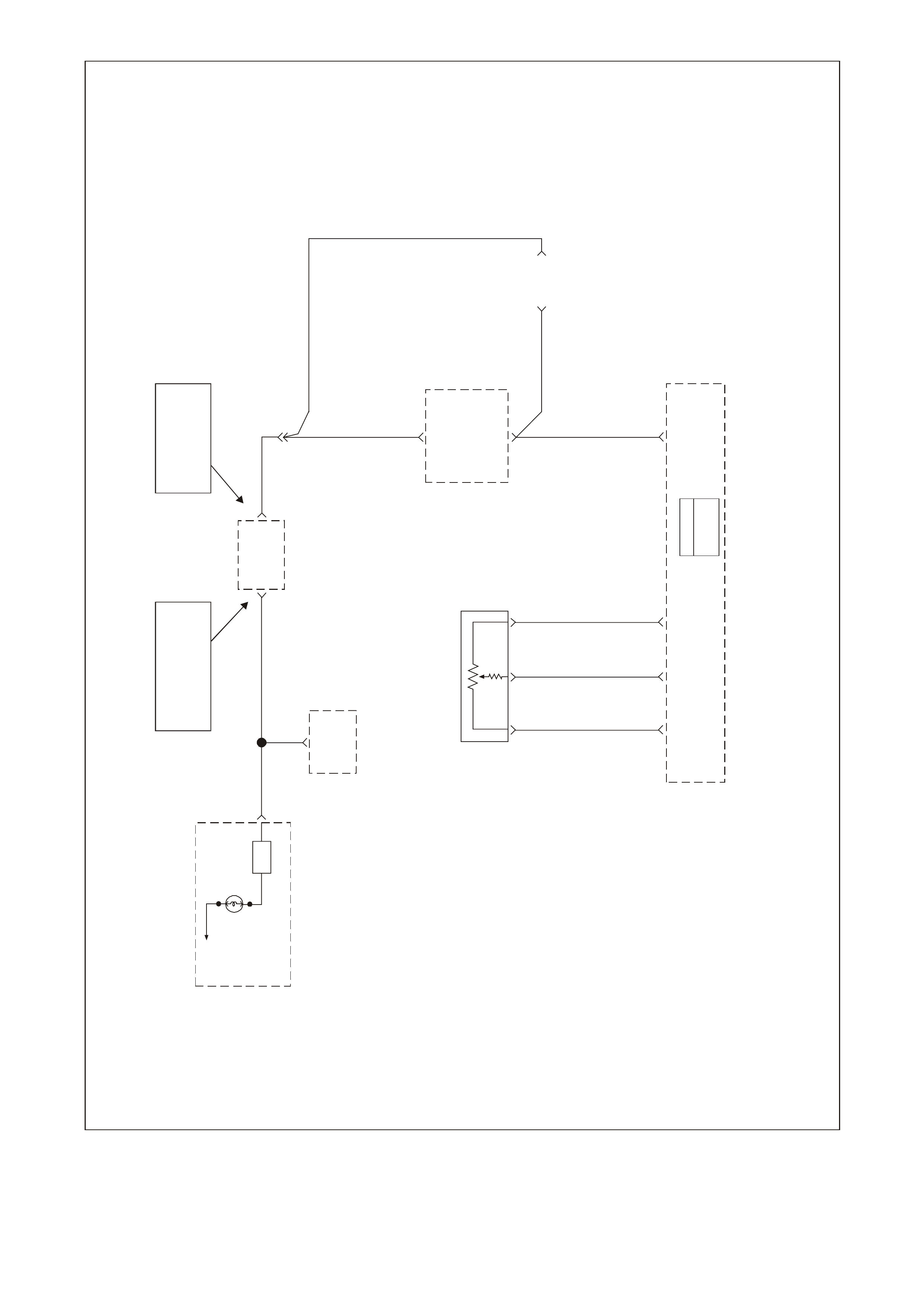
50 - VEHICLE SPEED SENSOR OUTPUT SIGNAL - The PCM alternately earth's this signal, in pulses, when it
receives a vehicle speed signal from the vehicle speed sensor in the transmission. This pulsing action takes place
about 6250 times per kilometre. The speedometer calculates vehicle speed based on the time between pulses.
51 - T RANSM ISSION FLUID TEMPERATURE SENSOR INPUT SIGNAL - The PCM sends a 5 volt signal voltage
out to the transmission fluid temperature sensor, which is a temperature-variable-resistor called a thermistor. The
sensor, being als o connected to ear th, will alter the voltage accor ding to transm is sion fluid tem perature. As the fluid
temperature increases, the voltage seen on this terminal will decrease.
52 - NOT USED
53 - ELECTRONIC T RACTION CONTROL RET ARD SIGNAL - The ABS/ET C m odule will send a Nm signal to the
PCM when torque reduction is requested from the ABS/ETC module for traction control. This Nm signal should
match closely with Torque Achieved Nm signal, when traction control is being requested.
54 - NOT USED
55 - NOT USED
56 - NOT USED
57 - INTAKE AIR TEMPERATURE SENSOR & A/C REFRIGERANT PRESSURE TRANSDUCER EARTH - This
terminal should be zero volts. It is connected through the PCM circuitry to engine earth.
58 - OIL PRESSURE SENSOR INPUT SIGNAL - T his signal indicates to the PCM when the oil level is low. W hen
the PCM receives this predetermined voltage from the oil pressure sensor, the PCM will turn ON the oil warning
lamp.
59 - NOT USED
60 - IGNITION REFERENCE LOW - This terminal should always be zero volts. It is the earth s ignal for the ignition
coil/modules 1, 3, 5 & 7.
61 - IGNITION REFERENCE LOW - This terminal should always be zero volts. It is the earth s ignal for the ignition
coil/modules 2, 4, 6 & 8.
62 - PRNDL C - This circuit along with the circ uits on PCM connec tor pins J 1 32, 34 & 72 indicate to the PCM what
transmission gear the driver has selected. The PCM will then send a command via the serial data line to the
instrument panel cluster (smart cluster) to indicate to the driver what gear has been selected.
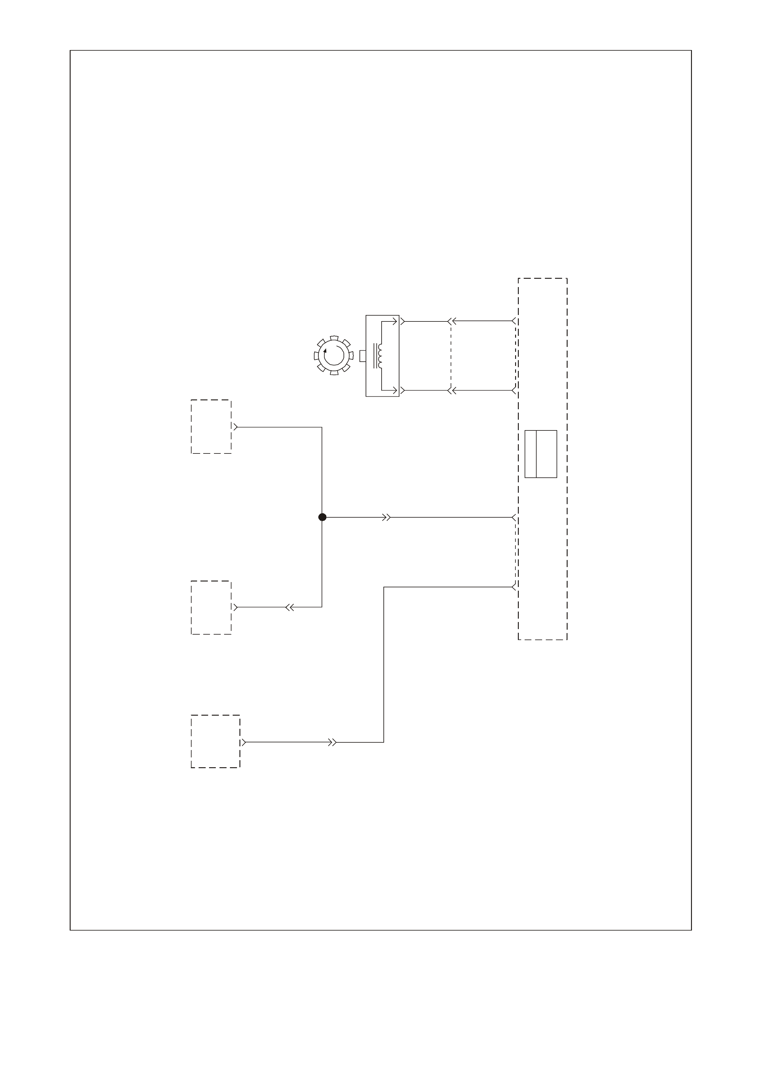
63 - TRANSMISSION RANGE A INPUT - The PCM sends out a buffered 12 volt signal to the pressure switch
assem bly, located in the autom atic tr ansm iss ion valve body. The 12 volt signal mus t pass through either a normally
open or normally closed switch to reach earth. When the switches are closed, the signal should be near 0 volts. The
PCM monitors the status of these signals to determine which gear servo is actually receiving hydraulic apply
pressure.
64 - NOT USED
65 - NOT USED
66 - IGNITION COIL/MODULE CONTROL #8 - This terminal is what triggers the ignition system coil/module for
cylinder #8. This terminal is connected from the PCM to the #8 ignition coil/module connector terminal G.
67 - IGNITION COIL/MODULE CONTROL #2 - This terminal is what triggers the ignition system coil/module for
cylinder #2. This terminal is connected from the PCM to the #2 ignition coil/module connector terminal B.
68 - IGNITION COIL/MODULE CONTROL #5 - This terminal is what triggers the ignition system coil/module for
cylinder #5. This terminal is connected from the PCM to the #5 ignition coil/module connector terminal C.
69 - IGNITION COIL/MODULE CONTROL #3 - This terminal is what triggers the ignition system coil/module for
cylinder #3. This terminal is connected from the PCM to the #3 ignition coil/module connector terminal F.
PCM Connector J2 (Red) Continued
70 - NOT USED
71 - NOT USED
72 - NOT USED
73 - NOT USED
74 - NOT USED
75 - NOT USED
76 - IDLE AIR CONTROL VALVE COIL B HIGH - This term inal connects the Idle Air Control valve, located on the
throttle body, to the PCM. It is diff icult to predict what the voltage will be, and the meas urement is unusable for any
service procedures.

77 - IDLE AIR CONTROL VALVE COIL B LOW - T his term inal connec ts the Idle Air Control valve, located on the
throttle body, to the PCM. It is diff icult to predict what the voltage will be, and the meas urement is unusable for any
service procedures.
78 - IDLE AIR CONTROL VALVE COIL A LOW - This term inal connects the Idle Air Control valve, located on the
throttle body, to the PCM. It is diff icult to predict what the voltage will be, and the meas urement is unusable for any
service procedures.
79 - IDLE AIR CONTROL VALVE COIL A HIGH - T his terminal c onnects the Idle Air Control valve, located on the
throttle body, to the PCM. It is diff icult to predict what the voltage will be, and the meas urement is unusable for any
service procedures.
80 - NOT USED
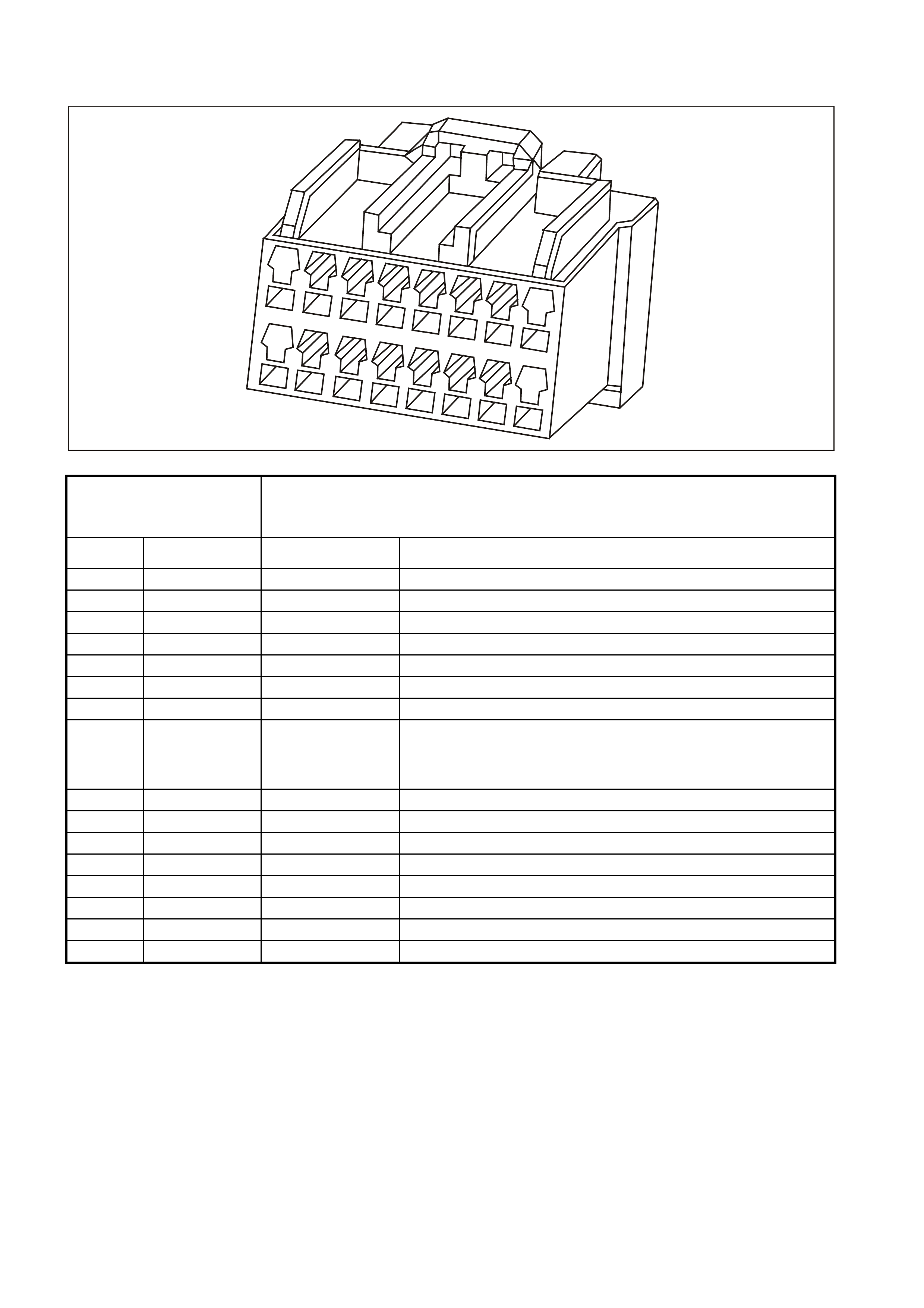
PIM CONNECTOR END VI EW
PIM CONNECTOR
GEN3 0104
8
16
1
9
Connector Part
Information
• PIM Connector YB215
• 16 Pin Connector
Pin Wire Color Circuit No. Functi on
1 Not Used - -
2 Not Used - -
3 Not Used - -
4 Not Used - -
5 Not Used - -
6 Red/Black 1221 UART Serial Data
7 Yellow 1049 Class II Serial Data
8 Grey/Blue
(AUTO)
Grey
(MANUAL)
1434
(AUTO)
434
(MANUAL)
Starter Relay Control
9 Not Used - -
10 Not Used - -
11 White/Black 451 Diagnostic Test Enable
12 Not Used - -
13 Not Used - -
14 Not Used - -
15 Pink 39 Ignition Feed
16 Black/Red 750 System Earth

PIM CONNECTOR TERMINAL DEFINITIONS
PIM CONNECTOR
1 - NOT USED
2 - NOT USED
3 - NOT USED
4 - NOT USED
5 - NOT USED
6 - SERIAL DATA (UART ) - This is a dedicated line for the T ech 2 sc an tool com munic ations. The c ircuit connects
the PIM, BCM, and ABS/ECT. T he Tech 2 sc an tool can talk to each of these modules by sending a message to a
controller and as k ing only it to res pond. The c om m unication rate is at 8192 baud. T he norm al voltage on this c ircuit
is about 5 volts, but when the Tech 2 scan tool is com municating with a controller, the voltage will vary and if read
with a DMM may read about 2.5 volts.
7 - SERIAL DATA (CLASS II) - This is a dedicated line for the Tech 2 scan tool communication. The circuit
connects the PCM, PIM, ABS/ETC, and BCM. T he Tech 2 s c an tool can talk to each of these m odules by sending a
message to a controller and asking only it to respond. The communication carried on Class II data streams are
prioritised. The normal voltage on this line is 0 volts, but when the Tech 2 scan tool is connected, the voltage will
about 7 volts indicating communication.
8 - STARTER RELAY CONTROL - When the PIM receives the proper Theft Deterrent signal from the BCM, the
PIM will supply a earth signal to the Start Relay. This will allow the vehicle to crank.
If a improper Theft Deterrent signal is sensed by the PIM, then the PIM will not supply a earth signal to the Start
Relay, and the PIM will not send a message to the PCM to allow fuel injection.
9 - NOT USED
10 - NOT USED
11 - DIAGNOSTIC TEST ENABLE - This terminal is connected to the DLC diagnostic test enable terminal. When
the diagnostic tes t terminal is not earthed, this term inal will have 5 volts on it. W hen the DLC diagnostic test enable
terminal is earthed, the resulting zero voltage at the PIM will instruct the PCM to operate in Diagnostic Mode.
12 - NOT USED
13 - NOT USED
14 - NOT USED
15 - IGNITION FEED - This is the power supply to the PIM from the ignition switch. The voltage should equal the
battery voltage when the key is in either the RUN, or CRANK position.
16 - SYSTEM EARTH - This terminal should have zero volts. This circuit is connected directly to the engine earth.
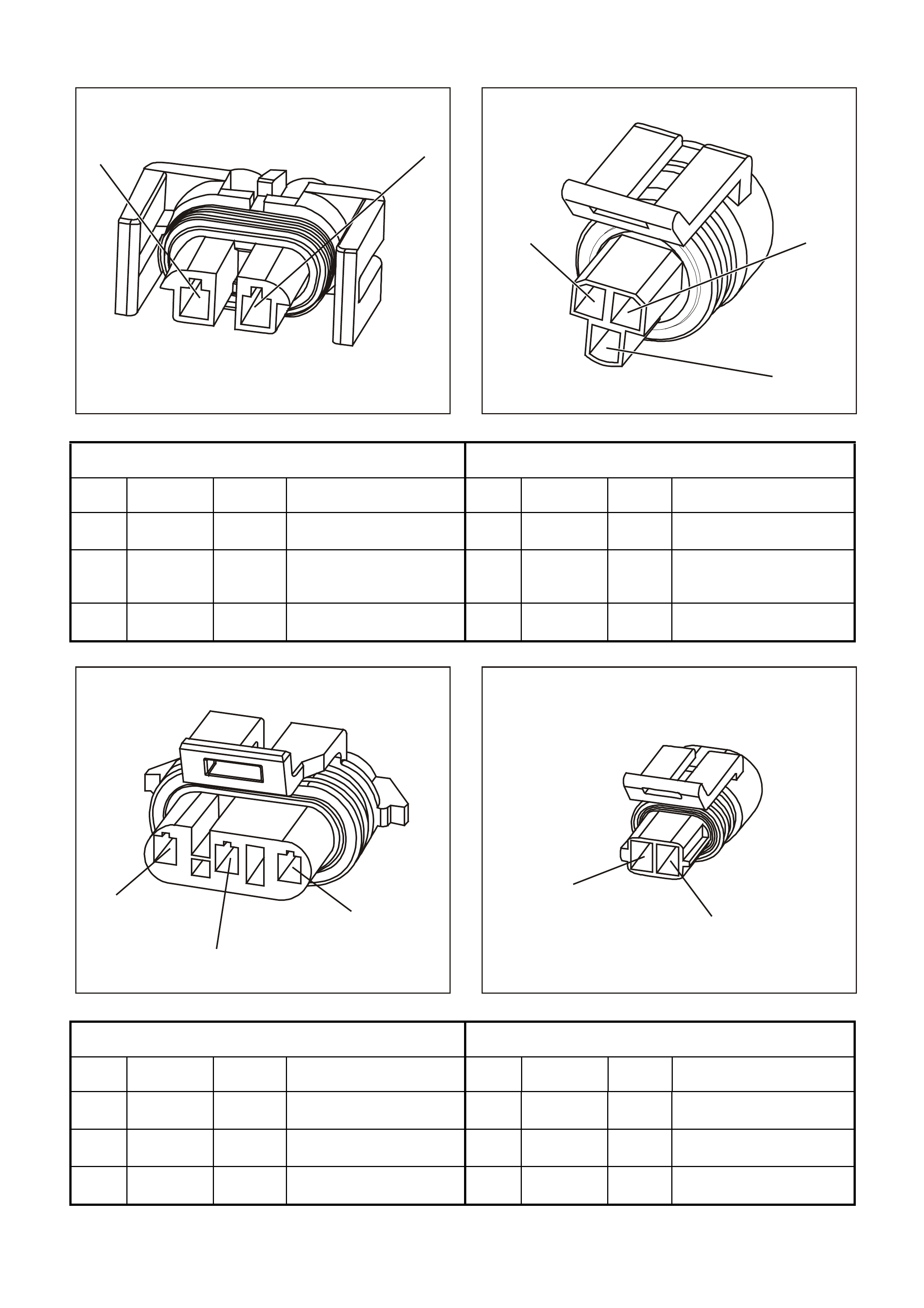
ENGINE CONTROL CONNECTOR END VIEWS
GE N 3 0073
21
2
3
1
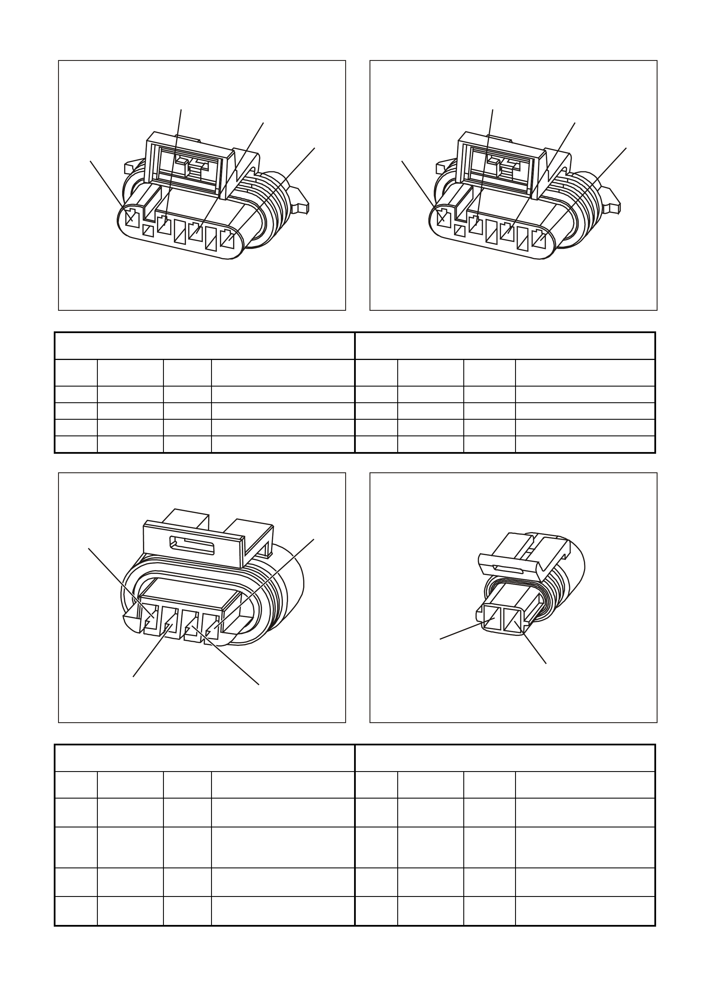
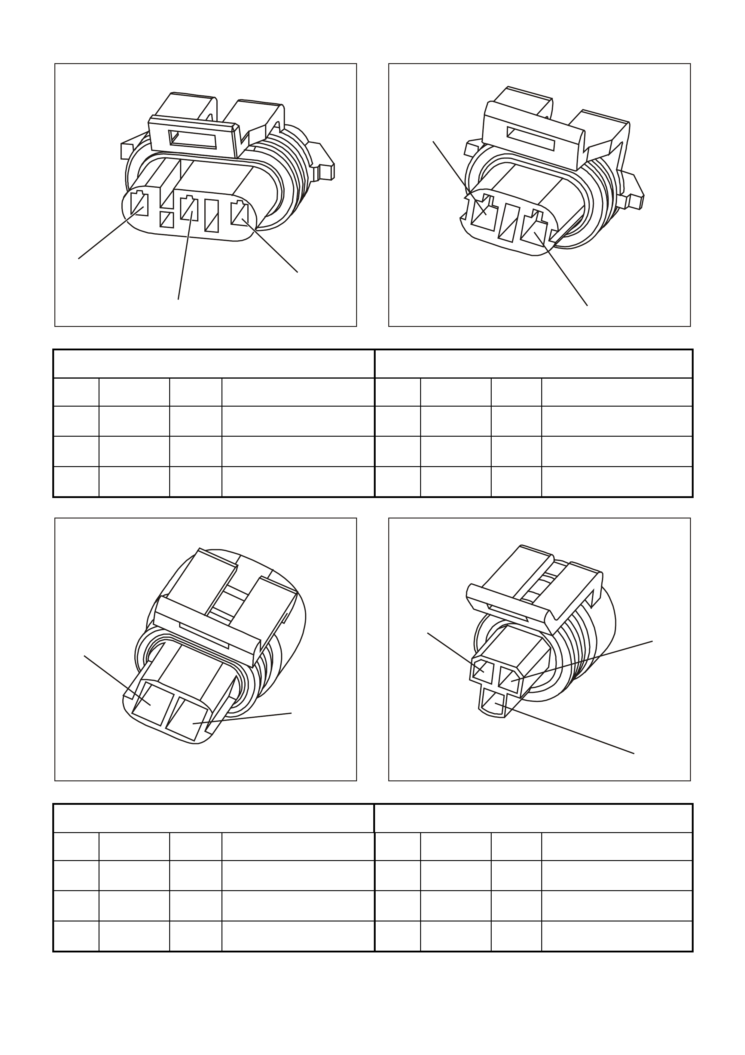
A/C Compressor Clutch Connector
YE105 A /C Refrigerant Pressure Sensor Connector
YE113
Pin Wire Colour Circuit
No. Function Pin Wire Colour Circuit
No. Function
1 B/R 750 A/C Compressor Clutch
Earth 1 G/O 469 A/C Refrigerant Pressure
Transducer Earth
2 G 59 A/C Compressor Clutch
Control 2 V/W 415 A/C Refrigerant Pressure
Transducer 5.0 V
Reference
3 G/B 259 A/C Refrigerant Pressure
Transducer Signal
GE N 3 0075
1
2
3
GE N 3 0076
1
2
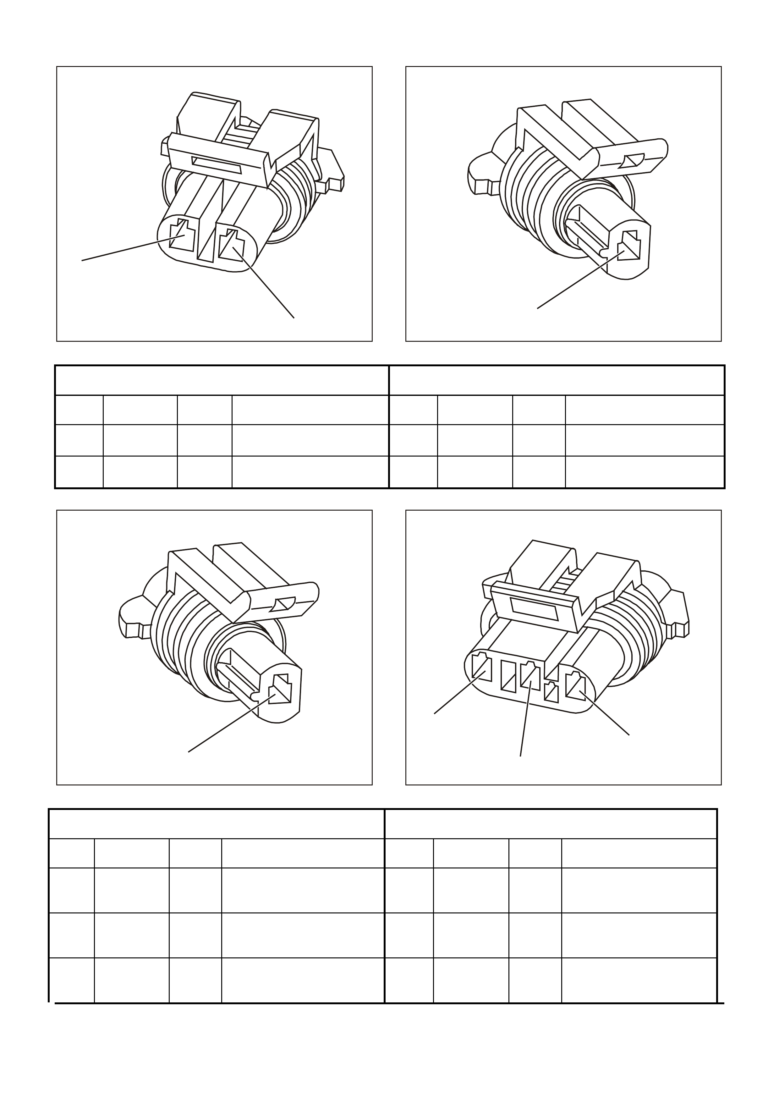
Camshaft Position (CMP) Sensor Connector
YE69 Engine Coolant Temperature (ECT) Sensor Connector
YE65
Pin Wire
Colour Circuit
No. Function Pin Wire
Colour Circuit
No. Function
1 BR 633 Camshaft Position (CMP)
Sensor Signal – Input 1 GY/B 455 Coolant Temperature
Sensor Earth
2 R/W 632 Camshaft Position (CMP)
Sensor Reference Low 2 Y 410 Coolant Temperature
Sensor Signal
3 W/B 631 Camshaft Position (CMP)
Sensor Ignition Feed
GE N 3 0075
1
2
3
GE N 3 0077
12
3
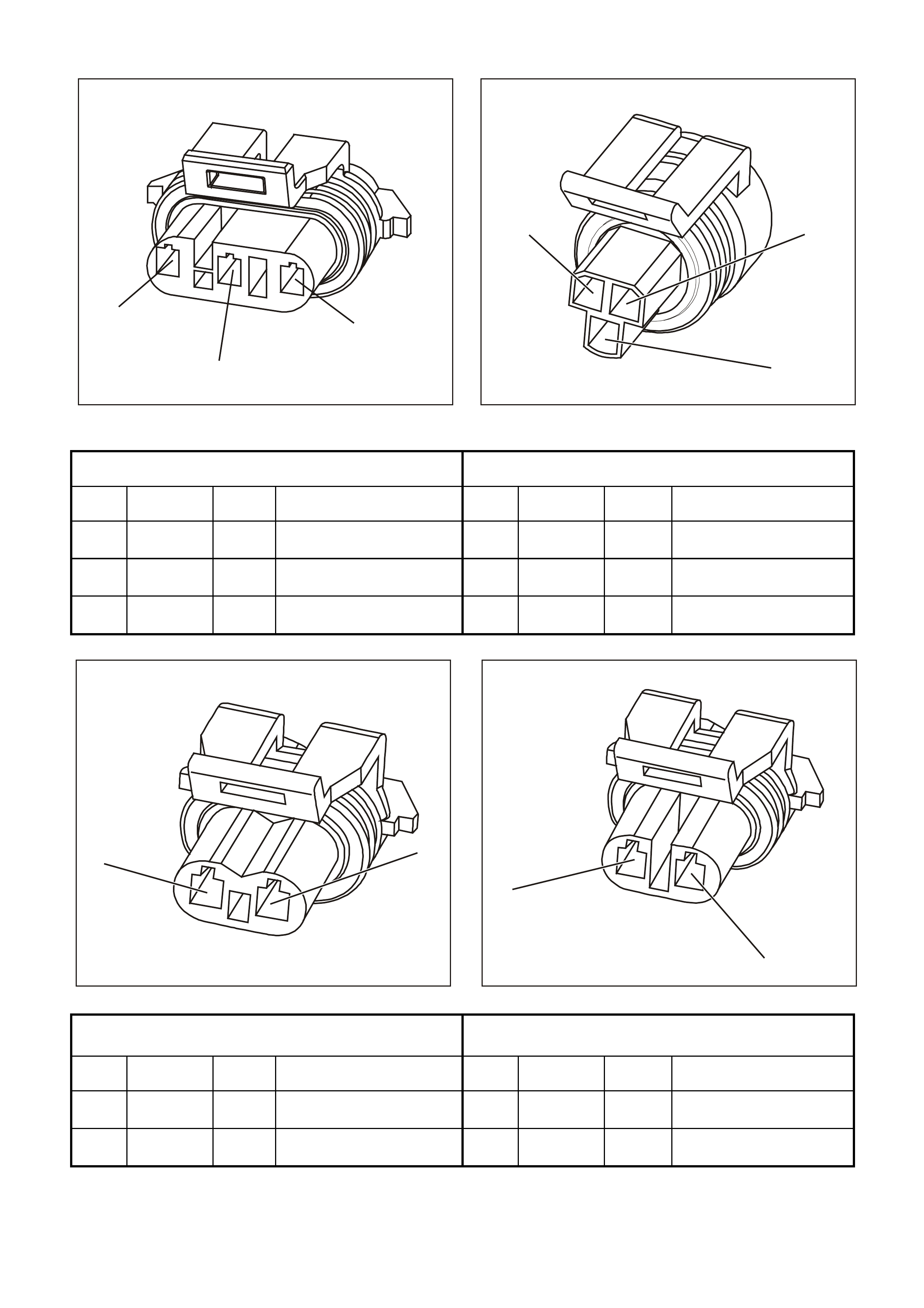
Crankshaft Position (CKP) Sensor Connector
YE67 Oil Pressure Sensor Connector
YE32
Pin Wire
Colour Circuit
No. Function Pin Wire
Colour Circuit
No. Function
1 BLU 643 Crankshaft Position (CKP)
Sensor Signal - Input 1 BLU/Y 334 Oil Pressure Sensor 5.0 V
Reference
2 LBLU/B 647 Crankshaft Position (CKP)
Sensor Reference Low 2 G 335 Oil Pressure Sensor
Reference Low
3 LBLU/W 646 Crankshaft Position (CKP)
Sensor Ignition Feed 3 BR/W 331 Oil Pressure Sensor
Signal - Input
GE N 3 0078
12
GE N 3 0079
1
2
Evaporative Emission (EVAP) Canister Purge Solenoid
Connector YE99 Engine Coolant Level Switch Connector
YE131
Pin Wire
Colour Circuit
No. Function Pin Wire
Colour Circuit
No. Function
1 P 439 Canister Purge Solenoid
Ignition Feed 1 B/R 750 Engine Coolant Level
Switch Earth
2 G/Y 428 Canister Purge Solenoid
Control 2 G 69 Engine Coolant Level
Switch Signal - Input
GE N 3 0080
12
GE N 3 0080
12
Fuel Injector #1 Connector
YE77 Fuel Injector #2 Connector
YE78
Pin Wire
Colour Circuit
No. Function Pin Wire
Colour Circuit
No. Function
1 LG 482 Injector #1 Ignition Feed 1 R 481 Injector #2 Ignition Feed
2 BLU 841 Injector #1 Control 2 G 842 Injector #2 Control
GE N 3 0080
12
GE N 3 0080
12
Fuel Injector #3 Connector
YE79 Fuel Injector #4 Connector
YE80
Pin Wire
Colour Circuit
No. Function Pin Wire
Colour Circuit
No. Function
1 LG 482 Injector #3 Ignition Feed 1 R 481 Injector #4 Ignition Feed
2 V 843 Injector #3 Control 2 BR/Y 844 Injector #4 Control
GE N 3 0080
12
GE N 3 0080
12
Fuel Injector #5 Connector
YE81 Fuel Injector #6 Connector
YE82
Pin Wire
Colour Circuit
No. Function Pin Wire
Colour Circuit
No. Function
1 LG 482 Injector #5 Ignition Feed 1 R 481 Injector #6 Ignition Feed
2 GY 845 Injector #5 Control 2 Y 846 Injector #6 Control
GE N 3 0080
12
GE N 3 0080
12
Fuel Injector #7 Connector
YE83 Fuel Injector #8 Connector
YE84
Pin Wire
Colour Circuit
No. Function Pin Wire
Colour Circuit
No. Function
1 LG 482 Injector #7 Ignition Feed 1 R 481 Injector #8 Ignition Feed
2 P/B 847 Injector #7 Control 2 LG 848 Injector #8 Control
GE N 3 0081
2
1
3
4
GE N 3 0081
2
1
3
4
Bank 1 Left Heated Oxygen (HO2S) Sensor Connector
YE97 Bank 2 Right Heated Oxygen (HO2S) Sensor Connector
YE97
Pin Wire
Colour Circuit
No. Function Pin Wire
Colour Circuit
No. Function
1 BLU/B 413 HO2S Low 1 GY/B 1413 HO2S Low
2 V 412 HO2S High 2 GY 1412 HO2S High
3 B/R 750 HO2S Earth 3 B/R 750 HO2S Earth
4 P 439 HO2S Ignition Feed 4 P 439 HO2S Ignition Feed
GE N 3 0082
41
32
GE N 3 0076
1
2
Idle Air Control (IAC) Valve Connector
YE36 Intake Air Temperature (IAT) Sensor Connector
YE23
Pin Wire
Colour Circuit
No. Function Pin Wire
Colour Circuit
No. Function
1 LG/B 444 Idle Air Control (IAC) Valve
Coil B Signal - Low 1 G/O 469 Intake Air Temperature
(IAT) Sensor Earth
2 LG/W 443 Idle Air Control (IAC) Valve
Coil B Signal - High 2 BR 472 Intake Air Temperature
(IAT) Sensor Signal -
Input
3 LBLU/B 442 Idle Air Control (IAC) Valve
Coil A Signal - Low
4 LBLU 441 Idle Air Control (IAC) Valve
Coil A Signal - High
GE N 3 0083
1
2
GE N 3 0084
1
Knock Sensor (KS) Two Way Harness Connector
YE19 Front Knock Sensor (KS) Connector
YE18
Pin Wire
Colour Circuit
No. Function Pin Wire
Colour Circuit
No. Function
1 BLU 815 Front Knock Sensor Signal
Circuit 1 BLU 815 Front Knock Sensor (KS)
Signal Circuit
2 LBLU 826 Rear Knock Sensor Signal
Circuit
GE N 3 0084
1
GE N 3 0085
1
2
3
Rear Knock Sensor (KS) Connector
YE18 Manifold Absolute Pressure (MAP) Sensor Connector
YE27
Pin Wire
Colour Circuit
No. Function Pin Wire
Colour Circuit
No. Function
1 LBLU 826 Rear Knock Sensor (KS)
Signal Circuit 1 B 421 Manifold Absolute
Pressure (MAP) Sensor
Earth
2 LG 432 Manifold Absolute
Pressure (MAP) Sensor
Signal
3 V/W 414 Manifold Absolute
Pressure (MAP) Sensor
5.0 V Reference
GE N 3 0086
1
2
3
ABC
GE N 3 0087
1
2
Mass Air Flow (MAF) Sensor Connector
YE100 Manual Transmission Reverse Lock Out Connector
YB125
Pin Wire
Colour Circuit
No. Function Pin Wire
Colour Circuit
No. Function
1 BR/W 792 Mass Air Flow (MAF)
Sensor Signal 1 P/BLU 339 Reverse Lock Out Ignition
Feed
2 B/R 750 Mass Air Flow (MAF)
Sensor Earth 2 Y 838 Reverse Lock Out Control
3 P 439 Mass Air Flow (MAF)
Sensor Ignition Feed
GE N 3 0088
2
1
GE N 3 0103
1
2
3
Vehicle Speed Sensor (VSS) Connector
YB195 Throttle Position (TP) Sensor Connector
YE30
Pin Wire
Colour Circuit
No. Function Pin Wire
Colour Circuit
No. Function
1 T 832 Vehicle Speed Sensor
(VSS) Signal – Low 1 GY 416 Throttle Position (TP)
Sensor 5.0 V Reference
2 BLU/W 831 Vehicle Speed Sensor
(VSS) Signal – High 2 B/Y 452 Throttle Position (TP)
Sensor Earth
3 BLU 417 Throttle Position (TP)
Sensor Signal
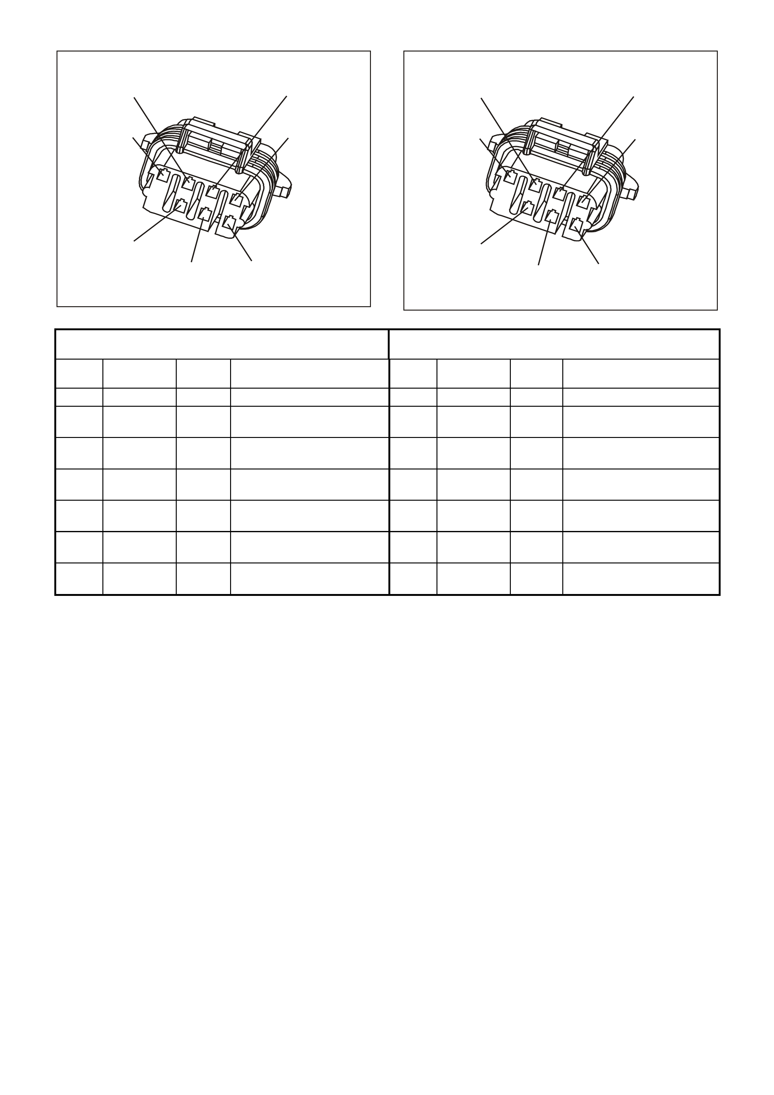
GE N 3 0089
5
4
3
21
6
7
GE N 3 0089
5
4
3
21
6
7
Right Bank Ignition Module Connector
YE124 Left Bank Ignition Module Connector
YE125
Pin Wire
Colour Circuit
No. Function Pin Wire
Colour Circuit
No. Function
1 B/R 750 Ignition Module Earth 1 B/R 750 Ignition Module Earth
2 Y/B 972 Ignition Coil/Module #2
Control 2 Y 977 Ignition Coil/Module #7
Control
3 W 974 Ignition Coil/Module #4
Control 3 G 975 Ignition Coil/Module #5
Control
4 V 959 Ignition Coil/Module
Reference Low 4 BR 958 Ignition Coil/Module
Reference Low
5 LG 976 Ignition Coil/Module #6
Control 5 BLU 973 Ignition Coil/Module #3
Control
6 LBLU 978 Ignition Coil/Module #8
Control 6 W 971 Ignition Coil/Module #1
Control
7 R 481 Right Bank Coil/Module
Ignition Feed 7 LG 482 Left Bank Coil/Module
Ignition Feed

GE N 3 0090
4
3
2
1
GE N 3 0078
12
PRNDL Switch Connector
YB20 Throttle Relaxer Connector
YE127
Pin Wire
Colour Circuit
No. Function Pin Wire
Colour Circuit
No. Function
1 BLU/W 771 PRNDL Switch A Input 1 R/B 466 Throttle Relaxer Power
Control
2 GY 773 PRNDL Switch C Input 2 R/W 456 Throttle Relaxer Earth
Control
3 W 776 PRNDL Switch P Input
4 Y 772 PRNDL Switch B Input
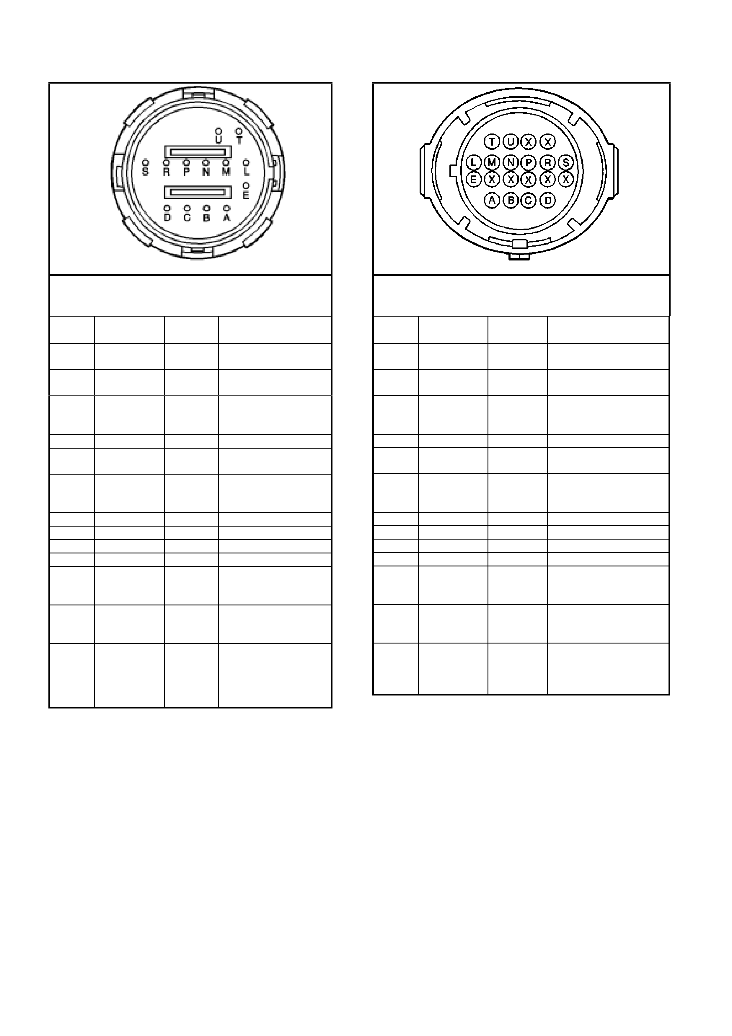
AUTOMATIC TRANSMISSION INLINE HARNESS CONNECTOR END VIEWS
Automatic Transmission Wiring Harness,
Transmission Side
YB 129
Pin Wire Color Circuit
No. Function
A LG 1222 1-2 Shift Solenoid
(A) Valve Control
B Y 1223 2-3 Shift Solenoid
(B) Valve Control
C V 1228 Pressure Control
Solenoid (PCS)
Valve HIGH
D LBLU 1229 PCS Valve LOW
E R 339 Transmission
Solenoid Power
L BR 1227 Transmission Fluid
Temperature (TFT)
Sensor HIGH
M GY 1230 TFT Sensor LOW
N P 1224 Range Signal A
P O 1226 Range Signal C
R DKBLU 1225 Range Signal B
S W 897 3-2 Shift Solenoid
Valve Assembly
Control
T B 422 Torque Converter
Clutch Solenoid
Valve Control
U T 418 Torque Converter
Clutch Pulse Width
Modulation
Solenoid Valve
Control
Automatic Transmission Wiring Harness,
Engine Side
YB 129
Pin Wire Color Circuit
No. Function
A LG 1222 1-2 Shift Solenoid (A)
Valve Control
B Y/B 1223 2-3 Shift Solenoid (B)
Valve Control
C R 1228 Pressure Control
Solenoid (PCS) Valve
HIGH
D GY/BLU 1229 PCS Valve LOW
E P/BLU 339 Transmission
Solenoid Power
L B/Y 1227 Transmission Fluid
Temperature (TFT)
Sensor HIGH
M B/W 1230 TFT Sensor LOW
N BR/Y 1224 Range Signal A
P GY 1226 Range Signal C
R Y 1225 Range Signal B
S G/W 897 3-2 Shift Solenoid
Valve Assembly
Control
T GY/R 422 Torque Converter
Clutch Solenoid Valve
Control
U BR 418 Torque Converter
Clutch Pulse Width
Modulation Solenoid
Valve Control
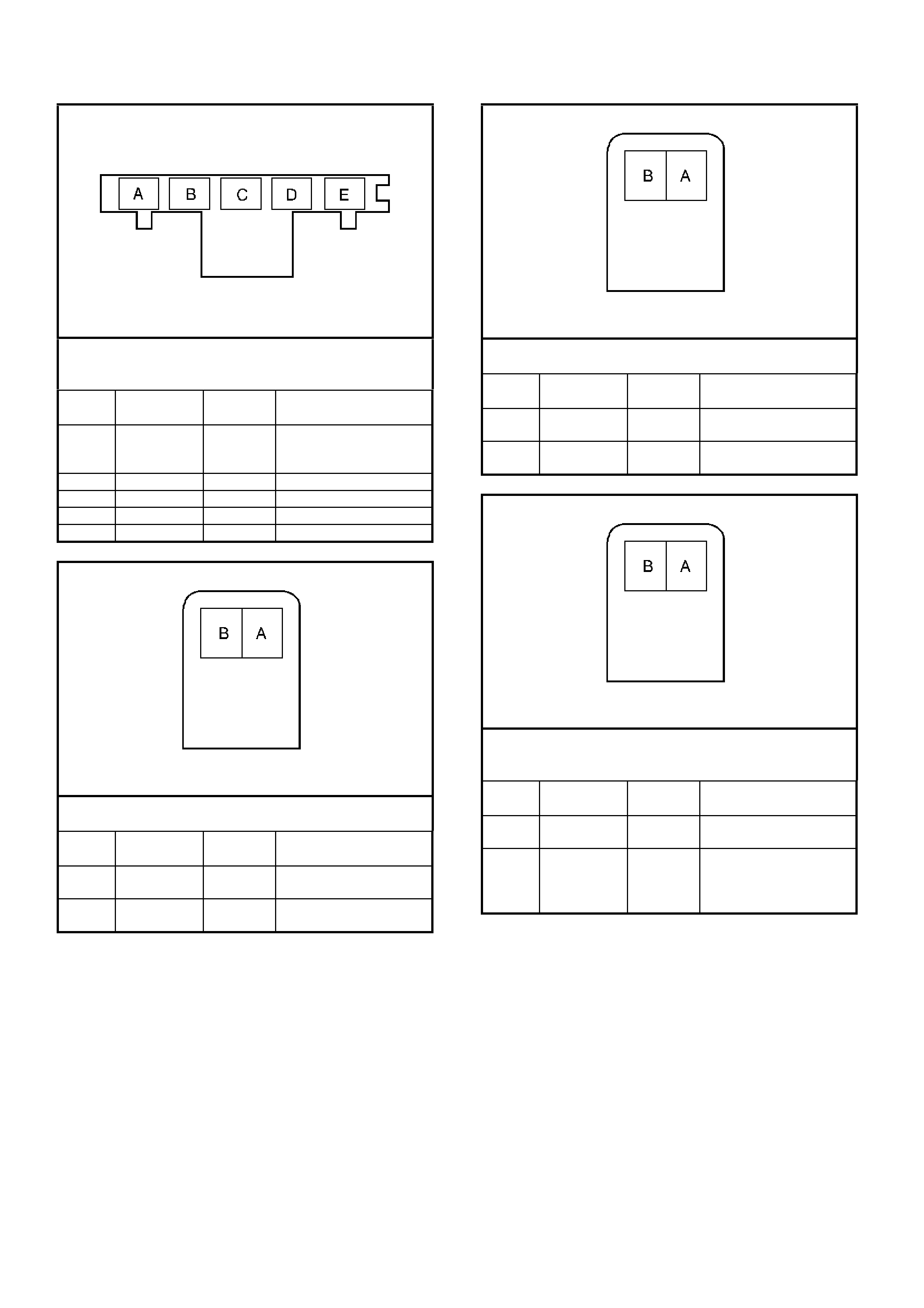
AUTOMATIC TRANSMISSION INTERNAL CONNECTOR END VIEWS
Automatic Transmission Fluid Pressure (TFP) Manual
Valve Position Switch Connector,
Wiring Harness Side
Pin Wire Color Circuit
No. Function
A BR 1227 Transmission Fluid
Temperature (TFT)
Sensor Signal
B GY 1230 TFT Sensor earth
C P 1224 Range Signal A Input
D O 1226 Range Signal C Input
E DKBLU 1225 Range Signal B Input
1-2 Shift Solenoid A (SS) Valve Connector,
Wiring Harness Side
Pin Wire Color Circuit
No. Function
A R 339 Transmission
Solenoid Power
B LG 1222 1-2 Shift Solenoid (A)
Valve Control
2-3 Shift Solenoid B (SS) Valve Connector,
Wiring Harness Side
Pin Wire Color Circuit
No. Function
A R 339 Transmission
Solenoid Power
B Y 1223 2-3 Shift Solenoid (B)
Valve Control
Torque Converter Clutch Pulse Width Modulated
(TCCPWM) Solenoid Valve Connector,
Wiring Harness Side
Pin Wire Color Circuit
No. Function
A R 339 Transmission
Solenoid Power
B T 418 Torque Converter
Clutch Pulse Width
Modulated Solenoid
Valve Control
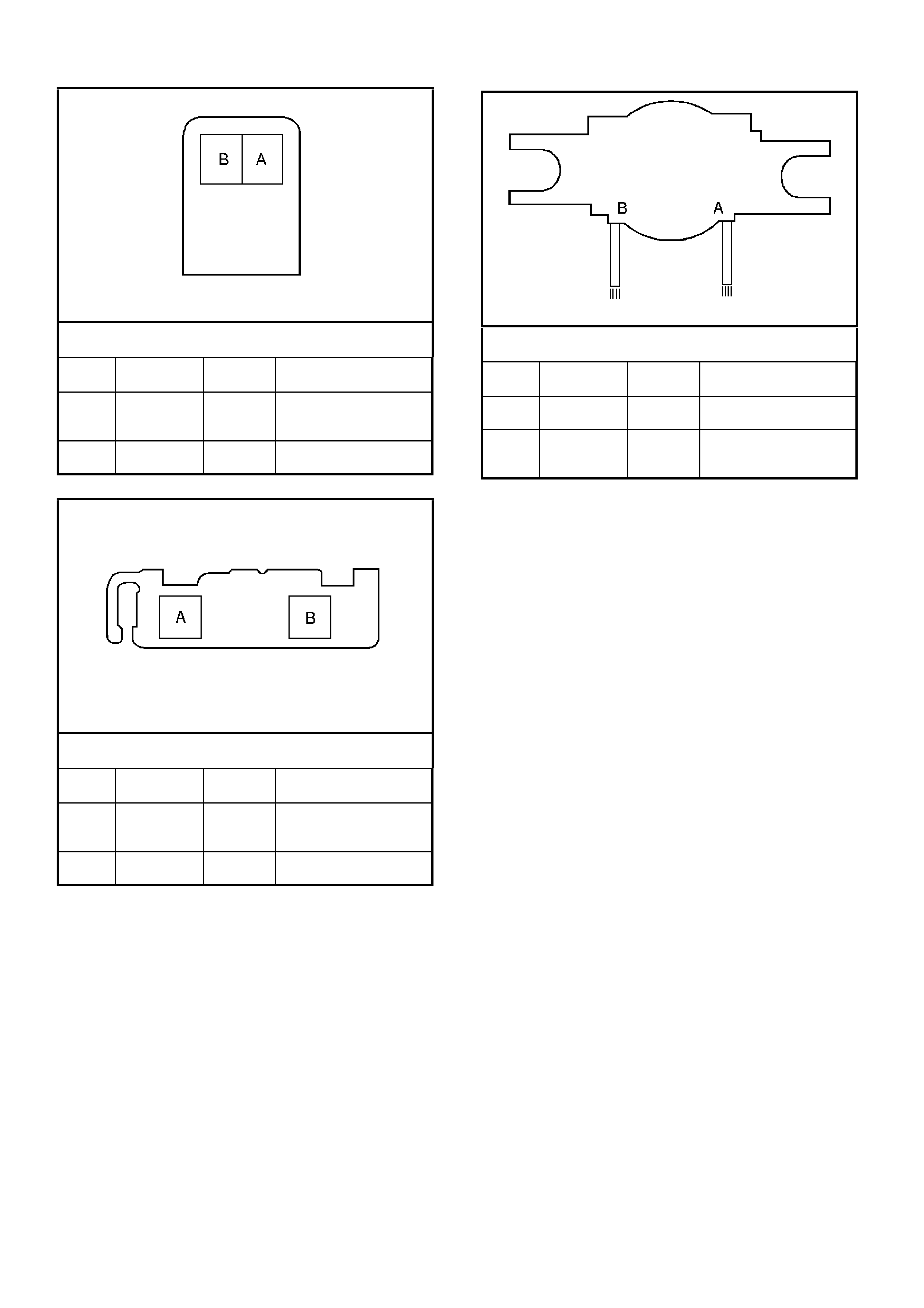
3-2 Shift Solenoid (SS) Valve Assembly Connector,
Wiring Harness Side
Pin Wire Color Circuit
No. Function
A W 897 3-2 Shift Solenoid
Valve Assembly
Control
B R 339 Transmission
Solenoid Power
Pressure Control Solenoid (PCS) Valve Connector,
Wiring Harness Side
Pin Wire Color Circuit
No. Function
A V 1228 Pressure Control
Solenoid (PCS) Valve
HIGH Control
B LBLU 1229 PCS Valve LOW
Control
Torque Converter Clutch (TCC) Solenoid Valve
Connector, Wiring Harness Side
Pin Wire Color Circuit
No. Function
A R 339 Transmission
Solenoid Power
B B 422 Torque Converter
Clutch Solenoid Valve
Control

PCM GEN III V8 ENGINE DIAGNOSTIC TROUBLE CODES (DTC)
DTC
DESCRIPTION ILLUMINATE CHECK
POWERTRAIN LAMP
(CPL)
P0101 MAF Sensor Performance Yes
P0102 MAF Sensor Circuit Low Frequency Yes
P0103 MAF Sensor Circuit High Frequency Yes
P0107 MAP Sensor Circuit Low Voltage Yes
P0108 MAP Sensor Circuit High Voltage Yes
P0112 IAT Sensor Circuit Low Voltage No
P0113 IAT Sensor Circuit High Voltage No
P0117 ECT Sensor Circuit Low Voltage Yes
P0118 ECT Sensor Circuit High Voltage Yes
P0121 TP Sensor Circuit Insufficient Activity Yes
P0122 TP Sensor Circuit Low Voltage Yes
P0123 TP Sensor Circuit High Voltage Yes
P0125 ECT Excessive Time to Closed Loop No
P0131 HO2S Circuit Low Voltage Bank 1 Sensor 1 Yes
P0132 HO2S Circuit High Voltage Bank 1 Sensor 1 Yes
P0133 HO2S Slow Response Bank 1 Sensor 1 Yes
P0134 HO2S Insufficient Activity Bank 1 Sensor 1 Yes
P0135 HO2S Heater Circuit Bank 1 Sensor 1 Yes
P0151 HO2S Circuit Low Voltage Bank 2 Sensor 1 Yes
P0152 HO2S Circuit High Voltage Bank 2 Sensor 1 Yes
P0153 HO2S Slow Response Bank 2 Sensor 1 Yes
P0154 HO2S Insufficient Activity Bank 2 Sensor 1 Yes
P0155 HO2S Heater Circuit Bank 2 Right Front Yes
P0171 Fuel Trim System Lean Bank 1 Yes
P0172 Fuel Trim System Rich Bank 1 Yes
P0174 Fuel Trim System Lean Bank 2 Yes
P0175 Fuel Trim System Rich Bank 2 Yes
P0230 Fuel Pump Control Circuit Yes
P0325 Knock Sensor System Yes
P0327 Knock Sensor Circuit Front Yes
P0332 Knock Sensor Circuit Rear Yes
P0335 CKP Sensor Circuit Yes
P0336 CKP Sensor Circuit Performance Yes
P0341 CMP Sensor Circuit Performance Yes
P0342 CMP Sensor Circuit Low Voltage Yes
P0343 CMP Sensor Circuit High Voltage Yes
P0351 Ignition Control #1 Circuit Yes
P0352 Ignition Control #2 Circuit Yes
P0353 Ignition Control #3 Circuit Yes
P0354 Ignition Control #4 Circuit Yes
P0355 Ignition Control #5 Circuit Yes
P0356 Ignition Control #6 Circuit Yes
P0357 Ignition Control #7 Circuit Yes
P0358 Ignition Control #8 Circuit Yes
P0443 EVAP Purge Solenoid Control Circuit Yes
P0481 High Speed Cooling Fan Relay Driver Circuit Yes
P0506 Idle Speed Low Yes
P0507 Idle Speed High Yes
P0522 Engine Oil Pressure Sensor Low Input Yes
P0523 Engine Oil Pressure Sensor High Input Yes
P0530 A/C Refrigerant Pressure Transducer Circuit No
P0562 System Voltage Low No
P0563 System Voltage High No
P0601 PCM Memory Yes
P0602 PCM Not Programmed Yes
P0608 VSS Output Circuit No

DTC
DESCRIPTION ILLUMINATE CHECK
POWERTRAIN LAMP
(CPL)
P0654 Engine Speed Output Circuit No
P1111 IAT Sensor Intermittent High Voltage No
P1112 IAT Sensor Intermittent Low Voltage No
P1114 ECT Sensor Intermittent Low Voltage No
P1115 ECT Sensor Intermittent High Voltage No
P1121 TP Sensor Intermittent High Voltage No
P1122 TP Sensor Intermittent Low Voltage No
P1133 HO2S Insufficient Switching Bank 1 Sensor 1 No
P1134 HO2S Transition Time Ratio Bank 1 Sensor 1 No
P1153 HO2S Insufficient Switching Bank 2 Sensor 1 No
P1154 HO2S Transition Ratio Bank 2 Sensor 1 No
P1258 Engine Coolant Over Temp Fuel Disable Yes
P1539 A/C Clutch Status Circuit High Voltage No
P1546 A/C Clutch Status Circuit Low Voltage No
P1626 Theft Deterrent System Fuel Enable Circuit Yes
P1630 PCM In Learn Mode Yes
P1631 Theft Deterrent Password Incorrect Yes
P1635 5 Volt Reference #1 Circuit Yes
P1639 5 Volt Reference #2 Circuit Yes

PIM GEN III V8 ENGINE DIAG NOSTIC TROUBLE CODES (DTC)
DTC
DESCRIPTION ILLUMINATE CHECK
POWERTRAIN LAMP
(CPL)
B2002 Low Speed Fan No BCM Response No
B2006 No Serial Data From PCM No
B2007 Starter Relay Voltage High No
B2009 EEPROM Checksum Error No

PCM GEN III V8 AUTOMATIC TRANSMISSION DIAGNOSTIC TROUBLE CODES (DTC)
DTC Description Default Action
P0218 Transmission Fluid Over temperature The PCM freezes shift adapts from being updated
The PCM illuminates the Check Powertrain Lamp (CPL)
P0502 Vehicle Speed Sensor Circuit Low The PCM commands first gear only
The PCM commands maximum line pressure
The PCM freezes shift adapts from being updated
The PCM inhibits TCC engagement
P0503 Vehicle Speed Sensor Circuit Intermittent The PCM commands second gear only
The PCM commands maximum line pressure
The PCM inhibits TCC engagement
The PCM inhibits 4th gear if the transmission is in hot
mode
The PCM freezes shift adapts from being updated
P0705 PRNDL Range Fault —
P0706 PRNDL Switch Fault —
P0711 TFT Sensor Circuit Range/Performance The PCM uses a transmission fluid temperature default
value based on engine coolant, engine run time and IAT
at startup
The PCM freezes shift adapts from being updated
P0712 TFT Sensor Circuit Low The PCM uses a transmission fluid temperature default
value based on engine coolant, engine run time and IAT
at startup
The PCM freezes shift adapts from being updated
P0713 TFT Sensor Circuit High The PCM uses a transmission fluid temperature default
value based on engine coolant, engine run time and IAT
at startup
The PCM freezes shift adapts from being updated
P0719 Brake Switch Circuit Low The PCM disregards the brake switch input for TCC
scheduling
P0724 Brake Switch Circuit High —
P0740 TCC Enable Solenoid Circuit Electrical The PCM inhibits TCC engagement
The PCM inhibits 4th gear if the transmission is in hot
mode
The PCM freezes shift adapts from being updated
P0742 TCC System Stuck On The PCM freezes shift adapts from being updated
The PCM illuminates the Check Powertrain Lamp (CPL)
P0748 PC Solenoid Circuit Electrical The PC solenoid valve is OFF
The PCM freezes shift adapts from being updated
P0751 1-2 SS Valve Performance The PCM commands D2 line pressure
The PCM inhibits 3-2 downshifts if the vehicle speed is
greater than 48 km/h
The PCM freezes shift adapts from being updated
The PCM illuminates the Check Powertrain Lamp (CPL)
P0753 1-2 SS Circuit Electrical The PCM commands D2 line pressure
The PCM inhibits 3-2 downshifts if the vehicle speed is
greater than 48 km/h
The PCM freezes shift adapts from being updated
The PCM illuminates the Check Powertrain Lamp (CPL)
P0756 2-3 SS Valve Performance The PCM commands third gear only
The PCM commands maximum line pressure
The PCM inhibits TCC engagement
The PCM freezes shift adapts from being updated
The PCM illuminates the Check Powertrain Lamp (CPL)

DTC Description Default Action
P0758 2-3 SS Circuit Electrical The PCM commands 3rd gear only
The PCM commands maximum line pressure
The PCM inhibits TCC engagement
The PCM freezes shift adapts from being updated
The PCM illuminates the Check Powertrain Lamp (CPL)
P0785 3-2 SS Circuit Electrical The PCM commands a soft landing to 3rd gear
The PCM inhibits TCC engagement
The PCM commands maximum line pressure
The PCM inhibits 4th gear if the transmission is in hot
mode
The PCM freezes shift adapts from being updated
The PCM illuminates the Check Powertrain Lamp (CPL)
P1810 TFP Switch Circuit Fault The PCM commands D2 line pressure
The PCM commands a D4 shift pattern
The PCM freezes shift adapts from being updated
The PCM illuminates the Check Powertrain Lamp (CPL)
P1860 TCC PWM Solenoid Circuit Electrical The PCM inhibits TCC engagement
The PCM inhibits 4th gear if the transmission is in hot
mode
The PCM freezes shift adapts from being updated
The PCM illuminates the Check Powertrain Lamp (CPL)
P1870 Transmission Component Slipping The PCM inhibits TCC engagement
The PCM commands maximum line pressure
The PCM inhibits 4th gear if the transmission is in hot
mode
The PCM freezes shift adapts from being updated
The PCM illuminates the Check Powertrain Lamp (CPL)
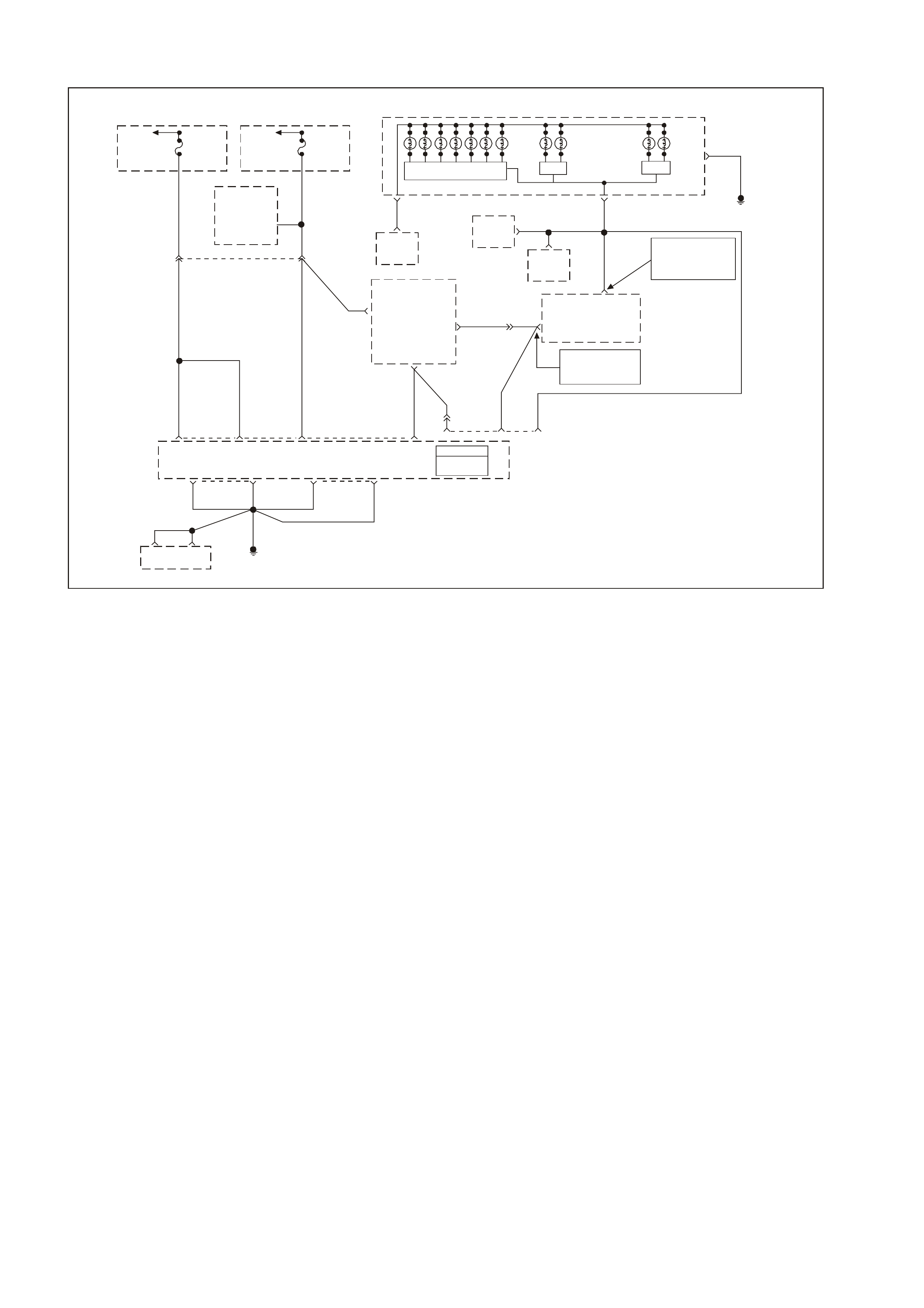
GEN III V8 PCM POWERTRAIN OBD SYSTEM CHECK
GEN3 0091
58 J1
Serial
Data
(Class 2)
PCM
J1 = BLUE
J2 = RED
Powertrain
Control
Module
(PCM)
Y1049 YE110
291
Data Link
Connector
(DLC)
R/B 1221
1049
Y
7
R/B
1221 YE112 2
6Serial Data
(UART)
Serial Data
(UART)
Serial Data
(Class 2)
Powertrain
Interface
Module
(PIM)
Ignition
Voltage
15
Fuse
F13
ECC
Module 6
P/BW 44
19
Gear Indicator Lamps (Option)
SDI
Low
Coolant
Lamp
SDI
Malfunction
Indicator
Lamp (MIL)
Check
Powertrain
Lamp
SDI
Oil
Warning
Lamp
Instrument Panel Cluster
G/W 1220
12
B/Y
155
9
G/W 1220
G/W 1220
Serial Data
(UART)
ABS/ECT
Module
11
Body
Control
Module
(BCM)
NOTE
BCM Termi nals
9 YB175 High Series
3 YB164 Low Serie s
NOTE
YB175 High Series
YB164 Low Series
6
01 40 J1 01 40 J2
B/R 750 B/R 750B/R 750 B/R 750
750
B/R
B/R 750
Engine Earth
Location E5 / E15
Oxygen Sensor
Heaters
Ignition
Positive
Voltage
Battery
Feed
Battery
Feed
O740
O740
195720
P39
O/B 740 P/B 39
P39
YE112
Refe r To
Wiring
Schematic
Part 1
To
Fusible
Link
FS
Fuse
F31 Fuse
F14
To
Ignition
Switch
Power
Economy
Lamp
CIRCUIT DESCRIPTION
The Powertrain OBD System Check is an organised approach to identifying a problem created by an electronic
engine control system malfunction. The Powertrain OBD System Check is the starting point for any driveability
complaint diagnosis. The Powertrain OBD System Check directs the service technician to the next logical step in
diagnosing a complaint. DO NOT PERFORM THIS CHECK IF NO DRIVEABILITY COMPLAINT EXISTS.
Understanding and using the table correctly will reduce the diagnostic time and prevent the replacement of good
parts.
Important: This vehicle is equipped with a Powertrain Control Module (PCM) utilising an Electrically Erasable
Programmable Read Only Memory (EEPROM). Program
the new PCM when diagnostics call f or replacem ent of the PCM. Refer to Section 6C3-3 SERVICE OPERATIONS
– GEN III V8 Engine, PCM Replacement Programming in this Service Information CD.
Important: This vehicle is equipped with a Powertrain Interface Module (PIM). This PIM is the vehicle serial data
translator between Class II and UART serial data.
DIAGNOSTIC AIDS
Important: If an intermittent condition exists, inspect the PCM wiring harnesses for improper installation of electrical
components. Inspect for aftermarket theft deterrent devices, lights, and cellular phones. Ensure that no aftermarket
equipment is connected to the Class II circuit. A cellular phone signal communication may cause an intermittent
condition.
• The PIM will contr ol the s tar ter motor oper ation, while the PCM will control the f uel inj ect or PWM. If the PCM is
non-functional, the vehicle may crank but will not start.
• If BCM DTC 7 and or DTC 17 are set, more that likely the BCM is causing the problem. Refer to BCM DTC
tables in Section 12J-1 L OW SERIES BCM or Section 12J-2 HIG H SERIES BCM of the VT Ser ies II Service
Information.
• If multiple DTCs are set, inspect the EFI relay for proper operation. This relay protects the battery from a
parasitic draw.
• The following components are powered by the EFI relay:
- Injectors/Ignition coils
- Transmission
- EVAP Solenoid
- MAF Sensor
- Heated Oxygen Sensors
- A/C Relay

• It is benef ic ial to r eview the Freeze Frame Data and/or F ail Recor ds . Us e the odometer inf or mation and the f ail
counter in order to determine how frequently and how recently the DTC set. This information and the other
operating conditions when the DTC set may help diagnose an intermittent problem. Capturing the stored info
preserves data that the PCM will lose when instructed to Clear Info at the end of a diagnostic table, or if you
disconnect the PCM or replace the PCM during a diagnostic procedure. The T ech 2 scan tool stores the data
in the Tech 2 scan tool’s m emory. Review the captured info a the end of the diagnostic procedure in order to
catch the next DTC in the event there are multiple DTCs stored. Follow the order of priority as listed above.
• If the engine is mis-firing and no DTCs are set, refer to Symptoms, Cuts Out, Misses in Section 6C3-2B
SYMPTOMS – GEN III V8 Engine of this Service Information CD.
TEST DESCRIPTION
The numbers below refer to the step numbers on the diagnostic table.
2. Use a properly functioning Tech 2 scan tool with the diagnostic tables in this section. DO NOT use the Clear
Info function unless instructed by a diagnostic procedure.
4. If the engine does not crank, there may be a problem with the Theft Deterrent system.
5. This step checks for BCM serial data communication.
6. This step checks for PIM serial data communication.
13. Compare actual control system data with the values in the Engine Tech 2 scan tool Data List to determine if
any parameter is not within limits. Keep in mind that a base engine problem (i.e. advanced cam timing) may
substantially alter sensor values. If the actual data does not correspond with the values in the Engine Tech 2
scan tool Data List, refer to the appropriate system/component diagnostic aids or test description.

POWERTRAIN OBD SYSTEM CHECK
Step Action Value(s) Yes No
1 Ignition ON engine OFF.
Is the Check Powertrain Lamp (CPL) ON for 2 seconds,
then OFF?
Go to Step 2 Go to Section
12C / 5.14 of the
VT Series I
Service
Information for
CPL Diagnosis
2 IMPORTANT: Check for applicable Service Bulletins
before proceeding with diagnosis. Do not turn the ignition
OFF when performing this Diagnostic table.
1. Connect a Tech 2 scan tool to the Data Link
Connector (DLC).
2. Turn ON the ignition leaving the engine OFF.
Does the Tech 2 scan tool power-up?
Go to Step 3 Go to Data Link
Connector
Diagnosis Table
3 1. Ignition OFF.
2. Disconnect both PCM connectors.
3. Ignition ON.
4. Probe PCM battery feed circuits and ignition feed
circuits with a test light connected to earth.
Is the test light ON for all circuits?
Go to Step 4 Go to Step 18
4 1. Ignition OFF.
2. PCM connectors still disconnected.
3. Probe PCM earth circuits with a test light connected to
B+.
Is the test light ON for all earth circuits?
Go to Step 5 Go to Step 19
5 1. Ignition OFF.
2. Reconnect both PCM connectors.
3. Connect Tech 2 scan tool to DLC.
4. Ignition ON, engine OFF.
Does Tech 2 scan tool display PCM serial data?
Go to Step 6 Go to Data Link
Connector
Diagnosis Table
6 Does the engine crank? Go to Step 12 Go to Step 7
7 Does the Tech 2 scan tool display BCM serial data? Go to Step 9 Go to Step 8
8 Does the Tech 2 scan tool display PIM serial data? Go to
Starter Cranking
Circuit Table
Go to Step 10
9 Are any BCM DTC(s) stored? Go to applicable
BCM DTC Tables
in Section 12J-1
LOW SERIES
BCM or 12J-2
HIGH SERIES
BCM of the VT
Series II Service
Information
Go to Step 11
10 Repair open or short in UART serial data circuit between
the BCM, PIM, and the DLC.
Is action complete?
Go to Step 17
11 Does the Tech 2 scan tool display the PCM Theft Status
as START? Go to
Starter Cranking
Circuit Table
Go to
Theft Deterrent
System. Section
12J-1 LOW
SERIES BCM or
12J-2 HIGH
SERIES BCM of
the VT Series II
Service
Information
12 Does the engine start? Go to Step 13 Go to Engine
Cranks but Does
Not Run Ta ble
13 Wi th the engine running, observe the Check Powertrain
Lamp (CPL).
Is the Check Powertrain Lamp (CPL) ON?
Go to Step 14 Go to Step 15

Step Action Value(s) Yes No
14 Observe the PCM DTC information using a Tech 2 scan
tool.
Are any PCM DTCs displayed?
Go to the
applicable DTC
table
Go to Check
Powertrain (CPL)
Lamp Table
15 Compare the Tech 2 scan tool data with the values
shown in the Engine Scan Data Engine Stream.
Are the values normal or within typical ranges?
Go to Step 16 Go to Diagnostic
Aids and Test
Descriptions
16 Does the Tech 2 scan tool display BCM, and PIM serial
data? Go to Symptoms Go to Step 10
17 Check and clear all DTCs from PCM, BCM, and PIM.
Retest vehicle, is vehicle OK? System OK Go to Step 1
18 Check for short to earth, and repair open in power circuit
that did not light test light. Replace fuse if necessary.
Is action complete?
System OK
19 Repair open in earth circuit that did not light test light.
Is action complete? System OK
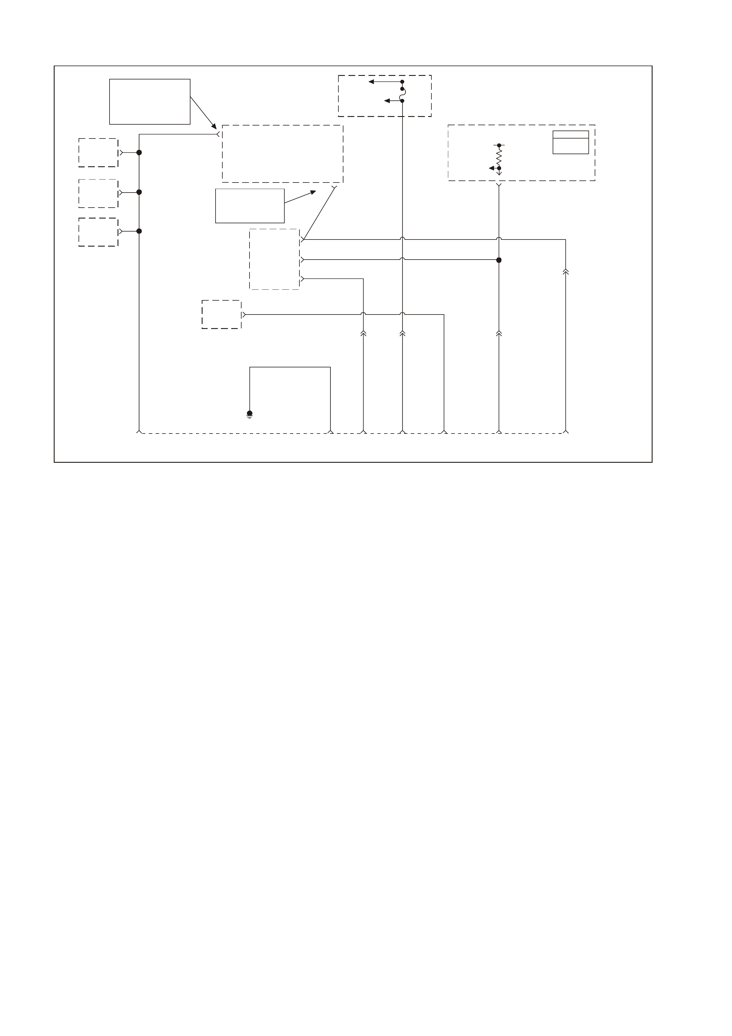
GEN III V8 PCM DATA LINK CONNECTOR DIAGNOSIS
GEN3 0093
PCM
J1 = BLU E
J2 = RED
NOTE
BCM Termi nal
9 YB175 High S eries
3 YB164 Low Serie s
Body
Earth 56 16 212 9
B/Y 155
BLU/B 863 R/B 1221
YE112
Data Link
Connector
(DLC)
Y1049
YE110
58 J1
Y1049
7V
Serial Data
(Class I I)
Fuse
F31
Fusible
Link FS
O/B 740
R/B
1221
Y
1049
YE111
W/B 451
BLU/B
863
6
7
11
R/B 1221
2
Serial Data
(UART)
Serial Data
(UART)
Serial Data
(UART)
Serial Data
(Class I I)
Diagnostic Test
Enable
Powertrain
Interface
Module
(PIM)
NOTE
YB175 High Serie s
YB164 Low Seri es
9
Body
Control
Module
(BCM)
12
Diagnostic
Enable
ABS/ETC
Module
1
G/W 1220
IP
Cluster
ECC
Module
ABS/ETC
Module
6
11
G/W
1220
B/Y 155
Powertrain
Control
Module
(PCM)
Circuit Description
Use a properly functioning Tech 2 scan tool with the diagnostic tables in this section. DO NOT use the Clear Info
function unless instructed by a diagnostic procedure.
Important: This vehicle, equipped with a Powertrain Control Module (PCM), utilises an Electrically Erasable
Programmable Read Only Memory (EEPROM). Pr ogram the new PCM when the diagnostics call for replacement of
the PCM. Refer to Section 6C3-3 SERVICE OPERATIONS – GEN III V8 Engine, PCM Replacement/ Programming
in this Service Information CD.
DIAGNOSTIC AIDS
• If there is a fault with the PIM power feed or earth circuit the Tech 2 scan tool will not communicate with the
PCM or BCM, or the PIM.
• If BCM DT C 007 is set, it indic ates there is a problem (open) in c ircuit 1221 (U ART s erial data circ uit) between
the BCM and the PIM.
• If PIM DTC B2006 is s et, it indic ates ther e is a problem (open, s hor t to earth, or shor t to voltage) in circuit 1049
(Class II Serial data circuit) between the PIM and the PCM.
• The following chart assumes the TECH 2 scan tool is fully functional.
TEST DESCRIPTION
The numbers below refer to the step number on the diagnostic table.
3. This step checks o see if the PCM is receiving all of the power supplies.
4. This step is checking the Earth circuits at the PCM.
9. This step checks to see if the Class II serial data circuit is shorted to earth.
13. This step checks to see if the Class II serial data circuit is shorted to voltage.
14. This step checks the PIM earth circuit.
15. This step checks the PIM for ignition feed.

GEN III V8 PCM DATA LINK CONNECTOR DIAGNOSIS
Step Action Value(s) Yes No
1 Did you perform the Powertrain On-Board Diagnostic
(OBD) System Check? Go to Step 2 Go to Powertrain
OBD System
Check Table
2 1. Turn ON the ignition leaving the engine OFF.
2. Connect TECH 2 to the Diagnostic Link Connector
(DLC).
Does the TECH 2 scan tool power-up
Go to Step 3 Go to Step 4
3 Will the engine crank over? Go to Step 7 Go to Step 11
4 1. Turn ON the ignition leaving the engine OFF.
2. Probe the DLC terminal 16, circuit 740 (Orange/Black
wire) with a test lamp connected to the battery earth.
Is the test lamp illuminated?
Go to Step 5 Repair circuit 740
as required
(including fuse
F31).
Verify repair.
5 Probe the DLC terminal 5, circuit 155 (Black/Yellow wire)
with a test lamp connected to B+.
Is the test lamp illuminated?
Go to Step 6 Repair circuit 155
as required.
Verify repair.
6 Inspect the TECH 2 scan tool connections to the DLC,
including proper terminal tension at the DLC.
Is the action complete.
Go to Powertrain
OBD System
Check Table
7 W ill the engine start and run? Replace PIM,
refer Section
6C3-3 Powertrain
Interface Module
Replacement.
Go to Step 13
8 1. Disconnect PCM connector YE122 and PIM connector
YB215.
2. Check for open in Class II serial data circuit 1049
(Yellow wire) between PCM connector YE122,
terminal J1-58 and PIM connector YB215, terminal 7.
Was a problem found?
Repair open in
circuit 1049.
Verify repair
Go to Step 9
9 1. Reconnect PCM and PIM connectors YE122 and
YB215.
2. Using test light connected to B+, probe the Class II
serial data circuit at the DLC, terminal 2, circuit 1049
(Yellow wire).
Is the test lamp illuminated?
Repair short to
earth in circuit
1049.
Verify repair.
Go to Step 10
10 Using a test light connected to a known good earth,
probe the Class II serial data circuit at the DLC, terminal
2, circuit 1049 (Yellow wire).
Is the test light illuminated?
Repair short to
voltage in circuit
1049. Verify
repair.
Replace PIM,
refer Section
6C3-3 Powertrain
Interface Module
Replacement.
11 Disconnect the PIM connector YB215.
Check resistance between PIM connector YB215,
terninal 16, circuit 750 (Black/Red wire) and earth
location E5/E15.
Is value as specified?
Less than
5 Ω Go to Step 12. Repair earth
circuit as
necessary.
Verify repair
12 Wi th PIM connector YB215 disconnected, turn ignition
ON and measure voltage between PIM connector YB215
terminals 8 and 16.
Is voltage as specified?
Approx. 12
volts Go to Step 13 Repair circuit 39
as required
(including fuse
F14).
Verify repair
13 1. Connect the TECH 2 scan tool to the DLC.
2. Select Body / Powertrain Interface Module (PIM) /
Diagnostic Trouble Codes.
Is PIM DTC B2006 set?
Go to Step 8 Go to Step 14
14 In Step 13, were any other PIM DTCs set? Go to applicable
PIM DTC Table Go to Step 15

Step Action Value(s) Yes No
15 1. Connect the TECH 2 scan tool to the DLC.
2. Select Body / Powertrain Interface Module (PIM) /
Diagnostic Trouble Codes.
Is PIM DTC B2006 set?
Go to Step 11 Go to Step 16
16 In Step 13, were any other PIM DTC(s) set? Go to applicable
PIM DTC Table Go to Step 17
17 1. Turn OFF the ignition.
2. Disconnect PCM connectors YE122 and YE123.
3. Turn ON the ignition.
4. Probe each PCM battery and PCM ignition feed circuit
in PCM connectors, J1-20, J1-57 (circuit 740, Orange
wire) and J1-19 (circuit 39, Pink wire) using a test
lamp connected to a known good earth.
Does the test lamp illuminate at each terminal?
Go to Step 18 Repair circuits
740 and/or 39 as
necessary
18 1. Turn ignition OFF.
2. With both PCM connectors YE122 and YE123
disconnected, check resistance of PCM earth circuit
750 (Black/Red wire) between terminals J1-01, J1-40,
J2-01 and J2-40 and earth location E5/E15.
Is value as specified at each of the PCM connector
terminals?
Less than 5
Ω Go to Step 19 Repair fault in
earth circuit as
necessary
19 Inspect the PCM and PCM wiring harness connectors for
correct connection.
Was a problem found?
Repair
connections as
necessary
Replace PCM,
refer Section
6C3-3 Powertrain
Control Module
Replacement
20 Check for short to earth, and repair open in power circuit
that did not light test light.
Is action complete?
System OK
21 Repair open in earth circuit that did not light test light.
Is action complete? System OK
22 Repair open in Class II Serial Data circuit from DLC to
PCM .
Is action complete?
Verify Repair
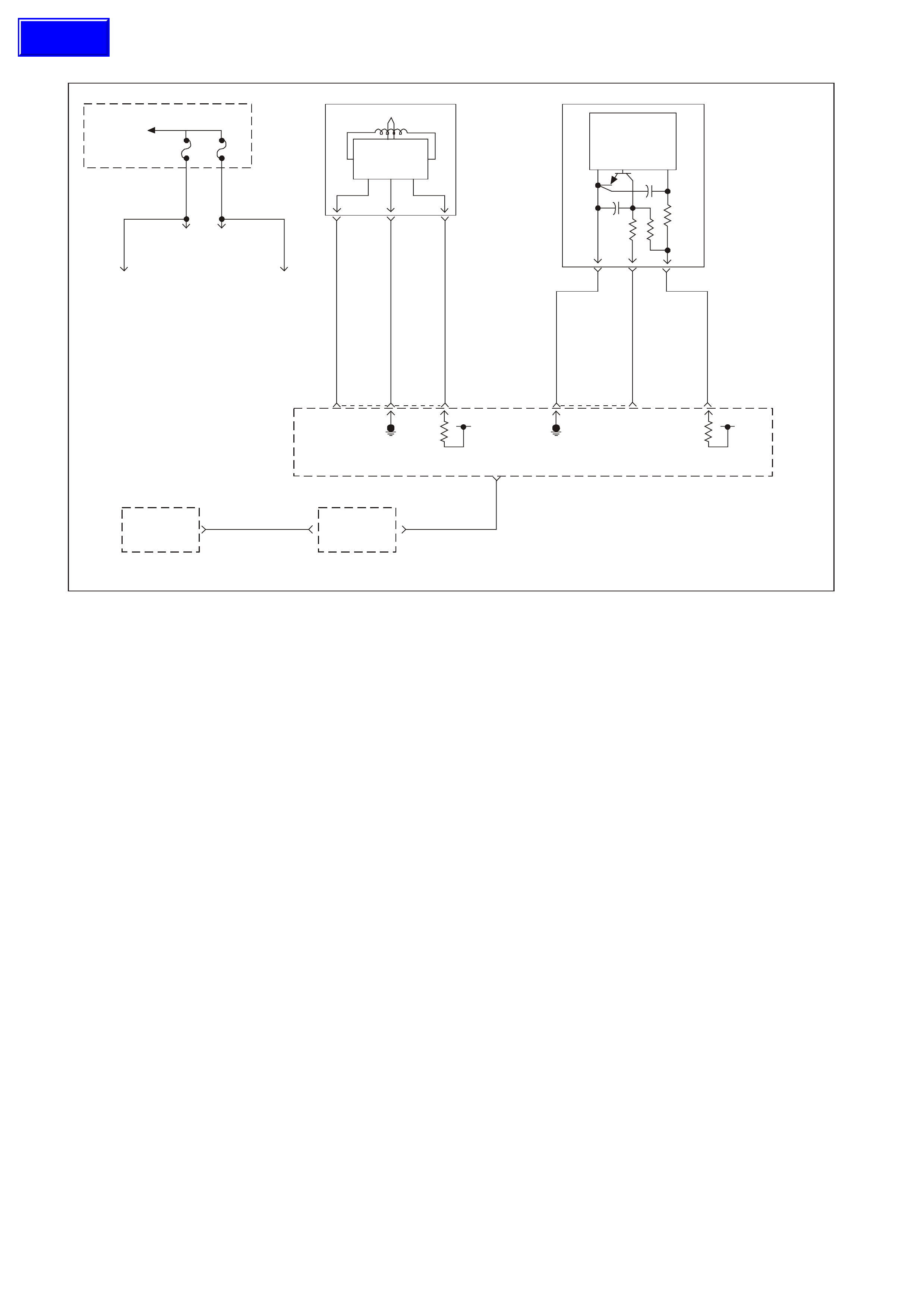
GEN III V8 PCM ENGINE CRANKS BUT DOES NOT RUN
GEN 3 00 94
Powertrain
Interface
Module (PIM)
To EFI
(Engine Cont.)
Relay F34 F35
To
Injectors
2, 4, 6, 8
To
Injectors
1, 3, 5, 7
To
Ignition Coils
2, 4, 6, 8
To
Ignition Coils
1, 3, 5, 7
Body
Control
Module
(BCM)
Theft
Deterrent Theft
Deterrent
(Starter Control)
R/B Y
1221 1049
26 7
The ft Deter ren t Fuel Disab le
(Serial Data)
58 J1
12 21 02 J1
12VIgnition
Feed
Reference
Low
CKP Sensor
Signal Input
61 73 39 J2J1
Ignition
Feed
12V
Reference
Low
CMP Sensor
Signal Input
BLU 643
LTBLU/B 647
LBLU/W 646 R/W 632 W/B 631
BR 633
Crankshaft
Position
(CKP)
Sensor
Magnetic
Pickup
Puls e Sh a per
And Volt age
Reg Electron i c s
Output
Gnd
Power
ABC
Camshaft
Position
(CMP)
Sensor
Hall Sensor
Trigger Circuit
Amplifier And
Voltage Reg
Electronics
29
Power
Gnd 1K
47g
4700pf
BA C
Powertrain
Control
Module
(PCM)
Description
The Engine Cranks but does not r un diagnostic table as s umes that the batter y condition and engine crank ing speed
are OK. If the battery condition and the cranking speed are not OK, refer to Section 12A BATTERY & CABLES
and Section 6D3-2 STARTING SYSTEM of the VT Series II Service Information for diagnosis. Make sure that
there is adequate fuel in the tank.
DIAGNOSTIC AIDS
• Check the duct work between the Mass Air Flow (MAF) sensor and the throttle body for air leaks.
A malfunctioning MAF sensor may cause a no start or a stall after start. If you suspect this, disconnect the MAF
sensor. The PCM will def ault to the s peed dens ity (MAP, IAT, RPM) in or der to c alc ulate the load and the air f low. If
this corrects the condition and the connections are OK, replace the MAF sensor.
If the steps above check OK, refer to Section 6C3-2B SYMPTOMS in this Service Information CD.
TEST DESCRIPTION
The numbers below refer to the step numbers on the diagnostic table.
2. This step checks to see if any PIM DTC’s are set.
7. The ignition feed circuit for the camshaft and crankshaft position sensors is internally connected within the
PCM. A short to earth on either circuit will cause a no start condition.
Techline

GEN III V8 PCM ENGINE CRANKS BUT DOES NOT RUN
Step Action Value(s) Yes No
1 Did you perform the Powertrain On-Board Diagnostic
(OBD) System Check? Go to Step 2 Go to Powertrain
OBD System
Check Table
2 Are any PIM DTC(s) set? Go to applicable
PIM DTC Tables Go to Step 3
3 1. Turn ON the ignition leaving the engine OFF.
2. Probe both sides of the fuses listed below using a test
lamp connected to earth.
- F31
- F33
- F34
- F35
Does the test lamp illuminate on both sides of all the
fuses?
Go to Step 4 Go to EFI Relay
Diagnosis Table
for further
diagnosis
4 Using Tech 2 scan tool, select the PCM Diagnostic
Trouble Code (DTC) option the DTC Information option.
Does the Tech 2 scan tool display any of the following
DTC(s) P0230, P0335, P0336, P0602 ?
Go to the
applicable DTC
table
Go to Step 5
5 Using the Tech 2 scan tool, Monitor the PCM theft status.
Does the Tech 2 scan tool display NO START? Go to Theft
Deterrent System
in Section 12J-1
LOW SERIES
BCM or Section
12J-2 HIGH
SEREIS BCM of
the VT Series II
Service
Information
Go to Step 6
6 Monitor the engine speed while cranking the engine.
Is engine RPM indicated on the Tech 2 scan tool? Go to Step 10 Go to Step 7
7 1. Disconnect the Crankshaft Position (CKP) Sensor
electrical connector.
2. Measure the voltage at the ignition feed circuit at the
CKP electrical connector using the DMM J39200.
Does the DMM display near the specified value?
B+ Go to Step 14 Go to Step 8
8 1. Disconnect the Camshaft Position (CMP) sensor
electrical connector.
2. Measure the voltage at the ignition feed circuit at the
CMP electrical connector using the DMM J39200.
Does the DMM display near the specified value?
B+ Go to Step 15 Go to Step 9
9 Inspect the camshaft and crankshaft position sensor
ignition feed circuits for a short to earth.
Did you find and correct the condition?
Go to Step 17 Go to Step 16
10 Check the engine coolant temperature using the Tech 2
scan tool.
Is the engine coolant temperature on the Tech 2 scan
tool close to the actual engine temperature?
Go to Step 11 Go to DTC
P0118 ECT
Sensor Circuit
High Voltage
Table
11 Enable the fuel pump using the Tech 2 scan tool.
Does the fuel pump operate? Go to Step 12 Go to Fuel Pump
Relay Circuit
Diagnosis Table
12 1. Turn OFF the ignition.
2. Install the fuel pressure gauge. Refer to Fuel System
Diagnosis.
3. Turn ON the ignition leaving the engine OFF.
4. Observe the fuel pressure.
Is the fuel pressure within the specific range?
380-420 kPa
(55-61 psi) Go to Step 13 Go to Fuel
System
Diagnosis Table

Step Action Value(s) Yes No
13 Perform the following additional checks:
• Check the ductwork between the Mass AirFlow
(MAF) Sensor and the throttle body for air leaks.
• Check that the throttle angle is at 0% at a closed
throttle. If the throttle angle is not at 0%, refer to DTC
P0122/P0123.
• A malfunctioning MAF Sensor may cause a no start
or a stall after a start. If you suspect this, disconnect
the MAF Sensor. The PCM will default to the speed
density (MAP, IAT, RPM) in order to calculate the
engine load and the intake air flow. If disconnecting
the MAF Sensor corrects the condition and the
connections are OK, replace the MAF Sensor.
• Inspect for an engine mechanical failure that causes
an engine not to start (i.e. timing chain, low
compression).
• Compare MAP/BARO parameters to another vehicle.
The parameter values should be close to each other.
Did you find and correct the condition?
Go to Step 17 Go to Hard Start
for diagnosis in
Section 6C3-2B
Symptoms in this
Section
14 Replace the CKP Sensor, refer to Section 6C3-3
Crankshaft Position Sensor Replacement.
Is the action complete?
Go to Step 17
15 Replace the CMP Sensor, refer to Section 6C3-3
Camshaft Position Sensor Replacement.
Is the action complete?
Go to Step 17
16 1. Replace PCM.
2. Refer to Section 6C3-3 for PCM Programming and
PCM/PIM/BCM Security Link Procedure.
Is action complete?
Go to Step 17
17 1. Select the Diagnostic Trouble Codes (DTC) option
and the Clear DTC Information option using the
Tech 2 scan tool.
2. Attempt to start the engine.
Does the engine start and continue to run?
Go to Step 18 Go to Step 3
18 1. Idle the engine at the normal operating temperature.
2. Select the Diagnostic Trouble Codes (DTC) option,
the DTC Information option then the Failed This
Ignition option using the Tech 2 scan tool.
Are any DTC(s) displayed?
Go to the
applicable DTC
table
Go to Step 19
19 Using the Tech 2 scan tool, check for any other DTC(s)
Does the Tech 2 scan tool display any DTC(s) that you
have not diagnosed?
Go to the
applicable DTC
table
System OK
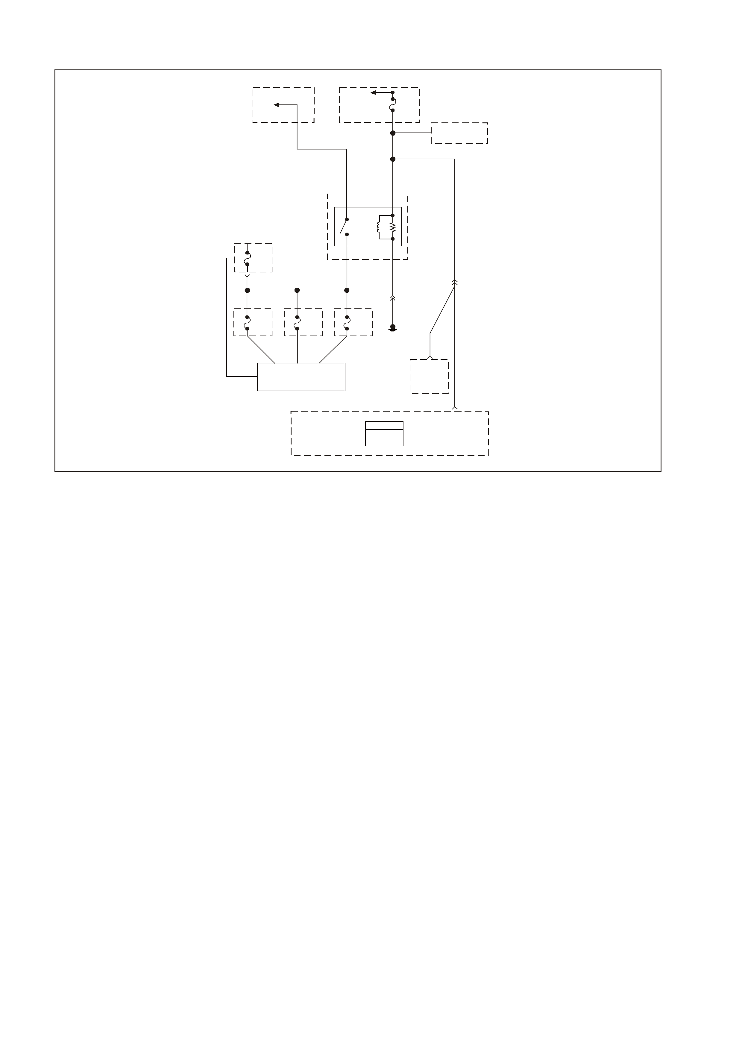
GEN III V8 PCM EFI (ENGINE CONT.) RELAY DIAGNOSIS
GEN3 0095
To
Fusible
Link
FS
To
Ignition
Switch Fuse
F14
Refe r To Wiring
Schematic Part 1
P/B
39
Ignition
Positive
Voltage
19 J1
Ignition
Positive
Voltage
Powertrain
Interface
Module
(PIM)
P/B 39
15
P39
YE112
Engine
Earth
YE114
B/W 152O/Y 479
Fuse
F35
Fuse
F34
87 85
EFI
(Engine Cont.)
Relay
P/B 39
12V Bus 1040
Fuse
F33
Fuse
F32
Re f er To:
Engine Controls Schematics
(Fuse Power Circuits Part 1)
30 86
PCM
J1 = BLU E
J2 = RED
Powertrain
Control
Module
(PCM)
NOTE: The EFI relay may be named Engine Cont. relay on later vehicles.
CIRCUIT DESCRIPTION
The EFI r elay protects the battery from a par asitic dr aw. The f ollowing components are powered by the EFI
relay:
• Injectors/Ignition coils
• Transmission
• A/C System
• EVAP Solenoid and EVAP Vent Valve
• MAF Sensor
• Heated Oxygen Sensors
DIAGNOSTIC AIDS
• The following may cause an intermittent:
- Poor connections. Check for adequate terminal tension.
- Corrosion.
- Incorrectly routed harness.
- Rubbed through wire insulation.
- Broken wire inside the insulation.
TEST DESCRIPTION
The numbers below refer to the step numbers on the diagnostic table.
NOTE: For any test that r equires probing the PCM or a com ponent harness connec tor, use the Connector
Test Adapter Kit J35616-A. Using this kit prevents damage to the harness connector terminals.
2. This test checks the fusible link FS power feed to the EFI relay.
3. This test checks the fused power feed ignition circuit.
4. This test is checking the earth circuit of the EFI relay.
5. T his step isolates the circuit from the EFI relay. All of the circuits at the relay are good if the test lamp
illuminates.

GEN III V8 PCM EFI (ENGINE CONT.) RELAY DIAGNOSIS
Step Action Value(s) Yes No
1 Did you perform the Powertrain On-Board Diagnostic
(OBD) System Check? Go to Step 2 Go to Powertrain
OBD System
Check Table
2 1. Turn OFF the ignition.
2. Remove the engine compartment Fuse/Relay panel
cover.
3. Remove the EFI (Engine Cont.) relay.
4. Probe the fusible link FS power feed circuit to the EFI
relay harness terminal 87 with a test lamp J34142-B
connected to a earth.
Does the test lamp illuminate?
Go to Step 3 Go to Step 8
3 1. Turn ON the ignition leaving the engine OFF.
2. Probe the fused ignition feed circuit to the EFI relay
harness terminal 85 with the test lamp J34142-B
connected to a earth.
Does the test lamp illuminate?
Go to Step 4 Go to Step 9
4 1. Turn OFF the ignition.
2. Probe the earth circuit to the EFI relay harness
terminal 86 with the test lamp J34142-B connected to
B+.
Does the test lamp illuminate?
Go to Step 5 Go to Step 10
5 1. Turn OFF the ignition
2. Jump the EFI relay B+ feed circuit terminal 87 and the
EFI relay load circuit terminal 30 together using a
fused jumper wire.
3. Probe the following fuses with a test lamp J34142-B
connected to earth:
- F32
- F33
- F34
- F35
Does the test lamp illuminate for all fuses?
Go to Step 6 Go to Step 11
6 Check for poor terminal contact at the EFI relay harness
connector.
Did you find and correct the condition?
System OK Go to Step 7
7 Replace the EFI relay.
Is the action complete? System OK
8 Repair the open in fusible link FS circuit to the EFI relay.
Is the action complete? System OK
9 Repair the fused ignition feed circuit to the EFI relay.
Replace fuse if open.
Is the action complete?
System OK
10 Repair the open in the earth circuit for the EFI relay.
Is the action complete? System OK
11 Repair open in the EFI relay load circuit, or open in
fuse(s) circuit that did not illuminate the test light.
Is the action complete?
System OK
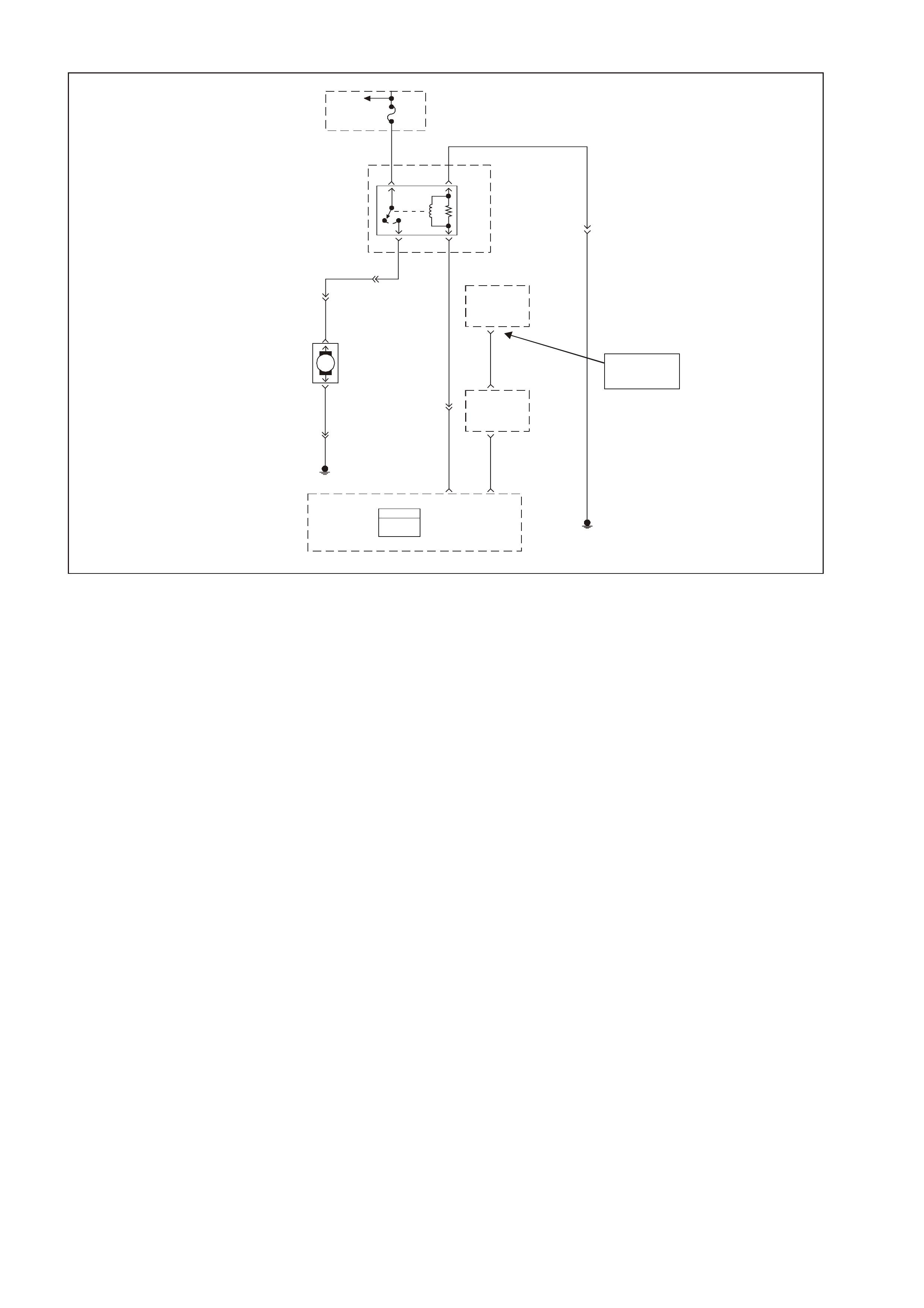
GEN III V8 PCM FUEL PUMP RELAY CIRCUIT DIAGNOSIS
GEN3 0096
To
Fusible
Link
FS
Fuse
F28
31
52
Fuel
Pump
Relay
V
120
120V
Fuel
Pump
Motor
M
465
240
G/W
O
Theft
Deterrent
Output
Signal
Body
Control
Module
(BCM)
2
1221R/B
6
156B/BLU
YR32
YE110
YB39
YR32
Engine Earth
Location E7
Theft
Deterrent
Starter
Disable
7
1049Y
J158
J209
Powertrain
Interface
Module
(PIM)
Fuel
Pump
Relay
Control
Theft
Deterrent
Fuel
Disable
(Serial Data)
PCM
J1 = BLUE
J2 = RED
Powertrain
Control
Module
(PCM) Engine Earth
Locat ion E 7
152B/W
YE114
NOTE
YB175 High Serie s
YB164 Low Seri es
Circuit Description
When the ignition switch is ON, the PCM activates the in-tank fuel pump. The fuel pump remains ON as
long as the PCM receives reference pulses from the ignition system. If there are no reference pulses, the
PCM turns the fuel pump OFF after about 2-3 seconds.
The pump delivers fuel to the fuel rail and injectors, then to the pressure regulator, where the system
pressure remains at 380-440 kPa (55-62 psi). Excess fuel returns to the fuel tanks. When the engine is
stopped, a Tech 2 scan tool in the output controls function can turn ON the fuel pump.
Improper fuel system pressure may result in one or many of the following symptoms:
• Cranks but will not run
• Cuts out, any feel like an ignition problem
• Poor fuel economy
• Loss of power
• Hesitation
• DTCs
Diagnostic Aids
• The following conditions may have caused the fuel pump fuse to open:
- The fuse was faulty
- There is an intermittent short in the fuel pump power feed circuit
- The fuel pump has an intermittent internal problem
• For an intermittent condition, refer to Section 6C3-2B SYMPTOMS of the VT Series II Service
Information.
Test Description
The numbers below refer to the step numbers on the diagnostic table.
3. This test checks for the proper fused power feed to the fuel pump relay.
4. This test checks to see if the earth signal is present at the fuel pump relay .
5. The test lam p only illuminates f or two seconds even though the Tec h 2 scan tool c om m anded position
is ON. You will have to command the fuel pump OFF then ON to re-enable the PCM fuel pump control.
12. Inspect the fuel pump fuse for an open. If the fuse is open, check the circuit for a short to earth.

GEN III V8 PCM FUEL PUMP RELAY CIRCUIT DIAGNOSIS
Step Action Value(s) Yes No
1 Did you perform the Powertrain On-Board Diagnostic
(OBD) System Check? Go to Step 2 Go to Powertrain
OBD System
Check Table
2 Check the fuel pump fuse.
Is the fuse open?
Go to Step 9 Go to Step 3
3 1. Install a Tech 2 scan tool.
2. Disconnect the fuel pump relay from the engine
compartment fuse/relay panel.
3. Turn ON the ignition leaving the engine OFF.
4. Probe the fused power feed circuit in the fuel pump
relay harness connector terminal 3 with the test lamp
J34142-B connected to earth.
Does the test lamp illuminate?
Go to Step 4 Go to Step 12
4 Probe the earth circuit in the fuel pump relay harness
connector terminal 1 with the test lamp J34142-B
connected to B+.
Does the test lamp illuminate?
Go to Step 5 Go to Step 13
5 1. Probe the fuel pump relay control circuit in the fuel
pump relay harness connector terminal 2 with the test
lamp J34142-B connected to earth.
2. Enable the fuel pump ON and OFF using the Tech 2
scan tool.
Does the test lamp turn ON and OFF?
Go to Step 6 Go to Step 11
6 Jumper the fused power feed circuit to the fuel pump
circuit (load) in the fuel pump relay harness connector
terminals 3 to 5 using a fused jumper wire.
Does the fuel pump operate?
Go to Step 18 Go to Step 7
7 1. Leave the fused jumper wire connected.
2. Disconnect the fuel pump harness connector at the
fuel pump.
3. Probe the power feed circuit in the fuel pump harness
connector with the test lamp J34142-B connected to
earth.
Does the test lamp illuminate?
Go to Step 8 Go to Step 14
8 1. Leave the fused jumper wire connected.
2. Connect the test lamp J34142-B between the fused
power feed circuit and the earth circuit in the fuel
pump harness connector terminals 3 and 1.
Does the test lamp illuminate?
Go to Step 25 Go to Step 15
9 1. Turn OFF the ignition.
2. Remove the fuel pump fuse.
3. Disconnect the fuel pump harness connector at the
fuel pump.
4. Probe the load circuit terminal 5 for the fuel pump
relay at the engine compartment fuse/relay panel with
the test lamp J34142-B connected to B+.
Does the test lamp illuminated?
Go to Step 16 Go to Step 10
10 Probe the fused power feed circuit for the fuel pump relay
at the engine compartment fuse/relay panel with the test
lamp J34142-B connected to B+.
Does the test lamp illuminate?
Go to Step 20 Go to Step 21

Step Action Value(s) Yes No
11 1. Turn OFF the ignition.
2. Disconnect the PCM RED connector.
3. Check the continuity of the fuel pump relay control
circuit from the relay harness connector to the PCM
connector using the DMM J39200.
Does the DMM display the specified value or lower?
5Ω Go to Step 22 Go to Step 17
12 Repair the open fused power feed circuit to the relay.
Replace fuse if open.
Is the action complete?
Go to Step 26
13 Repair the open relay earth circuit.
Is the action complete?
Go to Step 26
14 Repair the open circuit between the fuel pump relay and
fuel pump.
Is the action complete?
Go to Step 26
15 Repair the open in the earth circuit to the fuel pump.
Is the action complete?
Go to Step 26
16 Repair the short to earth in the fuel pump relay load
circuit between the relay and the fuel pump.
Is the action complete?
Go to Step 26
17 Repair open or short to earth in the fuel pump relay
control circuit.
Is the action complete?
Go to Step 26
18 Check for poor connections at the relay.
Was a problem found? Go to Step 26 Go to Step 19
19 Replace the relay.
Is the action complete? Go to Step 26
20 Repair the short to earth in the fuel pump relay fused
power feed circuit between the relay and the fuse.
Is the action complete?
Go to Step 26
21 1. Turn OFF the ignition.
2. Re-install the fuel pump relay.
3. Install a new fuse.
4. Connect the fuel pump harness to the fuel pump.
5. Turn ON the ignition leaving the engine OFF.
6. Command the fuel pump relay ON using a Tech 2
Tech 2 scan tool.
Is the Fuel Pump fuse open?
Go to Step 24 Intermittent
conditions. Refer
to Diagnostic
Aids
22 Check for a poor connection at the PCM.
Did you find and correct the condition? Go to Step 26 Go to Step 23
23 1. Replace PCM.
2. Refer to Section 6C3-3 Service Operations in the VT
Series II Service Information, for PCM Programming
and PCM/PIM/BCM Security Link Procedure.
Is action complete?
Go to Step 26
24 1. Inspect the fuel pump harness at the fuel tank for a
short to earth.
2. If you find a short, repair the circuit as necessary.
Was a problem found?
Go to Step 26 Go to Step 25
25 Replace the fuel pump.
Is the action complete? Go to Step 26

Step Action Value(s) Yes No
26 1. Select the Diagnosis Trouble Codes (DTC) option and
the Clear DTC Information option using the Tech 2
Tech 2 scan tool.
2. Attempt to start the engine.
Does the engine start and continue to run?
Go to Step 27 Go to Step 2
27 1. Idle the engine until the normal operating temperature
is reached.
2. Select the Diagnosis Trouble Code (DTC) option.
Are any DTCs displayed?
Go to applicable
DTC table Go to Step 28
28 Using the Tech 2 scan tool, check for any other DTC
Does the Tech 2 scan tool display any DTC that you
have not diagnosed?
Go to applicable
DTC table System OK
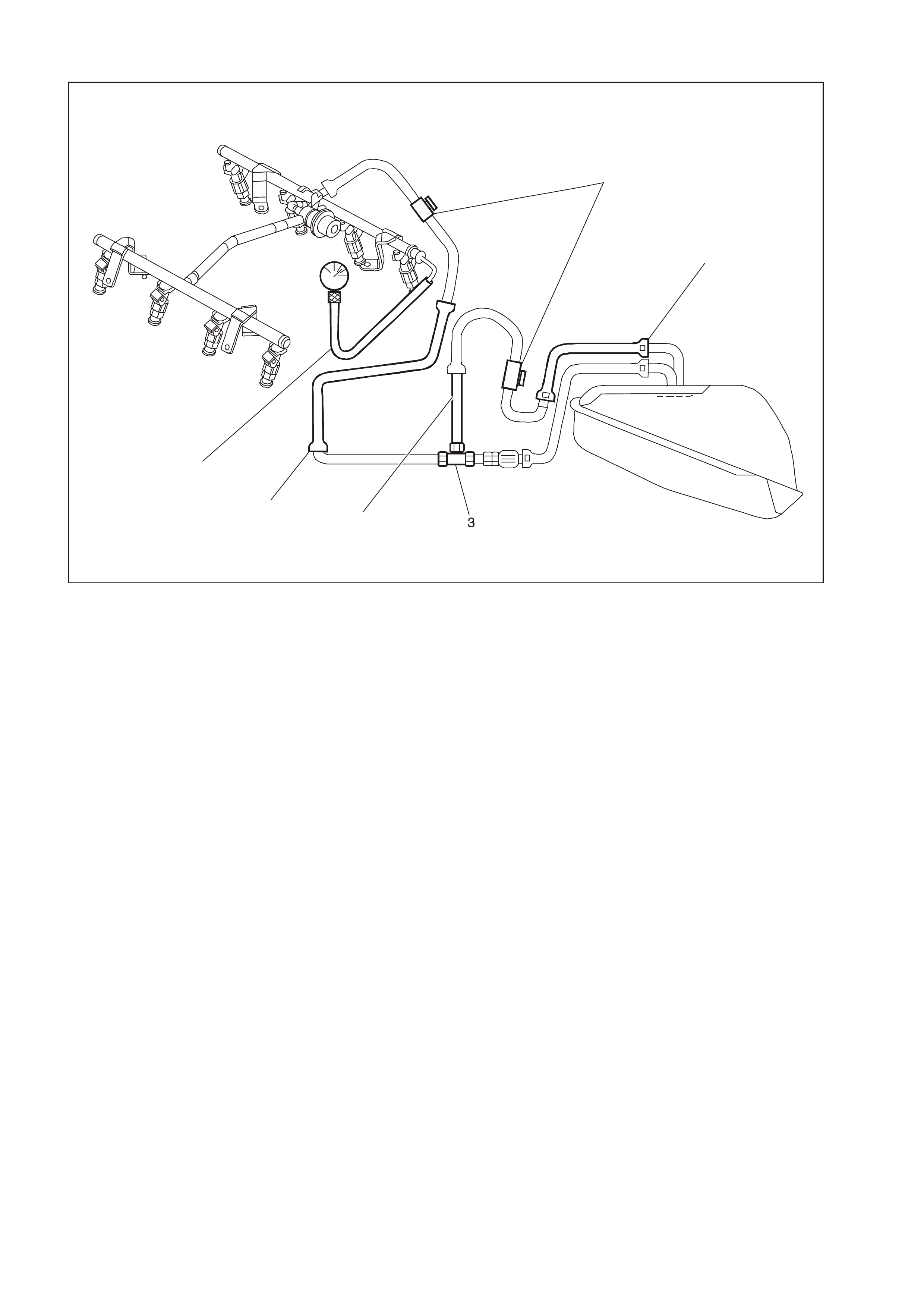
GEN III V8 PCM FUEL SYSTEM DIAGNOSIS
GEN3 0097
1
2
4
5
6
1. J 37287 Fuel Line Shut-off Adapter 4. Fuel Return Pipe
2. Rear Fuel Return Pipe 5. Fuel Feed Pipe
3. T-connector 6. J 34730-1A Fuel Pressure Gauge
CIRCUIT DESCRIPTION
When the ignition is turned ON, the Powertrain Control Module (PCM) supplies power to the in-tank fuel
pump. The in-tank fuel pump remains ON as long as the engine is cranking or running and the PCM
receives reference pulses. If there are no reference pulses, the PCM turns the in-tank fuel pump OFF 2
seconds after the ignition switch is turned ON or 2 seconds after the ignition stops running.
The electric fuel pump attaches to the fuel sender assembly inside the fuel tank. The fuel pump supplies
fuel through an in- pipe fuel filter to the f uel rail ass embly. The f uel pump provides fuel at a pres sure above
the pressure needed by the fuel injectors. The fuel pressure regulator keeps the fuel available to the fuel
injectors at a regulated pressure. The fuel pressure regulator attaches to the fuel sender assembly return
pipe. Unused fuel returns to the fuel tank by a separate fuel return pipe. The fuel return pipe attaches to a
T-connector in the fuel feed pipe on the outlet side of the fuel filter.

TEST DESCRIPTION
The numbers below refer to the step numbers on the diagnostic table.
2. When the ignition switch is ON and the fuel pump is running, the fuel pressure indicated by the fuel
pressure gauge should read 380-440 kPa (55-62 psi). The spring pressure inside the fuel pressure
regulator controls the fuel pressure.
3. A fuel system that drops more than 34 kPa (5 psi) in 10 minutes has a leak in one or more of the
following areas:
- The fuel pipes
- The fuel pump check valve
- The fuel pump flex pipe
- The valve or valve seat within the fuel pressure regulator
- The fuel injector(s)
4. A f uel system that dr ops mor e than 14 k Pa (2 ps i) in 10 minutes af ter being relieved to 69 kPa (10 ps i)
indicates a leaking fuel pump check valve.
5. Fuel pressure that drops- off during acc eleration, cr uise, or hard c ornering m ay cause a lean condition.
A lean condition can cause a loss of power, surging, or misfire. You can diagnose a lean condition
using a T ech 2 scan tool. If an extr emely lean condition occurs, the heated oxygen sensor(s ) will stop
toggling. The heated oxygen sensor output voltage(s) will drop below 300 mV. The fuel injector pulse
width will increase.
IMPORTANT: Make sure the fuel system is not operating in the Fuel Cut-Off Mode. This can cause false
indications by the Tech 2 scan tool.
10. A rich condition m ay result fr om the fuel pr essure being above 440 kPa ( 62 psi). A rich condition m ay
cause DTC P0132, DTC P0152, DTC P0172 or DTC P0175 to set. Driveability conditions associated
with rich conditions can include hard starting followed by black smoke and a strong sulfur smell in
exhaust.
11. This test determines if the high fuel pressure is due to a restricted fuel return pipe or if the high fuel
pressure is due to a faulty fuel pressure regulator.
12. A lean condition m ay result from the f uel pres sure being below 380 k Pa (55 ps i). A lean condition m ay
cause DTC P0131, DTC P0151, DTC P0171 or DTC P0174 to set. Driveability conditions associated
with lean conditions can Include hard starting (when the engine is cold), hesitation, poor driveability,
lack of power, surging, and misfiring.
NOTE: Do not allow the fuel press ure to exceed 500 k Pa (72 psi). Fuel pressure in excess of 500 kPa (72
psi) may damage the fuel pressure regulator.
13. Restricting the fuel return pipe with the J37287 fuel pipe shut-off adapter causes the fuel pressure to
rise above the r egulated f uel pr ess ur e. Using a Tech 2 s c an tool to pres s uris e the f uel system , the f uel
pressure should rise above 440 k Pa (62 psi) as the valve on the fuel pipe shut-off adapter connected
to the fuel return pipe becomes partially closed.
18. Check the spark plug associated with a particular fuel injector for fouling or saturation in order to
determine if that particular fuel injector is leaking. If checking the spark plug associated with a
particular fuel injector for fouling or saturation does not determine that a particular fuel injector is
leaking, use the following procedure:
1. Remove the fuel rail, but leave the fuel pipe connected to the fuel rail. Refer to
Section 6C3-3 FUEL RAIL ASSEMBLY REPLACEMENT in the VT Series II Service Information.
2. Lift the fuel rail just enough to leave the fuel injector nozzles in the fuel injector ports.
CAUTION: In order to reduce the risk of fire and personal injury that may result from fuel spraying
on the engine, verify that the fuel rail is positioned over the fuel injector ports. Also verify that the
fuel injector retaining clips are intact.
3. Pressurise the fuel system by using the Tech 2 scan tool fuel pump enable.
4. Inspect the fuel injector nozzle for leaks.

GEN III V8 PCM FUEL SYSTEM DIAGNOSIS
Step Action Value(s) Yes No
1 Did you perform the Powertrain On-Board Diagnostic
(OBD) System Check? Go to Step 2 Go to Powertrain
OBD System
Check Table
2 CAUTION: Wrap a shop towel around the fuel
pressure connection in order to reduce the risk of
fire and personal injury. The towel will absorb any
fuel leakage that may leak from the pressure gauge.
Place the towel in an approved container when the
connection of the fuel pressure gauge is complete.
1. Turn the ignition OFF.
2. Turn the air conditioning system OFF. Install the
J34730-1A fuel pressure gauge.
3. Install the J34730-1A fuel pressure gauge.
4. Place the bleed hose of the fuel pressure gauge into
an approved petrel container.
5. Turn the ignition ON.
6. Bleed the air out of the fuel pressure gauge.
7. Turn the ignition OFF for 10 seconds.
8. Turn the ignition ON.
IMPORTANT: The fuel pump will run for approximately 2
seconds. Cycle the ignition as necessary in order to
achieve the highest possible fuel pressure.
9. Observe the fuel pressure with the fuel pump running.
Is the fuel pressure within the specified limits?
380-440 kPa
(55-62 psi)
Go to Step 3 Go to Step 10
3 IMPORTANT: The fuel pressure may vary slightly when
the fuel pump stops running. After the fuel pump stops
running the fuel pressure should stabilise and remain
constant.
Does the fuel pressure drop more than the specified
value in 10 minutes?
34 kPa
(5 psi) Go to Step 8 Go to Step 4
4 Relieve the fuel pressure to the upper specified value.
Does the fuel pressure drop more than the lower
specified value in 10 minutes?
69 kPa
(10 psi)
__________
14 kPa
(2 psi)
Go to Step 17 Go to Step 5
5 Do you suspect the fuel pressure of dropping off during
acceleration, cruise, or hard cornering? 300mV Go to Step 6 Go to Section
6C3-2B
Symptoms
6 Inspect the following items for a restriction:
• The fuel filter.
• The fuel feed pipe.
Did you find a restriction?
Go to Step 21 Go to Step 7
7 1. Remove the fuel sender assembly. Refer to Section
6C3-3 Fuel Sender Assembly Replacement in this
Service Information CD.
2. Inspect the following items:
- The fuel pump strainer for a restriction.
- The fuel pump flex pipe for leaks.
- The fuel pressure regulator for leaks.
- The fuel pressure regulator fuel return flex pipe for
leaks.
- Verify the fuel pump is correct for this vehicle.
Did you find a problem in any of these areas?
Go to Step 21 Go to Step 17

Step Action Value(s) Yes No
8 1. Relieve the fuel pressure. Refer to Section 6C3-3 Fuel
Pressure Relief Procedure in this Service Information
CD.
2. Disconnect the fuel feed pipe from the fuel rail. Refer
to Section 6C3-3 Quick Connect Fitting(s) Service
(Metal Collar) in this Service Information CD.
3. Install the J37287 fuel pipe shut-off adapter between
the fuel feed pipe and the fuel rail.
4. Open the valve on the fuel feed pipe shut-off adapter
5. Pressurise the fuel system using a Tech 2 scan tool.
6. Place the bleed hose of the fuel pressure gauge into
an approved petrol container.
7. Bleed the air out of the fuel pressure gauge.
8. Wait for the fuel pressure to build.
9. Close the valve in the fuel feed pipe shut-off adapter.
Does the fuel pressure remain constant?
Go to Step 9 Go to Step 18
9 IMPORTANT: This step requires the aid of an assistant.
1. Open the valve in the fuel feed pipe shut-off adapter.
2. Relieve the fuel pressure. Refer to Section 6C3-3 Fuel
Pressure Relief Procedure in this Service
InformationCD.
3. Raise the vehicle.
4. Disconnect the steel fuel return pipe at the nylon rear
return pipe. Refer to Section 6C3-3 Quick Connect
Fitting(s) Service (Plastic Collar) in this Service
Information CD.
5. Drain any remaining fuel from the pipes into an
approved petrol container.
6. Install the J37287 fuel pipe shut-off adapter between
the steel fuel return pipe and rear nylon return pipe.
7. Pressurise the fuel system using a Tech 2 scan tool.
8. Wait for the fuel pressure to build.
9. Close the valve in the fuel pipe shut-off adapter that is
connected to the fuel return pipe.
Does the fuel pressure remain constant?
Go to Step 16 Go to Step 17
Step Action Value(s) Yes No
10 Is the fuel pressure above the specific value? 440 kPa
(62 psi) Go to Step 11 Go to Step 12
11 1. Relieve the fuel pressure. Refer to Section 6C3-3 Fuel
Pressure Relief Procedure in this Service Information
CD.
2. Disconnect the steel fuel return pipe at the nylon rear
return pipe. Refer to Section 6C3-3 Quick Connect
Fitting(s) Service (Plastic Collar) in this Service
Information CD.
3. Drain any remaining fuel from the fuel pipes into an
approved petrol container.
4. Attach a length of flexible fuel hose to the steel fuel
return pipe attached to the T-connector.
5. Place the open end of the flexible fuel hose into an
approved petrol container.
6. Turn ON the fuel pump using a Tech 2 scan tool.
7. Observe the fuel flow with the fuel pump running.
Is there fuel flow?
Go to Step 20 Go to Step 19
12 Is the fuel pressure above the specified value? 0 kPa (0 psi) Go to Step 13 Go to Step 14

Step Action Value(s) Yes No
13 IMPORTANT: This step requires the aid of an assistant.
1. Relieve the fuel pressure. Refer to Section 6C3-3
Fuel Pressure Relief Procedure in this Service
Information CD.
2. Raise the vehicle.
3. Disconnect the steel fuel return pipe at the nylon rear
return pipe. Refer to Section 6C3-3 Quick Connect
Fitting(s) Service (Plastic Collar) in this Service
Information CD.
4. Drain any remaining fuel from the fuel pipes into an
approved petrol container.
5. Install the J37287 fuel pipe shut-off adapter between
the steel fuel return pipe and the nylon rear fuel return
pipe.
6. Open the valve on the fuel pipe shut-off adapter.
7. Pressurise the fuel system using a Tech 2 scan tool.
8. Place the bleed hose of the fuel pressure gauge into
an approved petrol container.
9. Bleed the air out of the fuel pressure gauge.
10. Slowly close the valve in the fuel pipe shut-off adapter
that is connected to the fuel return pipe.
NOTE: Do not allow the fuel pressure to exceed 500 kPa
(72 psi). Fuel pressure in excess of 500 kPa (72 psi) may
damage the fuel pressure regulator.
Does the fuel pressure rise above the specified value?
440 kPa
(62 psi) Go to Step 16 Go to Step 7
14 Refer to Fuel Pump Relay Circuit Diagnosis Table in this
Section in order to diagnose the fuel pump electrical
circuit.
Did you find a problem with the fuel pump electrical
circuit?
Go to Step 21 Go to Step 15
15 Inspect the following items:
• The fuel filter for obstructions.
• The fuel feed pipe.
• The fuel pump strainer for obstructions.
• The fuel pump flex pipe for leaks.
Did you find a problem in any of these areas?
Go to Step 21 Go to Step 17
16 Faulty fuel pressure regulator. Replace the fuel sender
assembly. Refer to Section 6C3-3 Fuel Sender Assembly
Service in this Service Information CD.
Is the action complete?
System OK
17 Faulty fuel pump.
Replace the fuel sender assembly, refer to Section 6C3-3
Fuel Sender Assembly Service in this Service information
CD.
Is the action complete?
System OK
18 Locate and replace any leaking fuel injector(s).
Is the action complete? System OK
19 Locate and correct the restriction in the steel fuel return
pipe or the T-connector .
Is the action complete?
System OK
20 Inspect the nylon rear fuel return pipe for the restriction.
Did you find a restriction? Go to Step 21 Go to Step 16
21 Repair the problem as necessary.
Is the action complete? System OK
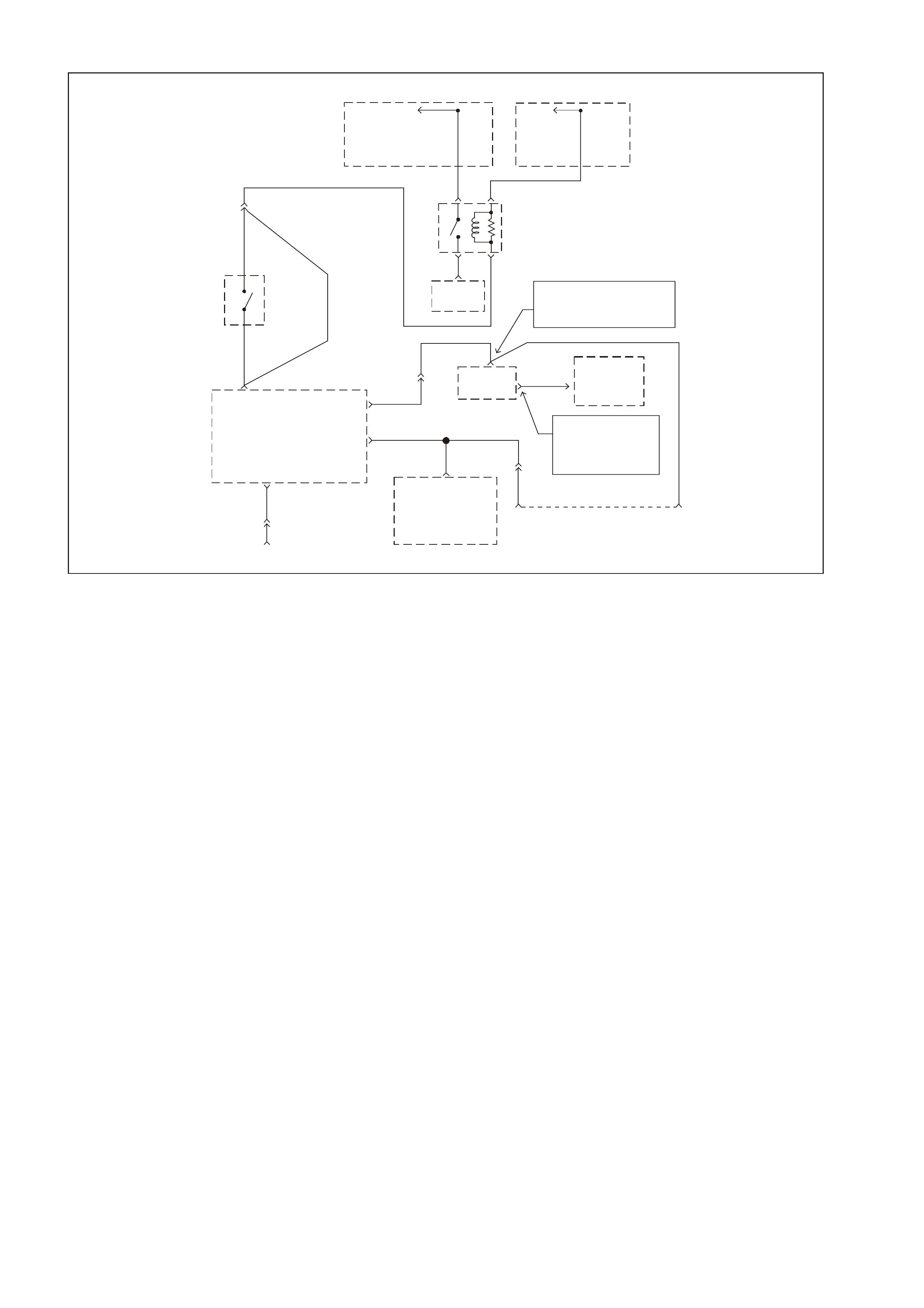
GEN III V8 PCM STARTER CRANKING CIRCUIT
GEN3 0098
Data Link
Connector
(DLC)
8
Start Relay
Control
GY/BLU 1434 GY
434
Serial Data
(UART)
Serial Data
(Cl ass II)
Diagnostic
"TEST"
Enable
11
W/B 451
YE111
Data Link
Connector
(DLC)
6
6
7
GY/BLU 1434
Neutral
Start
Switch
(Auto Onl y )
G
YE111
GY 434
Manual
Transmission
GY
434
R/B
1221
Fusible
Link
FJ
To
Ignition
Switch
V
5
R2
30 85
87 86
Start
Relay
To Starter
Solenoid NOTE
YB175 High Series BCM
YB164 Low Series BCM
R/B 1221 2
R/B
1221
YE112 Serial Data
(UART) 9R/B
122
To
Vehicle
Bus
NOTE
"9" YB175 High Series
"3" YB164 Low Series
Body Control
Module (BCM)
R/B 1221
92
Y1049
YE110
Y1049
58 J1
Y
1049
Serial
Data
Powertrain
Cont rol Modul e
(PCM)
E
Powertrain
Interface
Module
(PIM)
CIRCUIT DESCRIPTION
When the ignition is turned to the O N position, battery power is supplied from a fusible link to the start relay
term inal 30. As the ignition switch is turned to the ST ART position, power is als o supplied from the ignition
switch to the start relay terminal 85. The Powertrain Interface Module (PIM) supplies the earth signal
needed to energise the start relay and allows power to the starter motor.
When the BCM receives the c orr ect thef t deterr ent s ignal, the BCM will send a command via the ser ial data
(UART ) to the PIM to allow star ter motor operation. At the s ame time the BCM will send a c ommand via the
serial data (UART to the PIM, then Class II from PIM to PCM) circuit to the PCM to allow fuel injector
pulses.
If the PCM determines that a improper thef t deterrent signal was sent from the BCM, or no theft deterrent
signal was sent, the PCM will not allow fuel inj ection pulses . W hen the st art relay receives this earth s ignal
from the PIM, the relay will be energised, allowing the starter motor to operate.
If there is a problem with the theft deterrent signal from the BCM to the PCM, or a earth or power feed
problem at the PIM, DTC 1626, 1630, or P1631 will set.
If there is a high voltage problem on the starter relay PIM control circuit, PIM DTC P007 will set.
TEST DESCRIPTION
Numbers below refer to step numbers on the diagnostic table.
3. This step checks to see if DTC 1626, DTC 1630 or DTC P1631 are set. Either of these DTC could
prevent the vehicle from starting.
6. This step checks to see if power is being applied to the starter motor. If the test light illuminates, the
problem is with the starter motor.
14. This step checks the adjustment of the Neutral start switch.

GEN III V8 PCM STARTER CRANKING CIRCUIT
STEP ACTION VALUE YES NO
1 Did you perform the powertrain On-Board Diagnostic
(OBD) System Check? Go to Step 2 Go to Powertrain
OBD System
Check Table
2 1. Observe the Theft Deterrent LED on the Instrument
panel.
2. Key ON, engine OFF.
Is the Theft LED flashing?
Go to Theft
Deterrent
System. Section
12J-1 LOW
SERIES BCM or
Section 12J-2
HIGH SERIES
BCM in the VT
Series II Service
Information
Go to Step 3
3 1. Install a Tech 2 scan tool.
2. Using the Tech 2 scan tool, check for a DTC P1626,
DTC P1630, or DTC P1631.
Are any DTC(s) set?
Go to the
appropriate DTC
Table
Go to Step 4
4 Does the Tech 2 scan tool display PIM serial data? Go to Step 5 Go to Step 21
5 1. Ignition ON, engine OFF.
2. Using the Tech 2 scan tool, select the PIM Normal
Mode data list.
Does the PIM Normal Mode message display OK
START?
Go to Step 6 Go to Step 23
6 1. Ignition OFF.
2. Using a test light, probe the starter solenoid terminal
S with test light connected to earth.
3. Have an assistant turn the ignition switch to the
START position, note the test light.
Does the test light illuminate when the ignition switch is
turned to the START position?
Refer to
Section 6D3-2
Starting System
in the VT Series
II Service
Information
Go to Step 7
7 Check fusible link FJ.
Was fusible link blown? Go to Step 17 Go to Step 8
8 1. Remove the start relay.
2. With a test light connected to earth probe the start
relay harness terminal 30.
3. Turn the ignition ON.
Does the test light illuminate?
Go to Step 9 Go to Step 19
9 1. W ith the start relay still removed and the test light
connected to earth, probe the start relay harness
terminal 85.
2. Turn the ignition to the start position.
Did the test light illuminate?
Go to Step 11 Go to Step 18
10 Check for an open circuit between the starter solenoid
and the start relay.
Was a problem found?
System OK Go to Step 12
11 1. Ignition OFF.
2. Remove the start relay.
3. Connect a test light between the relay harness
terminal 85 and terminal 86.
4. Turn the ignition switch to the START position.
Does the test light illuminate when the ignition switch is
turned to the START position?
Go to Step 10 Go to Step 13
12 Replace the start relay.
Is the action complete? System OK
13 Is the vehicle equipped with a manual transmission? Go to Step 16 Go to Step 14
14 1. Ignition ON engine OFF.
2. With a test light connected to B+, probe both of the
circuits at the neutral start switch.
Did the test light illuminate at both terminals?
Go to Step 20 Go to Step 15
15 Check the adjustment of the neutral start switch.
NOTE: If the test light illuminated at only one terminal
and adjustment of neutral start switch does not fix the
problem, replace the switch.
Does test lamp now illuminate at both terminals?
System OK Go to Step 21

STEP ACTION VALUE YES NO
16 Check for open in the start relay control circuit from the
PIM to the Start Relay.
Was a problem found?
System OK Go to Step 21
17 Repair the short to earth in the faulty circuit.
Replace the fusible link as necessary.
Is the action complete?
System OK
18 Repair the open in the ignition circuit.
Is the action complete? System OK
19 Check for an open circuit including the fusible link.
Is the action complete? System OK
20 Check for an open in circuit 1434 from PIM terminal 8 to
Start Relay terminal 86.
Was a problem found?
Verify Repair Go to Step 23
21 Check the PIM power feed circuit and earth circuit for
opens or shorts.
Was a problem found?
Verify Repair Go to Step 22
22 Check for an open, short to Earth or short to voltage
in the UART circuit.
Was a problem found?
Verify Repair Go to Step 23
23 Check for poor connection at PIM.
Was a problem found? Verify Repair Go to Step 24
24 Replace PIM, Refer to Section 6C3-3 Powertrain
Interface Module Replacement in the VT Series II Service
Information.
Is action complete?
Verify Repair

GEN III V8 PCM DTC P0101 MASS AIR FLOW SYSTEM PERFORMANCE
GEN3 0155
PCM
J1 = BLUE
J2 = RED
To EFI
(Engine Cont.)
Relay Fuse
F33
5V 5V 5V
MAP
5V
Reference
MAF
Sensor
Signal
Oxygen
Sensor
Heaters
Intake Air
Temperature
(IAT)
Sensor
Ignition
Power MAF
Sensor
Signal
Mass Air
Flow (MAF)
Sensor
Manifold Ab solute
Pressure (MAP)
Sensor
To
A/C
Pressure
Sensor
MAP
Sensor
Signal
MAP
Sensor
Earth
IAT
Sensor
Earth
Engine
Earth
P 439
YE111
C
D
A
31 J2 48 J1 25 J2
G/O 469
57 J2
B421
32 J2
B/R 750
B/R 750
B
LG 432
BA
C
G/O 469
A
B
V/W 414
BR/W 792
A
54 J1
P439
IAT
Sensor
Signal
BR 472
Powertrain
Control
Module
(PCM)
CIRCUIT DESCRIPTION
The Mass Air Flow (MAF) sensor measures the amount of air ingested by the engine. The direct measurement of
the air entering the engine is more accurate than calculating the airflow from the MAP, the IAT and the engine
speed (speed/density ). The MAF sensor has a battery feed, earth, and a signal circuit.
The MAF sensor used on this engine is a hot wire type and is used to measure air flow rate. The MAF output
frequenc y is a f unc tion of the power r equired to k eep the air f low sensing elements (hot wire) at a f ix ed temperatur e
above the ambient tem perature. Air f lowing through the sens or cools the sensing elem ents. T he amount of cooling
is proportional to the am ount of air f low. T he MAF sensor requires a greater amount of curr ent in order to maintain
the hot wires at a constant temperature as the air flow increases. T he MAF sensor convert the changes in current
draw to a frequency signal read by the PCM. The PCM calculates the air flow (grams per second) based on this
signal.
The PCM monitors the MAF sensor frequency. The PCM can determine if the sensor is stuck low, stuck high, not
providing the airf low value expected for a given operating condition, or that the signal appears to be stuck based on
a lack of signal variation expected during the normal operation. This diagnostic checks the range/performance of
the MAF sensor.
The MAF s ystem perf or manc e or r ationality diagnostic uses the MAP, the IAT, and the engine speed to calc ulate an
expected airflow rate. T he PCM then compares the rate to the actual measured airflow from the MAF sensor. The
PCM only com pares the ac tual MAF value and the calculated value dur ing conditions where the values are lik ely to
match. This DTC sets if the actual MAF reading is not within a predetermined range of the calculated reading.
CONDITIONS FOR RUNNING THE DTC
• DTCs P0102, P0103, P0107, P0108, P0121, P0122, P0123 not set.
• The engine is running.
• The TP sensor angle is less than 50% and the engine vacuum (BARO-MAP) is greater than 65 kPa.
• The system voltage is greater than 11 volts but less than 16 volts.
• The change in TP sensor is less than 3%.
• All above conditions stable for 2.0 seconds
CONDITIONS FOR SETTING THE DTC
• The MAF frequency is 50% different from the speed density calculation.
• All conditions met for 5.0 seconds

ACTION TAKEN WHEN THE DTC SETS
• The PCM illuminates the Lamp (CPL) when the diagnostic runs and fails.
• T he PCM records the operating conditions at the time the diagnostic fails. The PCM stores this inform ation in
the Freeze Frame/Failure Records.
• The PCM utilises speed density (RPM, MAP, IAT) for fuel management.
CONDITIONS FOR CLEARING THE CPL/DTC
• The PCM turns the CPL OFF after the first ignition cycle that the diagnostic runs and does not fail.
• A last test failed (current DTC) clears when the diagnostic runs and does not fail.
• A History DTC clears after forty consecutive warm-up cycles, if this or any other emission related diagnostic
does not report any failure.
• Use a Tech 2 scan tool in order to clear the CPL/DTC.
DIAGNOSTIC AIDS
• Inspect the EFI relay for correct operation if you cannot find any problems with the ignition feed circuit to the
com ponent. Probe both sides of the fus e with a test lamp connec ted to earth in order to determ ine if a voltage
is supplied to the fuse. Refer to EFI Relay Diagnosis Table in this Section.
• The following may cause an intermittent:
- Incorrectly routed harness
- Rubbed through wire insulation
- Broken wire inside the insulation
• For an intermittent fault, refer to Section 6C3-2B SYMPTOMS in this Service information CD.
• Any un-metered air may cause this DTC to set. Check for the following:
- An engine vacuum leak
- The PCV system for vacuum leaks
- An incorrect PCV valve
- The engine oil dip stick not fully seated
TEST DESCRIPTION
The numbers below refer to the step numbers on the diagnostic table.
2. The MAF system performance or rationality diagnostic uses the MAP sensor signal along with other inputs in
order to calculate an expected airflow rate.
The PCM then c ompares the expec ted flow rate to the actual meas ured airflow from the MAF sensor. The firs t
few steps of this table verify that the MAP sensor is working properly. Correct any MAP sensor DTCs first.
Refer to DTC P0107 MAP Sensor Circ uit Low Voltage if the MAP s ens or voltage is les s than .08 volts. Ref er to
DTC P0108 MAP Sensor Circuit High Voltage if the MAP sensor voltage is greater than 4.0 volts.
3. Twist the sensor towards the front of the vehicle and lift upward in order to remove the MAP sensor.
6. Using the Freeze Frame/Failure Records data may aid in locating an intermittent condition. If you cannot
duplicate the DTC, the information included in the Freeze Frame and/or Failure Records data can help
determine the distance traveled since the DTC sets. The Fail Counter and Pass Counter can also help
determ ine how many ignition cycles the diagnostic reported a pass and/or a fail. Operate the vehicle within the
sam e f reeze f ram e conditions (RPM, load, vehicle s peed, tem perature etc .) that you observed. This will isolate
when the DTC failed. For any test that requires probing the PCM or component harness connectors, use the
Connector Test Adapter Kit J35616-A. Using this kit prevents any damage to the harness connector terminals.
7. Any un-metered air causes this DTC to set. Check the PCV system for vacuum leaks. Also inspect the dip stick
is seated correctly and the oil filler cap is tight.
8. This step verifies the signal circuit from the MAF sensor electrical connector to the PCM.
9. This step verifies whether a earth and B+ circuit is available.
10. This step checks the signal circuit for an open.
11. This step checks the signal circuit for a short to B+.

GEN III V8 PCM DTC P0101 MASS AIR FLOW SYSTEM PERFORMANCE
Step Action Value Yes No
1 Did you perform the Powertrain On-Board Diagnostic
(OBD) System Check? Go to Step 2. Go to Powertrain
OBD System
Check Table
2
If any MAP sensor DTCs are set, refer to the applicable
DTC before proceeding.
1. Idle the engine.
2. Monitor the MAP sensor voltage parameter using a
Tech 2 scan tool.
Is the MAP sensor voltage outside of the specified
range?
.08-4 volts Go to DTC
P0107 or P0108
Table
Go to Step 3
3 1. Turn OFF the ignition .
2. Remove the MAP sensor from the intake manifold
leaving the electrical harness connected.
3. Connect a hand operated vacuum pump to the MAP
sensor.
4. Turn ON the ignition leaving the engine OFF.
5. Observe the MAP sensor display while slowly applying
vacuum up to 20 inches Hg as indicated on the pump
gauge. Each 1 inch of vacuum applied should result in
a 3 to 4 kPa drop in the MAP sensor value on the
scan tool and the value should change smoothly with
each increase in vacuum.
Did the MAP sensor value change smoothly through the
entire range of the test without any erratic readings?
Go to Step 4 Go to Step 19
4 Apply 20 inches Hg vacuum to the MAP sensor.
Is the MAP sensor reading on the Tech 2 scan tool the
same or less than the specified value?
34 kPa Go to Step 5 Go to Step 19
5 Disconnect the vacuum source from the MAP sensor.
Does the MAP sensor reading return to the original
value?
Go to Step 6 Go to Step 19
6 1. Turn ON the ignition leaving the engine OFF.
2. Review the Freeze Frame/Failure Records data
for this DTC and observe the parameters.
3. Turn OFF the ignition for 15 seconds.
4. Start the engine.
5. Operate the vehicle within the conditions required for
this diagnostic to run, and as close to the conditions
recorded in the Freeze Frame/Failure Records as
possible. Special operating conditions that you need
to meet before the PCM will run this diagnostic, where
applicable, are listed in Conditions for Running the
DTC.
6. Select the Diagnostic Trouble Code (DTC) option, the
DTC Information option, and the Failed This Ignition
option using the Tech 2 scan tool.
Does the Tech 2 scan tool indicate that this diagnostic
failed this ignition?
Go to Step 7 Go to Diagnostic
Aids
7 1. Check for the following conditions:
- Objects blocking the MAF sensor inlet screen
- Intake manifold vacuum leaks
- Vacuum leaks at the throttle body
- Crankcase ventilation valve faulty, missing, or
incorrectly installed
2. If you find a condition, repair as necessary.
Did you find and correct the condition?
Go to Step 21 Go to Step 8

Step Action Value Yes No
8 1. Turn OFF the ignition.
2. Disconnect the MAF sensor connector.
3. Turn ON the ignition leaving the engine OFF.
4. Measure the voltage between the MAF sensor signal
circuit and the battery earth using the DMM J39200.
Is the voltage near the specified value?
5.0 volts Go to Step 9 Go to Step 10
9 Connect a test lamp J34142-B between the MAF sensor
ignition feed and the earth circuit at the MAF sensor
harness connector.
Is the test lamp illuminated?
Go to Step 13 Go to Step 12
10 Is the voltage less than the specified value? 4.5V Go to Step 14 Go to Step 11
11 1. Turn OFF the ignition.
2. Disconnect the PCM RED connector.
3. Turn ON the ignition leaving the engine OFF.
4. Measure the voltage between the MAF sensor signal
circuit and the battery earth using the DMM J39200.
Is the voltage near the specified value?
0.0V Go to Step 20 Go to Step 17
12 Connect a test lamp J34142-B between the MAF sensor
ignition feed circuit and the battery earth.
Is the test lamp illuminated?
Go to Step 15 Go to Step 16
13 1. Check for a poor connection at the MAF sensor.
2. If you find a poor connection, replace the faulty
terminal(s).
Did you find a poor connection?
Go to Step 21 Go to Step 18
14 1. Check the MAF sensor signal circuit between the
PCM and the MAF sensor for the following:
- An open circuit
- A short to earth
- A short to the MAF sensor earth circuit
2. Repair the circuit if the MAF sensor signal circuit is
open or shorted.
Did you find the MAF sensor signal circuit open or
shorted?
Go to Step 21 Go to Step 20
15 Locate and repair the open in the earth circuit to the MAF
sensor.
Is the action complete?
Go to Step 21
16 Locate and repair the open in the ignition feed circuit to
the MAF sensor.
Is the action complete?
Go to Step 21
17 Locate and repair the short to voltage in the MAF sensor
signal circuit.
Is the action complete?
Go to Step 21
18 Replace the MAF sensor. Refer to Section 6C3-3 MAF
Sensor Replacement in this Service information CD.
Is the action complete?
Go to Step 21
19 Replace the MAP sensor. Refer to Section 6C3-3 MAP
Sensor Replacement in this Service Information CD.
Is the action complete?
Go to Step 21
20 1. Replace PCM.
2. Refer to Section 6C3-3 in this Service Information CD
for PCM Programming and PCM/PIM/BCM Security
Link Procedure.
Is action complete?
Go to Step 21

Step Action Value Yes No
21 1. Select the Diagnostic Trouble Code (DTC) option and
the Clear DTC Information option using the Tech 2
scan tool.
2. Idle the engine at the normal operating temperature.
3. Select the Diagnostic Trouble Code (DTC) option and
the Specific DTC option, then enter the DTC number
using the Tech 2 scan tool.
4. Operate the vehicle within the Conditions for Running
the DTC as specified in the supporting text, if
applicable.
Does the Tech 2 scan tool indicate that this DTC reset?
Go to Step 2 Go to Step 22
22 Using the Tech 2 scan tool, check for any other DTC.
Does the Tech 2 scan tool display and DTCs that you
have not diagnosed?
Go to the
applicable DTC
table
System OK
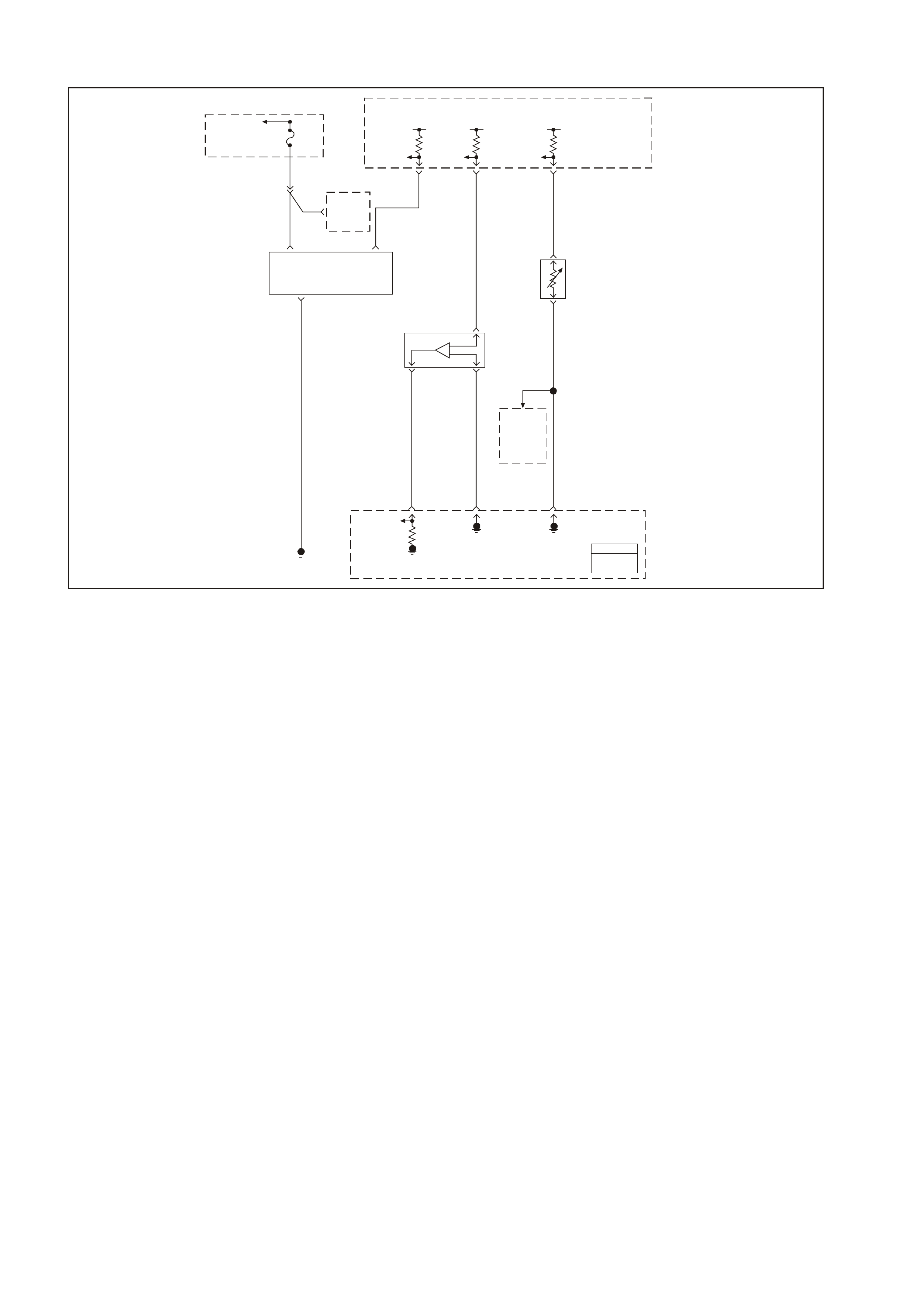
GEN III V8 PCM DTC P0102 MASS AIR FLOW SENSOR CIRCUIT LOW FREQUENCY
GEN3 0155
PCM
J1 = BLUE
J2 = RED
To EFI
(Engine Cont.)
Relay Fuse
F33
5V 5V 5V
MAP
5V
Reference
MAF
Sensor
Signal
Oxygen
Sensor
Heaters
Intake Air
Temperature
(IAT)
Sensor
Ignition
Power MAF
Sensor
Signal
Mass Air
Flow (MAF)
Sensor
Manifold Ab solute
Pressure (MAP)
Sensor
To
A/C
Pressure
Sensor
MAP
Sensor
Signal
MAP
Sensor
Earth
IAT
Sensor
Earth
Engine
Earth
P 439
YE111
C
D
A
31 J2 48 J1 25 J2
G/O 469
57 J2
B421
32 J2
B/R 750
B/R 750
B
LG 432
BA
C
G/O 469
A
B
V/W 414
BR/W 792
A
54 J1
P439
IAT
Sensor
Signal
BR 472
Powertrain
Control
Module
(PCM)
CIRCUIT DESCRIPTION
The Mass Air Flow (MAF) sensor measures the amount of air entering the engine via the inlet tract. The direct
measurement of the air entering the engine is more accurate than calculating the airflow from the MAP, the IAT,
and the engine speed (speed/density ). The MAF sensor has a battery feed, a earth and a signal circuit.
The MAF sensor used on this engine is a hot wire type. The MAF output frequency is a function of the power
required to keep the air flow sensing elements (hot wires) at a fixed temperature above the ambient temperature.
Air flowing through the sensor cools the sensing elem ents. The am ount of cooling is proportional to the am ount of
air flow. The MAF sensor requires a greater amount of current in order to maintain the hot wires at a constant
temper ature as the air flow increas es. T he MAF sensor c onverts the changes in current draw to a fr equency signal
read by the PCM. The PCM calculates the air flow (grams per second) based on this signal.
The PCM monitors the MAF sensor frequency. The PCM determines if the sensor is stuck low, stuck high, not
providing the airf low value expected for a given operating condition, or that the signal appears to be stuck based on
a lack of signal variation expected during the normal operation. This diagnostic checks for too low an airflow rate.
This DTC sets when the PCM detects that the MAF sensor frequency is below a predetermined value.
CONDITIONS FOR RUNNING THE DTC
• The engine speed is greater 300 RPM.
• The system voltage is at least 11.0 volts.
CONDITIONS FOR SETTING THE DTC
• The MAF frequency is less than 10 Hz.
• All conditions met for 1 second.
ACTION TAKEN WHEN THE DTC SETS
• The PCM illuminates the Lamp (CPL) when the diagnostic runs and fails.
• The PCM utilises speed density (RPM, MAP, IAT) for fuel management.
• T he PCM records the operating conditions at the time the diagnostic f ails. The PCM stores this inform ation in
the Freeze Frame/Failure Records.

CONDITIONS FOR CLEARING THE CPL/DTC
• The PCM turns the CPL OFF after three consecutive ignition cycles that the diagnostic runs and does not fail.
• A last test failed (current DTC) clears when the diagnostic runs and does not fail.
• A History DTC clears after forty consecutive warm-up cycles, if this or any other emission related diagnostic
does not report any failures.
• Use a Tech 2 scan tool in order to clear the CPL/DTC.
DIAGNOSTIC AIDS
• Inspect the EFI relay for proper operation if you cannot find any problems with the ignition feed circuit to the
com ponent. Probe both sides of the fus e with a test lamp connec ted to earth in order to determ ine if a voltage
is supplied to the fuse. Refer to EFI Relay Diagnosis in this Section.
• The following may cause an intermittent:
- Incorrectly routed wiring harness
- Rubbed through wire insulation
- Broken wire inside the insulation
• For an intermittent, refer to Section 6C3-2B SYMPTOMS in this Service Information CD.
• Any un-metered air may cause this DTC to set. Check for the following:
- An engine vacuum leak
- The PCV system for vacuum leaks
- An incorrect PCV valve
- The engine oil dip stick not fully seated
- The engine oil fill cap loose or missing
TEST DESCRIPTION
The numbers below refer to the step numbers on the diagnostic table.
2. Monitoring the MAF sens or fr equency will determine if the f ault is present or the malfunc tion is intermittent. For
any tes t that requires probing the PCM or com ponent har ness c onnectors , use the Connector Tes t Adapter Kit
J35616-A. Using this kit will prevent any damage to the harness connector terminals.
3. Using the Freeze Frame/Failure Records data may aid in locating an intermittent condition. If you cannot
duplicate the DT C, the information inc luded in the Freeze Fram e/Failure Records data can help determ ine the
distance traveled since the DTC set. The Fail Counter and Pass Counter can also help determine how many
ignition cycles the diagnostic reported a pass and/or a fail.
Operate the vehic le within the same fr eeze frame c onditions (RPM, load, vehicle speed, temperature etc.) that
you obs erved. T his will isolate when the DT C failed. For any test that requires pr obing the PCM or com ponent
harness c onnectors, use the Connector Test Adapter Kit J35616- A. Using this kit prevents any dam age to the
harness connector terminals.
4. This step chec ks whether the MAF sens or signal cir cuit is open or s horted to a earth. If 5.0 volts is present the
circuit is OK.
5. This step checks whether the B+ supply and the earth circuit are OK.
6. This step checks whether the B+ is available at the MAF sensor.
10. Inspect the fuse for being open. Inspect the MAF sensor ignition feed circuit for a short to earth if the fuse is
open. Inspect the EFI r elay for proper operation if you can not find any problem s with the ignition feed circuit to
the component. Probe both sides of the fuse with a test lamp connected to an earth in order to determine if a
voltage is supplied to the f use. Refer to EFI Relay Diagnosis Table in the Section for f urther diagnosis of the
ignition relay. Multiple DTCs set when a malfunction occurs with the ignition relay or the ignition feed circuit.
The following DTCs may set: P0102, P0443, P0740, P1860, and HO2S heater DTCs.
12. Inspect for proper terminal tension/connections at the PCM harness before replacing the PCM.

GEN III V8 PCM DTC P0102 MASS AIR FLOW SENSOR CIRCUIT LOW FREQUENCY
Step Action Value(s) Yes No
1 Did you perform the Powertrain On-Board Diagnostic
(OBD) System Check? Go to Step 2 Go to Powertrain
OBD System
Check Table
2
1. Install a Tech 2 scan tool.
2. Idle the engine.
3. Monitor the MAF sensor frequency display on the
Tech 2 Engine Data List.
Is the MAF sensor frequency below the specified value?
10 Hz Go to Step 4 Go to Step 3
3 1. Turn ON the ignition leaving the engine OFF.
2. Review the Freeze Frame/Failure Records data for
this DTC and observe the parameters.
3. Turn OFF the ignition for 15 seconds.
4. Start the engine.
5. Operate the vehicle within the conditions required for
this diagnostic to run, and as close to the conditions
recorded in the Freeze Frame/Failure Records as
possible. Special operating conditions that you need
to meet before the PCM will run this diagnostic, where
applicable, are listed in Conditions for Running the
DTC.
6. Select the Diagnostic Trouble Code (DTC) option, the
DTC Information and The Failed This Ignition option
using the Tech 2 scan tool.
Does the Tech 2 scan tool indicate that this diagnostic
failed this ignition?
Go to Step 4 Go to Diagnostic
Aids
4 1. Turn OFF the ignition.
2. Disconnect the MAF sensor connector.
3. Turn ON the ignition leaving the engine OFF.
4. Measure the voltage between the MAF sensor signal
circuit and the battery earth using a DMM J39200.
Is the voltage near the specified value?
5.0V Go to Step 5 Go to Step 8
5 Connect a test lamp J34142-B between the MAF sensor
ignition feed circuit and the earth circuit at the MAF
sensor harness connector.
Is the test lamp illuminated?
Go to Step 7 Go to Step 6
6 Connect a test lamp J34142-B between the MAF sensor
ignition feed circuit and the battery earth.
Is the test lamp illuminated?
Go to Step 9 Go to Step 10
7 1. Check for a poor connection at the MAF sensor
harness terminals.
2. If you find a poor connection, replace the faulty
terminal(s).
Did you find a poor connection?
Go to Step 13 Go to Step 11
8 1. Check the MAF sensor signal circuit between the
PCM and the MAF sensor for the following:
- An open circuit
- Short to a earth
- Short to the MAF sensor earth circuit
- Short to voltage
2. If you find the MAF sensor signal circuit is open or
shorted, repair the circuit as necessary.
Did you find the MAF sensor signal circuit open or
shorted?
Go to Step 13 Go to Step 12
9 Locate and repair the open in the earth circuit to the MAF
sensor.
Is the action complete?
Go to Step 13
10 Repair the ignition feed circuit to the MAF sensor.
Is the action complete? Go to Step 13

Step Action Value(s) Yes No
11 Replace the MAF sensor. Refer to Section 6C3-3 MAF
Sensor Replacement in this Service information CD.
Is the action complete?
Go to Step 13
12 1. Replace PCM.
2. Refer to Section 6C3-3 Service Operations in this
Service information CD, for PCM Programming and
PCM/PIM/BCM Security Link Procedure.
Is action complete?
Go to Step 13
13 1. Select the Diagnostic Trouble Code (DTC) option and
the Clear DTC Information option using the Tech 2
scan tool.
2. Idle the engine at the normal operating temperature.
3. Select the Diagnostic Trouble Code (DTC) option and
the Specified DTC option, then enter the DTC number
using the Tech 2 scan tool.
4. Operate the vehicle within the Conditions for Running
the DTC as specified in the supporting text, if
applicable.
Does the Tech 2 scan tool indicate that this DTC reset?
Go to Step 2 Go to Step 14
14 Using the Tech 2 scan tool, check for any other DTC.
Does the Tech 2 scan tool display any DTCs that you
have not diagnosed?
Go to the
applicable DTC
table
System OK

GEN III V8 PCM DTC P0103 MASS AIR FLOW SENSOR CIRCUIT HIGH FREQUENCY
GEN3 0155
PCM
J1 = BLUE
J2 = RED
To EFI
(Engine Cont.)
Relay Fuse
F33
5V 5V 5V
MAP
5V
Reference
MAF
Sensor
Signal
Oxygen
Sensor
Heaters
Intake Air
Temperature
(IAT)
Sensor
Ignition
Power MAF
Sensor
Signal
Mass Air
Flow (MAF)
Sensor
Manifold Ab solute
Pressure (MAP)
Sensor
To
A/C
Pressure
Sensor
MAP
Sensor
Signal
MAP
Sensor
Earth
IAT
Sensor
Earth
Engine
Earth
P 439
YE111
C
D
A
31 J2 48 J1 25 J2
G/O 469
57 J2
B421
32 J2
B/R 750
B/R 750
B
LG 432
BA
C
G/O 469
A
B
V/W 414
BR/W 792
A
54 J1
P439
IAT
Sensor
Signal
BR 472
Powertrain
Control
Module
(PCM)
CIRCUIT DESCRIPTION
The Mass Air Flow (MAF) sensor measures the amount of air entering the engine via the inlet tract. The direct
measurement of the air entering the engine is more accurate than calculating the airflow from the MAP, the IAT,
and the engine speed (speed/density ). The MAF sensor has a battery feed, a earth, and a signal circuit.
The MAF sensor used on this engine is a hot wire type. This engine uses the MAF sensor in order to m easure air
flow rate. The MAF output frequency is a func tion of the power required to keep the air flow sensing elements (hot
wires) at a fixed temperature above the ambient temperature. Air flowing through the sensor cools the sensing
elements. The amount of cooling is proportional to the amount of air flow. The MAF sensor requires a greater
amount of current in order to maintain the hot wires at a constant temperature as the air flow increases. The MAF
sensor converts the changes in current draw to a frequency signal read by the PCM. The PCM calculates the air
flow (grams per second) based on this signal.
The PCM monitors the MAF sensor frequency. The PCM determines if the sensor is stuck low, stuck high, nor
providing the airf low value expected for a given operating condition, or that the signal appears to be stuck based on
a lack of signal variation expected during the normal operation. This diagnostic check s for too high an airflow rate.
This DTC sets when the PCM detects that the MAF sensor frequency is above a predetermined value.
CONDITIONS FOR RUNNING THE DTC
• The engine speed is greater than 300 RPM.
• The system voltage is greater than 11.0 volts.
CONDITIONS FOR SETTING THE DTC
• The MAF frequency is greater than 11,250 Hz.
• All conditions met for at least 5 seconds.
ACTION TAKEN WHEN THE DTC SETS
• The PCM illuminates the Check Powertrain Lamp (CPL) when the diagnostic runs and fails.
• The PCM utilises speed density (RPM, MAP, IAT) for fuel management.
• T he PCM records the operating conditions at the time the diagnostic f ails. The PCM stores this inform ation in
the Freeze Frame/Failure Records.

CONDITIONS FOR CLEARING THE CPL/DTC
• The PCM turns the CPL OFF after three consecutive ignition cycles that the diagnostic runs and does not fail.
• A last test failed (current DTC) clears when the diagnostic runs and does not fail.
• A History DTC clears after forty consecutive warm-up cycles, if this or any other emission related diagnostic
does not report any failures.
• Use a Tech 2 scan tool in order to clear the CPL/DTC.
DIAGNOSTIC AIDS
• Water entering the air intake system that reaches the MAF sensor could cause this DTC to set. The water
rapidly cools the hot wires in the sensor, causing a false indication of excessive airflow. Check the following
areas for evidence (witness marks) of water intrusion:
- Air system
- Intake air system
• Inspect the EFI relay for proper operation if you cannot find any problems with the ignition feed circuit to the
com ponent. Probe both sides of the fus e with a test lamp connec ted to earth in order to determ ine if a voltage
is supplied to the fuse. Refer to EFI Relay Diagnosis in this Section.
• The following may cause an intermittent:
- Incorrectly routed wiring harness
- Rubbed through wire insulation
- Broken wire inside the insulation
- A poor connection in the ignition feed circuit to the MAF sensor can cause a DTC P0103 to set.
For an intermittent, refer to Section 6C3-2B SYMPTOMS in this Service Information CD.
TEST DESCRIPTION
The numbers below refer to the step numbers on the diagnostic table.
2. Monitoring the MAF sensor frequency determines if the fault is present or the malfunction is intermittent.
A poor connection at the MAF sensor or at the fuse causes this DTC to set.
For any test that requires probing the PCM or component harness connectors, use the Connector Test Adapter
Kit J35616-A. Using this kit prevents any damage to the harness connector terminals.
3. Using the Freeze Frame/Failure Records data may aid in locating an intermittent condition. If you cannot
duplicate the DTC, the infor mation included in the F reeze Frame/Failur e Recor ds data can help deter mine how
many the distance traveled since the DTC set. The Fail Counter and Pass Counter can also help determine
how many ignition cycles the diagnostic reported a pass and/or a fail. Operate the vehicle within the same
freeze fr ame conditions (RPM, load, vehicle speed, tem perature etc .) that you observed. This will isolate when
the DTC failed. For any test that requires probing the PCM or component harness connectors, use the
Connector Test Adapter Kit J35616-A. Using this kit prevents any damage to the harness connector terminals.
4. This step chec ks for electro-magnetic interf erence on the MAF s ensor s ignal circuit. T here should be no signal
indicated on the Tech 2 scan tool with the sensor disconnected.

GEN III V8 PCM DTC P0103 MASS AIR FLOW SENSOR CIRCUIT HIGH FREQUENCY
Step Action Value(s) Yes No
1 Did you perform the powertrain On-Board Diagnostic
(OBD) System Check? Go to Step 2 Go to Powertrain
OBD System
Check Table
2
1. Idle the engine.
2. Monitor the MAF sensor display on the Tech 2 scan
tool Engine Data List.
Is the MAF sensor frequency below the specified value?
11,250 Hz Go to Step 4 Go to Step 3
3 1. Turn ON the ignition leaving the engine OFF.
2. Review the Freeze Frame/Failure Records data for
this DTC and observe the parameters.
3. Turn OFF the ignition for 15 seconds.
4. Start the engine.
5. Operate the vehicle within the conditions required for
this diagnostic to run and as close to the conditions
recorded in the Freeze Frame/Failure Records as
possible. Special operating conditions that you need
to meet before the PCM will run this diagnostic, where
applicable, are listed in Conditions for Running the
DTC.
6. Select the Diagnostic Trouble Code (DTC) option, the
DTC Information option and The Failed This Ignition
option, using the Tech 2 scan tool.
Does the Tech 2 scan tool indicate that this diagnostic
failed this ignition?
Go to Step 4 Go to Diagnostic
Aids
4 1. Turn OFF the ignition.
2. Disconnect the MAF sensor connector.
3. Idle the engine.
4. Monitor the MAF sensor frequency using the Tech 2
scan tool.
Does the Tech 2 scan tool indicate a MAF sensor
frequency?
Go to Step 7 Go to Step 5
5 1. Check for a poor connection at the MAF sensor
harness terminals.
2. Replace the faulty terminal(s) if you find a poor
connection.
Did you find and correct the condition?
Go to Step 10 Go to Step 6
6 Replace the MAF sensor. Refer to Section 6C3-3 MAF
Sensor Replacement in this Service information CD.
Is the action complete?
Go to Step 10
7 1. Check the MAF sensor harness for incorrect routing
at the following locations:
- Near secondary ignition wires or components.
- Other high current components. Such as solenoids,
relays, and motors.
2. Correct the harness routing if you find incorrect
routing.
Did you find and correct the condition?
Go to Step 10 Go to Step 8
8 1. Check the MAF sensor signal circuit terminal
connections at the PCM connector.
2. Replace the faulty terminal(s) if you find a poor
connection.
Did you find and correct the condition?
Go to Step 10 Go to Step 9
9 1. Replace PCM.
2. Refer to Section 6C3-3 in this Service information CD
for PCM Programming and PCM/PIM/BCM Security
Link Procedure.
Is action complete?
Go to Step 10

Step Action Value(s) Yes No
10 1. Select the Diagnostic Trouble Code (DTC) option and
the Clear DTC Information option using the Tech 2
scan tool.
2. Idle the engine at the normal operating temperature.
3. Select the Diagnostic Trouble Code (DTC) option and
the Specific DTC option, then enter the DTC number
using the Tech 2 scan tool.
4. Operate the vehicle within the Conditions for Running
the DTC as specified in the supporting text, if
applicable.
Does the Tech 2 scan tool indicate that this DTC reset?
Go to Step 2 Go to Step 11
11 Using the Tech 2 scan tool, check for any other DTC.
Does the Tech 2 scan tool display any DTCs that you
have not diagnosed?
Go to applicable
DTC table System OK
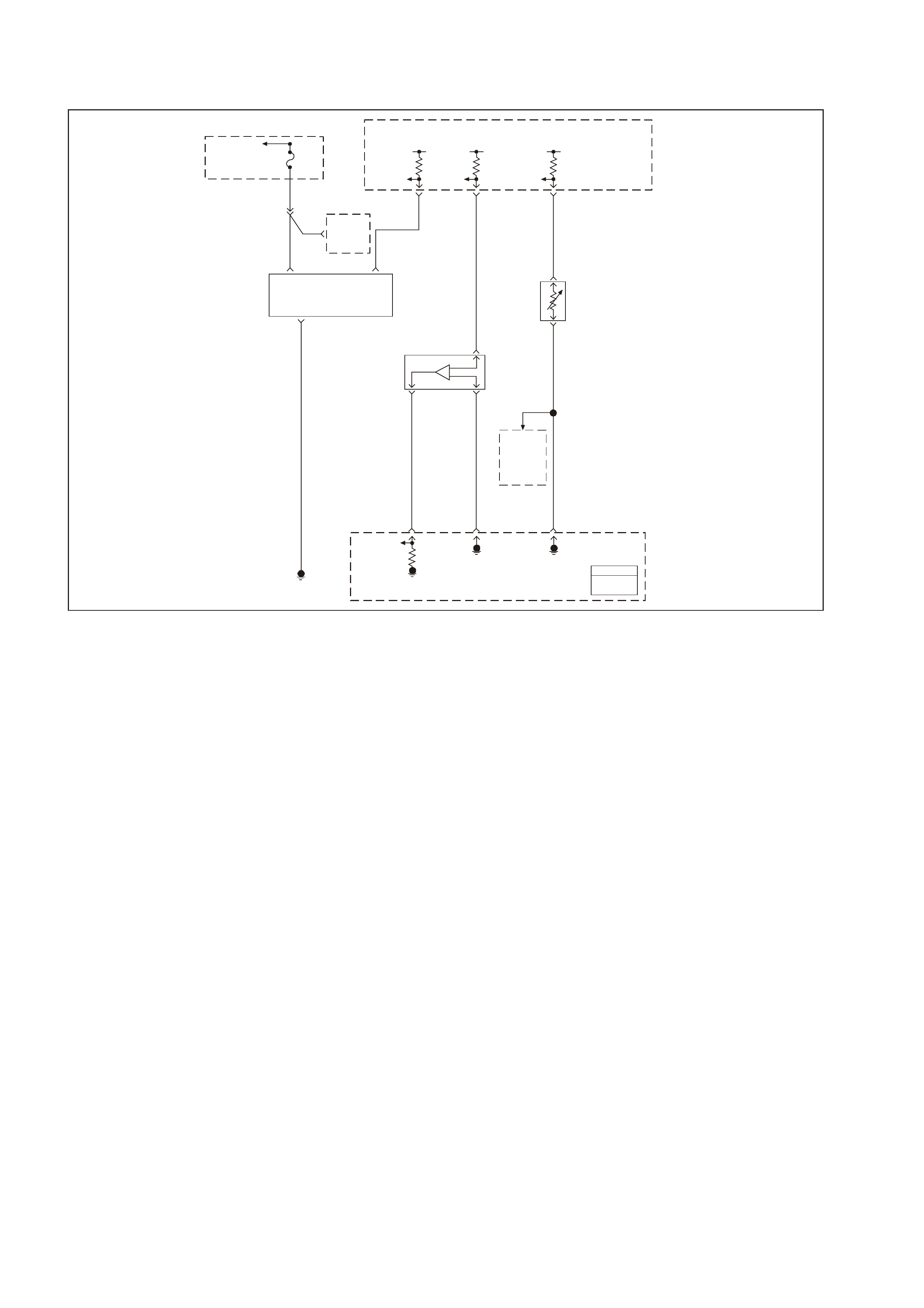
GEN III V8 PCM DTC P0107 MANIFOLD ABSOLUTE
PRESSURE SE NS O R CIRCUIT LOW VOLTAGE
GEN3 0155
PCM
J1 = BLUE
J2 = RED
To EFI
(Engine Cont.)
Relay Fuse
F33
5V 5V 5V
MAP
5V
Reference
MAF
Sensor
Signal
Oxygen
Sensor
Heaters
Intake Air
Temperature
(IAT)
Sensor
Ignition
Power MAF
Sensor
Signal
Mass Air
Flow (MAF)
Sensor
Manifold Ab solute
Pressure (MAP)
Sensor
To
A/C
Pressure
Sensor
MAP
Sensor
Signal
MAP
Sensor
Earth
IAT
Sensor
Earth
Engine
Earth
P 439
YE111
C
D
A
31 J2 48 J1 25 J2
G/O 469
57 J2
B421
32 J2
B/R 750
B/R 750
B
LG 432
BA
C
G/O 469
A
B
V/W 414
BR/W 792
A
54 J1
P439
IAT
Sensor
Signal
BR 472
Powertrain
Control
Module
(PCM)
CIRCUIT DESCRIPTION
The Manifold Absolute Pressure (MAP) sensor is mounted to the rear of the intake manifold. The MAP sensor
measures the pressure changes within the intake manifold which is an indication of the engine load. The MAP
sensor has a 5.0 volt reference, an earth, and a signal circuit.
The MAP sensor contains a diaphragm which changes the resistance based on pressure. When the manifold
pressure is low (high vacuum) the sensor output voltage is low. W hen the manifold pressure is high (low vacuum)
the sensor output voltage is high.
The MAP sensor voltage ( depending on altitude) can range fr om 1.0- 1.5 volts at idle (high vacuum ) to 4.0-4.9 volts
at wide open throttle (low vacuum).
When the PCM senses a signal voltage lower than the normal operating range of the sensor, this DTC will set.
CONDITIONS FOR RUNNING THE DTC
• No TP or ECT sensor DTCs set.
• The engine is running.
• The TP angle is above 20% when the engine speed is greater than 1200 RPM.
OR
• The TP angle is below 18% when the engine speed is below 1000 RPM.
CONDITIONS FOR SETTING THE DTC
• The MAP sensor voltage is less than 0.10 volts.
• All conditions met for greater than 2 seconds
ACTION TAKEN WHEN THE DTC SETS
• The PCM illuminates the Check Powertrain Lamp (CPL) when the diagnostic runs and fails.
• T he PCM records the operating conditions at the time the diagnostic f ails. The PCM stores this inform ation in
the Freeze Frame/Failure Records

CONDITIONS FOR CLEARING THE CPL/DTC
• The PCM turns the CPL OFF after the first ignition cycle that the diagnostic runs and does not fail.
• A last test failed (current DTC) clears when the diagnostic runs and does not fail.
• A History DTC clears after forty consecutive warm-up cycles, if this or any other emission related diagnostic
does not report any failure.
• Use a Tech 2 scan tool in order to clear the CPL/DTC.
DIAGNOSTIC AIDS
• The following may cause an intermittent:
- Incorrectly routed wiring harness
- Rubbed through wire insulation
- Broken wire inside the insulation
• T he PCM 5.0 volt referenc e circuits are internally connected within the PCM. If all the MAP sensor circ uits are
OK, inspect the following component/ circuits for malfunctions:
- A/C Refrigerant Pressure Transducer
For intermittent, refer to Section 6C3-2B SYMPTOMS in this Service Information CD.
TEST DESCRIPTION
The numbers below refer to the step numbers on the diagnostic table.
2. If the DT C P1635 sets at the sam e tim e, this indic ates that the 5.0 voltage ref erence c ircuit is either shorted to
an earth or shor ted to a voltage. The 5.0 volt ref erence circ uit is internally connected within the PCM. The A/C
Refrigerant Pressure Transducer may be causing this DTC to set. Refer to DTC P1635 for further diagnosis.
3. This step determined if the malfunction is present.
4. Using the Freeze Frame/Failure Records data may aid in locating an intermittent condition. If you cannot
duplicate the DT C, the information inc luded in the Freeze Fram e/Failure Records data can help determ ine the
distance traveled since the DTC set. The Fail Counter and Pass Counter can also help determine how many
ignition cycles the diagnostic reported a pass and/or fail.
Operate the vehic le within the sam e f r eeze frame c onditions ( RPM, load, vehic le speed, temper ature, etc .) that
you observed. This will isolate when the DTC failed.
5. If the Tech 2 scan tool displays 5.0 volts, the MAP sensor signal, 5.0 volt reference circuit, and the PCM are
OK. For any test that requires probing the PCM or component harness connectors, use the Connector Test
Adapter Kit J 35616-A. Using this kit will prevent any damage to the harness connector terminals.
6. If the Tech 2 scan tool displays 5.0 volts, the MAP sensor signal circuit and the PCM is OK. For any test that
requires pr obing the PCM or com ponents harness c onnectors, us e the Connector Tes t Adapter Kit J 35616-A.
Using this kit will prevent any damage to the harness connector terminals.
7. Disc onnecting the PCM allows using the DMM J 39200 in or der to chec k the continuity of the circuits . This aids
in locating an open or shorted circuit.

GEN III V8 PCM DTC P0107 MANIFOLD ABSOLUTE PRESSURE SENSOR CIRCUIT LOW VOLTAGE
Step Action Value(s) Yes No
1 Did you perform the Powertrain On-Board Diagnostic
(OBD) System Check? Go to Step 2 Go to Powertrain
OBD System
Check Table
2
1. Install a Tech 2 scan tool.
2. Idle the engine.
3. Monitor the Failed This Ignition option under the DTC
Information option using the Tech 2 scan tool.
Did DTC P1635 fail this ignition cycle?
Go to DTC
P1635
5 Volt Reference
Circuit Table
Go to Step 3
3 Monitor the MAP sensor voltage on Engine Data List on
the Tech 2 scan tool.
Is the MAP sensor voltage below the specified value?
0.10V Go to Step 5 Go to Step 4
4 1. Turn ON the ignition leaving the engine OFF.
2. Review the Freeze Frame/Failure Records data for
this DTC and observe the parameters.
3. Turn OFF the ignition for 15 seconds.
4. Start the engine.
5. Operate the vehicle within the conditions required for
this diagnostic to run, and as close to the conditions
recorded in the Freeze Frame/Failure Records as
possible. Special operating conditions that you need
to meet before the PCM will run this diagnostic, where
applicable, are listed in Conditions for Running the
DTC.
6. Select the Diagnostic Trouble Code (DTC) option, the
DTC Information, The Failed This Ignition, using the
Tech 2 scan tool.
Does the Tech 2 scan tool indicate that this diagnostic
failed this ignition?
Go to Step 5 Go to Diagnostic
Aids
5 1. Disconnect the MAP sensor electrical connector.
2. Jumper the 5.0 volt reference circuit and the MAP
sensor signal circuit together at the MAP sensor
harness connector.
3. Observe the MAP sensor voltage display on the scan
tool.
Is the MAP sensor voltage near the specified value?
5.0V Go to Step 11 Go to Step 6
6 1. Connect a test lamp J 34142-B between B+ and the
MAP sensor signal circuit at the MAP sensor harness
connector.
2. Observe the MAP sensor voltage display on the scan
tool.
Is the MAP sensor voltage near the specified value?
5.0V Go to Step 7 Go to Step 9
7 1. Turn OFF the ignition.
2. Disconnect the PCM BLUE connector.
3. Check the 5.0 volt reference circuit for an open or
short to an earth.
4. If you find the 5.0 volt reference circuit is open or
short to an earth, repair the circuit as necessary.
Did you find the 5.0 volt reference circuit open or shorted
to an earth?
Go to Step 13 Go to Step 8
8 1. Check the 5.0 volt reference circuit for a poor
connection at the PCM.
2. Replace the terminal if necessary.
Did the terminal require replacement?
Go to Step 13 Go to Step 12

Step Action Value(s) Yes No
9 1. Turn OFF the ignition.
2. Disconnect the PCM connectors.
3. Check the MAP sensor signal circuit for the following:
- Open circuit
- Short to an earth
- Short to sensor earth circuit
4. If you find the MAP sensor signal circuit is open or
shorted to an earth, repair the circuit as necessary.
Did you find the MAP sensor signal circuit open or
shorted to a earth?
Go to Step 13 Go to Step 10
10 Check the MAP sensor signal circuit for a poor
connection at the PCM and replace the terminal if
necessary.
Did the terminal require replacement?
Go to Step 13 Go to Step 12
11 Replace the MAP sensor. Refer to Section 6C3-3 MAP
Sensor Replacement in this Service information CD.
Is the action complete?
Go to Step 13
12 1. Replace PCM.
2. Refer to Section 6C3-3 in this Service Information CD
for PCM Programming and PCM/PIM/BCM Security
Link Procedure.
Is action complete?
Go to Step 13
13 1. Select the Diagnostic Trouble Code (DTC) option and
the Clear DTC Information option using the Tech 2
scan tool.
2. Idle the engine at the normal operating temperature.
3. Select the Diagnostic Trouble Code (DTC) option and
the Specified DTC option, then enter the DTC number
using the Tech 2 scan tool.
4. Operate the vehicle within the Conditions for Running
the DTC as specified in the supporting text, if
applicable.
Does the Tech 2 scan tool indicate that this DTC reset?
Go to Step 2 Go to Step 14
14 Using the Tech 2 scan tool, check for any other DTC.
Does the Tech 2 scan tool display any DTCs that you
have not diagnosed?
Go to the
applicable DTC
table
System OK

GEN III V8 PCM DTC P0108 MANIFOLD ABSOLUTE
PRESSURE SE NS O R CIRCUIT HIGH V OLTAGE
GEN3 0155
PCM
J1 = BLUE
J2 = RED
To EFI
(Engine Cont.)
Relay Fuse
F33
5V 5V 5V
MAP
5V
Reference
MAF
Sensor
Signal
Oxygen
Sensor
Heaters
Intake Air
Temperature
(IAT)
Sensor
Ignition
Power MAF
Sensor
Signal
Mass Air
Flow (MAF)
Sensor
Manifold Ab solute
Pressure (MAP)
Sensor
To
A/C
Pressure
Sensor
MAP
Sensor
Signal
MAP
Sensor
Earth
IAT
Sensor
Earth
Engine
Earth
P 439
YE111
C
D
A
31 J2 48 J1 25 J2
G/O 469
57 J2
B421
32 J2
B/R 750
B/R 750
B
LG 432
BA
C
G/O 469
A
B
V/W 414
BR/W 792
A
54 J1
P439
IAT
Sensor
Signal
BR 472
Powertrain
Control
Module
(PCM)
CIRCUIT DESCRIPTION
The Manifold Absolute Pressure (MAP) sensor is mounted to the rear of the intake manifold. The MAP sensor
measures the pressure changes within the intake manifold which is an indication of the engine load. The MAP
sensor has a 5.0 volt reference, an earth, and a signal circuit.
The MAP sensor contains a diaphragm which changes the resistance based on pressure. When the manifold
pressure is low (high vacuum) the sensor output voltage is low. W hen the manifold pressure is high (low vacuum)
the sensor output voltage is high.
The MAP sensor voltage ( depending on altitude) can range fr om 1.0- 1.5 volts at idle (high vacuum ) to 4.0-4.9 volts
at wide open throttle (low vacuum).
When the PCM senses a signal voltage higher than the normal operating range of the sensor, this DTC will set.
CONDITIONS FOR RUNNING THE DTC
• No TP or ECT sensor DTCs set.
• The engine is operating.
• The TP angle is above 20% when the engine speed is greater than 1000 RPM.
OR
• The TP angle is below 18% when the engine speed is below 1200 RPM.
CONDITIONS FOR SETTING THE DTC
• The MAP sensor voltage is greater than 4.3 volts.
• All conditions met for greater than 4 seconds
ACTION TAKEN WHEN THE DTC SETS
• The PCM illuminates the Check Powertrain Lamp (CPL) when the diagnostic runs and fails.
• T he PCM records the operating conditions at the time the diagnostic f ails. The PCM stores this inform ation in
the Freeze Frame/ Failure Records

CONDITIONS FOR CLEARING THE CPL/DTC
• The PCM turns the CPL OFF after three consecutive ignition cycles that the diagnostic runs and does not fail.
• A last test failed (current DTC) clears when the diagnostic runs and does not fail.
• A History DTC clears after forty consecutive warm-up cycles, if this or any other emission related diagnostic
does not report any failure.
• Use a Tech 2 scan tool in order to clear the CPL/DTC.
DIAGNOSTIC AIDS
• The following may cause an intermittent:
- Incorrectly routed harness
- Rubbed through wire insulation
- Broken wire inside the insulation
• The PCM 5.0 volt reference circuits are internally connected within the PCM. If all the MAP sensor circuits are
OK, inspect the following component/ circuits for malfunctions:
- A/C Refrigerant Pressure Transducer
For intermittent, refer to Section 6C3-2B SYMPTOMS in this Service Information CD.
TEST DESCRIPTION
The numbers below refer to the step numbers on the diagnostic table.
2. If the DT C P1635 sets at the sam e tim e, this indic ates that the 5.0 voltage ref erence c ircuit is either shorted to
an earth or shor ted to a voltage. The 5.0 volt ref erence circ uit is internally connected within the PCM. The A/C
Refrigerant Pressure Transducer may be causing this DTC to set. Refer to DTC P1635 for further diagnosis.
3. This step determined if the malfunction is present.
4. Using the Freeze Frame/Failure Records data may aid in locating an intermittent condition. If you cannot
duplicate the DT C, the information inc luded in the Freeze Fram e/Failure Records data can help determ ine the
distance traveled since the DTC set. The Fail Counter and Pass Counter can also help determine how many
ignition cycles the diagnostic reported a pass and/or fail. Operate the vehicle with the same freeze frame
conditions (RPM, load, vehicle speed, temperature, etc.) that you observed.
This will isolate when the DTC failed. For any test that requires probing the PCM or component harness
connectors, use the Connector Test Adapter Kit J 35616-A. Using this kit will prevent any damage to the
harness connector terminals.
5. This step checks whether the signal circuit is shorted to a voltage.
6. This step checks whether the earth circuit is available at the MAP sensor. For any test that requires probing the
PCM or component harness connectors, use the Connector Test Adapter Kit J 35616-A. Using this kit will
prevent any damage to the harness connector terminals.
9. Remove the MAP sensor and check if the vacuum is available to the sensor. Also, inspect the MAP sensor
seal for nicks and cuts.

GEN III V8 PCM DTC P0108 MANIFOLD ABSOLUTE PRESSURE SENSOR CIRCUIT HIGH VOLTAGE
Step Action Value(s) Yes No
1 Did you perform the Powertrain On-Board Diagnostic
(OBD) System Check? Go to Step 2 Go to Powertrain
OBD System
Check Table
2
1. Install a Tech 2 scan tool.
2. Idle the engine.
3. Monitor the Failed This Ignition option under the DTC
Information option using the Tech 2 scan tool.
Did DTC P1635 fail this ignition cycle?
Go to DTC
P1635
5 Volt Reference
Circuit Table
Go to Step 3
3 IMPORTANT: If the engine idle is rough, unstable or
incorrect, repair the idle condition before using this table,
refer to Section 6C3-2B Symptoms in this Service
Information CD.
Monitor the MAP sensor voltage on Engine Data List on
the Tech 2 scan tool.
Is the MAP sensor voltage below the specified value?
4.3V Go to Step 5 Go to Step 4
4 1. Turn ON the ignition leaving the engine OFF.
2. Review the Freeze Frame/Failure Records data for
this DTC and observe the parameters.
3. Turn OFF the ignition for 15 seconds.
4. Start the engine.
5. Operate the vehicle within the conditions required for
this diagnostic to run, and as close to the conditions
recorded in the Freeze Frame/Failure Records as
possible. Special operating conditions that you need
to meet before the PCM will run this diagnostic, where
applicable, are listed in Conditions for Running the
DTC.
6. Select the Diagnostic Trouble Code (DTC) option, the
DTC Information option and The Failed This Ignition
option, using the Tech 2 scan tool.
Does the Tech 2 scan tool indicate that this diagnostic
failed this ignition?
Go to Step 5 Go to Diagnostic
Aids
5 1. Disconnect the MAP sensor electrical connector.
2. Observe the MAP sensor voltage display on the scan
tool.
Is the MAP sensor voltage below the specified value?
1.0V Go to Step 6 Go to Step 7
6 Probe the sensor earth circuit with a test lamp J 34142-B
to B+.
Is the test lamp illuminated?
Go to Step 8 Go to Step 10
7 1. Check the MAP sensor signal circuit for a short to
voltage or a short to the 5.0 volt reference circuit.
2. Repair the MAP sensor signal circuit if the circuit is
shorted.
Is the MAP sensor signal circuit shorted?
Go to Step 16 Go to Step 12
8 Measure the voltage at the 5.0 volt reference circuit to
the battery earth using a DMM J 39200.
Is the voltage near the specified value?
5.0V Go to Step 9 Go to Step 15
9 Check for a plugged or leaking vacuum supply to the
MAP sensor.
Is the vacuum supply OK?
Go to Step 13 Go to Step 14
10 1. Check for a poor sensor earth terminal connection at
the PCM connector.
2. Replace the faulty terminal if a problem is found.
Did the terminal require replacement?
Go to Step 16 Go to Step 11

Step Action Value(s) Yes No
11 1. Check continuity of the MAP sensor earth circuit.
2. Repair the open or the poor connection if the MAP
sensor earth circuit measures over the specified
value.
Did you find and correct the condition?
5Ω Go to Step 16 Go to Step 12
12 1. Replace PCM.
2. Refer to Section 6C3-3 in this Service Information CD
for PCM Programming and PCM/PIM/BCM Security
Link Procedure.
Is action complete?
Go to Step 16
13 Replace the MAP sensor. Refer to Section 6C3-3 MAP
Sensor Replacement in this Service Information CD.
Is the action complete?
Go to Step 16
14 Repair the faulty vacuum supply.
Is the action complete? Go to Step 16
15 Repair the 5.0 volt reference circuit for a short to voltage.
Is the action complete. Go to Step 16
16 1. Select the Diagnostic Trouble Code (DTC) option and
the Clear DTC Information option using the Tech 2
scan tool.
2. Idle the engine at the normal operating temperature.
3. Select the Diagnostic Trouble Code (DTC) option and
the Specified DTC option, then enter the DTC number
using the Tech 2 scan tool.
4. Operate the vehicle within the Conditions for Running
the DTC as specified in the supporting text, if
applicable.
Does the Tech 2 scan tool indicate that this DTC reset?
Go to Step 2 Go to Step 17
17 Using the Tech 2 scan tool, check for any other DTC.
Does the Tech 2 scan tool display any DTCs that you
have not diagnosed?
Go to the
applicable DTC
table
System OK

GEN III V8 PCM DTC P0112 INTAKE AIR TEMPERATURE
SENSOR CIRCUIT LOW V O LTAGE
GEN3 0155
PCM
J1 = BLUE
J2 = RED
To EFI
(Engine Cont.)
Relay Fuse
F33
5V 5V 5V
MAP
5V
Reference
MAF
Sensor
Signal
Oxygen
Sensor
Heaters
Intake Air
Temperature
(IAT)
Sensor
Ignition
Power MAF
Sensor
Signal
Mass Air
Flow (MAF)
Sensor
Manifold Ab solute
Pressure (MAP)
Sensor
To
A/C
Pressure
Sensor
MAP
Sensor
Signal
MAP
Sensor
Earth
IAT
Sensor
Earth
Engine
Earth
P 439
YE111
C
D
A
31 J2 48 J1 25 J2
G/O 469
57 J2
B421
32 J2
B/R 750
B/R 750
B
LG 432
BA
C
G/O 469
A
B
V/W 414
BR/W 792
A
54 J1
P439
IAT
Sensor
Signal
BR 472
Powertrain
Control
Module
(PCM)
CIRCUIT DESCRIPTION
The Intake Air T emperatur e (IAT) sensor contains a sem iconductor device which c hanges the resistanc e based on
the temperature (a thermistor). The IAT sensor is located in the air intake passage of the engine air induction
system. The IAT sensor has a signal circuit and an earth circuit. T he PCM applies 5.0 volts on the signal circuit to
the sensor. The PCM monitors the changes in this voltage caused by changes in the resistance of the sensor in
order to determine intake air temperature.
When the intake air is c old, the s ensor ( thermis tor) r esis tanc e is high. T he PCM’s s ignal voltage is only pulled down
a sm all amount thr ough the sensor to an earth; ther efore, the PCM senses a high signal voltage (low tem perature).
When the intake air is warm, the sensor resistance is low. The signal voltage is pulled down a greater amount;
therefore, the PCM senses a low signal voltage (high temperature).
When the PCM senses a signal voltage lower than the normal operating range of the sensor, this DTC will set.
CONDITIONS FOR RUNNING THE DTC
• DTCs P0101, P0102, P103, P0117, P0118, P0125, P0500, P0502, P0503 not set.
• The engine run time is greater than 30 seconds.
• The vehicle speed at least 40 km/h (25 mph).
CONDITIONS FOR SETTING THE DTC
• The Intake Air Temperature is greater than 139°C.
• All conditions met for 5.0 seconds.
ACTION TAKEN WHEN THE DTC SETS
• The PCM stores the DTC information into memory when the diagnostic runs and fails.
• The Check Powertrain Lamp (CPL) will not be illuminated.
• T he PCM records the operating conditions at the time the diagnostic f ails. The PCM stores this inform ation in
the Freeze Frame/Failure Records.

CONDITIONS FOR CLEARING THE CPL/DTC
• A last test failed (current DTC) clears when the diagnostic runs and does not fail.
• A History DTC clears after forty consecutive warm-up cycles, if this or any other emission related diagnostic
does not report any failure.
• Use a Tech 2 scan tool in order to clear the CPL/DTC.
DIAGNOSTIC AIDS
• The following may cause an intermittent:
- Incorrectly routed wiring harness
- Rubbed through wire insulation
- Broken wire inside the insulation
• If the engine has sat overnight, the Engine Coolant Temperature and the engine Intake Air Temperature values
should display within a few degrees of each other. If the temperatures are not within 3°C (5°F), refer to
Section 6C3-4 SPECIFICATIONS Temperature vs. Resistance Chart in this Service Information CD.
• If you determine that the DTC occurs intermittently, performing the P1112 diagnostic table may isolate the
cause of the fault.
For intermittent, refer to Section 6C3-2B SYMPTOMS in this Service Information CD.
TEST DESCRIPTION
The numbers below refer to the step numbers on the diagnostic table.
2. This step determines if the malfunction is present.
3. Using the Freeze Frame/Failure Records data may aid in locating an intermittent condition. If you cannot
duplicate the DT C, the information inc luded in the Freeze Fram e/Failure Records data can help determ ine the
distance traveled since the DTC set. The Fail Counter and Pass Counter can also help determine how many
ignition cycles the diagnostic reported a pass and/or fail. Operate the vehicle with the same freeze frame
conditions (RPM, load, vehicle speed, temperature, etc.) that you observed.
This will isolate when the DTC failed. For any test that requires probing the PCM or component harness
connectors, use the Connector Test Adapter Kit J 35616-A. Using this kit will prevent any damage to the
harness connector terminals.
4. An intake air temperature below -30°C indicates the PCM and IAT wiring are OK.
5. Dis connecting the PCM allows using the DMM J 39200 in order to check continuity of the circuits. This aids in
locating an open or a shorted circuit.

GEN III V8 PCM DTC P0112 INTAKE AIR TEMPERATURE SENSOR CIRCUIT LOW VOLTAGE
Step Action Value(s) Yes No
1 Did you perform the Powertrain On-Board Diagnostic
(OBD) System Check? Go to Step 2 Go to Powertrain
OBD System
Check Table
2
1. Install a Tech 2 scan tool.
2. Idle the engine.
3. Monitor the IAT display on the Tech 2 scan tool
Engine Data List.
Is the IAT above the specified value?
139°C Go to Step 4 Go to Step 3
3 1. Turn ON the ignition leaving the engine OFF.
2. Review the Freeze Frame/Failure Records data for
this DTC and observe the parameters.
3. Turn OFF the ignition for 15 seconds.
4. Start the engine.
5. Operate the vehicle within the conditions required for
this diagnostic to run, and as close to the conditions
recorded in the Freeze Frame/Failure Records as
possible. Special operating conditions that you need
to meet before the PCM will run this diagnostic, where
applicable, are listed in Conditions for Running the
DTC.
6. Select the Diagnostic Trouble Code (DTC) option, the
DTC Information option and The Failed This Ignition
option using the Tech 2 scan tool.
Does the Tech 2 scan tool indicate that this diagnostic
failed this ignition?
Go to Step 4 Go to Diagnostic
Aids
4 1. Disconnect the IAT sensor electrical connector.
2. Observe the IAT display on the Tech 2 scan tool.
Is the IAT at the specified value?
-39°C Go to Step 6 Go to Step 5
5 1. Turn OFF the ignition.
2. Disconnect the PCM RED connector.
3. Check the IAT signal circuit for a short to a earth.
4. If you find the IAT sensor signal circuit is earthed,
repair the circuit as necessary.
Is the IAT signal circuit earthed?
Go to Step 8 Go to Step 7
6 Replace the IAT sensor. Refer to Section 6C3-3 IAT
Sensor Replacement in this Service Information CD.
Is the action complete?
Go to Step 8
7 1. Replace PCM.
2. Refer to Section 6C3-3 in this Service Information CD
for PCM Programming and PCM/PIM/BCM Security
Link Procedure.
Is action complete?
Go to Step 8
8 1. Select the Diagnostic Trouble Code (DTC) option and
the Clear DTC Information option using the Tech 2
scan tool.
2. Idle the engine at the normal operating temperature.
3. Select the Diagnostic Trouble Code (DTC) option and
the Specified DTC option, then enter the DTC number
using the Tech 2 scan tool.
4. Operate the vehicle within the Conditions for Running
the DTC as specified in the supporting text, if
applicable.
Does the Tech 2 scan tool indicate that this DTC reset?
Go to Step 2 Go to Step 9
9 Using the Tech 2 scan tool, check for any other DTC.
Does the Tech 2 scan tool display any DTCs that you
have not diagnosed?
Go to the
applicable DTC
table
System OK

GEN III V8 PCM DTC P0113 INTAKE AIR TEMPERATURE
SENSOR CIRCUIT HIGH VOLTAGE
GEN3 0155
PCM
J1 = BLUE
J2 = RED
To EFI
(Engine Cont.)
Relay Fuse
F33
5V 5V 5V
MAP
5V
Reference
MAF
Sensor
Signal
Oxygen
Sensor
Heaters
Intake Air
Temperature
(IAT)
Sensor
Ignition
Power MAF
Sensor
Signal
Mass Air
Flow (MAF)
Sensor
Manifold Ab solute
Pressure (MAP)
Sensor
To
A/C
Pressure
Sensor
MAP
Sensor
Signal
MAP
Sensor
Earth
IAT
Sensor
Earth
Engine
Earth
P 439
YE111
C
D
A
31 J2 48 J1 25 J2
G/O 469
57 J2
B421
32 J2
B/R 750
B/R 750
B
LG 432
BA
C
G/O 469
A
B
V/W 414
BR/W 792
A
54 J1
P439
IAT
Sensor
Signal
BR 472
Powertrain
Control
Module
(PCM)
CIRCUIT DESCRIPTION
The Intake Air T emperatur e (IAT) sensor contains a sem iconductor device which c hanges the resistanc e based on
the temperature (a thermistor). The IAT sensor is located in the air intake passage of the engine air induction
system. The IAT sensor has a signal circuit and an earth circuit. T he PCM applies 5.0 volts on the signal circuit to
the sensor. The PCM monitors the changes in this voltage caused by changes in the resistance of the sensor in
order to determine intake air temperature.
When the intake air is c old, the s ensor ( thermis tor) r esis tanc e is high. T he PCM’s s ignal voltage is only pulled down
a sm all amount thr ough the sensor to an earth; ther efore, the PCM senses a high signal voltage (low tem perature).
When the intake air is warm, the sensor resistance is low. The signal voltage is pulled down a greater amount;
therefore, the PCM senses a low signal voltage (high temperature).
When the PCM senses a signal voltage lower than the normal operating range of the sensor, this DTC will set.
CONDITIONS FOR RUNNING THE DTC
• DTCs P0101, P0102, P103, P0117, P0118, P0125, P0500, P0502, P0503 not set.
• The engine coolant temperature is greater than 0°C (32°F).
• The vehicle speed at less than 11 km/h (7 mph).
CONDITIONS FOR SETTING THE DTC
• The Intake Air Temperature is at or below -35°C
• All conditions met for 5.0 seconds.
ACTION TAKEN WHEN THE DTC SETS
• The PCM stores the DTC information into memory when the diagnostic runs and fails.
• The Check Powertrain Lamp (CPL) will not be illuminated.
• T he PCM records the operating conditions at the time the diagnostic f ails. The PCM stores this inform ation in
the Freeze Frame/Failure Records.

CONDITIONS FOR CLEARING THE CPL/DTC
• A last test failed (current DTC) clears when the diagnostic runs and does not fail.
• A History DTC clears after forty consecutive warm-up cycles, if this or any other emission related diagnostic
does not report any failure.
• Use a Tech 2 scan tool in order to clear the CPL/DTC.
DIAGNOSTIC AIDS
• The following may cause an intermittent:
- Incorrectly routed harness
- Rubbed through wire insulation
- Broken wire inside the insulation
• If the engine has sat overnight, the Engine Coolant Temperature and the engine Intake Air Temperature values
should display within a few degrees of each other. If the temperatures are not within 3°C (5°F), refer to
Section 6C3-4 SPECIFICATIONS Temperature vs. Resistance Chart in this Service Information CD.
• If you determine that the DTC occurs intermittently, performing the P1111 diagnostic table may isolate the
cause of the fault.
For intermittent, refer to Section 6C3-2B SYMPTOMS in this Service Information CD.
TEST DESCRIPTION
The numbers below refer to the step numbers on the diagnostic table.
2. This step determines if the malfunction is present. For any test that requires probing the PCM or component
harness connectors, use the Connector Test Adapter Kit J35616-A. Using this kit will prevent any damage to
the harness connector terminals.
3. Using the Freeze Frame/Failure Records data may aid in locating an intermittent condition. If you cannot
duplicate the DT C, the information inc luded in the Freeze Fram e/Failure Records data can help determ ine the
distance traveled since the DTC set. The Fail Counter and Pass Counter can also help determine how many
ignition cycles the diagnostic reported a pass and/or fail. Operate the vehicle with the same freeze frame
conditions (RPM, load, vehicle speed, temperature, etc.) that you observed.
This will isolate when the DTC failed. For any test that requires probing the PCM or component harness
connectors, use the Connector Test Adapter Kit J 35616-A. Using this kit will prevent any damage to the
harness connector terminals.
4. An intake air temperature above 140°C indicates the PCM and IAT wiring are OK.
5 An intake air temperature above 140°C indicates the PCM and IAT wiring are OK.
6. Dis connecting the PCM allows using the DMM J 39200 in order to check continuity of the circuits. This aids in
locating an open or a shorted circuit.
8 Disconnec ting the PCM allows using the DMM J 39200 in order to check continuity of the circuits. This aids in
locating an open or a shorted circuit.

GEN III V8 PCM DTC P0113 INTAKE AIR TEMPERATURE SENSOR CIRCUIT HIGH VOLTAGE
Step Action Value(s) Yes No
1 Did you perform the Powertrain On-Board Diagnostic
(OBD) System Check? Go to Step 2 Go to Powertrain
OBD System
Check Table
2
1. Install a Tech 2 scan tool.
2. Idle the engine.
3. Monitor the IAT sensor display on the Tech 2 scan
tool Engine Data List.
Is the IAT at or above the specified value?
-35°C Go to Step 4 Go to Step 3
3 1. Turn ON the ignition leaving the engine OFF.
2. Review the Freeze Frame/Failure Records data for
this DTC and observe the parameters.
3. Turn OFF the ignition for 15 seconds.
4. Start the engine.
5. Operate the vehicle within the conditions required for
this diagnostic to run, and as close to the conditions
recorded in the Freeze Frame/Failure Records as
possible. Special operating conditions that you need
to meet before the PCM will run this diagnostic, where
applicable, are listed in Conditions for Running the
DTC.
6. Select the Diagnostic Trouble Code (DTC) option, the
Specific DTC option, then enter the DTC number
using the Tech 2 scan tool.
Does the Tech 2 scan tool indicate that this diagnostic
failed this ignition?
Go to Step 4 Go to Diagnostic
Aids
4 1. Disconnect the IAT sensor electrical connector.
2. Jumper the IAT harness terminals together.
3. Observe the IAT parameter on the Tech 2 scan tool.
Is the IAT at the specified value?
139°C Go to Step 9 Go to Step 5
5 Jumper the IAT signal circuit to a known good earth.
Is the IAT at the specified value? 139°C Go to Step 8 Go to Step 6
6 1. Turn OFF the ignition.
2. Disconnect the PCM RED connector.
3. Check the IAT signal circuit for an open.
Is the IAT signal circuit open?
Go to Step 7 Go to Step 11
7 Repair the IAT sensor signal circuit.
Is the action complete? Go to Step 12
8 1. Turn OFF the ignition.
2. Disconnect both the PCM connectors.
3. Check the IAT sensor earth circuit for an open.
Is the IAT sensor earth circuit open?
Go to Step 10 Go to Step 11
9 Replace the IAT sensor. Refer to Section 6C3-3 IAT
Sensor Replacement in this Service Information CD.
Is the action complete?
Go to Step 12
10 Repair the IAT sensor earth circuit.
Is action complete? Go to Step 12
11 1. Replace PCM.
2. Refer to Section 6C3-3 in this Service Information CD
for PCM Programming and PCM/PIM/BCM Security
Link Procedure.
Is action complete?
Go to Step 12

Step Action Value(s) Yes No
12 1. Select the Diagnostic Trouble Code (DTC) option and
the Clear DTC Information option using the Tech 2
scan tool.
2. Idle the engine at the normal operating temperature.
3. Select the Diagnostic Trouble Code (DTC) option and
the Specified DTC option, then enter the DTC number
using the Tech 2 scan tool.
4. Operate the vehicle within the Conditions for Running
the DTC as specified in the supporting text, if
applicable.
Does the Tech 2 scan tool indicate that this DTC reset?
Go to Step 2 Go to Step 13
13 Select the Capture Info option and the Review Info option
using the Tech 2 scan tool.
Does the Tech 2 scan tool display any DTCs that you
have not diagnosed?
Go to the
applicable DTC
table
System OK
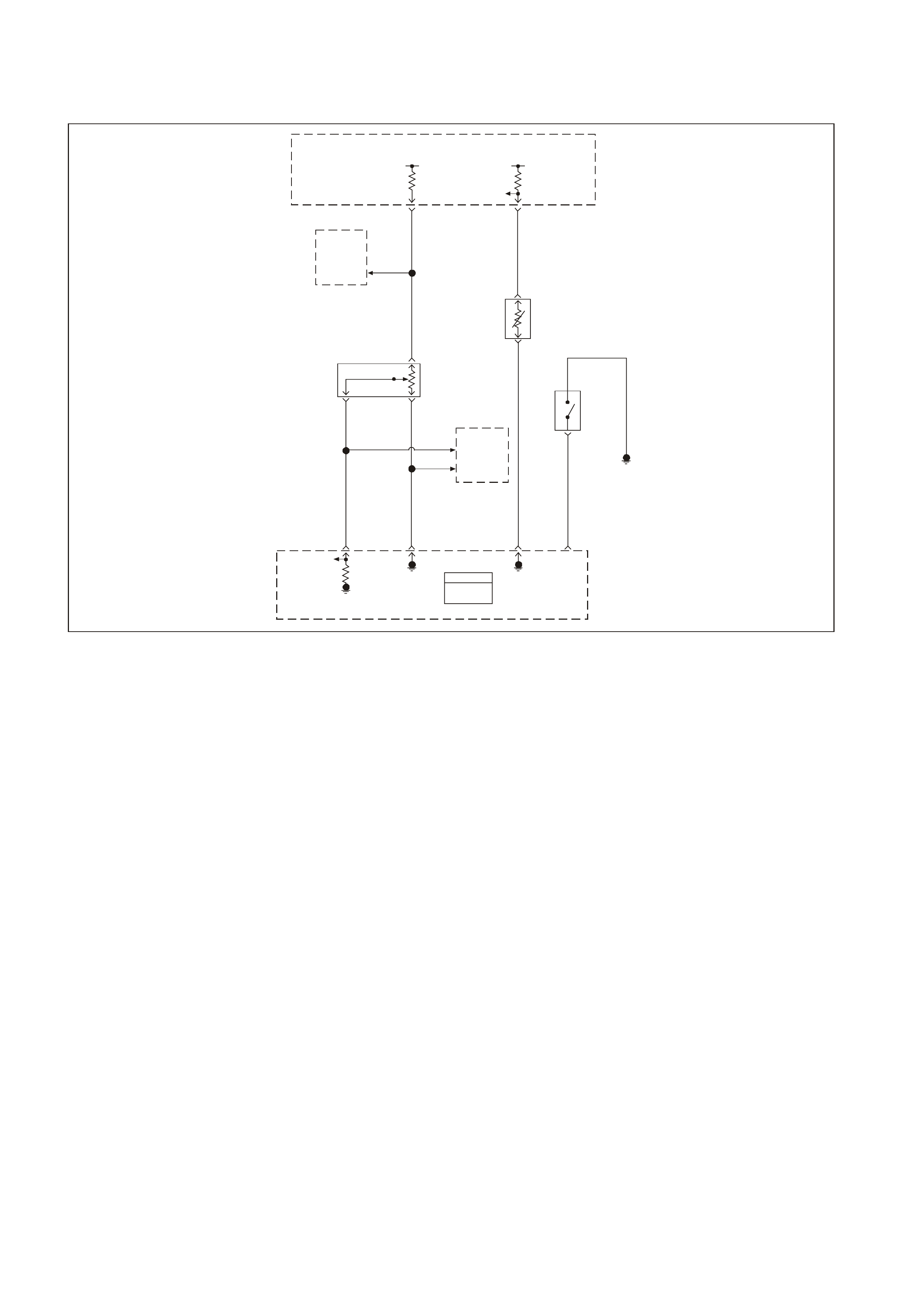
GEN III V8 PCM DTC P0117 ENGINE COOLANT
TEMPERATURE SENS O R CIRCUIT LOW VOLTAGE
GEN3 0156
PCM
J1 = B LUE
J2 = RE D
Powertrain
Control
Module
(PCM)
Powertrain
Control
Module
(PCM)
5V 5V
ECT
Sensor
Signal
TP Sensor
5V
Reference
Throttle
Relaxer
Control
Module
Engine Coolant
Temperature
(ECT)
Sensor
Throttle
Position
(TP)
Sensor Coolant
Level
Switch
Engine
Earth
TP
Sensor
Signal
Sensor
Earth
ECT
Sensor
Earth
Coolant
Level
Switch
Input
08 74 J1
Y410
B
A
B/R 750
G69
30 J1
GY/B 455
80 J1
B/Y 452
60
BLU 417
24 J2
B/Y 452
BLU 417
CB
40
43
GY 416
GY 416
A
GY
416
41
Throttle
Relaxer
Control
Module
J1
J1
CIRCUIT DESCRIPTION
The Engine Coolant Temperature (ECT) sensor contains a semiconductor device which changes the resistance
based on the tem per ature ( a thermis tor) . The ECT sens or is mounted in the lef t bank cylinder head near the front of
the engine. The ECT sensor has a signal circuit and a ear th circuit. T he PCM applies a voltage (about 5.0 volts) on
the signal circuit to the s ensor. T he PCM monitors the changes in this voltage caused by changes in the resistance
of the sensor in order to determine the coolant temperature.
When the coolant is c old, the sens or (ther m istor) r esistanc e is high. T he PCMs s ignal voltage is only pulled down a
small amount through the sensor to an earth; therefore, the PCM senses a high signal voltage (low temperature).
When the coolant is warm, the sensor resistance is low. The signal voltage is pulled down a greater amount;
therefore the PCM senses a low signal voltage (high temperature). At normal operating temperature, the voltage
should measure about 1.5-2.0 volts at the PCM.
When the PCM senses a signal voltage lower than the normal operating range of the sensor, this DTC will set.
CONDITIONS FOR RUNNING THE DTC
• The engine run time is greater than 10 seconds.
CONDITIONS FOR SETTING THE DTC
• The Engine Coolant Temperature is greater than 139°C (282°F).
• All conditions met for 20.0 seconds.
ACTION TAKEN WHEN THE DTC SETS
• The PCM illuminates the Check Powertrain Lamp (CPL) when the diagnostic runs and fails.
• T he PCM records the operating conditions at the time the diagnostic f ails. The PCM stores this information in
the Freeze Frame/Failure Records.

CONDITIONS FOR CLEARING THE CPL/DTC
• The PCM turns the CPL OFF after three consecutive ignition cycles that the diagnostic runs and does not fail.
• A last test failed (current DTC) clears when the diagnostic runs and does not fail.
• A History DTC clears after forty consecutive warm-up cycles, if this or any other emission related diagnostic
does not report any failure.
• Use a Tech 2 scan tool in order to clear the CPL/DTC.
DIAGNOSTIC AIDS
• The following may cause an intermittent:
- Incorrectly routed harness
- Rubbed through wi re insulation
- Broken wire inside the insulation
• If the engine has s at overnight, the Engine Coolant T emperatur e and the engine Intake Air Temper ature values
should display within a few degrees of each other. If the temperatures are not within 3°C (5°F), refer to
Section 6C3-4 SPCIFICATIONS, Temperature vs. Resistance Chart in this Service Information CD.
• If you determine that the DTC occurs intermittently, performing the P1111 diagnostic table may isolate the
cause of the fault.
• For intermittent, refer to Section 6C3-2B SYMPTOMS in this Service Information CD.
TEST DESCRIPTION
The numbers below refer to the step numbers on the diagnostic table.
2. This step determines if the malfunction is present.
3. Using the Freeze Frame/Failure Records data may aid in locating an intermittent condition. If you cannot
duplicate the DT C, the information inc luded in the Freeze Frame/Failure Recor ds data can help determine the
distance traveled since the DTC set. The Fail Counter and Pass Counter can also help determine how many
ignition cycles the diagnostic reported a pass and/or fail. Operate the vehicle with the same freeze frame
conditions (RPM, load, vehicle speed, temperature, etc.) that you observed. This will isolate when the DTC
failed. For any test that requires probing the PCM or com ponent harness connectors, use the Connector Test
adaptor Kit J 35616-A. Using this kit will prevent any damage to the harness connector terminals.
4. An engine coolant temperature below -30°C (-22°F) indicates the PCM and IAT wiring are OK.
5. Disconnecting the PCM allows using the DMM
J 39200 in order to check continuity of the circuits. This aids in locating an open or a shorted circuit.
7. Inspect for proper terminal tension/connections at the PCM harness before replacing the PCM.

GEN III V8 PCM DTC P0117 ENGINE COOLANT TEMPERATURE SENSOR CIRCUIT LOW VOLTAGE
Step Action Value(s) Yes No
1 Did you perform the Powertrain On-Board Diagnostic
(OBD) System Check? Go to Step 2 Go to Powertrain
OBD System
Check Table
2
Important: If the engine is overheating, correct the
overheating condition before proceeding with this table.
1. Install a Tech 2 scan tool.
2. Idle the engine.
3. Monitor the IAT display on the Engine Data List of
the Tech 2 scan tool.
Is the IAT at or above the specified value?
139°C
(282°F) Go to Step 4 Go to Step 3
3 1. Turn ON the ignition leaving the engine OFF.
2. Review the Freeze Frame/Failure Records data for
this DTC and observe the parameters.
3. Turn OFF the ignition for 15 seconds.
4. Start the engine.
5. Operate the vehicle within the conditions required for
this diagnostic to run, and as close to the conditions
recorded in the Freeze Frame/Failure Records as
possible. Special operating conditions that you need
to meet before the PCM will run this diagnostic,
where applicable, are listed in Conditions for
Running the DTC.
6. Select the Diagnostic Trouble Code (DTC) option,
the DTC Information option and The Failed This
Ignition option using the Tech 2 scan tool.
Does the Tech 2 scan tool indicate that this diagnostic
failed this ignition?
Go to Step 4 Go to Diagnostic
Aids
4 1. Disconnect the ECT sensor electrical connector.
2. Observe the ECT parameter on the Tech 2 scan
tool.
Is the ECT at or below specified value?
-30°C
(-22°F) Go to Step 6 Go to Step 5
5 1. Turn OFF the ignition.
2. Disconnect the PCM BLUE connector.
3. Check the ECT signal circuit for a short to a earth.
4. If you find the ECT sensor signal circuit is earthed,
repair the circuit as necessary.
Did you find and repair an earthed ECT signal circuit?
Go to Step 8 Go to Step 7
6 Replace the ECT sensor. Refer to Section 6C3-3 ECT
Sensor Replacement in this Service Information CD.
Is the action complete?
Go to Step 8
7 1. Replace PCM.
2. Refer to Section 6C3-3 in this Service Information
CD for PCM Programming and PCM/PIM/BCM
Security Link Procedure.
Is action complete?
Go to Step 8
8 1. Select the Diagnostic Trouble Code (DTC) option
and the Clear DTC Information option using the Tech
2 scan tool.
2. Idle the engine at the normal operating temperature.
3. Select the Diagnostic Trouble Code (DTC) option,
the DTC Information option and The Failed This
Ignition option using the Tech 2 scan tool.
4. Operate the vehicle within the Conditions for
Running the DTC as specified in the supporting text,
if applicable.
Does the Tech 2 scan tool indicate that this DTC reset?
Go to Step 2 Go to Step 9
9 Using the Tech 2 scan tool, check for any other DTCs.
Does the Tech 2 scan tool display any DTCs that you
have not diagnosed?
Go to the
applicable DTC
table
System OK
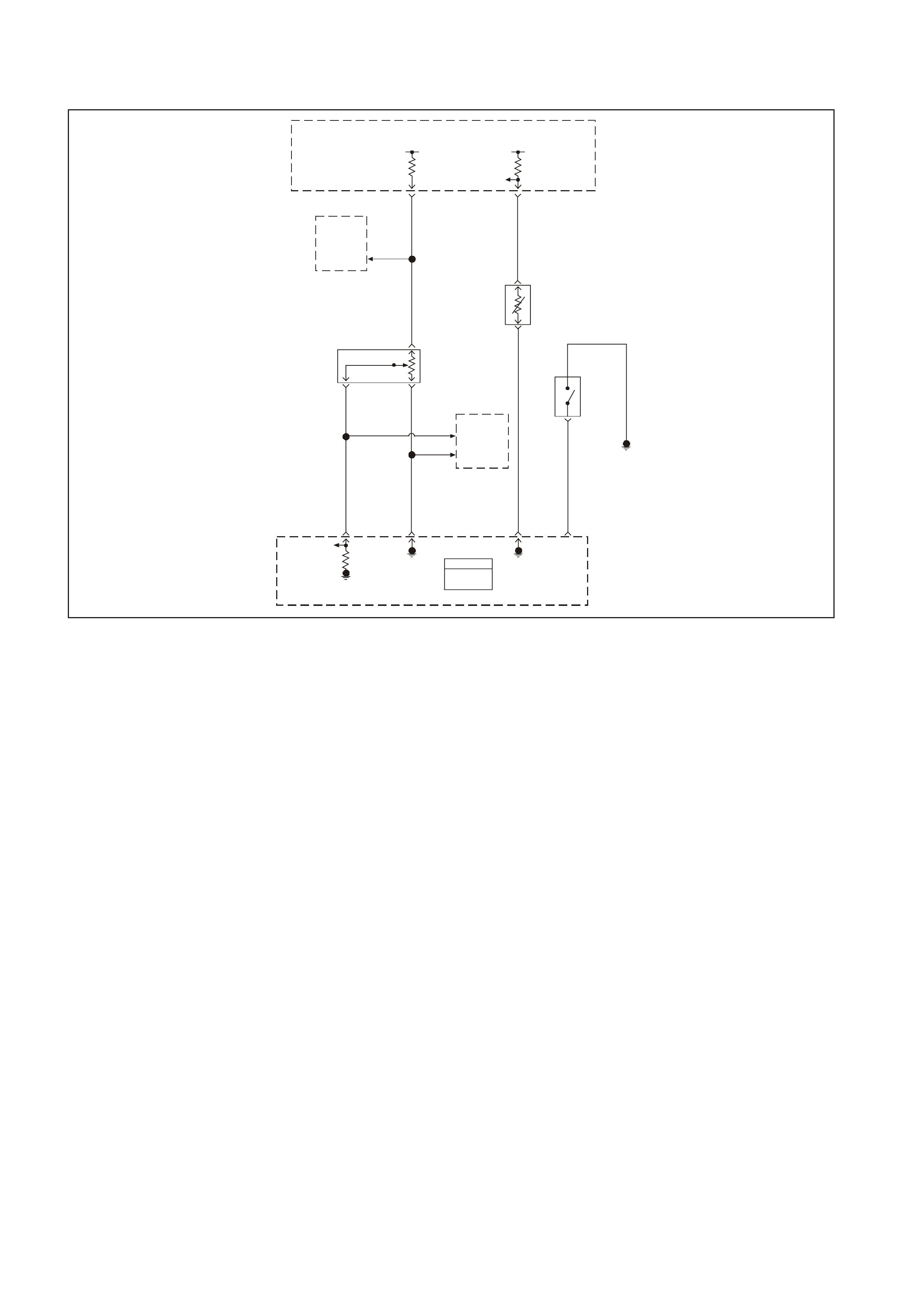
GEN III V8 PCM DTC P0118 ENGINE COOLANT
TEMPERATURE SENSOR CIRCUIT HIGH VOLTAGE
GEN3 0156
PCM
J1 = B LUE
J2 = RE D
Powertrain
Control
Module
(PCM)
Powertrain
Control
Module
(PCM)
5V 5V
ECT
Sensor
Signal
TP Sensor
5V
Reference
Throttle
Relaxer
Control
Module
Engine Coolant
Temperature
(ECT)
Sensor
Throttle
Position
(TP)
Sensor Coolant
Level
Switch
Engine
Earth
TP
Sensor
Signal
Sensor
Earth
ECT
Sensor
Earth
Coolant
Level
Switch
Input
08 74 J1
Y410
B
A
B/R 750
G69
30 J1
GY/B 455
80 J1
B/Y 452
60
BLU 417
24 J2
B/Y 452
BLU 417
CB
40
43
GY 416
GY 416
A
GY
416
41
Throttle
Relaxer
Control
Module
J1
J1
CIRCUIT DESCRIPTION
The Engine Coolant Temperature(ECT) sensor contains a semiconductor device which changes the resistance
based on the tem per ature ( a thermis tor) . The ECT sens or is mounted in the lef t bank cylinder head near the front of
the engine. The ECT sensor has a signal circuit and a ear th circuit. T he PCM applies a voltage (about 5.0 volts) on
the signal circuit to the s ensor. T he PCM monitors the changes in this voltage caused by changes in the resistance
of the sensor in order to determine the coolant temperature.
When the coolant is c old, the sens or (ther m istor) r esistanc e is high. T he PCMs s ignal voltage is only pulled down a
small amount through the sensor to an earth; therefore, the PCM senses a high signal voltage (low temperature).
When the coolant is warm, the sensor resistance is low. The signal voltage is pulled down a greater amount;
therefore the PCM senses a low signal voltage (high temperature). At normal operating temperature, the voltage
should measure about 1.5-2.0 volts at the PCM.
When the PCM senses a signal voltage higher than the normal operating range of the sensor, this DTC will set.
CONDITIONS FOR RUNNING THE DTC
• The engine run time is greater than 10 seconds.
CONDITIONS FOR SETTING THE DTC
• The engine coolant temperature is at or below -38.9 C (-38°F).
• All conditions met for 20.0 seconds.
ACTION TAKEN WHEN THE DTC SETS
• The PCM illuminates the Check Powertrain Lamp (CPL) when the diagnostic runs and fails.
• T he PCM records the operating conditions at the time the diagnostic f ails. The PCM stores this information in
the Freeze Frame/Failure Records.

CONDITIONS FOR CLEARING THE CPL/DTC
• The PCM turns the CPL OFF after three consecutive ignition cycles that the diagnostic runs and does not fail.
• A last test failed (current DTC) clears when the diagnostic runs and does not fail.
• A History DTC clears after forty consecutive warm-up cycles, if this or any other emission related diagnostic
does not report any failure.
• Use a Tech 2 scan tool in order to clear the CPL/DTC.
DIAGNOSTIC AIDS
• The following may cause an intermittent:
- Incorrectly routed harness
- Rubbed through wire insulation
- Broken wire inside the insulation
• If the engine has sat overnight, the engine coolant temperature and the engine intake air temperature values
should display within a few degrees of each other. If the temperatures are not within 3°C (5°F), refer to Section
6C3-4 SPECIFICATIONS Temperature vs. Resistance in this Service Information CD.
• If you determine that the DTC occurs intermittently, performing the P1111 diagnostic table may isolate the
cause of the fault.
• For intermittent, refer to Section 6C3-2B SYMPTOMS in this Service Information CD.
TEST DESCRIPTION
The numbers below refer to the step numbers on the diagnostic table.
2. This step determines if the malfunction is present. For any test that requires probing the PCM or component
harness connectors, use the Connector Test adaptor Kit J 35616-A. Using this k it will prevent any damage to
the harness connector terminals.
3. Using the Freeze Frame/Failure Records data may aid in locating an intermittent condition. If you cannot
duplicate the DT C, the information inc luded in the Freeze Frame/Failure Records data can help determine the
distance traveled since the DTC set. The Fail Counter and Pass Counter can also help determine how many
ignition cycles the diagnostic reported a pass and/or fail. Operate the vehicle with the same freeze frame
conditions (RPM, load, vehicle speed, temperature, etc.) that you observed. This will isolate when the DTC
failed. For any test that requires probing the PCM or com ponent harness connectors, use the Connector Test
adaptor Kit J 35616-A. Using this kit will prevent any damage to the harness connector terminals.
4. An engine coolant temperature above 140°C (284°F) indicates the PCM and IAT wiring are OK.
5. An engine coolant temperature above 140°C (284°F) indicates the PCM and IAT wiring are OK.
6. Dis connecting the PCM allows using the DMM J 39200 in order to check continuity of the circuits. T his aids in
locating an open or a shorted circuit.
8. Dis connecting the PCM allows using the DMM J 39200 in order to check continuity of the circuits. T his aids in
locating an open or a shorted circuit.
12. Inspect for proper terminal tension/connections at the PCM harness before replacing the PCM.GEN III V8 PCM

GEN III V8 PCM DTC P0118 ENGINE COOLANT TEMPERATURE SENSOR CIRCUIT HIGH VOLTAGE
Step Action Value(s) Yes No
1 Did you perform the Powertrain On-Board Diagnostic
(OBD) System Check? Go to Step 2 Go to Powertrain
OBD System
Check Table
2
1. Install a Tech 2 scan tool.
2. Idle the engine.
3. Monitor the ECT display on the Engine Data List of
the Tech 2 scan tool.
Is the ECT at or above the specified value?
-38.9°C
(-32.2°F) Go to Step 4 Go to Step 3
3 1. Turn ON the ignition leaving the engine OFF.
2. Review the Freeze Frame/Failure Records data for
this DTC and observe the parameters.
3. Turn OFF the ignition for 15 seconds.
4. Start the engine.
5. Operate the vehicle within the conditions required for
this diagnostic to run, and as close to the conditions
recorded in the Freeze Frame/Failure Records as
possible. Special operating conditions that you need
to meet before the PCM will run this diagnostic,
where applicable, are listed in Conditions for
Running the DTC.
6. Select the Diagnostic Trouble Code (DTC) option,
the DTC Information option and The Failed This
Ignition option using the Tech 2 scan tool.
Does the Tech 2 scan tool indicate that this diagnostic
failed this ignition?
Go to Step 4 Go to Diagnostic
Aids
4 1. Disconnect the ECT sensor electrical connector.
2. Jumper the ECT sensor harness terminals together.
3. Observe the ECT parameter on the Tech 2 scan
tool.
Is the ECT at the specified value?
140°C
(284°F) Go to Step 9 Go to Step 5
5 Jumper the ECT sensor signal circuit to a known good
earth.
Is the ECT sensors at the specified value?
140°C
(284°F) Go to Step 8 Go to Step 6
6 1. Turn OFF the ignition.
2. Disconnect the PCM BLUE connector.
3. Check the ECT signal circuit for a short to a earth.
Is the ECT signal circuit earthed?
Go to Step 7 Go to Step 11
7 Repair the ECT sensor signal circuit.
Is the action complete? Go to Step 14
8 1. Turn OFF the ignition.
2. Disconnect the PCM connectors.
3. Check the ECT sensor earth circuit for an open.
Was a problem found?
Go to Step 10 Go to Step 11
9 Replace the ECT sensor. Refer to Section 6C3-3 ECT
Sensor Replacement in this Service Information CD.
Is the action complete?
Go to Step 14
10 Repair the ECT sensor earth circuit.
Is the action complete? Go to Step 14
11 Check for a short to voltage on the signal circuit.
Did you find and correct the condition? Go to Step 14 Go to Step 12
12 Check for faulty connections at The PCM.
Did you find and correct the condition? Go to Step 14 Go to Step 13

Step Action Value(s) Yes No
13 1. Replace PCM.
2. Refer to Section 6C3-3 in this Service Information
CD for PCM Programming and PCM/PIM/BCM
Security Link Procedure.
Is action complete?
Go to Step 14
14 1. Select the Diagnostic Trouble Code (DTC) option
and the Clear DTC Information option using the Tech
2 scan tool.
2. Idle the engine at the normal operating temperature.
3. Select the Diagnostic Trouble Code (DTC) option,
the DTC Information option and The Failed This
Ignition option using the Tech 2 scan tool.
4. Operate the vehicle within the Conditions for
Running the DTC as specified in the supporting text,
if applicable.
Does the Tech 2 scan tool indicate that this DTC reset?
Go to Step 2 Go to Step 15
15 Using the Tech 2 scan tool, check for any other DTCs.
Does the Tech 2 scan tool display any DTCs that you
have not diagnosed?
Go to the
applicable DTC
table
System OK

GEN III V8 PCM DTC P0121 THROTTLE POSITION
SENSOR CIRCUIT INSUFFICIENT ACTIVITY
GEN3 0156
PCM
J1 = B LUE
J2 = RE D
Powertrain
Control
Module
(PCM)
Powertrain
Control
Module
(PCM)
5V 5V
ECT
Sensor
Signal
TP Sensor
5V
Reference
Throttle
Relaxer
Control
Module
Engine Coolant
Temperature
(ECT)
Sensor
Throttle
Position
(TP)
Sensor Coolant
Level
Switch
Engine
Earth
TP
Sensor
Signal
Sensor
Earth
ECT
Sensor
Earth
Coolant
Level
Switch
Input
08 74 J1
Y410
B
A
B/R 750
G69
30 J1
GY/B 455
80 J1
B/Y 452
60
BLU 417
24 J2
B/Y 452
BLU 417
CB
40
43
GY 416
GY 416
A
GY
416
41
Throttle
Relaxer
Control
Module
J1
J1
CIRCUIT DESCRIPTION
The T hrottle Position (T P) sensor is a potentiom eter. The T P sensor is mounted to the left side of the throttle body.
The TP sensor provides a voltage signal that changes relative to throttle blade angle. This signal voltage is one of
the most important inputs used by the PCM. The TP sensor has a 5.0 volt reference, an earth and a signal circuit.
TP sens or Signal voltage should be about 0.6 volt at idle. T he T P sensor voltage should increase to above 4.0 volts
at wide open throttle (WOT).
This diagnostic compares actual throttle position from the TP sensor to a predicted throttle position value. The
predicted throttle pos ition is calc ulated f r om engine speed and other inputs . If the PCM detects the predicted throttle
position is below the actual TP sensor value, this DTC will set.
CONDITIONS FOR RUNNING THE DTC
• No MAP sensor or TP sensor DTCs set.
• The engine run time is greater than 10 seconds.
• The engine coolant temperature is greater than 0°C (32°F).
• The IAC is between 0 and 255 counts.
• The MAP is less than 55 kPa.
OR
• The MAP is greater than 65 kPa.
• MAP steady.
CONDITIONS OF SETTING THE DTC
• The predicted throttle angle does not match the actual throttle angle.
• All conditions present for 20 seconds.
ACTION TAKEN WHEN THE DTC SETS
• The PCM illuminates the Check Powertrain Lamp (CPL) when the diagnostic runs and fails.
• T he PCM records the operating conditions at the time the diagnostic f ails. The PCM stores this information in
the Freeze Frame/Failure Records.

CONDITIONS FOR CLEARING THE CPL/DTC
• The PCM turns the CPL OFF after the first ignition cycle that the diagnostic runs and does not fail.
• A last test failed (current DTC) clears when the diagnostic runs and does not fail.
• A History DTC clears after forty consecutive warm-up cycles, if this or any other emission related diagnostic
does not report any failure.
• Use a Tech 2 scan tool in order to clear the CPL/DTC.
DIAGNOSTIC AIDS
• The following may cause an intermittent:
- Incorrectly routed harness
- Rubbed through wire insulation
- Broken wire inside the insulation
• The PCM 5.0 volt reference circuits are internally connected within the PCM. If all the TP sensor circuits are
OK, inspect the Fuel Tank Pressure Sensor for malfunctions.
• If it is determined that the DTC occurs intermittently, performing the DTC P1121 diagnostic table may isolate
the cause of the fault.
• For intermittent, refer to Section 6C3-2B SYMPTOMS in this Service Information CD.
TEST DESCRIPTION
The numbers below refer to the step numbers on the diagnostic table.
2. If DTC P1635 sets at the same time, this indicates that the 5.0 volt reference circuit is either shorted to an
earth or shorted to a voltage. The 5.0 volt reference circuit is internally connected within the PCM.
3. The MAP value should change with the engine speed. If a MAP sensor voltage changes, there is no
malfunction with the MAP sensor.
4. This step checks for an intermittent connection at the sensor.
8. If the TP sensor voltage changes, there is no malfunction with the TP sensor wiring or the PCM.
9. Using Freeze Fram e/Failure Records data may aid in locating an interm ittent condition. If you cannot duplicate
the DTC, the inform ation included in the Freeze Frame/Failure Records data can help determ ine the distance
traveled since the DTC set. The Fail Counter and Pass Counter can also help determine how many ignition
cycles the diagnostic reported a pass and/or a fail. Operate vehicle within the same freeze frame conditions
(RPM, load, vehicle speed, temperature etc.) that you observed. This will isolate when the DTC f ailed. For an
intermittent condition, refer to Section 6C3-2B SYMPTOMS in this Service Information CD.
11. This checks the 5.0 volt reference circuit, signal circuit, and the PCM. If the Tech 2 scan tool displayed 5.0
volts, the TP sensor circuits are OK.

GEN III V8 PCM DTC P0121 THROTTLE POSITION SENSOR CIRCUIT INSUFFICIENT ACTIVITY
Step Action Value(s) Yes No
1 Did you perform the Powertrain On-Board Diagnostic
(OBD) System Check? Go to Step 2 Go to Powertrain
OBD System
Check Table
2
1. Install a Tech 2 scan tool.
2. Idle the engine.
3. Monitor the Failed This Ignition option under the
DTC Information option using the Tech 2 scan tool.
Did the DTC P1635 fail this ignition?
Go to DTC
P1635 5 Volt
Reference Circuit
Go to Step 3
3 1. Start the engine.
2. Monitor the MAP sensor voltage.
3. Increase the engine speed to the specified value.
Does the MAP sensor voltage change when the engine
speed changed?
2000 RPM Go to Step 8 Go to Step 4
4 1. Turn ON the ignition leaving the engine OFF.
2. Move the MAP sensor electrical connector, the
harness and the PCM connectors (by hand only)
while observing the Tech 2 scan tool display.
Is the MAP value affected by moving the harness or
connectors?
Go to Step 16 Go to Step 5
5 1. Remove the MAP sensor from the intake manifold
but leave the electrical harness connected.
2. Connect a hand operated vacuum pump to the MAP
sensor.
3. Observe the MAP display while slowly applying
vacuum up to 20 inches Hg as indicated on the
pump gauge. Each 1 inch of vacuum applied should
result in a 3 to 4 kPa drop in the MAP sensor valve
on the scan tool and the value should change
smoothly with each increase in the vacuum.
Did the MAP value change smoothly through the entire
range of the test without an erratic readiness.?
Go to Step 6 Go to Step 17
6 Apply 20 inches Hg vacuum to the MAP sensor.
Is the MAP sensor reading the same or less than the
specified value?
34 kPa Go to Step 7 Go to Step 17
7 Disconnect the vacuum source from the MAP sensor.
Does the MAP sensor reading return to its original value? Go to Step 8 Go to Step 17
8 1. Turn ON the ignition leaving the engine OFF.
2. Monitor the TP sensor voltage while moving the
accelerator pedal from the closed throttle to a wide
open throttle.
Does the TP sensor voltage go from below the specified
value to above the specified value?
Below 1.0V
to above
4.0V
Go to Step 9 Go to Step 10
9 1. Turn ON the ignition leaving the engine OFF.
2. Review the Freeze Frame/Failure Records data for
this DTC and record the parameters.
3. Turn OFF the ignition for 15 seconds.
4. Start the engine.
5. Operate the vehicle within the conditions required for
this diagnostic to run, and as close to the conditions
recorded in Freeze Frame/Failure Records as
possible. Special operating conditions that you need
meet before the PCM will run this diagnostic, where
applicable, are listed in Conditions for Running the
DTC.
6. Select the Diagnostic Trouble Code (DTC) option,
the DTC Information option and The Failed This
Ignition option using the Tech 2 scan tool.
Does the Tech 2 scan tool indicate that this diagnostic
failed this ignition?
Go to Step 10 Go to Diagnostic
Aids

Step Action Value(s) Yes No
10 1. Disconnect the TP sensor.
2. Observe the TP sensor display on the Tech 2 scan
tool.
Is the TP sensor voltage near the specified value?
0.0V Go to Step 11 Go to Step 13
11 Jump the TP sensor 5.0 volt reference circuit to the TP
sensor signal circuit using a fused jumper wire.
Is the TP sensor voltage near the specified value?
5.0V Go to Step 12 Go to Step 14
12 Replace the TP sensor, refer to Section 6C3-3 TP
Sensor Replacement in this Service Information CD.
Is the action complete?
Go to Step 18
13 Check for the following conditions:
• TP signal circuit for a short to voltage.
• TP sensor earth circuit for high resistance between
the PCM and the TP sensor.
• TP sensor earth circuit for a poor connection.
If you find a problem, repair the wiring harness as
necessary.
Did you find and correct the condition?
Go to Step 18 Go to Step 15
14 Check for the following conditions:
• TP signal circuit or 5 volt reference circuit for a poor
connection.
• TP signal circuit or 5 volt reference circuit for high
resistance between the PCM and the TP sensor.
If you find a problem, repair the wiring harness as
necessary.
Did you find and correct the condition?
Go to Step 18 Go to Step 15
15 1. Replace PCM.
2. Refer to Section 6C3-3 in this Service Information
CD for PCM Programming and PCM/PIM/BCM
Security Link Procedure.
Is action complete?
Go to Step 18
16 Locate and repair the affected circuit.
Is the action complete? Go to Step 18
17 Replace the MAP sensor. Refer to Section 6C3-3 MAP
Sensor Replacement in this Service Information CD.
Is the action complete?
Go to Step 18
18 1. Select the Diagnostic Trouble Code (DTC) option
and the Clear DTC Information option using the Tech
2 scan tool.
2. Idle the engine at the normal operating temperature.
3. Select the Diagnostic Trouble Code (DTC) option
and the Specified DTC option, then enter the DTC
number using the Tech 2 scan tool.
4. Operate the vehicle within the Conditions for
Running the DTC as specified in the supporting text,
if applicable.
Does the Tech 2 scan tool indicate that this test reset?
Go to Step 2 Go to Step 19
19 Using the Tech 2 scan tool, check for any other DTCs
Does the Tech 2 scan tool display any DTCs that you
have not diagnosed?
Go to the
applicable DTC
table
System OK
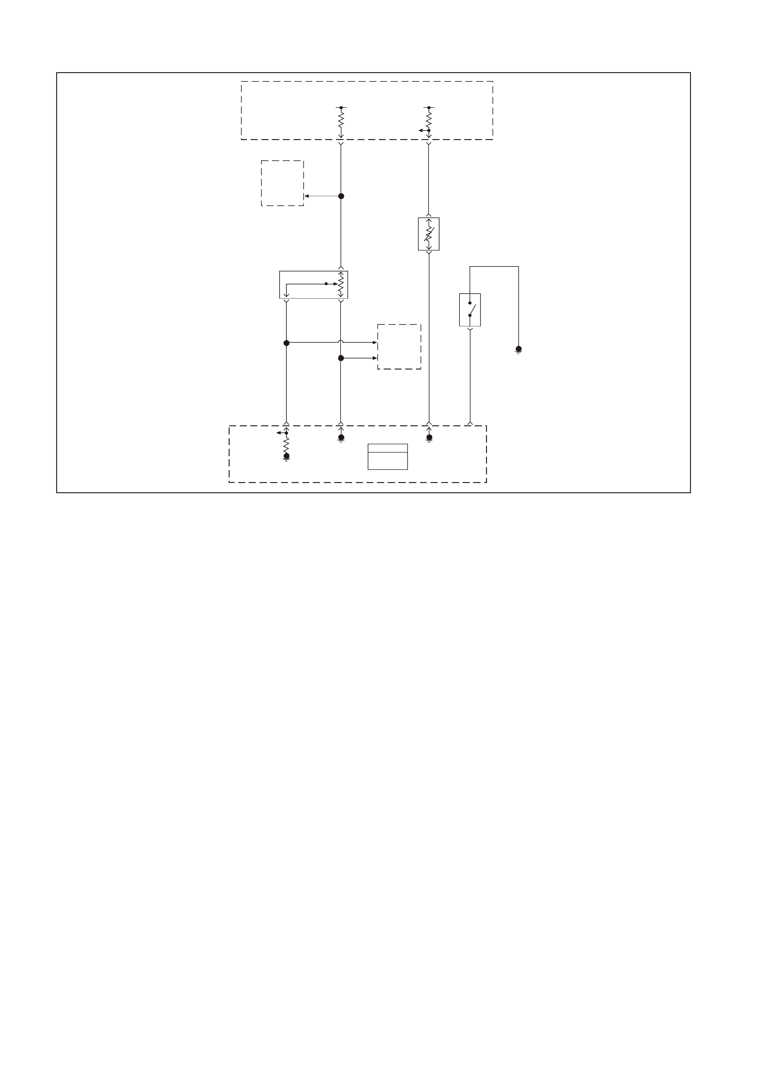
GEN III V8 PCM DTC P0122 THROTTLE POSITION SENSOR CIRCUIT LOW VOLTAGE
GEN3 0156
PCM
J1 = B LUE
J2 = RE D
Powertrain
Control
Module
(PCM)
Powertrain
Control
Module
(PCM)
5V 5V
ECT
Sensor
Signal
TP Sensor
5V
Reference
Throttle
Relaxer
Control
Module
Engine Coolant
Temperature
(ECT)
Sensor
Throttle
Position
(TP)
Sensor Coolant
Level
Switch
Engine
Earth
TP
Sensor
Signal
Sensor
Earth
ECT
Sensor
Earth
Coolant
Level
Switch
Input
08 74 J1
Y410
B
A
B/R 750
G69
30 J1
GY/B 455
80 J1
B/Y 452
60
BLU 417
24 J2
B/Y 452
BLU 417
CB
40
43
GY 416
GY 416
A
GY
416
41
Throttle
Relaxer
Control
Module
J1
J1
CIRCUIT DESCRIPTION
The T hrottle Position (T P) sensor is a potentiom eter. The T P sensor is mounted to the left side of the throttle body.
The TP sensor provides a voltage signal that changes relative to throttle blade angle. This signal voltage is one of
the most important inputs used by the PCM. The TP sensor has a 5.0 volt reference, an earth and a signal circuit.
TP sens or Signal voltage should be about 0.6 volt at idle. T he T P sensor voltage should increase to above 4.0 volts
at wide open throttle (WOT).
When the PCM senses a signal voltage lower than the normal operating range of the sensor, this DTC will set.
CONDITIONS FOR RUNNING THE DTC
• The ignition switch is in the ON position or the engine is operating.
CONDITIONS OF SETTING THE DTC
• The TP sensor signal voltage is less than 0.2 volts.
• The above conditions present for 10.0 seconds.
ACTION TAKEN WHEN THE DTC SETS
• The PCM illuminates the Check Powertrain Lamp (CPL) when the diagnostic runs and fails.
• T he PCM records the operating conditions at the time the diagnostic f ails. The PCM stores this information in
the Freeze Frame/Failure Records.
• The PCM uses a default TP sensor value.
• The Transmission TCC will not apply.
• High transmission line pressure.
• Fixed transmission shift points, hard shifts and no fourth gear in hot mode.
CONDITIONS FOR CLEARING THE CPL/DTC
• The PCM turns the CPL OFF after the first ignition cycle that the diagnostic runs and does not fail.
• A last test failed (current DTC) clears when the diagnostic runs and does not fail.
• A History DTC clears after forty consecutive warm-up cycles, if this or any other emission related diagnostic
does not report any failure.
• Use a Tech 2 scan tool in order to clear the CPL/DTC.

DIAGNOSTIC AIDS
• The following may cause an intermittent:
- Incorrectly routed harness
- Rubbed through wire insulation
- Broken wire inside the insulation
• The PCM 5.0 volt reference circuits are internally connected within the PCM. If all the TP sensor circuits are
OK, inspect the Fuel Tank Pressure Sensor for malfunctions.
• If it is determined that the DTC occurs intermittently, performing the DTC P1121 diagnostic table may isolate
the cause of the fault.
• For intermittent, refer to Section 6C3-2B SYMPTOMS in this Service Information CD.
TEST DESCRIPTION
The numbers below refer to the step numbers on the diagnostic table.
2. If DT C P1635 sets at the s am e tim e, this indic ates that the 5.0 volt ref erence c ircuit is either shorted to a ear th
or shorted to a voltage. The 5.0 volt reference circuit is internally connected within the PCM.
3. This step verifies that a malfunction is present.
4. Using Freeze Fram e/Failure Records data may aid in locating an interm ittent condition. If you cannot duplicate
the DTC, the inform ation included in the Freeze Frame/Failure Records data can help determ ine the distance
traveled since the DTC set. The Fail Counter and Pass Counter can also help determine how many ignition
cycles the diagnostic reported a pass and/or a fail. Operate vehicle within the same freeze frame conditions
(RPM, load, vehicle speed, temperature etc.) that you observed. This will isolate when the DTC f ailed. For an
intermittent condition, refer to Section 6C3-2B SYMPTOMS in this Service Information CD.
5. This determines if the short is caused from the ABS/ETC Control Module. After repairs are made, reconnect
the ABS/ETC Control Module and clear any DTCs that set when the ABS/ETC Control Module was
disconnected.
6. If the Tech 2 scan tool indicates 5.0 volts, the TP sensor circuits and PCM are OK.
7. Disconnecting the PCM will allow using the DMM J 39200 to check continuity of the circuits. This will aid in
locating an open or shorted circuit.
8. Disconnecting the PCM will allow using the DMM J 39200 to check continuity of the circuits. This will aid in
locating an open or shorted circuit.
10. Disconnecting the PCM will allow using the DMM J 39200 to check continuity of the circuits. This will aid in
locating an open or shorted circuit.

GEN III V8 PCM DTC P0122 THROTTLE POSITION SENSOR CIRCUIT LOW VOLTAGE
Step Action Value(s) Yes No
1 Did you perform the Powertrain On-Board Diagnostic
(OBD) System Check? Go to Step 2 Go to Powertrain
OBD System
Check Table
2
1. Install a Tech 2 scan tool.
2. Idle the engine.
3. Monitor the ECT display on the Engine Data List of
the Tech 2 scan tool.
Did the DTC P1635 fail this ignition?
Go to DTC
P1635
5 Volt Reference
Circuit Table
Go to Step 3
3 1. Turn ON the ignition leaving the engine OFF.
2. With the throttle closed, monitor the TP sensor
display on the Tech 2 scan tool.
Is the TP sensor voltage below the specified value?
0.2V Go to Step 5 Go to Step 4
4 1. Turn ON the ignition leaving the engine OFF.
2. Review the Freeze Frame/Failure Records data for
this DTC and record the parameters.
3. Turn OFF the ignition for 15 seconds.
4. Start the engine.
5. Operate the vehicle within the conditions required for
this diagnostic to run, and as close to the conditions
recorded in Freeze Frame/Failure Records as
possible. Special operating conditions that you need
meet before the PCM will run this diagnostic, where
applicable, are listed in Conditions for Running the
DTC.
6. Select the Diagnostic Trouble Code (DTC) option,
the DTC Information option and The Failed This
Ignition option using the Tech 2 scan tool.
Does the Tech 2 scan tool indicate that this diagnostic
failed this ignition?
Go to Step 5 Go to Diagnostic
Aids
5 Important: After you complete this diagnosis reconnect
the ABS/ETC Control Module. Also, clear the ABS/ETC
Control Module DTCs that set when the ABS/ETC
Control Module was disconnected.
1. Turn OFF the ignition.
2. Disconnect the Electronic Traction Control Module.
3. Turn ON the ignition.
Is the TP sensor signal voltage still below the specified
value?
0.2V Go to Step 6 Go to Section
12L of the VT
Series II Service
Information for
further diagnosis
of the ABS/ETC
Control Module
6 1. Disconnect the TP sensor electrical connector.
2. Jumper the 5.0 volt reference circuit and the TP
signal circuit together at the TP sensor harness
connector.
3. Observe the TP sensor voltage display on the scan
tool.
Is the TP sensor voltage above the specified value?
4.7V Go to Step 12 Go to Step 7
7 1. Connect the test lamp J 34142-B between B+ and
the TP sensor signal circuit at the TP sensor
harness connector.
2. Observe the TP sensor voltage display on the scan
tool
Is the TP sensor voltage above the specified value?
4.7V Go to Step 8 Go to Step 10
8 1. Turn OFF the ignition.
2. Disconnect the PCM BLUE connector.
3. Check the 5.0 volt reference circuit for an open or
short to earth.
4. If the 5.0 volt reference circuit is open or shorted to
earth, repair the circuit as necessary.
Did you find and correct the condition?
Go to Step 14 Go to Step 9

Step Action Value(s) Yes No
9 1. Check the 5.0 volt reference circuit for a poor
connection at the PCM.
2. If you find a poor connection replace the terminal as
necessary.
Did you find and correct the condition?
Go to Step 14 Go to Step 13
10 1. Turn OFF the ignition.
2. Disconnect the PCM RED connector.
3. Check for a short to voltage, open, or short to earth
on the TP sensor signal circuit; also check for a
short circuit between the TP sensor signal circuit and
the ABS/ETC Control Module.
4. If you find the TP sensor signal circuit is open or
shorted, repair the circuit as necessary.
Did you find and correct the condition?
Go to Step 14 Go to Step 11
11 1. Check the 5.0 volt reference circuit for a poor
connection at the PCM.
2. If you find a poor connection replace the terminal as
necessary.
Did you find and correct the condition?
Go to Step 14 Go to Step 13
12 Replace the TP sensor. Refer to Section 6C3-3 TP
Sensor Replacement in this Service Information CD.
Is the action complete?
Go to Step 14
13 1. Replace PCM.
2. Refer to Section 6C3-3 in this Service Information
CD for PCM Programming and PCM/PIM/BCM
Security Link Procedure.
Is action complete?
Go to Step 14
14 1. Select the Diagnostic Trouble Code (DTC) option
and the Clear DTC Information option using the Tech
2 scan tool.
2. Idle the engine at the normal operating temperature.
3. Select the Diagnostic Trouble Code (DTC) option,
the DTC Information option and The Failed This
Ignition option using the Tech 2 scan tool.
4. Operate the vehicle within the Conditions for
Running the DTC as specified in the supporting text,
if applicable.
Does the Tech 2 scan tool indicate that this DTC reset?
Go to Step 2 Go to Step 15
15 Using the Tech 2 scan tool, check for any other DTCs.
Does the Tech 2 scan tool display any DTCs that you
have not diagnosed?
Go to the
applicable DTC
table
System OK
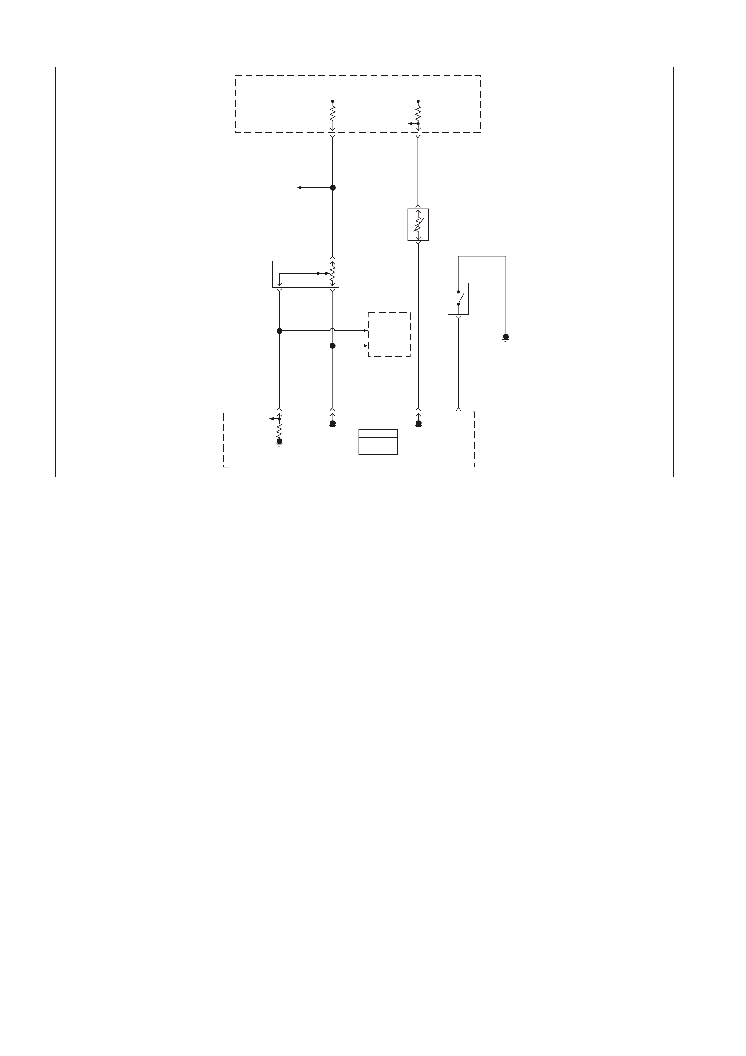
GEN III V8 PCM DTC P0123 THROTTLE POSITION SENSOR CIRCUIT HIGH VOLTAGE
GEN3 0156
PCM
J1 = B LUE
J2 = RE D
Powertrain
Control
Module
(PCM)
Powertrain
Control
Module
(PCM)
5V 5V
ECT
Sensor
Signal
TP Sensor
5V
Reference
Throttle
Relaxer
Control
Module
Engine Coolant
Temperature
(ECT)
Sensor
Throttle
Position
(TP)
Sensor Coolant
Level
Switch
Engine
Earth
TP
Sensor
Signal
Sensor
Earth
ECT
Sensor
Earth
Coolant
Level
Switch
Input
08 74 J1
Y410
B
A
B/R 750
G69
30 J1
GY/B 455
80 J1
B/Y 452
60
BLU 417
24 J2
B/Y 452
BLU 417
CB
40
43
GY 416
GY 416
A
GY
416
41
Throttle
Relaxer
Control
Module
J1
J1
CIRCUIT DESCRIPTION
The T hrottle Position (T P) sensor is a potentiom eter. The T P sensor is mounted to the left side of the throttle body.
The TP sensor provides a voltage signal that changes relative to throttle blade angle. This signal voltage is one of
the most important inputs used by the PCM. The TP sensor has a 5.0 volt reference, an earth and a signal circuit.
TP sens or Signal voltage should be about 0.6 volt at idle. T he T P sensor voltage should increase to above 4.0 volts
at wide open throttle (WOT).
When the PCM senses a signal voltage higher than the normal operating range of the sensor, this DTC will set.
CONDITIONS FOR RUNNING THE DTC
• The ignition switch is in the ON position or the engine is operating.
CONDITIONS OF SETTING THE DTC
• The TP sensor signal voltage is greater than 4.8 volts.
• Conditions present for 10.0 seconds.
ACTION TAKEN WHEN THE DTC SETS
• The PCM illuminates the Check Powertrain Lamp (CPL) when the diagnostic runs and fails.
• T he PCM records the operating conditions at the time the diagnostic f ails. The PCM stores this information in
the Freeze Frame/Failure Records.
• The PCM uses a default TP sensor value.
• The Transmission TCC will not apply.
• High transmission line pressure.
• Fixed transmission shift points, hard shifts and no fourth gear in hot mode.
CONDITIONS FOR CLEARING THE CPL/DTC
• The PCM turns the CPL OFF after the first ignition cycle that the diagnostic runs and does not fail.
• A last test failed (current DTC) clears when the diagnostic runs and does not fail.
• A History DTC clears after forty consecutive warm-up cycles, if this or any other emission related diagnostic
does not report any failure.
• Use a Tech 2 scan tool in order to clear the CPL/DTC.

DIAGNOSTIC AIDS
• The following may cause an intermittent:
- Incorrectly routed harness
- Rubbed through wire insulation
- Broken wire inside the insulation
• The PCM 5.0 volt reference circuits are internally connected within the PCM. If all the TP sensor circuits are
OK, inspect the Fuel Tank Pressure Sensor for malfunctions.
• If it is determined that the DTC occurs intermittently, performing the DTC P1121 diagnostic table may isolate
the cause of the fault.
• For intermittent, refer to Section 6C3-2B SYMPTOMS in this Service Information CD.
TEST DESCRIPTION
The numbers below refer to the step numbers on the diagnostic table.
2. If DT C P1635 sets at the s am e tim e, this indic ates that the 5.0 volt ref erence c ircuit is either shorted to a ear th
or shorted to a voltage. The 5.0 volt reference circuit is internally connected within the PCM.
3. This step verifies that a malfunction is present.
4. Using Freeze Fram e/Failure Records data may aid in locating an interm ittent condition. If you cannot duplicate
the DTC, the inform ation included in the Freeze Frame/Failure Records data can help determ ine the distance
traveled since the DTC set.
T he Fail Counter and Pass Counter can also help determ ine how many ignition cycles the diagnostic repor ted
a pass and/or a fail. Operate vehicle within the same freeze frame conditions (RPM, load, vehicle speed,
temperature etc.) that you observed. This will isolate when the DTC failed. For an intermittent condition, refer to
Section 6C3-2B SYMPTOMS in this Service Information CD.
5. Vehicle equipped with Electronic Traction Control will have to disconnect the ABS/ETC Control Module. This
will determ ine if the short is c aused from the ABS/ETC Control Module. Af ter repairs are m ade, reconnect the
ABS/ETC Control Module and clear the DTCs that set when the ABS/ETC Control Module was disconnected.
7. T his chec ks whether the ear th cir cuit is available to the TP sens or. Chec k for poor elec tr ical c onnec tions at the
TP sensor.

GEN III V8 PCM DTC P0123 THROTTLE POSITION SENSOR CIRCUIT HIGH VOLTAGE
Step Action Value(s) Yes No
1 Did you perform the Powertrain On-Board Diagnostic
(OBD) System Check? Go to Step 2 Go to Powertrain
OBD System
Check Table
2
1. Install a Tech 2 scan tool.
2. Idle the engine.
3. Monitor the Failed This Ignition option under the
DTC Information option using the Tech 2 scan tool.
Did the DTC P1635 fail this ignition?
Go to DTC
P1635
5 Volt Reference
Circuit Table
Go to Step 3
3 1. Turn ON the ignition leaving the engine OFF.
2. With the throttle closed, observe the TP sensor
voltage and percentage display on the Tech 2 scan
tool.
Is the TP sensor voltage or the Throttle Angle above the
specified value?
4.7V, 0% Go to Step 5 Go to Step 4
4 1. Turn ON the ignition leaving the engine OFF.
2. Review the Freeze Frame/Failure Records data for
this DTC and record the parameters.
3. Turn OFF the ignition for 15 seconds.
4. Start the engine.
5. Operate the vehicle within the conditions required for
this diagnostic to run, and as close to the conditions
recorded in Freeze Frame/Failure Records as
possible. Special operating conditions that you need
meet before the PCM will run this diagnostic, where
applicable, are listed in Conditions for Running the
DTC.
6. Select the Diagnostic Trouble Code (DTC) option,
the DTC Information option, The Failed This Ignition
option using the Tech 2 scan tool.
Does the Tech 2 scan tool indicate that this diagnostic
failed this ignition?
Go to Step 5 Go to Diagnostic
Aids
5 1. Turn OFF the ignition.
2. Disconnect the Traction Control Module.
3. Turn ON the ignition
Is the TP sensor voltage above the specified value?
4.7V Go to Step 6 Go to Section
12L of the VT
Series II Service
Information for
further diagnosis
of the ABS/ETC
Control Module
6 1. Disconnect the TP sensor electrical connector.
2. Observe the TP sensor voltage display on the scan
tool.
Is the TP sensor voltage below the specified value?
0.20V Go to Step 7 Go to Step 10
7 Probe the sensor earth circuit at the TP sensor harness
connector with a test lamp J 34142-B connected to B+.
Does the test lamp illuminate?
Go to Step 8 Go to Step 11
8 Measure the voltage at the 5.0 volt reference circuit to
earth using the DMM J39200.
Is the voltage greater than the specified value?
5.0V Go to Step 14 Go to Step 9
9 Replace the TP sensor. Refer to Section 6C3-3 TP
Sensor Replacement in this Service Information CD.
Is the action complete?
Go to Step 15
10 1. Turn OFF the ignition.
2. Disconnect the PCM connectors.
3. Check for a short to voltage on the TP sensor signal
circuit; also check for a short circuit between the TP
sensor signal circuit and the ABS/ETC Control
Module.
4. If you find the TP sensor signal circuit shorted, repair
the circuit as necessary.
Did you find and correct the condition?
Go to Step 15 Go to Step 13

Step Action Value(s) Yes No
11 1. Check for an open TP sensor earth circuit.
2. If you find TP sensor earth circuit open, repair the
circuit as necessary.
Did you find and correct the condition?
Go to Step 15 Go to Step 12
12 1. Turn OFF the ignition.
2. Disconnect the PCM connectors.
3. Check the TP sensor earth circuit for a good
connection at the PCM.
4. If you find a poor connection at the TP sensor earth
circuit, repair the circuit as necessary.
Did you find and correct the condition?
Go to Step 15 Go to Step 13
13 1. Replace PCM.
2. Refer to Section 6C3-3 in this Service Information
CD for PCM Programming and PCM/PIM/BCM
Security Link Procedure.
Is action complete?
Go to Step 15
14 Repair the 5 volt reference circuit for a short to voltage.
Refer to Section 12P Electrical Diagnosis / Repair
Procedures of the VT Series II Service Information.
Is the action complete?
Go to Step 15
15 1. Select the Diagnostic Trouble Code (DTC) option
and the Clear DTC Information option using the Tech
2 scan tool.
2. Idle the engine at the normal operating temperature.
3. Select the Diagnostic Trouble Code (DTC) option,
the DTC Information option, The Failed This Ignition
option using the Tech 2 scan tool.
4. Operate the vehicle within the Conditions for
Running the DTC as specified in the supporting text,
if applicable.
Does the Tech 2 scan tool indicate that this DTC reset?
Go to Step 2 Go to Step 16
16 Using the Tech 2 scan tool, check for any other DTCs.
Does the Tech 2 scan tool display any DTCs that you
have not diagnosed?
Go to the
applicable DTC
table
System OK

GEN III V8 ENGINE DTC P0125 ENGINE COOLANT TEMPERATURE (ECT)
SENSOR EXCESS TIME TO CLOSED LOOP FUEL CONTROL
GEN3 0156
PCM
J1 = B LUE
J2 = RE D
Powertrain
Control
Module
(PCM)
Powertrain
Control
Module
(PCM)
5V 5V
ECT
Sensor
Signal
TP Sensor
5V
Reference
Throttle
Relaxer
Control
Module
Engine Coolant
Temperature
(ECT)
Sensor
Throttle
Position
(TP)
Sensor Coolant
Level
Switch
Engine
Earth
TP
Sensor
Signal
Sensor
Earth
ECT
Sensor
Earth
Coolant
Level
Switch
Input
08 74 J1
Y410
B
A
B/R 750
G69
30 J1
GY/B 455
80 J1
B/Y 452
60
BLU 417
24 J2
B/Y 452
BLU 417
CB
40
43
GY 416
GY 416
A
GY
416
41
Throttle
Relaxer
Control
Module
J1
J1
CIRCUIT DESCRIPTION
The PCM monitors the ECT sensor in order to determine how long it takes the engine to reach the coolant
temper ature required f or Closed Loop operations. DT C P0125 sets if the PCM determines that the engine does not
reach Closed Loop temper ature in a specif ied amount of tim e. This tes t will not run if either the intak e air or engine
coolant temperature is too low at start-up. The PCM will only run this DTC on a cold start and only per cold start.
CONDITIONS FOR RUNNING THE DTC
• DTCs P0112, P0113, P0117, P0118 not set.
• The engine is operating.
• The engine coolant temperature is between -36°C (-33°F) and 40°C (104°F) at engine start-up.
• The intake air temperature is greater than -7°C (19°F).
• The vehicle speed is greater than 1.6 km/h (1 mph).
CONDITIONS FOR SETTING THE DTC
The closed loop coolant temperature of 34 °C (93°F) is not reached within a predetermined time. The maximum
allowable time depends on the start-up coolant temperature and the amount of airflow into the engine. The range for
the time is from 2 minutes and 20 seconds to 22 minutes and 30 seconds.
ACTION TAKEN WHEN THE DTC SETS
• The PCM stores the DTC information into memory when the diagnostic runs and fails.
• T he PCM records the operating conditions at the time the diagnostic f ails. The PCM stores this information in
the Freeze Frame/Failure Records.
CONDITIONS FOR CLEARING THE CPL/DTC
• The Check Powertrain Lamp (CPL) will not be illuminated.
• A last test failed (current DTC) clears when the diagnostic runs and does not fail.
• A History DTC clears after forty consecutive warm-up cycles, if this or any other emission related diagnostic
does not report any failure.
• Use a Tech 2 tool in order to clear the DTC.

DIAGNOSTIC AIDS
Using the Freeze Fram e/Failure Records data m ay aid in locating an intermittent condition. If you cannot duplicate
the DTC, the information included in the Freeze Frame/Failure Records data can help determine the distance
traveled since the DT C set. The Fail Counter and Pass Counter can also help determine how many ignition cycles
the diagnostic reported a pass and/or fail. Operate the vehicle within the same freeze fram e condition (RPM, load,
vehicle speed, temperature etc.) that you observed. This will isolate when the DTC failed. For an intermittent
condition, refer to Section 6C3-2B SYMPTOMS in this Service Information CD.
• If the engine has sat overnight, the engine coolant temperature and intake air temperature values should
display within a few degrees of each other. If the temperatures are not within 3°C (5°F), refer to
SECTION 6C3-4 SPECIFICATIONS Temperature vs. Resistance in this Service Information CD.
• If you determine that the DTC occurs intermittently, performing the P1114 or P1115 diagnostic table may
isolate the cause of the fault.
• An engine coolant temperature exceeding 34°C (93°F) indicates that the engine is capable of reaching the
proper temperature, but not necessarily in the correct amount of time.
• Repeat this diagnostic table on a cold engine, and measure the time required to reach the temperature
threshold. W hen s tarting a cold engine, meas ure the amount of time it takes the engine to reach the specif ied
temperature. The engine to reach the specified temperature. The engine should reach the specified
temper ature within 5 minutes or less . If the engine does not reach the spec ified temper ature within 5 minutes,
check the following:
- Coolant level
- Thermostat operation
- Are fans on at all times?
• Refer to Section 6B3 ENGINE COOLING of the VT Series II Service Information for additional information.
TEST DESCRIPTION
The numbers below refer to the step numbers on the diagnostic table.
2. An ECT failure could cause a DTC P0125 to set, so correct any ECT DTCs that are set. For any test that
requires probing the PCM or a com ponent harness connec tor, use the Connector T est adaptor Kit J 35616-A.
Using this kit prevents damage to the harness connector terminals.
6. If it is obvious that the engine is not reaching full operating tem perature, for example the radiator hoses never
get very warm, or there is a compliant of little or no heat from the radiator, you can skip this step.
9. This DTC will not report a pass. The scan tool status for this DTC will never report a pass. The scan tool will
only display when the diagnostic fails. The repair is not complete if the scan tool indicates that the diagnostic
ran and failed.

GEN III V8 ENGINE DTC P0125 ENGINE COOLANT TEMPERATURE (ECT)
SENSOR EXCESS TIME TO CLOSED LOOP FUEL CONTROL
Step Action Value(s) Yes No
1 Did you perform the Powertrain On-Board Diagnostic
(OBD) System Check? Go to Step 2 Go to Powertrain
OBD System
Check Table
2 Are any engine coolant temperature DTCs set? Go to applicable
DTC table Go to Step 3
3 1. Install a scan tool.
2. Turn ON the ignition leaving the engine OFF.
3. Disconnect the ECT Sensor.
Does the scan tool indicate the ECT sensor is at or below
the specified value?
-35°C
(-31°F) Go to Step 4 Go to DTC
P0117 ECT
Sensor Circuit
Low Voltage
Table
4 Jumper the terminals of the ECT sensor harness
connector together using a jumper wire.
Does the scan tool indicate the ECT is at or above the
specified value?
139°C
(282°F) Go to Step 5 Go to DTC
P0118 ECT
Sensor Circuit
High Voltage
Table
5 1. Reconnect the ECT sensor.
2. Idle the engine.
3. Observe the ECT sensor display on the Engine Data
List of the scan tool.
Important: Allow the engine to warm-up if it has not
already reached the specified temperature. 5 minutes is
the maximum amount of time it should take to reach this
temperature from a cold start. Less time is required if the
engine is already warm.
Does the scan tool indicate the engine coolant
temperature reaches the specified value?
34°C (93°F) The cooling
system must be
rechecked on a
cold start. Refer
to Diagnostic
Aids
Go to Step 6
6 Measure the resistance of the ECT sensor using a DMM
J 39200. Refer to Temperature vs. Resistance Chart in
Section 6C3-4 of this Service Information CD.
Is the ECT resistance close to the value indicated in the
Temperature Vs Resistance Table?
Go to Step 7 Go to Step 8
7 Check the following for an engine cooling system
problem:
• Thermostat operation
• Coolant level
• Coolant to water ratio
• Cooling fan operation etc.
Refer to Section 6B3 Engine Cooling of the VT Series II
Service Information.
Is the action complete?
Go to Step 9
8 Replace the ECT sensor. Refer to Section 6C3-3 ECT
Sensor Replacement in this Service Information CD.
Is the action complete?
Go to Step 9
9 1. Select the Diagnostic Trouble Code (DTC) option
and the Clear DTC Information option using the scan
tool.
2. Idle the engine at the normal operating temperature.
3. Select the Diagnostic Trouble Code (DTC) option,
the DTC Information option, The Failed This Ignition
option using the Tech 2 scan tool.
4. Operate vehicle within the Conditions for Running
the DTC as specified in the supporting text, if
applicable.
Does the scan tool indicate that this DTC reset?
Go to Step 2 Go to Step 10
10 Using the Tech 2 scan tool, check for any other DTCs.
Does the scan tool display any DTCs that you have not
diagnosed?
Go to the
applicable DTC
table
System OK

GEN III V8 PCM DTC P0131 HEATED OXYGEN SENSOR (HO2S)
CIRCUIT LOW VOLTAGE BANK 1 SENSOR 1
GEN3 0157
To
EFI
Relay Fuse
F33
YE111
P 439
Bank #1
Left Front
HO2S
High HO2S
Low
Bank #2
Right Front
HO2S
Low HO2S
High
PCM
J1 = B LUE
J2 = R ED
Powertrain
Control
Module
(PCM)
P439
B/R 750
Engine
Earth
D
Bank 2 Sensor 1
Heated Oxygen
Sensor (HO2S)
BA
GY/B 1413 GY 1412
26 66 J1
69 29
ABD
Bank 1 Sensor 1
Heat ed Oxygen
Sensor (HO2S)
BLU/B 413
P439 V412
B/R 750
C
B/R 750
C
CIRCUIT DESCRIPTION
The PCM supplies a voltage of about 450 m V between the HO2S high and low signal circuits. The oxygen sensor
varies the voltage over a r ange f r om about 1000 mV when the exhaus t is r ich, down through about 10 mV when the
exhaust is lean.
The PCM monitors and stores the Heated Oxygen Sensor (HO2S) voltage information. The PCM evaluates the
HO2S voltage samples in order to determine the amount of time the HO2S voltage was out of range. The PCM
compares the stored HO2S voltage samples taken within each sample period and determines if majority of the
samples are out of the operating range.
The PCM m onitors the HO2S voltage f or being f ixed below a predeterm ined voltage. If the PCM detects the voltage
is below a predetermined voltage, a DTC will set.
CONDITIONS FOR RUNNING THE DTC
Criteria 1
• DTCs P0101, P0102, P0103, P0112, P0113, P0117, P0118, P0121, P0122, P0123, P0335, P0336, P0351-
P0358, P1258 not set.
• The engine coolant temperature is greater than 48°C (118°F).
• The ignition voltage is greater than 9.0 volts.
• The fuel system is operating in Closed Loop.
• The fuel trim learn is enabled.
• The air/fuel ratio is between 14.5: and 14.7:1.
• The TP angle is between 0% and 70%.
OR
Criteria 2
• DTCs P0101, P0102, P0103, P0112, P0113, P0117, P0118, P0121, P0122, P0123, P0335, P0336, P0351,
P0358, P1258 not set.
• The ignition voltage is greater than 9.0 volts.
• The Power Enrichment mode is enabled for 0.5 seconds.
Techline

CONDITIONS FOR SETTING THE DTC
Criteria 1
• The HO2S signal voltage remains below 200 mV.
• The Criteria 1 conditions are present for 33 seconds.
OR
Criteria 2
• The HO2S signal voltage remains below 360 mV.
• The Criteria 2 conditions are present for 5.0 seconds.
ACTION TAKEN WHEN THE DTC SETS
• The PCM illuminates the Check Powertrain Lamp (CPL) when the diagnostic runs and fails.
• T he PCM records the operating conditions at the time the diagnostic fails. The PCM stores this information in
the Freeze Frame/Failure Records.
• Open Loop Fueling.
CONDITIONS FOR CLEARING THE CPL/DTC
• The PCM turns the CPL OFF after the first ignition cycle that the diagnostic runs and does not fails.
• A last test failed (current DTC) clears when the diagnostic runs and does not fail.
• A History DTC clears after forty consecutive warm-up cycles, if this or any other emission related diagnostic
does not report any failure.
• Use a Tech 2 scan tool in order to clear the CPL/DTC.
DIAGNOSTIC AIDS
• The PCM sets this DTC when the vehicle runs out of fuel.
• Heated O xygen Sensor (HO 2S) wire: Sensor pigtail may be in contact with the exhaust manifold or the exhaust
system.
• An oxygen supply inside the HO2S is necessary for proper operation. T he HO2S wires provides the supply of
oxygen. Inspect the HO2S wires and connections for breaks or contamination.
• Check for intermittent earth in signal wire between connector and sensor.
• Lean injector(s): Perform the Injector Balance Test.
• F uel contamination: Water near the in-tank fuel pum p inlet can be delivered to the injec tors. The water causes
a lean exhaust and can set a DTC.
• Fuel pressure: System will be lean if fuel pressure is low. Refer to Fuel System diagnosis Table in this
Section.
• Exhaust leaks: An exhaust leak near the HO2S can cause a lean condition.
• Vacuum or crankcase leaks can cause a lean condition.
• If the above are OK, the HO2S may be at fault.
• For an intermittent condition, refer to Section 6C3-2B SYMPTOMS in this Service Information CD.
TEST DESCRIPTION
The numbers below refer to the step numbers on the diagnostic table.
2. If the HO2S voltage is fixed well below 200 mV this indicates a short to battery earth or chassis earth. If the
voltage is fixed near or above 200 mV, this indicates a short to a PCM earth. W hen the HO2S voltage is fix
near 200 mV, indicates the DTC set when the fuel system was in a Power Enrichment mode of operations.
This DTC sets if the HO2S voltage is less than 360 mV during a Power Enrichment mode of operation.
3. Using the Freeze Frame/Failure Records data may aid in locating an intermittent condition. If you cannot
duplicate the DT C, the information inc luded in the Freeze Frame/Failure Records data can help determine the
distance traveled since the DTC set. The Fail Counter and Pass Counter can also help determine how many
ignition cycles the diagnostic reported a pass and/or fail. Operate the vehicle within the same freeze frame
condition (RPM, load, vehicle speed, temperature etc.) that you observed. This will isolate when the DTC
failed.
4. Earthing the low side circuit of the HO2S should cause the HO2S voltage to display a bias voltage. A voltage
staying near 0.0 volts indicates the low circuit is open, or the high circuit is open or earthed.
5. Disconnecting the PCM allows using a DMM J 39200 in order to check continuity of the circuits. This aids in
locating an open or shorted circuit.

GEN III V8 PCM DTC P0131 HEATED OXYGEN SENSOR (HO2S)
CIRCUIT LOW VOLTAGE BANK 1 SENSOR 1
Step Action Value(s) Yes No
1 Did you perform the Powertrain On-Board Diagnostic
(OBD) System Check? Go to Step 2 Go to Powertrain
OBD System
Check Table
2
Important: Check the HO2S for being secure before
proceeding with this DTC. A sensor that is loose could
cause this DTC to set.
1. Install a Tech 2 scan tool.
2. Idle the engine at the normal operating temperature.
3. Operate the vehicle within parameters specified
under Conditions for Running the DTC in the
supporting text.
4. Monitor the HO2S voltage display on the Engine
Data List using the Tech 2 scan tool.
Is the HO2S voltage less than the specified value?
200 mV Go to Step 4 Go to Step 3
3 1. Turn ON the ignition leaving the engine OFF.
2. Review the Freeze Frame/Failure Records data for
this DTC and observe the parameters.
3. Turn OFF the ignition for 15 seconds.
4. Idle the engine.
5. Operate the vehicle within the conditions required for
this diagnostic to run, and as close to the conditions
recorded in the Freeze Frame/Failure Records as
possible. Special operating conditions that you need
to meet before the PCM will run this diagnostic,
where applicable, are listed in Conditions for
Running the DTC.
6. Select the Diagnostic Trouble Code (DTC) option,
the DTC Information option, The Failed This Ignition
option using the Tech 2 scan tool.
Does the Tech 2 scan tool indicate that this diagnostic
failed this ignition?
Go to Step 4 Go to Diagnostic
Aids
4 1. Disconnect the HO2S.
2. Jumper the HO2S low circuit (PCM side) to a earth.
Is the HO2S voltage within the specified range?
350-550 mV Go to Diagnostic
Aids Go to Step 5
5 1. Turn OFF the ignition.
2. Disconnect the PCM BLUE connector.
3. Check the HO2S signal circuit for a short to earth or
a short to the sensor earth circuit.
Is the HO2S signal circuit shorted?
Go to Step 6 Go to Step 7
6 Repair the HO2S signal circuit.
Is the action complete? Go to Step 8
7 1. Replace PCM.
2. Refer to Section 6C3-3 in this Service Information
CD for PCM Programming and PCM/PIM/BCM
Security Link Procedure.
Is action complete?
Go to Step 8
8 1. Select the Diagnostic Trouble Code (DTC) option
and the Clear DTC Information option using the Tech
2 scan tool.
2. Idle the engine at the normal operating temperature.
3. Select the Diagnostic Trouble Code (DTC) option,
the DTC Information option, The Failed This Ignition
option using the Tech 2 scan tool.
4. Operate the vehicle within the Conditions for
Running the DTC as specified in the supporting text,
if applicable.
Does the Tech 2 scan tool indicate that this DTC reset?
Go to Step 2 Go to Step 9
9 Using the Tech 2 scan tool, check for any other DTCs.
Does the Tech 2 scan tool display any DTCs that you
have not diagnosed?
Go to the
applicable DTC
table
System OK
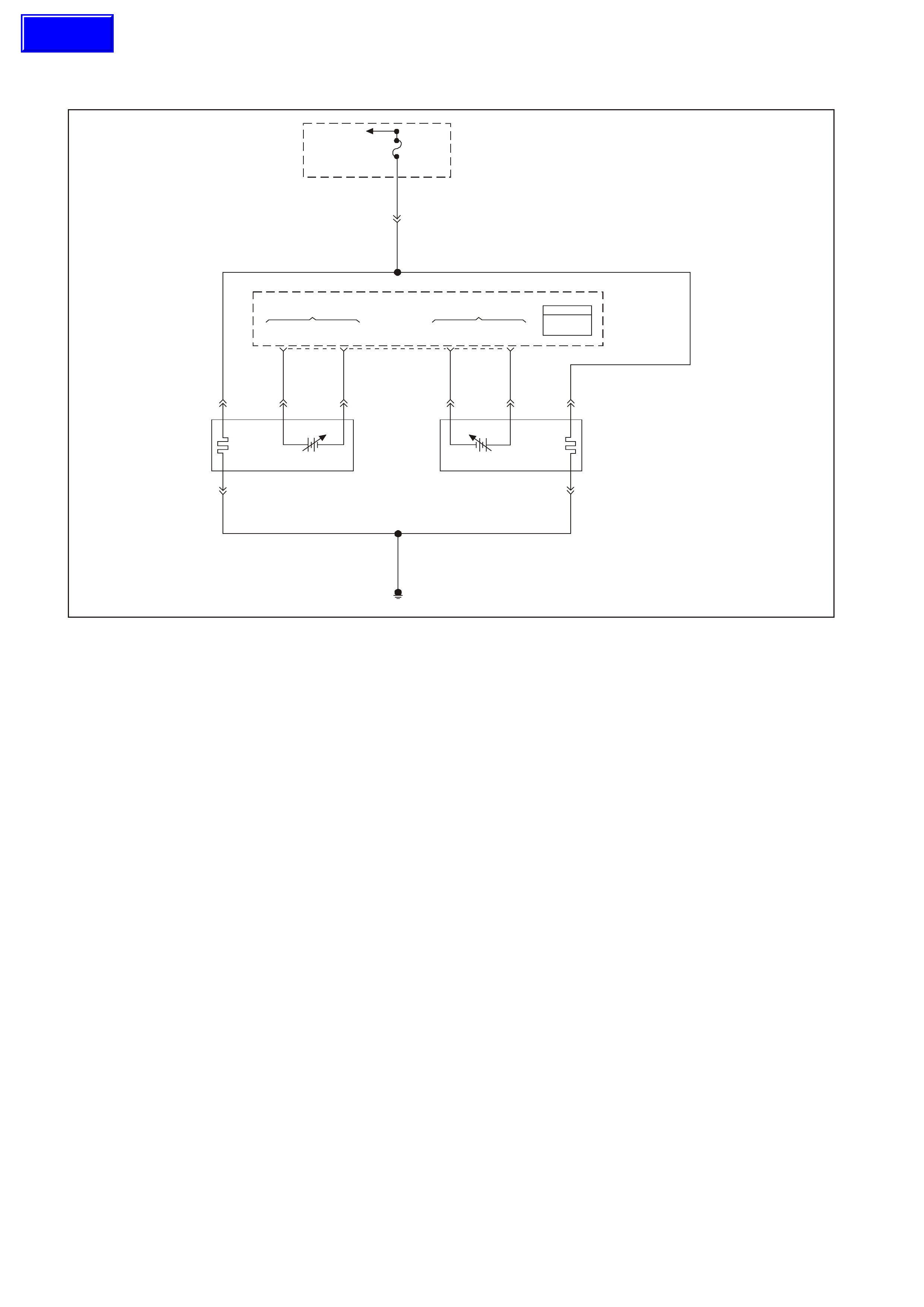
GEN III V8 PCM DTC P0132 HEATED OXYGEN SENSOR (HO2S)
CIRCUIT HIGH VOLTAGE BANK 1 SENSOR 1
GEN3 0157
To EFI
(Engine Cont.)
Relay Fuse
F33
YE111
P 439
Bank #1
Left Front
HO2S
High HO2S
Low
Bank #2
Right Front
HO2S
Low HO2S
High
PCM
J1 = B LUE
J2 = R ED
Powertrain
Control
Module
(PCM)
P439
B/R 750
Engine
Earth
D
Bank 2 Sensor 1
Heated Oxygen
Sensor (HO2S)
BA
GY/B 1413 GY 1412
26 66 J1
69 29
ABD
Bank 1 Sensor 1
Heat ed Oxygen
Sensor (HO2S)
BLU/B 413
P439 V412
B/R 750
C
B/R 750
C
CIRCUIT DESCRIPTION
The PCM supplies a voltage of about 450 m V between the HO2S high and low signal circuits. The oxygen sensor
varies the voltage over a r ange f r om about 1000 mV when the exhaus t is r ich, down through about 10 mV when the
exhaust is lean.
The PCM monitors and stores the heated oxygen sensor (HO2S) voltage information. The PCM evaluates the
HO2S voltage samples in order to determine the amount of time the HO2S voltage was out of range. The PCM
compares the stored HO2S voltage samples taken within each sample period and determines if majority of the
samples are out of the operating range.
The PCM monitors the HO 2S voltage f or being f ix ed above a predeter mined voltage. If the PCM detects the voltage
is above the predetermined voltage, a DTC will set.
CONDITIONS FOR RUNNING THE DTC
Criteria 1
• DTCs P0101, P0102, P0103, P0112, P0113, P0117, P0118, P0121, P0122, P0123, P0335, P0336, P0351-
P0358, P1258, not set.
• The ignition voltage is greater than 9.0 volts.
• The fuel system is operating in Closed Loop.
• The fuel trim learn is enabled.
• The air/fuel ratio is between 14.5:1 and 14.7:1.
OR
Criteria 2
• DTCs P0101, P0102, P0103, P0112, P0113, P0117, P0118, P0121, P0122, P0123, P0335, P0336, P0351-
P0358, P1258 not set.
• The ignition voltage is greater than 9.0 volts.
• Deceleration Fuel Cut-off mode is enabled for greater than 1.0 second.
Techline

CONDITIONS FOR SETTING THE DTC
Criteria 1
• The HO2S signal voltage remains below 775 mV.
• The Criteria 1 conditions are present for 33 seconds.
OR
Criteria 2
• The HO2S signal voltage remains below 540 mV.
• The Criteria 2 conditions are present for 5.0 seconds.
ACTION TAKEN WHEN THE DTC SETS
• The PCM illuminates the Check Powertrain Lamp (CPL) when the diagnostic runs and fails.
• T he PCM records the operating conditions at the time the diagnostic fails. The PCM stores this information in
the Freeze Frame/Failure Records.
• Open Loop Fueling.
CONDITIONS FOR CLEARING THE CPL/DTC
• The PCM turns the CPL OFF after the first ignition cycle that the diagnostic runs and does not fails.
• A last test failed (current DTC) clears when the diagnostic runs and does not fail.
• A History DTC clears after forty consecutive warm-up cycles, if this or any other emission related diagnostic
does not report any failure.
• Use a Tech 2 scan tool in order to clear the CPL/DTC.
DIAGNOSTIC AIDS
• Check the HO2S electrical connections for evidence of water intrusion. W ater present in the connector cause
the B+ supply to the heater to bleed over to the signal circuit.
• Fuel pressure: The system goes rich if the pressure is too high. The PCM compensates for some increase.
However, if the fuel pressure is too high, a DTC may set. Refer to Fuel System Diagnosis Table in this
Section.
• Rich injector(s): Perform the Injector Balance Test.
• Leaking injector: Refer to the Fuel Sys tem Diagnosis Table in this Section.
• Evaporative emissions (EVAP) canister purge. Check for fuel saturation. If full of fuel, check the canister
control and hoses. Refer to Section 6C3-1 GENERAL INFORMATION EVAP Control System Description in
this Service Information CD.
• MAF sensor: Disconnect the MAF sensor and see if the rich condition is correct. If so, check for proper
installation. If ins tallation is OK, replac e the MAF sensor. If the MAF sensor is installed backwards, the system
goes rich. The plastic portion of the sensor has arrows cast into it indicating proper air flow direction. The
arrows must point towards the engine.
• An oxygen supply inside the HO2S is necessary for proper operation. The HO2S wires provide the supply of
oxygen. Inspect the HO2S wires and connections for breaks or contamination.
• TP sensor: An intermittent TP sensor output causes the system to go rich, due to a false indication of the
engine accelerating. For an intermittent condition, refer to Section 6C3-2B SYMPTOMS in this Service
Information CD.
TEST DESCRIPTION
The numbers below refer to the step numbers on the diagnostic table.
2. T his DTC als o sets during a deceleration f uel cut-off. Ins pect items which could cause a rich exhaus t during a
deceleration (leaking injectors, stuck injectors, etc.). Refer to Conditions for Setting the DTC.
T he engine m ust be at the nor m al operating tem peratur e before per form ing this test. For any test that requires
probing the PCM or a component harness connector, use the Connector Test adaptor Kit J 35616-A. Using this
kit prevents damage to the harness connector terminals.
3. Using the Freeze Frame/Failure Records data may aid in locating an intermittent condition. If you can not
duplicate the DT C, the information inc luded in the Freeze Frame/Failure Recor ds data can help determine the
distance traveled since the DTC set. The Fail Counter and Pass Counter can also aid in determining how many
ignition cycles the diagnostic reported a pass and/or a fail. Operate the vehicle within the same freeze frame
conditions (R PM, load, vehicle s peed, temperatur e etc .) that the PCM r ecor ded. This will isolate when the DT C
failed. Refer to Section 6C3-2B SYMPTOMS in this Service Information CD.
5. Earthing the low side circuit of the HO2S should cause the HO2S voltage to display a bias voltage.
9. Review the system mechanisation. Check for a short between the HO2S signal circuit and any other wires
powered by this fuse that runs together inside the same harness.

GEN III V8 PCM DTC P0132 HEATED OXYGEN SENSOR (HO2S)
CIRCUIT HIGH VOLTAGE BANK 1 SENSOR 1
Step Action Value(s) Yes No
1 Did you perform the Powertrain On-Board Diagnostic
(OBD) System Check? Go to Step 2 Go to Powertrain
OBD System
Check Table
2
1. Install a Tech 2 scan tool.
2. Idle the engine at the normal operating temperature.
3. Operate the vehicle within parameters specified
under Conditions for Running the DTC in the
supporting text.
4. Monitor the HO2S voltage display on the Engine
Data List using the Tech 2 scan tool.
Is the HO2S voltage greater than the specified value?
775 mV Go to Step 4 Go to Step 3
3 1. Turn ON the ignition leaving the engine OFF.
2. Review the Freeze Frame/Failure Records data for
this DTC and observe the parameters.
3. Turn OFF the ignition for 15 seconds.
4. Idle the engine.
5. Operate the vehicle within the conditions required for
this diagnostic to run, and as close to the conditions
recorded in the Freeze Frame/Failure Records as
possible. Special operating conditions that you need
to meet before the PCM will run this diagnostic,
where applicable, are listed in Conditions for
Running the DTC.
6. Select the Diagnostic Trouble Code (DTC) option,
the DTC Information option, The Failed This Ignition
option using the Tech 2 scan tool.
Does the Tech 2 scan tool indicate that this diagnostic
failed this ignition?
Go to Step 4 Go to Diagnostic
Aids
4 1. Turn ON the ignition leaving the engine OFF.
2. Remove the HO2S heater fuse while monitoring the
HO2S voltage using a Tech 2 scan tool.
Does the voltage drop to within the specified range when
the power to the heater is disconnected?
350-550 mV Go to Step 5 Go to Step 7
5 1. Reinstall the fuse.
2. Disconnect the HO2S.
3. Jumper the HO2S low signal (PCM side) circuit to a
earth.
Does the Tech 2 scan tool indicate the HO2S voltage
within the specified value?
350-550 mV Go to Step 10 Go to Step 6
6 1. Turn ON the ignition leaving the engine OFF.
2. Remove the HO2S heater fuse while monitoring the
HO2S voltage using a Tech 2 scan tool.
Does the voltage drop to within the specified range when
the power to the heater is disconnected?
350-550 mV Go to Step 9 Go to Step 8
7 1. Turn OFF the ignition.
2. Disconnect the PCM BLUE connector.
3. Disconnect the HO2S.
4. Turn ON the ignition.
5. Check for a voltage on the HO2S sensor signal
circuit at the PCM harness connector using the DMM
J 39200.
Is a voltage present?
Go to Step 8 Go to Diagnostic
Aids
8 Repair the short to voltage in the HO2S signal circuit.
Is the action complete? Go to Step 12
9 Repair the short between the HO2S signal circuit and the
HO2S heater B+ circuit.
Is the action complete?
Go to Step 12

Step Action Value(s) Yes No
10 Replace the HO2S.
Is the action complete? Go to Step 12
11 1. Replace PCM.
2. Refer to Section 6C3-3 in this Service Information
CD for PCM Programming and PCM/PIM/BCM
Security Link Procedure.
Is action complete?
Go to Step 12
12 1. Select the Diagnostic Trouble Code (DTC) option
and the Clear DTC Information option using the Tech
2 scan tool.
2. Idle the engine at the normal operating temperature.
3. Select the Diagnostic Trouble Code (DTC) option,
the DTC Information option, The Failed This Ignition
option using the Tech 2 scan tool.
4. Operate the vehicle within the Conditions for
Running the DTC as specified in the supporting text,
if applicable.
Does the Tech 2 scan tool indicate that this DTC reset?
Go to Step 2 Go to Step 13
13 Using the Tech 2 scan tool, check for any other DTCs.
Does the Tech 2 scan tool display any DTCs that you
have not diagnosed?
Go to the
applicable DTC
table
System OK

GEN III V8 PCM DTC P0133 HEATED OXYGEN SENSOR (HO2S)
SLOW RESPONSE BANK 1 SENSOR 1
GEN3 0157
To EFI
(Engine Cont.)
Relay Fuse
F33
YE111
P 439
Bank #1
Left Front
HO2S
High HO2S
Low
Bank #2
Right Front
HO2S
Low HO2S
High
PCM
J1 = B LUE
J2 = R ED
Powertrain
Control
Module
(PCM)
P439
B/R 750
Engine
Earth
D
Bank 2 Sensor 1
Heated Oxygen
Sensor (HO2S)
BA
GY/B 1413 GY 1412
26 66 J1
69 29
ABD
Bank 1 Sensor 1
Heat ed Oxygen
Sensor (HO2S)
BLU/B 413
P439 V412
B/R 750
C
B/R 750
C
CIRCUIT DESCRIPTION
The PCM continuously monitors the Heated Oxygen Sensor (HO2S) activity for 100 seconds. During the monitor
period the PCM counts the number of times that the HO2S responds from rich to lean and from lean to rich and
adds the amount of time it took to complete all transactions. With this information, the PCM can determine the
average time for all transactions. If the average response time is too slow, the DTC will set.
The PCM determines the lean to rich transaction when the HO2S voltage changes from less than 300 mV to greater
than 600 mV. The PCM determines the rich to lean transaction when the HO2S voltage changes from more than
600 mV to less than 300 mV. An HO2S that responds too slowly is more likely defective. Replace the HO2S.
CONDITIONS FOR RUNNING THE DTC
• DTCs P0101, P0102, P0103, P0112, P0113, P0117, P0118, P0121, P0122, P0123, P0335, P0336, P0351-
P0358, P1258, not set.
• The engine coolant temperature is greater than 65°C (149°F)
• The ignition voltage is greater than 9.0 volts.
• The fuel system is operating in Closed Loop.
• The engine speed between 1000 RPM and 2300 RPM.
• The engine air flow is between 20 g/s and 50 g/s.
• The EVAP canister purge duty cycle is greater than 0%.
• The engine run time is greater than 120 seconds.
CONDITIONS FOR SETTING THE DTC
• The lean to rich response (below 300 mV to above 600 mV) average time is greater than 100 milliseconds.
• The rich to lean response (above 600 mV to below 300 mV) average time is greater than 100 milliseconds.
• The above conditions are met for 100 seconds.
ACTION TAKEN WHEN THE DTC SETS
• The PCM illuminates the Check Powertrain Lamp (CPL) when the diagnostic runs and fails.
• T he PCM records the operating conditions at the time the diagnostic f ails. The PCM stores this information in
the Freeze Frame/Failure Records.
• Open Loop Fueling.

CONDITIONS FOR CLEARING THE CPL/DTC
• The PCM turns the CPL OFF after three consecutive ignition cycles that the diagnostic runs and does not fails.
• A last test failed (current DTC) clears when the diagnostic runs and does not fail.
• A History DTC clears after forty consecutive warm-up cycles, if this or any other emission related diagnostic
does not report any failure.
• Use a Tech 2 scan tool in order to clear the CPL/DTC.
DIAGNOSTIC AIDS
• This diagnostic only runs once per ignition cycle.
• A malfunction in the HO2S heater circuits cause a DTC to set. Check HO2S heater circuit for intermittent
opens/connections.
• An oxygen supply inside the HO2S is necessary for proper operation. T he HO2S wires provides the supply of
oxygen. Inspect the HO2S wires and connections for breaks or contamination. Refer to Section 12P
ELECTRICAL DIAGNOSIS/ REPAIR PROCEDURES, of the VT Series II Service Information.
• Using the Freeze Frame/Failure Records data may aid in locating an intermittent condition. If you cannot
duplicate the DT C, the information inc luded in the Freeze Frame/Failure Recor ds data can help determine the
distance traveled since the DTC set. The Fail Counter and Pass Counter can also help determine how many
ignition cycles the diagnostic reported a pass and/or fail. Operate the vehicle within the same freeze frame
conditions (RPM, load, vehicle speed, temperature etc.) that you observed. This will isolate when the DTC
failed. For an intermittent condition, refer to Section 6C3-2B SYMPTOMS in this Service Information CD.
TEST DESCRIPTION
The numbers below refer to the step numbers on the diagnostic table.
2. This step deter mines if the fault is pr esent. This test may take 5 m inutes for the diagnostic to run. For any test
that requires probing the PCM or a component harness connector, use the Connector Test adaptor Kit J
35616-A. Using this kit prevents damage to the harness connector terminals.
3. When DTCs P0133 and P0153 are set at the same time, it is a good indication that a fuel contamination
problem is present.
4. An exhaust leak 15 - 30 CM (6-12 inches) away from the HO2S can cause a DTC to set.
5. This set checks whether a good earth circuit is available.
6. This step checks the integrity of the signal circuit to the PCM.
7. This step checks the integrity of the signal circuit to the PCM.
8. Certain RTV silicone gasket materials give off vapours that can contaminate the HO2S. There is also a
possibility of silicone contam ination caus ed by silicone in the f uel. If the sens ors appear to be contam inated by
silicone and all the silicone sealant is a non silicone base, advis e the custom er to try a differ ent fuel com pany.
A missing fuel filler restrictor indicates the customer may have used leaded fuel.

GEN III V8 PCM DTC P0133 HEATED OXYGEN SENSOR (HO2S) SLOW RESPONSE BANK 1 SENSOR 1
Step Action Value(s) Yes No
1 Did you perform the Powertrain On-Board Diagnostic
(OBD) System Check? Go to Step 2 Go to Powertrain
OBD System
Check Table
2
Important: If any DTCs are set (except P0153), refer to
those DTCs before proceeding with this diagnostic table.
1. Install a Tech 2 scan tool.
2. Idle the engine at the normal operating temperature.
3. Operate the vehicle within parameters listed under
Conditions for Running the DTC as specified in the
supporting text.
4. Monitor the Failed This Ignition option under the
DTC Information option using the Tech 2 scan tool.
Did DTC P0133 fail this ignition?
Go to Step 3 Go to Diagnostic
Aids
3 Did DTC P0153 also fail this ignition? Go to Step 8 Go to Step 4
4 1. Check for an exhaust system leak. After you inspect
the exhaust system, return to this diagnostic.
2. If you find an exhaust leak, repair the exhaust leak
as necessary
Did you isolate an exhaust leak?
Go to Step 2 Go to Step 5
5 Inspect the following items:
• Ensure that the HO2S is securely installed.
• Check for corrosion on the terminals.
• Check the terminals tension at the HO2S and at the
PCM.
• Check for damaged wiring.
Did you find a problem in any of the above areas?
Go to Step 9 Go to Step 6
6 1. Disconnect the Bank 1 HO2S .
2. Jumper the HO2S low (PCM side) signal circuit to a
earth.
3. Monitor the Bank 1 HO2S voltage on the Engine
Data List using the Tech 2 scan tool.
Does the Tech 2 scan tool indicate a voltage within the
specified range?
350-550 mV Go to Step 7 Go to Step 10
7 1. Jumper the Bank 1 HO2S high and low (PCM side)
signal circuit to a earth.
2. Monitor the Bank 1 HO2S voltage using the Tech 2
scan tool.
Does the Tech 2 scan tool indicate a voltage below
specified value?
200 mV Go to Step 12 Go to Diagnostic
Aids
8 Important: Determine and correct the cause of the
contamination before replacing a sensor. Check for the
following conditions:
• Fuel contamination
• Use of improper RTV sealant
• Engine oil/coolant consumption
Replace the affected Heated Oxygen sensor.
Is the action complete?
Go to Step 13
9 Repair the conditions as necessary.
Is the action complete? Go to Step 13
10 Repair the open Bank 1 HO2S low signal circuit or the
earthed Bank 1 HO2S high signal circuits.
Is the action complete?
Go to Step 13
11 Repair the open Bank 1 HO2S high signal circuit or the
faulty PCM connections.
Is the action complete?
Go to Step 13
12 Replace the Bank 1 HO2S.
Is the action complete? Go to Step 13

Step Action Value(s) Yes No
13
1. Select the Diagnostic Trouble Code (DTC) option
and the Clear DTC Information option using the Tech
2 scan tool.
2. Idle the engine at the normal operating temperature.
3. Select the Diagnostic Trouble Code (DTC) option,
the DTC Information option, The Failed This Ignition
option using the Tech 2 scan tool.
4. Operate the vehicle within the Conditions for
Running the DTC as specified in the supporting text,
if applicable.
Does the Tech 2 scan tool indicate that this DTC reset?
Go to Step 2 Go to Step 14
14 Using the Tech 2 scan tool, check for any other DTCs.
Does the Tech 2 scan tool display any DTCs that you
have not diagnosed?
Go to the
applicable DTC
table
System OK

GEN III V8 PCM DTC P0134 HEATED OXYGEN SENSOR (HO2S)
INSUFFICIENT ACTIVITY BANK 1 SENSOR 1
GEN3 0157
To EFI
(Engine Cont.)
Relay Fuse
F33
YE111
P 439
Bank #1
Left Front
HO2S
High HO2S
Low
Bank #2
Right Front
HO2S
Low HO2S
High
PCM
J1 = B LUE
J2 = R ED
Powertrain
Control
Module
(PCM)
P439
B/R 750
Engine
Earth
D
Bank 2 Sensor 1
Heated Oxygen
Sensor (HO2S)
BA
GY/B 1413 GY 1412
26 66 J1
69 29
ABD
Bank 1 Sensor 1
Heat ed Oxygen
Sensor (HO2S)
BLU/B 413
P439 V412
B/R 750
C
B/R 750
C
CIRCUIT DESCRIPTION
The PCM supplies a voltage of about 450 m V between the HO2S high and low signal circuits. The oxygen sensor
varies the voltage over a r ange f r om about 1000 mV when the exhaus t is r ich, down through about 10 mV when the
exhaust is lean.
The PCM monitors and stores the Heated Oxygen Sensor (HO2S) voltage information. The PCM evaluates the
HO2S voltage samples in order to determine the amount of time the HO2S voltage was out of range. The PCM
compares the stored HO2S voltage samples taken within each sample period and determines if majority of the
samples are out of the operating range.
The PCM monitors the HO2S voltage and detects if the voltage goes out of the bias range. If the PCM does not
detect the voltage went out of the bias range, the DTC will set.
CONDITIONS FOR RUNNING THE DTC
• DTCs P0101, P0102, P0103, P0112, P0113, P0117, P0118, P0121, P0122, P0123, P0335, P0336, P0351-
P0358, P1258, not set.
• The ignition voltage is greater than 9.0 volts.
• The fuel system is operating in Closed Loop.
• The engine run time is greater than 70 seconds.
• The engine coolant temperature is greater than 48°C (118°F)
CONDITIONS FOR SETTING THE DTC
• The HO2S signal voltage is steady between 350 mV and 550 mV.
• The conditions are present for 70 seconds.
ACTION TAKEN WHEN THE DTC SETS
• The PCM illuminates the Check Powertrain Lamp (CPL) when the diagnostic runs and fails.
• T he PCM records the operating conditions at the time the diagnostic f ails. The PCM stores this information in
the Freeze Frame/Failure Records.
• Open Loop Fueling.
Techline

CONDITIONS FOR CLEARING THE CPL/DTC
• The PCM turns the CPL OFF after three consecutive ignition cycles that the diagnostic runs and does not fails.
• A last test failed (current DTC) clears when the diagnostic runs and does not fail.
• A History DTC clears after forty consecutive warm-up cycles, if this or any other emission related diagnostic
does not report any failure.
• Use a Tech 2 scan tool in order to clear the CPL/DTC.
DIAGNOSTIC AIDS
• An oxygen supply inside the HO2S is necessary for proper operation. T he HO2S wires provides the supply of
oxygen. Inspect the HO2S wires and connections for breaks or contamination. Refer to Section 12P
ELECTRICAL DIAGNOSIS/ REPAIR PROCEDURES of the VT Series II Service Information.
• Using the Freeze Frame/Failure Records data may aid in locating an intermittent condition. If you cannot
duplicate the DT C, the information inc luded in the Freeze Frame/Failure Recor ds data can help determine the
distance traveled since the DTC set. The Fail Counter and Pass Counter can also help determine how many
ignition cycles the diagnostic reported a pass and/or fail. Operate the vehicle within the same freeze frame
conditions (RPM, load, vehicle speed, temperature etc.) that you observed. This will isolate when the DTC
failed. For an intermittent condition, refer to Section 6C3-2B SYMPTOMS in this Service Information CD.
TEST DESCRIPTION
The numbers below refer to the step numbers on the diagnostic table.
The engine must be at normal operating temperature before performing this test.
For any test that requires probing the PCM or a component harness connector, use the Connector Test
adaptor Kit J 35616-A. Using this kit prevents damage to the harness connector terminals.
3. Using the Freeze Frame/Failure Records data may aid in locating an intermittent condition. If you can not
duplicate the DT C, the information inc luded in the Freeze Frame/Failure Records data can help determine the
distance traveled since the DTC set. The Fail Counter and Pass Counter can also aid in determining how many
ignition cycles the diagnostic reported a pass and/or a fail. Operate the vehicle within the same freeze frame
conditions (R PM, load, vehicle s peed, temperatur e etc .) that the PCM r ecor ded. This will isolate when the DT C
failed. Refer to Section 6C3-2B SYMPTOMS in this Service Information CD.
4. If the Tech 2 scan tool indicates the HO2S voltage goes below 200 mV, this indicates the HO2S circuits and
PCM are OK.
5. This step checks whether the signal circuit from the PCM is OK.
6. Disconnecting the PCM allows using a DMM J 39200 in order to check continuity of the circuits. This aids in
locating an open or shorted circuit.
7. Disconnecting the PCM allows using a DMM J 39200 in order to check continuity of the circuits. This aids in
locating an open or shorted circuit.

GEN III V8 PCM DTC P0134 HEATED OXYGEN SENSOR (HO2S) INSUFFICIENT ACTIVITY BANK 1 SENSOR 1
Step Action Value(s) Yes No
1 Did you perform the Powertrain On-Board Diagnostic
(OBD) System Check? Go to Step 2 Go to Powertrain
OBD System
Check Table
2
Important: Check the HO2S for being secure before
proceeding with this DTC. A sensor that is loose could
cause this DTC to set.
1. Install a Tech 2 scan tool.
2. Idle the engine at the normal operating temperature
3. Operate the engine above 1200 RPM for two
minutes.
4. Monitor the HO2S voltage display on the Engine
Data List using the Tech 2 scan tool .
Does the Tech 2 scan tool indicate the Bank 1 HO2S
voltage varying outside the specified value?
350-550 mV Go to Step 3 Go to Step 4
3 1. Turn ON the ignition leaving the engine OFF.
2. Review the Freeze Frame/Failure Records data for
this DTC and observe the parameters.
3. Turn OFF the ignition for 15 seconds.
4. Idle the engine.
5. Operate the vehicle within the conditions required for
this diagnostic to run, and as close to the conditions
recorded in Freeze Frame/Failure Records a
possible. Special operating conditions that need to
be met before the PCM will run this diagnostic where
applicable, are listed in Conditions for Running the
DTC.
6. Select the Diagnostic Trouble Code (DTC) option,
the DTC Information option, The Failed This Ignition
option using the Tech 2 scan tool.
Does the Tech 2 scan tool indicate that this diagnostic
failed this ignition?
Go to Step 4 Go to Diagnostic
Aids
4 1. Turn ON the ignition leaving the engine OFF.
2. Disconnect the Bank 1 HO2S.
3. Jumper the HO2S high and low (PCM side) signal
circuits to a earth.
Monitor the Bank 1 HO2S voltage using the Tech 2 scan
tool.
Is the Bank 1 HO2S voltage below the specified value?
200 mV Go to Step 8 Go to Step 5
5 1. Remove the jumper wire.
2. Measure the voltage between the Bank 1 HO2S
heater earth circuit using a DMM J 39200.
Does the Bank 1 HO2S voltage measure above the
specified value?
375 mV Go to Step 6 Go to Step 7
6 1. Turn Off the ignition.
2. Disconnect the PCM BLUE connector.
3. Check the continuity of the Bank 1 HO2S low circuit.
4. Repair the open or the poor connection if the Bank 1
HO2S low circuit measures over the specified value.
Did you find and correct the Bank 1 HO2S 1 low circuit
condition?
2Ω Go to Step 13 Go to Step 9
7 1. Turn Off the ignition.
2. Disconnect the PCM connectors.
3. Check the continuity of the Bank 1 HO2S low circuit.
4. Repair the open or the poor connection if the Bank 1
HO2S low circuit measures over the specified value.
Did you find and correct the Bank 1 HO2S 1 low circuit
condition?
2Ω Go to Step 13 Go to Step 10

Step Action Value(s) Yes No
8 Check for a poor Bank 1 HO2S signal or low circuit
terminal connection at the Bank 1 HO2S harness
connector and replace the terminal(s) if necessary.
Did any terminals require replacement?
Go to Step 13 Go to Step 11
9 Check for a poor Bank 1 HO2S low circuit terminal
connection at the PCM, and replace the terminal if
necessary.
Did any terminals require replacement?
Go to Step 13 Go to Step 12
10 Check for a poor Bank 1 HO2S signal circuit terminal
connection at the PCM, and replace the terminal if
necessary.
Did any terminals require replacement?
Go to Step 13 Go to Step 12
11 Replace the Bank 1 HO2S.
Is the action complete? Go to Step 13
12 1. Replace PCM.
2. Refer to Section 6C3-3 in this Service Information
CD for PCM Programming and PCM/PIM/BCM
Security Link Procedure.
Is action complete?
Go to Step 13
13 1. Select the Diagnostic Trouble Code (DTC) option
and the Clear DTC Information option using the Tech
2 scan tool.
2. Idle the engine at the normal operating temperature.
3. Select the Diagnostic Trouble Code (DTC) option,
the DTC Information option, The Failed This Ignition
option using the Tech 2 scan tool.
4. Operate the vehicle within the Conditions for
Running the DTC as specified in the supporting text,
if applicable.
Does the Tech 2 scan tool indicate that this DTC reset?
Go to Step 2 Go to Step 14
14 Using the Tech 2 scan tool, check for any other DTCs.
Does the Tech 2 scan tool display any DTCs that you
have not diagnosed?
Go to the
applicable DTC
table
System OK

GEN III V8 PCM DTC P0135 HEATED OXYGEN SENSOR (HO2S)
HEATER CIRCUIT BANK SENSOR 1
GEN3 0157
To EFI
(Engine Cont.)
Relay Fuse
F33
YE111
P 439
Bank #1
Left Front
HO2S
High HO2S
Low
Bank #2
Right Front
HO2S
Low HO2S
High
PCM
J1 = B LUE
J2 = R ED
Powertrain
Control
Module
(PCM)
P439
B/R 750
Engine
Earth
D
Bank 2 Sensor 1
Heated Oxygen
Sensor (HO2S)
BA
GY/B 1413 GY 1412
26 66 J1
69 29
ABD
Bank 1 Sensor 1
Heat ed Oxygen
Sensor (HO2S)
BLU/B 413
P439 V412
B/R 750
C
B/R 750
C
CIRCUIT DESCRIPTION
The PCM supplies a bias voltage (approximately 450 mV) on the Heated Oxygen Sensor (HO2S) signal high and
low circuits. W hen you turn the ignition to the On position, battery voltage is supplied to the HO2S heater. As the
heater reaches the operating temperature, the HO2S voltage responds by changing from a bias voltage range to the
normal operation. Typically, as the HO2S reaches the operating temperature, the HO2S voltage goes from a bias
voltage to a voltage below 300 mV. Depending on the exhaus t gas c ontent, it is pos sible f or the HO2S voltage to go
above 450 mV.
The PCM runs the heater test only on a cold start (depends on the cumulative air flow) and only once an ignition
cycle. When you start the engine the PCM monitors the HO2S voltage. When the HO2S voltage goes above or
below the bias range threshold, the PCM determines how much time it took. If the PCM detects that the process
took too long for the HO2S to enter into normal operating range, a DTC will set. The time the process takes the
HO2S to reach operating temperature is based on the amount of air that flows into the engine.
CONDITIONS FOR RUNNING THE DTC
• DTCs P0101, P0102, P0103, P0112, P0113, P0117, P0118, P0121, P0122, P0123, P0335, P0336, P0351-
P0158, P1258 not set.
• The intak e air temperatur e and the engine coolant temper ature ar e less than 50° C ( 122°F) and are within 8° C
(14.5°F) of each other at engine start-up.
• The ignition voltage is between 10.0 volts and 18.0 volts.
• The engine air flow is less than 18g/s.
CONDITIONS FOR SETTING THE DTC
• The HO2S voltage remains between 300 mV and 700 mV for a predetermined amount of time (depends on
engine coolant temperature and air flow).
ACTION TAKEN WHEN THE DTC SETS
• The PCM illuminates the Check Powertrain Lamp (CPL) when the diagnostic runs and fails.
• T he PCM records the operating conditions at the time the diagnostic f ails. The PCM stores this information in
the Freeze Frame/Failure Records.

CONDITIONS FOR CLEARING THE CPL/DTC
• The PCM turns the CPL OFF after the first ignition cycle that the diagnostic runs and does not fail.
• A last test failed (current DTC) clears when the diagnostic runs and does not fail.
• A History DTC clears after forty consecutive warm-up cycles, if this or any other emission related diagnostic
does not report any failure.
• Use a Tech 2 scan tool in order to clear the CPL/DTC.Diagnostic Aids
• Using the Freeze Frame/Failure Records data may aid in locating an intermittent condition. If you cannot
duplicate the DTC, the information included in the Freeze Frame/Failure Records data can help determine the
distance traveled since the DTC Set. The Fail Counter and Pass Counter can also help determine how may
ignition cycles the diagnostic reported a pass and/or a fail. Operate the vehicle within the same freeze frame
conditions (RPM, load, vehicle speed, temperature etc.) that you observed. This will isolate when the DTC
failed. For an intermittent condition, refer to Section 6C3-2B SYMPTOMS in this Service Information CD.
• The heater diagnostic will only run on a cold start and run once per ignition cycle.
• Inspect the EFI relay for proper operation if you cannot find any problems with the ignition feed circuit to the
component. Probe both side of the fuse with a test lamp connected to earth in order to determine if a voltage is
supplied to the fuse. Refer to EFI Relay Diagnosis Chart in this Section.
• An oxy gen supply inside the HO2S is necessary for proper operation. The HO2S wires provides the supply of
oxygen. Inspect the HO2S wires and connections for breaks or contamination.
TEST DESCRIPTION
The numbers below refer to the step numbers on the diagnostic table.
2. Allow the engine to cool before performing this test. If the sensor is at the operating temperature the HO2S
voltage will stay high or low. If the HO2S voltage stays between 300-700 mV indicates the HO2S heater is
inoperative. For any test that requires probing the PCM or a com ponent harnes s connec tor, use the Connector
Test adaptor Kit J 35616-A. Using this kit will prevent damage to the harness connector terminals.
3. If more than one HO2S DTC is set, this is a good indication that the HO2S fuse is open. Check all the relate
circuits going to all the heated oxygen sensors for a short to earth. If all the wiring chec ks to be OK, it may be
necessary to disconnect each HO2S on at a time to locate a shorted sensor.
4. This step checks whether a B+ supply is available at the sensor.
5. This step checks whether a earth is available at the sensor.
6. This step checks whether the HO2S heater element is internally open.
7. Inspect the ignition feed circuits at the engine compartment Fuse/Relay panel for poor connections.
8. Check the earth circuits for an open if more then one heater DTC sets.

GEN III V8 PCM DTC P0135 HEATED OXYGEN SENSOR (HO2S) HEATER CIRCUIT BANK 1 SENSOR 1
Step Action Value(s) Yes No
1 Did you perform the Powertrain On-Board Diagnostic
(OBD) System Check ? Go to Step 2 Go to Powertrain
OBD System
Check Table
2 Important: Allow the engine to cool for about one half
hour before proceeding with this table.
1. Turn OFF the ignition.
2. Install the Tech 2 scan tool.
3. Turn ON the ignition leaving the engine OFF.
4. Monitor the HO2S voltage display on the Engine Data
List of the Tech 2 scan tool.
Does the HO2S voltage go from a bias voltage to above
or below the specified range?
300-700 mV Go to Diagnostic
Aids Go to Step 3
3 Inspect the HO2S heater fuse for an open.
Is the HO2S heater fuse open? Go to Step 11 Go to Step 4
4 1. Raise the vehicle.
2. Disconnect the HO2S electrical connector.
3. Probe the ignition feed circuit at the HO2S electrical
connector (PCM side) using a test lamp J34142-B
connected to earth (a known good earth. Do not use
the HO2S heater earth or the HO2S low circuits).
Does the test lamp illuminate?
Go to Step 5 Go to Step 7
5 Connect the test lamp J34142-B between the HO2S
ignition feed and the HO2S heater earth.
Does the test lamp illuminate?
Go to Step 6 Go to Step 8
6 Measure the resistance between the HO2S ignition feed
and the HO2S heater earth at the HO2S pigtail using a
DMM J39200.
Is the HO2S resistance within the specified range?
3.5 - 14.0Ω Go to Step 9 Go to Step 10
7 Repair the open in the HO2S ignition feed circuit to the
HO2S.
Is the action complete?
Go to Step 12
8 Repair the open in the HO2S heater earth circuit.
Is the action complete? Go to Step 12
9 1. Check for a poor connection at the HO2S harness
terminals.
2. If you find a poor connection, replace the terminals.
Did you find a poor connection?
Go to Step 12 Go to Step 10
10 Replace the HO2S.
Is the action complete? Go to Step 12 Go to Step 10
11 1. Locate and repair the short to earth in the HO2S
ignition feed circuit.
2. Replace the faulty fuse.
Is the action complete?
Go to step 12
12 1. Select the Diagnostic Trouble Code (DTC) option and
the Clear DTC Information option using the Tech 2
scan tool.
2. Idle the engine at the normal operating temperature.
3. Select the Diagnostic Trouble Code (DTC) option, the
DTC Information option, The Failed This Ignition
option using the Tech 2 scan tool.
4. Operate the vehicle within the Conditions for Running
the DTC as specified in the supporting text, if
applicable.
Does the Tech 2 scan tool indicate that this DTC reset?
Go to Step 2 Go to step 13
13 Using the Tech 2 scan tool, check for any other DTCs.
Does the Tech 2 scan tool display any DTCs that you
have not diagnosed?
Go to the
applicable DTC
table
System OK
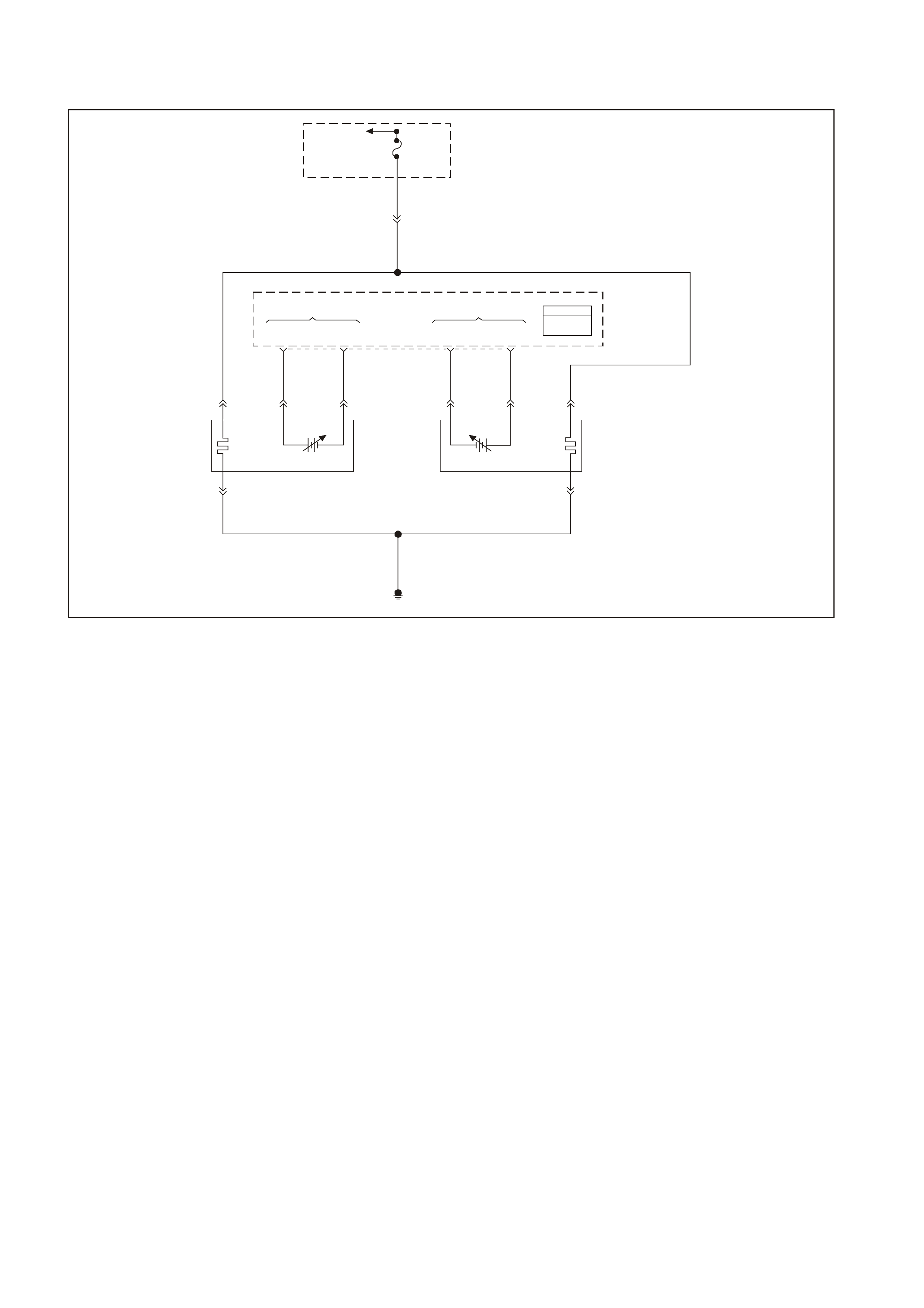
GEN III V8 PCM DTC P0151 HEATED OXYGEN SENSOR (HO2S)
CIRCUIT LOW VOLTAGE BANK 2 SENSOR 1
GEN3 0157
To EFI
(Engine Cont.)
Relay Fuse
F33
YE111
P 439
Bank #1
Left Front
HO2S
High HO2S
Low
Bank #2
Right Front
HO2S
Low HO2S
High
PCM
J1 = B LUE
J2 = R ED
Powertrain
Control
Module
(PCM)
P439
B/R 750
Engine
Earth
D
Bank 2 Sensor 1
Heated Oxygen
Sensor (HO2S)
BA
GY/B 1413 GY 1412
26 66 J1
69 29
ABD
Bank 1 Sensor 1
Heat ed Oxygen
Sensor (HO2S)
BLU/B 413
P439 V412
B/R 750
C
B/R 750
C
CIRCUIT DESCRIPTION
The PCM supplies a voltage of about 450 m V between the HO2S high and low signal circuits. The oxygen sensor
varies the voltage over a r ange f r om about 1000 mV when the exhaus t is r ich, down through about 10 mV when the
exhaust is lean.
The PCM monitors and stores the heated oxygen sensor (HO2S) voltage information. The PCM evaluates the
HO2S voltage samples in order to determine the amount of time the HO2S voltage was out of range. The PCM
compares the stored HO2S voltage samples taken within each sample period and determines if majority of the
samples are out of the operating range.
The PCM m onitors the HO2S voltage f or being f ixed below a predeterm ined voltage. If the PCM detects the voltage
is below a predetermined voltage, a DTC will set.
CONDITIONS FOR RUNNING THE DTC
CRITERIA 1
• DTCs P0101, P0102, P0103, P0112, P0113, P0117, P0118, P0121, P0122, P0123, P0335, P0336, P0351-
P0358, P1258 not set.
• The engine coolant temperature is greater than 48°C (118°F).
• The ignition voltage is greater than 9.0 volts.
• The fuel system is operating in Closed Loop.
• The fuel trim learn is enabled.
• The air/fuel ratio is between 14.5: and 14.7:1.
• The TP angle is between 0% and 70%.
OR
CRITERIA 2
• DTCs P0101, P0102, P0103, P0112, P0113, P0117, P0118, P0121, P0122, P0123, P0335, P0336, P0351,
P0358, P1258 not set.
• The ignition voltage is greater than 9.0 volts.
• The Power Enrichment mode is enabled for 0.5 seconds.

CONDITIONS FOR SETTING THE DTC
Criteria 1
• The HO2S signal voltage remains below 200 mV.
• The Criteria 1 conditions are present for 33 seconds.
OR
Criteria 2
• The HO2S signal voltage remains below 360 mV.
• The Criteria 2 conditions are present for 5.0 seconds.
ACTION TAKEN WHEN THE DTC SETS
• The PCM illuminates the Check Powertrain Lamp (CPL) when the diagnostic runs and fails.
• T he PCM records the operating conditions at the time the diagnostic fails. The PCM stores this information in
the Freeze Frame/Failure Records.
• Open Loop Fueling.
CONDITIONS FOR CLEARING THE CPL/DTC
• The PCM turns the CPL OFF after the first ignition cycle that the diagnostic runs and does not fails.
• A last test failed (current DTC) clears when the diagnostic runs and does not fail.
• A History DTC clears after forty consecutive warm-up cycles, if this or any other emission related diagnostic
does not report any failure.
• Use a Tech 2 scan tool in order to clear the CPL/DTC.
DIAGNOSTIC AIDS
• Heated O xygen Sensor (HO 2S) wire: Sensor pigtail may be in contact with the exhaust manifold or the exhaust
system.
• An oxygen supply inside the HO2S is necessary for proper operation. T he HO2S wires provides the supply of
oxygen. Inspect the HO2S wires and connections for breaks or contamination.
• Check for intermittent earth in signal wire between connector and sensor.
• Lean injector(s): Perform the Injector Balance Test.
• F uel contamination: Water near the in-tank fuel pum p inlet can be delivered to the injec tors. The water causes
a lean exhaust and can set a DTC.
• Fuel pressure: System will be lean if fuel pressure is low. Refer to Fuel System diagnosis Chart in this
Section.
• Exhaust leaks: An exhaust leak near the HO2S can cause a lean condition.
• Vacuum or crankcase leaks can cause a lean condition.
• If the above are OK, the HO2S may be at fault.
• For an intermittent condition, refer to Section 6C3-2B SYMPTOMS in this Service Information CD.
TEST DESCRIPTION
The numbers below refer to the step numbers on the diagnostic table.
2. If the HO2S voltage is fix well below 200 mV this indicates a short to battery earth or chassis earth. If the
voltage is fix near or above 200 mV, this indic ates a short to a PCM earth. When the HO2S voltage is f ix near
200 mV, indicates the DTC set when the fuel system was in a Power Enrichment mode of operations. This
DTC sets if the HO2S voltage is less than 360 mV during a Power Enrichment mode of operation.
3. Using the Freeze Frame/Failure Records data may aid in locating an intermittent condition. If you cannot
duplicate the DT C, the information inc luded in the Freeze Frame/Failure Records data can help determine the
distance traveled since the DTC set. The Fail Counter and Pass Counter can also help determine how many
ignition cycles the diagnostic reported a pass and/or fail. Operate the vehicle within the same freeze frame
condition (RPM, load, vehicle speed, temperature etc.) that you observed. This will isolate when the DTC
failed.
4. Earthing the low side circuit of the HO2S should cause the HO2S voltage to display a bias voltage. A voltage
staying near 0.0 volts indicates the low circuit is open, or the high circuit is open or earthed.
5. Disconnecting the PCM allows using a DMM J 39200 in order to check continuity of the circuits. This aids in
locating an open or shorted circuit.

GEN III V8 PCM DTC P0151 HEATED OXYGEN SENSOR (HO2S)
CIRCUIT LOW VOLTAGE BANK 2 SENSOR 1
Step Action Value(s) Yes No
1 Did you perform the Powertrain On-Board Diagnostic
(OBD) System Check? Go to Step 2 Go to Powertrain
OBD System
Check Table
2
Important: Check the HO2S for being secure before
proceeding with this DTC. A sensor that is loose could
cause this DTC to set.
1. Install a Tech 2 scan tool.
2. Idle the engine at the normal operating temperature.
3. Operate the vehicle within parameters specified under
Conditions for Running the DTC in the supporting text.
4. Monitor the HO2S voltage display on the Engine Data
List using the Tech 2 scan tool.
Is the HO2S voltage less than the specified value?
200 mV Go to Step 4 Go to Step 3
3 1. Turn ON the ignition leaving the engine OFF.
2. Review the Freeze Frame/Failure Records data for
this DTC and observe the parameters.
3. Turn OFF the ignition for 15 seconds.
4. Idle the engine.
5. Operate the vehicle within the conditions required for
this diagnostic to run, and as close to the conditions
recorded in the Freeze Frame/Failure Records as
possible. Special operating conditions that you need
to meet before the PCM will run this diagnostic, where
applicable, are listed in Conditions for Running the
DTC.
6. Select the Diagnostic Trouble Code (DTC) option, the
DTC Information option , The Failed This Ignition
option using the Tech 2 scan tool.
Does the Tech 2 scan tool indicate that this diagnostic
failed this ignition?
Go to Step 4 Go to Diagnostic
Aids
4 1. Disconnect the HO2S.
2. Jumper the HO2S low circuit (PCM side) to a earth.
Is the HO2S voltage within the specified range?
350-550 mV Go to Diagnostic
Aids Go to Step 5
5 1. Turn OFF the ignition.
2. Disconnect the PCM BLUE connector.
3. Check the HO2S signal circuit for a short to earth or a
short to the sensor earth circuit.
Is the HO2S signal circuit shorted?
Go to Step 6 Go to Step 7
6 Repair the HO2S signal circuit.
Is the action complete? Go to Step 8
7 1. Replace PCM.
2. Refer to Section 6C3-3 in this Service Information CD
for PCM Programming and PCM/PIM/BCM Security
Link Procedure.
Is action complete?
Go to Step 8
8 1. Select the Diagnostic Trouble Code (DTC) option and
the Clear DTC Information option using the Tech 2
scan tool.
2. Idle the engine at the normal operating temperature.
3. Select the Diagnostic Trouble Code (DTC) option, the
DTC Information option, The Failed This Ignition
option using the Tech 2 scan tool.
4. Operate the vehicle within the Conditions for Running
the DTC as specified in the supporting text, if
applicable.
Does the Tech 2 scan tool indicate that this DTC reset?
Go to Step 2 Go to Step 9
9 Using the Tech 2 scan tool, check for any other DTCs.
Does the Tech 2 scan tool display any DTCs that you
have not diagnosed?
Go to the
applicable DTC
table
System OK

GEN III 8 PCM DTC P0152 HEATED OXYGEN SENSOR (HO2S)
CIRCUIT HIGH VOLTAGE BANK 2 SENSOR 1
GEN3 0157
To EFI
(Engine Cont.)
Relay Fuse
F33
YE111
P 439
Bank #1
Left Front
HO2S
High HO2S
Low
Bank #2
Right Front
HO2S
Low HO2S
High
PCM
J1 = B LUE
J2 = R ED
Powertrain
Control
Module
(PCM)
P439
B/R 750
Engine
Earth
D
Bank 2 Sensor 1
Heated Oxygen
Sensor (HO2S)
BA
GY/B 1413 GY 1412
26 66 J1
69 29
ABD
Bank 1 Sensor 1
Heat ed Oxygen
Sensor (HO2S)
BLU/B 413
P439 V412
B/R 750
C
B/R 750
C
CIRCUIT DESCRIPTION
The PCM supplies a voltage of about 450 m V between the HO2S high and low signal circuits. The oxygen sensor
varies the voltage over a r ange f r om about 1000 mV when the exhaus t is r ich, down through about 10 mV when the
exhaust is lean.
The PCM monitors and stores the Heated Oxygen Sensor (HO2S) voltage information. The PCM evaluates the
HO2S voltage samples in order to determine the amount of time the HO2S voltage was out of range. The PCM
compares the stored HO2S voltage samples taken within each sample period and determines if majority of the
samples are out of the operating range.
The PCM monitors the HO 2S voltage f or being f ix ed above a predeter mined voltage. If the PCM detects the voltage
is above the predetermined voltage, a DTC will set.
CONDITIONS FOR RUNNING THE DTC
Criteria 1
• DTCs P0101, P0102, P0103, P0112, P0113, P0117, P0118, P0121, P0122, P0123, P0335, P0336, P0351-
P0358, P1258, not set.
• The ignition voltage is greater than 9.0 volts.
• The fuel system is operating in Closed Loop.
• The fuel trim learn is enabled.
• The air/fuel ratio is between 14.5: and 14.7:1.
OR
Criteria 2
• DTCs P0101, P0102, P0103, P0112, P0113, P0117, P0118, P0121, P0122, P0123, P0335, P0336, P0351-
P0358, P1258 not set.
• The ignition voltage is greater than 9.0 volts.
• Deceleration Fuel Cut-off mode is enabled for greater than 1.0 second.

CONDITIONS FOR SETTING THE DTC
Criteria 1
• The HO2S signal voltage remains below 775 mV.
• The Criteria 1 conditions are present for 33 seconds.
OR
Criteria 2
• The HO2S signal voltage remains below 540 mV.
• The Criteria 2 conditions are present for 5.0 seconds.
ACTION TAKEN WHEN THE DTC SETS
• The PCM illuminates the Check Powertrain Lamp (CPL) when the diagnostic runs and fails.
• T he PCM records the operating conditions at the time the diagnostic fails. The PCM stores this information in
the Freeze Frame/Failure Records.
• Open Loop Fueling.
CONDITIONS FOR CLEARING THE CPL/DTC
• The PCM turns the CPL OFF after the first ignition cycle that the diagnostic runs and does not fails.
• A last test failed (current DTC) clears when the diagnostic runs and does not fail.
• A History DTC clears after forty consecutive warm-up cycles, if this or any other emission related diagnostic
does not report any failure.
• Use a Tech 2 scan tool in order to clear the CPL/DTC.
DIAGNOSTIC AIDS
• Check the HO2S electrical connections for evidence of water intrusion. W ater present in the connector cause
the B+ supply to the heater to bleed over to the signal circuit.
• Fuel pressure: The system goes rich if the pressure is too high. The PCM compensates for some increase.
However, if the fuel pressure is too high, a DTC may set. Refer to Fuel System Diagnosis Chart in this
Section.
• Rich injector(s): Perform the Injector Balance Test.
• Leaking injector: Refer to the Fuel System Diagnosis in this Section.
• Evaporative emissions (EVAP) canister purge. Check for fuel saturation. If full of fuel, check the canister
control and hoses . Ref er to Sectio n 6C3- 1 GENERAL INFORMAION,EVAP Control System Desc r iption in this
Service Information CD.
• MAF sensor: Disconnect the MAF sensor and see if the rich condition is correct. If so, check for proper
installation. If installation OK, replace the MAF sensor. If the MAF sensor is installed backwards, the system
goes rich. The plastic portion of the sensor has arrows cast into it indicating proper air flow direction. The
arrows must point towards the engine.
• An oxygen supply inside the HO2S is necessary for proper operation. T he HO2S wires provides the supply of
oxygen. Inspect the HO2S wires and connections for breaks or contamination.
• TP sensor: An intermittent TP sensor output causes the system to go rich, due to a false indication of the
engine accelerating. For an intermittent condition, refer to Section 6C3-2B SYMPTOMS in this Service
Information CD.
TEST DESCRIPTION
The numbers below refer to the step numbers on the diagnostic table.
2. T his DTC als o sets during a deceleration f uel cut-off. Ins pect items which could cause a rich exhaus t during a
deceleration (leaking injectors, stuck injectors, etc.). Refer to Conditions for Setting the DTC.
T he engine m ust be at the nor m al operating tem peratur e before per form ing this test. For any test that requires
probing the PCM or a component harness connector, use the Connector Test adaptor Kit J 35616-A. Using this
kit prevents damage to the harness connector terminals.
3. Using the Freeze Frame/Failure Records data may aid in locating an intermittent condition. If you can not
duplicate the DT C, the information inc luded in the Freeze Frame/Failure Recor ds data can help determine the
distance traveled since the DTC set. The Fail Counter and Pass Counter can also aid in determining how many
ignition cycles the diagnostic reported a pass and/or a fail. Operate the vehicle within the same freeze frame
conditions (R PM, load, vehicle s peed, temperatur e etc .) that the PCM r ecor ded. This will isolate when the DT C
failed. Refer to Section 6C3-2B SYMPTOMS in this Service Information CD.
5. Earthing the low side circuit of the HO2S should cause the HO2S voltage to display a bias voltage.
9. Review the system mechanisation. Check for a short between the HO2S signal circuit and any other wires
powered by this fuse that runs together inside the same harness.

GEN III V8 PCM DTC P0152 HEATED OXYGEN SENSOR (HO2S)
CIRCUIT HIGH VOLTAGE BANK 2 SENSOR 1
Step Action Value(s) Yes No
1 Did you perform the Powertrain On-Board Diagnostic
(OBD) System Check? Go to Step 2 Go to Powertrain
OBD System
Check Table
2
1. Install a Tech 2 scan tool.
2. Idle the engine at the normal operating temperature.
3. Operate the vehicle within parameters specified under
Conditions for Running the DTC in the supporting text.
4. Monitor the HO2S voltage display on the Engine Data
List using the Tech 2 scan tool.
Is the HO2S voltage greater than the specified value?
775 mV Go to Step 4 Go to Step 3
3 1. Turn ON the ignition leaving the engine OFF.
2. Review the Freeze Frame/Failure Records data for
this DTC and observe the parameters.
3. Turn OFF the ignition for 15 seconds.
4. Idle the engine.
5. Operate the vehicle within the conditions required for
this diagnostic to run, and as close to the conditions
recorded in the Freeze Frame/Failure Records as
possible. Special operating conditions that you need
to meet before the PCM will run this diagnostic, where
applicable, are listed in Conditions for Running the
DTC.
6. Select the Diagnostic Trouble Code (DTC) option, the
DTC Information option, The Failed This Ignition
option using the Tech 2 scan tool.
Does the Tech 2 scan tool indicate that this diagnostic
failed this ignition?
Go to Step 4 Go to Diagnostic
Aids
4 1. Turn ON the ignition leaving the engine OFF.
2. Remove the HO2S heater fuse while monitoring the
HO2S voltage using a Tech 2 scan tool.
Does the voltage drop to within the specified range when
the power to the heater is disconnected?
350-550 mV Go to Step 5 Go to Step 7
5 1. Reinstall the fuse.
2. Disconnect the HO2S.
3. Jumper the HO2S low signal (PCM side) circuit to a
earth.
Does the Tech 2 scan tool indicate the HO2S voltage
within the specified value?
350-550 mV Go to Step 10 Go to Step 6
6 1. Turn ON the ignition leaving the engine OFF.
2. Remove the HO2S heater fuse while monitoring the
HO2S voltage using a Tech 2 scan tool.
Does the voltage drop to within the specified range when
the power to the heater is disconnected?
350-550 mV Go to Step 9 Go to Step 8
7 1. Turn OFF the ignition.
2. Disconnect the PCM BLUE connector.
3. Disconnect the HO2S.
4. Turn ON the ignition.
5. Check for a voltage on the HO2S sensor signal circuit
at the PCM harness connector using the DMM
J 39200.
Is the voltage present?
Go to Step 8 Go to Diagnostic
Aids
8 Repair the short to voltage in the HO2S signal circuit.
Is the action complete? Go to Step 12
9 Repair the short between the HO2S signal circuit and the
HO2S heater B+ circuit.
Is the action complete?
Go to Step 12
10 Replace the HO2S.
Is the action complete? Go to Step 12

Step Action Value(s) Yes No
11 1. Replace PCM.
2. Refer to Section 6C3-3 in this Service Information CD
for PCM Programming and PCM/PIM/BCM Security
Link Procedure.
Is action complete?
Go to Step 12
12 1. Select the Diagnostic Trouble Code (DTC) option and
the Clear DTC Information option using the Tech 2
scan tool.
2. Idle the engine at the normal operating temperature.
3. Select the Diagnostic Trouble Code (DTC) option, the
DTC Information option and The Failed This Ignition
option using the Tech 2 scan tool.
4. Operate the vehicle within the Conditions for Running
the DTC as specified in the supporting text, if
applicable.
Does the Tech 2 scan tool indicate that this DTC reset?
Go to Step 2 Go to Step 13
13 Using the Tech 2 scan tool, check for any other DTCs.
Does the Tech 2 scan tool display any DTCs that you
have not diagnosed?
Go to the
applicable DTC
table
System OK
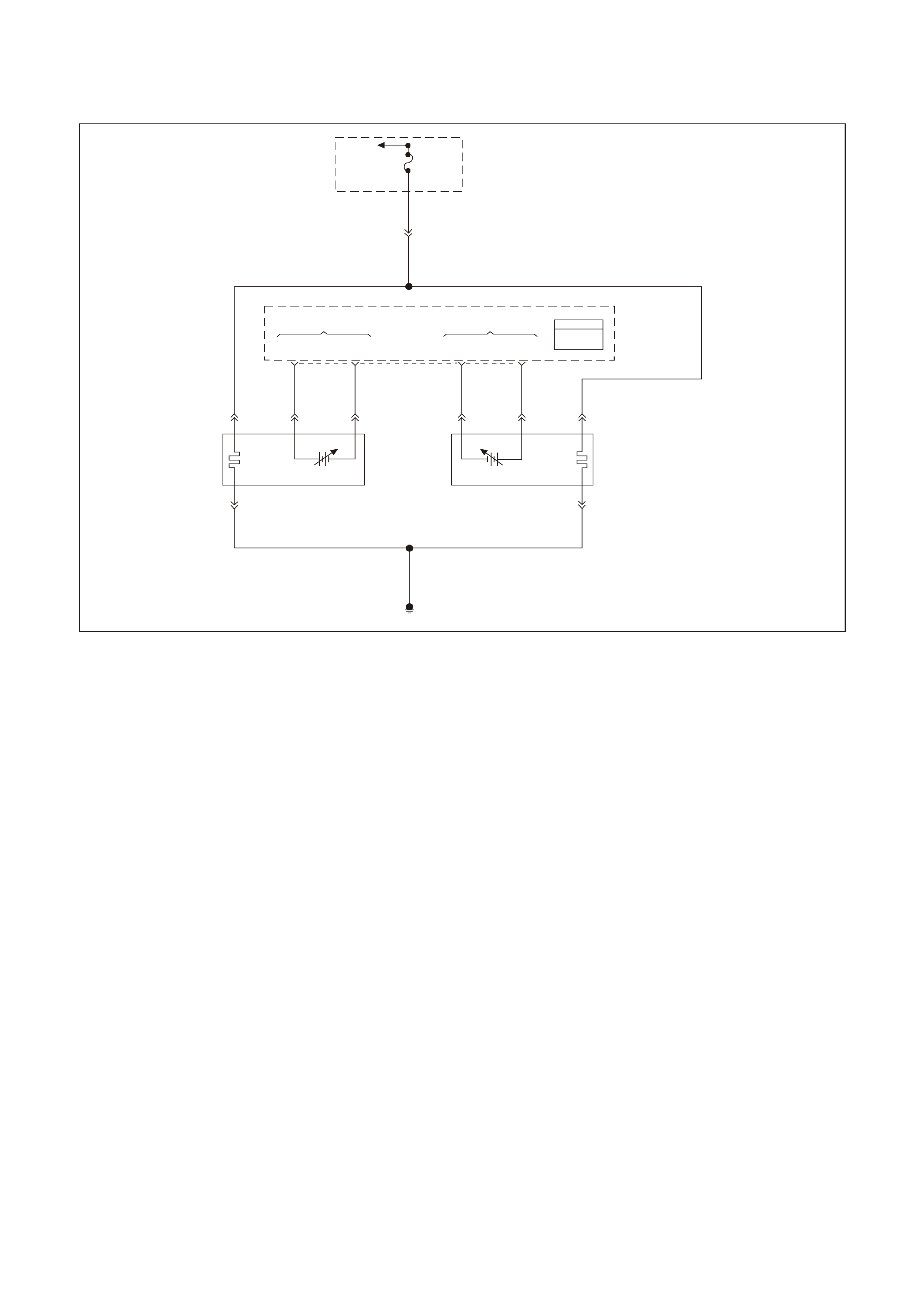
GEN III V8 PCM DTC P0153 HEATED OXYGEN SENSOR (HO2S)
SLOW RESPONSE BANK 2 SENSOR 1
GEN 3 01 57
To
EFI (Engine
Cont.) Relay Fuse
F33
YE111
P 439
Bank #1
Left Front
HO2S
High HO2S
Low
Bank #2
Right Front
HO2S
Low HO2S
High
PCM
J1 = B LUE
J2 = R ED
Powertrain
Control
Module
(PCM)
P439
B/R 750
Engine
Earth
D
Bank 2 Sensor 1
Heated Oxygen
Sensor (HO2S)
BA
GY/B 1413 GY 1412
26 66 J1
69 29
ABD
Bank 1 Sensor 1
Heat ed Oxygen
Sensor (HO2S)
BLU/B 413
P439 V412
B/R 750
C
B/R 750
C
CIRCUIT DESCRIPTION
The PCM continuously monitors the Heated Oxygen Sensor (HO2S) activity for 100 seconds. During the monitor
period the PCM counts the number of times that the HO2S responds from rich to lean and from lean to rich and
adds the amount of time it took to complete all transactions. With this information, the PCM can determine the
average time for all transactions. If the average response time is too slow, the DTC will set.
The PCM determines the lean to rich transaction when the HO2S voltage changes from less than 300 mV to greater
than 600 mV. The PCM determines the rich to lean transaction when the HO2S voltage changes from more than
600 mV to less than 300 mV. An HO2S that responds too slowly is more likely defective. Replace the HO2S.
CONDITIONS FOR RUNNING THE DTC
• DTCs P0101, P0102, P0103, P0112, P0113, P0117, P0118, P0121, P0122, P0123, P0335, P0336, P0351-
P0358, P1258, not set.
• The engine coolant temperature is greater than 65°C (149°F).
• The ignition voltage is greater than 9.0 volts.
• The fuel system is operating in Closed Loop.
• The engine speed between 1000 RPM and 2300 RPM.
• The engine air flow is between 20 g/s and 50 g/s.
• The EVAP canister purge duty cycle is greater than 0%.
• The engine run time is greater than 120 seconds.
CONDITIONS FOR SETTING THE DTC
• The lean to rich response (below 300 mV to above 600 mV) average time is greater than 100 milliseconds.
• The rich to lean response (above 600 mV to below 300 mV) average time is greater than 100 milliseconds.
• The above conditions are met for 100 seconds.

ACTION TAKEN WHEN THE DTC SETS
• The PCM illuminates the Check Powertrain Lamp (CPL) when the diagnostic runs and fails.
• T he PCM records the operating conditions at the time the diagnostic fails. The PCM stores this inform ation in
the Freeze Frame/Failure Records.
• Open Loop Fueling.
CONDITIONS FOR CLEARING THE CPL/DTC
• The PCM turns the CPL OFF after the first ignition cycle that the diagnostic runs and does not fail.
• A last test failed (current DTC) clears when the diagnostic runs and does not fail.
• A History DTC clears after forty consecutive warm-up cycles, if this or any other emission related diagnostic
does not report any failure.
• Use a Tech 2 scan tool in order to clear the CPL/DTC.
DIAGNOSTIC AIDS
• This diagnostic only runs once per ignition cycle.
• A malfunction in the HO2S heater circuits cause a DTC to set. Check HO2S heater circuit for intermittent
opens/connections.
• An oxygen supply inside the HO2S is necessary for proper operation. T he HO2S wires provides the supply of
oxygen. Inspect the HO2S wires and connections for breaks or contamination. Refer to
Electrical Diagnosis/Repair Procedures in Section 12P of the VT Series I Service Information.
• Using the Freeze Frame/Failure Records data may aid in locating an intermittent condition. If you cannot
duplicate the DT C, the information inc luded in the Freeze Fram e/Failure Records data can help determ ine the
distance traveled since the DTC set. The Fail Counter and Pass Counter can also help determine how many
ignition cycles the diagnostic reported a pass and/or fail. Operate the vehicle within the same freeze frame
conditions (RPM, load, vehicle speed, temperature etc.) that you observed. This will isolate when the DTC
failed. For an intermittent condition, refer to Section 6C-2B Symptoms of the VT Series II Service Information.
TEST DESCRIPTION
The numbers below refer to the step numbers on the diagnostic table.
2. This step deter mines if the fault is pr esent. This test may take 5 m inutes for the diagnostic to run. For any test
that requires probing the PCM or a component harness connector, use the Connector Test Adaptor Kit J
35616-A. Using this kit prevents damage to the harness connector terminals.
3. When DTCs P0133 and P0153 are set at the same time, it is a good indication that a fuel contamination
problem is present.
4. An exhaust leak 15 - 30 CM (6-12 inches) away from the HO2S can cause a DTC to set.
5. This set checks whether a good earth circuit is available.
6. This step checks the integrity of the signal circuit to the PCM.
7. This step checks the integrity of the signal circuit to the PCM.
8. Certain RTV silicone gasket materials give off vapors that can contaminate the HO2S. There is also a
possibility of s ilicone contam ination caused by silicone in the fuel. If the sens ors appear to be contam inated by
silicone and all the silicone sealant is a non s ilicone base, advise the c ustom er to try a different f uel com pany.
A missing fuel filler restrictor indicates the customer may have used leaded fuel.

GEN III V8 PCM DTC P0153 HEATED OXYGEN SENSOR (HO2S) SLOW RESPONSE BANK 2 SENSOR 1
Step Action Value(s) Yes No
1 Did you perform the Powertrain On-Board Diagnostic
(OBD) System Check? Go to Step 2 Go to Powertrain
OBD System
Check Table
2
Important: If any DTCs are set (except P0153), refer to
those DTCs before proceeding with this diagnostic table.
1. Install a Tech 2 scan tool.
2. Idle the engine at the normal operating temperature.
3. Operate the vehicle within parameters listed under
Conditions for Running the DTC as specified in the
supporting text.
4. Monitor the Failed This Ignition option under the DTC
Information option using the Tech 2 scan tool.
Did DTC P0153 fail this ignition?
Go to Step 3 Go to Diagnostic
Aids
3 Did DTC P0133 also fail this ignition? Go to Step 8 Go to Step 4
4 1. Check for an exhaust system leak. Refer to Section
8B Exhaust System of the VT Series II Service
Information. After you inspect the exhaust system,
return to this diagnostic.
2. If you find an exhaust leak, repair the exhaust leak as
necessary
Did you isolate an exhaust leak?
Go to Step 2 Go to Step 5
5 Inspect the following items:
• Ensure that the HO2S is securely installed.
• Check for corrosion on the terminals.
• Check the terminals tension at the HO2S and at the
PCM.
• Check for damaged wiring.
Did you find a problem in any of the above areas?
Go to Step 9 Go to Step 6
6 1. Disconnect the Bank 2 HO2S.
2. Jumper the HO2S low (PCM side) signal circuit to a
earth.
3. Monitor the Bank 2 HO2S voltage on the Engine Data
List using the Tech 2 scan tool.
Does the Tech 2 scan tool indicate a voltage within the
specified range?
350-550 mV Go to Step 7 Go to Step 10
7 1. Jumper the Bank 2 HO2S high and low (PCM side)
signal circuit to a earth.
2. Monitor the Bank 2 HO2S voltage using the Tech 2
scan tool.
Does the Tech 2 scan tool indicate a voltage below
specified value?
200mV Go to Step 12 Go to Diagnostic
Aids
8 Important: Determine and correct the cause of the
contamination before replacing a sensor. Check for the
following conditions:
• Fuel contamination
• Use of improper RTV sealant
• Engine oil/coolant consumption
Replace the affected Heated Oxygen sensor
Is the action complete?
Go to Step 13

Step Action Value(s) Yes No
9 Repair the conditions as necessary.
Is the action complete? Go to Step 13
10 Repair the open Bank 2 HO2S low signal circuit or the
earthed Bank 2 HO2S high signal circuits.
Is the action complete?
Go to Step 13
11 Repair the open Bank 2 HO2S high signal circuit or the
faulty PCM connections.
Is the action complete?
Go to Step 13
12 Replace the Bank 2 HO2S.
Is the action complete? Go to Step 13
13
1. Select the Diagnostic Trouble Code (DTC) option and
the Clear DTC Information option using the Tech 2
scan tool.
2. Idle the engine at the normal operating temperature.
3. Select the Diagnostic Trouble Code (DTC) option, the
DTC Information option, and the Failed This Ignition
option using the Tech 2 scan tool.
4. Operate the vehicle within the Conditions for Running
the DTC as specified in the supporting text, if
applicable.
Does the Tech 2 scan tool indicate that this DTC reset?
Go to Step 2 Go to Step 14
14 Using the Tech 2 scan tool, check for any other DTCs.
Does the Tech 2 scan tool display any DTCs that you
have not diagnosed?
Go to the
applicable DTC
table
System OK
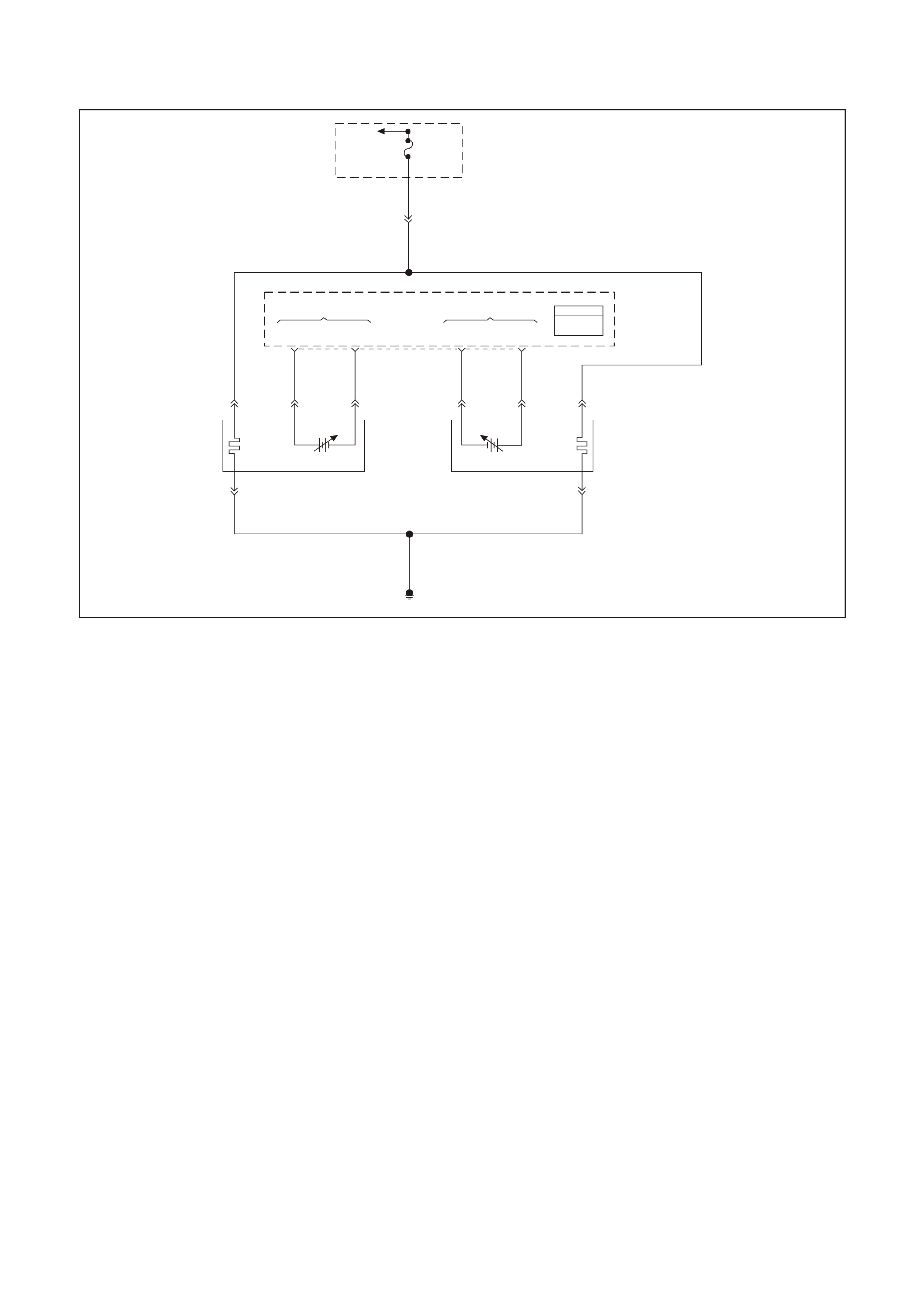
GEN III V8 PCM DTC P0154 HEATED OXYGEN SENSOR (HO2S)
INSUFFICIENT ACTIVITY BANK 2 SENSOR 1
GEN 3 01 57
To
EFI (Engine
Cont.) Relay Fuse
F33
YE111
P 439
Bank #1
Left Front
HO2S
High HO2S
Low
Bank #2
Right Front
HO2S
Low HO2S
High
PCM
J1 = B LUE
J2 = R ED
Powertrain
Control
Module
(PCM)
P439
B/R 750
Engine
Earth
D
Bank 2 Sensor 1
Heated Oxygen
Sensor (HO2S)
BA
GY/B 1413 GY 1412
26 66 J1
69 29
ABD
Bank 1 Sensor 1
Heat ed Oxygen
Sensor (HO2S)
BLU/B 413
P439 V412
B/R 750
C
B/R 750
C
CIRCUIT DESCRIPTION
The PCM supplies a voltage of about 450 m V between the HO2S high and low signal circuits. The oxygen sensor
varies the voltage over a r ange f r om about 1000 mV when the exhaust is r ich, down through about 10 mV when the
exhaust is lean.
The PCM monitors and stores the Heated Oxygen Sensor (HO2S) voltage information. The PCM evaluates the
HO2S voltage samples in order to determine the amount of time the HO2S voltage was out of range. The PCM
compares the stored HO2S voltage samples taken within each sample period and determines if majority of the
samples are out of the operating range.
The PCM monitors the HO2S voltage and detects if the voltage goes out of the bias range. If the PCM does not
detect the voltage went out of the bias range, the DTC will set.
CONDITIONS FOR RUNNING THE DTC
• DTCs P0101, P0102, P0103, P0112, P0113, P0117, P0118, P0121, P0122, P0123, P0335, P0336, P0351-
P0358, P1258, not set.
• The ignition voltage is greater than 9.0 volts.
• The fuel system is operating in Closed Loop.
• The engine run time is greater than 70 seconds.
• The engine coolant temperature is greater than 48°C (118°F)
CONDITIONS FOR SETTING THE DTC
• The HO2S signal voltage is steady between 350 mV and 550 mV.
• The conditions are present for 70 seconds.
ACTION TAKEN WHEN THE DTC SETS
• The PCM illuminates the Check Powertrain Lamp (CPL) when the diagnostic runs and fails.
• T he PCM records the operating conditions at the time the diagnostic f ails. The PCM stores this inform ation in
the Freeze Frame and/or the Failure Records.
• Open Loop Fueling.

CONDITIONS FOR CLEARING THE CPL/DTC
• The PCM turns the CPL OFF after the first ignition cycle that the diagnostic runs and does not fail.
• A last test failed (current DTC) clears when the diagnostic runs and does not fail.
• A History DTC clears after forty consecutive warm-up cycles, if this or any other emission related diagnostic
does not report any failure.
• Use a Tech 2 scan tool in order to clear the CPL/DTC.
DIAGNOSTIC AIDS
• An oxygen supply inside the HO2S is necessary for correct operation. The HO2S wires provide the supply of
oxygen. Inspect the HO2S wires and connections for breaks or contamination. Refer to Electrical
Diagnosis/Repair Procedures in Section 12P of the VT Series I Service Information.
• Using the Freeze Frame/Failure Records data may aid in locating an intermittent condition. If you cannot
duplicate the DT C, the information inc luded in the Freeze Fram e/Failure Records data can help determ ine the
distance traveled since the DTC set. The Fail Counter and Pass Counter can also help determine how many
ignition cycles the diagnostic reported a pass and/or fail. Operate the vehicle within the same freeze frame
conditions (RPM, load, vehicle speed, temperature etc.) that you observed. This will isolate when the DTC
failed.
• For an intermittent condition, refer to Section 6C3-2B Symptoms of the VT Series II Service Information.
TEST DESCRIPTION
The numbers below refer to the step numbers on the diagnostic table.
2. The engine must be at normal operating temperature before performing this test. For any test that requires
probing the PCM or a component harness connector, use the Connector Test Adaptor Kit J 35616-A. Using
this kit prevents damage to the harness connector terminals.
3. Using the Freeze Frame/Failure Records data may aid in locating an intermittent condition. If you can not
duplicate the DT C, the information inc luded in the Freeze Fram e/Failure Records data can help determ ine the
distance traveled since the DTC set. The Fail Counter and Pass Counter can also aid in determining how many
ignition cycles the diagnostic reported a pass and/or a fail. Operate the vehicle within the same freeze frame
conditions (R PM, load, vehicle s peed, temperatur e etc .) that the PCM r ecor ded. T his will isolate when the DT C
failed. refer to Section 6C3-2B Symptoms of the VT Series II Service Information.
4. If the T ech 2 scan tool indicates thew HO2S voltage goes below 200 m V, this indicates the HO 2S circuits and
PCM are OK.
5. This step checks whether the signal circuit from the PCM is OK.
6. Disconnecting the PCM allows using a DMM J 39200 in order to check continuity of the circuits. This aids in
locating an open or shorted circuit.
7. Disconnecting the PCM allows using a DMM J 39200 in order to check continuity of the circuits. This aids in
locating an open or shorted circuit.

GEN III V8 PCM DTC P0154 HEATED OXYGEN SENSOR (HO2S) INSUFFICIENT ACTIVITY BANK 2 SENSOR 1
Step Action Value(s) Yes No
1 Did you perform the Powertrain On-Board Diagnostic
(OBD) System Check? Go to Step 2 Go to Powertrain
OBD System
Check Table
2
Important: Check the HO2S for being secure before
proceeding with this DTC. A sensor that is loose could
cause this DTC to set.
1. Install a Tech 2 scan tool.
2. Idle the engine at the normal operating temperature
3. Operate the engine above 1200 RPM for two minutes.
4. Monitor the HO2S voltage display on the Engine Data
List using the Tech 2 scan tool .
Does the Tech 2 scan tool indicate the Bank 2 HO2S
voltage varying outside the specified value?
350-550 mV Go to Step 3 Go to Step 4
3 1. Turn ON the ignition leaving the engine OFF.
2. Review the Freeze Frame/Failure Records data for
this DTC and observe the parameters.
3. Turn OFF the ignition for 15 seconds.
4. Idle the engine.
5. Operate the vehicle within the conditions required for
this diagnostic to run, and as close to the conditions
recorded in Freeze Frame/Failure Records a possible.
Special operating conditions that need to be met
before the PCM will run this diagnostic where
applicable, are listed in Conditions for Running the
DTC.
6. Select the Diagnostic Trouble Code (DTC) option, the
DTC Informationoption, and the Failed This Ignition
option using the Tech 2 scan tool.
Does the Tech 2 scan tool indicate that this diagnostic
failed this ignition?
Go to Step 4 Go to Diagnostic
Aids
4 1. Turn ON the ignition leaving the engine OFF.
2. Disconnect the Bank 2 HO2S.
3. Jumper the HO2S high and low (PCM side) signal
circuits to a earth.
4. Monitor the Bank 2 HO2S voltage using the Tech 2
scan tool.
Is the Bank 2 HO2S voltage below the specified value?
200 mV Go to Step 8 Go to Step 5
5 1. Remove the jumper wire.
2. Measure the voltage between the Bank 2 HO2S
heater earth circuit using a DMM J 39200.
Does the Bank 2 HO2S voltage measure above the
specified value?
375 mV Go to Step 6 Go to Step 7
6 1. Turn Off the ignition.
2. Disconnect the PCM BLUE connector.
3. Check the continuity of the Bank 2 HO2S low circuit.
4. Repair the open or the poor connection if the Bank 2
HO2S low circuit measures over the specified value.
Did you find and correct the Bank 2 HO2S low circuit
condition?
2Ω Go to Step 13 Go to Step 9

Step Action Value(s) Yes No
7 1. Turn Off the ignition.
2. Disconnect the PCM connectors.
3. Check the continuity of the Bank 2 HO2S low circuit.
4. Repair the open or the poor connection if the Bank 2
HO2S low circuit measures over the specified value.
Did you find and correct the Bank 2 HO2S low circuit
condition?
2Ω Go to Step 13 Go to Step 10
8 Check for a poor Bank 2 HO2S signal or low circuit
terminal connection at the Bank 2 HO2S harness
connector and replace the terminal(s) if necessary.
Did any terminals require replacement?
Go to Step 13 Go to Step 11
9 Check for a poor Bank 2 HO2S low circuit terminal
connection at the PCM, and replace the terminal if
necessary.
Did any terminals require replacement?
Go to Step 13 Go to Step 12
10 Check for a poor Bank 2 HO2S signal circuit terminal
connection at the PCM, and replace the terminal if
necessary.
Did any terminals require replacement?
Go to Step 13 Go to Step 12
11 Replace the Bank 2 HO2S.
Is the action complete? Go to Step 13
12 1. Replace PCM.
2. Refer to Section 6C3-3 of the VT Series II Service
Information for PCM Programming and
PCM/PIM/BCM Security Link Procedure.
Is action complete?
Go to Step 13
13 1. Select the Diagnostic Trouble Code (DTC) option and
the Clear DTC Information option using the Tech 2
scan tool.
2. Idle the engine at the normal operating temperature.
3. Select the Diagnostic Trouble Code (DTC) option, the
DTC Information option, and the Failed This Ignition
option using the Tech 2 scan tool.
4. Operate the vehicle within the Conditions for Running
the DTC as specified in the supporting text, if
applicable.
Does the Tech 2 scan tool indicate that this DTC reset?
Go to Step 2 Go to Step 14
14 Using the Tech 2 scan tool, check for any other DTCs.
Does the Tech 2 scan tool display any DTCs that you
have not diagnosed?
Go to the
applicable DTC
table
System OK

GEN III V8 PCM DTC P0155 HEATED OXYGEN SENSOR (HO2S)
HEATER CIRCUIT BANK 2 SENSOR 1
GEN 3 01 57
To
EFI (Engine
Cont.) Relay Fuse
F33
YE111
P 439
Bank #1
Left Front
HO2S
High HO2S
Low
Bank #2
Right Front
HO2S
Low HO2S
High
PCM
J1 = B LUE
J2 = R ED
Powertrain
Control
Module
(PCM)
P439
B/R 750
Engine
Earth
D
Bank 2 Sensor 1
Heated Oxygen
Sensor (HO2S)
BA
GY/B 1413 GY 1412
26 66 J1
69 29
ABD
Bank 1 Sensor 1
Heat ed Oxygen
Sensor (HO2S)
BLU/B 413
P439 V412
B/R 750
C
B/R 750
C
CIRCUIT DESCRIPTION
The PCM supplies a bias voltage (approximately 450 mV) on the Heated Oxygen Sensor (HO2S) signal high and
low circuits. W hen you turn the ignition to the On position, battery voltage is supplied to the HO2S heater. As the
heater reaches the operating temperature, the HO2S voltage responds by changing from a bias voltage range to
the normal operation. Typically, as the HO2S reaches the operating temperature, the HO2S voltage goes from a
bias voltage to a voltage below 300 mV. Depending on the ex haust gas content, it is possible for the HO2S voltage
to go above 450 mV.
The PCM runs the heater test only on a cold start (depends on the cumulative air flow) and only once an ignition
cycle. When you start the engine the PCM monitors the HO2S voltage. When the HO2S voltage goes above or
below the bias range threshold, the PCM determines how much time it took. If the PCM detects that the process
took too long for the HO2S to enter into normal operating range, a DTC will set. The time the process takes the
HO2S to reach operating temperature is based on the amount of air that flows into the engine.
CONDITIONS FOR RUNNING THE DTC
• DTCs P0101, P0102, P0103, P0112, P0113, P0117, P0118, P0121, P0122, P0123, P0335, P0336, P0351-
P0158, P1258 not set.
• The intak e air temperatur e and the engine coolant temper ature ar e less than 50° C ( 122°F) and are within 8° C
(14.5°F) of each other at engine start-up.
• The ignition voltage is between 10.0 volts and 18.0 volts.
• The engine air flow is less than 18g/s.
CONDITIONS FOR SETTING THE DTC
• The HO2S voltage remains between 300 mV and 700 mV for a predetermined amount of time (depends on
engine coolant temperature and air flow).
ACTION TAKEN WHEN THE DTC SETS
• The PCM illuminates the Check Powertrain Lamp (CPL) when the diagnostic runs and fails.
• T he PCM records the operating conditions at the time the diagnostic f ails. The PCM stores this inform ation in
the Freeze Frame/Failure Records.

CONDITIONS FOR CLEARING THE CPL/DTC
• The PCM turns the CPL OFF after the first ignition cycle that the diagnostic runs and does not fail.
• A last test failed (current DTC) clears when the diagnostic runs and does not fail.
• A History DTC clears after forty consecutive warm-up cycles, if this or any other emission related diagnostic
does not report any failure.
• Use a Tech 2 scan tool in order to clear the CPL/DTC.
DIAGNOSTIC AIDS
• Using the Freeze Frame/Failure Records data may aid in locating an intermittent condition. If you cannot
duplicate the DT C, the information inc luded in the Freeze Fram e/Failure Records data can help determ ine the
distance traveled since the DTC Set. The Fail Counter and Pass Counter can also help determine how may
ignition cycles the diagnostic reported a pass and/or a fail. Operate the vehicle within the same freeze frame
conditions (RPM, load, vehicle speed, temperature etc.) that you observed. This will isolate when the DTC
failed. For an intermittent condition, refer to Section 6C3-2B Symptoms of the VT Series II Service
Information.
• The heater diagnostic will only run on a cold start and run once per ignition cycle.
• Inspect the EFI relay for proper operation if you cannot find any problems with the ignition feed circuit to the
com ponent. Probe both sides of the fus e with a test lamp connec ted to earth in order to determ ine if a voltage
is supplied to the fuse. Refer to EFI Relay Diagnosis Chart in this Section.
• An oxygen supply inside the HO2S is necessary for proper operation. T he HO2S wires provides the supply of
oxygen. Inspect the HO2S wires and connections for breaks or contamination.
TEST DESCRIPTION
The numbers below refer to the step numbers on the diagnostic table.
2. Allow the engine to cool before performing this test. If the sensor is at the operating temperature the HO2S
voltage will stay high or low. If the HO2S voltage stays between 300-700 mV indicates the HO2S heater is
inoperative. For any test that requires probing the PCM or a com ponent harnes s connector, use the Connector
Test Adaptor Kit J 35616-A. Using this kit will prevent damage to the harness connector terminals.
3. If more than one HO2S DTC is set, this is a good indication that the HO2S fuse is open. Check all the relate
circuits going to all the heated oxygen sensors for a short to earth. If all the wiring check s to be OK, it may be
necessary to disconnect each HO2S on at a time to locate a shorted sensor.
4. This step checks whether a B+ supply is available at the sensor.
5. This step checks whether a earth is available at the sensor.
6. This step checks whether the HO2S heater element is internally open.
7. Inspect the ignition feed circuits at the engine compartment Fuse & Relay panel for poor connections.
8. Check the earth circuits for an open if more then one heater DTC sets.

GEN III V8 PCM DTC P0155 HEATED OXYGEN SENSOR (HO2S) HEATER CIRCUIT BANK 2 SENSOR 1
Step Action Value(s) Yes No
1 Did you perform the Powertrain On-Board Diagnostic
(OBD) System Check ? Go to Step 2 Go to Powertrain
OBD System
Check Table
2 Important: Allow the engine to cool for about one half
hour before proceeding with this table.
1. Turn OFF the ignition.
2. Install the Tech 2 scan tool.
3. Turn ON the ignition leaving the engine OFF.
4. Monitor the HO2S voltage display on the Engine Data
List of the Tech 2 scan tool.
Does the HO2S voltage go from a bias voltage to above
or below the specified range?
300-700 mV Go to Diagnostic
Aids Go to Step 3
3 Inspect the HO2S heater fuse for an open.
Is the HO2S heater fuse open? Go to Step 11 Go to Step 4
4 1. Raise the vehicle.
2. Disconnect the HO2S electrical connector.
3. Probe the ignition feed circuit at the HO2S electrical
connector (PCM side) using a test lamp J34142-B
connected to earth (a known good earth. Do not use
the HO2S heater earth or the HO2S low circuits).
Does the test lamp illuminate?
Go to Step 5 Go to Step 7
5 Connect the test lamp J34142-B between the HO2S
ignition feed and the HO2S heater earth.
Does the test lamp illuminate?
Go to Step 6 Go to Step 8
6 Measure the resistance between the HO2S ignition feed
and the HO2S heater earth at the HO2S pigtail using a
DMM J39200.
Is the HO2S resistance within the specified range?
3.5 - 14.0Ω Go to Step 9 Go to Step 10
7 Repair the open in the HO2S ignition feed circuit to the
HO2S.
Is the action complete?
Go to Step 12
8 Repair the open in the HO2S heater earth circuit.
Is the action complete? Go to Step 12
9 1. Check for a poor connection at the HO2S harness
terminals.
2. If you find a poor connection, replace the terminals.
Did you find a poor connection?
Go to Step 12 Go to Step 10
10 Replace the HO2S.
Is the action complete? Go to Step 12
11 1. Locate and repair the short to earth in the HO2S
ignition feed circuit.
2. Replace the faulty fuse.
Is the action complete?
Go to step 12
12 1. Select the Diagnostic Trouble Code (DTC) option and
the Clear DTC Information option using the Tech 2
scan tool.
2. Idle the engine at the normal operating temperature.
3. Select the Diagnostic Trouble Code (DTC) option, the
DTC Information option, and the Failed This Ignition
option using the Tech 2 scan tool.
4. Operate the vehicle within the Conditions for Running
the DTC as specified in the supporting text, if
applicable.
Does the Tech 2 scan tool indicate that this DTC reset?
Go to Step 2 Go to step 13
13 Using the Tech 2 scan tool, check for any other DTCs.
Does the Tech 2 scan tool display any DTCs that you
have not diagnosed?
Go to the
applicable DTC
table
System OK
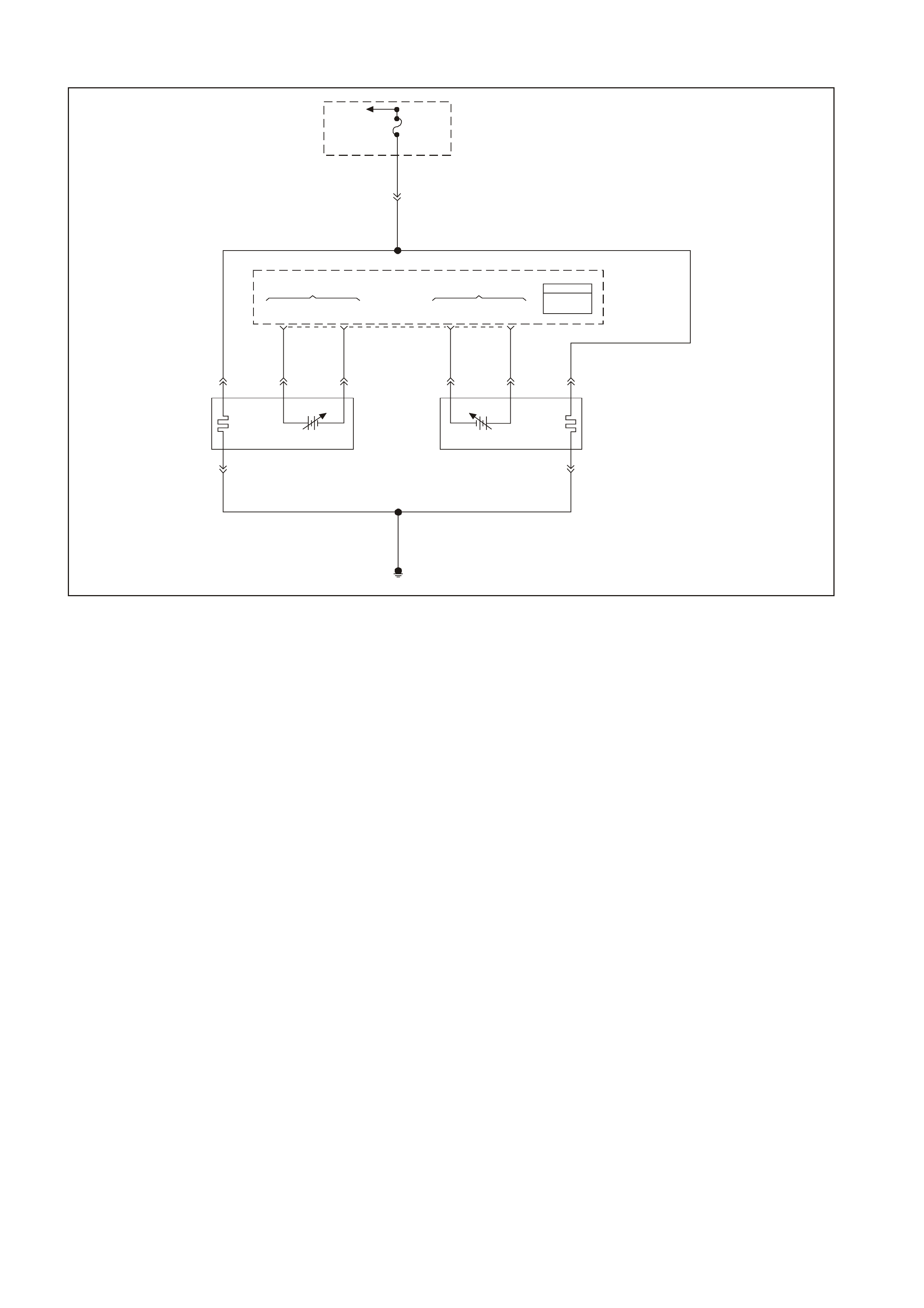
GEN III V8 PCM DTC P0171 FUEL SYSTEM LEAN BANK 1
GEN 3 01 57
To
EFI (Engine
Cont.) Relay Fuse
F33
YE111
P 439
Bank #1
Left Front
HO2S
High HO2S
Low
Bank #2
Right Front
HO2S
Low HO2S
High
PCM
J1 = B LUE
J2 = R ED
Powertrain
Control
Module
(PCM)
P439
B/R 750
Engine
Earth
D
Bank 2 Sensor 1
Heated Oxygen
Sensor (HO2S)
BA
GY/B 1413 GY 1412
26 66 J1
69 29
ABD
Bank 1 Sensor 1
Heat ed Oxygen
Sensor (HO2S)
BLU/B 413
P439 V412
B/R 750
C
B/R 750
C
CIRCUIT DESCRIPTION
The PCM controls a Closed Loop air/fuel metering system in order to provide the best possible combination of
driveability, fuel economy, and emission control. The PCM monitors the heated oxygen sensor signal voltage and
adjusts the fuel delivery based on the signal voltage while in Closed Loop.
A change m ade to the f uel delivery changes the Long and Short T erm F uel Tr im values. T he Short T erm Fuel T r im
values change rapidly in response to the HO2S signal voltages. These changes fine tune the engine fueling. The
Long Term Fuel Trim values change in response to trends in Short Term Fuel Trim. The Long Term Fuel Trim
makes coar s e adjus tments to f ueling in order to r e-c entre and r es tore c ontr ol to Short Term Fuel Trim. You can use
a Tech 2 scan tool in order to monitor the Short and Long Term Fuel Trim. The ideal fuel trim values are around
0%.
A positive Fuel Trim value indicates that the PCM is adding fuel in order to compensate for a lean condition. A
negative Fuel Trim value indicates that the PCM is reducing the amount of fuel in order to compensate for a rich
condition. If the PCM detects an excessively Rich or Lean condition, the PCM sets a DT C. The long term fuel trim
diagnostic parameter is an average of sever al of the long term s peed load learn cells which the PCM selec ts based
on the engine speed and the engine load.
CONDITIONS FOR RUNNING THE DTC
• DTCs P0101, P0102, P0103, P0107, P0108, P0112, P0113, P0117, P0118, P0121, P0122, P0123, P0335,
P0336, P0351, P0352, P0353, P0354, P0355, P0356, P0357, P0358, P1111, P1112, P1258, not set.
• The engine coolant temperature is between 50°C (122°F) and 115°C (239°F).
• The barometric pressure is greater than 74 kPa.
• The mass air flow is between 5.0 g/s and 90 g/s.
• The manifold absolute pressure is between 26 kPa and 90 kPa.
• The intake air temperature is between -20°C (-4°F) and 90°C (194°F).
• The engine speed is between 400 RPM and 3000 RPM.
• The TP sensor angle is less than 90%.
• The vehicle speed is less than 137 km/h (85 mph).

CONDITIONS FOR SETTING THE DTC
• The average Long Term Fuel Trim cell values are above a predetermined threshold.
• All the above conditions are present for 6 seconds.
ACTION TAKEN WHEN THE DTC SETS
• The PCM illuminates the Check Powertrain Lamp (CPL) when the diagnostic runs and fails.
• T he PCM records the operating conditions at the time the diagnostic fails. The PCM stores this inform ation in
the Freeze Frame/Failure Records.
CONDITIONS FOR CLEARING THE CPL/DTC
• T he PCM turns the CPL O FF after the f irst drip trips that the diagnostic runs and does not fail within the sam e
conditions that the DTC last failed.
NOTE: If the last failure was during a non-typical driving condition, the CPL may remain ON longer than the
three drive trips. Review the Freeze Frame/Failure Records for the last failure conditions.
• A History DTC clears after forty consecutive warm-up cycles, if this or any other emission related diagnostic
does not report any failures.
• A last test failed (Current DTC) clears when the diagnostic runs and does not fail.
• PCM battery voltage is interrupted.
• Use a Tech 2 scan tool in order to clear the CPL/DTC.
DIAGNOSTIC AIDS
• This DTC sets if the engine runs out of fuel.
• A fuel delivery malfunction causes this DTC to set. Thoroughly inspect all items that cause a lean condition.
• For an intermittent condition, refer to Section 6C3-2B Symptoms of the VT Series II Service Information.
TEST DESCRIPTION
The numbers below refer to the step numbers on the diagnostic table.
2. This s tep determines whether the f ault is present. For any test that requires probing the PCM or a component
harness connector, muse the Connector Test Adaptor Kit J 35626-A. Using the kit prevents damage to the
harness connector terminals.
3. Using the Freeze Frame/Failure Records data may aid in locating an intermittent condition. If you cannot
duplicate the DT C, the information inc luded in the Freeze Fram e/Failure Records data can help determ ine the
distance traveled since the DTC set. The Fail Counter and Pass Counter can also help determine how many
ignition cycles the diagnostic reported a pass and/or a fail. Operate the vehicle within the same freeze frame
conditions (RPM, load, vehicle speed, temperature etc.) that you observed. This will isolate when the DTC
failed.
For an intermittent condition, refer to Section 6C3-2B Symptoms of the VT Series II Service Information.
4. If DTC 174 is also set indicates both banks of the engine are operating lean. Inspect the items that would
cause both banks to operate lean.
5. A vacuum leak causes DTCs P0171 and P0174 to set at the same time. Inspect all areas of the engine for a
vacuum leak. Also inspect the PCV valve for being the correct one for this application. Make sure the engine oil
fill cap is in place and that it is tight. Check that the engine oil dip stick is fully seated.

GEN III V8 PCM DTC P0171 FUEL SYSTEM LEAN BANK 1
Step Action Value(s) Yes No
1 Did you perform the Powertrain On-Board Diagnostic
(OBD System Check? Go to Step 2 Go to Powertrain
OBD System
Check Table
2 Important: If any DTCs are set, except P0171 and
P0174, refer to those DTCs before proceeding with this
diagnostic.
1. Install a Tech 2 scan tool.
2. Idle the engine at the normal operating temperature.
3. Fuel system in Closed Loop.
4. Monitor the LT FT Bank 1 display on the Fuel Trim
Data List using the Tech 2 scan tool.
Is the LT FT less than the specified value indicated?
24%LT Go to Step 3 Go to Step 4
3 1. Turn ON the ignition leaving the engine OFF.
2. Review the Freeze Frame/Failure Records data for
this DTC and observe the parameters.
3. Turn OFF the ignition for 15 seconds.
4. Start the engine.
5. Operate the vehicle within the conditions required for
this diagnostic to run, and as close to the conditions
recorded in Freeze Frame/Failure Records as
possible. Special operating conditions that need to be
met before the PCM will run diagnostic, where
applicable, are listed in Conditions for Running the
DTC.
6. Select the Diagnostic Trouble Code (DTC) option, the
DTC Information option, and the Failed This Ignition
option using the Tech 2 scan tool.
Does the Tech 2 scan tool indicate that this diagnostic
failed this ignition?
Go to Step 4 Go to Diagnostic
Aids
4 Is DTC P0174 also set? Go to Step 5 Go to Step 6
5 Inspect the following items:
• Vacuum hoses for splits, kinks, and proper
connections. Refer to Vacuum Hose Routing
Diagrams in Section 6E3 Emission Control of the VT
Series II Service Information.
• Crankcase ventilation valve and/or system for leaks.
Refer to Crankcase Ventilation System Description
in Section 6C3-1 of the VT Series II Service
Information.
• Contaminated Fuel.
• PCM and sensor earths are clean, tight and in the
proper locations.
• Air induction system after MAF sensor for vacuum
leaks.
• Engine mechanical failure. Refer to Section 6A3
Engine Mechanical of the VT Series II Service
Information.
Did you find any problems in any of the above areas?
Go to Step 7 Go to Fuel
System
Diagnosis Table
6 Inspect the following items:
• Bank 1 exhaust leaks and missing or loose exhaust
hardware.
• Bank 1 HO2S 1 is installed securely and the
electrical connector not contacting exhaust system
or ignition wires.
• Engine mechanical failure. Refer to Section 6A3
Engine Mechanical of the VT Series II Service
Information.
• Vacuum leaks that will only affect bank 1, such as
the intake manifold, the injector O rings, etc.
Was a problem found in any of the above areas?
Go to Step 7 Refer to Fuel
System
Diagnosis Table
in this Section
7 Repair or replace any faulty items found.
Is the action complete? Go to Step 8

Step Action Value(s) Yes No
8 1. Select the Diagnostic Trouble Code (DTC) option
and the Clear DTC Information option using the Tech
2 scan tool.
2. Idle the engine at the normal operating temperature.
3. Select the Diagnostic Trouble Code (DTC) option,
the DTC Information option, and the Failed This
Ignition option using the Tech 2 scan tool.
4. Operate the vehicle within the Conditions for
Running the DTC as specified in the supporting text,
if applicable.
Does the Tech 2 scan tool indicate that this DTC reset?
Go to Step 2 Go to step 9
9 Using the Tech 2 scan tool, check for any other DTCs.
Does the Tech 2 scan tool display any DTCs that you
have not diagnosed?
Go to the
applicable DTC
table
System OK

GEN III V8 PCM DTC P0172 FUEL SYSTEM RICH BANK 1
GEN 3 01 57
To
EFI (Engine
Cont.) Relay Fuse
F33
YE111
P 439
Bank #1
Left Front
HO2S
High HO2S
Low
Bank #2
Right Front
HO2S
Low HO2S
High
PCM
J1 = B LUE
J2 = R ED
Powertrain
Control
Module
(PCM)
P439
B/R 750
Engine
Earth
D
Bank 2 Sensor 1
Heated Oxygen
Sensor (HO2S)
BA
GY/B 1413 GY 1412
26 66 J1
69 29
ABD
Bank 1 Sensor 1
Heat ed Oxygen
Sensor (HO2S)
BLU/B 413
P439 V412
B/R 750
C
B/R 750
C
CIRCUIT DESCRIPTION
The PCM controls a Closed Loop air/fuel metering system in order to provide the best possible combination of
driveability, fuel economy, and emission control. The PCM monitors the heated oxygen sensor signal voltage and
adjusts the fuel delivery based on the signal voltage while in Closed Loop. A change made to the fuel delivery
changes the Long and Short Term Fuel Trim values.
The Short Term F uel T r im values c hange r apidly in response to the HO2S s ignal voltages. These changes fine tune
the engine fueling. The Long Term Fuel Trim values change in response to trends in Short Term Fuel Trim. The
Long Term Fuel Trim m akes coarse adjustm ents to fueling in order to re-centre and restore control to Short Term
Fuel Trim.
You can us e a Tec h 2 scan tool in order to m onitor the Short and Long T erm Fuel T rim . The ideal fuel trim values
are around 0%. A positive Fuel Trim value indicates that the PCM is adding f uel in order to compensate for a lean
condition. A negative F uel T rim value indic ates that the PCM is reduc ing the am ount of f uel in order to c om pensate
for a rich condition. If the PCM detects an exc essively Rich or Lean c ondition, the PCM sets a DT C. The long term
fuel trim diagnostic parameter is an average of several of the long term speed load learn cells which the PCM
selects based on the engine speed and the engine load.
CONDITIONS FOR RUNNING THE DTC
• DTCs P0101, P0102, P0103, P0107, P0108, P0112, P0113, P0117, P0118, P0121, P0122, P0123, P0335,
P0336, P0351, P0352, P0353, P0354, P0355, P0356, P0357, P0358, P1111, P1112, P1258, not set.
• The engine coolant temperature is between 50°C (122°F) and 115°C (239°F).
• The barometric pressure is greater than 74 kPa.
• The mass air flow is between 5.0 g/s and 90 g/s.
• The manifold absolute pressure is between 26 kPa and 90 kPa.
• The intake air temperature is between -20°C (-4°F) and 90°C (194°F).
• The engine speed is between 400 RPM and 3000 RPM.
• The TP sensor angle is less than 90%.
• The vehicle speed is less than 137 km/h (85 mph).

CONDITIONS FOR SETTING THE DTC
• The average Long Term Fuel Trim cell values are above a predetermined threshold.
• All the above conditions are present for 49 seconds.
ACTION TAKEN WHEN THE DTC SETS
• The PCM illuminates the Check Powertrain Lamp (CPL) when the diagnostic runs and fails.
• T he PCM records the operating conditions at the time the diagnostic fails. The PCM stores this inform ation in
the Freeze Frame/Failure Records.
CONDITIONS FOR CLEARING THE CPL/DTC
• The PCM tur ns the CPL OF F af ter the f ir st dr ive trips that the diagnos tic runs and does not fail within the sam e
conditions that the DTC last failed.
NOTE: If the last failure was during a non-typical driving condition, the CPL may remain ON longer than the
three drive trips. Review the Freeze Frame/Failure Records for the last failure conditions.
• A History DTC clears after forty consecutive warm-up cycles, if this or any other emission related diagnostic
does not report any failures.
• A last test failed (Current DTC) clears when the diagnostic runs and does not fail.
• PCM battery voltage is interrupted.
• Use a Tech 2 scan tool in order to clear the CPL/DTC.
DIAGNOSTIC AIDS
• For an intermittent condition, refer to in Section 6C3-2B Symptoms of the VT Series II Service Information.
TEST DESCRIPTION
The numbers below refer to the step numbers on the diagnostic table.
2. This step determines whether the fault is present.
3. Using the Freeze Frame/Failure Records data may aid in locating an intermittent condition. If you cannot
duplicate the DT C, the information inc luded in the Freeze Fram e/Failure Records data can help determ ine the
distance traveled since the DTC set. The Fail Counter and Pass Counter can also help determine how many
ignition cycles the diagnostic reported a pass and/or a fail. Operate the vehicle within the same freeze frame
conditions(RPM, load, vehicle speed, temperature etc.) that you observed. This will isolate when the DTC
failed. For an intermittent condition, refer to in Section 6C3-2B Symptoms of the VT Series II Service
Information.
4. If DTC 175 is also set, then both banks are operating rich. Inspect items that would cause both banks to
operate rich.
5. Excessive fuel in the oil will cause DTCs P0172 and P0175 to set at the same time. Remove the PCV valve
from the intake manifold and plug with a suitable stopper. Also disconnect the fresh air pipe from the rocker
cover and plug with a suitable stopper . If the long term and s hort ter m f uel trim values inc reas e, indic ates ther e
is fuel in the oil.

GEN III V8 PCM DTC P0172 FUEL SYSTEM RICH BANK 1
Step Action Value(s) Yes No
1 Did you perform the Powertrain On-Board Diagnostic
(OBD System Check? Go to Step 2 Go to Powertrain
OBD System
Check Table
2 Important: If any DTCs are set, except P0172 and
P0175, refer to those DTCs before proceeding with this
diagnostic.
1. Install a Tech 2 scan tool.
2. Idle the engine at the normal operating temperature.
3. Fuel system in Closed Loop.
4. Monitor the LT FT Bank 1 display on the Fuel Trim
Data List using the Tech 2 scan tool.
Is the LT FT greater than the specified value indicated?
-13%LT Go to Step 3 Go to Step 4
3 1. Turn ON the ignition leaving the engine OFF.
2. Review the Freeze Frame/Failure Records data for
this DTC and observe the parameters.
3. Turn OFF the ignition for 15 seconds.
4. Start the engine.
5. Operate the vehicle within the conditions required for
this diagnostic to run, and as close to the conditions
recorded in Freeze Frame/Failure Records as
possible. Special operating conditions that need to
be met before the PCM will run diagnostic, where
applicable, are listed in Conditions for Running the
DTC.
6. Select the Diagnostic Trouble Code (DTC) option,
the DTC Information option, and the Failed This
Ignition option using the Tech 2 scan tool.
Does the Tech 2 scan tool indicate that this diagnostic
failed this ignition?
Go to Step 4 Go to Diagnostic
Aids
4 Is DTC P0175 also set? Go to Step 5 Go to Step 6
5 Inspect the following items:
• Collapsed air intake duct.
• The air filter element for being restricted.
• MAF sensor for being installed in the proper
direction and for foreign objects blocking the inlet
screen. Refer to MAF Sensor Replacement in
Section 6C3-3 of the VT Series II Service
Information.
• For fuel in the pressure regulator line. Refer to FFuel
System Diagnosis Table in this Section.
• Check for the incorrect MAP/BARO display.
Compare to another vehicle.
• For excessive fuel in the crankcase. Change oil as
necessary.
Was a problem found in any of the above areas?
Go to Step 7 Go to Fuel
System
Diagnosis Table
6 Important: When the fuel system check is finished,
return to this table.
Inspect the Bank 1 injectors for leaking, refer to Fuel
System Diagnosis Table in this Section.
Are any injectors leaking?
Go to Step 9 Go to Step 8
7 Repair or replace any faulty items found.
Is the action complete? Go to Step 9
8 Replace the faulty HO2S.
Is the action complete? Go to Step 9
9 1. Select the Diagnostic Trouble Code (DTC) option and
the Clear DTC Information option using the Tech 2
scan tool.
2. Idle the engine at the normal operating temperature.
3. Select the Diagnostic Trouble Code (DTC) option, the
DTC Information option, and the Failed This Ignition
option using the Tech 2 scan tool.
4. Operate the vehicle within the Conditions for Running
the DTC as specified in the supporting text, if
applicable.
Does the Tech 2 scan tool indicate that this DTC reset?
Go to Step 2 Go to Step 10
10 Using the Tech 2 scan tool, check for any other DTCs.
Does the Tech 2 scan tool display any DTCs that you
have not diagnosed?
Go to the
applicable DTC
table
System OK
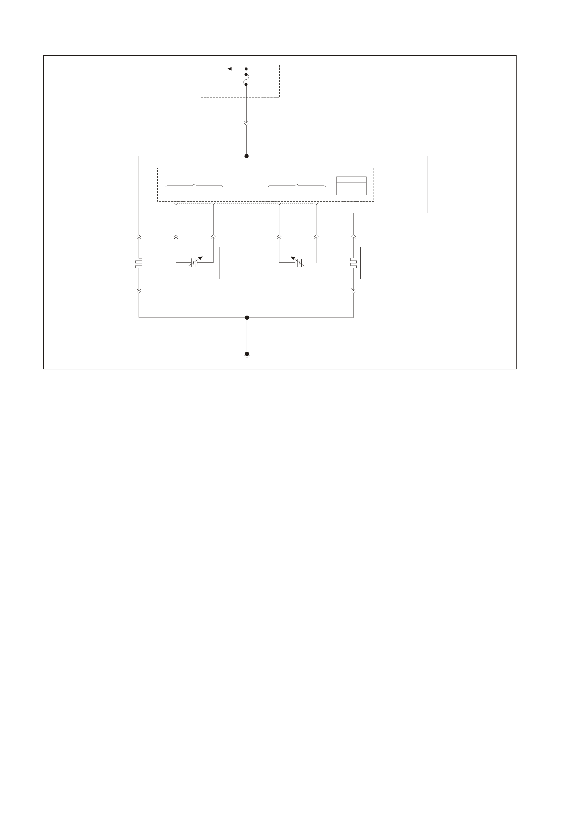
GEN III V8 PCM DTC P0174 FUEL SYSTEM LEAN BANK 2
GEN3 0157
To
EFI (Engine
Cont.) Relay Fuse
F33
YE111
P 439
Bank #1
Left Front
HO2S
High HO2S
Low
Bank #2
Right Front
HO2S
Low HO2S
High
PCM
J1 = B LU E
J2 = R ED
Powertrain
Control
Module
(PCM)
P439
B/R 750
Engine
Earth
D
Bank 2 Sensor 1
Heated Oxygen
Sensor (HO2 S )
BA
GY/B 1413 GY 1412
26 66 J1
69 29
ABD
Bank 1 Sensor 1
Heated Oxygen
Sensor (HO2S)
BLU/B 413
P439 V412
B/R 750
C
B/R 750
C
CIRCUIT DESCRIPTION
The PCM controls a Closed Loop air/fuel metering system in order to provide the best possible combination of
driveability, fuel economy, and emission control. The PCM monitors the heated oxygen sensor signal voltage and
adjusts the fuel delivery based on the signal voltage while in Closed Loop. A change made to the fuel delivery
changes the Long and Short Term Fuel Trim values.
The Short Term F uel T r im values c hange r apidly in response to the HO2S s ignal voltages. These changes fine tune
the engine fueling. The Long Term Fuel Trim values change in response to trends in Short Term Fuel Trim. The
Long Term Fuel Trim m akes coarse adjustm ents to fueling in order to re-centre and restore control to Short Term
Fuel Trim.
You can us e a Tec h 2 scan tool in order to m onitor the Short and Long T erm Fuel T rim . The ideal fuel trim values
are around 0%. A positive Fuel Trim value indicates that the PCM is adding f uel in order to compensate for a lean
condition. A negative F uel T rim value indic ates that the PCM is reduc ing the am ount of f uel in order to c om pensate
for a rich condition. If the PCM detects an exc essively Rich or Lean c ondition, the PCM sets a DT C. The long term
fuel trim diagnostic parameter is an average of several of the long term speed load learn cells which the PCM
selects based on the engine speed and the engine load.
CONDITIONS FOR RUNNING THE DTC
• DTCs P0101, P0102, P0103, P0107, P0108, P0112, P0113, P0117, P0118, P0121, P0122, P0123, P0335,
P0336, P0351, P0352, P0353, P0354, P0355, P0356, P0357, P0358, P1111, P1112, P1258, not set.
• The engine coolant temperature is between 50°C (122°F) and 115°C (239°F).
• The barometric pressure is greater than 74 kPa.
• The mass air flow is between 5.0 g/s and 90 g/s.
• The manifold absolute pressure is between 26 kPa and 90 kPa.
• The intake air temperature is between -20°C (-4°F) and 90°C (194°F).
• The engine speed is between 400 RPM and 3000 RPM.
• The TP sensor angle is less than 90%.
• The vehicle speed is less than 137 km/h (85 mph).
CONDITIONS FOR SETTING THE DTC
• The average Long Term Fuel Trim cell values are above a predetermined threshold.
• All the above conditions are present for 6 seconds.

ACTION TAKEN WHEN THE DTC SETS
• The PCM illuminates the Check Powertrain Lamp (CPL) when the diagnostic runs and fails.
• T he PCM records the operating conditions at the time the diagnostic fails. The PCM stores this inform ation in
the Freeze Frame/Failure Records.
CONDITIONS FOR CLEARING THE CPL/DTC
• The PCM tur ns the CPL OF F af ter the f ir st dr ive trips that the diagnos tic runs and does not fail within the sam e
conditions that the DTC last failed.
NOTE: If the last failure was during a non-typical driving condition, the CPL may remain ON longer than the
three drive trips. Review the Freeze Frame/Failure Records for the last failure conditions.
• A History DTC clears after forty consecutive warm-up cycles, if this or any other emission related diagnostic
does not report any failures.
• A last test failed (Current DTC) clears when the diagnostic runs and does not fail.
• PCM battery voltage is interrupted.
• Use a Tech 2 scan tool in order to clear the CPL/DTC.
DIAGNOSTIC AIDS
• This DTC sets if the engine runs out of fuel.
• A fuel delivery malfunction causes this DTC to set. Thoroughly inspect all items that cause a lean condition.
• For an intermittent condition, refer to Section 6C3-2B Symptoms of the VT Series II Service Information.
TEST DESCRIPTION
The numbers below refer to the step numbers on the diagnostic table.
2. T his step determ ines whether the fault is pres ent. For any test that requires probing the PCM or a com ponent
harness connector, use the Connector Test Adaptor Kit J 35626-A. Using the kit prevents damage to the
harness connector terminals.
3. Using the Freeze Frame/Failure Records data may aid in locating an intermittent condition. If you cannot
duplicate the DT C, the information inc luded in the Freeze Fram e/Failure Records data can help determ ine the
distance traveled since the DTC set. The Fail Counter and Pass Counter can also help determine how many
ignition cycles the diagnostic reported a pass and/or a fail. Operate the vehicle within the same freeze frame
conditions (RPM, load, vehicle speed, temperature etc.) that you observed. This will isolate when the DTC
failed. For an intermittent condition, refer to in Section 6C3-2B Symptoms of the VT Series II Service
Information.
4. If DTC 174 is als o set, this indicates both bank s of the engine are operating lean. Inspect the item s that would
cause both banks to operate lean.
5. A vacuum leak causes DTCs P0171 and P0174 to set at the same time. Inspect all areas of the engine for a
vacuum leak. Also inspect the PCV valve for being the correct one for this application. Make sure the engine oil
fill cap is in place and that it is tight. Check that the engine oil dip stick is fully seated.

GEN III V8 PCM DTC P0174 FUEL SYSTEM LEAN BANK 2
Step Action Value(s) Yes No
1 Did you perform the Powertrain On-Board Diagnostic
(OBD System Check? Go to Step 2 Go to Powertrain
OBD System
Check Table
2 Important: If any DTCs are set, except P0171 and
P0174, refer to those DTCs before proceeding with this
diagnostic.
1. Install a Tech 2 scan tool.
2. Idle the engine at the normal operating temperature.
3. Fuel system in Closed Loop.
4. Monitor the LT FT Bank 2 display on the Fuel Trim
Data List using the Tech 2 scan tool.
Is the LT FT less than the specified value indicated?
24%LT Go to Step 3 Go to Step 4
3 1. Turn ON the ignition leaving the engine OFF.
2. Review the Freeze Frame/Failure Records data for
this DTC and observe the parameters.
3. Turn OFF the ignition for 15 seconds.
4. Start the engine.
5. Operate the vehicle within the conditions required for
this diagnostic to run, and as close to the conditions
recorded in Freeze Frame/Failure Records as
possible. Special operating conditions that need to be
met before the PCM will run diagnostic, where
applicable, are listed in Conditions for Running the
DTC.
6. Select the Diagnostic Trouble Code (DTC) option, the
DTC Information option, and the Failed This Ignition
option using the Tech 2 scan tool.
Does the Tech 2 scan tool indicate that this diagnostic
failed this ignition?
Go to Step 4 Go to Diagnostic
Aids
4 Is DTC P0171 also set? Go to Step 5 Go to Step 6
5 Inspect the following items:
• Vacuum hoses for splits, kinks, and proper
connections. Refer to Vacuum Hose Routing
Diagrams in Section 6E3 Emission Control of the VT
Series II Service Information.
• Crankcase ventilation valve and/or system for leaks.
Refer to Crankcase Ventilation System Description
in Section 6C3-1 of the VT Series II Service
Information.
• Contaminated Fuel.
• PCM and sensor earths are clean, tight and in the
proper locations.
• Air induction system after MAF sensor for vacuum
leaks.
• Engine mechanical failure. Refer to Section 6A3
Engine Mechanical of the VT Series II Service
Information.
Did you find any problems in any of the above areas?
Go to Step 7 Go to Fuel
System
Diagnosis Table
6 Inspect the following items:
• Bank 2 exhaust leaks and missing or loose exhaust
hardware.
• Bank 2 HO2S 1 is installed securely and the
electrical connector not contacting exhaust system
or ignition wires.
• Engine mechanical failure. Refer to Section 6A3
Engine Mechanical of the VT Series II Service
Information.
• Vacuum leaks that will only affect bank 2, such as
the intake manifold, the injector O rings, etc.
Was a problem found in any of the above areas?
Go to Step 7 Refer to Fuel
System
Diagnosis Table
in this Section
7 Repair or replace any faulty items found.
Is the action complete? Go to Step 8

Step Action Value(s) Yes No
8 1. Select the Diagnostic Trouble Code (DTC) option and
the Clear DTC Information option using the Tech 2
scan tool.
2. Idle the engine at the normal operating temperature.
3. Select the Diagnostic Trouble Code (DTC) option, the
DTC Information option, and the Failed This Ignition
option using the Tech 2 scan tool.
4. Operate the vehicle within the Conditions for Running
the DTC as specified in the supporting text, if
applicable.
Does the Tech 2 scan tool indicate that this DTC reset?
Go to Step 2 Go to step 9
9 Using the Tech 2 scan tool, check for any other DTCs.
Does the Tech 2 scan tool display any DTCs that you
have not diagnosed?
Go to the
applicable DTC
table
System OK

GEN III V8 PCM DTC P0175 FUEL SYSTEM RICH BANK 2
GEN 3 01 57
To
EFI (Engine
Cont.) Relay Fuse
F33
YE111
P 439
Bank #1
Left Front
HO2S
High HO2S
Low
Bank #2
Right Front
HO2S
Low HO2S
High
PCM
J1 = B LUE
J2 = R ED
Powertrain
Control
Module
(PCM)
P439
B/R 750
Engine
Earth
D
Bank 2 Sensor 1
Heated Oxygen
Sensor (HO2S)
BA
GY/B 1413 GY 1412
26 66 J1
69 29
ABD
Bank 1 Sensor 1
Heat ed Oxygen
Sensor (HO2S)
BLU/B 413
P439 V412
B/R 750
C
B/R 750
C
CIRCUIT DESCRIPTION
The PCM controls a Closed Loop air/fuel metering system in order to provide the best possible combination of
driveability, fuel economy, and emission control. The PCM monitors the heated oxygen sensor signal voltage and
adjusts the fuel delivery based on the signal voltage while in Closed Loop. A change made to the fuel delivery
changes the Long and Short Term Fuel Trim values.
The Short Term F uel T r im values c hange r apidly in response to the HO2S s ignal voltages. These changes fine tune
the engine fueling. The Long Term Fuel Trim values change in response to trends in Short Term Fuel Trim. The
Long Term Fuel Trim m akes coarse adjustm ents to fueling in order to re-centre and restore control to Short Term
Fuel Trim.
You can us e a Tec h 2 scan tool in order to m onitor the Short and Long T erm Fuel T rim . The ideal fuel trim values
are around 0%. A positive Fuel Trim value indicates that the PCM is adding f uel in order to compensate for a lean
condition. A negative F uel T rim value indic ates that the PCM is reduc ing the am ount of f uel in order to c om pensate
for a rich condition. If the PCM detects an exc essively Rich or Lean c ondition, the PCM sets a DT C. The long term
fuel trim diagnostic parameter is an average of several of the long term speed load learn cells which the PCM
selects based on the engine speed and the engine load.
CONDITIONS FOR RUNNING THE DTC
• DTCs P0101, P0102, P0103, P0107, P0108, P0112, P0113, P0117, P0118, P0121, P0122, P0123, P0335,
P0336, P0351, P0352, P0353, P0354, P0355, P0356, P0357, P0358, P1111, P1112, P1258, not set.
• The engine coolant temperature is between 50°C (122°F) and 115°C (239°F).
• The barometric pressure is greater than 74 kPa.
• The mass air flow is between 5.0 g/s and 90 g/s.
• The manifold absolute pressure is between 26 kPa and 90 kPa.
• The intake air temperature is between -20°C (-4°F) and 90°C (194°F).
• The engine speed is between 400 RPM and 3000 RPM.
• The TP sensor angle is less than 90%.
• The vehicle speed is less than 137 km/h (85 mph).
CONDITIONS FOR SETTING THE DTC
• The average Long Term Fuel Trim cell values are above a predetermined threshold.
• All the above conditions are present for 6 seconds.

ACTION TAKEN WHEN THE DTC SETS
• The PCM illuminates the Check Powertrain Lamp (CPL) when the diagnostic runs and fails.
• The PCM records the operating conditions at the time the diagnostic fails. The PCM stores this information in
the Freeze Frame/Failure Records.
CONDITIONS FOR CLEARING THE CPL/DTC
• The PCM tur ns the CPL OF F af ter the f ir st dr ive trips that the diagnos tic runs and does not fail within the sam e
conditions that the DTC last failed.
NOTE: If the last failure was during a non-typical driving condition, the CPL may remain ON longer than the three
drive trips. Review the Freeze Frame/Failure Records for the last failure conditions.
• A History DTC clears after forty consecutive warm-up cycles, if this or any other emission related diagnostic
does not report any failures.
• A last test failed (Current DTC) clears when the diagnostic runs and does not fail.
• PCM battery voltage is interrupted.
• Use a Tech 2 scan tool in order to clear the CPL/DTC.
DIAGNOSTIC AIDS
• For an intermittent condition, refer to Section 6C3-2B Symptoms of the VT Series II Service Information.
TEST DESCRIPTION
The numbers below refer to the step numbers on the diagnostic table.
2. This step determines whether the fault is present.
3. Using the Freeze Frame/Failure Records data may aid in locating an intermittent condition. If you cannot
duplicate the DT C, the information inc luded in the Freeze Fram e/Failure Records data can help determ ine the
distance traveled since the DTC set The Fail Counter and Pass Counter can also help determine how many
ignition cycles the diagnostic reported a pass and/or a fail. Operate the vehicle within the same freeze frame
conditions (RPM, load, vehicle speed, temperature etc.) that you observed. This will isolate when the DTC
failed. For an intermittent condition, refer to Section 6C3-2B Symptoms of the VT Series II Service
Information.
4. If DTC 175 is also set, then both banks are operating rich. Inspect items that would cause both banks to
operate rich.
5. Excessive fuel in the oil will cause DTCs P0172 and P0175 to set at the same time. Remove the PCV valve
from the intake manifold and plug with a suitable stopper. Also disconnect the fresh air pipe from the rocker
cover and plug with a suitable stopper . If the long term and s hort ter m f uel trim values inc reas e, indic ates ther e
is fuel in the oil.

GEN III V8 PCM DTC P0175 FUEL SYSTEM RICH BANK 2
Step Action Value(s) Yes No
1 Did you perform the Powertrain On-Board Diagnostic
(OBD System Check? Go to Step 2 Go to Powertrain
OBD System
Check Table
2 Important: If any DTCs are set, except P0172 and
P0175, refer to those DTCs before proceeding with this
diagnostic.
1. Install a Tech 2 scan tool.
2. Idle the engine at the normal operating temperature.
3. Fuel system in Closed Loop.
4. Monitor the LT FT Bank 2 display on the Fuel Trim
Data List using the Tech 2 scan tool.
Is the LT FT greater than the specified value indicated?
-13%LT Go to Step 3 Go to Step 4
3 1. Turn ON the ignition leaving the engine OFF.
2. Review the Freeze Frame/Failure Records data for
this DTC and observe the parameters.
3. Turn OFF the ignition for 15 seconds.
4. Start the engine.
5. Operate the vehicle within the conditions required for
this diagnostic to run, and as close to the conditions
recorded in Freeze Frame/Failure Records as
possible. Special operating conditions that need to be
met before the PCM will run diagnostic, where
applicable, are listed in Conditions for Running the
DTC.
6. Select the Diagnostic Trouble Code (DTC) option, the
DTC Information option, and the Failed This Ignition
option using the Tech 2 scan tool.
Does the Tech 2 scan tool indicate that this diagnostic
failed this ignition?
Go to Step 4 Go to Diagnostic
Aids
4 Is DTC P0172 also set? Go to Step 5 Go to Step 6
5 Inspect the following items:
• Collapsed air intake duct.
• Restricted air filter element.
• Correctly installed MAF Sensor. Check for direction
and objects blocking the inlet screen. Refer to MAF
Sensor Replacement in Section 6C3-3 of the VT
Series II Service Information.
• For fuel in the pressure regulator line. Refer to Fuel
System Diagnosis Table in this Section.
• Check for the incorrect MAP/BARO display.
Compare to another vehicle.
• For excessive fuel in the crankcase. Change oil as
necessary.
Was a problem found in any of the above areas?
Go to Step 7 Go to Fuel
System
Diagnosis Table
6 Important: When the fuel system check is finished,
return to this table.
Inspect the Bank 2 injectors for leaking, refer to Fuel
System Diagnosis Table in this Section.
Are any injectors leaking?
Go to Step 9 Go to Step 8
7 Repair or replace any faulty items found.
Is the action complete? Go to Step 9
8 Replace the faulty HO2S.
Is the action complete? Go to Step 9
9 1. Select the Diagnostic Trouble Code (DTC) option and
the Clear DTC Information option using the Tech 2
scan tool.
2. Idle the engine at the normal operating temperature.
3. Select the Diagnostic Trouble Code (DTC) option, the
DTC Information option, and the Failed This Ignition
option using the Tech 2 scan tool.
4. Operate the vehicle within the Conditions for Running
the DTC as specified in the supporting text, if
applicable.
Does the Tech 2 scan tool indicate that this DTC reset?
Go to Step 2 Go to Step 10
10 Using the Tech 2 scan tool, check for any other DTCs.
Does the Tech 2 scan tool display any DTCs that you
have not diagnosed?
Go to the
applicable DTC
table
System OK
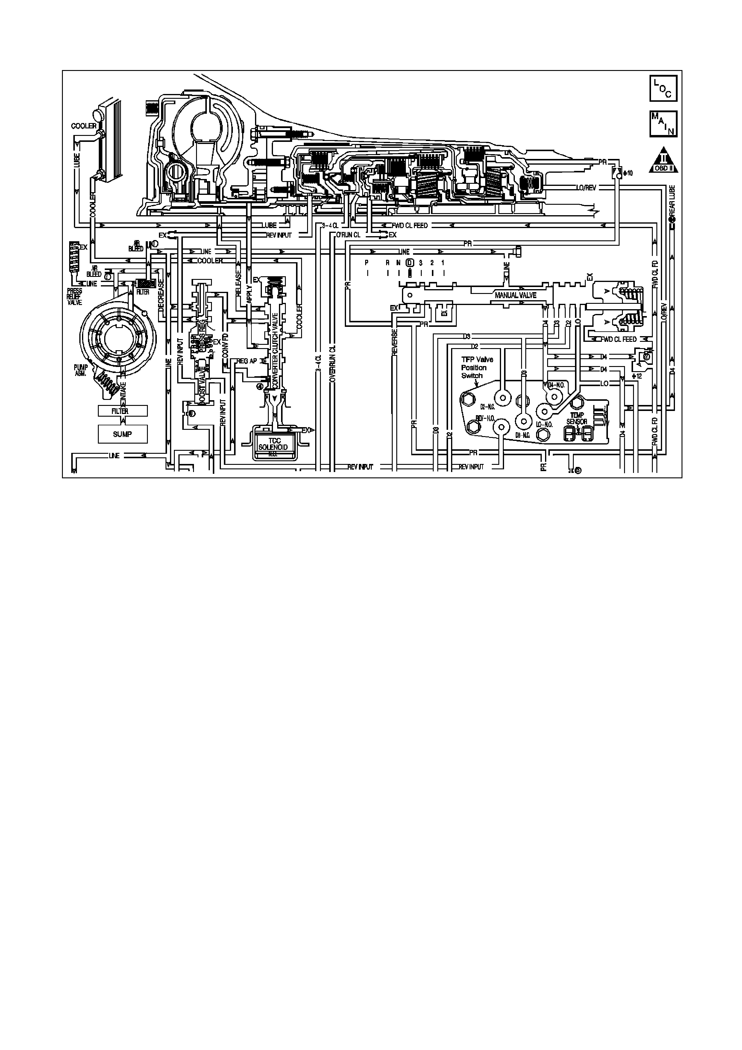
GEN III V8 PCM DTC P0218 TRANSMISSION FLUID OVERTEMPERATURE
CIRCUIT DESCRIPTION
The f low of tr ansmiss ion fluid starts in the bottom pan and is drawn through the filter, control valve body assembly,
transm iss ion case and into the oil pum p as sem bly. The oil pum p ass em bly pressurises the f luid and direc ts it to the
pressur e regulator valve where it bec om es the m ain supply of fluid to the various components and hydr aulic circuits
in the transmission.
Hot fluid exiting the torque c onverter f lows through the conver ter clutch apply valve and into the transm iss ion cooler
lines to the oil cooler loc ated in the vehicle radiator (and auxiliar y c ooler if equipped). From the cooler, fluid returns
to cool and lubricate the f ront of the tr ansmis sion. In forward drive r anges, D4 fluid f rom the m anual valve is routed
through an orificed cup plug in the rear of the transmission case to feed the rear lube fluid circuit.
When the Powertrain Control Module (PCM) detects a high transmission fluid temperature (TFT) for a long period of
time, then DTC P0218 sets.
CONDITIONS FOR RUNNING THE DTC
• No TFT sensor DTCs P0711, P0712 or P0713.
• The ignition switch is in the RUN position for 5 seconds.
CONDITIONS FOR SETTING THE DTC
• The TFT is greater than 130°C for 10 minutes (600 seconds).
ACTION TAKEN WHEN THE DTC SETS
• The PCM illuminates the Check Powertrain Lamp (CPL).
• The PCM freezes shift adapts from being updated.
• The PCM stores DTC P0218 in PCM history.
CONDITIONS FOR CLEARING THE CPL/DTC
• The PCM turns OFF the Check Powertrain Lamp (CPL) during the third consecutive trip in which the diagnostic
test runs and passes.
• A scan tool clears the DTC from the PCM history.
• The PCM clears the DTC from the PCM history if the vehicle completes warm-up cycles without a non-
emission-related diagnostic fault occurring.
• T he PCM cancels the DTC default actions when the fault no longer exists and the ignition switch is OFF long
enough in order to power down the PCM.

DIAGNOSTIC AIDS
• The TFT displayed on the scan tool should rise steadily to a normal operating temperature, then stabilise.
• Verify the customer's driving habits, trailer towing, overloading the vehicle, etc.
TEST DESCRIPTION
The numbers below refer to the step numbers on the diagnostic table.
1. This step checks for air flow restrictions or damage which may result in the transmission overheating.

GEN III V8 PCM DTC P0218 TRANSMISSION FLUID OVERTEMPERATURE
Step Action Value(s) Yes No
1 Was the Powertrain On-Board Diagnostic (OBD) System
Check performed? Go to Step 2 Go to Powertrain
OBD System
Check Table
2 1. Install the Tech 2 scan tool.
2. With the engine OFF, turn the ignition switch to the
RUN position.
Important: Before clearing the DTC, use the Scan Tool
in order to record the Failure Records. Using the Clear
Info function erases the Failure Records from the PCM.
3. Record the DTC Failure Records.
4. Clear the DTC.
5. Perform the transmission fluid checking procedure,
refer to Section 7C4 Transmission Fluid Checking
Procedure of the VT Series II Service Information.
Was the Transmission Fluid Checking Procedure
performed?
Go to Step 3 Go to Section
7C3
Transmission
Fluid Checking
Procedure of the
VT Series II
Service
Information
3 1. Inspect the engine cooling system and transmission
cooling system for the following conditions:
- Air flow restrictions
- Air flow blockage
- Debris
2. Inspect the transmission cooling system for damaged
cooler lines.
Was a condition found?
Go to Step 6 Go to Step 4
4 Perform the line pressure check procedure, refer to
Section 7C3 Line Pressure Check Procedure of the VT
Series II Service Information.
Was a condition found?
Go to Step 6 Go to Step 5
5 Inspect the torque converter stator for damage, refer to
Section 7C3 Torque Converter Diagnosis Procedure of
the VT Series II Service Information.
Was a condition found?
Go to Step 6 Go to Diagnostic
Aids
6 Perform the following procedure in order to verify the
repair:
1. Select DTC.
2. Select Clear Info.
3. With the engine OFF, turn the ignition switch to the
RUN position.
4. Verify that the Scan Tool indicates a TFT less than
129°C for at least five seconds.
Is the TFT less than 129°C for at least five seconds?
System OK Go to Step 1
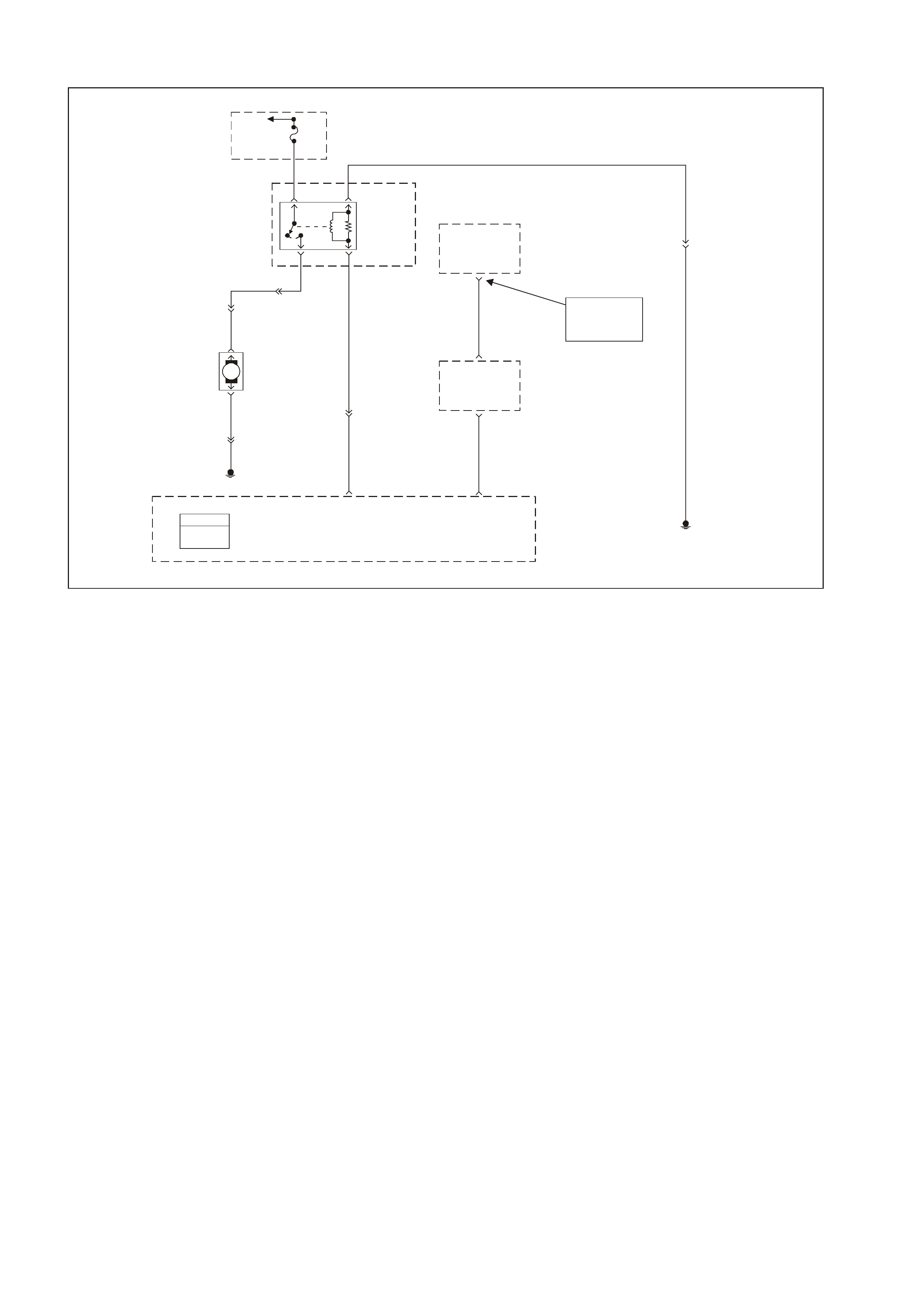
GEN III V8 PCM DTC P0230 FUEL PUMP CONTROL CIRCUIT
GEN3 0158
To
Fusible
Link
FS
Fuse
F28
31
Fuel
Pump
Relay
52
B/W 152
YE114
G/W 465
Body
Control
Module
(BCM)
Theft
Deterrent
Output
Signal
R/B 1221
2
6Powertrain
Interface
Module
(PIM)
Theft
Deterrent
Starter
Disable
7
Y 1049
58 J1 Powertrain
Control
Module
(PCM) Engine Earth
Locat ion E 3
Fuel
Pump
Relay
Control
Theft
Deterrent
Fuel
Disable
(Serial Data)
09 J2
YE110
PCM
J1 = BLUE
J2 = RED
Engine Earth
Location E7
YR32
Fuel
Pump
Motor
120
YR32
V
120 YB39
M
V
156
B/BLU
NOTE
BCM Termi nals
YB175 High Series
YB164 Low Series
CIRCUIT DESCRIPTION
When you turn the ignition switch to the ON position, the PCM activates the in-tank fuel pump. The fuel pump
remains ON as long as the PCM receives reference pulses from the electronic ignition system. If there are no
refer ence puls es , the PCM turns the f uel pump O FF af ter about 2-3 seconds . T he PCM controls the fuel pump relay
by applying B+ to the control circuit via an internal switch called a driver. The primary function of the driver is to
supply a voltage to the fuel pump relay. The driver has a fault line which the PCM monitors.
When the PCM commands the fuel pump ON, the voltage of the control circuit should be high (near battery
voltage). When the PCM commands the control circuit to the fuel pump OFF, the voltage potential of the circuit
should be low (near 0 volts) . This DTC s ets when the PCM detects the fuel pum p control circuit is shorted to earth
after the engine has been running. If the short occurs before key ON, the DTC will not set, and the fuel pump will
not operate.
CONDITIONS FOR RUNNING THE DTC
• The engine speed is greater than 400 RPM.
• The ignition voltage is between 6.0 volts and 16.0 volts.
CONDITIONS FOR SETTING THE DTC
• The PCM detects that the commanded state of the driver and the actual state of the control circuit do not
match.
• All of the above conditions present for a minimum of 10 seconds.
ACTION TAKEN WHEN THE DTC SETS
• The PCM illuminates the Check Powertrain Lamp (CPL) when the diagnostic runs and fails.
• T he PCM records the operating conditions at the time the diagnostic f ails. The PCM stores this inform ation in
the Freeze Frame/Failure Records.
CONDITIONS FOR CLEARING THE CPL/DTC
• The PCM turns the CPL OFF after the first drive trips that the diagnostic runs and does not fail.
• A last failed (current DTC) clears when the diagnostic runs and does not fail.
• A History DTC clears after forty consecutive warm-up cycles, if this or any other emission related diagnostic
does not report any failures.
• Use a Tech 2 scan tool to clear the CPL/DTC.

DIAGNOSTIC AIDS
• The following may cause an intermittent:
- Poor connections: Check for adequate terminal tension
- Corrosion
- Incorrectly routed harness
- Rubbed through wire insulation
- Broken wire inside the insulation
• Using the Freeze Frame/Failure Records data may aid in locating an intermittent condition. If you cannot
duplicate the DT C, the information inc luded in the Freeze Fram e/Failure Records data can help determ ine the
distance traveled since the DTC set. The Fail Counter and Pass Counter also help determine how many
ignition cycle the diagnostic reported a pass and/or a fail. Operate the vehicle within the same freeze frame
conditions (RPM, load, vehicle speed, temperature etc.) that you observed. This will isolate when the DTC
failed.
• For an intermittent condition, refer to Section 6C3-2B Symptoms of the VT Series II Service Information.
TEST DESCRIPTION
The numbers below refer to the step numbers on the diagnostic table.
2. Listen for an audible click when the relay operates. Command both the ON and the OFF states. Repeat the
commands as necessary.
3. This check can detect a partially shorted coil which would cause excessive current flow. Leaving the circuit
energised for 2 minutes allows the coil to warm up. When warm, the coil may short (goes above 0.75 Amp).
5. Identify and test the relay coil terminals in order to avoid improper diagnosis.
12. If you do not find any trouble in the control circuit or the connection at the PCM, the PCM may be
malfunctioning. However, this is an extremely unlikely failure. Before replacing the PCM, inspect for poor
connections at the PCM harness connectors.
13. The repair is not complete if the Tech 2 scan tool indicates that the diagnostic ran and failed.

GEN III V8 PCM DTC P0230 FUEL PUMP CONTROL CIRCUIT
Step Action Value(s) Yes No
1 Did you perform the Powertrain On-Board Diagnostic
(OBD) System Check ? Go to Step 2 Go to
Powertrain
OBD System
Check Table
2 1. Turn ON the ignition leaving the engine OFF.
2. Command the fuel pump relay ON and OFF using a
Tech 2 scan tool.
Does the fuel pump relay turn ON and OFF when
commanded?
Go to Step 3 Go to Step 5
3 1. Turn OFF the ignition.
2. Disconnect the PCM BLUE connector.
3. Turn ON the ignition leaving the engine OFF.
4. Measure the current from the relay control circuit in
the PCM harness connector to B+ for 2 minutes using
the DMM J 39200. on the 10 AMP scale.
Does the current draw measure less than the specified
value shown (but not 0)?
0.75A Go to Diagnostic
Aids Go to Step 4
4 1. Turn OFF the ignition.
2. Remove the fuel pump relay from the engine
compartment fuse & relay panel.
3. Measure the resistance from the relay control circuit
in the PCM harness connector to a earth using a
DMM J 39200. Refer to the wiring schematic for the
proper terminal identification.
Does the DMM display infinite resistance?
Go to Step 11 Go to Step 10
5 1. Turn OFF the ignition.
2. Remove the fuel pump relay from the engine
compartment fuse & relay panel.
3. Connect the test lamp J 34142-B between the earth
circuit and the control circuit at the engine
compartment fuse & relay panel.
4. Turn ON the ignition leaving the engine OFF.
5. Command the fuel pump relay ON and OFF using a
Tech 2 scan tool.
Does the test lamp turn ON and OFF when commanded?
Go to Step 8 Go to Step 6
6 Check the resistance from the fuel pump relay earth
circuit at the fuse & relay panel to the battery earth using
the DMM J 39200.
Is the resistance within the specified range?
0-5Ω
Go to Step 7
Go to Step 9
7 1. Turn OFF the ignition.
2. Reconnect the relay.
3. Disconnect the PCM connectors.
4. Turn ON the ignition leaving the engine OFF.
5. Probe the relay control circuit in the PCM harness
connector with a fused jumper wire connected to B+.
Does the relay operate?
Go to Step 12 Go to Step 10
8 Check the connections at the relay.
Did you find and correct the condition? Go to Step 13 Go to Step 11
9 Repair the open fuel pump relay earth circuit.
Is the action complete? Go to Step 13
10 Repair open or short to earth in the fuel pump relay
control circuit.
Is the action complete?
Go to Step 13
11 Replace the relay.
Is this action complete? Go to Step 13
12 1. Replace PCM.
2. Refer to Section 6C3-3 of the VT Series II Service
Information for PCM Programming and
PCM/PIM/BCM Security Link Procedure.
Is action complete?
Go to Step 13

Step Action Value(s) Yes No
13 1. Select the Diagnostic Trouble Code (DTC) option and
the Clear DTC Information option using the Tech 2
scan tool.
2. Idle the engine at the normal operating temperature.
3. Select the Diagnostic Trouble Code (DTC) option, the
DTC Information option, and the Failed This Ignition
option using the Tech 2 scan tool.
4. Operate the vehicle within the Conditions for Running
the DTC as specified in the supporting text, if
applicable.
Does the Tech 2 scan tool indicate that this DTC reset?
Go to Step 2
Go to Step 14
14 Using the Tech 2 scan tool, check for any other DTCs.
Are any DTCs displayed that you have not diagnosed? Go to the
applicable DTC
table
System OK
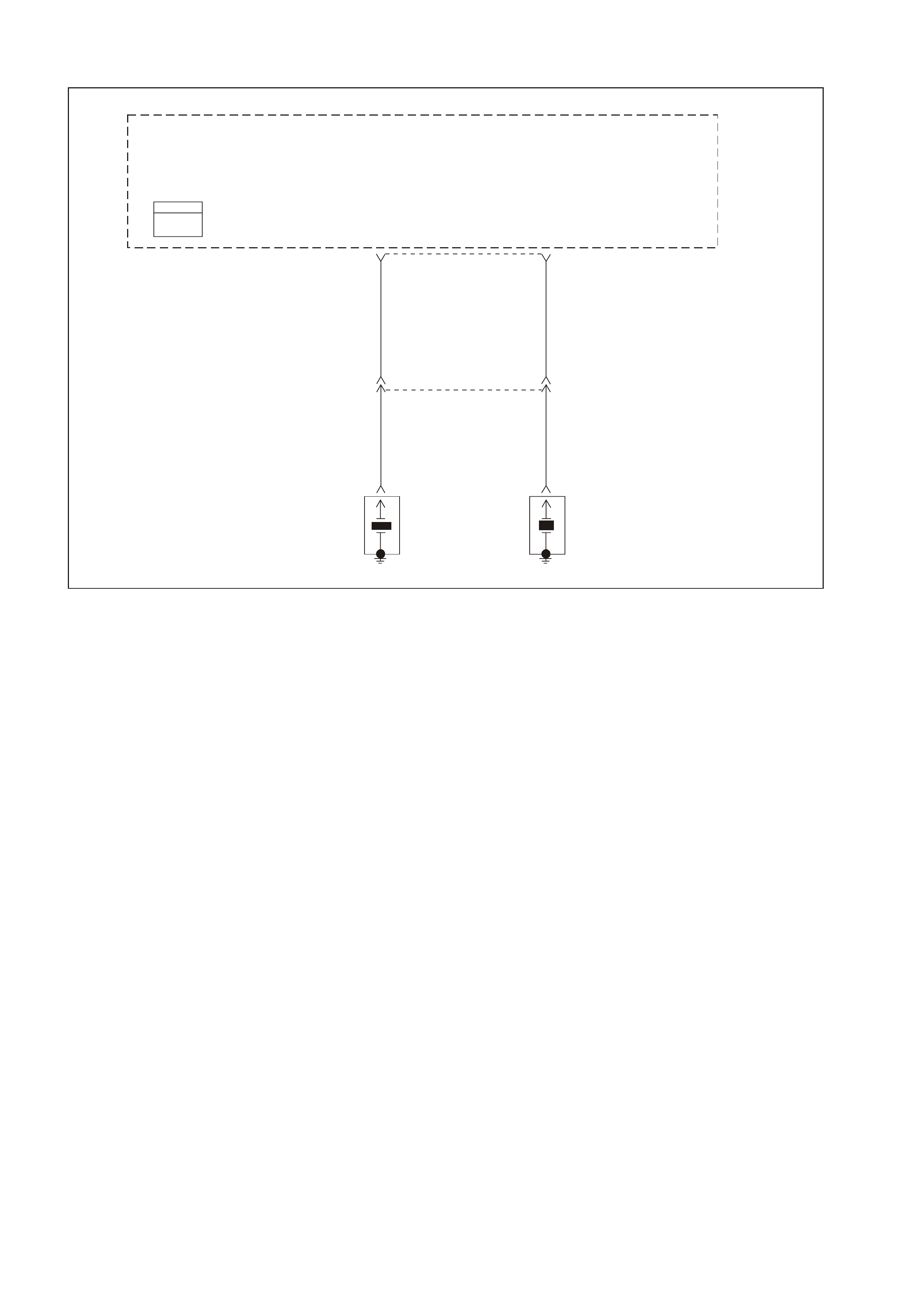
GEN III V8 PCM DTC P0325 KNOCK SENSOR SYSTEM
GEN3 0159
PCM
J1 = BLU E
J2 = RED KS
Signal KS
Signal
51 11 J1
Powertrain
Control
Module
(PCM)
LBLU 826BLU 815
LBLU 826
YE18
YE19
YE18
BLU 815
Front
Knock
Sensor
(KS)
Rear
Knock
Sensor
(KS)
LH RH
CIRCUIT DESCRIPTION
The KS system monitors both Knock Sensors in order to determine if detonation is present. If the KS system
determines that excessive knock (detonation) is present, the PCM retards the spark timing based on the signals
from the KS system. W hen knock is present, the KS system voltage input signal to the PCM goes low. The PCM
then retar ds timing until no k nock is pr esent. When the KS s ystem is m alf unctioning, the KS c ircuit voltage going to
the PCM goes low. The PCM interprets this low signal as spark knock.
CONDITIONS FOR RUNNING THE DTC
• The engine speed is between 1650 and 3000 RPM.
• The MAP is at or about 48 kPa.
• The engine coolant temperature is greater than 70°C (140°F).
• The throttle angle is greater than 0.5%.
• The TP sensor angle is steady within 1%.
• Battery voltage is between 10 and 16 volts.
• The engine run time is greater than 20 seconds.
CONDITIONS FOR SETTING THE DTC
• A malfunction with the KS system or circuits within the PCM are faulty.
• All above conditions present for 3.0 seconds.
ACTION TAKEN WHEN THE DTC SETS
• The PCM illuminates the Check Powrtrain Lamp (CPL) when the diagnostic runs and fails.
• T he PCM records the operating conditions at the time the diagnostic f ails. The PCM stores this inform ation in
the Freeze Frame/Failure Records.
CONDITIONS FOR CLEARING THE CPL/DTC
• The PCM turns the CPL OFF after the first ignition cycle that the diagnostic runs and does not fail.
• A last test failed (current DTC) clears when the diagnostic runs and does not fail.
• A History DTC clears after forty consecutive warm-up cycles, if this or any other emission related diagnostic
does not report any failures.
• Use a Tech 2 scan tool in order to clear the CPL/DTC.

DIAGNOSTIC AIDS
• If the diagnostic test does not run, review the Conditions for Running the DTC.
• For an intermittent condition, refer to Section 6C3-2B Symptoms of the VT Series II Service Information.
TEST DESCRIPTION
The number below refers to the step number on the diagnostic table.
2. This DTC indicates an internal PCM problem.

GEN III V8 PCM DTC P0325 KNOCK SENSOR SYSTEM
Step Action Value(s) Yes No
1 Did you perform the Powertrain On-Board Diagnostic
(OBD) System Check ? Go to Step 2 Go to Powertrain
OBD System
Check Table
2 1. Replace PCM.
2. Refer to Section 6C3-3 of the VT Series II Service
Information for PCM Programming and
PCM/PIM/BCM Security Link Procedure.
Is action complete?
Go to Step 3
3 1. Select the Diagnostic Trouble Code (DTC) option and
the Clear DTC option using the Tech 2 scan tool.
2. Idle the engine at the normal operating temperature.
3. Select the Diagnostic Trouble Code (DTC) option, the
DTC Information option, and The Failed This Ignition
option using the Tech 2 scan tool.
4. Operate vehicle within the Conditions for Running the
DTC as specified in the supporting test, if applicable.
Does the Tech 2 scan tool indicate that this DTC reset?
Go to Step 2 Go to Step 4
4 Using the Tech 2 scan tool, check for any other DTCs.
Does the Tech 2 scan tool display any DTCs that you
have not diagnosed?
Go to applicable
DTC table System OK
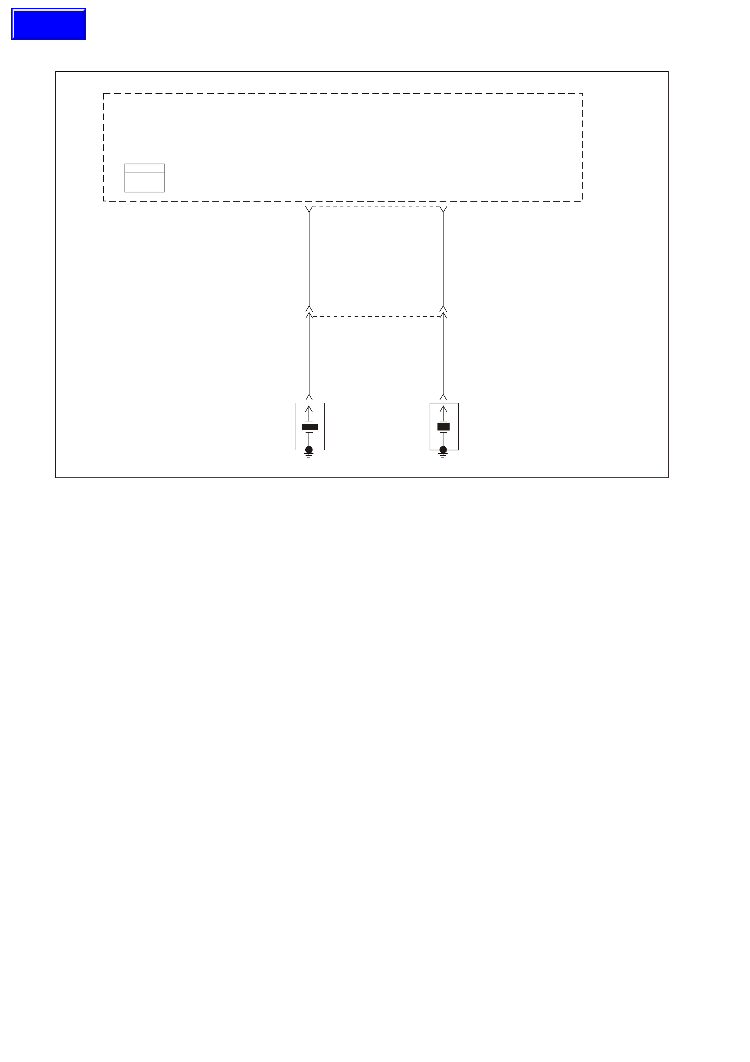
GEN III V8 PCM DTC P0327 KNOCK SENSOR CIRCUIT FRONT SENSOR
GEN3 0159
PCM
J1 = BLU E
J2 = RED KS
Signal KS
Signal
51 11 J1
Powertrain
Control
Module
(PCM)
LBLU 826BLU 815
LBLU 826BLU 815
YE18 YE18
YE19
Front
Knock
Sensor
(KS)
Rear
Knock
Sensor
(KS)
LH RH
CIRCUIT DESCRIPTION
The Knoc k Sensor (KS) system detects engine detonation. The PCM retar ds the spark timing bas ed on the signals
from the Knock Sensors. The Knock Sensors produce an AC voltage. The Knock Sensor voltages are an input to
the PCM. The amount of AC voltage produced is proportional to the amount of knock.
An operating engine produces a normal amount of engine mechanical vibration (noise). The Knock Sensors
produce an AC voltage signal from this noise. When an engine operates, the PCM learns the minimum and
maximum frequency of the noise the engine produces. W hen the PCM determines that this frequency is less than
or greater than the expected amount, a Knock Sensor DTC will set.
CONDITIONS FOR RUNNING THE DTC
• The engine run time is greater than 20 seconds.
• The engine coolant temperature is greater than 70°C (140°F).
• The engine speed is between 1650 and 3000 RPM.
• The TP Sensor angle is greater than 0.5%.
• The MAP is at or about 48 kPa.
• Battery voltage is between 10 and 16 volts.
CONDITIONS FOR SETTING THE DTC
• The PCM determines that this frequency is less than or greater than the expected amount for less than 3
seconds.
ACTION TAKEN WHEN THE DTC SETS
• The PCM illuminates the Check Powertrain Lamp (CPL) when the diagnostic runs and fails.
• T he PCM records the operating conditions at the time the diagnostic f ails. The PCM stores this inform ation in
the Freeze Frame/Failure Records.
CONDITIONS FOR CLEARING THE CPL/DTC
• The PCM turns the CPL OFF after the first ignition cycle that the diagnostic runs and does not fail.
• A last test failed (current DTC) clears when the diagnostic runs and does not fail.
• A History DTC clears after forty consecutive warm-up cycles, if this or any other emission related diagnostic
does not report any failures.
• Use a Tech 2 scan tool to clear the CPL/DTC.
Techline

DIAGNOSTIC AIDS
• Check the Knock Sensor for correct installation. A Knock Sensor that is loose or over torqued may cause the
DTC P0327 to set.
• For an intermittent, refer to Section 6C3-2B Symptoms of the VT Series II Service Information.
TEST DESCRIPTION
The numbers below refer to the step numbers on the diagnostic table.
2. This verifies the malfunction is present. The Tech 2 scan tool will display DTC Ran=Yes and Pass=Int if the
failure is intermittent. This indicates the diagnostic passed this ignition cycle and failed this ignition cycle. At this
point the resistance of the Knock Sensors should be verified to be in the correct range. If the Knock Sensor
resistance’s are correct, check the KS system wiring connections.
3. W hen checking the KS system connections, start at the KS system jum per harness connector located behind
the intake manifold. Then check the connections at the appropriate Knock Sensor. Freeze Frame/Failure
Records data does not include the parameter KS activity, however, other parameters may aid in locating the
conditions under which an intermittent occurred.
4. This test will isolate the Knock Sensor from the rest of the circuit.
5. Tap on the engine block just below the intake manifold between the timing chain cover and the valley cover.

GEN III V8 PCM DTC P0327 KNOCK SENSOR CIRCUIT FRONT SENSOR
Step Action Value(s) Yes No
1 Did you perform the Powertrain On-Board Diagnostic
(OBD) System Check ? Go to Step 2 Go to Powertrain
OBD System
Check Table
2 Important: If an engine knock can be heard, repair the
engine mechanical problem before proceeding with this
diagnostic.
1. Turn On the ignition leaving the engine OFF.
2. Review the Freeze Frame/Failure Records data for
this DTC and observe the parameters.
3. Turn OFF the ignition for 15 seconds.
4. Start the engine.
5. Operate the vehicle within the conditions required for
this diagnostic to run, and as close to the conditions
recorded in Freeze Frame/Failure Records as
possible. Special operating conditions that you need
to meet before the PCM will run this diagnostic where
applicable, are listed in Conditions for Running the
DTC.
6. Select the Diagnostic Trouble Code (DTC) option, the
DTC Information option, and The Failed This Ignition
option using the Tech 2 scan tool.
Does the Tech 2 scan tool indicate that this diagnostic
failed this ignition?
Go to Step 3 Refer to
Diagnostic Aids
3 1. Disconnect the Knock Sensor electrical connector
located behind the intake manifold.
2. Measure the resistance of the front Knock Sensor by
connecting the DMM between the front Knock Sensor
signal circuit on the sensor side and the engine block
using the DMM J 39200.
3. Set the DMM to the 400K ohm scale.
Is the resistance of the Knock Sensor within the specified
range?
93-107KΩ Go to Step 4 Go to Step 6
4 1. Connect the DMM between the front Knock Sensor
signal circuit on the sensor side and the engine block.
2. Set the DMM to the AC voltage scale.
3. Tap on the front of the engine while observing the
signal indicated on the DMM.
Is any signal indicated on the DMM while tapping on the
engine near the Knock Sensor?
Go to Step 5 Go to Step 7
5 1. Disconnect the PCM BLUE connector.
2. Check the KS signal circuit between the PCM and the
Knock Sensor connector for the following:
- An open
- A short to voltage
- A short to earth
Was a problem found and corrected?
Go to Step 10 Go to Step 8
6 1. Remove the intake manifold. Refer to Section 6A3
Engine Mechanical of the VT Series II Service
Information.
2. Check for an open or a short to earth in the signal
circuit between the Knock Sensor jumper harness
connector, located at the back of the intake manifold,
and the Knock Sensor connector.
Was a problem found and corrected?
Go to Step 10 Go to Step 7
7 Replace the Knock Sensor. Refer to Section 6C3-3
Knock Sensor Replacement of the VT Series II Service
Information.
Is the action complete?
Go to Step 10
8 Check the KS signal circuit for a poor terminal connection
at the PCM.
Was a problem found and corrected?
Go to Step 10 Go to Step 9
9 1. Replace PCM.
2. Refer to Section 6C3-3 of the VT Series II Service
Information for PCM Programming and
PCM/PIM/BCM Security Link Procedure.
Is action complete?
Go to Step 10

Step Action Value(s) Yes No
10 1. Select the Diagnostic Trouble Code (DTC) option and
the Clear DTC Information option using the Tech 2
scan tool.
2. Idle the engine at the normal operating temperature.
3. Select the Diagnostic Trouble Code (DTC) option, the
DTC Information option , and The Failed This Ignition
option using the Tech 2 scan tool.
4. Operate the vehicle within the Conditions for Running
the DTC as specified in the supporting text, if
applicable.
Does the Tech 2 scan tool indicate that this DTC reset?
Go to Step 2 Go to Step 11
11 Using the Tech 2 scan tool, check for any other DTCs.
Does the Tech 2 scan tool display any DTCs that you
have not diagnosed?
Go to the
applicable DTC
table
System OK

GEN III V8 PCM DTC P0332 KNOCK SENSOR CIRCUIT REAR SENSOR
GEN3 0159
PCM
J1 = BLU E
J2 = RED KS
Signal KS
Signal
51 11 J1
Powertrain
Control
Module
(PCM)
LBLU 826
YE19
YE18YE18
BLU 815
LBLU 826BLU 815
Front
Knock
Sensor
(KS)
Rear
Knock
Sensor
(KS)
LH RH
CIRCUIT DESCRIPTION
The Knock Sensor (KS) system detects engine detonation. The PCM retards the spark timing based on the signals
from the Knock Sensors. The Knock Sensors produce an AC voltage. The Knock Sensor voltages are an input to
the PCM. The amount of AC voltage produced is proportional to the amount of knock.
An operating engine produces a normal amount of engine mechanical vibration (noise). The Knock Sensors
produce an AC voltage signal from this noise. When an engine operates, the PCM learns the minimum and
maximum frequency of the noise the engine produces. When the PCM determines that this frequency is less than
or greater than the expected amount, a Knock Sensor DTC will set.
CONDITIONS FOR RUNNING THE DTC
• The engine run time is greater than 20 seconds.
• The engine coolant temperature is greater than 70°C (140°F).
• The engine speed is between 1650 and 3000 RPM.
• The TP sensor angle is greater than 0.5%.
• The MAP is at or about 48 kPa.
• Battery voltage is between 10 and 16 volts.
CONDITIONS FOR SETTING THE DTC
• The PCM determines that this f requency is less than or greater than the expected am ount for less than three
seconds.
ACTION TAKEN WHEN THE DTC SETS
• The PCM illuminates the Check Powertrain Lamp (CPL) when the diagnostic runs and fails.
• The PCM records the operating conditions at the time the diagnostic fails. The PCM stores this information in
the Freeze Frame/Failure Records.
CONDITIONS FOR CLEARING THE CPL/DTC
• The PCM turns the CPL OFF after the first ignition cycles that the diagnostic runs and does not fail.
• A last test failed (current DTC) clears when the diagnostic runs and does not fail.
• A History DTC clears after forty consecutive warm-up cycles, if this or any other emission related diagnostic
does not report any failures.
• Use a Tech 2 scan tool in order to clear the CPL/DTC.

DIAGNOSTIC AIDS
• Check the Knock Sensor for proper installation. A Knock Sensor that is loose or over torqued may cause the
DTC P0327 to set.
• For an intermittent, refer to Section 6C3-2B Symptoms of the VT Series II Service Information.
TEST DESCRIPTION
The numbers below refer to the step numbers on the diagnostic table.
2. This verifies the malfunction is present. The Tech 2 scan tool will display DTC Ran=Yes and Pass=Int if the
failure is intermittent. This indicates the diagnostic passed this ignition cycle and failed this ignition cycle. At this
point the resistance of the Knock Sensors should be verified to be in the correct range. If the Knock Sensor
resistanc e’s are c orrect, c heck the KS system wiring connections. When chec king the KS system connections,
start at the KS system jumper harness connector located behind the intake manifold. Then check the
connections at the appropriate Knock Sensor. Freeze Frame/Failure Records data does not include the
parameter KS activity, however, other parameters may aid in locating the conditions under which an
intermittent occurred.
3. This test will isolate the Knock Sensor from the rest of the circuit.
4. Tap on the engine block just below the intake manifold between the timing chain cover and the valley cover.

GEN III V8 PCM DTC P0332 KNOCK SENSOR CIRCUIT REAR SENSOR
Step Action Value(s) Yes No
1 Did you perform the Powertrain On-Board Diagnostic
(OBD) System Check ? Go to Step 2 Go to
Powertrain
OBD System
Check Table
2 Important: If an engine knock can be heard, repair the
engine mechanical problem before proceeding with this
diagnostic.
1. Turn On the ignition leaving the engine OFF.
2. Review the Freeze Frame/Failure Records data for
this DTC and observe the parameters.
3. Turn OFF the ignition for 15 seconds.
4. Start the engine.
5. Operate the vehicle within the conditions required for
this diagnostic to run, and as close to the conditions
recorded in Freeze Frame/Failure Records as
possible. Special operating conditions that you need
to meet before the PCM will run this diagnostic where
applicable, are listed in Conditions for Running the
DTC.
6. Select the Diagnostic Trouble Code (DTC) option, the
DTC Information option, and The Failed This Ignition
option using the Tech 2 scan tool.
Does the Tech 2 scan tool indicate that this diagnostic
failed this ignition?
Go to Step 3 Refer to
Diagnostic Aids
3 1. Disconnect the knock sensor electrical connector
located behind the intake manifold.
2. Measure the resistance of the rear knock sensor by
connecting the DMM between the rear knock sensor
signal circuit on the sensor side and the engine block
using the DMM J 39200.
3. Set the DMM to the 400K ohm scale.
Is the resistance of the knock sensor within the specified
range?
93-107KΩ Go to Step 4 Go to Step 6
4 1. Connect the DMM between the rear knock sensor
signal circuit on the sensor side and the engine block.
2. Set the DMM to the AC voltage scale.
3. Tap on the front of the engine while observing the
signal indicated on the DMM.
Is any signal indicated on the DMM while tapping on the
engine near the Knock Sensor?
Go to Step 5 Go to Step 7
5 1. Disconnect the PCM BLUE connector.
2. Check the KS signal circuit between the PCM and the
knock sensor connector for the following:
- An open
- A short to voltage
- A short to earth
Was a problem found and corrected?
Go to Step 10 Go to Step 8
6 1. Remove the intake manifold. Refer to Section 6A3
Engine Mechanical for procedure.
2. Check for an open or a short to earth in the signal
circuit between the knock sensor jumper harness
connector, located at the back of the intake manifold,
and the knock sensor connector.
Was a problem found and corrected?
Go to Step 10 Go to Step 7
7 Replace the Knock Sensor. Refer to Knock Sensor
Replacement in Section 6C3-3.
Is the action complete?
Go to Step 10
8 Check the KS signal circuit for a poor terminal connection
at the PCM.
Was a problem found and corrected?
Go to Step 10 Go to Step 9

Step Action Value(s) Yes No
9 1. Replace PCM.
2. Refer to Section 6C3-3 for PCM Programming and
PCM/PIM/BCM Security Link Procedure.
Is action complete?
Go to Step 10
10 1. Select the Diagnostic Trouble Code (DTC) option and
the Clear DTC Information option using the Tech 2
scan tool.
2. Idle the engine at the normal operating temperature.
3. Select the Diagnostic Trouble Code (DTC) option, the
DTC Information option, and The Failed This Ignition
using the Tech 2 scan tool.
4. Operate the vehicle within the Conditions for Running
the DTC as specified in the supporting text, if
applicable.
Does the Tech 2 scan tool indicate that this DTC reset?
Go to Step 2 Go to Step 11
11 Using the Tech 2 scan tool, check for any other DTCs.
Does the Tech 2 scan tool display any DTCs that you
have not diagnosed?
Go to the
applicable DTC
table
System OK

GEN III V8 PCM DTC P0335 CRANKSHAFT POSITION SENSOR CIRCUIT
GEN 3 01 60
Powertrain
Control
Module
(PCM)
Tachometer
Input
Instrument
Cluster
18
BR/R 121
Tach
Input 30 YE112
ABS/ETC
Module
BR 121
10 J2
CKP Se ns o r
Signal Input Reference
Low
12 21 02 J1
12VIgnition
Feed
61 73 39 J2
12V
Ignition
Feed
CMP Sensor
Signal Input
Reference
Low
J1
Hall Sensor
Trigger Circuit
Amplifi e r an d
Voltage Reg.
Electronics
Camshaft
Position
(CMP)
Sensor
29
1K
47g
4700pf
Power
Gnd
BAC
R/W 632 W/B 631
BR 633
ABC
BLU 643 LBLU/W 646
LBLU/B 647
Magnetic
Pickup Crankshaft
Position
(CKP)
Sensor
Puls e Sh a per
And Volt age
Reg. Electronics
Output Power
Gnd
Tachometer
Output
PCM
J1 = BLU E
J2 = RED
CIRCUIT DESCRIPTION
The Crank shaf t Position Sensor (CKP) is m ounted in the right rear of the engine block behind the starter . The CKP
Sensor work s in conj unction with a 24X reluc tor wheel m ounted on the rear of the crank s haft. The CKP Sensor has
a B+ power supply, an earth, and a signal circuit.
As the crankshaft rotates, the reluctor wheel teeth interrupt a magnetic field produced by a magnet within the
sensor. T he s ensor’s internal circ uitry detects this and pr oduces a s ignal which the PCM reads. T he PCM uses this
signal to accurately measure crankshaft velocity which is a variable used in order to detect misfire, spark and,
fueling.
CONDITIONS FOR RUNNING THE DTC
• DTCs P0101, P0102, P0103, P0341, P0342, P0343 are not set.
• The CMP sensor is transitioning.
• The ignition voltage is between 5 and 17.0 volts.
• The MAF is greater than 3 g/s.
• The ignition switch in the crank mode.
CONDITIONS FOR SETTING THE DTC
• The PCM determines no signal from the CKP Sensor for least than 3 seconds.
ACTION TAKEN WHEN THE DTC SETS
• The PCM illuminates the Check Powertrain Lamp (CPL) when the diagnostic runs and fails.
• T he PCM records the operating conditions at the time the diagnostic f ails. The PCM stores this inform ation in
the Freeze Frame/Failure Records.
CONDITIONS FOR CLEARING THE CPL/DTC
• The PCM turns the CPL OFF after the first drive trips that the diagnostic runs and does not fail.
• A last test failed (current DTC) clears when the diagnostic runs and does not fail.
• A History DTC clears after forty consecutive warm-up cycles, if this or any other emission related diagnostic
does not report any failures.
• Use a Tech 2 scan tool in order to clear the CPL/DTC.
Techline

DIAGNOSTIC AIDS
• The following problems may cause this DTC to set:
- Poor connections/terminal tension at the sensor.
- Crankshaft reluctor wheel damage or improper installation.
- The sensor coming in contact with the reluctor wheel.
- The engine running out of fuel.
• Us ing Freeze Fram e/Failure Records data may aid in locating an interm ittent condition. If you cannot duplicate
the DTC, the information included in the Freeze Frame/Failure Records data can aid in determining the
distance traveled since the DTC set. The Fail Counter and Pass Counter can also aid determining how many
ignition cycles the diagnostic reported a pass and/or a fail. Operate the vehicle within the same freeze frame
conditions (RPM, load, vehicle speed, temperature etc.) that you observed. This will isolate when the DTC
failed. For an intermittent condition, refer to Section 6C3-2B Symptoms of the VT Series II Service
Information.
• Excess crankshaft end play will cause the CKP Sensor reluctor wheel to move out of alignm ent with the CKP
sensor. This could result in any one of the following:
- A no start
- A start and stall
- Erratic performance
• An improperly installed propeller shaft could cause excess crankshaft end play. Refer to
Section 6A3 Engine Mechanical of the VT Series II Service Information for excess crankshaft end play
diagnosis.
• For an intermittent, refer to in Section 6C3-2B Symptoms of the VT Series II Service Information.
TEST DESCRIPTION
The numbers below refer to the step numbers on the diagnostic table.
3. This step determines if the fault is present.
6. This step simulates a CKP Sensor signal to the PCM. If the PCM receives the signal, the fuel pump will operate
for about two sec onds. If the fuel pum p oper ates , the problem is either ter minal contac t at the CKP Sens or, the
CKP Sensor or, the CKP Sensor reluctor wheel.
7. This test determines if the CKP Sensor signal circuit or if the PCM is faulty.
12. To inspect the reluctor wheel, remove the starter and rotate the crankshaft while viewing the reluctor wheel
through the CKP Sensor hole. If you cannot determ ine if the reluctor wheel is dam aged, the oil pan m ay have
to be removed.
15. Before replacing the PCM, check the PCM harness connections.
16. The repair is not complete if the Tech 2 scan tool indicates that the diagnostic ran and failed.

GEN III V8 PCM DTC P0335 CRANKSHAFT POSITION SENSOR CIRCUIT
Step Action Value(s) Yes No
1 Did you perform the Powertrain On-Board Diagnostic
(OBD) System Check ? Go to Step 2 Go to Powertrain
OBD System
Check Table
2 Does the engine start and continue to run? Go to Step 3 Go to Step 4
3 1. Turn ON the ignition leaving the engine OFF.
2. Review the Freeze Frame/Failure Records data for
this DTC and record or document the parameters.
3. Turn OFF the ignition for 15 seconds.
4. Start the engine.
5. Operate the vehicle within the conditions required for
this diagnostic to run, and as close to the conditions
recorded in Freeze Frame/Failure Records as
possible. Special operating conditions that you need
to meet before the PCM will run this diagnostic, where
applicable, are listed in Conditions for Running the
DTC.
6. Select the Diagnostic Trouble Code (DTC) option, the
DTC Information option, and The Failed This Ignition
option using the Tech 2 scan tool.
Does the Tech 2 scan tool indicate that this diagnostic
failed this ignition?
Go to Step 4 Go to Diagnostic
Aids
4 Caution: Before proceeding, remove fuses F34 & 35 for
the ignition coil and fuel injector feed circuits in order to
prevent personal injury from engine rotation, sparks, and
excessive engine fueling.
1. Turn ON the ignition leaving the engine OFF.
2. Lift the vehicle.
3. Disconnect the Crankshaft Position (CKP) Sensor.
4. Connect a test lamp to a earth.
5. Probe the CKP Sensor ignition feed circuit at the PCM
side of CKP Sensor harness connector.
Is the test lamp illuminated?
Go to Step 5 Go to Step 8
5 Connect the test lamp between the CKP Sensor ignition
feed circuit and the CKP Sensor earth circuit.
Is the test lamp illuminated?
Go to Step 6 Go to Step 9
6 Momentarily connect the test lamp between the CKP
Sensor signal circuit and the CKP Sensor ignition feed
circuit.
Does the fuel pump operate when ignition voltage was
applied to the CKP Sensor signal circuit?
Go to Step 11
Go to Step 7
7 1. Connect the CKP Sensor.
2. Disconnect the PCM BLUE connector.
3. Using test lead jumpers from connector kit J 35616-A
reconnect the reference Low and ignition feed circuits
from the PCM harness to PCM.
4. Probe the CKP Sensor signal circuit with a DMM
J 39200 set to the 40V AC scale using the brown
jumper from connector kit J 35616-A
5. Crank the engine.
Is the voltage within the specified range?
4.0-6.0V Go to Step 15 Go to Step 10
8 Check for an open or a short to earth in the CKP ignition
feed circuit.
Did you find and repair the condition?
Go to Step 16 Go to Step 15
9 Check for an open or a poor connection in the CKP earth
circuit.
Did you find and repair the condition?
Go to Step 16 Go to Step 15
10 Check the CKP Sensor signal circuit for the following:
• An open
• A short to earth
• A short to voltage
Did you find and repair the condition?
Go to Step 16 Go to Step 11

Step Action Value(s) Yes No
11 Remove the CKP Sensor and visually inspect the CKP
Sensor for the following conditions:
• Physical damage
• Loose or improper installation
• Wiring routed too closely to secondary ignition
components
• Poor connections/terminal tension at the sensor
Did you find and correct the condition?
Go to Step 16
Go to Step 12
12 Visually inspect the CKP Sensor reluctor wheel for
damage.
Did you find and correct the condition?
Go to Step 16 Go to Step 13
13 Check for poor connections/terminal tension at the CKP
Sensor.
Did you find and correct the condition?
Go to Step 16 Go to Step 14
14 Replace the CKP Sensor. Refer to Section 6C3-3
Crankshaft Position Sensor Replacement of the VT
Series II Service Information.
Is the action complete?
Go to Step 16
15 1. Replace PCM.
2. Refer to Section 6C3-3 of the VT Series II Service
Information for PCM Programming and
PCM/PIM/BCM Security Link Procedure.
Is action complete?
Go to Step 16
16 1. Select the Diagnostic Trouble Code (DTC) option and
the Clear DTC Information option using the Tech 2
scan tool.
2. Idle the engine at the normal operating temperature.
3. Select the Diagnostic Trouble Code (DTC) option, the
DTC Information option, and The Failed This Ignition
option using the Tech 2 scan tool.
4. Operate the vehicle within the Conditions for Running
the DTC as specified in the supporting text, if
applicable.
Does the Tech 2 scan tool indicate that this DTC reset?
Go to Step 2
Go to Step 17
17 Using the Tech 2 scan tool, check for any other DTCs.
Are any DTCs displayed that you have not diagnosed? Go to the
applicable DTC
table
System OK
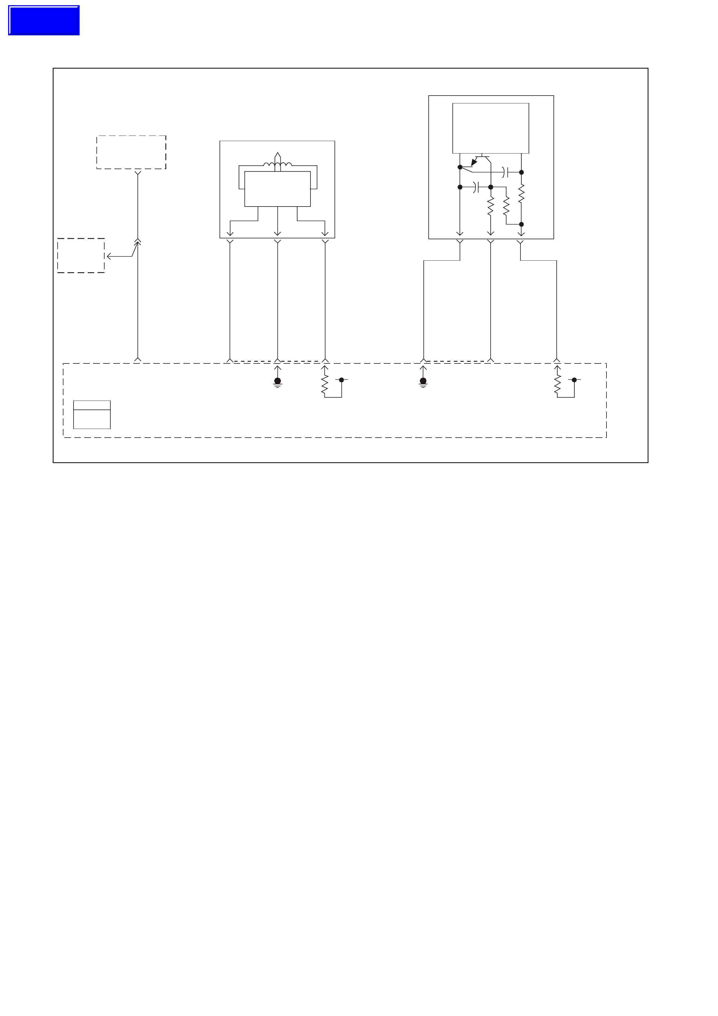
GEN III V8 PCM DTC P0336 CRANKSHAFT POSITION SENSOR CIRCUIT PERFORMANCE
GEN 3 01 60
Powertrain
Control
Module
(PCM)
Tachometer
Input
Instrument
Cluster
18
BR/R 121
Tach
Input 30 YE112
ABS/ETC
Module
BR 121
10 J2
CKP Se ns o r
Signal Input Reference
Low
12 21 02 J1
12VIgnition
Feed
61 73 39 J2
12V
Ignition
Feed
CMP Sensor
Signal Input
Reference
Low
J1
Hall Sensor
Trigger Circuit
Amplifi e r an d
Voltage Reg.
Electronics
Camshaft
Position
(CMP)
Sensor
29
1K
47g
4700pf
Power
Gnd
BAC
R/W 632 W/B 631
BR 633
ABC
BLU 643 LBLU/W 646
LBLU/B 647
Magnetic
Pickup Crankshaft
Position
(CKP)
Sensor
Pulse Shaper
And Voltage
Reg. Electronics
Output Power
Gnd
Tachometer
Output
PCM
J1 = BLU E
J2 = RED
CIRCUIT DESCRIPTION
The Crank shaf t Position Sensor (CKP) is m ounted in the right rear of the engine block behind the starter . The CKP
Sensor work s in conj unction with a 24X reluc tor wheel m ounted on the rear of the crank s haft. The CKP Sensor has
a B+ power supply, a earth, and a signal circuit.
As the crankshaft rotates, the reluctor wheel teeth interrupt a magnetic field produced by a magnet within the
sensor. T he s ensor’s internal circ uitry detects this and pr oduces a s ignal which the PCM reads. T he PCM uses this
signal to accurately measure crankshaft velocity which is a variable used in order to detect misfire, spark and,
fueling.
CONDITIONS FOR RUNNING THE DTC
• The engine speed is between 500 and 4000 RPM.
• The ignition voltage is between 5.0 and 17.0 volts.
CONDITIONS FOR SETTING THE DTC
• The PCM determines no signal from the CKP sensor signal is out of range for less than 1 second.
ACTION TAKEN WHEN THE DTC SETS
• The PCM illuminates the Check Powrtrain Lamp (CPL) when the diagnostic runs and fails.
• T he PCM records the operating conditions at the time the diagnostic f ails. The PCM stores this inform ation in
the Freeze Frame/Failure Records.
CONDITIONS FOR CLEARING THE CPL/DTC
• The PCM turns the CPL OFF after the first ignition cycle that the diagnostic runs and does not fail.
• A last test failed (current DTC) clears when the diagnostic runs and does not fail.
• A History DTC clears after forty consecutive warm-up cycles, if this or any other emission related diagnostic
does not report any failures.
• Use a Tech 2 scan tool in order to clear the CPL/DTC.
Techline

DIAGNOSTIC AIDS
• The following problems may cause this DTC to set:
- Poor connections/terminal tension at the sensor
- Crankshaft reluctor wheel damage or improper installation.
- The sensor coming in contact with the reluctor wheel.
- The engine running out of fuel.
• If the crankshaft rotates backwards, this DTC will set. This condition is only with vehicles equipped with a
manual transmission. This condition can occur when a vehicle is on an incline and the clutch is released and
an engine stall occurs.
• Us ing Freeze Fram e/Failure Records data may aid in locating an interm ittent condition. If you cannot duplicate
the DTC, the information included in the Freeze Frame/Failure Records data can aid in determining the
distance traveled since the DTC set. The Fail Counter and Pass Counter can also aid determining how many
ignition cycles the diagnostic reported a pass and/or a fail. Operate the vehicle within the same freeze frame
conditions (RPM, load, vehicle speed, temperature etc.) that you observed. This will isolate when the DTC
failed.
• Excess crankshaft end play will cause the CKP sensor reluctor wheel to move out of alignment with the CKP
sensor. This could result in any one of the following:
- A no start
- A start and stall
- Erratic performance
An improperly installed propeller shaft could cause excess crankshaft end play. Refer to
Section 6A3 Engine Mechanical of the VT Series II Service Information for excess crankshaft end play
diagnosis.
• For an intermittent, refer to Section 6C3-2B Symptoms of the VT Series II Service Information.
TEST DESCRIPTION
The numbers below refer to the step numbers on the diagnostic table.
2. This step verifies that the malfunction is present.
3. This step checks for EMI (Electro Magnetic Interference) on the CKP Sensor circuits.
6. Vertical lines across the face of the sensor could indicate foreign material passing between the CKP Sensor
and the reluctor wheel. Non vertical lines across the face of the sensor may indicate a crack in the CKP
Sensor. Either of these conditions causes this DTC to set
7. Damage to the reluctor wheel would affect the CKP Sensor output. To inspect the reluctor wheel, rem ove the
starter and rotate the crankshaft while viewing the reluctor wheel through the CKP Sensor hole. If you cannot
determine if the reluctor wheel is damaged, the oil pan may have to be removed. If this condition exists, refer to
Section 6A3 Engine Mechanical of the VT Series II Service Information for crankshaft replacement.

GEN III V8 PCM DTC P0336 CRANKSHAFT POSITION SENSOR CIRCUIT PERFORMANCE
Step Action Value(s) Yes No
1 Did you perform the Powertrain On-Board Diagnostic
(OBD) System Check ? Go to Step 2 Go to Powertrain
OBD System
Check Table
2 Important: IF DTC P0335 is also set, diagnose DTC
P0335 before proceeding with this DTC.
1. Install a Tech 2 scan tool.
2. Idle the engine for 2 minutes.
Does the Tech 2 scan tool indicate that DTC P0336
failed this ignition?
Go to Step 3 Intermittent
condition. Refer
to Diagnostic
Aids
3 1. Visually Physically inspect all circuits going to the
Crankshaft Position Sensor for the following:
- Routed to close to secondary ignition wires or
components
- Routed to close to after-market add on electrical
equipment
- Routed to close to solenoids, relays and motors
2. If you find incorrect routing, correct the harness
routing.
Did you find and correct the condition?
Go to Step 9 Go to Step 4
4 1. Check the terminal contact at the CKP Sensor.
2. Repair/replace the terminal if you find a problem.
Did you find and correct the condition?
Go to Step 9 Go to Step 5
5 1. Check the terminal contact at the PCM for the CKP
Sensor circuits.
2. Repair/replace the terminal if you find a problem.
Did you find and correct the condition?
Go to Step 9 Go to Step 6
6 1. Remove the CKP Sensor. Refer to Section 6C3-3
Crankshaft Position Sensor Replacement of the VT
Series II Service Information.
2. Inspect the CKP Sensor for signs of damage.
Did you find and correct the condition?
Go to Section
6A3 Engine
Mechanical of
the VT Series II
Service
Information
Go to Step 7
7 Inspect the CKP reluctor wheel for damage.
Did you find and correct the condition? Go to Section
6A3 Engine
Mechanical of
the VT Series II
Service
Information
Go to Step 8
8 Replace the CKP Sensor. Refer to Section 6C3-3
Crankshaft Position Sensor Replacement of the VT
Series II Service Information.
Is the action complete?
Go to Step 9
9 1. Select the Diagnostic Trouble Code (DTC) option and
the Clear DTC Information option using the Tech 2
scan tool.
2. Idle the engine at the normal operating temperature.
3. Select the Diagnostic Trouble Code (DTC) option, the
DTC Information option and The Failed This Ignition
option using the Tech 2 scan tool.
4. Operate the vehicle within the Conditions for Running
the DTC as specified in the supporting text, if
applicable.
Does the Tech 2 scan tool indicate that this DTC reset?
Go to Step 2 Go to Step 10
10 Using the Tech 2 scan tool, check for any other DTCs.
Does the Tech 2 scan tool display any DTCs that you
have not diagnosed?
Go to the
applicable DTC
table
System OK

GEN III V8 PCM DTC P0341 CAMSHAFT POSITION SENSOR CIRCUIT PERFORMANCE
GEN3 0160
Powertrain
Control
Module
(PCM)
Tachometer
Input
Instrument
Cluster
18
BR/R 121
Tach
Input 30 YE112
ABS/ETC
Module
BR 121
10 J2
CK P Sens o r
Signal Input Reference
Low
12 21 02 J1
12VIgnition
Feed
61 73 39 J2
12V
Ignition
Feed
CMP Sensor
Signal I nput
Reference
Low
J1
Hall Sensor
Trigger Circuit
Amplifier and
V o l tage Reg .
Electronics
Camshaft
Position
(CMP)
Sensor
29
1K
47g
4700pf
Power
Gnd
BAC
R/W 632 W/B 631
BR 633
ABC
BLU 643 LBLU/W 646
LBLU/B 647
Magnetic
Pickup Crankshaft
Position
(CKP)
Sensor
Pulse Sh ape r
And Voltage
Reg. Electronics
Output Power
Gnd
Tachometer
Output
PCM
J1 = B LUE
J2 = R ED
Circuit Description
The Cam s haft Position ( CMP) sens or is m ounted thr ough the top of the engine block at the rear of the valley cover.
The CMP sensor works in conjunction with a 1X reluctor wheel on the camshaft. The reluctor wheel is inside the
engine imm ediately in front of the rear cam bearing. The PCM provides a 12 volt power supply to the CMP sensor
as well as a earth and a signal circuit.
The CMP sensor determines whether a cylinder is on a firing stroke or on an exhaust stroke. As the camshaft
rotates, the reluctor wheel interrupts a m agnetic f ield produc ed by a m agnet within the sensor. T he sens ors inter nal
circuitr y detects this and pr oduces a s ignal which the PCM reads. T he PCM uses this 1X signal in com bination with
the Crank shaft Pos ition sensor 24X signal in order to determ ine crankshaf t position and strok e. This diagnostic for
the Camshaft Position sensor checks for a loss of Camshaft Position sensor signal.
Observe that as long as the 24X signal is available, the engine starts even if there is no Camshaft Position sensor
signal. The PCM can determine when a particular cylinder is on either a firing or exhaust stroke by the 24X signal
alone, but the PCM requires the cam signal in order to determine which (firing or exhaust). The system attempts
synchronisation and looks f or an inc rease in MAF signal indicating the engine star ted. If the PCM does not detect a
MAF increase, the PCM assumes it incorrectly synchronised to the exhaust stroke and re-synchs to the opposite
cam position. A slightly longer cranking time may be a symptom of this condition.
CONDITIONS FOR RUNNING THE DTC
• The ignition voltage is between 5.0 and 17.0 volts.
• The engine speed is less than 4000 RPM.
CONDITIONS FOR SETTING THE DTC
• The PCM detects that a CMP to CKP mis-match has occurred for 10 seconds.
ACTION TAKEN WHEN THE DTC SETS
• The PCM illuminates the Check Powertrain Lamp (CPL) when the diagnostic runs and fails.
• The PCM records the operating conditions at the time the diagnostic fails. The PCM stores this information in
the Freeze Frame/Failure Records.
Techline

CONDITIONS FOR CLEARING THE CPL/DTC
• The PCM turns the CPL OFF after the first ignition cycles that the diagnostic runs and does not fail.
• A last test failed (current DTC) clears when the diagnostic runs and does not fail.
• A History DTC clears after forty consecutive warm-up cycles, if this or any other emission related diagnostic
does not report any failures.
• Use a Tech 2 scan tool in order to clear the CPL/DTC.
DIAGNOSTIC AIDS
• The following mechanical problems may cause this DTC to set:
- Poor connections/terminal tension at the sensor
- Camshaft reluctor wheel damage
- The sensor coming in contact with the reluctor wheel
• Using Freeze Frame/Failure Records data may aid in locating an interm ittent condition. If you cannot duplicate
the DTC, the information included in the Freeze Frame/Failure Records data can aid in determining the
distance travelled since the DTC set. The Fail Counter and Pass Counter can also aid determining how many
ignition cycles the diagnostic reported a pass and/or a fail. Operate the vehicle within the same freeze frame
conditions (RPM, load, vehicle speed, temperature etc.) that you observed. This will isolate when the DTC
failed.
TEST DESCRIPTION
The numbers below refer to the step numbers on the diagnostic table.
2. This step verifies that the malfunction is present.
3. This step checks for EMI (Electro Magnetic Interference) on the CMP sensor circuits.
6. Vertical lines across the face of the sensor could indicate foreign material passing between the CMP sensor
and the reluctor wheel. This condition could cause this DTC to set.
7. Damage to the reluctor wheel would affect the CMP sensor output. If this condition exists, refer to
Section 6A3 ENGINE MECHANICAL in the VT Series II Service Information for Camshaft replacement.

GEN III V8 PCM DTC P0341 CAMSHAFT POSITION SENSOR CIRCUIT PERFORMANCE
Step Action Value(s) Yes No
1 Did you perform the Powertrain On-Board Diagnostic
(OBD) System Check ? Go to Step 2 Go to Powertrain
OBD System
Check Table
2 1. Install a Tech 2 scan tool.
2. Idle the engine for 2 minutes.
Does the Tech 2 scan tool indicate that DTC P0341 failed
this ignition?
Go to Step 3 Intermittent
condition. Refer
to Diagnostic
Aids
3 1. Inspect all Camshaft Position sensor circuits for the
following:
- Routed to close to secondary ignition wires or
components
- Routed to close to after-market add on electrical
equipment
- Routed to close to solenoids, relays and motors
2. If you find incorrect routing, correct the harness
routing.
Did you find and correct the condition?
Go to Step 9 Go to Step 4
4 1. Check the terminal contact at the CMP sensor.
2. If you find a problem, Repair/replace the terminal(s).
Did you find and correct the condition?
Go to Step 9 Go to Step 5
5 1. Check the terminal contact at the PCM for the CMP
sensor circuits.
2. Repair/replace the terminal if you find a problem.
Did you find and correct the condition?
Go to Step 9 Go to Step 6
6 1. Remove the CMP sensor. Refer to Section 6C3-3
Camshaft Position Sensor Replacement of the VT
Series II Service Information.
2. Inspect the CMP sensor for signs of damage.
Did you find and correct the condition?
Go To Section
6A3 Engine
Mechanical of the
VT Series II
Service
Information
Go to Step 7
7 Inspect the CMP reluctor wheel for damage.
Did you find and correct the condition? Go To Section
6A3 Engine
Mechanical of the
VT Series II
Service
Information
Go to Step 8
8 Replace the CMP Sensor. Refer to Section 6C3-3
Camshaft Position Sensor Replacement of the VT Series
II Service Information.
Is the action complete?
Go to Step 9
9 1. Select the Diagnostic Trouble Code (DTC) option and
the Clear DTC Information option using the Tech 2
scan tool.
2. Idle the engine at the normal operating temperature.
3. Select the Diagnostic Trouble Code (DTC) option, the
DTC Information option and The Failed This Ignition
option using the Tech 2 scan tool.
4. Operate the vehicle within the Conditions for Running
the DTC as specified in the supporting text, if
applicable.
Does the Tech 2 scan tool indicate that this DTC reset?
Go to Step 2 Go to Step 10
10 Using the Tech 2 scan tool, check for any other DTCs.
Does the Tech 2 scan tool display any DTCs that you
have not diagnosed?
Go to the
applicable DTC
table
System OK
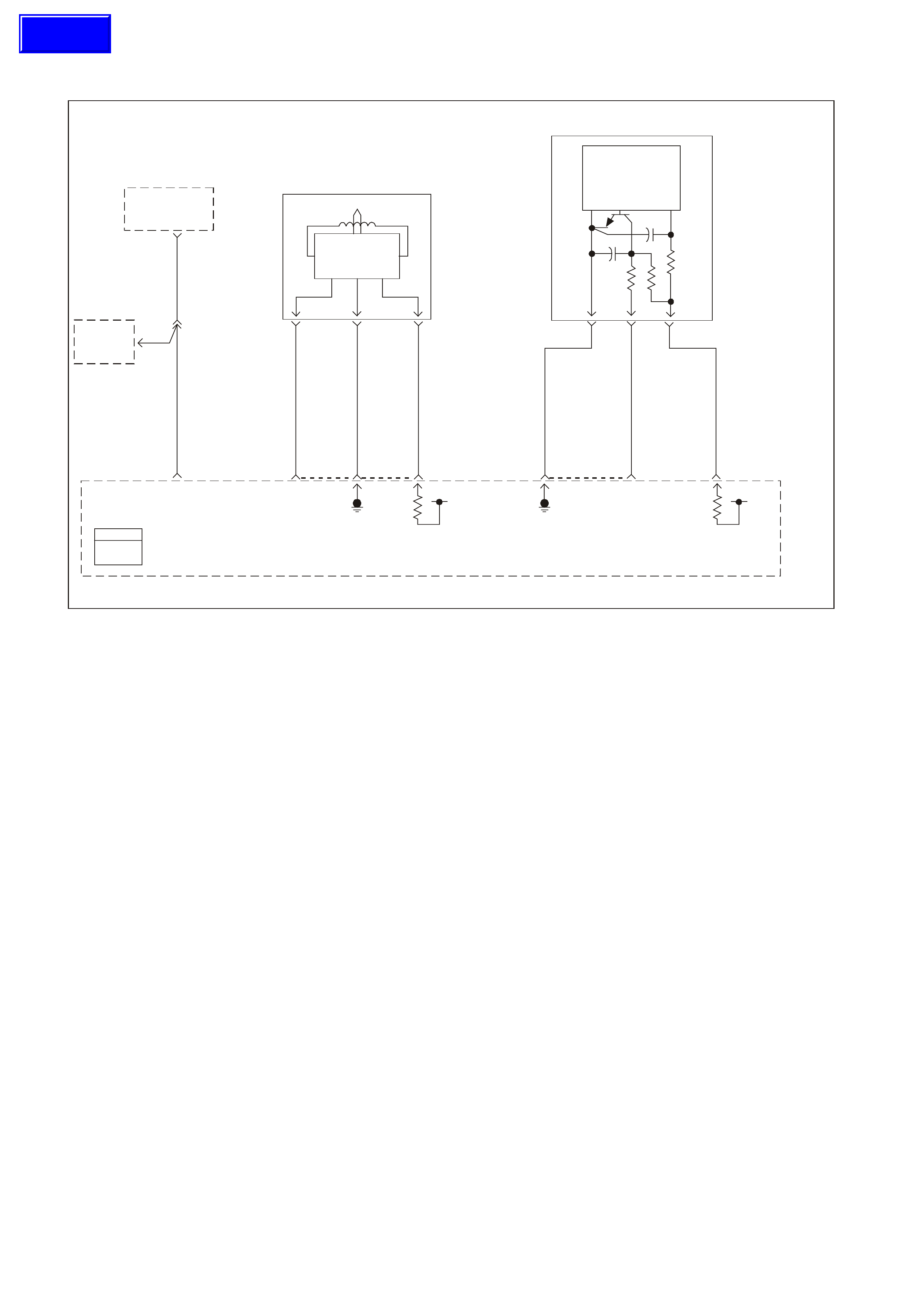
GEN III V8 PCM DTC P0342 CAMSHAFT POSITION SENSOR CIRCUIT LOW VOLTAGE
GEN3 0160
Powertrain
Control
Module
(PCM)
Tachometer
Input
Instrument
Cluster
18
BR/R 121
Tach
Input 30 YE112
ABS/ETC
Module
BR 121
10 J2
CK P Sens o r
Signal Input Reference
Low
12 21 02 J1
12VIgnition
Feed
61 73 39 J2
12V
Ignition
Feed
CMP Sensor
Signal I nput
Reference
Low
J1
Hall Sensor
Trigger Circuit
Amplifier and
V o l tage Reg .
Electronics
Camshaft
Position
(CMP)
Sensor
29
1K
47g
4700pf
Power
Gnd
BAC
R/W 632 W/B 631
BR 633
ABC
BLU 643 LBLU/W 646
LBLU/B 647
Magnetic
Pickup Crankshaft
Position
(CKP)
Sensor
Pulse Sh ape r
And Voltage
Reg. Electronics
Output Power
Gnd
Tachometer
Output
PCM
J1 = B LUE
J2 = R ED
CIRCUIT DESCRIPTION
The Camshaft Position sensor is mounted through the top of the engine block at the rear of the valley cover. The
CMP sensor work s in conj unction with a 1X reluctor wheel on the cam shaft. The reluctor wheel is inside the engine
imm ediately in front of the rear c am bearing. T he PCM provides a 12 volt power supply to the CMP sensor as well
as a earth and a signal circuit.
The CMP sensor determines whether a cylinder is on a firing stroke or on an exhaust stroke. As the camshaft
rotates, the reluctor wheel interrupts a m agnetic f ield produc ed by a m agnet within the sensor. T he sens ors inter nal
circuitry detects this and produces a signal, which the PCM reads. The PCM uses this 1X signal in combination
with the Crankshaf t Pos ition sens or 24X signal in or der to deter mine cr ank s haf t pos ition and s troke. T his diagnos tic
for the Camshaft Position sensor checks for a loss of Camshaft Position sensor signal.
Observe that as long as the 24X signal is available, the engine starts even if there is no Camshaft Position sensor
signal. The PCM can determine when a particular cylinder is on either a firing or exhaust stroke by the 24X signal
alone, but the PCM requires the cam signal in order to determine which (firing or exhaust). The system attempts
synchronisation and looks f or an inc rease in MAF signal indicating the engine star ted. If the PCM does not detect a
MAF increase, the PCM assumes it incorrectly synchronised to the exhaust stroke and re-synchs to the opposite
cam position. A slightly longer cranking time may be a symptom of this condition.
CONDITIONS FOR RUNNING THE DTC
• The ignition voltage is between 5.0 and 17.0 volts.
• The engine speed is less than 4000 RPM.
CONDITIONS FOR SETTING THE DTC
• The PCM detects the Cam signal is stuck low when the signal should be high for 5.0 seconds.
ACTION TAKEN WHEN THE DTC SETS
• The PCM illuminates the Check Powertrain Lamp (CPL) when the diagnostic runs and fails.
• The PCM records the operating conditions at the time the diagnostic fails. The PCM stores this information in
the Freeze Frame/Failure Records.
Techline

CONDITIONS FOR CLEARING THE CPL/DTC
• The PCM turns the CPL OFF after the first ignition cycles that the diagnostic runs and does not fail.
• A last test failed (current DTC) clears when the diagnostic runs and does not fail.
• A History DTC clears after forty consecutive warm-up cycles, if this or any other emission related diagnostic
does not report any failures.
• The PCM battery voltage is interrupted.
• Use a Tech 2 scan tool in order to clear the CPL/DTC.
DIAGNOSTIC AIDS
• The following mechanical problems may cause this DTC to set:
- Poor connections/terminal tension at the sensor
- Camshaft reluctor wheel damage
- The sensor coming in contact with the reluctor wheel
• Using Freeze Frame/Failure Records data may aid in locating an intermittent condition. If you cannot duplicate
the DTC, the information included in the Freeze Frame/Failure Records data can aid in determining the
distance traveled since the DTC set. The Fail Counter and Pass Counter can also aid determining how many
ignition cycles the diagnostic reported a pass and/or a fail. Operate the vehicle within the same freeze frame
conditions (RPM, load, vehicle speed, temperature etc.) that you observed. This will isolate when the DTC
failed.
TEST DESCRIPTION
The numbers below refer to the step numbers on the diagnostic table.
2. This step verifies that the fault is present. The Camshaft activity counter will start at 0 with key ON, then
increment up to 65535 then back to 0 and increment up again.
4. This step tests the Camshaft Position sensor ignition feed circuit from the PCM to the CMP.
5. This step checks the Camshaft Position sensor earth circuit from the PCM to the CMP.
6. This step c heck s the Cam s haft Position s ensor s ignal circuit. Applying a voltage causes the CAM signal activity
counter to increment.
7. This step checks the Camshaft Position sensor ignition feed circuit from the PCM to the CMP.
9. This step checks the Camshaft Position sensor earth circuit from the PCM to the CMP.

GEN III V8 PCM DTC P0342 CAMSHAFT POSITION SENSOR CIRCUIT LOW VOLTAGE
Step Action Value(s) Yes No
1 Did you perform the Powertrain On-Board Diagnostic (OBD)
System Check? Go to Step 2 Go to Powertrain
OBD System
Check Table
2 1. Install a Tech 2 scan tool.
2. Idle the engine.
3. Monitor the CAM signal activity counter in the Engine
Data List using the Tech 2 scan tool.
Does the Tech 2 scan tool parameter increment?
Go to Step 3 Go to Step 4
3 1. Turn ON the ignition leaving the engine OFF.
2. Review the Freeze Frame/Failure Records data for this
DTC and observe the parameters.
3. Turn OFF the ignition for 15 seconds.
4. Idle the engine.
5. Operate the vehicle within the conditions required for this
diagnostic to run, and as close to the conditions recorded
in Freeze Frame/Failure Records as possible. Special
operating conditions that you need to meet before the
PCM will run this diagnostic, where applicable, are listed
in Conditions for Running the DTC.
6. Select the Diagnostic Trouble Code (DTC) option, the
DTC Information option and The Failed This Ignition
option using the Tech 2 scan tool.
Does the Tech 2 scan tool indicate that this diagnostic failed
this ignition?
Go to Step 4 Refer to
Diagnostic Aids
4 1. Turn Off the ignition.
2. Disconnect the Camshaft Position Sensor (CMP).
3. Turn ON the ignition leaving the engine OFF.
4. Measure the Camshaft Position sensor ignition feed
voltage using the DMM.
Does the DMM display near the specified value?
B+ Go to Step 5 Go to Step 7
5 Measure the Camshaft Position sensor ignition feed circuit
to the Camshaft Position sensor earth circuit using the
DMM.
Does the DMM display the specified voltage?
B+ Go to Step 6 Go to Step 9
6 1. Start the engine.
2. Monitor the CAM signal activity counter in the Engine
Data List using the Tech 2 scan tool.
3. Momentarily and repeatedly probe the signal circuit with
the test lamp connected to B+.
Does the CAM signal activity counter increment when the
test lamp contacts the signal circuit?
Go to Step 15 Go to Step 10
7 1. Turn OFF the ignition.
2. Disconnect the PCM connector C2 located on the
opposite side of the manufacturer’s logo.
3. Test the continuity of the CMP ignition feed circuit using
the DMM.
Is there continuity and is the resistance within the specified
range?
0-5Ω Go to Step 8 Go to Step 12
8 Inspect the CMP ignition feed circuit for the following:
• A earthed circuit
• A poor connection
Did you find and correct the condition?
Go to Step 19 Go to Step 16
9 1. Turn OFF the ignition.
2. Disconnect the PCM connector C1 located on the same
side as the manufacturer’s logo.
3. Test the continuity of the CMP earth circuit using the
DMM.
Is there continuity and is the resistance within the specified
range?
0-5Ω Go to Step 16 Go to Step 13

Step Action Value(s) Yes No
10 1. Turn OFF the ignition.
2. Disconnect the PCM connector C1 located on the
same side as the manufacturer’s logo.
3. Test the continuity of the CMP signal circuit using the
DMM.
Is the voltage less than the specified value?
0-5Ω Go to Step 11 Go to Step 14
11 1. Turn ON the ignition leaving the engine OFF.
2. Test the CMP signal circuit for the following:
• A earthed circuit
• A circuit shorted to a voltage
Did you find and correct the condition?
Go to Step 19 Go to Step 16
12 1. Inspect the CMP ignition feed circuit for open.
2. If you find an open circuit, repair the CMP ignition feed
circuit.
Did you find and correct the condition?
Go to Step 19 Go to Step 16
13 Repair open in the CMP earth circuit.
Is the action complete? Go to Step 19
14 Repair open in the CMP signal circuit.
Is the action complete? Go to Step 19
15 1. Inspect for poor connections at the CMP harness
connector.
2. If you find a poor connection repair the connector as
necessary.
Did you find and correct the condition?
Go to Step 19 Go to Step 17
16 1. Inspect the PCM harness connector for poor
connections.
2. If you find a poor connection repair the connector as
necessary.
Did you find and correct the condition?
Go to Step 19 Go to Step 18
17 Replace the CMP sensor. Refer to Section 6C3-3
Camshaft Position Sensor Replacement of the VT Series
II Service Information.
Is action complete?
Go to Step 19
18 1. Replace PCM.
2. Refer to Section 6C3-3 of the VT Series II Service
Information for PCM Programming and
PCM/PIM/BCM Security Link Procedure.
Is action complete?
Go to Step 19
19 1. Select the Diagnostic Trouble Code (DTC) option and
the Clear DTC Information option using the Tech 2
scan tool.
2. Idle the engine at the normal operating temperature.
3. Select the Diagnostic Trouble Code (DTC) option, the
DTC Information option and The Failed This Ignition
option using the Tech 2 scan tool.
4. Operate the vehicle within the Conditions for Running
the DTC as specified in the supporting text, if
applicable.
Does the Tech 2 scan tool indicate that this DTC reset?
Go to Step 2 Go to Step 20
20 Using the Tech 2 scan tool, check for any other DTCs.
Does the Tech 2 scan tool display any DTCs that you
have not diagnosed?
Go to applicable
DTC Table System OK
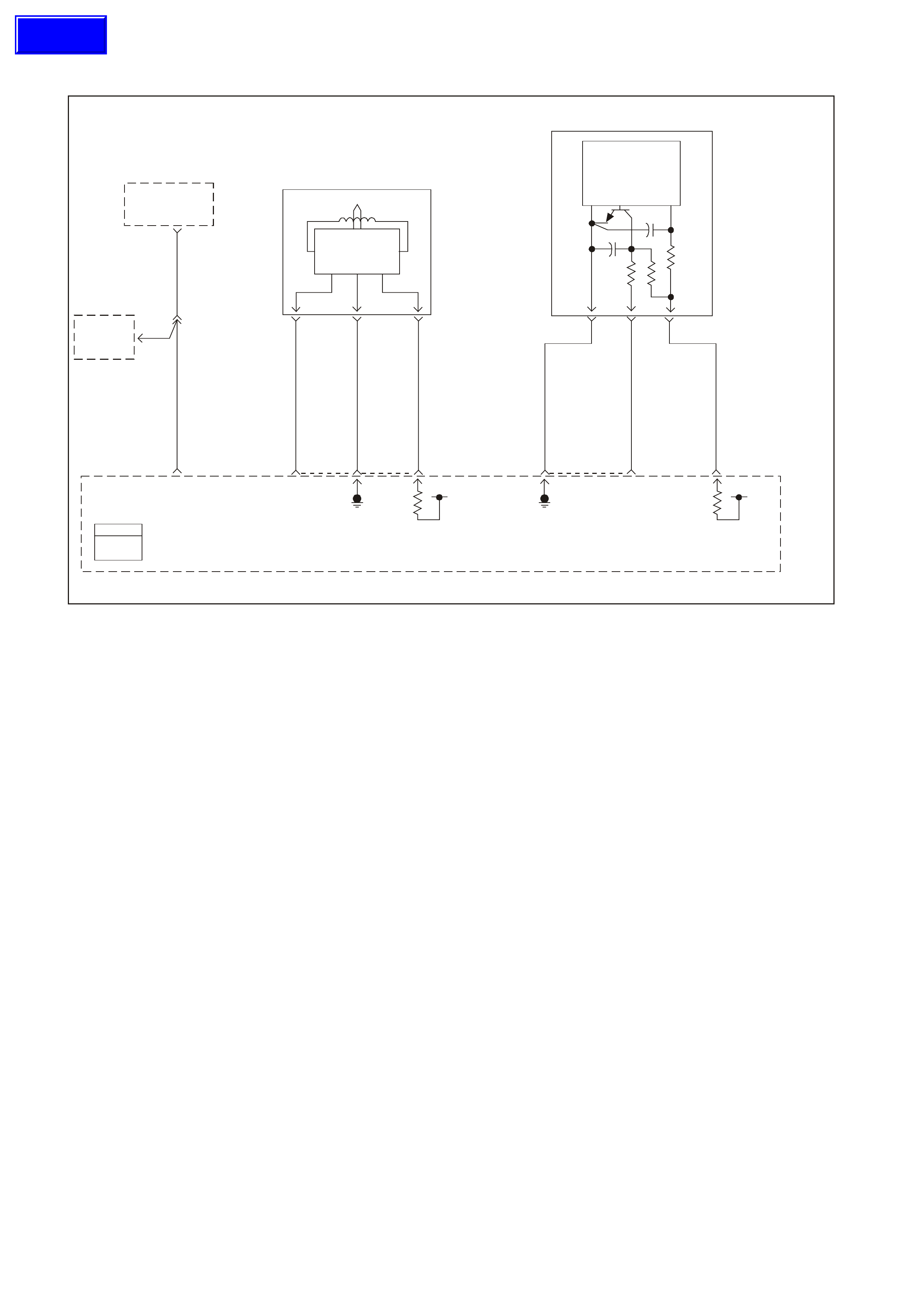
GEN III V8 PCM DTC P0343 CAMSHAFT POSITION SENSOR CIRCUIT HIGH VOLTAGE
GEN3 0160
Powertrain
Control
Module
(PCM)
Tachometer
Input
Instrument
Cluster
18
BR/R 121
Tach
Input 30 YE112
ABS/ETC
Module
BR 121
10 J2
CK P Sens o r
Signal Input Reference
Low
12 21 02 J1
12VIgnition
Feed
61 73 39 J2
12V
Ignition
Feed
CMP Sensor
Signal I nput
Reference
Low
J1
Hall Sensor
Trigger Circuit
Amplifier and
V o l tage Reg .
Electronics
Camshaft
Position
(CMP)
Sensor
29
1K
47g
4700pf
Power
Gnd
BAC
R/W 632 W/B 631
BR 633
ABC
BLU 643 LBLU/W 646
LBLU/B 647
Magnetic
Pickup Crankshaft
Position
(CKP)
Sensor
Pulse Sh ape r
And Voltage
Reg. Electronics
Output Power
Gnd
Tachometer
Output
PCM
J1 = B LUE
J2 = R ED
Circuit Description
The Camshaft Position (CMP) Sensor is mounted through the top of the engine block at the rear of the valley
cover. The CMP s ensor work s in conjunc tion with a 1X reluctor wheel on the cam shaf t. The r eluctor wheel is ins ide
the engine immediately in front of the rear cam bearing. The PCM provides a 12 volt power supply to the CMP
sensor as well as a earth and a signal circuit.
The CMP sensor determines whether a cylinder is on a firing stroke or on an exhaust stroke. As the camshaft
rotates, the reluctor wheel interrupts a m agnetic f ield produc ed by a m agnet within the sensor. T he sens ors inter nal
circuitry detects this and produces a signal, which the PCM reads. The PCM uses this 1X signal in combination
with the Crankshaf t Pos ition sens or 24X signal in or der to deter mine cr ank s haf t pos ition and s troke. T his diagnos tic
for the Camshaft Position sensor checks for a loss of Camshaft Position sensor signal.
Observe that as long as the 24X signal is available, the engine starts even if there is no Camshaft Position sensor
signal. The PCM can determine when a particular cylinder is on either a firing or exhaust stroke by the 24X signal
alone, but the PCM requires the cam signal in order to determine which (firing or exhaust). The system attempts
synchronisation and looks f or an inc rease in MAF signal indicating the engine star ted. If the PCM does not detect a
MAF increase, the PCM assumes it incorrectly synchronised to the exhaust stroke and re-synchs to the opposite
cam position. A slightly longer cranking time may be a symptom of this condition.
CONDITIONS FOR RUNNING THE DTC
• The ignition voltage is between 5.0 and 17.0 volts.
• The engine speed is less than 4000 RPM.
CONDITIONS FOR SETTING THE DTC
• The PCM detects the Cam signal is stuck High when the signal should be high for 5.0 seconds.
ACTION TAKEN WHEN THE DTC SETS
• The PCM illuminates the Check Powertrain Lamp (CPL) when the diagnostic runs and fails.
• The PCM records the operating conditions at the time the diagnostic fails. The PCM stores this information in
the Freeze Frame/Failure Records.
Techline

CONDITIONS FOR CLEARING THE CPL/DTC
• The PCM turns the CPL OFF after the first ignition cycles that the diagnostic runs and does not fail.
• A last test failed (current DTC) clears when the diagnostic runs and does not fail.
• A History DTC clears after forty consecutive warm-up cycles, if this or any other emission related diagnostic
does not report any failures.
• The PCM battery voltage is interrupted.
• Use a Tech 2 scan tool in order to clear the CPL/DTC.
DIAGNOSTIC AIDS
• The following mechanical problems may cause this DTC to set:
- Poor connections/terminal tension at the sensor
- Camshaft reluctor wheel damage
- The sensor coming in contact with the reluctor wheel
• Using Freeze Frame/Failure Records data may aid in locating an intermittent condition. If you cannot duplicate
the DTC, the information included in the Freeze Frame/Failure Records data can aid in determining the
distance traveled since the DTC set. The Fail Counter and Pass Counter can also aid determining how many
ignition cycles the diagnostic reported a pass and/or a fail. Operate the vehicle within the same freeze frame
conditions (RPM, load, vehicle speed, temperature etc.) that you observed. This will isolate when the DTC
failed.
TEST DESCRIPTION
The numbers below refer to the step numbers on the diagnostic table.
2. This step verifies that the fault is present. The Camshaft activity counter will start at 0 with key ON, then
increment up to 65535 then back to 0 and increment up again.
4. This step tests the Camshaft Position sensor ignition feed circuit from the PCM to the CMP.
5. This step checks the Camshaft Position sensor earth circuit from the PCM to the CMP.
6. This step c heck s the Cam s haft Position s ensor s ignal circuit. Applying a voltage causes the CAM signal activity
counter to increment.
7. This step checks the Camshaft Position sensor ignition feed circuit from the PCM to the CMP.
9. This step checks the Camshaft Position sensor earth circuit from the PCM to the CMP.

GEN III V8 PCM DTC P0343 CAMSHAFT POSITION SENSOR CIRCUIT HIGH VOLTAGE
Step Action Value(s) Yes No
1 Did you perform the Powertrain On-Board Diagnostic (OBD)
System Check? Go to Step 2 Go to Powertrain
OBD System
Check Table
2 1. Install a Tech 2 scan tool.
2. Idle the engine.
3. Monitor the CAM signal activity counter in the Engine
Data List using the Tech 2 scan tool.
Does the Tech 2 scan tool parameter increment?
Go to Step 3 Go to Step 4
3 1. Turn ON the ignition leaving the engine OFF.
2. Review the Freeze Frame/Failure Records data for this
DTC and observe the parameters.
3. Turn OFF the ignition for 15 seconds.
4. Idle the engine.
5. Operate the vehicle within the conditions required for this
diagnostic to run, and as close to the conditions recorded
in Freeze Frame/Failure Records as possible. Special
operating conditions that you need to meet before the
PCM will run this diagnostic, where applicable, are listed
in Conditions for Running the DTC.
6. Select the Diagnostic Trouble Code (DTC) option, the
DTC Information option and The Failed This Ignition
option using the Tech 2 scan tool.
Does the Tech 2 scan tool indicate that this diagnostic failed
this ignition?
Go to Step 4 Refer to
Diagnostic Aids
4 1. Turn Off the ignition.
2. Disconnect the Camshaft Position Sensor (CMP).
3. Turn ON the ignition leaving the engine OFF.
4. Measure the Camshaft Position sensor ignition feed
voltage using the DMM.
Does the DMM display near the specified value?
B+ Go to Step 5 Go to Step 7
5 Measure the Camshaft Position sensor ignition feed circuit
to the Camshaft Position sensor earth circuit using the
DMM.
Does the DMM display the specified voltage?
B+ Go to Step 6 Go to Step 9
6 1. Start the engine.
2. Monitor the CAM signal activity counter in the Engine
Data List using the Tech 2 scan tool.
3. Momentarily and repeatedly probe the signal circuit with
the test lamp connected to B+.
Dopes the CAM signal activity counter increment when the
test lamp contacts the signal circuit?
Go to Step 15 Go to Step 10
7 1. Turn OFF the ignition.
2. Disconnect the PCM connector C2 located on the
opposite side of the manufacturer’s logo.
3. Test the continuity of the CMP ignition feed circuit using
the DMM.
Is there continuity and is the resistance within the specified
range?
0-5Ω Go to Step 8 Go to Step 12
8 Inspect the CMP ignition feed circuit for the following:
• A earthed circuit
• A poor connection
Did you find and correct the condition?
Go to Step 19 Go to Step 16
9 1. Turn OFF the ignition.
2. Disconnect the PCM connector C1 located on the same
side as the manufacturer’s logo.
3. Test the continuity of the CMP earth circuit using the
DMM.
Is there continuity and is the resistance within the specified
range?
0-5Ω Go to Step 16 Go to Step 13

Step Action Value(s) Yes No
10 1. Turn OFF the ignition.
2. Disconnect the PCM connector C1 located on the
same side as the manufacturer’s logo.
3. Test the continuity of the CMP signal circuit using the
DMM.
Is the voltage less than the specified value?
0-5Ω Go to Step 11 Go to Step 14
11 1. Turn ON the ignition leaving the engine OFF.
2. Test the CMP signal circuit for the following:
• A earthed circuit
• A circuit shorted to a voltage
Did you find and correct the condition?
Go to Step 19 Go to Step 16
12 1. Inspect the CMP ignition feed circuit for an open.
2. If you find an open circuit, repair the CMP ignition feed
circuit.
Did you find and correct the condition?
Go to Step 19 Go to Step 16
13 Repair the CMP earth circuit for an open.
Is the action complete? Go to Step 19
14 Repair the CMP signal circuit for an open.
Is the action complete? Go to Step 19
15 1. Inspect for poor connections at the CMP harness
connector.
2. If you find a poor connection repair the connector as
necessary.
Did you find and correct the condition?
Go to Step 19 Go to Step 17
16 1. Inspect th3e PCM harness connector for poor
connections.
2. If you find a poor connection repair the connector as
necessary.
Did you find and correct the condition?
Go to Step 19 Go to Step 18
17 Replace the CMP sensor; refer to Section 6C3-3
Camshaft Position Sensor Replacement of the VT
Series II Service Information.
Is action complete?
Go to Step 19
18 1. Replace PCM.
2. Refer to Section 6C3-3 of the VT Series II Service
Information for PCM Programming and
PCM/PIM/BCM Security Link Procedure.
Is action complete?
Go to Step 19
19 1. Select the Diagnostic Trouble Code (DTC) option and
the Clear DTC Information option using the Tech 2
scan tool.
2. Idle the engine at the normal operating temperature.
3. Select the Diagnostic Trouble Code (DTC) option, the
DTC Information option and The Failed This Ignition
option using the Tech 2 scan tool.
4. Operate the vehicle within the Conditions for Running
the DTC as specified in the supporting text, if
applicable.
Does the Tech 2 scan tool indicate that this DTC reset?
Go to Step 2 Go to Step 20
20 Using the Tech 2 scan tool, check for any other DTCs.
Does the Tech 2 scan tool display any DTCs that you
have not diagnosed?
Go to applicable
DTC Table System OK

GEN III V8 PCM DTC P0351 IGNITION CONTROL #1 CIRCUIT
GEN3 0161
PCM
J1 = B LUE
J2 = R E D
Powertrain
Control
Module
(PCM)
26
Ignition
Control
1
60
Reference
Low
Fuse
F35
To EFI
(Eng ine Cont.)
Relay
To Injectors
1, 3, 5, 7
YE111
482
LG 971
W 958
BR
E
HG
BC
DIgnition
Coil/
Module
1
Ignition
Feed Ignition
Control
Signal
Reference
Low
Earth
A
Spark
Plug
YE125
Ignition
Coil #3
Ignition
Coil #5
Ignition
Coil #7
750
B/R
YE125
Engine Earth
Locat i on E5/15
Ignition
Coil/Modules
#3, 5, 7
J2
CIRCUIT DESCRIPTION
The ignition system on this engine uses an individual ignition coil/module for each cylinder. The PCM controls the
ignition system operation. T here are eight Ignition Control (IC) c ircuits, one per cylinder, that connect the PCM and
ignition coil/m odules. Eac h ignition coil/m odule has a power f eed, a chassis earth circuit and a ref erence low circuit.
The PCM c auses a spark to occur by earthing the IC circ uit, which signals the ignition m odule to trigger the ignition
coil and fire the spark plug. Sequencing and timing ar e PCM controlled. This DTC sets when the IC circuit is out of
range.
CONDITIONS FOR RUNNING THE DTC
• The ignition voltage is between 9.0 volts and 17.0 volts.
CONDITIONS FOR SETTING THE DTC
• The PCM detects the ignition control circuit is earthed, open or shorted to a voltage.
• All conditions met for less than 1 second.
ACTION TAKEN WHEN THE DTC SETS
• The PCM illuminates the Check Powertrain Lamp (CPL) when the diagnostic runs and fails.
• T he PCM records the operating conditions at the time the diagnostic f ails. The PCM stores this inform ation in
the Freeze Frame/Failure Records.
CONDITIONS FOR CLEARING THE CPL/DTC
• The PCM turns the CPL OFF after the first ignition cycle that the diagnostic runs and does not fail.
• A last test failed (current DTC) clears when the diagnostic runs and does not fail.
• A History DTC clears after forty consecutive warm-up cycles, if this or any other emission related diagnostic
does not report any failure.
• Use a Tech 2 scan tool in order to clear the CPL/DTC.

DIAGNOSTIC AIDS
• The following may be the cause of an intermittent:
- Poor connections. Check for adequate terminal tension.
- Corrosion
- Incorrectly routed harness
- Rubbed through wire insulation.
- Broken wire inside the insulation.
Using the Freeze Frame/Failure Records data may aid in locating an intermittent condition. If you cannot
duplicate the DT C, the information inc luded in the Freeze Fram e/Failure Records data can help determ ine the
distance traveled since the DTC Set. The Fail Counter and Pass Counter can also help determine how may
ignition cycles the diagnostic reported a pass and/or a fail. Operate the vehicle within the same freeze frame
conditions (RPM, load, vehicle speed, temperature etc.) that you observed. This will isolate when the DTC
failed.
For an intermittent condition, refer to Section 6C3-2B SYMPTOMS in the VT Series II Service Information.
TEST DESCRIPTION
The numbers below refer to the step numbers on the diagnostic table.
2. This step verifies that the fault is present.
4. This step checks the integrity of the IC circuit and the PCM output.
5. This step checks for a short to earth on the IC control circuit.

GEN III V8 PCM DTC P0351 IGNITION CONTROL #1 CIRCUIT
Step Action Value(s) Yes No
1 Did you perform the Powertrain On-Board Diagnostic
(OBD) System Check ? Go to Step 2 Go to Powertrain
OBD System
Check Table
2 Important: If all the Ignition Control (IC) DTCs are set at
the same time, inspect the IC earth circuits for an open.
1. Install a Tech 2 scan tool.
2. Idle the engine.
3. Monitor the (IC) Ignition Control status for the cylinder
with the ignition control DTC using the Tech 2 scan
tool in the Engine Data List.
Does the Tech 2 scan tool indicate Fault?
Go to Step 4 Go to Step 3
3 1. Turn ON the ignition leaving the engine OFF.
2. Review the Freeze Frame/Failure Records data for
this DTC and observe the parameters.
3. Turn OFF the ignition for 15 seconds.
4. Start the engine.
5. Operate the vehicle within the conditions required for
this diagnostic to run, and as close to the conditions
recorded in Freeze Frame/Failure Records as
possible. Special operating conditions that you need to
meet before the PCM will run this diagnostic, where
applicable, are listed in Conditions for Running the
DTC.
6. Select the Diagnostic Trouble Code (DTC) option, the
DTC Information option and The Failed This Ignition
option using the Tech 2 scan tool.
Does the Tech 2 scan tool indicate that this diagnostic
failed this ignition?
Go to Step 4 Go to Diagnostic
Aids
4 1. Turn OFF the engine.
2. Disconnect the ignition coil electrical harness.
3. Measure the frequency at the ignition control signal
circuit using the DMM J 39200 on the AC Hertz
setting.
4. Idle the engine.
Is the frequency within the specified range?
3.0-20 Hz Go to Step 8 Go to Step 5
5 Measure the voltage at the ignition control signal circuit
using the DMM J 39200.
Is the voltage greater than the specified value?
1.0 volts Go to Step 9 Go to Step 6
6 1. Turn OFF the ignition.
2. Disconnect the RED PCM connector.
3. Check the continuity from the IC circuit (at the ignition
coil harness connector) to the PCM connector using
the DMM J 39200.
Does the DMM indicate continuity?
Go to Step 7 Go to Step 10
7 Check the resistance from the IC circuit (at the ignition
coil harness connector to earth using the DMM J 39200.
Does the DMM indicate OL?
Go to Step 11 Go to step 10
8 Replace the ignition coil. Refer to Section 6C3-3 Ignition
Coil Replacement in the VT Series II Service Information.
Is the action complete?
Go to Step 13
9 Repair the Ignition Control circuit for a short to voltage.
Is the action complete? Go to Step 13

Step Action Value(s) Yes No
10 Repair the Ignition Control circuit for an open or earthed
circuit.
Is the action complete?
Go to Step 13
11 Check the terminal tension at the PCM and replace the
terminal if necessary.
Did you find and correct the condition?
Go to Step 13 Go to Step 12
12 1. Replace PCM.
2. Refer to Section 6C3-3 Service Operations in the VT
Series II Service Information, for PCM Programming
and PCM/PIM/BCM Security Link Procedure.
Is action complete?
Go to Step 13
13 1. Select the Diagnostic Trouble Code (DTC) option and
the Clear DTC Information option using the Tech 2
scan tool.
2. Idle the engine at the normal operating temperature.
3. Select the Diagnostic Trouble Code (DTC) option, the
DTC Information option and The Failed This Ignition
option using the Tech 2 scan tool.
4. Operate the vehicle within the Conditions for Running
the DTC as specified in the supporting text, if
applicable.
Does the Tech 2 scan tool indicate that this DTC reset?
Go to Step 2 Go to Step 14
14 Using the Tech 2 scan tool, check for any other DTCs.
Does the Tech 2 scan tool display any DTCs that you
have not diagnosed?
Go to the
applicable DTC
table
System OK

GEN III V8 PCM DTC P0352 IGNITION CONTROL #2 CIRCUIT
GEN3 0162
PCM
J1 = B LUE
J2 = R E D
Powertrain
Control
Module
(PCM)
67
Ignition
Control
2
61
Reference
Low
Fuse
F34
ToEFI
(Eng ine Cont.)
Relay
To Injectors
2, 4, 6, 8
YE111
481
R972
Y/B 959
V
E
HB
BC
DIgnition
Coil/
Module
2
Ignition
Feed Ignition
Control
Signal
Reference
Low
Earth
A
Spark
Plug
YE124
Ignition
Coil #4
Ignition
Coil #6
Ignition
Coil #8
750
B/R
YE124
Engine Earth
Locat i on E5/15
Ignition
Coil/Modules
#4, 6, 8
J2
Circuit Description
The ignition system on this engine uses an individual ignition coil/module for each cylinder. The PCM controls the
ignition system operation. T here are eight Ignition Control (IC) c ircuits, one per cylinder, that connect the PCM and
ignition coil/modules. Each ignition coil/module have a power feed, a chassis earth circuit and a reference low
circuit. T he PCM causes a spar k to occur by earthing the IC circuit, which s ignals the ignition module to trigger the
ignition coil and fire the spark plug. Sequencing and tim ing are PCM controlled. This DTC sets when the IC circuit
is out of range.
Conditions for Running the DTC
• The ignition voltage is between 9.0 volts and 17.0 volts.
CONDITIONS FOR SETTING THE DTC
• The PCM detects the ignition control circuit is earthed, open or shorted to a voltage.
• All conditions met for less than 1 second.
ACTION TAKEN WHEN THE DTC SETS
• The PCM illuminates the Check Powertrain Lamp (CPL) when the diagnostic runs and fails.
• T he PCM records the operating conditions at the time the diagnostic f ails. The PCM stores this inform ation in
the Freeze Frame/Failure Records.
CONDITIONS FOR CLEARING THE CPL/DTC
• The PCM turns the CPL OFF after the first ignition cycle that the diagnostic runs and does not fail.
• A last test failed (current DTC) clears when the diagnostic runs and does not fail.
• A History DTC clears after forty consecutive warm-up cycles, if this or any other emission related diagnostic
does not report any failure.
• Use a Tech 2 scan tool to clear the CPL/DTC.

DIAGNOSTIC AIDS
• The following may be cause an intermittent:
- Poor connections. Check for adequate terminal tension. Refer to Section 12P ELECTRICAL REPAIR
PROCEDURES in the VT Series I Service Information for the correct procedure.
- Corrosion.
- Incorrectly routed harness.
- Rubbed through wire insulation.
- Broken wire inside the insulation.
• Using the Freeze Frame/Failure Records data may aid in locating an intermittent condition. If you cannot
duplicate the DT C, the information inc luded in the Freeze Fram e/Failure Records data can help determ ine the
distance traveled since the DTC Set. The Fail Counter and Pass Counter can also help determine how may
ignition cycles the diagnostic reported a pass and/or a fail. Operate the vehicle within the same freeze frame
conditions (RPM, load, vehicle speed, temperature etc.) that you observed. This will isolate when the DTC
failed.
• For an intermittent condition, refer to Section 6C3-2B SYMPTOMS in the VT Series II Service Information.
TEST DESCRIPTION
The numbers below refer to the step numbers on the diagnostic table.
2. This step verifies that the fault is present.
4. This step checks the integrity of the IC circuit and the PCM output.
5. This step checks for a short to earth on the IC control circuit.

GEN III V8 PCM DTC P0352 IGNITION CONTROL #2 CIRCUIT
Step Action Value(s) Yes No
1 Did you perform the Powertrain On-Board Diagnostic
(OBD) System Check ? Go to Step 2 Go to Powertrain
OBD System
Check Table
2 Important: If all the Ignition Control (IC) DTCs are set at
the same time, inspect the IC earth circuits for an open.
1. Install a Tech 2 scan tool.
2. Idle the engine.
3. Monitor the (IC) Ignition Control status for the cylinder
with the ignition control DTC using the Tech 2 scan
tool in the Engine Data List.
Does the Tech 2 scan tool indicate Fault?
Go to Step 4 Go to Step 3
3 1. Turn ON the ignition leaving the engine OFF.
2. Review the Freeze Frame/Failure Records data for
this DTC and observe the parameters.
3. Turn OFF the ignition for 15 seconds.
4. Start the engine.
5. Operate the vehicle within the conditions required for
this diagnostic to run, and as close to the conditions
recorded in Freeze Frame/Failure Records as
possible. Special operating conditions that you need to
meet before the PCM will run this diagnostic, where
applicable, are listed in Conditions for Running the
DTC.
6. Select the Diagnostic Trouble Code (DTC) option, the
DTC Information option and The Failed This Ignition
option using the Tech 2 scan tool.
Does the Tech 2 scan tool indicate that this diagnostic
failed this ignition?
Go to Step 4 Go To Diagnostic
Aids
4 1. Turn OFF the engine.
2. Disconnect the ignition coil electrical harness.
3. Measure the frequency at the ignition control signal
circuit using the DMM J 39200 on the AC Hertz
setting.
4. Idle the engine.
Is the frequency within the specified range?
3.0-20 Hz Go to Step 8 Go to Step 5
5 Measure the voltage at the ignition control signal circuit
using the DMM J 39200.
Is the voltage greater than the specified value?
1.0 volts Go to Step 9 Go to Step 6
6 1. Turn OFF the ignition.
2. Disconnect the RED PCM connector.
3. Check the continuity from the IC circuit (at the ignition
coil harness connector) to the PCM connector using
the DMM J 39200.
Does the DMM indicate continuity?
Go to Step 7 Go to Step 10
7 Check the resistance from the IC circuit (at the ignition
coil harness connector to earth using the DMM J 39200.
Does the DMM indicate OL?
Go to Step 11 Go to step 10
8 Replace the ignition coil. Refer to Section 6C3-3 Ignition
Coil Replacement in the VT Series II Service Information.
Is the action complete?
Go to Step 13
9 Repair the Ignition Control circuit for a short to voltage.
Is the action complete? Go to Step 13
10 Repair the Ignition Control circuit for an open or earthed
circuit.
Is the action complete?
Go to Step 13

Step Action Value(s) Yes No
11 Check the terminal tension at the PCM and replace the
terminal if necessary.
Did you find and correct the condition?
Go to Step 13 Go to Step 12
12 1. Replace PCM.
2. Refer to Section 6C3-3 in the VT Series II Service
Information for PCM Programming and
PCM/PIM/BCM Security Link Procedure.
Is action complete?
Go to Step 13
13 1. Select the Diagnostic Trouble Code (DTC) option and
the Clear DTC Information option using the Tech 2
scan tool.
2. Idle the engine at the normal operating temperature.
3. Select the Diagnostic Trouble Code (DTC) option, the
DTC Information option and The Failed This Ignition
option using the Tech 2 scan tool.
4. Operate the vehicle within the Conditions for Running
the DTC as specified in the supporting text, if
applicable.
Does the Tech 2 scan tool indicate that this DTC reset?
Go to Step 2 Go to Step 14
14 Using the tech 2 scan tool, check for any other DTCs.
Does the Tech 2 scan tool display any DTCs that you
have not diagnosed?
Go to the
applicable DTC
table
System OK
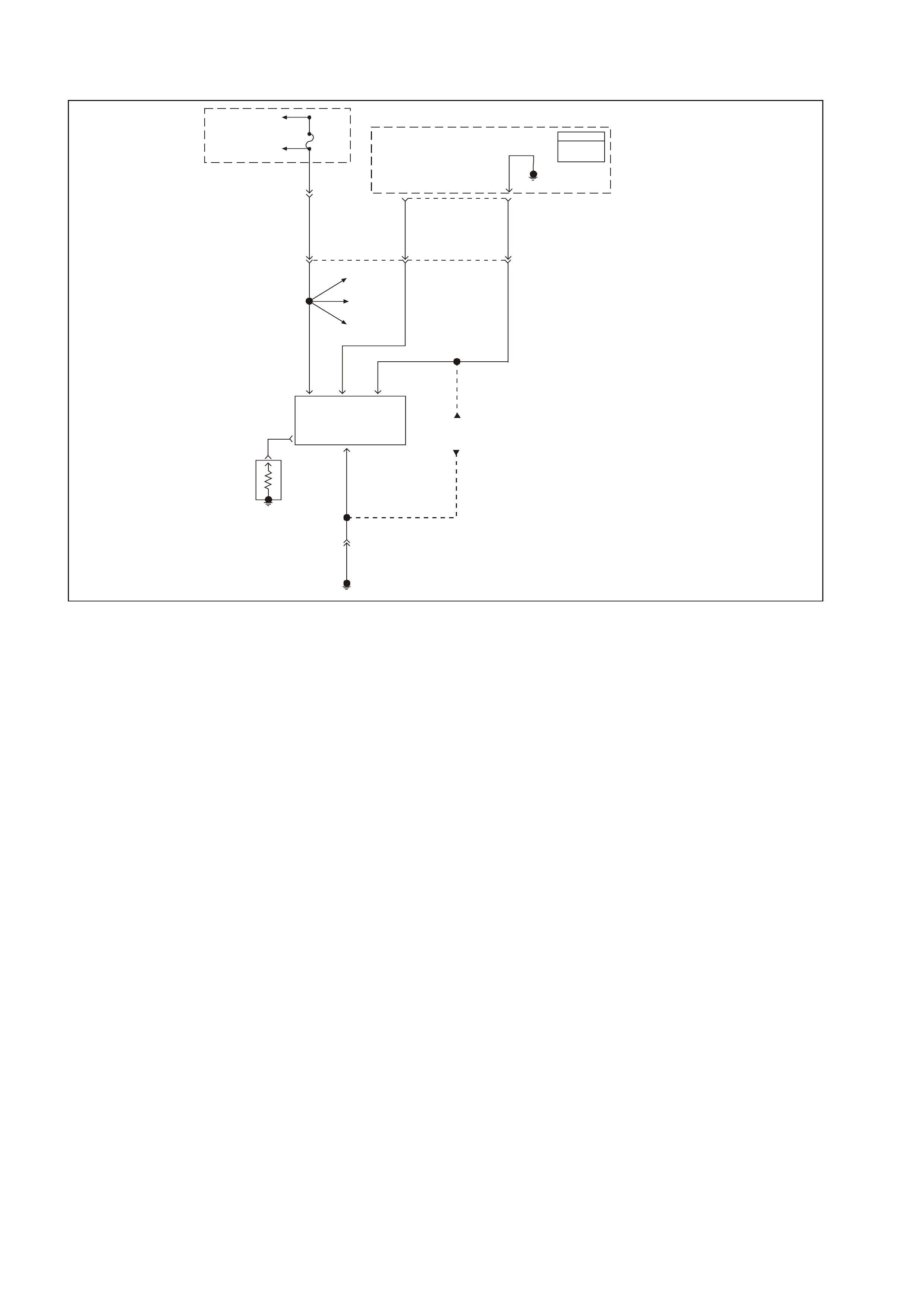
GEN III V8 PCMDTC P0353 IGNITION CONTROL #3 CIRCUIT
GEN3 0163
PCM
J1 = B LUE
J2 = R E D
Powertrain
Control
Module
(PCM)
69
Ignition
Control
3
60
Reference
Low
Fuse
F35
To EFI
(Eng in e Con t. )
Relay
To Injectors
1, 3, 5, 7
YE111
482
LG 973
BLU 958
BR
E
HF
BC
DIgnition
Coil/
Module
3
Ignition
Feed Ignition
Control
Signal
Reference
Low
Earth
A
Spark
Plug
YE125
Ignition
Coil #1
Ignition
Coil #5
Ignition
Coil #7
750
B/R
YE125
Engine Earth
Locat i on E5/15
Ignition
Coil/Modules
#1, 5, 7
J2
CIRCUIT DESCRIPTION
The ignition system on this engine uses an individual ignition coil/module for each cylinder. The PCM controls the
ignition system operation. T here are eight Ignition Control (IC) c ircuits, one per cylinder, that connect the PCM and
ignition coil/modules. Each ignition coil/module have a power feed, a chassis earth circuit and a reference low
circuit. T he PCM causes a spar k to occur by earthing the IC circuit, which s ignals the ignition module to trigger the
ignition coil and fire the spark plug. Sequencing and tim ing are PCM controlled. This DTC sets when the IC circuit
is out of range.
Conditions for Running the DTC
• The ignition voltage is between 9.0 volts and 17.0 volts.
CONDITIONS FOR SETTING THE DTC
• The PCM detects the ignition control circuit is earthed, open or shorted to a voltage.
• All conditions met for less than 1 second.
ACTION TAKEN WHEN THE DTC SETS
• The PCM illuminates the Check Powertrain Lamp (CPL) when the diagnostic runs and fails.
• T he PCM records the operating conditions at the time the diagnostic f ails. The PCM stores this inform ation in
the Freeze Frame/Failure Records.
CONDITIONS FOR CLEARING THE CPL/DTC
• The PCM turns the CPL OFF after the first ignition cycle that the diagnostic runs and does not fail.
• A last test failed (current DTC) clears when the diagnostic runs and does not fail.
• A History DTC clears after forty consecutive warm-up cycles, if this or any other emission related diagnostic
does not report any failure.
• Use a Tech 2 scan tool in order to clear the CPL/DTC.

DIAGNOSTIC AIDS
• The following may be cause an intermittent:
- Poor connections. Check for adequate terminal tension.
- Corrosion.
- Incorrectly routed harness.
- Rubbed through wire insulation.
- Broken wire inside the insulation.
• Using the Freeze Frame/Failure Records data may aid in locating an intermittent condition. If you cannot
duplicate the DT C, the information inc luded in the Freeze Fram e/Failure Records data can help determ ine the
distance traveled since the DTC Set. The Fail Counter and Pass Counter can also help determine how may
ignition cycles the diagnostic reported a pass and/or a fail. Operate the vehicle within the same freeze frame
conditions (RPM, load, vehicle speed, temperature etc.) that you observed. This will isolate when the DTC
failed.
• For an intermittent condition, refer to Section 6C3-2B SYMPTOMS in the VT Series II Service Information.
TEST DESCRIPTION
The numbers below refer to the step numbers on the diagnostic table.
2. This step verifies that the fault is present.
4. This step checks the integrity of the IC circuit and the PCM output.
5. This step checks for a short to earth on the IC control circuit.

GEN III V8 PCM DTC P0353 IGNITION CONTROL #3 CIRCUIT
Step Action Value(s) Yes No
1 Did you perform the Powertrain On-Board Diagnostic
(OBD) System Check ? Go to Step 2 Go to Powertrain
OBD System
Check Table
2 Important: If all the Ignition Control (IC) DTCs are set at
the same time, inspect the IC earth circuits for an open.
1. Install a Tech 2 scan tool.
2. Idle the engine.
3. Monitor the (IC) Ignition Control status for the cylinder
with the ignition control DTC using the Tech 2 scan
tool in the Engine Data List.
Does the Tech 2 scan tool indicate Fault?
Go to Step 4 Go to Step 3
3 1. Turn ON the ignition leaving the engine OFF.
2. Review the Freeze Frame/Failure Records data for
this DTC and observe the parameters.
3. Turn OFF the ignition for 15 seconds.
4. Start the engine.
5. Operate the vehicle within the conditions required for
this diagnostic to run, and as close to the conditions
recorded in Freeze Frame/Failure Records as
possible. Special operating conditions that you need to
meet before the PCM will run this diagnostic, where
applicable, are listed in Conditions for Running the
DTC.
6. Select the Diagnostic Trouble Code (DTC) option, the
DTC Information option and The Failed This Ignition
using the Tech 2 scan tool.
Does the Tech 2 scan tool indicate that this diagnostic
failed this ignition?
Go to Step 4 Go To Diagnostic
Aids
4 1. Turn OFF the engine.
2. Disconnect the ignition coil electrical harness.
3. Measure the frequency at the ignition control signal
circuit using the DMM J 39200 on the AC Hertz
setting.
4. Idle the engine.
Is the frequency within the specified range?
3.0-20 Hz Go to Step 8 Go to Step 5
5 Measure the voltage at the ignition control signal circuit
using the DMM J 39200.
Is the voltage greater than the specified value?
1.0 volts Go to Step 9 Go to Step 6
6 1. Turn OFF the ignition.
2. Disconnect the RED PCM connector.
3. Check the continuity from the IC circuit (at the ignition
coil harness connector) to the PCM connector using
the DMM J 39200.
Does the DMM indicate continuity?
Go to Step 7 Go to Step 10
7 Check the resistance from the IC circuit (at the ignition
coil harness connector to earth using the DMM J 39200.
Does the DMM indicate OL?
Go to Step 11 Go to step 10
8 Replace the ignition coil. Refer to Section 6C3-3 Ignition
Coil Replacement in the VT Series II Service Information.
Is the action complete?
Go to Step 13
9 Repair the Ignition Control circuit for a short to voltage.
Is the action complete? Go to Step 13
10 Repair the Ignition Control circuit for an open or earthed
circuit.
Is the action complete?
Go to Step 13

Step Action Value(s) Yes No
11 Check the terminal tension at the PCM and replace the
terminal if necessary.
Did you find and correct the condition?
Go to Step 13 Go to Step 12
12 1. Replace PCM.
2. Refer to Section 6C3-3 in the VT Series II Service
Information for PCM Programming and
PCM/PIM/BCM Security Link Procedure.
Is action complete?
Go to Step 13
13 1. Select the Diagnostic Trouble Code (DTC) option and
the Clear DTC Information option using the Tech 2
scan tool.
2. Idle the engine at the normal operating temperature.
3. Select the Diagnostic Trouble Code (DTC) option, the
DTC Information option and The Failed This Ignition
option using the Tech 2 scan tool.
4. Operate the vehicle within the Conditions for Running
the DTC as specified in the supporting text, if
applicable.
Does the Tech 2 scan tool indicate that this DTC reset?
Go to Step 12 Go to Step 14
14 Using the Tech 2 scan tool, check for any other DTCs.
Does the Tech 2 scan tool display any DTCs that you
have not diagnosed?
Go to the
applicable DTC
table
System OK
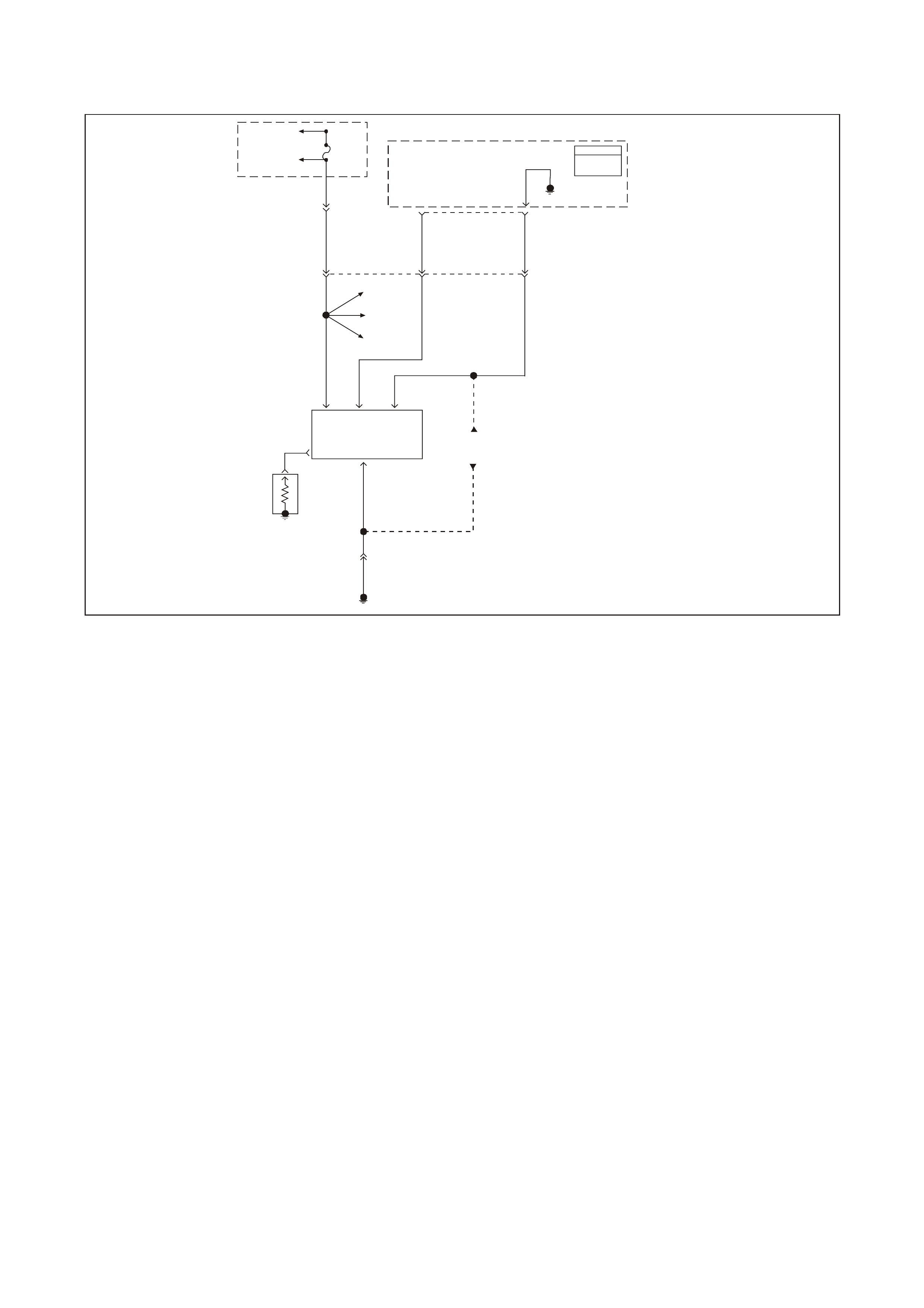
GEN III V8 PCM DTC P0354 IGNITION CONTROL #4 CIRCUIT
GEN3 0164
PCM
J1 = B LUE
J2 = R E D
Powertrain
Control
Module
(PCM)
29
Ignition
Control
4
61
Reference
Low
Fuse
F34
To EFI
(Eng in e Con t. )
Relay
To Injectors
2, 4, 6, 8
YE111
481
R974
W 959
V
E
HC
BC
DIgnition
Coil/
Module
4
Ignition
Feed Ignition
Control
Signal
Referenc
e
Earth
A
Spark
Plug
YE124
Ignition
Coil #2
Ignition
Coil #6
Ignition
Coil #8
750
B/R
YE124
Engine Earth
Locat i on E5/15
Ignition
Coil/Modules
#2, 6, 8
J2
CIRCUIT DESCRIPTION
The ignition system on this engine uses an individual ignition coil/module for each cylinder. The PCM controls the
ignition system operation. T here are eight Ignition Control (IC) c ircuits, one per cylinder, that connect the PCM and
ignition coil/modules. Each ignition coil/module have a power feed, a chassis earth circuit and a reference low
circuit. T he PCM causes a spar k to occur by earthing the IC circuit, which s ignals the ignition module to trigger the
ignition coil and fire the spark plug. Sequencing and tim ing are PCM controlled. This DTC sets when the IC circuit
is out of range.
CONDITIONS FOR RUNNING THE DTC
• The ignition voltage is between 9.0 volts and 17.0 volts.
CONDITIONS FOR SETTING THE DTC
• The PCM detects the ignition control circuit is earthed, open or shorted to a voltage.
• All conditions met for less than 1 second.
ACTION TAKEN WHEN THE DTC SETS
• The PCM illuminates the Check Powertrain Lamp (CPL) when the diagnostic runs and fails.
• The PCM records the operating conditions at the time the diagnostic fails. The PCM stores this information in
the Freeze Frame/Failure Records.
CONDITIONS FOR CLEARING THE CPL/DTC
• The PCM turns the CPL OFF after the first ignition cycle that the diagnostic runs and does not fail.
• A last test failed (current DTC) clears when the diagnostic runs and does not fail.
• A History DTC clears after forty consecutive warm-up cycles, if this or any other emission related diagnostic
does not report any failure.
• Use a Tech 2 scan tool to clear the CPL/DTC.

DIAGNOSTIC AIDS
• The following may be cause an intermittent:
- Poor connections. Check for adequate terminal tension.
- Corrosion.
- Incorrectly routed harness.
- Rubbed through wire insulation.
- Broken wire inside the insulation.
• Using the Freeze Frame/Failure Records data may aid in locating an intermittent condition. If you cannot
duplicate the DT C, the information inc luded in the Freeze Fram e/Failure Records data can help determ ine the
distance traveled since the DTC Set. The Fail Counter and Pass Counter can also help determine how may
ignition cycles the diagnostic reported a pass and/or a fail. Operate the vehicle within the same freeze frame
conditions (RPM, load, vehicle speed, temperature etc.) that you observed. This will isolate when the DTC
failed.
• For an intermittent condition, refer to Section 6C3-2B SYMPTOMS in the VT Series II Service Information.
TEST DESCRIPTION
The numbers below refer to the step numbers on the diagnostic table.
2. This step verifies that the fault is present.
4. This step checks the integrity of the IC circuit and the PCM output.
5. This step checks for a short to earth on the IC control circuit.

GEN III V8 PCM DTC P0354 IGNITION CONTROL #4 CIRCUIT
Step Action Value(s) Yes No
1 Did you perform the Powertrain On-Board Diagnostic
(OBD) System Check ? Go to Step 2 Go to Powertrain
OBD System
Check Table
2 Important: If all the Ignition Control (IC) DTCs are set at
the same time, inspect the IC earth circuits for an open.
1. Install a Tech 2 scan tool.
2. Idle the engine.
3. Monitor the (IC) Ignition Control status for the cylinder
with the ignition control DTC using the Tech 2 scan
tool in the Engine Data List.
Does the Tech 2 scan tool indicate Fault?
Go to Step 4 Go to Step 3
3 1. Turn ON the ignition leaving the engine OFF.
2. Review the Freeze Frame/Failure Records data for
this DTC and observe the parameters.
3. Turn OFF the ignition for 15 seconds.
4. Start the engine.
5. Operate the vehicle within the conditions required for
this diagnostic to run, and as close to the conditions
recorded in Freeze Frame/Failure Records as
possible. Special operating conditions that you need to
meet before the PCM will run this diagnostic, here
applicable, are listed in Conditions for Running the
DTC.
6. Select the Diagnostic Trouble Code (DTC) option, the
DTC Information option and The Failed This Ignition
option using the Tech 2 scan tool.
Does the Tech 2 scan tool indicate that this diagnostic
failed this ignition?
Go to Step 4 Go To Diagnostic
Aids
4 1. Turn OFF the engine.
2. Disconnect the ignition coil electrical harness.
3. Measure the frequency at the ignition control signal
circuit using the DMM J 39200 on the AC Hertz
setting.
4. Idle the engine.
Is the frequency within the specified range?
3.0-20 Hz Go to Step 8 Go to Step 5
5 Measure the voltage at the ignition control signal circuit
using the DMM J 39200.
Is the voltage greater than the specified value?
1.0 volts Go to Step 9 Go to Step 6
6 1. Turn OFF the ignition.
2. Disconnect the RED PCM connector.
3. Check the continuity from the IC circuit (at the ignition
coil harness connector) to the PCM connector using
the DMM J 39200.
Does the DMM indicate continuity?
Go to Step 7 Go to Step 10
7 Check the resistance from the IC circuit (at the ignition
coil harness connector to earth using the DMM J 39200.
Does the DMM indicate OL?
Go to Step 11 Go to step 10
8 Replace the ignition coil. Refer to Section 6C3-3 Ignition
Coil Replacement in the VT Series II Service Information.
Is the action complete?
Go to Step 13
9 Repair the Ignition Control circuit for a short to voltage.
Is the action complete? Go to Step 13
10 Repair the Ignition Control circuit for an open or earthed
circuit.
Is the action complete?
Go to Step 13

Step Action Value(s) Yes No
11 Check the terminal tension at the PCM and replace the
terminal if necessary.
Did you find and correct the condition?
Go to Step 13 Go to Step 12
12 1. Replace PCM.
2. Refer to Section 6C3-3 in the VT Series II Service
Information for PCM Programming and
PCM/PIM/BCM Security Link Procedure.
Is action complete?
Go to Step 13
13 1. Select the Diagnostic Trouble Code (DTC) option and
the Clear DTC Information option using the Tech 2
scan tool.
2. Idle the engine at the normal operating temperature.
3. Select the Diagnostic Trouble Code (DTC) option, the
DTC Information option and The Failed This Ignition
option using the Tech 2 scan tool.
4. Operate the vehicle within the Conditions for Running
the DTC as specified in the supporting text, if
applicable.
Does the Tech 2 scan tool indicate that this DTC reset?
Go to Step 2 Go to Step 14
14 Using the Tech 2 scan tool, check for any other DTCs.
Does the Tech 2 scan tool display any DTCs that you
have not diagnosed?
Go to the
applicable DTC
table
System OK
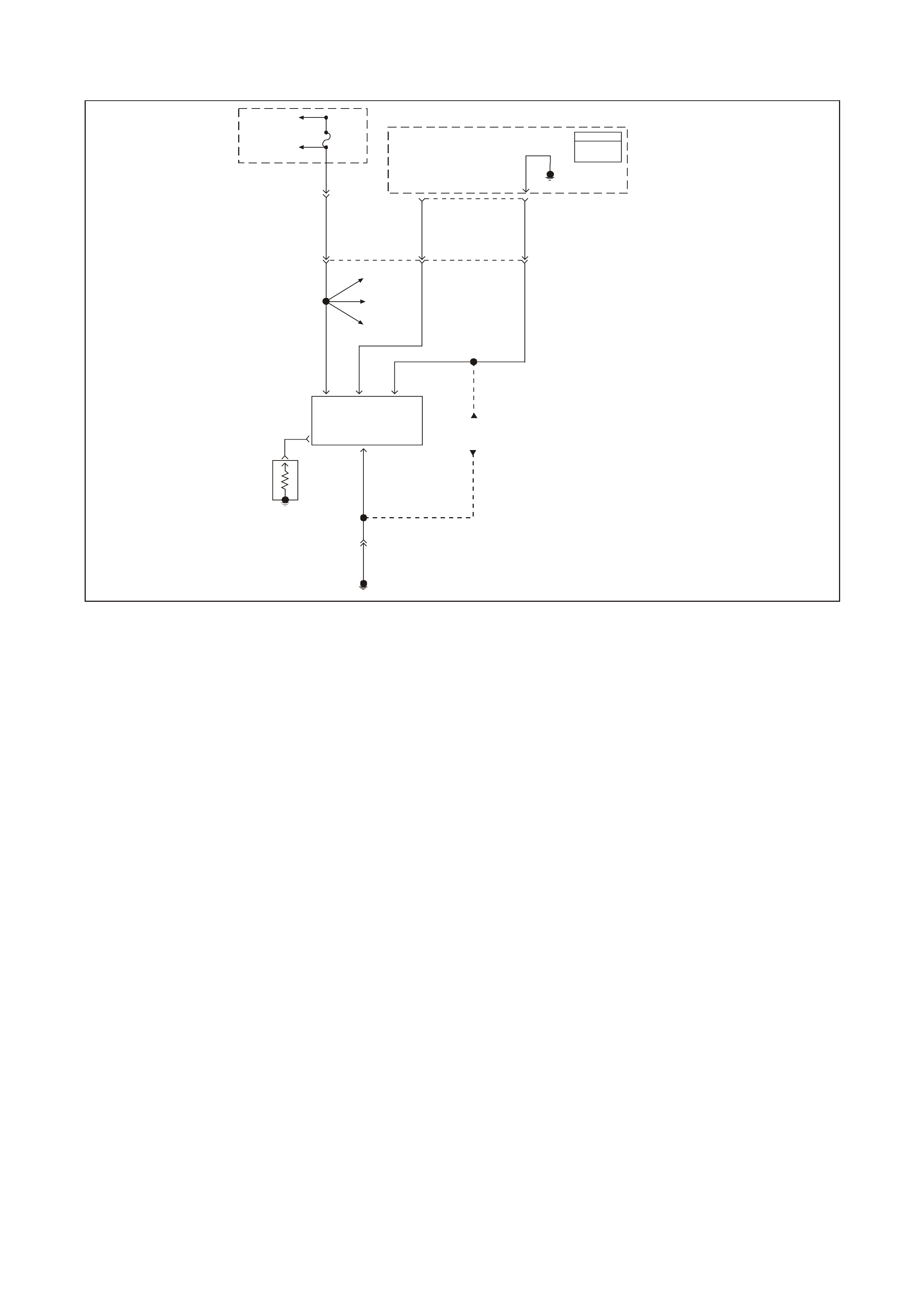
GEN III V8 PCM DTC P0355 IGNITION CONTROL #5 CIRCUIT
GEN3 0165
PCM
J1 = B LUE
J2 = R E D
Powertrain
Control
Module
(PCM)
68
Ignition
Control
5
60
Reference
Low
Fuse
F35
To EFI
(Eng in e Con t. )
Relay
To Injectors
1, 3, 5, 7
YE111
482
LG 975
G 958
BR
E
HC
BC
DIgnition
Coil/
Module
5
Ignition
Feed Ignition
Control
Signal
Referenc
e
Earth
A
Spark
Plug
YE125
Ignition
Coil #1
Ignition
Coil #3
Ignition
Coil #7
750
B/R
YE125
Engine Earth
Locat i on E5/15
Ignition
Coil/Modules
#1, 3, 7
J 2
CIRCUIT DESCRIPTION
The ignition system on this engine uses an individual ignition coil/module for each cylinder. The PCM controls the
ignition system operation. T here are eight Ignition Control (IC) c ircuits, one per cylinder, that connect the PCM and
ignition coil/modules. Each ignition coil/module have a power feed, a chassis earth circuit and a reference low
circuit. T he PCM causes a spar k to occur by earthing the IC circuit, which s ignals the ignition module to trigger the
ignition coil and fire the spark plug. Sequencing and tim ing are PCM controlled. This DTC sets when the IC circuit
is out of range.
CONDITIONS FOR RUNNING THE DTC
• The ignition voltage is between 9.0 volts and 17.0 volts.
CONDITIONS FOR SETTING THE DTC
• The PCM detects the ignition control circuit is earthed, open or shorted to a voltage.
• All conditions met for less than 1 second.
ACTION TAKEN WHEN THE DTC SETS
• The PCM illuminates the Check Powertrain Lamp (CPL) when the diagnostic runs and fails.
• T he PCM records the operating conditions at the time the diagnostic f ails. The PCM stores this inform ation in
the Freeze Frame/Failure Records.
• information in the Freeze Frame/Failure Records.
CONDITIONS FOR CLEARING THE CPL/DTC
• The PCM turns the CPL OFF after the first ignition cycle that the diagnostic runs and does not fail.
• A last test failed (current DTC) clears when the diagnostic runs and does not fail.
• A History DTC clears after forty consecutive warm-up cycles, if this or any other emission related diagnostic
does not report any failure.
• Use a Tech 2 scan tool to clear the CPL/DTC.

DIAGNOSTIC AIDS
• The following may be the cause of an intermittent:
- Poor connections. Check for adequate terminal tension
- Corrosion
- Incorrectly routed harness
- Rubbed through wire insulation
- Broken wire inside the insulation
• Using the Freeze Frame/Failure Records data may aid in locating an intermittent condition. If you cannot
duplicate the DT C, the information inc luded in the Freeze Fram e/Failure Records data can help determ ine the
distance traveled since the DTC Set. The Fail Counter and Pass Counter can also help determine how may
ignition cycles the diagnostic reported a pass and/or a fail. Operate the vehicle within the same freeze frame
conditions (RPM, load, vehicle speed, temperature etc.) that you observed. This will isolate when the DTC
failed.
• For an intermittent condition, refer to Section 6C3-2B SYMPTOMS in the VT Series II Service Information.
TEST DESCRIPTION
The numbers below refer to the step numbers on the diagnostic table.
2. This step verifies that the fault is present.
4. This step checks the integrity of the IC circuit and the PCM output.
5. This step checks for a short to earth on the IC control circuit.

GEN III V8 PCM DTC P0355 IGNITION CONTROL #5 CIRCUIT
Step Action Value(s) Yes No
1 Did you perform the Powertrain On-Board Diagnostic
(OBD) System Check ? Go to Step 2 Go to Powertrain
OBD System
Check Table
2 Important: If all the Ignition Control (IC) DTCs are set at
the same time, inspect the IC earth circuits for an open.
1. Install a Tech 2 scan tool.
2. Idle the engine.
3. Monitor the (IC) Ignition Control status for the cylinder
with the ignition control DTC using the Tech 2 scan
tool in the Engine Data List.
Does the Tech 2 scan tool indicate Fault?
Go to Step 4 Go to Step 3
3 1. Turn ON the ignition leaving the engine OFF.
1. Review the Freeze Frame/Failure Records data for
this DTC and observe the parameters.
2. Turn OFF the ignition for 15 seconds.
3. Start the engine.
4. Operate the vehicle within the conditions required for
this diagnostic to run, and as close to the conditions
recorded in Freeze Frame/Failure Records as
possible. Special operating conditions that you need to
meet before the PCM will run this diagnostic, where
applicable, are listed in Conditions for Running the
DTC.
5. Select the Diagnostic Trouble Code (DTC) option, the
DTC Information, The Failed This Ignition using the
Tech 2 scan tool.
Does the Tech 2 scan tool indicate that this diagnostic
failed this ignition?
Go to Step 4 Go To Diagnostic
Aids
4 1. Turn OFF the engine.
2. Disconnect the ignition coil electrical harness.
3. Measure the frequency at the ignition control signal
circuit using the DMM J 39200 on the AC Hertz
setting.
4. Idle the engine.
Is the frequency within the specified range?
3.0-20 Hz Go to Step 8 Go to Step 5
5 Measure the voltage at the ignition control signal circuit
using the DMM J 39200.
Is the voltage greater than the specified value?
1.0 volts Go to Step 9 Go to Step 6
6 1. Turn OFF the ignition.
2. Disconnect the RED PCM connector.
3. Check the continuity from the IC circuit (at the ignition
coil harness connector) to the PCM connector using
the DMM J 39200.
Does the DMM indicate continuity?
Go to Step 7 Go to Step 10
7 Check the resistance from the IC circuit (at the ignition
coil harness connector to earth using the DMM J 39200.
Does the DMM indicate OL?
Go to Step 11 Go to step 10
8 Replace the ignition coil. Refer to Section 6C3-3 Ignition
Coil Replacement in the VT Series II Service Information.
Is the action complete?
Go to Step 13
9 Repair the Ignition Control circuit for a short to voltage.
Is the action complete? Go to Step 13
10 Repair the Ignition Control circuit for an open or earthed
circuit.
Is the action complete?
Go to Step 13

Step Action Value(s) Yes No
11 Check the terminal tension at the PCM and replace the
terminal if necessary.
Did you find and correct the condition?
Go to Step 13 Go to Step 12
12 1. Replace PCM.
2. Refer to Section 6C3-3 in the VT Series II Service
Information for PCM Programming and
PCM/PIM/BCM Security Link Procedure.
Is action complete?
Go to Step 13
13 1. Select the Diagnostic Trouble Code (DTC) option and
the Clear DTC Information option using the Tech 2
scan tool.
2. Idle the engine at the normal operating temperature.
3. Select the Diagnostic Trouble Code (DTC) option, the
DTC Information, The Failed This Ignition using the
Tech 2 scan tool.
4. Operate the vehicle within the Conditions for Running
the DTC as specified in the supporting text, if
applicable.
Does the Tech 2 scan tool indicate that this DTC reset?
Go to Step 2 Go to Step 14
14 Using the Tech 2 scan tool, check for any other DTCs.
Does the Tech 2 scan tool display any DTCs that you
have not diagnosed?
Go to the
applicable DTC
table
System OK

GEN III V8 PCM DTC P0356 IGNITION CONTROL #6 CIRCUIT
GEN3 0166
PCM
J1 = B LUE
J2 = R E D
Powertrain
Control
Module
(PCM)
28
Ignition
Control
6
61
Reference
Low
Fuse
F34
To EFI
(Eng in e Con t. )
Relay
To Injectors
2, 4, 6, 8
YE111
481
R976
LG 959
V
E
H
BC
DIgnition
Coil/
Module
6
Ignition
Feed Ignition
Control
Signal
Referenc
e
Earth
A
Spark
Plug
YE124
Ignition
Coil #2
Ignition
Coil #4
Ignition
Coil #8
750
B/R
YE124
Engine Earth
Locat i on E5/15
Ignition
Coil/Modules
#2, 4, 8
J2
CIRCUIT DESCRIPTION
The ignition system on this engine uses an individual ignition coil/module for each cylinder. The PCM controls the
ignition system operation. T here are eight Ignition Control (IC) c ircuits, one per cylinder, that connect the PCM and
ignition coil/modules. Each ignition coil/module have a power feed, a chassis earth circuit and a reference low
circuit. T he PCM causes a spar k to occur by earthing the IC circuit, which s ignals the ignition module to trigger the
ignition coil and fire the spark plug. Sequencing and tim ing are PCM controlled. This DTC sets when the IC circuit
is out of range.
CONDITIONS FOR RUNNING THE DTC
• The ignition voltage is between 9.0 volts and 17.0 volts.
CONDITIONS FOR SETTING THE DTC
• The PCM detects the ignition control circuit is earthed, open or shorted to a voltage.
• All conditions met for less than 1 second.
ACTION TAKEN WHEN THE DTC SETS
• The PCM illuminates the Check Powertrain Lamp (CPL) when the diagnostic runs and fails.
• T he PCM records the operating conditions at the time the diagnostic f ails. The PCM stores this inform ation in
the Freeze Frame/Failure Records.
CONDITIONS FOR CLEARING THE CPL/DTC
• The PCM turns the CPL OFF after the first ignition cycle that the diagnostic runs and does not fail.
• A last test failed (current DTC) clears when the diagnostic runs and does not fail.
• A History DTC clears after forty consecutive warm-up cycles, if this or any other emission related diagnostic
does not report any failure.
• Use a Tech 2 scan tool to clear the CPL/DTC.

DIAGNOSTIC AIDS
• The following may be cause an intermittent:
- Poor connections. Check for adequate terminal tension
- Corrosion
- Incorrectly routed harness
- Rubbed through wire insulation
- Broken wire inside the insulation
• Using the Freeze Frame/Failure Records data may aid in locating an intermittent condition. If you cannot
duplicate the DT C, the information inc luded in the Freeze Fram e/Failure Records data can help determ ine the
distance traveled since the DTC Set. The Fail Counter and Pass Counter can also help determine how may
ignition cycles the diagnostic reported a pass and/or a fail. Operate the vehicle within the same freeze frame
conditions (RPM, load, vehicle speed, temperature etc.) that you observed. This will isolate when the DTC
failed.
• For an intermittent condition, refer to Section 6C3-2B SYMPTOMS in the VT Series II Service Information.
TEST DESCRIPTION
The numbers below refer to the step numbers on the diagnostic table.
2. This step verifies that the fault is present.
4. This step checks the integrity of the IC circuit and the PCM output.
5. This step checks for a short to earth on the IC control circuit.

GEN III V8 PCM DTC P0356 IGNITION CONTROL #6 CIRCUIT
Step Action Value(s) Yes No
1 Did you perform the Powertrain On-Board Diagnostic
(OBD) System Check ? Go to Step 2 Go to Powertrain
OBD System
Check Table
2 Important: If all the Ignition Control (IC) DTCs are set at
the same time, inspect the IC earth circuits for an open.
1. Install a Tech 2 scan tool.
2. Idle the engine.
3. Monitor the (IC) Ignition Control status for the cylinder
with the ignition control DTC using the Tech 2 scan
tool in the Engine Data List.
Does the Tech 2 scan tool indicate Fault?
Go to Step 4 Go to Step 3
3 1. Turn ON the ignition leaving the engine OFF.
2. Review the Freeze Frame/Failure Records data for
this DTC and observe the parameters.
3. Turn OFF the ignition for 15 seconds.
4. Start the engine.
5. Operate the vehicle within the conditions required for
this diagnostic to run, and as close to the conditions
recorded in Freeze Frame/Failure Records as
possible. Special operating conditions that you need to
meet before the PCM will run this diagnostic, where
applicable, are listed in Conditions for Running the
DTC.
6. Select the Diagnostic Trouble Code (DTC) option, the
DTC Information, The Failed This Ignition using the
Tech 2 scan tool.
Does the Tech 2 scan tool indicate that this diagnostic
failed this ignition?
Go to Step 4 Go To Diagnostic
Aids
4 1. Turn OFF the engine.
2. Disconnect the ignition coil electrical harness.
3. Measure the frequency at the ignition control signal
circuit using the DMM J 39200 on the AC Hertz
setting.
4. Idle the engine.
Is the frequency within the specified range?
3.0-20 Hz Go to Step 8 Go to Step 5
5 Measure the voltage at the ignition control signal circuit
using the DMM J 39200.
Is the voltage greater than the specified value?
1.0 volts Go to Step 9 Go to Step 6
6 1. Turn OFF the ignition.
2. Disconnect the RED PCM connector.
3. Check the continuity from the IC circuit (at the ignition
coil harness connector) to the PCM connector using
the DMM J 39200.
Does the DMM indicate continuity?
Go to Step 7 Go to Step 10
7 Check the resistance from the IC circuit (at the ignition
coil harness connector to earth using the DMM J 39200.
Does the DMM indicate OL?
Go to Step 11 Go to step 10
8 Replace the ignition coil. Refer to Section 6C3-3 Ignition
Coil Replacement in the VT Series II Service Information.
Is the action complete?
Go to Step 13
9 Repair the Ignition Control circuit for a short to voltage.
Is the action complete? Go to Step 13
10 Repair the Ignition Control circuit for an open or earthed
circuit.
Is the action complete?
Go to Step 13

Step Action Value(s) Yes No
11 Check the terminal tension at the PCM and replace the
terminal if necessary.
Did you find and correct the condition?
Go to Step 13 Go to Step 12
12 1. Replace PCM.
2. Refer to Section 6C3-3 in the VT Series II Service
Information for PCM Programming and
PCM/PIM/BCM Security Link Procedure.
Is action complete?
Go to Step 13
13 1. Select the Diagnostic Trouble Code (DTC) option and
the Clear DTC Information option using the Tech 2
scan tool.
2. Idle the engine at the normal operating temperature.
3. Select the Diagnostic Trouble Code (DTC) option, the
DTC Information, The Failed This Ignition using the
Tech 2 scan tool.
4. Operate the vehicle within the Conditions for Running
the DTC as specified in the supporting text, if
applicable.
Does the Tech 2 scan tool indicate that this DTC reset?
Go to Step 2 Go to Step 14
14 Using the Tech 2 scan tool, check for any other DTCs.
Does the Tech 2 scan tool display any DTCs that you
have not diagnosed?
Go to the
applicable DTC
table
System OK
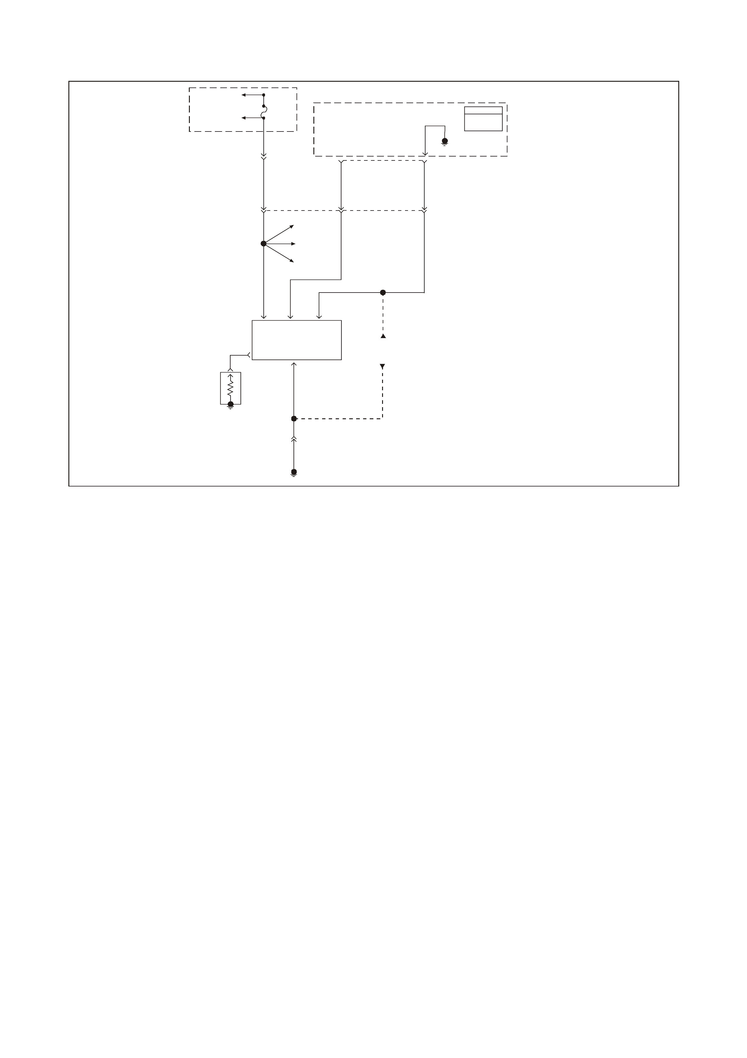
GEN III V8 PCM DTC P0357 IGNITION CONTROL #7 CIRCUIT
GEN3 0167
PCM
J1 = B LUE
J2 = R E D
Powertrain
Control
Module
(PCM)
27
Ignition
Control
7
60
Reference
Low
Fuse
F35
To EFI
(Eng ine Cont.)
Relay
To Injectors
1, 3, 5, 7
YE111
482
LG 977
Y 958
BR
E
HB
BC
DIgnition
Coil/
Module
7
Ignition
Feed Ignition
Control
Signal
Referenc
e
Earth
A
Spark
Plug
YE125
Ignition
Coil #1
Ignition
Coil #3
Ignition
Coil #5
750
B/R
YE125
Engine Earth
Locat i on E5/15
Ignition
Coil/Modules
#1, 3, 5
J2
CIRCUIT DESCRIPTION
The ignition system on this engine uses an individual ignition coil/module for each cylinder. The PCM controls the
ignition system operation. T here are eight Ignition Control (IC) c ircuits, one per cylinder, that connect the PCM and
ignition coil/modules. Each ignition coil/module have a power feed, a chassis earth circuit and a reference low
circuit. T he PCM causes a spar k to occur by earthing the IC circuit, which s ignals the ignition module to trigger the
ignition coil and fire the spark plug. Sequencing and tim ing are PCM controlled. This DTC sets when the IC circuit
is out of range.
CONDITIONS FOR RUNNING THE DTC
• The ignition voltage is between 9.0 volts and 17.0 volts.
CONDITIONS FOR SETTING THE DTC
• The PCM detects the ignition control circuit is earthed, open or shorted to a voltage.
• All conditions met for less than 1 second.
ACTION TAKEN WHEN THE DTC SETS
• The PCM illuminates the Check Powertrain Lamp (CPL) when the diagnostic runs and fails.
• T he PCM records the operating conditions at the time the diagnostic f ails. The PCM stores this inform ation in
the Freeze Frame/Failure Records.
• information in the Freeze Frame/Failure Records.
CONDITIONS FOR CLEARING THE CPL/DTC
• The PCM turns the CPL OFF after the first ignition cycle that the diagnostic runs and does not fail.
• A last test failed (current DTC) clears when the diagnostic runs and does not fail.
• A History DTC clears after forty consecutive warm-up cycles, if this or any other emission related diagnostic
does not report any failure.
• Use a Tech 2 scan tool to clear the CPL/DTC.

DIAGNOSTIC AIDS
• The following may be cause an intermittent:
- Poor connections. Check for adequate terminal tension
- Corrosion
- Incorrectly routed harness
- Rubbed through wire insulation
- Broken wire inside the insulation
• Using the Freeze Frame/Failure Records data may aid in locating an intermittent condition. If you cannot
duplicate the DT C, the information inc luded in the Freeze Fram e/Failure Records data can help determ ine the
distance traveled since the DTC Set. The Fail Counter and Pass Counter can also help determine how may
ignition cycles the diagnostic reported a pass and/or a fail. Operate the vehicle within the same freeze frame
conditions (RPM, load, vehicle speed, temperature etc.) that you observed. This will isolate when the DTC
failed.
• For an intermittent condition, refer to Section 6C3-2B SYMPTOMS in the VT Series II Service Information.
TEST DESCRIPTION
The numbers below refer to the step numbers on the diagnostic table.
2. This step verifies that the fault is present.
4. This step checks the integrity of the IC circuit and the PCM output.
5. This step checks for a short to earth on the IC control circuit.

GEN III V8 PCM DTC P0357 IGNITION CONTROL #7 CIRCUIT
Step Action Value(s) Yes No
1 Did you perform the Powertrain On-Board Diagnostic
(OBD) System Check ? Go to Step 2 Go to Powertrain
OBD System
Check Table
2 Important: If all the Ignition Control (IC) DTCs are set at
the same time, inspect the IC earth circuits for an open.
1. Install a Tech 2 scan tool.
2. Idle the engine.
3. Monitor the (IC) Ignition Control status for the cylinder
with the ignition control DTC using the Tech 2 scan
tool in the Engine Data List.
Does the Tech 2 scan tool indicate Fault?
Go to Step 4 Go to Step 3
3 1. Turn ON the ignition leaving the engine OFF.
2. Review the Freeze Frame/Failure Records data for
this DTC and observe the parameters.
3. Turn OFF the ignition for 15 seconds.
4. Start the engine.
5. Operate the vehicle within the conditions required for
this diagnostic to run, and as close to the conditions
recorded in Freeze Frame/Failure Records as
possible. Special operating conditions that you need to
meet before the PCM will run this diagnostic, where
applicable, are listed in Conditions for Running the
DTC.
6. Select the Diagnostic Trouble Code (DTC) option, the
DTC Information, The Failed This Ignition using the
Tech 2 scan tool.
Does the Tech 2 scan tool indicate that this diagnostic
failed this ignition?
Go to Step 4 Go To Diagnostic
Aids
4 1. Turn OFF the engine.
2. Disconnect the ignition coil electrical harness.
3. Measure the frequency at the ignition control signal
circuit using the DMM J 39200 on the AC Hertz
setting.
4. Idle the engine.
Is the frequency within the specified range?
3.0-20 Hz Go to Step 8 Go to Step 5
5 Measure the voltage at the ignition control signal circuit
using the DMM J 39200.
Is the voltage greater than the specified value?
1.0 volts Go to Step 9 Go to Step 6
6 1. Turn OFF the ignition.
2. Disconnect the RED PCM connector.
3. Check the continuity from the IC circuit (at the ignition
coil harness connector) to the PCM connector using
the DMM J 39200.
Does the DMM indicate continuity?
Go to Step 7 Go to Step 10
7 Check the resistance from the IC circuit (at the ignition
coil harness connector to earth using the DMM J 39200.
Does the DMM indicate OL?
Go to Step 11 Go to step 10
8 Replace the ignition coil. Refer to Section 6C3-3 Ignition
Coil Replacement in the VT Series II Service Information.
Is the action complete?
Go to Step 13
9 Repair the Ignition Control circuit for a short to voltage.
Is the action complete? Go to Step 13
10 Repair the Ignition Control circuit for an open or earthed
circuit.
Is the action complete?
Go to Step 13

Step Action Value(s) Yes No
11 Check the terminal tension at the PCM and replace the
terminal if necessary.
Did you find and correct the condition?
Go to Step 13 Go to Step 12
12 1. Replace PCM.
2. Refer to Section 6C3-3 in the VT Series II Service
Information for PCM Programming and
PCM/PIM/BCM Security Link Procedure.
Is action complete?
Go to Step 13
13 1. Select the Diagnostic Trouble Code (DTC) option and
the Clear DTC Information option using the Tech 2
scan tool.
2. Idle the engine at the normal operating temperature.
3. Select the Diagnostic Trouble Code (DTC) option, the
DTC Information, The Failed This Ignition using the
Tech 2 scan tool.
4. Operate the vehicle within the Conditions for Running
the DTC as specified in the supporting text, if
applicable.
Does the Tech 2 scan tool indicate that this DTC reset?
Go to Step 2 Go to Step 14
14 Using the Tech 2 scan tool, check for any other DTCs.
Does the Tech 2 scan tool display any DTCs that you
have not diagnosed?
Go to the
applicable DTC
table
System OK
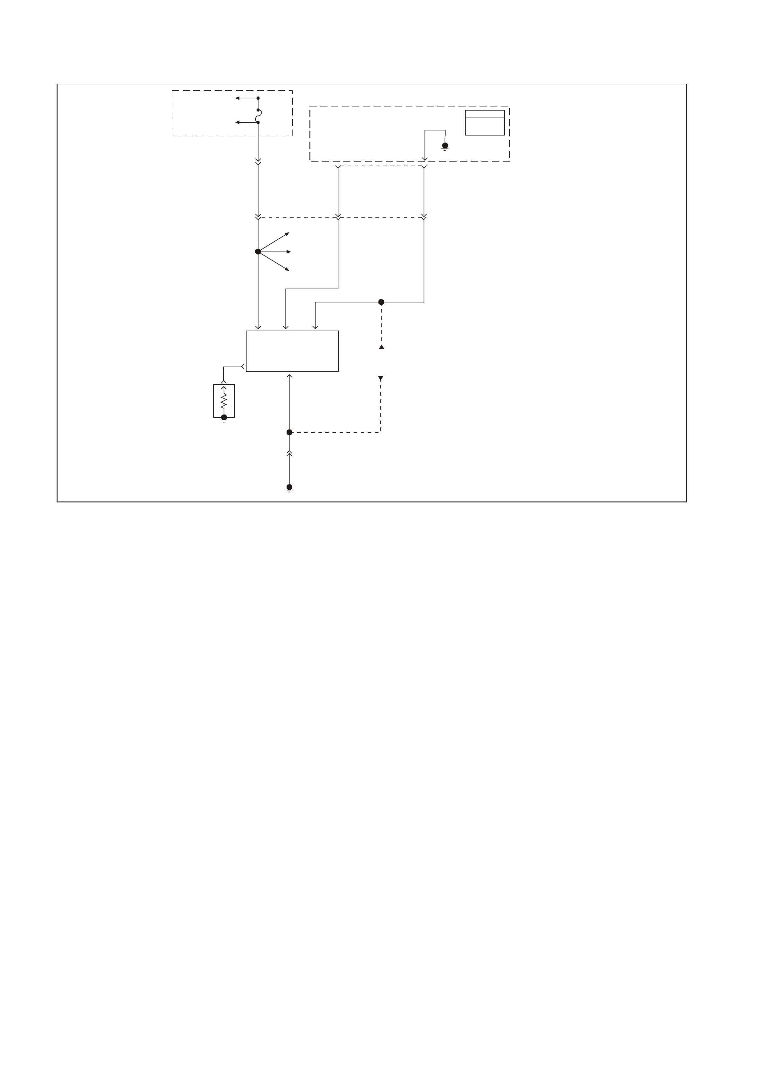
GEN III V8 PCM DTC P0358 IGNITION CONTROL #8 CIRCUIT
GEN3 0168
PCM
J1 = B LUE
J2 = R E D
Powertrain
Control
Module
(PCM)
66
Ignition
Control
8
61
Reference
Low
Fuse
F34
To EFI
(Eng in e Con t. )
Relay
To Injectors
2, 4, 6, 8
YE111
481
R978
LBLU 959
V
E
HG
BC
DIgnition
Coil/
Module
8
Ignition
Feed Ignition
Control
Signal
Reference
Low
Earth
A
Spark
Plug
YE124
Ignition
Coil #2
Ignition
Coil #4
Ignition
Coil #6
750
B/R
YE124
Engine Earth
Locat i on E5/15
Ignition
Coil/Modules
#2, 4, 6
J2
CIRCUIT DESCRIPTION
The ignition system on this engine uses an individual ignition coil/module for each cylinder. The PCM controls the
ignition system operation. T here are eight Ignition Control (IC) c ircuits, one per cylinder, that connect the PCM and
ignition coil/modules. Each ignition coil/module have a power feed, a chassis earth circuit and a reference low
circuit. T he PCM causes a spar k to occur by earthing the IC circuit, which s ignals the ignition module to trigger the
ignition coil and fire the spark plug. Sequencing and tim ing are PCM controlled. This DTC sets when the IC circuit
is out of range.
CONDITIONS FOR RUNNING THE DTC
• The ignition voltage is between 9.0 volts and 17.0 volts.
CONDITIONS FOR SETTING THE DTC
• The PCM detects the ignition control circuit is earthed, open or shorted to a voltage.
• All conditions met for less than 1 second.
ACTION TAKEN WHEN THE DTC SETS
• The PCM illuminates the Check Powertrain Lamp (CPL) when the diagnostic runs and fails.
• T he PCM records the operating conditions at the time the diagnostic f ails. The PCM stores this inform ation in
the Freeze Frame/ Failure Records.
CONDITIONS FOR CLEARING THE CPL/DTC
• The PCM turns the CPL OFF after the first ignition cycle that the diagnostic runs and does not fail.
• A last test failed (current DTC) clears when the diagnostic runs and does not fail.
• A History DTC clears after forty consecutive warm-up cycles, if this or any other emission related diagnostic
does not report any failure.
• Use a Tech 2 scan tool to clear the CPL/DTC.

DIAGNOSTIC AIDS
• The following may be cause an intermittent:
- Poor connections. Check for adequate terminal tension
- Corrosion
- Incorrectly routed harness
- Rubbed through wire insulation
- Broken wire inside the insulation
• Using the Freeze Frame/Failure Records data may aid in locating an intermittent condition. If you cannot
duplicate the DT C, the information inc luded in the Freeze Fram e/Failure Records data can help determ ine the
distance traveled since the DTC Set. The Fail Counter and Pass Counter can also help determine how may
ignition cycles the diagnostic reported a pass and/or a fail. Operate the vehicle within the same freeze frame
conditions (RPM, load, vehicle speed, temperature etc.) that you observed. This will isolate when the DTC
failed.
• For an intermittent condition, refer to Section 6C3-2B SYMPTOMS in the VT Series II Service Information.
TEST DESCRIPTION
The numbers below refer to the step numbers on the diagnostic table.
2. This step verifies that the fault is present.
4. This step checks the integrity of the IC circuit and the PCM output.
5. This step checks for a short to earth on the IC control circuit.

GEN III V8 PCM DTC P0358 IGNITION CONTROL #8 CIRCUIT
Step Action Value(s) Yes No
1 Did you perform the Powertrain On-Board Diagnostic
(OBD) System Check ? Go to Step 2 Go to Powertrain
OBD System
Check Table
2 Important: If all the Ignition Control (IC) DTCs are set at
the same time, inspect the IC earth circuits for an open.
1. Install a Tech 2 scan tool.
2. Idle the engine.
3. Monitor the (IC) Ignition Control status for the cylinder
with the ignition control DTC using the Tech 2 scan
tool in the Engine Data List.
Does the Tech 2 scan tool indicate Fault?
Go to Step 4 Go to Step 3
3 1. Turn ON the ignition leaving the engine OFF.
2. Review the Freeze Frame/Failure Records data for
this DTC and observe the parameters.
3. Turn OFF the ignition for 15 seconds.
4. Start the engine.
5. Operate the vehicle within the conditions required for
this diagnostic to run, and as close to the conditions
recorded in Freeze Frame/Failure Records as
possible. Special operating conditions that you need to
meet before the PCM will run this diagnostic, where
applicable, are listed in Conditions for Running the
DTC.
6. Select the Diagnostic Trouble Code (DTC) option, the
DTC Information, The Failed This Ignition using the
Tech 2 scan tool.
Does the Tech 2 scan tool indicate that this diagnostic
failed this ignition?
Go to Step 4 Go To Diagnostic
Aids
4 1. Turn OFF the engine.
2. Disconnect the ignition coil electrical harness.
3. Measure the frequency at the ignition control signal
circuit using the DMM J 39200 on the AC Hertz
setting.
4. Idle the engine.
Is the frequency within the specified range?
3.0-20 Hz Go to Step 8 Go to Step 5
5 Measure the voltage at the ignition control signal circuit
using the DMM J 39200.
Is the voltage greater than the specified value?
1.0 volts Go to Step 9 Go to Step 6
6 1. Turn OFF the ignition.
2. Disconnect the RED PCM connector.
3. Check the continuity from the IC circuit (at the ignition
coil harness connector) to the PCM connector using
the DMM J 39200.
Does the DMM indicate continuity?
Go to Step 7 Go to Step 10
7 Check the resistance from the IC circuit (at the ignition
coil harness connector to earth using the DMM J 39200.
Does the DMM indicate OL?
Go to Step 11 Go to step 10
8 Replace the ignition coil. Refer to Section 6C3-3 Ignition
Coil Replacement in the VT Series II Service Information.
Is the action complete?
Go to Step 13
9 Repair the Ignition Control circuit for a short to voltage.
Is the action complete? Go to Step 13
10 Repair the Ignition Control circuit for an open or earthed
circuit.
Is the action complete?
Go to Step 13

Step Action Value(s) Yes No
11 Check the terminal tension at the PCM and replace the
terminal if necessary.
Did you find and correct the condition?
Go to Step 13 Go to Step 12
12 1. Replace PCM.
2. Refer to Section 6C3-3 in the VT Series II Service
Information for PCM Programming and
PCM/PIM/BCM Security Link Procedure.
Is action complete?
Go to Step 13
13 1. Select the Diagnostic Trouble Code (DTC) option and
the Clear DTC Information option using the Tech 2
scan tool.
2. Idle the engine at the normal operating temperature.
3. Select the Diagnostic Trouble Code (DTC) option, the
DTC Information, The Failed This Ignition using the
Tech 2 scan tool.
4. Operate the vehicle within the Conditions for Running
the DTC as specified in the supporting text, if
applicable.
Does the Tech 2 scan tool indicate that this DTC reset?
Go to Step 2 Go to Step 14
14 Using the Tech 2 scan tool, check for any other DTCs.
Does the Tech 2 scan tool display any DTCs that you
have not diagnosed?
Go to the
applicable DTC
table
System OK
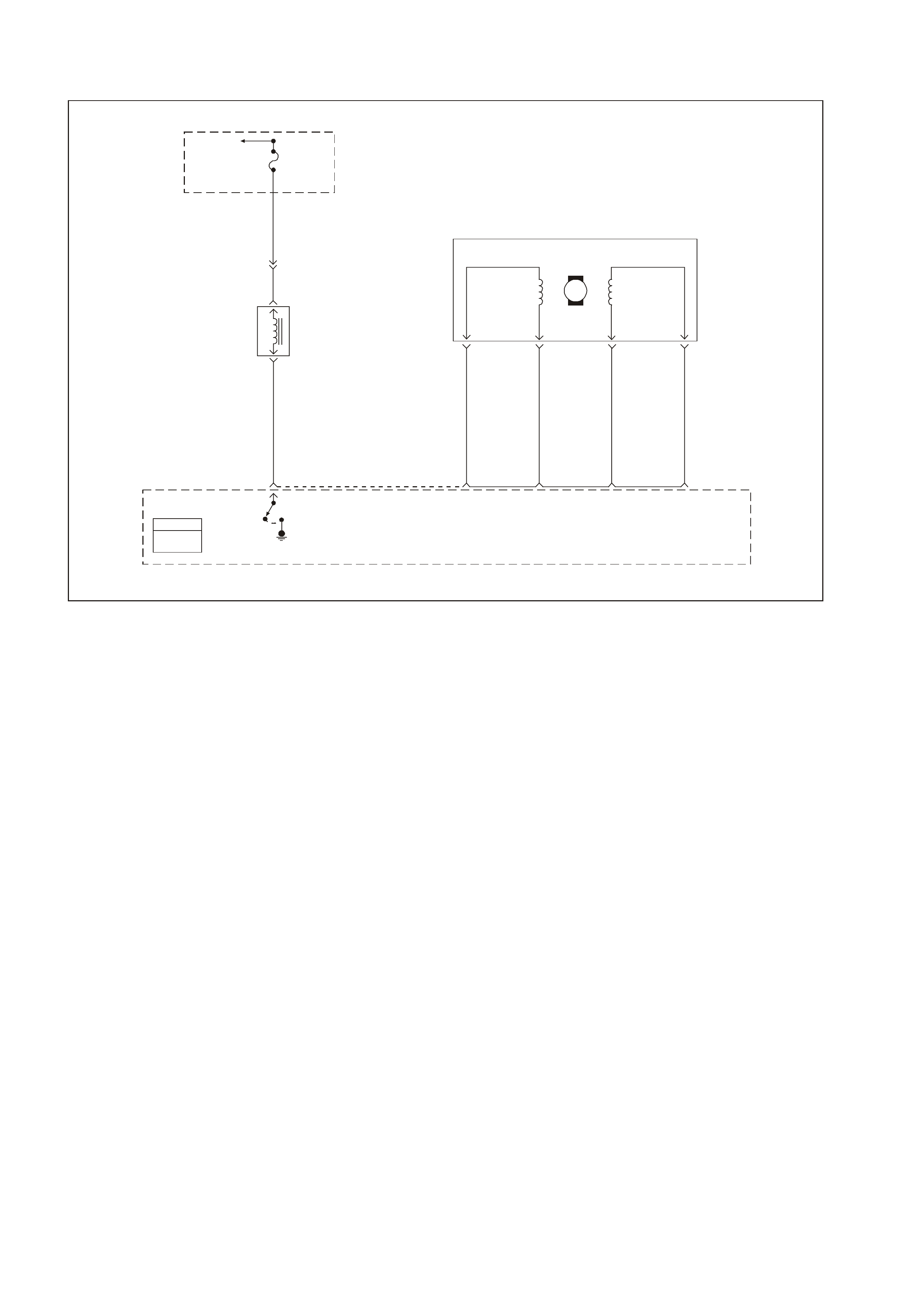
GEN III V8 PCM DTC P0443 EVAP PURGE SOLENOID CONTROL CIRCUIT
GEN3 0169
PCM
J1 = BLU E
J2 = RED
EVAP
Canister
Purge
Valve
Control
To EFI
(Eng in e Con t. )
Relay Fuse
F33
P 439
YE111
Evaporation
Emission
(EVAP)
Canister
Purge
Valve
A
B
G/Y 428
34
LBLU/B 442 LG/W 443
LBLU 441 LG/B 444
DCB
A
IAC
Coil A
High
79
IAC
Coil A
Low
78
IAC
Coil B
Low
77
IAC
Coil B
High
76 J2
Powertrain
Control
Module
(PCM)
M
Stepper
Motor
Coil
ACoil
B
Idle Air
Control
(IAC)
Valve
Circuit Description
An ignition voltage is supplied directly to the EVAP solenoid relay coil. The PCM controls the solenoid by earthing
the control circuit via an internal switch called a driver. The primary function of the driver is to supply the earth for
the controlled component. Each driver has a fault line which the PCM monitors. The voltage of the control circuit
should be low (near 0 volt) when the PCM com mands a component ON. T he voltage potential of the circ uit should
be high (near the battery voltage) when the PCM commands the control circuit to a components OFF. If the fault
detection circuit senses a voltage other than what the PCM is expected, the fault line status changes causing the
DTC to set.
CONDITIONS FOR RUNNING THE DTC
• The engine speed is greater than 400 RPM.
• The ignition voltage is between 6.0 volts and 16.0 volts.
CONDITIONS FOR SETTING THE DTC
• The PCM detects that the commanded state of the driver and the actual state of the control circuit do not
match.
• The conditions are present for a maximum of 10.0 seconds.
ACTION TAKEN WHEN THE DTC SETS
• The PCM illuminates the Check Powertrain Lamp (CPL) when the diagnostic runs and fails.
• T he PCM records the operating conditions at the time the diagnostic f ails. The PCM stores this inform ation in
the Freeze Frame/Failure Records.
CONDITIONS FOR CLEARING THE CPL/DTC
• The PCM turns the CPL OFF after the first ignition cycle that the diagnostic runs and does not fail.
• A last test failed (current DTC) clears when the diagnostic runs and does not fail.
• A History DTC clears after forty consecutive warm-up cycles, if this or any other emission related diagnostic
does not report any failures.
• Use a Tech 2 scan tool in order to clear the CPL/DTC.

DIAGNOSTIC AIDS
• Us ing Freeze Fram e/Failure Records data may aid in locating an interm ittent condition. If you cannot duplicate
the DTC, the information included in the Freeze Frame/Failure Records data can aid in determining the
distance traveled since the DTC set. The Fail Counter and Pass Counter can also aid determining how many
ignition cycles the diagnostic reported a pass and/or fail. Operate the vehicle within the same freeze frame
conditions (RPM, load, vehicle speed, temperature etc.) that you observed. This will isolate when the DTC
failed.
• For an intermittent, refer to Section 6C3-2B SYMPTOMS in the VT Series II Service Information.
TEST DESCRIPTION
The numbers below refer to the step numbers on the diagnostic table.
NOTE: The engine must be running in order to command the EVAP Purge Solenoid Valve ON and OFF.
2. Listen for an audible click when the solenoid operates. Be sure that both the ON and the OFF states are
commanded. Repeat the commands as necessary.
3. This check can detect a partial short which would cause excessive current flow. Leaving the circuit energised
for 2 minutes allows the coil to warm up. When warm, the coil may open (Amps drop to 0), or short (goes
above 0.75 Amp).
13. If no trouble is found in the contr ol circuit or the connection at the PCM, the PCM may be faulty, however, this
is an extremely unlikely failure.

GEN III V8 PCM DTC P0443 EVAP PURGE SOLENOID CONTROL CIRCUIT
Step Action Value(s) Yes No
1 Did you perform the Powertrain On-Board Diagnostic
(OBD) System Check? Go to Step 2 Go to Powertrain
OBD System
Check Table
2
1. Idle the engine at the normal operating temperature.
2. Command the solenoid ON and OFF using the scan
tool.
Does the solenoid turn ON and OFF when commanded?
Go to Step 3 Go to Step 5
3 1. Turn OFF the ignition.
2. Disconnect the PCM RED connector.
3. Turn ON the ignition leaving the engine OFF.
4. Measure the current from the solenoid control circuit in
the PCM harness connector to earth for 2 minutes
using the DMM J 39200 on the 10 Amp scale.
Does the current draw measure less than the specified
value shown but not 0?
0.75 A Go to Diagnostic
Aids Go to Step 4
4 1. Turn OFF the ignition.
2. Disconnect the solenoid.
3. Measure the resistance from the solenoid control
circuit in the PCM harness connector to earth using
the DMM J 39200.
Does the DMM display infinite resistance?
Go to Step 12 Go to Step 10
5 1. Turn OFF the ignition.
2. Disconnect the solenoid.
3. Connect the test lamp J 34142-B between the
terminals in the solenoid harness connector.
4. Idle the engine at the normal operating temperature.
5. Command the solenoid ON and OFF using the scan
tool.
Does the test lamp turn ON and OFF when commanded?
Go to Step 8 Go to Step 6
6 W ith the test lamp connected to earth, probe the ignition
feed circuit in the solenoid harness connector.
Is the test lamp illuminated?
Go to Step 7 Go to Step 11
7 1. Turn OFF the ignition.
2. Reconnect the solenoid.
3. Disconnect the RED PCM connector.
4. Turn ON the ignition leaving the engine OFF.
5. With a fused jumper wire connected to earth, probe
the solenoid control circuit in the PCM harness
connector.
Does the solenoid operate?
Go to Step 9 Go to Step 10
8 Check the connection at the solenoid?
Was a problem found and corrected? Go to Step 14 Go to Step 12
9 Check the connection at the PCM.
Was a problem found and corrected? Go to Step 14 Go to Step 13
10 Repair open or short to earth in the solenoid control
circuit.
Is the action complete?
Go to Step 14
11 Repair the faulty solenoid ignition feed circuit.
Is the action complete? Go to Step 14
12 Replace the solenoid.
Is the action complete? Go to Step 14
13 1. Replace PCM.
2. Refer to Section 6C3-3 Service Operations in the VT
Series II Service Information, for PCM Programming
and PCM/PIM/BCM Security Link Procedure.
Is action complete?
Go to Step 14

Step Action Value(s) Yes No
14 1. Select the Diagnostic Trouble Code (DTC) option and
the Clear DTC Information option using the Tech 2
scan tool.
2. Idle the engine at the normal operating temperature.
3. Select the Diagnostic Trouble Code (DTC) option, the
DTC Information option and The Failed This Ignition
option using the Tech 2 scan tool.
4. Operate the vehicle within the Conditions for Running
the DTC as specified in the supporting text, if
applicable.
Does the Tech 2 scan tool indicate that this DTC reset?
Go to Step 2 Go to Step 15
15 Using the Tech 2 scan tool, check for any other DTCs.
Does the Tech 2 scan tool display any DTCs that you
have not diagnosed?
Go to the
applicable DTC
table
System OK
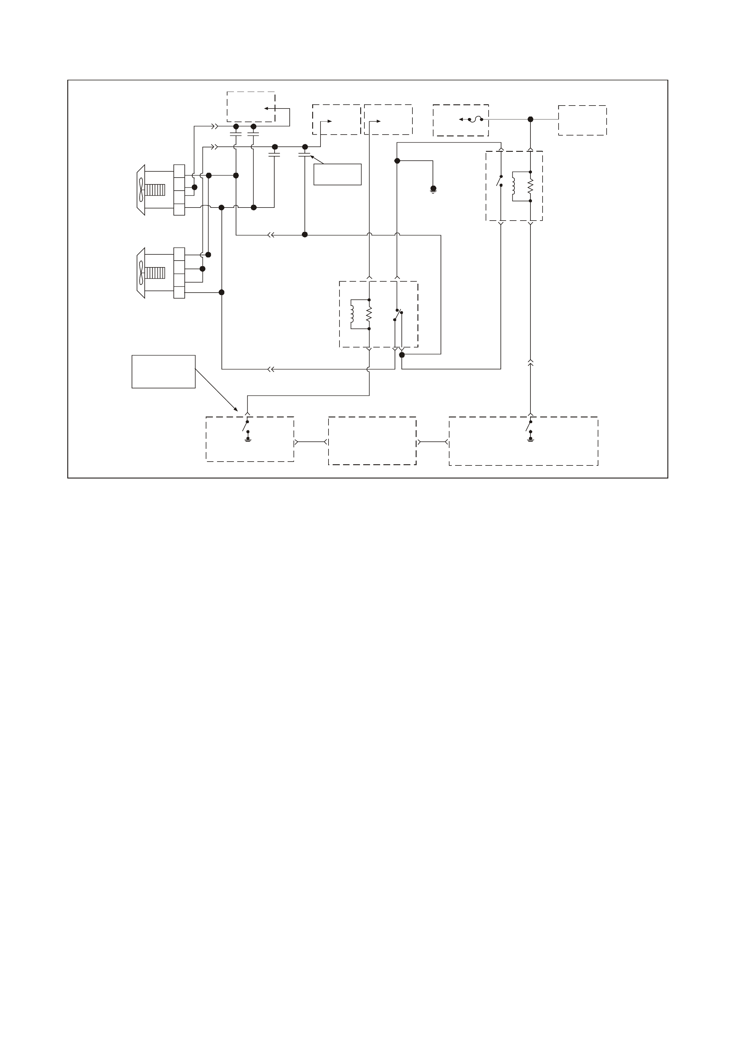
GEN III V8 PCM DTC P0481 COOLING FAN HIGH SPEED RELAY CONTROL
GEN3 0170
Refe r to Wiring
Schematic
Part 1
Engine Cooling
Fan Rel ay
H igh S p ee d
P/B
39
Fuse
F14
To
Ignition
Switch
To
Fusible
Link F S
To
Fusible
Link FU
To
Fusible
Link FT O/B 208
YE118
O/BLU 204
Y
250
O/BLU
250
YE104
12V Bus 1040
B/R 157
O/BLU
250
Engine
Earth
O/BLU 250
85
30
86
87
O/BLU 250
12V Bus 104 0
BLU/W 304
YE110
B/R 157
85 87
86 30 87A
Engine Cooling
Fan Relay
Low Sp eed
B533
YE104 O/B 473
O/B 473
BLU/Y
533
NOTE
YB174 High Series
YB163 Low Ser ies
Engine
Cooling
Fan Relay
Low Speed
Control
Powertrain
Control
Module
(PCM)
Engine Cooling
Fan Rel ay
High Speed
Control
J2
33
Cooling
Fan
2
Cooling
Fan
1
Serial Data
(Class II )
Body Control Module (BCM)
Serial Data
(UART)
7
R/B
122 62 Serial Data
(Class II)
Serial Data
(UART) Y
104958
7C1
Powe rt rain I nterfac e Modul e (PIM)
G208
R 208
Supression
Capacitors
CIRCUIT DESCRIPTION
Ignition voltage is supplied directly to the cooling fan relay coil. The PCM controls the relay by earthing the control
circuit via an internal switch called a driver. The primary function of the driver is to supply the earth for the
controlled component. Each driver has a fault line which the PCM monitors. When the PCM commands a
component ON, the voltage of the control circuit should be low (near 0 volts). When the PCM commands the
control circuit to a component OFF, the voltage potential of the circuit should be high (near the battery voltage). If
the fault detection circuit senses a voltage other than what the PCM is expected, the fault line status changes
causing the DTC to set.
The relay controls the high current flow to the cooling fans. This allows the PCM driver to only have to control the
relatively low current used by the relay.
CONDITIONS FOR RUNNING THE DTC
• The engine speed is greater than 600 RPM.
• The ignition voltage is between 6.0 and 16.0 volts.
CONDITIONS FOR SETTING THE DTC
• The PCM detects that the commanded state of the driver and the actual state of the control circuit do not
match.
• The conditions must be present for a minimum of 10 seconds.
ACTION TAKEN WHEN THE DTC SETS
• The PCM illuminates the Check Powertrain Lamp (CPL) when the diagnostic runs and fails.
• T he PCM records the operating conditions at the time the diagnostic f ails. The PCM stores this inform ation in
the Freeze Frame/Failure Records.

CONDITIONS FOR CLEARING THE MIL/DTC
• The PCM turns the CPL OFF after the first ignition cycle that the diagnostic runs and does not fail.
• A last test failed (current DTC) clears when the diagnostic runs and does not fail.
• A History DTC clears after forty consecutive warm-up cycles, if this or any other emission related diagnostic
does not report any failures.
• Use a Tech 2 scan tool to clear the CPL/DTC.
DIAGNOSTIC AIDS
• Using the Freeze Frame/Failure Records data may aid in locating an intermittent condition. If you cannot
duplicate the DTC, the information included in the Freeze Frame/Failure Records data can aid in determining
the distance traveled since the DTC reported a pass and/or fail. Operate the vehicle within the same freeze
frame conditions (RPM, load, vehicle speed, temperature, etc.) that you observed. This will isolate when the
DTC failed.
• For an intermittent, refer to Section 6C3-2B SYMPTOMS in the VT Series II Service Information.
TEST DESCRIPTION
The numbers below refer to the step numbers on the diagnostic table.
2. Listen for an audible click when the relay operates. Command both ON and OFF states. Repeat the
commands if necessary.
3. This check can detect a partially shorted coil which would cause excessive current flow. Leaving the circuit
energised for 2 minutes allows the coil to warm up. W hen warm the coil may open (Amps drop to 0), or short
(goes above 0.75 Amps).
13. If you do not find any trouble in the control circuit or the connection at the PCM, the PCM may be faulty.
14. The repair is not complete if the Tech 2 scan tool indicates that the diagnostic ran and failed.

GEN III V8 PCM DTC P0481 COOLING FAN HIGH SPEED RELAY CONTROL
Step Action Value(s) Yes No
1 Did you perform the Powertrain On-Board Diagnostic
(OBD) System Check? Go to Step 2 Go to Powertrain
OBD System
Check Table
2
1. Turn ON the ignition leaving the engine OFF.
2. Command the relay ON and OFF using a Tech 2 scan
tool.
Does the relay turn ON and OFF when commanded?
Go to Step 3 Go to Step 5
3 1. Turn OFF the ignition.
2. Disconnect the RED PCM connector.
3. Turn ON the ignition.
4. Measure current from the relay control circuit in the
PCM harness connector to earth for 2 minutes using
DMM J 39200 on 10 Amp scale.
Does the current draw measure less than the specified
value (but not 0)?
0.75A Go to
Diagnostic Aids Go to Step 4
4 1. Turn OFF the ignition.
2. Disconnect the relay.
3. Measure the resistance from the relay control circuit in
the PCM harness connector to earth using the DMM
J 39200.
Does the DMM display infinite resistance?
Go to Step 12 Go to Step 10
5 1. Turn OFF the ignition.
2. Disconnect the relay.
3. Connect the test lamp between the relay control circuit
and the relay B+ supply circuit at the Fuse/Relay
panel.
4. Turn ON the ignition.
5. Command the relay ON and OFF using a Tech 2 scan
tool.
Does the test lamp turn ON and OFF with each
command?
Go to Step 8 Go to Step 6
6 Probe the relay B+ supply circuit at the Fuse/Relay panel
with the test lamp connected to earth.
Is the test lamp ON?
Go to Step 7 Go to Step 11
7 1. Turn OFF the ignition.
2. Reconnect the relay.
3. Disconnect the RED PCM connector.
4. Turn ON the ignition.
5. Probe the relay control circuit in the PCM harness
connector with a fused jumper wire connected to
earth.
Does the relay operate?
Go to Step 9 Go to Step 10
8 Check the connections at the relay.
Did you find and correct the condition? Go to Step 14 Go to Step 12
9 Check the connections at the PCM.
Did you find and correct the condition? Go to Step 14 Go to Step 13
10 Repair open or short to earth in the relay control circuit.
Is action complete? Go to Step 14
11 Repair the relay B+ supply circuit.
Is action complete? Go to Step 14
12 Replace the relay.
Is action complete? Go to Step 14
13 1. Replace PCM.
2. Refer to Section 6C3-3 in the VT Series II Service
Information for PCM Programming and
PCM/PIM/BCM Security Link Procedure.
Is action complete?
Go to Step 14

Step Action Value(s) Yes No
14 1. Select the Diagnostic Trouble Code (DTC) option and
the Clear DTC Information option using the Tech 2
scan tool.
2. Idle the engine at the normal operating temperature.
3. Select the Diagnostic Trouble Code (DTC) option, the
DTC Information option and The Failed This Ignition
option using the Tech 2 scan tool.
4. Operate the vehicle within the Conditions for Running
the DTC as specified in the supporting text, if
applicable.
Does the Tech 2 scan tool indicate that this DTC reset?
Go to Step 2 Go to Step 15
15 Using the Tech 2 scan tool, check for any other DTCs.
Does the Tech 2 scan tool display any DTCs that you
have not diagnosed?
Go to the
applicable DTC
table
System OK
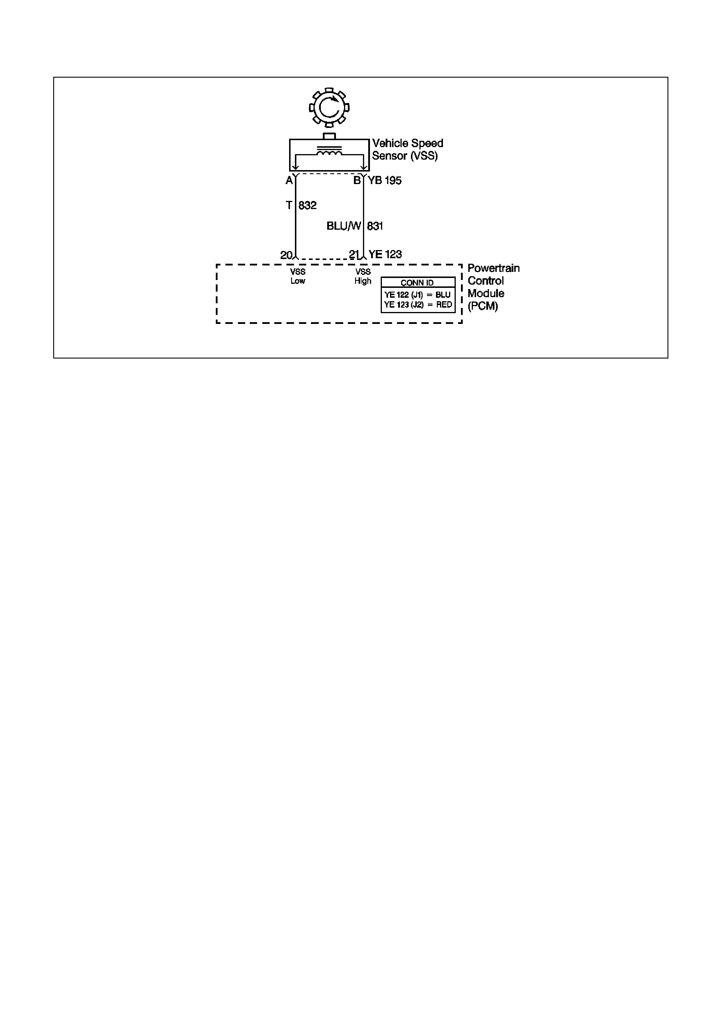
GEN III V8 PCM DTC P0502 VEHICLE SPEED SENSOR CIRCUIT LOW INPUT
CIRCUIT DESCRIPTION
The Vehicle Speed Sensor (VSS) assembly provides vehicle speed information to the Powertrain Control Module
(PCM). The VSS assembly is a Permanent Magnet (PM) generator. The PM generator produces a pulsing AC
voltage as rotor teeth on the transmission output shaft pass through the sensor's magnetic field. The AC voltage
level and the number of pulses increase as the speed of the vehicle increases. The PCM converts the pulsing
voltage to vehicle speed. The PCM uses the Vehicle Speed Signal to determine shift timing and Torque Converter
Clutch (TCC) scheduling.
If the PCM detects a low vehicle speed when there is a high engine speed in a drive gear range, then DT C P0502
sets.
CONDITIONS FOR RUNNING THE DTC
• No MAP sensor DTCs P0107 or P0108.
• No Throttle Position DTCs P0122 or P0123.
• No TFP manual valve position switch DTC P1810.
• The transmission is not in PARK or NEUTRAL.
• The Throttle Position angle is greater than 15%.
• The engine vacuum is 0-105 kPa.
• The engine speed is greater than 3000 RPM.
• The engine torque is 40.6-542.3 Nm.
CONDITIONS FOR SETTING THE DTC
• The transmission output speed is less than 150 RPM for 2.5 seconds.
ACTION TAKEN WHEN THE DTC SETS
• The PCM does not illuminate the Check Powertrain Lamp (CPL).
• The PCM commands first gear only.
• The PCM commands maximum line pressure.
• The PCM inhibits TCC engagement.
• The PCM freezes shift adapts from being updated.
• The PCM stores DTC P0502 in PCM history.
CONDITIONS FOR CLEARING THE DTC
• A scan tool clears the DTC from the PCM history.
• The PCM clears the DTC from the PCM history if the vehicle completes 40 warm-up cycles without an
emission-related diagnostic fault occurring.
• T he PCM cancels the DTC default actions when the fault no longer exists and the ignition switch is OFF long
enough in order to power down the PCM.

DIAGNOSTIC AIDS
• Inspect the wiring at the PCM, the VSS connector and all other circuit connecting points for the following
conditions:
- A backed out terminal
- A damaged terminal
- Reduced terminal tension
- A chafed wire
- A broken wire inside the insulation
- Moisture intrusion
- Corrosion
• W hen diagnosing for an intermittent short or open condition, massage the wiring harness while watching the
test equipment for a change.
TEST DESCRIPTION
The numbers below refer to the step numbers on the diagnostic table.
2. Disable the Electronic Traction Control (ETC) system (if fitted) when performing this step. When the ignition
key is cycled to the OFF position and then cycled back ON, the traction control system defaults to ON.
3. This step tests the VSS assembly circuit.
5. This step tests the integrity of the VSS assembly.

GEN III V8 PCM DTC P0502 VEHICLE SPEED SENSOR CIRCUIT LOW
Step Action Value(s) Yes No
1 Was the Powertrain On-Board Diagnostic (OBD) System
Check performed? Go to Step 2 Go to Powertrain
OBD System
Check Table
2 1. Install the Tech 2 Scan Tool.
2. With the engine OFF, turn the ignition switch to the
RUN position.
Important: Before clearing the DTC, use the Scan Tool
in order to record the Freeze Frame and Failure Records.
Using the Clear Info function erases the Freeze Frame
and Failure Records from the PCM.
3. Record the DTC Freeze Frame and Failure Records.
4. Clear the DTC.
5. Raise and support the final drive assembly.
6. Start the engine.
7. Disable the traction control system (if fitted).
8. Place the transmission in any drive range.
With the drive wheels rotating, does the Scan Tool
Transmission OSS increase with the drive wheel speed?
Go to Diagnostic
Aids Go to Step 3
3 1. Turn OFF the ignition.
2. Disconnect the engine wiring harness from the VSS
assembly.
3. Using the J 39200 digital multimeter (DMM) and the
J 35616 connector test adapter kit, measure the
resistance of the VSS assemb ly.
Does the resistance measure within the specified range?
1377-3355 Ω Go to Step 4 Go to Step 14
4 Measure the resistance from terminal B of the VSS
assembly to earth.
Does the resistance measure greater than the specified
value?
50 K Ω Go to Step 5 Go to Step 14
5 1. Place the transmission in NEUTRAL.
2. Select AC volts on the J 39200 DMM.
3. Hold one rear wheel from turning.
4. Rotate the other wheel by hand.
5. Measure the AC voltage from terminal A and B of the
VSS assembly.
Does the voltage measure greater than the specified
value?
0.3 volts Go to Step 6 Go to Step 13
6 1. Reconnect the engine wiring harness to the VSS
assembly.
2. Disconnect the PCM connector YE 123.
3. Measure the resistance between PCM connector
terminals 20 and 21.
Does the resistance measure within the specified range?
1377-3355 Ω Go to Step 7 Go to Step 8
7 Measure the resistance from terminal 21 to earth.
Does the resistance measure greater than the specified
range?
50 K Ω Go to Step 9 Go to Step 10
8 Does the resistance measure greater than the specified
value? 3355 Ω Go to Step 11 Go to Step 12
9 1. Reconnect the PCM connector YE 123.
2. Disconnect the engine wiring harness from the VSS
assembly.
3. Turn ON the ignition, with the engine OFF.
4. Test the High circuit 831 (BLU/W) of the VSS
assembly for a short to power.
5. Test the Low circuit 832 (T) of the VSS assembly for a
short to power.
Did you find and correct the condition?
Go to Step 16 Go to Step 15

Step Action Value(s) Yes No
10 1. Test the High circuit 831 (BLU/W) of the VSS
assembly for a short to earth.
2. Test the Low circuit 832 (T) of the VSS assembly for a
short to earth.
Did you find and correct the condition?
Go to Step 16
11 1. Test the High circuit 831 (BLU/W) of the VSS
assembly for an open.
2. Test the Low circuit 832 (T) of the VSS assembly for
an open.
Did you find and correct the condition?
Go to Step 16
12 Test the High circuit 831 (BLU/W) and the Low circuit 832
(T) of the VSS assembly for a short together.
Did you find and correct the condition?
Go to Step 16
13 1. Remove the VSS assembly.
2. Inspect the output shaft speed sensor rotor for
damage or misalignment.
Did you find a damaged condition?
Go to Step 16 Go to Step 14
14 Replace the VSS assembly.
Refer to Section 7C4 Vehicle Speed Sensor
Replacement in the VT Series II Service Information.
Is the replacement complete?
Go to Step 16
15 Replace the PCM.
Refer to Section 6C3 Powertrain Control Module in the
VT Series II Service Information.
Is the replacement complete?
Go to Step 16
16 Perform the following procedure in order to verify the
repair:
1. Select DTC.
2. Select Clear Info.
3. Operate the vehicle, so that the transmission output
speed is greater than 250 RPM for 2 seconds.
Was the above condition verified?
System OK Go to Step1

GEN III V8 PCM DTC P0503 VEHICLE SPEED SENSOR CIRCUIT INTERMITTENT
CIRCUIT DESCRIPTION
The Vehicle Speed Sensor (VSS) assembly provides vehicle speed information to the Powertrain Control Module
(PCM). The VSS assembly is a permanent magnet (PM) generator. The PM generator produces a pulsing AC
voltage as rotor teeth on the transmission output shaft pass through the sensor's magnetic field.
The AC voltage level and the number of pulses increase as the speed of the vehicle increases. The PCM converts
the pulsing voltage to vehicle speed. The PCM uses the Vehicle Speed Signal to determine shift timing and torque
converter clutch (TCC) scheduling. When the PCM detects an unrealistically large drop in vehicle speed, then DTC
P0503 sets.
CONDITIONS FOR RUNNING THE DTC
• No TFP manual valve position switch DTC P1810.
• The time since the last gear range change is greater than six seconds.
• The engine speed is greater than 300 RPM for five seconds.
• The engine is not in fuel cutoff.
• The transmission output speed rise does not exceed 600 RPM within six seconds.
CONDITIONS FOR SETTING THE DTC
• T he transm ission output speed dr op is greater than 1300 RPM f or three seconds when the transm ission is not
in PARK or NEUTRAL.
ACTION TAKEN WHEN THE DTC SETS
• The PCM does not illuminate the Check Powertrain Lamp (CPL).
• The PCM commands second gear only.
• The PCM commands maximum line pressure.
• The PCM inhibits TCC engagement.
• The PCM inhibits 4th gear if the transmission is in hot mode.
• The PCM freezes shift adapts from being updated.
• The PCM stores DTC P0503 in PCM history.
CONDITIONS FOR CLEARING THE DTC
• A scan tool clears the DTC from the PCM history.
• The PCM clears the DTC from the PCM history if the vehicle completes 40 warm-up cycles without an
emission-related diagnostic fault occurring.
• T he PCM cancels the DTC default actions when the fault no longer exists and the ignition switch is OFF long
enough in order to power down the PCM.

DIAGNOSTIC AIDS
• Inspect the wiring at the PCM, the VSS connector and all other circuit connecting points for the following
conditions:
- A backed out terminal
- A damaged terminal
- Reduced terminal tension
- A chafed wire
- A broken wire inside the insulation
- Moisture intrusion
- Corrosion
• W hen diagnosing for an intermittent short or open condition, massage the wiring harness while watching the
test equipment for a change.
TEST DESCRIPTION
The numbers below refer to the step numbers on the diagnostic table.
2. Disable the Electronic Traction Control (ETC) system when performing this step. When the ignition switch is
cycled OFF and then back ON, the traction control system defaults to ON.
3. This step tests the VSS assembly circuit.
5. This step tests the integrity of the VSS assembly.

GEN III V8 PCM DTC P0503 VEHICLE SPEED SENSOR CIRCUIT INTERMITTENT
Step Action Value(s) Yes No
1 Was the Powertrain On-Board Diagnostic (OBD) System
Check performed? Go to Step 2 Go to Powertrain
OBD System
Check Table
2 1. Install the Tech 2 Scan Tool.
2. With the engine OFF, turn the ignition switch to the
RUN position.
Important: Before clearing the DTC, use the Scan Tool
in order to record the Freeze Frame and Failure Records.
Using the Clear Info function erases the Freeze Frame
and Failure Records from the PCM.
3. Record the DTC Freeze Frame and Failure Records.
4. Clear the DTC.
5. Raise and support the final drive assembly.
6. Start the engine.
7. Disable the traction control system (if fitted).
8. Place the transmission in 3 range.
9. With the drive wheels rotating, slowly accelerate to
2000 engine RPM and hold. (Road test the vehicle if
necessary.)
Does the Scan Tool Transmission OSS drop or fluctuate
more than the specified value?
1300 RPM Go to Step 3 Go to Diagnostic
Aids
3 1. Turn OFF the ignition.
2. Disconnect the engine wiring harness from the VSS
assembly.
3. Using the J 39200 digital multimeter (DMM) and the
J 35616 connector test adapter kit, measure the
resistance of the VSS assemb ly.
Does the resistance measure within the specified range?
1377-3355 Ω Go to Step 4 Go to Step 14
4 Measure the resistance from terminal B of the VSS
assembly to earth.
Does the resistance measure greater than the specified
value?
50 K Ω Go to Step 5 Go to Step 14
5 1. Place the transmission in NEUTRAL.
2. Select AC volts on the J 39200 DMM.
3. Hold one rear wheel from turning.
4. Rotate the other wheel by hand.
5. Measure the AC voltage from terminal A and B of the
VSS assembly.
Does the voltage measure greater than the specified
value?
0.3 volts Go to Step 6 Go to Step 13
6 1. Reconnect the engine wiring harness to the VSS
assembly.
2. Disconnect the PCM connector YE 123.
3. Measure the resistance between PCM connector
terminals 20 and21.
Does the resistance measure within the specified range?
1377-3355 Ω Go to Step 7 Go to Step 8
7 Measure the resistance from terminal 21 to earth.
Does the resistance measure greater than the specified
range?
50 K Ω Go to Step 9 Go to Step 10
8 Does the resistance measure greater than the specified
value? 3355 Ω Go to Step 11 Go to Step 12

Step Action Value(s) Yes No
9 1. Reconnect the PCM connector YE 123.
2. Disconnect the engine wiring harness from the VSS
assembly.
3. Turn ON the ignition, with the engine OFF.
4. Test the High circuit 831 (BLU/W) of the VSS
assembly for a short to power.
5. Test the Low circuit 832 (T) of the VSS assembly for a
short to power.
Did you find and correct the condition?
Go to Step 16 Go to Step 15
10 1. Test the High circuit 831 (BLU/W) of the VSS
assembly for a short to earth.
2. Test the Low circuit 832 (T) of the VSS assembly for a
short to earth.
Did you find and correct the condition?
Go to Step 16
11 1. Test the High circuit 831 (BLU/W) of the VSS
assembly for an open.
2. Test the Low circuit 832 (T) of the VSS assembly for
an open.
Did you find and correct the condition?
Go to Step 16
12 Test the High circuit 831 (BLU/W) and the Low circuit 832
(T) of the VSS assembly for a short together.
Did you find and correct the condition?
Go to Step 16
13 1. Remove the VSS assembly.
2. Inspect the output shaft speed sensor rotor for
damage or misalignment.
Did you find a damaged condition?
Go to Step 16 Go to Step 14
14 Replace the VSS assembly.
Refer to Section 7C4 Vehicle Speed Sensor
Replacement in the VT Series II Service Information.
Is the replacement complete?
Go to Step 16
15 Replace the PCM.
Refer to Section 6C3-3 Powertrain Control Module in the
VT Series II Service Information.
Is the replacement complete?
Go to Step 16
16 Perform the following procedure in order to verify the
repair:
Select DTC.
Select Clear Info.
Operate the vehicle, ensuring that the transmission
output speed drop is less than 500 RPM for three
seconds and output speed is greater than 600 RPM for
three seconds.
Was the above condition verified?
System OK Go to Step 1
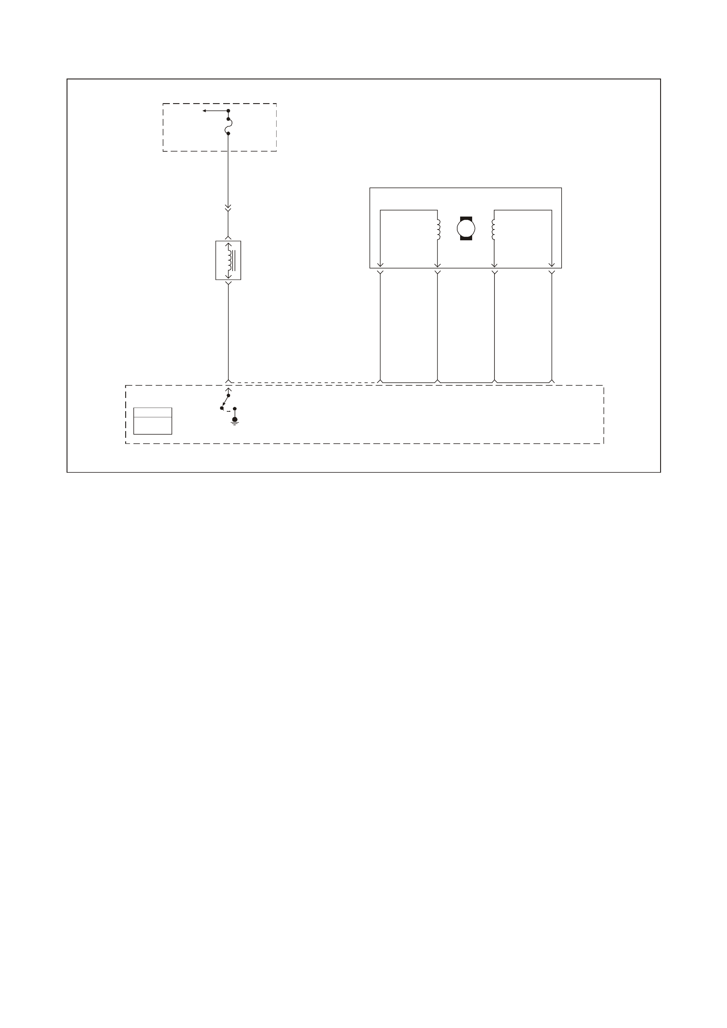
GEN III V8 PCM DTC P0506 IDLE SPEED LOW
GEN3 0169
PCM
J1 = BLU E
J2 = RED
EVAP
Canister
Purge
Valve
Control
To
EF I (Eng in e
Cont.) Relay Fuse
F33
P 439
YE111
Evaporation
Emission
(EVAP)
Canister
Purge
Valve
A
B
G/Y 428
34
LBLU/B 442 LG/W 443
LBLU 441 LG/B 444
DCB
A
IAC
Coil A
High
79
IAC
Coil A
Low
78
IAC
Coil B
Low
77
IAC
Coil B
High
76 J2
Powertrain
Control
Module
(PCM)
M
Stepper
Motor
Coil
ACoil
B
Idle Air
Control
(IAC)
Valve
CIRCUIT DESCRIPTION
The Idle Air Control (IAC) valve is a PCM controlled stepper motor located on the throttle body. The stepper motor
drives a valve pintle which protrudes into a passage that bypasses the throttle plates. The PCM commands the IAC
valve pintle to extend which decreases the idle speed. The bypass air flow is reduced and the idle speed
decreases as the pintle approaches its set. The PCM retreats the IAC valve pintle away from its seat to increase
the idle speed. The retracting of the IAC valve pintle allows more air to bypass the throttle plates. One of the PCMs
uses for the IAC system is to maintain a desires idle speed. This DTC sets when the PCM detects an engine speed
outside of the IAC’s range of control
CONDITIONS FOR RUNNING THE DTC
• DTCs P0101, P0102, P0103, P0107, P0108, P0112, P0113, P0117, P0118, P0171, P0172, P0174, P0175,
P0443, are not set.
• The engine run time is greater than 60 seconds.
• The engine coolant temperature is greater than 60°C (140°F).
• The intake air temperature is greater than -10°C (14°F).
• The barometric pressure is greater than 65 kPa.
• The ignition voltage is between 9.0 and 17.0 volts.
• The vehicle speed is no more than 1.6 km/h (1 mph)
CONDITIONS FOR SETTING THE DTC
• The actual idle speed is 100 RPM less than the desired idle speed.
• All of the above conditions are present for 15 seconds.
ACTION TAKEN WHEN THE DTC SETS
• The PCM illuminates the Check Powertrain Lamp (CPL) when the diagnostic runs and fails.
• The PCM records the operating conditions at the time the diagnostic fails. The PCM stores this information in
the Freeze Frame/Failure Records.

CONDITIONS FOR CLEARING THE CPL/DTC
• The PCM turns the CPL OFF after the first ignition cycle that the diagnostic runs and does not fail.
• A last test failed (current DTC) clears when the diagnostic runs and does not fail.
• A History DTC clears after forty consecutive warm-up cycles, if this or any other emission related diagnostic
does not report any failures.
• Use a Tech 2 scan tool in order to clear the CPL/DTC.
DIAGNOSTIC AIDS
• Using the Freeze Frame/Failure Records data may aid in locating an intermittent condition. If you cannot
duplicate the DTC, the information included in the Freeze Frame/Failure Records data can aid in determining
the distance traveled since the DTC reported a pass and/or fail. Operate the vehicle within the same freeze
frame conditions (RPM, load, vehicle speed, temperature, etc.) that you observed. This will isolate when the
DTC failed.
• For an intermittent, refer to Section 6C3-2B SYMPTOMS in the VT Series II Service Information.
TEST DESCRIPTION
The numbers below refer to the step numbers on the diagnostic table.
2. This test determines whether or not the engine can achieve the commanded RPM, and if not, whether the
RPM is too high or too low.

GEN III V8 PCM DTC P0506 IDLE SPEED LOW
Step Action Value(s) Yes No
1 Did you perform the Powertrain On-Board Diagnostic
(OBD) System Check? Go to Step 2 Go to Powertrain
OBD System
Check Table
2
1. Idle the engine.
2. Command the engine speed up to 1500 RPM, down to
500 RPM, up to 1500 RPM, and the EXIT using the
Tech 2 scan tool
Does the engine speed correspond, within 100 RPM, with
each command?
Go to Diagnostic
Aids Go to Step 3
3 Is the engine RPM greater than 100 RPM above Desired
RPM? Go to Step 4 Go to Step 5
4 Check for the following conditions:
• Vacuum leaks.
• Throttle plates not closing properly.
• A faulty PCV valve.
Did you find and correct the condition?
Go to Step 13 Go to Step 6
5 Check for the following conditions:
• Excessive deposits in the throttle body.
• Parasitic load on the engine (i.e. transmission
problem etc.).
Did you find and correct the conditions?
Go to Step 13 Go to Step 6
6 1. Turn OFF the ignition.
2. Disconnect the IAC harness connector and install the
appropriate IAC node light from kit J 37027-A.
3. Idle the engine.
4. Command the RPM up to 1500, down to 500 and up
to 1500 using the Tech 2 scan tool while observ ing the
node light.
Does both of the LED’s on the node light cycle red and
green, but never OFF?
Go to Step 7 Go to Step 8
7 Important: During the following test it is possible to
overextend the IAC valve pintle until it falls out of the
worm drive. If this occurs, manually screw the pintle shaft
into the worm drive about 2 turns to get it started, align
the keyways on the shaft with the keys in the housing and
gradually retract the pintle using the IAC driver tool.
1. Turn OFF the ignition.
2. Remove the IAC valve.
3. Connect the IAC valve to the IAC Driver tool from kit
J37027-A.
4. Hold the IAC valve with a finger over the pintle in case
it is over extended. Using the driver tool retract and
extend the pintle.
Does the pintle move steadily with each flash of the IAC
driver light?
Go to Step 9 Go to Step 10
8 Check for the following conditions:
• Faulty connection
• Open circuit
• Short to earth
• Short to B+
Did you find and correct the condition?
Go to Step 13 Go to Step 11
9 Check the IAC passages.
Is the action complete? Go to Step 13
10 Replace the IAC valve. Refer to Section 6C3-3 Idle Air
Control Valve Replacement in the VT Series II Service
Information.
Is the action complete?
Go to Step 13

Step Action Value(s) Yes No
11 Check the connections at the PCM.
Did you find and correct the condition? Go to Step 13 Go to Step 12
12 1. Replace PCM.
2. Refer to Section 6C3-3 in the VT Series II Service
Information for PCM Programming and
PCM/PIM/BCM Security Link Procedure.
Is action complete?
Go to Step 13
13 1. Select the Diagnostic Trouble Code (DTC) option and
the Clear DTC Information option using the Tech 2
scan tool.
2. Idle the engine at the normal operating temperature.
3. Select the Diagnostic Trouble Code (DTC) option, the
DTC Information option and The Failed This Ignition
option using the Tech 2 scan tool.
4. Operate the vehicle within the Conditions for Running
the DTC as specified in the supporting text, if
applicable.
Does the Tech 2 scan tool indicate that this DTC reset?
Go to Step 2 Go to Step 14
14 Using the Tech 2 scan tool, check for any other DTCs.
Does the Tech 2 scan tool display any DTCs that you
have not diagnosed?
Go to the
applicable DTC
table
System OK
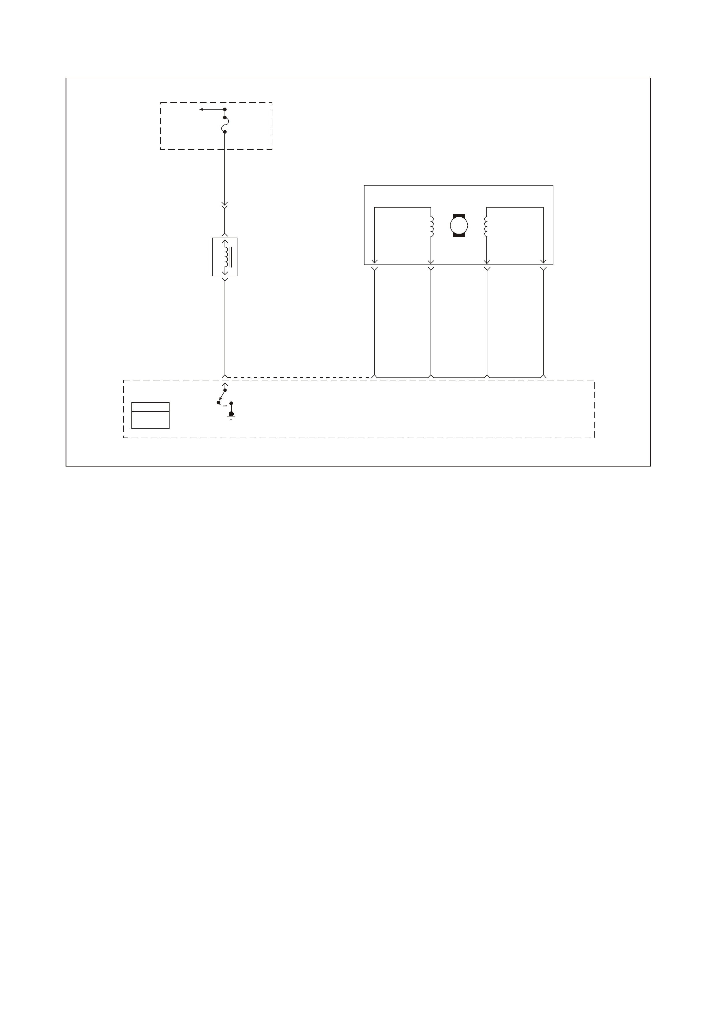
GEN III V8 PCM DTC P0507 IDLE SPEED HIGH
GEN3 0169
PCM
J1 = BLU E
J2 = RED
EVAP
Canister
Purge
Valve
Control
To
EF I (Eng in e
Cont.) Relay Fuse
F33
P 439
YE111
Evaporation
Emission
(EVAP)
Canister
Purge
Valve
A
B
G/Y 428
34
LBLU/B 442 LG/W 443
LBLU 441 LG/B 444
DCB
A
IAC
Coil A
High
79
IAC
Coil A
Low
78
IAC
Coil B
Low
77
IAC
Coil B
High
76 J2
Powertrain
Control
Module
(PCM)
M
Stepper
Motor
Coil
ACoil
B
Idle Air
Control
(IAC)
Valve
CIRCUIT DESCRIPTION
The Idle Air Control (IAC) valve is a PCM controlled stepper motor located on the throttle body. The stepper motor
drives a valve pintle which protrudes into a passage that bypasses the throttle plates. The PCM commands the IAC
valve pintle to extend to decreases the idle speed. The bypass air flow is reduced and the idle speed decreases as
the pintle approaches its seat. The PCM retracts the IAC valve pintle away from its seat to increase the idle speed.
The retracting of the IAC valve pintle allows more air to bypass the throttle plates. One of the PCMs uses for the
IAC system is to maintain a desired idle speed. This DTC sets when the PCM detects an engine speed outside of
the IAC’s range of control.
CONDITIONS FOR RUNNING THE DTC
• DTCs P0101, P0102, P0103, P0107, P0108, P0112, P0113, P0117, P0118, P0171, P0172, P0174, P0175,
P0443, are not set.
• The engine run time is greater than 60 seconds.
• The engine coolant temperature is greater than 60°C (140°F).
• The intake air temperature is greater than -10°C (14°F).
• The barometric pressure is greater than 65 kPa.
• The ignition voltage is between 9.0 and 17.0 volts.
• The vehicle speed is no more than 1.6 km/h (1 mph).
• Conditions for Setting the DTC
• The actual idle speed is 100 RPM less than the desired idle speed.
• All of the above conditions are present for 15 seconds.
ACTION TAKEN WHEN THE DTC SETS
• The PCM illuminates the Check Powertrain Lamp (CPL) when the diagnostic runs and fails.
• The PCM records the operating conditions at the time the diagnostic fails. The PCM stores this information in
the Freeze Frame/Failure Records.

CONDITIONS FOR CLEARING THE CPL/DTC
• The PCM turns the CPL OFF after the first ignition cycle that the diagnostic runs and does not fail.
• A last test failed (current DTC) clears when the diagnostic runs and does not fail.
• A History DTC clears after forty consecutive warm-up cycles, if this or any other emission related diagnostic
does not report any failures.
• Use a Tech 2 scan tool in order to clear the CPL/DTC.
DIAGNOSTIC AIDS
• Using the Freeze Frame/Failure Records data may aid in locating an intermittent condition. If you cannot
duplicate the DTC, the information included in the Freeze Frame/Failure Records data can aid in determining
the distance traveled since the DTC reported a pass and/or fail. Operate the vehicle within the same freeze
frame conditions (RPM, load, vehicle speed, temperature, etc.) that you observed. This will isolate when the
DTC failed.
• For an intermittent, refer to Section 6C3-2B SYMPTOMS in the VT Series II Service Information.
TEST DESCRIPTION
The numbers below refer to the step numbers on the diagnostic table.
2. This test determines whether or not the engine can achieve the commanded RPM, and if not, whether the
RPM is too high or too low.

GEN III V8 PCM DTC P0507 IDLE SPEED HIGH
Step Action Value(s) Yes No
1 Did you perform the Powertrain On-Board Diagnostic
(OBD) System Check? Go to Step 2 Go to Powertrain
OBD System
Check Table
2
1. Idle the engine.
2. Command the engine speed up to 1500 RPM, down to
500 RPM, up to 1500 RPM, and the EXIT using the
Tech 2 scan tool
Does the engine speed correspond, within 100 RPM, with
each command?
Go to Diagnostic
Aids Go to Step 3
3 Is the engine RPM greater than 100 RPM above Desired
RPM? Go to Step 4 Go to Step 5
4 Check for the following conditions:
• Vacuum leaks.
• Throttle plates not closing properly.
• A faulty PCV valve.
Did you find and correct the condition?
Go to Step 12 Go to Step 6
5 Check for the following conditions:
• Excessive deposits in the throttle body.
• Parasitic load on the engine (i.e. transmission
problem etc.).
Did you find and correct the conditions?
Go to Step 13 Go to Step 6
6 1. Turn OFF the ignition.
2. Disconnect the IAC harness connector and install the
appropriate IAC node light from kit J 37027-A.
3. Idle the engine.
4. Command the RPM up to 1500, down to 500 and up
to 1500 using the Tech 2 scan tool while observ ing the
node light.
Does both of the LED’s on the node light cycle red and
green, but never OFF?
Go to Step 7 Go to Step 8
7 Important: During the following test, it is possible to
overextend the IAC valve pintle until it falls out of the
worm drive. If this occurs, manually screw the pintle shaft
into the worm drive about 2 turns to get it started, align
the keyways on the shaft with the keys in the housing and
gradually retract the pintle using the IAC driver tool.
1. Turn OFF the ignition.
2. Remove the IAC valve.
3. Connect the IAC valve to the IAC Driver tool from kit
J37027-A.
4. Hold the IAC valve with a finger over the pintle in case
it is over extended. Using the driver tool retract and
extend the pintle.
Does the pintle move steadily with each flash of the IAC
driver light?
Go to Step 8 Go to Step 9
8 Check for the following conditions:
• Faulty connection
• Open circuit
• Short to earth
• Short to B+
Did you find and correct the condition?
Go to Step 12 Go to Step 10
9 Replace the IAC valve. Refer to Section 6C3-3 Idle Air
Control Valve Replacement of the VT Series II Service
Information.
Is the action complete?
Go to Step 12
10 Check the connections at the PCM.
Did you find and correct the condition? Go to Step 12 Go to Step 11

Step Action Value(s) Yes No
11 1. Replace PCM.
2. Refer to Section 6C3-3 Service Operations of the VT
Series II Service Information, for PCM Programming
and PCM/PIM/BCM Security Link Procedure.
Is action complete?
Go to Step 12
12 1. Select the Diagnostic Trouble Code (DTC) option and
the Clear DTC Information option using the Tech 2
scan tool.
2. Idle the engine at the normal operating temperature.
3. Select the Diagnostic Trouble Code (DTC) option, the
DTC Information option and The Failed This Ignition
option using the Tech 2 scan tool.
4. Operate the vehicle, within the Conditions for Running
the DTC, as specified in the supporting text, if
applicable.
Does the Tech 2 scan tool indicate that this DTC reset?
Go to Step 2 Go to Step 13
13 Using the Tech 2 scan tool, check for any other DTCs.
Does the Tech 2 scan tool display any DTCs that you
have not diagnosed?
Go to the
applicable DTC
table
System OK
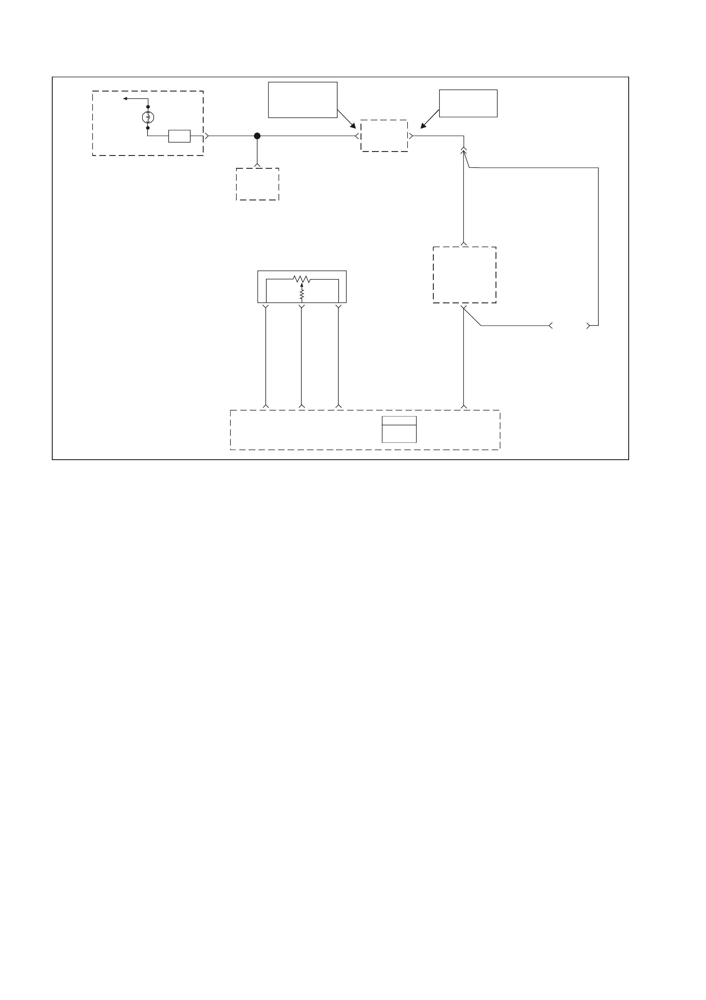
GEN III V8 PCM DTC P0522 ENGINE OIL PRESSURE SENSOR LOW VOLTAGE
GEN3 0171
J1 = BLU E
J2 = RED
Powertrain
Control
Module
(PCM)
YE112
CA
Y1049
BLU/Y 334
58 J107 J1 58 J2
R/B 1221
B
G 335
G/W
1220
R/B 1221
BR/W 331
Serial
Data
(Class 2)
Sensor
Earth
Sensor
Signal
Sensor
5V
Reference
1049
To
Fuse
F13 Oil
Warning
Lamp
SDI
Instrument Panel Cluster
12
To
Vehicle
Bus
Serial Data
(UART)
Body Control
Module (BCM)
2
6
Serial Data
(UART) Powertrain
Interface
Module
(PIM)
NOTE
YB164 Low Seri es
YB175 High Serie s
NOTE
BCM Ter m inals
"3" YB164 Low Series
"9" YB175 High Series
792 DLC
Connector
63 J1
Oil Pressure
Sensor Serial Data
(Class 2)
Y
PCM
CIRCUIT DESCRIPTION
The Engine Oil Pressure Sensor is mounted in the top rear of the engine. The Engine Oil Pressure Sensor
measures changes in engine oil pressure. The Engine Oil Pressure Sensor has a 5.0 volt reference, an earth and a
signal circuit.
The Engine Oil Pressure Sensor changes resistance based on engine oil pressure.
The Engine Oil Pressure Sensor is used to determine when the oil level is below a certain threshold. When the oil
pressure reaches a predetermined value, the PCM will determine this as low oil pressure. The PCM will then send
a serial data message to the Instrument Panel (IP) cluster to turn ON the Low Oil Warning lamp.
When the PCM senses a signal voltage lower than the normal operating range of the sensor, this DTC will set.
CONDITIONS FOR RUNNING THE DTC
• Engine running.
CONDITIONS FOR SETTING THE DTC
• Engine Oil Pressure Sensor voltage is less than 0.48 volts.
ACTION TAKEN WHEN THE DTC SETS
• The PCM illuminates the Check Powertrain Lamp (CPL) when the diagnostic runs and fails.
• The PCM records the operating conditions at the time the diagnostic fails. The PCM stares this information in
the Freeze Frame/Failure Records.
• Oil warning lamp will illuminate.
CONDITIONS FOR CLEARING THE CPL/DTC
• A Histor y DTC will c lear af ter for ty consecutive warm- up cycles, if no f ailures ar e reported by this or other non-
emission related diagnostic.
• A last test failed (Current DTC) will not clear when the diagnostic runs and does not fail.
• The PCM battery voltage is interrupted.
• Use a scan tool to in order to clear the CPL/DTC.

DIAGNOSTIC AIDS
NOTE: Remove any debris from the PCM module connector surfaces before servicing the PCM module. Inspect
the PCM module connector when diagnosing/ replacing the modules. Ensure that the connectors are installed
correctly.
• The following may cause an intermittent:
- Incorrectly routed harness
- Rubbed through wire insulation
- Broken wire inside the insulation
• The PCM 5.0 volt reference circuits are internally connected within the PCM. If all the Engine Oil sensor
circuits check to be OK, inspect related 5.0 volt reference circuits.
• If there is a failure with the Oil W arning Lam p, more than likely it is either a faulty bulb or a instrum ent cluster
fault.
TEST DESCRIPTION
The numbers below refer to the step numbers on the diagnostic table.
3. This step determines if the malfunction is present. For any test that requires probing of the PCM or any
component harness connectors, use the Connector Test Adaptor Kit J 35616-A. Using this kit prevents
damage to the harness connector terminals.
4. Using the Freeze Frame/Failure Records data may aid in locating an intermittent condition. If you cannot
duplicate the DT C, the information inc luded in the Freeze Fram e/Failure Records data can help determ ine the
distance traveled since the DTC set. The Fail Counter and Pass Counter can also help determine how many
ignition cycles the diagnostic reported a pas s and/or a fail. Oper ate the vehicle within the sam e Freeze Fram e
conditions (RPM, load, vehicle speed temperature etc.) that you observed. This will isolate when the DTC
failed.
5. If the Tech 2 scan tool displays 5.0 volts, this indicates that the Engine Oil Pressure sensor signal 5.0 volt
reference circuit and PCM are OK.
6. If the Tech 2 scan tool displays 5.0 volts, this indicates that the Engine Oil Pressure sensor signal circuit and
the PCM are OK.
7. Disconnecting the PCM allows using the DMM J 39200 to check the continuity of the circuits. This aids in
locating an open or shorted circuit.

GEN III V8 PCM DTC P0522 ENGINE OIL PRESSURE SENSOR LOW VOLTAGE
Step Action Value(s) Yes No
1 Did you perform the Powertrain On-Board Diagnostic
(OBD) System Check? Go to Step 2 Go to Powertrain
OBD System
Check Table
2 1. Install the Tech 2 scan tool.
2. Idle the engine.
3. Monitor the Failed This Ignition under DTC Status for
DTC P1635 using the Tech 2 scan tool.
Did DTC P1635 fail this ignition cycle?
Go to DTC
P1635 5 Volt
Reference #1
Circuit
Go to Step 3
3 Idle the engine and monitor the Engine Oil Pressure
voltage using the Tech 2 scan tool.
Is the Engine Oil Pressure voltage at or below the
specified value?
0.48V Go to Step 5 Go to Step 4
4 1. Turn ON the ignition leaving the engine OFF.
2. Review the Freeze Frame/Failure Records data for
this DTC and observe parameters.
3. Turn OFF the ignition for 15 seconds.
4. Operate the vehicle within the conditions required for
this diagnostic to run, and as close to the conditions
recorded in the Freeze Frame/Failure Records as
possible. Special operating conditions that you need to
meet before the PCM will run this diagnostic, where
applicable, are listed in Conditions for Running the
DTC.
5. Select the Diagnostic Trouble Code (DTC) option, the
DTC Information option and The Failed This Ignition
option using the Tech 2 scan tool.
Does the Tech 2 scan tool indicate that this diagnostic
failed this ignition.
Go to Step 5 Go to Diagnostic
Aids
5 1. Disconnect the Engine Oil Pressure sensor electrical
connector.
2. Jumper the 5.0 volt reference circuit and the engine oil
pressure signal circuit together at the Engine Oil
Pressure sensor harness connector.
3. Observe the Engine Oil Pressure voltage display on
the Tech 2 scan tool.
Is the Engine Oil Pressure voltage near the specified
value?
5.0V Go to Step 11 Go to Step 6
6 1. Connect a test lamp J 34142-B Between B+ and the
Engine Oil Pressure sensor signal circuit at the Engine
Oil Pressure sensor harness connector.
2. Observe the Engine Oil Pressure voltage display on
the Tech 2 scan tool.
Is the Engine Oil Pressure voltage at the specified value?
5.0V Go to Step 7 Go To Step 9
7 1. Turn OFF the ignition.
2. Disconnect the BLUE PCM connector.
3. Check the 5.0 volt reference circuit for an open or
short to earth.
4. Repair the 5.0 volt reference circuit if it is open or
shorted to earth.
Was the 5.0 volt reference circuit open or shorted to
earth?
Go to Step 13 Go to Step 8
8 1. Check the 5.0 volt reference circuit for a poor
connection at the PCM.
2. Replace the terminal if necessary.
Did the Terminal require replacement?
Go to Step 13 Go to Step 12

Step Action Value(s) Yes No
9 1. Turn OFF the ignition.
2. Disconnect the RED PCM connector.
3. Check the Engine Oil Pressure signal circuit for the
following:
• Open circuit
• Short to earth
• Short to sensor earth circuit.
4. Repair the Engine Oil Pressure sensor signal circuit if
it is open or shorted to earth.
Was the Engine Oil Pressure signal circuit open or
shorted to earth?
Go to Step 13 Go to Step 10
10 1. Check the Engine Oil Pressure Sensor signal circuit
for a poor connection at the PCM.
2. If you find a poor connection, replace the terminal.
Did the terminal require replacement?
Go to step 13 Go to Step 12
11 Important: Before replacing the Engine Oil Pressure
sensor, perform an engine oil pressure check. Refer to
Section 6A3 Engine Mechanical in the VT Series II
Service Information.
Replace the Engine Oil Pressure sensor.
Is the action complete?
Go to Step 13
12 1. Replace PCM.
2. Refer to Section 6C3-3 Service Operations in the VT
Series II Service Information, for PCM Programming
and PCM/PIM/BCM Security Link Procedure.
Is action complete?
Go to Step 13
13 1. Select the Diagnostic Trouble Code (DTC) option and
the Clear DTC option using the Tech 2 scan tool.
2. Idle the engine at the normal operating temperature.
3. Select the Diagnostic Trouble Code (DTC) option, the
DTC Information option and The Failed This Ignition
option using the Tech 2 scan tool.
4. Operate vehicle within the Conditions for Running this
DTC as specified in the supporting text, if applicable.
Does the Tech 2 scan tool indicate that this DTC reset?
Go to Step 2 Go to Step 14
14 Using the Tech 2 scan tool, check for any other DTCs.
Does the Tech 2 scan tool display any DTCs that you
have not diagnosed?
Go to the
applicable DTC
table
System OK
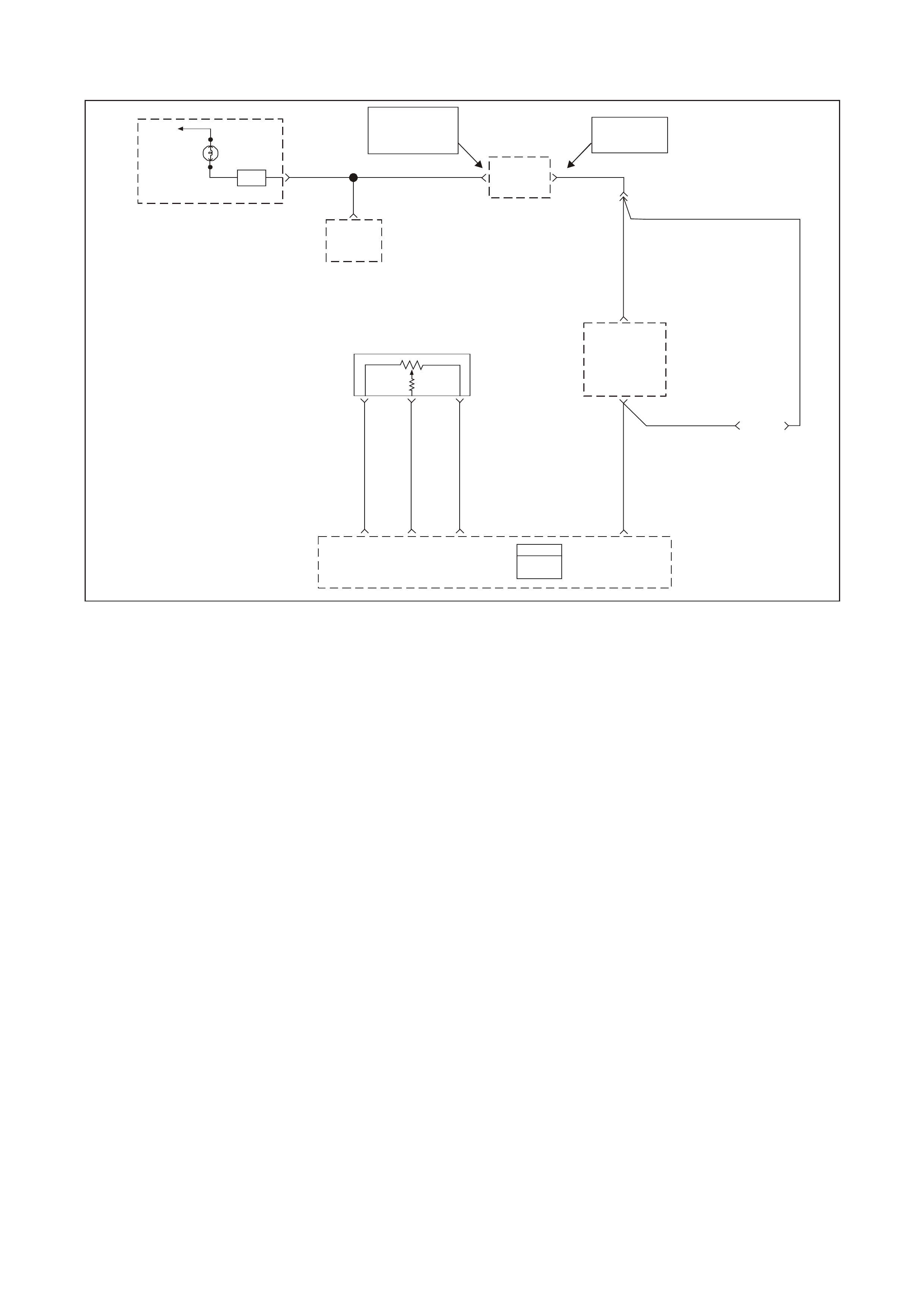
GEN III V8 PCM DTC P0523 ENGINE OIL PRESSURE SENSOR HIGH VOLTAGE
GEN3 0171
J1 = BLU E
J2 = RED
Powertrain
Control
Module
(PCM)
YE112
CA
Y1049
BLU/Y 334
58 J107 J1 58 J2
R/B 1221
B
G 335
G/W
1220
R/B 1221
BR/W 331
Serial
Data
(Class 2)
Sensor
Earth
Sensor
Signal
Sensor
5V
Reference
1049
To
Fuse
F13 Oil
Warning
Lamp
SDI
Instrument Panel Cluster
12
To
Vehicle
Bus
Serial Data
(UART)
Body Control
Module (BCM)
2
6
Serial Data
(UART) Powertrain
Interface
Module
(PIM)
NOTE
YB164 Low Seri es
YB175 High Serie s
NOTE
BCM Ter m inals
"3" YB164 Low Series
"9" YB175 High Series
792 DLC
Connector
63 J1
Oil Pressure
Sensor Serial Data
(Class 2)
Y
PCM
CIRCUIT DESCRIPTION
The Engine Oil Pressure Sensor is mounted in the top rear of the engine. The Engine Oil Pressure Sensor
measures changes in engine oil pressure. The Engine Oil Pressure Sensor has a 5.0 volt reference, a earth and a
signal circuit.
The Engine Oil Pressure Sensor changes resistance based on engine oil pressure.
The oil pressure sensor is used to determine when the oil level is below a certain threshold. When the oil pressure
reaches a predetermined value, the PCM will determine this as low oil pressure. The PCM will then send a serial
data message to the instrument panel (IP) cluster to turn ON the Low Oil Warning lamp.
When the PCM senses a signal voltage higher than the normal operating range of the sensor, this DTC will set.
CONDITIONS FOR RUNNING THE DTC
• Engine running.
CONDITIONS FOR SETTING THE DTC
• Engine Oil Pressure Sensor voltage is greater than 4.5 volts.
ACTION TAKEN WHEN THE DTC SETS
• The PCM illuminates the Check Powertrain Lamp (CPL) when the diagnostic runs and fails.
• T he PCM records the operating conditions at the time the diagnostic f ails. The PCM stores this inform ation in
the Freeze Frame/Failure Records.
• Oil warning lamp will illuminate.
CONDITIONS FOR CLEARING THE CPL/DTC
• A Histor y DTC will c lear af ter for ty consecutive warm- up cycles, if no f ailures ar e reported by this or other non-
emission related diagnostic.
• A last test failed (Current DTC) will not clear when the diagnostic runs and does not fail.
• The PCM battery voltage is interrupted.
• Use a Tech 2 scan tool in order to clear the CPL/DTC.

DIAGNOSTIC AIDS:
NOTE: Remove any debris from the PCM module connector surfaces before servicing the PCM module. Inspect
the PCM module connectors when diagnosing/replacing the modules. Ensure that the connectors are installed
correctly.
• The following may cause an intermittent:
- Incorrectly routed harness
- Rubbed through wire insulation
- Broken wire inside the insulation
• The PCM 5.0 volt reference circuits are internally connected within the PCM. If all the Engine Oil sensor
circuits check to be OK, inspect related 5.0 volt reference circuits. Refer to DTC P1635.
• If there is a failure with the Oil Warning Lamp, more than likely it is either a faulty bulb or a IP cluster problem.
TEST DESCRIPTION
The numbers below refer to the step numbers on the diagnostic table.
3. This step determines if the malfunction is present. For any test that requires probing of the PCM or any
component harness connectors, use the Connector Test Adaptor Kit J 35616-A. Using this kit prevents
damage to the harness connector terminals.
4. Using the Freeze Frame/Failure Records data may aid in locating an intermittent condition. If you cannot
duplicate the DT C, the information inc luded in the Freeze Fram e/Failure Records data can help determ ine the
distance traveled since the DTC set.
T he Fail Counter and Pass Counter can also help determ ine how m any ignition cycles the diagnos tic reported
a pass and/or a f ail. Operate the vehicle within the same Freeze Frame conditions (RPM, load, vehicle speed
temperature etc.) that you observed. This will isolate when the DTC failed.
5 This step checks if the signal circuit is shorted to a voltage.
6 This step checks if an earth circuit is available at the Engine Oil Pressure sensor.

GEN III V8 PCM DTC P0523 ENGINE OIL PRESSURE SENSOR HIGH VOLTAGE
Step Action Value(s) Yes No
1 Did you perform the Powertrain On-Board Diagnostic
(OBD) System Check? Go to Step 2 Go to Powertrain
OBD System
Check Table
2 1. Install the Tech 2 scan tool.
2. Idle the engine.
3. Monitor the Failed This Ignition under DTC Status for
DTC P1635 using the Tech 2 scan tool.
Did DTC P1635 fail this ignition cycle?
Go to DTC
P1635 5 Volt
Reference #1
Circuit
Go to Step 3
3 1. Install the Tech 2 scan tool
2. Idle the engine.
3. Monitor the Engine Oil Pressure sensor voltage on the
Tech 2 scan tool.
Is the Engine Oil Pressure sensor voltage above
specified value?
4.5V Go to Step 5 Go to Step 4
4 1. Turn ON the ignition leaving the engine OFF.
2. Review the Freeze Frame/Failure Records data for
this DTC and observe parameters.
3. Turn OFF the ignition for 15 seconds.
4. Start the engine and operate the vehicle within the
conditions required for this diagnostic to run, and as
close to the conditions recorded in the Freeze
Frame/Failure Records as possible. Special operating
conditions that need to meet before the PCM will run
this diagnostic, where applicable, are listed in
Conditions for Running the DTC.
5. Select the Diagnostic Trouble Code (DTC) option, the
DTC Information option and The Failed This Ignition
option using the Tech 2 scan tool.
Does the Tech 2 scan tool indicate that this diagnostic
failed this ignition.
Go to Step 5 Go to Diagnostic
Aids
5 1. Disconnect the Engine Oil Pressure sensor electrical
connector.
2. Observe the Engine Oil Pressure voltage display on
the Tech 2 scan tool.
Is the Engine Oil Pressure voltage near the specified
value?
1.0V Go to Step 6 Go to Step 7
6 Probe the sensor earth circuit with a test lamp J 34142-B
to B+.
Is the Test lamp illuminated?
Go to Step 8 Go To Step 9
7 1. Check the Engine Oil Pressure signal circuit for a
short to voltage or a short to the 5.0 volt reference
circuit.
2. Repair the Engine Oil Pressure Sensor signal circuit if
it is shorted.
Was the Engine Oil Pressure sensor signal circuit
shorted?
Go to Step 14 Go to Step 12
8 Measure the voltage at the 5.0 volt reference circuit to
earth using a DMM J 39200.
Is the voltage greater than the specified value?
5.0V Go to Step 13 Go to Step 9
9 1. Check for a poor sensor earth terminal connection at
the PCM connector.
2. If you find a problem, replace the faulty terminal.
Did the terminal require replacement?
Go to Step 14 Go to Step 10
10 1. Check the continuity of the Engine Oil Pressure
sensor earth circuit.
2. If you find a that the Engine Oil Pressure sensor earth
circuit measures over the specified value, repair the
open or the poor connection.
Was a condition found and corrected?
Go to step 14 Go to Step 11

Step Action Value(s) Yes No
11 1. Replace PCM.
2. Refer to Section 6C3-3 in the VT Series II Service
Information for PCM Programming and
PCM/PIM/BCM Security Link Procedure.
Is action complete?
Go to Step 14
12 Important: Before replacing the Engine Oil Pressure
sensor, perform the engine oil pressure check. Refer to
Section 6A3 Engine Mechanical in the VT Series II
Service Information.
Replace the Engine Oil Pressure sensor.
Is the action complete?
Go to Step 14
13 Repair the 5.0 volt reference circuit for a short to voltage.
Is action complete? Go to Step 14
14 1. Select the Diagnostic Trouble Code (DTC) option and
the Clear DTC option using the Tech 2 scan tool.
2. Idle the engine at the normal operating temperature.
3. Select the Diagnostic Trouble Code (DTC) option, the
DTC Information option and The Failed This Ignition
option using the Tech 2 scan tool.
4. Operate vehicle within the Conditions for Running this
DTC as specified in the supporting text, if applicable.
Does the Tech 2 scan tool indicate that this DTC reset?
Go to Step 2 Go to Step 15
15 Using the Tech 2 scan tool, check for any other DTCs.
Does the Tech 2 scan tool display any DTCs that you
have not diagnosed?
Go to the
applicable DTC
table
System OK
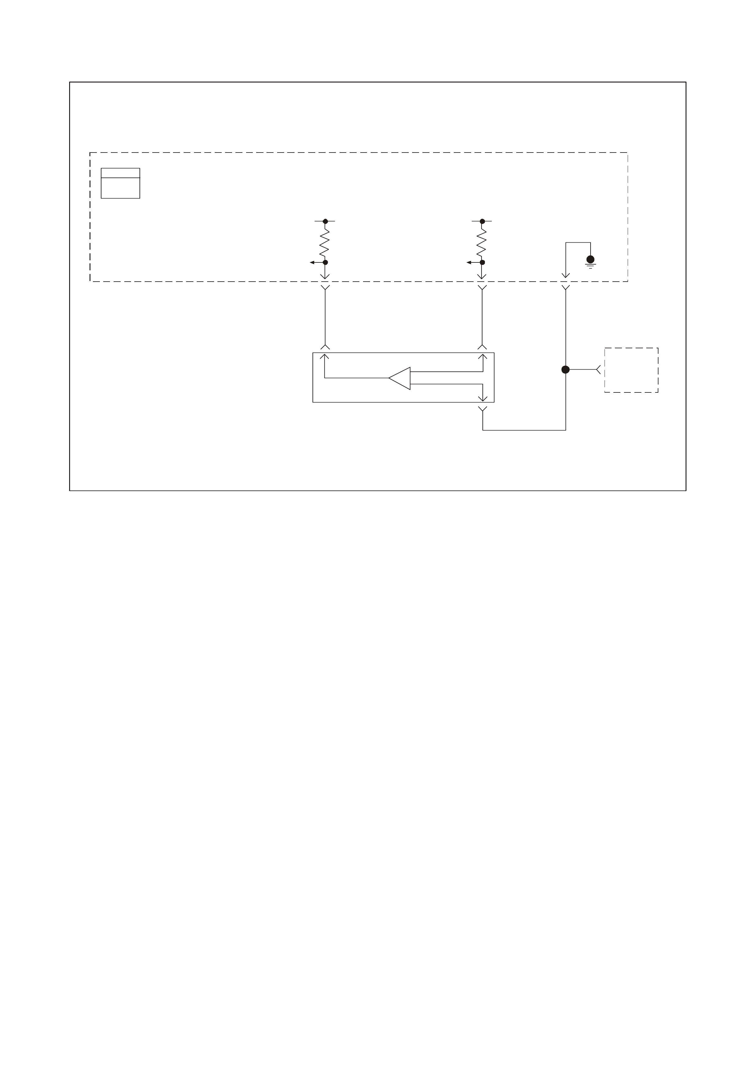
GEN III V8 PCM DTC P0530 A/C REFRIGERANT PRESSURE SENSOR CIRCUIT
GEN3 0172
Powertrain
Control
Module
(PCM)
IAT Sensor
CB
A
A/C
Refrigerant
Pressure
Sensor
PCM
J1 = BLU E
J2 = RED
A
/C Refrigerant
Pressure Sensor
Signal
A
/C Refrigerant
Pressure Sensor
Signal
A
/C Refrigerant
Pressure Sensor
5V Reference
5V
A
/C Refrigerant
Pressure Sensor
Earth
259G/B 415V/W 469G/O
J214 J145 J257
CIRCUIT DESCRIPTION
The A/C system uses an A/C Refrigerant Pressure Transducer mounted in the high side of the A/C system to
monitor A/C refrigerant pressure. The PCM utilises this information in order to turn ON the engine coolant fans
when the A/C refr igerant press ure is high.
The A/C Refrigerant Pressure Transducer operates much like other 3-wire sensors. The sensor supplies a signal
circuit to the PCM. As the A/C pressure increases or decreases, the resistance of the sensor changes and varies
the amount of signal returning to the PCM.
The PCM monitors the A/C Refrigerant Pressure Transducer signal circuit and can determine when the A/C
pressure is too high or too low. The PCM disables the A/C compressor clutch and sets a DTC P0530 when the
pressur es are out of range (high or low) f or a predeterm ined time. The PCM disa bles the A/C com pressor in or der
to prevent A/C compressor damage.
CONDITIONS FOR RUNNING THE DTC
• The PCM detects an A/C request.
CONDITIONS FOR SETTING THE DTC
• A/C Refrigerant Pressure Transducer indicates A/C refrigerant pressure is at or below 25 kPa (5 psi) for 5.0
seconds.
OR
• A/C Refrigerant Pressure Transducer indicates A/C refrigerant pressure is at or above 3140 kPa
(455 psi) for 5.0 seconds.
ACTION TAKEN WHEN THE DTC SETS
• The PCM stores the DTC information into memory when the diagnostic runs and fails.
• T he PCM records t he operatin g conditions at the tim e the diagnost ic fails. T he PCM stores th is inform ation in
the Freeze Frame/Failure Records.

CONDITIONS FOR CLEARING THE CPL/DTC
• A last test failed (current DTC) clears when the diagnostic runs and does not fail.
• A History DTC clears after forty consecutive warm-up cycles, if this or any other emission related diagnostic
does not report any failures.
• Use a Tech 2 scan tool in order to clear the CPL/DTC.
DIAGNOSTIC AIDS
• If the test did not fail this ig nit ion cycle, move the relat ed elec trical har n ess and th e c onnec tors whi le monitori ng
a Tech 2 scan tool.
• For an intermittent, refer to Section 6C3-2B SY MPTOMS in the VT Series II Service Information.
TEST DESCRIPTION
The numbers below refer to the step numbers on the diagnostic table.
3. The normal A/C pressure is between 700 and 1800 kPa (depending on A/C refrigerant charge and ambient
temper ature). If the A/C pr essure is withi n the range, r eview the fr eeze fram e data in order to deter mine wh en
the DTC P0530 set.
5. If the A/C pressure/voltage stays high after disconnecting the A/C Refrigerant Pressure Transducer electrical
connector, this indicates the signal circuit is shorted to a voltage.
7. This step checks for a good earth circuit.
8. This step checks the integrity of the A/C Refrigerant Pressure Transducer signal circuit.
11. If you have thoroug hly check ed the 5.0 volt refer ence circ uit (for opens , shorts to earth, PCM co nnectors etc.)
and checks OK, then replace the PCM.
IMPORTANT: Inspect the PCM engine earths for being secure and clean.
12. If you have th oroughl y checked the ear th circ uit for opens and the PCM c onnections are OK, then rep lace the
PCM.

GEN III V8 PCM DTC P0530 A/C REFRIGERANT PRESSURE SENSOR CIRCUIT
Step Action Value(s) Yes No
1 Did you perform the Powertrain On-Board Diagnostic
(OBD) System Check? Go to Step 2 Go to Powertrain
OBD System
Check Table
2
1. Install the Tech 2 scan tool
2. Idle the engine.
3. Monitor the Failed This Ignition option under DTC
information option for DTC P1639 using the Tech 2
scan tool.
Did DTC P1639 Fail This Ignition cycle?
Go to DTC
P1639
5 Volt Reference
Circuit Table
Go to Step 3
3 1. Turn ON the ignition leaving the engine OFF.
2. Monitor the A/C High Side using the Tech 2 scan tool
Does the Tech 2 scan tool indicate the A/C Pressure
between the specified range?
700–1800
kPa
0.1-1.8V
Go to Step 4 Go to Step 5
4 1. Turn ON the ignition leaving the engine OFF.
2. Review the Freeze Frame data and observe the
parameters.
3. Operate the vehicle within the Freeze Frame
conditions as obs erv ed.
Did the test Fail This Ignition cycle while operating the
vehicle in the conditions that you observed?
Go to Step 5 Refer to
Diagnostic Aids
5 Disconnect the A/C Refrigerant Pressure Transducer
electrical con nect or.
Does the Tech 2 scan tool indicate the A/C Pressure less
than the specified value?
700 kPa
1.0V Go to Step 6 Go to Step 10
6 Measure the voltage from the A/C Refrigerant Pressure
Transducer 5.0 volt reference circuit to the battery earth
using the DMM J 39200.
Is the voltage near the specified value?
5.0V Go to Step 7 Go to Step 11
7 Measure the voltage from the A/C Refrigerant Pressure
Transducer 5.0 volt reference circuit to the earth circuit
using the DMM J39200.
Is the voltage at the specified value.
5.0V Go to Step 8 Go to Step 12
8 Jumper the 5.0 volt reference circuit to the A/C
Refrigerant Pressure Transducer signal circuit using a
fused jumper wire.
Does the Tech 2 scan tool indicate the A/C Pressure
voltage at the specified value?
3152 kPa
5.0V Go to Step 9 Go to Step 13
9 Repair the faulty A/C Refrigerant Pressure Transducer
connection or faulty sensor.
Is the action complete?
Go to Step 14
10 Repair the short to voltage in the A/C Refrigerant
Pressure Transducer signal circuit.
Is the action complete?
Go to Step 14
11 Repair the 5.0 volt reference circuit to the A/C Refrigerant
Pressure Transducer.
Is the action complete?
Go to Step 14
12 Repair the earth circuit to the A/C Refrigerant Pressure
Transducer.
Is the action complete?
Go to Step 14
13 Repair the signal circuit to the A/C Refrigerant Pressure
Transducer.
Is the action complete?
Go to Step 14

Step Action Value(s) Yes No
14 1. Select the Diagnostic Trouble Code (DTC) option and
the Clear DTC Information option using the Tech 2
scan tool.
2. Idle the engine at the normal operating temperature.
3. Select the Diagnostic Trouble Code (DTC) option, the
DTC Information option and The Failed This Ignition
option using the Tech 2 scan tool.
4. Operate the vehicle within the Conditions for Running
the DTC as specified in the supporting text, if
applicable.
Does the Tech 2 scan tool indicate that this DTC reset?
Go to Step 2 Go to Step 15
15 Using the Tech 2 scan tool, check for any other DTCs.
Does the Tech 2 scan tool display any DTCs that you
have not diagnosed?
Go to the
applicable DTC
table
System OK

GEN III V8 PCM DTC P0562 SYSTEM VOLTAGE LOW
GEN3 0091
58 J1
Serial
Data
(Cl ass 2)
PCM
J1 = BLUE
J2 = RED
Powertrain
Control
Module
(PCM)
Y1049 YE110
291
Data Link
Connector
(DLC)
R/B 1221
1049
Y
7
R/B
1221 YE112 2
6Serial Data
(UART)
Serial Data
(UART)
Serial Data
(Class 2)
Powertrain
Interface
Module
(PIM)
Ignition
Voltage
15
Fuse
F13
ECC
Module 6
P/BLU 44
19
Gear Indicator Lamps (Option)
SDI
Low
Coolant
Lamp
SDI
Check
Powertrain
Malfunction
Indicator
Lamp (MIL)
SDI
Oil
Warning
Lamp
Instrument Panel Cluster
G/W 1220
12
B/Y
155
9
G/W 1220
G/W 1220
Serial Data
(UART)
ABS/ECT
Module
11
Body
Control
Module
(BCM)
NOTE
BCM Terminals
9 YB175 High Series
3 YB164 Low Ser ie s
NOTE
YB175 High Series
YB164 Low Ser ies
6
01 40 J1 01 40 J2
B/R 750 B/R 750B/R 750 B/R 750
750
B/R
B/R 750
Engine Earth
Location E5/15
Oxygen Sensor
Heaters
Ignition
Positive
Voltage
Battery
Feed
Battery
Feed
O740
O740
195720
P39
O/B 740 P/B 39
P39
YE112
Refer To
Wiring
Schematic
Part 1
To
Fusible
Link
FS
Fuse
F31 Fuse
F14
To
Ignition
Switch
Power
Economy
Lamp
CIRCUIT DESCRIPTION
The PCM continuously monitors the system voltage. The system voltage information is taken from the PCM’s
ignition feed circuit. Voltages below 8.0 volts or above 17.1 volts cause improper system operation and/or
com ponent damage. T he PCM operates in a default m ode if a PCM voltage DTC sets . If the system voltage is low
the PCM raises the idle s peed in order to increas e the generator output. The PCM disables most outputs to protect
the hardware if the s ys tem voltage is high. A Tech 2 scan tool will not display data if s ys tem voltage is outs ide this
range. Use a DMM in order to monitor the system voltage in order to check to see if the fault is currently present.
CONDITIONS FOR RUNNING THE DTC
• The engine run time is longer than 10 seconds.
• The engine speed is greater than 1000 RPM.
• The vehicle speed is greater than 8 km/h (5 mph).
CONDITIONS FOR SETTING THE DTC
• The PCM senses system voltage below 5.0 volts.
• All of the above conditions are present for 5.0 seconds.
ACTION TAKEN WHEN THE DTC SETS
• The PCM stores DTC P0562 in memory when the diagnostic runs and fails.
• The Check Powertrain Lamp (CPL) will not illuminate.
• T he PCM records the operating conditions at the time the diagnostic f ails. The PCM stores this inform ation in
the Freeze Frame/Failure Records.
• The PCM will command a high idle speed.
• The transmission defaults to third gear.
• The TCC operation is inhibited.

CONDITIONS FOR CLEARING THE CPL/DTC
• A last test failed (current DTC) clears when the diagnostic runs and does not fail.
• A History DTC clears after forty consecutive warm-up cycles, if this or any other emission related diagnostic
does not report any failures.
• Use a Tech 2 scan tool in order to clear the CPL/DTC.
DIAGNOSTIC AIDS
• An extremely low voltage (below 7.5 volts) may cause the loss of serial data and the CPL may not function. An
open ignition feed circuit causes a No Start and the CPL will not illuminate. A low system voltage may cause
other DTCs to set.
• Using the Freeze Frame/Failure Records data may aid in locating an intermittent condition. If you cannot
duplicate the DTC, the information included in the Freeze Frame/Failure Records data can aid in determining
the distance traveled since the DTC reported a pass and/or fail. Operate the vehicle within the same freeze
frame conditions (RPM, load, vehicle speed, temperature, etc.) that you observed. This will isolate when the
DTC failed.
• For an intermittent, refer to Section 6C3-2B SYMPTOMS in the VT Series II Service Information.
TEST DESCRIPTION
The numbers below refer to the step numbers on the diagnostic table.
2. This step checks the Charging system under load at idle. The voltage should remain above 8.0 volts.

GEN III V8 PCM DTC P0562 SYSTEM VOLTAGE LOW
Step Action Value(s) Yes No
1 Did you perform the Powertrain On-Board Diagnostic
(OBD) System Check? Go to Step 2 Go to Powertrain
OBD System
Check Table
2
1. Start the engine.
2. Load the electrical system by turning ON the
headlights and the heater fan to High.
3. Measure the battery voltage at the battery using the
DMM J 39200.
Is the battery voltage less than the specified value?
8.0 V Go to Section
12A Battery &
Cables in the VT
Series II Service
Information
Go to Step 3
3 1. Turn OFF the ignition.
2. Disconnect the BLUE PCM connector.
3. Turn ON the ignition leaving the engine OFF.
4. Measure the voltage at the terminal for the ignition
feed circuit using the DMM J 39200.
Is the voltage less than the specified value?
8.0V Go to Step 7 Go to Step 4
4 Check for faulty connections at the PCM.
Did you find and correct the condition? Go to Step 8 Go to Step 5
5 1. Turn OFF the ignition.
2. Reconnect the PCM.
3. Turn ON the ignition leaving the engine OFF.
4. Monitor the Fail This Ignition option under the
Diagnostic Trouble Codes (DTC) option using the
scan tool.
Did this DTC fail this ignition?
Go to Step 6 DTC is
intermittent. Go
to Diagnostic
Aids.
6 1. Replace PCM.
2. Refer to Section 6C3-3 Service Operations in the VT
Series II Service Information, for PCM Programming
and PCM/PIM/BCM Security Link Procedure.
Is action complete?
Go to Step 8
7 Repair the faulty ignition feed circuit to the PCM.
Is the action complete? Go to Step 8
8 1. Select the Diagnostic Trouble Code (DTC) option and
the Clear DTC Information option using the Tech 2
scan tool.
2. Idle the engine at the normal operating temperature.
3. Select the Diagnostic Trouble Code (DTC) option, the
DTC Information option and The Failed This Ignition
option using the Tech 2 scan tool.
4. Operate the vehicle within the Conditions for Running
the DTC as specified in the supporting text, if
applicable.
Does the Tech 2 scan tool indicate that this DTC reset?
Go to Step 2 Go to Step 9
9 Using the Tech 2 scan tool, check for any other DTCs.
Does the Tech 2 scan tool display any DTCs that you
have not diagnosed?
Go to the
applicable DTC
table
System OK
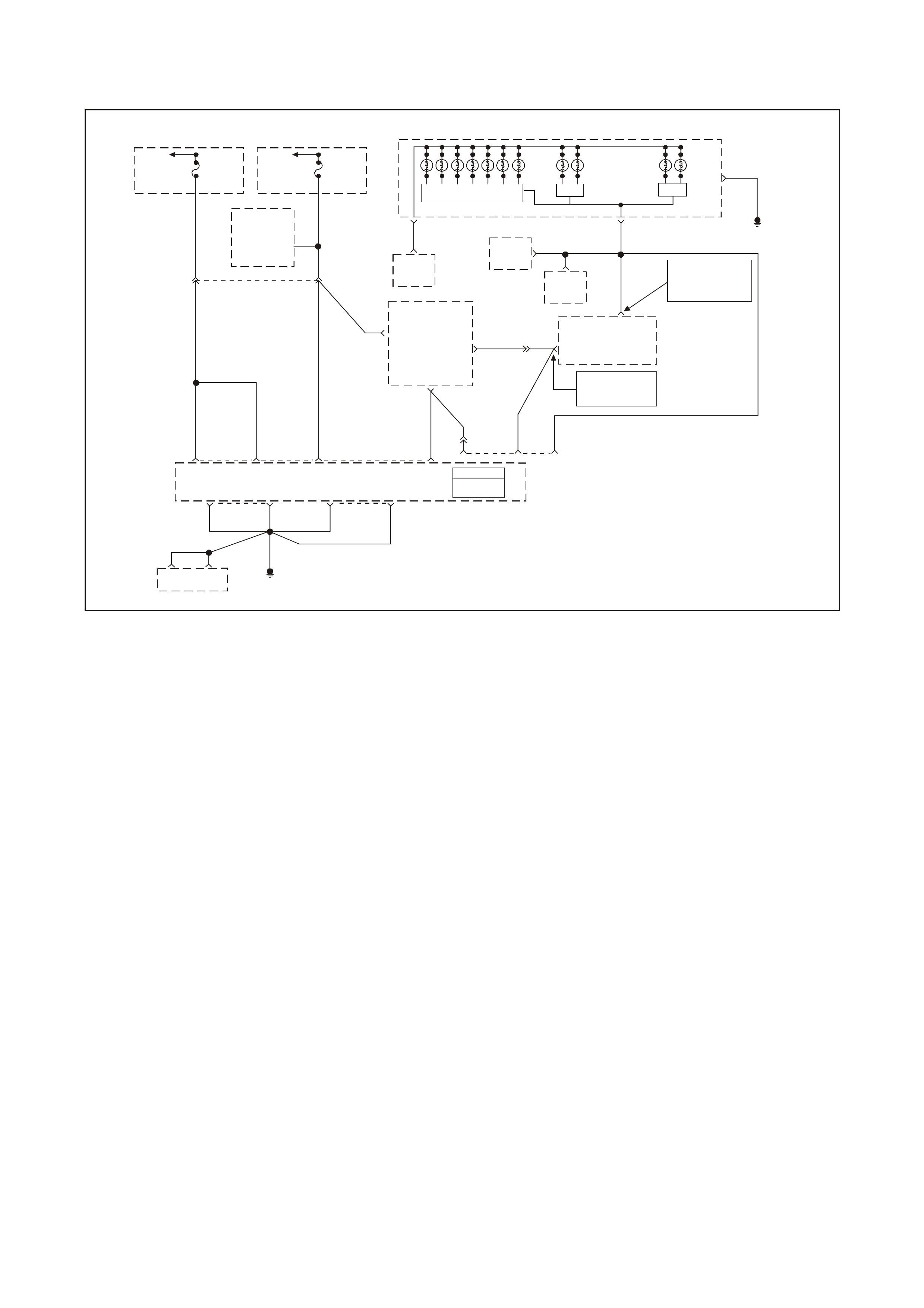
GEN III V8 PCM DTC P0563 SYSTEM VOLTAGE HIGH
GEN3 0091
58 C1
Serial
Data
(Cl ass 2)
PCM
J1 = BLUE
J2 = RED
Powertrain
Control
Module
(PCM)
Y1049 YE110
291
Data Link
Connector
(DLC)
R/B 1221
1049
Y
7
R/B
1221 YE112 2
6Serial Data
(UART)
Serial Data
(UART)
Serial Data
(Class 2)
Powertrain
Interface
Module
(PIM)
Ignition
Voltage
15
Fuse
F13
ECC
Module 6
P/BLU 44
19
Gear Indicator Lamps (Option)
SDI
Low
Coolant
Lamp
SDI
Check
Powertrain
Malfunction
Indicator
Lamp (MIL)
SDI
Oil
Warning
Lamp
Instrument Panel Cluster
G/W 1220
12
B/Y
155
9
G/W 1220
G/W 1220
Serial Data
(UART)
ABS/ECT
Module
11
Body
Control
Module
(BCM)
NOTE
BCM Terminals
9 YB175 High Series
3 YB164 Low Ser ie s
NOTE
YB175 High Series
YB164 Low Ser ies
6
01 40 J1 01 40 J2
B/R 750 B/R 750B/R 750 B/R 750
750
B/R
B/R 750
Engine Earth
Location E5/15
Oxygen Sensor
Heaters
Ignition
Positive
Voltage
Battery
Feed
Battery
Feed
O740
O740
195720
P39
O/B 740 P/B 39
P39
YE112
Refer To
Wiring
Schematic
Part 1
To
Fusible
Link
FS
Fuse
F31 Fuse
F14
To
Ignition
Switch
Power
Economy
Lamp
CIRCUIT DESCRIPTION
The PCM continuously monitors the System Voltage. The System Voltage information is taken from the PCM’s
ignition feed circuit. Voltages below 8.0 volts or above 17.1 volts cause improper system operation and/or
com ponent damage. T he PCM operates in a def ault mode if a PCM voltage DTC sets . If the system voltage is low,
the PCM raises the idle s peed in order to increas e the generator output. The PCM disables most outputs to protect
the hardware, if the system voltage is high. A Tec h 2 scan tool will not display data if system voltage is outs ide this
range. Use a DMM to monitor the system voltage to check if the fault is currently present.
CONDITIONS FOR RUNNING THE DTC
• The engine run time is longer than 10 seconds.
CONDITIONS FOR SETTING THE DTC
• The PCM senses system voltage above 17 volts.
• All of the above conditions are present for 5.0 seconds.
ACTION TAKEN WHEN THE DTC SETS
• The PCM stores DTC P0562 in memory when the diagnostic runs and fails.
• The Check Powertrain Lamp (CPL) will not illuminate.
• T he PCM records the operating conditions at the time the diagnostic f ails. The PCM stores this inform ation in
the Freeze Frame/Failure Records.
• The PCM disables most outputs.
• The transmission defaults to third gear.
• The TCC operation is inhibited.
• The PCM will cycle the cooling fans ON and OFF every few seconds during the time the condition is present.

CONDITIONS FOR CLEARING THE CPL/DTC
• A last test failed (current DTC) clears when the diagnostic runs and does not fail.
• A History DTC clears after forty consecutive warm-up cycles, if this or any other emission related diagnostic
does not report any failures.
• Use a Tech 2 scan tool in order to clear the CPL/DTC.
DIAGNOSTIC AIDS
• Check the generator voltage sense circuit for high resistance or loose connections. These could cause an
intermittent overcharging condition.
Refer to Section 6D3-1 - CHARGING SYSTEM and Section 6D3-2 - STARTING SYSTEM in the VT Series II
Service Information for circuit details.
• Using the Freeze Frame/Failure Records data may aid in locating an intermittent condition. If you cannot
duplicate the DTC, the information included in the Freeze Frame/Failure Records data can aid in determining
the distance traveled since the DTC reported a pass and/or fail. Operate the vehicle within the same freeze
frame conditions (RPM, load, vehicle speed, temperature, etc.) that you observed. This will isolate when the
DTC failed.
• For an intermittent, refer to Section 6C3-2B SYMPTOMS in the VT Series II Service Information.
TEST DESCRIPTION
The numbers below refer to the step numbers on the diagnostic table.
2. This step checks for excessive generator output. The voltage should remain below 17.1 volts.

GEN III V8 PCM DTC P0563 SYSTEM VOLTAGE HIGH
Step Action Value(s) Yes No
1 Did you perform the Powertrain On-Board Diagnostic
(OBD) System Check? Go to Step 2 Go to Powertrain
OBD System
Check Table
2
Important: If DTC P1635 and/or P1639 are set, refer to
those DTCs for further diagnosis.
1. Turn OFF all the accessories.
2. Measure the battery voltage at the battery using the
DMM J 39200.
3. Operate the engine speed above 2000 RPM.
Is the battery voltage less than the specified value?
17.1 V Go to Diagnostic
Aids. Go to Step 3
3 Repair the Starting/Charging system.
Is the repair complete? Go to Step 4
4 1. Select the Diagnostic Trouble Code (DTC) option and
the Clear DTC Information option using the Tech 2
scan tool.
2. Idle the engine at the normal operating temperature.
3. Select the Diagnostic Trouble Code (DTC) option, the
DTC Information option and The Failed This Ignition
option using the Tech 2 scan tool.
4. Operate the vehicle within the Conditions for Running
the DTC as specified in the supporting text, if
applicable.
Does the Tech 2 scan tool indicate that this DTC reset?
Go to Step 2 Go to Step 5
5 Using the Tech 2 scan tool, check for any other DTCs.
Does the Tech 2 scan tool display any DTCs that you
have not diagnosed?
Go to the
applicable DTC
table
System OK
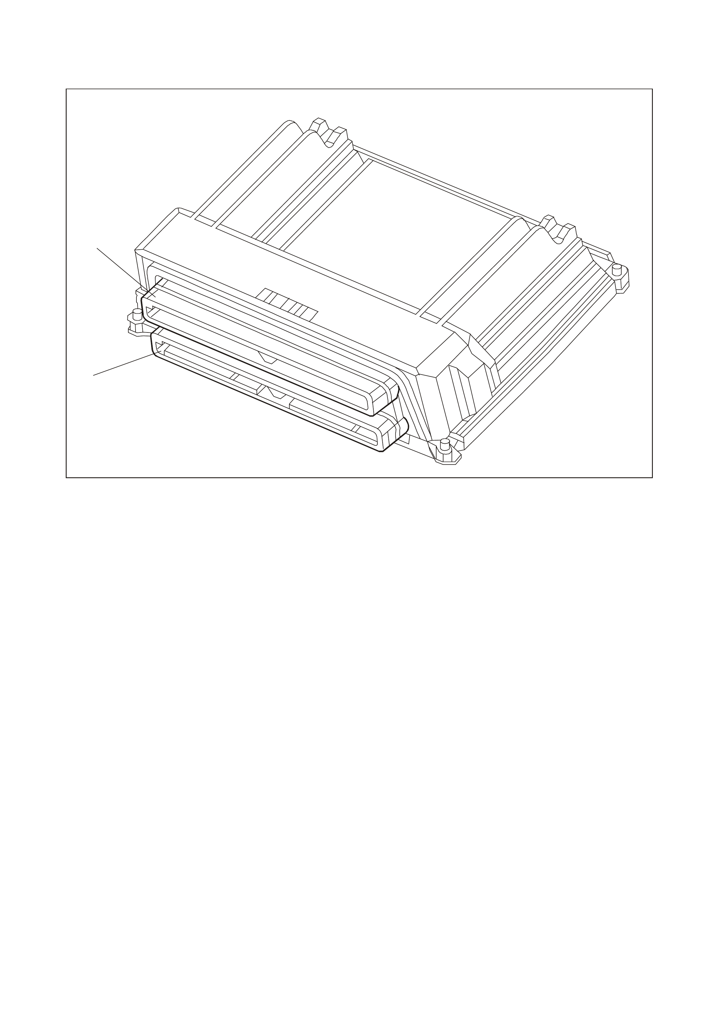
GEN III V8 PCM DTC P0601 POWERTRAIN CONTROL MODULE (PCM) MEMORY
GEN3 0173
1
2
1. Connector J1 BLUE
2. Connector J2 RED
CIRCUIT DESCRIPTION
The PCM EEPROM contains data which is essential to running the engine and transmission. The PCM
continuously checks the integrity of this data.
CONDITIONS FOR RUNNING THE DTC
• The ignition switch is in the crank position or the run position.
CONDITIONS FOR SETTING THE DTC
• The PCM is unable to correctly read data from the EEPROM (flash memory).
ACTION TAKEN WHEN THE DTC SETS
• The Check Powertrain Lamp (CPL) will not illuminate.
• T he PCM records the operating conditions at the time the diagnostic fails. The PCM stores this inform ation in
the Freeze Frame/Failure Records.
CONDITIONS FOR CLEARING THE CPL/DTC
• A last test failed (current DTC) clears when the diagnostic runs and does not fail.
• A History DTC clears after forty consecutive warm-up cycles, if this or any other emission related diagnostic
does not report any failures.
• Use a Tech 2 scan tool in order to clear the CPL/DTC.
DIAGNOSTIC AIDS
• Replace the PCM even if this DTC exists only in history.
• For an intermittent, refer to Section 6C3-2B SYMPTOMS in the VT Series II Service Information.
TEST DESCRIPTION
The numbers below refer to the step numbers on the diagnostic table.
2. This DTC indicates an internal PCM problem.

GEN III V8 PCM DTC P0601 POWERTRAIN CONTROL MODULE (PCM) MEMORY
Step Action Value(s) Yes No
1 Did you perform the Powertrain On-Board Diagnostic
(OBD) System Check? Go to Step 2 Go to Powertrain
OBD System
Check Table
2
1. Replace PCM.
2. Refer to Section 6C3-3 in the VT Series II Service
Information for PCM Programming and
PCM/PIM/BCM Security Link Procedure.
Is action complete?
Go to Step 3
3 1. Select the Diagnostic Trouble Code (DTC) option and
the Clear DTC Information option using the Tech 2
scan tool.
2. Idle the engine at the normal operating temperature.
3. Select the Diagnostic Trouble Code (DTC) option, the
DTC Information option and The Failed This Ignition
option using the Tech 2 scan tool.
4. Operate the vehicle within the Conditions for Running
the DTC as specified in the supporting text, if
applicable.
Does the Tech 2 scan tool indicate that this DTC reset?
Go to Step 2 Go to Step 4
4 Using the Tech 2 scan tool, check for any other DTCs.
Does the Tech 2 scan tool display any DTCs that you
have not diagnosed?
Go to the
applicable DTC
table
System OK
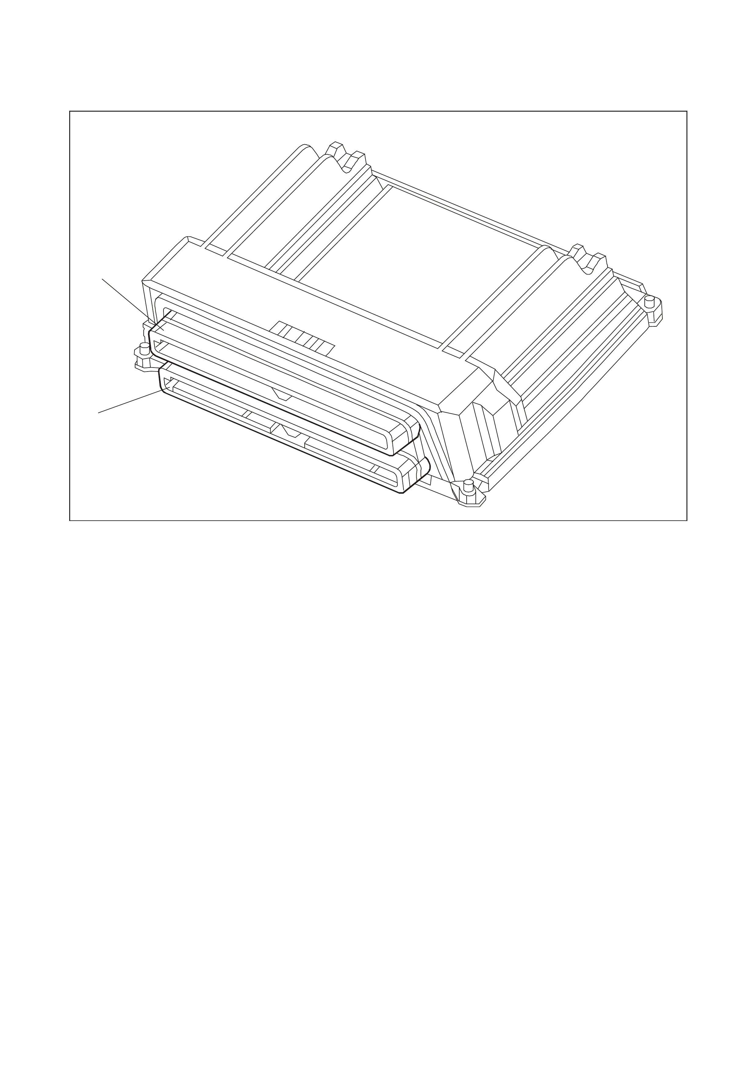
GEN III V8 PCM DTC P0602 POWERTRAIN
CONTROL MODULE (PCM) NOT PROGRAMMED
GEN3 0173
1
2
1. Connector J1 BLUE
2. Connector J2 RED
CIRCUIT DESCRIPTION
This DTC indic ates that the PCMs inter nal EEPROM is not f lashed with any vehicle software. If you install a service
PCM and do not flash the EEPROM, the engine will not run. This DTC indicates that an un-flashed PCM causes
the engine cranks but will not run situation.
CONDITIONS FOR RUNNING THE DTC
• The ignition switch is in the run position.
CONDITIONS FOR SETTING THE DTC
• No software data is present in the PCM.
ACTION TAKEN WHEN THE DTC SETS
• The PCM illuminates the Check Powertrain Lamp (CPL) when the diagnostic runs and fails.
• T he PCM records the operating conditions at the time the diagnostic f ails. The PCM stores this inform ation in
the Freeze Frame/Failure Records.
CONDITIONS FOR CLEARING THE CPL/DTC
• The PCM turns the CPL OFF after the first ignition cycle that the diagnostic runs and does not fail.
• A last test failed (current DTC) clears when the diagnostic runs and does not fail.
• A History DTC clears after forty consecutive warm-up cycles, if this or any other emission related diagnostic
does not report any failures.
1. Use a Tech 2 scan tool in order to clear the CPL/DTC.
TEST DESCRIPTION
The numbers below refer to the step numbers on the diagnostic table.
3. If the f lashing r outine fails , verify that the equipment us ed is func tioning properly and that all cable connections
are clean and tight. Also, make sure that the software you download is correct for the PCM being flashed. If
everything checks out OK, and a second attempt fails, the PCM is faulty.

GEN III V8 PCM DTC P0602 POWERTRAIN CONTROL MODULE (PCM) NOT PROGRAMMED
Step Action Value(s) Yes No
1 Did you perform the Powertrain On-Board Diagnostic
(OBD) System Check? Go to Step 2 Go to Powertrain
OBD System
Check Table
2 Program the PCM with the correct software. Refer to
PCM Programming in Section 6C3-3 in the VT Series II
Service Information.
Does DTC P0602 reset?
Go to Step 3 Go to Step 5
3 1. Verify that the equipment being used is functioning
properly and that all the cable connections are clean
and tight.
2. Attempt to program the PCM again.
Does DTC P0602 reset?
Go to Step 4 Go to Step 5
4
1. Replace PCM.
2. Refer to Section 6C3-3 in the VT Series II Service
Information for PCM Programming and
PCM/PIM/BCM Security Link Procedure.
Is action complete?
Go to Step 5
5 1. Select the Diagnostic Trouble Code (DTC) option and
the Clear DTC Information option using the Tech 2
scan tool.
2. Idle the engine at the normal operating temperature.
3. Select the Diagnostic Trouble Code (DTC) option, the
DTC Information option and The Failed This Ignition
option using the Tech 2 scan tool.
4. Operate the vehicle within the Conditions for Running
the DTC as specified in the supporting text, if
applicable.
Does the Tech 2 scan tool indicate that this DTC reset?
Go to Step 2 Go to Step 6
6 Using the Tech 2 scan tool, check for any other DTCs.
Does the Tech 2 scan tool display any DTCs that you
have not diagnosed?
Go to the
applicable DTC
table
System OK
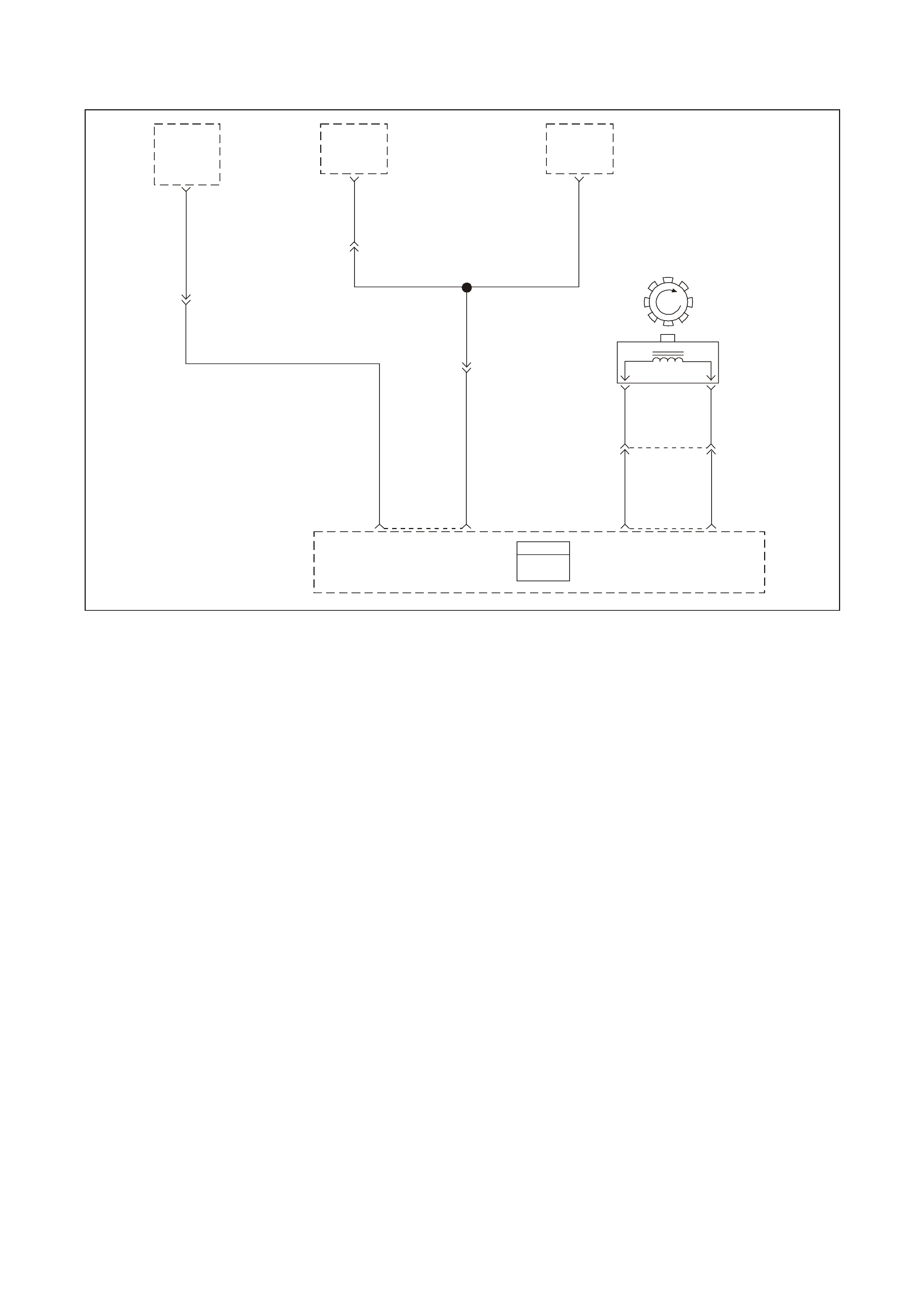
GEN III V8 PCM DTC P0608 VEHICLE SPEED OUTPUT CIRCUIT
GEN3 00174
PCM
J1 = BLUE
J2 = RED
V/W 123
V/W 123
GY/B 1687
GY/B 1687
V/W 123
Powertrain
Control
Module
(PCM)
ABS/ETC
Module
ETC
Spark
Retard
Signal
VSS
Input
Cruise
Control
Module VSS
Input
Instrument
Cluster
BLU/W 831 T 832
V ehi c le Sp eed
Sens or (VS S)
BA
20 J221
VSS
High VSS
Low
ETC
Retard
Signal
VSS
Output
50
53 J2
28
YE129
YE110
YE110
YB195
CIRCUIT DESCRIPTION
Various components apply a voltage to the Vehicle Speed Output circuit. The PCM creates the Vehicle Speed
Output signal by rapidly earthing this circuit via an internal switch called a driver. The driver operates at the same
rate as the VSS signal input. The various com ponents recognise the voltage being pulled to earth as an indication
of vehicle speed.
The PCM driver supplies the earth for the component being controlled. Each driver has a f ault line which the PCM
monitors. When the PCM commands a component ON, the voltage of the control circuit should be LOW (near 0
volts). When the PCM c omm ands the contr ol circuit to a com ponent OF F, the voltage potential of the circuit should
be HIGH near battery voltage). If the fault detection circuit senses a voltage other than what is expected, the fault
line status changes causing the DTC to set.
CONDITIONS FOR RUNNING THE DTC
• The engine speed is greater than 600 RPM
• The ignition voltage is between 6.0 volts and 16.0 volts.
CONDITIONS FOR SETTING THE DTC
• The PCM detects that the commanded state of the driver and the actual state of control circuit do not match.
• The condition must be present for a minimum of 10 seconds.
ACTION TAKEN WHEN THE DTC SETS
• The PCM stores the DTC information into memory when the diagnostic runs and fails.
• The Check Powertrain Lamp (CPL) will not illuminate.
• T he PCM records the operating conditions at the time the diagnostic f ails. The PCM stores this inform ation in
the Freeze Frame/Failure Records.
CONDITIONS FOR CLEARING THE CPL/DTC
• A last test failed (current DTC) clears when the diagnostic runs and does not fail.
• A History DTC clears after forty consecutive warm-up cycles, if this or any other emission related diagnostic
does not report any failures.
• Use a Tech 2 scan tool in order to clear the CPL/DTC.

DIAGNOSTIC AIDS
• Using the Freeze Frame/Failure Records data may aid in locating an intermittent condition. If you cannot
duplicate the DTC, the information included in the Freeze Frame/Failure Records data can aid in determining
the distance traveled since the DTC reported a pass and/or fail. Operate the vehicle within the same freeze
frame conditions (RPM, load, vehicle speed, temperature, etc.) that you observed. This will isolate when the
DTC failed.
• For an intermittent, refer to Section 6C3-2B SYMPTOMS in the VT Series II Service Information.
• If vehicle is fitted with cruise control, disconnecting the cruise module will isolate the cruise control system
from the rest of the vehicle systems.
TEST DESCRIPTION
The numbers below refer to the step numbers on the diagnostic table.
3. This step determines if the PCM is capable of controlling the speedometer.
5. Further circuit diagnosis m ay require instrum ent panel removal. The circuit from the PCM to the speedom eter
must be checked for being open, shorted to earth or, voltage. If you do not find any trouble, follow the
appropriate instrument panel diagnostic procedure.
7. The repair is not complete if the Tech 2 scan tool indicates that the DTC reset.

GEN III V8 PCM DTC P0608 VEHICLE SPEED OUTPUT CIRCUIT
Step Action Value(s) Yes No
1 Did you perform the Powertrain On-Board Diagnostic
(OBD) System Check? Go to Step 2 Go to Powertrain
OBD System
Check
2
1. Turn OFF the ignition.
2. Raise the drive wheels.
3. Start the engine.
4. Disable the traction control systems (if so equipped).
5. Allow the engine to idle in gear.
Does the vehicle speedometer indicate vehicle speed?
Go to Diagnostic
Aids Go to Step 3
3 1. Turn ON the ignition leaving the engine OFF.
2. Install a Tech 2 scan tool.
3. Using the Tech 2 scan tool, select F3: Body,
Instruments, F4: Miscellaneous Test, F7: Control
Tests, F0: Vehicle Speed.
4. Depress the ON up arrow key on the Tech 2 scan tool.
Does the speedometer read the same as the Tech 2 scan
tool commanded output?
Go to Step 6 Go to Step 4
4 1. Ignition OFF.
2. Disconnect the PCM RED connector.
3. Turn ON the ignition leaving the engine OFF.
4. Connect DMM between the PCM harness terminal for
VSS output and earth.
Is voltage at specified value?
B+ Go to Step 6 Go to Step 5
5 1. Check for open, short to earth in VSS output circuit.
Was a problem found? Go to Step 7 Further diagnosis
of circuit
required. Go to
Section 12C
Instruments in
the VT Series II
Service
Information.
6 1. Replace PCM.
2. Refer to Section 6C3-3 Service Operations in the VT
Series II Service Information, for PCM Programming
and PCM/PIM/BCM Security Link Procedure.
NOTE: If speedometer is still inoperative, refer to Section
12C in the VT Series II Service Information for further
diagnosis.
Is action complete?
Go to Step 7
7 1. Select the Diagnostic Trouble Code (DTC) option and
the Clear DTC Information option using the Tech 2
scan tool.
2. Idle the engine at the normal operating temperature.
3. Select the Diagnostic Trouble Code (DTC) option, the
DTC Information option and The Failed This Ignition
option using the Tech 2 scan tool.
4. Operate the vehicle within the Conditions for Running
the DTC as specified in the supporting text, if
applicable.
Does the Tech 2 scan tool indicate that this DTC reset?
Go to Step 2 Go to Step 8
8 Using the Tech 2 scan tool, check for any other DTCs.
Does the Tech 2 scan tool display any DTCs that you
have not diagnosed?
Go to the
applicable DTC
table
System OK
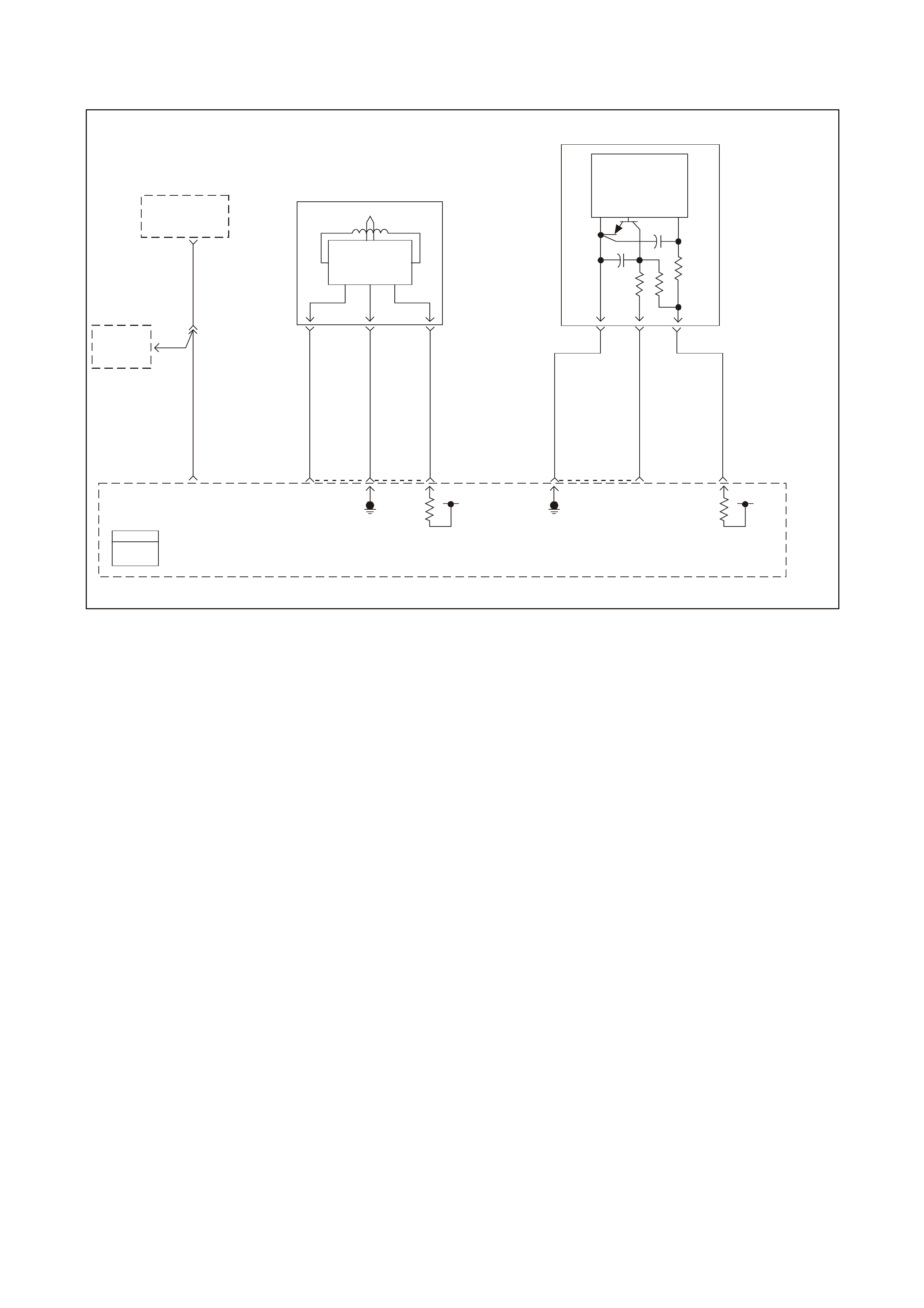
GEN III V8 PCM DTC P0654 ENGINE SPEED OUTPUT CIRCUIT
GEN 3 0160
Powertrain
Control
Module
(PCM)
Tachometer
Input
Instrument
Cluster
18
BR/R 121
Tach
Input 30 YE112
ABS/ETC
Module
BR 121
10 J2
CKP Senso r
Signal Input Reference
Low
12 21 02 J1
12VIgnition
Feed
61 73 39 J2
12V
Ignition
Feed
CMP Senso r
Si gnal I npu t
Reference
Low
J1
Hall Sensor
Trigger Circuit
Amplifier and
Voltage Reg.
Electronics
Camshaft
Position
(CMP)
Sensor
29
1K
47g
4700pf
Power
Gnd
BAC
R/W 632 W/B 631
BR 633
ABC
BLU 643 LBLU/W 646
LBLU/B 647
Magnetic
Pickup Crankshaft
Position
(CKP)
Sensor
Pulse Shaper
And Voltage
Reg. Electronics
Output Power
Gnd
Tachometer
Output
PCM
J1 = BLU E
J2 = RED
CIRCUIT DESCRIPTION
The PCM s upplies a voltage to the Engine Speed Output circ uit. The PCM creates the Engine Speed Output signal
by rapidly earthing this circuit via an internal switch called a driver. The other com ponents on this circuit recognise
the voltage being pulled to earth as an indication of engine speed.
The PCM driver supplies the earth for the component being controlled. Each driver has a f ault line which the PCM
monitors. When the PCM commands a component ON, the voltage of the control circuit should be LOW (near 0
volts). When the PCM c omm ands the contr ol circuit to a com ponent OF F, the voltage potential of the circuit should
be HIGH (near battery voltage). If the fault detection circuit senses a voltage other than what is expected, the fault
line status changes causing the DTC to set.
CONDITIONS FOR RUNNING THE DTC
• The engine speed is greater than 600 RPM.
• The ignition voltage is between 6.0 and 16.0 volts.
CONDITIONS FOR SETTING THE DTC
• The PCM detects that the commanded state of the driver and the actual state of the control circuit do not
match.
• All of the conditions are present for a minimum of 10.0 seconds.
ACTION TAKEN WHEN THE DTC SETS
• The PCM stores the DTC information into memory when the diagnostic runs and fails.
• The Check Powertrain Lamp (CPL) will not illuminate.
• T he PCM records the operating conditions at the time the diagnostic f ails. The PCM stores this inform ation in
the Freeze Frame/Failure Records.
CONDITIONS FOR CLEARING THE CPL/DTC
• A last test failed (current DTC) clears when the diagnostic runs and does not fail.
• A History DTC clears after forty consecutive warm-up cycles, if this or any other emission related diagnostic
does not report any failures.
• Use a Tech 2 scan tool to clear the CPL/DTC.

DIAGNOSTIC AIDS
• Using the Freeze Frame/Failure Records data may aid in locating an intermittent condition. If you cannot
duplicate the DTC, the information included in the Freeze Frame/Failure Records data can aid in determining
the distance traveled since the DTC reported a pass and/or fail. Operate the vehicle within the same freeze
frame conditions (RPM, load, vehicle speed, temperature, etc.) that you observed. This will isolate when the
DTC failed.
• For an intermittent, refer to Section 6C3-2B SYMPTOMS in the VT Series II Service Information.
TEST DESCRIPTION
The numbers below refer to the step numbers on the diagnostic table.
NOTE: If the instrument panel is completely inoperative, refer to Section 12C in the VT Series II Service
Information.
3. This step determines if the PCM is capable of controlling the tachometer.
5. Further circuit diagnosis may require instrument panel removal. Check the circuit from the PCM to the
tachometer for being open, shorted to earth or, voltage. If you can not find any trouble, follow the appropriate
instrument panel diagnostic procedure.
7. The repair is not complete if the Tech 2 scan tool indicates that the diagnostic ran and failed.

GEN III V8 PCM DTC P0654 ENGINE SPEED OUTPUT CIRCUIT
Step Action Value(s) Yes No
1 Did you perform the Powertrain On-Board Diagnostic
(OBD) System Check? Go to Step 2 Go to Powertrain
OBD System
Check Table
2
With the engine running, does the vehicle tachometer
indicate engine RPM? Go to Diagnostic
Aids Go to Step 3
3 1. Turn ON the ignition leaving the engine OFF.
2. Install a Tech 2 scan tool.
3. Using the Tech 2 scan tool, select F3: Body,
Instruments, F4: Miscellaneous Test, F7: Control
Tests, F1: Engine Speed.
4. Depress the ON up arrow key on the Tech 2 scan tool.
Does the tachometer read the same as the Tech 2
scan tool commanded output?
Go to Step 6 Go to Step 4
4 5. Ignition OFF.
6. Disconnect the PCM RED connector.
7. Turn ON the ignition leaving the engine OFF.
8. Connect DMM between the PCM harness terminal for
Tachometer output and earth.
Is voltage at specified value?
7 - 10 V Go to Step 6 Go to Step 5
5 Check for open, short to earth, or short to voltage in
Tachometer output circuit.
Was a problem found?
Go to Step 7 Further diagnosis
of circuit
required. Go to
Section 12C
Instruments in
the VT Series II
Service
Information
6 1. Replace PCM.
2. Refer to Section 6C3-3 in the VT Series II Service
Information for PCM Programming and
PCM/PIM/BCM Security Link Procedure.
NOTE: If the Tachometer is still inoperative, refer to
Section 12C in the VT Series II Service Information for
further diagnosis.
Is action complete?
Go to Step 7
7 1. Select the Diagnostic Trouble Code (DTC) option and
the Clear DTC Information option using the Tech 2
scan tool.
2. Idle the engine at the normal operating temperature.
3. Select the Diagnostic Trouble Code (DTC) option, the
DTC Information option and The Failed This Ignition
option using the Tech 2 scan tool.
4. Operate the vehicle within the Conditions for Running
the DTC as specified in the supporting text, if
applicable.
Does the Tech 2 scan tool indicate that this DTC reset?
Go to Step 2 Go to Step 8
8 Using the Tech 2 scan tool, check for any other DTCs.
Does the Tech 2 scan tool display any DTCs that you
have not diagnosed?
Go to the
applicable DTC
table
System OK
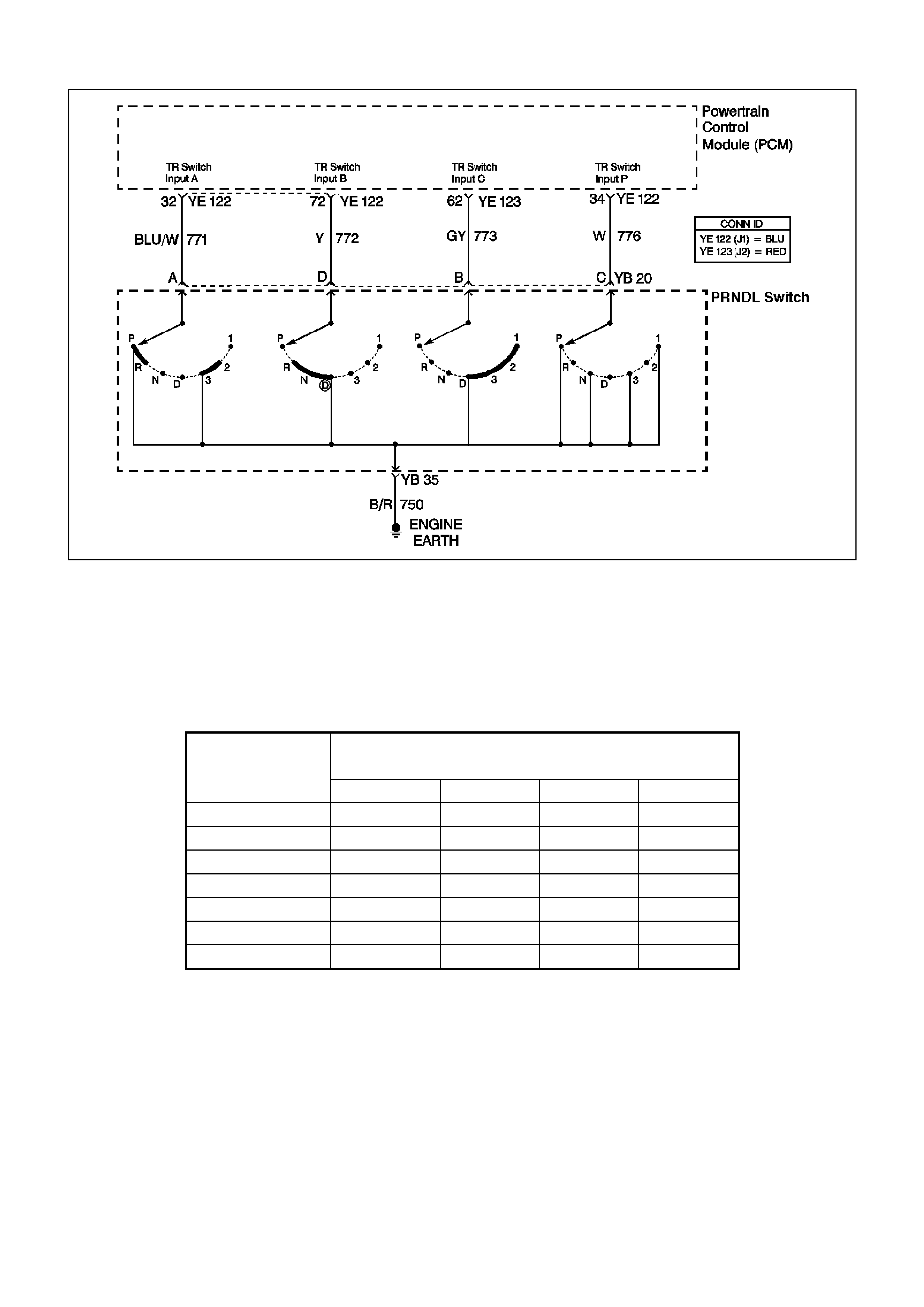
GEN III V8 PCM DTC P0705 TRANSMISSION RANGE SWITCH CIRCUIT
CIRCUIT DESCRIPTION
The Transmission Range (TR) Switch is part of the Transmission PRNDL switch mounted on the transmission
manual shaft. T he four inputs from the transm ission r ange switch indicate to the PCM which position is s elected by
the trans m ission selector lever . The input voltage level at the PCM is high (B+) when the transmis sion range s witch
is open and low when the switch is closed to earth. The state of each input is available for display on the Scan
Tool. The four parameters represent transmission range switch P (Parity), A, B, and C inputs respectively.
W hen the PCM detects an invalid transm ission range input com bination, then DTC P0705 sets. Valid trans mission
range input combinations are shown in the Transmission Range Switch Valid Combination table.
Gear Selector
Position Scan Tool TR Switch P/A/B/C Display
P A B C
Park (P) Closed 0 V Closed 0 V Open 12 V Open 12 V
Reverse (R) Open 12 V Closed 0 V Closed 0 V Open 12 V
Neutral (N) Closed 0 V Open 12 V Closed 0 V Open 12 V
D Open 12 V Open 12 V Closed 0 V Closed 0 V
3 Closed 0 V Closed 0 V Closed 0 V Closed 0 V
2 Open 12 V Closed 0 V Open 12 V Closed 0 V
1 Closed 0 V Open 12 V Open 12 V Closed 0 V
TRANSMISSION RANGE SWITCH VALID COMBINATION TABLE
CONDITIONS FOR RUNNING THE DTC
• The ignition is ON.
CONDITIONS FOR SETTING THE DTC
• The Transmission Range Switch inputs indicate an invalid combination.
• The above condition is present for longer than 30 seconds.
ACTION TAKEN WHEN THE DTC SETS
• The PCM does not illuminate the Check Powertrain Lamp (CPL).
• The PCM stores DTC P0705 in PCM history.

CONDITIONS FOR CLEARING THE DTC
• A scan tool clears the DTC from the PCM history.
• The PCM clears the DTC from the PCM history if the vehicle completes 40 warm-up cycles without an
emission-related diagnostic fault occurring.
• T he PCM cancels the DTC default actions when the fault no longer exists and the ignition switch is OFF long
enough in order to power down the PCM.
DIAGNOSTIC AIDS
• Inspect the wiring at the PCM, the Transmission Range Switch and all other circuit connecting points for the
following conditions:
- A backed out terminal
- A damaged terminal
- Reduced terminal tension
- A chafed wire
- A broken wire inside the insulation
- Moisture intrusion
- Corrosion
• If after a complete inspection and testing of the system the condition does not reveal, observe the scan tool
TR Switch P/A/B/C dis play while moving the connec tors and wiring. A change in the TR Switch display should
identify the location of the condition.
TEST DESCRIPTION
Numbers below refer to the step numbers on the Diagnostic Table.
2. If the TR Switch display corresponds with all gear selector positions, the condition may be intermittent. Refer
to Diagnostic Aids for intermittent diagnosis.
3. Disconnecting the Transmission Range Switch connector will cause the PCM to interpret all the circuits as
open and the Scan Tool P/A/B/C will display all Open 12 V. This would indicate that circuits from the TR
Switch to the PCM and the PCM are all OK.
4. By reconnecting the TR Switch and all Scan Tool TR Switch P/A/B/C display Open 12 V, the condition could
be in the engine earth circuit 750.
7. By providing the earth for each Transmission Range Switch circuit, the PCM should respond by changing the
TR Switch P/A/B/C display from Open 12 V to Closed 0 V. For the circuits that do not change, an open circ uit
must exist.
12. Before replacing the PCM, ensure that all connectors, wiring and components have been tested.

GEN III V8 PCM DTC P0705 TRANSMISSION RANGE SWITCH CIRCUIT
Step Action Value(s) Yes No
1 Was the Powertrain On-Board Diagnostic (OBD) System
Check performed? Go to Step 2 Go to Powertrain
OBD System
Check Table
2 1. Install the Tech 2 Scan Tool.
2. Place the transmission in PARK.
3. Turn the ignition switch ON.
4. Observe the Scan Tool TR Switch P/A/B/C display
while selecting each gear position.
5. Compare the Scan Tool display, with each gear
position selected, to the Transmission Range Switch
Valid Combinations table.
Does the Scan Tool display match the Transmission
Range Switch Valid Combinations table for each gear
position?
Go to Diagnostic
Aids Go to Step 3
3 Disconnect the Transmission Range Switch 4-way (YB
20) connector.
Does the Scan Tool TR Switch P/A/B/C display the
specified values?
P/
Open 12 V
A/
Open 12 V
B/
Open 12 V
C/
Open 12 V
Go to Step 4 Go to Step 7
4 Reconnect the Transmission Range Switch 4-way (YB
20) connector.
Does the Scan Tool TR Switch P/A/B/C display the
specified values?
P/
Open 12 V
A/
Open 12 V
B/
Open 12 V
C/
Open 12 V
Go to Step 5 Go to Step 11
5 Inspect the Transmission Neutral Start and Backup
Switch 5-way (YB 35) connector for being disconnected
or poor terminal contact at circuit 750 (B/R).
Was a condition found?
Go to Step 10 Go to Step 6
6 Inspect circuit 750 (B/R) from the Transmission Neutral
Start and Backup Switch 5-way (YB 35) connector for an
open condition.
Was an open condition found?
Go to Step 10 Go to Step 11
7 1. Use a fused jumper wire to earth each terminal of the
Transmission Range Switch 4-way (YB 20) connector,
while observing the Scan Tool TR Switch P/A/B/C
display.
2. Note the display change as each circuit is earthed.
Does each of the Scan Tool TR Switch P/A/B/C display
change from Open 12 V to Closed 0 V when earthed?
Go to Step 11 Go to Step 8
8 For the circuit or circuits that did not change status in
Step 7, inspect the circuit from the Transmission Range
Switch connector to the PCM for an open condition or for
circuits being shorted together.
Was an open or shorted together condition found?
Go to Step 10 Go to Step 9
9 Inspect for poor connections at the PCM.
Was a condition found? Go to Step 10 Go to Step 12
10 Repair the wiring as necessary.
Is the repair complete? Go to Step 13 Go to Wi ring
Repair
Procedures in the
VT Series I
Service
Information,
Section 12P

Step Action Value(s) Yes No
11 Replace the Transmission Range Switch. Refer to
Neutral Start and Back-up Lamp Switch Replacement.
Is the replacement complete?
Go to Step 13 Go to Section
7C4 Neutral Start
and Back-up
Lamp Switch
Replacement in
the VT Series II
Service
Information
12 Replace the PCM.
Refer to Powertrain Control Module in Section 6C3-3 in
the VT Series II Service Information.
Is replacement the complete?
Go to Step 13 Go to Section
6C3-3 Powertrain
Control Module
Replacement in
the VT Series II
Service
Information
13 1. Clear the DTCs.
2. Observe the Scan Tool TR Switch P/A/B/C display
while selecting each gear position.
3. Compare the Scan Tool display, with each gear
position selected, to the Transmission Range Switch
Valid Combinations table.
Does the Scan Tool display match the Transmission
Range Switch Valid Combinations table for each gear
position?
System OK Go to Step 1
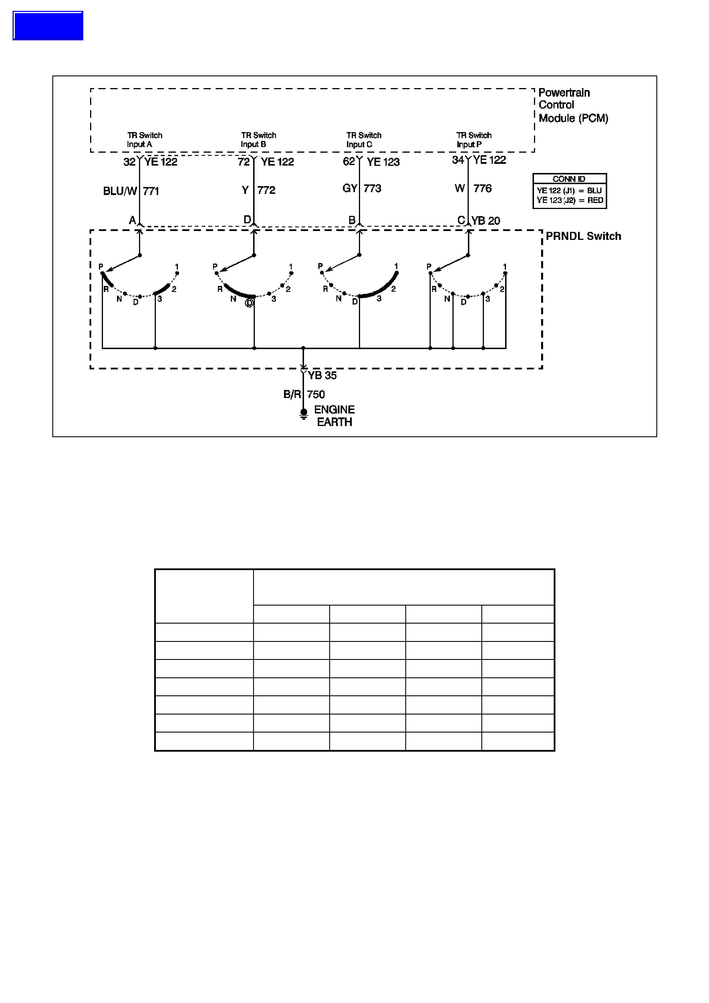
GEN III V8 PCM DTC P0706 TRANSMISSION RANGE SWITCH PERFORMANCE
CIRCUIT DESCRIPTION
The Transmission Range (TR) Switch is part of the Transmission PRNDL switch mounted on the transmission
manual shaft. T he four inputs from the transm ission r ange switch indicate to the PCM which position is s elected by
the trans m ission selector lever . The input voltage level at the PCM is high (B+) when the transmis sion range s witch
is open and low when the switch is closed to earth. The state of each input is available for display on the Scan
Tool. The four parameters represent transmission range switch P (Parity), A, B, and C inputs respectively.
W hen the PCM detects an invalid transm ission range input com bination, then DTC P0706 sets. Valid trans mission
range input combinations are shown in the Transmission Range Switch Valid Combination table.
Gear Selector
Position Scan Tool TR Switch P/A/B/C Display
P A B C
Park (P) Closed 0 V Closed 0 V Open 12 V Open 12 V
Reverse (R) Open 12 V Closed 0 V Closed 0 V Open 12 V
Neutral (N) Closed 0 V Open 12 V Closed 0 V Open 12 V
D Open 12 V Open 12 V Closed 0 V Closed 0 V
3 Closed 0 V Closed 0 V Closed 0 V Closed 0 V
2 Open 12 V Closed 0 V Open 12 V Closed 0 V
1 Closed 0 V Open 12 V Open 12 V Closed 0 V
TRANSMISSION RANGE SWITCH VALID COMBINATION TABLE
CONDITIONS FOR RUNNING THE DTC
• The ignition is ON.
CONDITIONS FOR SETTING THE DTC
• The Transmission Range Switch inputs indicate an invalid combination.
• The above condition is present for longer than 30 seconds.
ACTION TAKEN WHEN THE DTC SETS
• The PCM does not illuminate the Check Powertrain Lamp (CPL).
• The PCM stores DTC P0706 in PCM history.
Techline

CONDITIONS FOR CLEARING THE DTC
• A scan tool clears the DTC from the PCM history.
• The PCM clears the DTC from the PCM history if the vehicle completes 40 warm-up cycles without an
emission-related diagnostic fault occurring.
• T he PCM cancels the DTC default actions when the fault no longer exists and the ignition switch is OFF long
enough in order to power down the PCM.
DIAGNOSTIC AIDS
• Inspect the wiring at the PCM, the Transmission Range Switch and all other circuit connecting points for the
following conditions:
- A backed out terminal
- A damaged terminal
- Reduced terminal tension
- A chafed wire
- A broken wire inside the insulation
- Moisture intrusion
- Corrosion
• If after a complete inspection and testing of the system the condition does not reveal, observe the scan tool
TR Switch P/A/B/C dis play while moving the connec tors and wiring. A change in the TR Switch display should
identify the location of the condition.
TEST DESCRIPTION
Numbers below refer to the step numbers on the Diagnostic Table.
2. If the TR Switch display corresponds with all gear selector positions, the condition may be intermittent. Refer
to Diagnostic Aids for intermittent diagnosis.
3. Disconnecting the Transmission Range Switch connector will cause the PCM to interpret all the circuits as
open and the Scan Tool P/A/B/C will display all Open 12 V. This would indicate that circuits from the TR
Switch to the PCM and the PCM are all OK.
4. By reconnecting the TR Switch and all Scan Tool TR Switch P/A/B/C display Open 12 V, the condition could
be in the engine earth circuit 750.
7. By providing the earth for each Transmission Range Switch circuit, the PCM should respond by changing the
TR Switch P/A/B/C display from Open 12 V to Closed 0 V. For the circuits that do not change, an open circ uit
must exist.
12. Before replacing the PCM, ensure that all connectors, wiring and components have been tested.

GEN III V8 PCM DTC P0706 TRANSMISSION RANGE SWITCH PERFORMANCE
Step Action Value(s) Yes No
1 Was the Powertrain On-Board Diagnostic (OBD) System
Check performed? Go to Step 2 Go to Powertrain
OBD System
Check Table
2 1. Install the Tech 2 Scan Tool.
2. Place the transmission in PARK.
3. Turn the ignition switch ON.
4. Observe the Scan Tool TR Switch P/A/B/C display
while selecting each gear position.
5. Compare the Scan Tool display, with each gear
position selected, to the Transmission Range Switch
Valid Combinations table.
Does the Scan Tool display match the Transmission
Range Switch Valid Combinations table for each gear
position?
Go to Diagnostic
Aids Go to Step 3
3 Disconnect the Transmission Range Switch 4-way (YB
20) connector.
Does the Scan Tool TR Switch P/A/B/C display the
specified values?
P/
Open 12 V
A/
Open 12 V
B/
Open 12 V
C/
Open 12 V
Go to Step 4 Go to Step 7
4 Reconnect the Transmission Range Switch 4-way (YB
20) connector.
Does the Scan Tool TR Switch P/A/B/C display the
specified values?
P/
Open 12 V
A/
Open 12 V
B/
Open 12 V
C/
Open 12 V
Go to Step 5 Go to Step 11
5 Inspect the Transmission Neutral Start and Backup
Switch 5-way (YB 35) connector for being disconnected
or poor terminal contact at circuit 750 (B/R).
Was a condition found?
Go to Step 10 Go to Step 6
6 Inspect circuit 750 (B/R) from the Transmission Neutral
Start and Backup Switch 5-way (YB 35) connector for an
open condition.
Was an open condition found?
Go to Step 10 Go to Step 11
7 1. Use a fused jumper wire to earth each terminal of the
Transmission Range Switch 4-way (YB 20) connector,
while observing the Scan Tool TR Switch P/A/B/C
display.
2. Note the display change as each circuit is earthed.
Does each of the Scan Tool TR Switch P/A/B/C display
change from Open 12 V to Closed 0 V when earthed?
Go to Step 11 Go to Step 8
8 For the circuit or circuits that did not change status in
Step 7, inspect the circuit from the Transmission Range
Switch connector to the PCM for an open condition or for
circuits being shorted together.
Was an open or shorted together condition found?
Go to Step 10 Go to Step 9
9 Inspect for poor connections at the PCM.
Was a condition found? Go to Step 10 Go to Step 12
10 Repair the wiring as necessary.
Is the repair complete? Go to Step 13 Go to Wi ring
Repair
Procedures in the
VT Series I
Service
Information,
Section 12P

Step Action Value(s) Yes No
11 Replace the Transmission Range Switch. Refer to
Neutral Start and Back-up Lamp Switch Replacement.
Is the replacement complete?
Go to Step 13 Go to Section
7C4 Neutral Start
and Back-up
Lamp Switch
Replacement in
the VT Series II
Service
Information
12 Replace the PCM.
Refer to Powertrain Control Module in Section 6C3-3 in
the VT Series II Service Information.
Is replacement the complete?
Go to Step 13 Go to Section
6C3-3 Powertrain
Control Module
Replacement in
the VT Series II
Service
Information
13 1. Clear the DTCs.
2. Observe the Scan Tool TR Switch P/A/B/C display
while selecting each gear position.
3. Compare the Scan Tool display, with each gear
position selected, to the Transmission Range Switch
Valid Combinations table.
Does the Scan Tool display match the Transmission
Range Switch Valid Combinations table for each gear
position?
System OK Go to Step 1

GEN III V8 PCM DTC P0711 TFT SENSOR CIRCUIT RANGE/PERFORMANCE
CIRCUIT DESCRIPTION
The automatic transmission fluid temperature (TFT) Sensor is part of the automatic transmission fluid pressure
(TFP) manual valve position switch. The TFT Sensor is a resistor, or thermistor, which changes value based on
temperature. The sensor has a negative-temperature coefficient. This means that as the temperature increases,
the resistance decreases, and as the temperature decreases, the resistance increases.
The Powertrain Control Module (PCM) supplies a 5-volt reference signal to the sensor on circuit 1227 and
meas ures the voltage dr op in the circuit. W hen the trans mission f luid is cold, the sensor res istance is high and the
PCM detects high signal voltage. As the fluid tem peratur e warm s to a norm al oper ating tem perature, the resis tance
becomes less and the signal voltage decreases. The PCM uses this information to control shift quality and torque
converter clutch apply.
WHEN THE PCM DETECTS ONE OF THE FOLLOWING UNUSUAL CONDITIONS, THEN DTC P0711 SETS.
• An unrealistically large change in transmission temperature
• A transmission temperature which remains constant for a period of time in which a measurable amount of
change is expected

CONDITIONS FOR RUNNING THE DTC
• No VSS assembly DTCs P0502 or P0503.
• No Transmission Component Slipping DTC P1870.
• The system voltage is 8-18 volts.
• The engine is running for 409 seconds (6.8 minutes).
• The vehicle speed is greater than 8 km/h for 409 seconds cumulative during the current ignition cycle.
• The TCC slip speed is greater than 120 RPM for 409 seconds cumulative during the current ignition cycle.
• The TFT at startup is between -40 and +21°C.
• The TFT is between -38 and +151°C.
• The engine coolant temperature (ECT) is greater than 70°C and has changed by 50°C since startup.
CONDITIONS FOR SETTING THE DTC
• DTC P0711 sets if either of the following conditions occurs:
- The TFT does not change more than 1.50°C for 409 seconds since startup.
- The TFT changes more than 20°C in 200 milliseconds, 14 times within 7 seconds.
ACTION TAKEN WHEN THE DTC SETS
• The PCM does not illuminate the Check Powertrain Lamp (CPL).
Important: The actions listed below are in order of highest to lowest priority.
• The PCM determines a default TFT using the following matrix:
1 If any ECT DTCs P0117 or P0118 are set, then the default TFT is equal to 135°C.
2 If the ECT is 125°C or more, then the default TFT is equal to 135°C.
3 If the engine run time is less than 300 seconds and:
- No intak e air tem perature (IAT ) DT Cs P0112 or P0113 are set and IAT is available, then the def ault
TFT is equal to IAT.
- Any IAT DTCs P0112 or P0113 are set or IAT is NOT available, then the default TFT is equal to
90°C.
4 If the engine run time is greater than 300 seconds and no IAT DTCs P0112 or P0113 are set and IAT is
available and ECT is between 40 and 125°C and:
- IAT at startup is less than 15°C, then the default TFT is equal to the ECT plus 5°C.
- IAT at startup is greater than 35°C, then the default TFT is equal to the ECT plus 10°C.
- IAT at startup is between 15 and 35°C, then the default TFT is equal to the ECT.
5 If the engine run time is greater than 300 seconds and any IAT DTCs P0112 or P0113 are set or IAT is
NOT available, then the default TFT is equal to the ECT.
6 If the engine run time is greater than 300 seconds and ECT is less than 40°C or more, then the default
TFT is equal to 60°C.
• The PCM freezes shift adapts from being updated.
• The PCM stores DTC P0711 in PCM history.
CONDITIONS FOR CLEARING THE DTC
• A scan tool clears the DTC from PCM history.
• T he PCM clears the DT C from PCM his tory if the vehicle c ompletes 40 cons ecutive warm-up cycles without a
non-emission-related diagnostic fault occurring.
• T he PCM cancels the DTC default actions when the fault no longer exists and the ignition switch is OFF long
enough in order to power down the PCM.

DIAGNOSTIC AIDS
• Inspect the wiring at the PCM, the transmission connector and all other circuit connecting points for the
following conditions:
- A backed out terminal
- A damaged terminal
- Reduced terminal tension
- A chafed wire
- A broken wire inside the insulation
- Moisture intrusion
- Corrosion
TEST DESCRIPTION
The numbers below refer to the step numbers on the diagnostic table.
5. This step tests for an interm ittent shor t or open condition in the engine wiring harness. T he test light is used as
a resistor in the circuit.
6. This step determines if the PCM or the TFT Sensor is causing a steady, unchanging TFT reading.

GEN III V8 PCM DTC P0711 TFT SENSOR CIRCUIT RANGE/PERFORMANCE
Step Action Value(s) Yes No
1 Was the Powertrain On-Board Diagnostic (OBD) System
Check performed? Go to Step 2 Go to Powertrain
OBD System
Check Table
2 Perform the transmission fluid checking procedure. Refer
to Transmission Fluid Checking Procedure in Section
7C4, in the VT Series II Service Information.
Did you perform the fluid checking procedure?
Go to Step 3 Go to
Transmission
Fluid Checking
Procedure in
Section 7C4, in
the VT Series II
Service
Information
3 1. Install the Scan Tool.
2. With the engine OFF, turn the ignition switch to the
RUN position.
Important: Before clearing the DTC, use the Scan Tool
in order to record the Failure Records. Using the Clear
Info function erases the Failure Records from the PCM.
3. Record th e DTC Failure Records.
4. Clear the DTC.
5. Select TFT on the Scan Tool.
6. Drive the vehicle and observe the Scan Tool for either
of the following conditions:
- The TFT does not change more than 1.50°C in 409
seconds since startup
- The TFT changes more than 20°C in 200
milliseconds 14 times within 7 seconds (unrealistic
change).
Did either of the conditions occur?
Go to Step 4 Go to Diagnostic
Aids
4 Did the Scan Tool display a condition in which the TFT
does not change by more than the specified value in 409
seconds since startup?
1.5°C Go to Step 6 Go to Step 5
5 1. Turn the ignition OFF.
2. Disconnect the transmission 20-way (YB 129)
connector.
3. Install the J 39775 jumper harness on the engine side
of the 20-way connector.
4. Using the J 35616 connector test adapter kit, connect
a test light from terminal L to terminal M.
5. Refer to AT Inline Harness Connector End View in this
Section.
6. Turn the ignition switch to the RUN positi on.
7. While observing the Scan Tool display, move or
massage the engine wiring harness from PCM
connectors YE 122 and YE 123 to the transmission
20-way connector.
Does the TFT change by more than the specified value?
20°C Go to Step 7 Go to Step 8
6 1. Turn the ignition OFF.
2. Disconnect the transmission 20-way (YB 129)
connector.
3. Turn the ignition switch to the RUN positi o n.
Does the Scan Tool display the same condition as in Step
4?
Go to Step 11 Go to Step 10
7 1. Inspect circuits 1227 (B/Y) and 1230 (B/W) of the
engine wiring harness for an intermittent open or short
condition.
2. Repair the circuits if necessary.
Did you find an intermittent open or shorted condition?
Go to Step 12 Go to Step 11

Step Action Value(s) Yes No
8 Inspect circuits 1227 (BRN) and 1230 (GRY) of the
automatic transmission (A/T) wiring harness assembly for
an intermittent open or short condition.
Refer to Test Procedures in the VT Series I Service
Information, Section 12P.
Did you find an intermittent open or shorted condition?
Go to Step 9 Go to Step 10
9 Replace the automatic transmission wiring harness
assembly.
Refer to Control Valve Body and Wiring Harness
replacement in Section 7C4, in the VT Series I Service
Information.
Is the replacement complete?
Go to Step 12
10 Replace the TFT Sensor (this sensor is part of the TFP
manual valve position switch).
Refer to Control Valve Body and Wiring Harness
replacement in Section 7C4, in the VT Series I Service
Information.
Is the replacement complete?
Go to Step 12
11 Replace the PCM.
Refer to Powertrain Control Module in Section 6C3-3 in
the VT Series II Service Information.
Is the replacement complete?
Go to Step 12
12 Perform the following procedure in order to verify the
repair:
1. Select DTC.
2. Select Clear Info.
3. Drive the vehicle and ensure that the following
conditions are met:
- The TFT changes by more than 2.25°C for 11
seconds since startup
- The TFT does not change by more than 20°C within
200 milliseconds for a period of at least 11 seconds.
Were the above conditions verified?
Go to Step 1 System OK
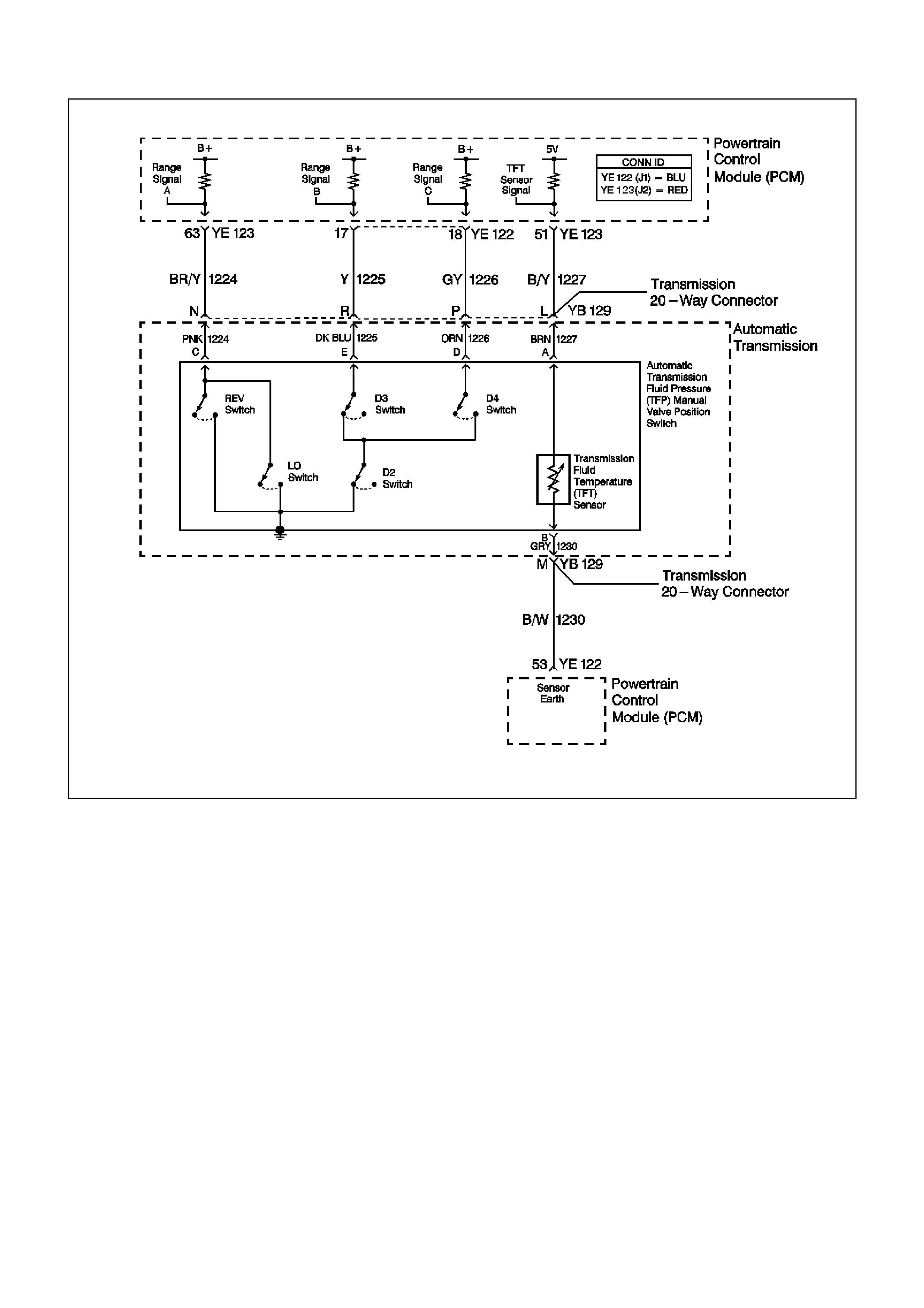
GEN III V8 PCM DTC P0712 TFT SENSOR CIRCUIT LOW INPUT
CIRCUIT DESCRIPTION
The automatic Transmission Fluid Temperature (TFT) Sensor is part of the automatic Transmission Fluid Pressure
(TFP) manual valve position switch. The TFT Sensor is a resistor, or thermistor, which changes value based on
temperature. The sensor has a negative-temperature coefficient. This means that as the temperature increases,
the resistance decreases, and as the temperature decreases, the resistance increases.
The Powertrain Control Module (PCM) supplies a 5-volt reference signal to the sensor on circuit 1227 and
meas ures the voltage dr op in the circuit. W hen the trans mission f luid is cold, the sensor res istance is high and the
PCM detects high signal voltage. As the fluid tem peratur e warm s to a norm al oper ating tem perature, the resis tance
becomes less and the signal voltage decreases. The PCM uses this information to control shift quality and torque
converter clutch apply.
W hen the PCM detec ts a continuous s hort to earth in the TF T signal circ uit or in the TFT Sensor, then DT C P0712
sets.
CONDITIONS FOR RUNNING THE DTC
• The system voltage is 8-18 volts.
• The ignition switch is in the RUN position.
CONDITIONS FOR SETTING THE DTC
• The TFT Sensor indicates a signal voltage less than 0.2 volts for 10 seconds.

ACTION TAKEN WHEN THE DTC SETS
• The PCM does not illuminate the Check Powertrain Lamp (CPL).
Important: The actions listed below are in order of highest to lowest priority.
• The PCM determines a default TFT using the following matrix:
1. If any ECT DTCs P0117 or P0118 are set, then the default TFT is equal to 135°C.
2. If the ECT is 125°C or more, then the default TFT is equal to 135°C.
3. If the engine run time is less than 300 seconds and:
- No intak e air tem perature (IAT ) DT Cs P0112 or P0113 are set and IAT is available, then the def ault
TFT is equal to IAT.
- Any IAT DTCs P0112 or P0113 are set or IAT is NOT available, then the default TFT is equal to
90°C.
4. If the engine run time is greater than 300 seconds and no IAT DTCs P0112 or P0113 are set and IAT is
available and ECT is between 40 and 125°C and:
- IAT at startup is less than 15°C, then the default TFT is equal to the ECT plus 5°C.
- IAT at startup is greater than 35°C, then the default TFT is equal to the ECT plus 10°C.
- IAT at startup is between 15 and 35°C, then the default TFT is equal to the ECT.
5. If the engine run time is greater than 300 seconds and any IAT DTCs P0112 or P0113 are set or IAT is
NOT available, then the default TFT is equal to the ECT.
6. If the engine run time is greater than 300 seconds and ECT is less than 40°C or more, then the default
TFT is equal to 60°C.
• The PCM freezes shift adapts from being updated.
• The PCM stores DTC P0712 in PCM history.
CONDITIONS FOR CLEARING THE DTC
• A scan tool clears the DTC from PCM history.
• T he PCM clears the DT C from PCM his tory if the vehicle c ompletes 40 cons ecutive warm-up cycles without a
non-emission-related diagnostic fault occurring.
• T he PCM cancels the DTC default actions when the fault no longer exists and the ignition switch is OFF long
enough in order to power down the PCM.
DIAGNOSTIC AIDS
• Inspect the wiring at the PCM, the transmission connector and all other circuit connecting points for the
following conditions:
- A backed out terminal
- A damaged terminal
- Reduced terminal tension
- A chafed wire
- A broken wire inside the insulation
- Moisture intrusion
- Corrosion
• W hen diagnosing for an intermittent short or open condition, massage the wiring harness while watching the
test equipment for a change.
• Us e the Tem per atur e vs Res is tance table when testing the TFT Sensor at various temperatur e levels. Test the
TFT Sensor in or der to evaluate the pos s ibility of a sk ewed (mis- sc aled) s ensor . A s k ewed sens or can r es ult in
delayed garage shifts or TCC complaints.
• The scan tool displays the transmission fluid temperature in degrees. After the transmission is operating, the
fluid temperature should rise steadily to a normal operating temperature, then stabilise.
• Verify customer driving habits, trailer towing, etc. Trailer towing should occur in D3.
TEST DESCRIPTION
The numbers below refer to the step numbers on the diagnostic table.
4. This step creates an open in the TFT circuit in order to test for an internal fault.

GEN III V8 PCM DTC P0712 TFT SENSOR CIRCUIT LOW INPUT
Step Action Value(s) Yes No
1 Was the Powertrain On-Board Diagnostic (OBD) System
Check performed? Go to Step 2 Go to Powertrain
OBD System
Check Table
2 Perform the transmission fluid checking procedure.
Refer to Transmission Fluid Checking Procedure in
Section 7C4, in the VT Series II Service Information.
Did you perform the fluid checking procedure?
Go to Step 3 Go to
Transmission
Fluid Checking
Procedure in
Section 7C4, in
the VT Series II
Service
Information
3 1. Install the Tech 2 Scan Tool.
2. With the engine OFF, turn the ignition switch to the
RUN position.
Important: Before clearing the DTC, use the Scan Tool
in order to record the Failure Records. Using the Clear
Info function erases the Failure Records from the PCM.
3. Record th e DTC Failure Records.
4. Clear the DTC.
5. Select TFT on the Scan Tool.
Does the Scan Tool display a TFT Sensor signal voltage
less than the specified value?
0.2 volts Go to Step 4 Go to Diagnostic
Aids
4
1. Turn the ignition OFF.
2. Disconnect the transmission 20-way connector.
3. With the engine OFF, turn the ignition switch to the
RUN position.
Does the Scan Tool display a TFT Sensor signal voltage
greater than the specified value?
4.92 volts
Go to Step 5
Go to Step 8
5
1. Install the J 39775 jumper harness on the
transmission side of the 20-way connector.
2. Using the J 39200 digital multimeter (DMM) and the
J 35616 connector test adapter kit, measure the
resistance between terminal L and terminal M.
Is the resistance within the specified range?
3088-3942 Ω
at 20°C,
159-198 Ω at
100°C
Go to Diagnostic
Aids
Go to Step 6
6
Inspect circuit 1227 (BRN) of the automatic transmission
(A/T) wiring harness assembly for a short to earth
condition.
Did you find a short to earth condition?
Go to Step 10
Go to Step 7
7
1. Disconnect the A/T wiring harness assembly at the
TFT Sensor.
2. Measure the resistance of the TFT Sensor.
Is the resistance within the specified range?
3088-3942 Ω
at 20°C,
159-198 Ω at
100°C
Go to Diagnostic
Aids
Go to Step 9
9 Replace the TFT Sensor (this is part of the TFP manual
valve position switch).
Refer to Control Valve Body and Wiring Harness
replacement in Section 7C4, in the VT Series I Service
Information.
Is the replacement complete?
Go to Step 12
10 Replace the automatic transmission wiring harness
assembly.
Refer to Control Valve Body and Wiring Harness
replacement in Section 7C4, in the VT Series I Service
Information.
Is the replacement complete?
Go to Step 12

Step Action Value(s) Yes No
11 Replace the PCM.
Refer to Powertrain Control Module in Section 6C3-3 in
the VT Series II Service Information.
Is the replacement complete?
Go to Step 12
12 Perform the following procedure in order to verify the
repair:
1. Select DTC.
2. Select Clear Info.
3. With the engine OFF, turn the ignition switch to the
RUN position.
4. Verify that the Scan Tool indicates a TFT Sensor
signal voltage greater than 0.2 volts for 10 seconds.
Was the above condition verified?
System OK
Go to Step 1

GEN III V8 PCM DTC P0713 TFT SENSOR CIRCUIT HIGH INPUT
CIRCUIT DESCRIPTION
The autom atic T ransm ission Fluid T emper ature (TF T) Sens or is part of the automatic T ransm ission Fluid Pressure
(TFP) manual valve position switch. The TFT sensor is a resistor, or thermistor, which changes value based on
temperature. The sensor has a negative-temperature coefficient. This means that as the temperature increases,
the resistance decreases, and as the temperature decreases, the resistance increases.
The Powertrain Control Module (PCM) supplies a 5-volt reference signal to the sensor on circuit 1227 and
meas ures the voltage dr op in the circuit. W hen the trans mission f luid is cold, the sensor res istance is high and the
PCM detects high signal voltage. As the fluid tem peratur e warm s to a norm al oper ating tem perature, the resis tance
becomes less and the signal voltage decreases. The PCM uses this information to control shift quality and torque
converter clutch apply.
W hen the PCM detec ts a continuous s hort to ear th in the TFT signal circuit or in the TFT sensor, then DT C P0712
sets.
CONDITIONS FOR RUNNING THE DTC
• The system voltage is 8-18 volts.
• The ignition switch is in the RUN position.
CONDITIONS FOR SETTING THE DTC
• The TFT sensor indicates a signal voltage greater than 4.92 volts for 409 seconds (6.8 minutes).

ACTION TAKEN WHEN THE DTC SETS
• The PCM does not illuminate the Check Powertrain Lamp (CPL).
Important: The actions listed below are in order of highest to lowest priority.
• The PCM determines a default TFT using the following matrix:
1. If any ECT DTCs P0117 or P0118 are set, then the default TFT is equal to 135°C.
2. If the ECT is 125°C or more, then the default TFT is equal to 135°C.
3. If the engine run time is less than 300 seconds and:
- No intake air temperatur e (IAT) DTCs P0112 or P0113 are set and IAT is available, then the default
TFT is equal to IAT.
- Any IAT DTCs P0112 or P0113 are set or IAT is NOT available, then the default TFT is equal to
90°C.
4. If the engine run tim e is greater than 300 seconds and no IAT DTCs P0112 or P0113 are set and IAT is
available and ECT is between 40 and 125°C and:
- IAT at startup is less than 15°C, then the default TFT is equal to the ECT plus 5°C.
- IAT at startup is greater than 35°C, then the default TFT is equal to the ECT plus 10°C.
- IAT at startup is between 15 and 35°C, then the default TFT is equal to the ECT.
5. If the engine run time is greater than 300 seconds and any IAT DTCs P0112 or P0113 are set or IAT is
NOT available, then the default TFT is equal to the ECT.
6. If the engine run time is greater than 300 seconds and ECT is less than 40°C or more, then the default
TFT is equal to 60°C.
• The PCM freezes shift adapts from being updated.
• The PCM stores DTC P0712 in PCM history.
CONDITIONS FOR CLEARING THE DTC
• A scan tool clears the DTC from PCM history.
• T he PCM clears the DT C from PCM his tory if the vehicle c ompletes 40 cons ecutive warm-up cycles without a
non-emission-related diagnostic fault occurring.
• T he PCM cancels the DTC default actions when the fault no longer exists and the ignition switch is OFF long
enough in order to power down the PCM.
DIAGNOSTIC AIDS
• Inspect the wiring at the PCM, the transmission connector and all other circuit connecting points for the
following conditions:
- A backed out terminal
- A damaged terminal
- Reduced terminal tension
- A chafed wire
- A broken wire inside the insulation
- Moisture intrusion
- Corrosion
• W hen diagnosing for an intermittent short or open condition, massage the wiring harness while watching the
test equipment for a change.
• The automatic Transmission Fluid Temperature (TFT) Sensor is part of the automatic Transmission Fluid
Pressure (T FP) manual valve position s witch. The T F T s ens or is a r esis tor , or ther mistor , which c hanges value
based on temperature. The sensor has a negative-temperature coefficient. This means that as the
temperature increases, the resistance decreases, and as the temperature decreases, the resistance
increases.
• The scan tool displays the transmission fluid temperature in degrees. After the transmission is operating, the
fluid temperature should rise steadily to a normal operating temperature, then stabilise.
TEST DESCRIPTION
The numbers below refer to the step numbers on the diagnostic table.
3. This step verifies that a condition exists in the TFT Sensor circuit.
4. This step simulates a T FT Sensor DTC P0712. If the PCM recognises high temperature, the PCM and wiring
are functioning normally.
5. This step tests the TFT Sensor and automatic transmission (A/T) wiring harness assembly.

GEN III V8 PCM DTC P0713 TFT SENSOR CIRCUIT HIGH INPUT
Step Action Value(s) Yes No
1 Was the Powertrain On-Board Diagnostic (OBD) System
Check performed? Go to Step 2 Go to Powertrain
OBD System
Check Table
2 Perform the transmission fluid checking procedure.
Refer to Transmission Fluid Checking Procedure in
Section 7C4, in the VT Series II Service Information.
Did you perform the fluid checking procedure?
Go to Step 3 Go to
Transmission
Fluid Checking
Procedure in
Section 7C4, in
the VT Series II
Service
Information
3 1. Install the Tech 2 Scan Tool.
2. With the engine OFF, turn the ignition switch to the
RUN position.
Important: Before clearing the DTC, use the Scan Tool
in order to record the Failure Records. Using the Clear
Info function erases the Failure Records from the PCM.
3. Record th e DTC Failure Records.
4. Clear the DTC.
Does the Scan Tool display a TFT Sensor signal voltage
greater than the specified value?
4.92 volts Go to Step 4 Go to Diagnostic
Aids
4
1. Turn the ignition OFF.
2. Disconnect the transmission 20-way connector.
3. Install the J39775 jumper harness on the engine side
of the 20-way connector.
4. Install a fused jumper wire from terminal L to terminal
M on the engine harness.
5. With the engine OFF, turn the ignition switch to the
RUN position.
Does the TFT Sensor signal voltage drop to less than the
specified value?
0.2 volts
Go to Step 5
Go to Step 9
5
1. Turn the ignition OFF.
2. Install the J 39775 jumper harness on the
transmission side of the 20-way connector.
3. Using the J 39200 digital multimeter (DMM) and the
J 35616 connector test adapter kit, measure the
resistance between terminal L and terminal M.
Is the resistance within the specified range?
3088-3942 Ω
at 20°C,
159-198 Ω at
100°C
Go to Diagnostic
Aids
Go to Step 6
6
Inspect circuits 1227 (BRN) and 452 (GRY) of the
automatic transmission (A/T) wiring harness assembly for
an open condition.
Did you find a short to earth condition?
Go to Step 11
Go to Step 7
7
1. Disconnect the A/T wiring harness assembly at the
TFT Sensor.
2. Measure the resistance of the TFT sensor.
Is the resistance within the specified range?
3088-3942 Ω
at 20°C,
159-198 Ω at
100°C
Go to Diagnostic
Aids
Go to Step 8
8
Replace the TFT Sensor (this is part of the TFP manual
valve position switch).
Refer to Control Valve Body and Wiring Harness
replacement in Section 7C4, in the VT Series I Service
Information.
Is the replacement complete?
Go to Step 13
9
1. Inspect circuit 1227 (B/Y) of the engine wiring harness
for an open or short to B+ condition.
2. Repair the circuit if necessary.
Did you find an open or short to B+ condition?
Go to Step 13
Go to Step 10
10
1. Inspect circuit 1230 (B/W) for an open condition.
2. Repair the circuit if necessary.
Did you find an open condition?
Go to Step 13 Go to Step 12

Step Action Value(s) Yes No
11
Replace the automatic transmission wiring harness
assembly.
Refer to Control Valve Body and Wiring Harness
replacement in Section 7C4, in the VT Series I Service
Information.
Is the replacement complete?
Go to Step 13
12 Replace the PCM.
Refer to Powertrain Control Module in Section 6C3-3 in
the VT Series II Service Information.
Is the replacement complete?
Go to Step 13
13 Perform the following procedure in order to verify the
repair:
1. Select DTC.
2. Select Clear Info.
3. With the engine OFF, turn the ignition switch to the
RUN position.
4. Verify that the Scan Tool indicates a TFT Sensor
signal voltage greater than 4.92 volts for 409 seconds
(6.8 minutes).
Was the above condition verified?
System OK
Go to Step 1
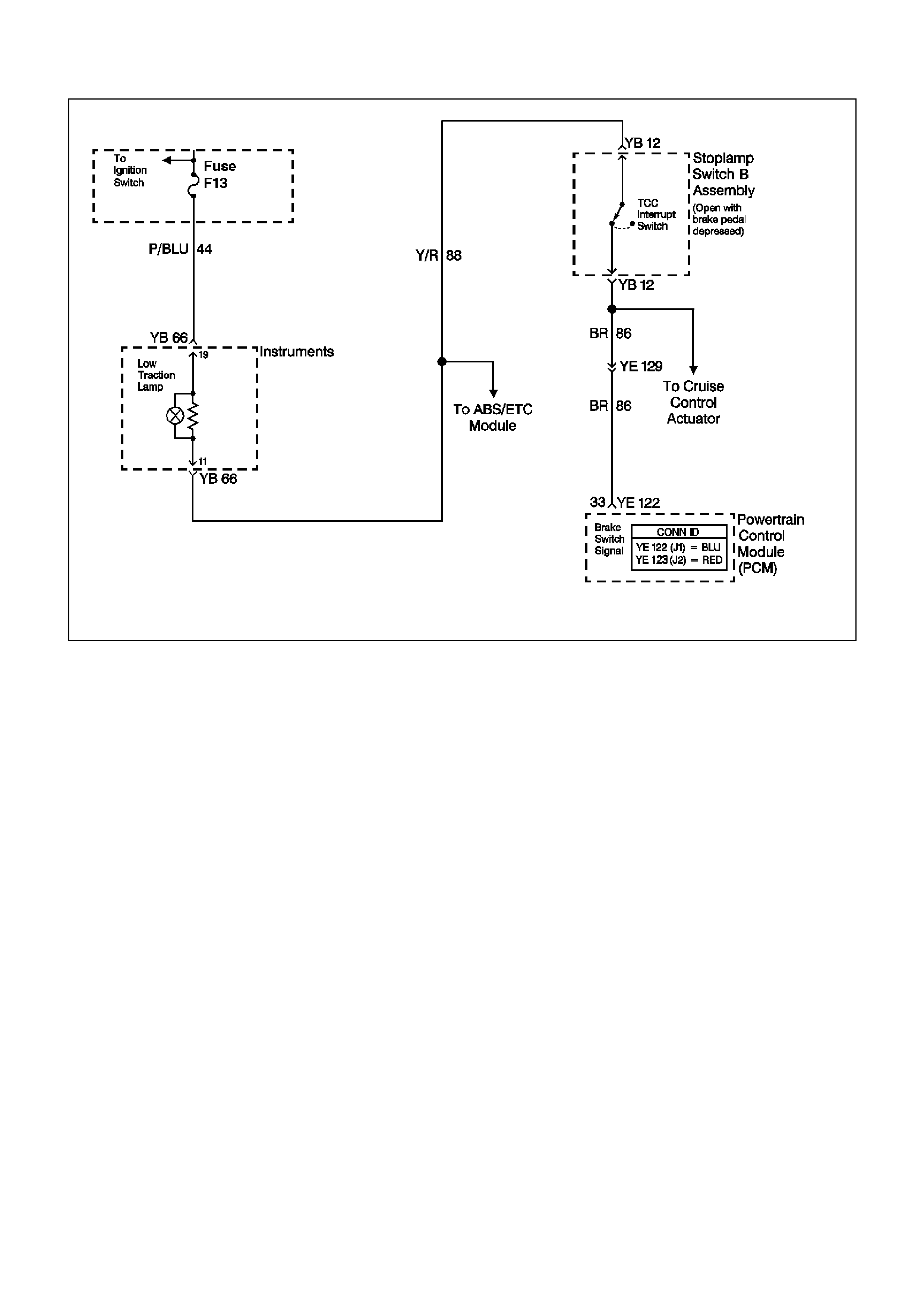
GEN III V8 PCM DTC P0719 BRAKE SWITCH CIRCUIT LOW INPUT
CIRCUIT DESCRIPTION
The brake switch indicates brake pedal status to the Powertrain Control Module (PCM). The brake switch is a
normally-closed switch that supplies voltage on circuit 86 to the PCM. Applying the brake pedal opens the switch,
interrupting voltage to the PCM. W hen the brake pedal is released, the PCM receives a constant voltage signal. If
the PCM receives a zero voltage signal at the brake switch input, and the Torque Converter Clutch (TCC) is
engaged, the PCM de-energises the TCC solenoid valve. The PCM disregards the brake switch input for TCC
scheduling if there is a brake switch circuit fault (Refer to Diagnostic Aids).
When the PCM detects an open brake switch circuit (0 volts, low input) during accelerations, then DTC P0719 sets.
CONDITIONS FOR RUNNING THE DTC
• No VSS assembly DTCs P0502 or P0503.
• The ignition switch is in the RUN position.
CONDITIONS FOR SETTING THE DTC
• The PCM detec ts an open br ak e s witch c irc uit (0 volts ) f or 15 minutes without changing for 2 s econds , and the
following events occur seven times:
- The vehicle speed is less than 8 km/h;
- Then the vehicle speed is 8-32 km/h for 4 seconds;
- Then the vehicle speed is greater than 32 km/h for 6 seconds.
ACTION TAKEN WHEN THE DTC SETS
• The PCM does not illuminate the Check Powertrain Lamp (CPL).
• The PCM disregards the brake switch input for TCC scheduling.
• The PCM stores DTC P0719 in PCM history.

CONDITIONS FOR CLEARING THE DTC
• A scan tool clears the DTC from PCM history.
• T he PCM clears the DT C from PCM his tory if the vehicle c ompletes 40 cons ecutive warm-up cycles without a
non-emission-related diagnostic fault occurring.
• T he PCM cancels the DTC default actions when the fault no longer exists and the ignition switch is OFF long
enough to power down the PCM.
DIAGNOSTIC AIDS
• Inspect the wiring at the PCM, the brake switch connector and all other circuit connecting points for the
following conditions:
- A backed out terminal
- A damaged terminal
- Reduced terminal tension
- A chafed wire
- A broken wire inside the insulation
- Moisture intrusion
- Corrosion
• W hen diagnosing for an intermittent short or open condition, massage the wiring harness while watching the
test equipment for a change.
• If the PCM detects a brake switch circuit f ault, then the brake switch input is disregarded for TCC scheduling.
The PCM then uses throttle position and vehicle speed to determine TCC application and release. Use of
these inputs may result in a noticeable harsh apply or abrupt release of the TCC.
• Ask about the customer's driving habits. Ask about unusual driving conditions (e.g. stop and go, expressway,
etc.).
• Inspect the brake switch for proper mounting and operation.
TEST DESCRIPTION
The number below refers to the step numbers on the diagnostic table.
3. This step isolates the brake switch as a source for setting the DTC.

GEN III V8 PCM DTC P0719 BRAKE SWITCH CIRCUIT LOW INPUT
Step Action Value(s) Yes No
1 Was the Powertrain On-Board Diagnostic (OBD) System
Check performed? Go to Step 2 Go to Powertrain
OBD System
Check Table.
2 1. Install the Tech 2 Scan Tool.
2. With the engine OFF, turn the ignition switch to the
RUN position.
Important: Before clearing the DTC, use the Scan Tool
in order to record the Failure Records. Using the Clear
Info function erases the Failure Records from the PCM.
3. Record th e DTC Failure Records.
4. Clear the DTC.
5. Select TCC Brake Switch on the Scan Tool.
6. Disconnect the brake switch connector from the brake
switch.
7. Connect a test lamp from circuit 88 (Y/R) of the brake
switch connector to earth.
Is the test lamp ON?
Go to Step 3 Go to Step 4
3 Install a fused jumper wire from circuit 88 (Y/R) to circuit
86 (BR) of the brake switch connector.
Did the TCC Brake Switch status change from Open to
Closed?
Go to Step 7 Go to Step 9
4 1. Remove the F13 fuse.
2. Inspect the fuse for an open.
Is the fuse open?
Go to Step 5 Go to Step 8
5 Important: The condition that affects this circuit may
exist in other connecting branches of the circuit. Refer to
Power Distribution Diagrams in the VT Series II Service
Information, Section 12P for complete circuit distribution.
1. Inspect circuit 88 (Y/R) for a short to earth condition.
2. Repair the circuit if necessary.
Did you find a short to earth condition?
Go to Step 11 Go to Step 6
6 1. Inspect circuit 86 (BR) for a short to earth condition.
2. Repair the circuit if necessary.
Did you find a short to earth condition?
Go to Step 11 Go to Step 10
7 Replace the brake switch.
Refer to Section 12B Stop Lamp Switch Replacement in
the VT Series II Service Information.
Is the replacement complete?
Go to Step 11
8 Important: The condition that affects this circuit may
exist in other connecting branches of the circuit. Refer to
Power Distribution Diagrams in the VT Series II Service
Information, Section 12P for complete circuit distribution.
1. Inspect circuit 88 (Y/R) for an open condition.
2. Repair the circuit if necessary.
Did you find an open condition?
Go to Step11
9 1. Inspect circuit 86 (BR) for an open condition.
2. Repair the circuit if necessary.
Did you find an open condition?
Go to Step 11 Go to Step 10

Step Action Value(s) Yes No
10 Replace the PCM.
Refer to Powertrain Control Module in Section 6C3-3 in
the VT Series II Service Information.
Is the replacement complete?
Go to Step 11
11 Perform the following procedure in order to verify the
repair:
1. Select DTC.
2. Select Clear Info.
3. With the engine OFF, turn the ignition switch to the
RUN position.
4. Apply and release the brake pedal.
5. Verify that the Scan Tool TCC Brake Switch status
indicates Closed (12 volts) for 2 seconds.
Was the above condition verified?
System OK
Go to Step 1

GEN III V8 PCM DTC P0724 BRAKE SWITCH CIRCUIT HIGH INPUT
CIRCUIT DESCRIPTION
The brake switch indicates brake pedal status to the Powertrain Control Module (PCM). The brake switch is a
normally-closed switch that supplies voltage on circuit 86 to the PCM. Applying the brake pedal opens the switch,
interrupting voltage to the PCM. W hen the brake pedal is released, the PCM receives a constant voltage signal. If
the PCM receives a zero voltage signal at the brake switch input, and the Torque Converter Clutch (TCC) is
engaged, the PCM de-energises the TCC solenoid valve. The PCM disregards the brake switch input for TCC
scheduling, if there is a brake switch circuit fault (Refer to Diagnostic Aids).
W hen the PCM detects an closed brak e switch circuit (12 volts, high input) during decelerations, then DTC P0724
sets.
CONDITIONS FOR RUNNING THE DTC
• No VSS assembly DTCs P0502 or P0503.
• The ignition switch is in the RUN position.
CONDITIONS FOR SETTING THE DTC
• The PCM detects an closed brake switch circuit (12 volts) without changing for 2 seconds, and the following
events occur seven times:
- The vehicle speed is greater than 32 km/h for 6 seconds;
- Then the vehicle speed is 8-32 km/h for 4 seconds;
- Then the vehicle speed is less than 8 km/h.
ACTION TAKEN WHEN THE DTC SETS
• The PCM does not illuminate the Check Powertrain Lamp (CPL).
• The PCM stores DTC P0724 in PCM history.

CONDITIONS FOR CLEARING THE DTC
• A scan tool clears the DTC from PCM history.
• T he PCM clears the DT C from PCM his tory if the vehicle c ompletes 40 cons ecutive warm-up cycles without a
non-emission-related diagnostic fault occurring.
• T he PCM cancels the DTC default actions when the fault no longer exists and the ignition switch is OFF long
enough in order to power down the PCM.
DIAGNOSTIC AIDS
• Inspect the wiring at the PCM, the brake switch connector and all other circuit connecting points for the
following conditions:
- A backed out terminal
- A damaged terminal
- Reduced terminal tension
- A chafed wire
- A broken wire inside the insulation
- Moisture intrusion
- Corrosion
• W hen diagnosing for an intermittent short or open condition, massage the wiring harness while watching the
test equipment for a change.
• Ask about the customer’s driving habits or unusual driving conditions (e.g. stop & go, highway, etc.).
• Inspect the brake switch for proper mounting and operation.
TEST DESCRIPTION
The number below refers to the step numbers on the diagnostic table.
2. This step isolates the brake switch as a source for setting the DTC.

GEN III V8 PCM DTC P0724 BRAKE SWITCH CIRCUIT HIGH INPUT
Step Action Value(s) Yes No
1 Was the Powertrain On-Board Diagnostic (OBD) System
Check performed? Go to Step 2 Go to Powertrain
OBD System
Check Table.
2 1. Install the Tech 2 Scan Tool.
2. With the engine OFF, turn the ignition switch to the
RUN position.
Important: Before clearing the DTC, use the Scan Tool
in order to record the Failure Records. Using the Clear
Info function erases the Failure Records from the PCM.
3. Record th e DTC Failure Records.
4. Clear the DTC.
5. Select TCC Brake Switch on the Scan Tool.
6. Disconnect the brake switch connector from the brake
switch.
Did the TCC Brake Switch status change from Closed to
Open?
Go to Step 3 Go to Step 4
3 Replace the brake switch.
Is the replacement complete? Go to Step 6
4 1. Inspect circuit 86 (BR) for a short to earth condition.
2. Repair the circuit if necessary.
Did you find a short to B+ condition?
Go to Step 6 Go to Step 5
5 Replace the PCM.
Refer to Powertrain Control Module in Section 6C3-3 in
the VT Series II Service Information.
Is the replacement complete?
Go to Step 6
6
Perform the following procedure in order to verify the
repair:
1. Select DTC.
2. Select Clear Info.
3. With the engine OFF, turn the ignition switch to the
RUN position.
4. Apply and release the brake pedal.
5. Verify that the Scan Tool TCC Brake Switch status
indicates Open (0 volts) for 2 seconds.
Was the above condition verified?
System OK
Go to Step 1
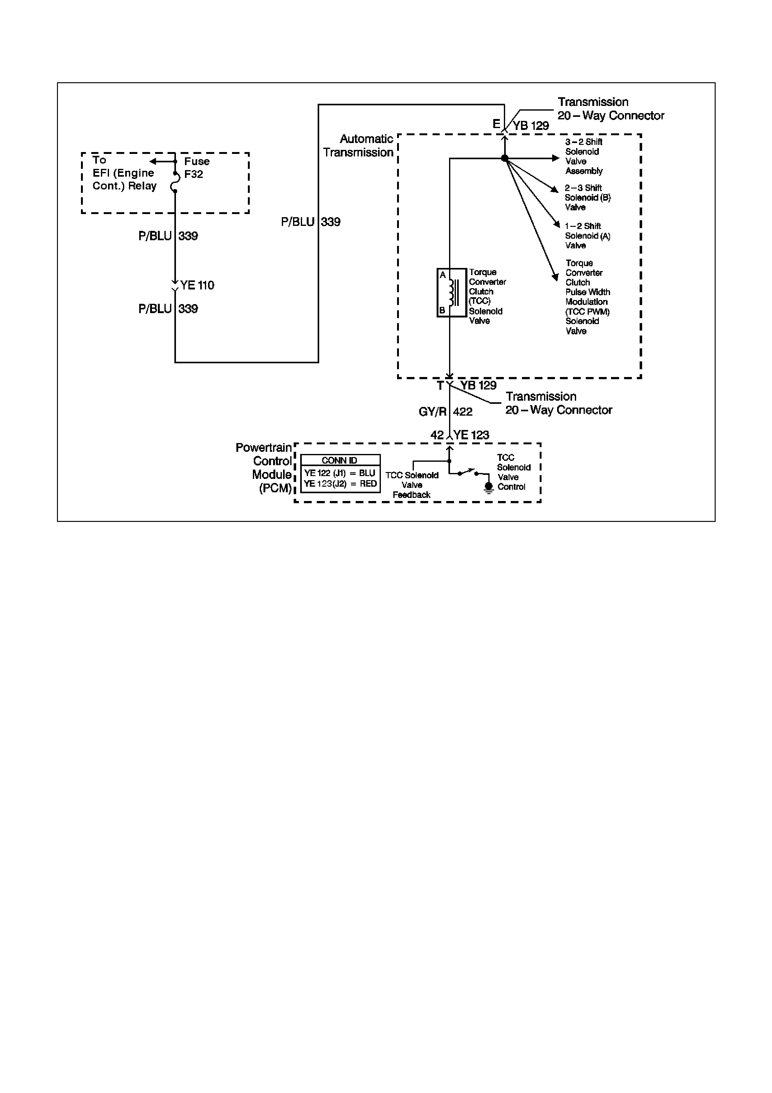
GEN III V8 PCM DTC P0740 TCC ENABLE SOLENOID CIRCUIT ELECTRICAL
CIRCUIT DESCRIPTION
The Torque Converter Clutch (TCC) solenoid valve is an electrical device that is used with the Torque Converter
Clutch Pulse Width Modulation (TCC PWM) solenoid valve, in order to control TCC apply and release. The TCC
solenoid valve attaches to the transm iss ion case as sem bly extending into the pump c over. T he T CC solenoid valve
receives ignition voltage through circuit 339. The Powertrain Control Module (PCM) controls the solenoid by
providing the earth path on circuit 422. T he PCM monitors the throttle position (TP) voltage, the vehicle speed and
other inputs in order to determine when to energise the TCC solenoid valve.
When the PCM detects a continuous open or a short to earth in the TCC solenoid valve circuit or in the TCC
solenoid valve, then DTC P0740 sets.
CONDITIONS FOR RUNNING THE DTC
• The system voltage is 8-18 volts.
• The engine speed is greater than 300 RPM for 5 seconds.
• The engine is not in fuel cutoff.
CONDITIONS FOR SETTING THE DTC
• DTC P0740 sets if either of the following conditions occurs for 5 seconds:
- The PCM commands the solenoid ON and the voltage input remains high (B+).
- The PCM commands the solenoid OFF and the voltage input remains low (0 volt).
ACTION TAKEN WHEN THE DTC SETS
• The PCM does not illuminate the Check Powertrain Lamp (CPL).
• The PCM inhibits TCC engagement.
• The PCM inhibits 4th gear if the transmission is in hot mode.
• The PCM freezes shift adapts from being updated.
• The PCM stores DTC P0740 in PCM history during the second consecutive trip in which the conditions for
setting the DTC are met.

CONDITIONS FOR CLEARING THE DTC
• A scan tool clears the DTC from the PCM history.
• The PCM clears the DTC from the PCM history if the vehicle completes 40 warm-up cycles without an
emission-related diagnostic fault occurring.
• T he PCM cancels the DTC default actions when the fault no longer exists and the ignition switch is OFF long
enough in order to power down the PCM.
DIAGNOSTIC AIDS
• Inspect the wiring at the PCM, the transmission connector and all other circuit connecting points for the
following conditions:
- A backed out terminal
- A damaged terminal
- Reduced terminal tension
- A chafed wire
- A broken wire inside the insulation
- Moisture intrusion
- Corrosion
• W hen diagnosing for an intermittent short or open condition, massage the wiring harness while watching the
test equipment for a change.
• With the TCC engaged, the TCC slip speed should be -20 to +40 RPM.
TEST DESCRIPTION
The numbers below refer to the step numbers on the diagnostic table.
2. This step tests for voltage to the solenoid.
4. This step tests the ability of the PCM and wiring to control the earth circuit.
6. This step tests the resistance of the TCC solenoid valve and the automatic transmission (A/T) wiring harness
assembly.

GEN III V8 PCM DTC P0740 TCC ENABLE SOLENOID CIRCUIT ELECTRICAL
Step Action Value(s) Yes No
1 Was the Powertrain On-Board Diagnostic (OBD) System
Check performed? Go to Step 2 Go to Powertrain
OBD System
Check Table.
2
1. Install the Tech 2 Scan Tool.
2. With the engine OFF, turn the ignition switch to the
RUN position.
Important: Before clearing the DTC, use the Scan Tool
in order to record the Freeze Frame and Failure Records.
Using the Clear Info function erases the Freeze Frame
and Failure Records from the PCM.
1. Record the DTC Freeze Frame and Failure Records.
2. Clear the DTC.
Are any of the following DTCs also set?
• P0753
• P0758
• P0785
• P1860
Go to Step 3
Go to Step 4
3
1. Inspect fuse F32.
2. If the fuse is open, inspect the following components
for a short to earth condition:
- Circuit 339 (P/BLU)
- The solenoids
- The A/T wiring harness assembly
3. Repair the circuit, the solenoids, and the harness if
necessary.
Did you find a short to earth condition?
Go to Step 12
Go to Step 4
4
1. Turn the ignition switch OFF.
2. Disconnect the transmission 20-way connector
(additional DTCs may set).
3. Install the J 39775 jumper harness on the engine side
of the 20-way connector.
4. With the engine OFF, turn the ignition switch to the
RUN position.
5. Connect a test lamp from cavity E of the J 39775
jumper harness to earth.
6. Refer to AT Inline Harness Connector End View in this
Section.
Is the test lamp ON?
Go to Step 6
Go to Step 5
5
Important: The condition that affects this circuit may
exist in other connecting branches of the circuit. Refer to
Power Distribution Diagrams in the VT Series II Service
Information, Section 12P for complete circuit distribution.
Repair the open or short to earth in ignition feed circuit
339 (P/BLU) to the TCC solenoid valve.
Is the repair complete?
Go to Step 12
6
1. Install the test lamp from cavities E to T of the
J 39775 jumper harness.
2. Using the transmission Miscellaneous Tests function
on the Scan Tool, command the TCC solenoid valve
ON and OFF three times.
Does the test lamp turn ON when the TCC solenoid valve
is commanded ON, and OFF when commanded OFF?
Go to Step 8
Go to Step 7

Step Action Value(s) Yes No
7
1. Inspect circuit 422 (GY/R) of the engine wiring
harness for an open, short to earth or short to power
condition.
2. Repair the circuit if necessary.
Did you find an open, short to earth or short to power
condition?
Go to Step 12
Go to Step 9
8
1. Install the J 39775 jumper harness on the
transmission side of the 20-way connector.
2. Using the J 39200 digital multimeter (DMM) and the
J 35616 connector test adapter kit, measure the
resistance between terminals T and E.
Is the resistance within the specified range?
21-33 Ω
Go to Step 10
Go to Step 11
9
Replace the PCM.
Refer to Powertrain Control Module in Section 6C3-3 in
the VT Series II Service Information.
Is the replacement complete?
Go to Step
12
10
Measure the resistance between terminal E and earth,
and between terminal T and earth.
Are both readings greater than the specified value?
250 K Ω
Go to
Diagnostic Aids
Go to Step 11
11
Replace the automatic transmission wiring harness
assembly (this includes the TCC solenoid valve).
Refer to Control Valve Body and Wiring Harness
replacement in Section 7C4, in the VT Series I Service
Information.
Is the replacement complete?
Go to Step 12
12
Perform the following procedure in order to verify the
repair:
1. Select DTC.
2. Select Clear Info.
3. Drive the vehicle in D with the TCC ON and OFF.
Ensure the following conditions are met:
- The PCM commands the TCC solenoid valve ON,
and the voltage input drops to zero.
- The PCM commands the TCC solenoid valve OFF,
and the voltage input increases to B+.
- All conditions are met for 5 seconds.
Were the above conditions verified?
System OK
Go to Step 1
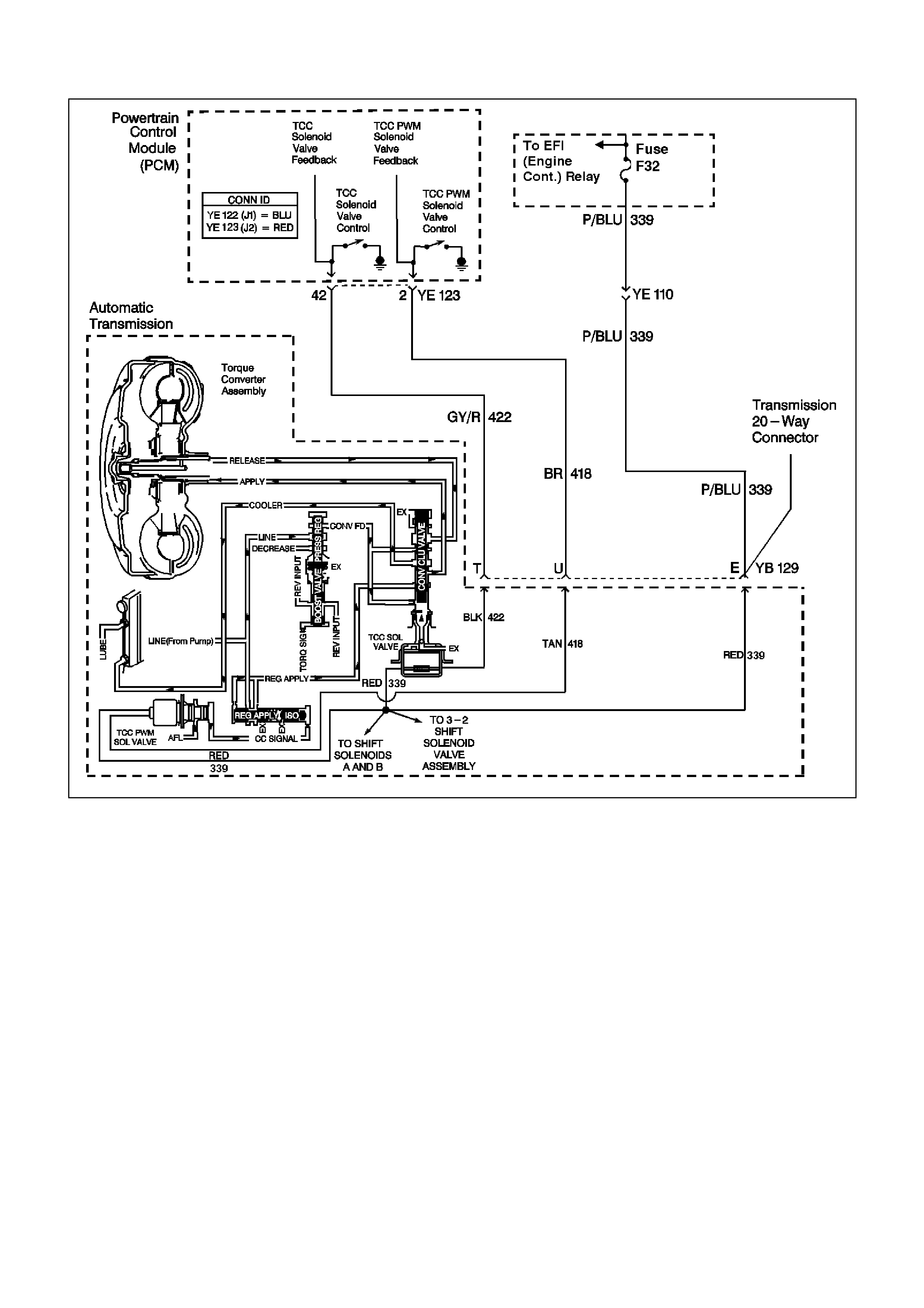
GEN III V8 PCM DTC P0742 TCC SYSTEM STUCK ON
CIRCUIT DESCRIPTION
The Torque Converter Clutch (TCC) solenoid valve is a normally-open exhaust valve that is used with the Torque
Converter Clutch Pulse Width Modulation (TCC PWM) solenoid valve in order to control fluid acting on the
converter clutch apply valve. The TCC solenoid valve attaches to the transmission case assembly extending into
the pump cover.
W hen energised by the Powertrain Control Module (PCM), the TCC solenoid valve stops converter signal oil from
exhausting. This causes converter signal oil pressure to increase and move the converter clutch apply valve
against spring force and into the apply position. In this position, release fluid is open to an exhaust port and
converter feed fluid fills the apply fluid circuit. The converter feed fluid applies the TCC. W hen the PCM no longer
provides a earth path, the TCC solenoid valve de-energises and apply fluid exhausts, releasing the TCC.
When the PCM detects low torque converter slip when the PCM commands the TCC OFF, then DTC P0742 sets.

CONDITIONS FOR RUNNING THE DTC
• No MAP sensor DTCs P0107 or P0108.
• No Throttle Position DTCs P0122 or P0123.
• No VSS assembly DTCs P0502 or P0503.
• No TCC solenoid valve DTC P0740.
• No TFP manual valve position switch DTC P1810.
• No TCC PWM solenoid valve DTC P1860.
• The Throttle Position angle is 10-45%.
• The engine speed is greater than 300 RPM for 5 seconds.
• The engine is not in fuel cutoff.
• The engine speed is 1000-3500 RPM.
• The engine torque is 54-542 Nm.
• The engine vacuum is 0-105 kPa.
• The speed ratio is 0.65-1.30 (the speed ratio is engine speed divided by output speed).
• The vehicle speed is 32-88 km/h.
• The commanded gear is not 1st.
• The gear range is D.
• The gear range does not change within 6 seconds.
• The PCM commands the TCC OFF.Conditions for Setting the DTC
• DTC P0742 sets if the following condition occurs three times:
- The TCC slip speed is -20 to +30 RPM for 4 seconds.
ACTION TAKEN WHEN THE DTC SETS
• The PCM illuminates the Check Powertrain Lamp (CPL) during the second consecutive trip in which the
conditions for setting the DTC are met.
• The PCM freezes shift adapts from being updated.
• The PCM stores DTC P0742 in PCM history during the second consecutive trip in which the conditions for
setting the DTC are met.
CONDITIONS FOR CLEARING THE CPL/DTC
• The PCM turns OFF the Check Powertrain Lamp (CPL) during the first trip in which the diagnostic test runs
and passes.
• A scan tool clears the DTC from the PCM history.
• The PCM clears the DTC from the PCM history if the vehicle completes 40 warm-up cycles without an
emission-related diagnostic fault occurring.
• T he PCM cancels the DTC default actions when the fault no longer exists and the ignition switch is OFF long
enough in order to power down the PCM.
DIAGNOSTIC AIDS
• The TCC fluid mechanically applies the TCC, possibly causing an engine stall, under the following conditions:
- The TCC is mechanically stuck ON
- The parking brake is applied
- Any gear range is selected
• A stuck TP sensor may set DTC P0742.
TEST DESCRIPTION
The number below refers to the step numbers on the diagnostic table.
3. T his step inspects the mechanical s tate of the TCC. When the PCM comm ands the TCC solenoid valve OFF,
the slip speed should increase.

GEN III V8 PCM DTC P0742 TCC SYSTEM STUCK ON
Step Action Value(s) Yes No
1 Was the Powertrain On-Board Diagnostic (OBD) System
Check performed? Go to Step 2 Go to Powertrain
OBD System
Check Table.
2 1. Install the Tech 2 Scan Tool.
2. With the engine OFF, turn the ignition switch to the
RUN position.
Important: Before clearing the DTC, use the Scan Tool
in order to record the Freeze Frame and Failure Records.
Using the Clear Info function erases the Freeze Frame
and Failure Records from the PCM.
3. Record the DTC Freeze Frame and Failure Records.
4. Clear the DTC.
5. Drive the vehicle in the D drive range in fourth gear
under steady acceleration, with a TP angle steady at
20%.
While the Scan Tool TCC Enable status is No, does the
Scan Tool display a TCC Slip Speed within the specified
range?
-20 to +30
RPM Go to Step 3 Go to Diagnostic
Aids
3 The TCC is hydraulically stuck ON. Inspect for the
following conditions:
• A restricted transmission cooler line.
• A clogged exhaust orifice in the TCC solenoid valve.
• The converter clutch apply valve is stuck in the apply
position.
• A misaligned or damaged valve body gasket.
• A restricted release passage.
Did you find and correct the condition?
Go to Step 4
4 Perform the following procedure in order to verify the
repair:
1. Select DTC.
2. Select Clear Info.
3. Drive the vehicle in D under the following conditions:
- Hold the throttle at 25% and accelerate to 88 km/h.
- Ensure that the Scan Tool TCC Slip Speed is 130 to
2000 RPM for 4 seconds, with the TCC OFF.
Were the above conditions verified?
System OK
Go to Step 1
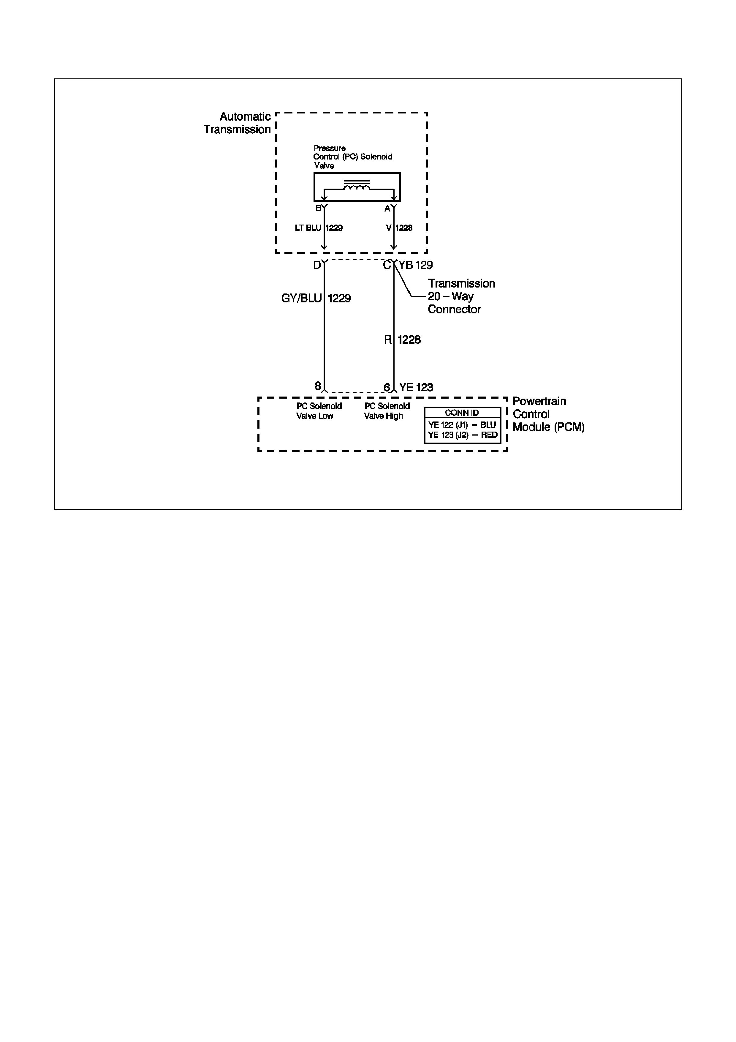
GEN III V8 PCM DTC P0748 PC SOLENOID CIRCUIT ELECTRICAL
CIRCUIT DESCRIPTION
The Pressure Control (PC) solenoid valve is an electronic device that regulates transmission line pressure based
on the current flow through its coil winding. The magnetic field produced by the coil moves the solenoid's internal
valve which varies pres sure to the press ure regulator valve. T he Powertrain Control Module (PCM) controls the PC
solenoid valve by applying a var ying amount of am per age to the solenoid. T he applied am perage can var y from 0.1
to 1.1 amps. Low amperage (0.1 amp) indicates high line pressure. High amperage (1.1 amps) indicates low line
pressure.
The duty cycle of the PC solenoid valve is expressed as a percentage of energised ON time. Zero percent
indicates zero O N time (non-energised) or no c urrent flow. Approxim ately 60% at idle indicates m aximum ON tim e
(energised) or high current flow. The PCM determines the appropriate line pressure for a given load by comparing
the throttle position (TP) voltage, the engine speed and other inputs.
When the PCM detects a continuous open or short to earth in the PC solenoid valve circuit or the PC solenoid
valve, then DTC P0748 sets.
CONDITIONS FOR RUNNING THE DTC
• The system voltage is 8-18 volts.
• The engine is running.
CONDITIONS FOR SETTING THE DTC
• T he PC so lenoid valve duty cycle reaches its high lim it (approx im ately 95%) or low lim it (approxim ately 0%) for
200 milliseconds.
ACTION TAKEN WHEN THE DTC SETS
• The PCM does not illuminate the Check Powertrain Lamp (CPL).
• The PC solenoid valve is OFF.
• The PCM freezes shift adapts from being updated.
• The PCM stores DTC P0748 in PCM history.

CONDITIONS FOR CLEARING THE DTC
• A scan tool clears the DTC from the PCM history.
• The PCM clears the DTC from the PCM history if the vehicle completes 40 warm-up cycles without an
emission-related diagnostic fault occurring.
• T he PCM cancels the DTC default actions when the fault no longer exists and the ignition switch is OFF long
enough in order to power down the PCM.
DIAGNOSTIC AIDS
• Inspect the wiring at the PCM, the transmission connector and all other circuit connecting points for the
following conditions:
- A backed out terminal
- A damaged terminal
- Reduced terminal tension
- A chafed wire
- A broken wire inside the insulation
- Moisture intrusion
- Corrosion
• W hen diagnosing for an intermittent short or open condition, massage the wiring harness while watching the
test equipment for a change.
• DTC P0748 may set under low voltage conditions caused by high electrical system demands.
TEST DESCRIPTION
The numbers below refer to the step numbers on the diagnostic table.
2. This step tests the ability of the PCM to command the PC solenoid valve.
3. T his step tes ts the PC solenoid valve and Autom atic T ransm ission (A/T) wiring harness asse mbly for incorrect
resistance.

GEN III V8 PCM DTC P0748 PC SOLENOID CIRCUIT ELECTRICAL
Step Action Value(s) Yes No
1 Was the Powertrain On-Board Diagnostic (OBD) System
Check performed? Go to Step 2 Go to Powertrain
OBD System
Check Table.
2 1. Install the Tech 2 Scan Tool.
2. With the engine OFF, turn the ignition switch to the
RUN position.
Important: Before clearing the DTC, use the Scan Tool
in order to record the Failure Records. Using the Clear
Info function erases the Failure Records from the PCM.
3. Record th e DTC Failure Records.
4. Clear the DTC.
5. Start the engine.
6. Using the Transmission Miscellaneous Tests function
on the Scan Tool , apply 100 milliamps through 1000
milliamps while observing Commanded PCS and
Actual PCS.
Is the Actual PCS always within the specified value of the
Commanded PCS?
160
milliamps Go to Diagnostic
Aids Go to Step 3
3 1. Turn the ignition OFF.
2. Disconnect the transmission 20-way (YB 129)
connector.
3. Install the J 39775 jumper harness on the
transmission side of the 20-way (YB 129) connector.
4. Using the J 39200 digital multimeter (DMM) and the
J 35616 connector test adapter kit, measure the
resistance between terminal C and terminal D.
Is the resistance within the specified range?
3-7 Ω Go to Step 8 Go to Step 4
4 Is the resistance greater than the specified value? 7 Ω. Go to Step 5 Go to Step 6
5 Inspect circuit 1228 (V) and circuit 1229 (LT BLU) of the
A/T wiring harness assembly for an open condition.
Did you find an open condition?
Go to Step18 Go to Step 10
6 Is the resistance less than the specified value? 3 Ω Go to Step 7
7 Inspect circuit 1228 (V) and circuit 1229 (LT BLU) of the
A/T wiring harness assembly for a shorted together
condition.
Did you find a shorted together condition?
Go to Step 18 Go to Step 10
8 Measure the resistance from terminal C to the
transmission case.
Is the resistance greater than the specified value?
250K Ω Go to Step 11 Go to Step 9
9 Inspect circuit 1228 (V) and circuit 1229 (LT BLU) of the
A/T wiring harness assembly for a short to earth
condition.
Did you find a short to earth condition?
Go to Step 18 Go to Step 10
10 Replace the PC solenoid valve.
Refer to PC Solenoid Valve Replacement in Section 7C5
in the VT Series I Service Information.
Is the replacement complete?
Go to Step 20
11 1. Disconnect the J 39775 jumper harness from the
transmission side of the 20-way (YB 129) connector.
2. Reconnect the transmission 20-way (YB 129)
connector.
3. Disconnect the PCM connector YE 123.
4. Using the J 39200 DMM and the J 35616 connector
test adapter kit, measure the resistance between
terminal 6 and terminal 8.
Is the resistance within the specified range?
3-7 Ω Go to Step 16 Go to Step 12

Step Action Value(s) Yes No
12 Is the resistance greater than the specified value? 7 Ω Go to Step 13 Go to Step 14
13 1. Inspect circuit 1228 (R) and circuit 1229 (GY/BLU) of
the engine wiring harness for an open condition.
2. Repair the circuits if necessary.
Did you find and correct an open condition?
Go to Step 20
14 Is the resistance less than the specified value? 3 Ω Go to Step 15
15 1. Inspect circuit 1228 (R) and circuit 1229 (GY/BLU) of
the engine wiring harness for a shorted together
condition.
2. Repair the circuits if necessary.
Did you find and correct the shorted condition?
Go to Step 20
16 Using the J 39200 DMM and the J 35616 connector test
adapter kit, measure the resistance between connector
YE 123 terminal 6 to earth.
Is the resistance less than the specified value?
9 Ω Go to Step 17 Go to Step 19
17 1. Inspect circuit 1228 (R) and circuit 1229 (GY/BLU) of
the engine wiring harness for a short to earth
condition.
2. Repair the circuits if necessary.
Did you find and correct the short to earth condition?
Go to Step 20
18 Replace the automatic transmission wiring harness
assembly.
Refer to Control Valve Body and Wiring Harness
replacement in Section 7C4, in the VT Series I Service
Information.
Is the replacement complete?
Go to Step 20
19 Replace the PCM.
Refer to Powertrain Control Module in Section 6C3-3 in
the VT Series II Service Information.
Is the replacement complete?
Go to Step 20
20 Perform the following procedure in order to verify the
repair:
1. Select DTC.
2. Select Clear Info.
3. Start the engine and ensure that the following
condition is met:
- The difference between the Scan Tool PC Solenoid
Actual Current and the PC Solenoid Reference
Current is less than 160 milliamps.
Was the above condition verified?
System OK
Go to Step 1

GEN III V8 PCM DTC P0751 1-2 SHIFT SOLENOID VALVE PERFORMANCE
CIRCUIT DESCRIPTION
The 1-2 Shift Solenoid (SS) valve controls the fluid f low acting on the 1- 2 and 3-4 shift valves. T he 1-2 SS valve is
a normally-open exhaust valve that is used with the 2-3 SS valve, in order to allow four different shifting
combinations.
W hen the PCM detects a 1-1-4-4 or a 2-2-3-3 shift pattern, depending on the state of the mechanical failure, then
DTC P0751 sets.
CONDITIONS FOR RUNNING THE DTC
• No Throttle Position DTCs P0122 or P0123.
• No VSS assembly DTCs P0502 or P0503.
• No TCC solenoid valve DTC P0740.
• No TCC stuck ON DTC P0742.
• No 1-2 SS valve DTC P0753.
• No 2-3 SS valve DTC P0758.
• No 3-2 SS valve assembly DTC P0785.
• No TFP manual valve position switch DTC P1810.
• No TCC PWM solenoid valve DTC P1860.
• The engine speed is greater than 300 RPM for 5 seconds.
• The engine is not in fuel cutoff.
• The gear range is D.
• The Throttle Position angle is 10-35%.
• The Throttle Position angle is constant +/- 5%.
• The PCM commands a 1-2, 2-3, and 3-4 shift.
• The TCC is commanded ON.
• The vehicle speed is greater than 8 km/h.
• The transmission fluid temperature is 20-130°C.

CONDITIONS FOR SETTING THE DTC
• DTC P0751 sets if the following conditions occur three times:
- Within 2 seconds, the engine speed in 2nd gear is 80 RPM greater than the last speed in 1st gear.
- Within 2 seconds, the engine speed in 3rd gear is 50 RPM less than the last speed in 2nd gear.
- Within 2 seconds, the engine speed in 4th gear is 10 RPM greater than the last speed in 3rd gear.
• All of the above conditions are met and one of the following conditions occurs:
Condition 1
- The speed ratio is 0.95 to 1.2 (speed ratio is engine speed divided by transmission output speed).
- The TCC slip speed is 200-1000 RPM for 4 seconds.
Condition 2
- The speed ratio is 0.65 to 0.8.
- The TCC slip speed is -20 to +40 RPM for 4 seconds.
ACTION TAKEN WHEN THE DTC SETS
• The PCM illuminates the Check Powertrain Lamp (CPL).
• The PCM commands D2 line pressure.
• The PCM inhibits 3-2 downshifts if the vehicle speed is greater than 48 km/h.
• The PCM freezes shift adapts from being updated.
• The PCM stores DTC P0751 in PCM history.
CONDITIONS FOR CLEARING THE CPL/DTC
• The PCM turns OFF the Check Powertrain Lamp (CPL) during the first trip in which the diagnostic test runs
and passes.
• A scan tool clears the DTC from the PCM history.
• The PCM clears the DTC from the PCM history if the vehicle completes 40 warm-up cycles without an
emission-related diagnostic fault occurring.
• T he PCM cancels the DTC default actions when the fault no longer exists and the ignition switch is OFF long
enough in order to power down the PCM.
DIAGNOSTIC AIDS
• Verify that the transmission meets the specifications in the Shift Speed table.
• Other internal transmission failures may cause more than one shift to occur.
• Refer to the Shift Solenoid Valve State and Gear Ratio table in Section 6C3-4 in the VT Series II Service
Information.
TEST DESCRIPTION
The number below refers to the step numbers on the diagnostic table.
2. This step tests that the PCM commanded all shifts, that all shift solenoid valves responded correctly, but that
all the shifts did not occur.

GEN III V8 PCM DTC P0751 1-2 SHIFT SOLENOID VALVE PERFORMANCE
Step Action Value(s) Yes No
1 Was the Powertrain On-Board Diagnostic (OBD) System
Check performed? Go to Step 2 Go to Powertrain
OBD System
Check Table.
2 1. Install the Tech 2 Scan Tool.
2. With the engine OFF, turn the ignition switch to the
RUN position.
Important: Before clearing the DTC, use the Scan Tool
in order to record the Freeze Frame and Failure Records.
Using the Clear Info function erases the Freeze Frame
and Failure Records from the PCM.
3. Record the DTC Freeze Frame and Failure Records.
4. Clear the DTC.
5. Drive the vehicle in D range under the following
conditions:
- Accelerate the vehicle, ensuring that the PCM
commands 1st, 2nd, 3rd and 4th gears.
Did you detect a 1-1-4-4 or 2-2-3-3 shift pattern?
Go to Step 3 Go to Diagnostic
Aids
3 Inspect the shift solenoid/hydraulic circuit for the following
conditions:
• An internal malfunction.
• Damaged seals on the shift solenoid valves.
Refer to Shift Solenoid Leak Test in Section 7C4 in
the VT Series II Service Information.
Did you find and correct the condition?
Go to Step 4
4 Perform the following procedure in order to verify the
repair:
1. Select DTC.
2. Select Clear Info.
3. Drive the vehicle in D under the following conditions
(only if traffic and road conditions permit):
- Hold the throttle at 20% and accelerate to 88 km/h.
- If the throttle moves more than 5%, stop the vehicle
and start over.
4. Ensure the transmission properly shifts through all
gears as commanded by the PCM.
Did the transmission shift through all gears as
commanded by the PCM?
System OK Go to Step 1
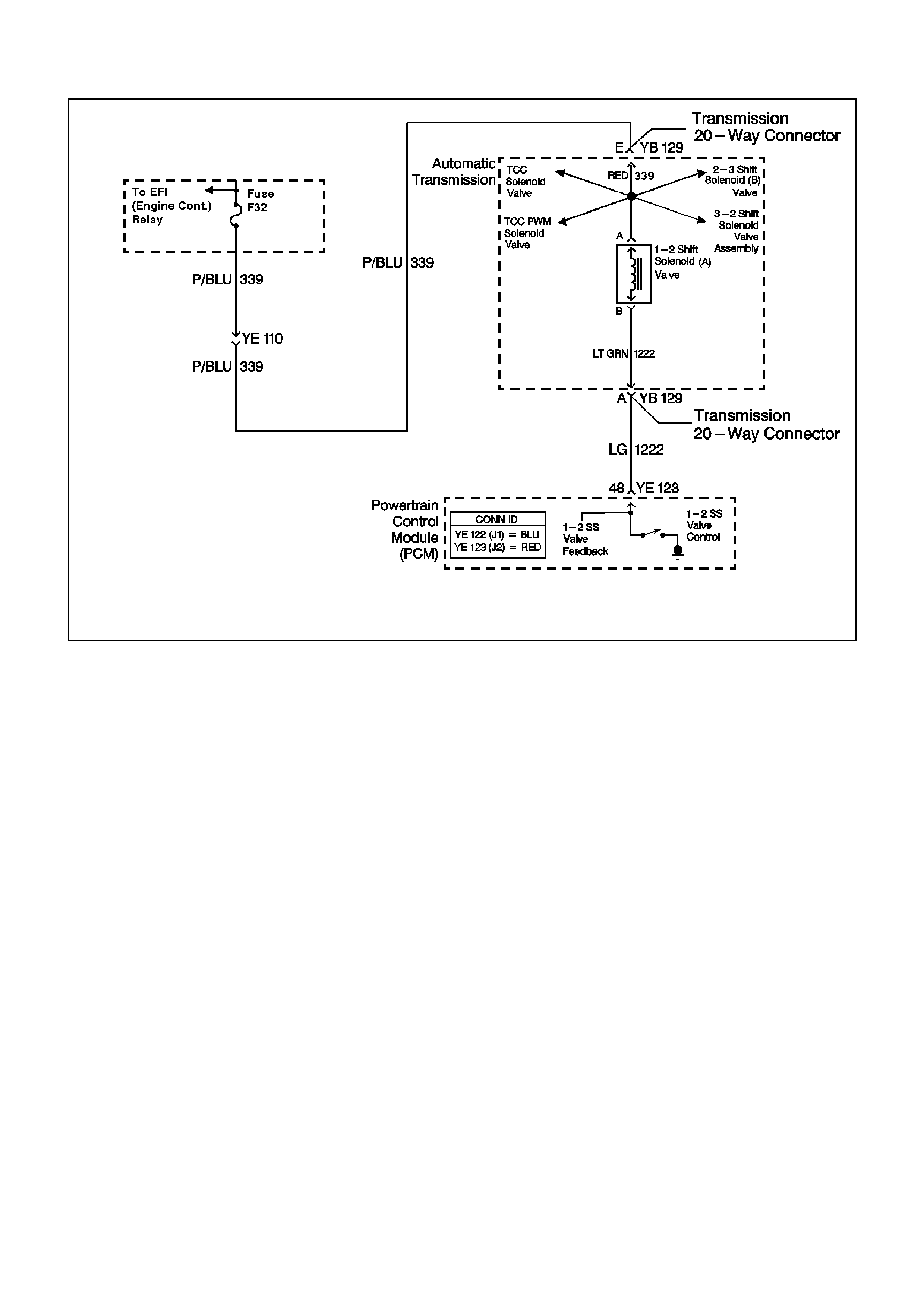
GEN III V8 PCM DTC P0753 1-2 SHIFT SOLENOID CIRCUIT ELECTRICAL
CIRCUIT DESCRIPTION
The 1-2 Shift Solenoid (SS) valve controls the fluid f low acting on the 1- 2 and 3-4 shift valves. T he 1-2 SS valve is
a normally-open exhaust valve that is used with the 2-3 SS valve in order to allow four different shifting
combinations. The solenoid attaches to the control valve body within the transmission. The 1-2 SS valve receives
ignition voltage through circuit 339. The Powertrain Control Module (PCM) controls the solenoid by providing the
earth path on circuit 1222.
When the PCM detects a continuous open or short to earth in the 1-2 SS valve circuit or the 1-2 SS valve, then
DTC P0753 sets.
CONDITIONS FOR RUNNING THE DTC
• The system voltage is 8-18 volts.
• The engine speed is greater than 300 RPM for 5 seconds.
• The engine is not in fuel cutoff.
CONDITIONS FOR SETTING THE DTC
• DTC P0753 sets if either of the following conditions occur for 5 seconds:
- The PCM commands the solenoid ON and the voltage input remains high (B+).
- The PCM commands the solenoid OFF and the voltage input remains low (0 volts).
ACTION TAKEN WHEN THE DTC SETS
• The PCM illuminates the Check Powertrain Lamp (CPL) during the second consecutive trip in which the
conditions for setting the DTC are met.
• The PCM commands D2 line pressure.
• The PCM inhibits 3-2 downshifts if the vehicle speed is greater than 48 km/h.
• The PCM freezes shift adapts from being updated.
• T he PCM stores DTC P0753 in the PCM history during the second cons ecutive trip in which the conditions f or
setting the DTC are met.

CONDITIONS FOR CLEARING THE CPL/DTC
• The PCM turns OFF the Check Powertrain Lamp (CPL) during the first trip in which the diagnostic test runs
and passes.
• A scan tool clears the DTC from the PCM history.
• The PCM clears the DTC from the PCM history if the vehicle completes 40 warm-up cycles without an
emission-related diagnostic fault occurring.
• T he PCM cancels the DTC default actions when the fault no longer exists and the ignition switch is OFF long
enough in order to power down the PCM.
DIAGNOSTIC AIDS
• Inspect the wiring at the PCM, the transmission connector and all other circuit connecting points for the
following conditions:
- A backed out terminal
- A damaged terminal
- Reduced terminal tension
- A chafed wire
- A broken wire inside the insulation
- Moisture intrusion
- Corrosion
• W hen diagnosing for an intermittent short or open condition, massage the wiring harness while watching the
test equipment for a change.
• An open ignition feed circuit can cause multiple DTCs to set.
• Refer to the Shift Solenoid Valve State and Gear Ratio table.
TEST DESCRIPTION
The numbers below refer to the step numbers on the diagnostic table.
4. This step tests the function of the 1-2 SS valve and the automatic transmission wiring harness assembly.
5. This step tests for power to the 1-2 SS valve from the ignition through the fuse.
7. This step tests the ability of the PCM and the wiring to control the earth circuit.
10. This step measures the resistance of the A/T wiring harness assembly and the 1-2 SS valve.

GEN III V8 PCM DTC P0753 1-2 SHIFT SOLENOID CIRCUIT ELECTRICAL
Step Action Value(s) Yes No
1 Was the Powertrain On-Board Diagnostic (OBD) System
Check performed? Go to Step 2 Go to Powertrain
OBD System
Check Table.
2 1. Install the Tech 2 Scan Tool.
2. With the engine OFF, turn the ignition switch to the
RUN position.
Important: Before clearing the DTC, use the Scan Tool
in order to record the Freeze Frame and Failure Records.
Using the Clear Info function erases the Freeze Frame
and Failure Records from the PCM.
3. Record the DTC Freeze Frame and Failure Records.
4. Clear the DTC.
Are any of the following DTCs also set?
• P0740
• P0758
• P0785
• P1860
Go to Step 3 Go to Step 4
3 1. Inspect fuse F32.
2. If the fuse is open, inspect the following components
for a short to earth condition:
- Circuit 339 (P/BLU)
- The solenoids
- The A/T wiring harness assembly
3. Repair the circuit, the solenoids, and the harness if
necessary.
Did you find a short to earth condition?
Go to Step 16 Go to Step 5
4 Using the transmission Miscellaneous Tests function on
the Scan Tool, command the 1-2 SS valve ON and OFF
three times while listening to the bottom of the
transmission pan (a stethoscope may be necessary).
Did the solenoid click when commanded?
Go to Diagnostic
Aids Go to Step 5
5 1. Turn the ignition OFF.
2. Disconnect the transmission 20-way (YB 129)
connector (additional DTCs may set).
3. Install the J 39775 jumper harness on the engine side
of the 20-way (YB 129) connector.
4. With the engine OFF, turn the ignition switch to the
RUN position.
5. Connect a test lamp from J 39775 jumper harness
cavity E to earth.
Is the test lamp ON?
Go to Step 7 Go to Step 6
6 Important: The condition that affects this circuit may
exist in other connecting branches of the circuit. Refer to
Power Distribution Diagrams in the VT Series II Service
Information, Section 12P for complete circuit distribution.
Repair the open or short to earth in ignition feed circuit
339 (P/BLU) to the 1-2 SS valve.
Is the repair complete?
Go to Step 16
7 1. Install a test lamp from J 39775 jumper harness cavity
E to cavity A.
2. Using the transmission Miscellaneous Tests function
on the Scan Tool, command the 1-2 SS valve ON and
OFF three times.
Is the test lamp ON when the 1-2 SS valve is
commanded ON, and OFF when commanded OFF?
Go to Step 10 Go to Step 8

Step Action Value(s) Yes No
8 1. Inspect circuit 1222 (LG) of the powertrain wiring
harness for an open, short to earth or short to power
condition.
2. Repair the circuit if necessary.
Did you find an open, short to earth or short to power
condition?
Go to Step 16 Go to Step 9
9 Replace the PCM.
Refer to Powertrain Control Module in Section 6C3-3.
Is the replacement complete?
Go to Step16
10 1. Install the J 39775 jumper harness on the
transmission side of the 20-way (YB 129) connector.
2. With the J 39200 digital multimeter (DMM) and the
J 35616 connector test adapter kit, measure the
resistance between terminals A and E.
Is the resistance within the range indicated?
19-31 Ω Go to Step 12 Go to Step 11
11 1. Disconnect the A/T wiring harness assembly from the
1-2 SS valve.
2. Measure the resistance of the 1-2 SS valve.
Is the resistance within the range indicated?
19-31 Ω Go to Step 14 Go to Step 15
12 Using the J 39200 DMM, measure the resistance
between terminal A and earth, and between terminal E
and earth.
Are both readings greater than the specified value?
250 K Ω Go to Diagnostic
Aids Go to Step 13
13 1. Disconnect the A/T wiring harness assembly from the
1-2 SS valve.
2. Using the J 39200 DMM, measure the resistance from
the component's terminals to earth.
Are both readings greater than the specified value?
250 K Ω Go to Step 14 Go to Step 15
14 Replace the automatic transmission wiring harness
assembly.
Refer to Control Valve Body and Wiring Harness
replacement in Section 7C4 in the VT Series I Service
Information.
Is the replacement complete?
Go to Step 16
15 Replace the 1-2 SS valve.
Refer to 1-2 Shift Solenoid Valve Replacement in Section
7C5 in the VT Series I Service Information.
Is the replacement complete?
Go to Step 16
16 Perform the following procedure in order to verify the
repair:
1. Select DTC.
2. Select Clear Info.
3. Drive the vehicle in D and ensure the following
conditions are met:
- The PCM commands the 1-2 SS valve ON and the
voltage input drops to zero.
- The PCM commands the 1-2 SS valve OFF and the
voltage input increases to B+.
- All conditions are met for 5 seconds.
Were the above conditions verified?
System OK Go to Step 1
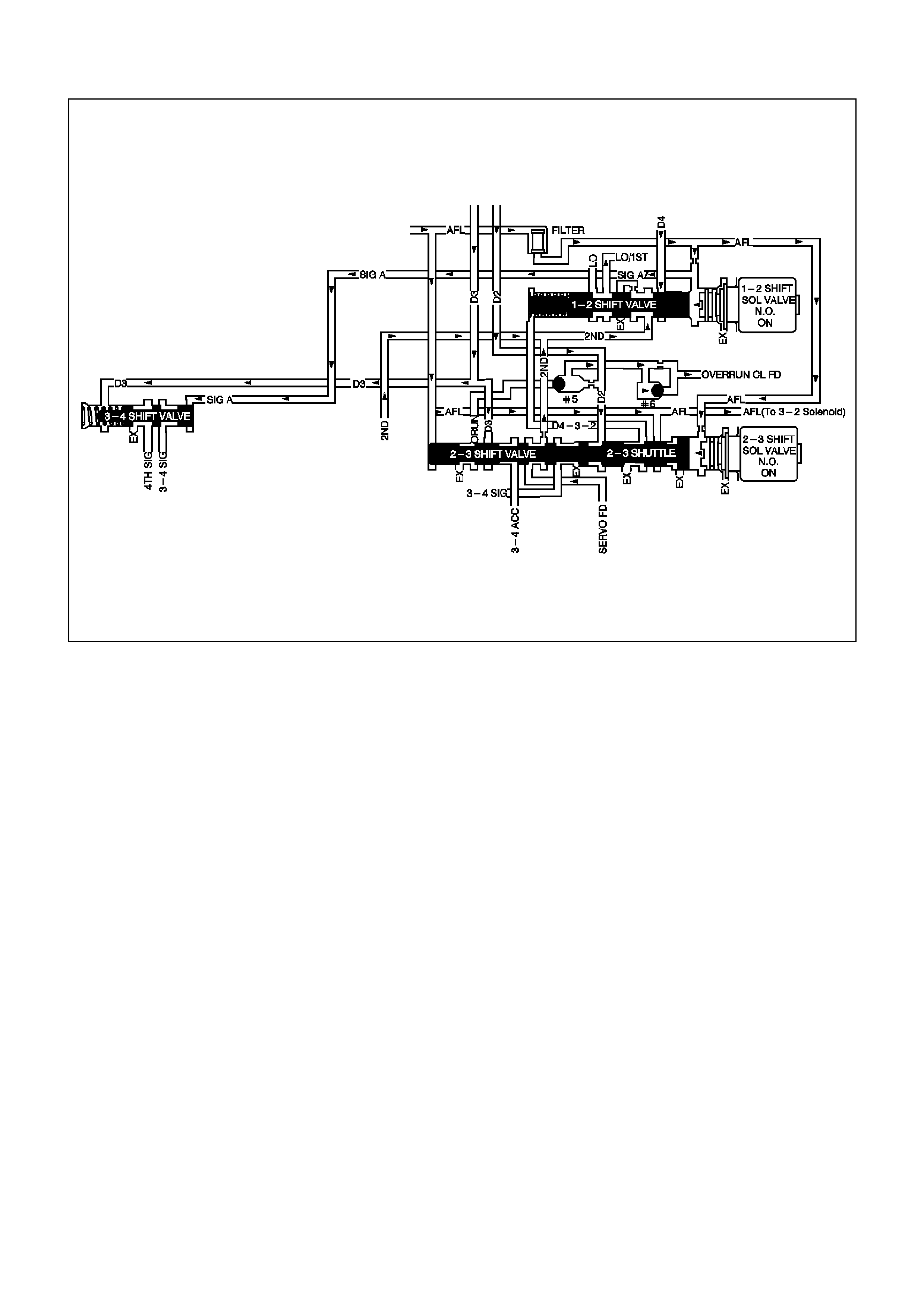
GEN III V8 PCM DTC P0756 2-3 SHIFT SOLENOID VALVE PERFORMANCE
CIRCUIT DESCRIPTION
The 2-3 Shift Solenoid (SS) valve controls the fluid flow acting on the 2-3 shift valves. The 2-3 SS valve is a
normally-open exhaust valve that is used with the 1-2 SS valve, in order to allow four different shifting
combinations.
W hen the PCM detects a 1-2-2-1 or a 4-3-3-4 shift pattern, depending on the state of the mechanical failure, then
DTC P0756 sets.
CONDITIONS FOR RUNNING THE DTC
• No Throttle Position DTCs P0122 or P0123.
• No VSS assembly DTCs P0502 or P0503.
• No TCC solenoid valve DTC P0740.
• No TCC stuck ON DTC P0742.
• No 1-2 SS valve DTC P0753.
• No 2-3 SS valve DTC P0758.
• No 3-2 SS valve assembly DTC P0785.
• No TFP manual valve position switch DTC P1810.
• No TCC PWM solenoid valve DTC P1860.
• The vehicle speed is greater than 8 km/h.
• The gear range is D4.
• The engine vacuum is 0-105 kPa.
• The engine torque is 0-542 Nm.
• The Throttle Position angle is 10-50%.
• The Throttle Position angle is constant +/- 7%.
• The PCM commands a 1-2, 2-3, and 3-4 shift.
• The engine speed is greater than 300 RPM for 5 seconds.
• The engine is not in fuel cutoff.
• The transmission fluid temperature is 20-130°C.

CONDITIONS FOR SETTING THE DTC
• DTC P0756 sets if the following conditions occur three times:
- Third gear is commanded for 2 to 6 seconds.
- The speed ratio in 3r d gear does not dr op more than 0.3 f r om the last s peed ratio in 2nd gear ( speed r atio
is engine speed divided by transmission output speed).
- The TCC slip speed in 3rd gear remains 400 RPM higher than the last TCC slip speed in 2nd gear.
• All of the above conditions are met for 1.5 seconds and one of the following conditions occurs:
Condition 1
- First gear is commanded for 1.5 seconds.
- The TP angle is greater than 25%.
- The transmission output speed is 400-1500 RPM.
- The speed ratio is 0.7 to 3.0.
- The TCC slip speed is -2000 to 0 RPM for 1.5 seconds.
Condition 2
- Fourth gear is commanded for 1.5 seconds.
- The transmission output speed is 1000-3000 RPM.
- The speed ratio is 1.68 to 3.0.
- The TCC slip speed is 1000 to 3000 RPM for 1 second.
ACTION TAKEN WHEN THE DTC SETS
• The PCM illuminates the Check Powertrain Lamp (CPL).
• The PCM commands 3rd gear only.
• The PCM inhibits TCC engagement.
• The PCM commands maximum line pressure.
• The PCM freezes shift adapts from being updated.
• The PCM stores DTC P0756 in PCM history.
CONDITIONS FOR CLEARING THE CPL/DTC
• The PCM turns OFF the Check Powertrain Lamp (CPL) during the first trip in which the diagnostic test runs
and passes.
• A scan tool clears the DTC from the PCM history.
• The PCM clears the DTC from the PCM history if the vehicle completes 40 warm-up cycles without an
emission-related diagnostic fault occurring.
• T he PCM cancels the DTC default actions when the fault no longer exists and the ignition switch is OFF long
enough in order to power down the PCM.
DIAGNOSTIC AIDS
• Verify that the transmission meets the specifications in the Shift Speed table.
• Other internal transmission failures may cause more than one shift to occur.
• Refer to the Shift Solenoid Valve State and Gear Ratio table in Section 6C3-4 in the VT Series II Service
Information.
TEST DESCRIPTION
The number below refers to the step numbers on the diagnostic table.
2. This step tests that the PCM commanded all shifts, that all shift solenoid valves responded correctly, but that
all the shifts did not occur.

GEN III V8 PCM DTC P0756 2-3 SHIFT SOLENOID VALVE PERFORMANCE
Step Action Value(s) Yes No
1 Was the Powertrain On-Board Diagnostic (OBD) System
Check performed? Go to Step 2 Go to Powertrain
OBD System
Check Table.
2 1. Install the Tech 2 Scan Tool.
2. With the engine OFF, turn the ignition switch to the
RUN position.
Important: Before clearing the DTC, use the Scan Tool
in order to record the Freeze Frame and Failure Records.
Using the Clear Info function erases the Freeze Frame
and Failure Records from the PCM.
3. Record the DTC Freeze Frame and Failure Records.
4. Clear the DTC.
5. Drive the vehicle in D range under the following
conditions:
- Accelerate the vehicle, ensuring that the PCM
commands 1st, 2nd, 3rd and 4th gears.
Did you detect a 1-2-2-1 or 4-3-3-4 shift pattern?
Go to Step 3 Go to Diagnostic
Aids
3 Inspect the shift solenoid/hydraulic circuit for the following
conditions:
• An internal malfunction.
• Damaged seals on the Shift Solenoid valves.
Refer to Shift Solenoid Leak Test in Section 7C4 in
the VT Series II Service Information.
Did you find and correct the condition?
Go to Step 4
4 Perform the following procedure in order to verify the
repair:
1. Select DTC.
2. Select Clear Info.
3. Drive the vehicle in D under the following conditions
(only if traffic and road conditions permit):
- Hold the throttle at 40% and accelerate to 64 km/h.
- Stop the vehicle, engine idling.
- Hold the throttle at 15% and accelerate to 80 km/h.
4. Ensure the transmission properly shifts through all
gears as commanded by the PCM.
Did the transmission shift through all gears as
commanded by the PCM?
System OK Go to Step 1
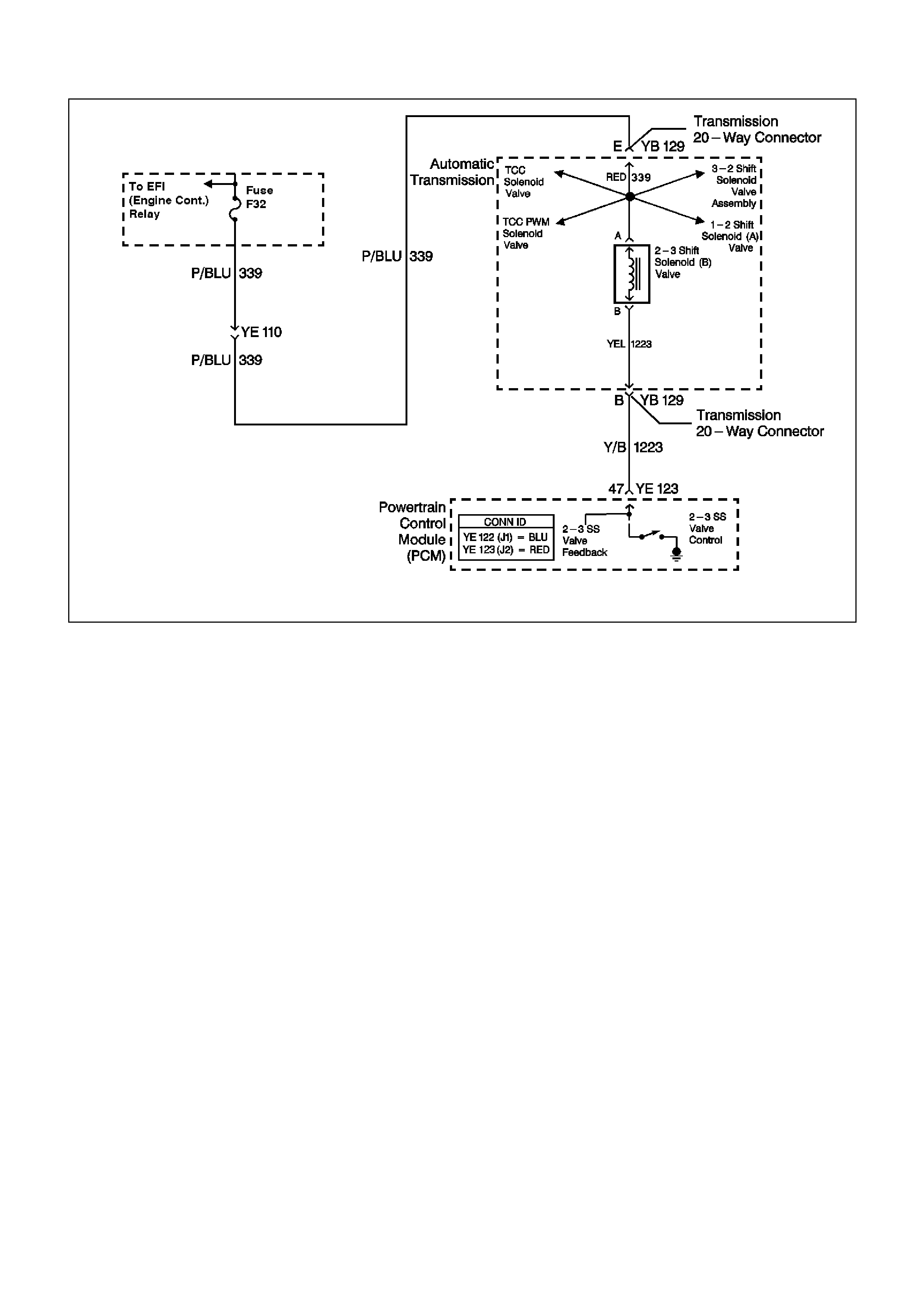
GEN III V8 PCM DTC P0758 2-3 SHIFT SOLENOID CIRCUIT ELECTRICAL
CIRCUIT DESCRIPTION
The 2-3 Shift Solenoid (SS) valve controls the fluid flow acting on the 2-3 shift valves. The 2-3 SS valve is a
norm ally-open exhaust valve that is used with the 1-2 SS valve in or der to allow four dif f erent shif ting com binations.
The solenoid attaches to the contro l valve body within the transm ission. The 2- 3 SS valve receives ignition voltage
through circuit 339. The Powertrain Control Module (PCM) controls the solenoid by providing the earth path on
circuit 1223.
When the PCM detects a continuous open or short to earth in the 2-3 SS valve circuit or the 2-3 SS valve, then
DTC P0758 sets.
CONDITIONS FOR RUNNING THE DTC
• The system voltage is 8-18 volts.
• The engine speed is 300 RPM for 5 seconds.
• The engine is not in fuel cutoff.
CONDITIONS FOR SETTING THE DTC
• DTC P0758 sets if either of the following conditions occur for 5 seconds:
- The PCM commands the solenoid ON and the voltage input remains high (B+).
- The PCM commands the solenoid OFF and the voltage input remains low (0 volts).
ACTION TAKEN WHEN THE DTC SETS
• The PCM illuminates the Check Powertrain Lamp (CPL).
• The PCM commands third gear only.
• The PCM commands maximum line pressure.
• The PCM inhibits TCC engagement.
• The PCM freezes shift adapts from being updated.
• The PCM stores DTC P0758 in the PCM history.

CONDITIONS FOR CLEARING THE CPL/DTC
• The PCM turns OFF the Check Powertrain Lamp (CPL) during the first trip in which the diagnostic test runs
and passes.
• A scan tool clears the DTC from the PCM history.
• The PCM clears the DTC from the PCM history if the vehicle completes 40 warm-up cycles without an
emission-related diagnostic fault occurring.
• T he PCM cancels the DTC default actions when the fault no longer exists and the ignition switch is OFF long
enough in order to power down the PCM.
DIAGNOSTIC AIDS
• Inspect the wiring at the PCM, the transmission connector and all other circuit connecting points for the
following conditions:
- A backed out terminal
- A damaged terminal
- Reduced terminal tension
- A chafed wire
- A broken wire inside the insulation
- Moisture intrusion
- Corrosion
• W hen diagnosing for an intermittent short or open condition, massage the wiring harness while watching the
test equipment for a change.
• Refer to the Shift Solenoid Valve State and Gear Ratio table in Section 6C3-4 in the VT Series II Service
Information.
TEST DESCRIPTION
The numbers below refer to the step numbers on the diagnostic table.
4. This step tests the function of the 2-3 SS valve and the automatic transmission wiring harness assembly.
5. This step tests for power to the 2-3 SS valve from the ignition through the fuse.
7. This step tests the ability of the PCM and the wiring to control the earth circuit.
10. This step measures the resistance of the A/T wiring harness assembly and the 2-3 SS valve.

GEN III V8 PCM DTC P0758 2-3 SHIFT SOLENOID CIRCUIT ELECTRICAL
Step Action Value(s) Yes No
1 Was the Powertrain On-Board Diagnostic (OBD) System
Check performed? Go to Step 2 Go to Powertrain
OBD System
Check Table.
2 1. Install the Tech 2 Scan Tool.
2. With the engine OFF, turn the ignition switch to the
RUN position.
Important: Before clearing the DTC, use the Scan Tool
in order to record the Freeze Frame and Failure Records.
Using the Clear Info function erases the Freeze Frame
and Failure Records from the PCM.
3. Record the DTC Freeze Frame and Failure Records.
4. Clear the DTC.
Are any of the following DTCs also set?
• P0740
• P0753
• P0785
• P1860
Go to Step 3 Go to Step 4
3 1. Inspect fuse F32.
2. If the fuse is open, inspect the following components
for a short to earth condition:
- Circuit 339 (P/BLU)
- The solenoids
- The A/T wiring harness assembly
3. Repair the circuit, the solenoids, and the harness if
necessary.
Did you find a short to earth condition?
Go to Step 16 Go to Step 5
4 Using the transmission Miscellaneous Tests function on
the Scan Tool, command the 2-3 SS valve ON and OFF
three times while listening to the bottom of the
transmission pan (a stethoscope may be necessary).
Did the solenoid click when commanded?
Go to Diagnostic
Aids Go to Step 5
5 1. Turn the ignition OFF.
2. Disconnect the transmission 20-way (YB 129)
connector (additional DTCs may set).
3. Install the J 39775 jumper harness on the engine side
of the 20-way (YB 129) connector.
4. With the engine OFF, turn the ignition switch to the
RUN position.
5. Connect a test lamp from J 39775 jumper harness
cavity E to earth.
Is the test lamp ON?
Go to Step 7 Go to Step 6
6 Important: The condition that affects this circuit may
exist in other connecting branches of the circuit. Refer to
Power Distribution Diagrams in the VT Series II Service
Information, Section 12P for complete circuit distribution.
Repair the open or short to earth in ignition feed circuit
339 (P/BLU) to the 2-3 SS valve.
Is the repair complete?
Go to Step 16
7 1. Install a test lamp from J 39775 jumper harness cavity
E to cavity B.
2. Using the transmission Miscellaneous Tests function
on the Scan Tool, command the 2-3 SS valve ON and
OFF three times.
Is the test lamp ON when the 1-2 SS valve is
commanded ON, and OFF when commanded OFF?
Go to Step 10 Go to Step 8

Step Action Value(s) Yes No
8 1. Inspect circuit 1223 (Y/B) of the powertrain wiring
harness for an open, short to earth or short to power
condition.
2. Repair the circuit if necessary.
Did you find an open, short to earth or short to power
condition?
Go to Step 16 Go to Step 9
9 Replace the PCM.
Refer to Powertrain Control Module in Section 6C3-3 in
the VT Series II Service Information.
Is the replacement complete?
Go to Step16
10 1. Install the J 39775 jumper harness on the
transmission side of the 20-way (YB 129) connector.
2. With the J 39200 digital multimeter (DMM) and the
J 35616 connector test adapter kit, measure the
resistance between terminals B and E.
Is the resistance within the range indicated?
19-31 Ω Go to Step 12 Go to Step 11
11 1. Disconnect the A/T wiring harness assembly from the
2-3 SS valve.
2. Measure the resistance of the 2-3 SS valve.
Is the resistance within the range indicated?
19-31 Ω Go to Step 14 Go to Step 15
12 Using the J 39200 DMM, measure the resistance
between terminal B and earth, and between terminal E
and earth.
Are both readings greater than the specified value?
250 K Ω Go to Diagnostic
Aids Go to Step 13
13 1. Disconnect the A/T wiring harness assembly from the
2-3 SS valve.
2. Using the J 39200 DMM, measure the resistance from
the component's terminals to earth.
Are both readings greater than the specified value?
250 K Ω Go to Step 14 Go to Step 15
14 Replace the automatic transmission wiring harness
assembly.
Refer to Control Valve Body and Wiring Harness
replacement in Section 7C4 in the VT Series I Service
Information.
Is the replacement complete?
Go to Step 16
15 Replace the 2-3 SS valve.
Refer to 2-3 Shift Solenoid Valve Replacement in Section
7C5 in the VT Series I Service Information.
Is the replacement complete?
Go to Step 16
16 Perform the following procedure in order to verify the
repair:
1. Select DTC.
2. Select Clear Info.
3. Drive the vehicle in D and ensure the following
conditions are met:
- The PCM commands the 2-3 SS valve ON and the
voltage input drops to zero.
- The PCM commands the 1-2 SS valve OFF and the
voltage input increases to B+.
- All conditions are met for 5 seconds.
Were the above conditions verified?
System OK Go to Step 1
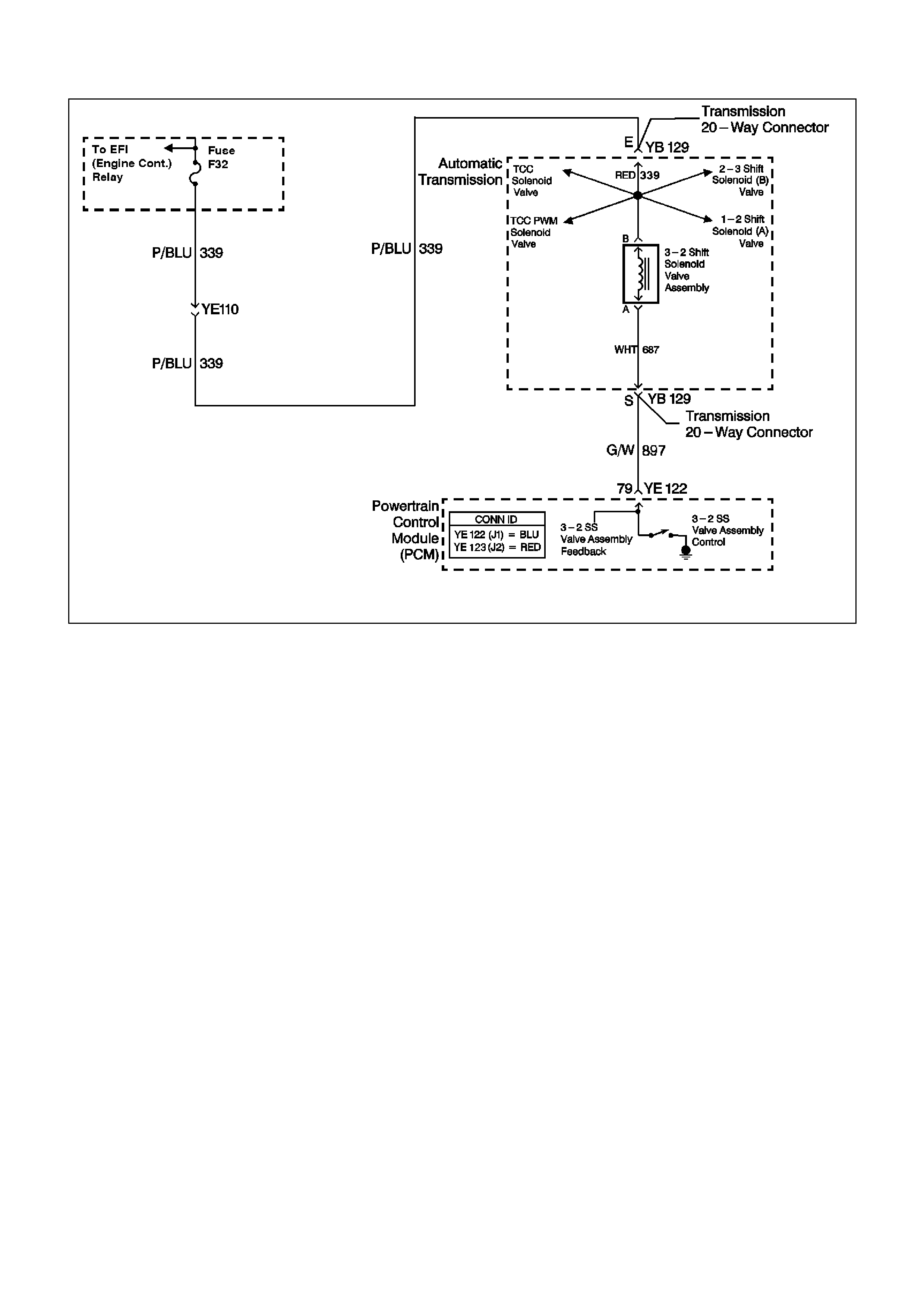
GEN III V8 PCM DTC P0785 3-2 SHIFT SOLENOID CIRCUIT ELECTRICAL
CIRCUIT DESCRIPTION
The 3- 2 Shift Solenoid (SS) valve is a norm ally-clos ed, 3-port, ON/OFF device that controls the 3-2 downshif t. The
solenoid attaches to the control valve body within the transmission. The solenoid receives ignition voltage through
circuit 339. The Powertrain Control Module (PCM) controls the solenoid by providing an earth path on circuit 897.
During a 3-2 downshift, the 2-4 band applies as the 3- 4 clutch releases . The PCM varies the tim ing between the 3-
4 clutch release and the 2-4 band apply depending on the vehicle speed and the throttle position.
When the PCM detec ts a c ontinuous open or short to earth in the 3-2 SS valve as s embly circuit or the 3-2 SS valve
assembly, then DTC P0785 sets.
CONDITIONS FOR RUNNING THE DTC
• The system voltage is 8-18 volts.
• The engine speed is greater than 300 RPM for 5 seconds.
• The engine is not in fuel cutoff.
CONDITIONS FOR SETTING THE DTC
• DTC P0785 sets if either of the following conditions occur for 5 seconds:
- The PCM commands the solenoid ON and the voltage input remains high (B+).
- The PCM commands the solenoid OFF and the voltage input remains low (0 volts).
ACTION TAKEN WHEN THE DTC SETS
• The PCM illuminates the Check Powertrain Lamp (CPL).
• The PCM commands a soft landing to third gear.
• The PCM commands maximum line pressure.
• The PCM inhibits TCC engagement.
• The PCM inhibits fourth gear if the transmission is in hot mode.
• The PCM freezes shift adapts from being updated.
• The PCM stores DTC P0785 in the PCM history.

CONDITIONS FOR CLEARING THE CPL/DTC
• The PCM turns OFF the Check Powertrain Lamp (CPL) during the third consecutive trip in which the
diagnostic test runs and passes.
• A scan tool clears the DTC from the PCM history.
• The PCM clears the DTC from the PCM history if the vehicle completes 40 warm-up cycles without an
emission-related diagnostic fault occurring.
• T he PCM cancels the DTC default actions when the fault no longer exists and the ignition switch is OFF long
enough in order to power down the PCM.
DIAGNOSTIC AIDS
• Inspect the wiring at the PCM, the transmission connector and all other circuit connecting points for the
following conditions:
- A backed out terminal
- A damaged terminal
- Reduced terminal tension
- A chafed wire
- A broken wire inside the insulation
- Moisture intrusion
- Corrosion
• W hen diagnosing for an intermittent short or open condition, massage the wiring harness while watching the
test equipment for a change.
TEST DESCRIPTION
The numbers below refer to the step numbers on the diagnostic table.
4. This step tests the ability of the PCM to control the solenoid.
5. This step tests for power to the 3-2 SS valve assembly.
7. This step tests the ability of the PCM and the wiring to control the earth circuit.
10. This step measures the resistance of the A/T wiring harness assembly and the 3-2 SS valve assembly.

GEN III V8 PCM DTC P0785 3-2 SHIFT SOLENOID CIRCUIT ELECTRICAL
Step Action Value(s) Yes No
1 Was the Powertrain On-Board Diagnostic (OBD) System
Check performed? Go to Step 2 Go to Powertrain
OBD System
Check Table.
2 1. Install the Tech 2 Scan Tool.
2. With the engine OFF, turn the ignition switch to the
RUN position.
Important: Before clearing the DTC, use the Scan Tool
in order to record the Freeze Frame and Failure Records.
Using the Clear Info function erases the Freeze Frame
and Failure Records from the PCM.
3. Record the DTC Freeze Frame and Failure Records.
4. Clear the DTC.
Are any of the following DTCs also set?
• P0740
• P0753
• P0758
• P1860
Go to Step 3 Go to Step 4
3 1. Inspect fuse F32.
2. If the fuse is open, inspect the following components
for a short to earth condition:
- Circuit 339 (P/BLU)
- The solenoids
- The A/T wiring harness assembly
3. Repair the circuit, the solenoids, and the harness if
necessary.
Did you find a short to earth condition?
Go to Step 16 Go to Step 5
4 Important: the 3-2 shift solenoid valve will rapidly apply
when commanded ON by the Scan Tool.
Using the transmission Miscellaneous Tests function on
the Scan Tool, command the 3-2 SS valve ON and OFF
three times while listening to the bottom of the
transmission pan (a stethoscope may be necessary).
Did the solenoid click when commanded?
Go to Diagnostic
Aids Go to Step 5
5 1. Turn the ignition OFF.
2. Disconnect the transmission 20-way (YB 129)
connector (additional DTCs may set).
3. Install the J 39775 jumper harness on the engine side
of the 20-way (YB 129) connector.
4. With the engine OFF, turn the ignition switch to the
RUN position.
5. Connect a test lamp from J 39775 jumper harness
cavity E to earth.
Is the test lamp ON?
Go to Step 7 Go to Step 6
6 Important: The condition that affects this circuit may
exist in other connecting branches of the circuit. Refer to
Power Distribution Diagrams in the VT Series II Service
Information, Section 12P for complete circuit distribution.
Repair the open or short to earth in ignition feed circuit
339 (P/BLU) to the 3-2 SS valve assembly.
Is the repair complete?
Go to Step 16
7 1. Install a test lamp from J 39775 jumper harness cavity
E to cavity S.
Important: The 3-2 shift solenoid will rapidly apply when
commanded ON by the Scan Tool.
2. Using the transmission Miscellaneous Tests function
on the Scan Tool, command the 3-2 SS valve ON and
OFF three times.
Is the test lamp ON when the solenoid is commanded ON
and OFF, when the solenoid is commanded OFF?
Go to Step 10 Go to Step 8

Step Action Value(s) Yes No
8 1. Inspect circuit 897 (G/W) of the powertrain wiring
harness for an open, short to earth or short to power
condition.
2. Repair the circuit if necessary.
Did you find an open, short to earth or short to power
condition?
Go to Step 16 Go to Step 9
9 Replace the PCM.
Refer to Powertrain Control Module in Section 6C3-3 in
the VT Series II Service Information.
Is the replacement complete?
Go to Step16
10 1. Install the J 39775 jumper harness on the
transmission side of the 20-way (YB 129) connector.
2. With the J 39200 digital multimeter (DMM) and the
J 35616 connector test adapter kit, measure the
resistance between terminals S and E.
Is the resistance within the range indicated?
20-32 Ω Go to Step 12 Go to Step 11
11 1. Disconnect the A/T wiring harness assembly from the
3-2 SS valve assembly.
2. Measure the resistance of the 3-2 SS valve assembly.
Is the resistance within the range indicated?
20-32 Ω Go to Step 14 Go to Step 15
12 Measure the resistance between terminal S and earth,
and between terminal E and earth.
Are both readings greater than the specified value?
250 K Ω Go to Diagnostic
Aids Go to Step 13
13 1. Disconnect the A/T wiring harness assembly from the
3-2 SS valve assembly.
2. Measure the resistance from the component’s
terminals to earth.
Are both measurements greater than the specified value?
250 K Ω Go to Step 14 Go to Step 15
14 Replace the automatic transmission wiring harness
assembly.
Refer to Control Valve Body and Wiring Harness
replacement in Section 7C4 in the VT Series I Service
Information.
Is the replacement complete?
Go to Step 16
15 Replace the 3-2 SS valve.
Refer to 3-2 Shift Solenoid Valve Replacement in Section
7C5 in the VT Series I Service Information.
Is the replacement complete?
Go to Step 16
16 Perform the following procedure in order to verify the
repair:
1. Select DTC.
2. Select Clear Info.
3. Drive the vehicle in 3 or D and perform a 3-2
downshift. Ensure the following conditions are met:
- The PCM commands the 3-2 SS valve ON and the
voltage input drops to zero.
- The PCM commands the 3-2 SS valve OFF and the
voltage input increases to B+.
- All conditions are met for 5 seconds.
Were the above conditions verified?
System OK Go to Step 1
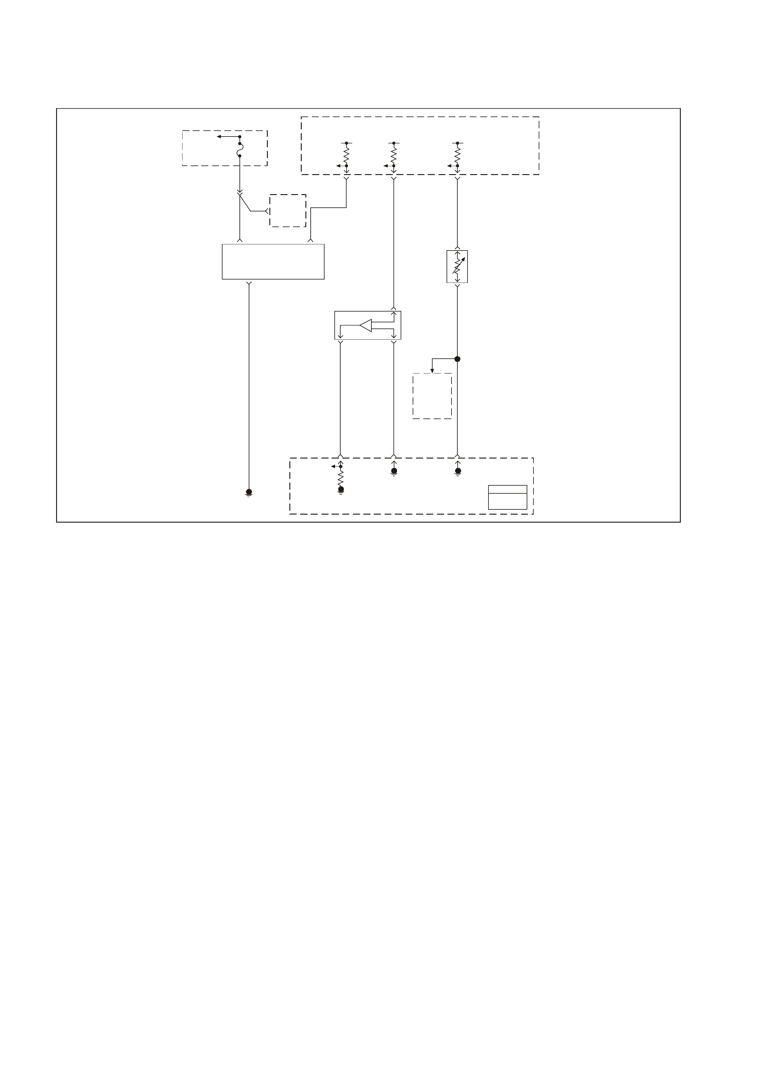
GEN III V8 PCM DTC P1111 INTAKE AIR TEMPERATURE SENSOR CIRCUIT
INTERMITTENT HIGH VOLTAGE
GEN3 0155
PCM
J1 = BLU E
J2 = RED
To EFI
(Eng in e Con t. )
Relay Fuse
F33
5V 5V 5V
MAP
5V
Reference
MAF
Sensor
Signal
Oxygen
Sensor
Heaters
Intake Air
Temperature
(AIT)
Sensor
Ignition
Power MAF
Sensor
Signal
Mass Air
Flow (MAF)
Sensor
Manifold Absolute
Pressure (MAP)
Sensor
To
A/C
Pressure
Sensor
MAP
Sensor
Signal
MAP
Sensor
Earth
IAT
Sensor
Earth
Engine
Earth
P 439
YE111
C
D
A
31 J2 48 J1 25 J2
G/O 469
57 J2
B421
32 J2
B/R 750
B/R 750
B
LG 432
BA
C
G/O 469
A
B
V/W 414
BR/W 792
A
54 J1
P439
IAT
Sensor
Signal
B/R 472
Powertrain
Control
Module
(PCM)
The Intake Air Temperature (IAT) Sensor contains a semiconductor device which changes resistance based on
temperature (a thermistor). The IAT Sensor mounts in the air intake passage of the engine air induction system.
The IAT Sensor has a signal circuit and a earth circuit. The PCM applies a voltage (about 5.0 volts) on the signal
circuit to the s ensor. T he PCM m onitors changes in this voltage caused by changes in the resis tance of the sensor,
in order to determine the Intake Air Temperature.
W hen the intake air is cold, the sensor (thermistor) resistance is high, and the PCM’s signal voltage is only pulled
down a small am ount through the s ensor to earth. T he PCM senses a high signal voltage (low temperature). When
the intake air is warm, the sensor resistance is low, and the signal voltage is pulled down a greater amount. This
causes the PCM to sense a low signal voltage (high temperature).
This DTC sets when the PCM senses a signal voltage higher than the normal operating range of the sensor.
CONDITIONS FOR RUNNING THE DTC
• DTC(s) P0102, P0103, P0117, P0118, P0502, P0503 are not set.
• The engine run time is greater than 100 seconds.
• The engine coolant temperature is greater than 0°C (32°F).
• The vehicle speed is less than 11 km/h (7 mph).
• The mass air flow is less than 15 g/s.
CONDITIONS FOR SETTING THE DTC
• The intake air temperature is less than -35°C (-31°F).
• All conditions are present for 0.3 seconds.
ACTIONS TAKEN WHEN THE DTC SETS
• The PCM stores the DTC information into memory when the diagnostic runs and fails.
• The Check Powertrain Lamp (CPL) will not illuminate.
• T he PCM records the operating conditions at the time the diagnostic f ails. The PCM stores this inform ation in
the Freeze Frame/Failure Records.

CONDITIONS FOR CLEARING THE CPL/DTC
• A History DT C will clear after for ty c onsecutive warm- up cycles, if no f ailures are repor ted by this or any other
non-emission related diagnostic.
• A last test failed (Current DTC) will clear when the diagnostic runs and does not fail.
• Use a Tech 2 scan tool in order to clear the CPL/DTC.
DIAGNOSTIC AIDS
• If the engine has sat overnight, the engine coolant temperature and intake air temperature values should
display within a few degrees of each other. If the temperatures are not within 3°C (5°F), refer to Tem perature
vs Resistance.
• For an intermittent, refer to Section 6C3-2B SYMPTOMS in the VT Series II Service Information.
TEST DESCRIPTION
The numbers below refer to the step numbers on the diagnostic table.
2. If DTC P0113 failed this ignition, this indicates a hard failure is present. W hen a hard failure is present, both
the hard and intermittent DTCs set.
3. When moving related connectors, inspect the connectors for the following:
- Poor mating of the connector halves or a terminal not fully seated in the connector body (backed out).
- Improperly formed or damaged terminals. Carefully reform or replace all connector terminals in the
related circuits in order to insure proper terminals contact tension.
- Poor terminal to wire connection. Inspect for poor crimps, crimping over wire insulation rather than the
wire.
- Dirt or corrosion on the terminals. Inspect the connector seals for being there and for being damaged.
4. When moving the related wiring harness, inspect the wiring for the following:
- Wire insulation that is rubbed through, causing an intermittent short.
- Wiring broken inside the insulation.
5. Using the Freeze Frame/Failure Records data may aid in locating an intermittent condition. If you cannot
duplicate the DT C, the information inc luded in the Freeze Fram e/Failure Records data can help determ ine the
distance traveled since the DTC set. The Fail Counter and Pass Counter can also help determine how many
ignition cycles the diagnostic reported a pass and/or fail. Operate the vehicle within the same freeze frame
condition (RPM, load, vehicle speed, temperature etc.) that you observed.
This will isolate when the DTC failed. For any test that requires probing the PCM or component harness
connectors , us e the Connector Tes t Adaptor Kit J 35616-A. Us ing this k it prevents any damage to the harnes s
connector terminals.

GEN III V8 PCM DTC P1111 INTAKE AIR TEMPERATURE SENSOR CIRCUIT INTERMITTENT HIGH VOLTAGE
Step Action Value(s) Yes No
1 Did you perform the Powertrain On-Board Diagnostic
(OBD) System Check? Go to Step 2 Go to
Powertrain OBD
System Check
Table
2 1. Turn ON the ignition leaving the engine OFF.
2. Observe the affected sensor value on a Tech 2 scan
tool while moving the related harness connectors (at
the component and the PCM)
Did DTC P0113 Fail This Ignition cycle?
Go to DTC P0113
IAT Sensor
Circuit High
Voltage
Go to Step 3
3 1. Turn ON the ignition leaving the engine OFF.
2. Observe the affected sensor value on a Tech 2 scan
tool while moving the related wiring harness.
Does the sensor value change abruptly while moving the
related electrical harness?
Go to Step 6 Go to Step 4
4 Observe the affected sensor value on a scan tool while
moving the related wiring harnesses.
Does the sensor value change abruptly while moving the
related electrical harnesses?
Go to Step 7 Go to Step 5
5 1. Turn ON the ignition leaving the engine OFF.
2. Review the Freeze Frame/Failure Records data for
this DTC and observe the parameters.
3. Turn OFF the ignition for 15 seconds.
4. Start the engine.
5. Operate the vehicle within the conditions required for
this diagnostic to run, and as close to the conditions
recorded in the Freeze Frame/Failure Records as
possible. Special operating conditions that you need to
meet before the PCM will run this diagnostic, where
applicable, are listed in Conditions for Running the
DTC.
6. Select the Diagnostic Trouble Code (DTC) option, the
DTC Information option and The Failed This Ignition
option using the Tech 2 scan tool.
Does the Tech 2 scan tool indicate that this diagnostic
failed this ignition?
Go to Step 8 Refer to
Diagnostic Aids
6 Repair the damaged connectors/terminals.
Is the repair complete? Go to Step 9
7 Repair the faulty wiring.
Is the repair complete? Go to Step 9
8 1. Re-inspect all the related circuits and the connectors.
2. Replace the sensor/component if all the circuits have
been checked thoroughly and no faults can be found.
Is the action complete?
Go to Step 9
9 1. Select the Diagnostic Trouble Code (DTC) option and
the Clear DTC Information option using the Tech 2
scan tool.
2. Idle the engine at the normal operating temperature.
3. Select the Diagnostic Trouble Code (DTC) option, the
DTC Information option and The Failed This Ignition
option using the Tech 2 scan tool.
4. Operate the vehicle within the Conditions for Running
the DTC as specified in the supporting text, if
applicable.
Does the Tech 2 scan tool indicate that this DTC reset?
Go to Step 2 Go to Step 10
10 Using the Tech 2 scan tool, check for any other DTCs.
Does the Tech 2 scan tool display any DTCs that you
have not diagnosed?
Go to the
applicable DTC
table
System OK
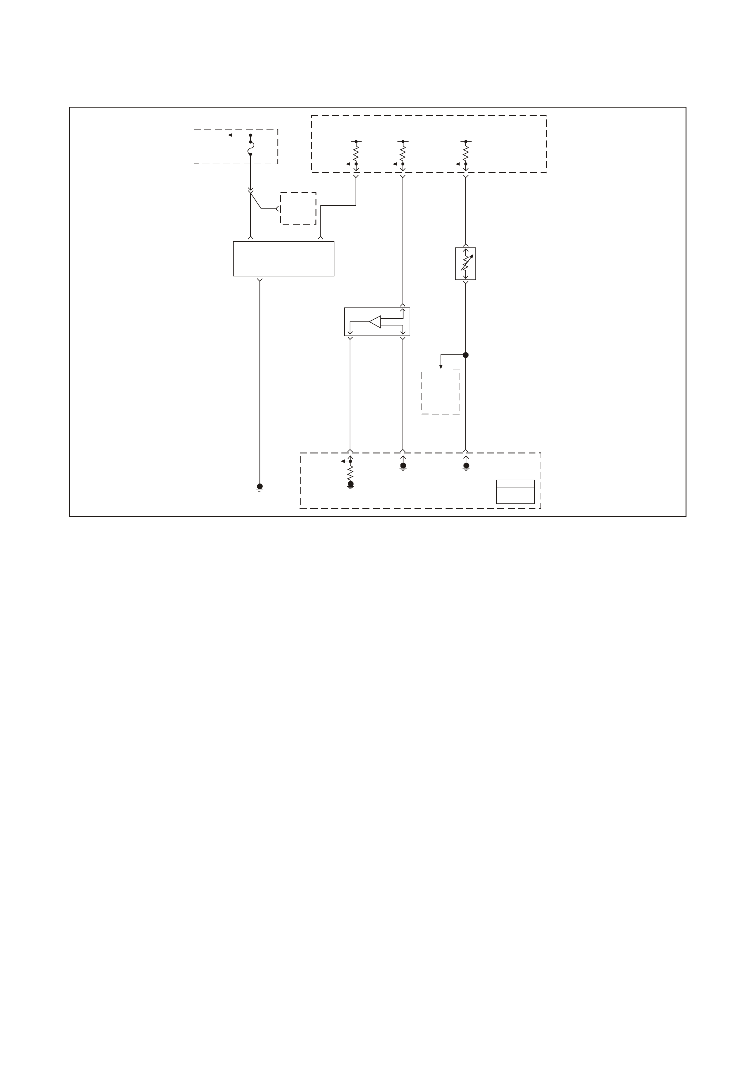
GEN III V8 PCM DTC P1112 INTAKE AIR TEMPERATURE SENSOR CIRCUIT
INTERMITTENT LOW VOLTAGE
GEN3 0155
PCM
J1 = BLU E
J2 = RED
To EFI
(Eng in e Con t. )
Relay Fuse
F33
5V 5V 5V
MAP
5V
Reference
MAF
Sensor
Signal
Oxygen
Sensor
Heaters
Intake Air
Temperature
(AIT)
Sensor
Ignition
Power MAF
Sensor
Signal
Mass Air
Flow (MAF)
Sensor
Manifold Absolute
Pressure (MAP)
Sensor
To
A/C
Pressure
Sensor
MAP
Sensor
Signal
MAP
Sensor
Earth
IAT
Sensor
Earth
Engine
Earth
P 439
YE111
C
D
A
31 J2 48 J1 25 J2
G/O 469
57 J2
B421
32 J2
B/R 750
B/R 750
B
LG 432
BA
C
G/O 469
A
B
V/W 414
BR/W 792
A
54 J1
P439
IAT
Sensor
Signal
B/R 472
Powertrain
Control
Module
(PCM)
CIRCUIT DESCRIPTION
The Intake Air Temperature (IAT) Sensor contains a semiconductor device which changes resistance based on
temperature (a thermistor). The IAT Sensor mounts in the air intake passage of the engine air induction system.
The IAT Sensor has a signal circuit and a earth circuit. The PCM applies a voltage (about 5.0 volts) on the signal
circuit to the s ensor. T he PCM monitors changes in this voltage c aused by changes in the r esistance of the sensor
in order to determine the intake air temperature.
W hen the intake air is cold, the sensor (thermistor) resistance is high, and the PCM’s signal voltage is only pulled
down a small am ount through the s ensor to earth. T he PCM senses a high signal voltage (low temperature). When
the intake air is warm, the sensor resistance is low, and the signal voltage is pulled down a greater amount. This
causes the PCM to sense a low signal voltage (high temperature).
This DTC sets when the PCM senses a signal voltage higher than the normal operating range of the sensor.
CONDITIONS FOR RUNNING THE DTC
• DTC(s) P0102, P0103, P0117, P0118, P0502, P0503 are not set.
• The engine run time is greater than 30 seconds.
• The vehicle speed is less than 40 km/h (25 mph).
CONDITIONS FOR SETTING THE DTC
• The intake air temperature is less than 139°C (282°F).
• All conditions are present for 0.3 seconds.
ACTIONS TAKEN WHEN THE DTC SETS
• The PCM stores the DTC information into memory when the diagnostic runs and fails.
• The Check Powertrain Lamp (CPL) will not illuminate.
• T he PCM records the operating conditions at the time the diagnostic f ails. The PCM stores this inform ation in
the Failure Records.

CONDITIONS FOR CLEARING THE CPL/DTC
• A History DT C will clear after for ty c onsecutive warm- up cycles, if no f ailures are repor ted by this or any other
non-emission related diagnostic.
• A last test failed (Current DTC) will clear when the diagnostic runs and does not fail.
• Use a Tech 2 scan tool in order to clear the CPL/DTC.
DIAGNOSTIC AIDS
• If the engine has sat overnight, the engine coolant temperature and intake air temperature values should
display within a few degrees of each other. If the temperatures are not within 3°C (5°F), refer to Tem perature
vs Resistance.
• For an intermittent, refer to Section 6C3-2B SYMPTOMS in the VT Series II Service Information.
TEST DESCRIPTION
The numbers below refer to the step numbers on the diagnostic table.
2. If DTC P0112 failed this ignition, this indicates a hard failure is present. W hen a hard failure is present, both
the hard and intermittent DTCs set.
3. When moving related connectors, inspect the connectors for the following:
- Poor mating of the connector halves or a terminal not fully seated in the connector body (backed out).
- Improperly formed or damaged terminals. Carefully reform or replace all connector terminals in the
related circuits in order to ensure correct terminal contact tension.
- Poor terminal to wire connection. Inspect for poor crimps, crimping over wire insulation rather than the
wire.
- Dirt or corrosion on the terminals. Inspect the connector seals for being there and for being damaged.
4. When moving the related wiring harness, inspect the wiring for the following:
- Wire insulation that is rubbed through, causing an intermittent short.
- Wiring broken inside the insulation.
5. Using the Freeze Frame/Failure Records data may aid in locating an intermittent condition. If you cannot
duplicate the DT C, the information inc luded in the Freeze Fram e/Failure Records data can help determ ine the
distance traveled since the DTC set. The Fail Counter and Pass Counter can also help determine how many
ignition cycles the diagnostic reported a pass and/or fail. operate the vehicle within the same freeze frame
condition (RPM, load, vehicle speed, temperature etc.) that you observed.
This will isolate when the DTC failed. For any test that requires probing the PCM or component harness
connectors , us e the Connector Tes t Adaptor Kit J 35616-A. Us ing this k it prevents any damage to the harnes s
connector terminals.

GEN III V8 PCM DTC P1112 INTAKE AIR TEMPERATURE SENSOR CIRCUIT INTERMITTENT LOW VOLTAGE
Step Action Value(s) Yes No
1 Did you perform the Powertrain On-Board Diagnostic
(OBD) System Check? Go to Step 2 Go to Powertrain
OBD System
Check Table
2
1. Install a Tech 2 scan tool.
2. Idle the engine.
3. Monitor the Failed This Ignition option under the DTC
Information option using the Tech 2 scan tool
Did DTC P0112 Fail This Ignition cycle?
Go to DTC
P0112 IAT
Sensor Circuit
Low Voltage
Go to Step 3
3 1. Turn OFF the ignition leaving the engine OFF.
2. Observe the affected sensor value on a Tech 2 scan
tool while moving the related harness connectors (at
the component and the PCM)
Does the sensor value change abruptly while moving the
related connector is being moved?
Go to Step 6 Go to Step 4
4 Observe the affected sensor value on a Tech 2 scan tool
while moving the related wiring harness.
Does the sensor value change abruptly while moving the
related electrical harness?
Go to Step 7 Go to Step 5
5 1. Turn ON the ignition leaving the engine OFF.
2. Review the Freeze Frame/Failure Records data for
this DTC and observe the parameters.
3. Turn OFF the ignition for 15 seconds.
4. Start the engine.
5. Operate the vehicle within the conditions required for
this diagnostic to run, and as close to the conditions
recorded in the Freeze Frame/Failure Records as
possible. Special operating conditions that you need to
meet before the PCM will run this diagnostic, where
applicable, are listed in Conditions for Running the
DTC.
6. Select the Diagnostic Trouble Code (DTC) option, the
DTC Information option and The Failed This Ignition
option using the Tech 2 scan tool.
Does the Tech 2 scan tool indicate that this diagnostic
failed this ignition?
Go to Step 8 Refer to
Diagnostic Aids
6 Repair the damaged connectors/terminals.
Is the repair complete? Go to Step 9
7 Repair the faulty wiring.
Is the repair complete? Go to Step 9
8 1. Re-inspect all the related circuits and the connectors.
2. Replace the sensor/component if all the circuits have
been checked thoroughly and no faults can be found.
Is the action complete?
Go to Step 9
9 1. Select the Diagnostic Trouble Code (DTC) option and
the Clear DTC Information option using the Tech 2
scan tool.
2. Idle the engine at the normal operating temperature.
3. Select the Diagnostic Trouble Code (DTC) option, the
DTC Information option and The Failed This Ignition
option using the Tech 2 scan tool.
4. Operate the vehicle within the Conditions for Running
the DTC as specified in the supporting text, if
applicable.
Does the Tech 2 scan tool indicate that this DTC reset?
Go to Step 2 Go to Step 10
10 Using the Tech 2 scan tool, check for any other DTCs.
Does the Tech 2 scan tool display any DTCs that you
have not diagnosed?
Go to the
applicable DTC
table
System OK

GEN III V8 PCM DTC P1114 ENGINE COOLANT TEMPERATURE SENSOR CIRCUIT
INTERMITTENT LOW VOLTAGE
GEN3 0156
PCM
J1 = B LUE
J2 = R ED
Powertrain
Control
Module
(PCM)
Powertrain
Control
Module
(PCM)
5V 5V
ECT
Sensor
Signal
TP Sensor
5V
Reference
Throttle
Relaxer
Control
Module
Engine Coolant
Temperature
(ECT)
Sensor
Throttle
Position
(TP)
Sensor Coolant
Level
Switch
Engine
Earth
TP
Sensor
Signal
Sensor
Earth
ECT
Sensor
Earth
Coolant
Level
Switch
Input
08 74 J1
Y410
B
A
B/R 750
G69
30 J1
GY/B 455
80 J1
B/Y 452
60
BLU 417
24 J2
B/Y 452
BLU 417
CB
40
43
GY 416
GY 416
A
GY
416
41
Throttle
Relaxer
Control
Module
J1
J1
CIRCUIT DESCRIPTION
The Engine Coolant T em perature (ECT ) Sensor contains a semic onductor device which c hanges resistance based
on temperature (a therm istor). The ECT Sensor mounts in the left bank cylinder head near the front of the engine.
The ECT Sensor has a signal circuit and a earth circuit. T he PCM applies a voltage (about 5.0 volts) on the signal
circuit to the sensor. The PCM monitors changes in this voltage caused by the changes in the resistance of the
sensor in order to determine the engine coolant temperature.
When the engine coolant is cold, the sensor (thermistor) resistance is high, and the PCM’s signal voltage is only
pulled down a small am ount through the s ensor to earth. T he PCM senses a high signal voltage (low temperature) .
W hen the intake air is warm, the sens or resistance is low, and the s ignal voltage is pulled down a greater am ount.
This causes the PCM to sense a low signal voltage (high temperature).
This DTC sets when the PCM senses a signal voltage higher than the normal operating range of the sensor.
CONDITIONS FOR RUNNING THE DTC
• The engine run time is greater than 10 seconds.
CONDITIONS FOR SETTING THE DTC
• The Engine Coolant Temperature is greater than 139°C (282°F) for less than a second.
ACTIONS TAKEN WHEN THE DTC SETS
• The PCM stores the DTC information into memory when the diagnostic runs and fails.
• The Check Powertrain Lamp (CPL) will not illuminate.
• T he PCM records the operating conditions at the time the diagnostic f ails. The PCM stores this inform ation in
the Freeze Frame/Failure Records.

CONDITIONS FOR CLEARING THE CPL/DTC
• A History DT C will clear after for ty c onsecutive warm- up cycles, if no f ailures are repor ted by this or any other
non-emission related diagnostic.
• A last test failed (Current DTC) will clear when the diagnostic runs and does not fail.
• Use a Tech 2 scan tool in order to clear the CPL/DTC.
DIAGNOSTIC AIDS
• Electro-Magnetic Interference (EMI) can cause an intermittent DTC. Inspect the related circuits for being too
closed to secondary ignition wires and the generator.
• If the engine has sat overnight, the engine coolant temperature and intake air temperature values should
display within a few degrees of each other. If the temperatures are not within 3°C (5°F), refer to Tem perature
vs. Resistance in Section 6C3-4 in the VT Series II Service Information.
• For an intermittent, refer to Section 6C3-2B SYMPTOMS in the VT Series II Service Information.
TEST DESCRIPTION
The numbers below refer to the step numbers on the diagnostic table.
2. If DTC P0117 failed this ignition, this indicates a hard failure is present. W hen a hard failure is present, both
the hard and intermittent DTC’s set.
3. When moving related connectors, inspect the connectors for the following:
- Poor mating of the connector halves or a terminal not fully seated in the connector body (backed out).
- Improperly formed or damaged terminals. Carefully reform or replace all connector terminals in the
related circuits in order to ensure correct terminal contact tension.
- Poor terminal to wire connection. Inspect for poor crimps, crimping over wire insulation rather than the
wire.
- Dirt or corrosion on the terminals. Inspect the connector seals for being there and for being damaged.
4. When moving the related wiring harness, inspect the wiring for the following:
- Wire insulation that is rubbed through, causing an intermittent short.
- Wiring broken inside the insulation.
5. Using the Freeze Frame/Failure Records data may aid in locating an intermittent condition. If you cannot
duplicate the DT C, the information inc luded in the Freeze Fram e/Failure Records data can help determ ine the
distance traveled since the DTC set. The Fail Counter and Pass Counter can also help determine how many
ignition cycles the diagnostic reported a pass and/or fail. Operate the vehicle within the same freeze frame
condition (RPM, load, vehicle speed, temperature etc.) that you observed.
This will isolate when the DTC failed. For any test that requires probing the PCM or component harness
connectors , us e the Connector Tes t Adaptor Kit J 35616-A. Us ing this k it prevents any damage to the harnes s
connector terminals.

GEN III V8 PCM DTC P1114 ENGINE COOLANT TEMPERATURE SENSOR CIRCUIT
INTERMITTENT LOW VOLTAGE
Step Action Value(s) Yes No
1 Did you perform the Powertrain On-Board Diagnostic
(OBD) System Check? Go to Step 2 Go to Powertrain
OBD System
Check Table
2 1. Install Tech 2 scan tool.
2. Idle the engine.
3. Monitor the Failed This Ignition option under the DTC
Information option using the scan tool.
Did DTC P0117 fail this ignition cycle?
Go to DTC
P0117 ECT
Sensor Circuit
Low Voltage
Go to Step 3
3 1. Turn ON the ignition leaving the engine OFF.
2. Observe the affected sensor value on the scan tool
while moving the related harness connectors (at the
component and the PCM).
Does the sensor value change abruptly while a related
connector is being moved?
Go to Step 6 Go to Step 4
4 Observe the affected sensor value on the scan tool while
moving the related wiring harnesses.
Does the sensor value change abruptly while moving the
related electrical harnesses?
Go to Step 7 Go to Step 5
5 1. Turn ON the ignition leaving the engine OFF.
2. Review the Freeze Frame/Failure Records data for
this DTC and observe the parameters.
3. Turn OFF the ignition for 15 seconds.
4. Start the engine.
5. Operate the vehicle within the conditions required for
this diagnostic to run, and as close to the conditions
recorded in the Freeze Frame/Failure Records as
possible. Special operating conditions that you need to
meet before the PCM will run this diagnostic, where
applicable, are listed in Conditions for Running the
DTC.
6. Select the Diagnostic Trouble Code (DTC) option, the
DTC Information option and The Failed This Ignition
option using the Tech 2 scan tool.
Does the Tech 2 scan tool indicate that this diagnostic
failed this ignition?
Go to Step 8 Go to Diagnostic
Aids
6 Repair the damaged connectors/terminals.
Is the repair complete? Go to Step 9
7 Repair the faulty wiring.
Is the repair complete? Go to Step 9
8 1. Re-inspect all the related circuits and the connectors.
2. Replace the sensor/component if all the circuits have
been checked thoroughly and no faults can be found.
Is the action complete?
Go to Step 9
9 1. Select the Diagnostic Trouble Code (DTC) option and
the Clear DTC Information option using the Tech 2
scan tool.
2. Idle the engine at the normal operating temperature.
3. Select the Diagnostic Trouble Code (DTC) option, the
DTC Information option and The Failed This Ignition
option using the Tech 2 scan tool.
4. Operate the vehicle within the Conditions for Running
the DTC as specified in the supporting text, if
applicable.
Does the Tech 2 scan tool indicate that this DTC reset?
Go to Step 2 Go to Step 10
10 Using the Tech 2 scan tool, check for any other DTC’s.
Does the Tech 2 scan tool display any DTCs that you
have not diagnosed?
Go to the
applicable DTC
table
System OK
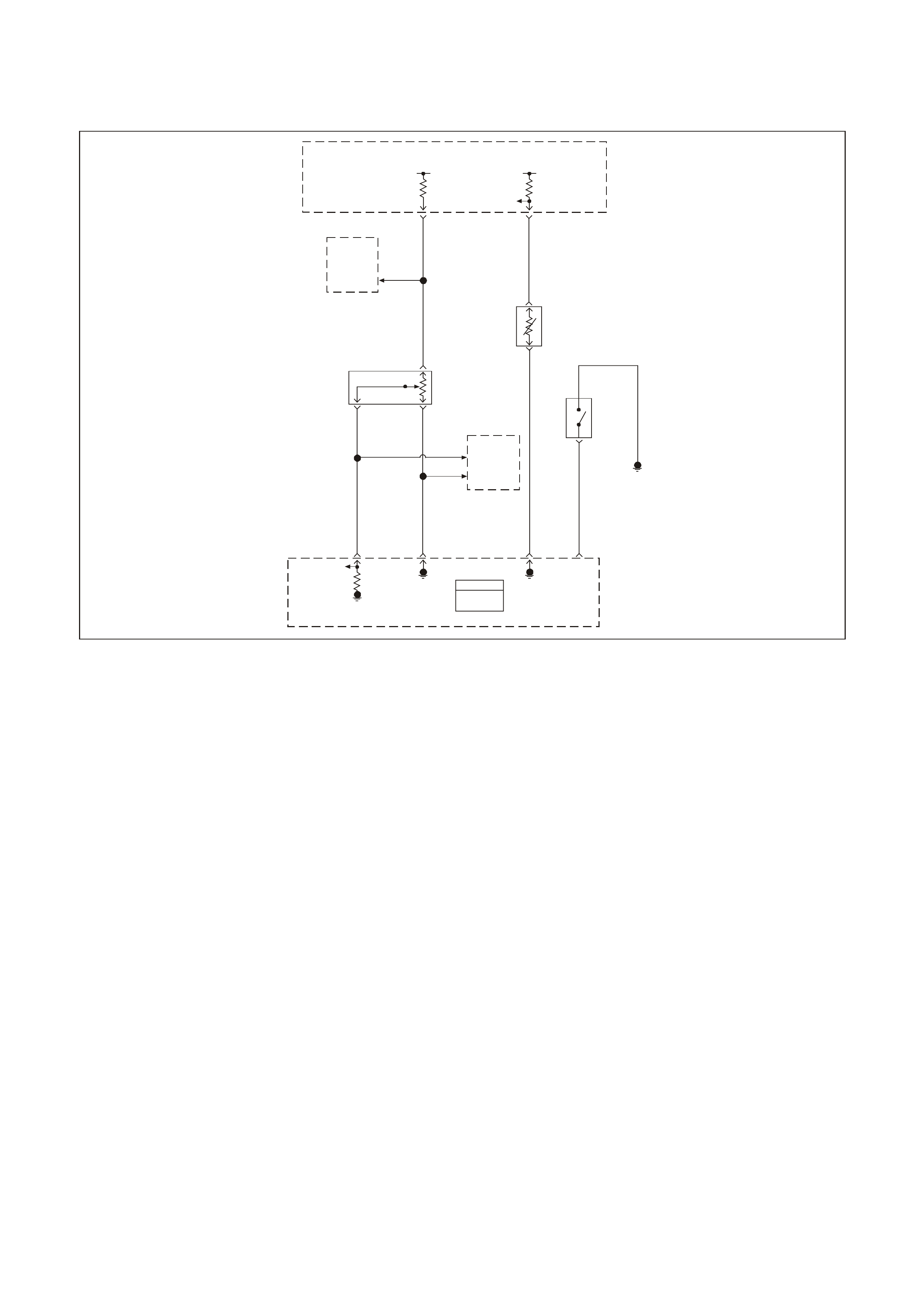
GEN III V8 PCM DTC P1115 ENGINE COOLANT TEMPERATURE SENSOR CIRCUIT
INTERMITTENT HIGH VOLTAGE
GEN3 0156
PCM
J1 = B LUE
J2 = R ED
Powertrain
Control
Module
(PCM)
Powertrain
Control
Module
(PCM)
5V 5V
ECT
Sensor
Signal
TP Sensor
5V
Reference
Throttle
Relaxer
Control
Module
Engine Coolant
Temperature
(ECT)
Sensor
Throttle
Position
(TP)
Sensor Coolant
Level
Switch
Engine
Earth
TP
Sensor
Signal
Sensor
Earth
ECT
Sensor
Earth
Coolant
Level
Switch
Input
08 74 J1
Y410
B
A
B/R 750
G69
30 J1
GY/B 455
80 J1
B/Y 452
60
BLU 417
24 J2
B/Y 452
BLU 417
CB
40
43
GY 416
GY 416
A
GY
416
41
Throttle
Relaxer
Control
Module
J1
J1
CIRCUIT DESCRIPTION
The Engine Coolant T em perature (ECT ) Sensor contains a semic onductor device which c hanges resistance based
on temperature (a therm istor). The ECT Sensor mounts in the left bank cylinder head near the front of the engine.
The ECT Sensor has a signal circuit and a earth circuit. T he PCM applies a voltage (about 5.0 volts) on the signal
circuit to the sensor. The PCM monitors changes in this voltage caused by the changes in the resistance of the
sensor in order to determine the engine coolant temperature.
When the engine coolant is cold, the sensor (thermistor) resistance is high, and the PCM’s signal voltage is only
pulled down a small am ount through the s ensor to earth. T he PCM senses a high signal voltage (low temperature) .
W hen the intake air is warm, the sens or resistance is low, and the s ignal voltage is pulled down a greater am ount.
This causes the PCM to sense a low signal voltage (high temperature).
This DTC sets when the PCM senses a signal voltage higher than the normal operating range of the sensor.
CONDITIONS FOR RUNNING THE DTC
• The engine operates longer than 60 seconds.
CONDITIONS FOR SETTING THE DTC
• The Engine Coolant Temperature is at or below -35°C (-31°F) for less than a second.
ACTIONS TAKEN WHEN THE DTC SETS
• The PCM stores the DTC information into memory when the diagnostic runs and fails.
• The Check Powertrain Lamp (CPL) will not illuminate.
• T he PCM records the operating conditions at the time the diagnostic f ails. The PCM stores this inform ation in
the Freeze Frame/Failure Records.

CONDITIONS FOR CLEARING THE CPL/DTC
• A History DT C will clear after for ty c onsecutive warm- up cycles, if no f ailures are repor ted by this or any other
non-emission related diagnostic.
• A last test failed (Current DTC) will clear when the diagnostic runs and does not fail.
• Use a Tech 2 scan tool in order to clear the CPL/DTC.
DIAGNOSTIC AIDS
• Electro-Magnetic Interference (EMI) can cause an intermittent DTC. Inspect the related circuits for being too
close to secondary ignition wires and the generator.
• If the engine has sat overnight, the engine coolant temperature and intake air temperature values should
display within a few degrees of each other. If the temperatures are not within 3°C (5°F), refer to Tem perature
vs. Resistance Chart in Section 6C3-4 in the VT Series II Service Information.
• For an intermittent, refer to Section 6C3-2B SYMPTOMS in the VT Series II Service Information.
TEST DESCRIPTION
The numbers below refer to the step numbers on the diagnostic table.
2. If DTC P0118 failed this ignition, this indicates a hard failure is present. W hen a hard failure is present, both
the hard and intermittent DTC’s set.
3. When moving related connectors, inspect the connectors for the following:
- Poor mating of the connector halves or a terminal not fully seated in the connector body (backed out).
- Improperly formed or damaged terminals. Carefully reform or replace all connector terminals in the
related circuits in order to ensure correct terminal contact tension.
- Poor terminal to wire connection. Inspect for poor crimps, crimping over wire insulation rather than the
wire.
- Dirt or corrosion on the terminals. Inspect the connector seals for being there and for being damaged.
4. When moving the related wiring harness, inspect the wiring for the following:
- Wire insulation that is rubbed through, causing an intermittent short.
- Wiring broken inside the insulation.
5. Using the Freeze Frame/Failure Records data may aid in locating an intermittent condition. If you cannot
duplicate the DT C, the information inc luded in the Freeze Fram e/Failure Records data can help determ ine the
distance traveled since the DTC set. The Fail Counter and Pass Counter can also help determine how many
ignition cycles the diagnostic reported a pass and/or fail. Operate the vehicle within the same freeze frame
condition (RPM, load, vehicle speed, temperature etc.) that you observed. This will isolate when the DTC
failed. For any test that requires probing the PCM or com ponent harness connectors, use the Connector Test
Adaptor Kit J 35616-A. Using this kit prevents any damage to the harness connector terminals.

GEN III V8 PCM DTC P1115 ENGINE COOLANT TEMPERATURE SENSOR CIRCUIT HIGH VOLTAGE
Step Action Value(s) Yes No
1 Did you perform the Powertrain On-Board Diagnostic
(OBD) System Check? Go to Step 2 Go to Powertrain
OBD System
Check Table
2
1. Install a Tech 2 scan tool.
2. Idle the engine.
3. Monitor the Failed This Ignition option under the DTC
Information option using the Tech 2 scan tool
Did DTC P0118 Fail This Ignition cycle?
Go to DTC
P0118 ECT
Sensor Circuit
High Voltage
Table
Go to Step 3
3 1. Turn ON the ignition leaving the engine OFF.
2. Observe the affected sensor value on a Tech 2 scan
tool while moving the related harness connectors (at
the component and the PCM)
Does the sensor value change abruptly while moving the
related connector is being moved?
Go to Step 6 Go to Step 4
4 Observe the affected sensor value on a Tech 2 scan tool
while moving the related wiring harness.
Does the sensor value change abruptly while moving the
related electrical harness?
Go to Step 7 Go to Step 5
5 1. Turn ON the ignition leaving the engine OFF.
2. Review the Freeze Frame/Failure Records data for
this DTC and observe the parameters.
3. Turn OFF the ignition for 15 seconds.
4. Start the engine.
5. Operate the vehicle within the conditions required for
this diagnostic to run, and as close to the conditions
recorded in the Freeze Frame/Failure Records as
possible. Special operating conditions that you need to
meet before the PCM will run this diagnostic, where
applicable, are listed in Conditions for Running the
DTC.
6. Select the Diagnostic Trouble Code (DTC) option, the
DTC Information option and The Failed This Ignition
option using the Tech 2 scan tool.
Does the Tech 2 scan tool indicate that this diagnostic
failed this ignition?
Go to Step 8 Go to Diagnostic
Aids
6 Repair the damaged connectors/terminals.
Is the repair complete? Go to Step 9
7 Repair the faulty wiring.
Is the repair complete? Go to Step 9
8 1. Re-inspect all the related circuits and the connectors.
2. Replace the sensor/component if all the circuits have
been checked thoroughly and no faults can be found.
Is the action complete?
Go to Step 9
9 1. Select the Diagnostic Trouble Code (DTC) option and
the Clear DTC Information option using the Tech 2
scan tool.
2. Idle the engine at the normal operating temperature.
3. Select the Diagnostic Trouble Code (DTC) option, the
DTC Information option and The Failed This Ignition
option using the Tech 2 scan tool.
4. Operate the vehicle within the Conditions for Running
the DTC as specified in the supporting text, if
applicable.
Does the Tech 2 scan tool indicate that this DTC reset?
Go to Step 2 Go to Step 10
10 Using the Tech 2 scan tool, check for any other DTCs.
Does the Tech 2 scan tool display any DTCs that you
have not diagnosed?
Go to the
applicable DTC
table
System OK
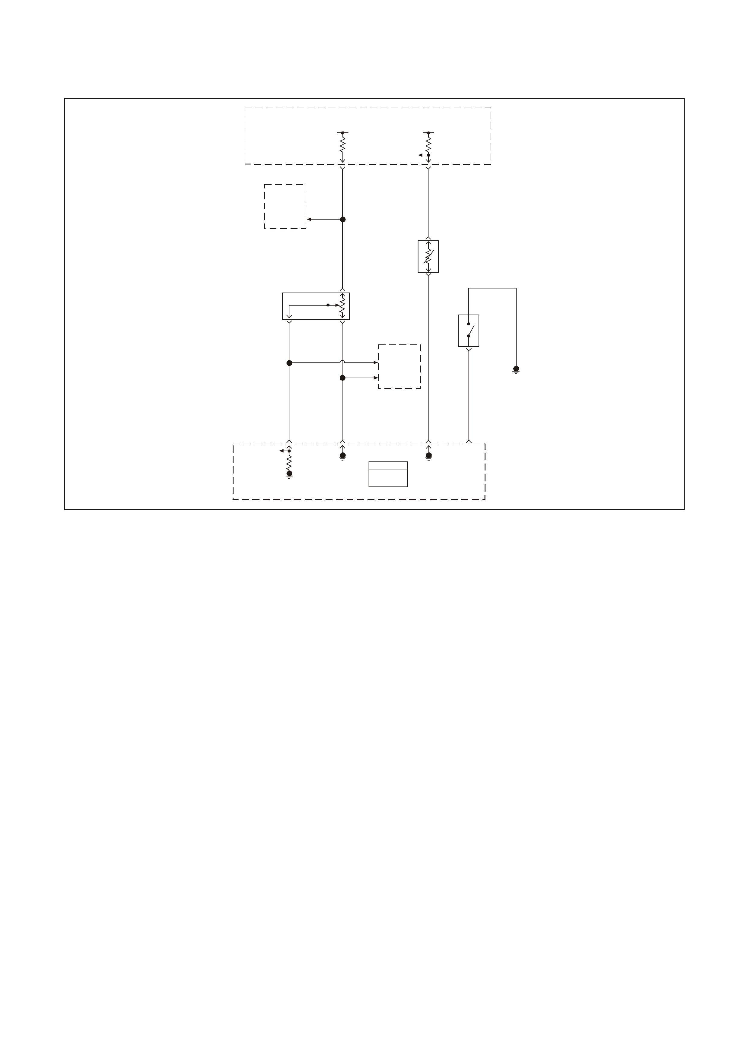
GEN III V8 PCM DTC P1121 THROTTLE POSITION SENSOR CIRCUIT INTERMITTENT
HIGH VOLTAGE
GEN3 0156
PCM
J1 = B LUE
J2 = R ED
Powertrain
Control
Module
(PCM)
Powertrain
Control
Module
(PCM)
5V 5V
ECT
Sensor
Signal
TP Sensor
5V
Reference
Throttle
Relaxer
Control
Module
Engine Coolant
Temperature
(ECT)
Sensor
Throttle
Position
(TP)
Sensor Coolant
Level
Switch
Engine
Earth
TP
Sensor
Signal
Sensor
Earth
ECT
Sensor
Earth
Coolant
Level
Switch
Input
08 74 J1
Y410
B
A
B/R 750
G69
30 J1
GY/B 455
80 J1
B/Y 452
60
BLU 417
24 J2
B/Y 452
BLU 417
CB
40
43
GY 416
GY 416
A
GY
416
41
Throttle
Relaxer
Control
Module
J1
J1
CIRCUIT DESCRIPTION
The Throttle Pos ition ( TP) Sens or is a potentiometer. T he TP Sensor is mounted to the lef t s ide of the thr ottle body.
The TP Sensor provides a voltage signal that c hanges relative to throttle blade angle. T his signal voltage is one of
the most important inputs used by the PCM. The TP Sensor has a 5.0 volt reference, a earth and a signal circuit.
TP sens or signal voltage s hould be about 0.6 volt at idle. The TP Sensor voltage should increase to above 4.0 volts
at wide open throttle (WOT).
When the PCM senses a signal voltage higher than the normal operating range of the sensor, this DTC will set.
CONDITIONS FOR RUNNING THE DTC
• The ignition switch is in the RUN position.
CONDITIONS FOR SETTING THE DTC
• The TP sensor voltage is greater than 4.8 volts.
ACTIONS TAKEN WHEN THE DTC SETS
• The PCM stores the DTC information into memory when the diagnostic runs and fails.
• The Check Powertrain Lamp (CPL) will not illuminate.
• T he PCM records the operating conditions at the time the diagnostic f ails. The PCM stores this inform ation in
the Freeze Frame/Failure Records.
CONDITIONS FOR CLEARING THE CPL/DTC
• A History DT C will clear after for ty c onsecutive warm- up cycles, if no f ailures are repor ted by this or any other
non-emission related diagnostic.
• A last test failed (Current DTC) will clear when the diagnostic runs and does not fail.
• Use a Tech 2 scan tool in order to clear the CPL/DTC.

DIAGNOSTIC AIDS
• An intermittent DTC can be caused by Electro-Magnetic Interference (EMI). Inspect related circuits for being
too close to secondary ignition wires and the alternator.
• For an intermittent, refer to Section 6C3-2B SYMPTOMS in the VT Series II Service Information.
TEST DESCRIPTION
The numbers below refer to the step numbers on the diagnostic table.
2. If DTC P0123 failed this ignition, this indicates a hard failure is present. W hen a hard failure is present, both
the hard and intermittent DTCs set.
3. When moving related connectors, inspect the connectors for the following:
- Poor mating of the connector halves or a terminal not fully seated in the connector body (backed out).
- Improperly formed or damaged terminals. Carefully reform or replace all connector terminals in the
related circuits in order to ensure correct terminal contact tension.
- Poor terminal to wire connection. Inspect for poor crimps, crimping over wire insulation rather than the
wire.
- Dirt or corrosion on the terminals. Inspect the connector seals for being there and for being damaged.
4. When moving the related wiring harness, inspect the wiring for the following:
- Wire insulation that is rubbed through, causing an intermittent short.
- Wiring broken inside the insulation.
5. Using the Freeze Frame/Failure Records data may aid in locating an intermittent condition. If you cannot
duplicate the DT C, the information inc luded in the Freeze Fram e/Failure Records data can help determ ine the
distance traveled since the DTC set. The Fail Counter and Pass Counter can also help determine how many
ignition cycles the diagnostic reported a pass and/or fail. operate the vehicle within the same freeze frame
condition (RPM, load, vehicle speed, temperature etc.) that you observed. This will isolate when the DTC
failed. For any test that requires probing the PCM or com ponent harness connectors, use the Connector Test
Adaptor Kit J 35616-A. Using this kit prevents any damage to the harness connector terminals.

GEN III V8 PCM DTC P1121 THROTTLE POSITION SENSOR CIRCUIT INTERMITTENT HIGH VOLTAGE
Step Action Value(s) Yes No
1 Did you perform the Powertrain On-Board Diagnostic
(OBD) System Check? Go to Step 2 Go to Powertrain
OBD System
Check Table
2 1. Install the Tech 2 scan tool.
2. Start and idle the engine.
3. Using a Tech 2 scan tool, monitor Failed This Ignition
under DTC Status for DTC P0123.
Did DTC P0123 fail this ignition cycle?
Go to DTC
P0123 TP
Sensor Circuit
High Voltage
Table
Go to Step 3
3 1. Install the Tech 2 scan tool.
2. Turn the ignition ON, engine OFF.
3. Using a Tech 2 scan tool, observe affected sensor
values while moving related harness connectors (at
component and PCM).
Does sensor value change abruptly while a related
connector is being moved?
Go to Step 6 Go to Step 4
4 Using a Tech 2 scan tool, observe affected sensor value
while moving related wiring harnesses.
Does sensor value change abruptly while moving related
electrical harnesses?
Go to Step 7 Go to Step 5
5 1. Turn ON the ignition leaving the engine OFF.
2. Review the Freeze Frame/Failure Records data for
this DTC and observe the parameters.
3. Turn OFF the ignition for 15 seconds.
4. Start the engine.
5. Operate the vehicle within the conditions required for
this diagnostic to run, and as close to the conditions
recorded in the Freeze Frame/Failure Records as
possible. Special operating conditions that you need to
meet before the PCM will run this diagnostic, where
applicable, are listed in Conditions for Running the
DTC.
6. Select the Diagnostic Trouble Code (DTC) option, the
DTC Information option and The Failed This Ignition
option using the Tech 2 scan tool.
Does the Tech 2 scan tool indicate that this diagnostic
failed this ignition?
Go to Step 8 Go to Diagnostic
Aids
6 Repair the damage connectors/terminals.
Is the repair complete? Go to Step 9
7 Repair the faulty wiring.
Is the repair complete? Go to Step 9
8 1. Re-inspect all the related circuits and the connectors.
2. Replace the sensor/component if all the circuits have
been checked thoroughly and no faults can be found.
Is the action complete?
Go to Step 9
9 1. Select the Diagnostic Trouble Code (DTC) option and
the Clear DTC Information option using the Tech 2
scan tool.
2. Idle the engine at the normal operating temperature.
3. Select the Diagnostic Trouble Code (DTC) option, the
DTC Information option and The Failed This Ignition
option using the Tech 2 scan tool.
4. Operate the vehicle within the Conditions for Running
the DTC as specified in the supporting text, if
applicable.
Does the Tech 2 scan tool indicate that this DTC reset?
Go to Step 2 Go to Step 10
10 Using the Tech 2 scan tool, check for any other DTCs.
Does the Tech 2 scan tool display any DTCs that you
have not diagnosed?
Go to the
applicable DTC
table
System OK
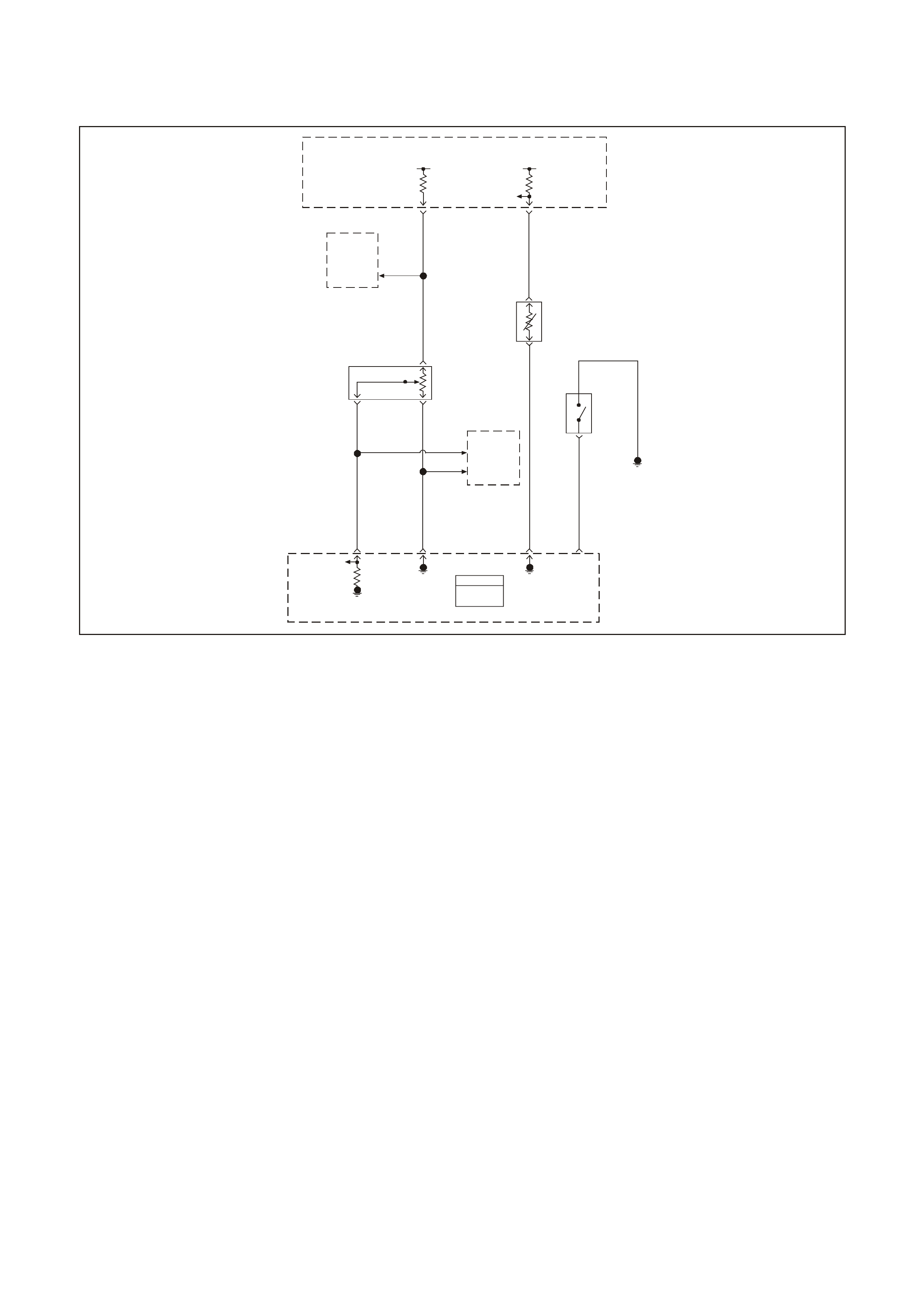
GEN III V8 PCM DTC P1122 THROTTLE POSITION SENSOR CIRCUIT
INTERMITTENT LOW VOLTAGE
GEN3 0156
PCM
J1 = B LUE
J2 = R ED
Powertrain
Control
Module
(PCM)
Powertrain
Control
Module
(PCM)
5V 5V
ECT
Sensor
Signal
TP Sensor
5V
Reference
Throttle
Relaxer
Control
Module
Engine Coolant
Temperature
(ECT)
Sensor
Throttle
Position
(TP)
Sensor Coolant
Level
Switch
Engine
Earth
TP
Sensor
Signal
Sensor
Earth
ECT
Sensor
Earth
Coolant
Level
Switch
Input
08 74 J1
Y410
B
A
B/R 750
G69
30 J1
GY/B 455
80 J1
B/Y 452
60
BLU 417
24 J2
B/Y 452
BLU 417
CB
40
43
GY 416
GY 416
A
GY
416
41
Throttle
Relaxer
Control
Module
J1
J1
CIRCUIT DESCRIPTION
The Throttle Pos ition ( TP) Sens or is a potentiometer. T he TP Sensor is mounted to the lef t s ide of the thr ottle body.
The TP Sensor provides a voltage signal that c hanges relative to throttle blade angle. T his signal voltage is one of
the most important inputs used by the PCM. The TP Sensor has a 5.0 volt reference, a earth and a signal circuit.
TP Sensor signal voltage should be about 0.6 volt at idle. T he TP sensor voltage should increase to above 4.0 volts
at wide open throttle (WOT).
When the PCM senses a signal voltage higher than the normal operating range of the sensor, this DTC will set.
CONDITIONS FOR RUNNING THE DTC
• TP sensor voltage is less than 0.2 volts for 3.0 seconds.
CONDITIONS FOR SETTING THE DTC
• The TP sensor voltage is less than 0.2 volts.
ACTIONS TAKEN WHEN THE DTC SETS
• The PCM stores the DTC information into memory when the diagnostic runs and fails.
• The Check Powertrain Lamp (CPL) will not illuminate.
• T he PCM records the operating conditions at the time the diagnostic f ails. The PCM stores this inform ation in
the Freeze Frame/Failure Records.
CONDITIONS FOR CLEARING THE CPL/DTC
• A History DT C will clear after for ty c onsecutive warm- up cycles, if no f ailures are repor ted by this or any other
non-emission related diagnostic.
• A last test failed (Current DTC) will clear when the diagnostic runs and does not fail.
• Use a Tech 2 scan tool in order to clear the CPL/DTC.

DIAGNOSTIC AIDS
• An intermittent DTC can be caused by Electro-Magnetic Interference (EMI). Inspect related circuits for being
too close to secondary ignition wires and the alternator.
• For an intermittent, refer to Section 6C3-2B SYMPTOMS in the VT Series II Service Information.
TEST DESCRIPTION
The numbers below refer to the step numbers on the diagnostic table.
2. If DTC P0122 failed this ignition, this indicates a hard failure is present. W hen a hard failure is present, both
the hard and intermittent DTC’s set.
3. When moving related connectors, inspect the connectors for the following:
- Poor mating of the connector halves or a terminal not fully seated in the connector body (backed out).
- Improperly formed or damaged terminals. Carefully reform or replace all connector terminals in the
related circuits in order to ensure correct terminal contact tension.
- Poor terminal to wire connection. Inspect for poor crimps, crimping over wire insulation rather than the
wire.
- Dirt or corrosion on the terminals. Inspect the connector seals for being there and for being damaged.
4. When moving the related wiring harness, inspect the wiring for the following:
- Wire insulation that is rubbed through, causing an intermittent short.
- Wiring broken inside the insulation.
5. Using the Freeze Frame/Failure Records data may aid in locating an intermittent condition. If you cannot
duplicate the DT C, the information inc luded in the Freeze Fram e/Failure Records data can help determ ine the
distance traveled since the DTC set. The Fail Counter and Pass Counter can also help determine how many
ignition cycles the diagnostic reported a pass and/or fail. Operate the vehicle within the same freeze frame
condition (RPM, load, vehicle speed, temperature etc.) that you observed. This will isolate when the DTC
failed. For any test that requires probing the PCM or com ponent harness connectors, use the Connector Test
Adaptor Kit J 35616-A. Using this kit prevents any damage to the harness connector terminals.

GEN III V8 PCM DTC P1121 THROTTLE POSITION SENSOR CIRCUIT INTERMITTENT HIGH VOLTAGE
Step Action Value(s) Yes No
1 Did you perform the Powertrain On-Board Diagnostic
(OBD) System Check? Go to Step 2 Go to Powertrain
OBD System
Check Table
2 1. Install the Tech 2 scan tool.
2. Start and idle the engine.
3. Using a Tech 2 scan tool, monitor Failed This Ignition
under DTC Status for DTC P0123.
Did DTC P0122 fail this ignition cycle?
Go to DTC
P0122 TP
Sensor Circuit
High Voltage
Table
Go to Step 3
3 1. Install the Tech 2 scan tool.
2. Turn the ignition ON, engine OFF.
3. Using a Tech 2 scan tool, observe affected sensor
values while moving related harness connectors (at
component and PCM).
Does sensor value change abruptly while a related
connector is being moved?
Go to Step 6 Go to Step 4
4 Using a Tech 2 scan tool, observe affected sensor value
while moving related wiring harnesses.
Does sensor value change abruptly while moving related
electrical harnesses?
Go to Step 7 Go to Step 5
5 1. Turn ON the ignition leaving the engine OFF.
2. Review the Freeze Frame/Failure Records data for
this DTC and observe the parameters.
3. Turn OFF the ignition for 15 seconds.
4. Start the engine.
5. Operate the vehicle within the conditions required for
this diagnostic to run, and as close to the conditions
recorded in the Freeze Frame/Failure Records as
possible. Special operating conditions that you need to
meet before the PCM will run this diagnostic, where
applicable, are listed in Conditions for Running the
DTC.
6. Select the Diagnostic Trouble Code (DTC) option, the
DTC Information option and The Failed This Ignition
option using the Tech 2 scan tool.
Does the Tech 2 scan tool indicate that this diagnostic
failed this ignition?
Go to Step 8 Go to Diagnostic
Aids
6 Repair the damage connectors/terminals.
Is the repair complete? Go to Step 9
7 Repair the faulty wiring.
Is the repair complete? Go to Step 9
8 1. Re-inspect all the related circuits and the connectors.
2. Replace the sensor/component if all the circuits have
been checked thoroughly and no faults can be found.
Is the action complete?
Go to Step 9
9 1. Select the Diagnostic Trouble Code (DTC) option and
the Clear DTC Information option using the Tech 2
scan tool.
2. Idle the engine at the normal operating temperature.
3. Select the Diagnostic Trouble Code (DTC) option, the
DTC Information option and The Failed This Ignition
option using the Tech 2 scan tool.
4. Operate the vehicle within the Conditions for Running
the DTC as specified in the supporting text, if
applicable.
Does the Tech 2 scan tool indicate that this DTC reset?
Go to Step 2 Go to Step 10
10 Using the Tech 2 scan tool, check for any other DTCs.
Does the Tech 2 scan tool display any DTCs that you
have not diagnosed?
Go to the
applicable DTC
table
System OK

GEN III V8 PCM DTC P1133 HEATED OXYGEN SENSOR INSUFFICIENT
SWITCHING BANK 1 SENSOR 1
GEN3 0157
To EFI
(Engine Cont.)
Relay Fuse
F33
YE111
P439
Bank #1
Left Front
HO2S
High HO2S
Low
Ban k #2
Right Front
HO2S
Low HO2S
High
PCM
J1 = B LUE
J2 = RED
Powertrain
Control
Module
(PCM)
P439
B/R 750
Engine
Earth
D
Bank 2 Sensor 1
Heat ed Oxygen
Sensor (HO2S)
BA
GY/B 1413 GY 1412
26 66 J1
69 29
ABD
Bank 1 Sensor 1
Heated Oxygen
Sensor (HO2S)
BLU/B 413
P439 V412
B/R 750
C
B/R 750
C
CIRCUIT DESCRIPTION
The PCM monitors the Heated Oxygen Sensor (HO2S) activity for 100 seconds. During this monitor period the
PCM counts the number of times that the HO2S switches from rich to lean and lean to rich. A DTC P1133 sets
when the PCM determines that the HO2S did not switch enough times.
A lean to rich switch is determined when the HO2S voltage changes from less than 300 mV to greater than 600
mV. A r ich to lean switch is determ ined when the HO2S voltage changes f rom more than 600 mV to less than 300
mV.
CONDITIONS FOR RUNNING THE DTC
• DTCs P0102, P0103, P0112, P0113, P0117, P0118, P0335, P0336, P0351-P0358, P1258 not set.
• The fuel system is operating in Closed Loop.
• The engine run time is greater than 2.0 seconds.
• The engine speed is greater than 1000 RPM but less than 2300 RPM.
• The ignition voltage is greater than 9.0 volts.
• The engine coolant temperature is greater than 65°C (149°F).
• The MAF is between 20 g/s and 50 g/s.
• The EVAP purge duty cycle is greater than 0%.
CONDITIONS FOR SETTING THE DTC
• T he PCM determ ines that within 100 seconds the HO2S lean to r ich switches ar e less than 10 and r ich to lean
switches are less than 10.
ACTIONS TAKEN WHEN THE DTC SETS
• The PCM stores the DTC information into memory when the diagnostic runs and fails.
• The Check Powertrain Lamp (CPL) will not illuminate.
• T he PCM records the operating conditions at the time the diagnostic f ails. The PCM stores this inform ation in
the Freeze Frame/Failure Records.

CONDITIONS FOR CLEARING THE CPL/DTC
• The PCM turns the CPL OFF after the first ignition cycle that the diagnostic runs and does not fail.
• A History DT C will clear after for ty c onsecutive warm- up cycles, if no f ailures are repor ted by this or any other
non-emission related diagnostic.
• A last test failed (Current DTC) will clear when the diagnostic runs and does not fail.
• Use a Tech 2 scan tool in order to clear the CPL/DTC.
DIAGNOSTIC AIDS
• Inspect the HO2S signal circuit for being shorted to a PCM earth. The HO2S signal circuit shorted to a PCM
earth will not cause a HO2S low DTC to set, but will set a switching DTC.
• A malfunction in the HO2S heater circuit will cause a DTC P1133 to set. Check HO2S heater circuit for
intermittent opens/connection.
• An oxygen supply inside the HO2S is necessary for proper operation. This supply of oxygen is provided
through the HO2S wires. All HO2S wires and connections should be inspected for breaks or contamination.
• Using the Freeze Frame/Failure Records data may aid in locating an intermittent condition. If you cannot
duplicate the DT C, the information inc luded in the Freeze Fram e/Failure Records data can help determ ine the
distance traveled since the DTC set. The Fail Counter and Pass Counter can also help determine how many
ignition cycles the diagnostic reported a pass and/or fail. Operate the vehicle within the same freeze frame
condition (RPM, load, vehicle speed, temperature etc.) that you observed. This will isolate when the DTC
failed. For any test that requires probing the PCM or com ponent harness connectors, use the Connector Test
Adaptor Kit J 35616-A. Using this kit prevents any damage to the harness connector terminals.
• For an intermittent, refer to Section 6C3-2B SYMPTOMS.
TEST DESCRIPTION
The numbers below refer to the step numbers on the diagnostic table.
2. This step determines if the fault is present. This test may take 5 minutes for the diagnostic to run.
3. DTCs P1133 and P1153 setting at the same time is a good indication that a fuel contamination condition is
present.
4. An exhaust leak 15 - 30 cm (6 - 12 inches) away from the HO2S can cause a DTC to set.
6. This step checks whether a good earth circuit is available.
7. This step checks the integrity of the signal circuit to the PCM.
8. Certain RTV s ilic on gas k et mater ials give off vapor s that c an contaminate the HO 2S. T her e is also a pos s ibility
of silic one contamination caus ed by silicone in the fuel. If the sensors appear contam inated by silicone and all
the silicone sealant is non-silicone base, advise the customer to try a different fuel company. A missing fuel
filler restrictor, indicates the customer may have used leaded fuel.

GEN III V8 PCM DTC P1133 HEATED OXYGEN SENSOR INSUFFICIENT SWITCHING BANK 1 SENSOR 1
Step Action Value(s) Yes No
1 Did you perform the Powertrain On-Board Diagnostic
(OBD) System Check? Go to Step 2 Go to Powertrain
OBD System
Check Table
2
Important: If any DTCs are set (except P1153), refer to
those DTCs before proceeding with this diagnostic table.
1. Install the Tech 2 scan tool.
2. Idle the engine at the normal operating temperature.
3. Operate the vehicle within the Conditions for Running
the DTC as specified in the supporting text, if
applicable.
4. Monitor the Failed This Ignition option under the DTC
Information option using the Tech 2 scan tool.
Does the Tech 2 scan tool indicate DTC P1133 test
failed?
Go to Step 3 Go to Diagnostic
Aids
3 Did the Tech 2 scan tool also indicate P1153 test failed? Go to Step 8 Go to Step 4
4 1. Inspect the exhaust system for leaks.
2. If you find an exhaust leak, repair the exhaust as
necessary.
Did you isolate an exhaust leak?
Go to Step 13 Go to Step 5
5 Inspect the following items:
• Ensure that the HO2S is securely installed.
• Check for corrosion on the terminals.
• Check the terminal tension at the HO2S and at the
PCM.
• Check for damaged wiring.
Did you find a condition in any of the above areas?
Go to Step 9 Go to Step 6
6 1. Disconnect the Bank 1 HO2S .
2. Jumper the HO2S low (PCM side) signal circuit to a
earth.
3. Monitor the Bank 1 HO2S voltage using the Tech 2
scan tool.
Is the HO2S voltage within the specified value?
350-550 mV Go to Step 7 Go to Step 10
7 1. Jumper the Bank 1 HO2S 1 high and low (PCM side)
signal circuit to a earth.
2. Monitor the Bank 1 HO2S voltage using the Tech 2
scan tool.
Is the HO2S voltage below the specified value?
200 mV Go to Step 12 Go to Step 11
8 Important: Before replacing a sensor, determine and
correct the cause of the contamination. Check for the
following conditions:
• Fuel contamination.
• Use of improper RTV sealant.
• Engine oil/coolant consumption.
Replace the affected Heated Oxygen Sensor.
Is the action complete?
Go to Step 13
9 Repair the condition as necessary.
Is the action complete? Go to Step 13
10 Repair the open Bank 1 HO2S low signal circuit or
earthed Bank 1 HO2S high signal circuit.
Is the action complete?
Go to Step 13
11 Repair the open Bank 1 HO2S high signal circuit or faulty
PCM connections.
Is the action complete?
Go to Step 13

Step Action Value(s) Yes No
12 Replace the Bank 1 HO2S.
Is the action complete? Go to Step 13
13 1. Select the Diagnostic Trouble Code (DTC) option and
the Clear DTC Information option using the Tech 2
scan tool.
2. Idle the engine at the normal operating temperature.
3. Select the Diagnostic Trouble Code (DTC) option, the
DTC Information option and The Failed This Ignition
option using the Tech 2 scan tool.
4. Operate the vehicle within the Conditions for Running
the DTC as specified in the supporting text, if
applicable.
Does the Tech 2 scan tool indicate that this DTC reset?
Go to Step 12 Go to Step 14
14 Using the Tech 2 scan tool, check for any other DTC’s.
Does the Tech 2 scan tool display any DTCs that you
have not diagnosed?
Go to the
applicable DTC
table
System OK
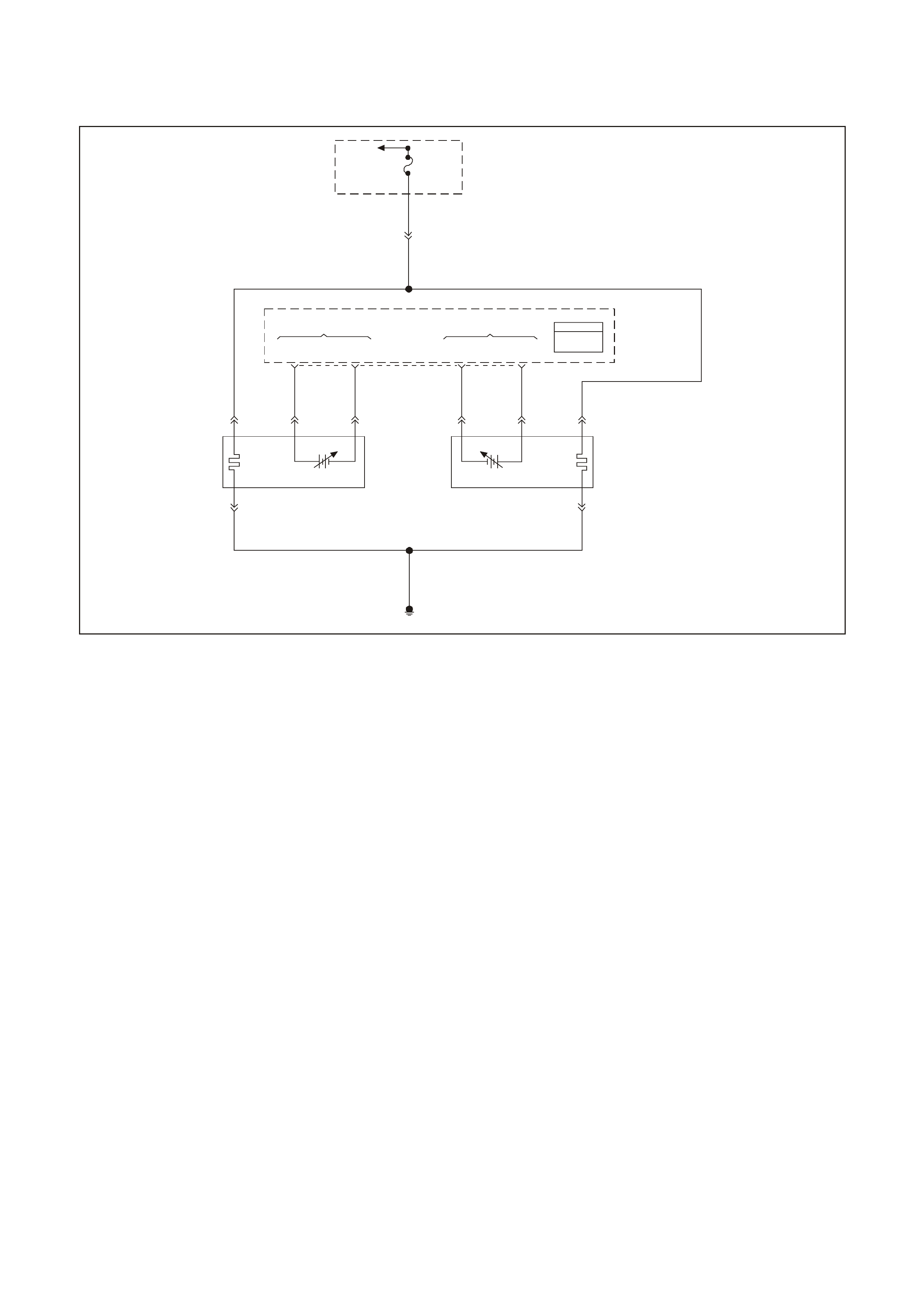
GEN III V8 PCM DTC P1134 HEATED OXYGEN SENSOR TRANSITION TIME
RATIO BANK 1 SENSOR 1
GEN3 0157
To EFI
(Engine Cont.)
Relay Fuse
F33
YE111
P439
Bank #1
Left Front
HO2S
High HO2S
Low
Ban k #2
Right Front
HO2S
Low HO2S
High
PCM
J1 = B LUE
J2 = RED
Powertrain
Control
Module
(PCM)
P439
B/R 750
Engine
Earth
D
Bank 2 Sensor 1
Heat ed Oxygen
Sensor (HO2S)
BA
GY/B 1413 GY 1412
26 66 J1
69 29
ABD
Bank 1 Sensor 1
Heated Oxygen
Sensor (HO2S)
BLU/B 413
P439 V412
B/R 750
C
B/R 750
C
CIRCUIT DESCRIPTION
The PCM monitors the Heated Oxygen Sensor (HO2S) activity for 100 seconds. During this monitor period the
PCM counts the number of times that the HO2S responds from rich to lean and from lean to rich and adds the
amount of time it took to complete all transitions.
W ith this inform ation, an average time f or all transitions can be determ ined. The PCM then divides the rich to lean
average by the lean to rich average to obtain a ratio. A DTC P1134 sets if the HO2S ratio is not within range.
CONDITIONS FOR RUNNING THE DTC
• DTCs P0102, P0103, P0112, P0113, P0117, P0118, P0335, P0336, P0351-P0358, P1221, P1258 not set.
• The fuel system is operating in Closed Loop.
• The engine run time is greater than 2.0 seconds.
• The engine speed is greater than 1000 RPM but less than 2300 RPM.
• The ignition voltage is greater than 9.0 volts.
• The engine coolant temperature is greater than 65°C (149°F).
• The MAF is between 20 g/s and 50 g/s.
• The EVAP purge duty cycle is greater than 0%.
CONDITIONS FOR SETTING THE DTC
• The PCM determines that the HO2S transition time ratio is not at the expected value.
ACTIONS TAKEN WHEN THE DTC SETS
• The PCM stores the DTC information into memory when the diagnostic runs and fails.
• The Check Powertrain Lamp (CPL) will not illuminate.
• T he PCM records the operating conditions at the time the diagnostic f ails. The PCM stores this inform ation in
the Freeze Frame/Failure Records.

CONDITIONS FOR CLEARING THE CPL/DTC
• The PCM turns the CPL OFF after the first ignition cycle that the diagnostic runs and does not fail.
• A History DT C will clear after for ty c onsecutive warm- up cycles, if no f ailures are repor ted by this or any other
non-emission related diagnostic.
• A last test failed (Current DTC) will clear when the diagnostic runs and does not fail.
• Use a Tech 2 scan tool in order to clear the CPL/DTC.
DIAGNOSTIC AIDS
• An oxygen supply inside the HO2S is necessary for proper operation. This supply of oxygen is provided
through the HO2S wires. All HO2S wires and connections should be inspected for breaks or contamination.
• Using the Freeze Frame/Failure Records data may aid in locating an intermittent condition. If you cannot
duplicate the DT C, the information inc luded in the Freeze Fram e/Failure Records data can help determ ine the
distance traveled since the DTC set. The Fail Counter and Pass Counter can also help determine how many
ignition cycles the diagnostic reported a pass and/or fail. Operate the vehicle within the same freeze frame
condition (RPM, load, vehicle speed, temperature etc.) that you observed. This will isolate when the DTC
failed.
For any test that requires probing the PCM or component harness connectors, use the Connector Test
Adaptor Kit J 35616-A. Using this kit prevents any damage to the harness connector terminals.
• For an intermittent, refer to Section 6C3-2B SYMPTOMS in the VT Series II Service Information.
TEST DESCRIPTION
The numbers below refer to the step numbers on the diagnostic table.
2. This step determines if the fault is present. This test may take 5 minutes for the diagnostic to run.
3. DTCs P1134 and P1154 setting at the same time is a good indication that a fuel contamination condition is
present.
4. An exhaust leak 15 - 30 cm (6 - 12 inches) away form the HO2S can cause a DTC to set.
6. This step checks whether a good earth circuit is available.
7. This step checks the integrity of the signal circuit to the PCM.
8. Certain RTV s ilic on gas k et mater ials give off vapor s that c an contaminate the HO 2S. T her e is also a pos s ibility
of silic one contamination caus ed by silicone in the fuel. If the sensors appear contam inated by silicone and all
the silicone sealant is non-silicone base, advise the customer to try a different fuel company. A missing fuel
filler restrictor, indicates the customer may have used leaded fuel.

GEN III V8 PCM DTC P1134 HEATED OXYGEN SENSOR TRANSITION TIME RATIO BANK 1 SENSOR 1
Step Action Value(s) Yes No
1 Did you perform the Powertrain On-Board Diagnostic
(OBD) System Check? Go to Step 2 Go to Powertrain
OBD System
Check Table
2
Important: If any DTCs are set (except P1154), refer to
those DTCs before proceeding with this diagnostic table.
1. Install the Tech 2 scan tool.
2. Idle the engine at the normal operating temperature.
3. Operate the vehicle within the Conditions for Running
the DTC as specified in the supporting text, if
applicable.
4. Monitor the Failed This Ignition option under the DTC
Information option using the Tech 2 scan tool.
Does the Tech 2 scan tool indicate DTC P1134 test
failed?
Go to Step 3 Go to Diagnostic
Aids
3 Did the Tech 2 scan tool also indicate P1154 test failed? Go to Step 8 Go to Step 4
4 1. Inspect the exhaust system for leaks.
2. If you find an exhaust leak, repair the exhaust as
necessary.
Did you isolate an exhaust leak?
Go to Step 13 Go to Step 5
5 Inspect the following items:
• Ensure that the HO2S is securely installed.
• Check for corrosion on the terminals.
• Check the terminal tension at the HO2S and at the
PCM.
• Check for damaged wiring.
Did you find a condition in any of the above areas?
Go to Step 9 Go to Step 6
6 1. Disconnect the Bank 1 HO2S.
2. Jumper the HO2S low (PCM side) signal circuit to
earth.
3. Monitor the Bank 1 HO2S voltage using the Tech 2
scan tool.
Is the HO2S voltage within the specified value?
350-550 mV Go to Step 7 Go to Step 10
7 1. Jumper the Bank 1 HO2S high and low (PCM side)
signal circuit to earth.
2. Monitor the Bank 1 HO2S voltage using the Tech 2
scan tool.
Is the HO2S voltage below the specified value?
200 mV Go to Step 12 Go to Step 11
8 Important: Before replacing a sensor, determine and
correct the cause of the contamination. Check for the
following conditions:
• Fuel contamination.
• Use of improper RTV sealant.
• Engine oil/coolant consumption.
Replace the affected Heated Oxygen Sensor.
Is the action complete?
Go to Step 13
9 Repair the condition as necessary.
Is the action complete? Go to Step 13
10 Repair the open Bank 1 HO2S low signal circuit or
earthed Bank 1 HO2S high signal circuit.
Is the action complete?
Go to Step 13
11 Repair the open Bank 1 HO2S high signal circuit or faulty
PCM connections.
Is the action complete?
Go to Step 13
12 Replace the Bank 1 HO2S .
Is the action complete? Go to Step 13

Step Action Value(s) Yes No
13 1. Select the Diagnostic Trouble Code (DTC) option and
the Clear DTC Information option using the Tech 2
scan tool.
2. Idle the engine at the normal operating temperature.
3. Select the Diagnostic Trouble Code (DTC) option, the
DTC Information option and The Failed This Ignition
option using the Tech 2 scan tool.
4. Operate the vehicle within the Conditions for Running
the DTC as specified in the supporting text, if
applicable.
Does the Tech 2 scan tool indicate that this DTC reset?
Go to Step 2 Go to Step 14
14 Using the Tech 2 scan tool, check for any other DTCs.
Does the Tech 2 scan tool display any DTCs that you
have not diagnosed?
Go to the
applicable DTC
table
System OK

GEN III V8 PCM DTC P1153 HEATED OXYGEN SENSOR INSUFFICIENT
SWITCHING BANK 2 SENSOR 1
GEN3 0157
To EFI
(Engine Cont.)
Relay Fuse
F33
YE111
P439
Bank #1
Left Front
HO2S
High HO2S
Low
Ban k #2
Right Front
HO2S
Low HO2S
High
PCM
J1 = B LUE
J2 = RED
Powertrain
Control
Module
(PCM)
P439
B/R 750
Engine
Earth
D
Bank 2 Sensor 1
Heat ed Oxygen
Sensor (HO2S)
BA
GY/B 1413 GY 1412
26 66 J1
69 29
ABD
Bank 1 Sensor 1
Heated Oxygen
Sensor (HO2S)
BLU/B 413
P439 V412
B/R 750
C
B/R 750
C
CIRCUIT DESCRIPTION
The PCM monitors the Heated Oxygen Sensor (HO2S) activity for 100 seconds. During this monitor period the
PCM counts the number of times that the HO2S switches from rich to lean and lean to rich. A DTC P1153 sets
when the PCM determines that the HO2S did not switch enough times.
A lean to rich switch is determined when the HO2S voltage changes from less than 300 mV to greater than 600
mV. A r ich to lean switch is determ ined when the HO2S voltage changes from more than 600 m V to less than 300
mV.
CONDITIONS FOR RUNNING THE DTC
• DTCs P0102, P0103, P0112, P0113, P0117, P0118, P0335, P0336, P0351-P0358, P1258 not set.
• The fuel system is operating in Closed Loop.
• The engine run time is greater than 2.0 seconds.
• The engine speed is greater than 1000 RPM but less than 2300 RPM.
• The ignition voltage is greater than 9.0 volts.
• The engine coolant temperature is greater than 65°C (149°F).
• The MAF is between 15 g/s and 35 g/s.
• The EVAP purge duty cycle is greater than 0%.
CONDITIONS FOR SETTING THE DTC
• T he PCM determ ines that within 100 seconds the HO2S lean to r ich switches ar e less than 30 and r ich to lean
switches are less than 30.
ACTIONS TAKEN WHEN THE DTC SETS
• The PCM stores the DTC information into memory when the diagnostic runs and fails.
• The Check Powertrain Lamp (CPL) will not be illuminated.
• T he PCM records the operating conditions at the time the diagnostic f ails. The PCM stores this inform ation in
the Freeze Frame/Failure Records.

CONDITIONS FOR CLEARING THE CPL/DTC
• The PCM turns the CPL OFF after the first ignition cycle that the diagnostic runs and does not fail.
• A History DT C will clear after for ty c onsecutive warm- up cycles, if no f ailures are repor ted by this or any other
non-emission related diagnostic.
• A last test failed (Current DTC) will clear when the diagnostic runs and does not fail.
• Use a Tech 2 scan tool in order to clear the CPL/DTC.
DIAGNOSTIC AIDS
• Inspect the HO2S signal circuit for being shorted to a PCM earth. The HO2S signal circuit shorted to a PCM
earth will not cause a HO2S low DTC to set, but will set a switching DTC.
• A malfunction in the HO2S heater circuit will cause a DTC P1153 to set. Check HO2S heater circuit for
intermittent opens/connection.
• An oxygen supply inside the HO2S is necessary for proper operation. This supply of oxygen is provided
through the HO2S wires. All HO2S wires and connections should be inspected for breaks or contamination.
Refer to Electrical Diagnosis/Repair Procedures in Section 12P, in the VT Series I Service Information.
• Using the Freeze Frame/Failure Records data may aid in locating an intermittent condition. If you cannot
duplicate the DT C, the information inc luded in the Freeze Fram e/Failure Records data can help determ ine the
distance traveled since the DTC set. The Fail Counter and Pass Counter can also help determine how many
ignition cycles the diagnostic reported a pass and/or fail. Operate the vehicle within the same freeze frame
condition (RPM, load, vehicle speed, temperature etc.) that you observed. This will isolate when the DTC
failed. For any test that requires probing the PCM or com ponent harness connectors, use the Connector Test
Adaptor Kit J 35616-A. Using this kit prevents any damage to the harness connector terminals.
• For an intermittent, refer to Section 6C3-2B SYMPTOMS in the VT Series II Service Information.
TEST DESCRIPTION
The numbers below refer to the step numbers on the diagnostic table.
2. This step determines if the fault is present. This test may take 5 minutes for the diagnostic to run.
3. DTCs P1133 and P1153 setting at the same time is a good indication that a fuel contamination condition is
present.
4. An exhaust leak 15 - 30 cm (6 - 12 inches) away from the HO2S can cause a DTC to set.
6. This step checks whether a good earth circuit is available.
7. This step checks the integrity of the signal circuit to the PCM.
8. Certain RTV s ilic on gas k et mater ials give off vapor s that c an contaminate the HO 2S. T her e is also a pos s ibility
of silic one contamination caus ed by silicone in the fuel. If the sensors appear contam inated by silicone and all
the silicone sealant is non-silicone base, advise the customer to try a different fuel company. A missing fuel
filler restrictor, indicates the customer may have used leaded fuel.

GEN III V8 PCM DTC P1153 HEATED OXYGEN SENSOR INSUFFICIENT SWITCHING BANK 2 SENSOR 1
Step Action Value(s) Yes No
1 Did you perform the Powertrain On-Board Diagnostic
(OBD) System Check? Go to Step 2 Go to Powertrain
OBD System
Check Table
2
Important: If any DTCs are set (except P1133), refer to
those DTCs before proceeding with this diagnostic table.
1. Install the Tech 2 scan tool.
2. Idle the engine at the normal operating temperature.
3. Operate the vehicle within the Conditions for Running
the DTC as specified in the supporting text, if
applicable.
4. Monitor the Failed This Ignition option under the DTC
Information option using the Tech 2 scan tool.
Does the Tech 2 scan tool indicate DTC P1153 test failed?
Go to Step 3 Go to Diagnostic
Aids
3 Did the Tech 2 scan tool also indicate P1133 test failed? Go to Step 8 Go to Step 4
4 1. Inspect the exhaust system for leaks.
2. If you find an exhaust leak, repair the exhaust as
necessary.
Did you isolate an exhaust leak?
Go to Step 13 Go to Step 5
5 Inspect the following items:
• Ensure that the HO2S is securely installed.
• Check for corrosion on the terminals.
• Check the terminal tension at the HO2S and at the
PCM.
• Check for damaged wiring.
Did you find a condition in any of the above areas?
Go to Step 9 Go to Step 6
6 1. Disconnect the Bank 2 HO2S.
2. Jumper the HO2S low (PCM side) signal circuit to a
earth.
3. Monitor the Bank 2 HO2S voltage using the Tech 2
scan tool.
Is the HO2S voltage within the specified value?
350-550 mV Go to Step 7 Go to Step 10
7 1. Jumper the Bank 2 HO2S high and low (PCM side)
signal circuit to earth.
2. Monitor the Bank 2 HO2S voltage using the Tech 2
scan tool.
Is the HO2S voltage below the specified value?
200 mV Go to Step 12 Go to Step 11
8 Important: Before replacing a sensor, determine and
correct the cause of the contamination. Check for the
following conditions:
• Fuel contamination.
• Use of improper RTV sealant.
• Engine oil/coolant consumption.
Replace the affected Heated Oxygen Sensor.
Is the action complete?
Go to Step 13
9 Repair the condition as necessary.
Is the action complete? Go to Step 13
10 Repair the open Bank 2 HO2S low signal circuit or earthed
Bank 2 HO2S high signal circuit.
Is the action complete?
Go to Step 13
11 Repair the open Bank 2 HO2S.
Is the action complete? Go to Step 13

Step Action Value(s) Yes No
12 Replace the Bank 2 HO2S.
Is the action complete? Go to Step 13
13 1. Select the Diagnostic Trouble Code (DTC) option and
the Clear DTC Information option using the Tech 2 scan
tool.
2. Idle the engine at the normal operating temperature.
3. Select the Diagnostic Trouble Code (DTC) option, the
DTC Information option and The Failed This Ignition
option using the Tech 2 scan tool.
4. Operate the vehicle within the Conditions for Running
the DTC as specified in the supporting text, if
applicable.
Does the Tech 2 scan tool indicate that this DTC reset?
Go to Step 2 Go to Step 14
14 Using the Tech 2 scan tool, check for any other DTCs.
Does the Tech 2 scan tool display any DTCs that you have
not diagnosed?
Go to the
applicable DTC
table
System OK

GEN III V8 PCM DTC P1154 HEATED OXYGEN SENSOR TRANSITION
TIME RATIO BANK 2 SENSOR 1
GEN 3 01 57
To EFI
(Engine Cont.)
Relay Fuse
F33
YE111
P 439
Bank #1
Left Front
HO2S
High HO2S
Low
Bank #2
Right Front
HO2S
Low HO2S
High
PCM
J1 = B LUE
J2 = R ED
Powertrain
Control
Module
(PCM)
P439
B/R 750
Engine
Earth
D
Bank 2 Sensor 1
Heated Oxygen
Sensor (HO2S)
BA
GY/B 1413 GY 1412
26 66 J1
69 29
ABD
Bank 1 Sensor 1
Heat ed Oxygen
Sensor (HO2S)
BLU/B 413
P439 V412
B/R 750
C
B/R 750
C
CIRCUIT DESCRIPTION
The PCM monitors the Heated Oxygen Sensor (HO2S) activity for 100 seconds. During this monitor period the PCM
counts the num ber of tim es that the HO 2S responds from r ich to lean and fr om lean to rich and adds the amount of
time it took to complete all transitions.
W ith this inform ation, an average time f or all transitions can be determ ined. The PCM then divides the rich to lean
average by the lean to rich average to obtain a ratio. A DTC P1134 sets if the HO2S ratio is not within range.
CONDITIONS FOR RUNNING THE DTC
• DTCs P0102, P0103, P0112, P0113, P0117, P0118, P0335, P0336, P0351-P0358, P1221, P1258 not set.
• The fuel system is operating in Closed Loop.
• The engine run time is greater than 2.0 seconds.
• The engine speed is greater than 1000 RPM but less than 2300 RPM.
• The ignition voltage is greater than 9.0 volts.
• The engine coolant temperature is greater than 65°C (149°F).
• The MAF is between 20 g/s and 50 g/s.
• The EVAP purge duty cycle is greater than 0%.
CONDITIONS FOR SETTING THE DTC
• The PCM determines that the HO2S transition time ratio is not at the expected value.

ACTIONS TAKEN WHEN THE DTC SETS
• The PCM stores into memory when the diagnostic runs and fails.
• The Check Powertrain Lamp (CPL) will not be illuminated.
• T he PCM records the operating conditions at the time the diagnostic fails. The PCM stores this inform ation in
the Freeze Frame/Failure Records.
CONDITIONS FOR CLEARING THE CPL/DTC
• The PCM turns the CPL OFF after the first ignition cycle that the diagnostic runs and does not fail.
• A History DT C will clear after for ty c onsecutive warm- up cycles, if no f ailures are repor ted by this or any other
non-emission related diagnostic.
• A last test failed (Current DTC) will clear when the diagnostic runs and does not fail.
• Use a Tech 2 scan tool to clear the CPL/DTC.
DIAGNOSTIC AIDS
• An oxygen supply inside the HO2S is necessary for proper operation. This supply of oxygen is provided
through the HO2S wires. All HO2S wires and connections should be inspected for breaks or contamination.
• Using the Freeze Frame/Failure Records data may aid in locating an intermittent condition. If you cannot
duplicate the DT C, the information inc luded in the Freeze Fram e/Failure Records data can help determ ine the
distance traveled since the DTC set. The Fail Counter and Pass Counter can also help determine how many
ignition cycles the diagnostic reported a pass and/or fail. Operate the vehicle within the same freeze frame
condition (RPM, load, vehicle speed, temperature etc.) that you observed. This will isolate when the DTC
failed. For any test that requires probing the PCM or com ponent harness connectors, use the Connector Test
Adaptor Kit J 35616-A. Using this kit prevents any damage to the harness connector terminals.
• For an intermittent, refer to Section 6C3-2B SYMPTOMS in the VT Series II Service Information.
TEST DESCRIPTION
The numbers below refer to the step numbers on the diagnostic table.
2. This step deter mines if the fault is pr esent. This test may take 5 m inutes for the diagnostic to run. For any test
that requires probing the PCM or a component harness connector, use the Connector Test Adaptor Kit J
35616-A. Using this kit will prevent damage to the harness connector terminals.
3. DTCs P1134 and P1154 setting at the same time is a good indication that a fuel contamination condition is
present.
4. An exhaust leak 15 - 30 cm (6 - 12 inches) away form the HO2S can cause a DTC to set.
6. This step checks whether a good earth circuit is available.
7. This step checks the integrity of the signal circuit to the PCM.
8. Certain RTV s ilic on gas k et mater ials give off vapor s that c an contaminate the HO 2S. T her e is also a pos s ibility
of silic one contamination caus ed by silicone in the fuel. If the sensors appear contam inated by silicone and all
the silicone sealant is non-silicone base, advise the customer to try a different fuel company. A missing fuel
filler restrictor, indicates the customer may have used leaded fuel.

GEN III V8 PCM DTC P1154 HEATED OXYGEN SENSOR TRANSITION TIME RATIO BANK 2 SENSOR 1
Step Action Value(s) Yes No
1 Did you perform the Powertrain On-Board Diagnostic
(OBD) System Check? Go to Step 2 Go to Powertrain
OBD System
Check Table
2
Important: If any DTCs are set (except P1134), refer to
those DTCs before proceeding with this diagnostic table.
1. Install the Tech 2 scan tool.
2. Idle the engine at the normal operating temperature.
3. Operate the vehicle within the Conditions for Running
the DTC as specified in the supporting text, if
applicable.
4. Monitor the Failed This Ignition option under the DTC
Information option using the Tech 2 scan tool.
Does the Tech 2 scan tool indicate DTC P1154 test
failed?
Go to Step 3 Go to Diagnostic
Aids
3 Did the Tech 2 scan tool also indicate P1134 test failed? Go to Step 8 Go to Step 4
4 1. Inspect the exhaust system for leaks.
2. If you find an exhaust leak, repair the exhaust as
necessary.
Did you isolate an exhaust leak?
Go to Step 13 Go to Step 5
5 Inspect the following items:
• Ensure that the HO2S is securely installed.
• Check for corrosion on the terminals.
• Check the terminal tension at the HO2S and at the
PCM.
• Check for damaged wiring.
Did you find a condition in any of the above areas?
Go to Step 9 Go to Step 6
6 1. Disconnect the Bank 2 HO2S.
2. Jumper the HO2S low (PCM side) signal circuit to a
earth.
3. Monitor the Bank 2 HO2S voltage using the Tech 2
scan tool.
Is the HO2S voltage within the specified value?
350-550 mV Go to Step 7 Go to Step 10
7 1. Jumper the Bank 2 HO2S high and low (PCM side)
signal circuit to earth.
2. Monitor the Bank 2 HO2S voltage using the Tech 2
scan tool.
Is the HO2S voltage below the specified value?
200 mV Go to Step 12 Go to Step 11
8 Important: Before replacing a sensor, determine and
correct the cause of the contamination. Check for the
following conditions:
• Fuel contamination.
• Use of improper RTV sealant.
• Engine oil/coolant consumption.
Replace the affected Heated Oxygen Sensor.
Is the action complete?
Go to Step 13
9 Repair the condition as necessary.
Is the action complete? Go to Step 13
10 Repair the open Bank 2 HO2S low signal circuit or
earthed Bank 2 HO2S high signal circuit.
Is the action complete?
Go to Step 13
11 Repair the open Bank 2 HO2S high signal circuit or faulty
PCM connections.
Is the action complete?
Go to Step 13
12 Replace the Bank 2 HO2S .
Is the action complete? Go to Step 13

Step Action Value(s) Yes No
13 1. Select the Diagnostic Trouble Code (DTC) option and
the Clear DTC Information option using the Tech 2
scan tool.
2. Idle the engine at the normal operating temperature.
3. Select the Diagnostic Trouble Code (DTC) option, the
DTC Information option and The Failed This Ignition
option using the Tech 2 scan tool.
4. Operate the vehicle within the Conditions for Running
the DTC as specified in the supporting text, if
applicable.
Does the Tech 2 scan tool indicate that this DTC reset?
Go to Step 2 Go to Step 14
14 Using the Tech 2 scan tool, check for any other DTCs.
Does the Tech 2 scan tool display any DTCs that you
have not diagnosed?
Go to the
applicable DTC
table
System OK
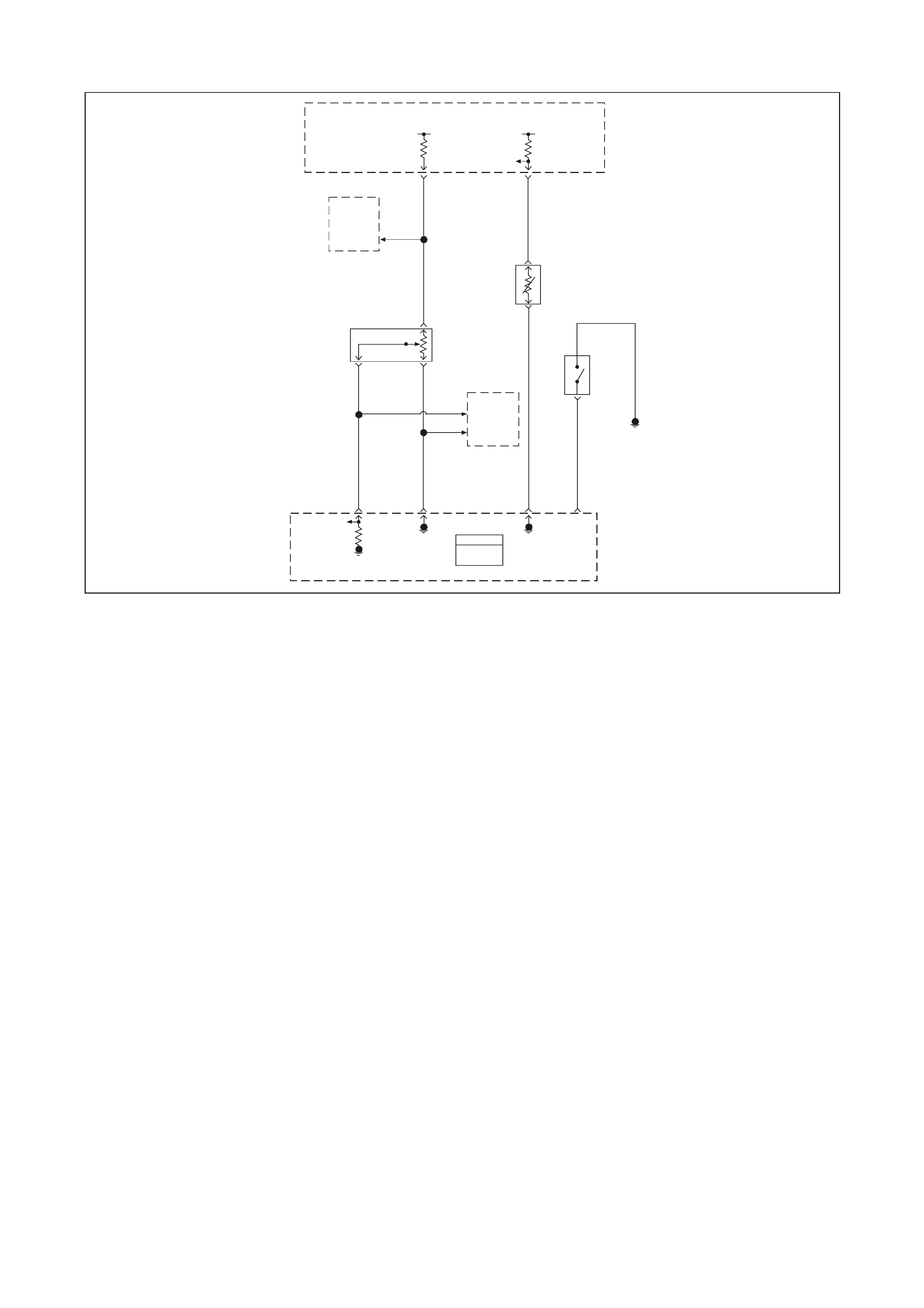
GEN III V8 PCM DTC P1258 ENGINE COOLANT OVER TEMP FUEL DISABLED
GEN3 0156
PCM
J1 = BLU E
J2 = RED
Powertrain
Control
Module
(PCM)
Powertrain
Control
Module
(PCM)
5V 5V
ECT
Sensor
Signal
TP Sensor
5V
Reference
Throttle
Relaxer
Control
Module
Engine Coolant
Temperature
(ECT)
Sensor
Throttle
Position
(TP)
Sensor Coolant
Level
Sensor
Engine
Earth
TP
Sensor
Signal Sensor
Earth ECT
Sensor
Earth
Coolant
Level
Sensor
Input
08 74 J1
Y410
B
A
B/R 750
G69
30 J1
GY/B 455
80 J1
B/Y 452
60
BLU 417
24 J2
B/Y 452
BLU 417
CB
40
43
GY 416
GY 416
A
GY
416
41
Throttle
Relaxer
Control
Module
J1
J1
CIRCUIT DESCRIPTION
In order to reduce the engine temperature the PCM has the ability to disable a number of fuel injectors during an
engine over tem perature condition. The PCM c onsiders the engine over tem perature whenever the ECT reaches a
predeterm ined tem perature. This DT C sets in order to show that the PCM detected an over tem perature condition
and that the system engaged the protection mode.
CONDITION FOR RUNNING THE DTC
• DTCs P0117, P0118, are not set.
• The engine is running.
CONDITION FOR SETTING THE DTC
• The engine coolant temperature is greater than 132°C (270°F).
• The above conditions present for greater than 10 seconds.
ACTION TAKEN WHEN THE DTC SETS
• The PCM illuminates the Check Powertrain Lamp (CPL) when the diagnostic runs and fails.
• T he PCM records the operating conditions at the time the diagnostic f ails. The PCM stores this inform ation in
the Freeze Frame/Failure Records.
CONDITIONS FOR CLEARING THE CPL/DTC
• The PCM turns the CPL OFF after the first ignition cycle that the diagnostic runs and does not fail.
• A History DT C will clear after for ty c onsecutive warm- up cycles, if no f ailures are repor ted by this or any other
non-emission related diagnostic.
• A last test failed (Current DTC) will clear when the diagnostic runs and does not fail.
• Use a Tech 2 scan tool in order to clear the CPL/DTC.

DIAGNOSTIC AIDS
Important: If an overheating condition exists, repair the overheat condition and change the engine oil and filter.
• Using the Freeze Frame/Failure Records data may aid in locating an intermittent condition. If you cannot
duplicate the DT C, the information inc luded in the Freeze Fram e/Failure Records data can help determ ine the
distance traveled since the DTC set. The Fail Counter and Pass Counter can also help determine how many
ignition cycles the diagnostic reported a pass and/or fail. Operate the vehicle within the same freeze frame
condition (RPM, load, vehicle speed, temperature etc.) that you observed. This will isolate when the DTC
failed. For any test that requires probing the PCM or com ponent harness connectors, use the Connector Test
Adaptor Kit J 35616-A. Using this kit prevents any damage to the harness connector terminals.
• For an intermittent, refer to Section 6C3-2B SYMPTOMS in the VT Series II Service Information.
TEST DESCRIPTION
The number below refers to the step number on the diagnostic table.
2. A cooling s ystem pr oblem will enable the engine protection mode. Refer to Section 6B3 ENGINE COOLING in
the VT Series II Service Information for further diagnosis.

GEN III V8 PCM DTC P1258 ENGINE COOLANT OVER TEMP FUEL DISABLED
Step Action Value(s) Yes No
1 Did you perform the Powertrain On-Board Diagnostic
(OBD) System Check? Go to Step 2 Go to Powertrain
OBD System
Check Table
2 Select the Diagnostic Trouble Code (DTC) option, the
DTC Information option and , The Failed This Ignition
option using the Tech 2 scan tool.
Does the Tech 2 scan tool display any DTCs related to
the Engine Coolant Temperature (ECT) sensor that you
have not diagnosed?
Go to the
applicable DTC Go to Section
6B3 Engine
Cooling in the VT
Series II Service
Information
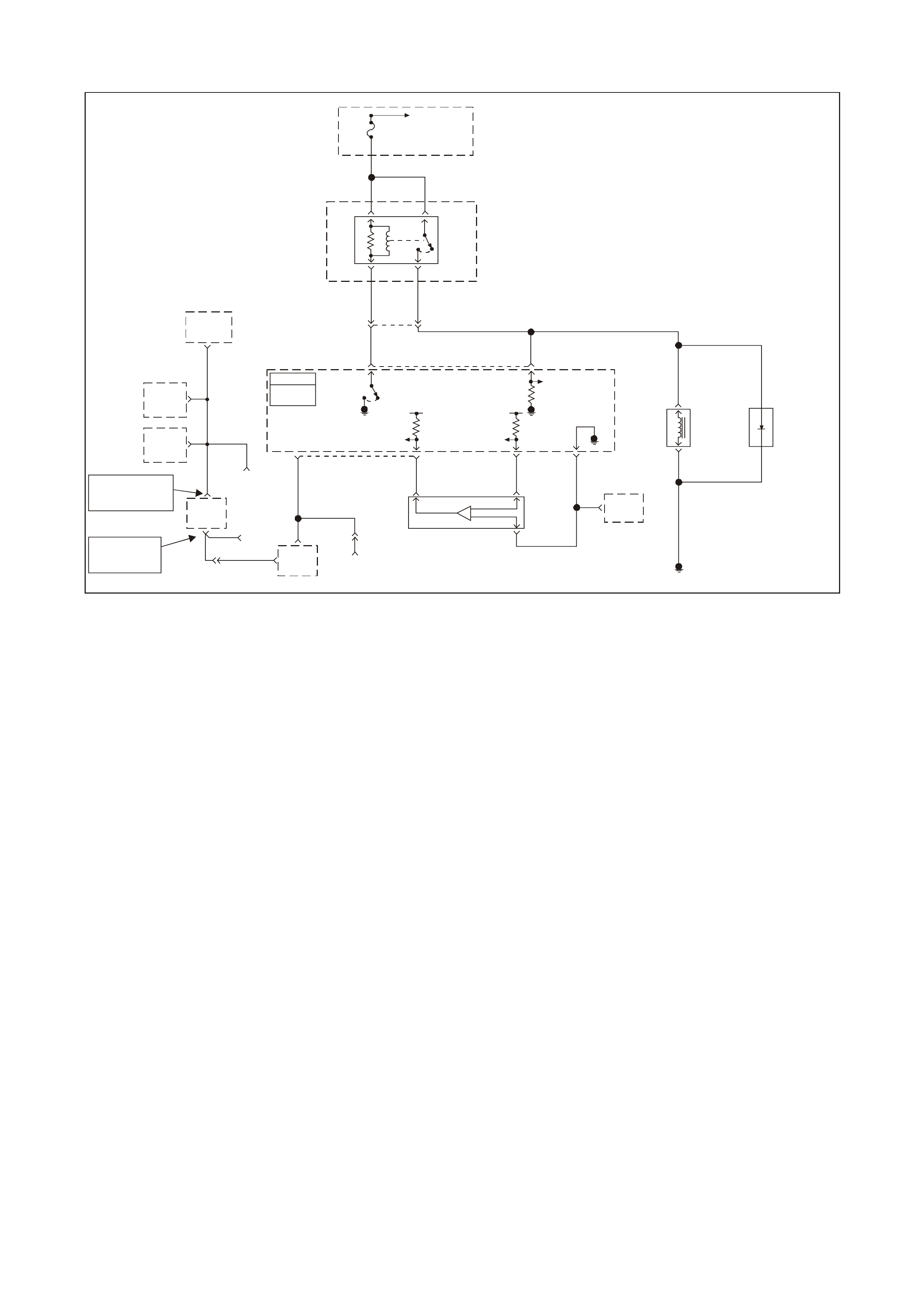
GEN III V8 PCM DTC P1539 A/C CLUTCH STATUS CIRCUIT HIGH VOLTAGE
GEN3 0175
A/C
Diode
Fuse
F33
To EFI
(Eng in e Con t. )
Relay
P 439
P 439
A/C
COMP
Relay
15
23
G59
LG/B 366
YE111
LG/B 366
43 18 J2
G
59
A/C
Clutch
Status
A/C Refrigerant
Pressure Sensor
Earth
A
B
A/C
Compressor
Clutch
Powertrain
Control
Module
(PCM)
Engine
Earth
B/R 750
A/C
Refrigerant
Pressure
Sensor
IAT
Sensor
G/O 469V/W 415
G/B 259
A/C Refrigerant
Pressure Sensor
5V Reference
A/C Refrigerant
Pressure Sensor
Signal
5V
57 J2
45 J114 J258 J1
Y 1049 CB
A
Y
1049 YE110
2Data Link
Connector
(DLC)
7
6
R/B
1221
YE112
DLC
9
2
BCM
DLC
1
G/W 1220
IP
Cluster
NOTE
"3" YB164 Low Series
"9" YB175 High Series
NOTE
YB164 Low Ser ies
YB175 High Series
12
11
ABS/ETC
Module
HVA
A/C
Control
6
A/C
Clutch
Relay
Control
Serial Data
(Class 2)
PCM
J1 = BLU E
J2 = RED
CIRCUIT DESCRIPTION
The PCM activates the A/C clutch relay when the PCM detects an A/C request. Voltage is present at both the A/C
compressor clutch and the A/C clutch status terminal at the PCM when the relay is activated.
A DT C P1539 s ets if the PCM detec ts voltage on the A/C clutc h s tatus ter minal when the system has not reques ted
the A/C.
A short to voltage at any point in the A/C status circuit, or the A/C relay contacts are stuck, sets a DTC P1539.
CONDITIONS FOR RUNNING THE DTC
• The A/C is not requested.
CONDITIONS FOR SETTING THE DTC
• Voltage is detec ted on the A/C status circ uit for m ore than 15 seconds after the PCM has dis engaged the A/C
clutch relay.
ACTION TAKEN WHEN THE DTC SETS
• The PCM store into memory when the diagnostic runs and fails.
• The Check Powertrain Lamp (CPL) will not be illuminated.
• T he PCM records the operating conditions at the time the diagnostic f ails. The PCM stores this inform ation in
the Freeze Frame/Failure Records.
CONDITIONS FOR CLEARING THE CPL/DTC
• A History DT C will clear after for ty c onsecutive warm- up cycles, if no f ailures are repor ted by this or any other
non-emission related diagnostic.
• A last test failed (Current DTC) will clear when the diagnostic runs and does not fail.
• Use a Tech 2 scan tool in order to clear the CPL/DTC.

DIAGNOSTIC AIDS
• T he A/C status circ uit goes to the A/C compres sor clutch and to the A/C clutch r elay. Inspec t all circuits going
to these components.
• For an intermittent, refer to Section 6C3-2B SYMPTOMS in the VT Series II Service Information.
TEST DESCRIPTION
The number below refer to the step number on the diagnostic table.
2. If the PCM detects a voltage on the A/C st atus circuit with the A/C OFF the Tec h 2 sc an tool indicates the A/C
status as ON.
3. If the Tech 2 scan tool displayed YES in the RAN column and INT in the FAIL column, this indicates an
intermittent condition is present. Inspect the A/C status circuit for an intermittent short to B+. Refer to
Sym ptoms ). Using the Freeze Fram e/Failure Recor ds data aids in locating an inter mittent condition. If you can
not duplicate the DTC, the information included in the Freeze Frame/Failure Records data determines the
distance traveled since the DTC set. The Fail Counter and the Pass Counter can also be used to determine
how many ignition cycles the diagnostic reported a pass and/or a fail. Operate the vehicle within the same
freeze frame condition (RPM, load, vehicle speed, temperature etc.) that the PCM recorded. This isolated
when the DTC failed.
4. The relay is shorted internally if the Tech 2 scan tool indicates that the test passed.
7. This DT C will not report a pass. T he Tec h 2 scan tool status f or this DT C will never report a pass. The Tech 2
scan tool will only display when the diagnostic fa ils. T he repair is not com plete if the T ech 2 sc an tool indicates
that the diagnostic ran and failed.

GEN III V8 PCM DTC P1539 A/C CLUTCH STATUS CIRCUIT HIGH VOLTAGE
Step Action Value(s) Yes No
1 Did you perform the Powertrain On-Board Diagnostic
(OBD) System Check? Go to Step 2 Go to Powertrain
OBD System
Check Table
2
Important: Diagnose DTC P1545 first if it is set.
1. Install a Tech 2 scan tool.
2. Idle the engine with the A/C OFF.
3. Monitor the A/C Status display on the Engine Data
List using a Tech 2 scan tool.
Does the Tech 2 scan tool indicate the A/C Status is ON?
Go to Step 4 Go to Step 3
3 1. Turn ON the ignition leaving the engine OFF.
2. Review the Freeze Frame/Failure Records data for
this DTC and observe the parameters.
3. Turn OFF the ignition for 15 seconds.
4. Idle the engine.
5. Operate the vehicle within the conditions required for
this diagnostic to run, and as close to the conditions
recorded in the Freeze Frame/Failure Records as
possible. Special operating conditions that need to be
met before the PCM will run this diagnostic, where
applicable, are listed in Conditions for Running the
DTC.
6. Select the Diagnostic Trouble Code (DTC) option, the
DTC Information option and The Failed This Ignition
option using the Tech 2 scan tool.
Does the Tech 2 scan tool indicate that this diagnostic
failed this ignition?
Go to Step 4 Refer to
Diagnostic Aids
4 1. Turn OFF the ignition.
2. Remove the A/C clutch relay.
3. Idle the engine for 30 seconds.
4. Monitor the Failed This Ignition option under the DTC
Information option using the Tech 2 scan tool.
Does the Tech 2 scan tool indicate that DTC P1539
failed?
Go to Step 5 Go to Step 6
5 Repair the short to B+ on the A/C clutch status circuit.
Is the action complete? Go to Step 7
6 Repair the faulty A/C clutch relay.
Is the action complete? Go to Step 7
7 1. Select the Diagnostic Trouble Code (DTC) option and
the Clear DTC Information option using the Tech 2
scan tool.
2. Idle the engine at the normal operating temperature.
3. Select the Diagnostic Trouble Code (DTC) option, the
DTC Information option and, The Failed This Ignition
option using the Tech 2 scan tool.
4. Operate the vehicle within the Conditions for Running
the DTC as specified in the supporting text, if
applicable.
Does the Tech 2 scan tool indicate that this DTC reset?
Go to Step 2 Go to Step 8
8 Using the Tech 2 scan tool, check for any other DTCs.
Does the Tech 2 scan tool display any DTCs that you
have not diagnosed?
Go to the
applicable DTC
table
System OK

GEN III V8 PCM DTC P1546 A/C CLUTCH STATUS CIRCUIT LOW VOLTAGE
GEN3 0175
A/C
Diode
Fuse
F33
To EFI
(Eng in e Con t. )
Relay
P 439
P 439
A/C
COMP
Relay
15
23
G59
LG/B 366
YE111
LG/B 366
43 18 J2
G
59
A/C
Clutch
Status
A/C Refrigerant
Pressure Sensor
Earth
A
B
A/C
Compressor
Clutch
Powertrain
Control
Module
(PCM)
Engine
Earth
B/R 750
A/C
Refrigerant
Pressure
Sensor
IAT
Sensor
G/O 469V/W 415
G/B 259
A/C Refrigerant
Pressure Sensor
5V Reference
A/C Refrigerant
Pressure Sensor
Signal
5V
57 J2
45 J114 J258 J1
Y 1049 CB
A
Y
1049 YE110
2Data Link
Connector
(DLC)
7
6
R/B
1221
YE112
DLC
9
2
BCM
DLC
1
G/W 1220
IP
Cluster
NOTE
"3" YB164 Low Series
"9" YB175 High Series
NOTE
YB164 Low Ser ies
YB175 High Series
12
11
ABS/ETC
Module
HVA
A/C
Control
6
A/C
Clutch
Relay
Control
Serial Data
(Class 2)
PCM
J1 = BLU E
J2 = RED
CIRCUIT DESCRIPTION
The PCM will activate the A/C clutch relay when the PCM detects that A/C has been requested. When the PCM
activates the relay, voltage should be pres ent at both the A/C com pres sor c lutch and the A/C clutch s tatus cir cuit at
the PCM.
CONDITIONS FOR RUNNING THE DTC
• The A/C is requested.
CONDITIONS FOR SETTING THE DTC
• The PCM commands the A/C ON and the PCM does not detect a voltage on the A/C clutch status line for more
than 5.0 seconds.
ACTION TAKEN WHEN THE DTC SETS
• The PCM stores the DTC information into memory when the diagnostic runs and fails.
• The Check Powertrain Lamp (CPL) will not be illuminated.
• T he PCM records the operating conditions at the time the diagnostic f ails. The PCM stores this inform ation in
the Freeze Frame/Failure Records.
CONDITIONS FOR CLEARING THE CPL/DTC
• The PCM turns the CPL OFF after the first ignition cycle that the diagnostic runs and does not fail.
• A History DT C will clear after for ty c onsecutive warm- up cycles, if no f ailures are repor ted by this or any other
non-emission related diagnostic.
• A last test failed (Current DTC) will clear when the diagnostic runs and does not fail.
• Use a Tech 2 scan tool in order to clear the CPL/DTC.

DIAGNOSTIC AIDS
Before replacing any components, check for the following:
• Incorrectly routed harness.
• Rubbed through wire insulation.
• Broken wire inside the insulation.
• For an intermittent, refer to Section 6C3-2B SYMPTOMS in the VT Series II Service Information.
TEST DESCRIPTION
The number below refer to the step number on the diagnostic table.
2. This step checks the operation of the A/C compressor clutch. The PCM disables the A/C compressor clutch
when this DTC is set.
3. Using the Freeze Frame/Failure Records data may aid in locating an intermittent condition. If you cannot
duplicate the DT C, the information inc luded in the Freeze Fram e/Failure Records data can help determ ine the
distance traveled since the DTC set. The Fail Counter and Pass Counter can also help determine how many
ignition cycles the diagnostic reported a pass and/or fail. Operate the vehicle within the same freeze frame
condition (RPM, load, vehicle speed, temperature etc.) that you observed. This will isolate when the DTC
failed.
4. This step checks whether the ignition voltage is available at the relay.
5. This step determines if the A/C relay is at fault or the A/C status circuit is at fault. If the A/C clutch engages,
this indicates that the A/C Status circuit is OK.
6. If the A/C Status is displayed as OFF, this indicates the A/C status circuit is open between the splice and the
PCM. If the A/C Status is displayed as ON, this indic ates a faulty connection at the A/C com pressor relay or a
faulty relay.
12. This DTC will not report a pass . The T ech 2 scan tool s tatus for this DTC will never report a pass. The Tec h 2
scan tool will only display when the diagnostic fa ils. T he repair is not com plete if the T ech 2 sc an tool indicates
that the diagnostic ran and failed.

GEN III V8 PCM DTC P1546 A/C CLUTCH STATUS CIRCUIT LOW VOLTAGE
Step Action Value(s) Yes No
1 Did you perform the Powertrain On-Board Diagnostic
(OBD) System Check? Go to Step 2 Go to Powertrain
OBD System
Check Table
2
1. Install the Tech 2 scan tool.
2. Idle the engine with the A/C ON for the specified
length of time.
Does the A/C clutch operate properly?
5 minutes Go to Step 3 Go to Step 4
3 1. Turn ON the ignition leaving the engine OFF.
2. Review Freeze Frame/Failure Records data for DTC
and note parameters.
3. Turn OFF the ignition for 15 seconds.
4. Idle the engine.
5. Operate the vehicle within the conditions required for
this diagnostic to run, and as close to the conditions
recorded in Freeze Frame/Failure Records as
possible. Special operating conditions that you need
to meet before the PCM will run the diagnostic, where
applicable, are listed in Conditions for Setting the
DTC.
6. Select the Diagnostic Trouble Code (DTC) option, the
DTC Information option and The Failed This Ignition
option using the Tech 2 scan tool.
Does the Tech 2 scan tool indicate that this diagnostic
failed this ignition?
Go to Step 4 Refer to
Diagnostic Aids
4 1. Turn OFF the ignition.
2. Disconnect the A/C clutch relay.
3. Turn ON the ignition leaving the engine off.
4. Probe the ignition feed circuit at the A/C relay terminal
(switch side of relay) with a test lamp to earth.
Does the test lamp illuminate?
Go to Step 5 Go to Step 9
5 Jump the ignition feed circuit to the A/C clutch status
circuit (load) at the engine compartment fuse & relay
panel using a fused jumper wire.
Does the A/C clutch engage?
Go to Step 6 Go to Step 10
6 Monitor the A/C Status display on the Engine Data List
using the Tech 2 scan tool with the fused jumper still
installed.
Does the Tech 2 scan tool indicate the A/C Status as
ON?
Go to Step 7 Go to Step 8
7 Repair the faulty A/C clutch relay connection or faulty A/C
clutch relay.
Is the action complete?
Go to Step 12
8 Check for an open A/C clutch status circuit from the
splice to the PCM.
Did you find and repair the condition?
Go to Step 12 Go to Step 11
9 Repair the open ignition feed circuit to A/C relay.
Is the action complete? Go to Step 12
10 Repair the open in A/C status circuit form the A/C relay to
splice.
Is the action complete?
Go to Step 12
11 1. Replace PCM.
2. Refer to Section 6C3-3 in the VT Series II Service
Information for PCM Programming and
PCM/PIM/BCM Security Link Procedure.
Is action complete?
Go to Step 12

Step Action Value(s) Yes No
12 1. Select the Diagnostic Trouble Code (DTC) option and
the Clear DTC Information option using the Tech 2
scan tool.
2. Idle the engine at the normal operating temperature.
3. Select the Diagnostic Trouble Code (DTC) option, the
DTC Information option and The Failed This Ignition
option using the Tech 2 scan tool.
4. Operate the vehicle within the Conditions for Running
the DTC as specified in the supporting text, if
applicable.
Does the Tech 2 scan tool indicate that this DTC reset?
Go to Step 2 Go to Step 13
13 Using the Tech 2 scan tool, check for any other DTCs.
Does the Tech 2 scan tool display any DTCs that you
have not diagnosed?
Go to the
applicable DTC
table
System OK

GEN III V8 PCM DTC P1626 THEFT DETERRENT SYSTEM FUEL ENABLE CIRCUIT
GEN3 0158
To
Fusible
Link
FS
Fuse
F28
31
Fuel
Pump
Relay
52
B/W 152
YE114
G/W
O
465
240
Body
Control
Module
(BCM)
Theft
Deterrent
Output
Signal
R/B 1221
2
6Powertrain
Interface
Module
(PIM)
Theft
Deterrent
Starter
Disable
7
Y 1049
58 J1 Powertrain
Control
Module
(PCM) Engine Earth
Locat ion E 3
Fuel
Pump
Relay
Control
Theft
Deterrent
Fuel
Disable
(Serial Data)
09 J2
YE110
PCM
J1 = BLUE
J2 = RED
Engine Earth
Location E7
YR32
Fuel
Pump
Motor
120
YR32
V
120 YB39
M
V
156B/BLU
CIRCUIT DESCRIPTION
The Vehicle Theft Deterrent (VTD) system consists of the following components:
• Powertrain Control Module (PCM)
• Powertrain Interface Module (PIM)
• Body Control Module (BCM)
• Ignition Lock and Key
After the Body Control Module (BCM) has conf irm ed the correc t key has been used, the BCM sends a password to
the PIM via the UART Serial Data circuit. The PIM will operate the starter m otor, and supply another password via
Class II Serial Data to the PCM. When this password matches the password stored in the PCM, the system enables
the fuel injection. If the BCM does not send a password or if the PCM does not receive it, the vehicle will not start
unless the PCM is in VTD Fail-Enable mode.
If the BCM and PCM loose communications with each other after the system has received the correct password,
the PCM goes into VT D Fail-Enable m ode. This allows the dr iver to restart the vehic le on future ignition cycles until
communications between the BCM and PCM are restored. If the BCM and PCM loose com munications before the
PCM receives the BCM password, the PCM disables the f uel injection until communications is restored in order to
prevent vehicle theft. In both cases DTC P1626 sets. The PCM will not disable the fuel injection once the PCM
enables the fuel within a given ignition cycle in order to prevent stalling as a result of theft deterrent system faults.
CONDITIONS FOR RUNNING THE DTC
• The engine is cranking.
CONDITIONS FOR SETTING THE DTC
• The system has reached fuel enable decision point.
• The PCM is in Fail Enable Mode due to loss of communication with the PIM after the system received the
correct password earlier in the ignition cycle.
• The PCM does receive the password message from the PIM prior to the theft deterrent Fuel Decision Point.

ACTION TAKEN WHEN THE DTC SETS
• The PCM enables the fuel injection on future ignition cy cles only if the PCM is in Fail-Enable Mode.
• The PCM illuminates the Check Powertrain Lamp (CPL) when the diagnostic runs and fails.
NOTE: This DTC is usually set if communication is lost. The CPL may not operate.
• T he PCM records the operating conditions at the time the diagnostic fails. The PCM stores this inform ation in
the Freeze Frame/Failure Records.
CONDITIONS FOR CLEARING THE CPL/DTC
• A History DT C will clear after for ty c onsecutive warm- up cycles, if no f ailures are repor ted by this or any other
related diagnostics.
• A last test failed (Current DTC) will clear when the diagnostic runs and does not fail.
• Use a Tech 2 scan tool in order to clear the CPL/DTC.
DIAGNOSTIC AIDS
• T he m ost likely cause of DT C P1626 is a loss of serial data c om m unication f rom the PIM to PCM. Check f or a
loss of power or earth to the PIM or for other causes of communication loss. Check for the following:
- Open Class II circuit
- Earthed Class II circuit
- Shorted to voltage Class II circuit
- PIM Ignition feed fault
- PIM earth fault
• Using the Freeze Frame/Failure Records data may aid in locating an intermittent condition.
• If you cannot duplicate the DTC, the information included in the Freeze Frame/Failure Records data can help
determine the distance traveled since the DTC set. The Fail Counter and Pass Counter can also help
determine how many ignition cycles the diagnostic reported a pass and/or fail. Operate the vehicle within the
same freeze frame condition (RPM, load, vehicle speed, temperature etc.) that you observed. This will isolate
when the DTC failed.
• For an intermittent, refer to Section 6C3-2B SYMPTOMS in the VT Series II Service Information.
TEST DESCRIPTION
The numbers below refer to the step number on the diagnostic table.
2. An engine that does not start and a DTC P1626 that is set, indicates that there is a Class II Serial Data circuit
problem. There may be several PIM DTCs set if the Class II Serial Data circuit has malfunctioned.
3. If both PCM DTC P1626, and P1630 are set, check for a fault with either the PIM power feed or PIM earth
circuits.
4. An engine that does not crank indicates there is a problem with the Body Control Module or the Powertrain
Interface Module. If a BCM or PIM DTCs are set, refer to that DTC for diagnosis.

GEN III V8 PCM DTC P1626 THEFT DETERRENT SYSTEM FUEL ENABLE CIRCUIT
Step Action Value(s) Yes No
1 Did you perform the Powertrain On-Board Diagnostic
(OBD) System Check? Go to Step 2 Go to Powertrain
OBD System
Check Table
2
Crank the engine.
Does the engine crank and run? Go to Step 9 Go to Step 3
3 Using Tech 2 scan tool, check for PCM DTC P1626, and
P1630.
Are both DTCs set?
Go to Step 5 Go to Step 4
4 Are any PIM DTCs set? Go to appropriate
PIM DTC Go to Step 7
5 1. Ignition OFF.
2. Remove PIM connector.
3. Check for open, or short to earth in power feed and
earth circuits to PIM.
Was a problem found?
Go to Step 9 Go to Step 6
6 Replace PIM. Refer Section 6C3 in the VT Series II
Service Information.
Is action complete?
Go to Step 9
7 Check for poor connection in Class II Serial Data circuit
from PCM to PIM.
Was a problem found?
Go to Step 8 Go to Step 9
8 Repair open, short to earth, or short to voltage in Class II
Serial Data circuit.
Is action complete?
Go to Step 9
9 1. Select the Diagnostic Trouble Code (DTC) option and
the Clear DTC Information option using the Tech 2
scan tool.
2. Idle the engine at the normal operating temperature.
3. Select the Diagnostic Trouble Code (DTC) option, the
DTC Information option and The Failed This Ignition
option using the Tech 2 scan tool.
4. Operate the vehicle within the Conditions for Running
the DTC as specified in the supporting text, if
applicable.
Does the Tech 2 scan tool indicate that this DTC reset?
Go to Step 2 Go to Step 10
10 Using the Tech 2 scan tool, check for any other DTCs.
Does the Tech 2 scan tool display any DTCs that you
have not diagnosed?
Go to the
applicable DTC
table
System OK
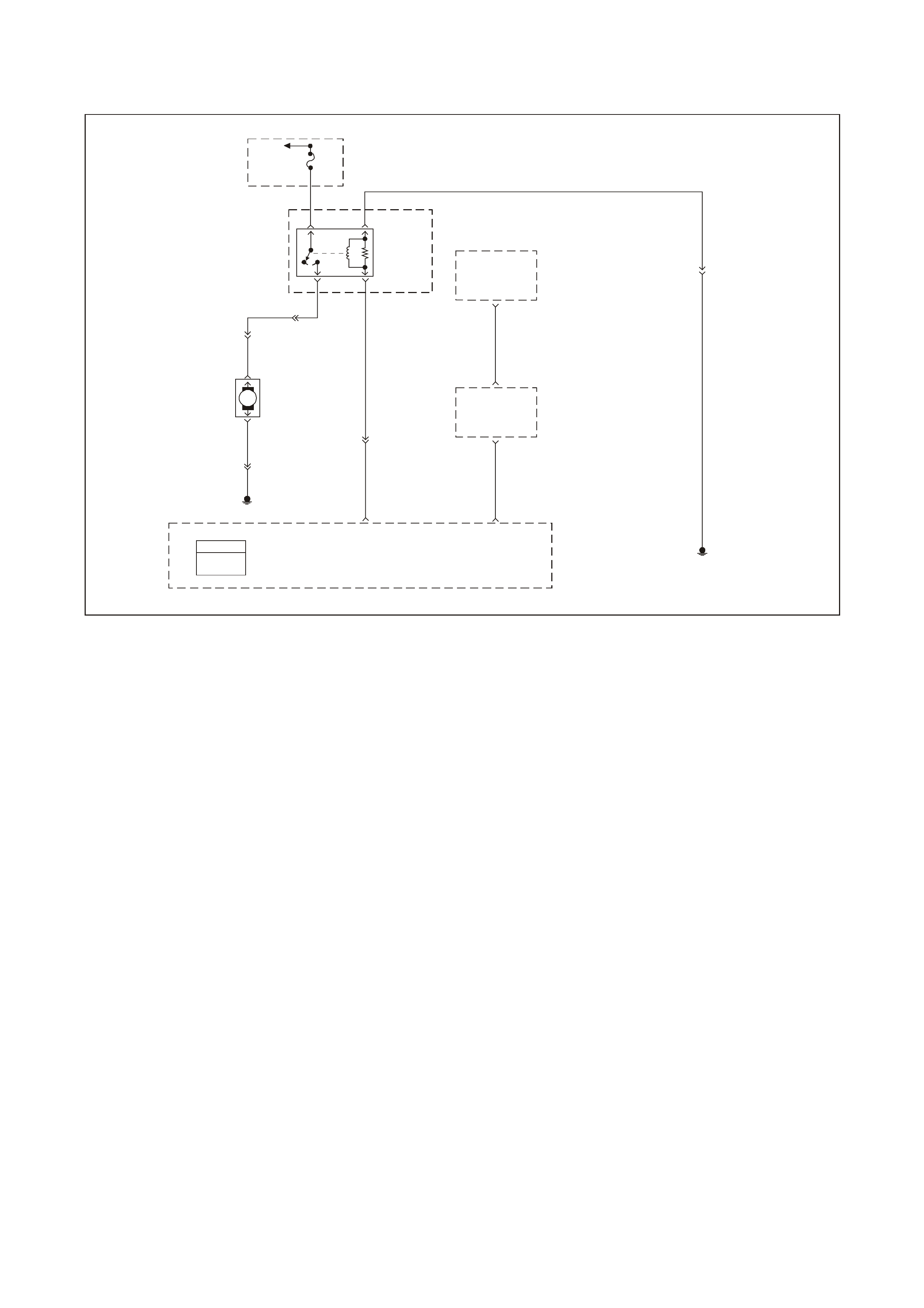
GEN III V8 PCM DTC P1630 THEFT DETERRENT POWERTRAIN
CONTROL MODULE IN LEARN MODE
GEN3 0158
To
Fusible
Link
FS
Fuse
F28
31
Fuel
Pump
Relay
52
B/W 152
YE114
G/W
O
465
240
Body
Control
Module
(BCM)
Theft
Deterrent
Output
Signal
R/B 1221
2
6Powertrain
Interface
Module
(PIM)
Theft
Deterrent
Starter
Disable
7
Y 1049
58 J1 Powertrain
Control
Module
(PCM) Engine Earth
Locat ion E 3
Fuel
Pump
Relay
Control
Theft
Deterrent
Fuel
Disable
(Serial Data)
09 J2
YE110
PCM
J1 = BLUE
J2 = RED
Engine Earth
Location E7
YR32
Fuel
Pump
Motor
120
YR32
V
120 YB39
M
V
156B/BLU
CIRCUIT DESCRIPTION
This diagnostic tes t check s for the Enable Pass word Learning Flag indicating the PCM is in learn pass word mode.
This mode allows the PCM to learn the pas sword from the Powertrain Interf ace Module (PIM) at as sembly or when
serviced. The password needs to be learned whenever the PCM, or the PIM is replaced.
CONDITIONS FOR RUNNING THE DTC
• T he PCM is ready to learn a new password from the PIM, but the PIM is not sending a valid password or not
sending a password at all.
CONDITIONS FOR SETTING THE DTC
• The PCM detects a wrong password from the PIM.
• Fuel disable lockout is set.
• The PIM or BCM was replaced.
• PIM Power or Earth circuit problem.
ACTION TAKEN WHEN THE DTC SETS
• The engine cranks but may not start.
• The PCM illuminates the Check Powertrain Lamp (CPL) when the diagnostic runs and fails.
• T he PCM records the operating conditions at the time the diagnostic f ails. The PCM stores this inform ation in
the Freeze Frame/Failure Records.

CONDITION FOR CLEARING THE CPL/DTC
• A History DTC will clear after forty consecutive warm-up cycles, if no failures are reported by this or any other
non-emission related diagnostic.
• The last test failed (Current DTC) will clear when the diagnostic runs and does not fail.
• The PCM battery voltage is interrupted.
• Use a Tech 2 scan tool in order to clear the CPL/DTC.
DIAGNOSTIC AIDS
• T he PCM in learn m ode is a DTC f or the personnel at the ass embly plant, dealership, and the outside garage
personnel as an indic ation that the system enables the learn m ode. T his m eans the PCM is now ready to learn
a new password from the PIM. This DTC set bec ause the PIM never s ent a valid password to the PCM while in
learn mode. When this occurs, the vehicle is vulnerable to vehicle theft.
Also, if there is a problem with the UART serial data line between the BCM and PIM, this may cause this
condition.
• Inspect the BCM for DTCs that may apply to the UART circuit. If any are found, refer to these DTC first.
• If both PCM DTCs P1626, and P1630 ar e set, check PIM power f eed and earth circuits f or opens or shorts. If
problem was found with PIM earth circuit, repair earth circuit, then power down PCM (key OFF) for 30 seconds.
Key ON and retest.
TEST DESCRIPTION
The numbers below refer to the step numbers on the diagnostic table.
2. If both PIM DTC P1626, and P1630 are set, check for a fault with either the PIM power feed or PIM earth
circuits.
5. If a PIM, or BCM was replaced and were not linked, this may set the DTC. Performing the link procedure will
assure that all controllers are linked together.

GEN III V8 PCM DTC P1630 THEFT DETERRENT POWERTRAIN CONTROL MODULE IN LEARN MODE
Step Action Value(s) Yes No
1 Did you perform the Powertrain On-Board Diagnostic
(OBD) System Check? Go to Step 2 Go to Powertrain
OBD System
Check Table
2 Using Tech 2 scan tool, check for DTC P1626, and
P1630.
Are both DTCs set?
Go to Step 3 Go to Step 5
3 1. Ignition OFF.
2. Remove PIM connector.
3. Check for open or short to earth in power feed and
earth circuits to PIM.
Was a problem found?
Go to Step 6 Go to Step 4
4 Replace PIM
Is action complete? Go to Step 6
5 1. Using Tech 2 scan tool, link PCM to PIM. Refer to
Section 6C3-3 in the VT Series II Service Information
for linking procedure.
2. Attempt to start vehicle.
Does vehicle crank and start?
Go to Step 6 Go to Body
Control Module
diagnostics.
Refer to Section
12J-1 Low Series
BCM or Section
12J-2 High
Series BCM in
the VT Series II
Service
Information.
6 1. Select the Diagnostic Trouble Code (DTC) option and
the Clear DTC Information option using the Tech 2
scan tool.
2. Idle the engine at the normal operating temperature.
3. Select the Diagnostic Trouble Code (DTC) option, the
DTC Information option and The Failed This Ignition
option using the Tech 2 scan tool.
4. Operate the vehicle within the Conditions for Running
the DTC as specified in the supporting text, if
applicable.
Does the Tech 2 scan tool indicate that this DTC reset?
Go to Step 2 Go to Step 7
7 Using the Tech 2 scan tool, check for any other DTCs.
Does the Tech 2 scan tool display any DTCs that you
have not diagnosed?
Go to the
applicable DTC
table
System OK
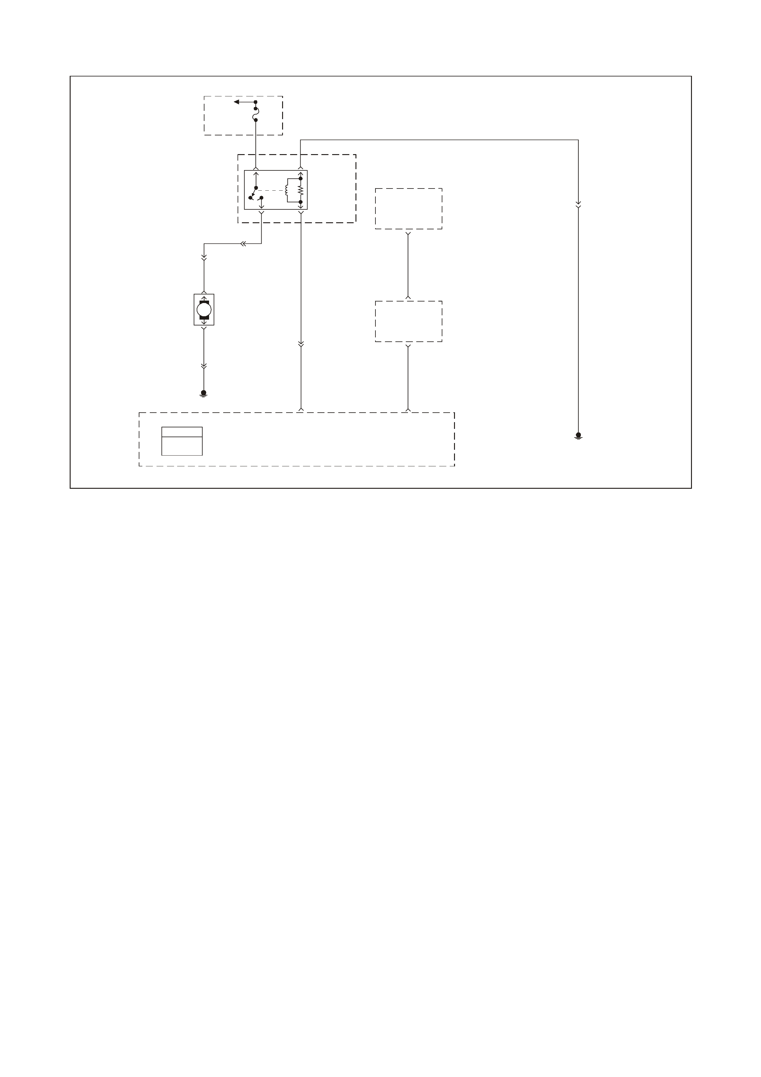
GEN III V8 PCM DTC P1631 THEFT DETERRENT PASSWORD INCORRECT
GEN3 0158
To
Fusible
Link
FS
Fuse
F28
31
Fuel
Pump
Relay
52
B/W 152
YE114
G/W
O
465
240
Body
Control
Module
(BCM)
Theft
Deterrent
Output
Signal
R/B 1221
2
6Powertrain
Interface
Module
(PIM)
Theft
Deterrent
Starter
Disable
7
Y 1049
58 J1 Powertrain
Control
Module
(PCM) Engine Earth
Locat ion E 3
Fuel
Pump
Relay
Control
Theft
Deterrent
Fuel
Disable
(Serial Data)
09 J2
YE110
PCM
J1 = BLUE
J2 = RED
Engine Earth
Location E7
YR32
Fuel
Pump
Motor
120
YR32
V
120 YB39
M
V
156B/BLU
CIRCUIT DESCRIPTION
This test checks for mismatched passwords between the PIM and PCM. Whenever replacing the PIM or PCM,
follow the Theft Learn procedure in order for the system to learn the new password.
CONDITIONS FOR RUNNING THE DTC
• Mismatched passwords between the PIM and PCM.
CONDITIONS FOR SETTING THE DTC
• The PCM detects a wrong password from the PIM.
• Fuel disable lockout is set.
• The PIM was replaced.
ACTION TAKEN WHEN THE DTC SETS
• The engine may crank but will not start.
• The PCM illuminates the Check Powertrain Lamp (CPL) when the diagnostic runs and fails.
• T he PCM records the operating conditions at the time the diagnostic f ails. The PCM stores this inform ation in
the Freeze Frame/Failure Records.

CONDITIONS FOR CLEARING THE CPL/DTC
• A History DT C will clear after for ty c onsecutive warm- up cycles, if no f ailures are repor ted by this or any other
non-emission related diagnostic.
• A last test failed (Current DTC) will clear when the diagnostic runs and does not fail.
• The PCM battery voltage is interrupted.
• Use a Tech 2 scan tool in order to clear the CPL/DTC.
DIAGNOSTIC AIDS
Important: Remove any debris from the PCM module connector surfaces before servicing the PCM module.
• T he PCM in learn m ode is a DTC f or the personnel at the ass embly plant, dealership, and the outside garage
personnel as an indic ation that the system enables the learn m ode. T his m eans the PCM is now ready to learn
a new password from the PIM while in the learn m ode. When this occurs, the vehicle is vulnerable to vehicle
theft.
• If using a Tech 2 scan tool and TIS for password linking, refer to BCM mode of Tech 2 scan tool for linking
procedure. This Tech 2 s c an tool operation will tak e appr oximately 2 minutes to perfor m. If no Tech 2 scan tool
and TIS is available, the following DTC P1631 diagnostic table must be followed.
TEST DESCRIPTION
The numbers below refer to the step numbers on the diagnostic table.
2. The 1 hour and 30 second time criteria is a minimum required amount of time. The time limit can exceed this
limit without interfering with the Auto Learn Procedure. Use a Tech 2 scan tool (Auto Learn Timer equals
Inactive) in order to determine when the 1 hour has expired.
4. If DTC P1631 is set, this indicates that you did not follow the procedure correctly. Perform the Re-learn
procedure again.

GEN III V8 PCM DTC P1631 THEFT DETERRENT PASSWORD INCORRECT
Step Action Value(s) Yes No
1 Did you perform the Powertrain On-Board Diagnostic
(OBD) System Check? Go to Step 2 Go to Powertrain
OBD System
Check Table.
2 Important:
• Check for any Theft Deterrent BCM or PIM DTCs
being set before proceeding with this table. If a BCM
or PIM DTC is set, refer to the appropriate DTC.
• Maintain the battery voltage while the PCM is in the
Learn Procedure. Follow this procedure exactly as
indicated or you will have to repeat the procedure
from the beginning.
• Performing the following procedure causes a DTC
P1630 to set when you complete the procedure. This
is the intended functionality. When P1630 sets, turn
OFF the ignition for 30 seconds, then turn ON the
ignition and P1630 clears. If the DTC P1630 does
not clear, go to the DTC P1630 table.
NOTE: Ensure the battery is fully charged.
1. Turn ON the ignition leaving the engine OFF for 1
hour and 10 minutes.
2. Turn OFF the ignition for 30 seconds.
3. Turn ON the ignition leaving the engine OFF for 1
hour and 10 minutes.
4. Turn OFF the ignition for 30 seconds.
5. Turn ON the Ignition leaving the engine OFF for 1
hour and 10 minutes or until DTC P1630 sets.
6. Turn OFF the ignition for 30 seconds.
7. Turn ON the ignition leaving the engine OFF and wait
30 seconds.
8. Attempt to start the engine.
Does the engine start and operate normally?
Go to Step 3 Go to Step 4
3 Important: Monitor all DTC status parameters and note
any additional DTCs before Clearing DTCs.
1. Clear the PCM DTCs.
2. Turn OFF the ignition for 30 seconds.
3. Attempt to start the engine.
Does the engine start and operate normally?
System OK Go to Step 4
4 Are DTCs P1626, P1630, or P1631 set? Go to applicable
DTC table Go to Step 2
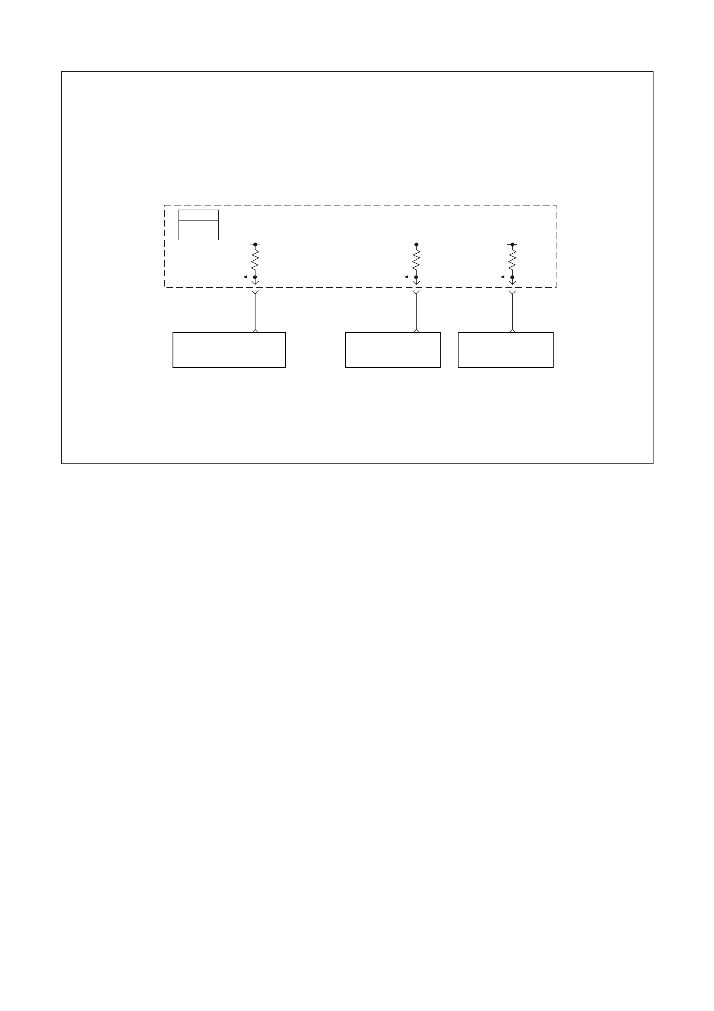
GEN III V8 PCM DTC P1635 5 VOLT REFERENCE #1 CIRCUIT
GEN176-1
Powertrain
Control
Module
(PCM)
PCM
J1 = BLU E
J2 = RED 5V 5V 5V
Map
5V
Reference
Oil Pressure Sensor
5 Volt Reference TP Sensor
5V Reference
48 J1
V/W 414
07 J1
BLU/Y 334
08 J1
G/Y 416
CIRCUIT DESCRIPTION
The PCM uses a common 5.0 volt reference circuit as a sensor feed. This circuit supplies 5 volts to the following
sensors:
• The TP Sensor
• The MAP sensor
• Oil Pressure Sensor
The PCM monitors the voltage on the 5.0 volt reference circuit. This DTC sets if the voltage is out of range.
CONDITIONS FOR RUNNING THE DTC
• The ignition switch is in the RUN position.
CONDITIONS FOR SETTING THE DTC
• The 5.0 volt reference #1 circuit is out of range.
• All of the above conditions are present for greater than 2 seconds.
ACTION TAKEN WHEN THE DTC SETS
• The PCM turns the CPL OFF after the first ignition cycle that the diagnostic runs and does not fail.
• T he PCM records the operating conditions at the time the diagnostic f ails. The PCM stores this inform ation in
the Freeze Frame/Failure Records.
CONDITIONS FOR CLEARING THE CPL/DTC
• The PCM turns the CPL OFF after three consecutive ignition cycles that the diagnostic runs and does not fail.
• A History DT C will clear after for ty c onsecutive warm- up cycles, if no f ailures are repor ted by this or any other
non-emission related diagnostic.
• A last test failed (Current DTC) will clear when the diagnostic runs and does not fail.
• Use a Tech 2 scan tool in order to clear the CPL/DTC.
Manifold Absolute
Press ure (MAP) Sensor Oil Pressure Sens or Throttle Position (TP)
Sensor

DIAGNOSTIC AIDS
• The Throttle Relaxer Control Module is also spliced into the TP circuits. If there is a problem with the Throttle
Relaxer Module or circuits, this could set this DTC. Inspect to determine that this is not causing the problem.
• Using the Freeze Frame/Failure Records data may aid in locating an intermittent condition. If you cannot
duplicate the DTC, the information included in the Freeze Frame/Failure Records data can help determine the
distance traveled since the DTC set. The Fail Counter and Pass Counter can also help determine how many
ignition cycles the diagnostic reported a pass and/or fail. Operate the vehicle within the same freeze frame
condition (RPM, load, vehicle speed, temperature etc.) that you observed. This will isolate when the DTC
failed.
• For an intermittent, refer to Section 6C3-2B SYMPTOMS in the VT Series II Service Information.
TEST DESCRIPTION
The numbers below refer to the step numbers on the diagnostic table.
2. The 5.0 volt reference circuit for the sensors listed are tied together inside the PCM. This step separates the
5.0 volt reference circuits and isolates the 5.0 volt reference circuit which is shorted to voltage.
3. The 5.0 volt reference circuit for the sensors listed are tied together inside the PCM. This step separates the
5.0 volt reference circuits and isolates the 5.0 volt reference circuit which is shorted to earth.
4. This step isolates the 5.0 volt reference circuit from the sensor signal circuit.

GEN III V8 PCM DTC P1635 5 VOLT REFERENCE #1 CIRCUIT
Step Action Value(s) Yes No
1 Did you perform the Powertrain On-Board Diagnostic
(OBD) System Check? Go to Step 2 Go to Powertrain
OBD System
Check Table
2
1. Turn OFF the ignition.
2. Disconnect the BLUE PCM harness connector.
3. Turn ON the ignition leaving the engine OFF.
4. Connect the DMM J 39200 to earth.
5. Probe the PCM harness connector 5.0 volt reference
circuits for the following components using the an
adaptor from the connector test adaptor kit J 35616-A.
- The TP Sensor
- The MAP sensor
- The Oil Pressure sensor
Do any of the circuits measure at or greater than
specified value?
5.0 V Go to Step 4 Go to Step 3
3 1. Turn OFF the ignition.
2. Connect a test lamp to B+
3. Turn ON the ignition leaving the engine OFF.
4. Probe the PCM harness connector 5.0 volt reference
circuits for the following components using the an
adaptor from the connector test adaptor kit J 35616-A.
- The TP Sensor
- The MAP sensor
- The Oil Pressure sensor
Did the test lamp illuminate for any of the circuits?
Go to Step 5 Go to Diagnostic
Aids
4 1. Disconnect the electrical connector at the sensor that
measured greater than the specified value.
2. Using a DMM, probe the affected 5.0 volt reference
circuit at the PCM harness connector using the test
adaptor kit J 35616-B.
Does the DMM display a voltage at or greater than the
specified value?
5.0V Go to Step 8 Go to Step 6
5 1. Disconnect the electrical connector at the sensor that
illuminated the test lamp.
2. Using a DMM, probe the affected 5.0 volt reference
circuit at the PCM harness connector using the test
adaptor kit J 35616-B.
Does the DMM display a voltage greater than the
specified value?
Go to Step 9 Go to Step 7
6 1. Connect a DMM J 39200 to earth.
2. Turn ON the ignition leaving the engine OFF.
3. Measure the voltage on the signal circuit at the
affected sensor.
Does the DMM display a voltage greater than the
specified value?
0.0 V Go to Step 10 Go to Step 12
7 1. Connect a test lamp to B+.
2. Turn ON the ignition leaving the engine OFF.
3. Probe the signal circuit at the affected sensor.
Is the test lamp illuminated?
Go to Step 11 Go to Step 12
8 Repair the short to voltage on the appropriate 5.0 volt
reference circuit. Inspect the Throttle Relaxer Control
Module circuit also for short if TP sensor was the
problem.
Is the action complete?
Go to Step 13

Step Action Value(s) Yes No
9 Repair the short to earth on the appropriate 5.0 volt
reference circuit. Inspect the Throttle Relaxer Control
Module circuit also for short if TP sensor was the
problem.
Is the action complete?
Go to Step 13
10 Repair the short to voltage on the appropriate sensor
signal circuit.
Is the action complete?
Go to Step 13
11 Repair the short to earth on the appropriate sensor signal
circuit.
Is the action complete?
Go to Step 13
12 1. Replace PCM.
2. Refer to Section 6C3-3 in the VT Series II Service
Information for PCM Programming and
PCM/PIM/BCM Security Link Procedure.
Is action complete?
Go to Step 12
13 1. Select the Diagnostic Trouble Code (DTC) option and
the Clear DTC Information option using the Tech 2
scan tool.
2. Idle the engine at the normal operating temperature.
3. Select the Diagnostic Trouble Code (DTC) option, the
DTC Information option and The Failed This Ignition
option using the Tech 2 scan tool.
4. Operate the vehicle within the Conditions for Running
the DTC as specified in the supporting text, if
applicable.
Does the Tech 2 scan tool indicate that this DTC reset?
Go to Step 2 Go to Step 14
14 Using the Tech 2 scan tool, check for any other DTCs.
Does the Tech 2 scan tool display any DTCs that you
have not diagnosed?
Go to the
applicable DTC
table
System OK
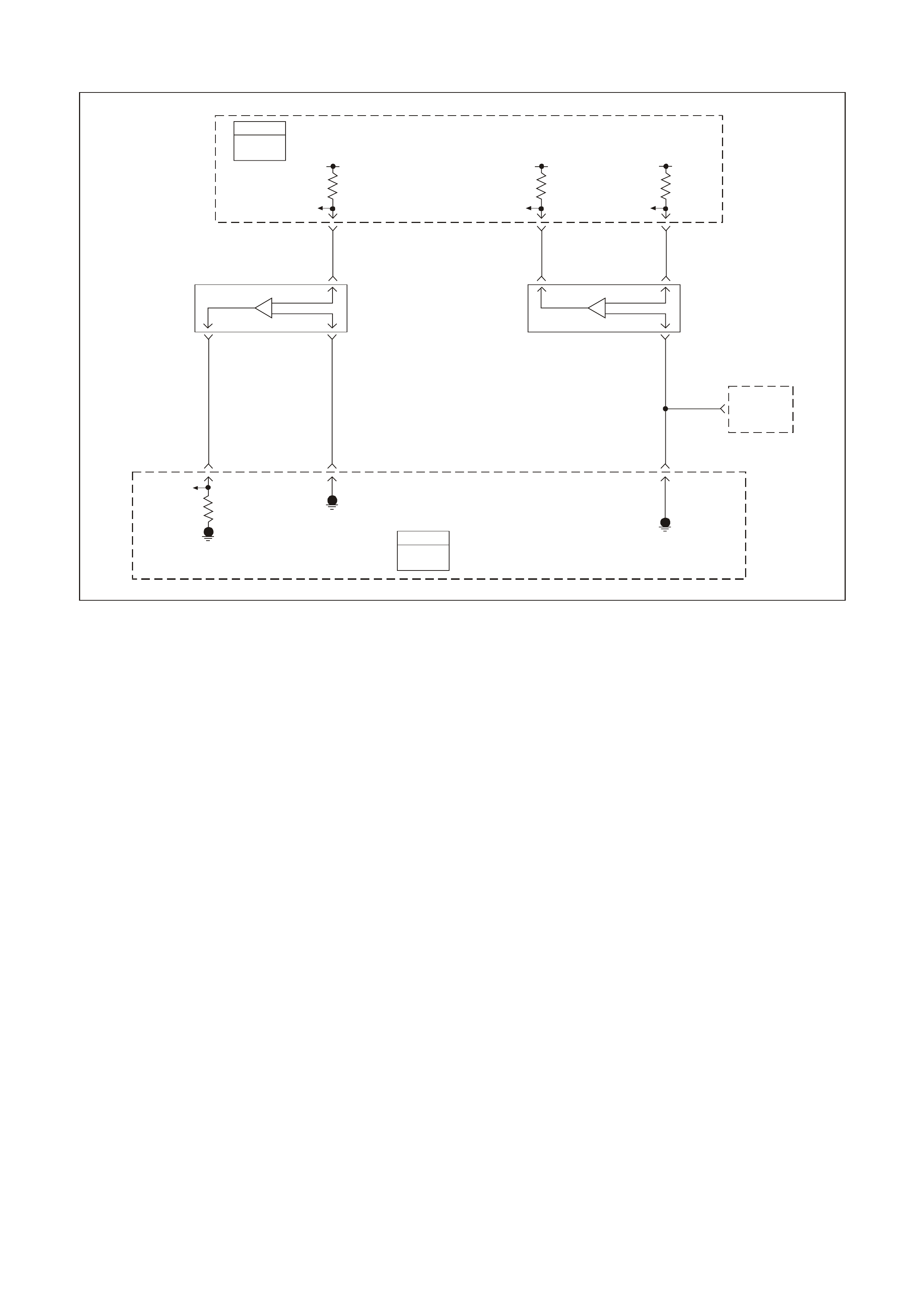
GEN III V8 PCM DTC P1639 5 VOLT REFERENCE #2 CIRCUIT
GEN 3 01 76
Powertrain
Control
Module
(PCM)
PCM
J1 =
BLUEJ2 = 5V 5V 5V
Map
5V
Reference
A
/C Refrigerant
Pressure Sensor
Signal
A
/C Refrigerant
Pressure Sensor
5V Reference
Manifold
Absolute
Pressure
(MAP)
Sensor
A/C
Refrigerant
Pressure
Sensor
48 J1
C
V/W 414
14 J2
C
G/B 259
45 J1
B
V/W 415
AB
B 421
LG 432
5432 J1
MAP
Sensor
Signal MAP
Sensor
Earth PCM
J1 = B LUE
J2 = R ED
57 J2
A
/C Refrigerant
Pressure Sensor
Earth
Powertrain
Control
Module
(PCM)
IAT
Sensor
G/O 469
A
CIRCUIT DESCRIPTION
The PCM uses a common 5.0 volt reference circuit as a sensor feed to the A/C Pressure Sensor.
The PCM monitors the voltage on the 5.0 volt reference circuit. This DTC sets if the voltage is out of range.
CONDITIONS FOR RUNNING THE DTC
• The engine operating.
CONDITIONS FOR SETTING THE DTC
• The 5.0 volt reference circuit is out of range.
• The above conditions is present for greater than 2 seconds.
ACTION TAKEN WHEN THE DTC SETS
• The PCM illuminates the Check Powertrain Lamp (CPL) when the diagnostic runs and fails.
• T he PCM records the operating conditions at the time the diagnostic f ails. The PCM stores this inform ation in
the Freeze Frame/Failure Records.
CONDITIONS FOR CLEARING THE CPL/DTC
• The PCM turns the CPL OFF after the first ignition cycle that the diagnostic runs and does not fail.
• A History DT C will clear after for ty c onsecutive warm- up cycles, if no f ailures are repor ted by this or any other
non-emission related diagnostic.
• A last test failed (Current DTC) will clear when the diagnostic runs and does not fail.
• Use a Tech 2 scan tool in order to clear the CPL/DTC.

DIAGNOSTIC AIDS
• Using the Freeze Frame/Failure Records data may aid in locating an intermittent condition. If you cannot
duplicate the DT C, the information inc luded in the Freeze Fram e/Failure Records data can help determ ine the
distance traveled since the DTC set. The Fail Counter and Pass Counter can also help determine how many
ignition cycles the diagnostic reported a pass and/or fail. Operate the vehicle within the same freeze frame
condition (RPM, load, vehicle speed, temperature etc.) that you observed. This will isolate when the DTC
failed.
• For an intermittent, refer to Section 6C3-2B SYMPTOMS in the VT Series II Service Information.
TEST DESCRIPTION
The numbers below refer to the step numbers on the diagnostic table.
2. This step checks to see if the A/C Pressure sensor is functioning properly.
3. This step checks to see if the A/C Pressure sensor voltage is above or below the correct operating range.

GEN III V8 PCM DTC P1639 5 VOLT REFERENCE #2 CIRCUIT
Step Action Value(s) Yes No
1 Did you perform the Powertrain On-Board Diagnostic
(OBD) System Check? Go to Step 2 Go to Powertrain
OBD System
Check Table
2 1. Install a Tech 2 scan tool.
2. Idle the engine.
3. Monitor the A/C Pressure sensor kPa.
Is the A/C Pressure sensor kPa within the specified
range?
25 to 3140
kPa Go to Diagnostic
Aids Go to Step 3
3
1. Disconnect the A/C Pressure sensor electrical
connector.
2. Ignition ON, engine OFF.
3. Using a DMM, probe the A/C Pressure sensor 5.0 volt
reference circuit at the A/C Pressure sensor harness
connector with the adaptors from the J 35616-A
terminal kit using a DMM J 39200 connected to earth.
Is the voltage at or between the specified value?
4.8 - 5.4V Go to Diagnostic
Aids Go to Step 4
4 Is the voltage above the specified value? 5.4 V Go to Step 5 Go to Step 6
5 Check for short to voltage for the A/C Pressure sensor 5
volt reference circuit.
Was a problem found?
Verify Repair Go to Step 7
6 Check for an open or short to earth for the A/C Pressure
sensor 5 volt reference circuit.
Was a problem found?
Verify Repair Go to Step 7
7 1. Replace PCM.
2. Refer to Section 6C3-3 in the VT Series II Service
Information for PCM Programming and
PCM/PIM/BCM Security Link Procedure.
Is action complete?
Go to Step 8
8 1. Select the Diagnostic Trouble Code (DTC) option and
the Clear DTC Information option using the Tech 2
scan tool.
2. Idle the engine at the normal operating temperature.
3. Select the Diagnostic Trouble Code (DTC) option, the
DTC Information option and The Failed This Ignition
option using the Tech 2 scan tool.
4. Operate the vehicle within the Conditions for Running
the DTC as specified in the supporting text, if
applicable.
Does the Tech 2 scan tool indicate that this DTC reset?
Go to Step 2 Go to Step 9
9 Using the Tech 2 scan tool, check for any other DTCs.
Does the Tech 2 scan tool display any DTCs that you
have not diagnosed?
Go to the
applicable DTC
table
System OK
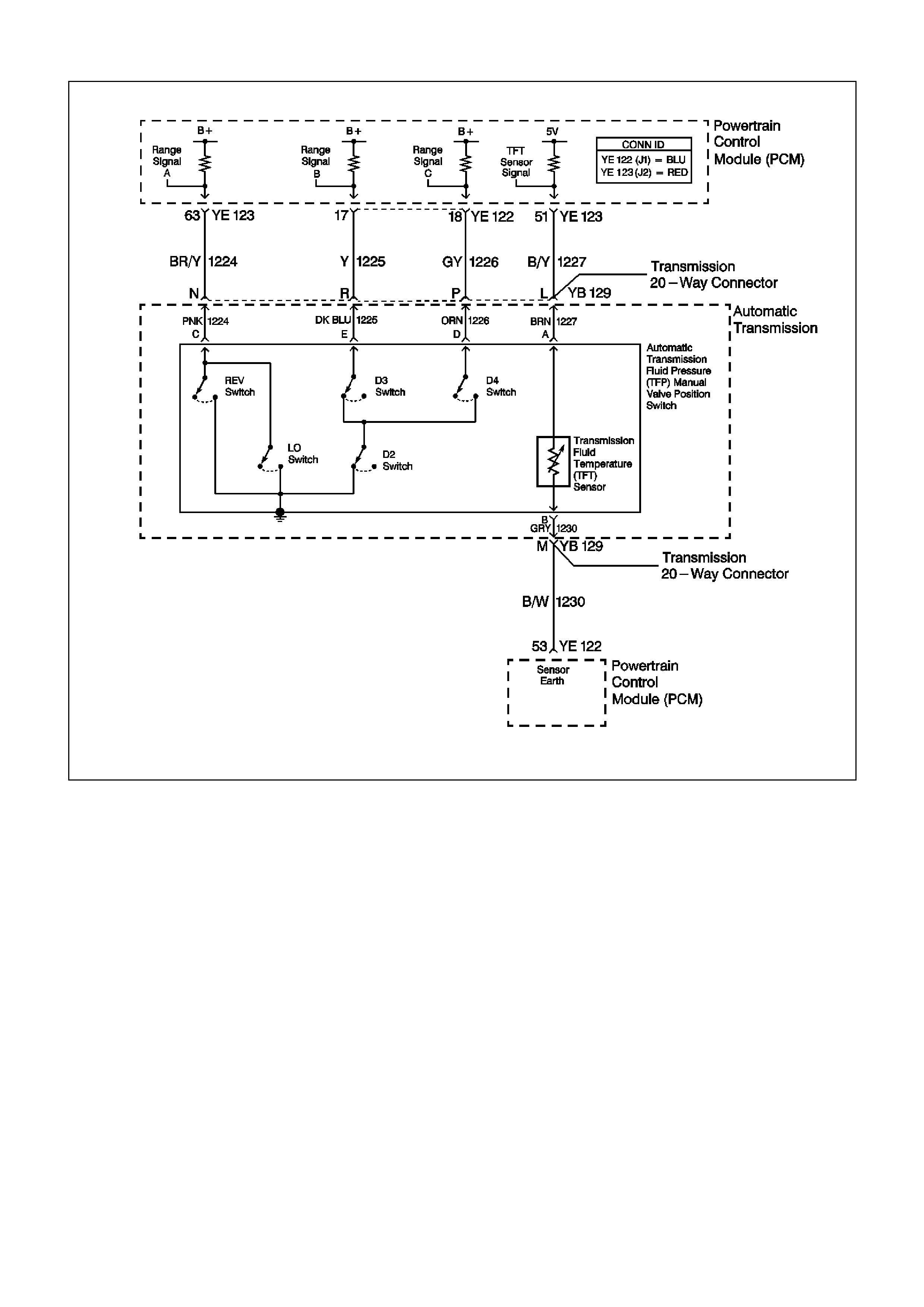
GEN III V8 PCM DTC P1810 TFP VALVE POSITION SWITCH CIRCUIT
CIRCUIT DESCRIPTION
The automatic Transmission Fluid Pressure (TFP) manual valve position switch consists of five pressure switches
(two norm ally-closed and three norm ally-open) and a T ransm iss ion Fluid T em perature ( TF T) Sensor c om bined into
one unit.
The combined unit mounts on the valve body. The Powertrain Control Module (PCM) supplies the battery voltage
for each range signal. By earthing one or more of the circuits through various combinations of the pressure
switches, the PCM detects which manual valve position you select.
The PCM compares the actual voltage combination of the switches to a TFP manual valve position switch
combination table stored in PCM memory.
The TFP manual valve position switch cannot distinguish between PARK and NEUTRAL because the monitored
valve body pressures are identical. With the engine OFF and the ignition switch in the RUN position, the TFP
manual valve position switch indicates PARK/NEUTRAL.
Disconnecting the transm ission 20-way (YB 129) connector rem oves the earth potential for the thr ee range signals
to the PCM. In this case, with the engine OFF, and the ignition switch in the RUN position, D2 will be indicated.
W hen the PCM detects an invalid state of the TFP manual valve position switch or the TFP m anual valve position
switch circuit by deciphering the TFP manual valve position switch inputs, then DTC P1810 sets.

CONDITIONS FOR RUNNING THE DTC
• No VSS assembly DTCs P0502 or P0503.
• The system voltage is 8-18 volts.
• The engine speed is greater than 300 RPM for 5 seconds.
• The engine is not in fuel cutoff.
• The engine torque is 54-542 Nm.
• The engine vacuum is 0-105 kPa.
CONDITIONS FOR SETTING THE DTC
• DTC P1810 sets if any of the following conditions occurs:
Condition 1
- The PCM detects an invalid TFP manual valve position switch state for 60 seconds.
Condition 2
- The engine speed is less than 80 RPM for 0.1 second; then the engine speed is 80-550 RPM for 0.07
second; then the engine speed is greater than 550 RPM.
- The vehicle speed is less than 3 km/h.
- The PCM detects a gear range of 2, D or R during an engine start.
- All conditions are met for 5 seconds.
Condition 3
- The TP angle is 8-45%.
- The PCM commands fourth gear.
- The TCC is locked ON.
- The speed ratio is 0.65-0.8 (speed ratio is engine speed divided by transmission output speed).
- The PCM detects a gear range of P or N when operating in D.
- All conditions are met for 10 seconds.
ACTION TAKEN WHEN THE DTC SETS
• The PCM turns OFF the Check Powertrain Lamp (CPL) during the first trip in which the diagnostic test runs
and passes.
• The PCM commands D2 line pressure.
• The PCM commands a D4 shift pattern.
• The PCM freezes shift adapts from being updated.
• The PCM stores DTC P1810 in PCM history during the second consecutive trip in which the conditions for
setting the DTC are met.
CONDITIONS FOR CLEARING THE CPL/DTC
• T he PCM turns OFF the check powertrain lam p (MIL) during the third consecutive trip in which the diagnostic
test runs and passes.
• A scan tool clears the DTC from the PCM history.
• The PCM clears the DTC from the PCM history if the vehicle completes 40 warm-up cycles without an
emission-related diagnostic fault occurring.
• T he PCM cancels the DTC default actions when the fault no longer exists and the ignition switch is OFF long
enough in order to power down the PCM.

DIAGNOSTIC AIDS
• Refer to the TFP Manual Valve Position Switch Logic table for the normal range signals and the invalid
combinations. In the table, Closed is 0 volts, Open is 12 volts.
• Inspect the wiring at the PCM, the transmission connector and all other circuit connecting points for the
following conditions:
- A backed out terminal
- A damaged terminal
- Reduced terminal tension
- A chafed wire
- A broken wire inside the insulation
- Moisture intrusion
- Corrosion
• W hen diagnosing for an intermittent short or open condition, massage the wiring harness while watching the
test equipment for a change.
• Refer to Section 6C3-2C TFP MANUAL VALVE POSITION SWITCH RESISTANCE CHECK or Functional
Test Procedure in the VT Series II Service Information for further information.
TFP MANUAL VALVE POSITION SWITCH LOGIC
Gear
Position
Range Signal A
Range Signal B
Range Signal C
Park Open 12 V Closed 0 V Open 12 V
Reverse Closed 0 V Closed 0 V Open 12 V
Neutral Open 12 V Closed 0 V Open 12 V
D Open 12 V Closed 0 V Closed 0 V
3 Open 12 V Open 12 V Closed 0 V
2 Open 12 V Open 12 V Open 12 V
1 Closed 0 V Open 12 V Open 12 V
Invalid Closed 0 V Open 12 V Closed 0 V
Invalid Closed 0 V Closed 0 V Closed 0 V
TEST DESCRIPTION
The numbers below refer to the step numbers on the diagnostic table.
3. This step tests the indicated range signal to the manual valve actually selected.
4. This step tests for correct voltage from the PCM to the transmission 20-way connector.

GEN III V8 PCM DTC P1810 TFP VALVE POSITION SWITCH CIRCUIT
Step Action Value(s) Yes No
1 Was the Powertrain On-Board Diagnostic (OBD) System
Check performed? Go to Step 2 Go to Powertrain
OBD System
Check Table.
2 Perform the following inspections:
• Ensure that the transmission linkage from the select
lever to the manual valve is adjusted correctly. Refer
to Selector Linkage Adjustment in Section 7C4 in the
VT Series I Service Information.
• Perform the fluid checking procedure, refer Section
7C4, in the VT Series II Service Information.
Did you perform the inspections?
Go to Step 3
3 1. Install the Tech 2 Scan Tool.
2. With the engine OFF, turn the ignition switch to the
RUN position.
Important: Before clearing the DTC, use the Scan Tool
in order to record the Freeze Frame and Failure Records.
Using the Clear Info function erases the Freeze Frame
and Failure Records from the PCM.
3. Record the DTC Freeze Frame and Failure Records.
4. Clear the DTC.
5. While the engine is idling at normal operating
temperature, apply the brake pedal.
6. Select each transmission range: P, R, N, D, 3, 2 and
1.
Refer to Section 6C3-4 TFP Manual Valve Position
Switch Logic table in the VT Series II Service Information.
Does each selected transmission range match the Scan
Tool TFP Switch A/B/C display?
Go to Diagnostic
Aids Go to Step 4
4 1. Turn the ignition OFF.
2. Disconnect the transmission 20-way (YB129)
connector (additional DTCs may set).
3. Install the J 39775 jumper harness on the engine side
of the 20-way (YB129) connector.
4. With the engine OFF, turn the ignition switch to the
RUN position.
5. Using the J 39200 digital multimeter (DMM) and the
J 35616 connector test adapter kit, check the voltage
at connector terminals N, R and P.
Is B+ displayed on all three circuits?
Go to Step 6 Go to Step 5
5 Inspect the circuits that did not indicate B+ for an open or
short to earth condition.
Refer to Test Procedures in the VT Series I Service
Information, Section 12P.
Did you find an open or short to earth condition?
Go to Step 8 Go to Step 7
6 In order to verify that circuit 1224 (BR/Y), circuit 1225 (Y)
and circuit 1226 (GY) are not shorted together, use a
fused jumper wire to earth on each circuit while
monitoring the Scan Tool TFP Switch A/B/C display.
When a range signal circuit is earthed, are any other
range signal circuits affected?
Go to Step 8 Go to TFP
Manual Valve
Position Switch
Resistance
Check in Section
6C3-2C in the VT
Series II Service
Information
7 Replace the PCM.
Refer to Powertrain Control Module in Section 6C3-3 in
the VT Series II Service Information.
Is the replacement complete?
Go to Step 9

Step Action Value(s) Yes No
8 Repair the affected wiring as necessary.
Refer to Wiring Repair Procedures in the VT Series I
Service Information, Section 12P.
Is the repair complete?
Go to Step 9
9 Perform the following procedure in order to verify the
repair:
1. Select DTC.
2. Select Clear Info.
3. Operate the vehicle under the following conditions:
- With the engine OFF, turn the ignition switch to the
RUN position for at least 2 seconds.
- Start the vehicle and idle for 5 seconds.
- Drive in D until the TCC locks for 10 seconds.
- Run the engine for at least 60 seconds from start
up.
Were the above conditions verified?
System OK Go to Step 1

GEN III V8 PCM DTC P1860 TCC PWM SOLENOID CIRCUIT
CIRCUIT DESCRIPTION
The Torque Converter Clutch Pulse Width Modulation (TCC PWM) solenoid valve controls the fluid acting on the
converter c lutch valve. The converter clutch valve controls the T CC application and release. T he solenoid attaches
to the control valve body within the transmission. The solenoid receives ignition voltage through circuit 339. The
powertrain control module (PCM) controls the solenoid by providing an earth path on circuit 418.
Current flows through the solenoid coil according to the duty cycle (percentage of ON and OFF time). The TCC
PWM solenoid valve provides a sm ooth engagem ent of the torque conver ter clutc h by operating during a duty cycle
percent of ON time.
When the PCM detects a continuous open or short to earth in the TCC PWM solenoid valve circuit or the TCC
PWM solenoid valve, then DTC P1860 sets.
CONDITIONS FOR RUNNING THE DTC
• The system voltage is 8-18 volts.
• The engine speed is greater than 300 RPM for 5 seconds.
• The engine is not in fuel cutoff.
• The PCM commands first gear.
• The TCC duty cycle is less than 10% or greater than 90%.
CONDITIONS FOR SETTING THE DTC
• DTC P1860 sets if either of the following conditions occur for 5 seconds:
- The PCM commands the solenoid ON (90%) and the voltage input remains high (B+).
- The PCM commands the solenoid OFF (0%) and the voltage input remains low (0 volt).

ACTION TAKEN WHEN THE DTC SETS
• The PCM illuminates the Check Powertrain Lamp (CPL) during the second consecutive trip in which the
conditions for setting the DTC are met.
• The PCM inhibits TCC engagement.
• The PCM inhibits 4th gear if the transmission is in hot mode.
• The PCM freezes shift adapts from being updated.
• The PCM stores DTC P1860 in PCM history during the second consecutive trip in which the conditions for
setting the DTC are met.
CONDITIONS FOR CLEARING THE CPL/DTC
• The PCM turns OFF the Check Powertrain Lamp (CPL) during the first trip in which the diagnostic test runs
and passes.
• A scan tool clears the DTC from the PCM history.
• The PCM clears the DTC from the PCM history if the vehicle completes 40 warm-up cycles without an
emission-related diagnostic fault occurring.
• T he PCM cancels the DTC default actions when the fault no longer exists and the ignition switch is OFF long
enough in order to power down the PCM.
DIAGNOSTIC AIDS
• Inspect the wiring at the PCM, the transmission connector and all other circuit connecting points for the
following conditions:
- A backed out terminal
- A damaged terminal
- Reduced terminal tension
- A chafed wire
- A broken wire inside the insulation
- Moisture intrusion
- Corrosion
• W hen diagnosing for an intermittent short or open condition, massage the wiring harness while watching the
test equipment for a change.
TEST DESCRIPTION
The numbers below refer to the step numbers on the diagnostic table.
4. This step tests for voltage to the solenoid.
6. This step tests the ability of the PCM and wiring to control the earth circuit.
8. This step tests the resistance of the TCC PWM solenoid valve and the automatic transmission (A/T) wiring
harness assembly.

GEN III V8 PCM DTC P1860 TCC PWM SOLENOID CIRCUIT
Step Action Value(s) Yes No
1 Was the Powertrain On-Board Diagnostic (OBD) System
Check performed? Go to Step 2 Go to Powertrain
OBD System
Check Table.
2 1. Install the Tech 2 Scan Tool.
2. With the engine OFF, turn the ignition switch to the
RUN position.
Important: Before clearing the DTC, use the Scan Tool
in order to record the Freeze Frame and Failure Records.
Using the Clear Info function erases the Freeze Frame
and Failure Records from the PCM.
3. Record the DTC Freeze Frame and Failure Records.
4. Clear the DTC.
Are any of the following DTCs also set?
• P0740
• P0753
• P0758
• P0785
Go to Step 3 Go to Step 4
3 1. Inspect fuse F32.
2. If the fuse is open, inspect the following components
for a short to earth condition:
- Circuit 339 (P/BLU)
- The solenoids
- The A/T wiring harness assembly
3. Repair the circuit, the solenoids, and the harness if
necessary.
Did you find a short to earth condition?
Go to Step 15 Go to Step 4
4 1. Turn the ignition OFF.
2. Disconnect the transmission 20-way (YB 129)
connector (additional DTCs may set).
3. Install J 39775 jumper harness on the engine side of
the 20-way (YB129) connector.
4. With the engine OFF, turn the ignition switch to the
RUN position.
5. Connect a lest lamp from J 39775 jumper harness
cavity E to earth.
Is the test lamp on?
Go to Step 6 Go to Step 5
5 Important: The condition that affects this circuit may
exist in other connecting branches of the circuit. Refer to
Power Distribution Diagrams in the VT Series II Service
Information, Section 12P for complete circuit distribution.
Repair the open or short to earth in ignition feed circuit
339 (P/BLU) to the TCC PWM solenoid valve.
Is the repair complete?
Go to Step 15
6 1. Install the test lamp from cavity E to cavity U of the
J 39775 jumper harness.
2. Using the transmission Miscellaneous Tests function
on the Scan Tool, command the TCC PWM solenoid
valve ON and OFF three times.
Does the test lamp turn ON when the TCC PWM
solenoid valve is commanded ON, and OFF when
commanded OFF?
Go to Step 8 Go to Step 7
7 1. Inspect circuit 418 (BR) of the powertrain wiring
harness for an open, short to earth or short to power
condition.
2. Repair the circuit if necessary.
Did you find an open, short to earth or short to power
condition?
Go to Step 15 Go to Step 9

Step Action Value(s) Yes No
8 1. Install J 39775 jumper harness on the transmission
side of the 20-way (YB 129) connector.
2. Using the J 39200 digital multimeter (DMM) and the
J 35616 connector test adapter kit, measure the
resistance between terminals E and U.
Is the resistance within the specified range?
10-15 Ω Go to Step 11 Go to Step 10
9 Replace the PCM.
Refer to Section 6C3-3 Powertrain Control Module
Replacement in the VT Series II Service Information.
Is the replacement complete?
Go to Step 15
10 1. Disconnect the A/T wiring harness assembly at the
TCC PWM solenoid valve.
2. Measure the resistance of the TCC PWM solenoid
valve.
Is the resistance within the specified range?
10-15 Ω Go to Step 13 Go to Step 14
11 Measure the resistance between terminal E and earth,
and between terminal U and earth.
Are both readings greater than the specified value?
250 K Ω Go to Diagnostic
Aids Go to Step 12
12 1. Disconnect the A/T wiring harness assembly at the
TCC PWM solenoid valve.
2. Measure the resistance between each of the
component terminals and earth.
Are both readings greater than the specified value?
250 K Ω Go to Step 13 Go to Step 14
13 Replace the automatic transmission wiring harness
assembly.
Refer to Control Valve Body and Wiring Harness
replacement in Section 7C4, in the VT Series I Service
Information.
Is the replacement complete?
Go to Step 15
14 Replace the TCC PWM solenoid valve.
Refer to TCC PWM Solenoid Valve Replacement in
Section 7C4, in the VT Series I Service Information.
Is the replacement complete?
Go to Step 15
15 • Perform the following procedure in order to verify the
repair:
1. Select DTC.
2. Select Clear Info.
3. Drive the vehicle in D with the TCC ON. Ensure
the following conditions are met:
- The PCM commands the TCC PWM solenoid
valve ON, and the voltage input drops to zero.
- The PCM commands the TCC PWM solenoid
valve OFF, and the voltage input increases to
B+.
- All conditions met for 5 seconds.
Were the above conditions verified?
System OK Go to Step 1
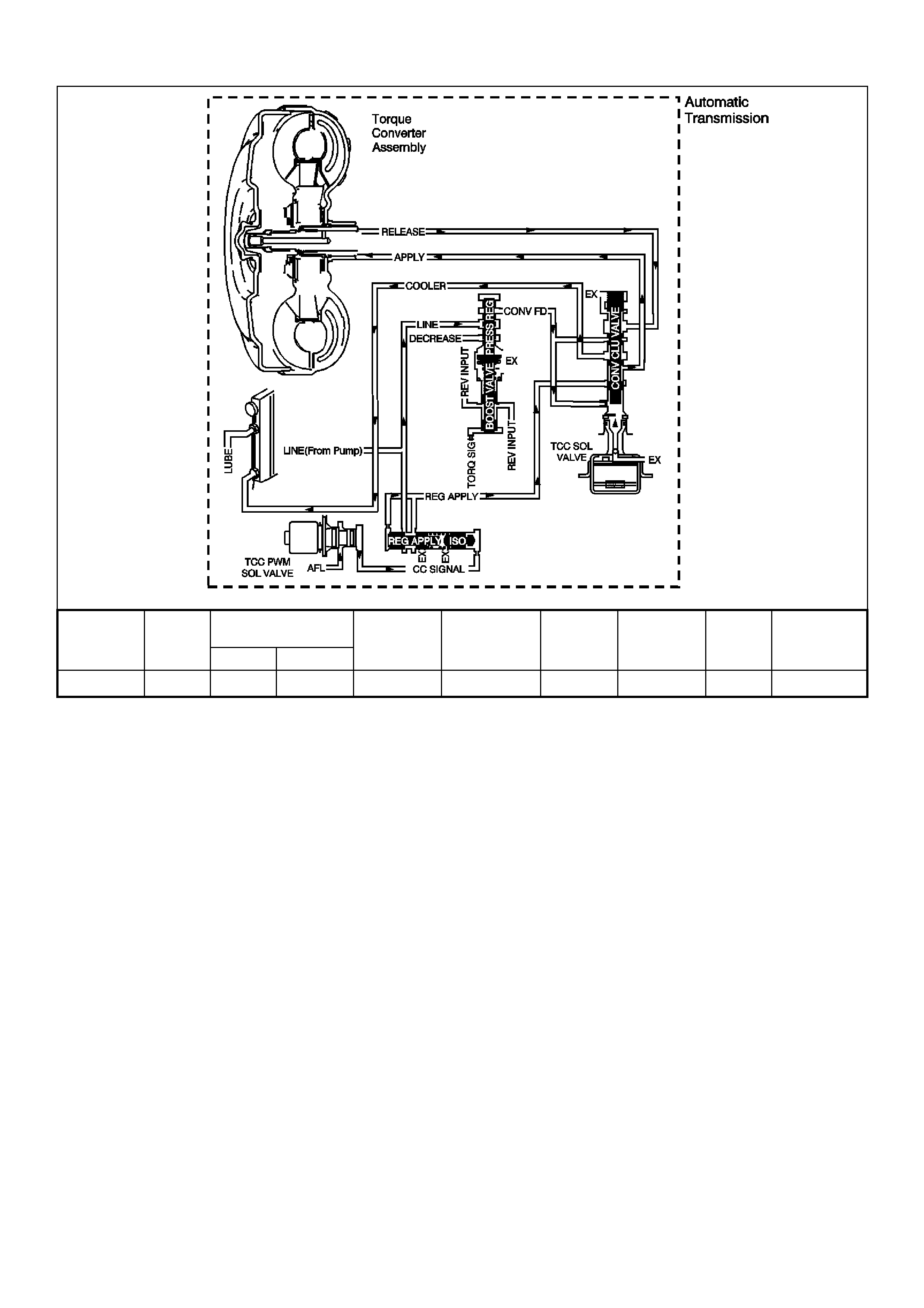
GEN III V8 PCM DTC P1870 TRANSMISSION COMPONENT SLIPPING
Shift Solenoid TCC
TCC PWM Forward 3-4 Torque
Converter
Range Gear 1-2 (A) 2-3 (B) Solenoid Solenoid 2-4 Band Clutch Clutch Clutch
Overdrive 4th ON OFF ON 90% (ON) Applied Applied Applied Applied
CIRCUIT DESCRIPTION
The Powertrain Control Module (PCM) monitors the difference between engine speed and transmission output
speed. In drive 3 range with the TCC engaged, the engine speed should closely match the transmission output
speed. In D drive range, with the TCC engaged, the TCC slip speed should be -20 to +40 RPM. The table above
indicates solenoid states and transmission components that apply, during 4th gear, with the TCC commanded ON.
When the PCM detects excessive TCC slip when the TCC should be engaged, then DTC P1870 sets.

CONDITIONS FOR RUNNING THE DTC
• No Throttle Position DTCs P0122 or P0123.
• No VSS assembly DTCs P0502 or P0503.
• No TCC solenoid valve DTC P0740.
• No 1-2 SS valve DTC P0753.
• No 2-3 SS valve DTC P0758.
• No 3-2 SS valve assembly DTC P0785.
• No TCC PWM solenoid valve DTC P1860.
• The engine speed is greater than 300 RPM for 5 seconds.
• The engine is not in fuel cutoff.
• The vehicle speed is 56-105 km/h.
• The speed ratio is 0.67-0.90 (the speed ratio is the engine speed divided by the transmission output speed).
• The engine speed is 1200-3500 RPM.
• The engine torque is 54-542 Nm.
• The gear range is D4.
• The commanded gear is not 1st gear.
• The Throttle Position angle is 10-50%.
• The TFT is between 20-130°C.
• The shift solenoid performance diagnostic counters are zero.
CONDITIONS FOR SETTING THE DTC
• DTC P1870 sets if the following conditions occur for three TCC cycles.
- The TCC is commanded ON for 5 seconds.
- The TCC is at maximum duty cycle for 1 second.
- The TCC slip speed is 80-800 RPM for 7 seconds.
Important: The following actions may occur before the DTC sets.
• If the TCC is commanded ON and at maximum duty cycle for 5 seconds, the Throttle Position angle is 10-40%,
and the tr ans miss ion s lip c ounter has inc r emented to either 1 or 2 (out of 3 to inc r ement the f ail counter f or the
current ignition cycle), then the following slip conditions and actions may increment the fail counter for the
current ignition cycle:
These conditions must occur sequentially.
- Condition 1: If the TCC slip s peed is 80-800 RPM for 7 seconds, then the PCM will comm and max imum
line pressure and freeze shift adapts from being updated.
- Condition 2: If Condition 1 is met and the TCC slip speed is 80-800 RPM for 7 seconds, then the PCM
will command the TCC OFF for 1.5 seconds.
- Condition 3: If Condition 2 is met and the TCC slip speed is 80-800 RPM for 7 seconds, then the fail
counter on the current ignition cycle is incremented.
• The above slip conditions and actions may be disregarded if the TCC is commanded OFF at any time as a
result of a driving manoeuvre (sudden acceleration or deceleration).
ACTION TAKEN WHEN THE DTC SETS
• The PCM illuminates the Check Powertrain Lamp (CPL) during the second consecutive trip in which the
conditions for setting the DTC are met.
• The PCM inhibits TCC engagement.
• The PCM commands maximum line pressure.
• The PCM inhibits 4th gear if the transmission is in hot mode.
• The PCM freezes shift adapts from being updated.
• The PCM stores DTC P1870 in PCM history during the second consecutive trip in which the conditions for
setting the DTC are met.

CONDITIONS FOR CLEARING THE CPL/DTC
• The PCM turns OFF the Check Powertrain Lamp (CPL) during the first trip in which the diagnostic test runs
and passes.
• A scan tool clears the DTC from the PCM history.
• The PCM clears the DTC from the PCM history if the vehicle completes 40 warm-up cycles without an
emission-related diagnostic fault occurring.
• T he PCM cancels the DTC default actions when the fault no longer exists and the ignition switch is OFF long
enough in order to power down the PCM.
DIAGNOSTIC AIDS
• Internal transmission failures may set DTC P1870.
TEST DESCRIPTION
The number below refers to the step numbers on the diagnostic table.
3. This step tests the torque converter for slippage while in a commanded lock-up state.

GEN III V8 PCM DTC P1870 TRANSMISSION COMPONENT SLIPPING
Step Action Value(s) Yes No
1 Was the Powertrain On-Board Diagnostic (OBD) System
Check performed? Go to Step 2 Go to Powertrain
OBD System
Check Table.
2 Perform the transmission fluid checking procedure. Refer
to Transmission Fluid Checking Procedure in Section
7C4, in the VT Series II Service Information.
Did you perform the fluid checking procedure?
Go to Step 3 Go to
Transmission
Fluid Checking
Procedure in
Section 7C4, in
the VT Series II
Service
Information.
3 1. Install the Scan Tool.
2. With the engine OFF, turn the ignition switch to the
RUN position.
Important: Before clearing the DTC, use the Scan Tool
in order to record the Freeze Frame and Failure Records.
Using the Clear Info function erases the Freeze Frame
and Failure Records from the PCM.
3. Record the DTC Freeze Frame and Failure Records.
4. Clear the DTC.
5. Drive the vehicle in D with the TCC commanded ON.
Is the Scan Tool TCC Slip Speed between the specified
range for 7 seconds?
80-800 RPM Go to Step 4 Go to Diagnostic
Aids
4 1. Inspect the torque converter clutch (TCC) solenoid
valve for the following conditions:
- Internal malfunction (such as sediment or damage)
- Damaged seals
2. Inspect the torque converter clutch pulse width
modulation (TCC PW M) solenoid valve for the
following conditions:
- Internal malfunction (such as sediment or damage)
- Damaged seals
Did you find a condition?
Go to Step 13 Go to Step 5
5 1. Inspect the 1-2 shift solenoid (A) valve for the
following conditions:
- Internal malfunction (such as sediment or damage)
- Damaged seals
Refer to Shift Solenoid Leak Test in Section 7C4, in
the VT Series II Service Information.
2. Inspect the 2-3 shift solenoid (B) valve for the
following conditions:
- Internal malfunction (such as sediment or damage)
- Damaged seals
Refer to Shift Solenoid Leak Test in Section 7C4, in
the VT Series II Service Information.
Did you find a condition?
Go to Step13 Go to Step 6
6 Inspect the valve body assembly for a stuck regulator
apply valve.
Refer to Unit Repair in Section 7C5 in the VT Series II
Service Information.
Did you find a condition?
Go to Step 13 Go to Step 7
7 Inspect the torque converter assembly for the following
conditions:
• Stator roller clutch not holding
• Internal damage
Did you find a condition?
Go to Step 13 Go to Step 8

Step Action Value(s) Yes No
8 Inspect the oil pump assembly for the following
conditions:
• Stuck converter clutch valve
• Converter clutch valve assembled backwards
• Incorrectly positioned converter clutch valve
retaining ring
• Incorrectly positioned pump to case gasket
• Restricted orifice cup plugs
• Damaged orifice cup plugs
• Over-tightened, or unevenly tightened pump body to
cover bolts
Refer to Section 7C5 Unit Repair in the VT Series II
Service Information.
Did you find a condition?
Go to Step 13 Go to Step 9
9 Inspect the input housing and shaft assembly for the
following conditions:
• Cut turbine shaft o-ring seal
• Damaged turbine shaft o-ring seal
• Restricted turbine shaft retainer and ball assembly
• Damaged turbine shaft retainer and ball assembly
Refer to Section 7C5 Unit Repair in the VT Series II
Service Information.
Did you find a condition?
Go to Step 13 Go to Step 10
10 Inspect the 2-4 band assembly for the following
conditions:
• Worn 2-4 band
• Damaged 2-4 band
• Incorrectly positioned 2-4 band
• Incorrectly assembled 2-4 band
• The band anchor pin is not engaged.
• Restricted apply passages in the 2-4 servo assembly
• Blocked apply passages in the 2-4 servo assembly
• Nicks or burrs on the servo pin
• Nicks or burrs on the pin bore in the case
• Damaged fourth servo piston
• Incorrectly assembled fourth servo piston
• Damaged band apply pin
• Incorrect band apply pin
• Damaged servo bore in the case
Go to Step 13 Go to Step 11
• Missing piston seals
• Cut piston seals
• Damaged piston seals
• Porosity in the pistons
• Porosity in the cover
• Porosity in the case
• Damaged piston seal grooves
• Plugged orifice cup plug
• Missing orifice cup plug
Refer to Section 7C5 Unit Repair in the VT Series II
Service Information.
Did you find a condition?

Step Action Value(s) Yes No
11 Inspect the forward clutch assembly for the following
conditions:
• Worn clutch plates
• Porosity in the forward clutch piston
• Damaged forward clutch piston
• Missing forward clutch piston inner and outer seals
• Cut forward clutch piston inner and outer seals
• Damaged forward clutch piston inner and outer seals
• Missing input housing to forward clutch housing O-
ring seal
• Cut input housing to forward clutch housing O-ring
seal
• Damaged input housing to forward clutch housing O-
ring seal
• Damaged forward clutch housing
• Damaged forward clutch housing retainer and ball
assembly
• Forward clutch housing retainer and ball assembly is
not sealing.
Refer to Section 7C5 Unit Repair in the VT Series II
Service Information.
Did you find a condition?
Go to Step 13 Go to Step 12
12 Inspect the 3-4 clutch assembly for the following
conditions:
• Worn clutch plates
• Porosity in the 3-4 clutch piston
• Damaged 3-4 clutch piston
• Missing 3-4 clutch inner and outer seals
• Cut 3-4 clutch inner and outer seals
• Damaged 3-4 clutch inner and outer seals
• Damaged 3-4 clutch spring assembly
• Damaged 3-4 clutch apply ring
• Damaged piston seal grooves
• Plugged orifice cup plug
• Missing orifice cup plug
Refer to Section 7C5 Unit Repair in the VT Series II
Service Information.
Did you find a condition?
Go to Step 13 Go to Diagnostic
Aids
13 Perform the following procedure in order to verify the
repair:
1. Select DTC.
2. Select Clear Info.
3. Operate the vehicle under the following conditions:
- Drive the vehicle in D, with the TCC ON, and a
throttle position of 10-50%.
- Ensure that the Scan Tool TCC Slip Speed is -20 to
+40 RPM for at least 7 seconds.
Were the above conditions verified?
System OK Go to Step 1
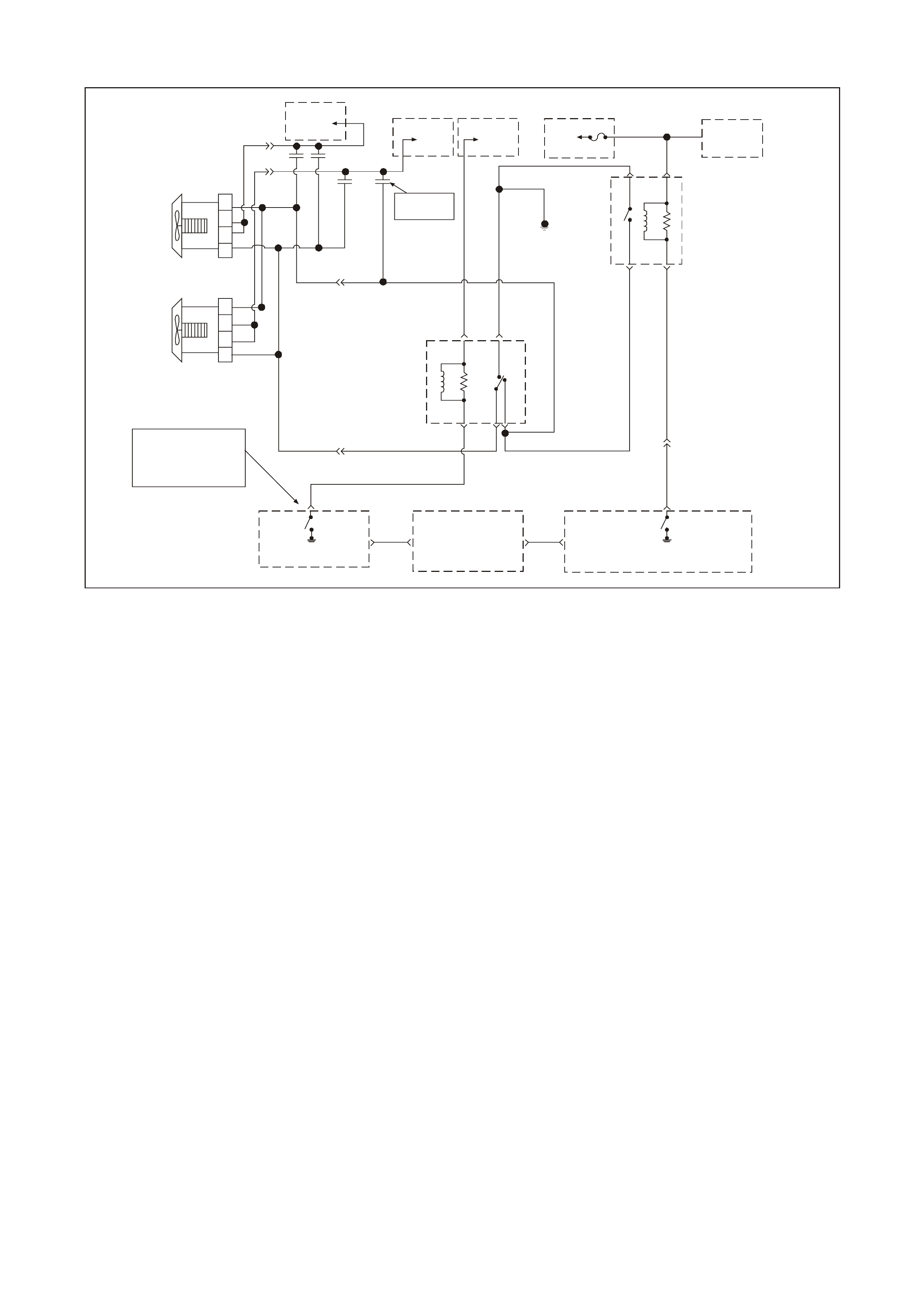
GEN III V8 PIM DTC B2002 LOW SPEED FAN NO BCM RESPONSE
GEN3 0170
Refe r to Wiring
Schematic
Part 1
Engine Cooling
Fan Relay
Hi gh S p ee d
P/B
39
Fuse
F14
To
Ignition
Switch
To
Fusible
Link FS
To
Fusible
Link F U
To
Fusible
Link F T O/B 208
YE118
O/BLU 204
Y
250
O/BLU
250
YE104
1040
B/R 157
O/BLU
250
Engine
Earth
O/BLU 250
85
30
86
87
O/BLU 250
12V Bus
12V Bus
1040
BLU/W 304
YE110
B/R 157
85 87
86 30 87A
Engine Cooling
Fan Relay
Low Speed
B533
YE104 O/B 473
O/B 473
BLU/Y
533
NOTE
BCM Termi nal "7" Conne ct or
YB174 High Series
YB163 Low Series
Engine
Cooling
Fan Relay
Low Speed
Control
Powertrain
Control
Module
(PCM)
Engine Cooling
Fan Relay
High Speed
Control
J2
33
Cooling
Fan
2
Cooling
Fan
1
Serial Data
(Class I I)
Body Control Module (BCM)
Serial Data
(UART)
7
R/B
122 62 Serial Data
(Class II)
Serial Data
(UART) Y
104958
7C1
Powertrain Interface Module (PIM)
G208
R 208
Supression
Capacitors
CIRCUIT DESCRIPTION
The PCM determines operation of the two speed engine cooling fans based on A/C request, engine coolant
temperature, A/C pressure sensor, and vehicle speed.
The engine cooling f an Low Speed Relay is energis ed by the BCM. When the PCM deter mines that the low speed
fan relay should be enabled, the PCM will send a message on the Class II serial data circuit to the PIM. The PIM will
inturn convert the PCM Class II message to a UART message and supply this UART message to the BCM. This
PCM message will request the BCM to supply the needed earth signal for the Low Speed Relay to operate. After the
BCM provides the earth s ignal for the Low Speed Relay, the BCM will send a m essage back to the PIM conf irming
that the earth signal was com manded. The PIM will convert this message from the BCM to Class II and supply to
the PCM.
CONDITIONS FOR RUNNING THE DTC
• The engine is idling.
CONDITIONS FOR SETTING THE DTC
• T he PCM sends a num ber of Low Speed request signals to the BCM thr ough the PIM, with no respons e back
from the BCM.
ACTION TAKEN WHEN THE DTC SETS
• The Check Powertrain Lamp (CPL) will not be illuminated.
DIAGNOSTIC AIDS
• Using the Freeze Frame/Failure Records data may aid in locating an intermittent condition. If you cannot
duplicate the DT C, the information inc luded in the Freeze Fram e/Failure Records data can help determ ine the
distance traveled since the DTC set. The Fail Counter and Pass Counter can also help determine how many
ignition cycles the diagnostic reported a pass and/or fail. Operate the vehicle within the same freeze frame
condition (RPM, load, vehicle speed, temperature etc.) that you observed. This will isolate when the DTC
failed.
• For an intermittent, refer to Section 6C3-2B SYMPTOMS in the VT Series II Service Information.

TEST DESCRIPTION
The numbers below refer to the step numbers on the diagnostic table.
2. T he test is determ ining if any BCM DTCs m ay be s et. There m ay be a BCM DT C that is related to this circuit,
and diagnosing this BCM DTC first may resolve the fault.
3. An open or s hort to earth on the UART s erial data circ uit will disable any comm unication between the PIM and
BCM.

GEN III V8 PIM DTC B2002 LOW SPEED FAN NO BCM RESPONSE
Step Action Value(s) Yes No
1 Did you perform the Powertrain On-Board Diagnostic
(OBD) System Check? Go to Step 2 Go to Powertrain
OBD System
Check Table
2 Are any BCM DTCs set? Go to appropriate
BCM DTC
Refer to Section
12J-1 Low Series
BCM or Section
12J-2 High
Series BCM in
the VT Series II
Service
Information
Go to Step 3
3 1. Engine at idle speed.
2. Using a Tech 2 scan tool, select LOW FAN.
Does the Tech 2 scan tool BCM Response display
change from FAN OFF to FAN ON when the test is
enabled?
Go to Step 4 Go to
Functional Check
table for Electric
Fan Control in
this Section for
further diagnosis
of the cooling fan
circuits
4 Does Tech 2 scan tool BCM Response display change
from FAN OFF to FAN ON when test is enabled? DTC B2002 is
intermittent.
Refer to
Diagnostic Aids
Refer to Section
12J-1 Low Series
BCM or Section
12J-2 High
Series BCM in
the VT Series II
Service
Information
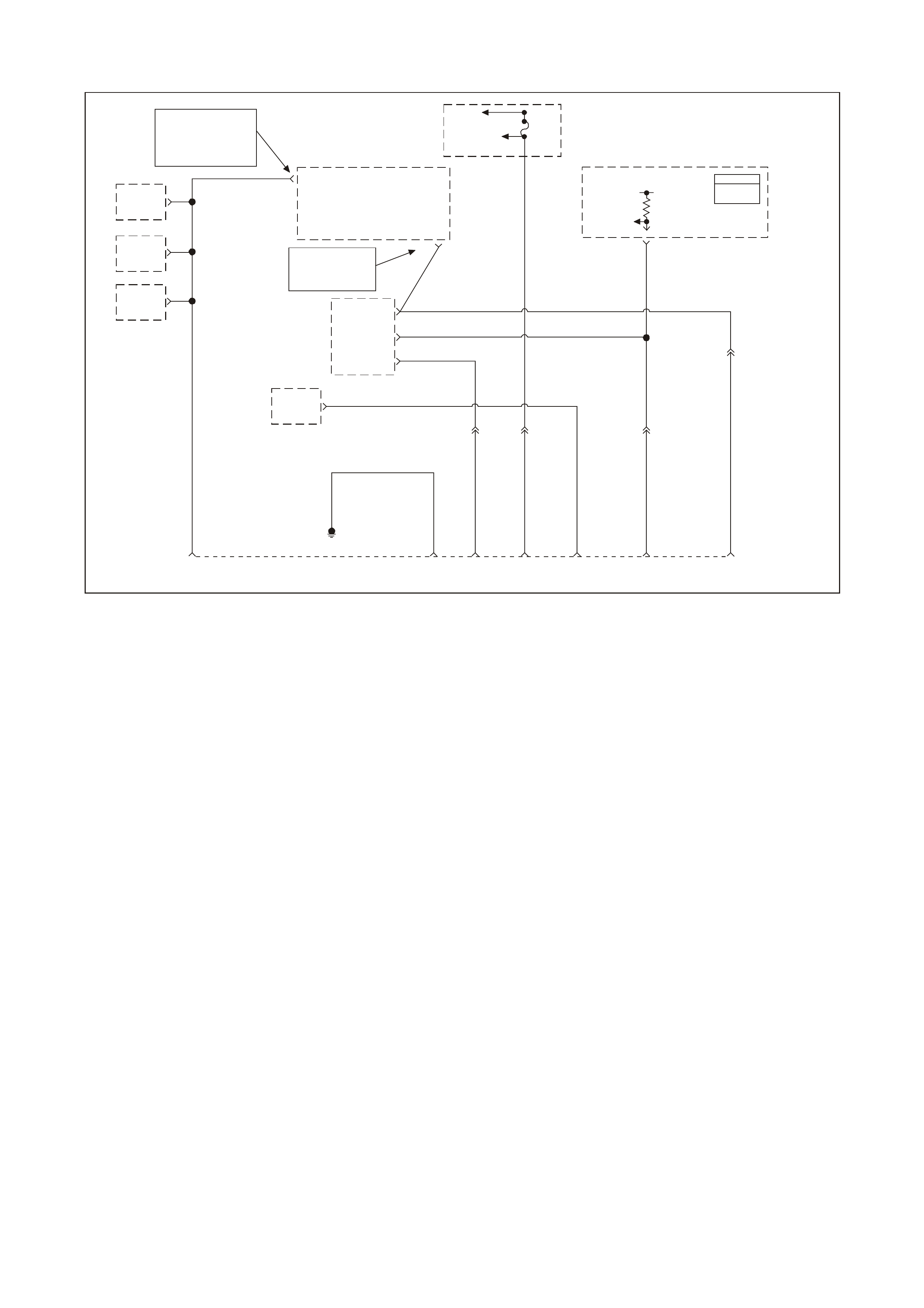
GEN III V8 PIM DTC B2006 NO SERIAL DATA FROM PCM
GEN3 0093
PCM
J1 = BLU E
J2 = RED
NOTE
BCM Termi nal
9 YB175 High S eries
3 YB164 Low Serie s
Body
Earth 5616 212 9
B/Y 155
BLU/B 863 R/B 1221
YE112
Data Link
Connector
(DLC)
Y1049
YE110
58 J1
Y1049
7V
Serial Data
(Class I I)
Fuse
F31
Fusible
Link FS
O/B 740
R/B
1221
Y
1049
YE111
W/B 451
BLU/B
863
6
7
11
R/B 1221
2
Serial Data
(UART)
Serial Data
(UART)
Serial Data
(UART)
Serial Data
(Class I I)
Diagnostic Test
Enable
Powertrain
Interface
Module
(PIM)
NOTE
YB175 High Serie s
YB164 Low Seri es
9
Body
Control
Module
(BCM)
12
Diagnostic
Enable
ABS/ETC
Module
1
G/W 1220
IP
Cluster
ECC
Module
ABS/ETC
Module
6
11
G/W
1220
B/Y 155
Powertrain
Control
Module
(PCM)
CIRCUIT DESCRIPTION
The PIM receives information from the PCM on the Class II serial data circuit. If ther e is a problem with this cir cuit
or the PCM is not com municating, the PIM will detect this lack of inform ation and will set a DTC. Also, if there is a
problem with the serial data circuit, performing the Powertrain OBD System Check will lead you to the Data Link
Connector Diagnosis, where the problem for which set this DTC will be diagnosed.
CONDITIONS FOR RUNNING THE DTC
• Key is ON.
• The ignition voltage is between 5.0 and 17 volts.
CONDITIONS FOR SETTING THE DTC
• PIM does not receive any serial data communication from the PCM.
ACTION TAKEN WHEN THE DTC SETS
• The Check Powertrain Lamp (CPL) will not be illuminated.
DIAGNOSTIC AIDS
• The following problems may cause this DTC to set:
- Poor connections/terminal tension at the PCM
- Poor connections/terminal tension at the PIM
• For an intermittent, refer to Section 6C3-2B SYMPTOMS in the VT Series II Service Information.
TEST DESCRIPTION
The numbers below refer to the step numbers on the diagnostic table.
1. The test confirms that the Powertrain OBD System Check has been performed
2. Diagnos is of this DTC will be perform ed using the Data Link Connector Diagnostic Table, f ound in the front of
this section. If there is an open, shor t to earth, or short to voltage in the Clas s II serial data circuit between the
PCM and the PIM, this will cause PIM DTC B2006 to set.

GEN III V8 PIM DTC B2006 NO SERIAL DATA FROM PCM
Step Action Value(s) Yes No
1 Did you perform the Powertrain On-Board Diagnostic
(OBD) System Check? Go to Step 2 Go to Powertrain
OBD System
Check Table
2 Refer to Data Link Connector Diagnosis in the front of
this Section for diagnosis of this PIM DTC.
Is action complete?
Verify Repair
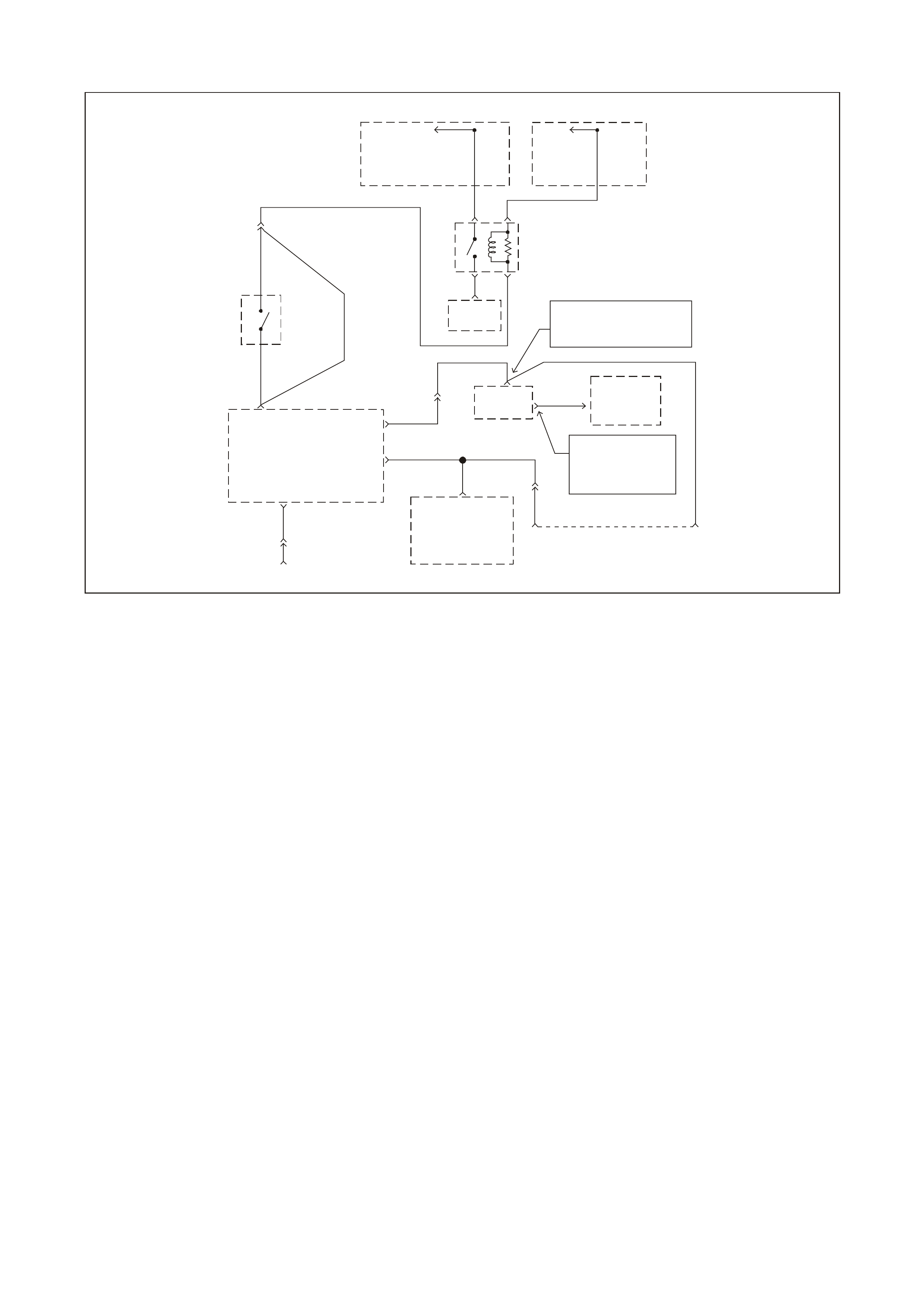
GEN III V8 PIM DTC B2007 STARTER RELAY VOLTAGE HIGH
GEN3 0098
Data Link
Connector
(DLC)
8
Start Relay
Control
GY/BLU 1434 GY
434
Serial Data
(UART)
Serial Data
(Cl ass II)
Diagnostic
"TEST"
Enable
11
W/B 451
YE111
Data Link
Connector
(DLC)
6
6
7
GY/BLU 1434
Neutral
Start
Switch
(Auto Onl y )
G
YE111
GY 434
Manual
Transmission
GY
434
R/B
1221
Fusible
Link
FJ
To
Ignition
Switch
Y
5
R2
30 85
87 86
Start
Relay
To Starter
Selenoid NOTE
YB175 High Series BCM
YB164 Low Series BCM
R/B 1221 2
R/B
1221
YE112 Serial Data
(UART) 9R/B
122
To
Vehicle
Bus
NOTE
"9" YB175 High Series
"3" YB164 Low Series
Body Control
Module (BCM)
R/B 1221
92
Y1049
YE110
Y1049
58 J1
Y
1049
Serial
Data
Powertrain
Cont rol Modul e
(PCM)
E
Powertrain
Interface
Module
(PIM)
CIRCUIT DESCRIPTION
When the key is turned to the crank position, power is supplied to the starter relay terminal 85. The PIM after
receiving the proper theft deterrent signal from the BCM will supply an earth signal the starter relay terminal 86. This
will energise the starter relay and allow the starter motor to operate. If there is a problem with the starter relay coil
(shorted internally) or the starter relay control circuit ( shorted to voltage) that is allowing 12 volts on the starter relay
control circuit, this will cause the PIM to set DTC B2007.
CONDITIONS FOR RUNNING THE DTC
• Key is in the crank position.
• The ignition voltage is between 5.0 and 17 volts.
CONDITIONS FOR SETTING THE DTC
• PIM detects high voltage on the starter relay control circuit.
ACTION TAKEN WHEN THE DTC SETS
• The Check Powertrain Lamp (CPL) will not be illuminated.
DIAGNOSTIC AIDS
• The following may cause an intermittent:
- Incorrectly routed harness
- Rubbed through wire insulation
- Broken wire inside the insulation
• For an intermittent, refer to Section 6C3-2B SYMPTOMS in the VT Series II Service Information.
TEST DESCRIPTION
The numbers below refer to the step numbers on the diagnostic table.
2. This test checks to see it the relay is causing the high voltage problem.
5. This test checks to see it the PIM is causing the problem.

GEN III V8 PIM DTC B2007 STARTER RELAY VOLTAGE HIGH
Step Action Value(s) Yes No
1 Did you perform the Powertrain On-Board Diagnostic
(OBD) System Check? Go to Step 2 Go to Powertrain
OBD System
Check Table
2 1. Ignition OFF.
2. Disconnect the PIM harness connector.
3. Ignition ON.
4. Using test light connected to earth, probe PIM
harness connector terminal for starter relay control.
Does test light illuminate?
Go to Step 3 Go to Step 5
3 While test light is still connected to PIM harness
connector, disconnect the starter relay.
Is test light still illuminated?
Go to Step 4 Go to Step 7
4 Repair short to voltage in the starter relay control circuit.
Is action complete? Verify Repair
5 1. Ignition OFF.
2. Reconnect the PIM harness connector.
3. Using scan tool, clear PIM DTCs.
4. Crank engine.
5. Using scan tool, check to see if PIM DTC B2007 has
reset.
Did PIM DTC B2007 reset?
Go to Step 6 System OK
6 1. Replace PIM.
2. Refer to Section 6C3-3 in the VT Series II Service
Information for PIM replacement and PCM/PIM/BCM
Security Link Procedure.
Is action complete?
System OK
7 Replace starter relay.
Is action complete? System OK

GEN III V8 PIM DTC B2009 EEPROM CHECKSUM ERROR
GE N3 0006
1
32
1. Throttle Relaxer Control Module
2. Powertrain Interface Module
3. Left A Pillar
CIRCUIT DESCRIPTION
The PIM EEPROM contains data which is essential to running the engine. The PIM continuously checks the integrity
of this data.
CONDITIONS FOR RUNNING THE DTC
• The ignition switch is in the crank position or the run position.
CONDITIONS FOR SETTING THE DTC
• The PIM is unable to correctly read data from its memory.
ACTION TAKEN WHEN THE DTC SETS
• The Check Powertrain Lamp (CPL) will not be illuminated.
DIAGNOSTIC AIDS
• Replace the PIM even if this DTC exists only in history.
• For an intermittent, refer to Section 6C3-2B SYMPTOMS in the VT Series II Service Information.
TEST DESCRIPTION
The number below refers to the step numbers on the diagnostic table.
2. This DTC indicates an internal PIM problem.

GEN III V8 PCM DTC B2009 EEPROM CHECKSUM ERROR
Step Action Value(s) Yes No
1 Did you perform the Powertrain On-Board Diagnostic
(OBD) System Check? Go to Step 2 Go to Powertrain
OBD System
Check Table
2 1. Replace PIM.
2. Refer to Section 6C3-3 Service Operations in the VT
Series II Service Information, for PIM replacement
and PCM/PIM/BCM Security Link Procedure.
Is action complete?
Go to Step 3
3 1. Select the Diagnostic Trouble Code (DTC) option and
the Clear DTC Information option using the Tech 2
scan tool.
2. Idle the engine at the normal operating temperature.
3. Select the Diagnostic Trouble Code (DTC) option
using the Tech 2 scan tool.
Does the Tech 2 scan tool indicate that this DTC reset?
Go to Step 2 Go to Step 4
4 Using the Tech 2 scan tool, check for any other DTCs.
Does the Tech 2 scan tool display any DTCs that you
have not diagnosed?
Go to the
applicable DTC
table
System OK