SECTION 6C3-3 - SERVICE OPERATIONS -
GEN III V8 ENGINE
CAUTION:
This vehicle will be equipped with a Supplemental Restraint System (SRS). A SRS will consist of either
seat belt pre-tensioners and a driver's air bag, seat belt pre-tensioners and a driver's and front
passenger's air b ags o r seat b elt p re-t ension ers, driv er’s an d f ron t p asseng er’s air bag and left and righ t
hand side air bags. Refer to SAFETY PRECAUTIONS, Section 12M Supplemental Restraint System of the
VT Series II Service Information before performing any service operation on, or around any SRS
components, the steering mechanism or wiring. Failure to follow the SAFETY PRECAUTIONS could
result in SRS deployment, resulting in possible personal injury or unnecessary SRS system repairs.
NOTE: When fastener s are rem oved, always reinstall them at the same loc ation from which they were removed. If
a fastener needs to be r eplac ed, use the c or rec t part number f as tener f or that application. If the correct part number
fastener is not available, a fastener of equal s ize and strength (or stronger ) may be used. Fastener s that are not to
be reused, or those requiring thread locking compound will be identified. The correct torque value must be used
when installing fasteners that require it. If the above conditions are not followed, parts of system damage could
result.
WHAT THIS SECTION CONTAINS
This Section describes the correct service procedures to repair components of the Powertrain Management
Systems. Emphasis is placed on the proper procedures and repair of components related to the systems. The
service oper ation illust rations f or each pr oc edure in mos t c as es will res ide to the right of the tex t. In s ome cas es the
illustrations may be above or below the text.
Techline
Techline
Techline
Techline
3.1 SERVICE PRECAUTIONSTHE FOLLOWING
REQUIREMENTS MUST BE OBSERVED WHEN WORKING ON VEHICLES:
1. Before removing PCM/PIM or fuel system components, disconnect the battery earth lead.
2. Never start the engine without the battery being securely connected.
3. Never disconnect the battery from the on-board electrical system while the engine is running.
4. When charging the battery, disconnect it from the vehicle's electrical system.
5. Never subject the PCM/PIM to temperatures above 80°C i.e. paint oven. Always remove PCM first if this
temperature is to be exceeded.
6. Ensure that all cable harness plugs are connected securely and that battery terminals are thoroughly clean.
7. The engine m anagement system har ness c onnectors are designed to f it one way only; there are index ing tabs
and slots on both halves of the connector. Forcing the connector into place is not necessary if it is being
installed with the correct orientation. Failure to take care to match the indexing tabs and slots to can cause
damage to the connector, the module, or other vehicle components or systems.
8. Never connect or disconnect cable harness plug at the PCM/PIM when the ignition is switched ON.
9. Before performing any electric welding (Arc, MIG, etc.) on the vehicle, disconnect the battery leads and the
PCM connectors.
10. W hen steam cleaning engines, do not direct the steam cleaning nozzle at PCM or system com ponents. If this
happens, corrosion of the terminals can take place.
11. Use only the test equipment specified in the diagnostic charts, since other test equipment may either give
incorrect results or damage good components.
12. A digital multimeter with an internal impedance rating of at least 10 million ohms per volt (10 megohm/volt)
must be used where required when testing circuits.
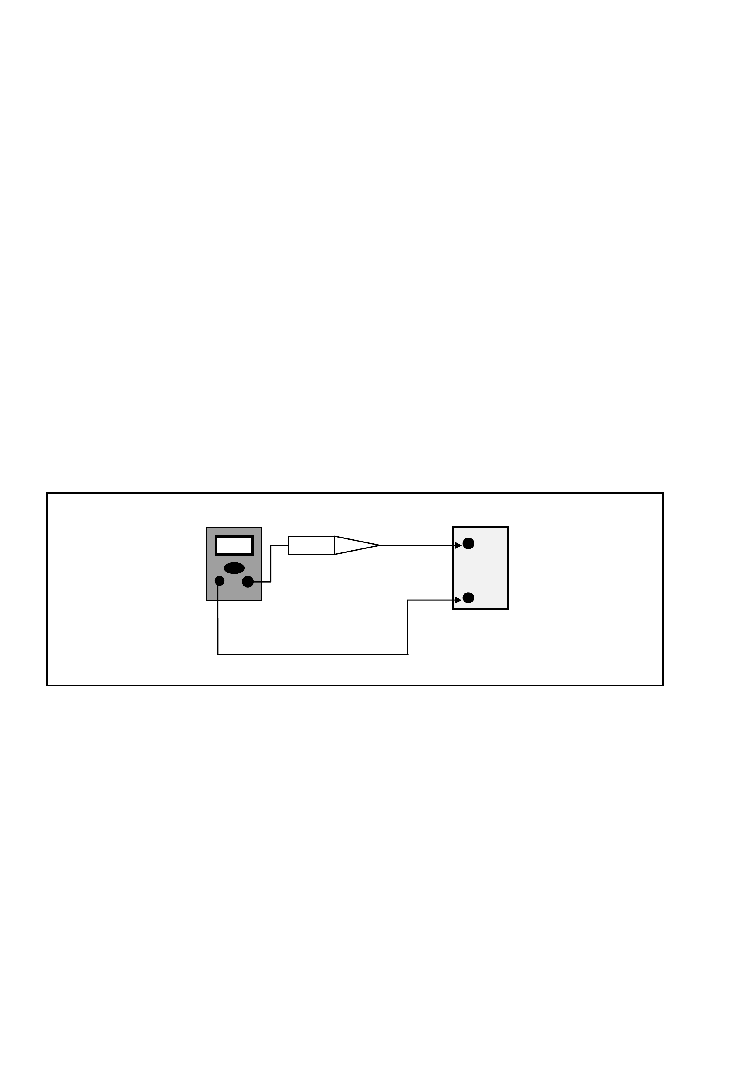
13. When a tes t light is spec if ied, a low-power tes t light must be us ed. Do not us e a high - wattage test light. While
a particular brand of test light is not suggested, a simple test on any test light will ensure it to be OK for PCM
circuit tes ting. Connect an acc urate am m eter ( such as the high-im pedance digital m u ltim eter) in ser ies with the
test light being
14. tested, and power the test light-ammeter circuit with the vehicle battery as shown below.
Test Light Check
If the ammeter indicates less than 3/10 amp
current flow (0.3 A or 300 mA), the test light is OK
to use.
If the ammeter indicates more than 3/10 amp current
flow (0.3 A or 300 mA), the test light is NOT OK to
use.
+
BATTERY
-
DC AMPS
TEST LIGHT
3.2 PO WERTRAIN CONTROL MODULE (PCM)
PCM REPLACEMENT/ PROGRAMMING
Service of the PCM should normally consist of either
replacement of the PCM or EEPROM (flash
memory) programming. If the diagnostic procedures
call for the PCM to be replaced, the PCM should be
first checked to ensure it is the correct part. If it is,
remove the faulty PCM and install the new PCM.
NOTE: The replacement PCM EEPROM will not be
programmed.
DTC P0601 and P0602 indicates the EEPROM is
not programmed or has malfunctioned. Refer to
Service Programming for programming procedures.
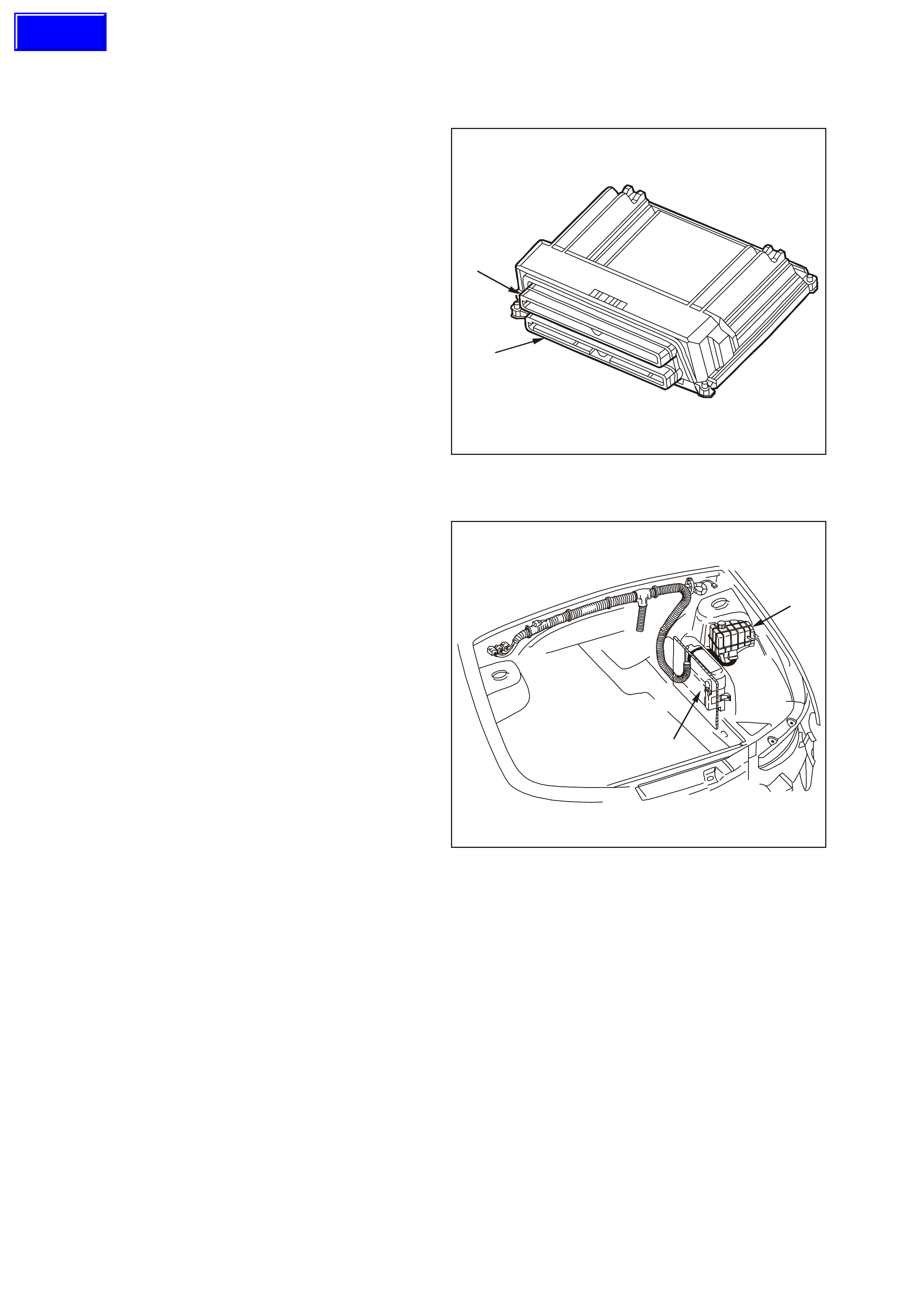
The PCM has two 80 pin connectors: J1 Blue (1), J2
Red (2).
IMPORTANT: The following must be performed
anytime the PCM is replaced:
1. Programming of the EEPROM
2. The Idle Learn Procedure
3. The Functional Check
1
2
Powertrain Control Module
The following must be performed anytime the PCM
is disconnected or loses power.
1. The Idle Learn Procedure
2. The Functional Check
All are described later in this section.
IMPORTANT: To prevent internal PCM damage, the
ignition must be OFF when disconnecting or
reconnecting power to the PCM.
IMPORTANT: Ensure that the cover is free of
contaminants (moisture) before servicing the PCM.
The moisture flows into the PCM connector body
when the PCM is disconnected and the hood is
opened.
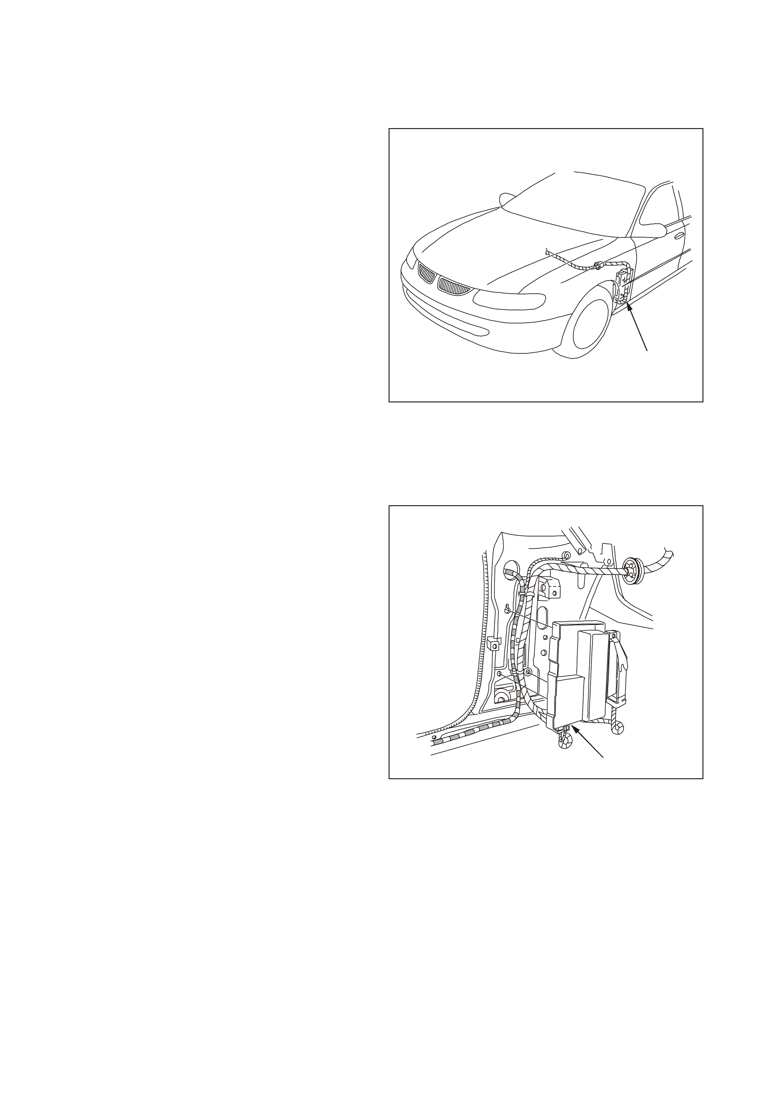
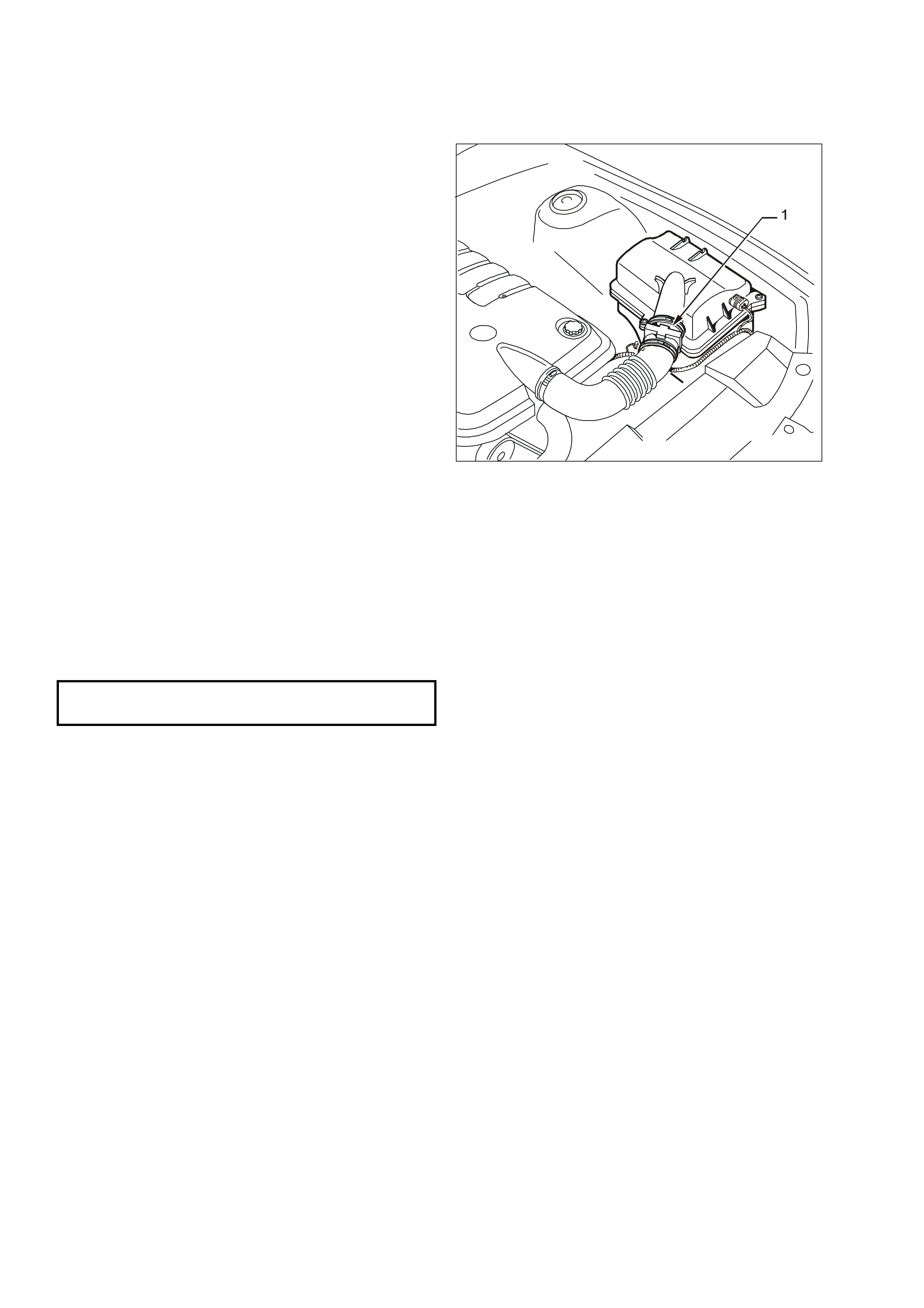
The location of the PCM (2) is by the left front
suspension tower, below the coolant surge tank (1).
REMOVE
IMPORTANT: Remove any debris from the PCM
connector surfaces before servicing the PCM.
Inspect the PCM module connector gaskets when
diagnosing or replacing the PCM. Ensure that the
gaskets are installed correctly as they prevent
contaminant intrusion into the PCM.
NOTE 1: Do not touch the connector pins or
soldered components on the circuit board in order to
prevent possible electrostatic discharge damage to
the PCM.
GE N 3 0005
1
2
Coolant Surge Tank and PCM Location
Techline
NOTE 2: To prevent internal damage to the PCM,
the ignition must be OFF when disconnecting or
reconnecting the PCM connector.
1. Ignition OFF.
2. Disengage the coolant surge tank from its
mounting points, refer Section 6B3 ENGINE
COOLING in of the VT Series II Service
Information.
NOTE: The coolant surge tank may be HOT. Allow
the coolant to cool before performing this procedure.
3. Lift the coolant surge tank up, turn it over and
disconnect the wiring harness connector from the
coolant level sensor. Set the surge tank to one
side.
4. Remove the air cleaner assembly, refer 3.23 Air
Cleaner Assembly in this Section.
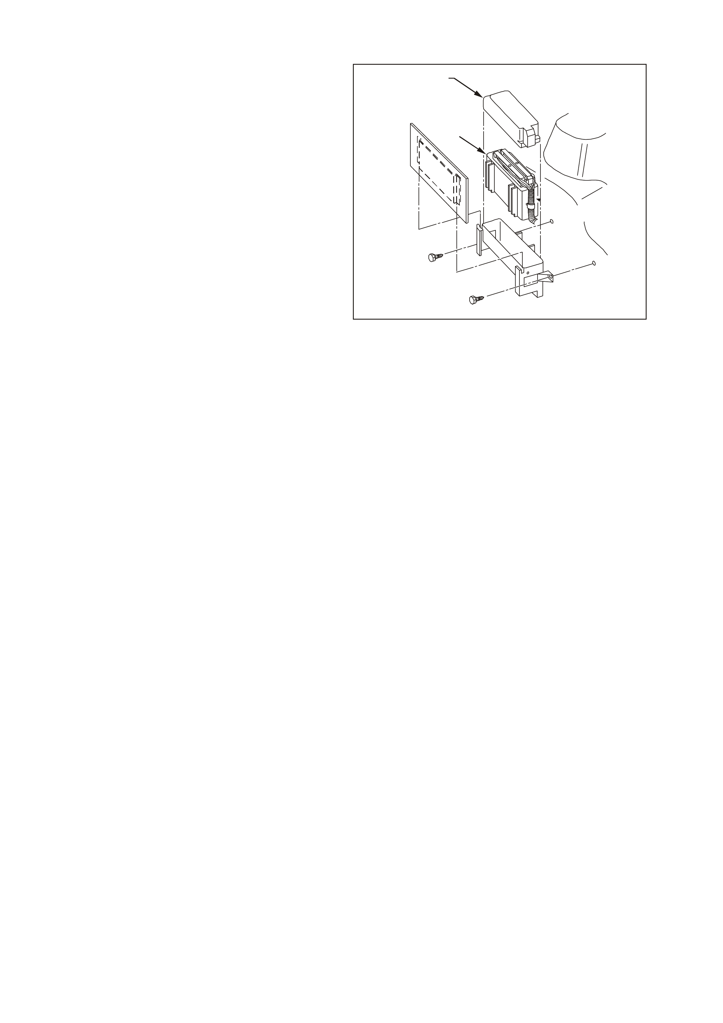
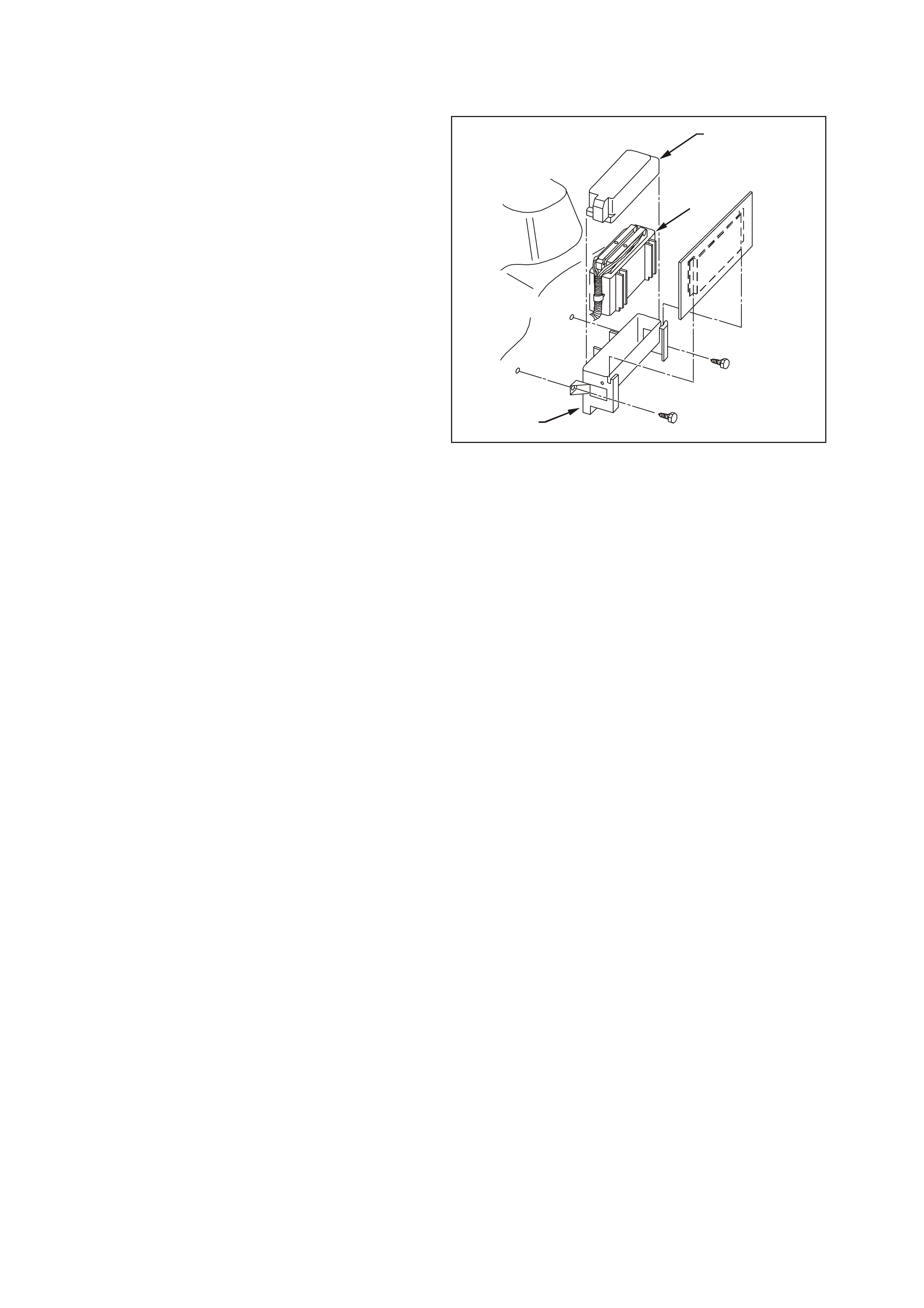
5. Remove PCM Harness Connector Cover (1).
6. Loosen the connector retaining screws at each
PCM connector and r emove the connector s from
the PCM.
7. Remove the PCM (2) from the mounting bracket
by levering back the bracket retainers at each
end, while lifting up the PCM.
GE N 3 0105
2
1
PCM Mounting Assembly
REINSTALL
NOTE 1: Do not touch the connector pins or
soldered components on the circuit board in order to
prevent possible electrostatic discharge damage to
the PCM.
NOTE 2: To prevent internal damage to the PCM,
the ignition must be OFF when disconnecting or
reconnecting the PCM connector.
1. Install the PCM (1) to the mounting bracket (2).
2. Reconnect the PCM connectors.
3. Install PCM connector cover (3).
4. Install coolant surge tank.
5. Install air cleaner assembly.
6. If a new PCM is being installed, program the
PCM memory using the following procedure.
SERVICE PROGRAMMING
NOTE: Follow the programming instructions
completely and do not key OFF during programming
unless instructed. If the key is turned OFF during
programming, possible PCM damage may occur.
WARNING: DO NOT DISCONNECT TECH 2
DURING EACH PROGRAMMING STEP.
1. Setup - Ensure that the f ollowing conditions have
been met:
- The battery is fully charged, but not charging
during programming.
- The ignition is ON.
- Ensure that all PCM connections are OK.
2. Connect TECH 2 to the vehicle and select
Service Programming System (SPS) / Request
Info.
3. Connect T ECH 2 to a TIS terminal and download
latest s of tware matc hing the vehicle. Ref er to TIS
terminal/equipment users instructions.
4. Connect TECH 2 to the vehicle again and select
Service Programming System (SPS) / Program
ECU.
5. If the PCM fails to program, proceed as follows:
- Ensure that all PCM connections are OK.
- Attempt to r e-pr ogram the PCM. If the PCM still
cannot be programmed correctly, replace the
PCM and program it according to this
procedure.
NOTE: Once new PCM has been programmed, it
must be Security Linked. Refer to PCM/PIM/BCM
Security Link for linking procedure. If updating
calibrations to the vehicle’s existing PCM hardware,
no linking procedure is necessary.
GE N 3 0105
1
3
2
PCM Mounting Assembly

PCM/PIM/BCM SECURITY LINK
Once the PCM, PIM and/ or BCM have been
replaced, the modules must be security linked to
each other. If the procedure is not performed, the
vehicle will not crank or run.
This linking procedure is found under the BODY
CONTROL MODULE of TECH 2 and is performed
as follows:
• Connect TECH 2 to DLC and select:
- Diagnostic / (X) 1999 / VT Commodore / Body
/ Body Control Module / Security / BCM Link to
PCM/PIM.
• The procedure ‘BCM Link to PCM/PIM’ will first
ask to select the installed engine. If V8 GEN III
is selected a ‘TIS program approve’ is required.
• Connect TECH 2 to TIS terminal and select
‘Program Approve’.
• After returning to the vehicle, select again the
linking procedure. BCM and PIM are link ed first,
followed by the PCM – PIM which is performed
automatically.
For additional information regarding TECH 2 and
TECH 2 test modes (including this linking
procedure), ref er to T ECH 2 DIAGNOSIS FO R BCM
in Section 12J-1 LOW SERIES BCM or Section
12J-2 HIGH SERIES BCM of the VT Series II
Service Information.
NOTE: After the new PCM has been linked, you
must then follow the Idle Learn Procedure in order
for the PCM to learn and reestablish the IAC valve
position.
IDLE LEARN PROCEDURE
Whenever the PCM or the battery is disconnected or
the PCM loses power, the PCM’s learned position of
the IAC valve pintle is lost, resulting in an unstable
idle.
Perform the following procedure in order to return
the IAC valve pintle to the correct position:
Automatic Transmission
1. Turn OFF the ignition.
2. Restore the PCM battery feed.
3. Turn OFF the A/C controls.
4. Set the park brake and block the drive wheels.
5. Start the engine.
6. Shift the transmission selector to D (drive).
7. Allow the engine to idle for 10 minutes.
8. Turn ON the A/C controls.
9. Allow the engine to idle for 10 minutes.
10. Shift the transmission selector to P (park).
11. Allow the engine to idle for 10 minutes.
12. Turn OFF the A/C controls.
13. Allow the engine to idle for 10 minutes.
14. Turn OFF the engine for 30 seconds.

Manual Transmission
1. Turn OFF the ignition.
2. Restore the PCM battery feed.
3. Turn OFF the A/C controls.
4. Set the park brake and block the drive wheels.
5. Place the transmission in neutral.
6. Start the engine.
7. Turn ON the A/C controls.
8. Allow the engine to idle for 10 minutes.
9. Turn OFF the A/C controls.
10. Allow the engine to idle for 10 minutes.
11. Turn OFF the engine for 30 seconds.
FUNCTIONAL CHECK
1. Clear the Diagnostic Trouble Codes (DTCs).
2. Perform the Powertrain OBD System Check.
3. Start the engine and idle for one minute.
4. Use the Tech 2 scan tool to check for DTCs
3.3 PO WERTRAIN INTERFACE MODULE (PIM)
PIM REPLACEMENT
If the diagnostic procedures call for the PIM to be
replaced, it should be checked first to ensure it is the
correct part. If it is, remove the faulty unit and install
the new PIM.
IMPORTANT: To prevent internal PIM damage, the
ignition must be OFF when disconnecting or
reconnecting power to the PIM.
IMPORTANT: Remove any debris from the PIM
connector surfaces before servicing the PIM. Inspect
the PIM module connector when
diagnosing/replacing the PIM.
NOTE: Do not touch the connector pins or soldered
components on the circuit board in order to prevent
possible electrostatic discharge (ESD) damage to
the PIM.
REMOVE
1. Ignition OFF.
2. Remove left hand front shroud panel lower trim
assembly (kick panel trim).
3. Remove PIM (1) from mounting bracket.
4. Remove wiring harness connector from PIM.
REINSTALL
1
Powertrain Interface Module (PIM) Location
1. Install wiring harness connector to PIM.
2. Install PIM to the mounting bracket.
3. Install the left hand front shroud panel lower trim
assembly (kick panel trim).
1
Powertrain Interface Module (PIM)

PCM/PIM/BCM SECURITY LINK
Once the PCM, PIM and/ or BCM have been
replaced, the modules must be security linked to
each other. If the procedure is not performed, the
vehicle will not crank or run.
This linking procedure is found under the BODY
CONTROL MODULE of TECH 2 and is performed
as follows:
• Connect TECH 2 to DLC and select:
- Diagnostic / (X) 1999 / VT Commodore / Body
/ Body Control Module / Security / BCM Link to
PCM/PIM.
• The procedure ‘BCM Link to PCM/PIM’ will first
ask to select the installed engine. If V8 GEN III
is selected a ‘TIS program approve’ is required.
• Connect TECH 2 to TIS terminal and select
‘Program Approve’.
After returning to the vehicle, select again the linking
procedure. BCM and PIM are linked first, followed by
the PCM–PIM, which is performed automatically.
For additional information regarding TECH 2 and
TECH 2 test modes (including this linking
procedure), refer to TECH 2 DIAGNOSIS FOR BCM
in Section 12J-1 Low Series BCM in or Section
12J-2 High Series BCM of the VT Series II Service
Information.
FUNCTIONAL CHECK
1. Start the engine and idle for one minute.
2. Use the Tech 2 scan tool to check for any PIM
DTCs
3. If any PIM DTC set, refer to appropriate PIM DTC
table.
3.4 ENGINE COOLANT TEMPERATURE (ECT) SENSOR
REMOVE
1. Raise the vehicle. Refer to Section 0A General
Information of the VT Series II Service
Information.
2. Drain the engine coolant. Refer to Section 6B3
Engine Cooling of the VT Series II Service
Information.
3. Lower the vehicle.
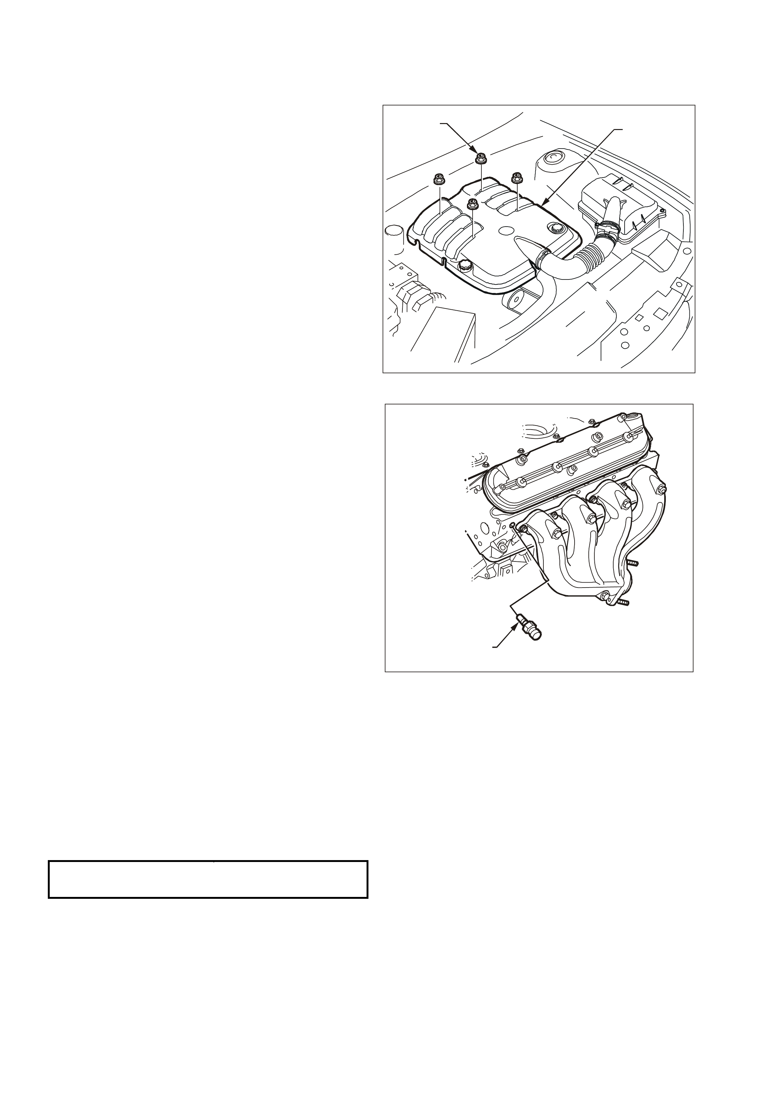
4. Remove the engine dress cover mounting nuts
(1) and the dress cover (2).
T6B3034
12
Engine Dress Cover
5. Disconnect the electrical connector from the ECT
sensor (1).
6. Remove the No.1 spark plug lead from the spark
plug.
7. Remove the ECT sensor.
NOTE: Use care when handling the coolant sensor.
Damage to the coolant sensor will affect the
operation of the fuel control sy stem.
REINSTALL
1. Coat the Engine Coolant Temperature (ECT)
sensor (1) thread with Loctite 242 sealer (Holden
Specification HN1256 Class 2, type 2) or
equivalent.
2. Install the ECT sensor into the left cylinder head.
3. Tighten the ECT sensor to the specified torque.
4. Install the No.1 spark plug lead onto the spark
plug.
5. Connect the ECT sensor electrical connector.
6. Refill the engine coolant. Refer to Section 6B3
Engine Cooling of the VT Series II Service
Information.
7. Start the engine and check for leaks.
8. Recheck the engine coolant level. Refer to
Section 6B3 Engine Cooling of the VT Series II
Service Information.
9. Reinstall the engine dress cover.
T6B3047
1
Engine Coolant Temperature (ECT) Sensor
ECT SENSOR
TIGHTENING TORQUE 17 Nm (13 lb/ ft)
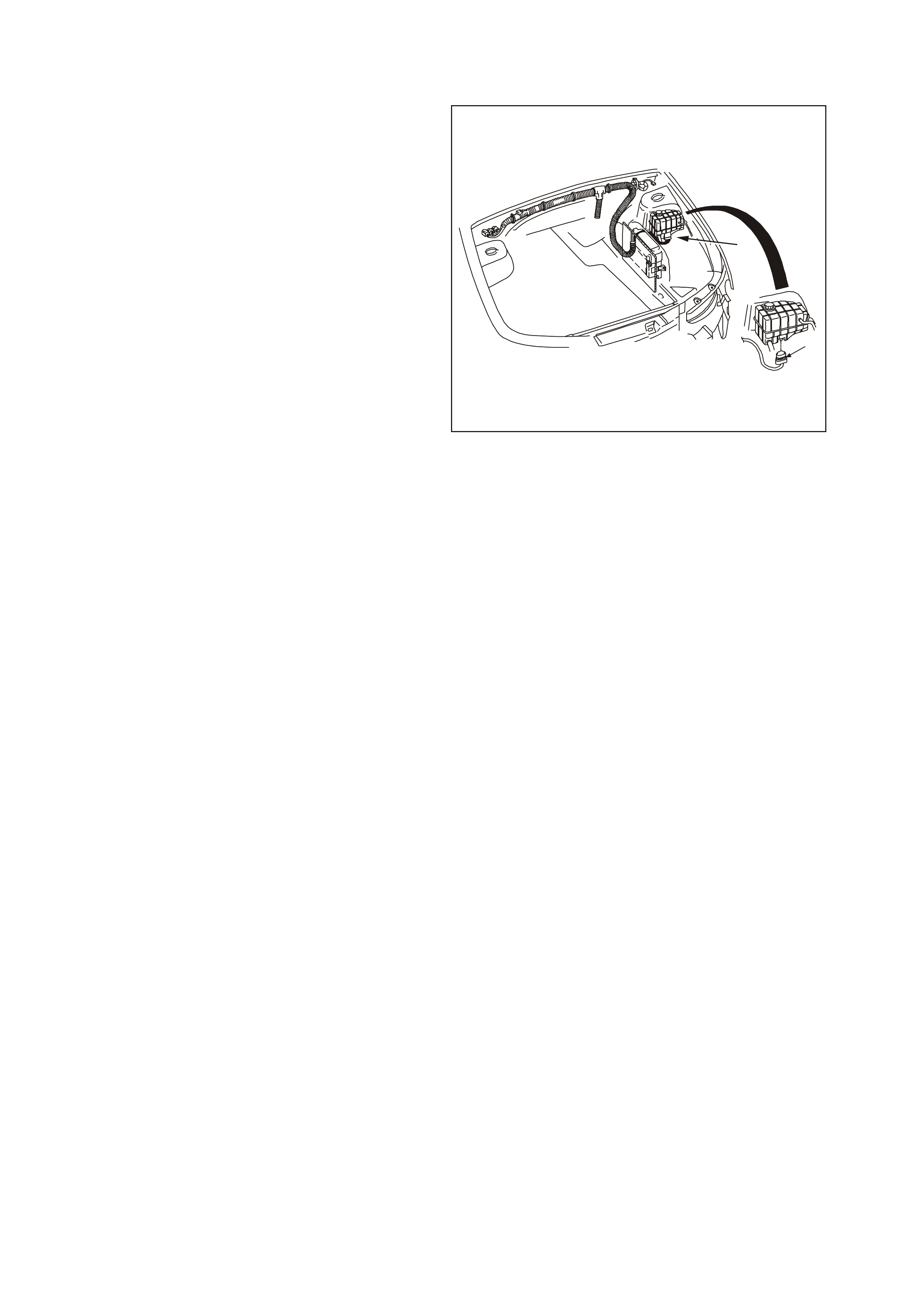
3.5 ENGINE COOLANT LEVEL SWITCH
CAUTION: To avoid serious personal injury,
never remove the radiator or coolant surge tank
when the engine is hot, even if the cooling
system should require filling. Sudden release of
cooling system pressure is very dangerous.
The engine coolant level switch (1) is part of the
coolant surge tank assembly and is serviceable only
by replacing the coolant surge tank. Refer to
Section 6B3 Engine Cooling of the VT Series II
Service Information or coolant surge tank
replacement.
GE N 3 0153
1
1
Engine Coolant Level Switch
3.6 INTAKE AIR TE MPERATURE (IAT) SENSOR
REMOVE
IMPORTANT:
Care must be taken when handling IAT Sensor as
damage will affect the operation of the fuel control
system.
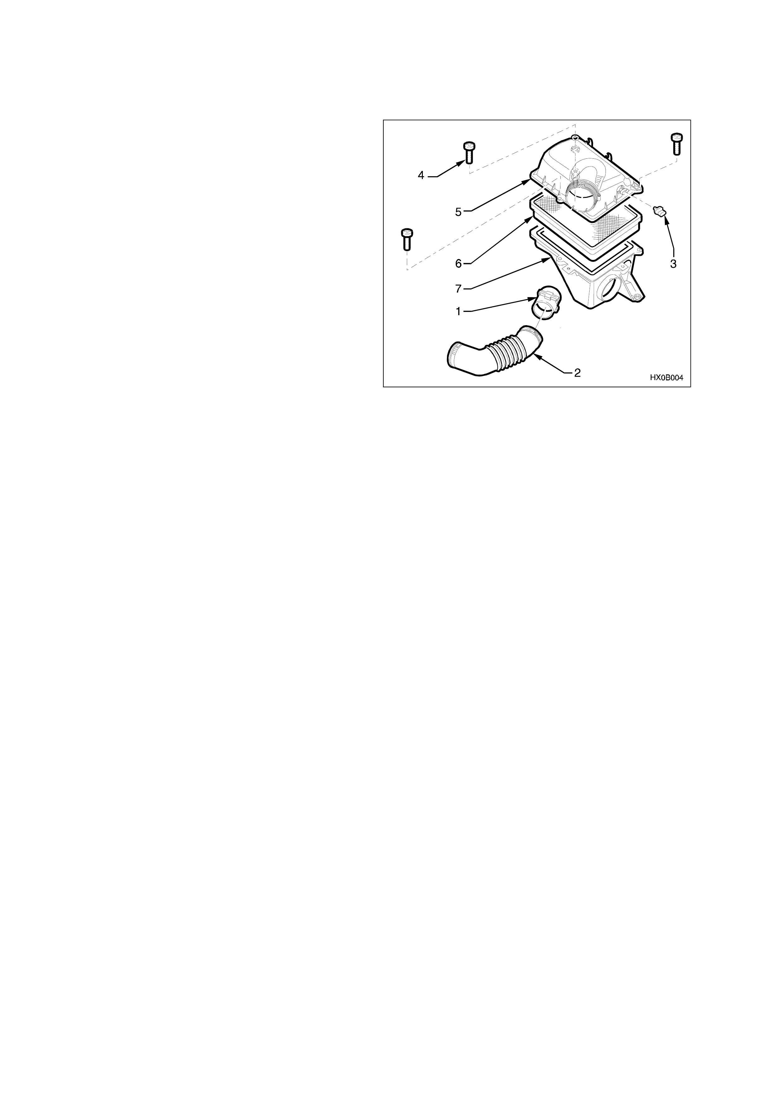
1. Lift up the tang on IAT sensor (3) wiring harness
connector and remove the connector from the
sensor.
2. Loosen the clamp on the air cleaner assembly
and move MAF sensor (1) to one side.
3. Disconnect air duct (2) from the air cleaner
assembly.
4. Remove three retainer bolts (4) securing the air
cleaner upper housing (5).
5. Remove air cleaner upper housing.
IMPORTANT:
The air filter should remain in the lower housing.
6. Using a pair of side cutters, cut across the IAT
sensor retainer to remove it. Once removed,
discard the retainer.
7. Pull the IAT sensor out from air cleaner upper
housing.
IAT Sensor Location
REINSTALL
1. Push new IAT sensor into air cleaner upper
housing, with the triangular tang on the mounting
flange locating on the mating rib of the air cleaner
upper housing.
2. Position the upper air cleaner housing assembly,
with the IAT sensor on the work bench, pushing
up into the air cleaner upper housing.
3. Position new retainer onto IAT sensor (1) and
then using a 20 mm socket, push the retainer
fully onto the IAT sensor.
4. Assemble the air filter element into the air cleaner
upper housing and place the upper housing onto
the lower housing, ensuring that air filter element
remains in position.
5. Snap five the retainer clips up into place over the
top of the air cleaner upper housing.
6. Reconnect wiring harness connector to IAT
sensor.
7. Carefully assemble the intake air duct and mass
air flow sensor onto air cleaner upper housing.
NOTE: Align the notch on air cleaner housing
adapter with notch in air duct adapter and notch in
clamp.
8. Tighten the air duct clamp securely.
9. Check that the mass air flow sensor wiring
harness connector has remained firmly in place.
3.7 MASS AIR FLOW (MAF) SENSOR
REMOVE
NOTE: Care must be taken when handling the MAF
sensor as damage will affect the operation of PCM
control.
1. Lift up the tang on the MAF sensor (1) wiring
harness connector and remove the connector
from sensor.
2. Loosen the clamp on air duct adapter, closest to
MAF sensor.
3. Loosen the clamp on the air duct at the MAF
sensor and pull back the air duct from the sensor.
NOTE: The air duct adapter (between air cleaner
and MAF sensor), retaining clamps, air duct and
MAF sensor have locating notches.
4. Remove MAF sensor from air duct adapter.
REINSTALL
NOTE: The embossed arrows on the MAF sensor
indicate the correct air flow direction. The arrows
must point towards the engine.
1. Install the MAF sensor into the air duct adapter
and air duct.
NOTE: Ensure all notches are aligned.
2. Install the retaining clamps, aligning notches,
tighten clamps to the specified torque.
3. Reconnect the MAF sensor wiring harness
connector
4. Start vehicle and check for air leaks.
T26C3002
MAF Sensor Location
AIR CLEANER DUCT CLAMP
TIGHTENING TORQUE 1.5 - 2.5 Nm
(1-2 lb/ft)
3.8 MANIFOLD ABSOLUTE PRESSURE (MAP) SENSOR
REMOVE
1. Remove engine dress cover. Refer to Engine
Coolant Temperature Sensor in this Section.
2. Disconnect the MAP sensor electrical connector
(1).
3. Twist the MAP sensor (2) forward in order to
release it from the retainer.
4. Pull the MAP sensor upward.
REINSTALL
IMPORTANT: Lightly coat the MAP sensor seal with
clean engine oil before installing the sensor.
1. Install the MAP sensor by pushing it down to
engage it into the retainer.
2. Connect the MAP sensor electrical connector.
3. Install engine dress cover.
2
1
MAP Sensor Location
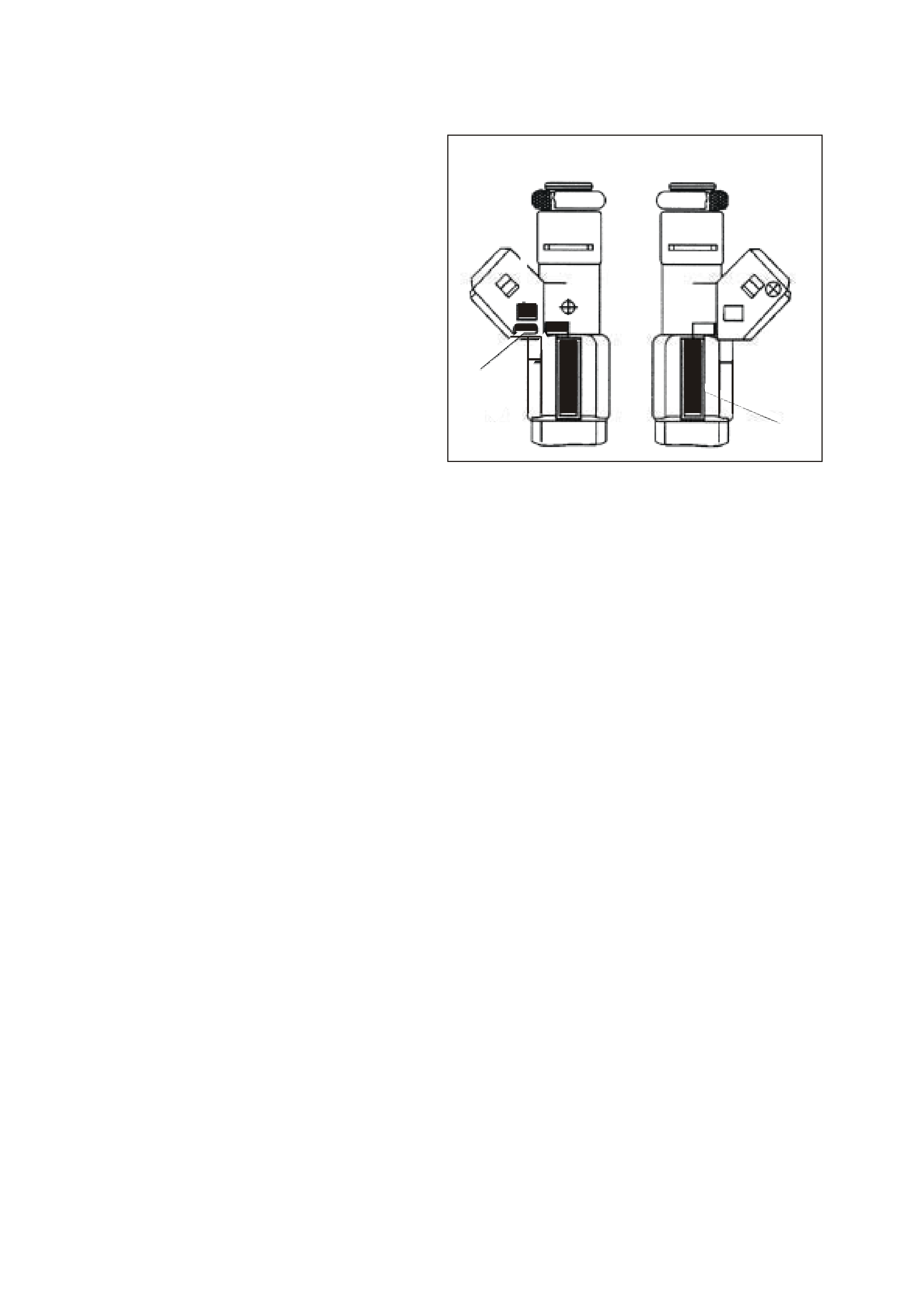
3.9 HEATED OXYGEN SENSORS (HO2S)
IMPORTANT: The heated oxygen sensors have a
permanently attached pigtail and connector. Do not
remove the pigtail from the sensor.
Handle the oxygen sensor carefully. Do not drop it
and keep it free of grease, dirt, or other
contaminants. Do not use cleaning solvents of any
type.
Do not repair the sensor or any of its parts.
Replace the oxygen sensor if any damage is
evident.
Correct oxy gen sensor operation requires an
external air reference. This external air reference is
obtained by way of the oxygen sensor signal and
heater wires. Any attempt to repair the wires, the
connectors, or the terminals results in the
obstruction of the air reference and degrades the
oxygen sensor performance.
NOTE 1: The heated oxygen sensor may be
difficult to remove when the engine temperature is
below 48°C (120°F). Excessive force may damage
the threads in the exhaust manifold or exhaust
pipe.
NOTE 2: It may be necessary to lower the exhaust
system to gain sufficient access to a HO2S and/or
its connector. Refer to Section 8B Exhaust
System of the VT Series II Service Information.
T26C3008
1
3
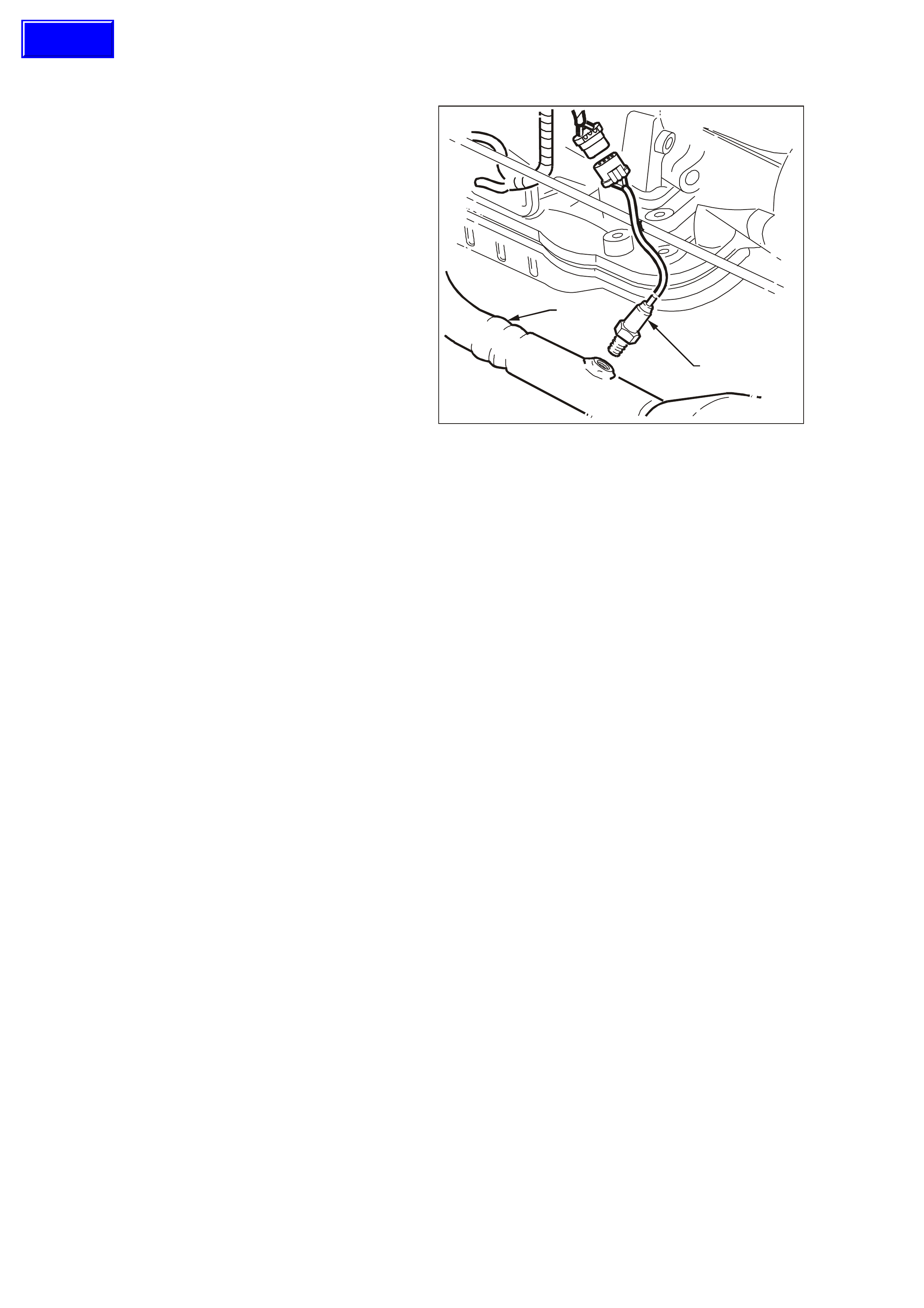
Left Hand HO2S Sensor 1
REMOVE
1. Raise the vehicle. Refer to Vehicle Lifting and
Jacking in Section 0A of the VT Series II
Service Information.
2. Disconnect the left-hand (1) or right-hand (2)
HO2S electrical connector.
3. Carefully remove the HO2S from left-hand (3) or
right-hand (4) exhaust pipe
Techline
REINSTALL
IMPORTANT: A special anti-seize compound is
used on the heated oxygen sensor threads. The
compound consists of graphite and glass beads
suspended in fluid. The graphite will burn away, but
the glass beads will remain, making the sensor
easier to remove. New or service sensors will have
the compound applied to the threads.
If a sensor is removed from an engine and is to be
reinstalled, the threads must have anti-seize
compound applied before reinstallation.
NOTE: Specified anti-seize compound is available
from authorised Holden Parts Outlets as part
number 5613695.
1. Coat the threads of the heated oxygen sensor
with anti-seize compound, if required.
2. Install the HO2S into the exhaust pipe and
tighten to the specified torque.
3. Connect the HO2S electrical connector.
4. Lower the vehicle.
4
2
Right Hand HO2S Sensor 1
HEATED OXGEN
SENSOR TIGHTENING
TORQUE 41 Nm (30 lb/ ft)
3.10 THROTTLE POSITION (TP) SENSOR
REMOVE
1. Remove engine dress cover. Refer to Engine
Coolant Temperature Sensor in this Section.
2. Depress the power steering reservoir retaining
clip and lift it up on the reservoir and set aside.
3. Unbolt and remove the power steering reservoir
mounting bracket.
4. Disconnect the electrical connector from the TP
sensor (1).
5. Remove the TP sensor attaching screws (2).
6. Remove the TP sensor and O-ring (3).
REINSTALL
1. Install the TP sensor O-ring seal on to the TP
sensor.
2. Install the TP sensor on the throttle body with
the throttle valve in the closed position.
NOTE: Ensure the TP sensor lever lines up with
the TP sensor drive lever on the throttle shaft.
3. Install the TP sensor attaching screws and
tighten to the specified torque.
4. Connect the TP sensor electrical connector.
5. Install the power steering reservoir mounting
bracket.
6. Install the power steering reservoir to mounting
bracket.
7. Install engine dress cover.
2
13
Throttle Position (TP) Sensor
TP SENSOR ATTACHING
SCREWS TIGHTENING
TORQUE 2 Nm (18 lb/in)

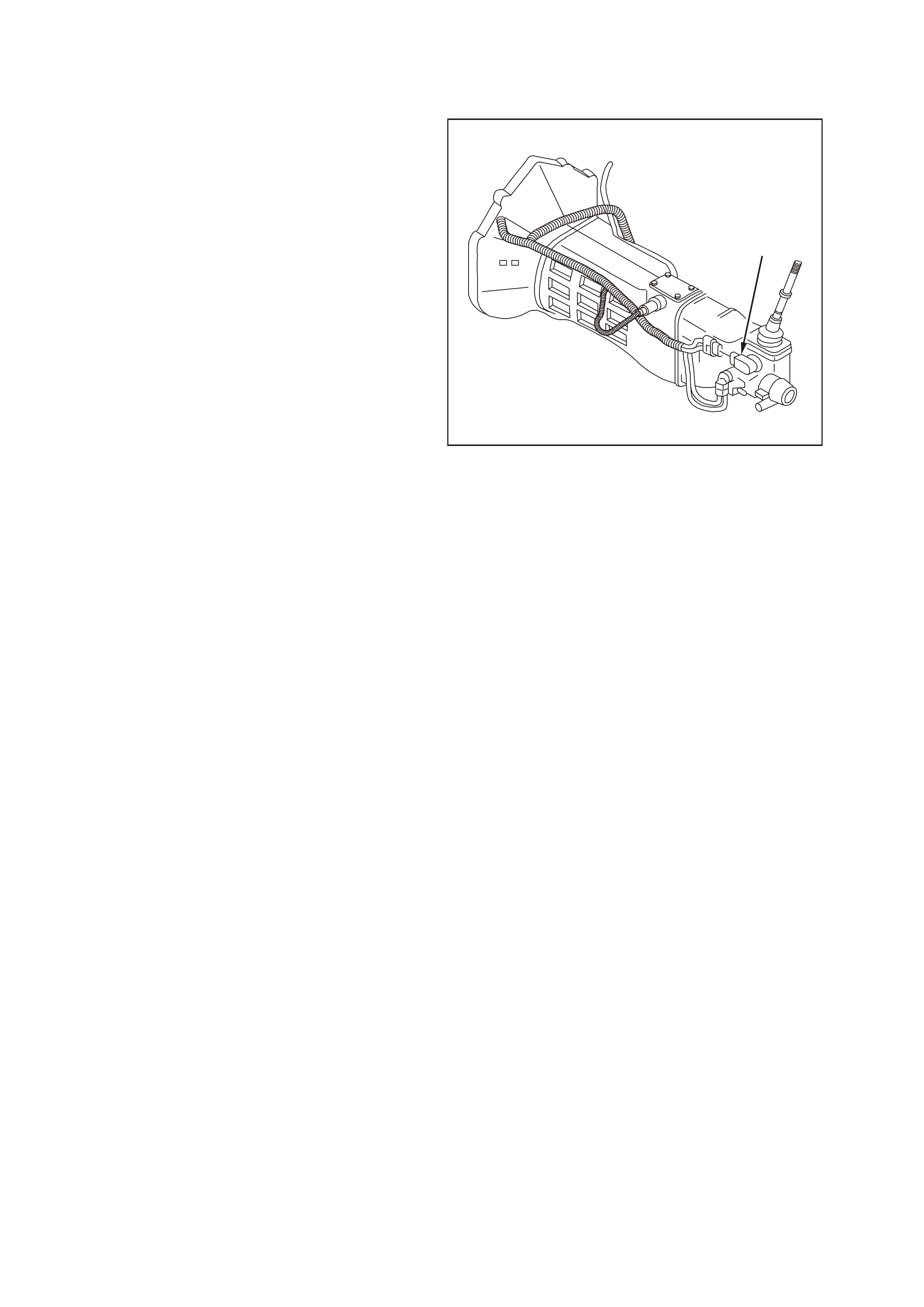
3.11 VEHICLE SPEED SENSOR
NOTE: This procedure refers to the vehicle speed
sensor fitted to vehicles with automatic
transmission. For manual transmission vehicle
speed sensor removal and reinstallation, refer to
Section 7B3 of the VT Series II Service
Information.
REMOVE
1. Raise the vehicle. Refer to Section 0A General
Information of the VT Series II Service
Information.
2. Disconnect the electrical connector from the
vehicle speed sensor (1)
3. Remove the vehicle speed sensor attaching bolt
(2).
4. Remove the vehicle speed sensor and the O-
ring. Use a suitable container to catch any
transmission fluid that may spill.
REINSTALL
1. Install the vehicle speed sensor with new O-ring
seal.
2. Install the speed sensor bolt and tighten to the
specified torque.
3. Connect the electrical connector.
4. Lower the vehicle.
5. Check the transmission fluid and add as
required. Refer Transmission Fluid Checking
Procedure in Section 7C4 of the VT Series II
Service Information.
2
1
Vehicle Speed Sensor
SPEED SENSOR ATTACHING
BOLT TIGHTENING TORQUE 11 Nm (97 lb/in)
3.12 IDLE AIR CONTROL VALVE
REMOVE
1. Remove engine dress cover. Refer to Engine
Coolant Temperature Sensor in this Section
for removal procedure.
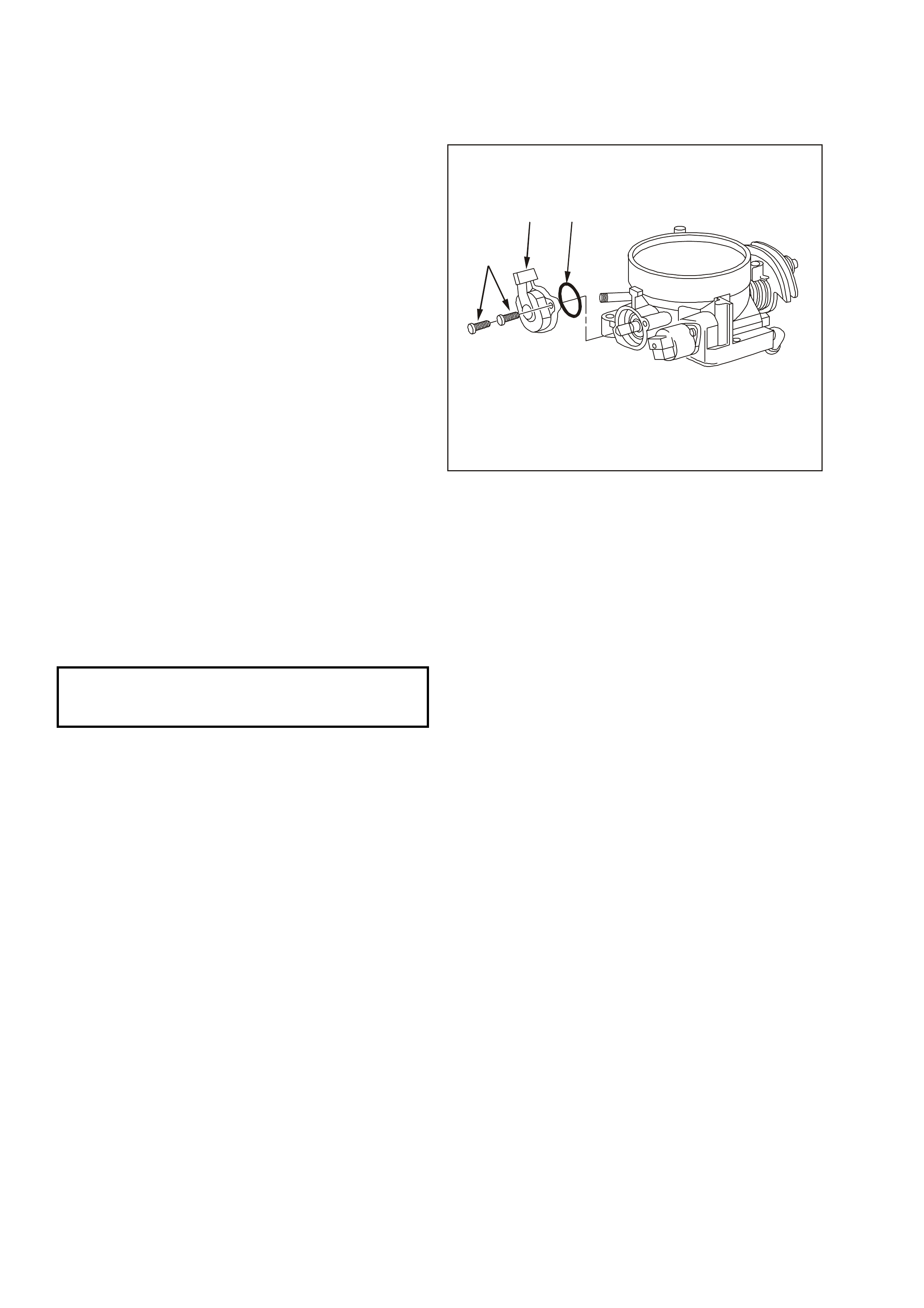
2. Disconnect the electr ical connec tor fr om the IAC
valve (1).
3. Remove the IAC valve attaching screws (2).
4. Remove the IAC valve.
5. Remove the IAC valve O-ring seal (3).
NOTE: Do Not push or pull on the IAC valve pintle
on valves that have been in service. The force
required to move the pintle may damage the
threads on the worm drive.
6. Clean the IAC valve O-ring sealing surface, the
pintle valve seat and the air passage using GM
cleaner 1052626 or GM X-66 A. Use a shop
towel or parts brus h to rem ove heavy deposits . If
the air passage has heavy deposits, rem ove the
throttle body for complete cleaning.
NOTE: Shiny spots on the pintle or seat are
norm al, and do not indicate m isalignment or a bent
pintle shaft.
7. Inspect the IAC valve O-ring for cuts, cracks, or
distortion. Replace the O-ring if it is damaged.
1
2
3
Idle Air Control (IAC) Valve
REINSTALL
IMPORTANT: If installing a new IAC valve, be sur e
to replace it with an identical part. T he pintle shape
of the IAC valve and the diameter of the IAC valve
are designed for the specific application.
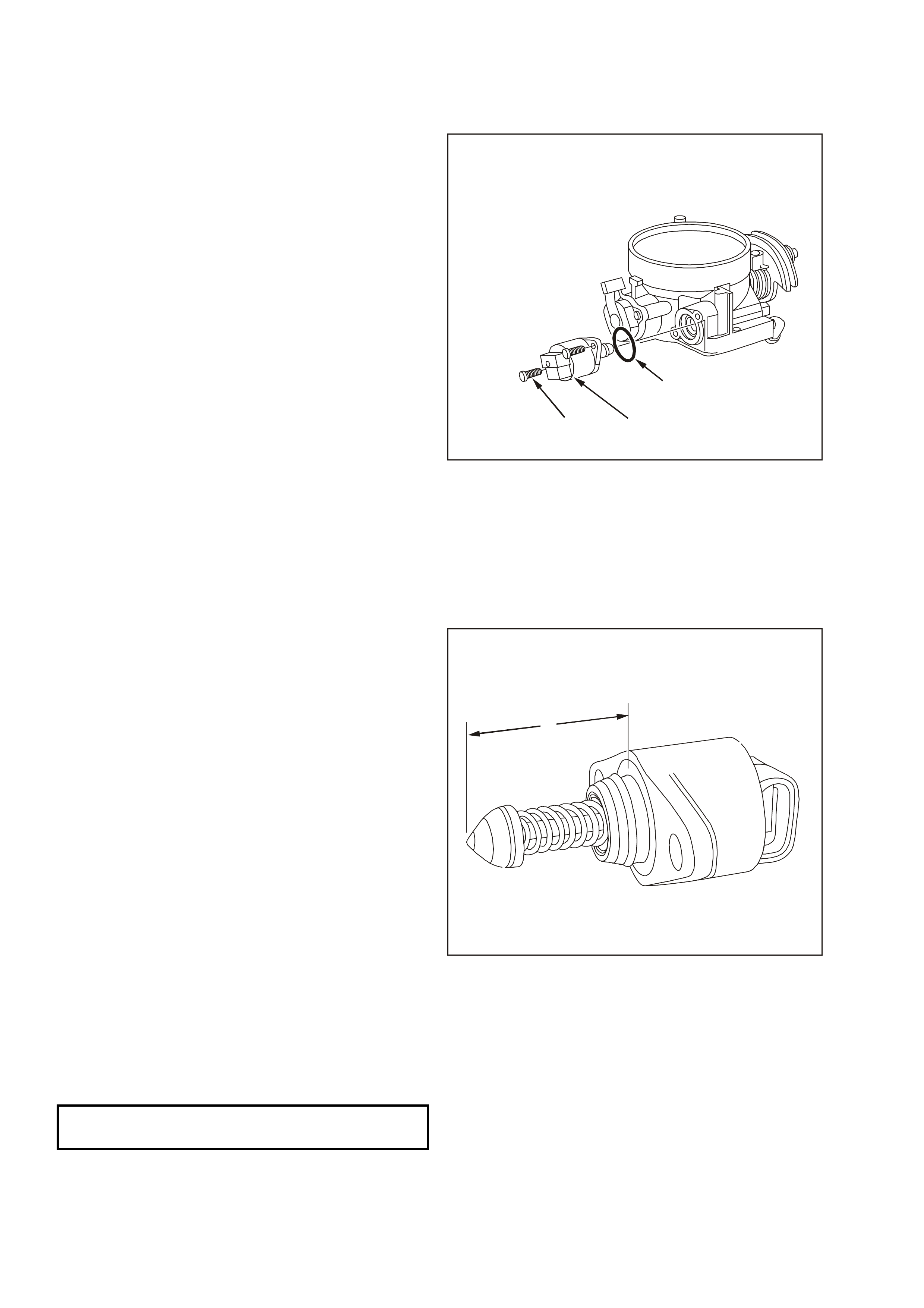
1. Meas ure the distance between the tip of the IAC
valve pintle and the mounting surface (A). If the
distance is greater than 28 mm, use finger
pressure to slowly retract the pintle. The force
required to retract the pintle on a new valve will
not cause damage to the valve.
2. Lubr icate the IAC valve O-ring with clean engine
oil.
3. Install the IAC valve O-ring on the IAC valve.
4. Install the IAC valve.
5. Apply Loctite 242 or equivalent to the IAC valve
attaching screw threads.
6. Install the IAC valve attaching screws and
tighten to the specified torque.
7. Connect the IAC valve electrical connector.
8. Install engine dress cover.
9. Perform the Idle Learn Procedure and the
Functional Check. Refer to PCM
Replacement/Programming in this Section of
the Service Information CD
A
IAC Valve Measured Distance
IAC VALVE ATTACHING SCREWS
TIGHTENING TORQUE 3 NM (27 LB/ IN)
3.13 CAMSHAFT POSITION (CMP) SENSOR
REMOVE
1. Disconnect the negative battery cable to avoid
possible fuel discharge if an accidental attempt
is made to start the engine.
2. Remove engine dress cover. Refer to Engine
Coolant Temperature Sensor in this Section
for removal procedure.
3. Relieve fuel system pressure. Refer to Fuel
Pressure Relief Procedure in this Section.
4. Remove the intake manifold. Refer to Section
6A3 Engine Mechanical of the VT Series II
Service Information.
IMPORTANT: Clean the area around the CMP
before removal to avoid debris from entering the
engine.
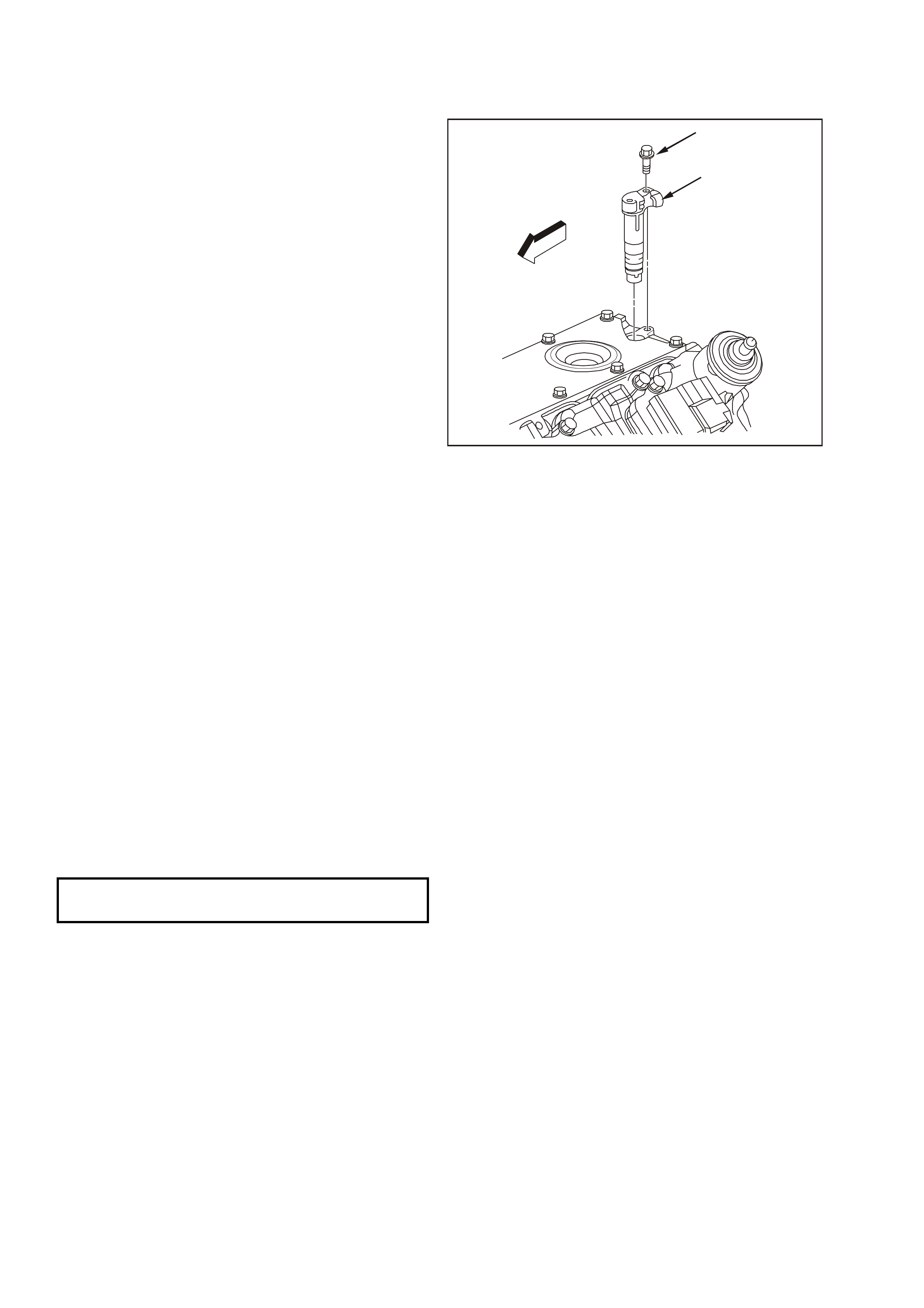
5. Remove the electrical connector from the
Camshaft Position (CMP) sensor (2).
6. Remove the CMP sensor retaining bolt (1).
5. Remove the CMP sensor.
REINSTALL
1. Install the CMP sensor.
2. Install the CMP sensor retaining bolt and tighten
to the specified torque.
3. Connect the CMP sensor electrical connector.
4. Install the intake manifold. Refer to Section 6A3
Engine Mechanical of the VT Series II Service
Information.
5. Inspect for leaks:
- Turn the ignition switch ON for 2 seconds
- Turn the ignition switch OFF for 10 seconds.
- Turn the ignition switch ON.
- Check for fuel leaks.
6. Perform the Idle Learn Procedure and the
Functional Check. Refer to PCM
Replacement/Programming.
7. Install engine dress cover.
1
2
Camshaft Position Sensor
CMP SENSOR ATTACHING
BOLT TIGHTENING TORQUE 25 Nm 18 lb/ft
3.14 THROTTLE CONTROL
Two Throttle Control cable sy stems are used with
the GEN III V8 Engine.
Vehicles that do not have Electronic Traction
Control (ETC), are fitted with a single throttle cable.
Vehicles that are fitted with ETC have two cables;
• an accelerator pedal cable which is routed
between the accelerator pedal and throttle
relaxer, and
• a throttle cable which is routed between the
throttle relaxer and throttle body.
Adjustment is only available on the throttle cables.
ACCELERATOR PEDAL CA BLE
- VEHICLES WITH ETC
Routing
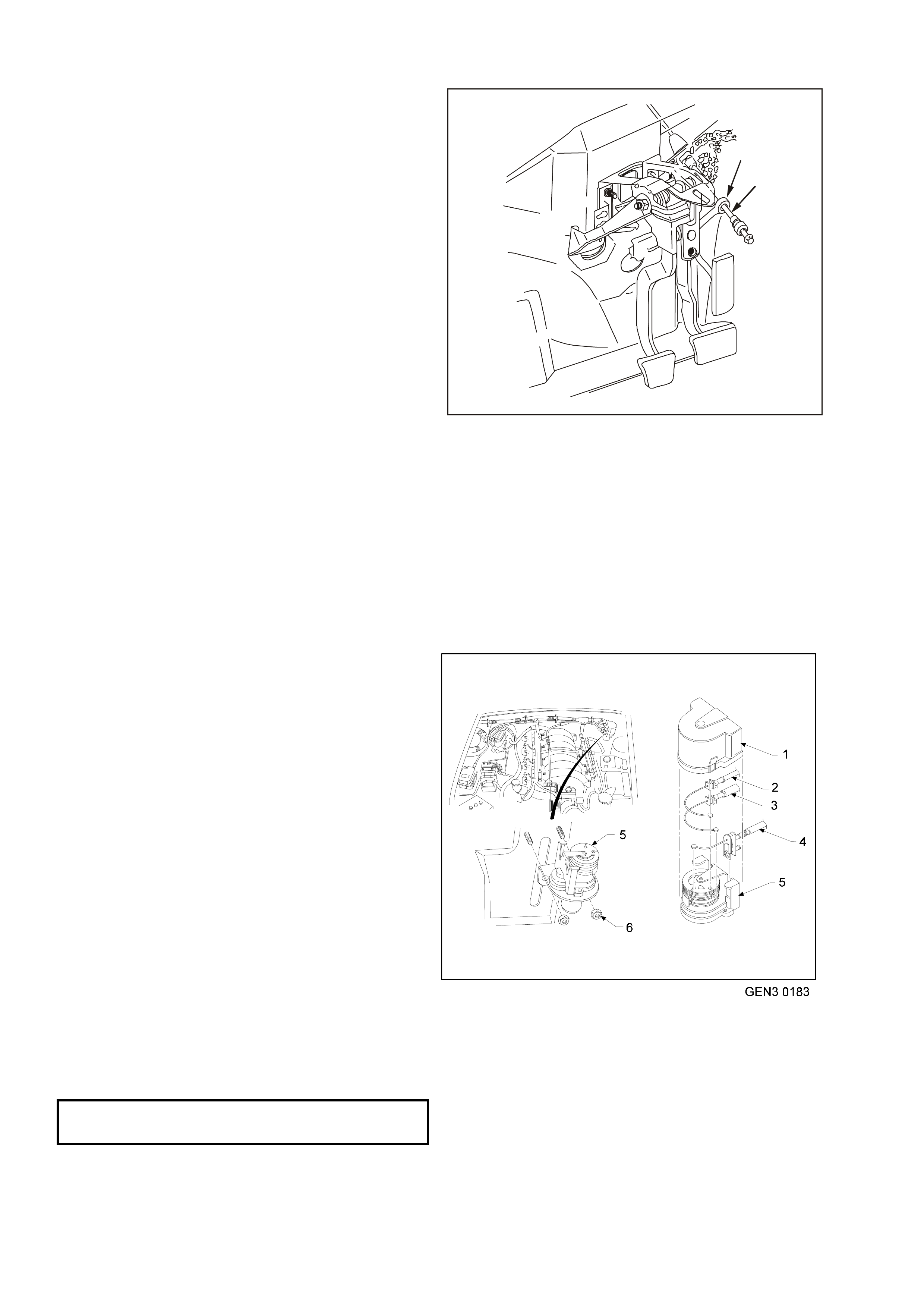
1. Accelerator Pedal Cable
2. Throttle Relaxer
1
2
Accelerator Pedal Cable Routing, with ETC
Remove
1. Remove the throttle relaxe r cover (1).
2. Remove the cruise control cable (2) (if
equipped).
3. Remove the accelerator pedal cable (3).
4. Open the retainer clip at the brake booster, and
remove the cable from the clip.
1
2
3
Throttle Relaxer
5. Remove the right instrument panel lower trim.
6. Disconnect the accelerator pedal cable (1) from
the accelerator pedal lever (2).
7. Squeeze the accelerator pedal cable cover
tangs and push the cable through the dash
panel.
8. Remove the accelerator cable.
REINSTALL
1. Install the accelerator pedal cable through the
dash panel. Snap the retainer through the dash
panel.
2. Install the accelerator pedal cable through the
slot in the accelerator pedal lever. Seat the
retainer in the accelerator pedal lever.
3. Attach the accelerator pedal cable to the brake
booster cable retaining clip.
4. Attach the acceler ator pedal cable to the throttle
relaxer.
5. Attach the cruise control cable to the throttle
relaxer (if equipped).
6. Install the throttle relaxer cover.
7. Refit the instrument panel lower trim.
2
1
Accelerator Pedal to Cable
THROTTLE CABLE - VEHICLES WITH ETC
Routing
1. Throttle Cable (with ETC)
2. Throttle Relaxer
1
2
Throttle Cable Routing, with ETC
Remove
1. Remove engine dress cover. Refer to Engine
Coolant Temperature Sensor in this Section
for removal procedure.
2. Remove the throttle relaxe r cover (1).
3. Remove the throttle cable (2) from the throttle
relaxer.
4. Open the retainer clip at the intake manifold,
and remove the cable from the clip.
1
2
Throttle Relaxer
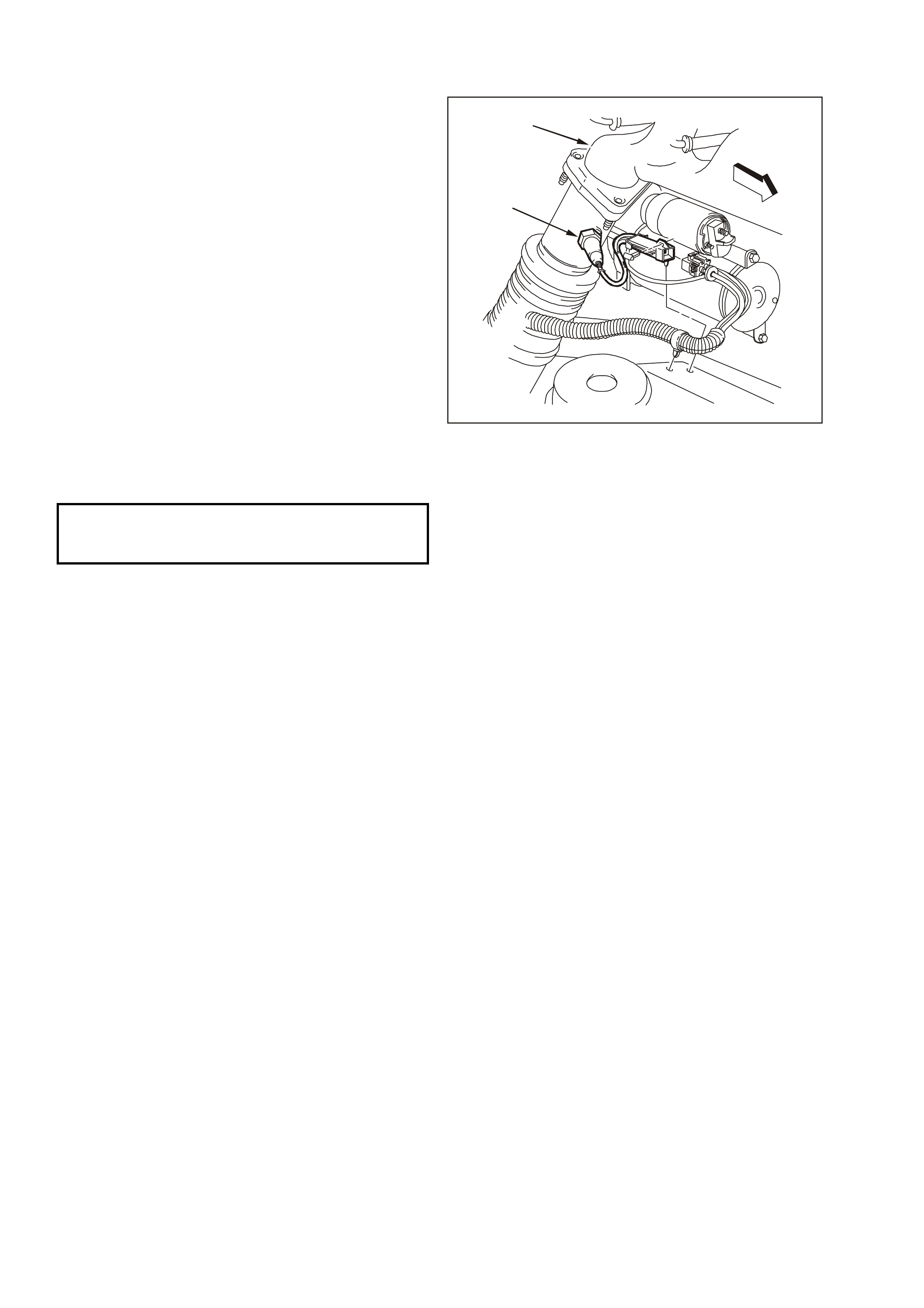
5. Lift the throttle cable (1) up at the throttle body
mounting bracket (2), and remove the cable
from the throttle body cam lever (3).
6. Remove throttle cable.
REINSTALL
1. Install the throttle cable to the throttle body cam
lever.
2. Attach the throttle cable to the throttle body
mounting bracket.
3. Attac h the thr ottle cable to the r etaining c lip over
the intake manifold.
4. Attach the throttle cable to the throttle relaxer.
5. Install the throttle relaxer cover.
6. Install the engine dress cover.
7. Adjust the throttle cable as described further in
this Section
1
2
3
Throttle Body Cable Mounting Bracket
THROTTLE CABLE - VEHICLES WITHOUT ETC
Routing
1. Accelerator Cable
2. Throttle Body Mounting Bracket
1
2
Throttle Cable Routing, without ETC
Remove
1. Remove engine dress cover. Refer to Engine
Coolant Temperature Sensor in this Section
for removal procedure.
2. Lift the throttle cable (1) up at the throttle body
cable mounting bracket (2), and remove the
cable from the throttle body cam lever (3).
3. Rem ove the throttle cable f rom the retaining c lip
over the intake manifold.
4. Open the retainer clip at the brake booster, and
remove the throttle cable from the clip.
1
2
3
Throttle Body Cable Mounting Bracket
5. Remove the right instrument panel lower trim.
6. Disconnect the throttle cable (1) from the
accelerator pedal lever (2).
7. Squeeze the throttle cable cover tangs and push
the cable through the dash panel.
8. Remove the throttle cable.
REINSTALL
1. Install the throttle cable through the dash panel.
Snap the retainer through the dash panel.
2. Install the throttle cable through the slot in the
accelerator pedal lever. Seat the retainer in the
accelerator pedal lever.
3. Attach the throttle cable to the brake booster
cable retaining clip.
4. Attach the throttle cable to the retaining clip over
the intake manifold.
5. Attach the throttle cable to throttle body
mounting bracket.
6. Install the throttle cable to the throttle body cam
lever.
7. Adjust the throttle cable as described in the
following Section.
8. Install the engine dress cover.
9. Install the right instrument panel lower trim.
2
1
Accelerator Pedal to Cable
THROTTLE RELAXER - VEHICLES WITH ETC
Remove
1. Remove the throttle relaxe r cover (1).
2. Disconnect the throttle relaxer electrical
connector.
3. Remove the nuts attaching the adjuster
assembly to the mounting bracket (2).
4. Remove the accelerator pedal, throttle and
cruise control (if fitted) cables from the throttle
relaxer (3, 4, 5).
Reinstall
1. Install the cables to the throttle relaxer
assembly.
2. Install the throttle relaxer assembly to the
mounting
3. bracket.
4. Tighten the assembly attaching nuts to the
specified torque.
5. Connect the electrical connector.
6. Adjust the throttle cables as described in the
following Section.
7. Install the throttle relaxer cover.
8. Install the engine dress cover.
Throttle Relaxer
THROTTLE RELAXER ATTACHING
NUT TIGHTENING TORQUE 2 -3 Nm
(1.5-2.2 lb/ ft)
THROTTLE CABLE ADJUSTMENT - ALL
1. Remove engine dress cover. Refer to Engine
Coolant Temperature Sensor in this Section
for removal procedure.
2. With throttle cable fully installed, unlock the
adjustment locking lever.
3. Ensure throttle is in the closed position.
4. With adjuster unlocked, pull back on accelerator
cable until the throttle cam begins to move from
the rest position.
5. Move the accelerator cable back towards the
throttle cam until the throttle cam is back at rest.
6. While holding the accelerator cable at the cam
rest position, lock the cable locking lever.
NOTE: A small amount of slack in the inner cable
is desirable
7. Using a Tech 2 scan tool, check the throttle
angle. When the accelerator is fully depressed
the throttle angle should read 100 percent.
When the accelerator is released the throttle
angle should read 0 percent. If correct results
are not obtained, check the cables for kinks or
damage and repeat procedure.
8. Install engine dress cover.
T6A3055
Throttle Cable Lock Adjuster
3.15 FUEL CONTROL SYSTEM
THROTTLE BODY
Remove
1. Disconnect the negative battery cable.
2. Remove engine dress cover. Refer to Engine
Coolant Temperature Sensor in this Section
for removal procedure.
3. Partially drain the cooling system in order to
remove the hoses at the throttle body.
4. Remove the air intake duct from throttle body.
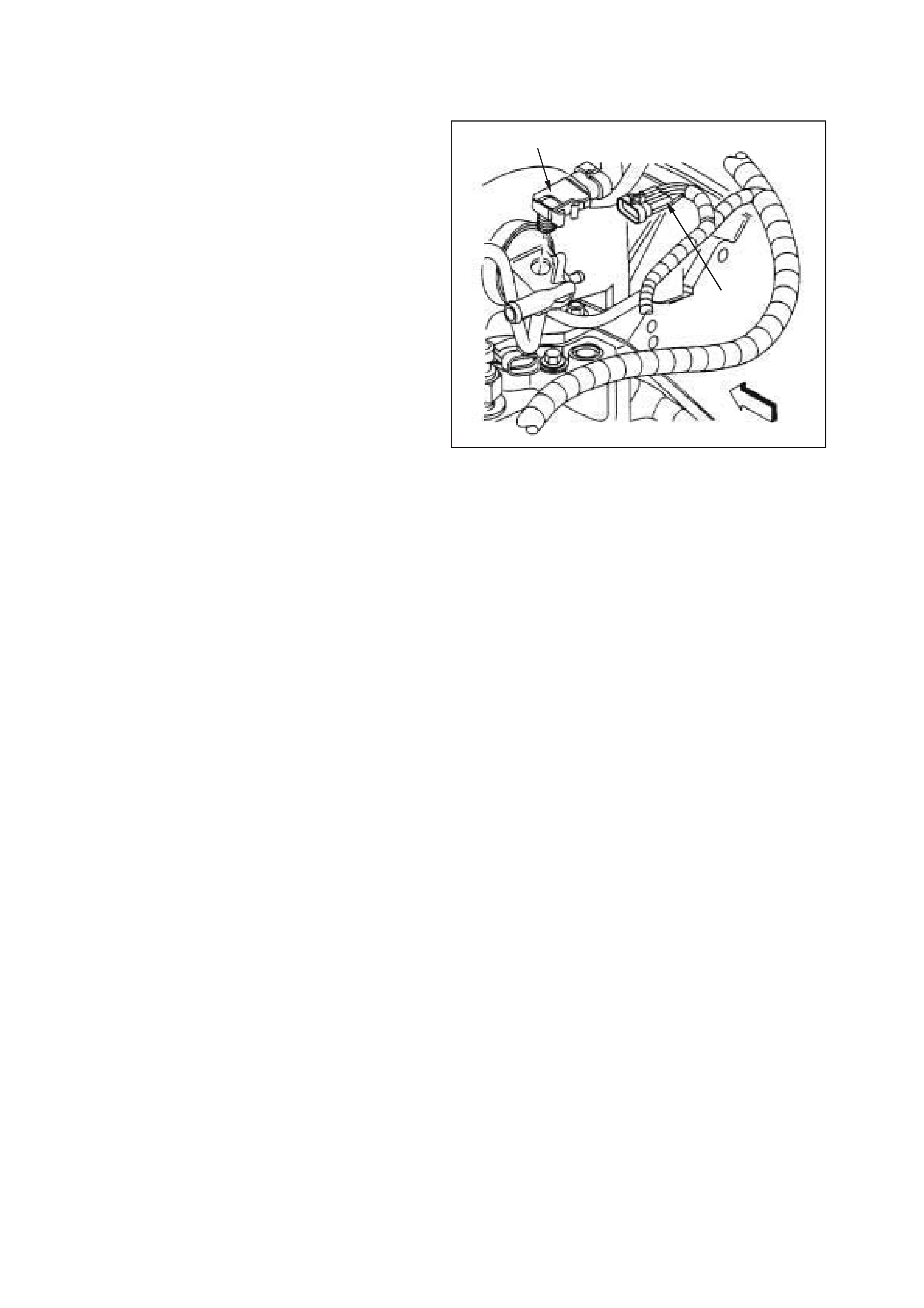
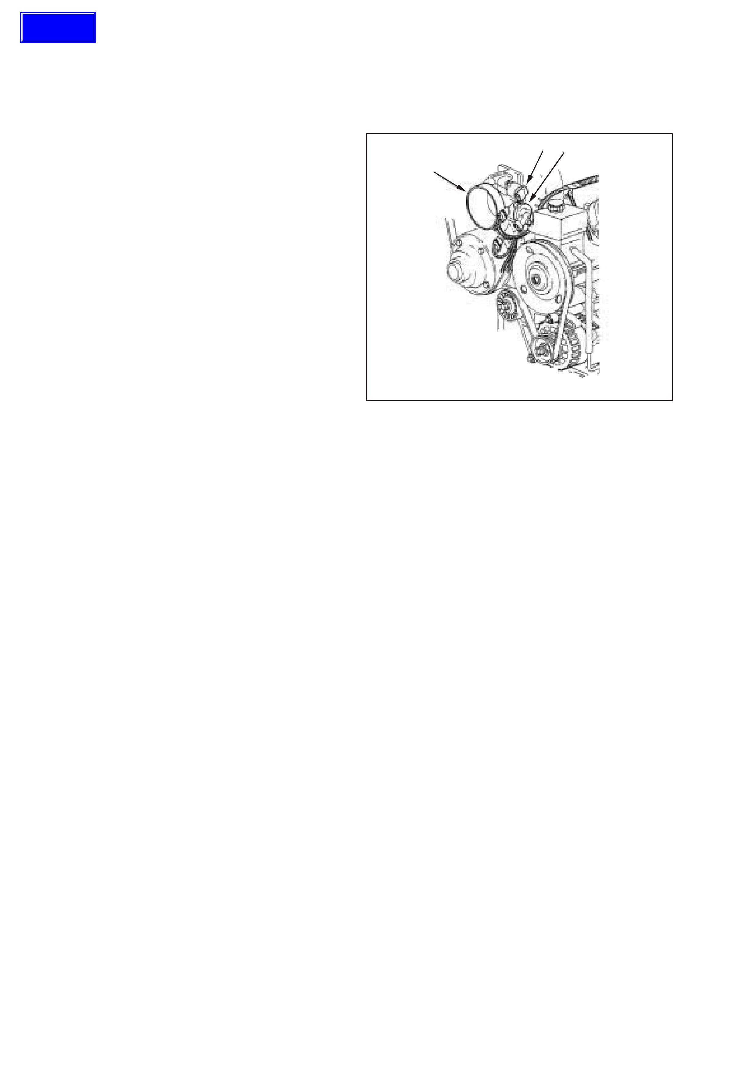
5. Disconnect the IAC valve (1) and TP Sensor (2)
electrical connectors.
6. Disconnect the throttle cable and the cruise
control cable (if equipped) from the throttle
body.
7. Disconnect the crankcase ventilation hose from
the throttle body.
8. Disconnect the EECS purge hose for the throttle
body.
9. Remove the throttle body attaching bolts.
10. Remove the throttle body (3) and the gasket.
11. Discard the gasket.
12. Clean the gasket sealing surfaces.
NOTE: To prevent damage to the sealing surfaces,
carefully use sharp tools when cleaning the old
gasket from the aluminum surfaces.
IMPORTANT: Do Not soak the throttle body in cold
immersion type cleaner. The throttle valve has a
factory applied sealing compound (DAG m aterial is
applied to the outside edge of the valve and the
throttle bore) to prevent air bypass at closed
throttle. Strong solvents or brus hing will rem ove the
material. To clean the throttle body following
disassem bly, use a s pray type cleaner such as GM
X-66A or GM 1052626. Use a shop towel to
remove heavy deposits.
The TP sensor and the IAC valve are electrical
components and should NOT come in contact with
solvent or cleaner, as damage may result.
3
2
1
Throttle Body Location
Techline
Reinstall
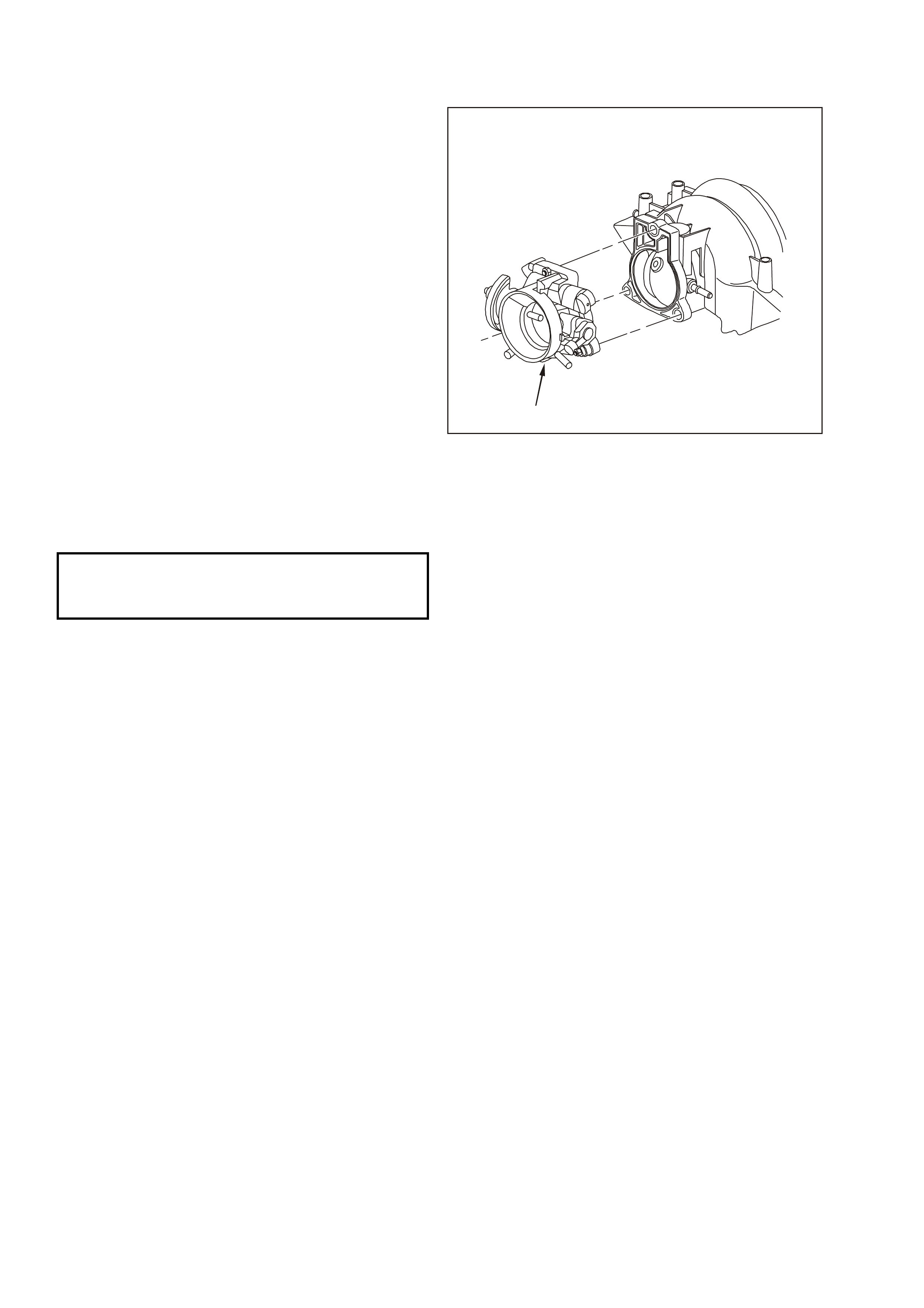
1. Install the throttle body (1) with a new gasket.
2. Install the throttle body attaching bolts and
tighten to the specified torque.
3. Connect the crankcase ventilation hose to the
throttle body.
4. Connect the EECS purge hose to the throttle
body.
5. Connect the cooling hoses to the throttle body.
6. Connect the throttle cable and the cruise control
cable (if equipped).
7. Connect the TP sensor and the IAC valve
electrical connectors.
8. Install the air intake duct.
9. Refill the cooling system.
10. Connect the negative battery cable.
11. With the engine OFF, check to see that the
accelerator pedal is free. Depress the
accelerator pedal to the floor and release.
12. Install engine dress cover.
13. Perform the Idle Learn Procedure and the
Functional Check. Refer to PCM
Replacement/Programming in this Section.
1
Throttle Body to Intake Manifold
THROTTLE BODY
ATTACHING BOLT
TIGHTENING TORQUE
12 Nm (106 lb/ft)
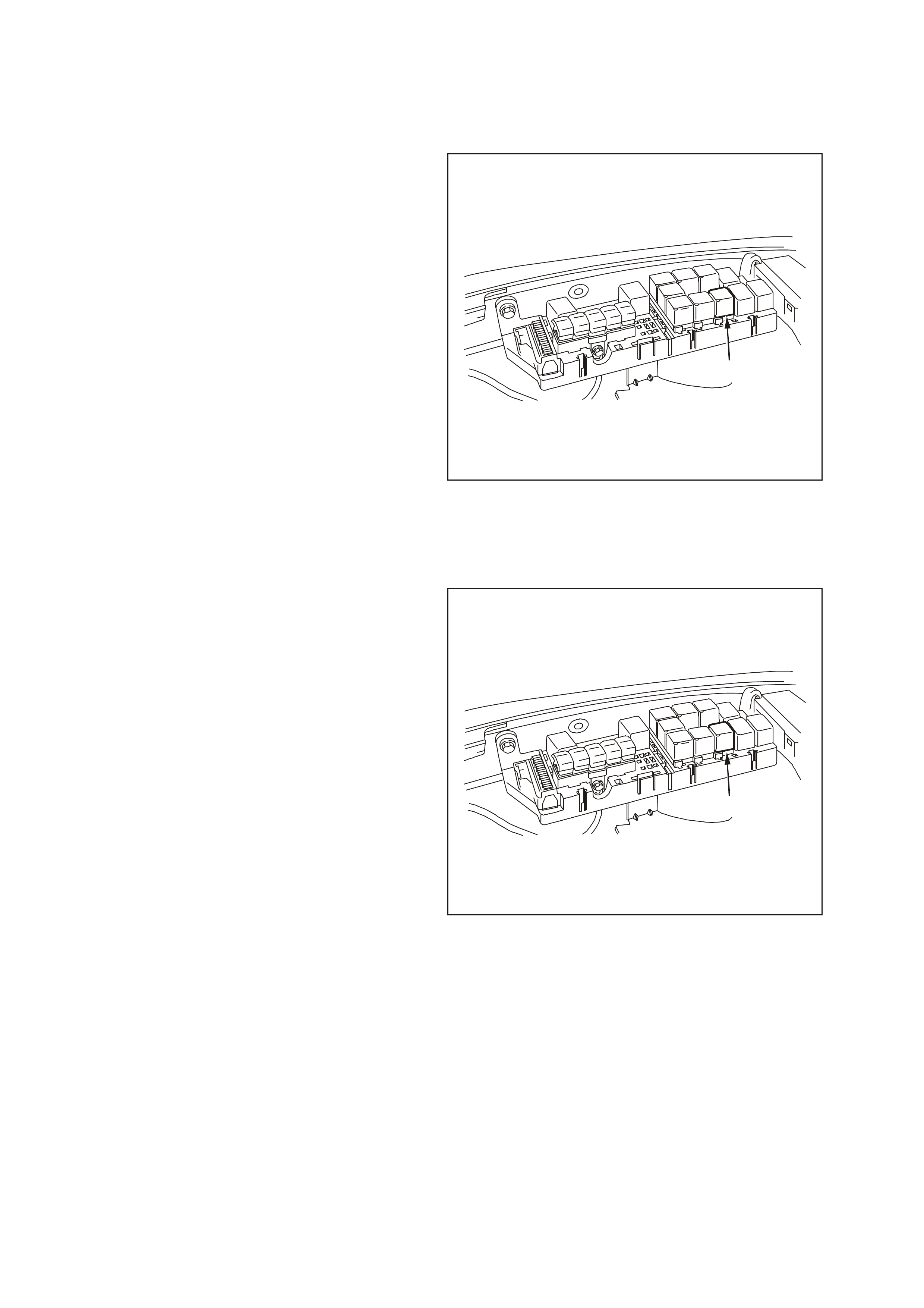
FUEL PUMP RELAY
Remove
NOTE: The fuel pump relay is located in the engine
compartment Fuse/Relay panel, forward of the right
side strut tower. Other than checking for loose
connectors, the only service possible is
replacement.
1. Turn OFF the ignition.
2. Remove the fuse/relay panel cover.
3. Remove the fuel pump relay (1) by pulling
upward.
REINSTALL
1. Install the fuel pump relay into the fuel pump
rela y socket.
2. Verify relay operation by turning the key ON and
listening for relay operation (relay should
operate for 2 seconds when key is turned ON).
If relay did not operate, refer to Fuel Pump
Relay Circuit Diagnosis in this Section.
3. Install the fuse/relay panel cover.
1
Fuel Pump Relay Location
FUEL PRESSURE RELIEF PROCEDURE
Caution: Relieve the fuel system pressure before
servicing fuel system components in order to
reduce the risk of fire and personal injury.
After relieving the system pressure, a small amount
of fuel may be released when servicing the fuel
lines or connections. In order to reduce the chance
of personal injury, cover the fittings with a shop
towel before disconnecting. This will catch any fuel
that may leak out. Place the towel in an approved
container when the disconnection is complete.
1. Remove cover from engine compartment relay
housing.
2. Remove fuel pump relay (1).
3. With throttle closed, crank engine.
NOTE: The engine may start and run until the fuel
supply remaining in the fuel delivery system is
depleted.
4. When the engine stops, re-energise the starter
motor for 10 seconds to ensure that the line
pressure has been fully relieved. The fuel
system is now safe to service.
5. Reinstall the fuel pump relay.
1
Fuel Pump Relay Location
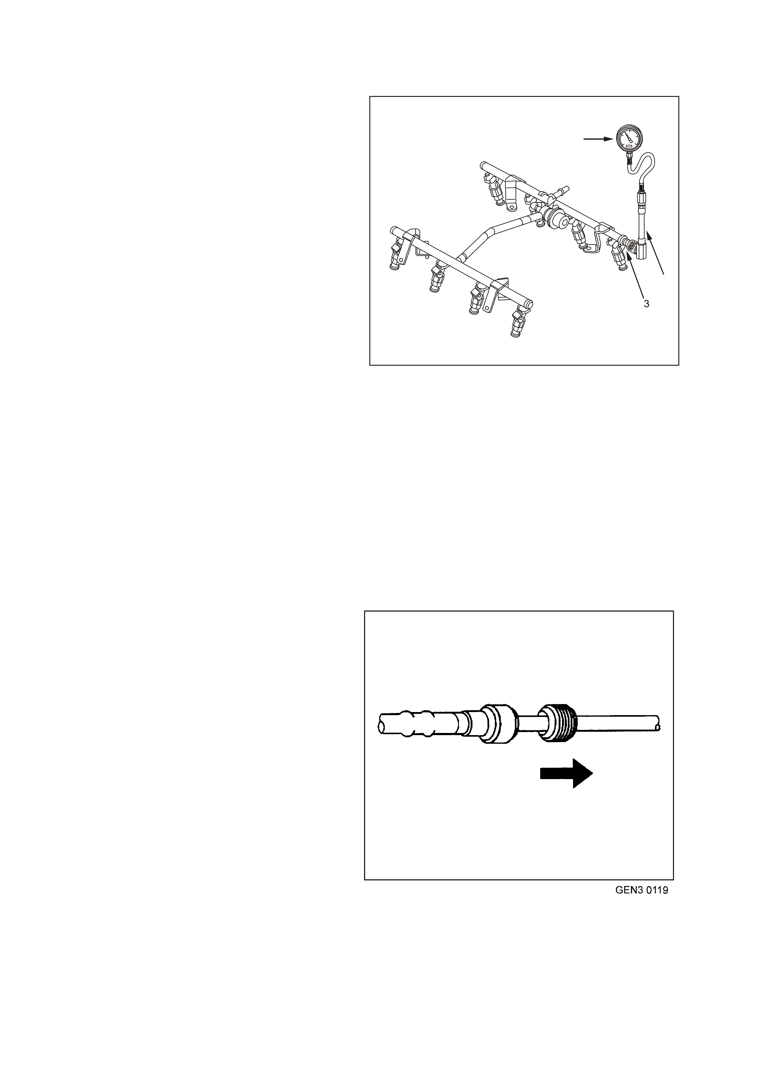
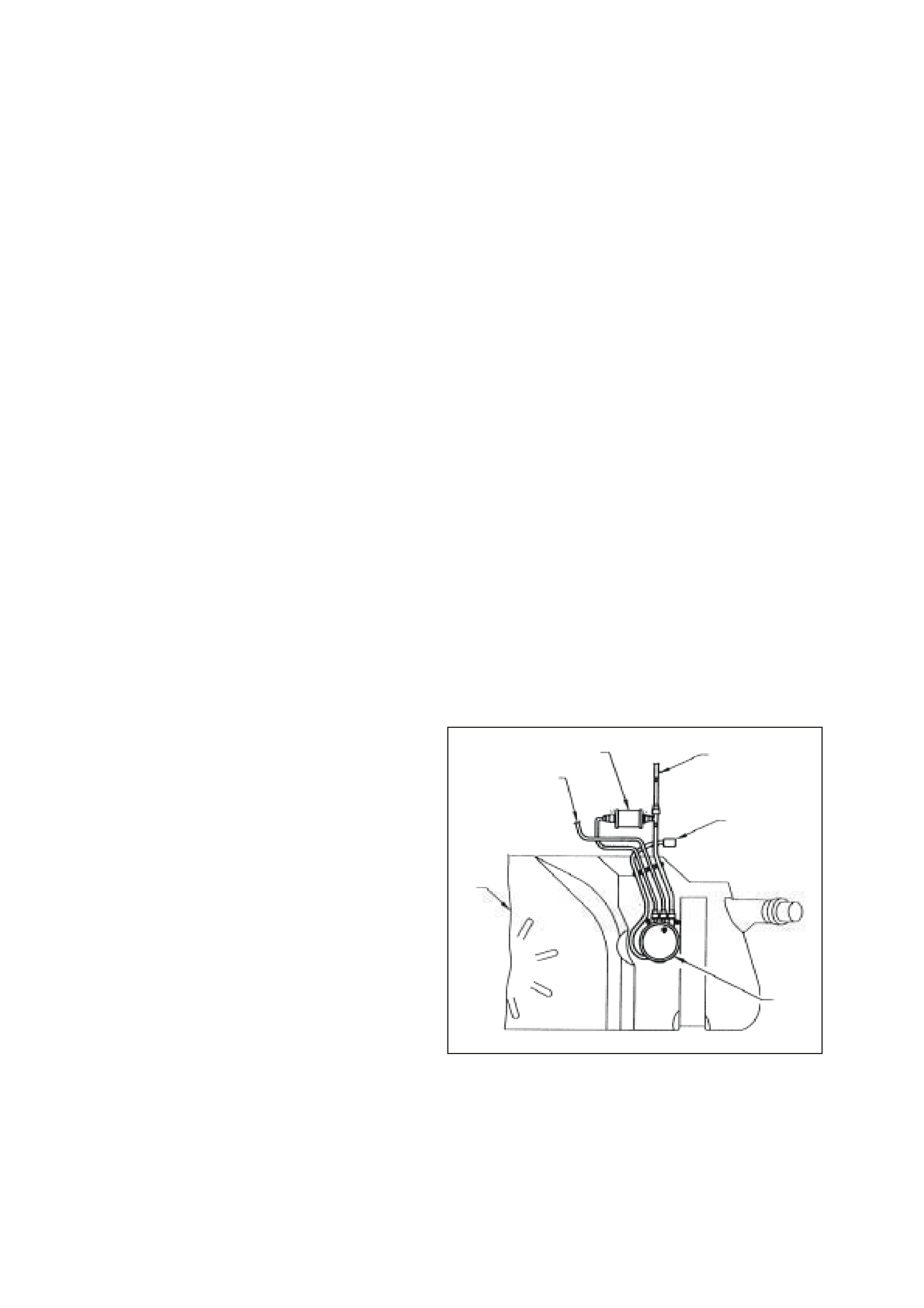
FUEL GAUGE INSTALLATION PROCEDURE
TOOL REQUIRED: SD28018 OR AU338 Fuel
Pressure Gauge, and AU453 Fuel Gauge Schrader
Fitting Adapter
1. Relieve fuel system pressure as previously
described.
2. Turn the ignition OFF.
3. Disconnect the negative battery cable in order to
avoid possible fuel discharge if an accidental
attempt is made to start the engine.
4. Remove engine dress cover. Refer to Engine
Coolant Temperature Sensor in this Section
for removal procedure.
5. Loosen the fuel filler cap in order to relieve the
fuel tank vapor pressure.
6. Connect the SD28018 or AU338 fuel pressure
gauge (1) to the AU453 fuel gauge schrader
fitting adapter (2), then connect to the fuel
pressure testing valve (3).
NOTE: Wrap a shop towel around the fitting while
connecting the gauge to avoid and/or capture any
fuel spillage.
7. Install the bleed hose of the gauge into an
approved petrol container.
8. Open the valve on the gauge to bleed the
system pressure. Fuel connections are now
safe for servicing.
9. Drain any fuel remaining in the gauge into an
approved petrol container.
1
2
Fuel Pressure Gauge Connected to Schrader Valve
QUICK CONNECT FITTINGS (METAL COLLAR)
REMOVE
TOOLS REQUIRED: 7370, and 7371 Quick
Connect Release tools
IMPORTANT: Relieve the fuel system pressure
before servicing any fuel system connection. Refer
to the Fuel Pressure Relief Procedure in this
Section.
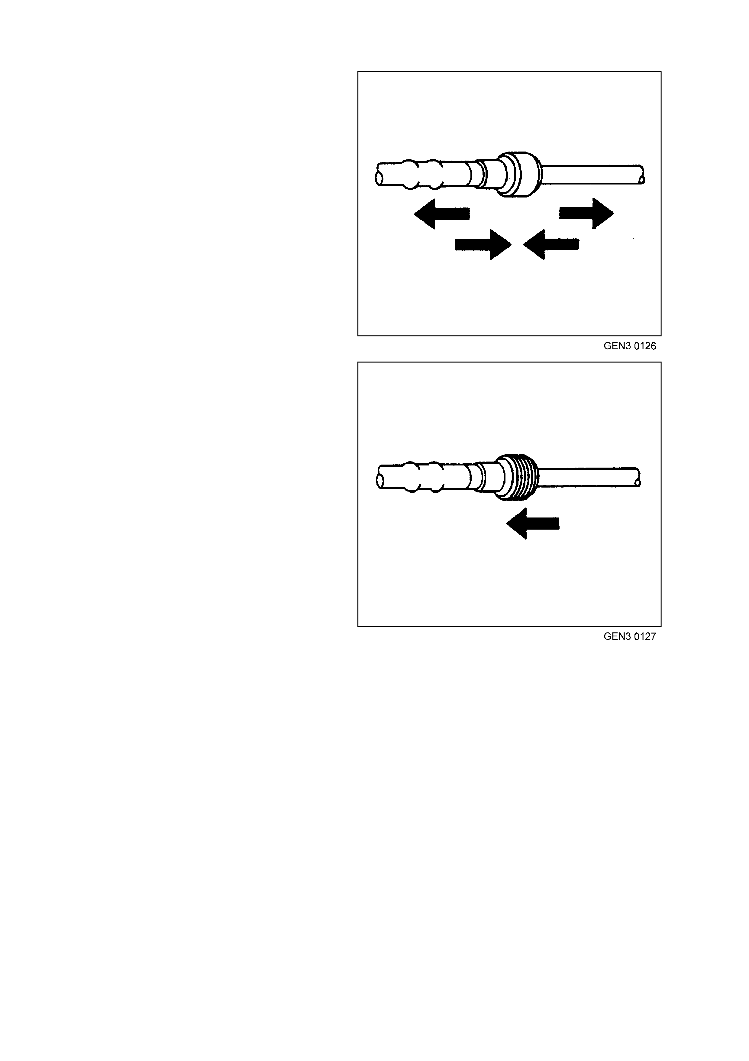
1. Slide the dust cover from the quick-connect
fitting.
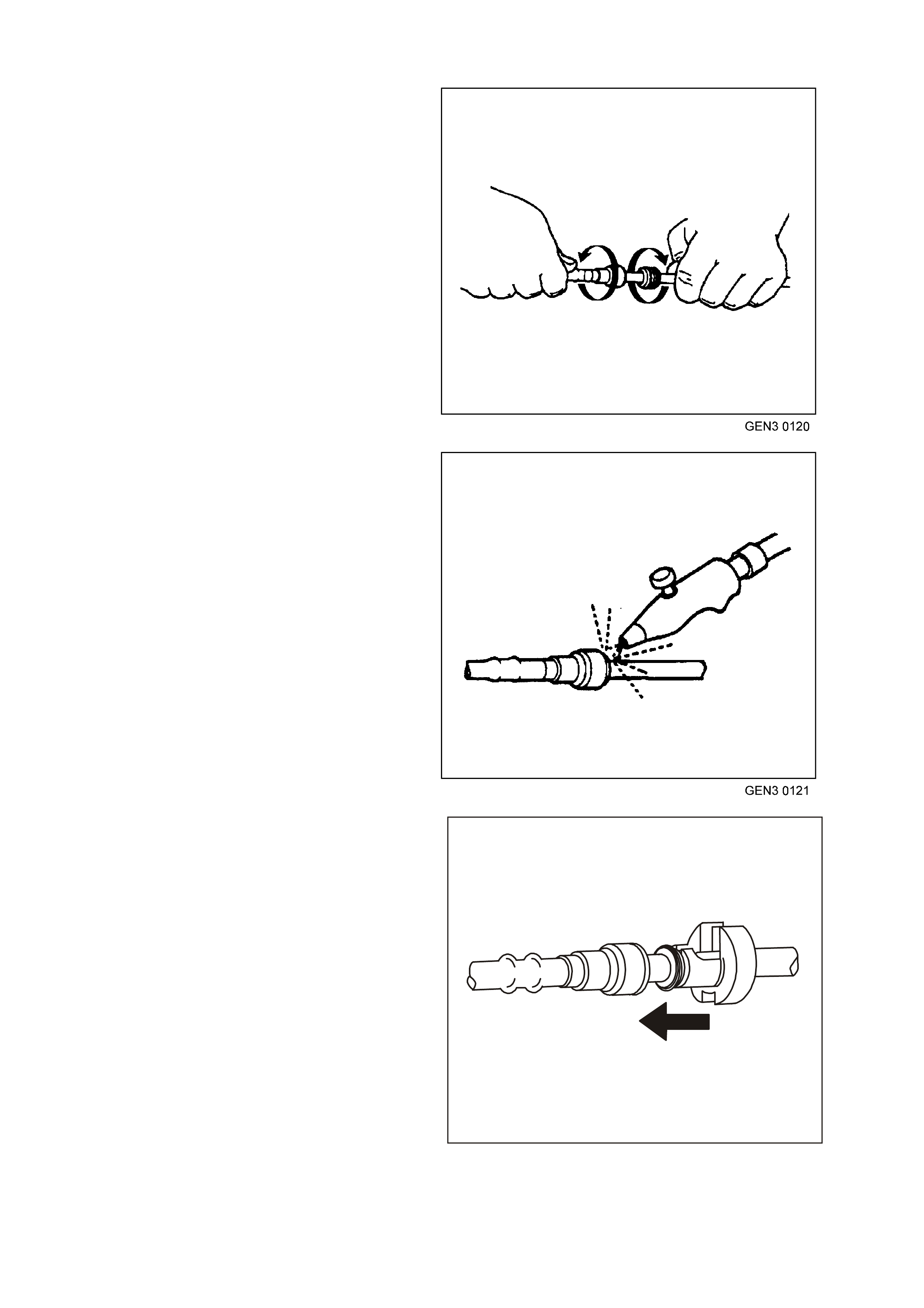
2. Grasp both sides of the fitting. Twist the female
connector 1/4 turn in each direction to loosen
any dirt within the fitting.
3. Blow dirt out of the fitting using compressed air.
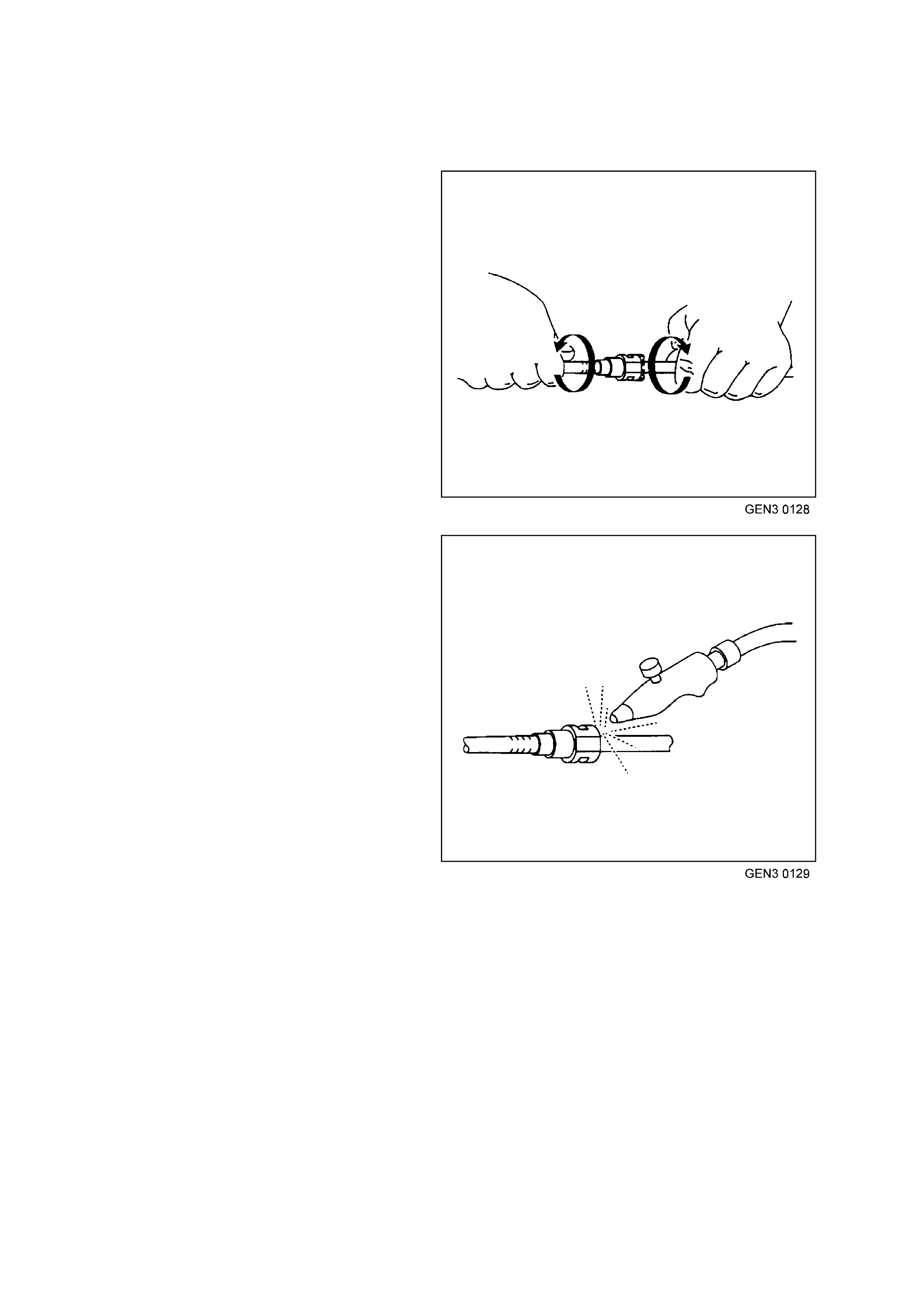
CAUTION: Wear safety glasses when using
compressed air, as flying dirt particles may cause
eye injury.
4. Choose the correct disconnection tool for the
size of the fitting. Insert the tool into the female
connector, then push inward to release the
locking tabs.
GE N 3 0122
5. Pull the connection apart.
NOTE: If it is necessary to remove rust or burrs
from a fuel pipe, use emery cloth in a radial motion
with the fuel pipe end in order to prevent damage to
the O-ring sealing surface.
6. Us ing a c lean shop towel, wipe off the male pipe
end.
7. Inspec t both ends of the f itting for dirt and burrs.
Clean or replace the components as required.
GE N 3 0123
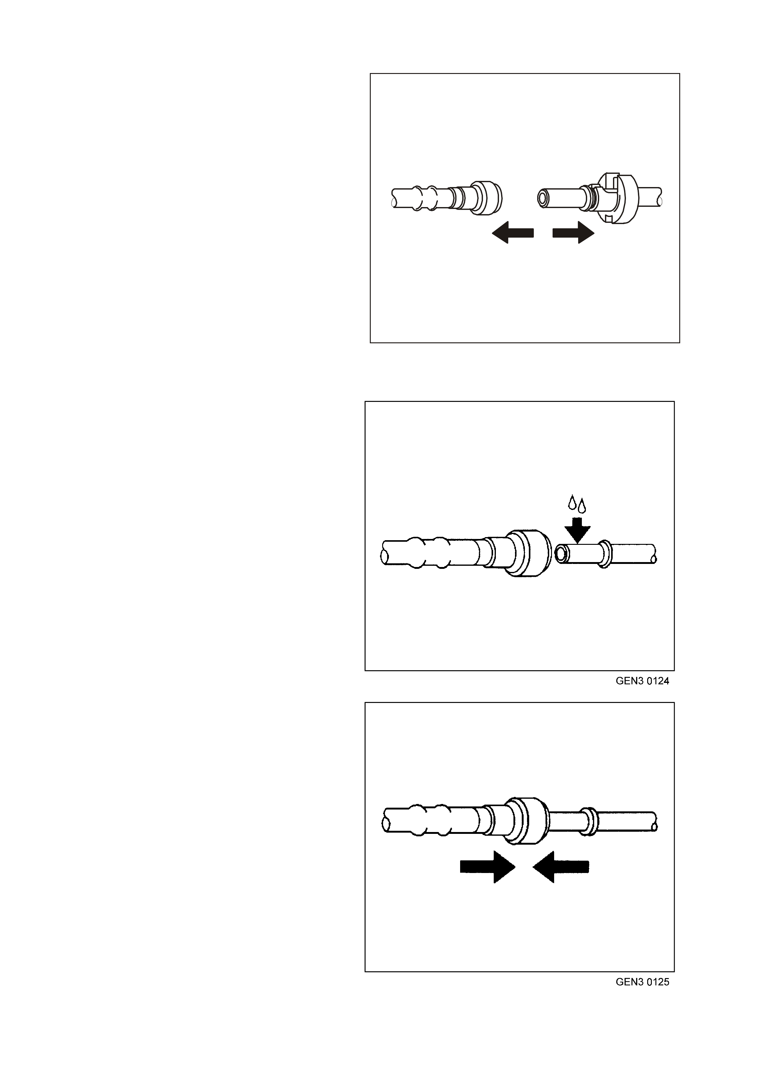
Reinstall
Caution: In order to reduce the risk of fire and
personal injury, before connecting fuel pipe fittings,
always apply a few drops of clean engine oil to the
male pipe ends.
This will ensure proper reconnection and prevent a
possible fuel leak.
During normal operation, the O-ring located in the
female connector will swell and may prevent proper
reconnection if not lubricated.
1. Apply a few drops of clean engine oil to the
male pipe end.
2. Push both sides of the fitting together to cause
the retaining tabs to snap into place.
3. Onc e ins talled, pull on both sides of the f itting to
ensure the connection is secure.
4. Reposition the dust cover over the quick-
connect fitting.
QUICK CONNECT FITTINGS
(PLASTIC COLLAR)
Remove
IMPORTANT: Relieve the fuel system pressure
before servicing any fuel system connection. Refer
to the Fuel Pressure Relief Procedure in this
Section.
1. Grasp both sides of the quick-connect fitting.
Twist the female connector 1/4 turn in each
direction in order to loosen any dirt within the
quick-connect fitting.
2. Using compressed air, blow any dirt out of the
quick-connect fitting.
Caution: Wear safety glasses when using
compressed air in order to prevent eye injury.
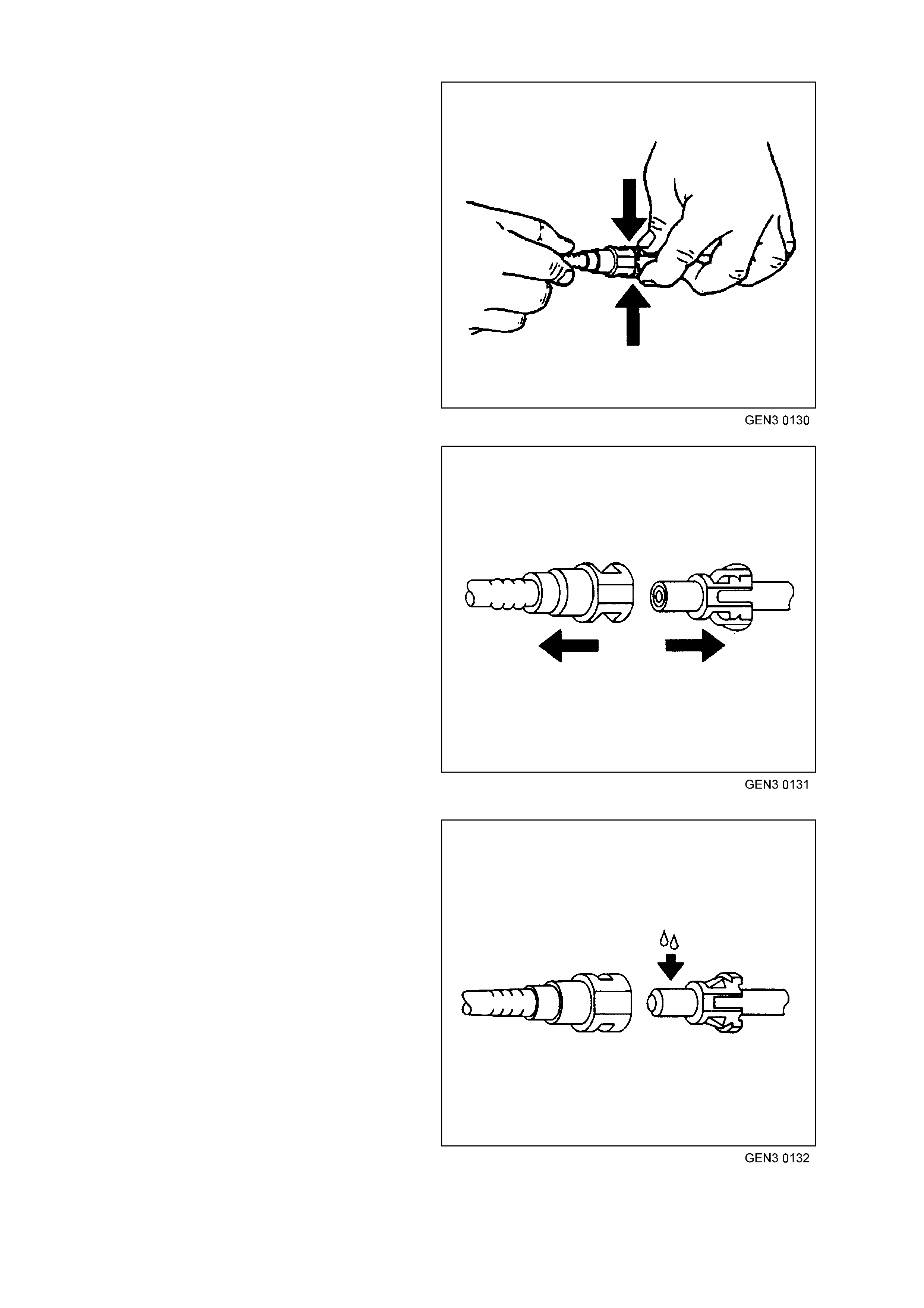
3. Squeeze the plastic retainer release tabs
4. Pull the connection apart.
Reinstall
CAUTION: In order to reduce the risk of fire and
personal injury, before connecting fuel pipe fittings,
always apply a few drops of clean engine oil to the
male pipe ends.
This will ensure proper reconnection and prevent a
possible fuel leak.
During normal operation, the O-ring located in the
female connector will swell and may prevent proper
reconnection if not lubricated.
1. Apply a few drops of clean engine oil to the
male fuel pipe end.
2. Push both sides of the quick-connect fitting
together in order to cause the retaining
tabs/fingers to snap into place.
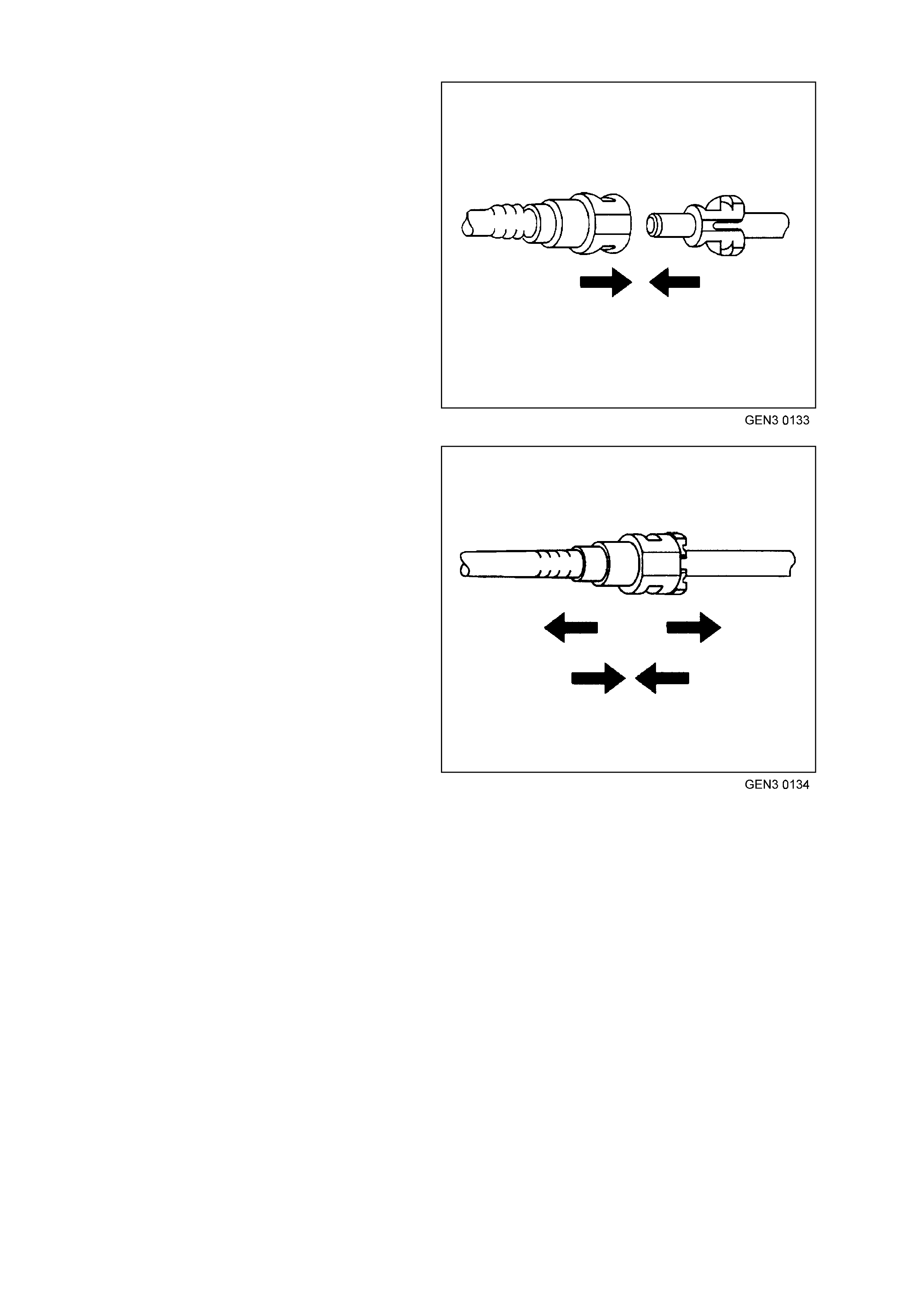
3. Once installed, pull on both sides of the quick-
connect fitting in order to make sure the
connection is secure.
FUEL FILTER
REMOVE
IMPORTANT Relieve the fuel system pressure
before servicing an y fuel system connectio n. Refer
to the Fuel Pressure Relief Procedure in
3.15, FUEL CONTROL SYSTEM in this Section.
1. Relieve fuel pressure as described in
3.15, FUEL CONTROL SYSTEM - Fuel
Pressure Relief Procedure in this Section.
2. Disconnect batt er y earth lead.
3. Raise rear of vehicle and support on safety
stands, refer to Section OA, GENERAL
INFORMATION in the VT Service Information.
4. Place a drain tray beneath fuel filter.
5. Remove the fuel filter from the retaining
brack et (1) with the fuel lines still connected to
the fuel filter to allow easier access.
Fuel Filter Retaining Bracket
QUICK CONNECT FITTINGS
(PLASTIC COLL AR)
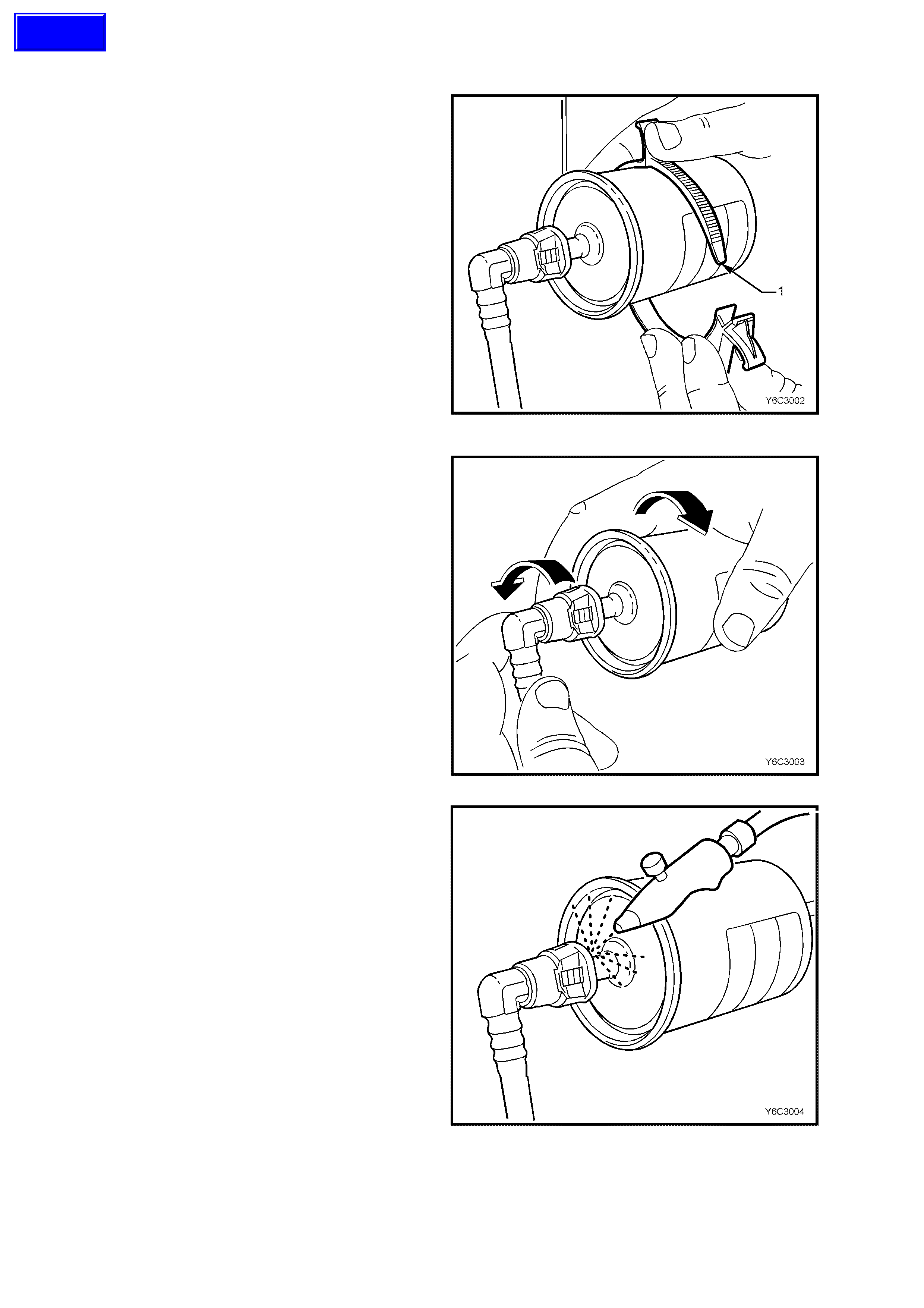
6. Grasp the quick-connect fittings both sides of
the fuel filter. Twist the female connectors 1/4
turn in each direction in order to loosen any dirt
within the quick-connect fitting.
Fuel Filter & Quick-connect Fittings
7. Using compressed air, blow any dirt out of the
quick-connect fitting to aid the release of any
tension or binding on the release tabs .
IMPORTANT
W ear safety glas ses whe n using com pres sed air in
order to prevent eye injury.
Cleaning Quick-connect Fittings
Techline
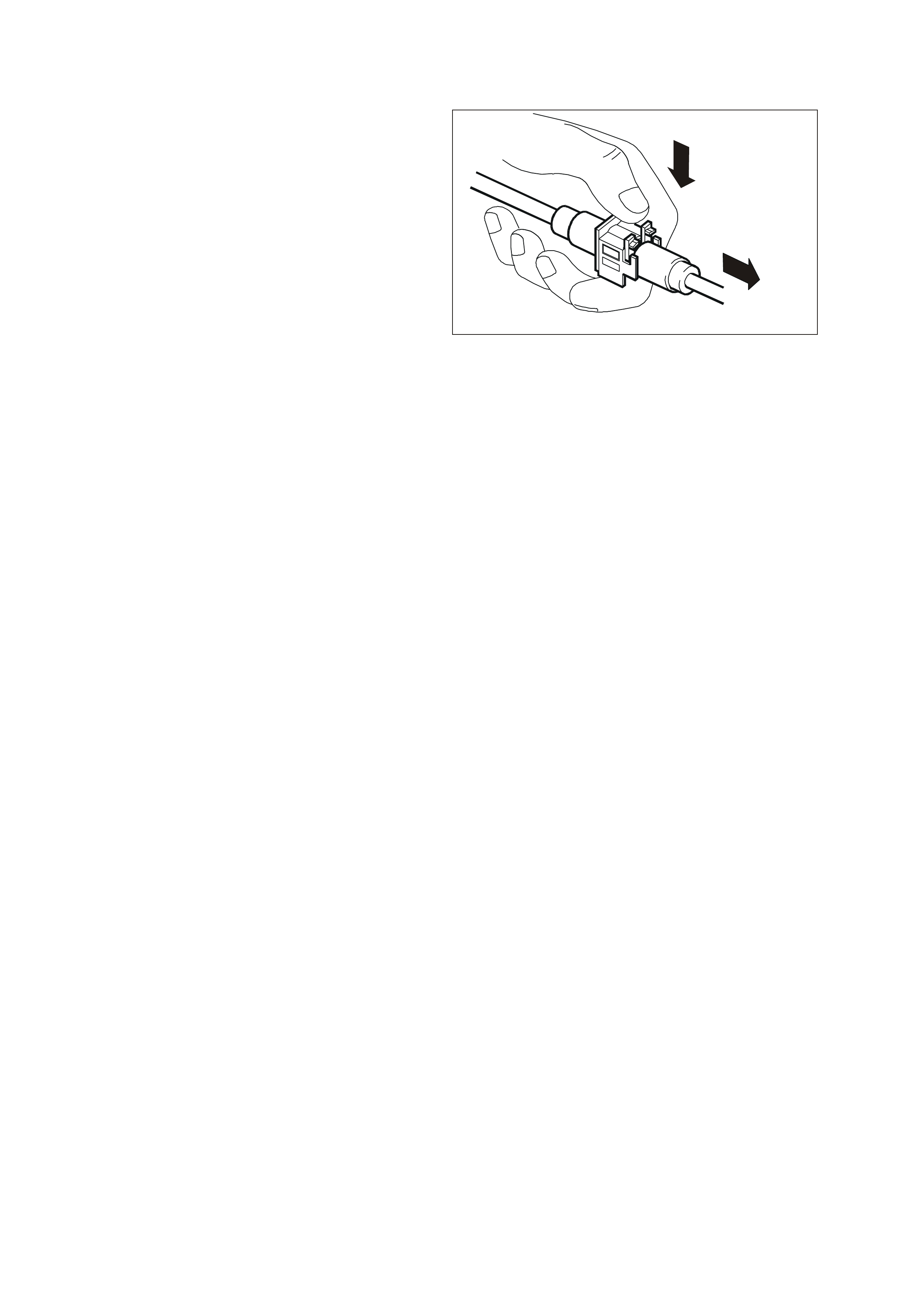
8. Hold the fuel filt er firm ly in one hand t o support
the filter.
9. Using your other hand, grasp the one of the
quick-connect fittings and squeeze the plastic
retainer release tabs (1) on each side of the
fitting whil e pushing the f itting firmly toward the
fuel filter to release an y tension on the release
tabs.
Quick-connect Fitting Release Tabs
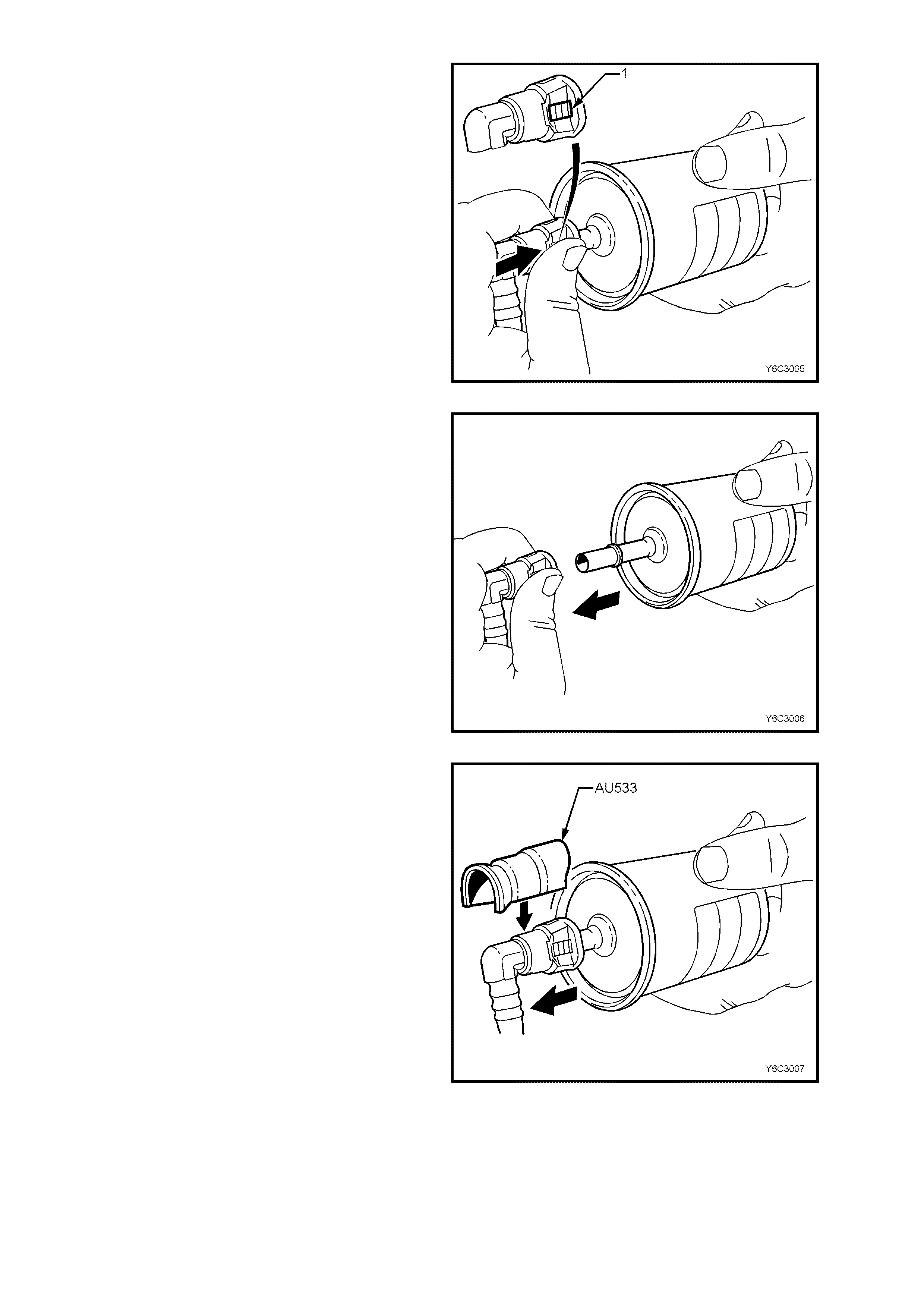
10. With the tension release tabs still held in the
squeezed position, move the complete quick-
connect fitting away from the fuel filter to
separate the connector fitting from the fuel
filter.
11. Apply the same method from step 8 to 10 for
the remaining quick-connect fitting.
Disconnecting Quick-Connect Fittings Without Special Tool
12. Alternat ely for s teps 8 to 10, use too l AU533 to
squeeze the release tabs, release the quick
connect fittings and rem ove both fuel pressure
hoses from the fuel filter.
13. Remove fuel filter from vehicle and disguard
safely remembering that some fuel will still
remain in the filter.
Disconnecting Quick-Connect Fittings With Special Tool
REINST ALL
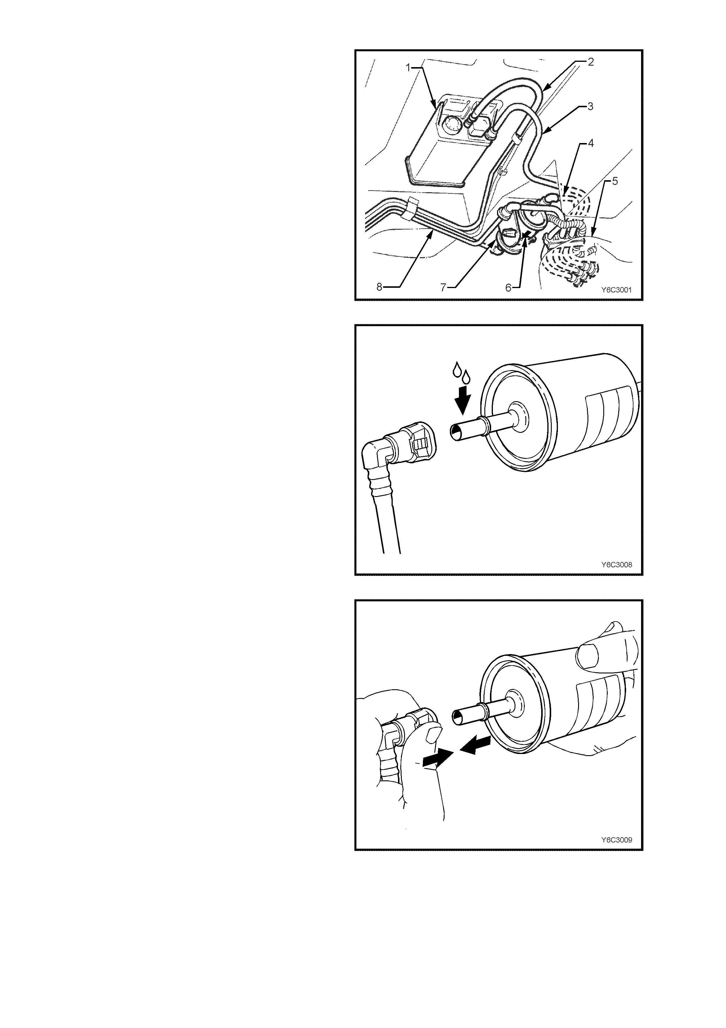
IMPORTANT The fuel filter (7) must be installed
with the flow arrow (6) on its body pointing in the
same direction as the fuel flow to the front of the
vehicle.
Fuel Filter Installation
IMPORTANT Before connecting fuel filter quick-
connect fittings, always apply a few drops of clean
engine oil to the male ends of the fuel filter.
This will ens ure proper rec onnection and pr event a
possible fuel leak.
During normal operation, the O-ring located in the
fem ale connec tor will s wel l and ma y prevent proper
reconnection if not lubr ic ate d.
1. Apply a few drops of clean engine oil to each
male fuel filter end.
Quick-Connect Fitting Seal lubrication
2. Push both the quick-connect fitting and the fuel
filter together in order to cause the retaining
tabs to snap into place. Apply this method to
both ends of the fuel filter and the respective
quick-connect fittings.
Re-installation Of Quick-connect Fitting To Fuel Filter
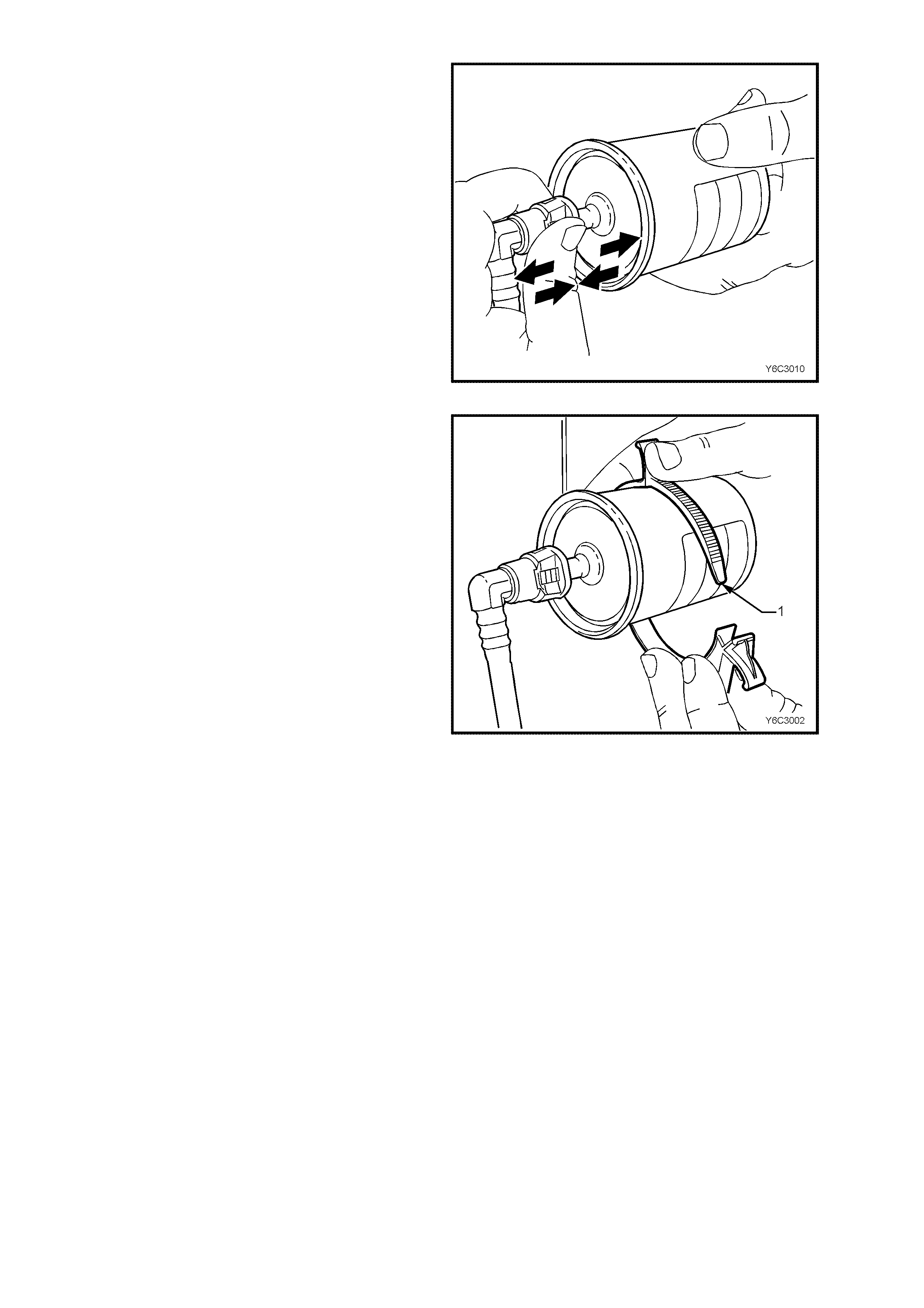
3. Once ins talled, pul l and pu sh on both t he quick -
connect fitting and the fuel filter in order to
make sure the connection is secure. Apply this
method to both ends of the fuel filter and the
respective quick-connect fittings.
Quick-connect Fitting To Fuel Filter Check
4. Install a new fuel filter to a new retaining bracket
(1).
5. Connect battery earth lead.
6. Check for fuel leaks, refer to
3.15, FUEL CONTROL SYSTEM – Leak
Testing in this Section of the VT Service
Information.
7. Remove safety stands and lower vehicle.
Re-installation Of Fuel Filter To Retainer Bracket
LEAK TESTING
Prior to st artin g the eng ine, f ollowing t he ins talla tion of an y fuel s ystem com ponent, c heck the fuel s ystem for leak s
using the following procedure:
1. Check to ensure that there is a sufficient level of fuel in the fuel tank.
2. Use sc an tool "Output T est" f or "Fuel Pum p." Enab ling the o utput test will activat e the fuel pum p to pres surize
the fuel system.
3. Check fuel system for leaks.
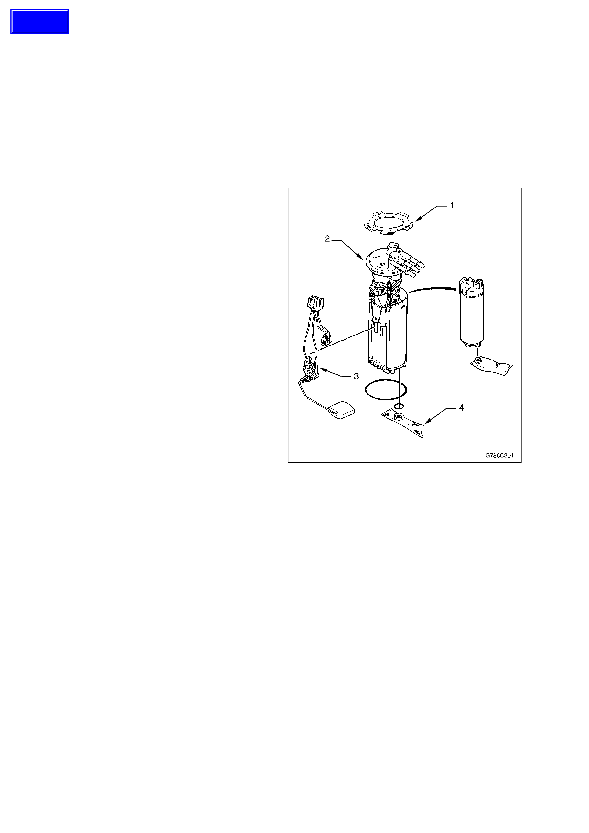
MODULAR FUEL SENDER ASSEMBLY
This Section describes the removal and installation
procedure for the modular fuel sender assembly,
and fuel level sensor. A full description of the
operation is provided in Section 8A, Fuel Tank in
the VT Series II Service Information.
NOTE: The modular fuel sender assembly is not
serviceable except for the fuel level sensor. If any
other part is found to be faulty, the complete fuel
sender assembly must be replaced.
Remove
TOOL REQUIRED: J 39765 Fuel Sender Locknut
Wrench.
CAUTION: In order to reduce the risk of fire or
personal injury that may result from fuel leakage,
always replace the fuel sender gasket when
reinstalling the fuel sender assembly.
NOTE: Do Not handle the fuel sender assembly by
the fuel pipes. The amount of leverage generated
by handling the fuel pipes could damage the joints.
1. Disconnect the negative battery cable.
2. Relieve the fuel system pressure. Refer to the
Fuel Pressure Relief Procedure in this
Section.
3. Drain and remove the fuel tank. Refer to
Section 8A, Fuel Tank, of the VT Series II
Service Information.
4. Remove the fuel sender assembly retaining ring
(1) using the J 39765 Fuel Sender Locknut
Wrench.
NOTE: The modular fuel sender assembly will
spring-up when the locking ring is removed.
5. Pull the modular fuel sender assembly (2)
straight up while draining the fuel from the
reservoir.
IMPORTANT: The reservoir bucket on the sender
assembly is full of fuel. Tip the assembly slightly
during removal in order to avoid damage to the fuel
level sensor (3) float. Place any remaining fuel into
an approved container once the modular fuel
sender assembly is removed from the fuel tank.
6. Clean the gasket sealing surfaces.
7. If required, remove the fuel level sensor by
disconnecting the wiring connector and
squeezing the retainer tabs and sliding the
sensor from the sender assembly.
Modular Fuel Sender Assembly
Reinstall
1. Fit the fuel level sensor to the modular fuel
sender assembly, ensuring the retaining tangs
are seated correctly.
2. Install the new gasket on the fuel sender
assembly.
IMPORTANT: The fuel strainer (4) must be in a
horizontal position when the sender assembly is
installed. Ensure the fuel strainer does not block
the travel of the float arm.
Techline

3. Carefully fold the strainer over itself to allow it to
fit through the opening in the fuel tank. Ensure
the strainer unfolds once it is placed in the tank.
4. Install the fuel sender assembly into the fuel
tank.
5. Fit and secure the sender assembly retaining
ring.
6. Install the fuel tank. Refer to Section 8A, Fuel
Tank, of the VT Series II Service Information.
7. Refill the fuel tank.
8. Install the fuel filler cap.
9. Connect the negative battery cable.
10. Inspect for leaks:
- Turn the ignition switch ON for 2 seconds
- Turn the ignition switch OFF for 10 seconds.
- Turn the ignition switch ON.
- Check for fuel leaks.
11. Perform the Idle Learn Procedure and the
Functional Check. Refer to
PCM Replacement/Programming in this
Section.
FUEL PULSE DAMPENER
Remove
1. Relieve the fuel system pressure. Refer to Fuel
Pressure Relief Procedure in this Section.
2. Disconnect the negative battery cable.
3. Remove engine dress cover. Refer to Engine
Coolant Temperature Sensor in this Section
for removal procedure.
4. Clean any dirt from the fuel pulse dampener
retaining ring.
5. Remove the fuel pulse dampener retaining ring
(1).
6. Discard the fuel pulse dampener retaining ring.
7. Remove the fuel pulse dampener (2) from the
fuel rail.
8. Remove and discard the fuel pulse dampener
O-ring.
Reinstall
1. Install the new O-ring on the fuel pulse
dampener.
2. Lubricate the fuel pulse dampener O-ring with
clean engine oil.
3. Push the fuel pulse dampener into the fuel rail.
4. Install the new fuel pulse dampener retaining
ring.
5. Connect the negative battery cable.
6. Inspect for leaks:
- Turn the ignition switch ON for 2 seconds
- Turn the ignition switch OFF for 10 seconds.
- Turn the ignition switch ON.
- Check for leaks.
7. Install engine dress cover.
8. Perform the Idle Learn Procedure and the
Functional Check. Refer to
PCM Replacement/Programming in this
Section.
2
1
Fuel Pulse Dampener
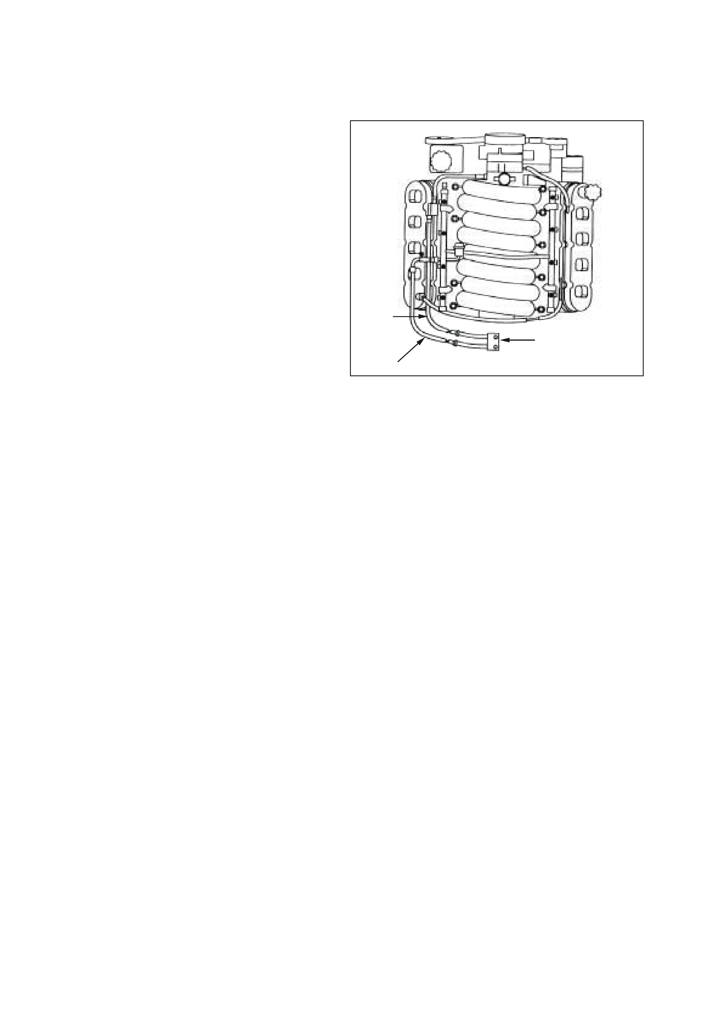
FUEL HOSE/ PIPES (ENGINE COMPARTMENT)
Remove
TOOLS REQUIRED: J7370, and 7371 Quick
Connect Release tools.
1. Relieve the fuel system pressure. Refer to the
Fuel Pressure Relief Procedure in this
Section.
2. Disconnect the negative battery cable.
3. Remove engine dress cover. Refer to
Engine Coolant Temperature in this Section
for removal procedure.
4. Clean all the engine compartment connecting
fuel pipe connections and the surrounding areas
before disconnecting to avoid possible
contamination of the fuel system.
5. Disconnect the engine compartment fuel feed
pipe (1) at the fuel rail. Refer to Quick Connect
Fittings Service (Metal Collar) in this Section.
6. Disconnect the engine compartment EECS pipe
(2) at the EECS canister purge solenoid. Refer
to Quick Connect Fittings Service (Plastic
Collar) in this Section.
7. Disconnect the engine compartment fuel feed
pipe at the chassis fuel feed pipe (3). Refer to
Quick Connect Fittings Service (Metal
Collar) in this Section.
8. Disconnect the engine compartment EECS pipe
at the chassis EECS pipe. Refer to Quick
Connect Fittings Service (Plastic Collar) in
this Section.
3
1
2
Engine Compartment Hose/Pipes
9. Cap the fuel pipes in order to prevent possible
fuel system contamination.
Reinstall
1. Remove the caps from the fuel pipes.
2. Connect the engine compartment fuel feed pipe
to the chassis fuel feed pipe. Refer to Quick
Connect Fittings Service (Metal Collar) in this
Section.
3. Connect the engine compartment EECS pipe to
the chassis EECS pipe. Refer to Quick
Connect Fittings Service (Plastic Collar) in
this Section.
4. Connect the engine compartment fuel feed pipe
to the fuel rail. Refer to Quick Connect Fittings
Service (Metal Collar) in this Section.
5. Connect the engine compartment EECS pipe to
the EECS canister purge solenoid. Refer to
Quick Connect Fittings Service (Plastic
Collar) in this Section.
6. Tighten the fuel filler cap.
7. Connect the negative battery cable.
8. Inspect for leaks:
- Turn the ignition switch ON for 2 seconds.
- Turn the ignition switch OFF for 10 seconds.
- Turn the ignition switch ON.
- Check for leaks.
- Install engine dress cover.
9. Perform the Idle Learn Procedure and
Functional Check. Refer to PCM
Replacement/Programming in this Section.
FUEL HOSE/PIPE ASSEMBLY (REAR PIPES)
Remove
1. Relieve the fuel system pressure. Refer to the
Fuel Pressure Relief Procedure in this
Section.
2. Disconnect the negative battery cable.
3. Drain the fuel tank. Refer to Section 8A, Fuel
Tank of the VT Series II Service Information.
4. Raise the vehicle.
5. Clean all the fuel and EECS pipe and hose
connections and the surrounding areas before
disconnecting in order to avoid possible
contamination of the fuel system.
6. Remove the fuel tank (1). Refer to Section 8A,
Fuel Tank of the VT Series II Service
Information.
7. Remove the rear fuel feed (2), fuel return (3),
and the EECS vapour pipe (4) from the fuel
sender assembly (5). Refer to Quick Connect
Fittings Service (Plastic Collar) in this
Section.
8. Remove the rear fuel and EECS pipes (6).
9. Cap the fuel pipes to prevent possible fuel
system contamination.
1
32
4
5
6
Rear Hose/Pipes

Reinstall
1. Remove the caps from the fuel pipes.
2. Connect the rear fuel feed, fuel return, and the
EECS vapour pipe to the fuel sender assembly.
Refer to Quick Connect Fittings Service
(Plastic Collar) in this Section.
3. Install the fuel tank, refer to Section 8A, Fuel
Tank of the VT Series II Service Information.
4. Lower the vehicle
5. Refill the fuel tank.
6. Connect the negative battery cable.
7. Tighten the fuel filler cap.
8. Inspect for leaks:
- Turn the ignition switch ON for 2 seconds.
- Turn the ignition switch OFF for 10 seconds.
- Turn the ignition switch ON.
- Check for leaks.
Perform the Idle Learn Procedure and the
Functional Check. Refer to PCM
Replacement/Programming in this Section.

FUEL SYSTEM CLEANING
IMPORTANT: Only use oil free compressed air to
blow out the fuel pipes.
Inspect the fuel tank internally and clean the fuel
tank if you find a blocked fuel filter.
1. Relieve the fuel system pressure. Refer to the
Fuel Pressure Relief Procedure in this
Section.
2. Disconnect the negative battery cable.
3. Drain the fuel tank. Refer to Section 8A Fuel
Tank of the VT Series II Service Information.
4. Remove the fuel tank. Refer to Section 8A
Fuel Tank of the VT Series II Service
Information.
5. Remove the modular fuel sender assembly.
Refer to Modular Fuel Sender Assembly in
this Section.
6. Inspect the fuel pump strainer. Replace fuel
modular sender assembly if strainer is
contaminated.
7. Inspect the fuel pump inlet for dirt and debris.
Replace modular fuel sender assembly if
strainer is contaminated.
8. Flush the fuel tank with hot water several
times.
IMPORTANT: When flushing the fuel tank, handle
the fuel and water mixture as a hazardous material.
Handle the fuel and water mixture in accordance
with all applicable local, state, and federal laws and
regulations.
9. Pour the water out of the fuel sender assembly
opening. Rock the tank to be sure that removal
of the water from the tank is complete.
NOTE: Ensure all traces of water are removed
from the tank before proceeding.
10. Install the fuel sender assembly. Refer to
Modular Fuel Sender Assembly in this
Section.
11. Install the fuel tank. Refer to Section 8A, Fuel
Tank of the VT Series II Service Information.
12. Refill the fuel tank.
13. Install the fuel filler cap.
14. Connect the negative battery cable.
15. Inspect for leaks:
- Turn the ignition switch ON for 2 seconds.
- Turn the ignition switch OFF for 10 seconds.
- Turn the ignition switch ON.
- Check for leaks.
16. Perform the Idle Learn Procedure and
Functional Check. Refer to
PCM Replacement /Programming in this
Section.
FUEL PRESSURE CONNECTION (SCHRADER VALVE)
Remove
1. Relieve the fuel system pressure. Refer to the
Fuel Pressure Relief Procedure in this
Section.
2. Disconnect the negative battery cable.
3. Remove engine dress cover. Refer to Engine
Coolant Temperature Sensor in this Section
for removal procedure.
4. Loosen fuel filler cap.
5. Remove fuel pressure connection valve cap (1).
6. Clean the area around the fuel pressure
connection.
7. Remove the fuel pressure connection valve (2)
(schrader valve) using a standard valve core
removal and installation tool
Reinstall
1. Install the fuel pressure connection valve (2)
(schrader valve) using a standard valve core
removal and installation tool.
2. Install the fuel pressure connection valve cap
(3).
3. Tighten the fuel filler cap.
4. Connect the negative battery cable.
5. Inspect for leaks:
- Turn the ignition switch ON for 2 seconds.
- Turn the ignition switch OFF for 10 seconds.
- Turn the ignition switch ON.
- Check for leaks.
6. Install engine dress cover.
7. Perform the Idle Learn Procedure and
Functional Check. Refer to
PCM Replacement/Programming in this
Section.
2
3
Fuel Pressure Connection Valve (Schrader Valve)
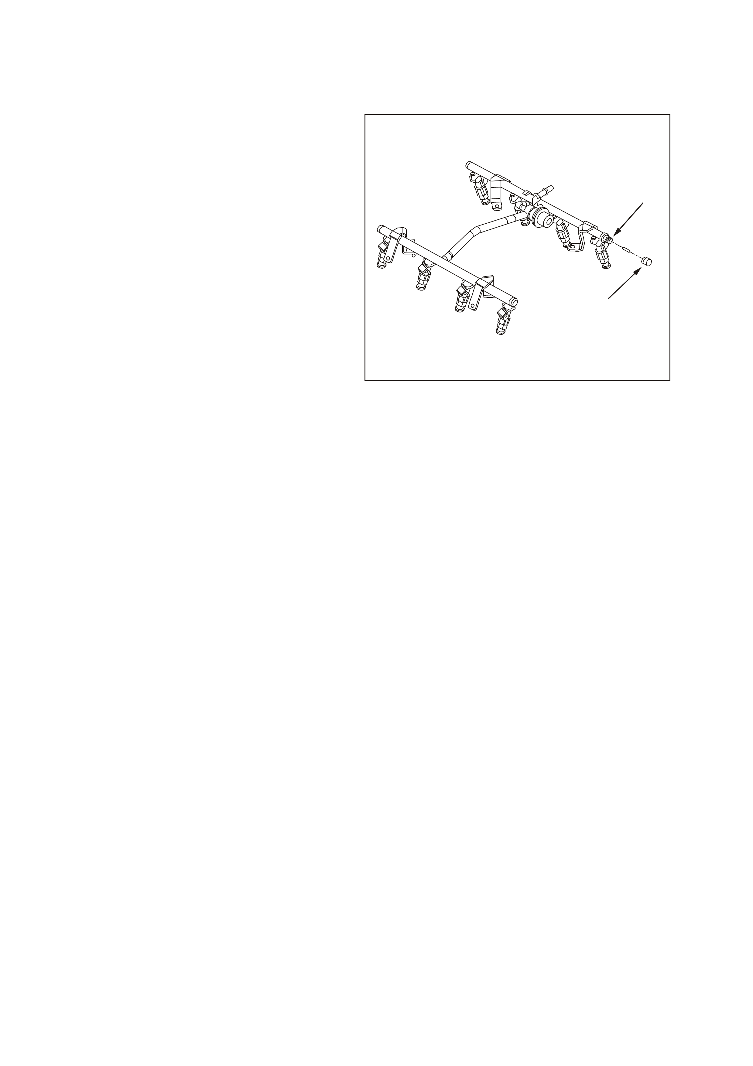
FUEL RAIL ASSEMBLY
REMOVE
TOOLS REQUIRED: J7370, and 7371 Quick
Connect Release tools.
1. Remove engine dress cover. Refer to Engine
Coolant Temperature in this Section for
removal procedure.
2. Relieve the fuel system pressure. Refer to the
Fuel Pressure Relief Procedure in this
Section.
3. Disconnect the negative battery cable.
4. Before removal, clean the fuel rail assembly with
a spray type engine cleaner, if necessary. Do
not soak fuel rails in liquid cleaning solvent.
NOTE: Remove the fuel rail assembly carefully in
order to prevent damage to the injector electrical
connector terminals and the injector spray tips.
Support the fuel rail after the fuel rail is removed in
order to avoid damaging the fuel rail components.
Cap the fittings and plug the holes when servicing
the fuel system in order to prevent dirt and other
contaminants from entering open pipes and
passages.
5. Disconnect the fuel feed hose from the fuel rail.
Refer to Quick Connect Fittings Service
(Metal Collar) in this Section.
6. Disconnect the accelerator cable from the
throttle body and remove the retaining clip from
the fuel rail.
7. Move the throttle cable aside.
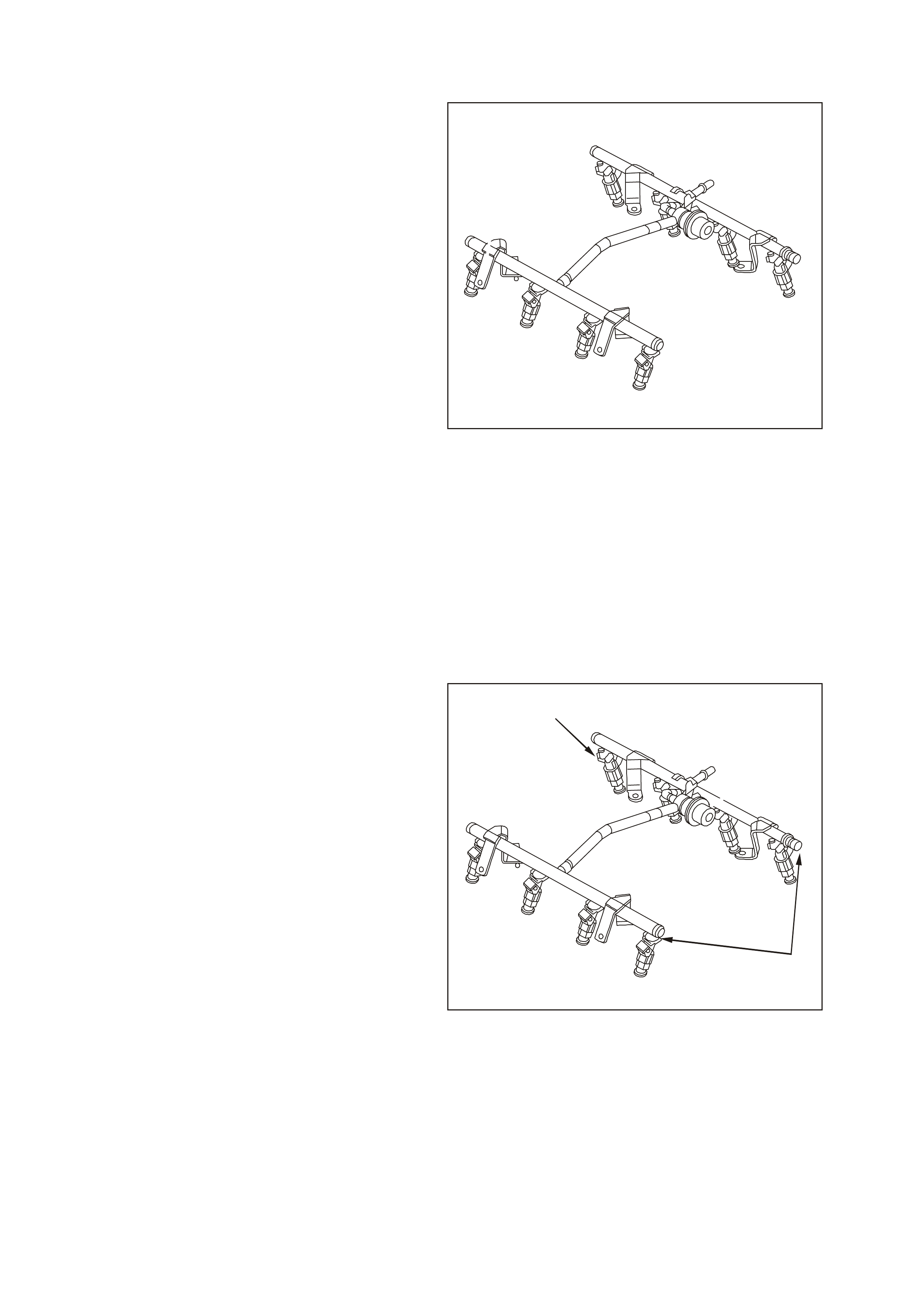
Fuel Rail
8. Disconnect the electrical connectors from the
fuel injectors (1). Identify the connectors to their
corresponding injectors to ensure correct
sequential injector firing order after reassembly.
9. Disconnect the electrical harness from the fuel
rail brackets.
10. Remove the fuel rail attaching bolts and the fuel
rail assembly (2).
11. Remove and discard the injector lower O-ring
seal from the spray tip end of each injector.
1
2
Fuel Rail Assembly
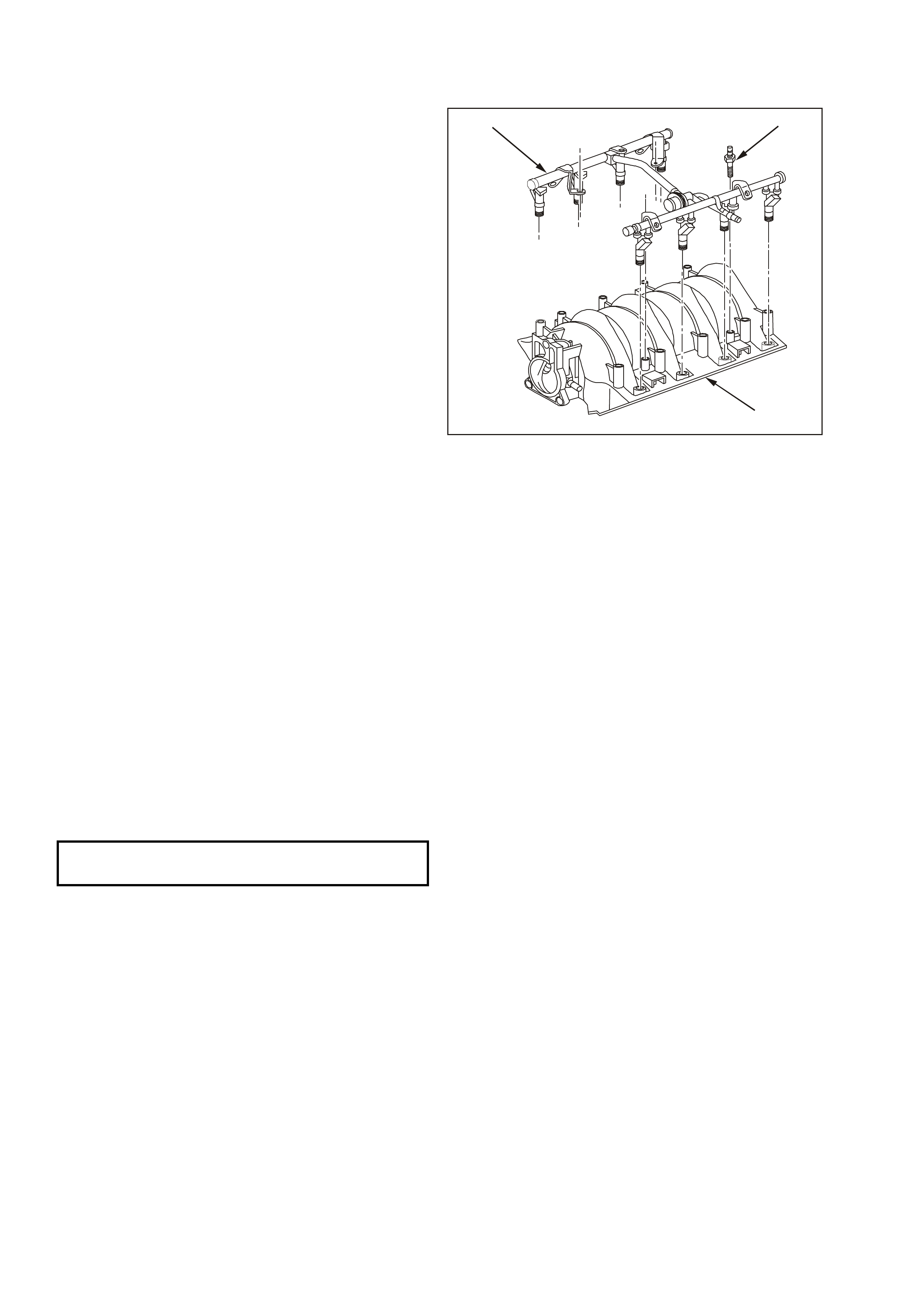
Reinstall
1. Lubricate the new lower injector O-ring seals
with clean engine oil.
2. Install the new O-ring seals on the spray tip end
of each injector.
3. Install the fuel rail assembly (1) to the intake
manifold (2).
4. Apply Loctite 242 (Holden Specification HN1256
Class 2, Type 2) or equivalent to the threads of
the fuel rail bolts.
5. Install the fuel rail attaching bolts (3) and tighten
to the specified torque.
6. Connect the injector electrical connectors.
NOTE: Ensure each connector is installed on the
correct injector to ensure correct sequential injector
firing order.
Rotate the injectors as required in order to avoid
stretching the wire harness.
7. Connect the electrical harness to the fuel rail
bracket.
8. Connect the throttle cable to the throttle body
and retaining clip.
9. Connect the fuel feed hose to the fuel rail fuel
pipe. Refer to Quick Connect Fittings Service
(Metal Collar) in this Section.
10. Tighten the fuel filler cap.
11. Connect the negative battery cable.
12. Inspect for leaks:
- Turn the ignition switch ON for 2 seconds.
- Turn the ignition switch OFF for 10 seconds.
- Turn the ignition switch ON.
- Check for leaks.
13. Install engine dress cover.
14. Perform the Idle Learn Procedure and
Functional Check. Refer to
PCM Replacement/Programming in this
Section.
13
2
Fuel Rail Removal
FUEL RAIL ATTACHING BOLTS
TIGHTENING TORQUE 10 Nm (89 lb/ in)
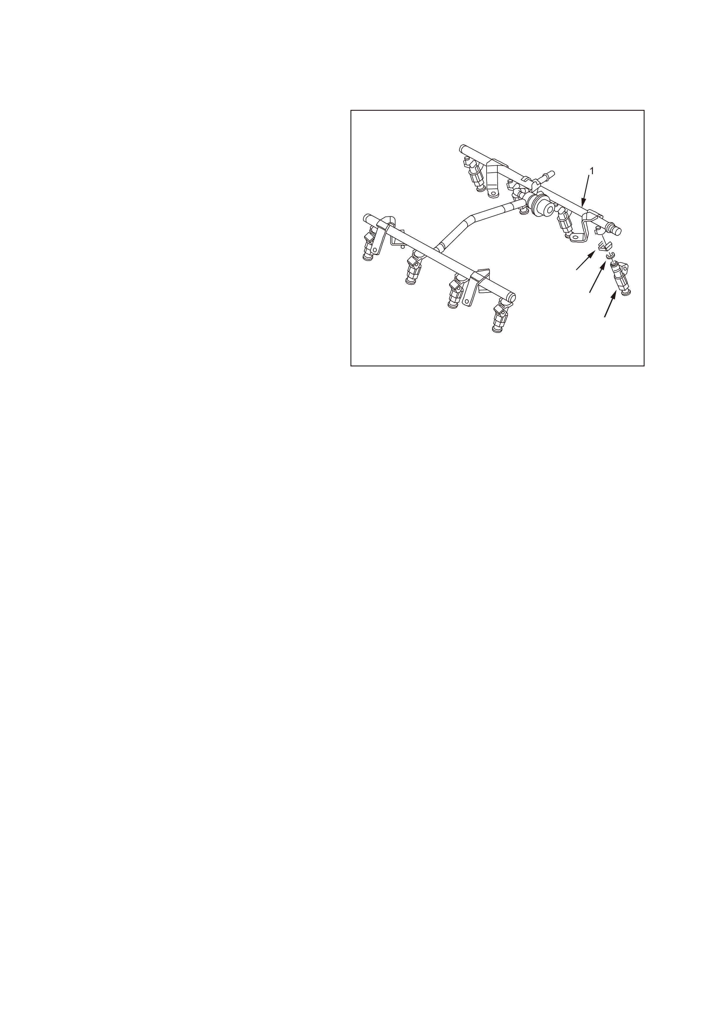
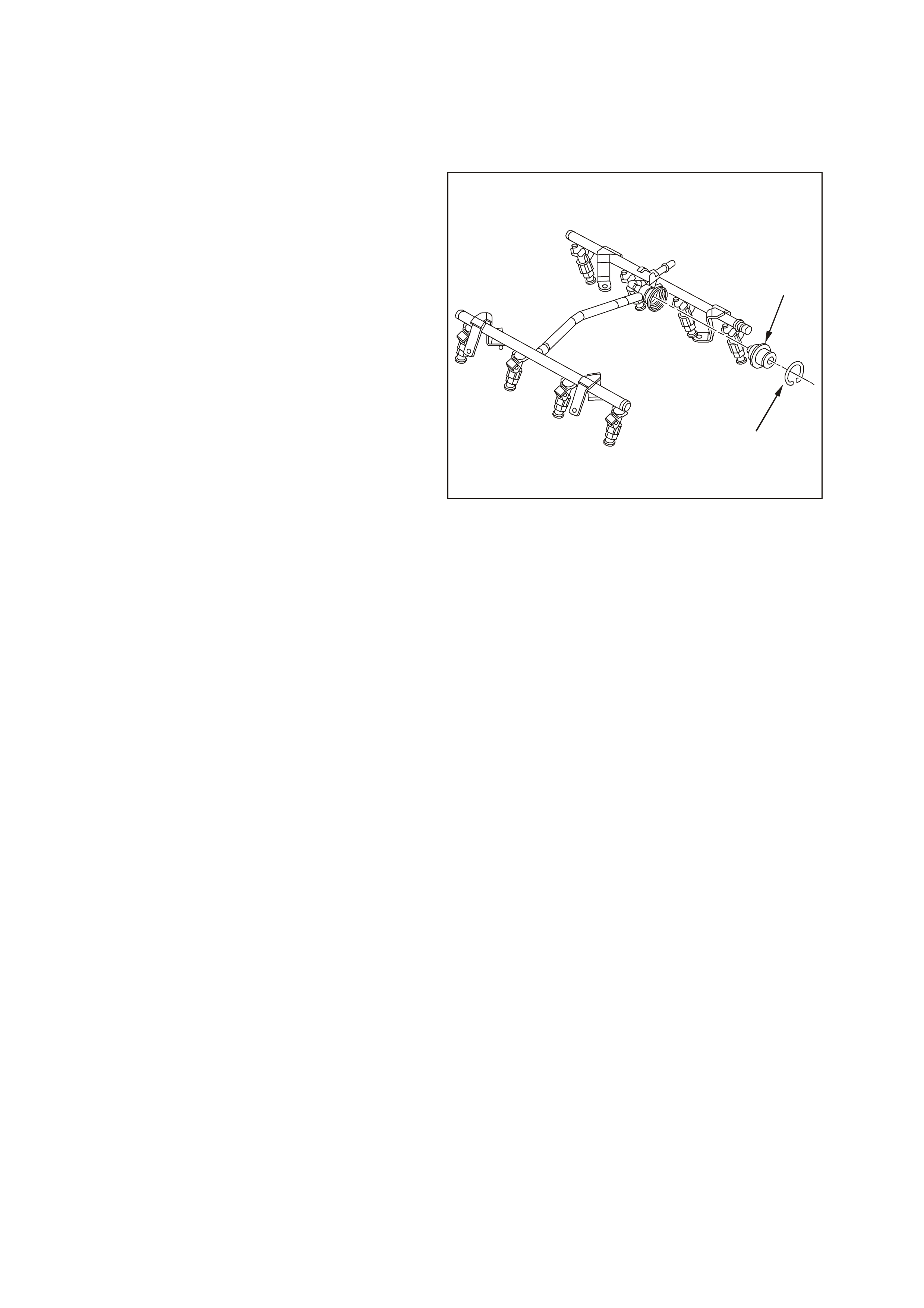
FUEL INJECTOR
Remove
IMPORTANT: Use care in removing the fuel
injectors to prevent damage to the electrical
connector pins on the injector and to prevent
damage to the nozzle. Service the fuel injector as a
complete assembly only. The fuel injector is an
electrical component. Do Not immerse the fuel
injector in any type of cleaner.
The engine oil may be contaminated with fuel if the
fuel injectors are leaking.
1. Relieve the fuel system pressure. Refer to the
Fuel Pressure Relief Procedure in this
Section.
2. Disconnect the negative battery cable.
3. Remove engine dress cover. Refer to Engine
Coolant Temperature Sensor in this Section
for removal procedure.
4. Remove the fuel rail assembly (1). Refer to Fuel
Rail Assembly Replacement in this Section.
5. Spread the injector retainer clip (2) to release
the injector from the fuel rail.
6. Remove the fuel injector (3).
7. Discard the injector retainer clip.
8. Remove and discard the injector O-ring seal (4)
from both ends of the injector.
3
4
2
Fuel Rail and Injectors
Reinstall
IMPORTANT: When ordering new fuel injectors,
ensure to order the correct injector for the
application being serviced The fuel injector
assembly is stamped with a part number
identification, a manufacturing date, a week code,
and a production plant number.
1. Lubricate the new injector O-ring seal with clean
engine oil.
2. Install the new injector O-ring seal on the
injector.
3. Install a new retainer clip on the injector.
4. Push the fuel injector into the fuel rail injector
socket with the electrical connector facing
outward. The retainer clip locks on to a flange
on the fuel rail injector socket.
5. Install the fuel rail assembly. Refer to Fuel Rail
Assembly Replacement in this Section.
6. Tighten the fuel filler cap.
7. Connect the negative battery cable.
8. Inspect for leaks:
- Turn the ignition switch ON for 2 seconds.
- Turn the ignition switch OFF for 10 seconds.
- Turn the ignition switch ON.
- Check for leaks.
9. Install engine dress cover.
10. Perform the Idle Learn Procedure and the
Functional Check. Refer to
PCM Replacement/Programming in this
Section.
Fuel Injector
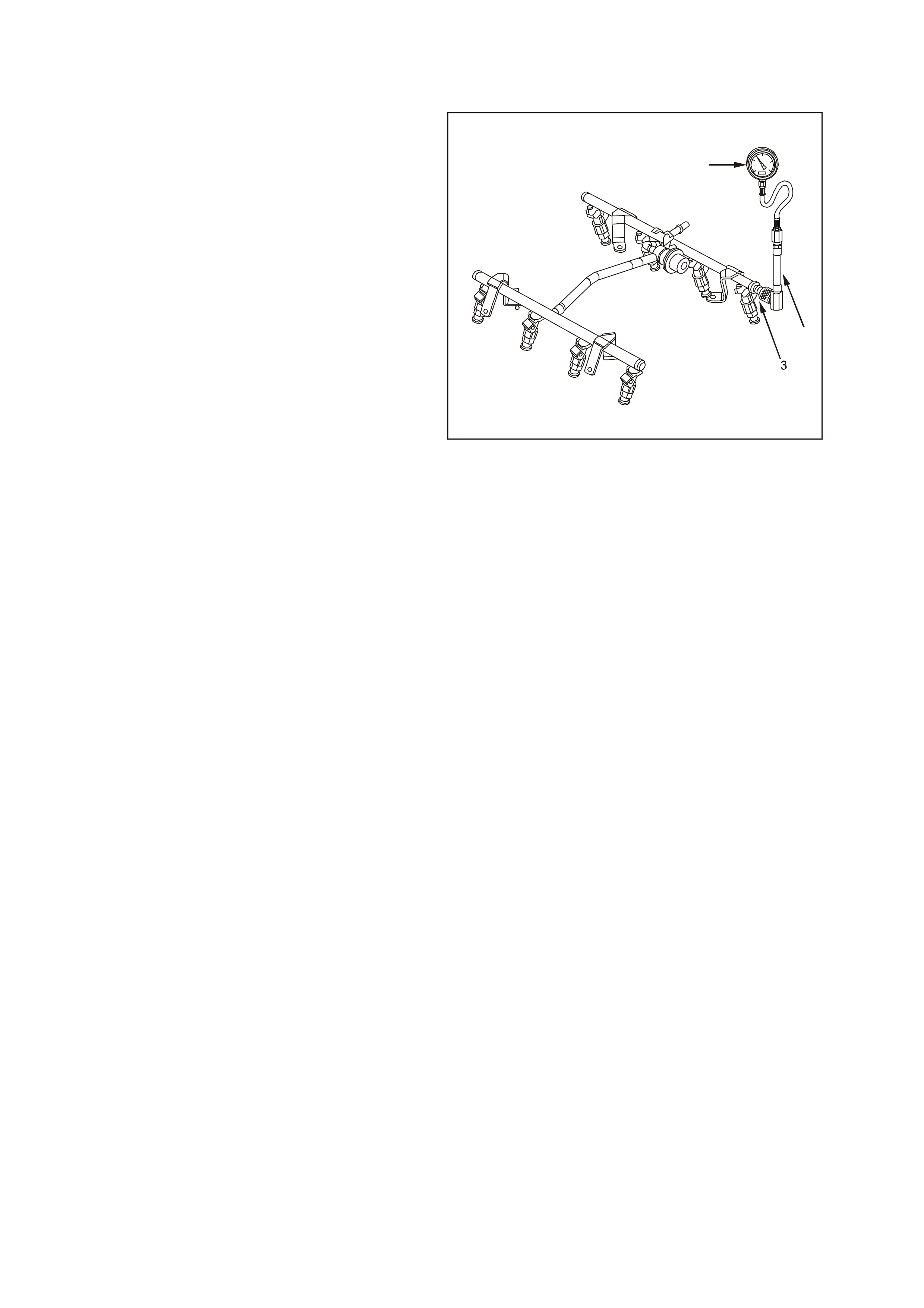
FUEL SYSTEM PRESSURE TEST
TOOLS REQUIRED: SD28018 or AU338 Fuel
Pressure Gauge, and AU453 Fuel Gauge Schrader
Fitting Adapter.
A fuel system pressure test is part of several of the
Diagnostic Tables and Symptom checks. To
perform this test, follow this procedure.
CAUTION: To reduce the risk of fire or personal
injury, it is necessary to relieve fuel system
pressure before performing this test. See Fuel
Pressure Relief Procedure in this Section.
IMPORTANT: At no time must the fuel inlet hose or
evaporative hose be clamped or bent over as this
will cause a permanent kinking of the inner section
of the hose assembly and will result in restricted
fuel flow.
1. Remove the engine dress cover. Refer to
Engine Coolant Temperature Sensor in this
Section for removal procedure.
2. Loosen the fuel filler cap to relieve the fuel tank
vapour pressure.
3. Remove the fuel test valve cap.
4. Connect the SD28018 or AU338 fuel pressure
gauge (1) to the AU453 fuel gauge schrader
fitting adapter (2), then connect to the fuel
pressure testing valve (3). Wrap a shop towel
around the fitting while connecting the gauge in
order to avoid and/or capture any fuel spillage.
5. Install the bleed hose of the gauge into an
approved petrol container.
6. Using a Tech 2 scan tool, enable fuel pump to
pressurise the system.
7. With fuel pump energised, open the valve to
bleed the air out of the fuel gauge.
Measure
1. Using the Tech 2 scan tool once again, enable
the fuel pump to pressurise the system.
2. The fuel gauge reading should be 380-440 kPa
(55-62 psi) for the GEN III V8 Engine
application. If not, refer to Section 6C3-2A
Diagnostic Tables - Fuel System Diagnosis in
the VT Series II Service Information.
3. Relieve the fuel system pressure. Refer to the
Fuel Pressure Relief Procedure in this
Section.
4. Remove fuel pressure gauge and adapter.
5. Reinstall fuel test valve cap.
6. Inspect for leaks:
- Turn the ignition switch ON for 2 seconds.
- Turn the ignition switch OFF for 10 seconds.
- Turn the ignition switch ON.
- Check for leaks.
7. Install engine dress cover.
1
2
Fuel Rail with Fuel Gauge
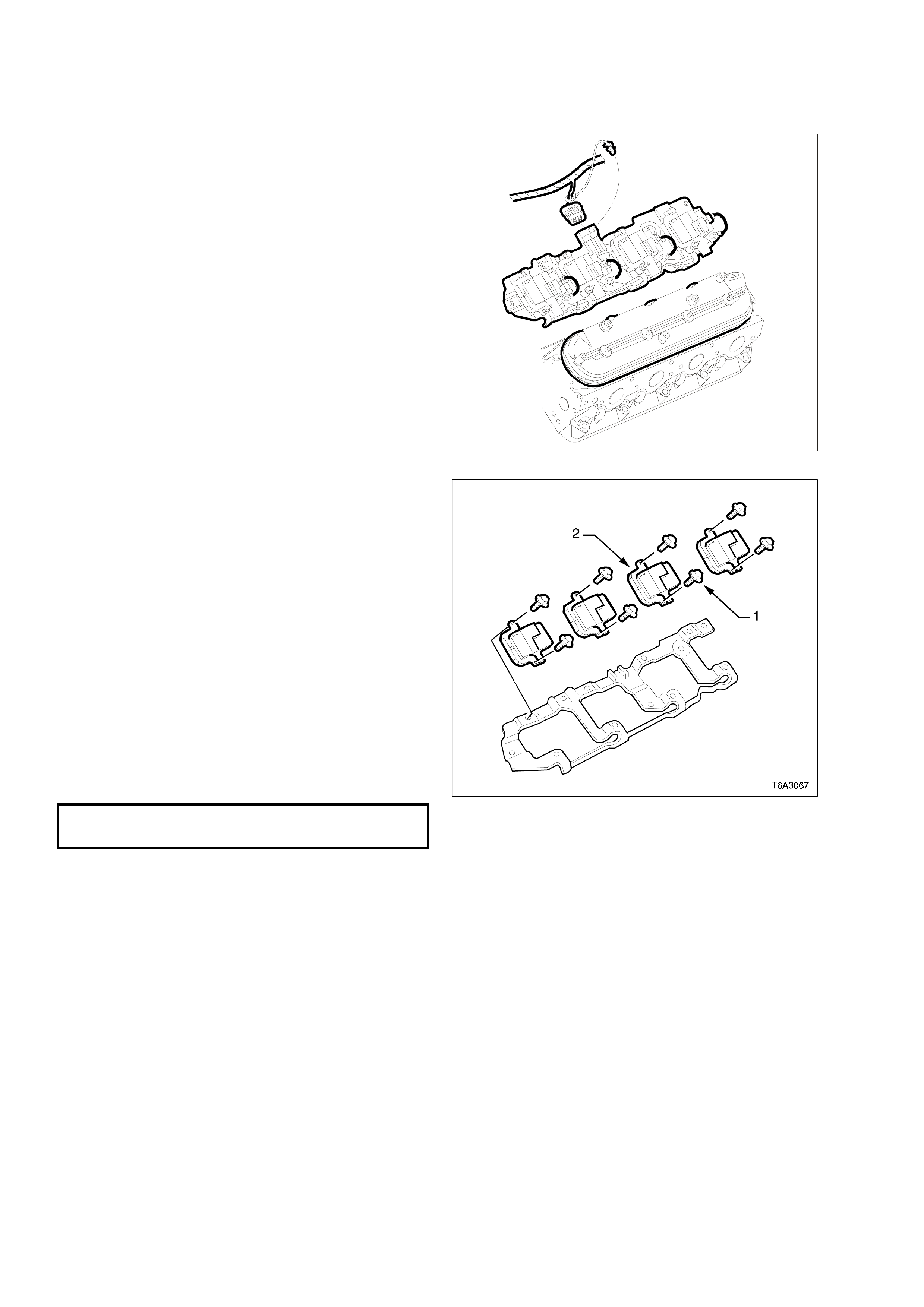
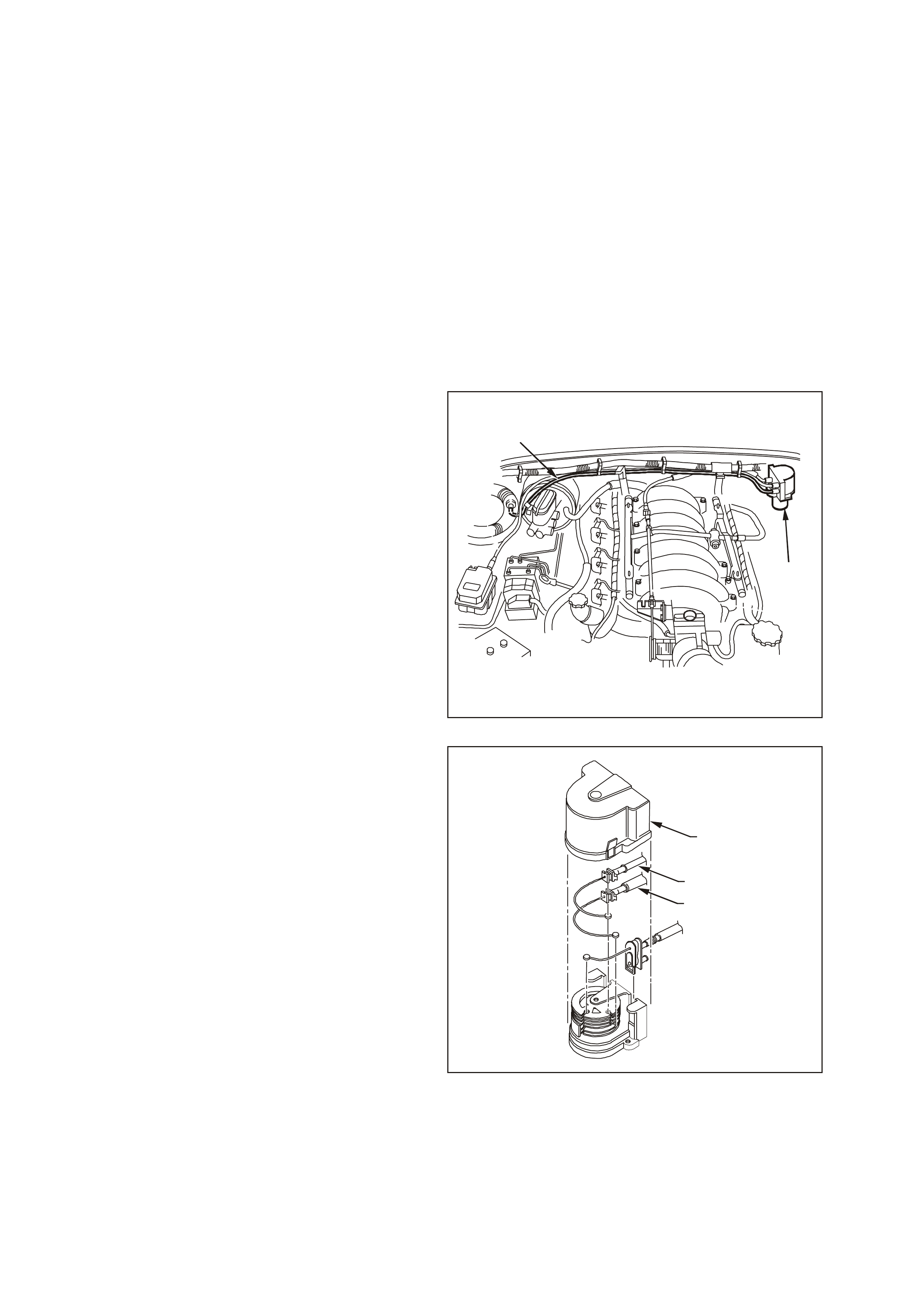
3.16 IGNITION COIL/MODULE
REMOVE
1. Remove engine dress cover. Refer to
Engine Coolant Temperature Sensor in this
Section for removal procedure.
2. Disconnect the negative battery cable.
3. Disconnect the main electrical connector
feeding the ignition coils.
4. Disconnect the ignition coil harness connectors.
5. Disconnect the spark plug wire at the ignition
coil.
T6A3065
Ignition Coil/Module Location
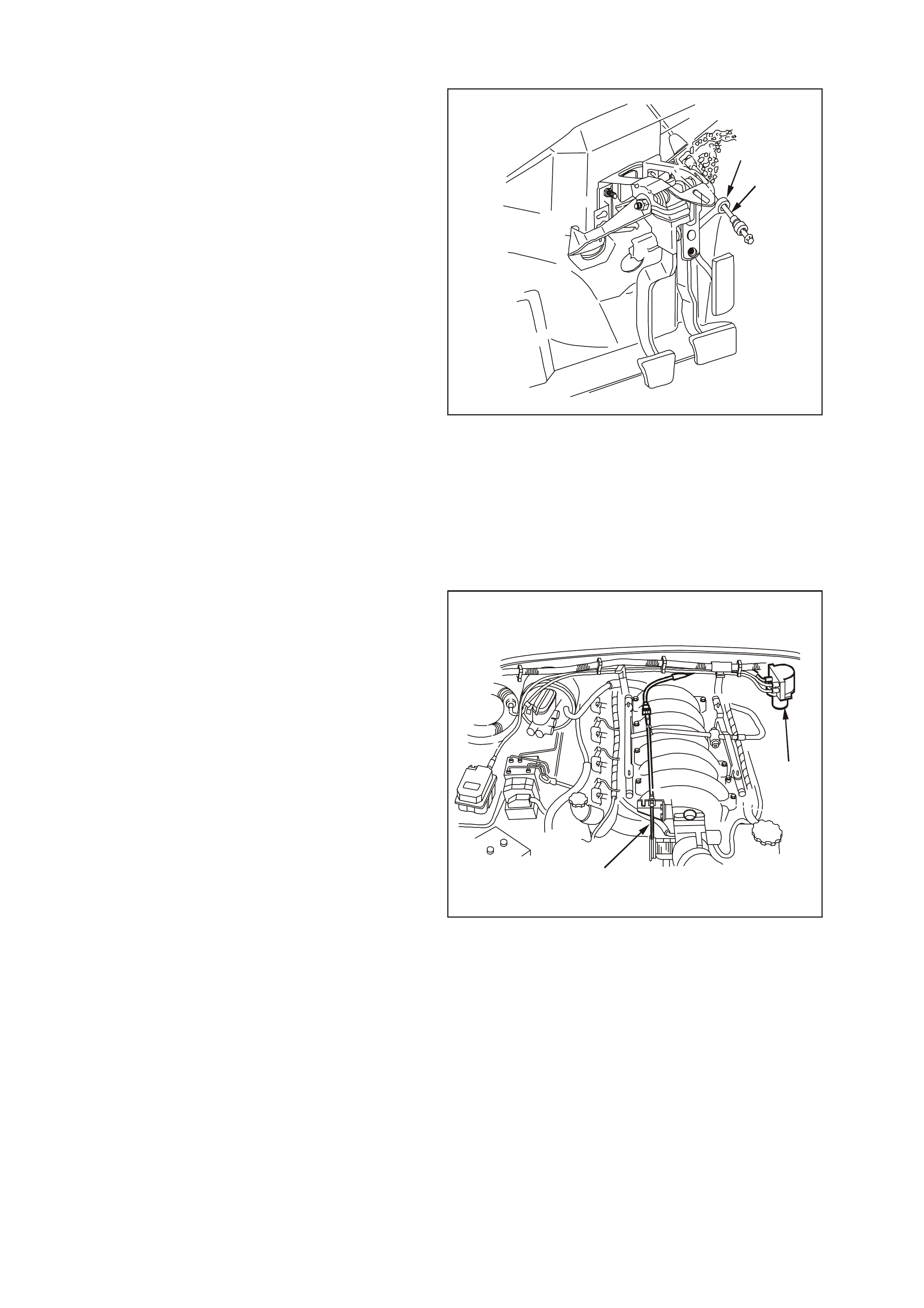
6. Remove the ignition coil retaining bolts (1).
7. Remove the ignition coil/modules (2).
REINSTALL
1. Install the ignition coil.
2. Install the ignition coil retaining bolts.
3. Connect the spark plug wire to the ignition coil.
4. Connect the ignition coil harness connector.
5. Connect the main electrical connector feeding
the ignition coils.
6. Connect the negative battery cable.
7. Install engine dress cover.
8. Perform the Idle Learn Procedure and the
Functional Check. Refer to PCM
Replacement/Programming in this Section.
IGNITION COIL RETAINING
BOLT TIGHTENING TORQUE 12 Nm (106 lb/in) Ignition Coil/Modules
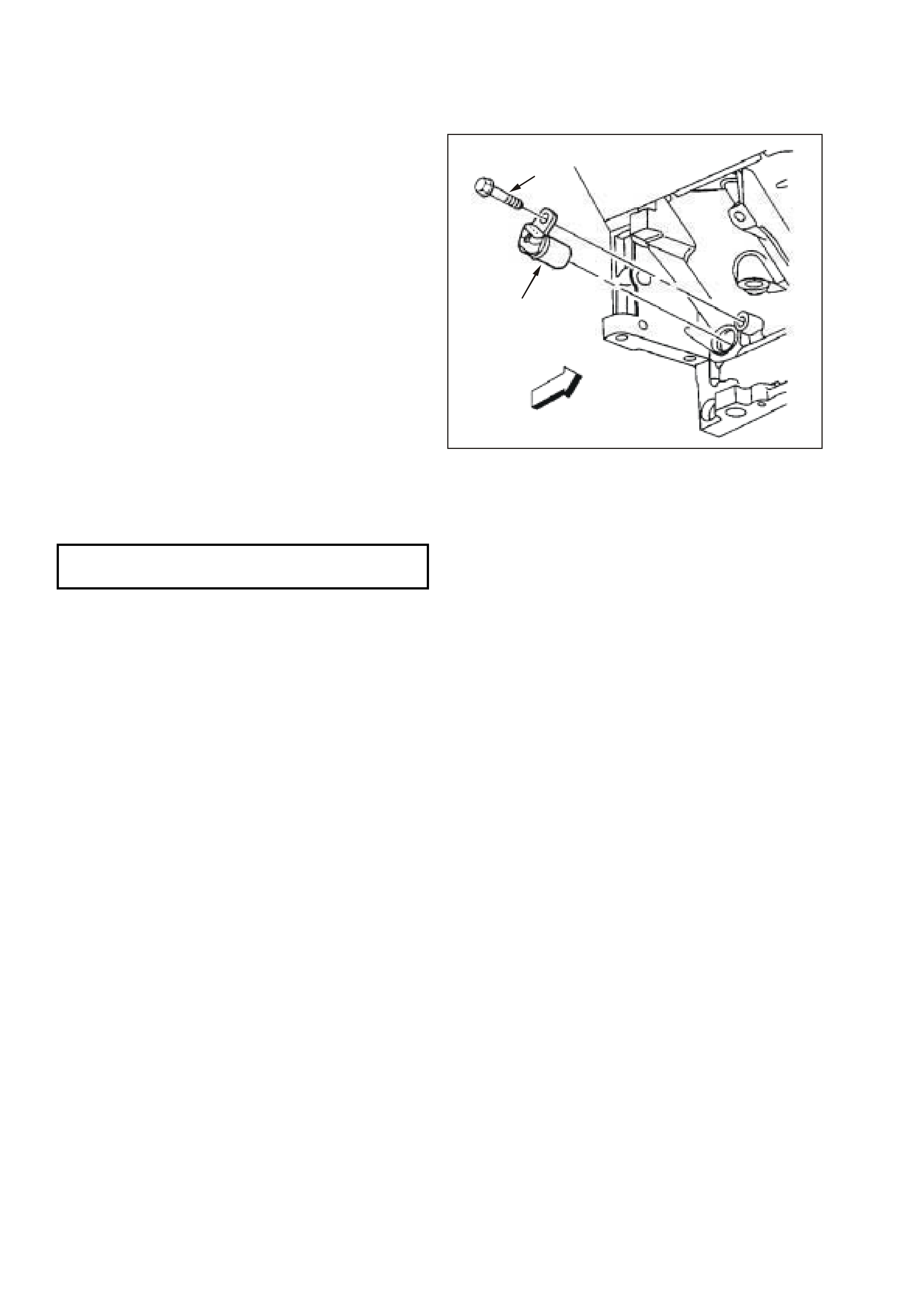
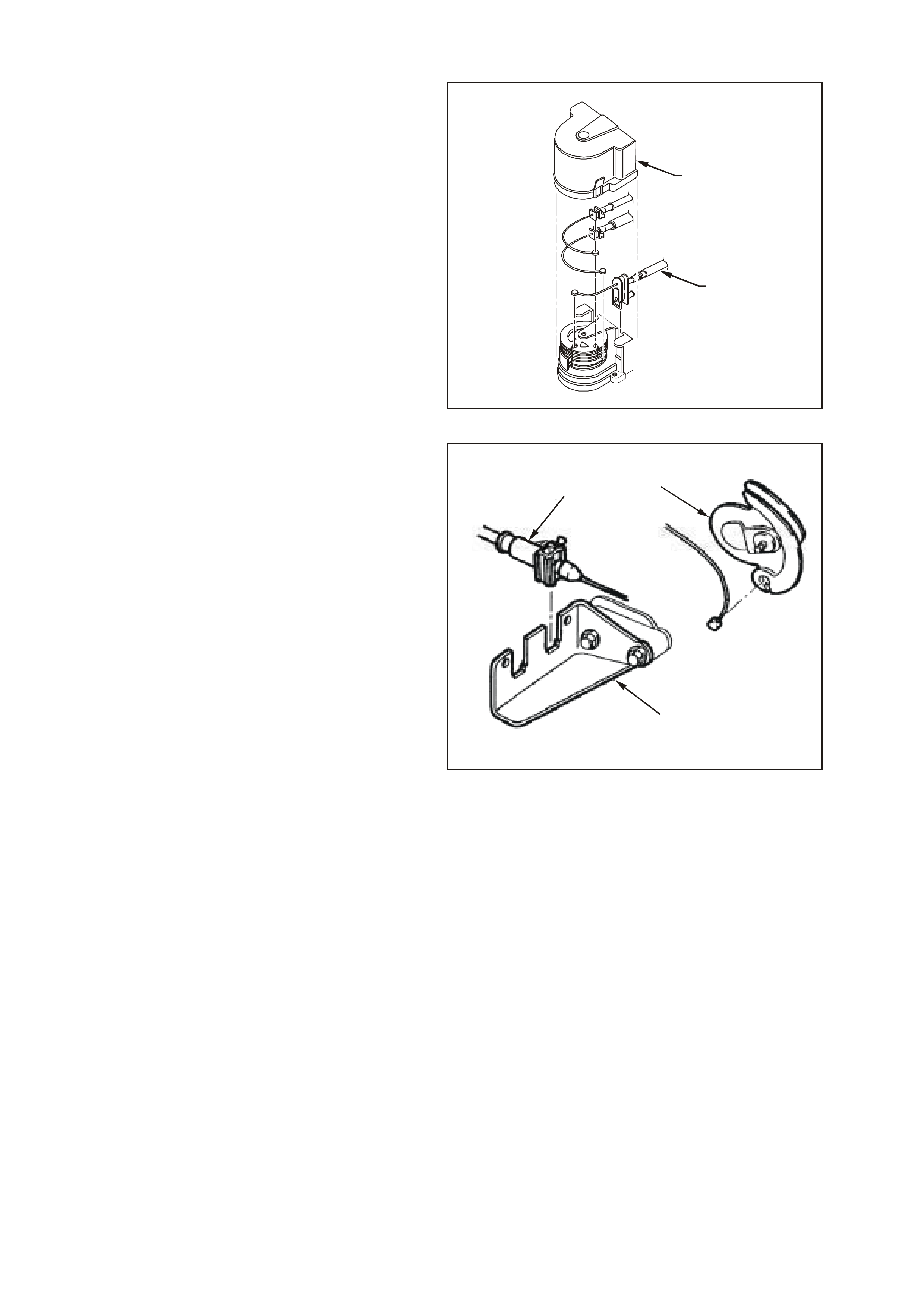
3.17 CRANKSHAFT POSITION (CKP) SENSOR
REMOVE
1. Remove the starter motor. Refer to Section
6D3, Starting System of the VT Series II
Service Information.
2. Disconnect the electrical connector from the
crankshaft position sensor (1).
3. Remove the crankshaft position retaining bolt
(2).
4. Remove the sensor.
REINSTALL
1. Install the crankshaft position sensor.
2. Install the crankshaft position retaining bolt and
tighten to the specified torque.
3. Connect the sensor electrical connector.
4. Install the starter motor. Refer to Section 6D3,
Starting System of the VT Series II Service
Information.
5. Perform the Idle Learn Procedure and the
Functional Check. Refer to PCM
Replacement/Programming in this Section.
1
2
CKP SENSOR TIGHTENING
TORQUE 25 Nm (18 lb/ft) Crankshaft Position Sensor Location
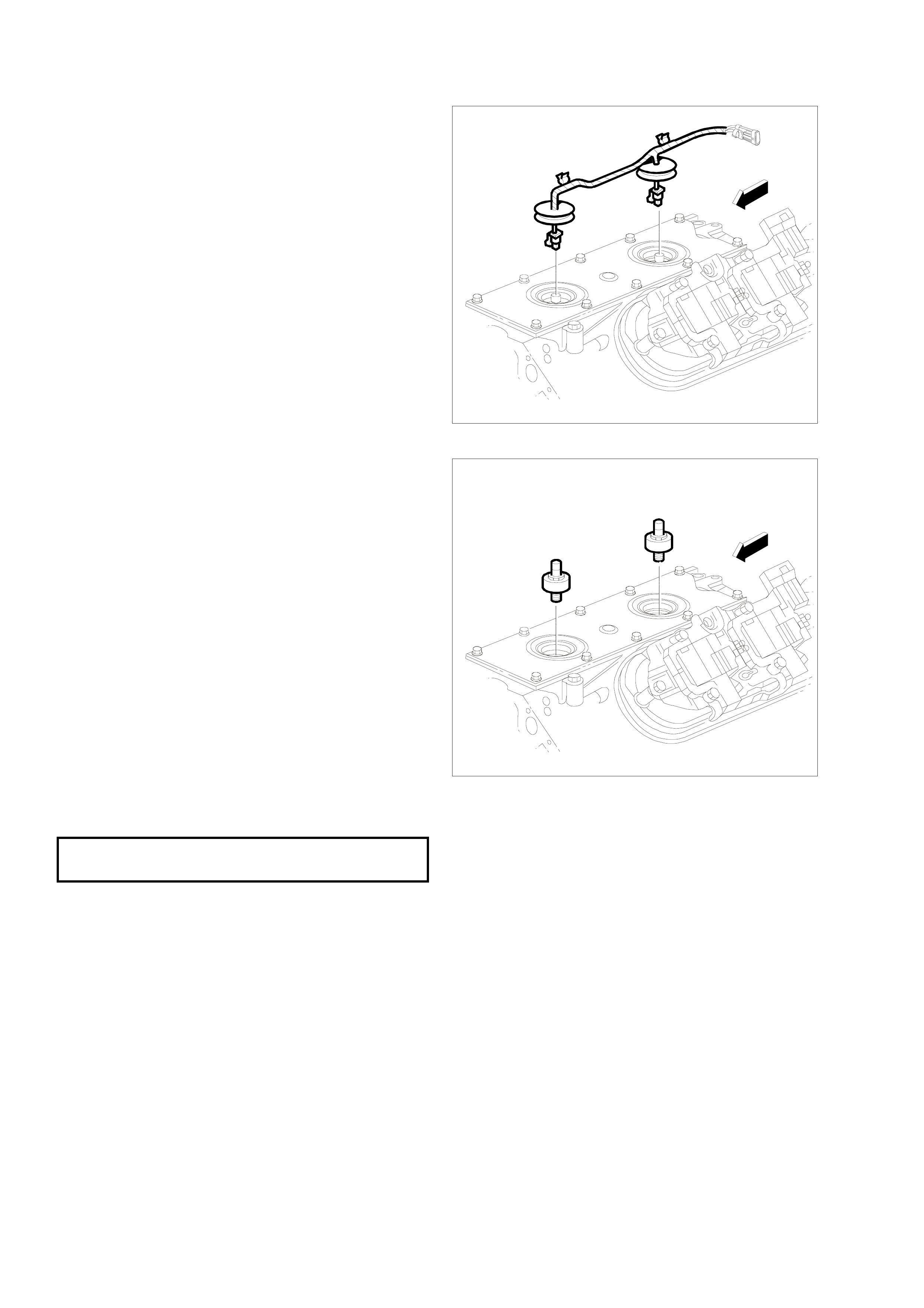
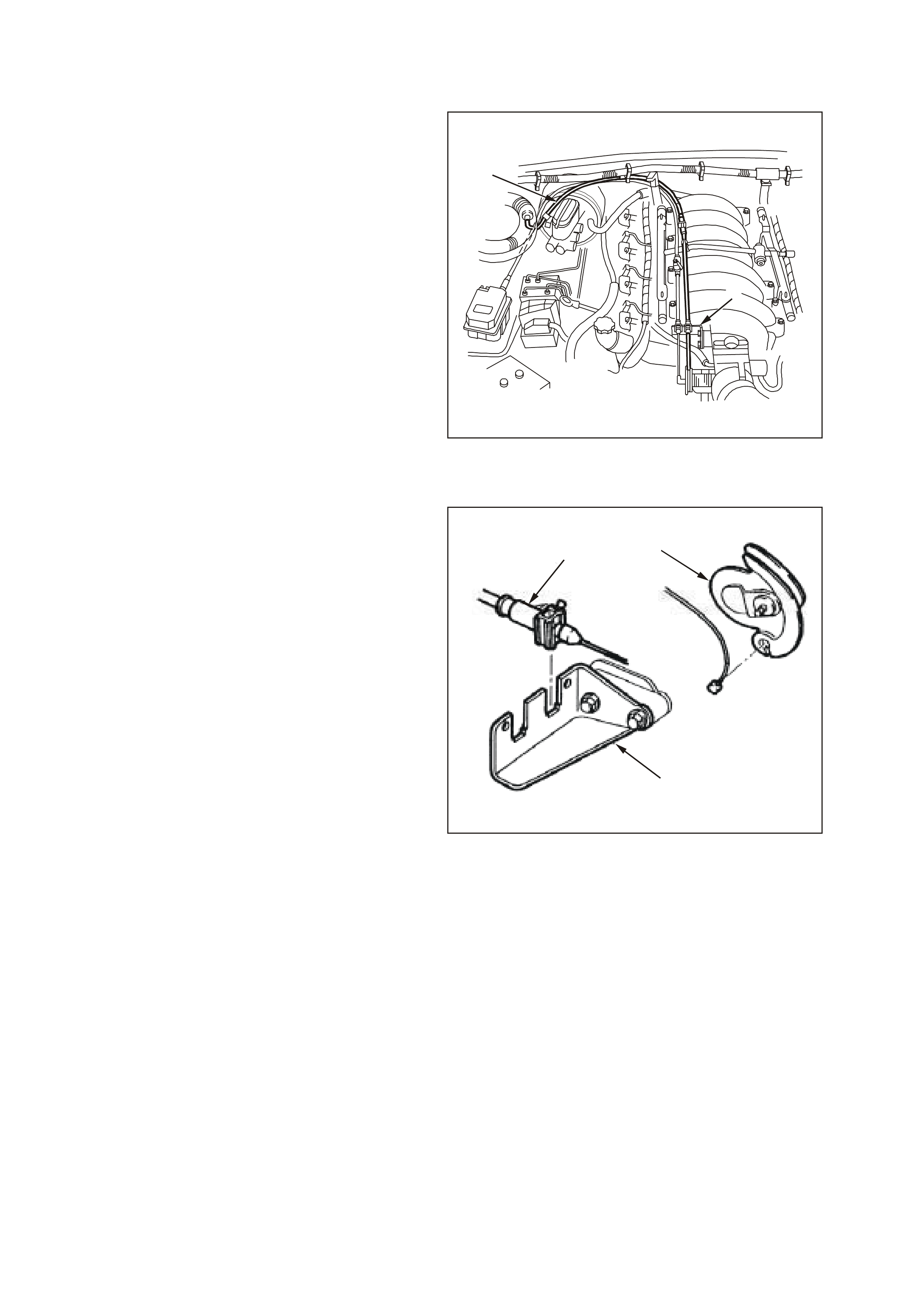
3.18 KNOCK SENSORS
REMOVE
1. Perform the fuel pressure relief procedure.
Refer to Fuel Pressure Relief Procedure in this
Section.
2. Disconnect the negative battery cable.
3. Remove engine dress cover. Refer to Engine
Coolant Temperature Sensor in this Section
for removal procedure.
4. Remove the intake manifold. Refer to Section
6A3, Engine Mechanical of the VT Series II
Service Information.
5. Remove the Knock Sensor wiring harness
assembly.
T6A3061
Knock Sensor Wiring Harness
6. Remove the Knock Sensor(s).
REINSTALL
NOTE: Do not apply sealant to the thread of a new
sensor as it is coated with a sealant during
production. Applying additional sealant may affect
the sensor's ability to detect engine knock.
NOTE: Ensure that the knock sensor is never over
tightened as damage to the sensor can occur.
1. Install the knock sensor(s) and tighten to the
specified torque.
2. Install the knock sensor wiring harness.
3. Install the intake manifold. Refer to Section
6A3, Engine Mechanical of the VT Series II
Service Information.
4. Install engine dress cover.
5. Perform the Idle Learn Procedure and the
Functional Check. Refer to PCM
Replacement/Programming in this Section.
T6A3062
KNOCK SENSOR TIGHTENING
TORQUE 15 Nm (11 lb/ft) Knock Sensors
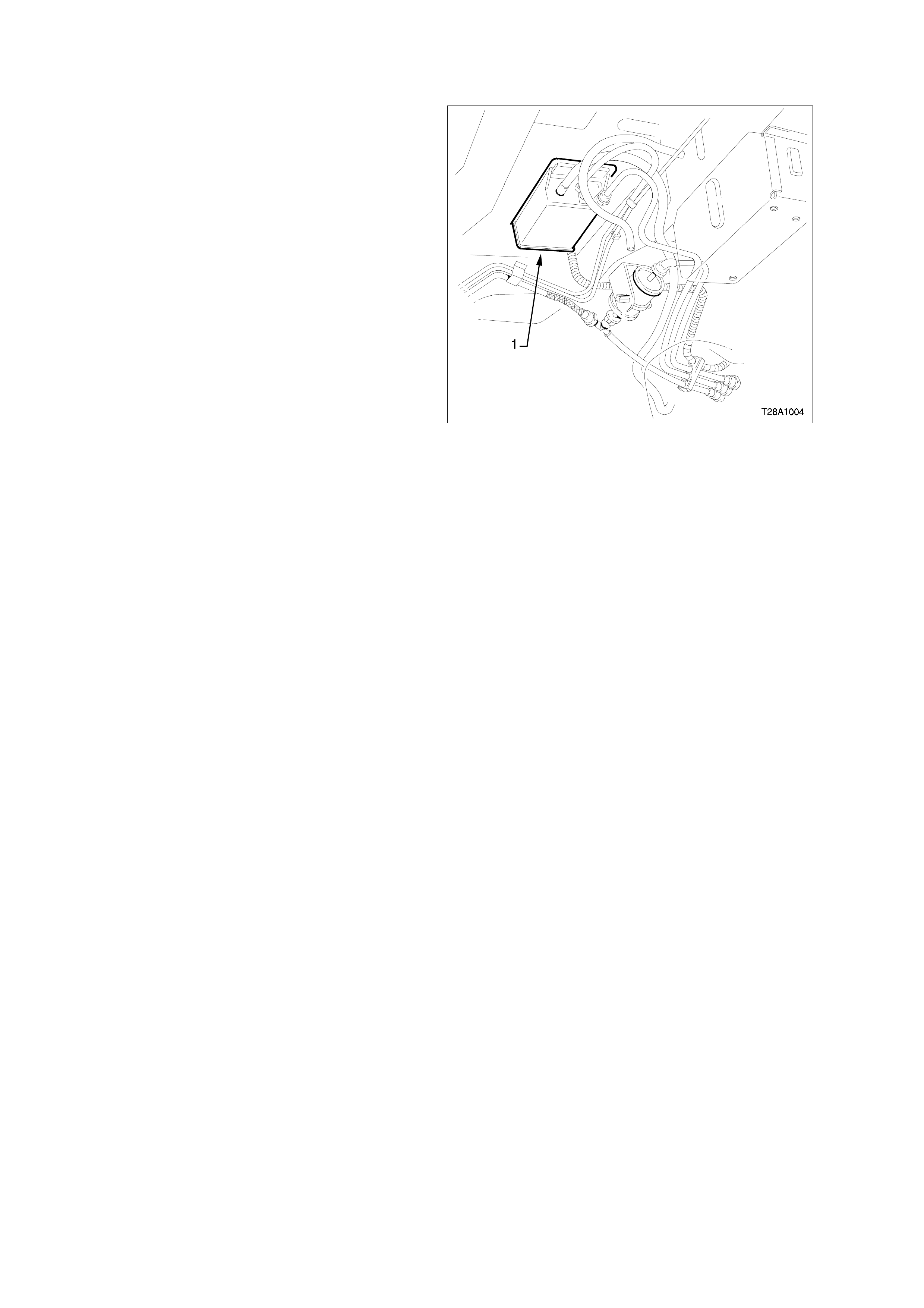
3.19 EVAPORATIVE EMISSION CONTROL SYSTEM (EECS) CANISTER
The Evaporative Emission Control System
(EECS) Canister (1) is located underneath the
vehicle near the fuel filter. For Canister removal
and reinstallation procedures, refer to Section
6E2 Emission Control - V8 Engine of the VT
Series I Service Information.
EECS Canister Location
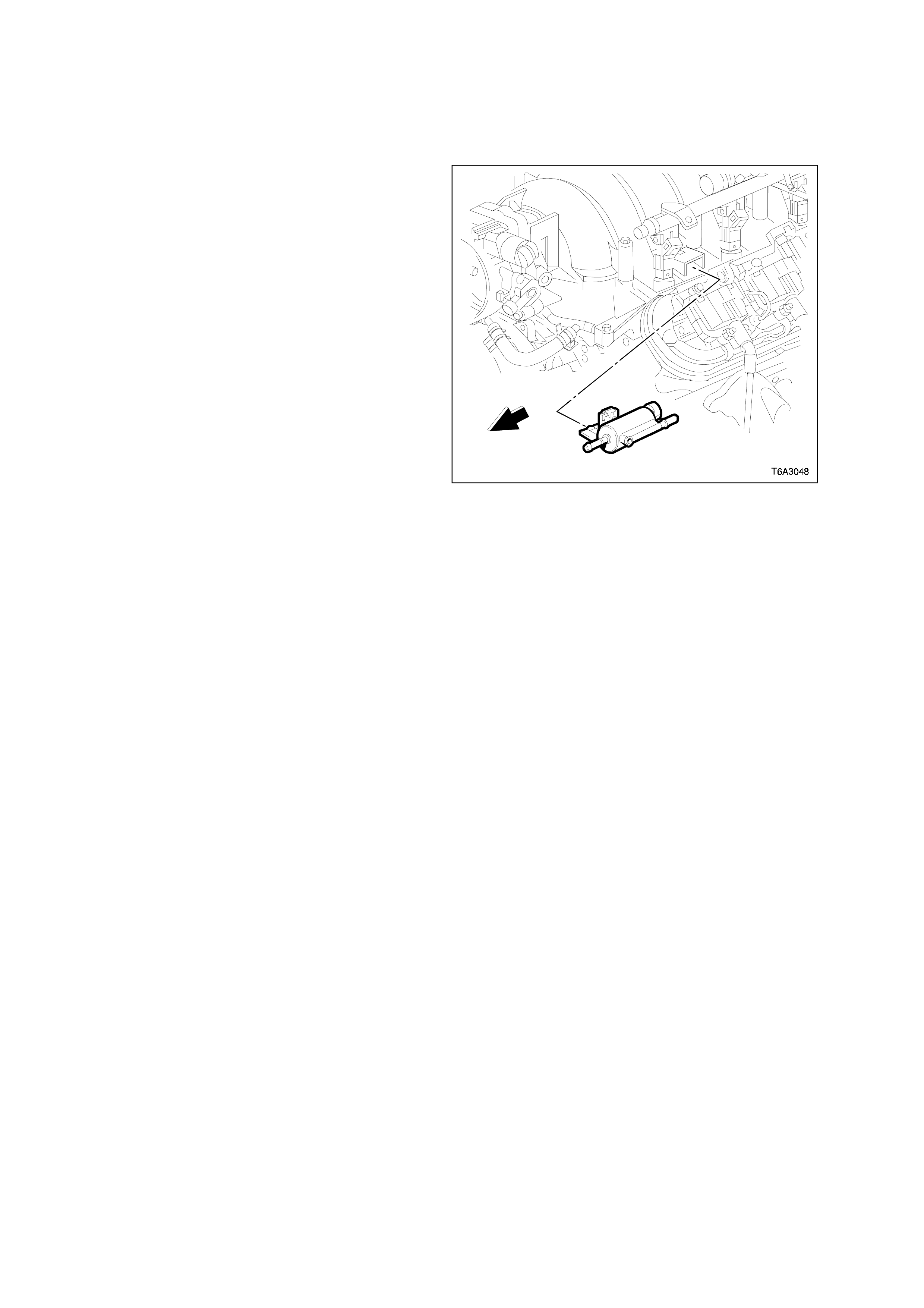
3.20 EVAPORATIVE EMISSION CONTROL
SYSTEM (EECS) CANISTER PURGE SOLENOID VALVE
TOOLS REQUIRED:
AU533 (RED TOOL)Quick Connect Release tool.
REMOVE
1. Remove engine dress cover. Refer to Engine
Coolant Temperature Sensor in this Section
for removal procedure.
2. Disconnect the electrical connector from the
EECS purge solenoid.
3. Disconnect front hose by squezing retaining clip
and pull hose from solenoid.
4. Disconnect rear hose from the purge solenoid
valve using tool AU533. Refer to Quick
Connect Fittings Service (Plastic Collar) in
this Section.
5. Remove the EECS purge solenoid from the
bracket.
REINSTALL
1. Install the EECS purge solenoid valve to the
bracket.
2. Connect both hoses to the purge solenoid.
Refer to Quick Connect Fittings Service
(Plastic Collar) in this Section.
3. Connect the electrical connector to the EECS
purge solenoid valve.
1. Install engine dress cover.
EECS Purge Solenoid Valve Location
EVAPORATIVE SYSTEM CLEANING
1. Turn OFF the ignition.
2. Remove the purge solenoid vacuum line from
the solenoid. Refer to Quick Connect Fittings
Service (Plastic Collar) in this Section.
3. Remove the evaporative purge solenoid valve
from the engine.
4. Lightly tap the purge solenoid valve on a clean
work area looking for carbon particles or carbon
dust exiting either of the vacuum ports.
5. Reinstall the components and continue with the
published service manual DTC procedures if no
carbon release is evident.
6. Continue with this service procedure if carbon is
being released from the component.
7. Remove the charcoal canister from the vehicle.
Refer to Section 6E2 Emission Control - V8
Engine of the VT Series I Service Information.
8. With both ends of the canister purge vapour
supply hose open, blow air through hose to
remove any carbon particles that may be in the
hose.
9. Remove purge hose between the purge
solenoid and the throttle body and blow air
through hose to remove any carbon particles
that may be in the hose.
10. Reinstall purge hose and canister to the vehicle,
and connect all hoses.
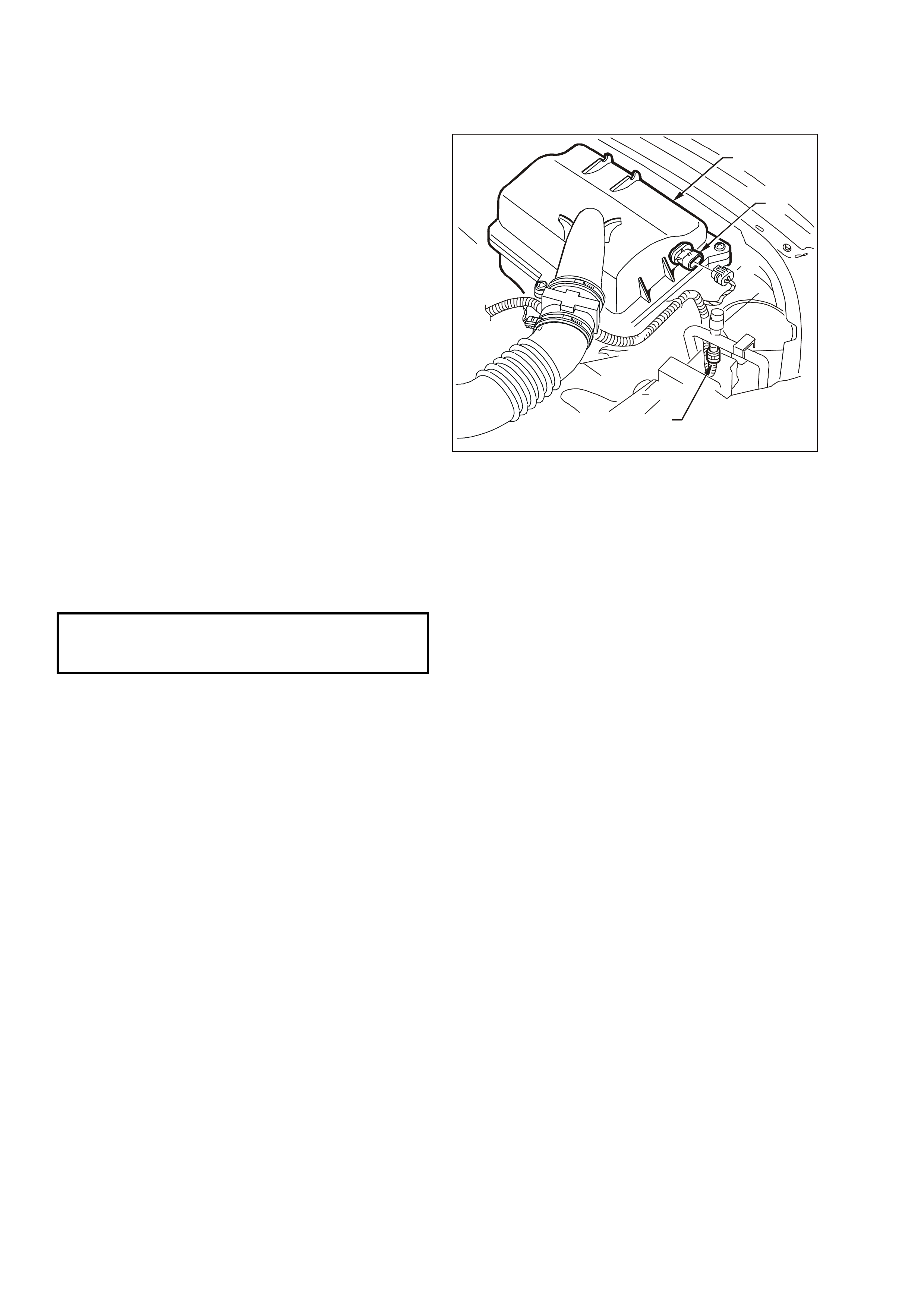
3.21 A/C REFRIGERANT PRESSURE TRANSDUCER
REMOVE
1. Radiator cover panel.
2. Disconnect IAT (1) electrical connector.
3. Remove the air cleaner upper housing (2).
4. Disconnect the electrical connector from the A/C
Refrigerant Pressure Transducer (3).
5. Remove the sensor from the high pressure line
and discard the seal.
NOTE: The sensor is mounted on a schrader type
valve, it is not necessary to discharge the A/C
system.
REINSTALL
1. Fit a new seal to the sensor fitting.
NOTE: Coat the seal with mineral base 525
viscosity refrigerant oil.
2. Install the A/C Refrigerant Pressure Transducer
to the high pressure line and tighten to the
specified torque.
3. Reconnect the A/C refrigerant pressure
electrical connector.
4. Install the air cleaner upper housing.
5. Reconnect the IAT electrical connector.
6. Install the radiator cover panel.
T26C3004
2
1
3
A/C Refrigerant Pressure Transducer Location
A/C REFRIGERANT PRESSURE
TRANSDUCER TIGHTENING
TORQUE
6 Nm (4 lb/ft)
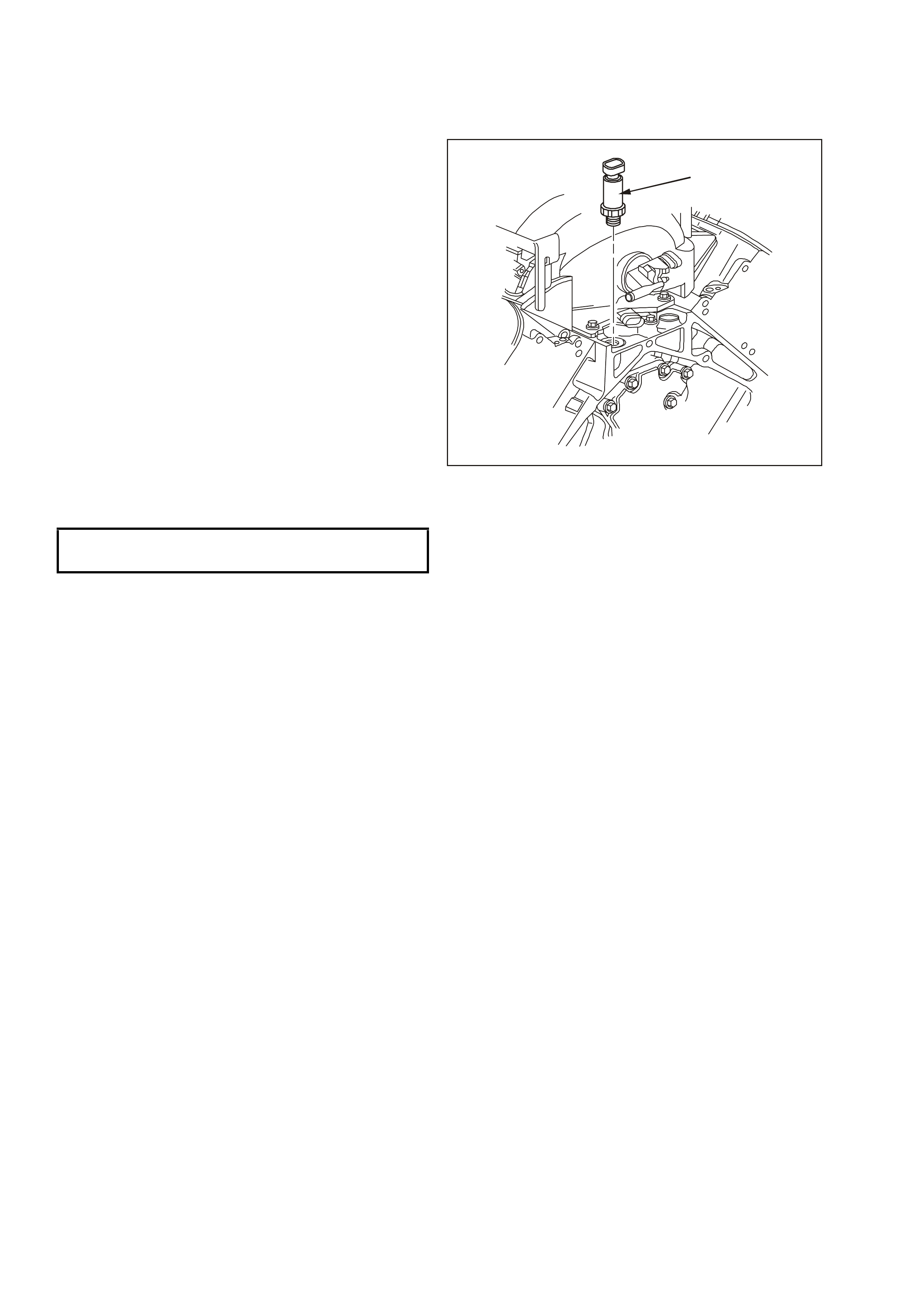
3.22 OIL PRESSURE SENSOR
REMOVE
TOOLS REQUIRED: J 41712 Oil Pressure Sensor
Socket
1. Remove engine dress cover. Refer to Engine
Coolant Temperature Sensor in this Section
for removal procedure.
2. Clean around area of oil pressure sensor (1), so
that no foreign debris will enter engine.
3. Disconnect the oil pressure sensor electrical
connector.
4. Using tool J 41712, remove oil pressure sensor.
REINSTALL
1. Install the oil pressure sensor (1) and tighten to
the specified torque.
2. Connect the oil pressure sensor electrical
connector.
3. Check engine oil level and top up if necessary.
4. Start engine and inspect for leaks.
5. Install engine dress cover.
1
OIL PRESSURE SENSOR
TIGHTENING TORQUE 20 Nm (15/lb ft)
Oil Pressure Sensor
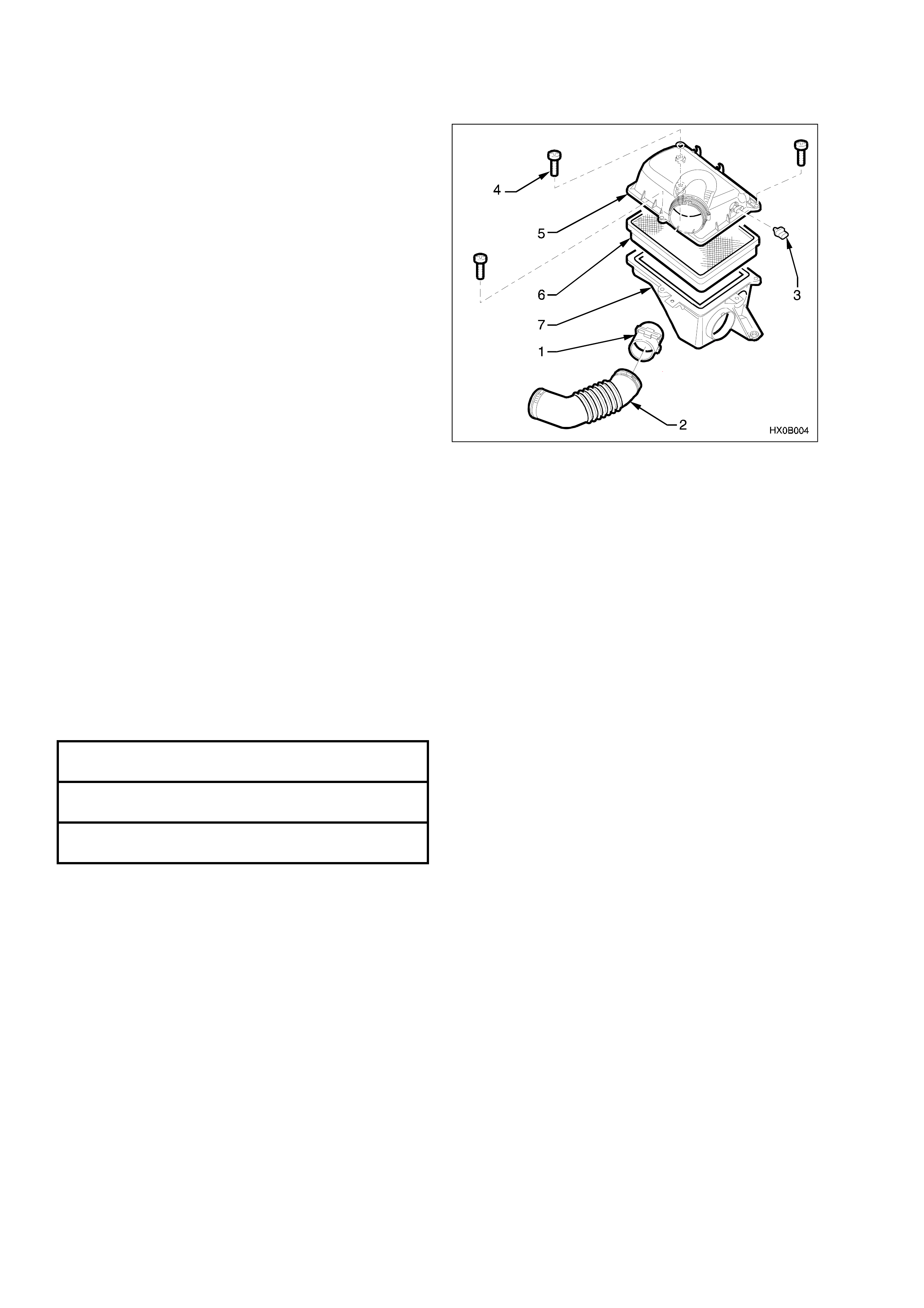
3.23 AIR CLEANER ASSEMBLY
REMOVE
1. Loosen the clamp on the air cleaner assembly
and move MAF sensor (1) to one side.
2. Disconnect air duct (2) from the air cleaner
assembly.
3. Pull up the retaining tang on the IAT sensor (3)
wiring harness connec tor and r emove connec tor
from the sensor.
4. Remove three retainer bolts (4) securing the air
cleaner upper housing (5).
5. Remove air cleaner upper housing and air
cleaner element assembly (6).
6. Rem ove the three retainer bolts securing the air
cleaner lower housing (7) to the fender inner
panel insulators.
7. Disengage the air cleaner lower inlet assembly
from lower housing and remove air cleaner
lower housing.
REINSTALL
1. Assemble the air cleaner lower housing on to
mounting insulators.
2. Install the retaining bolts and tighten to the
correct torque specification.
3. Assemble the air cleaner element into the air
cleaner upper housing and place the upper
housing onto the lower air cleaner housing
4. Install the three retaining bolts securing the top
of the air cleaner housing to the lower housing.
5. Reconnect wiring harness connector to IAT
sensor.
6. Reinstall MAF sens or to air c leaner housing and
tighten clamp.
7. Check that mass air flow sensor wiring harness
connector has remained firmly in place.
Air Cleaner Assembly
AIR CLEANER LOWER
HOUSING BOLTS 7.5-12.5 Nm (5.5-9.2 lb/ ft)
UPPER AIR CLEANER
HOUSING BOLTS 5 Nm (3 lb/ ft)
AIR CLEANER DUCT
CLAMPS 1.5-2.5 Nm (1-2 lb/ ft)