
SECTION 7C4 - HYDRA-MATIC 4L60-E AUTOMATIC
TRANSMISSION - ON-VEHICLE SERVICING
CAUTION:
This vehicle will be equipped with a Supplemental Restraint System (SRS). A SRS will consist of either
seat belt pre-tensioners and a driver's air bag, seat belt pre-tensioners and a driver's and front
passenger's air bags or seat belt pre-tensioners, driver’s and front passenger’s air bag and left and right
hand side air bags. Refer to SAFETY PRECAUTIONS, Section 12M , Supplemental Restraint System of this
Service Information CD before performing any service operation on, or around any SRS components, the
steering mechanism or wiring. Failure to follow the SAFETY PRECAUTIONS could result in SRS
deployment, resulting in possible personal injury or unnecessary SRS system repairs.
CAUTION:
This v ehicle may be equipped w ith LPG ( Liquefied Pet roleum Gas). In th e interests of saf ety, the LPG fuel
system should be isolated by turning ‘OFF’ the manual service valve and then draining the LPG service
lines, before any service work is carried out on the vehicle. Refer to the LPG leaflet included with the
Owner's Handbook for details or the appropriate Section of this Service Information CD for more specific
servicing information.
CAUTION:
Whenever any component that forms part of the ABS or ABS/ETC (if fitted), is disturbed during Service
Operations, it is vital that the complete ABS or ABS/ETC system is checked, using the procedure as
detailed in 4. DIAGNOSIS, ABS or ABS/ETC FUNCTION CHECK, in Section 12L ABS & ABS/ETC, VT
Series I Service Information (V6) or VT Series II Service Information (GEN III V8).
1. GENERAL INFORMATION
Information in this Section, details service operations that can be carried out on a transmission while it is still
installed in the vehicle, as well as the procedures required to remove and reinstall the transmission assembly
from/to the vehicle.
Effective from the start of VT Series II production, the floor pan opening was enlarged to accommodate the gearshift
selector control lever assembly of the 6 speed manual transmission, available with the GEN III V8 engine. This
required a design change f or the selector contr ol lever assem bly for autom atic transm ission equipped m odels, that
has also resulted in the selector control lever assembly, now being completely serviceable.
Only this and other service procedures or specifications that have changed since model introduction, are detailed
here (e.g. V6 Supercharged engine cooling system and GEN III V8 engine related). Therefore, for on-vehicle
service operations not inc luded here, r ef er to 7C4 AUTOM ATIC T RANSMISSION ON -VEHICL E SERVICING of the
VT Series I Service Information.
Techline
Techline
Techline

1.1 GENERAL SERVICE PRECAUTIONS
RECOMMENDA TIONS
W hen servicing the transmission, all parts should be cleaned and inspected as outlined under 'Clean and Inspect',
in these recommendations. Individual units should be reassembled before disassembly of other units to avoid
confusion and interchanging of parts.
1. Thoroughly clean the transmission exterior before removal of any component.
2. Disassembly and reassembly must be made on a clean work bench. Cleanliness is of the utm ost importance.
The bench tools, and parts must be kept clean at all times.
3. Before installing s cr ews and other f as tener s into aluminium par ts , DIP SCREWS INTO T RANSMISSIO N FLUID
(Only use Dexron III) to prevent galling aluminium threads and to prevent screws from seizing.
4. To prevent thread stripping, always use a torque wrench when installing screws.
5. If threads in aluminium parts are stripped or damaged, the part can be made serviceable by the use of
commercially available, thread inserts.
6. Protective tools must be used when assembling seals to prevent damage. The slightest flaw in the sealing
surface of the seal can cause an oil leak.
7. Aluminium castings and valve parts are very susceptible to nicks, burrs, etc., and should be handled with care.
8. Internal snap rings should be expanded and external s nap rings com press ed if they are to be re-used. T his will
ensure proper seating when reinstalled.
9. O-rings, gaskets and oil seals that are removed should not be re-used.
10. Teflon oil seal rings should not be removed unless damaged.
11. During assembly of each unit, all internal moving parts must be lubricated with transmission fluid.
Oil Cooler Pipes
If replacement of transmission steel tubing cooler pipes is required, use only double wrapped and brazed steel
tubing m eeting Holden Specification 123M or equivalent. Under no circum stances is c opper or aluminium tubing to
be used to replace steel tubing. These materials do not have satisf actory fatigue durability to withstand normal car
vibrations.
Steel tubing should be flared using the double flare method.
Clean and Inspect
After complete disassembly of a component, wash all metal parts in a clean solvent and dry with compressed air.
Blow oil passages out and chec k to m ake sur e they are not obstructed. Small pass ages s hould be chec ked with tag
wire. All parts should be inspected to determine which parts are to be replaced.
Pay particular attention to the following:
1. Inspect linkage and pivot points for excessive wear.
2. Bearing and thrust surfaces of all parts should be checked for excessive wear and scoring.
3. Check for broken seal rings, damaged ring lands and damaged threads.
4. Inspect seal and O-rings.
5. Mating surfac es of c astings should be check ed for bur rs. Irregularities m ay be rem oved by lapping the surf ace
with emery paper. The emery paper is laid on a flat surface, such as a piece of plate glass.
6. Castings should be checked for cracks and porosity.
NOTE: Do not use solvents on neoprene seals, composition faced clutch plates or thrust washers as damage to
parts may occur.

2. MAINTENANCE AND GENERAL INFORMATION
2.1 FLUID LEVEL CHECK
GENERAL INFORMATION
W hen adding or c hanging the transm ission fluid, use only Dexron® III (to Holden’s Spec ification HN2126). Ref er to
the Owner's Handbook for servicing intervals.
Because this transmission fluid changes colour and smell very early in its life, these indicators should not
necessarily be relied upon to diagnose either transmission internal condition nor fluid deterioration.
Reference to the Fluid Checking Procedure shows that a dark brown fluid colour, coupled with a delayed shift
pattern, may only indicate that the fluid requires replacement and alone, is not a definite indication of a potential
transmission failure.
NOTE Do not overfill the transmission. Overfilling will cause f oaming of the fluid, loss of fluid, shif t complaints and
possible damage to the transmission.
TRANSMISSION FLUID COLOUR
Transmission fluid colour when new and unused, is red. A red dye is added so that it can be distinguished from
other oils and lubricants. The red dye is not an indicator of fluid quality and is not permanent. As the vehicle is
driven, the transmission fluid will quickly begin to look darker in colour. The colour will then appear light brown.
A DARK brown colour with a distinctively burnt odour MAY indicate fluid deterior ation and a need for the fluid to be
changed.
TRANSMISSION FLUID CHECKING PROCEDURE
1. Start engine and drive vehicle for a distance of 24 km, or until transmission normal operating temperature is
reached.
NOTE: As temperature greatly affects transmission fluid levels, this operation must only be carried out with the
transmission at normal operating temperature (82 - 94° C).
If the vehicle is not at normal operating temperature, and the proper checking procedures are not followed, a false
reading of the fluid level on the dipstick could result.
2. Park vehicle on level ground.
3. With the foot brake firmly applied, move gear selector through each gear range, pausing for approximately three
seconds in each range. Finish in the 'PARK' position.
4. Apply park brake, then let the engine idle for three minutes with accessories turned off.
5 Lift the lock ing lever on the colour ed dipstick , rem ove the dipstick , wipe clean and reinstall. W ait three seconds
then remove again and check fluid colour, condition and level.
6. If the fluid level is low, add only enough Dexron® III to bring the level into the “HOT” area.
! Inacc urate fluid level readings will r esult if checked im mediately after the vehicle has been operated under any
or all of the following conditions:
a. In high ambient temperatures above 32° C.
b. At sustained high speeds.
c. In heavy city traffic during hot weather.
d. Towing.
e. In commercial use (e.g. taxi).
! If the vehicle has been operated under these conditions, switch the engine of f and allow the vehicle to 'cool' f or
approximately thirty minutes. After the cool-down period, re-start the vehicle and continue from step 2.

4L60-E TRANSMISSION FLUID CHECKING PROCEDURE
STEP ACTION YES NO
1. Check the fluid colour.
Is the fluid colour red? Go to Step 2 Go to Step 11
2. Is the fluid level satisfactory ? Go to Step 20 Go to Step 3
3. Check the fluid.
Is the fluid foamy? Go to Step 8 Go to Step 4
4. Check the fluid level. The correct fluid level should be in the
middle of the cross-hatch.
Is the level high?
Go to Step 9 Go to Step 5
5. Fluid will be low.
Add fluid to the correct fluid level.
Is the fluid level satisfactory?
Go to Step 6 Go to Step 1
6. Check for external leaks.
Were any leaks present? Go to Step 7 Go to Step 20
7. Correct the fluid leak condition.
Is action complete? Go to Step 20
8. Is the fluid level too high? Go to Step 9 Go to Step 10
9. Remove excess fluid to adjust to the correct fluid level.
Is action complete? Go to Step 20
10. 1. Check for contaminants in the fluid.
2. Drain the fluid to determine the source of contamination.
Is action complete?
Go to Step 15
11. Is the fluid colour a non-transparent pink? Go to Step 12 Go to Step 13
12. Replace the leaking radiator and cooler assembly.
Is the action complete? Go to Step 15
13. The fluid colour should be light brown. Transmission fluid may
turn dark with normal use. This does not always indicate
oxidation or contamination.
Is the fluid colour light brown?
Go to Step 14 Go to Step 1
14. Drain the fluid to determine if the fluid is contaminated. A very
small amount of material in the bottom of the oil pan is a normal
condition, but larger pieces of metal or other material in the
bottom of the oil pan are not and the transmission requires an
overhaul.
Was the fluid contaminated?
Go to Step 15 Go to Step 18
15. Overhaul the transmission or fit a SRTA unit. Refer to Section
7C5 Unit Repair of the VT Series I Service Information.
Is action complete?
Go to Step 16
16. Flush the cooler/s.
Is action complete? Go to Step 17
17. Add new fluid.
Is action complete? Go to Step 19
18. Change the fluid and filter.
Is action complete? Go to Step 19
19. Is the fluid level satisfactory? If not, correct as necessary.
Is action complete? Go to Step 20
20. Refer to Functional Test Procedure, in Section 7C3,
AUTOMATIC TRANSMISSION – HYDRAULIC/MECHANICAL
DIAGNOSIS of the VT Series II Service Information.
Is action complete?
Fluid Checking
Procedure
Completed
2.2 FLEXPLATE AND/OR TORQUE CONVERTER VIBRATION TEST
Should an im balance condition with either of these
two components be suspected, then the following
procedures should be followed. If this condition is
detected on any V6 engined model, then refer to
7C4 AUTOMATIC TRANSMISSION ON-VEHICLE
SERVICING of the VT Series I Service Information.
EVALUATION – GEN III V8 ENGINE
1. Start the engine and run until normal operating
temperature is reached.
2. With the engine at idle speed and the
transmission in "PARK" or "NEUTRAL", observe
the vibration condition.
3. Stop the engine.
RECTIFICATION – GEN III V8 ENGINE
1. Disconnect the battery earth connection.
2. Remove the starter motor. Refer to Section
6D3-2 STARTING SYSTEM - GEN III V8
engine, of the VT Series II Service Inform ation,
for the necessary procedure.
3. Rais e the vehic le and suppor t on s af ety stands.
Refer 0A GENERAL INFORMATION, of the
VT Series I Service Information for location of
recommended jacking and support points.
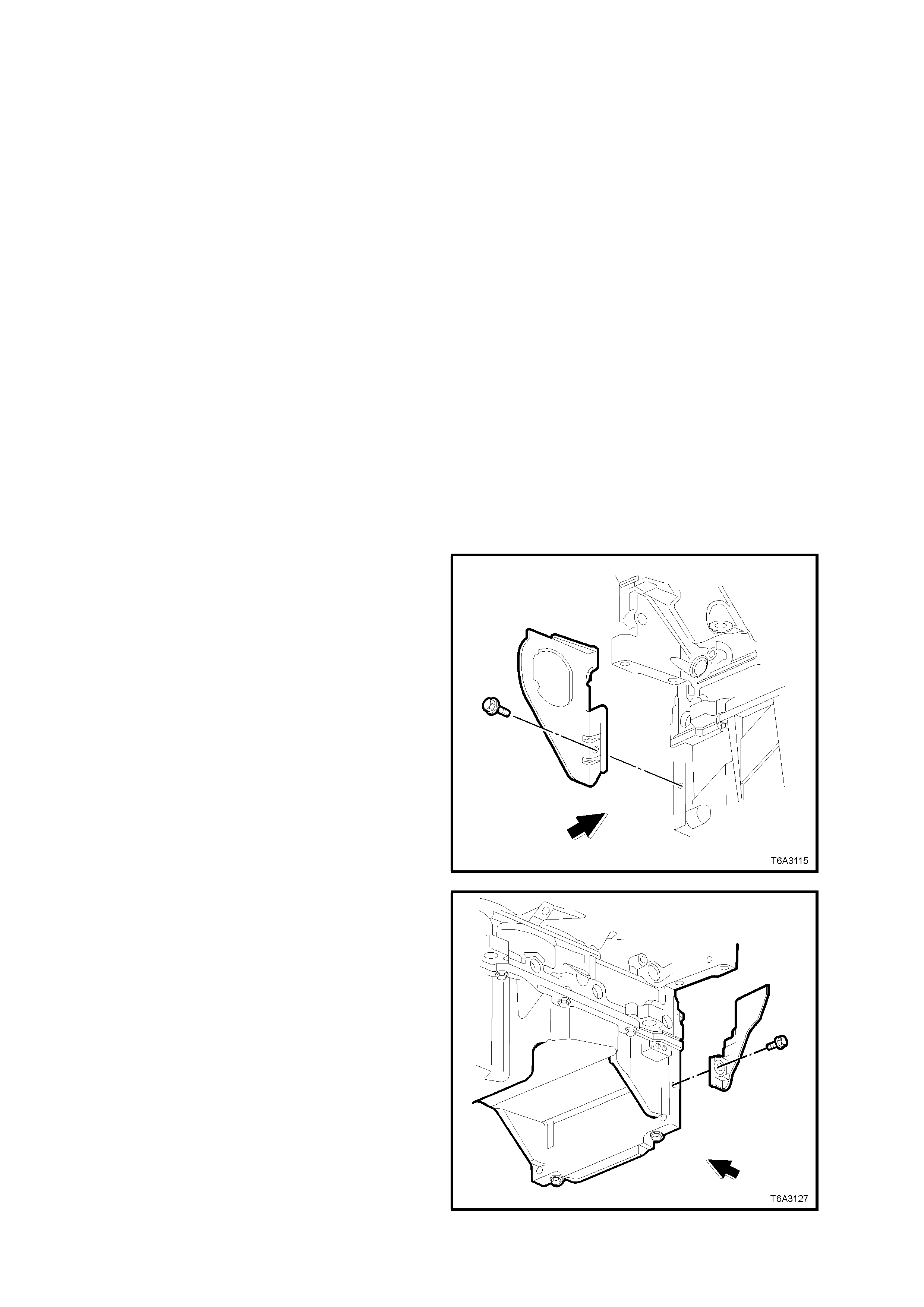
4. Remove the right hand close-out cover and
bolt.
5. Rotate the engine drive plate by hand, using a
suitable lever in the ring gear teeth, until a
torque converter to engine flexplate bolt
becomes accessible.
6. While locking the flexplate by inserting a
screwdriver blade or similar into the ring gear
teeth, remove the exposed torque converter to
engine flexplate bolt.
7. Rotate the f lexplate by one third of a turn, then
repeat step 6, until the three bolts have been
removed.
8. Rotate the torque converter through 1/3 turn
and reinstall the attaching bolts, after having
cleaned the threads an applying a thread
sealant such as Loctite 242 or equivalent to
Holden’s Specification HN1256, Class 2, Type
2. Tighten bolts to the correct torque
specification.
TORQUE CONVERTER TO
FLEXPLATE BOLT 60 - 70 Nm
TORQUE SPECIFICATION
9. Reinstall the right hand close-out cover and
bolt, then tighten to the correct torque
specification.
CLOSE-OUT COVER BOLT
TORQUE SPECIFICATION 10 – 14 Nm
10. Reinstall the starter motor, refer to Section
6D3-2 STARTING SYSTEM - GEN III V8
engine, of the VT Series II Service Information.
11. Start the engine and check for vibration.
Repeat the above procedure until the best
possible balance is obtained.
Figure 7C4-1

2.3 TRANSMISSION COOLER REVERSE FLUSH AND FLOW RATE CHECK –
ALL ENGINES
It is essential that a reverse flush and oil cooler flow rate check is performed, after ANY of the following
situations:
• Transmission replacement.
• If fluid contamination is suspected.
• Whenever the oil pump and/or torque converter is replaced.
NOTE: The reverse flush must be completed prior to conducting a flow rate check.
REVERSE FLUSH
The rec ommended procedur e f or rever se flushing the trans mission c ooler and lines , par ticular ly after an overhauled
or replaced transmission has been installed into the vehicle, is as follows:
1. Disconnect both cooler lines at the transmission and at the radiator cooler. Use a back-up spanner to hold
unions, to prevent damage to the lines.
2. Caref ully check the cooler inlet fitting (lower right hand s ide) to see whether any material is evident at this point.
If so, dis lodge and rem ove with a suitable tool and/or com pr essed air blown in the reverse direc tion through the
cooler.
3. Using a commercially available pressure spray gun and clean solvent, such as white spirit:
a. Back flush through both cooler lines.
b. Back flush through the cooler/s, including the external cooler (if fitted).
c. Blow compressed air through return and inlet pipes to remove solvent.
d. Flush pipes with transmission fluid.
4. Reconnect cooler lines to the transmission and cooler but leave the cooler return line to transmission
connection open.
5. Conduct a flow rate test as described below, to ensure that any restriction has been cleared.
6. If flow rate is satisfactory, reconnect the return line to the transmission, tightening all fittings to the specified
torque.
OIL COOLER PIPES TO
TRANSMISSION FITTING 35 – 41 Nm
TORQUE SPECIFICATION (All Engines)
OIL COOLER HOSE TO RADIATOR 25 – 30 Nm
PIPE TORQUE SPECIFICATION (V6 Engines Only)
7. Lower vehicle and check fluid level as detailed in 2.1 FLUID LEVEL CHECK, in this Section.
FLOW RATE CHECK
CAUTION: Do not run engine any longer than absolutely necessary, as too low a fluid level can cause
aeration and foaming.
1. When installing the transmission assembly, leave the cooler return line disconnected from the transmission
(upper fitting).
2. Ensure that the fluid level is to the recommended level, as detailed in 2.1 FLUID LEVEL CHECK, in this
Section.
3. Place a container underneath the disconnected cooler line.
4. With the selector lever in the Neutral position, start the engine and observe the fluid flow into the container, after
all air bubbles have ceased and a steady flow is evident. Measure the flow rate.
Result: The fluid flow rate should be approximately 0.7 litre in a 20 second period, WITH COLD AUTOMATIC
TRANSMISSIO N FLUID (AT F). W ith ATF at nor mal operating tem perature (86 – 93 °C), the f low rate will increase
and should be approximately 1.2 litres in a 20 second period.
If the f low rate is less than this s pecification, the s ource of the restriction m ust be located and rect ified. Possibilities
are either radiator tank cooler, faulty flexible hoses and/or external cooler (if fitted).
5. Reinstall the cooler return line to the transmission and tighten all fittings to the specified torque.
OIL COOLER PIPES TO
TRANSMISSION FITTING 35 – 41 Nm
TORQUE SPECIFICATION (All Engines)
OIL COOLER HOSE TO RADIATOR 25 – 30 Nm
PIPE TORQUE SPECIFICATION (V6 Engines Only)
3. ON-VEHICLE SERVICE OPERATIONS
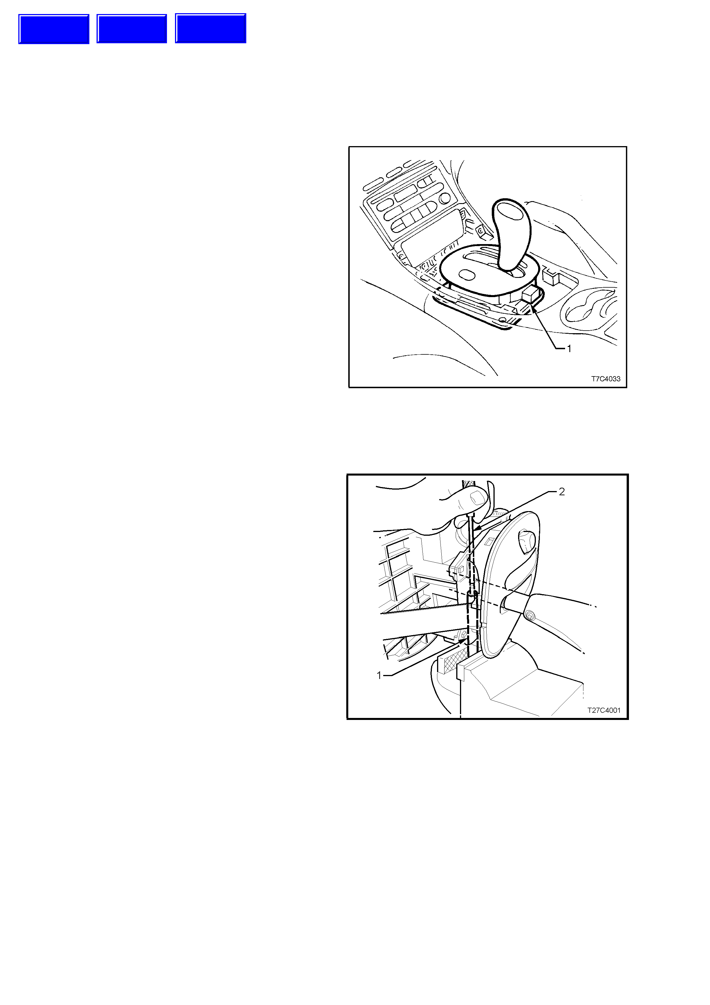
3.1 SELECTOR CONTROL LEVER ASSEMBLY
REMOVE
1. Raise vehicle and place on safety stands.
Refer 0A GENERAL INFORMATION of the VT
Series I Service Information for the location of
recommended jacking points.
2. Remove centre console insert (refer
1A3 INSTRUMENT PANEL AND CONSOLE,
of the VT Series I Service Information).
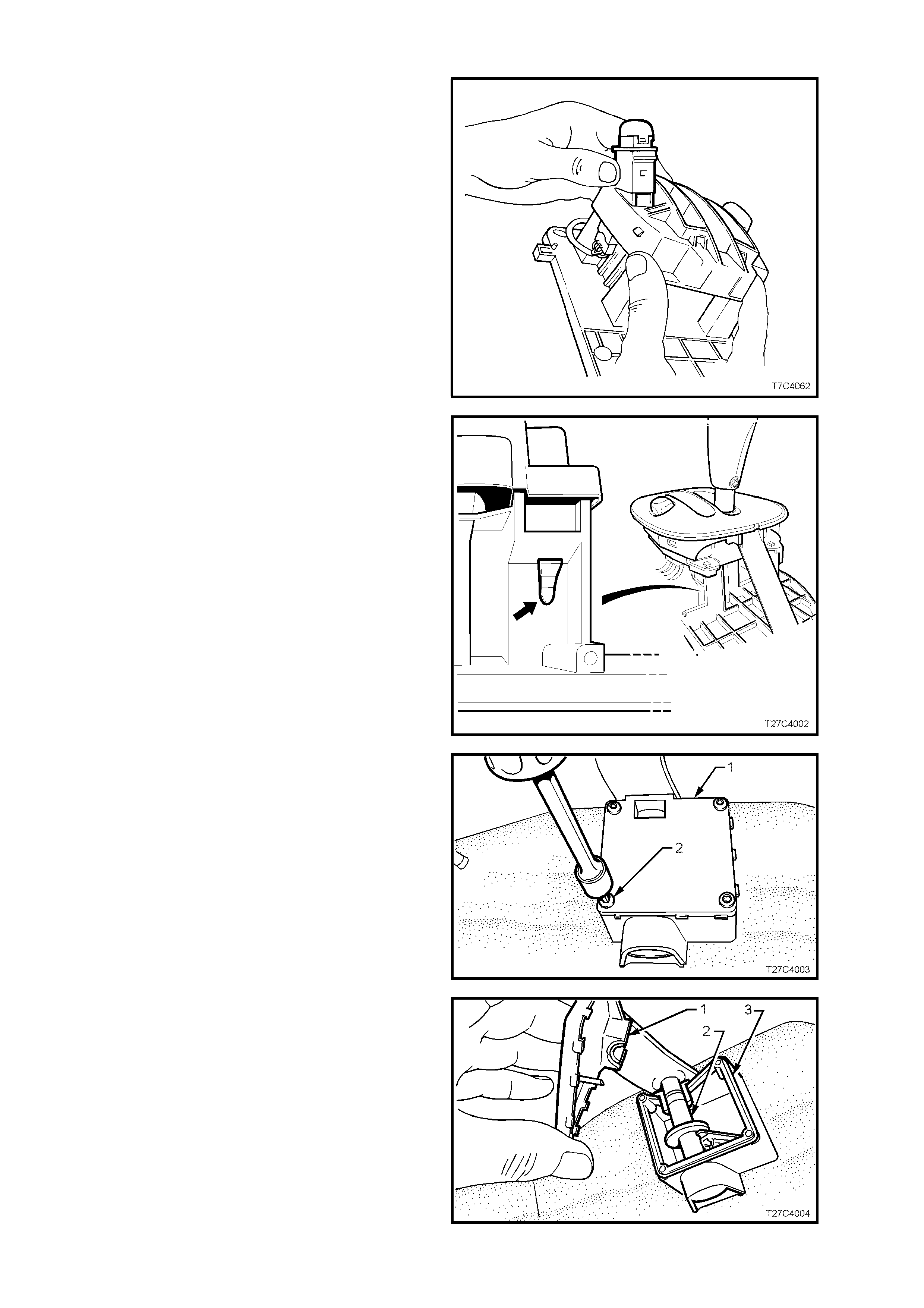
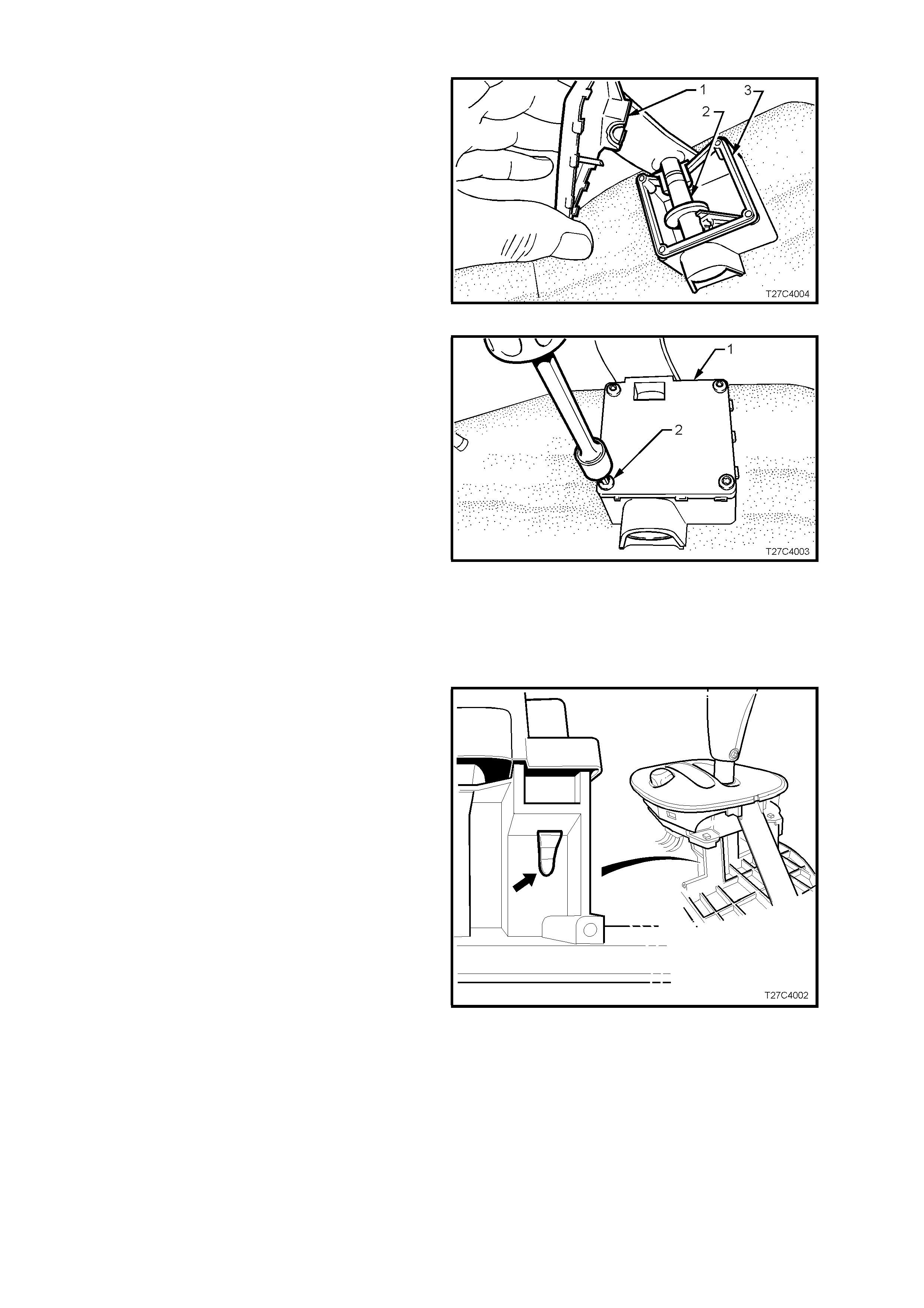
3. Disconnect the wiring harness connector (1)
from the control lever assembly patch harness.
4. From beneath vehicle, disconnect rod from
selector lever by removing bolt securing
trunnion to lever (refer to
3.2 SELECTOR LINKAGE in 7C4 ON-
VEHICLE SERVICING, of the VT Series I
Service Information).
5. Remove the f our nuts s ec uring the control lever
assembly to the floor pan.
6. From inside the vehicle, lift the control lever
assembly from the floor pan.
Figure 7C4-2
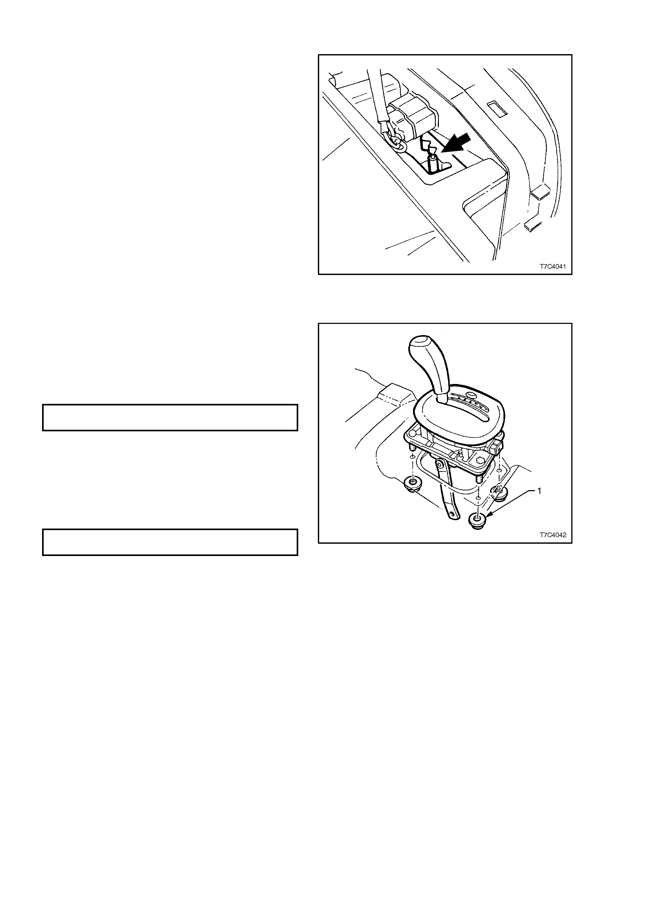
DISASSEMBLE
1. Clamp a 100 mm length of suitable diameter
tubing (1) such as 8 mm ID, vertically in a
bench vice, as shown.
2. Select the ‘Park’ position and locate the
protruding end of the selector lever roll pin,
over the tubing, on the metal side of the
selector handle.
3. Using a suitable sized pin punch (2) and
hammer, remove the roll pin.
Figure 7C4-3
Techline
Techline
Techline
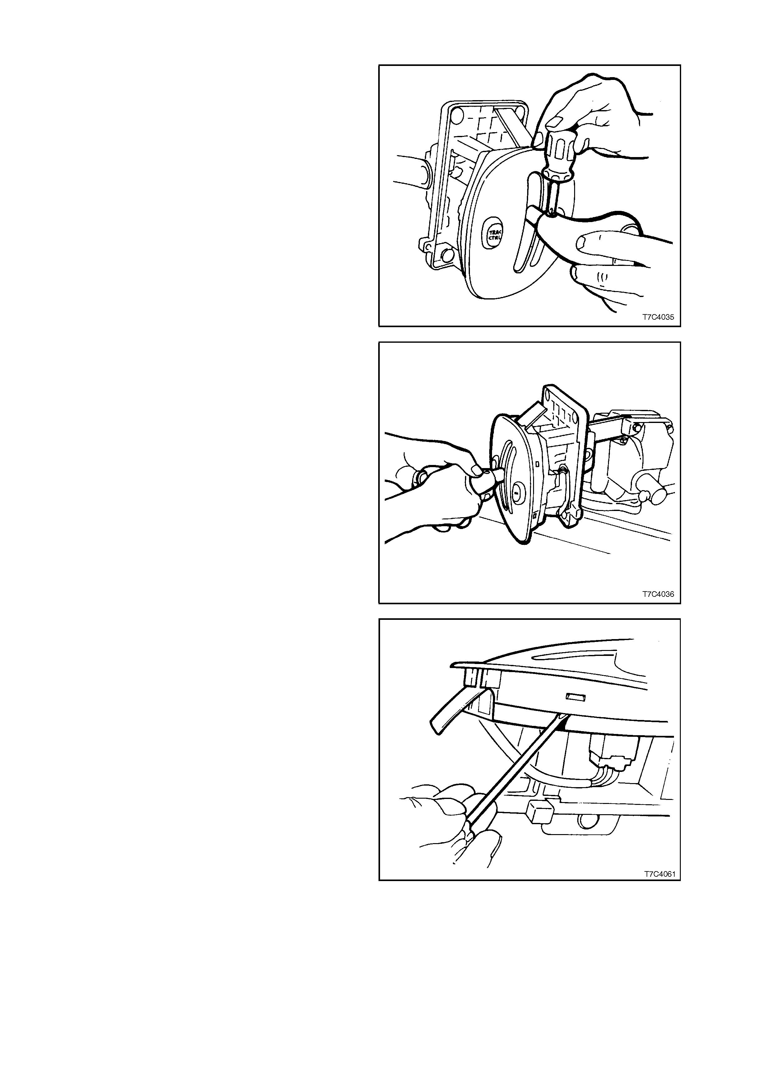
4. Remove the selector handle securing screw.
Figure 7C4-4
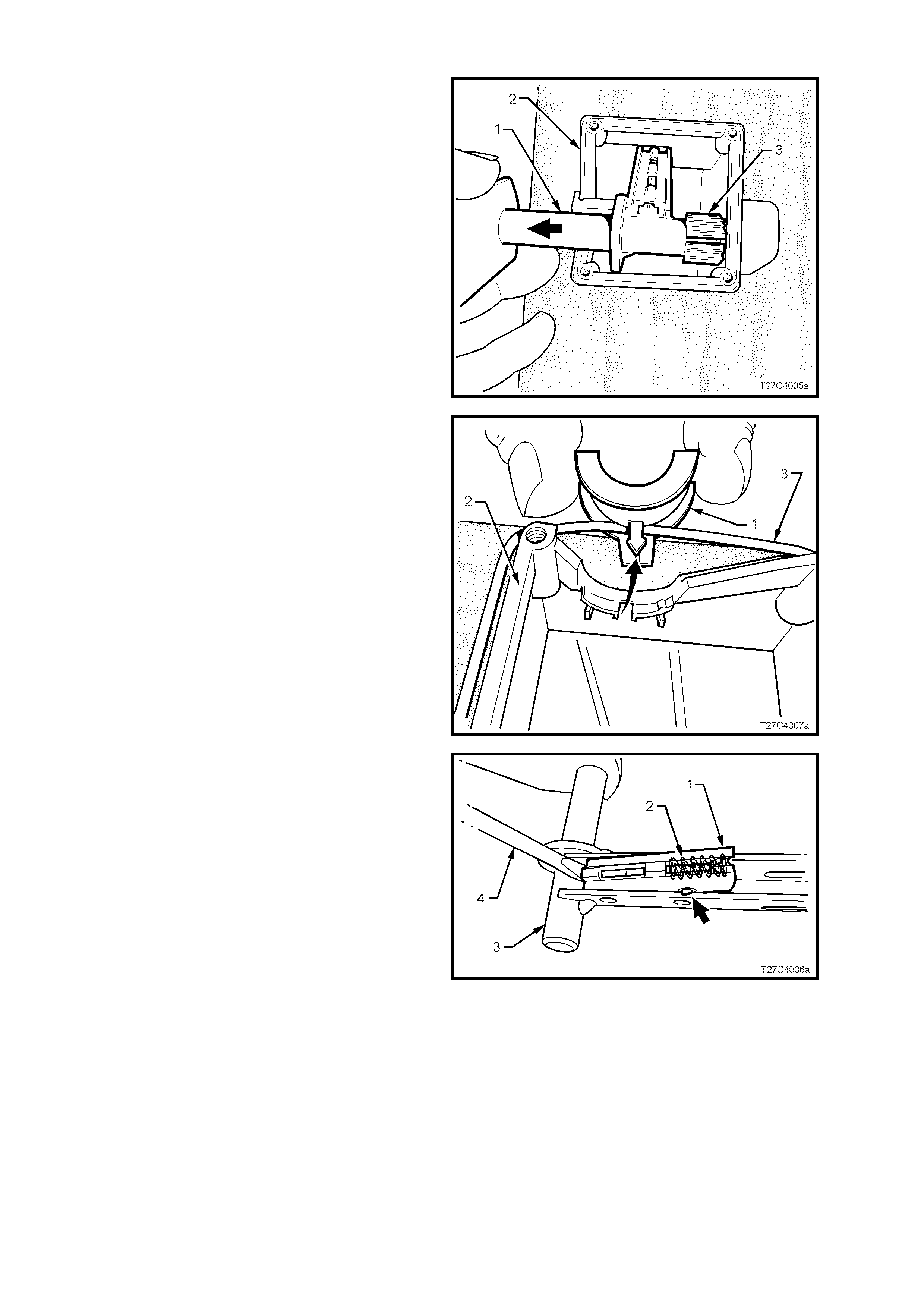
5. With the lower select or lever clam ped in a vic e,
hold the selector knob as shown and remove
by roc king bac k and for th while firm ly pulling on
the handle.
6. Remove the selector knob, button slider and
slider spring from the selector handle. The
lower slider guide (and lower s pr ing) will rema in
in the handle.
Figure 7C4-5
7. Carefully prise the upper housing from the
lower, freeing the four locating tangs.
NOTE: If more convenient, the lower housing can
be separated from the base plate. See step 12 in
this Disassembly procedure.
Figure 7C4-6
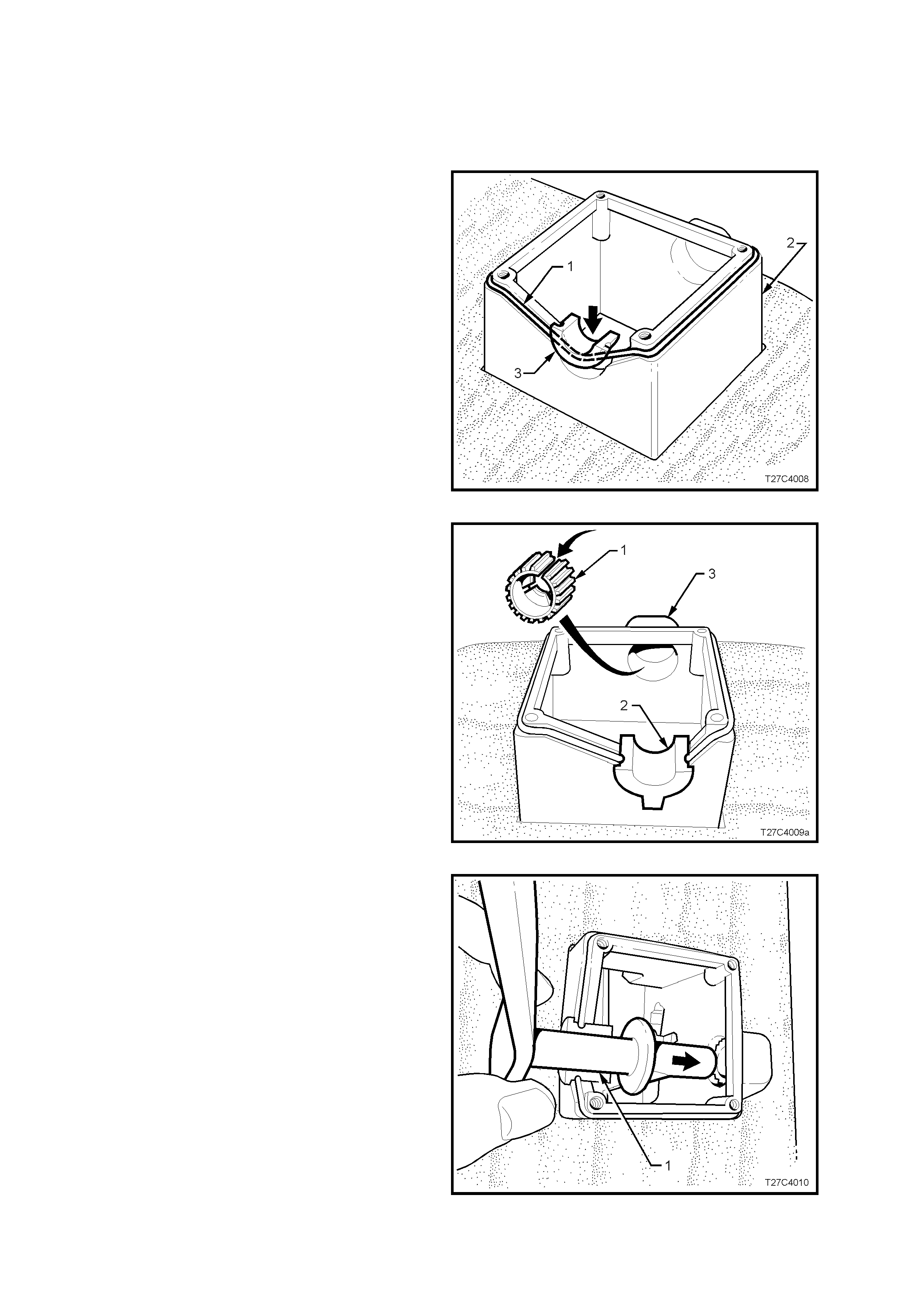
8. Rem ove the selec tor indicator globe and holder
from the lower housing and the patch harness
connector/s from the switch/es. Release the
wiring harness connector from the lower
housing and remove the patch harness from
the selector lever mechanism.
NOTE: The patch harness connectors are different
colours; White for the ‘PWR’ switch and Black for
the ‘TRAC CTRL’ switch (if fitted).
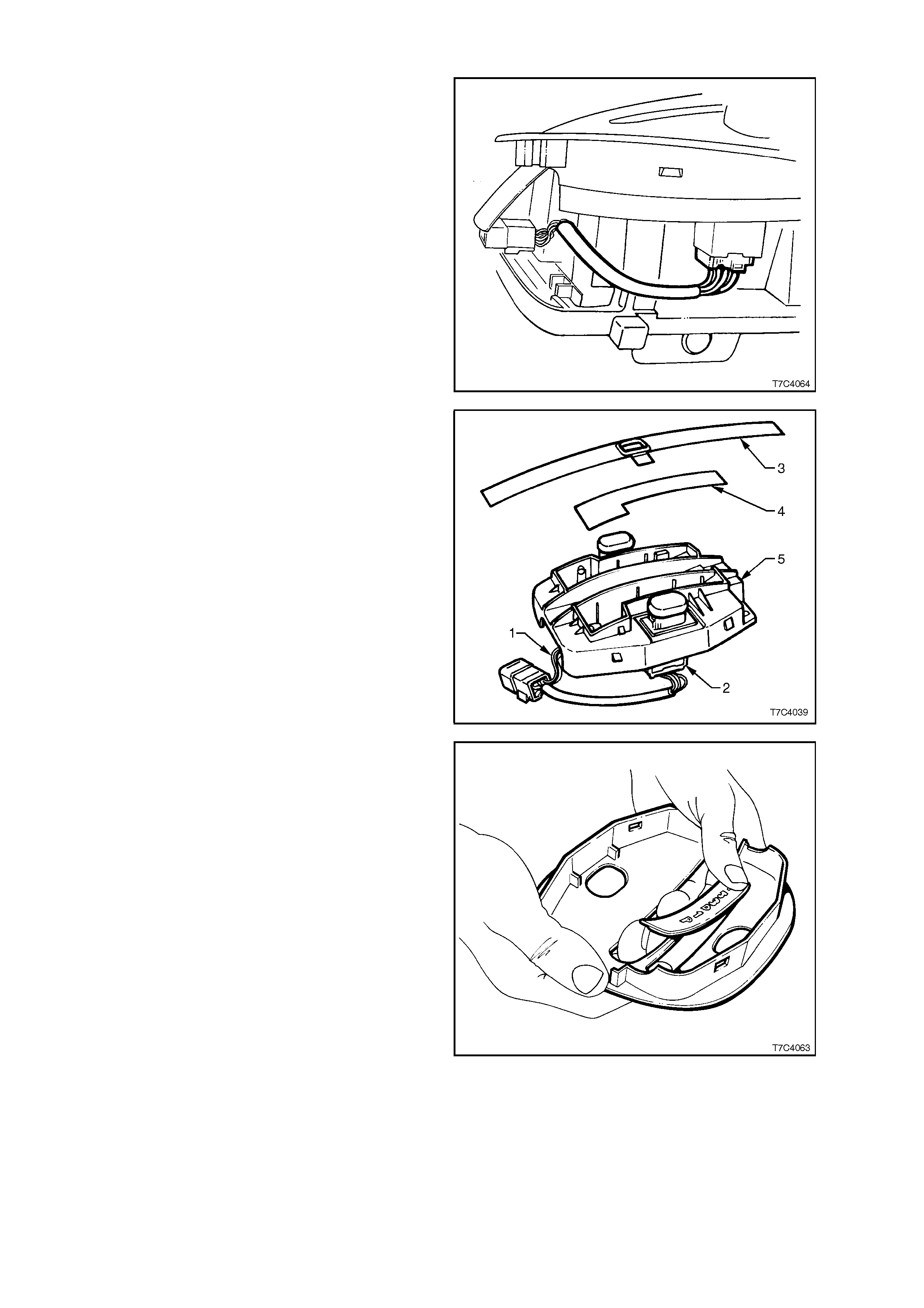
Figure 7C4-7
9. Remove the selector slide indicator (3) and
globe diffuser (4) from the lower housing (5).
Figure 7C4-8
10. If required, the selector indicator lens can be
removed from the upper housing by pressing
from the outside, inwards.
Figure 7C5-9
11. To remove the ‘PWR’ switch or ‘TRAC CTRL’
switch ( if f itted), us e a s mall bladed sc rewdriver
and lever one of the locating tangs under the
lower housing to free the switch. Remove from
above, as shown.
Figure 7C4-10
12. To separate the lower housing from the base
plate, use a small bladed screwdriver to
depress eac h of the four retaining tangs on the
lower housing (arrow), while applying a
separating force to both components.
Figure 7C4-11
13. To dismantle the base (1), use a T15 Torx bit
and suitable socket equipment to remove the
four Torx screws (2), securing the lower
bearing plate to the base.
Figure 7C4-12
14. Lif t the lower bearing plate ( 1) free to reveal the
shift lever s haf t (2 ) and the bear ing plate O- r ing
seal (3).
NOTE: The outer bearing half is formed as part of
the lower bearing plate.
Figure 7C4-13
15. Lift the selector lever and handle (1) free from
the base (2), by lifting up and to the left (arr ow),
to clear the inner bush (3).
16. Slide the inner bush (3) from the shaft and set
to one side (the bush may stay in the housing
when the shaft is removed).
NOTE: The inner bush is index ed to the bor e of the
base plate.
Figure 7C4-14
17. Separ ate the upper bush (1) half from the base
(2) by prising free with a screwdriver blade to
free the inner barbed locating tang (arrow).
18. Lift the sealing O-ring (3) from the base and
discard, as it must be replaced on reassembly.
Figure 7C4-15
19. If requir ed, the lower slider guide (1) and spring
(2) can be removed from the handle (3) by
prising free with a small bladed screwdriver (4).
Figure 7C4-16
REASSEMBLE
Reassembly is the opposite of the disassembly
process, noting the following points:
1. If the lower slider guide was removed during
the disassembly process, carefully check that
damage has not been caused to the four
retaining protrusions on the sides of the slider
guide (arrow in Fig. 7C4-16). Replace as
required.
2. Before installation of the lower slider guide,
apply multi-purpose chassis grease such as
NLGI No. 1 Lithium grease (meeting Holden
Specification HN 1225) to the inner surfaces,
then press into place in the handle, ensuring
that the retaining protrusions are all engaged.
Install the lower slider guide spring, retaining
with the previously applied grease.
3. Fit a NEW O-ring seal (1) around the lower
aperture of the base (2) and secure by
installing the upper bush half (3), ensuring that
the locking barb is fully installed into the base.
Figure 7C4-17
4. Apply multi-purpose chassis grease such as
NLGI No. 1 Lithium grease (meeting Holden
Specification HN 1225) to the inner bush (1)
and the upper half of the outer bush (2).
5. Install the inner bush (1) to the base (3),
aligning the split in the bush (arrow) with the
key in the bush bore of the base (3).
Figure 7C4-18
6. Install the shift handle shaft through the base,
align the inner pin and install the shaft to the
previously installed, inner bush.
Figure 7C4-19
7. After applying multi-purpose chassis grease
such as NLGI No. 1 Lithium grease (Holden
Specification HN 1225) to the lower half of the
shaft bush, install the lower cover (1) to the
base (3), ens uring that the O - ring seal (2) is not
displaced.
Figure 7C4-20
8. Secure cover (1) by installing four screws (2),
tightening with a T15 Torx bit and suitable
socket equipment. Do not over-tighten screws.
Figure 7C4-21
9. Before reinstallation, either switch can be
tested by referring to
Section 12L, ABS & ABS/ETC, of the VT
Series I Service Information, as both switches
are the same.
10. When reinstalling the lower cover assembly to
the base, ensure that the four retaining barbs
(arrow) are fully engaged in the base. Four
distinct ‘clicks’ should be heard.
Figure 7C4-22
11. W hen installing the roll pin to the button slider,
it will be helpf ul to us e a guide pin to as sis t with
hole alignment. Use the tube clamped in vice
jaws as described for removal, bearing against
the metal side of the selector handle.
Important: Careful alignment of the selector
handle and the button slider is required, if
irreparable damage to the button slider is to be
avoided.
12. Install the pin sufficient to engage each of the
moulded selector detents in the base (arrow).
Figure 7C4-23
REINSTALL
1. Clean m ating surfaces of floor pan and inspect
the base seal for damage, replacing if
necessary.
2. Reinstall selector lever assembly to the floor
pan, install the four retaining nuts (1) and
tighten to the correct torque specification.
SELECTOR BASE RETAINING
NUT TORQUE SPECIFICATION 12 - 18 Nm
3. The remainder of the reinstallation is the
reverse of the removal procedure.
4. Adjust shift linkage as detailed in
3.2 SELECTOR LINKAGE in 7C4 ON-
VEHICLE SERVICING, of the VT Series I
Service Information). Tighten the selector rod
locking bolt to the correct torque specification.
SELECTOR LEVER LOCKING
BOLT TORQUE SPECIFICATION 15 - 35 Nm
Figure 7C4-24
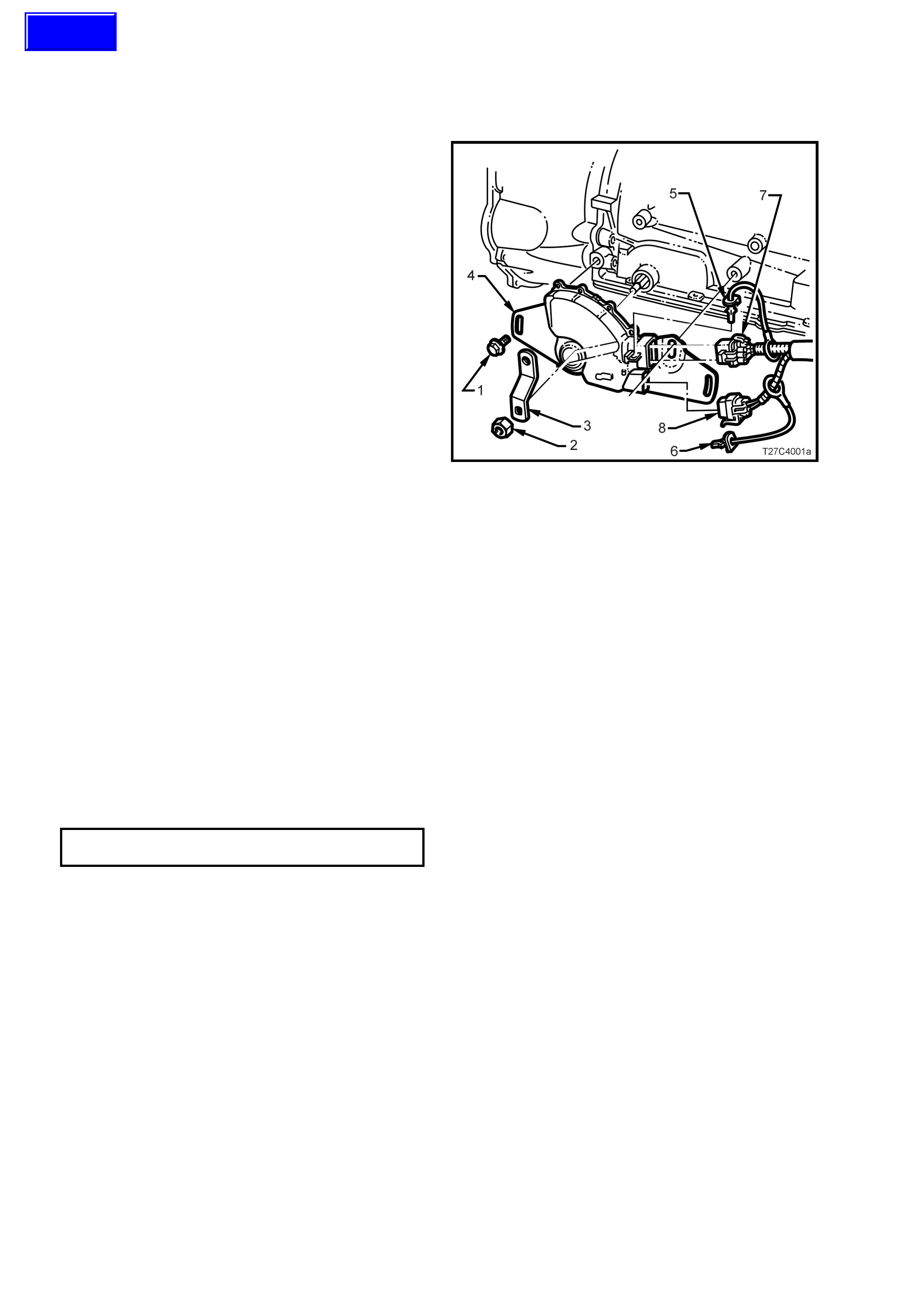
3.2 NEUTRAL START AND BACK-UP LAMP SWITCH
REMOVE
1. Raise the front of the vehicle and place on
safety stands. Refer to Section 0A, GENERAL
INFORMATION of the VT Series I Service
Information for the location of recommended
jacking points.
2. While holding the lower selector lever (3) with
an adjus table wrench, r emove the retaining nut
(2).
3. Carefully remove the lever (3) from the
transmission manual shaft.
4. Prise the wiring harness connector CPA
(Connector Position Assurance) securing pins
(5 and 6) from the neutral start and back-up
lamp switch (4), taking care not to break the
pins in the process. Disconnect the two wiring
harness connectors (7) from the switch
assembly (8).
5. Remove the two switch retaining screws (1),
then slide the switch assembly (4) over the
manual shaft and remove from the vehicle.
NOTE: Connector ‘8’ and the CPA ‘6’, will only be
fitted to those vehicles where the PRNDL indicator
is in the instrument panel.
Figure 7C4-25
REINSTALL
Reinstallation of the neutr al start and back-up lam p
switch is the reverse of the removal procedure
except for the following:
1. When installing the two switch securing
screws, leave them finger tight, until the
adjustment process has been completed.
2. After installing the selector lever and retaining
nut, hold the lever with an adjustable wrench
and tighten the nut to the correct torque
specification.
SELECTOR LEVER RETAINING
NUT TORQUE SPECIFICATION 15 - 35 Nm
3. Check the selector linkage adjustment. Refer
3.2 SELECTOR LINKAGE, in 7C4
AUTOMATIC TRANSMISSION ON-VEHICLE
SERVICING of the VT Series I Service
Information.
4. On completion of the neutral start and back-up
lamp s witch adjustment pr ocedure that follows,
check that the engine can only be started when
the gearshift lever is either in the ‘P’ (Park) or
‘N’ (Neutral) positions.
Techline

ADJUST
1. With the vehicle raised, rotate the neutral start
and back-up lamp switch back and forth until
the best ‘neutral’ position is attained, then
lightly tighten the front bolt to retain.
2. With the ignition switched to the ON position,
check that the engine can be started in both
the Park and Neutral selector positions only. A
further light adjustment may be required to
achieve this state.
Also chec k that the engine will not crank in any
of the remaining s elector positions and that the
Reverse lamps illum inate when Reverse range
is selected.
3. After switch adjustment, tighten the switch
retaining bolts to the correct torque
specification.
NOTE: To gain access to the rear bolt, it will be
necessar y to rem ove the wiring harness connec tor.
Following the bolt tightening procedure, reinstall the
connector/s and the CPA securing pin/s.
NEUTRAL START & BACK-UP
LAMP SW ITCH RETAINING BOLT 15 - 35 Nm
TORQUE SPECIFICATION
4. Lower the vehicle to the ground and check the
operation of the neutr al start and back -up lamp
switch. The vehicle should only start in either
‘P’ (Park) or ‘N’ (Neutral) ranges and the
reverse lamps should only illuminate when the
‘R’ (Reverse) range is selected.
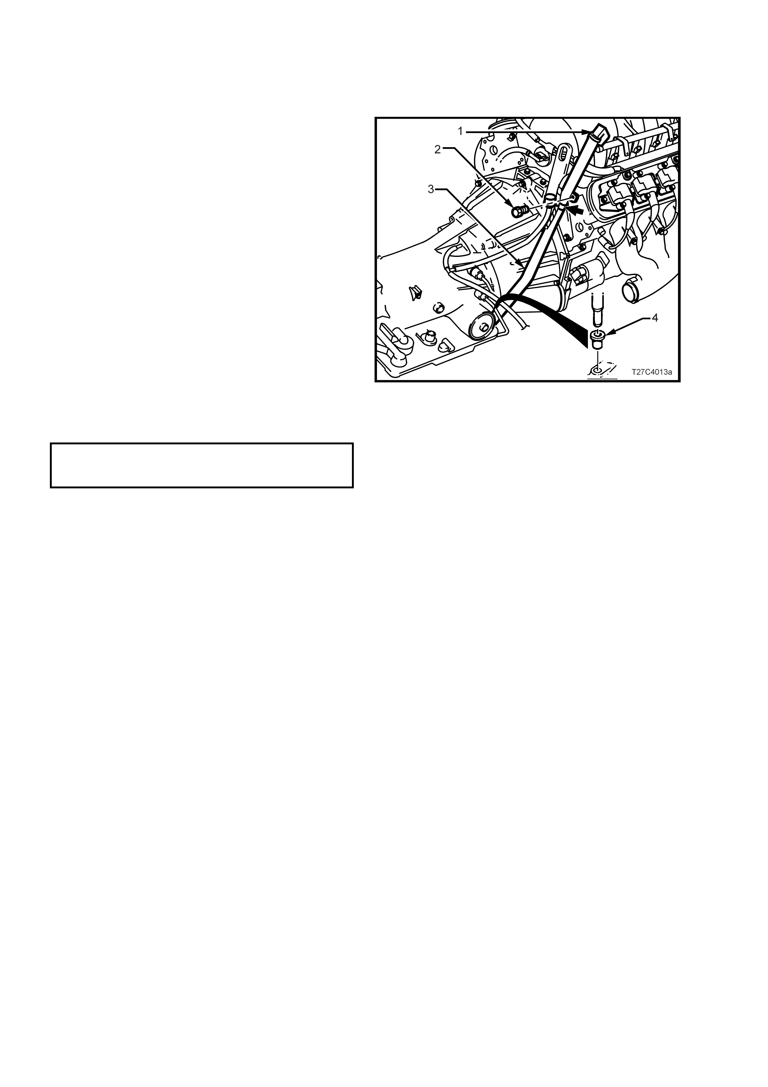
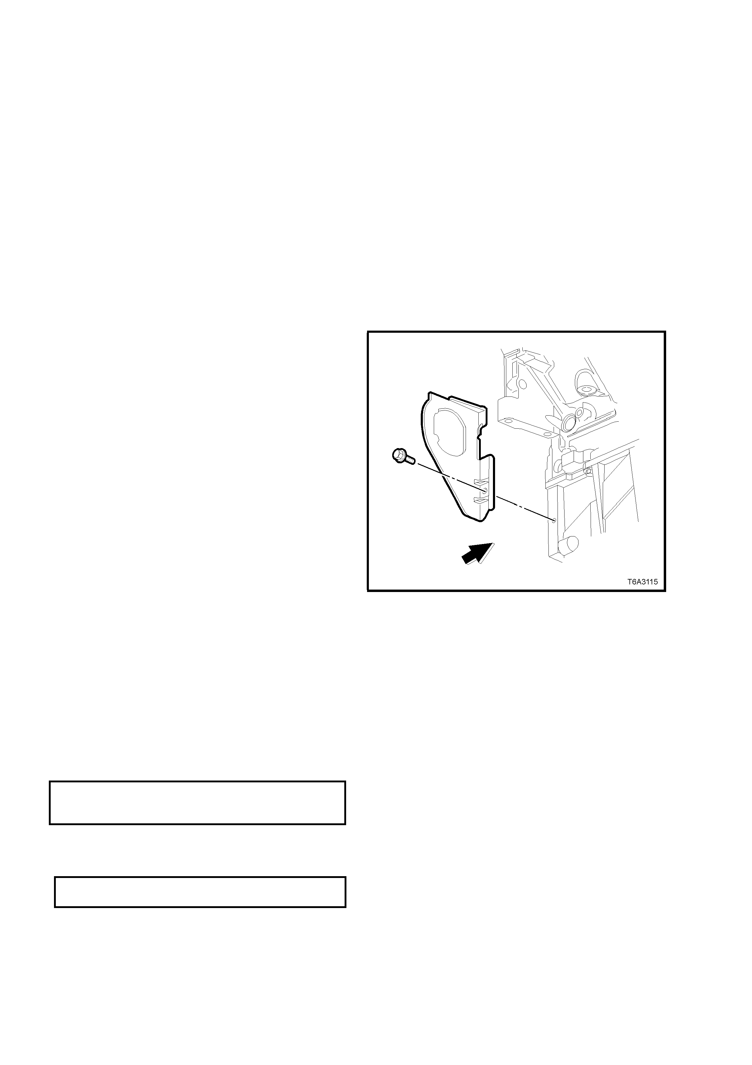
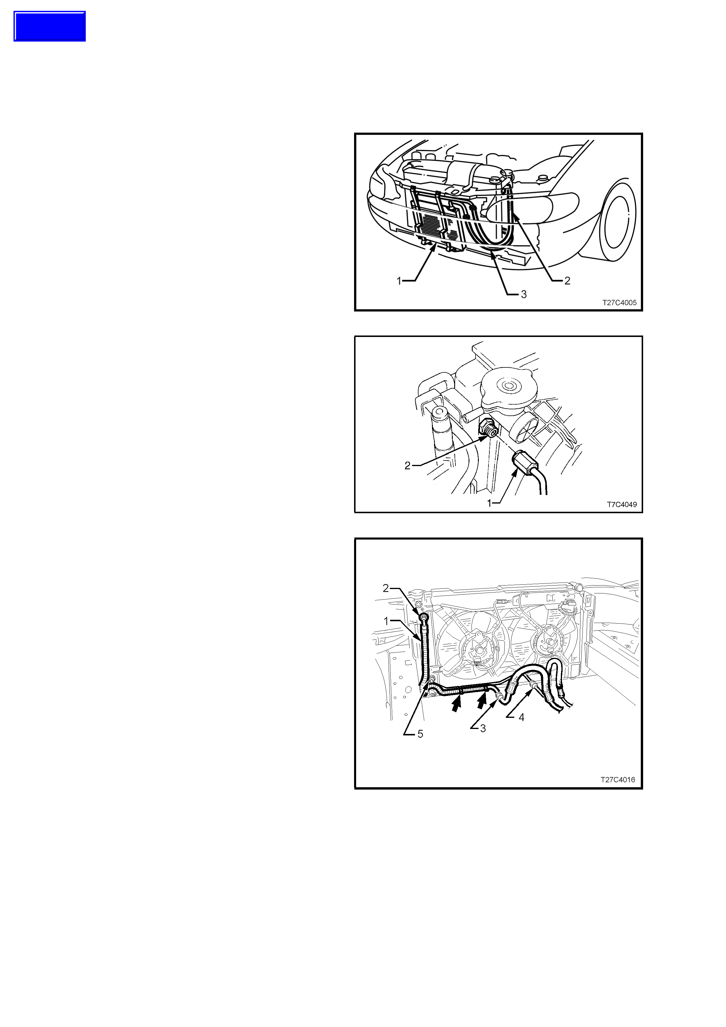
3.3 FILLER TUBE – GEN III V8 ENGINE
REPLACE
1. Disconnect the battery earth lead.
2. Release the dipstick lock down lever (1) and
remove the transmission dipstick.
3. Rem ove the bolt (2) secur ing transmis sion filler
tube (3) to the right hand cylinder head.
4. Using a twisting/pulling motion, remove filler
tube (3) from the transmission case seal (4).
5. Release the transmission breather tube from
the dipstick bracket (arrow), after lowering the
dipstick enough to gain access.
6. Lubr ic ate a new the filler tube s eal (4) , lubr icate
with transmission fluid and install into
transmission case .
7. Reinstall the filler tube (2) in the reverse order
to removal but secure the transmission
breather hose to the hole in the filler tube
brack et (arrow), bef ore the tube is installed into
the transmission case seal (4).
8. Tighten the filler tube bracket retaining bolt (2)
to the correct torque specification.
FILLER TUBE RETAINING
BRACKET BOLT 20 - 30 Nm
TORQUE SPECIFICATION
Figure 7C4-26
3.4 TRANSMISSION ASSEMBLY – GEN III V8 ENGINE
REMOVE
1. Disconnect the battery earth lead.
2. Raise vehicle and place on safety stands.
Refer to Section 0A, GENERAL
INFORMATION of the VT Series I Service
Information for the location of recommended
jacking points.
3. Place drip tray beneath transmission.
4. Remove the filler tube retaining bolt from the
rear of the right hand cylinder head. Refer
3.2 FILLER TUBE – GEN III V8 ENGINE.
5. Plug filler tube hole to prevent dirt entry.
6. Remove propeller shaft assembly: Refer to
4C PROPELLER SHAFT AND UNIVERSAL
JOINTS of the VT Series I Service Information.
7. Disconnect electrical connectors from vehicle
speed sensor, oxygen sensors and neutral
back up lamp switch.
8. Hold the transmission selector lever with an
adjustable wrench while loosening the retaining
nut. Remove the selector lever from the
manual shaft.
9. Remove the starter motor. Refer to Section
6D3-2 STARTING SYSTEM - GEN III V8
engine, of the VT Series II Service Inform ation,
for the necessary procedure.
10. Remove the right hand close-out cover and
bolt.
11. Rotate the engine drive plate by hand, using a
suitable lever in the ring gear teeth, until a
torque converter to engine flexplate bolt
becomes accessible.
12. While holding the starter m otor ring gear with a
suitable lever, loosen then remove the torque
converter to engine flexplate bolt. Rotate the
engine and rem ove the r emaining two bolts in a
similar manner.
13. Mark relative position of torque converter and
flexplate, then remove three torque converter to
flexplate attaching bolts. Discard the removed
bolts.
Figure 7C4-27
14. Remove the left close-out cover and bolt.
Figure 7C4-28
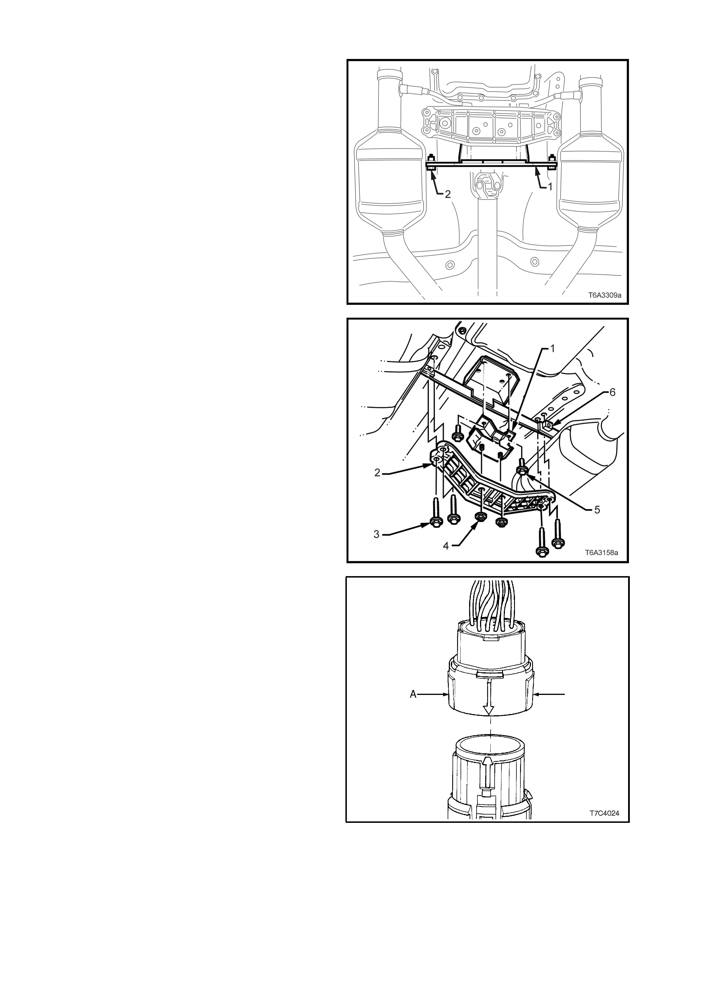
15. Rem ove the two bolts ( 2) securing the catalytic
converter bracket (1) to each catalytic
converter.
Figure 7C4-29
16. Using a s criber or sim ilar, m ark the relationship
of the engine rear crossmember (2) to the
frame, to assist with alignment on reinstallation.
17. Support the transmission. Do not place the
support under the case extension or oil pan.
18. Remove the four bolts (3) holding the rear
cross m em ber (2) to the fram e, r em ove the rear
support to crossmember nuts (4), then remove
the crossmember from the vehicle.
19. Remove the rear mount to transmission
extension housing bolts (5), then remove the
mount (1) and the catalytic converter bracket
(6) from the vehicle.
Figure 7C4-30
20. Lower rear of transmission enough to provide
sufficient clearance, without placing any strain
on any electrical wiring and remove electrical
connector from the transmission as follows:
NOTE: Take care when lowering rear of
transmission that the engine oil pan does not
contact or damage the power steering rack and/or
fluid pipes.
If required, remove the steering rack from the
crossmember and let hang from the tie rods, after
disconnecting the input shaft coupling and fluid
feed and return pipes. Refer to 9A STEERING of
the VT Series II Service Information for more detail.
• Roll back the dust boot from the connector, to
gain access to the connector.
• Squeeze the widest side of the connector
inwards (A) and PULL DIRECTLY UPWARD.
Important: Do not wriggle the connector from
side to side while removing it! If this situation
occurs, there is a very real possibility of the
connector pins being permanently damaged.
21. While the rear of the transmission is lowered,
disconnect the breather and cooler pipes from
transmission and plug connections, both in the
transmission and the pipe ends themselves, to
prevent dirt entry.
Figure 7C4-31
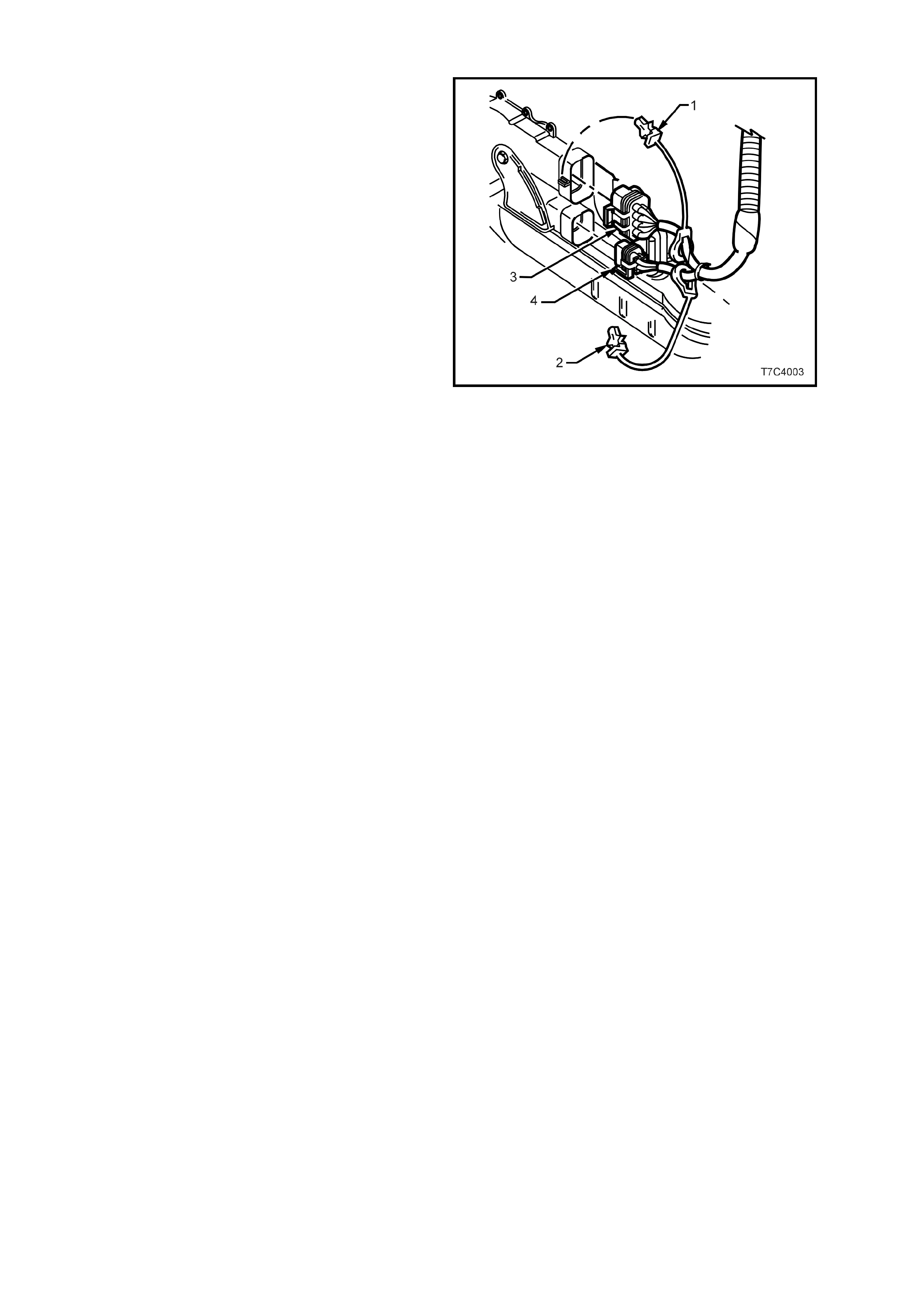
22. Remove the wiring harness CPA (Connector
Position Assurance) security pins (1 and 2)
from the neutral star t and back- up lamp switch,
then remove connectors (3 and 4) from the
switch.
NOTE: Connector ‘4’ and the CPA ‘2’, will only be
fitted to those vehicles where the PRNDL indicator
is in the instrument panel.
23. Remove the wiring harness clip retaining
screws from both the right and left sides of the
transmission case, then secure the harness to
one side.
24. Lower r ear of transm iss ion further if necess ary,
to gain access to the converter housing bolts.
Then, using a long socket extension, a
universal joint and a suitable size socket,
remove the remaining converter housing bolts.
25. Support transmission assembly on a suitable
cradle and secure. Also place a suitable
support under engine oil pan to support engine
after transmission has been removed.
Figure 7C4-32
26. Remove transmission assembly from the
vehicle.
27. Install s uitable converter holding tool to prevent
converter becoming dislodged.
REINSTALL
Reinstallation is the reverse of the removal
procedure, noting the following points:
1. Ensure transmission and engine mating
surfaces are clean and free of burrs.
2. Lubricate the torque converter spigot with
wheel bearing greas e to Holden’s Specification
HN1227, prior to installation.
3. Ensure that engine block locating dowels
completely enter torque converter housing
holes.
4. Prior to reinstalling NEW converter to flexplate
bolts, ensure locating marks on converter and
flexplate are aligned.
NOTE: Remove the small access hole cover plate
(if fitted) in the lower rear surface of the torque
converter housing and lever the torque converter
forward, prior to installing and tightening the torque
converter to flexplate attaching bolts. Reinstall the
access hole cover plate.

5. Apply thread sealant such as Loctite 242 or
equivalent to Holden’s Specification HN1256,
Class 2, Type 2 to the cleaned torque converter
bolt threads. T ighten bolts to the correct torque
specification.
TORQUE CONVERTER TO
ENGINE FLEXPLATE BOLT 60 - 70 Nm
TORQUE SPECIFICATION
6. Reinstall both the left and right hand close-out
covers, install the retaining screw in each and
tighten to the correct torque specification.
CLOSE-OUT COVER RETAINING
BOLT TORQUE SPECIFICATION 10 – 14 Nm
7. Reinstall the starter motor. Refer to Section
6D3-2 STARTING SYSTEM - GEN III V8
engine, of the VT Series II Service Inform ation,
for the necessary procedure.
Figure 7C4-33
8. Install the eight torque converter housing to
engine block bolts, tightening in sequence as
shown, to the correct torque specification.
TORQUE CONVERTER HOUSING
TO ENGINE CYLINDER BLOCK 4 0 - 60 Nm
BOLT TORQUE SPECIFICATION
NOTE: Ensure that the s tarter m otor heat shield (2,
3 and 4) is installed under bolts ‘2’ and ‘5’, refer
Fig’s. 7C4-32/33.
9. The oil filler tube seal must be installed into
transm ission bef ore installation of the f iller tube
to avoid damage to the seal.
NOTE: The transmission breather tube must also
be sec ured to the f iller tube brac k et before the tube
is installed.
10. Prior to installing the wiring harness connector
to the transmission, check that all connector
pins and seals are in sound condition. Push
down on the connector body until a 'click' is
heard. Secure the wiring harness to the
transmission with a screw on each side.
11. T ighten all bolts and nuts to the tor que settings,
as spec ified in 5. T ORQUE SPECIF ICATIO NS,
in this Section.
Important: Refer to 2.4 TRANSMISSION
COOLER REVERSE FLUSH AND FLOW RATE
CHECK in this Section for vital information on
this requirement.
12. Lower vehicle and check fluid level, refer to
2.1 FLUID LEVEL CHECK, in this Section.
13. Road test vehicle to ensure correct operation.
Figure 7C4-34

3.5 TRANSMISSION COOLER
SUMMARY
There are a number of different arrangements for the automatic transmission oil coolers fitted to VT Series II
vehicles, that are summarised here.
V6 Naturally Aspirated – A lar ge capacity cooler is m ounted in the left hand radiator header tank, plus an external
auxiliary cooler, is located in front of the air conditioning condenser (if fitted).
V6 Supercharged – A smaller capacity cooler is located in each of the radiator header tanks, plus an external
auxiliary cooler, is mounted in front of the air conditioning condenser.
Introduced as a change to the V6 Supercharged engine available in VT Series II vehicles, from production serial
number L518684 and a pr oduction date of O c tober 18, 1999, the number of transm is sion oil coolers was reduced to
one (located in the left hand radiator tank) but with an increased capacity. The arrangement of pipes and hoses
then became common with the Naturally Aspirated V6 engine.
The cooling fans have also been commonised with the V6 Naturally Aspirated engine, now being 200 W. Service
operations for the revised fans though, remains unchanged.
GEN III V8 Engine – A large capacity cooler is located in each of the radiator header tanks. No external cooler is
required.
Techline
3.6 TRANSMISSION COOLER PIPES/HOSES
REMOVE
Auxiliary Oil Cooler Hoses – All V6 Engines
1. Place a drain tray beneath the front of the
vehicle.
2. Remove front bumper bar assembly. Refer
1D BUMPER BARS of the VT Series I Service
Information.
3. Disconnect the two transmission oil cooler
hoses (2 and 3), at the auxiliary oil cooler (1).
To prevent foreign matter entry, plug all open
connection points.
Figure 7C4-35
4. Hold the union (2) at the top left of the radiator
tank with a back-up spanner and disconnect
the oil cooler hose (1) from that location.
Figure 7C4-36
5. Remove the clips (arrows) securing the oil
cooler pipes to each other.
6. While using a back-up spanner on the oil
cooler hose fitting (3), disconnect the
transmission return line pipe.
7. Rem ove both auxiliary oil cooler pipe and hose
assemblies from the vehicle.
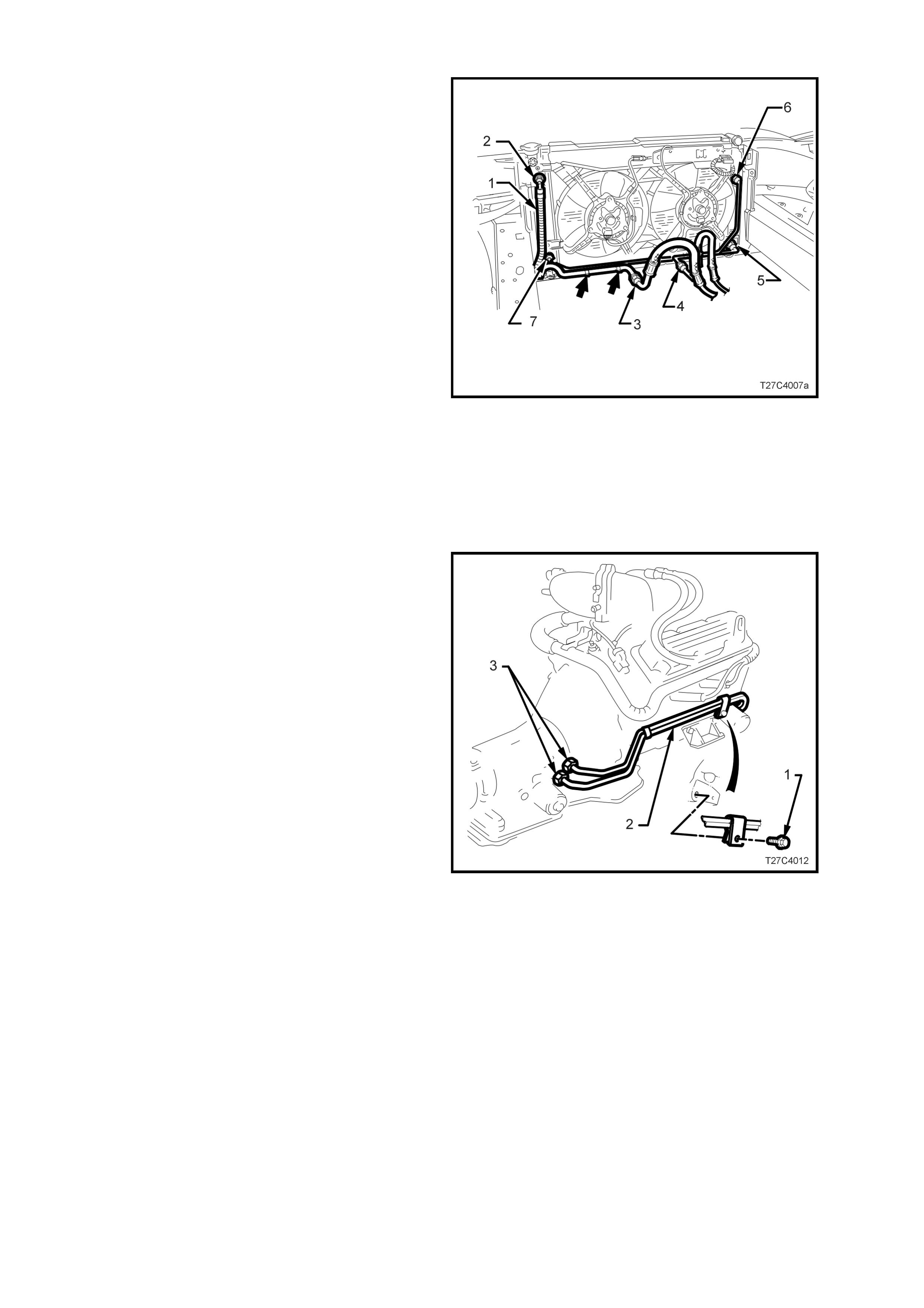
Radiator Cooler Pipes
V6 Naturally Aspirated & V6 Supercharged
Engines (after the breakpoint – see
3.5 TRANSMISSION COOLER, Summary).
1. While using a back-up spanner on the
transmission feed cooler hose fitting (4),
disconnect the oil cooler pipe flare nut.
2. Hold the union at the lower left of the radiator
tank (5) with a back-up spanner and disconnect
the oil cooler pipe from that location.
3. Remove the radiator cooler pipe from the
vehicle.
Figure 7C4-37
Techline
V6 Supercharged Engine (Before the breakpoint
– see 3.5 TRANSMISSION COOLER,
Summary).).
1. If the auxiliary oil cooler hoses/pipes have not
been removed, refer to this service operation
earlier in this Section.
2. While using a back-up spanner on the
transmission feed cooler hose connection (4),
disconnect the oil c ooler pipe flare nut f rom the
radiator end.
3. Hold the union at the lower right (5) of the
radiator tank with a back-up spanner and
disconnect the oil cooler pipe from that
location.
4. Repeat step 3 for the remaining unions on the
upper right (6) and lower left (7) of the radiator
header tanks.
5. If not removed in a previous operation, remove
the clips securing the oil cooler pipes to each
other (arrows).
6. Remove radiator cooler pipes from the engine
bay area.
Figure 7C4-38
Transmission Oil Cooler Pipes - All V6 Engines
1. Remove the clamp bolt securing the
transmission return line pipe to the front of the
engine.
2. Remove the clamp bolt (1) securing the
transmission cooler pipes (2) to the right hand
side of the engine, as shown.
3. Using a pipe spanner, loosen then remove the
transmission cooler pipes from the
transmission fittings (3).
NOTE 1: Use a back-up spanner on the
transmission fittings.
NOTE 2: Applying heat to the pipe spanner and
bending it slightly to modify its shape, will assist in
the loosening process.
4. Remove the cooler pipes (2) from the vehicle
and separate if required, by removing the pipe
clip.
NOTE: While the engine shown is the V6
supercharged unit, the naturally aspirated V6
version pipe layout is the same.
Figure 7C4-39
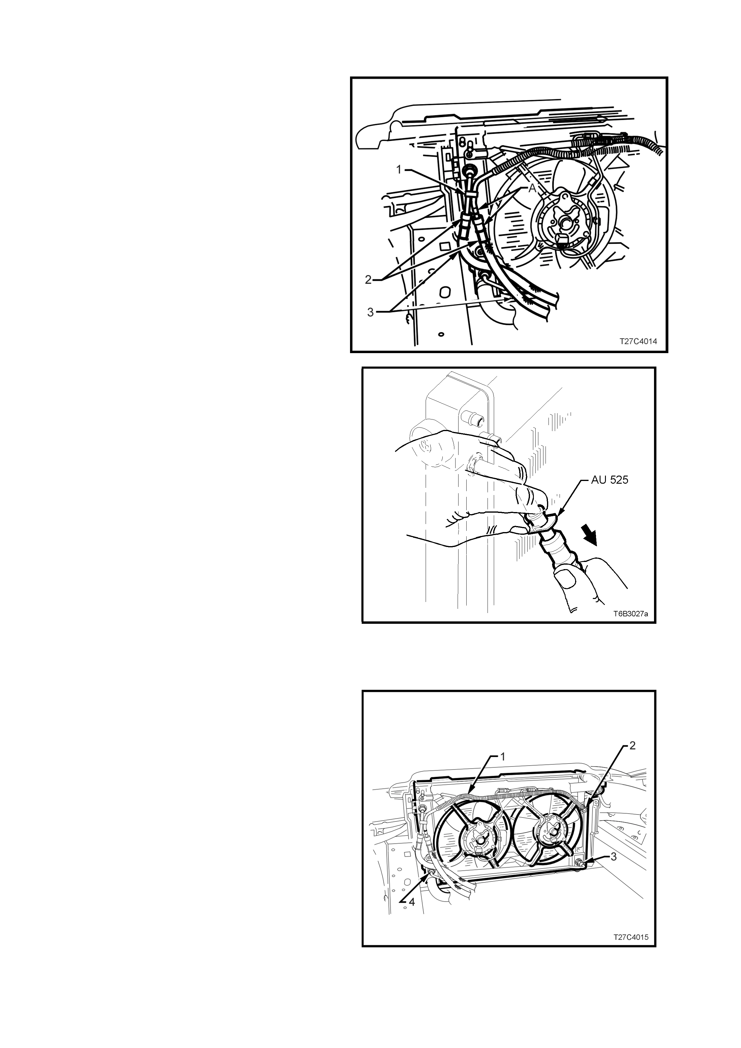
For GEN III V8 Powered Vehicles:
NOTE: As an auxiliary, external oil cooler is not
used with the GEN III V8 engine, the oil cooler hose
rem oval proc edures des cribed her e, will only ref lect
this transmission cooler arrangement.
Oil Cooler Hoses:
NOTE: As the two cooler hoses can be reinstalled
on the incorrec t radiator cooler pipes, takes note of
the locations on rem oval. For production purposes,
white adhesive tape is applied to the correc t mating
parts (‘A’).
1. Dis connect the tr ansmiss ion oil cooler hose (3)
quick connect fittings (2), using Tool No.
AU525, as follows:
Figure 7C4-40
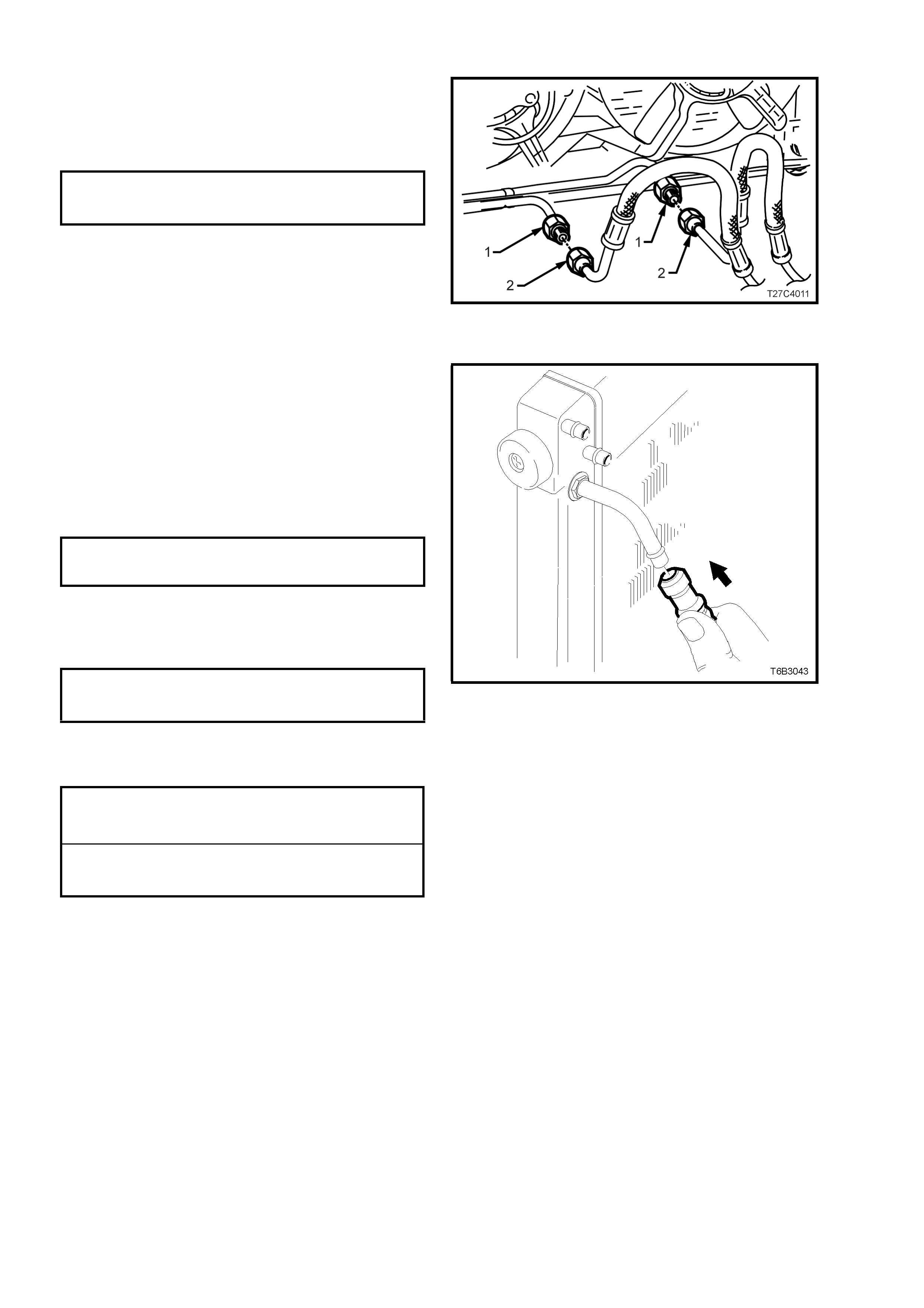
a. Grasp the cooler hose and while pushing
down on Tool AU525 as shown, push up
on the hose to release the connection.
Repeat for the second hose, as required.
Plug hose and oil cooler pipe openings to
prevent foreign matter entry.
Important: If the quick connect release tool is not
available and the coolant line, flar e nut connections
are r emoved at the radiator tank, then it is vital that
a 25 mm back-up spanner is used on the radiator
tank fitting before loosening the pipe flare nuts!
If a fitting is loosened in error, then it must be
replaced with a new part, as micro-encapsulated
sealant is used on the fitting threads that requires
part replacement. Refer to Radiator Repair
Procedure in 6B3 ENGINE COOLING – GEN III V8
ENGINE of the VT Series II Service Information.
NOTE: As the hoses are permanently fitted to the
cooler pipes leading to and from the transmission,
if hose replacement is required, then the pipe/hose
combination must be fitted.
Figure 7C4-41
Radiator Cooler Pipes
1. Release the clip (1 in Fig. 7C4-39), while
holding the cooler pipes together.
2. Hold the union at the upper right of the radiator
tank (2) with a back-up spanner and disconnect
the oil cooler pipe (1) from that location.
3. If the lower pipe is to be removed, then repeat
step 1 for pipe connections ‘3’ and ‘4’.
4. Remove the radiator lower cross-over pipe
from the vehicle.
Figure 7C4-42
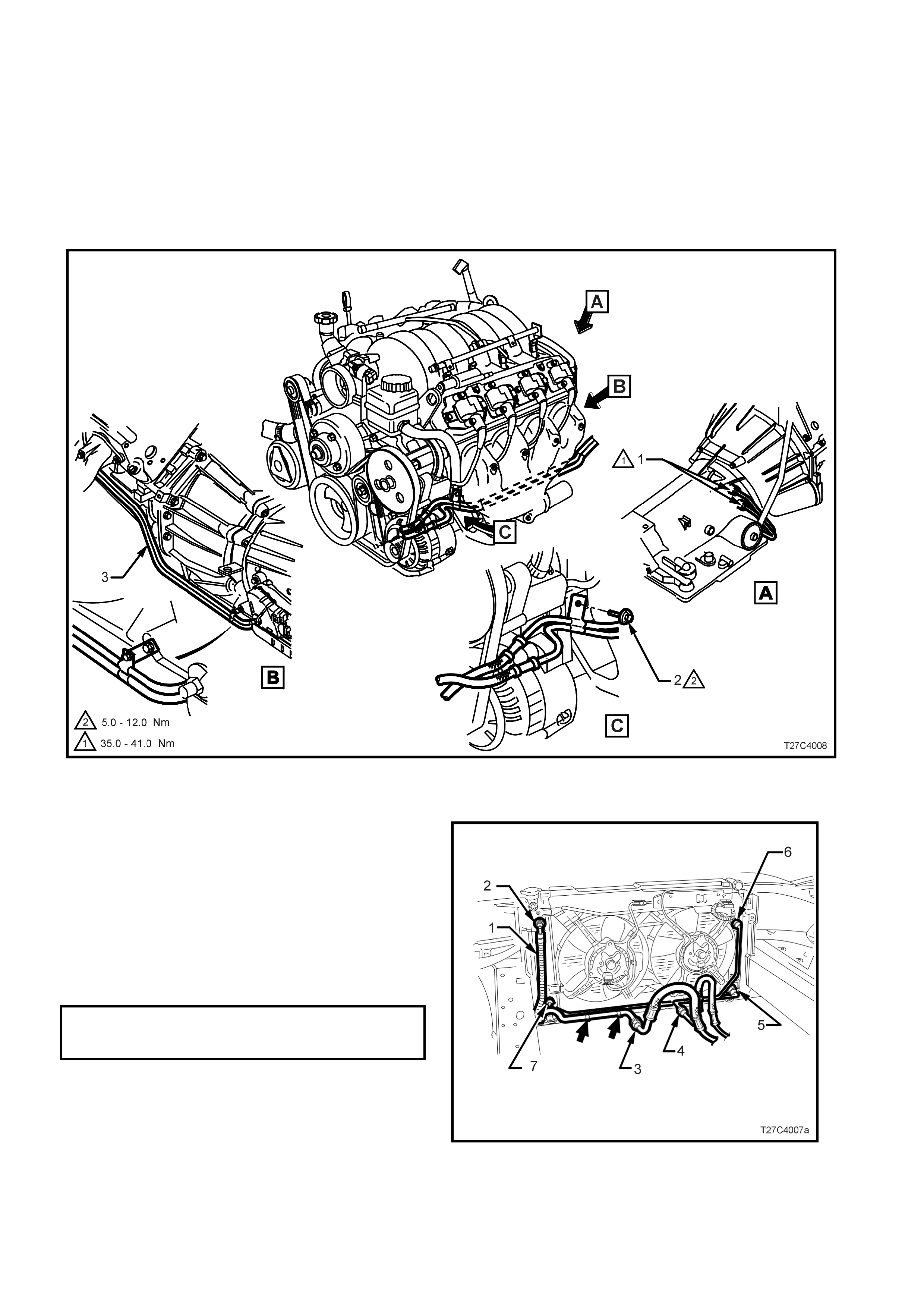
Transmission Oil Cooler Pipes (Refer Fig. 7C4-43)
1. Remove the clamp bolt securing the transmission cooler pipes to the left hand front of the engine (2).
2. Remove the clamp bolt (3) securing the transmission cooler pipes (4) to the neutral safety and back-up lamp
switch.
3. Using a pipe spanner, loosen, then remove the transmission cooler pipes from the transmission fittings (1).
NOTE 1: Use a back-up spanner on the transmission fittings.
NOTE 2: Applying heat to the pipe spanner and bending it slightly to modify it, will assist in the loosening process.
4. Remove the cooler pipes (4) from the vehicle and separate if required, by removing the pipe clip.
Figure 7C4-43
REINSTALL
The reinstallation process of the oil cooler
pipes/hoses, is the reverse to removal, except for
the following:
V6 Engines
1. When tightening oil cooler pipes/hoses to the
radiator fittings(2, 5, 6, and 7), ALW AYS use a
back -up spanner on the radiator f lare nut fitting
BEFORE tightening the flare nuts to the corr ect
torque specification.
TRANSMISSION COOLER HOSE/PIPE
FLARE NUT TO RADIATOR FITTING 25 – 30 Nm
TORQUE SPECIFICATION
NOTE: The V6 Supercharged engine, automatic
transmission oil cooler arrangement (prior to the
stated breakpoint) is shown. For the V6 Naturally
Aspirated and Supercharged engines (after the
stated br eakpoint), the only radiator flare nut f ittings
requiring the procedure detailed in Step 1, are (2
and 7).
Figure 7C4-44
2. Before tightening the transmission oil cooler
pipe fittings (1) to the radiator hose fittings (2),
a back-up spanner MUST be used on the oil
cooler hose fittings (2) BEFORE tightening to
the correct torque specification.
OIL COOLER HOSE FI TTING TO
RADIATOR PIPE FITTING 25 – 30 Nm
TORQUE SPECIFICATION
Figure 7C4-45
GEN III V8 Engine
1. Remove plugs installed in transmission cooler
pipe and hose openings, before reinstalling
cooler hose quic k connect f ittings. T ug on each
to ensure correct installation.
2. Ensure that all pipe clamps are fitted correctly
and that pipe/hose routings are as in Fig. 7C4-
42.
3. Ensure that all fasteners and fittings are
tightened to the correct torque specifications.
TRANSMISSION OIL COOLER PI P E
TO RADIATOR SIDE TANK F LA RE 25 - 30 Nm
NUT TORQUE S PECIFICATIO N
NOTE: A back - up s panner must always be used on
the radiator side tank cooler pipe flare nut fittings to
avoid disturbing the thread sealant applied at
manufacture.
OIL COOLER PIPE TO
TRANSMISSION FLARE NUT 35 – 41 Nm
TORQUE SPECIFICATION
NOTE: A back-up spanner must always be used on
the transmission cooler pipe flare nut fittings when
tightening the pipes.
Figure 7C4-46
TRANSMISSION OIL COOLER PIPE
BRACKET SCREW 20 – 35 Nm
TORQUE SPECIFICATION
NEUTRAL START AND BACK-UP
LAMP SW ITCH SCREW 15 – 35 Nm
TORQUE SPECIFICATION
NOTE: If the neutr al start and back -up lam p switch
position is altered when one of the mounting
screws is removed, then check the switch
adjustment as detailed in 3.1 NEUTRAL START
AND BACK-UP LAMP SWITCH, Adjust, in this
Section.
4. Top up transmission fluid level as required,
road test to check vehicle operation, then
check for fluid leaks. Refer to
2.1 FLUID LEVEL CHECK in this Section.
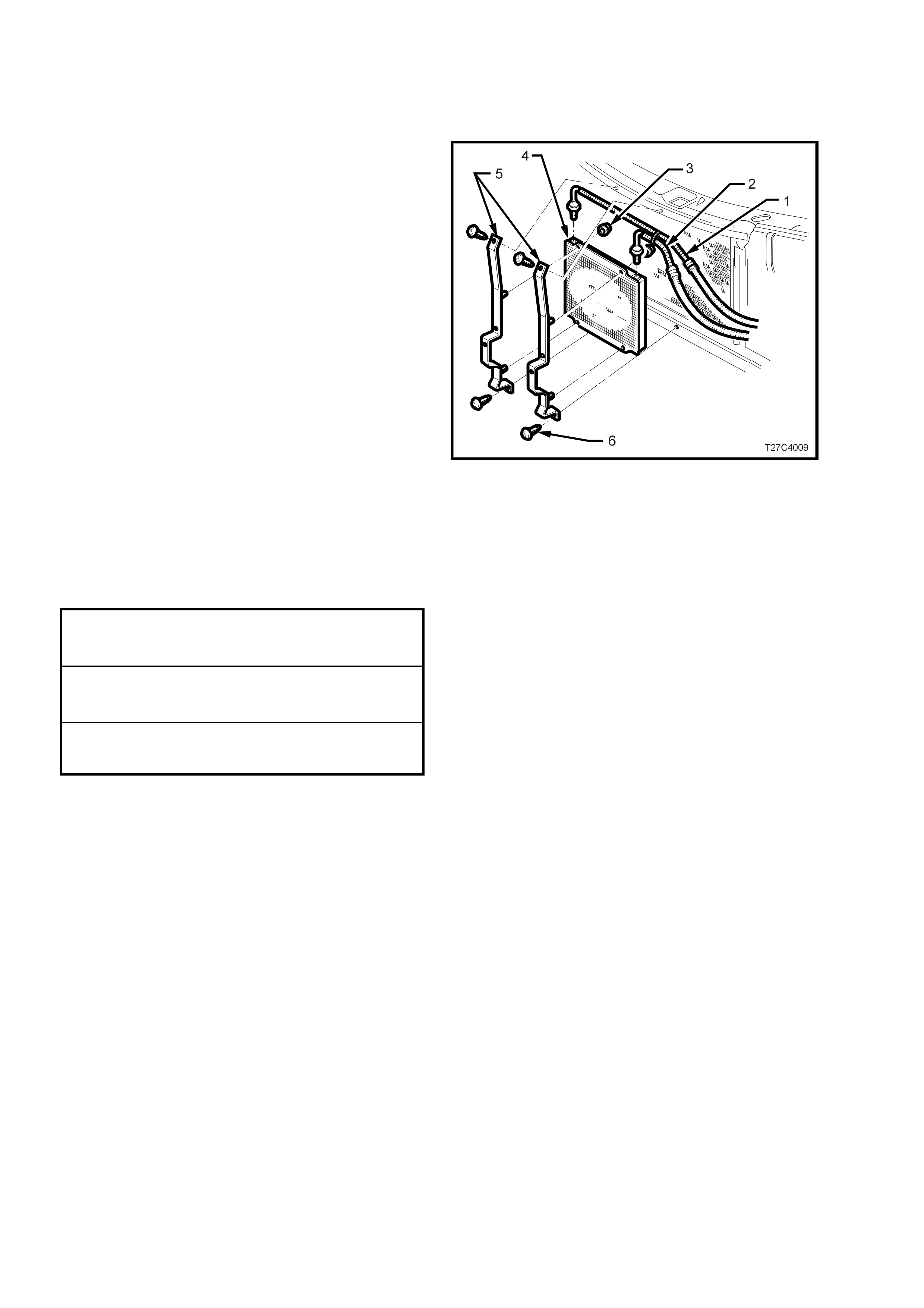
3.7 AUXILIARY OIL COOLER
REMOVE
1. Remove front bumper bar assembly. Refer
1D BUMPER BARS of the VT Series I Service
Information.
2. Place a dr ip tray beneath the auxiliary oil cooler
assembly.
3. Disconnect the two transmission oil cooler hose
(1 and 2) fittings at the auxiliary oil cooler (4).
To prevent foreign matter entry, plug all open
connection points.
4. Remove the auxiliary cooler mounting bracket
retaining scr ews (6) , then remove the cooler (4)
and bracket assembly (5) from the vehicle.
5. If required, remove the four nuts (3) securing
the auxiliary cooler to the mounting brackets
(5), then remove them from the vehicle.
Figure 7C4-47
REINSTALL
The ins tallation proc es s of the auxiliary oil cooler , is
the reverse to removal, except for the following:
1. Ensure that all fasteners and fittings are
tightened to the correct torque specifications.
OIL COOLER HOSE FITTINGS TO
AUXILIARY COOLER 25 - 35 Nm
TORQUE SPECIFICATION
AUXILIARY COOLER TO
MOUNTING BRACKET NUTS 5.0 – 12.0 Nm
TORQUE SPECIFICATION
AUXILIARY COOLER MOUNTING
BRACKET SCREWS 1.0 - 2.5 Nm
TORQUE SPECIFICATION
2. Reinstall the front bumper bar assembly, refer
to 1D BUMPER BARS of the VT Series I
Service Information.
3. Start the engine and check the fluid level,
topping up as required.
4. Road test the vehicle to check for correct
operation and until fluids are at normal
operating tem peratur e. Chec k for leak s and top
up transm iss ion fluid level as r equired. Refer to
2.1 FLUID LEVEL CHECK in this Section.

4. SPECIFICATIONS
NOTE: For a complete listing of specifications as they apply to components not discussed in this Section, refer to
Section 7C4 HYDRA-MATIC 4L60-E AUTOMATIC TRANSMISSION: ON-VEHICLE SERVICING AND
Section 7C5 HYDRA-MATIC 4L60-E AUTOMATIC TRANSMISSION: UNIT REPAIR, of the VT Series I Service
Information.
GENERAL:
Type........................................................................ Hydra-matic 4L60-E
Transmission Code................................................. V6 Engine - 9HFD
V6 Supercharged Engine - 9HND
GEN III V8 Engine - 9HPD
Special Features..................................................... Electronically controlled shift pattern, feel and torque
converter clutch operation
Selector Location.................................................... Floor mounted console
GEAR RATIOS:
Park (P)................................................................... -
Reverse (R)............................................................. 2.294:1
Neutral (N) .............................................................. -
Drive (D).................................................................. 0.696:1
Third (3) .................................................................. 1.000:1
Second (2) .............................................................. 1.625:1
First (1).................................................................... 3.059:1
SHIFT SPEEDS:........................................................ Refer to Section 7C3 DIAGNOSIS, in VT Series II.
OIL PRESSURE:....................................................... Refer to Section 7C3 DIAGNOSIS, in VT Series II.
TORQUE CONVERTER:
Number of Elements............................................... Three, plus torque converter clutch
Maximum Torque Ratio at Stall .............................. V6 and V6 Supercharged Engine - 1.63:1 (k=133)
GEN III V8 Engine – 1.9:1 (k=101)
Nominal Diameter................................................... V6 and V6 Supercharged Engine - 258 mm
GEN III V8 Engine - 300 mm
LUBRICANT:
Type Recommended .............................................. Dexron III (To Holden's Specification HN2126)
Capacity.................................................................. Nominal Only. Check when transmission
is at operating temperature.
Refill................................................................... V6 Engine - 4.8 litres
GEN III V8 Engine - 5.0 litres
Total (Dry).......................................................... V6 Engine - 7.9 litres
GEN III V8 Engine - 10.6 litres
Fluid Cooling...................................................... Engine coolant to fluid in one (V6 ) or both radiator
......................................................................... tanks (V6 Supercharged and GEN III V8) and
......................................................................... externally by air to fluid cooler (V6 engines only).
2 - 4 SERVO:
Selective Pin Length
1 Groove............................................................ 65.82 - 66.12 mm
2 Grooves .......................................................... 67.23 - 67.53 mm
No Groove ......................................................... 68.64 - 68.94 mm

5. TORQUE WRENCH SPECIFICATIONS
NOTE: Only those torque wrench specifications related to the operations described in this Section are included
here. For the remainder of torque wrench specifications, refer to either Section 7C4 HYDRA-MATIC 4L60-E
AUTOMATIC TRANSMISSION: ON-VEHICLE SERVICE or Section 7C5 HYDRA-MATIC 4L60-E AUTOMATIC
TRANSMISSION: UNIT REPAIR, of the VT Series I Service Information.
Nm
Auxiliary Oil Cooler Mounting Bracket Screws – All V6 Engines ........................................ 1.0 - 2.5
Auxiliary Oil Cooler to Mounting Bracket Nut – All V6 Engines........................................... 5.0 - 12
Catalytic Converter Bracket Bolt to Catalytic Converter...................................................... 20 - 30
Close-out Cover Bolt (either side)....................................................................................... 10 - 14
Filler Tube Bracket Retaining Bolt - GEN III V8 Engine ................................... 20 - 30
Neutral Start and Back-up Lamp Switch Bolt...................................................................... 15 - 35
Oil Cooler Hose Fittings to Auxiliary Oil Cooler – All V6 Engines ....................................... 25 - 30
Oil Cooler Hose Fittings to Radiator – All V6 Engines ....................................................... 25 - 30
Oil Cooler Pipe Bracket Screw to Engine Block – GEN III V8 Engine................................ 15 - 35
Oil Cooler Pipe to Radiator Flare Nut Fitting – GEN III V8 Engine ..................................... 25 - 30
Oil Cooler Pipe to Transmission Fitting............................................................................... 35 - 41
Selector Lever Retaining Nut.............................................................................................. 15 - 35
Starter Motor Brace Bolt – GEN III V8 Engine.................................................................... 40 - 55
Torque Converter Housing to Engine Block Bolt – GEN III V8 Engine............................... 40 -60
Torque Converter to Engine Flexplate Attaching Bolt......................................................... 60 - 70
Transmission Crossmember to Side Frame Bolt................................................................ 30 - 30
Transmission Oil Cooler Pipe Fittings to Oil Cooler Pipes – All V6 Engines ...................... 25 - 30
Transmission Support to Crossmember Nut ...................................................................... 50 - 65
Transmission Support to Transmission Extension Housing Bolt........................................ 20 – 30

6. SPECIAL TOOLS
TOOL No. REF. IN TEXT TOOL DESCRIPTION COMMENTS
AU525 QUICK CONNECT RELEASE TOOL
AU525
New release.
Use to release the quick
connect fittings on the
automatic transmission cooler
lines at the radiator end.