
SECTION 7C5 - HYDRA-MATIC 4L60-E AUTOMATIC
TRANSMISSION: UNIT REPAIR
CAUTION:
This vehicle will be equipped w ith a Supplemental Restraint System (SRS). An SRS will consist of either
seat belt pre-tensioners and a driver's side air bag, or seat belt pre-tensioners and a driver's and front
passenger's side air bags. Refer to CAUTIONS, Section 12M, of the VT Series I Service Information before
performing any service operation on or around any SRS components, the steering mechanism or wiring.
Failure to follow the CAUTIONS could result in SRS deployment, resulting in possible personal injury or
unnecessary SRS system repairs.
1. TRANSMISSION DISASSEMBLE
1.1 GENERAL SERVICE INFORMATION
The use of air powered tools to disassem ble or reassem ble this transmission is not recom mended. Apart from the
fact that thr ead stripping is m ore likely when incorr ect torque values are applied to f asteners, com ponent parts can
be distorted to the point where malfunctions will occur.
Teflon Sealing Rings
If any sealing rings are found to be dam aged, cut or do not rotate freely in their groove, check that the ring groove
has no trapped debris, is not burred or damaged in such a way that early failure of a replacement ring will occur.
Thrust Washer Surfaces
On inspection, thrust washer and thrust bearing surfaces m ay appear to be polished at points of contact. This is a
normal condition and should not be considered as damage, requiring replacement.
Techline
Techline
Techline
1.2 TRANSMISSION PREPARATION
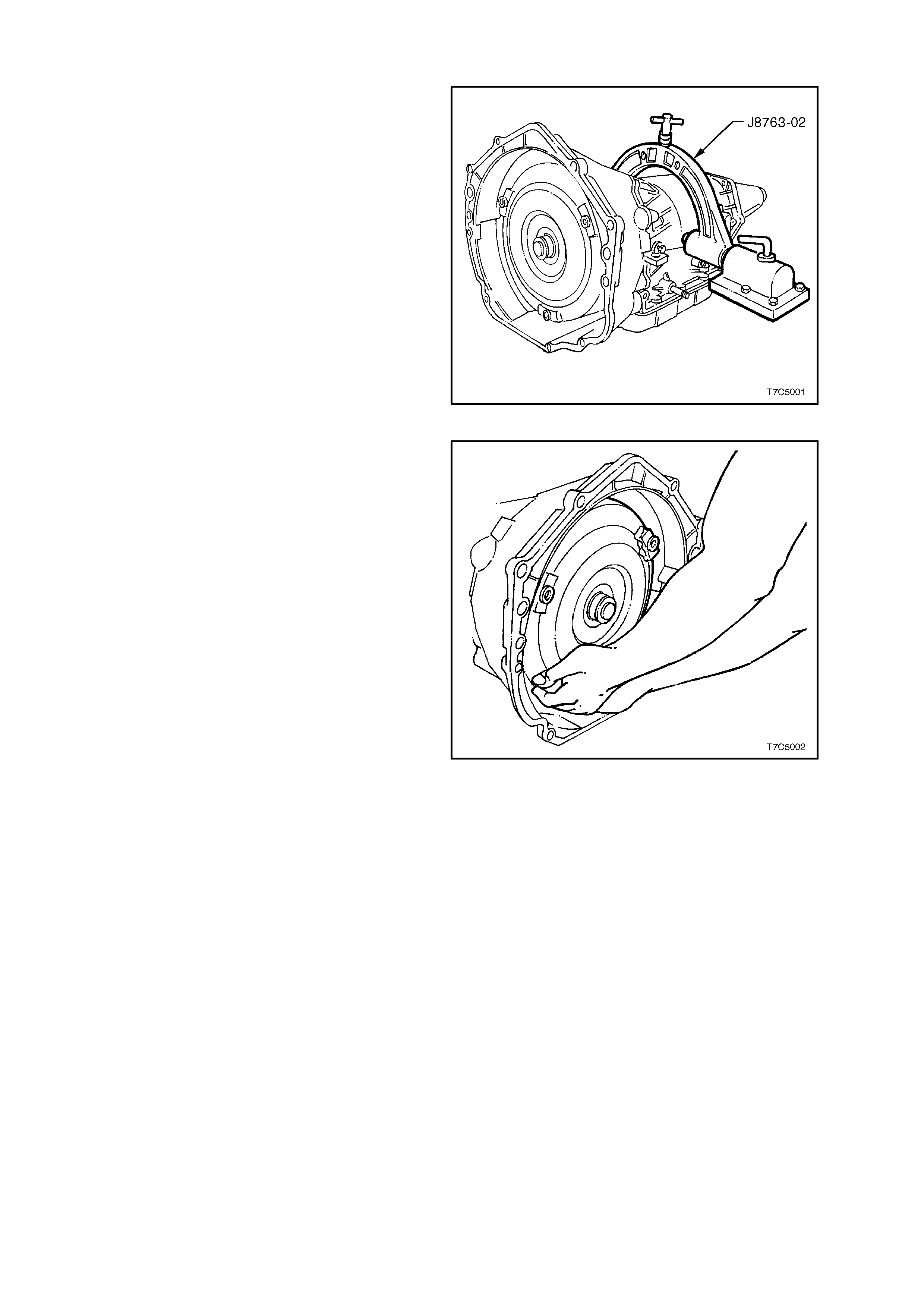
1. Thoroughly clean exterior of transmission.
2. Install transmission holding fixture, E1363 (or
J8763-02) as shown. Note that the 2-4 Servo
should be facing away from the workbench.
NOTE: If removal of the wiring harness is
anticipated as being necessary, the wiring harness
connector should be pushed into the case before
fitting the tr ans miss ion holding f ixtur e. This r emoval
operation can be achieved by pushing down
squarely on the wiring harnes s c onnec tor, us ing a 1
5/16" socket (¾" drive) to compress the four
connector retaining lugs.
Figure 7C5-1
3. Remove torque converter by sliding clear of
input shaft. Drain stored converter fluid into a
suitable container.
CAUTION: T ake care when removin g the torq ue
converter as it is a heavy assembly and
personal injury may result if lifted incorrectly.
4. Rotate the transmission so that the converter
housing faces upward and drain the fluid from
the case extension.
Ensure that the container has the capacity to
hold at least 8 litres.
Figure 7C5-2
1.3 2-4 SERVO ASSEMBLY
REMOVE
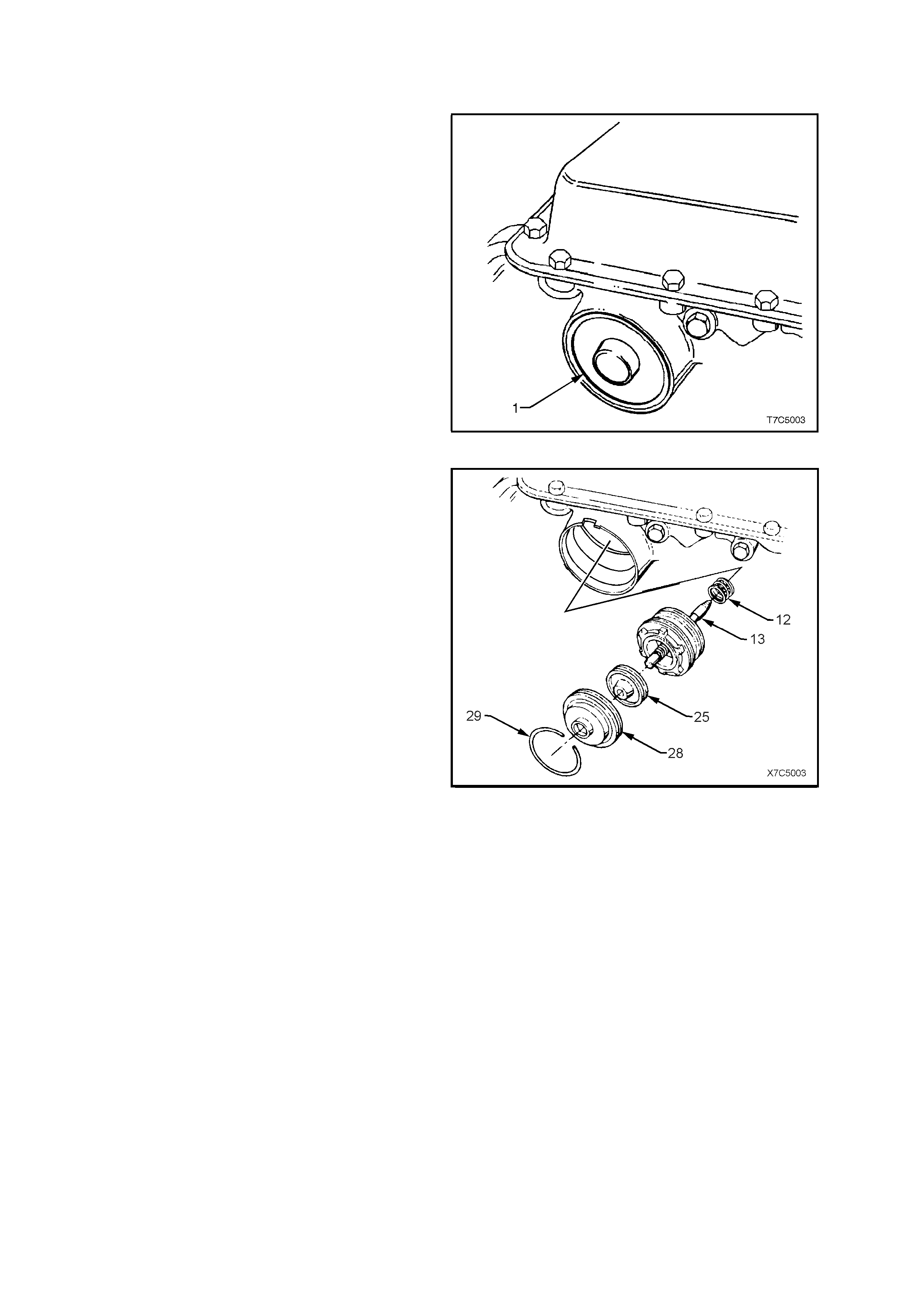
1. Depress 2-4 servo cover (1) with a hammer
handle and hold.
2. Remove cover retainer ring.
Figure 7C5-3
3. To remove cover (28), either cut the O-ring
seal (not shown) and remove with thin nosed
pliers first, or stretch the O-ring by pulling it
through one of the two openings, while
removing the cover.
NOTE: The fourth apply piston (25) may come out
with the cover (28). If so, and the piston
accidentally falls to the floor, check that the teflon
ring grooves have not been damaged to the point
where ring binding and/or damage could occur.
4. Remove fourth apply piston (25) from second
apply piston assembly.
5. Remove second apply piston and servo pin
assembly (13).
6. Remove servo return spring (12).
Figure 7C5-4
DISASSEMBLE
1. Remove servo pin retainer clip (24) from
second apply piston pin assembly.
2. Remove washer (23) and apply pin spring (22).
3. Remove second apply piston pin (13).
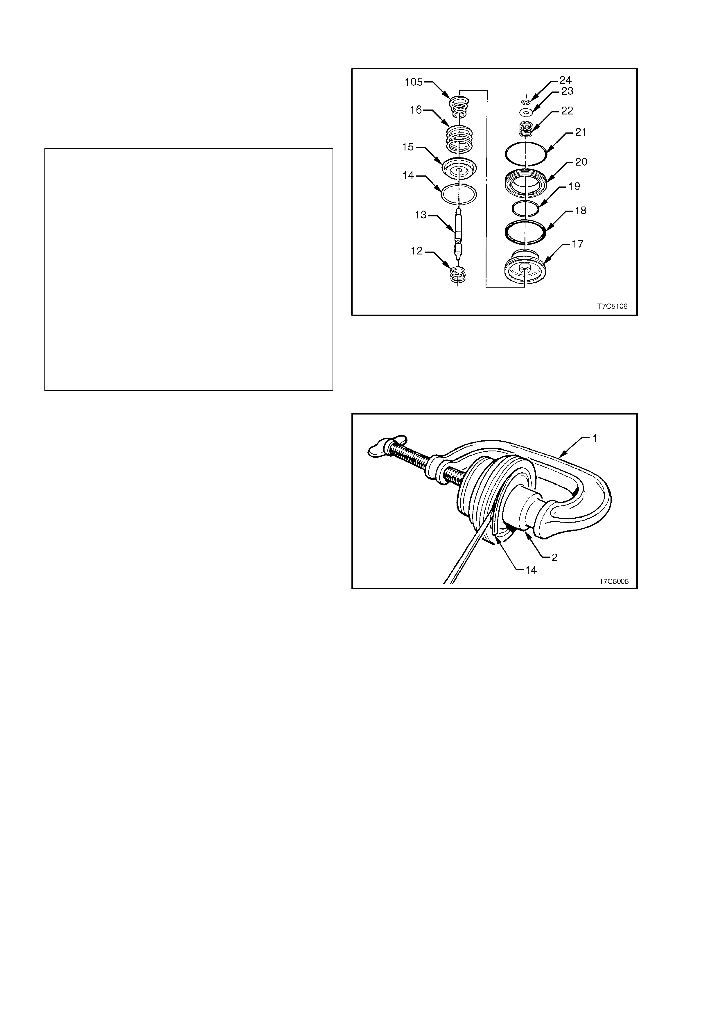
Legend - 2nd Apply Piston Assembly
12 Spring, servo return
13 Pin, 2nd apply piston
14 Ring, retainer (2nd apply piston)
15 Retainer, servo cushion spring
16 Spring, servo cushion (outer)
105 Spring, servo cushion (inner) (V6 engine
only).
17 Piston, 2nd apply
18 Ring, oil seal (2nd apply piston - outer)
19 Ring, oil seal (2nd apply piston - inner)
20 Housing, servo piston (inner)
21 Seal, O-ring
22 Spring, servo apply pin
23 Washer, servo apply pin
24 C-clip retainer, servo apply pin
Figure 7C5-5
4. Fit a suitable G -c lamp (1) and soc ket (2), to the
second apply piston assembly as shown.
5. Use this arrangement to compress piston
assembly.
6. Remove second apply piston retainer ring (14).
7. Remove G-clamp and socket.
8. Remove cushion spring (16) and tapered
cushion spring (105) and retainer (15), refer
Fig. 7C5-5.
Figure 7C5-6
SERVO PIN LENGTH
NOTE: At this s tage, it is advisable to m easure the
servo pin, installed length as described in the next
four steps. Should the pin prove to be too short or
too long, look closely at the 2-4 band and reverse
input drum for wear and/or damage, once the
transmission has been disassembled.
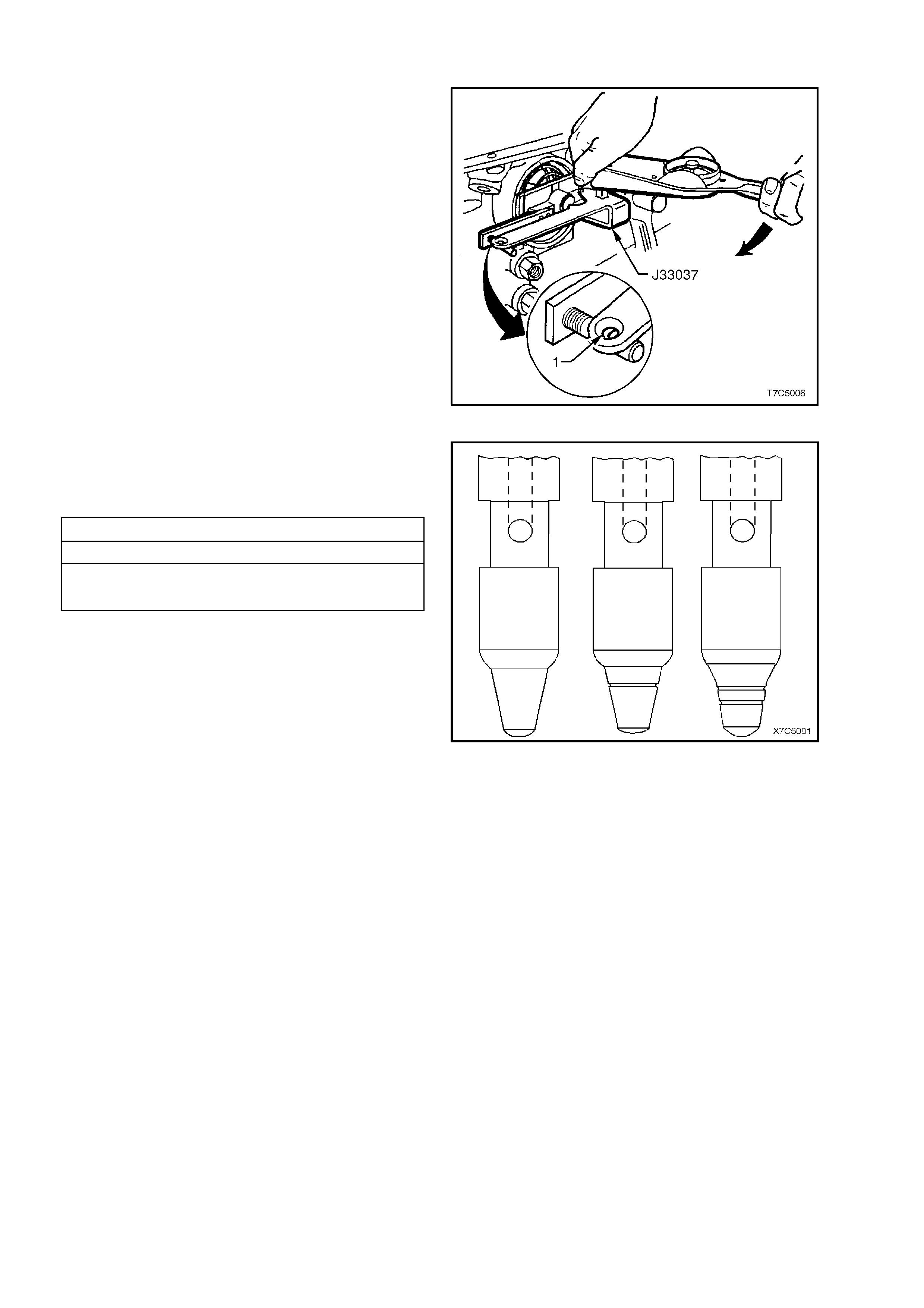
1. Install the pin, tapered end first.
2. Install Tool No. J33037 as shown, and refit the
servo cover retaining ring, to hold the tool.
3. Apply 11 Nm torque. If white line appears in
gauge hole (1), pin length is correct.
4. Remove Tool No. J33037.
Figure 7C5-7
5. Measure the pin length ‘A’ and record.
6. If pin length is incorrect and requires
replacement, use selection chart to determine
correct pin length.
2 - 4 SERVO PIN SELECTION
PIN LE NGTH (mm) IDENTIFI CATION
65.82 - 66.12 1 Groove
67.23 - 67.53 2 Grooves
68.64 - 68.94 No Groove
Figure 7C5-8
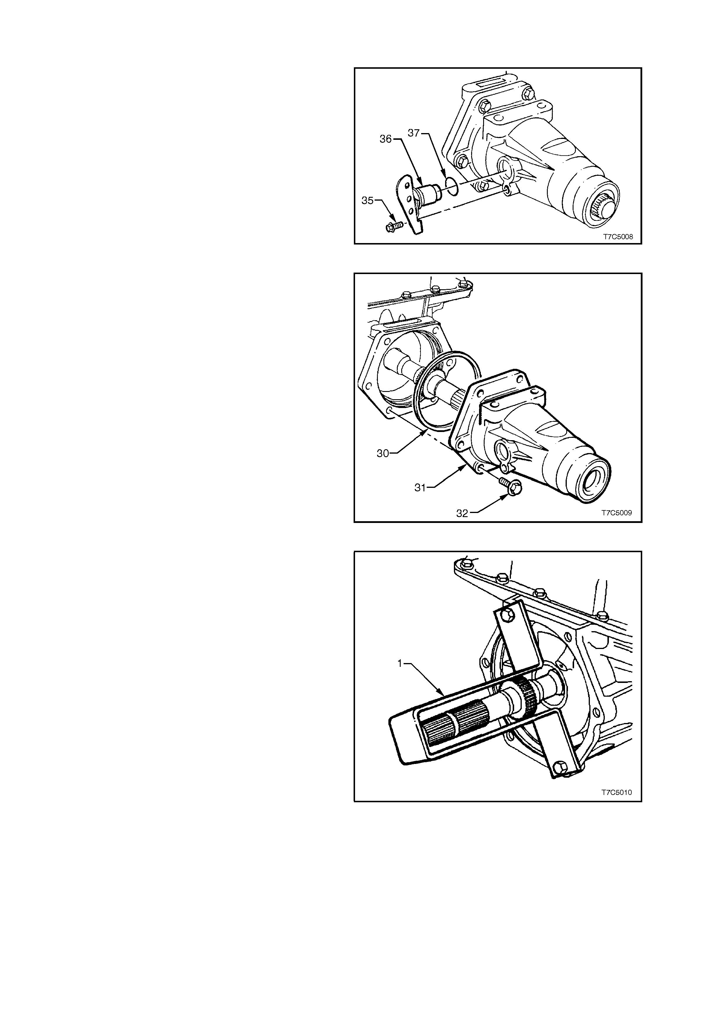
1.4 SPEED SENSOR AND CASE EXTENSION
1. Remove the speed sensor retaining screw (35)
from the extension housing, then remove the
sensor (36) and O-ring (37).
NOTE: No special tool is required for this
operation.
Figure 7C5-9
2. If required, remove the case extension seal,
using a suitable seal removing tool, such as
E308 or similar.
3. Remove six case extension bolts (32).
4. Withdraw case extension (31) and O-ring seal
(30).
Figure 7C5-10
5. To support and stop the output shaft from
falling from the transmission at a later point in
the disassembly process, fabricate a support
bracket (1) from a strip of suitable sheet metal
(as shown). Install bracket using two case
extension bolts.
Figure 7C5-11
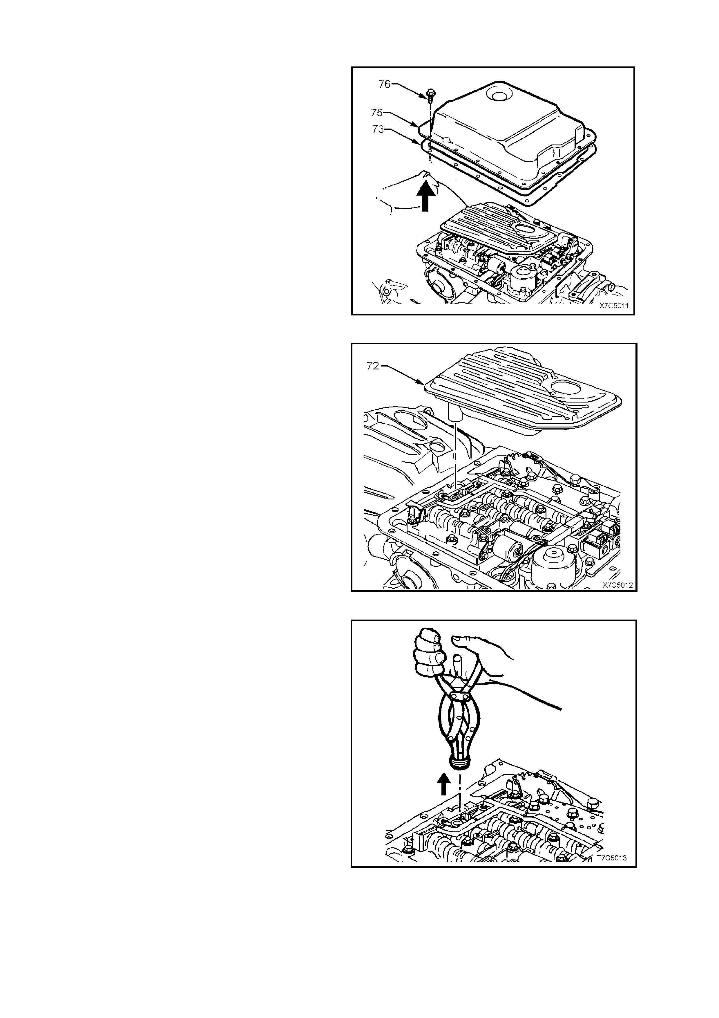
1.5 OIL PAN AND FILTER ASSEMBLY
1. Clean all dirt from around the oil pan, screws
and transmission case.
2. Remove all oil pan screws (76), the oil pan
(75), gasket (73) and magnet (not shown), from
the transmission case.
Figure 7C5-12
3. Lift the oil filter (72) and twist to remove from
the oil pump body.
4. Particles trapped by the filter may help in
diagnosis. Cut away the top of the plastic filter
housing and remove. Inspect the filter material
for particles that might indicate the reason for
the transmission failure (Not necessarily the
cause!). Examples of the type of material are;
- Clutch friction material.
- Bronze slivers, indicating bush wear.
- Steel particles.
Figure 7C5-13
5. Using suitable circlip pliers as shown, or a
commercially available, two-legged puller and
slide hammer, remove the filter seal, taking
care not to damage the oil pump bore during
the process.
NOTE: If scratched, f luid leakage could occ ur from
this point, once the vehicle has been put back into
service.
Figure 7C5-14
1.6 CONTROL VALVE BODY AND WIRING HARNESS
NOTE: If removal of the wiring harness is
necessary, the wiring harness connector should
have been pushed into the case before fitting the
transmission holding fixture.
After removing the holding fixture from the
transmission case, use a 1 5/16" socket (¾" drive)
and push down squarely on the wiring harness
connector, to compress the connector retaining
lugs.
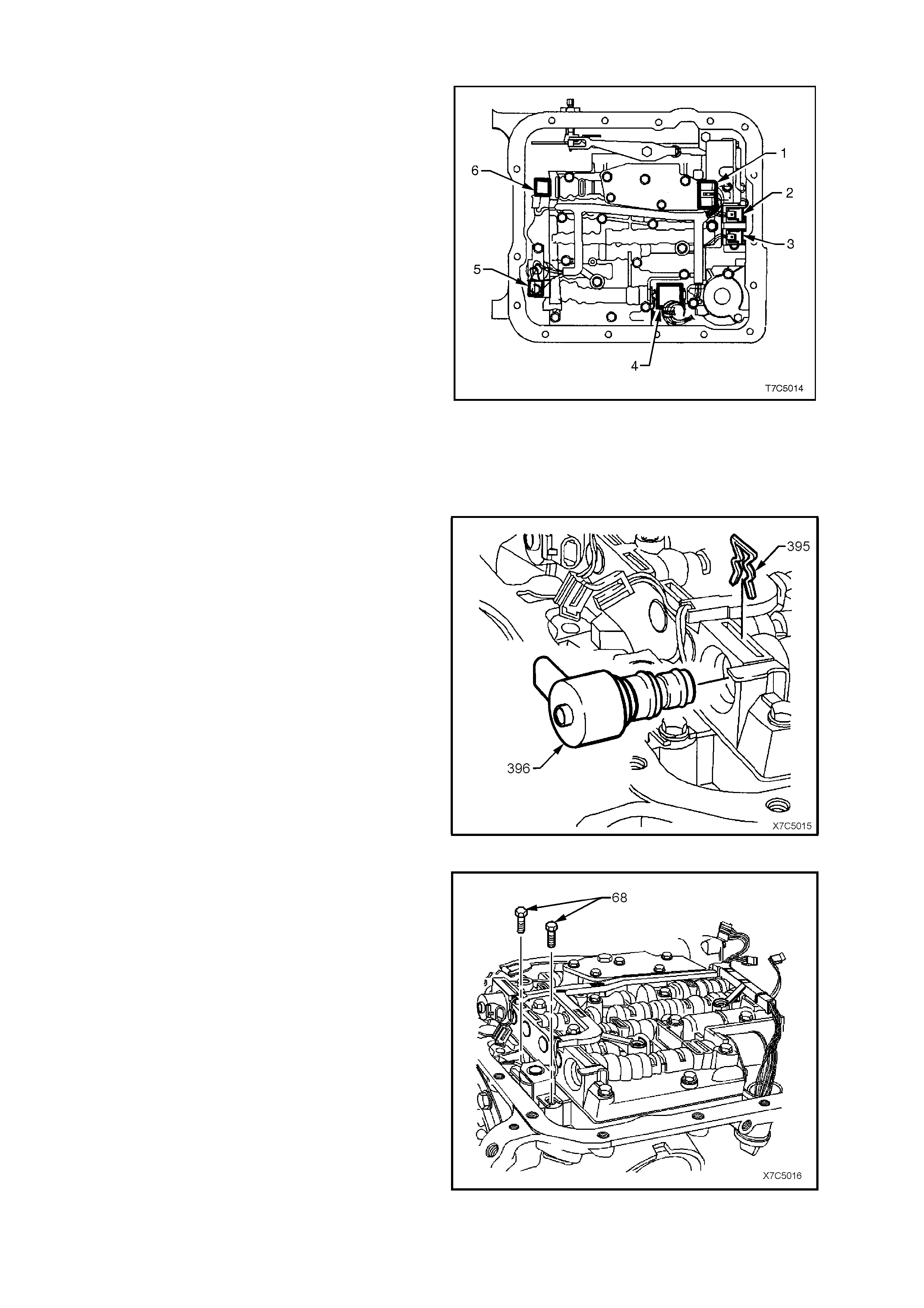
1. Disconnect wiring harness connectors from all
electrical components, except the Torque
Converter Clutch (TCC) Solenoid:
1. Transmission Fluid Pressure Manual Valve
Position Switch Assembly (TFP).
2. 1-2 Shift Valve Solenoid.
3. 2-3 Shift Valve Solenoid.
4. Pressure Control Solenoid (PCS).
5. TCC Pulse Width Modulated (TCC PWM)
Solenoid.
6. 3-2 Control Solenoid.
NOTE: The s ec urity tang on the PCS (4), is located
at the rear of the connector.
Figure 7C5-15
2. Remove the TCC Pulse Width Modulated
(PWM) solenoid retainer clip (395), then the
solenoid (396).
Figure 7C5-16
3. Remove two bolts (68) holding the TCC
solenoid assembly.
Figure 7C5-17

4. Lift the TCC solenoid assembly from oil pump.
5. Carefully drape the wiring harness over the
side of the transmission case, after wrapping a
piece of lint free cloth around the wiring
harness to prevent chafing of the insulation on
the transmission oil pan rail.
NOTE: If removal of the wiring harness/TCC
Solenoid from the transmission case is required, it
will not be possible until the control valve body has
been removed.
Figure 7C5-18
6. Remove the Transmission Fluid Pressure
Manual Valve Position Switch Assembly (TFP)
retaining bolts, then remove the TFP (69) and
shield (106) from the valve body.
Figure 7C5-19
7. Remove the bolt (64) securing the manual
detent spring (63), then remove the detent
sprin g assembly.
Figure 7C5-20
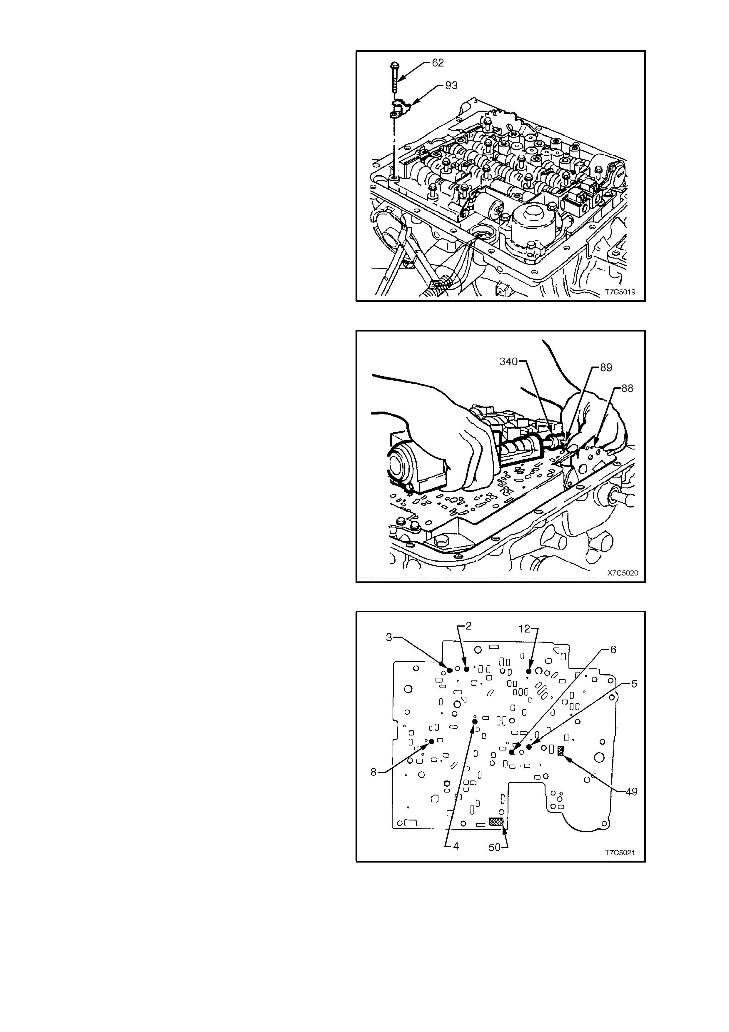
8. Progressively loosen, then remove all
remaining control valve bolts (62).
9. In the process, remove the fluid level indicator
stop bracket (93).
Figure 7C5-21
10. Remove control valve body assembly by lifting
from the rear, supporting the valve body in one
hand, while holding the manual valve link (89)
with the other.
NOTE: Take care when lifting the control valve
body, not to disturb the seven checkballs located
on the spacer plate.
11. As the valve body is being lifted, rotate it
slightly to release the manual valve link (89)
from the manual valve (340). After removing
the control valve body, disconnect the manual
valve link (89) from the inner detent lever (88).
Figure 7C5-22
12. Remove the seven checkballs from the spacer
plate (2, 3, 4, 5, 6, 8 and 12).
NOTE: Shown are the ball locations on the spacer
plate after the control valve body and other
components have been removed.
Figure 7C5-23
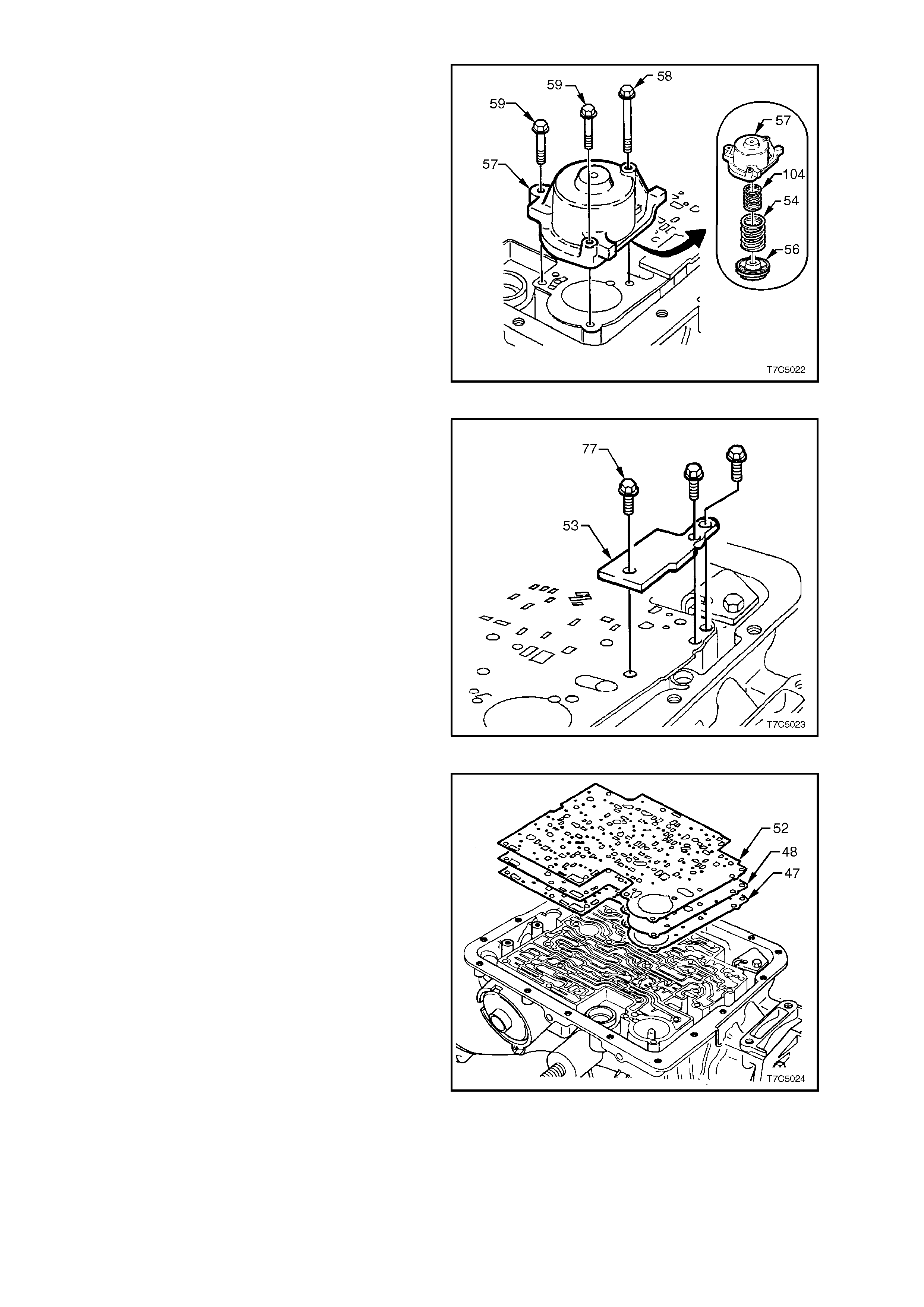
13. W hile holding the cover (57) down against 1-2
accumulator spring force (54/104),
progressively loosen, then remove the three 1-
2 acc um ulator c over bolts ( '58'x 1 and '59' x 2) .
Remove the cover and pin (57), 1-2
accumulator piston (56), two springs (54/105).
14. Remove the 1-2 accumulator piston (56) from
the cover, by applying low air pressure to the
oil drilling in the cover.
CAUTION: To avoid the possibility of personal
injury and/or damage to the 1-2 accumulator piston,
do not use air pres sure in exc ess of 70 k Pa for this
operation.
15. Remove and discard the seal from the 1-2
accumulator piston.
16. Tag the outer 1-2 accumulator spring (54) for
correct reassembly.
Figure 7C5-24
17. Remove the three spacer plate retaining bolts
(77) and retaining plate (53).
Figure 7C5-25
18. Remove the spacer plate (48) and two spacer
plate gaskets (47/52) from the transmission
case.
Figure 7C5-26
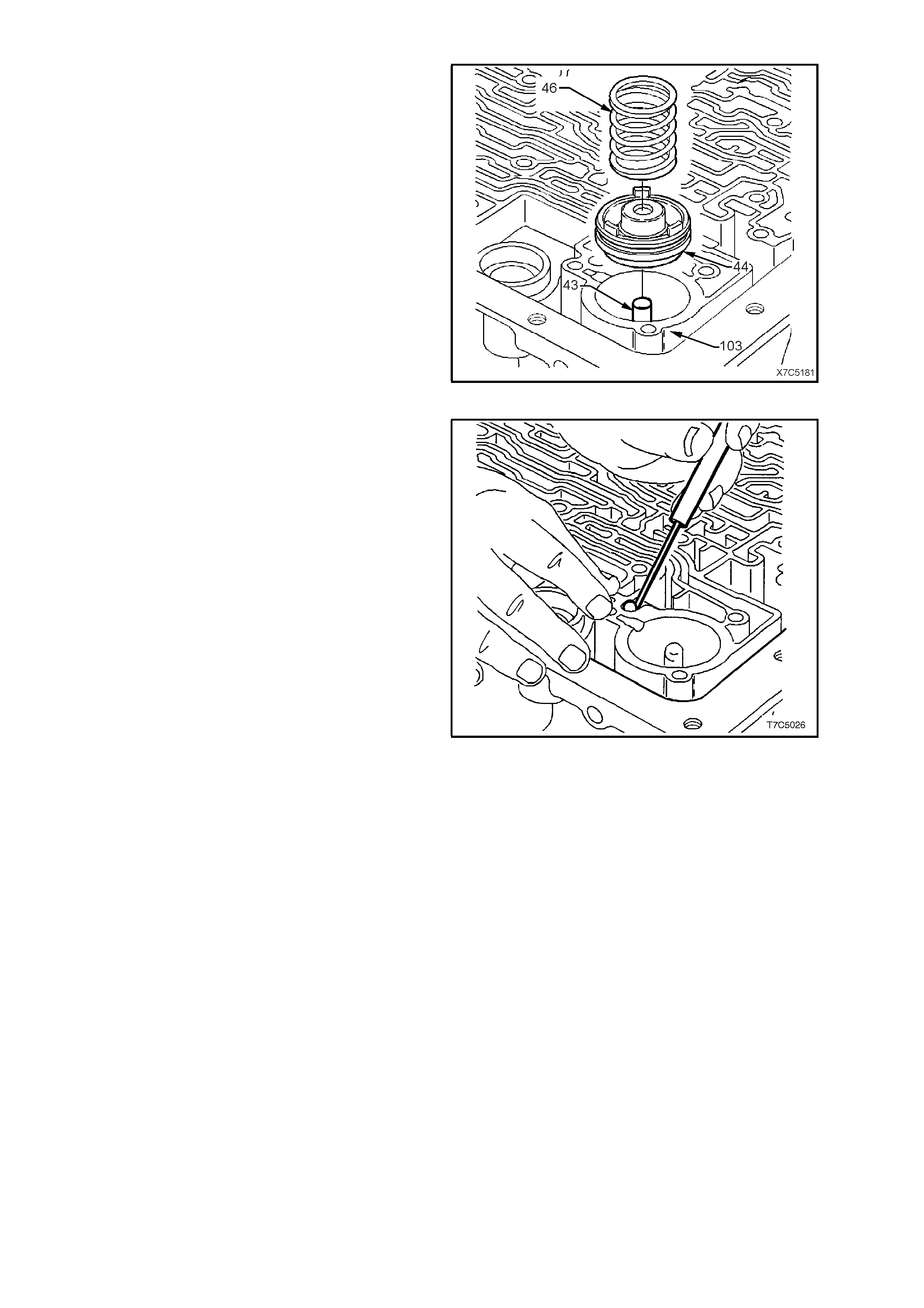
19. Remove the 3-4 accumulator spring (46) and
tag for correct reassembly.
NOTE: T here is no 3-4 ac cumulator s pring fitted to
the automatic transmission fitted to the GEN III V8
engine (code HPD).
20. Using f lat blade snap ring pliers, rem ove the 3-
4 accumulator piston (44) from the
transmission case (103), by rotating the piston
while pulling it from the case, then remove the
position guide pin (43) from the case.
21. Remove and discard the seal from the 3-4
accumulator piston.
Figure 7C5-27
22. Remove the check ball #1 from the
transmission case, as shown.
NOTE: For control valve body disassembly
procedure, refer to 2.16 CONTROL VALVE BODY
in this Section.
Figure 7C5-28
1.7 CONVERTER HOUS ING
1. Rotate the transmission assembly until the
converter housing is facing upward as shown,
then lock the assembly in that position.
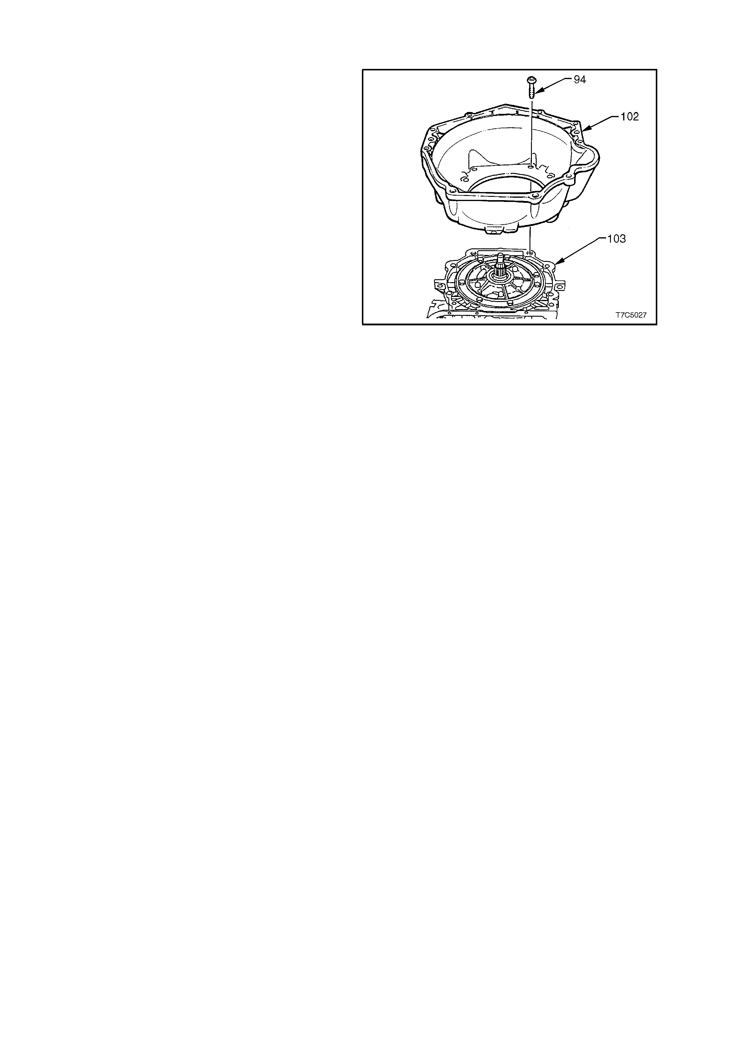
2. Using Torx Plus bit, Tool No. J41510 or
commercial equivalent, progressively loosen,
then remove the converter housing bolts (94).
NOTE: Do not use a standar d, # 50 Torx bit, as the
bolt design is such that only the Torx Plus bit is
capable of applying sufficient loosening torque
without bolt damage.
3. Remove the converter housing (102) from the
transmission case (103).
NOTE: The converter housing (102) shown is
‘typical’ and is not intended to be specific to any
particular engine application.
Figure 7C5-29
1.8 TRANSMISSION E ND P LAY CHECK
To assist in the diagnostic process, transmission
end play should be checked prior to removing
internal components. If the measured end play is
outside specifications, then a careful inspection for
worn or misassembled parts can then be made
during the disassembly process.
1. Leave the trans miss ion with the input shaft in a
vertical position.
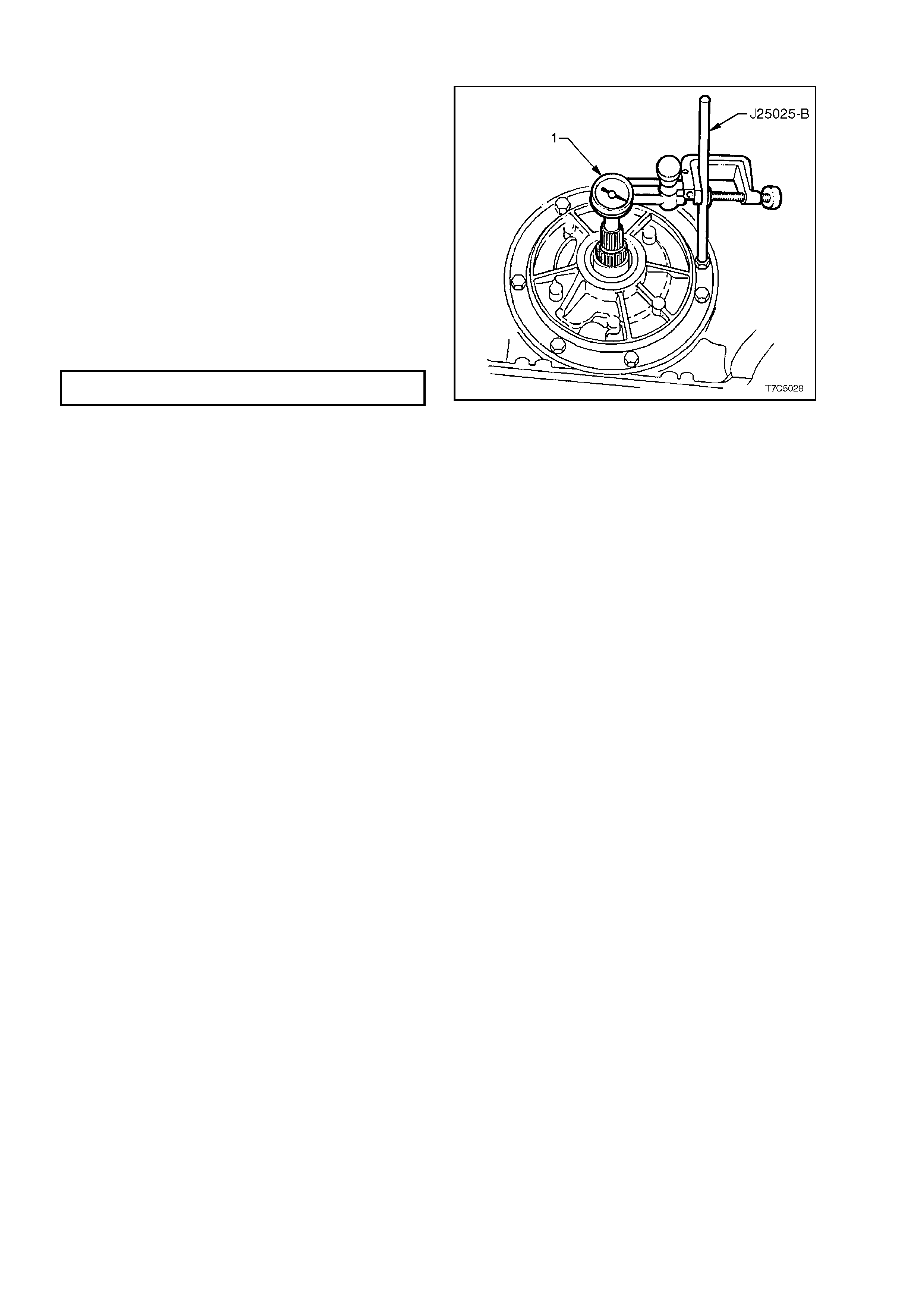
2. Remove an oil pump bolt and install Tool No.
J25025-B and secure with the locknut.
3. Install dial indicator (1) using a commercially
available clamp on Tool No. J25025-B and set
to zero in contact with end of input shaft.
4. Pull up on input shaft by hand to measure end
play.
TRANSMISSION END PLAY
SPECI F ICATIO N 0.13 - 0.92 mm
5. Remove Tool No. J25025-B and dial indicator.
Figure 7C5-30
1.9 OIL PUMP ASSEMBLY
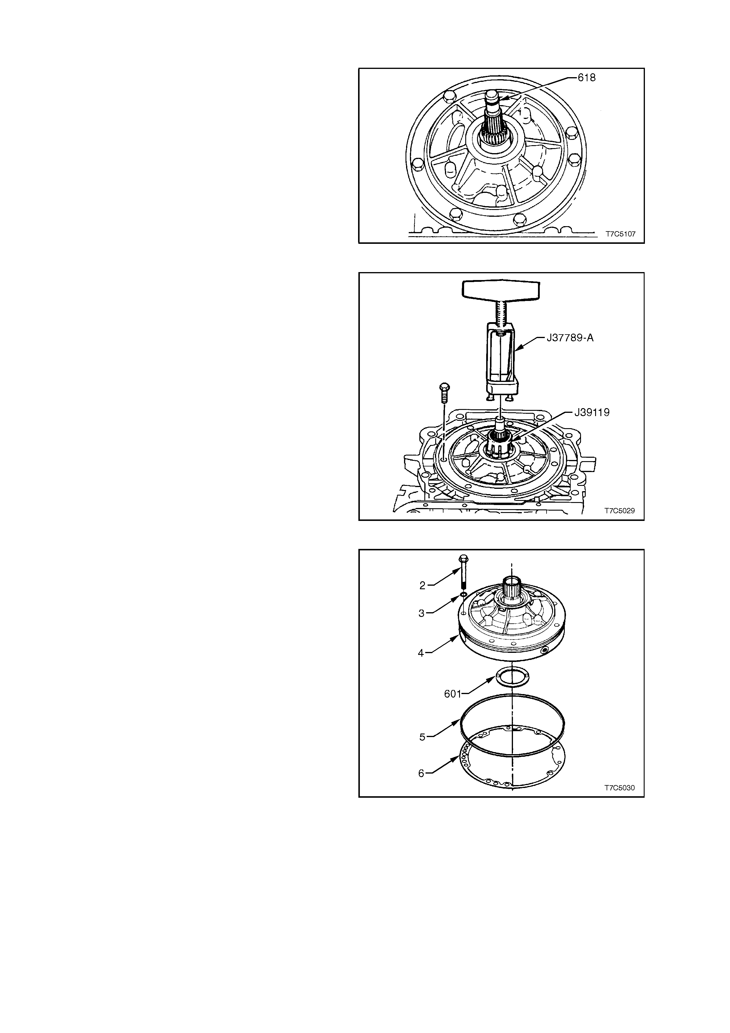
1. Remove input shaft O-ring (618) from the
turbine shaft.
2. Prise the front helix seal retainer from the oil
pump housing.
3. Using a suitable seal removing tool, such as
E308 or similar, extract the seal and discard.
Figure 7C5-31
4. Remove remaining oil pump bolts and seals.
5. Slide Tool No. J39119 over the stator shaft until
it locks under the splines. Install Tool No.
J37789-A over J39119 and tighten the clamp
bolt. Unseat oil pump assembly by turning the
forcing screw against the input shaft. Remove
the oil pump assembly from the transmission
case.
6. Remove special tools from the oil pump.
Figure 7C5-32
7. Remove oil pump to case seal (5) and gasket
(6).
8. Rem ove reverse input clutch to oil pum p thrust
washer (601).
NOTE: Thrust washer (601) is selectable to obtain
the correct transmission end play, measured in
1.8 TRANSMISSION END PLAY CHECK in this
Section.
Figure 7C5-33
1.10 REVERSE INPUT CLUTCH, INPUT CLUTCH, 2-4 BAND AND INPUT GEAR SET
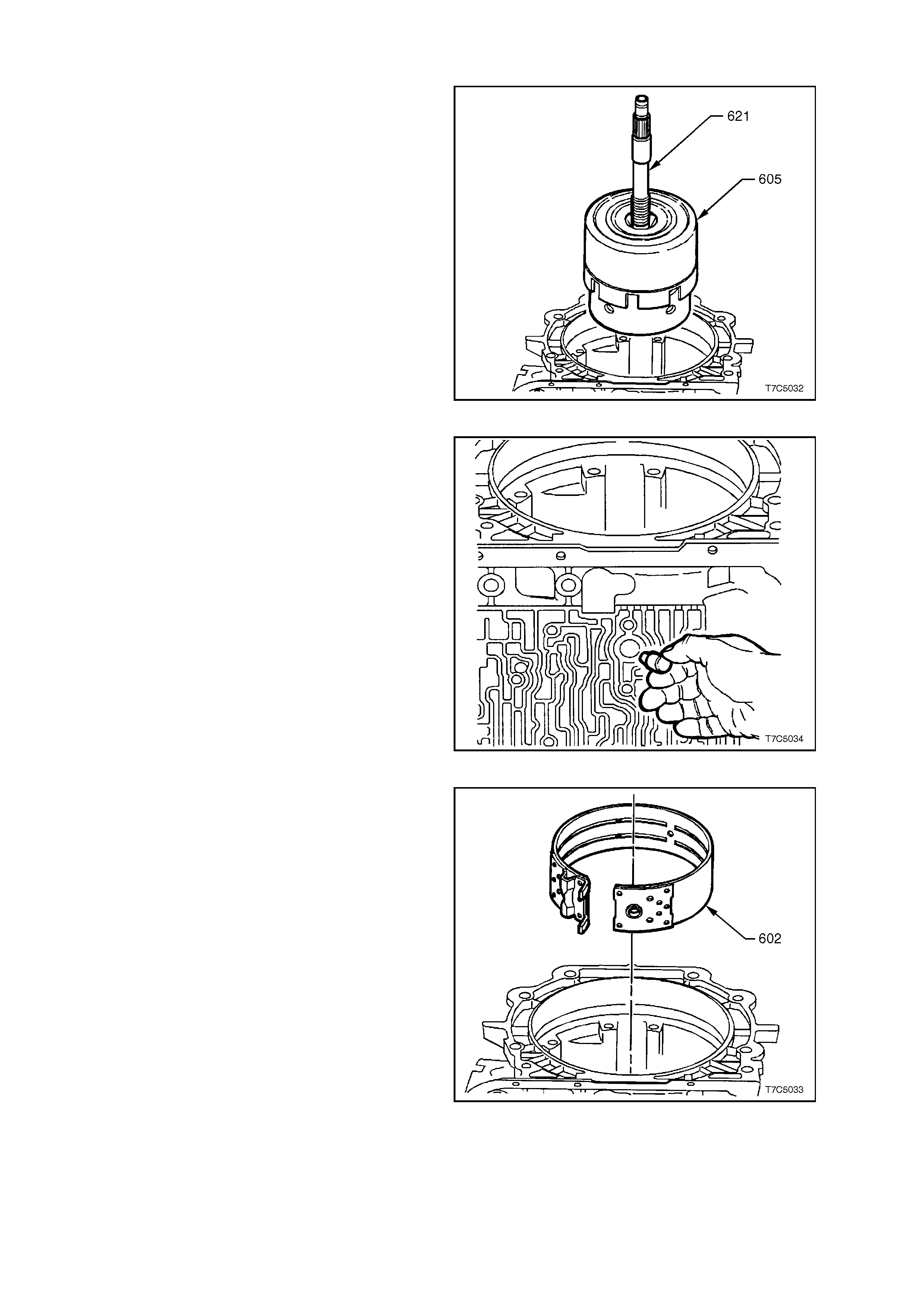
1. Remove reverse input clutch (605) and input
clutch assembly by grasping input shaft (621)
and withdrawing the assembly from
transmission case .
NOTE: Take care, as this assembly is heavy.
Figure 7C5-34
2. Remove 2-4 band anchor pin from the
transmission case .
Figure 7C5-35
3. Remove 2-4 band assembly (602).
Figure 7C5-36
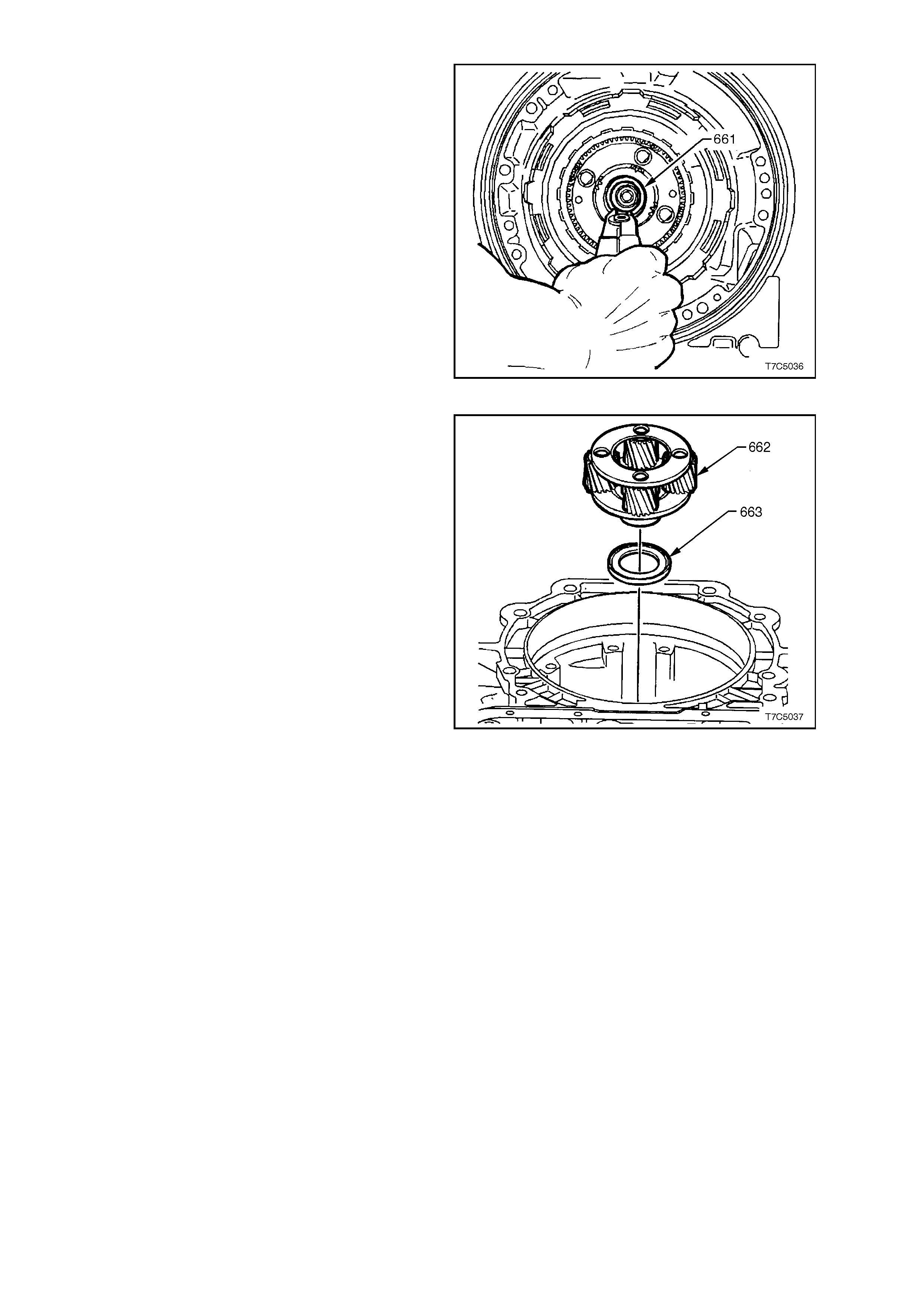
4. Remove input carrier to output shaft retaining
ring (661) using suitable snap ring pliers.
NOTE 1. Do not over expand ring.
NOTE 2. Using the snap ring pliers that are
available as Tool No. J34627, will not only make
the task of circlip removal easier but there will be
less chance of the snap ring being over expanded.
NOTE 3. T he output shaf t will tend to f all out of the
transmission when the retaining ring is removed,
unless the fabricated bracket was fitted to the
output shaft (Refer to
1.4 SPEED SENSOR A ND CASE EXTENSION).
Figure 7C5-37
5. Remove input carrier assembly (662).
6. Remove thrust bearing (663).
Figure 7C5-38
1.11 REACTION GEAR SET
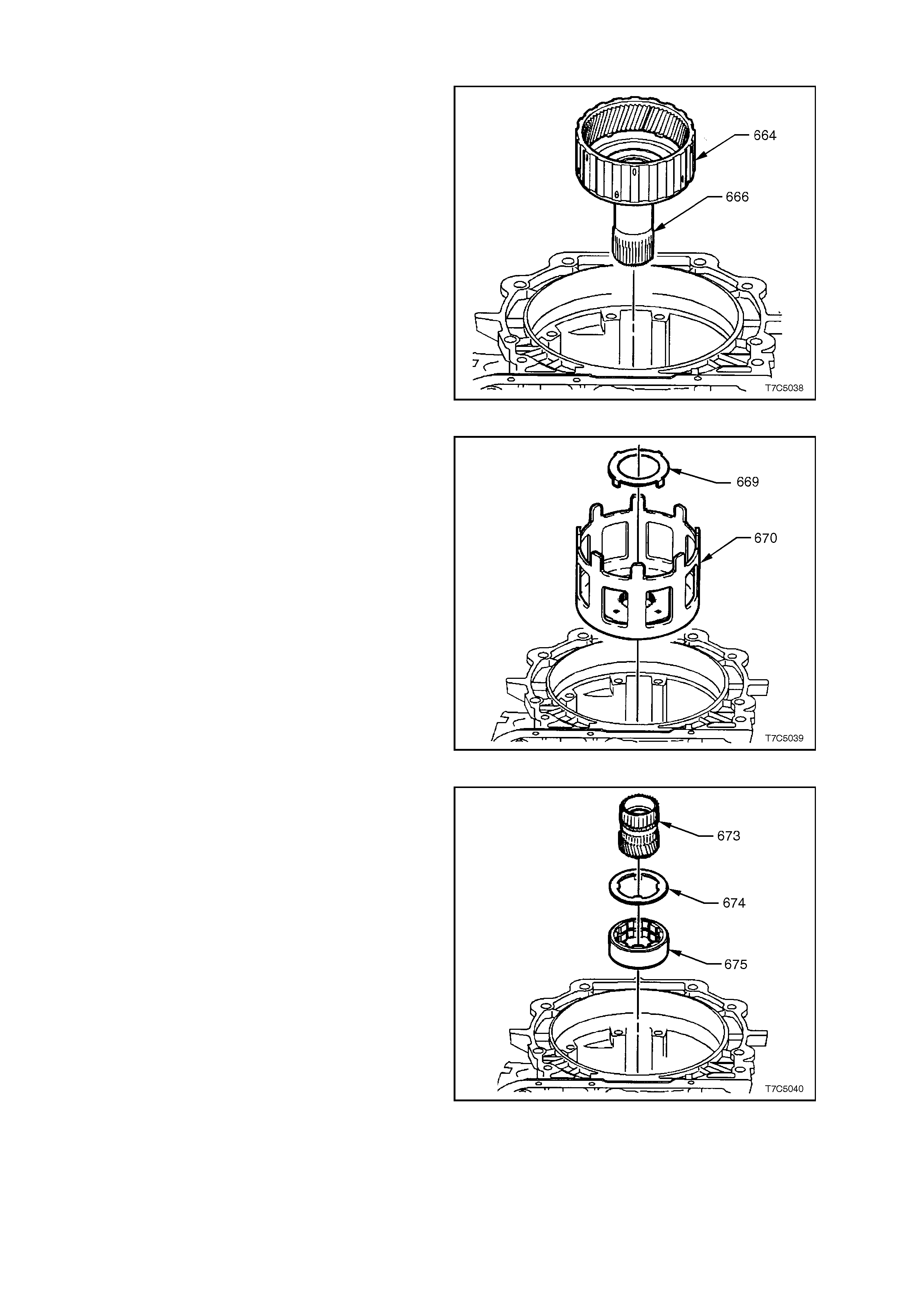
1. Remove input internal gear (664) and reaction
carrier shaft (666).
Figure 7C5-39
2. Remove reaction shaft/shell thrust washer
(669) and reaction sun shell (670).
Figure 7C5-40
3. Remove reaction sun gear (673).
4. Remove race/reaction shell thrust washer
(674).
5. Remove low and reverse roller clutch race
(675), by holding the inner surface and turning
the race in the 'free' direction.
Figure 7C5-41
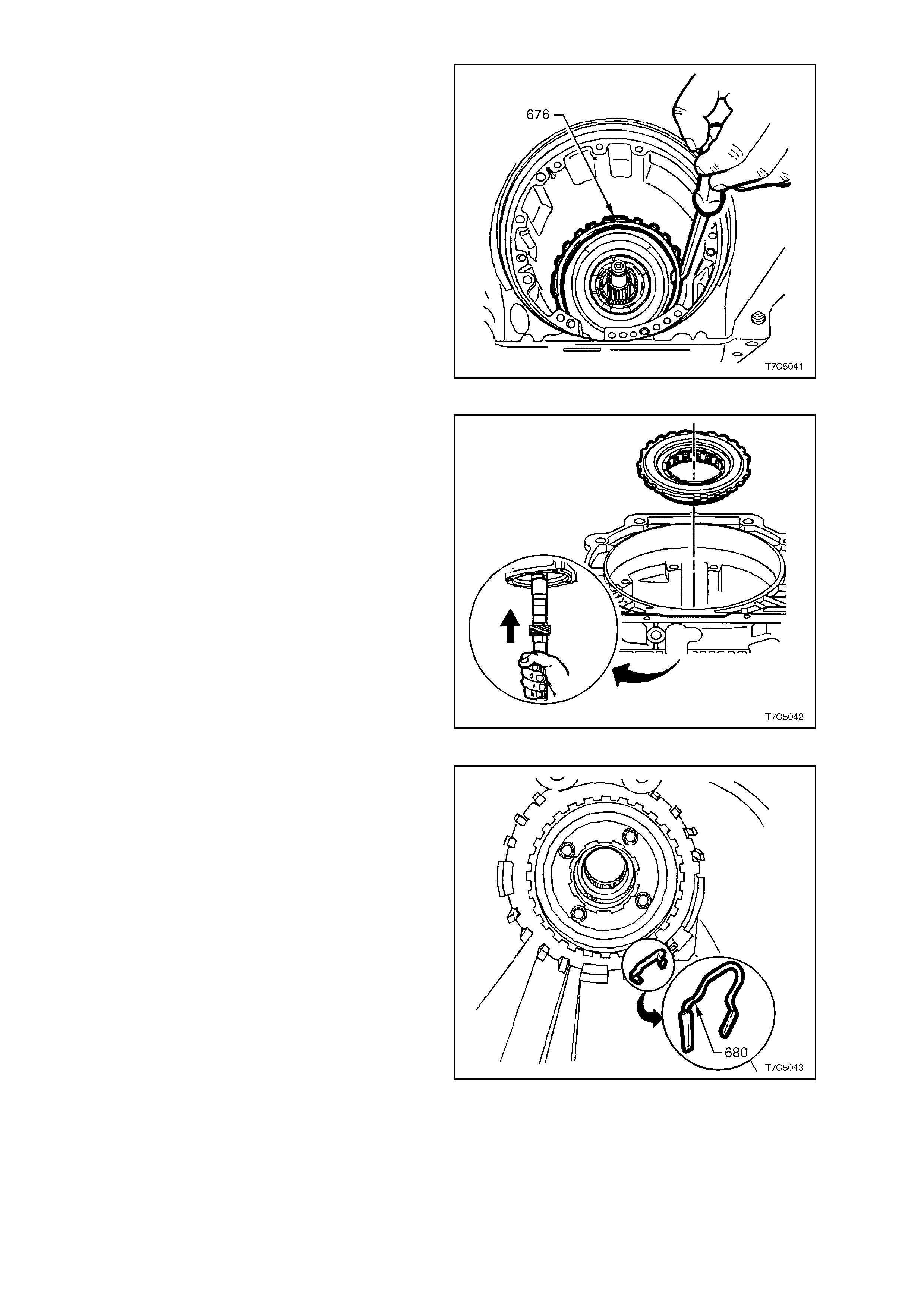
6. Remove low and reverse support to case
retaining ring (676).
7. Remove fabricated bracket and withdraw
output shaft (see Fig. 7C5-11).
NOTE: Depending on the distance the transmission
has travelled, there may be some resistance to
removal of the mainshaft from the input carrier. If
so, tap the inboard end of the output shaft with a
plastic faced hammer to dislodge.
Figure 7C5-42
8. Reinser t m ainshaf t and push up to dislodge the
low and reverse clutch support assembly.
9. Remove the low and reverse clutch support
from the transmission case.
Figure 7C5-43
10. Remove low and reverse clutch support
retainer spring (680).
Figure 7C5-44
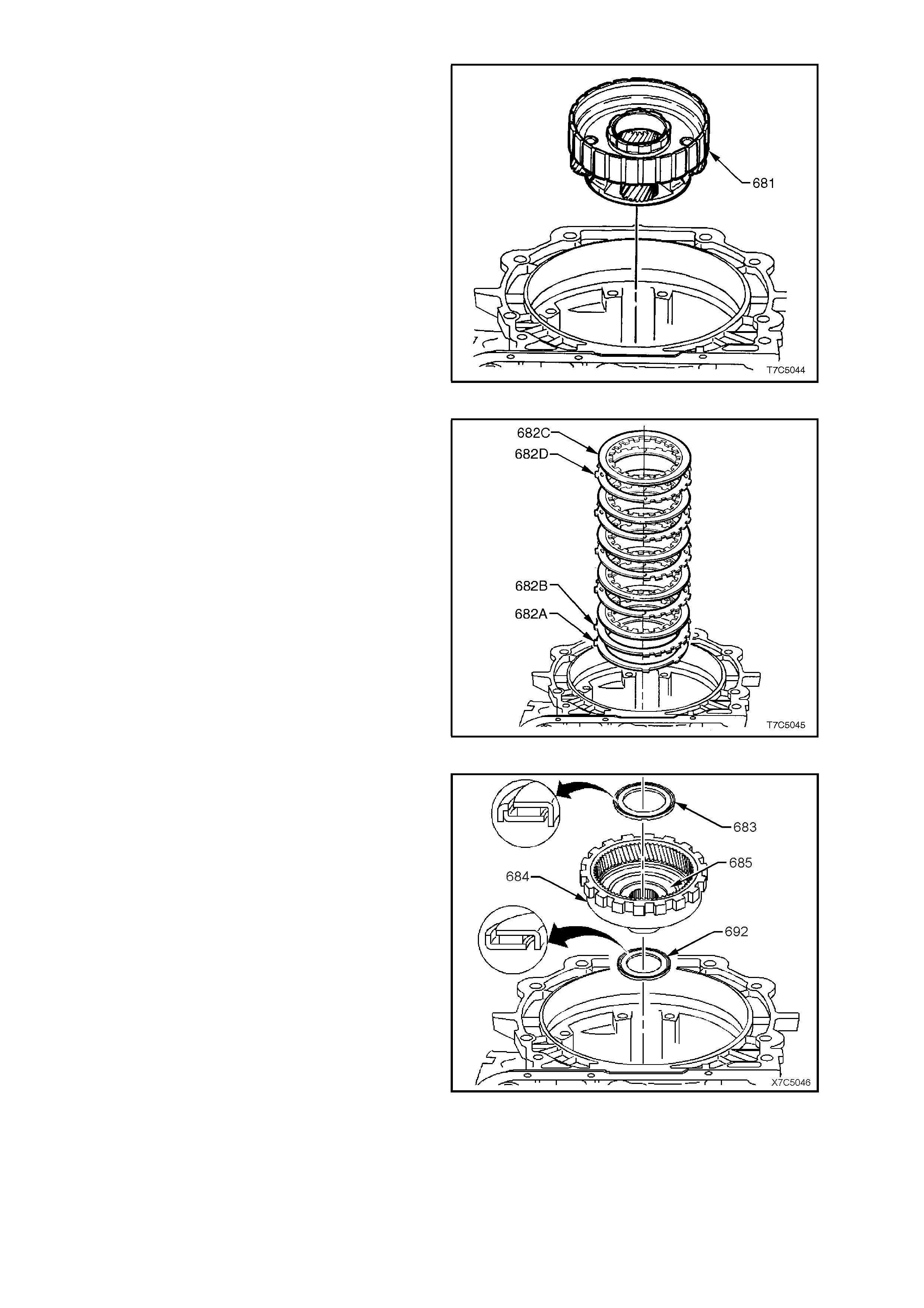
11. Remove the reaction carrier (681).
Figure 7C5-45
12. Remove low and reverse clutch plate
assembly;
682C Composition plates.
682D Steel plates.
682B Selective spacer plate.
682A Wave plate.
Figure 7C5-46
13. Remove reaction carrier support thrust bearing
(683), reaction internal gear (684) and support
assembly (685).
14. Remove reaction gear support to case bearing
assembly (692).
NOTE: The orientation of the two thrust bearings
for correct reassembly.
Figure 7C5-47
1.12 LOW AND REVERSE CLUTCH ASSEMBLY
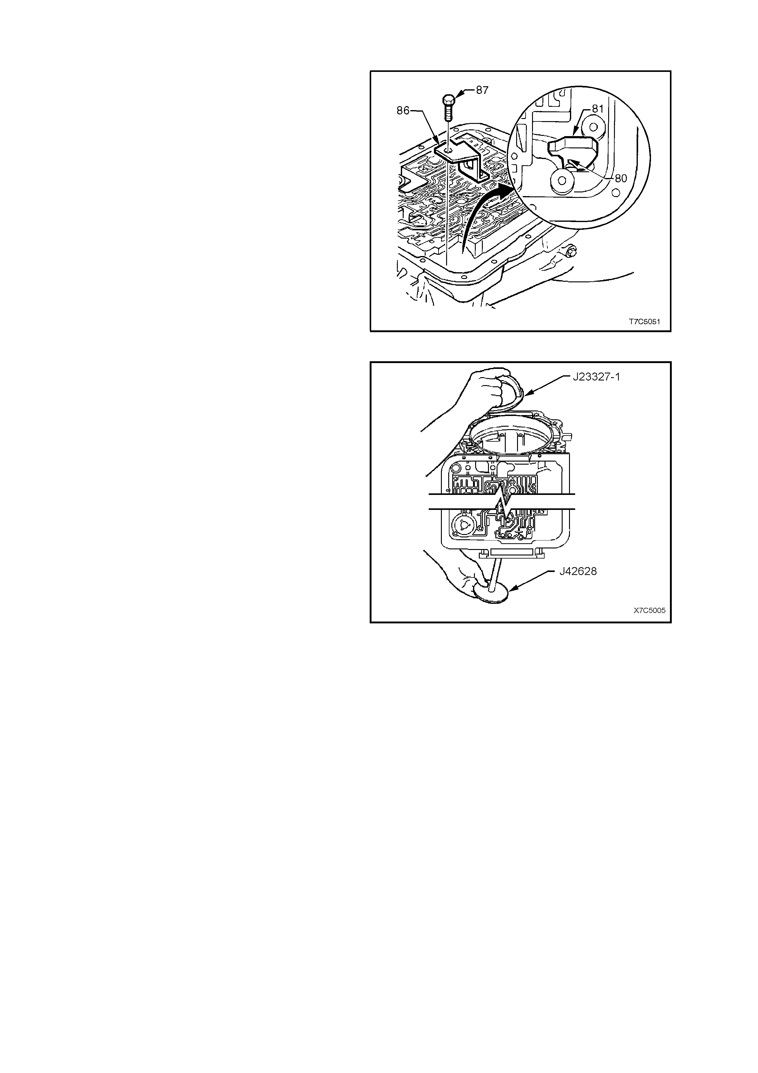
1. Remove bolts (87- two places) securing the
parking pawl bracket (86). This will allow the
spring (80) to retract the parking pawl (81),
providing clearance to remove the low and
reverse clutch.
NOTE: If the parking pawl needs to be removed
completely because of interference, follow the next
three steps.
Otherwise, continue the disassembly from step 5.
2. Remove pawl shaft plug with a suitable easy
out extractor (not shown).
3. Use a magnet to remove pawl pivot shaft.
4. Remove parking pawl bracket, pawl and spring.
Figure 7C5-48
5. Install the forcing bolt of Tool No. J23327-1
through plate J42628, then install into the rear
of the transmission case.
6. Install press c age of Tool No. J23327-1 into the
transmission case, over the forcing bolt and
secure with the provided wing nut.
Figure 7C5-49
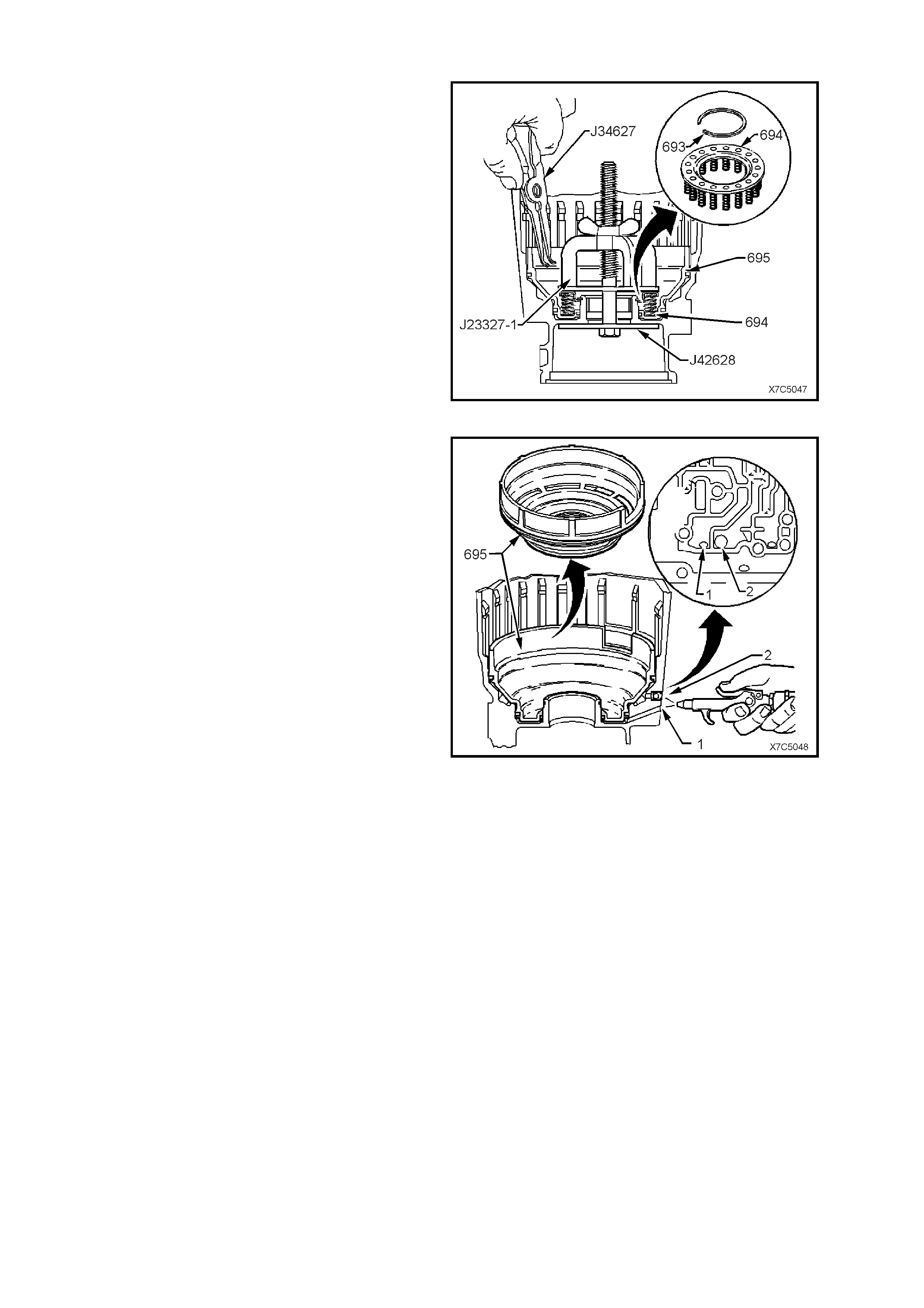
7. Tighten the wing nut of Tool J23327-1 to
compress the low and reverse clutch springs
(694) and clear access to the retaining snap
ring (693).
8. Remove low and reverse clutch retaining snap
ring (693), using snap ring pliers J34627 or
equivalent.
9. Remove J23327-1 and low and reverse clutch
spring assembly (694).
Figure 7C5-50
10. Apply low pressure air to either the Low feed
passage (1) or the Reverse feed passage (2),
as shown, to assist in the removal of the low
and reverse clutch piston. Remove piston
(695).
CAUTION: To reduce the possibility of injury, do
not use air pressure in excess of 70 kPa for this
operation.
Figure 7C5-51
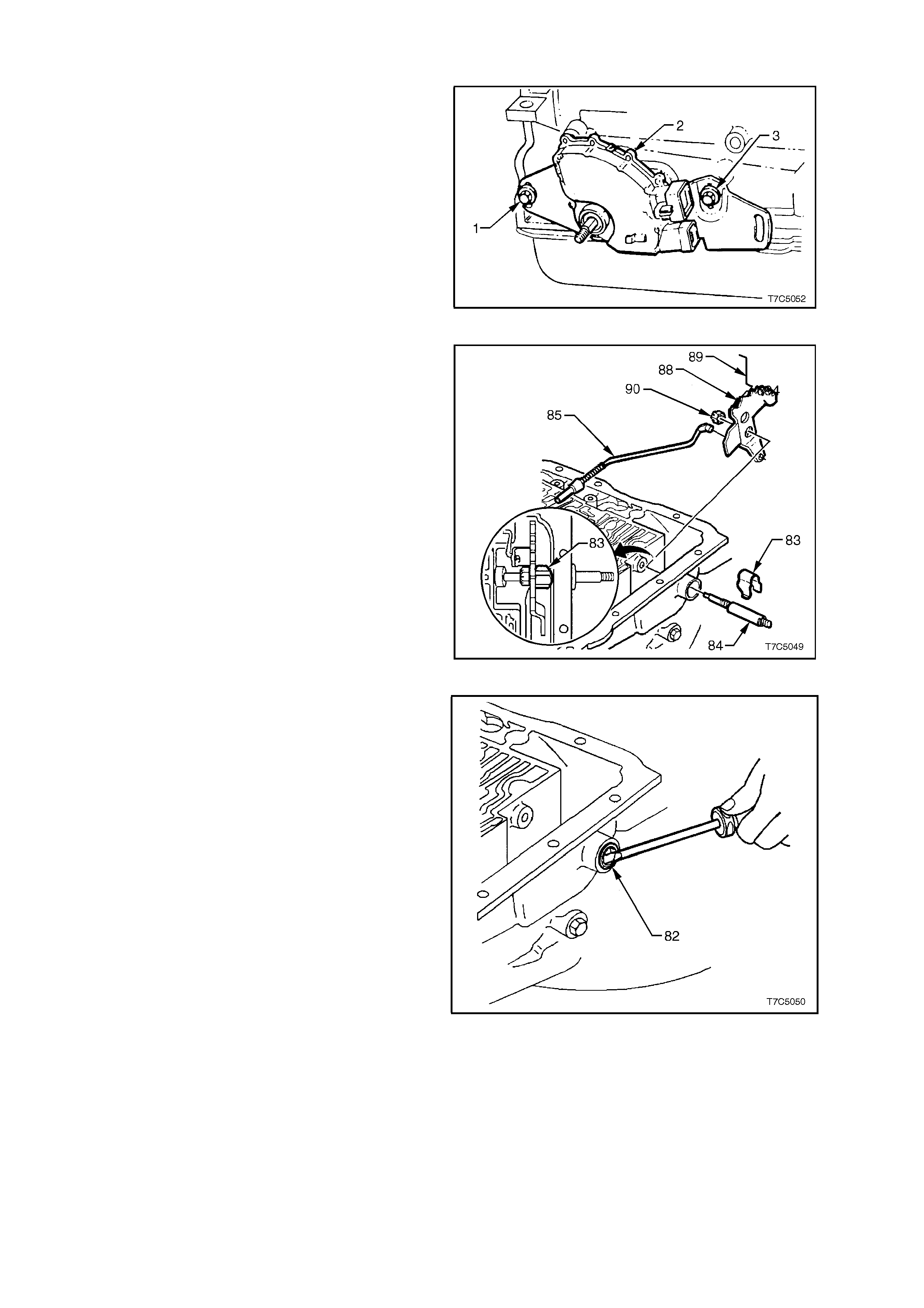
1.13 INNER MANUAL SHAFT, LINKAGE AND SEAL
1. Rem ove the two screws (1 and 3) securing the
neutral start and back-up lamp switch (2), then
remove the switch (2) from the transmission
case.
Figure 7C5-52
2. Remove the nut (90) securing the inner detent
lever (88) to the manual shaft (84).
3. Remove the inner detent lever ( 88) and par king
pawl actuator rod (85).
4. Rem ove the retaining c lip (83) f rom the m anual
shaft (84).
5. Withdraw the manual shaft (84) from the
transmission case .
Figure 7C5-53
6. Pry out the manual shaft seal (82) from the
transmission case with a suitable screwdriver.
NOTE: An alternative method of seal removal is to
use the released special tools. Refer to
7C4 AUTOMATIC TRANSMISSION – ON-
VEHICLE SERVICING in the VX Series, for details.
Figure 7C5-54
2. COMPONENT DISASSEMBLE, INSPECTION, REASSEMBLE
2.1 CASE
INSPECT
1. W ash case thoroughly with solvent, dry with air
and blow out all oil passages.
NOTE: Do not use cloth to dry.
2. Inspect case for cracks or porosity.
3. Check case to valve body face for damage,
distortion and inter-connected oil passages.
NOTE: F ac e f latness c an be chec ked by inspecting
the case, spacer plate gask et for complete witness
marks. If the marks are incomplete, an uneven
case surface, or cross channel leaks are indicated.
4. Check transmission vent tube, located at the
top of the transmission case (refer ‘9’ in Fig.
7C5-56), for damage and/or blockage.
5. Using compressed air, check all oil passages.
For case channel identification, refer to
7C3 DIAGNOSIS of the VT Series I Service
Information for identification of these fluid
passages.
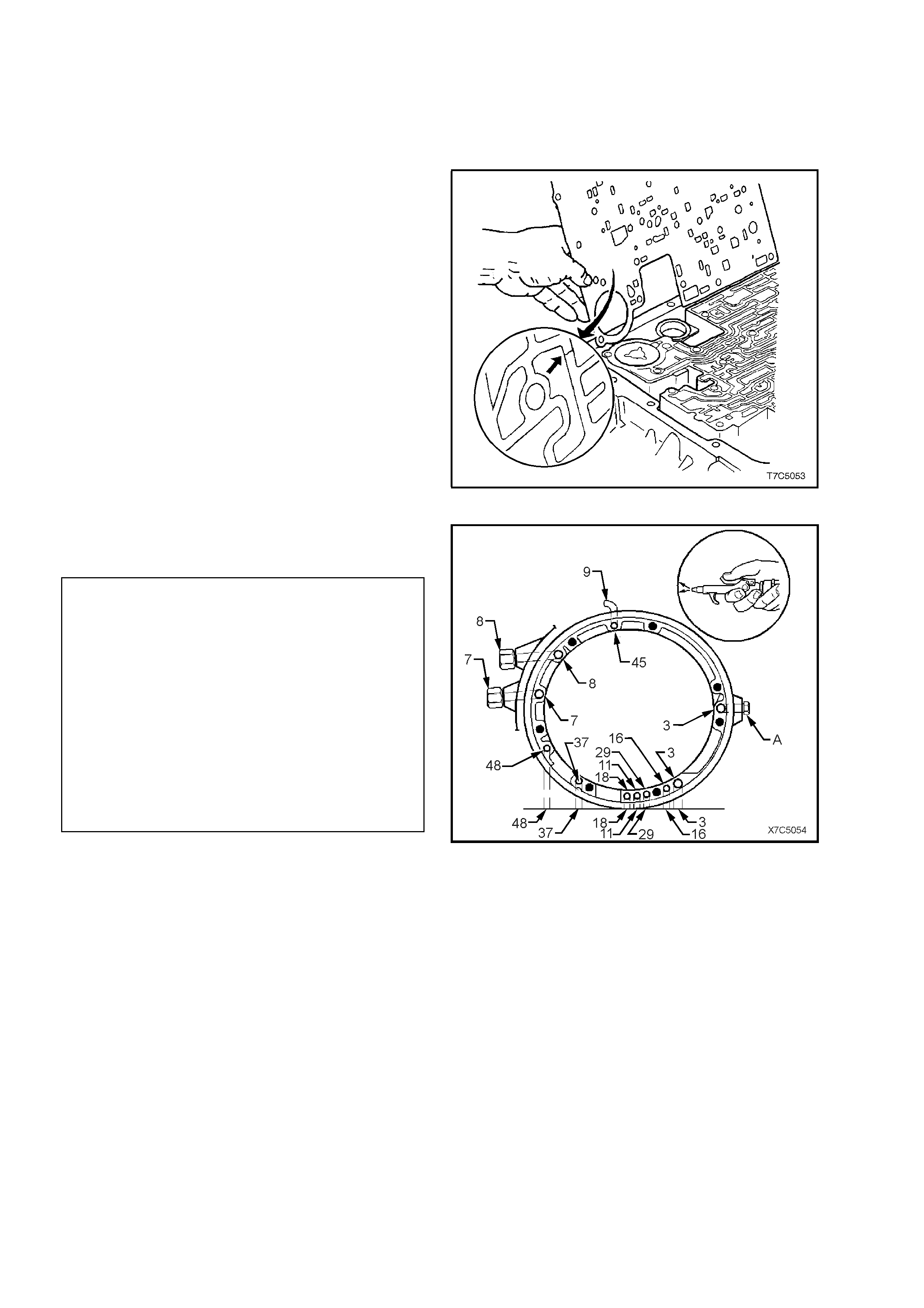
Figure 7C5-55
6. Check oil pump fluid passages by blowing
LOW pressure compressed air into the
numbered passages as shown.
Legend - Case, Oil Pump Fluid Passages
3 Line Pressure
7 To External Cooler
8 From External Cooler
11 Torque Signal
16 Reverse Input Clutch
18 Forward Clutch Feed
29 3-4 Clutch
37 Overrun Clutch
45 Vent
48 Torque Converter Clutch Regulated Apply
A Line Pressure Plug
Figure 7C5-56
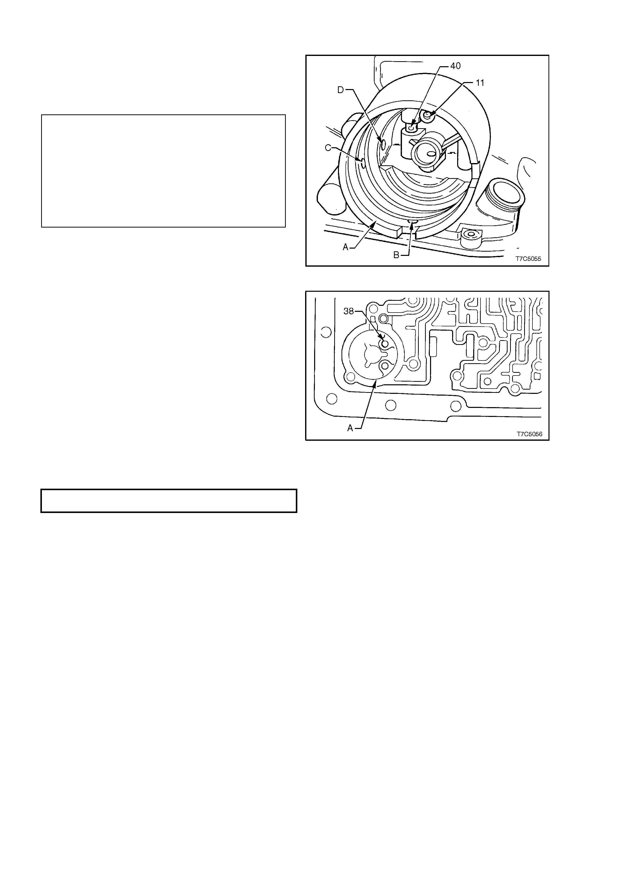
7. Inspect 2-4 servo bore (A) for damage or
porosity. Ensure all slots and passages are
clear. Check for sharp edges. Check orifice
cup plug in the servo bore (11) for debris or
damage.
Legend - 2-4 Servo Bore and Components
A 2-4 Servo Bore
B Servo Exhaust Hole
C 2nd and 4th Band Apply Passage
D 3rd Accumulator Pressure Tap Passage
11 Orifice Cup Plug
40 3rd Accumulator Retainer and Ball
Assembly
Figure 7C5-57
8. Inspect 3-4 accumulator bore (A) and orifice
cup plug (38) for damage or porosity. Ensure
all slots and passages are clear. Check for
sharp edges. Check for pin damage.
9. Inspect vehicle speed sender unit bore for
damage or porosity.
10. Inspect all bolt holes and oil cooler pipe
connections for thread damage. Repair with
thread inserts or equivalent, as necessary.
Figure 7C5-58
11. If removed, tighten oil c ooler pipe connections to
the correct torque specification.
OIL COOLER PI PE CONNECTIONS
TORQUE SPECIFICATION ............................. 35 - 41 Nm
12. Inspect case interior for:
a. Damaged ring grooves or casting flash.
b. Clutch plate lugs worn or damaged.
c. Worn or damaged bushes.
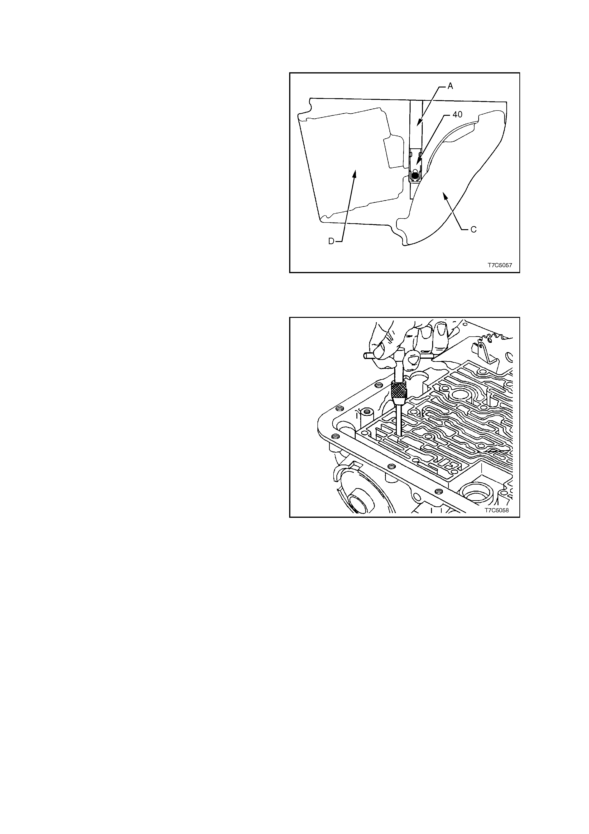
2.2 THIRD ACCUMULATOR RETAINER AND BALL ASSEMBLY
INSPECT
1. Inspect third accumulator ball and retainer
(refer ‘40’ in Figs. 7C5-57 and 7C5-59) for:
a. Ball missing, damaged or sticking.
b. Retainer loose or not seated correctly.
c. Feed slots restricted.
2. Check third accumulator ball assembly (40) for
leaking as follows:
a. Reinstall the assembled 2-4 servo
components, including cover and retaining
ring, into 2-4 servo bore (D).
b. Pour suitable solvent into third ac cum ulator
bore (A).
c. Watch for leakage into case interior (C).
NOTE: Bec aus e f luid will flow f rom the or if ic e in the
case servo plug (‘11’ in Fig. 7C5-57), careful
observation of the source of the fluid leakage will
be required.
d. Remove 2-4 servo components.
Figure 7C5-59
REPLACE
If leakage is observed to come from the third
accumulator ball assembly, replace as follows:
1. Remove old assembly with a suitable screw
extractor (6.3 mm or #4).
Figure 7C5-60
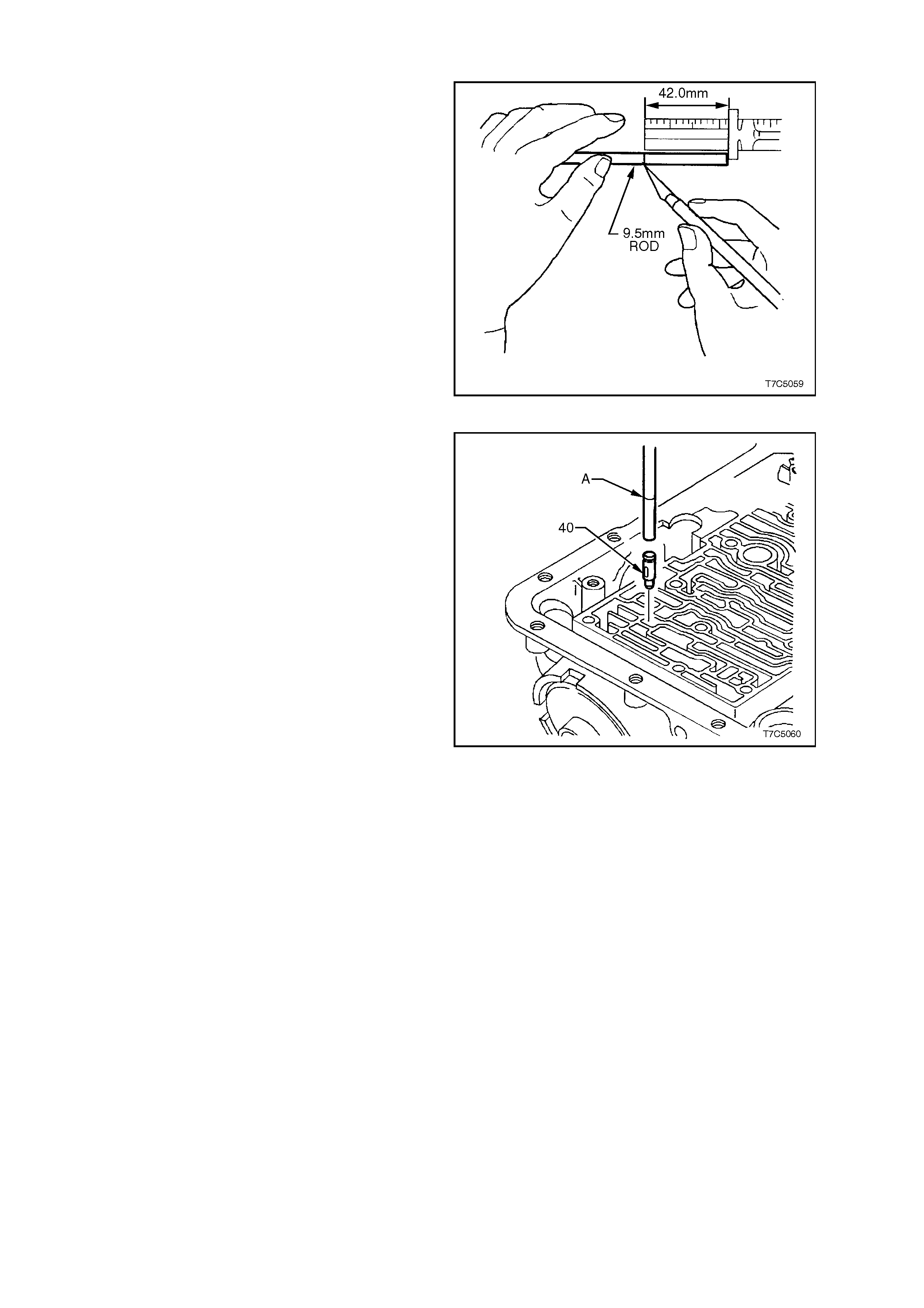
2. Select a suitable length of 9.5 mm rod and
scribe a mark, 42 mm from a squared end, to
indicate the correct depth of installation.
Figure 7C5-61
3. Using the 9.5 mm rod, install a new 3rd
accumulator retainer and ball check assembly
(40), aligning the oil feed slots with the servo
bore (refer ‘40’ in Fig. 7C5-57).
4. Install the 3rd accumulator ball and retainer
assembly (40) until the scribe mark (A) on the
rod, is level with the case face.
Figure 7C5-62
2.3 CASE BUSHING
REPLACE
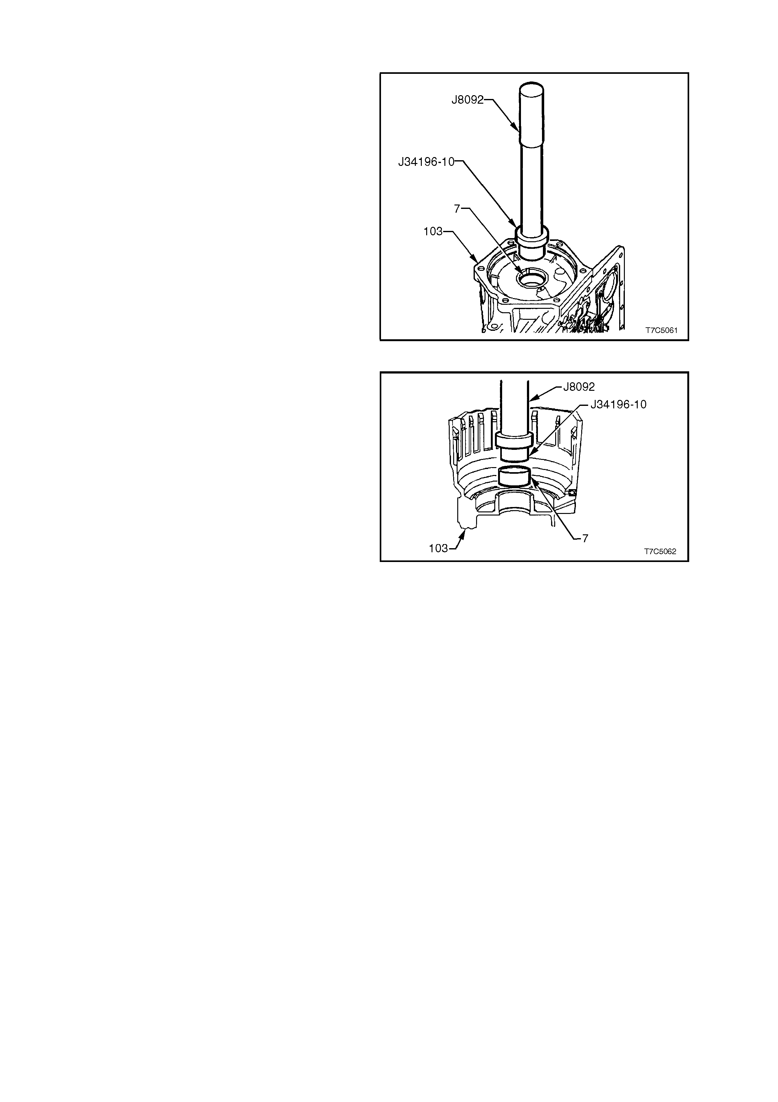
1. Using bush re m over T ool J34196-10 and dr iver
handle Tool J8092, press the rear bushing from
the transmission case.
Figure 7C5-63
2. Install a new bush, using the same tools as f or
removal.
Figure 7C5-64

2.4 2-4 SERVO ASSEMBLY
INSPECT
1. Inspect components for wear or damage. Check springs for broken coils and/or distortion.
2. Inspect bore in transmission case for any sharpness that may damage servo seals.
2.5 LOW AND REVERSE CLUTCH ASSEMBLY
INSPECT
1. Inspect piston (695) for porosity or damage.
2. Inspect spring assembly (694) for damage.
3. Inspect retaining ring (693) for distortion.
4. Remove piston seals (696) and discard.
Lubricate new seals with transm ission f luid and
install on piston.
Figure 7C5-65
5. Inspect low and reverse clutc h plates ( 682C/D).
Check composition plates (682C) for wear,
heat damage or delamination and check steel
plates ( 682D) f or heat damage or s ur f ac e f inish
damage.
Figure 7C5-66
SPACER PLATE SELECTION
Select the correct spacer plate as described in the
following steps.
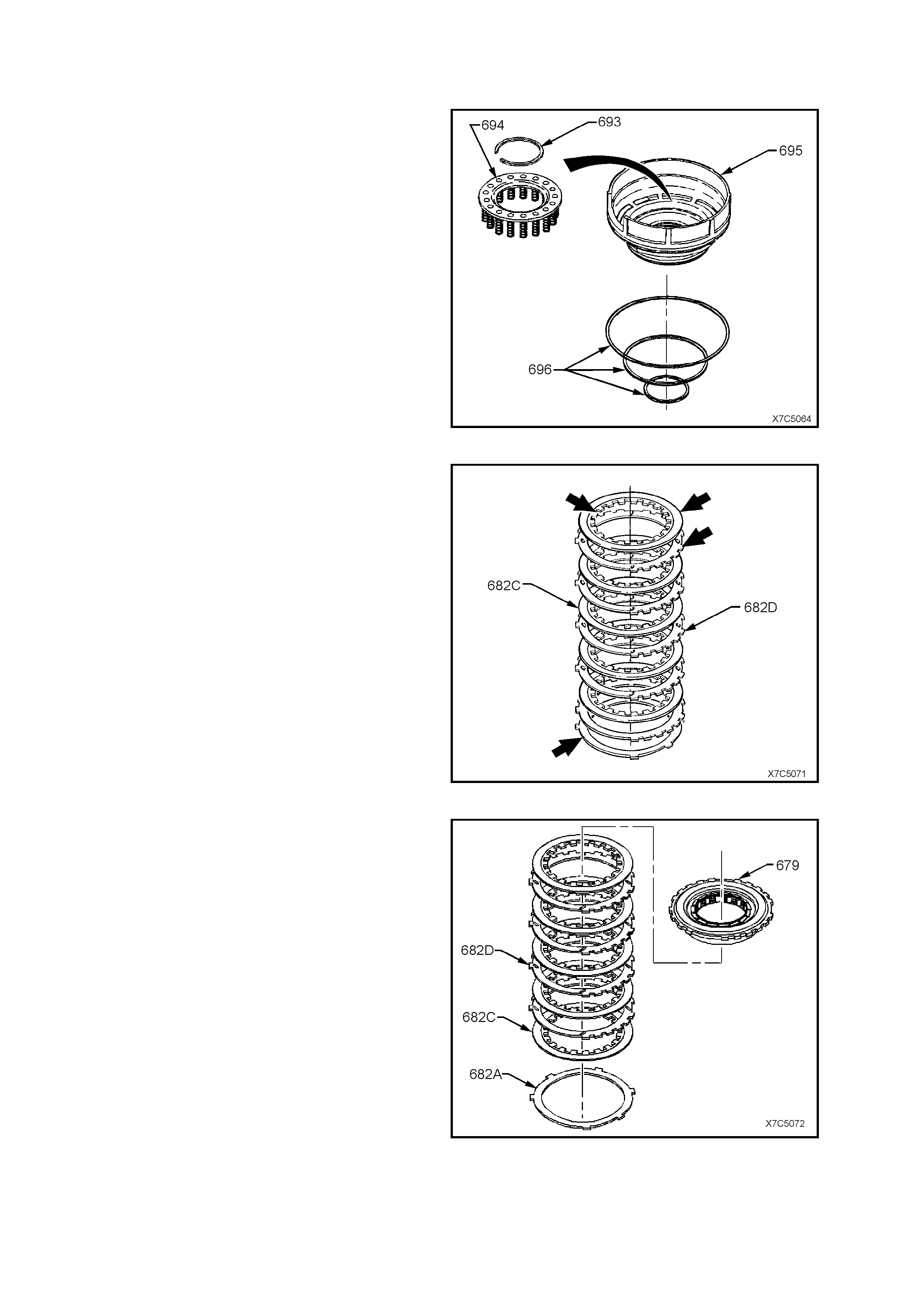
1. Stack the low and reverse clutch plates on a
flat surface in the following order:
a. 1 waved plate (682A).
b. 5 fibre (682C) and 4 steel (682D) plates,
starting with a fibre ( compos ition) plate and
alternating with a steel plate, etc.
c. Low and reverse clutch support (679).
2. Apply a light (approx. 2 kg), evenly distributed
load to the low and reverse support assembly.
Important: Excessive pressure will start to flatten
the wave plate, resulting in an incorrect
measurement.
Figure 7C5-67
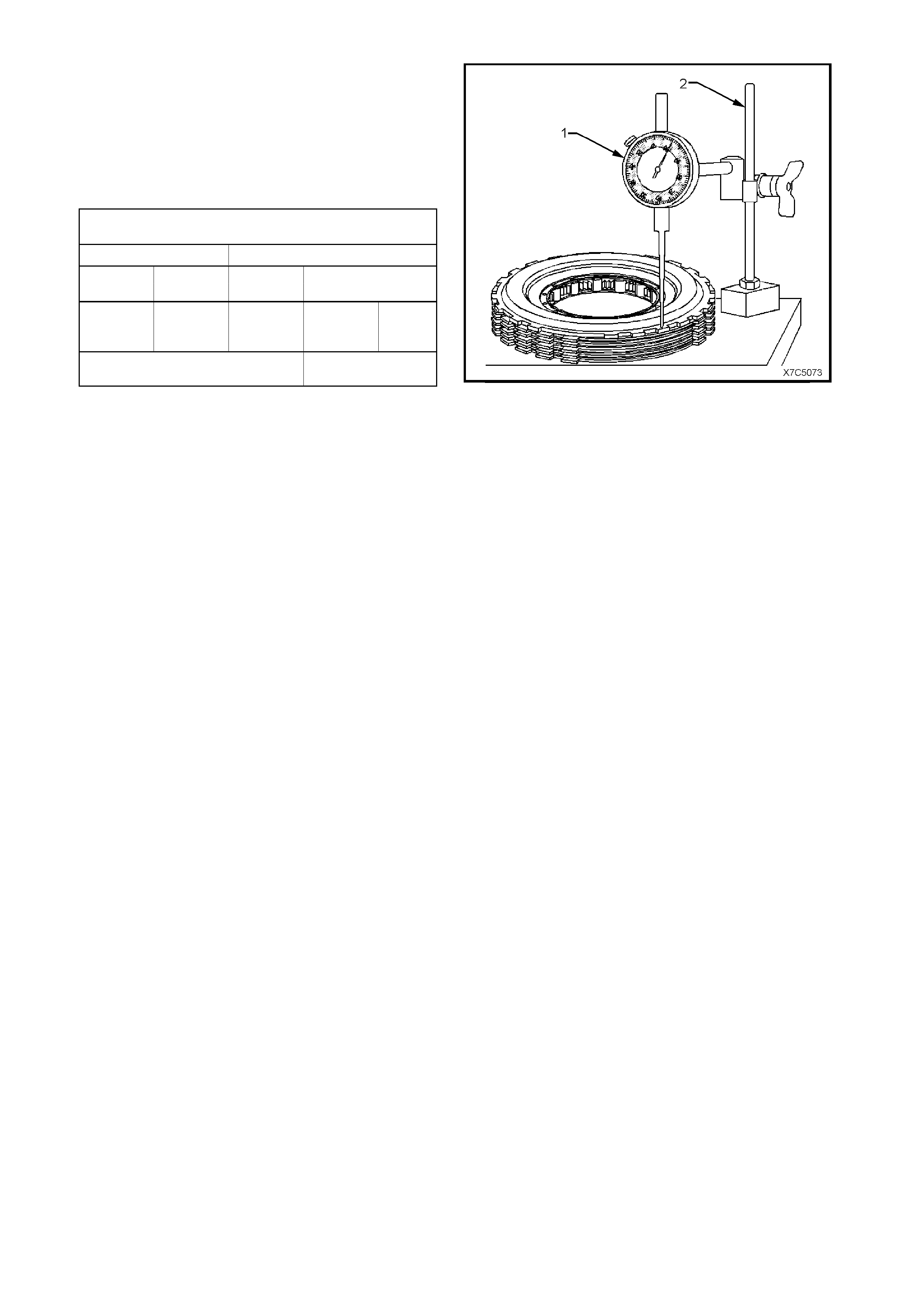
3. Using a commercially available dial indicator
(1) and magnetic stand (2), measure height of
clutch pac k f rom work s ur f ace to top of low and
reverse clutch support, noting the dimension,
with the light load applied.
4. Use the following Selection Chart to select the
correct spacer plate, relative to the measured
height.
LOW AND REVERSE CL UTCH S P ACER PLATE
SELECTION
IF PACK HEIGHT IS USE THIS SELECTIVE PLATE
FROM TO IDENTITY PLATE THICKNESS
(mm) (mm) (mm)
27.545 28.065 NONE 1.684 1.829
28.066 28.586 0 1.168 1.314
27.026 27.544 1 2.198 2.344
OVERALL CLUT CH PACK HE IGHT 29.22 - 29.90 mm
(Including Spacer Plate)
NOTE 1: The selective plate shown as 'NONE' in
the above chart, refers to a fifth, steel reaction
plate, which is to be used as the spacer plate.
NOTE 2: Should a measurement fall in an overlap
in the Selection Chart, either the s elec tive plate that
is thinner or thicker, can be fitted.
NOTE 3: Regardless of the com binations us ed, the
critical specification that must be achieved, is the
overall clutch pack height (including the spacer
plate), which is to be between 29.22 mm and 29.90
mm.
Figure 7C5-68
5. Install correct spacer plate between wave plate
and first composition clutch plate with
identification side facing upwards.
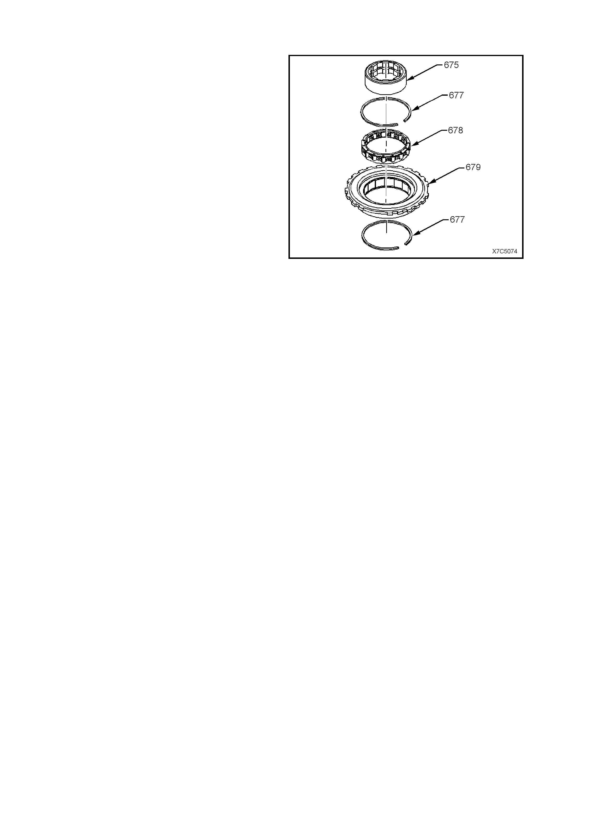
2.6 LOW AND REVERSE CLUTCH SUPPORT ASSEMBLY
1. Disassemble low and reverse support
assembly as follows:
a. Remove inner race (675).
b. Remove one retaining ring (677).
c. Remove roller clutch assembly (678).
2. Inspect inner race for damage.
3. Inspect roller clutch assembly for damaged
rollers or broken springs.
4. Inspect support assembly for loose cams,
cracks or damage.
NOTE: The low and reverse support assembly is
reassembled during transmission reassembly.
Figure 7C5-69
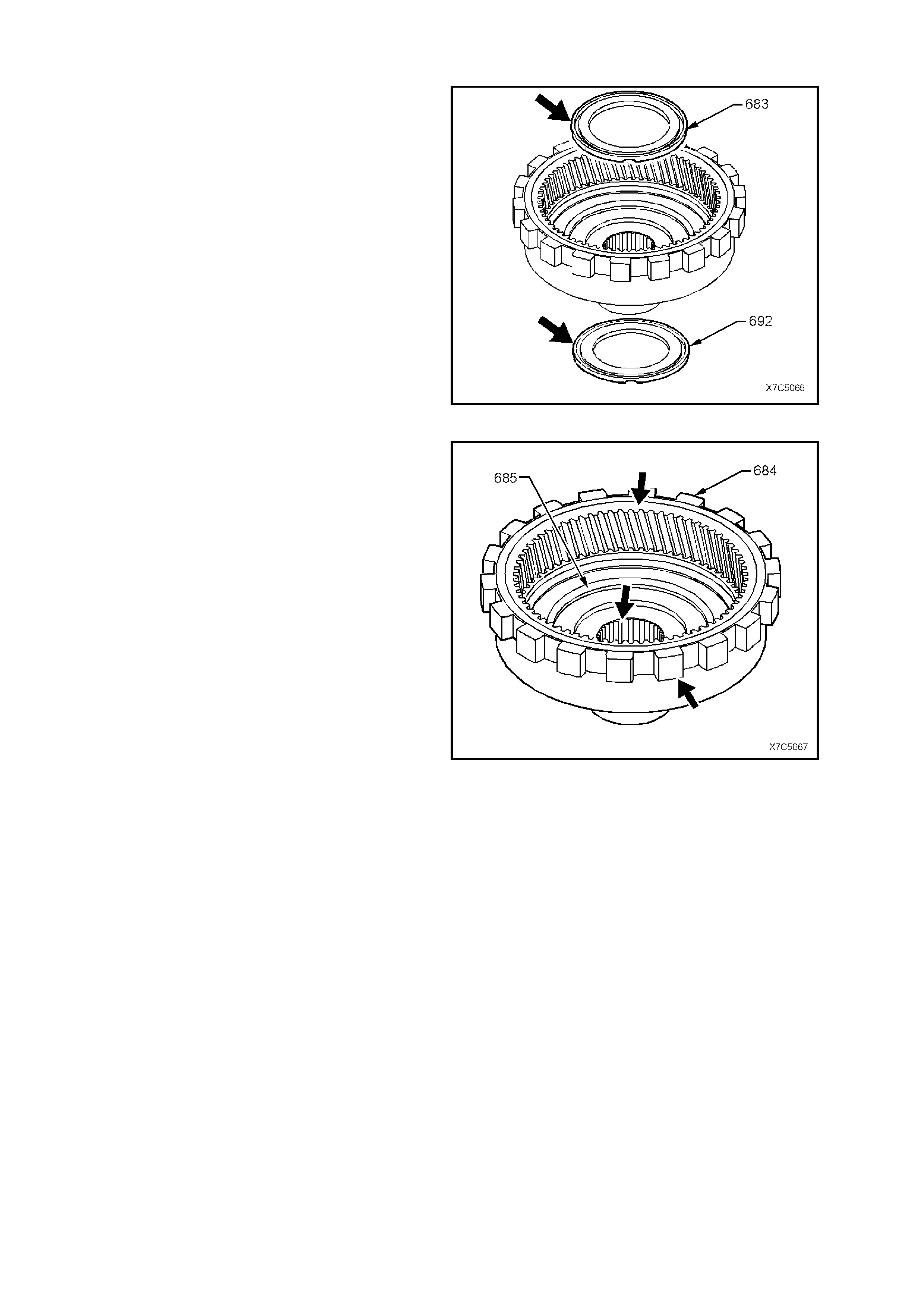
2.7 REACTION INTERNAL GEAR AND CARRIER ASSEMBLY
INSPECT
1. Inspect both the reaction to support thrust
bearing assembly (683) and the reaction gear
to support case bearing assembly (692) for
damage.
Figure 7C5-70
2. Inspect reaction internal gear (684) and support
(685) for correct assembly, stripped splines,
cracks, teeth or lug damage.
Figure 7C5-71
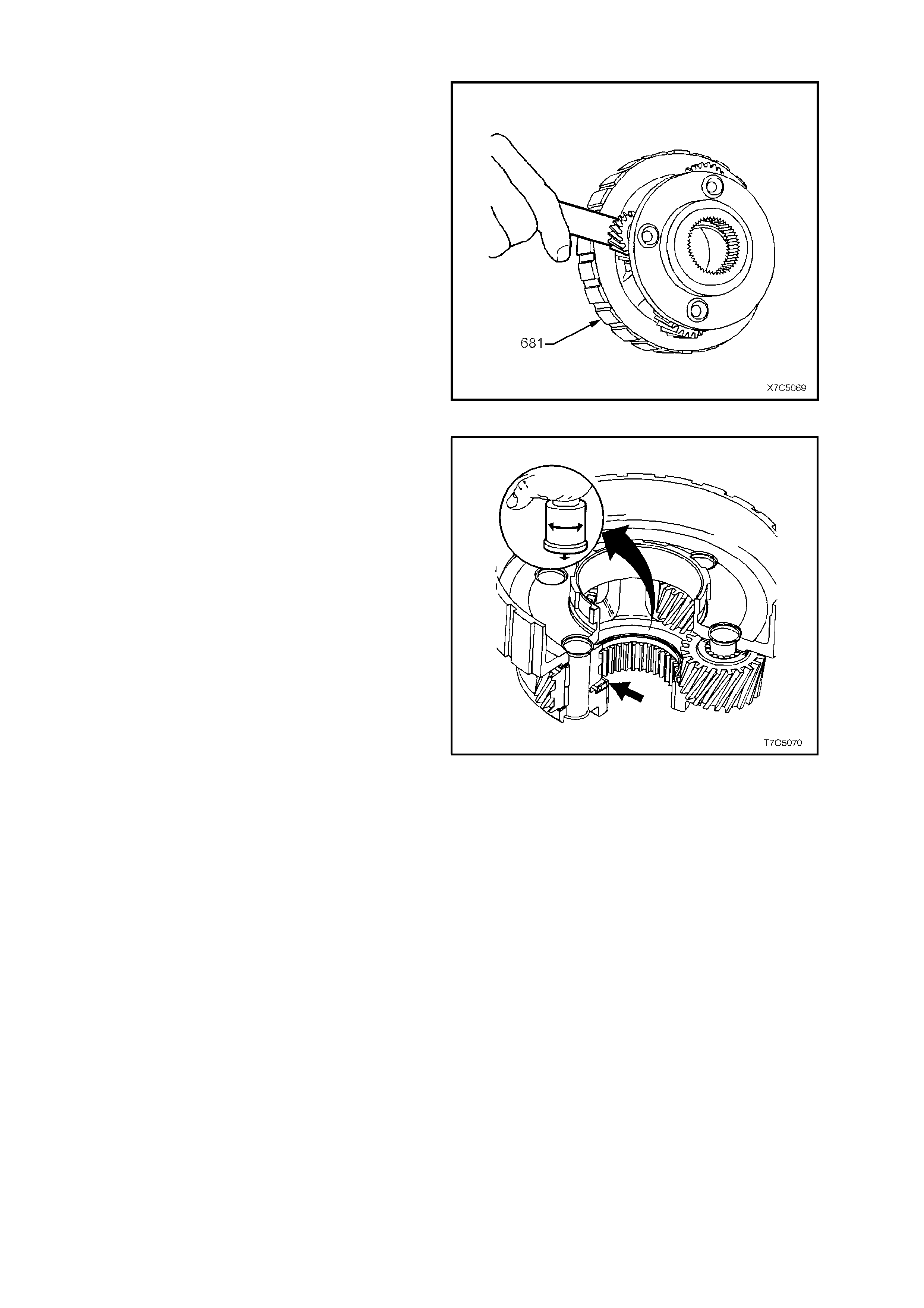
3. Inspect reaction carrier assembly (681) for
pinion gear wear, proper pinion staking and
free turning of pinions.
4. Check for excessive pinion washer wear by
measuring pinion end play. End play should be
0.20 to 0.60 mm. The reac tion car r ier assembly
is ser viced as a c om plete assembly and should
be replaced if worn or defective.
Figure 7C5-72
5. Check carrier assembly captive thrust bearing
(lower arrow) as follows:
a. Place a suitable bush (or socket) on
bearing race (do not contact pinion gears)
and turn bush with palm of your hand.
b. Any imperfections will be felt through the
bush.
Figure 7C5-73
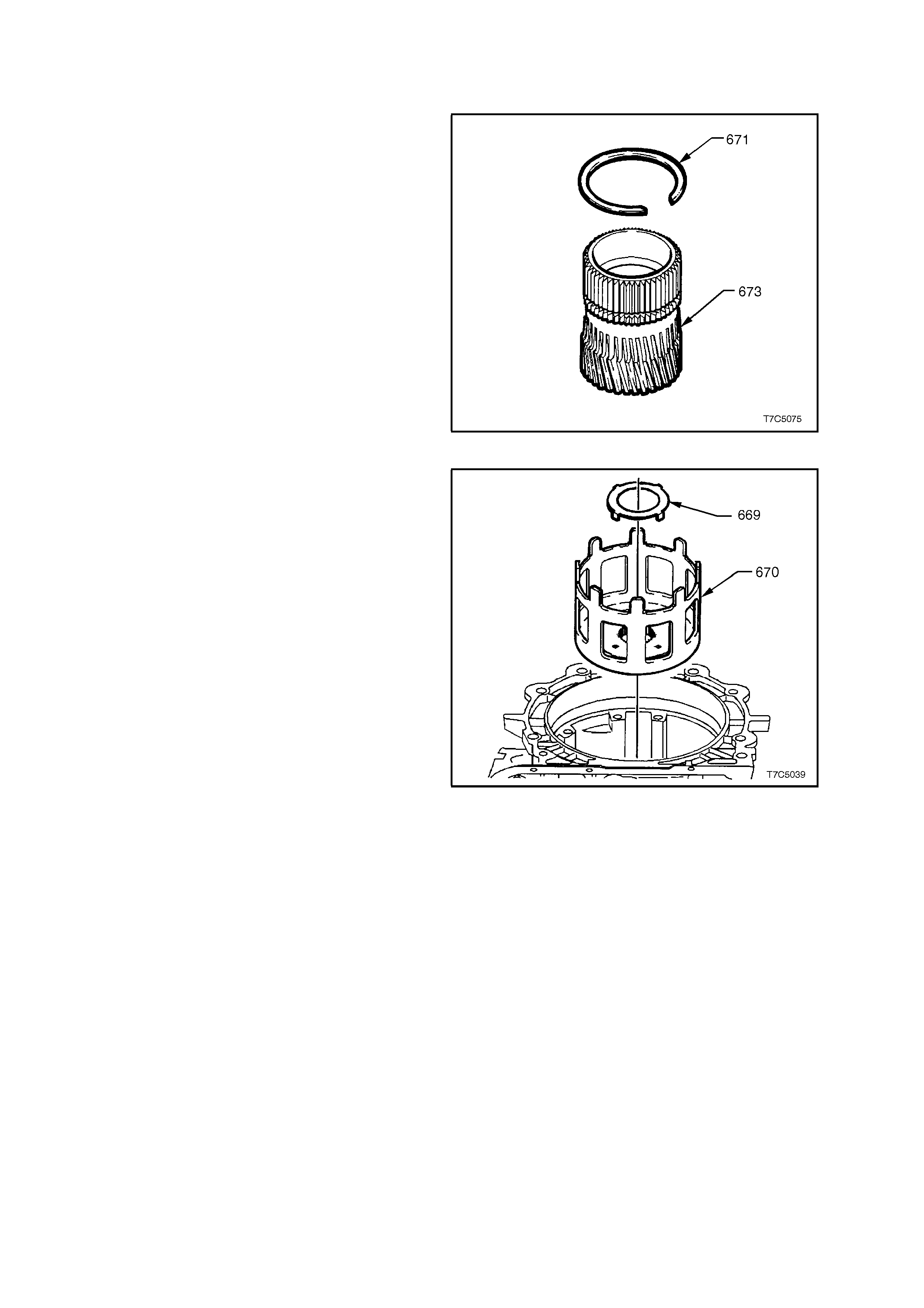
2.8 REACTION SUN GEAR AND SHELL
INSPECT
1. Inspect reaction sun gear (673) for damage to
bush, dam age to spline or teeth, loose or weak
retaining ring. Do not remove snap ring (671)
except for replacement.
Figure 7C5-74
2. Inspect reaction sun shell (670) for damage or
wear to tangs.
3. Inspect thrust washers (669, 674 - not shown)
for wear or damage.
Figure 7C5-75
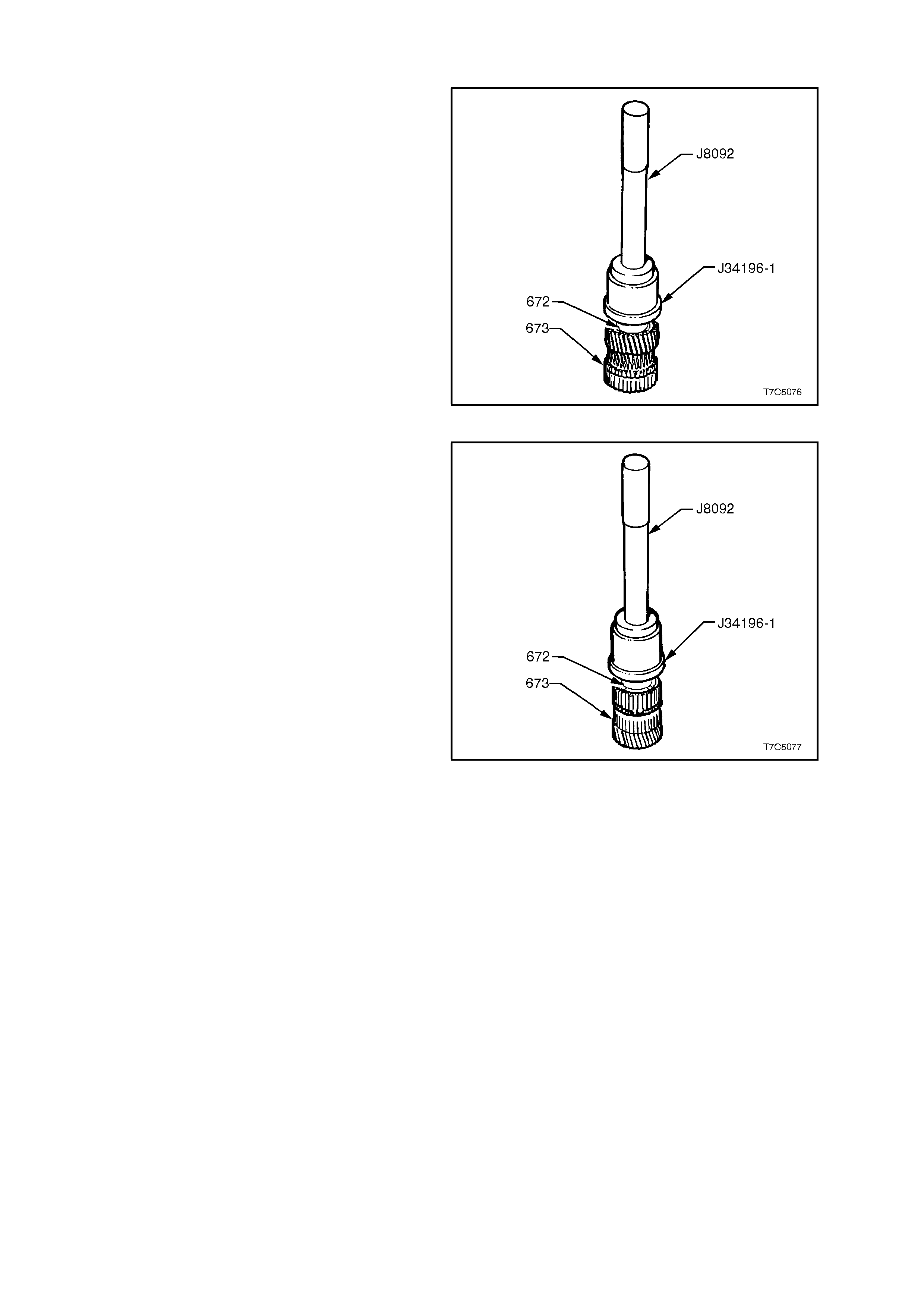
SUN GEAR BUSH - REPLACE
1. Should the sun gear bushing (672) require
replacem ent, use bush remover Tool J34196-1
and driver handle J8092 to pr ess the bus h f r om
the gear.
Figure 7C5-76
2. Install a replacement bush (672) using the
sam e tools but pres s the bus h in f rom the other
side of the sun gear, as shown.
3. If removed, install a new retaining ring (671) to
the sun gear (see Fig. 7C5-74).
Figure 7C5-77
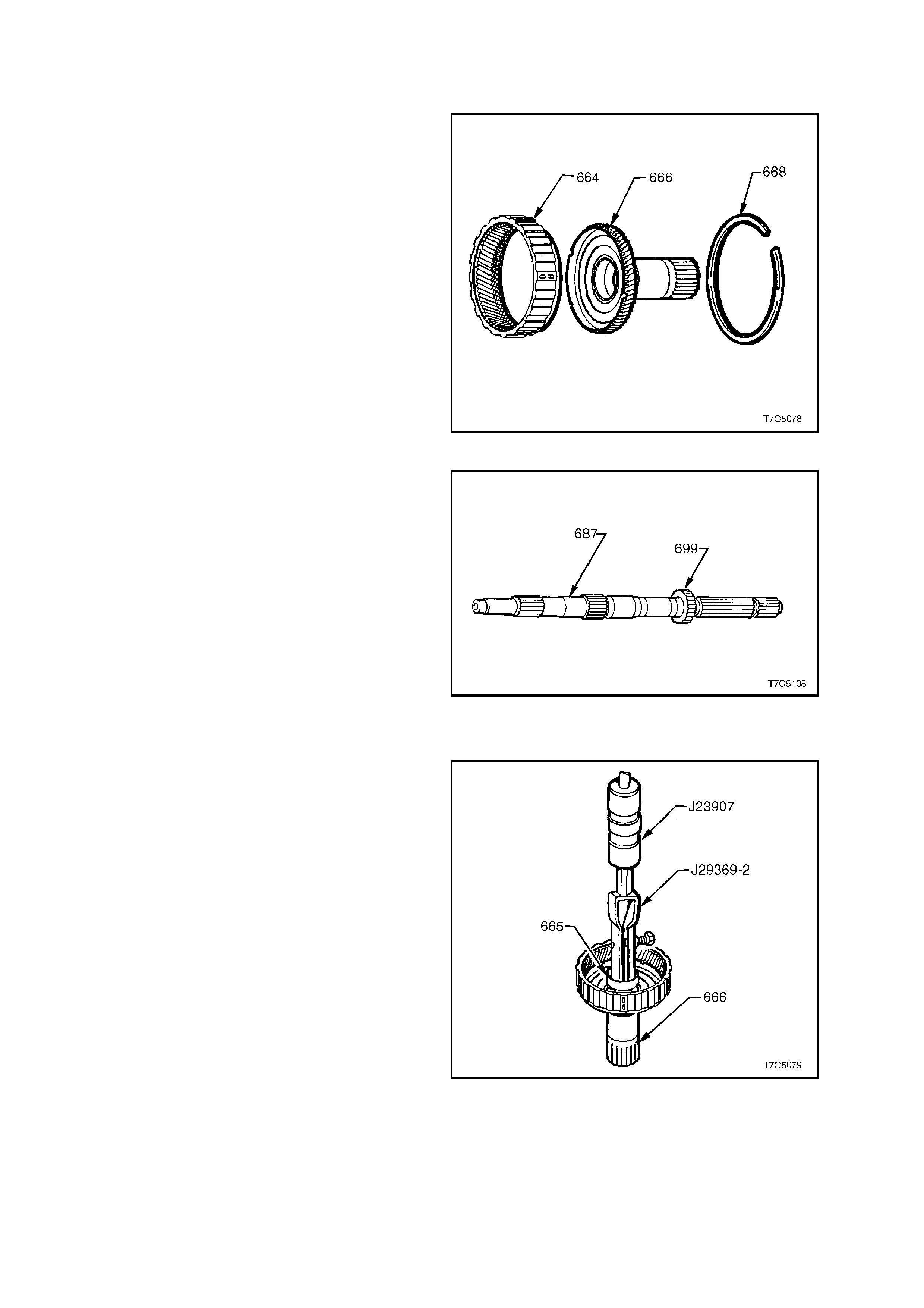
2.9 INPUT INTERNAL GEAR AND OUTPUT SHAFT
INSPECT
1. Rem ove retaining ring (668) from input internal
gear (664).
2. Remove reaction carrier shaft (666) from input
internal gear and inspect shaft for:
a. Damaged or worn bushes.
b. Cracks.
c. Damaged spline or gear teeth.
d. Undercutting around shaft from
interference with sun gear.
3. Inspect input internal gear (664) for cracked or
damaged splines or gear teeth.
4. Inspect carrier to reaction shaft thrust bearing
(not shown) for wear or damage.
5. If all parts are serviceable, reassemble the
reaction carrier shaft (666) into the input
internal gear (664) and install the retaining ring
(668).
Figure 7C5-78
6. Inspect transmission output shaft (687) for:
a. Blocked or restricted lube passages.
b. Damage to splines or ring groove.
c. Burrs or damage to bearing journals.
d. Burrs or damage to case extension seal
surface. Polish with crocus cloth if
necessary.
e. Tooth dam age to transmiss ion output shaft
sensor rotor (699).
Figure 7C5-79
REACTION CARRIER SHAFT BUSHES - REPLACE
1. Using univer sal bushing r em over J29369- 2 and
slide hammer J23907 or equivalent, remove
front bushing (665) from the reaction carrier
gear shaft (666).
Figure 7C5-80
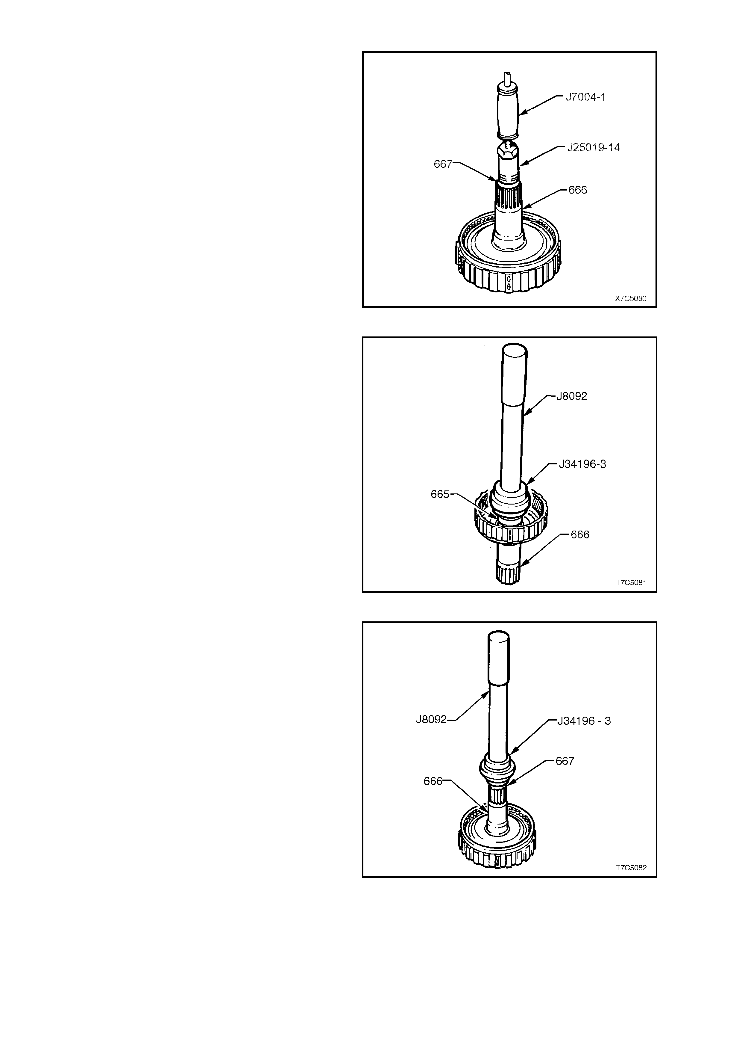
2. Remove the rear bushing (667) from the
reaction carrier gear shaft (666) by using bush
puller Tool J25019-14 and slide hammer
J7004-1 or equivalent.
Figure 7C5-81
3. Install front bushing (665), using bush installer
Tool J34196-3 and driver handle J8092.
Figure 7C5-82
4. Install r ear bushing ( 667), using the sam e tools
as for the front bushing.
Figure 7C5-83
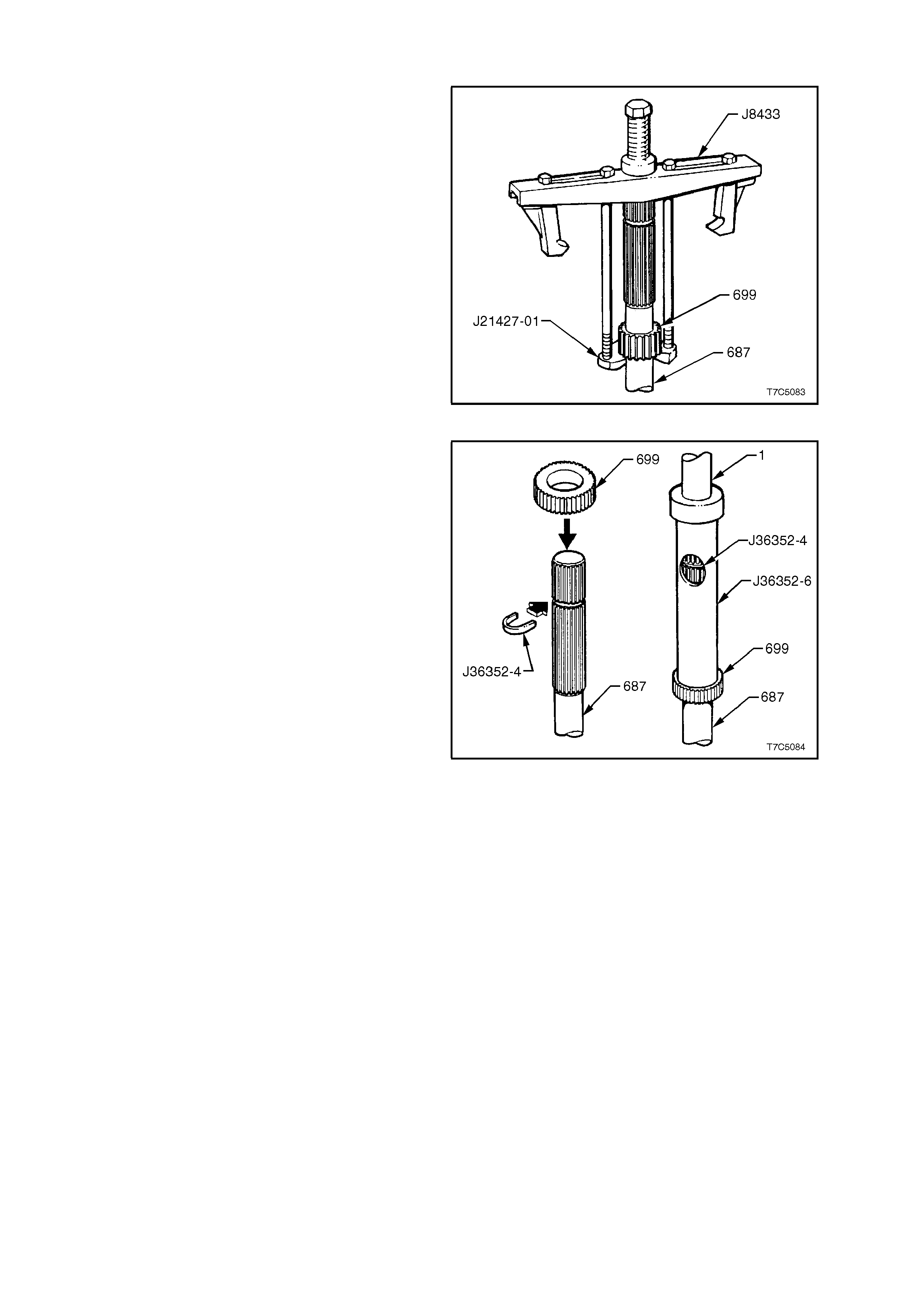
2.10 TRANSMISSION OUTPUT SPEED SENSOR RING
REPLACE
NOTE: Normally this operation is not necessary
and should only be carried out, if inspection of the
Speed Sensor Ring (699) shows that tooth damage
has occurred. Once removed, the ring must be
replaced and not re-used.
1. Using T ool Nos. J 8433 and J 21427-01, r emove
the speed sensor ring (699) from the output
shaft (687).
Figure 7C5-84
2. Place a new speed sensor ring (699) over the
transmission output shaft (687).
3. Insert C-washer, Tool No. J36352-4 into the
groove on the transmission output shaft (687).
4. Place Tool No. J36352-6 over the output shaft
and press sensor ring onto the output shaft
until the tube contacts the C-washer (J36352-
4), in the window.
Figure 7C5-85
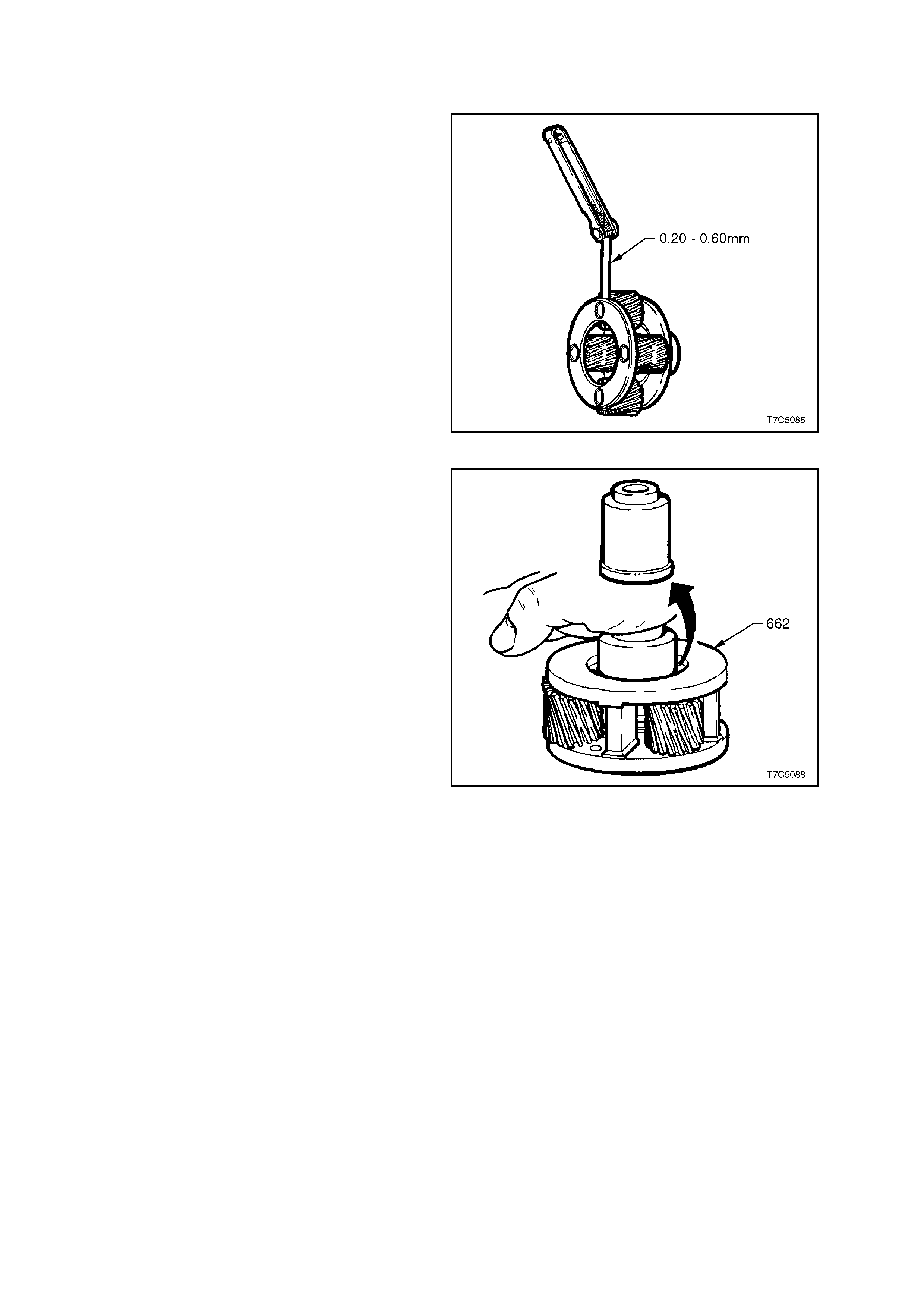
2.11 INPUT CARRIER AND SUN GEAR
INSPECT
1. Inspect carrier assembly (662) for pinion gear
wear, proper pinion staking and free turning of
pinions.
2. Check for excessive pinion washer wear by
measuring pinion end play. End play should be
0.20 to 0.60 mm.
NOTE: T he input carrier assem bly is serviced as a
complete assembly and must be replaced if
components are worn or defective.
Figure 7C5-86
3. Check carrier assembly captive thrust bearing
as follows:
a. Place a suitable bush (or socket) on
bearing race (do not contact pinion gears)
and turn bush with palm of your hand.
b. Any imperfections will be felt through bush.
Figure 7C5-87
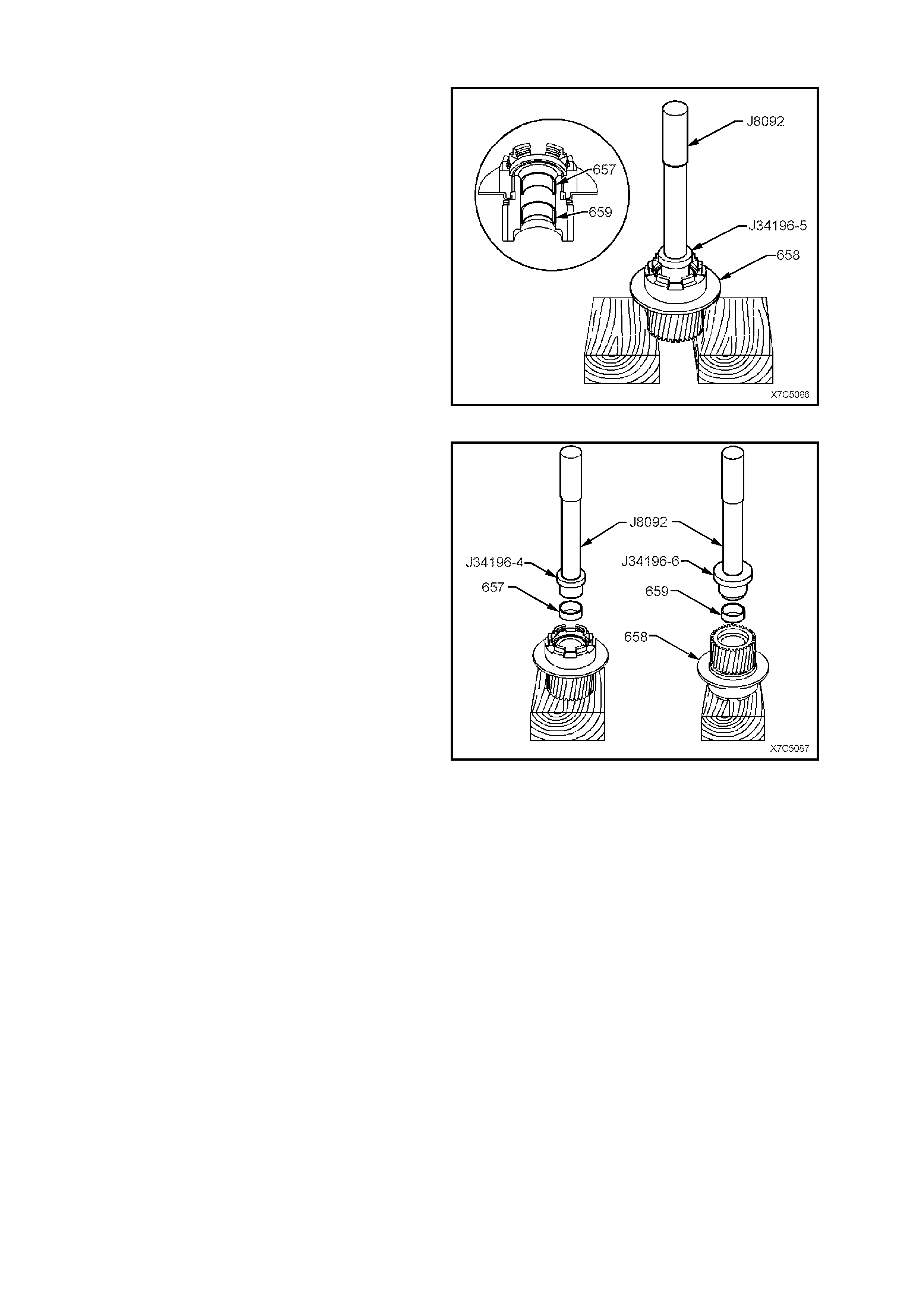
INPUT SUN GEAR BUSHES - REPLACE
1. Using bush removing tool J34196-5 and driver
handle J8092, press both sun gear bushes
(657/ 659) from the gear.
Figure 7C5-88
2. Press the front sun gear bush (657) in to the
gear, using Tool J34196-4 and driver handle
J8092.
3. Press the rear sun gear bush (659) in to the
gear, using Tool J34196-6 and driver handle
J8092.
Figure 7C5-89
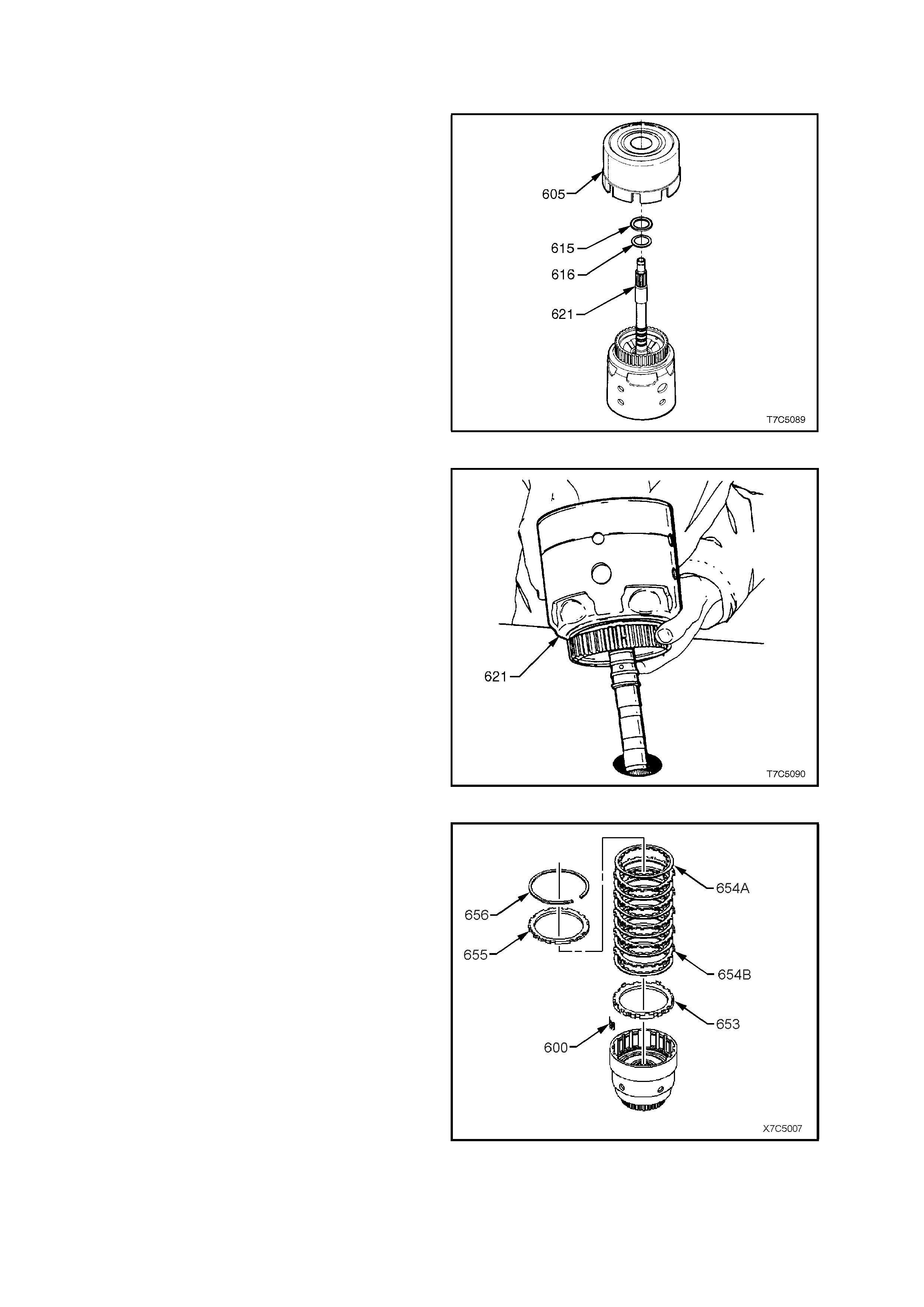
2.12 INPUT CLUTCH HOUSING ASSEMBLY
DISASSEMBLE
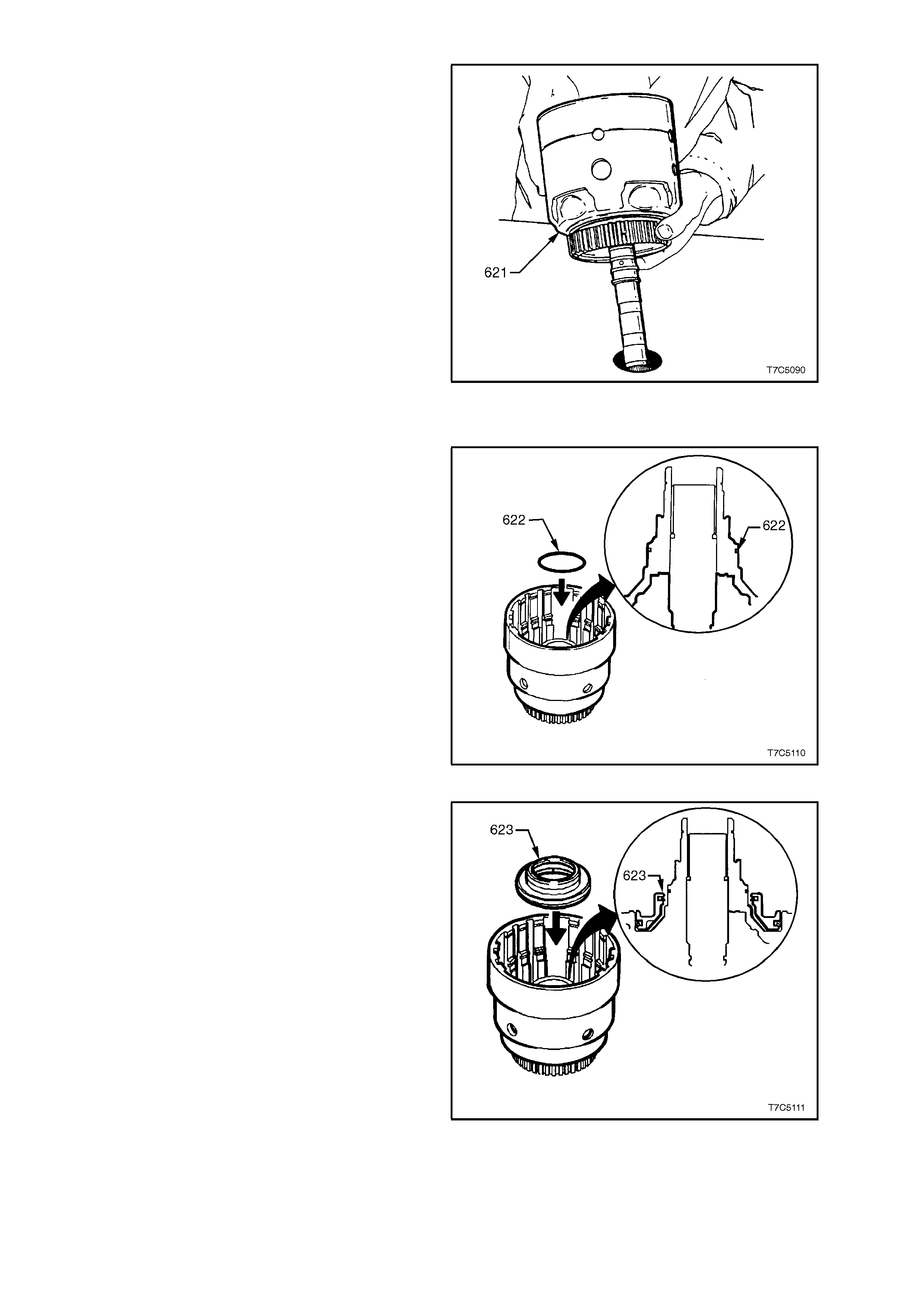
1. Remove r ever se input c lutc h housing and dr um
assembly (605) from input housing and shaft
assembly (621).
2. Remove thrust bearing (615) and selective
thrust washer (616).
Figure 7C5-90
3. Place input clutch housing and drum assembly
(621) on work bench with input shaft protruding
through hole in workbench.
NOTE: F or identification of par ts, refer to Fig. 7C5-
93.
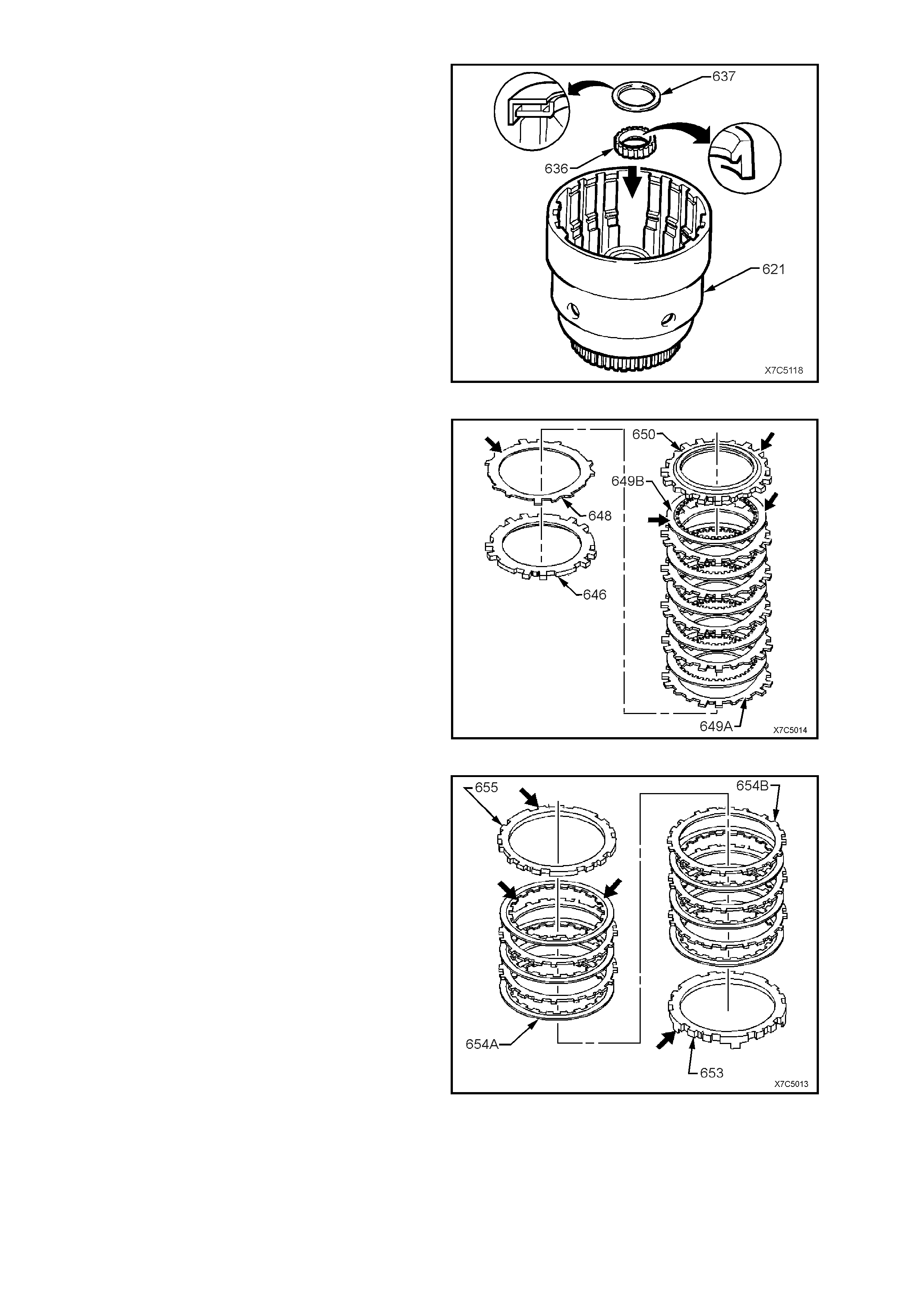
Figure 7C5-91
4. Remove 3-4 clutch plate retaining ring (656)
and backing plate (655).
5. Remove 3-4 clutch plates (654B and 654B).
6. Remove five, 3-4 clutch boost spring
assemblies (600).
7. Remove stepped, 3-4 clutch apply plate (653).
Figure 7C5-92
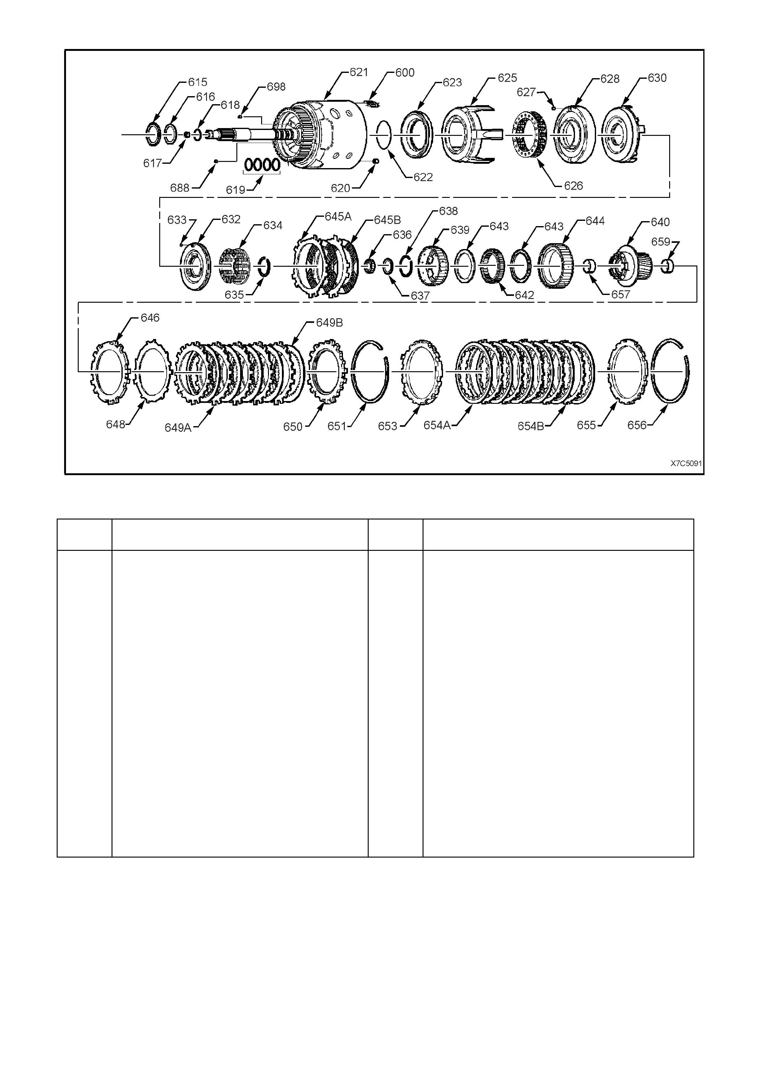
Figure 7C5-93 Input Clutch Housing - Exploded View
Legend – Input Clutch Housing Components
REF
No. PART NAME REF
No. PART NAME
600.
615.
616.
617.
618.
619.
620.
621.
622.
623.
625.
626.
627.
628.
630.
632.
633.
634.
635.
636.
637.
638.
Spring Assembly, 3-4 Clutch Boost - 5 places
Bearing Assembly, Stator Shaft – Selective
Washer
Washer, Thrust Selective
Retainer & Ball Assy., Check Valve
Seal, O-Ring, Turbine Shaft
Ring, Oil Seal (Solid)
Retainer & Checkball Assy.
Retainer & Checkball Assy.
Seal, O-Ring Input to Forward Clutch Housing
Piston, 3rd and 4th Clutch
Ring, 3rd & 4th Clutch (Apply)
Spring Assy., 3rd and 4th Clutch
Retainer & Ball Assy, Forward Clutch Housing
Housing, Forward Clutch
Piston, Forward Clutch
Piston, Overrun Clutch
Ball, Overrun Clutch
Spring Assy., Overrun Clutch
Snap Ring, Overrun Clutch Spring Retainer
Seal, Input Housing to Output Shaft
Bearing Assembly , Input Sun Gear
Snap Ring, Overrun Clutch Hub Retaining
639.
640.
642.
643.
644.
645a.
645b.
646.
648.
649a.
649b.
650.
651.
653.
654a.
654b.
655.
656.
657.
659.
688.
698.
Hub, Overrun Clutch
Forward Sprag Clutch Inner Race & Input Clutch
Assy Forward Sprag Assy.
Retainer Ring, Sprag Assy.
Race, Forward Clutch (Outer)
Plate Assy., Overrun Clutch (Steel)
Plate Assy., Overrun Clutch (Composition)
Plate, Forward Clutch (Apply)
Plate, Forward Clutch (Waved)
Plate, Forward Clutch (Steel)
Plate Assy., Forward Clutch (Composition)
Plate, Forward Clutch Backing (Selective)
Ring, Forward Clutch Backing Plate Retainer
Plate, 3rd & 4th Clutch Apply (Stepped)
Plate Assy., 3rd & 4th Clutch (Composition)
Plate Assy., 3rd & 4th Clutch (Steel)
Plate, 3rd & 4th Clutch Backing (Selective)
Ring, 3rd & 4th Clutch Backing Plate Retainer
Bush, Input Sun Gear, Front
Bush, Input Sun Gear, Rear
Plug, Cup
Plug, Orifice Cup
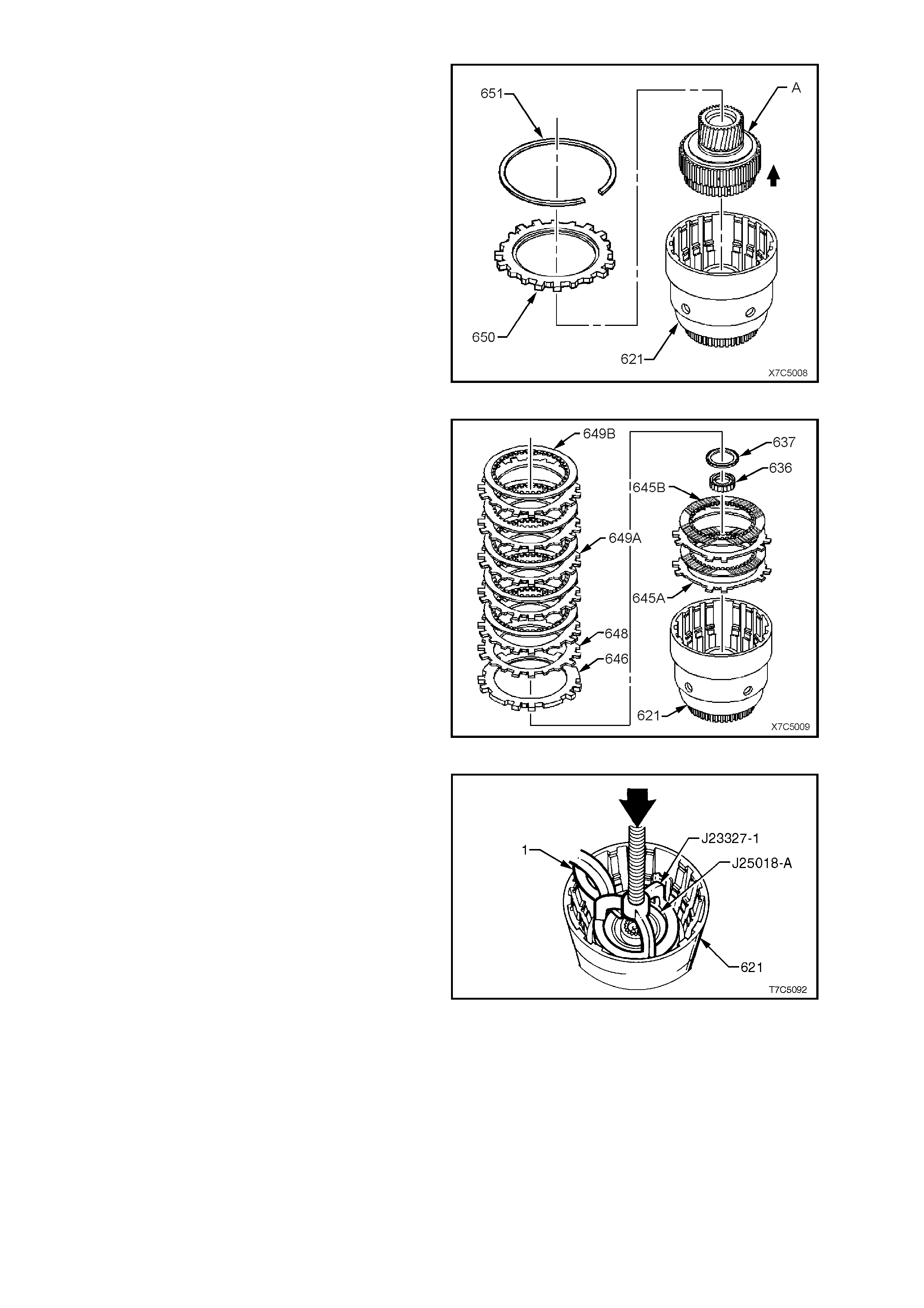
8. Remove forward clutch backing plate retaining
ring (651) and backing plate (650).
9. Lif t the forward clutch s prag and input sun gear
assembly ‘A’ from the input shaft and housing
assembly (621).
Figure 7C5-94
10. Remove forward clutch plates (649A and
649B).
11. Remove forward clutch wave plate (648).
12. Remove forward clutch apply plate (646).
13. Remove input sun gear bearing assembly
(637).
14. Remove input housing to output shaft lip seal
(636).
15. Remove overrun clutch plates (645A and
645B).
Figure 7C5-95
16. Place input housing and shaft assembly (621)
in a suitable press.
17. Install part of Tool Nos. J23327-1 and J25018-
A underneath, as shown.
18. Compress overrun clutch spring assembly (not
visible) in press and remove overrun clutch
retaining ring (not visible), using suitable snap
ring pliers (1).
19. Return input housing and shaft assembly to
workbench.
Figure 7C5-96
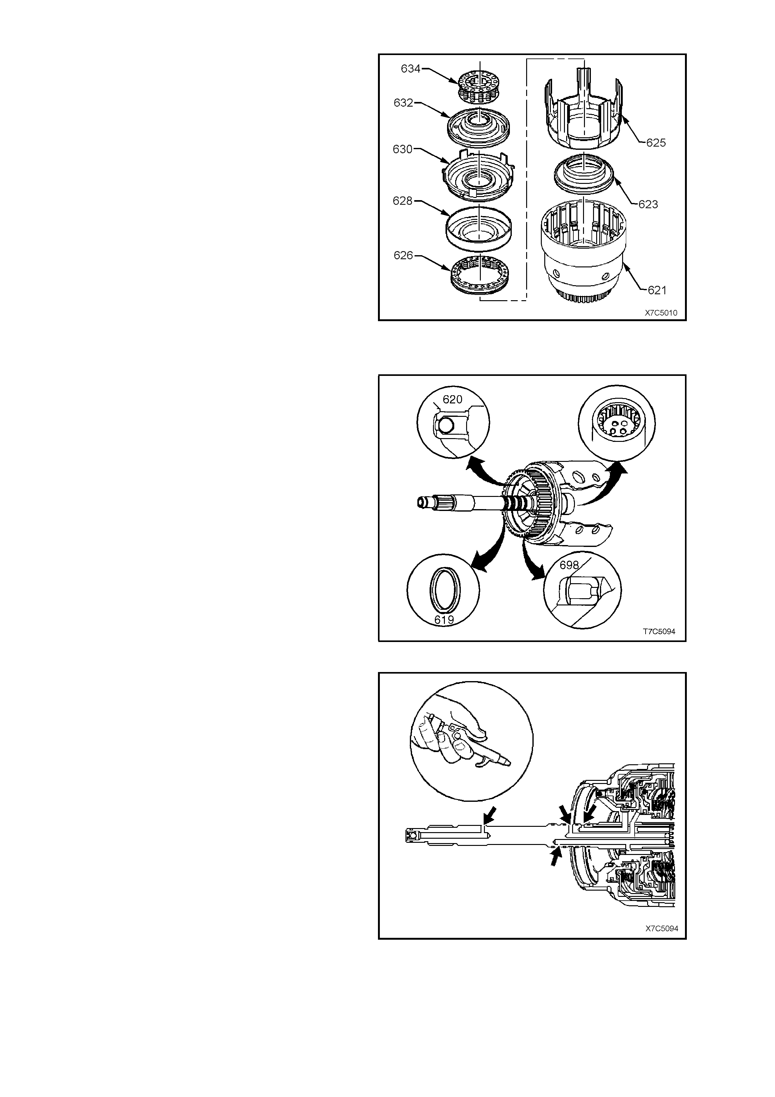
20. Remove overrun clutch spring assembly (634).
21. Remove forward clutch piston assembly (630),
together with the overrun clutch piston (632).
22. Separate the two pistons and remove all seals.
NOTE: Separate assembly by impacting the input
housing assembly on a wooden block.
23. Remove forward clutch housing (628).
24. Remove 3-4 clutch spring assembly (626).
25. Remove 3-4 clutch apply ring (625) and piston
(623) with seals.
26. Discard all removed seals.
Figure 7C5-97
INSPECT
1. Inspect input housing and shaft assembly for
porosity, wear or damage.
2. Check orifice cup plug (698) is not missing.
3. Check for cracks at all lube holes.
4. Check that the four turbine shaft sealing rings
(619) rotate f r eely in their grooves and that they
are undamaged and free from burrs.
5. Inspect check ball and retainer (620). Check
that the ball moves freely and that the retainer
is not loose in the housing. Leak test the c heck
ball, with solvent.
Figure 7C5-98
6. Blow through all input shaft passages with
com press ed air. T he three tur bine shaft sealing
balls must not be loose or leaking
Figure 7C5-99
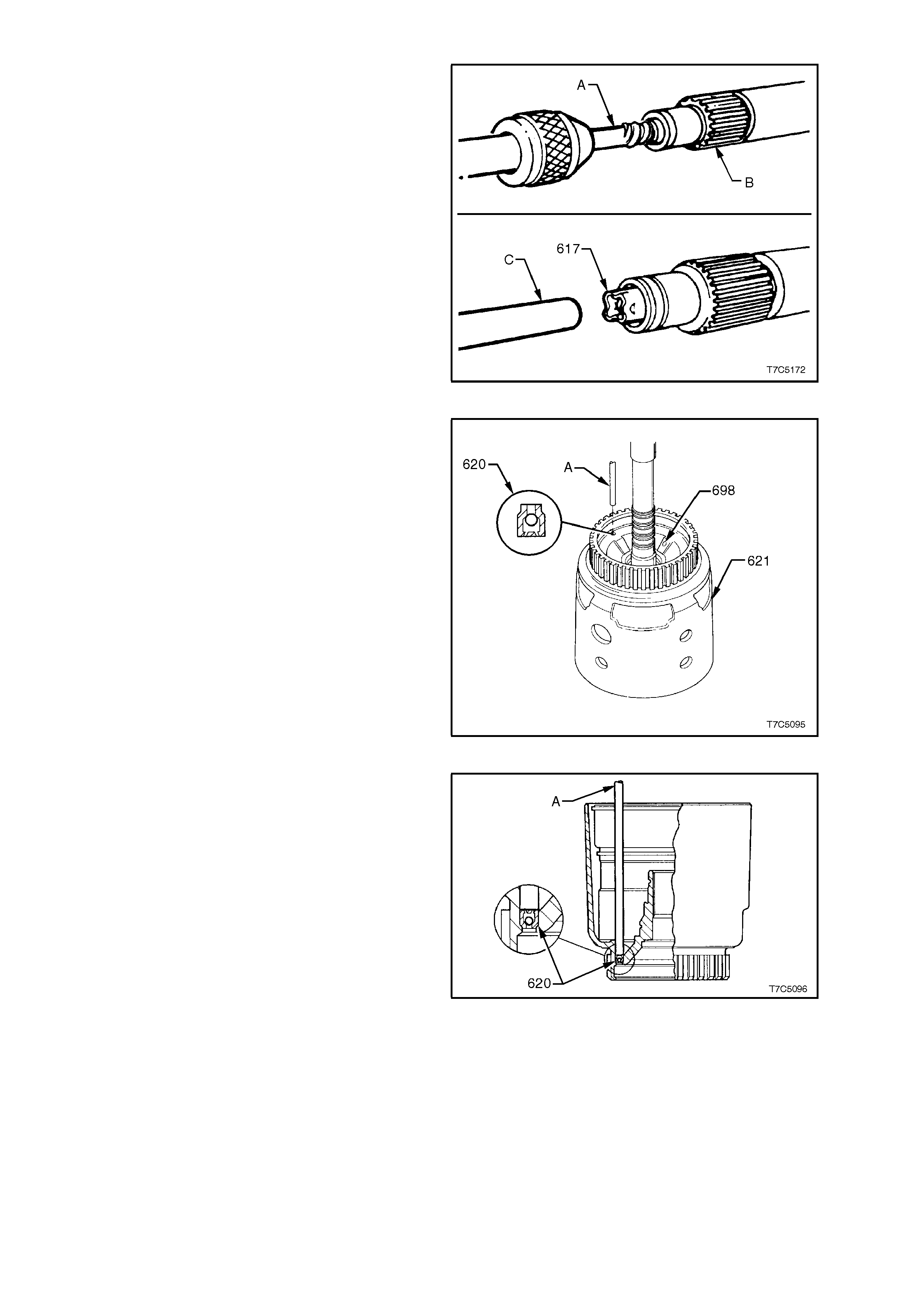
7. If required, replace the turbine shaft retainer
and check ball assembly (617), as follows;
a. Straighten the retainer tangs and remove
the ball.
b. Use a suitable easy out extractor (A) to
remove retainer from the turbine shaft (B).
c. Install new check ball and retainer
assembly (617), using 9.5 mm (3/8”) rod
(C), until the retainer is 3.0 mm below the
end of the input shaft.
d. Check that the check ball moves freely.
NOTE: The end of the turbine shaft (B) may vary,
depending on the engine application.
Figure 7C5-100
8. Replace input shaft housing check ball
assembly, if necessary, as follows:
a. Tap out retainer and ball assembly (620),
using 5.7 mm (1/4 inch) rod (A).
Figure 7C5-101
b. Install new assembly with 5.7 mm rod (A)
until shoulder is seated in housing from
input shaft side, as shown.
Figure 7C5-102
9. Inspect 3-4 clutch piston (623) for porosity or
damage.
10. Inspect 3-4 clutch apply ring (625) for bent tangs.
11. Inspect 3-4 clutch spring assembly (626) for
distortion or damage.
12. Inspect each of the five 3-4 clutch spring
assemblies (600) for damage or distortion.
13. Inspect the 3-4 clutch plates for damaged tangs,
delamination and/or excessive wear.
NOTE: The green/black appearance of the 3-4 clutch
plates is normal. Therefore, do not assume that
these plates are burned because of colour.
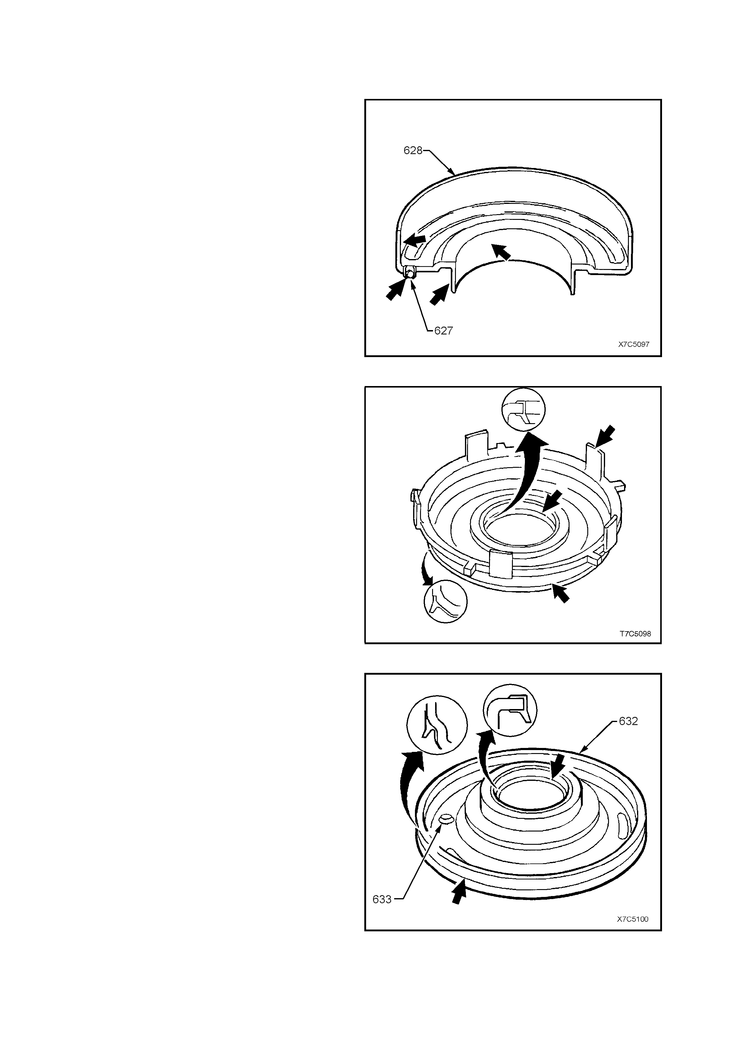
14. Inspect forward clutch housing (628) for:
a. Correct check ball (627) operation.
b. Damage, distortion or cracks.
c. Burrs in seal areas.
Figure 7C5-103
15. Inspect forward clutch piston (630) for:
a. Porosity or damage.
b. Ring groove damage.
c. Apply leg damage.
NOTE: As the inner and outer piston seals are
bonded to the forward clutch piston, if any seal
damage is found, then the piston assembly must be
replaced.
Figure 7C5-104
16. Inspect overrun clutch piston (632) for:
a. Porosity or damage.
b. Ring groove damage.
c. Seal damage.
d. Check ball operation (overrun) (633).
NOTE: As the inner and outer pis ton seals ar e now
bonded to the overrun clutch piston, if any seal
damage is found, then the piston assembly must be
replaced.
17. Inspect overrun spring assembly (634) for
damage or distortion.
18. Inspect overrun clutch plates (645), forward
clutch plates (649) and 3-4 clutch plates (654).
Check composition plates for damaged tangs,
delamination or excessive wear. Check steel
plates for damaged tangs, wear or heat
damage.
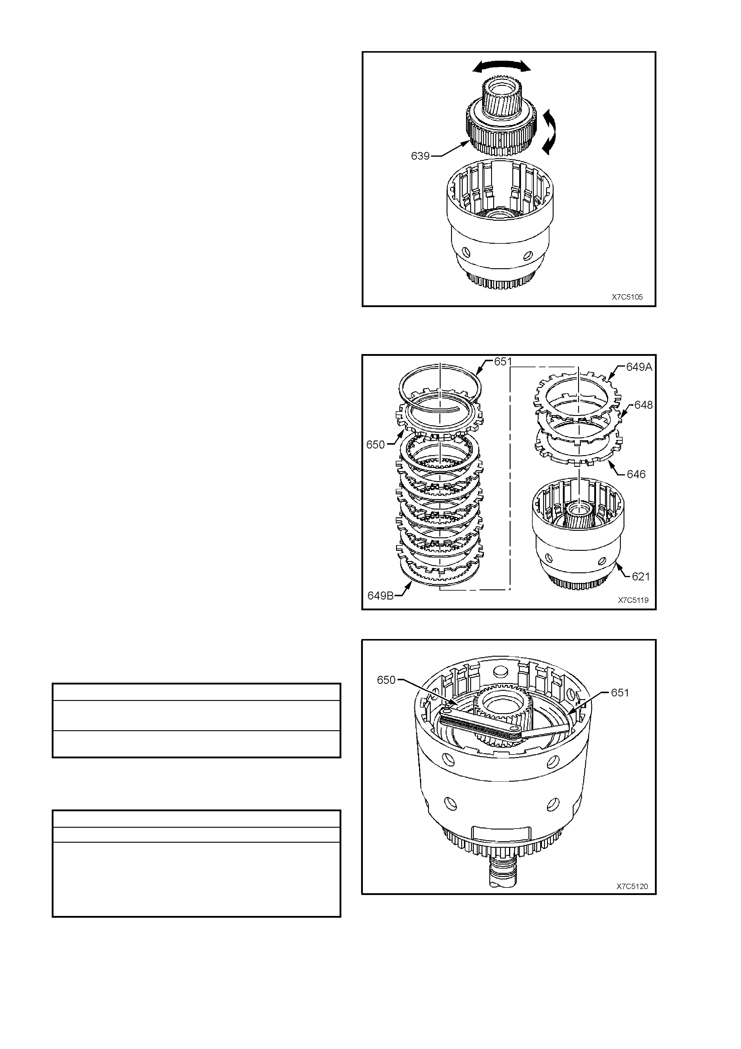
Figure 7C5-105
19. Inspect input sun gear bearing assembly (637)
and input housing to output s haft seal (636) f or
wear, damage or distortion.
Figure 7C5-106
20. Inspect forward clutch waved plate (648), the
apply plate (646), the steel plates (649A), the
composition plates (649B) and the selective
backing plate (650) for:
a. Flatness.
b. Delamination of the composition plates
(649B).
c. Heat damage and/or excessive wear.
d. Burrs, nicks and other surface finish
damage.
Figure 7C5-107
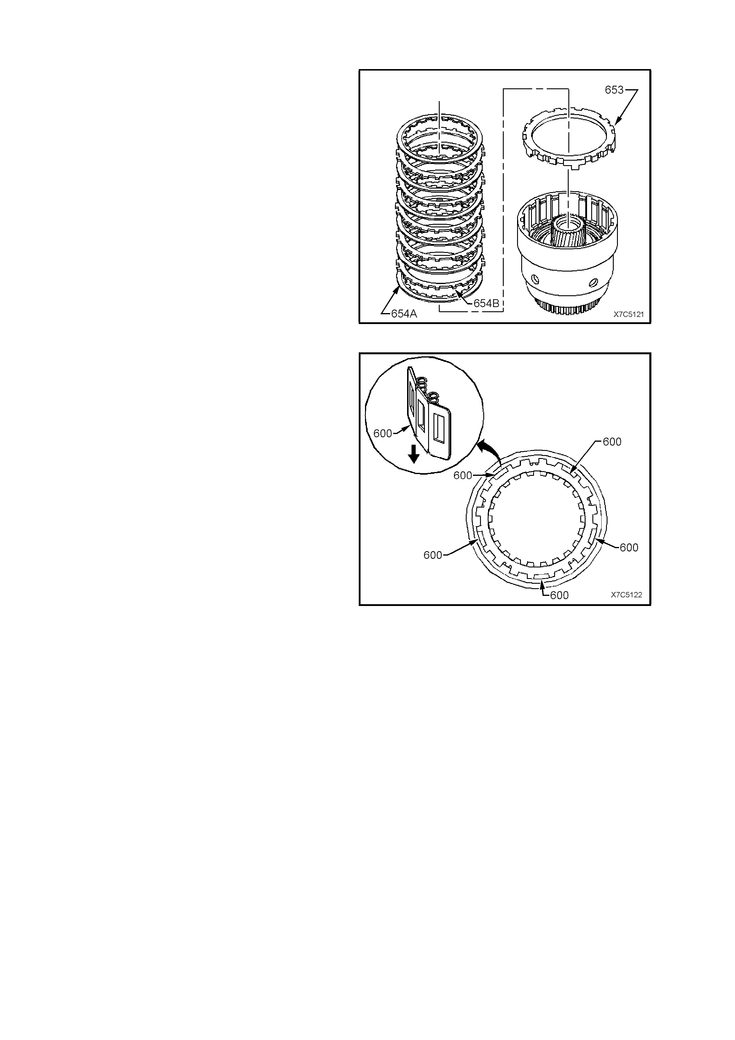
21. Inspect 3-4 clutch apply plate (653), the
composition plates (654A), the steel plates
(654B) and the selective backing plate (655),
for:
a. Flatness.
b. Delamination of the composition plates
(654A).
c. Heat damage and/or excessive wear.
d. Burrs, nicks and other surface finish
damage.
Figure 7C5-108
FORWARD CLUTCH SPRAG ASSEMBLY
DISASSEMBLE
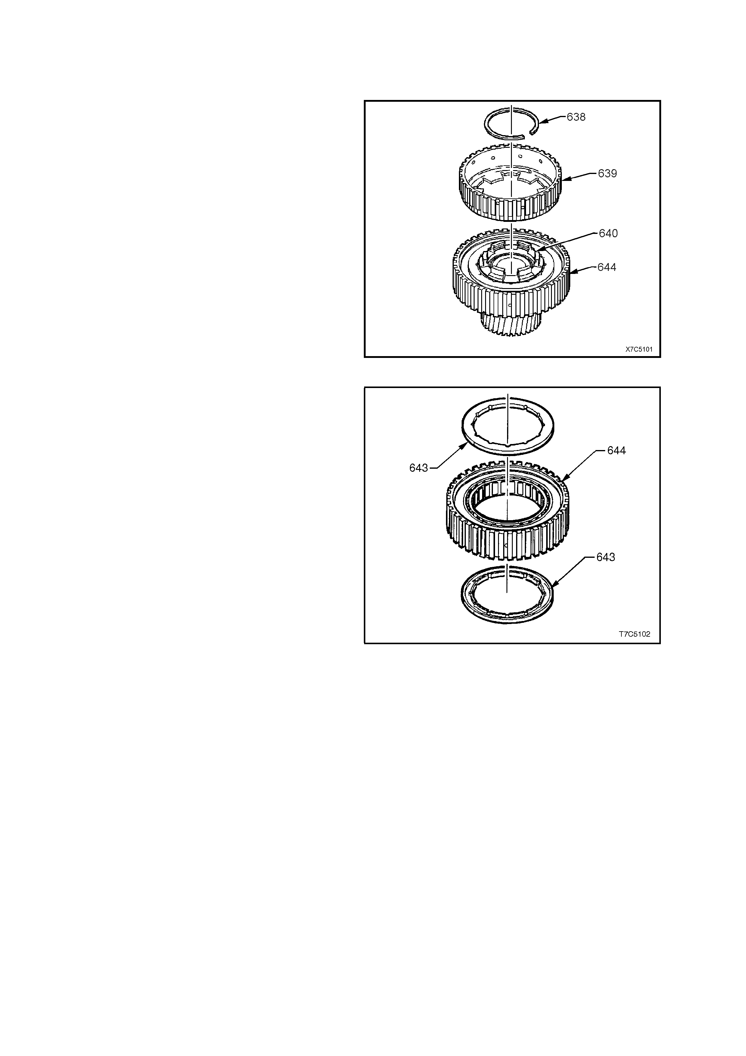
1. Disassemble forward sprag clutch assembly as
follows:
a. Remove overrun clutch hub retaining snap
ring (638) and clutch hub (639).
b. Remove forward clutch outer race (644).
c. Remove forward sprag clutch inner race
and sun gear assembly (640) from the
forward clutch sprag assembly (644).
Figure 7C5-109
d. Remove sprag assembly retainer rings
(643).
e. Remove the forward sprag assembly from
the forward clutch outer race (644).
Figure 7C5-110
Inspect
1. Inspect forward clutch sprag assembly (642)
for:
a. Wear or damage.
b. Weak or broken springs.
c. Damaged or missing retaining caps.
2. Inspect forward clutch outer race (644) for:
a. Spline damage.
b. Surface finish damage.
c. Plugged lubrication holes.
Figure 7C5-111
3. Inspect overrun clutch hub (639) for:
a. Spline damage.
b. Plugged lubrication holes.
c. Damaged tangs.
d. Cracks.
4. Inspect forward sprag clutch inner race and
input sun gear assembly (640) for:
a. Spline damage.
b. Ring groove damage.
c. Surface finish damage.
d. Loose retainer.
Figure 7C5-112
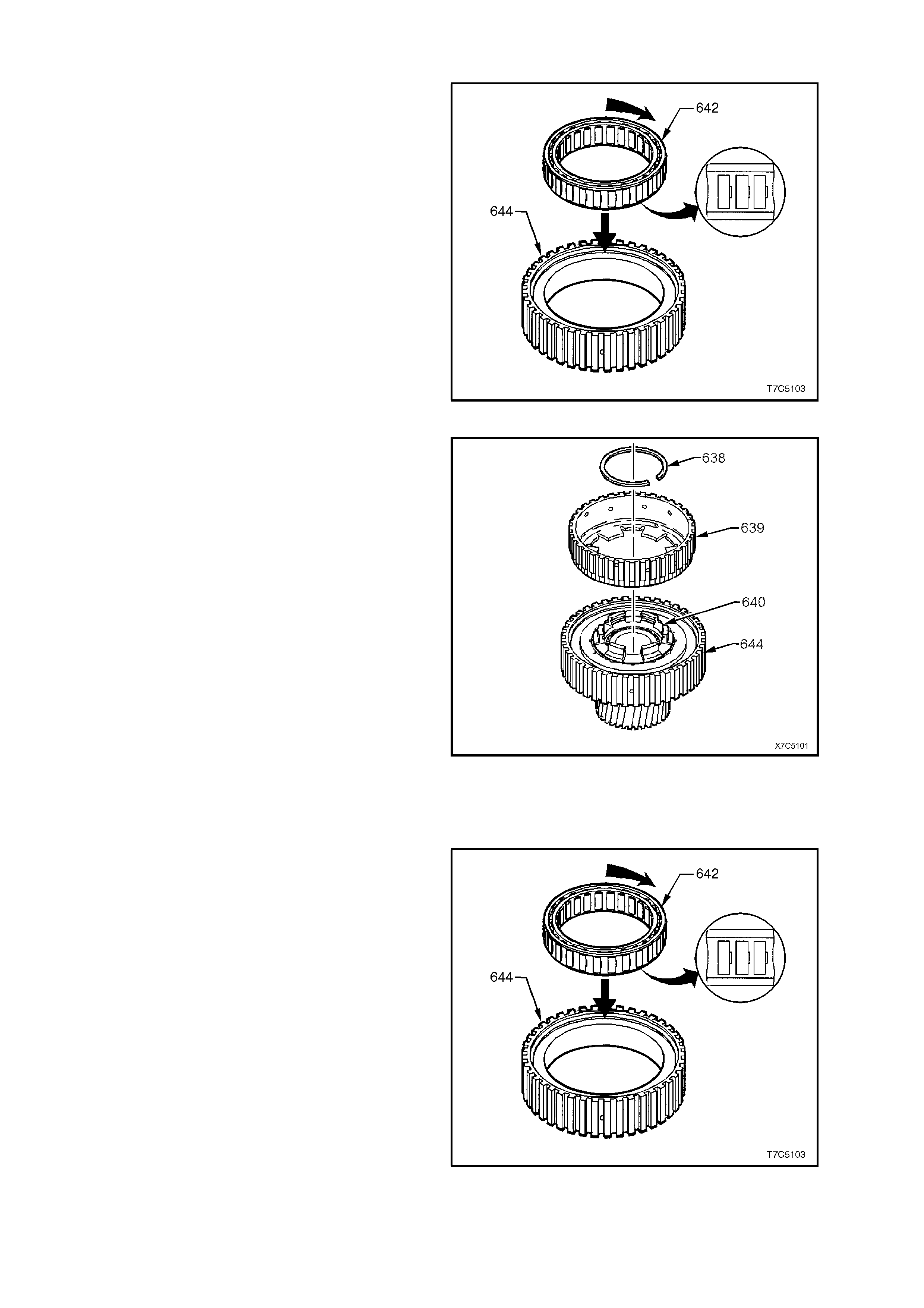
REASSEMBLE
Forward Clutch Sprag A ssembly
1. Reinstall forward sprag assembly (642) into
forward clutch outer race (644). Notches in
sprag cage point in the direction shown.
Figure 7C5-113
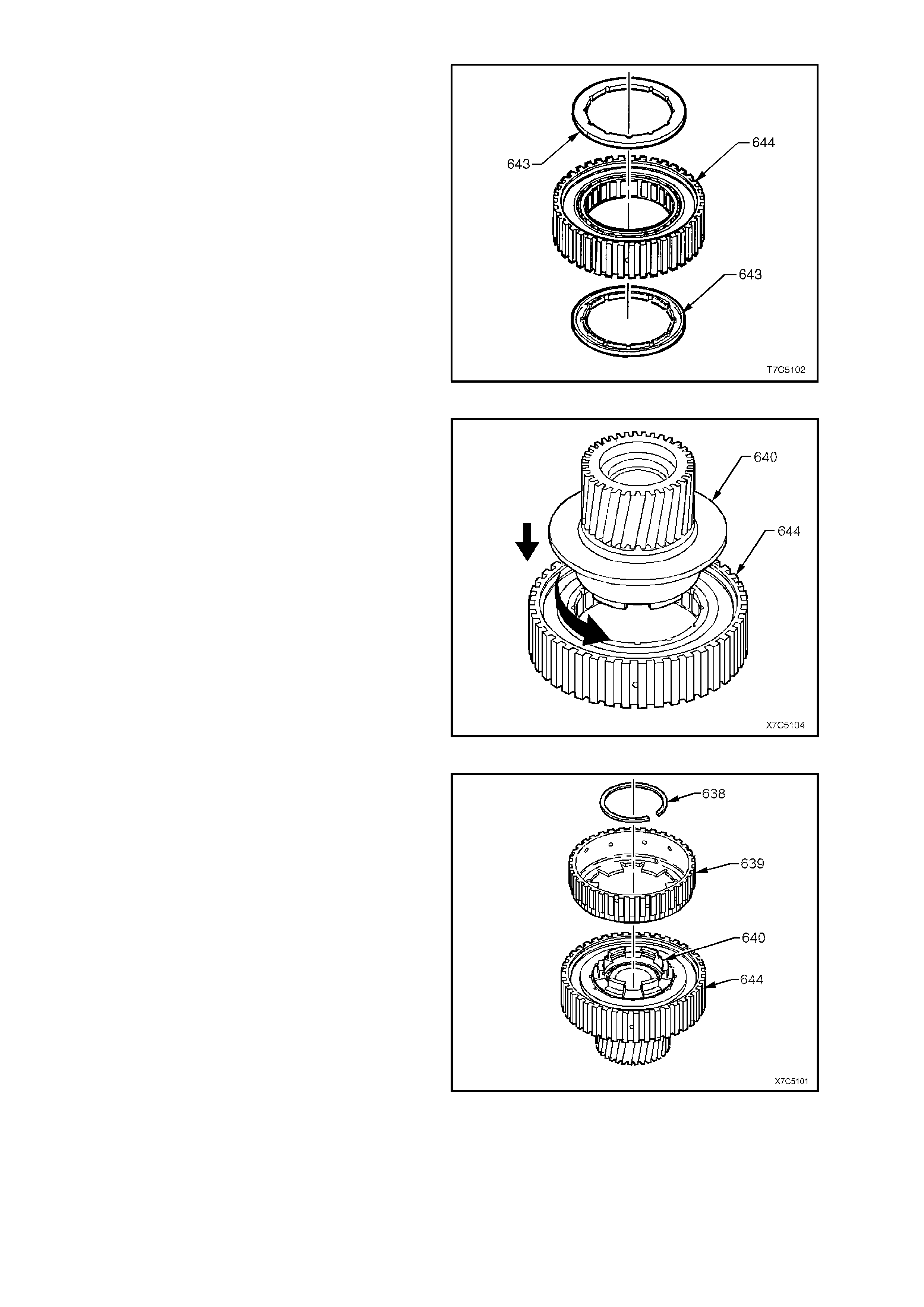
2. Reinstall a sprag retaining ring (643) to each
side of the forward clutch outer race (644) with
the retaining ring recesses facing outward.
Figure 7C5-114
3. Reinstall the forward sprag clutch inner race
and input sun gear assembly (640) into the
sprag retaining ring (643) and the outer race
(644), as follows:
a. Hold outer race (644) in right hand,
supporting the forward sprag assembly
(642) with fingers at the recessed side of
outer race (644).
b. Insert retaining ring and the forward sprag
clutch inner race and input sun gear
assembly (640) from the opposite side of
outer race (644) by pushing in and turning
anti-clockwise (curved arrow).
4. Turn the assembly over and reinstall the
remaining sprag assembly outer retaining ring
(643), with the recess facing inward toward the
sprag (642).
Figure 7C5-115
5. Reinstall overrun clutch hub (639) onto the
forward sprag clutch inner race and input sun
gear assembly (640).
6. Reinstall overrun clutc h hub retaining snap ring
(638) into groove in the forward sprag clutch
inner race and input sun gear assembly (640).
7. Test assembly for correct operation as follows;
a. Hold the forward clutch outer race (644) in
the left hand and grasp the overrun clutch
hub (639) with the right. Attempt to rotate
the hub in both directions.
b. Provided the overrun clutch hub (639)
rotates when turned clockwise and locks
up when attempting to turn it counter-
clockwise, then the sprag has been
assembled correctly. If however, the
assembly operates back wards, the s pr ag is
assembled incorrectly. Dismantle and re-
assemble correctly.
Figure 7C5-116
8. Place input housing and shaft assembly (621)
on workbench with input shaft protruding
through hole in workbench.
Figure 7C5-117
3-4 Clutch Assembly
1. Lubricate a new O-ring (622) with petroleum
jelly and install on input housing.
Figure 7C5-118
2. Coat new 3-4 clutch piston inner and outer lip
seals with petroleum jelly.
3. Reinstall 3-4 clutch piston (623) in input
housing as shown, taking care not to damage
seals.
Figure 7C5-119
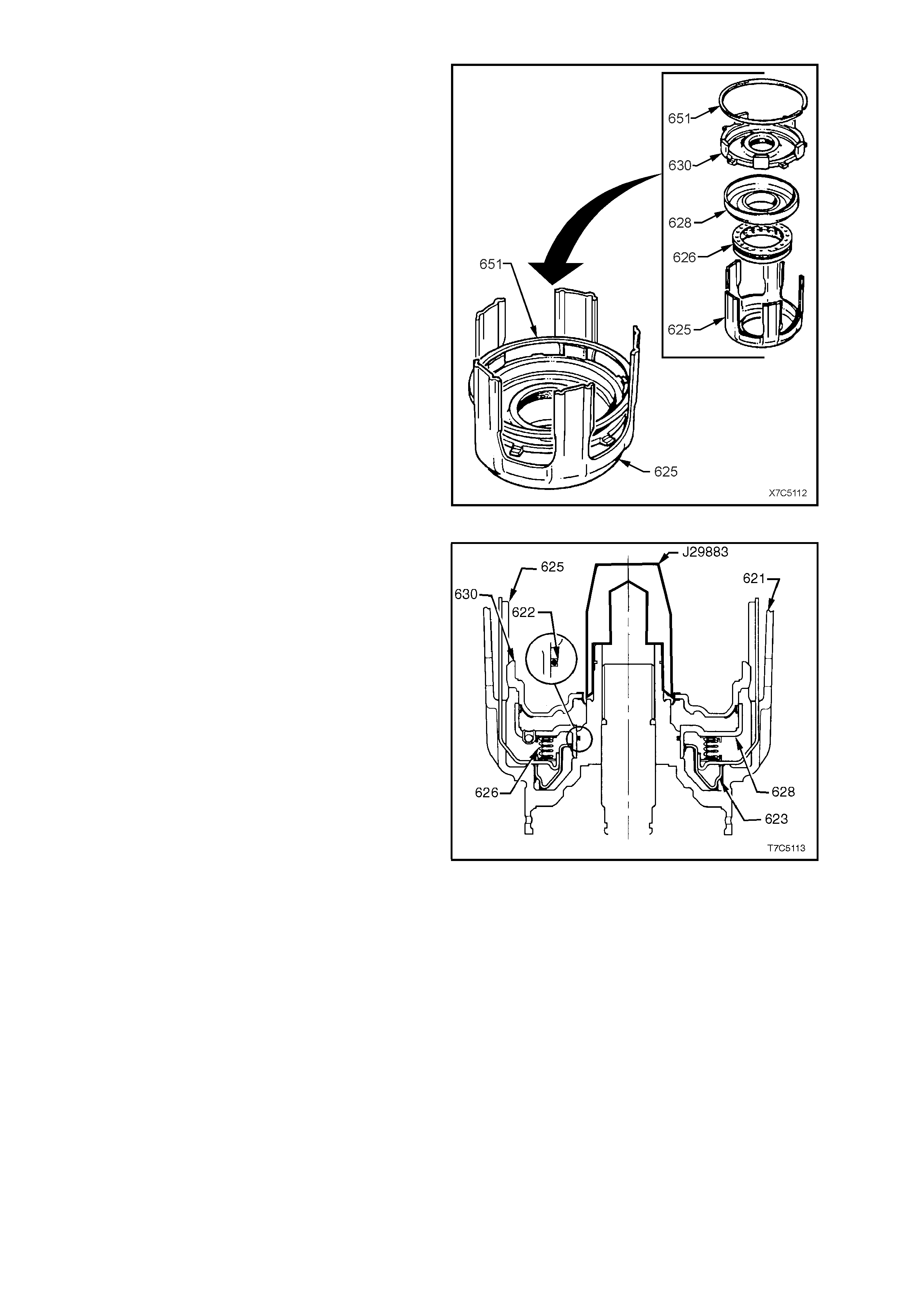
4. Locate 3-4 clutch spring assembly (626) onto
the five legged 3-4 clutch apply ring (625).
5. Coat forward clutch piston inner and outer
bonded seals with petroleum jelly and install
the forward clutch piston (630) into forward
clutch hous ing ( 628) tak ing car e not to dam age
the outer seal.
6. Reinstall forward clutch assembly onto 3-4
clutch spring assembly, locating forward clutch
piston smaller apply legs between 3-4 clutch
apply ring legs, as shown.
7. Use the forward clutch backing plate retaining
ring (651) to hold these parts in place during
installation.
Figure 7C5-120
8. Fit T ool J29883 on input housing as shown and
coat with petroleum jelly.
9. Reinstall 3-4 clutch apply ring/forward clutch
assembly into input housing as follows:
a. Hold assembly by apply ring legs and
carefully lower into the input housing and
shaft assembly.
b. Do not let forward clutch piston separate
from forward clutch housing.
c. Seat assembly by pushing down firmly onto
the forward clutch piston. It may be
necessary to slightly 'rock' assembly to
overcome cocking. Ensure the forward
clutch housing is seated over the O-ring
(622).
10. Remove Tool No. J29883 and the temporarily
installed retaining ring (651).
Figure 7C5-121
Overrun Clutch Assembly
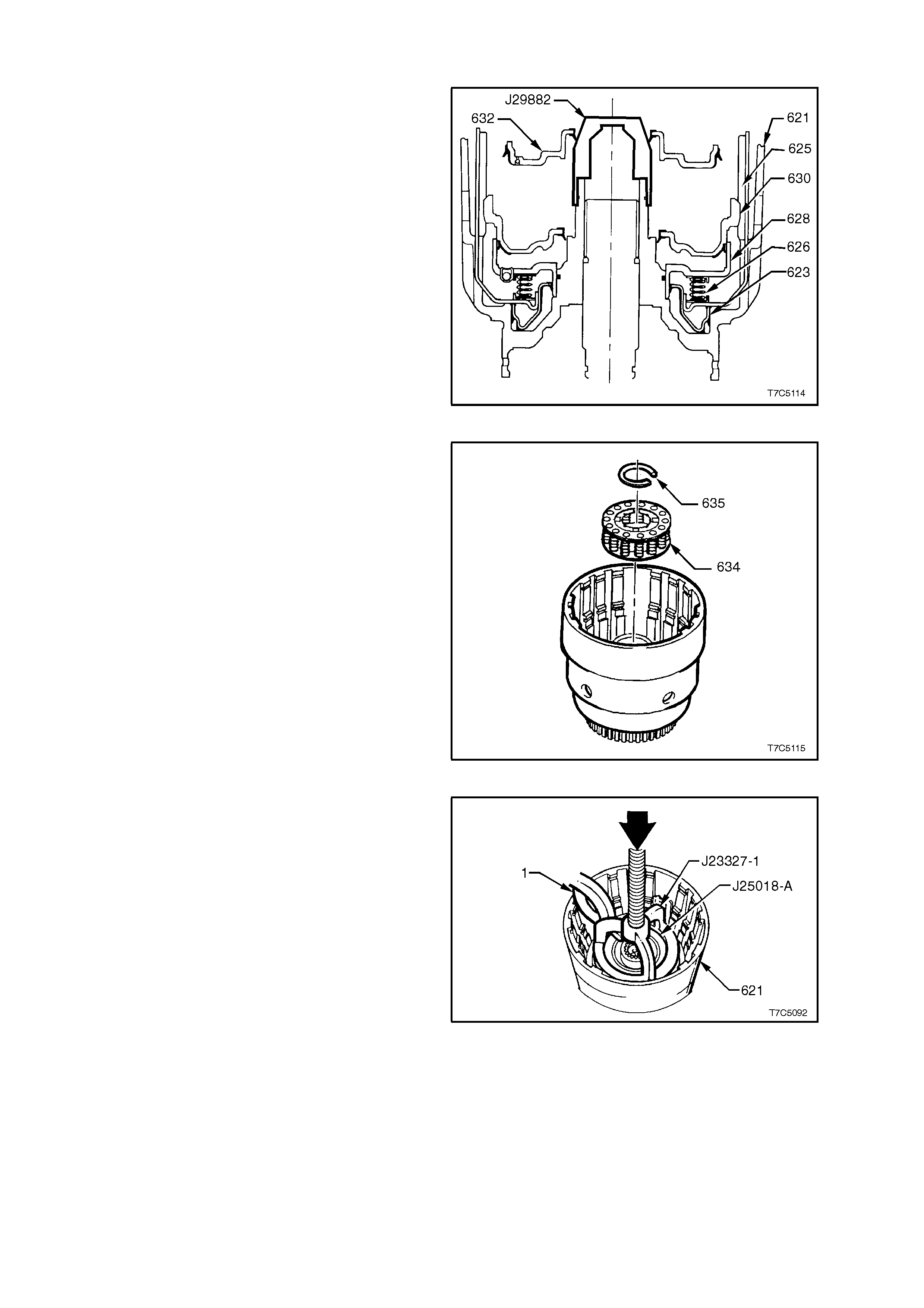
11. Fit Tool J29882 on input housing, as shown
and coat with petroleum jelly.
12. Lubricate overrun clutch piston (632) inner and
outer bonded seals with petroleum jelly and
install pis ton (632) with hub fac ing upwards, as
shown. To ease ins tallation of the outer bonded
seal, coat a straightened paper clip or similar
with petroleum jelly and work around the piston
circumference.
NOTE: If all components are correctly seated, the
overrun clutch piston hub (632) locates
approximately three mm below snap ring groove in
input housing hub.
13. Remove tool J29882.
Figure 7C5-122
14. Reinstall overrun clutch spring assembly (634)
onto overrun clutch piston.
Figure 7C5-123
15. Install J23327-1 and J25018-A as shown.
16. Place input housing and shaft assembly (621)
in a suitable press.
17. Compress overrun clutch spring assembly and
install a new clutch retaining ring (not visible),
using suitable s nap ring pliers (1). Do not over-
compress springs or over-expand the retaining
ring. Remove special tools.
Figure 7C5-124
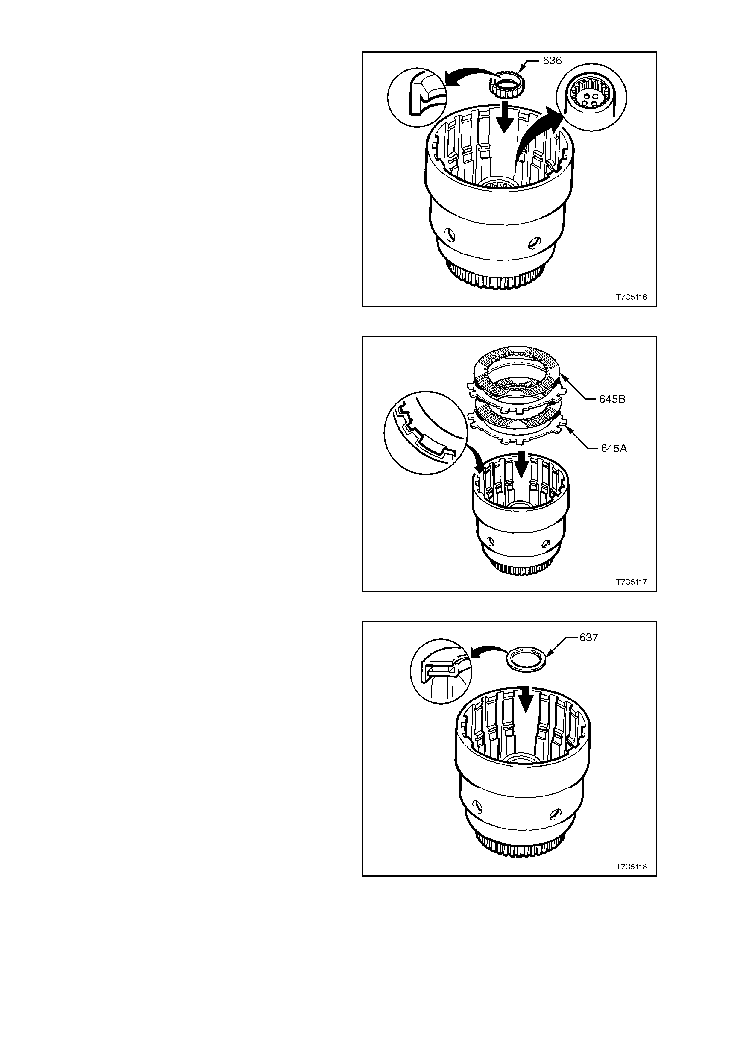
18. Install new output shaft seal (636) into input
housing, noting seal lip orientation.
Figure 7C5-125
19. Pre-lubricate overrun clutch plates (645B) in
automatic transmission fluid and reinstall into
input housing; steel (645A) first, then
composition (645B), steel and the second
composition plate. Align the steel plates with
the wide notch, as shown.
NOTE: This clutch pack is the smallest set in the
transmission.
Figure 7C5-126
20. Reinstall input sun gear thrust bearing
assembly (637) onto input clutch hub with
inside race f ac ing input housing hub, as s hown.
Retain thrust bearing in place with petroleum
jelly.
Figure 7C5-127
21. Using a fine bladed screwdriver or similar, line
up the inner tangs of the two composition
overrun clutch plates.
22. Reinstall forward clutch sprag assembly into
input clutch housing, locating overrun clutch
hub (639) into overrun clutch plates.
Figure 7C5-128
Forward Clutch Assembly
23. Reinstall forward clutch apply plate (646) into
input clutch housing (621), indexing as shown.
24. Reins tall waved steel f orward c lutch plate (648)
into input clutch housing, again indexing as
before.
25. Reinstall remaining forward clutch plates (649)
into input housing; starting with a steel plate
(649A), then composition (649B), etc.
26. Reinstall forward clutch selective backing plate
(650) and then reinstall retaining ring (651).
Figure 7C5-129
27. Measure end clearance between backing plate
(650) and retaining ring (651) with two feeler
gauges.
BACKING PLATE CLEARANCE
V6 and V6 Supercharged Engines
with 258 mm Torque Converter 0.866 – 1.876 mm
GEN III V8 Engine with
300 mm Torque Converter 0.866 – 1.876 mm
If clearance is incorrect, select a suitable
selective backing plate (650) from chart below
and install instead of the original backing plate.
FORWARD CLUTCH SEL ECTIVE P LATE
PLATE THICKNESS (mm) IDENTIFICATION
6.97 - 7.07 A
6.38 - 6.48 B
5.79 - 5.89 C
5.20 - 5.30 D
4.61 - 4.71 E
NOTE: Identification letters are stamped on the
backing plate.
Figure 7C5-130
3-4 Clutch
28. Reinstall 3-4 clutch apply plate (653), with the
protruding lugs facing inward, as shown.
29. Reinstall 3- 4 clutch plates (654), starting with a
composition (654A), then steel (654B), etc.
NOTE: The first steel plate (654B) has the same
spline configuration as the 3-4 clutch apply plate
(653).
Figure 7C5-131
NOTE: Install the steel plates with the wider lug
openings in the wide gap of the input housing
(621), to allow space for the five spring boost
assemblies.
30. Reinstall five spring boost assemblies (600),
exposed spring ends uppermost and equally
spaced in the locations shown.
Figure 7C5-132
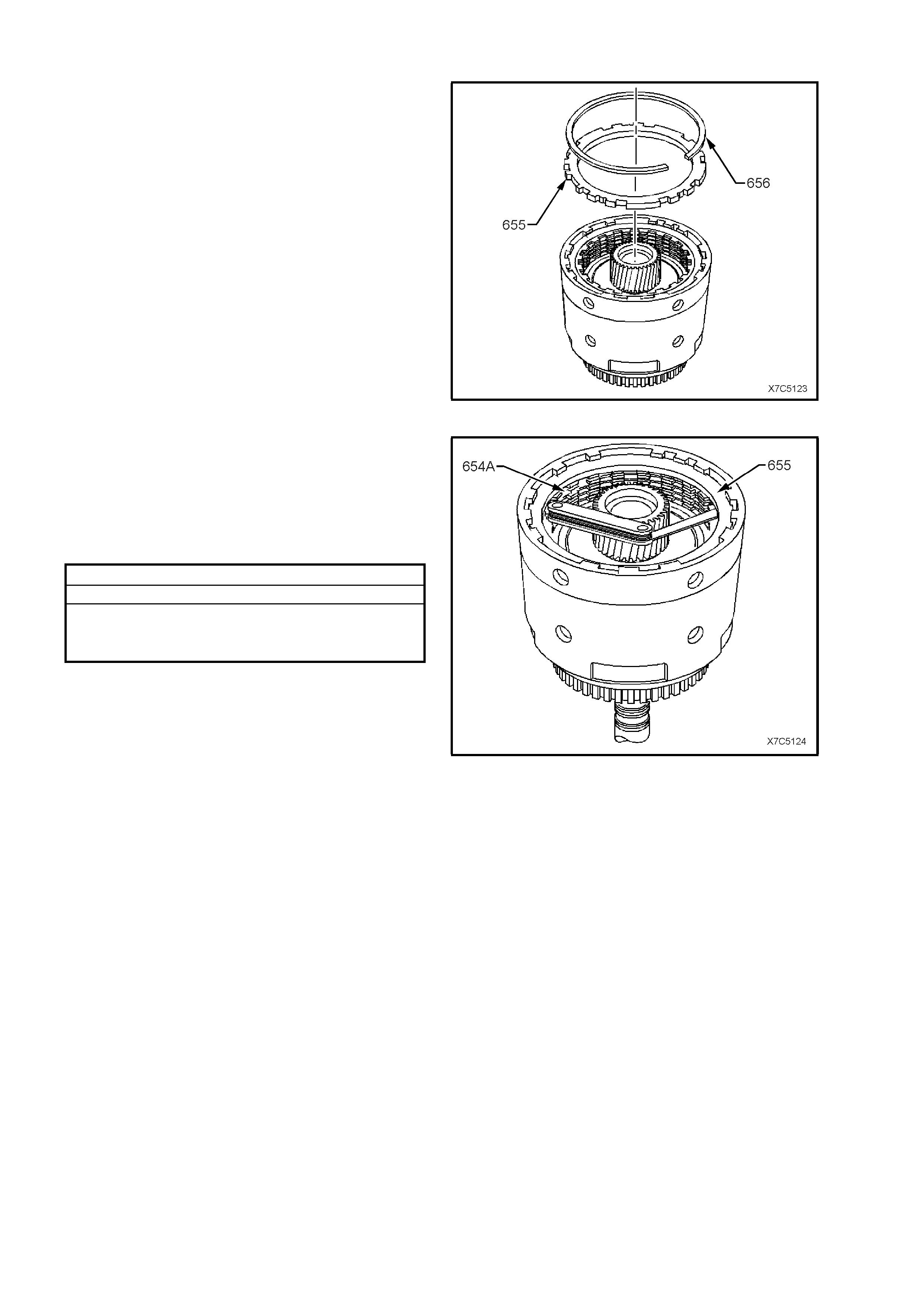
31. Reinstall 3-4 clutch selective backing plate
(655), chamfered side up (if applicable) and
wide tangs over the spring boost assemblies
(600). Reinstall retaining ring (656).
Figure 7C5-133
32. Measure clearance between backing plate
(655) and adjacent composition plate with a
feeler gauge. Clearance should be 0.90 - 2.10
mm. If clearance is incorrect, select a suitable
selective backing plate from the chart below
and install in the place of the original backing
plate.
3-4 CLUTCH SELECTIVE PLATE
PLATE THICKNESS (mm) IDENTIFICATION
5.88 - 5.68 A
4.99 - 4.76 B
4.10 - 3.90 C
NOTE: Identification letters are stamped on the
backing plate.
Figure 7C5-134
INPUT CLUTCH HOUSING AIR CHECKS
1. Check overrun clutch by using a rubber tipped
air nozzle (4) to apply air pressure to the
overrun clutch passage (1) while blocking
forward clutch apply hole (2). Overrun clutch
should apply. Lube passage (3) is shown to
assist with correct orifice identification.
NOTE: Unless the forward clutch apply hole is
blocked during this test, air will leak past the
forward clutch piston lip seals and exit via the
forward clutch feed hole in the input shaft.
2. Check the forward clutch by applying air
pressure to the forward clutch apply hole.
Forward clutch should apply.
Figure 7C5-135
3. Check 3-4 c lutch by applying air pres sure (3) to
the 3-4 clutch ball and retainer assembly (1),
while blocking the 3-4 feed hole (2) in the
turbine shaft. The 3-4 clutch should apply.
Figure 7C5-136
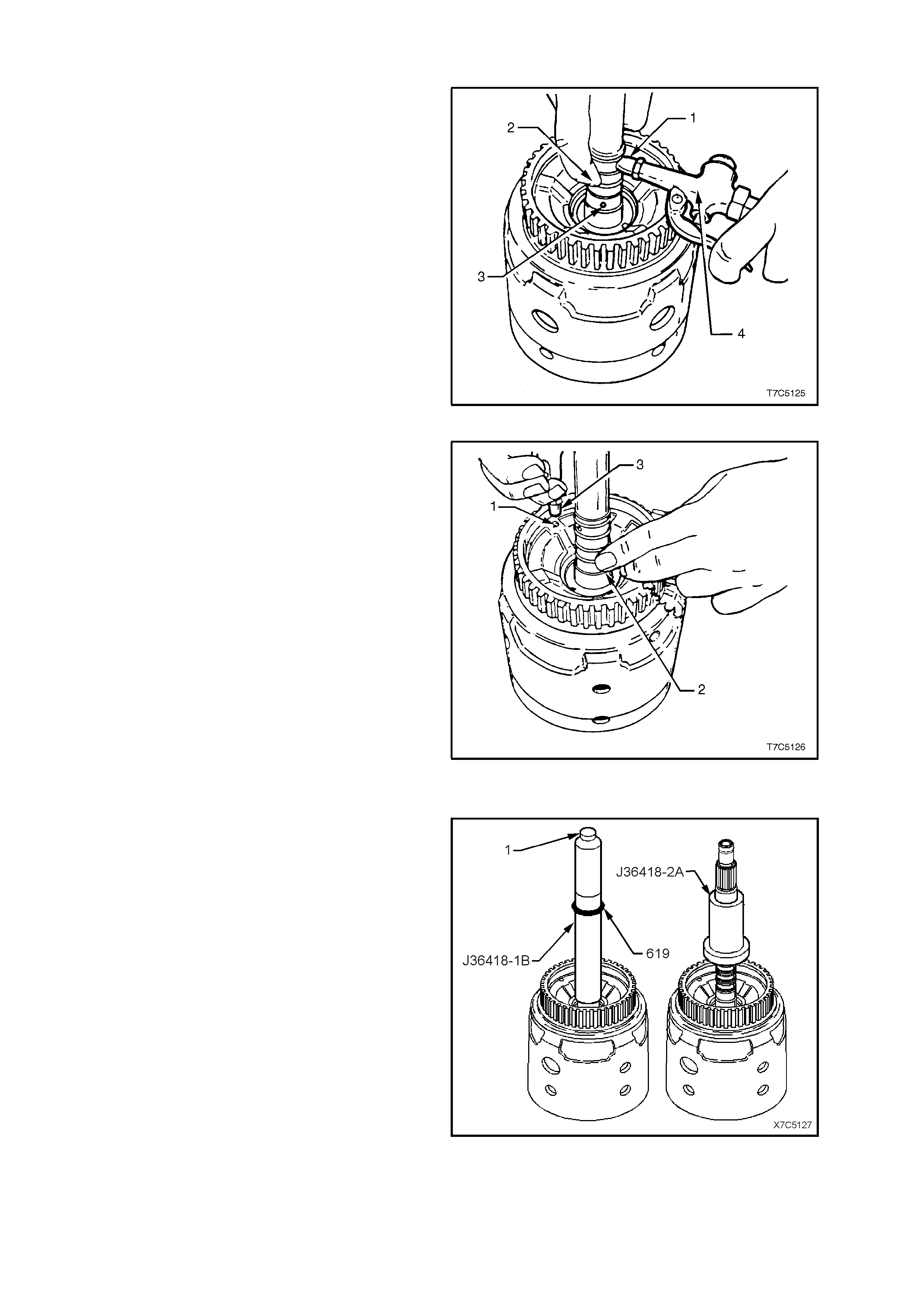
REINSTALL TURBINE SHAFT SEALING RINGS
1. Install Tool No. J36418-1B over input shaft.
2. Slide four new input shaft oil seal rings (619),
lubricated with petroleum jelly over tool J36418-
1B and install as follows:
a. Use the knurled screw (1) in the end of
Tool J36418-1B, to adjust the inner end of
the Tool so the innermost seal groove in
the input shaft is exposed.
b. Slide the first input shaft seal ring down
until it slips off the end of the Tool and is
installed in the input shaft groove.
c. Turn the knurled crew (1) in a clockwise
direction until the second groove in the
input shaft is exposed, then repeat step ‘b’.
d. Continue to install remaining sealing rings,
using the above steps ‘a’ and ‘b’ until all
sealing rings have been installed.
3. Rem ove J36418-1B and ins tall J36418-2A over
all of the seals to re-size them. Leave J36418-
2A in place until the transmission is
reassembled.
Figure 7C5-137
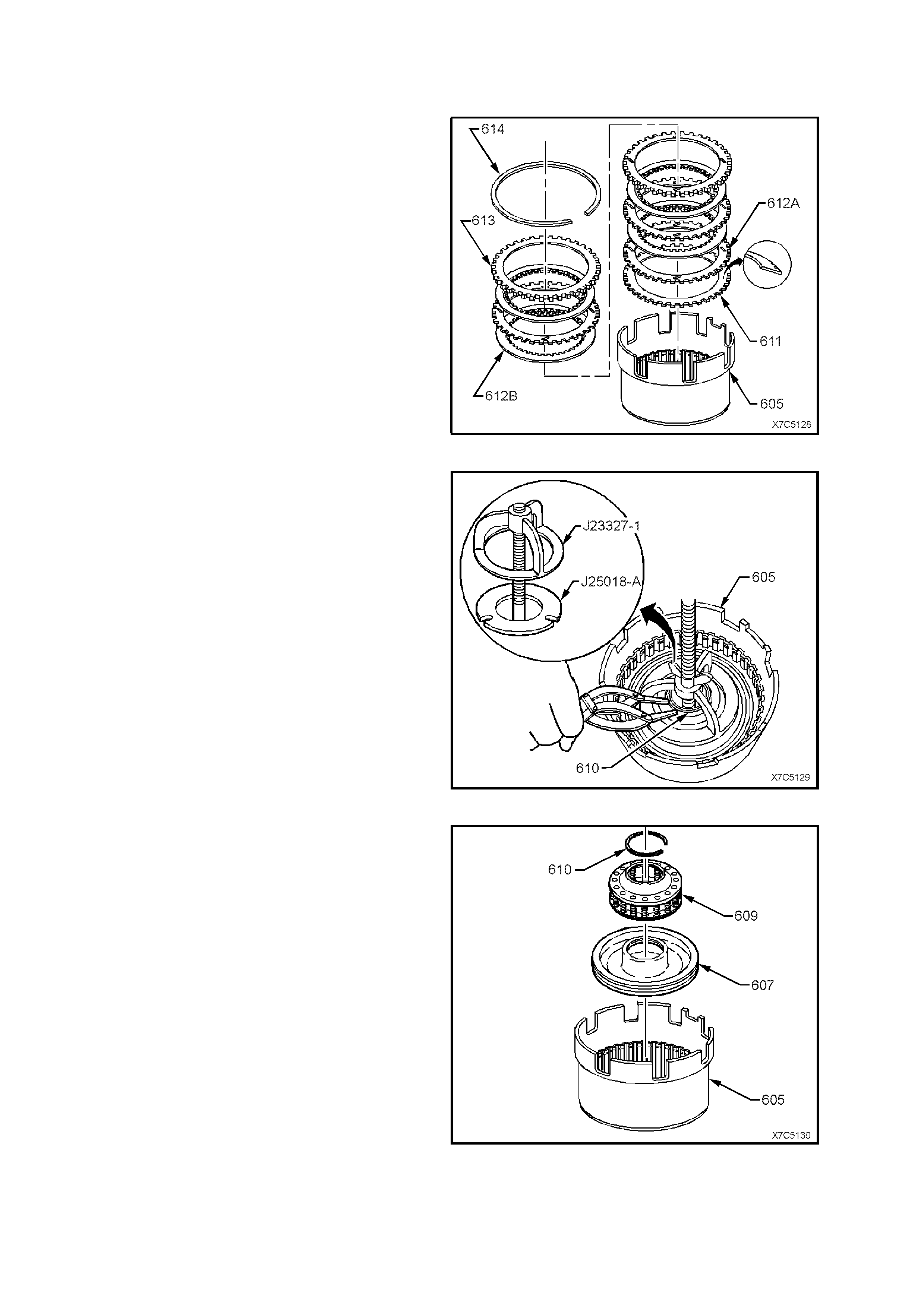
2.13 REVERSE INPUT CLUTCH ASSEMBLY
DISASSEMBLE
1. Rem ove backing plate retaining r ing (614) from
housing and drum assembly (605).
2. Remove backing plate (613) and clutch plates
(612A/B) including Belleville plate (611).
Figure 7C5-138
3. Install Tools J23327-1 with J25018-A
underneath and compress reverse input clutch
sprin g assembly.
4. Remove spring assembly retaining ring (610).
Figure 7C5-139
5. Remove J23327 and J25018-A and remove
spring assembly (609).
6. Remove piston (607) and discard piston seals.
Figure 7C5-140
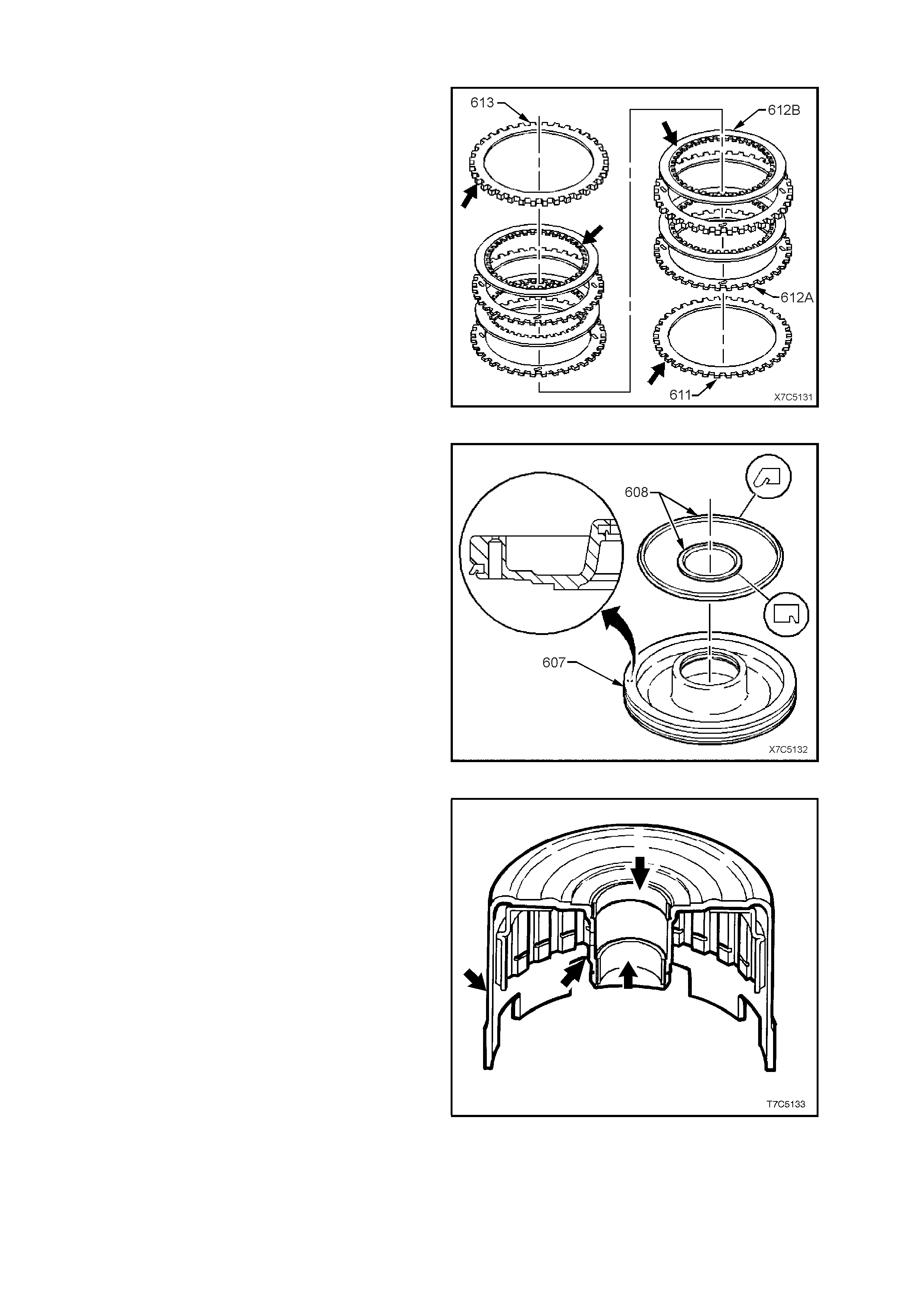
INSPECT
1. Inspect selective backing plate (613) for
damage, burrs or distortion.
2. Inspect clutch plates:
a. Check composition plates (612B) for tang
damage, delamination or wear.
b. Check steel plates (612A) for tang
damage, wear or heat damage.
3. Check the waved plate (611) for heat damage
or tang wear.
4. Inspect spring assembly for distortion or
damage.
Figure 7C5-141
5. Inspect the reverse input clutch piston (607)
for:
a. Damage or porosity.
b. Ring groove damage.
6. Remove both piston seals (608) and discard.
Figure 7C5-142
7. Inspect housing and drum assembly (605) for:
a. Damaged or worn bushes.
b. Surface damage to hub or outer housing.
c. Leaking weld.
Figure 7C5-143

d. Outer housing 'dishing' at point ‘A’.
Should the bushes require replacement, refer to the
following procedure.
Figure 7C5-144
REVERSE INPUT CLUTCH HOUSING BUSHES - REPLACE
1. Using bush remover J25019-16 and slide
hammer J7004-1, remove the front bushing
(603) from the reverse input clutch housing.
Figure 7C5-145
2. T urn the reverse input clutch housing over and
use bush remover J25019-4 and driver handle
J8092 to remove the rear bush (606) from the
reverse input clutch housing.
Figure 7C5-146
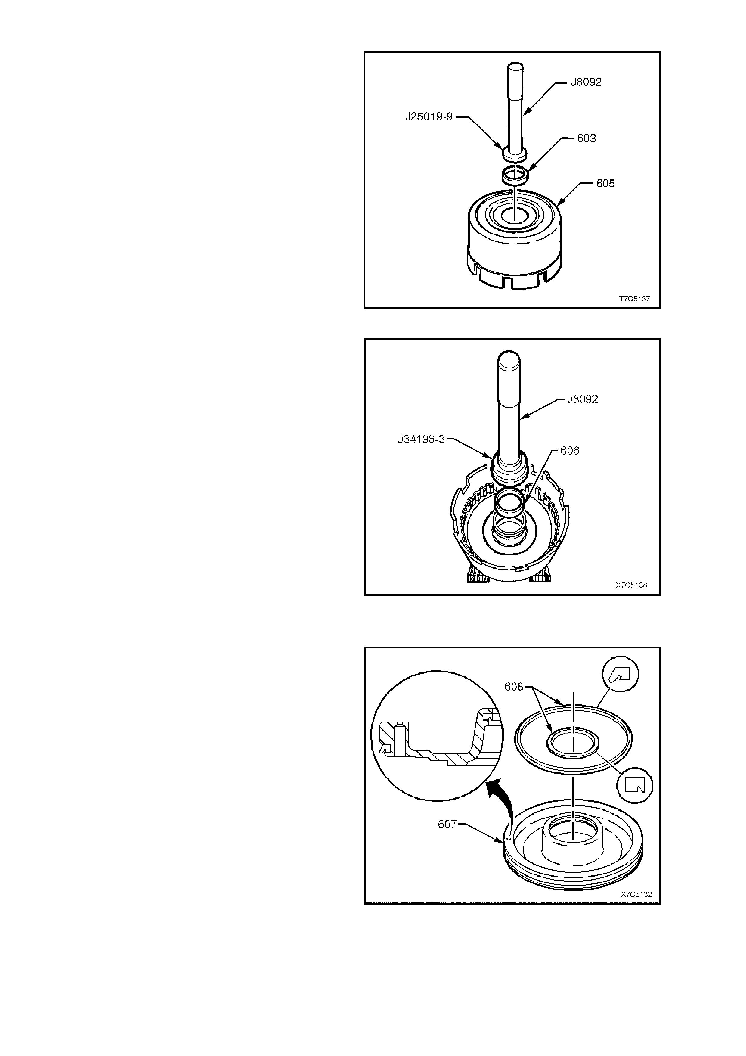
3. Press a new front bush (603) into the reverse
input clutch housing (605), using installer
J25019-9 and driver handle J8092.
Figure 7C5-147
4. Support the reverse input clutch housing on
suitable pieces of wood and install a new rear
bush (606), using installer J34196-3 and driver
handle J8092
Figure 7C5-148
REASSEMBLE
1. Lubricate new piston seals (608) with
transmission fluid and install seals on piston
(607) with lips facing in the directions shown.
Figure 7C5-149
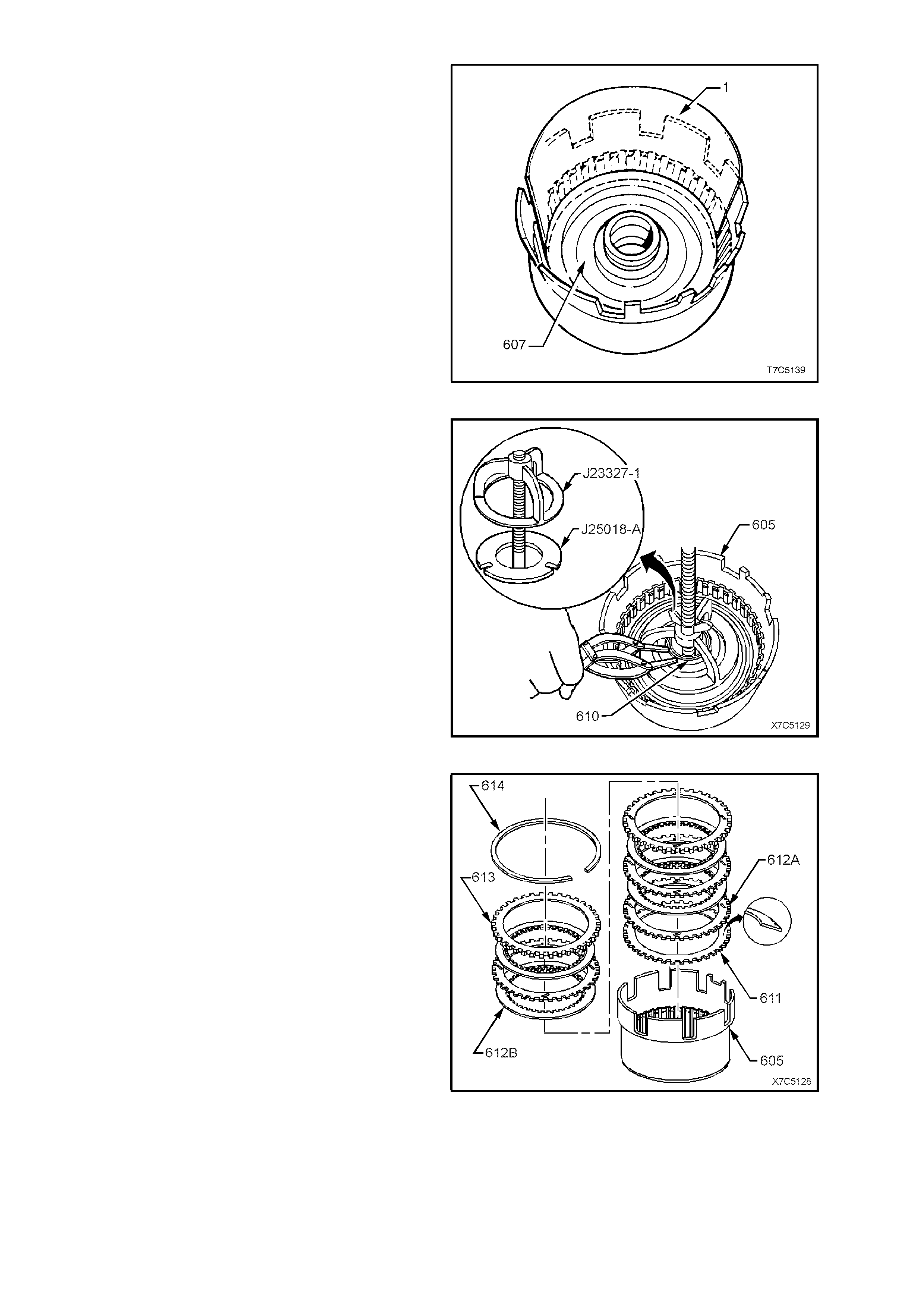
2. Position a strip of thin plastic material
(approximately 0.01 mm thick) (1) around one
half of the hub and coat with petroleum jelly.
3. Coat piston seals with petroleum jelly and, with
seal lips facing down, reinstall piston (607) by
tilting down on the side opposite the plastic
strip.
4. Gently work the piston down against the plastic
strip and into the hub. Remove the plastic strip.
5. Reinstall spring assembly with larger opening
facing piston.
Figure 7C5-150
6. Install Tools J25018-A and J23327-1,
compress the spring assembly and reinstall
spring assembly retaining ring (610). Remove
tools.
Figure 7C5-151
7. Reinstall Belleville clutch plate (611), concave
side down, as shown.
8. Reinstall rem aining c lutch plates , starting with a
steel turbulator plate (612A), then composition
(612B), etc.
9. Reinstall selective backing plate (613),
chamfered side up and reinstall retaining ring
(614).
Figure 7C5-152
10. Apply an evenly distributed, medium load
(approx. 10 kg) to the backing plate (613) as
shown in the inset.
NOTE: Exce ssive pressur e will distort the Belleville
plate.
11. Use a feeler gauge to measure the gap
between the selective backing plate (613) and
retaining ring (614). Clearance should be
between 1.02 and 1.95 mm.
12. If gap is not to specification, select another
backing plate from the table below to replace
the original.
REVERSE INPUT CLUTCH BACKING PLATE SELECTION
PLATE THICKNESS (mm) IDENTIFICATION
7.249 - 7.409 2
6.519 - 6.678 3
5.787 - 5.947 4
NOTE: Identification numbers are stamped on the
backing plate.
Figure 7C5-153
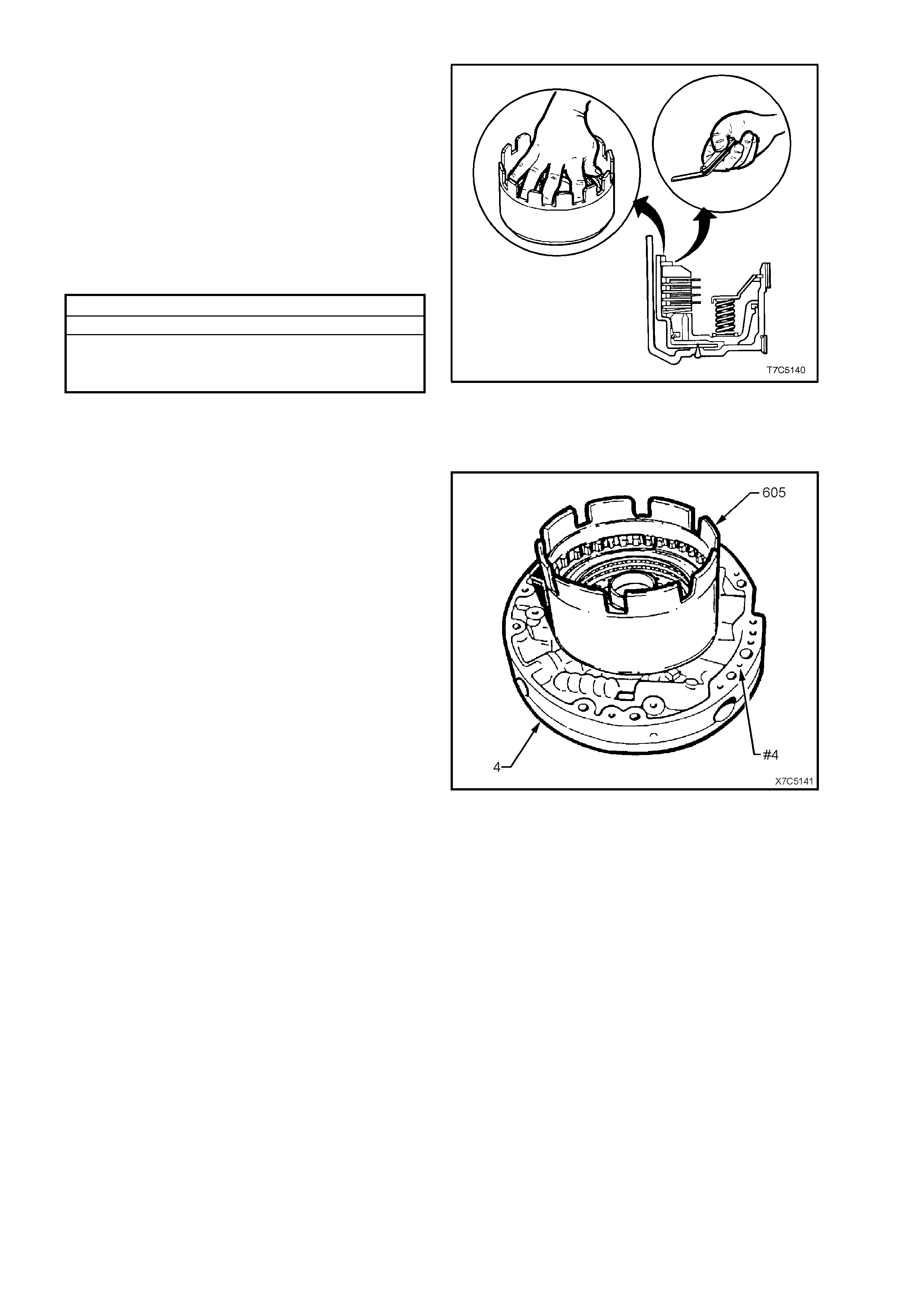
REVERSE INPUT CLUTCH AIR CHECK
NOTE: Even though air pressure will be lost
through the bleed hole in the piston during this
process, it is recommended that the reverse input
clutch be completely assembled, prior to
conducting this test.
If air tested with only the piston and return spring
assembly secured with a retaining ring, the piston
may 'over-s trok e' and dislodge the snap r ing and/or
cause the piston seals to become dislodged from
the piston and damaged. In either case, there is a
safety risk that is to be avoided.
1. Mount the reverse input drum assembly (605)
and thrust washer (601), onto the inverted
pump assembly (4), as shown.
2. Apply air pressure in bursts to the oil pump
housing passage (#4) and observe the
movement of the clutch piston and the clutch
pack.
If the clutch does not apply, there is a
possibility that the air pressure is too low.
Therefore, increase the pressure before
condemning the clutch piston assembly.
Figure 7C5-154

2.14 2-4 BAND
INSPECT
1. Inspect 2-4 band assembly for damage, delamination or excessive wear.
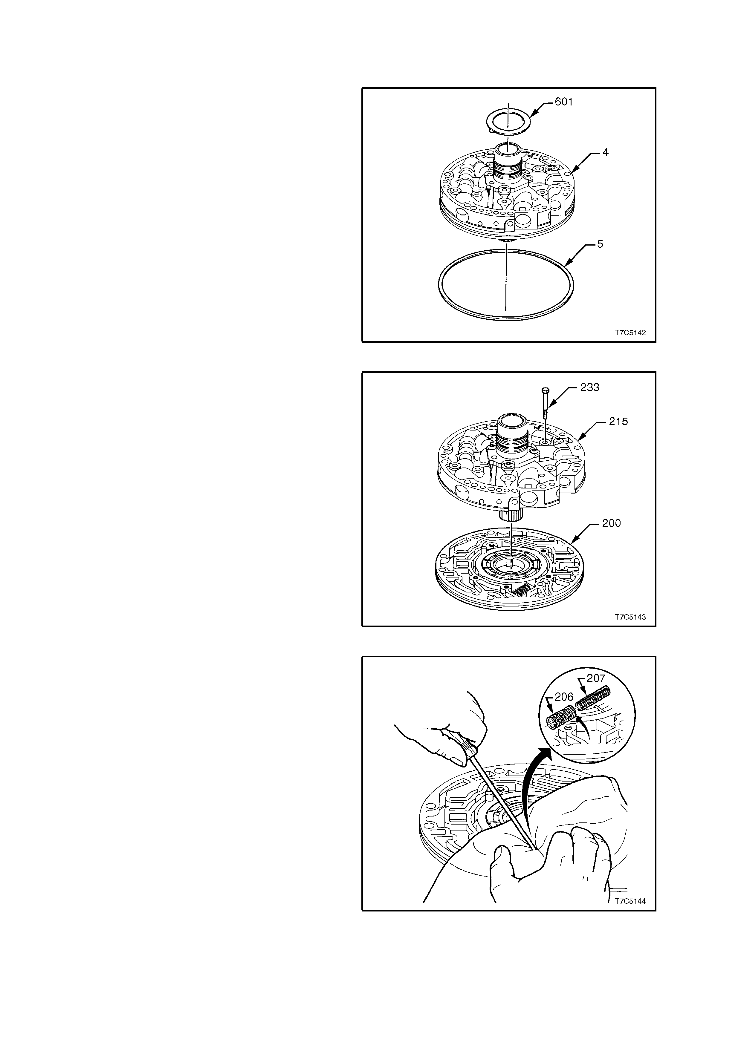
2.15 OIL PUMP
DISASSEMBLE
1. Position the oil pump assembly (4) so that the
stator shaft protrudes through a hole in the
workbench.
2. Remove the thrust washer (601), from the
reverse input dr um support and the O -ring seal
(5) from the pump body.
Figure 7C5-155
3. Remove five bolts (233) securing the pump
cover to the pump body.
4. Separate the pump cover assembly (215) from
pump body (200).
Figure 7C5-156
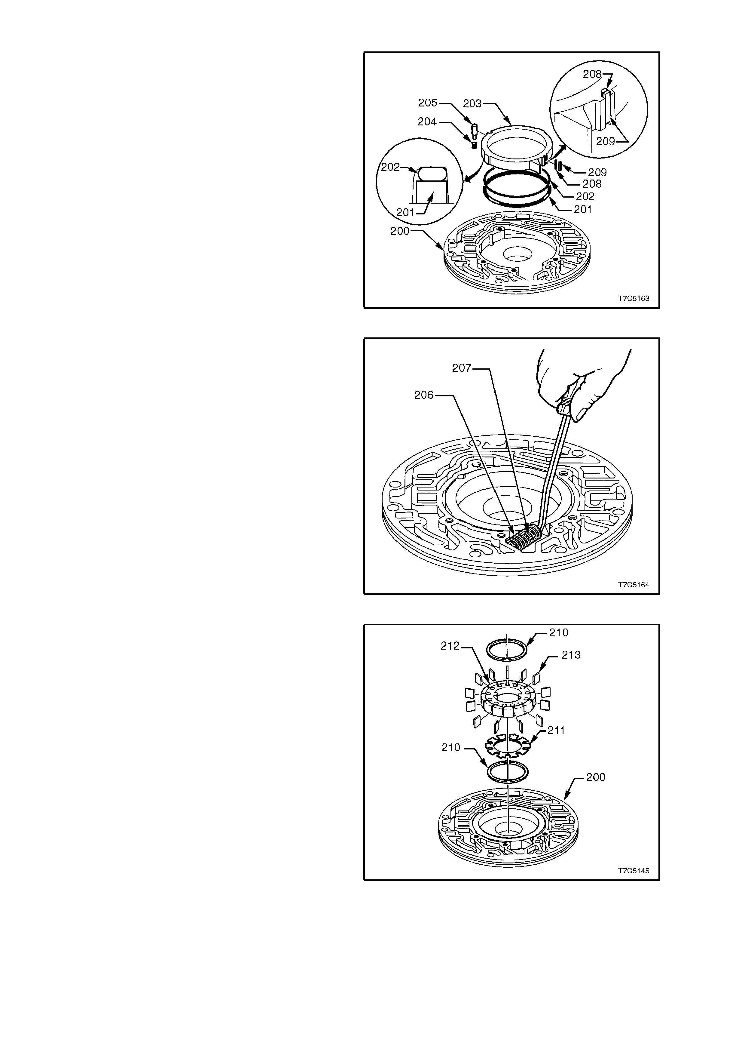
Oil Pump Body
1. Compress pump slide springs (206 and 207)
with a suitable lever or long nose pliers and
remove springs.
CAUTION: Springs are under a high load. Place
a rag over the springs (as shown) before
removal to prevent possible injury.
Figure 7C5-157
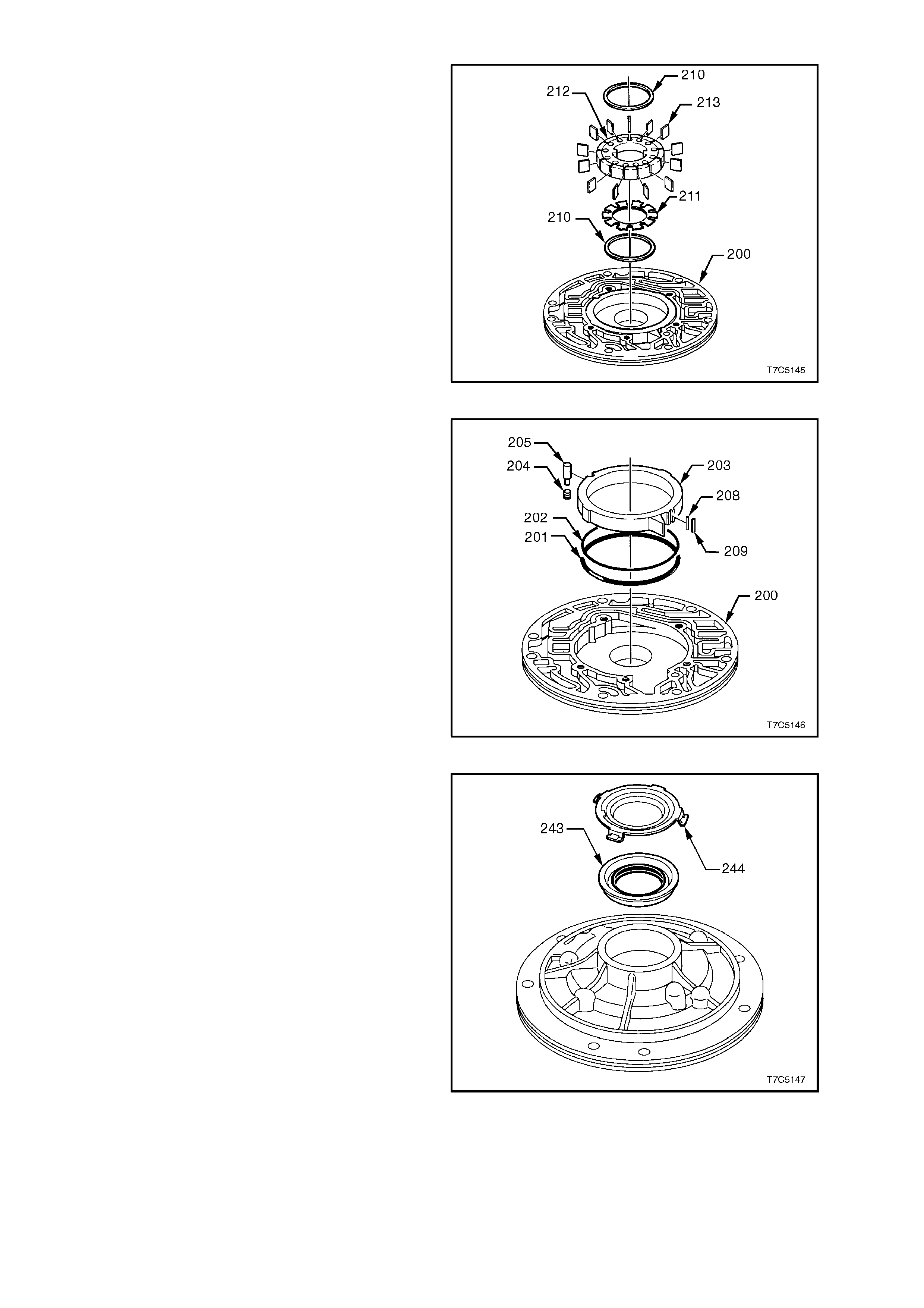
2. Remove following components from pump
cavity in body (200):
a. Upper pump vane guide ring (210).
b. Thirteen pump vanes (213). Note wear
mark patterns for reassembly.
c. Pump rotor (212).
d. Rotor guide (211).
e. Lower pump vane guide ring (210).
Figure 7C5-158
f. Slide (203).
g. Slide seal (209).
h. Seal support (208).
i. Pivot slide pin (205) and spring (204).
j. Slide seal ring (201) and back up seal
(202).
Figure 7C5-159
3. Use a screwdriver to prise out the front helix
seal retainer (244) and oil seal assembly (243)
from the pump body.
Figure 7C5-160

Oil Pump Cover
1. Compress converter clutch apply stop valve
(223) with a screwdriver and use circlip pliers to
remove the circlip (222).
2. Slowly release spring force and remove the
stop valve (223), the converter clutch apply
valve (224) and the two converter clutch valve
springs (225 and 226). Lay components out in
order for inspection.
Figure 7C5-161
3. Using a screwdriver, push the reverse boost
valve sleeve (220) in against spring force and
remove circlip (221) with suitable circlip pliers.
4. Slowly release spring force and remove the
reverse boost valve sleeve (220), the reverse
boost valve (219), the pressure regulator
isolator spring (218), the pressure regulator
spring (217) and the pressure regulator valve
(216). Lay all components out in order for
inspection.
Figure 7C5-162
5. Prise pressure release pin (227) from pump
cover then remove spring (229) and ball (228).
CAUTION: Spring is under very high load.
Cover assembly with cloth when removing pin.
6. Using long nose pliers, pull cover screen (232)
and O-ring seal (231) from the pump cover.
Figure 7C5-163
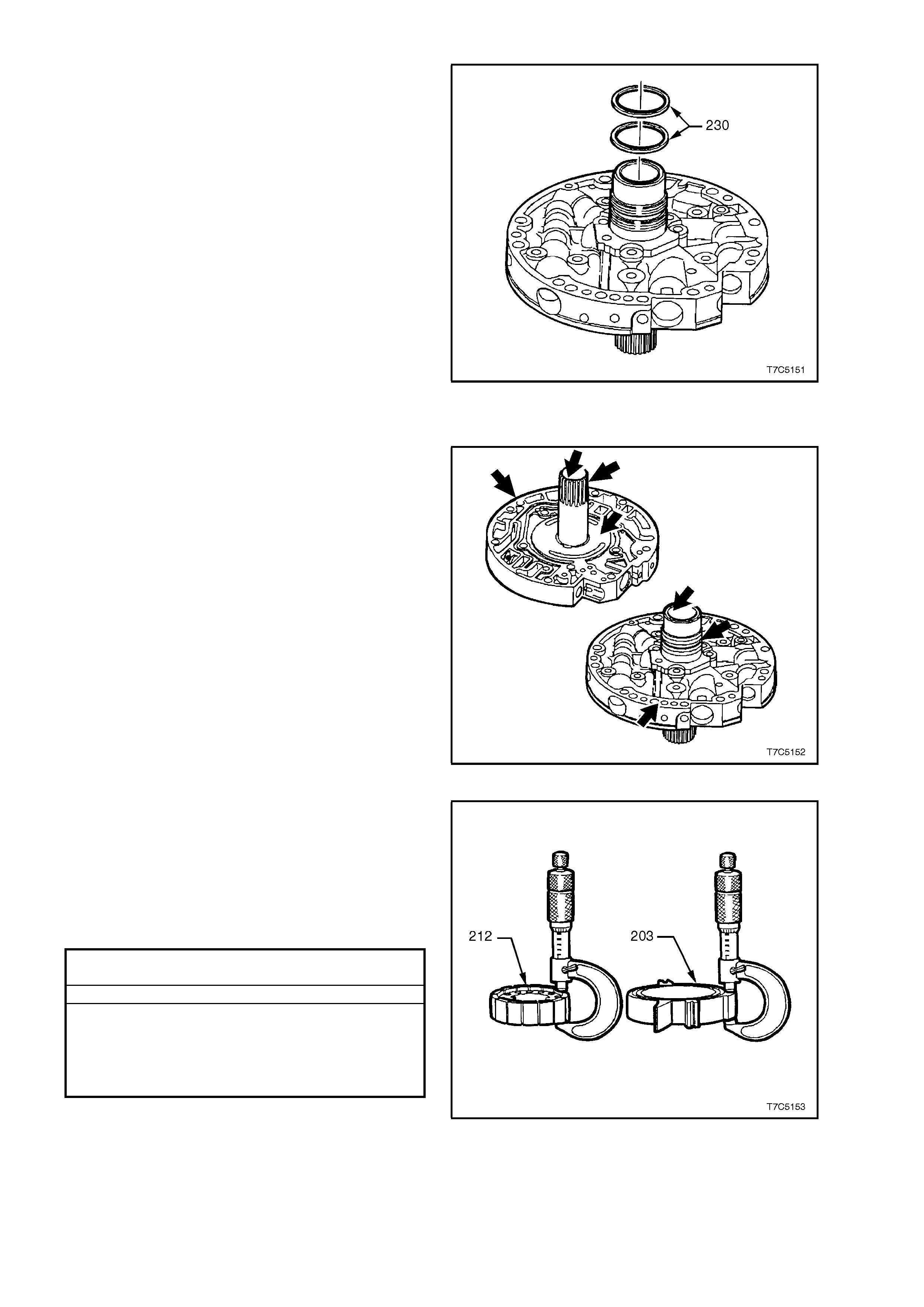
7. Carefully cut the two stator shaft seals (230)
and discard.
8. Wash all components with solvent and air dry.
Do not dry with a cloth.
Figure 7C5-164
INSPECT
1. Inspect pump cover (215) and body (200) for:
a. Worn or damaged bushes.
b. Porosity.
c. Scored or irregular mating faces.
d. Foreign material.
e. Cross channel leaks.
f. Ring groove damage.
2. Inspect valve trains for chips, burrs, distortion,
blocked passages and free movement of
components in bores. Remove burrs with
lapping compound.
3. Inspec t press ure relief com ponents for damage
or distortion.
Figure 7C5-165
4. Inspect pump rotor and slide for cracks.
5. If inspection indic ates that the pum p rotor (212)
or slide (203) require replacement, measure
components over undamaged surfaces and
ensure that the rotor and slide selected, are
from the same size groups. Lightly hone both
sides of replacement rotor or slide to remove
any nicks or burrs.
OIL PUMP ROTOR AND OIL PUMP SLIDE SELECTION
CHART
THICKNESS (mm) IDENTIFICATION
17.948 - 17.961 1
17.961 - 17.974 2
17.974 – 17.987 3
17.987 - 18.000 4
18.000 - 18.013 5
NOTE: While there are no identification numbers
stamped on the oil pump rotor and slide, the size
grading is used in manufacture to achieve a ‘best
match’ rotor and slide to the oil pump body.
Therefore, should inspection show excessive wear
and/or dam age to these components, the com plete
oil pump body assembly must be replaced.
Figure 7C5-166
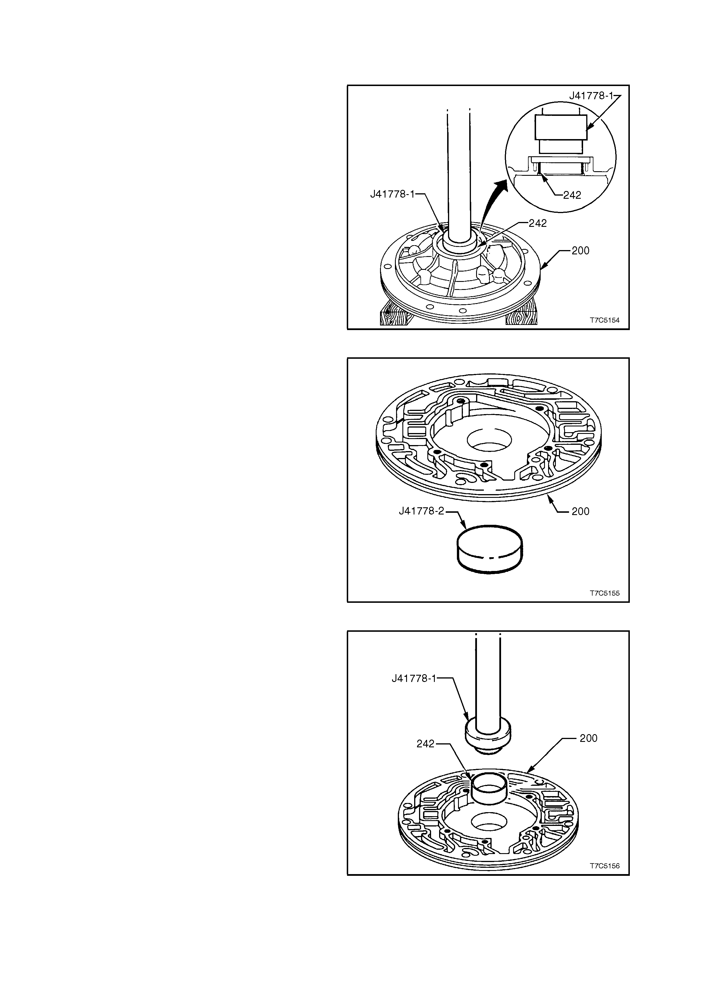
OIL PUMP BUSHINGS – REPLACE
Oil Pump Cover
1. Remove the pump, cavity body bushing (242),
using a bench press and Tool J41778-1.
Figure 7C5-167
2. To install a new bushing, first place the stop
plate, Tool J41778-2 under the oil pump cavity
body (200), as shown.
Figure 7C5-168
3. Position both components under a bench
press.
4. Install a new bush (242) into the oil pump cavity
body, using Tool J41778-1.
NOTE: Having stop plate J41778-2 under the pump
cavity body, effectively limits how far the new bush
can be installed.
Figure 7C5-169

Pump Cover
1. Using bush remover J21465-15 and slide
hammer J7004- 1, remove the s tator s haf t, f r ont
bushing.
Figure 7C5-170
2. Using bush remover J25019-14 and slide
hammer J7004-1, remove the stator shaft rear
bushing, from the pump cover.
Figure 7C5-171
3. Install a new front stator shaft bush (234), using
installer J21465-2 and driver handle J8092.
Figure 7C5-172
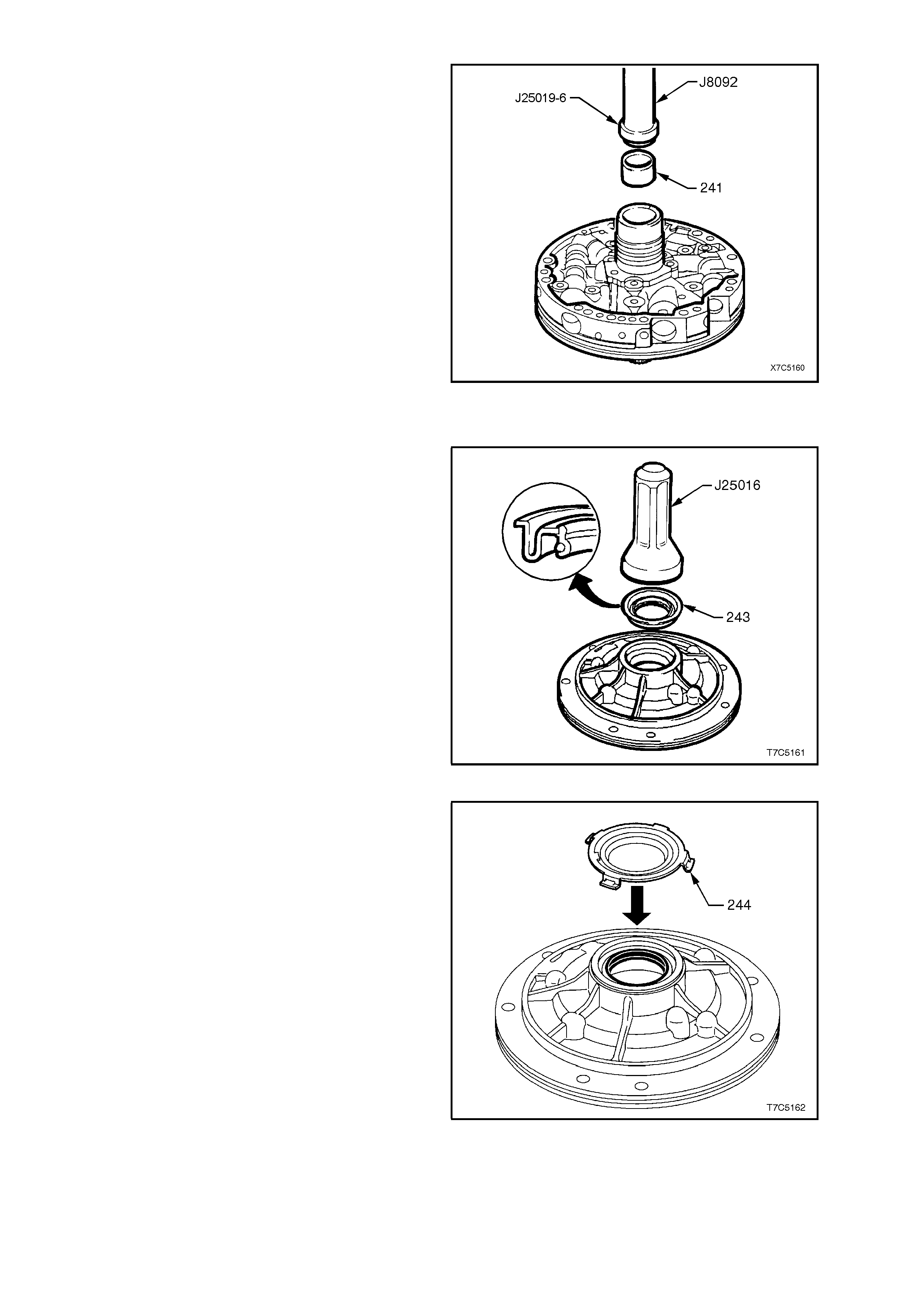
4. Install a new stator s haft rear bush (241) , using
installer J25019-6 and driver handle J8092.
Figure 7C5-173
REASSEMBLE
1. Install new oil seal (243), using seal installer,
Tool J25016.
Figure 7C5-174
2. Install front helix retainer (244).
Figure 7C5-175
3. Install new slide seal back-up O-ring (202) and
support ring (201) into groove on rear side of
slide, retaining both with petroleum jelly.
4. Reinstall pump slide into body, aligning notch
with pivot pin hole.
5. Reinstall slide seal support (208) together with
slide seal (209) into notch in pump slide.
6. Install pivot pin spring (204) and pin (205).
Figure 7C5-176
7. Carefully com pres s slide s pr ings ( 206/207) with
long nose pliers, then use a piece of hacksaw
blade against the slide flange to assist (or a
wide bladed screwdriver as shown) and
reinstall springs in pump body.
CAUTION: Spring tension is very high when both
are compressed. Protect eyes from possible
damage.
Figure 7C5-177
8. Reinstall one of the vane guide rings (210) into
pump body (200).
9. Locate rotor guide (211) onto rotor and retain
with petroleum jelly.
10. Reinstall rotor, with rotor guide facing pump
body.
11. Reinstall pump vanes (213), assembling with
the wear marks in the same position as
originally found on disassembly.
12. Reinstall remaining vane guide ring (210).
Figure 7C5-178

Place pump body assembly to one side and
reassemble pump cover as follows:
13. Reinstall inner (225) and outer (226) converter
clutch apply valve springs onto the stem of the
converter clutch apply valve (224) and, as an
assembly, reinstall into valve bore of the cover.
14. Reinstall valve stop (223) and while
compressing the springs, install the retaining
circlip (222) in converter clutch valve bore,
ensuring that the circlip is correctly seated in
groove.
Figure 7C5-179
15. Reinstall pressure regulator valve (216),
pressure regulator isolator spring (218) and
pressure regulator spring (217) into the
pressure regulator valve bore of oil pump
cover.
16. Reinstall the reverse boost valve (219) into the
reverse boost valve sleeve (220), then reinstall
the assembly into the pressure regulator valve
bore, aligned as shown.
17. While compressing the valve train against the
pressure regulator spring forces, install the
retaining circlip (221), ensuring the circlip is
correctly seated in groove.
Figure 7C5-180
18. Reinstall pres sure relief ball (228) , spring (229)
and pin (227) in pump cover.
19. Reins tall c over filter sc reen (232) with new seal
(231).
Figure 7C5-181

20. Expand new solid stator shaft oil seals (230)
over Tool No. J39855-1 and install, using Tool
No. J38735-3.
21. Once both s eals ar e ins talled, c ompres s to size
by fitting s izing tool, J 39855-2, using petroleum
jelly to assist, as required. Leave sizing tool
installed until the pump assembly is reinstalled
into the transmission.
Figure 7C5-182
22. Place the stator shaft through a hole in the
workbench.
23. Install pump cover assembly (215) on pump
body assembly (200) and reinstall five cover to
body bolts (233), finger tight.
24. To align pump cover to body, fit alignment band
tool J21368 as shown, and secure finger tight.
25. Tighten cover to pump body bolts to specified
torque. Remove pump assembly alignment
band tool.
PUMP COVER TO PUMP BODY
TORQUE SPECIFICATION ............................. 20 - 27 Nm
Figure 7C5-183
OIL PUMP AIR CHECKS
NOTE 1. It is advisable to wear safety glasses
when performing any of the following air check
procedures.
NOTE 2. To check for a restriction (rather than a
blocked passage), perform tests with a piston type
oil can filled with transm ission f luid, rather than use
compressed air.
Air check oil pump as indicated in Fig. 7C5-184 and
the following table to ensure that all passages are
open and all cup plugs are correctly installed.
Figure 7C5-184

BLOW AIR IN: CHECK FOR AIR OUT:
#18 Forward Clutch Feed The second hole down inside the stator shaft bore.
#11 Torque Signal Block hole #47 with a finger. Inject short blasts of
compressed air into hole #11. The Boost valve will click
with each blast of air.
#29 3 - 4 Clutch The first hole down inside the stator shaft bore.
#16 Reverse Input Clutch The reverse input feed hole between the two oil seals on
the outside of the pump hub. The air seats the reverse
check ball, shown as #237 (A).
#3 (B) Line Pressure (To Valve Body) Line Pressure hole #3 (A) and through the filter screen
(232).
CAUTION: Take care that the air pressure does not blow
the filter screen out, as personal injury could result.
#47 Void This drilling terminates in a cavity in the pump body.
#3 (A) Line Pressure (To Pressure Tap Point) Line pressure hole #3 (B) and through the filter screen
(232).
CAUTION: Take care that the air pressure does not blow
the filter screen out, as personal injury could result.
#45 Vent The vent cavity.
#8 From Oil Cooler From the lube cavity in the top of the stator support shaft.
#43 Torque Converter Clutch Release Insert an Allen key through the hole in the converter clutch
valve and push on the valve against spring force. Air will
then come out of the lower hole inside the stator support.
#7 To Oil Cooler Through the filter screen.
CAUTION: Take care that the air pressure does not blow
the filter screen out, as personal injury could result.
#48 Torque Converter Clutch Regulated Apply Through the hole normally filled by the converter clutch
solenoid.
#37 Overrun Clutch The third hole down inside the stator support shaft. Air
pressure will also seat the Check Valve, shown as #237 (B).
#46 Seal Drain Back Between the stator shaft and the oil pump body seal.

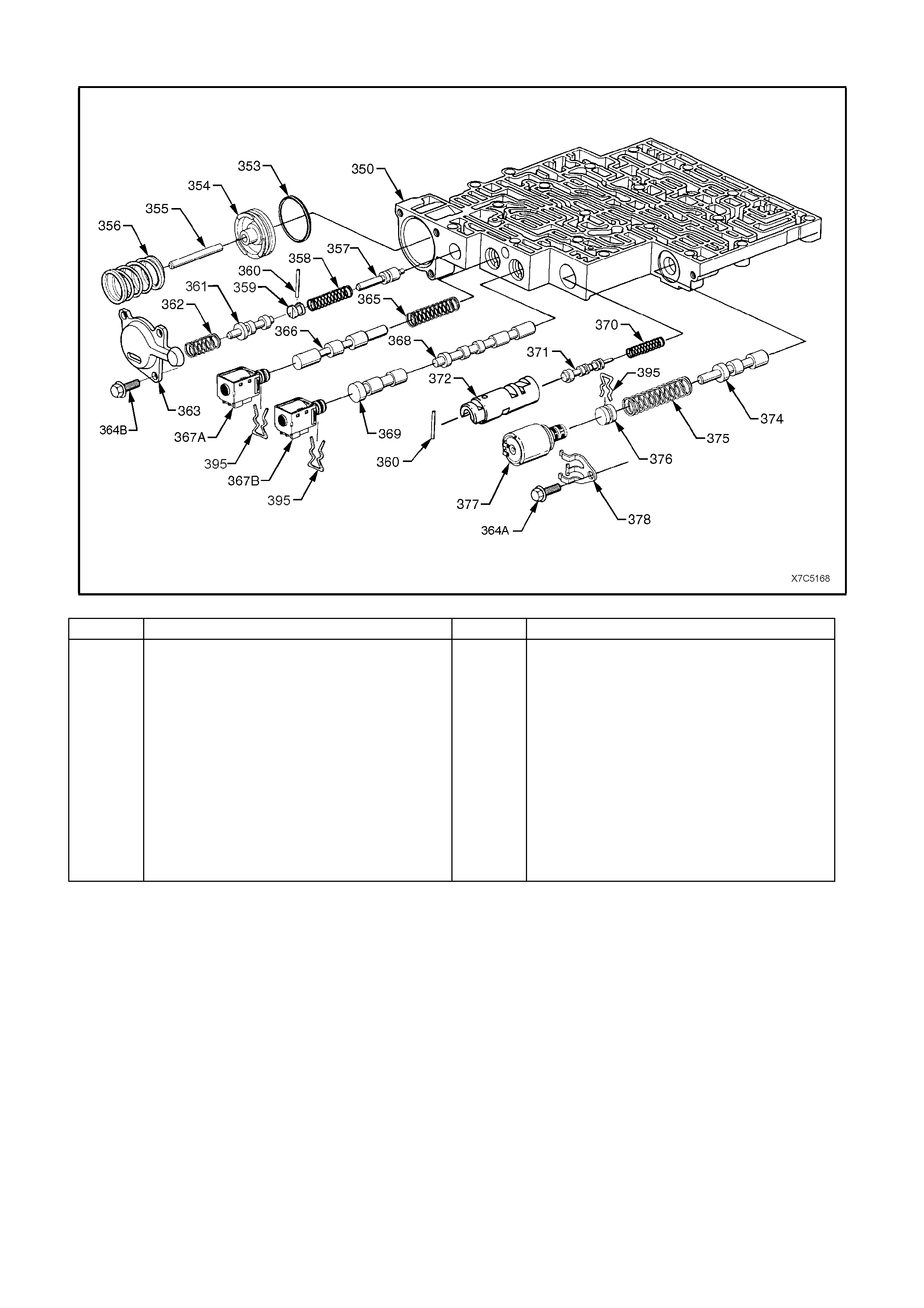
2.16 CONTROL V ALVE BODY
DISASSEMBLE
NOTE 1: Some valve trains are under pressure from spring force. Cover the bores while removing roll pins and
retainer clips.
NOTE 2: Valves, springs and bus hings m ust be laid out in the exact or der of rem oval, to ensure c orrect or ientation
when reassembling.
NOTE 3: While the following sequenc e of dis assem bly is suggested, it is not m andatory. Refer to exploded view for
identification of the various components and their locations for this control valve body.
1. Remove the pressure control solenoid retaining bolt (364A), the retainer (378) and the solenoid (377).
2. While supporting the bore plug (376), remove the retaining clip (395), the bore plug, actuator feed limit valve
spring (375) and valve (374).
3. Remove the 2-3 s hif t s olenoid retaining c lip ( 395), the s olenoid ( 367B); then remove the valve train consisting of
the 2-3 shuttle valve (369) and 2-3 shift valve (368).
4. Remove the 1-2 shift solenoid retaining clip (395), then the solenoid (367A), 1-2 shift valve (366) and spring
(365).
5. Remove the 1-2 accumulator roll pin (360), the 1-2 accumulator sleeve (372), valve (371) and spring (370).
6. Remove the three forward accumulator cover retaining bolts (364B), then the cover (363).
7. Remove the forward accum ulator spring (356), piston (354) and pin (355). Discard the sealing ring (353) after
removing it from the piston.
8. Remove the low overrun valve spring (362) and valve (361).
9. While supporting the bore plug ( 359) with a suitable pr obe, rem ove the roll pin ( 360), the bore plug, the f orward
abuse valve spring (358) and valve (357).
Techline
REF No. PART NAME REF No. PART NAME
350
353
354
355
356
357
358
359
360
361
362
363
364A
364B
365
Valve Assembly, Control Body
Seal, Forward Accumulator
Piston, Forward Accumulator
Pin, Forward Accumulator
Spring, Forward Accumulator
Valve, Forward Abuse
Spring, Forward Abuse Valve
Plug, Bore
Pin, Coiled Spring
Valve, Low Overrun
Spring, Low Overrun Valve
Cover, Forward Accumulator
Bolt, Pressure Control Solenoid Retainer
Bolt, Forward Accumulator Cover
Spring, 1 - 2 Shift Valve
366
367A
367B
368
369
370
371
372
374
375
376
377
378
395
Valve, 1 - 2 Shift
1 - 2 Shift Solenoid (A)
2 - 3 Shift Solenoid (B)
Valve, 2 - 3 Shift
Valve, 2 - 3 Shuttle
Spring, 1 - 2 Accumulator Valve
Valve, 1 - 2 Accumulator
Sleeve, 1 - 2 Accumulator
Valve, Actuator Feed Limit
Spring, Actuator Feed Limit Valve
Plug, Bore
Pressure Control Solenoid
Retainer, Pressure Control Solenoid
Retainer, Bore Plug and Solenoid
Figure 7C5-185 Control Valve Body ‘A’ - Exploded View
10. Turn the control valve body around and remove the manual valve (340).
11. While supporting the 3-2 control solenoid (394), remove the retaining clip (395) and the solenoid.
12. Remove the 3-2 control valve (391) and spring (392).
13. Hold 3-2 downshift bore plug (381) in, then remove the retaining clip (395). Follow this with the 3-2 downshift
valve spring (390) and valve (389).
14. W hile supporting the reverse abuse bore plug (359) with a suitable probe, remove the roll pin (360) and plug.
Then remove the reverse abuse valve spring (388) and valve (387).
15. Support the 3-4 shift valve bore plug (381), while removing the clip (395). Then remove the 3-4 shift valve spring
(386) and valve (385).
16. Support the 3-4 relay valve bore plug (381), while removing the clip (395). Then remove the 3-4 relay valve
(384), 4-3 sequence valve (383) and spring (382).
17. Support the bore plug (381) while removing the retaining clip (395), then remove the regulator apply valve (380),
spring (397) and isolator valve (398), behind it.
18. Clean all valves, springs, bushings and control valve body in clean solvent, then dry with compressed air.
NOTE: The Torque Converter Clutch PWM Solenoid (396) is removed prior to the TCC Solenoid, during the
process of removing the control valve body from the transmission.
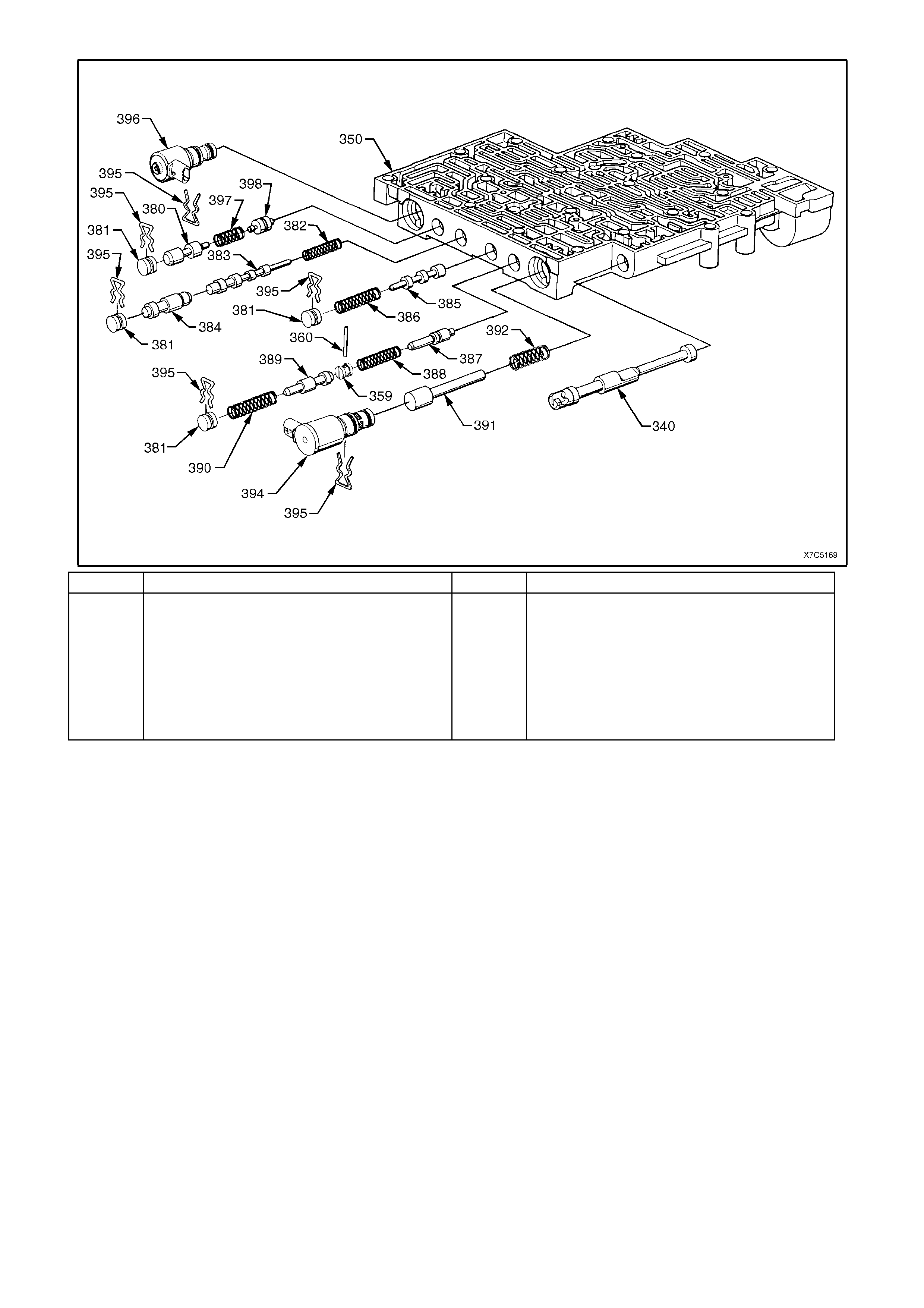
REF No. PART NAME REF No. PART NAME
340
380
381
382
383
384
385
386
387
Valve, Manual
Valve, Regulator Apply
Plug, Bore
Spring, 4 - 3 Sequence Valve
Valve, 4 - 3 Sequence
Valve, 3 - 4 Relay
Valve, 3 - 4 Shift
Spring, 3 - 4 Shift Valve
Valve, Reverse Abuse
388
389
390
391
392
394
395
387
398
Spring, Reverse Abuse Valve
Valve, 3 - 2 Downshift
Spring, 3 - 2 Downshift Valve
Valve, 3 -2 Control
Spring, 3 -2 Control Valve
3 - 2 Control Solenoid
Retainer, Bore Plug and Solenoid
Spring, Regulator Supply
Valve, Isolator
Figure 7C5-186 Control Valve Body ‘B’ - Exploded View
INSPECT
NOTE 1: T he use of a honing stone, f ine sandpaper or croc us cloth is not recom m ended f or s ervicing stuck valves.
All valve lands have sharply machined corners that are necessary for "cleaning" the bore. If these corners are
rounded, foreign material could wedge between the valve and its bore, causing valve sticking.
NOTE 2: If it is found to be necessary to clean a valve, "micro fine" lapping compound with a 900 grit or finer may
be used.
NOTE 3: Too much "lapping" of a valve will create excessive clearances, increasing the chance of valve
malfunction.
1. Inspect all valves and bushings for scoring, scratches or nicks.
2. Inspect all springs for damaged or distorted coils.
3. Inspect valve body casting for porosity, cracks, damaged machined surfaces, blocked or partially blocked
passages and scored or damaged valve train bores.
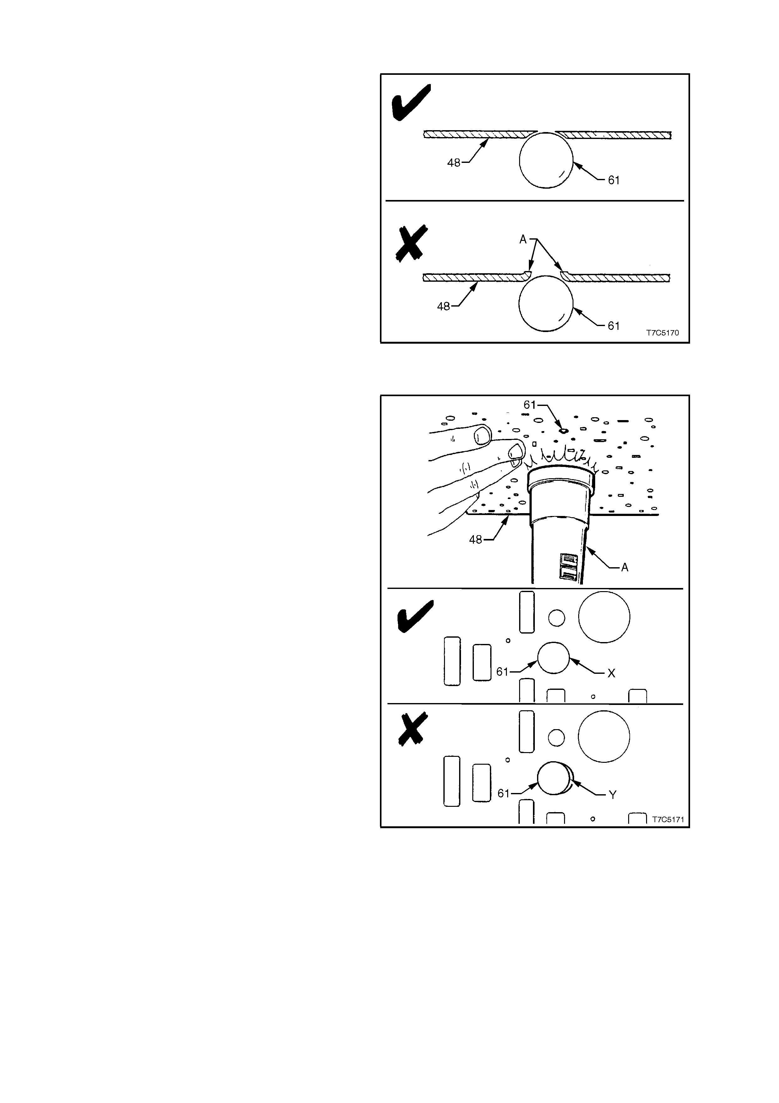
SPACER PLATE EVALUA TION
During inspection of the spacer plate, it is
acceptable for some check ball peening to be
evident but the following is recommended when
establishing the serviceability of this component.
Procedure 1:
The spacer plate (48) must be inspected thoroughly
for r aised m aterial on the opposite side of all c heck
ball (61) locations. If the material on the opposite
side is raised (A), the peening is considered to be
too severe and the spacer plate must be replaced.
Figure 7C5-187
Procedure 2:
To verify that a check ball location has peened
evenly and the ball is seating correctly, seat the
check ball (61) on the spac er plate. Use a tor ch (A)
to shine a beam of light on the opposite side and
check for light between the spacer plate and the
check ball.
No light s hould be vis ible, as indicated at ‘X ’. If it is ,
as indicated by ‘Y’, the spacer plate must be
replaced. Perform this check for all check ball
locations on the spacer plate.
Figure 7C5-188

REASSEMBLE
1. Reassemble all components in the reverse
order to disassembly. Use Fig’s 7C5-185/186
as a reference. Note orientation of all valves,
sleeves and solenoids.
Important: W hen reinstalling each of the bore plug
retainer clips (395), ensure that they are installed
from the transmission case side of the valve body
(i.e. the machined side). If this is not done, then
reinstalling the wiring harness will not be possible
without damage. Also, c orr ec t ins tallation of the fluid
filter will not be possible, preventing fitment of the oil
pan.
NOTE: The TCC PW M Solenoid (396) is not to be
installed until the TCC Solenoid has been installed
and the retaining bolts torqued to specif ication. This
operation occurs during the installation of the
control valve body to the transmission case.
2. Tighten all retaining bolts to the correct torque
specification.
PRESS URE CONT ROL SOLENOID
BRACKET TO VALVE BODY
TORQUE SPECIFICATION ............................. 8 - 14 Nm
FORWA RD A CCUMULA T OR COVER
TO VALVE BODY BOLT
TORQUE SPECIFICATION ............................. 8 - 14 Nm
3. To prevent dust contamination, store
assembled control valve body in a clean plastic
bag, until transmission is reassembled
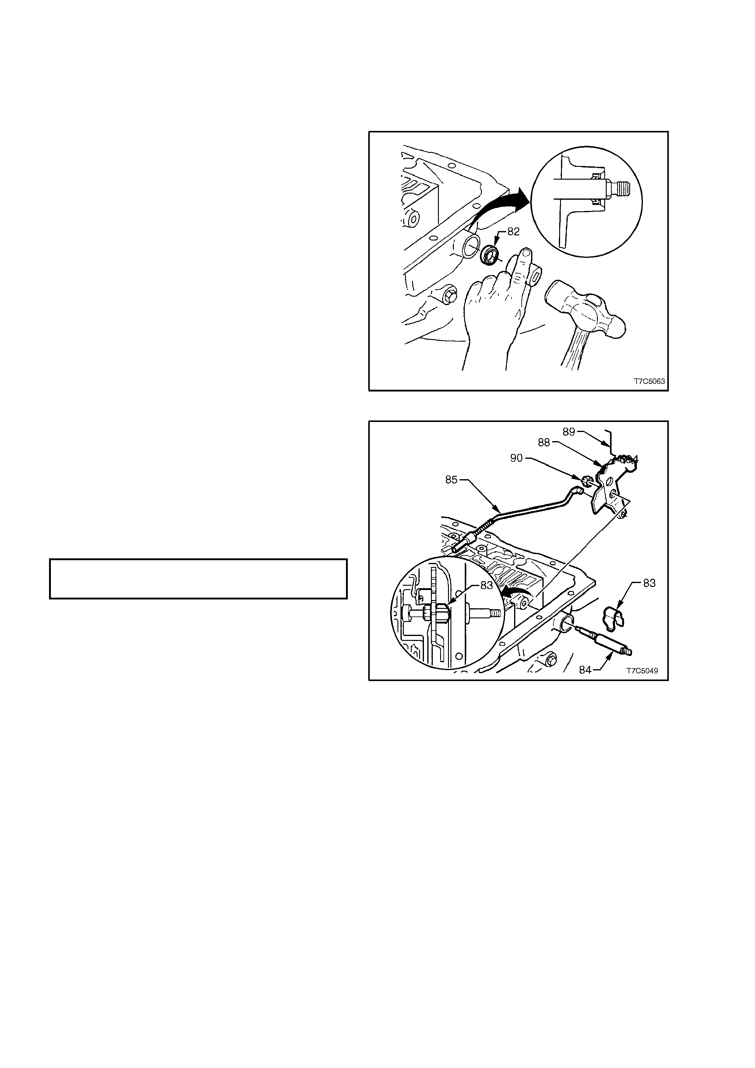
3. TRANSMISSION REASSEMBLE
3.1 MANUAL SHAFT AND PARKING LINKAGE
If previously removed, reinstall manual shaft and
parking linkage components, as detailed in the
following steps:
1. Using a suitable sized socket, install a new
manual shaft seal (82) into the transmission
case. Lubricate the seal lips with a small
amount of clean, automatic transmission fluid.
Figure 7C5-189
2. Install the parking pawl actuator (85) to the
inner detent lever (88).
3. Remove any burrs from the manual shaft (84)
and, after lubricating with transmission fluid,
carefully install into the transmission case,
locating the inner detent lever (88), over the
flats on the manual shaft (84).
4. Install the inner manual shaft nut (90) and
tighten to the correct torque specification.
MANUAL SHAFT TO INNER
DETENT LEVER NUT
TORQUE SPECIFICATION ............................. 27 - 34 Nm
5. Install the manual shaft retainer clip (83) over
the manual shaft (84).
Figure 7C5-190
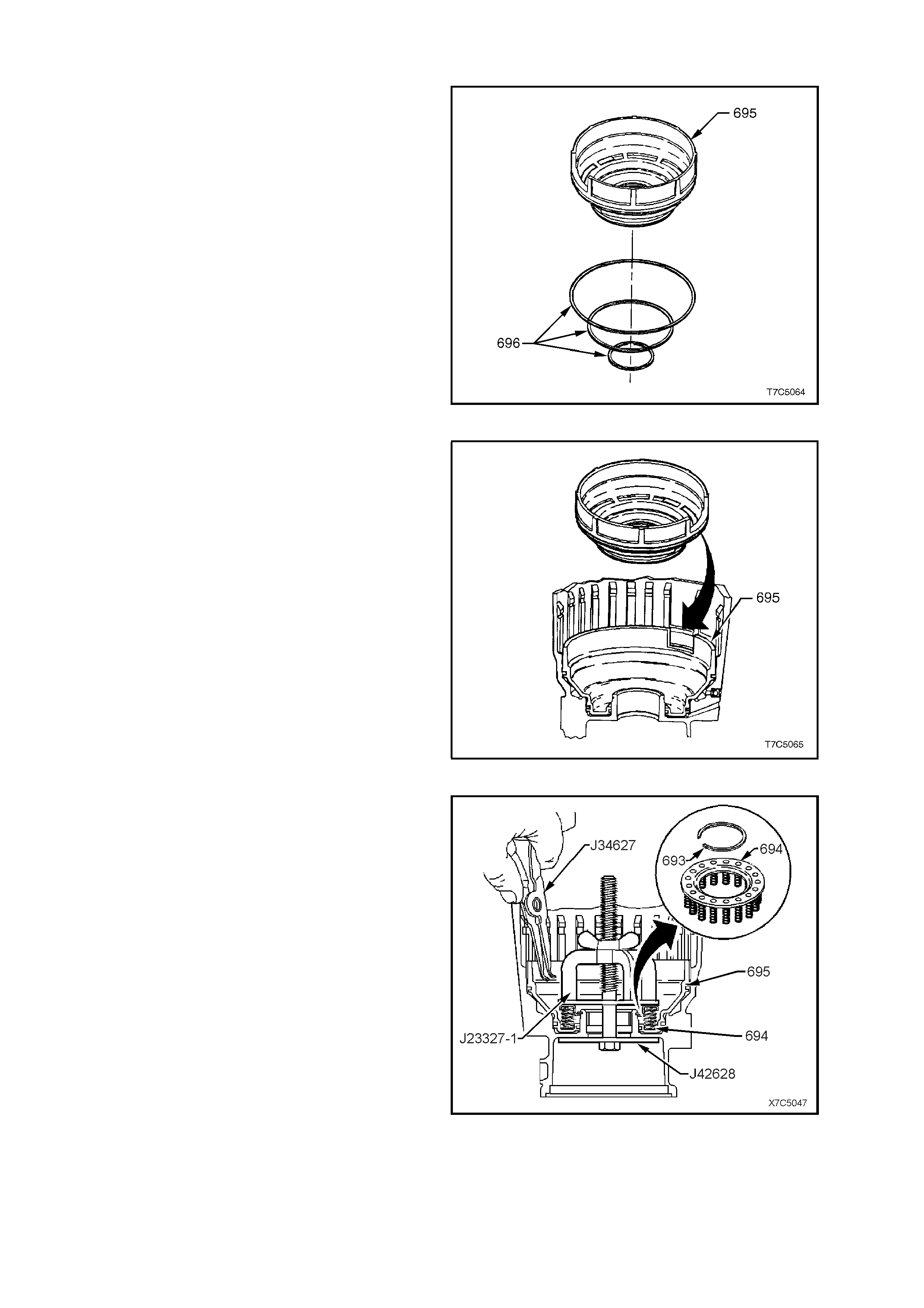
3.2 LOW AND REVERSE CLUTCH PISTON
1. Lubricate new low and reverse clutch piston,
square section seals (696), with transmission
fluid (or petroleum jelly) and install on piston
(695).
Figure 7C5-191
2. Reinstall piston (695) in transmission case,
aligning piston with notch in bottom of cas e, as
indicated. Use Tool J23327-1 (refer Fig. 7C5-
193), to ensure the pis ton is installed square to
its bore.
Figure 7C5-192
3. Locate spring assembly on piston as shown,
with flat side uppermost.
4. Install Tool J23327 and J42628, then com pres s
spring assembly below groove in case.
NOTE: Make sure the lower plate, Tool J42628
indexes correctly in the recess in the end of the
transmission case .
5. Reinstall retaining ring and remove special
tools.
Figure 7C5-193
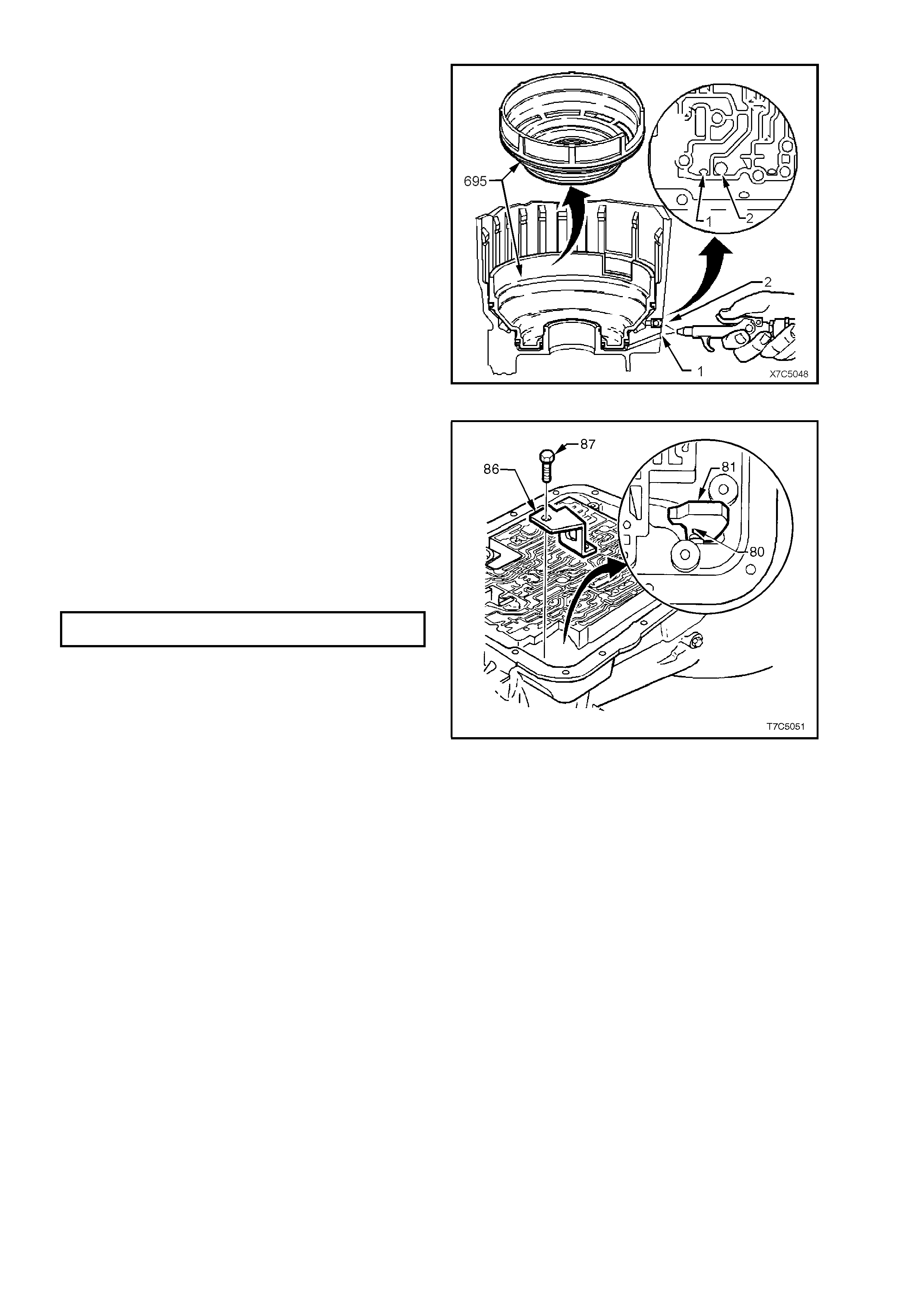
6. To check the operation of the low and reverse
piston, apply low pressure air to either the Low
feed passage (1) or the Reverse feed passage
(2), as shown. As air is supplied, the low and
reverse piston should be seen to move when
viewed in the parking pawl area of the cas e. Air
leaks should also be listened for, during this
check.
NOTE: The low and reverse clutch spring assembly
and retainer ring are not shown, to more clearly
show the air passage arrangements.
Figure 7C5-194
7. If previously removed, locate parking pawl (81)
and return spring (80) in case.
8. Reinstall parking pawl pivot shaft (79) - not
shown. Check for free movement of
components.
9. Coat retaining plug (78) - not shown, with
Loctite 242 sealant or equivalent and install
plug with hammer and punch.
10. Reinstall park pawl bracket (86) and bolts (87)
and tighten to the specified torque.
PARK PAWL BRACKET BOLT
TORQUE SPECIFICATION ............................. 27 - 34 Nm
Figure 7C5-195
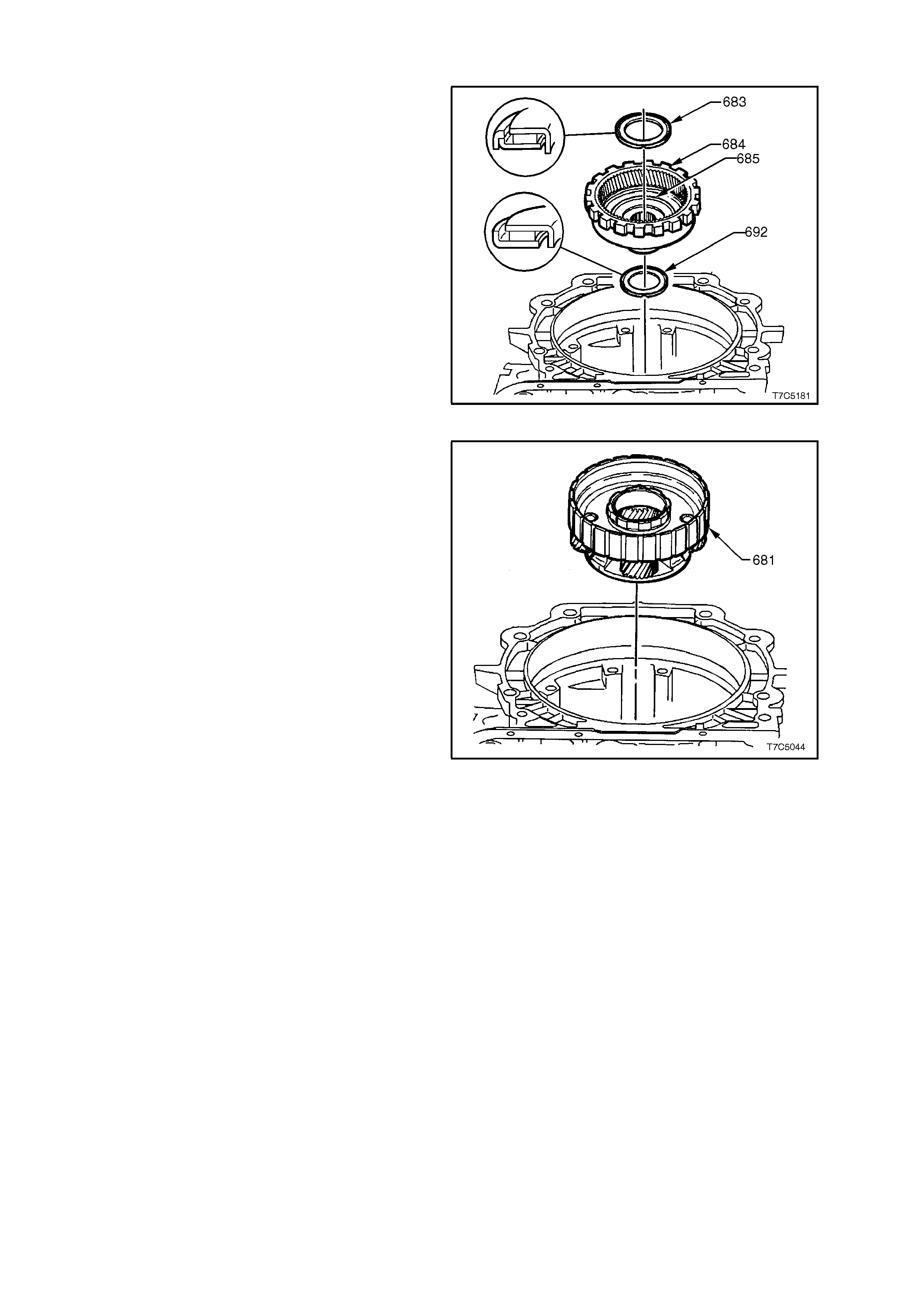
3.3 REACTION PLANETARY GEAR SET
1. Reinstall gear support to case bearing (692)
onto transmission case hub (685) as shown;
i.e. with outside bearing race towards case
hub. Retain with petroleum jelly.
2. Reinstall reaction internal gear (684) and
support (685) assembly into bearing (692) and
transmission case hub.
3. Reinstall reaction carrier to support thrust
bearing (683) on support (685) with outer
bearing race facing support.
Figure 7C5-196
4. Reinstall reaction carrier assembly (681) onto
thrust bearing.
Figure 7C5-197
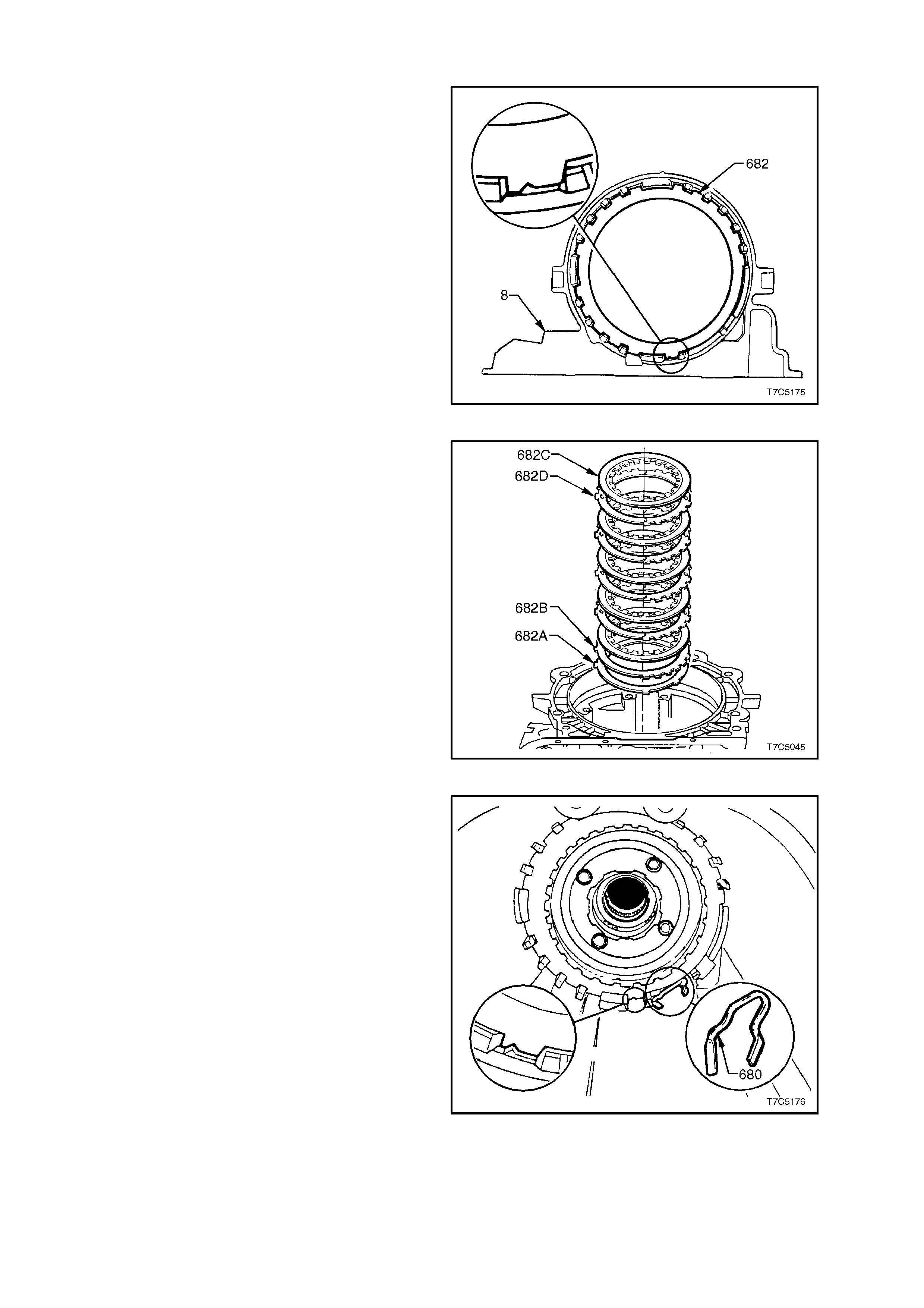
3.4 LOW AND REVERSE CLUTCH PLATES AND SUPPORT ASSEMBLY
1. Soak composition plates in new transmission
fluid.
2. Reinstall low and reverse clutch assembly by
starting with the waved plate (682A), indexing
in the transmission case (8) as shown.
3. Reinstall the selective plate (682B), (as
correctly selected during com ponent inspection
procedures), also indexing the same as for the
waved plate.
Figure 7C5-198
4. Reinstall a composition clutch plate (682C),
then a turbulator steel plate (682D),
composition, steel, etc. Also index the
turbulator steel plates the s ame as for the wave
and selective plates.
Figure 7C5-199
5. Apply petroleum jelly to the flat portion of the
spring (680) and insert the spring into the
curved area in the transmission case as
shown.
Figure 7C5-200
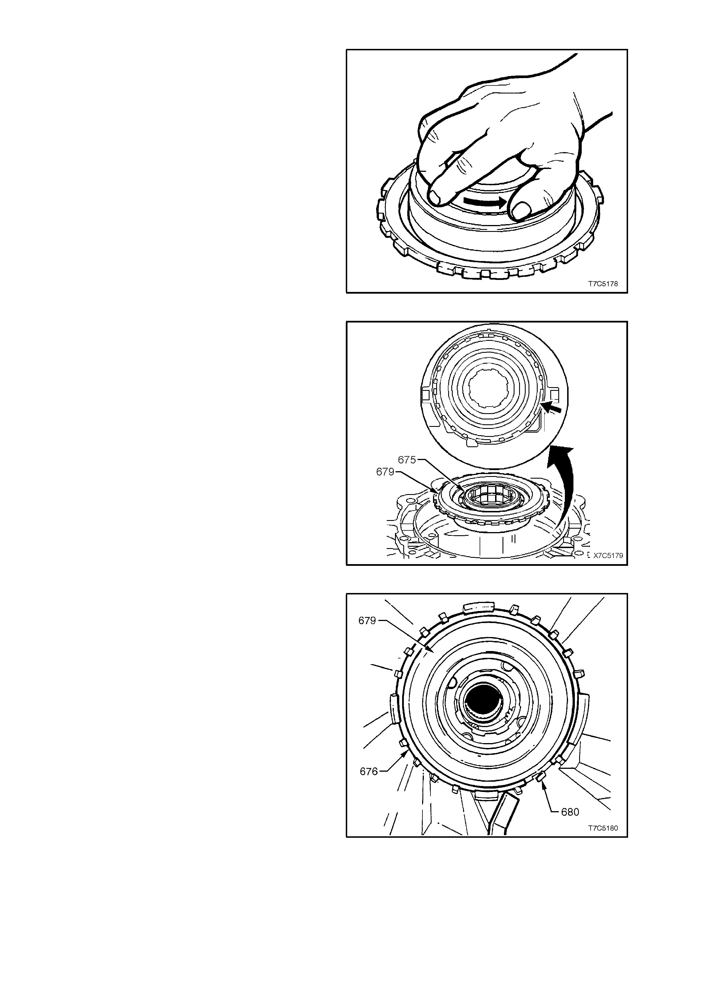
6. Reinstall low and reverse roller clutch ass embly
(678) into cam and support assembly (679).
7. Reinstall both retaining rings (677) that were
removed during roller clutch disassembly.
8. Reinstall inner low and reverse clutch race
(675) by pushing and turning in the direction
shown.
NOTE: Test for correct operation as shown. The
race should ‘free-wheel’ in the direction indicated
by the arrow.
Figure 7C5-201
9. Pull the low and reverse ro ller clutch inner r ace
(675) up from its normally seated position (as
shown), to enable a grip on the support
assembly (679) to be made. Slightly tilt the
support assembly while aligning the wide notch
on the support with a matching wide lug on the
case.
10. Push the assembly into the case until it is
squarely seated and then, while turning the
roller clutch inner race in a clockwise direction
(free), push it down until the internal splines line
up with those on the reaction carrier.
Figure 7C5-202
11. Reinstall support retaining ring (676) by
aligning one end against the low and reverse
clutch support retainer spring (680), then work
the remainder into the groove with the aid of a
screwdriver. Make sure the snap ring is fully
seated in the groove.
Figure 7C5-203
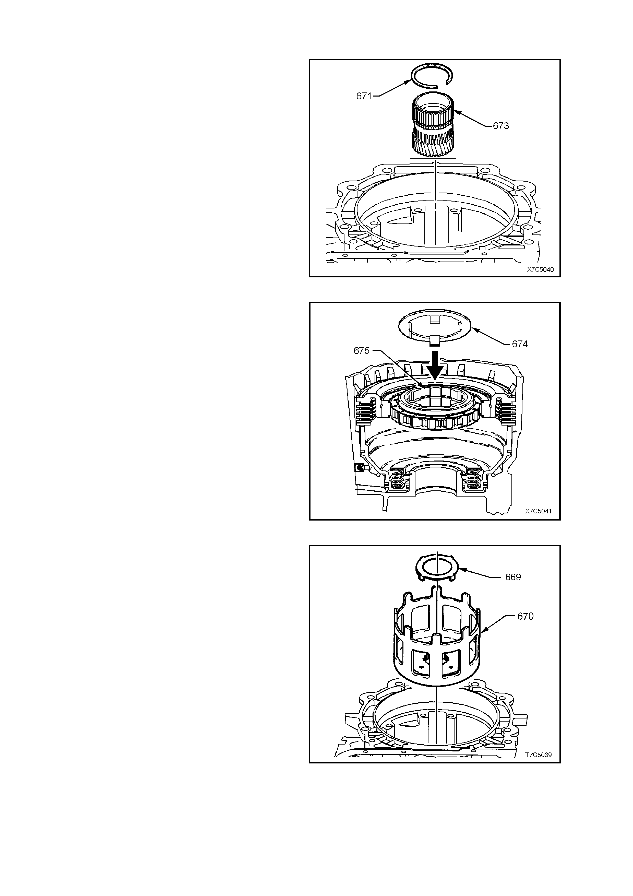
3.5 REACTION GEAR, INPUT GEAR AND OUTPUT SHAFT
1. If removed, install a new reaction sun gear
retaining ring (671) onto reaction sun gear
(673).
2. Reinstall reaction sun gear (673), helical gear
side down, into reaction carrier in transmission
case meshing teeth with pinion gears.
Figure 7C5-204
3. Reinstall thrust washer (674) into the
transmission case, ensuring that the lugs on
the thrust washer face downward and locate in
the inner race of the low and reverse roller
clutch (675).
Figure 7C5-205
4. Reinstall bronze thrust washer (669) onto
reaction sun shell (670) and secure with
petroleum jelly. Tangs on washer locate in four
holes in reaction sun shell.
5. Reinstall reaction sun shell (670) onto thrust
washer (674), locating shell over reaction sun
gear.
Figure 7C5-206
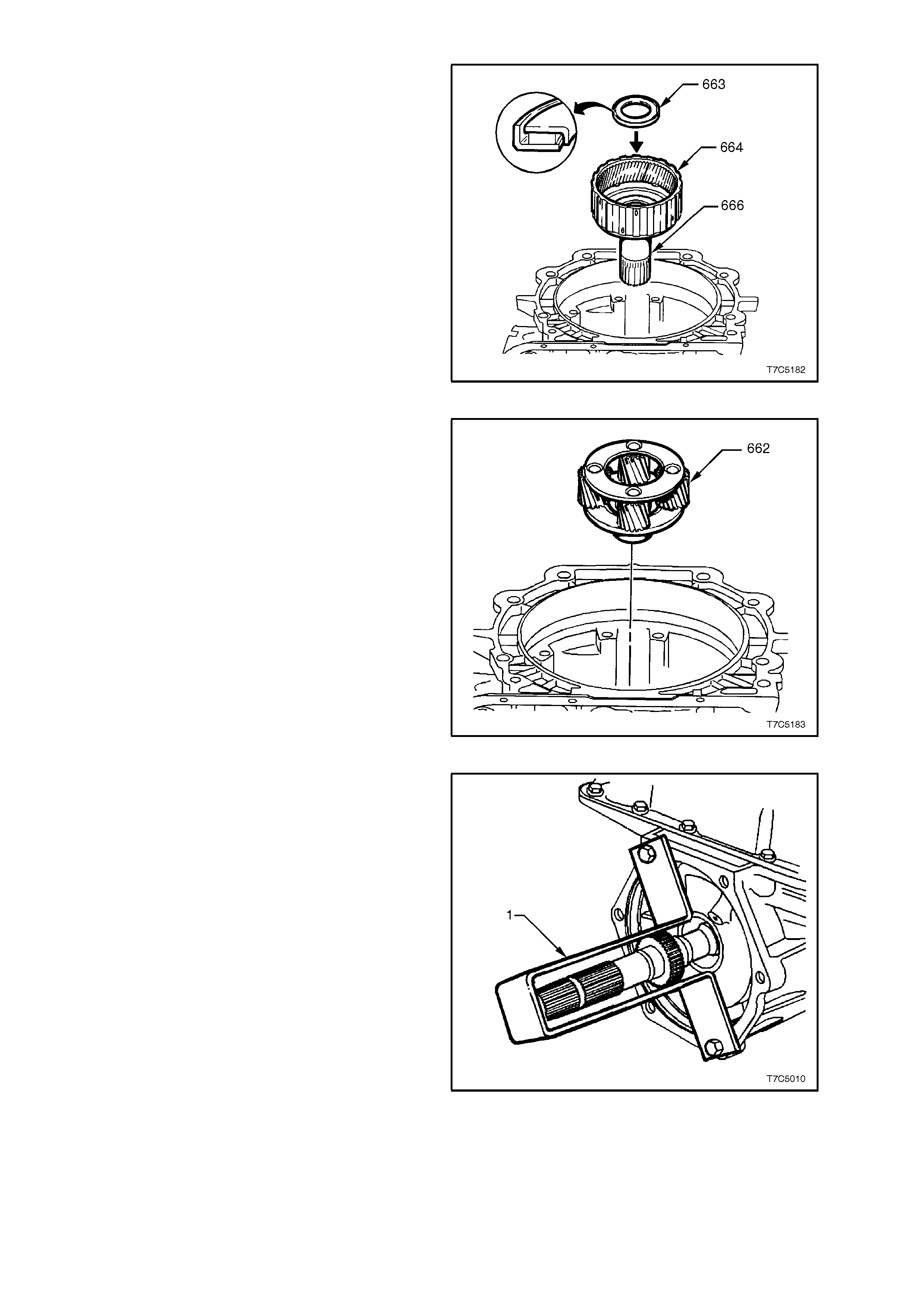
6. Reinstall thrust bearing (663) onto reaction
carrier shaft assembly with outer race against
reaction carrier shaft, as shown. Turn and
press until the splines on the reaction carrier
shaft (666) are aligned with the splines on the
reaction carrier assembly (681, in Figure 7C5-
197).
Figure 7C5-207
7. Reinstall input carrier assembly (662), rotating
back and forth, to index with the teeth of the
input internal gear.
Figure 7C5-208
8. While supporting the input carrier assembly
(662), reins tall output shaf t into the input carr ier
and attach the support bracket (1) that was
used during disassembly.
Figure 7C5-209
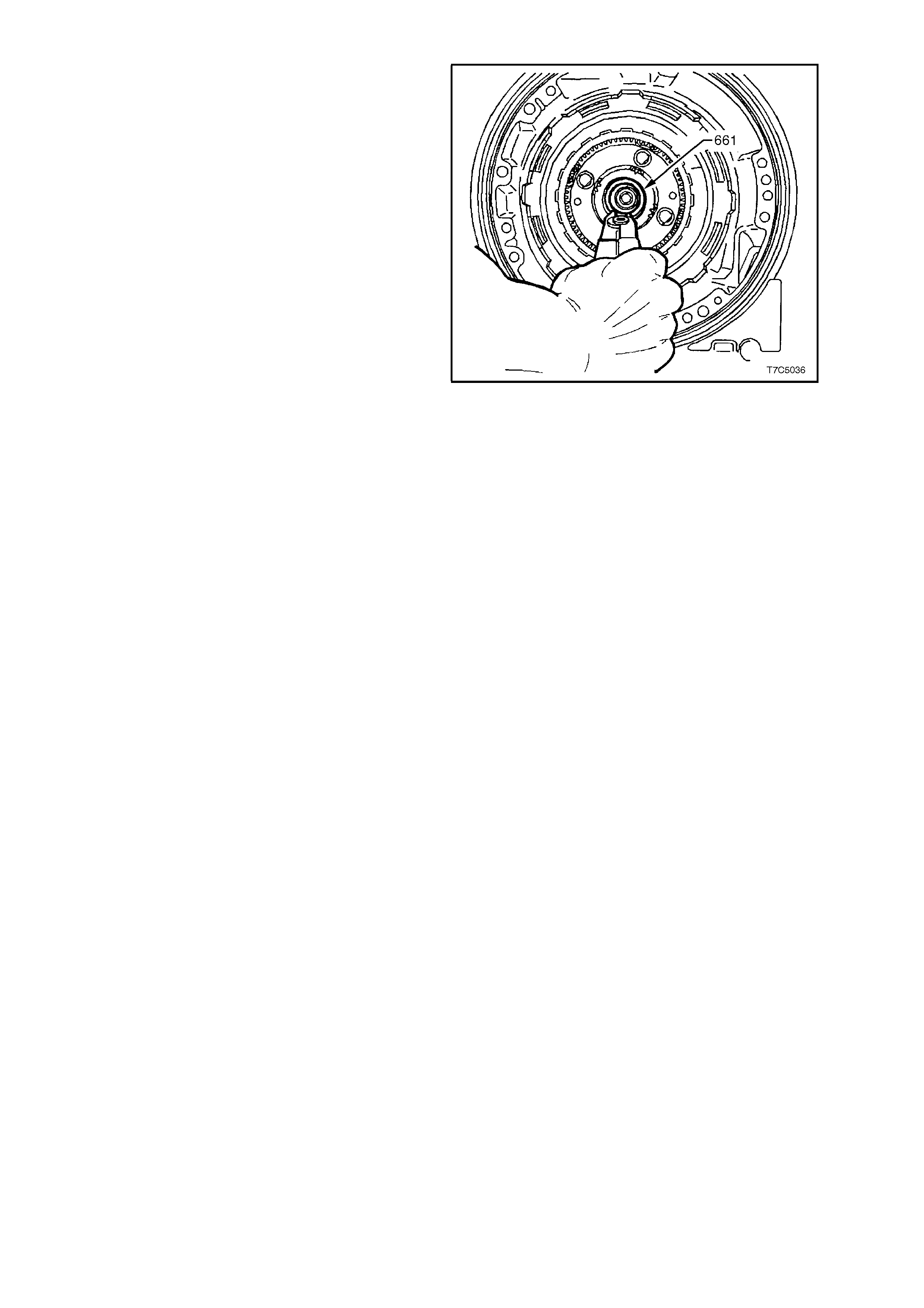
9. Reinstall retaining ring (661) into output shaft
ring groove. If ring was previously over-
expanded, use a new ring. Do not over-expand
ring during installation.
NOTE: Using snap ring pliers, Tool No. J34627, will
assist in preventing retaining ring over-expansion,
as they have been designed for this specific task.
Figure 7C5-210
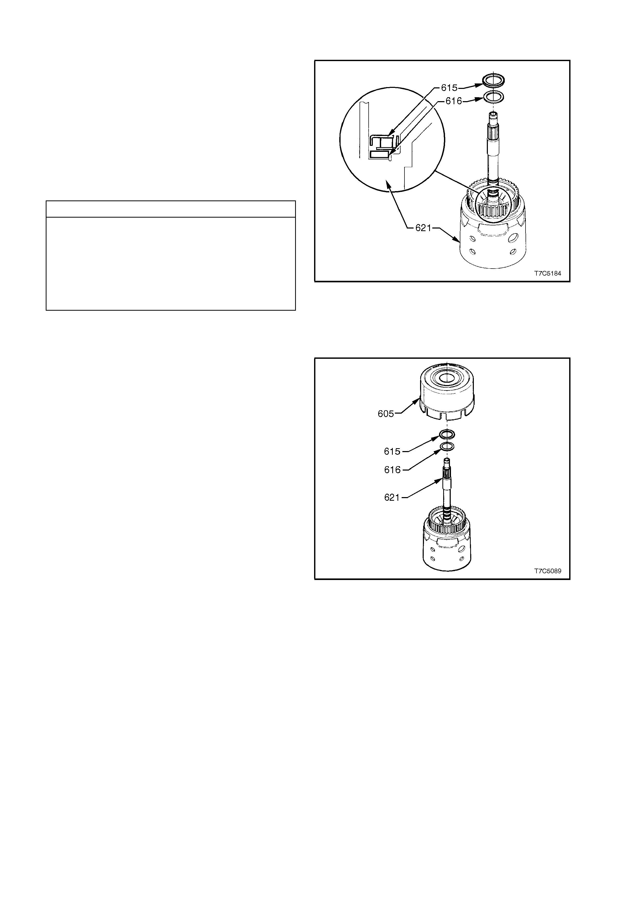
3.6 REVERSE INPUT CLUTCH, INPUT CLUTCH AND INPUT GEAR SET
1. Remove Tool J36418-2A (refer Fig. 7C5-137)
from input shaft and reinstall selective thrust
washer (616) on input housing and shaft
assembly.
NOTE: This selective washer (616) controls the
end play of the transmission, measured in
1.8 TRANSMISSION END PLAY CHECK, in this
Section. If the measured end play was not to
specification, replace original selective washer with
a new one, selected from the table below. The
identification number is stamped on the washer.
TRANSMISSION END PLAY W ASHER SELECTION
WASHER THICKNESS (mm) IDENTIFICATION
1.87 - 1.97 67
2.04 - 2.14 68
2.21 - 2.31 69
2.38 - 2.48 70
2.55 - 2.65 71
2.72 - 2.82 72
2.89 - 2.99 73
3.06 - 3.16 74
2. Reinstall bearing assembly (615) on selective
thrust washer with inside race (black) facing the
selective washer (616).
Figure 7C5-211
3. Reinstall reverse input clutch assembly (605)
onto input housing and shaft assembly (621),
aligning reverse input clutch plate tangs with
input housing hub. Ensure all clutch plates are
engaged.
Figure 7C5-212
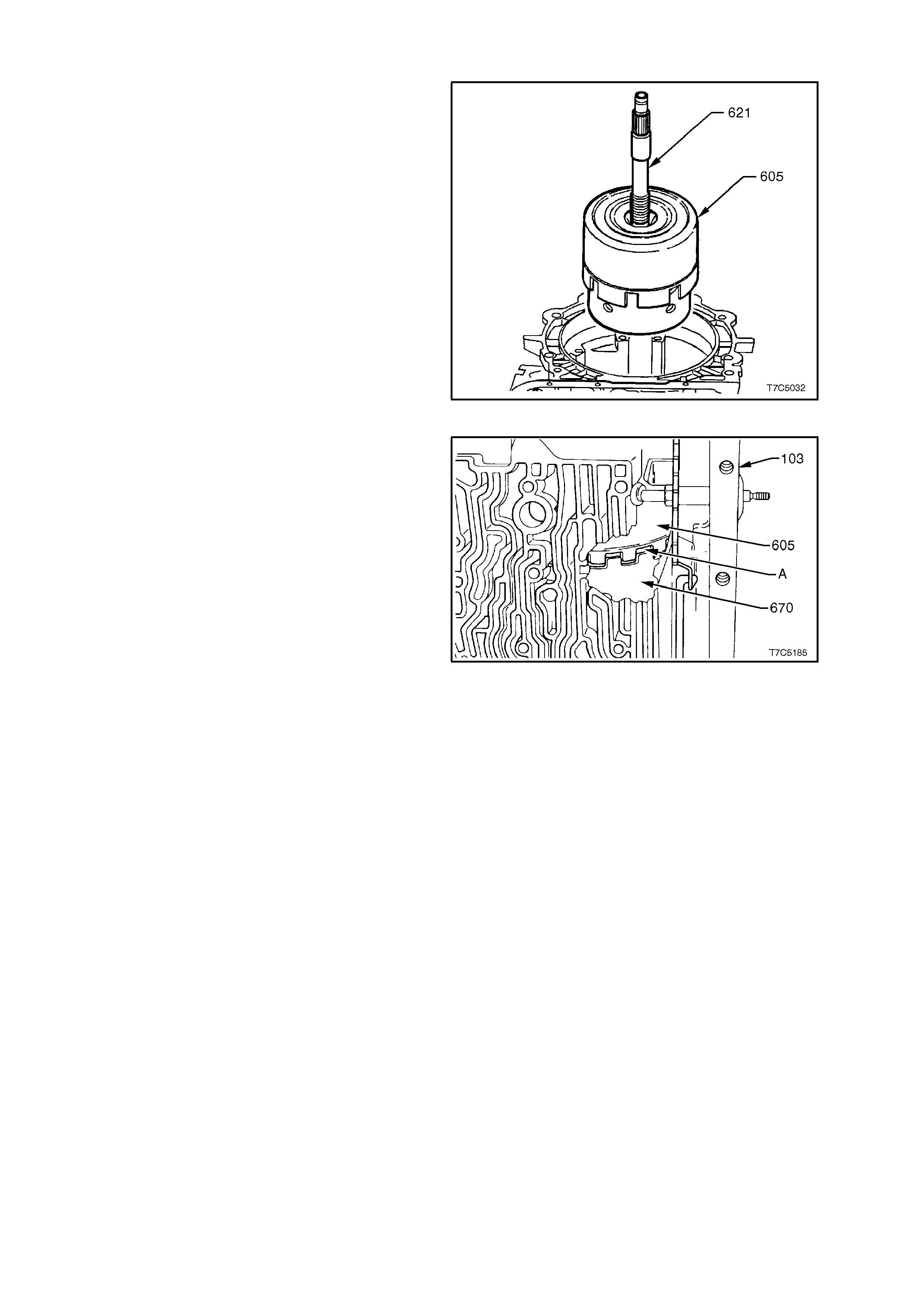
4. Reinstall reverse input (605) and input clutch
(621) assemblies into transmission case.
Locate 3- 4 clutc h plate tangs over input inter nal
gear. Ensure all c lutc h plates ar e fully engaged.
When correctly installed, reverse input clutch
housing (605) is located just below case oil
pump, machined land in the transmission case.
Figure 7C5-213
NOTE: There should be approximately 3.8 mm
clearance (A) between reverse input clutch (605)
and reaction sun gear shell (670), as shown. This is
normal.
Figure 7C5-214
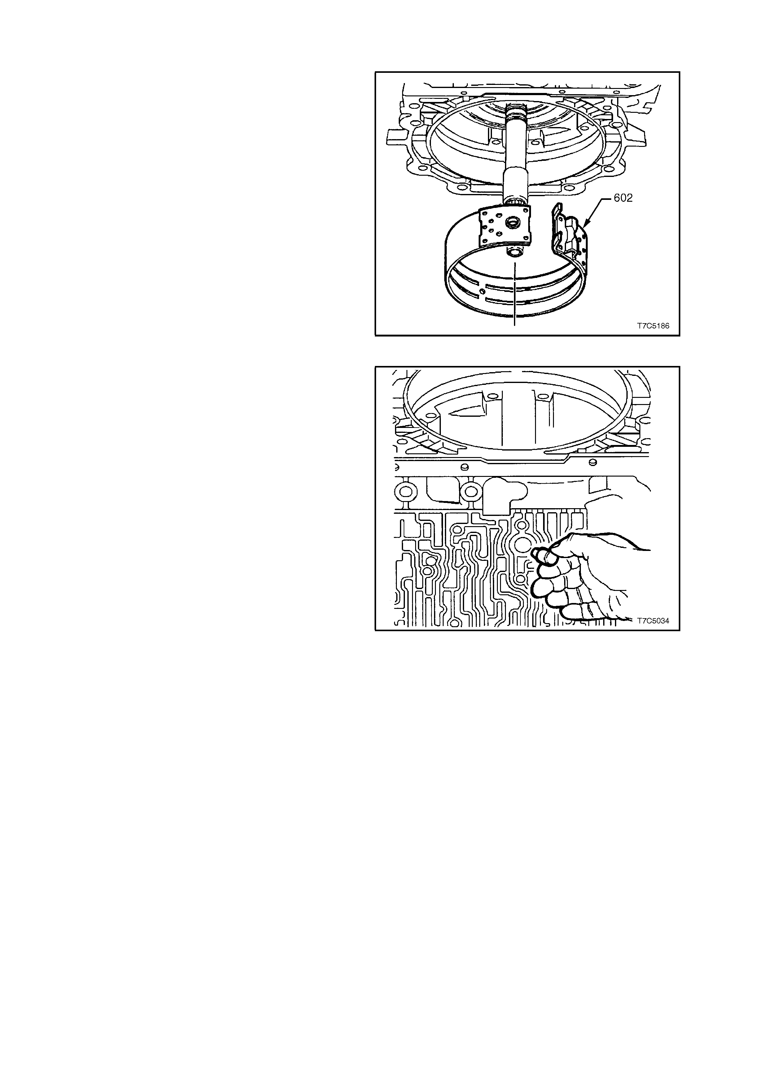
3.7 2-4 BAND ASSEMBLY
1. Inspect 2-4 band assembly for damage or
wear, noting that the band material is now
grey/black in colour. Only replace the band if
the material is scored, flaking or heavily worn.
2. Rotate transmission through 90° as shown, so
that the case channels are uppermost.
3. Using both hands, squeeze the 2-4 band into a
circle and work the band into place around the
reverse input drum housing (605). With the
transmission in the position shown, the weight
of the reverse input and input clutch assembly
will be such that adequate clearance will be
provided for reinstallation of the band.
Figure 7C5-215
4. After reinstalling 2-4 band assembly (602) into
transmission, align the anchor pin end of the
band, with the hole in case.
5. Reinstall 2-4 band anchor pin into tr ansmiss ion
case, as indicated. Ensure pin engages 2-4
band assembly.
Figure 7C5-216

3.8 OIL PUMP
1. Install Tool J25025-1 alignment pins, into case
as shown (part of Tool J25025-B).
Figure 7C5-217
2. Rem ove st ator shaf t oil seal sizing tool J39855-
2 (refer Fig. 7C5-182).
3. Reinstall thrust washer ( 601) on oil pum p (4) as
shown. Retain with petroleum jelly.
4. Lubricate new oil pump square section seal (5)
with petroleum jelly and install in the pump
body groove. When correctly installed and not
twisted, the seal colour strip should be visible
around the pump body (4).
Figure 7C5-218
5. Fit new oil pump gasket (6) to transmission
case, align bolt holes and locate over the
alignment pins (arrows). Retain with petroleum
jelly.
Figure 7C5-219
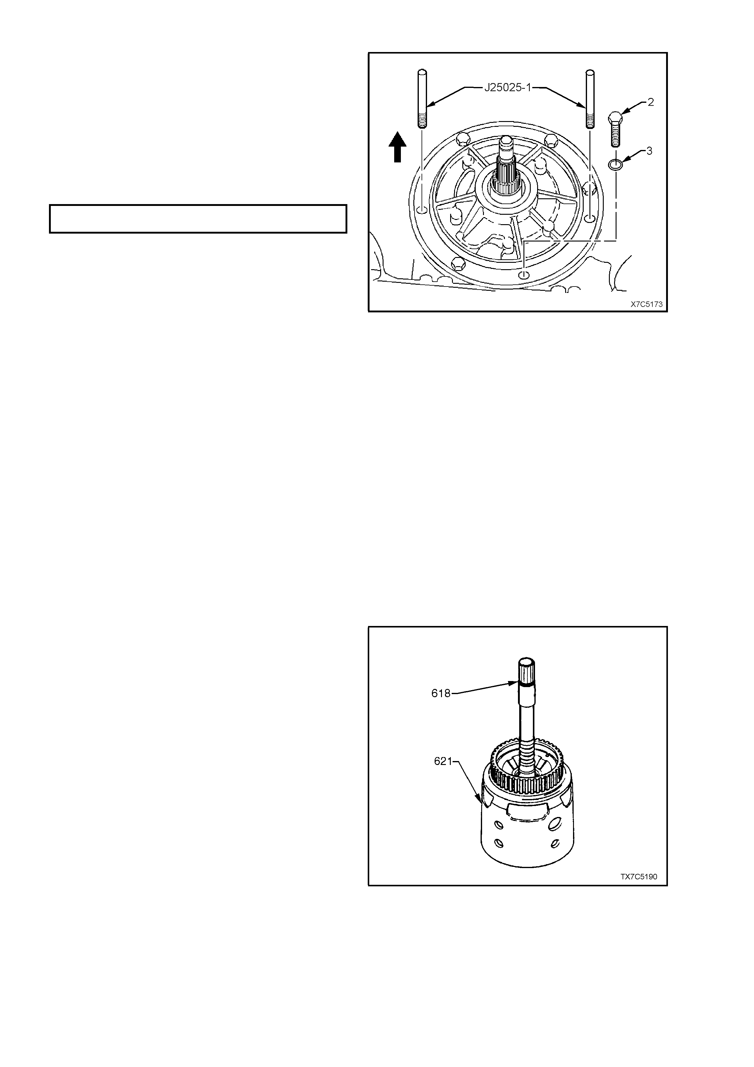
6. Prim e oil pum p with new transm ission fluid and
reinstall assembly into case, over alignment
pins.
7. Reinstall bolts (2), complete with NEW sealing
washers (3), then remove alignment pins,
J25025-1.
8. Progressively tighten bolts in an alternating
pattern to draw the pump body fully into the
transmission case. Tighten bolts to specified
torque.
OIL PUMP TO CASE BOLT
TORQUE SPECIFICATION ............................. 26 - 32 Nm
Figure 7C5-220
9. Af ter rem oving the output shaf t suppor t brack et,
turn input shaft by hand. If unable to do so,
transmission is incorrectly assembled (possible
thrust washer dislodgment). Dismantle and
rectify problem.
10. Measure transmission end play as described in
1.8 TRANSMISSION END PLAY CHECK, in
this Section. If end play is not to specification,
replace selective thrust washer (616) between
the input housing (621) and the stator shaft
bearing assembly (615). Refer to Step 1 of
3.6 REVERSE INPUT CLUTCH, INPUT
CLUTCH AND INPUT GEAR SET, in this
Section.
NOTE: If end play is to specification, the output
shaft can be turned in both forward and reverse
directions. The effort required to turn the output
shaft in the reverse direction however, will be
greater than in the forward direction.
11. Install new O-ring seal (618) into groove at end
of turbine shaft.
Figure 7C5-221
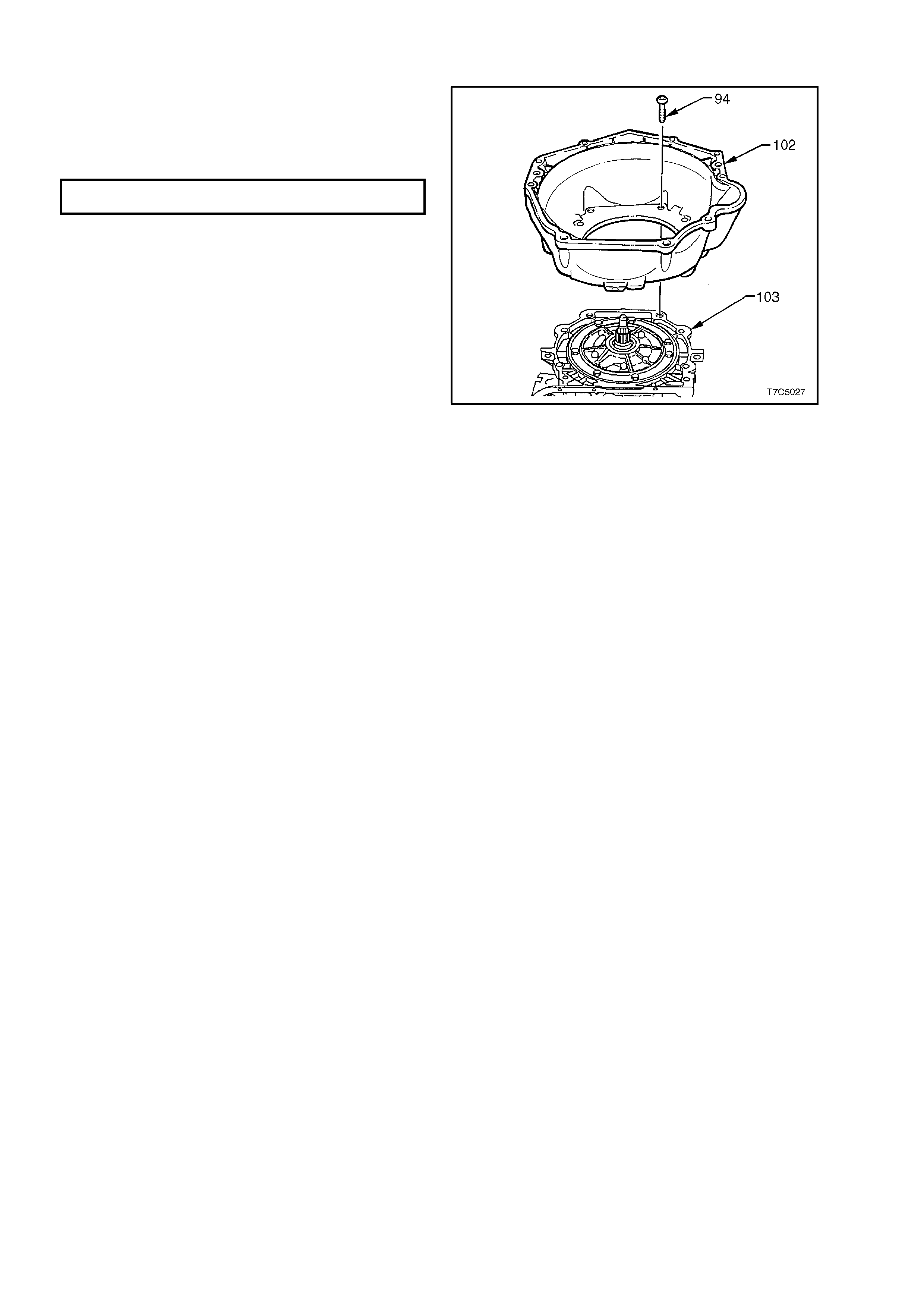
3.9 CONVERTER HOUS ING
1. Install the converter housing to the
transmission case .
2. Install all converter hous ing bolts and tighten to
the specified torque, using Torx Plus bit, Tool
No. J41510 or commercial equivalent.
CONVERTER HOUSING BOLT
TORQUE SPECIFICATION ............................. 65 - 75 Nm
NOTE: Do not use a standar d, # 50 Torx bit, as the
bolt design is such that only the Torx Plus bit is
capable of applying the correct torque without bolt
damage.
Figure 7C5-222
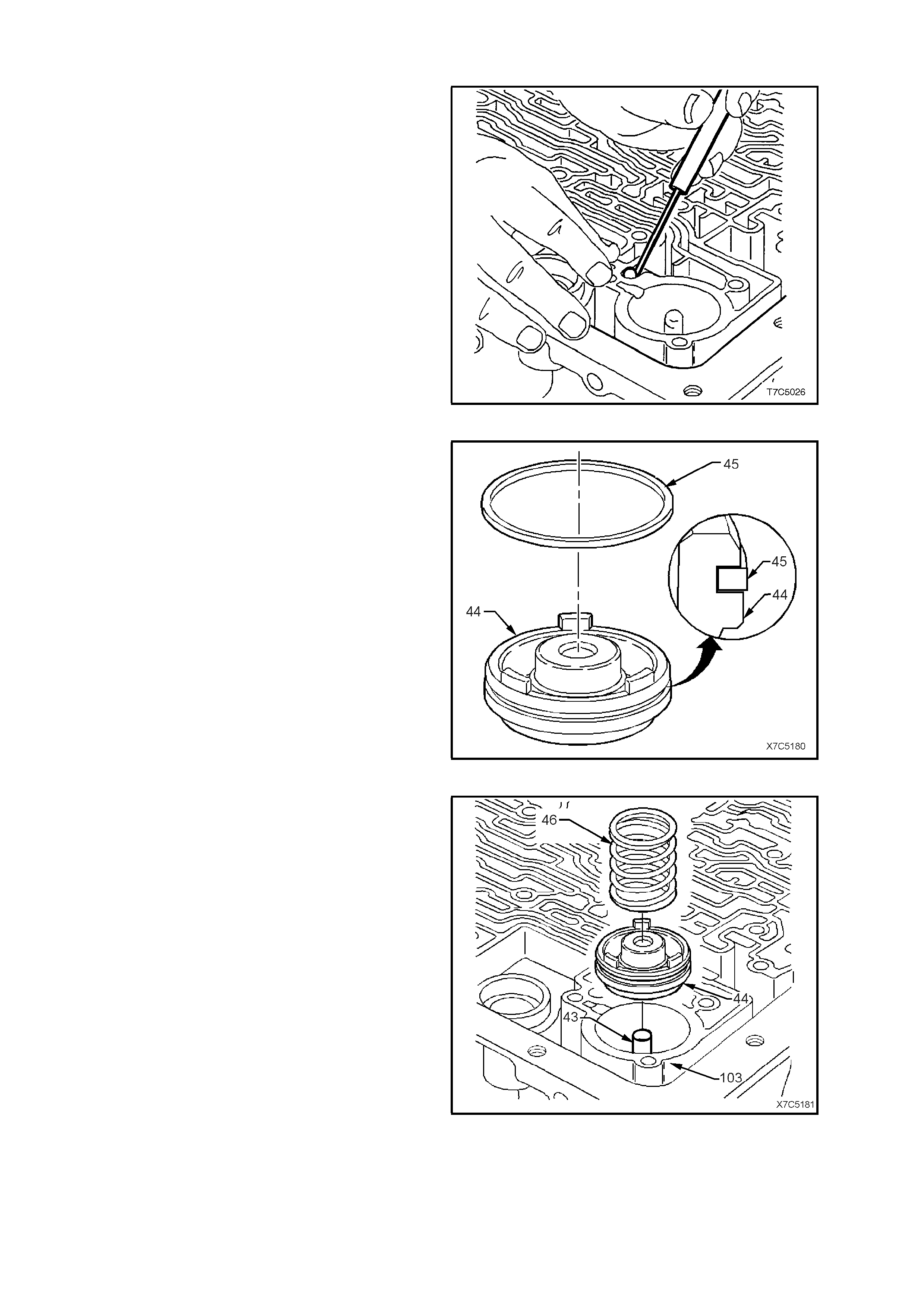
3.10 CONTROL V ALVE BODY AND ASSOCIATE D COMP ONENTS
1. Reinstall check ball into case. Secure with a
smear of petroleum jelly.
2. If previously remo ved, install a new O-ring onto
the wiring harness through connector, smear
with petroleum jelly and install into the case.
Ensure that each of the four lugs on the
connector body has 'clicked' into place, on the
outside of the case.
Figure 7C5-223
3. Coat new 3-4 accum ulator piston s eal (45) with
petroleum jelly and install on piston (44). Rotate
piston seal in the piston groove to ensure that
no binding occurs and that it is correctly
seated.
Figure 7C5-224
4. Reinstall 3-4 accumulator pin (43) into case
(103).
5. Reinstall 3-4 accumulator piston (44) over pin
(43) with three lugs facing out of bore.
6. Reinstall 3-4 accumulator piston spring (46).
NOTE: There is no 3-4 accumulator spring (46)
fitted to the 4L60-E automatic transmission used
with the GEN III V8 engine (code HPD).
Figure 7C5-225
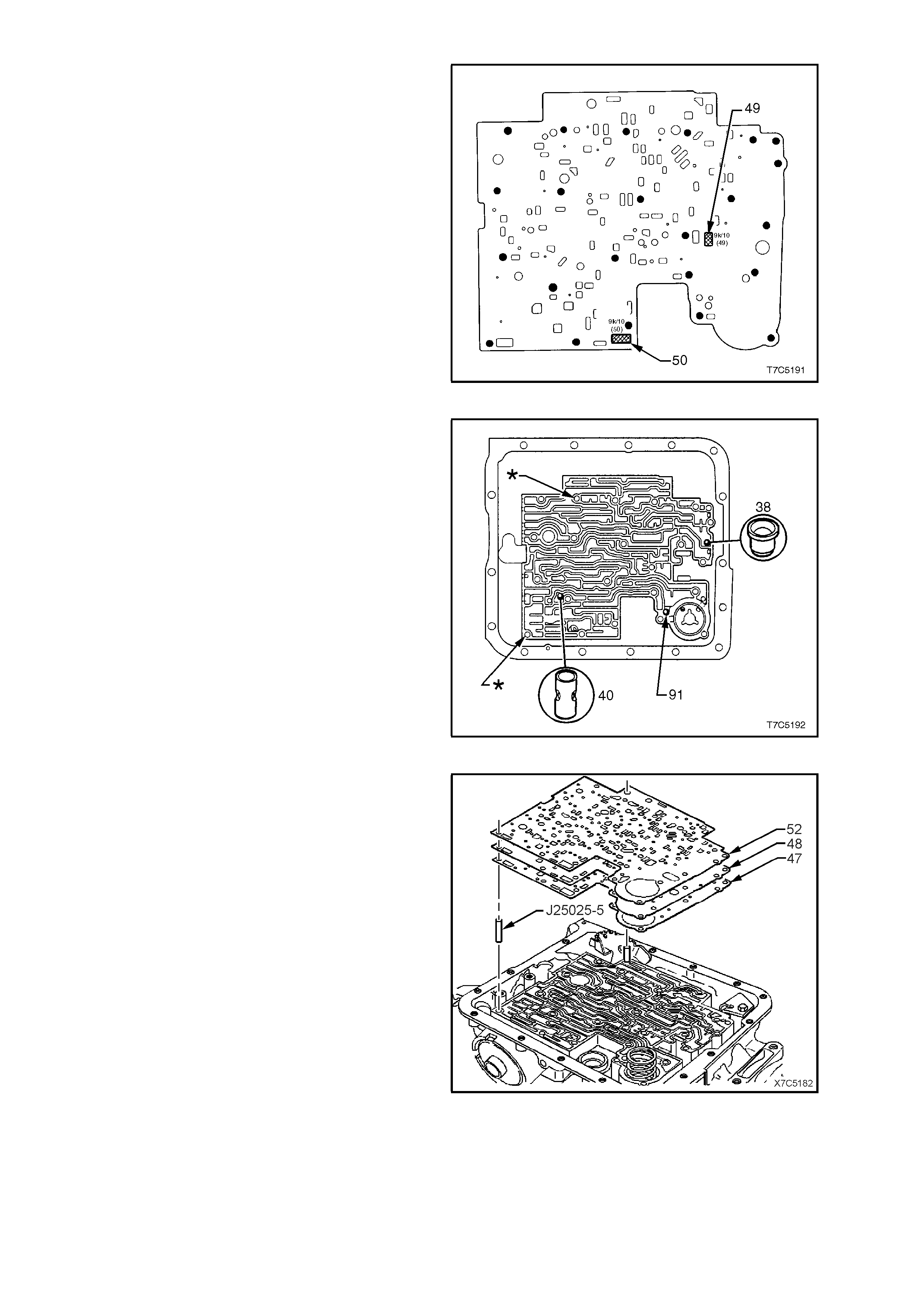
7. if a new spacer plate is to be fitted (or if
inspection of the screens shows them to be
fouled with debris) , it will be neces sary to install
two filter screens (49 and 50) to the spacer
plate before fitment. Location of these two
screens is as shown.
Figure 7C5-226
8. Install two suitable guide pins (part of Tool No.
J25025-B), into case at the locations indicated
by an asterisk (!). These locations are
important, as the matching holes in the spacer
plate have a closer clearance tolerance than
the other holes.
The view shown, also confirms the location of
the chec k ball #1 (91), the orif ice plug #10 (38)
and the 3rd accumulator, check ball assembly
#7 (40).
Important: Ensure that the guide pins are fully
installed s o that no thread is visible. Ot herwise, the
spacer plate gasket could become caught in a
thread during installation, resulting in incorrect
alignment.
Figure 7C5-227
9. Smear petroleum jelly over a new spacer plate
to case gasket (47) and install on transmission
case, over the guide pins. Gasket is identified
with a 'C' (Case).
10. Reinstall spacer plate (48) over the guide pins.
11. Smear petroleum je lly over a new valve body to
spacer plate gasket (52) and install on
transm ission cas e, over the guide pins. Gask et
is identified with a 'V' (Valve body).
Important: Incorrec t placement of the spacer plate
gaskets may cause transmission shift problems.
Figure 7C5-228

12. Install three spacer plate support plate (53)
retaining bolts (77), tightening to specified
torque.
SPACER PLATE SUPPORT PLATE
TORQUE SPECIFICATION ............................. 8 - 14 Nm
Figure 7C5-229
13. Coat new 1-2 accum ulator pis ton seal (55) with
petroleum jelly and install on piston (56). Rotate
piston seal in the piston groove to ensure that
no binding occurs.
Figure 7C5-230
14. Reinstall the previously tagged, two 1-2
accumulator springs (54 and 104) into the
accumulator cover.
15. Reinstall piston into cover and pin assembly.
The three lugs on the piston point into the
cover.
Figure 7C5-231
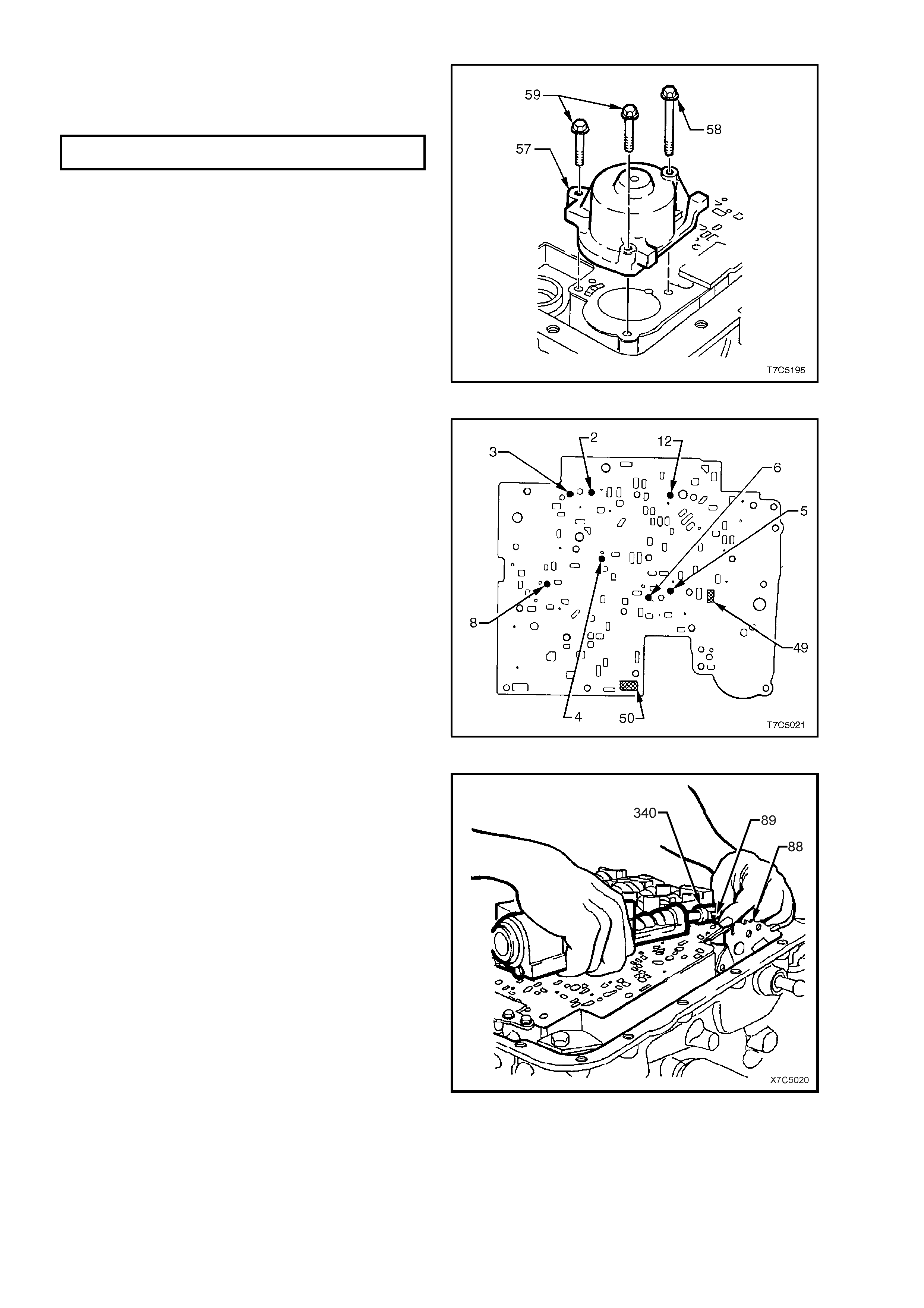
16. Reinstall 1-2 accumulator assembly onto
transmission, while holding piston in place.
Reinstall and tighten bolts (58/59) to the c orr ec t
torque specification.
1-2 ACCUMULATOR COVE R B O LT
TORQUE SPECIFICATION ............................. 8 - 14 Nm
Figure 7C5-232
17. Remove spacer plate guide pins from case.
18. Reinstall seven check balls onto the control
valve body spacer plate in the locations as
shown and secure with a small amount of
petroleum jelly.
Figure 7C5-233
19. Insert the manual valve link (89) into the inner
detent lever (88).
20. Turn the valve body over and, while supporting
the m anual valve link (89) in one hand and the
valve body in the other, rotate the valve body
slightly and connect the link with the manual
valve (340). Move the manual valve (340)
forward, to retain the link connection and
carefully lower the valve body into position.
Figure 7C5-234

21. Reinstall the dipstick stop bracket (93) and
retaining bolt (62). Do not tighten at this time.
Figure 7C5-235
22. Install a new shield (106) to the transmission
fluid pressure (TFP) manual valve position
switch, reinstall bolts (‘70’ two places and ‘62’
three places) but do not fully tighten at this
stage.
23. Loosely install the remainder of the control
valve body bolts.
Figure 7C5-236
24. Coat a new TCC solenoid O-ring with
petroleum jelly, install on the TCC solenoid,
then the assembly into the oil pump body.
25. Reinstall the two TCC solenoid retaining bolts
(68) but do not fully tighten at this time.
NOTE: Do not install the wiring harness locating
clips to the control valve body at this time, as they
would hinder access to the control valve body
retaining bolts.
Figure 7C5-237
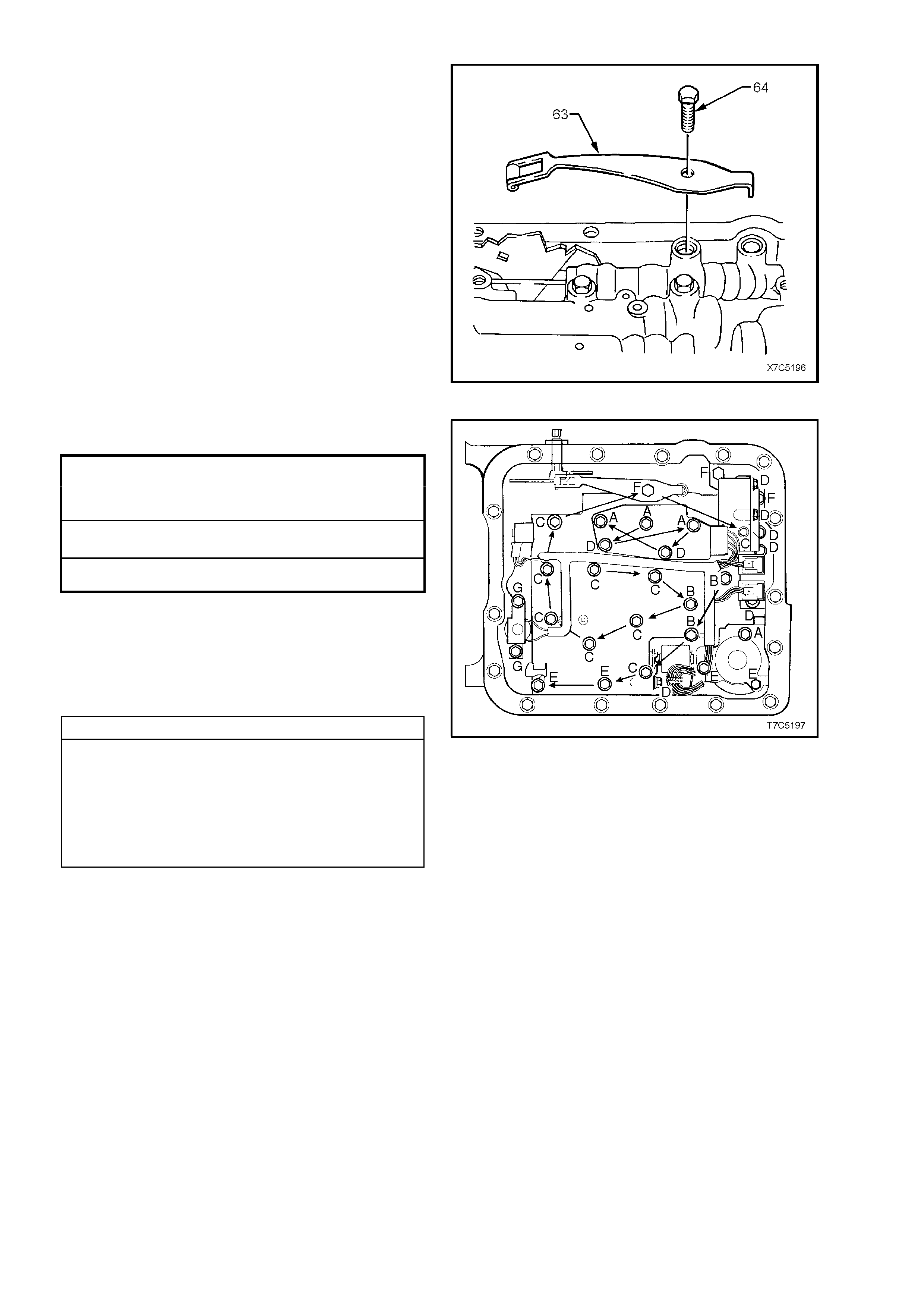
26. Reinstall the manual detent spring assembly
(63) retaining bolt (64).
Figure 7C5-238
27. Tighten all bolts to the specified torque
specification, in the order shown.
CONTROL VALVE BODY and
TFP MANUAL VALVE POSITION
SW ITCH ASSEMBLY BOLT
TORQUE SPECIFICATION ............................. 8 – 14 Nm
MANUAL DETENT SP RING
TORQUE SPECIFICATION ............................. 20 – 27 Nm
TCC SOLENOID BOLT
TORQUE SPECIFICATION ............................. 8 – 14 Nm
Important: The control valve body bolts must be
tightened in an outward spiral from the centre, as
shown. Failure to follow this pattern m ay dis tort the
valve body, causing valves to jam in their bores.
NOTE: There are 7 different bolt sizes used. The
letters shown, relate to the following bolt sizes.
Control Valve Body Fastener Specifications
A - M6 x 1.00 x 65.0
B - M6 x 1.00 x 54.4
C - M6 x 1.00 x 47.5
D - M6 x 1.00 x 18.0
E - M6 x 1.00 x 35.0
F - M8 x 1.25 x 20.0
G - M6 x 1.00 x 12.0
Figure 7C5-239

28. Coat a new TCC PWM solenoid O-ring with
petroleum jelly, install on the solenoid (396).
Then reinstall the solenoid into the control valve
body, securing with retaining clip (395).
Figure 7C5-240
29. Reinstall electrical wiring harness connectors to
the respective components as shown, and
indicated below.
Electrical Connector Identification
1. Transmission Fluid Pressure (TFP) Manual
Valve Position Switch.
2. 1-2 Shift Valve Solenoid.
3. 2-3 Shift Valve Solenoid.
4. Pressure Control Solenoid (PCS).
5. TCC Pulse Width Modulated (TCC PWM)
Solenoid.
6. 3-2 Control Solenoid.
30. Check the security of each connection by
gentling pulling on the connector.
31. Install the wiring harness carrier over the
control valve body bolt lugs, ensuring that the
tag (arrow) is located under the TFP Manual
Valve Position Switch.
NOTE: If the harness carrier is not located
correctly, the oil filter will not be installed fully and
will foul the oil pan.
Figure 7C5-241
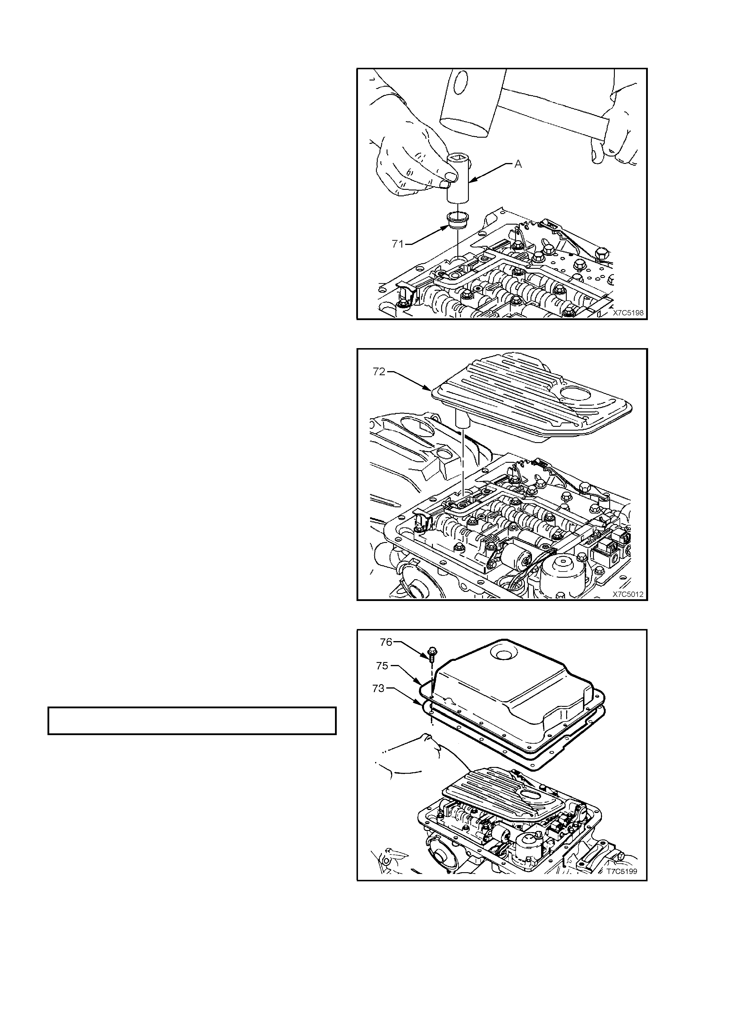
3.11 OIL FILTER AND OIL PAN
1. Lubricate new oil filter seal (71) with petroleum
jelly and install into the oil pump bore, using a
suitable size socket or piece of tubing (A).
Figure 7C5-242
2. Install a new oil filter (72) into the oil filter seal.
Figure 7C5-243
3. Check that the magnet is in the designated
position in the oil pan.
4. Install a new oil pan gasket.
5. Reinstall oil pan and tighten bolts to specified
torque.
OIL PAN BOLT
TORQUE SPECIFICATION ............................. 10 – 14 Nm
Figure 7C5-244
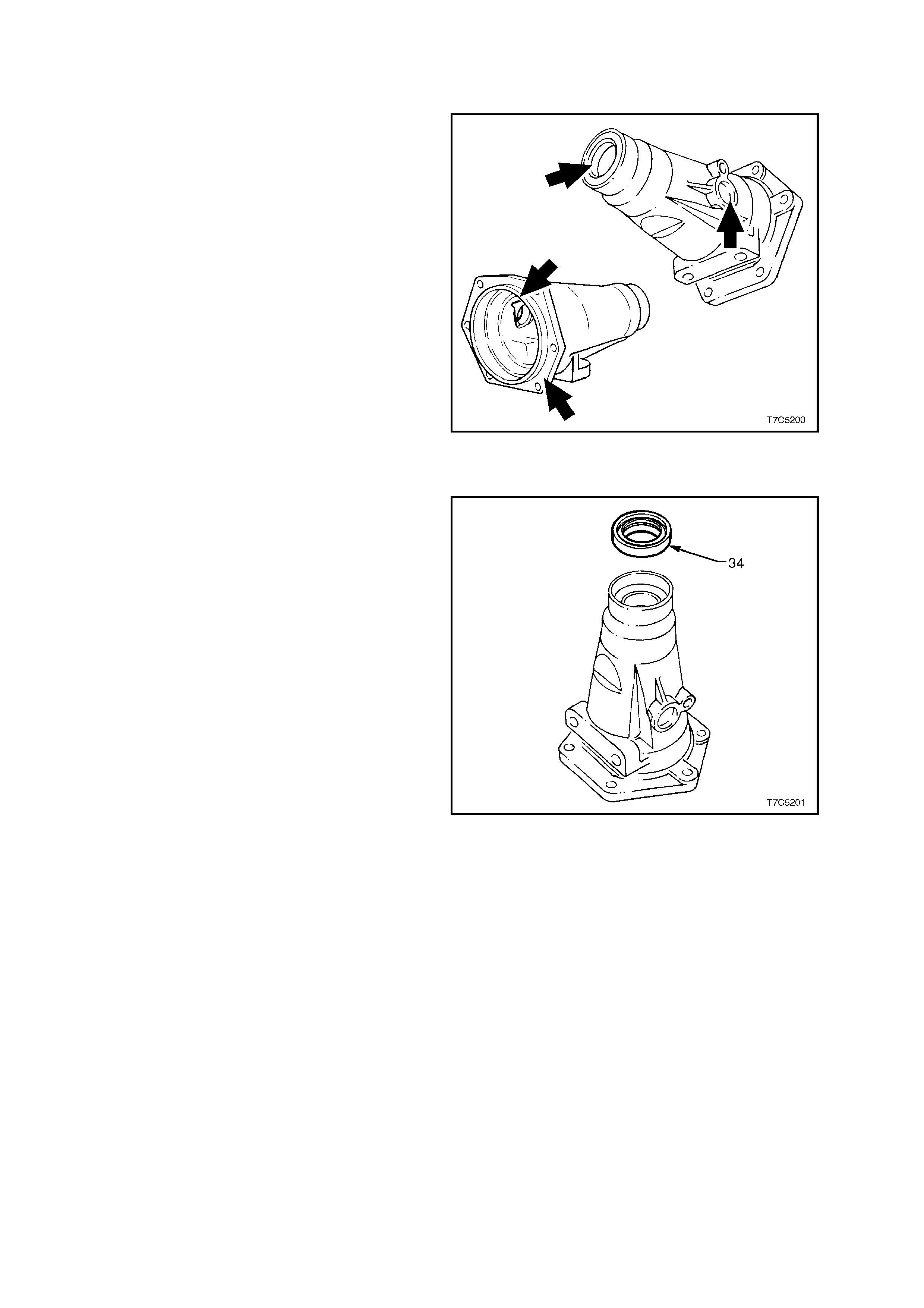
3.12 CASE EXTENSION HOUSING AND SPEED SENSOR
INSPECT
1. Inspect all machined surfaces for nicks or
burrs, removing as required with a fine cut file.
2. Check the propeller shaft sliding yoke bush for
wear.
Figure 7C5-245
CASE EXTENSION HOUSING BUSH - REPLACE
1. If not previously carried out, remove the case
extension oil seal, using a removing tool such
as Tool E308 or commercial equivalent.
Figure 7C5-246
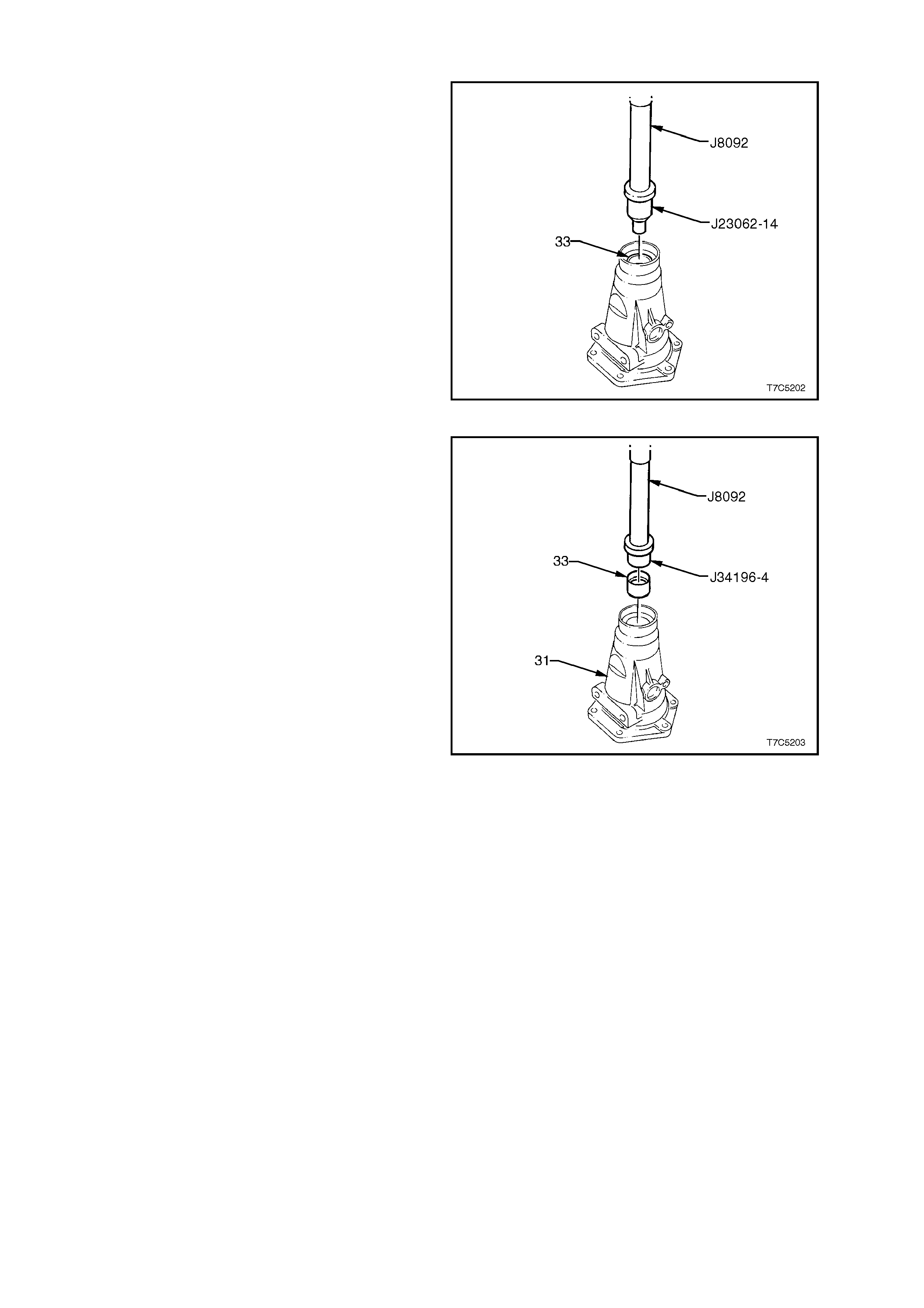
2. Using bush remover, Tool J23062-14 and
driver handle J8092, press the bush (33) from
the extension housing.
Figure 7C5-247
3. Install a new bush (33) into the extension
housing (31), using installer J34196-4 and
driver handle J8092.
Figure 7C5-248
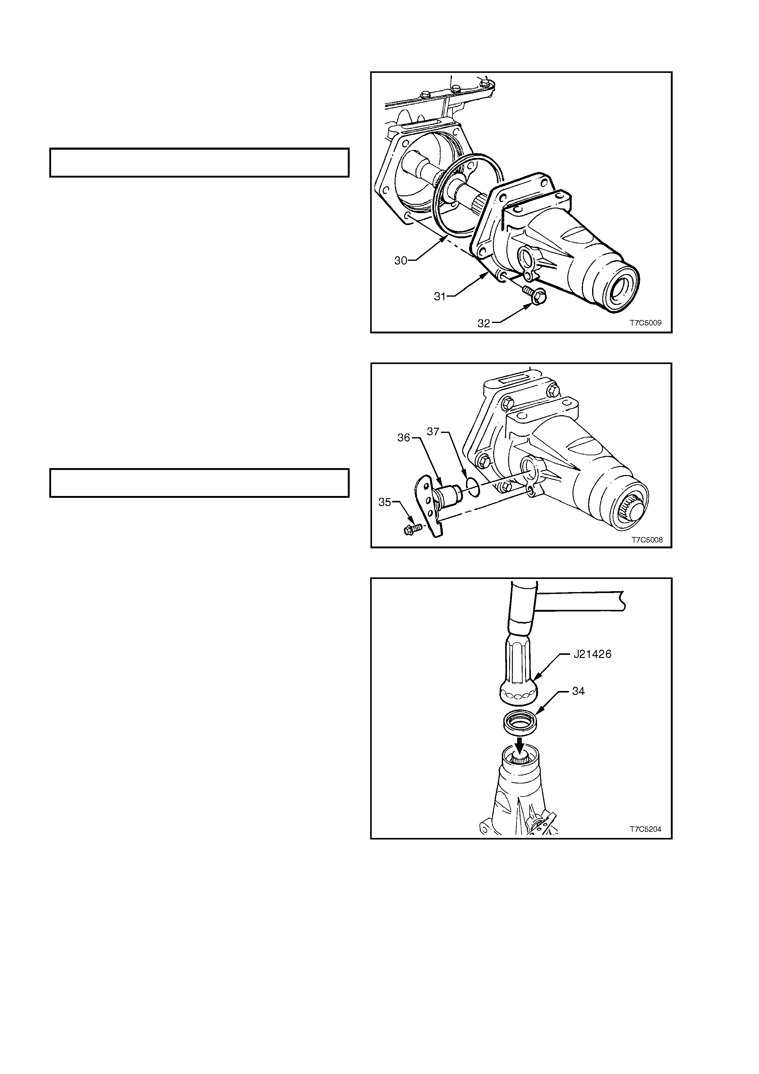
REINSTALL
1. Install a new seal (30) to the case extension
(31), then install to the rear of the transm ission
case.
2. Reinstall the six attac hing bolts (32) and tighten
to the correct torque specification.
CASE EXTENSION HOUSING BOLT
TORQUE SPECIFICATION ............................. 42 – 48 Nm
Figure 7C5-249
3. Inspect the speed sensor for damage and, if
serviceable, lubricate new O-ring (37) with
petroleum jelly and install on speed sensor
(36).
4. Reinstall the sensor to the case extension,
install the retaining bolt and tighten to the
correct torque specification.
SPEE D SENSOR RE T AINING BO LT
TORQUE SPECIFICATION ............................. 11 – 14 Nm
Figure 7B-250
5. Install new extension housing seal (34), using
Tool J21426.
Figure 7C5-251
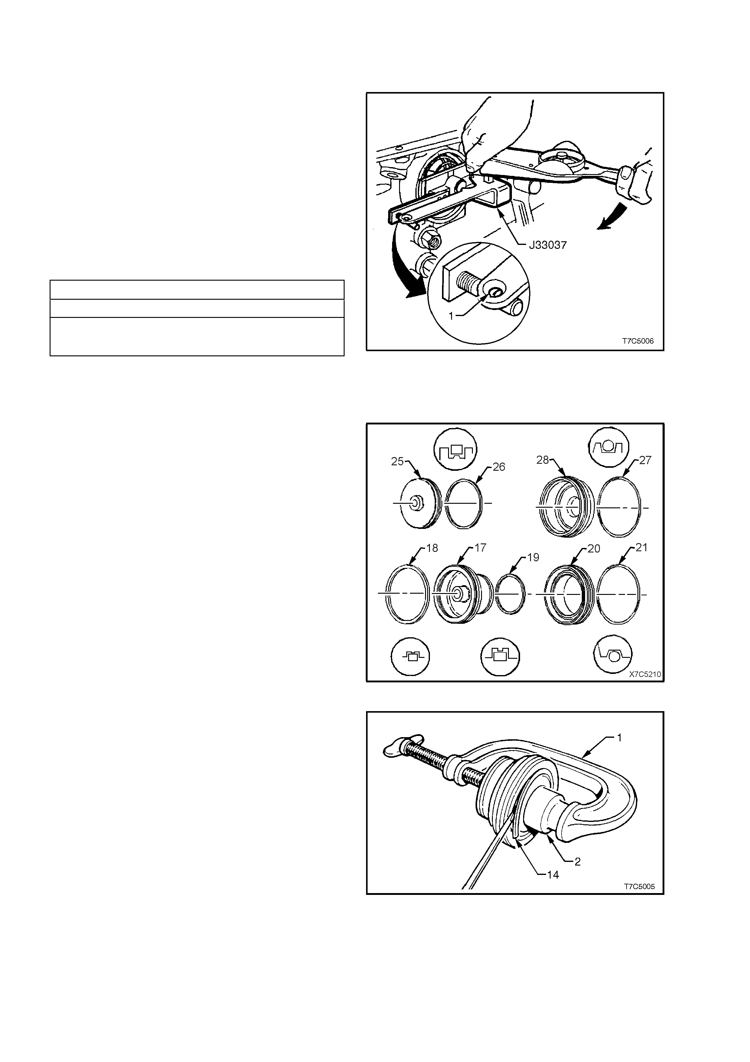
3.13 2-4 SERVO ASSEMBLY
SERVO PIN LENGTH - CHECK
1. Install the pin, tapered end first, into the
transmission case .
2. Install Tool J33037 as shown, then install the
servo cover retaining ring to secure the tool.
3. Apply 11 Nm of torque to the tool arm. If the
white line appears in the gauge eyelet (1), then
the pin length is correct.
4. Remove Tool J330307 and the 2nd apply
piston pin, from the transmission case.
5. Should the white line not appear in the gauge
hole (1), then a replacement pin must be
selected from the following:
2 - 4 SERVO PIN SELECTION
PIN LE NGTH (mm) IDENTIFI CATION
65.82 - 66.121 Groove
67.23 - 67.53 2 Grooves
68.64 - 68.94 No Groove
Figure 7C5-252
REINSTALL
1. Install new seals to the 2-4 servo pistons
components as follows:
a. The square section 4th apply piston outer
seal (26) to the 4th apply piston (25).
b. The 2-4 servo cover round section O-ring
seal (27) to the 2-4 servo cover (28).
c. The 2nd apply piston outer (18) and inner
(19) square section seals to the 2nd apply
piston (17).
d. The round section O-ring seal (21) to the
servo piston inner housing (20).
Figure 7C5-253
2. Reinstall cushion springs (16 and 105) into the
well of the second apply piston (17), as shown
next.
NOTE: An automatic transmission fitted to the GEN
III V8 engine (code HPD) only has the outer
cushion spring (16).
3. Reinstall cushion spring retainer (15) on top of
spring (16).
4. Use a G-clamp (1) and suitable sized socket
(2), to c ompress the spring/s under the second
apply piston assembly.
5. Reinstall retaining ring (14), checking that the
ring is fully installed into the piston groove.
6. Remove tools to release spring tension.
Figure 7C5-254
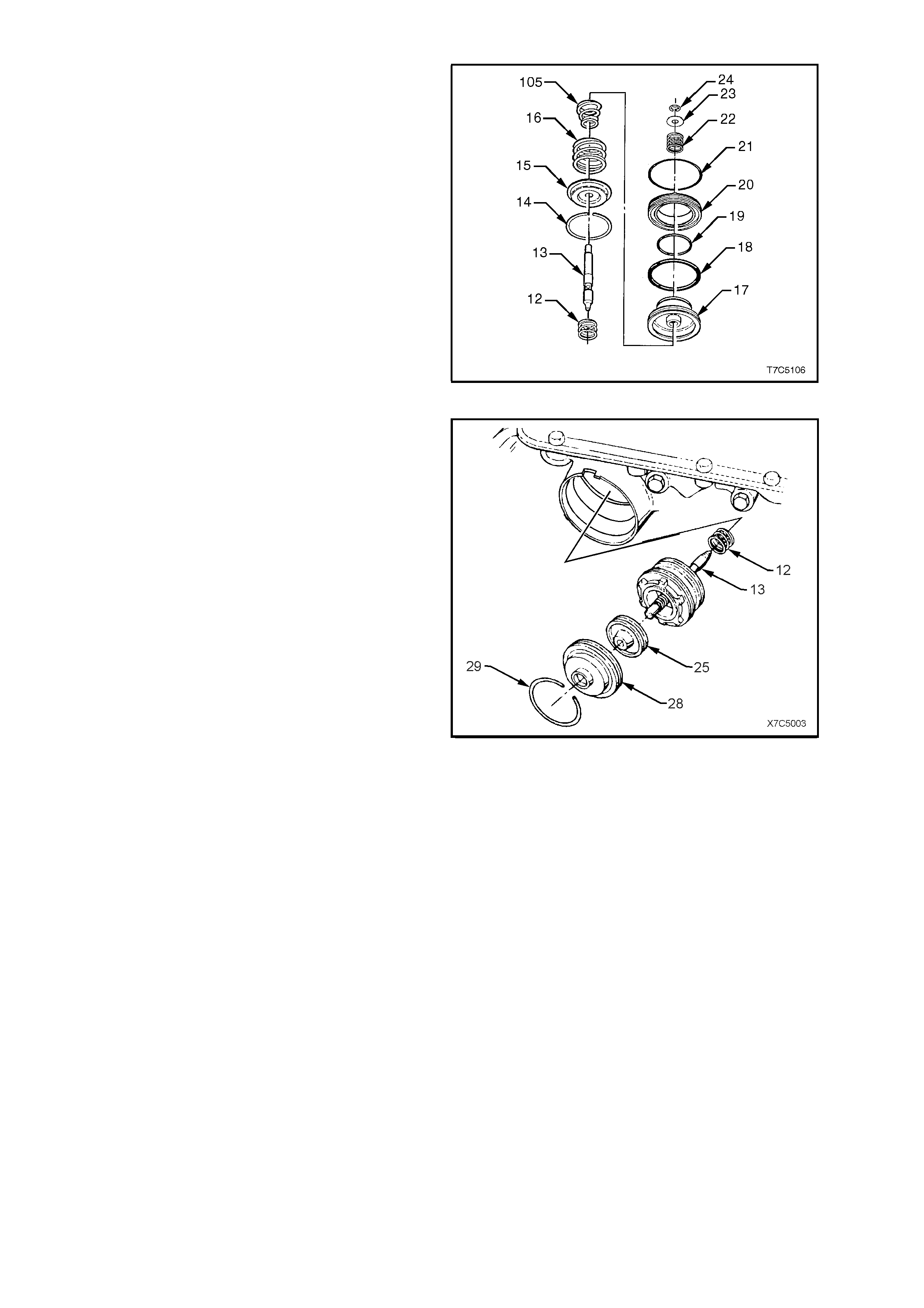
7. Reinstall the apply pin ring retainer (24) and
test that the 2-4 servo pin does not bind.
8. Reinstall servo apply pin spring (22) and
washer (23), securing with C-clip (24).
9. After applying petroleum jelly to the inner and
outer 2nd apply piston sealing rings (18 and
19), install to piston (17).
10. Apply petroleum jelly to a new servo piston,
inner housing O-ring seal (21) and install on
inner housing (20), ensuring that the seal is
correctly seated in the groove.
11. Reinstall the inner housing (20) over the 2nd
apply piston's inner sealing ring (19).
Figure 7C5-255
12. Reinstall 4th apply piston assembly (25) into
the servo cover (28), with the piston boss
facing the cover.
13. Reinstall servo return spring (12), servo apply
pin and 2nd apply piston assembly into servo
bore in the transmission case.
14. Reinstall the 4th apply piston and outer cover
over the servo pin.
15. Using a hammer handle, press the outer cover
(28) in until the retaining ring groove in the case
is visible.
16. Reinstall retaining ring (29).
Figure 7C5-256
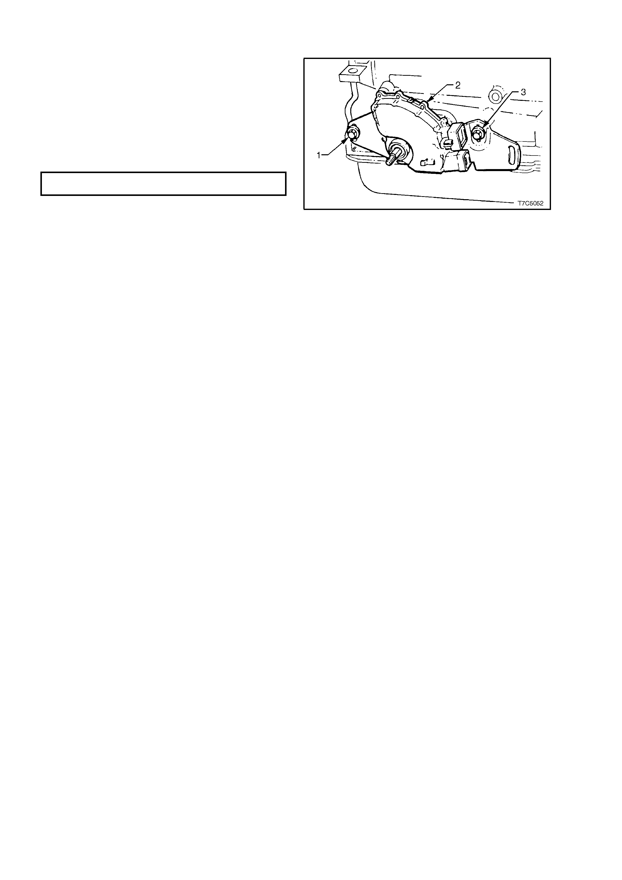
3.14 NEUTRAL START & BACK-UP LAMP SWITCH ASSEMBLY
1. Reinstall the neutral start and back-up lamp
switch (2) but do not fully tighten the attaching
screws (1 and 3).
NOTE: Final adjustment of the neutral start and
back-up lamp switch is carried out after the
transmission is reinstalled into the vehicle and the
shift linkage installed.
2. Reinstall the selector lever and the retaining
nut. Tighten to the correct torque specification.
SELECTOR LEVER RETAINING
NUT TORQUE SPECIFICATION..................... 15 - 35 Nm
NOTE: The lever must be held securely while the
nut is tightened.
Figure 7C5-257

3.15 TORQUE CONV ERTER
INSPECT
The torque converter is serviced as an assembly and should be replaced if any of the following conditions exist:
a. Metal particles f ound when f lushing c ooler or c onver ter pipes - c onver ter flushing is not r ec ommended. Refer to
7C4 ON-VEHICLE SERVICING, the VT Series I Service Information for more detailed information regarding
cooler flushing procedures.
b. Oil pump damaged.
c. Leaking converter welds.
d. Converter pilot broken, damaged or poor fit in crankshaft.
e. Converter hub scored or damaged.
f. Internal damage to stator.
g. Transmission fluid contaminated with coolant.
h. Excess end play.
The Torque Converter Should NOT be Replaced If:
a. T he tr ansm iss ion fluid has an odour , disc olouration or no evidence of m etallic or c lutch plate m aterial has been
found.
If any of these conditions apply:
- Drain as much fluid as possible from the torque converter.
- Replace the oil filter and pan gasket.
- Fill transmission with the correct fluid, to the recommended level. See
Section 7C4 ON-VEHICLE SERVICING, the VT Series I Service Information the for more specific
information.
b. Any converter bolt hole threads are damaged or stripped.
If either of these instances are found to exist, install thread inserts.
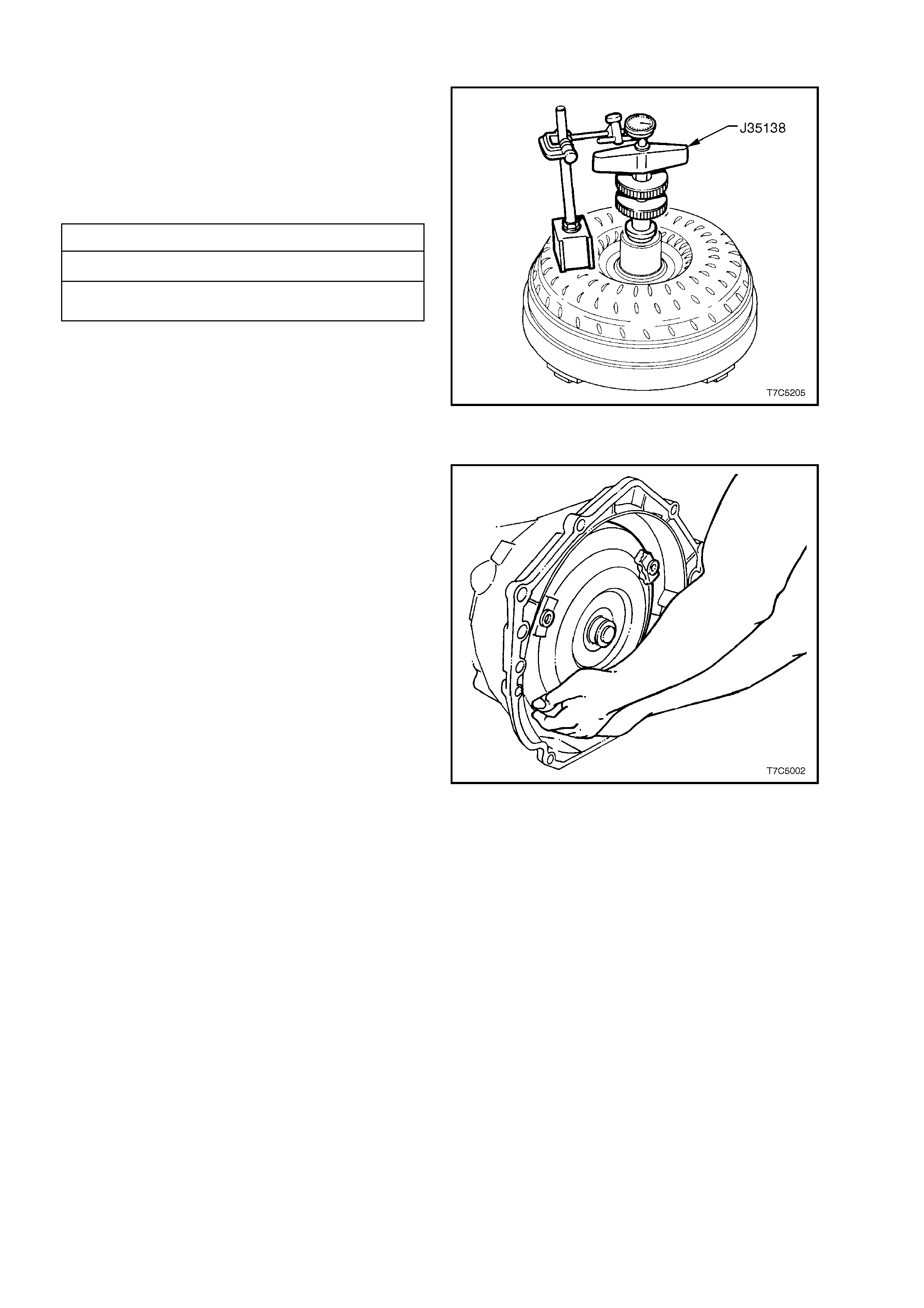
END PLAY - CHECK
The only satisfactory method of accurately
determ ining torque c onver ter end play, is to use the
optional Tool No. J35138, in conjunction with an
accurate dial indicator and a magnetic stand.
After zeroing the dial indicator , move the handle up
and down and take the end play reading from the
dial indicator needle fluctuation.
TORQUE CONVERTER END PLAY
Torque Converter Diameter End Play
V6 & V6 Supercharged - 258 mm 0.1 – 0.5 mm
GEN III V8 – 300 mm 0.1 – 0.5 m m
Figure 7C5-258
REINSTALL
1. Reinstall torque converter to turbine shaft, with
the transmission in a horizontal position.
2. Reinstall a restraining plate across the
transmission converter housing to prevent the
converter from accidentally being dislodged,
prior to transmission installation.
Figure 7C5-259
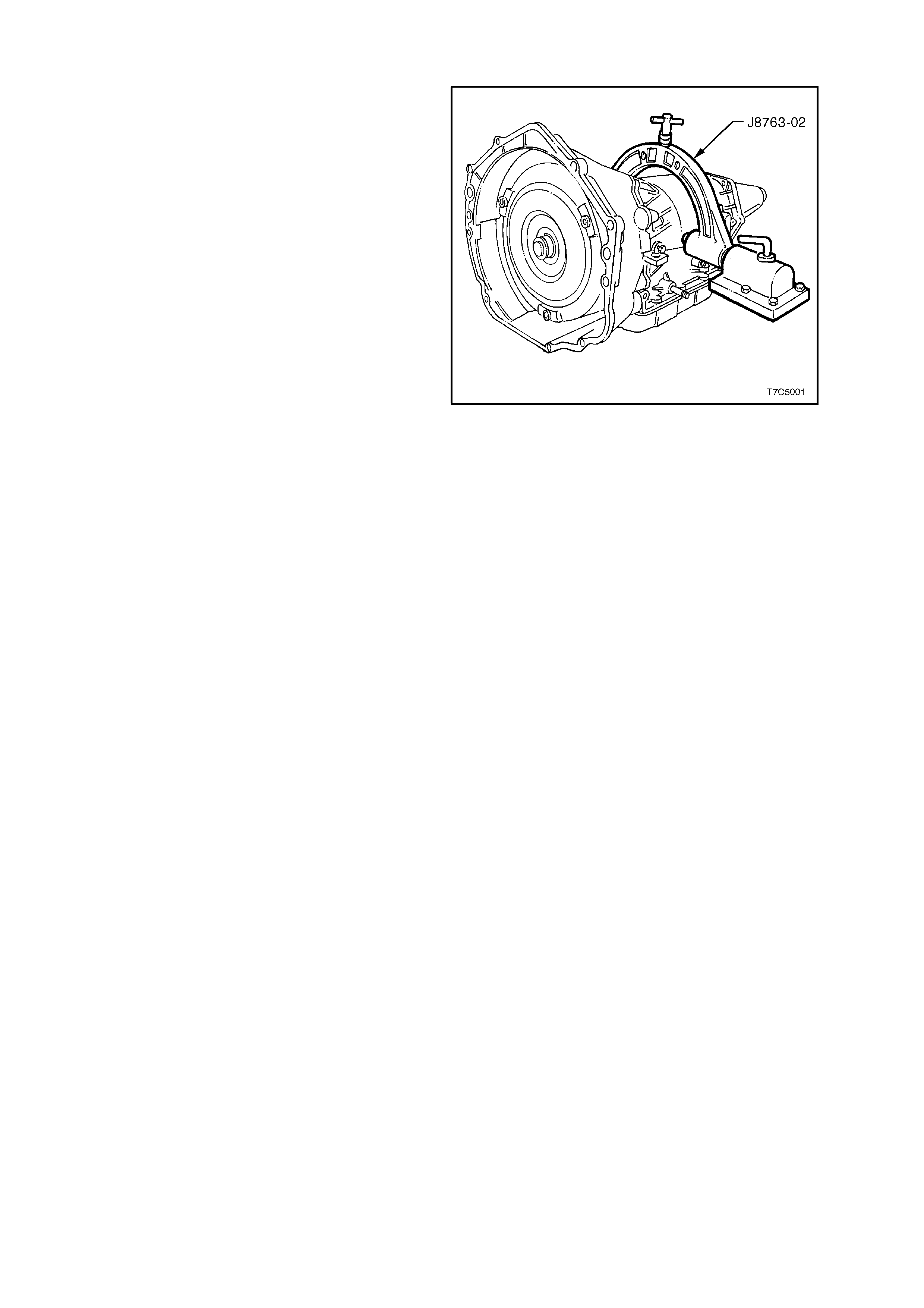
3.16 TRANSMISSION FIXTURE REMOVAL
1. Remove the transmission and holding fixture
(J8763-02) from the bench bracket.
2. Loosen the clamp screws and remove the
bracket from the transmission.
3. Plug all openings such as the oil cooler fittings
and output shaft to prevent the ingress of
foreign material, prior to installation in the
vehicle.
Figure 7C5-260
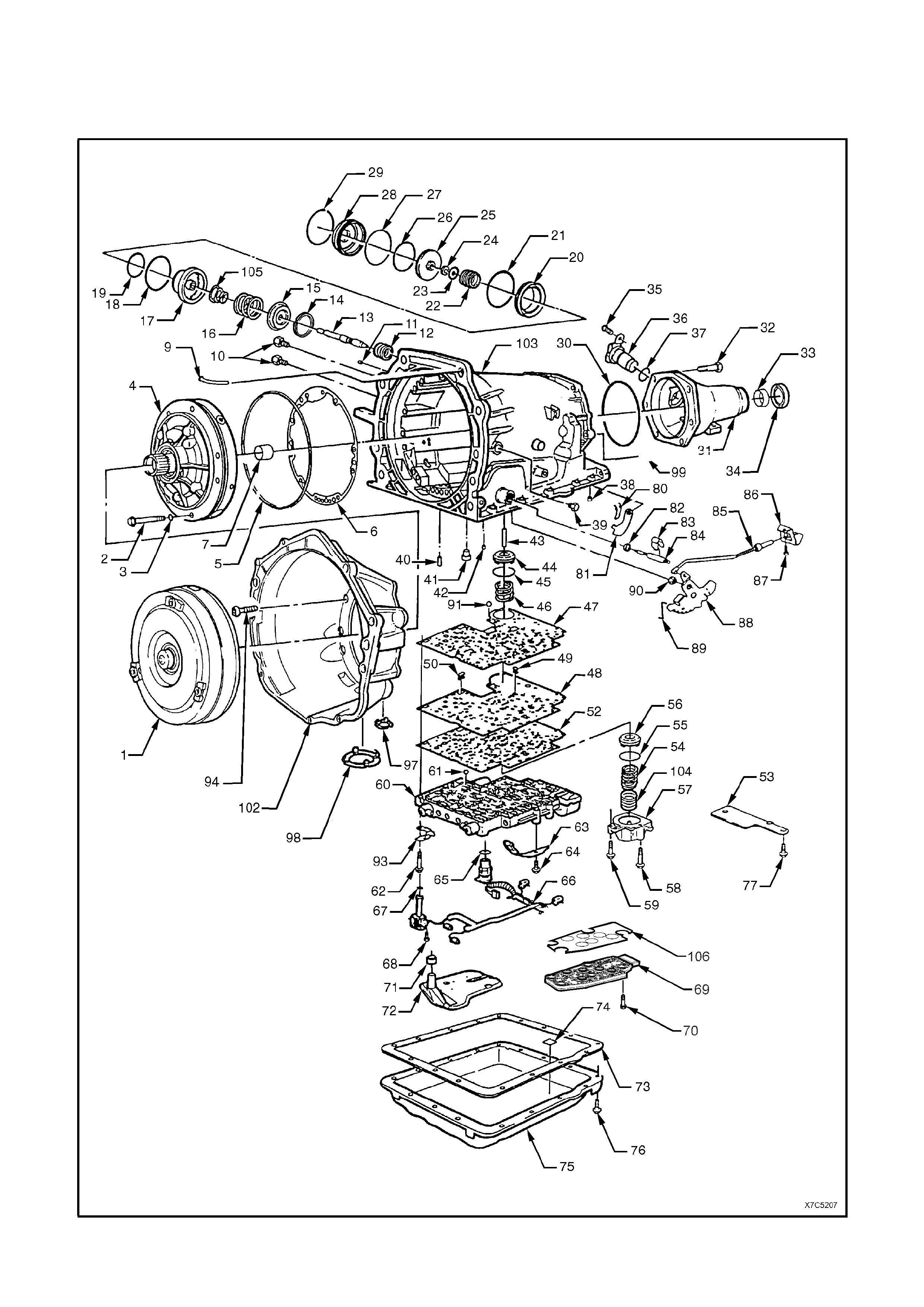
4. TRANSM I SSION REFERENCE DIAGRAMS
Figure 7C5-261 - Transmission Case and External Parts
REF No. PART NAME REF No. PART NAME
1.
2.
3.
4.
5.
6.
7.
9.
10.
11.
12.
13.
14.
15.
16.
17.
18.
19.
20.
21.
22.
23.
24.
25.
26.
27.
28.
29.
30.
31.
32.
33.
34.
35.
36.
37.
38.
39.
40.
41.
42.
43.
44.
45.
46.
47.
48.
49.
50.
52.
53.
54.
55.
56.
57.
58.
59.
60.
Torque Converter Assembly
Bolt, Oil Pump to Case
O-ring, Oil Pump to Case Bolt
Pump Assembly, Oil
Seal, Oil (Oil Pump to Case)
Gasket, Oil Pump Cover to Case
Bush, Case
Vent Assembly, Transmission
Connector, Oil Cooler Pipe
Plug, Case Servo
Spring, Servo Return
Pin, 2nd Apply Piston
Ring, Retainer (2nd Apply Piston)
Retainer, Servo Cushion Spring (Outer)
Spring, Servo Cushion (Outer)
Piston, 2nd Apply
Ring, Oil Seal (2nd Apply Piston - Outer)
Ring, Oil Seal (2nd Apply Piston - Inner)
Housing, Servo Piston (Inner)
Seal O-ring
Spring, Servo Apply Pin
Washer, Servo Apply Pin
Ring, Retainer (Apply Pin)
Piston 4th Apply
Ring, Oil Seal (4th Apply Piston - Outer)
Seal, O-ring (2-4 Servo Cover)
Cover, 2-4 Servo
Ring, Servo Cover Retaining
Seal, Case Extension to Case
Extension, Case
Bolt, Case Extension to Case
Bush, Case Extension
Seal Assembly, Case Extension Oil
Bolt, Speed Sensor Retaining
Sensor, Vehicle Speed
Seal, O-ring (Vehicle Speed Sensor)
Plug, Transmission Case (Accumulator Bleed)
Plug, Line Pressure
Retainer and Ball Assembly, 3rd Accumulator
Pin, Band Anchor
Retainer and Ball Assembly, (Double Orifice)
Pin, Accumulator Piston
Piston, 3-4 Accumulator
Ring, Oil Seal (3-4 Accumulator Piston)
Spring, 3-4 Accumulator (V6 Engine Only)
Gasket, Spacer Plate to Case
Plate, Valve Body Spacer
Screen, Shift Solenoids
Screen, Pressure Control Solenoid
Gasket, Spacer Plate to Valve Body
Plate, Spacer Plate Support
Spring, 1-2 Accumulator (Outer)
Ring, Oil Seal (1-2 Accumulator)
Piston, 1-2 Accumulator
Cover and Pin Assembly, 1-2 Accumulator
Bolt, Accumulator Cover
Bolt, Accumulator Cover
Valve Assembly, Control Body
61.
62.
63.
64.
65.
66.
67.
68.
69.
70.
71.
72.
73.
74.
75.
76.
77.
78.
79.
80.
81.
82.
83.
84.
85.
86.
87.
88.
89.
90.
91.
93.
94.
97.
98.
102.
103.
104.
105.
106.
Checkball
Bolt, Valve Body
Spring Assembly, Manual Detent
Bolt, Manual Detent Spring
O-ring Seal, Wiring Harness Pass-through
Connector,
Solenoid Assembly Harness, Wiring
Seal, O-ring, (Solenoid)
Bolt, Hex Washer Head (Solenoid)
Switch Assembly, Transmission Fluid Pressure
Manual Valve Position
Bolt, Pressure Switch Assembly
Seal, Filter
Filter Assembly, Transmission Oil
Gasket, Transmission Oil Pan
Magnet, Chip Collector
Pan, Transmission Oil
Screw, Transmission Oil Pan
Bolt, Spacer Plate Support
Plug, Steel Cup (not shown)
Shaft, Parking Brake Pawl (not shown)
Spring, Parking Brake Pawl
Pawl, Parking Brake
Seal, Manual Shaft
Retainer, Manual Shaft
Shaft, Manual
Actuator Assembly, Parking Lock
Bracket, Parking Lock
Bolt, Parking Lock Bracket
Lever, Inside Detent
Link, Manual Valve
Nut, Hex Head
Number 10 Checkball
Bracket, Dipstick Stop
Bolt, Converter Housing to Case
Plug, Converter Housing Access Hole
Plate, Converter Bolt Inspection
Housing, Torque Converter
Case, Transmission Main
Spring, 1-2 Accumulator (Inner)
Spring, Servo Cushion (Inner) (V6 Engine
Only)
Shield, Transmission Fluid Pressure Switch
Assembly, Manual Valve Position
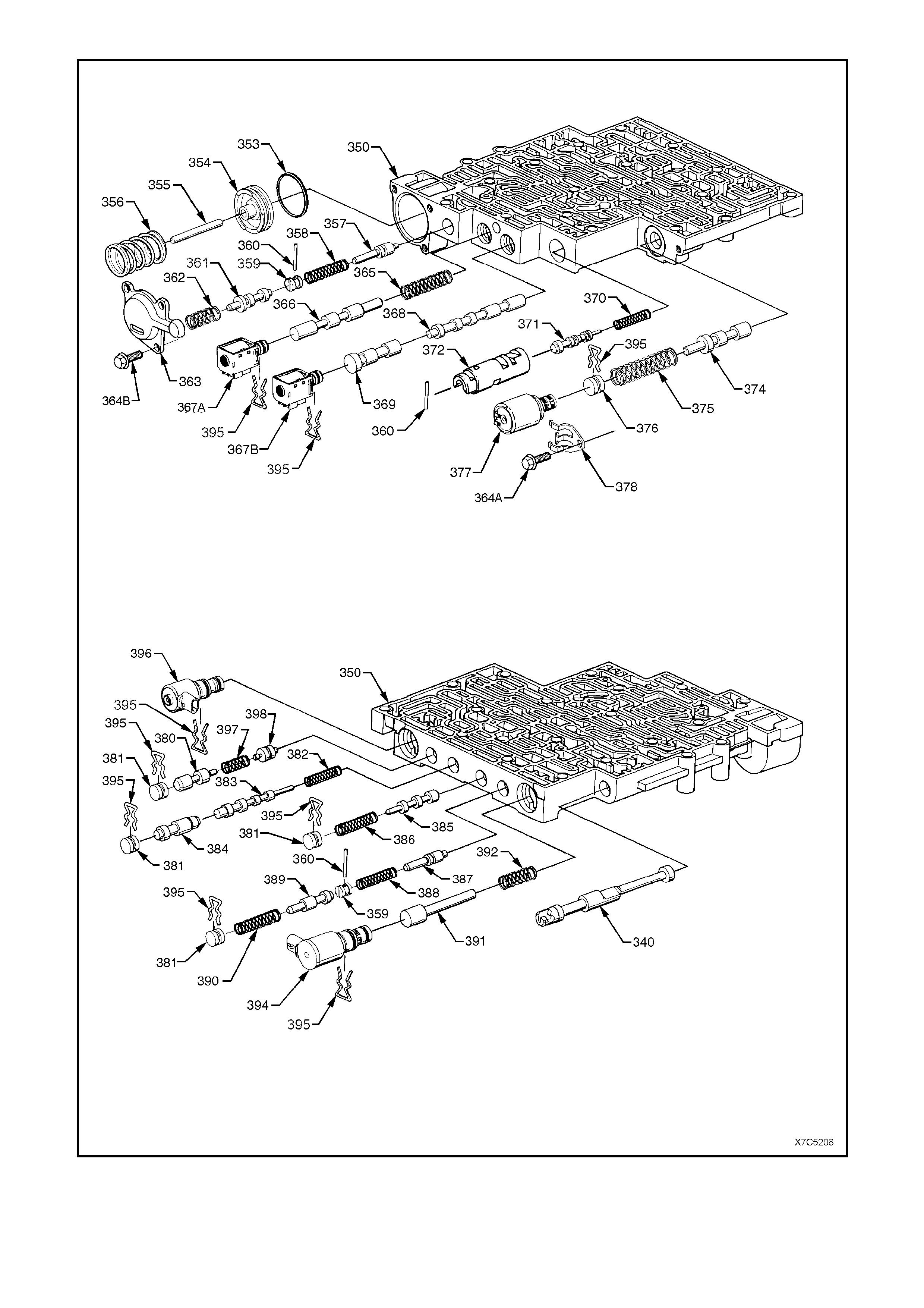
Figure 7C5-262 - Control Valve Body Assembly

REF No. PART NAME
340.
350.
353.
354.
355.
356.
357.
358.
359.
360.
361.
362.
363.
364A.
364B.
365.
366.
367A.
367B.
368.
369.
370.
371.
372.
374.
375.
376.
377.
378.
380.
381.
382.
383.
384.
385.
386.
387.
388.
389.
390.
391.
392.
394.
395.
396.
397.
398.
Valve, Manual
Valve Assembly, Control Body
Seal, Forward Accumulator
Piston, Forward Accumulator
Pin, Forward Accumulator
Spring, Forward Accumulator
Valve, Forward Abuse
Spring, Forward Abuse Valve
Plug, Bore
Pin, Coiled Spring
Valve, Low Overrun
Spring, Low Overrun Valve
Cover, Forward Accumulator
Bolt, Pressure Control Solenoid Retainer
Bolt, Forward Accumulator Cover
Spring, 1 - 2 Shift Valve
Valve, 1 - 2 Shift
1 - 2 Shift Solenoid (A)
2 - 3 Shift Solenoid (B)
Valve, 2 - 3 Shift
Valve, 2 - 3 Shuttle
Spring, 1 - 2 Accumulator Valve
Valve, 1 - 2 Accumulator
Sleeve, 1 - 2 Accumulator
Valve, Actuator Feed Limit
Spring, Actuator Feed Limit Valve
Plug, Bore
Pressure Control Solenoid
Retainer, Pressure Control Solenoid
Valve, Regulator Apply
Plug, Bore
Spring, 4 - 3 Sequence Valve
Valve, 4 - 3 Sequence
Valve, 3 - 4 Relay
Valve, 3 - 4 Shift
Spring, 3 - 4 Shift Valve
Valve, Reverse Abuse
Spring, Reverse Abuse Valve
Valve, 3 - 2 Downshift
Spring, 3 - 2 Downshift Valve
Valve, 3 -2 Control
Spring, 3 -2 Control Valve
3 - 2 Control Solenoid
Retainer, Bore Plug and Solenoid
TCC PW M Solenoid Valve
Spring, Regulator Supply
Valve, Isolator
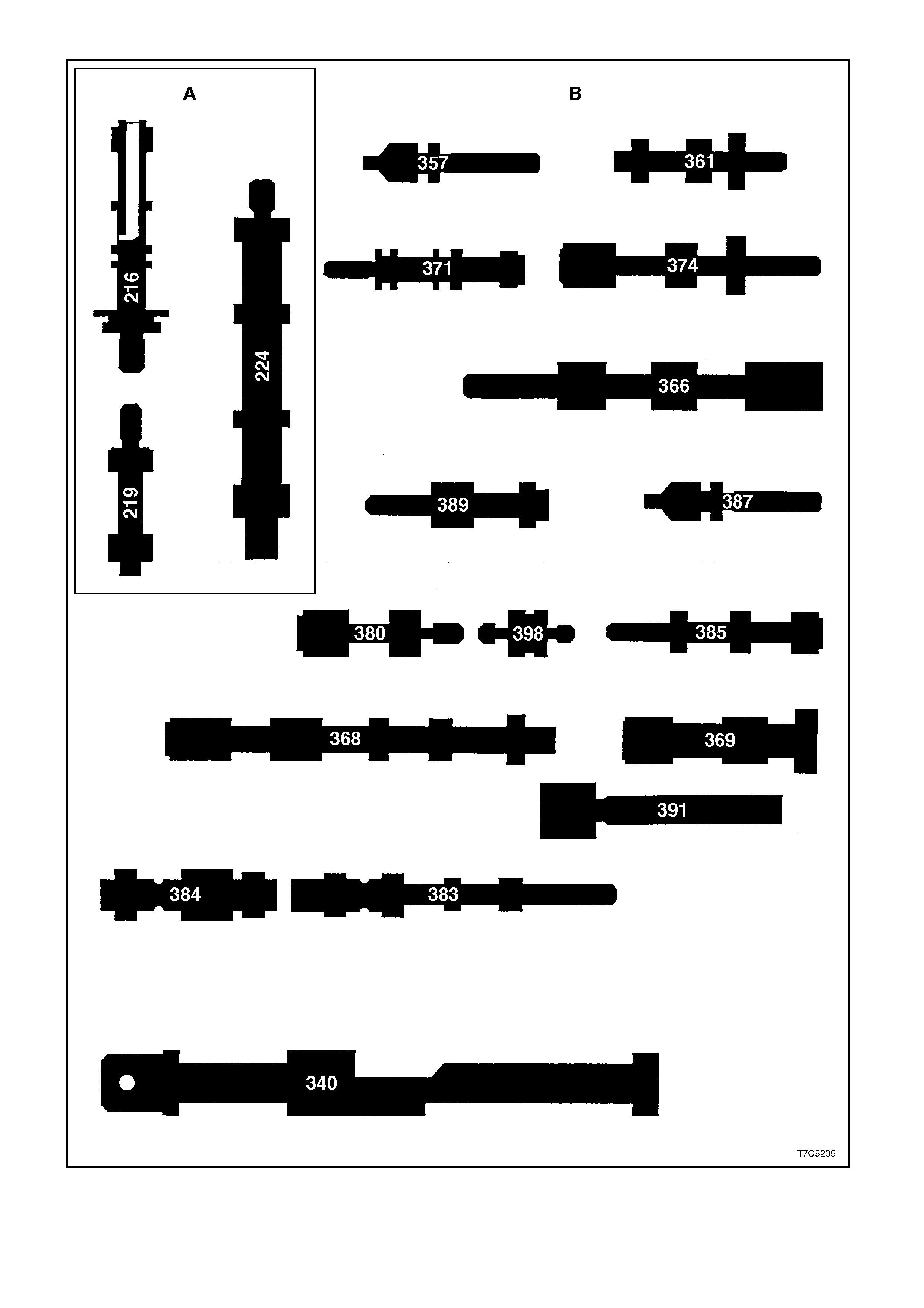
F
igure 7C5-263 - Control Valve Identification

Ref. No. PART NAME
A Located in the Oil Pump
216.
219.
224.
Valve, Pressure Regulator
Valve, Reverse Boost
Valve, Converter Clutch
B Located in the Control Valve Body
340.
357.
361.
366.
368.
369.
371.
374.
380.
383.
384.
385.
387.
389.
391.
398.
Valve, Manual
Valve, Forward Abuse
Valve, Low Overrun
Valve, 1 - 2 Shift
Valve, 2 - 3 Shift
Valve, 2 - 3 Shuttle
Valve, 1 - 2 Accumulator
Valve, Actuator Feed Limit
Valve, Regulator Apply
Valve, 4 - 3 Sequence
Valve, 3 - 4 Relay
Valve, 3 - 4 Shift
Valve, Reverse Abuse
Valve, 3 -2 Downshift
Valve, 3 -2 Control
Valve, Isolator
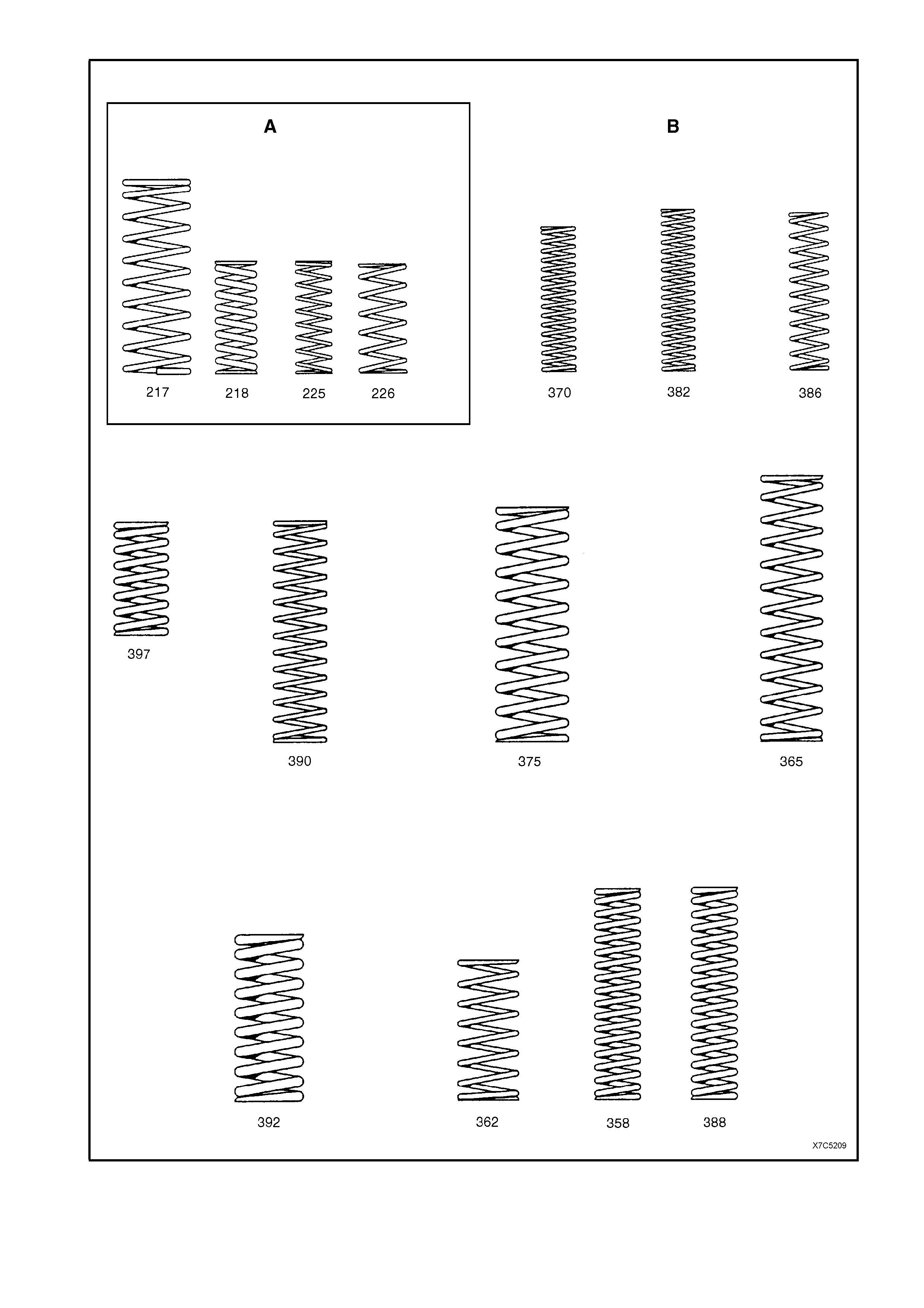
Figure 7C5-264 - Control Valve Spring Identification
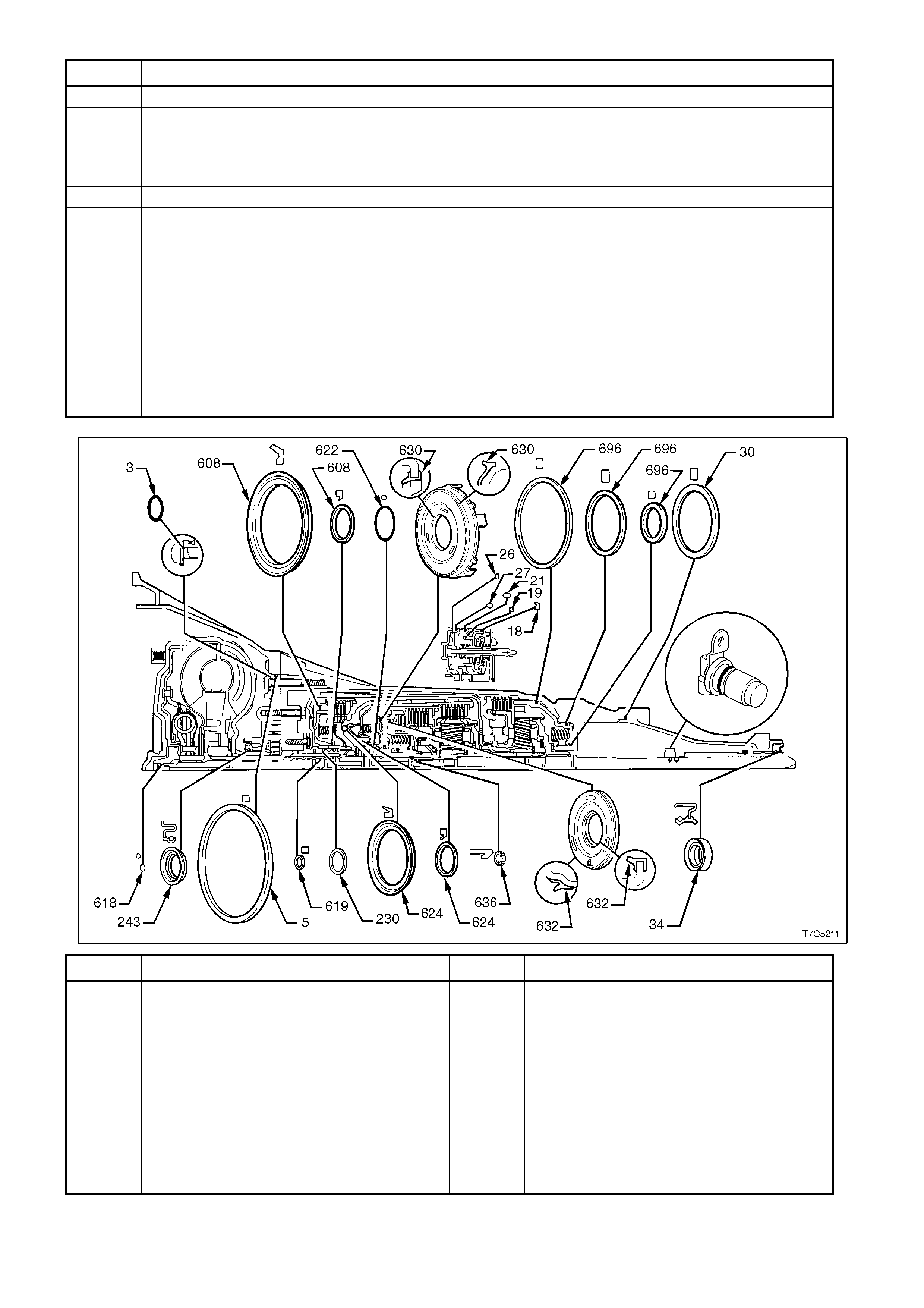
Ref. No. PART NAME
A Located in the Oil Pump
217.
218.
225.
226.
Spring, Pressure Regulator Valve
Spring, Pressure Regulator Isolator
Spring, Converter Clutch Valve (Inner)
Spring, Converter Clutch Valve (Outer)
B Located in the Control Valve Body
358.
362.
365.
370.
375.
382.
386.
388.
390.
392.
387.
Spring, Forward Abuse Valve
Spring, Low Overrun Valve
Spring, 1 - 2 Shift Valve
Spring, 1 - 2 Accumulator Valve
Spring, Actuator Feed Limit Valve
Spring, 4 - 3 Sequence Valve
Spring, 3 - 4 Shift Valve
Spring, Reverse Abuse Valve
Spring, 3 - 2 Downshift Valve
Spring, 3 -2 Control Valve
Spring, Regulator Supply
Ref. No. PART NAME Ref. No. PART NAME
3.
5.
18.
19.
21.
26.
27.
30.
34.
37.
230.
O-ring, Pump to Case Bolt
Seal, Oil (Pump to Case)
Ring, Oil Seal (2nd Apply Piston - Outer)
Ring, Oil Seal (2nd Apply Piston - Inner)
Seal, O-ring.
Ring, Oil Seal (4th Apply Piston - Outer)
Seal, O-ring (2-4 Servo Cover)
Seal, Case Extension to Case
Seal, Case Extension
Seal, O-ring (Vehicle Speed Sensor)
Ring, Oil Seal (Stator Shaft)
243.
608.
618.
619.
622.
624.
630.
632.
636.
696.
Seal Assembly, Oil
Seals, Reverse Input Clutch
Seal, O-ring (Turbine Shaft)
Ring, Oil Seal (Solid)
Seal, O-ring (Input to Forward Housing)
Seals, 3rd and 4th Clutch (Service
Replacement)
Piston, Forward Clutch
Piston, Overrun Clutch
Seal, Input Housing to Output Shaft
Seals, (Low and Reverse Clutch Piston)
Figure 7C5-265 Seal Locations and Orientation
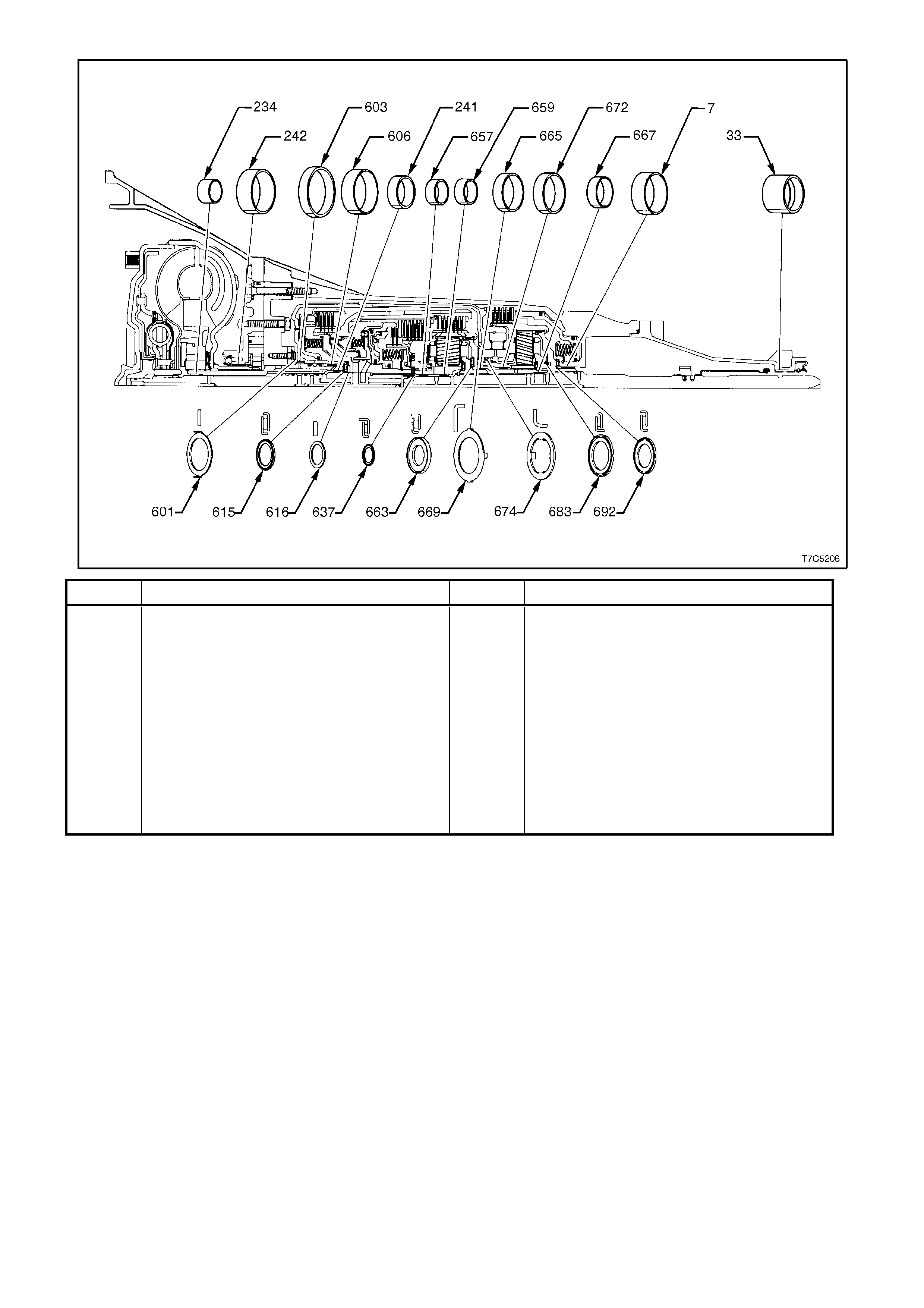
Ref. No. PART NAME Ref. No. PART NAME
7.
33.
234.
241.
242.
601.
603.
606.
615.
616.
637.
Bushing, Case
Bushing, Case Extension
Bushing, Stator Shaft (Front)
Bushing, Stator Shaft (Rear)
Bushing, Oil pump Body
Washer, Thrust (Pump to Drum)
Bushing, Reverse Input Clutch (Front)
Bushing, Reverse Input Clutch (Rear)
Bearing Assembly, Stator Shaft Selective
Washer
Washer, Thrust (Selective)
Bearing Assembly, Input Sun Gear
657.
659.
663.
665.
667.
669.
672.
674.
683.
692.
Bushing, Input Sun Gear (Front)
Bushing, Input Sun Gear (Rear)
Bearing Assembly, Thrust (Input carrier to
Reaction Shaft
Bushing, Reaction Carrier Shaft (Front)
Bushing, Reaction Carrier Shaft (Rear)
Washer, Thrust (Reaction Shaft/Shell)
Bushing, Reaction Gear
Washer, Thrust (Race/Reaction Shell)
Bearing Assembly, (Reaction Carrier/Support)
Bearing, Reaction Gear Support to Case
Figure 7C5-266 Bush/Bearing Locations and Orientation

5. SPECIFICATIONS
GENERAL
Type........................................................................ Hydra-matic 4L60-E.
Code ....................................................................... V6 Engine – HFD.
V6 Supercharged Engine – HND.
GEN III V8 Engine – HPD.
Special Features..................................................... Electronically controlled shift pattern, feel and torque
converter clutch operation. Overdrive 4th speed range.
Selector Location.................................................... Floor mounted console.
GEAR RATIOS:
Park (P).............................................................. −
Reverse (R) ....................................................... 2.294:1
Neutral (N) ......................................................... −
Overdrive (OD - 4)............................................. 0.696:1
Drive (D - 3) ....................................................... 1.000:1
Second (2)......................................................... 1.625:1
First (1) .............................................................. 3.059:1
SHIFT SPEEDS......................................................... Refer to 7C3 DIAGNOSIS of the VT Series I and of the
VT Series II Service Information.
OIL PRESSURE ........................................................ Refer to 7C3 DIAGNOSIS of the VT Series I and of the
VT Series II Service Information.
TORQUE CONVERTER:
Number of Elements.......................................... 3 plus torque converter clutch.
Maximum torque ratio at stall............................. V6 and V6 Supercharged Engines – 1.63:1 (k=133).
GEN III V8 Engine – 1.9:1 (k=101)
Nominal Diameter.............................................. V6 and V6 Supercharged Engines – 258 mm.
GEN III V8 Engine – 300 mm.
End Play............................................................. 0.1 – 0.5 mm (All Engines)
LUBRICANT:
Type recommended........................................... Dexron® III
Capacity............................................................. Nominal only. Check when transmission is at operating
temperature.
Refill................................................................. V6 and V6 Supercharged Engines – 4.8 litres.
GEN III V8 Engine – 5.0 litres
Total (Dry)........................................................ V6 and V6 Supercharged Engines – 7.9 litres.
GEN III V8 Engine – 10.6 litres.
Fluid Cooling...................................................... Engine coolant to fluid in one or both radiator tanks and
externally, air to fluid cooler, where fitted.
CLUTCHES AND BAND
2 - 4 BAND:
Type................................................................... Composition lined, steel band.
Operation........................................................... Servo.
Adjustment......................................................... Selective Apply Pin.
65.82 - 66.12 mm 1 Groove.
67.23 - 67.53 mm 2 Grooves.
68.64 - 68.94 mm No Groove.
REVERSE INPUT CLUTCH:
Type........................................................................ Multiple wet disc.
Clutch plate, number and thickness:
Steel................................................................... 4 1.892 - 2.045 mm.
Composition....................................................... 4 1.730 - 1.880 mm.
Belleville............................................................. 1 2.210 - 2.311 mm.
Backing plate..................................................... 1 Selective.
Backing plate, identification and thickness:..... '2' 7.249 - 7.409 mm.
'3' 6.519 - 6.678 mm.
'4' 5.787 - 5.947 mm.
Backing plate travel ........................................... 1.02 - 1.94 mm

FORWARD CLUTCH:
Type.............................................................................. Multiple wet disc
Clutch plate, number and thickness:
Flat steel plates........................................................ 5 2.29 mm
Composition plates.................................................. 5 1.78 mm
Apply plate............................................................... 1 4.30 mm
Waved steel plate.................................................... 1 1.79 mm
Backing plate ................................................................ 1 Selective
Backing plate, identification and thickness:............. 'A' 6.97 - 7.07 mm
'B' 6.38 - 6.48 mm
'C' 5.79 - 5.89 mm
'D' 5.20 - 5.30 mm
'E' 4.61 - 4.71 mm
Backing plate travel:
V6 and V6 Supercharged Engines ........................ 0.866 – 1.876 mm
GEN III V8 Engine ................................................. 0.866 – 1.876 mm
OVERRUN CLUTCH:
Type.............................................................................. Multiple wet disc
Clutch plates, number and thickness:
Flat steel .................................................................. 2 2.248 - 2.400 mm
Composition............................................................. 2 2.03 mm
3 - 4 CLUTCH:
Type.............................................................................. Multiple wet disc
Clutch plates, number and thickness:
Flat steel .................................................................. 5 2.71 mm
Composition............................................................. 6 2.03 mm
Flat steel apply plate................................................ 1 5.60 mm
Flat steel (same spline configuration as flat steel)... 1 1.78 mm
Backing plate........................................................... 1 Selective
Backing plate, identification and thickness:........... 'A' 5.88 - 5.68 mm
'B' 4.99 - 4.76 mm
'C' 4.10 - 3.90 mm
Backing plate travel ................................................. 2.10 – 0.90 mm
LOW AND REVERSE CLUTCH:
Type Multiple wet disc
Clutch plates, number and thickness:
Flat steel ....................................................................... 5 1.75 mm
Composition.................................................................. 5 2.25 mm
Flat steel - waved.......................................................... 1 2.42 mm
Selective flat steel plate................................................ 1 Selective
Selective plate, identification and thickness:
Measured Dimension: 28.065 – 27.545 mm.......... NONE 1.684 - 1.829 mm
28.586 – 28.066 mm.......... '0' 1.168 - 1.314 mm
27.544 – 27.026 mm.......... '1' 2.198 - 2.344 mm
Overall clutch pack height
(Including spacer plate) ........................................... 29.22 - 29.90 mm
Clutch plate support thickness...................................... 6.655 - 6.909 mm
CLEARANCES:
Transmission end play.................................................. 0.13 - 0.92 mm
Pinion gears end play (all)............................................. 0.20 - 0.60 mm
Torque converter end play............................................ 0 - 0.5 mm

6. TORQUE WRENCH SPECIFICATIONS
NOTE: For a lis ting of tor que wrench spec ific ations relating to the re m oval and reinstallation pr ocedures assoc iated
with the automatic trans miss ion, ref er to Section 7C4 HYDRA-MATIC 4L60-E AUTOMATIC TRANSMISSION: ON-
VEHICLE SERVICING of the VX Series Service Information. Nm
1 - 2 accumulator cover bolt............................................................ 8 - 14
Control valve body bolt.................................................................... 8 - 14
Converter housing to case bolt ....................................................... 65 - 75
Extension housing to transmission case bolt.................................. 42 - 48
Forward accumulator cover to valve body bolt................................ 8 - 14
Manual detent spring retaining bolt................................................. 20 - 27
Manual shaft selector lever nut....................................................... 15 - 35
Manual shaft to inner detent lever nut............................................. 27 - 34
Neutral start and back-up lamp switch bolts................................... 15 - 35
Oil cooler pipe connections............................................................. 35 - 41
Oil pan bolt...................................................................................... 10 - 14
Oil pump cover to pump body bolt .................................................. 20 - 27
Oil pump to case bolt ...................................................................... 26 - 32
Pressure control solenoid bracket to valve body bolt...................... 8 - 14
Park pawl bracket bolt..................................................................... 27 - 34
Spacer plate support plate bolt ....................................................... 8 - 14
Speed sensor retaining bolt ............................................................ 11 - 14
Torque converter clutch solenoid bolt............................................. 8 - 14
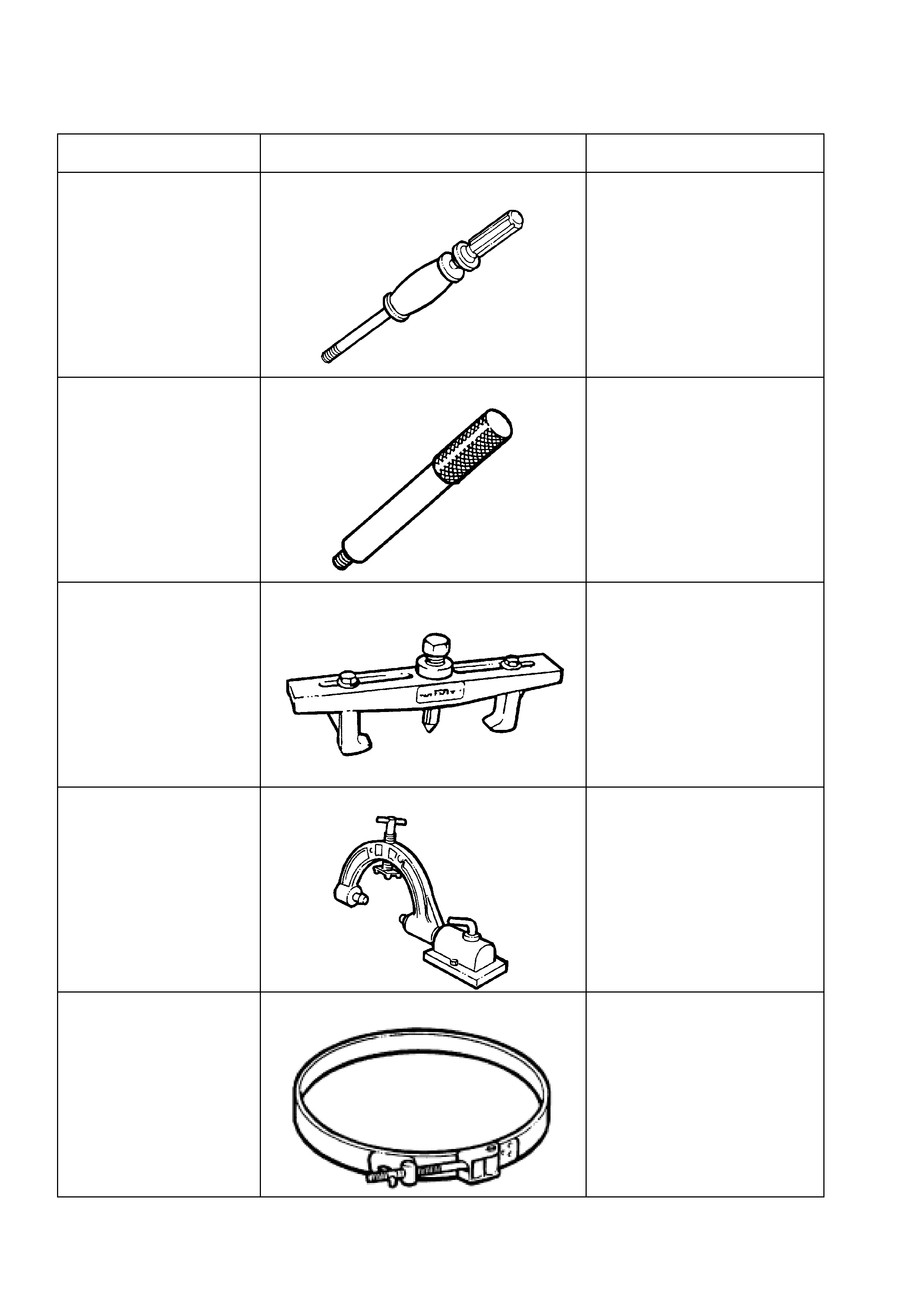
7. SPECIAL TOOLS
TOOL No. REF. IN TEXT TOOL DESCRIPTION COMMENTS
J7004-1 SLIDE HAMMER
Used for a number of bush
removal operations.
J8092 DRIVER HANDLE
Used for a number of bush
installation operations.
J8433 PULLER
Used with J21427-01 to remove
the output speed sensor ring
from the mainshaft.
J8763-02
HOLDING FIXTURE
Also required is the bench
fixture, J3289-20.
J21368 OIL PUMP ALIGNMENT BAND Used to align the two oil pump
sections before tightening the
securing bolts.
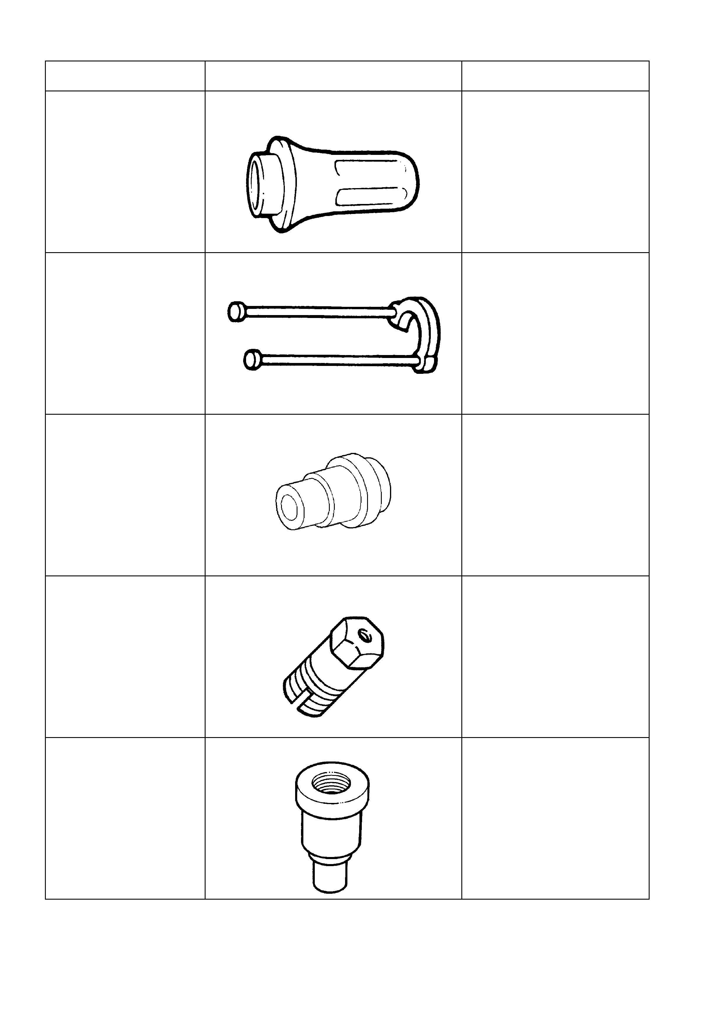
TOOL No. REF. IN TEXT TOOL DESCRIPTION COMMENTS
J21426 REAR SEAL INSTALLER
Used to install the extension
housing oil seal.
J21427-01 PULLER ADAPTOR
Used with J8433 to remove the
output speed sensor ring from
the mainshaft.
J21465-2 INSTALLER
Used with driver J8092 to install
the front stator shaft bush
J21465-15 REMOVER
Used in conjunction with slide
hammer J7004-1 to remove the
stator shaft front bushing.
J23062-14 BUSH REMOVER
Used in conjunction with driver
handle J8092
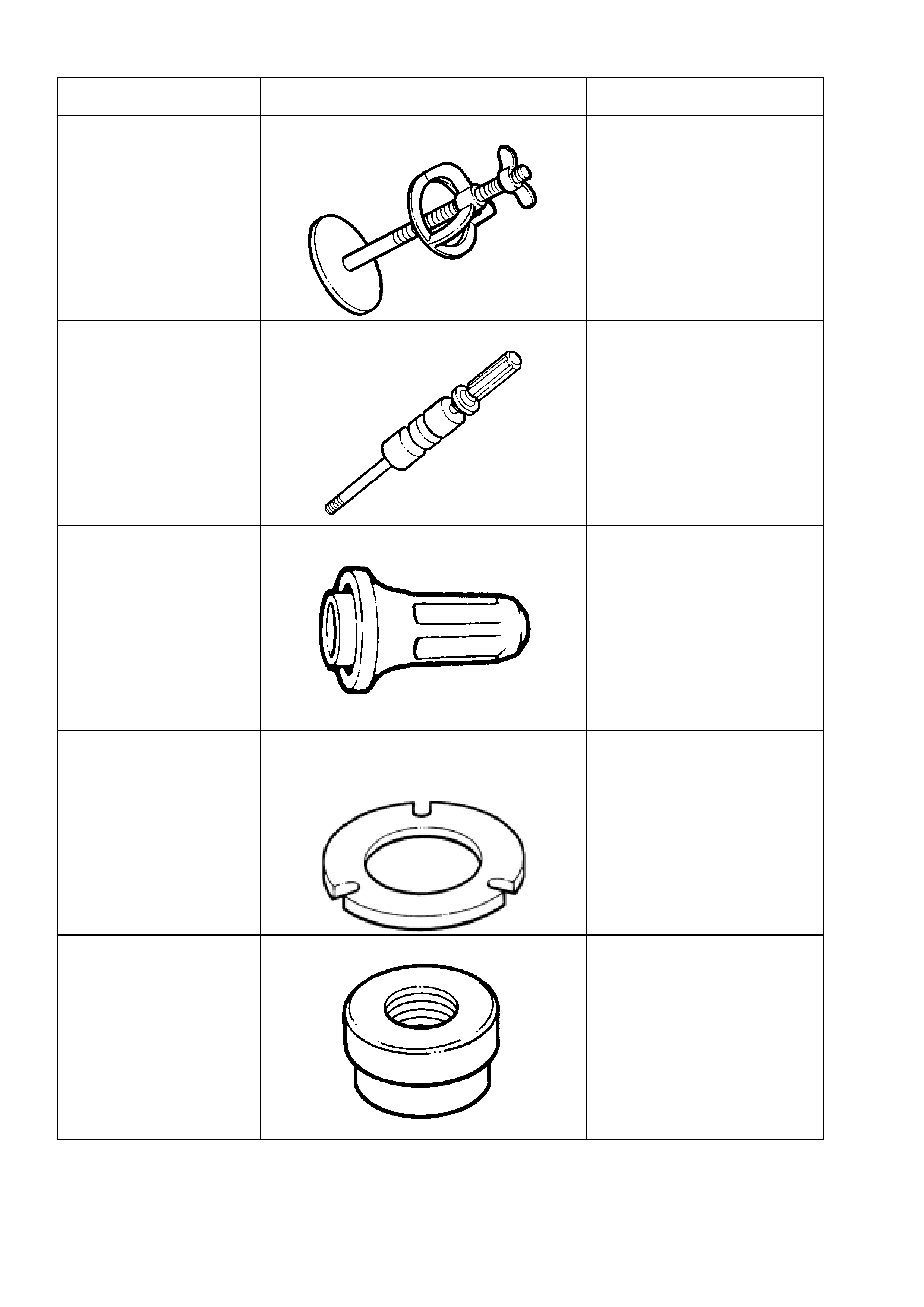
TOOL No. REF. IN TEXT TOOL DESCRIPTION COMMENTS
J23327-1 CLUTCH SPRING COMPRESSOR
Needed to compress the clutch,
before dismantling.
Plate J42628 is also required.
J23907 SLIDE HAMMER
Used with J29369-2 to remove
the reaction carrier shaft
bushes.
J25016 OIL PUMP SEAL INSTALLER
Used to install the oil pump oil
seal/
J25018-A CLUTCH SPRING COMPRESSOR
ADAPTOR
Used with compressor J23327
to compress the reverse input
clutch during disassembly.
J25019-9 BUSH INSTALLER
Used in conjunction with driver
handle J8092
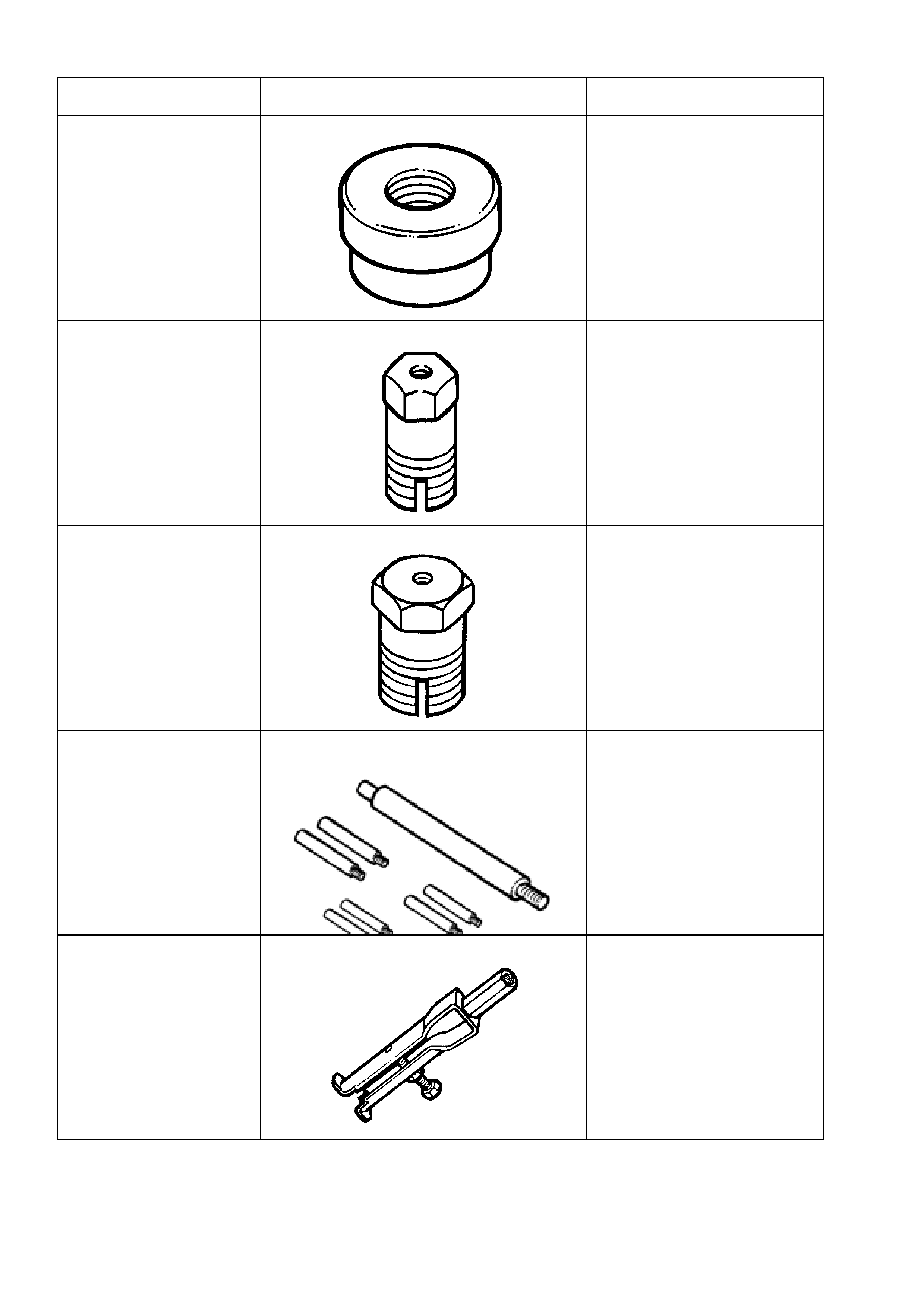
TOOL No. REF. IN TEXT TOOL DESCRIPTION COMMENTS
J25019-12 BUSH INSTALLER
Used in conjunction with driver
handle J8092
J25019-14 BUSH REMOVER
Used with slide hammer J7004-
1.
J25019-16 BUSH REMOVER
Used with slide hammer J7004-
1.
J25025-B DIAL INDICATOR STAND AND GUIDE PIN
SET Used for various tasks, stated in
the text.
J29369-2 UNIVERSAL BUSH REMOVER
Used with slide hammer
J23907.
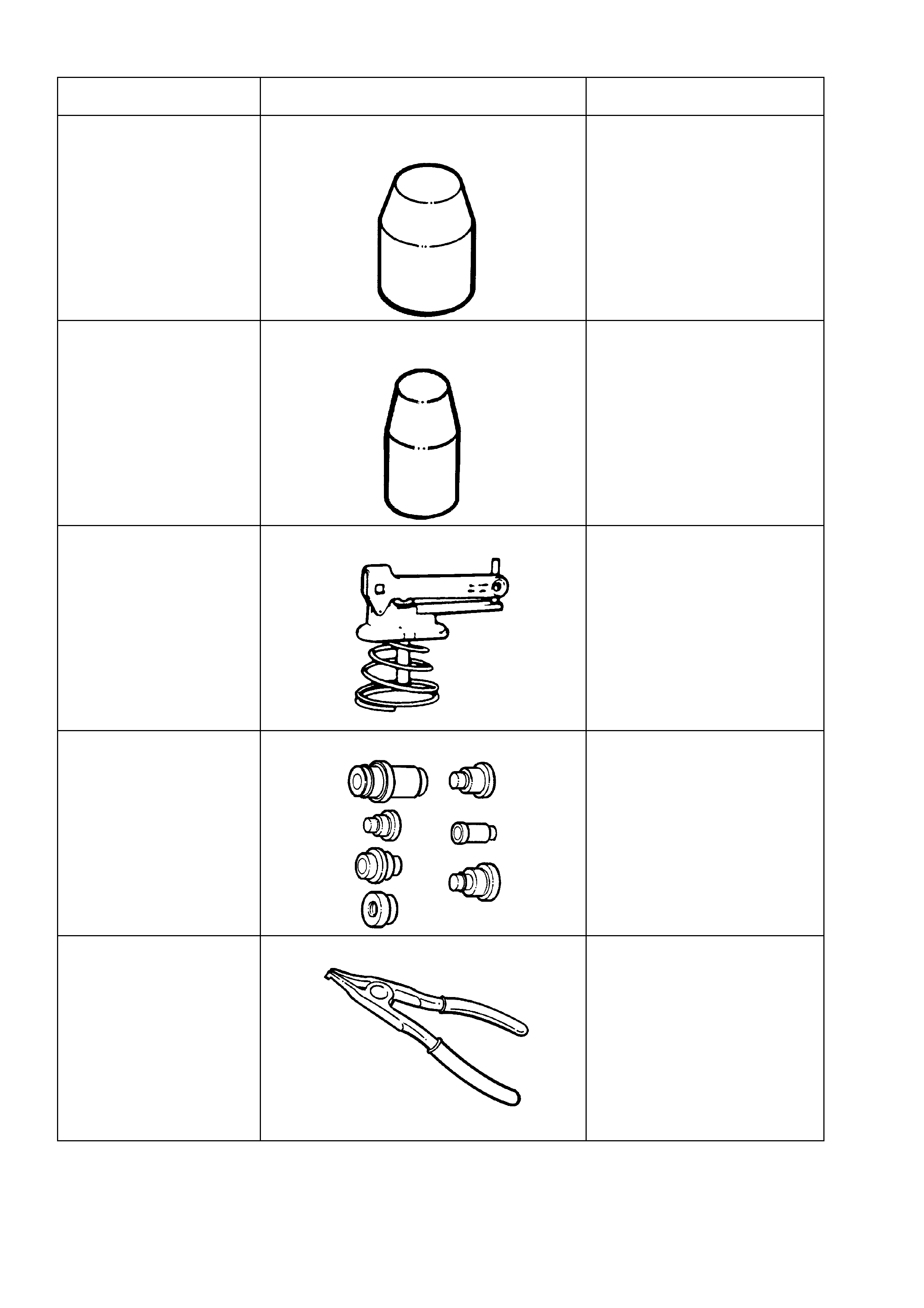
TOOL No. REF. IN TEXT TOOL DESCRIPTION COMMENTS
J29882 INNER OVERRUN CLUTCH SEAL
PROTECTOR
Used to protect the inner,
overrun clutch piston seal from
damage during installation.
J29883 INNER FORWARD CLUTCH SEAL
PROTECTOR
Used to protect the inner,
forward clutch piston seal from
damage during installation.
J33037 2 - 4 BAND APPLY PIN TOOL
Used to check the selective
apply pin length.
J34196-B BUSH REMOVER/INSTALLER SET
Used for various applications,
described in the text.
J34627 SNAP RING PLIERS
Specific purpose is to assist in
the removal/replacement of the
output shaft snap ring.
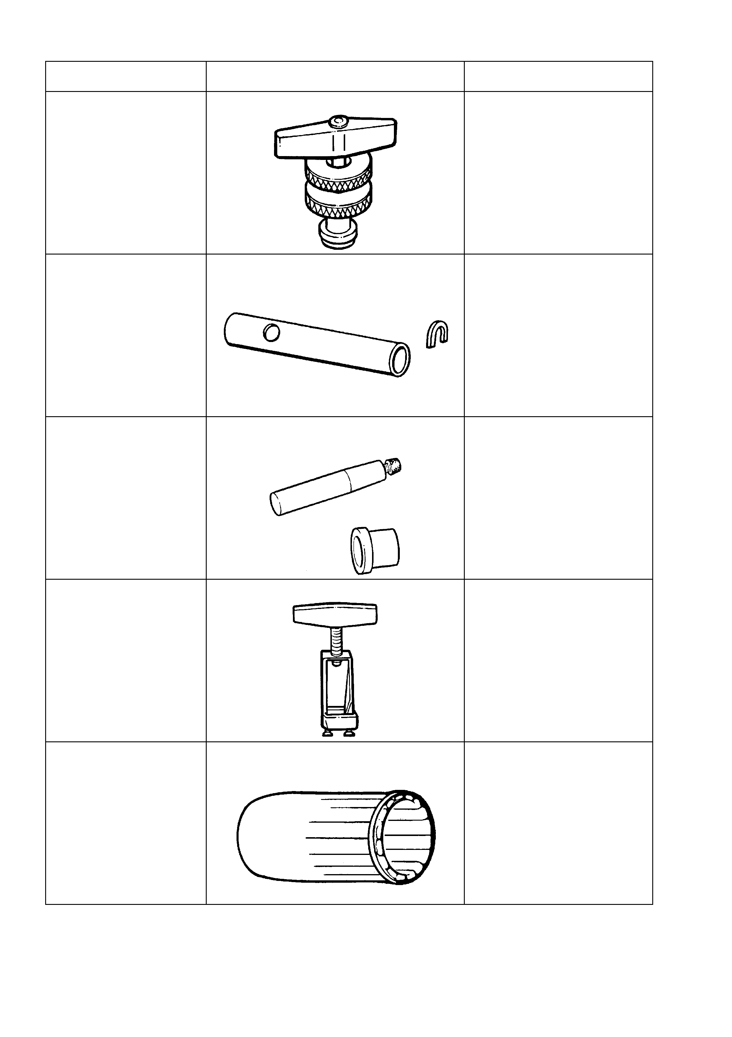
TOOL No. REF. IN TEXT TOOL DESCRIPTION COMMENTS
J35138 TORQUE CONVERTER END PLAY
To be used in conjunction with
commercially available
magnetic stand and dial
indicator.
J36352 SPEED SENSOR INSTALLER &
GAUGING TOOL
Needed to correctly install the
output speed sensor ring to the
mainshaft.
Comprises sleeve, J36352-6
and C-washer J36352-4.
J36418-B TURBINE SHAFT SEAL INSTALLER &
RESIZER
Used to install and re-size the
turbine shaft seal.
Comprises J36418-1B installer
(revised to suit 300 mm torque
converter turbine shaft
dimensions) and J36418-2A
resizer.
NOTE: J36418-1B will service
back to all 4L60-E
transmissions.
J37789-A OIL PUMP REMOVER
Used with J39119 to remove
the oil pump assembly.
J38735-3 STATOR SHAFT SEALING RING
INSTALLER
Used with J39855-1 to install
the stator shaft seal.
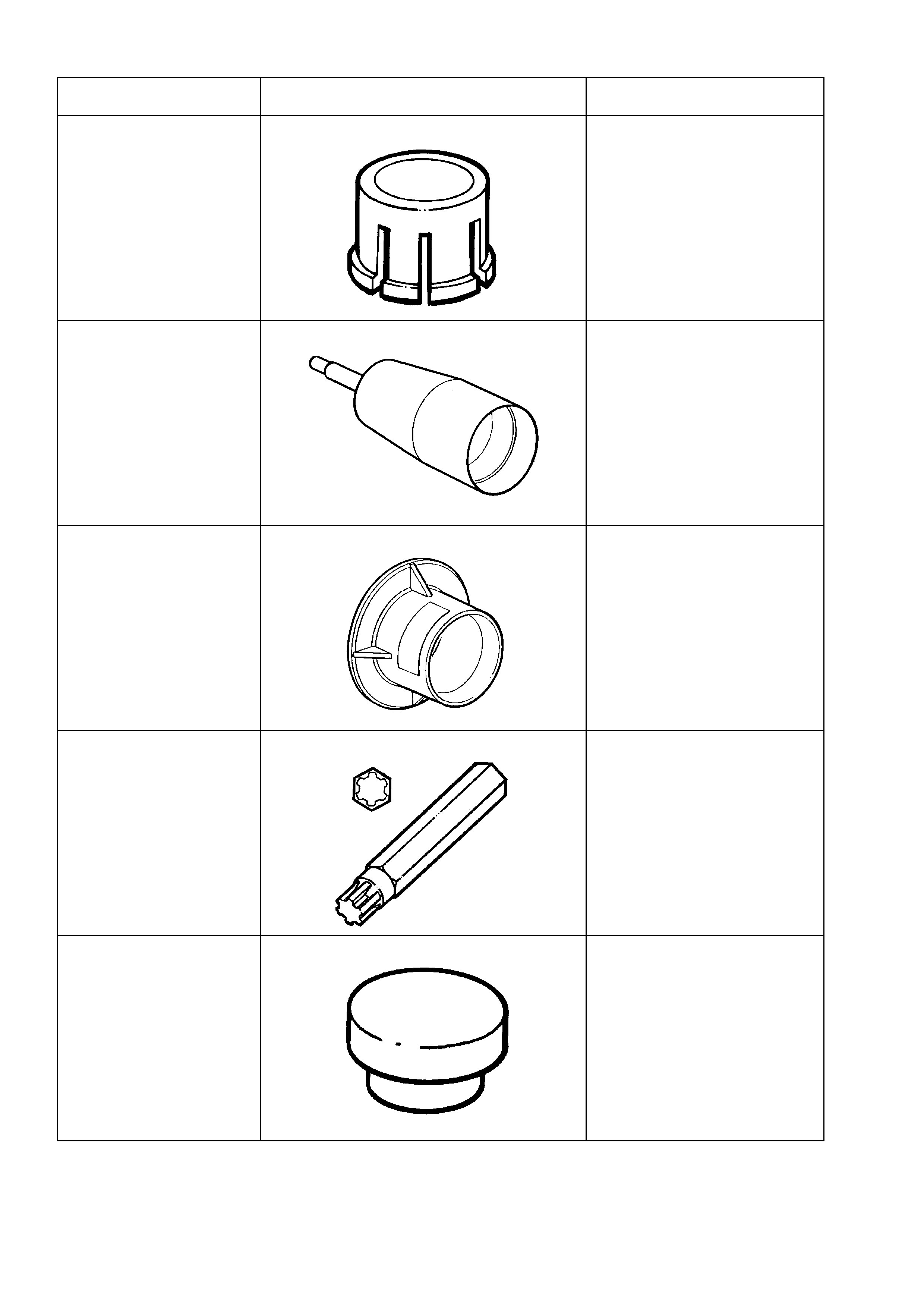
TOOL No. REF. IN TEXT TOOL DESCRIPTION COMMENTS
J39119 OIL PUMP REMOVER ADAPTOR
Used with J37789-A to remove
the oil pump assembly.
J39855-1 STATOR SHAFT SEAL EXPANDER
Used to expand the stator shaft
seal prior to installation.
J39855-2 STATOR SHAFT SEAL RESIZER
Used to re-size the stator shaft
seal after installation.
J41510 #50 TORX PLUS BIT
Used to loosen and tighten the
torque converter housing to
transmission case bolts.
J41778-1 OIL PUMP BUSH INSTALLER
Used with a bench press.
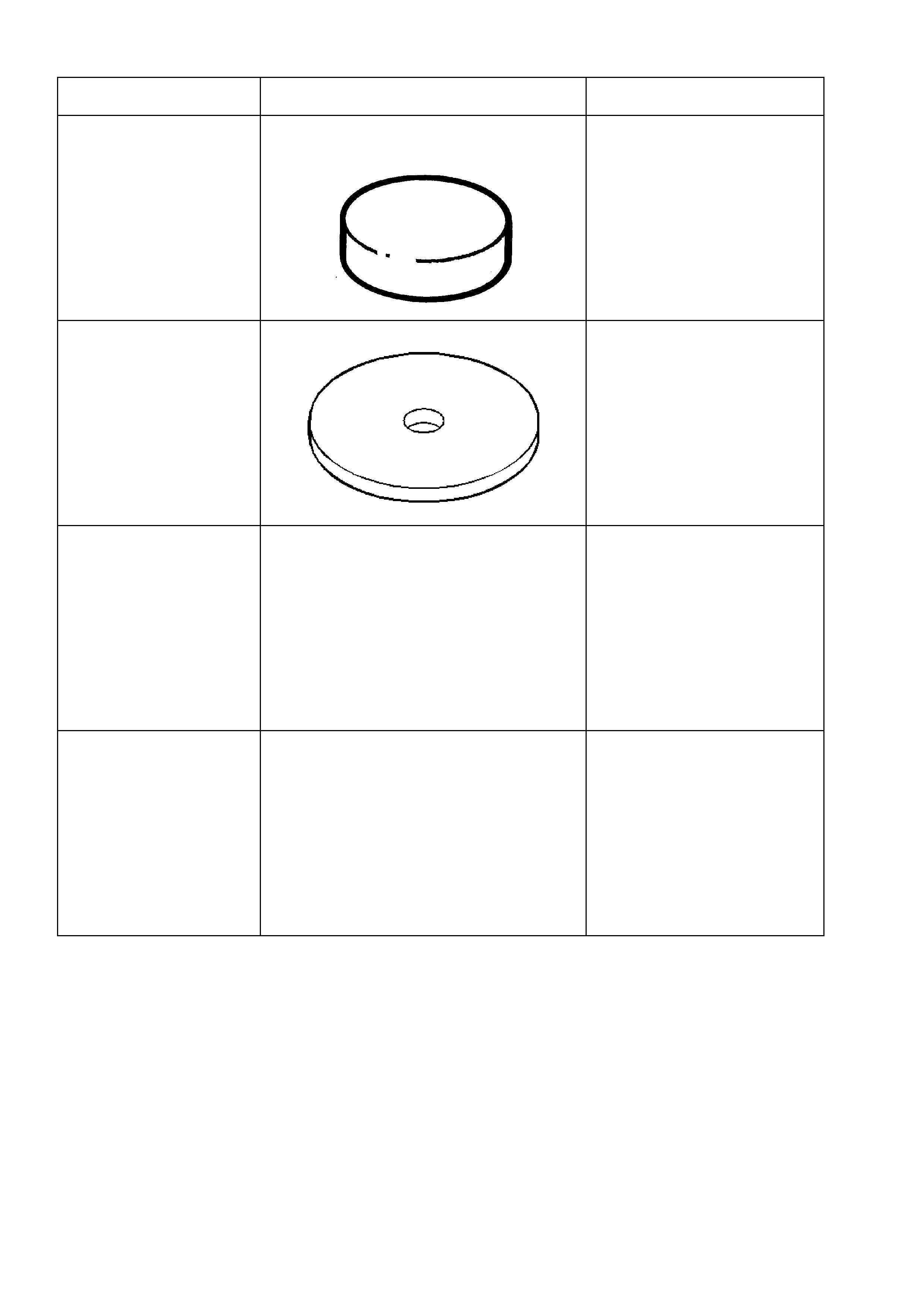
TOOL NO. REF. IN TEXT TOOL DESCRIPTION COMMENTS
J41778-2 SUPPORT PLATE
Used to support the oil pump
during bush installation.
J42628 PLATE
New release.
Used with clutch spring
compressor, J23327-1.
AU MANUAL SHAFT OIL SEAL REMOVER
New release.
Used to remove the manual
shaft oil seal without first
removing the manual shaft.
NOTE: Can be used on all
4L60-E transmissions.
AU MANUAL SHAFT OIL SEAL INSTALLER
New release.
Used to install the manual shaft
oil seal.
NOTE: Can be used on all
4L60-E transmissions.