
SECTION 12C - INSTRUMENTS, WIPERS/
WASHERS & HORN
IMPORTANT:
Before performing any Service Operation or other procedure described in this Section, refer to Section
00 CAUTIONS AND NOTES for correct workshop practices with regard to safety and/or property damage.
1. GENERAL I NFORMATI O N
1.1 VX AND VU SERIES II MODELS
The Instruments, Wipers/Washers and Horn fitted to VX and VU Series II Models carries over from VX Series I
Models, noting the following:
• A new wiper/washer control switch has been fitted to VX Series II Models.
• W ith the introduction of the theft deterrent system as standard equipment on all VX Series II Models, the theft
deterrent hor n pr eviously fitted to vehic les with a high s er ies BCM, has been f itted as standar d equipment on all
VX Series II Models.
For information relating to the Instruments, Wipers/Washers and Horn fitted to VX and VU Series II Models not
covered in this section, refer to Section 12C INSTRUMENTS, WIPERS/WASHERS & HORN in the VX Series I
Service Information, in conjunction with Section 12C INSTRUMENTS, WIPERS/WASHERS & HORN in the
VT Series I and VT Series II Service Information.
Techline
Techline
Techline

1.2 WH SERIES II MODELS
The Instruments, W ipers/Washers and Horn fitted to WH Series II Models carries over from WH Series I Models,
noting the following:
• A new wiper/w asher control switch has been fitted to WH Series II Models.
• The instrument cluster colour and graphics have been revised.
For inf ormation relating to the Instr uments, Wipers/Washer s and Horn fitted to W H Series II Models not covered in
this section, refer to Section 12C INSTRUMENTS, WIPERS/WASHERS & HORN in the WH Series II Service
Information, in conj unc tion with Section 12C INST RUMENTS, WIPERS/WASHERS & HORN in the VT Series I and
VT Series II Service Information.
2. SERVICE OPERATIONS
2.1 WI PER/WASHE R CONTROL SWITCH
REMOVE
CAUTION: If vehicle is equipped with SRS
(AIRBAG), disable the system. Refer to
Section 12M SUPPLEMENTAL RESTRAINT
SYSTEM in the VT Series I Service Information.
1. Disconnect battery earth lead.
2. Remove ignition keys from ignition switch.
3. Lower fuse panel cover.
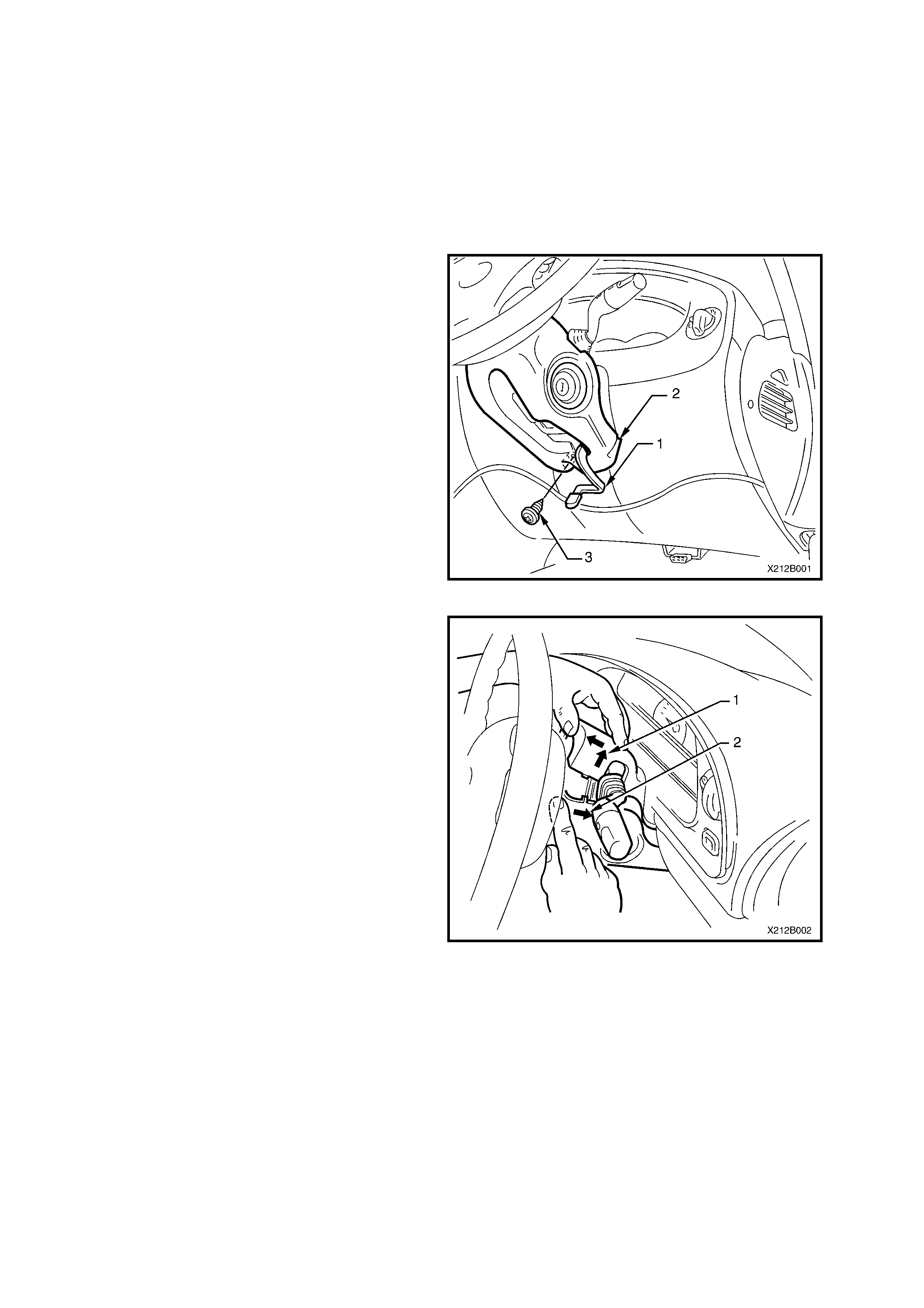
4. Release steering column height adjuster (1),
completely lower steering column and leave
lever in the release position.
5. Remove steering column lower cover (2) to
steering column attaching screw (3).
Figure 12C-1
6. Place a clean shop rag over and around
steering column upper cover. This prevents any
possibility of damage to cover should there be
any c ontact with lower edge of ins trument facia
while removing the cover.
7. Insert finger between the steering wheel and
the lower cover as shown in Fig. 12C-2 and
apply a small amount of pressure (pushing
towards instrument cluster).
8. Pull steering column upper cover (1) up and
toward steering wheel at the same time pulling
lower cover (2) down and away from steering
wheel. This will release the steering column
lower cover end retainers from mating slots in
upper cover (refer item 4, Fig 12C-1).
9 Remove upper cover by lifting upwards and
rearwards.
10. While feeding the key reader outer surround
from lower cover, remove cover.
Figure 12C-2
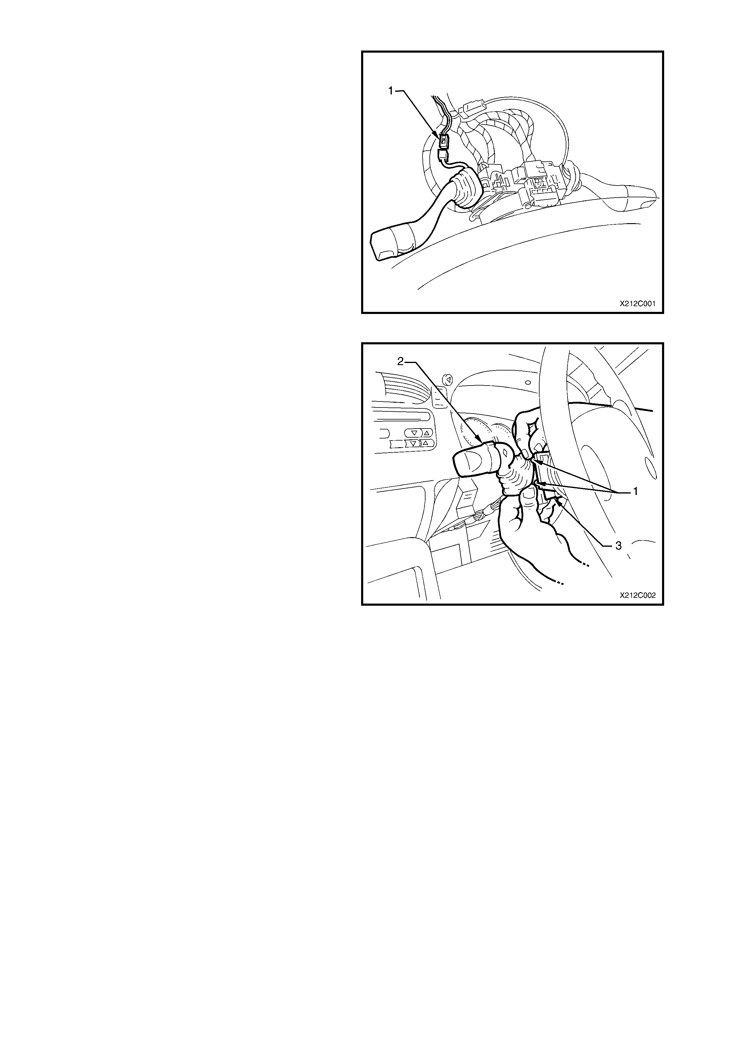
11. On vehicles with high series BCM, disconnect
the wiring harness connec tor to the wiper dwell
control switch harness connector (1) by
depressing harness retaining tang and pulling
connectors apart.
NOTE: The switch side of the harness connector
for the wiper dwell contr ol is wrapped in f oam as an
anti-rattle measure. Should the foam wrap be
damaged during the removal or test procedures, it
must be replaced with a suitable alternative.
Figure 12C-3
12. Depress r etaining tangs (1) on s witch ass embly
and withdraw wiper/washer switch (2) from
switch housing on steering column (3).
13. Lift up wiring harness connec tor retaining tangs
on either side of wiper/washer switch body and
pull connector from switch.
14. Remove switch.
Figure 12C-4
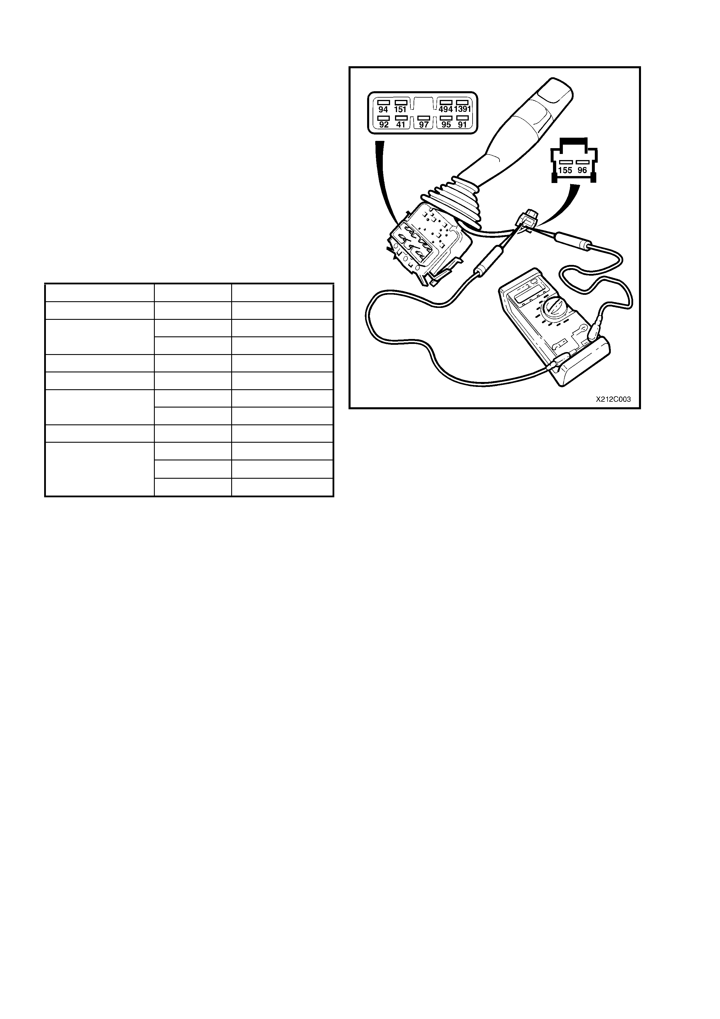
TESTING SWITCH
Using an ohmmeter connected to the various
switch terminals (refer to Fig. 12C-5), check the
operation of the wiper/washer switch as per the
following chart.
If continuity is not present at the specif ied term inals
for any given switch position, replace switch
assembly.
NOTE: With dwell control adjusted fully up,
multimeter should register approximately 4.2 to 6.5
kohms, and with control adjusted fully down,
approxim ately 476 to 889 ohms when connec ted to
terminals 155 and 96 on the wiper dwell harness
connector, refer to Fig. 12C-5.
Switch Position Terminals Indication if O.K.
Off 91 & 95 Continuity
91 & 95 Continuity
INT 97 & 41 Continuity
1 (Low Speed) 91 & 41 Continuity
2 (High Speed) 41 & 92 Continuity
94 & 41 Continuity Front Wash 151 & 494 Continuity
Rear Wipe 41 & 1391 Continuity
41 & 494 Continuity
41 & 1391 Continuity
Rear Wash
94 & 151 Continuity
Figure 12C-5
REINSTALL
Installation of the wiper/washer switch is the reverse
of the removal procedure, noting the following:
Check operation of all wiper/washer switch functions.
NOTE: The switch side of the harness connector f or
the wiper dwell control is wrapped in f oam as an anti-
rattle measure. Should the foam wrap be damaged
during the removal or test procedures, it must be
replaced with a suitable alternative.
IMPORTANT: If vehicle is equipped with SRS
AIRBAG, enable the system. Refer to
Section 12M SUPPLEMENTAL RESTRAINT
SYSTEM, in the VT Series I Service Information.