
Instrument Panel and Console Page 1A3–1
Page 1A3–1
Section 1A3
Instrument Panel and Console
ATTENTION
Before performing any service operation or other procedure described in this Section, refer to Section 00
Warnings, Cautions and Notes for correct workshop practices with regard to safety and/or property damage.
1 General Description ...............................................................................................................................4
1.1 General Information............................................................................................................................................... 4
1.2 Floor Console Components.................................................................................................................................. 5
Except Utility and Regular Cab............................................................................................................................. 5
Utility and Regular Cab ......................................................................................................................................... 6
1.3 Instrument Panel Components............................................................................................................................. 7
2 Service Operations – Floor Console ....................................................................................................9
2.1 Floor Console Cover Assembly............................................................................................................................ 9
Remove................................................................................................................................................................... 9
Disassemble......................................................................................................................................................... 10
Side Window Switch Assembly........................................................................................................................ 10
Floor Console Liner.......................................................................................................................................... 10
Auxiliary Switch Liner or Auxiliary Switch and Bezel........................................................................................ 10
Floor Console Storage Tray and Cup Holder ................................................................................................... 11
Mobile Phone Compartment............................................................................................................................. 12
Reassemble.......................................................................................................................................................... 12
Reinstall................................................................................................................................................................ 12
2.2 Instrument Panel Lower Extension Side Trim................................................................................................... 13
Remove................................................................................................................................................................. 13
Reinstall................................................................................................................................................................ 13
2.3 Floor Console Assembly..................................................................................................................................... 14
Remove................................................................................................................................................................. 14
Disassemble......................................................................................................................................................... 16
Armrest Assembly............................................................................................................................................ 16
Rear Air Outlet Housing Assembly or Rear Upper Compartment Assembly .................................................... 16
Floor Console Rear Compartment.................................................................................................................... 17
Floor Console Liner and Compartment Lamp Assembly or Lamp Opening Cover........................................... 18
Accessory Power Socket.................................................................................................................................. 18
Reassemble.......................................................................................................................................................... 19
Reinstall................................................................................................................................................................ 20
3 Service Operations – Instrument Panel .............................................................................................21
3.1 Instrument Panel Lower Trim Plate Assembly.................................................................................................. 21
Remove................................................................................................................................................................. 21
Driver Side ....................................................................................................................................................... 21
Passenger Side................................................................................................................................................ 22
Reinstall................................................................................................................................................................ 22
3.2 Instrument Panel Compartment Assembly........................................................................................................ 23
Remove................................................................................................................................................................. 23
Disassemble......................................................................................................................................................... 24
Reassemble.......................................................................................................................................................... 25
Reinstall................................................................................................................................................................ 25
Techline
Techline
Techline

Instrument Panel and Console Page 1A3–2
Page 1A3–2
3.3 Instrument Panel Compartment Lamp and Switch........................................................................................... 26
Remove................................................................................................................................................................. 26
Instrument Panel Compartment Lamp Switch.................................................................................................. 26
Instrument Panel Compartment Lamp.............................................................................................................. 26
Reinstall................................................................................................................................................................ 26
3.4 Instrument Panel Lower Trim Panel Assembly................................................................................................. 27
Remove................................................................................................................................................................. 27
Reinstall................................................................................................................................................................ 27
3.5 Instrument Panel Lower Trim Panel Retainer.................................................................................................... 28
Remove................................................................................................................................................................. 28
Reinstall................................................................................................................................................................ 28
3.6 Audio Head Unit................................................................................................................................................... 29
Remove................................................................................................................................................................. 29
Reinstall................................................................................................................................................................ 29
3.7 Instrument Panel Centre Trim Assembly (with Upper Centre Trim Panel)...................................................... 30
Remove................................................................................................................................................................. 30
Disassemble......................................................................................................................................................... 31
Reassemble.......................................................................................................................................................... 31
Reinstall................................................................................................................................................................ 31
3.8 Instrument Panel Centre Trim Assembly (with Instrument Panel Upper Compartment)............................... 32
Remove................................................................................................................................................................. 32
Disassemble......................................................................................................................................................... 33
Instrument Panel Upper Compartment............................................................................................................. 34
Reassemble.......................................................................................................................................................... 35
Reinstall................................................................................................................................................................ 35
3.9 Auxiliary Gauge Assembly.................................................................................................................................. 36
Remove................................................................................................................................................................. 36
Disassemble......................................................................................................................................................... 36
Reassemble.......................................................................................................................................................... 37
Reinstall................................................................................................................................................................ 37
3.10 Instrument Panel Centre Trim Assembly (with Auxiliary Gauge Assembly) .................................................. 38
Remove................................................................................................................................................................. 38
Disassemble......................................................................................................................................................... 39
Reassemble.......................................................................................................................................................... 40
Reinstall................................................................................................................................................................ 40
3.11 Instrument Panel Lower Compartment and Ashtray Assembly....................................................................... 41
Remove................................................................................................................................................................. 41
Reinstall................................................................................................................................................................ 41
3.12 Instrument Panel Lower Extension.................................................................................................................... 42
Remove................................................................................................................................................................. 42
Reinstall................................................................................................................................................................ 42
3.13 Manual HVAC Controller ..................................................................................................................................... 43
Remove................................................................................................................................................................. 43
Reinstall................................................................................................................................................................ 44
3.14 Audio Head Unit Housing and Bracket Assembly ............................................................................................ 45
Remove................................................................................................................................................................. 45
Reinstall................................................................................................................................................................ 46
3.15 Instrument Cluster Trim Assembly .................................................................................................................... 47
Remove................................................................................................................................................................. 47
Disassemble......................................................................................................................................................... 47
Instrument Panel Steering Column Opening Filler ........................................................................................... 47
3.16 In-car Air Temperature Sensor ........................................................................................................................... 48
Remove................................................................................................................................................................. 48
Reinstall................................................................................................................................................................ 48
3.17 Instrument Cluster............................................................................................................................................... 49
Remove................................................................................................................................................................. 49
Reinstall................................................................................................................................................................ 49
3.18 Headlamp Switch................................................................................................................................................. 50
Remove................................................................................................................................................................. 50
Reinstall................................................................................................................................................................ 50

Instrument Panel and Console Page 1A3–3
Page 1A3–3
3.19 Trip Computer Switch.......................................................................................................................................... 51
Remove................................................................................................................................................................. 51
Reinstall................................................................................................................................................................ 51
3.20 Instrument Panel Outer Cover............................................................................................................................ 52
Remove................................................................................................................................................................. 52
Reinstall................................................................................................................................................................ 52
3.21 Windshield Defroster Grille................................................................................................................................. 53
Remove................................................................................................................................................................. 53
Reinstall................................................................................................................................................................ 53
3.22 Remote Key Receiver and Headlamp Auto Control / Sunload Sensor............................................................ 54
Remove................................................................................................................................................................. 54
Reinstall................................................................................................................................................................ 54
3.23 Instrument Panel Speaker................................................................................................................................... 55
Remove................................................................................................................................................................. 55
Reinstall................................................................................................................................................................ 55
3.24 Instrument Panel Pad Assembly ........................................................................................................................ 56
Remove................................................................................................................................................................. 56
Disassemble......................................................................................................................................................... 58
Reassemble.......................................................................................................................................................... 59
Reinstall................................................................................................................................................................ 59
3.25 Instrument Panel Brackets and Braces ............................................................................................................. 61
Instrument Panel Compartment Bracket ........................................................................................................... 61
Remove............................................................................................................................................................ 61
Reinstall ........................................................................................................................................................... 61
Instrument Panel Lower Bracket........................................................................................................................ 62
Remove............................................................................................................................................................ 62
Reinstall ........................................................................................................................................................... 62
Instrument Panel Outer Upper Bracket.............................................................................................................. 63
Remove............................................................................................................................................................ 63
Reinstall ........................................................................................................................................................... 63
Lower Audio Head Unit Bracket ......................................................................................................................... 64
Remove............................................................................................................................................................ 64
Reinstall ........................................................................................................................................................... 64
Steering Column Bracket Inner Brace ............................................................................................................... 65
Remove............................................................................................................................................................ 65
Reinstall ........................................................................................................................................................... 65
Steering Column Bracket Outer Brace............................................................................................................... 66
Remove............................................................................................................................................................ 66
Reinstall ........................................................................................................................................................... 66
4 Torque Wrench Specifications............................................................................................................67
5 Special Tools ........................................................................................................................................69

Instrument Panel and Console Page 1A3–4
Page 1A3–4
1 General Description
1.1 General Information
The instrument panel houses the instrum ent cluster within a hood, while the centre fascia, which integrates with the floor
console, houses components such as the double DIN sized audio system, controls for manual or electronic climate
control, centre vent outlets and cup-holders for Level 2 and 3 vehicles.
The soft-touch instrument panel pad is attached to a dash panel carrier. Several br ackets and braces form the backbone
of the instrument panel pad and carrier assembly and support other components such as the instrument panel inflatable
restraint (if fitted) and fuse panel.
All models include an instrum ent panel lower trim plate assembly, fitted between the instrument and dash panels on each
side of the vehicle. Sound-deaden ing foam is applied to the plate which provides an effective reduction in noise
transmittance. Where fitted, the stepwell lamps are mounted to the plate assembly.
The large instrument panel compartment is illuminated and can be locked with a unique key. A large lower trim panel is
fitted on the driver’s side which can be opened to provide access to the instrument panel fuse and relay panel assem bl y.
Two storage compartments are provided, one on the instrument panel at the front of the console and the other at the rear
of the console (except Utility and Regular Cab). As an option, an as htray and cigar lighter assembly replaces the storage
compartments.
A large storage compartment with armrest is incorporated in the floor console. An accessory power socket is provided
within the storage compartment providing a 12-volt power supply when the ignition switch is in ACC or ON positions.
Depending on model level or options fitted, the console ma y also include power side window switches, a cup-holder for
Level 1 vehicles, mobile phone holder for Level 2 and 3 vehicles and au xiliary switches for various functions.
An air duct is fitted to the underside of the floor console on all models exc ept Utility and Regular Cab, which provi des
ventilation to the rear seat passeng ers throu gh the rear air outlet housing at the end of the console. For Utility and
Regular Cab vehicles, a stora ge bin is provided at the rear of the consol e in place of the rear air outlet housing.
A latch clip is fitted to the floor console armrest assembly on vehicles fitted with leather trims.
Refer to Figure 1A3 – 1 and Figure 1A3 – 2 for an illustration of the console components and F ig ure 1A3 – 3 for the
instrument panel components. Note that diagrams do not show switches or electrical components.
Instrument Panel and Console Page 1A3–5
Page 1A3–5
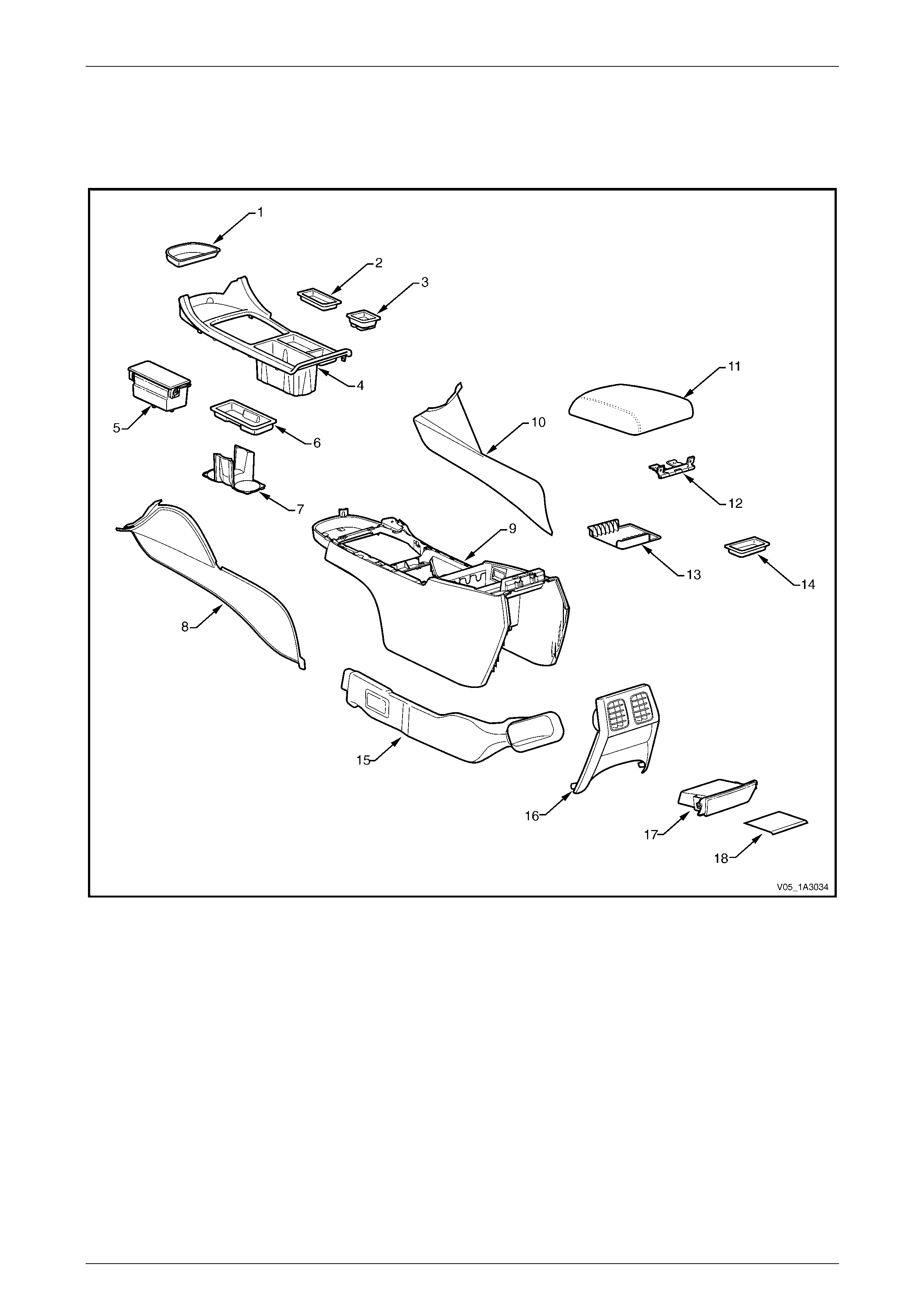
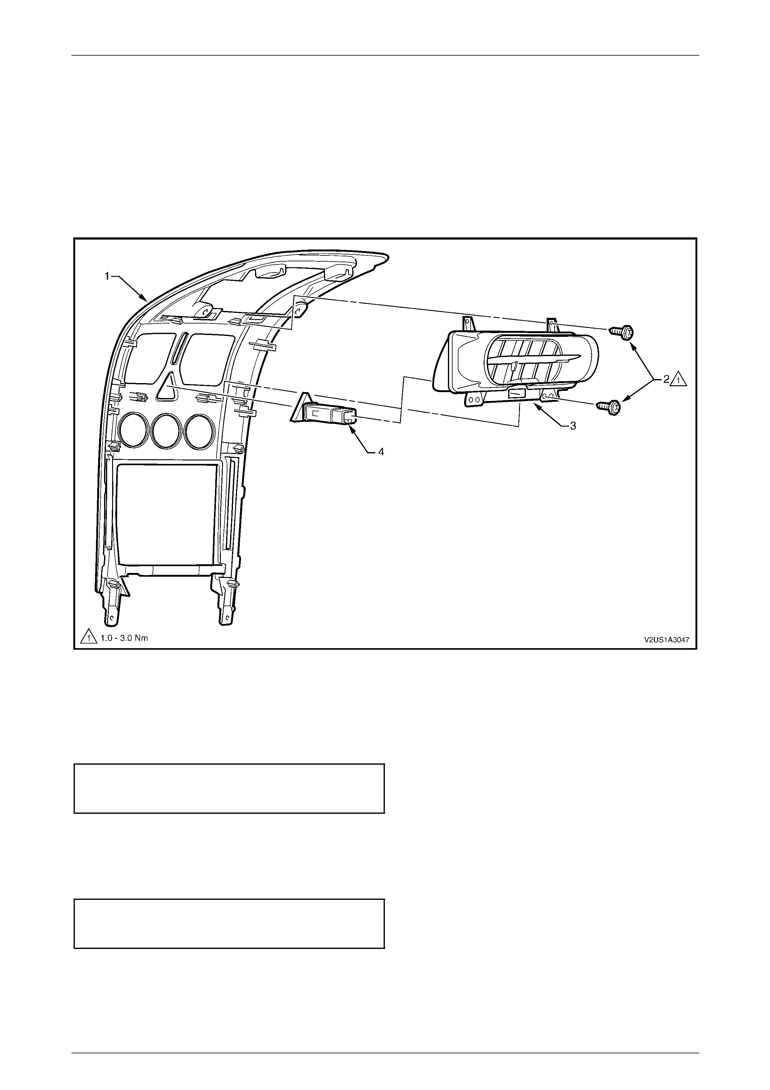
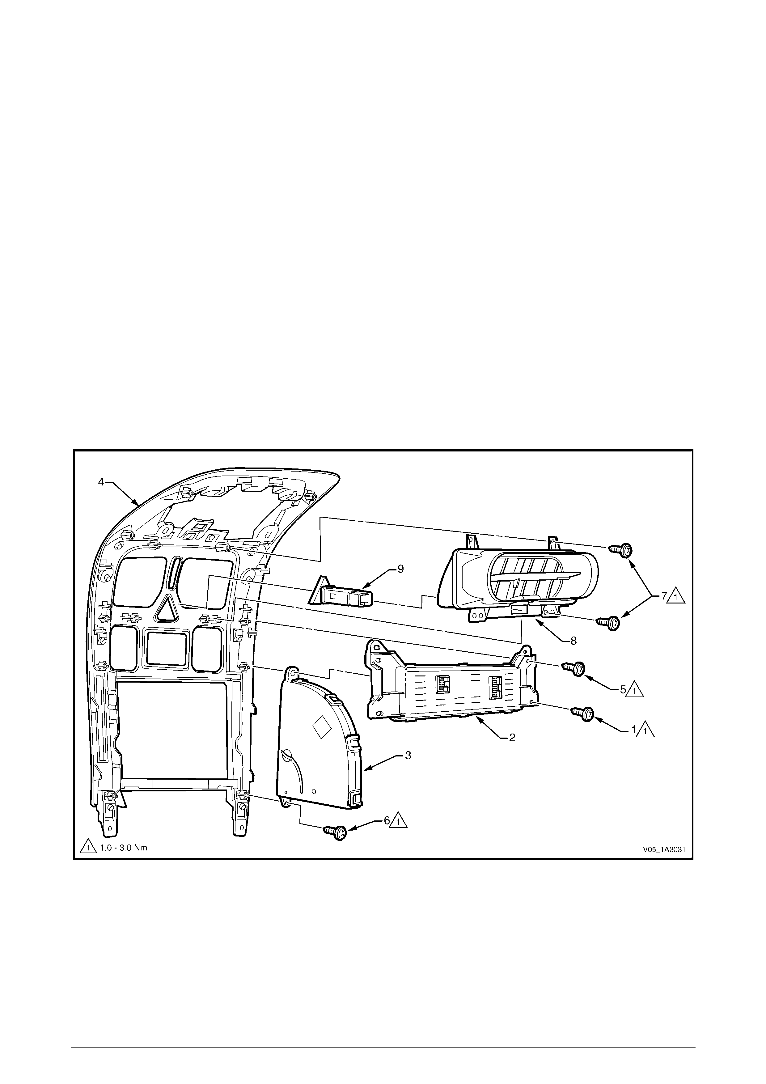
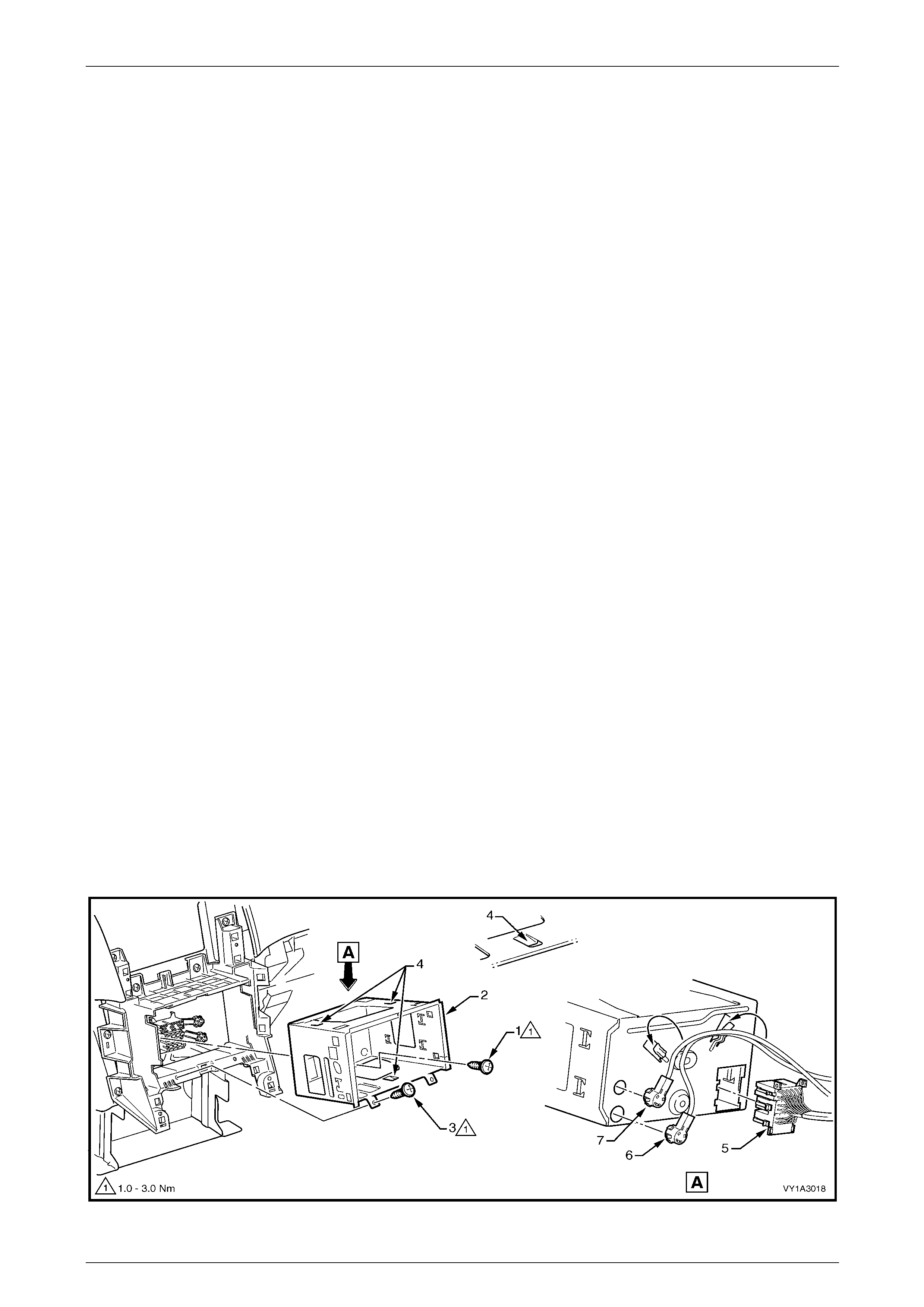
1.2 Floor Console Components
Except Utility and Regular Cab
Figure 1A3 – 1
Legend
1 Floor Console Front Compartment Liner
2 Floor Console Liner
3 Auxiliary Switch Liner or Bezel
4 Floor Console Cover
5 Mobile Phone Compartment, Level 2 and 3
6 Floor Console Storage Tray, Where Fitted
7 Cup Holder, Level 1
8 Instrument Panel Lower Extension Side Trim, Left-hand
9 Floor Console
10 Instrument Panel Lower Extension Side Trim, Right-hand
11 Armrest Assembly
12 Floor Console Compartment Armrest Hinge
13 Floor Console Compartment Liner
14 Floor Console Compartment Upper Liner
15 Floor Console Rear Air Duct
16 Floor Console Rear Air Outlet Housing Assembly
17 Floor Console Rear Compartment Assembly
18 Floor Console Rear Compartment Liner
Instrument Panel and Console Page 1A3–6
Page 1A3–6
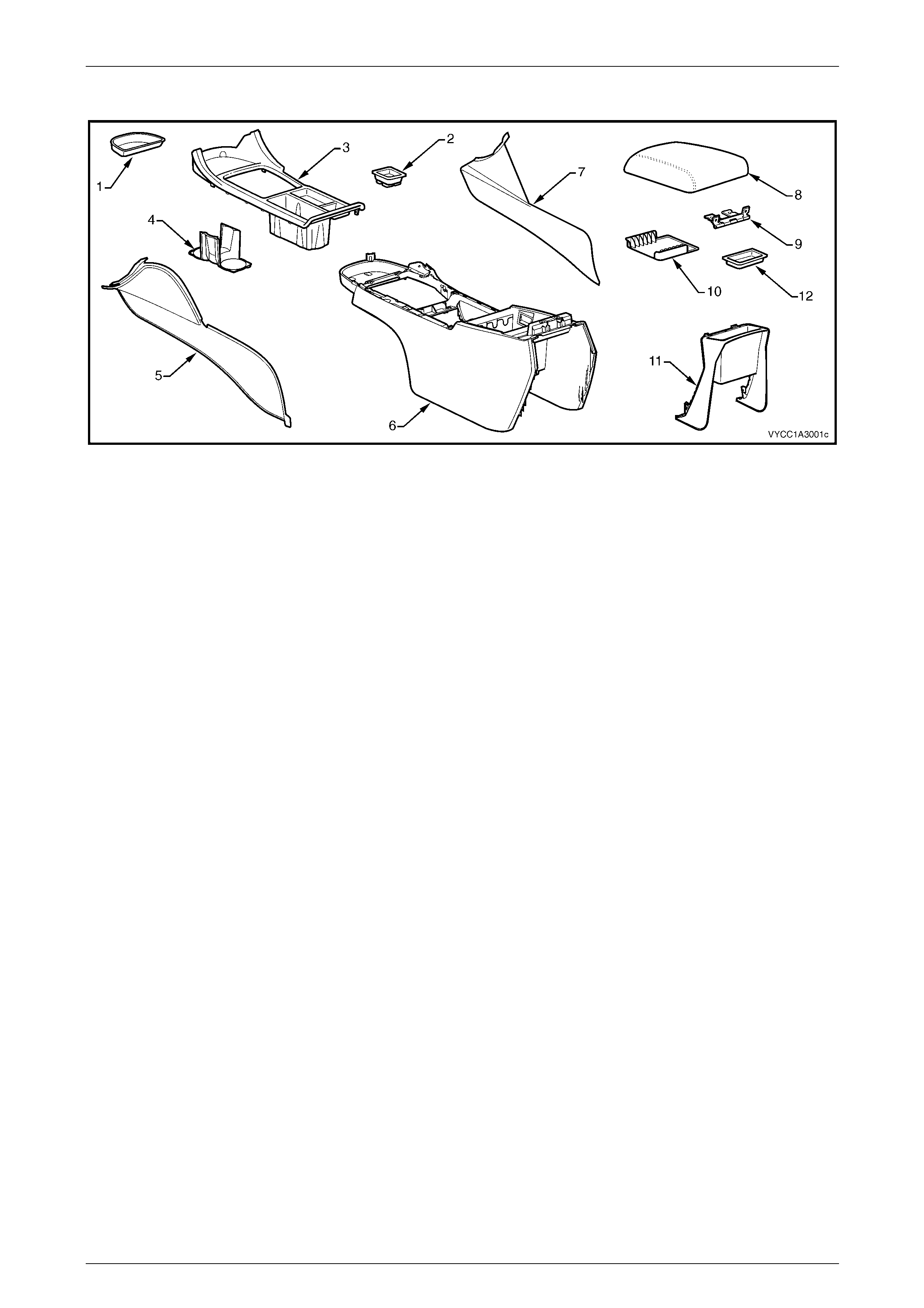
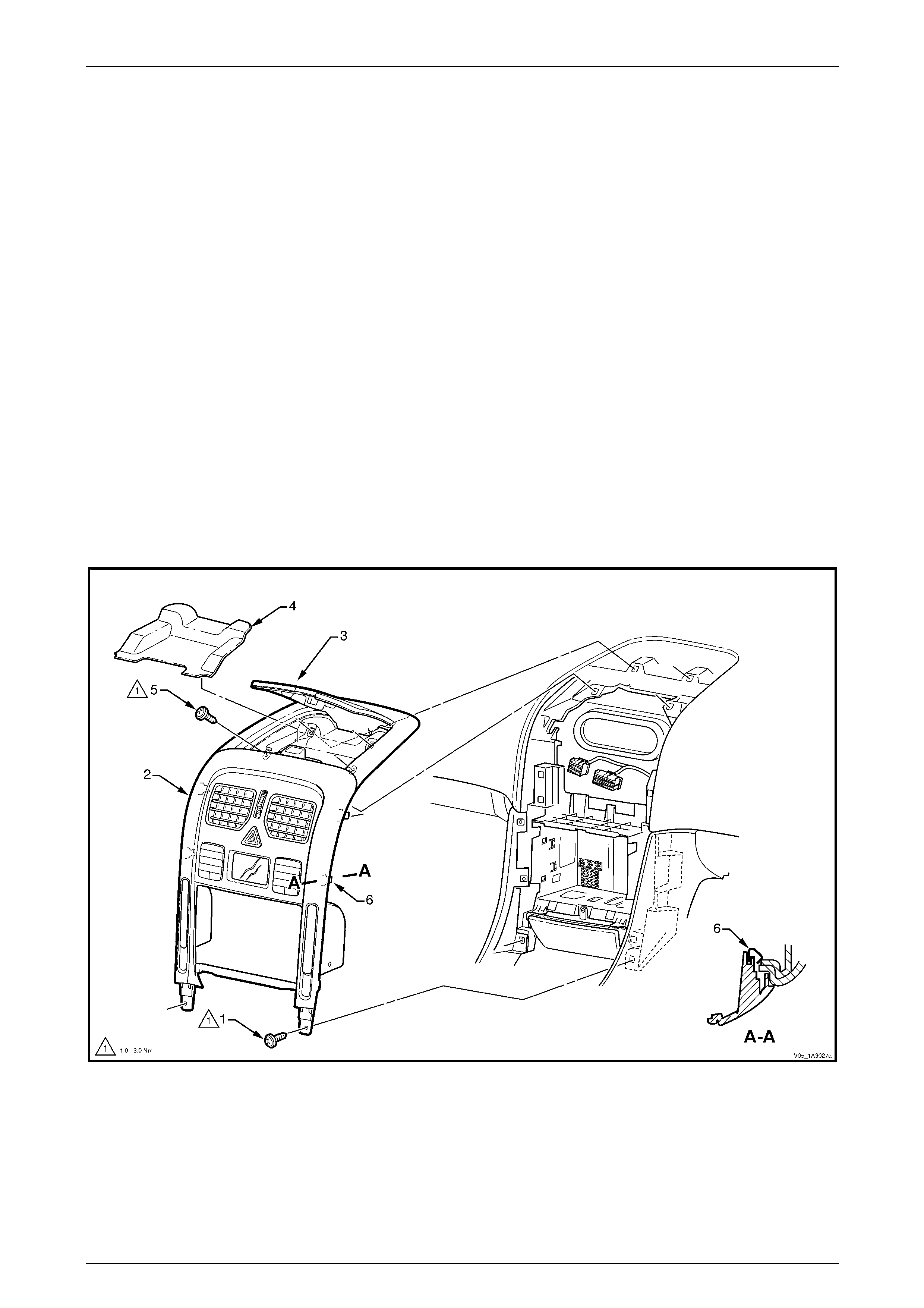
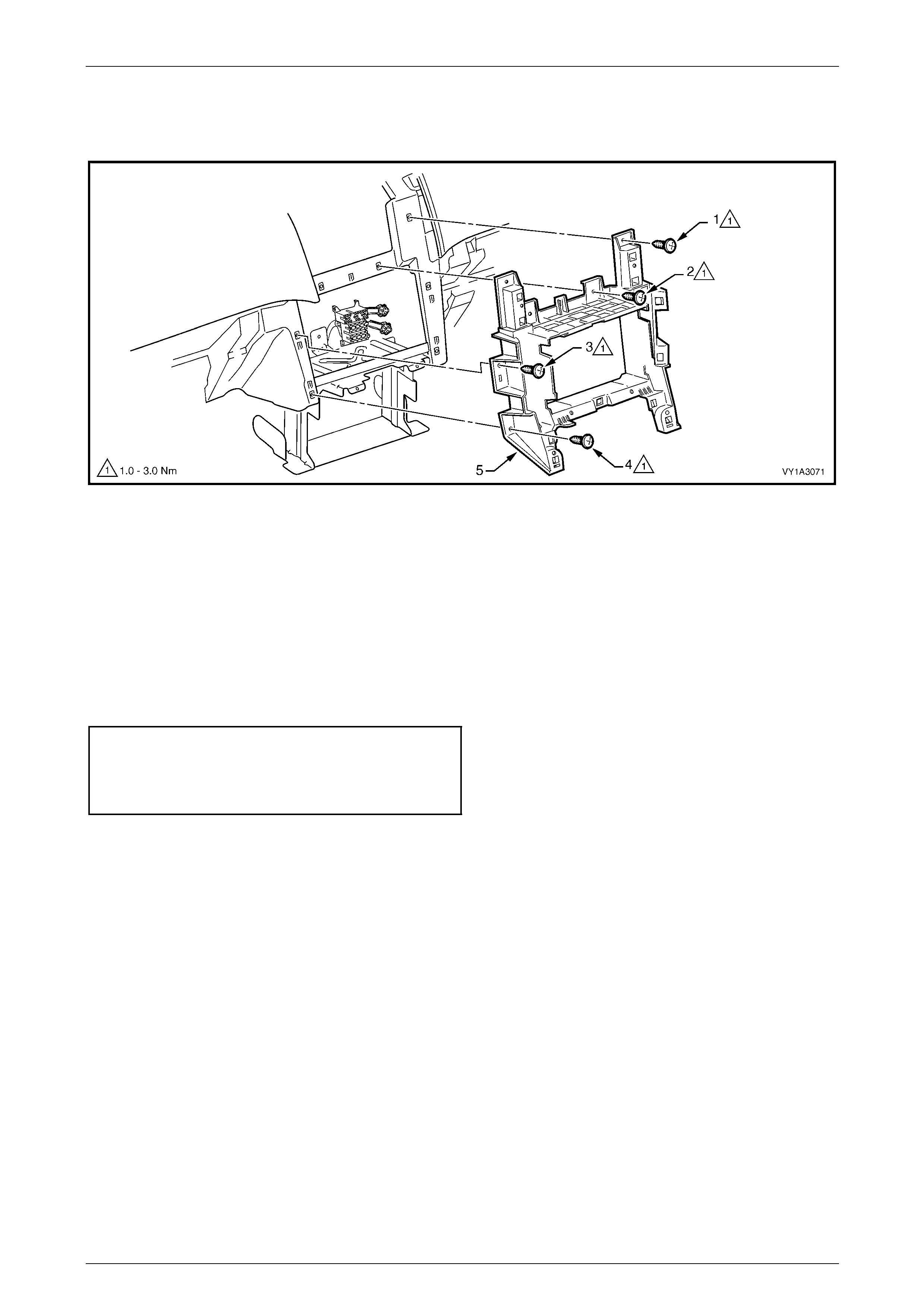
Utility and Regular Cab
Figure 1A3 – 2
Legend
1 Floor Console Front Compartment Liner
2 Auxiliary Switch Liner or Bezel
3 Floor Console Cover
4 Cup Holder
5 Instrument Panel Lower Extension Side Trim, Left-hand
6 Floor Console
7 Instrument Panel Lower Extension Side Trim, Right-hand
8 Armrest Assembly
9 Floor Console Compartment Armrest Hinge
10 Floor Console Compartment Liner
11 Floor Console Rear Upper Compartment Assembly
12 Floor Console Compartment Upper Liner
Instrument Panel and Console Page 1A3–7
Page 1A3–7
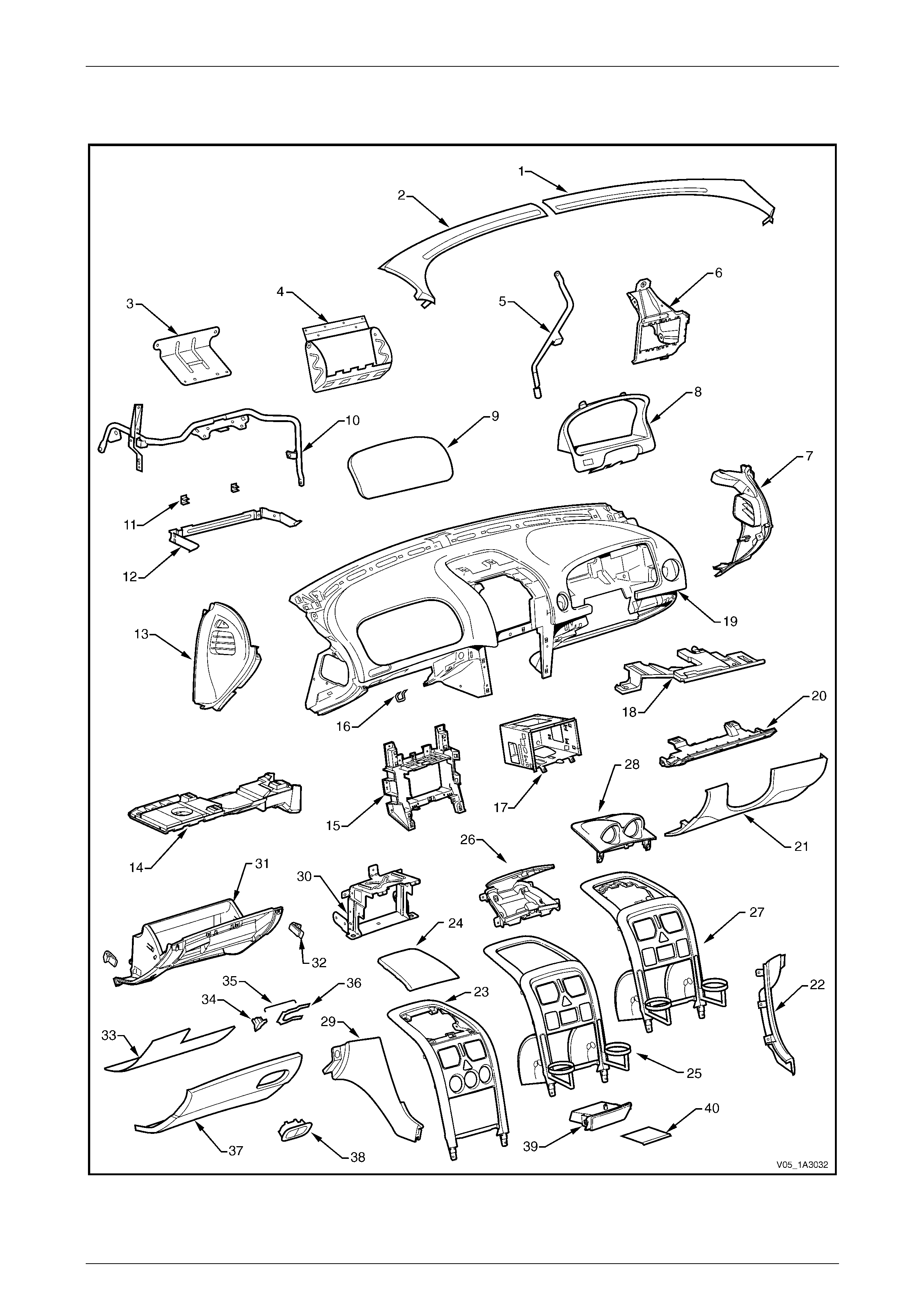
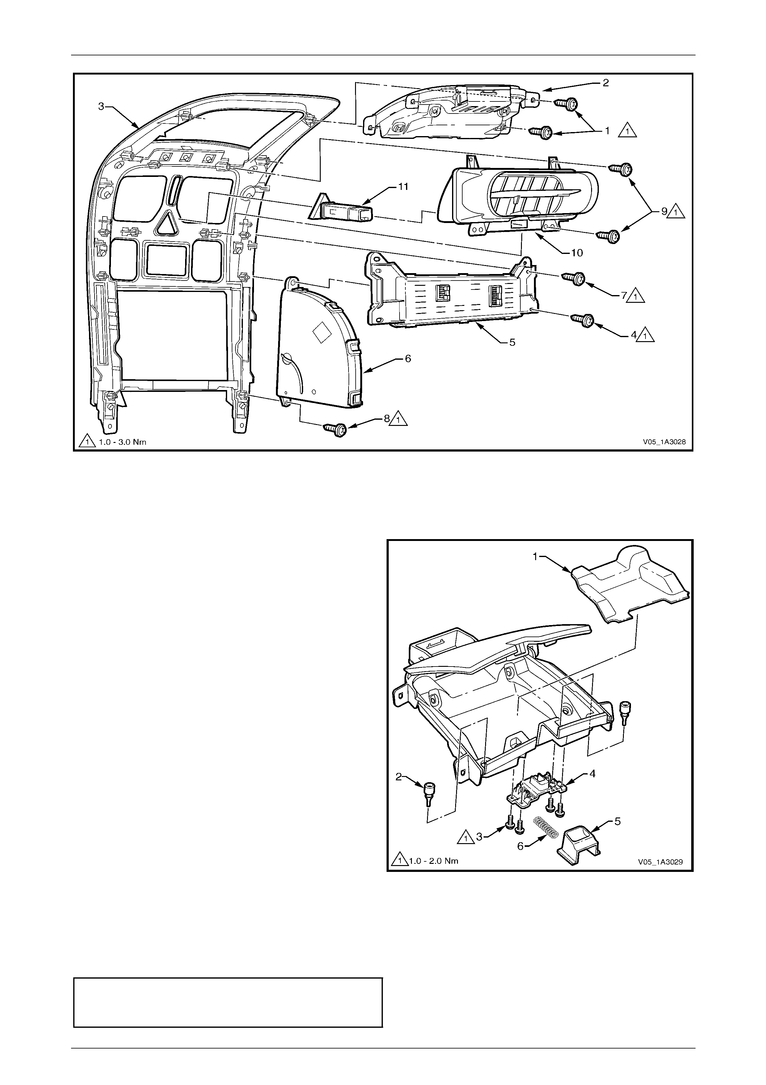
1.3 Instrument Panel Components
Figure 1A3 – 3

Instrument Panel and Console Page 1A3–8
Page 1A3–8
Legend
1 Windshield Defroster Grille, Right-hand
2 Windshield Defroster Grille, Left-hand
3 Instrument Panel Outer Upper Bracket *
4 Instrument Panel Inflatable Restraint Bracket
5 Steering Column Bracket Inner Brace
6 Steering Column Bracket Outer Brace
7 Instrument Panel Outer Cover, Right-hand
8 Instrument Cluster Trim Assembly
9 Instrument Panel Inflatable Restraint Opening Trim Cover
10 Instrument Panel Lower Bracket
11 Instrument Panel Compartment Hinge
12 Instrument Panel Compartment Bracket
13 Instrument Panel Outer Cover, Left-hand
14 Instrument Panel Lower Trim Plate Assembly, Left-hand
15 Audio Head Unit Bracket Assembly
16 Instrument Panel Compartment Lock Striker
17 Audio Head Unit Housing
18 Instrument Panel Lower Trim Plate Assembly, Right-hand
19 Instrument Panel Pad Assembly
20 Instrument Panel Lower Trim Panel Retainer
21 Instrument Panel Lower Trim Panel Assembly
22 Instrument Panel Lower Extension, Right-hand
23 Instrument Panel Centre Trim Assembly (with upper centre
trim panel)
24 Instrument Panel Upper Centre Trim Panel
25 Instrument Panel Centre Trim Assembly (with instrument
panel upper compartment)
26 Instrument Panel Upper Compartment
27 Instrument Panel Centre Trim Assembly (with instrument
panel gauge assembly)
28 Instrument Panel Gauge Assembly
29 Instrument Panel Lower Extension, Left-hand
30 Lower Audio Head Unit Bracket
31 Instrument Panel Compartment
32 Instrument Panel Compartment Bumper Stop
33 Instrument Panel Compartment Liner
34 Instrument Panel Compartment Latch Assembly
35 Instrument Panel Compartment Latch Rod
36 Instrument Panel Compartment Latch Retainer
37 Instrument Panel Compartment Door
38 Instrument Panel Compartment Latch Actuator
39 Instrument Panel Lower Compartment or Ashtray Assembly
40 Instrument Panel Lower Compartment Liner
* Vehicles without an instrument panel i nflatable restraint module
Instrument Panel and Console Page 1A3–9
Page 1A3–9
2 Service Operations – Floor
Console
2.1 Floor Console Cover Assembly
LT Section No. — 14–900
Remove
1 Remove the following components, as required:
a Navigation remote control assembly, refer to Section 12L Navigation System.
b Navigation escutcheon, refer to Section 12L Navigation System.
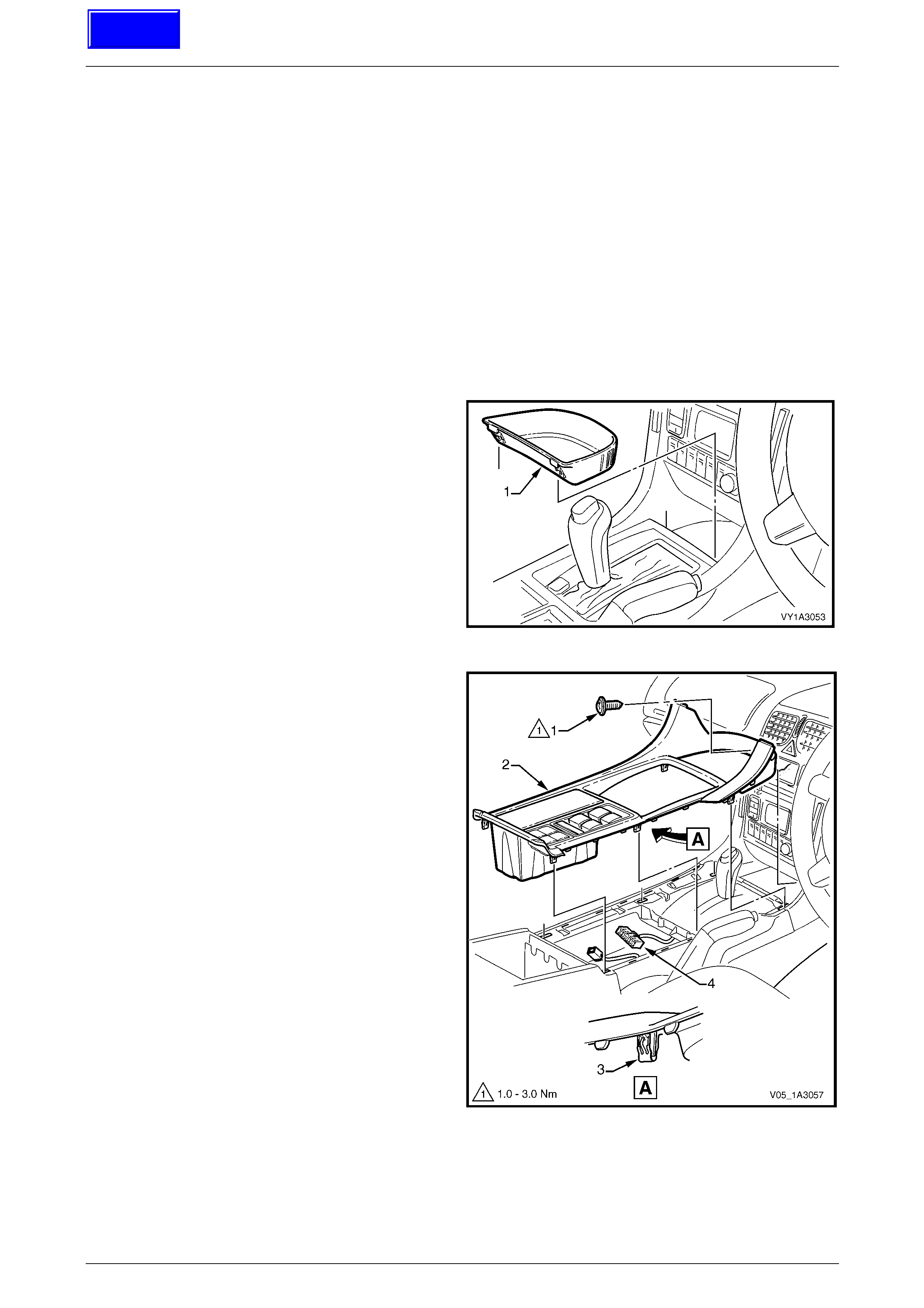
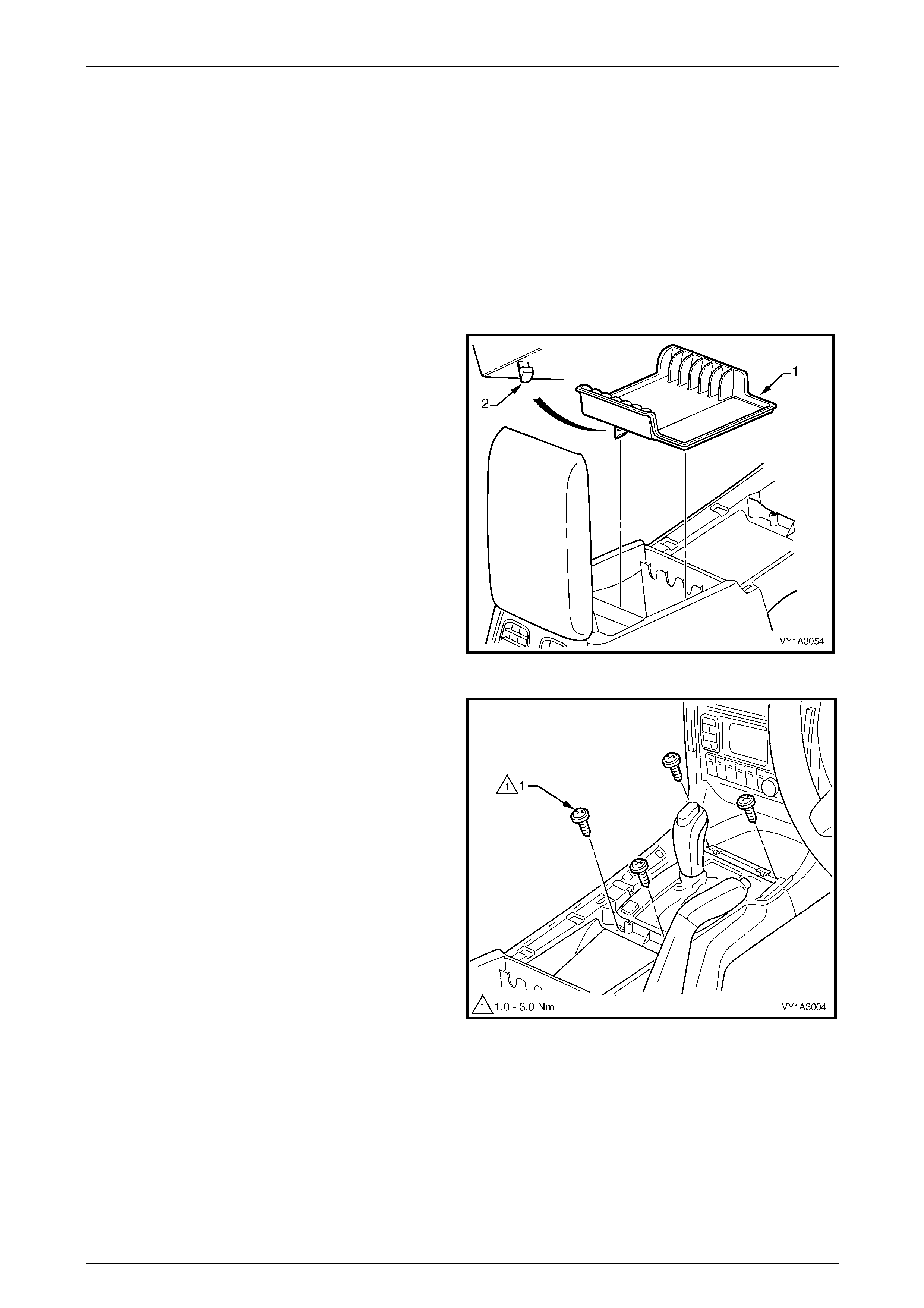
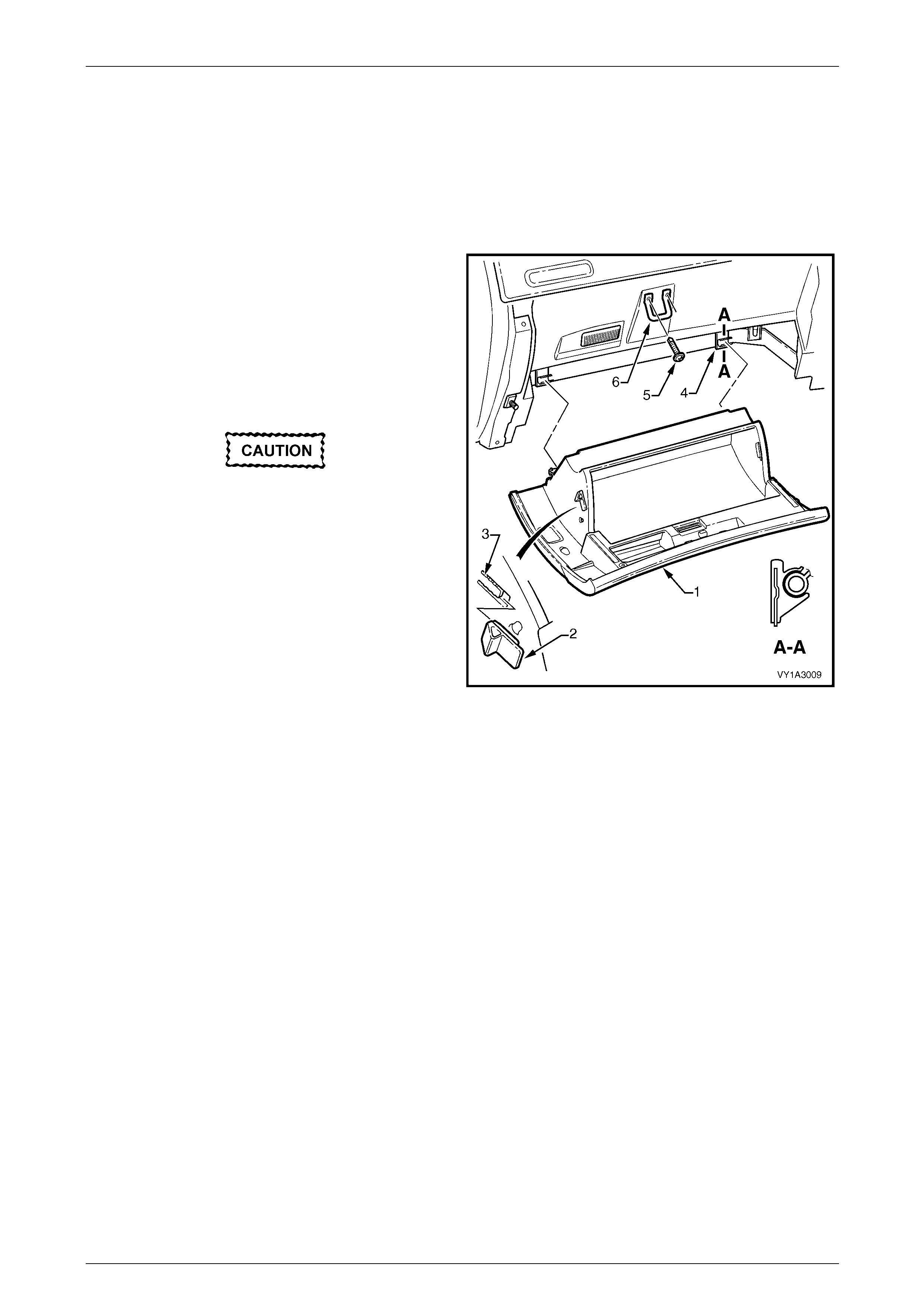
2 Remove the floor console front compartment liner (1)
by lifting upwards to disengage it from the console
cover.
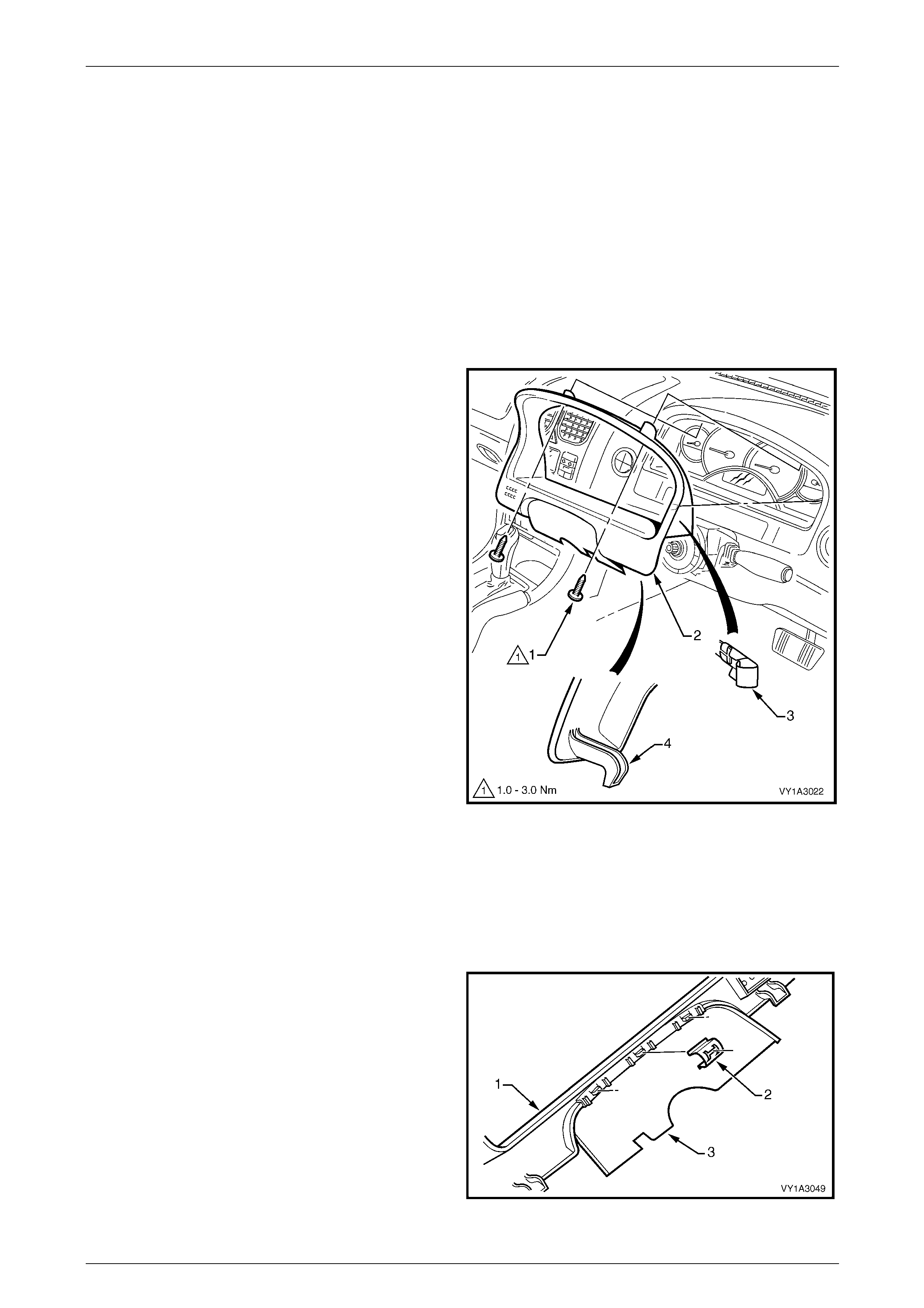
Figure 1A3 – 4
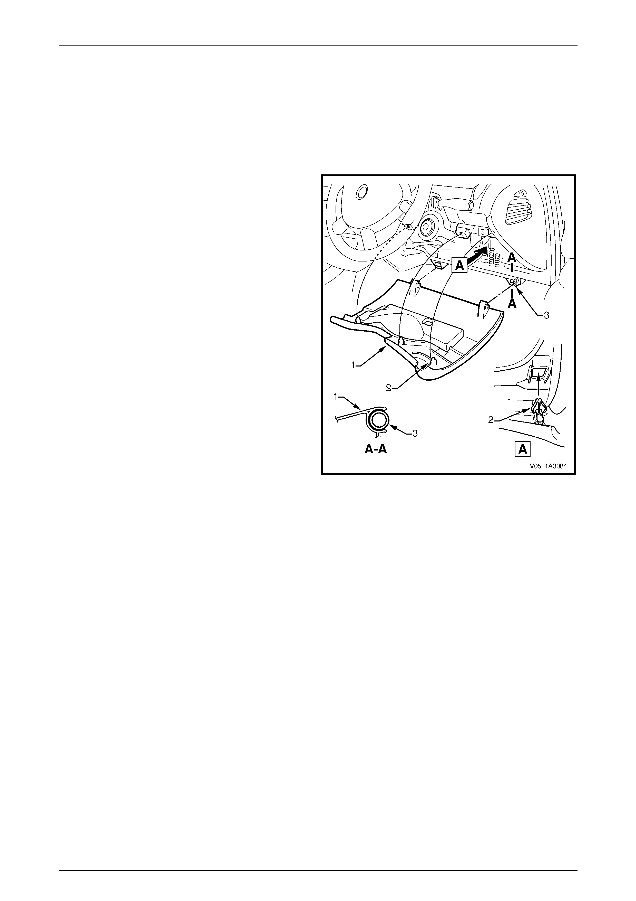
3 Remove the screw (1) slightly to the right of centre,
attaching the floor console cover assembly (2).
NOTE
Vehicles fitted with Navigation System do not
have this screw.
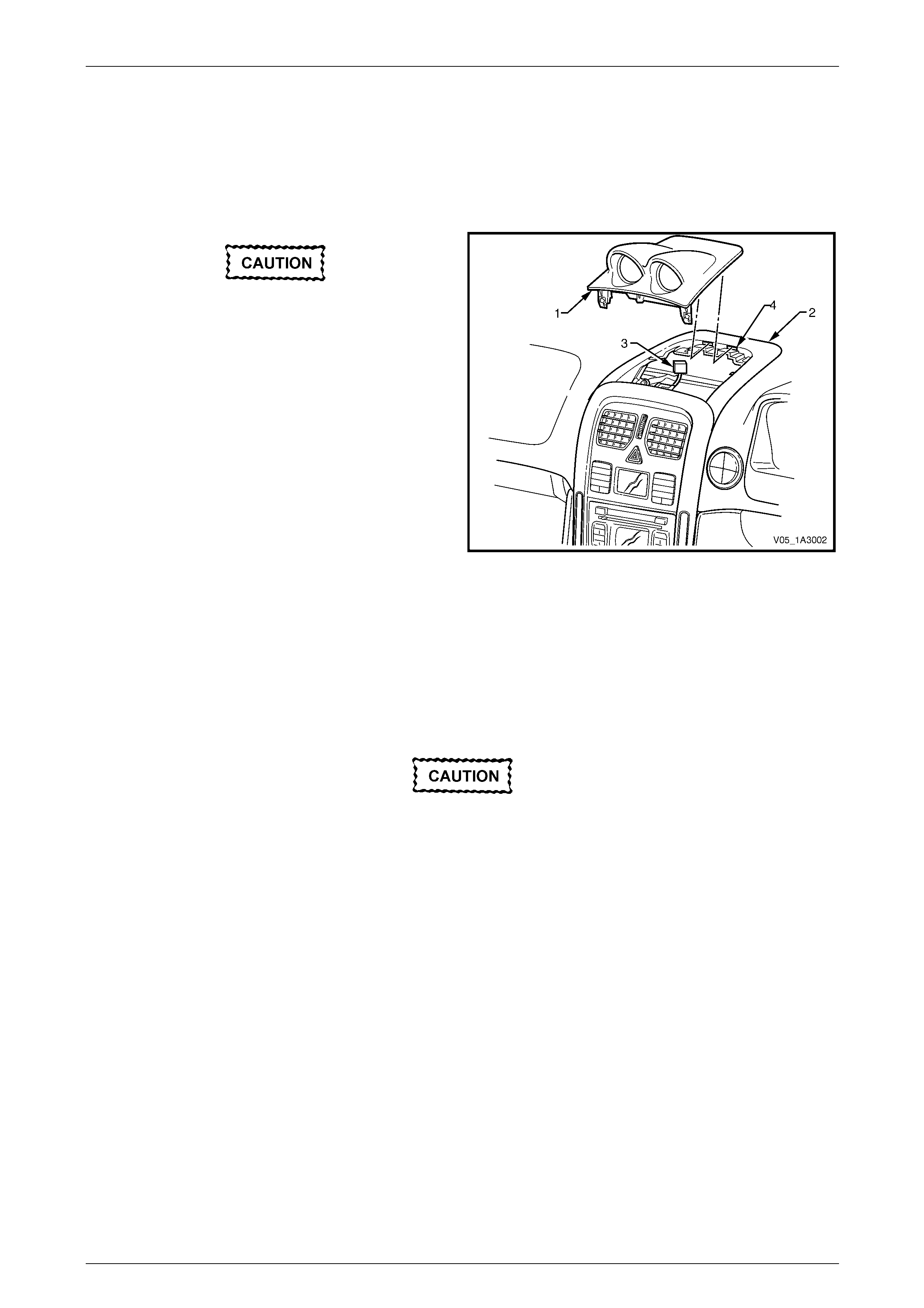
4 Prise the cover assembly from the floor console, six
places (3).
5 Lift the cover assembly up from the rear, disconnect
the wiring connector(s) (4) from the side window
switch assembly and any au xiliary switches if fitted,
and remove the cover assembly.
NOTE
Take note of which coloured auxiliary switch
connector goes to corresponding switch for
reinstallation.
Figure 1A3 – 5
Techline
Instrument Panel and Console Page 1A3–10
Page 1A3–10
Disassemble
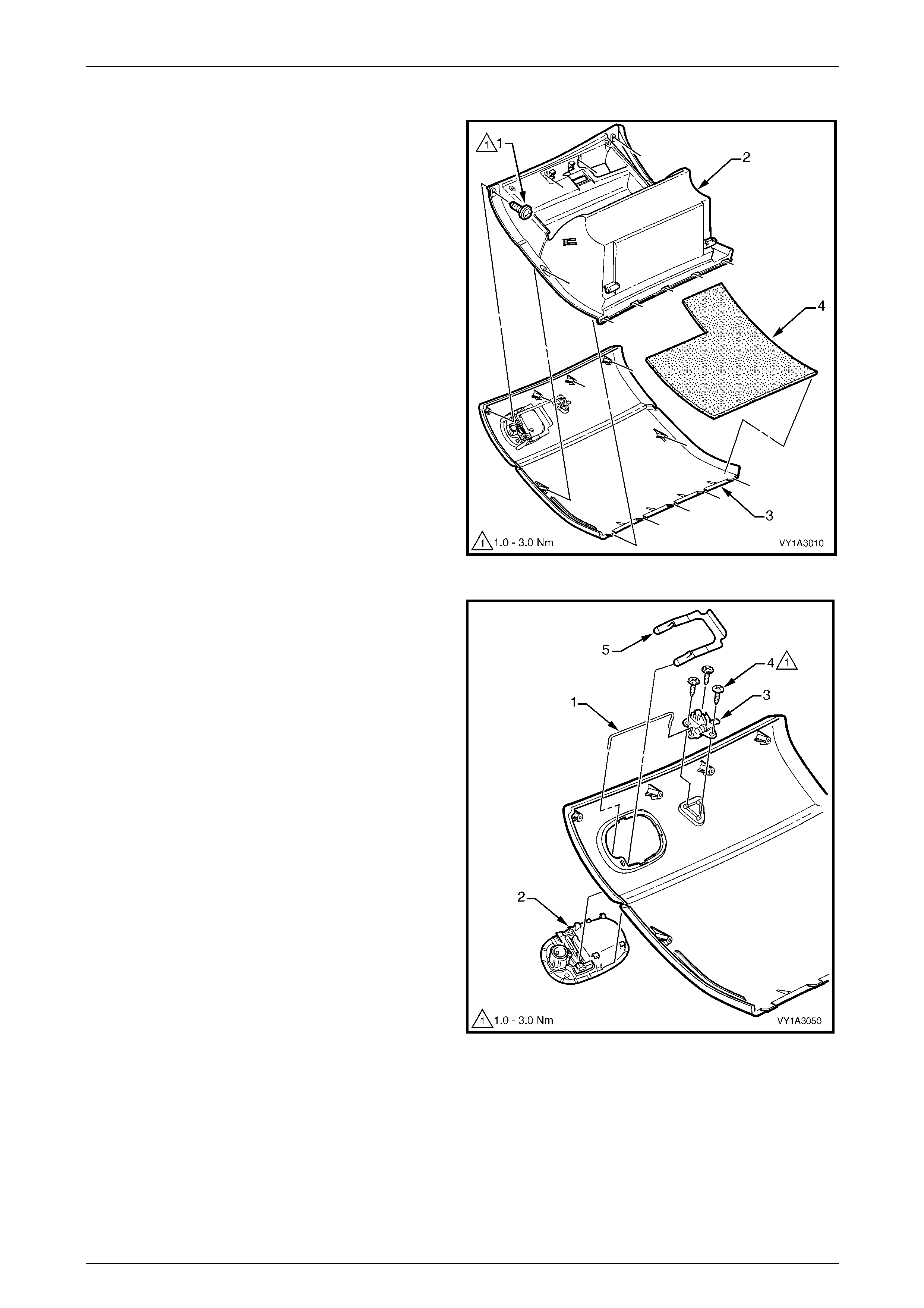
Disassemble the components from the underside of the console cover, where fitted.
Side Window Switch Assembly
1 Depress the retaining tabs, six places, securing the
side window switch assembly (1).
2 Remove the switch assembly from the console cover.
Figure 1A3 – 6
Floor Console Liner
1 Remove the floor console liner (1), by disengaging the
retaining lug securing the liner to the cover assembly.
Figure 1A3 – 7
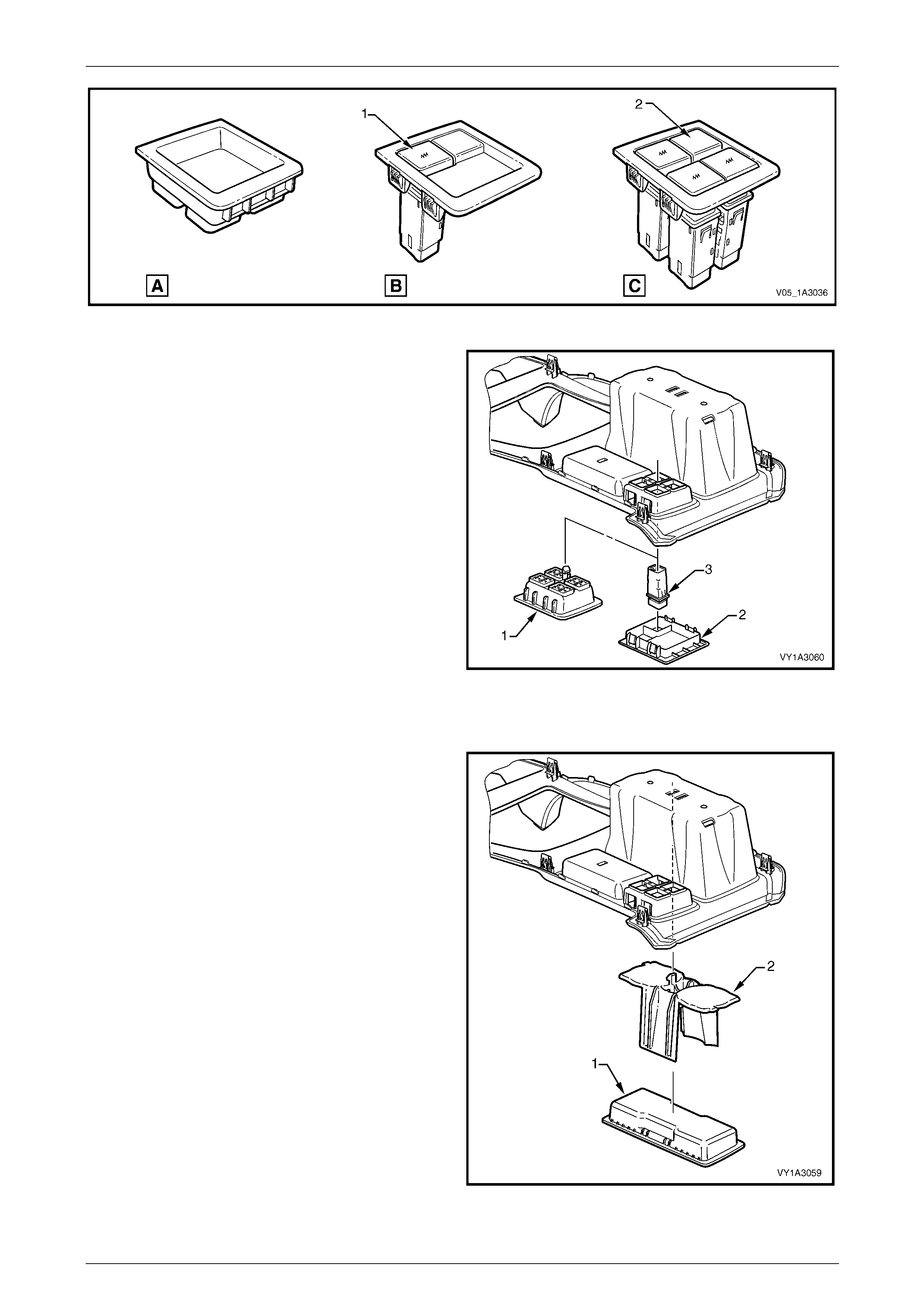
Auxiliary Switch Liner or Auxiliary Switch and Bezel
1 Depending on options fitted, the location shown in Figure 1A3 – 8 will be fitted with either:
a An auxiliary s witch liner (A) where no auxiliary switches are fitted,
b A one cavity auxiliary switch bezel (B) when fitted with one switch (1) only, or
c A four cavity auxiliary switch bezel (C) when fitted with two or more switches.
In this configuration, empty cavities are fitted with switch blank(s) (2).
Instrument Panel and Console Page 1A3–11
Page 1A3–11
Figure 1A3 – 8
2 Auxiliary switch liner (1):
a Remove the liner by disengagi ng the retaining
lug securing the liner to the cover assembly.
3 Auxiliary switch bezel (2, one or four cavity type):
a Depress the four tabs securing the auxi liary
switch bezel to the cover assembly and remove.
b Depress the two tabs securing the s witch(s) or
blanks to the cover assembly and remove the
switch or blank.
NOTE
The switches can only fit in the one location as
shown in Figure 1A3 – 8.
Figure 1A3 – 9
Floor Console Storage Tray and Cup Holder
1 Lift out the floor console storage tray (1) if fitted, and
remove.
2 Remove the cup holder (2) by disengaging the
retaining lug securing the liner to the cover assembly.
Figure 1A3 – 10
Instrument Panel and Console Page 1A3–12
Page 1A3–12
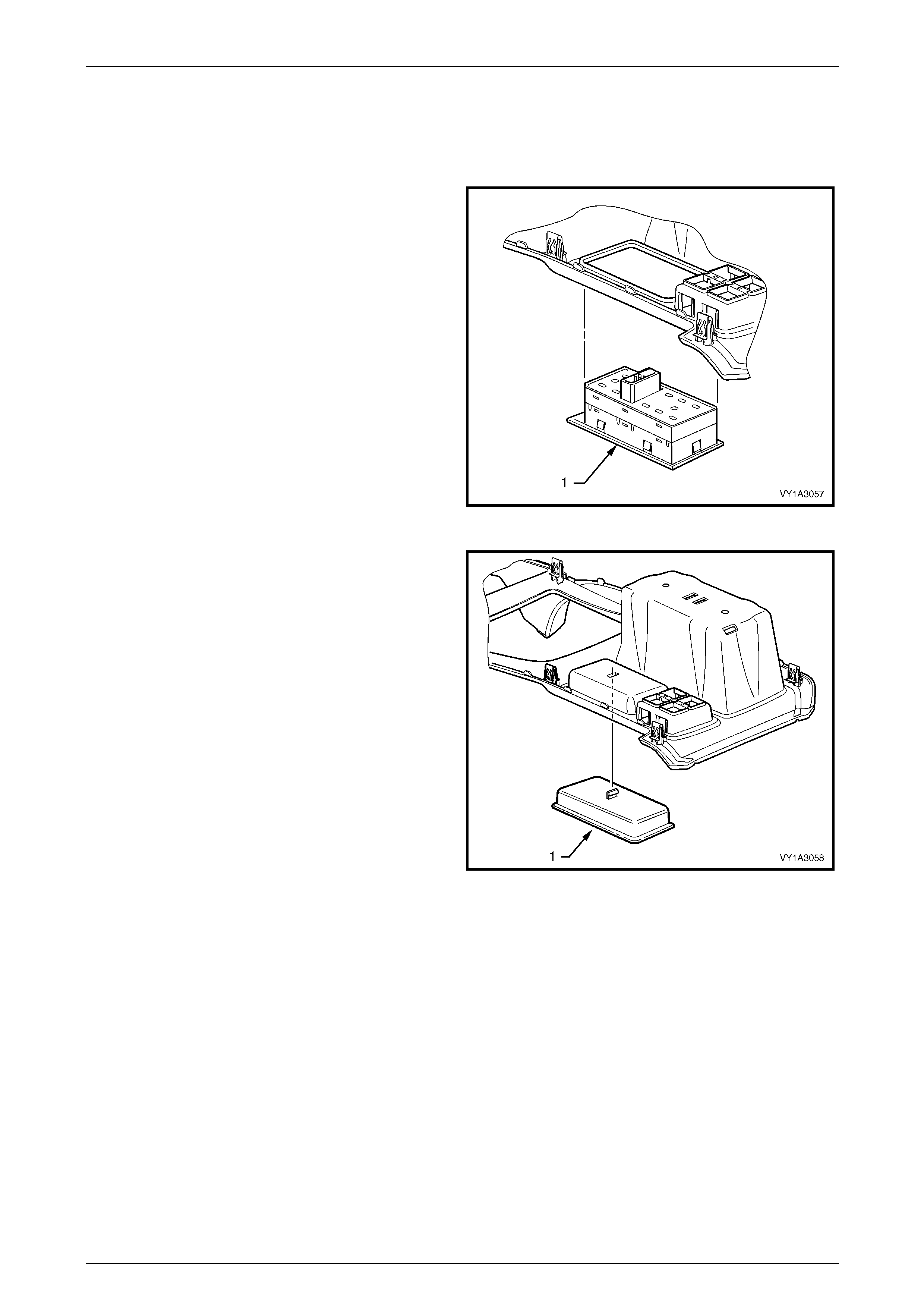
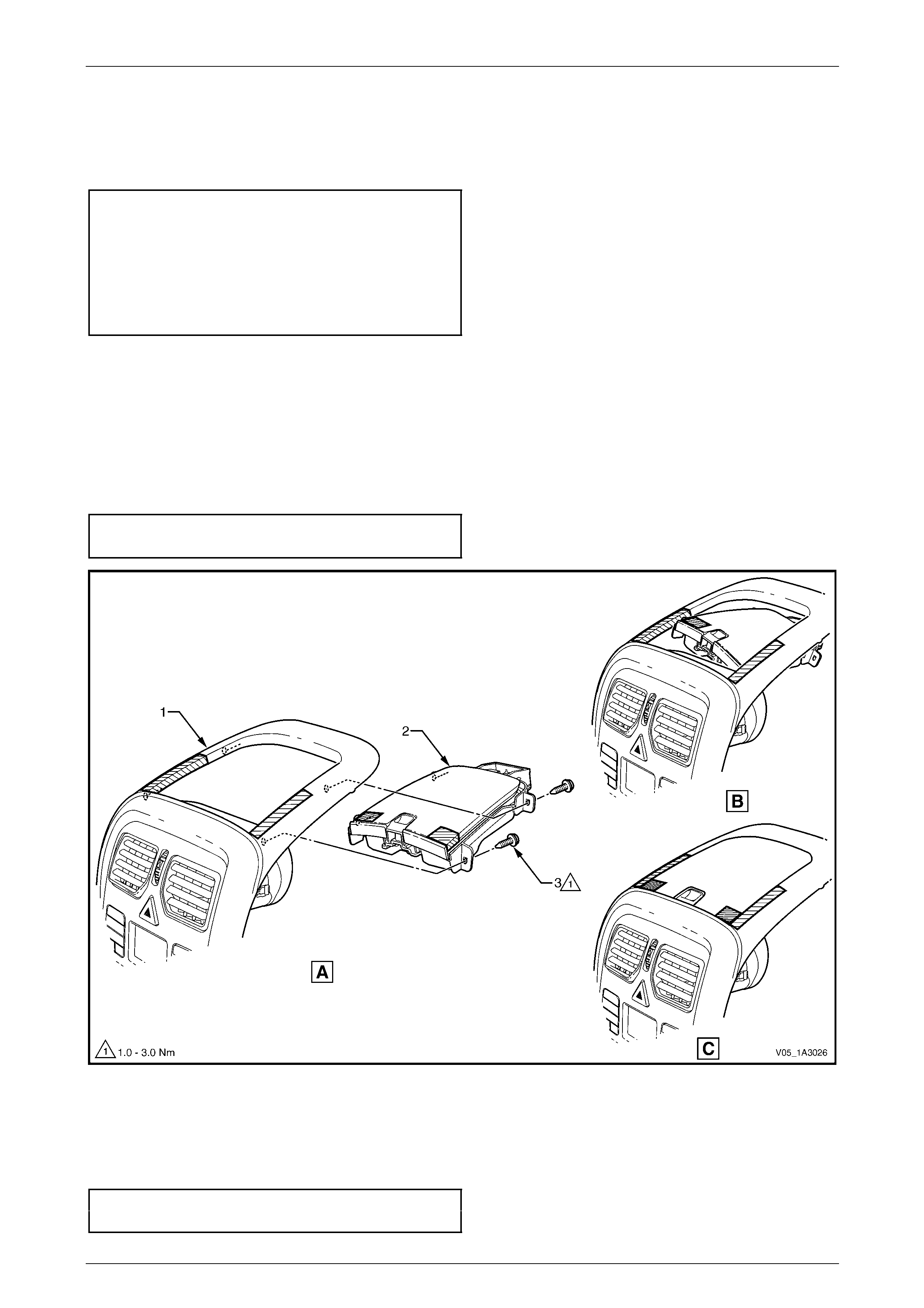
Mobile Phone Compartment
1 Remove the two screws (1) attaching the mo bile
phone compartment assemb ly (2) to the floor console
cover.
2 Remove the compartment assembly from the console
cover.
Figure 1A3 – 11
Reassemble
Reassembly of the floor console assembly is the reverse of the disassembly procedure, noting the following:
1 Ensure correct orientation of the console components.
2 Tighten the attaching scre ws to the specified torque.
Mobile phone compartment assembly
attaching screw torque specification...........1.0 – 3.0 Nm
Reinstall
Reinstallation of the floor console cover assembly is the reverse of the removal procedu r e, noting the following:
1 If the vehicle is fitted with Navigation System, modify the front section of the floor cons ole cover assembly, refer to
Section 12L Navigation System .
2 Tighten the attaching screw to the specifi ed torque.
Floor console cover assembly
attaching screw torque specification...........1.0 – 3.0 Nm
Instrument Panel and Console Page 1A3–13
Page 1A3–13
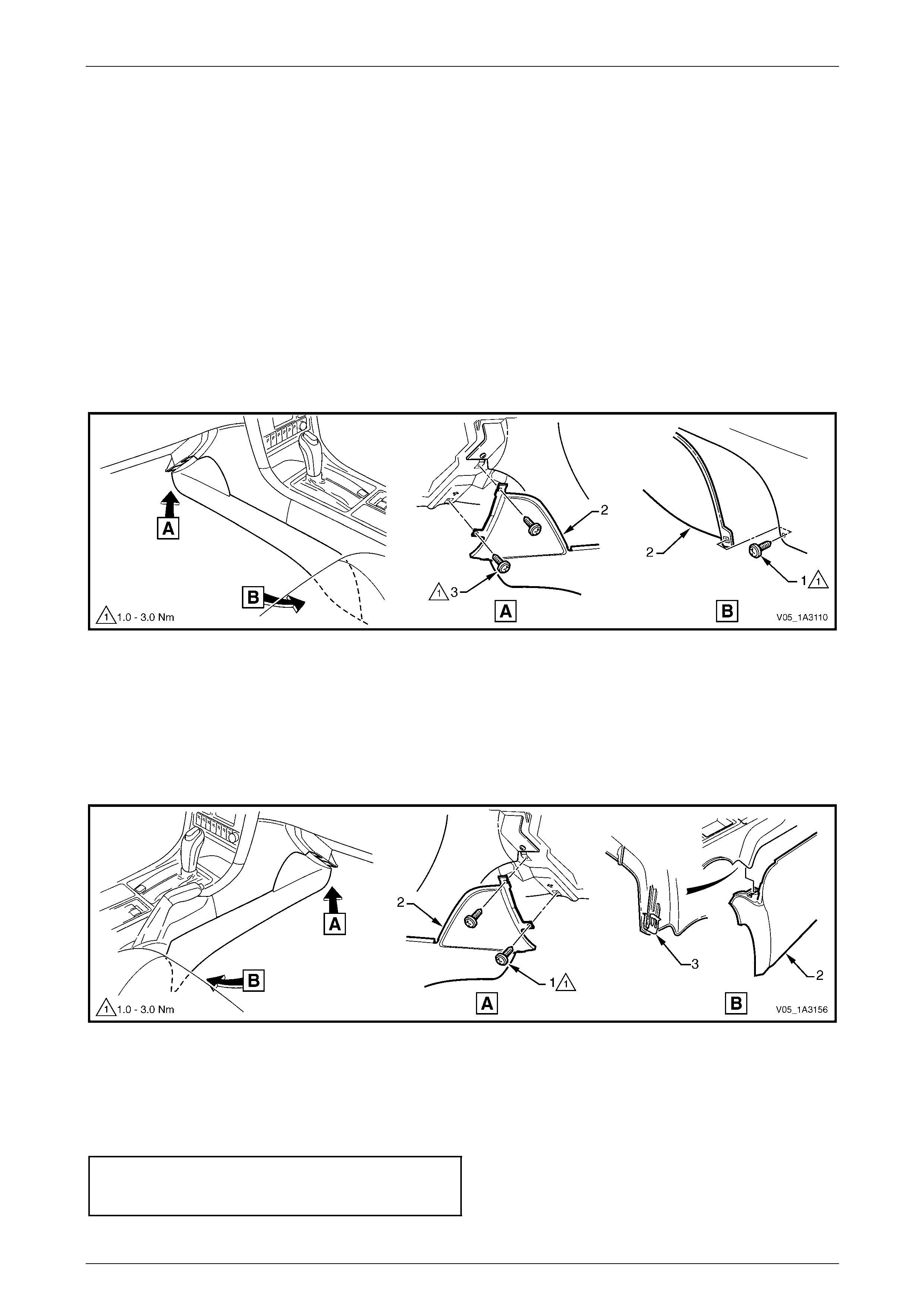
2.2 Instrument Panel Lower Extension Side
Trim
LT Section No. — 14–900
Remove
1 Move the front seats to their rearmost position. For the left-hand side, move the front to the uppermost position.
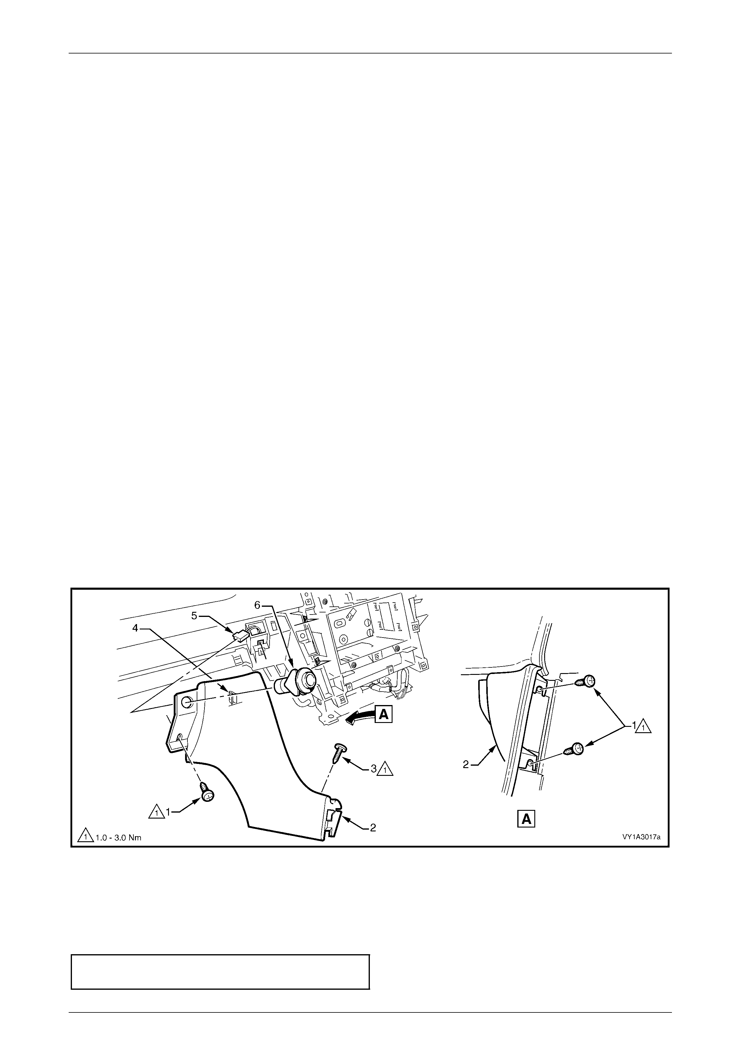
2 Refer to Figure 1A3 – 12, for the left-hand side:
a Remove the screw (1) attaching the instrument panel lower extension side trim (2) to the floor console.
b Open the instrument panel compartment and remove the two screws (3) attaching the side trim to the
instrument panel.
c Remove the side trim.
Figure 1A3 – 12
3 Refer to Figure 1A3 – 13, for the right-hand side:
a Open the instrument panel lower trim panel and remove the two scre ws (1) attaching the instrument panel
lower extension side trim (2) to the instrument panel.
b Prise the rear of the trim panel downward to disengage it from the floor consol e retaining clip (3).
c Remove the side trim.
Figure 1A3 – 13
Reinstall
Reinstallation of the instrument panel lower extension side trim is the reverse of the removal procedure. Ensure the trim
panel is correctly seated and tighten the attaching screws to the specified torque.
Instrument panel lower extension side
trim panel attaching screw
torque specification.....................................1.0 – 3.0 Nm
Instrument Panel and Console Page 1A3–14
Page 1A3–14
2.3 Floor Console Assembly
LT Section No. — 14–900
Remove
1 Remove the following components, as required:
a Floor console cover assembl y, refer to 2.1 Floor Console Cover Assembly.
b Left-hand and right-hand instrument panel lower extension side trims,
refer to 2.2 Instrument Panel Lower Extension Side Trim.
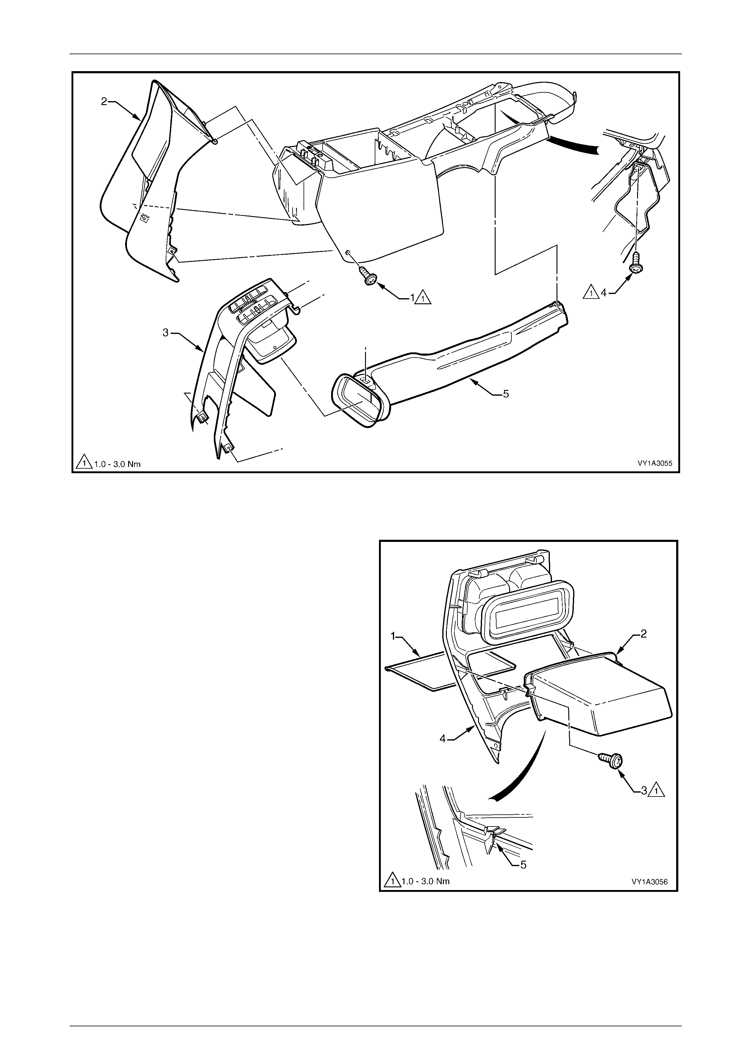
2 Remove the floor console compartment liner (1) by
carefully grasping the liner a nd disengaging the two
lugs (2).
Figure 1A3 – 14
3 For automatic transmission vehicles, remove the four
screws (1) attaching the console to the automatic
transmission selector assembly.
Figure 1A3 – 15
Instrument Panel and Console Page 1A3–15
Page 1A3–15
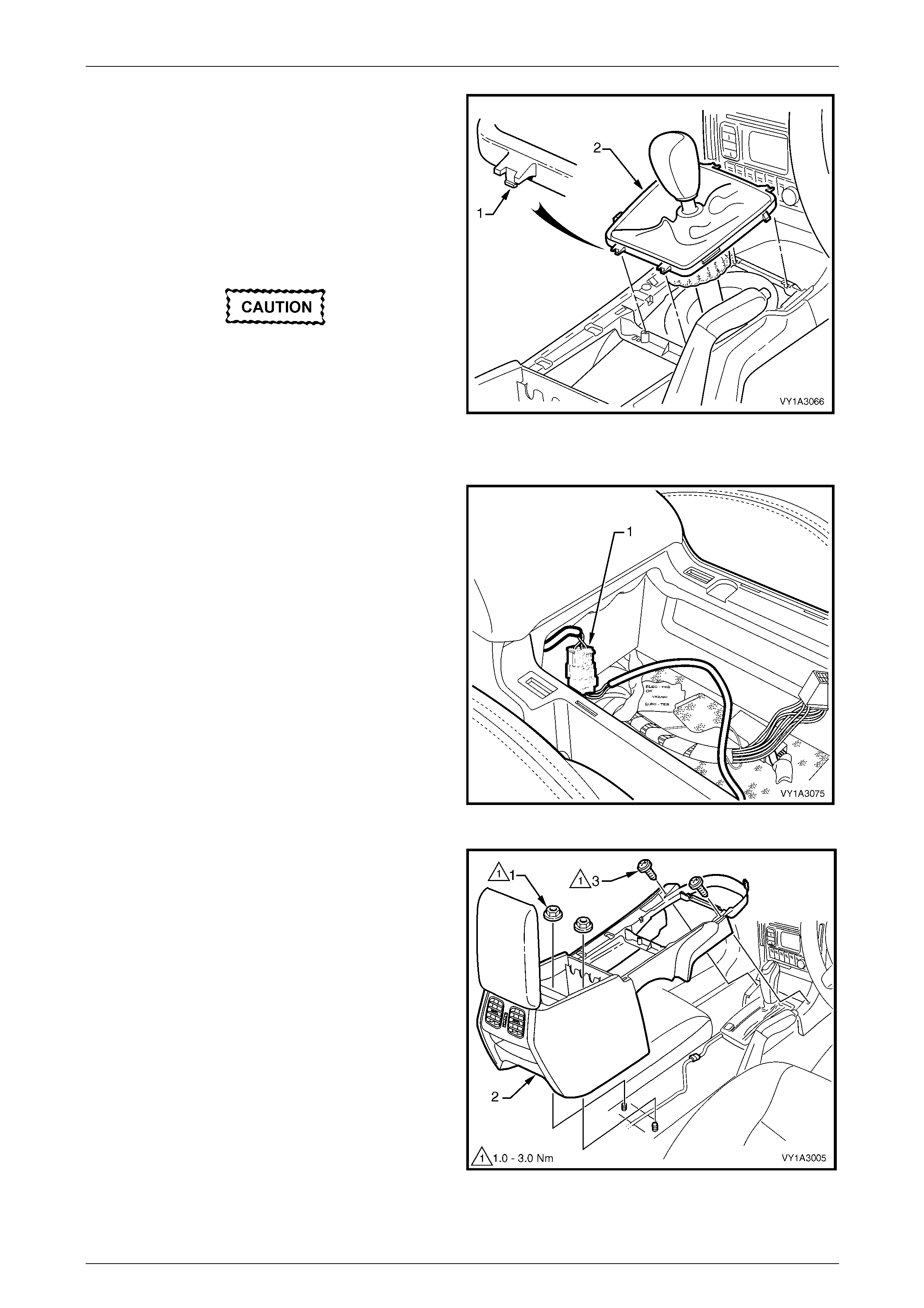
4 For manual transmission vehicles:
a Use a fine flat-blade screwdriver to disen gage
the lug (1), attaching the manual transmission
gear lever boot assembly (2) to the console, two
places front and rear.
b Remove the boot assembly from the console and
raise it over the gear knob. Remove the console
over the boot assembly when the remai nin g
fasteners are removed.
Do not attempt to remove the gear
knob from the gear lever shaft as it is
glued in place. The gear knob, boot
assembly and lever shaft can be removed
from the transmission if required, refer to
Section 7B1 Manual Transmission – V6 or
Section 7B2 Manual Transmission – GEN III
V8. Figure 1A3 – 16
5 Disconnect the console wiring connector (1) from the
front of the console storage bin.
Figure 1A3 – 17
6 Remove the two nuts (1) attaching the floor
console (2) to the vehicle floor.
7 Remove the two screws (3) attaching the front of the
console to the instrument panel assembly.
8 Lift the rear of the console upward and remove.
NOTE
The console rear air duct will disco nnect from the
console front air duct during removal. The rear
air duct will remain with the console.
Figure 1A3 – 18
Instrument Panel and Console Page 1A3–16
Page 1A3–16
Disassemble
For details of the floor console wiring harness routing and attachment,
refer to Section 12O Fuses, Relays and Wiring Harnesses.
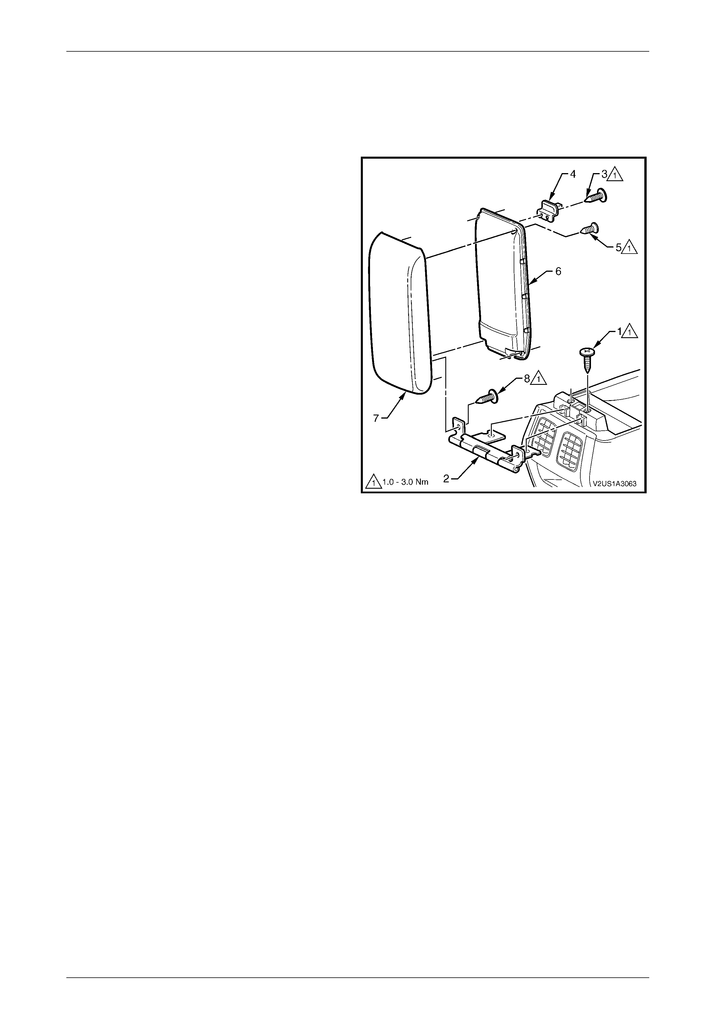
Armrest Assembly
1 Remove the screw (1), two places, attaching the floor
console compartment armrest hinge (2) and armrest
assembly to the floor console.
2 Slide the armrest assembly rearward to remove the
hinge from the floor console.
3 Where fitted, remove the screw (3), two places,
attaching the armrest assembly latch clip (4) to the
armrest assembly and remove the latch.
4 Remove the screw (5), four places, attaching the
armrest inner moulding (6) to the armrest outer
moulding (7).
5 Unclip the armrest inner mouldin g at three pl aces
along each side and remove fr om the armrest outer
moulding.
6 Remove screw (8), two places, attaching the hinge to
the outer and remove the hinge.
Figure 1A3 – 19
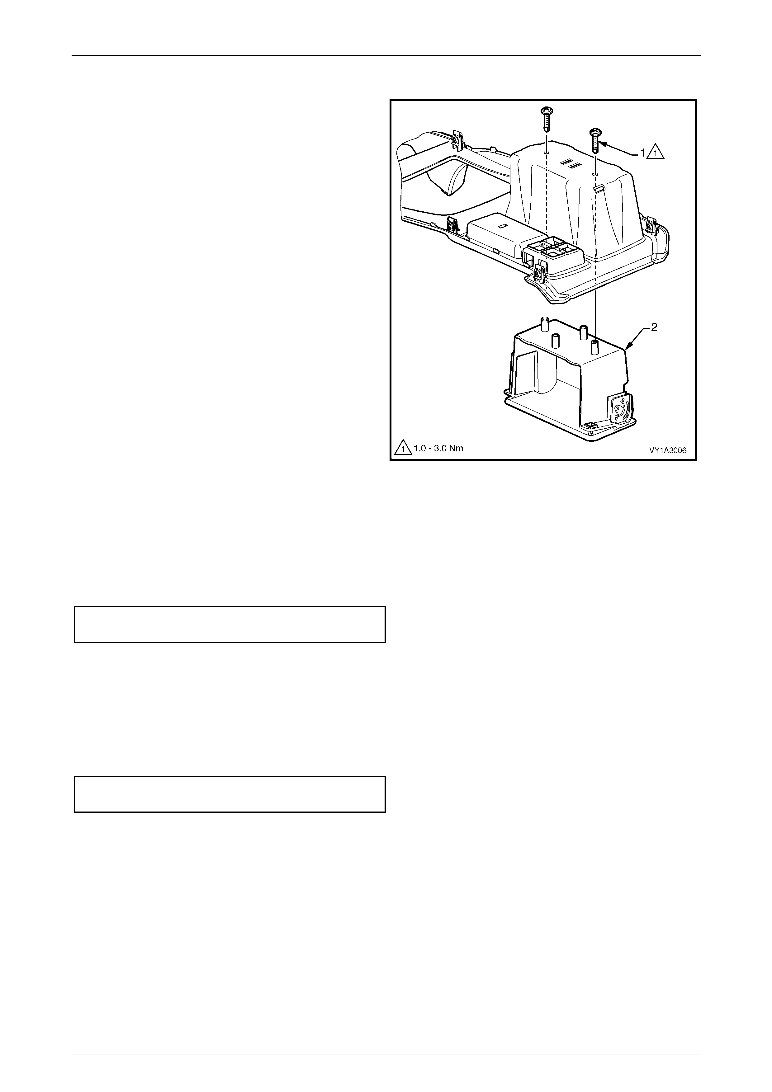
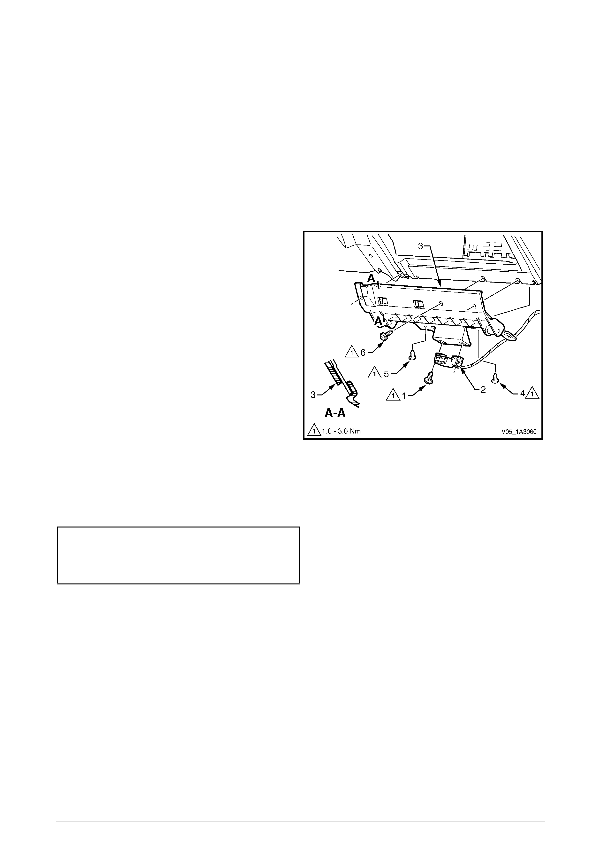
Rear Air Outlet Housing Ass embly or Rear Upper Compartment As sembly
1 Remove the screw (1), one place each side, attaching the floor console rear upper compartment assembly (2), for
Utility and Regular Cab vehicl es, or the floor console rear air outlet housing assembly (3) to the floor console, refer
to Figure 1A3 – 20.
2 Remove the compartment or housing by swinging the lower edge rearward and detach ing the upper tangs.
3 Remove the screw (4) attaching the floor console rear air duct (5) to the floor cons ole and remove the duct.
Instrument Panel and Console Page 1A3–17
Page 1A3–17
Figure 1A3 – 20
Floor Console Rear Compartment
1 Remove the floor console rear compartment liner (1)
from within the floor console rear compartment (2).
2 Remove the screw (3), two places, attaching the
compartment to the rear air outlet housing
assembly (4).
3 Tilt the compartment downwards slightly and
disengage the two lugs (5) from beneath the
compartment and remove.
Figure 1A3 – 21
Instrument Panel and Console Page 1A3–18
Page 1A3–18
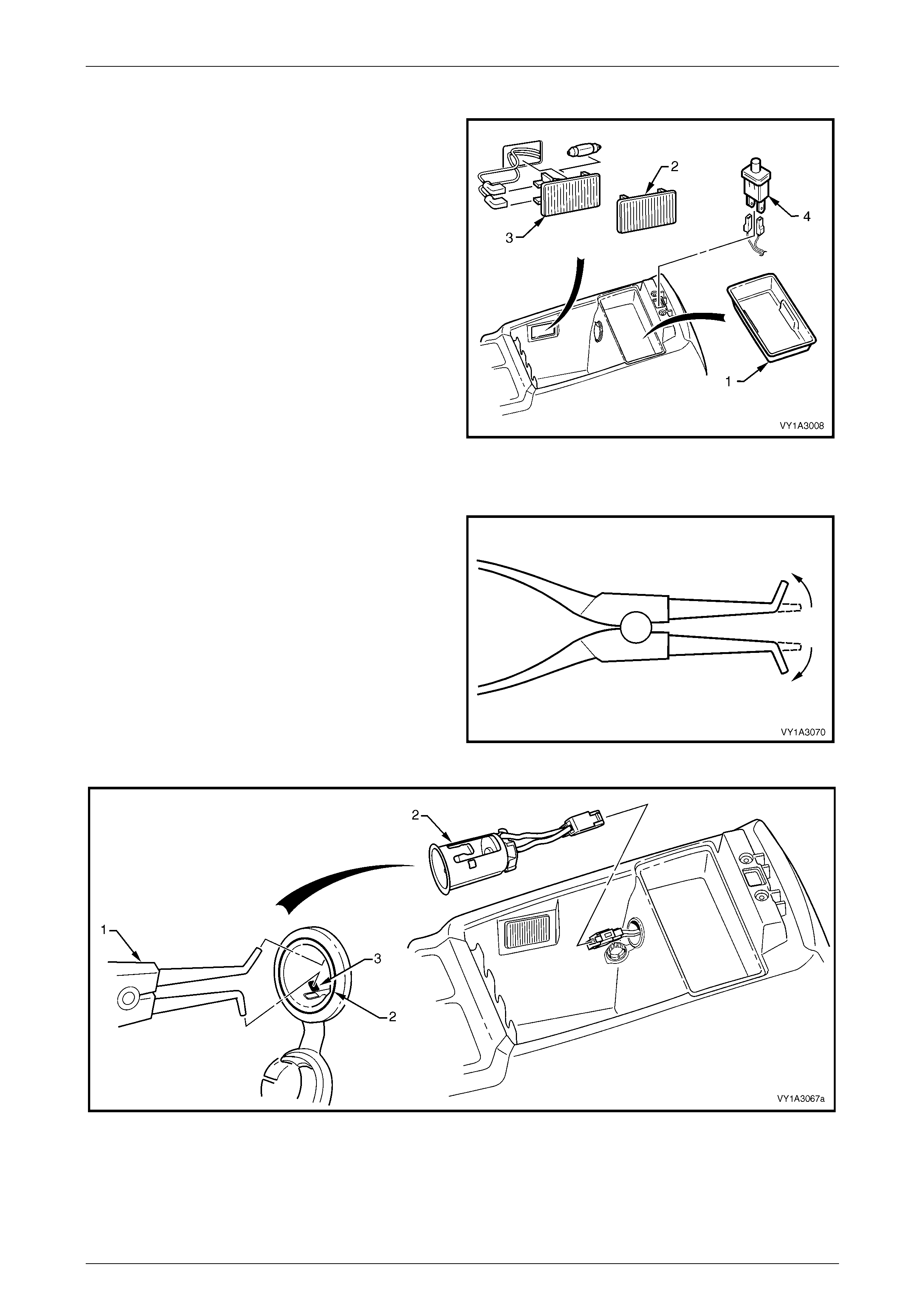
Floor Console Liner and Compartment Lamp Assembly or Lamp Opening Cover
1 Lift out the floor console liner (1).
2 Prise the rear edge of either the floor co nsole
compartment lamp opening cover (2) or floor console
compartment lamp assembly (3).
3 If fitted, disconnect the lamp wiring connectors and
remove the lamp assembly.
4 If fitted, prise the floor console compartment lamp
switch (4) from the console, disconnect the wiring
connectors and remove the switch.
Figure 1A3 – 22
Accessory Power Socket
1 To remove the accessory power socket, a pair of
external circlip pliers will need to be modified. Bend
the tips of the pliers outward to between 60° and 90°.
2 Refer to Figure 1A3 – 24:
a From within the console compartment, insert the
circlip pliers (1) into the socket (2) and locate the
tips of the pliers onto the retaining tab (3), two
places.
b Open the tips of the pliers to depress the tabs,
and prise the socket from the bezel with a fine,
flat-blade screwdriver.
c Withdraw the socket, disconnect the wiring
connector and remove the socket. Figure 1A3 – 23
Figure 1A3 – 24
Instrument Panel and Console Page 1A3–19
Page 1A3–19
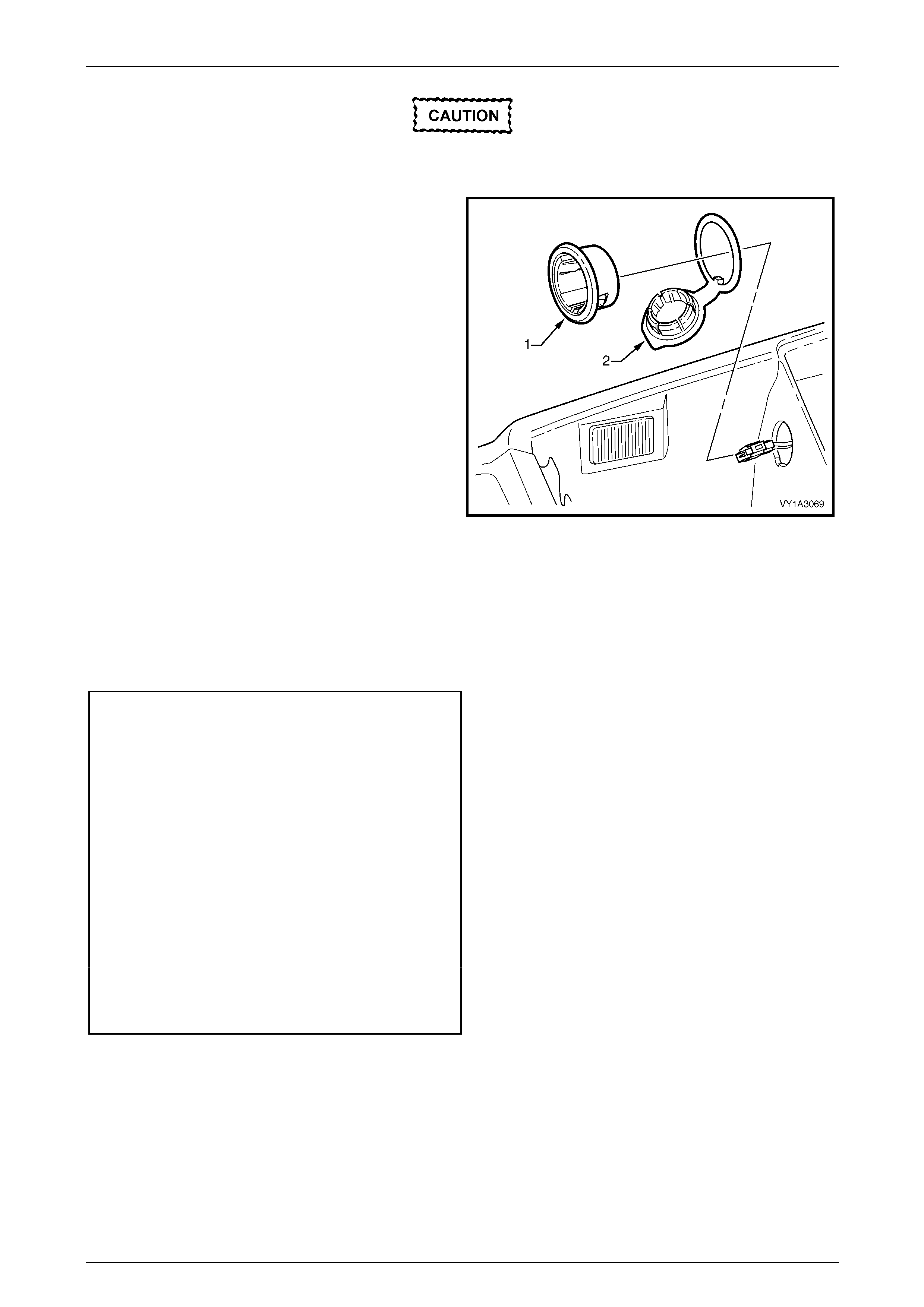
Take care as the bezel retaining tabs are
easily broken.
3 From within the console compartment, caref ully
withdraw the bezel (1) and cover (2).
NOTE
The socket must be removed before performing
this step as its removal releases the bezel
retaining tabs.
4 If required, slide the cover from the bezel.
Figure 1A3 – 25
Reassemble
Reassembly of the floor console is the reverse of disassembly procedure, noting the following:
1 The accessory power socket can onl y be installed in the one orientation.
2 Tighten all fasteners to the specified torque.
Floor console rear compartme nt attachin g
screw torque specification...........................1.0 – 3.0 Nm
Floor console rear air duct attachi ng
screw torque specification...........................1.0 – 3.0 Nm
Floor console rear air outlet h ousing
assembly attaching screw
torque specification.....................................1.0 – 3.0 Nm
Floor console rear upper compartment
assembly attaching screw
torque specification.....................................1.0 – 3.0 Nm
Floor console compartment armrest hinge
attaching screw torque specification...........1.0 – 3.0 Nm
Floor console compartment armrest inner
attaching screw torque specification...........1.0 – 3.0 Nm
Armrest assembly latch clip screw
torque specification.....................................1.0 – 3.0 Nm

Instrument Panel and Console Page 1A3–20
Page 1A3–20
Reinstall
Reinstallation of the floor console assembly is the reverse of the removal procedure, noting the following:
1 If the vehicle is fitted with Navigation System and a new floor console is being installed, ensure the navigation
remote control presenter wedge nutserts are fitted, refer to Section 12L Navigation System.
2 Tighten all fasteners to the correct torque specifications.
NOTE
Ensure the floor console assembly is correctly
seated against the instrument panel lower
extensions before tightening screws; tighten the
front screws first.
Floor console attaching scre w
torque specification.....................................1.0 – 3.0 Nm
Floor console attaching nut
torque specification.....................................1.0 – 3.0 Nm
Floor console to automatic
transmission selector assembly
attaching screw torque specification...........1.0 – 3.0 Nm
Instrument Panel and Console Page 1A3–21
Page 1A3–21
3 Service Operations – Instrument
Panel
3.1 Instrument Panel Lower Trim Plate
Assembly
LT Section No. — 09–140
Remove
Driver Side
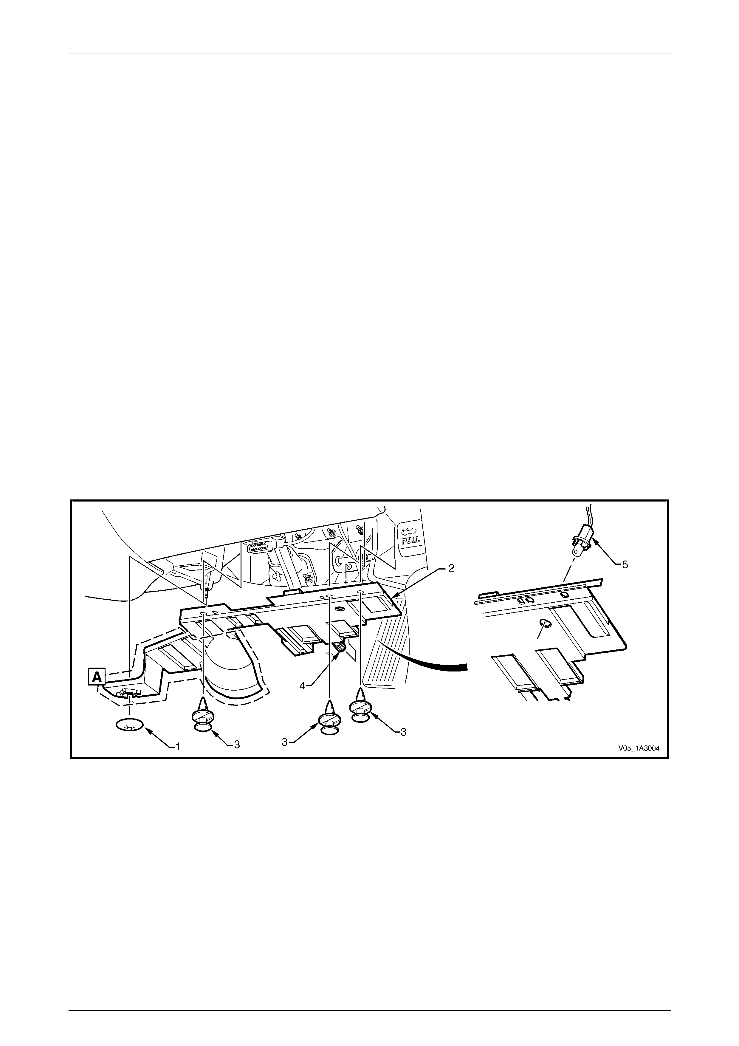
1 For automatic transmission vehicles, remove the retain er (1) attaching the instrument panel lower trim plate
assembly (2) to the HVAC unit, refer Figure 1A3 – 26.
NOTE
The area shown A is not applicable to manual
transmission vehicles.
2 Prise the insert and remove the retainers (3), attaching the plate assemb ly to the instrument panel.
3 Lower the plate assembly slightly and withdraw the lug (4) from the pedal bracket.
4 If fitted, remove the stepwell lamp (5) by rotating the socket and removing from the plate assembly.
5 Remove the plate assembly.
Figure 1A3 – 26
Instrument Panel and Console Page 1A3–22
Page 1A3–22
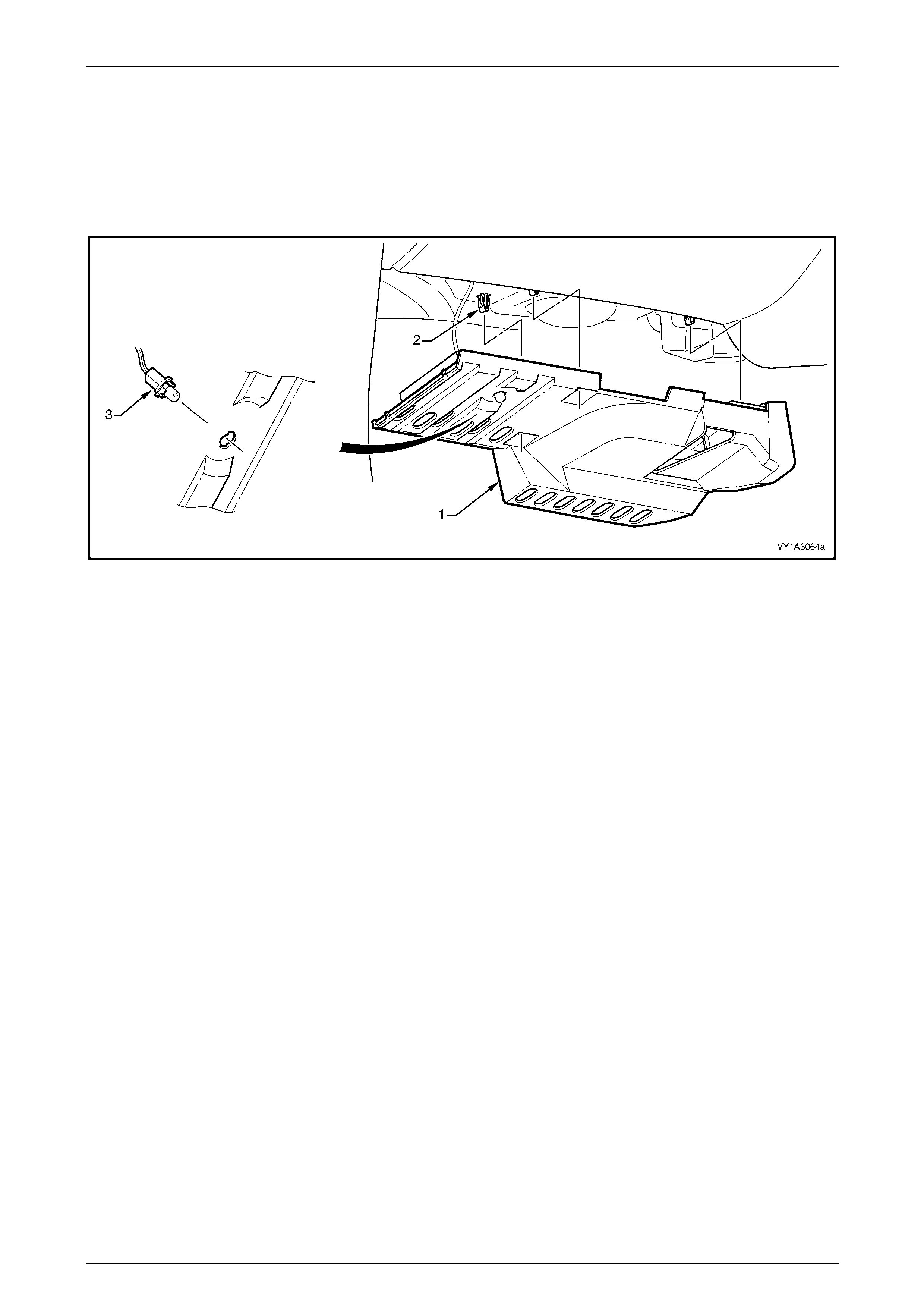
Passenger Side
1 Grasp the inner end of the instrument panel lower trim plate assembly (1) and carefully pull downwards to
disengage the three retaining clips (2), refer to Figure 1A3 – 27.
2 Lower the plate assembly slightly and if fitted, remove the stepwell lamp (3) by rotating the socket and removin g
from the plate assembly.
3 Remove the plate assembly.
Figure 1A3 – 27
Reinstall
Reinstallation of the instrument panel lower trim plate assembly is the reverse of the removal procedure.
Instrument Panel and Console Page 1A3–23
Page 1A3–23
3.2 Instrument Panel Compartment
Assembly
LT Section No. — 09–140
Remove
1 Open the instrument panel compartment assembly (1).
2 Using a fine flat-blade screwdriver, flatten the
instrument panel compartment bumper stop ( 2) each
side, and carefully open the compartment assembly
fully.
3 From the inside of the compartment assembly, push
outwards on the bumper stop (2), and slide the
bumper from the lug (3). Repeat for the opposite side.
Take care when disengaging the hinges as
removing the compartment assembly on the
wrong angle may cause damage.
4 Close the compartment assembly a third of the way
and grasping each side pu ll rearward to disengage the
compartment assembly from each instrument pane l
compartment hinge (4).
NOTE
For removal of the instrument
panel compartment hinges, refer to
3.25 Instrument Panel Brackets and Braces.
5 As required, remove the t wo screws (5) attaching the
instrument panel compartment lock striker (6) and
remove the striker.
Figure 1A3 – 28
Instrument Panel and Console Page 1A3–24
Page 1A3–24
Disassemble
1 From the rear side of the compartment assembly,
remove the screw (1), six places, attaching the
instrument panel compartment (2) to the instrument
panel compartment door (3).
2 Lower the upper edge of the door and withdraw the
retaining tabs along the lower edge from the
compartment.
3 Remove the door and instrument pan el compartment
liner (4).
Figure 1A3 – 29
4 Unclip the instrument panel compartment latch rod (1)
from the instrument panel compartment latch actuator
assembly (2) and instrument panel compartment latch
assembly (3).
5 Remove the three screws (4) attaching the latch
assembly to the door.
6 Depress the two tangs on the retainer (5) and slide the
retainer from the actuator assembly.
7 Remove the actuator assembly.
Figure 1A3 – 30
Instrument Panel and Console Page 1A3–25
Page 1A3–25
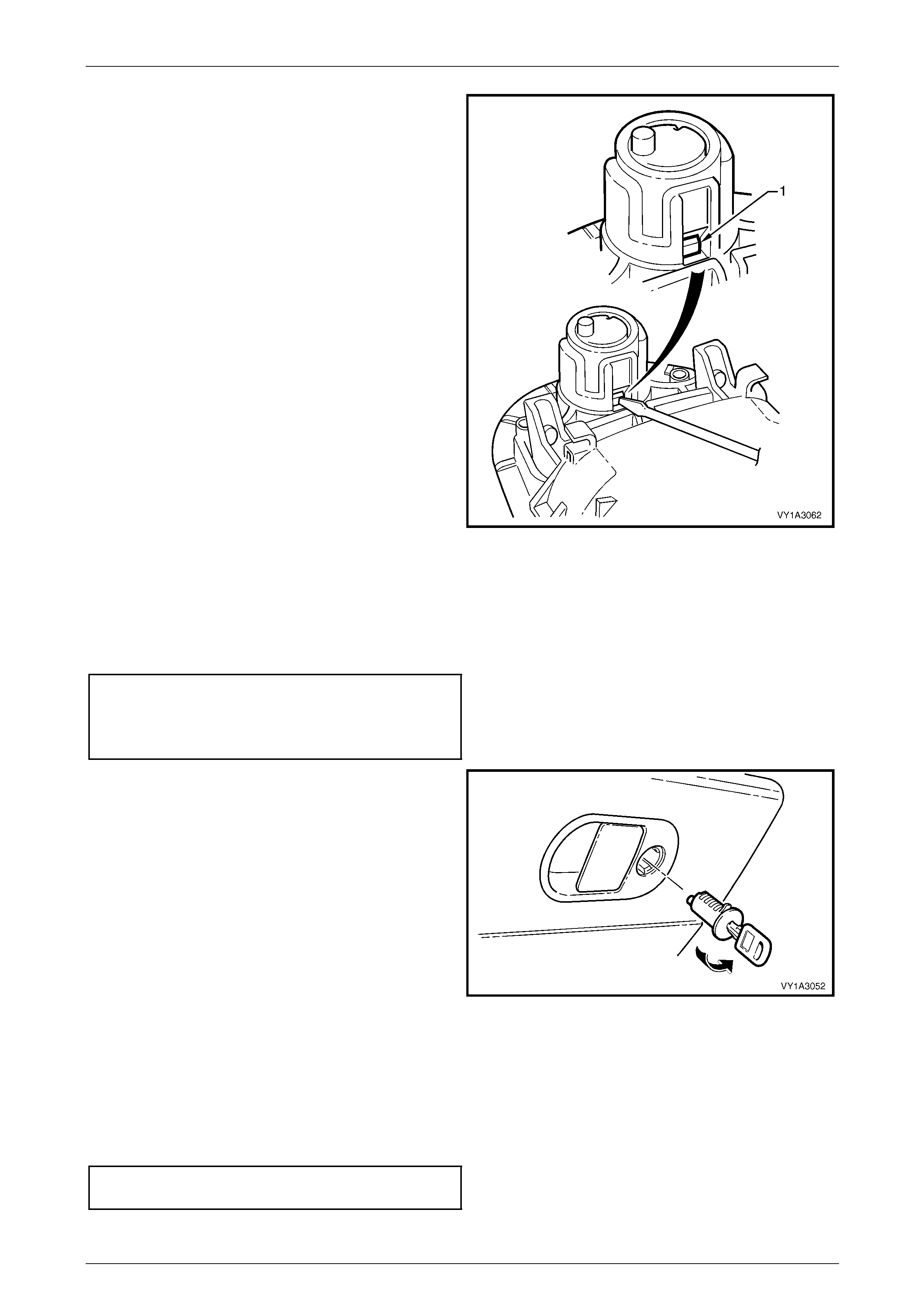
8 As required, remove the lock c ylinder from the
actuator assembly by inserting the key a nd turning to
the locked position (clockwise).
9 Insert a fine flat-blade screwdriver into the cavit y on
the back of the actuator and depress the pin (1).
10 While holding the pin depressed, turn the key
clockwise quarter of a turn.
11 Withdraw the cylinder.
NOTE
Replacement lock cylinders are supplied
uncoded. Send the new lock cylinder to an
authorised locksmith for coding to the existing
keys before installation.
Figure 1A3 – 31
Reassemble
Reassembly of the instrument panel compartment assembly is the reverse of the disassembly procedure, noting the
following:
1 Tighten the attaching scre ws to the specifi ed torque.
Instrument panel compartment latch assembly
attaching screw torque specificatio n............ 1.0 – 3.0 Nm
Instrument panel compartment door attaching
screw torque specification...........................1.0 – 3.0 Nm
2 If installing the lock cylinder, insert the key and fit the
lock cylinder into its cavit y in the vertica l position and
rotate anti-clockwise half a turn.
3 Check the operation of the lock and actuator.
Figure 1A3 – 32
Reinstall
Reinstallation of the instrument panel compartment assembly is the reverse of the removal proc edure, noting the
following:
1 As required, adjust the instrument panel compartment lock striker to provide secure closing of the instrument panel
compartment.
2 Tighten the attaching scre ws to the specifi ed torque.
Instrument panel compartment lock striker
attaching screw torque specification...........1.0 – 3.0 Nm
Instrument Panel and Console Page 1A3–26
Page 1A3–26
3.3 Instrument Panel Compartment Lamp
and Switch
LT Section No. — 02–780
Remove
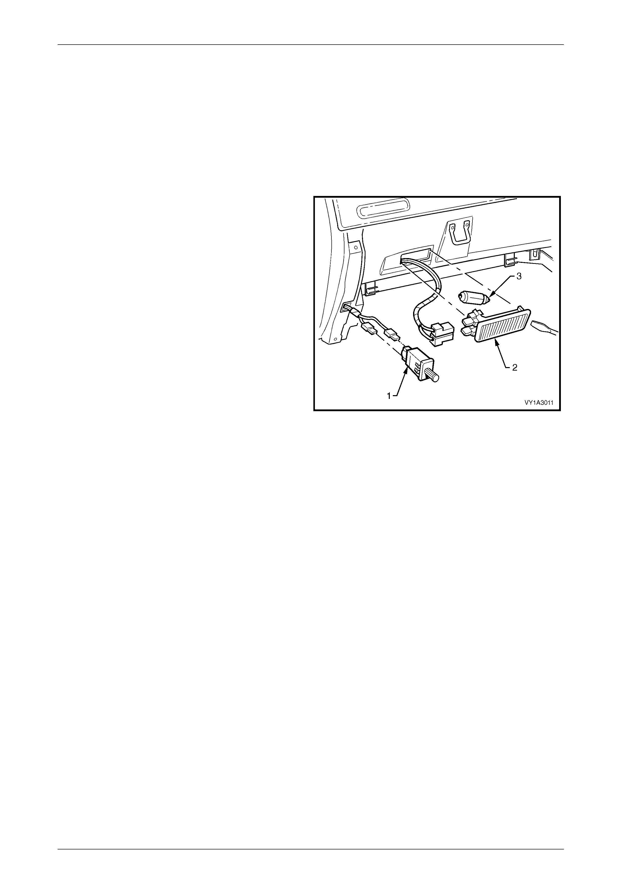
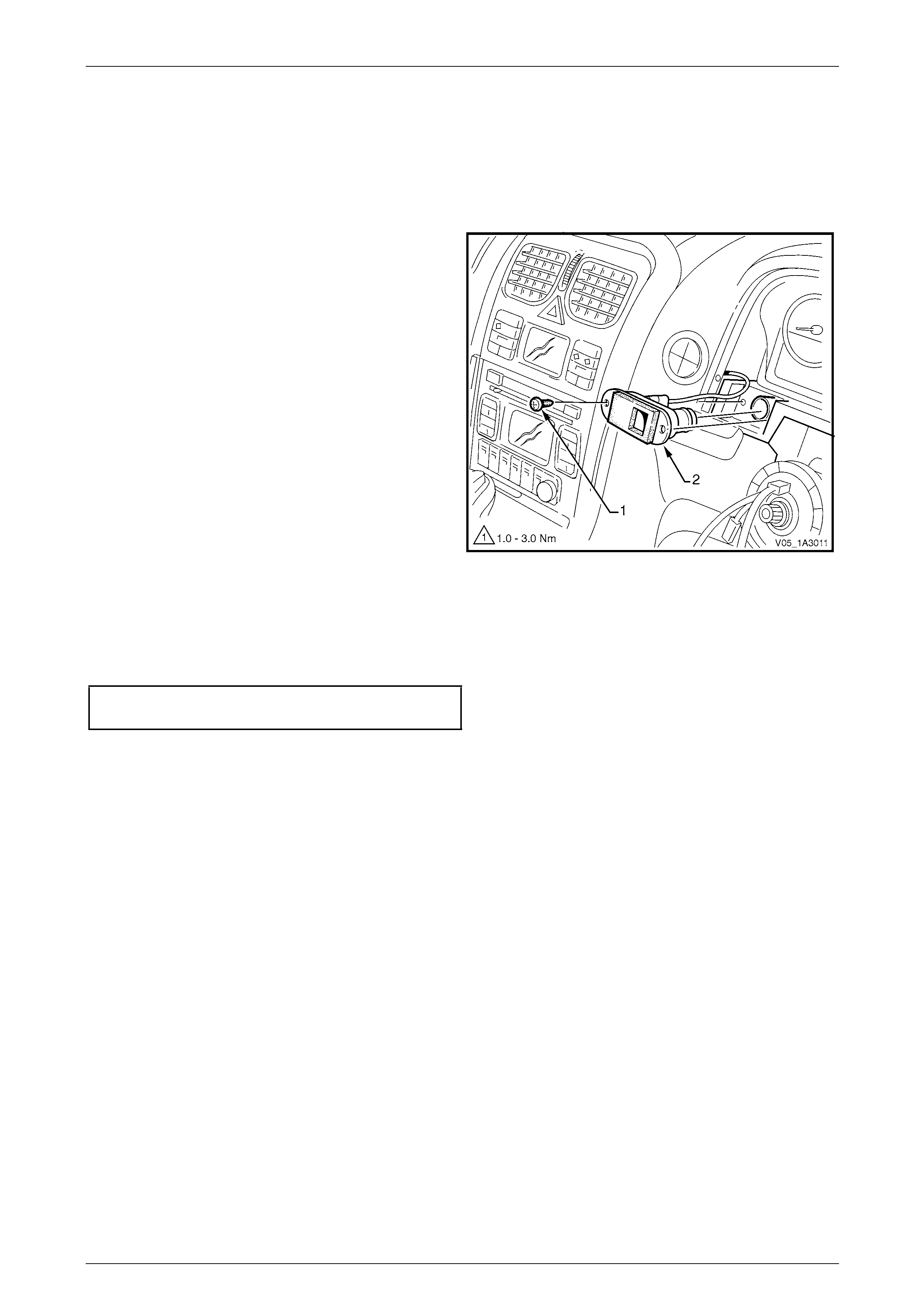
Instrument Panel Compartment Lamp Switch
1 From either side of the instrument panel compartment
lamp switch (1), carefully insert a fine flat blade
screwdriver and prise the switch from the instrument
panel.
2 Disconnect the wiring harness connectors and remove
the switch.
Instrument Panel Compartment Lamp
1 From the right-hand side of the instrument panel
compartment lamp (2), carefully insert a fine flat blade
screwdriver.
2 Prise the lamp from the instrument panel and slid e it
out of its cavity.
3 Disconnect the wiring harness connectors and remove
the lamp.
4 As required, remove the globe (3).
Figure 1A3 – 33
Reinstall
Reinstallation of the instrument panel compartment lamp and switch is the reverse of the removal procedure.
Instrument Panel and Console Page 1A3–27
Page 1A3–27
3.4 Instrument Panel Lower Trim Panel
Assembly
LT Section No. — 09–200
Remove
1 Grasp the upper edge of the instrument panel lower
trim panel assembly (1) and pull outwards to
disengage the three retaini ng clips (2).
2 Swing the panel assembly open.
3 Holding each side of the pane l assembly, pull
rearwards to disengage it from the t wo instrument
panel lower trim panel retainers (3).
Figure 1A3 – 34
Reinstall
Reinstallation of the instrument panel lower trim panel assembly is the reverse of the removal procedure.
NOTE
Ensure each retaining clip is aligned correctly
prior to pushing the panel assembl y into place.
Instrument Panel and Console Page 1A3–28
Page 1A3–28
3.5 Instrument Panel Lower Trim Panel
Retainer
LT Section No. — 09–200
Remove
1 Remove the following components, as required:
a Driver side instrument panel lower trim plate assembly,
refer to 3.1 Instrument Panel Lower Trim Plate Assembly.
b Instrument panel lower trim panel assembly, refer to 3.4 Instrument Panel Lower Trim Panel Assembly.
2 Remove the screw (1), two places, attaching the data
link connector (2) to the instrument panel lower trim
panel retainer (3).
3 Remove the two screws (4 and 5) attaching the
retainer to the air duct.
4 Remove the screw (6), three places, attaching the
retainer to the instrument panel assembly and
instrument panel.
5 Slide the retainer do wnward to disengage the two lugs
from the instrument panel assembly as shown in
Figure 1A3 – 35 (AA) and remove the retaine r.
Figure 1A3 – 35
Reinstall
Reinstallation of the instrument panel lower trim panel retainer is the reverse of the removal procedure. Tighten the
attaching screws to the specified torque.
Data link connector attaching
screw torque specification.............................. 1.0 – 3.0 Nm
Instrument panel lower trim panel retainer
attaching screw torque specificatio n............ 1.0 – 3.0 Nm
Instrument Panel and Console Page 1A3–29
Page 1A3–29
3.6 Audio Head Unit
LT Section No. — 09–440
It is recommended the audio head unit does
not contain a CD when being removed. Under
some circumstances, a CD may become
dislodged if the unit is treated roughly during
removal.
Remove
1 Eject any CDs that may be in the changer.
2 Ensure the audio system is off.
3 Using the special service tools KM6067 (1), insert the
tools into the access holes and push the service tools
in to engage the barbs of the retaining s pring clips.
4 Apply outward pressur e to the service tools to release
the spring clips then pull the audi o head unit (2) out of
the cradle.
NOTE
• The wiring connectors r emain attached to the
audio head unit housing and will disconnect
on removal of the audio head unit.
• For service and diagnosis of the
audio head unit assembly, refer to
Section 12D Entertainment System.
5 Remove the service tools. Figure 1A3 – 36
Reinstall
1 Slide the audio head unit into the cradle.
2 Using finger pressure over the removal tool holes, push the unit in until the spring clips engage.
Do not apply pressure to the buttons or
knobs, as damage may result.
3 Check the audio system for correct operation. Load any customers CDs that were originally in the audio system.
Instrument Panel and Console Page 1A3–30
Page 1A3–30
3.7 Instrument Panel Centre Trim Assembly
(with Upper Centre Trim Panel)
LT Section No. — 09–300
Remove
1 Remove the following components, as required:
a Floor console cover assembl y, refer to 2.1 Floor Console Cover Assembly.
b Audio head unit assembly, refer to 3.6 Audio Head Unit.
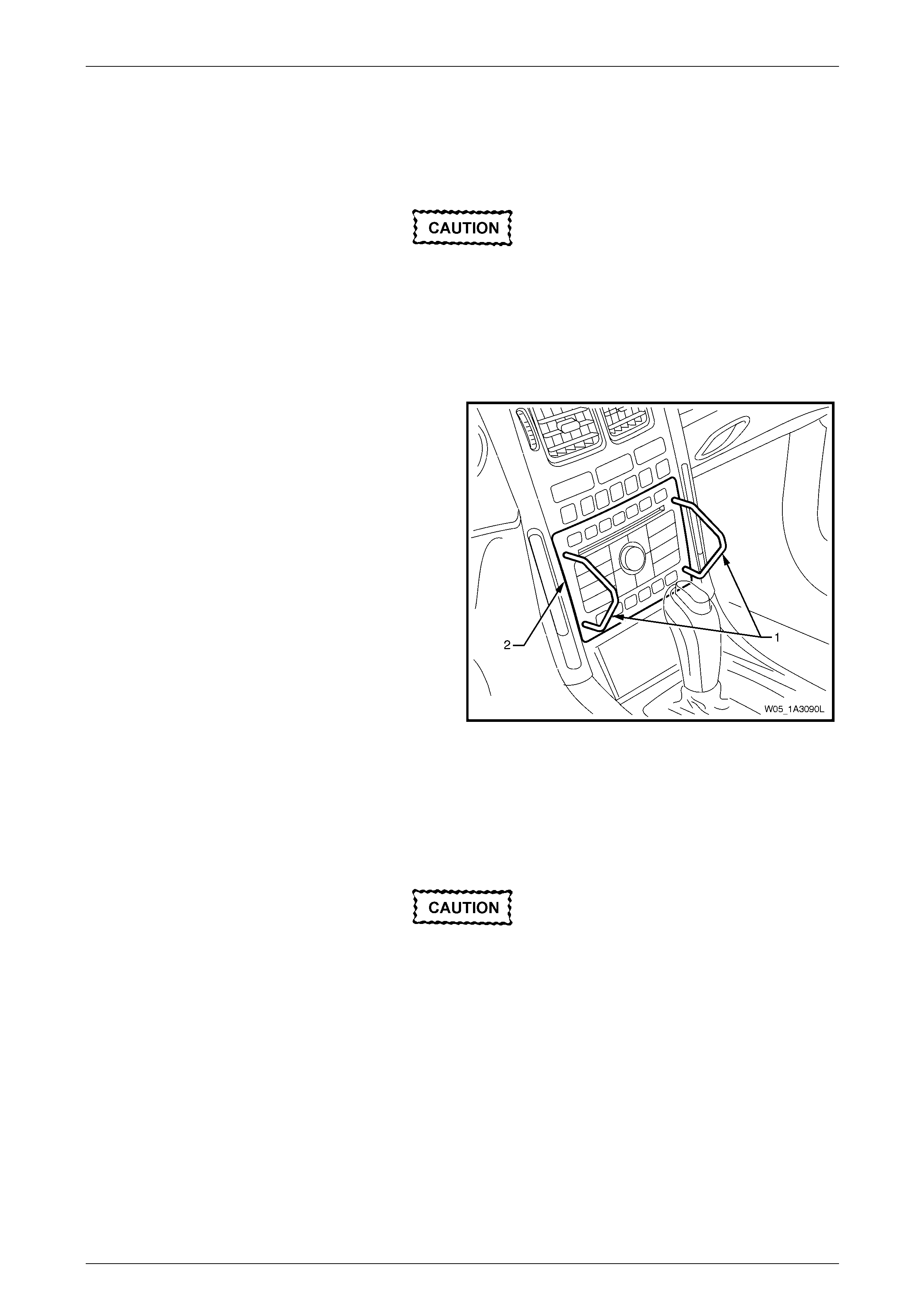
2 Carefully prise the front edge of the instrument panel upper centre trim panel (1), and pull upward to disengage the
retaining clips at each corner from the instrument panel centre trim assembly (2), refer to Figure 1A3 – 37.
NOTE
A fine flat blade screwdriver may be used;
however take steps to ensure the trims are not
marked or damaged.
3 Remove the lower screw (3), two places, attaching the centre trim assembly to the instrument panel.
4 Remove the upper screws (4 and 5), two places each, attaching the centre trim assembly to the instrument panel.
5 Remove the centre trim assembly, disengag ing the cl ip (6), four places, far enough to disconnect the wiring
connectors from the rear of the hazard warning switch.
NOTE
The manual HVAC contr oller remains attached to
the instrument panel.
6 Remove the centre trim assembly.
Figure 1A3 – 37
Instrument Panel and Console Page 1A3–31
Page 1A3–31
Disassemble
1 Remove the screws (2), four places, attaching the instrument panel centre air outlet ho using assembly (3) to the
centre trim (1) and remove the housing asse mbly and hazard warning switch (4), refer to Figure 1A3 – 38.
2 Unclip the hazard warning s witch from the instrument panel centre air outlet housing assembly.
NOTE
For service and diagnosis of the hazard warning
switch, refer to Section 12B Lighting Systems.
Figure 1A3 – 38
Reassemble
Reassembly of the instrument panel centre trim assembly is the reverse of the disassembly procedure. Tighten the
attaching screws to the specified torque.
Instrument panel centre air outlet
housing assembly attaching
screw torque specification...........................1.0 – 3.0 Nm
Reinstall
Reinstallation of the instrument panel centre trim assembly is the reverse of the removal procedure. Tighten all attaching
screws to the specified torque.
Instrument panel centre trim
assembly attaching screw
torque specification.....................................1.0 – 3.0 Nm
Instrument Panel and Console Page 1A3–32
Page 1A3–32
3.8 Instrument Panel Centre Trim Assembly
(with Instrument Panel Upper
Compartment)
LT Section No. — 09–300
Remove
1 Remove the following components, as required:
a Floor console cover assembl y, refer to 2.1 Floor Console Cover Assembly.
b Audio head unit assembly, refer to 3.6 Audio Head Unit.
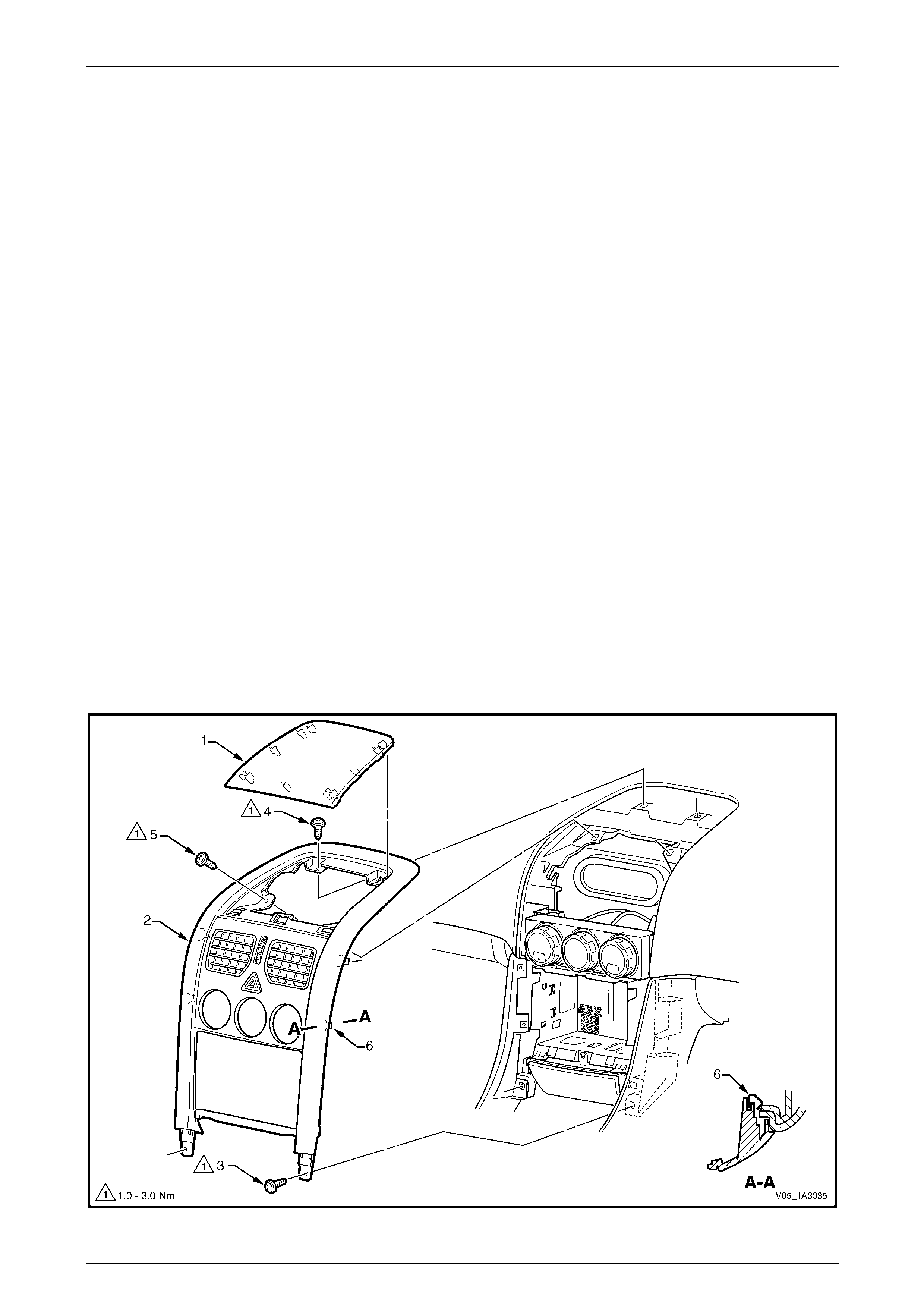
2 Remove the lower screw (1), two places, attaching the instrument pa nel centre trim assembly (2) to the instrument
panel, refer to Figure 1A3 – 39.
3 Open the instrument panel upper com partment (3) and remove the compartment liner (4).
4 Remove the screw (5), four places, from within the upper compartment attaching the upper compartment and
centre trim assembly to the instrument panel.
5 Remove the centre trim assembly and instrument panel upper compartment, disengaging the clip (6), four plac es,
far enough to disconnect the wiring connectors from the rear of the hazard warning switch and the OCC control
module.
6 Remove the centre trim assembly.
Figure 1A3 – 39
Instrument Panel and Console Page 1A3–33
Page 1A3–33
Disassemble
Before removing the instrument panel top
compartment, apply masking tape to the areas
shown to protect the surfaces of the centre trim
and the instrument panel upper compartment,
refer to Figure 1A3 – 40.
Figure 1A3 – 40
1 Remove the screws (1), four places, attaching the instrument panel upper compartment (2) to the instrument panel
centre trim (3), refer to Figure 1A3 – 41.
2 With the compartment lid closed, put slight pressure on the rear section of the lid, slide the component down and
out, away from the front of the centre trim.
3 Remove the screw (4), one place each side, attaching the OCC control module (5) and cu p holder assembly (6) to
the centre trim.
4 Remove the screw (7), one place each side, attaching the OCC control module to the centre trim and remove the
control module.
5 Remove the screw (8) attaching the cup holder assembl y to the centre trim and remove the cup holder. Repeat for
the opposite side as required.
6 Remove the screw (9), four places, attaching the instrument panel centre air outlet housing assembly (10) to the
centre trim and remove the housing assembly and hazard warning switch (11).
7 Unclip the hazard warning s witch from the instrument panel centre air outlet housing assembly.
NOTE
• For further information on the OCC control
module, refer to Section 2D HVAC Occupant
Climate Control (Auto A/C) – Description and
Operation.
• For service and diagnosis of
the hazard warning switch, refer to
Section 12B Lighting System.
Instrument Panel and Console Page 1A3–34
Page 1A3–34
Figure 1A3 – 41
Instrument Panel Upper Compartment
Disassemble
The liner (1) is removed during the instrument panel centre
fascia removal procedure.
1 Remove the damper grommets (2) by pulling from the
top of the compartment.
2 Remove the four screws (3) and remove the latch
assembly (4).
3 Disassemble the latch assembly by sliding the
button (5) away from the housing, releasing the
spring (6).
Figure 1A3 – 42
Reassemble
Reassembly of the instrument panel upper compartment is the reverse of the disassembly proc edure. Tighten the
attaching screws to the specified torque.
Instrument panel upper compartment
latch assembly attaching screws
torque specification.....................................1.0 – 2.0 Nm
Instrument Panel and Console Page 1A3–35
Page 1A3–35
Reassemble
Reassembly of the instrument panel centre trim assembly is the reverse of the disassembly proc edure. Special
procedures need to be taken for the install ation of the Instrument Panel Upper Compartment.
1 Tighten the attaching scre ws to the specifi ed torque.
Instrument panel cup holder assembly
attaching screw torque specification...........1.0 – 3.0 Nm
OCC Control Module attaching screw
torque specification.....................................1.0 – 3.0 Nm
Instrument panel centre air outlet
housing assembly attaching scre w
torque specification.....................................1.0 – 3.0 Nm
2 Care must be taken when installing the upper compartment. Apply masking tape to the positions shown in Figure
1A3 – 40.
3 From below the instrument panel centre trim (1), guide the storage compartment (2) over the centre air outlet
housing, refer to Figure 1A 3 – 43.
4 As shown in (B), leading the left side first, feed into the centre trim along the masking points.
5 Feed compartment into centre trim until it is in the correct position (C)
6 Install the screws (3), two places each side, and tighten to the correct torque specification.
Instrument panel upper compartment
attaching screw torque specification...........1.0 – 3.0 Nm
Figure 1A3 – 43
Reinstall
Reinstallation of the instrument panel centre trim assembly is the reverse of the removal procedure. T ighten the attaching
screws to the specified torque.
Instrument panel centre trim assembly
attaching screw torque specification...........1.0 – 3.0 Nm
Instrument Panel and Console Page 1A3–36
Page 1A3–36
3.9 Auxiliary Gauge Assembly
LT Section No. — 09–300
Remove
Take care not to mark or damage the gauge
assembly or the in strument panel centre trim
assembly.
1 Carefully prise the front edg e of the auxiliary gauge
assembly (1) and pull upward to disengage the three
retaining clips, located at the front edge of the centre
trim assembly (2).
NOTE
A fine flat-bladed screwdriver with the tip
wrapped in a shop rag may be used to prise the
front edge of the gauge assembly.
2 Disconnect the wiring connector (3) from the gauge
assembly.
3 Guide assembly clear of rear slots (4) and remove.
NOTE
For more information regard ing the gauges, refer
to Section 12C Instrumentation.
Figure 1A3 – 44
Disassemble
Except for removal from the gauge assembly
housing do not perform any further
disassembly of the inclinometer assembl y.
1 Remove the two screws (1) attaching the au xiliary gauge assembly (2) to the gauge assembly housing (3), refer to
Figure 1A3 – 45.
2 Remove the gauge assembly from the housing.
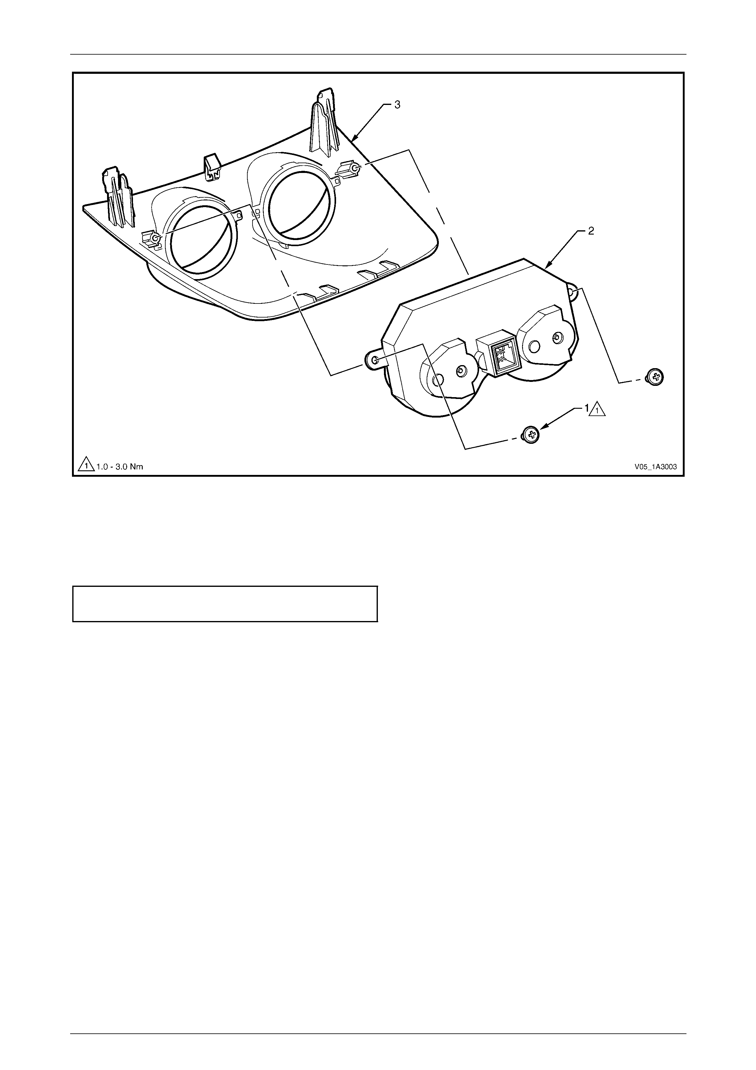
Instrument Panel and Console Page 1A3–37
Page 1A3–37
Figure 1A3 – 45
Reassemble
Reassembly of the auxiliary gauge assembly is the reverse of the disassem bly procedure. Tighten the attaching screws
to the specified torque.
Auxiliary gauge assembly
attaching screw torque specification...........1.0 – 3.0 Nm
Reinstall
Reinstallation of the auxiliary gau ge assembly is the reverse of the removal procedure.
Instrument Panel and Console Page 1A3–38
Page 1A3–38
3.10 Instrument Panel Centre Trim Assembly
(with Auxiliary Gauge Assembly)
LT Section No. — 09–300
Remove
1 Remove the following components, as required:
a Floor console cover assembl y, refer to 2.1 Floor Console Cover Assembly.
b Audio head unit assembly, refer to 3.6 Audio Head Unit.
c Auxiliary gauge assembly, refer to 3.9 Auxiliary Gauge Assembly.
2 Remove the lower screw (1), two places, attaching the instrument pa nel centre trim assembly (2) to the instrument
panel, refer to Figure 1A3 – 39.
3 Remove the upper screw (3), two places, from the top of the centre trim assembly.
4 Remove the centre trim assembly, disengag ing the cl ip (4), four places, far enough to disconnect the wiring
connectors from the rear of the hazard warning switch and the OCC control module.
5 Remove the centre trim assembly.
Figure 1A3 – 46
Instrument Panel and Console Page 1A3–39
Page 1A3–39
Disassemble
1 Remove the screw (1), one place each side, attaching the OCC control module (2) and cu p holder assembly (3) to
the centre trim (4), refer to Figure 1A3 – 47.
2 Remove the screw (5), one place each side, attaching the OCC control module to the centre trim and remove the
control module.
3 Remove the screw (6) attaching the cup holder assembl y to the centre trim and remove the cup holder. Repeat for
opposite side as required.
4 Remove the screws (7), two places each side, attaching the instrument panel centre air outlet housing assembly (8)
to the centre trim and remove the housing assembly and hazard warning switch (9).
5 Unclip the hazard warning s witch from the instrument panel centre air outlet housing assembly.
NOTE
For further information on the OCC control
module, refer to Section 2D HVAC Occupant
Climate Control (Auto A/C) – Description and
Operation.
NOTE
For service and diagnosis of the hazard warning
switch, refer to Section 12B Lighting System.
Figure 1A3 – 47

Instrument Panel and Console Page 1A3–40
Page 1A3–40
Reassemble
Reassembly of the instrument panel centre trim assembly is the reverse of the disassembly procedure. Tighten the
attaching screws to the specified torque.
Instrument panel cup holder assembly
attaching screw torque specification...........1.0 – 3.0 Nm
OCC Control Module attaching screw
torque specification.....................................1.0 – 3.0 Nm
Instrument panel centre air outlet
housing assembly attaching scre w
torque specification.....................................1.0 – 3.0 Nm
Reinstall
Reinstallation of the instrument panel centre trim assembly is the reverse of the removal procedure. T ighten the attaching
screws to the specified torque.
Instrument panel centre trim assembly
attaching screw torque specification...........1.0 – 3.0 Nm
Instrument Panel and Console Page 1A3–41
Page 1A3–41
3.11 Instrument Panel Lower Compartment
and Ashtray Assembly
LT Section No. — 09–300
NOTE
Where fitted, an instrument panel ashtray
assembly replaces the instrument panel lower
compartment. Removal of both components is
the same, however each has it s own disassem bly
procedure.
Remove
1 Remove the following components, as required:
a Floor console cover assembl y, refer to 2.1 Floor Console Cover Assembly.
b Audio head unit assembly, refer to 3.6 Audio Head Unit.
c Instrument panel centre trim assembly, refer to:
• 3.7 Instrument Panel Centre Trim Assembly (with Upper Centre Tr im Panel), or
• 3.8 Instrument Panel Centre Trim Assembl y (with Instrument Panel Upper Compartme nt), or
• 3.10 Instrument Panel Centre Tr im Assembly (with Au xiliary Gauge Assembly).
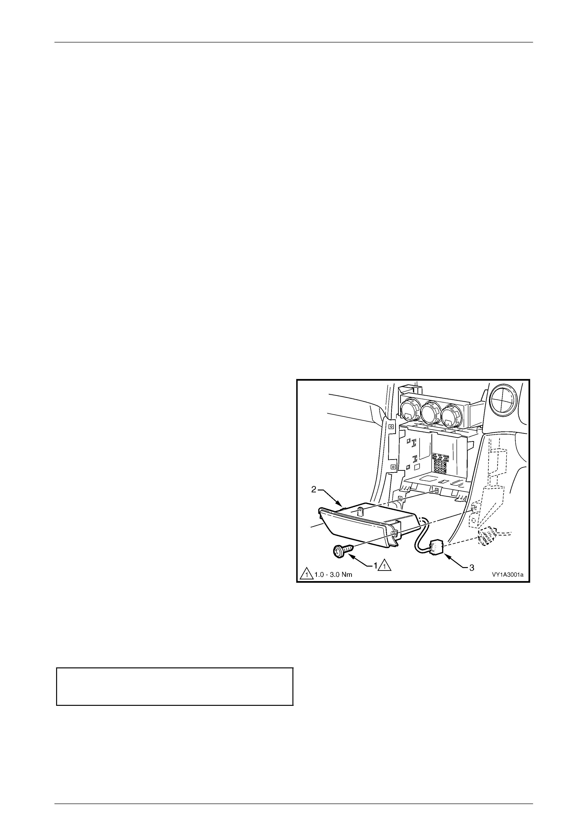
2 Remove the screw (1), three places, attaching the
instrument panel lower compartment assembly or
ashtray assembly (2) to the instrument panel.
3 Slide the compartment or ashtray assembl y outward to
remove.
NOTE
If an ashtray assembly is fitted, disconnect the
wiring connector (3).
Figure 1A3 – 48
Reinstall
Reinstallation of the instrument panel lower compartment or ashtray assembly is the reverse of the removal procedure.
Tighten the attaching screws to the specifi ed torque.
Instrument panel lower compartment
or ashtray assembly screw
torque specification.....................................1.0 – 3.0 Nm
Instrument Panel and Console Page 1A3–42
Page 1A3–42
3.12 Instrument Panel Lower Extension
LT Section No. — 09–300
Remove
1 Remove the following components, as required:
a Floor console cover assembl y, refer to 2.1 Floor Console Cover Assembly.
b Audio head unit assembly, refer to 3.6 Audio Head Unit.
c Instrument panel centre trim assembly, refer to:
• 3.7 Instrument Panel Centre Trim Assembly (with Upper Centre Tr im Panel), or
• 3.8 Instrument Panel Centre Trim Assembl y (with Instrument Panel Upper Compartme nt), or
• 3.10 Instrument Panel Centre Tr im Assembly (with Au xiliary Gauge Assembly).
d Instrument panel lower compartment assembly or instrument panel ashtray assembly, refer to
3.11 Instrument Panel Lower Compartment and Ashtray Assembly.
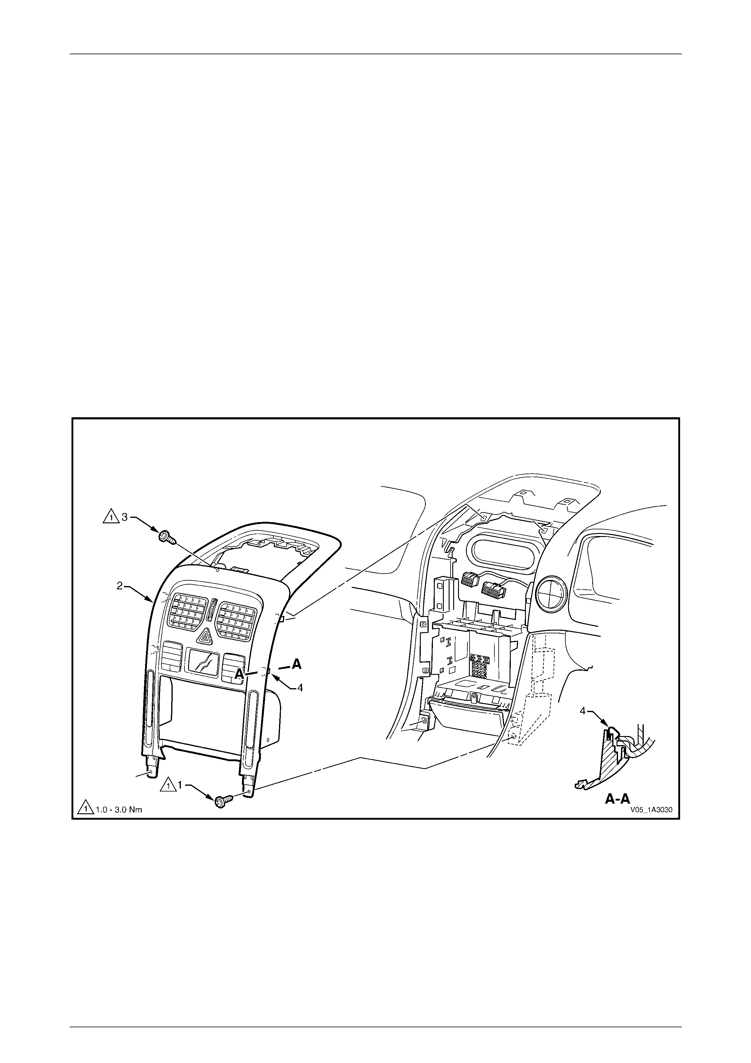
2 Remove the three screws (1), attaching the instrument panel lower extension (2) to the instrument panel, refer to
Figure 1A3 – 49.
3 For the left-hand side, remove the screw (3) attaching the floor console fro nt duct, where fitted.
4 Grasp the top of the extension and pull rearwards to release the clip (4).
5 If fitted, disconnect the wiring connector (5) from the rear compartment li d release switch (6) and remove the panel.
6 If required, remove the rear compartment lid release switch by depressing the tabs on the back of the s witch and
pushing it out of the extension.
NOTE
For service and diagnosis of the rear
compartment lid release switch, refer to
Section 12J Body Control Module.
Figure 1A3 – 49
Reinstall
Reinstallation of the instrument panel lower extension is the reverse of the removal procedure. Tighten the attaching
screws to the specified torque.
Instrument panel lower extension side
trim attaching screw torque specification....1.0 – 3.0 Nm
Instrument Panel and Console Page 1A3–43
Page 1A3–43
3.13 Manual HVAC Controller
LT Section No. — 08–155
NOTE
For removal of OCC control module, refer to:
• 3.8 Instrument Panel Centre Trim Assembly
(with Instrument Panel Upper Compartment) –
Disassemble, or
• 3.10 Instrument Panel Centre Trim Assembl y
(with Auxiliary Gauge Assembly) –
Disassemble.
Remove
1 Remove the following components, as required:
a Floor console cover assembl y, refer to 2.1 Floor Console Cover Assembly.
b Audio head unit assembly, refer to 3.6 Audio Head Unit.
c Instrument panel centre trim assembly, refer to:
• 3.7 Instrument Panel Centre Trim Assembly (with Upper Centre Tr im Panel), or
• 3.8 Instrument Panel Centre Trim Assembl y (with Instrument Panel Upper Compartme nt), or
• 3.10 Instrument Panel Centre Tr im Assembly (with Au xiliary Gauge Assembly).
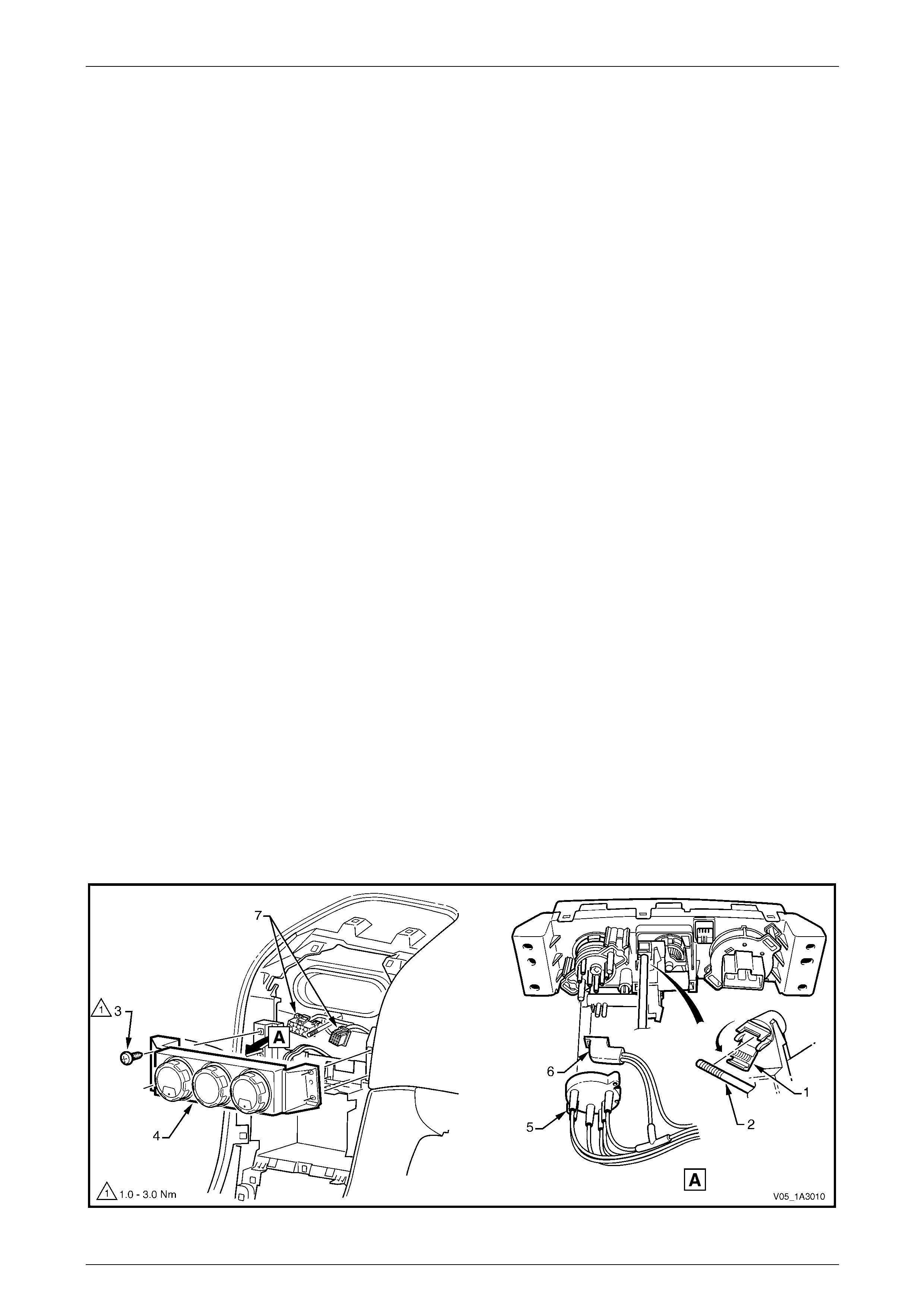
2 From the rear of the controller, open the push-rod lockin g tab (1) and disconnect the control rod (2), refer to Figure
1A3 – 50.
3 Remove the screws (3), two places each side, attaching the manual HVAC controller (4) to the instrument panel.
4 Pull the controller outwards slightly to access the rear.
5 Disconnect the two vacuum hose connections (5 and 6) and the two wiring connectors (7).
6 Remove the control assembly.
NOTE
For service and diagnosis of the manual HVAC
controller, refer to Section 2B HVAC Climate
Control (Manual A/C) – Servicing and Di agnosis.
Figure 1A3 – 50

Instrument Panel and Console Page 1A3–44
Page 1A3–44
Reinstall
1 Install the two wiring connectors and the l ower then upper vacuum hose connections.
2 Push the control rod toward the HVAC unit (front of vehicle) fully.
3 Seat the control assembly in position.
4 Install the four screws and tighten to the specified torque.
Manual HVAC controller attachin g
screw torque specification...........................1.0 – 3.0 Nm
5 Rotate the heat control knob to the full cold position.
6 Position the locking tab so that it will close upward.
7 Connect the control rod to the controller lever and close the lockin g-tab.
8 Check for correct operation.
Instrument Panel and Console Page 1A3–45
Page 1A3–45
3.14 Audio Head Unit Housing and Bracket
Assembly
LT Section No. — 09–440
Remove
1 For the audio head unit housin g, remove the following components, as required:
a Floor console cover assembl y, refer to 2.1 Floor Console Cover Assembly.
b Audio head unit assembly, refer to 3.6 Audio Head Unit.
c Instrument panel centre trim assembly, refer to:
• 3.7 Instrument Panel Centre Trim Assembly (with Upper Centre Tr im Panel), or
• 3.8 Instrument Panel Centre Trim Assembl y (with Instrument Panel Upper Compartme nt), or
• 3.10 Instrument Panel Centre Tr im Assembly (with Au xiliary Gauge Assembly).
2 For the audio head unit bracket, remove the above components, the audio head unit housing and the follo wing
components, as required:
a Instrument panel lower compartment assembly or instrument panel ashtray assembly, refer to
3.11 Instrument Panel Lower Compartment and Ashtray Assembly.
b Left-hand and right-hand instrument panel lower extension, refer to 3.12 Instrument Panel Lower Extension.
c Manual HVAC controller if fitted, refer to 3.13 Manual HVAC Controller.
3 Remove the screw (1) from the rear face of the audio head unit housi ng (2) attaching the housing to the instrument
panel, refer to Figure 1A3 – 51.
4 Remove the screw (3), two places, attaching the front edge of the audio head unit housing.
5 Lift the three retaining tabs (4), on the audio head unit housing.
6 Withdraw the housing from the bracket assembly far enough to allow access to the audio head unit and antenna
wiring connectors.
NOTE
If there is not sufficient length in the audio head
unit harness, either unclip the connector from
within the housing or remove the passenger side
instrument panel lower extension side trim and
unclip the harness from the vehicle floor.
7 From the rear of the housing, unclip the audio head unit wiring connector (5), if not previously done, the antenna
connector (6) and if fitted, the diversity anten na connector (7) from the housing.
8 Disconnect the antenna lead( s) and remove the housing.
Figure 1A3 – 51
Instrument Panel and Console Page 1A3–46
Page 1A3–46
9 Remove the screws (1), eight places, attaching the audio head unit bracket assembly (5) to the instrument panel,
refer to Figure 1A3 – 52.
10 Remove the bracket assembly from its locating tabs.
Figure 1A3 – 52
Reinstall
Reinstallation of the audio head unit housing and bracket assembly is the reverse of the removal procedure. Tighten the
attaching screws to the specified torque.
NOTE
To avoid operational problems, ensure the audio
head unit wiring and antenna connectors are
installed correctl y.
Audio head unit bracket asse mbly attaching
screw torque specification...........................1.0 – 3.0 Nm
Audio head unit housing attaching screw
torque specification.....................................1.0 – 3.0 Nm
Instrument Panel and Console Page 1A3–47
Page 1A3–47
3.15 Instrument Cluster Trim Assembly
LT Section No. — 09–100
Remove
NOTE
The steering wheel has been removed for clarity;
the cluster trim can be removed with steering
column, covers and steering wheel installed.
1 Release the steering column adjustment lever and move the column to its lowest position.
2 Remove the two screws (1) attaching the instrument
cluster trim assembly (2) to the instrument panel.
3 Depress the top of the trim assembly slightly and tilt
the top of the trim assembly out of the instrument
panel pad, disengaging the retaining clips (3) each
side.
4 Unhooking each lug (4) from the instrument panel pad.
5 Remove the trim assembly.
Figure 1A3 – 53
Disassemble
Instrument Panel Steering Column Opening Filler
Remove
1 From the rear of the instrument cluster trim
assembly (1), prise the retainers (2), three places,
attaching the instrument panel steering column
opening filler (3).
2 Remove the filler from the trim assembly.
Reinstall
1 Fit the filler to the trim assembly, ensuring it is
correctly seated on each lug.
2 Attach the three retainers securely.
Figure 1A3 – 54
Instrument Panel and Console Page 1A3–48
Page 1A3–48
3.16 In-car Air Temperature Sensor
LT Section No. —
Remove
1 Remove the instrument cluster trim assembly, refer to
3.15 Instrument Cluster Trim Assembly.
2 Remove the screw (1), two places, attaching the in-car
air temperature sensor (2) to the instrument panel.
3 Extract the sensor assembly from the cavity and
disconnect the air tube and wiring connector.
4 Remove the sensor assembly.
NOTE
For service and diagnosis of the sensor
assembly, refer to Section 2E HVAC Occupant
Climate Control (Auto A/C) – Diagnostics
Figure 1A3 – 55
Reinstall
Reinstallation of the in-car temperature sensor is the reverse of the removal procedur e. Tighten the attaching screws to
the specified torque.
In-car air temperature sensor attaching
screw torque specification...........................1.0 – 3.0 Nm
Instrument Panel and Console Page 1A3–49
Page 1A3–49
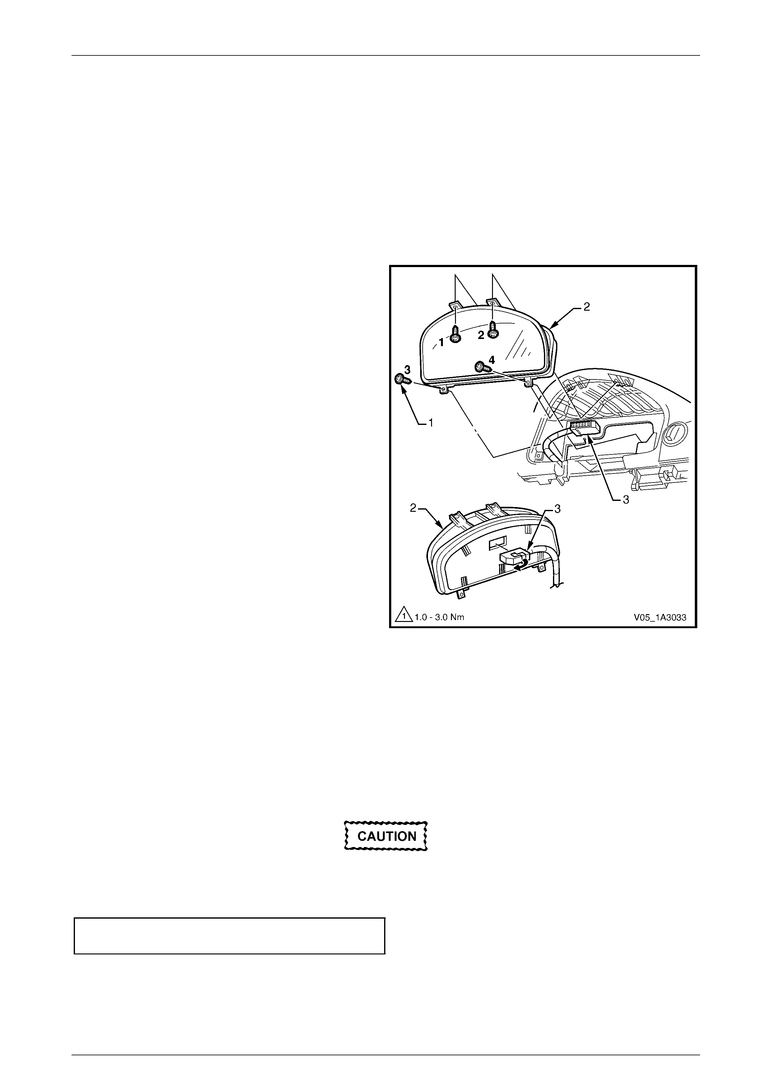
3.17 Instrument Cluster
LT Section No. — 09–100
Remove
1 Remove the following components, as required:
a Instrument cluster trim assembly, refer to 3.15 Instrument Cluster Trim Assembly.
b In-car air temperature sensor, if fitted, refer to 3.16 In-car Air Temperature Sensor.
2 Remove the four screws (1) attaching the instrument
cluster (2) to the instrument panel.
3 Roll the top of the cluster from its cavity.
4 Using a fine flat blade scre wdriver, open the wiring
connector locking tab (3) on the back of the cluster.
5 Remove the cluster assembly.
NOTE
For service and diagnosis of the instrument
cluster, refer to Section 12C Instrumentation.
Figure 1A3 – 56
Reinstall
Reinstallation of the instrument cluster is the reverse of the removal procedure.
NOTE
Ensure the locking tab on the wiring connector is
fully closed.
Tighten the screws in the correct sequence
and to the specified torque, refer to Figure
1A3 – 56.
Instrument cluster attaching
screw torque specification...........................1.0 – 3.0 Nm
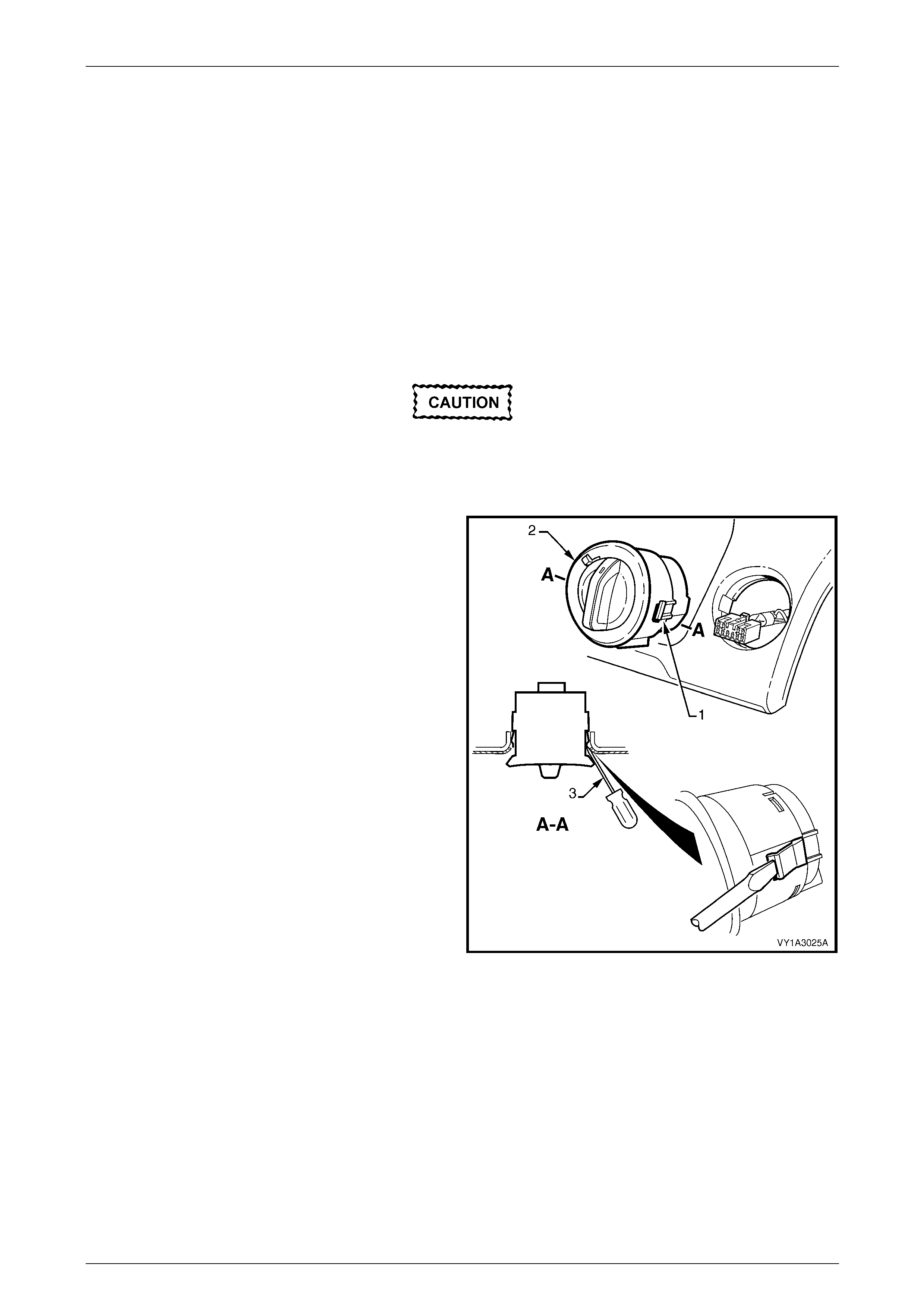
Instrument Panel and Console Page 1A3–50
Page 1A3–50
3.18 Headlamp Switch
LT Section No. — 02–800
Remove
1 Remove the following components, as required:
a Instrument cluster trim assembly, refer to 3.15 Instrument Cluster Trim Assembly.
b Right-hand instrument pa nel outer cover, refer to 3.20 Instrument Panel Outer Cover.
c The driver’s side outer duct,
refer to Section 2C HVAC Climate Control (Manual A/C) – Remov al an d Installation.
Care must be exercised when removing the
headlamp switch as the retaining clips and
locating guide will catch and damage the
instrument panel outer material.
2 Squeeze the retaining clips (1) on either side of the
headlamp s witch assemb ly (2) and carefully push the
assembly part way from the cavity.
3 Insert a fine blade screwdriver (3) as shown and hold
the retaining clip depresse d while slowly manipulating
the switch from its cavity. Repeat for the opposite side
and for the locating guide underneath as required.
4 Disconnect the wiring connector and remove the
switch assembly.
NOTE
For service and diagnosis of
the headlamp switch assembly, refer to
Section 12B Lighting System.
Figure 1A3 – 57
Reinstall
Reinstallation of the headlamp switch is the reverse of the removal proced ure. Ensure the retaining clips are correctly
seated.
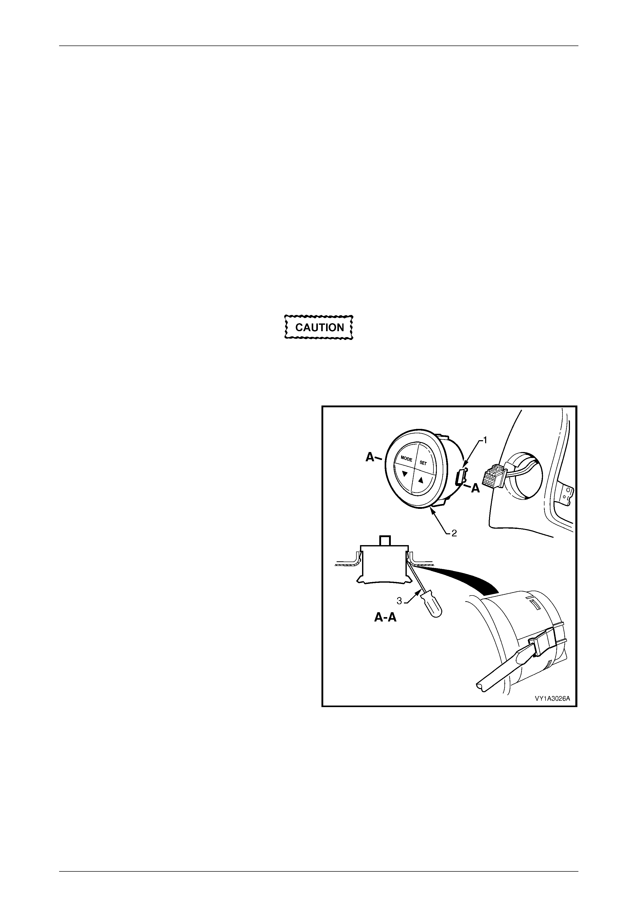
Instrument Panel and Console Page 1A3–51
Page 1A3–51
3.19 Trip Computer Switch
LT Section No. — 02–800
Remove
1 Remove the following components, as required:
a Instrument cluster trim assembly, refer to 3.15 Instrument Cluster Trim Assembly.
b Instrument panel centre trim assembly, refer to:
• 3.7 Instrument Panel Centre Trim Assembly (with Upper Centre Tr im Panel), or
• 3.8 Instrument Panel Centre Trim Assembl y (with Instrument Panel Upper Compartme nt), or
• 3.10 Instrument Panel Centre Tr im Assembly (with Au xiliary Gauge Assembly).
c Manual HVAC controller, refer to 3.13 Manual HVAC C ontroller.
Care must be exercised when removing the
trip computer switch as the retaining clips
and locating guide will catch and damage the
instrument panel outer material.
2 Squeeze the retaining clips (1) on either side of the trip
computer switch assembly (2) and carefully push the
assembly part way out.
3 Insert a fine flat blade screwdriver (3) as shown an d
hold the retaining clips depressed while slowly
manipulating the switch from its cavit y. Repeat for the
opposite side and for the locating guide underneath as
required.
4 Disconnect the wiring connector and remove the
switch assembly.
NOTE
For service and diagnosis of the trip computer
switch, refer to Section 12C Instrumentation.
Figure 1A3 – 58
Reinstall
Reinstallation of the trip computer switch is the reverse of the removal procedure. Ensure the retaining clips are correctly
seated.
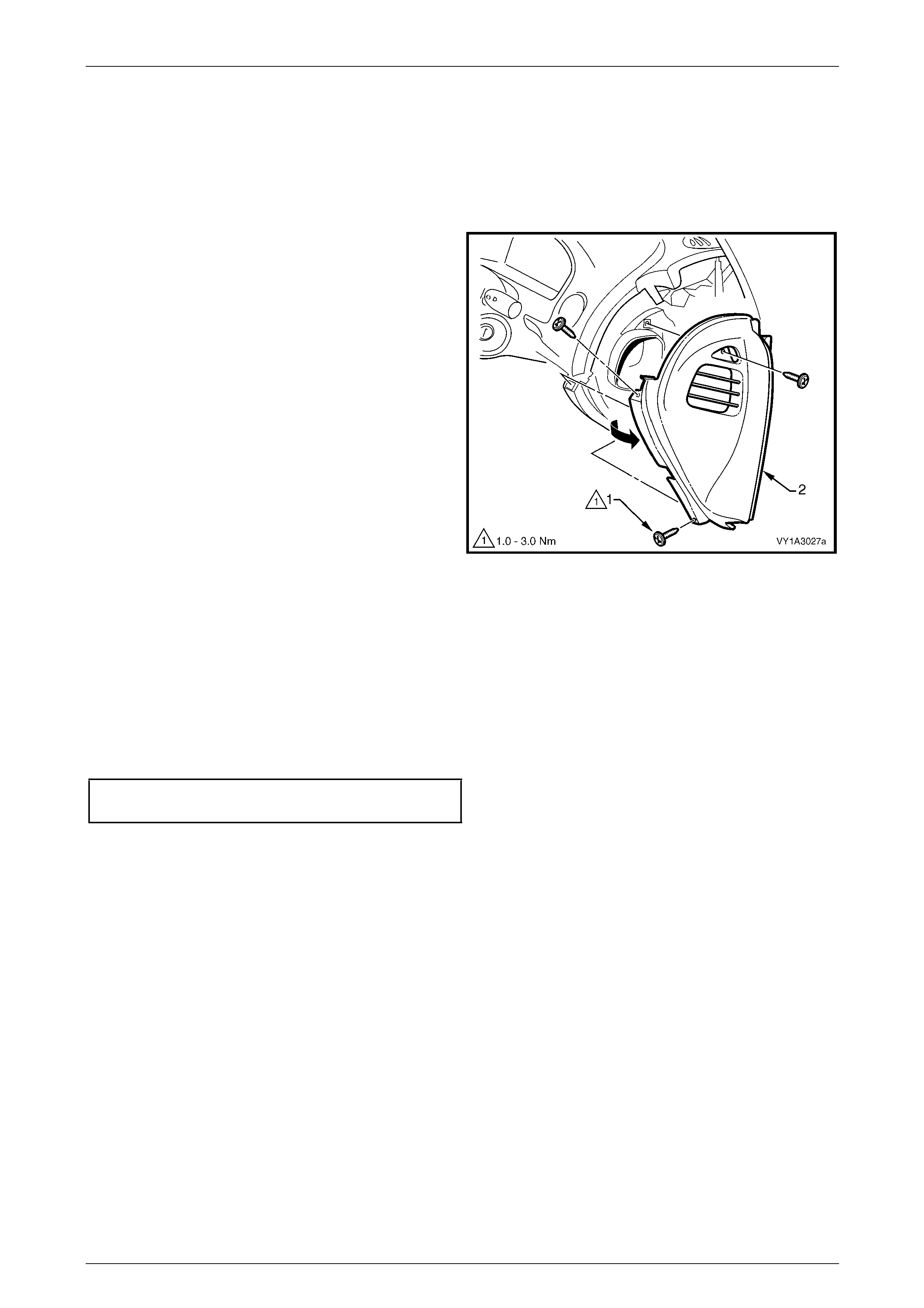
Instrument Panel and Console Page 1A3–52
Page 1A3–52
3.20 Instrument Panel Outer Cover
LT Section No. — 09–135
Remove
1 Remove the three screws (1) attaching either the right-
hand (shown) or left-hand instrument panel outer
cover (2) to the instrument panel.
2 Remove the cover by rotating outward to disengage
the ventilation ducts.
Figure 1A3 – 59
Reinstall
Reinstallation of the instrument panel outer cover is the reverse of the removal procedure. Tighten the attaching screws
to the specified torque.
NOTE
Ensure the ventilation ducts are correctly seated
and any seals are in place.
Instrument panel outer cover attaching
screw torque specification...........................1.0 – 3.0 Nm
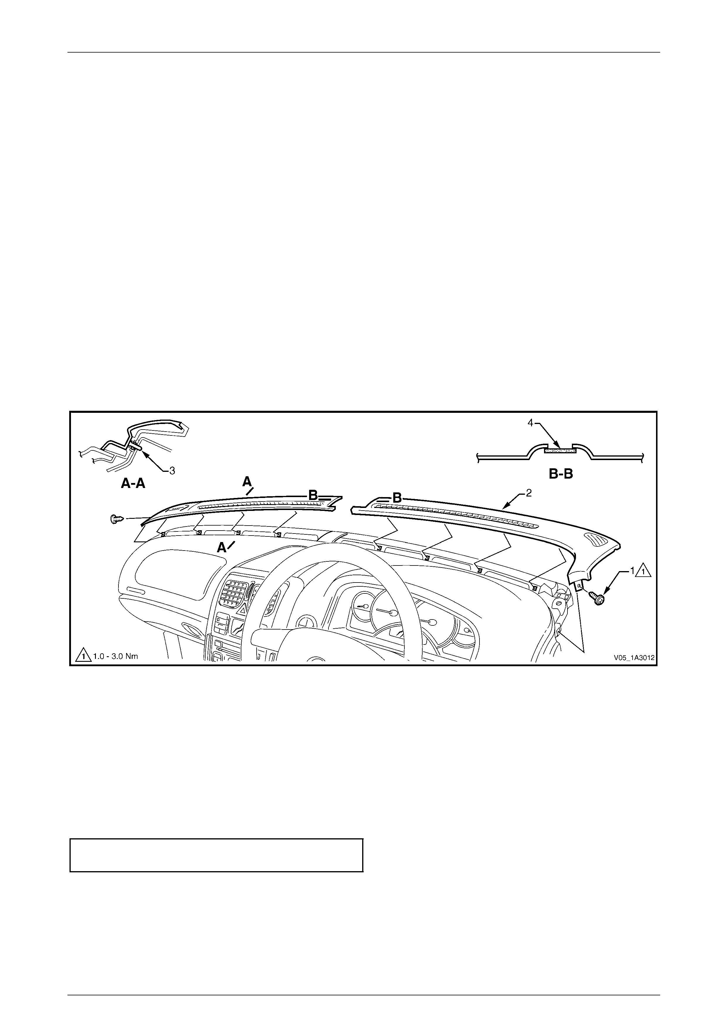
Instrument Panel and Console Page 1A3–53
Page 1A3–53
3.21 Windshield Defroster Grille
LT Section No. — 09–125
Remove
1 Remove the instrument panel outer cover from the appropriate side(s), as required,
refer to 3.20 Instrument Panel Outer Cover.
2 Remove the screw (1) attaching each windshield defroster grille (2) to the instrume nt panel, refer to
Figure 1A3 – 60.
3 Carefully remove the grille by unclipping (3), four places, at an angle equal to the windshield.
NOTE
As the grille is retained securely, removal may
prove difficult. If required, a hook (such as an
Allen key held with vice-grips) can be used to
assist removal. Insert the hook at the inner then
outer end of the vent opening. Ensure it is
hooked under the grille and not the sheet metal
below.
Figure 1A3 – 60
Reinstall
Reinstallation of the windshield defroster grille is the reverse of the removal procedure, noting the following:
1 Ensure the remote key receiver and headlamp auto contr ol / sunload sensor (4) is correctly seated prior to installing
the grille assembly.
2 Ensure the four clips are correctly seated prior to installing the screw.
3 Tighten the attaching scre ws to the specifi ed torque.
Windshield defroster grille attaching
screw torque specification...........................1.0 – 3.0 Nm
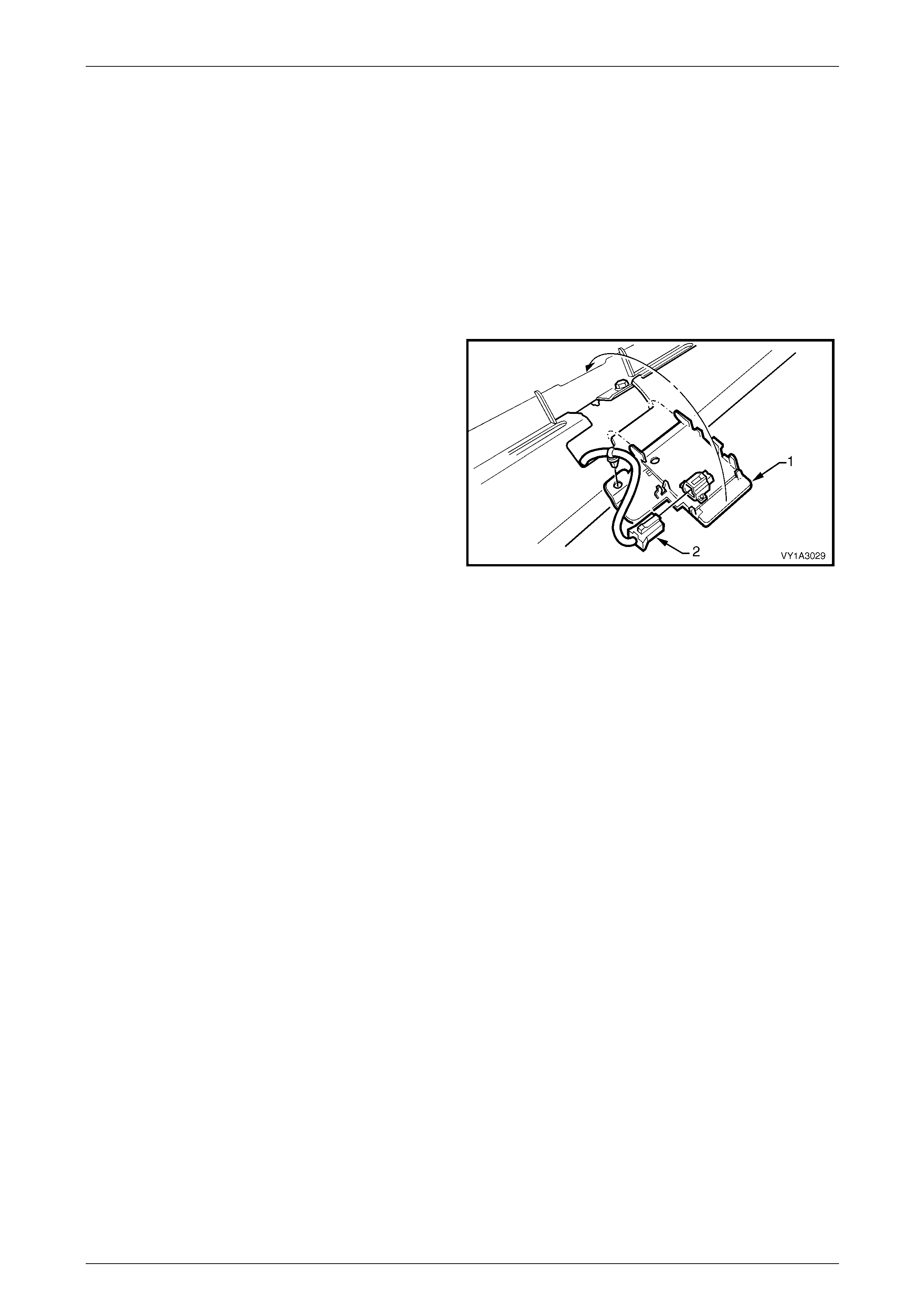
Instrument Panel and Console Page 1A3–54
Page 1A3–54
3.22 Remote Key Receiver and Headlamp
Auto Control / Sunload Sensor
LT Section No. — 08–155
Remove
1 Remove the following components, as required:
a Instrument panel outer cover from both sides, refer to 3.20 Instrument Panel Outer Cover.
b Windshield defroster grille assembly from both sides, refer to 3.21 Windshield Defroster Grille.
2 Carefully unclip the remote key receiver and sensor
(1) from the instrument panel.
3 Disconnect the wiring connector (2), uncli p the wiring
harness from the sensor assembly and remove the
sensor.
NOTE
• For service and diagnosis of the remote key
receiver and headlamp auto control sensor,
refer to Section 12J Body Control Module.
• For further information on the sunload
sensor, refer to Section 2D HVAC Occupant
Climate Control (Auto A/C) – Description and
Operation. Figure 1A3 – 61
Reinstall
Reinstallation of the remote key receiver and headlamp auto control / sunload sensor assembly is the reverse of the
removal procedure.
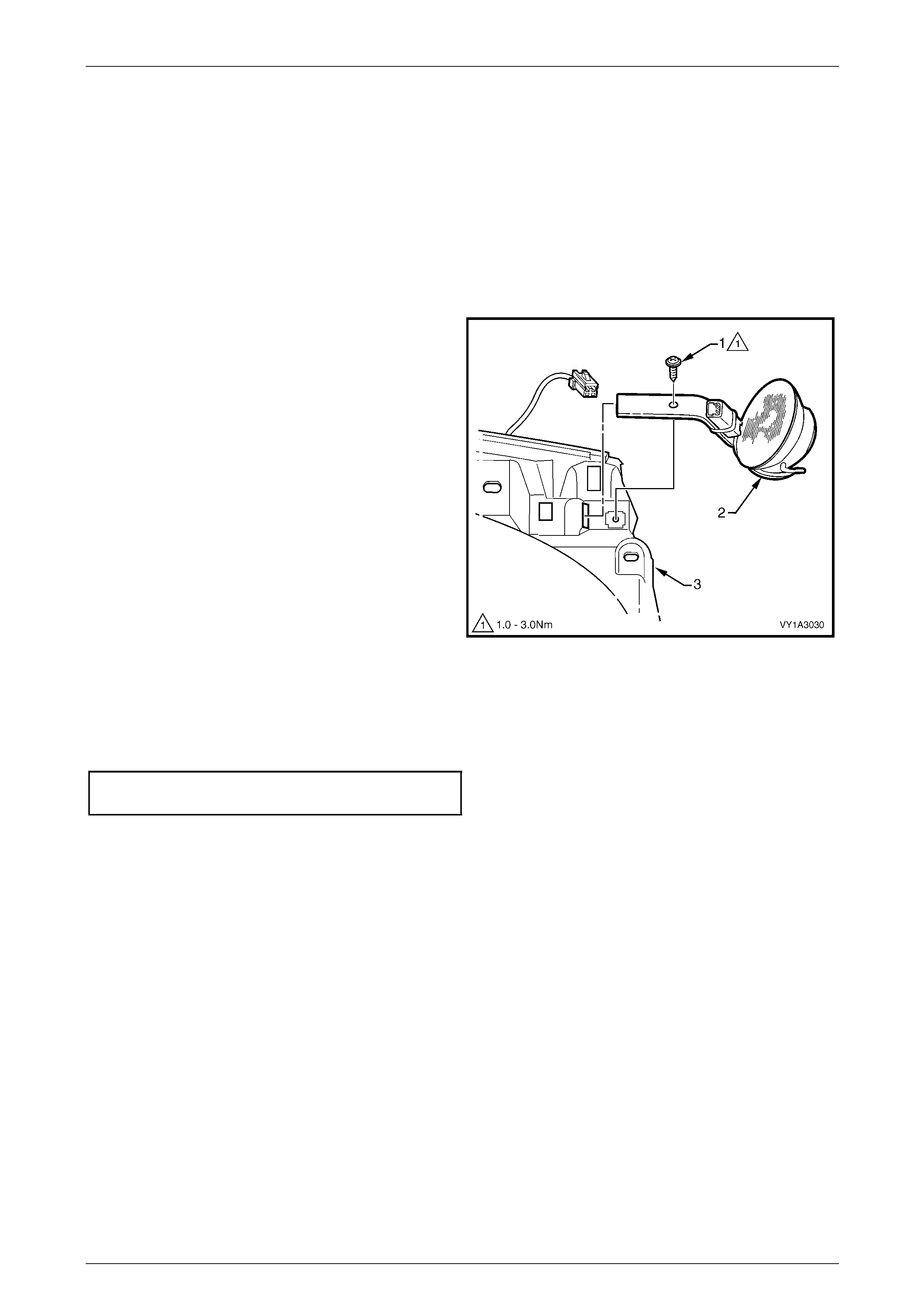
Instrument Panel and Console Page 1A3–55
Page 1A3–55
3.23 Instrument Panel Speaker
LT Section No. — 09–500
Remove
1 Remove the following compo nents on the applicable side, as required:
a Instrument panel outer cover, refer to 3.20 Instrument Panel Outer Cover.
b Windshield defroster grille assembly, refer to 3.21 Windshield Defroster Grille.
2 Remove the screw (1) attaching the instrument panel
speaker (2) to the instrument panel (3).
3 Disconnect the wiring connector and remove the
speaker by withdrawing it from the slot in the
instrument panel.
NOTE
For service and diagnosis of
the instrument panel speaker, refer to
Section 12D Entertainment System.
Figure 1A3 – 62
Reinstall
Reinstallation of the instrument panel speaker is the reverse of the removal proc edure. Tighten the attaching screw to the
specified torque.
Instrument panel speaker attaching
screw torque specification...........................1.0 – 3.0 Nm

Instrument Panel and Console Page 1A3–56
Page 1A3–56
3.24 Instrument Panel Pad Assembly
LT Section No. — 09–125
Remove
1 Remove the following components, as required:
a Floor console assembly, refer to 2.3 Floor Console Asse mbly.
b Driver and passenger side instrument panel lower trim plate assembly,
refer to 3.1 Instrument Panel Lower Trim Plate Assembly.
c Instrument panel compartment assembly, refer to 3.2 Instrument Panel Compartment Assembly.
d Instrument panel compartment lamp and switch,
refer to 3.3 Instrument Panel Compartment Lamp and S witch.
e Instrument panel lower trim panel, refer to 3.4 Instrument Panel Lower Trim Panel Assembl y.
f Instrument panel lower trim panel retainer, refer to 3.5 Instrument Panel Lower Trim Panel Retainer.
g Audio head unit assembly, refer to 3.6 Audio Head Unit.
h Instrument panel centre trim assembly, refer to:
• 3.7 Instrument Panel Centre Trim Assembly (with Upper Centre Tr im Panel), or
• 3.8 Instrument Panel Centre Trim Assembl y (with Instrument Panel Upper Compartme nt), or
• 3.10 Instrument Panel Centre Tr im Assembly (with Au xiliary Gauge Assembly).
i Instrument panel lower compartment or ashtray assembly, refer to
3.11 Instrument Panel Lower Compartment and Ashtray Assembly.
j Instrument panel lower extension, refer to 3.12 Instrument Panel Lower Extension.
k Manual HVAC controller, where fitted, refer to 3.13 Manual HVAC Controller.
l Audio head unit housing and bracket assembly,
refer to 3.14 Audio Head Unit Housing and Bracket Assembly.
m Instrument cluster trim assembly, refer to 3.15 Instrument Cluster Trim Assembly.
n In-car air temperature sensor, if fitted, refer to 3.16 In-car Air Temperature Sensor.
o Instrument cluster, refer to 3.17 Instrument Cluster.
p Headlamp switch, refer to 3.18 Headlamp Switch.
q Trip Computer Switch, refer to 3.19 Trip Computer Switch.
r Left-hand and right-hand instrument pane l outer covers, refer to 3.20 Instrument Panel Outer Cover.
s Left-hand and right-hand wind shield defroster grille assemb lies, refer to 3.21 Windshield Defroster Grille .
t Remote key receiver and headlam p auto co ntrol / sunload sensor,
refer to 3.22 Remote Key Receiver and Headlamp Auto Control / Sunload Sensor.
u Instrument panel speaker, refer to 3.23 Instrument Pan el Speaker.
Disconnection of the battery affects certain
vehicle electronic systems, refer to
Section 00 Warning, Cautions and Notes,
Battery Disconnection Procedures before
disconnecting the battery.
2 Disconnect the battery.
3 Remove the steering column covers, refer to Section 9 Steering.
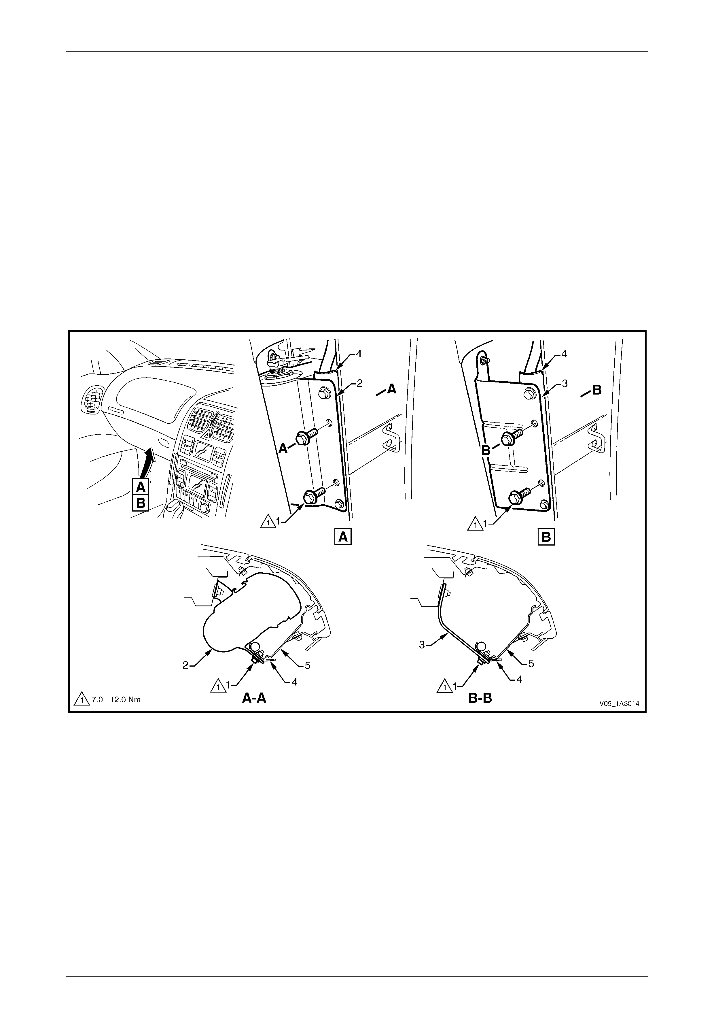
Instrument Panel and Console Page 1A3–57
Page 1A3–57
4 Remove the steering wheel inflatable restraint module, refer to Section 12M Occupant Protection S ystem .
NOTE
A Special Tool is required.
5 Remove the steering wheel, refer to Section 9 Steering.
6 Remove the turn signal switch assembly, refer to Section 12B Lighting System.
7 Remove the wiper and washer control switch, refer to Section 12N Wipers, Washers and Horn.
8 Remove the two inner screws (1) attaching the instrument panel inflatable restraint (2) or instrument panel outer
upper bracket (3) and instrument panel lower bracket (4) to the instrument panel inflatable restraint bracket (5),
refer to Figure 1A3 – 63.
NOTE
View A is for vehicles with an instrument panel
inflatable restraint. View B is for vehicles without
an instrument panel inflatable restraint.
Figure 1A3 – 63
9 Referring to Figure 1A3 – 64, remove the following screws attaching the instrument pad assembly:
a left-hand end (1) one place,
b left-hand air duct (2) one place,
c passenger side lower (3 and 4) two places each,
d left of centre (5) one place,
e driver side lower (6) one place,
f within the instrument cluster hood (7), one place,
g right-hand air duct (8) one place,
h right-hand end (9) one place, and
i along the upper edge (10), five places.
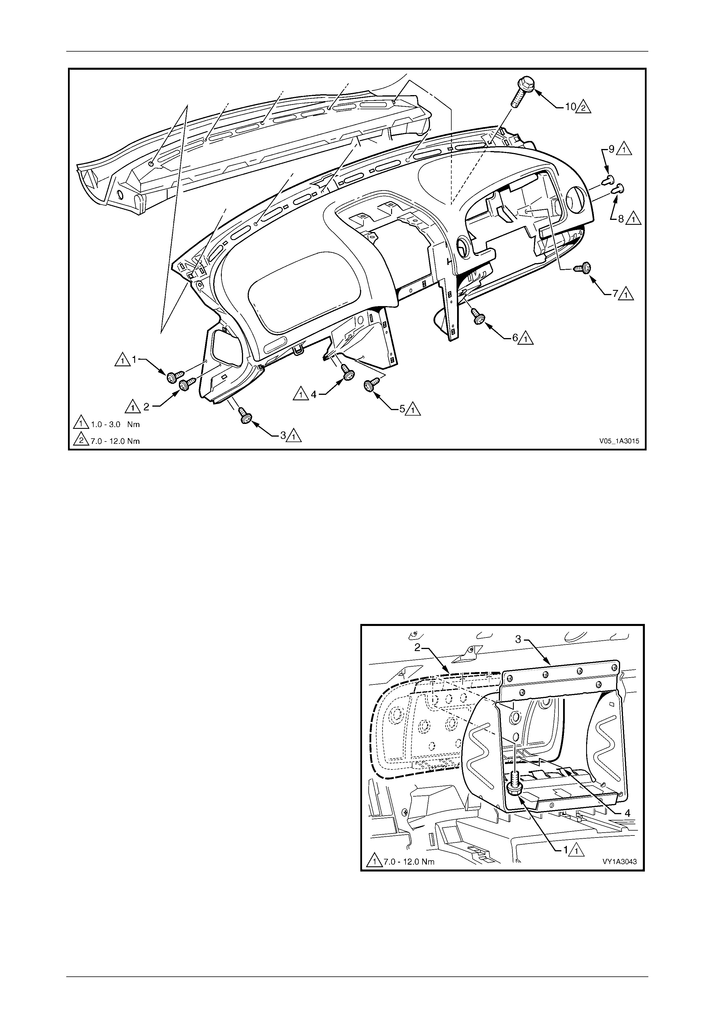
Instrument Panel and Console Page 1A3–58
Page 1A3–58
Figure 1A3 – 64
10 With the aid of an assistant, carefully lift the pad assembly out of the vehicle and place on a soft surface.
Disassemble
NOTE
The instrument panel pad is attached to the
carrier with screws and adhesive and is not
serviced.
1 From the rear side of the instrument panel pad
assembly, remove the screw (1), four places, attaching
the instrument panel inflatable restraint opening trim
cover (2) to the instrument panel inflatable restraint
bracket (3).
2 While pushing on the trim cover, detach the tab (4),
four places, and remove the trim cover.
Figure 1A3 – 65
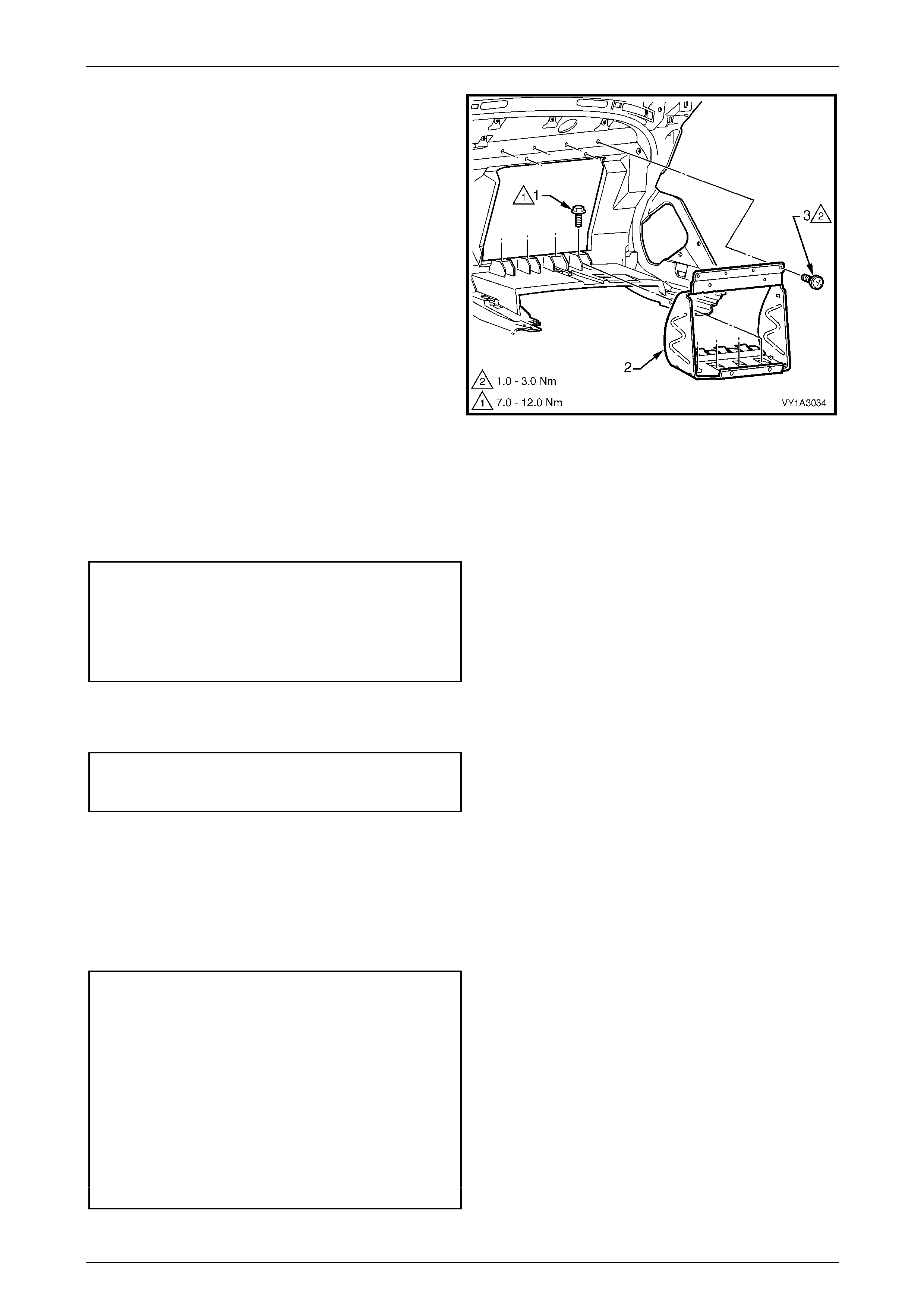
Instrument Panel and Console Page 1A3–59
Page 1A3–59
3 From the rear side of the instrument panel pad
assembly, remove the screw (1), four places, attaching
the instrument panel inflatable restraint brack et (2) to
the pad assembly.
4 Remove the screw (3), six places, and remove the
bracket from the pad assembly.
Figure 1A3 – 66
Reassemble
1 Fit the bracket in position, ensuring the lower screw hole tabs are correctly positioned in the pad assembl y.
2 Install the upper and lower screws and tighten to the specified torque.
Instrument panel inflatable rest raint
bracket lower attaching screw torque
specification..............................................7.0 – 12.0 Nm
Instrument panel inflatable rest raint
bracket upper attaching screw
torque specification.....................................1.0 – 3.0 Nm
3 Locate the trim cover in the pad assembly opening and align the trim cover with the four tabs.
4 Push the trim cover into position, install the four screws and tighten to the specified torque.
Instrument panel inflatable rest raint
opening trim cover attaching screw
torque specification...................................7.0 – 12.0 Nm
Reinstall
Reinstallation of the instrument panel pad assembly is the reverse of the removal procedure, noting the follo wing:
1 Ensure the wiring connectors are located through their correct cavit y,
refer to Section 12O Fuses, Relays and Wiring Harnesses.
2 Tighten the attaching scre ws to the specifi ed torque.
Instrument panel inflatable rest raint to
instrument panel lower bracket attaching scre w
torque specification...................................7.0 – 12.0 Nm
Instrument panel pad assembly side
attaching screw torque specification...........1.0 – 3.0 Nm
Instrument panel pad assembly to air
duct attaching screw torque specification ...1.0 – 3.0 Nm
Instrument panel pad assembly lo wer
attaching screw torque specification...........1.0 – 3.0 Nm
Instrument panel pad assembly upper
attaching screw torque specification.........7.0 – 12.0 Nm
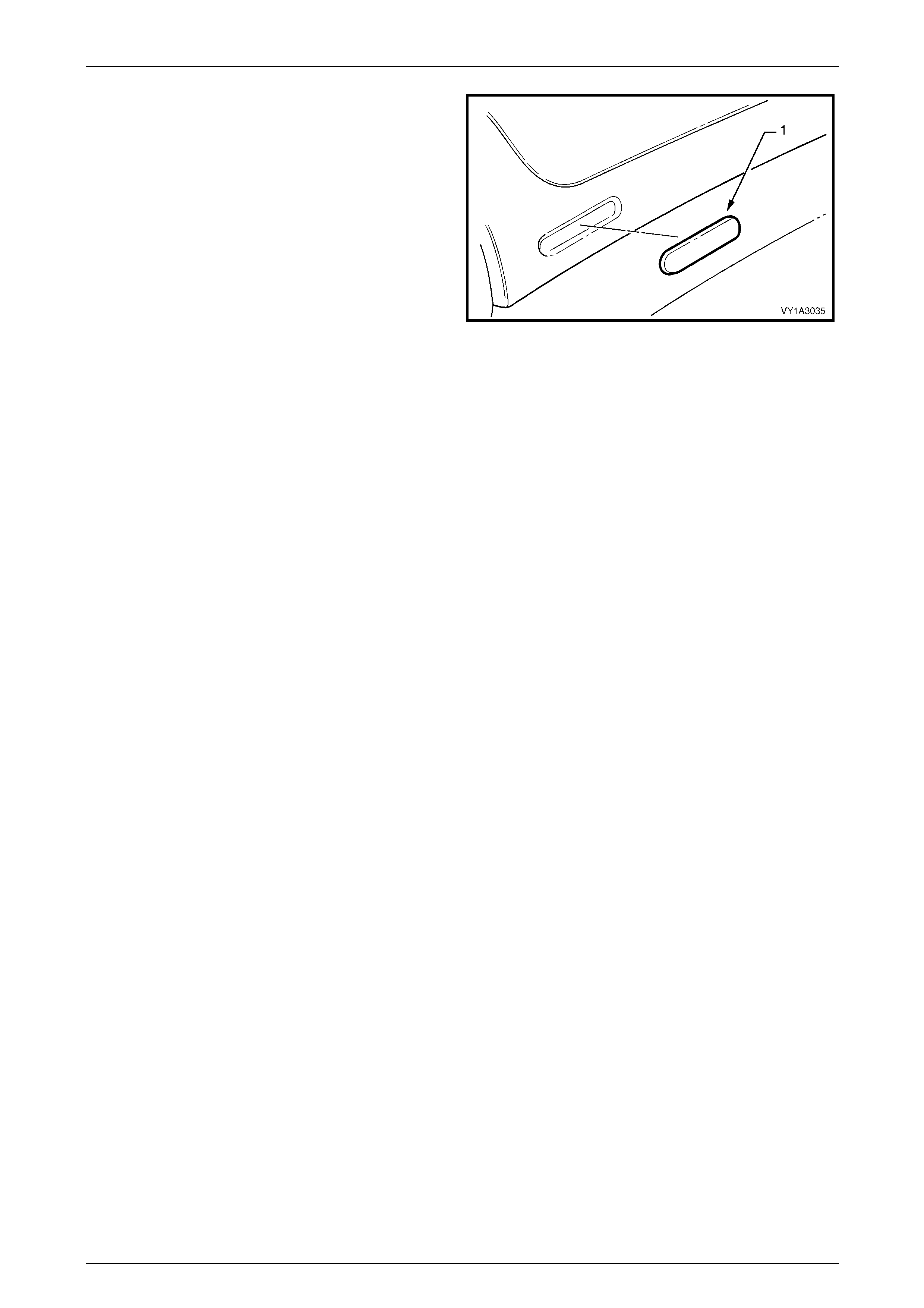
Instrument Panel and Console Page 1A3–60
Page 1A3–60
3 If a new instrument panel pad assembly is being
installed, fit a new nameplate (1). Clean the surface
with wax and grease remover such as Prep sol or
equivalent and affix the emble m centrally in its recess.
NOTE
Press the emblem firmly for at least 10 seconds.
Figure 1A3 – 67
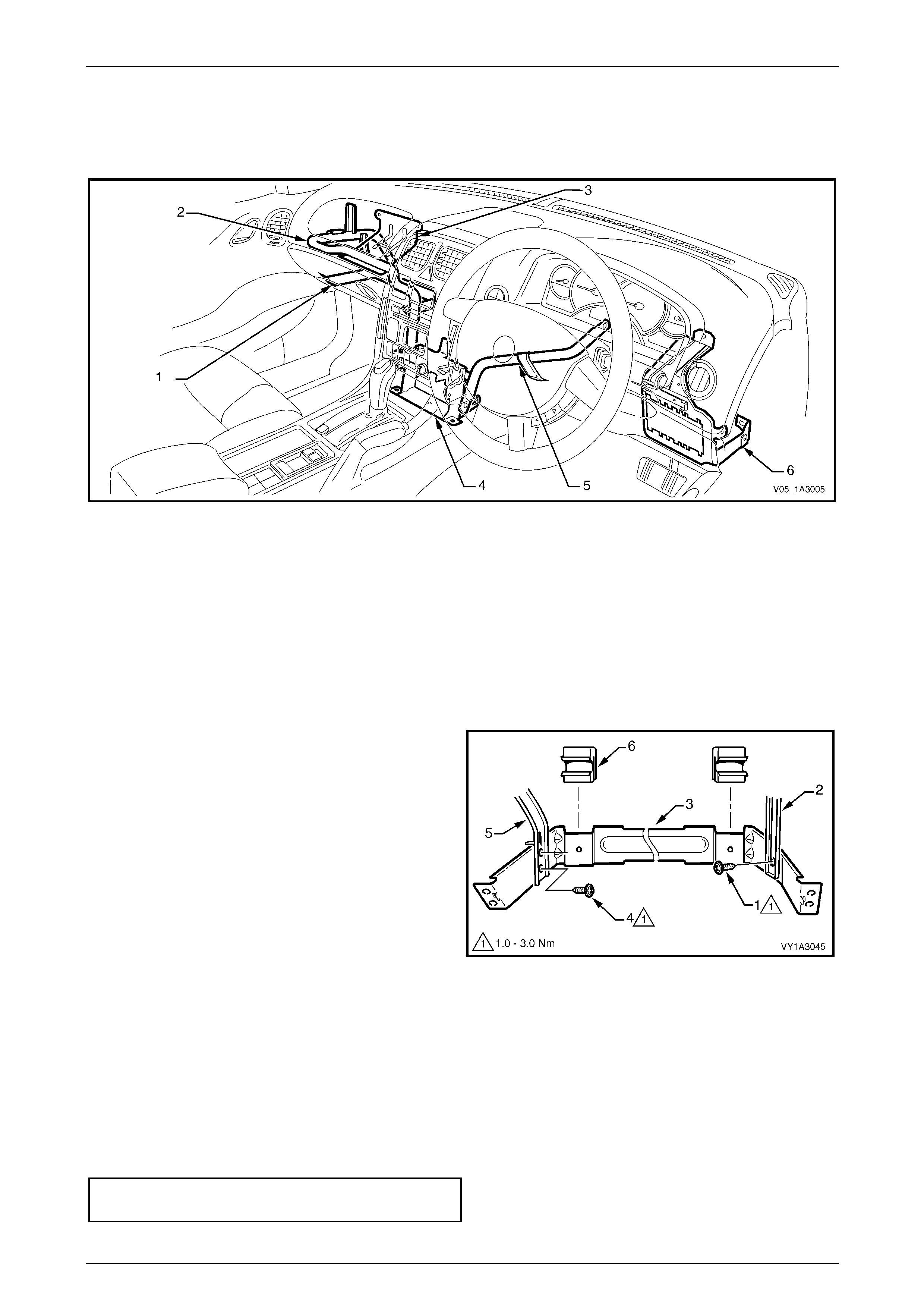
Instrument Panel and Console Page 1A3–61
Page 1A3–61
3.25 Instrument Panel Brackets and Braces
LT Section No. —
Figure 1A3 – 68
Legend
1 Instrument Panel Compartment Bracket
2 Instrument Panel Lower Bracket
3 Instrument Panel Outer Upper Bracket
4 Lower Audio Head Unit Bracket
5 Steering Column Bracket Inner Brace
6 Steering Column Bracket Outer Brace
Instrument Panel Compartment Bracket
Remove
1 Remove the instrument panel compartment, refer to
3.2 Instrument Panel Compartment Assembly.
2 Remove the screw (1) attaching the HVAC unit (2) to
the instrument panel compartment bracket (3).
3 Remove the screw (4), two places, attaching the
bracket to the instrument panel lower bracket (5) and
remove the bracket.
4 As required, prise each instrument panel co mpartment
hinge (6) from the bracket.
Figure 1A3 – 69
Reinstall
Reinstallation of the instrument panel compartment bracket is the reverse of the removal procedure. Tighten the
attaching screws to the specified torque.
NOTE
Take care not to over-tighten the screw attaching
the HVAC unit as the bracket can be easily
damaged.
Instrument panel compartment bracket
attaching screw torque specification...........1.0 – 3.0 Nm
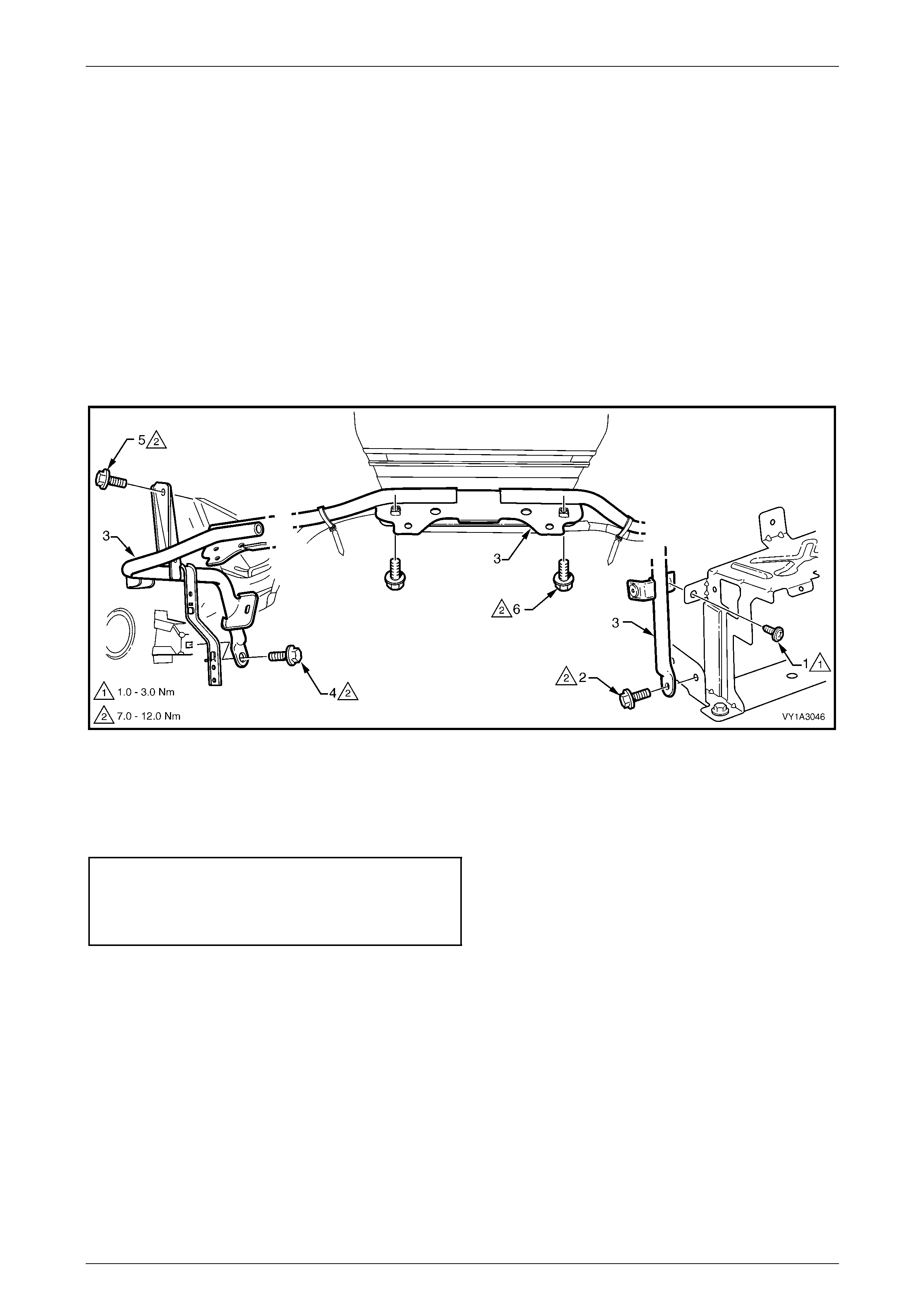
Instrument Panel and Console Page 1A3–62
Page 1A3–62
Instrument Panel Lower Bracket
Remove
1 Remove the following components, as required:
a Instrument panel pad assembly, refer to 3.24 Instrument Panel Pad Assembly.
b Instrument panel compartment bracket as previousl y descr ibed.
c Navigation speaker assembly, if fitted, refer to Section 12L Navigation System.
2 Remove the screws (1 and 2) attaching the instrument panel lower bracket (3) to the lower audio head unit bracket,
refer to Figure 1A3 – 70.
3 Remove the screws (4 and 5) attaching the bracket to the vehicle.
4 Remove the two screws (6) attaching the bracket to the instrument panel inflatable restraint or instrument panel
outer upper bracket (vehicles without instrument panel inflatable restraint), detach the wiring harnesses as required
and remove the bracket.
Figure 1A3 – 70
Reinstall
Reinstallation of the instrument panel lower bracket is the reverse of the removal proced ure. Tighten the attaching
screws to the specified torque.
Instrument panel lower bracket attaching
self-tapping screw torque specification.......1.0 – 3.0 Nm
Instrument panel lower bracket attaching
screw torque specification.........................7.0 – 12.0 Nm
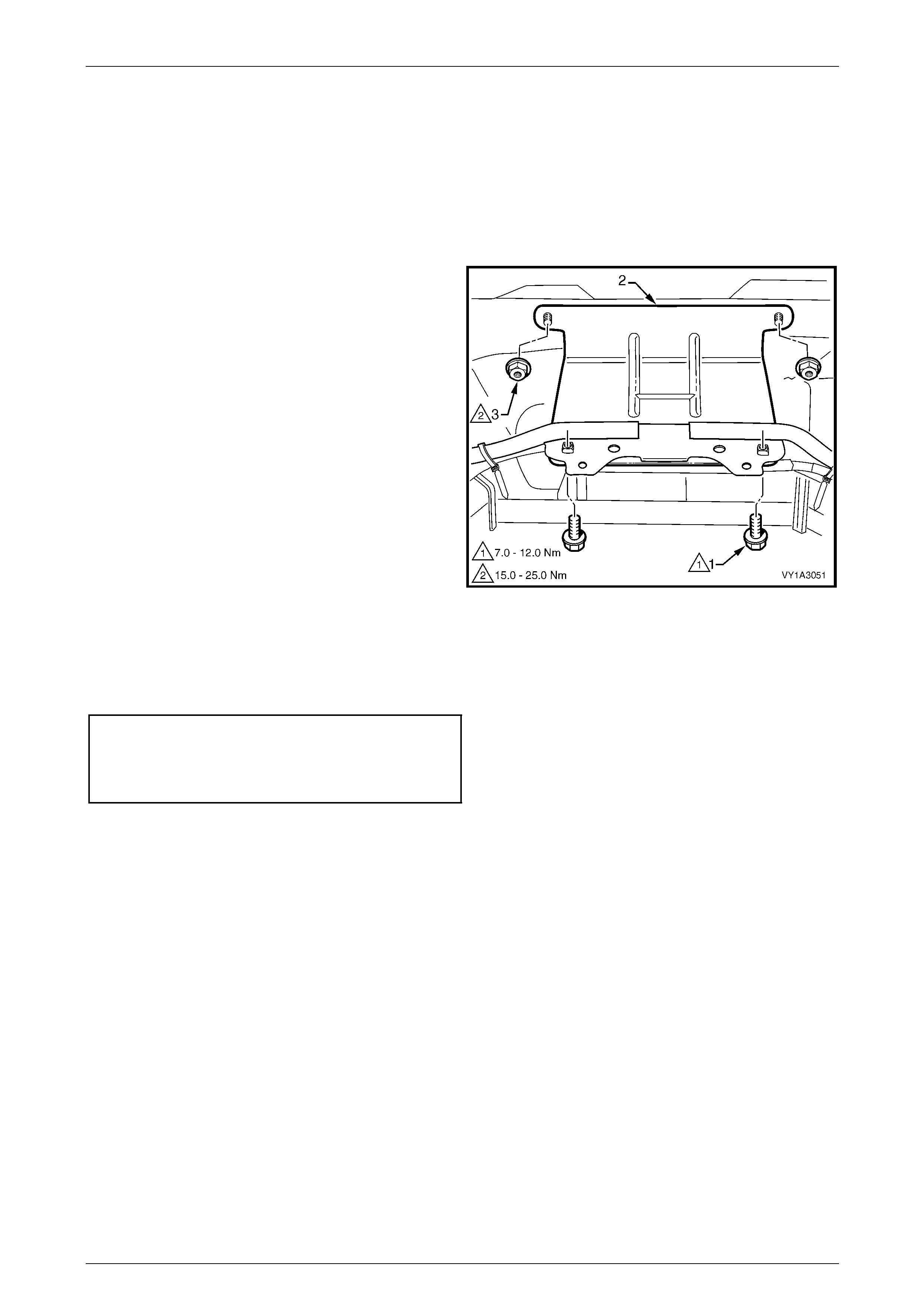
Instrument Panel and Console Page 1A3–63
Page 1A3–63
Instrument Panel Outer Upper Bracket
NOTE
The instrument panel outer upper bracket is only
fitted to vehicles without an instrument panel
inflatable restraint module.
Remove
1 Remove instrument panel pad assembl y, refer to
3.24 Instrument Panel Pad Assembly.
2 Remove the two screws (1) attaching the instrument
panel outer upper bracket (2) to the instrument pane l
lower bracket.
3 Remove the two nuts (3) attaching the bracket to the
dash panel assembly and remove the bracket.
Figure 1A3 – 71
Reinstall
Reinstallation of the instrument panel outer upper bracket is the reverse of the removal pr ocedure. Tighten the attaching
screws to the specified torque.
Instrument panel upper outer bracket
attaching screw torque specification.........7.0 – 12.0 Nm
Instrument panel upper outer bracket
attaching nut torque specification............15.0 – 25.0 Nm
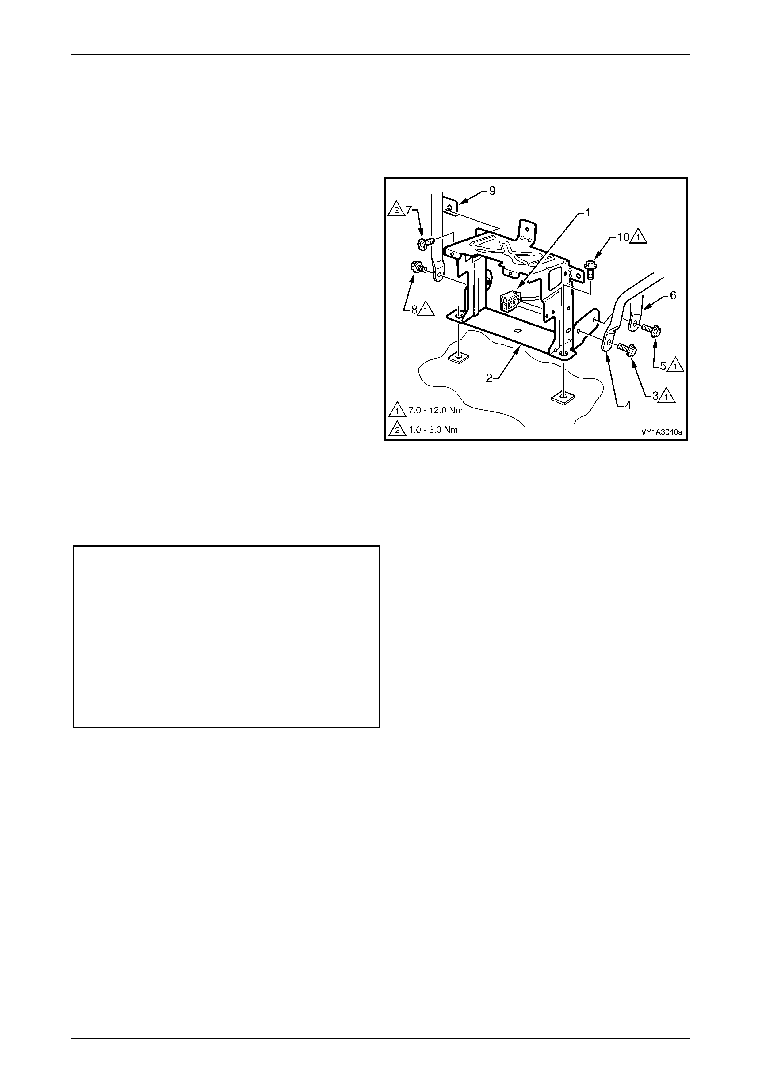
Instrument Panel and Console Page 1A3–64
Page 1A3–64
Lower Audio Head Unit Bracket
Remove
1 Remove the instrument panel pad assembly, as required, refer to 3.24 Instrument Panel Pad Assembly.
2 Withdraw the floor console front duct from the HVAC unit.
3 Unclip the wiring connector (1) from the lower audio
head unit bracket (2).
4 From the driver’s side, remove the screw (3), attaching
the steering column bracket inner brac e (4) to the
lower bracket.
5 Remove the screw (5), attaching the HVAC unit (6) to
the bracket.
6 From the passenger side, remove the
screws (7 and 8) attaching the instrument panel lower
bracket (9) to the bracket.
7 Remove the screw (10), two places, and remove the
bracket.
Figure 1A3 – 72
Reinstall
Reinstallation of the lower audio head unit bracket is the reverse of the removal procedure. T ighten the attaching screws
to the specified torque.
Steering column bracket inner brace
attaching screw torque specification.........7.0 – 12.0 Nm
HVAC unit attaching screw
torque specification...................................7.0 – 12.0 Nm
Instrument panel lower bracket attaching
self-tapping screw torque specification.......1.0 – 3.0 Nm
Instrument panel lower bracket attaching
screw torque specification.........................7.0 – 12.0 Nm
Lower audio head unit bracket attaching screw
torque specification...................................7.0 – 12.0 Nm
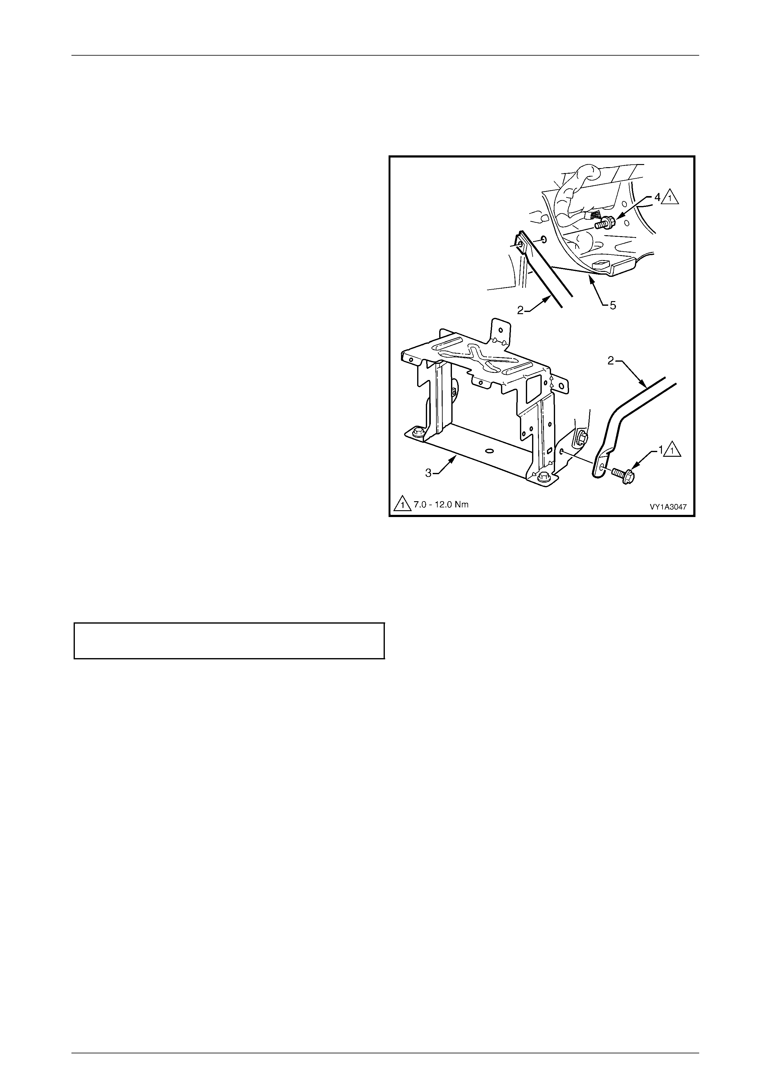
Instrument Panel and Console Page 1A3–65
Page 1A3–65
Steering Column Bracket Inner Brace
Remove
1 Remove the instrument panel pad assembly, as required, refer to 3.24 Instrument Panel Pad Assembly.
2 Remove the screw (1) attaching the steering column
bracket inner brace (2) to the lower audio head unit
bracket (3).
3 Remove the screw (4) attaching the brace to the
steering column bracket (5).
4 Remove the brace.
Figure 1A3 – 73
Reinstall
Reinstallation of the steering column bracket inner brace is the reverse of the removal procedure. T ighten the attaching
screws to the specified torque.
Steering column bracket inner brace
attaching screw torque specification.........7.0 – 12.0 Nm
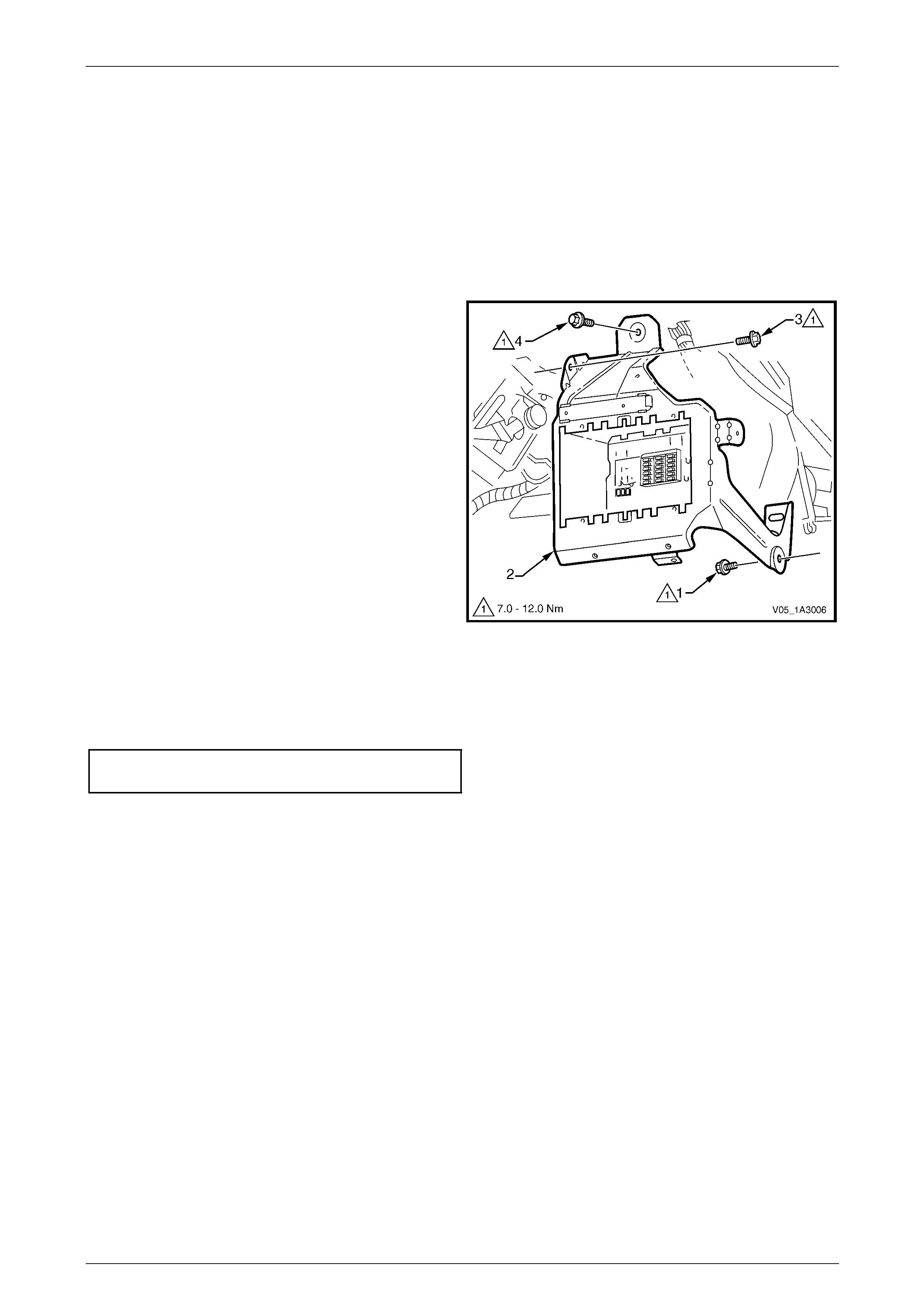
Instrument Panel and Console Page 1A3–66
Page 1A3–66
Steering Column Bracket Outer Brace
Remove
1 Remove the following components, as required:
a Instrument panel pad assembly, refer to 3.24 Instrument Panel Pad Assembly.
b Body control module, refer to Section 12J Body Control Module.
c Fuse and relay block, refer to Section 12O Fuses, Relays and Wiring Harnesses.
d PIM connector A5 for V6 vehicles, refer to Section 12O Fuses, Relays and Wiring Harnesses.
2 Remove the screw (1) attaching the steering column
bracket outer brace (2) to the vehicle.
3 Remove the screw (3) attaching the brace to the
steering column bracket.
4 Remove the screw (4) attaching the brace to the dash
panel and remove the brac e.
Figure 1A3 – 74
Reinstall
Reinstallation of the steering column bracket outer brace is the reverse of the remov al procedure. Tighten the attaching
screws to the specified torque.
Steering column bracket outer brace
attaching screw torque specification.........7.0 – 12.0 Nm

Instrument Panel and Console Page 1A3–67
Page 1A3–67
4 Torque Wrench Specifications
Mobile Phone Compartment Assembly Attaching Screw ..............1.0 – 3.0 Nm
Floor Console Cover Assembly Attaching Screw..........................1.0 – 3.0 Nm
Instrument Panel Lower Extension Side Trim Panel
Attaching Screw ...........................................................................1.0 – 3.0 Nm
Floor Console Rear Compartment Attaching Screw .....................1.0 – 3.0 Nm
Floor Console Rear Air Duct Attaching Screw...............................1.0 – 3.0 Nm
Floor Console Rear Air Outlet Housing Assembly
Attaching Screw ............................................................................1.0 – 3.0 Nm
Floor Console Rear Upper Compartment Assembly
Attaching Screw ............................................................................1.0 – 3.0 Nm
Floor Console Compartment Armrest Hinge Attaching Screw.......1.0 – 3.0 Nm
Floor Console Compartment Armrest Inner Attaching Screw........1.0 – 3.0 Nm
Armrest Assembly Latch Clip Screw .............................................1.0 – 3.0 Nm
Floor Console Attaching Screw.....................................................1.0 – 3.0 Nm
Floor Console Attaching Nut ..........................................................1.0 – 3.0 Nm
Floor Console To Automatic Transmission Selector Assembly
Attaching Screw ............................................................................1.0 – 3.0 Nm
Instrument Panel Compartment Latch Assembly
Attaching Screw .......................................................................................1.0 – 3.0 Nm
Instrument Panel Compartment Door Attaching Screw.................1.0 – 3.0 Nm
Instrument Panel Compartment Lock Striker Attaching Screw......1.0 – 3.0 Nm
Data Link Connector Attaching screw..................................................1.0 – 3.0 Nm
Instrument Panel Lower Trim Panel Retainer Attaching Screw......1.0 – 3.0 Nm
Instrument Panel Centre Air Outlet housing Assembly
Attaching Screw ............................................................................1.0 – 3.0 Nm
Instrument Panel Centre Trim Assembly Attaching Screw............1.0 – 3.0 Nm
Instrument Panel Upper Compartment Latch Assembly
Attaching Screws...........................................................................1.0 – 2.0 Nm
Instrument Panel Cup Holder Assembly attaching Screw .............1.0 – 3.0 Nm
OCC Control Module Attaching Screw ..........................................1.0 – 3.0 Nm
Instrument Panel Centre Air Outlet Housing Assembly
Attaching Screw ............................................................................1.0 – 3.0 Nm
Instrument Panel Upper Compartment Attaching Screw...............1.0 – 3.0 Nm
Instrument Panel Centre Trim Assembly Attaching Screw............1.0 – 3.0 Nm
Auxiliary Gauge Assembly Attaching Screw..................................1.0 – 3.0 Nm
Instrument Panel Cup Holder Assembly Attaching Screw.............1.0 – 3.0 Nm
OCC Control Module Attaching Screw ..........................................1.0 – 3.0 Nm
Instrument Panel Centre Air Outlet housing Assembly
Attaching Screw ............................................................................1.0 – 3.0 Nm
Instrument Panel Centre Trim Assembly Attaching Screw............1.0 – 3.0 Nm
Instrument Panel Lower Compartment Or Ashtray Assembly
Attaching Screw ............................................................................1.0 – 3.0 Nm
Instrument Panel Lower Extension Side Trim Attaching Screw.....1.0 – 3.0 Nm

Instrument Panel and Console Page 1A3–68
Page 1A3–68
Manual HVAC Controller Attaching Screw ....................................1.0 – 3.0 Nm
Audio Head Unit Bracket Assembly Attaching Screw....................1.0 – 3.0 Nm
Audio Head Unit Housing Attaching Screw ...................................1.0 – 3.0 Nm
In-Car Air Temperature Sensor Attaching Screw ..........................1.0 – 3.0 Nm
Instrument Cluster Attaching Screw..............................................1.0 – 3.0 Nm
Instrument Panel Outer Cover Attaching Screw............................1.0 – 3.0 Nm
Windshield Defroster Grille Attaching Screw.................................1.0 – 3.0 Nm
Instrument Panel Speaker Attaching Screw..................................1.0 – 3.0 Nm
Instrument Panel Inflatable Restraint Bracket Lower
Attaching Screw ..........................................................................7.0 – 12.0 Nm
Instrument Panel Inflatable Restraint Bracket Upper
Attaching Screw ............................................................................1.0 – 3.0 Nm
Instrument Panel Inflatable Restraint Opening T rim Cover
Attaching Screw ..........................................................................7.0 – 12.0 Nm
Instrument Panel Inflatable Restraint To Instrument Panel
Lower Bracket Attaching Screw...................................................7.0 – 12.0 Nm
Instrument Panel Pad Assembly Side Attaching Screw.................1.0 – 3.0 Nm
Instrument Panel Pad Assembly To Air Duct Attaching Screw.....1.0 – 3.0 Nm
Instrument Panel Pad Assembly Lower Attaching Screw..............1.0 – 3.0 Nm
Instrument Panel Pad Assembly Upper Attaching Screw............7.0 – 12.0 Nm
Instrument Panel Compartment Bracket Attaching Screw.............1.0 – 3.0 Nm
Instrument Panel Lower Bracket Attaching Self-Tapping Screw ...1.0 – 3.0 Nm
Instrument Panel Lower Bracket Attaching Screw.......................7.0 – 12.0 Nm
Instrument Panel Upper Outer Bracket Attaching Screw.............7.0 – 12.0 Nm
Instrument Panel Upper Outer Bracket Attaching Nut...............15.0 – 25.0 Nm
Steering Column Bracket Inner Brace Attaching Screw ..............7.0 – 12.0 Nm
HVAC Unit Attaching Screw........................................................7.0 – 12.0 Nm
Instrument Panel Lower Bracket Attaching Self-Tapping Screw ...1.0 – 3.0 Nm
Instrument Panel Lower Bracket Attaching Screw.......................7.0 – 12.0 Nm
Lower Audio Head Unit Bracket Attaching Screw........................7.0 – 12.0 Nm
Steering Column Bracket Inner Brace Attaching Screw ..............7.0 – 12.0 Nm
Steering Column Bracket Outer Brace Attaching Screw..............7.0 – 12.0 Nm
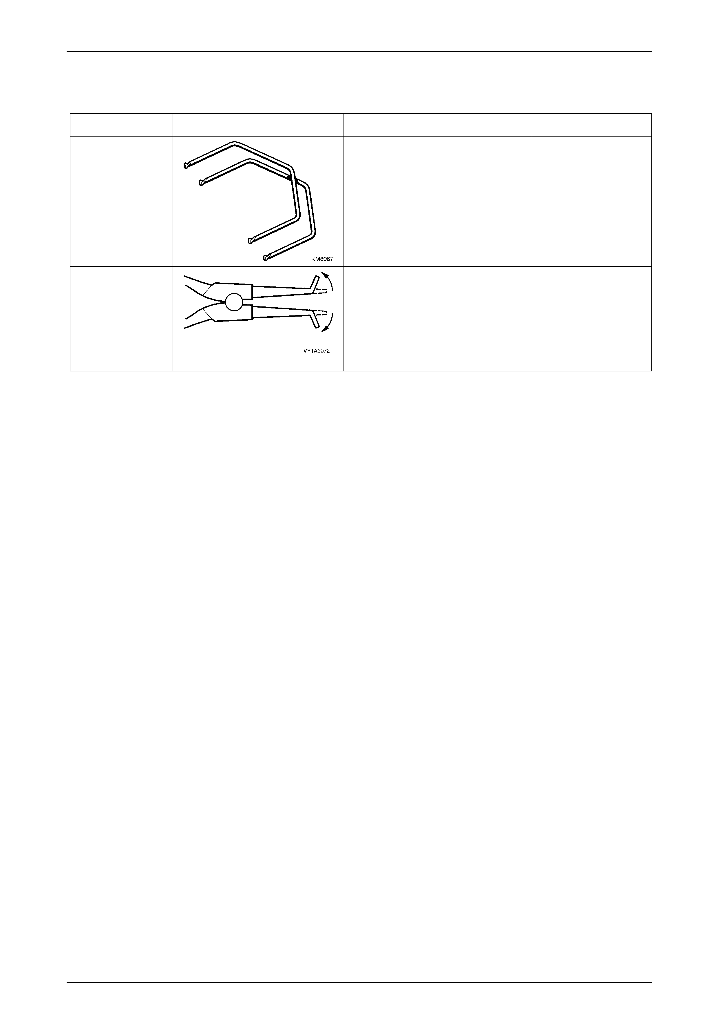
Instrument Panel and Console Page 1A3–69
Page 1A3–69
5 Special Tools
Tool Number Illustration Description Tool Classification
KM6067
Audio Head Unit Removal Tool
Used for removing audio unit from its
mounting location.
Mandatory
–
Accessory Socket Removal Tool
Modified commercially available
external circlip pliers. Used for
removing the floor console accessory
power socket from its retaining bezel.
Refer to 2.3 Floor Console Assembly.
Dealer Fabricat ed