
Sheetmetal Page 1B–1
Page 1B–1
Section 1B
Sheetmetal
ATTENTION
Before performing any service operation or other procedure described in this Section, refer to Section 00
Warnings, Cautions and Notes for correct workshop practices with regard to safety and/or property damage.
1 General Information ...............................................................................................................................3
2 Service Notes..........................................................................................................................................4
2.1 Body Structure Replacement Part Refinishing ................................................................................................... 4
2.2 Anti-corrosive Treatment ...................................................................................................................................... 5
3 Body Structure Replacement Parts......................................................................................................6
3.1 Sedan...................................................................................................................................................................... 7
Underbody.............................................................................................................................................................. 7
Upperbody, Excluding Roof Structure................................................................................................................. 9
Roof Structure...................................................................................................................................................... 10
Body Assembly.................................................................................................................................................... 11
3.2 Wagon, Excluding AWD...................................................................................................................................... 13
Underbody............................................................................................................................................................ 13
Upperbody............................................................................................................................................................ 15
Body Assembly.................................................................................................................................................... 17
3.3 AWD Wagon ......................................................................................................................................................... 19
Underbody............................................................................................................................................................ 19
Upperbody............................................................................................................................................................ 21
Roof Assembly..................................................................................................................................................... 22
Body Assembly.................................................................................................................................................... 23
3.4 Coupe.................................................................................................................................................................... 25
Underbody............................................................................................................................................................ 25
Upperbody............................................................................................................................................................ 27
Body Assembly.................................................................................................................................................... 29
3.5 Utility..................................................................................................................................................................... 31
Underbody............................................................................................................................................................ 31
Upperbody............................................................................................................................................................ 33
Body Assembly.................................................................................................................................................... 35
3.6 Regular Cab, Excluding AWD............................................................................................................................. 37
Underbody............................................................................................................................................................ 37
Upperbody............................................................................................................................................................ 39
Body Assembly.................................................................................................................................................... 41
3.7 AWD Regular Cab................................................................................................................................................ 43
Underbody............................................................................................................................................................ 43
Upperbody............................................................................................................................................................ 45
Body Assembly.................................................................................................................................................... 47
3.8 Crew Cab, Excluding AWD .................................................................................................................................. 49
Underbody............................................................................................................................................................ 49
Upperbody Sheetmetal........................................................................................................................................ 51
Body Assembly.................................................................................................................................................... 53
Rear Tray Body Assembly .................................................................................................................................. 55

Sheetmetal Page 1B–2
Page 1B–2
3.9 AWD Crew Cab..................................................................................................................................................... 57
Underbody............................................................................................................................................................ 57
Upperbody Sheetmetal........................................................................................................................................ 59
Body Assembly.................................................................................................................................................... 61
Rear Tray Body Assembly .................................................................................................................................. 63
4 Service Operations...............................................................................................................................65
4.1 Front Fender, Except Coupe............................................................................................................................... 65
Remove................................................................................................................................................................. 65
Disassemble......................................................................................................................................................... 67
Reinstall................................................................................................................................................................ 67
4.2 Front Fender, Coupe............................................................................................................................................ 69
Remove................................................................................................................................................................. 69
Reinstall................................................................................................................................................................ 70
4.3 Battery Tray Assembly........................................................................................................................................ 72
Remove................................................................................................................................................................. 72
Reinstall................................................................................................................................................................ 72
4.4 Front Side Rail Brace........................................................................................................................................... 73
Remove................................................................................................................................................................. 73
Reinstall................................................................................................................................................................ 73
4.5 Side Speaker Mounting Bracket, Coupe............................................................................................................ 74
Remove................................................................................................................................................................. 74
Reinstall................................................................................................................................................................ 74
4.6 Load Floor Front Panel Assembly, Utility.......................................................................................................... 75
Remove................................................................................................................................................................. 75
Reinstall................................................................................................................................................................ 75
4.7 Front Inner Side Panel Cover, Utility.................................................................................................................. 76
Remove................................................................................................................................................................. 76
Reinstall................................................................................................................................................................ 76
4.8 Rear Inner Side Panel Cover, Utility................................................................................................................... 77
Remove................................................................................................................................................................. 77
Reinstall................................................................................................................................................................ 77
4.9 Rear Tray Body Assembly, Crew Cab................................................................................................................ 78
Remove................................................................................................................................................................. 79
Reinstall................................................................................................................................................................ 80
4.10 Inner Side Panel Extension Cover, Cre w Cab ................................................................................................... 82
Remove................................................................................................................................................................. 82
Reinstall................................................................................................................................................................ 82
4.11 Front End Panel Cover, Crew Cab...................................................................................................................... 83
Remove................................................................................................................................................................. 83
Reinstall................................................................................................................................................................ 83
4.12 Subframe Assembly, Regular Cab ..................................................................................................................... 84
Remove................................................................................................................................................................. 84
Disassemble......................................................................................................................................................... 86
Reassemble.......................................................................................................................................................... 86
Reinstall................................................................................................................................................................ 87
4.13 Subframe Assembly, Crew Cab.......................................................................................................................... 89
Remove................................................................................................................................................................. 89
Disassemble......................................................................................................................................................... 91
Reassemble.......................................................................................................................................................... 91
Reinstall................................................................................................................................................................ 92
5 Torque Wrench Specifications............................................................................................................94

Sheetmetal Page 1B–3
Page 1B–3
1 General Information
This Section contains an illus t rated listin g of the service d sh eetmetal components that form the vehicle’s body structure.
This listing is provided for information o nly and is to be used as a guide. For the latest configurations refer to the current
spare parts information.

Sheetmetal Page 1B–4
Page 1B–4
2 Service Notes
2.1 Body Structure Replacement Part
Refinishing
The vehicle body structure is designed to meet or exceed many regulations, including crash performance and occupant
protection, etc. When replacing or repairing a part or sub-assembly, care must be taken to ensure that the correct
alignment and strength of the unit as a whole is maintained.
In some instances, replacing a part or sub-assembly with a new one, rather than repairing the damaged part, can more
effectively and economically repair major damage to the body structure.
Spot welding is used extensiv ely for joining panels or assemblies, however special adhesives are playing an ever-
increasing role in the joini ng of body structure components, either on their own or together with spot welds. Where
repairs are performed, it is imperative that the correct adhesives are used. Effective rust proofing techn iques, as outlined
in the following paragraphs, must also be observed.
It is for these reasons that only qualified persons with suitable training and qualif ications should perform the repair or
replacement of body structure components. F urther information can be found in the MY 2005 VZ Series Service Manual
Supplement, Body Structure Repair.

Sheetmetal Page 1B–5
Page 1B–5
2.2 Anti-corrosive Treatment
Pre-coated and galvanised steel is used extensively for various body struct ure components for increased corrosion
protection. Body panels such as the engin e hoo d, door and rear compartment lid outer panels are pre-coated on the
inner surface of the metal to improve corrosion protecti on. Other body structure members have complete double-sided
galvanised protection.
In addition, a rust preventative material is spra yed after p aint application to areas such as the interior surfaces of doors,
etc. This rust preventative material must be replaced whenever a panel repair or replacement procedure disturbs its
application.
Rust preventative compounds used for repairs should be light bodied materials designed to penetrate between metal-to-
metal surfaces such as pinch weld flanges and integral panel attaching points.
All bare metal surfaces must be treated with metal conditioner and primed. T hese operations need to be carried out pri or
to the application of sealers, waxes and sound deadeners. Attaching points of new replacement panels shou ld be
resealed. The hemming flanges of replacement doors, liftgates, endgates and rear comp artment lids will require re-
sealing.
Open joins that require bridging of the sealer to close a gap should b e sealed with a heavy-bodied caulking material.
When colour applicatio n is required to restore repaired area s to original appearance, con v entional refinishing
preparation, undercoat build-u p and colour application techniques should be employed.
When deadeners are disturbe d during damage repair, or a panel has been replaced, the deadener material must be
replaced with an equivalent material. The location and pattern for replacement material can be determined by observing
the original deadener application outlines.
Further information can be found in the MY 200 5 VZ Series Service Manual Supplement, Body Structure Repair.

Sheetmetal Page 1B–6
Page 1B–6
3 Body Structure Replacement
Parts
The following illustrations and tables describe the body struc ture assemblies and panels that are available for service
replacement.
The purpose of this information is to provid e the repairer with a better understanding of available replacement sections.
For further information regarding the body structure, refer to the MY2005 VZ Series Service Manual Supplement, Body
Structure Repair.
NOTE
Always refer to an authorised dea ler for the latest
configurations.
Sheetmetal Page 1B–7
Page 1B–7
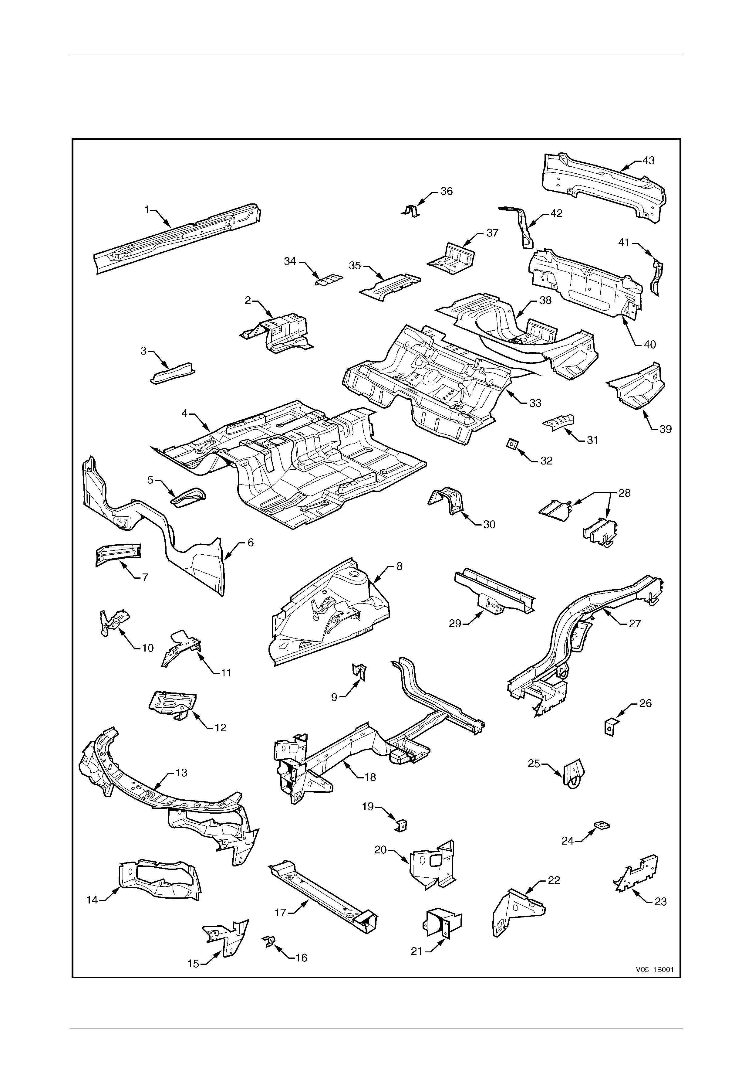
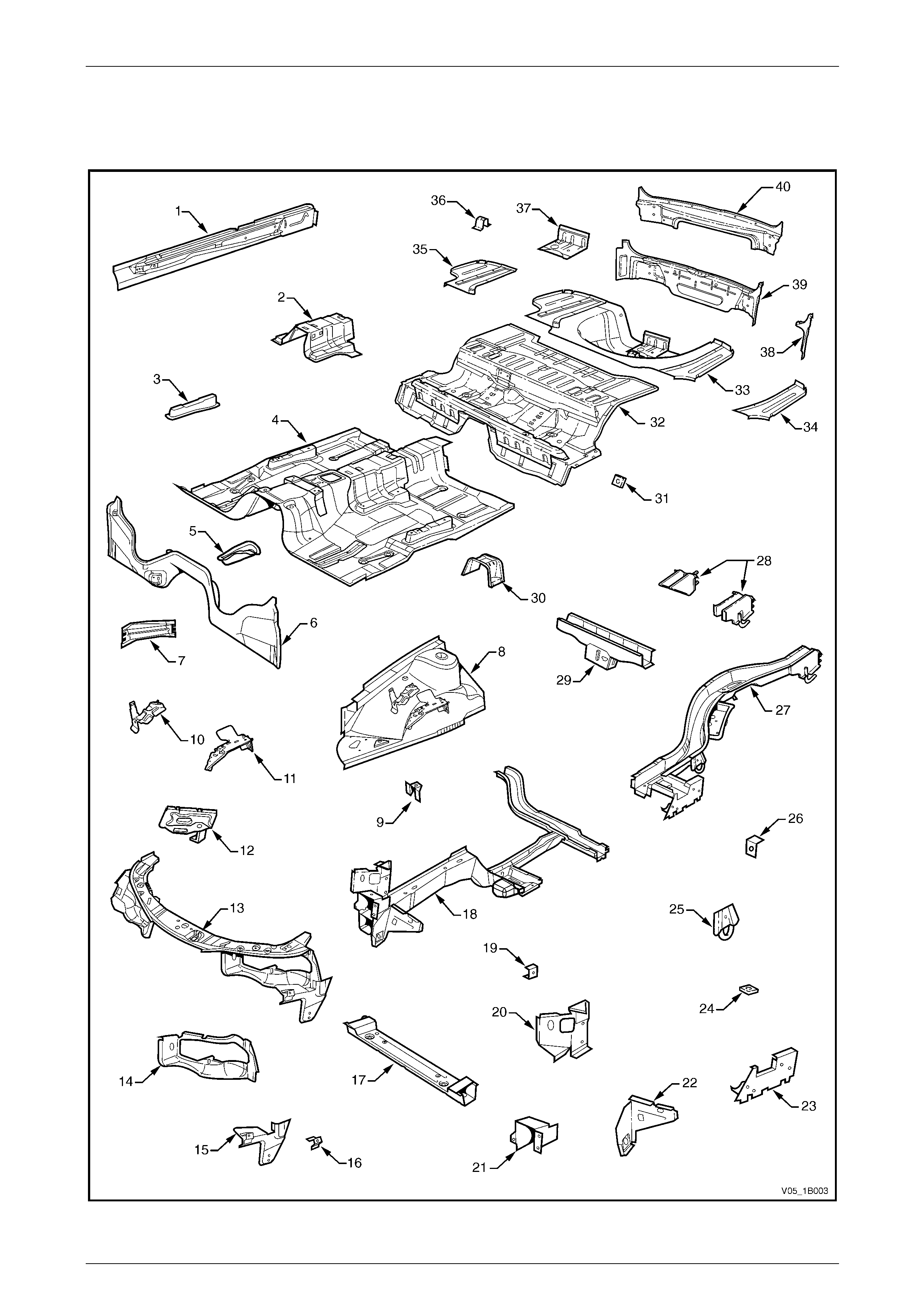
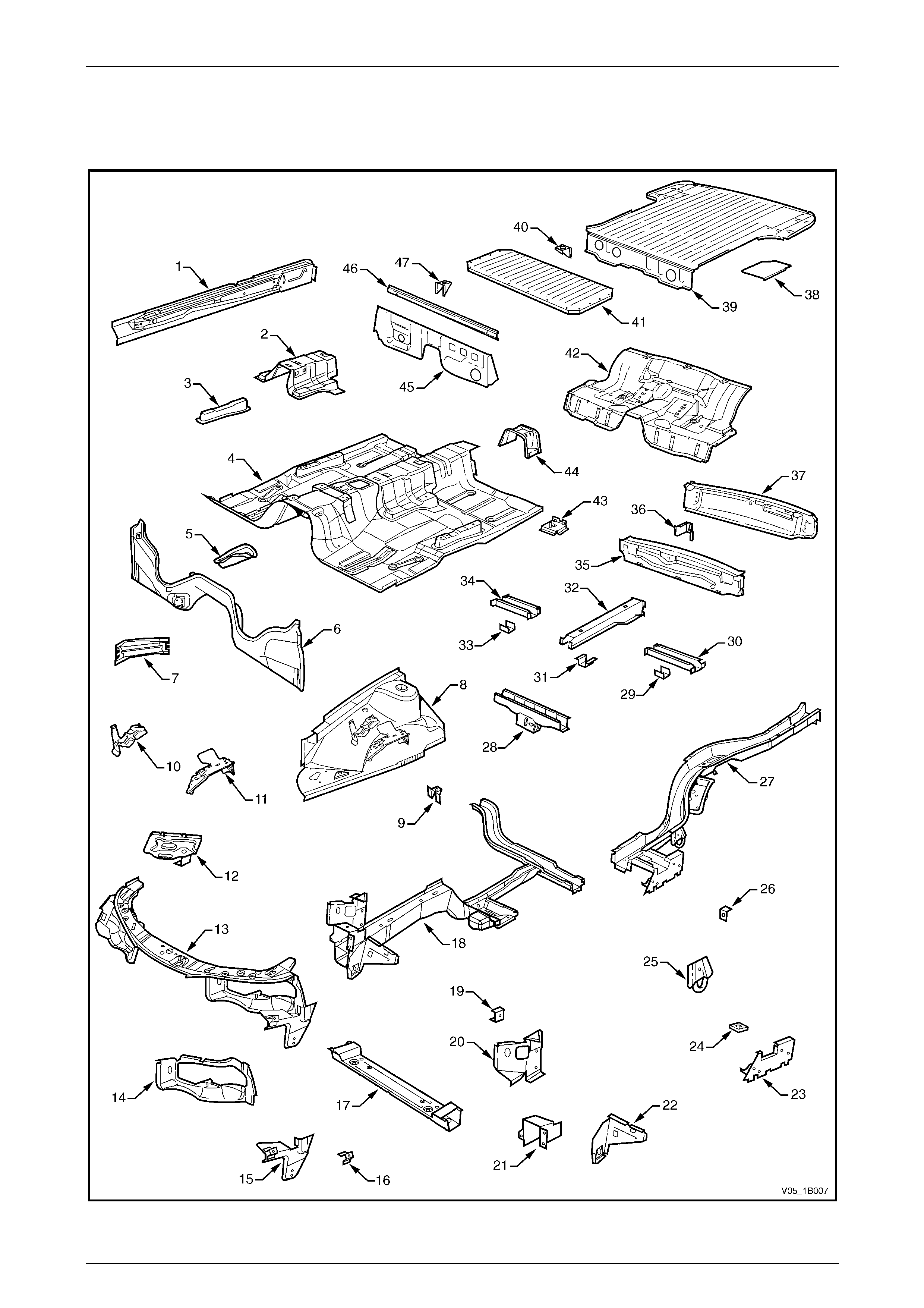
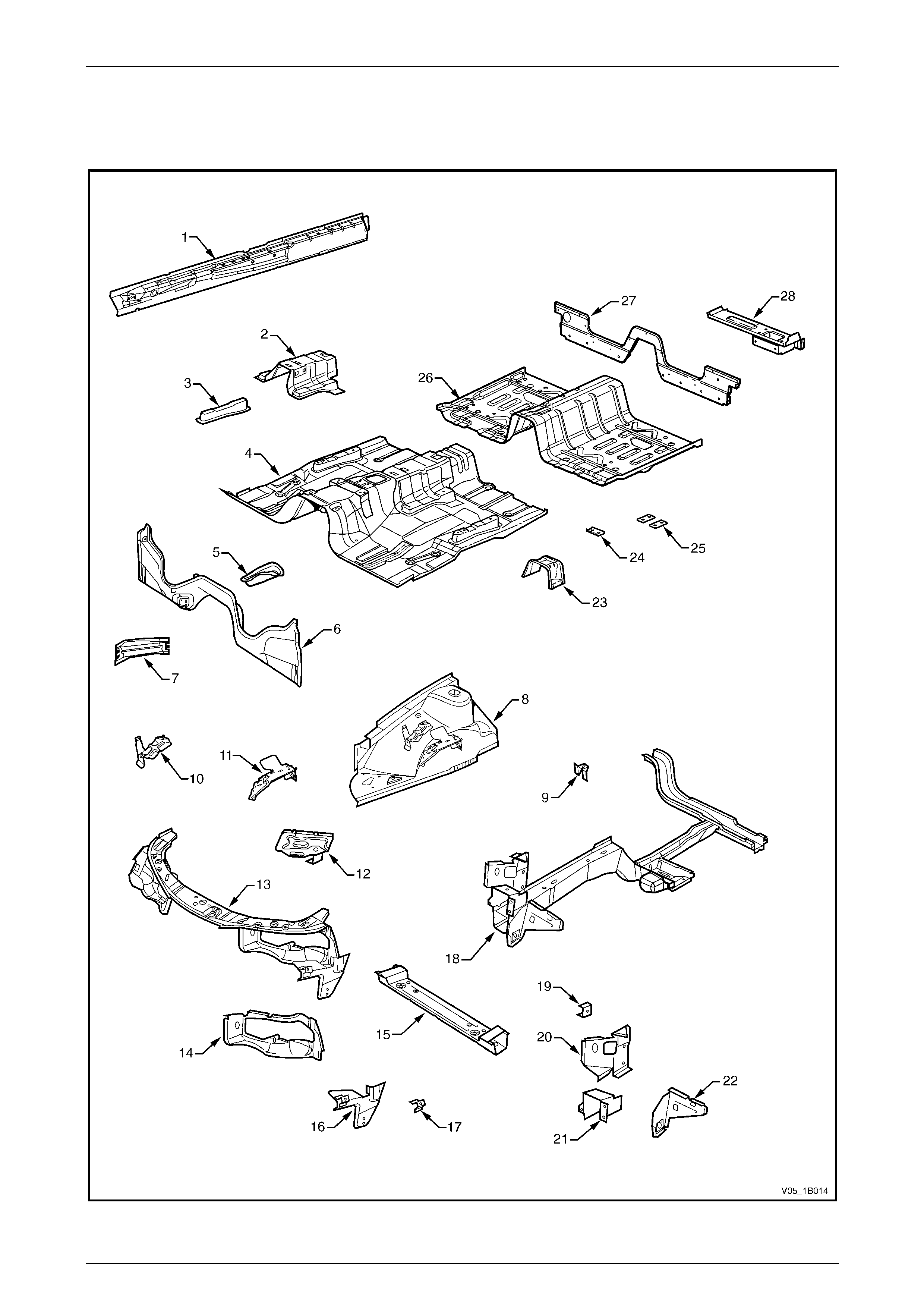
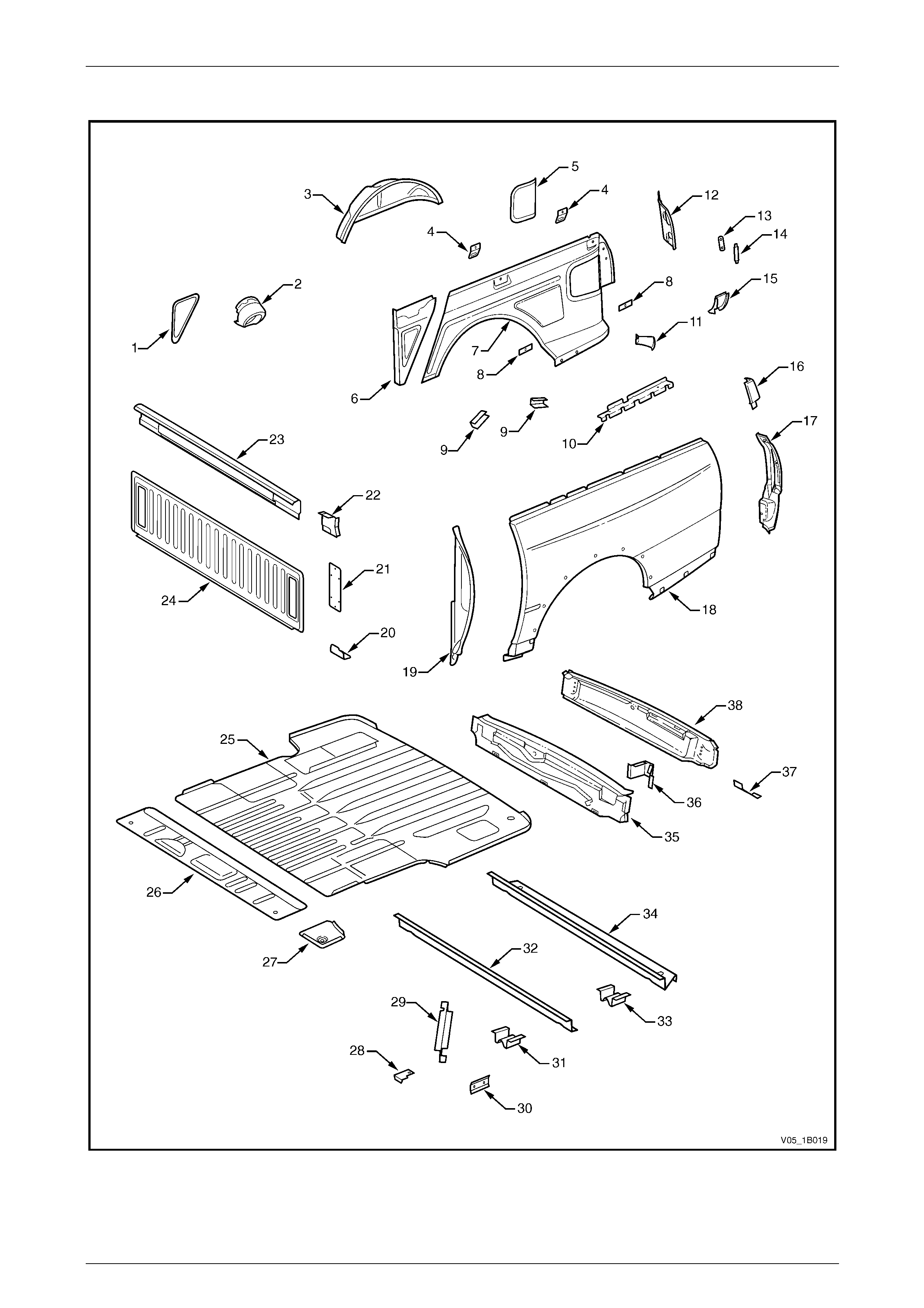
3.1 Sedan
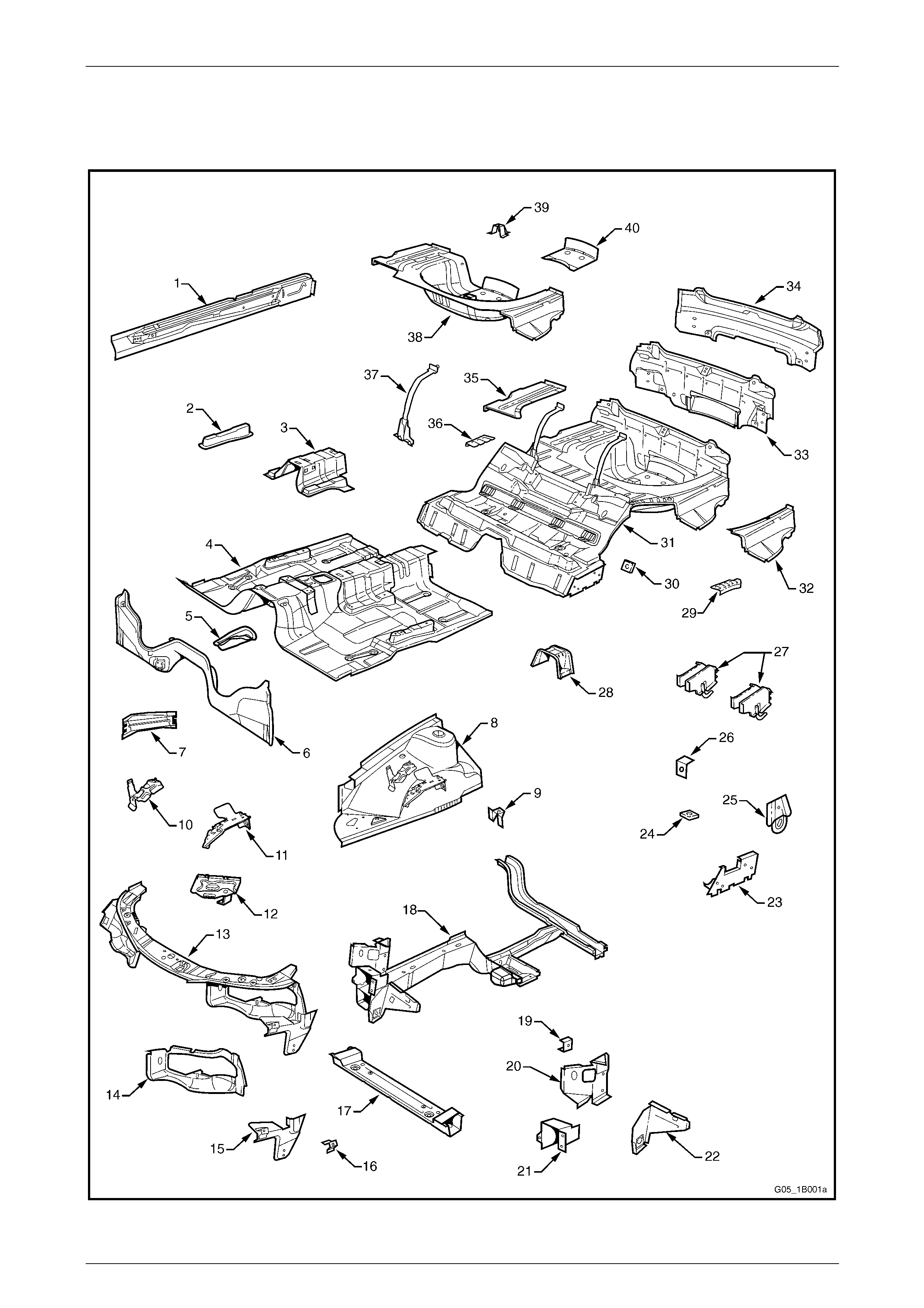
Underbody
Figure 1B – 1

Sheetmetal Page 1B–8
Page 1B–8
Legend
1 Inner Rocker Panel Assembly, RH / LH
2 Seat Inner Bracket Assembly
3 Seat Outer Bracket Assembly, RH / LH
4 Front Floor Panel Assembly
5 Transmission Support Bracket, RH / LH
6 Front Floor Panel Extension
7 Front Side Rail Brace, RH / LH
8 Front Wheelhouse Panel Assembly, RH / LH
9 Horn Bracket Assembly, LH only
10 Relay Housing Bracket, RH only
11 ABS Modulator Bracket Assembly, RH only
12 Battery Tray Assembly, RH only
13 Front End Panel Assembly
14 Headlamp Panel, LH / RH
15 Headlamp & Front Fascia Mount Bracket, LH / RH
16 Fender Front Lower Bracket, LH / RH
17 Radiator Lower Support Assembly
18 Front Side Rail Assembly, LH / RH
19 Radiator Side Mounting Bracket, LH / RH
20 Front Wheelhouse Bracket Assembly, LH / RH
21 Front Bumper Impact Bar Bracket, LH / RH
22 Front Wheelhouse Panel Bracket, LH / RH
23 Rear Floor Panel Outer Extension, LH / RH
24 Rear Suspension Support Mount Plate, LH / RH
25 Rear Tie Down Assembly, LH / RH
26 Rear Brake Hose Bracket, LH / RH
27 Rear Side Rail Assembly, LH / RH
28 Rear Bumper Impact Bar Brace Assembly, LH / RH
29 Crossmember Assembly No. 2
30 Propeller Shaft Hanger Assembly
31 Rear Floor Panel Reinforcement, LH
32 Rear Seat Belt Anchor Plate Assembly, 3 places
33 Rear Floor Panel Assembly
34 Rear Floor Panel Reinforcement, RH
35 Rear Compartment Floor Panel Outer Extension, RH
36 Spare Wheel Anchor Plate Assembly
37 Fuel Tank Support Reinforcement Assembly
38 Rear Compartment Floor Panel Assembly
39 Rear Compartment Floor Panel Outer Extension, LH
40 Rear End Panel Assembly
41 Rear End Panel Extension, LH
42 Rear End Panel Extension, RH
43 Rear End Lower Panel
Sheetmetal Page 1B–9
Page 1B–9
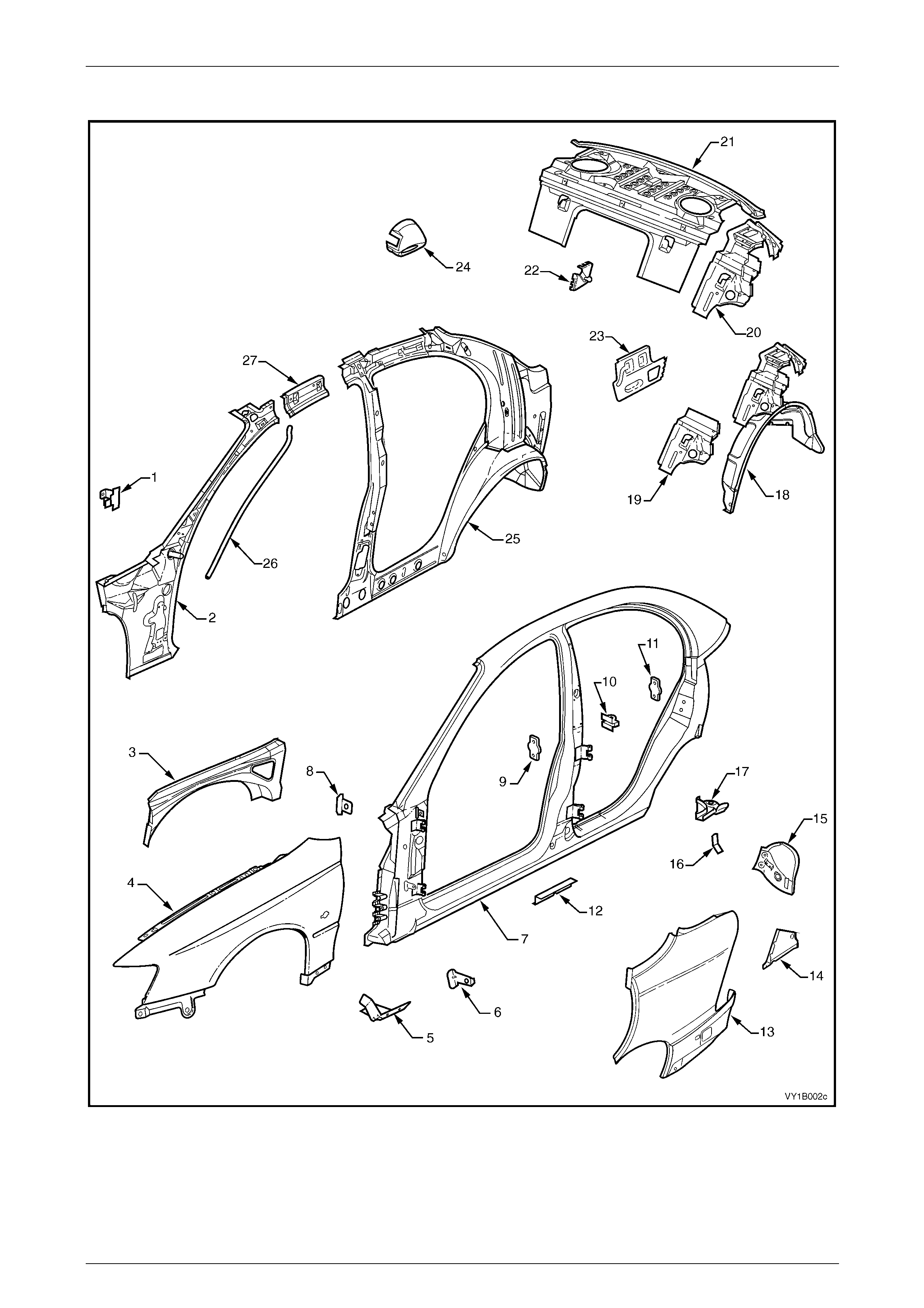
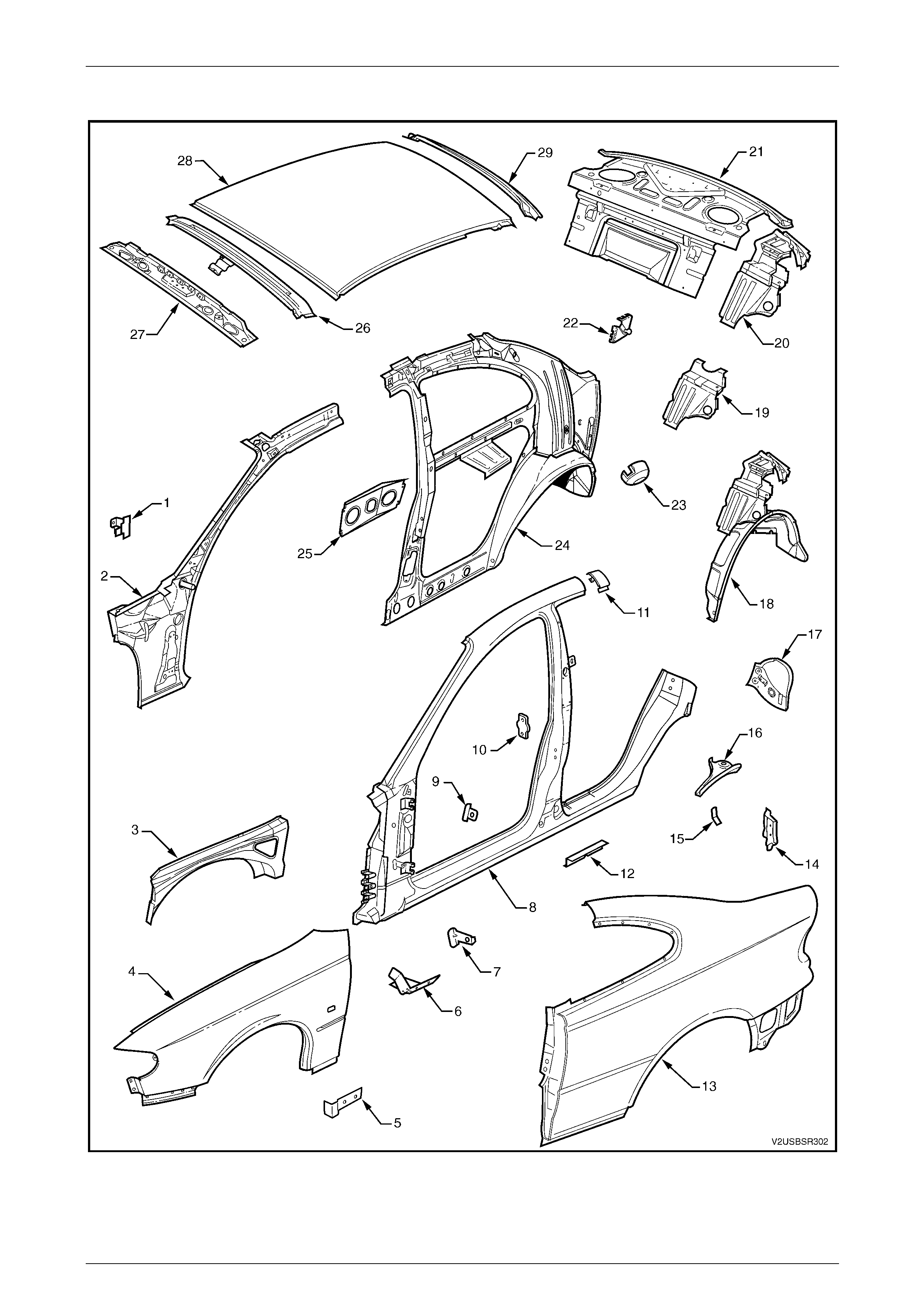
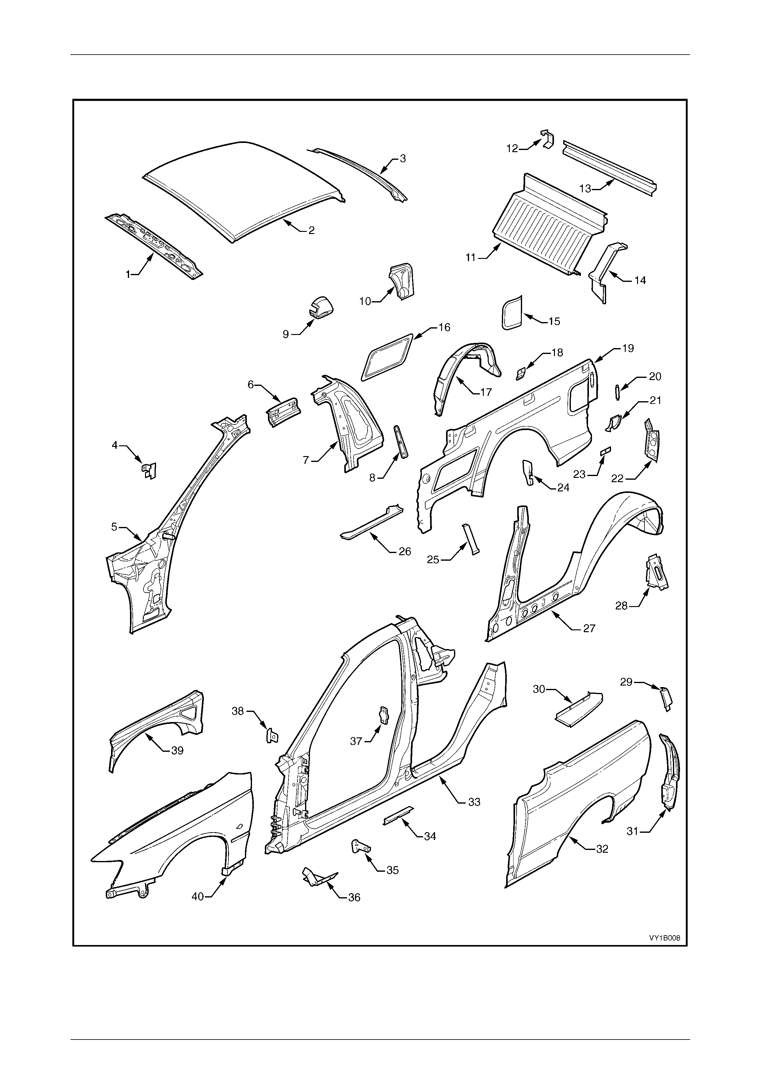
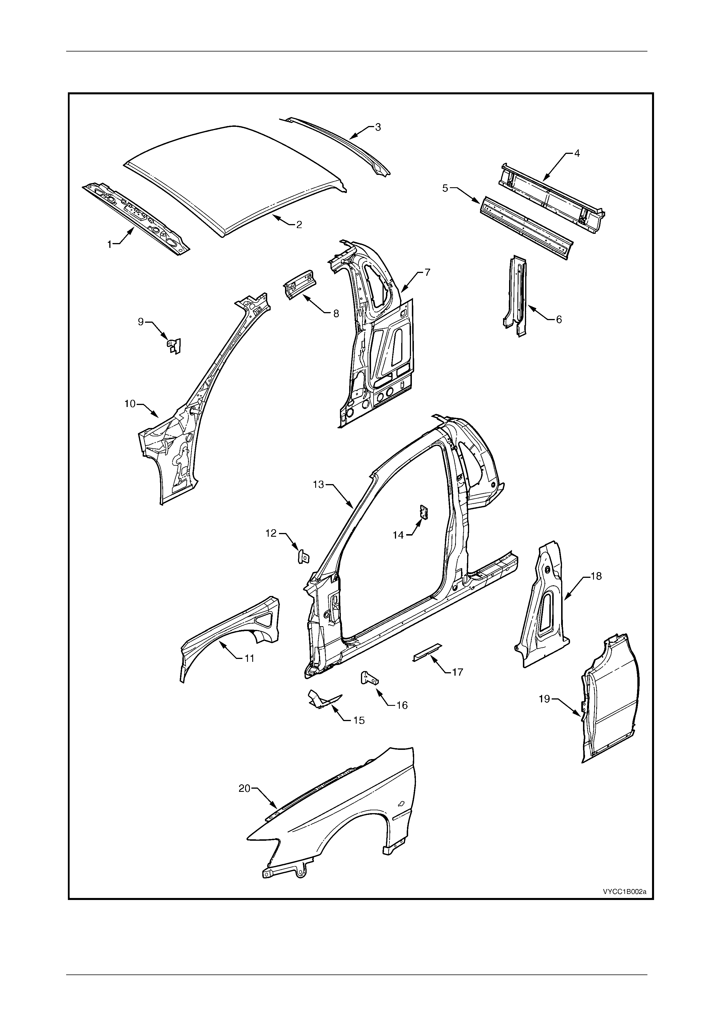
Upperbody, Excluding Roof Structure
Figure 1B – 2
Sheetmetal Page 1B–10
Page 1B–10
Legend
1 Hinge Pillar Trim Panel Bracket, LH / RH
2 Hinge Pillar Inner Panel Assembly, LH / RH
3 Front Wheelhouse Panel Upper Side Rail, LH / RH
4 Front Fender, LH / RH *
5 Fender Lower Rear Bracket, LH / RH
6 Fender Rear Bracket, LH / RH
7 Door Opening Frame Assembly, LH / RH
8 Fender Upper Rear Bracket, LH / RH
9 Front Door Striker Anchor Plate, LH / RH
10 Rear Door Check Link Bracket, LH / RH
11 Rear Door Striker Anchor Plate, LH / RH
12 Underbody Jacking Locator, LH / RH
13 Rear Quarter Panel, LH / RH
14 Quarter Panel Lower Extension, LH / RH
15 Tail Lamp Housing, LH / RH
16 Wiring Harness Bracket, LH / RH
17 Quarter Panel Upper Extension, LH / RH
18 Rear Wheelhouse Inner Panel Assembly, LH / RH
19 Rear Seat Back Panel Extension, LH / RH
20 Rear Seat Back Panel Extension Assembly, LH / RH
21 Rear Window Panel Assembly
22 Rear Compartment Lid Strut Bracket Assembly, LH / RH
23 Tail Lamp Housing Brace, LH / RH
24 Fuel Filler Pipe Housing, RH only
25 Quarter Panel Inner Assembly, LH / RH
26 Sunroof front drain tube, LH / RH #
27 Quarter Panel Inner Extension, LH / RH
* Some models are fitted with a front fender centre moulding assembly. In this instance a different front fender is fitted.
# Vehicles with on-line sunroo f assembly.
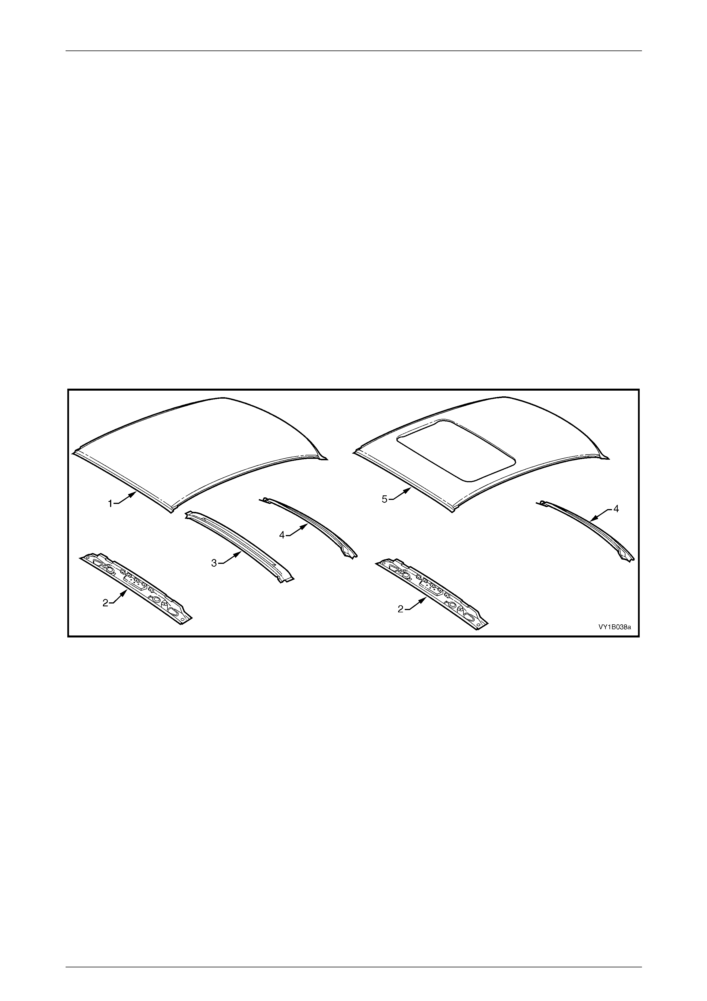
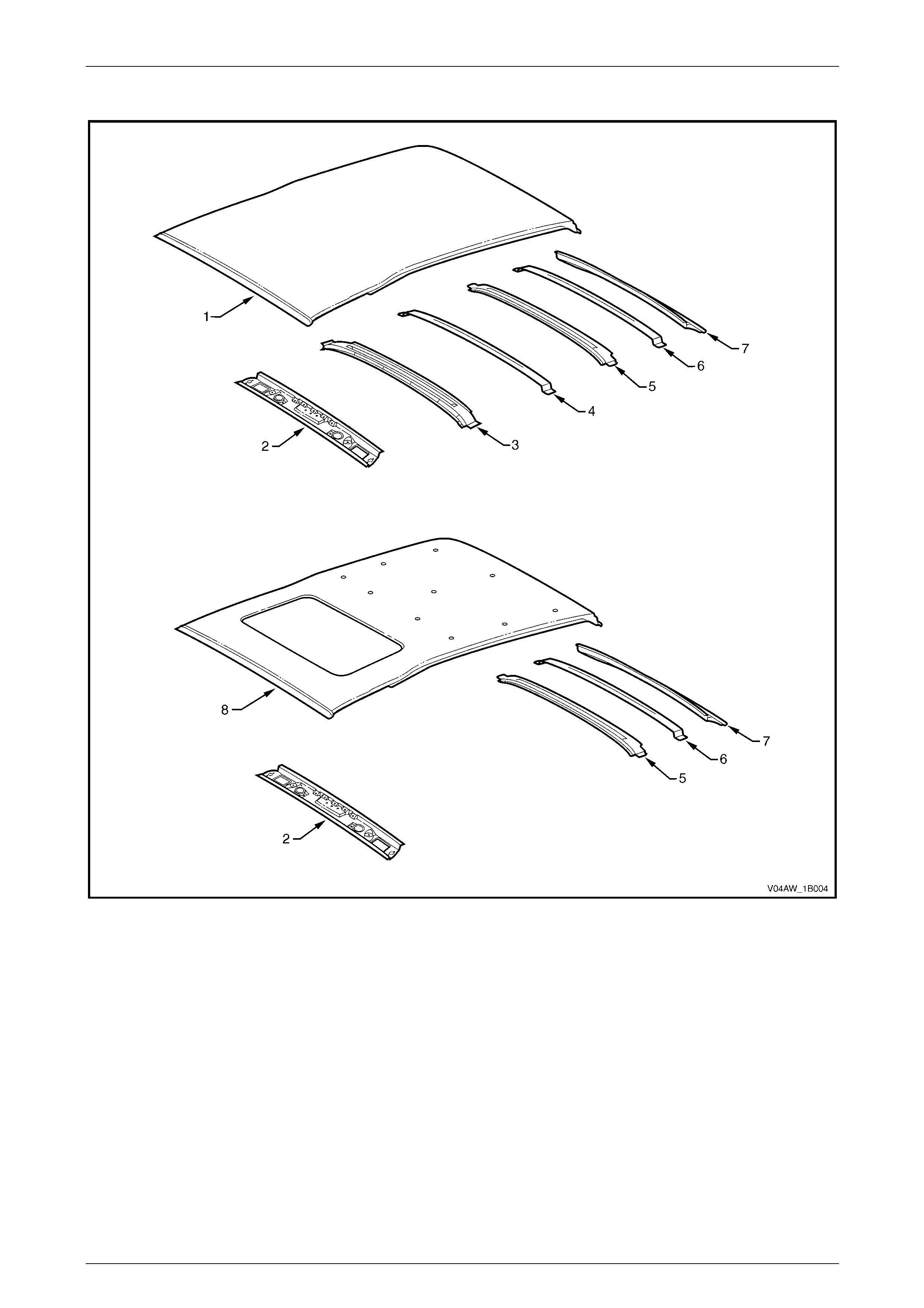
Roof Structure
Figure 1B – 3
Legend
1 Roof Panel
2 Roof Front Header Panel
3 Roof Bow Panel
4 Roof Rear Panel
5 Roof Panel Assembly #
# Vehicles with on-line sunroo f assembly.
Sheetmetal Page 1B–11
Page 1B–11
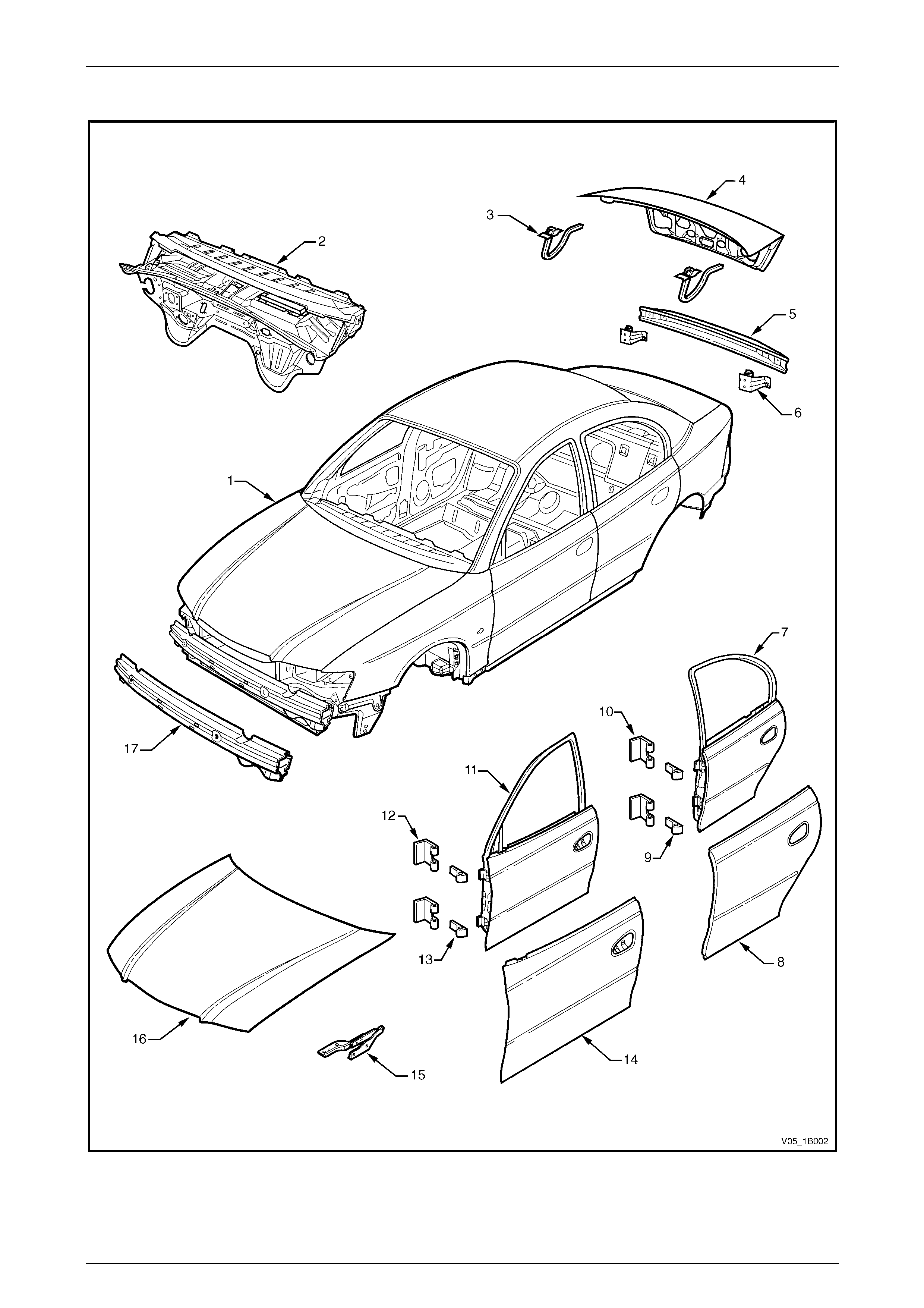
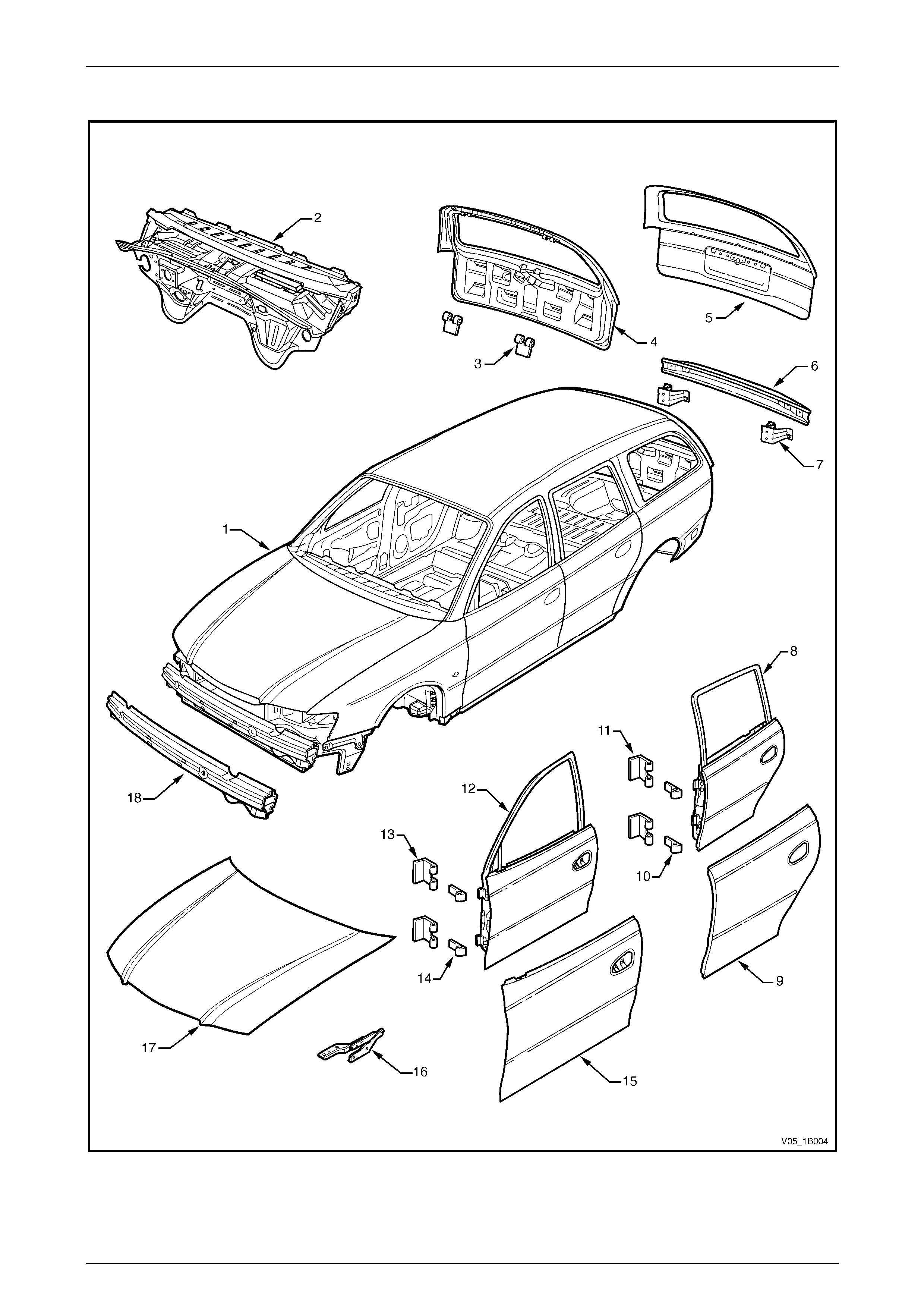
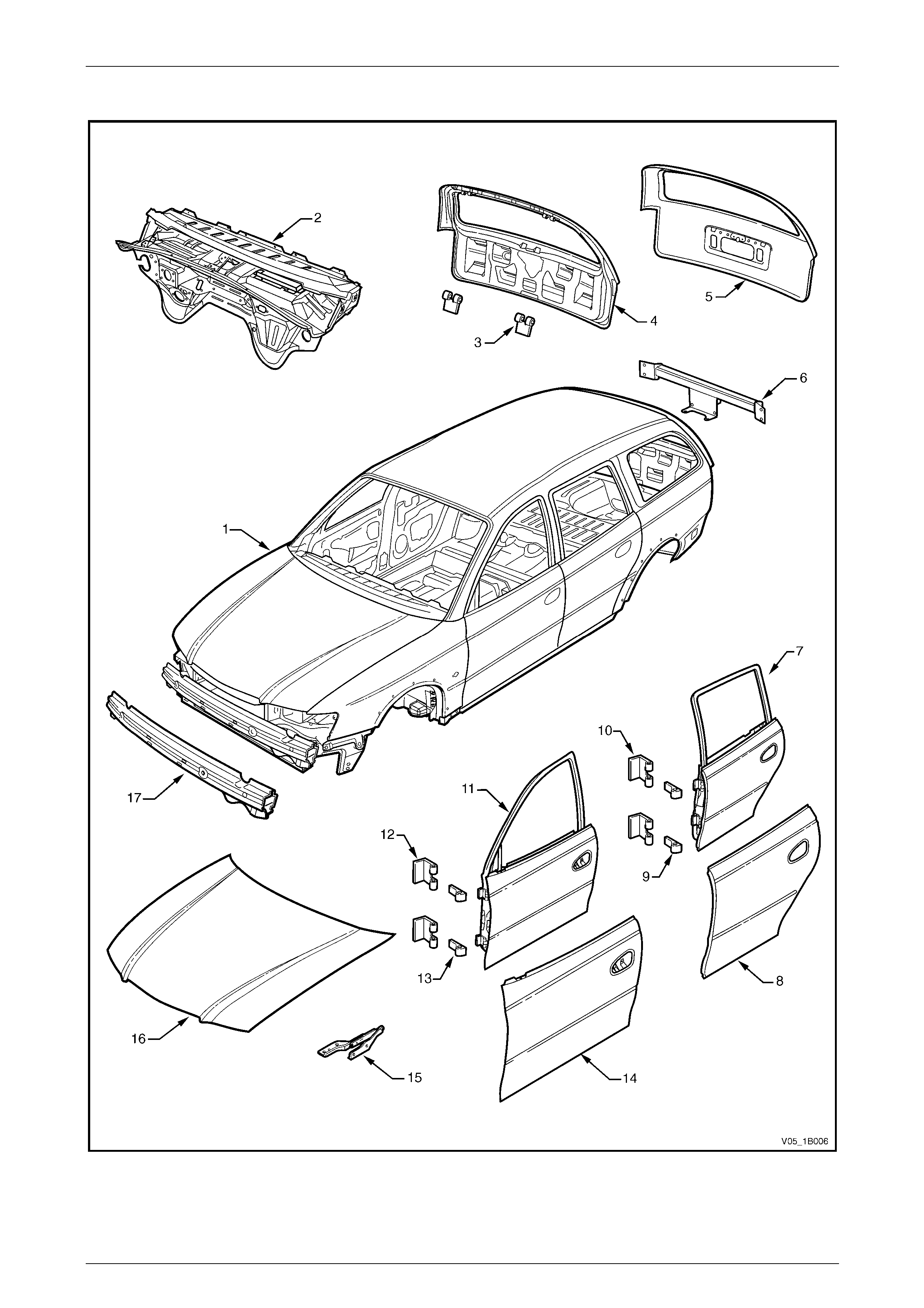
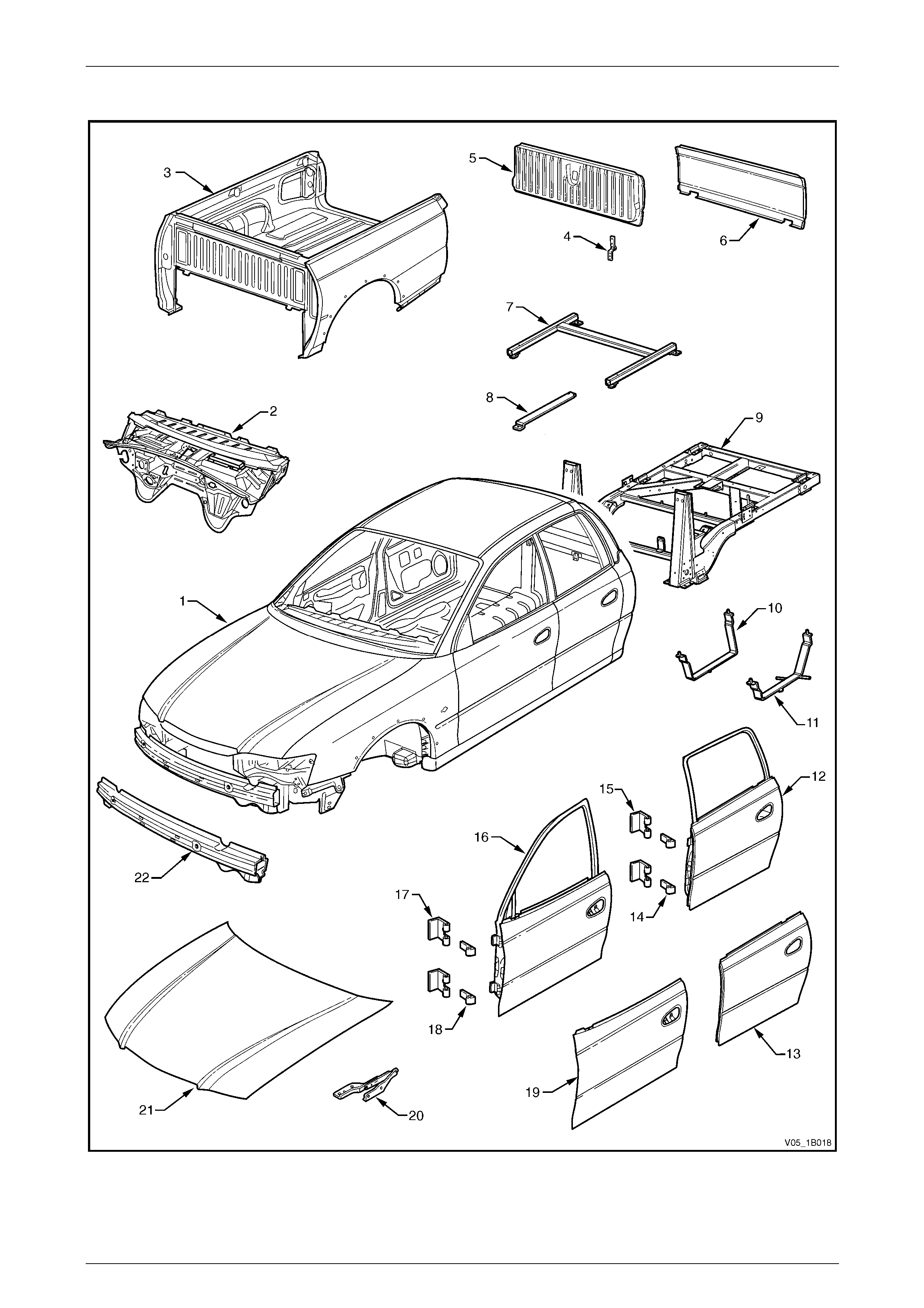
Body Assembly
Figure 1B – 4

Sheetmetal Page 1B–12
Page 1B–12
Legend
1 Body Assembly
2 Dash Panel Assembly
3 Rear Compartment Lid Hinge Assembly
4 Rear Compartment Lid Assembly
5 Rear Bumper Impact Bar
6 Rear Bumper Impact Bar Bracket Assembly
7 Rear Door Assembly, LH / RH
8 Rear Door Outer Panel, LH / RH
9 Rear Door Hinge (door side), LH / RH
10 Rear Door Hinge (body side), LH / RH
11 Front Door Assembly, LH / RH
12 Front Door Hinge (body side), LH / RH
13 Front Door Hinge (door side), LH / RH
14 Front Door Outer Panel, LH / RH
15 Hood Hinge Assembly, LH / RH
16 Hood Assembly
17 Front Bumper Impact Bar Assembly
Sheetmetal Page 1B–13
Page 1B–13
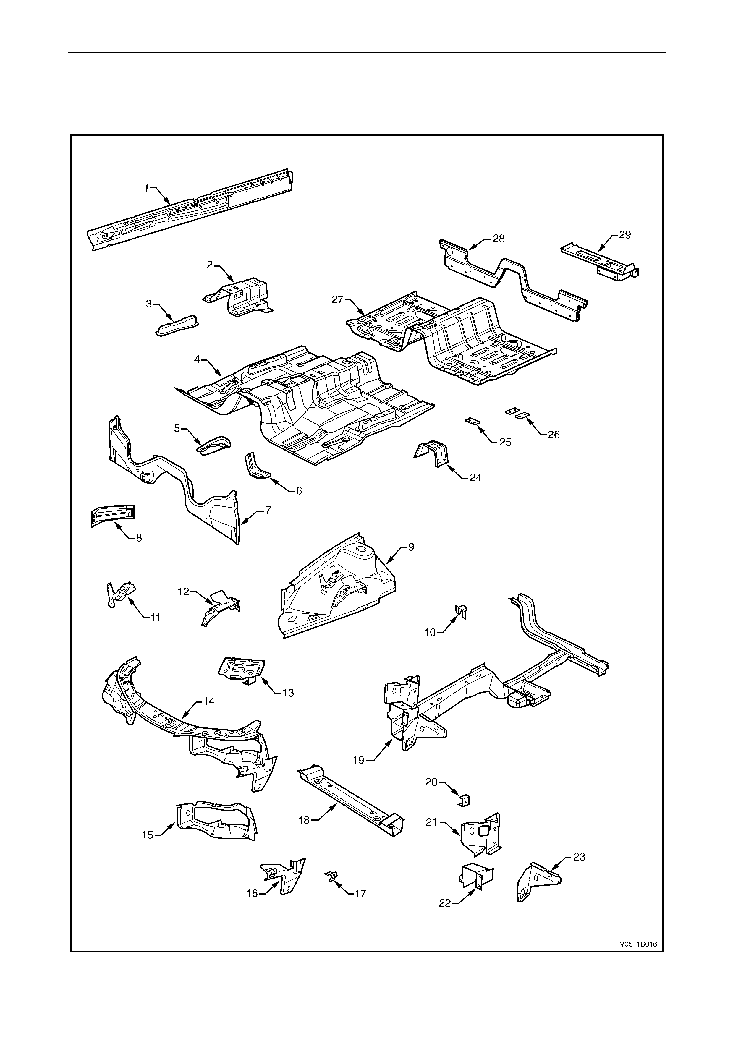
3.2 Wagon, Excluding AWD
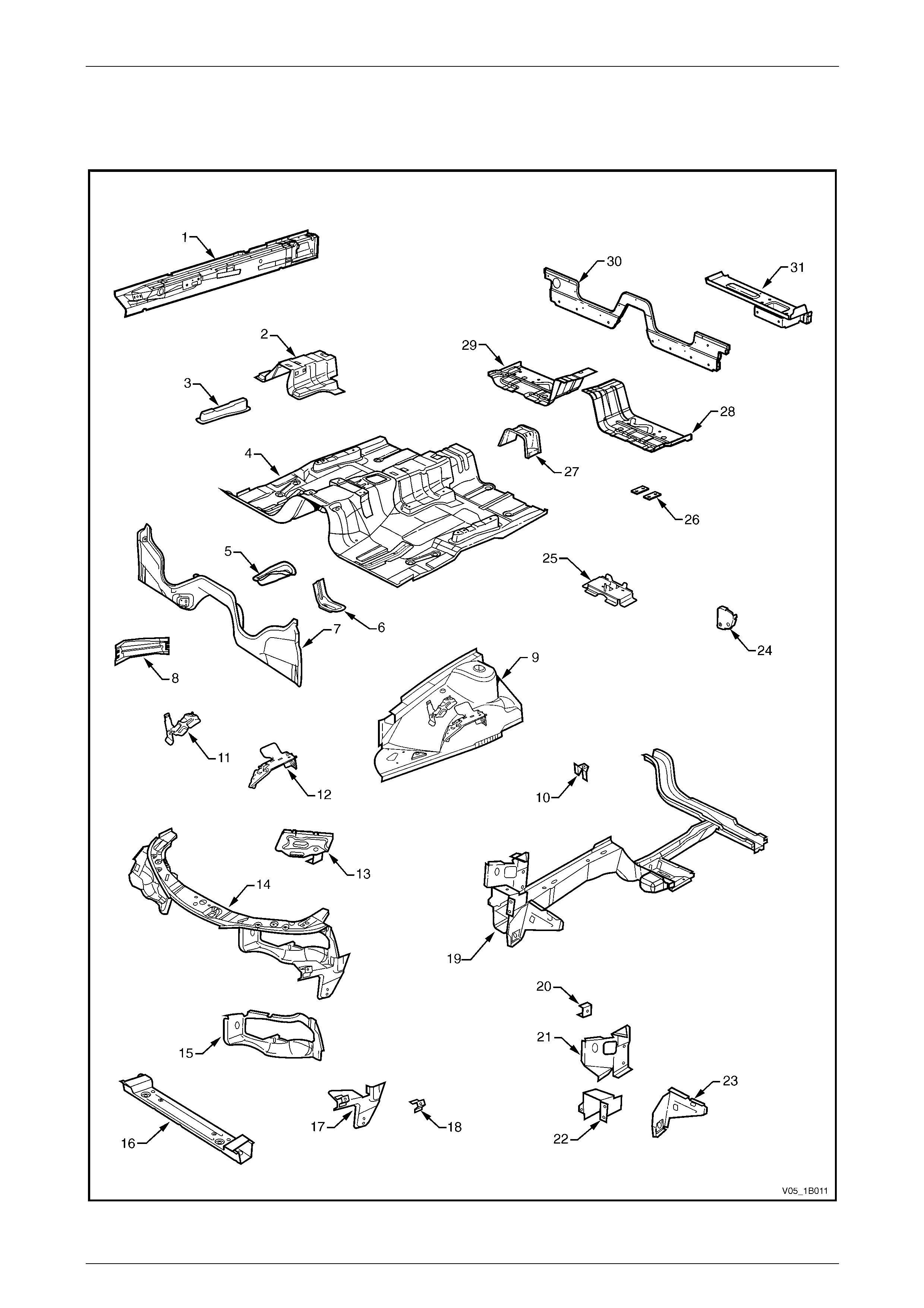
Underbody
Figure 1B – 5

Sheetmetal Page 1B–14
Page 1B–14
Legend
1 Inner Rocker Panel Assembly, RH / LH
2 Seat Inner Bracket Assembly
3 Seat Outer Bracket Assembly, RH / LH
4 Front Floor Panel Assembly
5 Transmission Support Bracket, RH / LH
6 Front Floor Panel Extension
7 Front Side Rail Brace, RH / LH
8 Front Wheelhouse Panel Assembly, RH / LH
9 Horn Bracket Assembly, LH only
10 Relay Housing Bracket, RH only
11 ABS Modulator Bracket Assembly, RH only
12 Battery Tray Assembly, RH only
13 Front End Panel Assembly
14 Headlamp Panel, LH / RH
15 Headlamp & Front Fascia Mount Bracket, LH / RH
16 Fender Front Lower Bracket, LH / RH
17 Radiator Lower Support Assembly
18 Front Side Rail Assembly, LH / RH
19 Radiator Side Mounting Bracket, LH / RH
20 Front Wheelhouse Bracket Assembly, LH / RH
21 Front Bumper Impact Bar Bracket, LH / RH
22 Front Wheelhouse Panel Bracket, LH / RH
23 Rear Floor Panel Outer Extension, LH / RH
24 Rear Suspension Support Mount Plate, LH / RH
25 Rear Tie Down Assembly, LH / RH
26 Rear Brake Hose Bracket, LH / RH
27 Rear Side Rail Assembly, LH / RH
28 Rear Bumper Impact Bar Brace Assembly, LH / RH
29 Crossmember Assembly No. 2
30 Propeller Shaft Hanger Assembly
31 Rear Seat Belt Anchor Plate Assembly, 3 places
32 Rear Floor Panel Assembly
33 Rear Compartment Floor Panel Assembly
34 Rear Compartment Floor Panel Outer Extension, LH
35 Rear Compartment Floor Panel Outer Extension, RH
36 Spare Wheel Anchor Plate Assembly
37 Fuel Tank Support Reinforcement Assembly
38 Rear End Panel Extension, LH / RH
39 Rear End Panel Assembly
40 Rear End Lower Panel
Sheetmetal Page 1B–15
Page 1B–15
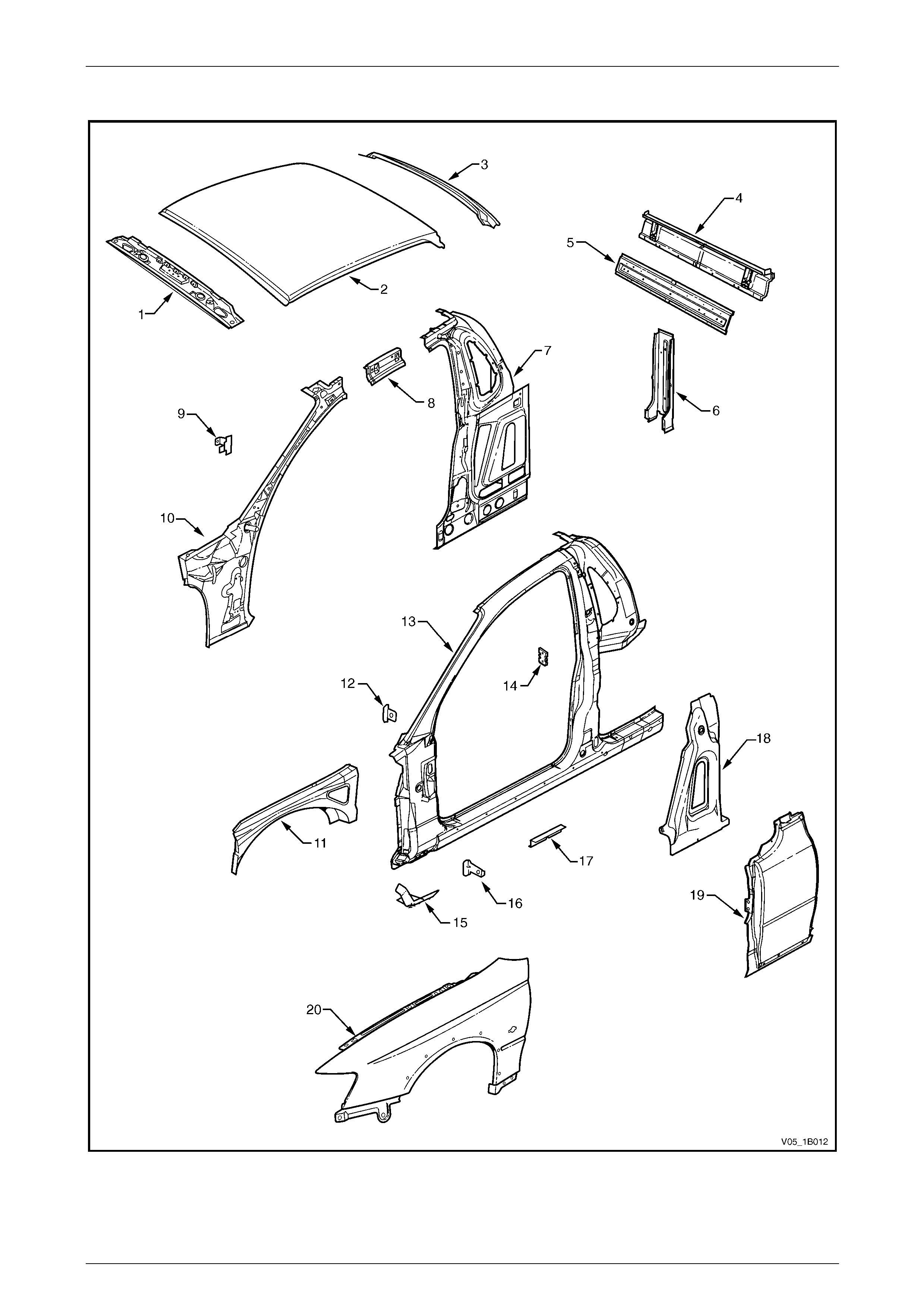
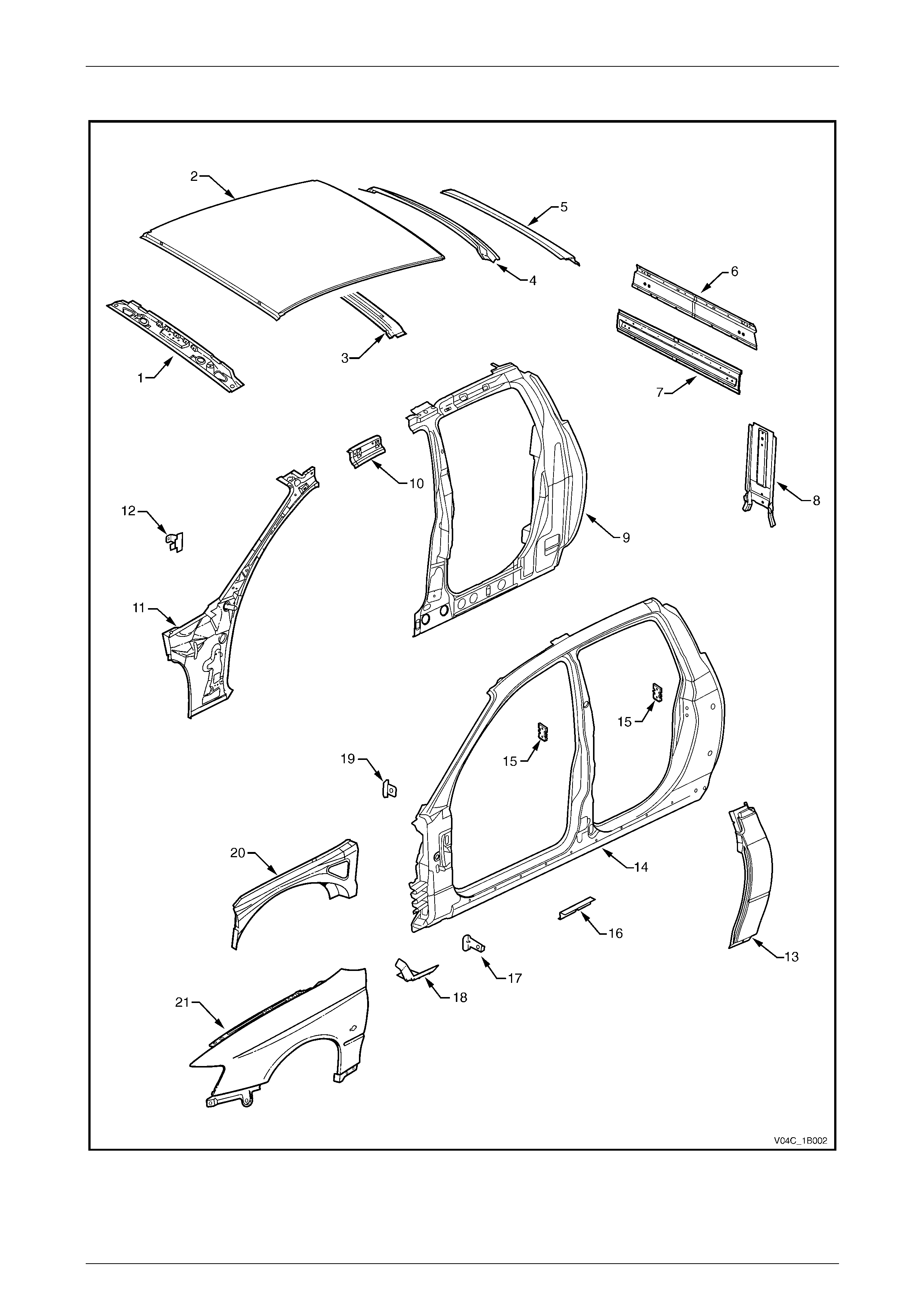
Upperbody
Figure 1B – 6

Sheetmetal Page 1B–16
Page 1B–16
Legend
1 Hinge Pillar Trim Panel Bracket, LH / RH
2 Hinge Pillar Inner Panel Assembly, LH / RH
3 Front Wheelhouse Panel Upper Side Rail, LH / RH
4 Front Fender, LH / RH
5 Fender Lower Rear Bracket, LH / RH
6 Fender Rear Bracket, LH / RH
7 Door Opening Frame Assembly, LH / RH
8 Fender Upper Rear Bracket, LH / RH
9 Front Door Striker Anchor Plate, LH / RH
10 Rear Door Check Link Bracket, LH / RH
11 Rear Door Striker Anchor Plate, LH / RH
12 Underbody Jacking Locator, LH / RH
13 Rear Quarter Panel, LH / RH
14 Rear Bumper Fascia Side Bracket, LH / RH
15 Quarter Panel Extension, LH / RH
16 Quarter Outer Lower Rear Panel, LH / RH
17 Fuel Filler Pipe Housing, RH only
18 Quarter Inner Lower Rear Extension, LH / RH
19 Quarter Panel Inner Assembly, LH / RH
20 Cargo Screen Reinforcement Assembly, LH / RH
21 Quarter Panel Inner Extension, LH / RH
22 Rear Wheelhouse Inner Panel Assembly , LH / RH
23 Roof Front Header Panel
24 Roof Bow Panel No. 1
25 Roof Bow Panel No. 2
26 Roof Panel
27 Roof Bow Panel No. 3
28 Roof Bow Panel No. 2
29 Roof Rear Panel
Sheetmetal Page 1B–17
Page 1B–17
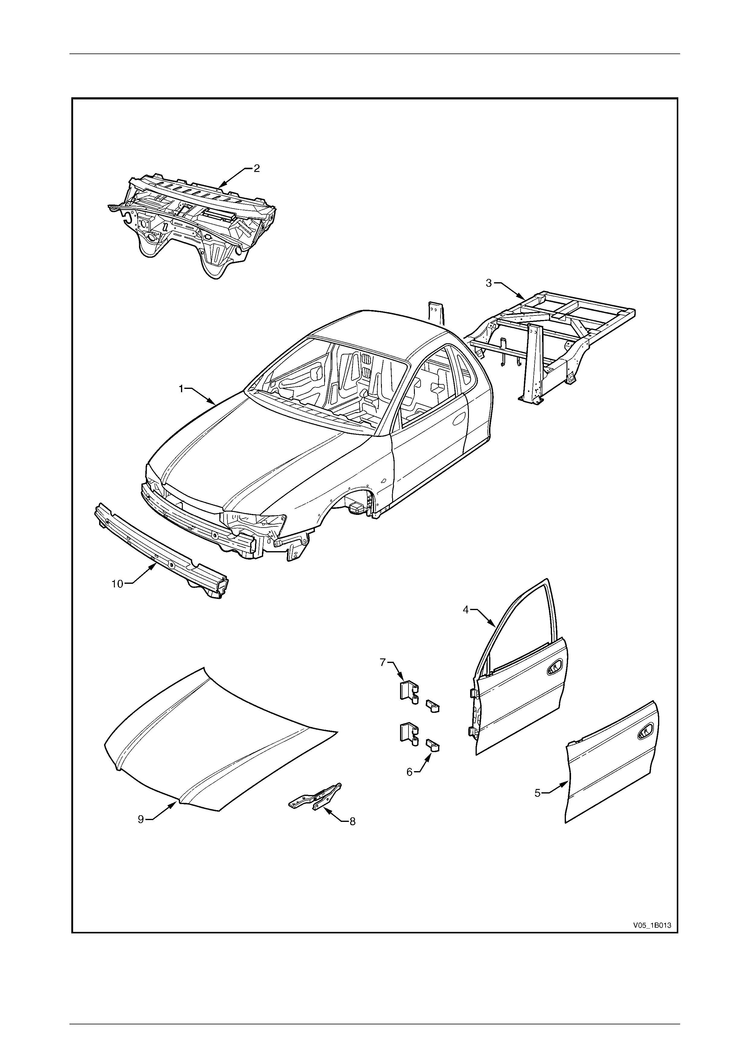
Body Assembly
Figure 1B – 7

Sheetmetal Page 1B–18
Page 1B–18
Legend
1 Body Assembly
2 Dash Panel Assembly
3 Liftgate Hinge (liftgate side)
4 Liftgate Assembly
5 Liftgate Outer Panel
6 Rear Bumper Impact Bar
7 Rear Bumper Impact Bar Bracket Assembly
8 Rear Door Assembly, LH / RH
9 Rear Door Outer Panel, LH / RH
10 Rear Door Hinge (door side), LH / RH
11 Rear Door Hinge (body side), LH / RH
12 Front Door Assembly, LH / RH
13 Front Door Hinge (body side), LH / RH
14 Front Door Hinge (door side), LH / RH
15 Front Door Outer Panel, LH / RH
16 Hood Hinge Assembly, LH / RH
17 Hood Assembly
18 Front Bumper Impact Bar Assembly

Sheetmetal Page 1B–19
Page 1B–19
3.3 AWD Wagon
Underbody
Figure 1B – 8

Sheetmetal Page 1B–20
Page 1B–20
Legend
1 Inner Rocker Panel Assembly, RH / LH
2 Seat Inner Bracket Assembly
3 Seat Outer Bracket Assembly, RH / LH
4 Front Floor Panel Assembly
5 Transmission Support Bracket, RH
6 Transmission Support Bracket, LH
7 Front Floor Panel Extension
8 Front Side Rail Brace, RH / LH
9 Front Wheelhouse Panel Assembly, RH / LH
10 Horn Bracket Assembly, LH only
11 Relay Housing Bracket, RH only
12 ABS Modulator Bracket Assembly, RH only
13 Battery Tray Assembly, RH only
14 Front End Panel Assembly
15 Headlamp Panel, LH / RH
16 Headlamp & Front Fascia Mount Bracket, LH / RH
17 Fender Front Lower Bracket, LH / RH
18 Radiator Lower Support Assembly / RH
19 Front Side Rail Assembly, LH / RH
20 Radiator Side Mounting Bracket, LH / RH
21 Front Wheelhouse Bracket Assembly, LH / RH
22 Front Bumper Impact Bar Bracket, LH / RH
23 Front Wheelhouse Panel Bracket, LH / RH
24 Rear Floor Panel Outer Extension, LH / RH
25 Rear Suspension Support Mount Plate, LH / RH
26 Rear Tie Down Assembly, LH / RH
27 Rear Brake Hose Bracket, LH / RH
28 Rear Side Rail Assembly, LH / RH
29 Rear Bumper Impact Bar Brace Assembly, LH / RH
30 Crossmember Assembly No. 2
31 Propeller Shaft Hanger Assembly
32 Rear Seat Belt Anchor Plate Assembly, 3 places
33 Rear Floor Panel Assembly
34 Rear Compartment Floor Panel Assembly
35 Rear Compartment Floor Panel Outer Extension, LH
36 Rear Compartment Floor Panel Outer Extension, RH
37 Spare Wheel Anchor Plate Assembly
38 Fuel Tank Support Reinforcement Assembly
39 Rear End Panel Extension, LH / RH
40 Rear End Panel Assembly
41 Rear End Lower Panel
Sheetmetal Page 1B–21
Page 1B–21
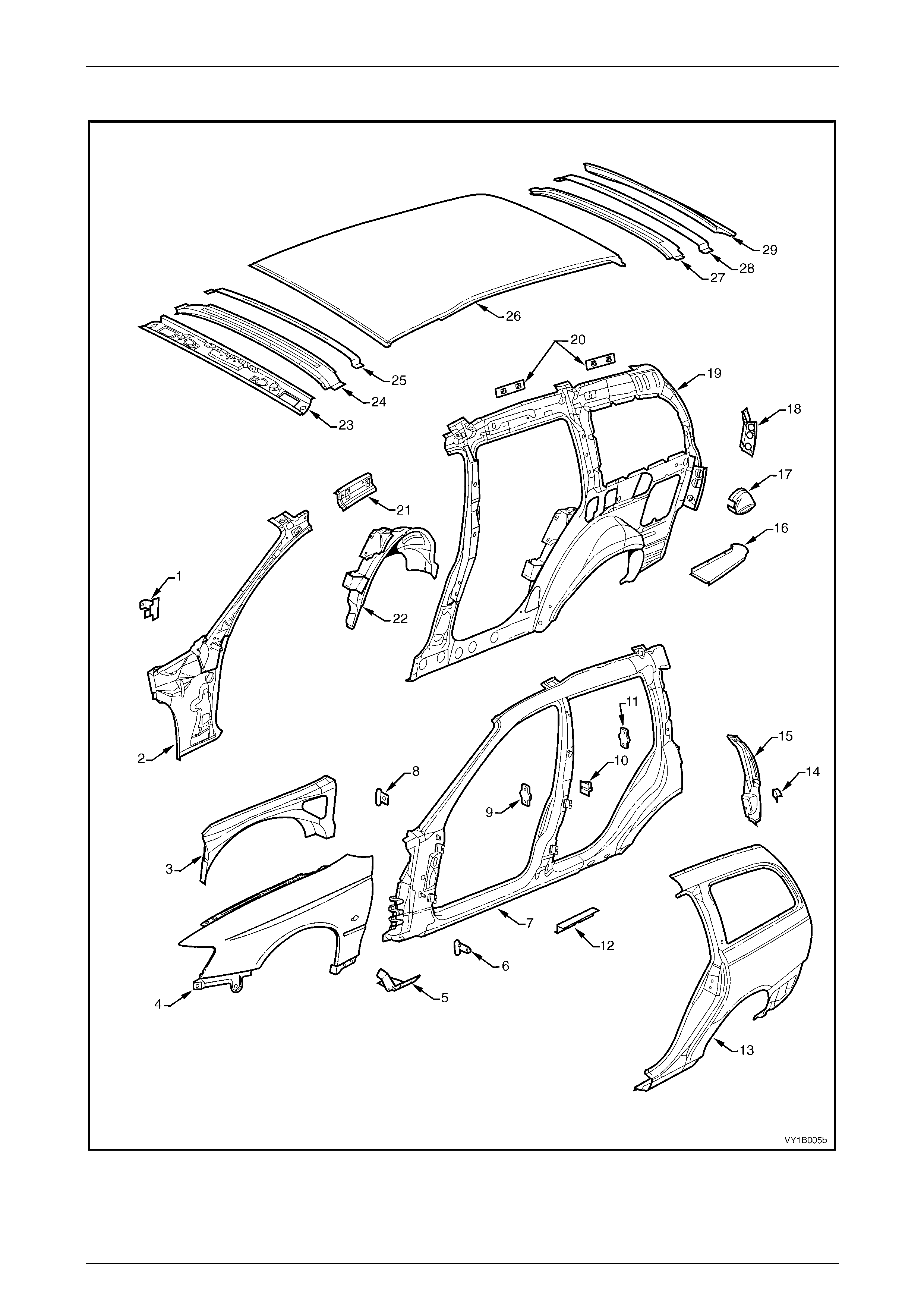
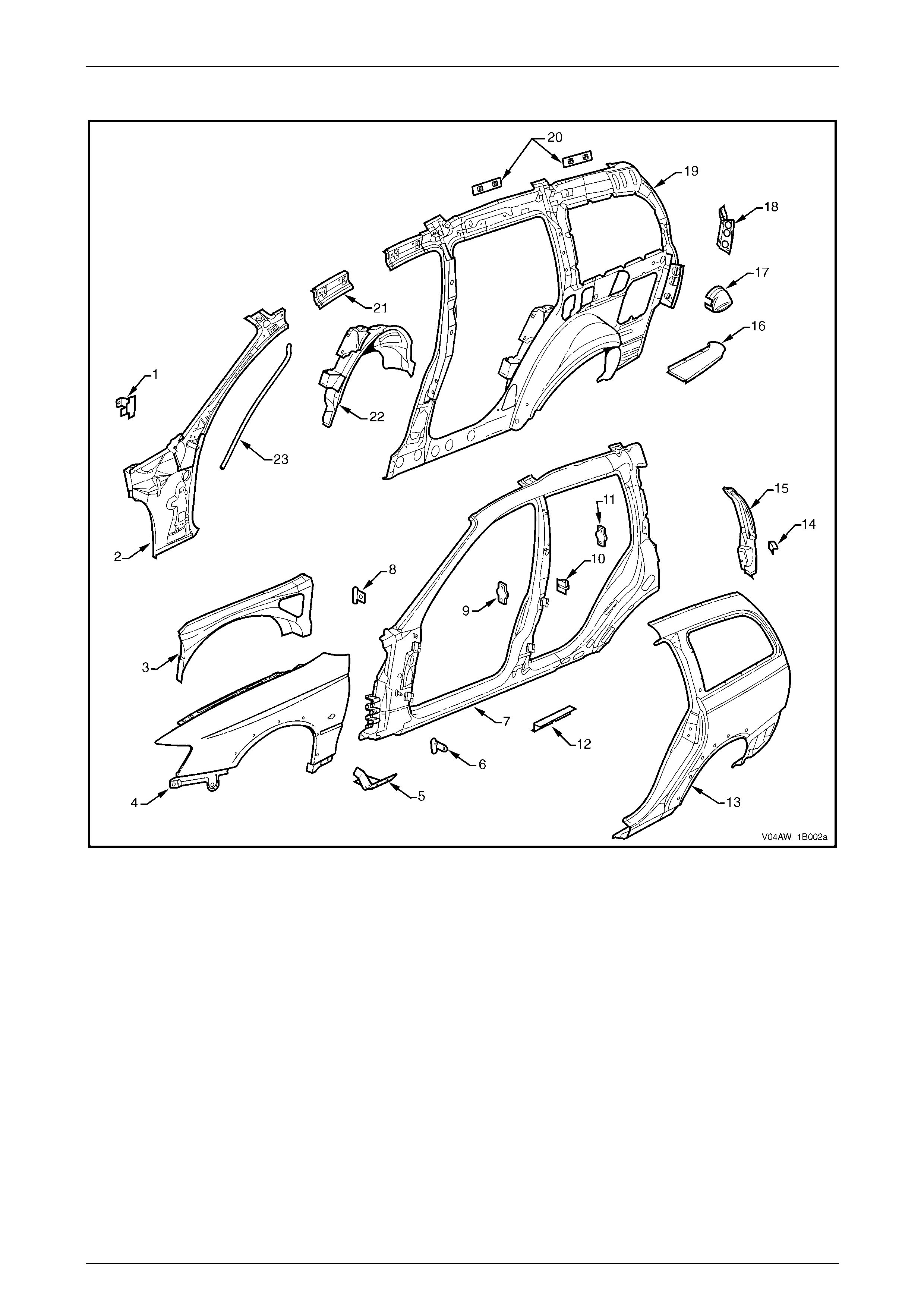
Upperbody
Figure 1B – 9
Legend
1 Hinge Pillar Trim Panel Bracket, LH / RH
2 Hinge Pillar Inner Panel Assembly, LH / RH
3 Front Wheelhouse Panel Upper Side Rail, LH / RH
4 Front Fender, LH / RH
5 Fender Lower Rear Bracket, LH / RH
6 Fender Rear Bracket, LH / RH
7 Door Opening Frame Assembly, LH / RH
8 Fender Upper Rear Bracket, LH / RH
9 Front Door Striker Anchor Plate, LH / RH
10 Rear Door Check Link Bracket, LH / RH
11 Rear Door Striker Anchor Plate, LH / RH
12 Underbody Jacking Locator, LH / RH
13 Rear Quarter Panel, LH / RH
14 Rear Bumper Fascia Side Bracket, LH / RH
15 Quarter Panel Extension, LH / RH
16 Quarter Outer Lower Rear Panel, LH / RH
17 Fuel Filler Pipe Housing, RH only
18 Quarter Inner Lower Rear Extension, LH / RH
19 Quarter Panel Inner Assembly, LH / RH
20 Cargo Screen Reinforcement Assembly, LH / RH
21 Quarter Panel Inner Extension, LH / RH
22 Rear Wheelhouse Inner Panel Assembly, LH / RH
23 26 Sunroof front drain tube, LH / RH #
# Vehicles with on-line sunroo f assembly.
Sheetmetal Page 1B–22
Page 1B–22
Roof Assembly
Figure 1B – 10
Legend
1 Roof Panel
2 Roof Front Header Panel
3 Roof Bow Panel No. 1
4 Roof Bow Panel No. 2
5 Roof Bow Panel No. 3
6 Roof Bow Panel No. 2
7 Roof Rear Panel
8 Roof Panel Assembly #
# Vehicles with on-line sunroo f assembly.
Sheetmetal Page 1B–23
Page 1B–23
Body Assembly
Figure 1B – 11

Sheetmetal Page 1B–24
Page 1B–24
Legend
1 Body Assembly
2 Dash Panel Assembly
3 Liftgate Hinge (liftgate side)
4 Liftgate Assembly
5 Liftgate Outer Panel
6 Towbar Assembly
7 Rear Door Assembly, LH / RH
8 Rear Door Outer Panel, LH / RH
9 Rear Door Hinge (door side), LH / RH
10 Rear Door Hinge (body side), LH / RH
11 Front Door Assembly, LH / RH
12 Front Door Hinge (body side), LH / RH
13 Front Door Hinge (door side), LH / RH
14 Front Door Outer Panel, LH / RH
15 Hood Hinge Assembly, LH / RH
16 Hood Assembly
17 Front Bumper Impact Bar Assembly
Sheetmetal Page 1B–25
Page 1B–25
3.4 Coupe
Underbody
Figure 1B – 12

Sheetmetal Page 1B–26
Page 1B–26
Legend
1 Inner Rocker Panel Assembly, RH / LH
2 Seat Inner Bracket Assembly
3 Seat Outer Bracket Assembly, RH / LH
4 Front Floor Panel Assembly
5 Transmission Support Bracket, RH / LH
6 Front Floor Panel Extension
7 Front Side Rail Brace, RH / LH
8 Front Wheelhouse Panel Assembly, RH / LH
9 Horn Bracket Assembly, LH only
10 Relay Housing Bracket, RH only
11 ABS Modulator Bracket Assembly, RH only
12 Battery Tray Assembly, RH only
13 Front End Panel Assembly
14 Headlamp Panel, LH / RH
15 Headlamp & Front Fascia Mount Bracket, LH / RH
16 Fender Front Lower Bracket, LH / RH
17 Radiator Lower Support Assembly
18 Front Side Rail Assembly, LH / RH
19 Radiator Side Mounting Bracket, LH / RH
20 Front Wheelhouse Bracket Assembly, LH / RH
21 Front Bumper Impact Bar Bracket, LH / RH
22 Front Wheelhouse Panel Bracket, LH / RH
23 Rear Floor Panel Outer Extension, LH / RH
24 Rear Suspension Support Mount Plate, LH / RH
25 Rear Tie Down Assembly, LH / RH
26 Rear Brake Hose Bracket, LH / RH
27 Rear Bumper Impact Bar Brace Assembly, LH / RH
28 Propeller Shaft Hanger Assembly
29 Rear Floor Panel Reinforcement, LH
30 Rear Seat Belt Anchor Plate Assembly, 3 places
31 Rear Underbody Assembly
32 Rear Compartment Floor Panel Outer Extension, LH
33 Rear End Panel Assembly
34 Rear End Lower Panel
35 Rear Compartment Floor Panel Outer Extension, RH
36 Rear Floor Panel Reinforcement, RH
37 Fuel Tank Strap Bracket Assembly, LH / RH
38 Rear Compartment Floor Panel Assembly
39 Spare Wheel Anchor Plate Assembly
40 Fuel Tank Support Reinforcement Assembly
Sheetmetal Page 1B–27
Page 1B–27
Upperbody
Figure 1B – 13

Sheetmetal Page 1B–28
Page 1B–28
Legend
1 Hinge Pillar Trim Panel Bracket, LH / RH
2 Hinge Pillar Inner Panel Assembly, LH / RH
3 Front Wheelhouse Panel Upper Side Rail, LH / RH
4 Front Fender, LH / RH
5 Rocker Panel Moulding Bracket, LH / RH
6 Fender Lower Rear Bracket, LH / RH
7 Fender Rear Bracket, LH / RH
8 Door Opening Frame Assembly, LH / RH
9 Fender Upper Rear Bracket, LH / RH
10 Front Door Striker Anchor Plate, LH / RH
11 Body Pillar Inner Panel Reinforcement, LH / RH
12 Underbody Jacking Locator, LH / RH
13 Rear Quarter Panel, LH / RH
14 Quarter Outer Panel Extension, LH / RH
15 Rear Lamp Wiring Harness Extension Bracket, LH / RH
16 Quarter Panel Lower Extension, LH / RH
17 Tail Lamp Housing, LH / RH
18 Rear Wheelhouse Inner Panel Assembly, LH / RH
19 Rear Seat Back Panel Extension, LH / RH
20 Rear Seat Back Panel Extension Assembly, LH / RH
21 Rear Window Panel Assembly
22 Rear Compartment Lid Strut Bracket Assembly, LH / RH
23 Fuel Filler Pipe Housing, RH only
24 Quarter Panel Inner Assembly, LH / RH
25 Radio Quarter Speaker Bracket, LH / RH
26 Roof Bow Panel
27 Roof Front Header Panel
28 Roof Panel
29 Roof Rear Panel

Sheetmetal Page 1B–29
Page 1B–29
Body Assembly
Figure 1B – 14

Sheetmetal Page 1B–30
Page 1B–30
Legend
1 Body Assembly
2 Dash Panel Assembly
3 Rear Compartment Lid Hinge Assembly
4 Rear Compartment Lid Assembly
5 Rear Bumper Impact Bar
6 Rear Bumper Impact Bar Bracket Assembly
7 Front Door Assembly, LH / RH
8 Front Door Outer Panel, LH / RH
9 Front Door Hinge (door side), LH / RH
10 Front Door Hinge (body side), LH / RH
11 Hood Hinge Assembly, LH / RH
12 Hood Assembly
13 Front Bumper Impact Bar Assembly
Sheetmetal Page 1B–31
Page 1B–31
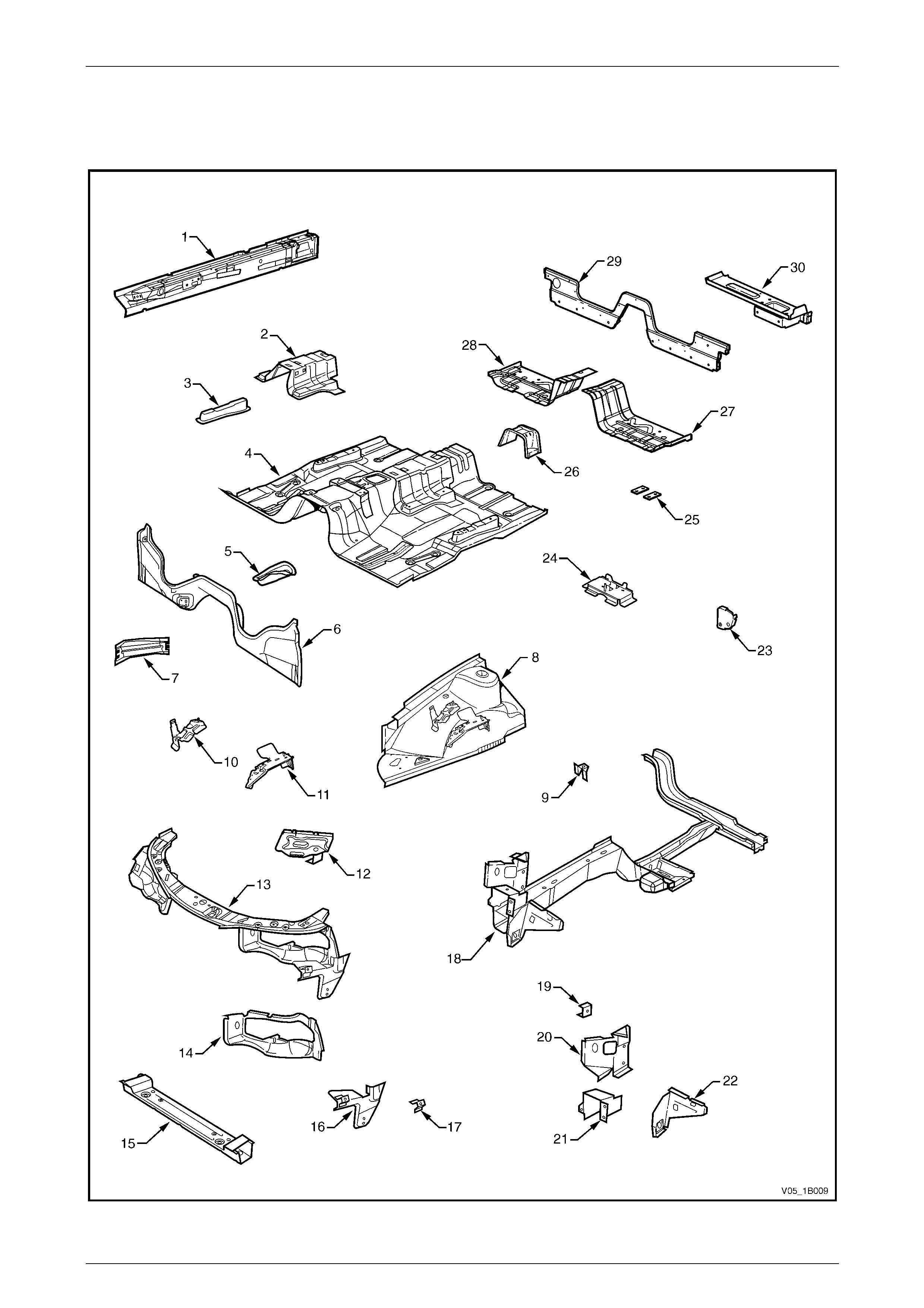
3.5 Utility
Underbody
Figure 1B – 15

Sheetmetal Page 1B–32
Page 1B–32
Legend
1 Inner Rocker Panel Assembly, RH / LH
2 Seat Inner Bracket Assembly
3 Seat Outer Bracket Assembly, RH / LH
4 Front Floor Panel Assembly
5 Transmission Support Bracket, RH / LH
6 Front Floor Panel Extension
7 Front Side Rail Brace, RH / LH
8 Front Wheelhouse Panel Assembly, RH / LH
9 Horn Bracket Assembly, LH only
10 Relay Housing Bracket, RH only
11 ABS Modulator Bracket Assembly, RH only
12 Battery Tray Assembly, RH only
13 Front End Panel Assembly
14 Headlamp Panel, LH / RH
15 Headlamp & Front Fascia Mount Bracket, LH / RH
16 Fender Front Lower Bracket, LH / RH
17 Radiator Lower Support Assembly
18 Front Side Rail Assembly, LH / RH
19 Radiator Side Mounting Bracket, LH / RH
20 Front Wheelhouse Bracket Assembly, LH / RH
21 Front Bumper Impact Bar Bracket, LH / RH
22 Front Wheelhouse Panel Bracket, LH / RH
23 Rear Floor Panel Outer Extension, LH / RH
24 Rear Suspension Support Mount Plate, LH / RH
25 Rear Tie Down Assembly, LH / RH
26 Rear Brake Hose Bracket, LH / RH
27 Rear Side Rail Assembly, LH / RH
28 Crossmember Assembly No. 2
29 Spare Wheel Support, LH
30 Load Floor Reinforcement Rail, LH
31 Spare Wheel Support
32 Load Floor Centre Rail Assembly
33 Spare Wheel Support, RH
34 Load Floor Reinforcement Rail, RH
35 Rear End Panel
36 Endgate Hinge Bracket Assembly (body side), RH / LH
37 Rear End Lower Panel
38 Load Floor Panel Reinforcement, LH / RH
39 Load Floor Panel
40 Fuel Tank Bracket Assembly, RH / LH
41 Load Floor Front Panel Assembly
42 Rear Floor Panel Assembly
43 Jack Stowage Bracket Assembly, LH only
44 Propeller Shaft Hanger Assembly
45 Front Floor Rear Extension Assembly
46 Front Floor Rear Extension Reinforcement
47 Fuel Tank Bracket Assembly, RH / LH
Sheetmetal Page 1B–33
Page 1B–33
Upperbody
Figure 1B – 16

Sheetmetal Page 1B–34
Page 1B–34
Legend
1 Roof Front Header Panel
2 Roof Panel
3 Roof Rear Panel
4 Hinge Pillar Trim Panel Bracket, LH / RH
5 Hinge Pillar Inner Panel Assembly, LH / RH
6 Quarter Panel Inner Extension, LH / RH
7 Side Inner Upper Panel, LH / RH
8 Seat Belt Guide Anchor Plate Assembly, LH / RH
9 Fuel Filler Pipe Housing, RH only
10 Rear Wheelhouse Outer Extension, RH only
11 Front Seat Back Panel
12 Load Compartment Extension Panel Bracket, RH only
13 Load Compartment Extension Outer Panel
14 Front Seat Back Panel Outer, LH / RH
15 Rear Inner Side Panel Cover, LH / RH
16 Front Inner Side Panel Cover, LH / RH
17 Rear Wheelhouse Inner Panel, LH / RH
18 Cargo Tie-Down Bracket (3 places), LH / RH
19 Side Inner Upper Panel, LH / RH
20 Endgate Striker Anchor Plate Retainer, LH / RH
21 Quarter Lower Rear Panel, LH / RH
22 Quarter Inner Lower Rear Extension, LH / RH
23 Cargo Tie-Down Anchor Plate Assembly (3 places), LH / RH
24 Rear Wheelhouse Bracket, LH / RH
25 Load Floor Panel Outer Reinforcement, LH / RH
26 Load Floor Panel Outer Extension, LH / RH
27 Quarter Panel Inner Assembly, LH / RH
28 Quarter Inner & Rear Wheelhouse Brace, LH / RH
29 Quarter Panel Upper Extension, LH / RH
30 Quarter Outer Lower Rear Panel, LH / RH
31 Quarter Panel Extension, LH / RH
32 Rear Quarter Panel, LH / RH
33 Door Opening Frame Assembly, LH / RH
34 Underbody Jacking Locator, LH / RH
35 Fender Rear Bracket, LH / RH
36 Fender Lower Rear Bracket, LH / RH
37 Front Door Striker Anchor Plate, LH / RH
38 Fender Upper Rear Bracket, LH / RH
39 Front Wheelhouse Panel Upper Side Rail, LH / RH
40 Front Fender, LH / RH*
* Some models are fitted with a front fender centre moulding assembly. In this instance a different front fender is fitted.
Sheetmetal Page 1B–35
Page 1B–35
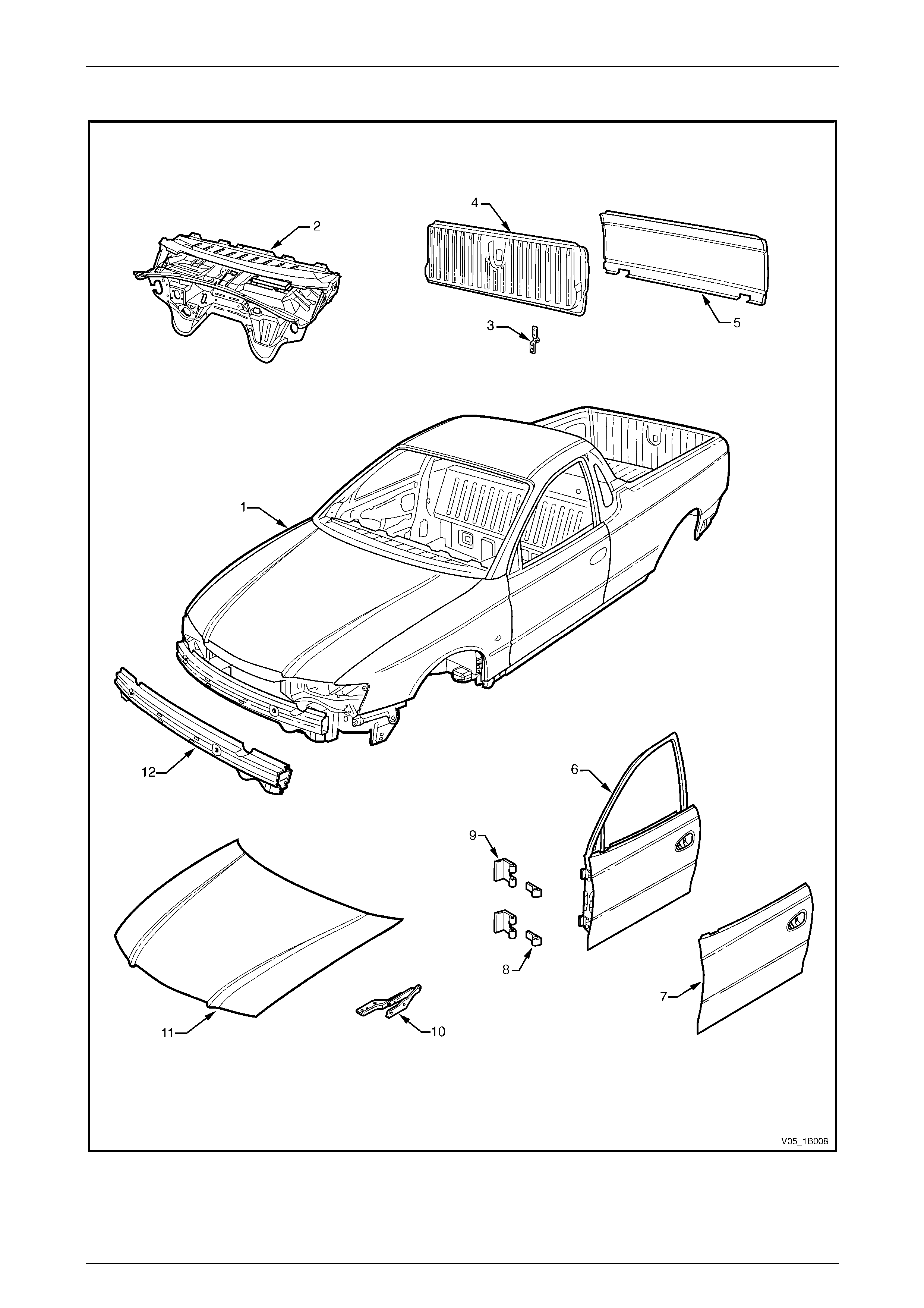
Body Assembly
Figure 1B – 17

Sheetmetal Page 1B–36
Page 1B–36
Legend
1 Body Assembly
2 Dash Panel Assembly
3 Endgate Hinge Assembly, LH / RH
4 Endgate Assembly
5 Endgate Outer Panel
6 Front Door Assembly, LH / RH
7 Front Door Outer Panel, LH / RH
8 Front Door Hinge (door side), LH / RH
9 Front Door Hinge (body side), LH / RH
10 Hood Hinge Assembly, LH / RH
11 Hood assembly
12 Front Bumper Impact Bar Assembly
Sheetmetal Page 1B–37
Page 1B–37
3.6 Regular Cab, Excluding AWD
Underbody
Figure 1B – 18

Sheetmetal Page 1B–38
Page 1B–38
Legend
1 Inner Rocker Panel Assembly, RH / LH
2 Seat Inner Bracket Assembly
3 Seat Outer Bracket Assembly, RH / LH
4 Front Floor Panel Assembly
5 Transmission Support Bracket, RH / LH
6 Front Floor Panel Extension
7 Front Side Rail Brace, RH / LH
8 Front Wheelhouse Panel Assembly, RH / LH
9 Horn Bracket Assembly, LH only
10 Relay Housing Bracket, RH only
11 ABS Modulator Bracket Assembly, RH only
12 Battery Tray Assembly, RH only
13 Front End Panel Assembly
14 Headlamp Panel, LH / RH
15 Radiator Lower Support Assembly
16 Headlamp & Front Fascia Mount Bracket, LH / RH
17 Fender Front Lower Bracket, LH / RH
18 Front Side Rail Assembly, LH / RH
19 Radiator Side Mounting Bracket, LH / RH
20 Front Wheelhouse Bracket Assembly, LH / RH
21 Front Bumper Impact Bar Bracket, LH / RH
22 Front Wheelhouse Panel Bracket, LH / RH
23 Inner Rocker Panel Filler, LH / RH
24 Jack Stowage Bracket, LH only
25 Floor Panel Plate Assembly (2 places), LH / RH
26 Propeller Shaft Hanger Assembly
27 Front Floor Panel Extension, LH / RH
28 Front Floor Panel Extension, RH / RH
29 Rear Lower Body Panel
30 Rear Lower Body Panel Assembly, LH / RH
Sheetmetal Page 1B–39
Page 1B–39
Upperbody
Figure 1B – 19

Sheetmetal Page 1B–40
Page 1B–40
Legend
1 Roof Front Header Panel
2 Roof Panel
3 Roof Rear Header Panel
4 Rear Body Upper Outer Panel Assembly
5 Rear Body Upper Inner Panel Assembly
6 Rear Body Lower Panel
7 Quarter Panel Inner Assembly, LH / RH
8 Quarter Panel Inner Extension, LH / RH
9 Hinge Pillar Trim Panel Bracket, LH / RH
10 Hinge Pillar Inner Panel Assembly, LH / RH
11 Front Wheelhouse Panel Upper Side Rail, LH / RH
12 Fender Upper Rear Bracket, LH / RH
13 Door Opening Frame Assembly, LH / RH
14 Door Striker Anchor Plate, LH / RH
15 Fender Lower Rear Bracket, LH / RH
16 Fender Rear Bracket, LH / RH
17 Underbody Jacking Locator, LH / RH
18 Quarter Panel Reinforcement, LH / RH
19 Quarter Panel, LH / RH
20 Front Fender, LH / RH

Sheetmetal Page 1B–41
Page 1B–41
Body Assembly
Figure 1B – 20

Sheetmetal Page 1B–42
Page 1B–42
Legend
1 Body Assembly
2 Dash Panel Assembly
3 Subframe Assembly
4 Front Door Assembly, LH / RH
5 Front Door Outer Panel, LH / RH
6 Front Door Hinge (door side), LH / RH
7 Front Door Hinge (body side), LH / RH
8 Hood Hinge Assembly, LH / RH
9 Hood Assembly
10 Front Bumper Impact Bar Assembly
Sheetmetal Page 1B–43
Page 1B–43
3.7 AWD Regular Cab
Underbody
Figure 1B – 21

Sheetmetal Page 1B–44
Page 1B–44
Legend
1 Inner Rocker Panel Assembly, RH / LH
2 Seat Inner Bracket Assembly
3 Seat Outer Bracket Assembly, RH / LH
4 Front Floor Panel Assembly
5 Transmission Support Bracket, RH
6 Transmission Support Bracket, LH
7 Front Floor Panel Extension
8 Front Side Rail Brace, RH / LH
9 Front Wheelhouse Panel Assembly, RH / LH
10 Horn Bracket Assembly, LH only
11 Relay Housing Bracket, RH only
12 ABS Modulator Bracket Assembly, RH only
13 Battery Tray Assembly, RH only
14 Front End Panel Assembly
15 Headlamp Panel, LH / RH
16 Radiator Lower Support Assembly
17 Headlamp & Front Fascia Mount Bracket, LH / RH
18 Fender Front Lower Bracket, LH / RH
19 Front Side Rail Assembly, LH / RH
20 Radiator Side Mounting Bracket, LH / RH
21 Front Wheelhouse Bracket Assembly, LH / RH
22 Front Bumper Impact Bar Bracket, LH / RH
23 Front Wheelhouse Panel Bracket, LH / RH
24 Inner Rocker Panel Filler, LH / RH
25 Jack Stowage Bracket, LH only
26 Floor Panel Plate Assembly (2 places), LH / RH
27 Propeller Shaft Hanger Assembly
28 Front Floor Panel Extension, LH
29 Front Floor Panel Extension, RH
30 Rear Lower Body Panel
31 Rear Lower Body Panel Assembly, LH / RH
Sheetmetal Page 1B–45
Page 1B–45
Upperbody
Figure 1B – 22

Sheetmetal Page 1B–46
Page 1B–46
Legend
1 Roof Front Header Panel
2 Roof Panel
3 Roof Rear Header Panel
4 Rear Body Upper Outer Panel Assembly
5 Rear Body Upper Inner Panel Assembly
6 Rear Body Lower Panel
7 Quarter Panel Inner Assembly, LH / RH
8 Quarter Panel Inner Extension, LH / RH
9 Hinge Pillar Trim Panel Bracket, LH / RH
10 Hinge Pillar Inner Panel Assembly, LH / RH
11 Front Wheelhouse Panel Upper Side Rail, LH / RH
12 Fender Upper Rear Bracket, LH / RH
13 Door Opening Frame Assembly, LH / RH
14 Door Striker Anchor Plate, LH / RH
15 Fender Lower Rear Bracket, LH / RH
16 Fender Rear Bracket, LH / RH
17 Underbody Jacking Locator, LH / RH
18 Quarter Panel Reinforcement, LH / RH
19 Quarter Panel, LH / RH
20 Front Fender, LH / RH
Sheetmetal Page 1B–47
Page 1B–47
Body Assembly
Figure 1B – 23

Sheetmetal Page 1B–48
Page 1B–48
Legend
1 Body Assembly
2 Dash Panel Assembly
3 Subframe Assembly
4 Front Door Assembly, LH / RH
5 Front Door Outer Panel, LH / RH
6 Front Door Hinge (door side), LH / RH
7 Front Door Hinge (body side), LH / RH
8 Hood Hinge Assembly, LH / RH
9 Hood Assembly
10 Front Bumper Impact Bar Assembly
Sheetmetal Page 1B–49
Page 1B–49
3.8 Crew Cab, Excluding AWD
Underbody
Figure 1B – 24

Sheetmetal Page 1B–50
Page 1B–50
Legend
1 Inner Rocker Panel Assembly, RH / LH
2 Seat Inner Bracket Assembly
3 Seat Outer Bracket Assembly, RH / LH
4 Front Floor Panel Assembly
5 Transmission Support Bracket, RH / LH
6 Front Floor Panel Extension
7 Front Side Rail Brace, RH / LH
8 Front Wheelhouse Panel Assembly, RH
9 Horn Bracket Assembly, LH only
10 Relay Housing Bracket, RH only
11 ABS Modulator Bracket Assembly, RH only
12 Battery Tray Assembly, RH only
13 Front End Panel Assembly
14 Headlamp Panel, LH / RH
15 Radiator Lower Support Assembly
16 Headlamp & Front Fascia Mount Bracket, LH / RH
17 Fender Front Lower Bracket, LH / RH
18 Front Side Rail Assembly, LH / RH
19 Radiator Side Mounting Bracket, LH / RH
20 Front Wheelhouse Bracket Assembly, LH / RH
21 Front Bumper Impact Bar Bracket, LH / RH
22 Front Wheelhouse Panel Bracket, LH / RH
23 Propeller Shaft Hanger Assembly
24 Rear Seatbelt Anchor Plate Assembly (3 places)
25 Floor Panel Plate Assembly (2 places), LH / RH
26 Front Floor Panel Extension Assembly
27 Rear Lower Body Panel
28 Rear Lower Body Panel Assembly, LH / RH
Sheetmetal Page 1B–51
Page 1B–51
Upperbody Sheetmetal
Figure 1B – 25

Sheetmetal Page 1B–52
Page 1B–52
Legend
1 Roof Front Header Panel
2 Roof Panel
3 Roof Bow Panel
4 Roof Rear Header Inner Panel
5 Roof Rear Header Outer Panel
6 Rear Body Upper Outer Panel Assembly
7 Rear Body Upper Inner Panel Assembly
8 Rear Body Lower Panel Assembly
9 Quarter Panel Inner Assembly, LH / RH
10 Quarter Panel Inner Extension, LH / RH
11 Hinge Pillar Inner Panel Assembly, LH / RH
12 Hinge Pillar Trim Panel Bracket, LH / RH
13 Quarter Panel, LH / RH
14 Door Opening Frame Assembly, LH / RH
15 Door Striker Anchor Plate, LH / RH
16 Underbody Jacking Locator, LH / RH
17 Fender Rear Bracket, LH / RH
18 Fender Lower Rear Bracket, LH / RH
19 Fender Upper Rear Bracket, LH / RH
20 Front Wheelhouse Panel Upper Side Rail, LH / RH
21 Front Fender, LH / RH*
* Some models are fitted with a front fender centre moulding assembly. In this instance a different front fender is fitted.

Sheetmetal Page 1B–53
Page 1B–53
Body Assembly
Figure 1B – 26

Sheetmetal Page 1B–54
Page 1B–54
Legend
1 Body Assembly
2 Dash Panel Assembly
3 Rear Tray Body Assembly
4 Endgate Hinge Assembly, LH / RH
5 Endgate Assembly
6 Endgate Outer Panel
7 Floor Support Frame
8 Fuel Tank Upper Strap, LH / RH
9 Subframe Assembly
10 Fuel Tank Lower Strap, RH
11 Fuel Tank Lower Strap, LH
12 Rear Door Assembly, LH / RH
13 Rear Door Outer Panel, LH / RH
14 Rear Door Hinge (body side), LH / RH
15 Rear Door Hinge (door side), LH / RH
16 Front Door Assembly, LH / RH
17 Front Door Hinge (body side), LH / RH
18 Front Door Hinge (door side), LH / RH
19 Front Door Outer Panel, LH / RH
20 Hood Hinge Assembly, LH / RH
21 Hood Assembly
22 Front Bumper Impact Bar Assembly

Sheetmetal Page 1B–55
Page 1B–55
Rear Tray Body Assembly
Figure 1B – 27

Sheetmetal Page 1B–56
Page 1B–56
Legend
1 Inner Side Panel Extension Cover, RH only
2 Fuel Filler Pipe Housing, RH only
3 Rear Wheelhouse Inner Panel, LH / RH
4 Cargo Tie Down Bracket (2 places), LH / RH
5 Rear Inner Side Panel Cover, LH / RH
6 Inner Side Panel Extension Assembly, LH / RH
7 Inner Side Panel, LH / RH
8 Cargo Tie Down Anchor Plate Assembly (2 places), LH / RH
9 Wheelhouse Filler Panel Bracket (2 places), LH / RH
10 Rear Quarter Closing Panel, LH / RH
11 Quarter Panel Rear Brace, LH / RH
12 Quarter Inner Lower Rear Extension, LH / RH
13 Endgate Striker Anchor Plate, LH / RH
14 Endgate Striker Anchor Plate Retainer, LH / RH
15 Quarter Lower Rear Panel, LH / RH
16 Quarter Panel Upper Extension, LH / RH
17 Quarter Panel Extension, LH / RH
18 Rear Quarter Panel, LH / RH
19 Quarter Panel Front Gusset, LH / RH
20 Rear Body Front Bracket, LH / RH
21 Front End Panel Cover, LH / RH
22 Front Cover Attachment Beam, LH / RH
23 Front End Panel Sill Assembly
24 Front End Panel
25 Load Floor Panel
26 Load Floor Front Extension
27 Load Floor Panel Front Extension, LH / RH
28 Front End Panel Locator, LH / RH
29 Load Floor Panel Support, LH / RH
30 Load Floor Panel Side Support, LH / RH
31 Load Floor Panel Locator, LH / RH
32 Load Floor Panel Front Support
33 Load Floor Panel Locator Guide, LH / RH
34 Load Floor Panel Rear Support
35 Rear End Panel
36 Endgate Hinge Reinforcement, LH / RH
37 Rear Fascia Centre Bracket, LH / RH
38 Rear End Lower Panel
Sheetmetal Page 1B–57
Page 1B–57
3.9 AWD Crew Cab
Underbody
Figure 1B – 28

Sheetmetal Page 1B–58
Page 1B–58
Legend
1 Inner Rocker Panel Assembly, RH / LH
2 Seat Inner Bracket Assembly
3 Seat Outer Bracket Assembly, RH / LH
4 Front Floor Panel Assembly
5 Transmission Support Bracket, RH
6 Transmission Support Bracket, LH
7 Front Floor Panel Extension
8 Front Side Rail Brace, RH / LH
9 Front Wheelhouse Panel Assembly, RH / LH
10 Horn Bracket Assembly, LH only
11 Relay Housing Bracket, RH only
12 ABS Modulator Bracket Assembly, RH only
13 Battery Tray Assembly, RH only
14 Front End Panel Assembly
15 Headlamp Panel, LH / RH
16 Headlamp & Front Fascia Mount Bracket, LH / RH
17 Fender Front Lower Bracket, LH / RH
18 Radiator Lower Support Assembly
19 Front Side Rail Assembly, LH / RH
20 Radiator Side Mounting Bracket, LH / RH
21 Front Wheelhouse Bracket Assembly, LH / RH
22 Front Bumper Impact Bar Bracket, LH / RH
23 Front Wheelhouse Panel Bracket, LH / RH
24 Propeller Shaft Hanger Assembly
25 Rear Seatbelt Anchor Plate Assembly (3 places)
26 Floor Panel Plate Assembly (2 places), LH / RH
27 Front Floor Panel Extension Assembly
28 Rear Lower Body Panel
29 Rear Lower Body Panel Assembly, LH / RH

Sheetmetal Page 1B–59
Page 1B–59
Upperbody Sheetmetal
Figure 1B – 29

Sheetmetal Page 1B–60
Page 1B–60
Legend
1 Roof Front Header Panel
2 Roof Panel
3 Roof Bow Panel
4 Roof Rear Header Inner Panel
5 Roof Rear Header Outer Panel
6 Rear Body Upper Outer Panel Assembly
7 Rear Body Upper Inner Panel Assembly
8 Rear Body Lower Panel Assembly
9 Quarter Panel Inner Assembly, LH / RH
10 Quarter Panel Inner Extension, LH / RH
11 Hinge Pillar Inner Panel Assembly, LH / RH
12 Hinge Pillar Trim Panel Bracket, LH / RH
13 Quarter Panel, LH / RH
14 Door Opening Frame Assembly, LH / RH
15 Door Striker Anchor Plate, LH / RH
16 Underbody Jacking Locator, LH / RH
17 Fender Rear Bracket, LH / RH
18 Fender Lower Rear Bracket, LH / RH
19 Fender Upper Rear Bracket, LH / RH
20 Front Wheelhouse Panel Upper Side Rail, LH / RH
21 Front Fender, LH / RH
Sheetmetal Page 1B–61
Page 1B–61
Body Assembly
Figure 1B – 30

Sheetmetal Page 1B–62
Page 1B–62
Legend
1 Body Assembly
2 Dash Panel Assembly
3 Rear Tray Body Assembly
4 Endgate Hinge Assembly, LH / RH
5 Endgate Assembly
6 Endgate Outer Panel
7 Floor Support Frame
8 Fuel Tank Upper Strap, LH / RH
9 Subframe Assembly
10 Fuel Tank Lower Strap, RH
11 Fuel Tank Lower Strap, LH
12 Rear Door Assembly, LH / RH
13 Rear Door Outer Panel, LH / RH
14 Rear Door Hinge (body side), LH / RH
15 Rear Door Hinge (door side), LH / RH
16 Front Door Assembly, LH / RH
17 Front Door Hinge (body side), LH / RH
18 Front Door Hinge (door side), LH / RH
19 Front Door Outer Panel, LH / RH
20 Hood Hinge Assembly, LH / RH
21 Hood Assembly
22 Front Bumper Impact Bar Assembly
Sheetmetal Page 1B–63
Page 1B–63
Rear Tray Body Assembly
Figure 1B – 31

Sheetmetal Page 1B–64
Page 1B–64
Legend
1 Inner Side Panel Extension Cover, RH only
2 Fuel Filler Pipe Housing, RH only
3 Rear Wheelhouse Inner Panel, LH / RH
4 Cargo Tie Down Bracket (2 places), LH / RH
5 Rear Inner Side Panel Cover, LH / RH
6 Inner Side Panel Extension Assembly, LH / RH
7 Inner Side Panel, LH / RH
8 Cargo Tie Down Anchor Plate Assembly (2 places) , LH / RH
9 Wheelhouse Filler Panel Bracket (2 places), LH / RH
10 Rear Quarter Closing Panel, LH / RH
11 Quarter Panel Rear Brace, LH / RH
12 Quarter Inner Lower Rear Extension, LH / RH
13 Endgate Striker Anchor Plate, LH / RH
14 Endgate Striker Anchor Plate Retainer, LH / RH
15 Quarter Lower Rear Panel, LH / RH
16 Quarter Panel Upper Extension, LH / RH
17 Quarter Panel Extension, LH / RH
18 Rear Quarter Panel, LH / RH
19 Quarter Panel Front Gusset, LH / RH
20 Rear Body Front Bracket, LH / RH
21 Front End Panel Cover, LH / RH
22 Front Cover Attachment Beam, LH / RH
23 Front End Panel Sill Assembly
24 Front End Panel
25 Load Floor Panel
26 Load Floor Front Extension
27 Load Floor Panel Front Extension, LH / RH
28 Front End Panel Locator, LH / RH
29 Load Floor Panel Support, LH / RH
30 Load Floor Panel Side Support, LH / RH
31 Load Floor Panel Locator, LH / RH
32 Load Floor Panel Front Support
33 Load Floor Panel Locator Guide, LH / RH
34 Load Floor Panel Rear Support
35 Rear End Panel
36 Endgate Hinge Reinforcement, LH / RH
37 Rear Fascia Centre Bracket, LH / RH
38 Rear End Lower Panel
Sheetmetal Page 1B–65
Page 1B–65
4 Service Operations
4.1 Front Fender, Except Coupe
LT Section – 12-425
Remove
1 Remove the following components:
a Front bumper fascia assembly, refer to Section 1D Bumper Bars.
b Rocker panel moulding, refer to Section 1A9 Exteri or Ornamentation.
c Front wheelhouse liner, refer to Section 1A1 Body.
d For AWD vehicles, remove the wheelhouse opening flare assembly,
refer to Section 1A9 Exterior Ornamentation .
e The fender name plate and where fitted, the fender section of the body sid e moulding,
refer to Section 1A9 Exterior Ornamentation .
f Where fitted, the radio antenna assembly, refer to Section 12D Entertainm ent System.
g Hood strut assembly to fender screws,
refer to Section 1A4 Hood, Rear Compartment Lid, Liftgate and Endgate.
2 Either:
a For vehicles without a front fender centre moulding assembly, remove the front side turn signal lamp
assembly, refer to Section 12B Lighting System, or
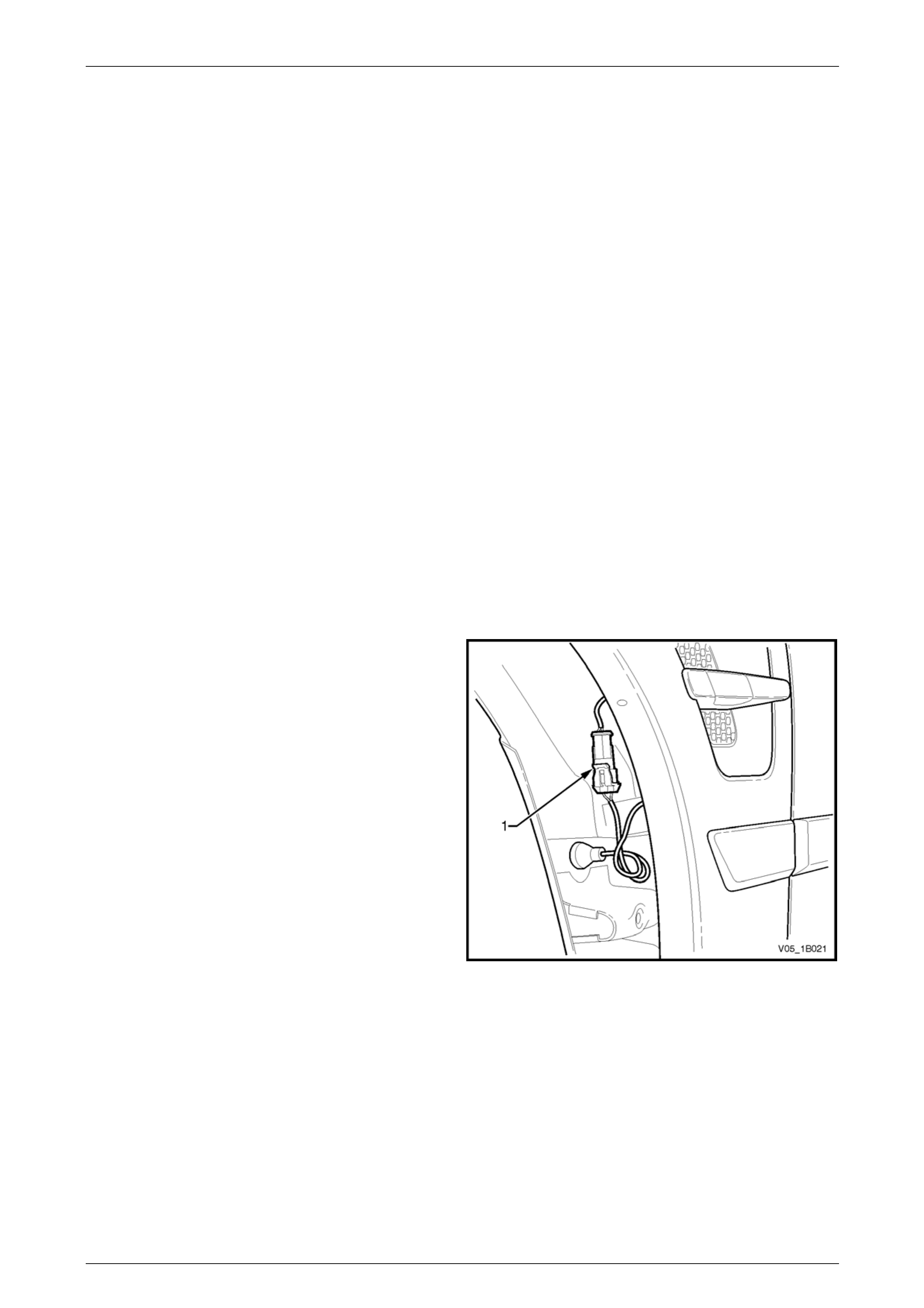
b For vehicles with a front fender centre moulding
assembly, disconnect the front side turn signal
lamp wiring connector (1).
Figure 1B – 32
Sheetmetal Page 1B–66
Page 1B–66
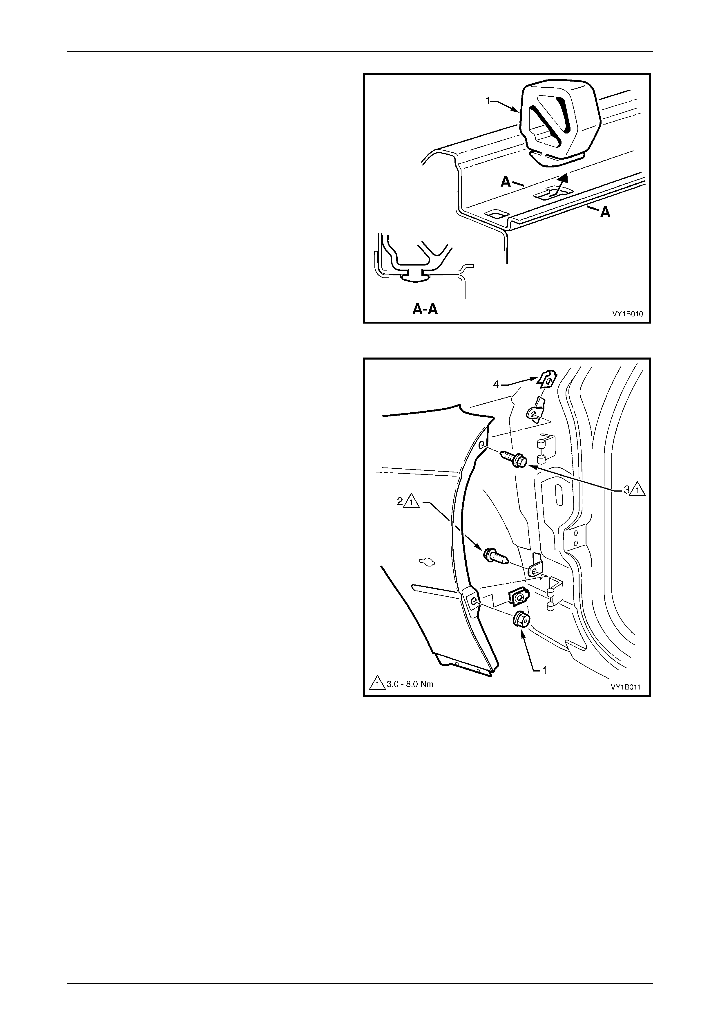
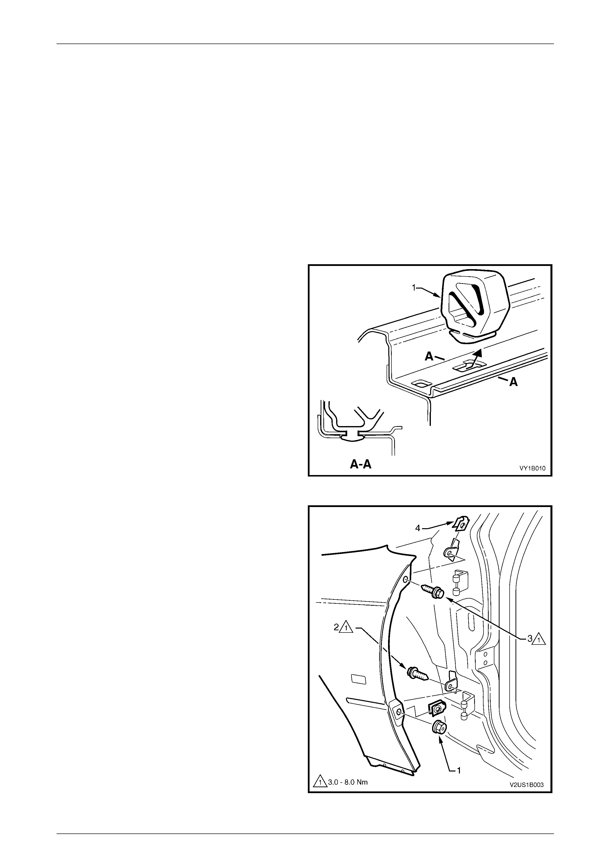
3 While tilting the hood side bu m per (1) forward slightly,
carefully slide it rearward to disengage it from the
inner edge of the fender.
Figure 1B – 33
4 From the rear of the fender, remove the nut (1).
5 From behind the fender, remove the screw (2)
attaching the rear of the fender.
6 Remove the screw (3) attaching the rear of the fender
to the vehicle.
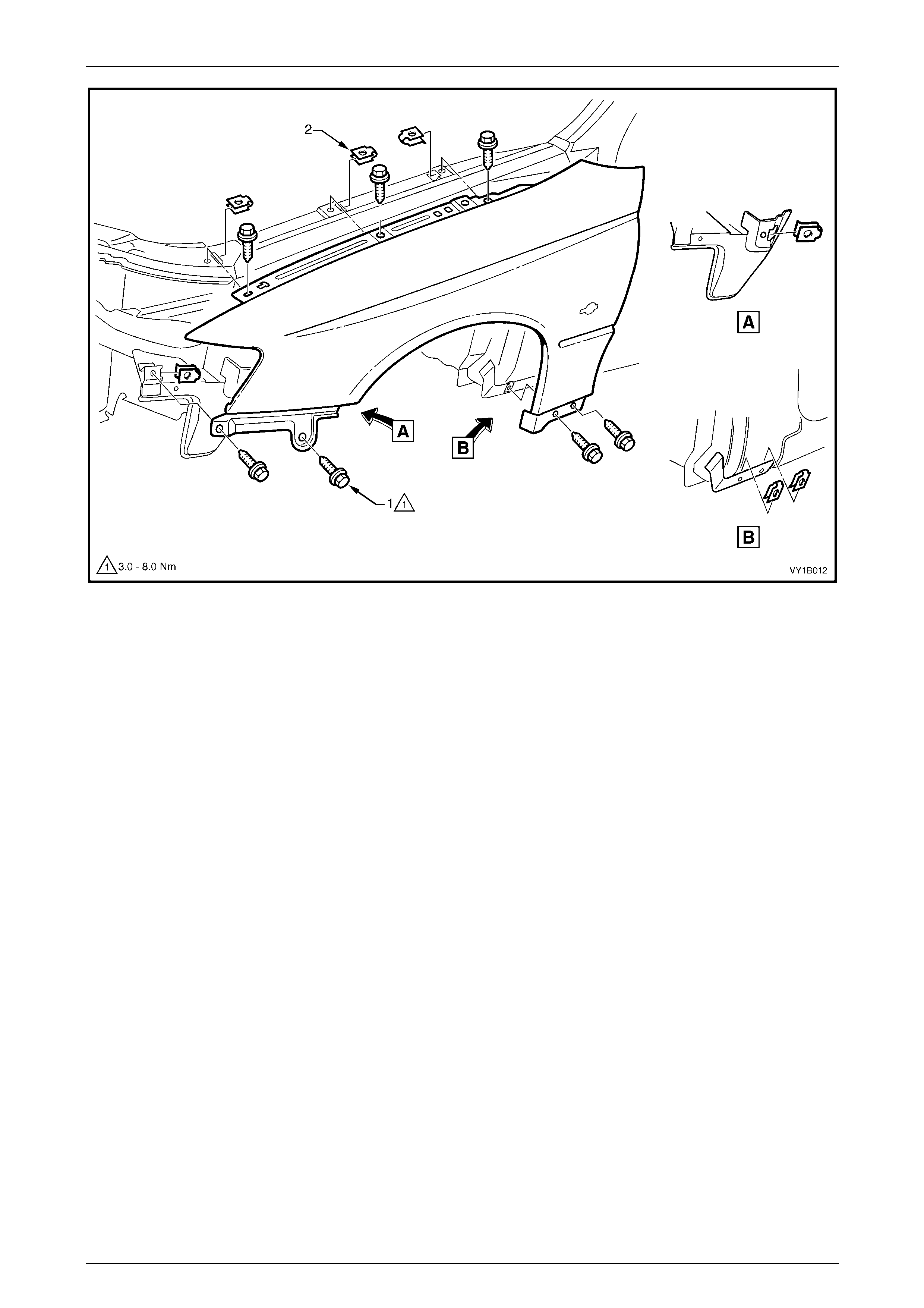
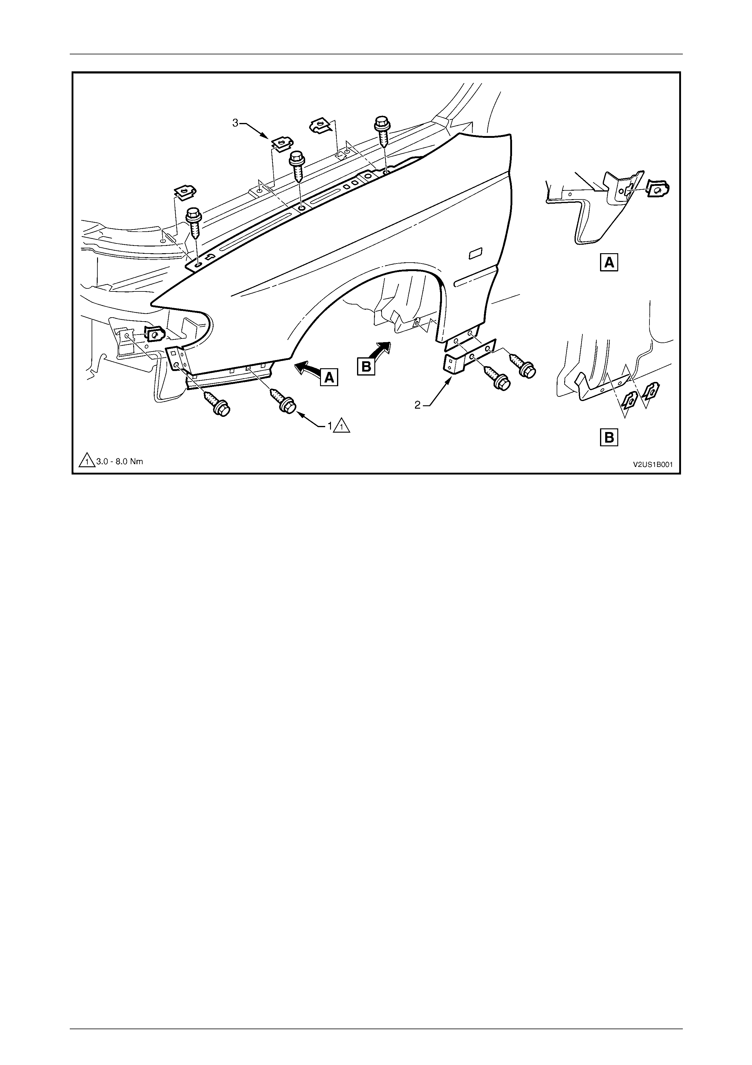
7 Remove the seven screws (1) attaching the fender to
the vehicle, refer to Figure 1B – 35.
8 Remove the fender.
Figure 1B – 34
Sheetmetal Page 1B–67
Page 1B–67
Figure 1B – 35
Disassemble
For service procedures of the front fender centre moulding assembly, where fitted,
refer to Section 1A9 Exterior Ornamentation .
Reinstall
1 Install the J-nuts as required, refer to Figure 1B – 34 (4, t wo plac es) and in Figure 1B – 35 (2, six places).
NOTE
Replace any nuts that are worn or damaged.
2 Install the fender in position a nd start all screws.
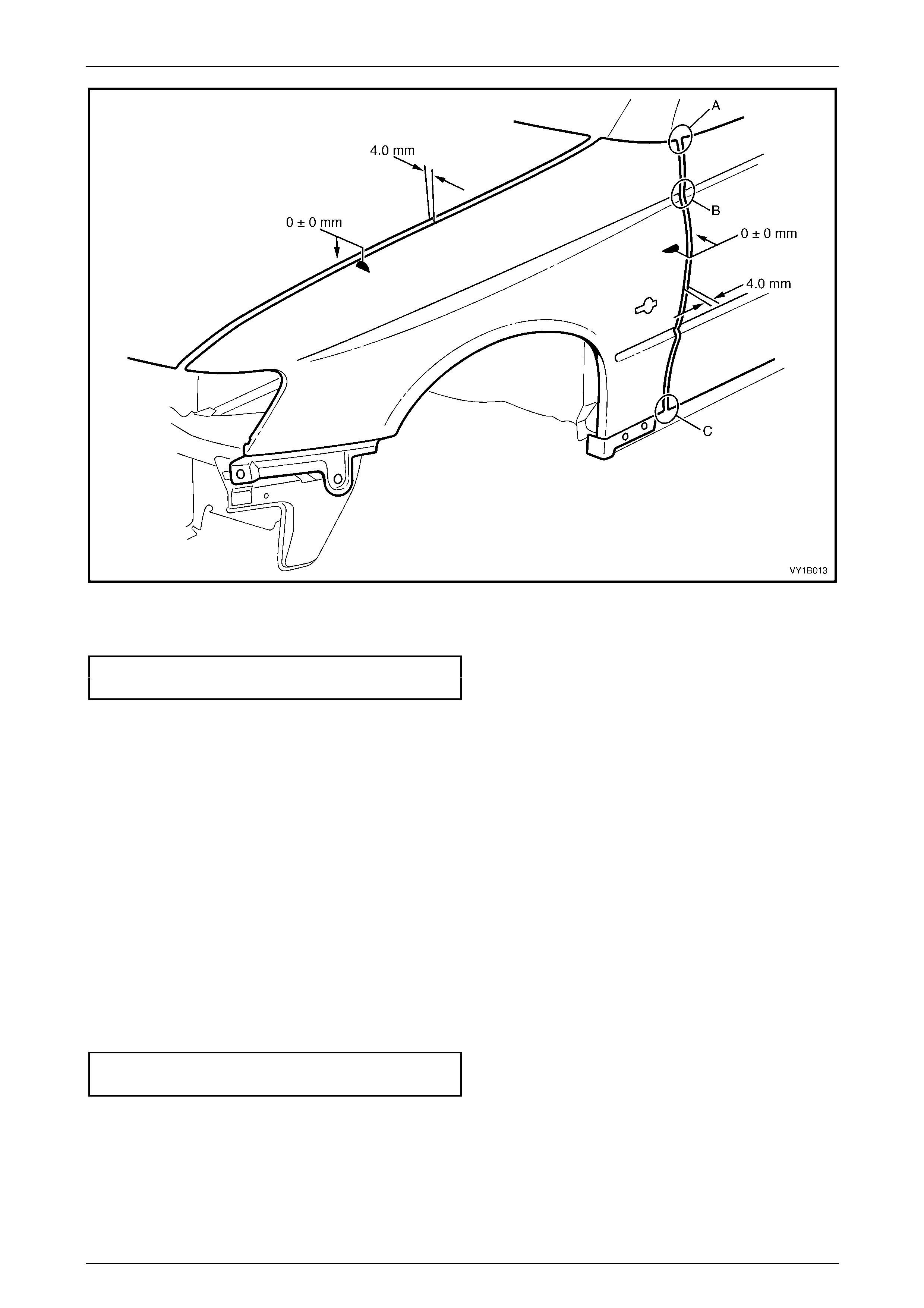
3 Carefully close the door and align the rear of the fend er to the door panel surface and body lines at points A, B & C,
refer to Figure 1B – 36.
Sheetmetal Page 1B–68
Page 1B–68
Figure 1B – 36
4 Tighten the lower rear screw from behind the fender to the correct torque specification, refer to Figure 1B – 34.
Front fender attaching screw
torque specification.....................................3.0 – 8.0 Nm
5 Open the door and tighten the upper rear screw to the correct torque specification.
6 Recheck alignment and also check for an even gap of 4.0 mm to the front door, refer to Figure 1B – 36.
7 If the gap is not to specification, carefully bend the rear fender brackets.
8 Carefully close the hood and adjust the position of the fender to provide an even gap of 4.0 mm.
9 Open the hood and tighten the three upper fender screws to the correct torque specification, refer to
Figure 1B – 35.
10 Recheck alignment and readjust as required.
NOTE
Also check that the up per fend er surfac e a lig ns to
the engine hood surface. If not adjust the hood,
refer to Section 1A4 Hood, Rear Compartment
Lid, Liftgate and Endgate.
11 Tighten all of the remaining s c rews to the correct torque specification.
Front fender attaching screw
torque specification.....................................3.0 – 8.0 Nm
12 Following painting, install the plastic nut onto the rear lo wer fender screw and install other removed components as
required.
Sheetmetal Page 1B–69
Page 1B–69
4.2 Front Fender, Coupe
LT Section – 12-425
Remove
1 Remove the following components:
a Front bumper fascia assembly, refer to Section 1D Bumper Bars.
b Rocker Panel Moulding, refer to Section 1A9 Exteri or Ornamentation.
c Front wheelhouse liner, refer to Section 1A1 Body.
d Front side turn signal lamp assembly, refer to Section 12B Lighting System.
e Hood strut assembly to fender screws,
refer to Section 1A4 Hood, Rear Compartment Lid, Liftgate and Endgate.
2 While tilting the hood side bu m per (1) forward slightly,
carefully slide it rearward to disengage it from the
inner edge of the fender.
Figure 1B – 37
3 From the rear of the fender, remove the nut (1).
4 From behind the fender, remove the screw (2)
attaching the rear of the fender.
5 Remove the screw (3) attaching the rear of the fender
to the vehicle.
6 Remove the seven screws (1) attaching the fender to
the vehicle, refer to Figure 1B – 39.
7 If required, prise the rocker panel mould in g bracket (2)
from the lower rear edge of the fender.
Figure 1B – 38
Sheetmetal Page 1B–70
Page 1B–70
Figure 1B – 39
8 Remove the fender.
9 If required, using a flat-blade screwdriver remove the J-nuts from the vehicle and rear of the fender, refer to (4) in
Figure 1B – 38 and (3) in Figur e 1B – 39.
Reinstall
1 Install the J-nuts as required, refer to Figure 1B – 38 (4, t wo places) and Figure 1B – 39 (3, six places).
NOTE
Replace any nuts that are worn or damaged.
2 Install the fender in position a nd start all screws.
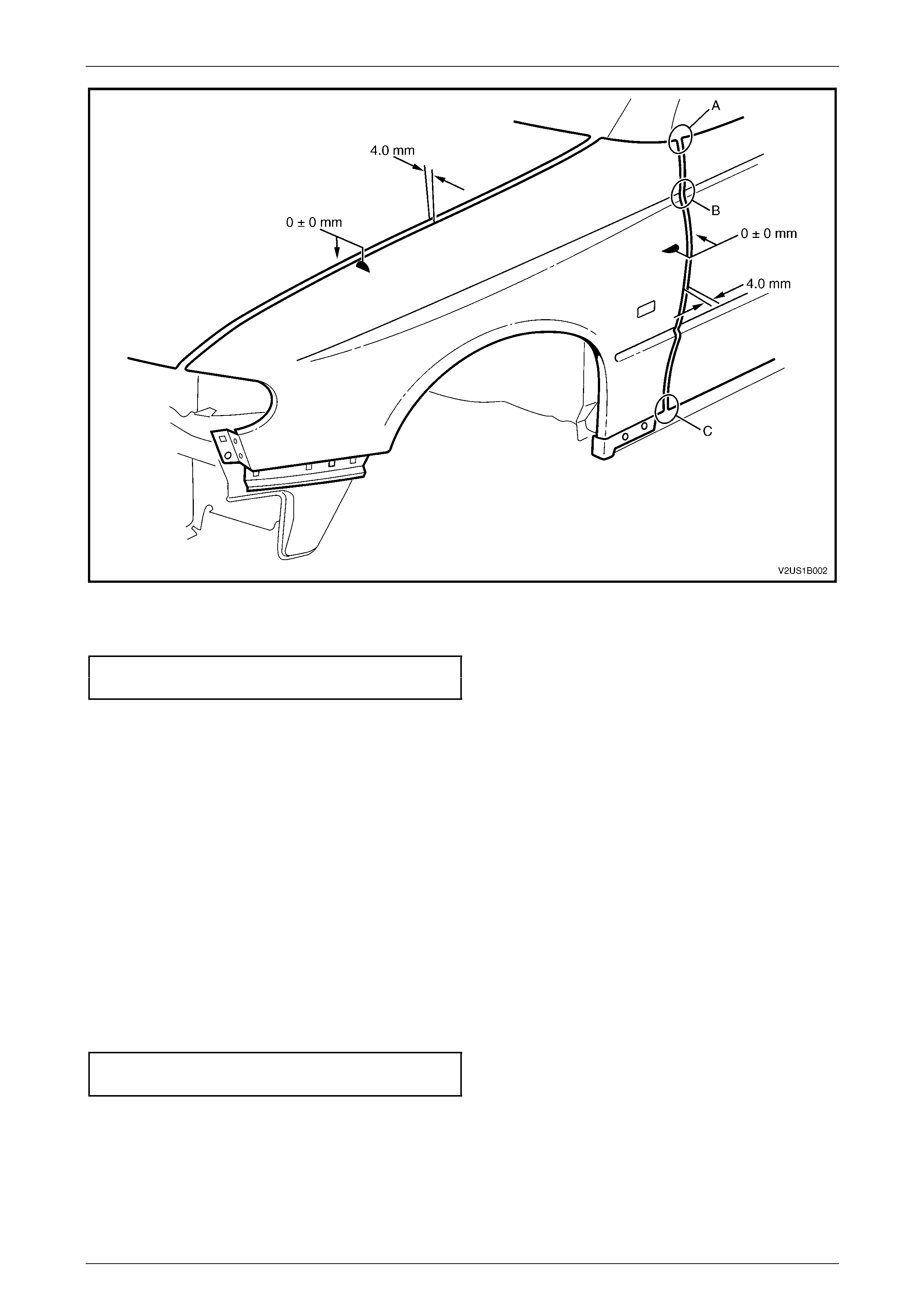
3 Carefully close the door and align the rear of the fend er to the door panel surface and body lines at points A, B & C,
refer to Figure 1B – 40.
Sheetmetal Page 1B–71
Page 1B–71
Figure 1B – 40
4 Tighten the lower rear screw (2) from behind the fend er to the correct torque specification, refer to Figure 1B – 38.
Front fender attaching screw
torque specification.....................................3.0 – 8.0 Nm
5 Open the door and tighten the upper rear screw to the correct torque specification.
6 Recheck alignment and also check for an even gap of 4.0 mm to the front door, refer to Figure 1B – 40.
7 If the gap is not to specification, carefully bend the rear fender brackets.
8 Carefully close the hood and adjust the position of the fender to provide an even gap of 4.0 mm.
9 Open the hood and tighten the three upper fender screws to the correct torque specification, refer to
Figure 1B – 39.
10 Recheck alignment and readjust as required.
NOTE
Also check that the up per fend er surfac e a lig ns to
the engine hood surface. If not adjust the hood,
refer to Section 1A4 Hood, Rear Compartment
Lid, Liftgate and Endgate.
11 Tighten all of the remaining s c rews to the correct torque specification.
Front fender attaching screw
torque specification.....................................3.0 – 8.0 Nm
12 Following painting, install the plastic nut onto the rear lo wer fender screw and install other removed components as
required.
Sheetmetal Page 1B–72
Page 1B–72
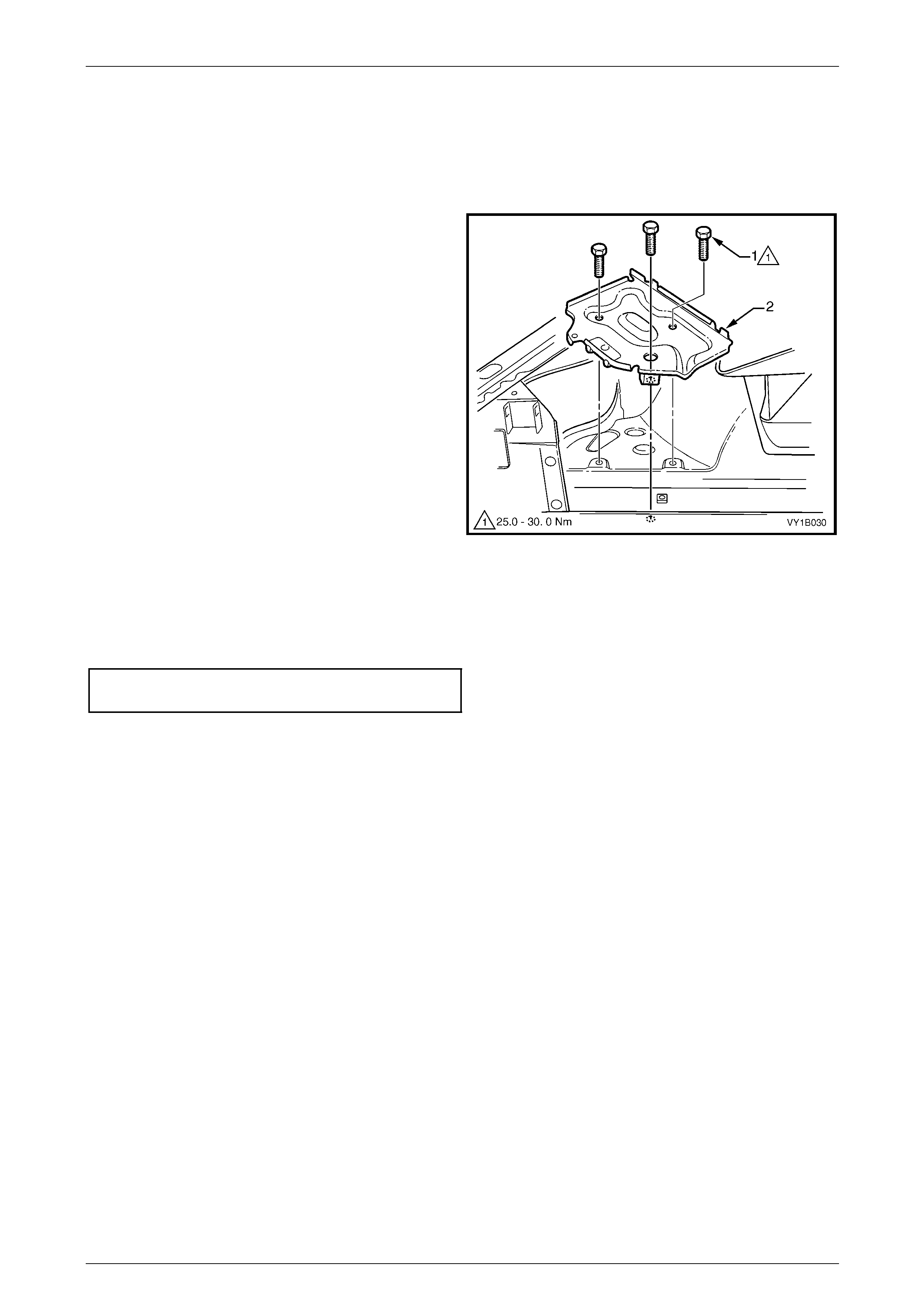
4.3 Battery Tray Assembly
LT Section – 02-200
Remove
1 Remove the battery, refer to Section 12A Battery.
2 Remove the three screws (1) attaching the battery tray
assembly (2) to the front wheelhouse and rail.
Figure 1B – 41
Reinstall
Reinstallation of the batter y tray assembly is the reverse of the removal procedure. Tighten the screws to the correct
torque specification.
Battery tray assembly attaching
screw torque specification.......................25.0 – 30.0 Nm
Sheetmetal Page 1B–73
Page 1B–73
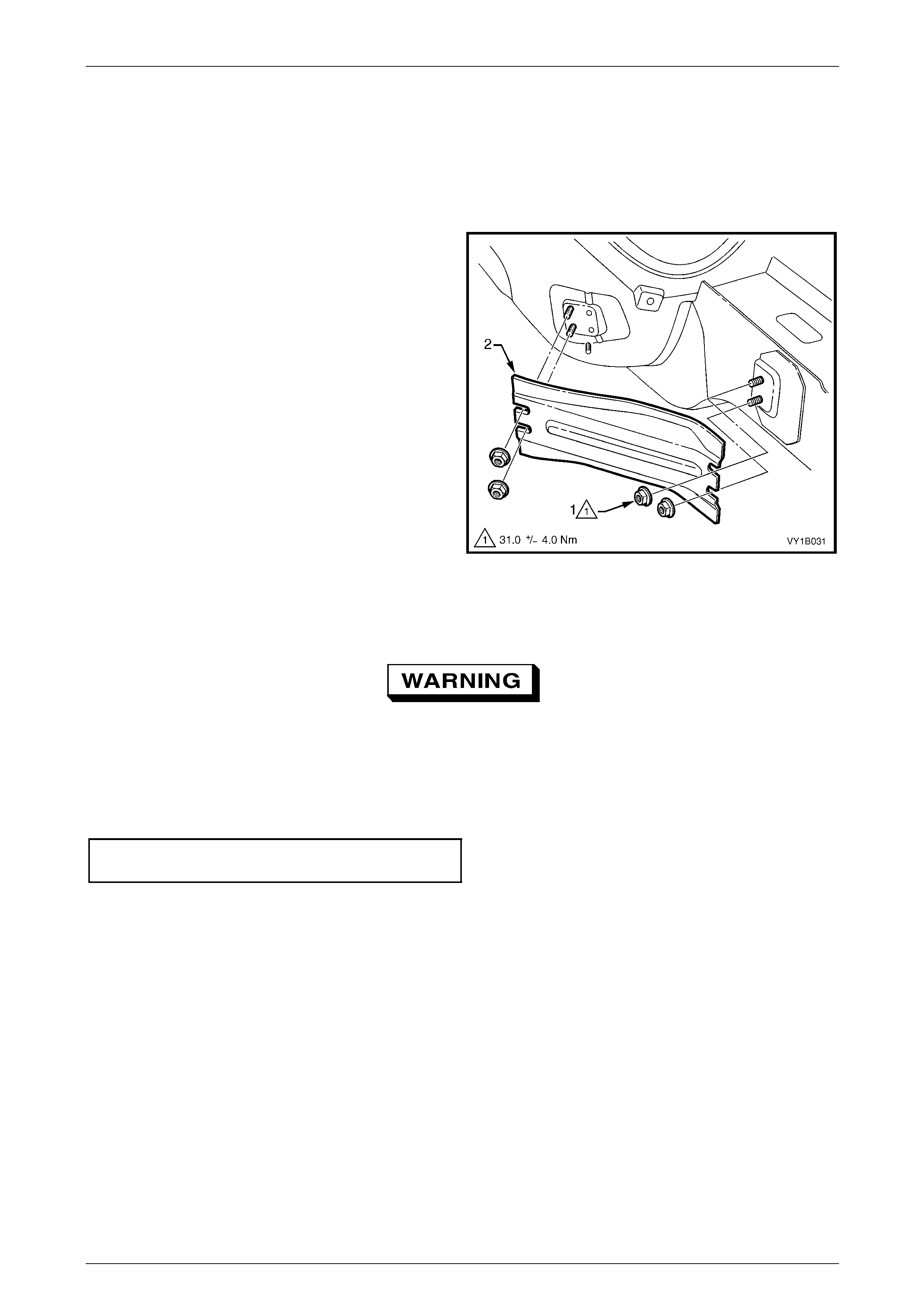
4.4 Front Side Rail Brace
LT Section – 12-425
Remove
1 Loosen the two rear nuts and remove the two front
nuts (1) attaching the front side rail brace (2).
2 Remove the brace from the vehicle.
Figure 1B – 42
Reinstall
As the braces serve as a critical structural
component of the body structure, correct
fitment and torque are crucial.
1 Reinstall the brace ens uring it is correctly orientated.
2 Tighten the nuts to the correct torque specification.
Front side rail brace upper attaching
nut torque specification.............................31.0 ± 4.0 Nm
Sheetmetal Page 1B–74
Page 1B–74
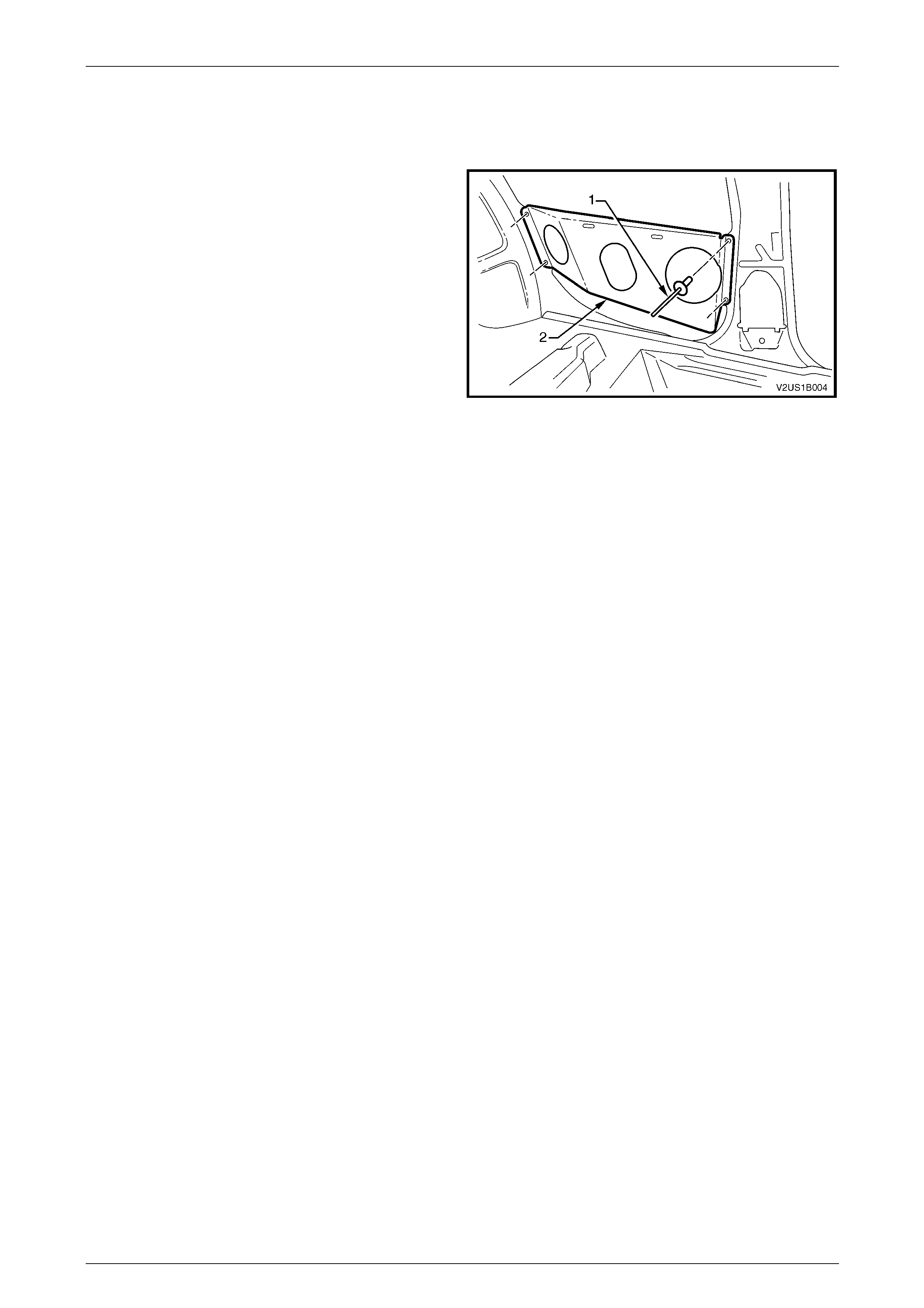
4.5 Side Speaker Mounting Bracket, Coupe
Remove
1 Using a 5 mm drill bit, drill out the rivet (1), four places,
attaching the side speaker mounting bracket (2) to the
vehicle.
2 Remove the bracket.
Figure 1B – 43
Reinstall
Reinstallation of the side speaker mounting bracket is the reverse of the removal procedure. Use new 5 mm rivets.
Sheetmetal Page 1B–75
Page 1B–75
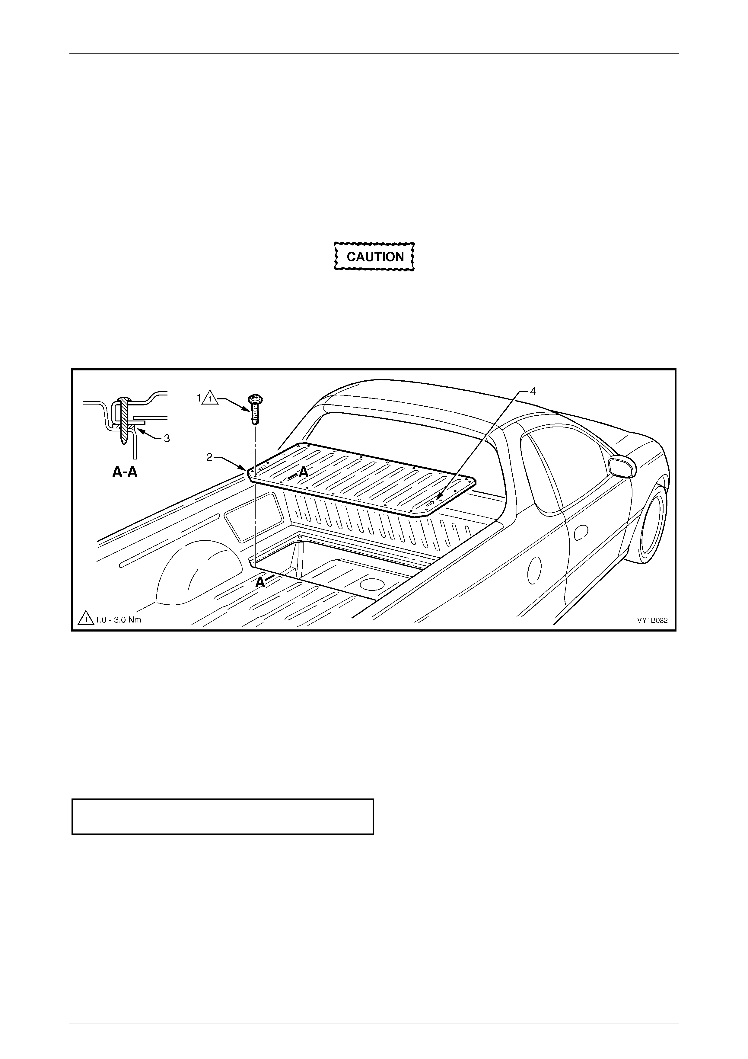
4.6 Load Floor Front Panel Assembly, Utility
LT Section – 12-480
Remove
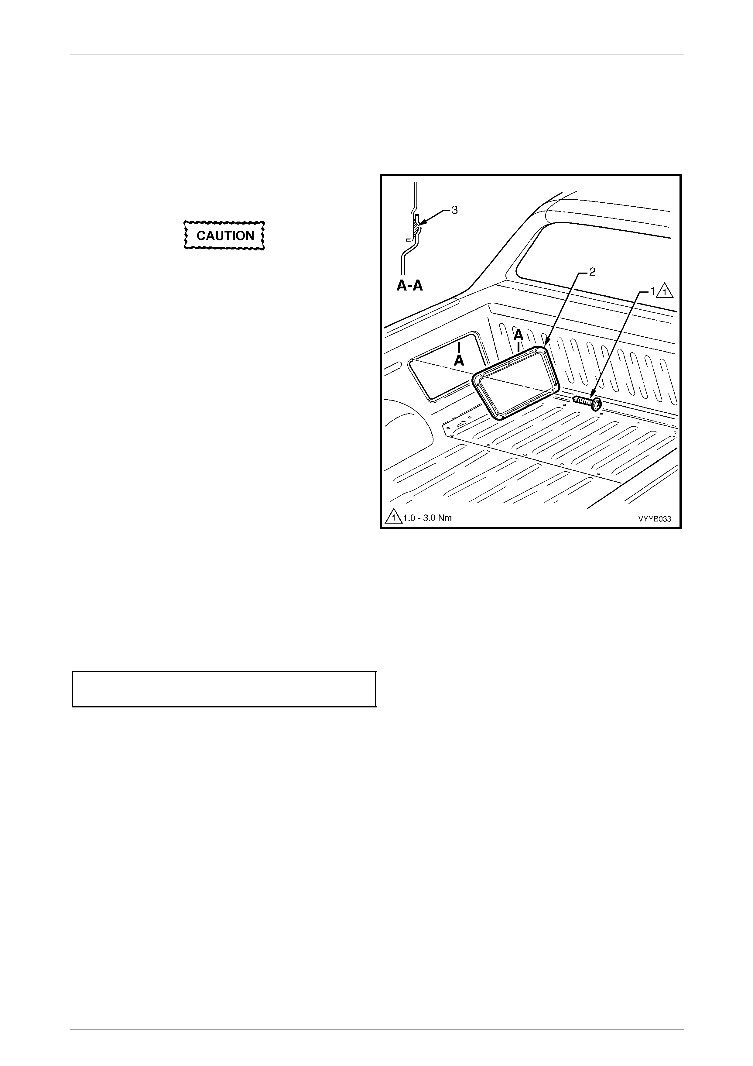
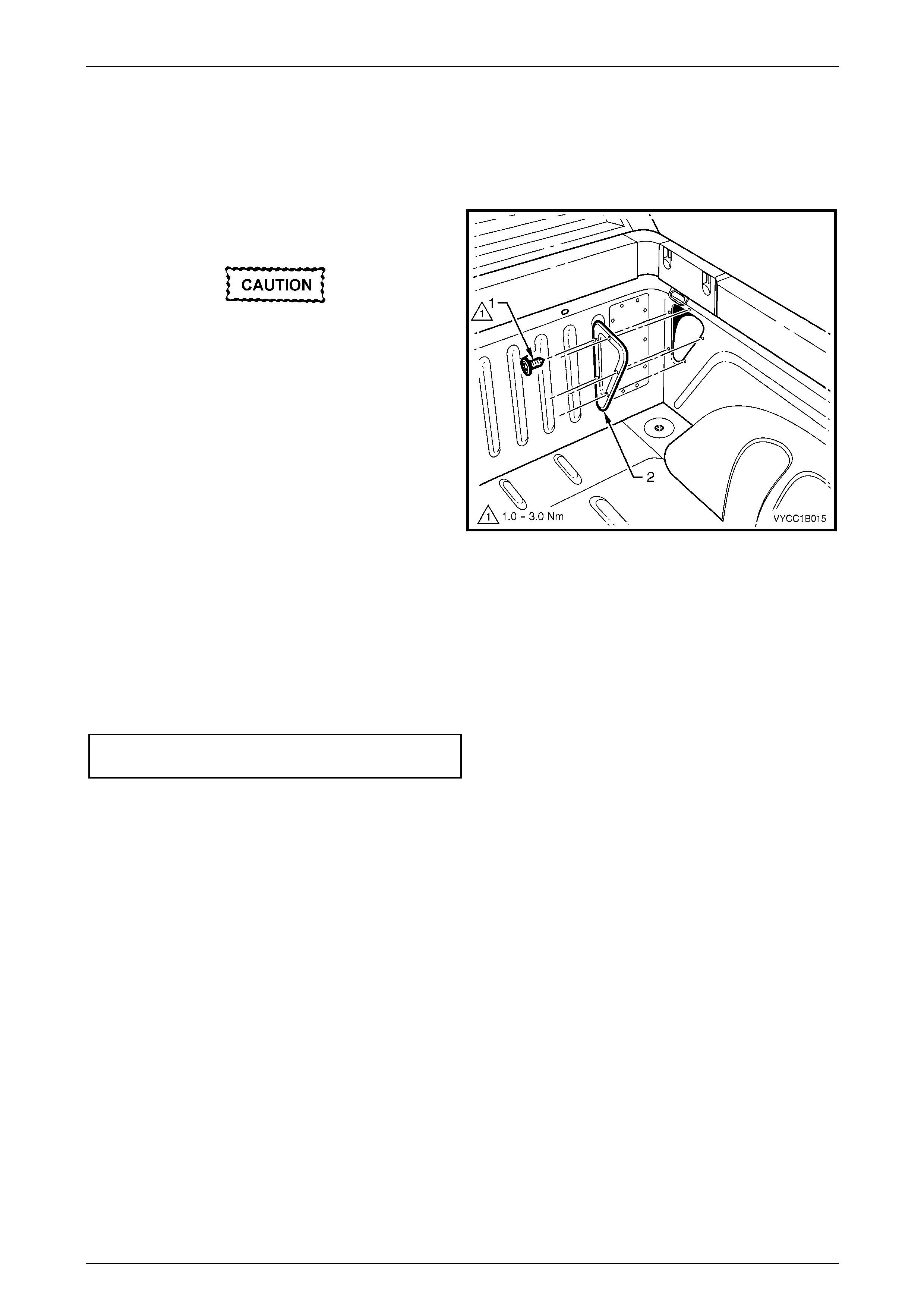
1 Remove the screw (1), 22 places, attaching the load floor front panel assembly (2) to the vehicle, refer to
Figure 1B – 44.
Protect the paintwork with a rag.
2 Using a flat-blade screwdriver or suitab le lever and a piece a scrap wood as a fulcrum, prise each corner of the
panel assembly from the vehicle to break the sealer (3).
3 With the aid of an assistant, lift the panel assembly from the vehicle.
Figure 1B – 44
Reinstall
1 If required apply a continuous bead of sealer such as a non-hardening butyl sealer ar ound the perimeter of the
lower flange of the panel assembly.
2 With the aid of an assistant, install the panel assembly ensuring it is correctly orientated. The arrow (4) must be
pointing forward, refer to Figure 1B – 44.
3 Start all screws and then tighten to the correct torque specification.
Load floor front panel assem bly
attaching screw torque specification...........1.0 – 3.0 Nm
4 Remove any residual sealer as required.
Sheetmetal Page 1B–76
Page 1B–76
4.7 Front Inner Side Panel Cover, Utility
LT Section – 12-480
Remove
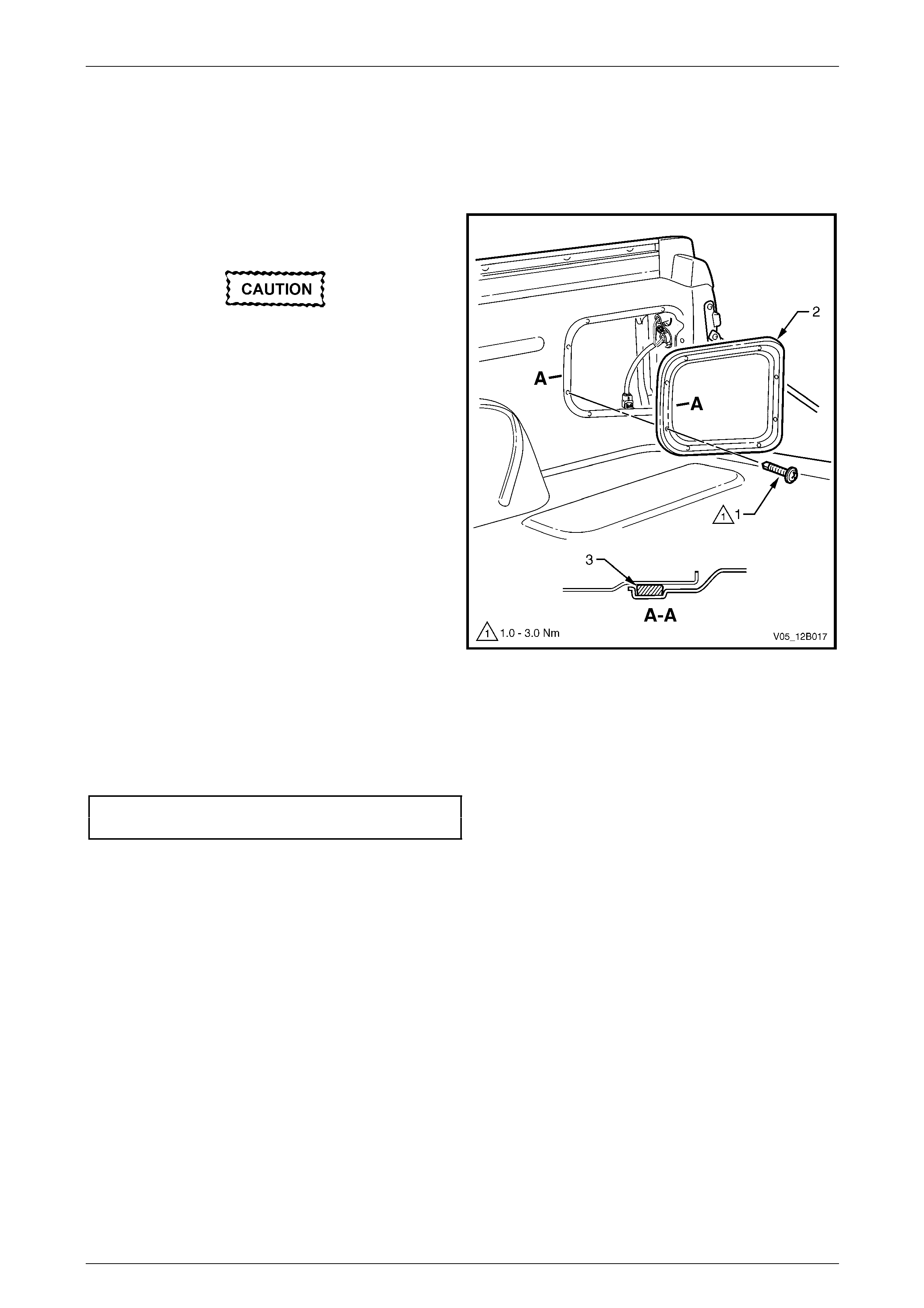
1 Remove the screw (1), 10 places, attaching the front
inner side panel cover (2) to the vehicle.
Protect the paintwork with a rag.
2 Using a flat-blade screwdriver or suitab le lever,
carefully prise the corner of the cover from the vehicle
to break the sealer (3).
3 Remove the cover from the vehicle.
Figure 1B – 45
Reinstall
1 Apply a continuous bead of sealer such non-hardening butyl sealer around the perimeter of the cover.
2 Install the cover ensuring it is correctly orientated.
3 Start all screws and then tighten to the correct torque specification.
Front inner side panel cover
attaching screw torque specification...........1.0 – 3.0 Nm
4 Remove any residual sealer as required.
Sheetmetal Page 1B–77
Page 1B–77
4.8 Rear Inner Side Panel Cover, Utility
LT Section – 12-480
Remove
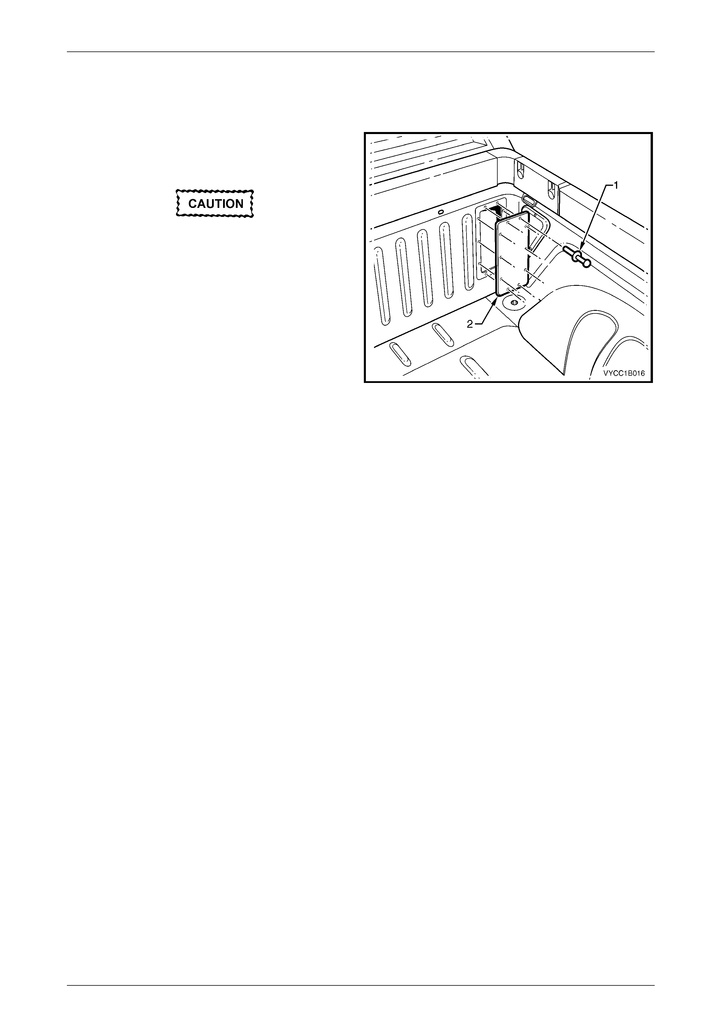
1 Remove the screw (1), eight places, attaching the rear
inner side panel cover (2) to the vehicle.
Protect the paintwork with a rag.
2 If required, use a flat-blade screwdriver or suitable
lever, carefully prise the corner of the cover from the
vehicle. Do not break the seal (3).
3 Remove the cover from the vehicle.
Figure 1B – 46
Reinstall
1 Install the cover ensuring it is correctly orientated and the seal is correctly positioned.
2 Start all screws and then tighten to the correct torque specification.
Rear inner side panel cover
attaching screw torque specification...........1.0 – 3.0 Nm
Sheetmetal Page 1B–78
Page 1B–78
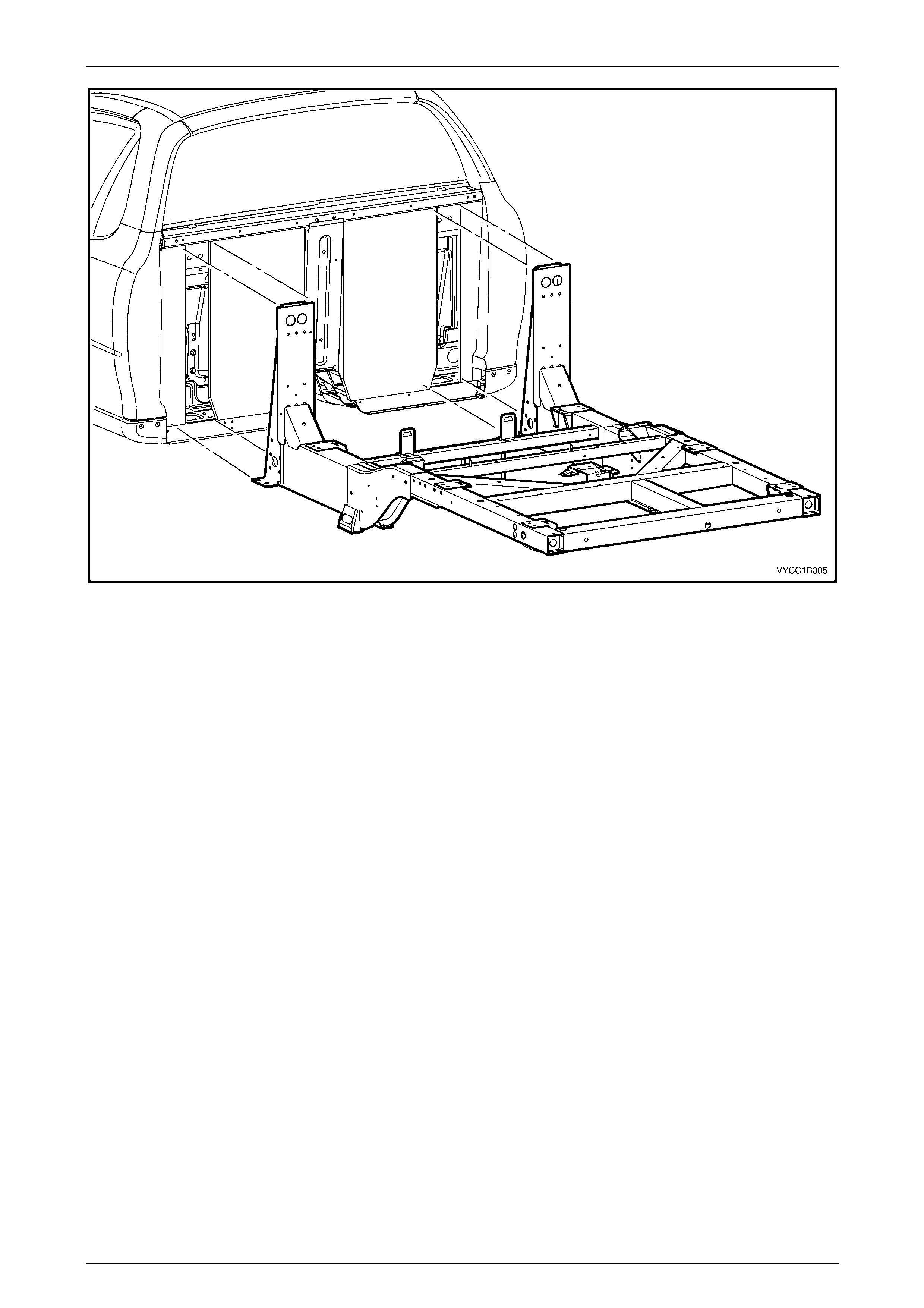
4.9 Rear Tray Body Assembly, Crew Cab
Figure 1B – 47
Sheetmetal Page 1B–79
Page 1B–79
Remove
1 Disconnect the wiring harness at the rear of the cab, refer to Section 12O Fuses, Relays and Wiring Harnesses.
2 Remove the fuel filler neck, refer to Section 8A1 Fuel System .
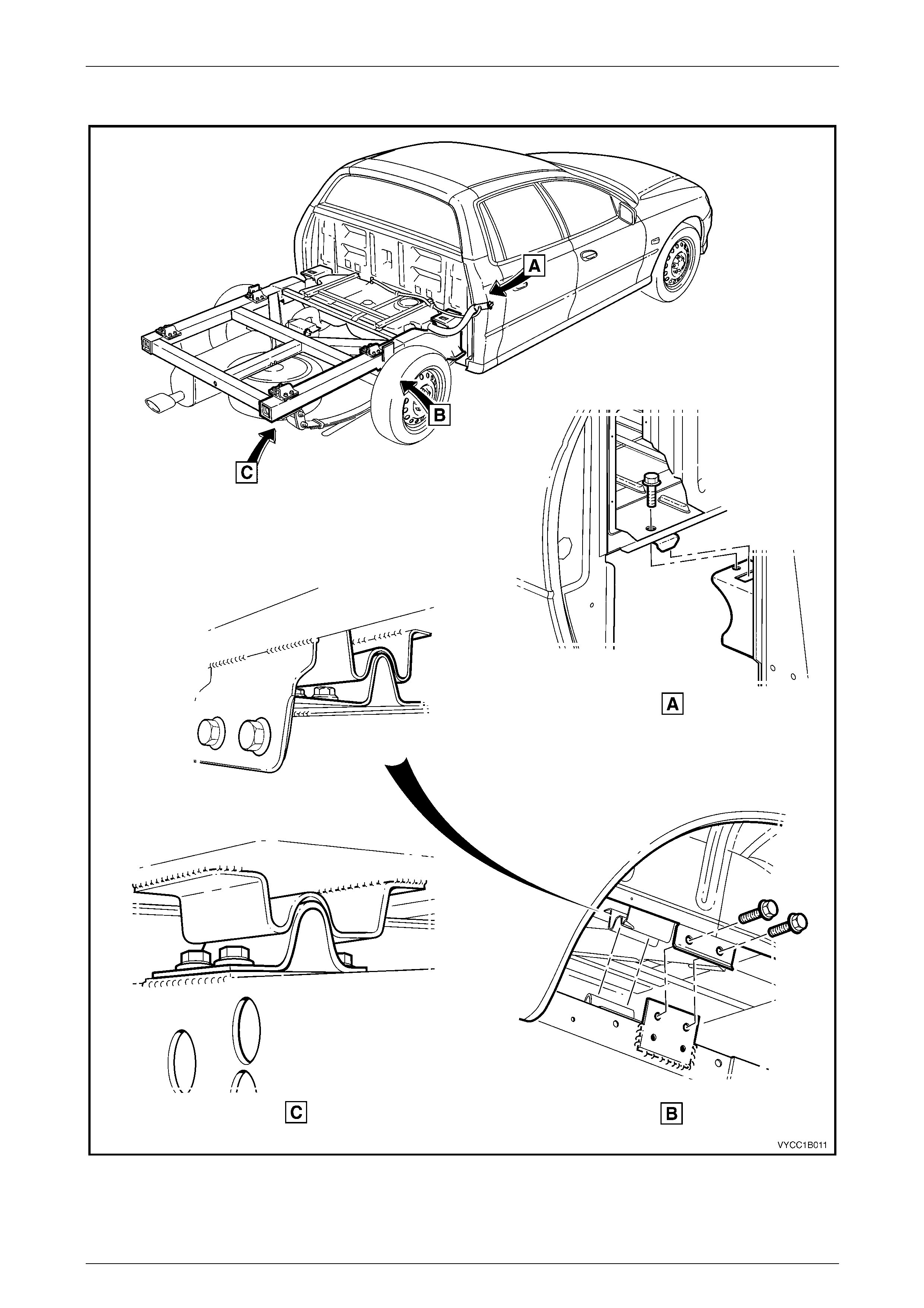
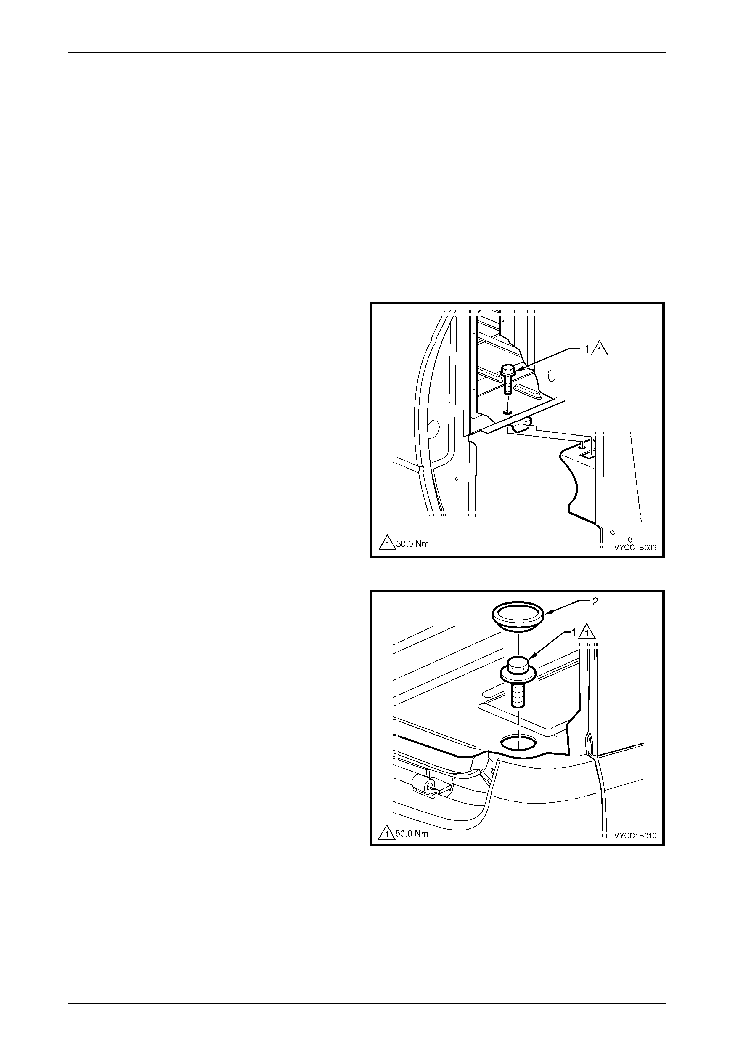
3 Remove the mounting bolt (1), two places each side of
the vehicle, attaching the rear tra y body assembl y to
the subframe centre mount (2).
Figure 1B – 48
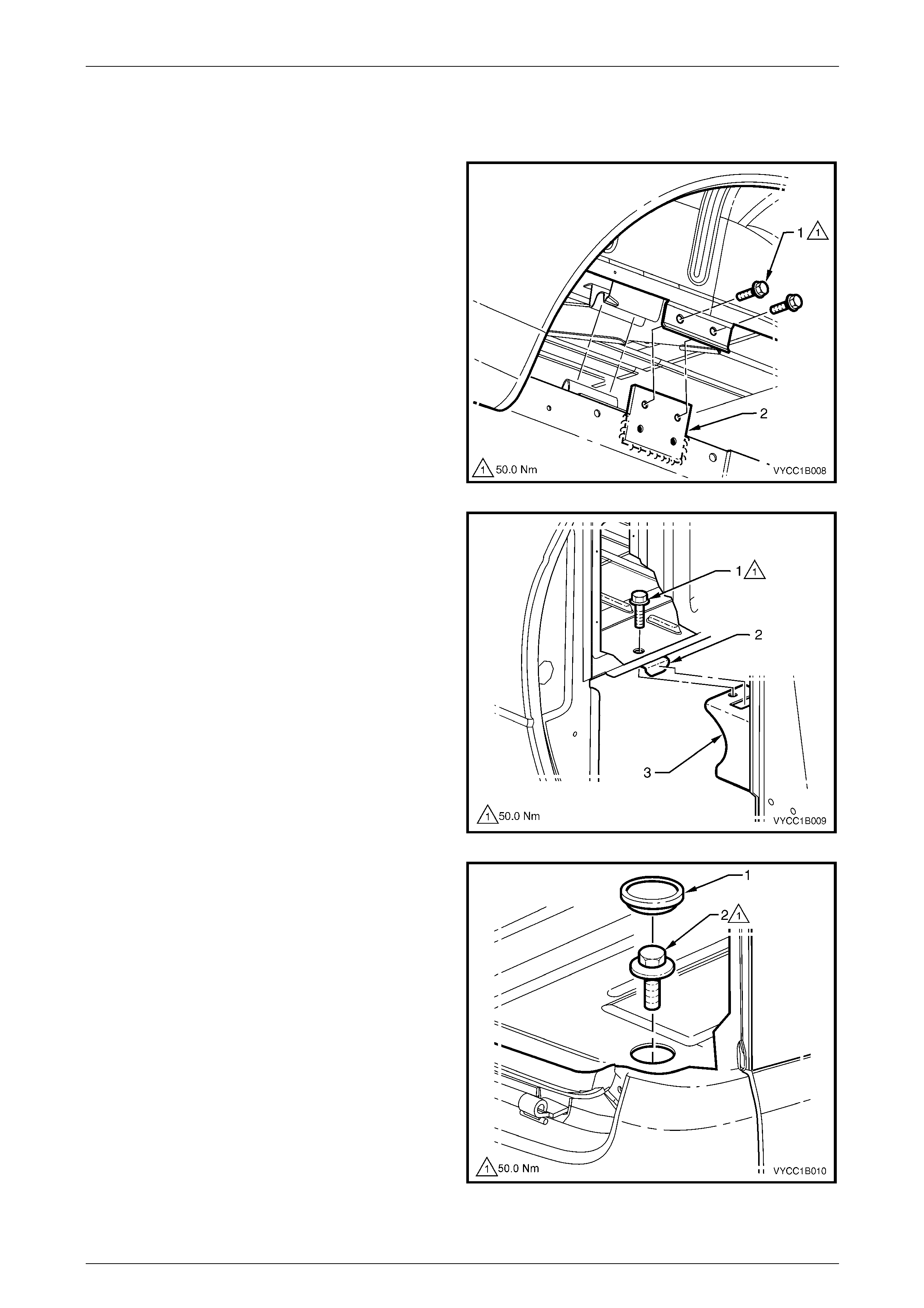
4 Remove the bolt (1), one place each side attaching
each front corner of the body assembly (2) to the
subframe (3).
Figure 1B – 49
5 Remove the grommet (1), one place each side to allow
access to the mounting bolt (2).
6 Remove the bolt, one place each side attaching each
rear corner of the body assembly to the subframe.
7 With the aid of several assistants or using a suitable
lifting hoist, carefully raise the body assembly clear of
the vehicle and remove.
Figure 1B – 50
Sheetmetal Page 1B–80
Page 1B–80
Reinstall
NOTE
The floor support frame has strips of foam glued
to it. If the foam is damaged, replace it with
commercially available high-density foam and fix
with contact adhesive.
1 With the aid of several assistants or using a suitable lifting hoist, carefully position the rear tray body assembly over
the subframe.
NOTE
Ensure the front location tab is positioned in the
slot of the front subframe mount correctly.
2 Slide the tray as far forward as possible a nd then
reinstall the bolt (1), one place in each front corner.
Do not tighten.
Figure 1B – 51
3 Reinstall the bolt (1), one place in each rear corner.
Do not tighten or install the grommet (2) at this stage.
Figure 1B – 52

Sheetmetal Page 1B–81
Page 1B–81
4 Reinstall the two bolts (1) in the centre mou nt (2),
each side of the vehicle. Do not tighten.
5 Ensure the rear body is positioned correctly on all
mounting points and then tigh ten all bolts to the
correct torque specification.
Rear tray body assembly mounting bolt
torque specification............................................50.0 Nm
6 Reinstall the grommet (2), one place e ach si de in the
rear body floor, refer to Figure 1B – 52.
7 Refit the fuel filler neck,
refer to Section 8A1 Fuel System.
8 Reconnect the wiring harness at the rear of the body,
refer to Section 12O Fuses, Relays and Wiring
Harnesses.
9 Ensure all lights are working correctly. Figure 1B – 53
Sheetmetal Page 1B–82
Page 1B–82
4.10 Inner Side Panel Extension Cover, Crew
Cab
Remove
1 Remove the screw (1), five places, attaching the inner
side panel extension cover (2).
Protect the paintwork with a rag.
2 Using a flat-blade screwdriver or suitab le lever,
carefully prise the corner of the cover from the inner
side panel to break the sealer.
3 Remove the cover.
Figure 1B – 54
Reinstall
1 Clean off any old sealer and ensure the cover and inner side panel are clean and dry.
2 Apply a continuous bead of seal er such as non-hardening butyl sealer aro und the perimeter of the cover.
3 Install the cover ensuring it is correctly orientated.
4 Start all screws and then tighten to the correct torque specification.
Inner side panel extension co ver attaching
screw torque specification...........................1.0 – 3.0 Nm
5 Remove any residual sealer as required.
Sheetmetal Page 1B–83
Page 1B–83
4.11 Front End Panel Cover, Crew Cab
Remove
1 Remove the pop rivet (1), 10 places, attaching the
front end panel cover (2) to the front end panel by
drilling the heads of the rivets.
Protect the paintwork with a rag.
2 Using a flat-blade screwdriver, carefully prise the
corner of the cover from the front end panel to break
the sealer.
3 Remove the cover.
Figure 1B – 55
Reinstall
1 If required, clean off any old sealer and ensu r e the front end panel cover and front end pa nel are clean and dry.
2 Apply a continuous bead of seal er such as non-hardening butyl sealer aro und the perimeter of the cover.
3 Install the cover ensuring it is correctly orientated and attach with new pop rivets
4 Remove any residual sealer as required.

Sheetmetal Page 1B–84
Page 1B–84
4.12 Subframe Assembly, Regular Cab
The vehicle may become unbalanced on
stands or a hoist once the subf rame, rear axle
or rear suspension is removed. Ensure the
cab and subframe are supported sufficiently
to avoid injury or damage before proceeding.
Any collision that has damaged the subframe
to the extent that it needs to be replaced, may
have caused some deformation to the cab
structure and a complete thorough inspection
and dimension check of the cab bodywork is
recommended.
NOTE
Where a replacement of the subframe assembly
is required, ancillary components will need to be
removed from the subframe. In this case it may
be more convenient for the technician to remove
these components while the subframe is still
assembled to the vehicle.
Remove
1 If fitted, remove the tray, refer to Section 1B1 Tray.
2 If required, disconnect the wiring harness connectors for the rear lamps and remove the lamps,
refer to Section 12B Lighting System.
3 Disconnect the rear body wiring harness from the body wiring harness at the right-hand si de, forward of the rear
axle and unattach the wiring harnesses as required, refer to Section 12O Fuses, Relays and Wiring Harnesses.
4 Remove the rear seat back body panel trim assembly, refer to Section 1A8 Headlining and Interior Trim.
5 Remove the body side rear trim panel, rear outer trim panel and the inner rear body panel,
refer to Section 1A9 Exterior Ornamentation .
6 Disconnect and seal the fuel lines at the con nectors located just behind the cab and, if required, remove the fuel
tank, refer to Section 8A1 Fuel System.
7 Disconnect the handbrake ca ble and brake lines, refer to Section 5A Service and Park Braking System.
8 If fitted, disconnect the rear ABS sensor leads, refer to Section 5B ABS / TCS / ESP – General Information.
9 Remove the rear and intermediate exhaust assemblies at the front to intermediate pipe flange joint(s), refer to
Section 8B Exhaust System.
NOTE
Once the propeller shaft has been removed from
the transmission, it may be necessary to fit a
blanking plug into the rear of the transmission to
prevent any loss of transmission fluid.

Sheetmetal Page 1B–85
Page 1B–85
10 Remove the propeller shaft, refer Section 4C1 Rear Propeller Shaft and Universal Joints.
NOTE
Removal of the rear suspension and axle
assemblies is not a mandatory requirement for
the removal of the subframe assembly. The rear
suspension and axle assembly may if required,
be removed from the subframe assembly as a
complete unit. If removed, support the subframe
with a suitable jack or lifting crane.
11 If required, remove the rear axle assembl y, refer to Section 4B2 Rear Final Drive and Live Axle.
12 If required, remove the rear suspension assembly, refer to Section 4A2 Leaf Spring Rear Suspe nsion.
13 Remove the noise reduction foam (1), four
places from between the subframe mounts and
the cab. For further information, refer to
Section 1A9 Exterior Ornamentation.
14 Remove the nut (2), two places either side, securi ng
the top stud plate to the subframe.
Figure 1B – 56
15 Remove the lower bolt (1), two places each side of the
subframe rail. Repeat for the opposite side of the
vehicle.
16 With the aid of an assist, remove the subframe
assembly from the cab by either lifting or rolling it clear
of the cab, refer to Figure 1B – 58.
Figure 1B – 57
Sheetmetal Page 1B–86
Page 1B–86
Figure 1B – 58
Disassemble
If not already done, as required remove the following.
1 Remove the fuel tank, carbon canister, fuel filler neck, lower fuel tank straps, heat shield and the remaining fuel
and vapour lines attached to the subframe, refer to Section 8A1 Fuel System.
2 Remove the brake proportioning valve and the remaining rear brake lines,
refer to Section 5A Service and Park Braking System.
3 Remove the rear axle assembly, refer to Section 4B2 Re ar Final Drive and Live A xl e.
4 Remove the rear suspension, shock absorbers and bump stops,
refer to Section 4A2 Leaf Spring Rear Susp ension.
5 Remove the spare wheel winch, refer to Section 10 W heels and Tyres.
Reassemble
1 Reassemble the subframe components in the reverse order of the disassemble process. Follow the assembly
procedures in the Sections referred to for the relevant components.
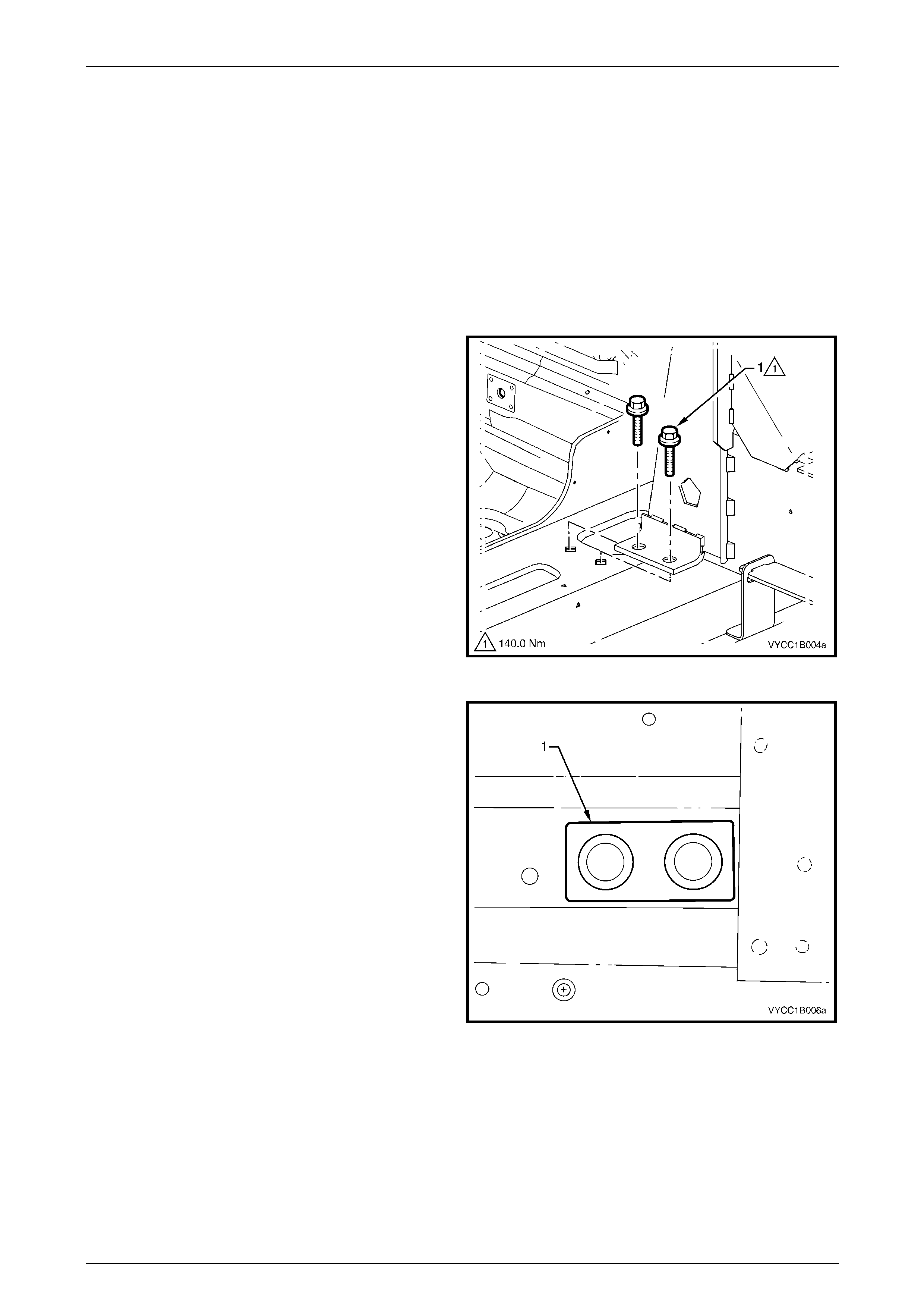
Sheetmetal Page 1B–87
Page 1B–87
Reinstall
1 With the assistance of another person and using a su itable jack or lifting device, align the subframe assembly
squarely to the cab and position the subframe on to the mat ing surfaces of the cab lower cross member.
2 Slide the frame forward until the upper face contacts the back of the cab.
NOTE
When installing the mounting nuts and bolts do
not use any sealers or thre ad locking compounds
on the bolts, nuts or between the joints on the
subframe mounts.
3 Insert the lower bolt (1), two places each side of the
subframe rail. Do not tighten. Repeat for the opposite
side of the vehicle
Figure 1B – 59
4 From within the cab, install the stud plat e (1) one place
each side of the vehicle, through the rear support
panel.
Figure 1B – 60
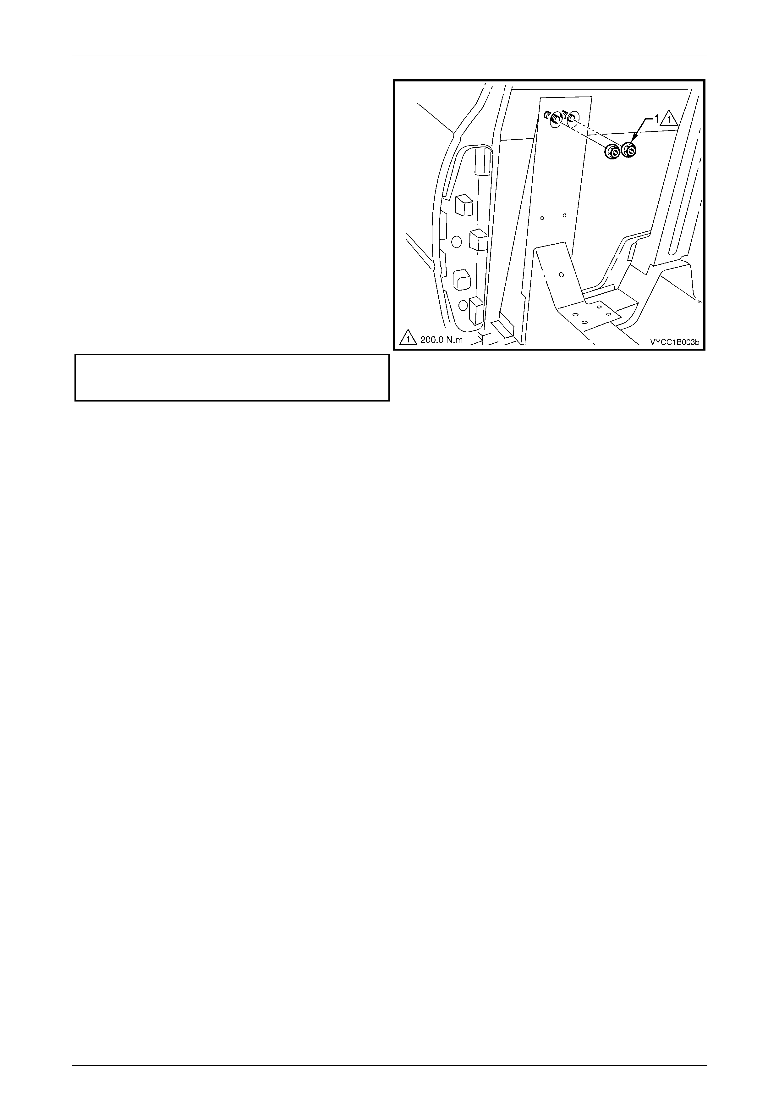
Sheetmetal Page 1B–88
Page 1B–88
5 Install new top flange nuts (1), two places each side
for the stud plate. Do not tighten.
NOTE
Support the subframe so that the weight does
not hang on the mounting points causing an
adverse effect on the tightening of the bolts.
6 Initially tighten all mounting fixtures to obtain the
correct location of the subframe, ensuring there are no
gaps at the mounting points to the body.
7 Tighten the four lo wer mounting bo lts in a diagonal
pattern to the correct torque specification. Repe at for
the other side of the vehicle.
8 Tighten the two top mounti ng nuts to the correct
torque specification. Repeat for the other side of the
vehicle.
Subframe lower attaching bolts........................140.0 Nm
Subframe top stud plate nuts........................... 200.0 Nm
Figure 1B – 61
9 To ensure correct alignment of the subframe to the body, it is recommended that a check of the body dimensions is
performed, refer to Section 1A2 Body Dimensions.
10 Reinstall the remaining com ponents in the reverse order to removal, referring to the ap propriate Sections.
NOTE
To ensure that the vehicle’s steering
and handling is at its optimum, it is
recommended that a wheel alignment
be performed after the subframe assembly
has been removed and refitted. For RWD
vehicles refer to Section 3A Front Suspension,
or for AWD vehicles refer to
Section 3B Front Suspension – AWD.

Sheetmetal Page 1B–89
Page 1B–89
4.13 Subframe Assembly, Crew Cab
The vehicle may become unbalanced on
stands or a hoist once the subf rame, rear axle
or rear suspension is removed. Ensure the
cab and subframe are supported sufficiently
to avoid injury or damage before proceeding.
Any collision that has damaged the subframe
to the extent that it needs to be replaced, may
have caused some deformation to the cab
structure and a complete thorough inspection
and dimension check of the cab bodywork is
recommended.
NOTE
Where a replacement of the subframe assembly
is required, ancillary components will need to be
removed from the subframe. In this case it may
be more convenient for the technician to remove
these components while the subframe is still
assembled to the vehicle.
Remove
1 If required, remove the rear tray body assembly, refer to 4.9 Rear Tray Body Assembly, Crew Cab.
2 Disconnect and plug the fuel lines at the con nectors located just behind the cab and, if required, remove the fuel
tank, refer to Section 8A1 Fuel System.
3 Disconnect the handbrake ca ble and brake lines, refer to Section 5A Service and Park Braking System.
4 If fitted, disconnect the rear ABS sensor leads, refer to Section 5B ABS / TCS / ESP – General Information.
5 Remove the rear and intermediate exhaust assemblies, refer to Section 8B Exhaust System.
NOTE
Once the propeller shaft has been removed from
the transmission, it may be necessary to fit a
blanking plug into the rear of the transmission to
prevent any loss of transmission fluid.
6 Remove the propeller shaft, refer to Section 4C1 Rear Propeller Shaft and Universal Joints.
NOTE
Removal of the rear suspension and axle
assemblies is not a mandatory requirement for
the removal of the subframe assembly. The rear
suspension and axle assembly may if required,
be removed from the subframe assembly as a
complete unit. If removed, support the subframe
with a suitable jack or lifting crane.
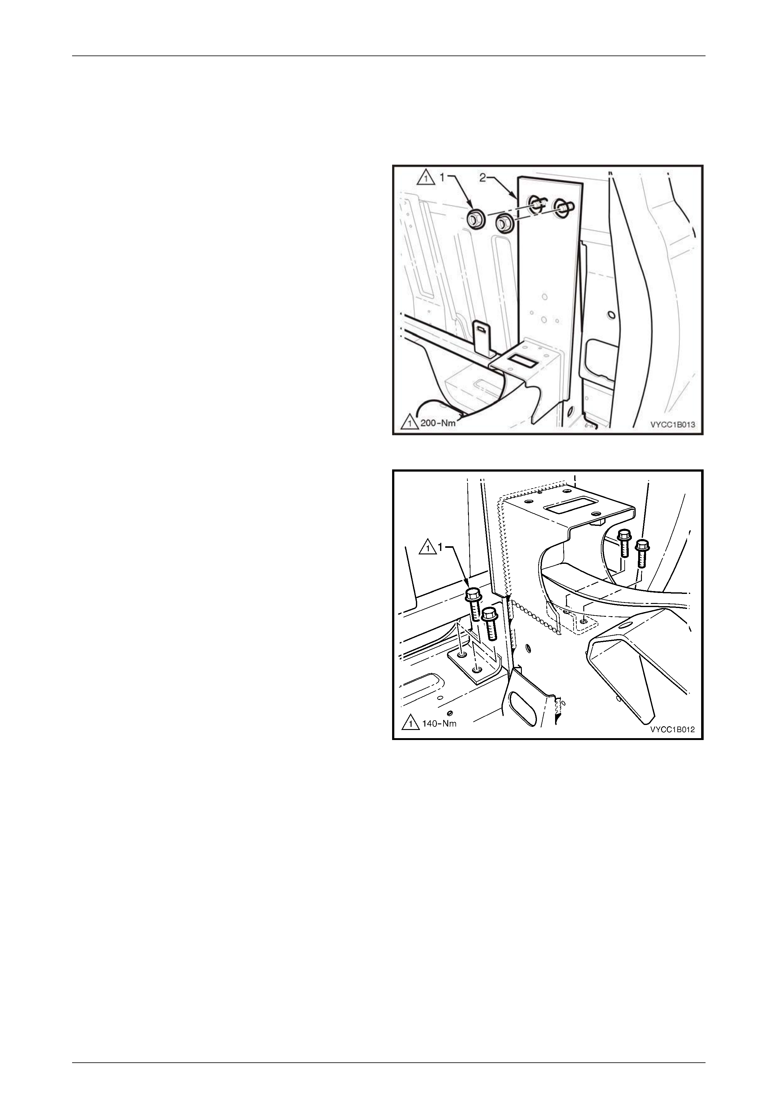
Sheetmetal Page 1B–90
Page 1B–90
7 If required, remove the rear axle assembl y, refer to Section 4B2 Rear Final Drive Live Axle.
8 If required, remove the rear suspension assembly, refer to Section 4A2 Leaf Spring Rear Suspe nsion.
9 Remove the outer trim panel and noise reduction foam from between the subframe mounts and the cab,
refer to Section 1A9 Exterior Ornamentation .
10 Remove the two flange nuts (1), either side, attaching
the subframe assembly (2) to the cab.
Figure 1B – 62
11 Remove the lower bolt (1), four places each side of the
vehicle.
12 With the aid of an assistant, remove the subframe
assembly from the cab by either, lifting or rolling it
clear of the cab, refer to Figure 1B – 64.
Figure 1B – 63
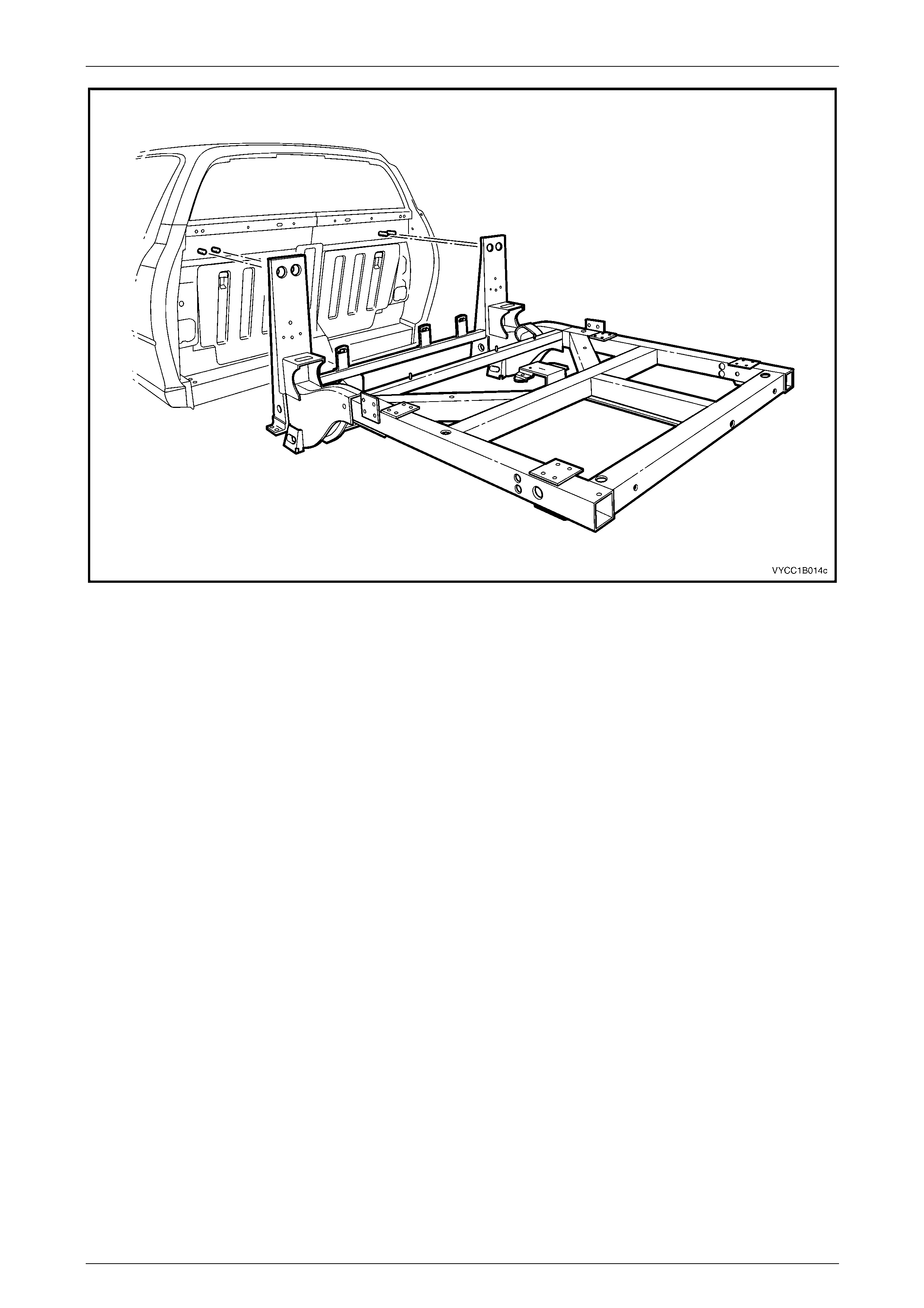
Sheetmetal Page 1B–91
Page 1B–91
Figure 1B – 64
Disassemble
If not already removed, as required remove the following:
1 Remove the fuel tank, carbon canister, fuel filler neck, lower fuel tank straps, heat shield and the remaining fuel
and vapour lines attached to the subframe, refer to Section 8A1 Fuel System.
2 Remove the brake proportioning valve and the remaining rear brake lines,
refer to Section 5A Service and Park Braking System.
3 Remove the rear axle assembly, refer to Section 4B2 Re ar Final Drive and Live A xl e.
4 Remove the rear suspension, shock absorbers and bump stops,
refer to Section 4A2 Leaf Spring Rear Susp ension.
5 Remove the spare wheel winch, refer to Section 10 W heels and Tyres.
Reassemble
1 Reassemble the subframe components in the reverse order of the disassemble process. Follow the assembly
procedures in the Sections referred to for the relevant components.
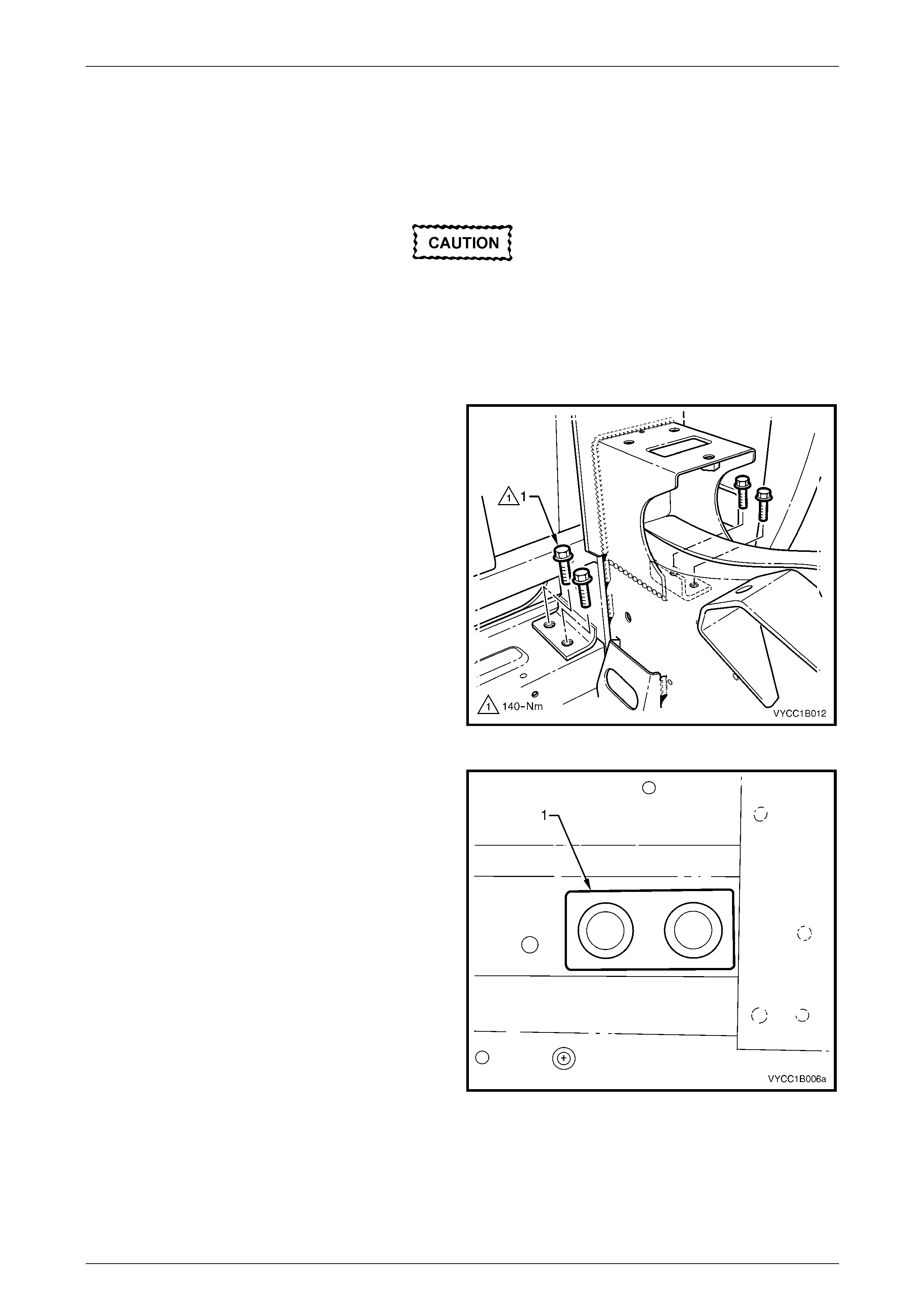
Sheetmetal Page 1B–92
Page 1B–92
Reinstall
1 With the aid of an assistant and using a suitable jack or lifting device, align the subframe assembly squarely to the
cab and position the subframe on to the mating surfaces of the cab lower crossmember.
2 Slide the subframe for ward until the upper face contacts the back of the cab.
Ensure new subframe stud plates, mounting
bolts and nuts are used when reinstalling the
rear subframe. When installing the new
attaching nuts and bolts do not use any
sealers or thread locking compounds on the
bolts, nuts or between the joints on the
subframe mounts.
3 Insert the new lower bolt (1), four places each side of
the vehicle. Do not tighten.
Figure 1B – 65
4 If removed, from inside the vehicle reinstall the stud
plate (1) through the rear body upper panel, one place
each side of the vehicle.
Figure 1B – 66
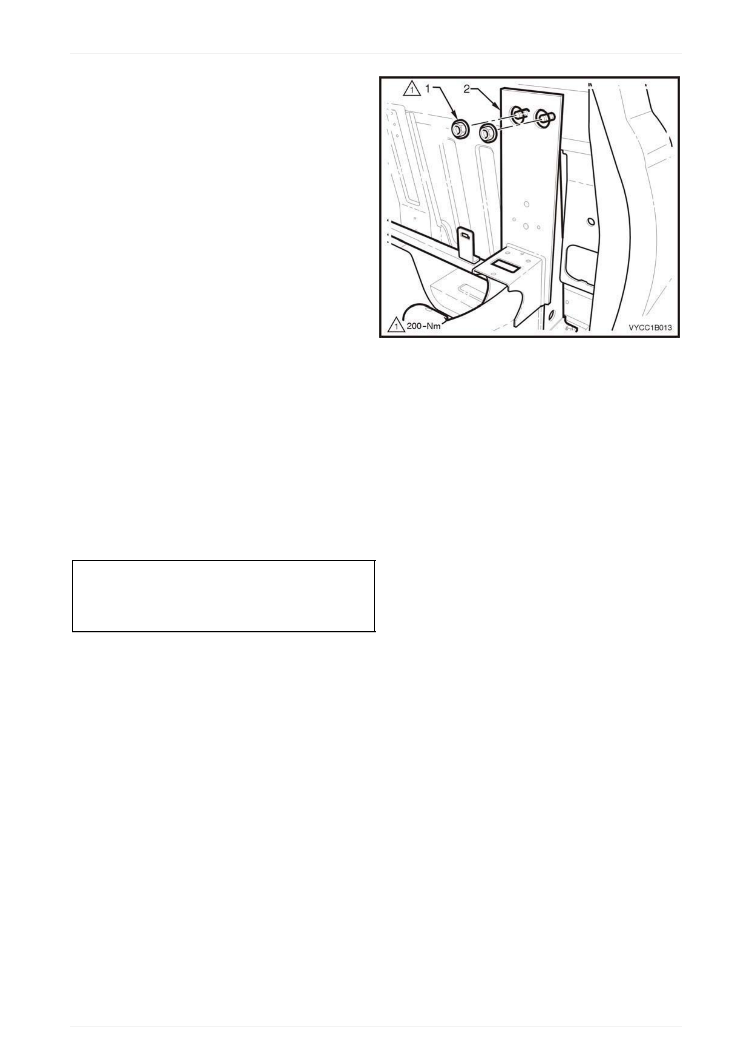
Sheetmetal Page 1B–93
Page 1B–93
5 Install new top flange nuts (1), two places each side,
attaching the subframe assembl y (2) to the cab.
Do not tighten.
Figure 1B – 67
NOTE
Support the subframe assembly so that the
weight of the subframe does not hang on the
mounting points causing an adverse effect on the
tightening of the bolts.
6 Initially tighten all mountin g fixtures to obtain the correct location of the subframe assembly, ensur ing there are no
gaps at the mounting points to the cab.
7 Tighten the four lo wer mounting bo lts in a diagonal pattern to the correct torque specificat ion, repeat for the other
side of the vehicle.
8 Tighten the two top mounting nuts to the correct torque specification, repeat for the other side of the vehicle.
Subframe assembly lower attaching bolt
torque specification..........................................140.0 Nm
Subframe assembly top stud plate nut
torque specification..........................................200.0 Nm
9 To ensure correct alignment of the subframe to the cab, it is recommended that a check of the body dimensions be
performed, refer to Section 1A2 Body Dimensions.
10 Reinstall the remaining com ponents in the reverse order to removal, referring to the ap propriate Sections.
NOTE
To ensure that the vehicle’s steering
and handling is at its optimum, it is
recommended that a wheel alignment
be performed after the subframe assembly
has been removed and refitted. For RWD
vehicles refer to Section 3A Front Suspension,
or for AWD vehicles refer to
Section 3B Front Suspension – AWD.

Sheetmetal Page 1B–94
Page 1B–94
5 Torque Wrench Specifications
Front Fender Attaching Screw.......................................................3.0 – 8.0 Nm
Battery Tray Assembly Attaching Screw....................................25.0 – 30.0 Nm
Front Side Rail Brace Attaching Nut............................................31.0 ± 4.0 Nm
Load Floor Front Panel Assembly Attaching Screw, Utility............1.0 – 3.0 Nm
Inner Side Panel Cover Attaching Screw, Utility............................1.0 – 3.0 Nm
Rear Tray Body Assembly Mounting Bolt, Crew Cab...........................50.0 Nm
Inner Side Panel Extension Cover Attaching Screw, Crew Cab....1.0 – 3.0 Nm
Subframe Assembly Lower Attaching Bolt, Regular & Crew Cab.......140.0 Nm
Subframe Assembly Top Stud Plate Attaching Nut, Regul ar &
Crew Cab ...........................................................................................200.0 Nm