
5B4 ABS-TCS / ESP Page 5B4–1
Page 5B4–1
Section 5B4
ABS-TCS / ESP – V6 and V6 AWD
ATTENTION
Before performing any service operation or other procedure described in this Section, refer to Section 00
Warnings, Cautions and Notes for correct w orkshop practices wi th regard to safety and/or property damage.
1 General Information...............................................................................................................................8
1.1 Definition of Wheel Slip......................................................................................................................................... 8
Longitudinal Wheel Slip........................................................................................................................................8
Lateral Wheel Slip.................................................................................................................................................. 9
Understeer........................................................................................................................................................ 10
Oversteer ......................................................................................................................................................... 10
Limitation of the Conventional Braking System ............................................................................................... 11
1.2 Definition of ABS-TCS / ESP Active Braking..................................................................................................... 12
Antilock Braking System..................................................................................................................................... 12
Electronic Brake-force Distribution System...................................................................................................... 12
Traction Control System ..................................................................................................................................... 12
Electronic Stability Program............................................................................................................................... 12
Electronic Brake Assist....................................................................................................................................... 12
Hill Descent Control – All Wheel Drive Wagon.................................................................................................. 12
HDC Stand-by Mode........................................................................................................................................ 13
HDC Active Mode............................................................................................................................................. 13
HDC Speed Adjustment ................................................................................................................................... 13
2 Component Description and Operation.............................................................................................14
2.1 Component Location........................................................................................................................................... 14
2.2 Electronic Control Unit........................................................................................................................................ 15
Electronic Control Unit Inputs............................................................................................................................ 15
Electronic Control Unit Outputs......................................................................................................................... 15
Electronic Control Unit Self-test Initialisation Sequence................................................................................. 15
2.3 Hydraulic Modulator Assembly........................................................................................................................... 16
Hydraulic Circuit Components ........................................................................................................................... 17
2.4 Wheel Speed Sensors ......................................................................................................................................... 18
Wheel Speed Sensor Principles of Operation................................................................................................... 18
Front Wheel Speed Sensor – Rear Wheel Drive Vehicles................................................................................. 18
Front Wheel Speed Sensor – All Wheel Drive Vehicles.................................................................................... 19
Rear Wheel Speed Sensor................................................................................................................................... 19
Testing Wheel Speed Sensor Using an Oscilloscope ...................................................................................... 20
2.5 Stop Lamp Switch-A............................................................................................................................................ 21
2.6 Electronic Stability Program Switch .................................................................................................................. 22
2.7 Hill Descent Control Switch – All Wheel Drive Wagon ..................................................................................... 23
2.8 Yaw-rate Sensor Assembly................................................................................................................................. 24
Lateral Acceleration Sensor................................................................................................................................ 24
Yaw-rate Sensor................................................................................................................................................... 25
2.9 Steering Angle Sensor......................................................................................................................................... 26
Steering Angle Sensor Layout............................................................................................................................ 27
Steering Angle Sensor Operation....................................................................................................................... 27
Steering Angle Sensor Calibration..................................................................................................................... 27
Techline
Techline
Techline
Techline
Techline

5B4 ABS-TCS / ESP Page 5B4–2
Page 5B4–2
3 System Operation.................................................................................................................................28
3.1 Non-ABS Braking................................................................................................................................................. 28
Non-ABS Braking Operation............................................................................................................................... 28
Condition Description ....................................................................................................................................... 28
Normal Braking Hydraulic Circuit...................................................................................................................... 29
3.2 Antilock Braking System..................................................................................................................................... 30
ABS Phase – Maintaining Pressure.................................................................................................................... 30
Condition Description ....................................................................................................................................... 30
Control Action................................................................................................................................................... 30
ABS Phase Hydraulic Circuit – Maintaining Pressure....................................................................................... 31
ABS Phase – Reducing Pressure ....................................................................................................................... 32
Condition Description ....................................................................................................................................... 32
Control Action................................................................................................................................................... 32
ABS Phase Hydraulic Circuit – Reducing Pressure.......................................................................................... 33
ABS Phase – Increasing Pressure...................................................................................................................... 34
Condition Description ....................................................................................................................................... 34
Control Action................................................................................................................................................... 34
ABS Phase Hydraulic Circuit – Increasing Pressure ........................................................................................ 35
3.3 Electronic Brake-force Distribution System...................................................................................................... 36
EBD System Keep Alive Function ...................................................................................................................... 36
EBD Phase – Maintaining Pressure.................................................................................................................... 36
Condition Description ....................................................................................................................................... 36
Control Action................................................................................................................................................... 36
EBD Phase Hydraulic Circuit – Maintaining Pressure ...................................................................................... 37
EBD Phase – Reducing Pressure....................................................................................................................... 38
Condition Description ....................................................................................................................................... 38
Control Action................................................................................................................................................... 38
EBD Phase Hydraulic Circuit – Reducing Pressure.......................................................................................... 39
EBD Phase – Increasing Pressure...................................................................................................................... 40
Condition Description ....................................................................................................................................... 40
Control Action................................................................................................................................................... 40
3.4 Traction Control System ..................................................................................................................................... 41
TCS Mode – Engine Torque Reduction.............................................................................................................. 41
TCS Mode – Brake Intervention.......................................................................................................................... 41
TCS Mode Hydraulic Circuit – Brake Intervention............................................................................................ 42
3.5 Electronic Stability Program............................................................................................................................... 43
ESP Engine Torque Reduction........................................................................................................................... 43
ESP Brake Intervention ....................................................................................................................................... 43
Understeer........................................................................................................................................................ 43
ESP Hydraulic Circuit – Understeer Brake Intervention.................................................................................... 45
Oversteer ......................................................................................................................................................... 46
ESP Hydraulic Circuit – Oversteer Brake Intervention...................................................................................... 48
4 Wiring Diagram and Connector Chart................................................................................................49
4.1 Wiring Diagram .................................................................................................................................................... 49
4.2 Connector Chart................................................................................................................................................... 50
4.3 Connector Information ........................................................................................................................................ 51
Electronic Control Unit – A116 ........................................................................................................................... 51
Front and Rear Wheel Speed Sensor – B52L, B52R, B76L and B76R............................................................. 52
Yaw - rate Sensor – B85 ........................................................................................................................................ 53
Steering Angle Sensor – B161............................................................................................................................ 53

5B4 ABS-TCS / ESP Page 5B4–3
Page 5B4–3
5 Diagnostics...........................................................................................................................................54
5.1 Diagnostic General Descriptions........................................................................................................................ 54
Diagnostic Trouble Code Tables........................................................................................................................ 54
Diagnostic Trouble Codes .................................................................................................................................. 55
Status of DTCs................................................................................................................................................. 55
Action Taken When a DTC Sets....................................................................................................................... 55
Conditions for Clearing DTCs........................................................................................................................... 55
6 ABS-TCS Diagnostic Starting Point...................................................................................................56
6.1 Basic Requirements ............................................................................................................................................ 56
Basic Know ledge Required................................................................................................................................. 56
Basic Diagnostic Tools Required....................................................................................................................... 56
6.2 Diagnostic Precautions....................................................................................................................................... 57
6.3 Preliminary Checks.............................................................................................................................................. 58
6.4 Diagnostic System Check................................................................................................................................... 59
Description........................................................................................................................................................... 59
Test Description................................................................................................................................................... 59
7 Intermittent Faults................................................................................................................................60
7.1 Intermittent Fault Diagnostic Table.................................................................................................................... 60
Description........................................................................................................................................................... 60
8 Diagnostic Trouble Codes...................................................................................................................62
8.1 DTC List................................................................................................................................................................ 62
8.2 DTC C0035, C0040, C0045 or C0050 – Wheel Speed Sensor Circuit Fault...................................................... 64
DTC Description................................................................................................................................................... 64
Circuit Description............................................................................................................................................... 64
Additional Information......................................................................................................................................... 64
Conditions for Running the DTC........................................................................................................................ 64
Conditions for Setting the DTC .......................................................................................................................... 64
Action Taken When the DTC Sets ...................................................................................................................... 64
Conditions for Clearing the DTC........................................................................................................................ 64
Test Description................................................................................................................................................... 64
DTC C0035, C0040, C0045 or C0050 Diagnostic Table ..................................................................................... 65
8.3 DTC C0060, C0065, C0070, C0075, C0080, C0085, C0090, C0095, C0141, C0146, C0151 or C0156 – Hydraulic
Modulator Solenoid Valve Circuit Fault............................................................................................................. 67
DTC Description................................................................................................................................................... 67
Circuit Description............................................................................................................................................... 67
Additional Information......................................................................................................................................... 67
Conditions for Running the DTC........................................................................................................................ 67
Conditions for Setting the DTC .......................................................................................................................... 67
Action Taken When the DTC Sets ...................................................................................................................... 68
Conditions for Clearing the DTC........................................................................................................................ 68
Test Description................................................................................................................................................... 68
DTC C0060, C0065, C0070, C0075, C0080, C0085, C0090, C0095, C0141, C0146, C0151 or C0156 Diagnostic
Table................................................................................................................................................................ 68

5B4 ABS-TCS / ESP Page 5B4–4
Page 5B4–4
8.4 DTC C0110 – Hydraulic Modulator Pump Motor Circuit Fault.......................................................................... 69
DTC Description................................................................................................................................................... 69
Circuit Description............................................................................................................................................... 69
Additional Information......................................................................................................................................... 69
Conditions for Running the DTC........................................................................................................................ 69
Conditions for Setting the DTC .......................................................................................................................... 69
Action Taken When the DTC Sets ...................................................................................................................... 69
Conditions for Clearing the DTC........................................................................................................................ 69
Test Description................................................................................................................................................... 69
DTC C0110 Diagnostic Table .............................................................................................................................. 70
8.5 DTC C0121 – Electronic Control Unit Internal Valve Relay Fault..................................................................... 71
DTC Description................................................................................................................................................... 71
Circuit Description............................................................................................................................................... 71
Additional Information......................................................................................................................................... 71
Conditions for Running the DTC........................................................................................................................ 71
Conditions for Setting the DTC .......................................................................................................................... 71
Action Taken When the DTC Sets ...................................................................................................................... 71
Conditions for Clearing the DTC........................................................................................................................ 71
Test Description................................................................................................................................................... 71
DTC C0121 Diagnostic Table .............................................................................................................................. 72
8.6 DTC C0131 – Hydraulic Modulator Pressure Sensor Fault............................................................................... 73
DTC Description................................................................................................................................................... 73
Circuit Description............................................................................................................................................... 73
Additional Information......................................................................................................................................... 73
Conditions for Running the DTC........................................................................................................................ 73
Conditions for Setting the DTC .......................................................................................................................... 73
Action Taken When the DTC Sets ...................................................................................................................... 73
Conditions for Clearing the DTC........................................................................................................................ 73
Test Description................................................................................................................................................... 73
DTC C0131 Diagnostic Table .............................................................................................................................. 74
8.7 DTC C0161 – Brake Sw itch Circuit Fault............................................................................................................ 75
DTC Description................................................................................................................................................... 75
Circuit Description............................................................................................................................................... 75
Additional Information......................................................................................................................................... 75
Conditions for Running the DTC........................................................................................................................ 75
Conditions for Setting the DTC .......................................................................................................................... 75
Action Taken When the DTC Sets ...................................................................................................................... 75
Conditions for Clearing the DTC........................................................................................................................ 75
Test Description................................................................................................................................................... 75
DTC C0161 Diagnostic Table .............................................................................................................................. 76
8.8 DTC C0186 – Lateral Acceleration Sensor Fault ............................................................................................... 77
DTC Description................................................................................................................................................... 77
Circuit Description............................................................................................................................................... 77
Additional Information......................................................................................................................................... 77
Conditions for Running the DTC........................................................................................................................ 77
Conditions for Setting the DTC .......................................................................................................................... 77
Action Taken When the DTC Sets ...................................................................................................................... 77
Conditions for Clearing the DTC........................................................................................................................ 77
Test Description................................................................................................................................................... 77
DTC C0186 – Diagnostic Table ........................................................................................................................... 78

5B4 ABS-TCS / ESP Page 5B4–5
Page 5B4–5
8.9 DTC C0196 – Yaw- rate Sensor Output Signal Fault.......................................................................................... 80
DTC Description................................................................................................................................................... 80
Circuit Description............................................................................................................................................... 80
Additional Information......................................................................................................................................... 80
Conditions for Running the DTC........................................................................................................................ 80
Conditions for Setting the DTC .......................................................................................................................... 80
Action Taken When the DTC Sets ...................................................................................................................... 80
Conditions for Clearing the DTC........................................................................................................................ 80
Test Description................................................................................................................................................... 80
DTC C0196 – Diagnostic Table ........................................................................................................................... 81
8.10 DTC C0245, C0252 or C0253 – Wheel Speed Sensor Signal Output Fault...................................................... 83
DTC Description................................................................................................................................................... 83
Circuit Description............................................................................................................................................... 83
Additional Information......................................................................................................................................... 83
Conditions for Running the DTC........................................................................................................................ 83
Conditions for Setting the DTC .......................................................................................................................... 83
DTC C0245 ...................................................................................................................................................... 83
DTC C0252 ...................................................................................................................................................... 83
DTC C0253 ...................................................................................................................................................... 83
Action Taken When the DTC Sets ...................................................................................................................... 83
Conditions for Clearing the DTC........................................................................................................................ 83
Test Description................................................................................................................................................... 83
DTC C0245, C0252 or C0253 Diagnostic Table.................................................................................................. 84
8.11 DTC C0460 – Steering Angle Sensor Circuit Fault............................................................................................ 86
DTC Description................................................................................................................................................... 86
Circuit Description............................................................................................................................................... 86
Additional Information......................................................................................................................................... 86
Conditions for Running the DTC........................................................................................................................ 86
Conditions for Setting the DTC .......................................................................................................................... 86
Action Taken When the DTC Sets ...................................................................................................................... 86
Conditions for Clearing the DTC........................................................................................................................ 86
Test Description................................................................................................................................................... 86
DTC C0460 – Diagnostic Table ........................................................................................................................... 87
8.12 DTC C0550 and C0551 – Electronic Control Unit Internal Fault....................................................................... 88
DTC Description................................................................................................................................................... 88
Circuit Description............................................................................................................................................... 88
Additional Information......................................................................................................................................... 88
Conditions for Running the DTC........................................................................................................................ 88
Conditions for Setting the DTC .......................................................................................................................... 88
C0550............................................................................................................................................................... 88
C0551............................................................................................................................................................... 88
Action Taken When the DTC Sets ...................................................................................................................... 88
Conditions for Clearing the DTC........................................................................................................................ 88
Test Description................................................................................................................................................... 88
DTC C0550 and C0551 Diagnostic Table............................................................................................................ 89
8.13 DTC C0569 – Electronic Control Unit Configuration Mismatch....................................................................... 90
DTC Description................................................................................................................................................... 90
Circuit Description............................................................................................................................................... 90
Additional Information......................................................................................................................................... 90
Conditions for Running the DTC........................................................................................................................ 90
Conditions for Setting the DTC .......................................................................................................................... 90
Action Taken When the DTC Sets ...................................................................................................................... 90
Conditions for Clearing the DTC........................................................................................................................ 90
Test Description................................................................................................................................................... 90
DTC C0569 Diagnostic Table .............................................................................................................................. 91

5B4 ABS-TCS / ESP Page 5B4–6
Page 5B4–6
8.14 DTC C0800 – Battery Voltage Out of Range ...................................................................................................... 92
DTC Description................................................................................................................................................... 92
Circuit Description............................................................................................................................................... 92
Additional Information......................................................................................................................................... 92
Conditions for Running the DTC........................................................................................................................ 92
Conditions for Setting the DTC .......................................................................................................................... 92
Action Taken When the DTC Sets ...................................................................................................................... 92
Conditions for Clearing the DTC........................................................................................................................ 92
Test Description................................................................................................................................................... 92
DTC C0800 Diagnostic Table .............................................................................................................................. 93
8.15 DTC C0895 – Steering Angle Sensor Supply Voltage Out of Range ............................................................... 94
DTC Description................................................................................................................................................... 94
Circuit Description............................................................................................................................................... 94
Additional Information......................................................................................................................................... 94
Conditions for Running the DTC........................................................................................................................ 94
Conditions for Setting the DTC .......................................................................................................................... 94
Action Taken When the DTC Sets ...................................................................................................................... 94
Conditions for Clearing the DTC........................................................................................................................ 94
Test Description................................................................................................................................................... 94
DTC C0895 Diagnostic Table .............................................................................................................................. 95
9 Service Operations...............................................................................................................................96
9.1 Safety and Precautionary Measures................................................................................................................... 96
9.2 ABS-TCS / ESP Brake Bleeding Procedure ....................................................................................................... 98
9.3 Electronic Control Unit / Hydraulic Modulator Assembly................................................................................. 99
Remove................................................................................................................................................................. 99
Disassemble....................................................................................................................................................... 100
Inspect ................................................................................................................................................................ 100
Reassemble........................................................................................................................................................ 101
Reinstall.............................................................................................................................................................. 101
9.4 Front Wheel Speed Sensor – Rear Wheel Drive Vehicles............................................................................... 102
9.5 Front Wheel Speed Sensor – All Wheel Drive Vehicles.................................................................................. 103
Remove............................................................................................................................................................... 103
Reinstall.............................................................................................................................................................. 104
9.6 Front Wheel Speed Sensor Lead – Rear Wheel Drive Vehicles..................................................................... 105
Remove............................................................................................................................................................... 105
Reinstall.............................................................................................................................................................. 106
9.7 Front Wheel Speed Sensor Lead – All Wheel Drive Vehicles......................................................................... 107
9.8 Rear Wheel Speed Sensor................................................................................................................................. 108
Remove............................................................................................................................................................... 108
Reinstall.............................................................................................................................................................. 109
9.9 Front Wheel Speed Sensor Pulse Ring – Rear Wheel Drive Vehicles........................................................... 110
9.10 Front Wheel Speed Sensor Pulse Ring – All Wheel Drive Vehicles............................................................... 111
9.11 Rear Wheel Speed Sensor Pulse Ring............................................................................................................. 112
9.12 Electronic Stability Program Switch ................................................................................................................ 113
Replace............................................................................................................................................................... 113
Test ..................................................................................................................................................................... 113
9.13 Hill Descent Control Sw itch – All Wheel Drive Vehicles................................................................................. 114
Replace............................................................................................................................................................... 114
Test ..................................................................................................................................................................... 114

5B4 ABS-TCS / ESP Page 5B4–7
Page 5B4–7
9.14 Yaw-rate Sensor................................................................................................................................................. 115
Remove............................................................................................................................................................... 115
Reinstall.............................................................................................................................................................. 115
9.15 Steering Angle Sensor....................................................................................................................................... 116
Replace............................................................................................................................................................... 116
Calibration.......................................................................................................................................................... 116
10 Specifications.....................................................................................................................................117
11 Torque Wrench Specifications .........................................................................................................118
12 Special Tools ......................................................................................................................................119
5B4 ABS-TCS / ESP Page 5B4–8
Page 5B4–8
1 General Information
The antilock braking system-traction control system with electronic stability program utilises (ABS-TCS / ESP) the
existing components of the conventional braking system and incorporates an electronic control unit (ECU), hydraulic
modulator, wheel speed sensors and the functionality of engine torque reduction from the engine control management
system. In addition it adds:
• a steering angle sensor to determine driver steering inputs, and
• a yaw-rate sensor to measure vehicle rotation around its vertical axis.
This allows the ABS-TCS / ESP to apply active braking and engine torque reduction to prevent longitudinal and lateral
wheel slip when driving under various vehicle load and road surface conditions.
1.1 Definition of Wheel Slip
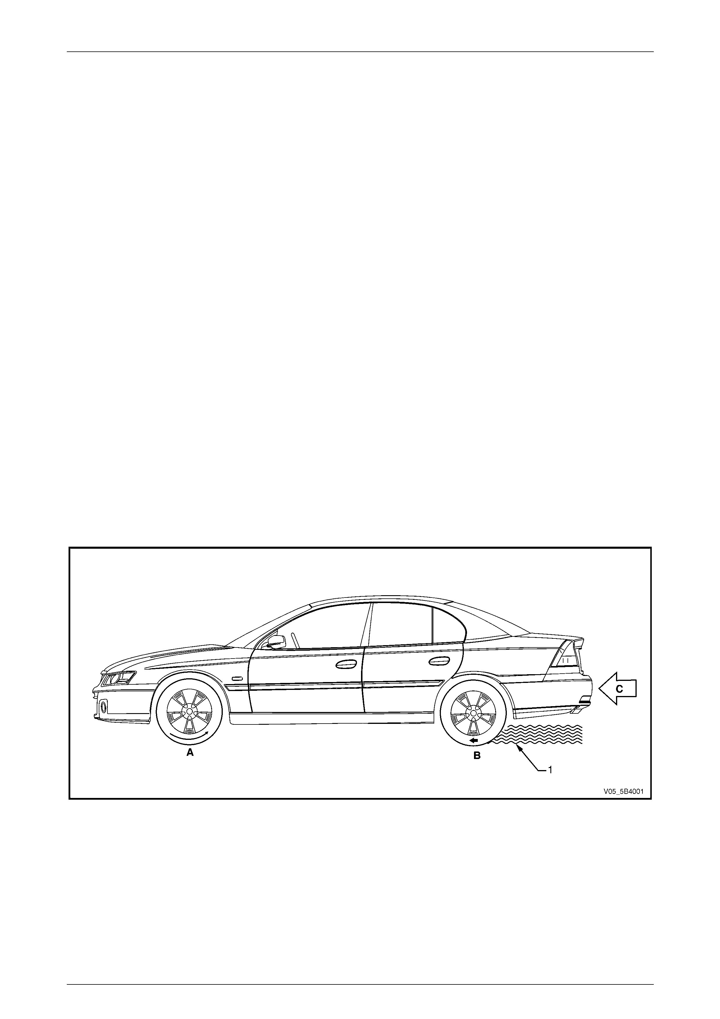
Longitudinal Wheel Slip
Longitudinal wheel slip is the loss of traction between the tyres and the road surface, which happens when the vehicle is
moving in a straight ahead direction and the braking or acceleration forces applied to the tyres exceeds the tyre traction
available to the vehicle. Refer to Figure 5B4 – 1 for the illustration of the following:
• At 0% slip, the tyre rolls freely (A).
• At 100% slip, the tyre locks-up (B) as the weight of the vehicle pushes the non-rotating tyre along the road
surface (C).
When the tyres are locked-up, the vehicle's forward energy is converted into braking energy (friction) between the
tyre and the road surface (1). This will result in an unstable and inefficient braking due to the effect of the following
factors:
• Asphalt, cement, gravel or dirt road surfaces provide different degree of tyre traction.
• Oil puddles, ice spots or other contaminants that cause a sudden change in the road surface condition.
• Wet, dry, smooth, rough road surface condition affects tyre traction.
Figure 5B4 – 1
When none of the wheels are locked during braking, the heat energy produced by the braking action is transferred to the
brake pads and the brake disc. The friction surfaces between the brake pads and the brake disc are designed to provide
a stable and controlled braking action. Therefore, a vehicle that is braked without locking the wheels will stop in a shorter
distance while maintaining directional stability and steering capability. Maximum braking efficiency is achieved when a
wheel lock slip is prevented.
5B4 ABS-TCS / ESP Page 5B4–9
Page 5B4–9
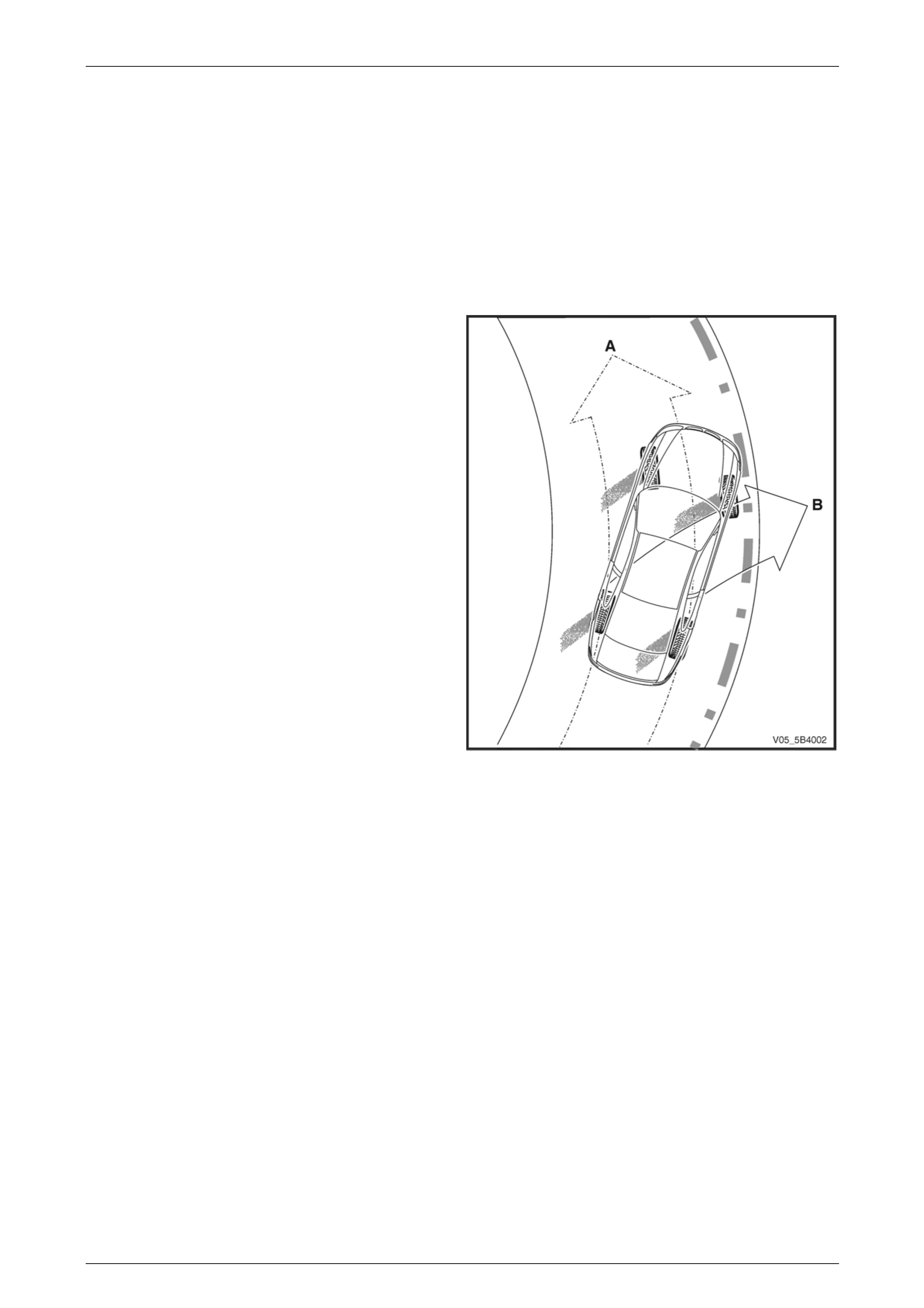
Lateral Wheel Slip
Lateral wheel slip is the loss of traction between the tyres and the road surface, which occurs when the vehicle is
cornering or when excessive engine torque is applied to the vehicle and the following forces applied to the tyres exceeds
the tyre traction available to the vehicle:
• cornering forces,
• acceleration force, or
• braking force.
In addition, steering control depends upon tyre traction. A locked wheel in a 100% slip condition delivers poor braking and
directional control.
The front tyre direction (A) has minimal steering effect while
the vehicle skids in direction (B). The tyres must regain their
traction before steering control is restored to the vehicle.
Figure 5B4 – 2
5B4 ABS-TCS / ESP Page 5B4–10
Page 5B4–10
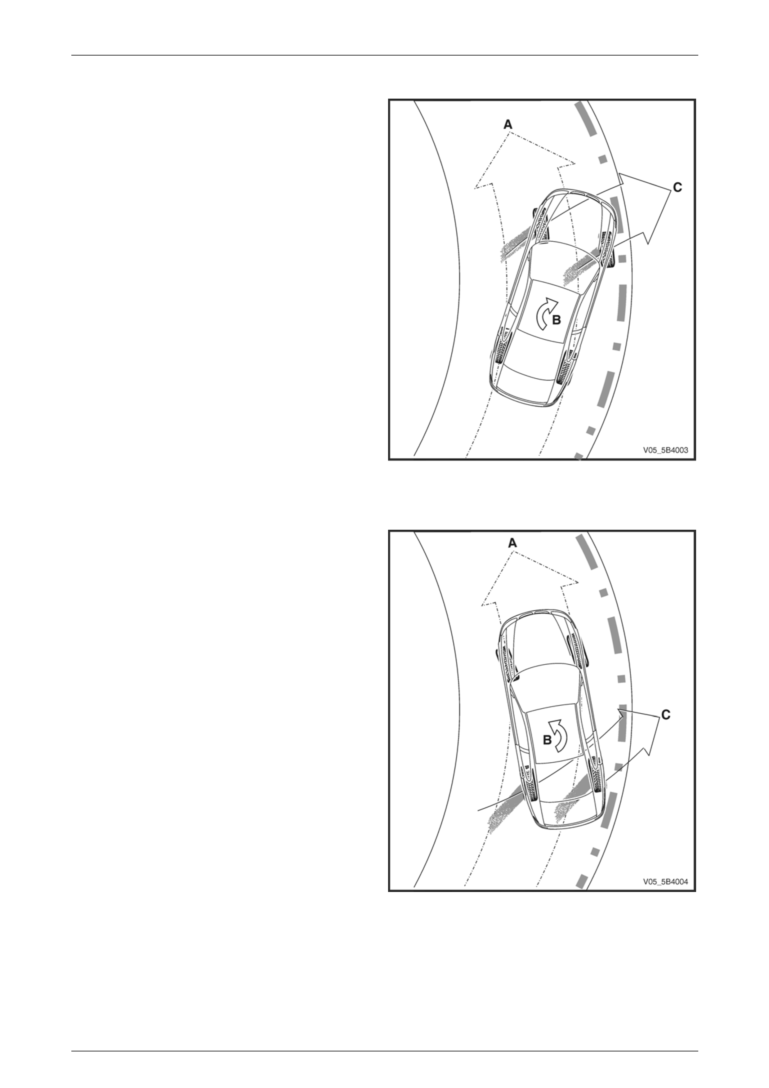
Understeer
When the vehicle is cornering (A) at high speed or when the
vehicle encounters a slippery road surface, the vehicle
understeers when the cornering, braking or acceleration
forces applied to the wheels exceeds the traction available
between the tyres and the road surface.
Under this condition, the vehicle spins (B) with the front of
the vehicle sliding in direction (C).
Figure 5B4 – 3
Oversteer
When the vehicle is cornering (A) at high speed or when the
vehicle encounters a slippery road surface, the vehicle
oversteers when the cornering, braking or acceleration
forces applied to the wheels exceeds the traction available
between the tyres and the road surface.
Under this condition, the vehicle spins (B) with the rear of
the vehicle sliding in direction (C).
Figure 5B4 – 4

5B4 ABS-TCS / ESP Page 5B4–11
Page 5B4–11
Limitation of the Conventional Braking System
Skilled drivers prevent wheel lock-up during hard or emergency hard braking situations by controlling the braking force
applied to the brake pedal, which limits the braking force applied to the vehicle. The braking force applied must be limited
to a point just short of a wheel lock-up to achieve the shortest possible stopping distance.
However, wheel slip on wet roads or other reduced traction conditions is difficult to prevent through the conventional
braking system. Even skilled drivers cannot control the brake pressure applied to the vehicle precisely enough to prevent
wheel lock-up under all road surface conditions.
In addition, when only one wheel slips, increasing or reducing brake pedal pressure increases or reduces the braking
force applied to all four wheels.

5B4 ABS-TCS / ESP Page 5B4–12
Page 5B4–12
1.2 Definition of ABS-TCS / ESP Active
Braking
Antilock Braking System
The antilock braking system (ABS) incorporates sensors that constantly monitor and compare the rotational speed of
each wheel to determine the vehicle reference speed and to detect a possible wheel lock-up condition.
When the ABS detects the beginning of a wheel lock-up condition or when one or more wheels are decelerating faster
than the vehicle reference speed, it actively modulates the brake fluid pressure applied to the affected wheel to prevent
the wheel lock-up condition. Refer to 3.2 Antilock Braking System for information on the ABS operation.
Electronic Brake-force Distribution System
The electronic brake-force distribution (EBD) system is part of the ABS-TCS software programmed into the electronic
control unit (ECU) and is designed to replace the rear brake proportioning valve in preventing rear wheel lock-up during
moderate braking.
This functionality enables the EBD system to apply dynamic front to rear brake proportioning, which responds to changes
in vehicle loads, road surface conditions and brake pressure application.
Refer to 3.3 Electronic Brake-force Distribution System for further information on the EBD system.
Traction Control System
The traction control system (TCS) prevents wheel slip by applying active braking and engine torque reduction when
driving under various vehicle load and road surface conditions. Refer to 3.4 Traction Control System for further
information on the TCS.
Electronic Stability Program
When the vehicle oversteers or understeers, the electronic stability program (ESP) utilises the engine torque reduction
functionality and active braking control in the ABS-TCS to stabilise and steer the vehicle to the correct direction.
Refer to 3.5 Electronic Stability Program for further information on the ESP.
Electronic Brake Assist
Electronic brake assist (EBA) provides the shortest possible braking distance when the driver is hesitant to apply full
braking force during emergency driving situation.
EBA monitors and evaluates the output signal of the brake fluid pressure sensor in the hydraulic modulator to determine
the rate of brake pedal application. It recognises an emergency-braking situation by the speed at which the brake pedal is
depressed not by the force applied to the pedal.
When EBA detects an emergency braking situation, and determines that insufficient braking force is being applied to the
brake pedal, it uses the active braking control of the ABS-TCS to increase the brake fluid pressure applied to each
wheels to the maximum safe level.
Hill Descent Control – All Wheel Drive Wagon
In conjunction with the cruise control system components, hill descent control (HDC) utilises the active braking capability
of the ABS-TCS to maintain a vehicle target speed when travelling downhill. Refer to Section 12E Cruise Control for
further information on the cruise control system.

5B4 ABS-TCS / ESP Page 5B4–13
Page 5B4–13
HDC Stand-by Mode
NOTE
The HDC can only be switched on at speeds
below 50 km/h and can only become active at
speeds below 35 km/h.
The HDC performs the following functions when the HDC switch is pressed while the vehicle is stationary and the engine
not running:
• Switches from off mode to stand-by mode while the vehicle remains stationary.
• Illuminates the HDC warning display in the instrument cluster multi-function display (MFD).
• Once the vehicle begins to move, calculates the vehicle acceleration based on the output signals of the wheel
speed sensors and the accelerator pedal position sensor to determine a downhill driving situation.
• Switches to stand-by mode when the vehicle speed exceeds 35 km/h.
• Switches off when the vehicle speed exceeds 80 km/h.
HDC Active Mode
Once the HDC detects a downhill driving condition, the HDC performs the following:
• Switches from stand-by mode to active mode.
• Control the vehicle's descent at a target speed of 5 km/h through the active braking.
• Sends a serial data control signal to the Powertrain interface module (PIM) to illuminate the rear brake lights while
the HDC applies active braking.
• Sends a serial data control signal to the instrument cluster to illuminate the HDC warning display in a flashing
mode.
NOTE
Occasional buzzing noise from the engine
compartment may be heard while the HDC is
active.
HDC Speed Adjustment
The vehicle speed can be adjusted by the following actions:
• Use of the following cruise control switch functionality:
• Res-Accel switch to increase the vehicle target speed.
• Set-Decel switch to reduce the vehicle target speed.
• Pressing the brake pedal to use normal braking and reduce vehicle speed.
• Pressing the accelerator pedal by more than 18% shifts the HDC into stand-by mode, which allows the vehicle to
accelerate without any brake intervention. Once the accelerator pedal is released, the vehicle returns to normal
HDC operation.
5B4 ABS-TCS / ESP Page 5B4–14
Page 5B4–14
2 Component Description and
Operation
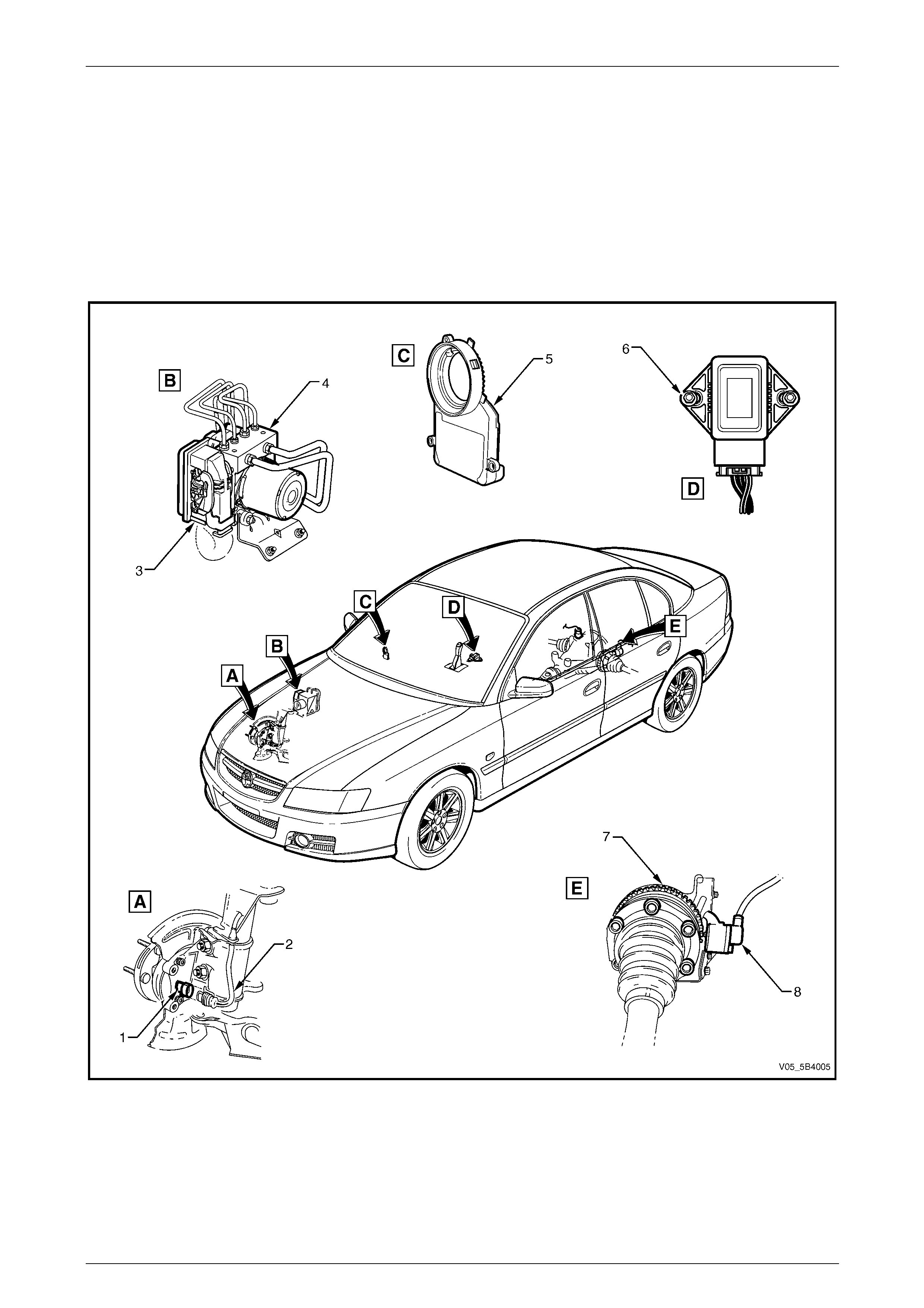
2.1 Component Location
NOTE
Components are located in the same position for
Sedan and AWD Wagon vehicles.
Figure 5B4 – 5
Legend
1 Front Wheel Speed Sensor
2 Front Wheel Speed Sensor Lead
3 Electronic Control Unit (ECU)
4 Hydraulic Modulator Assembly
5 Steering Angle Sensor
6 Yaw-rate Sensor
7 Rear Wheel Speed Sensor Pulse Ring
8 Rear Wheel Speed Sensor
5B4 ABS-TCS / ESP Page 5B4–15
Page 5B4–15
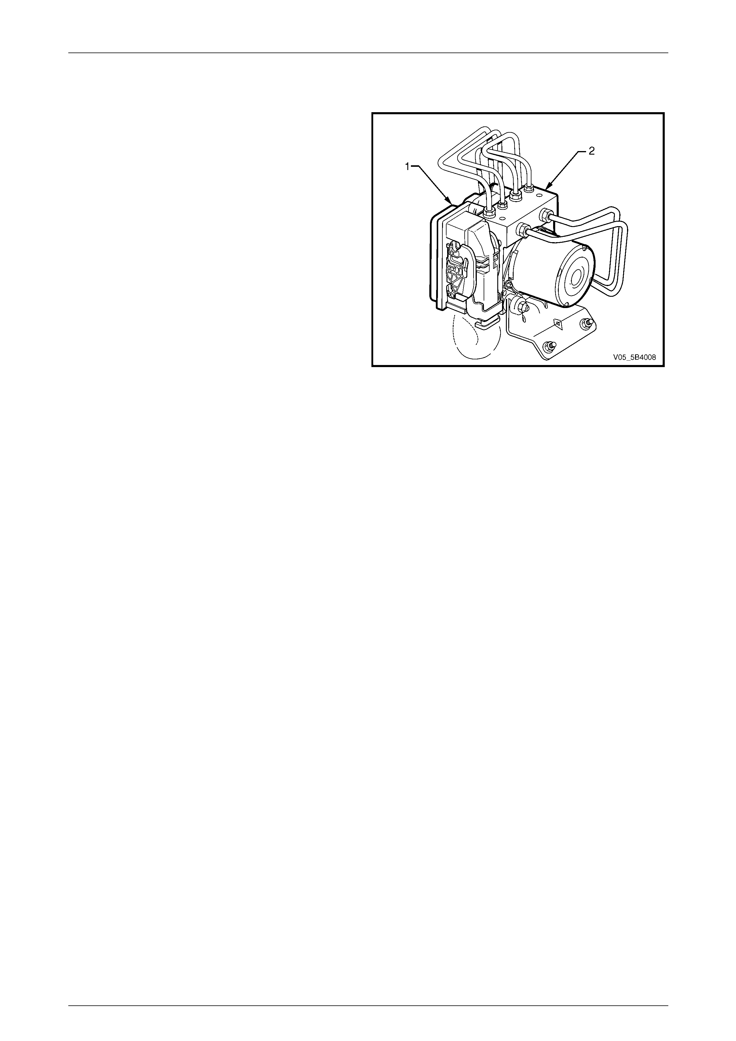
2.2 Electronic Control Unit
The electronic control unit (ECU) (1) is the control centre of
the antilock braking system-traction control system with
electronic stability program (ABS-TCS / ESP). It is
integrated with the hydraulic modulator (2) to form one
assembly.
Figure 5B4 – 6
Electronic Control Unit Inputs
The ECU constantly monitors and evaluates input signals from the following:
• wheel speed sensors,
• yaw-rate sensor,
• steering angle sensor,
• stop lamp switch,
• ignition on input,
• battery voltage, and
• serial data communication circuit.
Electronic Control Unit Outputs
Based on the inputs received, the ECU sends output signals to the following:
• instrument cluster multi-function display (MFD),
• diagnostic link connector,
• hydraulic modulator solenoid valves,
• hydraulic modulator pump motor, and
• serial data communication circuit.
Electronic Control Unit Self-test Initialisation Sequence
When the ignition is switched on, the ECU constantly performs a self-test that detects and isolates ABS-TCS / ESP
faults. In addition, the ECU performs one Self-test Initialisation Sequence for each ignition cycle. This Initialisation
Sequence commences when the vehicle reaches approximately 15 km/h.
NOTE
The Initialisation Sequence may be heard and
felt while it is taking place, which is considered
part of the normal system operation. Refer to
3.2 Antilock Braking System.
During the Initialisation Sequence, the ECU sends a control signal to the hydraulic modulator to cycle each of the
solenoid valves as well as operate the pump motor to check for correct component operation. If the pump or any solenoid
valves fail to operate, the ECU sets a diagnostic trouble code (DTC).
Refer to 5.1 Diagnostic General Descriptions for information on action taken by the ECU when a DTC sets.
When the vehicle speed exceeds 15 km/h, the ECU continuously monitors the ABS-TCS / ESP by comparing the logical
sequence of input and output signals with the normal operating parameters stored in the ECU. If any of the input or
output signals are outside the normal operating parameters, the ECU sets a DTC.

5B4 ABS-TCS / ESP Page 5B4–16
Page 5B4–16
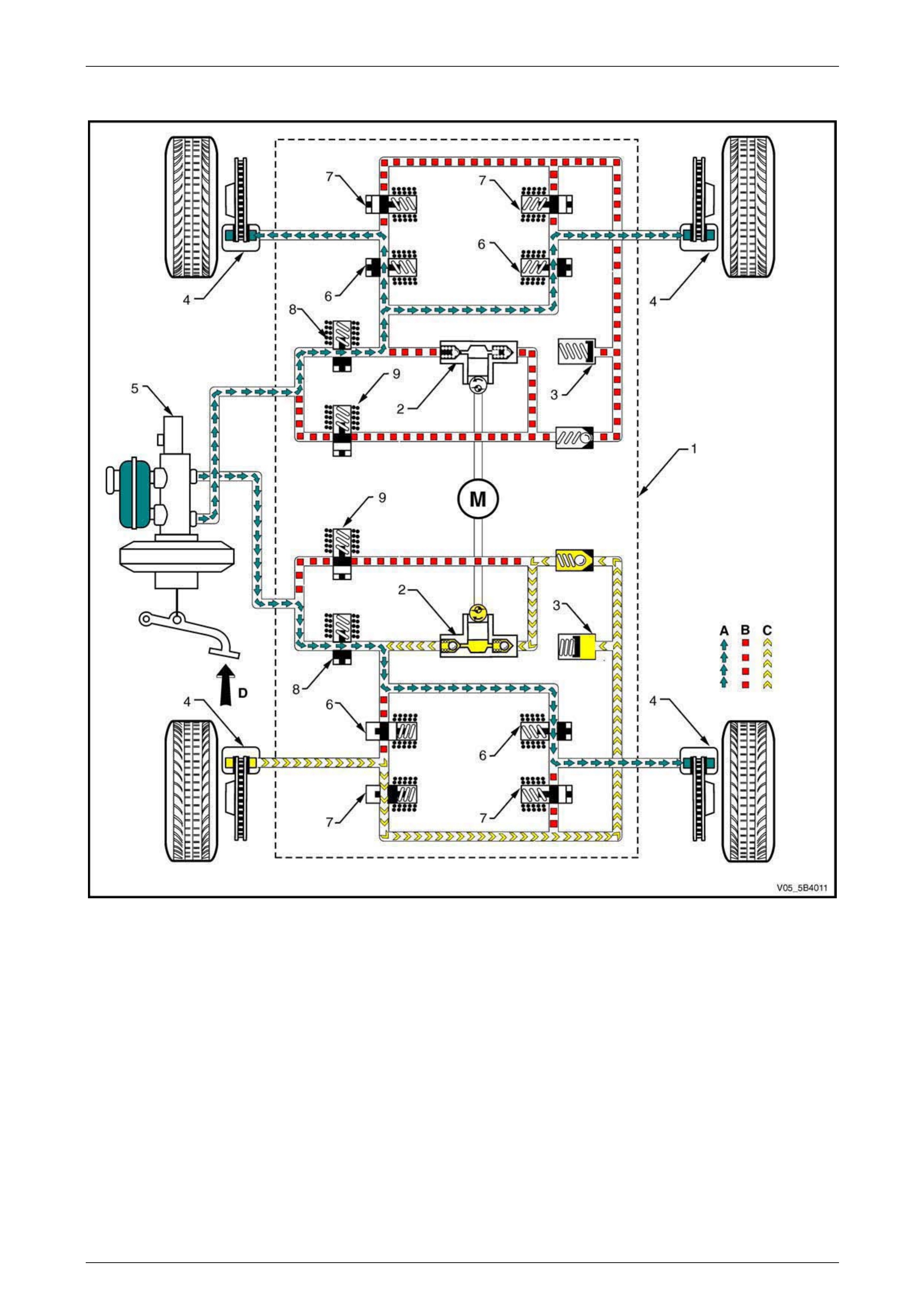
2.3 Hydraulic Modulator Assembly
NOTE
Figure 5B4 – 7 shows an illustration of the
hydraulic modulator components while in ABS
pressure reducing phase. Refer to this illustration
for the following hydraulic circuit components.
The hydraulic modulator assembly (1) modulates the brake fluid pressure (A) based on the control signal sent by the
electronic control unit (ECU).
To allow individual control of each wheel brake fluid circuit, a four-channel circuit configuration with a front/rear split is
used. Each of the brake fluid circuits are hydraulically isolated, which enables continued braking ability if a leak develops
in any of the brake fluid circuits. The hydraulic modulator components consist of the following:
• Two return pumps (2) – each pump draws excess brake fluid from the accumulators (3) and brake callipers (4)
allowing the hydraulic modulator to return brake fluid to the brake master cylinder (5) against brake fluid pressure
(C) during the ABS-TCS / ESP pressure reducing phase. In addition, the return pump applies pressure to the brake
callipers during ABD brake intervention phase.
• One electric motor (M) – the electric motor drives the return pump.
• Two accumulators – the accumulators store the excess brake fluid during the ABS-TCS / ESP pressure reducing
phase that enables the hydraulic modulator to apply instant pressure reduction.
• Four inlet valves (6) – at rest position, each inlet valve allows brake fluid pressure to be applied to the brake
callipers. When active, each inlet valve isolates a brake calliper from the brake master cylinder.
• Four outlet valves (7) – at rest position, each outlet valve isolates a brake calliper from the accumulator and return
pump. When active, each outlet valve directs excess brake fluid to the accumulator and return pump that allows
pressure reduction.
• Two isolating solenoid valves (8) – the isolating solenoid valves isolate the rear brake fluid circuits from the brake
master cylinder which prevents the return of the brake fluid to the brake master cylinder during TCS operation.
• Two rear priming valves (9) – allow brake fluid to be drawn from the brake master cylinder into the hydraulic pump
during TCS operation.
5B4 ABS-TCS / ESP Page 5B4–17
Page 5B4–17
Hydraulic Circuit Components
Figure 5B4 – 7
Legend
1 Hydraulic Modulator Assembly
2 Return Pump
3 Accumulator
4 Brake Calliper
5 Brake Master Cylinder
6 Inlet Valves
7 Outlet Valves
8 Isolating Solenoid Valve
9 Priming Solenoid Valve
A Normal (conventional) brake fluid pressure
B Stopped brake fluid pressure flow (solenoid valve closed)
C Pump generated brake fluid pressure flow
D Brake pedal applied
M Motor

5B4 ABS-TCS / ESP Page 5B4–18
Page 5B4–18
2.4 Wheel Speed Sensors
Wheel Speed Sensor Principles of Operation
The wheel speed sensor (1) in conjunction with a pulse ring
(2) generates an AC signal voltage where the amplitude and
frequency of the signal generated is proportional to the
wheel speed.
The following wheel speed sensor sine waves compares the
signal generated by the wheel speed sensor at high speed
and low speed:
• The continuous line (3) represents the voltage
generated by the wheel speed sensor versus time (t)
at high wheel speed.
• The dotted line (4) represents the voltage generated
by the wheel speed sensor versus time (t) at low wheel
speed.
Signals generated by the wheel speed sensor are
transmitted to the electronic control unit (ECU). The ECU
uses this signal voltage to determine the rotational speed of
each wheel. Figure 5B4 – 8
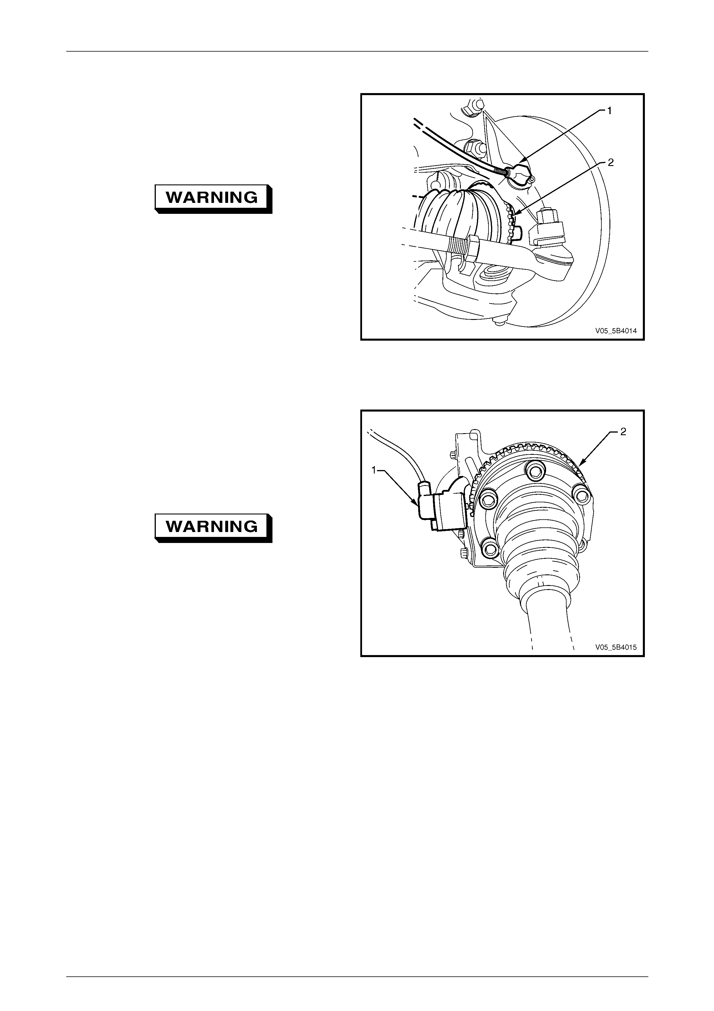
Front Wheel Speed Sensor – Rear Wheel Drive Vehicles
The front wheel speed sensors (1) are incorporated as part
of the front wheel hub assembly.
There is a specific right and left front wheel hub which
incorporates the wheel speed sensor and a 48 tooth magnet
impulse ring. The front wheel hub assembly is a sealed for
life unit.
The front wheel hub assembly part numbers are etched on
the outer surface (2) of the hub wheel flange.
If the front wheel hub assembly requires
replacement, the correct replacement part
must be installed. Otherwise, ABS-TCS / ESP
malfunction w ill occur.
Figure 5B4 – 9
5B4 ABS-TCS / ESP Page 5B4–19
Page 5B4–19
Front Wheel Speed Sensor – All Wheel Drive Vehicles
The front wheel speed sensor (1) is located at the steering
knuckle.
The front wheel speed sensor pulse ring (2) is a part of the
front driveshaft constant velocity joint assembly and is not
serviced separately.
If the front constant velocity joint requires
replacement, the correct replacement part
must be installed. Otherw ise, ABS-TCS / ESP
malfunction w ill occur.
Figure 5B4 – 10
Rear Wheel Speed Sensor
The rear wheel speed sensor (1) is located in a bracket
which is part of the final drive rear cover.
The rear wheel speed sensor pulse ring (2) is part of the
final drive inner axle flanges and is not serviced separately.
Refer to Section 4B1 Rear Final Drive and Drive Shafts for
the final drive inner axle flange service procedures.
If the final drive inner axle flange requires
replacement, the correct replacement part
must be installed. Otherwise ABS-TCS / ESP
malfunction w ill occur.
Figure 5B4 – 11
5B4 ABS-TCS / ESP Page 5B4–20
Page 5B4–20
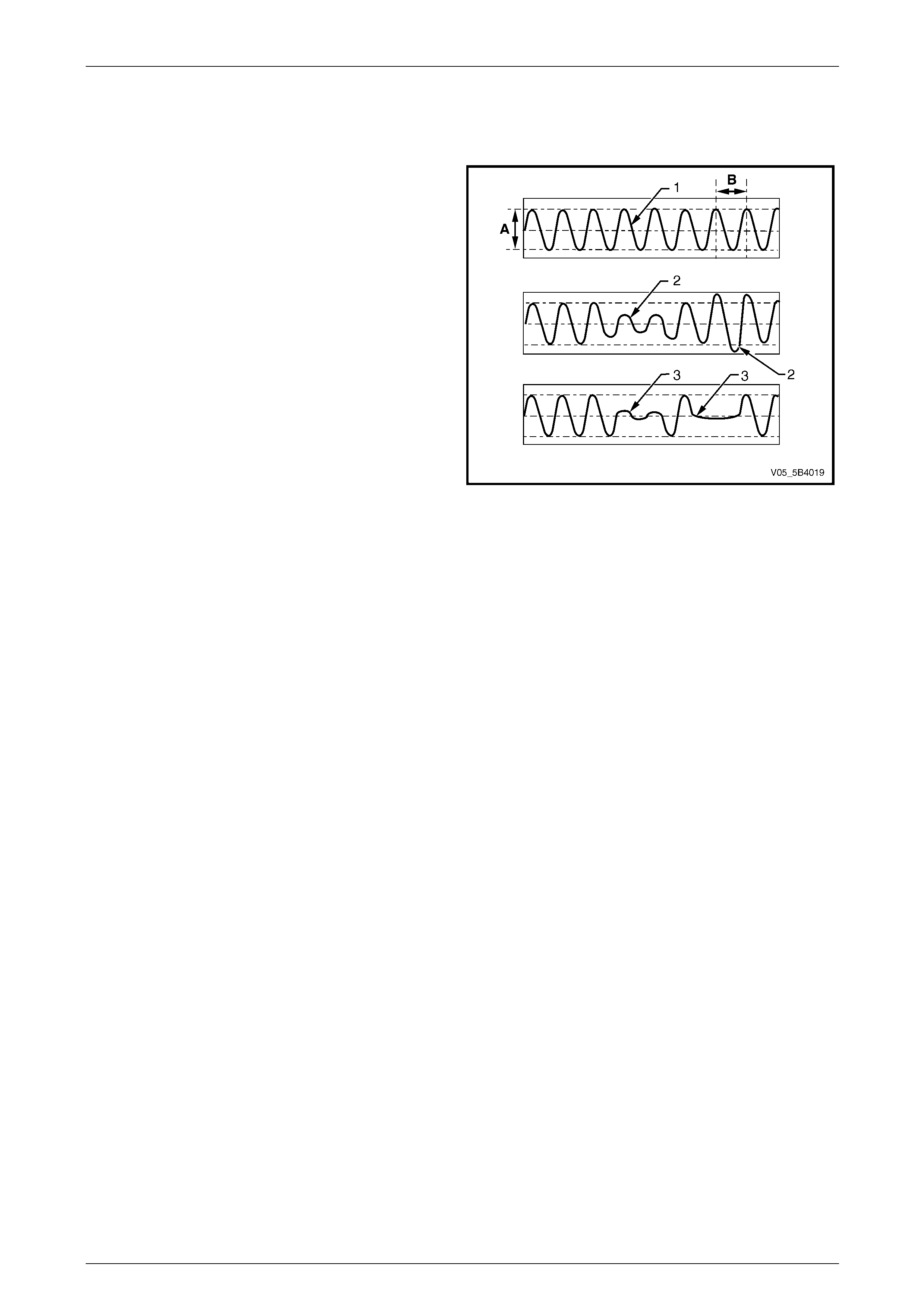
Testing Wheel Speed Sensor Using an Oscilloscope
Using an oscilloscope to display the output signal voltage of a suspected wheel speed sensor will enable the service
technician to graphically view a pulse ring related wheel speed sensor fault that may be difficult to detect otherwise.
A normal wheel speed sensor signal produces a sine
wave (1) with the height of the amplitude (A) and the width
of the frequency (B) proportional to the wheel speed.
If the pulse ring is out of round or if it is incorrectly aligned
with the wheel speed sensor, the air gap between the wheel
speed sensor and the pulse ring will vary as the wheel
rotates. This fault will produce a wheel speed sensor signal
with varying amplitude (2).
If the pulse ring teeth are missing or damaged, the
oscilloscope sine wave pattern will display flat spots (3) that
represent the missing or damaged pulse ring teeth.
Figure 5B4 – 12
5B4 ABS-TCS / ESP Page 5B4–21
Page 5B4–21
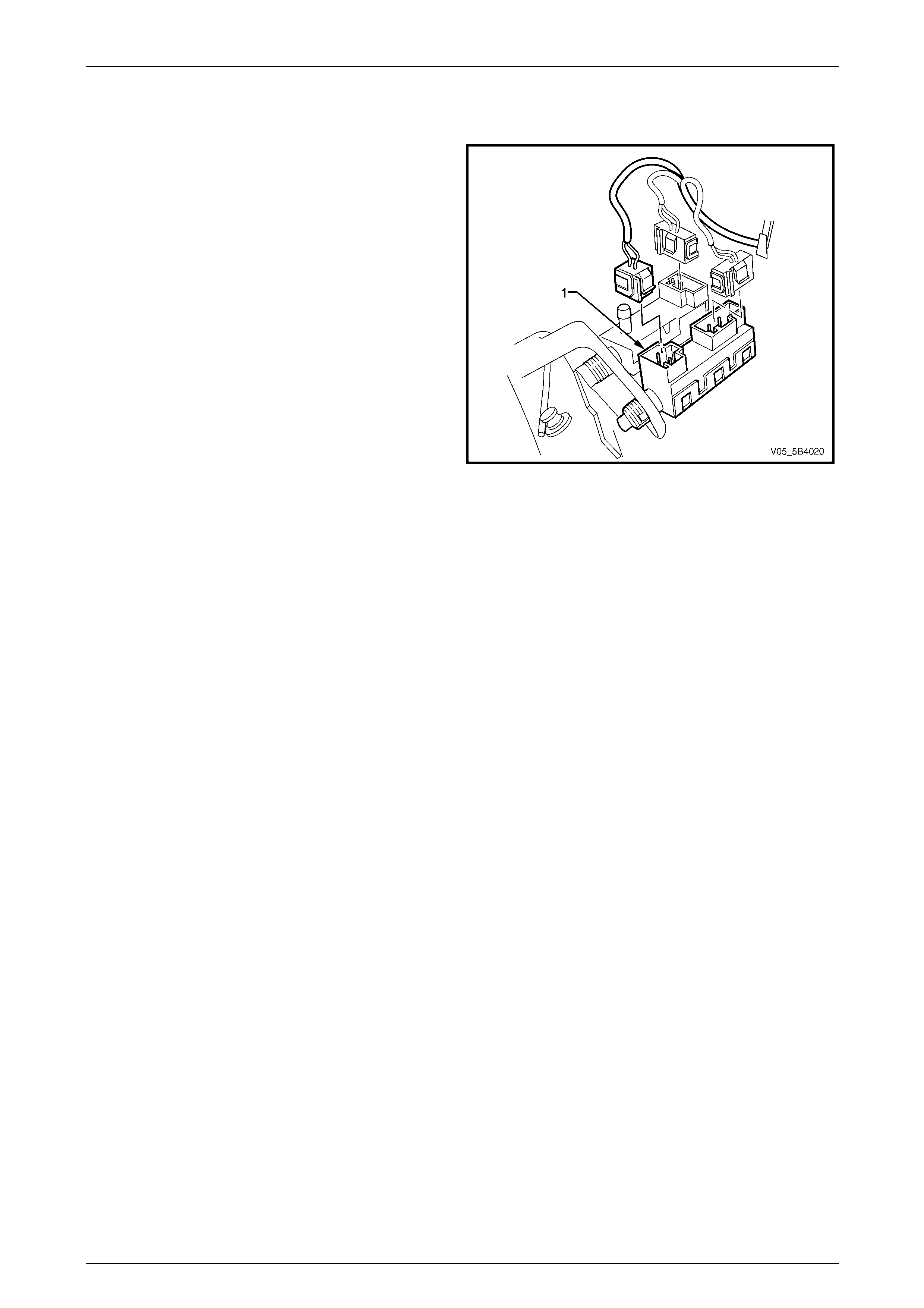
2.5 Stop Lamp Switch-A
The stop lamp switch A (1) is a normally open switch that
closes when the brake pedal is depressed.
The electronic control unit (ECU) uses the stop lamp switch
signal voltage to determine when the brake pedal is
depressed.
For stop lamp switch service operations, refer to
Section 12B Lighting System.
Figure 5B4 – 13
5B4 ABS-TCS / ESP Page 5B4–22
Page 5B4–22
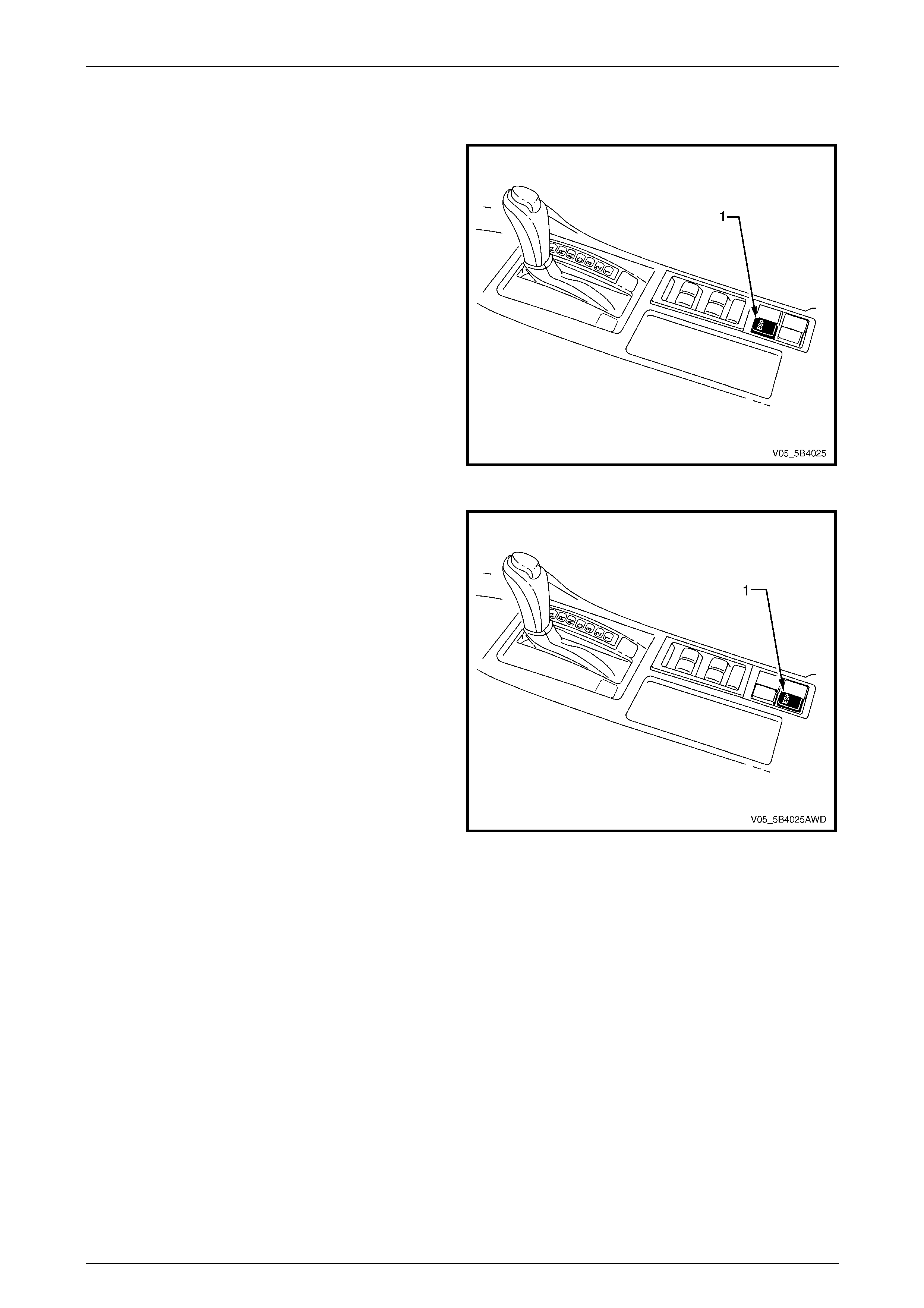
2.6 Electronic Stability Program Switch
Fro rear wheel drive vehicles, the electronic stability
program (ESP) switch (1) is located in the floor console as
shown.
Figure 5B4 – 14
For all wheel drive vehicles, the ESP switch (1) is located in
the floor console as shown.
The ESP switch is a momentary contact switch that sends a
ground output signal to the powertrain interface module
(PIM).
The PIM converts this signal into GM LAN protocol and
sends a signal to the ECU via the serial data bus to perform
the following functions:
• Pressing the ESP switch once deactivates the ESP for
the duration of that ignition cycle. The ABS-TCS will
still function normally when the ESP is deactivated.
• Pressing the ESP switch again when the ESP is
deactivated, activates the ESP.
• Pressing the ESP switch for more than 60 seconds will
be interpreted as a short circuit. Consequently, a PIM
DTC will be logged and the ESP will be deactivated for
the duration of that ignition cycle.
If there are no current TCS DTC logged, the ESP activates
at the next ignition cycle.
Refer to Section 6E1 Powertrain Interface Module – V6 for
further information on the ESP switch.
Figure 5B4 – 15
5B4 ABS-TCS / ESP Page 5B4–23
Page 5B4–23
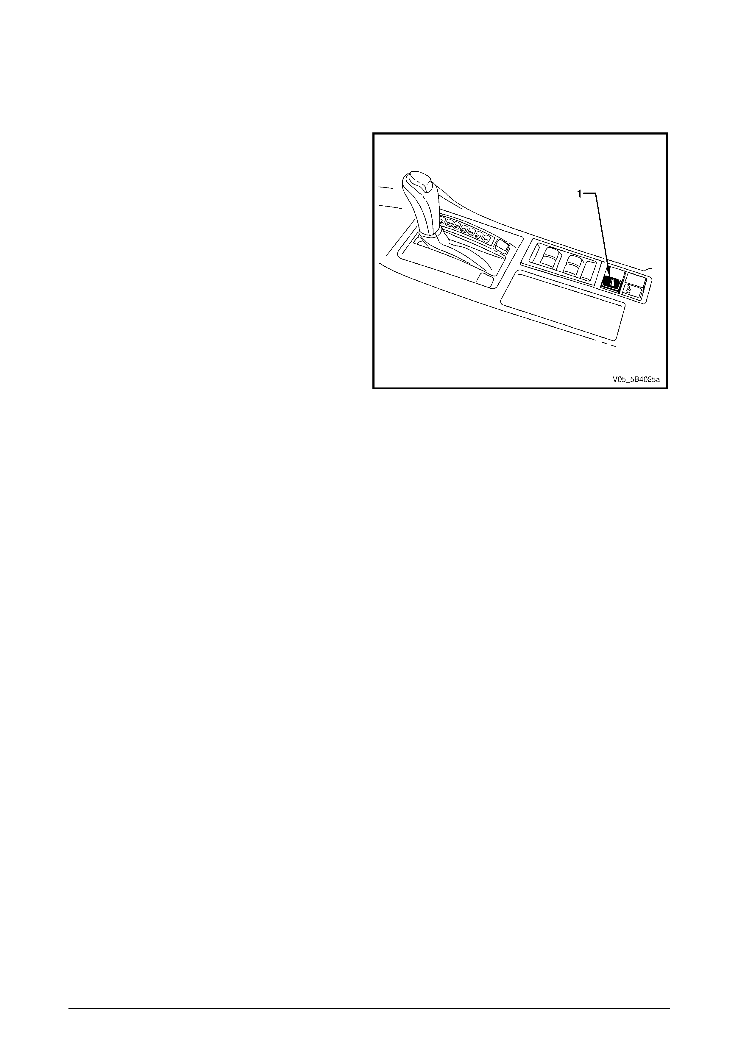
2.7 Hill Descent Control Switch – All Wheel
Drive Wagon
The hill descent control (HDC) switch (1) is located in the
floor console. It is a momentary contact switch that sends a
ground output signal to the Powertrain Interface Module
(PIM).
The PIM converts this signal into GM LAN protocol and
sends a signal to the ECU via the serial data bus to perform
the following functions:
• Pressing the HDC switch once enables the HDC.
NOTE
The HDC can only be enabled at speeds below
50 km/h and can only become active at speeds
below 35 km/h.
• Pressing the HDC switch when the HDC is enabled,
disables the HDC, regardless of the vehicle speed.
• Pressing the HDC switch for more than 60 seconds will
be interpreted as a short circuit. Consequently, a PIM
DTC will be logged and the HDC will be disabled for
the duration of that ignition cycle.
Refer to Section 6E1 Powertrain Interface Module – V6 for
further information on the HDC switch.
Figure 5B4 – 16
5B4 ABS-TCS / ESP Page 5B4–24
Page 5B4–24
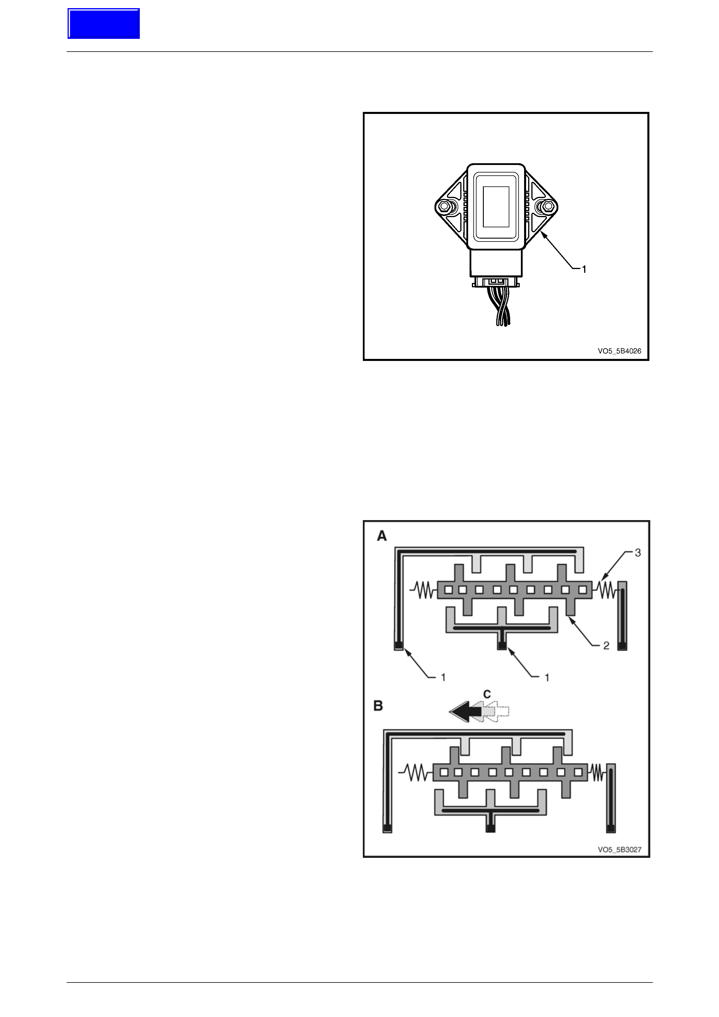
2.8 Yaw-rate Sensor Assembly
The yaw-rate sensor assembly (1) comprises of a yaw-rate
sensor and a lateral acceleration sensor.
• The yaw-rate sensor produces a signal output voltage
that corresponds to a vehicle rotation around its
vertical axis.
• The lateral acceleration sensor produces a signal
output voltage that corresponds to a vehicle lateral
wheel skid.
The ECU uses the output signal voltage of the yaw-rate
sensor and the acceleration sensor in conjunction with the
wheel speed sensor signal output voltage and serial data
output signal of the steering angle sensor, to support the
calculation of actual vehicle behaviour as compared to the
driver intended direction.
Figure 5B4 – 17
Lateral Acceleration Sensor
NOTE
Figure 5B4 – 18 represents the lateral
acceleration sensor in symbolic form, which aims
to show the operation of the acceleration sensor
in a simplified manner.
The lateral acceleration sensor consists of the following
components:
• Differential capacitors connected to the fixed side
plates (1).
• Mass plate (2) suspended by springs (3) about its
centre of mass, which moves in response to vehicle
lateral acceleration.
When the vehicle is stationary (View A), the distance
between the mass plate and the two side plates are equal.
Therefore, the capacitance between the two capacitors is
the same and the acceleration sensor signal voltage is zero.
As the vehicle accelerates (View B), the side plates move
with the vehicle (C) while the mass plate, which is
suspended by springs tends to move in the opposite
direction. Therefore, the distance between the side plates
and the mass plates changes in proportion to the level of
acceleration.
This changes the capacitance between the two capacitors
causing the acceleration sensor to produce a signal voltage
with an amplitude proportional to the movement of the mass
plates.
Figure 5B4 – 18
Techline
5B4 ABS-TCS / ESP Page 5B4–25
Page 5B4–25
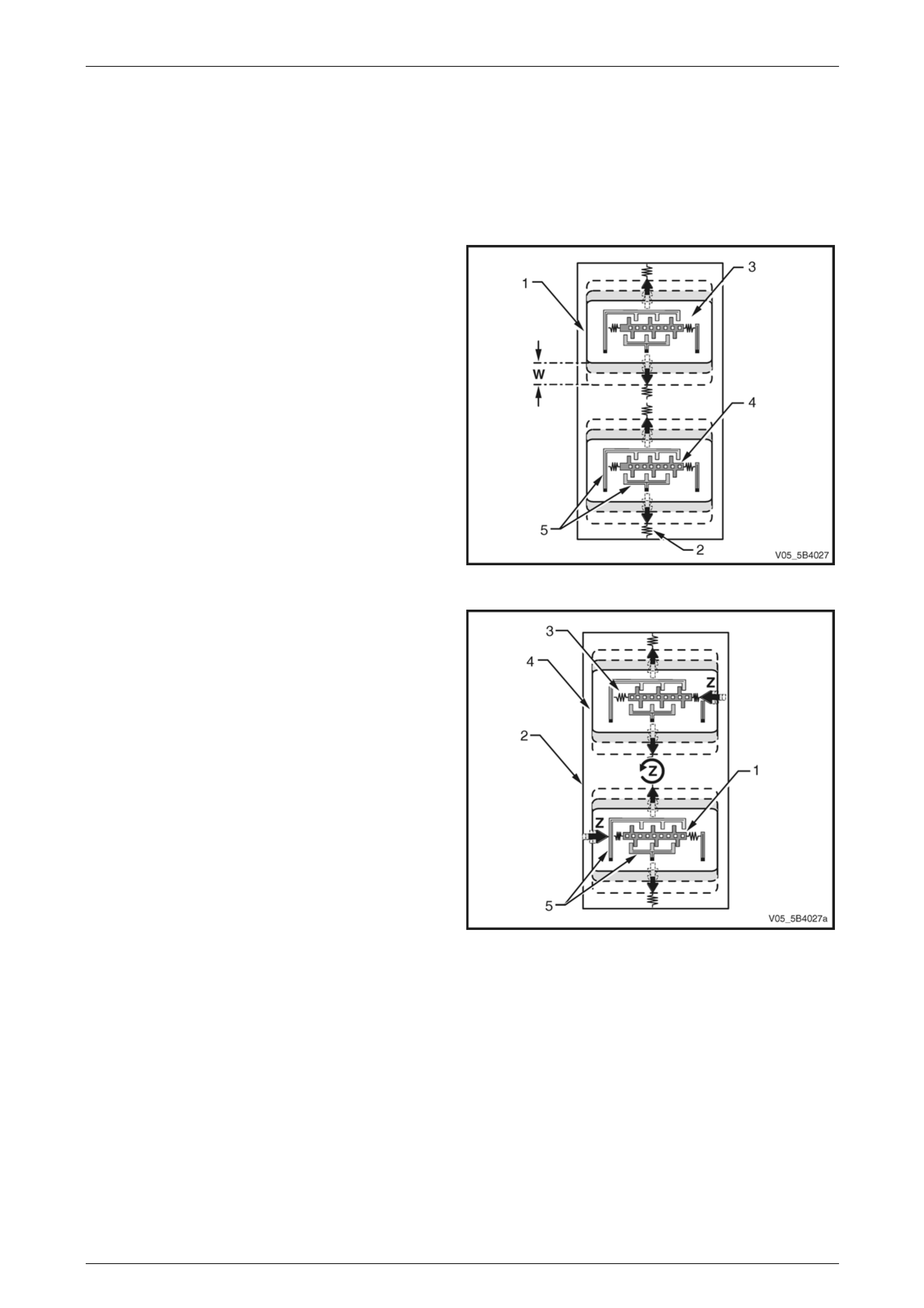
Yaw-rate Sensor
NOTE
Figure 5B4 – 19 and Figure 5B4 – 20 represent
the yaw-rate sensor in symbolic form, which
shows the operation of the yaw-rate sensor in a
simplified manner.
The yaw-rate sensor consists of the following components:
• two oscillating plates (1) suspended by springs (2)
around its centre of mass,
• an acceleration sensor (3) incorporated within the
oscillating plates, and
• permanent magnets, which project magnetic field to
the oscillating plates.
While in the presence of a magnetic field, electric current is
applied to the oscillating plates, which causes the plates to
move at a constant amplitude (W).
When the vehicle is driving in a straight-ahead direction and
there are no lateral forces applied to the acceleration
sensors, the distance between the mass plates (4) and the
side plates of the acceleration sensors are equal (5).
Therefore, the capacitance between the capacitors are the
same and the acceleration sensor signal voltage is zero.
Figure 5B4 – 19
When the vehicle rotates around its vertical axis, the
following situation occurs.
• With the exception of the mass plates (1), the yaw-rate
sensor (2), which is firmly attached to the vehicle
rotates with the vehicle (Z).
• The mass plates, which are suspended by springs (3)
and moves along with the oscillating plates (4) tends to
float in its current position while the fixed side plates
(5) rotate with the vehicle. Therefore, the distance
between the fixed side plates and the mass plates of
the acceleration sensor changes in proportion to the
level of vehicle rotation around its vertical axis.
• This changes the capacitance between the capacitors
causing the acceleration sensor to produce a signal
voltage with an amplitude proportional to the
movement of the mass plates.
The evaluation circuit of the yaw-rate sensor compares and
evaluates the output signal of both acceleration sensors to
calculate the level of vehicle rotation around its vertical axis. Figure 5B4 – 20
5B4 ABS-TCS / ESP Page 5B4–26
Page 5B4–26
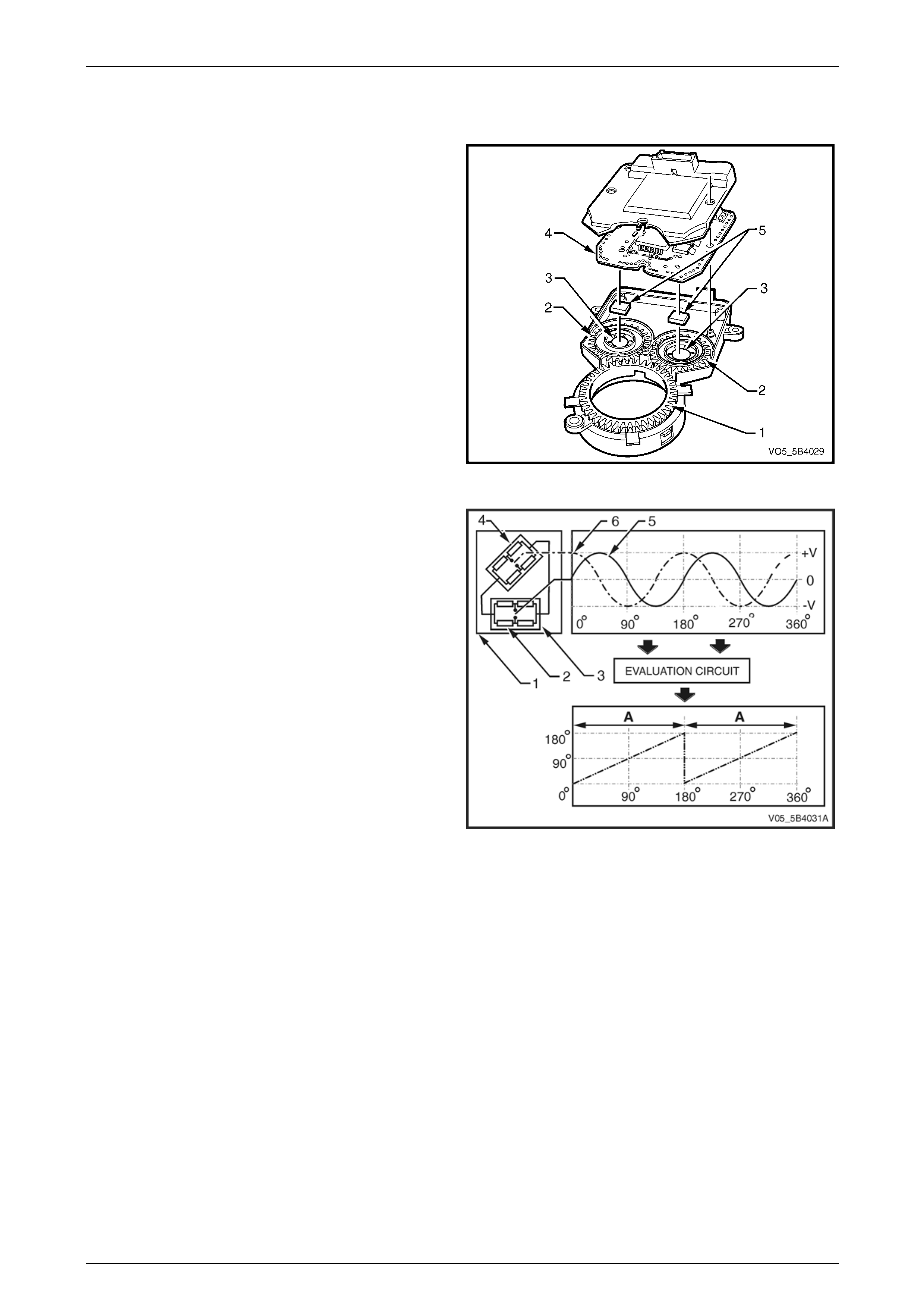
2.9 Steering Angle Sensor
The steering angle sensor provides a signal output that
represents the steering wheel degree of rotation. The ECU
uses this information to calculate the driver intended driving
direction. The steering angle sensor contains:
1 gear wheel,
2 measuring gears,
3 measuring gear magnets,
4 evaluation circuit, and
5 anisotropic magneto resistive (AMR) integrated circuit
(IC).
Figure 5B4 – 21
The anisotropic magneto resistive integrated circuit (AMR
IC) (1) comprises of eight AMR elements (2) which are
configured to form two Wheatstone bridges (3).
One of the Wheatstone bridges (4) is 45 degrees offset from
the other to enable the AMR IC to produce sine (5) and
cosine (6) output signal.
The AMR elements change resistance that corresponds to
the changes in the angle of magnetic field projected to the
AMR IC, regardless of the polarity of the magnetic field.
The evaluation circuit of the steering angle sensor evaluates
and combines the output signal of the AMR IC to produce
two identical linear output signals (A) that represents the
360°angular rotation of the magnetic field.
The omni polarity of the AMR elements limits the signal
output range of a single AMR IC from 0° to 180°.
Figure 5B4 – 22
5B4 ABS-TCS / ESP Page 5B4–27
Page 5B4–27
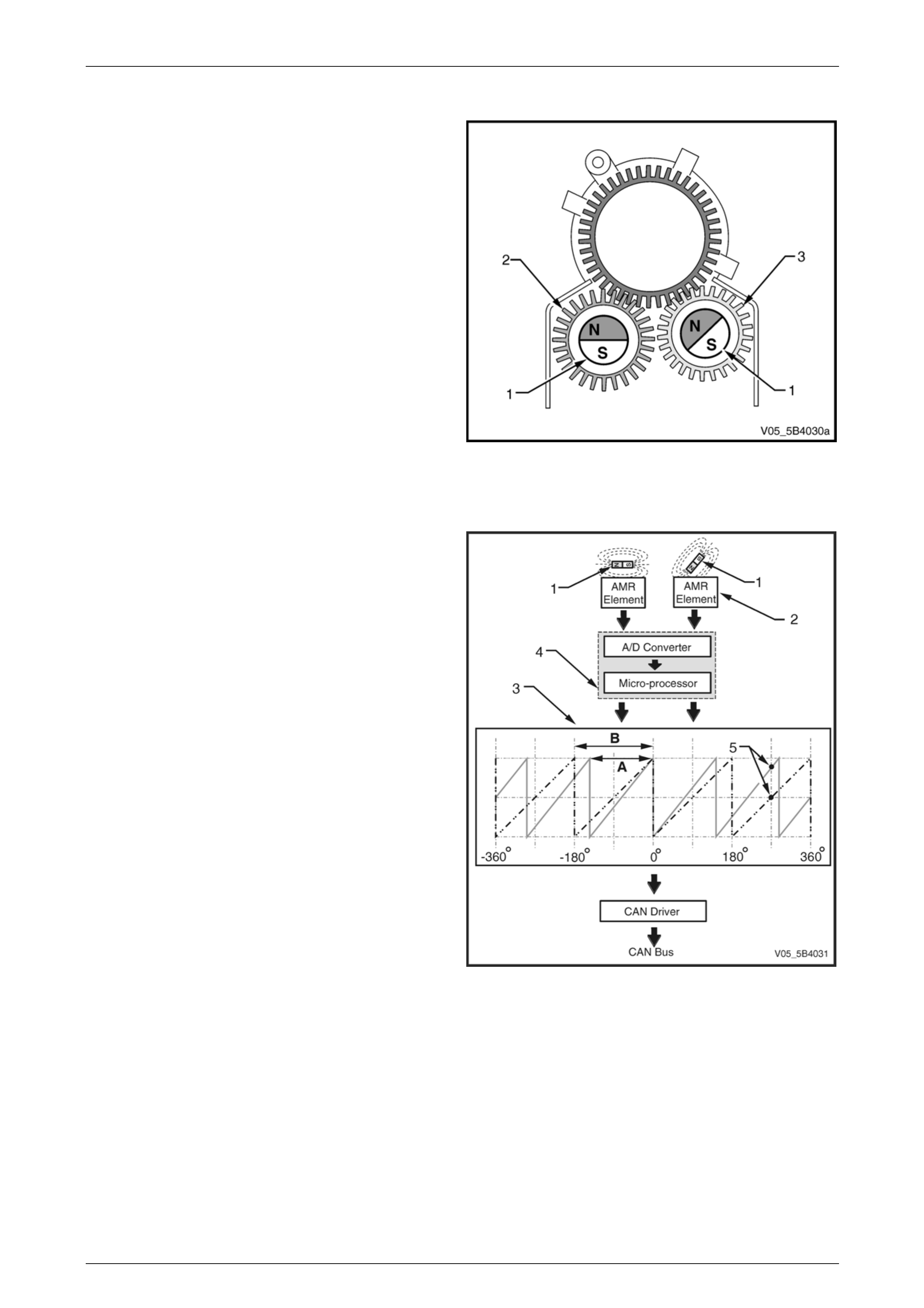
Steering Angle Sensor Layout
To increase the output signal range of the steering angle
sensor, and enable it to produce an output signal that can
represent the ± 760º of steering wheel rotation, two AMR
ICs are fitted to the steering angle sensor.
The magnets (1) that project magnetic fields to the AMR ICs
are mounted on the primary measuring gear (2) and
secondary measuring gear (3).
The secondary gear has two less teeth when compared
against the primary measuring gear. This causes the
measuring gears to rotate at a different ratio.
Figure 5B4 – 23
Steering Angle Sensor Operation
The angular orientation of the magnetic fields produced by
the measuring gear magnets (1) corresponds to the degree
of steering wheel angular position.
This magnetic field changes the resistance value of the
AMR elements, which enable the AMR ICs (2) to produce a
pair of signal outputs (3).
The difference in the rotational ratio between the measuring
gears causes the signal output of the second AMR IC (A) to
be shorter in range when compared against the signal
output of the first AMR IC (B).
The evaluation circuit (4) compares and evaluates this
difference, and the rate of change between the output
signals of the AMR ICs, at parallel points (5) to calculate the
precise steering wheel angular position.
Figure 5B4 – 24
Steering Angle Sensor Calibration
The ECU monitors and evaluates the output signal of the steering angle sensor. When the vehicle is driven in a straight
ahead direction for 15 minutes or more, the ECU sets this driving direction as the straight ahead position. If the ECU
detects the steering angle sensor orientation deviates from the straight ahead position, the ECU performs the following
functions:
• If the deviation is 15 degrees or less, the ECU automatically performs steering angle sensor calibration.
• If the deviation is greater than 15 degrees, DTC C0460 Steering Angle Sensor Fault sets.
The steering angle sensor may be recalibrated using Tech 2. Refer to 9.15 Steering Angle Sensor for information on the
steering angle sensor calibration procedure.

5B4 ABS-TCS / ESP Page 5B4–28
Page 5B4–28
3 System Operation
3.1 Non-ABS Braking
Under normal braking and driving conditions, the antilock braking system (ABS) functions like a conventional braking
system. Refer to Section 5A Service and Park Braking System for further information on the conventional braking system.
Non-ABS Braking Operation
When the brakes are applied (D), the brake booster assists the brake master cylinder (1) in providing brake fluid pressure
(A) to the brake callipers (2) without any intervention from the hydraulic modulator (3). Refer to
Figure 5B4 – 25.
However, the electronic control unit (ECU) constantly monitors each wheel for wheel slip. When the ECU detects a wheel
slip, it switches to the appropriate mode. Refer to 3.2 Antilock Braking System.
Condition Description
At normal braking, all the valves in the hydraulic modulator are in their normal rest positions allowing for uninterrupted
flow of brake fluid from the master cylinder to the brake callipers. The hydraulic modulator provides conventional non-
ABS braking by allowing the brake fluid to flow between the brake master cylinder and the brake calliper in either
direction.
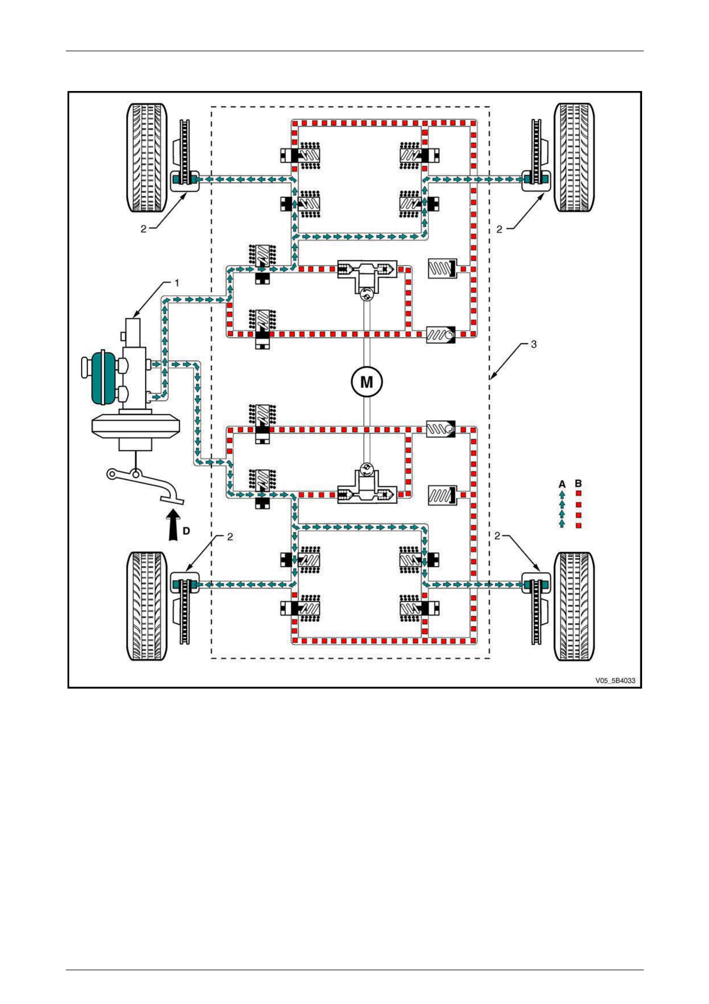
5B4 ABS-TCS / ESP Page 5B4–29
Page 5B4–29
Normal Braking Hydraulic Circuit
Figure 5B4 – 25
Legend
1 Brake Master Cylinder
2 Brake Calliper
3 Hydraulic Modulator Assembly
A Normal (conventional) brake fluid pressure
B Stopped brake fluid pressure flow (solenoid valve closed)
D Brake pedal applied
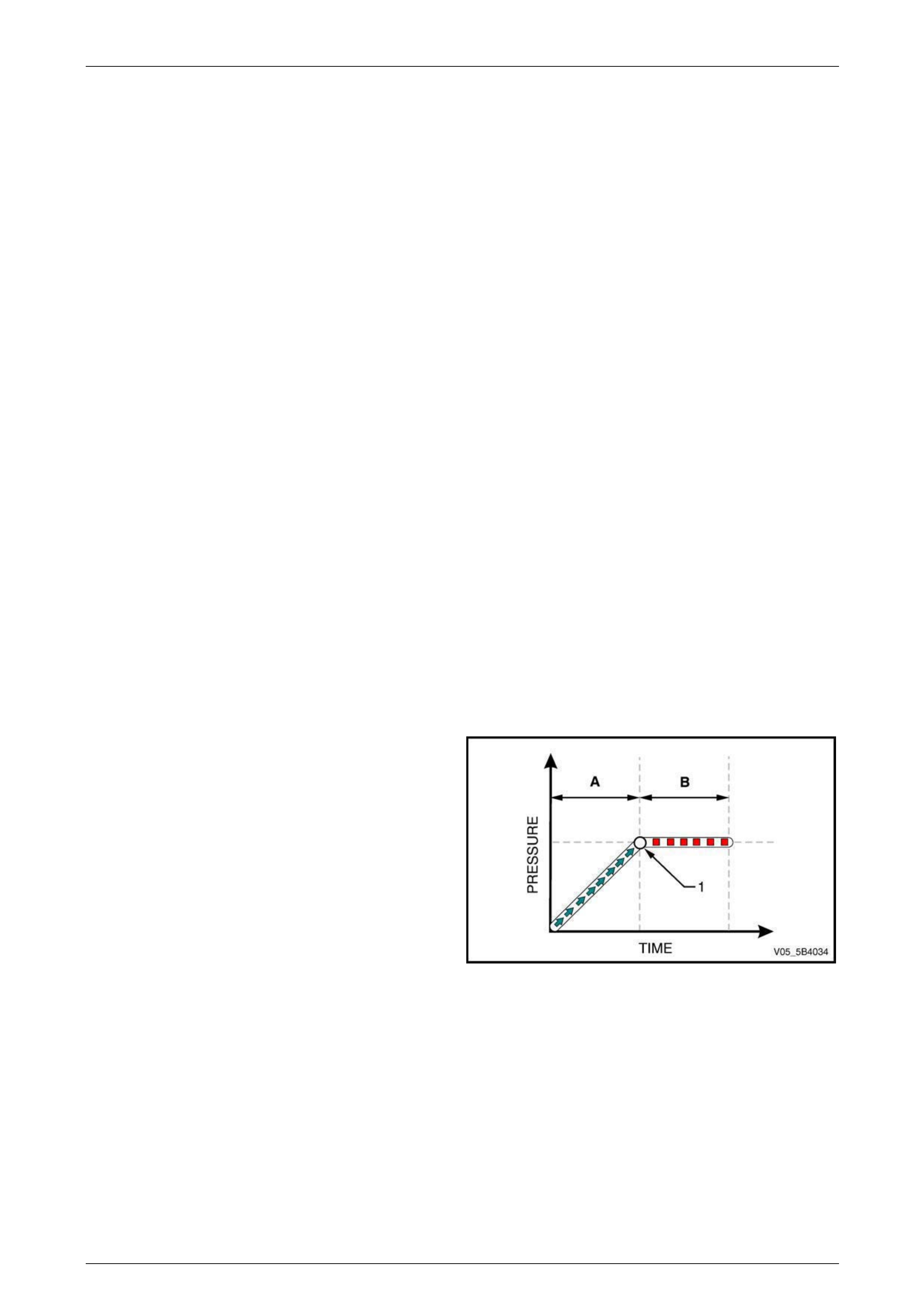
5B4 ABS-TCS / ESP Page 5B4–30
Page 5B4–30
3.2 Antilock Braking System
The antilock braking system (ABS) prevents wheel lock-up during hard or emergency braking by modulating the brake
fluid pressure applied to the appropriate wheels. The ABS cycles through the following phases when the electronic
control unit (ECU) detects the beginning of a wheel lock-up:
• maintaining pressure,
• reducing pressure, and
• increasing pressure. NOTE
The following are conditions that may be
experienced when the ABS is active and are
considered normal:
• During ABS controlled braking, the braking
pressure of the affected wheel is automatically
adjusted to prevent wheel lock-up, regardless
of pressure applied to the brake pedal.
• A series of rapid pulsations are felt through
the brake pedal – these pulsations occur as
solenoid valves within the hydraulic modulator
change position to modulate the brake
hydraulic pressure.
• A ticking or popping noise in the hydraulic
modulator occurs as the hydraulic modulator
solenoid valves cycle rapidly to modulate the
hydraulic brake pressure.
• Intermittent chirping noises may be heard as
the tyres approach slipping on dry pavement.
• Electric motor and pump noise and rapid
brake pedal pulsation caused by the operation
of the hydraulic modulator pump during the
ABS reducing or increasing pressure phase or
the ECU self-test.
ABS Phase – Maintaining Pressure
Condition Description
When the brakes are applied (A) and the ECU detects that a
wheel reaches a point (1) where it is beginning to lock-up,
the hydraulic modulator controls the brake fluid pressure of
the affected wheel to maintain its brake fluid pressure (B)
and prevent a wheel lock-up.
Figure 5B4 – 26
Control Action
NOTE
The following ABS situation assumes the rear
left wheel is beginning to lock-up. Refer to
Figure 5B4 – 27 for the illustration of the
ABS Phase Hydraulic Circuit – Maintaining
Pressure.
The ECU monitors and compares signals from each wheel speed sensor to determine wheel slip. If a wheel lock-up is
detected during braking, the ECU switches to the maintaining pressure phase and sends a control signal to the hydraulic
modulator (1) to close the rear left inlet valve (2).
With both the rear left inlet valve and outlet valve (3) closed, the rear left brake fluid circuit is isolated and the rear left
brake fluid pressure is kept constant (B) regardless of the brake fluid pressure (A) exerted by the brake pedal (D).
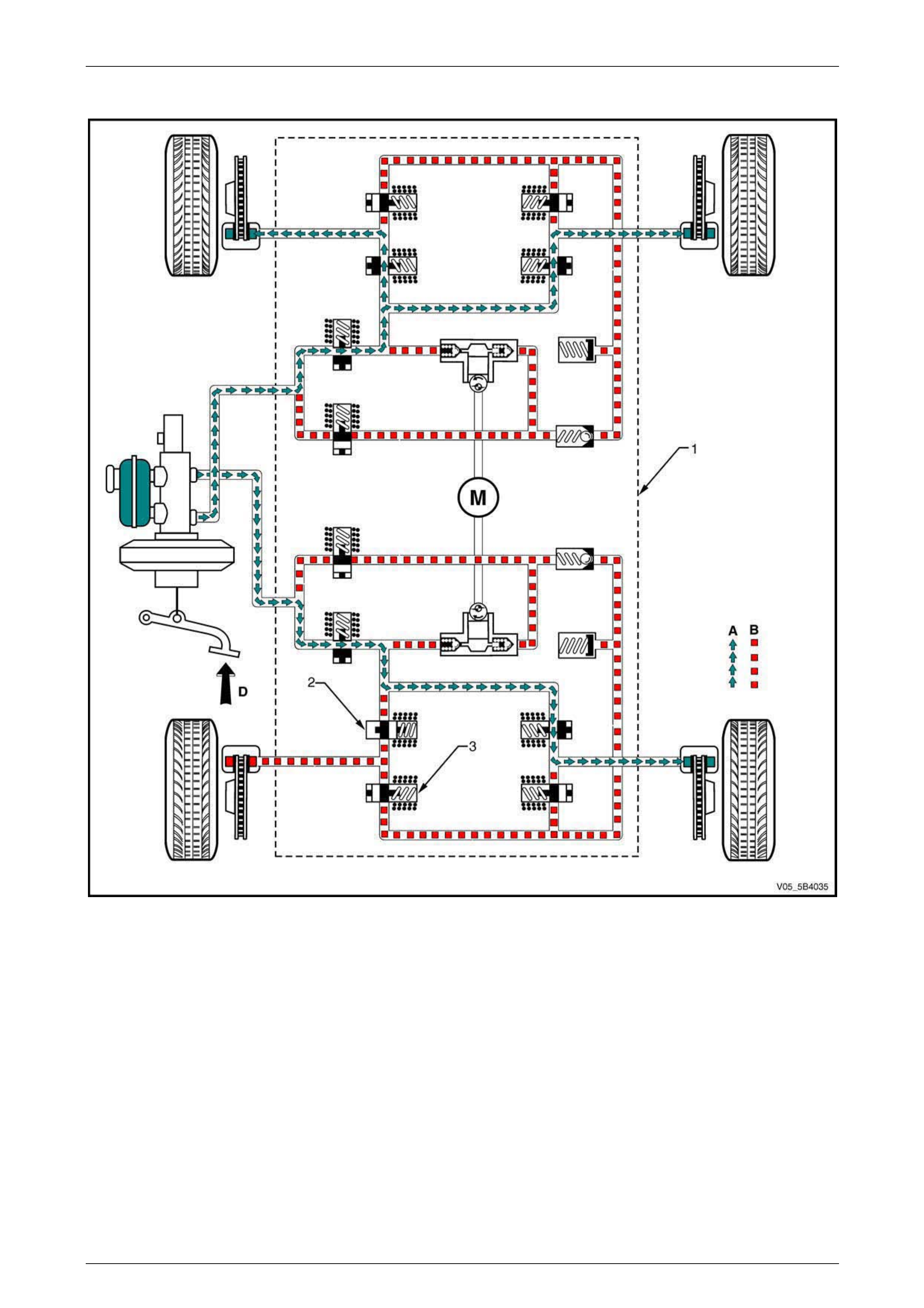
5B4 ABS-TCS / ESP Page 5B4–31
Page 5B4–31
ABS Phase Hydraulic Circuit – Maintaining Pressure
Figure 5B4 – 27
Legend
1 Hydraulic Modulator Assembly
2 Inlet Valve
3 Outlet Valve
A Normal (conventional) brake fluid pressure
B Stopped brake fluid pressure flow (solenoid valve closed)
D Brake pedal applied

5B4 ABS-TCS / ESP Page 5B4–32
Page 5B4–32
ABS Phase – Reducing Pressure
Condition Description
If the ECU detects the affected wheel is still locking-up while
the ABS is already in the maintaining pressure phase (B),
the ABS switches to reducing pressure phase (C) at a
predetermined point (1).
The hydraulic modulator modulates the brake fluid circuit of
the affected wheel to reduce its brake fluid pressure and
prevent wheel lock-up.
Figure 5B4 – 28
Control Action
NOTE
The following ABS situation assumes the rear left
wheel is still locking-up while the ABS is already
in maintaining pressure phase. Refer to
Figure 5B4 – 29 for the illustration of the
ABS Phase Hydraulic Circuit – Reducing
Pressure.
The ECU monitors and compares signals from each wheel speed sensor to determine wheel slip. If the rear left wheel
lock-up is still detected when the ABS is already in the maintaining pressure phase, the ECU switches to the ABS
reducing pressure phase. The ECU sends a control signal to the hydraulic modulator (1) to:
• Close rear left inlet valve (2).
• Open the rear left outlet valve (3).
• Operate the hydraulic modulator pump (4). The hydraulic modulator pump will remain operational for the duration of
the ABS phase.
This results in the following actions during the reducing pressure phase:
1 The rear left brake fluid is initially directed towards the accumulator (5) to guarantee instant pressure reduction
when the rear left outlet valve is opened.
2 The accumulator stores the excess rear left brake fluid.
3 The hydraulic modulator pump builds-up the rear left brake fluid return flow pressure that will allow the brake fluid
released from rear left brake calliper (6) to be returned back to the brake master cylinder (7) against brake pedal
pressure (D). Because the brake pedal is still being depressed during this phase, the released pressure from the
brake calliper has to be greater than the brake fluid pressure applied by the master cylinder.
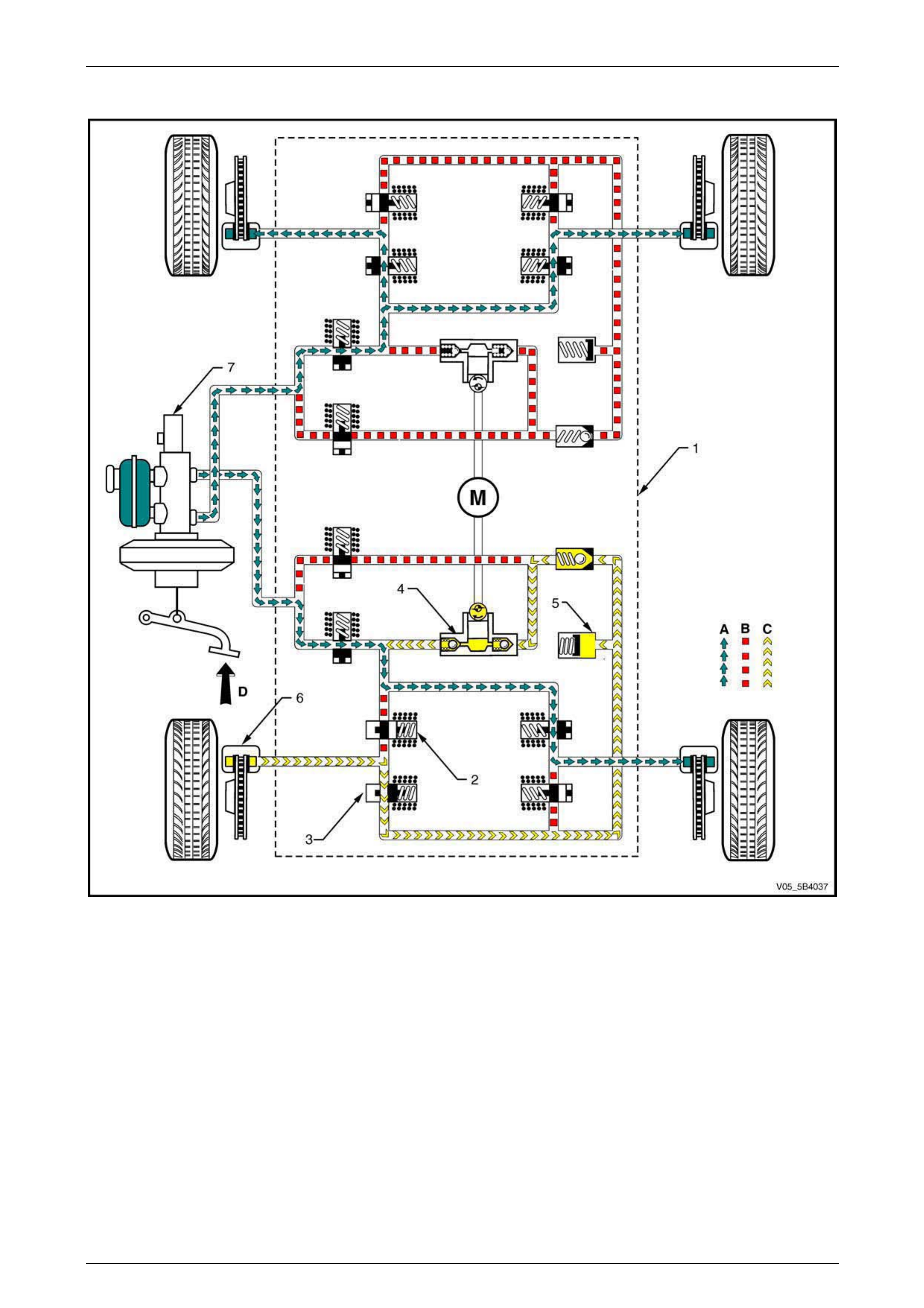
5B4 ABS-TCS / ESP Page 5B4–33
Page 5B4–33
ABS Phase Hydraulic Circuit – Reducing Pressure
Figure 5B4 – 29
Legend
1 Hydraulic Modulator Assembly
2 Inlet Valve
3 Outlet Valve
4 Hydraulic Pump
5 Accumulator
6 Brake Calliper
7 Brake master cylinder
A Normal (conventional) brake fluid pressure
B Stopped brake fluid pressure flow (solenoid valve closed)
C Hydraulic modulator pump generated brake fluid pressure
flow
D Conventional brake pressure combined with released brake
fluid pressure

5B4 ABS-TCS / ESP Page 5B4–34
Page 5B4–34
ABS Phase – Increasing Pressure
Condition Description
If the reduction in the brake fluid pressure in the reducing
pressure phase (C) results in the pressure reaching a point
(1) where insufficient braking force is applied to the affected
wheel, the ECU determines the affected wheel is now under-
braked.
The ABS switches from reducing pressure phase to
increasing pressure phase (A). In this phase, the hydraulic
modulator modulates the affected wheel brake fluid circuit to
increase its brake fluid pressure, which increases braking
force and balances wheel speed during braking.
Figure 5B4 – 30
Control Action
NOTE
The following ABS situation assumes the rear
left wheel speed is under-braked as a result of
the reduced braking force applied during the
ABS reducing pressure phase. Refer to
Figure 5B4 – 31 for the illustration of the
ABS Phase Hydraulic Circuit – Increasing
Pressure.
The ECU monitors and compares signals from each wheel speed sensor to determine wheel slip. If the ECU detects the
rear left wheel speed is higher than the other three wheels as a result of the reduced braking force applied during the
reducing pressure phase, the ECU switches to the increasing pressure phase. The ECU sends a control signal to the
hydraulic modulator (1) to:
• Close (normal position) the rear left outlet valve (3).
• Open (normal position) the rear left inlet valve (2).
• Continue operation of the hydraulic modulator pump (4) for the duration of the ABS phase.
The master cylinder (5) brake fluid pressure (A) is again directed to the rear left brake calliper (6) as in normal brake
operation. The previously reduced rear left brake fluid pressure is now increased to reduce the rear left wheel speed.
These ABS phases are repeated until the ECU detects the wheel speeds are balanced or the brake pedal pressure
removed. There are approximately four to six control cycles per second depending on the road surface condition.

5B4 ABS-TCS / ESP Page 5B4–35
Page 5B4–35
ABS Phase Hydraulic Circuit – Increasing Pressure
Figure 5B4 – 31
Legend
1 Hydraulic Modulator Assembly
2 Inlet Valve
3 Outlet Valve
4 Hydraulic Pump Assembly
5 Brake Master Cylinder
6 Brake Calliper
A Normal (conventional) brake fluid pressure
B Stopped brake fluid pressure flow (solenoid valve closed)
C Hydraulic modulator pump generated brake fluid pressure
flow
D Brake pedal applied

5B4 ABS-TCS / ESP Page 5B4–36
Page 5B4–36
3.3 Electronic Brake-force Distribution
System
The electronic brake-force distribution (EBD) system is part of the ABS software programmed into the electronic control
unit (ECU). It is designed to replace the rear brake proportioning valve in reducing rear wheel slip during moderate
braking.
The EBD system utilises the existing ABS active controls to regulate the vehicle's rear brake fluid pressure. This enables
the EBD system to provide dynamic front to rear brake proportioning under various vehicle loads, driving manoeuvres, or
road conditions.
In some situations, when the EBD system is activated, a brake pedal height drop of approximately 10 mm will be
experienced when the driver varies the brake pedal pressure while performing brake stops. This is caused by the
hydraulic modulator performing an adjustment on the rear brake fluid pressure and is considered normal.
EBD System Keep Alive Function
The EBD system plays an important role in vehicle stability during braking. For this reason, the EBD system has a Keep
Alive Function integrated in its software. When the ECU detects a fault in the ABS, depending on the type of failure,
certain parts of the system are kept alive. This allows the EBD system to apply some rear wheel brake proportioning even
under certain ABS faults.
EBD Phase – Maintaining Pressure
Condition Description
When the brakes are applied (A) and the ECU determines
the rear wheels reach a point (1) where their rotational
speed is decelerating faster than the front wheels, the
hydraulic modulator modulates the rear wheel brake fluid
pressure (B) to maintain the rear braking force and prevent
a wheel lock-up.
NOTE
The EBD system operation takes effect before
the increased slip rate required for an ABS brake
intervention.
Figure 5B4 – 32
Control Action
NOTE
The following EBD situation assumes the
rear wheels are beginning to slip. Refer to
Figure 5B4 – 33 for the illustration of the
EBD Phase Hydraulic Circuit – Maintaining
Pressure.
The ECU monitors and evaluates signals from each wheel speed sensor to determine wheel slip. When the ECU
determines the rear wheels are decelerating faster than the front wheels but the rate of deceleration doesn't reach a point
where it requires ABS intervention, the ECU switches to EBD maintaining pressure phase.
As a first step during the EBD maintaining pressure phase, the ECU sends a control signal to the hydraulic modulator (1)
to close the rear inlet valves (2) and isolate the rear brake fluid circuit from the brake master cylinder. This maintains the
rear brake fluid pressure regardless of the brake fluid pressure (A) exerted by the brake pedal (D).
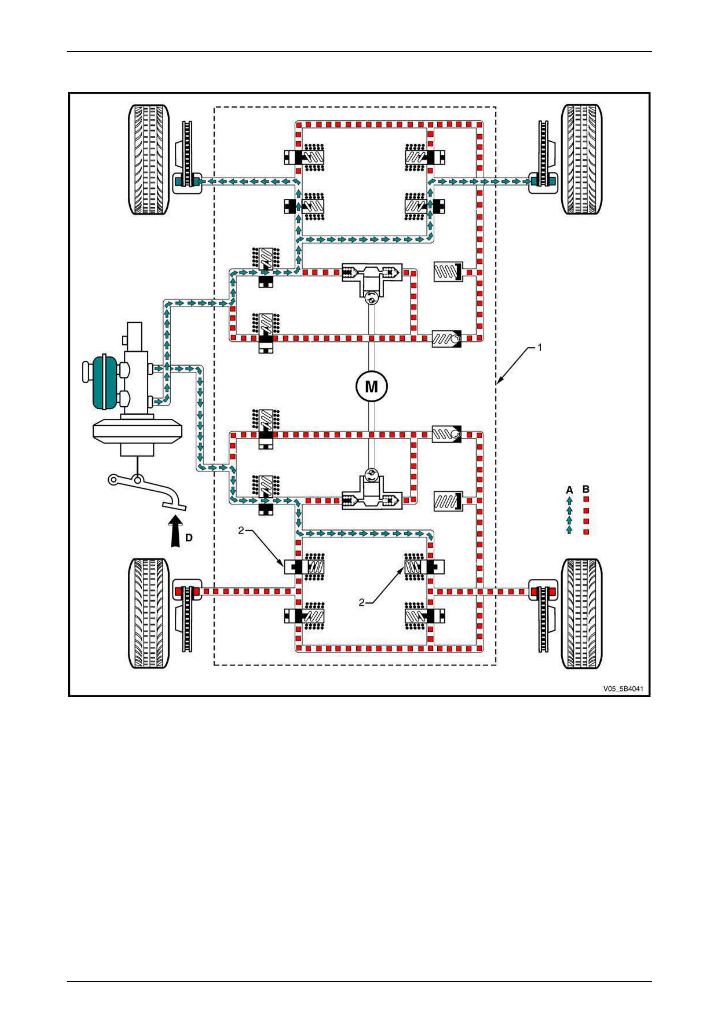
5B4 ABS-TCS / ESP Page 5B4–37
Page 5B4–37
EBD Phase Hydraulic Circuit – Maintaining Pressure
Figure 5B4 – 33
Legend
1 Hydraulic Modulator Assembly
2 Rear Inlet Valve
A Normal (conventional) brake fluid pressure
B Stopped brake fluid pressure flow (solenoid valve closed)
D Brake pedal applied
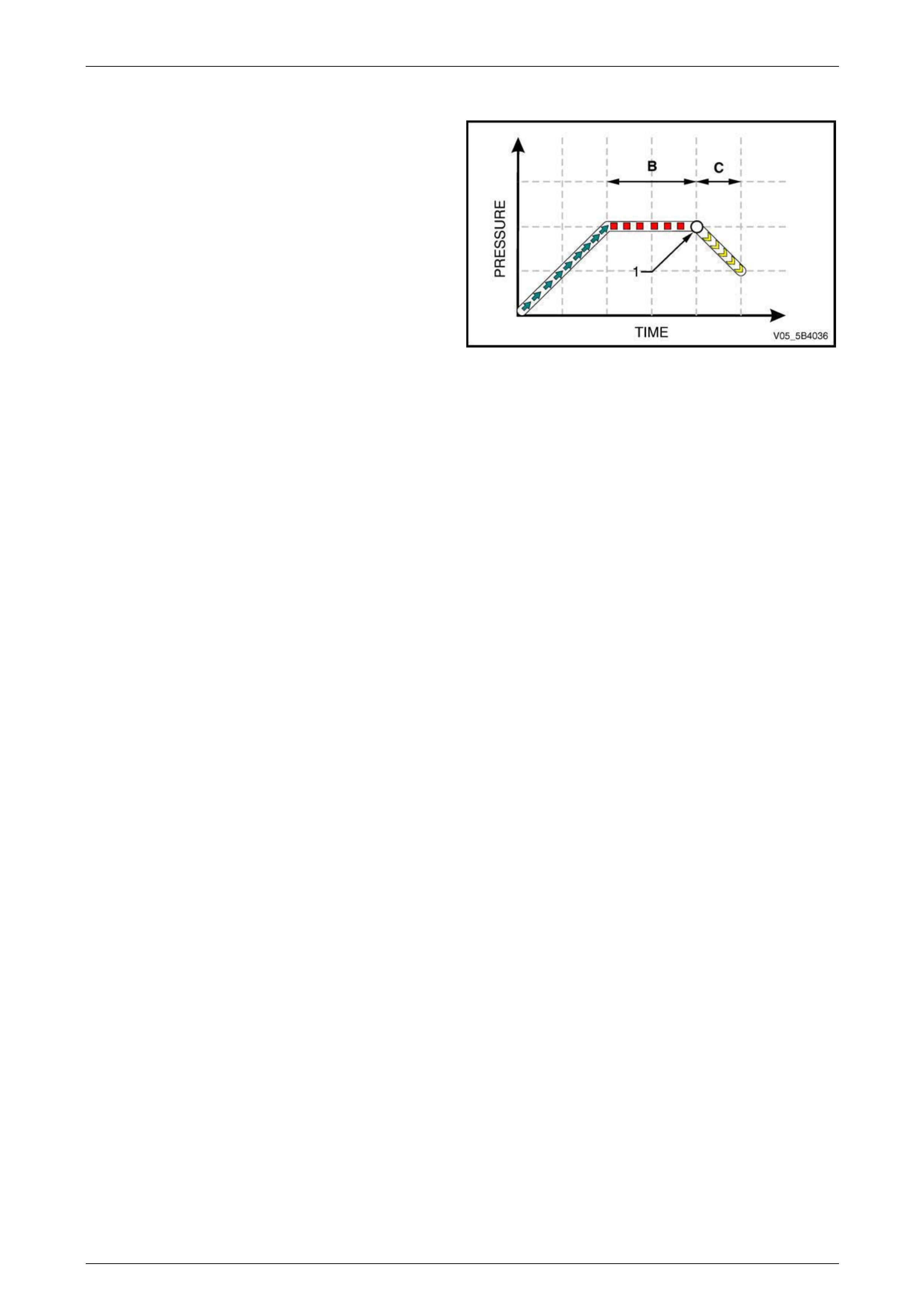
5B4 ABS-TCS / ESP Page 5B4–38
Page 5B4–38
EBD Phase – Reducing Pressure
Condition Description
If maintaining the brake fluid pressure in the EBD system
maintaining pressure phase (B) did not prevent the rear
wheels from decelerating faster than the front wheels, the
EBD system switches from maintaining pressure phase to
reducing pressure phase (C) at a predetermined point (1).
The hydraulic modulator modulates the rear wheel brake
fluid circuits to reduce its brake fluid pressure and prevent
wheel lock-up.
NOTE
The EBD system operation takes effect before the increased
slip rate required for an ABS brake intervention. Figure 5B4 – 34
Control Action
NOTE
The following EBD system situation assumes
the rear wheels are still decelerating faster than
the front wheels while the EBD system is
already in maintaining pressure phase. Refer
to Figure 5B4 – 35 for the illustration of the
EBD Phase Hydraulic Circuit – Reducing
Pressure.
If the ECU detects the rear wheels are still decelerating faster than the front wheels while the EBD system is already in
maintaining pressure phase, the ECU switches to the reducing pressure phase. The ECU sends a control signal to the
hydraulic modulator (1) to:
• Close the rear inlet valves (2).
• Open the rear outlet valves (3).
This results in the following actions during the reducing pressure phase:
1 The rear brake fluid is directed towards the accumulator (4) to allow brake fluid pressure reduction.
2 The accumulator stores the excess rear brake fluid. It is capable of storing all the excess brake fluid during an EBD
system operation. However, if the accumulator has been filled to its limit and the ECU still determines the rear
wheels are decelerating faster than the front wheels, the ECU operates the hydraulic modulator pump (5) and
returns the excess brake fluid to the brake master cylinder (6).
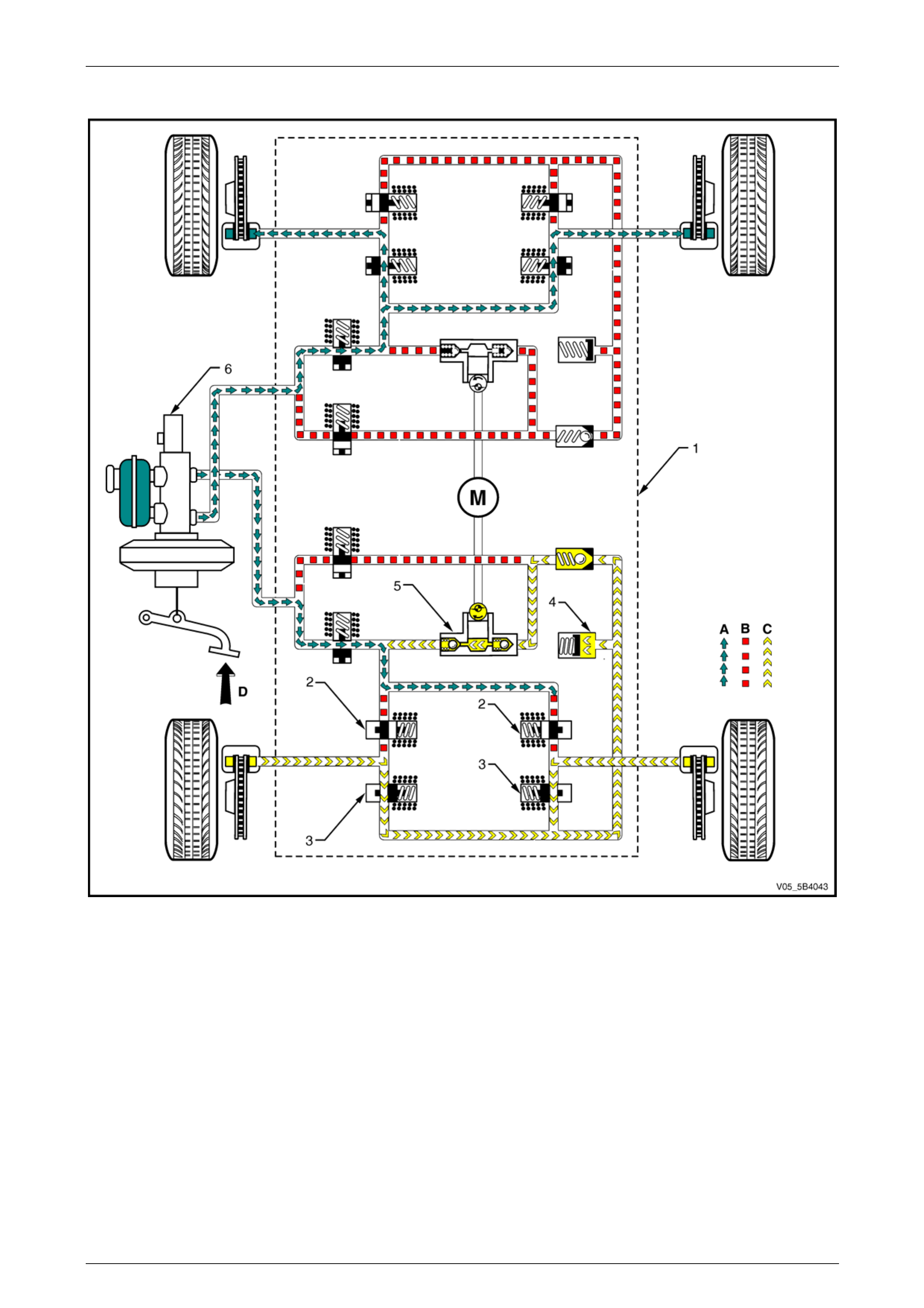
5B4 ABS-TCS / ESP Page 5B4–39
Page 5B4–39
EBD Phase Hydraulic Circuit – Reducing Pressure
Figure 5B4 – 35
Legend
1 Hydraulic Modulator Assembly
2 Rear Inlet Valve
3 Rear Outlet Valve
4 Accumulator
5 Hydraulic Modulator Pump
6 Brake Master Cylinder
A Normal (conventional) brake fluid pressure
B Stopped brake fluid pressure flow (solenoid valve closed)
C Hydraulic modulator pump generated brake fluid pressure
flow
D Brake pedal applied
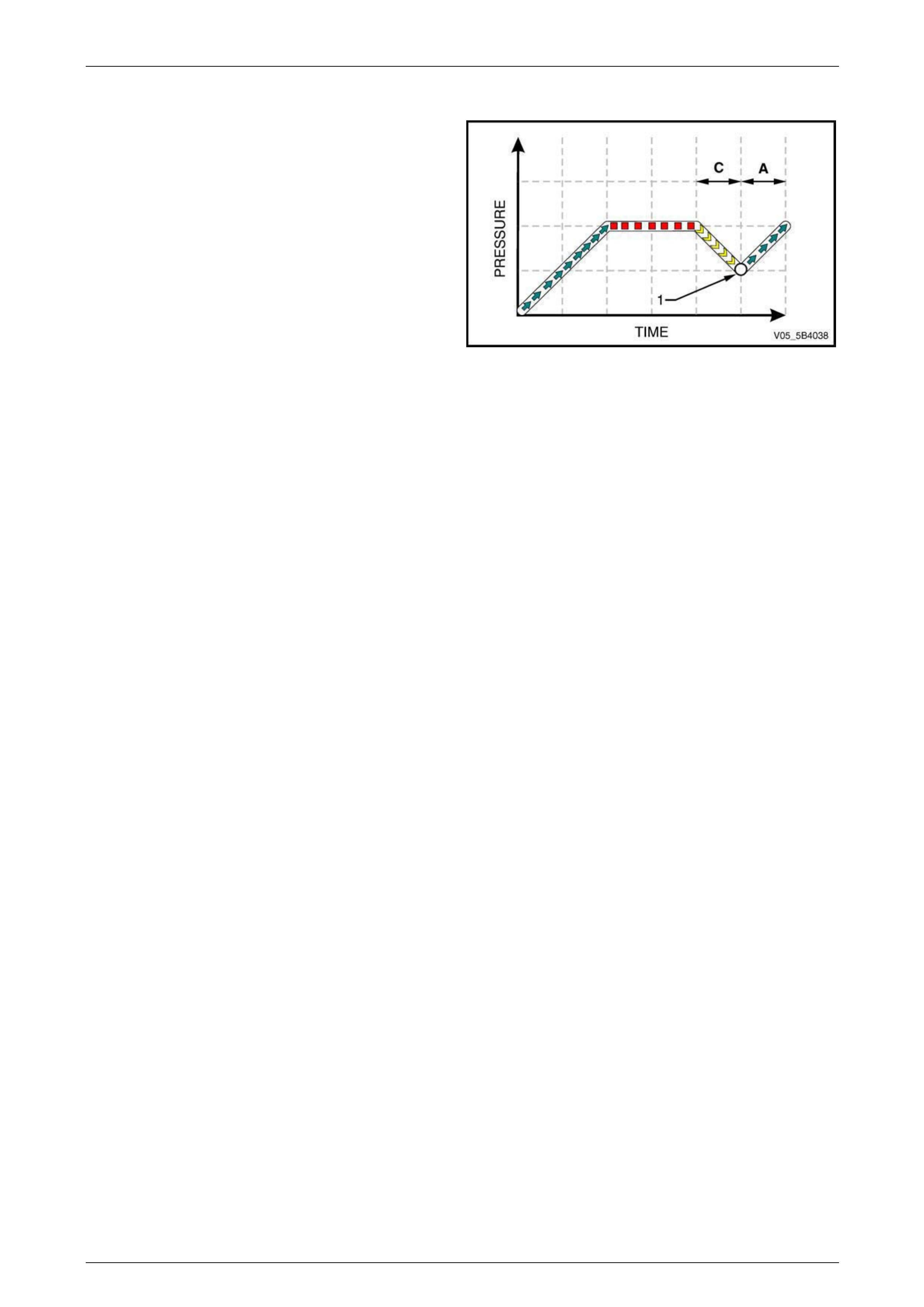
5B4 ABS-TCS / ESP Page 5B4–40
Page 5B4–40
EBD Phase – Increasing Pressure
Condition Description
If reducing the rear brake fluid pressure in the EBD reducing
pressure phase (C) causes the brake fluid pressure to drop
to a point (1) where the front and rear wheels are now
rotating at the same speed or almost at the same speed, the
EBD system switches from reducing pressure phase to
increasing pressure phase (A).
In this phase, the ECU sends a signal to the hydraulic
modulator to allow normal brake master cylinder pressure to
be applied to the rear wheels as in normal brake operation.
Figure 5B4 – 36
Control Action
NOTE
The following EBD system operation assumes the
front and rear wheels are now rotating at the
same speed or almost at the same speed, as a
result of the reduced braking force applied during
the EBD reducing pressure phase.
The ECU monitors and compares signals from each wheel speed sensor to determine wheel slip. If the ECU detects the
front and rear wheels are now rotating at the same speed or almost at the same speed as a result of the reduced braking
force applied during the EBD reducing pressure phase, the EBD system switches from reducing pressure phase to
increasing pressure phase.
The ECU sends a control signal to the hydraulic modulator to return the rear outlet valves and the rear inlet valves to their
normal rest position.
The master cylinder brake fluid pressure is directed to the rear brake callipers as in normal brake operation. The
previously reduced rear brake fluid pressure is now increased to normal brake master cylinder pressure and the front and
rear wheels brake fluid pressures are again equal. Refer to 3.1 Non-ABS Braking for information on normal brake
operation.
These EBD phases are repeated until the ECU detects the wheel speeds are balanced or the brake pedal pressure
removed. There are approximately four to six control cycles per second depending on the road surface condition.

5B4 ABS-TCS / ESP Page 5B4–41
Page 5B4–41
3.4 Traction Control System
The traction control system (TCS) utilises the active braking controls in the ABS and the engine torque reduction function
of the engine management system to prevent longitudinal wheel spin during vehicle acceleration.
Refer to Section 6C1-1 Engine Management – V6 – General Information for information on engine torque reduction.
TCS Mode – Engine Torque Reduction
NOTE
The following TCS situation assumes the rear
left wheel is beginning to slip. Refer to
Figure 5B4 – 37 for the illustration of the
TCS Mode Hydraulic Circuit – Brake Intervention.
The ECU monitors and compares signals from each wheel speed sensor to determine wheel slip. If the ECU detects a
longitudinal wheel spin due to a slippery road surface or excessive engine torque and the brakes are not applied, the
ECU switches to the TCS mode.
During TCS Mode, the ECU initially sends a serial data communication signal to the engine control module (ECM)
requesting engine torque reduction.
NOTE
Slight engine power loss may be experienced
when the TCS is active. This is caused by the
engine torque reduction functionality of the engine
management system.
If the rear left wheel spin is still detected while the ECM is already applying engine torque reduction, the ECU applies
brake intervention.
TCS Mode – Brake Intervention
The ECU monitors and compares signals from each wheel speed sensor to determine wheel slip. If the ECU detects the
rear left wheel still slips while the ECM is already applying engine torque reduction due to a slippery road surface or
excessive engine torque and the brakes are not applied, the ECU switches to the TCS brake intervention mode. During
this mode, the ECU sends a signal to the hydraulic modulator (1) to:
• close the isolating valve (2),
• open the prime valve (3),
• close the rear right inlet valve (4), and
• operate the hydraulic modulator pump (5).
This results in the following operations during the TCS Mode:
• The rear isolation valve is closed to isolate the rear brake fluid circuits from the master cylinder and prevent the
brake fluid returning to the brake master cylinder when the hydraulic pump builds-up the brake fluid pressure.
• The rear right inlet valve is closed to isolate the rear right wheel hydraulic circuit allowing the hydraulic modulator to
supply brake fluid pressure only to the rear left wheel.
• The rear priming valve is open to allow brake fluid to be drawn from the master cylinder into the hydraulic pump.
• The hydraulic pump applies brake fluid pressure (C) to the rear left brake calliper to stop it the rear left wheel from
spinning.
• The hydraulic modulator modulates the rear left inlet valve (4a) and rear left outlet valve (6) to assist in obtaining
maximum road surface traction in the same manner as ABS. The difference between ABS and TCS is that during
TCS mode, the brake fluid pressure is increased to reduce wheel spin. In contrast, during the ABS, the brake fluid
pressure is decreased to avoid wheel lock-up.
NOTE
If at any time during TCS mode the brakes are
manually applied, the brake switch sends a signal
to the ECU to exit the TCS brake intervention
mode and allow for manual braking.
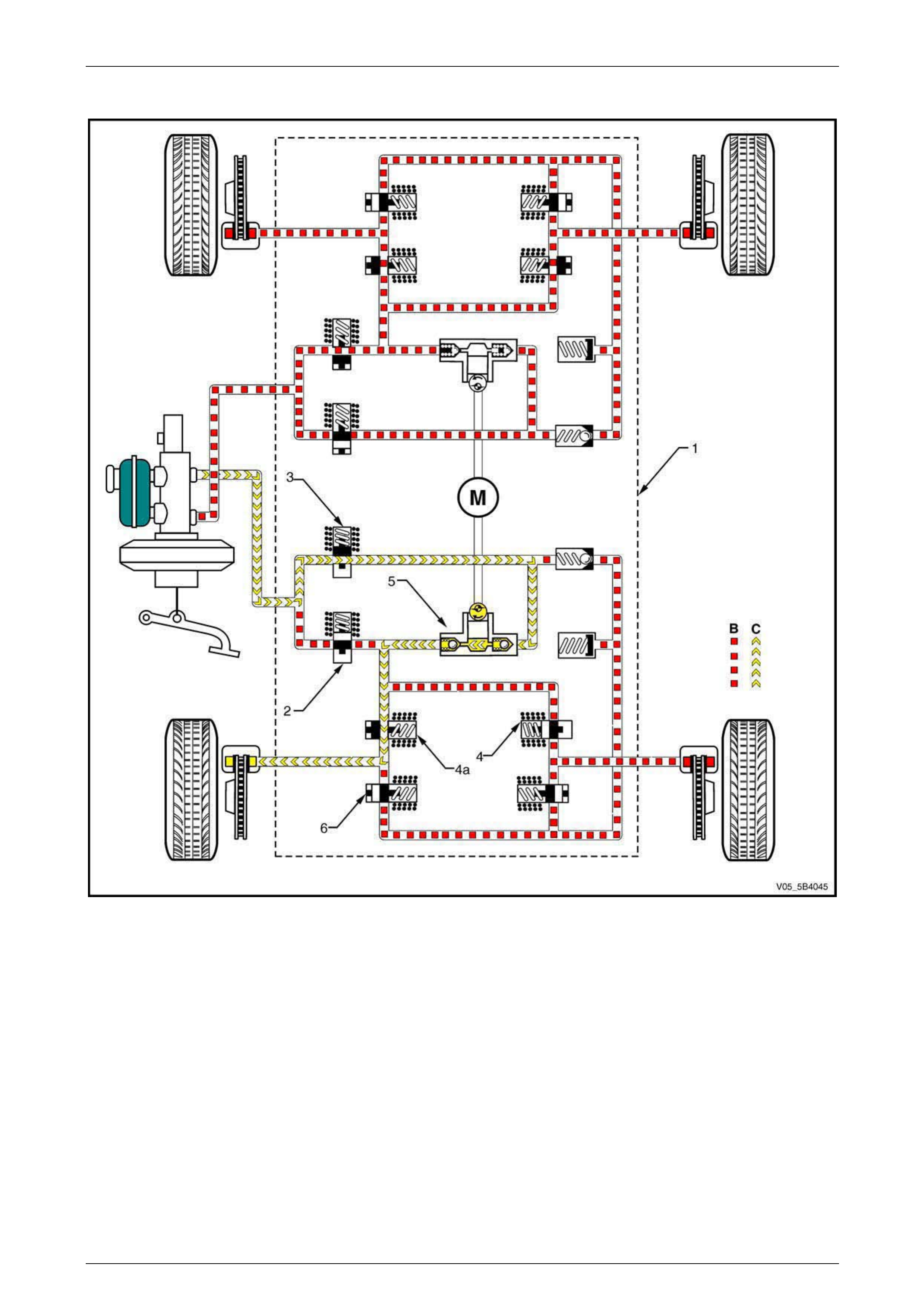
5B4 ABS-TCS / ESP Page 5B4–42
Page 5B4–42
TCS Mode Hydraulic Circuit – Brake Intervention
Figure 5B4 – 37
Legend
1 Hydraulic Modulator Assembly
2 Isolating Valve
3 Prime Valve
4 Rear Right Inlet Valve
4a Rear Left Inlet Valve
5 Hydraulic Pump
6 Rear Left Outlet Valve
B Stopped brake fluid pressure flow (solenoid valve closed)
C Hydraulic modulator pump generated brake fluid pressure
flow
M Pump motor
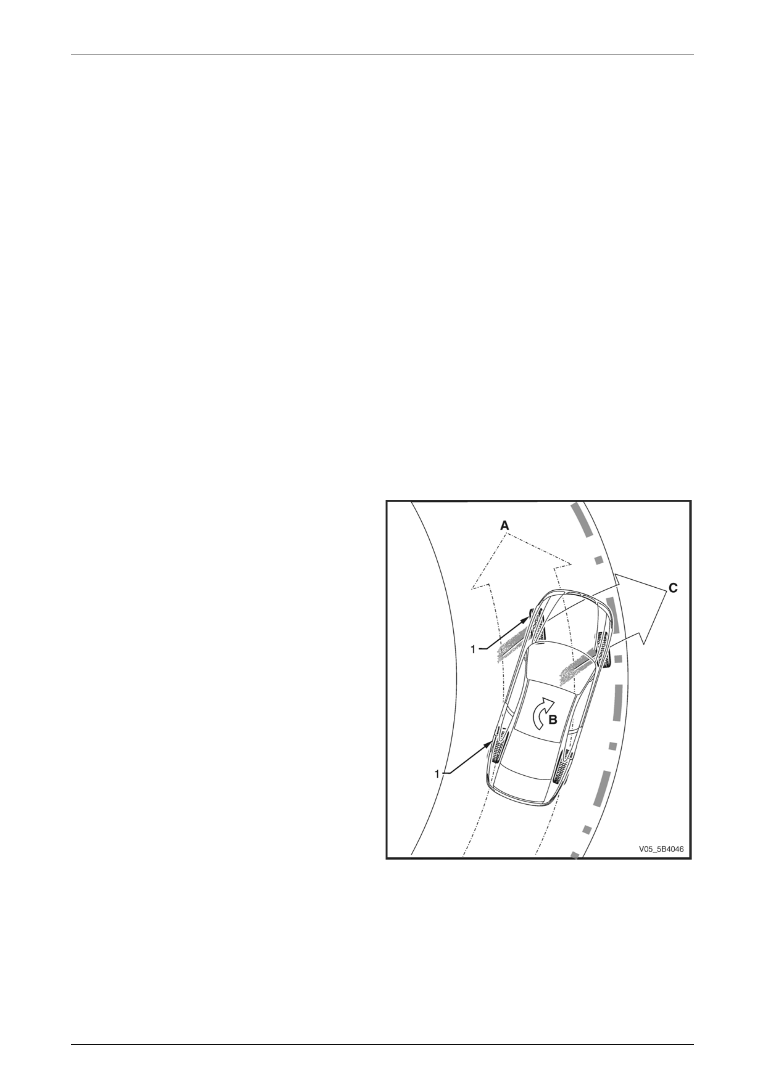
5B4 ABS-TCS / ESP Page 5B4–43
Page 5B4–43
3.5 Electronic Stability Program
The electronic stability program (ESP) is designed to provide optimum vehicle stability and steering control during high
speed cornering or when driving on a slippery road surface.
The ESP incorporates the following components:
• Steering angle sensor to determine driver steering input, which the ECU uses to support the calculation of intended
vehicle direction,
• yaw-rate sensor to measure vehicle rotation around its vertical axis, which the ECU uses to support the calculation
of actual vehicle behaviour, and
• active braking and engine torque reduction functionality of the TCS to prevent wheel spin.
When the ESP detects a lateral wheel slip or when the calculated vehicle direction deviates from the actual vehicle
direction, the ESP utilises the engine torque reduction functionality and the active braking controls in the ABS-TCS to
stabilise and steer the vehicle to the correct direction.
ESP Engine Torque Reduction
The ESP monitors the wheel speed sensor, yaw-rate sensor and the steering angle sensor to determine lateral wheel
slip. When the ESP detects a lateral wheel slip, the ESP initially utilises the torque reduction functionality of the TCS and
sends a serial data communication signal to the engine control module (ECM) requesting engine torque reduction. In
addition, if the ESP still detects a lateral wheel slip, the ESP applies active brake intervention.
ESP Brake Intervention
Understeer
The ESP applies active brake intervention when the ECU
receives the following input signals and determines the
vehicle is beginning to understeer.
• the steering angle sensor sends a signal to the ECU
the driver intends to steer in direction (A), and
• the yaw-rate sensor detects the vehicle begins to spin
(B) with the front of the vehicle beginning to slide in
direction (C).
The ESP uses the existing active braking control in the ABS-
TCS to apply a calculated braking force to one or both inner
wheels (1) of the vehicle to stabilise and steer the vehicle to
the intended direction.
Figure 5B4 – 38

5B4 ABS-TCS / ESP Page 5B4–44
Page 5B4–44
NOTE
Applying brake-force to the inner wheel (1) slows
down the inner side of the vehicle, which induces
the vehicle to rotate on its vertical axis (A).
Figure 5B4 – 39
Control Action
NOTE
The following ESP situation assumes the ECU
detects the beginning of an understeer. Refer to
Figure 5B4 – 40 for the illustration of the
ESP Hydraulic Circuit – Understeer Brake
Intervention.
The ECU monitors and compares signals from the yaw-rate sensor, steering angle sensor and each wheel speed sensor
to determine wheel slip. When the ECU detects the beginning of a vehicle understeer condition, the ECU sends the
following signal to the hydraulic modulator (1) to:
• Close the front and rear isolating valves (2).
• Open the front and rear prime valves (3).
• Close the front right and rear right inlet valves (4).
• Operate the hydraulic modulator pump (5).
This results in the following actions:
• The rear isolation valve is closed to isolate the rear brake fluid circuits from the master cylinder and prevent the
brake fluid returning to the brake master cylinder when the hydraulic pump builds-up the brake fluid pressure.
• The front right and rear right inlet valves are closed to isolate the right wheel hydraulic circuits, allowing the
hydraulic modulator to supply brake fluid pressure only to the left wheels.
• The rear priming valve is open to allow brake fluid to be drawn from the master cylinder into the hydraulic pump.
• The hydraulic pump applies appropriate brake fluid pressure (C) to the left brake callipers to steer the vehicle to the
intended direction.
• The hydraulic modulator modulates the front left and rear left inlet valves (4a) and outlet valves (6) to assist in
obtaining maximum road surface traction in the same manner as in the TCS Mode.
NOTE
If at any time during ESP Mode the brakes are
manually applied, the brake switch sends a signal
to the ECU to exit the ESP Brake Intervention
Mode and allow normal braking.
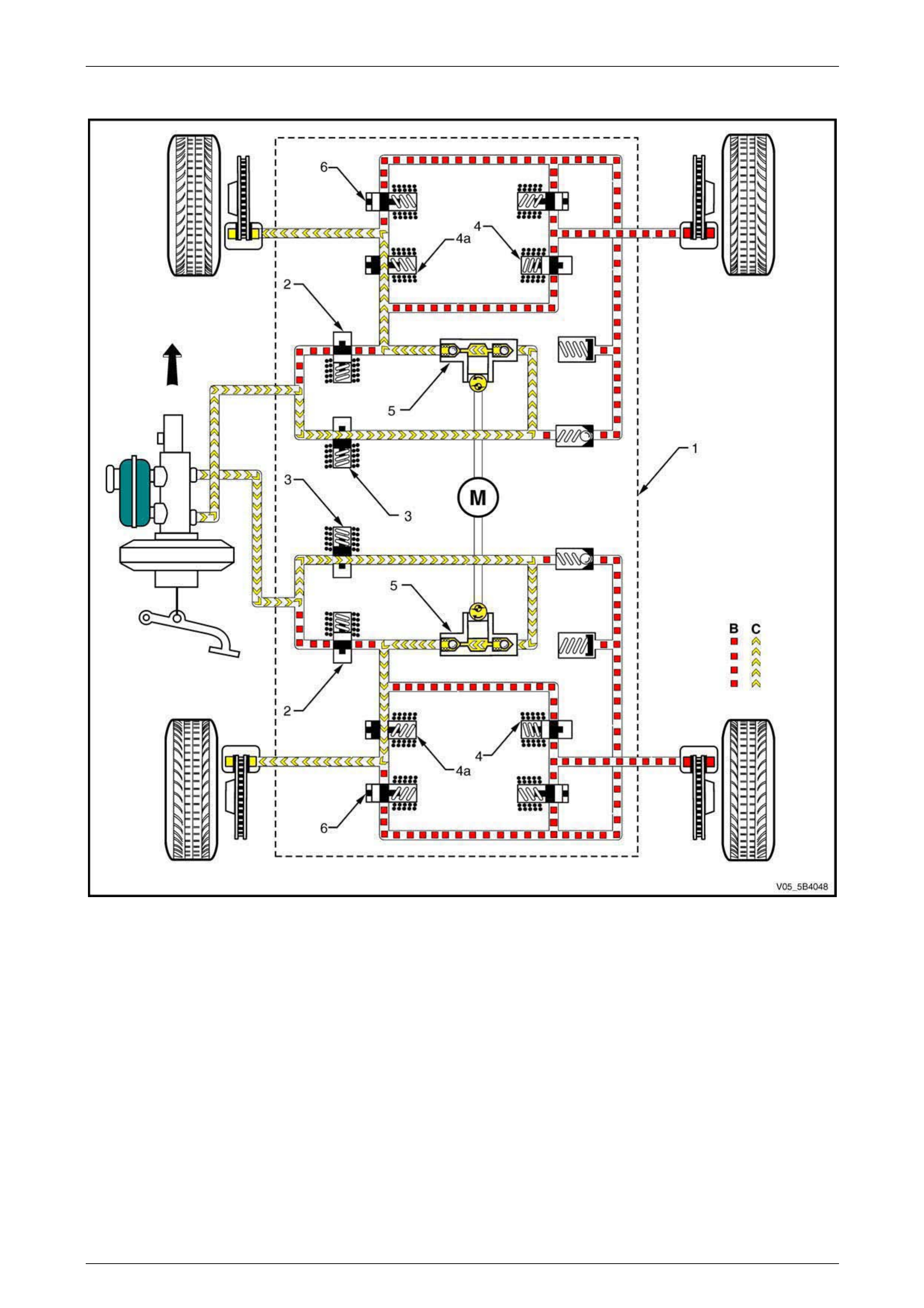
5B4 ABS-TCS / ESP Page 5B4–45
Page 5B4–45
ESP Hydraulic Circuit – Understeer Brake Intervention
Figure 5B4 – 40
Legend
1 Hydraulic Modulator Assembly
2 Isolating Valve
3 Prime Valve
4 Front Right and Rear Right Inlet Valve
4a Front Left and Rear Left Inlet Valve
5 Hydraulic Pump
6 Front Left and Rear Left Outlet Valve
B Stopped brake fluid pressure flow (Solenoid Valve Closed)
C Hydraulic modulator pump generated brake fluid pressure
flow
M Pump motor
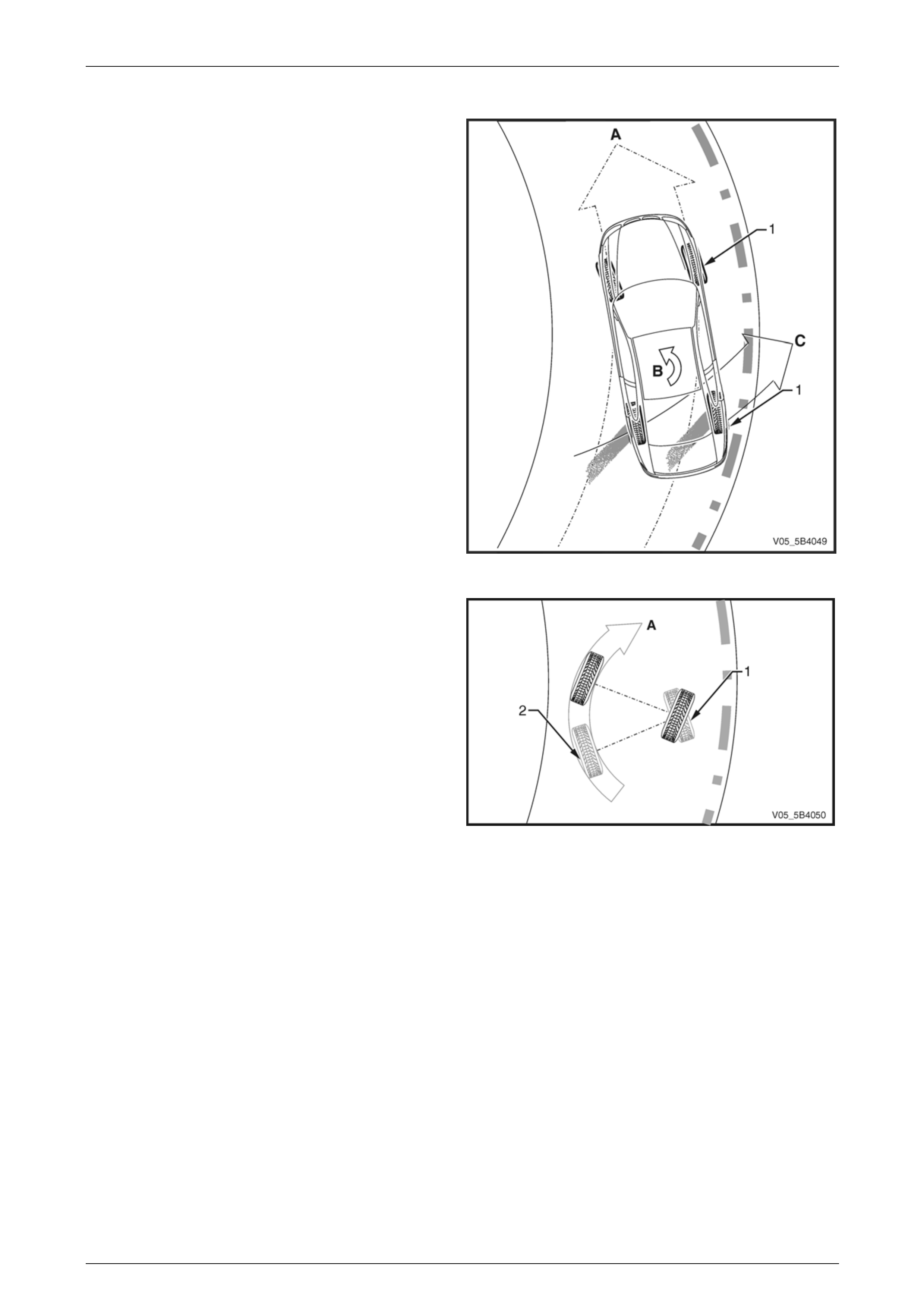
5B4 ABS-TCS / ESP Page 5B4–46
Page 5B4–46
Oversteer
The ESP applies active brake intervention when the ECU
receives the following input signals and determines the
vehicle is beginning to oversteer:
• the steering angle sensor sends a signal to the ECU
the driver intends to steer in direction (A), and
• the yaw-rate sensor detects the vehicle begins to spin
(B) with the rear of the vehicle beginning to slide in
direction (C),
The ESP uses the existing active braking control in the ABS-
TCS to apply a calculated braking force to one or both outer
wheels (1) of the vehicle to stabilise and steer the vehicle to
the intended direction.
Figure 5B4 – 41
NOTE
Applying brake-force to the outer wheel (1) slows
down the outer side of the vehicle, which induces
the inner wheel to rotate on its vertical axis (A).
Figure 5B4 – 42

5B4 ABS-TCS / ESP Page 5B4–47
Page 5B4–47
Control Action
NOTE
The following ESP situation assumes the ECU
detects the beginning of an oversteer. Refer to
Figure 5B4 – 43 for the illustration of the
ESP Hydraulic Circuit – Oversteer Brake
Intervention.
The ECU monitors and compares signals from the yaw-rate sensor, steering angle sensor and each wheel speed sensor
to determine wheel slip. When the ECU detects the beginning of a vehicle oversteer condition, the ECU sends the
following control signal to the hydraulic modulator (1) to:
• Close the front and rear isolating valves (2).
• Open the front and rear prime valves (3).
• Close the front left and rear left inlet valves (4)
• Operate the hydraulic modulator pump (5).
This results in the following actions:
• The rear isolation valve is closed to isolate the brake fluid circuits from the master cylinder and prevent the brake
fluid returning to the brake master cylinder when the hydraulic pump builds-up the brake fluid pressure.
• The front left and rear left inlet valves are closed to isolate the right wheel hydraulic circuits, allowing the hydraulic
modulator to supply brake fluid pressure only to the left wheels.
• The priming valves are open to allow brake fluid to be drawn from the master cylinder into the hydraulic pump.
• The hydraulic pump applies appropriate brake fluid pressure (C) to the left brake callipers to steer the vehicle to the
intended direction.
• The hydraulic modulator modulates the front right and rear right inlet valves (4a) and outlet valves (6) to assist in
obtaining maximum road surface traction in the same manner as in the TCS Mode.
NOTE
If at any time during ESP Mode the brakes are
manually applied, the brake switch sends a signal
to the ECU to exit the ESP Brake Intervention
Mode and allow for normal braking.
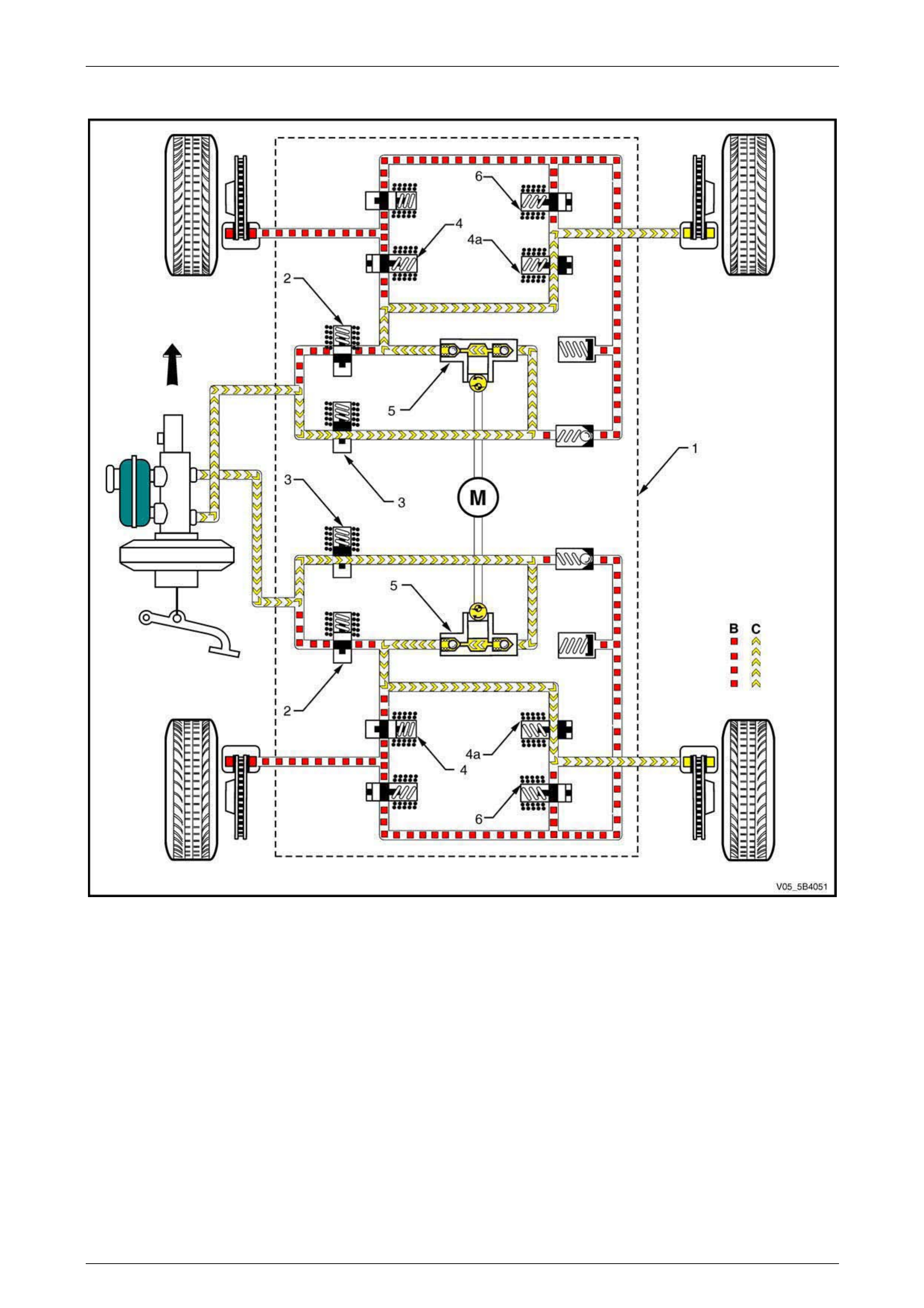
5B4 ABS-TCS / ESP Page 5B4–48
Page 5B4–48
ESP Hydraulic Circuit – Oversteer Brake Intervention
Figure 5B4 – 43
Legend
1 Hydraulic Modulator Assembly
2 Isolating Valve
3 Prime Valve
4 Front Left and Rear Left Inlet Valve
4a Front Right and Rear Right Inlet Valve
5 Hydraulic Pump
6 Front Right and Rear Right Outlet Valve
B Stopped brake fluid pressure flow (Solenoid Valve Closed)
C Hydraulic modulator pump generated brake fluid pressure
flow
M Pump motor
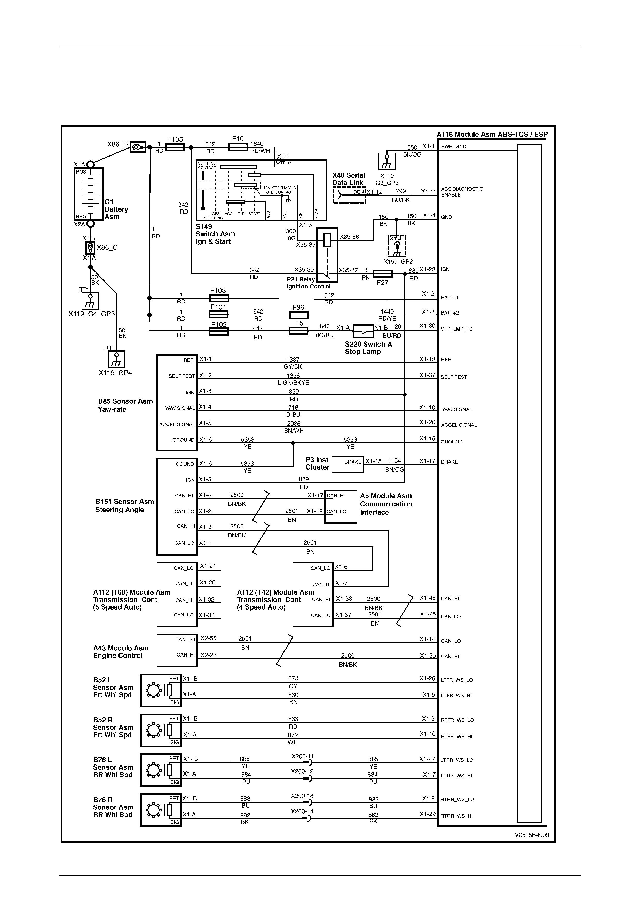
5B4 ABS-TCS / ESP Page 5B4–49
Page 5B4–49
4 Wiring Diagram and Connector
Chart
4.1 Wiring Diagram
Figure 5B4 – 44
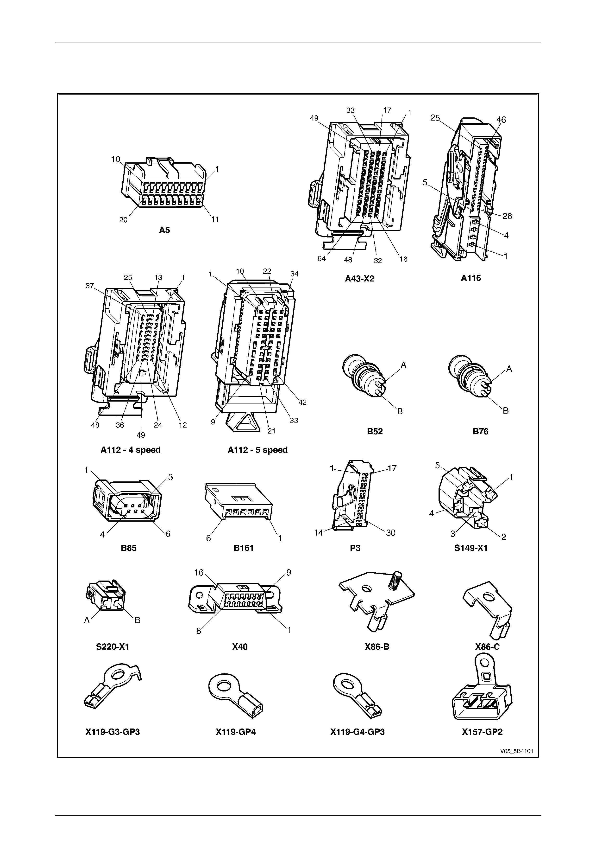
5B4 ABS-TCS / ESP Page 5B4–50
Page 5B4–50
4.2 Connector Chart
Figure 5B4 – 45
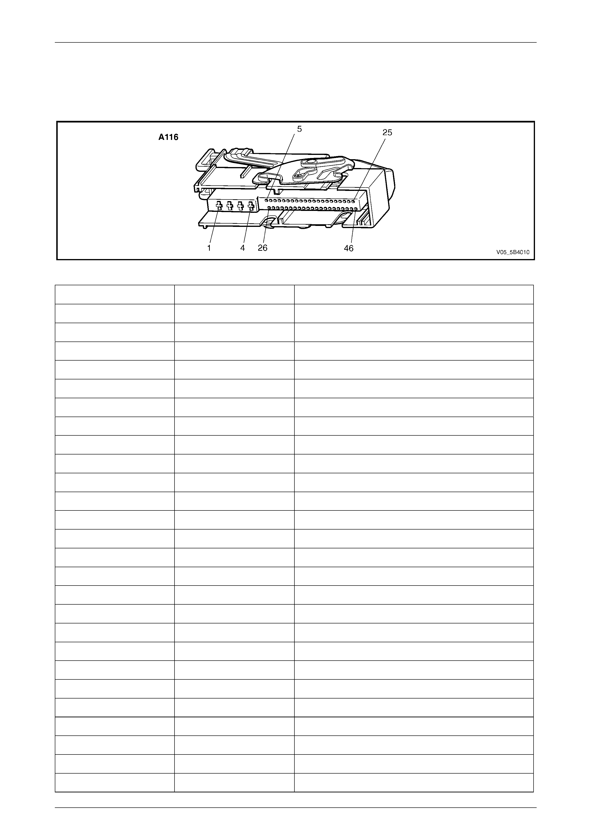
5B4 ABS-TCS / ESP Page 5B4–51
Page 5B4–51
4.3 Connector Information
Electronic Control Unit – A116
Figure 5B4 – 46
Pin Circuit No. Function
1 350 Main Ground
2 542 12 V Uninterrupted Supply Voltage – Fuse 103
3 1440 12 V Uninterrupted Supply Voltage – Fuse 36
4 150 ECU Ground
5 830 Front Left Wheel Speed Sensor Signal
6 — Not Connected
7 884 Rear Left Wheel Speed Sensor Signal
8 883 Rear Right Wheel Speed Sensor Low Ref
9 833 Front Right Wheel Speed Sensor Low Ref
10 872 Front Right Wheel Speed Sensor Signal
11 799 ABS Diagnostic Enable
12 — Not Connected
13 — Not Connected
14 2500 CAN LO
15 5353 Yaw-rate Sensor Ground
16 716 Yaw-rate Sensor Signal
17 1134 Instrument Cluster Brake Circuit
18 1337 Yaw-rate Sensor 5 V Reference
19 — Not Connected
20 2086 Acceleration Sensor Signal
21 — Not Connected
22 — Not Connected
23 — Not Connected
24 — Not Connected
25 2501 CAN LO 2
26 873 Front Left Wheel Speed Sensor – Low Ref
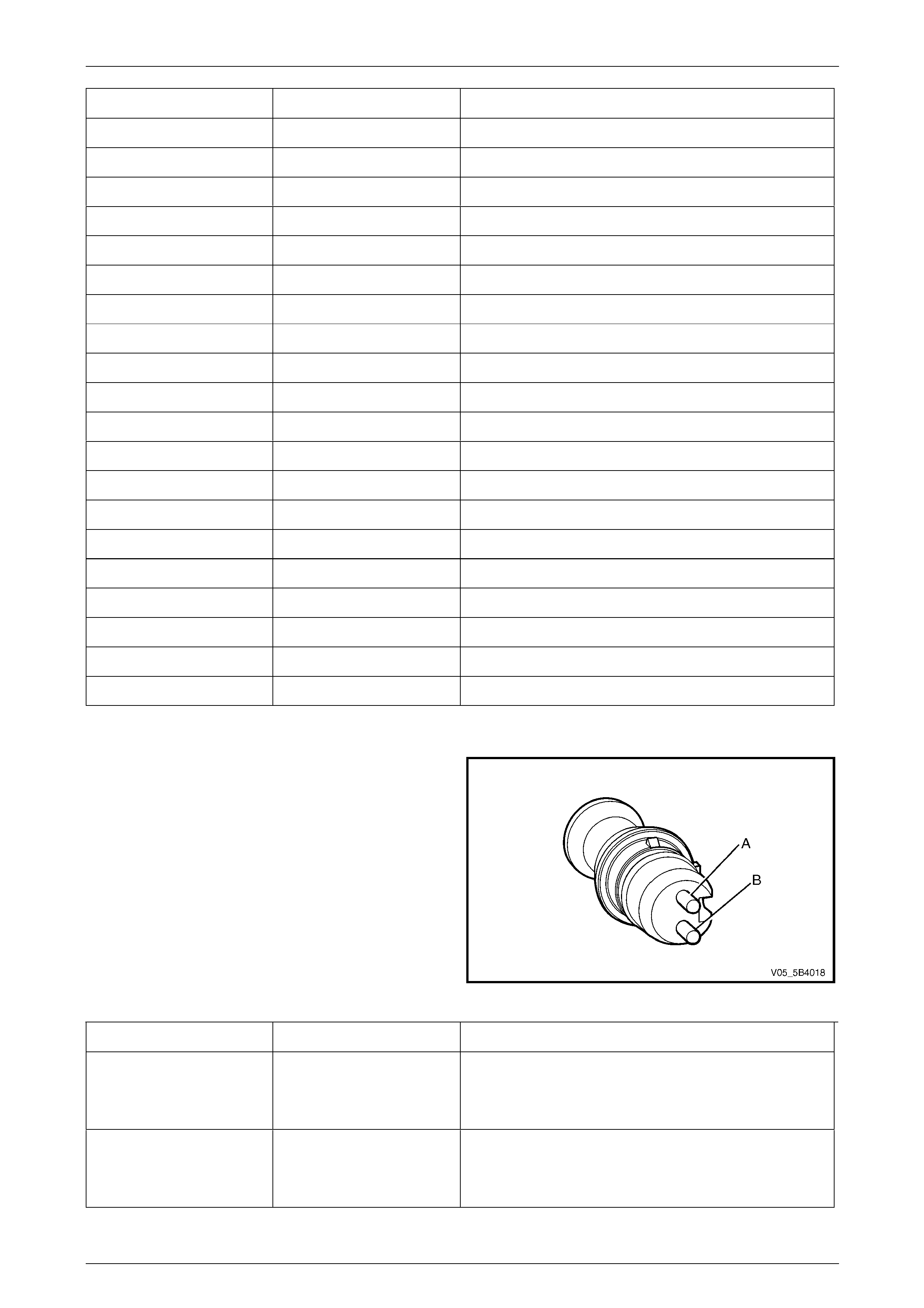
5B4 ABS-TCS / ESP Page 5B4–52
Page 5B4–52
Pin Circuit No. Function
27 885 Rear Left Wheel Speed Sensor – Low Ref
28 839 12 V Ignition Supply Voltage Fuse 27
29 882 Rear Right Wheel Speed Sensor Signal
30 20 Stop Light Switch 12 V Signal
31 — Not Connected
32 — Not Connected
33 — Not Connected
34 — Not Connected
35 2501 CAN HI
36 — Not Connected
37 1338 Yaw-rate Sensor – Self Test
38 — Not Connected
39 — Not Connected
40 — Not Connected
41 — Not Connected
42 — Not Connected
43 — Not Connected
44 — Not Connected
45 2500 CAN HI 2
46 — Not Connected
Front and Rear Wheel Speed Sensor – B52L, B52R, B76L and B76R
Figure 5B4 – 47
Pin Circuit No. Function
A B52L – 830
B52R – 872
B76L – 884
B76R – 882
Wheel Speed Sensor Signal
B B52L – 873
B52R – 833
B76L – 885
B76R – 883
Wheel Speed Sensor Low Reference
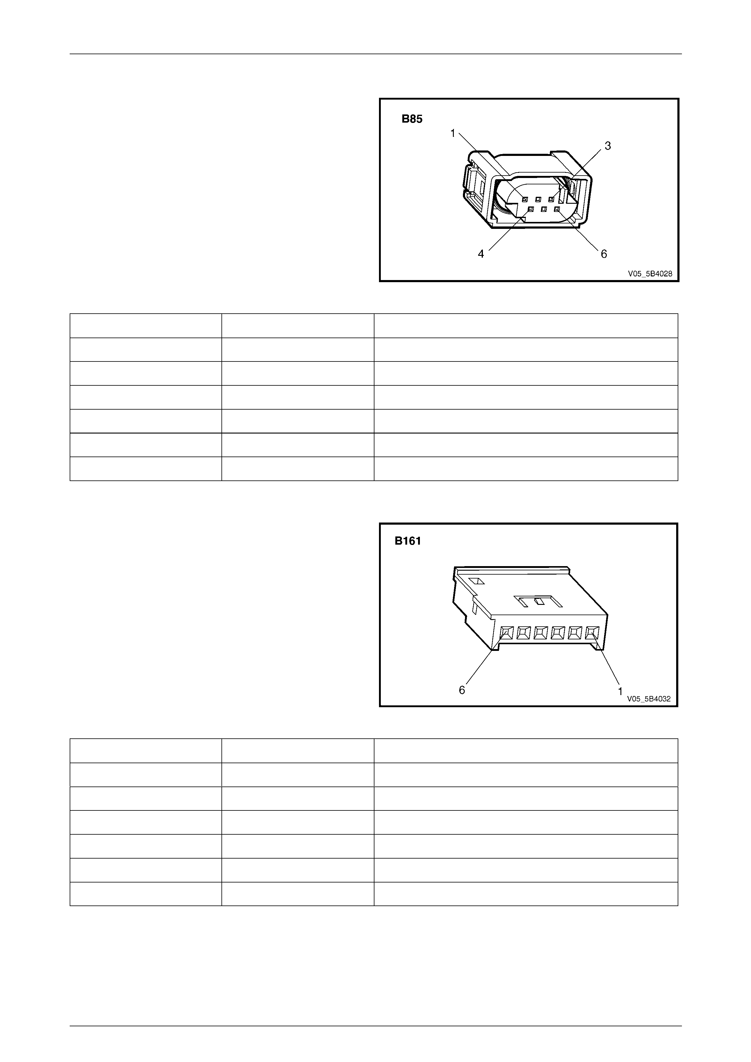
5B4 ABS-TCS / ESP Page 5B4–53
Page 5B4–53
Yaw-rate Sensor – B85
Figure 5B4 – 48
Pin Circuit No. Function
1 1337 Yaw-rate Sensor 5 V Reference
2 1338 Yaw-rate Sensor Self-test
3 839 Yaw-rate Sensor 12 V Ignition
4 716 Yaw-rate Sensor Signal (yaw-rate)
5 2086 Yaw-rate Sensor Signal (acceleration)
6 5353 Yaw-rate Sensor Low Reference
Steering Angle Sensor – B161
Figure 5B4 – 49
Pin Circuit No. Function
1 2501 Steering Angle Sensor CAN LO 1
2 2501 Steering Angle Sensor CAN LO 2
3 2500 Steering Angle Sensor CAN HI 1
4 2500 Steering Angle Sensor CAN HI 2
5 839 Steering Angle Sensor 12 V Ignition Supply
6 5353 Steering Angle Sensor Low Reference

5B4 ABS-TCS / ESP Page 5B4–54
Page 5B4–54
5 Diagnostics
5.1 Diagnostic General Descriptions
The ABS-TCS / ESP diagnostic procedure is organised in a logical structure that begins with the Diagnostic System
Check. The Diagnostic System Check directs the diagnostic procedure to the logical steps or appropriate diagnostic table
required to diagnose an ABS-TCS / ESP fault.
The diagnostic tables locate a faulty circuit or component through a logic based on the process of elimination.
Understanding and the correct use of the diagnostic tables is essential to reduce diagnostic time and to prevent
misdiagnosis.
However, the diagnostic information covered in this Section covers faults only in the ABS-TCS / ESP. If there are faults
with the conventional braking system such as the following, these faults must be corrected before attempting to rectify
any suspected ABS-TCS / ESP fault:
• brake noise.
• spongy brake pedal feel.
• brake pedal or vehicle vibration during normal brake application.
• brake pulling to one side.
• parking brake problem.
Refer to Section 5A Service and Park Braking System for the diagnosis and repair procedure of the conventional braking
system.
Diagnostic Trouble Code Tables
The diagnostic procedure is directed to the diagnostic trouble code (DTC) tables if there are DTCs currently stored in the
electronic control unit (ECU).
The diagnostic tables are designed to locate a faulty circuit or component through a logic based on the process of
elimination. These diagnostic tables are developed with the following assumptions:
• the vehicle functioned correctly at the time of assembly,
• there are no multiple faults, and
• the problem currently exists.
If there are multiple DTCs stored in the ECU, the diagnostic process must begin with the most likely DTC that may trigger
other DTCs. The following situation is an example of a DTC that may trigger other DTCs to set.
• If there is a battery supply voltage fault in the ECU, DTC C0800 Battery Voltage Out of Range may set.
• Insufficient battery supply voltage to an ABS-TCS / ESP component such as the hydraulic modulator pump
motor may cause incorrect hydraulic modulator operation. This condition will cause incorrect ABS-TCS / ESP
operation and may trigger DTC C0110 to also set.
• A battery supply voltage to the ECU that is too high may cause damage to other ABS-TCS / ESP
components. If this charging system fault is not rectified and an ABS-TCS / ESP component is replaced,
premature failure of the replacement component may occur.
Therefore, knowledge of the ABS-TCS / ESP and Tech 2 limitations are important to reduce diagnostic time and to
prevent misdiagnosis. Refer to 6.1 Basic Requirements.

5B4 ABS-TCS / ESP Page 5B4–55
Page 5B4–55
Diagnostic Trouble Codes
The ECU performs a self-test that detects and isolates ABS-TCS / ESP faults. When a fault is detected, the ECU will log
a diagnostic trouble code (DTC) that represents the fault detected. The DTCs stored in the ECU may be accessed using
Tech 2. Refer to Section 0C Tech 2 for information on Tech 2.
Status of DTCs
The ECU designates the DTCs logged into a Current or History DTC.
Current DTCs
If the fault that triggers the DTC is present during the last ECU self-diagnostics, that DTC will be designated as a current
DTC.
History DTCs
If the fault that triggers the DTC is not present during the last ECU self-test, that DTC will be designated as a History
DTC.
Action Taken When a DTC Sets
• The ECU disables the ABS-TCS / ESP for the duration of the ignition cycle.
• One or all of the following warning indicators may activate:
• ABS-TCS warning indicator,
• ABS-TCS warning display,
• ESP warning display,
• HDC warning display,
• brake failure indicator, and/or
• Trac-off warning display.
Conditions for Clearing DTCs
• The current DTC moves into a history DTC when there is no DTC logged during the current ECU self-test.
• Use Tech 2 to clear the DTC.

5B4 ABS-TCS / ESP Page 5B4–56
Page 5B4–56
6 ABS-TCS Diagnostic Starting
Point
6.1 Basic Requirements
Basic Knowledge Required
A lack of basic understanding regarding
electronics, electrical wiring circuits and use
of electrical circuit testing tools when
performing the ABS-TCS / ESP diagnostic
procedures could result in incorrect
diagnostic results or damage to components.
A general understanding of basic electronics, electrical wiring circuits and the correct use of the basic ABS-TCS / ESP
electrical circuit testing tools is required to perform the diagnostic procedures detailed in this Section.
Refer to Section 12P Wiring Diagrams for information on electrical circuits.
In addition, a general understanding of the ABS-TCS / ESP and its component operation is essential to prevent
misdiagnosis and component damage.
Basic Diagnostic Tools Required
Use of incorrect electrical circuit diagnostic
tools when performing the ABS-TCS / ESP
diagnostic procedures could result in
incorrect diagnostic results or damage to
components.
The following electrical circuit testing tools are required to perform the diagnostic procedures detailed in this Section.
• Tech 2, refer to Section 0C Tech 2,
• test lamp, refer to Section 12P Wiring Diagrams,
• digital multimeter with 10 MΩ impedance, refer to Section 12P Wiring Diagrams.
• connector test adapter kit Tool No. J35616-A.

5B4 ABS-TCS / ESP Page 5B4–57
Page 5B4–57
6.2 Diagnostic Precautions
In addition to the safety and precautionary
measures listed in 9.1 Safety and
Precautionary Measures, the following
Diagnostic Precautions must be observed
when performing any ABS-TCS / ESP
diagnostic procedure.
• If there is a fault in the conventional braking system, rectify that fault before proceeding with the ABS-TCS / ESP
diagnostics.
• Use only the test equipment specified in the diagnostic tables: other test equipment may either give incorrect results
or may damage good components.
• The vehicle drive wheels must be chocked and the parking brake firmly applied while checking any system.
• Do not clear any DTCs unless instructed.
• The fault must be present when using the DTC Diagnostic Tables. Otherwise, misdiagnosis or replacement of good
parts may occur.
• Always use connector adaptors such as those contained in connector test adapter kit Tool No. J35616-A to prevent
connector terminal damage.
• Thorough inspection of the wiring circuits and connectors that are part of diagnostic procedure must be performed,
otherwise misdiagnosis may occur.
• Inspect the electrical circuitry or connector terminals that are suspected to be causing the complaint for the
following:
• backed-out connector terminals,
• improper wiring connector mating,
• broken wiring connector locks,
• damaged connector terminals, and
• physical damage to the wiring harness.
• Before replacing a component, inspect its connector terminal for corrosion or deformation that may cause the fault.
• If Tech 2 was used for diagnosis, disconnect it from the DLC and switch the ignition off for at least 10 seconds
before road testing. This is necessary to reset the ECU as it is disabled during most Tech 2 diagnostic procedures.
• After completing the required diagnostic and repair operations, road test the vehicle to ensure correct ABS-
TCS / ESP operation.

5B4 ABS-TCS / ESP Page 5B4–58
Page 5B4–58
6.3 Preliminary Checks
The Preliminary Checks are an examination of easily accessible components that could cause problems with the ABS-
TCS / ESP. This visual and physical inspection procedure may quickly identify the fault and eliminate the need for
additional diagnosis.
• Is the fault specifically isolated to this system? If unsure, refer to Section 0D Vehicle Diagnostics.
• Refer to Service Techlines for relevant information regarding the fault.
• Ensure that only the recommended tyres and wheel size are fitted to the vehicle.
• Check the hydraulic modulator for external leaks.
• Check the ABS-TCS / ESP fuses.
• Check the ABS-TCS / ESP warning indicator fuse and stop lamp indicator fuse.
Refer to Section 12O Fuses, Relays and Wiring Harnesses.
• Ensure the battery is fully charged.
• Check the battery connections for corrosion or a loose terminal.
• Perform a visual and physical inspection of the following:
• ABS-TCS / ESP component wiring harness and terminals for proper connections, pinches or cuts.
• Wiring harness routing which may be positioned very close to a high voltage or high current device such as
the following:
• secondary ignition components,
• motors and generators, and
• aftermarket stereo amplifiers
NOTE
High voltage or high current devices may induce
electrical noise on a circuit, which can interfere
with normal circuit operation.
• ABS-TCS / ESP related components for poor mating of the connector halves or a terminal not fully seated in
the connector body.
• ABS-TCS / ESP components are sensitive to Electro-magnetic Interference (EMI). Check for incorrect
aftermarket theft deterrent devices, lights or mobile phone installations if an intermittent malfunction is
suspected.

5B4 ABS-TCS / ESP Page 5B4–59
Page 5B4–59
6.4 Diagnostic System Check
Description
The diagnostic procedure is organised in a logical structure that begins with the Diagnostic System Check which directs
the technician to the logical steps necessary to diagnose an ABS-TCS / ESP fault.
Test Description
The following numbers refer to the step numbers in the diagnostic table:
4 Tests the operation of Tech 2.
6 Tests the integrity of the GM LAN serial data communication circuit. A PIM DTC sets if the PIM detects a fault in the
communication circuit. A fault on the serial data communication circuit may trigger multiple DTCs on other sensors
and components.
Step Action Yes No
1 Have you read the Basic Requirements? Go to Step 2 Refer to 6.1 Basic
Requirements
2 Have you read the Diagnostic Precautions?
Go to Step 3
Refer to 6.2
Diagnostic
Precautions
3 Have you performed the Preliminary Checks? Go to Step 4 Refer to 6.3
Preliminary Checks
4 1 Switch off the ignition.
2 Connect Tech 2 to the Diagnostic Link Connector (DLC).
3 Switch on the ignition with the engine not running.
4 Press the Tech 2 power button on.
Does the Tech 2 screen illuminate and display Tech 2? Go to Step 5 Refer to Section 0C
Tech 2
5 Using Tech 2, attempt to communicate with the PIM.
Does the PIM fail to communicate?
Refer to Section
6E1 Powertrain
Interface Module –
V6 Go to Step 6
6 Using Tech 2, view and record DTCs set at the PIM.
Does DTC U1064, U2100, U2105, U2106, U2108, B1009, B1013,
B1014, B1000, B1019, B3057, B3924, P0633, P1611 or P1678 set in
the PIM?
Refer to Section
6E1 Powertrain
Interface Module –
V6 Go to Step 7
7 Using Tech 2, view and record any ABS-TCS / ESP DTCs.
Does Tech 2 display any DTC? Go to Step 8
Refer to 7.1
Intermittent Fault
Diagnostic Table
8 Does Tech 2 display multiple DTCs?
Go to Step 9
Go to the DTC
Table of the DTC
displayed. Refer to
8.1 DTC List
9 Refer to the DTC Table of the fault that is most likely to trigger multiple
DTCs. Refer to 5.1 Diagnostic General Descriptions for information
on multiple DTCs fault. — —
When all diagnosis and repairs are completed, check the system for correct operation.

5B4 ABS-TCS / ESP Page 5B4–60
Page 5B4–60
7 Intermittent Faults
7.1 Intermittent Fault Diagnostic Table
Description
A fault is intermittent if one of the following exists:
• the fault is not always present,
• the fault cannot be presently duplicated, and
• there is no Current DTC but a History DTC is stored.
Checks Actions
Preliminary • Perform the Preliminary Checks. Refer to 6.3 Preliminary Checks.
• Gather information from the customer regarding the conditions that trigger the
intermittent fault such as:
• At what vehicle speed range does the fault occur?
• Does the fault occur when operating aftermarket electrical equipment inside
the vehicle?
• Does the fault occur on rough roads or in wet road conditions?
• If a wheel speed sensor fault is present only during wet road conditions,
inspect the wheel speed sensor electrical circuit for signs of water intrusion.
If the DTC is not current, simulate the effect of a wet road condition by
performing the following:
1 Mix two teaspoons of salt with 35 ml water.
2 Spray the saltwater solution to the suspected area.
3 Road test the vehicle at various road conditions.
4 Accelerate the vehicle at speed greater than 40 km/h for at least 30
seconds.
5 If the suspected wheel speed sensor sets a current DTC, refer to the
appropriate DTC diagnostic table.
Tech 2 Tests The following are lists of Tech 2 diagnostic tests that may be used to diagnose
intermittent faults:
• Wriggle test the suspected ABS-TCS / ESP component wiring harness and
connectors while observing the Tech 2 operating parameters of the circuit being
tested. If the Tech 2 read-out fluctuates during this procedure, check the wiring
harness circuit for loose connection.
• Road test the vehicle in the conditions that triggers the intermittent fault while an
assistant observes the suspected Tech 2 operating parameter data.
• Capture and store data in the Snapshot mode when the fault occurs. The stored
data may be played back at a slower rate to aid in diagnostics. Refer to the Tech 2
User Instructions for more information on the Snapshot function.
• Operate suspected ABS-TCS / ESP components to test their operation using Tech
2 Output Control Data.

5B4 ABS-TCS / ESP Page 5B4–61
Page 5B4–61
Checks Actions
Warning Indicator The following conditions may cause an intermittent Warning Indicator fault with no DTC
listed.
• Electromagnetic interference (EMI) caused by a faulty relay.
• Incorrect installation of aftermarket electrical equipment such as the following:
• Mobile phones
• Theft deterrent alarms
• Lights
• Radio equipment
• Stereo amplifier
• Warning indicator circuit is intermittently shorted to ground.
• Electronic control unit (ECU) ground connections are loose.
Wheel Speed Sensors • Visually inspect wheel speed sensors and pulse rings for looseness, damage,
foreign material accumulation and proper mounting. Replace damaged
components, remove any foreign material and/or properly attach loose
components.
• With the aid of an assistant, monitor the Tech 2 wheel speed sensor data display
while test driving the vehicle. Check for any wheel speed sensor that displays
erratic speed range.
Additional Tests • Incorrect installation of aftermarket electrical equipment such as the following:
• Mobile phones
• Theft deterrent alarms
• Lights
• Radio equipment
• Stereo amplifier
• Electromagnetic interference (EMI) caused by a faulty relay. The fault is triggered
when the relay or solenoid is activated.
• Test the A/C compressor clutch and some relays that contain a clamping diode or
resistor.
• Test the generator for a faulty rectifier bridge that may allow the A/C noise into the
ECU electrical circuit
When all diagnosis and repairs are completed, check the system for correct operation.

5B4 ABS-TCS / ESP Page 5B4–62
Page 5B4–62
8 Diagnostic Trouble Codes
8.1 DTC List
DTC Description Diagnostic Table
C0035 Left Front Wheel Speed Sensor Signal or Low Reference
Circuit Fault 8.2 DTC C0035, C0040, C0045 or C0050 –
Wheel Speed Sensor Circuit
C0040 Right Front Wheel Speed Sensor Signal or Low Reference
Circuit Fault 8.2 DTC C0035, C0040, C0045 or C0050 –
Wheel Speed Sensor Circuit
C0045 Left Rear Wheel Speed Sensor Signal or Low Reference
Circuit Fault 8.2 DTC C0035, C0040, C0045 or C0050 –
Wheel Speed Sensor Circuit
C0050 Right Rear Wheel Speed Sensor Signal or Low Reference
Circuit Fault 8.2 DTC C0035, C0040, C0045 or C0050 –
Wheel Speed Sensor Circuit
C0060
Left Front Hydraulic Modulator Outlet Solenoid Valve Circuit
Fault 8.3 DTC C0060, C0065, C0070, C0075, C0080,
C0085, C0090, C0095, C0141, C0146,
C0151 or C0156 – Hydraulic Modulator
Solenoid Valve Circuit
C0065
Left Front Hydraulic Modulator Inlet Solenoid Valve Circuit
Fault 8.3 DTC C0060, C0065, C0070, C0075, C0080,
C0085, C0090, C0095, C0141, C0146,
C0151 or C0156 – Hydraulic Modulator
Solenoid Valve Circuit
C0070
Right Front Hydraulic Modulator Outlet Solenoid Valve
Circuit Fault 8.3 DTC C0060, C0065, C0070, C0075, C0080,
C0085, C0090, C0095, C0141, C0146,
C0151 or C0156 – Hydraulic Modulator
Solenoid Valve Circuit
C0075
Right Front Hydraulic Modulator Inlet Solenoid Valve Circuit
Fault 8.3 DTC C0060, C0065, C0070, C0075, C0080,
C0085, C0090, C0095, C0141, C0146,
C0151 or C0156 – Hydraulic Modulator
Solenoid Valve Circuit
C0080
Left Rear Hydraulic Modulator Outlet Solenoid Valve Circuit
Fault 8.3 DTC C0060, C0065, C0070, C0075, C0080,
C0085, C0090, C0095, C0141, C0146,
C0151 or C0156 – Hydraulic Modulator
Solenoid Valve Circuit
C0085
Left Rear Hydraulic Modulator Inlet Solenoid Valve Circuit
Fault 8.3 DTC C0060, C0065, C0070, C0075, C0080,
C0085, C0090, C0095, C0141, C0146,
C0151 or C0156 – Hydraulic Modulator
Solenoid Valve Circuit
C0090
Right Rear Hydraulic Modulator Outlet Solenoid Valve
Circuit Fault 8.3 DTC C0060, C0065, C0070, C0075, C0080,
C0085, C0090, C0095, C0141, C0146,
C0151 or C0156 – Hydraulic Modulator
Solenoid Valve Circuit
C0095
Right Rear Hydraulic Modulator Inlet Solenoid Valve Circuit
Fault 8.3 DTC C0060, C0065, C0070, C0075, C0080,
C0085, C0090, C0095, C0141, C0146,
C0151 or C0156 – Hydraulic Modulator
Solenoid Valve Circuit
C0110 Hydraulic Modulator Pump Motor Circuit Fault 8.4 DTC C0110 – Hydraulic Modulator Pump
Motor Circuit Fault
C0121 Electronic Control Unit Internal Valve Relay Fault 8.5 DTC C0121 – Electronic Control Unit
Internal Valve Relay
C0131 Hydraulic Modulator Pressure Sensor Fault 8.6 DTC C0131 – Hydraulic Modulator Pressure
Sensor Fault

5B4 ABS-TCS / ESP Page 5B4–63
Page 5B4–63
DTC Description Diagnostic Table
C0141
Hydraulic Modulator Front Isolating Solenoid Valve 1 Circuit
Fault 8.3 DTC C0060, C0065, C0070, C0075, C0080,
C0085, C0090, C0095, C0141, C0146,
C0151 or C0156 – Hydraulic Modulator
Solenoid Valve Circuit
C0146
Hydraulic Modulator Front Priming Solenoid Valve 1 Circuit
Fault 8.3 DTC C0060, C0065, C0070, C0075, C0080,
C0085, C0090, C0095, C0141, C0146,
C0151 or C0156 – Hydraulic Modulator
Solenoid Valve Circuit
C0151
Hydraulic Modulator Rear Isolating Solenoid Valve 2 Circuit
Fault 8.3 DTC C0060, C0065, C0070, C0075, C0080,
C0085, C0090, C0095, C0141, C0146,
C0151 or C0156 – Hydraulic Modulator
Solenoid Valve Circuit
C0156
Hydraulic Modulator Rear Priming Solenoid Valve 2 Circuit
Fault 8.3 DTC C0060, C0065, C0070, C0075, C0080,
C0085, C0090, C0095, C0141, C0146,
C0151 or C0156 – Hydraulic Modulator
Solenoid Valve Circuit
C0161 Brake Switch Circuit Malfunction 8.7 DTC C0161 – Brake Switch Circuit
C0186 Lateral Acceleration Sensor 8.8 DTC C0186 – Lateral Acceleration Sensor
Fault
C0196 Yaw-rate Sensor Output Signal Fault 8.9 DTC C0196 – Yaw-rate Sensor Output
Signal Fault
C0245 Wheel Speed Signal Output Fault 8.10 DTC C0245, C0252 or C0253 – Wheel
Speed Sensor Signal Output
C0252 Wheel Speed Signal Outside Operating Parameters 8.10 DTC C0245, C0252 or C0253 – Wheel
Speed Sensor Signal Output
C0253 Long Term Compensation Disabled 8.10 DTC C0245, C0252 or C0253 – Wheel
Speed Sensor Signal Output
C0460 Steering Angle Sensor Fault 8.11 DTC C0460 – Steering Angle Sensor
Circuit Fault
C0550 Electronic Control Unit Internal Fault 8.12 DTC C0550 and C0551 – Electronic
Control Unit Internal Fault
C0551 ECU Not Programmed 8.12 DTC C0550 and C0551 – Electronic
Control Unit Internal Fault
C0569 Electronic Control Unit Configuration Mismatch 8.13 DTC C0569 – Electronic Control Unit
Configuration Mismatch
C0800 Battery Voltage Out of Range 8.14 DTC C0800 – Battery Voltage Out of
Range
C0895 Steering Angle Sensor Supply Voltage Out of Range 8.15 DTC C0895 – Steering Angle Sensor
Supply Voltage Out of Range

5B4 ABS-TCS / ESP Page 5B4–64
Page 5B4–64
8.2 DTC C0035, C0040, C0045 or C0050 –
Wheel Speed Sensor Circuit Fault
DTC Description
This diagnostic procedure supports the following DTCs:
• DTC C0035 – Left Front Wheel Speed Sensor Signal or Low Reference Circuit Fault.
• DTC C0040 – Right Front Wheel Speed Sensor Signal or Low Reference Circuit Fault.
• DTC C0045 – Left Rear Wheel Speed Sensor Signal or Low Reference Circuit Fault.
• DTC C0050 – Right Rear Wheel Speed Sensor Signal or Low Reference Circuit Fault.
Circuit Description
The electronic control unit (ECU) supplies ground to the wheel speed sensor low reference circuit. The wheel speed
sensor in conjunction with a pulse ring generates an AC signal voltage. The amplitude and frequency of the signal
generated is proportional to the wheel speed.
The ECU monitors each wheel speed sensor signal circuit to determine the rotational speed of each wheel and calculate
wheel slip.
Refer to 4 Wiring Diagram and Connector Chart to aid in diagnosis.
Additional Information
• For intermittent faults, refer to 7.1 Intermittent Fault Diagnostic Table.
• High voltage or high current devices such as spark plugs and spark plug wires may induce electrical noise on the
front left wheel speed sensor circuit. This electrical noise can interfere with normal wheel speed sensor operation.
Ensure the wheel speed sensor wiring harness is routed away from these high voltage or high current devices.
• Refer to 2.4 Wheel Speed Sensors for the following information:
• wheel speed sensor description and operation, and
• wheel speed sensor test procedure using an oscilloscope.
Conditions for Running the DTC
The ignition is switched on.
Conditions for Setting the DTC
If the ECU detects a short to voltage, open circuit or erratic signal fault in the wheel speed sensor signal circuit and/or
wheel speed sensor low reference circuit.
Action Taken When the DTC Sets
Refer to 5.1 Diagnostic General Descriptions for information on action taken by the ECU when a DTC sets.
Conditions for Clearing the DTC
Refer to 5.1 Diagnostic General Descriptions for information on the conditions for clearing DTCs.
Test Description
The following numbers refer to the step numbers in the diagnostic table:
2 Verifies the fault that triggers the DTC currently exists.
3 Tests the front left wheel speed sensor internal circuitry.
4 Tests for a fault in the wheel speed sensor pulse ring.
5 Tests the front left wheel speed sensor output voltage capacity.

5B4 ABS-TCS / ESP Page 5B4–65
Page 5B4–65
DTC C0035, C0040, C0045 or C0050 Diagnostic Table
Step Action Yes No
1 Has the Diagnostic System Check been performed?
Go to Step 2
Refer to
6.4 Diagnostic
System Check
2 1 Switch off the ignition for 10 seconds.
2 Road test the vehicle at speed greater than 40 km/h.
3 Using Tech 2, view DTCs.
Does DTC C0035, C0040, C0045 or C0050 fail this ignition cycle? Go to Step 3
Refer to Additional
Information in this
Section
3 1 Disconnect the appropriate wheel speed sensor connector.
2 Using a digital multimeter, measure the resistance across the
pins of the wheel speed sensor connector.
Does the multimeter display 1.3 – 1.8 kΩ @ 20°C? Go to Step 4 Go to Step 7
4 1 Raise the appropriate side of the vehicle and support on safety
stands. Refer to Section 0A General Information for location of
the jacking points.
2 Connect an oscilloscope to the wheel speed sensor connector
terminals.
3 Observe the wheel speed sensor output signal pattern while
spinning the appropriate wheel. Refer to 2.4 Wheel Speed
Sensors for information on testing a wheel speed sensor using
an oscilloscope.
NOTE
If an oscilloscope is not available, perform the following
visual inspection:
• Inspect the wheel speed sensor pulse ring for damaged
teeth.
• While rotating the wheel, check the wheel speed
sensor alignment to the pulse ring.
• Check the wheel speed sensor run-out.
• Check the wheel speed sensor or pulse ring for dirt or
other contaminants that may affect its operation.
Was any fault found and rectified? Go to Step 11 Go to Step 5
5 Using a digital multimeter, measure the AC signal voltage across the
pins of the front speed sensor connector while spinning the front left
wheel.
Does the multimeter display greater than 100 mV? Go to Step 6 Go to Step 7

5B4 ABS-TCS / ESP Page 5B4–66
Page 5B4–66
Step Action Yes No
6 Test the wheel speed sensor signal circuit and low reference circuit for
a high resistance, open circuit, short to voltage, short to ground or
shorted together fault. Refer to Section 12P Wiring Diagrams for
information on electrical fault diagnosis.
Go to Step 11 Go to Step 8
7 Inspect for shorted terminals or poor connections at the appropriate
wheel speed sensor wiring connector. Refer to Section 12P Wiring
Diagrams for information on electrical fault diagnosis.
Was any fault found and rectified? Go to Step 11 Go to Step 9
8 Inspect for shorted terminals or poor connections at the ECU wiring
connector. Refer to Section 12P Wiring Diagrams for information on
electrical fault diagnosis.
Was any fault found and rectified? Go to Step 11 Go to Step 10
9 Replace the faulty wheel speed sensor. Refer to 9 Service
Operations.
Was the repair completed? Go to Step 11 —
10 Replace the ECU. Refer to 9.3 Electronic Control Unit / Hydraulic
Modulator Assembly.
Was the repair completed? Go to Step 11 —
11 1 Using Tech 2, clear the DTCs.
2 Switch off the ignition for 10 seconds.
3 Operate the vehicle within the conditions for running DTCs
C0035, C0040, C0045 and C0050.
Does any wheel speed sensor circuit DTC fail this ignition cycle? Go to Step 2 Go to Step 12
12 Using Tech 2, select the DTC display function.
Does Tech 2 display any DTCs?
Go to the
appropriate DTC
Table System OK
When all diagnosis and repairs are completed, check the system for correct operation.

5B4 ABS-TCS / ESP Page 5B4–67
Page 5B4–67
8.3 DTC C0060, C0065, C0070, C0075, C0080,
C0085, C0090, C0095, C0141, C0146,
C0151 or C0156 – Hydraulic Modulator
Solenoid Valve Circuit Fault
DTC Description
This diagnostic procedure supports the following DTCs:
• DTC C0060 – Left Front Hydraulic Modulator Outlet Solenoid Valve Circuit Fault.
• DTC C0065 – Left Front Hydraulic Modulator Inlet Solenoid Valve Circuit Fault.
• DTC C0070 – Right Front Hydraulic Modulator Outlet Solenoid Valve Circuit Fault.
• DTC C0075 – Right Front Hydraulic Modulator Inlet Solenoid Valve Circuit Fault.
• DTC C0080 – Left Rear Hydraulic Modulator Outlet Solenoid Valve Circuit Fault.
• DTC C0085 – Left Rear Hydraulic Modulator Inlet Solenoid Valve Circuit Fault.
• DTC C0090 – Right Rear Hydraulic Modulator Outlet Solenoid Valve Circuit Fault.
• DTC C0095 – Right Rear Hydraulic Modulator Inlet Solenoid Valve Circuit Fault.
• DTC C0141 – Hydraulic Modulator Front Isolating Solenoid Valve 1 Circuit Fault.
• DTC C0146 – Hydraulic Modulator Front Priming Solenoid Valve 1 Circuit Fault.
• DTC C0151 – Hydraulic Modulator Rear Isolating Solenoid Valve 2 Circuit Fault.
• DTC C0156 – Hydraulic Modulator Rear Priming Solenoid Valve 2 Circuit Fault.
Circuit Description
The electronic control unit (ECU) energises the solenoid valve relay when the ignition is switched on. When energised,
the solenoid valve relay applies battery voltage to the hydraulic modulator solenoid valve coils. The solenoid valve relay
remains energised until the ignition is switched off or the ABS-TCS / ESP is disabled.
The ECU controls the operation of each solenoid valve by applying ground to the solenoid valve coil control circuit to
modulate the brake fluid pressure of each brake circuit.
The ECU monitors the solenoid valve relay and the solenoid valves circuit for correct operation.
Refer to 4 Wiring Diagram and Connector Chart to aid in diagnosis.
Additional Information
• For intermittent faults, refer to 7.1 Intermittent Fault Diagnostic Table.
• Refer to 2.3 Hydraulic Modulator Assembly for the hydraulic modulator description and operation.
Conditions for Running the DTC
Runs in conjunction with the ECU Self-test initialisation sequence.
Conditions for Setting the DTC
If the ECU detects a short to voltage, open circuit or invalid signal fault in any of the following hydraulic modulator
components:
• Inlet and outlet solenoid valves,
• Isolating solenoid valve, or
• Priming solenoid valve.

5B4 ABS-TCS / ESP Page 5B4–68
Page 5B4–68
Action Taken When the DTC Sets
Refer to 5.1 Diagnostic General Descriptions for information on action taken by the ECU when a DTC sets.
Conditions for Clearing the DTC
Refer to 5.1 Diagnostic General Descriptions for information on the conditions for clearing DTCs.
Test Description
The following numbers refer to the step numbers in the diagnostic table:
2 Verifies the fault that triggers the DTC currently exists.
3 Verify the integrity of the ECU internal circuitry. Internal fault within the ECU may trigger this fault code.
DTC C0060, C0065, C0070, C0075, C0080, C0085, C0090, C0095, C0141, C0146, C0151 or
C0156 Diagnostic Table
Step Action Yes No
1 Has the Diagnostic System Check been performed?
Go to Step 2
Refer to
6.4 Diagnostic
System Check
2 1 Switch off the ignition for 10 seconds.
2 Operate the vehicle within the conditions for running these DTCs
or road test the vehicle at speed greater than 15 km/h.
3 Using Tech 2, view DTCs.
Does DTC C0060, C0065, C0070, C0075, C0080, C0085, C0090,
C0095, C0141, C0146, C0151 or C0156 fail this ignition cycle? Go to Step 3
Refer to Additional
Information in this
Section
3 Is DTC C0550 or C0551 also set? Refer to 8.12 DTC
C0550 and C0551 –
Electronic Control
Unit Internal Fault Go to Step 4
4 1 Test all ground circuits of the ECU for a high resistance or an
open circuit fault. Refer to Section 12P Wiring Diagrams for
information on electrical fault diagnosis.
2 Test the ABS-TCS / ESP fuses and replace as required. Refer to
Section 12O Fuses, Relays and Wiring Harnesses.
3 Test the ECU battery supply voltage circuit for a high resistance,
open circuit or short to ground fault. Refer to Section 12P Wiring
Diagrams for information on electrical fault diagnosis.
Was any fault found and rectified? Go to Step 7 Go to Step 5
5 Inspect for poor connections at the ECU wiring connector. Refer to
Section 12P Wiring Diagrams for information on electrical fault
diagnosis.
Was any fault found and rectified? Go to Step 7 Go to Step 6
6 Replace the hydraulic modulator. Refer to 9.3 Electronic Control Unit /
Hydraulic Modulator Assembly.
Was the repair completed? Go to Step 7 —
7 1 Using Tech 2, clear the DTCs.
2 Switch off the ignition for 10 seconds.
3 Operate the vehicle within the conditions for running DTCs.
Does any hydraulic modulator solenoid valve circuit DTC fail this
ignition cycle? Go to Step 2 Go to Step 8
8 Using Tech 2, select the DTC display function.
Does Tech 2 display any DTCs?
Go to the
appropriate DTC
Table System OK
When all diagnosis and repairs are completed, check the system for correct operation.

5B4 ABS-TCS / ESP Page 5B4–69
Page 5B4–69
8.4 DTC C0110 – Hydraulic Modulator Pump
Motor Circuit Fault
DTC Description
This diagnostic procedure supports DTC C0110 – Hydraulic Modulator Pump Motor Circuit Fault.
Circuit Description
The electronic control unit (ECU) operates the hydraulic modulator pump motor by grounding the pump motor relay
control circuit to achieve the following:
• ABS Reducing Pressure Phase – the hydraulic modulator pump builds-up the brake fluid pressure to allow the
released brake fluid pressure from the slipping wheel to be returned to the brake master cylinder reservoir against
brake pedal pressure.
• TCS Brake Intervention Mode – the hydraulic modulator pump builds-up the brake fluid pressure, which is directed
to the spinning wheel to prevent wheel-spin.
The ECU monitors the pump motor relay and the pump motor circuit for correct operation.
Refer to 4 Wiring Diagram and Connector Chart to aid in diagnosis.
Additional Information
• For intermittent faults, refer to 7.1 Intermittent Fault Diagnostic Table.
• Refer to 2.3 Hydraulic Modulator Assembly for the hydraulic modulator description and operation.
Conditions for Running the DTC
Runs in conjunction with the ECU Self-test Initialisation Sequence.
Conditions for Setting the DTC
• If the pump motor relay is activated and there is no pump motor system voltage present after 60 milliseconds.
• If the pump motor system voltage is present for greater than 2.5 seconds and the pump motor relay did not
activate.
• If there is no pump motor run down voltage after the pump motor relay is deactivated.
Action Taken When the DTC Sets
Refer to 5.1 Diagnostic General Descriptions for information on action taken by the ECU when a DTC sets.
Conditions for Clearing the DTC
Refer to 5.1 Diagnostic General Descriptions for information on the conditions for clearing DTCs.
Test Description
The following numbers refer to the step numbers in the diagnostic table:
2 Verifies the fault that triggers the DTC currently exists.
3 Verify the integrity of the ECU internal circuitry. Internal fault within the ECU may trigger this fault code.

5B4 ABS-TCS / ESP Page 5B4–70
Page 5B4–70
DTC C0110 Diagnostic Table
Step Action Yes No
1 Has the Diagnostic System Check been performed?
Go to Step 2
Refer to
6.4 Diagnostic
System Check
2 1 Switch off the ignition for 10 seconds.
2 Operate the vehicle within the conditions for running these DTCs
or road test the vehicle at speed greater than 15 km/h.
3 Using Tech 2, view DTCs.
Does DTC C0110 fail this ignition cycle? Go to Step 3
Refer to Additional
Information in this
Section
3 Is DTC C0550 0r C0551 also set? Refer to 8.12 DTC
C0550 and C0551 –
Electronic Control
Unit Internal Fault Go to Step 4
4 1 Test all ground circuits of the ECU for a high resistance or an
open circuit fault. Refer to Section 12P Wiring Diagrams for
information on electrical fault diagnosis.
2 Test the ABS-TCS / ESP fuses and replace as required. Refer to
Section 12O Fuses, Relays and Wiring Harnesses.
3 Test the ECU battery supply voltage circuit for a high resistance,
open circuit or short to ground fault. Refer to Section 12P Wiring
Diagrams for information on electrical fault diagnosis.
Was any fault found and rectified? Go to Step 7 Go to Step 5
5 Inspect for poor connections at the ECU wiring connector. Refer to
Section 12P Wiring Diagrams for information on electrical fault
diagnosis.
Was any fault found and rectified? Go to Step 7 Go to Step 6
6 Replace the hydraulic modulator. Refer to 9.3 Electronic Control Unit /
Hydraulic Modulator Assembly.
Was the repair completed? Go to Step 7 —
7 1 Using Tech 2, clear the DTCs.
2 Switch off the ignition for 10 seconds.
3 Operate the vehicle within the conditions for running DTC
C0110.
Does DTC C0110 fail this ignition cycle? Go to Step 2 Go to Step 8
8 Using Tech 2, select the DTC display function.
Does Tech 2 display any DTCs?
Go to the
appropriate DTC
Table System OK
When all diagnosis and repairs are completed, check the system for correct operation.

5B4 ABS-TCS / ESP Page 5B4–71
Page 5B4–71
8.5 DTC C0121 – Electronic Control Unit
Internal Valve Relay Fault
DTC Description
This diagnostic procedure supports DTC C0121 – Electronic Control Unit Internal Valve Relay Fault.
Circuit Description
The electronic control unit (ECU) energises the solenoid valve relay when the ignition is switched on. When energised,
the solenoid valve relay applies battery voltage to the hydraulic modulator solenoid valve coils. The solenoid valve relay
remains energised until the ignition is switched off or the ABS-TCS / ESP is disabled.
The ECU controls the operation of each solenoid valve by applying ground to the solenoid valve coil control circuit to
modulate the brake fluid pressure of each brake circuit.
The ECU monitors the solenoid valve relay and the solenoid valves circuit for correct operation.
Refer to 4 Wiring Diagram and Connector Chart to aid in diagnosis.
Additional Information
• For intermittent faults, refer to 7.1 Intermittent Fault Diagnostic Table.
• Refer to 2.3 Hydraulic Modulator Assembly for the hydraulic modulator description and operation.
Conditions for Running the DTC
The ignition is switched on.
Conditions for Setting the DTC
If the ECU detects a short to voltage, short to ground, low voltage, invalid signal or incorrect valve relay operation.
Action Taken When the DTC Sets
Refer to 5.1 Diagnostic General Descriptions for information on action taken by the ECU when a DTC sets.
Conditions for Clearing the DTC
Refer to 5.1 Diagnostic General Descriptions for information on the conditions for clearing DTCs.
Test Description
The following numbers refer to the step numbers in the diagnostic table:
2 Verifies the fault that triggers the DTC currently exists.
3 Verifies the condition of the battery supply voltage. Incorrect battery voltage may trigger this DTC

5B4 ABS-TCS / ESP Page 5B4–72
Page 5B4–72
DTC C0121 Diagnostic Table
Step Action Yes No
1 Has the Diagnostic System Check been performed?
Go to Step 2
Refer to
6.4 Diagnostic
System Check
2 1 Switch off the ignition for 10 seconds.
2 Road test the vehicle at speed greater than 15 km/h.
3 Using Tech 2, view DTCs.
Does DTC C0121 fail this ignition cycle? Go to Step 3
Refer to Additional
Information in this
Section
3 Is DTC C0800 also set? Refer to 8.14 DTC
C0800 – Battery
Voltage Out of
Range Go to Step 4
4 1 Test all ground circuits of the ECU for a high resistance or an
open circuit fault. Refer to Section 12P Wiring Diagrams for
information on electrical fault diagnosis.
2 Test the ABS-TCS / ESP fuses and replace as required. Refer to
Section 12O Fuses, Relays and Wiring Harnesses.
3 Test the ECU battery supply voltage circuit for a high resistance,
open circuit or short to ground fault. Refer to Section 12P Wiring
Diagrams for information on electrical fault diagnosis.
Was any fault found and rectified? Go to Step 6 Go to Step 5
5 Replace the ECU and hydraulic modulator assembly. Refer to 9.3
Electronic Control Unit / Hydraulic Modulator Assembly.
Was the repair completed? Go to Step 6 —
6 1 Using Tech 2, clear the DTCs.
2 Switch off the ignition for 10 seconds.
3 Operate the vehicle within the conditions for setting DTC C0121.
Does DTC C0121 fail this ignition cycle? Go to Step 2 Go to Step 7
7 Using Tech 2, select the DTC display function.
Does Tech 2 display any DTCs?
Go to the
appropriate DTC
Table System OK
When all diagnosis and repairs are completed, check the system for correct operation.

5B4 ABS-TCS / ESP Page 5B4–73
Page 5B4–73
8.6 DTC C0131 – Hydraulic Modulator
Pressure Sensor Fault
DTC Description
This diagnostic procedure supports DTC C0131 – Hydraulic Modulator Pressure Sensor Fault.
Circuit Description
The ECU monitors and evaluates the signal output signal from the hydraulic modulator pressure sensor to determine the
brake fluid pressure applied to each wheel. This enables the ECU to detect the speed at which brake pedal force is
applied.
Refer to 4 Wiring Diagram and Connector Chart to aid in diagnosis.
Additional Information
• For intermittent faults, refer to 7.1 Intermittent Fault Diagnostic Table.
• Refer to 2.3 Hydraulic Modulator Assembly for the hydraulic modulator description and operation.
Conditions for Running the DTC
Runs in conjunction with the ECU Self-test initialisation sequence.
Conditions for Setting the DTC
If the ECU detects a fault in the hydraulic modulator pressure sensor signal voltage output.
Action Taken When the DTC Sets
Refer to 5.1 Diagnostic General Descriptions for information on action taken by the ECU when a DTC sets.
Conditions for Clearing the DTC
Refer to 5.1 Diagnostic General Descriptions for information on the conditions for clearing DTCs.
Test Description
The following numbers refer to the step numbers in the diagnostic table:
2 Verifies the fault that triggers this DTC currently exists.
3 Verify the integrity of the ECU internal circuitry. Internal fault within the ECU may trigger this fault code.

5B4 ABS-TCS / ESP Page 5B4–74
Page 5B4–74
DTC C0131 Diagnostic Table
Step Action Yes No
1 Has the Diagnostic System Check been performed?
Go to Step 2
Refer to
6.4 Diagnostic
System Check
2 1 Switch off the ignition for 10 seconds.
2 Operate the vehicle within the conditions for setting this DTC or
road test the vehicle at speed greater than 15 km/h.
3 Using Tech 2, view DTCs.
Does DTC C0131 fail this ignition cycle? Go to Step 3
Refer to Additional
Information in this
Section
3 Is DTC C0550 or C0551 also set? Refer to 8.12 DTC
C0550 and C0551 –
Electronic Control
Unit Internal Fault Go to Step 4
4 1 Test all ground circuits of the ECU for a high resistance or an
open circuit fault. Refer to Section 12P Wiring Diagrams for
information on electrical fault diagnosis.
2 Test the ABS-TCS / ESP fuses and replace as required. Refer to
Section 12O Fuses, Relays and Wiring Harnesses.
3 Test the ECU battery supply voltage circuit for a high resistance,
open circuit or short to ground fault. Refer to Section 12P Wiring
Diagrams for information on electrical fault diagnosis.
Was any fault found and rectified? Go to Step 7 Go to Step 5
5 Inspect for poor connections at the ECU wiring connector. Refer to
Section 12P Wiring Diagrams for information on electrical fault
diagnosis.
Was any fault found and rectified? Go to Step 7 Go to Step 6
6 Replace the hydraulic modulator. Refer to 9.3 Electronic Control Unit /
Hydraulic Modulator Assembly.
Was the repair completed? Go to Step 7 —
7 1 Using Tech 2, clear the DTCs.
2 Switch off the ignition for 10 seconds.
3 Operate the vehicle within the conditions for setting DTC C0131.
Does DTC C0131 fail this ignition cycle? Go to Step 2 Go to Step 8
8 Using Tech 2, select the DTC display function.
Does Tech 2 display any DTCs?
Go to the
appropriate DTC
Table System OK
When all diagnosis and repairs are completed, check the system for correct operation.

5B4 ABS-TCS / ESP Page 5B4–75
Page 5B4–75
8.7 DTC C0161 – Brake Switch Circuit Fault
DTC Description
This diagnostic procedure supports DTC C0161 – Brake Switch Circuit Fault.
Circuit Description
The stop lamp switch is a normally open switch that closes when the brake pedal is depressed. When the brake pedal is
depressed, the stop lamp switch supplies signal voltage to the stop lamp signal circuit.
The electronic control unit (ECU) monitors the brake switch signal voltage to determine when the brake is applied and to
check stop lamp circuit.
Refer to 4 Wiring Diagram and Connector Chart to aid in diagnosis.
Additional Information
• For intermittent faults, refer to 7.1 Intermittent Fault Diagnostic Table.
• Refer to Section 12B Lighting System for stop lamp switch description and operation.
Conditions for Running the DTC
The ignition is switched on.
Conditions for Setting the DTC
An open or high resistance in the following:
• Stop lamp switch signal circuit,
• stop lamp ground circuit, or
• stop lamp.
Action Taken When the DTC Sets
• The ECU stores this information only for as long as the fault is present.
• The ABS-TCS / ESP remains functional.
Conditions for Clearing the DTC
Refer to 5.1 Diagnostic General Descriptions for information on the conditions for clearing DTCs.
Test Description
The following number refers to the step number in the diagnostic table:
2 Tests the stop lamp circuit.

5B4 ABS-TCS / ESP Page 5B4–76
Page 5B4–76
DTC C0161 Diagnostic Table
Step Action Yes No
1 Has the Diagnostic System Check been performed?
Go to Step 2
Refer to
6.4 Diagnostic
System Check
2 1 Check the stop lamps for correct operation.
2 If required, test the stop lamp circuit and the stop lamp switch for
correct adjustment. Refer to Section 12B Lighting System for
further information on the stop lamp switch adjustment.
Was any fault found and rectified? Go to Step 8 Go to Step 3
3 1 Using Tech 2, view the brake switch status parameter in the
ABS-TCS / ESP data list.
2 While observing the brake switch status parameter, depress the
brake pedal.
Does the brake switch status parameter display Applied? Go to Step 4 Go to Step 5
4 1 Switch off the ignition for 10 seconds.
2 Operate the vehicle within the conditions for setting DTC C0161.
3 Using Tech 2, select the DTC display function.
Does DTC C0161 fail this ignition cycle? Go to Step 5
Refer to Additional
Information in this
Section
5 Test the stop lamp switch signal circuit for a high resistance, open
circuit or short to ground condition. Refer to Section 12P Wiring
Diagrams for information on electrical fault diagnosis
Was any fault found and rectified? Go to Step 8 Go to Step 6
6 Inspect for poor connections at the ECU wiring connector. Refer to
Section 12P Wiring Diagrams for information on electrical fault
diagnosis.
Was any fault found and rectified? Go to Step 8 Go to Step 7
7 Replace the ECU. Refer to 9.3 Electronic Control Unit / Hydraulic
Modulator Assembly.
Was the repair completed? Go to Step 8 —
8 1 Using Tech 2, clear the DTCs.
2 Switch off the ignition for 10 seconds.
3 Operate the vehicle within the conditions for running DTC
C0161.
Does DTC C0161 fail this ignition cycle? Go to Step 2 Go to Step 9
9 Using Tech 2, select the DTC display function.
Does Tech 2 display any DTCs?
Go to the
appropriate DTC
Table System OK
When all diagnosis and repairs are completed, check the system for correct operation.

5B4 ABS-TCS / ESP Page 5B4–77
Page 5B4–77
8.8 DTC C0186 – Lateral Acceleration Sensor
Fault
DTC Description
This diagnostic procedure supports DTC C0186 Lateral Acceleration Sensor Fault.
Circuit Description
The ECU supplies 5 V to the yaw-rate sensor reference circuit and a ground through the yaw-rate sensor low reference
circuit, which is shared with the steering angle sensor. The ECU, yaw-rate sensor assembly and steering angle sensor
share a common12 V supply voltage circuit.
The lateral acceleration sensor produces signal output voltage that corresponds to the vehicle lateral acceleration.
Refer to 4 Wiring Diagram and Connector Chart to aid in diagnosis.
Additional Information
• For intermittent faults, refer to 7.1 Intermittent Fault Diagnostic Table.
• Refer to 2.8 Yaw-rate Sensor Assembly for the following information:
• Lateral Acceleration Sensor component description and operation, and
• Yaw-rate Sensor Assembly connector illustration and terminal assignment.
Conditions for Running the DTC
The ignition is switched on.
Conditions for Setting the DTC
If the ECU detects a fault in the lateral acceleration signal voltage output.
Action Taken When the DTC Sets
• The ECU disables ESP for the duration of the ignition cycle.
• The ABS warning lamp, the ABS warning icon and the Trac-off icon activates.
Conditions for Clearing the DTC
Refer to 5.1 Diagnostic General Descriptions for information on the conditions for clearing DTCs.
Test Description
The following number refers to the step number in the diagnostic table:
2 Verifies the fault that triggers this DTC currently exists.

5B4 ABS-TCS / ESP Page 5B4–78
Page 5B4–78
DTC C0186 – Diagnostic Table
Step Action Yes No
1 Has the Diagnostic System Check been performed?
Go to Step 2
Refer to
6.4 Diagnostic
System Check
2 1 Switch off the ignition for 10 seconds.
2 Road test the vehicle at speed greater than 15 km/h.
3 Using Tech 2, view the DTCs.
Does DTC C0186 fail this ignition cycle? Go to Step 3
Refer to
Additional
information in
this Section
3 Test the shared 12 V ignition circuit of the yaw-rate sensor assembly
for a high resistance, open circuit or short to ground fault. Refer to
Section 12P Wiring Diagrams for information on electrical fault
diagnosis.
NOTE
The yaw-rate sensor assembly shares the 12 V ignition
circuit with the ECU and the steering angle sensor. A fault
in the 12 V ignition circuit may trigger DTCs on
components that share this circuit.
Was any fault found and rectified? Go to Step 13 Go to Step 4
4 Test the shared reference ground circuit of the yaw-rate sensor
assembly for a high resistance or an open circuit fault. Refer to
Section 12P Wiring Diagrams for information on electrical fault
diagnosis.
NOTE
The yaw-rate sensor assembly shares the reference
ground circuit with steering angle sensor. A fault in the
reference ground circuit may also trigger DTCs on the
steering angle sensor.
Was any fault found and rectified? Go to Step 13 Go to Step 5
5
1 Disconnect the yaw-rate sensor assembly wiring connector.
2 Switch On the ignition with the engine not running.
3 Using a digital multimeter, measure the voltage between the
yaw-rate sensor 5 V reference circuit and a good ground.
Does the multimeter display 4.8 – 5.2 V? Go to Step 7 Go to Step 6
6
Test the yaw-rate sensor 5 V reference circuit for a short to voltage,
high resistance or an open circuit fault. Refer to Section 12P Wiring
Diagrams for information on electrical fault diagnosis.
Was any fault found and rectified? Go to Step 13 Go to Step 11
7 Test the lateral acceleration sensor signal circuit for a short to ground,
short to voltage, high resistance or an open circuit fault. Refer to
Section 12P Wiring Diagrams for information on electrical fault
diagnosis.
Was any fault found and rectified? Go to Step 13 Go to Step 8
8 Test the yaw-rate sensor assembly self-test circuit for a short to
ground, short to voltage, high resistance or an open circuit fault. Refer
to Section 12P Wiring Diagrams for information on electrical fault
diagnosis
Was any fault found and rectified? Go to Step 13 Go to Step 9

5B4 ABS-TCS / ESP Page 5B4–79
Page 5B4–79
Step Action Yes No
9 Inspect for poor connections at the yaw-rate sensor wiring connector.
Refer to Section 12P Wiring Diagrams for information on testing wiring
circuits.
Was any fault found and rectified? Go to Step 13 Go to Step 10
10 Replace the yaw-rate sensor, refer to 9.14 Yaw-rate Sensor.
Was the repair completed? Go to Step 13 —
11 Inspect for poor connections at the ECU wiring connector. Refer to
Section 12P Wiring Diagrams for information on electrical fault
diagnosis.
Was any fault found and rectified? Go to Step 13 Go to Step 12
12 Replace the ECU. Refer to 9.3 Electronic Control Unit / Hydraulic
Modulator Assembly.
Was the repair completed? Go to Step 13 —
13 1 Using Tech 2, clear the DTCs.
2 Switch Off the ignition for 10 seconds.
3 Operate the vehicle within the conditions for running DTC 186.
Does DTC C0186 fail this ignition cycle? Go to Step 2 Go to Step 14
14 Using Tech 2, select the DTC display function.
Does Tech 2 display any DTCs?
Go to the
appropriate DTC
Table System OK
When all diagnosis and repairs are completed, check the system for correct operation.

5B4 ABS-TCS / ESP Page 5B4–80
Page 5B4–80
8.9 DTC C0196 – Yaw-rate Sensor Output
Signal Fault
DTC Description
This diagnostic procedure supports DTC C0196 – Yaw-rate Sensor Output Signal Fault.
Circuit Description
The ECU supplies 5 V to the yaw-rate sensor assembly reference circuit and a ground through the yaw-rate sensor low
reference circuit, which is shared with the steering angle sensor. The ECU, yaw-rate sensor assembly and steering angle
sensor share a common12 V supply voltage circuit.
The yaw-rate sensor produces signal output voltage that corresponds to the vehicle rotation around its vertical axis.
Refer to 4 Wiring Diagram and Connector Chart to aid in diagnosis.
Additional Information
• For intermittent faults, refer to 7.1 Intermittent Fault Diagnostic Table.
• Refer to 2.8 Yaw-rate Sensor Assembly for the following information:
• Yaw-rate Sensor component description and operation, and
• Yaw-rate Sensor connector illustration and terminal assignment.
Conditions for Running the DTC
The ignition is switched on.
Conditions for Setting the DTC
If the ECU detects a fault in the yaw-rate signal voltage output.
Action Taken When the DTC Sets
• The ECU disables ESP for the duration of the ignition cycle.
• The ABS warning lamp, the ABS warning icon and the Trac-off icon activates.
Conditions for Clearing the DTC
Refer to 5.1 Diagnostic General Descriptions for information on the conditions for clearing DTCs.
Test Description
The following number refers to the step number in the diagnostic table:
2 Verifies the fault that triggers this DTC currently exists.

5B4 ABS-TCS / ESP Page 5B4–81
Page 5B4–81
DTC C0196 – Diagnostic Table
Step Action Yes No
1 Has the Diagnostic System Check been performed?
Go to Step 2
Refer to
6.4 Diagnostic
System Check
2 1 Switch off the ignition for 10 seconds.
2 Road test the vehicle at speed greater than 15 km/h.
3 Using Tech 2, view the DTCs.
Does DTC C0196 fail this ignition cycle? Go to Step 3 Refer to Additional
information
3 Test the shared 12 V ignition circuit of the yaw-rate sensor assembly
for a high resistance, open circuit or short to ground fault. Refer to
Section 12P Wiring Diagrams for information on electrical fault
diagnosis.
NOTE
The yaw-rate sensor assembly shares the 12 V ignition
circuit with the ECU and the steering angle sensor. A fault
in the 12 V ignition circuit may trigger DTCs on
components that share this circuit.
Was any fault found and rectified? Go to Step 13 Go to Step 4
4 Test the shared reference ground circuit of the yaw-rate sensor
assembly for a high resistance or an open circuit fault. Refer to
Section 12P Wiring Diagrams for information on electrical fault
diagnosis.
NOTE
The yaw-rate sensor assembly shares the reference
ground circuit with the steering angle sensor. A fault in the
reference ground circuit may also trigger DTCs on the
steering angle sensor.
Was any fault found and rectified? Go to Step 13 Go to Step 5
5
1 Disconnect the yaw-rate sensor assembly wiring connector.
2 Switch on the ignition with the engine not running.
3 Using a digital multimeter, measure the voltage between the
yaw-rate sensor 5 V reference circuit and a good ground.
Does the multimeter display 4.8 – 5.2 V? Go to Step 7 Go to Step 6
6
Test the yaw-rate sensor 5 V reference circuit for a short to voltage,
high resistance or an open circuit fault. Refer to Section 12P Wiring
Diagrams for information on electrical fault diagnosis.
Was any fault found and rectified? Go to Step 13 Go to Step 11
7 Test the yaw-rate sensor signal circuit for a short to ground, short to
voltage, high resistance or an open circuit fault. Refer to Section 12P
Wiring Diagrams for information on electrical fault diagnosis
Was any fault found and rectified? Go to Step 13 Go to Step 8
8 Test the yaw-rate sensor assembly self-test circuit for a short to
ground, short to voltage, high resistance or an open circuit fault. Refer
to Section 12P Wiring Diagrams for information on electrical fault
diagnosis
Was any fault found and rectified? Go to Step 13 Go to Step 9

5B4 ABS-TCS / ESP Page 5B4–82
Page 5B4–82
Step Action Yes No
9 Inspect for poor connections at the yaw-rate sensor wiring connector.
Refer to Section 12P Wiring Diagrams for information on testing wiring
circuits.
Was any fault found and rectified? Go to Step 13 Go to Step 10
10 Replace the yaw-rate sensor assembly, refer to 9.14 Yaw-rate
Sensor.
Was the repair completed? Go to Step 13 —
11 Inspect for poor connections at the ECU wiring connector. Refer to
12P Wiring Diagrams for information on electrical fault diagnosis.
Was any fault found and rectified? Go to Step 13 Go to Step 12
12 Replace the ECU. Refer to 9.3 Electronic Control Unit / Hydraulic
Modulator Assembly..
Was the repair completed? Go to Step 13 —
13 1 Using Tech 2, clear the DTCs.
2 Switch off the ignition for 10 seconds.
3 Operate the vehicle within the conditions for running DTC
C0196.
Does DTC C0196 fail this ignition cycle? Go to Step 2 Go to Step 14
14 Using Tech 2, select the DTC display function.
Does Tech 2 display any DTCs?
Go to the
appropriate DTC
Table System OK
When all diagnosis and repairs are completed, check the system for correct operation.

5B4 ABS-TCS / ESP Page 5B4–83
Page 5B4–83
8.10 DTC C0245, C0252 or C0253 – Wheel
Speed Sensor Signal Output Fault
DTC Description
This diagnostic procedure supports the following DTCs:
• DTC C0245 – Wheel Speed Signal Output Fault.
• DTC C0252 – Wheel Speed Signal Outside Operating Parameters.
• DTC C0253 – Long Term Compensation Disabled.
Circuit Description
The electronic control unit (ECU) supplies ground to the wheel speed sensor low reference circuit. The wheel speed
sensor in conjunction with a pulse ring generates an AC signal voltage. The amplitude and frequency of the signal
generated is proportional to the wheel speed. The ECU monitors the wheel speed sensor signal voltage to determine the
rotational speed of each wheel and to calculate the vehicle reference speed.
The ECU compensates for normal long-term rotational wheel speed deviation if the difference does not exceed the
predetermined parameters. These deviations may be caused by difference in tyre wear or difference in tyre pressure
between the wheels.
Refer to 4 Wiring Diagram and Connector Chart to aid in diagnosis.
Additional Information
• For intermittent faults, refer to 7.1 Intermittent Fault Diagnostic Table.
• Refer to 2.3 Hydraulic Modulator Assembly for the hydraulic modulator description and operation.
Conditions for Running the DTC
The ECU receives a wheel speed sensor output signal.
Conditions for Setting the DTC
DTC C0245
If the ECU detects there is a deviation of greater than 6 km/h between a wheel speed and the vehicle speed and the ECU
cannot specifically identify which wheel speed sensor is causing the fault.
Once the ECU identifies the wheel speed sensor that triggers DTC C0245, it will take the following actions:
• The ECU will set the DTC that represents the faulty wheel speed sensor.
• The ECU will designate DTC C0245 as a history DTC.
DTC C0252
If the wheel speed deviation between the wheels is outside the ECU’s programming parameters.
DTC C0253
If the long term wheel speed deviation exceeds the programmed parameters.
Action Taken When the DTC Sets
Refer to 5.1 Diagnostic General Descriptions for information on action taken by the ECU when a DTC sets.
Conditions for Clearing the DTC
Refer to 5.1 Diagnostic General Descriptions for information on the conditions for clearing DTCs.
Test Description
The following numbers refer to the step numbers in the diagnostic table:
2 Verifies the fault that triggers this DTC currently exists.
3 Tests for specific wheel speed sensor fault.
6 Tests for a fault in the wheel speed sensor pulse ring.

5B4 ABS-TCS / ESP Page 5B4–84
Page 5B4–84
DTC C0245, C0252 or C0253 Diagnostic Table
Step Action Yes No
1 Has the Diagnostic System Check been performed?
Go to Step 2
Refer to
6.4 Diagnostic
System Check
2 1 Switch off the ignition for 10 seconds.
2 Road test the vehicle at speed greater than 40 km/h.
3 Using Tech 2, view the DTCs.
Does DTC C0245, C0252 or C0253 fail this ignition cycle? Go to Step 3
Refer to Additional
Information in this
Section
3 Does DTC C0035, C0040, C0045 or C0050 also fail this ignition
cycle? Refer to 8.2 DTC
C0035, C0040,
C0045 or C0050 –
Wheel Speed
Sensor Circuit Fault Go to Step 4
4 Inspect for incorrect tyre size, incorrect tyre pressure or other fault that
may cause false wheel speed reading.
Was any fault found and rectified? Go to Step 9 Go to Step 5
5 1 Raise the front and rear of the vehicle and support on safety
stands. Refer to Section 0A General Information for location of
the jacking points.
2 Inspect all wheel speed sensors, their pulse ring and wiring
harness for signs of physical damage or conditions that may
trigger intermittent fault. Refer to 7 Intermittent Faults.
Was any fault found and rectified? Go to Step 9 Go to Step 6
6 1 Connect an oscilloscope to the front left wheel speed sensor
connector terminals.
2 Spin the front left wheel.
3 Observe the wheel speed sensor output signal display. Refer to
2.4 Wheel Speed Sensors.
NOTE
If an oscilloscope is not available, perform the following
visual inspection:
1 Inspect the front left wheel speed sensor pulse ring for
damaged teeth
2 While rotating the front left wheel, check the wheel speed
sensor alignment to the pulse ring.
3 Check the front left wheel speed sensor run-out.
4 Check the front left wheel speed sensor or pulse ring for
dirt or other contaminants that may affect its operation.
5 Perform the visual inspection procedure to the remaining
wheel speed sensors.
4 Perform the testing procedure to the remaining wheel speed
sensors.
Was any fault found and rectified? Go to Step 9 Go to Step 7

5B4 ABS-TCS / ESP Page 5B4–85
Page 5B4–85
Step Action Yes No
7 Inspect for poor connections at the ECU wiring connector. Refer to
Section 12P Wiring Diagrams for information on electrical fault
diagnosis.
Go to Step 9 Go to Step 8
8 Replace the ECU. Refer to 9.3 Electronic Control Unit / Hydraulic
Modulator Assembly.
Was the repair completed? Go to Step 9 —
9 1 Using Tech 2, clear the DTCs.
2 Switch off the ignition for 10 seconds.
3 Operate the vehicle within the conditions for running DTCs
C0245, C0252 and C0253.
Does any wheel speed sensor signal output DTC fail this ignition
cycle? Go to Step 2 Go to Step 10
10 Using Tech 2, select the DTC display function.
Does Tech 2 display any DTCs?
Go to the
appropriate DTC
Table System OK
When all diagnosis and repairs are completed, check the system for correct operation.

5B4 ABS-TCS / ESP Page 5B4–86
Page 5B4–86
8.11 DTC C0460 – Steering Angle Sensor
Circuit Fault
DTC Description
This diagnostic procedure supports DTC C0460 – Steering Angle Sensor Fault.
Circuit Description
The steering angle sensor shares a 12 V ignition supply voltage with the ECU and the yaw-rate sensor. The ECU applies
a ground to the steering angle sensor low reference circuit, which is shared with the yaw-rate sensor.
The steering angle sensor provides a serial data signal output to the ECU that represents the steering wheel degree of
rotation. The ECU utilises this signal to calculate the driver intended driving direction.
Refer to 4 Wiring Diagram and Connector Chart to aid in diagnosis.
Additional Information
• For intermittent faults, refer to 7.1 Intermittent Fault Diagnostic Table.
• Refer to 2.9 Steering Angle Sensor for the following information:
• Steering angle sensor component description and operation, and
• Steering angle sensor connector illustration and terminal assignment.
• An electrical fault in the shared electrical circuits may trigger DTCs on the components or sensors that shares in the
faulty shared circuit. Test the electrical circuit of the appropriate sensors or components to isolate the fault.
Conditions for Running the DTC
The ignition is switched on.
Conditions for Setting the DTC
If the ECU detects the following steering angle sensor fault,
• steering angle sensor internal failure,
• steering angle sensor output signal out of range or
• steering angle sensor not calibrated.
Action Taken When the DTC Sets
Refer to 5.1 Diagnostic General Descriptions for information on the conditions for clearing DTCs.
Conditions for Clearing the DTC
Refer to 5.1 Diagnostic General Descriptions for information on the conditions for clearing DTCs.
Test Description
The following numbers refer to the step numbers in the diagnostic table:
2 Verifies the fault that triggers this DTC currently exists.
4 Test the shared 12 V ignition circuit.
5 Test the shared reference ground circuit.

5B4 ABS-TCS / ESP Page 5B4–87
Page 5B4–87
DTC C0460 – Diagnostic Table
Step Action Yes No
1 Has the Diagnostic System Check been performed?
Go to Step 2
Refer
6.4 Diagnostic
System Check
2 1 Using Tech 2, calibrate the steering angle sensor, refer to 9.15
Steering Angle Sensor.
2 Switch off the ignition for 10 seconds.
3 Road test the vehicle in a straight ahead direction for 15
minutes.
3 Using Tech 2, select the DTC display function.
Does DTC C0460 fail this ignition cycle? Go to Step 3
Refer to Additional
Information in this
Section
4 Test the shared 12 V ignition circuit of the steering angle sensor for a
high resistance, open circuit or short to ground fault. Refer to Section
12P Wiring Diagrams for information on electrical fault diagnosis.
NOTE
The steering angle sensor shares the 12 V ignition circuit
with the ECU and the yaw-rate sensor. A fault in the 12 V
ignition circuit may trigger DTCs on components that share
this circuit.
Was any fault found and rectified? Go to Step 8 Go to Step 5
5 Test the shared reference ground circuit of the steering angle sensor
for a high resistance or an open circuit fault. Refer to Section 12P
Wiring Diagrams for information on electrical fault diagnosis.
NOTE
The steering angle sensor shares the ground reference
circuit with the yaw-rate sensor. A fault in the reference
ground circuit may also trigger DTCs on the yaw-rate
sensor.
Was any fault found and rectified? Go to Step 8 Go to Step 6
6 Inspect for poor connections at the steering angle sensor wiring
connector. Refer to Section 12P Wiring Diagrams for information on
electrical fault diagnosis.
Was any fault found and rectified? Go to Step 8 Go to Step 7
7 Replace the steering angle sensor, refer to 9.15 Steering Angle
Sensor.
Was the repair completed? Go to Step 8 —
8 1 Using Tech 2, clear the DTCs.
2 Switch off the ignition for 10 seconds.
3 Operate the vehicle within the conditions for running DTC
C0460.
Does DTC C0460 fail this ignition cycle? Go to Step 2 Go to Step 9
9 Using Tech 2, select the DTC display function.
Does Tech 2 display any DTCs?
Go to the
appropriate DTC
Table System OK

5B4 ABS-TCS / ESP Page 5B4–88
Page 5B4–88
8.12 DTC C0550 and C0551 – Electronic
Control Unit Internal Fault
DTC Description
This diagnostic procedure supports the following DTCs:
• DTC C0550 – Electronic Control Unit Internal Fault.
• DTC C0551 – ECU Not Programmed.
Circuit Description
The electronic control unit (ECU) is the control centre is the ABS-TCS / ESP. The programming and calibration needed
by the ECU to control the operation of the ABS-TCS / ESP are stored in the ECU read only memory (ROM). The ECU
constantly performs a self-test that detects and isolates ABS-TCS / ESP faults.
Refer to 4 Wiring Diagram and Connector Chart to aid in diagnosis.
Additional Information
• Refer to 5.1 Diagnostic General Descriptions for information on the conditions for clearing DTCs.
• For intermittent faults, refer to 7 Intermittent Faults.
Conditions for Running the DTC
The ignition is switched on.
Conditions for Setting the DTC
C0550
If an internal ECU system fault exists.
C0551
If an the ECU is not programmed or if the ECU programming is lost.
Action Taken When the DTC Sets
Refer to 5.1 Diagnostic General Descriptions for information on action taken by the ECU when a DTC sets.
Conditions for Clearing the DTC
Refer to 5.1 Diagnostic General Descriptions for information on the conditions for clearing DTCs.
Test Description
The following numbers refer to the step numbers in the diagnostic table:
2 Verifies the fault that triggers this DTC currently exists.
3 Verifies the condition of the battery supply voltage. Incorrect battery voltage may trigger this DTC.
4 Ensures there is no fault in the ABS-TCS / ESP fuses. A blown fuse may trigger this DTC.

5B4 ABS-TCS / ESP Page 5B4–89
Page 5B4–89
DTC C0550 and C0551 Diagnostic Table
Step Action Yes No
1 Has the Diagnostic System Check been performed?
Go to Step 2
Refer to
6.4 Diagnostic
System Check
2 1 Switch off the ignition for 10 seconds.
2 Road test the vehicle at speed greater than 15 km/h.
3 Using Tech 2, view the DTCs.
Does DTC C0550 or C0551 fail this ignition cycle? Go to Step 3
Refer to Additional
Information in this
Section
3 Is DTC C0800 also set? Refer to 8.14 DTC
C0800 – Battery
Voltage Out of
Range Go to Step 4
4 1 Test all ground circuits of the ECU for a high resistance or an
open circuit fault. Refer to Section 12P Wiring Diagrams for
information on electrical fault diagnosis.
2 Test the ABS-TCS fuses and replace as required. Refer to
Section 12O Fuses, Relays and Wiring Harnesses.
3 Test the ECU battery supply voltage circuit for a high resistance,
open circuit or short to ground fault. Refer to Section 12P Wiring
Diagrams for information on electrical fault diagnosis.
Was any fault found and rectified? Go to Step 6 Go to Step 5
5 Replace the ECU. Refer to 9.3 Electronic Control Unit / Hydraulic
Modulator Assembly.
Was the repair completed? Go to Step 6 —
6 1 Using Tech 2, clear the DTCs.
2 Switch off the ignition for 10 seconds.
3 Operate the vehicle within the conditions for running DTC C0550
and C0551.
Does DTC C0550 or C0551 fail this ignition cycle? Go to Step 2 Go to Step 7
7 Using Tech 2, select the DTC display function.
Does Tech 2 display any DTCs?
Go to the
appropriate DTC
Table System OK
When all diagnosis and repairs are completed, check the system for correct operation.

5B4 ABS-TCS / ESP Page 5B4–90
Page 5B4–90
8.13 DTC C0569 – Electronic Control Unit
Configuration Mismatch
DTC Description
This diagnostic procedure supports DTC C0569 – Electronic Control Unit Configuration Mismatch.
Circuit Description
The electronic control unit (ECU) is the control centre is the ABS-TCS / ESP. The programming and calibration needed
by the ECU to control the operation of the ABS-TCS / ESP are stored in the ECU’s read only memory (ROM). The ECU
constantly performs a self-test that detects and isolates ABS-TCS / ESP faults.
Refer to 4 Wiring Diagram and Connector Chart to aid in diagnosis.
Additional Information
• Refer to 5.1 Diagnostic General Descriptions for information on the conditions for clearing DTCs.
• For intermittent faults, refer to 7 Intermittent Faults.
• Refer to Section 6E1 Powertrain Interface Module – V6 for configuration programming of the vehicle systems.
Conditions for Running the DTC
The ignition is switched on.
Conditions for Setting the DTC
If the ECU system configuration doesn't match the vehicle system configuration.
Action Taken When the DTC Sets
Refer to 5.1 Diagnostic General Descriptions for information on action taken by the ECU when a DTC sets.
Conditions for Clearing the DTC
Refer to 5.1 Diagnostic General Descriptions for information on the conditions for clearing DTCs.
Test Description
The following number refers to the step number in the diagnostic table:
3 Incorrect vehicle system configuration may trigger this DTC.

5B4 ABS-TCS / ESP Page 5B4–91
Page 5B4–91
DTC C0569 Diagnostic Table
Step Action Yes No
1 Has the Diagnostic System Check been performed?
Go to Step 2
Refer to
6.4 Diagnostic
System Check
2 1 Switch off the ignition for 10 seconds.
2 Using Tech 2, view the DTCs.
Does DTC C0569 fail this ignition cycle? Go to Step 3
Refer to Additional
Information in this
Section
3 1 Using Tech 2, observe the vehicle system configuration. Refer to
Section 6E1 Powertrain Interface Module – V6 for information on
vehicle system configuration.
2 Ensure the vehicle systems are correctly configured in the PIM.
Was any fault found and rectified? Go to Step 5 Go to Step 4
4 Replace the ECU. Refer to 9.3 Electronic Control Unit / Hydraulic
Modulator Assembly.
Was the repair completed? Go to Step 5 —
5 1 Using Tech 2, clear the DTCs.
2 Switch off the ignition for 10 seconds.
3 Operate the vehicle within the conditions for running DTC
C0569.
Does DTC C0569 fail this ignition cycle? Go to Step 2 Go to Step 6
6 Using Tech 2, select the DTC display function.
Does Tech 2 display any DTCs?
Go to the
appropriate DTC
Table System OK
When all diagnosis and repairs are completed, check the system for correct operation.

5B4 ABS-TCS / ESP Page 5B4–92
Page 5B4–92
8.14 DTC C0800 – Battery Voltage Out of
Range
DTC Description
This diagnostic procedure supports DTC C0800 – Battery Voltage Out of Range.
Circuit Description
The electronic control unit (ECU) monitors the battery supply voltage available to the ECU. If the voltage available to the
ECU is out of the specified range, the following fault may occur:
• A low battery supply voltage to the ECU may cause incorrect ABS-TCS / ESP operation.
• A battery supply voltage to the ECU that is too high may cause damage to the ABS-TCS / ESP components.
Refer to 4 Wiring Diagram and Connector Chart to aid in diagnosis.
Additional Information
• For intermittent faults, refer to 7.1 Intermittent Fault Diagnostic Table.
• Thorough inspection of the battery and the charging system must be performed.
Refer to Section 6D1-1 Charging System – V6 and Section 12A Battery.
• An electrical fault in the shared electrical circuits may trigger DTCs on the components or sensors that shares in the
faulty shared circuit. Test the electrical circuit of the appropriate sensors or components to isolate the fault.
Conditions for Running the DTC
The ignition is switched on.
Conditions for Setting the DTC
DTC C0800 sets if ECU battery supply voltage meets one of the following conditions while the vehicle speed is greater
than 6 km/h:
• if the ECU battery supply voltage is less than 9.4 V and the ABS-TCS / ESP is not active,
• if the ECU battery supply voltage is less than 8.8 V and the ABS-TCS / ESP is active, or
• if the ECU battery supply voltage is greater than 17.4 V regardless of the ABS-TCS / ESP mode.
Action Taken When the DTC Sets
Refer to 5.1 Diagnostic General Descriptions for information on action taken by the ECU when a DTC sets.
Conditions for Clearing the DTC
Refer to 5.1 Diagnostic General Descriptions for information on the conditions for clearing DTCs.
Test Description
The following numbers refer to the step numbers in the diagnostic table:
2 Verifies if a fault exists in the battery or charging system.
3 Verifies the fault that triggers this DTC currently exists.

5B4 ABS-TCS / ESP Page 5B4–93
Page 5B4–93
DTC C0800 Diagnostic Table
Step Action Yes No
1 Has the Diagnostic System Check been performed?
Go to Step 2
Refer to
6.4 Diagnostic
System Check
2 Test the charging system and the battery. Refer to Section 6D1-1
Charging System – V6 and 12A Battery.
Was any fault found and rectified? Go to Step 10 Go to Step 3
3 1 Switch off the ignition for 10 seconds.
2 Road test the vehicle at speed greater than 15 km/h.
3 Using Tech 2, view the DTCs.
Does DTC C0800 fail this ignition cycle? Go to Step 4
Refer to Additional
Information in this
Section
4 Test the ABS-TCS / ESP fuses and replace as required. Refer to
Section 12O Fuses, Relays and Wiring Harnesses.
Was any fault found and rectified? Go to Step 10 Go to Step 5
5 Test the ECU 12 V ignition circuit for a high resistance, open circuit or
short to ground fault. Refer to Section 12P Wiring Diagrams for
information on electrical fault diagnosis.
NOTE
The ECU shares the 12 V ignition circuit with the steering
angle sensor and the yaw-rate sensor. A fault in the 12 V
ignition circuit may trigger DTCs on components that share
this circuit.
Was any fault found and rectified? Go to Step 10 Go to Step 6
6 Test the ECU Battery 1 and Battery 2 supply voltage circuit for a high
resistance, open circuit or short to ground fault. Refer to Section 12P
Wiring Diagrams for information on electrical fault diagnosis.
Was any fault found and rectified? Go to Step 10 Go to Step 7
7 Test all ground circuits of the ECU for a high resistance or an open
circuit fault. Refer to Section 12P Wiring Diagrams for information on
electrical fault diagnosis.
Was any fault found and rectified? Go to Step 10 Go to Step 8
8 Inspect for shorted terminals or poor connections at the ECU wiring
connector. Refer to Section 12P Wiring Diagrams for information on
electrical fault diagnosis.
Was any fault found and rectified? Go to Step 10 Go to Step 9
9 Replace the ECU. Refer to 9.3 Electronic Control Unit / Hydraulic
Modulator Assembly.
Was the repair completed? Go to Step 10 —
10 1 Using Tech 2, clear the DTCs.
2 Switch off the ignition for 10 seconds.
3 Operate the vehicle within the conditions for running DTC
C0800.
Does DTC C0800 fail this ignition cycle? Go to Step 2 Go to Step 11
11 Using Tech 2, select the DTC display function.
Does Tech 2 display any DTCs?
Go to the
appropriate DTC
Table System OK
When all diagnosis and repairs are completed, check the system for correct operation.

5B4 ABS-TCS / ESP Page 5B4–94
Page 5B4–94
8.15 DTC C0895 – Steering Angle Sensor
Supply Voltage Out of Range
DTC Description
This diagnostic procedure supports DTC C0895 – Steering Angle Sensor Supply Voltage Out of Range
Circuit Description
The steering angle sensor shares a 12 V ignition supply voltage with the ECU and the yaw-rate sensor. The ECU applies
a ground to the steering angle sensor low reference circuit, which is shared with the yaw-rate sensor.
The steering angle sensor provides a serial data signal output to the ECU that represents the steering wheel degree of
rotation. The ECU utilises this signal to calculate the driver intended driving direction.
Refer to 4 Wiring Diagram and Connector Chart to aid in diagnosis.
Additional Information
• For intermittent faults, refer to 7.1 Intermittent Fault Diagnostic Table.
• Thorough inspection of the battery and the charging system must be performed.
Refer to Section 6D1-1 Charging System – V6 and Section 12A Battery.
• An electrical fault in the shared electrical circuits may trigger DTCs on the components or sensors that share the
faulty shared circuit. Test the electrical circuit of the appropriate sensors or components to isolate the fault.
Conditions for Running the DTC
The ignition is switched on.
Conditions for Setting the DTC
If the steering angle sensor ignition circuit meets one of the following conditions while the vehicle speed is greater than 6
km/h:
• the steering angle sensor ignition circuit drops below 9.4 V and the ABS-TCS / ESP is not active,
• the steering angle sensor ignition circuit drops below 8.8 V and the ABS-TCS / ESP is active, or
• the steering angle sensor ignition circuit exceeds 17.4 V regardless of the ABS-TCS / ESP mode.
Action Taken When the DTC Sets
Refer to 5.1 Diagnostic General Descriptions for information on action taken by the ECU when a DTC sets.
Conditions for Clearing the DTC
Refer to 5.1 Diagnostic General Descriptions for information on the conditions for clearing DTCs.
Test Description
The following numbers refer to the step numbers in the diagnostic table:
2 Verifies the fault that triggers this DTC currently exists.
3 Verifies the condition of the shared ignition circuit.
5 Tests the integrity of the ECU low reference circuit.

5B4 ABS-TCS / ESP Page 5B4–95
Page 5B4–95
DTC C0895 Diagnostic Table
Step Action Yes No
1 Has the Diagnostic System Check been performed?
Go to Step 2
Refer to
6.4 Diagnostic
System Check
2 1 Switch off the ignition for 10 seconds.
2 Road test the vehicle at speed greater than 15 km/h.
3 Using Tech 2, view the DTCs.
Does DTC C0895 fail this ignition cycle? Go to Step 3
Refer to Additional
information in this
Section
3 Is DTC C0800 also set? Refer to
8.14 DTC C0800 –
Battery Voltage
Out of Range Go to Step 4
4 Test the steering angle sensor 12 V ignition circuit for a high
resistance, open circuit or short to ground fault. Refer to Section 12P
Wiring Diagrams for information on electrical fault diagnosis.
NOTE
The steering angle sensor shares the 12 V ignition circuit
with the ECU and the yaw-rate sensor. A fault in the 12 V
ignition circuit may trigger DTCs on components that share
this circuit.
Was any fault found and rectified? Go to Step 10 Go to Step 5
5 1 Disconnect the steering angle sensor connector.
2 Using a digital multimeter, measure the resistance between the
steering angle sensor low reference terminal and a good ground.
Does the multimeter display 5Ω? Go to Step 8 Go to Step 6
6 Test the low reference circuit of the steering angle sensor for a high
resistance or an open circuit fault. Refer to Section 12P Wiring
Diagrams for information on electrical fault diagnosis.
NOTE
The steering angle sensor shares the reference ground
circuit with the yaw-rate sensor. A fault in the reference
ground circuit may also trigger DTCs on the yaw-rate
sensor.
Was any fault found and rectified? Go to Step 10 Go to Step 9
7 Inspect for poor connections at the steering angle sensor wiring
connector. Refer to Section 12P Wiring Diagrams for information on
electrical fault diagnosis.
Was any fault found and rectified? Go to Step 10 Go to Step 8
8 Replace the steering angle sensor, refer to 9.15 Steering Angle
Sensor.
Was the repair completed? Go to Step 10 —
9 Replace the ECU. Refer to 9.3 Electronic Control Unit / Hydraulic
Modulator Assembly.
Was the repair completed? Go to Step 10 —
10 1 Using Tech 2, clear the DTCs.
2 Switch off the ignition for 10 seconds.
3 Operate the vehicle within the conditions for running DTC
C0895.
Does DTC C0895 fail this ignition cycle? Go to Step 2 Go to Step 11
11 Using Tech 2, select the DTC display function.
Does Tech 2 display any DTCs? Go to the
appropriate DTC
Table System OK

5B4 ABS-TCS / ESP Page 5B4–96
Page 5B4–96
9 Service Operations
ATTENTION
All ABS-TCS / ESP fasteners are important attaching parts as they affect the performance of vital components
and/or could result in major repair expense. Where specified in this Section, fasteners must be replaced w ith
parts of the same part number or an approved equivalent. Do not use fasteners of an inferior quality or
substitute design.
Torque values must be used as specified during assembly to ensure proper retention of all ABS-TCS / ESP
components.
Fasteners must be replaced after loosening.
If this symbol precedes a fastener torque wrench specification, the recommendation regarding that fastener
must be adhered to.
9.1 Safety and Precautionary Measures
The following safety and precautionary
measures must be followed when servicing
and diagnosing the ABS-TCS / ESP,
otherwise, personal injury and/or improper
braking system operation may occur.
• If any ABS-TCS / ESP component is serviced, the complete ABS-TCS / ESP must be checked. Refer to
6.4 Diagnostic System Check.
• Certain components in the ABS-TCS / ESP are not intended to be serviced individually and must be replaced as an
assembly. Attempting to service components, such as the solenoid valves or pump motor in the hydraulic
modulator, may result in improper system operation and/or personal injury.
• If the brake hydraulic system is serviced, the brake system must be bled and all brake hydraulic fittings must be
tested for leakage. Refer to Section 5A Service and Park Braking System.
• Whenever welding with electric welding equipment, disconnect the wiring harness connector from the electronic
control unit (ECU).
• Never disconnect or reconnect the ECU wiring harness connector when the battery is connected or the ignition is
switched on.
• Do not touch the ECU connector pins or soldered components on the ECU circuit board to prevent possible
Electrostatic Discharge damage.
• When pressure washing engines, do not direct the cleaning nozzle at ABS-TCS / ESP components.
• To avoid wiring connector terminal damage, always use suitable wiring harness test leads (such as those in Tool
No, J39700) when carrying test operation on the ECU or sensor wiring connector.
• As the ABS-TCS / ESP components are extremely sensitive to electromagnetic interference (EMI), ensure the
ABS-TCS / ESP wiring harnesses are routed correctly and securely fitted on their mounting clips when performing
service procedures.
• Due to the sensitive nature of the ABS-TCS / ESP circuitry, specific wiring repair procedures have been developed.
These procedures and instructions are detailed in 12P Wiring Diagrams and are the only recommended and
approved wiring repair methods.
• Ensure the brake lines and the wheel speed sensor wiring harness connections are assigned correctly.
• The ECU is calibrated to use tyres of a known rolling radius and pulse rings with a specific number of teeth. The
number of teeth on the pulse rings correspond directly to tyre size. If any of the tyres fitted to the vehicle are larger
or smaller than specified, the ECU will receive false wheel speed signals that could result in personal injury and/or
improper ABS-TCS / ESP operation.

5B4 ABS-TCS / ESP Page 5B4–97
Page 5B4–97
• Do not allow the suspension components to hang by the wheel speed sensor cables.
• Ensure that all wiring harness connectors are seated correctly.
• Never disconnect the battery from the vehicle electrical system while the engine is running.
• Always disconnect the battery from the vehicle electrical system before charging.
• Do not use a fast charger for starting the vehicle.
• Ensure the battery cable terminals are secure.
• The ECU and the hydraulic modulator must never be disassembled. Repair of either of these two units is by
replacement only. Apart from the brake line connections and the screws securing the ECU to the hydraulic
modulator, no screws at the hydraulic modulator may be loosened. Once any screw is loosened, brake fluid leakage
from the hydraulic modulator may occur.
• Replacement hydraulic modulator assemblies are pre-filled with brake fluid. To avoid unnecessary fluid spillage, do
not remove the sealing plugs from hydraulic modulator ports until the brake fittings are ready for fitment.
• Once a replacement hydraulic modulator has been fitted, the sealing plugs must be fitted to the original modulator
to prevent entry of dirt.
• To prevent entry of dirt into the hydraulic modulator ports, ensure the hydraulic modulator is clean before
disconnecting or reconnecting its brake pipe fittings.
• Remove the ECU from its packaging only when it is ready to be fitted to the hydraulic modulator.
• Before installing a new ECU or hydraulic modulator, ensure the correct type is fitted. Always refer to the latest spare
parts information.
• Even the slightest trace of mineral oil leads to failure of the brake system. If mineral oil is found in the brake system
or there is a suspicion of mineral oil being in the brake system, the complete brake system must be thoroughly
flushed with the correct type of brake fluid. In addition, the brake master cylinder must be replaced.
• Do not allow brake fluid to come in contact with the vehicle paintwork as the brake fluid causes paint damage.
• Store the brake fluid in well-sealed containers as the brake fluid absorbs moisture from the air thus reducing its
boiling point. If the brakes are subjected to a very severe loading, this can lead to vapour-bubble formation in the
brake system which may lead to brake failure.
In addition, the brake fluid absorbs moisture from the atmosphere as it is operated in the vehicle. Therefore, the
brake fluid must be replaced at the time or distance intervals as specified.
Refer to Section 0B Lubrication and Service.
• Only use the specified brake fluid.
• Do not remove the ECU seal as it is not available as a spare part.
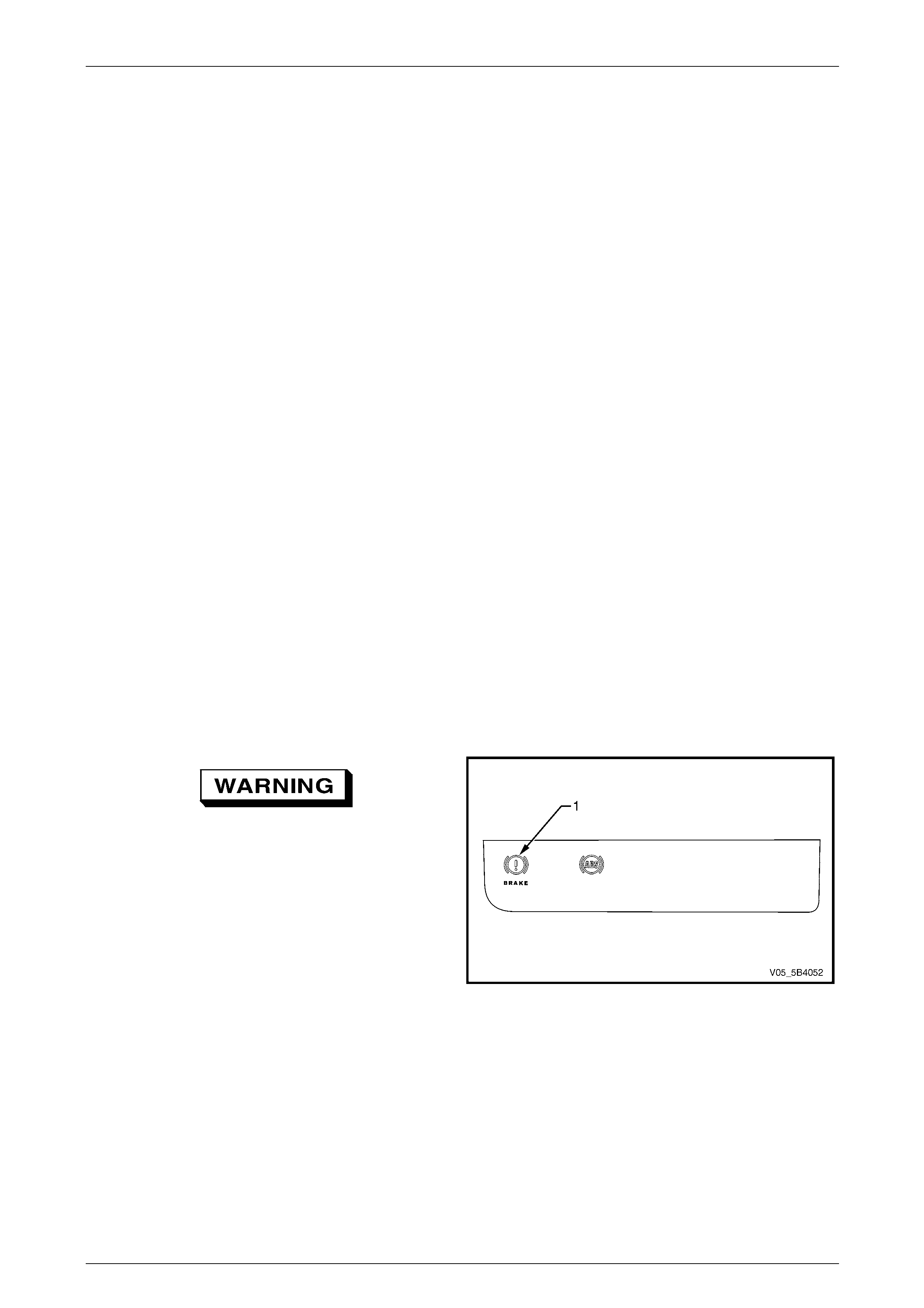
5B4 ABS-TCS / ESP Page 5B4–98
Page 5B4–98
9.2 ABS-TCS / ESP Brake Bleeding
Procedure
NOTE
The conventional brake system bleeding
procedure must be completed before performing
the ABS-TCS / ESP brake bleeding procedure.
Refer to Section 5A Service and Park Braking
System.
1 Connect Tech 2 to the vehicle. Refer to Section 0C Tech 2 for information on the use of Tech 2.
2 Start the engine and allow to run at idle speed.
3 Perform the instructions listed in the Tech 2 Brake Bleed Procedure.
NOTE
Ensure the brake fluid level in the brake master
cylinder doesn't drop below the minimum level
during the duration of this procedure.
4 Turn the ignition switch off.
5 Disconnect Tech 2 from the DLC.
6 Fill the brake master cylinder reservoir to the maximum fill level with the specified brake fluid.
7 Perform another conventional braking system brake bleeding procedure.
Refer to Section 5A Service and Park Braking System.
8 With the ignition switched off, depress the brake pedal three to five times to deplete the brake booster vacuum
reserve.
9 Slowly depress the brake pedal. If the brake pedal feels spongy, repeat the ABS-TCS / ESP brake bleeding
procedure.
10 If the brake pedal still feels spongy after repeating the ABS-TCS / ESP bleeding procedure, inspect the brake
system for external or internal leakage. Refer to Section 5A Service and Park Braking System.
If the brake fail indicator (1) remains
illuminated after a service procedure, do not
drive the vehicle until the fault is diagnosed
and repaired.
11 Turn the ignition switch on with the engine not running
and the park brake not applied. If the park brake /
brake fail indicator remains illuminated, diagnose and
repair the fault.
Refer to Section 5A Service and Park Braking System.
12 Road test the vehicle to allow ABS-TCS / ESP self test
initialisation to occur. If the brake pedal feels spongy,
repeat the ABS-TCS / ESP brake bleed procedure
until a firm brake pedal feel is obtained.
13 Check the ABS-TCS / ESP operation. Refer to
6.4 Diagnostic System Check.
Figure 5B4 – 50
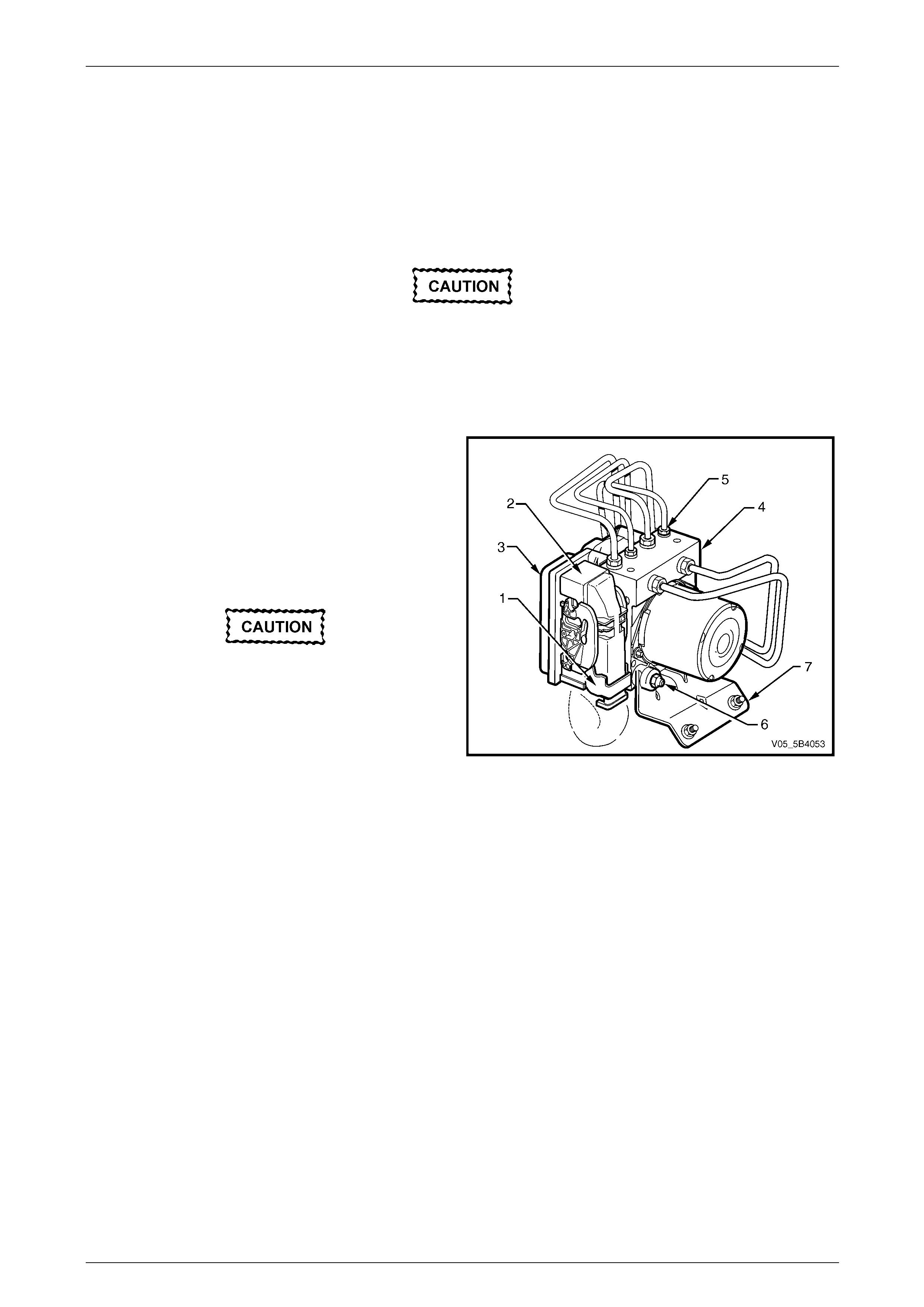
5B4 ABS-TCS / ESP Page 5B4–99
Page 5B4–99
9.3 Electronic Control Unit / Hydraulic Modulator
Assembly
LT Section No. — 04–730
Remove
Disconnection of the battery affects certain
vehicle electronic systems. Refer to
Section 00 Warnings, Caution and Notes
before disconnecting the battery.
1 Disconnect the battery negative terminal.
2 Retract the release bar (1) to disengage the wiring
connector (2) from the electronic control unit (ECU)
(3).
3 Disconnect the wiring connector from the ECU and lay
aside with the connector pins side facing downwards.
4 Place shop rags around and beneath the hydraulic
modulator (4).
Immediately seal off the brake pipes and the
hydraulic modulator with dummy plugs to
prevent the loss of brake fluid and entry of
dirt.
5 Loosen and disconnect the hydraulic modulator brake
pipe fittings (5).
6 Carefully reposition the pipes away from the hydraulic
modulator ports. Do not to damage or kink the brake
pipes in any way.
Figure 5B4 – 51
7 Remove the nut (6), two places, securing the ECU / hydraulic modulator assembly to the mounting bracket (7).
8 Remove the ECU / hydraulic modulator assembly from the vehicle.
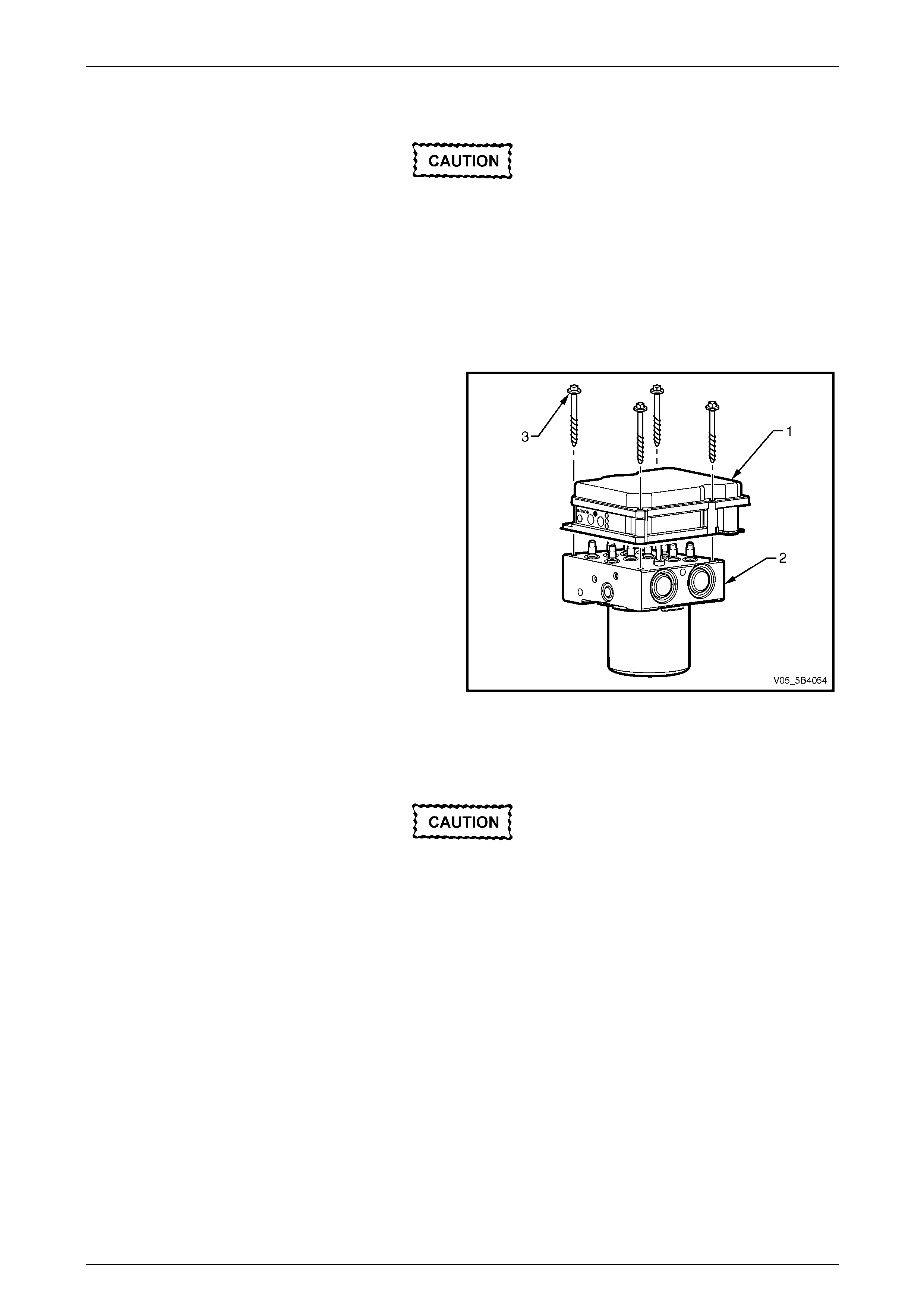
5B4 ABS-TCS / ESP Page 5B4–100
Page 5B4–100
Disassemble
If diagnosis indicates that the ABS ECU must
be replaced, then refer to the current
PartFinder™ release to determine the correct
replacement part and complete the following
procedure for the replacement operation.
However if the indications are that the
hydraulic modulator has failed, then the
complete ECU / hydraulic modulator assembly
must be replaced.
NOTE
It is possible to disassemble the ECU (1) from
the hydraulic modulator (2) without removing the
hydraulic modulator from the vehicle.
1 Support the ECU / hydraulic modulator assembly in a
horizontal position with the ECU on top.
2 Remove the four screws (3) securing the ECU to the
hydraulic modulator.
3 Lift the ECU upwards and remove from the hydraulic
modulator.
4 Cover the hydraulic modulator valve body to prevent
damage or entry of dirt.
Figure 5B4 – 52
Inspect
When cleaning the ECU to hydraulic
modulator mating surfaces, do not use
compressed air or chemical solvents.
Inspect the ECU and the hydraulic modulator for the following faults:
• Inspect the ECU to hydraulic modulator mating surfaces and seal. The seal is not available as a spare part and the
mating surfaces cannot be mechanically reworked. Therefore, if the ECU to hydraulic modulator seal or its mating
surfaces are damaged, the complete ECU / hydraulic modulator assembly must be replaced.
• Inspect the coils of the solenoid valves for correct alignment. The coils must not be adjusted under any
circumstance. If the coils are not aligned correctly, replace the ECU.
• Ensure the contacts pins of the hydraulic pump are aligned correctly.
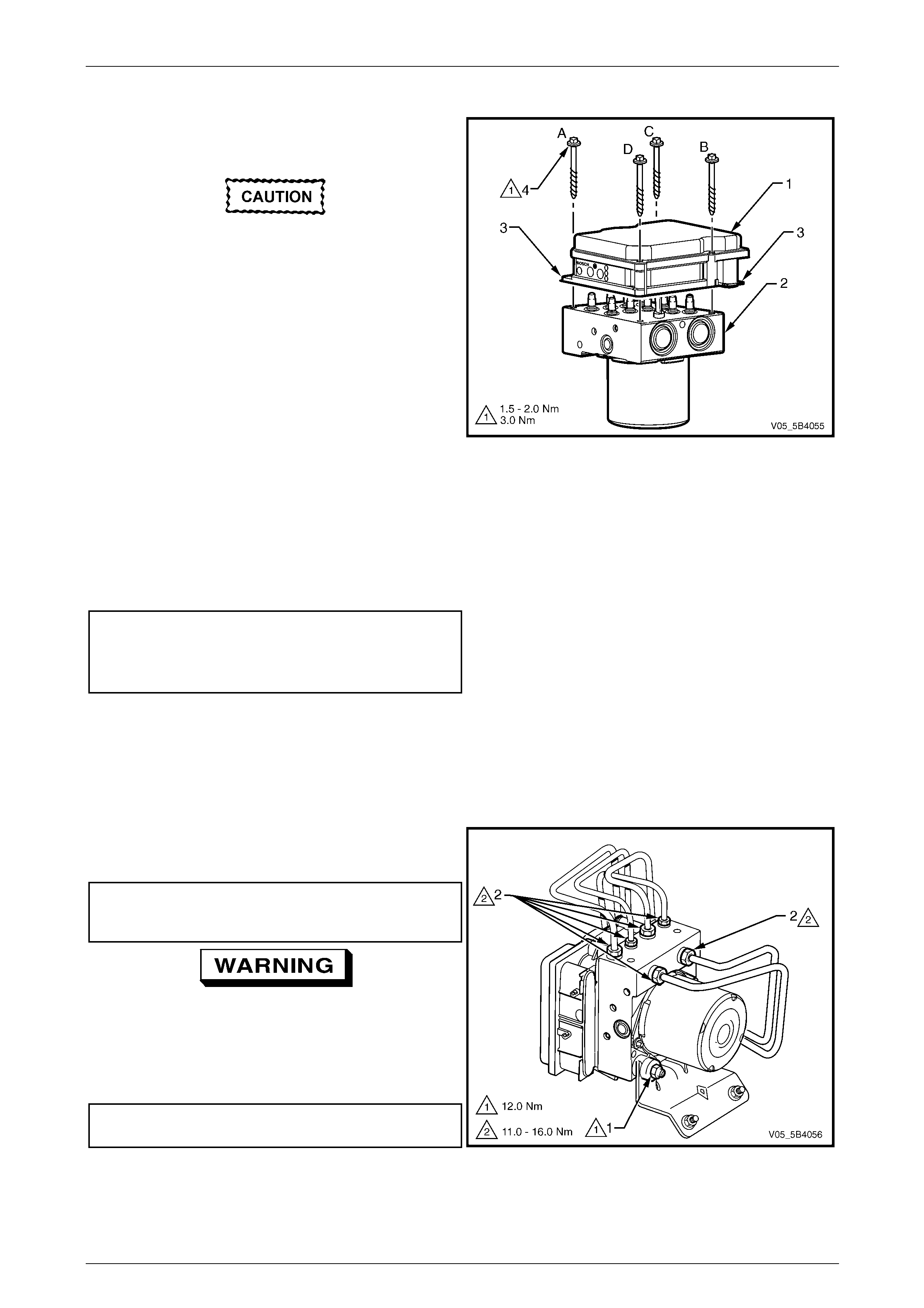
5B4 ABS-TCS / ESP Page 5B4–101
Page 5B4–101
Reassemble
1 Ensure the ECU (1) to hydraulic modulator (2) mating
surface is clean.
2 Remove the new ECU from its protective packaging.
Do not push the ECU housing cover with the
palm of the hand or the ball of the thumb
when installing the ECU to the hydraulic
modulator. Otherwise, ECU damage may
occur.
NOTE
When installing the ECU to the hydraulic unit,
press the ECU only from its outer edges (3).
3 Align and then install the ECU into the hydraulic
modulator.
Figure 5B4 – 53
4 Ensure there is no gap between ECU and the hydraulic modulator mating surface.
NOTE
A gap between the ECU and the hydraulic
modulator may indicate a bent hydraulic pump
contact pin or misaligned solenoid valve coil.
5 Install the four screws (4) retaining the ECU to the hydraulic modulator.
6 Tighten the screws in the specified diagonal pattern (from A to D) and to the correct torque specification.
Electronic control unit retaining
screw torque specification
Stage 1 ................ 1.5 – 2.0 Nm
Stage 2 .......................... 3.0 Nm
Reinstall
Reinstallation of the electronic control unit / hydraulic modulator assembly is the reverse of the removal procedure, noting
the following:
1 Ensure the mounting bracket area is clean and free from brake fluid contamination.
2 Ensure the bottom hydraulic modulator rubber insulator is correctly fitted.
3 Tighten the nut (1), two places, securing the ECU /
hydraulic modulator assembly to the correct torque
specification.
Electronic control unit / hydraulic
modulator assembly securing
nut torque specification......................................12.0 Nm
If the brake pipe fittings are incorrectly fitted,
wheel lock-up will occur and personal injury
may result.
4 Install the brake pipe fittings (2) to the correct hydraulic
modulator ports and tighten to the correct torque
specification.
Brake pipe fitting
torque specification.................................11.0 – 16.0 Nm
Figure 5B4 – 54
5 Bleed the ABS-TCS / ESP hydraulic circuit. Refer to 9.2 ABS-TCS / ESP Brake Bleeding Procedure.
6 Check the ABS-TCS / ESP operation. Refer to 6.4 Diagnostic System Check.

5B4 ABS-TCS / ESP Page 5B4–102
Page 5B4–102
9.4 Front Wheel Speed Sensor – Rear Wheel
Drive Vehicles
The front wheel speed sensors are incorporated as part of the front suspension front wheel hub assembly. Apart from
wheel stud replacement, there are no serviceable items in the front wheel hub assembly.
Refer to Section 3A Front Suspension for service information on the front wheel hub assembly.
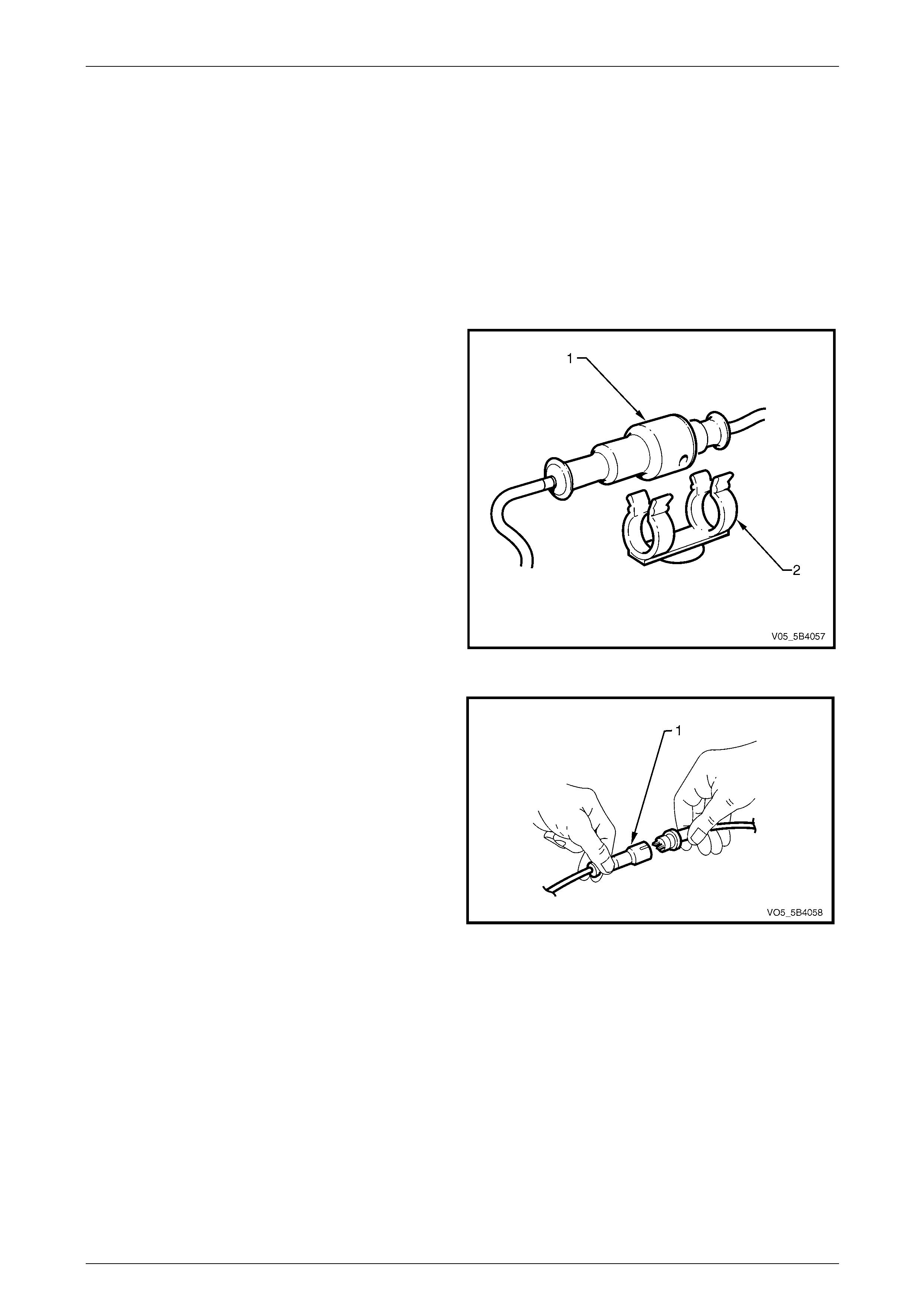
5B4 ABS-TCS / ESP Page 5B4–103
Page 5B4–103
9.5 Front Wheel Speed Sensor – All Wheel
Drive Vehicles
LT Section No. — 04–730
Remove
1 Raise the front of the vehicle and support on safety stands, Refer to Section 0A General Information for location of
the jacking points.
2 Remove the appropriate wheel. Refer to Section 10 Wheels and Tyres.
3 From within the engine compartment, remove the
appropriate front wheel speed sensor wiring connector
(1) from its mounting clip (2).
Figure 5B4 – 55
4 Using a small screwdriver, disconnect the front wheel
speed sensor wiring connector (1) from the wiring
harness connector.
5 Inspect the connector O-ring and replace if required.
Figure 5B4 – 56
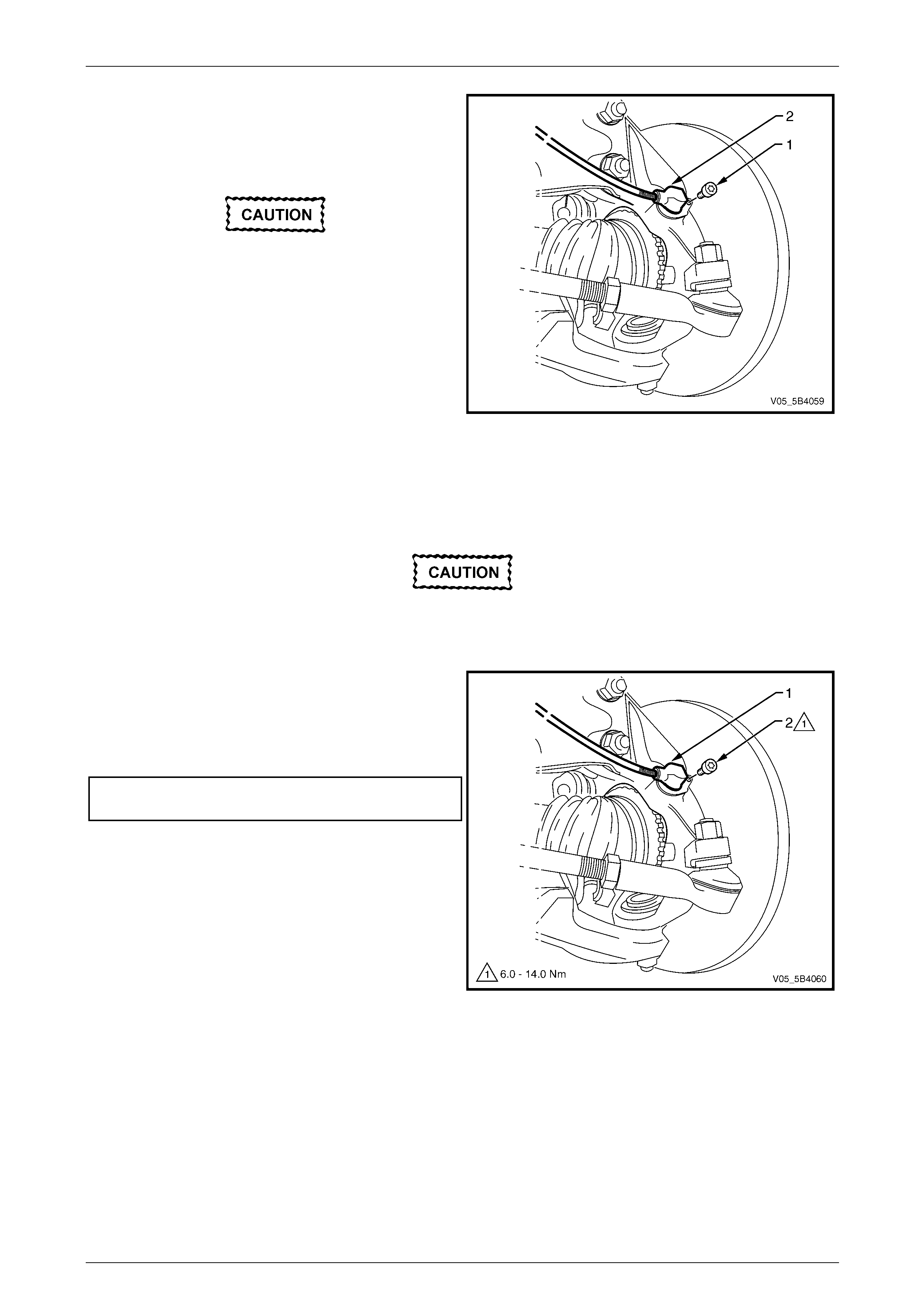
5B4 ABS-TCS / ESP Page 5B4–104
Page 5B4–104
6 Remove the screw (1) attaching the front wheel speed
sensor (2) to the steering knuckle.
7 With a twisting motion, withdraw the wheel speed
sensor from the steering knuckle bore.
Do not use a screwdriver or other device to
prise the w heel speed sensor out. Otherw ise,
damage to the wheel speed sensor may
occur.
8 Note the wheel speed sensor wiring harness routing
and then remove the sensor assembly from the
vehicle.
9 Clean the wheel speed sensor to steering knuckle
mating surface. Figure 5B4 – 57
Reinstall
Reinstallation of the front right wheel speed sensor is the reverse of the removal procedure, noting the following:
A replacement wheel sensor must only be
taken out its packaging immediately before
installing on the vehicle.
1 With a twisting motion, install the front right wheel
speed sensor (1) to the steering knuckle bore.
2 Install the screw (2) attaching the front wheel speed
sensor to the steering knuckle and tighten to the
correct torque specification.
Front wheel speed sensor
attaching screw.........................................6.0 – 14.0 Nm
3 Check the ABS-TCS / ESP operation, refer to
6.4 Diagnostic System Check.
Figure 5B4 – 58

5B4 ABS-TCS / ESP Page 5B4–105
Page 5B4–105
9.6 Front Wheel Speed Sensor Lead – Rear
Wheel Drive Vehicles
LT Section No. — 04–730
Remove
1 Raise the front of the vehicle and support on safety stands, Refer to Section 0A General Information for location of
the jacking points.
2 Remove the appropriate wheel. Refer to Section 10 Wheels and Tyres.
3 From within the engine compartment, remove the
appropriate wheel speed sensor wiring connector (1)
from its mounting clip.
Figure 5B4 – 59
4 Using a small screwdriver, disconnect the wheel speed
sensor wiring connector (1) from the wiring harness
connector.
5 Inspect the connector O-ring and replace if required.
Figure 5B4 – 60
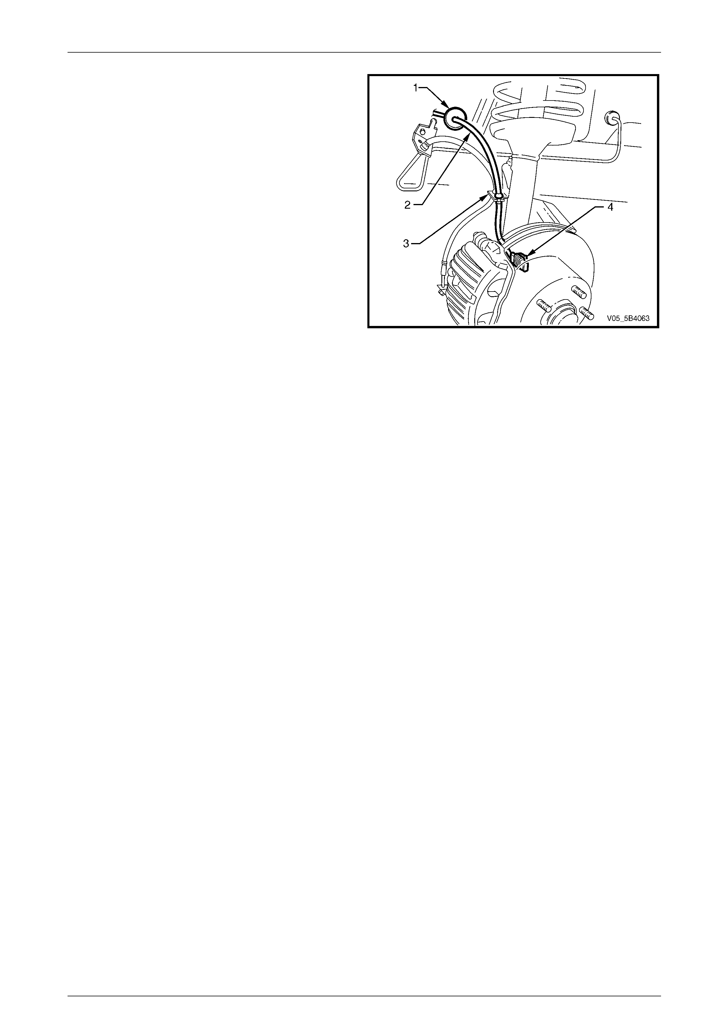
5B4 ABS-TCS / ESP Page 5B4–106
Page 5B4–106
6 Disengage the sensor lead grommet (1) from the inner
wheelhouse.
7 Disengage the sensor lead (2) from its front strut
mounting bracket (3).
8 Disconnect the wheel speed sensor connector (4) from
the wheel speed sensor.
9 Note the wheel speed sensor wiring harness routing.
10 Remove the sensor lead assembly from the vehicle.
Figure 5B4 – 61
Reinstall
Reinstallation of the wheel speed sensor lead is the reverse of the removal procedure, noting the following:
1 Ensure the wheel speed sensor wiring harness is routed correctly.
2 Check the ABS-TCS / ESP operation. Refer to 6.4 Diagnostic System Check.

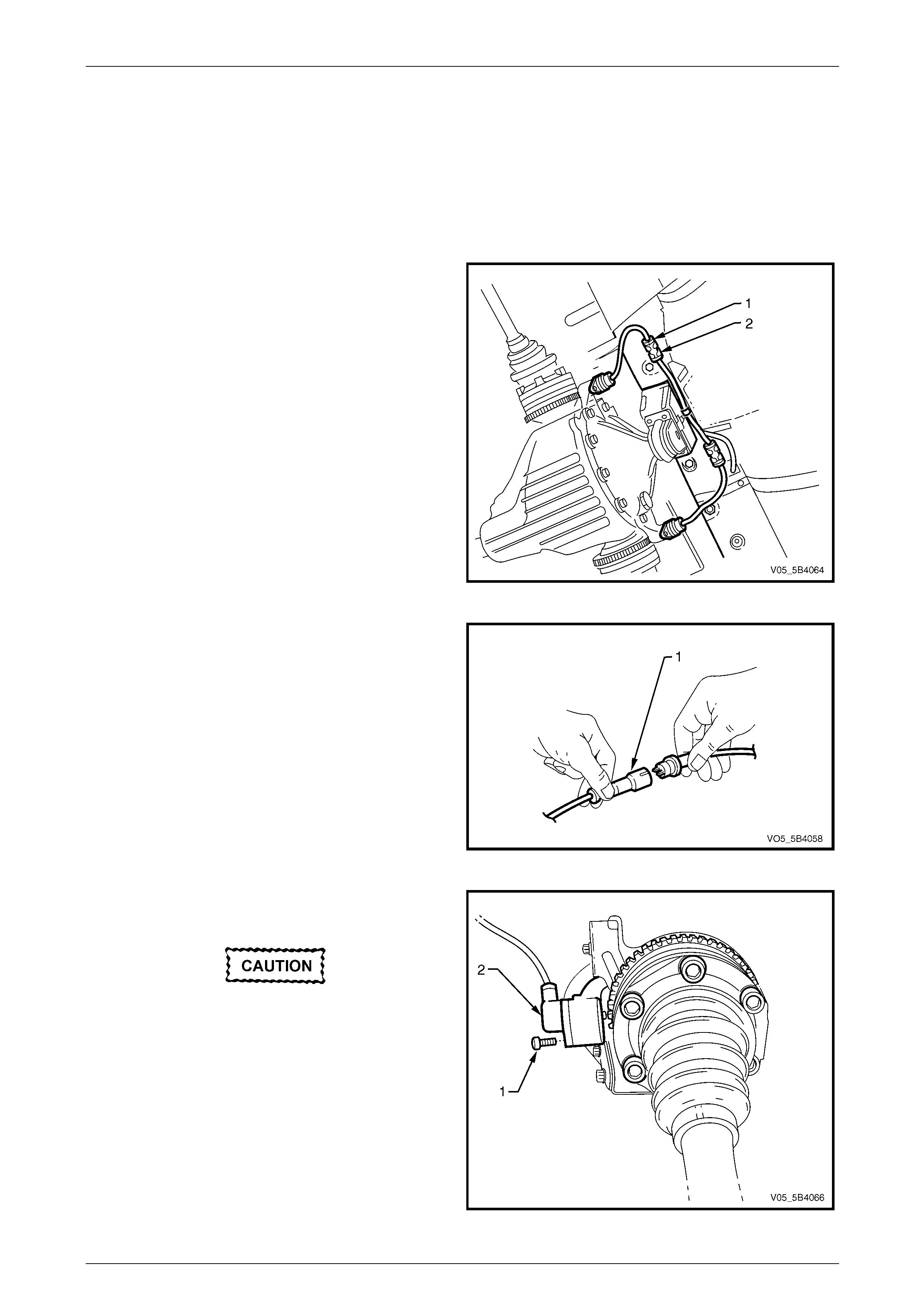
5B4 ABS-TCS / ESP Page 5B4–108
Page 5B4–108
9.8 Rear Wheel Speed Sensor
LT Section No. — 04–730
Remove
1 Raise the rear of the vehicle and support using safety stands under trailing arms to support weight of vehicle. Refer
to Section 0A General Information.
2 Disconnect the appropriate sensor lead connector (1)
from its underbody mounting clip (2).
Figure 5B4 – 62
3 Using a small screwdriver, disconnect the wheel speed
sensor wiring connector (1) from the wiring harness
connector.
4 Inspect the connector O-ring and replace if required.
Figure 5B4 – 63
5 Remove the screw (1) attaching the rear wheel speed
sensor (2) to final drive rear cover.
Do not use a screwdriver or other device to
prise the w heel speed sensor out. Otherw ise,
damage to the wheel speed sensor may
occur.
6 With a twisting motion, withdraw the rear wheel speed
sensor from the final drive cover bore.
7 Clean the wheel speed sensor to final drive cover
mating surface.
Figure 5B4 – 64
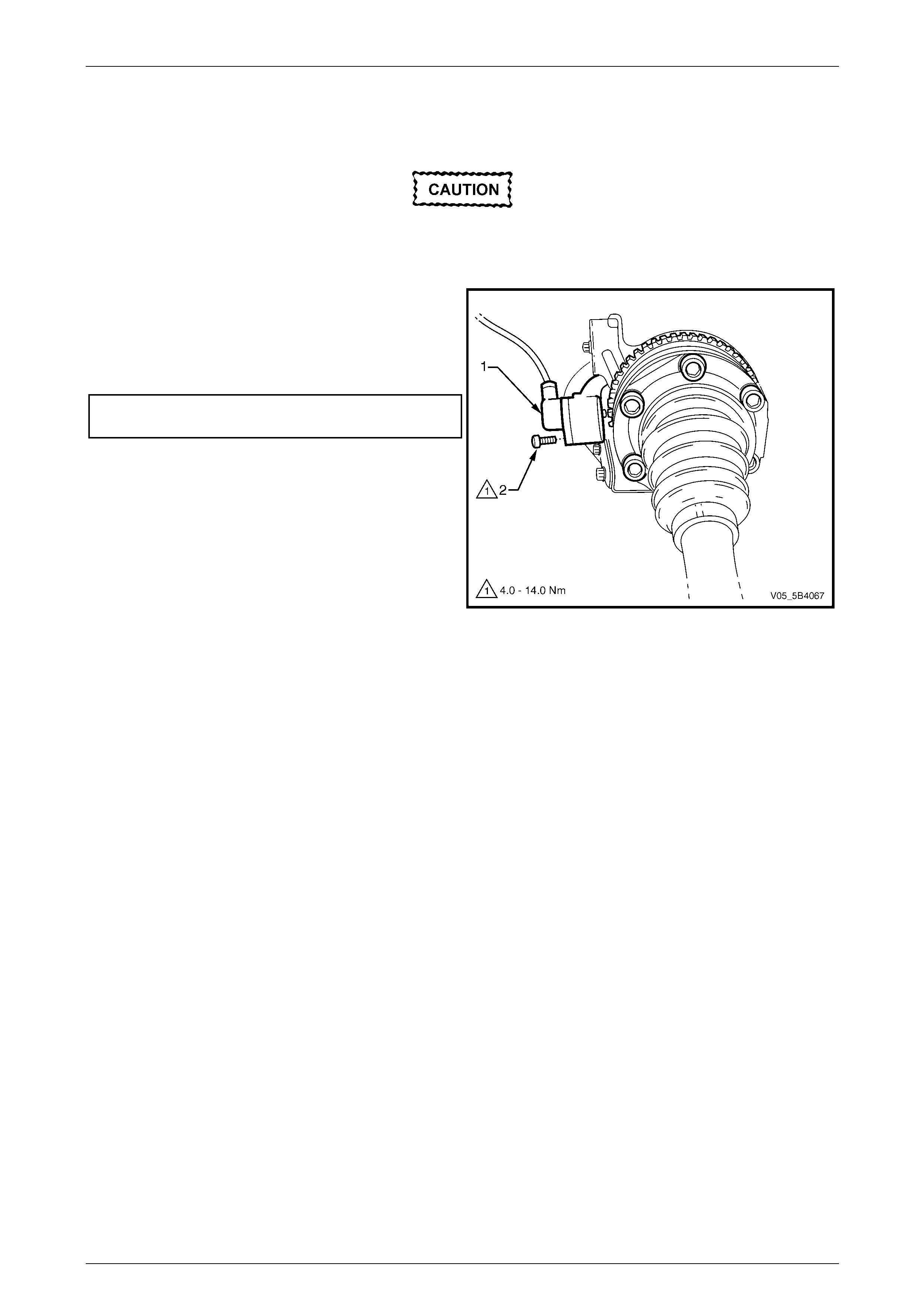
5B4 ABS-TCS / ESP Page 5B4–109
Page 5B4–109
Reinstall
Reinstallation of the rear wheel speed sensor is the reverse of the removal procedure, noting the following:
A replacement wheel sensor must only be
taken out its packaging immediately before
installing on the vehicle.
1 With a twisting motion, install the rear wheel speed
sensor (1) to the final drive cover bore.
2 Install the screw (2) attaching the rear wheel speed
sensor to final drive rear cover and tighten to the
correct torque specification.
Rear wheel speed sensor attaching
screw torque specification.........................4.0 – 14.0 Nm
3 Check ABS-TCS / ESP operation. Refer to
6.4 Diagnostic System Check.
Figure 5B4 – 65

5B4 ABS-TCS / ESP Page 5B4–110
Page 5B4–110
9.9 Front Wheel Speed Sensor Pulse Ring –
Rear Wheel Drive Vehicles
If the front wheel hub assembly requires
replacement, the correct replacement part
must be installed. Otherwise, ABS-TCS / ESP
malfunction w ill occur.
The front wheel speed sensor pulse ring is incorporated into the front suspension front wheel hub assembly. Apart
from wheel stud replacement, there are no serviceable items in the front wheel hub assembly. Refer to
Section 3A Front Suspension for wheel hub assembly service information.

5B4 ABS-TCS / ESP Page 5B4–111
Page 5B4–111
9.10 Front Wheel Speed Sensor Pulse Ring –
All Wheel Drive Vehicles
If the front wheel hub assembly requires
replacement, the correct replacement part
must be installed. Otherwise, ABS-TCS / ESP
malfunction w ill occur.
The front wheel speed sensor pulse rings are part of the front driveshaft constant velocity joint assemblies and are not
serviced separately. Refer to Section 4B3 Front Final Drive and Drive Shafts for the front driveshaft constant velocity joint
service information.

5B4 ABS-TCS / ESP Page 5B4–112
Page 5B4–112
9.11 Rear Wheel Speed Sensor Pulse Ring
If the final drive inner axle flange requires
replacement, the correct replacement part
must be installed. Otherwise, ABS-TCS / ESP
malfunction w ill occur.
The rear wheel speed sensor pulse ring is part of the final drive inner axle flange and is not serviced separately.
Refer to Section 4B1 Rear Final Drive and Drive Shafts for the final drive inner axle flange service procedure.
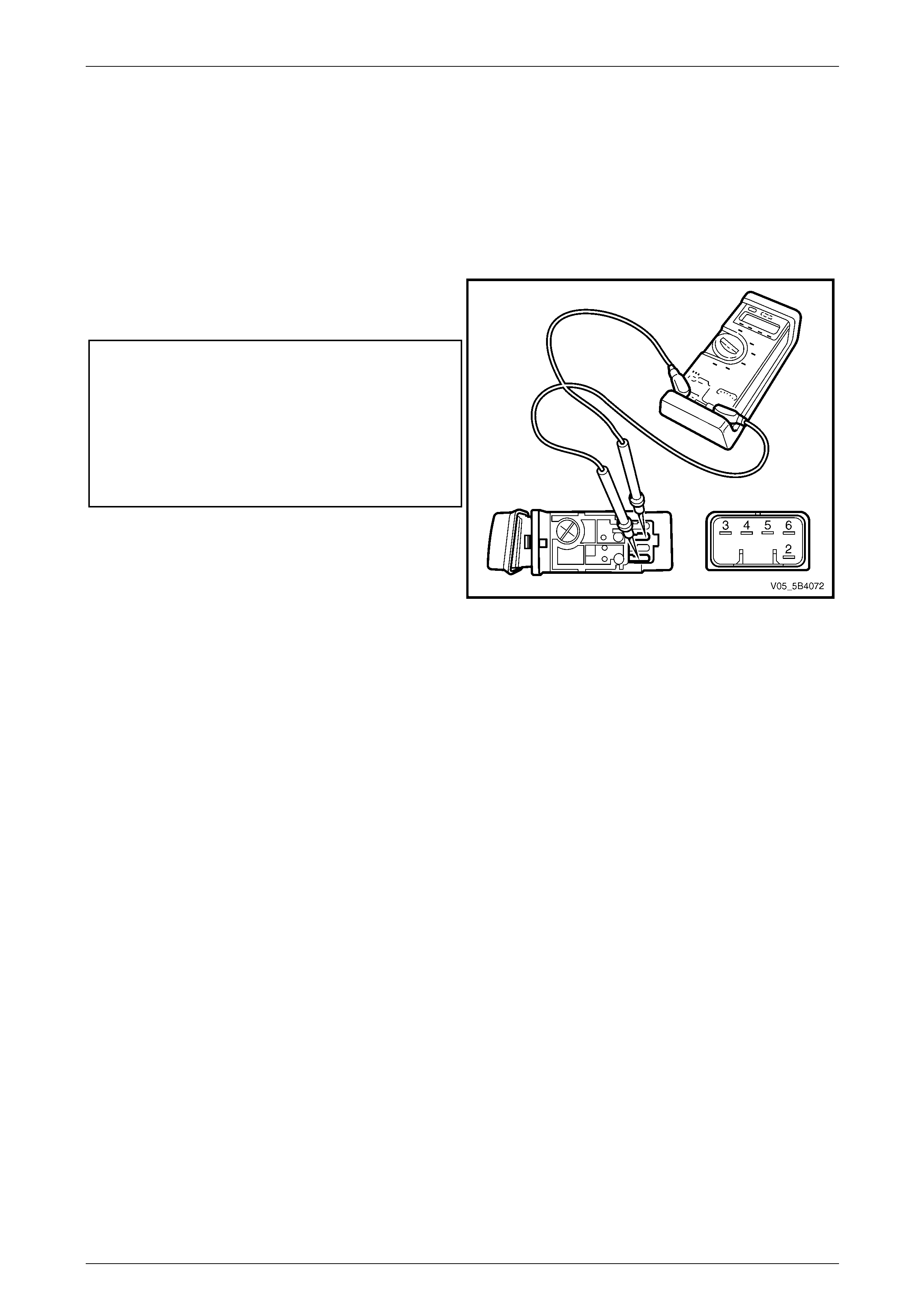
5B4 ABS-TCS / ESP Page 5B4–113
Page 5B4–113
9.12 Electronic Stability Program Switch
Replace
Refer to Section 1A3 Instrument Panel and Console for the electronic stability program (ESP) switch replacement
procedure.
Test
1 Using a digital multimeter, measure the resistance
across the ESP switch terminals and compare the
reading against the specifications.
ESP switch at rest
Terminals 3 and 4...........................................continuity
Terminals 3 and 5.........................................open circuit
ESP sw itch when depressed
Terminals 3 and 4........................................open circuit
Terminals 3 and 5............................................continuity
Illumination lamp check
Terminals 2 and 6............... illumination lamp resistance
2 If the resistance is not within specifications, replace
the ESP switch or the illumination lamp.
Figure 5B4 – 66

5B4 ABS-TCS / ESP Page 5B4–114
Page 5B4–114
9.13 Hill Descent Control Switch – All Wheel
Drive Vehicles
Replace
Refer to Section 1A3 Instrument Panel and Console for the Hill Descent Control (HDC) switch replacement procedure.
Test
1 Using a digital multimeter, measure the resistance
across the Hill Descent switch terminals and compare
the reading against the specifications.
Hill Descent sw itch at rest
Terminals 3 and 4...........................................continuity
Terminals 3 and 5.........................................open circuit
Hill Descent sw itch when depressed
Terminals 3 and 4........................................open circuit
Terminals 3 and 5............................................continuity
Illumination lamp check
Terminals 2 and 6............... illumination lamp resistance
2 If the resistance is not within specifications, replace
the Hill Descent switch or the illumination lamp.
Figure 5B4 – 67
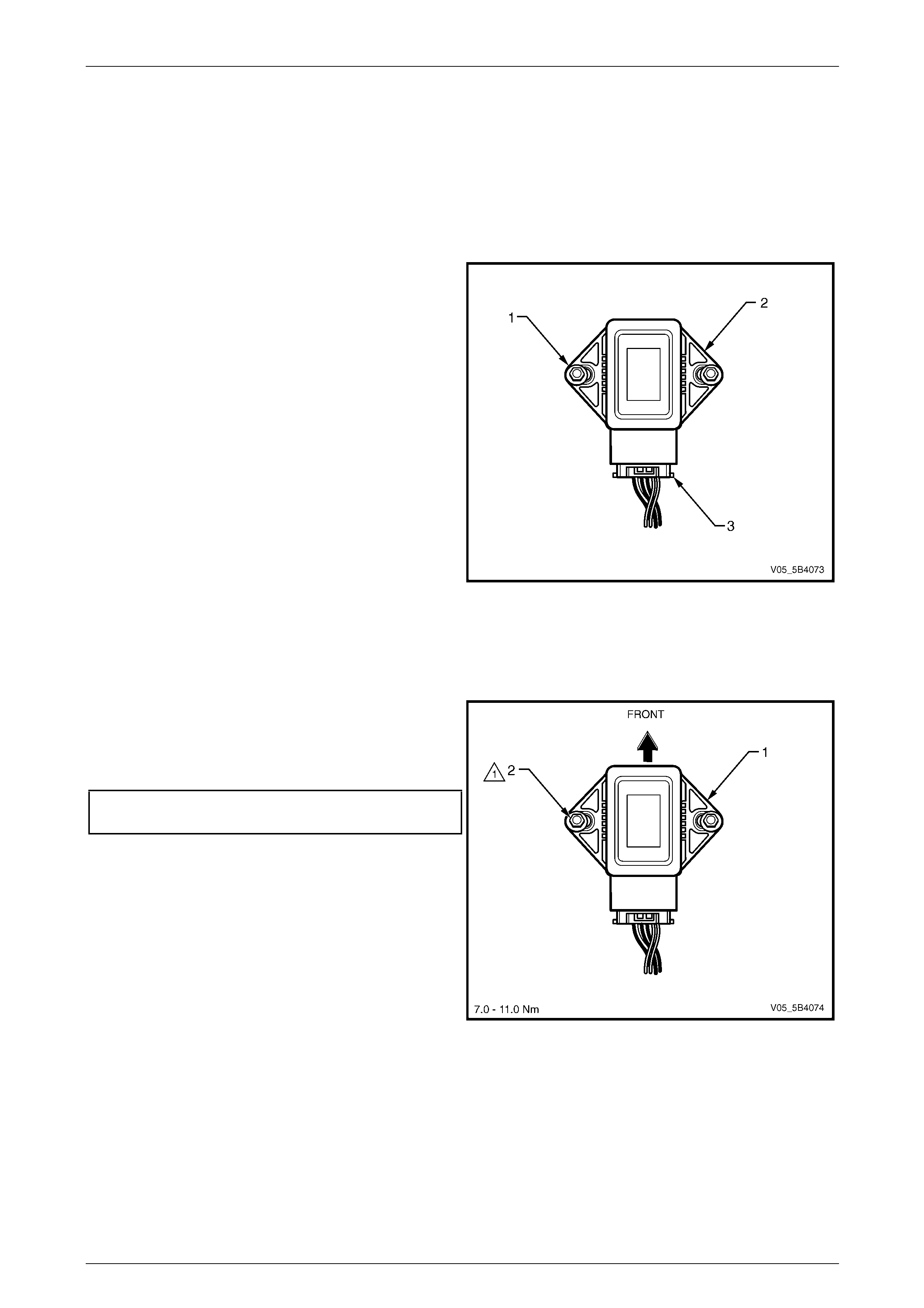
5B4 ABS-TCS / ESP Page 5B4–115
Page 5B4–115
9.14 Yaw-rate Sensor
LT Section No. — 04–730
Remove
1 Remove the floor console assembly, refer to Section 1A3 Instrument Panel and Console.
2 Remove the two nuts (1) attaching the yaw-rate
sensor (2).
3 Depress the yaw-rate sensor wiring connector clip (3),
and disconnect the yaw-rate sensor connector.
4 Remove the yaw-rate sensor from the vehicle.
Figure 5B4 – 68
Reinstall
Reinstallation of the yaw-rate sensor is the reverse of the removal procedure, noting the following:
1 Install the yaw-rate sensor (1) to its correct position
and orientation.
2 Install the two nuts (2) attaching the yaw-rate sensor
and tighten to the correct torque specification.
Yaw-rate sensor attaching
nut torque specification.............................7.0 – 11.0 Nm
3 Check the ABS-TCS / ESP operation, refer to
6.4 Diagnostic System Check.
Figure 5B4 – 69

5B4 ABS-TCS / ESP Page 5B4–116
Page 5B4–116
9.15 Steering Angle Sensor
Replace
The steering angle sensor is part of the clock spring coil assembly. Refer to Section 12M Occupant Protection System for
the steering angle sensor replacement procedure.
Calibration
1 Road test the vehicle and note the steering wheel position when the vehicle is travelling in the straight-ahead
direction.
2 Connect Tech 2 to the vehicle. Refer to Section 0C Tech 2 for the use of Tech 2.
3 Perform the instructions displayed in the Tech 2 Steering Angle Sensor Calibration Procedure.
4 Check the ABS-TCS / ESP operation, refer to 6.4 Diagnostic System Check.

5B4 ABS-TCS / ESP Page 5B4–117
Page 5B4–117
10 Specifications
Wheel Speed Sensor Winding Resistance ...............................................1.3 – 1.8 kΩ @ 20°c
Front and Rear Wheel Speed Sensor Air Gap..................................................Non-adjustable
Wheel Speed Sensor Pulse Rings...............................................................................48 teeth
Brake Fluid ......................................................................................................................Dot 4

5B4 ABS-TCS / ESP Page 5B4–118
Page 5B4–118
11 Torque Wrench Specifications
ATTENTION
All ABS-TCS / ESP fasteners are important attaching parts as they affect the performance of vital components
and/or could result in major repair expense. Where specified in this Section, fasteners must be replaced w ith
parts of the same part number or a GM approved equivalent. Do not use fasteners of an inferior quality or
substitute design.
Torque values must be used as specified during assembly to ensure proper retention of all ABS-TCS / ESP
components.
Fasteners must be replaced after loosening.
If this symbol precedes a fastener torque wrench specification, the recommendation regarding that fastener
must be adhered to.
Electronic Control Unit Retaining Screw
Stage 1.......................................................................................1.5 – 2.0 Nm
Stage 2.................................................................................................3.0 Nm
Electronic Control Unit / Hydraulic Modulator
Assembly Securing Nut......................................................................12.0 Nm
Brake Pipe Fitting....................................................................11.0 – 16.0 Nm
Hydraulic Modulator Brake Pipe Fitting ................................... 11.0 – 16.0 Nm
Front Wheel Speed Sensor Attaching Screw – AWD................6.0 – 14.0 Nm
Rear Wheel Speed Sensor Attaching Screw............................. 4.0 – 14.0 Nm
Yaw-rate Sensor Attaching Nut .................................................7.0 – 11.0 Nm
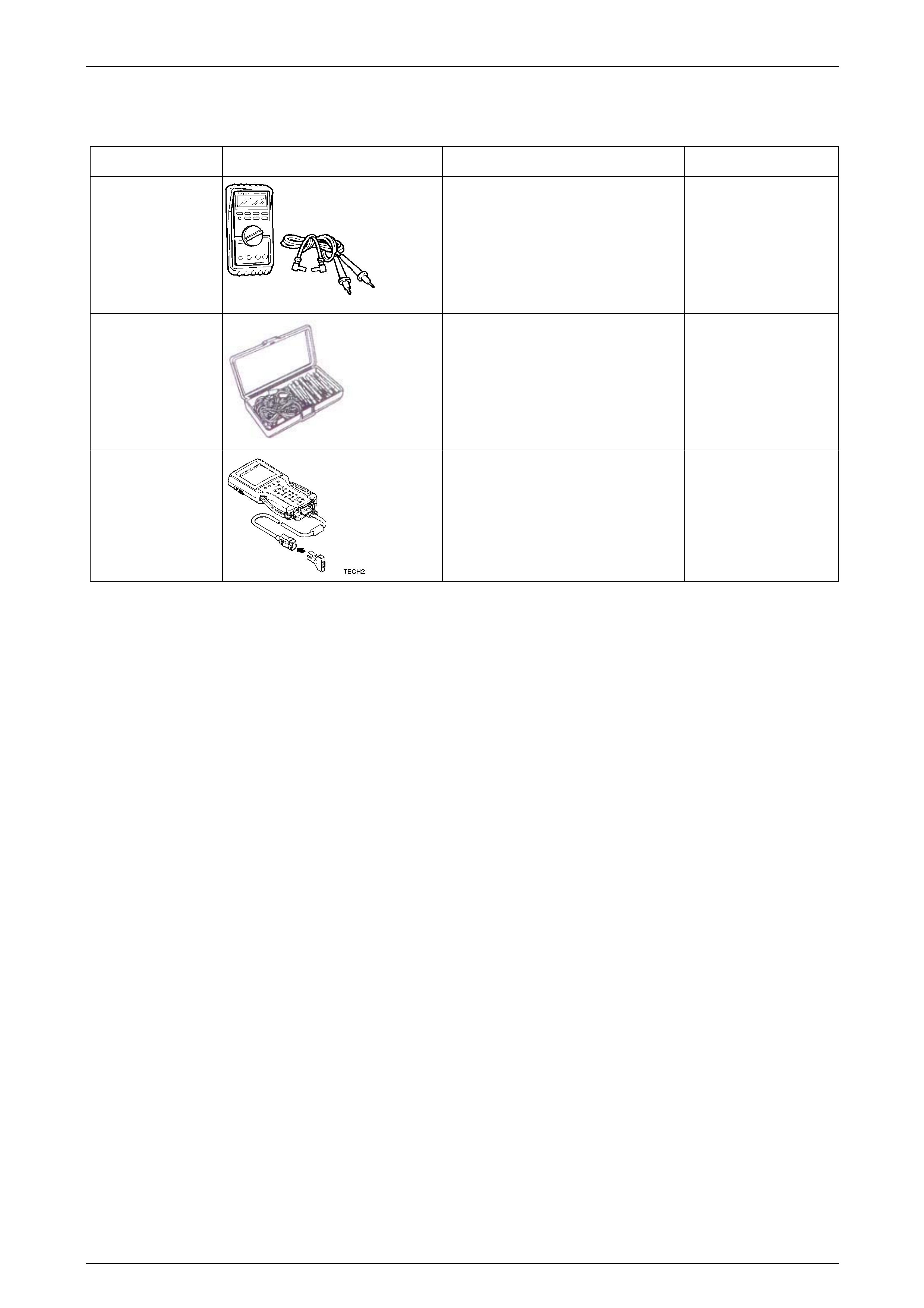
5B4 ABS-TCS / ESP Page 5B4–119
Page 5B4–119
12 Special Tools
Tool Number Illustration Description Tool Classification
3588
Digital Multimeter
Also Previously released as J39200 or
equivalent.
NOTE: The instrument must have 10
MΩ impedance and be capable of
reading frequencies.
Mandatory
J35616
Connector Test Adaptor Kit
Used when carrying out electrical
diagnostic circuit checks.
Desirable
70000861
Tech 2 Diagnostic Scan Tool
Previously released.
Mandatory