
Engine Management – V6 – General Information Page 6C1-1–1
Section 6C1-1
Engine Management V6 – General Information
ATTENTION
Before performing any service operation or other procedure described in this Section, refer to Section 00
Warnings, Cautions and Notes for correct workshop practices with regard to safety and / or property damage.
1 General Information ...............................................................................................................................3
1.1 Introduction............................................................................................................................................................ 3
1.2 Emission Control................................................................................................................................................... 4
Euro 2 Emissions Standards ................................................................................................................................ 4
2 Component Locations ...........................................................................................................................5
2.1 Cylinder Numbering............................................................................................................................................... 5
2.2 Engine Compartment............................................................................................................................................. 6
2.3 Engine..................................................................................................................................................................... 7
Alloytech................................................................................................................................................................. 7
Alloytech 190.......................................................................................................................................................... 8
All Engines ............................................................................................................................................................. 9
2.4 Manual Transmission .......................................................................................................................................... 10
2.5 Interior .................................................................................................................................................................. 11
3 System Operation.................................................................................................................................12
3.1 Fuel Delivery System........................................................................................................................................... 12
Fuel System Pressure ......................................................................................................................................... 12
Fuel Injection System.......................................................................................................................................... 13
Short Term Fuel Trim....................................................................................................................................... 13
Long Term Fuel Trim........................................................................................................................................ 13
3.2 Air / Fuel Control System.................................................................................................................................... 14
Starting Mode....................................................................................................................................................... 14
Run Mode ............................................................................................................................................................. 14
Acceleration Mode............................................................................................................................................ 14
Deceleration Mode........................................................................................................................................... 14
Fuel Shut-off Mode........................................................................................................................................... 14
Battery Voltage Correction Mode..................................................................................................................... 15
Limp Mode ....................................................................................................................................................... 15
Engine Protection Mode................................................................................................................................... 15
Clear Flood Mode............................................................................................................................................. 15
3.3 Ignition Control System ...................................................................................................................................... 16
3.4 Starter Motor Operation ...................................................................................................................................... 17
Auto Start Feature................................................................................................................................................ 17
Clutch Pedal Position Switch.............................................................................................................................. 17
3.5 Throttle Actuator Control System ...................................................................................................................... 18
Description........................................................................................................................................................... 18
Throttle Body Relearn Procedure....................................................................................................................... 19
TAC System Default Actions / Reduce Power Modes....................................................................................... 19
Forced Engine Shutdown.................................................................................................................................... 19
3.6 Camshaft Position Actuator Control System .................................................................................................... 20
Operation.............................................................................................................................................................. 21
Variable Valve Timing Phases ......................................................................................................................... 21
3.7 Cruise Control System ........................................................................................................................................ 23
3.8 Brake Torque Management................................................................................................................................. 24
Page 6C1-1–1
Techline

Engine Management – V6 – General Information Page 6C1-1–2
3.9 Emission Control Systems.................................................................................................................................. 25
Evaporative Emission Control System .............................................................................................................. 25
Engine Ventilation System.................................................................................................................................. 26
3.10 Serial Data Communication System................................................................................................................... 27
3.11 Self Diagnostics System ..................................................................................................................................... 28
3.12 Service Programming System............................................................................................................................ 29
3.13 Theft Deterrent System ....................................................................................................................................... 30
4 Component Description and Operation.............................................................................................31
4.1 A/C Refrigerant Pressure Sensor....................................................................................................................... 31
4.2 Brake Pedal Switches.......................................................................................................................................... 32
Stop Lamp and BTSI Switch Assembly ............................................................................................................. 32
Cruise Control Release and Extended Brake Travel Switch Assembly.......................................................... 32
4.3 Barometric Pressure Sensor............................................................................................................................... 33
4.4 Camshaft Position Sensor .................................................................................................................................. 34
4.5 Crankshaft Position Sensor................................................................................................................................ 35
4.6 Clutch Pedal Switch Assemblies – Manual Vehicles Only............................................................................... 36
4.7 Engine Control Module........................................................................................................................................ 37
4.8 Engine Coolant Temperature Sensor................................................................................................................. 38
4.9 Electric Cooling Fans.......................................................................................................................................... 39
4.10 Engine Oil Level and Temperature Sensor........................................................................................................ 40
Engine Oil Temperature Sensor ......................................................................................................................... 40
Engine Oil Level Sensor...................................................................................................................................... 41
4.11 Engine Oil Pressure Sensor................................................................................................................................ 42
4.12 Fuel Injectors........................................................................................................................................................ 43
4.13 Fuel Rail Assembly.............................................................................................................................................. 44
4.14 Heated Oxygen Sensors...................................................................................................................................... 45
LSF 4.2 Two-step Planar Heated Oxygen Sensors ........................................................................................... 45
LSU 4.2 Wide-band Planar Heated Oxygen Sensors ........................................................................................ 46
4.15 Ignition Coil and Spark Plug............................................................................................................................... 48
4.16 Intake Air Temperature Sensor........................................................................................................................... 49
4.17 Intake Manifold Runner Control Valve ............................................................................................................... 50
4.18 Knock Sensor....................................................................................................................................................... 51
4.19 Mass Air Flow Sensor.......................................................................................................................................... 52
Air Intake System................................................................................................................................................. 52
Mass Air Flow Sensor.......................................................................................................................................... 52
Construction..................................................................................................................................................... 53
Operation ......................................................................................................................................................... 53
4.20 Vehicle Speed Sensor – Manual Transmission Only........................................................................................ 54
5 Abbreviations and Glossary of Terms...............................................................................................55
Page 6C1-1–2

Engine Management – V6 – General Information Page 6C1-1–3
1 General Information
The V6 engine management system
incorporates functions and components that
could cause personal injury or vehicle
damage. Refer to Section 6C1-2 Engine
Management – V6 – Diagnostics, and Section
6C1-3 Engine Management – V6 – Service
Operations, before attempting any diagnosis
or repairs.
1.1 Introduction
The V6 engine management system is d esig ned to improve engine performance and i ncrease vehicle safety while
meeting the stringent Euro 2 vehicle emission standard. This is achieved b y the introduction of the following engine
management sub-systems and components:
• Throttle actuator control (TAC) System – the TAC system allows the engine control module (ECM) to electronically
control the throttle plate opening eliminating the need for the following components:
• mechanical link bet ween the throttle plate and accelerator pedal,
• cruise control module, and
• idle air control motor.
Refer to 3.5 Throttle Actuator Control System for details of the T AC System operation and to 3.7 Cruise Control
System for details of the cruise control operation.
This feature results in improved driveability, better fuel economy and emission control. In addition, the TAC system
allows the ABS-TCS electroni c control unit (if fitted) to request engine speed reduction from the ECM to improve
the vehicle's braking and traction control performance. Refer to Section 5B ABS / T CS / ESP – General
Information.
• Wide band heated oxygen sensor (Alloytec190 only) – provides a more accurate meas urement of the oxygen
concentration in the exhaust gas. Refer to 4.14 Heated Oxygen Sensors.
• Intake manifold runner control (Alloytec190 only) – enables the ECM to change the intake manifold configuration
according to engine demand. The variable intake manifold configuration allo ws the optimum eng ine intake air flow
during low or high engine speed, which improves engine performance. Refer to 4.17 Intake Manifold Runner
Control Valve.
• Pencil Coil – allows the ignitio n coil to be fitte d directly on the spark plug eliminating the need for spark plug wires.
Refer to 4.15 Ignition Coil and Spark Plug.
• Camshaft Position Actuators – enables the ECM to adjust the camshaft timing according to the demand placed on
the engine. The variable camshaft timing provides better balance between engine power output, fuel economy and
emission control. Refer to 3.6 Camshaft Position Actuator Control System.
The engine management system has a self diagnostic capability, as well as connections to enable diagnosis of faults. If
the ECM recognises operational problems it can al ert the driver via the check powertrain icon in the instrument cluster
multi-function display. The ECM also interfaces with other systems in the vehicle as required.
For further information on the air-conditioni ng system refer to:
• Section 2A HVAC Climate Control (Manual A/C) – Description and Operation or
• Section 2D HVAC Occupant Climate Contro l (Auto A/C) – Description and Operation.
For the location of fuses, fusible links and relays, refer to Section 12O Fuses, Relays, an d Wiring Harnesses.
Page 6C1-1–3

Engine Management – V6 – General Information Page 6C1-1–4
1.2 Emission Control
Euro 2 Emissions Standards
The vehicle has been configured to comply with Euro 2 vehicle emissions standards. Euro 2 is a European standard
which sets vehicle emissions targets to compel vehicle manufacturers to reduce harmful vehicle emissions such as
carbon monoxide (CO), hydrocarbons (HC) and the various oxides of nitrogen (NOx).
Australian Design Rule 79/00 implements the 'Euro 2' exhau s t and evaporative emissions requirements for lig ht vehicles
to reduce air pollution. The following tests are prescribed:
• average tailpipe emissions after a cold start,
• carbon monoxide emission at idling speed,
• emission of crankcase gases,
• evaporative emissions, and
• durability of pollution-control d evices.
Page 6C1-1–4
Engine Management – V6 – General Information Page 6C1-1–5
2 Component Locations
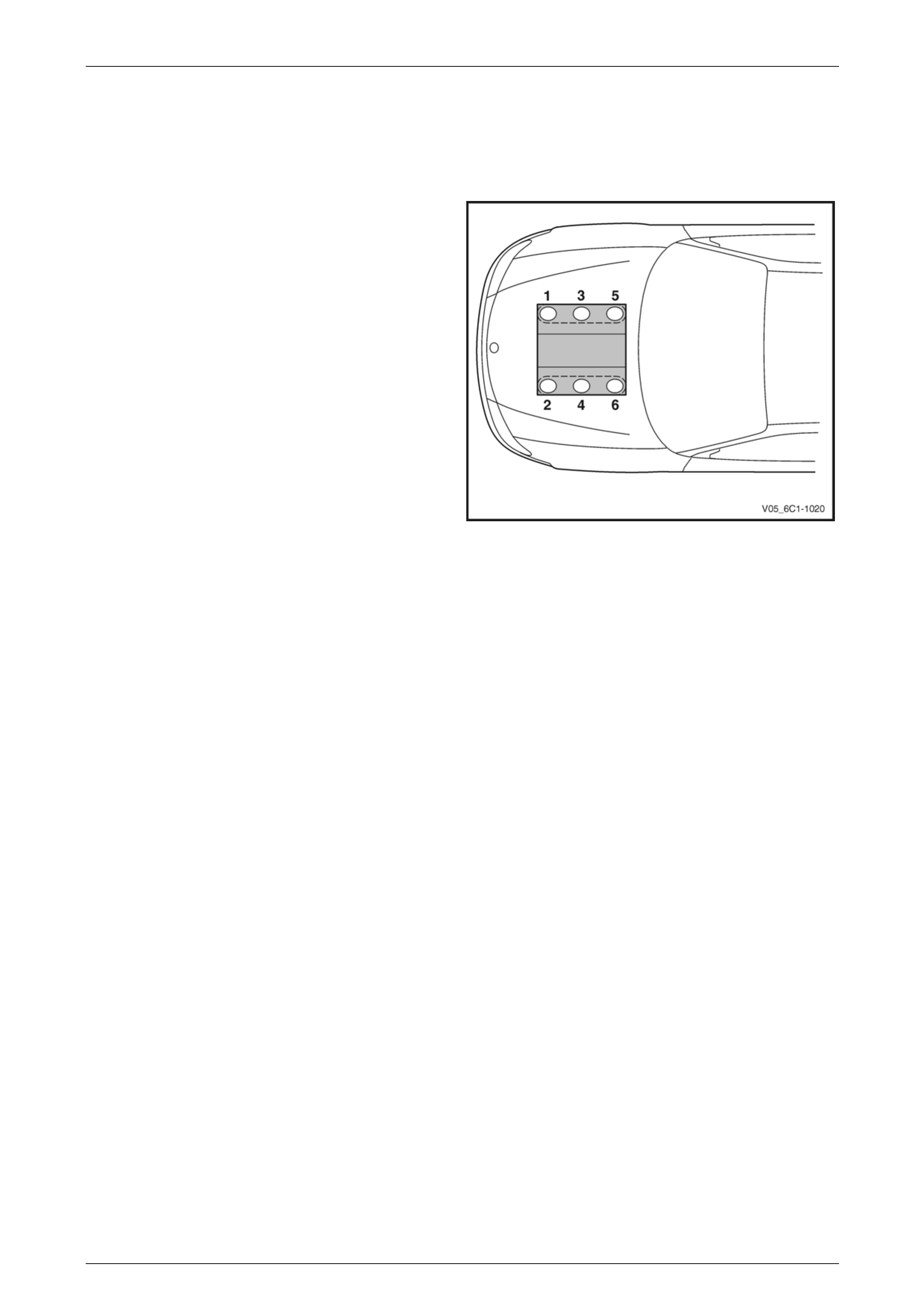
2.1 Cylinder Numbering
Engine cylinder identification follows the inter national
standard OBD II. This standard calls for the engine cylinder
bank number one to be identified by the location of cylinder
number one. Therefore the numbering for the V6 engine is:
The V6 engine cylinders are numbered as follows:
• 1, 3, 5 – Right-hand side (Bank 1),
• 2, 4, 6 – Left-hand side (Bank 2).
The engine firing order is 1, 2, 3, 4, 5, 6.
Figure 6C1-1 – 1
Page 6C1-1–5
Engine Management – V6 – General Information Page 6C1-1–6
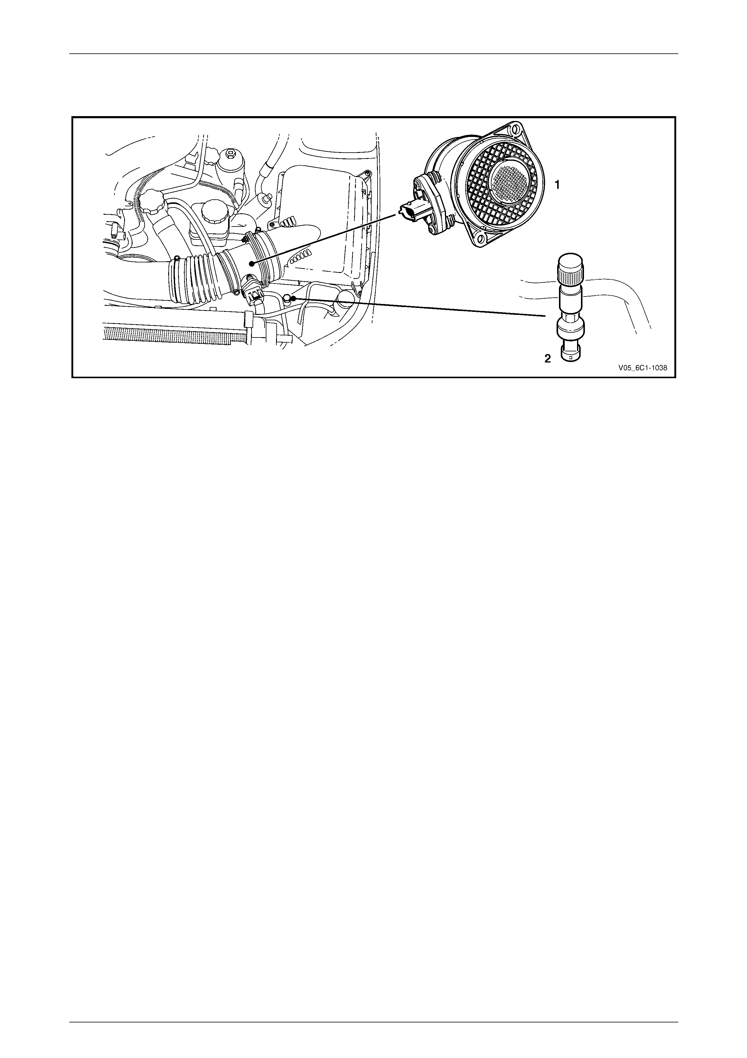
2.2 Engine Compartment
Figure 6C1-1 – 2
Legend
1 Mass Air Flow (MAF) Sensor 2 Air-conditioner Refrigerant Pressure Sensor
Page 6C1-1–6
Engine Management – V6 – General Information Page 6C1-1–7
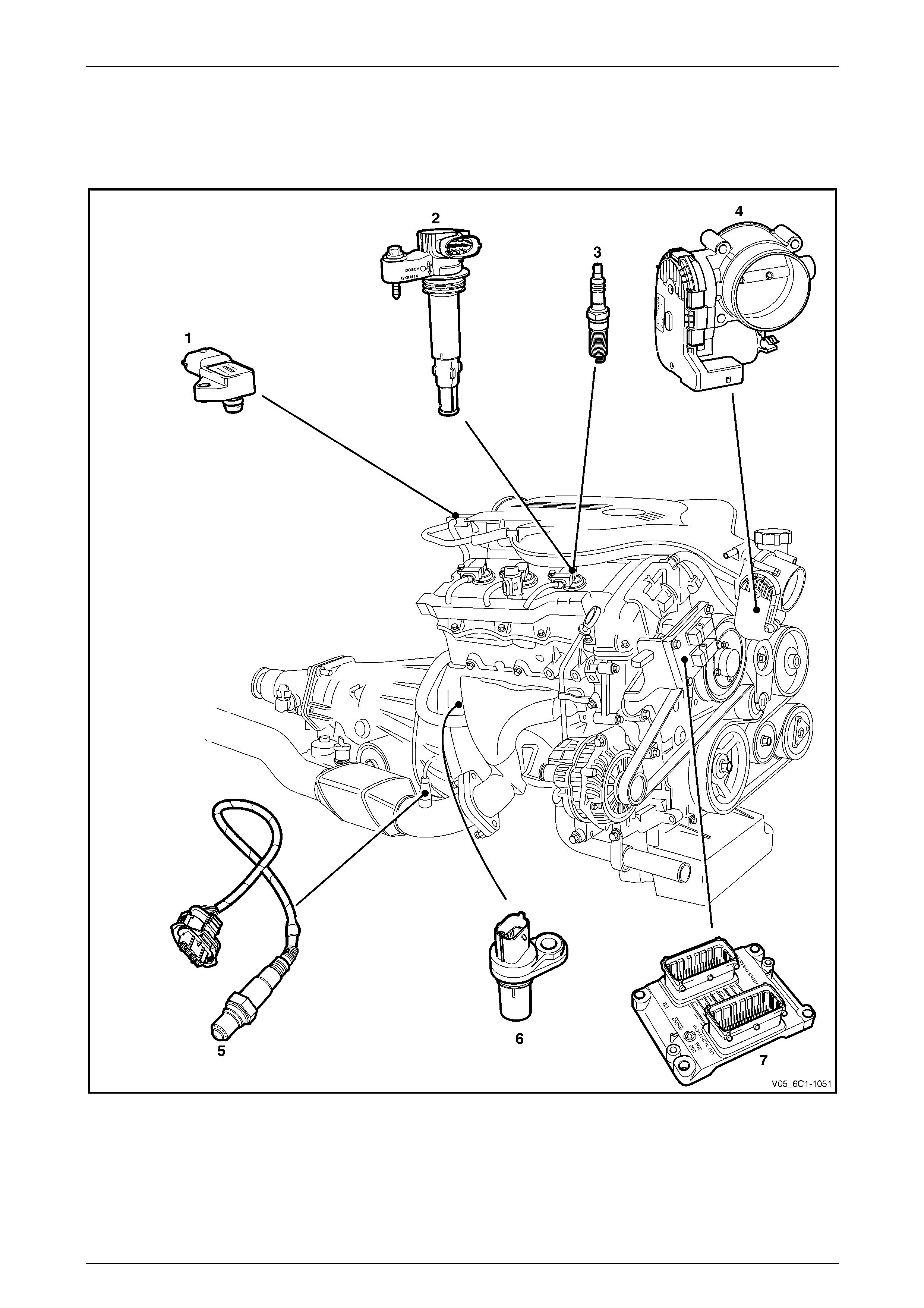
2.3 Engine
Alloytech
Figure 6C1-1 – 3
1 Barometric Pressure (BARO) Sensor
2 Ignition Coil Assembly (six places)
3 Spark Plug (six places)
4 Throttle Body Assembly
5 Heated Oxygen Sensor (HO2S), Pre-Catalyst (two places)
6 Crankshaft Position (CKP) Sensor
7 Engine Control Module (ECM)
Page 6C1-1–7

Engine Management – V6 – General Information Page 6C1-1–8
Alloytech 190
Figure 6C1-1 – 4
Legend
1 Barometric Pressure (BARO) Sensor
2 Intake Manifold Runner Control (IMRC) Valve
3 Ignition Coil Assembly (six places)
4 Spark Plug (six places)
5 Throttle Body Assembly
6 Engine Control Module (ECM)
7 Crankshaft Position (CKP) Sensor
8 Heated Oxygen Sensor (HO2S), Pre-Catalyst (two places)
9 Heated Oxygen Sensor (HO2S), Post-Catalyst (two places)
Page 6C1-1–8
Engine Management – V6 – General Information Page 6C1-1–9
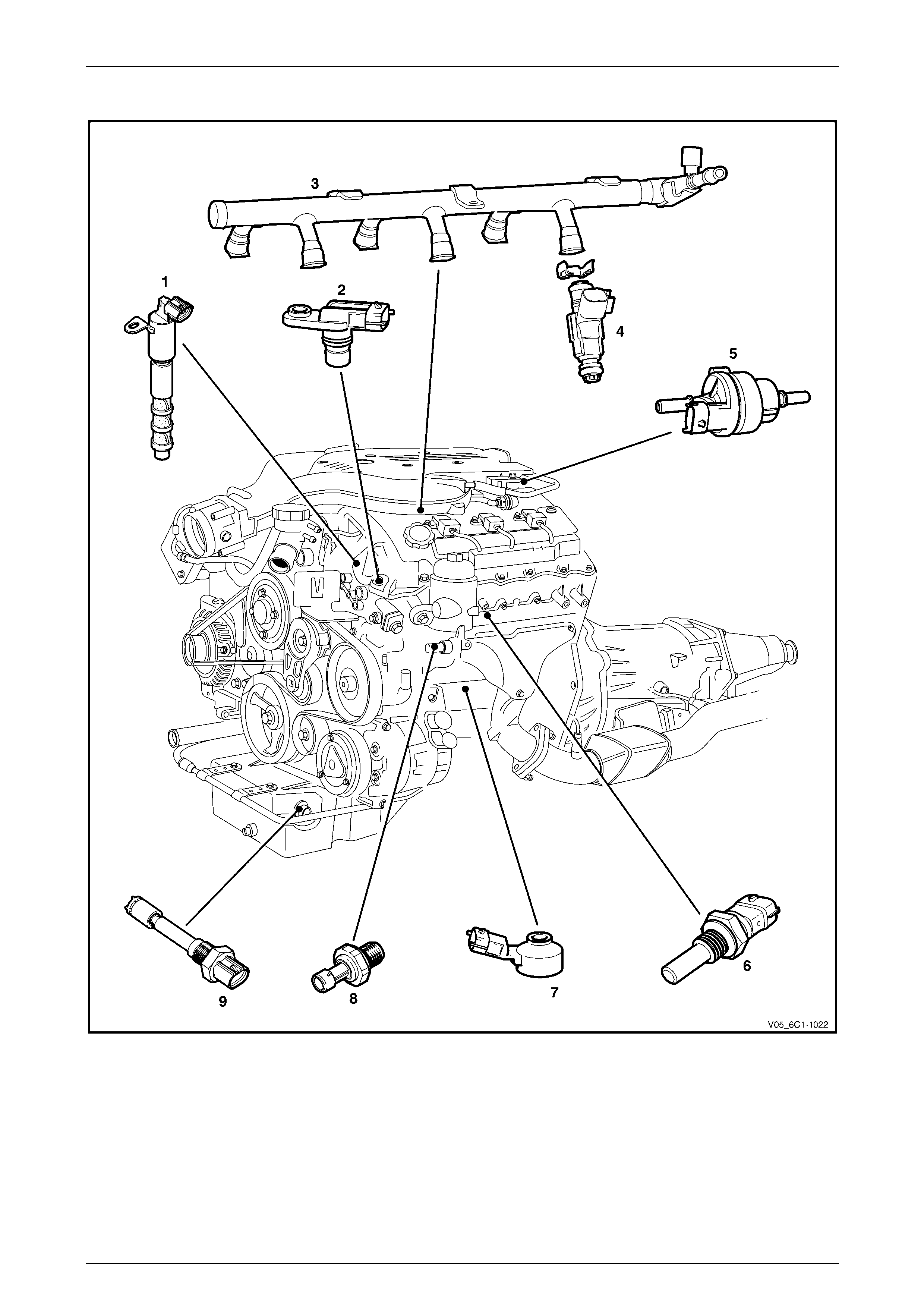
All Engines
Figure 6C1-1 – 5
Legend
1 Camshaft Position (CMP) Actuator Solenoid, Alloytec
(two places), Alloytec190 (four places)
2 Camshaft Position (CMP) Sensor, Alloytec (two places),
Alloytec190 (four places)
3 Fuel Rail Assembly
4 Fuel Injector (six places)
5 Evaporative Canister Purge (EVAP) Valve
6 Engine Coolant Temperature (ECT) Sensor
7 Knock (KS) Sensor (two places)
8 Engine Oil Pressure Sensor
9 Engine Oil Level / Temperature Sensor
Page 6C1-1–9
Engine Management – V6 – General Information Page 6C1-1–10
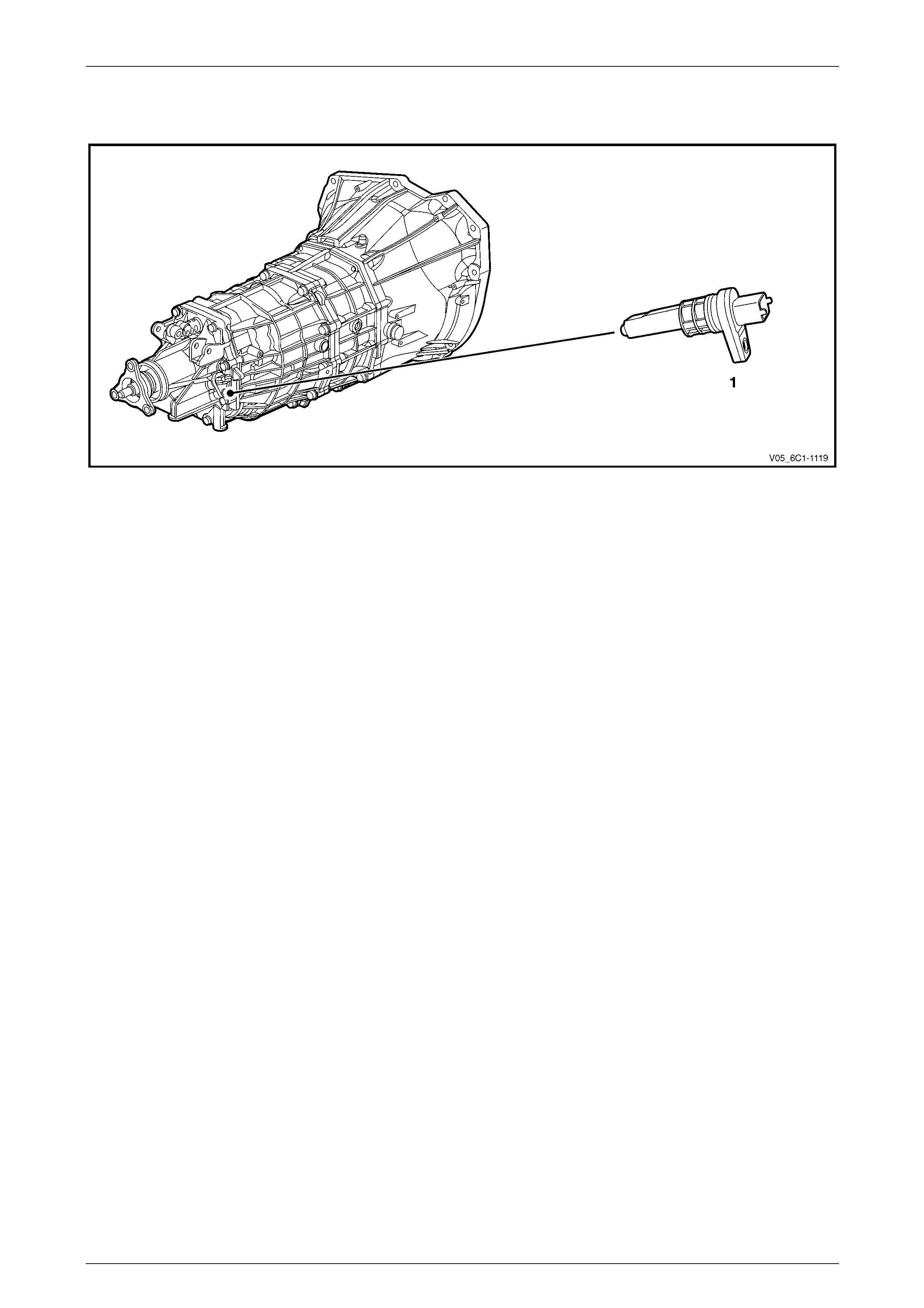
2.4 Manual Transmission
Figure 6C1-1– 6
Legend
1 Vehicle Speed Sensor (VSS)
Page 6C1-1–10
Engine Management – V6 – General Information Page 6C1-1–11
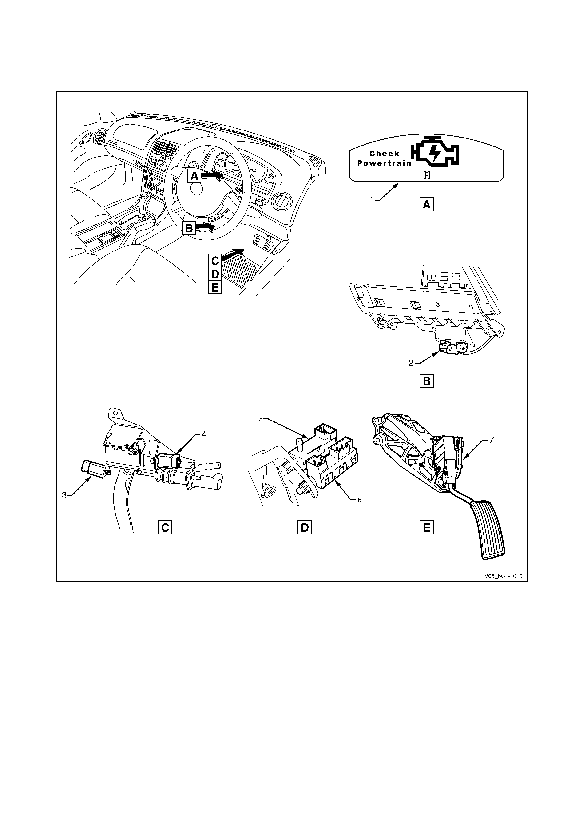
2.5 Interior
Figure 6C1-1 – 7
Legend
1 Check Powertrain Icon
2 Data Link Connector (DLC)
3 Clutch Pedal Cruise Control Cancel Switch
4 Clutch Pedal Position Switch
5 Extended Brake Pedal Travel and Brake Pedal Cruise
Control Cancel Switch
6 Stop Lamp and BTSI Switch Assembly
7 Accelerator Pedal Assembly
Page 6C1-1–11
Engine Management – V6 – General Information Page 6C1-1–12
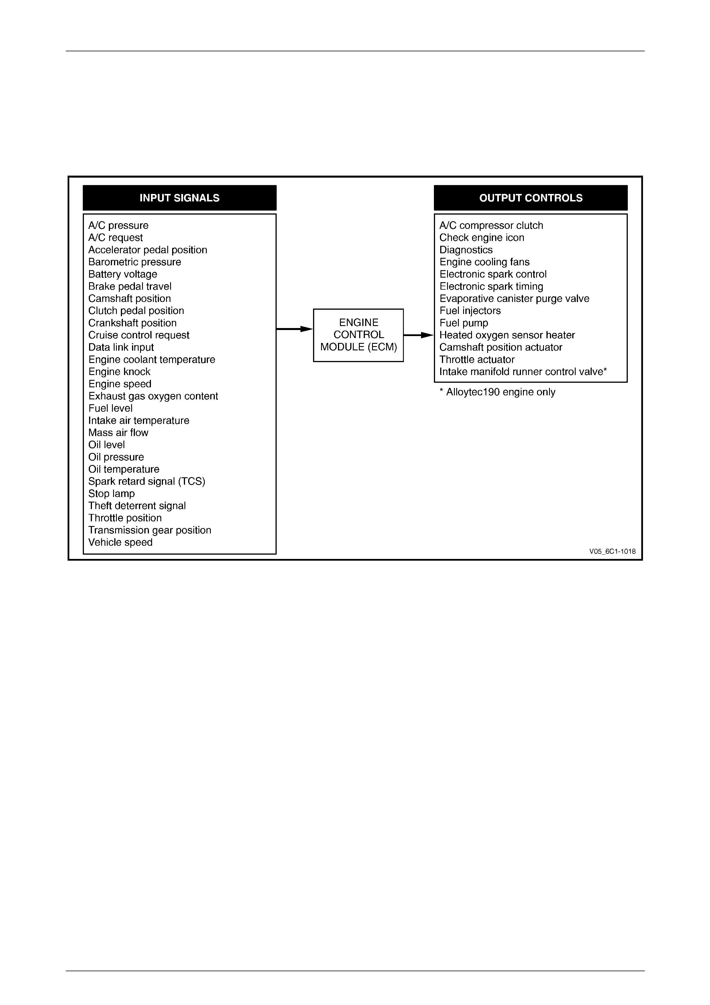
3 System Operation
The engine control module (E CM) is the control centre of the V6 engine management system. The ECM constantly
monitors and evaluates inputs from various sensors and switches. Based on these inputs, the ECM controls the
operation of the engine management system. Refer to Figure 6C1-1 – 8 for the illustration of the inputs and outputs of
the ECM.
Figure 6C1-1 – 8
3.1 Fuel Delivery System
Fuel System Pressure
When the ignition s witch is turned on, the EC M energises the fuel pump circuit and the fuel pump runs a nd builds up
pressure in the fuel system. The fuel pump will continue to operate if the engine is started or as long as the engine is
cranking or running and the ECM detects crankshaft position (CKP) sensor signal pulses. If the CKP sensor signal
pulses stop, the ECM de-energises the fuel pump circuit within two seconds, which stops the fuel pump oper ation.
The vehicle is fitted with a modular fuel pump and sender assembly that provides delivery of fuel from the fuel tank and
information on the fuel level. The fuel del ivery system is a single line, on-demand design. With the fuel pressure regulator
incorporated into the modular fuel pump and sender assembly, the need for a return pipe from the engine is eliminated.
The electric fuel pump contained in the modular fuel pump and sender assembly provides fuel at a pressure greater than
the regulated pressure which is supplied to the fuel rail. The fuel is then distributed through the fuel rail to six injectors
located directly above each cylind er’s two intake valves.
Having a single line fuel supply system reduces the internal temperature of the fuel tank by not returning hot fuel from the
engine. In reducing the internal temperature of the fuel tank, lower evaporative emissions are achieved.
Unleaded fuel must be used to ensure correct emission parameters and engine operati on. Leaded fuel damages the
emission control system and use of leade d fuel ca n result in loss of emission warranty. Using unleaded fuel will also
minimise any spark plug fouling and extend engine oil life.
Page 6C1-1–12

Engine Management – V6 – General Information Page 6C1-1–13
Fuel Injection System
Each cylinder of the V6 engine is fitted with one fuel injector. The engine control relay applies ignition positive voltage to
the fuel injector ignition circuit. The ECM controls the operation of the fuel injectors by applying a pulse width modulated
(PWM) ground to the fuel injector control circuit to control each fuel injector on-time.
While the engine is running, the ECM constantly monitors the various inputs and recalculates the appropriate on-time for
each injector. The calculatio n is based on the following:
• the injector flow rate,
• mass of fuel passed by the energised injector per unit of time,
• the desired air / fuel ratio, and
• actual air mass in each cylinder.
The ECM calculates the duration of the fuel injector on-time to deliver the correct amount of fuel for optimum drivability
and emission control. The period of time the fuel i njector is e nergised is called the injector on-time and is measured in
milliseconds (thousandths of a second).
The V6 engine uses the sequential fue l injection system. Each fuel injector is energised individually at the correct
moment during its firing stroke as the cylinder’s intake valves are closing to provide enough time for the fuel to atomise
completely and mix with the intake air.
Short Term Fuel Trim
The short term fuel trim (STFT) represents the duration of the fuel injector on-time as calculated by the ECM while the
ECM is in Closed Loop mode. The STFT allows the ECM to calculate the fuel injector on-time based on the heated
oxygen sensor (HO2S) signal input to the ECM. Therefore, the STFT is disabled when the ECM is in Open Loo p mode.
• If the air / fuel mixture in the exhaust is balanced (l ambd a = 1) or when the STFT is disabled, the STFT value is
0%.
• When the HO2S sends an input signal to the ECM indicating the air / fuel mixture is rich, the STFT will be less than
0%, which indicates the ECM is decreasing the fuel injector on-time to reduce the amount of fuel in the ai r / fuel
mixture.
• When the HO2S sends an input signal to the ECM indicating the air / fuel mixture is lean, the STFT will be greater
than 0%, which indicates the ECM is increasing the fuel injector on-time to increase the amount of fuel in the air /
fuel mixture.
The percentage values of the STFT range from -25% – 25% and are directly proportional to the duration of the fuel
injector on-time.
Long Term Fuel Trim
The ECM stores the long term fuel trim (LTFT) in its memory to adjust the fuel injector on-time according to the long term
changes or deterioration in the engin e components. The normal LTFT value is 0%.
The following describes the LT FT operation when the engine air filter is dirty that caus es a restricted intake airflow fault
condition:
1 The HO2S sends an input signal to the ECM the air / fuel mixture is rich because of the reduced airflow. The ST FT
may reduce to a value of -10%, which decreases the fuel injector on-time to reduce the amount of fuel in the air /
fuel mixture supplied to the engi ne.
Without the use of the LTFT, the restricted airflow caused by the dirty air filter may reduce the STFT value to -10%
until the air filter is replaced. This will decrease the range of negative adjustment available to the STFT to
compensate for other factors.
2 When the ECM detects the STFT has remained at -10% for a specific period, the ECM switches to the LTFT. The
LTFT adjusts the duratio n of the fuel i nj ector on-time u ntil th e air / fuel mixture in the ex haust is balanced (lambda =
1) and the STFT value returns to 0%.
3 The ECM stores this Long Term FT value in its memory, which is used to calculate the base fuel injector on-time.
The percentage values of the Long Term FT range from -100% – 100%. If the ECM detects the LTFT values are outside
the specified percentage range for a predetermined period, the ECM will set a Diagnostic Trouble Code and switch to
Open Loop mode.
Page 6C1-1–13

Engine Management – V6 – General Information Page 6C1-1–14
3.2 Air / Fuel Control System
The engine control module (ECM) controls the amount of air and fuel delivered into each of the engine cylinders. Based
on the various ECM inputs, the ECM switches to the following air / fuel control system mode to provide the optimum air /
fuel ratio under all engine op erating conditions.
Starting Mode
When the ignition s witch is moved to the START position and the engine beg ins to turn, a prime pulse may be injected to
speed starting. As soon as the ECM receive s an input signal from the camshaft position (CMP) and crankshaft position
(CKP) sensor and determines which cylind er is in the firing stroke, the ECM applies a pulse width modulated (PWM)
ground to the injector control circuit. T he ECM monitors ma ss air flow, intake air temperature, engine coolant
temperature, and throttle position to determine the required fuel injector on-time required for starting the engine.
Run Mode
The engine switches to run mode when the engine speed reaches 480 r.p.m. after being started. The run mode has two
sub-modes called Open Loo p and Closed Loop.
Open Loop Mode
The heated oxygen se nsor (HO2S) does not produce a usable signal voltage output until it reaches operating
temperature. Therefore, while the HO2S is below its operating temperature, the ECM switches to open loop mode.
In open loop, the ECM ignores the signals from the HO2S and calculates the required injector pulse width based
primarily on inputs from the mass air flow (MAF), intake air temperature (IAT), and engine coolant temperature sensors.
The system will stay in the open loop mode until the HO2S produce a usable output.
Closed Loop Mode
Once the HO2S reaches operating temperature and starts producing its own signal voltage output, the ECM switches to
the closed loop mode.
In closed loop mode, the ECM initially calculates in jector pulse width based on the same sensors used in open lo op, and
additionally the ECM uses the oxygen sensor signals to modify and fine tune the fuel pulse width calculations to precisely
maintain the ideal 14.7 to 1 air / fuel ratio.
Acceleration Mode
The ECM monitors and calculates inp ut signals from the accelerator pedal position (APP) and MAF sensor signals to
determine when the vehicle is being accelerated. If the ECM detects the accelerator pedal is depressed and there is a
demand for the vehicle to accelerate, the ECM switches to acceleration mode. In acceleration mode, the ECM increases
the fuel injector on-time to provide more fuel accordingly.
Deceleration Mode
The ECM monitors and calculates inp ut sign als from the APP and MAF sensor signals to determine when the vehicle is
being decelerated. If the ECM detects the vehicle is decelerating, the ECM switches to deceleration mode. In
deceleration mode, the ECM decreases the fuel injector on-time, or disables the fuel injectors for short periods, to red uce
exhaust emissions and improve fuel eco nomy.
Fuel Shut-off Mode
To protect the engine from damage or to improve the veh icle's driveability, the ECM switches to the fuel shut-off mode. In
fuel shut-off mode, the ECM performs the following:
• The ECM disables the six fuel injectors under the following conditions:
• ignition off – to prevent engine dieselin g,
• ignition on but no ignition refe rence signal – prevents flooding or backfiring,
• at high engine speed – greate r than the red line (rev limiter),
• at high vehicle speed – gre ater than the rated tire speed (vehicle speed limiter), or
• extended high speed closed throttle coast-down – reduces engine emissions and increas es engine braking.
• The ECM selectively disables the appropriate number of fuel injectors under the following conditions:
• torque management enabled – transmission shifts or abusive mane uvers, or
• traction control enabled – in c onjunction with brake application.
Page 6C1-1–14

Engine Management – V6 – General Information Page 6C1-1–15
Battery Voltage Co rrection Mode
The ECM monitors the battery voltage circuit to ensure the voltage ava ilable to the engine management system stays
within the specified range. A low system voltage changes the voltage across the fuel injectors, which affects the fuel
injector flow rate. In addition, a lo w system voltage fault condition ma y cause other engine management system
components to malfunction.
The ECM switches to battery voltage correction mode when the ECM detects a low battery voltage fault condition. While
in battery voltage correction mode, the ECM performs the following functions to compensate for the low system voltage:
• increases the injector on-time to maintain the correct amount of fuel being delivered, and
• increases the idle speed to increase the gen erator outp ut.
Limp Mode
The programming in the ECM software allows the engine to run in a back-up fuel strategy or limp mode when the ECM
fails to receive signal inputs from critical sensors or when a critical engin e mana gement fault condition exists.
The ECM switches to limp mode to enable the vehic le to be driven until service operations can be p erformed.
Engine Protection Mode
Engine protection mode is en gaged to protect engine components from friction damage in the eve nt of an engine over-
temperature condition being detected by the ECM.
When the ECM is in engine protection mode, fuel injectors are systematically disabled and re-activated. The injectors
that have been shut down allow the air being drawn into the engine to assist with engine cooling.
Clear Flood Mode
If the engine is flooded with fuel during starti ng and will not start, the clear flood mode can be manually selected b y
depressing the accelerator pedal to wide open throttle (WOT). In this mode, the ECM will completely disable the fuel
injectors, and will maintain this state during engine cranking as long as the ECM detects a WOT condition with engine
speed less than 1,000 r.p.m.
Page 6C1-1–15

Engine Management – V6 – General Information Page 6C1-1–16
3.3 Ignition Control System
The electronic ignition s ystem provides a spark to ignite the compressed air / fuel mixture at the correct time. The ECM
maintains correct spark timing and d well for all engine operating conditions. The ECM calculates the optimum spark
parameters from information received from the various se nsors and triggers the appropriate ignition module / coil to fire
the spark plug.
Page 6C1-1–16

Engine Management – V6 – General Information Page 6C1-1–17
3.4 Starter Motor Operation
The engine control module controls the activation of the start relay in response to inputs from:
• Ignition switch,
• battery,
• theft deterrent engine crank inhibit or (a functi on of the theft deterrent system), and
• automatic transmission gear selector position / clutch ped al position switch for vehicles with manual transmissions.
Auto Start Feature
Once the ignition switch has been turned to the START position, the starter motor will crank the engine .
If the ignition switch is returned to the ON position before the engine has started, the starter motor will continue to
operate until the engine starts. If the engine fails to start, cranking will continue for approximately four sec onds from
when the ignition switch was returned to the ON position.
Turning the ignition switch to the OFF position will cancel the Auto Start and the starter motor will stop cranking. For
further information on the starter motor system, refer to Section 6D1-2 Starting System – V6.
Clutch Pedal Position Switch
The clutch pedal position switch provides an input to the ECM to ensure the clutch pedal is depress ed while the vehicle
is being started. For further information on the clutch pedal position switch, refer to 4.6 Clutch Pedal Switch Assemblies
– Manual Vehicles Only.
Page 6C1-1–17
Engine Management – V6 – General Information Page 6C1-1–18
3.5 Throttle Actuator Control System
Description
The throttle actuator control (TAC) system is used to impr ov e emissions, fuel economy and driveability. The TAC system
eliminates the mechanical link between the accelerator pedal and the throttle plate and eliminates the need for a cruise
control module and idle air control motor. The TAC system comprises of:
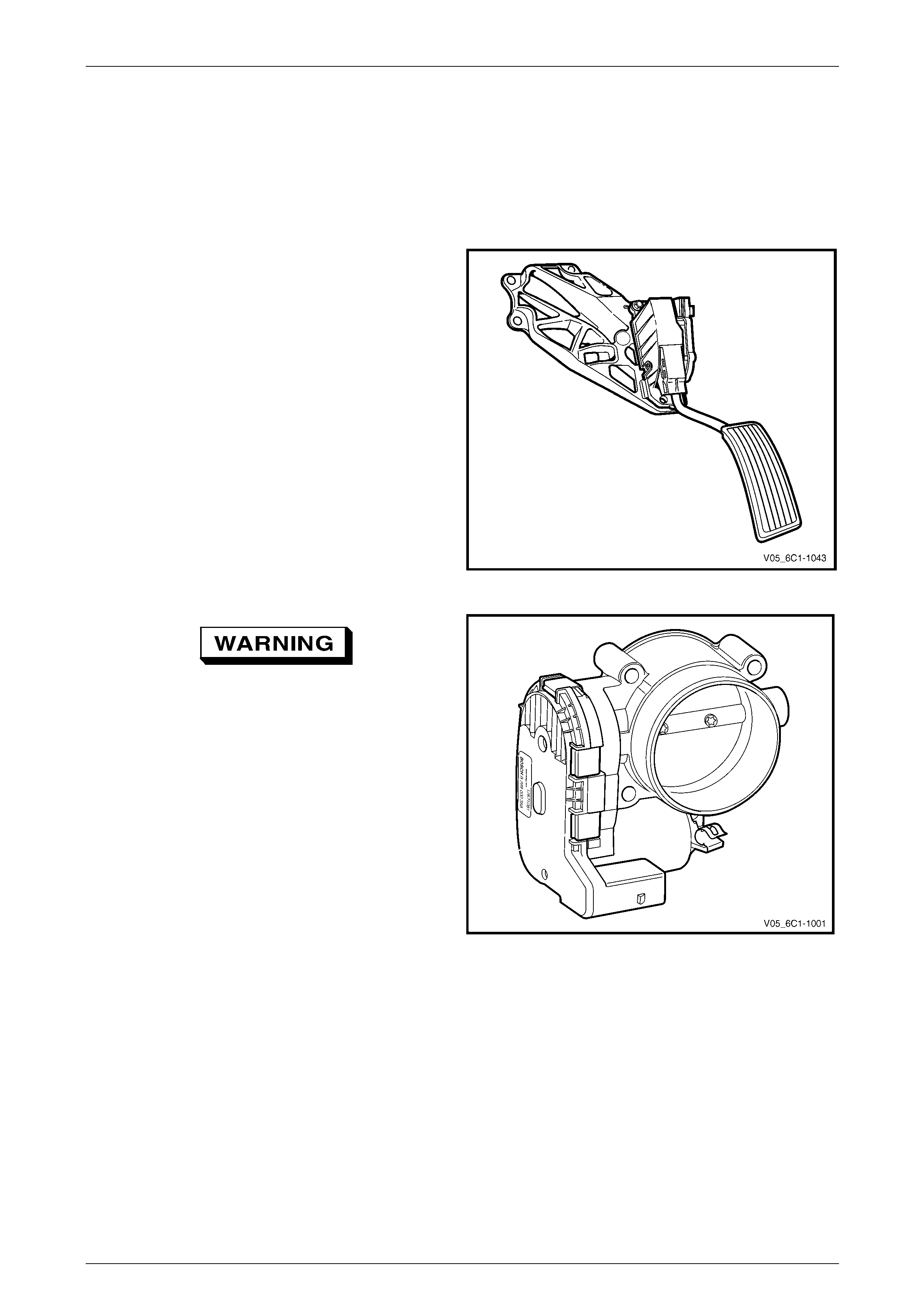
• The accelerator pedal assem bly which includes:
• the accelerator pedal,
• the accelerator pedal position (APP) sensor one,
• the accelerator pedal position (APP) sensor two.
Figure 6C1-1 – 9
To avoid serious personal injury, never
attempt to rotate the throttle plate manually
whilst the throttle body harness connector is
connected to the throttle bod y.
• The throttle body assembly which i nclu des:
• the throttle position (TP) sensor one,
• the throttle position (TP) sensor t wo,
• the throttle actuator control (TAC) motor, and
• the throttle plate.
• The engine control module (E CM).
Figure 6C1-1 – 10
The ECM monitors the accelerator pedal position through the two APP sensors and processes this information along with
other system sensor inputs to command the throttle plate to a certain position.
The throttle plate is controlled by a direct current motor called the throttle actuator control motor. The ECM operates this
motor in the forward or reverse direction by controlling battery voltage and / or ground to two internal drivers. The throttle
plate is held at a rest position of seven percent open using a constant force return spring. This spring holds the throttle
plate to the rest position when there is no current flowing to the actuator motor.
The ECM monitors the throttle plate angle through two TP sensors. Using this information, the ECM can precis ely adjust
the throttle plate.
The ECM performs diagnostics that monitor the voltage levels of both APP sensors, both TP sensors and the throttle
actuator control motor circuit. It also monitors the spring return rate. T hese diagnostics are performed at different times
based on whether the engine is running, not running, or whether the ECM is currently in a throttle body relearn
procedure.
Page 6C1-1–18

Engine Management – V6 – General Information Page 6C1-1–19
Two sensors within the accelerator ped al assembly and throttle body assembly are used to provide redundancy. If a
malfunction is detected, the throttle plate is moved to a pre-determined position.
Every ignition cycle, the ECM performs a quick throttle return spring test to ensure the throttle plate can return to the
seven percent rest position from the zero percent position. This is to ensure the throttle plate can be brought to the rest
position in case of an actuator motor circuit failure.
Throttle Body Relearn Procedure
The ECM stores values that include the lowest possible TP sensor positions (zero percent), the rest positions (seven
percent), and the spring return rate. T hese values will only be erased or overwritten if the ECM is reprogrammed or if a
throttle body relear n procedure is performed.
NOTE
If the battery has been disconnected, the ECM
performs a throttle body relearn procedure once
the battery has been reconne cted and the ig nition
turned on.
The ECM performs a throttle body relearn procedure anytime the ignition is turned on and the following conditions have
been met:
• the engine has been off for greater than 29 seconds,
• the engine speed is less than 40 r.p.m.,
• the vehicle speed is 0 km/h,
• the engine coolant temperature (ECT) is 5 – 60°C; if Tech 2 is used to perform the relearn procedure, the ECT is
5 – 100°C,
• the intake air temperature (IAT) is greater than 5 – 60°C; if Tech 2 is used to perform the relearn procedure, the
IAT is 5 – 100°C,
• the APP sensor angle is less than 15 percent, and
• ignition voltage is greater than 10 V.
The throttle body relearn procedure is performed 29 seconds after the ignition is turned on. The ECM commands the
throttle plate from the rest position (even pe r cent open) to full closed (zero percent), then to around 10 percent open.
This procedure takes about six – eigth sec on ds. If an y faults occur in the TAC system, a DTC sets. At the start of this
procedure, the Tech 2 TAC Learn Counter parameter should display 0, then count up to 11 after the procedure is
completed. If the counter did not start at 0, or if the counter did not end at 11, a fault has occurred and a DTC should set.
TAC System Default Actions / Reduce Power Modes
The ECM switches to the following reduce power modes if the ECM detects a fault condition in the TA C system:
• If an APP sensor circuit fault or TP sensor circuit fault is detected, the ECM limits engine torque so the vehicl e
cannot reach speeds of great er than 100 km/h. The ECM remains in this reduce power mode during the entire
ignition cycle, even if the fault is corrected.
• If there is a fault condition with the throttle actuator control circuits, a throttle actuator command vs. actual position
fault, a return spring check fault, or a TP sensor one circuit fault, the ECM limits engine speed to 2500 r.p.m. and
three – six fuel injectors are ra ndomly disabled. At this time the reduce power indicator is commanded on. The
ECM remains in the reduce po wer mode during the entire ignition cycle even if the fault is corrected.
NOTE
If a TP sensor one or throttle actuator control
circuit fault is present at the time the vehicle is at
idle, with no accelerator pedal angle, the engine
may stall.
Forced Engine Shutdown
A further safety feature which is built into the TAC system is the ECM will initiate an engine shut down if, the ECM's
internal monitoring functions detects a serious internal fault, the fuel injectors will be turned off.
Page 6C1-1–19
Engine Management – V6 – General Information Page 6C1-1–20
3.6 Camshaft Position Actuator Control
System
The Alloytec engine has variable timing on the intake camshafts only, while the Allo ytec190 engine has variable timing
on both intake and exhaust camshafts.
NOTE
The parameters under which variable valve
timing will occur is very complex. The conditions
outlined below is a brief summary of the
conditions the ECM uses to determine the point
at which variable valve timing will commence:
The ECM will only initiate variable timing if all of the following conditions exist:
• Engine coolant temperature is greater tha n -12°C and less than 130°C,
• air intake temperature is great er than -48°C,
• engine oil temperature is greater than -10°C and less than 155°C, and
• engine speed is greater tha n 1000 r.p.m. for longer than two seconds, and less than 7320 r.p.m.
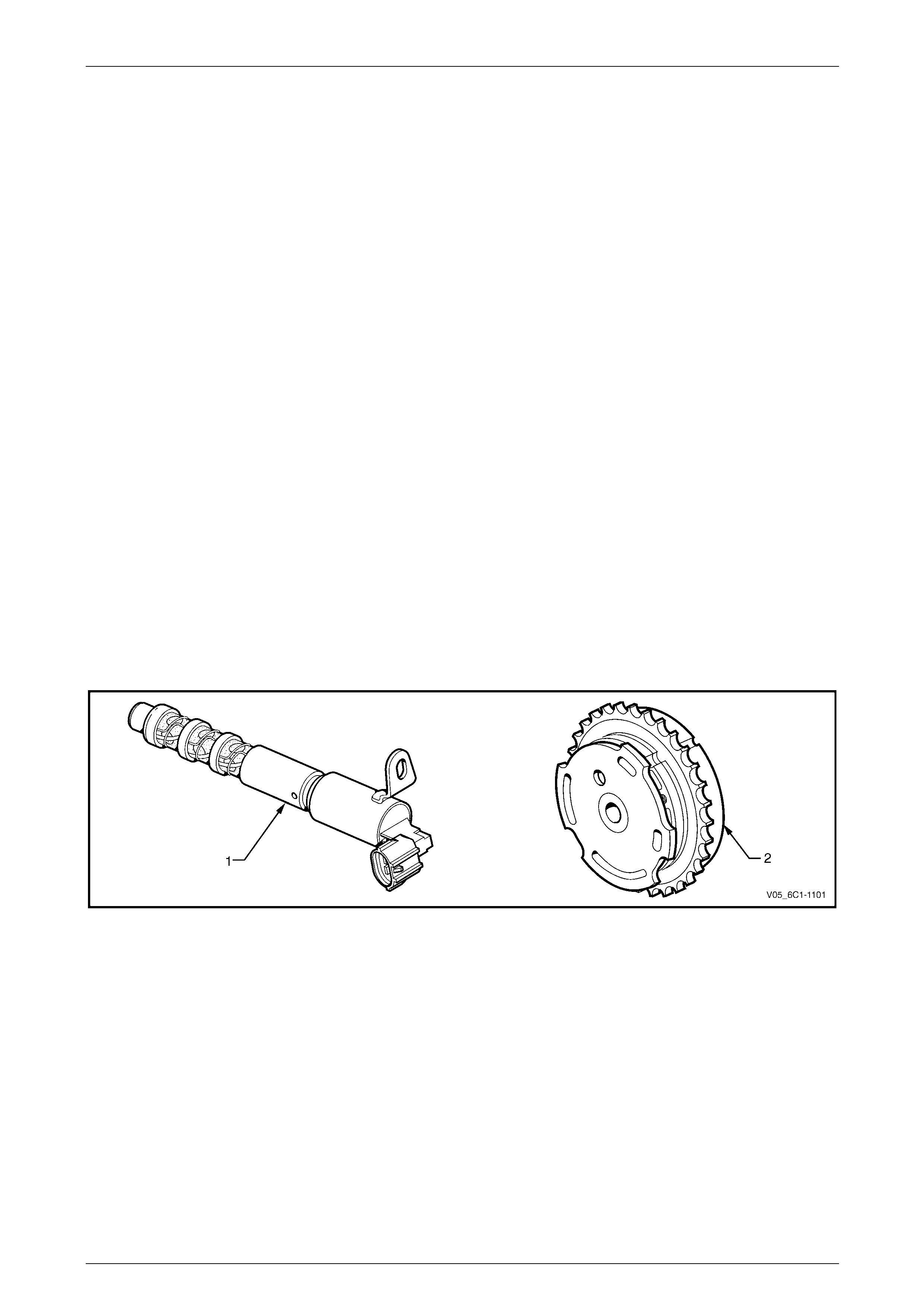
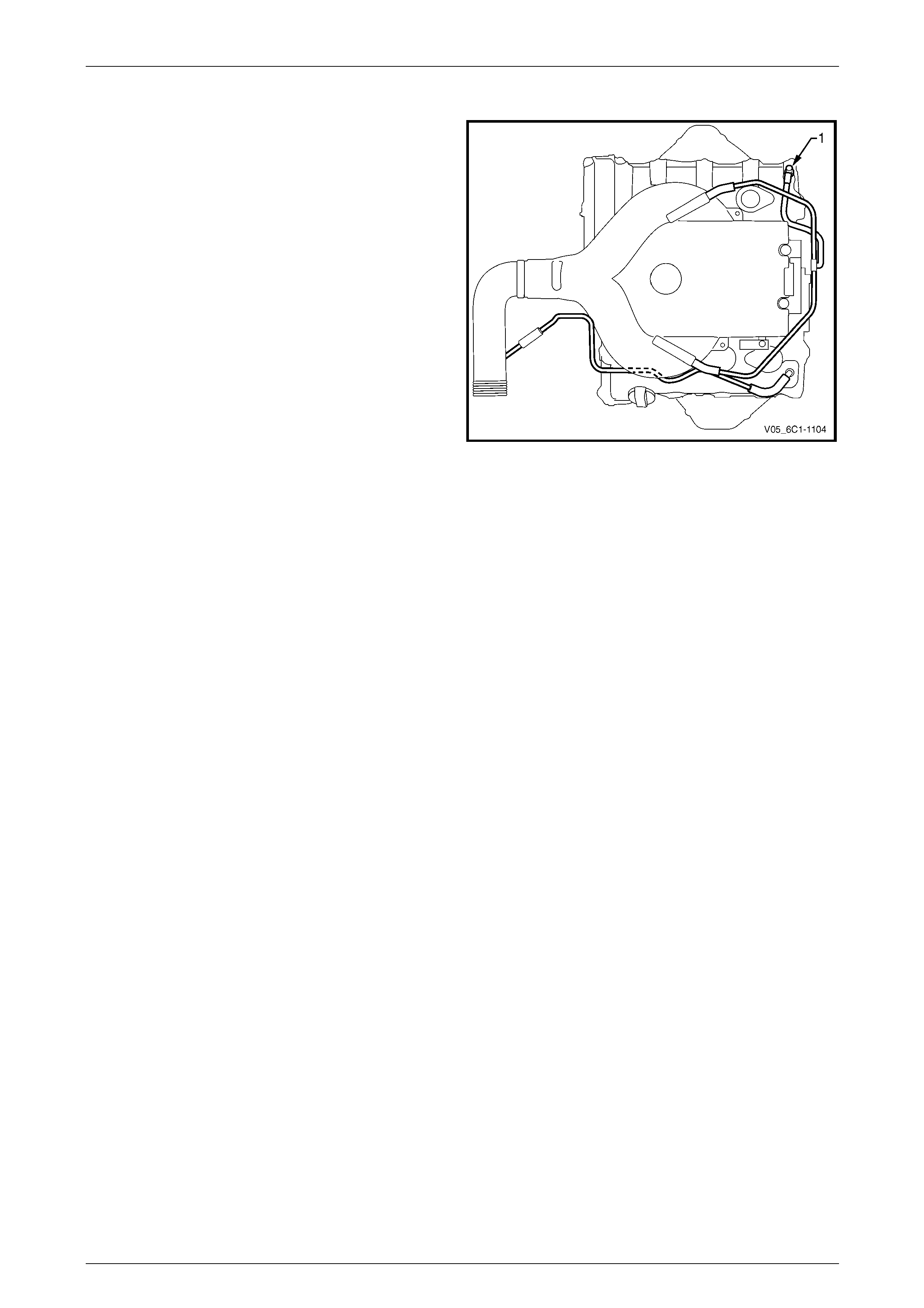
The ECM adjusts the timing of each camshaft by applying a pulse width modulated (PWM) control signal to the camshaft
position (CMP) actuator solenoid valve (1), which in turn controls the oil pressure / flow to the CMP actuator (2).
Refer to Figure 6C1-1 – 11.
The engine control module (E CM) advances or retards the camshaft timing, based on various system inputs, to provide
optimum valve overlap over the entire operating range of the engine.
The intake camshafts can be advanced u p to 25 camsh aft degrees, and the exhaust camshafts can be retarded up to 25
camshaft degrees.
The crankshaft position (CKP) sensor an d the camshaft position (CMP) sensors are used to monitor changes in the
camshaft positions.
Figure 6C1-1 – 11
Page 6C1-1–20
Engine Management – V6 – General Information Page 6C1-1–21
Operation
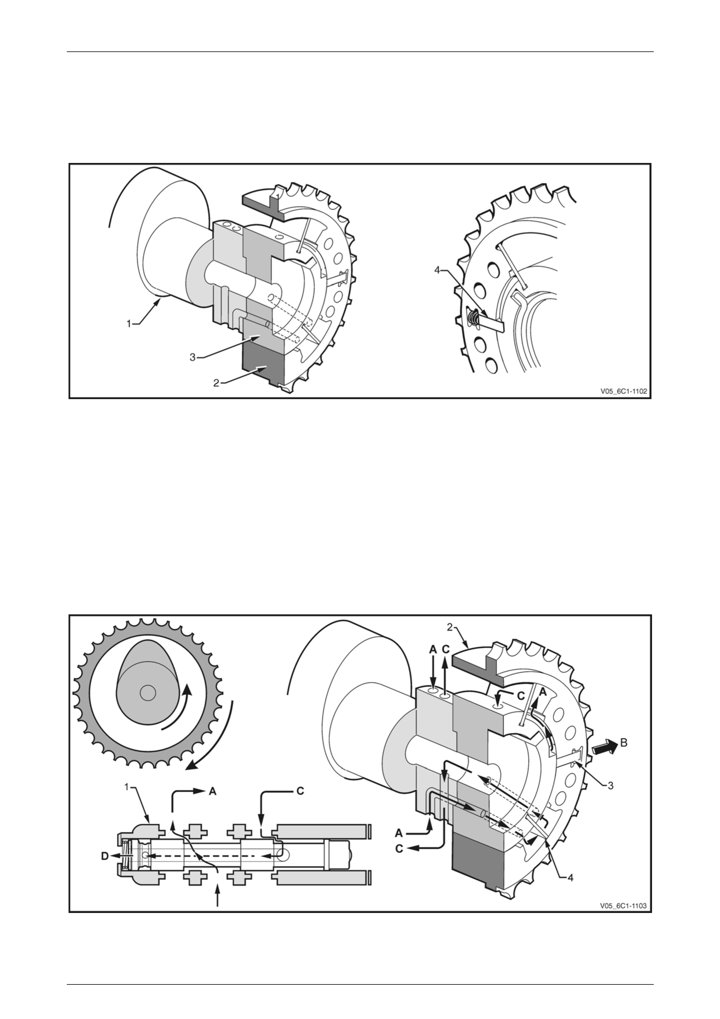
A CMP actuator assembly is fitted to each variable camshaft (1). The actuator has an outer housing (2) that is driven by
the engine timing chain, an d an inner housing (3), refer to Figure 6C1-1 – 12.
When the engine is not running or at idle, a lock pi n (4) contained in each actuator locks the camshaft to the outer
housing, to prevent camshaft timing adjustme nt.
Figure 6C1-1 – 12
Variable Valve Timing Phases
Variable Valve T ming – Increase i
When the ECM commands the actuator sole noid valve (1) to redirect the oil pressure supply to the CMP actuator (2),
the oil pressure supply (A) moves the lock pin (3) in the direction of the arrow (B) to unlock the actuator, refer to
Figure 6C1-1 – 13.
At the same time, oil pressure (A) is applied to the one side of each of the four fixed vanes (4). The oil pressure builds
up, until it overcomes the CMP actuator return spring (not shown) and starts to advance the camshaft (intake) or retard
the camshaft (exhaust). As the camshaft starts to move, the oil (C) on the opposite side of the vane where the oil
pressure is currently being applied, drains back through the CMP actuator oil gall eries and out through the actuator
solenoid valve (D).
Figure 6C1-1 – 13
Page 6C1-1–21
Engine Management – V6 – General Information Page 6C1-1–22
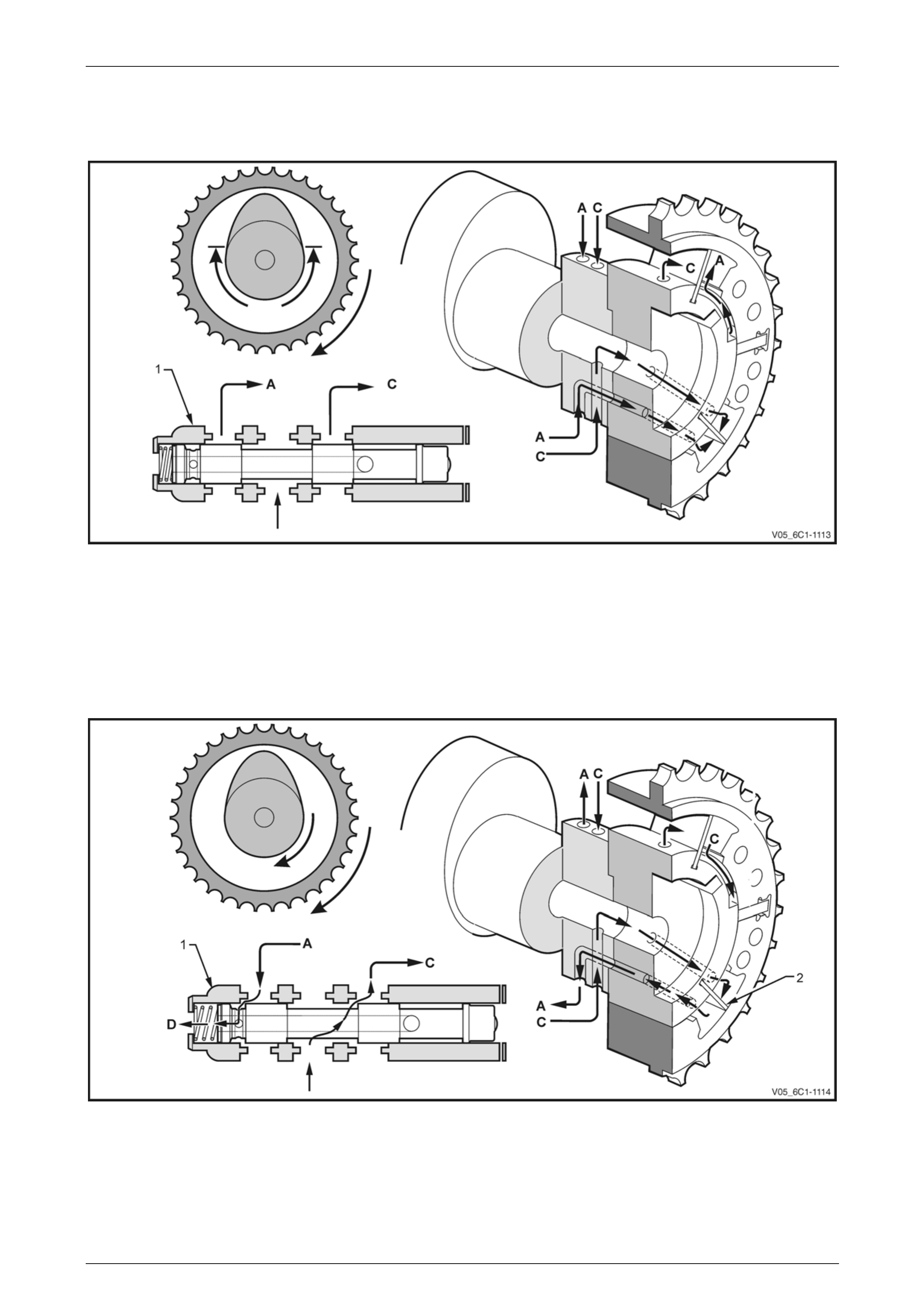
Variable Valve Timing – Maintained
When the valve timing has been advanced or retarded, and the timing is to be maintained, the actuator solenoid valve (1)
applies oil pressure (A) and (C) to both sides of the fixed vane.
Figure 6C1-1 – 14
Variable Valve T ming – Reducedi
When the amount of variable valve timing is reduced, the actuator solenoid valve (1) applies oil pressure (C), to one side
of the vane (2) (this is to the opposite side of the vane used to increase the valve timing).
As the camshaft begins to move, the oil (A) on the opposite side of the vane wher e the oil pressure is currently being
applied, drains back through the CMP actuator oil galleries and out through the actuator solenoid valve (D).
Figure 6C1-1 – 15
Page 6C1-1–22

Engine Management – V6 – General Information Page 6C1-1–23
3.7 Cruise Control System
The cruise control system integrates with the engine control module (ECM) through the powertrain interface module
(PIM), to control the electronic throttle actuator and maintain the vehicle at the speed set by the driver.
When the cruise ON-OFF button is pressed, the PIM, on receiving the input from the cruise control s witch, outputs a
signal via the serial data bus to the ECM. T he ECM recognises the command from the PIM to engage the cruise control.
The ECM then provides a signal for the instru ment cluster, via the PIM, to inform the user that cruise control is Engaged.
The user activates the cruise control at a de s ired speed greater than 40 km/h by rotating the cruise control switch
assembly to SET–DECEL. The PIM, on receiving the input from the cruise control switch, outputs a signal via the serial
data bus to the ECM. The ECM then activates the cruise control and sets the speed. The ECM receives all the various
inputs required to maintain the correct speed and th en controls the throttle plate depending on the load on the engin e
(ascending or descending hill s, etc).
The cruise control is deactivated b y either pressing the brake pedal, clutch pedal or by the cruise control ON-OFF button.
In each of these instances, the ECM receive s an input when any of these switches are activated. For further information
on the cruise control system, refer to Section 12E Cruise Control.
Page 6C1-1–23

Engine Management – V6 – General Information Page 6C1-1–24
3.8 Brake Torque Management
Brake torque management places limits on engine torque when the brakes are applied, regardless of the accelerator
pedal position (APP). The conditions under which brake torque management occur are as follows:
• The accelerator has been depressed before the brakes are applied,
• the brakes are applied and the ECM receives an input from the stop lamp switch,
• vehicle speed is greater than 5 km/h,
• engine speed is greater than 1200 r.p.m. and
• conditions exist for greater than 2.5 seconds.
When brake torque management has been implemented, the torque is reduced by altering the throttle plate opening by
25%. The ECM will monitor the rate at which the vehic le is slowing and adjust the throttle plate opening accordingly.
Page 6C1-1–24
Engine Management – V6 – General Information Page 6C1-1–25
3.9 Emission Control Systems
Evaporative Emission Control System
The evaporative emission con trol system used is the
activated carbon (charcoal) canister storage method. Fuel
vapour is drawn from the fuel tank into the canister where it
is held by the activated carbon until the ECM comman ds the
evaporative emission (EVAP) purge solenoid valve to open.
The ECM energises the EVAP purge sole noid valve by
applying a pulse width modulated (PWM) ground to the
EVAP purge solenoid valve control circuit.
Figure 6C1-1 – 16
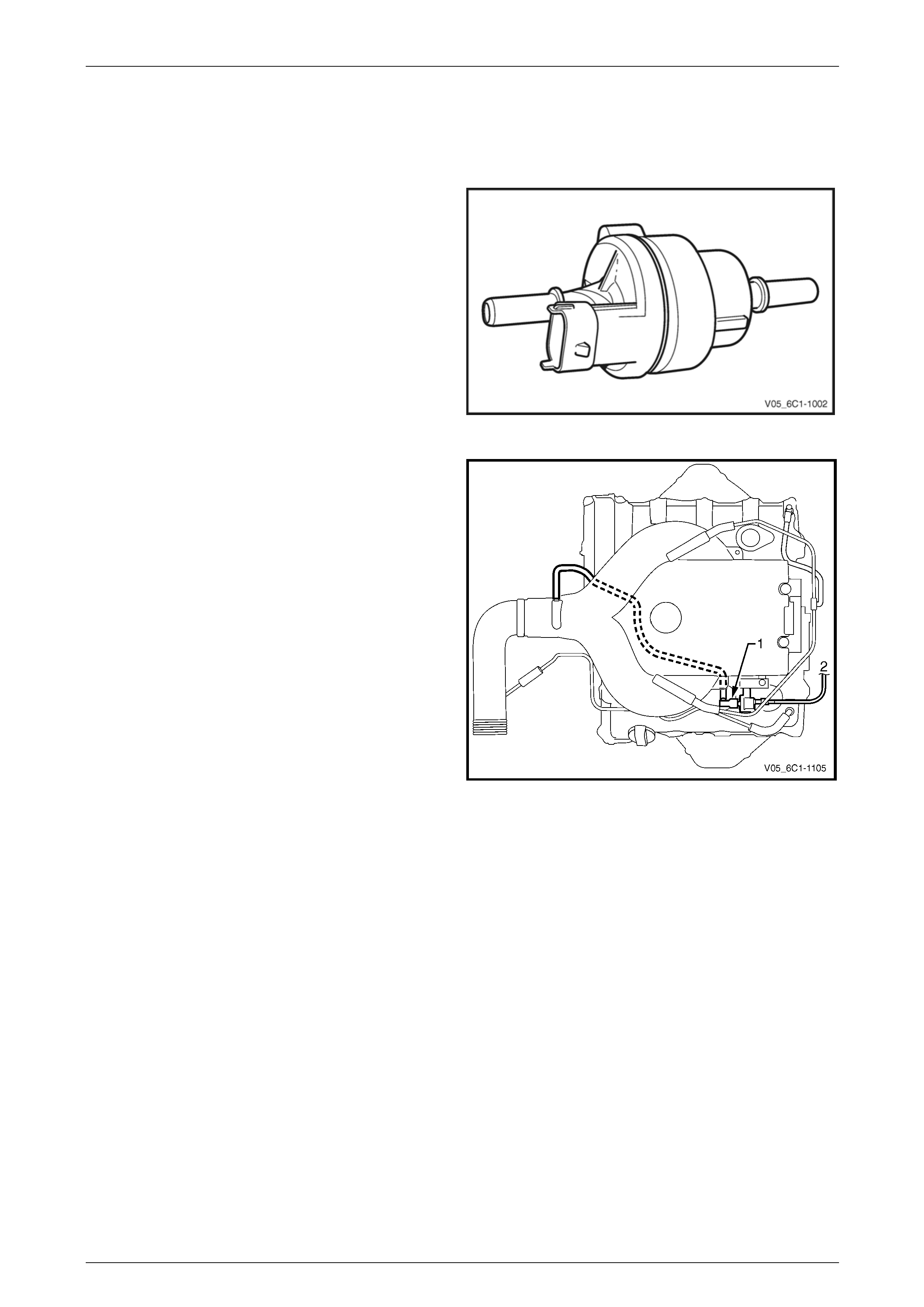
When ECM commands the EVAP valve (1) to open, the fuel
vapours are drawn from the canister line (2) into the intake
manifold where it is consumed in the normal combusti on
process.
Figure 6C1-1 – 17
The ECM energises the EVAP valve when the appropriate conditions have been met, such as:
• engine coolant temperatur e is less than 20°C at cold start up and the engine has been ru nning longer than
three minutes and 10 seconds, or
• engine coolant temperature is greater than 80°C and the engine has been running longer than five seconds, or
• engine is not in decel fuel cut-off mode and the throttle opening is less than 96%, or
• the engine is in closed loop fuel mode.
A higher purge rate is used under co nditions that are likely to produce large amounts of vapo ur, when the following
conditions have been met:
• intake air temperature is greater than 50°C, or
• engine coolant temperature is greater than 100°C, or
• the engine has been runn ing for greater than 15 minutes.
The EVAP purge PWM duty cycle varies according to operating conditions determined by mass air flow, fuel trim and
intake air temperature. The EVAP canister purge valve is re-enabled when throttle position angle decreases below 96%.
For further information on the evaporative emission control system, refer to Section 8A1 Fuel System.
Page 6C1-1–25
Engine Management – V6 – General Information Page 6C1-1–26
Engine Ventilation System
The engine ventilation system contains a Positive crankcase
ventilation (PCV) valve (1) located in the righ t-hand
camshaft cover. A hose is routed from the PCV valve to
each side of the intake manifold which provides an even
distribution of crankcase fumes, thereby impr oving spark
plug reliability and a reduction in emissions.
A breather pipe is routed from the intake manifold to the left-
hand camshaft cover and provides fresh filter ed air from the
intake duct to the engine.
For further information of the engine ventilati on system,
refer to Section 6A1 Engine Mechanical – V6.
Figure 6C1-1 – 18
Page 6C1-1–26

Engine Management – V6 – General Information Page 6C1-1–27
3.10 Serial Data Communication System
The engine control module (ECM) communicates directly with the following control units using the Gener al Motors local
area network (GM LAN) serial data communication protocol:
• Transmission control module (TCM)
• ABS-TCS electronic control unit (ECU) (If fitted)
• Powertrain interface module (PIM)
The body control module (BCM) and other vehicle control modules communicate with each other through the universal
asynchronous receive and transmit (UART) serial data protocol where the BCM is the Bus Master. Refer to Section 12J
Body Control Module for further information.
As the GM LAN serial data communication protocol is not compatible with the UART serial data communication protocol,
a powertrain interface module (PIM) is integrated to the serial data communication system to perform the following tasks
(Refer to Section 6E1 Powertrain Interface Module – V6):
• Translate the GM LAN serial data transmitted by the ECM, TCM and ABS-T CS ECU into a UART serial data that
can be received and recog nised by the BCM, Instrument Cluster Assembly and other vehicle control modules.
• Translate the UART serial data transmitted by the BCM and other vehicle control modules into GM LAN serial data
that can be received and recognised by the ECM, TCM and ABS-TCS ECU.
• Translate the cruise control switch signal i nto a GM LAN serial data that can be received and recognis ed by the
ECM.
Page 6C1-1–27
Engine Management – V6 – General Information Page 6C1-1–28
3.11 Self Diagnostics System
The ECM constantly performs self-diagnostic tests on the engine management system. W hen the ECM detects a
malfunction, it also stores a diagnostic troubl e code (DTC). A stored DTC will identify the problem area(s) and is
designed to assist the technician in rectifying the fault. In addition, DTCs are classified as either Current or History DTC.
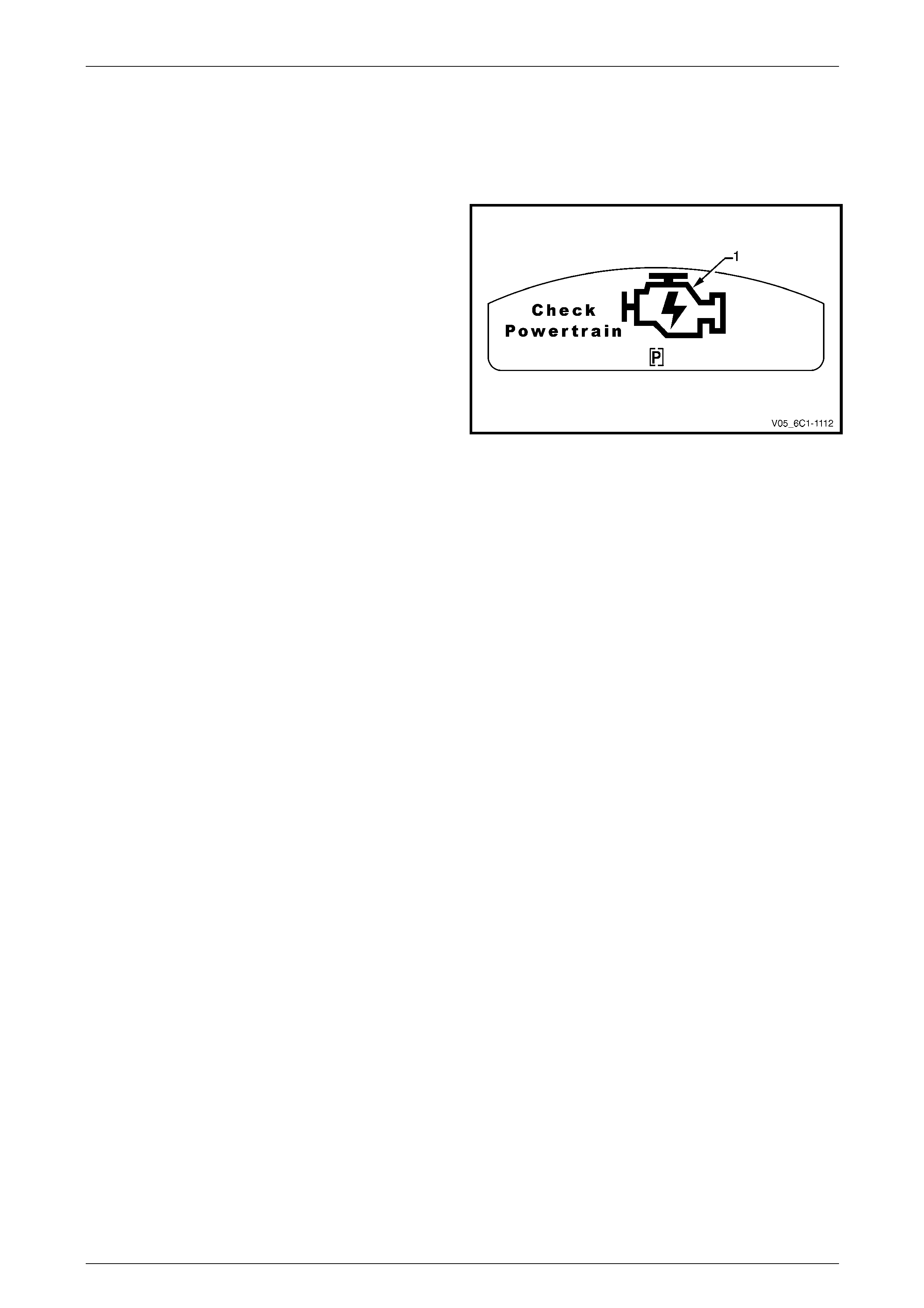
Depending on the type of DTC set, the ECM may command
the multifunction display (MFD) Check Powertrain icon (1) to
illuminate and warn the driver there is a fault in the Engine
Management System. Refer to Section 12C Instrumentation
for further information on the Check Po wertrain Icon.
Figure 6C1-1 – 19
Page 6C1-1–28

Engine Management – V6 – General Information Page 6C1-1–29
3.12 Service Programming System
The ECM has an Electronically erasable programmable read only memory (EEPROM) where the software and
calibration information required to operate the engine management system are stored.
The ECM features a service programming system (SPS) to flash pr ogram the EEPROM in the ECM with the latest ECM
software to provide optimum performance, driv eability and emissions control or to program a new ECM.
Flash programming refers to the SPS used to transfer (or download) ECM data from a computer terminal to the vehicle’s
ECM. The system is designed so the vehicle verification procedures are required to elim inate EEPROM tampering that
could increase engine emission levels.
There are three main flash programming techniques:
1 Direct programming (pass through). This is where the vehicle’s data link connector (DLC) is connected directly to a
computer terminal. On screen directions are then followed for downloading.
2 Remote Programming. Reprogramming inform ation is downloaded from a computer terminal to Tech 2. Tech 2 is
then connected to the vehicle’s DLC. On screen directions are then followed for downloading.
3 Off-board Programming. The off-board programming method is used when a re-programmable ECM must be
programmed while it is removed from the ve hicle. For example, an independent repair facility may find it necessary
to replace a faulty ECM. On flash programming eq uipped vehicles, the replacement ECM must be programmed
with data for the specific vehicle identification number (VIN) or the vehicle may not operate prop erly.
Page 6C1-1–29

Engine Management – V6 – General Information Page 6C1-1–30
3.13 Theft Deterrent System
The vehicle incorporates a the ft deterrent system. After the ignition switch is turned to the ON position, and the
powertrain interface module (PIM) has authenticated the body control module (BCM), the PIM sends an encrypted
security code to the engine control module (ECM). T he ECM compares the received security code with its own security
code, and if it is valid, the ECM enables the vehicle to be started. F or further information and diagnosis of the theft
deterrent system, refer to Section 12J Body Control Module.
For further information on the PIM, refer to Section 6E1 Powertrain Interface Module – V6.
Page 6C1-1–30
Engine Management – V6 – General Information Page 6C1-1–31
4 Component Description and
Operation
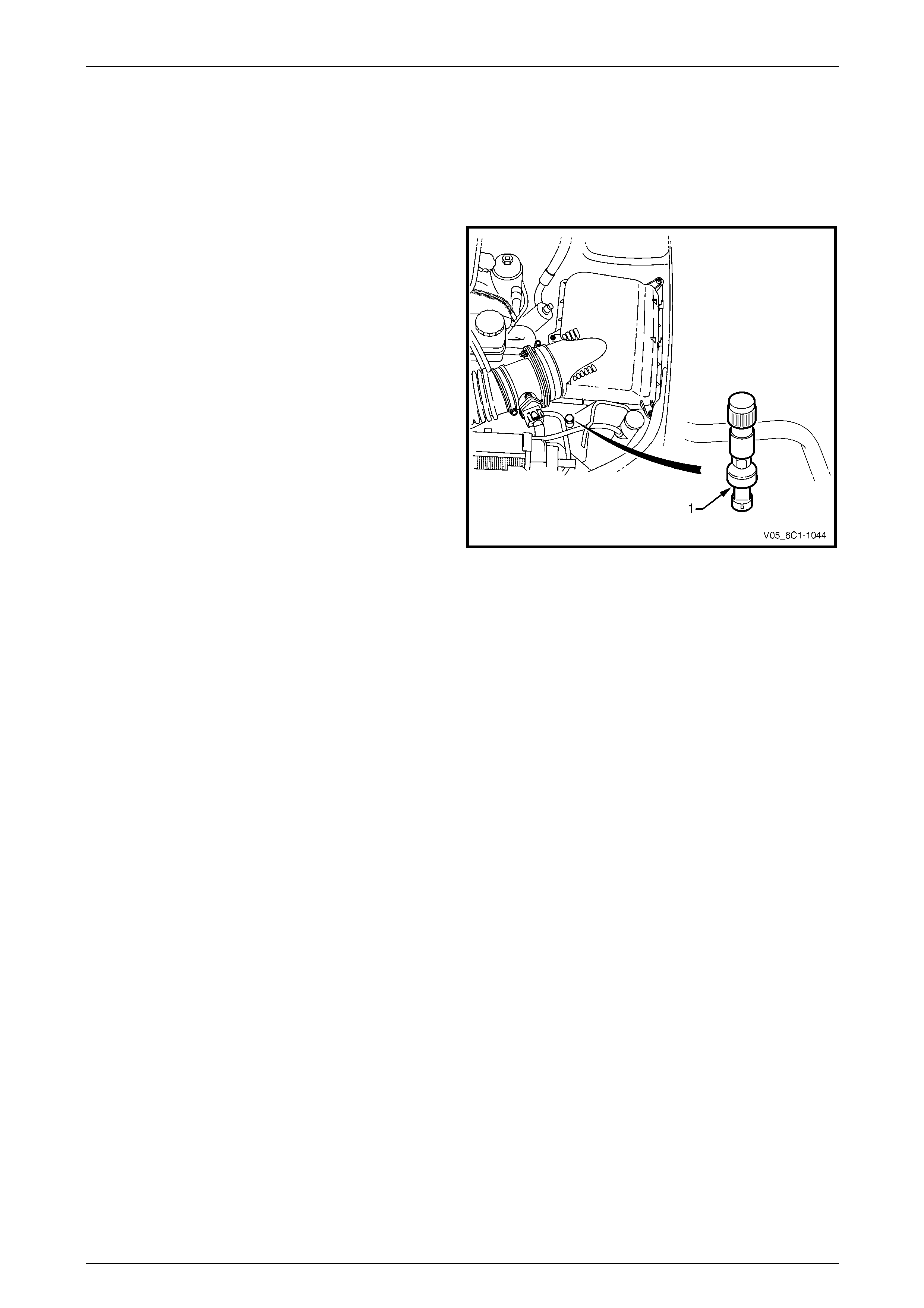
4.1 A/C Refrigerant Pressure Sensor
The engine control module (ECM) applies a positive 5 V
reference voltage and ground to the air-conditioner (A/C)
refrigerant pressure sensor (1). The A/C refrigerant pressure
sensor provides signal voltag e to the ECM that is
proportional to the A/C refrigerant pressure. The ECM
monitors the A/C refrigerant pressure sensor signal voltage
to determine the refrigerant pressure.
• The A/C refrigerant pressure sensor voltage increases
as the refrigerant pressure increases.
• When the ECM detects the refrigerant pressure
exceeds a predetermined value, the ECM activates
the cooling fans to reduce the refrigerant pre ssure.
• When the ECM detects the refrigerant pressure is too
high or too low, the ECM disables the A/C clutch to
protect the A/C compressor from damage.
Figure 6C1-1 – 20
Page 6C1-1–31
Engine Management – V6 – General Information Page 6C1-1–32
4.2 Brake Pedal Switches
Stop Lamp and BTSI Switch Assembly
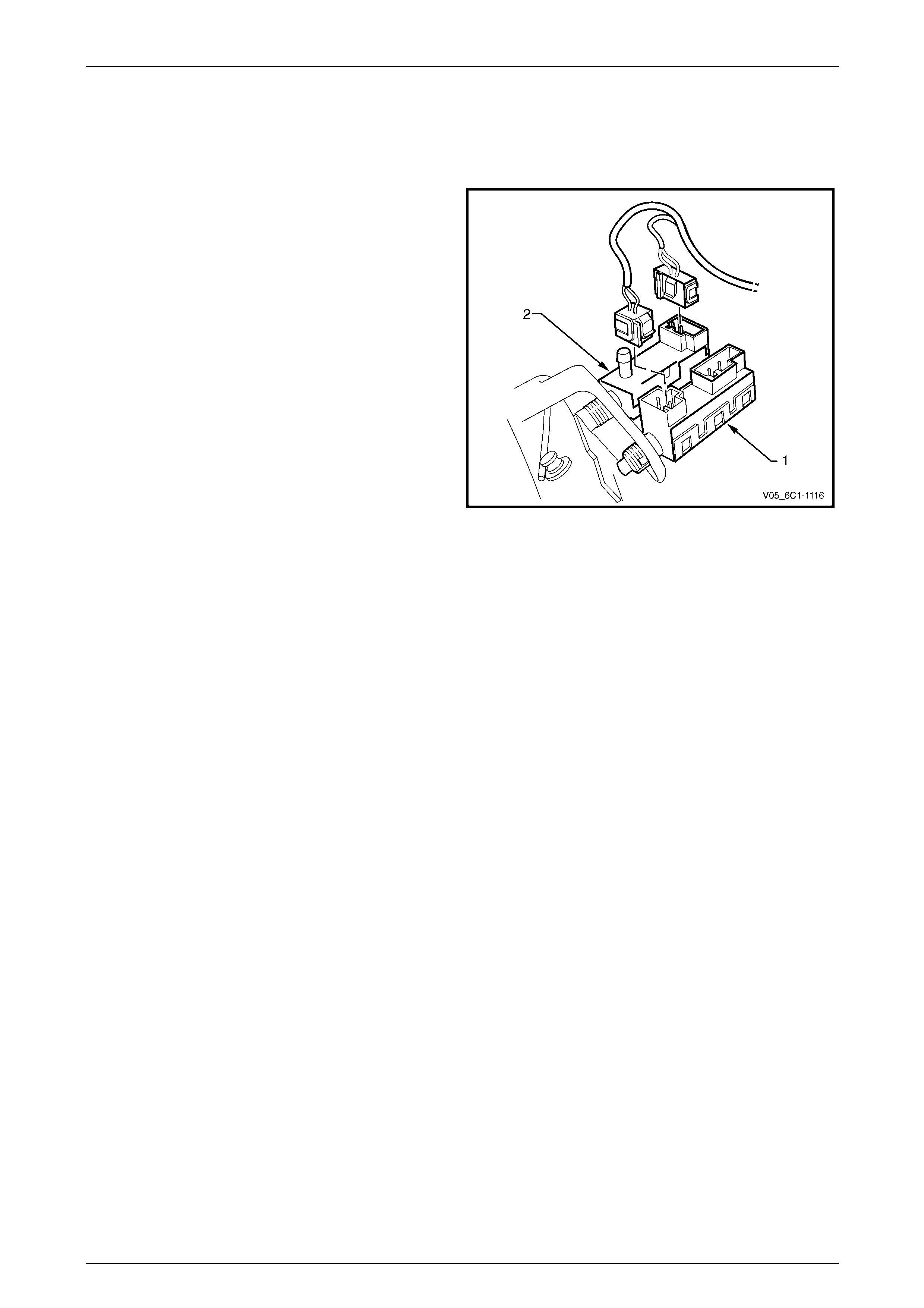
The stop lamp and BTSI s witch assembly (1) is located o n
the brake pedal support.
The engine control module (E CM) uses the stop lamp switch
signal voltage to determine when the brake pedal is
depressed.
The ECM uses this input for brake torque management, for
cross referencing the stop lamp switch against the cruise
control cancel switch for correct operation etc. F or further
information on brake torque mana gement, refer to
3.8 Brake Torque Management.
The stop lamp switch is a normally open switch with the
brake pedal at rest.
Figure 6C1-1 – 21
Cruise Control Release and Extended Brake Travel Switch Assembly
The cruise control release and extended brake travel s witch assemb ly (2) is located on the brake pedal support. Refer to
Figure 6C1-1 – 21.
The engine control module (E CM) uses the cruise control release switch signal voltage to determi ne when the brake
pedal is depressed. The ECM uses this input to cancel cruise control operation, for cross referencing the cruise co ntrol
release switch against the stop lamp s witch for correct operation etc.
The engine control module (E CM) uses the extended brake travel switch signal voltage to determine when full brake
pedal travel has been achi eved. The ECM uses this input to compensate for the air being used by the brake booster.
Both of these switches are normally closed when the brake ped al is in the rest position, opening when the pedal is
pressed. Activation of this switch removes the signal to the ECM.
For further information on the cruise control system, refer to 3.7 Cruise Control System, refer to 3.8 Brake Torque
Management.
Page 6C1-1–32

Engine Management – V6 – General Information Page 6C1-1–33
4.3 Barometric Pressure Sensor
The barometric pressure (BARO) sensor me asures
barometric (atmospheric) pressure. The ECM uses this
signal to make corrections to the operating parameters of
the system based on changes in air density, since the
oxygen content of atmospheric air varies pro portionally to air
density (barometric / atmospheric pressure). Barometric
pressure is affected mainly by altitude and climate.
The BARO sensor provides a voltage signal to the ECM that
is a function of barometric pressure. It does this through a
series of deformation resistors, which change resistance
when a mechanical force is applied. This force is applied to
the resistors by a diaphragm on which the atmospheric
pressure acts.
The ECM supplies the BARO sensor with a 5 V reference
and a ground circuit. Figure 6C1-1 – 22
Page 6C1-1–33
Engine Management – V6 – General Information Page 6C1-1–34
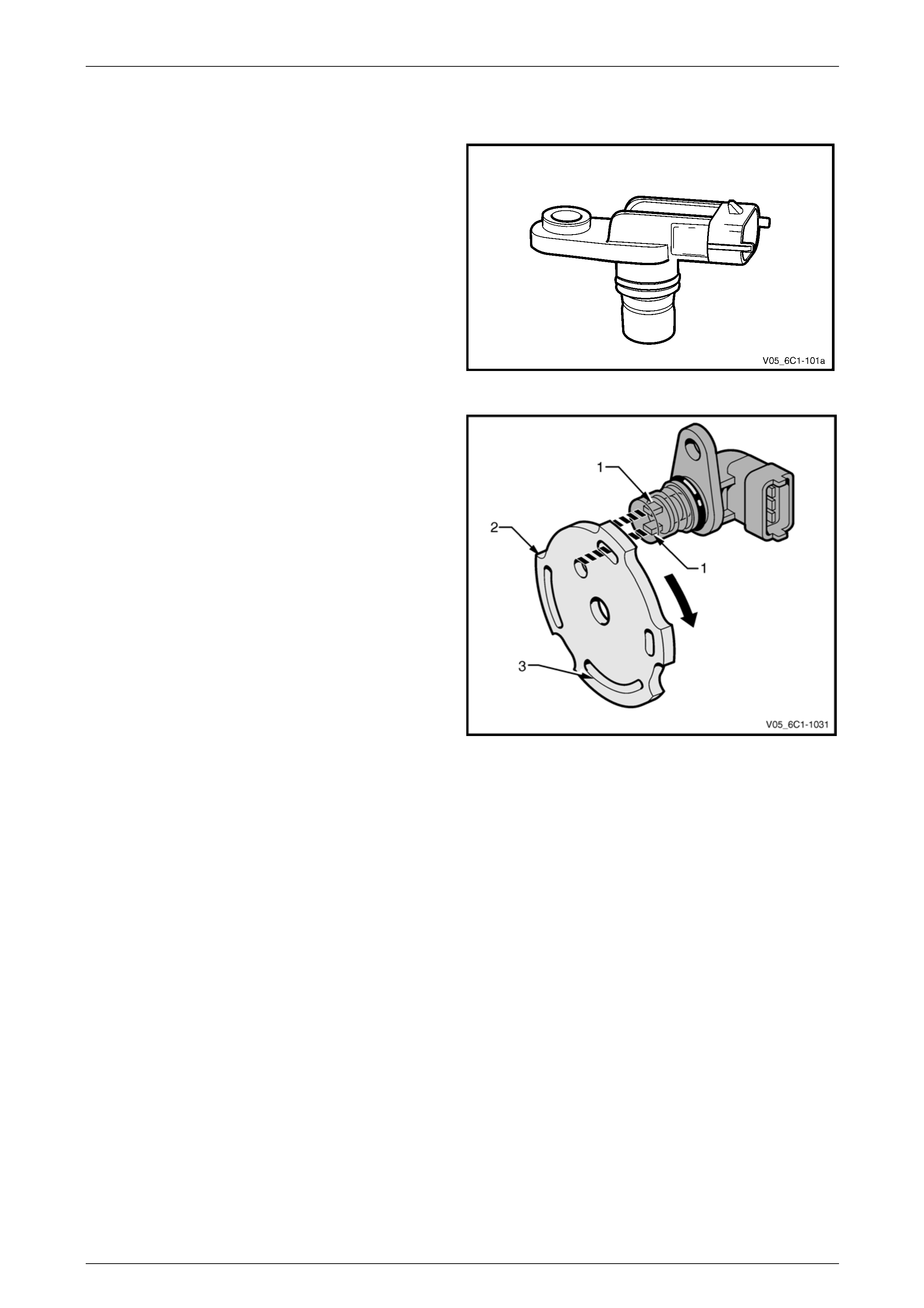
4.4 Camshaft Position Sensor
Alloytec engines are fitted with two camshaft position (CMP)
sensors, one for each intake camshaft. Alloytec190 engines
have four, one for every camshaft.
The CMP sensors are used by the ECM to determine the
position of the camshafts. In conjunction with the crankshaft
position sensor, the CMP enables the ECM to determine
engine rotational pos ition.
Figure 6C1-1 – 23
The CMP sensor operates on the dual-Hall sensing
principle. The sensor contains two hall elements (1) which
operate in conjunction with a two-track trigger wheel (2)
mounted on the camshaft.
As the tracks (3) on the trigger wheel pass the elements,
magnetic flux affects a voltage in the Hall elements. T he
integrated circuit inside the sensor conditions the signal
generated by the Hall eleme nts to provide a rectangular
wave on / off signal to the ECM.
The ECM supplies the CMP sensors with a 5 V reference
and ground circuit.
Figure 6C1-1 – 24
Page 6C1-1–34
Engine Management – V6 – General Information Page 6C1-1–35
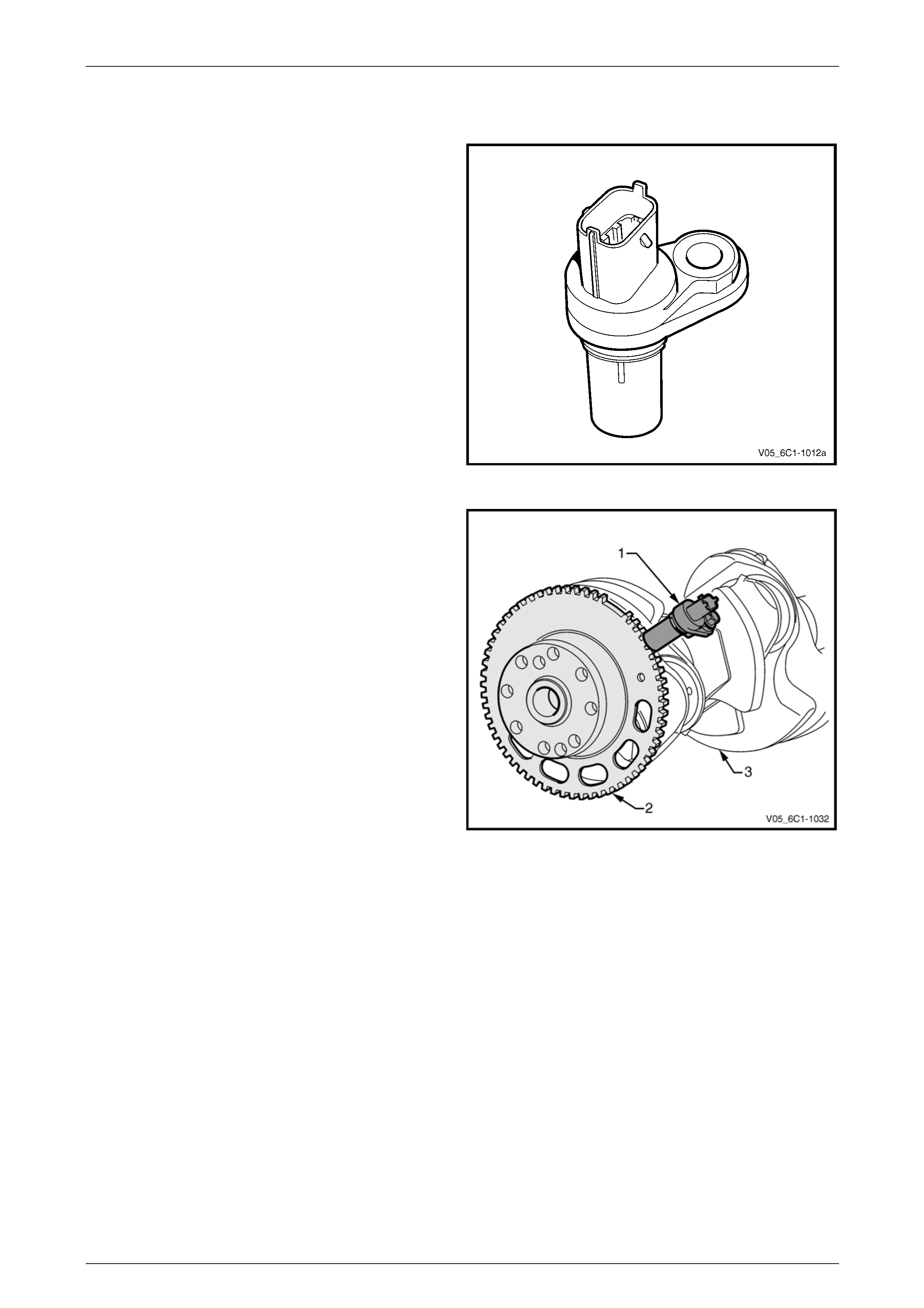
4.5 Crankshaft Position Sensor
In conjunction with the camshaft position sensor, the
crankshaft position (CKP) sensor enables the ECM to
determine engine rotational position. The CKP is also used
to determine engine speed (r.p.m.).
Figure 6C1-1 – 25
The CKP sensor (1) operates on the variable reluctance
(pulse generator) sensi ng principle. It contains a magnet
and pickup coil and is used in conjunction with a 58 tooth
ferromagnetic reluctor wheel (2) attached to t he
crankshaft (3).
As the crankshaft rotates, the reluctor wheel revolves past
the CKP, causing fluctuations in the magnetic field inside
the sensor. This action creates an AC voltage across the
pickup coil which is processed by the ECM. An increase in
engine speed will increase the output voltage and
frequency.
The reluctor wheel teeth are placed six degrees apart.
Having only 58 teeth leaves a 12 degree open span, which
creates a signature pattern that enables the ECM to
determine the crankshaft position. The ECM determines
which two cylinders are approaching the top dead centre
based on the crankshaft position sensor signal. The CMP
sensor signals are used by the ECM to determine which
cylinder is on the firing stroke. Figure 6C1-1 – 26
Page 6C1-1–35
Engine Management – V6 – General Information Page 6C1-1–36
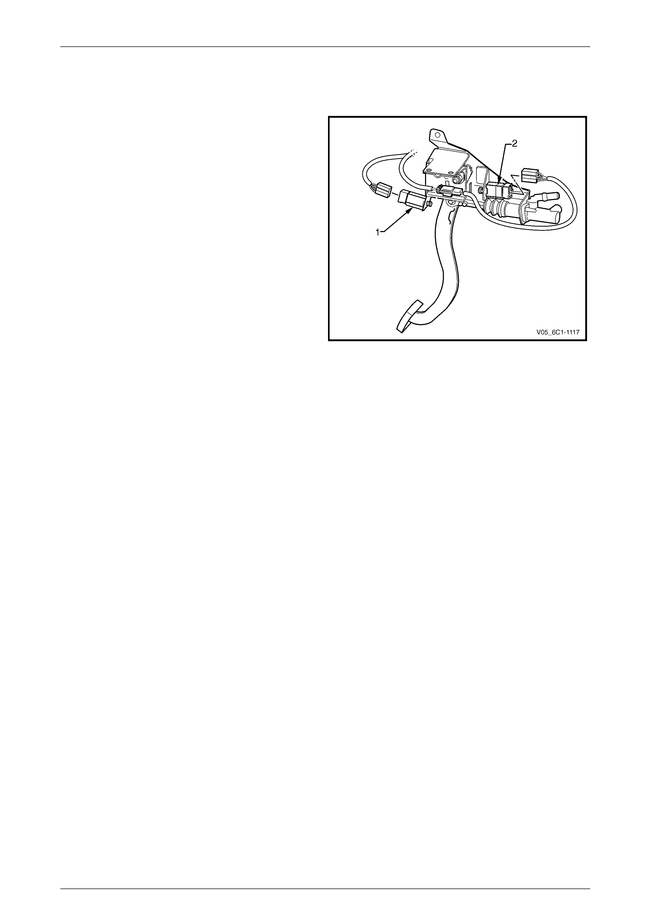
4.6 Clutch Pedal Switch Assemblies –
Manual Vehicles Only
There are two clutch pedal switch assemblies, the cruise
control cancel switch (1) and the clutch pedal position
switch (2).
The cruise control cancel switch is normally closed when the
clutch pedal is at rest, opening when the pedal is pressed.
Activation of this switch removes the signal to the ECM
which will then deactivate the cruise co ntrol. F or further
information on the cruise control system, refer to
Section 7A1 Clutch – V6.
The clutch pedal position switch is normally open when the
clutch pedal is at rest, closing when the pedal is fully
pressed. Activation of this switch sends a signal to the ECM
which will then allow operation of the starter motor. For
further information on the starting system, refer to
Section 6D1-2 Starting System – V6.
Figure 6C1-1 – 27
Page 6C1-1–36

Engine Management – V6 – General Information Page 6C1-1–37
4.7 Engine Control Module
Located at the right front of the engine assembly, the engine
control module (ECM) monitors input signals from the
various sensors and switches connected to the engine
management system. The ECM processes this information,
to control the following:
• fuel delivery and inj ection system,
• throttle actuation system,
• inlet manifold runner control valve (Alloytec190 engine
only),
• camshaft position actuators,
• ignition system,
• on-board diagnostics,
• the engine cooling fans, and
• the air-conditioner compressor clutch (where fitted).
The ECM supplies 5 V to the various sensors through p ull-
up resistors to the internal regulated power supplies.
The ECM controls output circuits such as the injectors,
cooling fan relays, etc. by applying control signal to the
ground circuits of the components through transistors or a
device inside the ECM called a driver. The exception to this
is the fuel pump relay control circuit. The fuel pump relay is
the only ECM controlled circ uit where the ECM controls the
12 V sent to the coil of the relay. The ground side of the fuel
pump relay coil is connecte d to engine ground.
The ECM communicates directly with the various control
units within the vehicle using the General Motors local area
network (GM LAN) serial data communication protocol.
Refer to 3.10 Serial Data Communication System.
Figure 6C1-1 – 28
Page 6C1-1–37
Engine Management – V6 – General Information Page 6C1-1–38
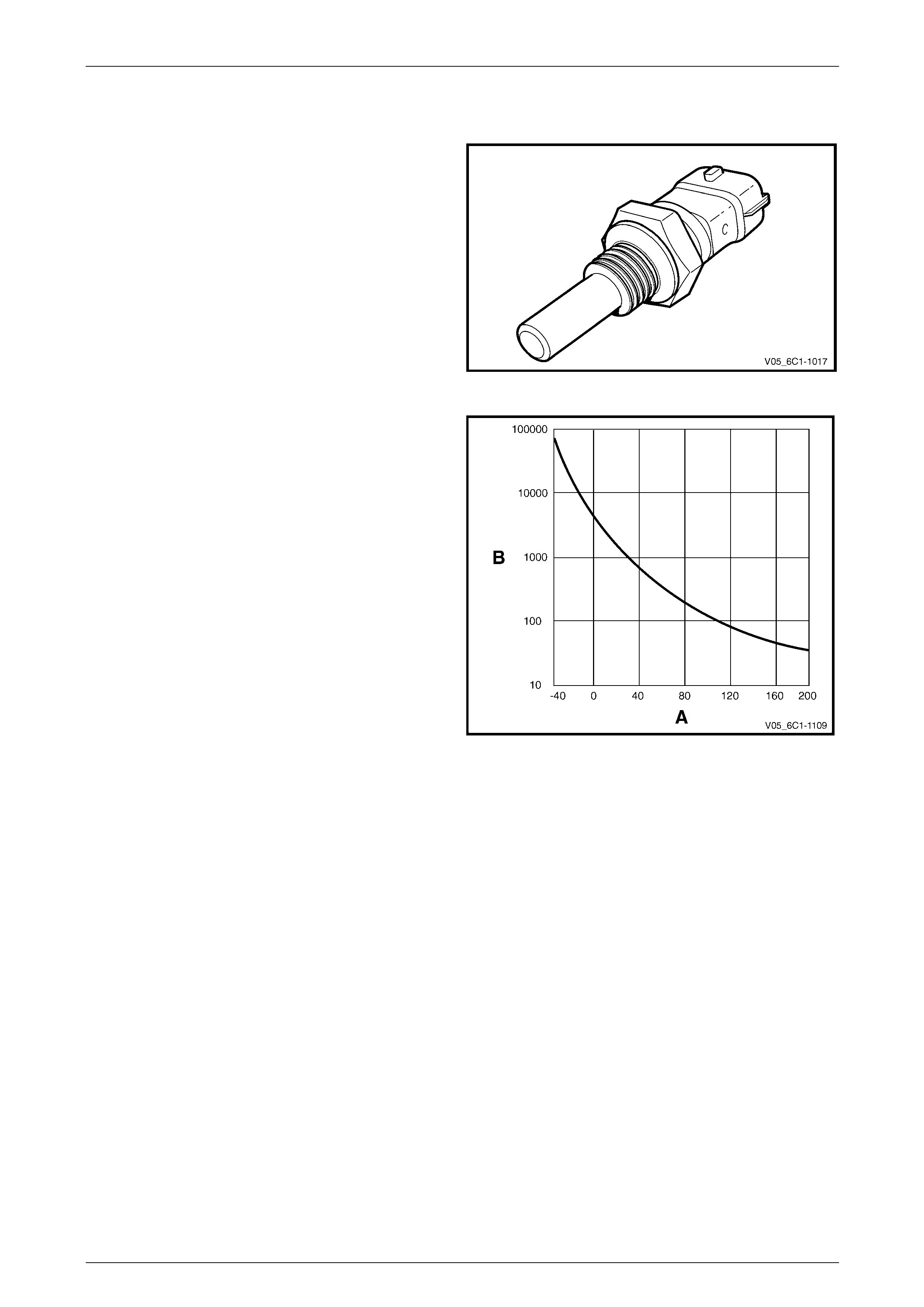
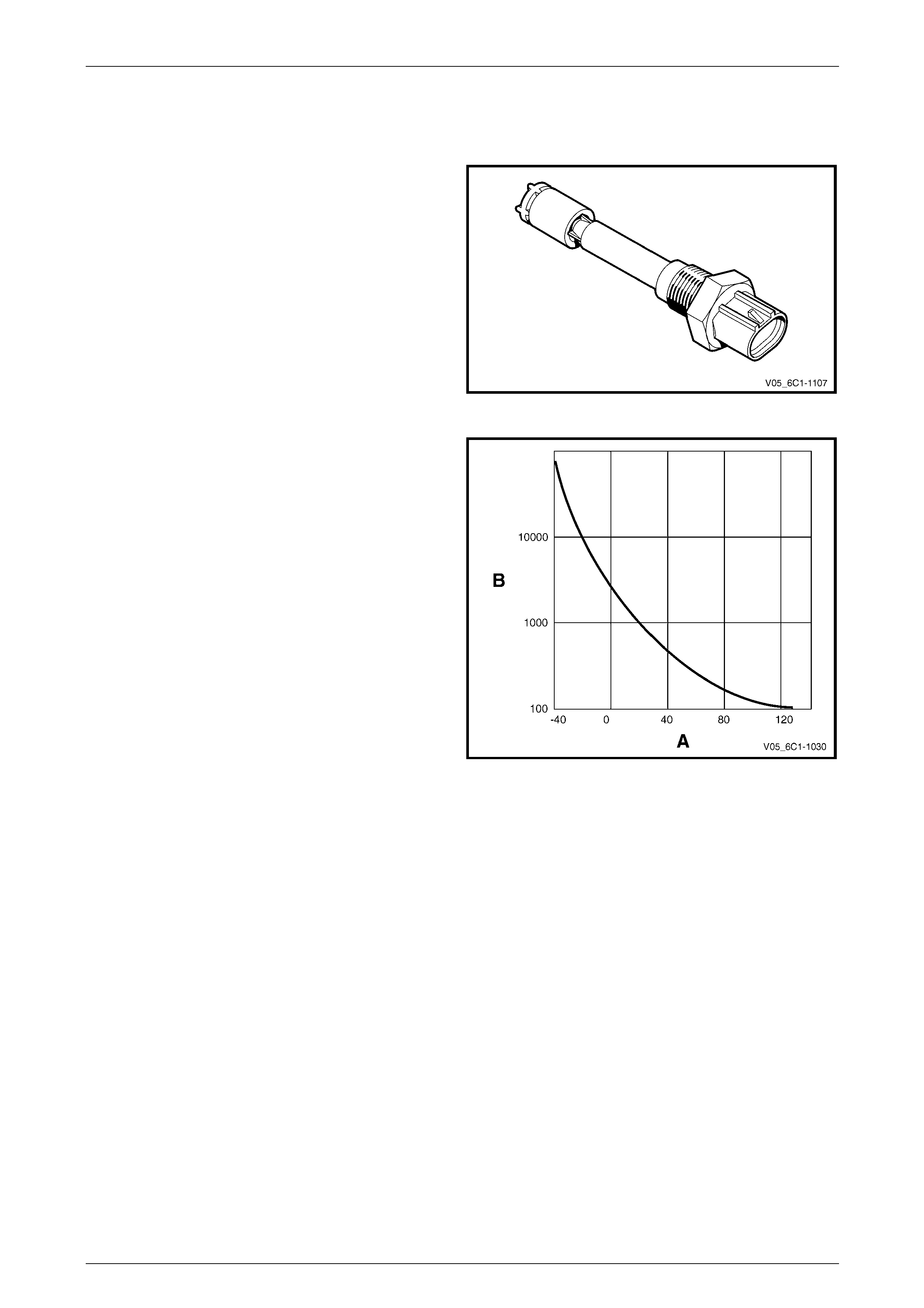
4.8 Engine Coolant Temperature Sensor
The engine coolant temperature (ECT) sensor is a
thermistor, which is a resistor that changes it’s resistance
value based on temperature.
Figure 6C1-1 – 29
The ECT is mounted in the engine coolant stream and as it
is a negative temperature coef ficient (NTC) type, low engine
coolant temperature produc es a high sensor resistance
while high engine coo lant temperature causes low sensor
resistance.
Legend
A Temperature
B Resistance
The ECM provides a 5 V reference signal to the ECT and
monitors the return signal which enables it to calculate the
engine temperature.
The ECM uses this signal to make corrections to the
operating parameters of the system based on changes in
engine coolant temperatur e.
Figure 6C1-1 – 30
Page 6C1-1–38

Engine Management – V6 – General Information Page 6C1-1–39
4.9 Electric Cooling Fans
The ECM controls the operation of two dual speed electric
engine cooling fans. T he ECM operates the fans at either
low or high speed based on in puts from engine coolant
temperature, vehicle speed and air-conditioner request. For
further information on cooling fan operation refer to
Section 6B1 Engine Co oling – V6.
Figure 6C1-1 – 31
Page 6C1-1–39
Engine Management – V6 – General Information Page 6C1-1–40
4.10 Engine Oil Level and Temperature
Sensor
The engine oil level (EOL) and temperature sensor is a dual
purpose sensor and is fitted in the engine su mp. It combines
a switch to signal oil level and a thermistor typ e temperature
sensor to provide oil temperat ure signal to the ECM.
Figure 6C1-1 – 32
Engine Oil Temperature Sensor
The engine oil temperature sensor is a negative
temperature coefficient (NTC) type. At low engine oil
temperature, the sensor produces a hig h resistance, whilst
at high temperature the sensor produces a low resistance.
Legend
A Temperature
B Resistance
The ECM provides a 5 V reference signal to the engine oil
temperature sensor and monit ors the return signal which
enables it to calculate the engine oil temperature.
The ECM uses oil temperatur e as one of the inputs in
determining the point at which camshaft phasing will
commence. For further information on camshaft phasing,
refer to 3.6 Camshaft Position Actuator Control System. Figure 6C1-1 – 33
Page 6C1-1–40

Engine Management – V6 – General Information Page 6C1-1–41
Engine Oil Level Sensor
The engine oil level sensor is comprised of a magnetic reed
switch (1) contained within the sensor, a float (2) and a
magnetic pin (3). The magnetic reed switch is a normally
open switch, which closes when a magnet fi eld is present.
When the engine oil leve l is within specifications, the pin on
the inside of the float is pushed up against the reed switch
(view A). When the oil level drops an d the magnetic pin
moves away from the reed switch (view B), the switch
contacts opens.
The ECM provides a 5 V reference signal to the engine oil
temperature sensor and monit ors the return signal. The
ECM only monitors the oil level signal prior to engine start-
up, and once the engi ne is cranking, the ECM disregards
the oil level sensor signal.
Figure 6C1-1 – 34
Page 6C1-1–41
Engine Management – V6 – General Information Page 6C1-1–42
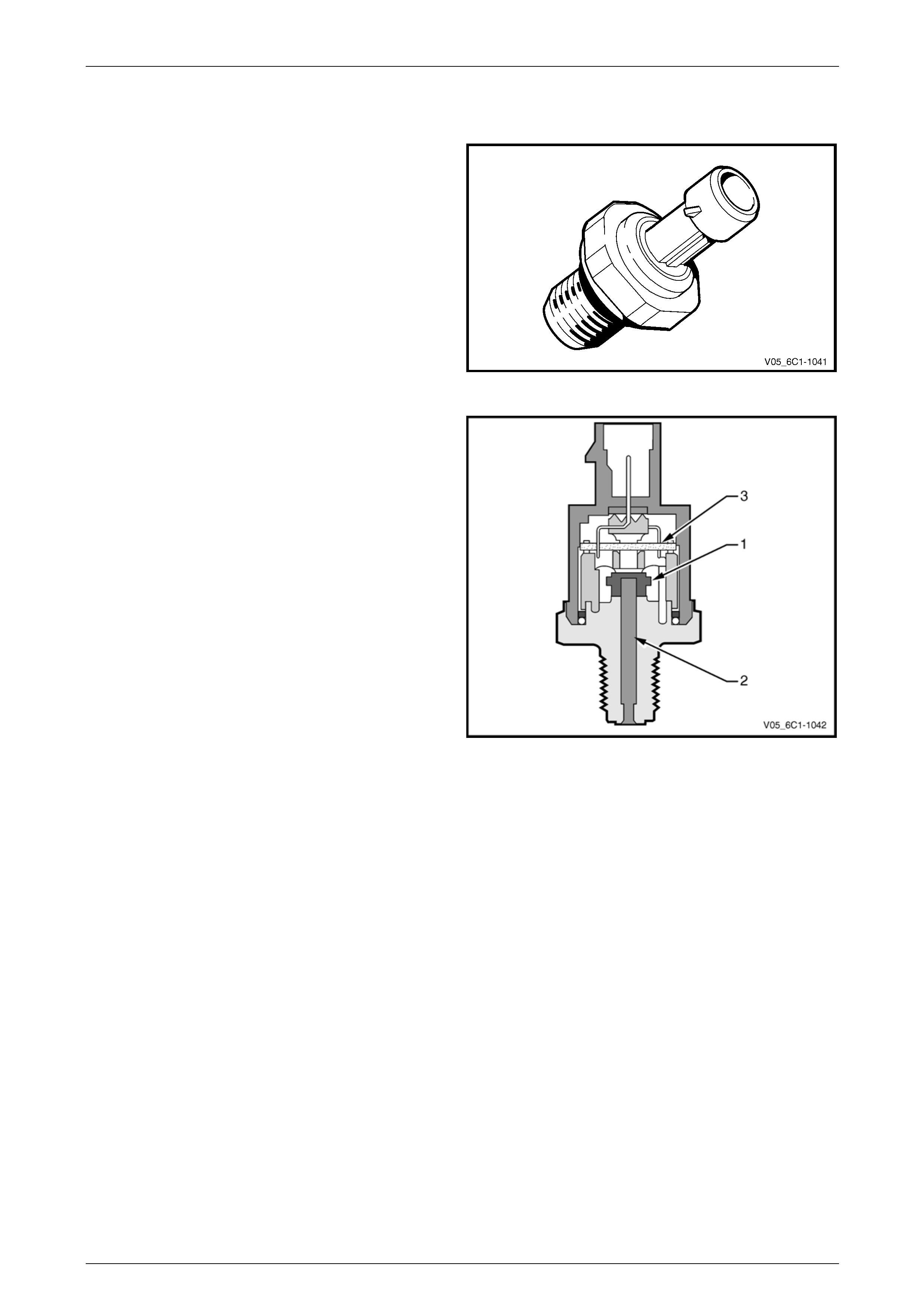
4.11 Engine Oil Pressure Sensor
The engine oil pressur e (EOP) sensor measures engine oil
pressure. When the EOP sensor signal is below a certain
value, the ECM activates the Check Oil warning message in
the instrument cluster multi-function display (MFD).
Figure 6C1-1 – 35
The EOP sensor provides a voltage signal to the ECM that
is a function of engine oil pressure. It does this through a
series of deformation resistors (1), which chang e resistance
when a mechanical force is applied. This force is applied to
the resistors by a diaphragm on which the engine oil
pressure acts (2).
The sensor has an internal ev aluation circuit (3) and is
provided with a 5 V reference voltage, a ground and a signal
circuit.
Figure 6C1-1 – 36
Page 6C1-1–42
Engine Management – V6 – General Information Page 6C1-1–43
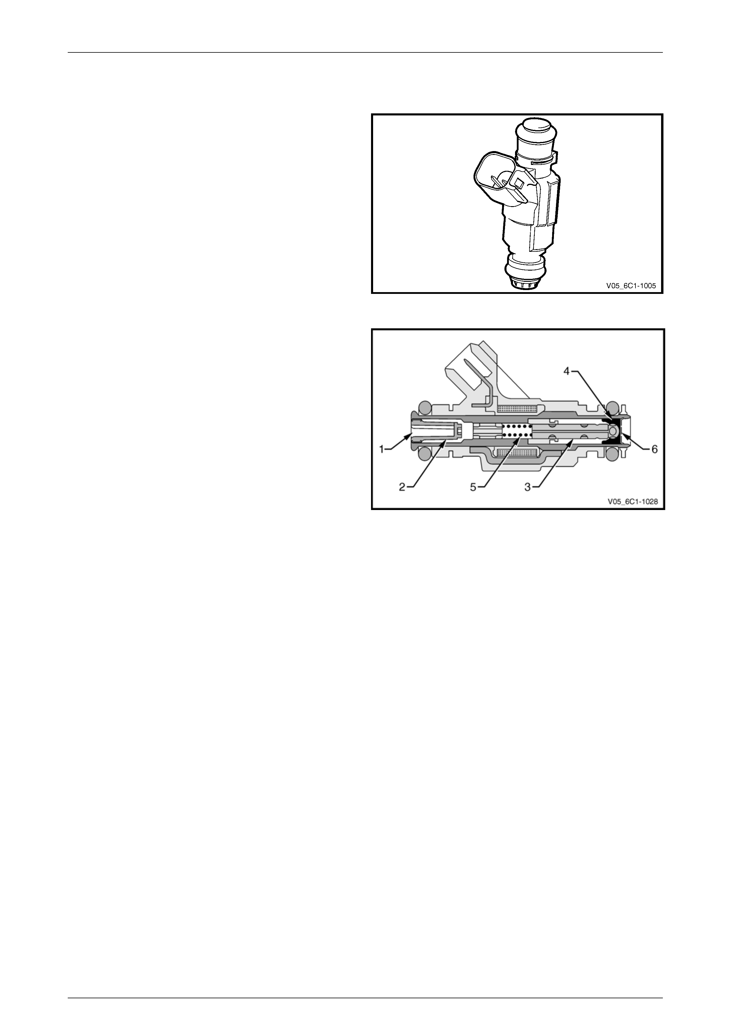
4.12 Fuel Injectors
A fuel injector is a solenoid device that is controlled by the
ECM. The six injectors deliver a precise amount of fuel into
the intake ports as required by the engine.
Figure 6C1-1 – 37
The fuel port (1) connects to the fuel rail. A strainer (2) is
provided in the port to protect the injector from fuel
contamination.
In the de-energised state (no voltage), the valve needle and
sealing ball assembly (3) are held against a cone-shaped
valve seat (4) by spring force (5) and fuel pressure.
When the injector is energise d by the ECM, the valve
needle, which has an integr al armature, is moved upward by
the injector solenoids magnetic field, un-seating the ball.
An orifice plate (6), located at the base of the injector has
four small holes which provide very fine atomisation of the
fuel. The plate is insensitive to fuel deposits ensuring reliable
fuel delivery.
The fuel is directed at each of the intake valves, causing the
fuel to become further vaporised before entering the
combustion chamber.
Figure 6C1-1 – 38
Page 6C1-1–43

Engine Management – V6 – General Information Page 6C1-1–44
4.13 Fuel Rail Assembly
The fuel rail assembly is mou nted on the lower intake
manifold and distributes the fuel to each cylinder through
individual fuel injectors. T he fuel rail assembly consists of:
• the pipe that carries fuel to each injector,
• a fuel pressure test port,
• six individual fuel inj ectors,
• wiring harness, and
• wiring harness tray.
Figure 6C1-1 – 39
Page 6C1-1–44
Engine Management – V6 – General Information Page 6C1-1–45
4.14 Heated Oxygen Sensors
The heated oxygen se nsors (HO2S) are mounted in the exhaust system and enable the ECM to measure oxygen
content in the exhaust stream. The ECM uses this information to accurately control the air / fuel ratio, because the
oxygen content in the exhaust gas is indicative of the air / fuel ratio of engine combustion.
When the sensor is cold, it produces little or n o signal voltage, therefore the ECM only reads the HO2S signal when the
HO2S sensor is warm. As soon as the HO2S are warm and outputting a usable signal, the ECM begins making fuel
mixture adjustments base d o n the HO2S signals. This is known as closed loop mode.
Alloytec engines are fitted with two LSF 4.2 two-step planar type HO2S, one in each exhaust pip e upstream of the
catalytic converter. Alloytec190 engines have four HO2S, one LSU 4.2 wide-band pla nar type HO2S upstream of the
catalytic converter in each exhaust pi pe, and one LSF 4.2 two-step planar type HO2S in each exhaust pipe downstream
of the catalytic converter.
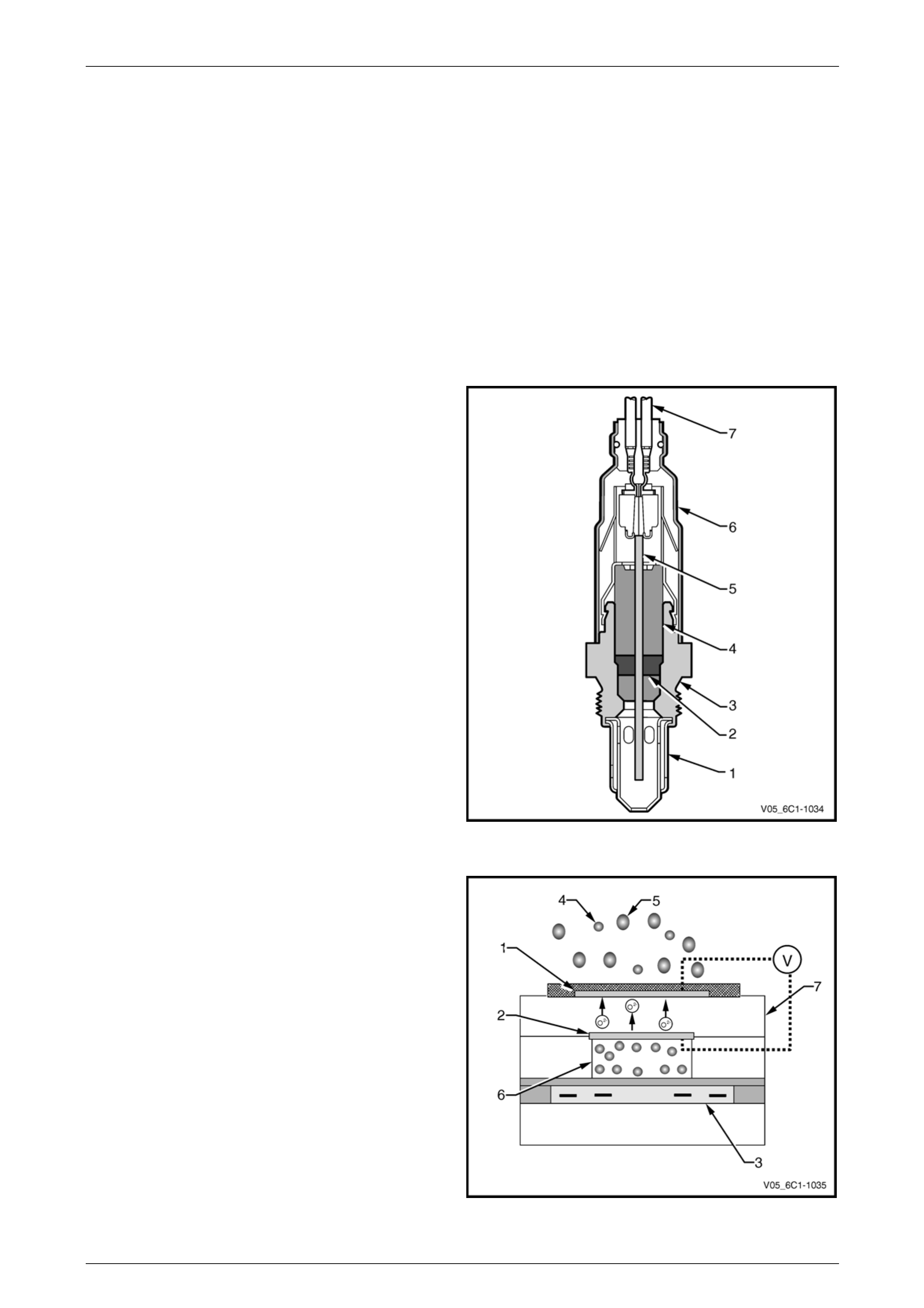
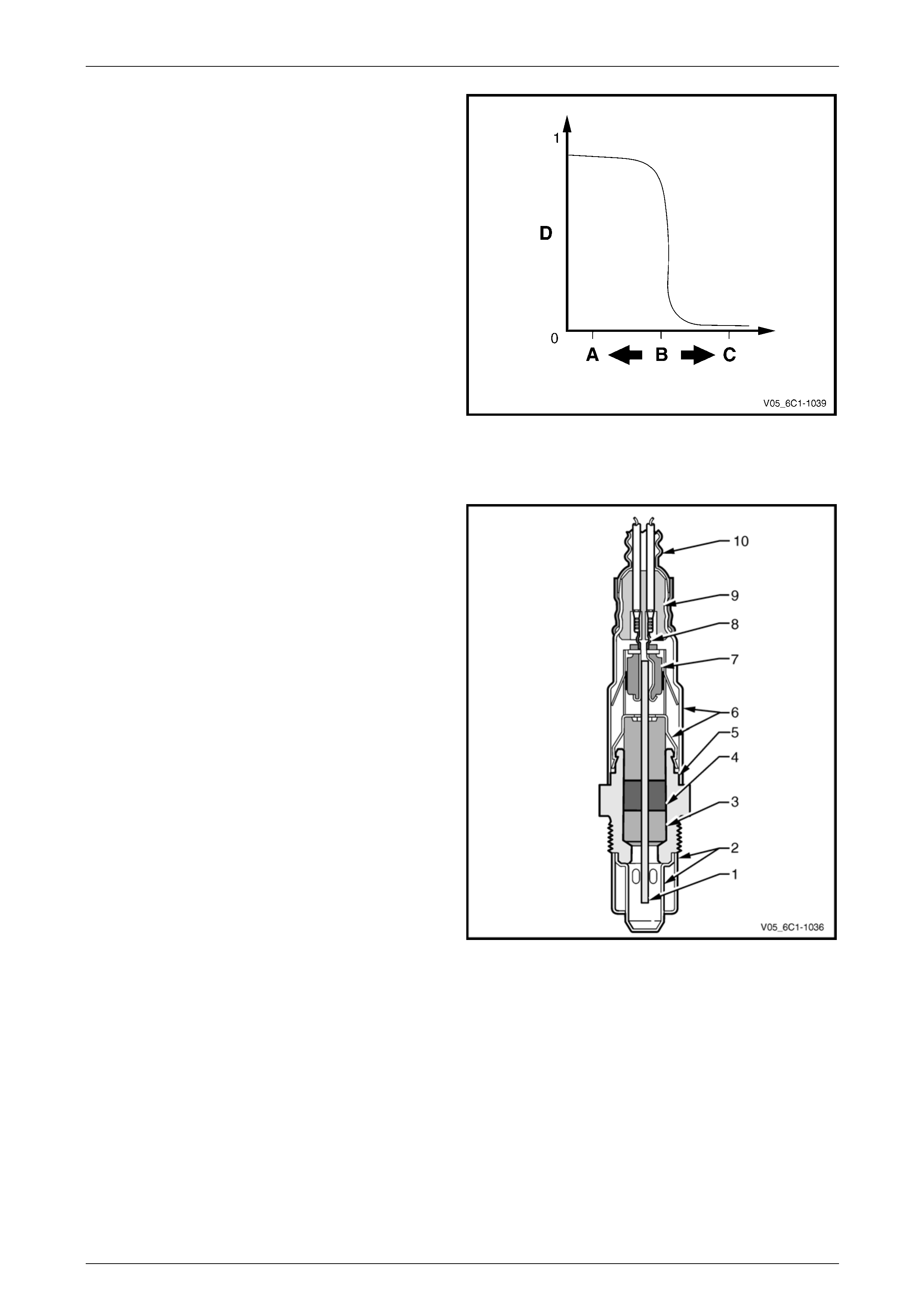
LSF 4.2 Two-step Planar Heated Oxygen Sensors
The LSF 4.2 two-step planar h eated oxygen sensors have
four wires:
• The internal heater element supply, which has 12 V
continually applied whenever the ignition is on.
• Heater element ground – The ECM applies pulse
width modulated (PWM) ground to the HO2S heater
control circuit to control the rate at which the sensor
heats up. This reduces the risk of the sensor bein g
damaged from heating up too quickl y under certain
conditions such as extreme cold temperatures. Once
the sensor has reached the desired operating
temperature, the ECM will monitor and continue to
maintain the sensor temperature.
• Sensor signal to the ECM.
• Sensor ground.
Legend
1 Protective Tube
2 Ceramic Seal Packing
3 Sensor Housing
4 Ceramic Support Tube
5 Planar Measuring Element
6 Protective Sleeve
7 Connection Cable Figure 6C1-1 – 40
Measurement is achieved b y comparing the oxygen content
of the exhaust gas to the oxygen content of a reference gas
(outside air) using the Nernst principle. Oxygen molecules
from the exhaust gas will accumulate on the outer electrode,
while oxygen molecules from the reference gas will
accumulate on the inner electrode. This creates a voltag e
difference across the Nernst cell, bet ween the two
electrodes, which is the signal voltage to the ECM.
Legend
1 Outer Electrode
2 Inner Electrode
3 Heater Element
4 Oxygen Molecule (in exhaust stream)
5 Other Molecules (in exhaust stream)
6 Reference Gas (outside air)
7 Nernst Cell
V Signal Voltage Figure 6C1-1 – 41
Page 6C1-1–45
Engine Management – V6 – General Information Page 6C1-1–46
When the fuel system is correctly operating in the closed-
loop mode, the oxygen sensor voltage output is rapidly
changing several times per second, fluctuating from
approximately 100mV (high oxygen co ntent – lean mixture)
to 900mV (low oxygen content – rich mixture). The transition
from rich to lean occurs quickly at about 450-500 mV (air
flow (A/F) ratio 14.7:1, or lambda = 1). Due to this, two-step
HO2S sensors are also known as s witching type HO2S
sensors.
Legend
A Rich Mixture
B A/F Ratio 14.7:1 (Lambda = 1)
C Lean Mixture
D Sensor Voltage
Figure 6C1-1 – 42
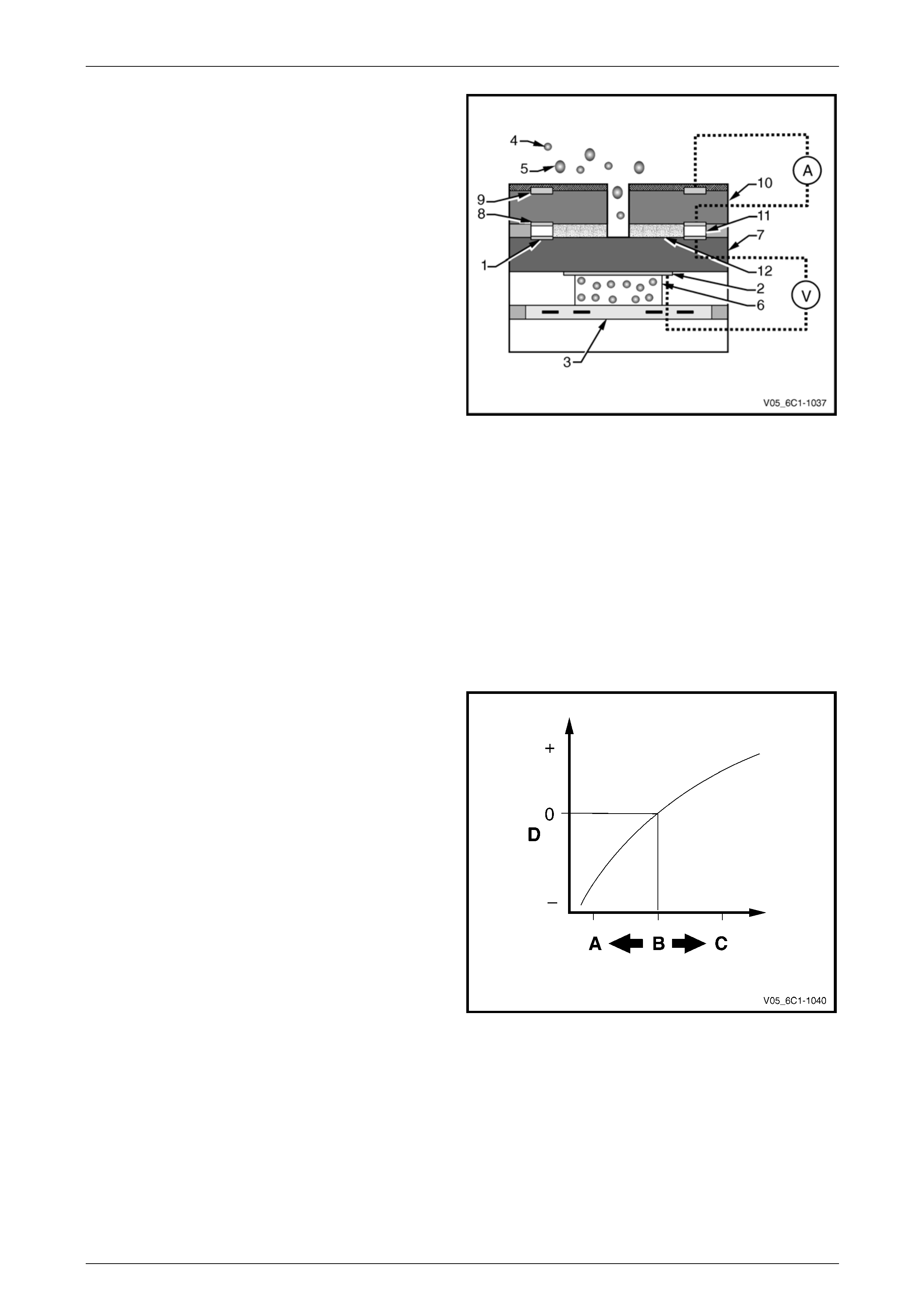
LSU 4.2 Wide-band Planar Heated Oxygen Sensors
The LSU 4.2 wide-band planar heated oxygen sensors have
six wires:
• The internal heater element supply, which has 12 V
continually applied whenever the ignition is on.
• Heater element ground – The ECM applies pulse
width modulated (PWM) ground to the HO2S heater
control circuit to control the rate at which the sensor
heats up. This reduces the risk of the sensor bein g
damaged from heating up too quickl y under certain
conditions such as extreme cold temperatures. Once
the sensor has reached the desired operating
temperature, the ECM will monitor and continue to
maintain the sensor temperature.
• Output voltage.
• Sensor ground.
• Trim current.
• Pumping current.
Legend
1 Measuring Cell (nernst cell and pump cell)
2 Double Protective Tube
3 Seal Ring
4 Seal Packing
5 Sensor Housing
6 Protective Sleeve
7 Contact Holder
8 Contact Clip
9 PTFE Sleeve (teflon)
10 PTFE Shaped Sleeve
Figure 6C1-1 – 43
Page 6C1-1–46
Engine Management – V6 – General Information Page 6C1-1–47
Similar to the two-step HO2S, measurement is achieved by
comparing the oxygen content of the exhaust gas to the
oxygen content of a reference gas. However, the way in
which the ECM calculates the exha ust oxygen content is
different, and results in a continual sig nal. This allows the
ECM to monitor not only whether the fuel mixture is rich or
lean, but exactly how rich or ho w lean. T he wide-band
HO2S is basically a two-step HO2S with the addition of a
pump cell.
The ECM applies a pump voltage acr oss the pump cell,
which causes oxygen to be pumpe d from the e xhaust gas
into or out of the diffusion gap through the diffusion barrier.
While monitoring the Nernst cell, the ECM varies the pump
current so the gas in the diffusion gap remains constant at
an A/F ratio of 14.7:1 (nernst cell output of 450 mV).
Legend
1 Outer Electrode
2 Inner Electrode
3 Heater Element
4 Oxygen Molecule (in exhaust stream)
5 Other Molecules (in exhaust stream)
6 Reference Gas (outside air)
7 Nernst Cell
8 Pump Cell Electrode
9 Pump Cell Electrode
10 Pump Cell
11 Diffusion Gap
12 Porous Diffusion Barrier
A Pump Current
V Nernst Cell Voltage
Figure 6C1-1 – 44
If the exhaust gas is lean, the pump cell pumps oxygen to
the outside (positive pump cur rent). If the exhaust gas is
rich, oxygen is pumped from the exhaust gas into the
diffusion gap (negative pump current). B y monitoring how
much it has to vary the pumping current, the ECM
determines the exact A/F ratio.
Legend
A Rich Mixture
B A/F Ratio 14.7:1 (Lambda = 1)
C Lean Mixture
D Sensor Current
Figure 6C1-1 – 45
Page 6C1-1–47
Engine Management – V6 – General Information Page 6C1-1–48
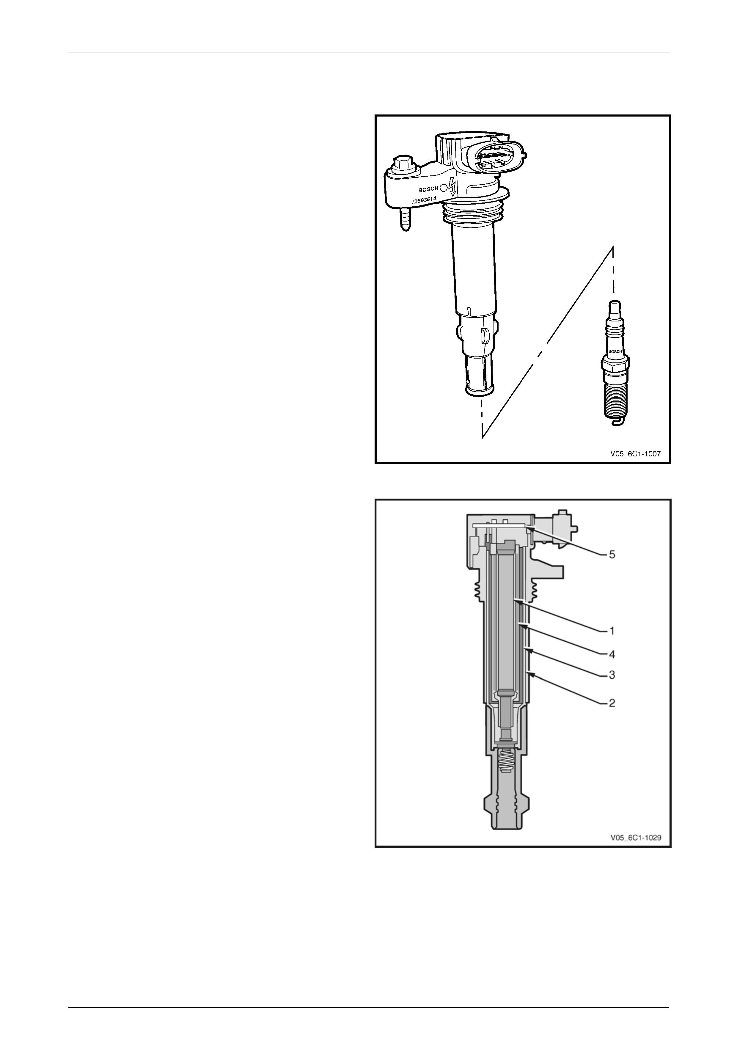
4.15 Ignition Coil and Spark Plug
Long-life platinum tip spark plugs are used which, along with
the ignition coil spark plug boot and spring, require
replacement at 100,000 kilometre service i ntervals. The
spark plugs, featuring a J-gap and a conical seat, do not
require inspection between services, and must not be re-
gapped.
Individual pencil-type ignition coils, one for each cylinder, are
mounted in the centre of the camshaft covers, and have
short boots connecting the coils directly to the spark plugs.
The pencil coil makes use of the space ava ilable in the spark
plug cavity in the cylinder head and cams haft cover. As a
pencil coil is always mounted directly on to the spark plug,
no high-tension ignition l eads are required, further enhancing
reliability.
Figure 6C1-1 – 46
Pencil coils operate similarly to other compact coils, however
due to their shape, the structure differs considerabl y.
The central rod core (1) consists of laminations of varying
widths, stacked in packs that are nearly spherical. A yoke
plate (2), made from layered electrical sheet steel, provides
the magnetic circuit. The primary winding (3) is located
around the secondary windi ng (4), which supports the core.
A printed circuit board, or driver module, (5) is located at the
top of the coil and controls the firing of the coil based on
input from the ECM.
The ECM is responsible for maintaining correct spark timing
and dwell for all driving conditi ons. The ECM calculates the
optimum spark parameters from information received from
the various sensors, and triggers the appropr iate ignition
module which then operates the coi l.
The ignition coil / modules are supplied with the following
circuits:
• Ignition feed circuit.
• Ground circuit.
• Ignition control circuit.
• Reference low circuit.
Figure 6C1-1 – 47
Page 6C1-1–48
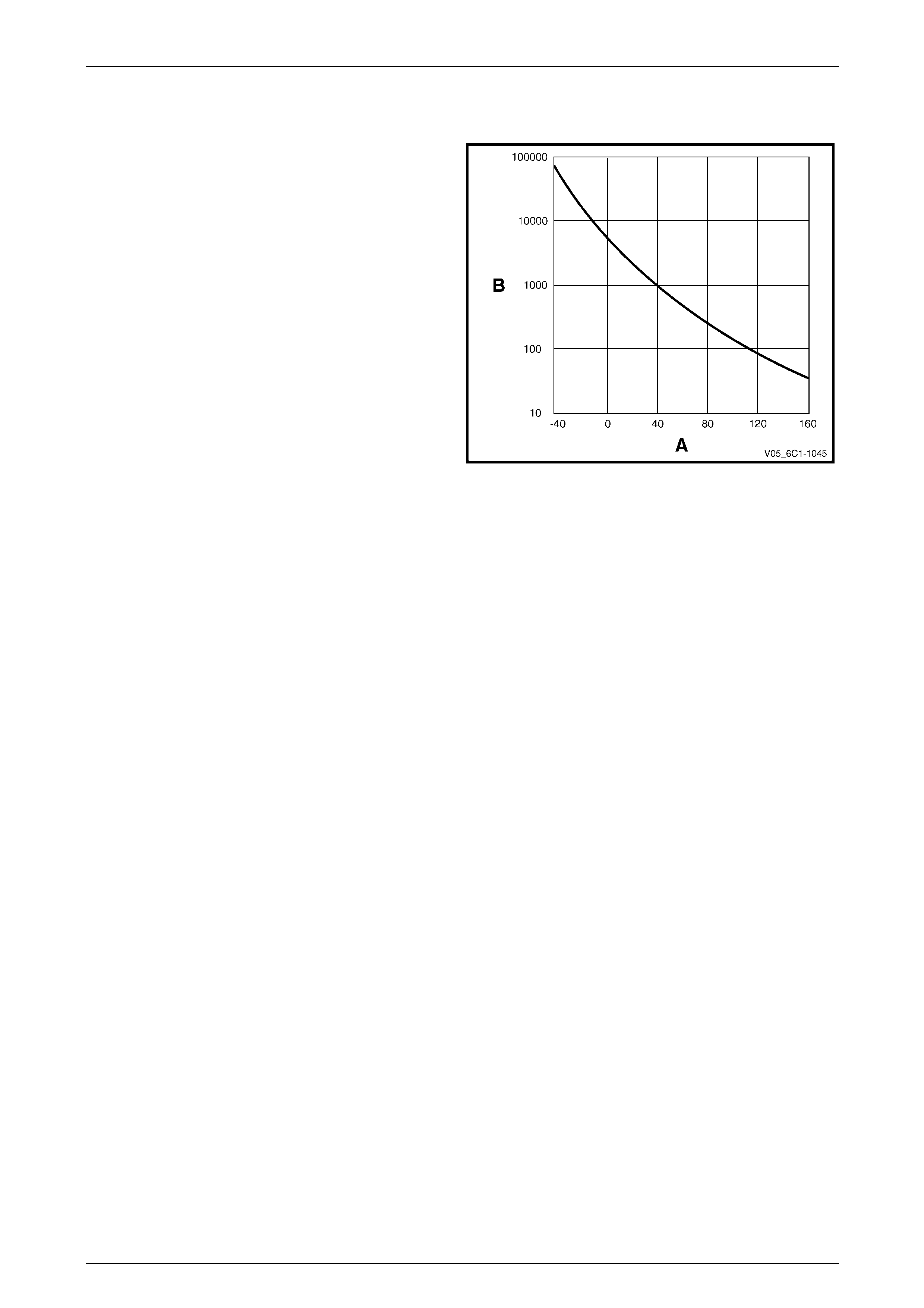
Engine Management – V6 – General Information Page 6C1-1–49
4.16 Intake Air Temperature Sensor
The air intake temperature (AIT ) sensor is a thermistor,
which is a resistor that changes it’s resistance value based
on temperature.
The IAT sensor is part of the air mass sensor and is not a
serviceable item. The sensor is a negative temperature
coefficient (NTC) type, intake air temperature produces a
high sensor resistance while high en gine coolant
temperature causes low sensor resistance.
Legend
A Temperature
B Resistance
The ECM provides a 5 V reference sign al to the IAT and
monitors the return signal which enables it to calculate the
intake air temperature.
The ECM uses this signal to make corrections to the
operating parameters of the system b ased o n changes in air
intake temperature. Figure 6C1-1 – 48
Page 6C1-1–49
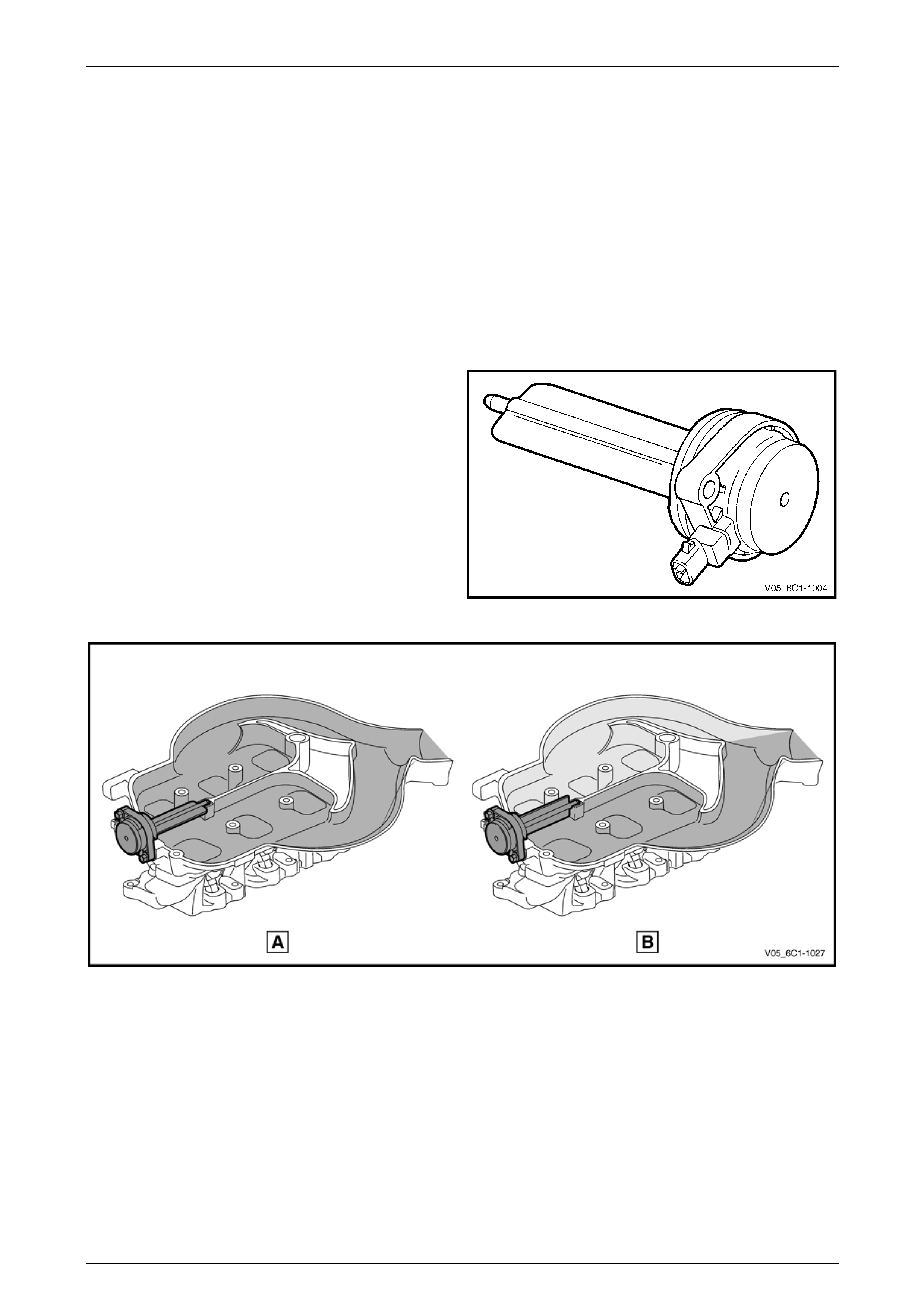
Engine Management – V6 – General Information Page 6C1-1–50
4.17 Intake Manifold Runner Control Valve
The intake manifold runner control (IMRC) valve is fitted into the intake manifold of Alloytec190 engines only.
The purpose of the IMRC is to alter the length and volume of the intake manifold runners. Varying the intake manifold
takes advantage of the natural pulse / pressure waves occur ring in the manifold that are cr eated by the process of air
induction into the cylinders.
During induction with an open intake valve, a return pressure wave is generated in the intake manifold. At the open
(throttle) end of the intake manifold, the pressure wave encounters ambient, inactive air and is reflected back again,
returning in the direction of the intake valve.
The waves vary in length and speed, and are proportional to engine speed, and the length and volume of the intake
manifold runners. Therefore, at a given engi ne speed, the manifold can be tuned to increase the air charge into the
cylinders via the returning pul se waves to achieve higher engine torque. By using varying geometry intake manifold
tubing, there is a wider speed range in which the tuning can be effected.
The IMRC valve is supplied with ignition voltage via the
main relay and its operation is controlled by the ECM by
switching the ground circuit.
At lower engine speeds the valve flap is open (A), while at
higher engine spee ds, the ECM commands the valve to
close (B) by switching the circuit to ground, refer to Figure
6C1-1 – 50.
The characteristic flow in the manifold is altered b y the
IMRC valve position.
Figure 6C1-1 – 49
Figure 6C1-1 – 50
Page 6C1-1–50
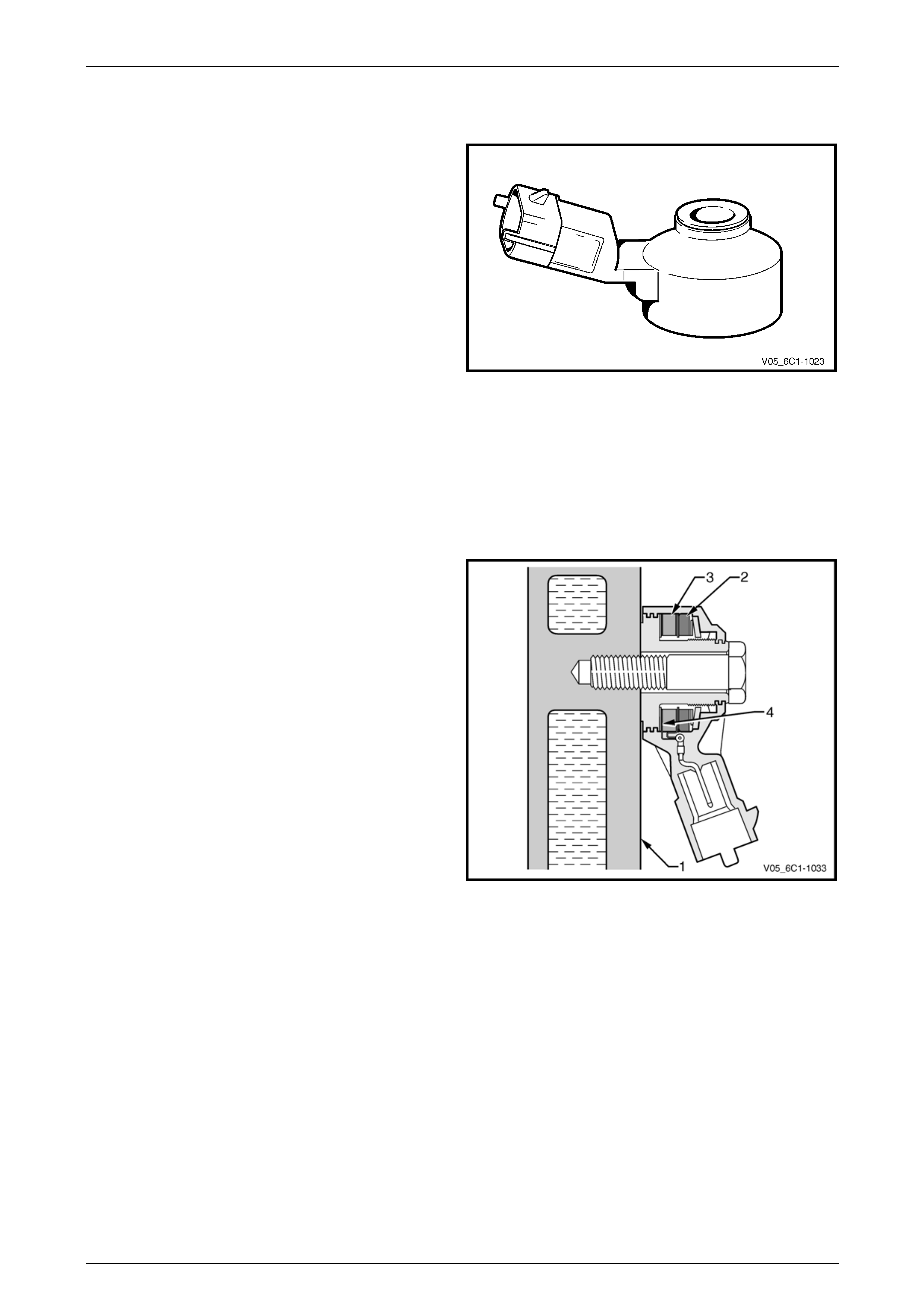
Engine Management – V6 – General Information Page 6C1-1–51
4.18 Knock Sensor
The knock sensor (KS) signal is used by the ECM to provide
optimum ignition timing while minimising engine knock or
detonation.
The ECM monitors the voltage of the left-hand (Bank 2)
sensor during the 45 degrees after cylinder 2, 4, or 6 has
fired and the voltage of the right-hand (Bank 1) sensor
during the 45 degrees after cylinder 1, 3, or 5 has fired.
If knock occurs in any of the cylinders, the ignition will be
retarded by three degrees for that particular cylinder. If the
knocking then stops, the ignition will be restored to what it
was before in steps of 0.75 degrees.
Should knocking continue in the same cylinder despite of
the ignition being retarded, the ECM will ret ard the ignition
an additional step of three degrees, and so on, up to a
maximum of 12.75 degrees. The ignition will also be
retarded at high ambient temperatures to counteract
knocking tendencies provoked by high intake air
temperatures.
Should either Bank 1 or Bank 2 sensor fail to work, or
should an open circuit occur, the ignitio n timing will then be
set at a default strategy that will retard the ignition much
more than normal.
Figure 6C1-1 – 51
The knock sensor is tuned to detect the frequency of the
vibration created by combustion knock. The vibration is
transferred to the knock sensor through the cylinder
block (1).
Inside the sensor is a mass (2) that is excited by this
vibration, and the mass exerts a compressive force onto a
piezo-ceramic element (3). The compressive force causes a
charge transfer inside the element, so that an AC voltag e
appears across the two outer faces (4) of the element. The
amount of the AC voltage produced is proportional to the
amount of knock.
Figure 6C1-1 – 52
Page 6C1-1–51
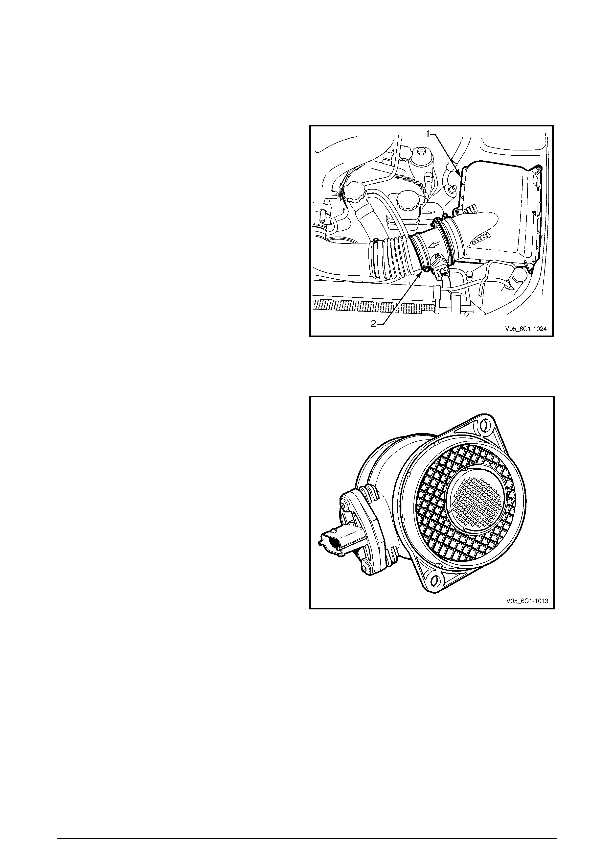
Engine Management – V6 – General Information Page 6C1-1–52
4.19 Mass Air Flow Sensor
Air Intake System
The air intake system draws outside air through an air
cleaner assembly (1). The air is then routed throu gh a mass
air flow (MAF) sensor (2) and into the throttle body an d
intake manifold. The air is then directed into the intake
manifold runners, through the c ylinder heads and into the
cylinders.
An arrow marked on the body of the MAF sensor indicates
correct air flow direction. The arrow must point toward the
engine.
Figure 6C1-1 – 53
Mass Air Flow Sensor
A hot film type mass air flow (MAF) sensor is used which
measures the air mass inducted into th e engine, regardless
of the engine’s operating state . The MAF precisely
measures a portion of the total airflo w and takes into
account the pulsation and reverse flows generated by the
engine’s inlet and exhaust valves.
Changes in intake air temperature have no effect on
measuring accuracy.
Figure 6C1-1 – 54
Page 6C1-1–52
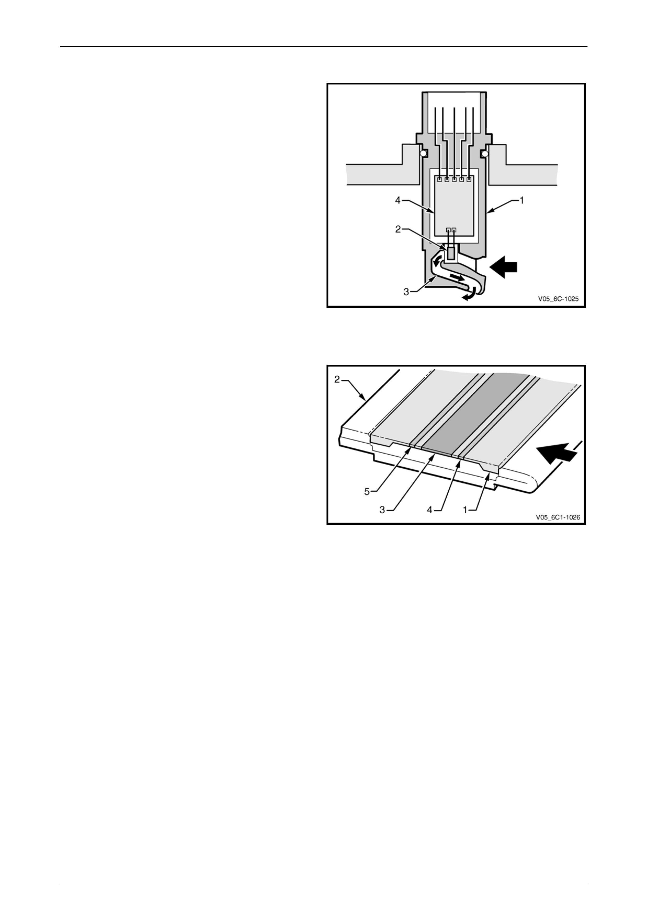
Engine Management – V6 – General Information Page 6C1-1–53
Construction
Projecting into the MAF sensor bod y is the compact design
sensor assembly (1), which consists of:
• the sensor element (2),
• partial airflow measuring tube (3), and
• integrated evaluatio n electronics (4).
Figure 6C1-1 – 55
Operation
A diaphragm (1) on the sensor element (2) is heated by a
centrally mounted heater resistor (3), which is held at a
constant temperature. The temperature drops sharply each
side of the heating zone.
Temperature of the diaphragm is registered to the
evaluation electronics by two temperature-dependent
resistors located on the upstream (4) and downstream (5)
side of the resistor.
With no air flow through the air flo w measuring tube and
over the sensor element, the temperature ch aracteristic is
the same each side of the heating zone a nd the resistance
values are identical.
As air flows over the sensor element, the upstream resistor
value alters due to the cooling effect of the air flow. As the
air flows over the heating zone the air tempe r ature is
increased.
Figure 6C1-1 – 56
The air then passes over the downstream resistor and alters the resistance value, but as the air temperature is higher,
the value is different to the upstream resistor. This change i n temperature creates a temperature differential between the
two resistors.
It is this differential that is used to calculate the air mass flow, which is independent of absolute temperature. The
differential is also directional, which means the MAF not only measures the mass of the incoming air, but also its
direction.
As the evaluation electronics are meas uring the resistance differential between the resistors, the air ma ss flow for the
entire amount of air passing through the MAF is calculated and sent to the ECM as an analog signal of 0 – 5 V.
The ECM can also detect air flow that is inappropriate for a given operating condition based on the signal voltage, or a
signal that appears to be fixed based on the lack of normal signal fluctuations expected during engine operation.
Tech 2 can display the MAF value in grams per second (g/s). Values should change rather quickly on acceleration, but
should remain fairly stable at any given engine speed.
Page 6C1-1–53
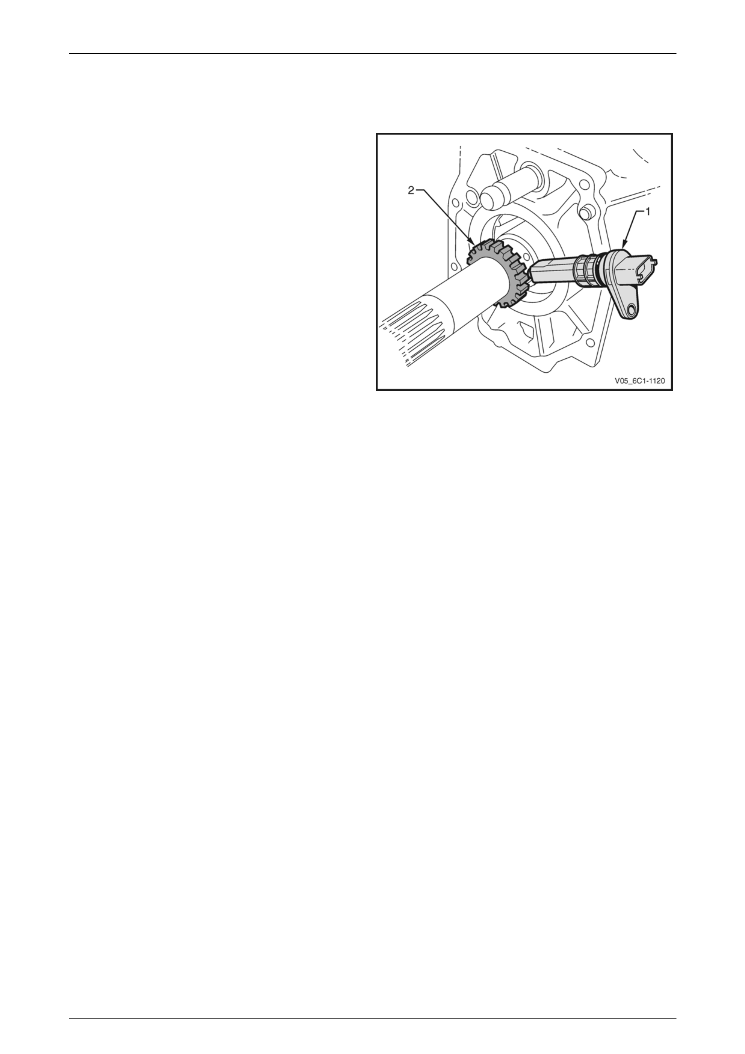
Engine Management – V6 – General Information Page 6C1-1–54
4.20 Vehicle Speed Sensor – Manual
Transmission Only
The vehicle speed sensor (V SS) (1) operates on the Hall
sensing principle. The sensor contains a hall element which
operates in conjunction with a toothed trigger wheel (2)
mounted on the transmission output shaft.
As the teeth on the gear trigger wheel passes the element,
magnetic flux affects a voltage in the Hall element. The
integrated circuit inside the sensor conditions the signal
generated by the Hall eleme nt to provide a rectangular wave
on / off signal to the ECM.
The ignition control relay applies battery voltage to the VSS,
and the ground circuit of the sensor is directly connecte d to
ground.
The engine control module (E CM) converts and outputs the
VSS signal to the instrument cluster assembly via a
dedicated circuit.
Figure 6C1-1 – 57
Page 6C1-1–54

Engine Management – V6 – General Information Page 6C1-1–55
5 Abbreviations and Glossary of
Terms
Abbreviations and terms used in this Section are listed below in alphabetical order with an explanation o f the
abbreviation or term.
Abbreviation Description
A/C Air-conditioning
AC Alternating Current – An electrical current where the polarit y is constantly changing between positive and
negative
A/F Air / Fuel (A/F Ratio)
Analogue Signal An electrical signal that constantly varies in voltage within a given parameter
Barometric Pressure Barometric absolute pressure (atmospheric pressure)
CAN Controller Area Network – A type of serial data for communication between electronic devices.
Catalytic Converter A muffler-shaped device fi tted in the exhaust system, usually close to the engine. Through chemical reaction,
a catalytic converter converts harmful gases produced by the combustion process such as HC, CO, and Nox,
into environmentally safe water vapour, carbon dioxide, and nitrogen.
CKT Circuit
Closed Loop A fuel control mode of operation that uses the signal from the exhaust oxygen sensor(s), to control the air / fuel
ratio precisely at a 14.7 to 1 ratio. This allows maximum efficiency of the catalytic converter.
CO Carbon Monoxide. One of the gases produced by the engine combustion process.
DC Direct Current
Digital Signal An electrical signal that is either on or off.
DLC Data Link Connector. Used at the assembly plant to evaluate the engine management system. For service, it
allows the use of Tech 2 in performing system checks.
DLC Data Stream An output from the ECM initiated by Tech 2 and transmitted via the Data Link Connector(DLC).
DMM (10 MΩ) Digital Multimeter. A multipurpose meter that has capability of measuring voltage, current flow and resistance.
A digital multimeter has an input impedance of 10 MΩ (megohms), which means they draw very little power
from the device under test, they are very accurate and will not damage delicate electronic components
Driver An electronic device, usually a power transistor, that operates as an electrical switch.
DTC Diagnostic Trouble Code. If a fault occurs in the engine management system, the ECM may set a four digit
diagnostic trouble code (DTC) which represents the fault condition. Tech 2 is used to interface with the ECM
and access the DTC(s). The ECM may also operate the check powertrain icon in the instrument cluster multi
function display.
Duty Cycle The time, in percentage, that a circuit is on versus off.
ECT Sensor Engine Coolant Temperature sensor. A device that provides a variable voltage to the ECM based on the
temperature of the engine coolant.
EEPROM Electrically Erasable Programmable Read Only Memory. A type of read only memory (ROM) that can be
electrically programmed, erased and reprogrammed using Tech 2. Also referred to as Flash Memory
EMI or Electrical
Noise An unwanted signal interfering with a required signal. A common example is the effect of high voltage power
lines on an AM radio.
Engine Braking A condition where the engine is used to slow the vehicle on closed throttle or low gear.
EPROM Erasable Programmable Read Only Memory. A type of Read Only Memory (ROM) that can be erased with
ultraviolet light and then reprogrammed.
ESD Electrostatic Discharge. The discharge of static electricity which has built up on an insulated material
EVAP Evaporative emission control system. Used to prevent fuel vapours from the fuel tank from entering into the
atmosphere. The vapours are stored in a canister that contains an activated charcoal element. The fuel
vapours are purged from the canister into the manifold to be burned in the engine.
GM LAN General Motors Local Area Network - A type of serial data for communication between electronic devices.
Fuse A thin metal strip which melts when excessive current flows through it, creating an open circuit and protecting
a circuit from damage.
HC Hydrocarbon. Result of unburned fuel produced by incomplete combustion.
Heavy Throttle Approximately 3/4 of accelerator pedal travel (75% throttle position)
IAT Sensor Intake Air Temperature sensor. A device that provides a variable voltage to the ECM based on the
temperature of air entering the intake system.
Ideal Mixture The air / fuel ratio which provides the best performance, while maintaining maximum conversion of exhaust
emissions, typically 14.7 to 1 on spark ignition engines
IGN Ignition
Inputs Information from sensors (MAF, TP, etc.) and switches (A/C request, etc.) used by the ECM to determine how
to control its outputs.
Page 6C1-1–55

Engine Management – V6 – General Information Page 6C1-1–56
Abbreviation Description
Intermittent An electrical signal that occurs now and then; not continuously. In electrical circuits, refers to occasional open,
short, or ground in a circuit
Light Throttle Approximately 1/4 of accelerator pedal travel (25% throttle position)
Low A voltage less than a specific threshold. Operates the same as a ground and may, or may not, be connected
to chassis ground.
MAF Sensor Mass Air Flow Sensor. A device that provides a variable voltage to the ECM based on the amount of air flow
entering in the intake system.
Medium Throttle Approximately 1/2 of accelerator pedal travel (50% throttle position)
N.C Normally Closed. Switch contacts that are closed when they are in the normal operating position
N.O Normally Open. Switch contacts that are normally open when in the normal operating position
NOx Nitrogen Oxide. One of the pollutants found in spark ignition engine exhaust that is f ormed from normal
combustion and increases in severity with combustion temperature.
O2 Sensor Oxygen Sensor. A device located in the exhaust system that provides a variable voltage to the ECM based on
the oxygen content of exhaust gas.
May also include a heating circuit to provide faster initial warm-up (HO2 sensor).
OBD On Board Diagnostic
Open Loop ECM control of the fuel control system without the use of the oxygen sensor signal.
Output Functions that are controlled by the ECM, typically these can include solenoids and relays, etc.
ECM Engine Control Module. An electronic device which controls the engine management system.
ECU Electronic Control Unit. An electronic device which controls specific system functions
PCV Positive Crankcase Ventilation. Method of reburning crankcase fumes rather than passing them directly into
the atmosphere
PIM Powertrain Interface Module – The PIM acts as a communication translator bet ween the ECM and other on-
board controllers that use a different serial data protocol.
PM Permanent Magnet
PWM Pulse Width Modulated. A digital signal turned on and off for a percentage of available cycle time. A signal that
is 30% on and 70% of would be termed a 30% on PWM signal.
Quad Driver A transistor in the ECM capable of operating four separate outputs. Outputs can be either on-off or pulse width
modulated.
RAM Random Access Memory. A microprocessor can write into or read from this memory as needed. This memory
is volatile and needs a constant power supply to be retained. If the power is lost or removed, RAM data is lost.
r.p.m. Revolutions Per Minute
Serial Data Serial data is a series of rapidly changing voltage signals pulsed from high to low. These signals are typically
5 V (UART), 7 V (Class II), and 12 or 0 V (high or low) and are transmitted through a wire often referred to as
the Serial Data Circuit.
SFI Sequential Fuel Injection. Method of injecting fuel into the engine one cylinder at a time in relation to the
engines firing order.
Solenoid An electromagnetic coil which creates a magnetic field when current is applied, causing a plunger or ball to
move.
Switch Device to opens and close a circuit, thereby controlling current flow.
Tech 2 Tech 2 is a peripheral device that aids in the diagnosis and repair of electronic systems such as engine
management, transmission control, ABS, etc. Tech 2 connects to the vehicle’s Data Link Connector (DLC).
TP Sensor Throttle Position sensor. A device that provides a variable voltage to the ECM based on the position of the
throttle plate.
Vacuum – manifold Vacuum sourced downstream of the throttle plate.
Vacuum – ported Vacuum sourced upstream of the throttle plate.
VSS Vehicle Speed Sensor. A permanent magnet type device that provides a digital voltage to the ECM.
UART Universal Asynchronous Receive and Transmit. A type of serial data for communicati on between electronic
devices.
WOT Wide Open Throttle – Full travel of the accelerator pedal (100% throttle position).
Page 6C1-1–56