
Engine Management – V6 – Diagnostics Page 6C1-2–1
Section 6C1-2 Engine Management – V6
Diagnostics
ATTENTION
Before performing any Service Operation or other procedure described in this Section, refer to Section 00
Warnings, Cautions and Notes for correct workshop practices with regard to safety and/or property damage.
1 General Information...............................................................................................................................4
1.1 Diagnostic System Check..................................................................................................................................... 4
1.2 Diagnostic Trouble Code Tables.......................................................................................................................... 5
1.3 Symptoms Diagnostics......................................................................................................................................... 6
1.4 Diagnostic Trouble Codes .................................................................................................................................... 7
2 Wiring Diagrams and Connector Charts..............................................................................................9
2.1 Wiring Diagrams .................................................................................................................................................... 9
2.2 ECM Connector End Views................................................................................................................................. 18
2.3 Connector End Views.......................................................................................................................................... 22
3 Diagnostics Starting Point ..................................................................................................................25
3.1 Basic Requirements ............................................................................................................................................ 25
3.2 Diagnostic Precautions....................................................................................................................................... 26
3.3 Preliminary Checks.............................................................................................................................................. 27
3.4 Diagnostic System Check................................................................................................................................... 28
4 Symptoms Diagnostics........................................................................................................................30
4.1 Symptoms Diagnosis Table................................................................................................................................30
4.2 Intermittent Fault Conditions.............................................................................................................................. 31
4.3 Backfire................................................................................................................................................................. 33
4.4 Cranks But Does Not Run................................................................................................................................... 35
4.5 Cuts Out, Misses.................................................................................................................................................. 36
4.6 Detonation / Spark Knock................................................................................................................................... 38
4.7 Dieseling, Run-on ................................................................................................................................................ 39
4.8 Hard Start.............................................................................................................................................................. 40
4.9 Hesitation, Sag and Stumble .............................................................................................................................. 41
4.10 Lack of Pow er, Sluggishness or Sponginess ................................................................................................... 42
4.11 Poor Fuel Economy............................................................................................................................................. 43
4.12 Rough, Unstable, Incorrect Idle or Stalling ....................................................................................................... 45
4.13 Surges / Chuggles ............................................................................................................................................... 46
5 Functional Checks ...............................................................................................................................48
5.1 General Information............................................................................................................................................. 48
5.2 Fuel Injector Coil Test ......................................................................................................................................... 49
5.3 Fuel Injector Balance Test .................................................................................................................................. 54
5.4 Fuel Injector Leak Down Test ............................................................................................................................. 57
5.5 Alcohol / Contaminants in Fuel Diagnosis........................................................................................................ 59
5.6 Crankshaft Position (CKP) System Variation Learn Proced ure....................................................................... 60
5.7 Throttle Body Relearn ......................................................................................................................................... 61
5.8 Intake Manifold Runner Control (IMRC) System Diagnosis ............................................................................. 62
5.9 Electronic Ignition (EI) System Diagnosis......................................................................................................... 64
Page 6C1-2–1

Engine Management – V6 – Diagnostics Page 6C1-2–2
6 Diagnostic Trouble Code Tables ........................................................................................................67
6.1 DTC List in Ascending Order.............................................................................................................................. 67
6.2 DTC P0008, P0009, P0016, P0017, P0018 or P0019........................................................................................... 80
6.3 DTC P0010, P0013, P0020, P0023, P2088, P2089, P2090, P2091, P2092, P2093, P2094 or P2095 ................. 83
6.4 DTC P0011, P0014, P0021, P0024, P1011, P1012, P1013, or P1014.................................................................. 86
6.5 DTC P0030, P0031, P0032, P0036, P0037, P0038, P0050, P0051, P0052, P0056, P0057 or P0058 ................. 89
6.6 DTC P0040 or P0041 ............................................................................................................................................ 92
6.7 DTC P0053 or P0059 ............................................................................................................................................ 94
6.8 DTC P0101, P0102 or P0103................................................................................................................................96
6.9 DTC P0112 or P0113 .......................................................................................................................................... 100
6.10 DTC P0116, P0117, P0118, P0125 or P1258 ..................................................................................................... 103
6.11 DTC P0121, P0122, P0123, P0221, P0222,or P0223......................................................................................... 106
6.12 DTC P0130, P0131, P0132, P0135, P0137, P0138, P0140, P0141, P0150 P0151, P0152, P0155, P0157, P0158,
P0160, P0161, P2243, P2247, P2270, P2271, P2272, P2273, P2297 or P2298 ................................................ 110
6.13 DTC P0133 or P0153 .......................................................................................................................................... 117
6.14 DTC P0139 or P0159 .......................................................................................................................................... 121
6.15 DTC P0196, P0197 or P0198.............................................................................................................................. 125
6.16 DTC P0201, P0202, P0203, P0204, P0205, P0206, P0261, P0262, P0264, P0265, P0267, P0268, P0270, P0271,
P0273, P0274, P0276 or P0277.......................................................................................................................... 128
6.17 DTC P0219.......................................................................................................................................................... 131
6.18 DTC P0300.......................................................................................................................................................... 133
6.19 DTC P0301, P0302, P0303, P0304, P0305 or P0306......................................................................................... 136
6.20 DTC P0324.......................................................................................................................................................... 139
6.21 DTC P0327, P0328, P0332 or P0333.................................................................................................................. 142
6.22 DTC P0335, P0336, P0337 or P0338.................................................................................................................. 145
6.23 DTC P0341, P0342, P0343, P0346, P0347, P0348, P0366, P0367, P0368, P0391, P0392 or P0393 ............... 149
6.24 DTC P0351, P0352, P0353, P0354, P0355, P0356, P2300, P2301, P2303, P2304, P2306, P2307, P2309, P2310,
P2312, P2313, P2315 or P2316.......................................................................................................................... 152
6.25 DTC P0420 or P0430 .......................................................................................................................................... 155
6.26 DTC P0443, P0458 or P0459.............................................................................................................................. 157
6.27 DTC P0460, P0461, P0462 or P0463.................................................................................................................. 160
6.28 DTC P0480, P0481, P0691, P0692, P0693 or P0694......................................................................................... 162
6.29 DTC P0500.......................................................................................................................................................... 165
6.30 DTC P0504 or P0571 .......................................................................................................................................... 168
6.31 DTC P0506, P0507, P0638, P1551, P2100, P2101, P2119 or P2176................................................................. 171
6.32 DTC P0513, P0633, P1629, P1632, P1677, P1678 or P1679............................................................................. 176
6.33 DTC P0521, P0522 or P0523.............................................................................................................................. 179
6.34 DTC P0532 or P0533 .......................................................................................................................................... 182
6.35 DTC P0560, P0562 or P0563.............................................................................................................................. 185
6.36 DTC P0601, P0602, P0604 or P0606.................................................................................................................. 187
6.37 DTC P0615, P0616 or P0617.............................................................................................................................. 189
6.38 DTC P0625 or P0626 .......................................................................................................................................... 191
6.39 DTC P0627, P0628 or P0629.............................................................................................................................. 193
6.40 DTC P0645, P0646 or P0647.............................................................................................................................. 195
6.41 DTC P0685, P0686 or P0687.............................................................................................................................. 197
6.42 DTC P0700.......................................................................................................................................................... 199
6.43 DTC P0704.......................................................................................................................................................... 200
6.44 DTC P0850.......................................................................................................................................................... 202
6.45 DTC P0864.......................................................................................................................................................... 204
6.46 DTC P1648.......................................................................................................................................................... 206
6.47 DTC P1668, P2500 or P2501.............................................................................................................................. 208
6.48 DTC P1845.......................................................................................................................................................... 210
6.49 DTC P2008, P2009 or P2010.............................................................................................................................. 212
6.50 DTC P2096 or P2098 .......................................................................................................................................... 214
6.51 DTC P2097 or P2099 .......................................................................................................................................... 218
6.52 DTC P2105.......................................................................................................................................................... 222
6.53 DTC P2107.......................................................................................................................................................... 224
6.54 DTC P2122, P2123, P2127, P2128 or P2138 ..................................................................................................... 226
6.55 DTC P2177 or P2179 .......................................................................................................................................... 229
Page 6C1-2–2

Engine Management – V6 – Diagnostics Page 6C1-2–3
6.56 DTC P2178 or P2180 .......................................................................................................................................... 233
6.57 DTC P2187 or P2189 .......................................................................................................................................... 236
6.58 DTC P2188 or P2190 .......................................................................................................................................... 240
6.59 DTC P2195 or P2197 .......................................................................................................................................... 243
6.60 DTC 2196 or P2198............................................................................................................................................. 248
6.61 DTC P2227, P2228 or P2229.............................................................................................................................. 253
6.62 DTC P2231, P2232, P2234, P2235, P2251 or P2254......................................................................................... 256
6.63 DTC P2237, P2238, P2239, P2240, P2241 or P2242......................................................................................... 260
6.64 DTC P2626, P2627, P2628, P2629, P2630 or P2631......................................................................................... 264
6.65 DTC U0001.......................................................................................................................................................... 268
6.66 DTC U0101.......................................................................................................................................................... 270
6.67 DTC U0121 or U0415.......................................................................................................................................... 272
6.68 DTC U0155 or U0423.......................................................................................................................................... 274
7 V6 Engine – Tech 2 Functions ..........................................................................................................276
7.1 Introduction........................................................................................................................................................ 276
7.2 Tech 2 Functions ............................................................................................................................................... 277
7.3 HFV6 Engine Data Lists..................................................................................................................................... 279
7.4 Tech 2 Data Definitions..................................................................................................................................... 294
7.5 OBD Data............................................................................................................................................................ 299
7.6 Actuator Test...................................................................................................................................................... 300
7.7 Programming...................................................................................................................................................... 303
Page 6C1-2–3

Engine Management – V6 – Diagnostics Page 6C1-2–4
1 General Information
1.1 Diagnostic System Check
The engine management diagnostic procedure is organised in a logical structure that begins with the Diagnostic System
Check. The Diagnostic System Check directs the diagnostic procedure to the logical steps necessary to diagnose an
engine driveability fault condition.
Page 6C1-2–4

Engine Management – V6 – Diagnostics Page 6C1-2–5
1.2 Diagnostic Trouble Code Tables
The Diagnostic System Check directs the diagnostic procedure to the appropriate diagnostic trouble code (DTC) tables if
there is a DTC currently stored in the engine control module (ECM).
The diagnostic tables locate a faulty circuit or component through a logic based on the process of elimination. These
diagnostic tables are developed with the following assumptions:
• the vehicle functioned correctly at the time of assembly,
• there are no multiple faults, and
• the problem currently exists.
Understanding and the correct use of the diagnostic trouble code (DTC) tables are essential to reduce diagnostic time
and to prevent misdiagnosis.
Multiple DTC Fault Conditions
Some fault conditions trigger multiple component DTCs even if the fault condition exists only on a single component. If
there are multiple DTCs stored in the ECM, the service technician must view and record all DTCs logged.
The relationship between the logged DTCs can then be analysed to determine the source of the fault condition. Always
begin the diagnostic process with the DTC table of the fault condition that may trigger other DTCs to set.
The following fault conditions may trigger multiple DTCs:
• a fault in the serial data communication circuit,
• a system voltage that is too low may cause incorrect engine management system operation or engine management
component malfunction,
• a system voltage that is too high may damage the ECM and / or other engine management components,
• fault condition in the ECM read only memory (ROM) or random access memory (RAM),
• fault condition in the ECM internal circuitry or programming,
• improperly connected sensor or component wiring connector, or
• an electrical fault condition in the following shared ECM electrical circuits trigger DTCs on components or sensors
that share in the faulty shared circuit. Test the electrical circuit of the appropriate sensors or components to isolate
the fault condition. Refer to 2 Wiring Diagrams and Connector Charts.
• 5 V Reference Circuit,
• Low Reference Circuit, or
• Ignition Control Voltage Circuit.
If there are no obvious faults to begin a multiple DTC fault condition diagnostic procedure, diagnose the DTCs in the
following order unless directed otherwise:
1 Always start with the lowest numbered component level DTCs such as:
• sensor DTCs,
• solenoid DTCs, or
• relay DTCs.
2 Then follow with system level DTCs such as:
• misfire DTCs,
• fuel trim DTCs, or
• catalyst DTCs.
Page 6C1-2–5

Engine Management – V6 – Diagnostics Page 6C1-2–6
1.3 Symptoms Diagnostics
The Diagnostic System Check directs the service technician to the symptoms diagnostics if the following conditions exist:
• a vehicle driveability fault condition exists,
• there is no current diagnostic trouble code presently stored in the ECM, and
• all Tech 2 engine data parameters are within normal operating range.
Page 6C1-2–6

Engine Management – V6 – Diagnostics Page 6C1-2–7
1.4 Diagnostic Trouble Codes
The ECM constantly performs self-diagnostic tests on the engine management system. When the ECM detects a fault
condition in the engine operating parameters, the ECM sets a diagnostic trouble code (DTC) to represent that fault
condition. The following are the types of DTCs programmed in the ECM. In addition, DTCs are classified as either a
current or history DTC.
• Type A – emission related DTCs,
• Type B – emission related DTCs, and
• Type C – non-emission related DTCs.
NOTE
Depending on the type of DTC set, the ECM may
command the ‘Check Powertrain’ icon (MY2005
vehicles) or, for MY2006 vehicles, the Malfunction
Indicator Lamp (MIL) to activate and warn the
driver there is a fault in the engine management
system. Refer to Section 12C Instrumentation for
further information on the Check Engine warning
display.
Type A – Emission Related DTCs
The ECM takes the following action when a Type A DTC runs and fails:
• sets a current Type A DTC that represents the fault condition,
• illuminates the instrument cluster Multi-Function Display (MFD) Check Powertrain icon, or the Malfunction Indicator
Lamp (MIL), and
• records the operating condition at the time the diagnostic fails and stores this information in the freeze
frame / failure record.
Type B – Emission Related DTCs
The ECM takes the following action when a Type B DTC runs and fails:
• On the first time a Type B DTC fails, the ECM takes the following actions:
− sets a current Type B DTC that represents the fault condition, and
− records the operating conditions at the time the fault sets and stores this information in the failure records.
• On the second consecutive ignition cycle that a Type B DTC fails, the ECM takes the following actions:
− activates the instrument cluster Multi-Function Display (MFD) Check Powertrain icon, or the Malfunction
Indicator Lamp (MIL), and
− records the operating condition at the time the diagnostic fails and stores this information in the freeze frame /
failure record.
Conditions for Clearing Type A or Type B DTCs
• The current DTC clears when there is no fault condition in the current ECM self-diagnostics.
• If there are no DTCs logged after three or four consecutive ignition cycles, the ECM deactivates the Check
Powertrain icon, or the Malfunction Indicator Lamp (MIL).
• Type A or Type B History DTC clears when there is no fault condition after 40 consecutive warm-up cycles.
• Use Tech 2 to clear DTC/s.
Page 6C1-2–7

Engine Management – V6 – Diagnostics Page 6C1-2–8
Type C – Non-Emission Related DTCs
The ECM takes the following action when a Type A DTC runs and fails:
• sets a current Type C DTC that represents the fault condition,
• records the operating conditions at the time the DTC is logged and stores this information in the Failure Record,
and:
• the instrument cluster MFD may display a message.
NOTE
The instrument cluster Check Powertrain icon, or
the malfunction indicator lamp (MIL) is not
activated when a Type C DTC sets.
Conditions for Clearing Type C DTCs
• The current DTC clears when there is no fault condition in the current ECM self-diagnostics.
• Type C History DTC clears when there is no fault condition after 40 consecutive warm-up cycles.
• Use Tech 2 to clear DTCs.
Current DTCs
A DTC is a Current DTC if the fault condition that triggers that DTC is present during the last ECM self-diagnostics.
History DTCs
A DTC is a History DTC if the fault condition that triggers that DTC is not present during the last ECM self-diagnostics.
Page 6C1-2–8
Engine Management – V6 – Diagnostics Page 6C1-2–9
2 Wiring Diagrams and Connector
Charts
2.1 Wiring Diagrams
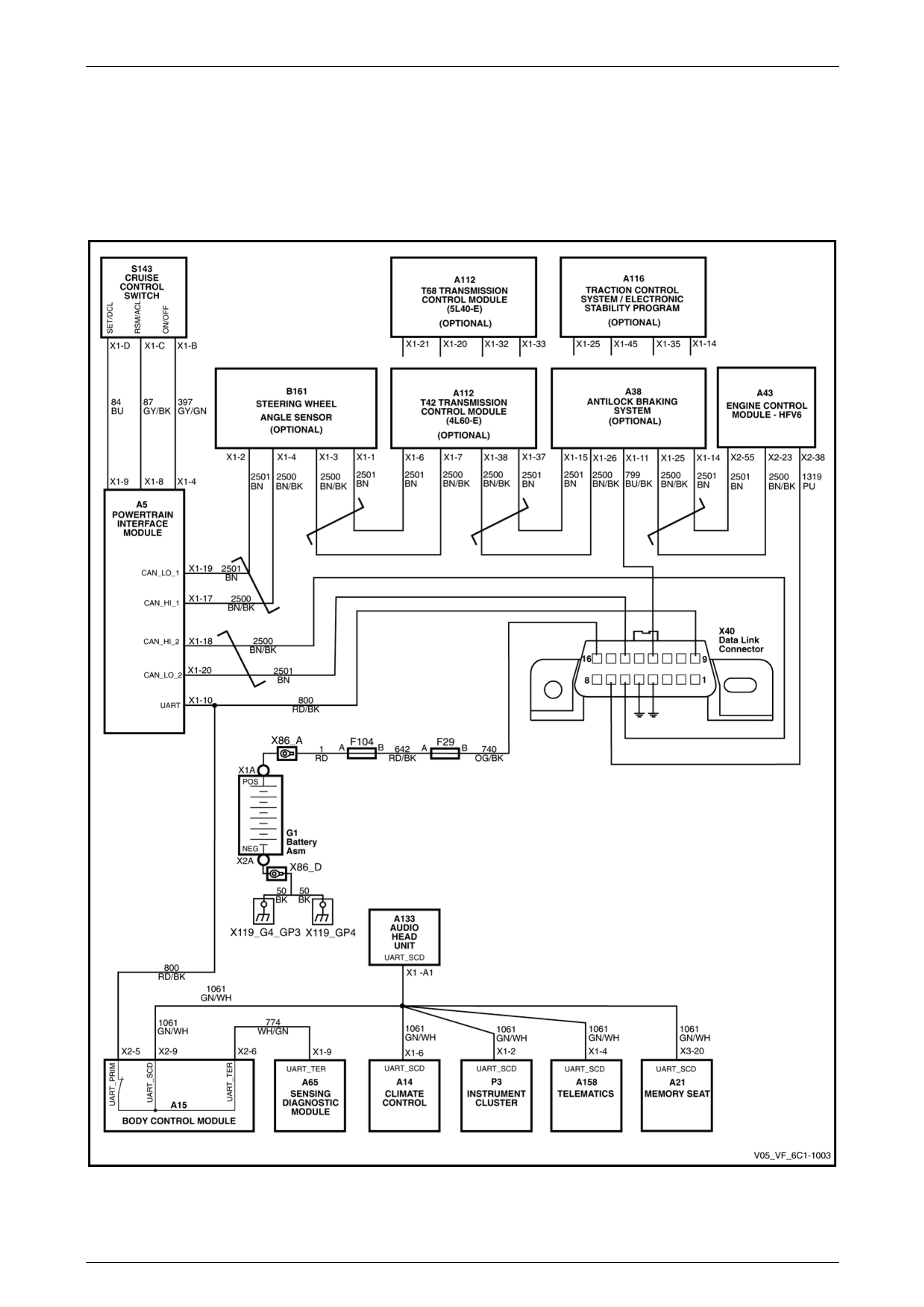
Serial Data and Data Link Connector
Figure 6C1-2 – 1
Page 6C1-2–9
Engine Management – V6 – Diagnostics Page 6C1-2–10
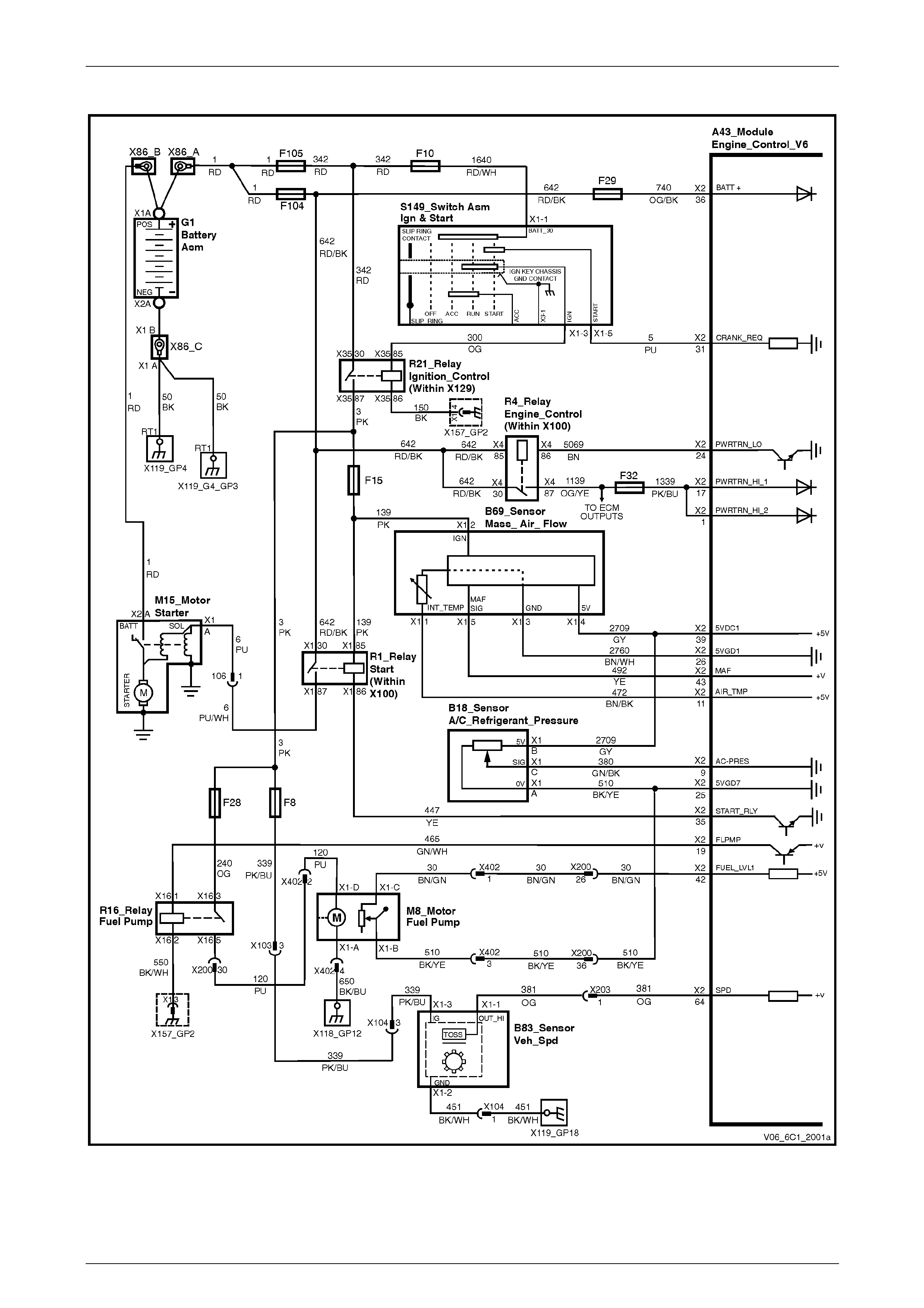
Power Supplies and ECM Inputs
Figure 6C1-2 – 2
Page 6C1-2–10
Engine Management – V6 – Diagnostics Page 6C1-2–11
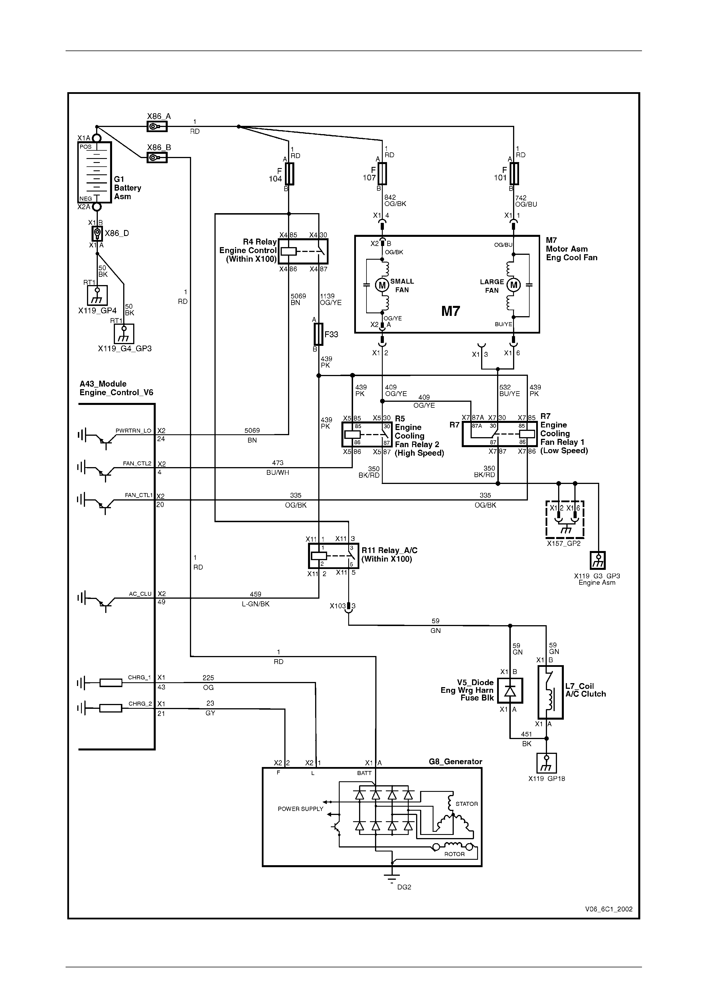
Cooling Fans, A/C Clutch & Generator
Figure 6C1-2 – 3
Page 6C1-2–11
Engine Management – V6 – Diagnostics Page 6C1-2–12
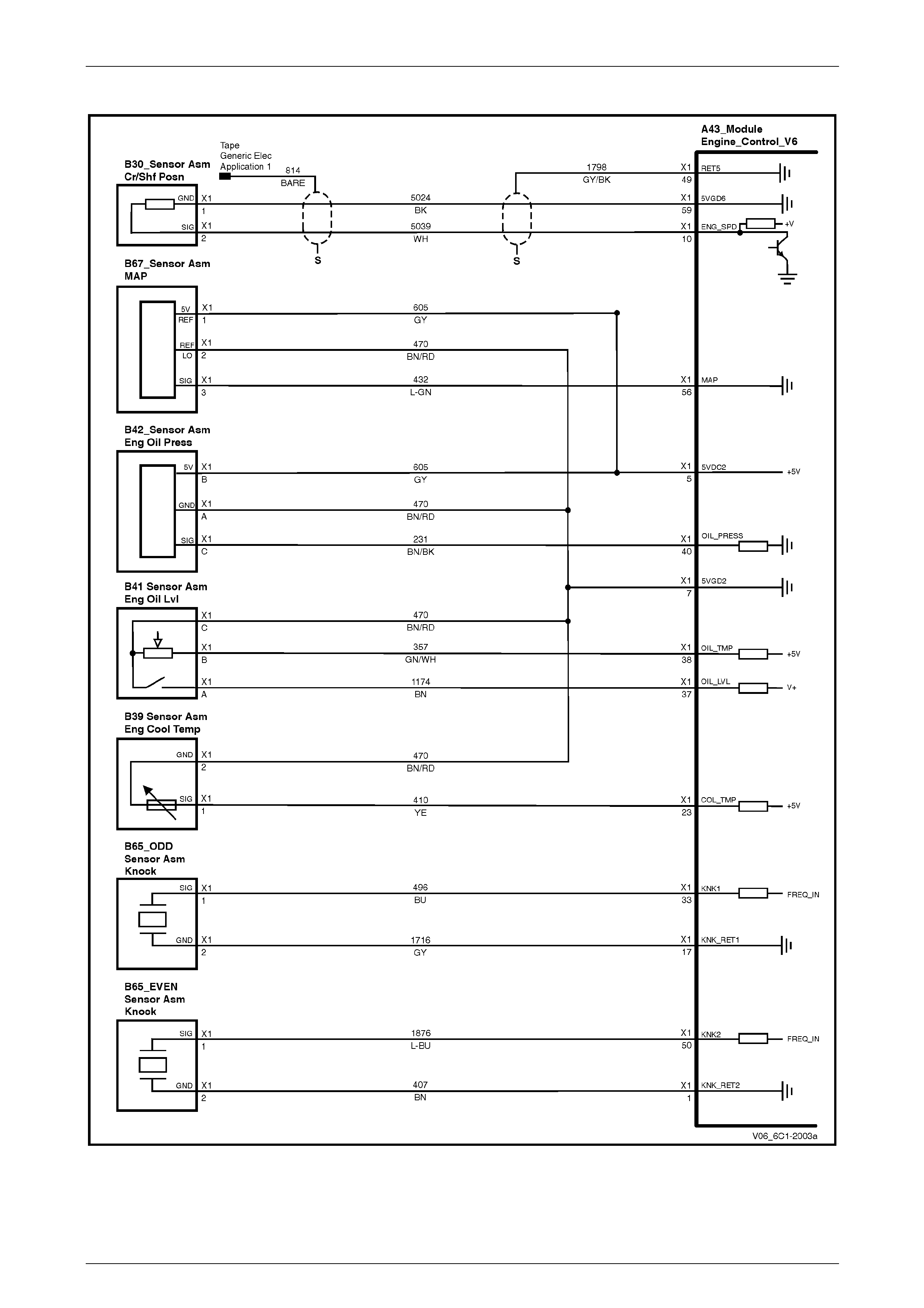
Sensors
Figure 6C1-2 – 4
Page 6C1-2–12
Engine Management – V6 – Diagnostics Page 6C1-2–13
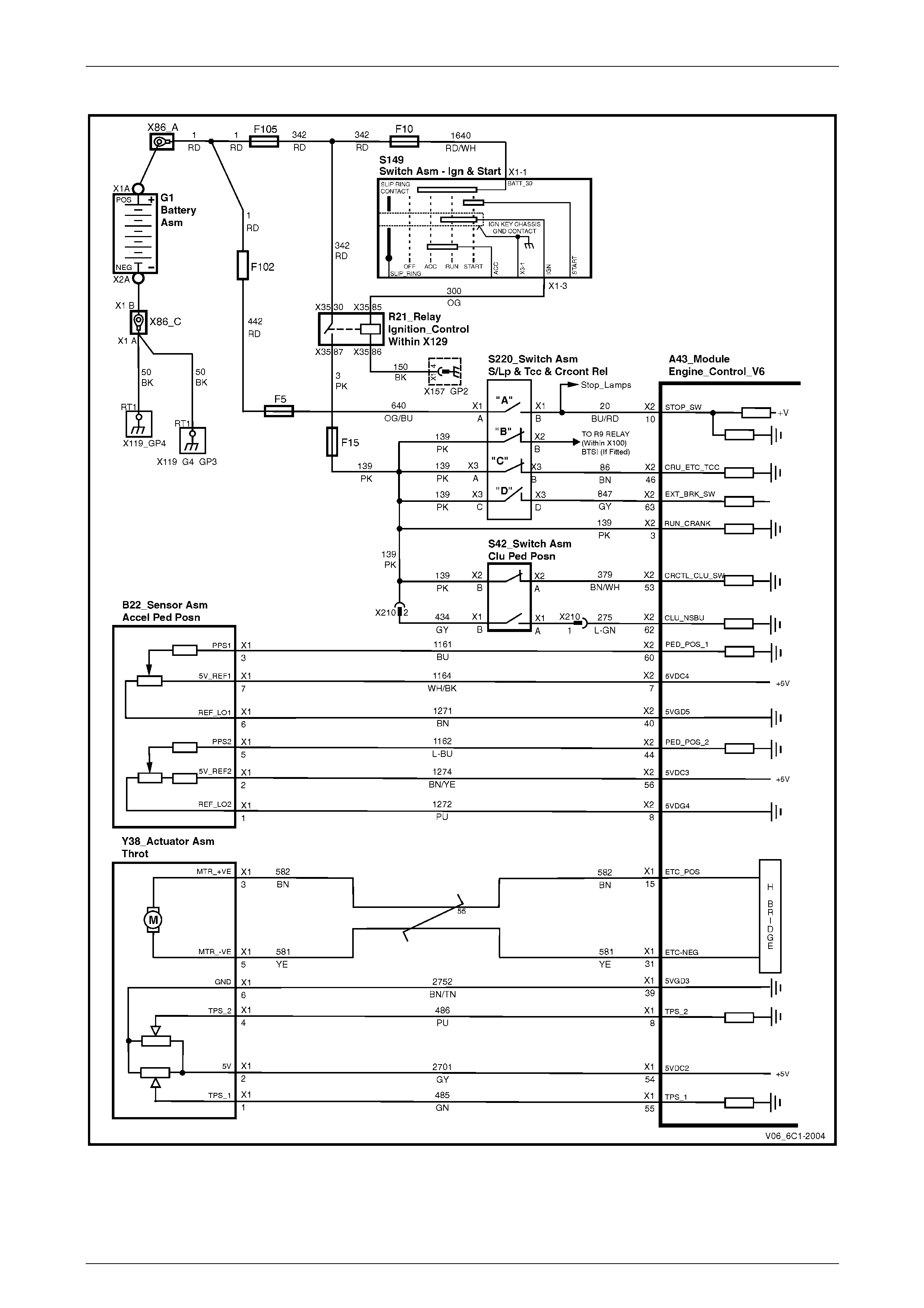
Switches & Throttle Control
Figure 6C1-2 – 5
Page 6C1-2–13
Engine Management – V6 – Diagnostics Page 6C1-2–14
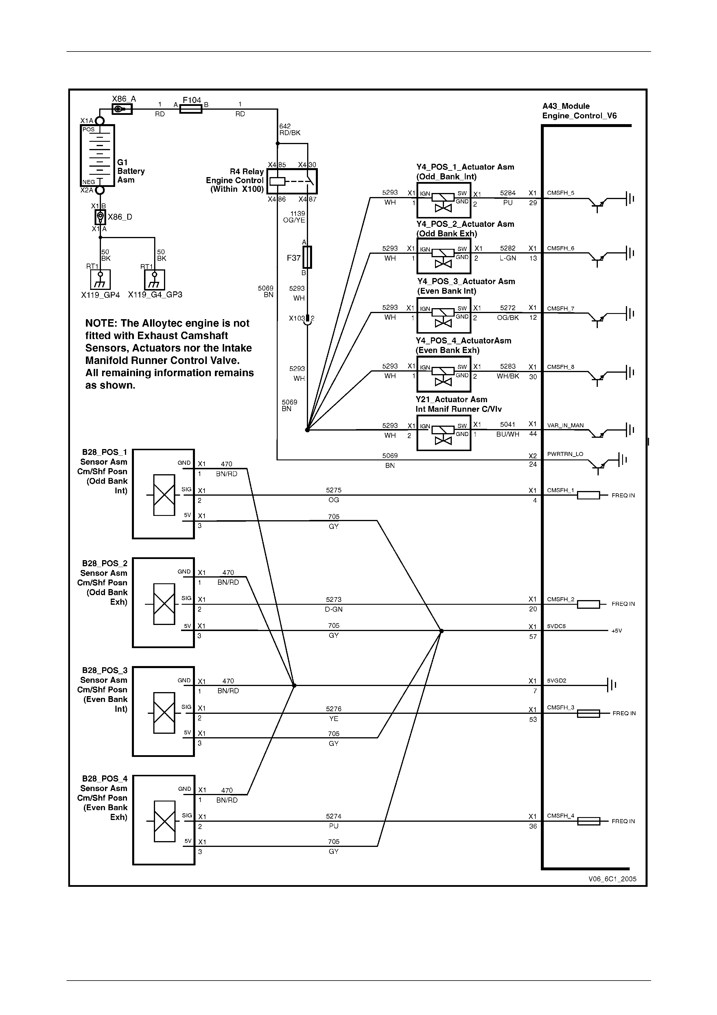
Camshaft Control – Alloytec 190 / High Output Engine
Figure 6C1-2 – 6
Page 6C1-2–14
Engine Management – V6 – Diagnostics Page 6C1-2–15
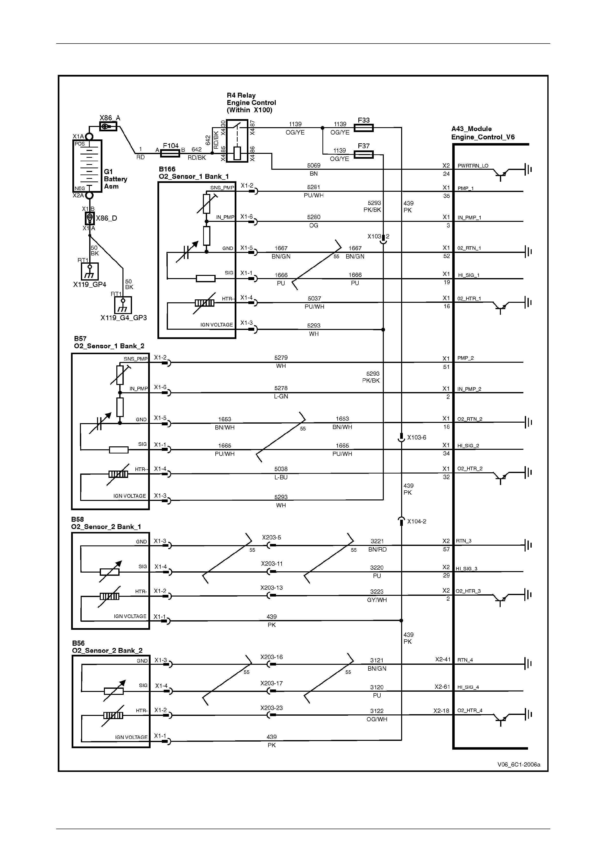
HO2S – All Alloytec Engines
Figure 6C1-2 – 7
Page 6C1-2–15
Engine Management – V6 – Diagnostics Page 6C1-2–16
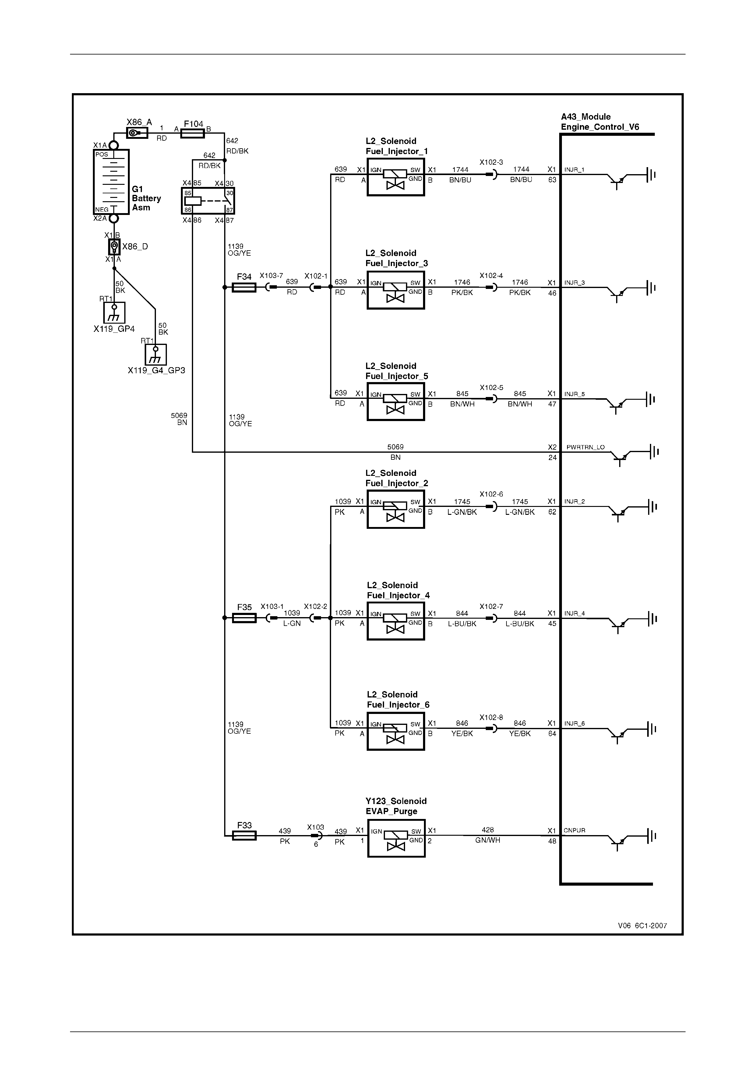
Fuel Injectors and EVAP Purge Solenoid
Figure 6C1-2 – 8
Page 6C1-2–16

Engine Management – V6 – Diagnostics Page 6C1-2–17
Ignition System
Figure 6C1-2 – 9
Page 6C1-2–17
Engine Management – V6 – Diagnostics Page 6C1-2–18
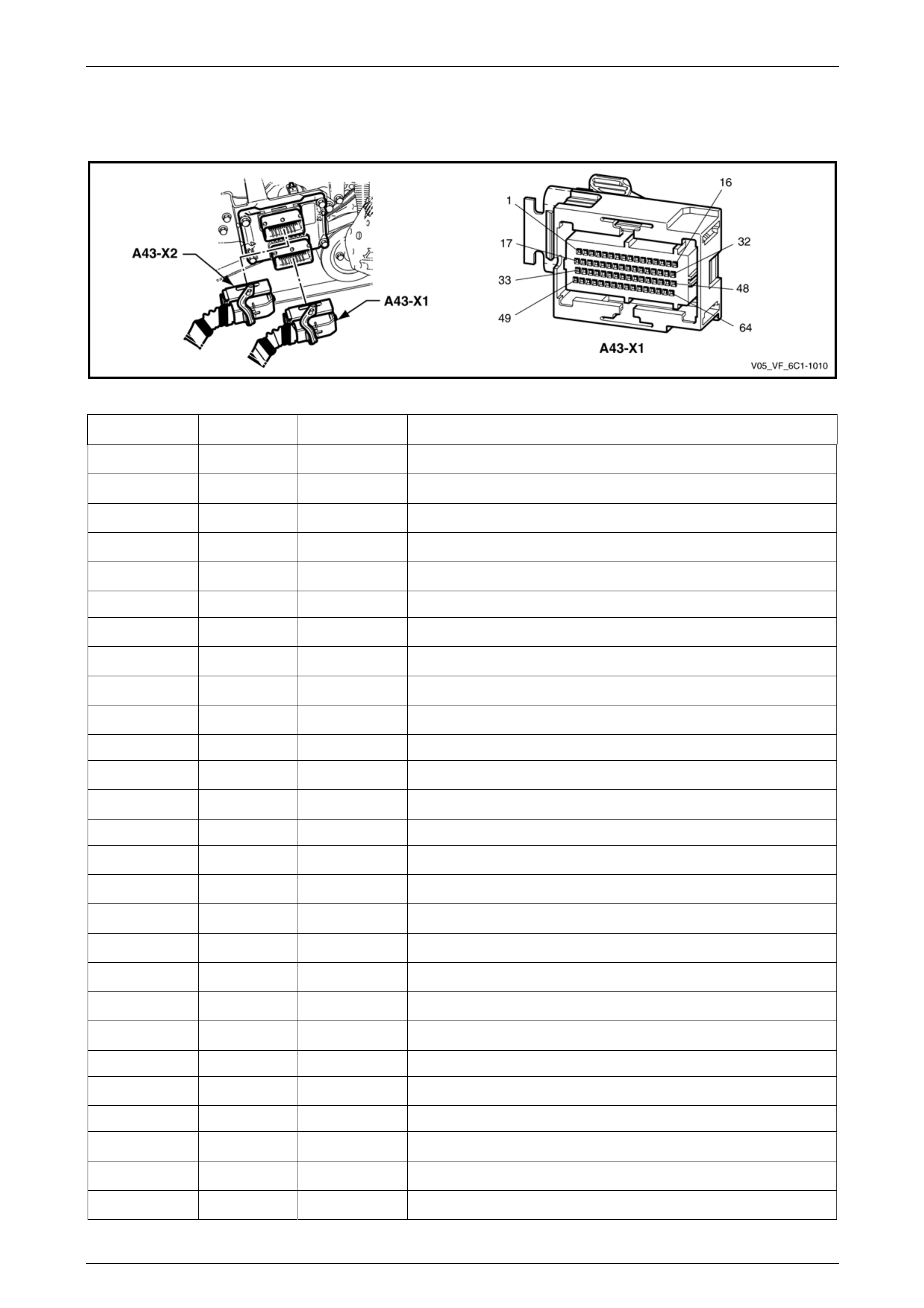
2.2 ECM Connector End Views
Engine Control Module A43 V6 – Connector X1
Figure 6C1-2 – 10
Terminal / Pin Wire Colour Circuit No. Function
X1–1 BN 407
Low Reference – Knock Sensor Bank 2
X1–2 L-GN 5278
B2S1 HO2S Input Pump Current (Bank 2 Sensor 1)
X1–3 OG 5280
B1S1 HO2S Input Pump Current (Bank 1 Sensor 1)
X1–4 OG 5275
CMP Sensor Signal – Intake Bank 1
X1–5 GY 605
5 Volt Reference – 6
X1–6 — —
Not Used
X1–7 BN/RD 470
Low Reference – Ground 2
X1–8 PU 486
TP Sensor 2 Signal
X1–9 GN/WH 2124
EST 4 Control
X1–10 WH 5039
CKP Sensor High
X1–11 — —
Not Used
X1–12 OG/BK 5272
CMP Actuator Solenoid Control – Intake Bank 2
X1–13 L-GN 5282
CMP Actuator Solenoid Control – Exhaust Bank 1
X1–14 — —
Not Used
X1–15 BN 582
TAC Motor Control (Positive)
X1–16 PU/WH 5037
B1S1 HO2S Heater Low Reference (Bank 1 Sensor 1)
X1–17 GY 1716
Low Reference – Knock Sensor Bank 1
X1–18 BN/WH 1653
B2S1 HO2S Low Signal (Bank 2 Sensor 1)
X1–19 PU 1666
B1S1 HO2S High Signal (Bank 1 Sensor 1)
X1–20 D-GN 5273
CMP Sensor Signal – Exhaust Bank 1
X1–21 GY 23
Generator Field Duty Cycle Signal (‘F’ Terminal)
X1–22 — —
Not Used
X1–23 YE 410
ECT Sensor Signal
X1–24 — —
Not Used
X1–25 BU/WH 2126
EST 6 Control
X1–26 OG/WH 2122
EST 2 Control
X1–27 — —
Not Used
Page 6C1-2–18

Engine Management – V6 – Diagnostics Page 6C1-2–19
X1–28 — —
Not Used
X1–29 PU 5284
CMP Actuator Solenoid Control – Intake Bank 1
X1–30 WH/BK 5283
CMP Actuator Solenoid Control – Exhaust Bank 2
X1–31 YE 581
TAC Motor Control (Negative)
X1–32 L-BU 5038
B2S1 HO2S Heater Low Control (Bank 2 Sensor 1)
X1–33 BU 496
Knock Sensor 1 Signal (Bank 1)
X1–34 PU/WH 1665
B2S1 HO2S High Signal (Bank 2 Sensor 1)
X1–35 PU/WH 5281
B1S1 HO2S Pump Current (Bank 1 Sensor 1)
X1–36 PU 5274
CMP Sensor Signal – Exhaust Bank 2
X1–37 BN 1174
Oil Level Switch Signal
X1–38 GN/WH 357
Oil Temperature Sensor Signal
X1–39 BN/TN 2752
Low Reference – Ground 3
X1–40 BN/BK 231
Oil Pressure Sensor Signal
X1–41 D-GN 2125
EST 5 Control
X1–42 PU 2121
EST 1 Control
X1–43 OG 225
Generator Turn On Signal (‘L’ Terminal)
X1–44 BU/WH 5041
IMRC Solenoid Control
X1–45 L-BU/BK 844
Fuel Injector 4 Control
X1–46 PK/BK 1746
Fuel Injector 3 Control
X1–47 BN/WH 845
Fuel Injector 5 Control
X1–48 GN/WH 428
EVAP Canister Purge Solenoid Control
X1–49 GY/BK 1798
CKP Sensor Shield Return
X1–50 L-BU 1876
Knock Sensor 2 Signal (Bank 2)
X1–51 WH 5279
B2S1 HO2S Pump Current (Bank 2 Sensor 1)
X1–52 BN/GN 1667
B1S1 HO2S Low Signal (Bank 1 Sensor 1)
X1–53 YE 5276
CMP Sensor Signal – Intake Bank 2
X1–54 GY 2701
5 Volt Reference – 2
X1–55 GN 485
TP Sensor 1 Signal
X1–56 L-GN 432
MAP Sensor Signal
X1–57 GY 705
5 Volt Reference – 5
X1–58 L-BU 2123
EST 3 Control
X1–59 BK 5024
CKP Sensor Low – Ground 6
X1–60 — —
Not Used
X1–61 — —
Not Used
X1–62 L-GN/BK 1745
Fuel Injector 2 Control
X1–63 BN/BU 1744
Fuel Injector 1 Control
X1–64 YE/BK 846
Fuel Injector 6 Control
Page 6C1-2–19
Engine Management – V6 – Diagnostics Page 6C1-2–20
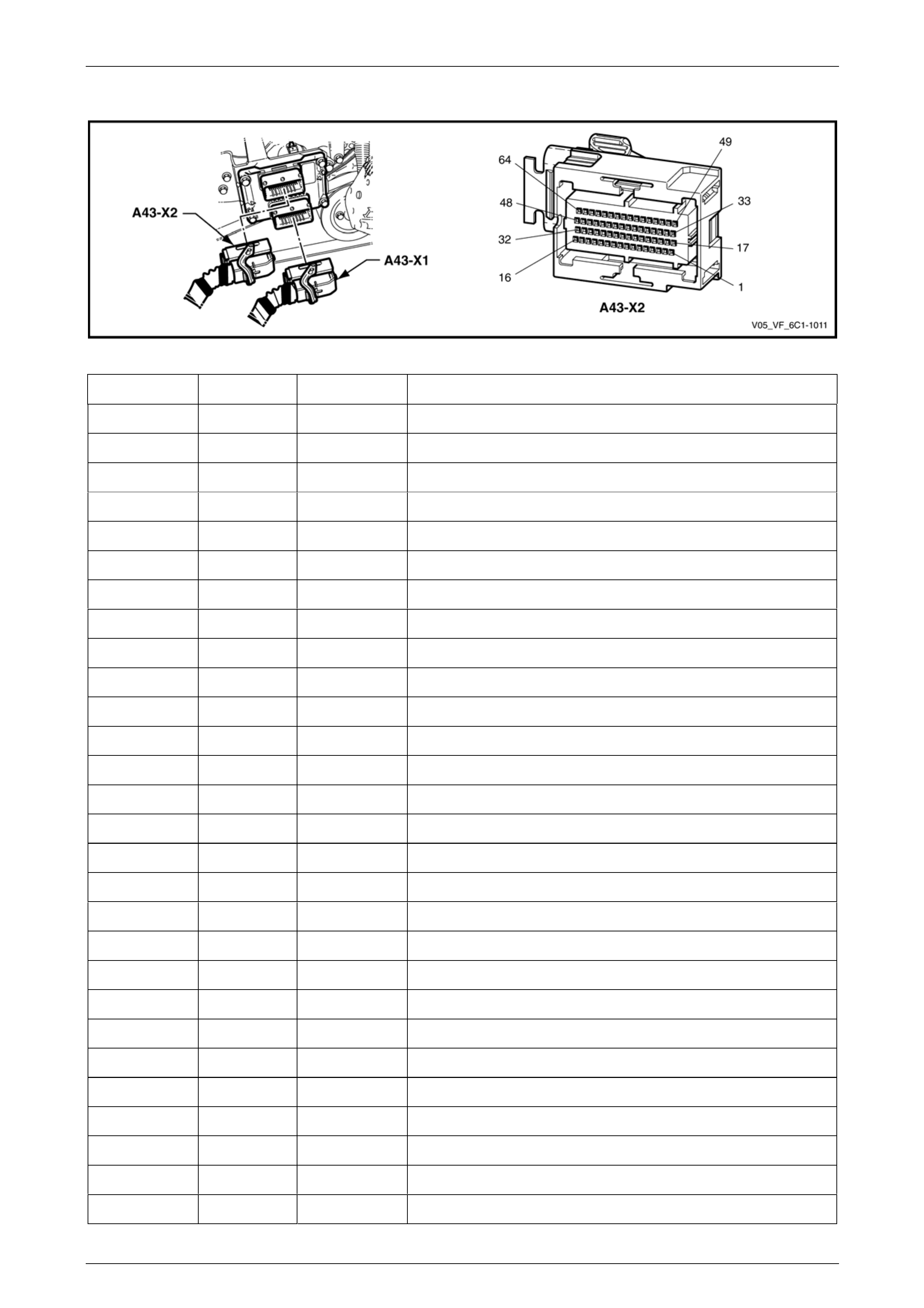
Engine Control Module A43 V6 – Connector X2
F
Term Pin W r Cir o.
igure 6C1-2 – 11
inal / ire Colou cuit N Function
X2–1 PK/BU 1339 Ignition Voltage 1
X2–2 GY/WH 3223 B1S2 O2 Sensor Heater Control (Bank 1 Sensor 2)
X2–3 PK 139 Ignition Voltage 1
X2–4 BU d Cooling Fan Relay Control /WH 473 High Spee
X2–5 BN/RD eed Signal 121 Engine Sp
X2–6 — — Not Used
X2–7 W K 1164 rence 4 H/B 5 Volt Refe
X2–8 PU 1272 Low Reference Ground 4
X2–9 GN/BK 380 A/C Refrigerant Pressure Sensor Signal
X2–10 BU/RD 20 Stop Lamp Switch Signal
X2–11 BN/BK 472 IAT Sensor Signal
X2–12 — — Not Used
X2–13 — — Not Used
X2–14 — — Not Used
X2–15 — — Not Used
X2–16 — — Not Used
X2–17 PK/BU 1339 Ignition Voltage 1
X2–18 OG/WH 3122 ensor Heater Control (Bank 2 Sensor 2) B2S2 O2 S
X2–19 G H Relay Control N/W 465 Fuel Pump
X2–20 OG/BK 335 Low Speed Cooling Fan Control
X2–21 — — Not Used
X2–22 P 5197 from Instrument) U/WH Vehicle Speed (
X2–23 BN/BK 2500 GMLAN Serial Data Bus – High
X2–24 BN 5069 ntrol Relay Control Engine Co
X2–25 BK/YE nce – Ground 7 510 Low Refere
X2–26 B N/WH 2760 Low Reference – Ground 1
X2–27 — — Not Used
X2–28 — — Not Used
Page 6C1-2–20

Engine Management – V6 – Diagnostics Page 6C1-2–21
X2–29 PU 3220 B1S2 O2 Sensor High Signal (Bank 1 Sensor 2)
X2–30 — — Not Used
X2–31 PU 5 Crank Voltage
X2–32 OG/BK 1786 Park/Neutral Switch Signal
X2–33 — — Not Used
X2–34 — — Not Used
X2–35 YE 447 Starter Relay Coil Control
X2–36 OG/BK sitive Voltage 740 Battery Po
X2–37 — — Not Used
X2–38 PU 1319 onnector (DLC) Serial Data Data Link C
X2–39 GY 2709 rence 1 5 Volt Refe
X2–40 BN 1271 Low Reference – Ground 5
X2–41 BN/GN 3121 ensor Low Signal (Bank 2 Sensor 2) B2S2 O2 S
X2–42 BN/GN Sensor Signal 30 Fuel Level
X2–43 YE 492 MAF Sensor Signal
X2–44 L-BU 1162 APP Sensor 2 Signal
X2–45 — — Not Used
X2–46 BN 86 Brake Switch (S220 – ‘C’) Cruise Cancel Signal
X2–47 — — Not Used
X2–48 — — Not Used
X2–49 L-GN/BK 459 tch Relay Control A/C Compressor Clu
X2–50 — — Not Used
X2–51 — — Not Used
X2–52 — — Not Used
X2–53 B N/WH 379 Clutch Switch (S42) Cruise Cancel Signal
X2–54 — — Not Used
X2–55 BN 2501 GMLAN Serial Data Bus – Low
X2–56 BN/YE 1274 5 Volt Reference 3
X2–57 BN/RD 3221 B1S2 O2 Sensor Low Signal (Bank 1 Sensor 2)
X2–58 BN/WH 4 Accessory Voltage
X2–59 — — Not Used
X2–60 BU 1161 APP Sensor 1 Signal
X2–61 PU 3120 B2S2 O2 Sensor High Signal (Bank 2 Sensor 2)
X2–62 L-GN 275 Clutch Switch (S42) Clutch Disengaged Signal
X2–63 GY 847 Extended Travel Brake Switch Signal
X2–64 OG 381 Vehicle Speed Sensor Signal
Page 6C1-2–21
Engine Management – V6 – Diagnostics Page 6C1-2–22
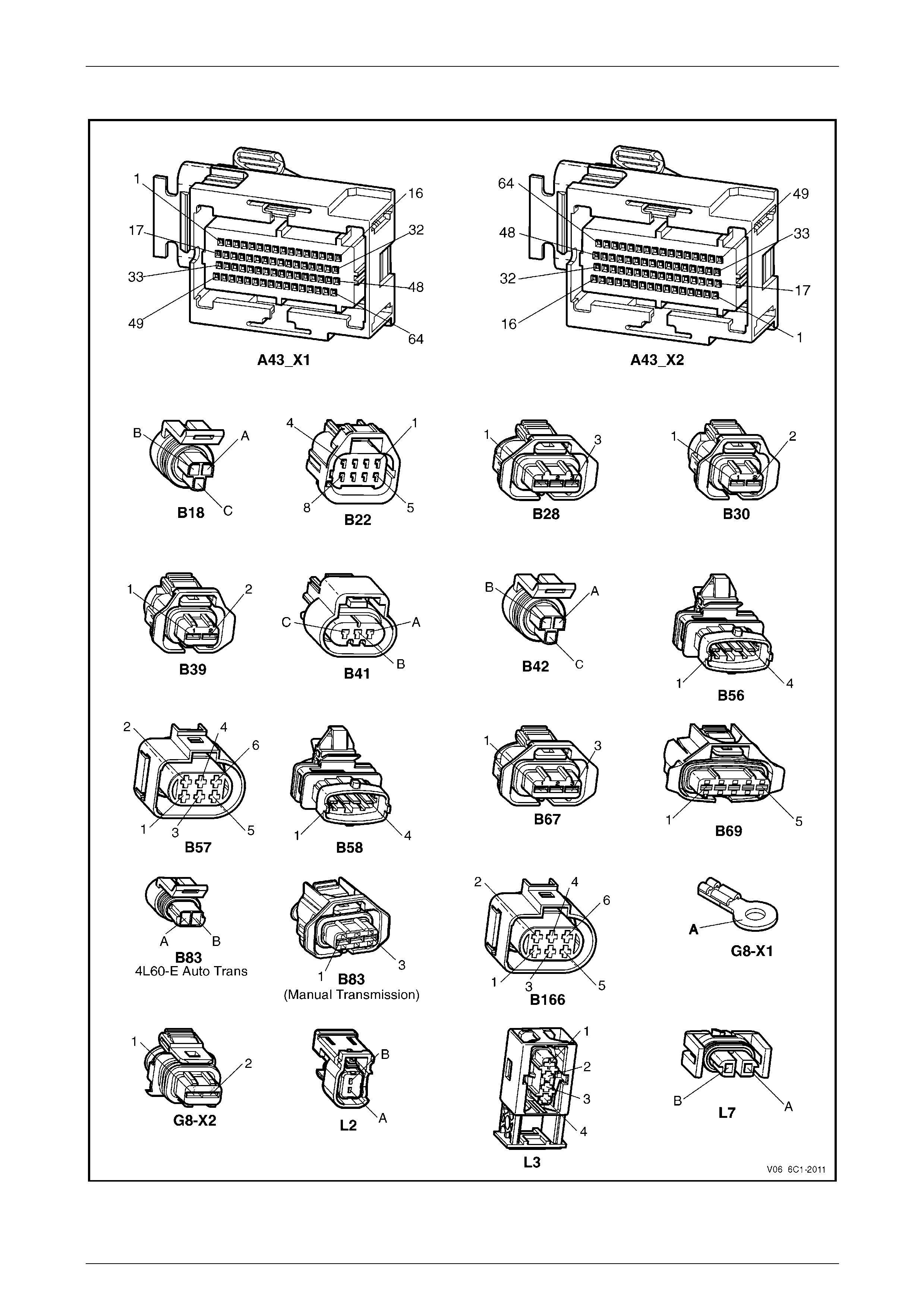
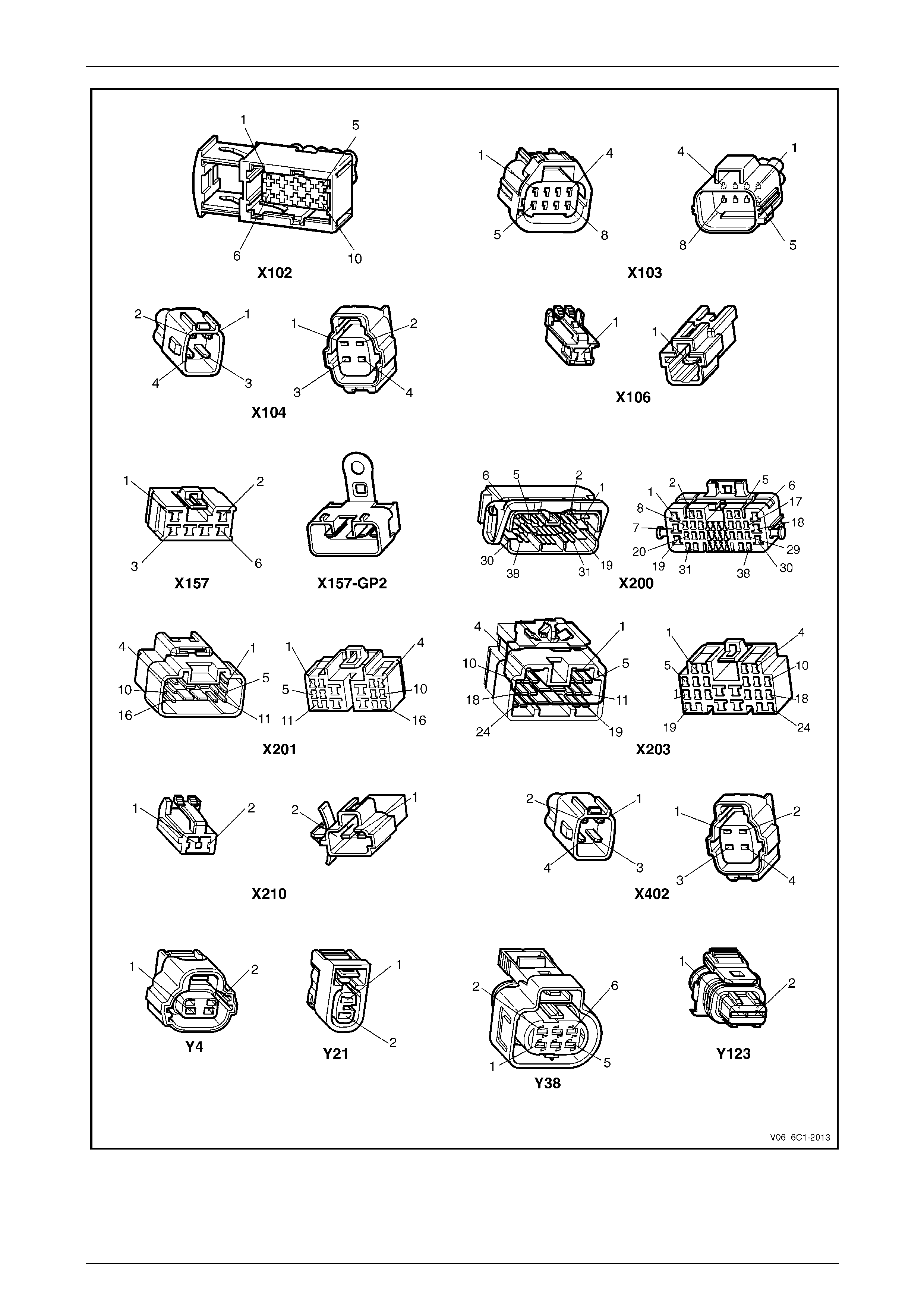
2.3 Connector End Views
Figure 6C1-2 – 12
Page 6C1-2–22
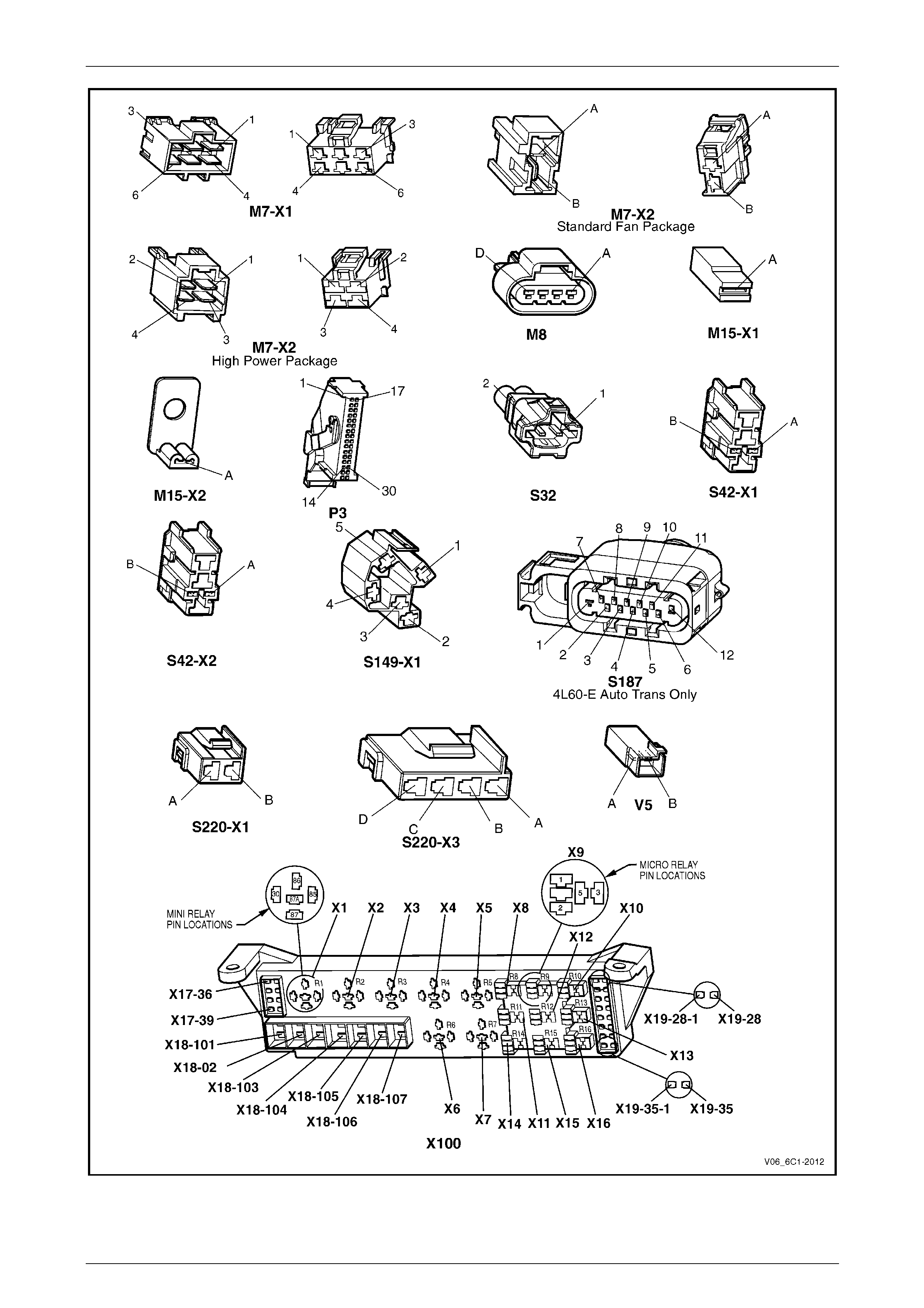
Engine Management – V6 – Diagnostics Page 6C1-2–23
Figure 6C1-2 – 13
Page 6C1-2–23
Engine Management – V6 – Diagnostics Page 6C1-2–24
Figure 6C1-2 – 14
Page 6C1-2–24

Engine Management – V6 – Diagnostics Page 6C1-2–25
3 Diagnostics Starting Point
3.1 Basic Requirements
Basic Knowledge Required
A lack of basic understanding regarding
electronics, electrical wiring circuits and use
of electrical circuit testing tools when
performing an engine management system
diagnostic procedure could result in incorrect
diagnostic results or damage to engine
management system components.
Understanding of the following is required to perform the diagnostic procedures detailed in this Section. Refer to
Section 12P Wiring Diagrams and to Basic Tools Required.
• Basic electronics,
• Electrical wiring circuits,
• Electrical circuits testing, and
• Correct use of the basic engine management system diagnostic tools.
In addition, understanding of the engine management system is essential to prevent misdiagnosis and component
damage. Refer to Section 6C1-1 Engine Management – V6 – General Information.
Basic Tools Required
Use of incorrect electrical circuit diagnostic
tools when performing the engine
management diagnostic procedures could
result in incorrect diagnostic results or
damage to engine management system
components.
e f are required to perform the diagnostic procedures detailed in this Section.
• Digital multimeter with 10 MΩ impedance, refer to Section 12P Wiring Diagrams.
Th ollowing electrical circuit testing tools
• Tech 2, refer to Section 0C Tech 2,
• Test lamp, refer to Section 12P Wiring Diagrams, and
Page 6C1-2–25

Engine Management – V6 – Diagnostics Page 6C1-2–26
3.2 Diagnostic Precautions
The following precautions must be observed when performing the powertrain diagnostic procedure, otherwise incorrect
diagnostic results or damage to engine management system components will occur:
• Disconnection of the battery affects certain vehicle electronic systems. Refer to Section 00 Cautions and Notes
before disconnecting the battery.
• Disconnect the battery negative lead when performing the following procedures:
− Disconnecting the ECM connectors, or
− Charging the battery.
• Disconnect the battery terminal lead and the ECM connectors before attempting any electric arc welding on the
vehicle.
• Do not start the engine if the battery terminal is not properly secured to the battery.
• Do not disconnect or reconnect the following while the ignition is switched on or when the engine is running:
− Any engine management system component electrical wiring connector, or
− Battery terminal leads.
• Ensure the correct procedure for disconnecting and connecting engine management system electrical wiring
connectors is always followed. For information on the correct procedure for disconnecting and connecting specific
wiring connectors, refer to Section 6C1-3 Engine Management – V6 – Service Operations.
• Ensure that all wiring harness connectors are fitted correctly.
• When steam or pressure cleaning engines, do not direct the cleaning nozzle at engine management system
components.
• Do not clear any DTCs unless instructed.
• The fault must be present when using the diagnostic trouble code (DTC) diagnostic tables. Otherwise, misdiagnosis
or replacement of good parts may occur.
• Do not touch the ECM connector pins or soldered components on the ECM circuit board to prevent ECM
Electrostatic Discharge damage. Refer to Section 12P Wiring Diagrams for information on Electrostatic Discharge.
• Use only the test equipment specified in the diagnostic tables as other test equipment may give incorrect results or
damage good components.
• The ECM is designed to withstand normal current draw associated with vehicle operations. However, the following
fault conditions or incorrect test procedure may overload the ECM internal circuit and damage the ECM:
− A short to voltage fault condition in any of the ECM low reference circuits may cause internal ECM and / or
sensor damage. Therefore, any short to voltage fault condition in the ECM low reference circuits must be
rectified before replacing a faulty component.
− A short to ground fault condition in any of the ECM 5 V reference circuits may cause internal ECM and / or
sensor damage. Therefore, any short to ground fault condition in the ECM 5 V reference circuits must be
rectified before replacing a faulty component.
− When using a test lamp to test an electrical circuit, do not use any of the ECM low reference circuits or 5 V
reference circuits as a reference point. Otherwise, excessive current draw from the test lamp may damage the
ECM.
• Disregard DTCs that set while performing the following diagnostic Steps:
− Using Tech 2 actuator tests, or
− Disconnecting an engine management system sensor connector then switching on the ignition.
• After completing the required diagnostics and service operations, road test the vehicle to ensure correct engine
management system operation.
Page 6C1-2–26

Engine Management – V6 – Diagnostics Page 6C1-2–27
3.3 Preliminary Checks
The preliminary checks are a set of visual and physical checks or inspections that may quickly identify engine
management system fault condition.
• Refer to the appropriate Service Techlines for relevant information regarding the fault condition.
• Ensure the battery is fully charged.
• Inspect the battery connections for corrosion or a loose terminal.
• Ensure that all engine management system related fuses are serviceable.
• Inspect for incorrect aftermarket theft deterrent devices, lights or mobile phone installation.
• Ensure there is no speaker magnet positioned too close to any electronic module that contains relays.
• Inspect the engine wiring harness for proper connections, pinches or cuts.
• Ensure that all engine management related electrical wiring connectors are fitted correctly.
• Inspect the ECM ground connections for corrosion, loose terminal or incorrect position.
• Ensure the resistance between the ECM housing and the battery negative cable is less than 0.5 Ω.
• Check the ECM bracket fasteners for correct torque value.
• Check all engine management related components for correct installation.
• Inspect the vacuum hoses for splits, kinks, oil contamination and proper connections, refer to the vehicle emission
control information label. Check the hoses thoroughly for any type of leak or restriction.
• Inspect the air intake ducts for being collapsed, split or for having damaged areas.
• Inspect for air leaks at the throttle body mounting area, mass air flow (MAF) sensor, intake manifold and intake
manifold sealing surfaces.
• Check for wiring harness routing that may be positioned too close to a high voltage or high current device such as
the following:
− Secondary ignition components, and
− Motors and generators.
NOTE
High voltage or high current devices may induce
electrical noise on a circuit, which can interfere
with normal circuit operation.
Page 6C1-2–27

Engine Management – V6 – Diagnostics Page 6C1-2–28
3.4 Diagnostic System Check
Description
The engine management diagnostic procedure is organised in a logical structure that begins with the Diagnostic System
Check. The Diagnostic System Check directs the diagnostic procedure to the logical steps necessary to diagnose an
engine driveability fault condition.
Test Description
The following numbers refer to the step numbers in the diagnostic table:
4 Tests the operation of Tech 2.
6 Tests the integrity of the GM LAN serial data communication circuit. A PIM DTC sets if the PIM detects a fault
condition in the communication circuit. A fault condition on the serial data communication circuit may trigger multiple
DTCs on other sensors and components.
7 Tests for fault conditions on the vehicle theft deterrent system. The BCM is an integral part of the theft deterrent
system. Any fault condition on the BCM that may affect the operation of the theft deterrent system must be rectified
before proceeding with this diagnostic table.
Step Action Yes No
1 Have you read the basic requirements?
Go to Step 2
Refer to
3.1 Basic
Requirements
2 Have you read the diagnostic precautions?
Go to Step 3
Refer to
3.2 Diagnostic
Precautions
3 Have you performed the preliminary checks?
Go to Step 4
Refer to
3.3 Preliminary
Checks
4 1 Switch off the ignition.
2 Connect Tech 2 to the diagnostic link connector (DLC).
3 Switch on the ignition with the engine not running.
4 Push Tech 2 power button on.
Does Tech 2 screen illuminate and display Tech 2? Go to Step 5 Refer to Section 0C
Tech 2
5 Using T ech 2, attempt to communicate with the PIM and the BCM.
Does the PIM or the BCM fail to communicate?
Refer to
Section 6E1
Powertrain Interface
Module – V6 Go to Step 6
6 Does DT C U1064, U2100, U2105, U2106, U2108, B1009, B1013,
B1014, B1000, B1019, B3057, B3924, P0633, P1611 or P1678 also
set in the PIM?
Refer to
Section 6E1
Powertrain Interface
Module – V6 Go to Step 7
7 Does DT C 2, DTC 17, DTC 19, DT C 20, DTC 24 DTC 25 also set in
the BCM? Refer to
Section 12J Body
Control Module Go to Step 8
8 Using T ech 2, view and record DTCs set at the ECM and TCM.
Does Tech 2 display any DTC? Go to Step 9
Refer to
4.1 Symptoms
Diagnosis Table
9 Does T ech 2 display multiple DTCs?
Go to Step 10
Go to the diagnostic
table of the DTC
displayed. Refer to
6.1 DTC List in
Ascending Order.
Page 6C1-2–28

Engine Management – V6 – Diagnostics Page 6C1-2–29
Step Action Yes No
10 Does Tech 2 display any serial data communication circuit DTC? Go to the
appropriate serial
data communication
circuit DTC table.
Refer to 6.1 DTC
List in Ascending
Order
Go to Step 11
11 Does Tech 2 display any immobiliser circuit DTC? Go to the
appropriate
immobiliser circuit
DTC table. Refer to
6.1 DTC List in
Ascending Order. Go to Step 12
12 Refer to the DTC Table of the fault condition that is most likely to
trigger multiple DTCs. Refer to 1.2 Diagnostic Trouble Code Tables in
this Section. — —
When all diagnosis and repairs are completed, check the system for correct operation.
Page 6C1-2–29

Engine Management – V6 – Diagnostics Page 6C1-2–30
4 Symptoms Diagnostics
4.1 Symptoms Diagnosis Table
Step Action Yes No
1 Has the Diagnostic System Check been performed?
Go to Step 2
Refer to
3.4 Diagnostic
System Check
2 Is the fault intermittent? Refer to
4.2 Intermittent
Fault Conditions
Go to Step 3
3 Does the engine backfire? Refer to
4.3 Backfire Go to Step 4
4 Does the engine crank but does not run? Refer to
4.4 Cranks But
Does Not Run
Go to Step 5
5 Does the engine cut-out or miss? Refer to
4.5 Cuts Out,
Misses
Go to Step 6
6 Is there a detonation or spark knock noise coming from the engine? Refer to
4.6 Detonation /
Spark Knock
Go to Step 7
7 Is there an engine dieseling or run-on condition? Refer to
4.7 Dieseling, Run-
on
Go to Step 8
8 Is there an engine hard starting condition? Refer to
4.8 Hard Start Go to Step 9
9 Is there an engine hesitation, sag or stumble condition? Refer to
4.9 Hesitation, Sag
and Stumble
Go to Step 10
10 Does the engine suffer from lack of power, sluggishness or
sponginess? Refer to
4.10 Lack of Power,
Sluggishness or
Sponginess
Go to Step 11
11 Does the engine suffer from poor fuel economy? Refer to
4.11 Poor Fuel
Economy
Go to Step 12
12 Does the engine suffer from rough, unstable or incorrect idle and
engine stalling? Refer to
4.12 Rough,
Unstable, Incorrect
Idle or Stalling
Go to Step 13
13 Does the engine surge or chuggle? Refer to
4.13 Surges /
Chuggles
Go to Step 14
When all diagnosis and repairs are completed, check the system for correct operation.
Page 6C1-2–30

Engine Management – V6 – Diagnostics Page 6C1-2–31
4.2 Intermittent Fault Conditions
Description
A fault condition is intermittent if one of the following conditions exists:
• the fault condition is not always present,
• the fault condition cannot be presently duplicated, or
• there is no Current DTC but a History DTC is stored.
Diagnostic Table
Checks Actions
Preliminary • Perform the preliminary checks. Refer to 3.3 Preliminary Checks in this Section .
• Gather information from the customer regarding the conditions that trigger the
intermittent fault such as:
• At what engine or ambient temperature range does the fault occur?
• Does the fault occur when operating aftermarket electrical equipment inside
the vehicle?
• Does the fault occur on rough roads or in wet road conditions?
• If the intermittent fault is a start and then stall condition, check theft deterrent
system. Refer to Section 12J Body Control Module.
Tech 2 Tests The following are lists of Tech 2 diagnostic tests that may be used to diagnose
intermittent faults:
• Wriggle test the suspected wiring harness and connectors while observing
Tech 2 operating parameters. If Tech 2 read-out fluctuates during this procedure,
check the tested wiring harness circuit for a loose connection.
• Observe the freeze frame / failure records for the suspected history DTC and
then operate the vehicle in the conditions that triggers the intermittent fault while
an assistant observes the suspected Tech 2 operating parameter data.
• Capture and store data in the snapshot mode when the fault occurs. The stored
data may be played back at a slower rate to aid diagnostics. Refer to
Tech 2 User Instructions for further information on the Snapshot function.
• Compare the engine operating parameters of the engine being diagnosed to the
engine operating parameters of a known good engine.
Check Powertrain icon or
Malfunction Indicator Lamp The following conditions may cause an intermittent Check Powertrain icon or
Malfunction Indicator Lamp (MIL) fault with no DTC listed:
• Electromagnetic interference (EMI) caused by a faulty relay, ECM controlled
solenoid, switch or other external source.
• Incorrect installation of aftermarket electrical equipment such as the following:
• mobile phones,
• theft deterrent alarms,
• lights, or
• radio equipment.
• ECM grounds are loose.
Page 6C1-2–31

Engine Management – V6 – Diagnostics Page 6C1-2–32
Checks Actions
Temperature Related Temperature related intermittent fault condition occurs only when the engine or
ambient temperature is hot, or only when it is cold.
• If the intermittent fault is heat related, review Tech 2 data in relationship to the
following:
• high ambient temperature,
• engine generated heat,
• circuit generated heat due to a poor electrical connection or high electrical
load, and
• higher than normal load conditions (towing, etc.).
• If the intermittent fault is related to cold ambient or engine temperature, review
Tech 2 data in relationship to the following:
• low ambient temperature, and
• the fault condition that occurs only on a cold start situation.
Additional Tests • Incorrect installation of aftermarket electrical equipment such as the following:
• mobile phones,
• theft deterrent alarms,
• lights, or
• radio equipment.
• Electromagnetic interference (EMI) caused by a faulty relay, ECM controlled
solenoid or switch. The fault is triggered when the relay or solenoid is activated.
• Test the A/C compressor clutch and some relays that contain a clamping diode
or resistor for an open circuit.
• Test the generator for a faulty rectifier bridge that may allow the A/C noise into
the ECM electrical circuit.
When all diagnosis and repairs are completed, check the system for correct operation.
Page 6C1-2–32

Engine Management – V6 – Diagnostics Page 6C1-2–33
4.3 Backfire
Description
The air / fuel mixture in the intake manifold or in the exhaust system ignites which produces a loud popping noise.
Checks Actions
Preliminary Perform the Preliminary Checks. Refer to 3.3 Preliminary Checks in this Section.
Sensor / System • Check the air intake system and crankcase for air leaks.
• Check the PCV System for correct operation. Refer to Section 6A1 Engine
Mechanical – V6.
• Use Tech 2 to monitor the knock sensor system for excessive spark retard activity.
Check for items that cause spark retard activity.
Fuel System • Check the fuel system for the following fault conditions. Refer to Section 8A1
Fuel System.
• restricted fuel filter,
• incorrect fuel pressure, and
• contaminated fuel.
• Check the operation of the fuel injectors. Refer to Section 6C1-3 Engine
Management – V6 – Service Operations.
• Perform the fuel injector balance test, refer to 5.3 Fuel Injector Balance Test in
this Section.
• Check the items that can cause an engine to run lean.
• Check the items that cause an engine to run rich.
Ignition System • Check for an intermittent ignition circuit malfunction.
• Inspect for moisture or corrosion around the spark plug / ignition coil area.
• Test the ignition coil voltage output. Refer to Section 6C1-3 Engine Management –
V6 – Service Operations.
• Remove and inspect the spark plugs. Refer to Section 6C1-3 Engine Management
– V6 – Service Operations.
NOTE
If the spark plugs are fouled, determine the cause of the fouling before
replacing the spark plugs. Refer to Section 6C1-3 Engine Management – V6
– Service Operations.
• Check for loose ignition coil ground circuit.
Engine Cooling System Check the engine for over-heating. Refer to Section 6B1 Engine Cooling – V6.
Engine Mechanical Check for the following engine fault conditions. Refer to Section 6A1 Engine Mechanical
– V6.
• low compression, and
• worn valve train components.
Page 6C1-2–33

Engine Management – V6 – Diagnostics Page 6C1-2–34
Checks Actions
Additional Checks • Check the exhaust system for possible restrictions. Refer to Section 8B
Exhaust System.
• Electromagnetic interference (EMI) on the crankshaft position (CKP) sensor can
cause an engine misfire condition.
Using Tech 2, monitor the engine speed parameter. A sudden increase in the
engine speed parameters without moving the throttle position indicates that an
Electromagnetic Interference fault may be present.
Wiring harness routing which may be positioned very close to a high voltage or
high current device such as the following may induce EMI:
• secondary ignition components, or
• motors and generators.
Dirty starter motor commutator or brushes can mask the crankshaft position
sensor signal.
• Check the torque converter clutch (TCC) operation. A TCC that applies too soon
can cause engine detonation, which will trigger spark retard activity. Refer to
Section 7C1 Automatic Transmission – 4L60E – General Information or
Section 7E1 Automatic Transmission – 5L40E – General Information.
When all diagnosis and repairs are completed, check the system for correct operation.
Page 6C1-2–34

Engine Management – V6 – Diagnostics Page 6C1-2–35
4.4 Cranks But Does Not Run
Definition
The engine cranks normally but does not start.
Checks Actions
Preliminary • Perform the preliminary checks. Refer to 3.3 Preliminary Checks in this Section.
• Check the theft deterrent system for correct operation. Refer to Section 12J
Body Control Module.
Sensor / System • Check the engine coolant temperature (ECT) sensor for an incorrect value.
Compare the engine coolant temperature against the intake air temperature (IAT)
on a cold engine. The ECT and IAT sensor values should be within ± 3°C of each
other. Refer to Section 6C1-3 Engine Management – V6 – Service Operations for
details of the Temperature vs. Resistance Table.
• Check the mass air flow (MAF) sensor installation. Incorrect installation of the MAF
sensor may cause hard start condition. Refer to Section 6C1-3 Engine
Management – V6 – Service Operations.
• Check for a dirty starter motor commutator or brushes that can mask the
crankshaft position sensor signal.
Fuel System • Check the fuel system for the following fault conditions. Refer to Section 8A1
Fuel System.
• restricted fuel filter,
• incorrect fuel pressure,
• contaminated fuel, and
• incorrect fuel pump relay operation.
• Check the operation of the fuel injectors. Refer to Section 6C1-3 Engine
Management – V6 – Service Operations.
Ignition System • Inspect for moisture or corrosion around the spark plug / ignition coil area.
• Test the ignition coil voltage output. Refer to Section 6C1-3 Engine Management –
V6 – Service Operations.
• Remove and inspect the spark plugs. Refer to Section 6C1-3 Engine Management
– V6 – Service Operations.
NOTE
If the spark plugs are fouled, determine the cause of the fouling before
replacing the spark plugs. Refer to Section 6C1-3 Engine Management – V6
– Service Operations.
Check for loose ignition coil ground circuit.
Engine Mechanical • Check for excessive oil in combustion chamber. Refer to Section 6A1 Engine
Mechanical – V6.
• Check for the following engine fault conditions. Refer to Section 6A1 Engine
Mechanical – V6.
• low compression, and
• worn valve train components.
When all diagnosis and repairs are completed, check the system for correct operation.
Page 6C1-2–35

Engine Management – V6 – Diagnostics Page 6C1-2–36
4.5 Cuts Out, Misses
Description
Steady pulsation or jerking that is usually more severe as the engine load increases. This condition is not normally felt
greater than 1500 rpm or 48 km/h. The exhaust has a steady spitting sound at idle or low speed.
Checks Actions
Preliminary • Perform the preliminary checks. Refer to 3.3 Preliminary Checks in this Section.
• Check the air filter element and intake air ducts for blockages.
• Check for intake manifold vacuum leak.
Sensor / System • Using Tech 2, check the heated oxygen sensor (HO2s) operating parameters. The
HO2s should respond quickly to different throttle positions.
• Use Tech 2 to monitor the knock sensor system for excessive spark retard activity.
Check for items that cause spark retard activity. Refer to 6.21 DTC P0327,
P0328, P0332 or P0333 in this Section.
Fuel System • Check the fuel system for the following fault conditions. Refer to Section 8A1
Fuel System.
• restricted fuel filter,
• incorrect fuel pressure, and
• contaminated fuel.
• Check the operation of the fuel injectors. Refer to Section 6C1-3 Engine
Management – V6 – Service Operations.
• Perform the fuel injector balance test, refer to 5.3 Fuel Injector Balance Test in
this Section.
• Check for fault conditions that cause an engine to run rich or to run lean.
Ignition System • Inspect for moisture or corrosion around the spark plug / ignition coil area.
• Test the ignition coil voltage output. Refer to Section 6C1-3 Engine Management –
V6 – Service Operations.
• Remove and inspect the spark plugs. Refer to Section 6C1-3 Engine Management
– V6 – Service Operations.
NOTE
If the spark plugs are fouled, determine the cause of the fouling before
replacing the spark plugs. Refer to Section 6C1-3 Engine Management – V6
– Service Operations.
• Check for loose ignition coil grounds.
Engine Mechanical Check for the following engine fault conditions. Refer to Section 6A1 Engine Mechanical
–V6.
• low compression, and
• worn valve train components.
Page 6C1-2–36

Engine Management – V6 – Diagnostics Page 6C1-2–37
Checks Actions
Additional Checks • Check the exhaust system for possible restrictions. Refer to Section 8B Exhaust
System.
• Electromagnetic interference (EMI) on the crankshaft position (CKP) sensor can
cause an engine misfire condition.
Using Tech 2, monitor the engine speed parameter. A sudden increase in the
engine speed parameters without moving the throttle position indicates that an
electromagnetic interference fault may be present.
• Wiring harness routing which may be positioned very close to a high voltage or
high current device such as the following may induce EMI:
• secondary ignition components, or
• motors and generators.
When all diagnosis and repairs are completed, check the system for correct operation.
Page 6C1-2–37

Engine Management – V6 – Diagnostics Page 6C1-2–38
4.6 Detonation / Spark Knock
Description
The engine produces sharp rapid metallic knocks that are more audible during acceleration.
Checks Actions
Preliminary Perform the preliminary checks. Refer to 3.3 Preliminary Checks in this Section.
Sensor System Use Tech 2 to monitor the knock sensor system.
Fuel System • Check the fuel system for the following fault conditions. Refer to
Section 8A1 Fuel System.
• restricted fuel filter,
• incorrect fuel pressure, and
• contaminated fuel.
• Check the operation of the fuel injectors. Refer to Section 6C1-3
Engine Management – V6 – Service Operations.
• Perform the fuel injector balance test, refer to 5.3 Fuel Injector Balance Test in
this Section.
• Ensure the fuel tank is filled with petrol that has a minimum octane reading of 92.
• Check for fault conditions that can cause an engine to run lean.
Ignition System Check the spark plugs for proper heat range. Refer to Section 6C1-3
Engine Management – V6 – Service Operations.
Engine Mechanical • Check the combustion chambers for excessive carbon build-up. Refer to
Section 6A1 Engine Mechanical – V6.
• Check the camshaft timing. Refer to Section 6A1 Engine Mechanical – V6.
Additional Checks • Check the torque converter clutch (TCC) operation. The T CC applying too soon
can cause the engine to spark knock. Refer to Section 7C2 Automatic
Transmission – 4L60E – Electrical Diagnosis or Section 7E2 Automatic
Transmission – 5L40E – Electrical Diagnosis.
When all diagnosis and repairs are completed, check the system for correct operation.
Page 6C1-2–38

Engine Management – V6 – Diagnostics Page 6C1-2–39
4.7 Dieseling, Run-on
Description
The engine continues to run after the ignition is switched off but runs very roughly and then stalls.
Checks Actions
Preliminary Perform the preliminary checks. Refer to 3.3 Preliminary Checks in this Section.
Fuel System Inspect the injectors for leaking condition. Refer to Section 6C1-3 Engine Management –
V6 – Service Operations.
Engine Cooling System • Check for engine overheating. Refer to Section 6B1 Engine Cooling – V6.
• Check the engine thermostat for proper operation and correct heat range.
Refer to Section 6B1 Engine Cooling – V6.
Engine Mechanical • Check for build up of carbon deposit in the combustion chamber, which may cause
hot spots and increased compression ratio. Refer to Section 6A1 Engine
Mechanical – V6.
• Using Tech 2, check for incorrect engine idle speed.
Additional • If the engine continues to run after the ignition is switched off but the engine runs
normally, check the following:
• ignition switch operation,
• voltage feedback from alternator L terminal to ignition switch, and
• sticking ignition control relay.
When all diagnosis and repairs are completed, check the system for correct operation.
Page 6C1-2–39

Engine Management – V6 – Diagnostics Page 6C1-2–40
4.8 Hard Start
Definition
The engine cranks normally but takes longer to start than usual. As soon as the engine runs, the engine may stall
immediately.
Checks Actions
Preliminary • Perform the preliminary checks. Refer to 3.3 Preliminary Checks in this Section.
• Check the theft deterrent system for correct operation. Refer to Section 12J Body
Control Module.
Sensor / System • Check the engine coolant temperature (ECT) sensor for an incorrect value.
Compare the engine coolant temperature against the intake air temperature (IAT)
on a cold engine. The ECT and IAT sensor values should be within ± 3°C of each
other. Refer to Section 6C1-3 Engine Management – V6 – Service Operations for
details of the Temperature vs. Resistance Table.
• Check the mass air flow (MAF) sensor installation. Incorrect installation of the MAF
sensor may cause hard start condition. Refer to Section 6C1-3 Engine
Management – V6 – Service Operations.
• Test the resistance of the crankshaft position (CKP) sensor. The CKP sensor
resistance must be within 700 – 1,200 Ω at all temperatures.
• Check for dirty starter motor commutator or brushes that can mask the crankshaft
position sensor signal.
Fuel System • Check the fuel system for the following fault conditions. Refer to
Section 8A1 Fuel System.
• restricted fuel filter,
• incorrect fuel pressure, and
• contaminated fuel.
• Check the operation of the fuel injectors. Refer to Section 6C1-3 Engine
Management – V6 – Service Operations.
Ignition System • Inspect for moisture or corrosion around the spark plug / ignition coil area.
• Test the ignition coil voltage output. Refer to Section 6C1-3 Engine Management –
V6 – Service Operations.
• Remove and inspect the spark plugs. Refer to Section 6C1-3 Engine Management
– V6 – Service Operations.
NOTE
If the spark plugs are fouled, determine the cause of the fouling before
replacing the spark plugs. Refer to Section 6C1-3 Engine Management – V6
– Service Operations.
• Check for loose ignition coil ground circuit.
Engine Mechanical • Check for excessive oil in combustion chamber. Refer to Section 6A1 Engine
Mechanical – V6.
• Check for the following engine fault conditions. Refer to Section 6A1 Engine
Mechanical – V6.
• low compression, and
• worn valve train components.
When all diagnosis and repairs are completed, check the system for correct operation.
Page 6C1-2–40

Engine Management – V6 – Diagnostics Page 6C1-2–41
4.9 Hesitation, Sag and Stumble
Description
Momentary lack of response or hesitation as the accelerator is depressed. This condition is usually more severe when
first trying to make the vehicle move from a standing start but can occur at any vehicle speed.
Checks Actions
Preliminary • Perform the preliminary checks. Refer to 3.3 Preliminary Checks in this Section.
• Check the air filter element and intake air ducts for blockages.
Sensor / System • Using Tech 2, check the heated oxygen sensor (HO2s) operating parameters. The
HO2s should respond quickly to different throttle positions.
• Inspect the accelerator pedal position (APP) sensor harness connector for correct
connection. Poor connection of this connector will not set a DTC.
Fuel System • Check the fuel system for the following fault conditions. Refer to
Section 8A1 Fuel System.
• restricted fuel filter,
• incorrect fuel pressure, and
• contaminated fuel.
• Check the operation of the fuel injectors. Refer to Section 8A1 Fuel System.
• Perform the fuel injector balance test, refer to 5.3 Fuel Injector Balance Test in
this Section.
• Check for fault conditions that cause an engine to run rich or to run lean.
Ignition System • Inspect for moisture or corrosion around the spark plug / ignition coil area.
• Test the ignition coil voltage output. Refer to Section 6C1-3 Engine Management –
V6 – Service Operations.
• Remove and inspect the spark plugs. Refer to Section 6C1-3 Engine Management
– V6 – Service Operations.
NOTE
If the spark plugs are fouled, determine the cause of the fouling before
replacing the spark plugs. Refer to Section 6C1-3 Engine Management – V6
– Service Operations.
• Check for loose ignition coil ground circuit.
Engine Cooling System Check the engine thermostat for correct operation and heat range. Refer to
Section 6B1 Engine Cooling – V6.
Additional Checks • If fitted, check for the correct operation of the intake manifold runner control
system. Refer to Section 6C1-3 Engine Management – V6 – Service Operations.
• Check the generator output voltage. Refer to Section 6D1-1
Charging System – V6.
When all diagnosis and repairs are completed, check the system for correct operation.
Page 6C1-2–41

Engine Management – V6 – Diagnostics Page 6C1-2–42
4.10 Lack of Power, Sluggishness or
Sponginess
Description
The engine delivers less than normal power. There is little or no increase in vehicle speed when the accelerator pedal is
partially depressed.
Checks Actions
Preliminary • Perform the preliminary checks. Refer to 3.3 Preliminary Checks in this Section.
• Check the air filter element and intake air ducts for blockages.
Sensor / System • Use Tech 2 to monitor the knock sensor system for excessive spark retard activity.
Check for items that cause spark retard activity.
• Inspect the accelerator pedal position (APP) sensor harness connector for correct
connection. Poor connection of this connector will not set a DTC.
Fuel System • Check the fuel system for the following fault conditions. Refer to
Section 8A1 Fuel System.
• restricted fuel filter,
• incorrect fuel pressure, and
• contaminated fuel.
• Check the operation of the fuel injectors. Refer to Section 6C1-3 Engine
Management – V6 – Service Operations.
• Perform the fuel injector balance test, refer to 5.3 Fuel Injector Balance Test in
this Section.
• Check for fault conditions that can cause the engine to run rich or run lean.
Ignition System • Inspect for moisture or corrosion around the spark plug / ignition coil area.
• Test the ignition coil voltage output. Refer to Section 6C1-3 Engine Management –
V6 – Service Operations.
• Remove and inspect the spark plugs. Refer to Section 6C1-3 Engine Management
– V6 – Service Operations.
NOTE
If the spark plugs are fouled, determine the cause of the fouling before
replacing the spark plugs. Refer to Section 6C1-3 Engine Management – V6
– Service Operations.
• Check for loose ignition coil ground circuit.
Engine Mechanical • Check for the following engine mechanical fault condition. Refer to Section 6A1
Engine Mechanical – V6.
• low engine compression, and
• worn valve train components.
Additional Checks • Check the exhaust system for possible restrictions. Refer to Section 8B Exhaust
System.
• Test for other TCM related faults that may cause the transmission to operate in the
default mode.
• Check for transmission mechanical faults that may produce similar symptoms such
as slipping clutch.
• If fitted, check for the correct operation of the intake manifold runner control
system. Refer to Section 6C1-3 Engine Management – V6 – Service Operations.
When all diagnosis and repairs are completed, check the system for correct operation.
Page 6C1-2–42

Engine Management – V6 – Diagnostics Page 6C1-2–43
4.11 Poor Fuel Economy
Description
As confirmed by an actual road test, the fuel economy as compared to the previous fuel consumption of the same vehicle
is noticeably lower.
Checks Actions
Preliminary • Perform the preliminary checks. Refer to 3.3 Preliminary Checks in this Section.
• Check the air filter element and intake air ducts for blockages.
• Check for correct tyre pressure. Refer to Section 10 Wheels and Tyres.
• Check the recent driving conditions are the same compared to the previous when
the fuel consumption is normal. The following are list of driving conditions that may
affect fuel consumption:
− vehicle load,
− acceleration rate,
− A/C or other electrical equipment use, and
− vehicle used for towing.
Sensor / System • Check the air intake system and crankcase for air leaks.
• Check the PCV System for correct operation. Refer to Section 6A1
Engine Mechanical – V6.
• Check for the correct calibration of the speedometer. Refer to
Section 12C Instrumentation.
• Use Tech 2 to monitor the knock sensor system for excessive spark retard activity.
Check for items that cause spark retard activity.
• Using Tech 2, check the heated oxygen sensor (HO2s) operating parameters. The
HO2s should respond quickly to different throttle positions.
Fuel System • Check the fuel system for the following fault conditions. Refer to
Section 8A1 Fuel System.
− restricted fuel filter,
− incorrect fuel pressure, and
− contaminated fuel.
• Check the operation of the fuel injectors. Refer to Section 6C1-3 Engine
Management – V6 – Service Operations.
• Perform the fuel injector balance test, refer to 5.3 Fuel Injector Balance Test in
this Section.
• Check the items that cause an engine to run rich.
• Check for foreign material accumulation in the throttle bore, carbon build-up on the
throttle valve or on the throttle shaft.
• Check the throttle body for tampering.
Page 6C1-2–43

Engine Management – V6 – Diagnostics Page 6C1-2–44
Checks Actions
Ignition System • Inspect for moisture or corrosion around the spark plug / ignition coil area.
• Test the ignition coil voltage output. Refer to Section 6C1-3 Engine Management –
V6 – Service Operations.
• Remove and inspect the spark plugs. Refer to Section 6C1-3 Engine Management
– V6 – Service Operations.
NOTE
If the spark plugs are fouled, determine the cause of the fouling before
replacing the spark plugs. Refer to Section 6C1-3 Engine Management – V6
– Service Operations.
• Check for loose ignition coil ground circuit.
Engine Cooling System • Check the engine thermostat for proper operation and correct heat range.
Refer to Section 6B1 Engine Cooling – V6.
Engine Mechanical Check for the following engine fault conditions. Refer to Section 6A1 Engine Mechanical
– V6.
• low compression, and
• worn valve train components.
Additional Checks • Check the exhaust system for possible restrictions. Refer to Section 8B Exhaust
System.
• Electromagnetic interference (EMI) on the crankshaft position (CKP) sensor can
cause an engine misfire condition.
Using Tech 2, monitor the engine speed parameter. A sudden increase in the
engine speed parameters without moving the throttle position indicates that an
Electromagnetic Interference fault may be present.
Wiring harness routing which may be positioned very close to a high voltage or
high current device such as the following may induce EMI:
• secondary ignition components, and
• motors and generators.
• Check the torque converter clutch (TCC) operation. A TCC that applies too soon
can cause engine detonation, which will trigger spark retard activity. Refer to
Section 7C2 Automatic Transmission – 4L60E – Electrical Diagnosis or
Section 7E2 Automatic Transmission – 5L40E – Electrical Diagnosis.
• Test for other TCM related faults that may cause the transmission to operate in the
default mode. Refer to Section 7C2 Automatic Transmission – 4L60E – Electrical
Diagnosis or Section 7E2 Automatic Transmission – 5L40E –
Electrical Diagnosis.
• Check for transmission mechanical faults such as slipping clutch. Refer to
Section 7C3 Automatic Transmission – 4L60E – Hydraulic and Mechanical
Diagnosis or Section 7E3 Automatic Transmission – 5L40E – Hydraulic and
Mechanical Diagnosis.
• Check the brake system including the parking brake for sticking or incorrect
operation. Refer to Section 5A Service and Park Braking System.
When all diagnosis and repairs are completed, check the system for correct operation.
Page 6C1-2–44

Engine Management – V6 – Diagnostics Page 6C1-2–45
4.12 Rough, Unstable, Incorrect Idle or
Stalling
Description
Engine idle speed fluctuates causing the engine to run unevenly. If the engine idle speed drops too low, the engine may
stall.
Checks Actions
Preliminary • Perform the preliminary checks. Refer to 3.3 Preliminary Checks in this Section.
• Check the air filter element and intake air ducts for blockages.
Sensor / System • Check the throttle actuator control (TAC) system. Refer to Section 6C1-3 Engine
Management – V6 – Service Operations.
• Check the air intake system and crankcase for air leaks. Refer to Section 6C1-3
Engine Management – V6 – Service Operations.
• Check the PCV System for correct operation. Refer to Section 6A1 Engine
Mechanical – V6.
• Use Tech 2 to monitor the knock sensor system for excessive spark retard activity.
Check for items that cause spark retard activity.
• Using Tech 2, check the heated oxygen sensor (HO2s) operating parameters. The
HO2s sensor should respond quickly to different throttle positions.
Fuel System • Check the fuel system for the following fault conditions. Refer to Section 8A1
Fuel System.
− restricted fuel filter,
− incorrect fuel pressure, and
− contaminated fuel.
• Check the operation of the fuel injectors. Refer to Section 6C1-3 Engine
Management – V6 – Service Operations.
• Perform the fuel injector balance test, refer to 5.3 Fuel Injector Balance Test in
this Section.
• Check the items that cause an engine to run rich.
Ignition System • Inspect for moisture or corrosion around the spark plug and ignition coil area.
• Test the ignition coil voltage output. Refer to Section 6C1-3 Engine Management –
V6 – Service Operations.
• Remove and inspect the spark plugs. Refer to Section 6C1-3 Engine Management
–V6 – Service Operations.
NOTE
If the spark plugs are fouled, determine the cause of the fouling before
replacing the spark plugs. Refer to Section 6C1-3 Engine Management – V6
– Service Operations.
• Check for loose ignition coil grounds.
Engine Mechanical • Parasitic load on the engine such as the following:
• automatic transmission fault condition, or
• a belt driven accessory fault condition.
• Check for the following engine fault conditions. Refer to Section 6A1 Engine
Mechanical –V6.
• low compression, or
• worn valve train components.
When all diagnosis and repairs are completed, check the system for correct operation.
Page 6C1-2–45

Engine Management – V6 – Diagnostics Page 6C1-2–46
4.13 Surges / Chuggles
Description
With the accelerator pedal in a steady position, the vehicle speeds up and slows down or the engine power fluctuates.
Checks Actions
Preliminary Perform the preliminary checks. Refer to 3.3 Preliminary Checks in this Section.
Sensor / System • Using Tech 2, check the heated oxygen sensor (HO2s) operating parameters. The
HO2s should respond quickly to different throttle positions.
• Test the resistance of the crankshaft position (CKP) sensor. The CKP sensor
resistance must be 700 – 1,200 Ω at all temperatures.
Fuel System • Check the fuel system for the following fault conditions. Refer to Section 8A1
Fuel System.
• restricted fuel filter,
• incorrect fuel pressure, and
• contaminated fuel.
• Check the operation of the fuel injectors. Refer to Section 6C1-3 Engine
Management – V6 – Service Operations.
• Perform the fuel injector balance test, refer to 5.3 Fuel Injector Balance Test in
this Section.
• Check the items that cause an engine to run rich.
• Check for fault conditions that can cause an engine to run lean.
Ignition System • Inspect for moisture or corrosion around the spark plug / ignition coil area.
• Test the ignition coil voltage output. Refer to Section 6C1-3 Engine Management –
V6 – Service Operations.
• Remove and inspect the spark plugs. Refer to Section 6C1-3 Engine Management
– V6 – Service Operations.
NOTE
If the spark plugs are fouled, determine the cause of the fouling before
replacing the spark plugs. Refer to Section 6C1-3 Engine Management – V6
– Service Operations.
• Check for loose ignition coil ground circuit.
Page 6C1-2–46

Engine Management – V6 – Diagnostics Page 6C1-2–47
Checks Actions
Additional Checks • Check the torque converter clutch (TCC) operation. A TCC that applies too soon
can cause engine detonation, which will trigger spark retard activity. Refer to
Section 7C2 Automatic Transmission – 4L60E – Electrical Diagnosis or
Section 7E2 Automatic Transmission – 5L40E – Electrical Diagnosis.
• Test the A/C clutch for correct operation. Refer to Section 2B HVAC Climate
Control – Servicing and Diagnosis.
• Check the evaporative emission (EVAP) canister purge solenoid for the following
conditions: Refer to Section 6C1-3 Engine Management – V6 – Service
Operations.
− stuck open condition, and
− charcoal contamination.
• Check the exhaust system for possible restrictions. Refer to Section 8B Exhaust
System.
• Electromagnetic interference (EMI) on the crankshaft position (CKP) sensor can
cause an engine misfire condition.
Using Tech 2, monitor the engine speed parameter. A sudden increase in the
engine speed parameters without moving the throttle position indicates that an
Electromagnetic Interference fault may be present.
Wiring harness routing which may be positioned very close to a high voltage or
high current device such as the following may induce EMI:
• secondary ignition components, or
• motors and generators.
When all diagnosis and repairs are completed, check the system for correct operation.
Page 6C1-2–47

Engine Management – V6 – Diagnostics Page 6C1-2–48
5 Functional Checks
5.1 General Information
The items detailed in the following pages are to be used when there is a customer complaint and there are no diagnostic
trouble codes set, or one or more of the Tech 2 data values are not within the typical values. They are also
to be used when instructed from a DTC table. Before using these tables, you should refer to 4 Symptoms Diagnostics in
this Section, which may direct you to using the following functional checks.
The purpose of these tables is to diagnose engine control module (ECM) controlled components or sub-systems that do
not have diagnostic trouble codes assigned to them. Another purpose of these tables is for Technicians who feel
confident that a particular part of the sub-system is not operating properly and wants only to check that particular item for
proper operation without going through lengthy diagnostic procedures.
Page 6C1-2–48

Engine Management – V6 – Diagnostics Page 6C1-2–49
5.2 Fuel Injector Coil Test
The fuel injector coil test is divided into two parts. Begin by performing the fuel injector coil quick test. Then only perform
the Injector Coil Test – With Special Tool J39021 procedure if the quick test determines that there is a faulty fuel injector.
Fuel Injector Coil Quick Test
Test Description
The following numbers refer to the step numbers in the diagnostic table:
1 This step checks if the engine coolant temperature is within the correct range.
2 This step tests each fuel injector resistance within a specific temperature range.
3 This step determines if all of the fuel injectors are within 3 ohms of each other.
Step Action Value(s) Yes No
1 Using Tech 2, observe the engine coolant temperature
(ECT). Refer to Section 0C Tech 2.
Is the ECT within the specified range? 10 – 32°C Go to Step 2 Go to Step 3
2 1 Disconnect the fuel injector harness connector,
refer to 2.15 Fuel Rail Assembly, in Section 6C1-3
Engine Management – V6 – Service Operations.
2 Using a digital ohmmeter and connector test
adaptor kit J 35616-A, measure the resistance of
each fuel injector between the ignition voltage
circuit and the fuel injector control circuit. Refer to
Section 12P Wiring Diagrams for information on
testing for continuity and to Figure 6C1-2 – 15 and
Figure 6C1-2 – 16 for the fuel injector harness
connector.
Do any of the fuel injectors display a resistance outside
the specified range? 11 – 14
Refer to Injector Coil
Test – With Special
Tool J39021 Injectors OK
3 1 Disconnect the fuel injector harness connector,
refer to 2.15 Fuel Rail Assembly, in Section 6C1-3
Engine Management – V6 – Service Operations.
2 Using a digital ohmmeter and connector test
adaptor kit J 35616-A, measure the resistance of
each fuel injector between the ignition voltage
circuit and the fuel injector control circuit. Refer to
Section 12P Wiring Diagrams for information on
testing for continuity and to Figure 6C1-2 – 15 and
Figure 6C1-2 – 16 for the fuel injector harness
connector.
3 Record each fuel injector value.
4 Subtract the lowest resistance value from the
highest.
Is the difference equal to, or less than, the specified
value? 3 Injectors OK
Refer to Injector Coil
Test – With Special
Tool J39021
Page 6C1-2–49
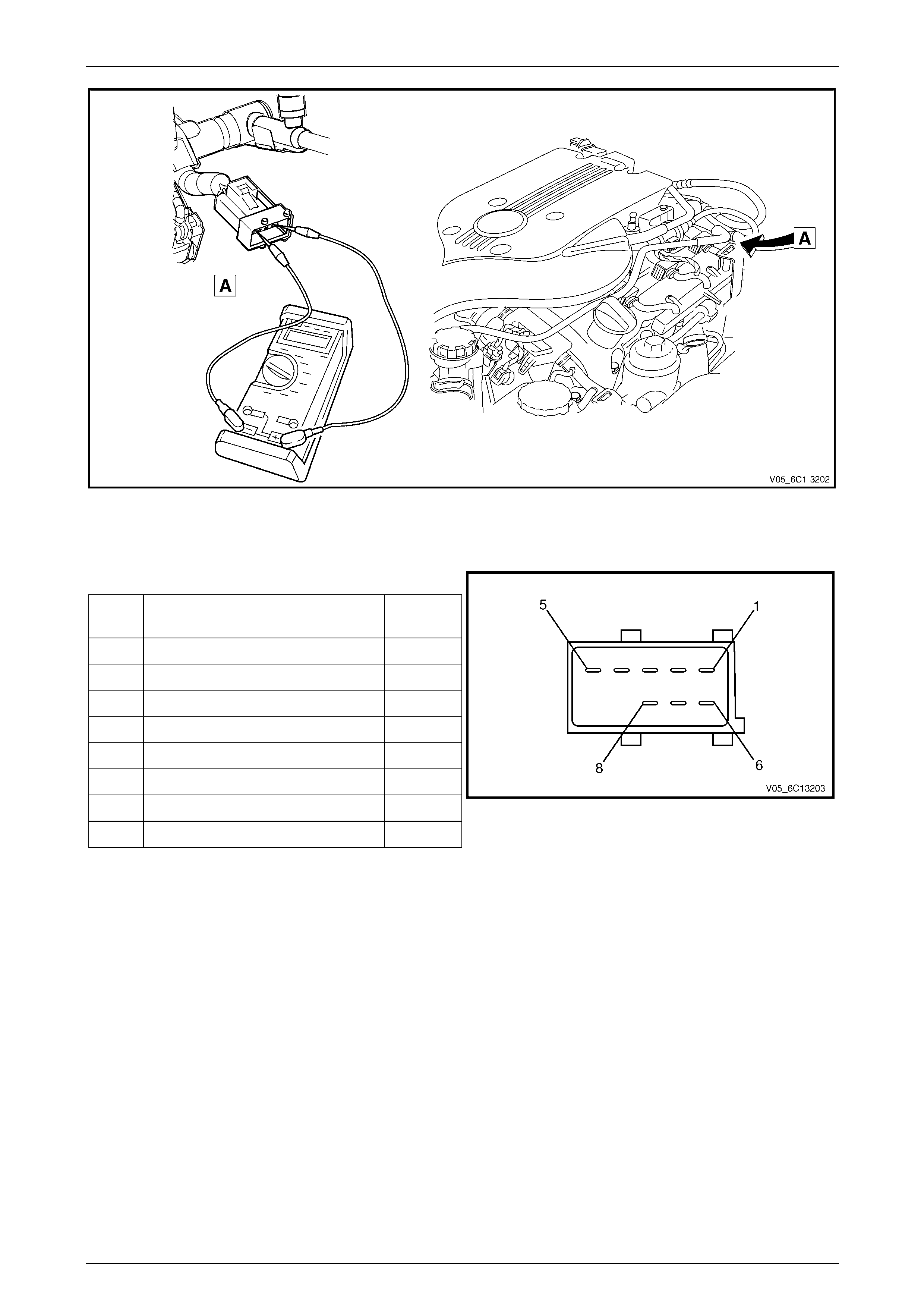
Engine Management – V6 – Diagnostics Page 6C1-2–50
Figure 6C1-2 – 15
Fuel Injector Harness to Engine Harness Connector
Pin Description
Pin Function Circuit
Number
1 Ignition Voltage Circuit – Cyl. 1, 3, 5 639
2 Ignition Voltage Circuit – Cyl. 2, 4, 6 1039
3 Injector 1 Control Circuit 1744
4 Injector 3 Control Circuit 1746
5 Injector 5 Control Circuit 845
6 Injector 2 Control Circuit 1745
7 Injector 4 Control Circuit 844
8 Injector 6 Control Circuit 846
Figure 6C1-2 – 16
Injector Coil Test – With Special Tool J39021
1 Depressurise the fuel system, refer to Section 8A1 Fuel System.
2 Turn the ignition OFF.
NOTE
After removing the upper intake manifold, plug
the lower manifold opening to prevent dirt and
other contaminants from entering.
3 Remove the upper intake manifold assembly, refer to Section 6A1 Engine Mechanical – V6.
4 Using Tech 2, observe the engine coolant temperature (ECT), refer to Section 0C Tech 2. If the ECT is 10 – 32°C,
refer to Engine Coolant Temperature Between 10 – 32(C, or if the ECT is outside this range, refer to Engine
Coolant Temperature Outside 10 – 32(C.
Page 6C1-2–50

Engine Management – V6 – Diagnostics Page 6C1-2–51
Engine Coolant Temperature Between 10 – 32°C
Step Action Value(s) Yes No
1 1 Set the amperage supply selector switch on the
fuel injector tester (1), special tool J 39021 to the
Coil Test 0.5 A position. Refer to
Figure 6C1-2 – 17.
2 Connect the fuel injector tester leads (4 and 5) to
B+ and ground.
3 Connect the digital multimeter (2) positive and
negative lead to the fuel injector tester. Set the
multimeter to read DC Voltage.
4 Connect the fuel injector tester, using fuel injector
harness adapter, special tool J44602 to a fuel
injector.
5 Press the Push to Start Test button on the fuel
injector tester.
6 Observe and record the voltage reading on the
digital multimeter.
NOTE
The voltage reading may rise during the test.
Record the voltage reading after one second
of the test.
7 Repeat steps 4 through 6 for each fuel injector.
NOTE
The table in Figure 6C1-2 – 18 shows an
example of the results from a fuel injector
coil test.
Did any fuel injector have an erratic voltage reading
(large fluctuations in voltage that did not stabilise), or
voltage readings outside of the specified value? 5.5 – 6.6 V
Replace the faulty
fuel injector/s. Refer
to 2.15 Fuel Rail
Assembly, in
Section 6C1-3
Engine
Management – V6 –
Service Operations. System OK
When all repairs are completed, check the system for fuel leaks and correct operation.
Page 6C1-2–51

Engine Management – V6 – Diagnostics Page 6C1-2–52
Engine Coolant Temperature Outside 10 – 32°C
Step Action Value(s) Yes No
1 1 Set the amperage supply selector switch on the
fuel injector tester (1), special tool J 39021 to the
Coil Test 0.5 A position. Refer to
Figure 6C1-2 – 17.
2 Connect the fuel injector tester leads (4 and 5) to
B+ and ground.
3 Connect the digital multimeter (2) positive and
negative lead to the fuel injector tester. Set the
multimeter to read DC Voltage.
4 Connect the fuel injector tester, using injector
harness adapter, special tool J44602 to a fuel
injector.
5 Press the Push to Start Test button on the fuel
injector tester.
6 Observe and record the voltage reading on the
digital multimeter.
NOTE
The voltage reading may rise during the test.
Record the voltage reading after one second
of the test.
7 Repeat steps 4 through 6 for each fuel injector.
8 Identify the highest voltage reading recorded from
the six fuel injectors tested that is 9.5 V or less.
NOTE
Disregard those voltage readings that are
greater than 9.5 V. Voltage readings greater
than 9.5 V indicate a faulty fuel injector.
9 Subtract the remaining voltage readings recorded
in Step 8, from the highest voltage reading.
Are any of the values recorded in Step 9 greater than
the specified value? 0.6 V Go to Step 2 System OK
2 1 Replace any fuel injector that has any of the
following:
− a subtracted value exceeding 0.6 V,
− an initial reading greater than 9.5 V, and
− an erratic reading.
NOTE
The table in Figure 6C1-2 – 19 shows an
example of the results from a fuel injector
coil test.
Has the repair been completed? – System OK. –
When all repairs are completed, check the system for fuel leaks and correct operation.
Page 6C1-2–52
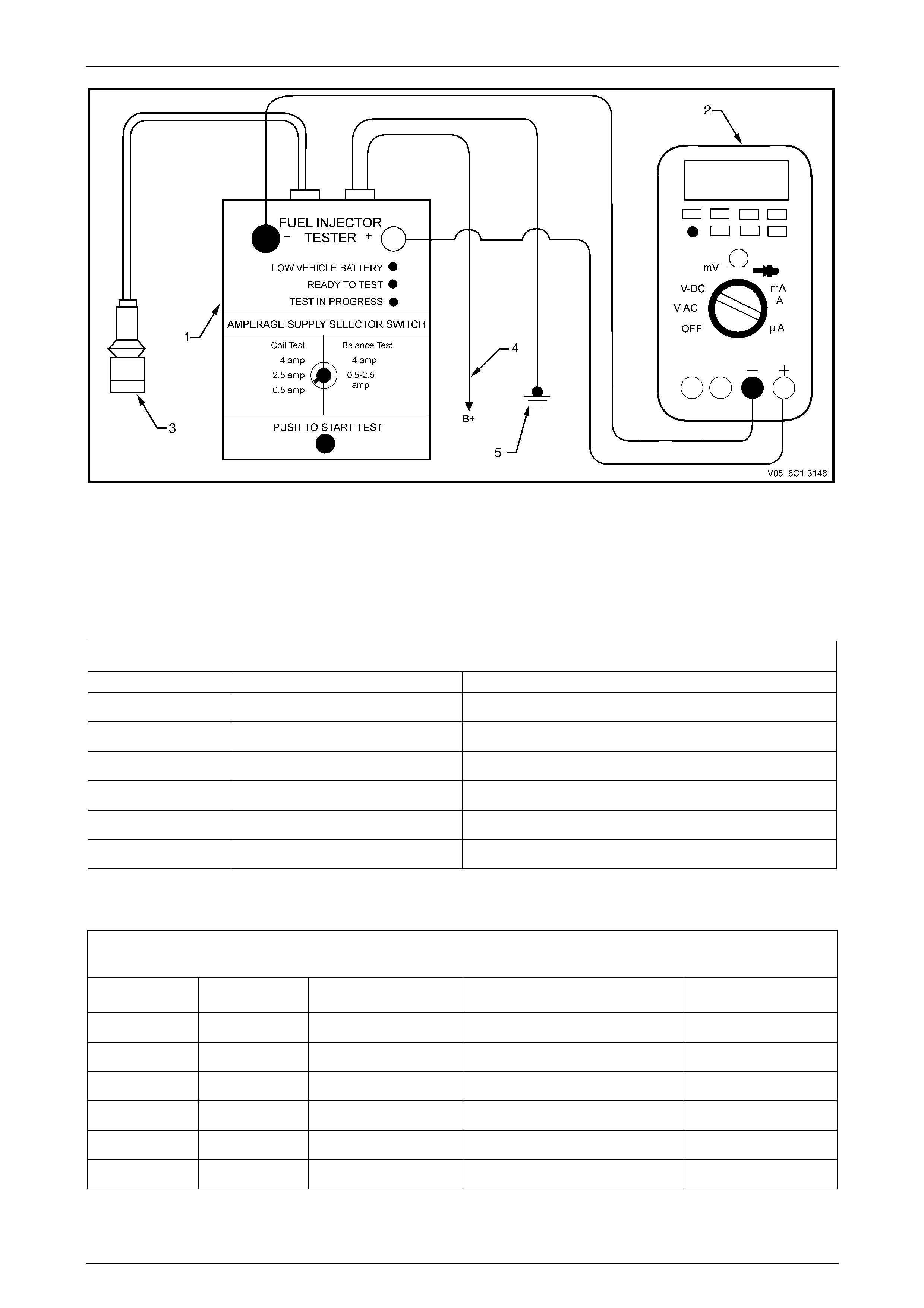
Engine Management – V6 – Diagnostics Page 6C1-2–53
Figure 6C1-2 – 17
Legend
1 Fuel Injector Tester – Special Tool J39021
2 Digital Multimeter
3 Fuel Injector Harness Adapter – Special Tool J44602
4 To Battery Positive Terminal
5 Battery Earth
Fuel Injector Coil Test Example – Engine Coolant Temp erature 10 – 32°C (Typical Values Shown)
Fuel Injector No. Voltage Reading Pass / Fail (acceptable range 5.5 - 6.6 V)
1 6.6 Pass
2 5.4 Fail
3 6.2 Pass
4 6.1 Pass
5 6.7 Fail
6 6.0 Pass
Figure 6C1-2 – 18
Fuel Injector Coil Test Example – Engine Coolant Temp erature Greater / Less Than 10 – 32°C (Typical Values
Shown)
Fuel Injector No. Voltage Reading Highest Voltage Reading
(9.5 V or less) Subtracted Value
(acceptable voltage 0.6 V) Pass / Fail
1 9.8 – –
Fail
2 6.4 7.0 0.6 Pass
3 6.9 7.0 0.1 Pass
4 5.8 7.0 1.2 Fail
5 7.0 7.0 0.0 Pass
6 6.3 7.0 0.7 Fail
Figure 6C1-2 – 19
Page 6C1-2–53

Engine Management – V6 – Diagnostics Page 6C1-2–54
5.3 Fuel Injector Balance Test
To avoid irregular fuel pressure readings, do
not perform this procedure if the engine
coolant temperature is greater th an 94° C.
2 el injectors that are not functioning correctly before proceeding.
3 m is functioning correctly before proceeding with
4 ge is still connected to the fuel pressure test point, pressurise the fuel system. Refer to
5 When the fuel pressure reading stabilises, record the fuel pressure reading indicated by the fuel pressure gauge.
n Step 5 is
known as the first pressure reading.
8 Follow the Tech 2 prompts, recording the fuel pressure gauge reading for each injector.
tep 8 are
known as the second pressure reading
9 Perform the Fuel Injector Pressure Drop Calculation in this Section.
2 el injectors that are not functioning correctly before proceeding.
3 m is functioning correctly before proceeding with
4 ge is still connected to the fuel pressure test point, pressurise the fuel system. Refer to
5 When the fuel pressure reading stabilises, record the fuel pressure reading indicated by the fuel pressure gauge.
n Step 5 is
known as the first pressure reading.
6 Remove the upper intake manifold assembly, refer to Section 6A1 Engine Mechanical – V6.
event dirt and
other contaminants from entering.
7 39021 Fuel Injector Tester (1), and Tool No. J 44602 (3) to the fuel injector connector. Refer to
Figure 6C1-2 – 20.
Fuel Injector Balance Test – With Tech 2
1 Check the engine coolant temperature is less than 94°C.
Perform the fuel injector coil test and replace any fu
Refer to 5.2 Fuel Injector Coil Test in this Section.
Perform the fuel system pressure check and ensure the fuel syste
the fuel injector balance test. Refer to Section 8A1 Fuel System.
While the fuel pressure gau
Section 8A1 Fuel System.
NOTE
The fuel pressure reading taken i
6 Connect Tech 2 to the data link connector (DLC) and turn the ignition on.
7 On Tech 2 select Engine / V6 Engine / Actuator Test / Fuel Injector Balance.
NOTE
The fuel pressure readings taken in S
Fuel Injector Balance Test – Without Tech 2
1 Check the engine coolant temperature is less than 94°C.
Perform the fuel injector coil test and replace any fu
Refer to 5.2 Fuel Injector Coil Test in this Section.
Perform the fuel system pressure check and ensure the fuel syste
the fuel injector balance test. Refer to Section 8A1 Fuel System.
While the fuel pressure gau
Section 8A1 Fuel System.
NOTE
The fuel pressure reading taken i
NOTE
After removing the upper intake manifold, plug
the lower manifold opening to pr
Connect Tool No. J
Page 6C1-2–54
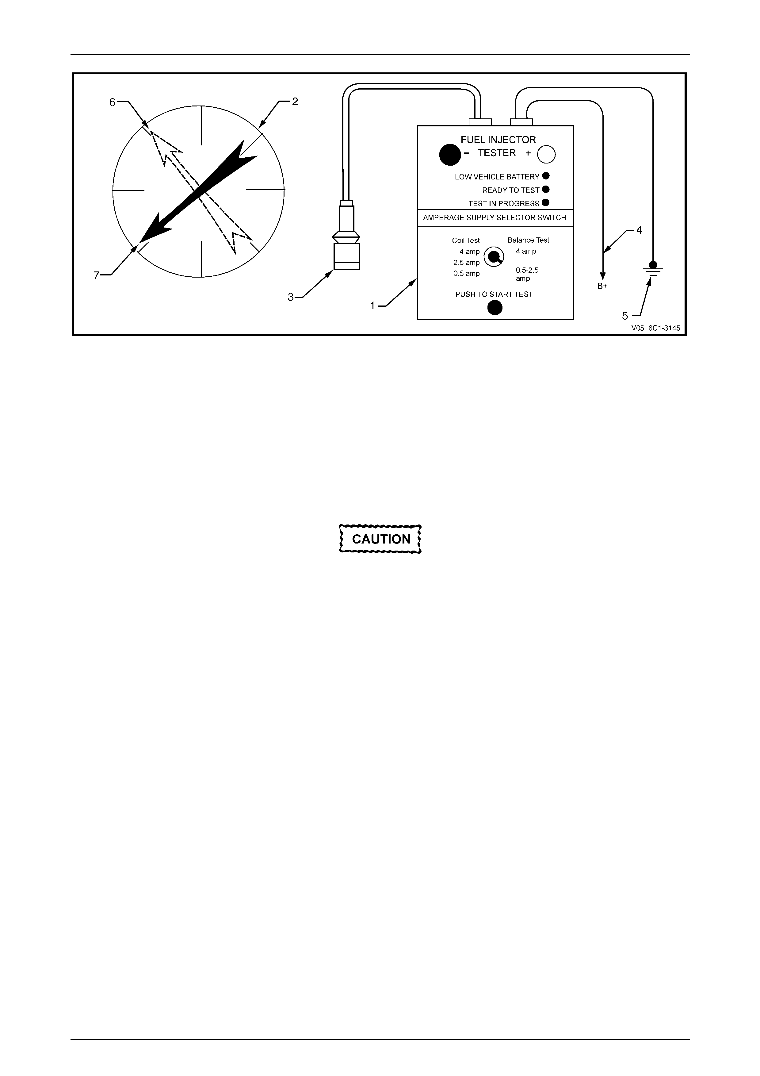
Engine Management – V6 – Diagnostics Page 6C1-2–55
Figure 6C1-2 – 20
Legend
1 Fuel Injector Tester – Special Tool J39021
2 Fuel Pressure Gauge – Special Tool SD28018
3 Fuel Injector Harness Adapter – Special Tool J44602
4 To Battery Positive Terminal
5 Battery Earth
6 First Pressure Reading
7 Second Pressure Reading
8 Connect the fuel injector tester battery positive lead (4) and battery negative lead (5) to the battery, refer to
Figure 6C1-2 – 20.
9 Set the amperage supply selector of the fuel injector tester to the Balance Test 0.5 – 2.5 A position.
As the fuel pressure tends to increase after
the fuel injector stops fuel delivery, record the
fuel pressure value immediately after the fuel
injector stops fuel delivery. Do not record the
higher fuel pressure value.
the fuel injector.
11 Record the fuel pressure reading indicated by the fuel pressure gauge.
tep 10 is
known as the second pressure reading
13 Perform the Fuel Injector Pressure Drop Calculation in this Section.
10 Press the Push to Start Test Button on the fuel injector tester to activate
NOTE
The fuel pressure readings taken in S
12 Repeat the balance test pressure reading for each fuel injector.
Page 6C1-2–55

Engine Management – V6 – Diagnostics Page 6C1-2–56
Fuel Injector Pressure Drop Calculation
Fuel Injector Balance Test Example – Typical Valu es Sh ow n
Cylinder 1 2 3 4 5 6
1st Pressure Reading 360 kPa 360 kPa 360 kPa 360 kPa 360 kPa 360 kPa
2nd Pressure
Reading 155 kPa 131 kPa 155 kPa 200 kPa 146 kPa 150 kPa
Amount of Pressure
Drop 205 kPa 229 kPa 205 kPa 160 kPa 214 kPa 210 kPa
Average Range
194 - 214 kPa Injector
OK Replace fuel
injector – too much
pressure drop
Injector
OK Replace fuel
injector – too little
pressure drop
Injector
OK Injector
OK
Figure 6C1-2 – 21
1 Subtract the second pressure reading from the first pressure reading to calculate the pressure drop value. Refer to
Figure 6C1-2 – 21, typical results.
2 Calculate the pressure drop value for each fuel injector.
3 Add all the individual pressure drop values of each fuel injector to calculate the total pressure drop.
4 Divide the total pressure drop by the number of fuel injectors to calculate the average pressure drop.
Fuel Injector Pressure Drop Analysis
1 A fuel injector is faulty if its pressure drop value deviates from the average pressure drop by more than 10 kPa.
Do not repeat any portion of the test before
running the engine to prevent the engine from
flooding.
2 Re-test any fuel injector that does not meet the specification.
3 Replace all faulty fuel injectors, refer to 2.15 Fuel Rail Assembly, in Section 6C1-3 Engine Management – V6 –
Service Operations.
Page 6C1-2–56
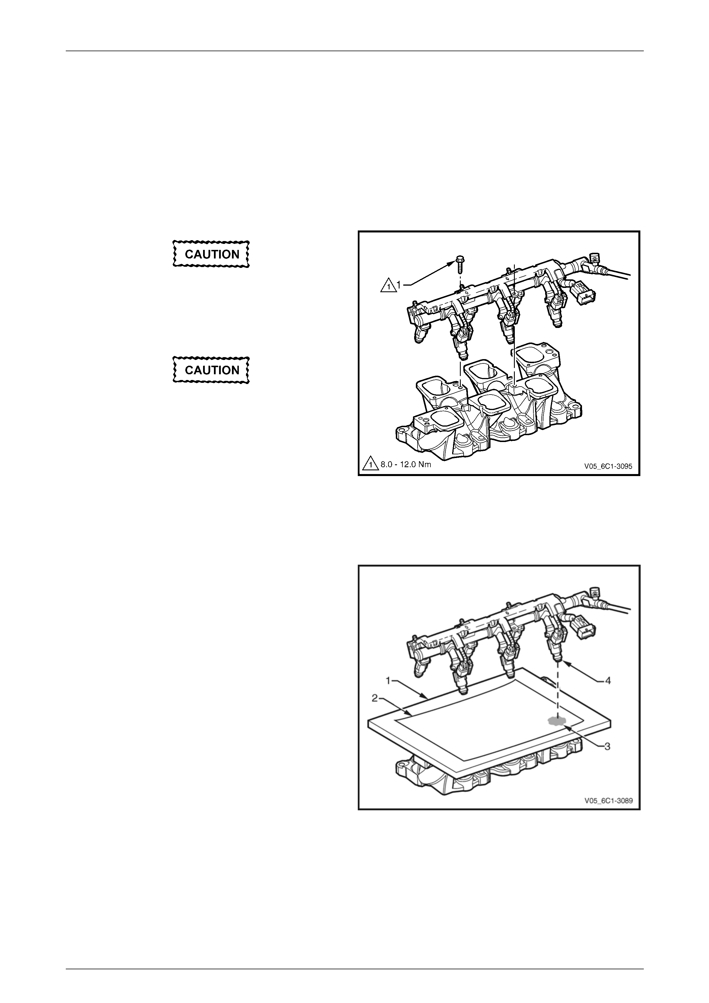
Engine Management – V6 – Diagnostics Page 6C1-2–57
5.4 Fuel Injector Leak Down Test
1 Turn the ignition switch OFF.
NOTE
After removing the upper intake manifold, plug
the lower manifold opening to prevent dirt and
other contaminants from entering.
2 Remove the upper intake manifold assembly, refer to Section 6A1 Engine Mechanical – V6.
Clean around the area where the fuel
3 , attaching the fuel
rail to the lower intake manifold.
injectors enter the lower intake manifold.
Remove the bolt (1), three places
Care must be taken when removing the fuel
rail and injector assembly to prevent damage
to the injector sp ray tips and injector h arness
el rail and injector assembly
4 Lift up and support the fuel rail and injector assembly.
isconnect the fuel feed hose from the
fuel rail.
connector terminals.
Support the fu
after removal.
NOTE
Do not d
Figure 6C1-2 – 22
5
6 e the
refer to Section 0C Tech 2 for this
7 fuel system is pressurised, check the
• weeping at the fuel injector spray
8
1-3 Engine Management – V6
9 Carefully reinstall the fuel rail and injector assembly.
Place a board (1) with a sheet of clean paper (2),
preferably white, onto the lower intake manifold.
Using Tech 2, enable the fuel pump to pressuris
fuel system,
procedure.
Whilst the
following:
• Signs of fuel stains on the paper (3).
Signs of
tips (4).
If any of the above conditions are present, replace
the leaking fuel injector/s, refer to 2.15 Fuel Rail
Assembly, in Section 6C
– Service Operations.
Figure 6C1-2 – 23
Page 6C1-2–57

Engine Management – V6 – Diagnostics Page 6C1-2–58
Ensure the fuel injectors are correctly seated
in the lower intake manifold, and the fuel rail
attaching brackets are correctly located prior
to tightening the attaching bolts.
10 Tighten the fuel rail bolts to the correct torque specification.
Fuel rail attaching bolt
torque specification ..................................8.0 – 12.0 Nm
11 Reinstall the upper intake manifold assembly, refer to Section 6A1 Engine Mechanical – V6.
efer to Section 8A1 Fuel System.
13 Road test the vehicle and check for correct operation.
12 Inspect the fuel rail and quick connect fitting for leaks, r
Page 6C1-2–58

Engine Management – V6 – Diagnostics Page 6C1-2–59
5.5 Alcohol / Contaminants in Fuel
Diagnosis
Description
Water contamination in the fuel system may cause driveability conditions such as hesitation, stalling, no start, or misfires
in one or more cylinders. Water may collect near a single fuel injector at the lowest point in the fuel rail, and cause a
misfire in that cylinder. If the fuel system is contaminated with water, inspect the fuel system components for rust, or
deterioration.
Alcohol (e.g. Ethanol) concentrations more than 10% in the fuel can be detrimental to fuel system components. Alcohol
contamination may cause fuel system corrosion, deterioration of rubber components, and subsequent fuel filter
restriction. Fuel contaminated with alcohol may cause driveability conditions such as hesitation, lack of power, stalling, or
no start. Some types of alcohol are more detrimental to fuel system components than others.
Alcohol in Fuel Testing Procedure
NOTE
The procedures detailed are not intended to be
accurate but rather, indicative of a contamination
situation.
The fuel sample should be drawn from the bottom of the tank so that any water present in the tank will be detected. The
sample should be bright and clear. If alcohol contamination is suspected, then use the following procedure to test the fuel
quality.
• Using a 100 ml graduated cylinder with 1 ml marks, fill the cylinder with fuel to the 90 ml mark.
• Add 10 ml of water to bring the total fluid volume to 100 ml and install a stopper.
• Shake the cylinder vigorously for 10 – 15 seconds.
• Carefully loosen the stopper to release the pressure.
• Re-install the stopper and shake the cylinder vigorously again for 10 – 15 seconds.
• Put the cylinder on a level surface for approximately 5 minutes to allow adequate liquid separation.
If alcohol is present in the fuel, the volume of the lower layer, that now contains both alcohol and water, will be more than
10 ml. For example, if the volume of the lower layer is increased to 15 ml, this indicates at least 5 percent alcohol in the
fuel. The actual amount of alcohol may be somewhat more because this procedure does not extract all of the alcohol
from the fuel. To obtain an accurate determination of the amount of alcohol contamination in a given fuel sample, then
professional analysis should be sought.
Particulate Contaminants in Fuel Testing Procedure
The fuel sample should be drawn from the bottom of the tank so that any contaminants present in the tank will be
detected. The sample should be bright and clear. If the sample appears cloudy or contaminated with water as indicated
by a water layer at the bottom of the sample, use the following procedure to diagnose the fuel.
• Using an approved fuel container, draw approximately 0.5 litre of fuel.
• Place the cylinder on a level surface for approximately 5 minutes to allow settling of the particulate contamination.
Particulate contamination will show up in various shapes and colours. Sand will typically be identified by a white or light
brown crystals. Rubber will appear as black and irregular particles. If particles are found, clean the entire fuel system
thoroughly. Refer to Section 8A1 Fuel Tank.
Page 6C1-2–59

Engine Management – V6 – Diagnostics Page 6C1-2–60
5.6 Crankshaft Position (CKP) System
Variation Learn Procedure
Description
The crankshaft position system variation learn feature is carried out automatically on the HFV6 engine under decel with
fuel cut. The road speed and duration of the self-learn process varies with different vehicle equipment levels such as
transmission, final drive ratio etc.
The variation learn procedure cannot be over-written, nor can it be accessed with Tech 2.
Page 6C1-2–60

Engine Management – V6 – Diagnostics Page 6C1-2–61
5.7 Throttle Body Relearn
A throttle body relearn procedure is performed in one of two ways:
• Engine Control Module initiated throttle body relearn, or
• Tech 2 initiated throttle body relearn.
Engine Control Module Throttle Body Relearn
The engine control module (ECM) will automatically perform a throttle body relearn procedure if either of the following
conditions exist:
• The battery has been disconnected, or
• The ignition switch is in the ON position for greater than 29 seconds, and the following conditions are met:
− Engine speed is less than 40 rpm,
− Vehicle speed is 0 km/h,
− Engine coolant temperature is 5 – 60°C,
− Intake air temperature is 5 – 60°C,
− Accelerator pedal position sensor angle is less than 14.9%, and
− Ignition voltage is greater than 10 V.
Tech 2 Throttle Body Relearn
To perform a throttle body relearn using Tech 2, complete the following procedure:
NOTE
Tech 2 will not initiate a throttle body relearn if the
engine is running.
1 Connect Tech 2 to the data link connector (DLC) and turn the ignition on.
2 On Tech 2 select Engine / Programming / Throttle Body Relearn.
3 When Tech 2 displays ‘Do you really want to Reset?’, press the ‘Yes’ soft key.
4 When Tech 2 displays ‘Programming Completed’, and the electronic throttle control value displayed by Tech 2 is
‘11’, press the ‘Confirm’ soft key to return to the Tech 2 Programming screen.
5 The throttle body relearn is now complete.
Page 6C1-2–61

Engine Management – V6 – Diagnostics Page 6C1-2–62
5.8 Intake Manifold Runner Control (IMRC)
System Diagnosis
Circuit Description
An intake manifold runner control (IMRC) valve is used to change the intake manifold plenum configuration. When the
IMRC valve is open, the intake manifold is configured to one large plenum. When the IMRC valve is closed, the intake
manifold is configured to 2 smaller plenums. The IMRC valve improves engine performance at low and high engine
speeds.
Ignition voltage is supplied directly to the IMRC solenoid. The engine control module (ECM) controls the solenoid by
grounding the control circuit with a solid state device called a driver. The driver is equipped with a feedback circuit that is
pulled up to a voltage. The ECM can determine if the control circuit is open, shorted to ground, or shorted to a voltage by
monitoring the feedback voltage.
Additional Information
Inspect the IMRC solenoid valve for witness marks that indicate that the valve was hitting the intake manifold. This
condition may be temperature related.
Test Description
The number below refers to the step number on the diagnostic table.
2 This diagnostic table will only diagnose the mechanical portion of the IMRC solenoid. If there is a DTC set for the
IMRC solenoid, refer to the appropriate DTC table. Refer to DTC List in Ascending Order.
Diagnostic Table
Step Action Value(s) Yes No
1 Has the Diagnostic System Check been completed? — Go to Step 2
Refer to
3.4 Diagnostic
System Check
2
1 Ignition ON, engine OFF.
2 Use Tech 2 to check the DTC information.
Is DTC P2008, P2009, or P2010 set?
— Go to 6.1 DTC List
in Ascending Order Go to Step 3
3
1 Remove the intake manifold runner control (IMRC)
solenoid from the intake manifold, but leave the
electrical connector connected. Refer to Intake
Manifold Runner Control Solenoid Valve, in
Section 6C1-3 Engine Diagnosis – V6 – Service
Operations.
2 Use Tech 2 to command the IMRC solenoid ON
and OFF.
3 Observe the valve of the IMRC solenoid while you
command the IMRC solenoid ON and OFF.
Does the valve of the IMRC solenoid move in both
directions?
—
Go to Step 4 Go to Step 5
Page 6C1-2–62

Engine Management – V6 – Diagnostics Page 6C1-2–63
4
1 Inspect the inside of the intake manifold for the
following conditions:
• Carbon build-up that limits the movement of
the IMRC valve.
• Casting flash that limits the movement of the
IMRC valve.
• Foreign material that limits the movement of
the IMRC valve.
2 Clean or replace the upper intake manifold as
required. Refer to 2.12 Upper Intake Manifold, in
Section 6A1 Engine Mechanical – V6 Engine.
Did you find and correct the condition?
—
Go to Step 6
Go to Additional
Information in this
DTC
5
1 Replace the IMRC solenoid. Refer to Intake
Manifold Runner Control Solenoid Valve, in
Section 6C1-3 Engine Diagnosis – V6 – Service
Operations.
Did you complete the replacement?
—
Go to Step 6 —
6
1 Connect all disconnected components.
2 Clear the DTCs with Tech 2.
3 Start the engine.
4 Operate the system to verify the repair.
Did you correct the condition?
—
Go to Step 7 Go to Step 2
7 1 Using T ech 2, select the DT C display function.
Does Tech 2 display any DTCs? — Go to the
appropriate DTC
Table System OK
When all diagnosis and repairs are completed, clear all DTCs and verify correct operation
Page 6C1-2–63

Engine Management – V6 – Diagnostics Page 6C1-2–64
5.9 Electronic Ignition (EI) System Diagnosis
Circuit Description
The engine control module (ECM) controls the ignition coils by pulsing the ignition control (IC) circuits, which triggers an
ignition coil and fires the spark plug. The ECM controls the sequencing and the timing of each ignition coil. The ignition
system consist of the following components:
• The six ignition coils
• The crankshaft position (CKP) sensor
• The four camshaft position (CMP) sensors
• The ECM
The ignition coils use the following circuits:
• An IC circuit
• An ignition 1 voltage circuit
• Two ground circuits
Additional Information
• Use the J 35616-B Connector Test Adapter Kit for any test that requires probing the ECM harness connector or a
component harness connector.
• Inspect the ignition coils for aftermarket devices. An aftermarket device connected to the ignition coil circuits, may
cause a condition with the ignition coils.
• For an intermittent fault condition, refer to 4.2 Intermittent Fault Conditions in this Section.
• To assist diagnosis, refer to 2 Wiring Diagrams and Connector Charts in this Section for the system wiring diagram
and connector charts.
Test Description
The numbers below refer to the step numbers on the diagnostic table.
4 The ignition coils for each bank are fused separately. If a fuse opens or the ignition 1 voltage circuit opens between
the fuse and the splice, all the ignition coils for one bank of the engine would be inoperative. If the ground circuit
opens at the engine block, the ignition coils would be inoperative for one bank of the engine.
5 This step tests for an open or a high resistance in the ignition 1 voltage circuit of the ignition coil. If the DMM does
not display near battery voltage there is an open or a high resistance in the circuit.
6 This step determines if the ground circuit is open. If the circuit is open, the ignition coils would be inoperative for
one bank of the engine.
7 This step determines if the ignition 1 voltage circuit is shorted to ground. If the fuse is open, the ignition coils would
be inoperative for one bank of the engine.
Diagnostic Table
Step Action Value(s) Yes No
1 Has the Diagnostic System Check been performed? — Go to Step 2
Refer to
3.4 Diagnostic
System Check
2
Were you sent here from DTC P0300 or P0301-P0306?
—
Go to Step 3
Go to 6.18 DTC
P0300 or 6.19 DTC
P0301, P0302,
P0303, P0304,
P0305 or P0306
Page 6C1-2–64

Engine Management – V6 – Diagnostics Page 6C1-2–65
3
1 Start the engine.
2 Allow the engine to reach operating temperature.
3 Operate the engine at 2,000 rpm.
4 Monitor all of the Misfire Current Counters with a
scan tool. There are a total of 6 counters,
1 counter per cylinder.
Are any of the Misfire Current Counters incrementing?
—
Go to Step 4
Go to
4.2 Intermittent
Fault Conditions
4 Are all the misfire counters incrementing for one bank of
the engine? — Go to Step 7 Go to Step 5
5
1 Ignition OFF.
2 Disconnect the appropriate ignition coil.
3 Ignition ON, engine OFF.
4 Connect a test lamp between the battery voltage
circuit of the ignition coil and a good ground.
5 Measure the voltage between the probe of the test
lamp and a good ground with a DMM. Refer to
Section 12 P Wiring Diagrams for the procedure to
measure voltage drop.
Is the voltage at the specified value?
B+
Go to Step 6 Go to Step 9
6
1 Connect the test lamp between the battery voltage
circuit of the ignition coil and to each ground circuit
of the ignition coil.
Does the test lamp illuminate at each ground circuit?
—
Go to Step 8 Go to Step 10
7
1 Test the battery voltage circuit for an open or high
resistance at the splice of the affected bank of
ignition coils. Refer to Section 12P Wiring
Diagrams for circuit testing procedures.
Did you find and correct the condition?
—
Go to Step 12 Go to Step 10
8
1 Test for an intermittent and for a poor connection
at the ignition coil. Refer to Section 12P Wiring
Diagrams for circuit testing procedures.
Did you find and correct the condition?
—
Go to Step 12 Go to Step 11
9
NOTE
The battery voltage circuit is shared with
other components. Disconnecting a
component on the shared battery voltage
circuit may isolate a shorted component.
Review the electrical schematic and
diagnose the shared circuits and
components.
1 Repair a short to ground, an open or high
resistance in the ignition 1 voltage circuit. Refer to
Section 12P Wiring Diagrams for wiring repair
procedures.
2 Replace the fuse as necessary.
Did you complete the repair?
—
Go to Step 12 —
10
1 Repair the open or high resistance in the ground
circuit. Refer to Section 12P Wiring Diagrams for
wiring repair procedures.
Did you complete the repair?
—
Go to Step 12 —
Page 6C1-2–65

Engine Management – V6 – Diagnostics Page 6C1-2–66
11
1 Replace the ignition coil. Refer to 2.17 Ignition
Coils, in Section 6C1-3 Engine Management –
V6 – Service Operations.
Did you complete the replacement?
—
Go to Step 12 —
12
1 Connect all disconnected components.
2 Use Tech 2 to clear the DTC/s.
3 Start the engine.
4 Observe the Capture Info with Tech 2.
Do any of the misfire counters increment?
—
Go to Step 2 Go to Step 13
13 1 Using Tech 2, select the DTC display function.
Does Tech 2 display any DTCs? — Go to the
appropriate DTC
Table System OK
When all diagnosis and repairs are completed, clear all DTCs and verify correct operation
Page 6C1-2–66

Engine Management – V6 – Diagnostics Page 6C1-2–67
6 Diagnostic Trouble Code Ta bles
6.1 DTC List in Ascending Order
As a number of diagnostic tables cater for multiple DTC numbers, a specific DTC table may be difficult to locate.
To make a specific DTC diagnostic table easier to find, the next list is arranged in numerical ascending order.
The actual diagnostic table can be located by selecting the link provided.
DTC Description Diagnostic Table
P0008 Engine Position System Performance (Bank 1) 6.2 DTC P0008, P0009, P0016, P0017, P0018
or P0019
P0009 Engine Position System Performance (Bank 2) 6.2 DTC P0008, P0009, P0016, P0017, P0018
or P0019
P0010 Intake Camshaft Position Control Solenoid Circuit
Malfunction (Bank 1) 6.3 DTC P0010, P0013, P0020, P0023, P2088,
P2089, P2090, P2091, P2092, P2093,
P2094 or P2095
P0011 Intake Camshaft Position Range / Performance (Bank 1) 6.4 DTC P0011, P0014, P0021, P0024, P1011,
P1012, P1013, or P1014
P0013 Exhaust Camshaft Position Control Solenoid Circuit
Malfunction (Bank 1) 6.3 DTC P0010, P0013, P0020, P0023, P2088,
P2089, P2090, P2091, P2092, P2093,
P2094 or P2095
P0014 Exhaust Camshaft Position Range / Performance (Bank 1) 6.4 DTC P0011, P0014, P0021, P0024, P1011,
P1012, P1013, or P1014
P0016 Crankshaft / Intake Camshaft Position not Plausible
(Bank 1) 6.2 DTC P0008, P0009, P0016, P0017, P0018
or P0019
P0017 Crankshaft / Exhaust Camshaft Position not Plausible
(Bank 1) 6.2 DTC P0008, P0009, P0016, P0017, P0018
or P0019
P0018 Crankshaft / Intake Camshaft Position not Plausible
(Bank 2) 6.2 DTC P0008, P0009, P0016, P0017, P0018
or P0019
P0019 Crankshaft / Exhaust Camshaft Position not Plausible
(Bank 2) 6.2 DTC P0008, P0009, P0016, P0017, P0018
or P0019
P0020 Intake Camshaft Position Control Solenoid Circuit
Malfunction (Bank 2) 6.3 DTC P0010, P0013, P0020, P0023, P2088,
P2089, P2090, P2091, P2092, P2093,
P2094 or P2095
P0021 Intake Camshaft Position Range / Performance (Bank 2) 6.4 DTC P0011, P0014, P0021, P0024, P1011,
P1012, P1013, or P1014
P0023 Exhaust Camshaft Position Control Solenoid Circuit
Malfunction (Bank 2) 6.3 DTC P0010, P0013, P0020, P0023, P2088,
P2089, P2090, P2091, P2092, P2093,
P2094 or P2095
P0024 Exhaust Camshaft Position Range / Performance (Bank 2) 6.4 DTC P0011, P0014, P0021, P0024, P1011,
P1012, P1013, or P1014
P0030 O2 Sensor Heater Circuit Malfunction (Bank 1, Sensor 1) 6.5 DTC P0030, P0031, P0032, P0036, P0037,
P0038, P0050, P0051, P0052, P0056,
P0057 or P0058
P0031 O2 Sensor Heater Circuit Low Voltage (Bank 1, Sensor 1) 6.5 DTC P0030, P0031, P0032, P0036, P0037,
P0038, P0050, P0051, P0052, P0056,
P0057 or P0058
P0032 O2 Sensor Heater Circuit High Voltage (Bank 1, Sensor 1) 6.5 DTC P0030, P0031, P0032, P0036, P0037,
P0038, P0050, P0051, P0052, P0056,
P0057 or P0058
P0036 O2 Sensor Heater Circuit Malfunction (Bank 1, Sensor 2) 6.5 DTC P0030, P0031, P0032, P0036, P0037,
P0038, P0050, P0051, P0052, P0056,
P0057 or P0058
Page 6C1-2–67

Engine Management – V6 – Diagnostics Page 6C1-2–68
DTC Description Diagnostic Table
P0037 O2 Sensor Heater Circuit Low Voltage (Bank 1, Sensor 2) 6.5 DTC P0030, P0031, P0032, P0036, P0037,
P0038, P0050, P0051, P0052, P0056,
P0057 or P0058
P0038 O2 Sensor Heater Circuit High Voltage (Bank 1, Sensor 2) 6.5 DTC P0030, P0031, P0032, P0036, P0037,
P0038, P0050, P0051, P0052, P0056,
P0057 or P0058
P0040 O2 Sensor Signals Not Plausible (Bank 1, Sensor 1 &
Bank 2, Sensor 1) 6.6 DTC P0040 or P0041
P0041 O2 Sensor Signals Not Plausible (Bank 1, Sensor 2 &
Bank 2, Sensor 2) 6.6 DTC P0040 or P0041
P0050 O2 Sensor Heater Circuit Malfunction (Bank 2, Sensor 1) 6.5 DTC P0030, P0031, P0032, P0036, P0037,
P0038, P0050, P0051, P0052, P0056,
P0057 or P0058
P0051 O2 Sensor Heater Circuit Low Voltage (Bank 2, Sensor 1) 6.5 DTC P0030, P0031, P0032, P0036, P0037,
P0038, P0050, P0051, P0052, P0056,
P0057 or P0058
P0052 O2 Sensor Heater Circuit High Voltage (Bank 2, Sensor 1) 6.5 DTC P0030, P0031, P0032, P0036, P0037,
P0038, P0050, P0051, P0052, P0056,
P0057 or P0058
P0053 O2 Sensor Heater Resistance Range / Performance
(Bank 1, Sensor 1) 6.7 DTC P0053 or P0059
P0056 O2 Sensor Heater Circuit Malfunction (Bank 2, Sensor 2) 6.5 DTC P0030, P0031, P0032, P0036, P0037,
P0038, P0050, P0051, P0052, P0056,
P0057 or P0058
P0057 O2 Sensor Heater Circuit Low Voltage (Bank 2, Sensor 2) 6.5 DTC P0030, P0031, P0032, P0036, P0037,
P0038, P0050, P0051, P0052, P0056,
P0057 or P0058
P0058 O2 Sensor Heater Circuit High Voltage (Bank 2, Sensor 2) 6.5 DTC P0030, P0031, P0032, P0036, P0037,
P0038, P0050, P0051, P0052, P0056,
P0057 or P0058
P0059 O2 Sensor Heater Resistance Range / Performance (Bank
2, Sensor 1) 6.7 DTC P0053 or P0059
P0101 Mass Air Flow Sensor Circuit Range / Performance 6.8 DTC P0101, P0102 or P0103
P0102 Mass Air Flow Sensor Voltage Low 6.8 DTC P0101, P0102 or P0103
P0103 Mass Air Flow Sensor Voltage High 6.8 DTC P0101, P0102 or P0103
P0112 Intake Air Temperature Sensor Circuit Low Voltage 6.9 DTC P0112 or P0113
P0113 Intake Air Temperature Sensor Circuit High Voltage 6.9 DTC P0112 or P0113
P0116 Engine Coolant Temperature Sensor Circuit Range /
Performance 6.10 DTC P0116, P0117, P0118, P0125 or
P1258
P0117 Engine Coolant Temperature Sensor Circuit Low Voltage 6.10 DTC P0116, P0117, P0118, P0125 or
P1258
P0118 Engine Coolant Temperature Sensor Circuit High Voltage 6.10 DTC P0116, P0117, P0118, P0125 or
P1258
P0121 Throttle Position Sensor 1 Circuit Range / Performance 6.11 DTC P0121, P0122, P0123, P0221,
P0222,or P0223
P0122 Throttle Position Sensor 1 Circuit Low Voltage 6.11 DTC P0121, P0122, P0123, P0221,
P0222,or P0223
P0123 Throttle Position Sensor 1 Circuit High Voltage 6.11 DTC P0121, P0122, P0123, P0221,
P0222,or P0223
Page 6C1-2–68

Engine Management – V6 – Diagnostics Page 6C1-2–69
DTC Description Diagnostic Table
P0125 Insufficient Engine Coolant Temperature For Closed Loop
Fuel Control 6.10 DTC P0116, P0117, P0118, P0125 or
P1258
P0130 O2 Sensor Circuit Malfunction (Bank 1, Sensor 1) 6.12 DTC P0130, P0131, P0132, P0135,
P0137, P0138, P0140, P0141, P0150
P0151, P0152, P0155, P0157, P0158,
P0160, P0161, P2243, P2247, P2270,
P2271, P2272, P2273, P2297 or P2298
P0131 O2 Sensor Circuit Low Voltage (Bank 1, Sensor 1) 6.12 DTC P0130, P0131, P0132, P0135,
P0137, P0138, P0140, P0141, P0150
P0151, P0152, P0155, P0157, P0158,
P0160, P0161, P2243, P2247, P2270,
P2271, P2272, P2273, P2297 or P2298
P0132 O2 Sensor Circuit High Voltage (Bank 1 Sensor 1) 6.12 DTC P0130, P0131, P0132, P0135,
P0137, P0138, P0140, P0141, P0150
P0151, P0152, P0155, P0157, P0158,
P0160, P0161, P2243, P2247, P2270,
P2271, P2272, P2273, P2297 or P2298
P0133 O2 Sensor Circuit Slow Response (Bank 1 Sensor 1) 6.13 DTC P0133 or P0153
P0135 O2 Sensor Heater Circuit Range / Performance (Bank 1,
Sensor 1) 6.12 DTC P0130, P0131, P0132, P0135,
P0137, P0138, P0140, P0141, P0150
P0151, P0152, P0155, P0157, P0158,
P0160, P0161, P2243, P2247, P2270,
P2271, P2272, P2273, P2297 or P2298
P0137 O2 Sensor Circuit Low Voltage (Bank 1, Sensor 2) 6.12 DTC P0130, P0131, P0132, P0135,
P0137, P0138, P0140, P0141, P0150
P0151, P0152, P0155, P0157, P0158,
P0160, P0161, P2243, P2247, P2270,
P2271, P2272, P2273, P2297 or P2298
P0138 O2 Sensor Circuit High Voltage (Bank 1, Sensor 2) 6.12 DTC P0130, P0131, P0132, P0135,
P0137, P0138, P0140, P0141, P0150
P0151, P0152, P0155, P0157, P0158,
P0160, P0161, P2243, P2247, P2270,
P2271, P2272, P2273, P2297 or P2298
P0139 O2 Sensor Slow Response (Bank1 Sensor 2) 6.14 DTC P0139 or P0159
P0140 O2 Sensor Circuit No Activity Detected (Bank 1 Sensor 2) 6.12 DTC P0130, P0131, P0132, P0135,
P0137, P0138, P0140, P0141, P0150
P0151, P0152, P0155, P0157, P0158,
P0160, P0161, P2243, P2247, P2270,
P2271, P2272, P2273, P2297 or P2298
P0141 O2 Sensor Heater Circuit Range / Performance (Bank 1,
Sensor 2) 6.12 DTC P0130, P0131, P0132, P0135,
P0137, P0138, P0140, P0141, P0150
P0151, P0152, P0155, P0157, P0158,
P0160, P0161, P2243, P2247, P2270,
P2271, P2272, P2273, P2297 or P2298
P0150 O2 Sensor Circuit Malfunction (Bank 2, Sensor 1) 6.12 DTC P0130, P0131, P0132, P0135,
P0137, P0138, P0140, P0141, P0150
P0151, P0152, P0155, P0157, P0158,
P0160, P0161, P2243, P2247, P2270,
P2271, P2272, P2273, P2297 or P2298
P0151 O2 Sensor Circuit Low Voltage (Bank 2, Sensor 1) 6.12 DTC P0130, P0131, P0132, P0135,
P0137, P0138, P0140, P0141, P0150
P0151, P0152, P0155, P0157, P0158,
P0160, P0161, P2243, P2247, P2270,
P2271, P2272, P2273, P2297 or P2298
Page 6C1-2–69

Engine Management – V6 – Diagnostics Page 6C1-2–70
DTC Description Diagnostic Table
P0152 O2 Sensor Circuit High Voltage (Bank 2, Sensor 1) 6.12 DTC P0130, P0131, P0132, P0135,
P0137, P0138, P0140, P0141, P0150
P0151, P0152, P0155, P0157, P0158,
P0160, P0161, P2243, P2247, P2270,
P2271, P2272, P2273, P2297 or P2298
P0153 O2 Sensor Circuit Slow Response (Bank 2 Sensor 1) 6.13 DTC P0133 or P0153
P0155 O2 Sensor Heater Circuit Range / Performance (Bank 2,
Sensor 1) 6.12 DTC P0130, P0131, P0132, P0135,
P0137, P0138, P0140, P0141, P0150
P0151, P0152, P0155, P0157, P0158,
P0160, P0161, P2243, P2247, P2270,
P2271, P2272, P2273, P2297 or P2298
P0157 O2 Sensor Circuit Low Voltage (Bank 2, Sensor 2) 6.12 DTC P0130, P0131, P0132, P0135,
P0137, P0138, P0140, P0141, P0150
P0151, P0152, P0155, P0157, P0158,
P0160, P0161, P2243, P2247, P2270,
P2271, P2272, P2273, P2297 or P2298
P0158 O2 Sensor Circuit High Voltage (Bank 2, Sensor 2) 6.12 DTC P0130, P0131, P0132, P0135,
P0137, P0138, P0140, P0141, P0150
P0151, P0152, P0155, P0157, P0158,
P0160, P0161, P2243, P2247, P2270,
P2271, P2272, P2273, P2297 or P2298
P0159 O2 Sensor Slow Response (Bank1 Sensor 2) 6.14 DTC P0139 or P0159
P0160 O2 Sensor Circuit No Activity Detected (Bank 2, Sensor 2) 6.12 DTC P0130, P0131, P0132, P0135,
P0137, P0138, P0140, P0141, P0150
P0151, P0152, P0155, P0157, P0158,
P0160, P0161, P2243, P2247, P2270,
P2271, P2272, P2273, P2297 or P2298
P0161 O2 Sensor Heater Circuit Range / Performance (Bank 2,
Sensor 2) 6.12 DTC P0130, P0131, P0132, P0135,
P0137, P0138, P0140, P0141, P0150
P0151, P0152, P0155, P0157, P0158,
P0160, P0161, P2243, P2247, P2270,
P2271, P2272, P2273, P2297 or P2298
P0196 Engine Oil Temperature Sensor Range / Performance 6.15 DTC P0196, P0197 or P0198
P0197 Engine Oil Temperature Voltage Low 6.15 DTC P0196, P0197 or P0198
P0198 Engine Oil Temperature Voltage High 6.15 DTC P0196, P0197 or P0198
P0201 Injector 1 Control Circuit Malfunction 6.16 DTC P0201, P0202, P0203, P0204,
P0205, P0206, P0261, P0262, P0264,
P0265, P0267, P0268, P0270, P0271,
P0273, P0274, P0276 or P0277
P0202 Injector 2 Control Circuit Malfunction 6.16 DTC P0201, P0202, P0203, P0204,
P0205, P0206, P0261, P0262, P0264,
P0265, P0267, P0268, P0270, P0271,
P0273, P0274, P0276 or P0277
P0203 Injector 3 Control Circuit Malfunction 6.16 DTC P0201, P0202, P0203, P0204,
P0205, P0206, P0261, P0262, P0264,
P0265, P0267, P0268, P0270, P0271,
P0273, P0274, P0276 or P0277
P0204 Injector 4 Control Circuit Malfunction 6.16 DTC P0201, P0202, P0203, P0204,
P0205, P0206, P0261, P0262, P0264,
P0265, P0267, P0268, P0270, P0271,
P0273, P0274, P0276 or P0277
P0205 Injector 5 Control Circuit Malfunction 6.16 DTC P0201, P0202, P0203, P0204,
P0205, P0206, P0261, P0262, P0264,
P0265, P0267, P0268, P0270, P0271,
P0273, P0274, P0276 or P0277
Page 6C1-2–70

Engine Management – V6 – Diagnostics Page 6C1-2–71
DTC Description Diagnostic Table
P0206 Injector 6 Control Circuit Malfunction 6.16 DTC P0201, P0202, P0203, P0204,
P0205, P0206, P0261, P0262, P0264,
P0265, P0267, P0268, P0270, P0271,
P0273, P0274, P0276 or P0277
P0219 Engine Overspeed Condition 6.17 DTC P0219
P0221 Throttle Position Sensor 2 Circuit Range / Performance 6.11 DTC P0121, P0122, P0123, P0221,
P0222,or P0223
P0222 Throttle Position Sensor 2 Circuit Low Voltage 6.11 DTC P0121, P0122, P0123, P0221,
P0222,or P0223
P0223 Throttle Position Sensor 2 Circuit High Voltage 6.11 DTC P0121, P0122, P0123, P0221,
P0222,or P0223
P0261 Injector 1 Control Circuit Low Voltage 6.16 DTC P0201, P0202, P0203, P0204,
P0205, P0206, P0261, P0262, P0264,
P0265, P0267, P0268, P0270, P0271,
P0273, P0274, P0276 or P0277
P0262 Injector 1 Control Circuit High Voltage 6.16 DTC P0201, P0202, P0203, P0204,
P0205, P0206, P0261, P0262, P0264,
P0265, P0267, P0268, P0270, P0271,
P0273, P0274, P0276 or P0277
P0264 Injector 2 Control Circuit Low Voltage 6.16 DTC P0201, P0202, P0203, P0204,
P0205, P0206, P0261, P0262, P0264,
P0265, P0267, P0268, P0270, P0271,
P0273, P0274, P0276 or P0277
P0265 Injector 2 Control Circuit High Voltage 6.16 DTC P0201, P0202, P0203, P0204,
P0205, P0206, P0261, P0262, P0264,
P0265, P0267, P0268, P0270, P0271,
P0273, P0274, P0276 or P0277
P0267 Injector 3 Control Circuit Low Voltage 6.16 DTC P0201, P0202, P0203, P0204,
P0205, P0206, P0261, P0262, P0264,
P0265, P0267, P0268, P0270, P0271,
P0273, P0274, P0276 or P0277
P0268 Injector 3 Control Circuit High Voltage 6.16 DTC P0201, P0202, P0203, P0204,
P0205, P0206, P0261, P0262, P0264,
P0265, P0267, P0268, P0270, P0271,
P0273, P0274, P0276 or P0277
P0270 Injector 4 Control Circuit Low Voltage 6.16 DTC P0201, P0202, P0203, P0204,
P0205, P0206, P0261, P0262, P0264,
P0265, P0267, P0268, P0270, P0271,
P0273, P0274, P0276 or P0277
P0271 Injector 4 Control Circuit High Voltage 6.16 DTC P0201, P0202, P0203, P0204,
P0205, P0206, P0261, P0262, P0264,
P0265, P0267, P0268, P0270, P0271,
P0273, P0274, P0276 or P0277
P0273 Injector 5 Control Circuit Low Voltage 6.16 DTC P0201, P0202, P0203, P0204,
P0205, P0206, P0261, P0262, P0264,
P0265, P0267, P0268, P0270, P0271,
P0273, P0274, P0276 or P0277
P0274 Injector 5 Control Circuit High Voltage 6.16 DTC P0201, P0202, P0203, P0204,
P0205, P0206, P0261, P0262, P0264,
P0265, P0267, P0268, P0270, P0271,
P0273, P0274, P0276 or P0277
P0276 Injector 6 Control Circuit Low Voltage 6.16 DTC P0201, P0202, P0203, P0204,
P0205, P0206, P0261, P0262, P0264,
P0265, P0267, P0268, P0270, P0271,
P0273, P0274, P0276 or P0277
Page 6C1-2–71

Engine Management – V6 – Diagnostics Page 6C1-2–72
DTC Description Diagnostic Table
P0277 Injector 6 Control Circuit High Voltage 6.16 DTC P0201, P0202, P0203, P0204,
P0205, P0206, P0261, P0262, P0264,
P0265, P0267, P0268, P0270, P0271,
P0273, P0274, P0276 or P0277
P0300 Engine Misfire Detected 6.18 DTC P0300
P0301 Cylinder 1 Misfire Detected 6.19 DTC P0301, P0302, P0303, P0304, P0305
or P0306
P0302 Cylinder 2 Misfire Detected 6.19 DTC P0301, P0302, P0303, P0304, P0305
or P0306
P0303 Cylinder 3 Misfire Detected 6.19 DTC P0301, P0302, P0303, P0304, P0305
or P0306
P0304 Cylinder 4 Misfire Detected 6.19 DTC P0301, P0302, P0303, P0304, P0305
or P0306
P0305 Cylinder 5 Misfire Detected 6.19 DTC P0301, P0302, P0303, P0304, P0305
or P0306
P0306 Cylinder 6 Misfire Detected 6.19 DTC P0301, P0302, P0303, P0304, P0305
or P0306
P0324 Knock Sensor Module Performance 6.20 DTC P0324
P0327 Knock Sensor Circuit Low Frequency (Bank 1) 6.21 DTC P0327, P0328, P0332 or P0333
P0328 Knock Sensor Circuit High Frequency (Bank 1) 6.21 DTC P0327, P0328, P0332 or P0333
P0332 Knock Sensor Circuit Low Frequency (Bank 2) 6.21 DTC P0327, P0328, P0332 or P0333
P0333 Knock Sensor Circuit High Frequency (Bank 2) 6.21 DTC P0327, P0328, P0332 or P0333
P0335 Crankshaft Position Sensor Circuit Malfunction 6.22 DTC P0335, P0336, P0337 or P0338
P0336 Crankshaft Position Sensor Signal Range / Performance 6.22 DTC P0335, P0336, P0337 or P0338
P0337 Crankshaft Position Sensor Circuit Low Duty Cycle 6.22 DTC P0335, P0336, P0337 or P0338
P0338 Crankshaft Position Sensor Circuit High Duty Cycle 6.22 DTC P0335, P0336, P0337 or P0338
P0341 Intake Camshaft Position Sensor Range / Performance
(Bank 1) 6.23 DTC P0341, P0342, P0343, P0346,
P0347, P0348, P0366, P0367, P0368,
P0391, P0392 or P0393
P0342 Intake Camshaft Position Sensor Low Voltage (Bank 1) 6.23 DTC P0341, P0342, P0343, P0346,
P0347, P0348, P0366, P0367, P0368,
P0391, P0392 or P0393
P0343 Intake Camshaft Position Sensor High Voltage (Bank 1) 6.23 DTC P0341, P0342, P0343, P0346,
P0347, P0348, P0366, P0367, P0368,
P0391, P0392 or P0393
P0346 Intake Camshaft Position Sensor Range / Performance
(Bank 2) 6.23 DTC P0341, P0342, P0343, P0346,
P0347, P0348, P0366, P0367, P0368,
P0391, P0392 or P0393
P0347 Intake Camshaft Position Sensor Low Voltage (Bank 2) 6.23 DTC P0341, P0342, P0343, P0346,
P0347, P0348, P0366, P0367, P0368,
P0391, P0392 or P0393
P0348 Intake Camshaft Position Sensor High Voltage (Bank 2) 6.23 DTC P0341, P0342, P0343, P0346,
P0347, P0348, P0366, P0367, P0368,
P0391, P0392 or P0393
P0351 Ignition Coil Cylinder 1 Circuit Malfunction 6.24 DTC P0351, P0352, P0353, P0354,
P0355, P0356, P2300, P2301, P2303,
P2304, P2306, P2307, P2309, P2310,
P2312, P2313, P2315 or P2316
Page 6C1-2–72

Engine Management – V6 – Diagnostics Page 6C1-2–73
DTC Description Diagnostic Table
P0352 Ignition Coil Cylinder 2 Circuit Malfunction 6.24 DTC P0351, P0352, P0353, P0354,
P0355, P0356, P2300, P2301, P2303,
P2304, P2306, P2307, P2309, P2310,
P2312, P2313, P2315 or P2316
P0353 Ignition Coil Cylinder 3 Circuit Malfunction 6.24 DTC P0351, P0352, P0353, P0354,
P0355, P0356, P2300, P2301, P2303,
P2304, P2306, P2307, P2309, P2310,
P2312, P2313, P2315 or P2316
P0354 Ignition Coil Cylinder 4 Circuit Malfunction 6.24 DTC P0351, P0352, P0353, P0354,
P0355, P0356, P2300, P2301, P2303,
P2304, P2306, P2307, P2309, P2310,
P2312, P2313, P2315 or P2316
P0355 Ignition Coil Cylinder 5 Circuit Malfunction 6.24 DTC P0351, P0352, P0353, P0354,
P0355, P0356, P2300, P2301, P2303,
P2304, P2306, P2307, P2309, P2310,
P2312, P2313, P2315 or P2316
P0356 Ignition Coil Cylinder 6 Circuit Malfunction 6.24 DTC P0351, P0352, P0353, P0354,
P0355, P0356, P2300, P2301, P2303,
P2304, P2306, P2307, P2309, P2310,
P2312, P2313, P2315 or P2316
P0366 Exhaust Camshaft Position Sensor Range / Performance
(Bank 1) 6.23 DTC P0341, P0342, P0343, P0346,
P0347, P0348, P0366, P0367, P0368,
P0391, P0392 or P0393
P0367 Exhaust Camshaft Position Sensor Low Voltage (Bank 1) 6.23 DTC P0341, P0342, P0343, P0346,
P0347, P0348, P0366, P0367, P0368,
P0391, P0392 or P0393
P0368 Exhaust Camshaft Position Sensor High Voltage (Bank 1) 6.23 DTC P0341, P0342, P0343, P0346,
P0347, P0348, P0366, P0367, P0368,
P0391, P0392 or P0393
P0391 Exhaust Camshaft Position Sensor Range / Performance
(Bank 2) 6.23 DTC P0341, P0342, P0343, P0346,
P0347, P0348, P0366, P0367, P0368,
P0391, P0392 or P0393
P0392 Exhaust Camshaft Position Sensor Low Voltage (Bank 2) 6.23 DTC P0341, P0342, P0343, P0346,
P0347, P0348, P0366, P0367, P0368,
P0391, P0392 or P0393
P0393 Exhaust Camshaft Position Sensor High Voltage (Bank 2) 6.23 DTC P0341, P0342, P0343, P0346,
P0347, P0348, P0366, P0367, P0368,
P0391, P0392 or P0393
P0420 Catalytic System – Low Efficiency (Bank 1) 6.25 DTC P0420 or P0430
P0430 Catalytic System – Low Efficiency (Bank 2) 6.25 DTC P0420 or P0430
P0443 Evaporative Emission Control System Purge Solenoid
Circuit Malfunction 6.26 DTC P0443, P0458 or P0459
P0458 Evaporative Emission Control System Purge Solenoid
Circuit Low Voltage 6.26 DTC P0443, P0458 or P0459
P0459 Evaporative Emission Control System Purge Solenoid
Circuit High Voltage 6.26 DTC P0443, P0458 or P0459
P0460 Fuel Level Sensor Range / Performance 6.27 DTC P0460, P0461, P0462 or P0463
P0461 Fuel Level Sensor Range / Performance 6.27 DTC P0460, P0461, P0462 or P0463
P0462 Fuel Level Sensor Low Voltage 6.27 DTC P0460, P0461, P0462 or P0463
P0463 Fuel Level Sensor High Voltage 6.27 DTC P0460, P0461, P0462 or P0463
P0480 Cooling Fan Relay 1 Circuit Malfunction 6.28 DTC P0480, P0481, P0691, P0692, P0693
or P0694
Page 6C1-2–73

Engine Management – V6 – Diagnostics Page 6C1-2–74
DTC Description Diagnostic Table
P0481 Cooling Fan Relay 2 and 3 Circuit Malfunction 6.28 DTC P0480, P0481, P0691, P0692, P0693
or P0694
P0500 Vehicle Speed Sensor Circuit Malfunction 6.29 DTC P0500
P0504 Brake Switch Circuit Malfunction 6.30 DTC P0504 or P0571
P0506 Idle Speed Control rpm Too Low 6.31 DTC P0506, P0507, P0638, P1551,
P2100, P2101, P2119 or P2176
P0507 Idle Speed Control rpm Too High 6.31 DTC P0506, P0507, P0638, P1551,
P2100, P2101, P2119 or P2176
P0513 Wrong Transponder Key 6.32 DTC P0513, P0633, P1629, P1632,
P1677, P1678 or P1679
P0521 Oil Pressure Sensor Range / Performance 6.33 DTC P0521, P0522 or P0523
P0522 Oil Pressure Sensor Voltage Low 6.33 DTC P0521, P0522 or P0523
P0523 Oil Pressure Sensor Voltage High 6.33 DTC P0521, P0522 or P0523
P0532 A/C Pressure Sensor Voltage Low 6.34 DTC P0532 or P0533
P0533 A/C Pressure Sensor Voltage High 6.34 DTC P0532 or P0533
P0560 System Voltage Malfunction 6.35 DTC P0560, P0562 or P0563
P0562 System Voltage Low Voltage 6.35 DTC P0560, P0562 or P0563
P0563 System Voltage High Voltage 6.35 DTC P0560, P0562 or P0563
P0571 Brake Switch Circuit Malfunction 6.30 DTC P0504 or P0571
P0601 Replace Electronic Control Unit (ECU) 6.36 DTC P0601, P0602, P0604 or P0606
P0602 Program Electronic Control Unit (ECU) 6.36 DTC P0601, P0602, P0604 or P0606
P0604 Replace Electronic Control Unit (ECU) 6.36 DTC P0601, P0602, P0604 or P0606
P0606 Replace Electronic Control Unit (ECU) 6.36 DTC P0601, P0602, P0604 or P0606
P0615 Starter Relay Circuit Malfunction 6.37 DTC P0615, P0616 or P0617
P0616 Starter Relay Circuit Low Voltage 6.37 DTC P0615, P0616 or P0617
P0617 Starter Relay Circuit High Voltage 6.37 DTC P0615, P0616 or P0617
P0625 Alternator F Terminal Low Voltage 6.38 DTC P0625 or P0626
P0626 Alternator F Terminal High Voltage 6.38 DTC P0625 or P0626
P0627 Fuel Pump Relay Circuit Malfunction 6.39 DTC P0627, P0628 or P0629
P0628 Fuel Pump Relay Voltage Low 6.39 DTC P0627, P0628 or P0629
P0629 Fuel Pump Relay Voltage High 6.39 DTC P0627, P0628 or P0629
P0633 Immobiliser Function Not Programmed 6.32 DTC P0513, P0633, P1629, P1632,
P1677, P1678 or P1679
P0638 Commanded Versus Actual Throttle Position Correlation 6.31 DTC P0506, P0507, P0638, P1551,
P2100, P2101, P2119 or P2176
P0645 A/C Relay Circuit Malfunction 6.39 DTC P0645, P0646 or P0647
P0646 A/C Relay Voltage Low 6.39 DTC P0645, P0646 or P0647
P0647 A/C Relay Voltage High 6.39 DTC P0645, P0646 or P0647
P0685 Engine Control Ignition Relay Circuit Malfunction 6.41 DTC P0685, P0686 or P0687
P0686 Engine Control Ignition Relay Circuit Low Voltage 6.41 DT C P0685, P0686 or P0687
Page 6C1-2–74

Engine Management – V6 – Diagnostics Page 6C1-2–75
DTC Description Diagnostic Table
P0687 Engine Control Ignition Relay Circuit High Voltage 6.41 DTC P0685, P0686 or P0687
P0691 Cooling Fan Relay 1 Circuit Low Voltage 6.27 DTC P0480, P0481, P0691, P0692, P0693
or P0694
P0692 Cooling Fan Relay 1 Circuit High Voltage 6.27 DTC P0480, P0481, P0691, P0692, P0693
or P0694
P0693 Cooling Fan Relay 2 and 3 Circuit Low Voltage 6.27 DTC P0480, P0481, P0691, P0692, P0693
or P0694
P0694 Cooling Fan Relay 2 and 3 Circuit High Voltage 6.27 DTC P0480, P0481, P0691, P0692, P0693
or P0694
P0700 Malfunction Indicator (MI) Request from Transmission
Control Module (TCM) 6.42 DTC P0700
P0704 Clutch Switch Input Circuit Malfunction 6.43 DTC P0704
P0850 Park / Neutral Signal Circuit Incorrect Signal 6.44 DTC P0850
P0864 Invalid Signal from TCM (Transmission Control Module) 6.45 DTC 864
P1011 Intake Camshaft Actuator Park Position (Bank 1) 6.4 DTC P0011, P0014, P0021, P0024, P1011,
P1012, P1013, or P1014
P1012 Exhaust Camshaft Actuator Park Position (Bank 1) 6.4 DTC P0011, P0014, P0021, P0024, P1011,
P1012, P1013, or P1014
P1013 Intake Camshaft Actuator Park Position (Bank 2) 6.4 DTC P0011, P0014, P0021, P0024, P1011,
P1012, P1013, or P1014
P1014 Exhaust Camshaft Actuator Park Position (Bank 2) 6.4 DTC P0011, P0014, P0021, P0024, P1011,
P1012, P1013, or P1014
P1258 Engine Coolant Over Temperature – Protection Mode
Active 6.10 DTC P0116, P0117, P0118, P0125 or
P1258
P1551 Throttle Control Lower Position Not Reached during
Learning Mode 6.31 DTC P0506, P0507, P0638, P1551,
P2100, P2101, P2119 or P2176
P1629 Immobiliser Fuel Enable Signal Not Received 6.32 DTC P0513, P0633, P1629, P1632,
P1677, P1678 or P1679
P1632 Immobiliser Fuel Disable Signal Received 6.32 DTC P0513, P0633, P1629, P1632,
P1677, P1678 or P1679
P1648 Wrong Security Code Entered 6.45 DTC P1648
P1668 Alternator L Terminal Circuit Malfunction 6.47 DTC P1668, P2500 or P2501
P1677 Immobiliser Function not Enabled 6.32 DTC P0513, P0633, P1629, P1632,
P1677, P1678 or P1679
P1678 Engine Control Module Identification Failed 6.32 DTC P0513, P0633, P1629, P1632,
P1677, P1678 or P1679
P1679 Immobiliser Environment Identification Failed 6.32 DTC P0513, P0633, P1629, P1632,
P1677, P1678 or P1679
P1845 Engine Torque Reduction Malfunction 6.48 DTC P1845
P2008 Intake Manifold Runner Control Solenoid Circuit Malfunction 6.49 DTC P2008, P2009 or P2010
P2009 Intake Manifold Runner Control Solenoid Circuit Low
Voltage 6.49 DTC P2008, P2009 or P2010
P2010 Intake Manifold Runner Control Solenoid Circuit High
Voltage 6.49 DTC P2008, P2009 or P2010
P2088 Intake Camshaft Position Control Solenoid Circuit Low
Voltage (Bank 1) 6.3 DTC P0010, P0013, P0020, P0023, P2088,
P2089, P2090, P2091, P2092, P2093,
P2094 or P2095
Page 6C1-2–75

Engine Management – V6 – Diagnostics Page 6C1-2–76
DTC Description Diagnostic Table
P2089 Intake Camshaft Position Control Solenoid Circuit High
Voltage (Bank 1) 6.3 DTC P0010, P0013, P0020, P0023, P2088,
P2089, P2090, P2091, P2092, P2093,
P2094 or P2095
P2090 Exhaust Camshaft Position Control Solenoid Circuit Low
Voltage (Bank 1) 6.3 DTC P0010, P0013, P0020, P0023, P2088,
P2089, P2090, P2091, P2092, P2093,
P2094 or P2095
P2091 Exhaust Camshaft Position Control Solenoid Circuit High
Voltage (Bank 1) 6.3 DTC P0010, P0013, P0020, P0023, P2088,
P2089, P2090, P2091, P2092, P2093,
P2094 or P2095
P2092 Intake Camshaft Position Control Solenoid Circuit Low
Voltage (Bank 2) 6.3 DTC P0010, P0013, P0020, P0023, P2088,
P2089, P2090, P2091, P2092, P2093,
P2094 or P2095
P2093 Intake Camshaft Position Control Solenoid Circuit High
Voltage (Bank 2) 6.3 DTC P0010, P0013, P0020, P0023, P2088,
P2089, P2090, P2091, P2092, P2093,
P2094 or P2095
P2094 Exhaust Camshaft Position Control Solenoid Low Voltage
(Bank 2) 6.3 DTC P0010, P0013, P0020, P0023, P2088,
P2089, P2090, P2091, P2092, P2093,
P2094 or P2095
P2095 Exhaust Camshaft Position Control Solenoid Circuit High
Voltage (Bank 2) 6.3 DTC P0010, P0013, P0020, P0023, P2088,
P2089, P2090, P2091, P2092, P2093,
P2094 or P2095
P2096 Post Catalyst O2 Sensor Fuel Trim Below Lower Limit
(Bank 1) 6.50 DTC P2096 or P2098
P2097 Post Catalyst O2 Sensor Fuel Trim Above Upper Limit
(Bank 1) 6.51 DTC P2097 or P2099
P2098 Post Catalyst O2 Sensor Fuel Trim Below Lower Limit
(Bank 2) 6.50 DTC P2096 or P2098
P2099 Post Catalyst O2 Sensor Fuel Trim Above Upper Limit
(Bank 2) 6.51 DTC P2097 or P2099
P2100 Throttle Control Motor Malfunction 6.31 DTC P0506, P0507, P0638, P1551,
P2100, P2101, P2119 or P2176
P2101 Throttle Control Position Range / Performance 6.31 DTC P0506, P0507, P0638, P1551,
P2100, P2101, P2119 or P2176
P2105 Throttle Control Forced Engine Shutdown 6.52 DTC P2105
P2107 Throttle Control Malfunction 6.53 DTC P2107
P2119 Closed Throttle Position Range / Performance 6.31 DTC P0506, P0507, P0638, P1551,
P2100, P2101, P2119 or P2176
P2122 Accelerator Pedal Position Sensor 1 Voltage Low 6.54 P2122, P2123, P2127, P2128 or P2138
P2123 Accelerator Pedal Position Sensor 1 Voltage High 6.54 P2122, P2123, P2127, P2128 or P2138
P2127 Accelerator Pedal Position Sensor 2 Voltage Low 6.54 P2122, P2123, P2127, P2128 or P2138
P2128 Accelerator Pedal Position Sensor 2 Voltage High 6.54 P2122, P2123, P2127, P2128 or P2138
P2138 Accelerator Pedal Position Sensor 1-2 Correlation 6.54 P2122, P2123, P2127, P2128 or P2138
P2176 Throttle Control Lower Position not Learned 6.31 DTC P0506, P0507, P0638, P1551,
P2100, P2101, P2119 or P2176
P2177 Fuel Trim Lean during Cruising / Acceleration (Bank 1) 6.55 DTC P2177 or P2179
P2178 Fuel Trim Rich during Cruising / Acceleration (Bank 1) 6.56 DTC P2178 or P2180
P2179 Fuel Trim Lean during Cruising / Acceleration (Bank 2) 6.55 DTC P2177 or P2179
P2180 Fuel Trim Rich during Cruising / Acceleration (Bank 2 6.56 DTC P2178 or P2180
Page 6C1-2–76

Engine Management – V6 – Diagnostics Page 6C1-2–77
DTC Description Diagnostic Table
P2187 Fuel Trim Lean during Idling / Deceleration (Bank 1) 6.57 DTC P2187 or P2189
P2188 Fuel Trim Rich during Idling / Deceleration (Bank 1) 6.58 DTC P2188 or P2190
P2189 Fuel Trim Lean during Idling / Deceleration (Bank 2) 6.57 DTC P2187 or P2189
P2190 Fuel Trim Rich during Idling / Deceleration (Bank 2) 6.58 DTC P2188 or P2190
P2195 B1S1 O2 Sensor – System Too Lean (Bank 1 Sensor 1) 6.59 DTC P2195 or P2197
P2196 B1S1 O2 Sensor – System Too Rich (Bank 1 Sensor 1) 6.60 DTC P2196 or P2198
P2197 B2S1 O2 Sensor – System Too Lean (Bank 2 Sensor 1) 6.59 DTC P2195 or P2197
P2198 B2S1 O2 Sensor – System Too Rich (Bank 2 Sensor 1) 6.60 DTC P2196 or P2198
P2227 Barometric Pressure Sensor Range / Performance 6.61 DTC P2227, P2228 or P2229
P2228 Barometric Pressure Sensor Voltage Low 6.61 DTC P2227, P2228 or P2229
P2229 Barometric Pressure Sensor Voltage High 6.61 DTC P2227, P2228 or P2229
P2231 O2 Sensor Signal Short to Heater Circuit (Bank 1,
Sensor 1) 6.61 DTC P2231, P2232, P2234, P2235, P2251
or P2254
P2232 O2 Sensor Signal Short to Heater Circuit (Bank 1
Sensor 2) 6.62 DTC P2231, P2232, P2234, P2235, P2251
or P2254
P2234 O2 Sensor Signal Short to Heater Circuit (Bank 2,
Sensor 1) 6.62 DTC P2231, P2232, P2234, P2235, P2251
or P2254
P2235 O2 Sensor Signal Short to Heater Circuit (Bank 2
Sensor 2) 6.62 DTC P2231, P2232, P2234, P2235, P2251
or P2254
P2237 O2 Sensor Pump Current Circuit Malfunction (Bank 1,
Sensor 1) 6.63 DTC P2237, P2238, P2239, P2240, P2241
or P2242
P2238 O2 Sensor Pump Current Circuit Low Voltage (Bank 1,
Sensor 1) 6.63 DTC P2237, P2238, P2239, P2240, P2241
or P2242
P2239 O2 Sensor Pump Current Circuit High Voltage (Bank 1,
Sensor 1) 6.63 DTC P2237, P2238, P2239, P2240, P2241
or P2242
P2240 O2 Sensor Pump Current Circuit Malfunction (Bank 2,
Sensor 1) 6.63 DTC P2237, P2238, P2239, P2240,
P2241, P2242, P2626 or P02629
P2241 O2 Sensor Pump Current Circuit Low Voltage (Bank 2,
Sensor 1) 6.63 DTC P2237, P2238, P2239, P2240,
P2241, P2242, P2626 or P02629
P2242 O2 Sensor Pump Current Circuit High Voltage (Bank 2,
Sensor 1) 6.63 DTC P2237, P2238, P2239, P2240,
P2241, P2242, P2626 or P02629
P2243 O2 Sensor Voltage Signal Circuit Malfunction (Bank 1,
Sensor 1) 6.12 DTC P0130, P0131, P0132, P0135,
P0137, P0138, P0140, P0141, P0150
P0151, P0152, P0155, P0157, P0158,
P0160, P0161, P2243, P2247, P2270,
P2271, P2272, P2273, P2297 or P2298
P2247 O2 Sensor Voltage Signal Circuit Malfunction (Bank 2,
Sensor 1) 6.12 DTC P0130, P0131, P0132, P0135,
P0137, P0138, P0140, P0141, P0150
P0151, P0152, P0155, P0157, P0158,
P0160, P0161, P2243, P2247, P2270,
P2271, P2272, P2273, P2297 or P2298
P2251 O2 Sensor Ground Circuit Malfunction (Bank 1, Sensor 1) 6.62 DTC P2231, P2232, P2234, P2235, P2251
or P2254
P2254 O2 Sensor Ground Circuit Malfunction (Bank 2, Sensor 1) 6.62 DTC P2231, P2232, P2234, P2235, P2251
or P2254
Page 6C1-2–77

Engine Management – V6 – Diagnostics Page 6C1-2–78
DTC Description Diagnostic Table
P2270 O2 Sensor Lean / Rich Switch Signal Malfunction (Bank 1,
Sensor 2) 6.12 DTC P0130, P0131, P0132, P0135,
P0137, P0138, P0140, P0141, P0150
P0151, P0152, P0155, P0157, P0158,
P0160, P0161, P2243, P2247, P2270,
P2271, P2272, P2273, P2297 or P2298
P2271 O2 Sensor Rich / Lean Switch Signal Malfunction (Bank 1,
Sensor 2) 6.12 DTC P0130, P0131, P0132, P0135,
P0137, P0138, P0140, P0141, P0150
P0151, P0152, P0155, P0157, P0158,
P0160, P0161, P2243, P2247, P2270,
P2271, P2272, P2273, P2297 or P2298
P2272 O2 Sensor Lean / Rich Switch Signal Malfunction (Bank 2,
Sensor 2) 6.12 DTC P0130, P0131, P0132, P0135,
P0137, P0138, P0140, P0141, P0150
P0151, P0152, P0155, P0157, P0158,
P0160, P0161, P2243, P2247, P2270,
P2271, P2272, P2273, P2297 or P2298
P2273 O2 Sensor Rich / Lean Switch Signal Malfunction (Bank 2,
Sensor 2) 6.12 DTC P0130, P0131, P0132, P0135,
P0137, P0138, P0140, P0141, P0150
P0151, P0152, P0155, P0157, P0158,
P0160, P0161, P2243, P2247, P2270,
P2271, P2272, P2273, P2297 or P2298
P2297 O2 Sensor Range / Performance During Deceleration Fuel
Cutoff (Bank 1, Sensor 1) 6.12 DTC P0130, P0131, P0132, P0135,
P0137, P0138, P0140, P0141, P0150
P0151, P0152, P0155, P0157, P0158,
P0160, P0161, P2243, P2247, P2270,
P2271, P2272, P2273, P2297 or P2298
P2298 O2 Sensor Range / Performance During Deceleration Fuel
Cutoff (Bank 2, Sensor 1) 6.12 DTC P0130, P0131, P0132, P0135,
P0137, P0138, P0140, P0141, P0150
P0151, P0152, P0155, P0157, P0158,
P0160, P0161, P2243, P2247, P2270,
P2271, P2272, P2273, P2297 or P2298
P2300 Ignition Coil Cylinder 1 Circuit Low Voltage 6.24 DTC P0351, P0352, P0353, P0354,
P0355, P0356, P2300, P2301, P2303,
P2304, P2306, P2307, P2309, P2310,
P2312, P2313, P2315 or P2316
P2301 Ignition Coil Cylinder 1 Circuit High Voltage 6.24 DTC P0351, P0352, P0353, P0354,
P0355, P0356, P2300, P2301, P2303,
P2304, P2306, P2307, P2309, P2310,
P2312, P2313, P2315 or P2316
P2303 Ignition Coil Cylinder 2 Circuit Low Voltage 6.24 DTC P0351, P0352, P0353, P0354,
P0355, P0356, P2300, P2301, P2303,
P2304, P2306, P2307, P2309, P2310,
P2312, P2313, P2315 or P2316
P2304 Ignition Coil Cylinder 2 Circuit High Voltage 6.24 DTC P0351, P0352, P0353, P0354,
P0355, P0356, P2300, P2301, P2303,
P2304, P2306, P2307, P2309, P2310,
P2312, P2313, P2315 or P2316
P2306 Ignition Coil Cylinder 3 Circuit Low Voltage 6.24 DTC P0351, P0352, P0353, P0354,
P0355, P0356, P2300, P2301, P2303,
P2304, P2306, P2307, P2309, P2310,
P2312, P2313, P2315 or P2316
P2307 Ignition Coil Cylinder 3 Circuit High Voltage 6.24 DTC P0351, P0352, P0353, P0354,
P0355, P0356, P2300, P2301, P2303,
P2304, P2306, P2307, P2309, P2310,
P2312, P2313, P2315 or P2316
P2309 Ignition Coil Cylinder 4 Circuit Low Voltage 6.24 DTC P0351, P0352, P0353, P0354,
P0355, P0356, P2300, P2301, P2303,
P2304, P2306, P2307, P2309, P2310,
P2312, P2313, P2315 or P2316
Page 6C1-2–78

Engine Management – V6 – Diagnostics Page 6C1-2–79
DTC Description Diagnostic Table
P2310 Ignition Coil Cylinder 4 Circuit High Voltage 6.24 DTC P0351, P0352, P0353, P0354,
P0355, P0356, P2300, P2301, P2303,
P2304, P2306, P2307, P2309, P2310,
P2312, P2313, P2315 or P2316
P2312 Ignition Coil Cylinder 5 Circuit Low Voltage 6.24 DTC P0351, P0352, P0353, P0354,
P0355, P0356, P2300, P2301, P2303,
P2304, P2306, P2307, P2309, P2310,
P2312, P2313, P2315 or P2316
P2313 Ignition Coil Cylinder 5 Circuit High Voltage 6.24 DTC P0351, P0352, P0353, P0354,
P0355, P0356, P2300, P2301, P2303,
P2304, P2306, P2307, P2309, P2310,
P2312, P2313, P2315 or P2316
P2315 Ignition Coil Cylinder 6 Circuit Low Voltage 6.24 DTC P0351, P0352, P0353, P0354,
P0355, P0356, P2300, P2301, P2303,
P2304, P2306, P2307, P2309, P2310,
P2312, P2313, P2315 or P2316
P2316 Ignition Coil Cylinder 6 Circuit High Voltage 6.24 DTC P0351, P0352, P0353, P0354,
P0355, P0356, P2300, P2301, P2303,
P2304, P2306, P2307, P2309, P2310,
P2312, P2313, P2315 or P2316
P2500 Alternator L Terminal Low Voltage 6.47 DTC P1668, P2500 or P2501
P2501 Alternator L Terminal High Voltage 6.47 DTC P1668, P2500 or P2501
P2626 O2 Sensor Pump Current Trim Circuit Malfunction (Bank 1,
Sensor 1) 6.64 DTC P2626, P2627, P2628, P2629, P2630
or P2631
P2627 O2 Sensor Pump Current Trim Circuit Low Voltage (Bank 1,
Sensor 1) 6.64 DTC P2626, P2627, P2628, P2629, P2630
or P2631
P2628 O2 Sensor Pump Current Trim Circuit High Voltage
(Bank 1, Sensor 1) 6.64 DTC P2626, P2627, P2628, P2629, P2630
or P2631
P2629 O2 Sensor Pump Current Trim Circuit Malfunction (Bank 2,
Sensor 1) 6.64 DTC P2626, P2627, P2628, P2629, P2630
or P2631
P2630 O2 Sensor Pump Current Trim Circuit Low Voltage (Bank 2,
Sensor 1) 6.64 DTC P2626, P2627, P2628, P2629, P2630
or P2631
P2631 O2 Sensor Pump Current Trim Circuit High Voltage
(Bank 2, Sensor 1) 6.64 DTC P2626, P2627, P2628, P2629, P2630
or P2631
U0001 No Communication with CAN-Bus (High Speed) 6.65 DTC U0001
U0101 CAN-Bus No Communication With TCM (Transmission
Control Module) 6.66 DTC U0101
U0121 CAN-Bus No Communication With ABS / TC / ESP 6.67 DTC U0121 or U0415
U0155 CAN-Bus No Communication With Gateway 6.68 DTC U0155 or U 0423
U0415 CAN-Bus Invalid Data ABS / TC / ESP 6.66 U0121 or U0415
U0423 CAN-Bus Invalid Data From Gateway 6.67 DTC U0155 or U 0423
Page 6C1-2–79

Engine Management – V6 – Diagnostics Page 6C1-2–80
6.2 DTC P0008, P0009, P0016, P0017, P0018
or P0019
DTC Descriptor
This diagnostic procedure supports the following DTCs:
• DTC P0008 – Engine Position System Performance (Bank 1)
• DTC P0009 – Engine Position System Performance (Bank 2)
• DTC P0016 – Crankshaft / Intake Camshaft Position Not Plausible (Bank 1)
• DTC P0017 – Crankshaft / Exhaust Camshaft Position Not Plausible (Bank 1)
• DTC P0018 – Crankshaft / Intake Camshaft Position Not Plausible (Bank 2)
• DTC P0019 – Crankshaft / Exhaust Camshaft Position Not Plausible (Bank 2)
Circuit Description
The engine control relay applies ignition positive battery voltage to the camshaft position (CMP) actuator solenoids
through the ignition voltage circuit.
Using a device called a driver, the ECM applies a pulse width modulated (PWM) ground to the individual CMP solenoid
control circuit. This controls the oil pressure that advances or retards each camshaft position.
The ECM compares the camshaft position to the crankshaft position to detect CMP system malfunction. A CKP / CMP
sensor correlation DTC sets if the ECM detects a deviation between the target position of the camshaft and the
crankshaft position.
Conditions for Running the DTC
DTC P0008 or P0009
Run continuously once the following conditions are met.
• DTCs P0010, P0011, P0013, P0014, P0020, P0021, P0023, P0024, P0341, P0342, P0343, P0346, P0347, P0348,
P0366, P0367, P0368, P0391, P0392, P0393, P2088, P2089, P2090, P2091, P2092, P2093, P2094 and P2095 ran
and passed:
• The engine is running.
• The ECM has learned the camshafts position.
DTC P0016, P0017, P0018 or P0019
Run continuously once the following conditions are met.
• DTCs P0010, P0011, P0013, P0014, P0020, P0021, P0023, P0024, P0335, P0336, P0338, P0341, P0342, P0343,
P0346, P0347, P0348, P0366, P0367, P0368, P0391, P0392, P0393, P2088, P2089, P2090, P2091, P2092,
P2093, P2094 and P2095 ran and passed:
• The calculated engine oil temperature is less than 95°C.
• The engine coolant temperature is 20 – 90°C.
• The engine is running for greater than 5 seconds.
Conditions for Setting the DTC
DTC P0008
The ECM detects that both camshafts on Bank 1 of the engine are misaligned with the crankshaft.
DTC P0009
The ECM detects that both camshafts on Bank 2 of the engine are misaligned with the crankshaft.
Page 6C1-2–80

Engine Management – V6 – Diagnostics Page 6C1-2–81
DTC P0016, P0017, P0018 or P0019
The ECM detects the following deviation in the correlation between the camshaft position and the crankshaft position for
greater than 10 minutes:
• a camshaft position is too advanced in relationship to the crankshaft, or
• a camshaft position is too retarded in relationship to the crankshaft.
Conditions for Clearing DTC
The CKP / CMP sensor correlation DTCs are Type B DTCs. Refer to 1.4 Diagnostic Trouble Codes in this Section for
action taken when Type B DTCs set and conditions for clearing Type B DTCs.
Additional Information
• Refer to Section 6C1-1 Engine Management – V6 – General Information for details of the CMP system operation.
• Inspect the engine for recent engine mechanical repairs. Incorrect camshaft, camshaft actuator or timing chain
installation will trigger these DTCs.
• The engine oil condition has a major impact on the operation of the camshaft actuator.
• A low oil level may set these DTCs.
• For an intermittent fault condition, refer to 4.2 Intermittent Fault Conditions in this Section.
• Since fault condition in a wiring connector may trigger DTCs, always test the connectors related to this diagnostic
procedure for shorted terminals or poor wiring connection before replacing any component. Refer to Section 12P
Wiring Diagrams for information on electrical fault diagnosis.
• To assist diagnosis, refer to 2 Wiring Diagrams and Connector Charts in this Section for the system wiring diagram
and connector charts.
Test Description
The following numbers refer to the step numbers in the diagnostic table:
3 A fault condition in any of the listed sensors will trigger these DTCs.
5 Incorrect camshaft, camshaft actuator or timing chain installation will trigger these DTCs.
DTC P0008, P0009, P0016 to P0019 Diagnostic Table
Step Action Yes No
1 1 Has the Diagnostic System Check been performed?
Go to Step 2
Refer to
3.4 Diagnostic
System Check
2 1 Switch off the ignition for 30 seconds.
2 Start the engine.
3 Allow the engine to reach the normal operating temperature.
4 Increase the engine speed to 2,000 rpm for 10 seconds.
5 Using Tech 2, select the DTC display function.
Does DTC P0008, P0009, P0016, P0017, P0018 or P0019 fail this
ignition cycle? Go to Step 3
Refer to Additional
Information in this
DTC
3 1 Are DTCs relating to the following DTCs also set:
• Camshaft actuator circuit
• CMP sensor circuit
• CKP sensor circuit
Go to the
appropriate DTC
Table in this Section Go to Step 4
Page 6C1-2–81

Engine Management – V6 – Diagnostics Page 6C1-2–82
Step Action Yes No
4 1 Inspect the engine for the following fault conditions. Refer to 6A1
Engine Mechanical – V6:
• incorrect installation of the CMP sensor,
• incorrect installation of the CKP sensor,
• timing chain tensioner fault condition,
• incorrectly installed timing chain,
• excessive play in the timing chain, and
• timing chain that jumped teeth.
Was any fault found and rectified? Go to Step 5
Refer to Additional
Information in this
DTC
5 1 Using T ech 2, clear the DTCs.
2 Switch off the ignition for 30 seconds.
3 Start the engine.
4 Operate the vehicle within the conditions for running the DTC.
Does any of the crankshaft / camshaft position correlation DTCs fail
this ignition cycle? Go to Step 2 Go to Step 6
6 Using T ech 2, select the DTC display function.
Does Tech 2 display any DTCs?
Go to the
appropriate DTC
Table in this Section System OK
When all diagnosis and repairs are completed, check the system for correct operation.
Page 6C1-2–82

Engine Management – V6 – Diagnostics Page 6C1-2–83
6.3 DTC P0010, P0013, P0020, P0023, P2088,
P2089, P2090, P2091, P2092, P2093,
P2094 or P2095
DTC Descriptor
This diagnostic procedure supports the following DTCs:
• DTC P0010 – Intake Camshaft Position Control Solenoid Circuit Malfunction (Bank 1)
• DTC P0013 – Exhaust Camshaft Position Control Solenoid Circuit Malfunction (Bank 1)
• DTC P0020 – Intake Camshaft Position Control Solenoid Circuit Malfunction (Bank 2)
• DTC P0023 – Exhaust Camshaft Position Control Solenoid Circuit Malfunction (Bank 2)
• DTC P2088 – Intake Camshaft Position Control Solenoid Circuit Low Voltage (Bank 1)
• DTC P2089 – Intake Camshaft Position Control Solenoid Circuit High Voltage (Bank 1)
• DTC P2090 – Exhaust Camshaft Position Control Solenoid Circuit Low Voltage (Bank 1)
• DTC P2091 – Exhaust Camshaft Position Control Solenoid Circuit High Voltage (Bank 1)
• DTC P2092 – Intake Camshaft Position Control Solenoid Circuit Low Voltage (Bank 2)
• DTC P2093 – Intake Camshaft Position Control Solenoid Circuit High Voltage (Bank 2)
• DTC P2094 – Exhaust Camshaft Position Control Solenoid Circuit Low Voltage (Bank 2)
• DTC P2095 – Exhaust Camshaft Position Control Solenoid Circuit High Voltage (Bank 2)
Circuit Description
The engine control relay applies ignition positive battery voltage to the camshaft position (CMP) actuator solenoids
through the ignition voltage circuit.
Using a device called a driver, the ECM applies pulse width modulated (PWM) ground to the individual CMP solenoid
control circuit to control the oil pressure that advances or retards each camshaft position.
The driver has a feedback circuit that is pulled-up to a voltage. The ECM monitors the driver feedback circuit to
determine an open, short to ground or short to a positive voltage fault condition in the control circuit.
A CMP actuator solenoid control circuit DTC sets if the ECM detects an open circuit fault condition in a CMP solenoid
control circuit when the solenoid is commanded off.
Conditions for Running the DTC
DTC P0010, P0013, P0020, P0023, P2088, P2090, P2092 or P2094
Run continuously once the following conditions are met:
• The engine speed is greater than 80 rpm
• The ignition voltage is 10.0 – 16.0 V.
• The ECM has commanded the CMP actuator on and off at least once during the ignition cycle.
DTC P2089, P2091, P2093, or P2095
Run continuously once the following conditions are met:
• The engine speed is greater than 80 rpm
• The ignition voltage is 10.0 – 16.0 V.
Page 6C1-2–83

Engine Management – V6 – Diagnostics Page 6C1-2–84
Conditions for Setting the DTC
DTC P0010, P0013, P0020 or P0023
The ECM detects an open circuit fault condition in a CMP solenoid control circuit when the solenoid is commanded off.
DTC P2088, P2090, P2092 or P2094
The ECM detects a short to ground fault condition in a CMP solenoid control circuit.
DTC P2089, P2091, P2093 or P2095
The ECM detects a short to voltage fault condition in a CMP solenoid control circuit.
Conditions for Clearing DTC
The CMP actuator solenoid control circuit DTCs are Type B DTCs. Refer to 1.4 Diagnostic Trouble Codes in this Section
for action taken when Type B DTCs set and conditions for clearing Type B DTCs.
Additional Information
• Refer to Section 6C1-1 Engine Management – V6 – General Information for details of the intake CMP actuator
operation.
• For an intermittent fault condition, refer to 4.2 Intermittent Fault Conditions in this Section.
• Since fault condition in a wiring connector may trigger DTCs, always test the connectors related to this diagnostic
procedure for shorted terminals or poor wiring connection before replacing any component. Refer to Section 12P
Wiring Diagrams for information on electrical fault diagnosis.
• To assist diagnosis, refer to 2 Wiring Diagrams and Connector Charts in this Section for the system wiring diagram
and connector charts.
Test Description
The following number refers to the step number in the diagnostic table:
4 The ECM monitors the driver feedback circuit to determine if the CMP actuator control circuit is open, shorted to
ground or shorted to a positive voltage. If the voltage is outside the specified range, there is a fault condition with
the control circuit.
DTC P0010, P0013, P0020, P0023, P2088 to P2095 Diagnostic Table
Step Action Yes No
1 Has the Diagnostic System Check been performed?
Go to Step 2
Refer to
3.4 Diagnostic
System Check
2 1 Switch off the ignition for 30 seconds.
2 Start the engine.
3 Allow the engine to reach the normal operating temperature.
4 Increase the engine speed to 2,000 rpm for 10 seconds or
operate the vehicle within the conditions for running the DTC.
5 Using Tech 2, select the DTC display function.
Does P0010, P0013, P0020, P0023, P2088, P2089, P2090, P2091,
P2092, P2093, P2094 or P2095 fail this ignition cycle? Go to Step 3
Refer to Additional
Information in this
DTC
3 1 Disconnect the appropriate CMP actuator wiring connector.
2 Switch on the ignition with the engine not running.
3 Connect a test lamp between the CMP actuator ignition voltage
circuit and a good ground.
Does the test lamp illuminate? Go to Step 4 Go to Step 5
Page 6C1-2–84

Engine Management – V6 – Diagnostics Page 6C1-2–85
Step Action Yes No
4 1 Switch on the ignition with the engine not running.
2 Using a digital multimeter, measure the voltage between the
appropriate CMP solenoid control circuit and a good ground.
Does the multimeter display 2.0 – 3.0 V? Go to Step 7 Go to Step 6
5 Repair the open circuit fault condition at the CMP solenoid ignition
voltage circuit. Refer to Section 12P Wiring Diagrams for information
on electrical wiring repair procedures.
Was the repair completed? Go to Step 9 —
6 T est the appropriate CMP control circuit for a high resistance or open
circuit fault condition. Refer to Section 12P Wiring Diagrams for
information on electrical fault diagnosis.
Was any fault found and rectified? Go to Step 9 Go to Step 8
7 Replace the appropriate CMP solenoid. Refer to Section 6C1-3
Engine Management V6 – Service Operations.
Was the repair completed? Go to Step 9 —
8 Replace the ECM. Refer to Section 6C1-3 Engine Management – V6 –
Service Operations.
Was the repair completed? Go to Step 9 —
9 1 Using T ech 2, clear the DTCs.
2 Switch off the ignition for 30 seconds.
3 Operate the vehicle within the conditions for running the DTC.
Does any of the CMP actuator solenoid control circuit DTCs fail this
ignition cycle? Go to Step 2 Go to Step 10
10 Using Tech 2, select the DTC display function.
Does Tech 2 display any DTCs?
Go to the
appropriate DTC
Table in this Section System OK
When all diagnosis and repairs are completed, check the system for correct operation.
Page 6C1-2–85

Engine Management – V6 – Diagnostics Page 6C1-2–86
6.4 DTC P0011, P0014, P0021, P0024, P1011,
P1012, P1013, or P1014
DTC Descriptors
This diagnostic procedure supports the following DTCs:
• DTC P0011 – Intake Camshaft Position Range / Performance (Bank 1)
• DTC P0014 – Exhaust Camshaft Position Range / Performance (Bank 1)
• DTC P0021 – Intake Camshaft Position Range / Performance (Bank 2)
• DTC P0024 – Exhaust Camshaft Position Range / Performance (Bank 2)
• DTC P1011 – Intake Camshaft Actuator Park Position (Bank 1)
• DTC P1012 – Exhaust Camshaft Actuator Park Position (Bank 1)
• DTC P1013 – Intake Camshaft Actuator Park Position (Bank 2)
• DTC P1014 – Exhaust Camshaft Actuator Park Position (Bank 2)
Circuit Description
The engine control relay applies ignition positive battery voltage to the camshaft position (CMP) actuator solenoids
through the ignition voltage circuit.
Using a device called a driver, the ECM applies a pulse width modulated (PWM) ground to the individual CMP solenoid
control circuit. This controls the oil pressure that advances or retards each camshaft position.
The ECM compares the camshaft position to the crankshaft position to detect CMP system malfunction. A CMP system
performance or park position DTC sets if the ECM detects a deviation between the camshafts actual position and the
ECM calculated camshaft position.
Conditions for Running the DTC
DTC P0011, P0014, P0021 and P0024
Run continuously once the following conditions are met.
• DTCs P0010, P0013, P0020, P0023, P0342, P0343, P0347, P0348, P0367, P0368, P0392, P0393, P2088, P2089,
P2090, P2091, P2092, P2093, P2094 and P2095 ran and passed:
• The ECM has commanded the CMP actuator from the park position to the phased position 5 times in 10 seconds.
• The engine speed is greater than 1,000 rpm
• The engine is operating for approximately 5 minutes.
DTC P1011, P1012, P1013 and P1014
Run continuously once the following conditions are met.
• DTCs P0010, P0013, P0020, P0023, P2088, P2089, P2090, P2091, P2092, P2093, P2094 and P2095 ran and
passed:
• The ECM has completed the CMP actuator solenoid output driver test.
• The engine speed is greater than 1,000 rpm
Page 6C1-2–86

Engine Management – V6 – Diagnostics Page 6C1-2–87
Conditions for Setting the DTC
DTC P0011, P0014, P0021 or P0024
The ECM detects the following conditions:
• The target position (ECM calculated position of the camshaft) and the actual position of the camshaft deviates by
greater than 5 degrees.
• The difference between the actual camshaft angle and the locked position angle deviates by greater than
1 degree.
• The above conditions exists for 7 seconds.
DTC P1011, P1012, P1013 and P1014
The ECM detects that a CMP actuator is not in the parked position on engine start-up.
Conditions for Clearing DTC
DTC P0011, P0014, P0021 and P0024
The CMP system performance DTCs are Type B DTCs. Refer to 1.4 Diagnostic Trouble Codes in this Section for action
taken when Type B DTCs set and conditions for clearing Type B DTCs.
DTC P1011, P1012, P1013 and P1014
The CMP system park position DTCs are Type C DTCs. Refer to 1.4 Diagnostic Trouble Codes in this Section for action
taken when Type C DTCs set and conditions for clearing Type C DTCs.
Additional Information
• Refer to Section 6C1-1 Engine Management – V6 – General Information for details of the CMP system operation.
• The following conditions may trigger the camshaft position system performance or park position DTCs:
• Mechanical fault condition in the CMP actuator assembly. Refer to Section 6A1 Engine Mechanical – V6.
• Switching off the engine while the accelerator pedal is depressed.
• Switching off the engine while driving.
• Pressing the accelerator pedal while cranking the engine.
• An engine idle flare during start-up.
• The engine oil condition has a major impact on the operation of the camshaft actuator.
• A low oil level may set these DTCs.
• For an intermittent fault condition, refer to 4.2 Intermittent Fault Conditions in this Section.
• Since fault condition in a wiring connector may trigger DTCs, always test the connectors related to this diagnostic
procedure for shorted terminals or poor wiring connection before replacing any component. Refer to Section 12P
Wiring Diagrams for information on electrical fault diagnosis.
• To assist diagnosis, refer to 2 Wiring Diagrams and Connector Charts in this Section for the system wiring diagram
and connector charts.
Test Description
The following numbers refer to the step numbers in the diagnostic table:
3 A fault condition in any of the listed sensors will trigger these DTCs.
5 Isolates the fault condition. The CMP actuator is faulty if the DTC moves with the suspected sensor.
Page 6C1-2–87

Engine Management – V6 – Diagnostics Page 6C1-2–88
DTC P0011, P0014, P0021, P0024, P1011 to P1014 Diagnostic Table
Step Action Yes No
1 Has the Diagnostic System Check been performed?
Go to Step 2
Refer to
3.4 Diagnostic
System Check
2 1 Switch off the ignition for 30 seconds.
2 Start the engine.
3 Allow the engine to reach the normal operating temperature.
4 Increase the engine speed to 2,000 rpm for 10 seconds.
5 Using Tech 2, select the DTC display function.
Does DTC P0011, P0014, P0021, P0024, P1011, P1012, P1013 or
P1014 fail this ignition cycle? Go to Step 3 Refer to Additional
Information
3 Are DT Cs relating to the following sensors also set:
• CMP sensor circuit or performance
• CMP actuator circuit or performance
• CKP sensor circuit or performance
• Oil pressure sensor
Go to the
appropriate DTC
Table in this Section Go to Step 4
4 Remove and inspect the CMP actuator solenoid. Refer to Section
6C1-3 Engine Management – V6 – Service Operations.
Was any fault found and rectified? Go to Step 7 Go to Step 5
5 1 Swap the suspected the CMP actuator solenoid with the CMP
actuator solenoid that is operating correctly.
2 Operate the vehicle within the conditions for running the DTC.
3 Using Tech 2, select the DTC display function.
Does the suspected CMP actuator solenoid trigger a DTC in its new
location? Go to Step 6
Refer to Additional
Information in this
DTC
6 Replace the suspected CMP solenoid. Refer to Section 6C1-3 Engine
Management – V6 – Service Operations.
Was the repair completed? Go to Step 7 —
7 1 Using T ech 2, clear the DTCs.
2 Switch off the ignition for 30 seconds.
3 Start the engine.
4 Operate the vehicle within the conditions for running the DTC.
Does any of the camshaft position system performance or park DTCs
position fail this ignition cycle? Go to Step 2 Go to Step 8
8 Using T ech 2, select the DTC display function.
Are there any DTCs displayed?
Go to the
appropriate DTC
Table in this Section System OK
When all diagnosis and repairs are completed, check the system for correct operation.
Page 6C1-2–88

Engine Management – V6 – Diagnostics Page 6C1-2–89
6.5 DTC P0030, P0031, P0032, P0036, P0037,
P0038, P0050, P0051, P0052, P0056,
P0057 or P0058
DTC Descriptor
This diagnostic procedure supports the following DTCs:
• DTC P0030 – O2 Sensor Heater Circuit Malfunction (Bank 1, Sensor 1)
• DTC P0031 – O2 Sensor Heater Circuit Low Voltage (Bank 1, Sensor 1)
• DTC P0032 – O2 Sensor Heater Circuit High Voltage (Bank 1, Sensor 1)
• DTC P0036 – O2 Sensor Heater Circuit Malfunction (Bank 1, Sensor 2)
• DTC P0037 – O2 Sensor Heater Circuit Low Voltage (Bank 1, Sensor 2)
• DTC P0038 – O2 Sensor Heater Circuit High Voltage (Bank 1, Sensor 2)
• DTC P0050 – O2 Sensor Heater Circuit Malfunction (Bank 2, Sensor 1)
• DTC P0051 – O2 Sensor Heater Circuit Low Voltage (Bank 2, Sensor 1)
• DTC P0052 – O2 Sensor Heater Circuit High Voltage (Bank 2, Sensor 1)
• DTC P0056 – O2 Sensor Heater Circuit Malfunction (Bank 2, Sensor 2)
• DTC P0057 – O2 Sensor Heater Circuit Low Voltage (Bank 2, Sensor 2)
• DTC P0058 – O2 Sensor Heater Circuit High Voltage (Bank 2, Sensor 2)
Circuit Description
The engine control relay applies positive voltage to the heater ignition voltage circuits of the HO2S. The ECM applies a
pulse width modulated (PWM) ground to the heater control circuit of the HO2S through a device within the ECM called a
driver, to control the HO2S rate of heating.
The driver has a feedback circuit that is pulled-up when the voltage is approximately 3.3 V. The ECM monitors the Driver
feedback circuit to determine if the control circuit is open, shorted to ground or shorted to a positive voltage.
An HO2S heater control circuit DTC sets if the ECM detects a high resistance, open circuit, short to ground or short to
voltage fault condition in the HO2S heater control circuit.
Conditions for Running the DTC
Runs continuously once the following conditions are met:
• The ignition voltage is 10.0 – 16.0 V.
• Engine speed is greater than 80 rpm
Conditions for Setting the DTC
DTC P0030, P0036, P0050 or P0056
The ECM detects an open circuit fault condition in the HO2S heater control circuit when the HO2S heater is commanded
off.
DTC P0031, P0037, P0051 or P0057
The ECM detects a short to ground fault condition in the HO2S heater control circuit when the HO2S heater is
commanded off.
DTC P0032, P0038, P0052 or P0058
The ECM detects a short to voltage fault condition in the HO2S heater control circuit for five seconds when the HO2S
heater is commanded on.
Page 6C1-2–89

Engine Management – V6 – Diagnostics Page 6C1-2–90
Conditions for Clearing the DTC
The HO2S heater control circuit DTCs are Type B DTCs. Refer to 1.4 Diagnostic Trouble Codes in this Section for action
taken when Type B DTC sets and conditions for clearing Type B DTCs.
Additional Information
• Refer to Section 6C1-1 Engine Management – V6 – General Information for details of the HO2S system operation.
• For an intermittent fault condition, refer to 4.2 Intermittent Fault Conditions in this Section.
• A faulty HO2S heater element may cause an open heater circuit condition. This fault may be intermittent or only
show up after the sensor has operated for a period.
• Inspect the HO2S wiring harness for contact with the exhaust system.
• The front and the rear HO2Ss have a separate fuse connection. If both front or both rear DTCs are set, the
appropriate HO2S ignition voltage circuit may be open.
• Since fault condition in a wiring connector may trigger DTCs, always test the connectors related to this diagnostic
procedure for shorted terminals or poor wiring connection before replacing any component. Refer to Section 12P
Wiring Diagrams for information on electrical fault diagnosis.
• To assist diagnosis, refer to 2 Wiring Diagrams and Connector Charts in this Section for the system wiring diagram
and connector charts.
Test Description
The following number refers to the step number in the diagnostic table:
4 The ECM monitors the driver feedback circuit to determine if the heater control circuit is open, shorted to ground or
shorted to a positive voltage. If the voltage is outside the specified range, there is a fault condition with the heater
control circuit.
DTC P0030 to P0032, P0036 to P0038, P0050 to P0052 and P0056 to P0058 Diagnostic Table
Step Action Yes No
1 Has the Diagnostic System Check been performed?
Go to Step 2
Refer to
3.4 Diagnostic
System Check
2 1 Switch off the ignition for 30 seconds.
2 Start the engine.
3 Allow the engine to run at idle speed for at least 30 seconds.
4 Increase the engine speed to 2,000 rpm for 10 seconds.
5 Using Tech 2, select the DTC display function.
Does DTC P0030, P0031, P0032, P0036, P0037, P0038, P0050,
P0051, P0052, P0056, P0057 or P0058 fail this ignition cycle? Go to Step 3
Refer to Additional
Information in this
DTC
3 1 Disconnect the appropriate HO2S wiring connector.
2 Switch on the ignition with the engine not running.
3 Connect a test lamp between the HO2S heater ignition voltage
circuit and the ECM housing.
Does the test lamp illuminate? Go to Step 4 Go to Step 5
Page 6C1-2–90

Engine Management – V6 – Diagnostics Page 6C1-2–91
Step Action Yes No
4 Using a digital multimeter, measure the voltage between the HO2S
heater control circuit and a good ground.
Does the multimeter display:
For Euro 2 emissions (MY2005 vehicles)
• Alloytec 190 HO2S 1: 4.6 – 5.2 V?
• Alloytec 190 HO2S 2: 2.8 – 4.2 V?
• Alloytec HO2S 1: 2.8 – 4.2 V?
For Euro 3 emissions (MY2006 vehicles)
• All Alloytec Engines HO2S 1: 4.6 – 5.2 V?
• All Alloytec Engines HO2S 2: 2.8 – 4.2 V? Go to Step 7 Go to Step 6
5 NOTE
The HO2S ignition voltage circuit is shared with other
sensors. Ensure that all circuits and components that
share this ignition voltage circuit are tested for a short to
ground.
Repair the high resistance open circuit or short to ground fault
condition in the HO2S heater ignition voltage circuit. Refer to
Section 12P Wiring Diagrams for information on electrical wiring repair
procedures.
Was the repair completed? Go to Step 9 —
6 T est the HO2S heater control circuit for a high resistance, open circuit,
short to ground or short to voltage fault condition. Refer to 12P Wiring
Diagrams for information on electrical fault diagnosis.
Was any fault found and rectified? Go to Step 9 Go to Step 8
7 Replace the appropriate HO2S. Refer to Section 6C1-3 Engine
Management – V6 – Service Operations.
Was the repair completed? Go to Step 9 —
8 Replace the ECM. Refer to Section 6C1-3 Engine Management – V6 –
Service Operations.
Was the repair completed? Go to Step 9 —
9 1 Using T ech 2, clear the DTCs.
2 Switch off the ignition for 30 seconds.
3 Start the engine.
4 Operate the vehicle within the conditions for running the DTC.
Does any of the HO2S heater control circuit DTCs fail this ignition
cycle? Go to Step 2 Go to Step 10
10 Using Tech 2, select the DTC display function.
Does Tech 2 display any DTCs?
Go to the
appropriate DTC
Table in this Section System OK
When all diagnosis and repairs are completed, check the system for correct operation.
Page 6C1-2–91

Engine Management – V6 – Diagnostics Page 6C1-2–92
6.6 DTC P0040 or P0041
DTC Descriptor
This diagnostic procedure supports the following DTCs:
• DTC P0040 – O2 Sensor Signals Not Plausible (Bank 1, Sensor 1 & Bank 2, Sensor 1)
• DTC P0041 – O2 Sensor Signals Not Plausible (Bank 1, Sensor 2 & Bank 2, Sensor 2)
Circuit Description
The engine control relay applies positive voltage to the heater ignition voltage circuits of the HO2S. The ECM applies a
pulse width modulated (PWM) ground to the heater control circuit of the HO2S through a device within the ECM called a
driver, to control the HO2S rate of heating.
The ECM applies a voltage of approximately 450 mV between the reference signal circuit and low reference circuit of the
HO2S while the sensor temperature is less than the operating range.
Once the HO2S reaches operating temperature, the sensor varies this reference signal voltage, which constantly
fluctuates between the high voltage output and the low voltage output.
• The low voltage output is 0 – 450 mV, which occurs if the air fuel mixture is lean.
• The high voltage output is 450 – 1,000 mV, which occurs if the air fuel mixture is rich.
The ECM monitors, stores and evaluates the HO2S voltage fluctuation information to determine the level of oxygen
concentration in the exhaust.
An HO2S signal not plausible or wire connector swapped DTC sets if the ECM detects the HO2S signal voltages are
heading in the opposite direction of what was commanded.
Additional Information
• Refer to Section 6C1-1 Engine Management – V6 – General Information in this Section for details of the HO2S
system operation.
• For an intermittent fault condition, refer to 4.2 Intermittent Fault Conditions in this Section.
• The HO2S must be tightened correctly. A loose HO2S will trigger these DTCs.
• Since fault condition in a wiring connector may trigger DTCs, always test the connectors related to this diagnostic
procedure for shorted terminals or poor wiring connection before replacing any component. Refer to Section 12P
Wiring Diagrams for information on electrical fault diagnosis.
• To assist diagnosis, refer to 2 Wiring Diagrams and Connector Charts in this Section for the system wiring diagram
and connector charts.
Conditions for Running the DTC
Run continuously once the following conditions are met:
• The ignition voltage is 10.0 – 16.0 V.
• The engine is running.
• The O2 sensors are in closed loop.
• The ECM is commanding the HO2Ss fuel trim.
Conditions for Setting the DTC
The ECM detects the HO2S signal voltages are heading in the opposite direction of what was commanded.
Conditions for Clearing the DTC
The HO2S signal not plausible DTCs are Type B DTCs. Refer to 1.4 Diagnostic Trouble Codes in this Section for action
taken when Type B DTC sets and conditions for clearing Type B DTCs.
Page 6C1-2–92

Engine Management – V6 – Diagnostics Page 6C1-2–93
DTC P0040 and P0041 Diagnostic Table
Step Action Yes No
1 Has the Diagnostic System Check been performed?
Go to Step 2
Refer to
3.4 Diagnostic
System Check
2 1 Switch off the ignition for 30 seconds.
2 Start the engine.
3 Allow the engine to reach the normal operating temperature.
4 Increase the engine speed to 2,000 rpm for 10 seconds.
5 Using Tech 2, select the DTC display function.
Does P0040 or P0041 fail this ignition cycle? Go to Step 3
Refer to Additional
Information in this
DTC
3 Check the HO2S 2 wiring connectors for a swapped connector fault
condition.
Was any fault found and rectified? Go to Step 5 Go to Step 4
4 Are DT Cs relating to other circuits of the HO2S also set? Go to the
appropriate DTC
Table in this Section
Refer to Additional
Information in this
DTC
5 1 Using T ech 2, clear the DTCs.
2 Switch off the ignition for 30 seconds.
3 Start the engine.
4 Operate the vehicle within the conditions for running the DTC.
Does any of the HO2S signal not plausible or wire connector swapped
DTCs fail this ignition cycle? Go to Step 2 Go to Step 6
6 Using T ech 2, select the DTC display function.
Does Tech 2 display any DTCs?
Go to the
appropriate DTC
Table in this Section System OK
When all diagnosis and repairs are completed, check the system for correct operation.
Page 6C1-2–93

Engine Management – V6 – Diagnostics Page 6C1-2–94
6.7 DTC P0053 or P0059
DTC Descriptor
This diagnostic procedure supports the following DTCs:
• DTC P0053 – O2 Sensor Heater Resistance Range / Performance (Bank 1, Sensor 1)
• DTC P0059 – O2 Sensor Heater Resistance Range / Performance (Bank 2, Sensor 1)
Circuit Description
The engine control relay applies positive voltage to the heater ignition voltage circuits of the HO2S. The ECM applies a
pulse width modulated (PWM) ground to the heater control circuit of the HO2S through a device within the ECM called a
driver, to control the HO2S rate of heating.
The ECM maintains the voltage between the reference signal circuit and low reference circuit of the HO2S 1 to about 450
mV by increasing or decreasing the oxygen content in the HO2S diffusion gap. To achieve this, the ECM controls the
current applied to the oxygen pumping cell in the HO2S.
• If the air / fuel mixture in the exhaust is balanced (lambda = 1), the oxygen pumping cell current is zero.
• If the exhaust gas in the HO2S 1 diffusion gap is lean, the ECM applies a positive current to the oxygen pumping
cell to discharge oxygen from the diffusion gap.
• If the exhaust gas in the HO2S 1 diffusion gap is rich, the ECM applies a negative current to the oxygen pumping
cell to draw oxygen into the diffusion gap.
The pumping current required to maintain the HO2S 1 signal circuit voltage to about 450 mV is proportional to the level of
oxygen concentration in the exhaust gas. The ECM monitors and evaluates the oxygen pumping current to determine the
level of oxygen concentration in the exhaust.
An HO2S internal heater resistance performance DTC sets if the ECM detects an internal fault condition in the ECM
HO2S heater circuit.
Conditions for Running the DTC
Run continuously once the following conditions are met:
• DTCs P0030, P0031, P0032, P0101, P0121, P012, P0123, P0131, P0132, P0133, P0221, P0222, P0223, P0336,
P0338, P2237, P2243 and P2626 ran and passed.
• The calculated exhaust temperature is greater than 400ºC.
• The engine does not misfire.
• The ignition voltage is 10.0 – 16.0 V.
• The HO2S is commanded on.
• The engine is running at speed greater than 25 rpm
Conditions for Setting the DTC
There is an internal fault condition in the ECM HO2S heater circuit.
Conditions for Clearing the DTC
The HO2S internal heater resistance performance DTCs are Type B DTCs. Refer to 1.4 Diagnostic Trouble Codes in
this Section for action taken when Type B DTC sets and conditions for clearing Type B DTCs.
Page 6C1-2–94

Engine Management – V6 – Diagnostics Page 6C1-2–95
Additional Information
• Refer to Section 6C1-1 Engine Management – V6 – General Information for details of the HO2S system operation.
• For an intermittent fault condition, refer to 4.2 Intermittent Fault Conditions in this Section.
• The HO2S must be tightened correctly. A loose HO2S will trigger these DTCs.
• Since fault condition in a wiring connector may trigger DTCs, always test the connectors related to this diagnostic
procedure for shorted terminals or poor wiring connection before replacing any component. Refer to Section 12P
Wiring Diagrams for information on electrical fault diagnosis.
• To assist diagnosis, refer to 2 Wiring Diagrams and Connector Charts in this Section for the system wiring diagram
and connector charts.
DTC P0053 and P0059 Diagnostic Table
Step Action Yes No
1 Has the Diagnostic System Check been performed?
Go to Step 2
Refer to
3.4 Diagnostic
System Check
2 1 Switch off the ignition for 30 seconds.
2 Start the engine.
3 Allow the engine to reach the normal operating temperature.
4 Increase the engine speed to 2,000 rpm for 10 seconds.
5 Using Tech 2, select the DTC display function.
Does P0053 or P0059 fail this ignition cycle? Go to Step 3
Refer to Additional
Information in this
DTC
3 Are DT Cs relating to other circuits of the HO2S also set? Go to the
appropriate DTC
Table in this Section Go to Step 4
4 Replace the ECM. Refer to Section 6C1-3 Engine Management – V6 –
Service Operations.
Was the repair completed? Go to Step 5 —
5 1 Using T ech 2, clear the DTCs.
2 Switch off the ignition for 30 seconds.
3 Start the engine.
4 Operate the vehicle within the conditions for running the DTC.
Does any of the HO2S internal heater resistance performance DTCs
fail this ignition cycle? Go to Step 2 Go to Step 6
6 Using T ech 2, select the DTC display function.
Does Tech 2 display any DTCs?
Go to the
appropriate DTC
Table in this Section System OK
When all diagnosis and repairs are completed, check the system for correct operation.
Page 6C1-2–95

Engine Management – V6 – Diagnostics Page 6C1-2–96
6.8 DTC P0101, P0102 or P0103
DTC Descriptors
This diagnostic procedure supports the following DTCs:
• DTC P0101 – Mass Air Flow Sensor Circuit Range / Performance
• DTC P0102 – Mass Air Flow Sensor Voltage Low
• DTC P0103 – Mass Air Flow Sensor Voltage High
Circuit Description
The ignition control relay applies ignition positive voltage to the mass airflow (MAF) sensor. The ECM applies 5 V
reference voltage and ground through the low reference circuit.
A heater resistor on the MAF sensor heats a micro-mechanical sensor diaphragm at a constant temperature. Two
temperature dependent resistors positioned at each side of the heater resistor measure the intake air temperature:
• The first is located at a position before the intake air passes through the heater resistor. This temperature
dependent resistor measures the temperature of the intake air before the air is heated.
• The second is located at a position after the intake air has passed through the heater resistor. This sensor
measures the temperature of the intake air after the air is heated.
The evaluation circuit on the MAF sensor converts the difference in the resistance value of these two temperature
dependent resistors into an analogue signal voltage. The ECM monitors this signal voltage through the MAF sensor
signal to calculate the engine intake air mass.
A MAF sensor circuit DTC sets if the ECM detects the actual MAF sensor signal is not within the predetermined range of
the calculated MAF sensor value.
Conditions for Running the DTC
DTC P0101
Runs continuously once the following conditions are met:
• DTCs P0121, P0122, P0123, P0221, P0222 and P0223 ran and passed.
• The engine is running.
• The ignition voltage is 10.0 – 16.0 V.
• The MAF sensor signal is -11.6 to +295 grams per second.
• The ECM detects greater than 150 crankshaft revolutions.
DTC P0102
Runs continuously once the following conditions are met:
• DTCs P0121, P0122, P0123, P0221, P0222 and P0223 ran and passed.
• The engine is running.
• The ignition voltage is 10.0 – 16.0 V.
DTC P0103
Runs continuously once the following conditions are met:
• DTCs P0121, P0122, P0123, P0221, P0222 and P0223 ran and passed.
• The engine is running at speed greater than 320 rpm
• The ignition voltage is 10.0 – 16.0 V.
Page 6C1-2–96

Engine Management – V6 – Diagnostics Page 6C1-2–97
Conditions for Setting the DTC
DTC P0101
The ECM detects the MAF sensor signal is not within the predetermined range of the calculated MAF value for 2
seconds.
DTC P0102
The ECM detects the MAF sensor signal is less than -11.7 grams per second.
DTC P0103
The ECM detects the MAF sensor signal is greater than 294 grams per second.
Additional Information
• The MAF sensor circuit DTCs is a Type B DTC. Refer to 1.4 Diagnostic Trouble Codes in this Section for action
taken when a Type B DTC sets and conditions for clearing Type B DTC.
• Refer to Section 6C1-1 Engine Management – V6 – General Information for details of the MAF sensor operation.
• For an intermittent fault condition, refer to 4.2 Intermittent Fault Conditions in this Section.
• Inspect the MAF sensor for an incorrectly routed harness or if the harness is too close to the following:
− ignition coil,
− solenoids,
− relays, and
− motors.
• A low minimum air rate may cause this DTC to set during deceleration. Inspect for the following conditions:
− a plugged or a collapsed intake air duct, or a dirty air filter element,
− objects that block the MAF sensor air inlet screen, and
− sticking or dirty throttle plate or throttle bore.
• Any un-metered air that enters the engine may cause this DTC to set. Inspect for vacuum leaks in the following:
− intake manifold,
− throttle body,
− barometric pressure (BARO) sensor seal,
− EVAP canister purge valve seal,
− brake booster system,
− air induction system, and
− crankcase ventilation system.
• Since fault condition in a wiring connector may trigger DTCs, always test the connectors related to this diagnostic
procedure for shorted terminals or poor wiring connection before replacing any component. Refer to Section 12P
Wiring Diagrams for information on electrical fault diagnosis.
• To assist diagnosis, refer to 2 Wiring Diagrams and Connector Charts in this Section for the system wiring diagram
and connector charts.
Page 6C1-2–97

Engine Management – V6 – Diagnostics Page 6C1-2–98
DTC P0101, P0102 or P0103 Diagnostic Table
Step Action Yes No
1 Has the Diagnostic System Check been performed?
Go to Step 2
Refer to
3.4 Diagnostic
System Check
2 1 Switch off the ignition for 30 seconds.
2 Operate the vehicle within the conditions for running the DTC.
3 Using Tech 2, select the DTC display function.
Does DTC P0101, P0102 or P0103 fail this ignition cycle? Go to Step 3
Refer to Additional
Information in this
DTC
3 Inspect for the following fault conditions:
• engine vacuum leak,
• air leak in the intake air duct between the MAF sensor and the
throttle body,
• plugged or collapsed intake air duct,
• objects that block the MAF sensor inlet screen,
• restricted air filter element,
• restricted throttle plate or carbon build-up around the throttle
plate,
• unseated engine oil dipstick,
• loose or missing engine oil cap, and
• over filled crankcase.
Was any fault found and rectified? Go to Step 14 Go to Step 4
4 1 Disconnect the MAF sensor wiring connector.
2 Connect a test lamp between the MAF sensor ignition voltage
circuit and the ECM housing.
3 Switch on the ignition with the engine not running.
Does the test lamp illuminate? Go to Step 5 Go to Step 11
5 1 Switch on the ignition with the engine not running.
2 Using a digital multimeter, measure the voltage between the
MAF sensor 5 V reference circuit and the ECM housing.
Does the multimeter display 4.8 – 5.2 V? Go to Step 6 Go to Step 8
6 1 Switch off the ignition.
2 Connect a 3 A fused jumper wire between the MAF sensor 5 V
reference circuit and signal circuit.
3 Switch on the ignition with the engine not running.
4 Using Tech 2, observe the MAF sensor voltage parameter.
Does Tech 2 display 4.8 – 5.2 V? Go to Step 7 Go to Step 9
Page 6C1-2–98

Engine Management – V6 – Diagnostics Page 6C1-2–99
Step Action Yes No
7 1 Switch off the ignition.
2 Remove ECM Fuse 29 from the engine compartment fuse and
relay panel assembly.
3 Using a digital multimeter, measure the resistance between the
MAF sensor low reference circuit and the ECM housing.
NOTE
Install ECM Fuse 29 to the engine compartment fuse and
relay panel assembly after completing the test.
Does the multimeter display 5 Ω? Go to Step 12 Go to Step 10
8 T est the MAF sensor 5 V reference circuit for a high resistance, open
circuit or short to voltage fault condition. Refer to Section 12P Wiring
Diagrams for information on electrical fault diagnosis.
NOTE
The MAF sensor shares the 5 V reference circuit with other
sensors. A fault condition in the 5 V reference circuit will
trigger DTCs on sensors that share this circuit.
Was any fault found and rectified? Go to Step 14 Go to Step 13
9 T est the MAF sensor signal circuit for a high resistance, open circuit,
short to ground or short to voltage fault condition. Refer to
Section 12P Wiring Diagrams for information on electrical fault
diagnosis.
Was any fault found and rectified? Go to Step 14 Go to Step 13
10 Test the MAF sensor low reference circuit for a high resistance or an
open circuit fault condition. Refer to Section 12P Wiring Diagrams for
information on electrical fault diagnosis.
Was any fault found and rectified? Go to Step 14 Go to Step 13
11 Repair the high resistance or open circuit fault condition in the MAF
sensor circuit ignition voltage. Refer to Section 12P Wiring Diagrams
for information on electrical wiring repair procedures.
Was the repair completed? Go to Step 14 —
12 Replace the MAF sensor. Refer to Section 6C1-3 Engine Management
– V6 – Service Operations.
Was the repair completed? Go to Step 14 —
13 Replace the ECM. Refer to Section 6C1-3 Engine Management – V6 –
Service Operations.
Was the repair completed? Go to Step 14 —
14 1 Using Tech 2, clear the DTCs.
2 Switch off the ignition for 30 seconds.
3 Start the engine.
4 Operate the vehicle within the conditions for running the DTC.
Does any of the MAF Sensor Circuit DTCs fail this ignition cycle? Go to Step 2 Go to Step 15
15 Using Tech 2, select the DTC display function.
Does Tech 2 display any DTCs?
Go to the
appropriate DTC
Table in this Section System OK
When all diagnosis and repairs are completed, check the system for correct operation.
Page 6C1-2–99

Engine Management – V6 – Diagnostics Page 6C1-2–100
6.9 DTC P0112 or P0113
DTC Descriptors
This diagnostic procedure supports the following DTCs:
• DTC P0112 – Intake Air Temperature Sensor Circuit Low Voltage
• DTC P0113 – Intake Air Temperature Sensor Circuit High Voltage
Circuit Description
The ECM applies a reference 5 V to the intake air temperature (IAT) sensor signal circuit and ground through the low
reference circuit. The IAT sensor is a variable resistor that measures the engine intake air temperature.
• Increased temperature in the intake air decreases the resistance value of the IAT sensor. This increases the IAT
sensor pull-down rate to ground. Therefore, the higher the intake air temperature, the lower the signal voltage
output of the IAT sensor.
• Decreased temperature in the intake air increases the resistance value of the IAT sensor. This reduces the IAT
sensor pull-down rate to ground. Therefore, the lower the intake air temperature, the higher the signal voltage
output of the IAT sensor.
An IAT sensor circuit DTC sets if the ECM detects the intake air temperature is outside the specified range.
Conditions for Running the DTC
Runs continuously once the following conditions are met:
• The engine is running for longer than 3.0 minutes.
• The engine is idling for longer than 10.0 seconds
Conditions for Setting the DTC
DTC P0112
The ECM detects the intake air temperature is greater than 132°C for longer than 3.0 seconds.
DTC P0113
The ECM detects the intake air temperature is less than - 38°C for longer than 3.0 seconds.
Conditions for Clearing the DTC
The IAT sensor DTCs are Type B DTCs. Refer to 1.4 Diagnostic Trouble Codes in this Section for action taken when a
Type B DTC sets and conditions for clearing Type B DTC.
Additional Information
• Refer to Section 6C1-1 Engine Management – V6 – General Information for details of the IAT Sensor operation.
• For an intermittent fault condition, refer to 4.2 Intermittent Fault Conditions in this Section.
• Test the IAT sensor using the IAT Temperature vs. Resistance in Section 6C1-3 Engine Management – V6 –
Service Operations. If the engine has sat overnight, the IAT sensor should display within 3°C of the ECT sensor
values.
• Since fault condition in a wiring connector may trigger DTCs, always test the connectors related to this diagnostic
procedure for shorted terminals or poor wiring connection before replacing any component. Refer to Section 12P
Wiring Diagrams for information on electrical fault diagnosis.
• To assist diagnosis, refer to 2 Wiring Diagrams and Connector Charts in this Section for the system wiring diagram
and connector charts.
Page 6C1-2–100

Engine Management – V6 – Diagnostics Page 6C1-2–101
Test Description
The following numbers refer to the step numbers in the diagnostic table:
3 Tests the signal circuit of the IAT sensor.
4 Measures the integrity of the IAT sensor low reference circuit. Removal of the ECM Fuse 29 enables the ECM to
power down completely prior to the test procedure.
DTC P0112 or P0113 Diagnostic Table
Step Action Yes No
1 Has the Diagnostic System Check been performed?
Go to Step 2
Refer to
3.4 Diagnostic
System Check
2 1 Switch off the ignition for 30 seconds.
2 Start the engine.
3 Allow the engine to reach the normal operating temperature.
4 Using Tech 2, select the DTC display function.
Does DTC P0112 or P0113 fail this ignition cycle? Go to Step 3
Refer to Additional
Information in this
DTC
3 1 Switch off the ignition.
2 Disconnect the IAT sensor wiring connector.
3 Switch on the ignition with the engine not running.
4 Using a digital multimeter, measure the voltage between the IAT
sensor signal circuit and the ECM housing.
Does the multimeter display 4.8 – 5.2 V? Go to Step 4 Go to Step 5
4 1 Switch off the ignition.
2 Remove ECM Fuse 29 from the engine compartment fuse and
relay panel assembly.
3 Using a digital multimeter, measure the resistance between the
IAT sensor low reference circuit and the ECM housing.
NOTE
Install the ECM Fuse 29 to the engine compartment fuse
and relay panel assembly after completing this test.
Does the multimeter display 5 Ω? Go to Step 7 Go to Step 6
5 T est the IAT sensor signal circuit for a high resistance, open circuit,
short to ground or short to voltage fault condition. Refer to
Section 12P Wiring Diagrams for information on electrical fault
diagnosis.
Was any fault found and rectified? Go to Step 9 Go to Step 8
6 T est the IAT sensor low reference circuit for a high resistance, open
circuit, short to ground or short to voltage fault condition. Refer to
Section 12P Wiring Diagrams for information on electrical fault
diagnosis.
NOTE
The IAT sensor shares the low reference circuit with other
sensors. A fault condition in the low reference circuit may
trigger DTCs on sensors that share this circuit. Refer to
2 Wiring Diagrams and Connector Charts to assist
diagnosis.
Was any fault found and rectified? Go to Step 9 Go to Step 8
Page 6C1-2–101

Engine Management – V6 – Diagnostics Page 6C1-2–102
Step Action Yes No
7 Replace the IAT sensor. Refer to Section 6C1-3 Engine Management
– V6 – Service Operations.
Was the repair completed? Go to Step 9 —
8 Replace the ECM. Refer to Section 6C1-3 Engine Management – V6 –
Service Operations.
Was the repair completed? Go to Step 9 —
9 1 Using T ech 2, clear the DTCs.
2 Switch off the ignition for 30 seconds.
3 Start the engine.
4 Operate the vehicle within the conditions for running the DTC.
Does any of the IAT sensor DTCs fail this ignition cycle? Go to Step 2 Go to Step 10
10 Using Tech 2, select the DTC display function.
Does Tech 2 display any DTCs?
Go to the
appropriate DTC
Table in this Section System OK
When all diagnosis and repairs are completed, check the system for correct operation.
Page 6C1-2–102

Engine Management – V6 – Diagnostics Page 6C1-2–103
6.10 DTC P0116, P0117, P0118, P0125 or
P1258
DTC Descriptors
This diagnostic procedure supports the following DTCs:
• DTC P0116 – Engine Coolant Temperature Sensor Circuit Range / Performance
• DTC P0117 – Engine Coolant Temperature Sensor Circuit Low Voltage
• DTC P0118 – Engine Coolant Temperature Sensor Circuit High Voltage
• DTC P0125 – Insufficient Engine Coolant Temperature For Closed Loop Fuel Control
• DTC P1258 – Engine Coolant Over Temperature - Protection Mode Active
Circuit Description
The ECM applies a reference 5 V to the engine coolant temperature (ECT) sensor signal circuit and ground through the
low reference circuit. The ECT sensor is a variable resistor that measures the temperature of the engine coolant.
• Increased temperature in the engine coolant decreases the resistance value of the ECT sensor. This increases the
ECT sensor pull-down rate to ground. Therefore, the higher the engine coolant, the lower the signal voltage output
of the ECT sensor.
• Decreased temperature in the engine coolant increases the resistance value of the ECT sensor. This reduces the
ECT sensor pull-down rate to ground. Therefore, the lower the engine coolant temperature, the higher the signal
voltage output of the ECT sensor.
An ECT sensor DTC sets if the ECM detects the engine coolant temperature is outside the predetermined range.
Conditions for Running the DTC
DTC P0116
Runs continuously when the engine is running.
DTC P0117, P0118 and P1258
Runs continuously when the ignition is switched on.
DTC P00125
Runs continuously once the following conditions are met:
• DTCs P0112, P0113, P0117, P0118, P0480, P0481, P0691, P0692, P0693, and P0694 are not set.
• The engine is running.
Conditions for Setting the DTC
DTC P0116
The ECM detects the engine coolant temperature sensor value is 10°C less than the minimum calculated engine
temperature.
DTC P0117
The ECM detects the engine coolant temperature is greater than 140°C for longer than 3 seconds.
DTC P0118
The ECM detects the engine coolant temperature is less than -39°C for longer than 3 seconds.
Page 6C1-2–103

Engine Management – V6 – Diagnostics Page 6C1-2–104
DTC P0125
The ECM determines the calculated engine temperature by measuring the amount of airflow into the engine. This DTC
sets if the ECM detects the actual ECT sensor is not within 10ºC of the calculated engine temperature for approximately
2 – 5 minutes.
DTC P1258
The ECM detects the engine coolant temperature is greater than 131°C for longer than 2 seconds.
Conditions for Clearing the DTC
The ECT sensor DTCs are Type B DTCs. Refer to 1.4 Diagnostic Trouble Codes in this Section for action taken when a
Type B DTC sets and conditions for clearing Type B DTC.
Additional Information
• Refer to Section 6C1-1 Engine Management – V6 – General Information for details of the ECT sensor operation.
• For an intermittent fault condition, refer to 4.2 Intermittent Fault Conditions in this Section.
• DTCs P0116, P0117, P0118 and P0125 diagnostic table is developed with the assumption the engine cooling
system is functioning correctly. Therefore, rectify any engine cooling system fault conditions before proceeding with
this diagnostic table.
• Test the ECT sensor using the ECT Temperature vs. Resistance in Section 6C1-3 Engine Management –V6 –
Service Operations. If the engine has sat overnight, the ECT sensor should display within 3°C of the IAT sensor
values. When the engine is first started, the ECT should rise steadily to about 90°C then stabilise when thermostat
opens.
• Since fault condition in a wiring connector may trigger DTCs, always test the connectors related to this diagnostic
procedure for shorted terminals or poor wiring connection before replacing any component. Refer to Section 12P
Wiring Diagrams for information on electrical fault diagnosis.
• To assist diagnosis, refer to 2 Wiring Diagrams and Connector Charts in this Section for the system wiring diagram
and connector charts.
Test Description
The following numbers refer to the step numbers in the diagnostic table:
2 A fault condition in the engine cooling system may trigger these DTCs.
7 The ECT sensor low reference circuit is shared with other components. DTC P0118 may set if the shared low
reference circuit is shorted to voltage. Test the low reference circuit of all components that share this circuit to find
the source of the fault condition.
DTC P0116, P0117, P0118, P0125 and P1258 Diagnostic Table
Step Action Yes No
1 Has the Diagnostic System Check been performed?
Go to Step 2
Refer to
3.4 Diagnostic
System Check
2 T est the engine cooling system for correct operation. Refer to
Section 6B1 Engine Cooling – V6.
Was any fault found and rectified? Go to Step 10 Go to Step 3
3 1 Switch off the ignition for 30 seconds.
2 Operate the vehicle within the conditions for running the DTC.
3 Using Tech 2, select the DTC display function.
Does DTC P0116, P0117, P0118, P0125 or P1258 fail this ignition
cycle? Go to Step 4
Refer to Additional
Information in this
DTC
Page 6C1-2–104

Engine Management – V6 – Diagnostics Page 6C1-2–105
Step Action Yes No
4 1 Switch off the ignition.
2 Disconnect the ECT sensor wiring connector.
3 Switch on the ignition with the engine not running.
4 Using a digital multimeter, measure the voltage between the
ECT sensor signal circuit and the ECM housing.
Does the multimeter display 4.8 – 5.2 V? Go to Step 5 Go to Step 6
5 1 Switch off the ignition.
2 Remove ECM Fuse 29 from the engine compartment fuse and
relay panel assembly.
3 Using a digital multimeter, measure the resistance between the
ECT sensor low reference circuit and the ECM housing.
NOTE
Install the ECM Fuse 29 to the engine compartment fuse
and relay panel assembly after completing this test.
Does the multimeter display 5 Ω? Go to Step 8 Go to Step 7
6 T est the IAT sensor signal circuit for a high resistance, open circuit,
short to ground or short to voltage fault condition. Refer to
Section 12P Wiring Diagrams for information on electrical fault
diagnosis.
Was any fault found and rectified? Go to Step 10 Go to Step 9
7 T est the ECT sensor low reference circuit for a high resistance, open
circuit, short to ground or short to voltage fault condition. Refer to
Section 12P Wiring Diagrams for information on electrical fault
diagnosis.
NOTE
The ECT sensor shares the low reference circuit with other
sensors. A fault condition in the low reference circuit may
trigger DTCs on sensors that share this circuit. Refer to 2
Wiring Diagrams and Connector Charts in this Section to
assist diagnosis.
Was any fault found and rectified? Go to Step 10 Go to Step 9
8 Replace the ECT sensor. Refer to Section 6C1-3 Engine Management
– V6 – Service Operations.
Was the repair completed? Go to Step 10 —
9 Replace the ECM. Refer to Section 6C1-3 Engine Management – V6 –
Service Operations.
Was the repair completed? Go to Step 10 —
10 1 Using Tech 2, clear the DTCs.
2 Switch off the ignition for 30 seconds.
3 Start the engine.
4 Operate the vehicle within the conditions for running the DTC.
Does any of the ECT sensor DTCs fail this ignition cycle? Go to Step 2 Go to Step 11
11 Using Tech 2, select the DTC display function.
Does Tech 2 display any DTCs?
Go to the
appropriate DTC
Table in this Section System OK
When all diagnosis and repairs are completed, check the system for correct operation.
Page 6C1-2–105

Engine Management – V6 – Diagnostics Page 6C1-2–106
6.11 DTC P0121, P0122, P0123, P0221,
P0222,or P0223
DTC Descriptors
This diagnostic procedure supports the following DTCs:
• DTC P0121 – Throttle Position Sensor 1 Circuit Range / Performance
• DTC P0122 – Throttle Position Sensor 1 Circuit Low Voltage
• DTC P0123 – Throttle Position Sensor 1 Circuit High Voltage
• DTC P0221 – Throttle Position Sensor 2 Circuit Range / Performance
• DTC P0222 – Throttle Position Sensor 2 Circuit Low Voltage
• DTC P0223 – Throttle Position Sensor 2 Circuit High Voltage
Circuit Description
The ECM applies 5 V to the throttle position (TP) sensor 1 through the 5 V reference circuit and the ground through the
low reference circuit. TP sensor 1 and TP sensor 2 share common 5 V reference circuit and low reference circuit.
The TP sensor 1 and TP sensor 2 have individual signal circuits with opposite functionality. These signal circuits provide
the ECM with a signal voltage that is proportional to the throttle plate movement.
• The TP sensor 1 signal voltage is less than 1 V when the throttle plate is in closed position, which increases to
greater than 4 V when the throttle plate is moved to wide-open throttle.
• The TP sensor 2 signal voltage is greater than 4 V when the throttle plate is in closed position, which decreases to
less than 1 V when the throttle plate is moved to wide-open throttle.
The ECM monitors and compares the TP sensor 1 signal voltage to the TP sensor signal voltage 2. In addition, the ECM
compares the TP sensor signal to the MAF sensor signal to determine a calculated TP sensor signal.
A TP sensor DTC sets if the ECM detects a fault condition in the TP sensor signal output.
Conditions for Running the DTC
DTC P0121 runs continuously once the following conditions are met:
• The ignition voltage is greater than 7 V.
• The TP sensor 1 signal voltage is 0.17 – 4.6 V.
DTC P0122, P0123, P0222 and P0223 runs continuously once the following conditions are met:
• The ignition voltage is greater than 7 V.
• The ignition is switched on.
DTC P0221 runs continuously once the following conditions are met:
• The battery voltage is greater than 7 V.
• The TP sensor 2 signal voltage is 0.15 – 4.8 V.
DTC P0222 runs continuously once the following conditions are met:
• The battery voltage is greater than 7 V.
• The ignition is switched on.
Page 6C1-2–106

Engine Management – V6 – Diagnostics Page 6C1-2–107
Conditions for Setting the DTC
DTC P0121
The following conditions exist:
• The TP sensor 1 signal voltage and the TP sensor 2 signal voltage have a difference of greater than 9 percent.
• The TP sensor signal voltage has a difference of greater than 9 percent from the calculated TP sensor signal
voltage.
DTC P0122
The ECM detects the TP sensor 1 signal voltage is less than 0.18 volt.
DTC P0123
The ECM detects the TP sensor 1 signal voltage is greater than 4.6 V.
DTC P0221
The following conditions exist:
• The TP sensor 2 signal voltage and the TP sensor 1 signal voltage have a difference of greater than 9 percent.
• The TP sensor 2 signal voltage has a difference of greater than 9 percent from the calculated TP sensor signal
voltage.
DTC P0222
The ECM detects the TP sensor 2 signal voltage is less than 0.16 volt.
DTC P0223
The ECM detects the TP sensor 2 signal voltage is greater than 4.8 V.
Conditions for Clearing the DTC
DTCs P0121, P0122, P0123, P0221, P0222 are P0223 are Type B DTCs. Refer to 1.4 Diagnostic Trouble Codes in this
Section for action taken when a Type B DTC sets and conditions for clearing Type B DTCs.
Additional Information
• Refer to Section 6C1-1 Engine Management – V6 – General Information for details of the TP sensor operation.
• The ECM defaults to a reduced power mode if there is a fault condition in the TP sensor circuits for the entire
ignition cycle, even if the fault condition is corrected.
• For an intermittent fault condition, refer to 4.2 Intermittent Fault Conditions in this Section.
• The TP sensors share a common 5 V reference circuit, test for a fault condition in the 5 V reference circuit if both
DTCs P0122 and P0222 are set.
• Since fault condition in a wiring connector may trigger DTCs, always test the connectors related to this diagnostic
procedure for shorted terminals or poor wiring connection before replacing any component. Refer to Section 12P
Wiring Diagrams for information on electrical fault diagnosis.
• To assist diagnosis, refer to 2 Wiring Diagrams and Connector Charts in this Section for the system wiring diagram
and connector charts.
Test Description
The following number refers to the step number in the diagnostic table:
6 Measures the integrity of the TP sensor low reference circuit. Removal of the ECM Fuse 29 enables the ECM to
power down completely prior to the test procedure.
Page 6C1-2–107

Engine Management – V6 – Diagnostics Page 6C1-2–108
DTC P0121, P0122, P0123, P0221, P0222 or P0223 Diagnostic Table
Step Action Yes No
1 Has the Diagnostic System Check been performed?
Go to Step 2
Refer to
3.4 Diagnostic
System Check
2 1 Switch off the ignition for 30 seconds.
2 Start the engine.
3 Quickly depress the accelerator pedal to wide-open throttle then
release pedal. Repeat this procedure several times or operate
the vehicle within the conditions for running the DTC.
4 Using Tech 2, select the DTC display function.
Does DTC P0121, P0122, P0123, P0221, P0222 or P0223 fail this
ignition cycle? Go to Step 3
Refer to Additional
Information in this
DTC
3 1 Disconnect the throttle actuator wiring connector.
2 Switch on the ignition with the engine not running.
3 Using a digital multimeter, measure the voltage between the TP
sensor 5 V reference circuit and the ECM housing.
Does the multimeter display 4.8 – 5.2 V? Go to Step 4 Go to Step 7
4 1 Connect a 3 A fused jumper wire between the TP sensor 5 V
reference circuit and the TP sensor 1 signal circuit.
2 Switch on the ignition with the engine not running.
3 Using Tech 2, observe the TP sensor 1 voltage parameter.
Does Tech 2 display 4.8 – 5.2 V? Go to Step 5 Go to Step 8
5 1 Connect a 3 A fused jumper wire between the TP sensor 5 V
reference circuit and the TP sensor 2 signal circuit.
2 Using Tech 2, observe the TP sensor 2 voltage parameter.
Does Tech 2 display 4.8 – 5.2 V? Go to Step 6 Go to Step 9
6 1 Switch off the ignition.
2 Remove ECM Fuse 29 from the engine compartment fuse and
relay panel assembly.
3 Using a digital multimeter, measure the resistance between the
TP sensor low reference circuit and the ECM housing.
NOTE
Install the ECM Fuse 29 to the engine compartment fuse
and relay panel assembly after completing the test.
Does the multimeter display 5 Ω? Go to Step 11 Go to Step 10
7 NOTE
TP sensor 1 share the 5 V reference circuit with TP sensor
2. A fault condition in the TP sensor 5 V reference circuit
may trigger DTCs on both sensors.
Test the TP sensor 5 V reference circuit for a high resistance, open
circuit, short to ground or short to voltage fault condition. Refer to
Section 12P Wiring Diagrams for information on electrical fault
diagnosis.
Was any fault found and rectified? Go to Step 13 Go to Step 12
Page 6C1-2–108

Engine Management – V6 – Diagnostics Page 6C1-2–109
Step Action Yes No
8 T est the TP sensor 1 signal circuit for a high resistance, open circuit,
short to ground or short to voltage fault condition. Refer to
Section 12P Wiring Diagrams for information on electrical fault
diagnosis.
Was any fault found and rectified? Go to Step 13 Go to Step 12
9 T est the TP sensor 2 signal circuit for a high resistance, open circuit,
short to ground or short to voltage fault condition. Refer to
Section 12P Wiring Diagrams for information on electrical fault
diagnosis.
Was any fault found and rectified? Go to Step 13 Go to Step 12
10 Test the TP sensor low reference circuit for a high resistance or an
open circuit fault condition. Refer to Section 12P Wiring Diagrams for
information on electrical fault diagnosis.
Was any fault found and rectified? Go to Step 13 Go to Step 12
11 Replace the throttle body assembly. Refer to Section 6C1-3 Engine
Management – V6 – Service Operations.
Was the repair completed? Go to Step 13 —
12 Replace the ECM. Refer to Section 6C1-3 Engine Management – V6 –
Service Operations.
Was the repair completed? Go to Step 13 —
13 1 Using Tech 2, clear the DTCs.
2 Switch off the ignition for 30 seconds.
3 Start the engine.
4 Operate the vehicle within the conditions for running the DTC.
Does any of the TP Sensor Circuit DTCs fail this ignition cycle? Go to Step 2 Go to Step 14
14 Using Tech 2, select the DTC display function.
Does Tech 2 display any DTCs?
Go to the
appropriate DTC
Table in this Section System OK
When all diagnosis and repairs are completed, check the system for correct operation.
Page 6C1-2–109

Engine Management – V6 – Diagnostics Page 6C1-2–110
6.12 DTC P0130, P0131, P0132, P0135, P0137,
P0138, P0140, P0141, P0150 P0151,
P0152, P0155, P0157, P0158,
P0160, P0161, P2243, P2247, P2270,
P2271, P2272, P2273, P2297 or P2298
DTC Descriptors
This diagnostic procedure supports the following DTCs:
• DTC P0130 – O2 Sensor Circuit Malfunction (Bank 1, Sensor 1)
• DTC P0131 – O2 Sensor Circuit Low Voltage (Bank 1, Sensor 1)
• DTC P0132 – O2 Sensor Circuit High Voltage (Bank 1, Sensor 1)
• DTC P0135 – O2 Sensor Heater Circuit Range / Performance (Bank 1, Sensor 1)
• DTC P0137 – O2 Sensor Circuit Low Voltage (Bank 1, Sensor 2)
• DTC P0138 – O2 Sensor Circuit High Voltage (Bank 1, Sensor 2)
• DTC P0140 – O2 Sensor Circuit No Activity Detected (Bank 1, Sensor 2)
• DTC P0141 – O2 Sensor Heater Circuit Range / Performance (Bank 1, Sensor 2)
• DTC P0150 – O2 Sensor Circuit Malfunction (Bank 2, Sensor 1)
• DTC P0151 – O2 Sensor Circuit Low Voltage (Bank 2, Sensor 1)
• DTC P0152 – O2 Sensor Circuit High Voltage (Bank 2, Sensor 1)
• DTC P0155 –O2 Sensor Heater Circuit Range / Performance (Bank 2, Sensor 1)
• DTC P0157 – O2 Sensor Circuit Low Voltage (Bank 2, Sensor 2)
• DTC P0158 – O2 Sensor Circuit High Voltage (Bank 2, Sensor 2)
• DTC P0160 – O2 Sensor Circuit No Activity Detected (Bank 2, Sensor 2)
• DTC P0161 – O2 Sensor Heater Circuit Range / Performance (Bank 2, Sensor 2)
• DTC P2243 – O2 Sensor Voltage Signal Circuit Malfunction (Bank 1, Sensor 1)
• DTC P2247 – O2 Sensor Voltage Signal Circuit Malfunction (Bank 2, Sensor 1)
• DTC P2270 – O2 Sensor Lean / Rich Switch Signal Malfunction (Bank 1, Sensor 2)
• DTC P2271 – O2 Sensor Rich / Lean Switch Signal Malfunction (Bank 1, Sensor 2)
• DTC P2272 – O2 Sensor Lean / Rich Switch Signal Malfunction (Bank 2, Sensor 2)
• DTC P2273 – O2 Sensor Rich / Lean Switch Signal Malfunction (Bank 2, Sensor 2)
• DTC P2297 – O2 Sensor Range / Performance During Deceleration Fuel Cutoff (Bank 1, Sensor 1)
• DTC P2298 – O2 Sensor Range / Performance During Deceleration Fuel Cutoff (Bank 2, Sensor 1)
Circuit Description
The engine control relay applies positive voltage to the heater ignition voltage circuits of the HO2S. The ECM applies a
pulse width modulated (PWM) ground to the heater control circuit of the HO2S through a device within the ECM called a
driver, to control the HO2S rate of heating.
HO2 Sensor 2
The ECM applies a voltage of approximately 450 mV between the reference signal circuit and low reference circuit of the
HO2S while the sensor temperature is less than the operating range.
Once the HO2S reaches operating temperature, the sensor varies this reference signal voltage, which constantly
fluctuates between the high voltage output and the low voltage output.
• The low voltage output is 0 – 450 mV, which occurs if the air fuel mixture is lean.
• The high voltage output is 450 – 1,000 mV, which occurs if the air fuel mixture is rich.
The ECM monitors, stores and evaluates the HO2S voltage fluctuation information to determine the level of oxygen
concentration in the exhaust.
Page 6C1-2–110

Engine Management – V6 – Diagnostics Page 6C1-2–111
HO2 Sensor 1
The ECM maintains the voltage between the reference signal circuit and low reference circuit of the HO2S 1 to about 450
mV by increasing or decreasing the oxygen content in the HO2S diffusion gap. To achieve this, the ECM controls the
current applied to the oxygen pumping cell in the HO2S
The pumping current required to maintain the HO2S 1 signal circuit voltage to about 450 mV is proportional to the level of
oxygen concentration in the exhaust gas.
• If the air / fuel mixture in the exhaust is balanced (lambda = 1), the oxygen pumping cell current is zero.
• If the exhaust gas in the HO2S 1 diffusion gap is lean, the ECM applies a positive current to the oxygen pumping
cell to discharge oxygen from the diffusion gap.
• If the exhaust gas in the HO2S 1 diffusion gap is rich, the ECM applies a negative current to the oxygen pumping
cell to draw oxygen into the diffusion gap.
The ECM monitors and evaluates the oxygen pumping current to determine the level of oxygen concentration in the
exhaust.
An HO2S reference circuit DTC sets if the ECM detects the HO2S signal voltage is outside the predetermined range for a
specified period.
Conditions for Running the DTC
DTC P0130, P0131, P0132, P0137, P0138, P0140, P0150, P0151 or P0152
Run continuously once the following conditions are met:
• The ignition voltage is 10.0 – 16.0 V.
• The engine is running.
DTC P0135 and P0155
Condition 1
Run continuously once the following conditions are met:
• DTCs P0030, P0031, P0032, P0050, P0051, P0052, P0101, P103, P0121, P0122, P0123, P0131, P0132, P0151,
P0152, P0221, P0222, P0223, P0335, P0336, P0338, P2237, P2240, P2243, P2247, P2251 and P2254 ran and
passed.
• The ignition voltage is 10.0 – 16.0 V.
• The HO2S is at operating temperature.
• The ECM internal sensing element resistance test is enabled.
Condition 2
Run continuously once the following conditions are met:
• DTCs P0030, P0031, P0032, P0050, P0051, P0052, P0101, P103, P0121, P0122, P0123, P0131, P0132, P0151,
P0152, P0221, P0222, P0223, P0335, P0336, P0338, P2237, P2240, P2243, P2247, P2251 and P2254 ran and
passed.
• The ignition voltage is 10.0 – 16.0 V.
• The HO2S is at operating temperature.
• The ECM internal sensing element resistance test is enabled.
• The fuel injectors are not disabled.
• If the engine is operating and the ignition is turned off, the engine must be off for at least 5 minutes for this DTC to
run.
Page 6C1-2–111

Engine Management – V6 – Diagnostics Page 6C1-2–112
DTC P0137 and P0157
Run continuously once the following conditions are met:
• DTCs P0117, P0118, P0125 and P0128 ran and passed.
• The engine is operating for longer than two minutes.
• The ignition voltage is 10.0 – 16.0 V.
• The HO2S is at operating temperature.
• The calculated exhaust temperature is 250ºC – 800ºC.
• The engine coolant temperature is less than 40ºC at start-up and greater than 60ºC when the ignition was turned off
last ignition cycle.
• The fuel tank level is greater than 25 percent.
DTC P0138 and P0158
Run continuously once the following conditions are met:
• The engine is operating for longer than two minutes.
• The ignition voltage is 10.0 – 16.0 V.
• The HO2S is at operating temperature.
• The calculated exhaust temperature is 250ºC – 800ºC.
DTC P0140 and P0160
Run continuously once the following conditions are met for longer than 90 seconds:
• The engine is operating.
• The ignition voltage is 10.0 – 16.0 V.
• The calculated exhaust temperature is 250º C – 800º C.
DTC P0141 and P0161
Run continuously once the following conditions are met:
• DTCs P0036, P0037, P0038, P0056, P0057, and P0058 ran and passed.
• DTCs P0137, P0138, P0140, P0157, P0158, or P0160 are not set.
• The engine is operating.
• The ECM internal sensing element resistance is valid.
• The fuel system is not in decel fuel shut-off.
• The intake air temperature is greater than -7ºC.
• If the engine is operating and the ignition is turned off, the engine must be off for at least 5 minutes for this DTC to
run.
• The ignition voltage is 10.0 – 16.0 V.
• The calculated exhaust temperature is 360ºC – 500ºC.
DTC P2243 and P2247
Run continuously once the following conditions are met:
• DTCs P0030, P0031, P0032, P0050, P0051 and P0052 ran and passed.
• The ECM internal sensing element resistance is greater than 570 .
• The HO2S is at operating temperature.
Page 6C1-2–112

Engine Management – V6 – Diagnostics Page 6C1-2–113
DTC P2270 and P2272
Run continuously once the following conditions are met:
• DTCs P0036, P0037, P0038, P0056, P0057, P0058, P0137, P0138, P0140, P0141, P0157, P0158, P0160, P0161,
P0342, P0343, P0366, P0367, P0368, P0443, P0451, P0452, P0453, P0458 and P0459 ran and passed.
• The engine is running.
• The HO2S 2 are at operating temperature for longer than 10 seconds.
• The long term fuel control is enabled.
• The MAF sensor is greater than 10 g/s.
DTC P2297 and P2298
Condition 1
Run continuously once the following conditions are met:
• DTCs P0130 and P0150 ran and passed.
• The HO2S 1 are at operating temperature.
• The desired HO2S 1 signal is less than 1.6 lambda.
• The internal ECM HO2S 1 signal voltage is less than 4.81 V.
• The fuel injectors are enabled.
Condition 2
Run continuously once a decel fuel cut-off has occurred 11 times with successful adjustments
Conditions for Setting the DTC
DTC P0130 and P0150
The ECM detects the HO2S signal voltage is out of range.
DTC P0131 and P0151
The ECM internal HO2S voltage is less than the specified threshold.
DTC P0132 and P0152
The ECM internal HO2S voltage is less than the specified threshold.
DTC P0135 and P0155
Condition 1
The ECM internal HO2S sensing element resistance is less than the specified threshold for longer than 15 seconds.
Condition 2
The ECM detects the calculated HO2S temperature is greater than a predetermined threshold.
DTC P0137 and P0157
The ECM detects the HO2S signal voltage is less than 60 mV.
Page 6C1-2–113

Engine Management – V6 – Diagnostics Page 6C1-2–114
DTC P0138 and P0158
The ECM detects the HO2S signal voltage is greater than 1050 mV.
DTC P0140 and P0160
The ECM detects one of the following conditions:
• The HO2S signal voltage is 400 – 500 mV for longer than 5 minutes, or
• the internal resistance of the HO2S is greater than 40,000 when the calculated exhaust temperature is greater
than 600ºC.
DTC P0141 and P0161
The ECM detects the HO2S internal resistance is not within the expected range for longer than 6 seconds.
DTC P2243 and P2247
The ECM detects the internal HO2S signal voltage is not 0.2 – 4.7 V.
DTC P2270 and P2272
When the ECM detects the HO2S 2 is less than 650 mV for 100 seconds, the ECM enriches the fuel mixture up to 30
percent for 10 seconds. This DTC sets if the ECM detects the HO2S 2 is still less than 650 mV.
DTC P2271 and P2273
When the ECM detects the HO2S 2 is greater than 650 mV for 100 seconds, the ECM leans the fuel mixture up to -7
percent for 10 seconds. If this signal voltage is still greater than 650 mV, the ECM tests the HO2S at the next decel fuel
cut-off. This DTC sets if the ECM detects the HO2S 2 signal voltage is greater than 200 mV after 4 seconds in decel fuel
cu-off mode.
DTC P2297 and P2298
The ECM detects the internal HO2S 1 signal voltage is greater than 3.7 V for longer than 10 seconds.
Conditions for Clearing the DTC
The HO2S reference circuit DTCs are Type B DTCs. Refer to 1.4 Diagnostic Trouble Codes in this Section for action
taken when Type B DTC sets and conditions for clearing Type B DTCs.
Additional Information
• Refer to Section 6C1-1 Engine Management – V6 – General Information for details of the HO2S system operation.
• For an intermittent fault condition, refer to 4.2 Intermittent Fault Conditions in this Section.
• The HO2S must be tightened correctly. A loose HO2S will trigger these DTCs.
• A fault condition in the fuel delivery system, air intake system or exhaust system may trigger these DTCs.
• Since fault condition in a wiring connector may trigger DTCs, always test the connectors related to this diagnostic
procedure for shorted terminals or poor wiring connection before replacing any component. Refer to Section 12P
Wiring Diagrams for information on electrical fault diagnosis.
• To assist diagnosis, refer to 2 Wiring Diagrams and Connector Charts in this Section for the system wiring diagram
and connector charts.
Page 6C1-2–114

Engine Management – V6 – Diagnostics Page 6C1-2–115
DTC P0130 to P0132, P0135 to P0138, P0140, P0141, P0150 to P0152, P0155, P0157, P0158,
P0160, P0161, P2243, P2247, P2270 to P2273, P2297 or P2298 Diagnostic Table
Step Action Yes No
1
Has the Diagnostic System Check been performed? Go to Step 2
Refer to
3.4 Diagnostic
System Check
2 1 Switch off the ignition for 30 seconds.
2 Start the engine.
3 Allow the engine to reach the normal operating temperature.
4 Increase the engine speed to 2,000 rpm for 10 seconds or
operate the vehicle within the conditions for setting the DTC.
5 Using Tech 2, select the DTC display function.
Does DTC P0130, P0131, P0132, P0135, P0137, P0138, P0140,
P0141, P0150, P0151, P0152, P0155, P0160, P0161, P2243, P2247,
P2270, P2271, P2272, P2273, P2297 or P2298 fail this ignition cycle? Go to Step 3
Refer to Additional
Information in this
DTC
3 Are DT Cs relating to the heater circuit of the O2 sensor, also set?
(e.g. P0030, P0031, P0032, P0036, P0037, P0038, P0050, P0051,
P0052, P0056, P0057 or P0058)
Go to the
appropriate DTC
Table in this Section Go to Step 4
4 1 Disconnect the appropriate HO2S wiring connector.
2 Switch on the ignition with the engine not running.
3 Using a digital multimeter, measure the voltage between the
HO2S reference signal circuit and low reference circuit.
Does the multimeter display 350 – 550 mV? Go to Step 7 Go to Step 5
5 1 T est the reference signal circuit of the HO2S for a high
resistance, open circuit, short to ground or short to voltage fault
condition. Refer to Section 12P Wiring Diagrams for information
on electrical fault diagnosis.
Was any fault found and rectified? Go to Step 10 Go to Step 6
6 1 T est the low reference circuit of the HO2S for a high resistance,
open circuit, short to ground or short to voltage fault condition.
Refer to Section 12P Wiring Diagrams for information on
electrical fault diagnosis.
Was any fault found and rectified? Go to Step 10 Go to Step 9
7 1 T est or inspect for the following conditions that may cause the
HO2S to detect an incorrect air / fuel mixture:
− lean or rich fuel injector fuel delivery,
− restricted air intake system,
− contaminated fuel,
− low fuel line pressure,
− exhaust leak near the HO2S, and
− leak in the crankcase or vacuum line.
Was any fault found and rectified? Go to Step 10 Go to Step 8
8 1 Replace the appropriate HO2S. Refer to Section 6C1-3 Engine
Management – V6 – Service Operations.
Was the repair completed? Go to Step 10 —
Page 6C1-2–115

Engine Management – V6 – Diagnostics Page 6C1-2–116
Step Action Yes No
9 1 Replace the ECM. Refer to Section 6C1-3 Engine Management
– V6 – Service Operations.
Was the repair completed? Go to Step 10 —
10 1 Using Tech 2, clear the DTCs.
2 Switch off the ignition for 30 seconds.
3 Start the engine.
4 Operate the vehicle within the conditions for running the DTC.
Does any HO2S reference circuit DTC fail this ignition cycle? Go to Step 2 Go to Step 11
11 1 Using Tech 2, select the DTC display function.
Does Tech 2 display any DTCs?
Go to the
appropriate DTC
Table in this Section System OK
When all diagnosis and repairs are completed, check the system for correct operation.
Page 6C1-2–116

Engine Management – V6 – Diagnostics Page 6C1-2–117
6.13 DTC P0133 or P0153
DTC Descriptors
This diagnostic procedure supports the following DTCs:
• DTC P0133 – HO2S Circuit Slow Response – Bank 1 Sensor 1
• DTC P0153 – HO2S Circuit Slow Response – Bank 2 Sensor 1
Circuit Description
The wide band heated oxygen sensor (HO2S) measures the amount of oxygen in the exhaust system and provides more
information than the switching style HO2S. The wide band sensor consists of an oxygen sensing cell, an oxygen pumping
cell, and a heater.
The exhaust gas sample passes through a diffusion gap between the sensing cell and the pumping cell. The engine
control module (ECM) supplies a voltage to the HO2S and uses this voltage as a reference to the amount of oxygen in
the exhaust system. An electronic circuit within the ECM controls the pump current through the oxygen pumping cell to
maintain a constant voltage in the oxygen sensing cell. The ECM monitors the voltage variation in the sensing cell and
attempts to keep the voltage constant by increasing or decreasing the amount of current flow, or oxygen ion flow, to the
pumping cell.
By measuring the amount of current required to maintain the voltage in the sensing cell, the ECM can determine the
concentration of oxygen in the exhaust. The HO2S voltage is displayed as a lambda value. A lambda value of 1 is equal
to a stoichiometric air fuel ratio of 14.7:1. Under normal operating conditions, the lambda value will remain around 1.
When the fuel system is lean, the oxygen level will be high and the lambda signal will be high or more than 1. When the
fuel system is rich, the oxygen level will be low, and the lambda signal will be low or less than 1. The ECM uses this
information to maintain the correct air / fuel ratio.
Conditions for Running the DTC
• Before the ECM can report DTC P0133 or P0153 failed, DTCs P0121, P0122, P0123, P0221, P0222, P0223,
P0336, P0338, P2237, and P2240 must run and pass.
• DTCs P0030, P0031, P0032, P0050, P0051, P0052, P0053, P0059, P0130, P0131, P0132, P0135, P0150, P0151,
P0151, P0152, P0155, P0442, P0443, P0446, P0455, P0458, P0459, P0496, P167A, P167B, P2096, P2097,
P2098, P2099, P2231, P2234, P2243, P2247, P2251, P2254, P2297, P2298, P2626, and P2629 are not set.
• The HO2S is at operating temperature.
• The HO2S is between 0.94 – 1.06 lambda.
• The engine speed is between 1,480 – 2,040 rpm.
• The volumetric efficiency is between 16.5 – 38.3 percent.
• The change in volumetric efficiency is less than 3 percent.
• The evaporative emission (EVAP) purge is not active, or the ECM determines the EVAP hydrocarbon (HC)
concentration is less than a predetermined amount when EVAP purge is active.
• The long term fuel trim correction is active.
• DTCs P0133 and P0153 run continuously once the above conditions are met for 10 minutes.
Conditions for Setting the DTC
• The ECM has determined that the dynamic value of the affected HO2S is less than a predetermined threshold.
• The above condition is met for more than 4 seconds.
Page 6C1-2–117

Engine Management – V6 – Diagnostics Page 6C1-2–118
Action Taken When the DTC Sets
• The ECM illuminates the Check Powertrain icon, or the malfunction indicator lamp (MIL) on the second consecutive
ignition cycle that the diagnostic runs and fails.
• The control module records the operating conditions at the time the diagnostic fails. The first time the diagnostic
fails, the control module stores this information in the Failure Records. If the diagnostic reports a failure on the
second consecutive ignition cycle, the control module records the operating conditions at the time of the failure. The
control module writes the operating conditions to the Freeze Frame and updates the Failure Records.
Conditions for Clearing the MIL/DTC
• The ECM turns OFF the Check Powertrain icon, or the malfunction indicator lamp (MIL) after four consecutive
ignition cycles that the diagnostic runs and does not fail.
• A current DTC, Last Test Failed, clears when the diagnostic runs and passes.
• A history DTC clears after 40 consecutive warm-up cycles, if no failures are reported by this or any other emission
related diagnostic.
• Use Tech 2 to clear the MIL/DTC.
Additional Information
• Use the J 35616 Connector Test Adapter Kit for any test that requires probing the ECM harness connector or a
component harness connector.
• The lower connector of the ECM is connector A43-X1 and the upper connector of the ECM is connector A43-X2.
Refer to 2.2 ECM Connector End Views in this Section.
• The front wide band sensors do not toggle or switch like a switching HO2S. The front HO2S signals will be relatively
stable for an idling engine.
• For an intermittent fault condition, refer to 4.2 Intermittent Fault Conditions in this Section.
• Since fault condition in a wiring connector may trigger DTCs, always test the connectors related to this diagnostic
procedure for shorted terminals or poor wiring connection before replacing any component. Refer to Section 12P
Wiring Diagrams for information on electrical fault diagnosis.
• To assist diagnosis, refer to 2 Wiring Diagrams and Connector Charts in this Section for the system wiring diagram
and connector charts.
• The following table illustrates the typical voltages for the HO2S circuits:
HO2S Voltages
Conditions:
• Ignition ON, Engine OFF
• HO2S Disconnected
HO2S Circuit Voltage
Heater Control 4.6 – 5.0 V
Heater Supply Voltage B+
Reference Voltage 2.6 – 3.1 V
Low Reference 2.2 – 2.7 V
Pump Current Less than 0.5 A
Input Pump Current Less than 0.5 A
Test Description
The numbers below refer to the step numbers on the diagnostic table.
2 This step determines if the condition exists.
4 This step determines if the fuel system is contaminated.
Page 6C1-2–118

Engine Management – V6 – Diagnostics Page 6C1-2–119
DTC P0133 or P0153 Diagnostic Table
Step Action Yes No
1 Has the Diagnostic System Check been completed? Go to Step 2
Refer to
3.4 Diagnostic
System Check
2
NOTE
• DTC P0133 is for Bank 1 sensor 1 and DTC P0153 is
for bank 2 sensor 1.
• DTC P0132 causes DTC P0153 to set. If DTC P0132 is
set with DTC P0153, refer to 6.12 DTC P0132 or
P0152 in this Section.
• Inspect the heated oxygen sensor (HO2S) for being
secure before proceeding with this DTC. A sensor that
is loose could cause this DTC to set.
1 Start engine and allow to reach operating temperature.
2 Observe the diagnostic trouble code (DTC) information with
Tech 2.
Did DTC P0133 and / or DTC P0153 fail this ignition cycle? Go to Step 4 Go to Step 3
3
1 Observe the Freeze Frame / Failure Records for this DTC.
2 Turn OFF the ignition for 30 seconds.
3 Start the engine.
4 Operate the vehicle within the Conditions for Running the DTC.
You may also operate the vehicle within the conditions that you
observed from the Freeze Frame / Failure Records.
Did the DTC fail this ignition? Go to Step 4
Go to Additional
Information in this
DTC
4 Did DT C P0133 and DTC P0153 fail this ignition cycle? Go to Step 7 Go to Step 5
1 Inspect for an exhaust leak near the HO2S. Refer to Section 8B
Exhaust System. After you inspect the exhaust system, return to
this diagnostic.
Did you find and correct the condition? Go to Step 8
5
Go to Step 6
6
1 Inspect or test for the following conditions:
• Inspect that the HO2S is securely installed.
• Inspect for corrosion on the HO2S terminals.
• Inspect the terminal tension at the HO2S and at the engine
control module (ECM). Refer to Section 12
Wiring Diagrams.
• Inspect the HO2S wiring for damage.
Did you find and correct the condition? Go to Step 8 Go to Step 7
Page 6C1-2–119

Engine Management – V6 – Diagnostics Page 6C1-2–120
Step Action Yes No
NOTE
7
If both DTCs are set, determine and correct the cause of
the contamination before replacing a sensor.
1 Inspect for the following conditions:
• Fuel contamination – refer to 5.5 Alcohol / Contaminants in
Fuel Diagnosis in this Section.
• The correct RTV sealant.
• Engine oil consumption – refer to Section 6A1
Engine Mechanical – V6.
• Engine coolant consumption – refer to Section 6B1
Engine Cooling – V6.
2 Replace the HO2S. Refer to Section 6C1-3 Engine Management
– V6 – Service Operations.
Did you complete the replacement? Go to Step 8 —
8
1 Use Tech 2 to Clear the DTCs.
2 Turn OFF the ignition for 30 seconds.
3 Start the engine.
4 Operate the vehicle within the Conditions for Running the DTC.
You may also operate the vehicle within the conditions that you
observed from the Freeze Frame / Failure Records.
Did the DTC fail this ignition? Go to Step 2 Go to Step 9
9 1 Using T ech 2, select the DT C display function.
Does Tech 2 display any DTCs?
Go to the
appropriate DTC
Table in this Section System OK
When all diagnosis and repairs are completed, clear all DTCs and verify correct operation
Page 6C1-2–120

Engine Management – V6 – Diagnostics Page 6C1-2–121
6.14 DTC P0139 or P0159
DTC Descriptors
This diagnostic procedure supports the following DTCs:
• DTC P0139 – O2 Sensor Circuit Slow Response (Bank 1 Sensor 2)
• DTC P0159 – O2 Sensor Circuit Slow Response (Bank 2 Sensor 2)
Circuit Description
The post catalytic converter heated oxygen sensor (HO2S) produces a voltage that varies between 100 – 900 mV under
normal operating conditions. The engine control module (ECM) produces a bias voltage on the HO2S signal circuit of 420
– -480 mV. The reference ground for the sensor is provided through the ECM.
The ECM monitors the signal voltage to determine if the exhaust is lean or rich. The oxygen sensor voltage is high when
the exhaust is rich, and low when the exhaust is lean. The ECM constantly monitors the HO2S signal during the Closed
Loop operation. If the ECM detects that the decel fuel cut-off rich-to-lean transition time is too long, DTC P0139 will set
for Bank 1 sensor 2, or DTC P0159 will set for bank 2 sensor 2.
Conditions for Running the DTC
• DTCs P0021, P0024, P0030, P0031, P0032, P0036, P0037, P0038, P0050, P0051, P0052, P0056, P0057, P0058,
P0101, P0102, P0103, P0106, P0107, P0108, P0116, P0117, P0118, P0121, P0122, P0123, P0125, P0128,
P0131, P0132, P0135, P0137, P0138, P0139, P0140, P0141, P0151, P0152, P0155, P0157, P0158, P0159,
P0160, P0161, P0201-P0208, P0221, P0222, P0223, P0261, P0262, P0264, P0265, P0267, P0268, P0270,
P0271, P0273, P0274, P0276, P0277, P0279, P0280, P0282, P0283, P0300, P0301-P0308, P0335, P0336,
P0340, P0341, P0345, P0346, P0351-P0358, P0365, P0366, P0390, P0391, P0442, P0443, P0446, P0449,
P0453, P0454, P0455, P0458, P0459, and P0496 are not set.
• The ECT Sensor parameter is more than 66° C.
• The Vehicle Speed Sensor parameter is between 5 – 180 km/h.
• The calculated catalytic converter temperature is more than 520° C.
• DTC P0139 or P0159 runs continuously once the above conditions are met.
Conditions for Setting the DTC
• The ECM detects that the decel fuel cut-off and rich-to-lean transition time has exceeded 1 second.
Action Taken When the DTC Sets
• The ECM illuminates the Check Powertrain icon, or the malfunction indicator lamp (MIL) on the second consecutive
ignition cycle that the diagnostic runs and fails.
• The ECM records the operating conditions at the time the diagnostic fails. The first time the diagnostic fails, the
control module stores this information in the Failure Records. If the diagnostic reports a failure on the second
consecutive ignition cycle, the control module records the operating conditions at the time of the failure.
• The ECM writes the operating conditions to the Freeze Frame and updates the Failure Records.
Conditions for Clearing the MIL/DTC
• The ECM turns OFF the Check Powertrain icon, or the malfunction indicator lamp (MIL) after three consecutive
ignition cycles that the diagnostic runs and does not fail.
• A current DTC, Last Test Failed, clears when the diagnostic runs and passes.
• A history DTC clears after 40 consecutive warm-up cycles, if no failures are reported by this or any other emission
related diagnostic.
• Use Tech 2 to clear the MIL and the DTC.
Page 6C1-2–121

Engine Management – V6 – Diagnostics Page 6C1-2–122
DTC P0139 or P0159 Diagnostic Table
Step Action Value(s) Yes No
1 Has the Diagnostic System Check been completed? — Go to Step 2
Refer to
3.4 Diagnostic
System Check
2
1 Start and run the engine until normal operating
temperature is reached.
2 Quickly cycle the throttle from closed throttle to
wide open throttle (WOT) 3 times within
5 seconds while observing the HO2S Bank 1
Sensor 2 or HO2S Bank 2 Sensor 2 voltage
parameter with Tech 2.
Does the voltage react immediately when performing
the above action?
—
Go to Step 3 Go to Step 4
3
1 Observe the Freeze Frame / Failure Records for
this DTC.
2 Turn OFF the ignition for 30 seconds.
3 Start the engine.
4 Operate the vehicle within the Conditions for
Running the DTC. You may also operate the
vehicle within the conditions that you observed
from the Freeze Frame / Failure Records.
Did the DTC fail this ignition?
—
Go to Step 4 Go to 4.2 Intermittent
Fault Conditions.
4
1 Ignition OFF.
2 Disconnect the affected heated oxygen sensor
(HO2S) 2
3 Connect a 3 Amp fused jumper wire between the
HO2S high signal circuit, on the engine harness
side connector, and a good ground.
4 Ignition ON, engine OFF.
5 Use Tech 2 to observe the affected HO2S 2
parameter
Is the voltage less than the specified value?
25 mV
Go to Step 5 Go to Step 7
5
1 Remove the jumper wire from the previous step.
2 Connect a 3 Amp fused jumper wire between the
HO2S high signal circuit and the HO2S low signal
circuit, on the engine harness side connector.
3 Use Tech 2 to observe the HO2S 2 parameter.
Is the voltage less than the specified value?
25 mV
Go to Step 6 Go to Step 8
6
1 Remove the jumper wire from the previous step.
2 Measure the resistance of the following circuits
with a DMM:
• The HO2S heater low control circuit.
• The ignition voltage circuit Refer to
Section 12P Wiring Diagrams.
Is the resistance of either circuit more than the
specified value?
5 Ω
Go to Step 12 Go to Step 9
Page 6C1-2–122

Engine Management – V6 – Diagnostics Page 6C1-2–123
7
1 Test the HO2S high signal circuit for an open or
high resistance. Refer to Section 12P Wiring
Diagrams.
Did you find and correct the condition?
—
Go to Step 15 Go to Step 11
8
1 Test the HO2S low signal circuit for an open or
high resistance. Refer to Section 12P Wiring
Diagrams.
Did you find and correct the condition?
—
Go to Step 15 Go to Step 11
9
1 The HO2S is detecting a rich or lean exhaust
condition or may be contaminated. Inspect for
one of the following conditions:
• HO2S connector water intrusion.
• A silicon-contaminated HO2S.
• Fuel-contaminated engine oil – refer to
5.5 Alcohol / Contaminants in Fuel
Diagnosis in this Section.
• Rich fuel injectors.
• Lean fuel injectors. Refer to Section 8A1
Fuel System
• An exhaust leak between the HO2S and the
engine. Refer to Section 8B Exhaust
System.
• Vacuum leaks.
• Fuel contamination. Water, even in small
amounts, can be delivered to the fuel
injectors, causing a lean exhaust to be
indicated. Excessive alcohol in the fuel can
also cause this condition. Refer to
5.5 Alcohol / Contaminants in Fuel
Diagnosis in this Section.
• An inaccurate mass air flow (MAF) sensor.
2 Repair any of the above or similar engine
conditions, as necessary.
Did you find and correct the condition?
—
Go to Step 15 Go to Step 10
10 1 Test for intermittent and poor connections at the
HO2S. Refer to Section 12P Wiring Diagrams.
Did you find and correct the condition? — Go to Step 15 Go to Step 13
11
1 Test for intermittent and poor connections at the
engine control module (ECM). Refer to
Section 6C1-3 Engine Management – V6 –
Service Operations.
Did you find and correct the condition?
—
Go to Step 15 Go to Step 14
12 1 Repair the circuit with high resistance. Refer to
12P Wiring Diagrams.
Did you complete the repair? — Go to Step 15 —
13
1 Replace the affected HO2S. Refer to
Section 6C1-3 Engine Management – V6 –
Service Operations.
Did you complete the replacement?
—
Go to Step 15 —
Page 6C1-2–123

Engine Management – V6 – Diagnostics Page 6C1-2–124
14 1 Replace the ECM. Refer to Section 6C1-3 Engine
Management – V6 – Service Operations.
Did you complete the replacement? — Go to Step 15 —
15
1 Use Tech 2 to clear the DTCs.
2 Turn OFF the ignition for 30 seconds.
3 Start the engine.
4 Operate the vehicle within the Conditions for
Running the DTC. You may also operate the
vehicle within the conditions that you observed
from the Freeze Frame / Failure Records.
Did the DTC fail this ignition?
—
Go to Step 2 Go to Step 16
16 1 Using Tech 2, select the DTC display function.
Does Tech 2 display any DTCs? — Go to the
appropriate DTC
Table in this Section System OK
When all diagnosis and repairs are completed, clear all DTCs and verify correct operation
Page 6C1-2–124

Engine Management – V6 – Diagnostics Page 6C1-2–125
6.15 DTC P0196, P0197 or P0198
DTC Descriptors
This diagnostic procedure supports the following DTCs:
• DTC P0196 – Engine Oil Temperature Sensor Range / Performance
• DTC P0197 – Engine Oil Temperature Voltage Low
• DTC P0198 – Engine Oil Temperature Voltage High
Circuit Description
The ECM applies a positive 5 V reference voltage to the engine oil temperature (EOT) sensor through the 5 V reference
circuit and the ground through the low reference circuit.
The EOT sensor is a variable resistor that measures the temperature of the engine oil. This sensor provides signal
voltage to the ECM that is proportional to the oil temperature off the engine.
The ECM monitors and compares the EOT sensor signal voltage against a specified range. An EOT sensor circuit DTC
sets if the ECM detects the EOT sensor signal voltage is outside the specified range.
Conditions for Running the DTC
DTC P0196, P0197 and P0198 run continuously when the engine is running.
Conditions for Setting the DTC
DTC P0196
The ECM detects the engine oil temperature sensor is not within 100°C of the modelled temperature
NOTE
The modelled temperature is the temperature that
the ECM expects to see given current engine
operating conditions.
DTC P0197
The ECM detects the engine oil temperature is less than -35°C for longer than 3 seconds.
DTC P0198
The ECM detects the engine oil temperature is greater than 170°C for longer than 3 seconds.
Conditions for Clearing DTC
The EOT sensor circuit DTCs are Type C DTCs. Refer to 1.4 Diagnostic Trouble Codes in this Section for action taken
when a Type C DTC sets and conditions for clearing Type C DTCs.
Additional Information
• Refer to Section 6C1-1 Engine Management – V6 – General Information for details of the EOT sensor operation.
• For an intermittent fault condition, refer to 4.2 Intermittent Fault Conditions in this Section.
• Since fault condition in a wiring connector may trigger DTCs, always test the connectors related to this diagnostic
procedure for shorted terminals or poor wiring connection before replacing any component. Refer to Section 12P
Wiring Diagrams for information on electrical fault diagnosis.
• To assist diagnosis, refer to 2 Wiring Diagrams and Connector Charts in this Section for the system wiring diagram
and connector charts.
Page 6C1-2–125

Engine Management – V6 – Diagnostics Page 6C1-2–126
Test Description
The following numbers refer to the step numbers in the diagnostic table:
5 Test signal circuit of the EOT sensor. This circuit should display a voltage within the specified range.
6 Measures the integrity of the EOT sensor low reference circuit. Removal of the Fuse 29 enables the ECM to power
down completely prior to the test procedure.
DTC P0196, P0197 or P0198 Diagnostic Table
Step Action Yes No
1 Has the Diagnostic System Check been performed?
Go to Step 2
Refer to
3.4 Diagnostic
System Check
2 T est the engine cooling system for correct operation. Refer to
Section 6B1 Engine Cooling – V6.
Was any fault found and rectified? Go to Step 11 Go to Step 3
3 Inspect the engine oil condition. Refer to Section 6A1
Engine Mechanical – V6.
Was any fault found and rectified? Go to Step 11 Go to Step 4
4 1 Switch off the ignition for 30 seconds.
2 Operate the vehicle within the conditions for running the DTC.
3 Using Tech 2, select the DTC display function.
Does DTC P0196, P0197 or P0198 fail this ignition cycle? Go to Step 5
Refer to Additional
Information in this
DTC
5 1 Switch off the ignition.
2 Disconnect the EOT sensor wiring connector.
3 Switch on the ignition with the engine not running.
4 Using a digital multimeter, measure the voltage between the
EOT sensor signal circuit and the ECM housing.
Does the multimeter display 4.8 – 5.2 V? Go to Step 6 Go to Step 7
6 1 Switch off the ignition.
2 Remove ECM / TCM Fuse 29 from the engine compartment fuse
and relay panel assembly.
3 Using a digital multimeter, measure the resistance between the
EOT sensor low reference circuit and the ECM housing.
NOTE
Install the ECM Fuse 29 to the engine compartment fuse
and relay panel assembly after completing this test.
Does the multimeter display 5 Ω? Go to Step 9 Go to Step 8
7 T est EOT sensor signal circuit for a high resistance, open circuit, short
to ground or short to voltage fault condition. Refer to
Section 12P Wiring Diagrams for information on electrical fault
diagnosis.
Was any fault found and rectified? Go to Step 11 Go to Step 10
Page 6C1-2–126

Engine Management – V6 – Diagnostics Page 6C1-2–127
Step Action Yes No
8 T est the EOT sensor low reference circuit for a high resistance and
open circuit fault condition. Refer to Section 12P Wiring Diagrams for
information on electrical fault diagnosis.
NOTE
The EOT sensor shares the low reference circuit with other
sensors. A fault condition in the low reference circuit may
trigger DTCs on sensors that share this circuit. Refer to 2
Wiring Diagrams and Connector Charts in this Section to
assist diagnosis.
Was any fault found and rectified? Go to Step 11 Go to Step 10
9 Replace the EOT sensor. Refer to Section 6C1-3 Engine Management
– V6 – Service Operations.
Was the repair completed? Go to Step 11 —
10 Replace the ECM. Refer to Section 6C1-3 Engine Management –
V6 – Service Operations.
Was the repair completed? Go to Step 11 —
11 1 Using Tech 2, clear the DTCs.
2 Switch off the ignition for 30 seconds.
3 Start the engine.
4 Operate the vehicle within the conditions for running the DTC.
Does any of the conditions for the engine oil pressure sensor circuit
DTCs fail this ignition cycle? Go to Step 2 Go to Step 12
12 Using Tech 2, select the DTC display function.
Does Tech 2 display any DTCs?
Go to the
appropriate DTC
Table in this Section System OK
When all diagnosis and repairs are completed, check the system for correct operation.
Page 6C1-2–127

Engine Management – V6 – Diagnostics Page 6C1-2–128
6.16 DTC P0201, P0202, P0203, P0204, P0205,
P0206, P0261, P0262, P0264, P0265,
P0267, P0268, P0270, P0271, P0273,
P0274, P0276 or P0277
DTC Descriptors
This diagnostic procedure supports the following DTCs:
• DTC P0201 – Injector 1 Control Circuit Malfunction
• DTC P0202 – Injector 2 Control Circuit Malfunction
• DTC P0203 – Injector 3 Control Circuit Malfunction
• DTC P0204 – Injector 4 Control Circuit Malfunction
• DTC P0205 – Injector 5 Control Circuit Malfunction
• DTC P0206 – Injector 6 Control Circuit Malfunction
• DTC P0261 – Injector 1 Control Circuit Low Voltage
• DTC P0262 – Injector 1 Control Circuit High Voltage
• DTC P0264 – Injector 2 Control Circuit Low Voltage
• DTC P0265 – Injector 2 Control Circuit High Voltage
• DTC P0267 – Injector 3 Control Circuit Low Voltage
• DTC P0268 – Injector 3 Control Circuit High Voltage
• DTC P0270 – Injector 4 Control Circuit Low Voltage
• DTC P0271 – Injector 4 Control Circuit High Voltage
• DTC P0273 – Injector 5 Control Circuit Low Voltage
• DTC P0274 – Injector 5 Control Circuit High Voltage
• DTC P0276 – Injector 6 Control Circuit Low Voltage
• DTC P0277 – Injector 6 Control Circuit High Voltage
Circuit Description
The engine control relay applies ignition positive voltage to the fuel injector ignition circuit. The ECM applies a pulse width
modulated (PWM) ground to the injector control circuit through a device within the ECM called a driver to control each
fuel injector on time.
The driver has a feedback circuit that is pulled-up when the voltage is approximately 3.3 V. The ECM monitors the driver
feedback circuit to determine if the control circuit is open, shorted to ground or shorted to a positive voltage.
A fuel injector control circuit DTC sets if the ECM detects a fault condition in a fuel injector control circuit.
Conditions for Running the DTC
Run continuously once the following conditions are met:
• the battery voltage is 10.0 – 16.0 V, and
• engine speed is greater than 80 rpm
Conditions for Setting the DTC
DTC P0201, P0202, P0203, P0204, P0205 or P0206
The ECM detects an open circuit fault condition in a fuel injector circuit.
Page 6C1-2–128

Engine Management – V6 – Diagnostics Page 6C1-2–129
DTC P0261, P0264, P0267, P0270, P0273 and P0276
The ECM detects a short to ground fault condition in the control circuit a fuel injector.
DTC P0262, P0265, P0268, P0271, P0274 and P0277
The ECM detects a short to voltage fault condition in the control circuit of a fuel injector.
Conditions for Clearing the DTC
The fuel injector control circuit DTCs are Type B DTCs. Refer to 1.4 Diagnostic Trouble Codes in this Section for action
taken when Type B DTC sets and conditions for clearing Type B DTCs.
Additional Information
• Refer to Section 6C1-1 Engine Management – V6 – General Information for details of the fuel injector operation.
• Using Tech 2, observe the appropriate fuel injector status parameter while wriggle testing related harness and
connectors. Tech 2 reading will change from Ok to Fault if there is an intermittent fault condition in the harness or
connector being tested.
• Perform the fuel injector coil test to help isolate an intermittent condition. Refer to 5.2 Fuel Injector Coil Test in this
Section.
• For an intermittent fault condition, refer to 4.2 Intermittent Fault Conditions in this Section.
• Since fault condition in a wiring connector may trigger DTCs, always test the connectors related to this diagnostic
procedure for shorted terminals or poor wiring connection before replacing any component. Refer to Section 12P
Wiring Diagrams for information on electrical fault diagnosis.
• To assist diagnosis, refer to 2 Wiring Diagrams and Connector Charts in this Section for the system wiring diagram
and connector charts.
Test Description
The following numbers refer to the step numbers in the diagnostic table:
3 Determines if there is a fault condition in the ignition voltage supply circuit. The fuel injectors for each bank of the
engine are fused separately. If all DTCs for a single bank are set, there may be a fault in one of the ignition supply
circuits.
5 Verifies the ECM is sending control voltage to the fuel injector.
6 Tests if the feed back voltage circuit within the ECM is providing the correct voltage.
DTC P0201 to P0206, P0261, P0262, P0264, P0265, P0267, P0268, P0270, P0271, P0273,
P0274, P0276 and P0277 Diagnostic Table
Step Action Yes No
1 Has the Diagnostic System Check been performed?
Go to Step 2
Refer to
3.4 Diagnostic
System Check
2 1 Switch off the ignition for 30 seconds.
2 Start the engine.
3 Using Tech 2, select the DTC display function.
Does DTC P0201, P0202, P0203, P0204, P0205, P0206, P0261,
P0262, P0264, P0265, P0267, P0268, P0270, P0271, P0273, P0274,
P0276 or P0277 set? Go to Step 3
Refer to Additional
Information in this
DTC
Page 6C1-2–129

Engine Management – V6 – Diagnostics Page 6C1-2–130
Step Action Yes No
3 1 Disconnect the fuel injector interconnect harness connector.
Refer to Section 6C1-3 Engine Management – V6 – Service
Operations.
2 Switch on the ignition with the engine not running.
3 Connect a test lamp between the ignition voltage circuit of the
appropriate fuel injector, ECM side of the interconnect
connector, and the ECM housing.
Does the test lamp illuminate? Go to Step 4 Go to Step 5
4 1 Switch on the ignition with the engine not running.
2 Using a digital multimeter, measure the voltage between the
appropriate fuel injector control circuit, ECM side of the
interconnect connector, and the ECM housing.
Does the multimeter display 2.6 – 4.6 mV? Go to Step 7 Go to Step 6
5 Repair the open circuit or short to ground fault condition in the ignition
voltage circuit of the appropriate fuel injector. Refer to Section 12P
Wiring Diagrams for information on electrical wiring repair procedures.
Was the repair completed? Go to Step 10 —
6 T est the control circuit of the appropriate fuel injector, between the
interconnect connector and the ECM, for a high resistance, open
circuit, short to ground or short to voltage fault condition. Refer to
Section 12P Wiring Diagrams for information on electrical fault
diagnosis.
Was any fault found and rectified? Go to Step 10 Go to Step 9
7 1 Remove the upper intake manifold. Refer to Section 6A1-Engine
Mechanical – V6.
2 Test the control circuit and the ignition voltage circuit of the
appropriate fuel injector, between the interconnect connector
and the appropriate fuel injector connector, for a high resistance,
open circuit, short to ground or short to voltage fault condition.
Refer to Section 12P Wiring Diagrams for information on
electrical fault diagnosis.
Was any fault found and rectified? Go to Step 10 Go to Step 8
8 Replace the appropriate fuel injector. Refer to Section 6C1-3 Engine
Management – V6 – Service Operations.
Was the repair completed? Go to Step 10 —
9 Replace the ECM. Refer to Section 6C1-3 Engine Management – V6 –
Service Operations.
Was the repair completed? Go to Step 10 —
10 1 Using Tech 2, clear the DTCs.
2 Switch off the ignition for 30 seconds.
3 Start the engine.
4 Operate the vehicle within the conditions for running the DTC.
Does any of the fuel injector control circuit DTCs fail this ignition
cycle? Go to Step 2 Go to Step 11
11 Using Tech 2, select the DTC display function.
Does Tech 2 display any DTCs?
Go to the
appropriate DTC
Table in this Section System OK
When all diagnosis and repairs are completed, check the system for correct operation.
Page 6C1-2–130

Engine Management – V6 – Diagnostics Page 6C1-2–131
6.17 DTC P0219
DTC Descriptor
This diagnostic procedure supports DTC P0219 – Engine Overspeed Condition.
Circuit Description
The ECM continually monitors the engines operating environment. A engine over-speed condition DTC sets if the ECM
detects an engine speed in excess of 7200 RPM.
NOTE
An over-speed condition will occur when a low
gear on a manual transmission vehicle has been
selected whilst the vehicle is travelling at high
road speed. This DTC will not set if the engine is
free-revved as the ECM will limit engine speed.
Conditions for Running the DTC
DTC P0219 runs continuously when the following conditions are met:
• The vehicle is fitted with a manual transmission
• The engine is running.
• The ignition voltage is between 10.0 – 16.0 V.
Conditions for Setting the DTC
The ECM detects an engine speed in excess of 7200 RPM for 1 second or longer.
Conditions for Clearing the DTC
The engine over-speed DTC is a Type C DTC. Refer to 1.4 Diagnostic Trouble Codes in this Section for action taken
when Type C DTCs set and conditions for clearing Type C DTCs.
Additional Information
• For an intermittent fault condition, refer to 4.2 Intermittent Fault Conditions in this Section.
• Since fault condition in a wiring connector may trigger DTCs, always test the connectors related to this diagnostic
procedure for shorted terminals or poor wiring connection before replacing any component. Refer to Section 12P
Wiring Diagrams for information on electrical fault diagnosis.
• To assist diagnosis, refer to 2 Wiring Diagrams and Connector Charts in this Section for the system wiring diagram
and connector charts.
DTC P0219 Diagnostic Table
Step Action Yes No
1 Has the diagnostic system check been performed?
Go to Step 2
Refer to
3.4 Diagnostic
System Check
2 1 Switch off the ignition for 30 seconds.
2 Operate the vehicle within the conditions for running the DTC.
5 Using Tech 2, select the DTC display function.
Does DTC P0219 fail this ignition cycle? Go to Step 3
Refer to Additional
Information in this
DTC
Page 6C1-2–131

Engine Management – V6 – Diagnostics Page 6C1-2–132
3 Replace the ECM. Refer to Section 6C1-3 Engine Management –
V6 – Service Operations.
Was the repair completed? Go to Step 4 —
4 1 Using Tech 2, clear the DTCs.
2 Switch off the ignition for 30 seconds.
3 Start the engine.
4 Operate the vehicle within the conditions for running the DTC.
Does DTC P0219 fail this ignition cycle? Go to Step 2 Go to Step 5
5 Using Tech 2, select the DTC display function.
Are there any DTCs displayed?
Go to the
appropriate DTC
Table in this Section System OK
When all diagnosis and repairs are completed, check the system for correct operation.
Page 6C1-2–132

Engine Management – V6 – Diagnostics Page 6C1-2–133
6.18 DTC P0300
DTC Descriptor
This diagnostic procedure supports the following DTC:
DTC P0300 Engine Misfire Detected.
Circuit Description
The engine control module (ECM) uses information from the crankshaft position (CKP) sensor and the camshaft position
(CMP) sensors to determine when an engine misfire is occurring. By monitoring variations in the crankshaft rotation
speed for each cylinder, the ECM is able to detect individual misfire events. A misfire rate that is high enough can cause
3-way catalytic converter damage. The Check Powertrain icon, or the malfunction indicator lamp (MIL) will flash ON and
OFF when the conditions for catalytic converter damage are present. DTCs P0301 through P0306 correspond to
cylinders 1 through 6. If the ECM is able to determine that a specific cylinder is misfiring, the DTC for that cylinder will set.
If the misfire rate is sufficient to cause emission levels to exceed a predetermined value, this DTC sets.
Conditions for Running the DTC
• DTCs P0121, P0122, P0123, P0221, P0222, P0223, P0335, P0336, or P0338 are not set.
• The engine speed is between 400 – 7,000 rpm and steady.
• The delivered torque signal is more than 10 percent at idle.
• The delivered torque signal is between 9 – 30 percent with the transmission in drive.
• The intake air temperature (IAT) is more than –30° C.
• The fuel level is more than 12 percent.
• The torque management is not active.
• The antilock brake system / traction control system (ABS / TCS) is not active.
• The fuel cut-off is not active, including the traction control, the deceleration, the high vehicle speed, and the high
engine speed.
• DTC P0300 runs continuously when the above conditions exist for at least 1,000 engine revolutions.
•
•
•
Conditions for Setting the DTC
• The ECM detects a crankshaft rotation speed variation indicating a misfire rate sufficient to cause emissions levels
to exceed mandated standards.
The condition above exists for more than 4 seconds.
Action Taken When the DTC Sets
• The control module activates the Check Powertrain icon, or the MIL on the second ignition cycle that the diagnostic
runs and fails.
The control module records the operating conditions at the time the diagnostic fails. The first time the diagnostic
fails, the control module stores this information in the Failure Records. If the diagnostic reports a failure on the
second consecutive ignition cycle, the control module records the operating conditions at the time of the failure. The
control module writes the operating conditions to the Freeze Frame and updates the Failure Records.
Conditions for Clearing the MIL/DTC
• The ECM turns OFF the Check Powertrain icon, or the malfunction indicator lamp (MIL) after four consecutive
ignition cycles that the diagnostic runs and does not fail.
• A current DTC, Last Test Failed, clears when the diagnostic runs and passes.
• A history DTC clears after 40 consecutive warm-up cycles, if no failures are reported by this or any other emission
related diagnostic.
Use Tech 2 to clear the Check Powertrain icon, or MIL and the DTC.
Page 6C1-2–133

Engine Management – V6 – Diagnostics Page 6C1-2–134
Additional Information
• A misfire DTC could be caused by an excessive vibration from sources other than the engine. Inspect for the
following possible sources:
− A tyre or wheel that is out of round or out of balance
− Variable thickness brake rotors
− An unbalanced drive shaft
− Certain rough road conditions
− A damaged accessory drive component or belt
• A misfire DTC could be caused by a camshaft actuator stuck in the full advance or retard position.
• For an intermittent condition, refer to 4.2 Intermittent Fault Conditions in this Section.
Yes
Test Description
The numbers below refer to the step numbers on the diagnostic table.
2 This step determines if there is a current condition.
4 If the Misfire Current Counters are incrementing, but the engine is NOT misfiring, this indicates a mechanical
condition. For example, an accessory drive belt could cause this condition.
DTC P0300 - Engine Misfire Detected
Step Action No
1 Has the Diagnostic System Check been completed? Go to Step 2
Refer to
3.4 Diagnostic
System Check
2
NOTE
The engine may only misfire when the engine is under a
load. An engine load may be necessary to verify the
condition.
1 Start the engine.
2 Use Tech 2 to monitor the Misfire Current Cyl 1 – 6 parameters.
Are any of the Misfire Current Counters incrementing? Go to Step 4. Go to Step 3
3
1 Clear the DTC.
1 Switch off the ignition for 30 seconds.
2 Operate the vehicle within the conditions for running the DTC.
3 Using Tech 2, select the DTC display function.
Does DTC P0300 fail this ignition cycle? Go to Step 4
Refer to Additional
Information in this
DTC
4 Is the engine misfiring? Go to Step 5 Go to Symptoms
Diagnostics
5
1 Observe the DTC information using Tech 2.
Is DTC P0011, P0014, P0021, P0024, P0201-P0206, P0261, P0262,
P0264, P0265, P0267, P0268, P0270, P0271, P0273, P0274, P0276,
P0277, P0335, P0336, P0338, P0351-P0356, P2088, P2090, P2092,
P2094, P2300, P2301, P2303, P2304, P2306, P2307, P2309, P2310,
P2312, P2313, P2315, or P2316 also set?
Go to the
appropriate DTC
Table in this Section Go to Step 6
6 Is there an engine mechanical noise?
Go to Symptoms in
6A1 Engine
Mechanical Go to Step 7
Page 6C1-2–134

Engine Management – V6 – Diagnostics Page 6C1-2–135
Step Action Yes No
7
Is there more than one cylinder specific misfire DTC set? Go to Step 8
Go to
6.19 DTC P0301,
P0302, P0303,
P0304, P0305 or
P0306
8 Are there any heated oxygen sensor (HO2S) DTCs set?
Go to the
appropriate DTC
Table in this Section Go to Step 9
9
1 Inspect or test for the following conditions:
• Inspect the vacuum hoses for splits, kinks, and proper
connections.
• Inspect the throttle body and the intake manifold for
vacuum leaks.
• Inspect the crankcase ventilation valve and / or system for
any vacuum leaks.
• Test for the correct fuel pressure. Refer to Section 8A1
Fuel Tank.
• Inspect the fuel system for any restrictions, leaks or fuel
contamination. Refer to Section 8A1 Fuel Tank.
• Inspect for fouled or damaged spark plugs. Determine
what caused the spark plugs to foul. Refer to
Section 6C1-3 Engine Management – Service Operations.
• Inspect the exhaust system for restrictions. Refer to
Section 8B Exhaust System.
• Inspect the engine control grounds for being clean, tight,
and in the correct location.
• Inspect for a camshaft actuator stuck in the full advance or
retard position.
2 Repair as required.
Did you find and correct the condition? Go to Step 10
Go to Symptoms in
6A1 Engine
Mechanical
10
1 Use Tech 2 to clear the DTCs.
2 Switch off the ignition for 30 seconds.
3 Start the engine.
4 Operate the vehicle within the Conditions for Running DTC 300.
Did the DTC fail this ignition? Go to Step 2 Go to Step 11
11 1 Using Tech 2, select the DTC display function.
Does Tech display any DTCs?
Go to the
appropriate DTC
Table in this Section System OK
When all diagnosis and repairs are completed, clear all DTCs and verify correct operation
Page 6C1-2–135

Engine Management – V6 – Diagnostics Page 6C1-2–136
6.19 DTC P0301, P0302, P0303, P0304, P0305
or P0306
DTC Descriptor
This diagnostic procedure supports the following DTCs:
• DTC P0301 – Cylinder 1 Misfire Detected
• DTC P0302 – Cylinder 2 Misfire Detected
• DTC P0303 – Cylinder 3 Misfire Detected
• DTC P0304 – Cylinder 4 Misfire Detected
• DTC P0305 – Cylinder 5 Misfire Detected
• DTC P0306 – Cylinder 6 Misfire Detected
Circuit Description
The engine control module (ECM) uses information from the crankshaft position (CKP) sensor and the camshaft position
(CMP) sensor to determine when an engine misfire is occurring. By monitoring variations in the crankshaft rotation speed
for each cylinder, the ECM is able to detect individual misfire events. A misfire rate that is high enough can cause 3-way
catalytic converter damage. The Check Powertrain icon, or the malfunction indicator lamp (MIL) will flash ON and OFF
when the conditions for catalytic converter damage are preset. DTCs P0301 – P0306 correspond to cylinders 1 to 6. If
the ECM is able to determine that a specific cylinder is misfiring, the DTC for that cylinder sets.
Conditions for Running the DTC
• DTCs P0121, P0122, P0123, P0221, P0222, P0223, P0335, P0336, or P0338 are not set.
• The engine speed is between 400 – 7,000 rpm and steady.
• The delivered torque signal is more than 10 percent at idle with the transmission in neutral.
• The delivered torque signal is between 10 – 30 percent with the transmission in drive.
• The intake air temperature (IAT) is more than –30° C.
• The engine run time is more than 45 seconds.
• The fuel level is more than 12 percent.
• The torque management is not active.
• The antilock brake / traction control (ABS / TC) system is not active.
• The fuel cut-off is not active, including the traction control, the deceleration, the high vehicle speed, and the high
engine speed.
DTCs P0301, P0302, P0303, P0304, P0305, and P0306 run continuously when the above conditions exist for at least
1,000 engine revolutions.
Conditions for Setting the DTC
• The ECM detects a crankshaft rotation speed variation indicating a single cylinder misfire rate sufficient to cause
emissions levels to exceed mandated standards.
• The condition exists for more than 4 seconds.
Action Taken When the DTC Sets
• The control module activates the Check Powertrain icon, or the MIL on the second ignition cycle that the diagnostic
runs and fails.
• The control module records the operating conditions at the time the diagnostic fails. The first time the diagnostic
fails, the control module stores this information in the Failure Records. If the diagnostic reports a failure on the
second consecutive ignition cycle, the control module records the operating conditions at the time of the failure. The
control module writes the operating conditions to the Freeze Frame and updates the Failure Records.
Page 6C1-2–136

Engine Management – V6 – Diagnostics Page 6C1-2–137
Conditions for Clearing the MIL/DTC
• The ECM turns OFF the Check Powertrain icon, or the malfunction indicator lamp (MIL) after four consecutive
ignition cycles that the diagnostic runs and does not fail.
• A current DTC, Last Test Failed, clears when the diagnostic runs and passes.
• A history DTC clears after 40 consecutive warm-up cycles, if no failures are reported by this or any other emission
related diagnostic.
• Use Tech 2 to clear the Check Powertrain icon, or the MIL and the DTC.
Additional Information
• A misfire DTC could be caused by an excessive vibration from sources other than the engine. Check for the
following possible sources:
− Tyre or wheel out of round or balance
− Variable thickness brake rotor or drum
− Drive shaft not balanced
− Certain rough road conditions
− Damaged accessory drive belt
• For an intermittent condition, refer to 4.2 Intermittent Fault Conditions in this Section.
• Since a fault condition in a wiring connector may trigger DTCs, always test the connectors related to this diagnostic
procedure for shorted terminals or poor wiring connection before replacing any component. Refer to Section 12P
Wiring Diagrams for information on electrical fault diagnosis.
• To assist diagnosis, refer to 2 Wiring Diagrams and Connector Charts in this Section for the system wiring diagram
and connector charts.
DTC P0301, P0302, P0303, P0304, P0305 or P0306 Diagnostic Table
Step Action Yes No
1 Has the Diagnostic System Check been completed? Go to Step 2
Refer to
3.4 Diagnostic
System Check
2 Were you sent here from DTC P0300? Go to Step 3 Go to 6.18 DTC
P0300
3
1 Ignition OFF.
2 Remove the ignition coil of the misfiring cylinder, but leave the
electrical connector connected. Refer to 2.17 Ignition Coil, in
Section 6C1-3 Engine Management – V6 – Service Operations.
3 Inspect the ignition coil boot for the following conditions:
− Holes.
− Tears.
− Carbon tracking.
− Oil contamination or water intrusion.
Did you find a condition with the ignition coil boot? Go to Step 12 Go to Step 4
4
1 Remove the fuel pump fuse from the under-hood fuse and relay
centre.
2 Install the J 26792 Spark Tester to the ignition coil boot and a
good ground.
3 Crank the engine while observing J 26792.
Does the spark tester spark and is the spark consistent? Go to Step 5
Go to 5.9 Electronic
Ignition (EI) System
Diagnosis
Page 6C1-2–137

Engine Management – V6 – Diagnostics Page 6C1-2–138
Step Action Yes No
5
1 Ignition OFF.
2 Remove the spark plug from the cylinder that indicated a misfire.
3 Inspect the spark plug. Refer to 2.25 Spark Plugs – Inspect, in
Section 6C1-3 Engine Management – V6 – Service Operations.
Does the spark plug appear to be OK? Go to Step 9 Go to Step 6
6
Is the spark plug oil or coolant fouled?
Go to 2.25 Spark
Plugs – Inspect, in
Section 6C1-3
Engine
Management – V6 –
Service Operations Go to Step 7
7 Is the spark plug gas fouled? Go to Step 10 Go to Step 9
8 Does the spark plug show any signs of being cracked, worn, or
incorrectly gap? Go to Step 11 Go to Step 9
9
1 Swap the suspected spark plug with another cylinder that is
operating correctly.
2 Start the engine.
3 Operate the engine within the conditions that the misfire
occurred.
4 Use Tech 2 to monitor the Misfire Current Counters.
Did the misfire move with the spark plug? Go to Step 11 Go to Step 10
10
NOTE
• Make sure all the fuel injectors operate. High resistance
in a fuel injector circuit causes the fuel injector to be
inoperative without setting a fuel injector DTC.
• Return to this diagnostic after you complete the Fuel
Injector Coil Test.
1 Perform the fuel injector coil test. Refer to 5.2 Fuel Injector Coil
Test in this Section.
Did you find and correct the condition? Go to Step 13 Go to 4 Symptoms
Diagnostics
11 1 Replace the spark plug. Refer to 2.25 Spark Plugs, in
Section 6C1-3 Engine Management – V6 – Service Operations.
Did you complete the replacement? Go to Step 13 —
12 1 Replace the ignition coil. Refer to 2.17 Ignition Coils, in
Section 6C1-3 Engine Management – V6 – Service Operations.
Did you complete the replacement? Go to Step 13 —
13 1 Using Tech 2, clear the DTCs.
2 Switch off the ignition for 30 seconds.
3 Start the engine.
4 Operate the vehicle within the conditions for running DTC P0301
to P0306.
Do any Cylinder Engine Misfire DTCs fail this ignition cycle? Go to Step 2 Go to Step 14
14 Using Tech 2, select the DTC display function.
Does Tech 2 display any DTCs?
Go to the
appropriate DTC
Table in this Section System OK
When all diagnosis and repairs are completed, clear all DTCs and verify correct operation
Page 6C1-2–138

Engine Management – V6 – Diagnostics Page 6C1-2–139
6.20 DTC P0324
DTC Descriptor
This diagnostic procedure supports DTC P0324 – Knock Sensor Module Performance
Circuit Description
The ECM supplies the ground to the knock sensor (KS) low reference circuit. The KS produces a signal voltage, which is
proportional to the level of the engine vibration or spark knock.
When the ECM detects an excessive spark knock, it retards the ignition timing until the spark knock stops.
Runs continuously once the following conditions are met:
The KS circuitry within the ECM receives, amplifies, filters and evaluates the KS signal voltage. The ECM performs the
following tests to determine if the ECM internal KS circuitry is functioning correctly.
Test One
The ECM performs the following:
1 Turns off the knock sensor signal circuits.
2 Applies different test signals to the ECM internal KS circuitry.
3 Verifies each test signal output response is within range.
4 If the ECM detects any of the tested signals are not within the normal range, DTC P0324 sets.
Test Two
The ECM performs the following:
1 Turns off the knock sensor signal circuits.
2 Tests for any output response when no test signals are applied.
3 If the ECM detects an output response, DTC P0324 sets.
Test Three
1 Turns off the knock sensor signal circuits.
2 Generates an internal test pulse then monitors the return signal.
3 If the return test pulse is less than a calibrated threshold, DTC P0324 sets.
DTC P0324 sets if the ECM detects an incorrect response to the ECM internal KS circuitry tests.
Conditions for Running the DTC
Condition One
• The ECM is controlling the ignition spark.
• The engine speed is less than 2,300 rpm and steady.
• The volumetric efficiency is steady.
Condition Two
Runs continuously once the following conditions are met:
• The ECM is controlling the ignition spark.
• The engine speed is 1,000 – 4,000 rpm
• The engine coolant temperature is greater than 60° C.
• The volumetric efficiency is steady.
Page 6C1-2–139

Engine Management – V6 – Diagnostics Page 6C1-2–140
Condition Three
Runs continuously once the following conditions are met:
• The ECM is controlling the ignition spark.
• The engine speed is less than 2,300 rpm and steady.
• The engine coolant temperature is greater than 40° C.
• The volumetric efficiency is steady.
Conditions for Setting the DTC
The ECM detects an incorrect response to an internal ECM KS circuitry test.
Conditions for Clearing the DTC
DTC P0324 – Knock Sensor (KS) Module Performance is a Type B DTC. Refer to 1.4 Diagnostic Trouble Codes in this
Section for action taken when a Type B DTC sets and conditions for clearing Type B DTC.
Additional Information
• Refer to Section 6C1-1 Engine Management – V6 – General Information for details of the knock sensor (KS)
system operation.
• The ECM turns off the KS signal circuits when performing the ECM internal KS circuitry tests. DTC P0324 sets if
there is a fault condition in the internal ECM KS circuitry. Therefore, the KS and the KS signal circuits are not tested
in DTC P0324 Diagnostic Table.
• For an intermittent fault condition, refer to 4.2 Intermittent Fault Conditions in this Section.
• Since fault condition in a wiring connector may trigger DTCs, always test the connectors related to this diagnostic
procedure for shorted terminals or poor wiring connection before replacing any component. Refer to Section 12P
Wiring Diagrams for information on electrical fault diagnosis.
• To assist diagnosis, refer to 2 Wiring Diagrams and Connector Charts in this Section for the system wiring diagram
and connector charts.
Test Description
The following number refers to the step number in the diagnostic table:
3 A crankshaft sensor DTC may trigger DTC P0324.
Page 6C1-2–140

Engine Management – V6 – Diagnostics Page 6C1-2–141
DTC P0324 Diagnostic Table
Step Action Yes No
1 Has the Diagnostic System Check been performed?
Go to Step 2
Refer to
3.4 Diagnostic
System Check
2 1 Switch off the ignition for 30 seconds.
2 Operate the vehicle within the conditions for running the DTC.
3 Using Tech 2, select the DTC display function.
Does DTC P0324 fail this ignition cycle? Go to Step 3
Refer to Additional
Information in this
DTC
3 Are DT Cs relating to the CKP Sens or Circuit also set? Refer to
6.22 DTC P0335,
P0336, P0337 or
P0338 Go to Step 4
4 Replace the ECM. Refer to Section 6C1-3 Engine Management –
V6 – Service Operations.
Was the repair completed? Go to Step 5 —
5 1 Using T ech 2, clear the DTCs.
2 Switch off the ignition for 30 seconds.
3 Start the engine.
4 Operate the vehicle within the conditions for running DTC
P0324.
Does DTC P0324 fail this ignition cycle? Go to Step 2 Go to Step 6
6
System OK
Using Tech 2, select the DTC display function.
Does Tech 2 display any DTCs?
Go to the
appropriate DTC
Table in this Section
When all diagnosis and repairs are completed, check the system for correct operation.
Page 6C1-2–141

Engine Management – V6 – Diagnostics Page 6C1-2–142
6.21 DTC P0327, P0328, P0332 or P0333
DTC Descriptor
This diagnostic procedure supports the following DTCs:
• DTC P0327 – Knock Sensor Circuit Low Frequency (Bank 1)
• DTC P0328 – Knock Sensor Circuit High Frequency (Bank 1)
• DTC P0332 – Knock Sensor Circuit Low Frequency (Bank 2)
• DTC P0333 – Knock Sensor Circuit High Frequency (Bank 2)
Circuit Description
The ECM supplies the ground to the knock sensor (KS) low reference circuit. The KS produces a signal voltage, which is
proportional to the level of the engine vibration or spark knock.
When the ECM detects an excessive spark knock, it retards the ignition timing until the spark knock stops.
To differentiate between a normal engine vibration and the vibration created by a spark knock, the ECM samples the KS
signal under different engine speeds and load condition. The ECM uses this samples to determine maximum and
minimum KS signal voltage produced when the engine is running under normal conditions.
A knock sensor circuit DTC sets if the ECM detects the KS signal voltage is outside the normal range.
Conditions for Running the DTC
DTC P0327 and P0332
Run continuously once the following conditions are met:
• DTCs P0324, P0335, P0342, P0343, P0347, P0348, P0367, P0368, P0392, and P0393 ran and passed.
• The ECM controls the ignition spark.
• Engine speed is greater than 2000 rpm and steady.
• The engine coolant temperature is greater than 60ºC.
• The volumetric efficiency is steady.
DTC P0328 or P0333
Run continuously once the following conditions are met:
• The ECM controls the ignition spark.
• Engine speed is greater than 2,000 rpm and steady.
• The engine coolant temperature is greater than 60°C.
• The volumetric efficiency is steady.
Conditions for Setting the DTC
DTC P0327 and P0332
The ECM detects the KS signal voltage is less than the minimum KS signal normal range for at least 10 seconds.
DTC P0328 and P0333
The ECM detects the KS signal voltage is greater than the maximum KS signal normal range.
Page 6C1-2–142

Engine Management – V6 – Diagnostics Page 6C1-2–143
Conditions for Clearing DTC
The knock sensor circuit DTCs are Type B DTCs. Refer to 1.4 Diagnostic Trouble Codes in this Section for action taken
when Type B DTC sets and conditions for clearing Type B DTCs.
Additional Information
• Refer to Section 6C1-1 Engine Management – V6 – General Information for details of the knock sensor (KS)
system operation.
• Preconditions for running knock sensor circuit DTCs requires that DTC P0324 has ran and passed. Therefore, the
diagnostic table for the knock sensor circuit DTCs is developed with the assumption the ECM internal KS circuitry is
functioning correctly.
• Excessive engine mechanical noise or engine knocking condition may trigger knock sensor circuit DTCs.
• The knock sensor must be tightened correctly. Refer to Section 6C1-3 Engine Management – V6 – Service
Operations.
• The mounting between the knock sensor and engine must be free of burrs, casting flash and foreign material.
• The knock sensor head must be clear from hoses, brackets and engine wiring.
• If the knock sensor lead is damaged in any way, the sensor must be replaced.
• Since fault condition in a wiring connector may trigger DTCs, always test the connectors related to this diagnostic
procedure for shorted terminals or poor wiring connection before replacing any component. Refer to Section 12P
Wiring Diagrams for information on electrical fault diagnosis.
• To assist diagnosis, refer to 2 Wiring Diagrams and Connector Charts in this Section for the system wiring diagram
and connector charts.
Test Description
The following numbers refer to the step numbers in the diagnostic table:
3 Identifies engine mechanical fault conditions that may trigger knock sensor circuit DTCs.
4 Identifies KS fault conditions that may trigger knock sensor circuit DTCs.
DTC P0327, P0328, P0332 and P0333 Diagnostic Table
Step Action Yes No
1 Has the Diagnostic System Check been performed?
Go to Step 2
Refer to
3.4 Diagnostic
System Check
2 1 Switch off the ignition for 30 seconds.
2 Operate the vehicle within the conditions for running the DTC.
3 Using Tech 2, select the DTC display function.
Does DTC P0327, P0328, P0332 or P0333 fail this ignition cycle? Go to Step 3
Refer to Additional
Information in this
DTC
3 Check the engine for excessive mechanical engine noise or
engine knocking fault condition. Refer to Section 6A1 Engine
Mechanical – V6.
Was any fault found and rectified? Go to Step 7 Go to Step 4
Page 6C1-2–143

Engine Management – V6 – Diagnostics Page 6C1-2–144
Step Action Yes No
4 Inspect the appropriate KS for the following fault condition. Refer to
Section 6C1-3 Engine Management – V6 – Service Operations.
• incorrect KS attaching bolt torque value,
• burrs, casting flash or foreign material between the knock sensor
and engine,
• hoses, brackets or engine wiring touching the KS, and
• damaged KS wiring harness.
• sensor wiring harness for conditions that may induce
electromagnetic interference. Refer to 4.2 Intermittent Fault
Conditions in this Section.
Was any fault found and rectified? Go to Step 7 Go to Step 5
5 T est the appropriate KS signal circuit and low reference circuit for a
high resistance, open circuit, short to ground or short to voltage or
shorted together fault condition. Refer to Section 12P Wiring Diagrams
for information on electrical fault diagnosis.
Was any fault found and rectified? Go to Step 7 Go to Step 6
6 Replace the faulty KS. Refer to 6C1-3 Engine Management – V6 –
Service Operations.
Was the repair completed? Go to Step 7 —
7 1 Using T ech 2, clear the DTCs.
2 Switch off the ignition for 30 seconds.
3 Start the engine.
4 Operate the vehicle within the conditions for running the DTC.
Does any of the knock sensor circuit DTCs fail this ignition cycle? Go to Step 2 Go to Step 8
8 Using T ech 2, select the DTC display function.
Does Tech 2 display any DTCs?
Go to the
appropriate DTC
Table in this Section System OK
When all diagnosis and repairs are completed, check the system for correct operation.
Page 6C1-2–144

Engine Management – V6 – Diagnostics Page 6C1-2–145
6.22 DTC P0335, P0336, P0337 or P0338
DTC Descriptors
This diagnostic procedure supports the following DTCs:
• DTC P0335 – Crankshaft Position Sensor Circuit Malfunction
• DTC P0336 – Crankshaft Position Sensor Signal Range / Performance
• DTC P0337 – Crankshaft Position Sensor Circuit Low Duty Cycle
• DTC P0338 – Crankshaft Position Sensor Circuit High Duty Cycle
Circuit Description
The ECM applies the ground to the crankshaft position (CKP) sensor low reference circuit.
The CKP sensor in conjunction with the 58X reluctor wheel generates an AC signal voltage. The amplitude and frequency
of the signal generated is proportional to the engine speed. The ECM uses this signal from the CKP sensor signal circuit
to determine the engine rpm
In addition, the CKP sensor sends a signal to the ECM when piston No. 1 and piston No. 4 are at the top dead centre
position. The ECM monitors both the CKP signal and the camshaft position (CMP) sensor signal to determine the
compression stroke of piston No. 1.
A CKP sensor DTC sets if the ECM detects a fault condition in the CKP sensor signal circuit.
Conditions for Running the DTC
DTC P0335
Runs continuously once the following conditions are met:
• The engine is cranking or running.
• The ECM detects greater than 8 CMP sensor pulses.
DTC P0336
Runs continuously once the following conditions are met:
• DTCs P0341, P0342 and P0343 ran and passed.
• The engine is cranking or running.
• The ECM detects a valid CMP signal.
DTC P0337 and P0338
Runs continuously once the following conditions are met:
• DTCs P0341, P0342 and P0343 ran and passed.
• The engine is cranking or running.
• The ECM detects a valid CMP signal.
Page 6C1-2–145

Engine Management – V6 – Diagnostics Page 6C1-2–146
Conditions for Setting the DTC
DTC P0335
The ECM does not detect a signal from the CKP sensor for 5 seconds.
DTC P0336
The ECM loses the crankshaft reference position and has to re-synchronise the crankshaft to camshaft one or more
times during six consecutive crankshaft revolutions.
DTC P0337
The ECM detects less than 58 reference signal pulses from the CKP sensor in the last eight consecutive crankshaft
revolutions.
DTC P0338
The ECM detects more than 58 reference signal pulses from the CKP sensor in the last eight consecutive crankshaft
revolutions.
Conditions for Clearing DTC
The CKP sensor circuit DTCs are Type B DTCs. Refer to 1.4 Diagnostic Trouble Codes in this Section for action taken
when a Type B DTC sets and conditions for clearing Type B DTCs.
Additional Information
• Refer to Section 6C1-1 Engine Management – V6 – General Information for details of the CKP sensor operation.
• For an intermittent fault condition, refer to 4.2 Intermittent Fault Conditions in this Section.
• If the ECM has stored and learned the camshafts reference position, the ECM will utilise the camshaft position
(CMP) sensor signal in place of the CKP signal when there is fault condition in the CKP circuit. This will enable the
engine to operate in a limp mode when there is a CKP circuit fault condition.
• During a limp mode, the following DTCs may set and should be ignored.
• DTC P0324 – Knock Sensor Module Performance
• DTC P01011 – Intake Camshaft Position Actuator Park Position Bank 1
• The following fault condition may trigger DTC P0338:
• Fault condition in the CMP sensor circuits.
• Misaligned CKP sensor reluctor wheel or incorrect reluctor wheel installation.
• Excessive crankshaft end play that alters the alignment of the reluctor wheel.
• Obstruction between the CKP sensor and the reluctor wheel.
• Since fault condition in a wiring connector may trigger DTCs, always test the connectors related to this diagnostic
procedure for shorted terminals or poor wiring connection before replacing any component. Refer to Section 12P
Wiring Diagrams for information on electrical fault diagnosis.
• To assist diagnosis, refer to 2 Wiring Diagrams and Connector Charts in this Section for the system wiring diagram
and connector charts.
Test Description
The following numbers refer to the step numbers in the diagnostic table:
3 The ECM supplies 2.5 V to signal circuit of the CKP sensor circuit to reduce the electro-magnetic interference
(EMI). If the voltage is not within range, this indicates there is an ECM or an ECM circuit fault condition.
4 The ECM supplies 2.5 V to low reference circuit of the CKP sensor circuit to reduce the electro-magnetic
interference (EMI). If the voltage is not within range, this indicates there is an ECM or an ECM circuit fault condition.
Page 6C1-2–146

Engine Management – V6 – Diagnostics Page 6C1-2–147
DTC P0335 to P0338 Diagnostic Table
Step Action Yes No
1 Has the Diagnostic System Check been performed?
Go to Step 2
Refer to
3.4 Diagnostic
System Check
2 1 Switch off the ignition for 30 seconds.
2 Start the engine.
3 Increase the engine speed to 1000 rpm for 30 seconds.
4 Using Tech 2, select the DTC display function.
Does DTC P0335, P0336, P0337 or P0338 fail this ignition cycle? Go to Step 3
Refer to Additional
Information in this
DTC
3 1 Disconnect the CKP sensor connector.
2 Switch on the ignition with the engine not running.
3 Using a digital multimeter, measure the voltage between the
signal circuit of the sensor connector and a good ground.
Does the multimeter display 2 – 3 V? Go to Step 4 Go to Step 7
4 Using a digital multimeter, measure the voltage between the CKP
sensor low reference circuit and a good ground.
Does the multimeter display 2 – 3 V? Go to Step 5 Go to Step 7
5 Using a digital multimeter, measure the resistance between the
ground shield circuit of the CKP sensor at the ECM connector and the
ECM housing.
Does the multimeter display 5 Ω? Go to Step 6 Go to Step 7
6 Perform the following CKP sensor inspection:
• Inspect the sensor wiring harness for conditions that may induce
electromagnetic interference. Refer to
4.2 Intermittent Fault Conditions in this Section.
• Inspect the sensor for incorrect sensor installation or incorrect
attaching bolt torque value. Refer to Section 6C1-3 Engine
Management – V6 – Service Operations.
Was any fault found and rectified? Go to Step 11 Go to Step 9
7 T est the CKP sensor signal circuit and low reference circuit for a high
resistance, open circuit, short to ground, short to voltage or shorted
together fault condition. Refer to Section 12P Wiring Diagrams for
information on electrical fault diagnosis.
Was any fault found and rectified? Go to Step 11 Go to Step 10
8 Repair the open or high resistance fault condition in the CKP sensor
ground shield circuit. Refer to Section 12P Wiring Diagrams for
information on electrical repair procedures.
Was the repair completed? Go to Step 11 —
9 Replace CKP sensor. Refer to Section 6C1-3 Engine Management –
V6 – Service Operations.
Was the repair completed? Go to Step 11 —
10 Replace the ECM. Refer to Section 6C1-3 Engine Management – V6 –
Service Operations.
Was the repair completed? Go to Step 11 —
Page 6C1-2–147

Engine Management – V6 – Diagnostics Page 6C1-2–148
Step Action Yes No
11 1 Using Tech 2, clear the DTCs.
2 Switch off the ignition for 30 seconds.
3 Start the engine.
4 Operate the vehicle within the conditions for running the DTC.
Does any of the CKP sensor circuit DTCs fail this ignition cycle? Go to Step 2 Go to Step 12
12 Using Tech 2, select the DTC display function.
Does Tech 2 display any DTCs?
Go to the
appropriate DTC
Table in this Section System OK
When all diagnosis and repairs are completed, check the system for correct operation.
Page 6C1-2–148

Engine Management – V6 – Diagnostics Page 6C1-2–149
6.23 DTC P0341, P0342, P0343, P0346, P0347,
P0348, P0366, P0367, P0368, P0391,
P0392 or P0393
DTC Descriptors
This diagnostic procedure supports the following DTCs:
• DTC P0341 – Intake Camshaft Position Sensor Range / Performance (Bank 1)
• DTC P0342 – Intake Camshaft Position Sensor Low Voltage (Bank 1)
• DTC P0343 – Intake Camshaft Position Sensor High Voltage (Bank 1)
• DTC P0346 – Intake Camshaft Position Sensor Range / Performance (Bank 2)
• DTC P0347 – Intake Camshaft Position Sensor Low Voltage (Bank 2)
• DTC P0348 – Intake Camshaft Position Sensor High Voltage (Bank 2)
• DTC P0366 – Exhaust Camshaft Position Sensor Range / Performance (Bank 1)
• DTC P0367 – Exhaust Camshaft Position Sensor Low Voltage (Bank 1)
• DTC P0368 – Exhaust Camshaft Position Sensor High Voltage (Bank 1)
• DTC P0391 – Exhaust Camshaft Position Sensor Range / Performance (Bank 2)
• DTC P0392 – Exhaust Camshaft Position Sensor Low Voltage (Bank 2)
• DTC P0393 – Exhaust Camshaft Position Sensor High Voltage (Bank 2)
Circuit Description
The ECM applies 5 V to the camshaft position (CMP) sensors through the 5 V reference and ground through the low
reference circuit.
The CMP sensor is a Hall effect switch. In conjunction with a 4X reluctor wheel, the CMP sensors provide a signal
voltage to the ECM. The ECM uses this signal voltage to determine the position of the camshafts.
The ECM compares the CMP signal voltage to the number of crankshaft revolutions. A CMP sensor DTC sets if the ECM
detects a fault condition in the CMP sensor circuits.
Conditions for Running the DTC
The engine is running.
Conditions for Setting the DTC
DTC P0342 or P0347
The ECM detects no pulses from the CMP sensor signal circuit and the CMP sensor signal voltage is low in correlation
with the number of crankshaft revolutions.
DTC P0367 or P0392
The ECM detects no pulses from the CMP sensor signal circuit and the CMP sensor signal voltage is low in correlation
with the number of crankshaft revolutions.
DTC P0341, P0346, P0366 or P0391
The ECM detects a signal from the CMP sensor signal circuit and the sensor signal range is not within the predetermined
parameter or the when the CMP sensor does not correlate with the crankshaft position.
DTC P0343 or P0348
The ECM detects no pulses from the CMP sensor signal circuit and the CMP sensor signal voltage is always high.
DTC P0368 or P0393
The ECM detects no pulses from the CMP sensor signal circuit and the CMP sensor signal voltage is always high.
Page 6C1-2–149

Engine Management – V6 – Diagnostics Page 6C1-2–150
Conditions for Clearing the DTC
The CMP sensor circuit DTCs are Type B DTCs. Refer to 1.4 Diagnostic Trouble Codes in this Section for action taken
when Type B DTCs set and conditions for clearing Type B DTCs.
Additional Information
• Refer to Section 6C1-1 Engine Management – V6 – General Information for details of the CMP sensor operation.
• For an intermittent fault condition, refer to 4.2 Intermittent Fault Conditions in this Section.
• Since fault condition in a wiring connector may trigger DTCs, always test the connectors related to this diagnostic
procedure for shorted terminals or poor wiring connection before replacing any component. Refer to Section 12P
Wiring Diagrams for information on electrical fault diagnosis.
• To assist diagnosis, refer to 2 Wiring Diagrams and Connector Charts in this Section for the system wiring diagram
and connector charts.
Test Description
The following numbers refer to the step numbers in the diagnostic table:
3 Tests the signal circuit of the CMP sensor. This circuit is pulled-up to about 5 V.
4 Measures the integrity of the CMP sensor low reference circuit. Removal of the ECM Fuse 29 enables the ECM to
power down completely prior to the test procedure.
DTC P0341 to P0343, P0346 to P0348, P0366 to P0368, P0391 to P0393 Diagnostic Table
Step Action Yes No
1 Has the Diagnostic System Check been performed?
Go to Step 2
Refer to
3.4 Diagnostic
System Check
2 1 Switch off the ignition for 30 seconds.
2 Start the engine.
3 Increase the engine speed to 1000 rpm for 30 seconds.
4 Using Tech 2, select the DTC display function.
Does P0341, P0342, P0343, P0346, P0347, P0348, P0366, P0367,
P0368, P0391, P0392 or P0393 fail this ignition cycle? Go to Step 3
Refer to Additional
Information in this
DTC
3 1 Switch off the ignition.
2 Disconnect the appropriate CMP sensor wiring connector.
3 Switch on the ignition with the engine not running.
4 Using a digital multimeter, measure the voltage between the
signal circuit of the appropriate CMP sensor and the ECM
housing.
Does the multimeter display 4.8 – 5.2 V? Go to Step 4 Go to Step 7
4 1 Switch off the ignition.
2 Remove ECM Fuse 29 from the engine compartment fuse and
relay panel assembly.
3 Using a digital multimeter, measure the resistance between the
CMP sensor low reference circuit and the ECM housing.
NOTE
Install the ECM Fuse 29 to the engine compartment fuse
and relay panel assembly after completing this test.
Does the multimeter display 5 Ω? Go to Step 5 Go to Step 8
Page 6C1-2–150

Engine Management – V6 – Diagnostics Page 6C1-2–151
Step Action Yes No
5 T est the signal circuit of the CMP sensor for a high resistance, open
circuit, short to ground or short to voltage fault condition. Refer to
Section 12P Wiring Diagrams for information on electrical fault
diagnosis.
Was any fault found and rectified? Go to Step 11 Go to Step 6
6 Perform the following CMP sensor inspection:
• Inspect the sensor wiring harness for conditions that may induce
electromagnetic interference. Refer to
4.2 Intermittent Fault Conditions in this Section.
• Inspect the sensor for incorrect sensor installation or incorrect
attaching bolt torque value. Refer to Section 6C1-3 Engine
Management – V6 – Service Operations.
• Inspect the CMP sensor reluctor wheel for damage or conditions
that causes misalignment.
Was any fault found and rectified? Go to Step 11 Go to Step 9
7 T est the CMP sensor 5 V reference circuit for a high resistance, open
circuit, short to voltage or short to ground fault condition. Refer to
Section 12P Wiring Diagrams for information on electrical fault
diagnosis.
NOTE
Each CMP sensor shares a common 5 V reference circuit.
A fault condition in the 5 V reference circuit may trigger
DTCs on all CMP sensors. Refer to 2 Wiring Diagrams
and Connector Charts in this Section to assist diagnosis.
Was any fault found and rectified? Go to Step 11 Go to Step 10
8 T est the CMP sensor low reference circuit for a high resistance or an
open circuit fault condition. Refer to Section 12P Wiring Diagrams for
information on electrical fault diagnosis.
NOTE
The CMP sensor shares the low reference circuit with
other sensors. A fault condition in the low reference circuit
may trigger DTCs on sensors that share this circuit. Refer
to 2 Wiring Diagrams and Connector Charts in this Section
to aid diagnosis.
Was any fault found and rectified? Go to Step 11 Go to Step 10
9 Replace the appropriate CMP sensor. Refer to Section 6C1-3
Engine Management – V6 – Service Operations.
Was the repair completed? Go to Step 11 —
10 Replace the ECM. Refer to Section 6C1-3 Engine Management –
V6 – Service Operations.
Was the repair completed? Go to Step 11 —
11 1 Using Tech 2, clear the DTCs.
2 Switch off the ignition for 30 seconds.
3 Start the engine.
4 Operate the vehicle within the conditions for running the DTC.
Does any of the CMP Sensor Circuit DTCs fail this ignition cycle? Go to Step 2 Go to Step 12
12 Using Tech 2, select the DTC display function.
Does Tech 2 display any DTCs?
Go to the
appropriate DTC
Table in this Section System OK
When all diagnosis and repairs are completed, check the system for correct operation.
Page 6C1-2–151

Engine Management – V6 – Diagnostics Page 6C1-2–152
6.24 DTC P0351, P0352, P0353, P0354, P0355,
P0356, P2300, P2301, P2303, P2304,
P2306, P2307, P2309, P2310, P2312,
P2313, P2315 or P2316
DTC Descriptors
This diagnostic procedure supports the following DTCs:
• DTC P0351 – Ignition Coil Cylinder 1 Circuit Malfunction
• DTC P0352 – Ignition Coil Cylinder 2 Circuit Malfunction
• DTC P0353 – Ignition Coil Cylinder 3 Circuit Malfunction
• DTC P0354 – Ignition Coil Cylinder 4 Circuit Malfunction
• DTC P0355 – Ignition Coil Cylinder 5 Circuit Malfunction
• DTC P0356 – Ignition Coil Cylinder 6 Circuit Malfunction
• DTC P2300 – Ignition Coil Cylinder 1 Circuit Low Voltage
• DTC P2301 – Ignition Coil Cylinder 1 Circuit High Voltage
• DTC P2303 – Ignition Coil Cylinder 2 Circuit Low Voltage
• DTC P2304 – Ignition Coil Cylinder 2 Circuit High Voltage
• DTC P2306 – Ignition Coil Cylinder 3 Circuit Low Voltage
• DTC P2307 – Ignition Coil Cylinder 3 Circuit High Voltage
• DTC P2309 – Ignition Coil Cylinder 4 Circuit Low Voltage
• DTC P2310 – Ignition Coil Cylinder 4 Circuit High Voltage
• DTC P2312 – Ignition Coil Cylinder 5 Circuit Low Voltage
• DTC P2313 – Ignition Coil Cylinder 5 Circuit High Voltage
• DTC P2315 – Ignition Coil Cylinder 6 Circuit Low Voltage
• DTC P2316 – Ignition Coil Cylinder 6 Circuit High Voltage
Circuit Description
The engine control relay applies positive voltage to the ignition voltage circuit of the ignition coil and the ignition coil dual
line ground circuits are directly connected to ground.
The ECM applies control voltage to the control circuit of the ignition coil during the calculated dwell period that allows
current flow to the ignition coil primary winding to generate a magnetic flux field. At the appropriate firing point, the ECM
interrupts the control voltage applied to the ignition coil.
Interruption of voltage applied to the control circuit of the ignition coil primary winding induces the transfer of electrical
energy from the ignition coil primary winding to the ignition coil secondary winding, which triggers the ignition coil to
produce a spark at the spark plug.
An ignition coil control circuit DTC sets if the ECM detects a fault condition in the control circuit of an ignition coil.
Conditions for Running the DTC
Run continuously once the following conditions are met:
• The engine is running.
• The engine speed is 480 – 5,000 rpm
• The battery voltage is 10.0 – 16.0 V.
Page 6C1-2–152

Engine Management – V6 – Diagnostics Page 6C1-2–153
Conditions for Setting the DTC
DTC P0351, P0352, P0353, P0354, P0355 or P0356
The ECM detects an open circuit fault condition in the ignition coil control circuit.
DTC P2300, P2303, P2306, P2309, P2312 or P2315
The ECM detects a short to ground fault condition in the ignition coil control circuit.
DTC P2301, P2304, P2307, P2310, P2313 and P2316
The ECM detects a short to voltage fault condition in the ignition coil control circuit.
Conditions for Clearing the DTC
The ignition coil control circuit DTCs are Type B DTCs. Refer to 1.4 Diagnostic Trouble Codes in this Section for action
taken when Type B DTC sets and conditions for clearing Type B DTCs.
Additional Information
• Refer to Section 6C1-1 Engine Management – V6 – General Information for details of the ignition coil operation.
• A short to voltage fault condition damages the ignition coil. Do not replace the ignition until this fault condition is
rectified.
• The ignition coils for each bank of the engine are fused separately. If all DTCs for a single bank are set, there may
be a fault in one of the ignition supply circuits.
• The ignition coils for each bank of the engine have a separate ground connections. If all DTCs for a single bank are
set, there may be a fault in one of the ground circuits.
• For an intermittent fault condition, refer to 4.2 Intermittent Fault Conditions in this Section.
• Since fault condition in a wiring connector may trigger DTCs, always test the connectors related to this diagnostic
procedure for shorted terminals or poor wiring connection before replacing any component. Refer to Section 12P
Wiring Diagrams for information on electrical fault diagnosis.
• To assist diagnosis, refer to 2 Wiring Diagrams and Connector Charts in this Section for the system wiring diagram
and connector charts.
Test Description
The following numbers refer to the step numbers in the diagnostic table:
3 Determines if there is a fault condition in the ignition voltage supply circuit.
5 Determines if there is a fault condition in the ground circuits of the ignition coil.
6 Tests if the ECM is commanding the ignition coil on and off.
DTC P0351 to P0356, P2300, P2301, P2303, P2304, P2306, P2307, P2309, P2310, P2312,
P2313, P2315 or P2316 Diagnostic Table
Step Action Yes No
1 Has the Diagnostic System Check been performed?
Go to Step 2
Refer to
3.4 Diagnostic
System Check
2 1 Switch off the ignition for 30 seconds.
2 Start the engine.
3 Using Tech 2, select the DTC display function.
Does DTC P0351, P0352, P0353, P0354, P0355, P0356, P2300,
P2301, P2303, P2304, P2306, P2037, P2309, P2310, P2312, P2313,
P2315 or P2316 fail this ignition cycle? Go to Step 3
Refer to Additional
Information in this
DTC
Page 6C1-2–153

Engine Management – V6 – Diagnostics Page 6C1-2–154
Step Action Yes No
3 1 Disconnect the wiring connector of the appropriate ignition coil.
2 Switch on the ignition with the engine not running.
3 Connect a test lamp between the ignition voltage circuit of the
appropriate ignition coil connector and the ECM housing.
Does the test lamp illuminate? Go to Step 4 Go to Step 6
4 Connect a test lamp between a 12 V and each of the ground circuits of
the ignition coil connector.
Does the test lamp illuminate? Go to Step 5 Go to Step 7
5 1 Start the engine.
2 Using a digital multimeter, measure the frequency at the control
circuit of the ignition coil.
Does the multimeter display 3 – 20 Hz? Go to Step 9 Go to Step 8
6 Repair the high resistance or open circuit fault condition at the ignition
voltage circuit of the ignition coil. Refer to Section 12P Wiring
Diagrams for information on electrical wiring repair procedures.
Was the repair completed? Go to Step 11 —
7 Repair the high resistance or open circuit fault condition at the ignition
coil ground circuits. Refer to Section 12P Wiring Diagrams for
information on electrical wiring repair procedures.
Was the repair completed? Go to Step 11 —
8 T est the appropriate ignition coil cont rol circuit for a high resistance,
open circuit, short to ground or short to voltage fault condition. Refer
to Section 12P Wiring Diagrams for information on electrical fault
diagnosis.
Was any fault found and rectified? Go to Step 11 Go to Step 10
9
A short to voltage fault condition damages the ignition
coil. Do not replace the ignition until this fault
condition is rectified.
Replace the faulty ignition coil. Refer to Section 6C1-3 Engine
Management – V6 – Service Operations.
Was the repair completed? Go to Step 11 —
10 Replace the ECM. Refer to Section 6C1-3 Engine Management – V6 –
Service Operations.
Was the repair completed? Go to Step 11 —
11 1 Using Tech 2, clear the DTCs.
2 Switch off the ignition for 30 seconds.
3 Start the engine.
4 Operate the vehicle within the conditions for running the DTC.
Does any of the ignition coil control circuit DTCs fail this ignition cycle? Go to Step 2 Go to Step 12
12 Using Tech 2, select the DTC display function.
Does Tech 2 display any DTCs?
Go to the
appropriate DTC
Table in this Section System OK
When all diagnosis and repairs are completed, check the system for correct operation.
Page 6C1-2–154

Engine Management – V6 – Diagnostics Page 6C1-2–155
6.25 DTC P0420 or P0430
•
If the ECM detects the average OSC is less than a threshold, this DTC sets. This indicates that the TW C oxygen storage
capacity is below a threshold considered acceptable.
• The engine intake air temperature (IAT) at engine start-up is more than –30° C.
•
DTC Descriptors
This diagnostic procedure supports the following DTCs:
• DTC P0420 Catalyst System Low Efficiency Bank 1
DTC P0430 Catalyst System Low Efficiency Bank 2
Circuit Description
To maintain a reasonably low emission level of hydrocarbons (HC), carbon monoxide (CO), and oxides of nitrogen (NOx)
a 3-way catalytic converter (TWC) is used. The catalyst within the converter promotes a chemical reaction that oxidizes
the HC and CO present in the exhaust gas. This reaction converts the gases into harmless water vapour and carbon
dioxide. The catalyst also reduces the NOx, converting the NOx into nitrogen. The engine control module (ECM) monitors
this process using the post catalyst heated oxygen sensor (HO2S) signal. The post-catalyst HO2S located in the exhaust
stream after the TWC, produces an output signal that indicates the oxygen storage capacity of the catalyst. The oxygen
storage capacity (OSC) determines the ability of the catalyst to convert the exhaust emissions effectively. If the catalyst is
functioning correctly, the post-catalyst HO2S signal will be far less active than the signal produced by the pre-catalyst
HO2S.
To determine OSC, the ECM commands a rich air / fuel mixture until all oxygen is removed from the catalyst. The ECM
then commands a lean air / fuel mixture and monitors the rear heated oxygen sensors to calculate the oxygen storage
capacity. The catalyst is operated in this mode until one of the following conditions occur:
• The oxygen stored in the catalyst exceeds a calibrated threshold, which is determined from the rear HO2S signal.
• The rear HO2S indicates the catalyst to be completely saturated with oxygen, which is determined from the rear
HO2S signal.
Conditions for Running the DTC
• Before the ECM can report, the following DTCs must run and pass:
DTC P0420 or P0430 failed, DTCs P0030, P0031, P0032, P0036, P0037, P0038, P0050, P0051, P0052, P0053,
P0056, P0057, P0058, P0059, P0101, P0102, P0103, P0121, P0122, P0123, P0130, P0131, P0132, P0133,
P0135, P0137, P0138, P0139, P0140, P0141, P0150, P0151, P0152, P0153, P0155, P0157, P0158, P0159,
P0160, P0161, P0221, P0222, P0223, P0335, P0336, P0338, P167A, P167B, P2096, P2097, P2098, P2099,
P2195, P2196, P2197, P2198, P2232, P2235, P2237, P2240, P2243, P2247, P2251, P2254, P2270, P2271,
P2272, P2273, P2297, P2298, P2626, and P2629.
• The following DTCs are not set:
DTCs P0010, P0011, P0013, P0014, P0020, P0021, P0023, P0024, P0030, P0031, P0032, P0036, P0037, P0038,
P0050, P0051, P0052, P0053, P0056, P0057, P0058, P0059, P0101, P0102, P0103, P0116, P0117, P0118,
P0119, P0121, P0122, P0123, P0125, P0130, P0131, P0132, P0133, P0135, P0137, P0138, P0139, P0140,
P0141, P0150, P0151, P0152, P0153, P0155, P0157, P0158, P0159, P0160, P0161, P0221, P0222, P0223,
P0300, P0301-P0306, P0443, P0458, P0459, P0496, P167A, P167B, P2088, P2089, P2090, P2091, P2092,
P2093, P2094, P2095, P2096, P2097, P2098, P2099, P2100, P2101, P2107, P2119, P2122, P2123, P2127,
P2128, P2138, P2176, P2177, P2178, P2179, P2180, P2187, P2188, P2189, P2190, P2195, P2196, P2197,
P2198, P2232, P2235, P2237, P2240, P2243, P2247, P2251, P2254, P2270, P2271, P2272, P2273, P2297,
P2298, P2626, and P2629.
• The engine speed is 1,040 – 3,000 rpm.
• The air flow into the engine is between 7.0 – 16.0 g/s and not changing more than 3.0 g/s
• The engine is operating for more than 7 minutes.
• The engine is operating in closed loop.
• The calculated TWC temperature is between 500 – 750° C and steady.
• The above conditions exist for approximately 17 minutes.
DTCs P0420 and P0430 run once a drive cycle. The ECM will attempt to run this diagnostic up to three times a
drive cycle.
Page 6C1-2–155

Engine Management – V6 – Diagnostics Page 6C1-2–156
Conditions for Setting the DTC
The ECM determines that the catalyst efficiency has degraded below a calibrated threshold for more than 4 seconds.
Action Taken When the DTC Sets
• The control module activates the Check Powertrain icon, or the malfunction indicator lamp (MIL) on the second
consecutive ignition cycle that the diagnostic runs and fails.
• The control module records the operating conditions at the time the diagnostic fails. The first time the diagnostic
fails, the control module stores this information in the Failure Records. If the diagnostic reports a failure on the
second consecutive ignition cycle, the control module records the operating conditions at the time of the failure. The
control module writes the operating conditions to the Freeze Frame and updates the Failure Records.
Conditions for Clearing the DTC
The EVAP Purge Solenoid Valve Control Circuit DTCs are Type B DTCs. Refer to 1.4 Diagnostic Trouble Codes in this
Section for action taken when a Type B DTC sets and conditions for clearing Type B DTCs.
P0420 or P0430 Diagnostic Table
Step Action Yes No
Refer to
3.4 Diagnostic
System Check
1 Has the Diagnostic System Check been completed? Go to Step 2
Go to the
appropriate DTC
Table in this Section
2 Go to Step 3
Are any other DTCs set?
1 Inspect for the following conditions:
• The catalytic converter is an original equipment part.
• Inspect the exhaust system for leaks, damage, loose or
missing hardware in the area from the converter to the
heated oxygen sensor 2.
3
• The HO2S 2 is secure and the wiring is not damaged or
contacting the exhaust.
Did you find and correct the condition? Go to Step 5 Go to Step 4
4
—
NOTE
Before replacing the 3-way catalytic converter (TWC),
correct any conditions that may have damaged the
converter.
1 Replace the catalytic converter. Refer to the appropriate
procedure in 8B Exhaust System.
Did you complete the replacement? Go to Step 5
5 1 Using T ech 2, clear the DTC/s.
2 Switch off the ignition for 30 seconds.
3 Start the engine.
4 Operate the vehicle within the conditions for running the DTC.
Does any of the EVAP purge solenoid valve control circuit DTCs fail
this ignition cycle? Go to Step 2 Go to Step 6
6 Using T ech 2, select the DTC display function.
Does Tech 2 display any DTCs?
Go to the
appropriate DTC
Table in this Section System OK
When all diagnosis and repairs are completed, clear all DTCs and verify correct operation
Page 6C1-2–156

Engine Management – V6 – Diagnostics Page 6C1-2–157
6.26 DTC P0443, P0458 or P0459
DTC Descriptors
This diagnostic procedure supports the following DTCs:
• DTC P0443 – Evaporative Emission Control System Purge Solenoid Circuit Malfunction
• DTC P0458 – Evaporative Emission Control System Purge Solenoid Circuit Low Voltage
• DTC P0459 – Evaporative Emission Control System Purge Solenoid Circuit High Voltage
Circuit Description
The Engine control relay applies ignition positive battery voltage to the evaporative emission (EVAP) purge solenoid.
Using a device called a driver, the ECM applies a pulse width modulated (PWM) ground to the EVAP solenoid control
circuit to purge the fuel vapour from the EVAP canister into the intake manifold.
The driver has a feedback circuit that is pulled-up to a voltage. The ECM monitors the driver feedback circuit to
determine if the control circuit is open, shorted to ground or shorted to a positive voltage.
An EVAP purge solenoid valve control circuit DTC sets if the ECM detects the voltage on the EVAP solenoid control
circuit outside the predetermined range when the solenoid is commanded off.
Conditions for Running the DTC
DTC P0443 and P0458
Runs continuously once the following conditions are met:
• The engine speed is greater than 80 rpm
• The ignition voltage is 10.0 – 16.0 V.
• The ECM has commanded the EVAP Purge Solenoid Valve on and off at least once during the ignition cycle.
DTC P0459
Runs continuously once the following conditions are met:
• The engine speed is greater than 80 rpm
• The ignition voltage is 10.0 – 16.0 V.
• The fuel system is in closed loop.
• The engine speed is above idle.
• The engine is at operating temperature.
• The ECM has commanded the EVAP Purge Solenoid Valve on and off with a duty cycle of greater than 2.5%.
Conditions for Setting the DTC
DTC P0443
The ECM detects the voltage on the EVAP solenoid control circuit is not within the predetermined range when the
solenoid is commanded off.
DTC P0458
The ECM detects the voltage on the EVAP solenoid control circuit is less than 2.6 V when the solenoid is commanded
off.
DTC P0459
The ECM detects the voltage on the EVAP solenoid control circuit is greater than 4.6 V when the solenoid is commanded
on.
Page 6C1-2–157

Engine Management – V6 – Diagnostics Page 6C1-2–158
Conditions for Clearing the DTC
The EVAP Purge Solenoid Valve Control Circuit DTCs are Type B DTCs. Refer to 1.4 Diagnostic Trouble Codes in this
Section for action taken when a Type B DTC sets and conditions for clearing Type B DTCs.
Additional Information
• Refer to Section 6C1-1 Engine Management – V6 – General Information for details of the EVAP Purge Solenoid
Valve operation.
• For an intermittent fault condition, refer to 4.2 Intermittent Fault Conditions in this Section.
• Since fault condition in a wiring connector may trigger DTCs, always test the connectors related to this diagnostic
procedure for shorted terminals or poor wiring connection before replacing any component. Refer to Section 12P
Wiring Diagrams for information on electrical fault diagnosis.
• To assist diagnosis, refer to 2 Wiring Diagrams and Connector Charts in this Section for the system wiring diagram
and connector charts.
Test Description
The following number refers to the step number in the diagnostic table:
4 Tests the feedback voltage from the ECM.
DTC P0443, P0458 or P0459 Diagnostic Table
Step Action Yes No
Has the Diagnostic System Check been performed? Refer to
3.4 Diagnostic
System Check
1
Go to Step 2
1 Switch off the ignition for 30 seconds.
2
2 Allow the engine to reach the normal operating temperature or
operate the vehicle within the conditions for running the DTC.
Refer to Additional
Information in this
DTC
3 Using Tech 2, select the DTC display function.
Go to Step 3
Does DTC P0443, P0458 or P0459 fail this ignition cycle?
1 Disconnect the EVAP solenoid valve wiring connector.
3
2 Switch on the ignition with the engine not running.
3 Connect a test lamp between the EVAP solenoid valve ignition
voltage circuit and the ECM housing.
Go to Step 4 Go to Step 5
Does the test lamp illuminate?
1 Switch on the ignition with the engine not running.
4
2 Using a digital multimeter, measure the voltage between the
EVAP solenoid valve control circuit and the ECM housing.
Go to Step 7 Go to Step 6
Does the multimeter display 2.6 – 4.6 V?
Repair the high resistance, open circuit or short to ground fault
condition at the EVAP solenoid valve ignition voltage circuit. Refer to
Section 12P Wiring Diagrams for information on electrical wiring repair
procedures
5
Go to Step 9 —
Was the repair completed?
6 T est the control circuit of the EVAP solenoid valve for a high
resistance, open circuit, short to ground or short to voltage fault
condition. Refer to Section 12P Wiring Diagrams for information on
electrical fault diagnosis.
Was any fault found and rectified? Go to Step 9 Go to Step 8
Page 6C1-2–158

Engine Management – V6 – Diagnostics Page 6C1-2–159
Step Action Yes No
7 Replace the EVAP solenoid valve. Refer to Section 6C1-3 Engine
Management – V6 – Service Operations.
Was the repair completed? Go to Step 9 —
8 Replace the ECM. Refer to Section 6C1-3 Engine Management –
V6 – Service Operations.
Was the repair completed? Go to Step 9 —
9 1 Using T ech 2, clear the DTCs.
2 Switch off the ignition for 30 seconds.
3 Start the engine.
4 Operate the vehicle within the conditions for running the DTC.
Does any of the EVAP purge solenoid valve control circuit DTCs fail
this ignition cycle? Go to Step 2 Go to Step 10
10 Using Tech 2, select the DTC display function.
Does Tech 2 display any DTCs?
Go to the
appropriate DTC
Table in this Section System OK
When all diagnosis and repairs are completed, check the system for correct operation.
Page 6C1-2–159

Engine Management – V6 – Diagnostics Page 6C1-2–160
6.27 DTC P0460, P0461, P0462 or P0463
DTC Descriptors
This diagnostic procedure supports the following DTCs:
• DTC P0460 – Fuel Level Sensor Range / Performance
• DTC P0461 – Fuel Level Sensor Range / Performance
• DTC P0462 – Fuel Level Sensor Low Voltage
• DTC P0463 – Fuel Level Sensor High Voltage
Circuit Description
The fuel level sensor changes resistance based on the fuel level in the fuel tank. The engine control module (ECM)
monitors changes in the resistance of the sensor to determine the fuel level. This information is then sent to the
instrument cluster via the GM LAN serial data circuit.
When the fuel tank is full, the sensor resistance is high and the ECM senses high signal voltage. When the fuel tank is
empty, the sensor resistance is low and the ECM senses a low signal voltage.
When the ECM senses a signal voltage outside the normal operating range of the sensor, a fuel level sensor DTC will
set.
Conditions for Running the DTC
The ignition is on.
Conditions for Setting the DTC
DTC P0461
The ECM detects that greater than 170 km have been accumulated and the fuel level in the fuel tank has not changed by
at least 3.0 litres.
DTC P0462
The ECM detects the fuel level signal voltage is less than 0.5 V for 20 seconds.
DTC P0463
The ECM detects the fuel level signal voltage is greater than 4.5 V for 20 seconds.
Conditions for Clearing the DTC
The fuel level sensor circuit DTCs are Type C DTCs. Refer to 1.4 Diagnostic Trouble Codes in this Section for action
taken when Type C DTCs set and conditions for clearing Type C DTCs.
Additional Information
• Refer to Section 12C Instrumentation for further information on the fuel gauge system.
• Depending on the current fuel level, it may be difficult to locate a malfunctioning sending unit. The malfunction may
only occur when the fuel level is full or near empty. The fuel sender unit may need to be removed for further
diagnosis. A fuel level sensor that has an intermittent condition may cause a DTC to set. Remove the fuel level
sensor to test the resistance of the sensor, refer to Section 8A1 Fuel System for this procedure. Replace the sensor
if the resistance is not within the specified range.
• The following may occur with a fuel level sensor DTC set:
• The vehicle fuel gauge displays empty.
• The Instrument Multi-function Display (MFD) displays a fuel condition message.
• Since a fault condition in a wiring connector may trigger DTCs, always test the connectors related to this diagnostic
procedure for shorted terminals or poor wiring connection before replacing any component. Refer to Section 12P
Wiring Diagrams for information on electrical fault diagnosis.
• For an intermittent fault condition, refer to 4.2 Intermittent Fault Conditions in this Section.
• To assist diagnosis, refer to 2 Wiring Diagrams and Connector Charts in this Section for the system wiring diagram
and connector charts.
Page 6C1-2–160

Engine Management – V6 – Diagnostics Page 6C1-2–161
DTC P0461, P0462 or P0463 Diagnostic Table
Step Action Yes No
1 Has the Diagnostic System Check been performed?
Go to Step 2
Refer to
3.4 Diagnostic
System Check
2 1 Switch off the ignition for 30 seconds.
2 Operate the vehicle within the conditions for running the DTC or
road test the vehicle under various driving condition.
3 Using Tech 2, select the DTC display function.
Does DTC P0461, P0462, P0463 fail this ignition cycle? Go to Step 3
Refer to Additional
Information in this
DTC
3 1 Switch off the ignition.
2 Disconnect the fuel level sensor wiring connector.
3 Switch on the ignition with the engine not running.
4 Using a digital multimeter, measure the voltage between the fuel
level signal circuit and the ECM housing.
Does the multimeter indicate 4.8 – 5.2 V? Go to Step 4 Go to Step 5
4 1 Switch off the ignition.
2 Remove ECM Fuse F29 from the engine compartment fuse and
relay panel assembly.
3 Using a digital multimeter, measure the resistance between the
fuel level sensor low reference circuit and the ECM housing.
NOTE
Install the ECM Fuse F29 to the engine compartment fuse
and relay panel assembly after completing this test.
Does the multimeter indicate less than 5 Ω? Go to Step 7 Go to Step 6
5 Test the fuel level sensor signal circuit for a high resistance, open
circuit, short to ground or short to voltage fault condition. Refer to
Section 12P Wiring Diagrams for information on electrical fault
diagnosis.
Was any fault found and rectified? Go to Step 9 Go to Step 8
6 Test the fuel level sensor low reference circuit for a high resistance,
open circuit, short to ground or short to voltage fault condition. Refer
to Section 12P Wiring Diagrams for information on electrical fault
diagnosis.
Was any fault found and rectified? Go to Step 9 Go to Step 8
7 Replace the fuel level sensor. Refer to Section 8A1 Fuel Systems.
Was the repair completed? Go to Step 9 –
Replace the ECM. Refer to Section 6C1-3 Engine Management –
V6 – Service Operations.
8 –
Go to Step 9
Was the repair completed?
1 Using Tech 2, clear the DTCs.
9
2 Switch off the ignition for 30 seconds.
3 Start the engine.
4 Operate the vehicle within the conditions for running the DTC.
Go to Step 2 Go to Step 10
Do any fuel level sensor DTCs fail this ignition cycle?
Using Tech 2, select the DTC display function. Go to the
appropriate DTC
Table in this Section
10
Does Tech 2 display any DTCs? System OK
When all diagnosis and repairs are completed, check the system for correct operation.
Page 6C1-2–161

Engine Management – V6 – Diagnostics Page 6C1-2–162
6.28 DTC P0480, P0481, P0691, P0692, P0693
or P0694
DTC Descriptors
This diagnostic procedure supports the following DTCs:
• DTC P0480 – Cooling Fan Relay 1 Circuit Malfunction
• DTC P0481 – Cooling Fan Relay 2 and 3 Circuit Malfunction
• DTC P0691 – Cooling Fan Relay 1 Circuit Low Voltage
• DTC P0692 – Cooling Fan Relay 1 Circuit High Voltage
• DTC P0693 – Cooling Fan Relay 2 and 3 Circuit Low Voltage
• DTC P0694 – Cooling Fan Relay 2 and 3 Circuit High Voltage
Circuit Description
The engine control relay applies ignition positive battery voltage to the ignition circuit of the engine cooling fan relay 1 and
relay 2. Using a device called a driver, the ECM performs the following tasks:
• grounds the engine cooling fan relay 1 control signal circuit to operate the small engine cooling fan, or
• grounds the engine cooling fan relay 2 control signal circuit to operate both the small engine cooling fan and the
large engine cooling fan.
The driver has a feedback circuit that is pulled-up to a voltage. The ECM monitors the driver feedback circuit to
determine if the control circuit is open, shorted to ground or shorted to a positive voltage.
A cooling fan relay control circuit DTC sets if the ECM detects a fault condition in the engine cooling fan relay control
circuit.
Conditions for Running the DTC
Run continuously once the following conditions are met:
• the ignition voltage is 10 – 16 V,
• the engine speed is greater than 40 rpm, and
• the ECM driver transitions from on to off or from off to on.
Conditions for Setting the DTC
DTC P0480
The ECM detects an open circuit fault condition in the control circuit of the engine cooling fan relay 1.
DTC P0481
The ECM detects an open circuit fault condition in the control circuit of the engine cooling fan relay 2.
DTC P0691
The ECM detects a short to ground fault condition in the control circuit of the engine cooling fan relay 1.
DTC P0692
The ECM detects a short to voltage fault condition in the control circuit of the engine cooling fan relay 1.
DTC P0693
The ECM detects a short to ground fault condition in the control circuit of the engine cooling fan relay 2.
DTC P0694
The ECM detects a short to voltage fault condition in the control circuit of the engine cooling fan relay 2.
Page 6C1-2–162

Engine Management – V6 – Diagnostics Page 6C1-2–163
Conditions for Clearing DTC
The cooling fan relay control circuit DTCs are Type B DTCs. Refer to 1.4 Diagnostic Tr ouble Codes in this Section for
action taken when Type B DTCs set and conditions for clearing Type B DTCs.
Additional Information
• Refer to Section 6B1 – Engine Cooling – V6 for details of the engine cooling fan operation.
• For an intermittent fault condition, refer to 4.2 Intermittent Fault Conditions in this Section.
• Since fault condition in a wiring connector may trigger DTCs, always test the connectors related to this diagnostic
procedure for shorted terminals or poor wiring connection before replacing any component. Refer to Section 12P
Wiring Diagrams for information on electrical fault diagnosis.
• To assist diagnosis, refer to 2 Wiring Diagrams and Connector Charts in this Section for the system wiring diagram
and connector charts.
DTC P0480, P0481, P0691 to P0694 Diagnostic Table
Step Action Yes No
1 Has the Diagnostic System Check been performed?
Go to Step 2
Refer to
3.4 Diagnostic
System Check
2 1 Switch off the ignition for 30 seconds.
2 Start the engine.
3 Allow the engine to reach the normal operating temperature.
4 Increase the engine speed to 2,000 rpm for 10 seconds or
operate the vehicle within the conditions for setting the DTC.
5 Using Tech 2, select the DTC display function.
Does DTC P0480, P0481, P0691, P0692, P0693 or P0694 fail this
ignition cycle? Go to Step 3
Refer to Additional
Information in this
DTC
3 1 Remove the appropriate engine cooling fan relay. Refer to
Section 12O Fuses, Relays and Wiring Harnesses.
2 Connect a test lamp between the ignition voltage circuit of the
engine cooling fan relay and the ECM housing.
3 Switch on the ignition with the engine not running.
Does the test lamp illuminate? Go to Step 4 Go to Step 5
4 1 Switch off the ignition.
2 Connect a test lamp between the control circuit of the
appropriate engine cooling fan relay and a 12 V.
3 Switch on the ignition with the engine not running.
4 Using Tech 2, command the appropriate engine cooling fan relay
on and then off.
Does the test lamp turn on and off when the engine cooling fan relay is
commanded on and off? Go to Step 7 Go to Step 6
5 Repair the high resistance or open circuit fault condition in the ignition
voltage circuit of the engine cooling fan relay. Refer to Section 12P
Wiring Diagrams for information on electrical wiring repair procedures.
Was the repair completed? Go to Step 9 —
Page 6C1-2–163

Engine Management – V6 – Diagnostics Page 6C1-2–164
Step Action Yes No
6 T est the engine cooling fan relay control circuit for a high resistance,
open circuit, short to ground or short to voltage fault condition. Refer
to Section 12P Wiring Diagrams for information on electrical fault
diagnosis.
Was any fault found and rectified? Go to Step 9 Go to Step 8
Replace the faulty engine cooling fan relay. Refer to Section 12O
Fuses, Relays and Wiring Harnesses.
7
Go to Step 9 —
Was the repair completed?
Replace the ECM. Refer to Section 6C1-3 Engine Management – V6 –
Service Operations.
8
Go to Step 9 —
Was the repair completed?
1 Using Tech 2, clear the DTCs.
9
2 Switch off the ignition for 30 seconds.
3 Start the engine.
4 Operate the vehicle within the conditions for running the DTC.
Does any of the cooling fan relay control circuit DTCs fail this ignition
cycle? Go to Step 2 Go to Step 10
Using Tech 2, select the DTC display function. Go to the
appropriate DTC
Table in this Section
10
Does Tech 2 display any DTCs? System OK
When all diagnosis and repairs are completed, check the system for correct operation.
Page 6C1-2–164

Engine Management – V6 – Diagnostics Page 6C1-2–165
6.29 DTC P0500
DTC Descriptor
This diagnostic procedure supports DTC P0500 – Vehicle Speed Sensor Circuit Malfunction (Manual T r ansmission).
Circuit Description
Vehicle speed information is provided to the engine control module (ECM) by the vehicle speed sensor (VSS). The
ignition control relay applies ignition positive voltage to the VSS, and the ground circuit of the VSS is directly connected
to ground.
The VSS is a Hall effect switch. In conjunction with an 18 tooth reluctor wheel, the VSS provide a signal voltage to the
ECM. The ECM uses this signal voltage to determine vehicle speed.
If the ECM detects no vehicle speed, while other sensors indicate that the vehicle is moving, then DTC P0500 sets.
Conditions for Running the DTC
Runs once the following conditions are met:
• The engine coolant temperature is greater than 40º C,
• the ECM is in fuel shut-off mode, and
• the engine speed is between 1,520 and 3,520 rpm
Conditions for Setting the DTC
The ECM detects a speed of less than 0 km/h for 8 seconds continuously, or 50 seconds cumulative.
Conditions for Clearing the DTC
The vehicle speed sensor circuit malfunction DTC is a Type C DTC. Refer to 1.4 Diagnostic Trouble Codes in this
Section for action taken when Type C DTCs set and conditions for clearing Type C DTCs.
Additional Information
• For an intermittent fault condition, refer to 4.2 Intermittent Fault Conditions in this Section.
• Refer to Section 6C1-1 Engine Management – V6 – General Information for details on:
• VSS operation, and
• fuel shut-off mode.
• Refer to Section 7B1 Manual Transmission for VSS replacement procedures.
• Since a fault condition in a wiring connector may trigger DTCs, always test the connectors related to this diagnostic
procedure for shorted terminals or poor wiring connection before replacing any component. Refer to Section 12P
Wiring Diagrams for information on electrical fault diagnosis.
• To assist diagnosis, refer to 2 Wiring Diagrams and Connector Charts in this Section for the system wiring diagram
and connector charts.
Page 6C1-2–165

Engine Management – V6 – Diagnostics Page 6C1-2–166
DTC P0500 Diagnostic Table
Step Action Yes No
1 Has the diagnostic system check been performed?
Go to Step 2
Refer to
3.4 Diagnostic
System Check
2 1 Switch off the ignition for 30 seconds.
2 Operate the vehicle within the conditions for running the DTC.
3 Using Tech 2, select the DTC display function.
Does DTC P0500 fail this ignition cycle? Go to Step 3
Refer to Additional
Information in this
DTC
3 1 Switch off the ignition.
2 Disconnect the wiring connector from the VSS.
3 Connect a test lamp between the ignition circuit of the VSS and
ground.
4 Switch on the ignition with the engine not running.
Does the test lamp illuminate? Go to Step 5 Go to Step 4
4 Repair the high resistance or open circ uit fault condition in the ignition
circuit of the VSS. Refer to Section 12P Wiring Diagrams for
information on electrical wiring repair procedures.
Was the repair completed? Go to Step 12 —
5 1 Connect a test lamp between the ground circuit and ignition
circuit of the VSS.
2 Switch on the ignition with the engine not running.
Does the test lamp illuminate? Go to Step 7 Go to Step 6
6 Repair the high resistance or open circuit fault condition in the ground
circuit of the VSS. Refer to Section 12P Wiring Diagrams for
information on electrical wiring repair procedures.
Was the repair completed? Go to Step 12 —
7
To avoid damage to the drive axles, support the lower
control arms in the normal horizontal position. Do not
run the vehicle in gear with the wheels hanging down
1 nds.
Information for the location of
2 und circuit of the
3 tion circuit of the
4 gital
l circuit and ground.
e multimeter.
Does the multimeter indicate greater than 0.15 V AC? Go to Step 10 Go to Step 8
at full travel.
Raise the vehicle and support the drive axles with safety sta
Refer to Section 0A General
jacking and support points.
Connect a fused jumper wire between the gro
connector and the ground circuit of the VSS.
Connect a fused jumper wire between the igni
connector and the ignition circuit of the VSS.
Using connector test adaptor kit J 35616-A, connect a di
multimeter between the VSS signa
5 Place the transmission in neutral.
6 Rotate the rear wheels by hand while observing th
Page 6C1-2–166

Engine Management – V6 – Diagnostics Page 6C1-2–167
Step Action Yes No
8 Perform the following VSS inspection:
• Inspect the VSS wiring harness for conditions that may induce
electromagnetic interference. Refer to 4.2 Intermittent Fault
Conditions in this Section.
• Inspect the VSS for incorrect installation or incorrect attaching
bolt torque value. Refer to Section 6C1-3 Engine Management –
V6 – Service Operations.
• Inspect the VSS sensor reluctor wheel for damage or conditions
that causes misalignment.
Was any fault found and rectified? Go to Step 12 Go to Step 9
9 Replace the VSS. Refer to Section 7B1 Manual Transmission – V6.
Was the repair completed? Go to Step 12 —
10 Test the VSS signal circuit for a high resistance, open circuit, short to
ground or short to voltage fault condition. Refer to Section 12P
Wiring Diagrams for information on electrical fault diagnosis.
Was any fault found and rectified? Go to Step 12 Go to Step 11
Replace the ECM. Refer to Section 6C1-3 Engine Management –
V6 – Service Operations.
11
Go to Step 12 —
Was the repair completed?
1 Using Tech 2, clear the DTCs.
12
2 Switch off the ignition for 30 seconds.
3 Start the engine.
4 Operate the vehicle within the conditions for running the DTC.
Go to Step 2 Go to Step 13
Does DTC P0500 fail this ignition cycle?
Using Tech 2, select the DTC display function. Go to the
appropriate DTC
Table in this Section
13
Are there any DTCs displayed? System OK
When all diagnosis and repairs are completed, check the system for correct operation.
Page 6C1-2–167

Engine Management – V6 – Diagnostics Page 6C1-2–168
6.30 DTC P0504 or P0571
DTC Descriptor
This diagnostic procedure supports:
• DTC P0504 – Brake Switch Circuit Malfunction.
• DTC P0571 – Cruise Control Brake Switch Circuit
Circuit Description
There are two stop lamp switch assemblies which comprise two individual switches within each assembly. The ECM uses
inputs from stop lamp switches ‘A’, ‘C’ and ‘D’.
Stop lamp switch ‘A’ is the stop lamp switch, stop lamp switch ‘B’ is the BTSI relay power supply (where fitted), ‘C’ is the
cruise control cancel switch, and stop lamp switch ‘D’ is the extended brake travel switch. DTC P0504 will not set if there
is a fault with switch ‘D’.
Switch ‘A’ is a normally open switch that closes when the brake pedal is depressed. When the brake pedal is depressed,
the stop lamp switch supplies signal voltage to the stop lamp signal circuit.
Switches ‘C’ and ‘D’ are normally closed switches that open when the brake pedal is depressed. For further information
on the brake switch assemblies, refer to Section 6C1-1 Engine Management – V6 – General Information.
The ECM monitors brake pedal ‘A’ and ‘C’ stop lamp switch signals, and if the signals do not correlate, DTC P0504 will
set. If the ECM determines that a fault exists in the cruise cancel switch circuit, DTC 571 will set.
Conditions for Running the DTC
Run continuously once the following conditions are met:
• The ignition is switched on.
• The ignition voltage is 10.0 – 16.0 V.
Conditions for Setting the DTC
The ECM detects one of the following conditions:
• Only one switch signal is present when the vehicle accelerates or decelerates rapidly ten times.
NOTE
The ECM will count over several drive cycles.
• A signal is seen from stop lamp switches ‘A’ and / or ‘C’ when the vehicle accelerates rapidly.
• The ECM does not detect a signal from the switches during braking.
Conditions for Clearing the DTC
The brake switch circuit DTC is a Type B DTC. Refer to 1.4 Diagnostic Trouble Codes in this Section for action taken
when Type B DTCs set and conditions for clearing Type C DTCs.
Additional Information
• For an intermittent fault condition, refer to 4.2 Intermittent Fault Conditions in this Section.
• Refer to Section 6C1-1 Engine Management – V6 – General Information for details of the brake switch operation.
• Refer to Section 12E Cruise Control for brake pedal switch operation and testing.
• Since a fault condition in a wiring connector may trigger DTCs, always test the connectors related to this diagnostic
procedure for shorted terminals or poor wiring connection before replacing any component. Refer to Section 12P
Wiring Diagrams for information on electrical fault diagnosis.
• To assist diagnosis, refer to 2 Wiring Diagrams and Connector Charts in this Section for the system wiring diagram
and connector charts.
Page 6C1-2–168

Engine Management – V6 – Diagnostics Page 6C1-2–169
Test Description
The following number refers to the step numbers in the diagnostic table:
3 A fault condition in stop lamp switches ‘A’ and / or ‘C’ may trigger these DTCs.
DTC P0504 or P0571 Diagnostic Table
Step Action Yes No
Has the diagnostic system check been performed?
Go to Step 2
Refer to
3.4 Diagnostic
System Check
1
2 1 Switch off the ignition for 30 seconds.
2 Operate the vehicle within the conditions for running the DTC.
3 Using Tech 2, select the DTC display function.
Does DTC P0504 or DTC P0571 fail this ignition cycle? Go to Step 3
Refer to Additional
Information in this
DTC
3 1 Ignition ON, engine OFF.
2 On Tech 2 select: Engine / V6 Engine / Data Display /
Cruise / Traction Data.
3 Observe the status of the brake lamp switch, initial brake apply
signal and the extended travel brake pedal switch.
4 Fully depress the brake pedal.
NOTE
Full brake pedal travel must be achieved to test the
activation of the extended brake travel switch assembly.
Does Tech 2 display change from Inactive to Active in all switches
when the pedal is pressed?
Refer to Additional
Information in this
DTC Go to Step 4
4 Did the brake lamp switch Tech 2 status fail to change? Go to Step 5 Go to Step 9
5 1 Disconnect the wiring connector from stop lamp switch ‘A’. Refer
to Section 12E Cruise Control.
2 Ignition ON.
3 Connect a test lamp between the voltage circuit of stop lamp
switch ‘A’ and a good ground.
Does the test lamp illuminate? Go to Step 7 Go to Step 6
6 1 Repair the high resistance or open circuit fault condition in the
voltage circuit of stop lamp switch ‘A’. Refer to Section 12P
Wiring Diagrams for information on electrical wiring repair
procedures.
Was the repair completed? Go to Step 14 —
7 1 Test stop lamp switch ‘A’. Refer to Section 12E Cruise Control.
Was any fault found and rectified? Go to Step 14 Go to Step 8
8 1 Test the control circuit of the stop lamp switch ‘A’ for a high
resistance, open circuit, short to ground or short to voltage fault
condition. Refer to Section 12P Wiring Diagrams for information
on electrical fault diagnosis.
Was the repair completed? Go to Step 14 Go to Step 13
Page 6C1-2–169

Engine Management – V6 – Diagnostics Page 6C1-2–170
Step Action Yes No
1 Disconnect the wiring connectors from stop lamp switches ‘C’
and ‘D’. Refer to Section 12E Cruise Control.
2 Ignition ON.
3 Connect a test lamp between the voltage circuit of stop lamp
switches ‘C’ and ‘D’ and a good ground.
Does the test lamp illuminate? Go to Step 11
9
Go to Step 10
10 1 Repair the high resistance or open circuit fault condition in the
voltage circuit of stop lamp switch ‘C’ and ‘D’. Refer to
Section 12P Wiring Diagrams for information on electrical wiring
repair procedures.
Was the repair completed? Go to Step 14 —
11 1 Test stop lamp switches ‘C’ and ‘D’. Refer to
Section 12E Cruise Control.
Was any fault found and rectified? Go to Step 14 Go to Step 12
12 1 Test the control circuits of stop lamp switches ‘C’ and ‘D’ for a
high resistance, open circuit, short to ground or short to voltage
fault condition. Refer to Section 12P Wiring Diagrams for
information on electrical fault diagnosis.
Was the repair completed? Go to Step 14 Go to Step 13
13 1 Replace the ECM. Refer to Section 6C1-3 Engine
Management – V6 – Service Operations.
Was the repair completed? Go to Step 14 —
14 1 Using Tech 2, clear the DTCs.
2 Switch off the ignition for 30 seconds.
3 Start the engine.
4 Operate the vehicle within the conditions for running the DTC.
Does DTC P0504 or P571 fail this ignition cycle? Go to Step 2 Go to Step 2
15 1 Using Tech 2, select the DTC display function.
Are there any DTCs displayed?
Go to the
appropriate DTC
Table in this Section System OK
When all diagnosis and repairs are completed, check the system for correct operation.
Page 6C1-2–170

Engine Management – V6 – Diagnostics Page 6C1-2–171
6.31 DTC P0506, P0507, P0638, P1551, P2100,
P2101, P2119 or P2176
DTC Descriptors
This diagnostic procedure supports the following DTCs:
• DTC P0506 – Idle Speed Control rpm Too Low
• DTC P0507 – Idle Speed Control rpm Too High
• DTC P0638 – Commanded Versus Actual Throttle Position Correlation
• DTC P1551 – Throttle Control Lower Position Not Reached During Learning Mode
• DTC P2100 – Throttle Control Motor Malfunction
• DTC P2101 – Throttle Control Position Range / Performance
• DTC P2119 – Closed Throttle Position Range / Performance
• DTC P2176 – Throttle Control Lower Position not Learned
Circuit Description
The ECM monitors and evaluates the accelerator pedal position (APP) sensors signal voltage along with other sensor
inputs to determine the desired throttle opening. To control the throttle plate movement, the ECM applies a pulse width
modulated (PWM) signal voltage to the throttle actuator motor through the throttle actuator motor control circuits.
• At engine idle speed or when no current is flowing into the throttle actuator motor, a constant force return spring
holds the throttle plate at a constant seven percent throttle opening position.
• To control the throttle opening, the ECM applies PWM voltage to the throttle actuator motor. The ECM increases
this PWM voltage duty cycle to increase the throttle opening.
• To decrease the throttle opening from the seven percent rest position, the ECM reverses the polarity of the throttle
actuator motor control circuit then applies a PWM voltage to the throttle actuator motor.
In addition, the ECM monitors the signal voltage applied to the throttle actuator motor control circuit. A TAC motor control
circuit DTC sets if the ECM detects a fault condition in the TAC circuits or motor performance.
Conditions for Running the DTC
DTC P0506 and P0507
Runs continuously once the following conditions are met:
• DTCs P0112, P0113, P0117, P0118, P0121, P0122, P0123, P0221, P0222, P0223, P0443, P0446, P0455, P0458
and P0459 are not set.
• The ignition is switched on.
• The vehicle speed is 0 km/h.
• The engine coolant temperature is greater than 60°C.
• The intake air temperature is greater than -10.5°C.
• The volumetric efficiency is less than 35 percent.
• The EVAP purge solenoid is off.
DTC P0638
Runs continuously once the following conditions are met:
• The ignition is switched on.
• The ignition voltage is greater than 7 V.
Page 6C1-2–171

Engine Management – V6 – Diagnostics Page 6C1-2–172
DTC P2100
Runs continuously once the following conditions are met:
• DTC P2101 ran and passed.
• The ignition is switched on.
DTC P2101
Runs continuously once the following conditions are met:
• The battery voltage is greater than 7 V.
• The ignition is switched on.
DTC P1551, P2119 and P2176
Runs continuously once the following conditions are met:
• The ignition is switched on.
• The vehicle speed is 0 km/h.
• The engine speed is less than 40 rpm
• The engine coolant temperature is 5 – 60°C.
• The intake air temperature is 5 – 60°C.
• The ignition voltage is greater than 10 V.
• The APP is less than 15 percent.
Conditions for Setting the DTC
DTC P0506
The actual engine speed is less than the desired idle speed by at least 100 rpm for 10 seconds.
DTC P0507
The actual engine speed is greater than the desired idle speed by at least 200 rpm for 10 seconds or the ECM detects
three fuel cut-offs due to an engine over speed condition while the engine is idling.
DTC P0638
The ECM detects the commanded duty cycle is greater than 80 percent for longer than 0.6 second.
DTC P1551
The ECM detects the TP sensor angle is outside the predetermined range of 1.8 – 13.0 percent when the TAC motor is
deactivated.
DTC 2100
The ECM detects that its internal TAC motor output driver does not deactivate when commanded off.
DTC P2101
The ECM detects the difference between the commanded and the actual throttle opening is greater than 10 percent.
DTC P2119
The ECM determines the throttle plate didn't return to the rest position within 720 milliseconds.
DTC P2176
One of the following conditions exist:
• The TP sensor 1 voltage is outside the range of 0.2 – 0.9 V during the throttle learn procedure.
• The TP sensor 2 voltage is outside the range of 4.2 – 4.8 V during the throttle learn procedure.
• The throttle learn procedure is not learned after an ECM replacement.
Page 6C1-2–172

Engine Management – V6 – Diagnostics Page 6C1-2–173
Conditions for Clearing DTC
The TAC motor control circuit DTCs are Type A DTCs. Refer to 1.4 Diagnostic Trouble Codes in this Section for action
taken when a Type A DTC sets and conditions for clearing Type A DTCs.
Additional Information
• Refer to Section 6C1-1 Engine Management – V6 – General Information for details of the Throttle Actuator Control
System operation.
• For an intermittent fault condition, refer to 4.2 Intermittent Fault Conditions in this Section.
• Since fault condition in a wiring connector may trigger DTCs, always test the connectors related to this diagnostic
procedure for shorted terminals or poor wiring connection before replacing any component. Refer to Section 12P
Wiring Diagrams for information on electrical fault diagnosis.
• To assist diagnosis, refer to 2 Wiring Diagrams and Connector Charts in this Section for the system wiring diagram
and connector charts.
Test Description
The following numbers refer to the step numbers in the diagnostic table:
4 A constant force return spring holds the throttle plate at a constant seven percent throttle opening position and
should move in either direction under spring pressure and without binding.
8 When the ignition is switched on, the ECM operates the throttle actuator motor to verify the integrity of the TAC
system prior to start up. This can be seen by the momentary flash of the test lamp as the ignition is switched on.
P0506, P0507, P0638, P1551, P2100, P2101, P2119 or P2176 Diagnostic Table
Step Action Yes No
Has the Diagnostic System Check been performed? Refer to
3.4 Diagnostic
System Check
1
Go to Step 2
1 Switch off the ignition for 30 seconds.
2
2 Operate the vehicle within the conditions for running the DTC.
3 Start the engine.
4 Quickly depress the accelerator pedal to wide-open throttle then
release pedal. Repeat this procedure several times.
5 Using Tech 2, select the DTC display function. Refer to Additional
Information in this
DTC
Does DTC P0506, P0507, P0638, P1551, P2100, P2101, P2119 or
P2176 fail this ignition cycle? Go to Step 3
Is DTC P0121, P0122, P0123, P0221, P0222 or P0223 also set? Go to the
appropriate DTC
Table in this Section
3
Go to Step 4
Page 6C1-2–173

Engine Management – V6 – Diagnostics Page 6C1-2–174
Step Action Yes No
1 Disconnect the throttle actuator wiring connector.
4
Accidental operation of the TAC motor while
performing throttle plate inspection may cause severe
personal injury. Refer to Section 6C1-3 Engine
Management – V6 – Service Operations for additional
precautions on throttle body service procedure.
2 Inspect the throttle plate for the following:
• excessive dirt build-up in the throttle body,
• not in rest position,
• binding open or binding close,
• binding when moving from open to close or close to open
position, and
• free to move open or close without spring pressure.
Go to Step 13 Go to Step 5
Was any fault found and rectified?
Inspect the engine for fault conditions that causes incorrect idle speed.
Refer to 4.12 Rough, Unstable, Incorrect Idle or Stalling in this
Section.
5
Go to Step 13 Go to Step 6
Was any fault found and rectified?
1 Switch on the ignition with the engine not running.
6
2 Using a digital multimeter, measure the voltage between the
TAC positive circuit and the ECM housing.
Go to Step 7 Go to Step 9
Does the multimeter display 2 – 4 V?
1 Switch on the ignition with the engine not running.
7
2 Using a digital multimeter, measure the voltage between the
TAC negative control circuit and the ECM housing.
Go to Step 8 Go to Step 9
Does the multimeter display 2 – 4 V?
1 Switch off the ignition.
8
2 Connect Tool No. J34730-405 injector test lamp between the
positive and negative control circuit of the TAC.
3 Switch on the ignition for about 5 seconds then switch off while
observing the test lamp.
Go to Step 11 Go to Step 10
Does the test lamp illuminate briefly each time the ignition cycles?
Test the TAC control circuit that measured outside the specified value
for a high resistance, open circuit, short to ground or short to voltage
fault condition. Refer to Section 12P Wiring Diagrams for information
on electrical fault diagnosis.
9
Go to Step 13 Go to Step 12
Was any fault found and rectified?
Test the positive and negative control circuits of the TAC for a shorted
together fault condition. Refer to Section 12P Wiring Diagrams for
information on electrical fault diagnosis.
10
Was any fault found and rectified? Go to Step 13 Go to Step 12
11 Replace the throttle body assembly. Refer to Section 6C1-3 Engine
Management – V6 – Service Operations.
Was the repair completed? Go to Step 13 —
Page 6C1-2–174

Engine Management – V6 – Diagnostics Page 6C1-2–175
Step Action Yes No
12 Replace the ECM. Refer to Section 6C1-3 Engine Management – V6 –
Service Operations.
Was the repair completed? Go to Step 13 —
13 1 Using Tech 2, clear the DTCs.
2 Switch off the ignition for 30 seconds.
3 Start the engine.
4 Operate the vehicle within the conditions for running the DTC.
Does any of the TAC motor control circuit DTCs fail this ignition cycle? Go to Step 2 Go to Step 14
14 Using Tech 2, select the DTC display function.
Does Tech 2 display any DTCs?
Go to the
appropriate DTC
Table in this Section System OK
When all diagnosis and repairs are completed, check the system for correct operation.
Page 6C1-2–175

Engine Management – V6 – Diagnostics Page 6C1-2–176
6.32 DTC P0513, P0633, P1629, P1632, P1677,
P1678 or P1679
DTC Descriptors
This diagnostic procedure supports the following DTCs:
• DTC P0513 – Wrong Transponder Key
• DTC P0633 – Immobiliser Function Not Programmed
• DTC P1629 – Immobiliser Fuel Enable Signal Not Received
• DTC P1632 – Immobiliser Fuel Disable Signal Received
• DTC P1677 – Immobiliser Function Not Enabled
• DTC P1678 – Engine Control Module Identification Failed
• DTC P1679 – Immobiliser Environment Identification Failed
Circuit Description
The engine control module (ECM), the powertrain interface module (PIM) and the body control module (BCM) are integral
parts of the vehicle theft deterrent system. The theft deterrent system authenticates the security code programmed into
each of these modules to prevent unauthorised vehicle operation. This authentication process includes the following
steps:
• The ignition voltage is 10.0 – 16.0 V.
1 At predetermined situations, the BCM sends a security code to the PIM.
2 When the ignition is switched ON, the PIM receives and compares this security code from the BCM against the
security code programmed into the PIM.
3 Once the PIM receives the correct security code from the BCM, it sends a security code to the ECM.
4 The ECM receives and compares this security code from the PIM against the security code programmed into the
ECM.
5 The authentication process is complete once the ECM receives the correct security code from the PIM within the
specified time frame.
6 The ECM allows normal vehicle operation.
NOTE
If any of these authentication processes fail, the
vehicle will not start and DTCs will set. For further
information on the theft deterrent system, refer to
Section 12J Body Control Module.
Conditions for Running the DTC
Conditions for running the DTC are:
• The ignition is switched on.
Conditions for Setting the DTC
P0513
The ECM receives an incorrect response from the PIM during the theft deterrent security authentication process.
P0633
An attempt is made to start the engine before the immobiliser function has been programmed into a new PIM.
Page 6C1-2–176

Engine Management – V6 – Diagnostics Page 6C1-2–177
P1629
The ECM has not received a fuel enable password from the body control module (BCM).
P1632
The ECM receives an incorrect response from the PIM during the theft deterrent security authentication process.
P1677
An attempt is made to start the vehicle after the ECM was reset.
P1678
The ECM does not receive a valid response from the PIM when an attempt is made to start the engine.
P1679
The ECM receives a message from the PIM stating that it can't authenticate to the BCM.
Conditions for Clearing the DTC
Refer to 1.4 Diagnostic Trouble Codes in this Section for action taken when a Type B DTC sets and conditions for
clearing Type B DTCs.
Additional Information
• Refer to Section 6C1-1 Engine Management –V6 – General Information for details of the ECM operation.
• Refer to Section 12J Body Control Module for the following information:
• BCM link to PIM, and
• Theft Deterrent System.
• Since a fault condition in a wiring connector may trigger DTCs, always test the connectors related to this diagnostic
procedure for shorted terminals or poor wiring connection before replacing any component. Refer to Section 12P
Wiring Diagrams for information on electrical fault diagnosis.
• For an intermittent fault condition, refer to 4.2 Intermittent Fault Conditions in this Section.
• To assist diagnosis, refer to 2 Wiring Diagrams and Connector Charts in this Section for the system wiring diagram
and connector charts.
DTC P0513, P0633, P1629, P1632, P0633, P1677, P1678, P1679 Diagnostic Table
Step Action Yes No
Has the Diagnostic System Check been performed? Refer to
3.4 Diagnostic
System Check
1
Go to Step 2
1 Switch off the ignition for 30 seconds.
2
2 Operate the vehicle within the conditions for setting the DTC.
3 Using Tech 2, select the DTC display function. Refer to Additional
Information in this
DTC
Does DTC P0513, P1629, P1632, P0633, P1677, P1678 or P1679 fail
this ignition cycle? Go to Step 3
Using Tech 2, perform the BCM Link to ECM / PIM procedure. Refer
to Section 6E1 Powertrain Interface Module – V6.
3
Go to Step 7 Go to Step 4
Has the linking procedure been performed correctly?
Test the BCM system. Refer to Section 12J Body Control Module.
4
Go to Step 7
Has any fault been found and rectified? Go to Step 5
Page 6C1-2–177

Engine Management – V6 – Diagnostics Page 6C1-2–178
Step Action Yes No
1 Test all ground circuits of the PIM for a high resistance or an
open circuit fault condition. Refer to Section 12P Wiring
Diagrams for information on electrical fault diagnosis.
5
2 Test the PIM ignition supply voltage circuit for a high resistance,
open circuit or short to ground fault condition. Refer to
Section 12P Wiring Diagrams for information on electrical fault
diagnosis.
Go to Step 7 Go to Step 6
Has any fault been found and rectified?
Replace the PIM. Refer to Section 6E1 Powertrain Interface Module –
V6.
6
Go to Step 7 —
Has the repair been completed?
1 Using Tech 2, clear the DTCs.
2 Switch off the ignition for 30 seconds.
3 Start the engine.
7
4 Operate the vehicle within the conditions for running the DTC.
Do any of the immobiliser DTCs fail this ignition cycle? Go to Step 2 Go to Step 8
8 Using T ech 2, select the DTC display function.
Does Tech 2 display any DTCs?
Go to the
appropriate DTC
Table in this Section System OK
When all diagnosis and repairs are completed, clear all DTCs and check the system for correct operation.
Page 6C1-2–178

Engine Management – V6 – Diagnostics Page 6C1-2–179
6.33 DTC P0521, P0522 or P0523
DTC Descriptors
This diagnostic procedure supports the following DTCs:
• DTC P0521 – Oil Pressure Sensor Range / Performance
• DTC P0522 – Oil Pressure Sensor Voltage Low
• DTC P0523 – Oil Pressure Sensor Voltage High
The ECM detects engine oil pressure is:
• greater than 800 kPa at idle, or
• engine rpm is greater than 2000 rpm and oil pressure is less than 8 kPa.
P0522
Circuit Description
The ECM applies a positive 5 V reference voltage to the engine oil pressure (EOP) sensor through the 5 V reference
circuit and the ground through the low reference circuit.
The EOP sensor provides signal voltage to the ECM that is proportional to the oil pressure generated by the engine oil
pump. The ECM monitors the EOP sensor signal voltage. If the ECM detects a low oil pressure condition, it sends a
serial data communication signal to the instrument cluster to illuminate the check oil warning icon.
The ECM monitors and compares the EOP sensor signal voltage against a specified range. An EOP sensor circuit DTC
sets if the ECM detects the EOP sensor signal voltage is outside the specified range.
Conditions for Running the DTC
DTC P0521, P0522 and P0523 run continuously when the engine is running.
Conditions for Setting the DTC
P0521
The oil pressure sensor signal voltage is less than 0.2 V for more than 10 seconds.
P0523
The oil pressure sensor signal voltage is more than 4.9 V for more than 10 seconds.
Conditions for Clearing DTC
The EOP sensor circuit DTCs are Type B DTC. Refer to 1.4 Diagnostic Trouble Codes in this Section for action taken
when a Type B DTC sets and conditions for clearing Type B DTCs.
Additional Information
• Refer to Section 6C1-1 Engine Management – V6 – General Information for details of the EOP sensor operation.
• For an intermittent fault condition, refer to 4.2 Intermittent Fault Conditions in this Section.
• Since fault condition in a wiring connector may trigger DTCs, always test the connectors related to this diagnostic
procedure for shorted terminals or poor wiring connection before replacing any component. Refer to Section 12P
Wiring Diagrams for information on electrical fault diagnosis.
• To assist diagnosis, refer to 2 Wiring Diagrams and Connector Charts in this Section for the system wiring diagram
and connector charts.
Page 6C1-2–179

Engine Management – V6 – Diagnostics Page 6C1-2–180
Test Description
The following numbers refer to the step numbers in the diagnostic table:
4 Test signal circuit of the EOP sensor. This circuit should display a voltage within the specified range.
5 Measures the integrity of the EOP sensor low reference circuit. Removal of the ECM Fuse 29 enables the ECM to
power down completely prior to the test procedure.
P0521 to P0523 Diagnostic Table
Step Action Yes No
1 Has the Diagnostic System Check been performed?
Go to Step 2
Refer to
3.4 Diagnostic
System Check
2 1 Switch off the ignition for 30 seconds.
2 Operate the vehicle within the conditions for running the DTC.
3 Using Tech 2, select the DTC display function.
Does DTC P0521, P0522 or P0523 fail this ignition cycle? Go to Step 3
Refer to Additional
Information in this
DTC
3 1 Switch off the ignition.
2 Disconnect the EOP sensor wiring connector.
3 Switch on the ignition with the engine not running.
4 Using a digital multimeter, measure the voltage between the
EOP sensor 5 V reference circuit and the ECM housing.
Does the multimeter display 4.8 – 5.2 V? Go to Step 4 Go to Step 6
4 1 Connect a 3 A fused jumper wire between the EOP sensor 5 V
reference circuit and the EOP sensor signal circuit.
2 Switch on the ignition with the engine not running.
3 Using Tech 2, observe the EOP sensor parameter.
Does Tech 2 display 780 – 980 kPa? Go to Step 5 Go to Step 7
5 1 Switch off the ignition.
2 Remove ECM / TCM Fuse 29 from the engine compartment fuse
and relay panel assembly.
3 Using a digital multimeter, measure the resistance between the
EOP sensor low reference circuit and the ECM housing.
NOTE
Install the ECM Fuse 29 to the engine compartment fuse
and relay panel assembly after completing this test.
Does the multimeter display 5 Ω? Go to Step 9 Go to Step 8
6 T est the EOP sensor 5 V reference circuit for an open, short to ground
or high resistance fault condition. Refer to Section 12P
Wiring Diagrams for information on electrical fault diagnosis.
Was any fault found and rectified? Go to Step 11 Go to Step 10
7 T est EOP sensor signal circuit for short to ground fault condition.
Refer to Section 12P Wiring Diagrams for information on electrical
fault diagnosis.
Was any fault found and rectified? Go to Step 11 Go to Step 10
Page 6C1-2–180

Engine Management – V6 – Diagnostics Page 6C1-2–181
Step Action Yes No
8 1 Disconnect the ECM wiring connector.
2 Test the EOP sensor low reference circuit for a high resistance
and open circuit fault condition. Refer to Section 12P Wiring
Diagrams for information on electrical fault diagnosis.
NOTE
The EOP sensor shares the low reference circuit with other
sensors. A fault condition in the low reference circuit may
trigger DTCs on sensors that share this circuit. Refer to 2
Wiring Diagrams and Connector Charts in this Section to
assist diagnosis.
Was any fault found and rectified? Go to Step 11 Go to Step 10
9 Replace the EOP sensor. Refer to Section 6C1-3 Engine Management
– V6 – Service Operations.
Was the repair completed? Go to Step 11 —
10 Replace the ECM. Refer to Section 6C1-3 Engine Management – V6 –
Service Operations.
Was the repair completed? Go to Step 11 —
11 1 Using Tech 2, clear the DTCs.
2 Switch off the ignition for 30 seconds.
3 Start the engine.
4 Operate the vehicle within the conditions for running the DTC.
Does any of the engine oil pressure sensor circuit DTCs s fail this
ignition cycle? Go to Step 2 Go to Step 12
12 Using Tech 2, select the DTC display function.
Does Tech 2 display any DTCs?
Go to the
appropriate DTC
Table in this Section System OK
When all diagnosis and repairs are completed, check the system for correct operation.
Page 6C1-2–181

Engine Management – V6 – Diagnostics Page 6C1-2–182
6.34 DTC P0532 or P0533
DTC Descriptors
This diagnostic procedure supports the following DTCs:
• DTC P0532 – A/C Pressure Sensor Voltage Low
• DTC P0533 – A/C Pressure Sensor Voltage High
Circuit Description
The ECM supplies a positive 5 V reference voltage to the air-conditioning (A/C) refrigerant pressure sensor through
reference circuit and the ground through the low reference circuit.
The A/C pressure sensor provides signal voltage to the ECM through the signal circuit that is proportional to the A/C
refrigerant pressure. The ECM monitors the signal voltage of the A/C pressure sensor to determine the refrigerant
pressure.
• The A/C pressure sensor voltage increases as the refrigerant pressure increases.
• When the ECM detects the refrigerant pressure exceeds a predetermined value, the ECM activates the cooling
fans to reduce the refrigerant pressure.
• When the ECM detects the refrigerant pressure is too high or too low, the ECM disables the A/C clutch to protect
the A/C compressor from damage.
An A/C refrigerant pressure sensor circuit DTC sets if the ECM detects the A/C pressure sensor signal is not within the
specified range for 3 seconds.
Conditions for Running the DTC
DTC P0532 and P0533 run continuously when the engine is running or when the A/C is switched on.
Conditions for Setting the DTC
DTC P0532
The A/C refrigerant pressure signal voltage is less than 0.2 V for longer than 3 seconds.
DTC P0533
The A/C refrigerant pressure signal voltage is greater than 4.9 V for longer than 3 seconds.
Conditions for Clearing the DTC
The A/C refrigerant pressure sensor circuit DTCs are Type C DTCs. Refer to 1.4 Diagnostic Trouble Codes in this
Section for action taken when Type C DTC sets and conditions for clearing Type C DTCs.
Additional Information
• Refer to Section 6C1-1 Engine Management – V6 – General Information for details of the A/C Refrigerant Pressure
Sensor operation.
• For an intermittent fault condition, refer to 4.2 Intermittent Fault Conditions in this Section.
• The A/C refrigerant pressure sensor circuit diagnostic table is developed with the assumption the A/C refrigerant
system is functioning correctly. Therefore, rectify any A/C refrigerant system fault conditions before proceeding with
this diagnostic procedure.
− An A/C refrigerant low-pressure fault condition may cause DTC P0532 to set.
− An A/C refrigerant high-pressure fault condition may cause DTC P0533 to set.
• Since fault condition in a wiring connector may trigger DTCs, always test the connectors related to this diagnostic
procedure for shorted terminals or poor wiring connection before replacing any component. Refer to Section 12P
Wiring Diagrams for information on electrical fault diagnosis.
• To assist diagnosis, refer to 2 Wiring Diagrams and Connector Charts in this Section for the system wiring diagram
and connector charts.
Page 6C1-2–182

Engine Management – V6 – Diagnostics Page 6C1-2–183
Test Description
The following numbers refer to the step numbers in the diagnostic table:
2 Determines if there is an A/C refrigerant system fault condition.
6 Measures the integrity of the A/C Refrigerant Pressure Sensor low reference circuit. Removal of the ECM Fuse 29
enables the ECM to power down completely prior to the test procedure.
DTC P0532 or P0533 Diagnostic Table
Step Action Yes No
1 Has the Diagnostic System Check been performed?
Go to Step 2
Refer to
3.4 Diagnostic
System Check
2 T est the A/C refrigerant system. Refer to Section 2B HVAC Climate
Control – Servicing and Diagnosis.
Was any fault found and rectified? Go to Step 12 Go to Step 3
3 1 Switch off the ignition for 30 seconds.
2 Operate the vehicle within the conditions for running the DTC.
3 Using Tech 2, select the DTC display function.
Does DTC P0532 or P0533 fail this ignition cycle? Go to Step 4
Refer to Additional
Information in this
DTC
4 1 Switch off the ignition.
2 Disconnect the A/C pressure sensor connector.
3 Switch on the ignition with the engine not running.
4 Using a digital multimeter, measure the voltage between the A/C
pressure sensor 5 V reference circuit and the ECM housing.
Does the multimeter display 4.8 – 5.2 V? Go to Step 5 Go to Step 7
5 1 Connect a 3 A fused jumper wire between the A/C pressure
sensor 5 V reference circuit and signal circuit.
2 Switch on the ignition with the engine not running.
3 Using Tech 2, observe the ECM A/C pressure voltage
parameter.
Does Tech 2 display 4.8 – 5.2 V? Go to Step 6 Go to Step 8
6 1 Switch off the ignition.
2 Remove ECM Fuse 29 from the engine compartment fuse and
relay panel assembly.
3 Using a digital multimeter, measure the resistance between the
A/C refrigerant pressure low reference circuit and the ECM
housing.
NOTE
Install the ECM Fuse 29 to the engine compartment fuse
and relay panel assembly after completing the test.
Does the multimeter display 5Ω? Go to Step 10 Go to Step 9
7 T est the A/C pressure sensor 5 V reference circuit for a high
resistance, open circuit, short to ground, or short to voltage fault
condition. Refer to Section 12P Wiring Diagrams for information on
electrical fault diagnosis.
Was any fault found and rectified? Go to Step 12 Go to Step 11
Page 6C1-2–183

Engine Management – V6 – Diagnostics Page 6C1-2–184
Step Action Yes No
8 T est the A/C pressure sensor signal circuit for a high resistance, open
circuit, short to ground, or short to voltage fault condition. Refer to
Section 12P Wiring Diagrams for information on electrical fault
diagnosis.
Was any fault found and rectified? Go to Step 12 Go to Step 11
9 T est the A/C pressure sensor low reference circuit for a high
resistance or open circuit condition. Refer to Section 12P Wiring
Diagrams for information on electrical fault diagnosis.
Was any fault found and rectified? Go to Step 12 Go to Step 11
10 Replace the A/C pressure sensor . Refer to Section 6C1-3 Engine
Management – V6 – Service Operations.
Was the repair completed? Go to Step 12 —
11 Replace the ECM. Refer to Section 6C1-3 Engine Management – V6 –
Service Operations.
Was the repair completed? Go to Step 12 —
12 1 Using Tech 2, clear the DTCs.
2 Switch off the ignition for 30 seconds.
3 Start the engine.
4 Operate the vehicle within the conditions for running the DTC.
Does any of the A/C refrigerant pressure sensor circuit DTCs fail this
ignition cycle? Go to Step 2 Go to Step 13
13 Using Tech 2, select the DTC display function.
Does Tech 2 display any DTCs?
Go to the
appropriate DTC
Table in this Section System OK
When all diagnosis and repairs are completed, check the system for correct operation.
Page 6C1-2–184

Engine Management – V6 – Diagnostics Page 6C1-2–185
6.35 DTC P0560, P0562 or P0563
DTC Descriptors
This diagnostic procedure supports the following DTCs:
• DTC P0560 – System Voltage Malfunction
• DTC P0562 – System Voltage Low Voltage
• DTC P0563 – System Voltage High Voltage
Circuit Description
Battery voltage is supplied continuously to the engine control module (ECM) through the continuous battery supply circuit
and the ground through the ground connection of the ECM housing to the engine.
Turning the ignition switch on activates the ignition control relay, which directs ignition positive voltage from the battery to
the ECM switched battery supply circuit which activates the ECM. The ECM then applies control voltage to the control
circuit of the engine control relay to activate the engine control relay. The engine control relay supplies ignition voltage to
the various engine management system components.
The ECM monitors the battery voltage circuits to ensure the voltage available to the engine management system stays
within the specified range. Incorrect system voltage may cause incorrect engine management system operation or
component malfunction.
An ECM system voltage DTC sets if the ECM detects the voltage available to any of the ECM voltage supply circuit is
outside the specified range.
Conditions for Running the DTC
DTCs P0560, P0563 and P0563 runs continuously when the engine is running at speeds greater than 1500 rpm
Conditions for Setting the DTC
DTC P0560
The ECM detects the ignition 1, ignition 2 or switched battery supply voltage is out of the specified range for 30 seconds.
DTC P0562
The ECM detects the ECM system voltage is less than 11 V for 5 seconds.
DTC P0563
The ECM detects the ECM system voltage is greater than 16 V.
Conditions for Clearing the DTC
The ECM system voltage DTCs are Type C DTCs. Refer to 1.4 Diagnostic Trouble Codes in this Section for action taken
when a Type C DTC sets and conditions for clearing Type C DTCs.
Additional Information
• For an intermittent fault condition, refer to 4.2 Intermittent Fault Conditions in this Section.
• Refer to Section 6C1-1 Engine Management – V6 – General Information for details of the ECM operation.
• Since fault condition in a wiring connector may trigger DTCs, always test the connectors related to this diagnostic
procedure for shorted terminals or poor wiring connection before replacing any component. Refer to Section 12P
Wiring Diagrams for information on electrical fault diagnosis.
• To assist diagnosis, refer to 2 Wiring Diagrams and Connector Charts in this Section for the system wiring diagram
and connector charts.
Page 6C1-2–185

Engine Management – V6 – Diagnostics Page 6C1-2–186
DTC P0560, P0562 or P0563 Diagnostic Table
Step Action Yes No
1 Has the Diagnostic System Check been performed?
Go to Step 2
Refer to
3.4 Diagnostic
System Check
2 1 Switch off the ignition for 30 seconds.
2 Increase the engine speed to 1500 rpm or operate the vehicle
within the conditions for running the DTC.
3 Using Tech 2, select the DTC display function.
Does DTC P0560, P0562, or P0563 fail this ignition cycle? Go to Step 3
Refer to Additional
Information in this
DTC
3 T est the battery condition. Refer to Section 12A Battery.
Was any fault found and rectified? Go to Step 9 Go to Step 4
4 T est the charging system operation. Refer to Section 6D1-1
Charging System – V6.
Was any fault found and rectified? Go to Step 9 Go to Step 5
5 T est all the ECM fuses. Refer to Section 12O Relays, Fuses and
Wiring Harnesses.
Was any fault found and rectified? Go to Step 9 Go to Step 6
6 Check the ECM ground connections for corrosion, loose terminal or
incorrect position. Refer to Section 12P Wiring Diagrams for
information on electrical fault diagnosis.
Was any fault found and rectified? Go to Step 9 Go to Step 7
7 T est the following circuits for a high resistance or open circuit fault
condition.
• Continuous battery supply circuit,
• switched battery supply circuit,
• ignition 1 circuit, and
• ignition 2 circuit.
Refer to Section 12P Wiring Diagrams for information on electrical
fault diagnosis.
Was any fault found and rectified? Go to Step 9 Go to Step 8
8 Replace the ECM. Refer to Section 6C1-3 Engine Management – V6 –
Service Operations.
Was the repair completed? Go to Step 9 —
9 1 Using T ech 2, clear the DTCs.
2 Switch off the ignition for 30 seconds.
3 Start the engine.
4 Operate the vehicle within the conditions for running the DTC.
Does any of the ECM system voltage DTCs fail this ignition cycle? Go to Step 2 Go to Step 10
10 Using Tech 2, select the DTC display function.
Does Tech 2 display any DTCs?
Go to the
appropriate DTC
Table in this Section System OK
When all diagnosis and repairs are completed, check the system for correct operation.
Page 6C1-2–186

Engine Management – V6 – Diagnostics Page 6C1-2–187
6.36 DTC P0601, P0602, P0604 or P0606
DTC Description
This diagnostic procedure supports the following DTCs:
• DTC P0601 – Replace Electronic Control Unit (ECU)
• DTC P0602 – Program Electronic Control Unit (ECU)
• DTC P0604 – Replace Electronic Control Unit (ECU)
• DTC P0606 – Replace Electronic Control Unit (ECU)
Circuit Description
The engine control module (ECM) is the control centre of the engine management system. The programming and
calibration needed by the ECM to control the functionality of the engine management system are stored in the ECM read
only memory (ROM).
An ECM internal circuit, programming or memory fault DTC sets if there is an internal microprocessor integrity fault
condition with the ECM or if the ECM is not programmed.
Conditions for Running the DTC
DTC P0601
Runs once when the checksum calculation at power down is completed in the last ignition cycle.
DTC P0602 and P0606
Runs continuously when the ignition is switched on with the engine not running.
DTC P0604
Runs once when the read / write test at power-down is completed in the last ignition cycle.
Conditions for Setting the DTC
DTC P0601
The ECM detects an incorrect ROM checksum for greater than 30 seconds.
DTC P0602
The ECM programming is incomplete.
DTC P0604
The ECM detects an error in the RAM for 6 seconds.
DTC P0606
There is an internal ECM circuit fault condition for 6 seconds.
Conditions for Clearing the DTC
The ECM Internal Circuit, Programming or Memory Fault DTCs are Type A DTCs. Refer to 1.4 Diagnostic Trouble
Codes in this Section for action taken when a Type A DTC sets and conditions for clearing Type A DTCs.
Additional Information
• Refer to Section 6C1-1 Engine Management – V6 – General Information for details of the ECM operation.
• Since fault condition in a wiring connector may trigger DTCs, always test the connectors related to this diagnostic
procedure for shorted terminals or poor wiring connection before replacing any component. Refer to Section 12P
Wiring Diagrams for information on electrical fault diagnosis.
• For an intermittent fault condition, refer to 4.2 Intermittent Fault Conditions in this Section.
• To assist diagnosis, refer to 2 Wiring Diagrams and Connector Charts in this Section for the system wiring diagram
and connector charts.
Page 6C1-2–187

Engine Management – V6 – Diagnostics Page 6C1-2–188
DTC P0601, P0602, P0604 and P0606 Diagnostic Table
Step Action Yes No
1 Has the Diagnostic System Check been performed?
Go to Step 2
Refer to
3.4 Diagnostic
System Check
2 1 Switch off the ignition for 30 seconds.
2 Operate the vehicle within the conditions for running the DTC.
3 Using Tech 2, select the DTC display function.
Does DTC P0601, P0602, P0604 or P0606 fail this ignition cycle? Go to Step 3
Refer to Additional
Information in this
DTC
3 T est all ECM fuses and ground connections. Refer to Section 12O
Relays, Fuses and Wiring Harnesses.
Was any fault found and rectified? Go to Step 6 Go to Step 4
4 Attempt to program the ECM. Refer to Section 0C Tech 2.
Was the programming successful? Go to Step 6 Go to Step 5
5 Replace the ECM. Refer to Section 6C1-3 Engine Management – V6 –
Service Operations.
Was the repair completed? Go to Step 6 —
6 1 Using T ech 2, clear the DTCs.
2 Switch off the ignition for 30 seconds.
3 Start the engine.
4 Operate the vehicle within the conditions for running the DTC.
Does any of the ECM internal circuit, programming or memory fault
DTCs fail this ignition cycle? Go to Step 2 Go to Step 7
7 Using T ech 2, select the DTC display function.
Does Tech 2 display any DTCs?
Go to the
appropriate DTC
Table in this Section System OK
When all diagnosis and repairs are completed, check the system for correct operation.
Page 6C1-2–188

Engine Management – V6 – Diagnostics Page 6C1-2–189
6.37 DTC P0615, P0616 or P0617
DTC Descriptors
This diagnostic procedure supports the following DTCs:
• DTC P0615 – Starter Relay Circuit Malfunction
• DTC P0616 – Starter Relay Circuit Low Voltage
• DTC P0617 – Starter Relay Circuit High Voltage
Circuit Description
The engine control relay applies battery voltage to the coil circuit of the starter relay through the ignition circuit. When the
ignition switched is turned to the Start position and all the conditions required to enable an engine cranking is met, the
ECM grounds the starter relay control circuit to activate the starter relay. When active, the starter relay applies battery
voltage to the starter motor solenoid control circuit to operate the starter motor. Refer to Section 6D1-2
Starting System – V6 for information on the cranking system operation.
The ECM monitors the control circuit of the starter relay for conditions that are incorrect for the commanded state. A
starter relay control circuit DTC sets if the ECM detects a fault condition in the starter relay control circuit.
Conditions for Running the DTC
DTCs P0615, P0616 and P0617 run continuously once the following conditions are met:
• The ignition is switched on
• The ignition voltage is 10.0 – 16.0 V.
Conditions for Setting the DTC
The ECM detects a condition that is incorrect for the starter relay commanded state.
Conditions for Clearing the DTC
The starter relay control circuit DTCs are Type C DTCs. Refer to 1.4 Diagnostic Tr ouble Codes in this Section for action
taken when Type C DTCs set and conditions for clearing Type C DTCs.
Additional Information
• Refer to Section 6D1-2 Starting System – V6 for information on the cranking system operation.
• For an intermittent fault condition, refer to 4.2 Intermittent Fault Conditions in this Section.
• Since fault condition in a wiring connector may trigger DTCs, always test the connectors related to this diagnostic
procedure for shorted terminals or poor wiring connection before replacing any component. Refer to Section 12P
Wiring Diagrams for information on electrical fault diagnosis.
• To assist diagnosis, refer to 2 Wiring Diagrams and Connector Charts in this Section for the system wiring diagram
and connector charts.
Test Description
The following number refers to the step number in the diagnostic table:
3 A fault condition in the starting system or theft deterrent system may trigger this DTC.
DTC P0615, P0616 or P0617 Diagnostic Table
Step Action Yes No
1 Has the Diagnostic System Check been performed?
Go to Step 2
Refer to
3.4 Diagnostic
System Check
Page 6C1-2–189

Engine Management – V6 – Diagnostics Page 6C1-2–190
Step Action Yes No
2 1 Switch off the ignition for 30 seconds.
2 Turn the ignition switch to the Start position or operate the
vehicle within the conditions for running the DTC.
3 Using Tech 2, select the DTC display function.
Does DTC P0615, P0616 and P0617 fail this ignition cycle? Go to Step 3
Refer to Additional
Information in this
DTC
3 Check for a fault condition in the following systems which can disable
the starting system:
• Starting System, refer to Section 6D1-2 Starting System – V6.
• Theft Deterrent System, refer to Section 12J Body Control
Module.
Was any fault found and rectified? Go to Step 10 Go to Step 4
4 1 Remove the starter relay. Refer to Section 12O Fuses, Relays
and Wiring Harnesses.
2 Connect a test lamp between the ignition circuit of the starter
relay and a good ground.
3 Switch on the ignition.
Does the test lamp illuminate when the ignition switch is turned to the
on position? Go to Step 5 Go to Step 6
5 1 Connect a test lamp between the control circuit of the starter
relay and a 12 V.
2 Turn the ignition switch to the Start position and then release it
back to the on position.
Does the test lamp turn on when the ignition switch is turned to the
Start position and then turn off when the ignition switch returns to the
on position? Go to Step 8 Go to Step 7
6 Repair the ignition voltage circuit of the starter relay for a high
resistance or open circuit fault condition. Refer to Section 12P
Wiring Diagrams for information on electrical wiring repair procedures.
Was the repair completed? Go to Step 10 —
7 T est the control circuit of the starter relay for a high resistance, open
circuit, short to ground or a short to voltage fault condition. Refer to
Section 12P Wiring Diagrams for information on electrical fault
diagnosis.
Was any fault found and rectified? Go to Step 10 Go to Step 9
8 Replace the starter relay. Refer to Section 12O Fuses, Relays and
Wiring Harnesses.
Was the repair completed? Go to Step 10 —
9 Replace the ECM. Refer to Section 6C1-3 Engine Management – V6 –
Service Operations.
Was the repair completed? Go to Step 10 —
10 1 Using Tech 2, clear the DTCs.
2 Switch off the ignition for 30 seconds.
3 Start the engine.
4 Operate the vehicle within the conditions for running the DTC.
Does the starter relay control circuit DTCs fail this ignition cycle? Go to Step 2 Go to Step 11
11 Using Tech 2, select the DTC display function.
Does Tech 2 display any DTCs?
Go to the
appropriate DTC
Table in this Section System OK
When all diagnosis and repairs are completed, check the system for correct operation.
Page 6C1-2–190

Engine Management – V6 – Diagnostics Page 6C1-2–191
6.38 DTC P0625 or P0626
DTC Descriptors
This diagnostic procedure supports the following DTCs:
DTC P0626
• DTC P0625 – Alternator F Terminal Low Voltage
• DTC P0626 – Alternator F Terminal High Voltage
Circuit Description
The voltage regulator within the generator regulates the generator charge output by increasing or decreasing the
generator on time. The generator field (Gen F) duty cycle output signal represents the generator on time. Refer to
Section 6D1-1 Charging System – V6 for details of the charging system operation.
The ECM monitors the Gen F terminal output signal to calculate Gen F duty cycle percentage. This enables the ECM to
provide engine idle compensation based on electrical loads and to detect a fault condition in the generator operation.
A Generator F-terminal circuit DTC sets if the ECM detects the Gen F duty cycle is outside the specified range for a
predetermined set of parameters.
Conditions for Running the DTC
DTC P0625
Runs continuously when the following conditions are met:
• There is no generator, CKP sensor or CMP sensor DTC set.
• The engine speed is less than 3000 rpm
• The generator is not commanded off.
DTC P0626
Runs continuously when the following conditions are met:
• There is no generator, CKP sensor or CMP sensor DTC set.
• The ignition is switched on with the engine not running
Conditions for Setting the DTC
DTC P0625
The ECM detects the Gen F Terminal Signal parameter is less than five percent for 15 seconds.
The ECM detects the Gen F Terminal Signal parameter is greater than five percent for 15 seconds.
Conditions for Clearing DTC
The Generator F-terminal circuit are Type C DTCs. Refer to 1.4 Diagnostic Tr ouble Codes in this Section for action
taken when a Type C DTC sets and conditions for clearing Type C DTCs.
Additional Information
• For an intermittent fault condition, refer to 4.2 Intermittent Fault Conditions in this Section.
• Refer to Section 6C1-1 Engine Management – V6 – General Information for details of the ECM operation.
• Refer to Section 6D1-1 Charging System – V6 for details of the charging system operation.
• Since fault condition in a wiring connector may trigger DTCs, always test the connectors related to this diagnostic
procedure for shorted terminals or poor wiring connection before replacing any component. Refer to Section 12P
Wiring Diagrams for information on electrical fault diagnosis.
• To assist diagnosis, refer to 2 Wiring Diagrams and Connector Charts in this Section for the system wiring diagram
and connector charts.
Page 6C1-2–191

Engine Management – V6 – Diagnostics Page 6C1-2–192
DTC P0625 or P0626 Diagnostic Table
Step Action Yes No
1 Has the Diagnostic System Check been performed?
Go to Step 2
Refer to
3.4 Diagnostic
System Check
2 1 Switch off the ignition for 30 seconds.
2 Operate the vehicle within the conditions for running the DTC.
3 Using Tech 2, select the DTC display function.
Does DTC P0625 or P0626 fail this ignition cycle? Go to Step 3
Refer to Additional
Information in this
DTC
3 T est the charging system for any fault condition that may cause
incorrect generator operation. Refer to Section 6D1-1 Charging
System – V6.
Was any fault found and rectified? Go to Step 6 Go to Step 4
4 T est the Gen F signal circuit for a high resistance, open circuit, short
to ground or short to voltage fault condition. Refer to Section 12P
Wiring Diagrams for information on electrical fault diagnosis.
Was any fault found and rectified? Go to Step 6 Go to Step 5
5 Replace the ECM. Refer to Refer to Section 6C1-3 Engine
Management – V6 – Service Operations.
Was the repair completed? Go to Step 7 —
6 1 Using T ech 2, clear the DTCs.
2 Switch off the ignition for 30 seconds.
3 Start the engine.
4 Operate the vehicle within the conditions for running the DTC.
Does any of the Generator F-terminal circuit DTCs fail this ignition
cycle? Go to Step 2 Go to Step 8
7 Using T ech 2, select the DTC display function.
Does Tech 2 display any DTCs?
Go to the
appropriate DTC
Table in this Section System OK
When all diagnosis and repairs are completed, check the system for correct operation.
Page 6C1-2–192

Engine Management – V6 – Diagnostics Page 6C1-2–193
6.39 DTC P0627, P0628 or P0629
DTC Descriptors
This diagnostic procedure supports the following DTCs:
• DTC P0627 – Fuel Pump Relay Circuit Malfunction
• Since fault condition in a wiring connector may trigger DTCs, always test the connectors related to this diagnostic
procedure for shorted terminals or poor wiring connection before replacing any component. Refer to Section 12P
Wiring Diagrams for information on electrical fault diagnosis.
• DTC P0628 – Fuel Pump Relay Voltage Low
• DTC P0629 – Fuel Pump Relay Voltage High
Circuit Description
The ground circuit of the fuel pump relay coil is directly connected to ground. When the ignition switch is turned on and all
the conditions required to enable fuel pump operation are met, the ECM applies battery voltage to the fuel pump relay
control circuit to operate the fuel pump. Refer to Section 8A1 Fuel System for further information.
The ECM monitors the control circuit of the fuel pump relay for conditions that are incorrect for the commanded state. A
fuel pump relay control circuit DTC sets if the ECM detects a fault condition in this circuit.
NOTE
If activated, the engine immobilisation system will
disable the operation of the fuel pump relay.
Refer to Section 12K Telematics for further
information.
Conditions for Running the DTC
Run continuously once the following conditions are met:
• the ignition is switched on, and
• the ignition voltage is 10.0 – 16.0 V.
Conditions for Setting the DTC
The ECM detects a condition that are incorrect for the fuel pump relay commanded state.
Conditions for Clearing the DTC
The fuel pump relay control circuit DTCs are Type C DTCs. Refer to 1.4 Diagnostic Trouble Codes in this Section for
action taken when Type C DTCs set and conditions for clearing Type C DTCs.
Additional Information
• Refer to Section 8A1 Fuel System for details of the fuel pump operation.
• Refer to Section 12K Telematics for details of the Immediate Engine Immobilisation System.
• For an intermittent fault condition, refer to 4.2 Intermittent Fault Conditions in this Section.
• To assist diagnosis, refer to 2 Wiring Diagrams and Connector Charts in this Section for the system wiring diagram
and connector charts.
Test Description
The following number refers to the step number in the diagnostic table:
7 A fault condition in the vehicle Telematics may trigger a fault condition in the fuel pump relay control circuit.
Page 6C1-2–193

Engine Management – V6 – Diagnostics Page 6C1-2–194
DTC P0627 to P0629 Diagnostic Table
Step Action Yes No
1 Has the Diagnostic System Check been performed?
Go to Step 2
Refer to
3.4 Diagnostic
System Check
2 1 Switch off the ignition for 30 seconds.
2 Turn the ignition switch to the Start position or operate the
vehicle within the conditions for running the DTC.
3 Using Tech 2, select the DTC display function.
Does DTC P0627, P0628 and P0629 fail this ignition cycle? Go to Step 3
Refer to Additional
Information in this
DTC
3 1 Remove the fuel pump relay. Refer to Section 12O Fuses,
Relays and Wiring Harnesses.
2 Connect a test lamp between the ground circuit of the fuel pump
relay and a 12 V.
Does the test lamp illuminate? Go to Step 4 Go to Step 5
4 1 Connect a test lamp between the control circuit and ground
circuit of the fuel pump relay.
2 Using Tech 2, command the fuel pump relay on.
Does the test lamp switch from off to on as Tech 2 commands the fuel
pump relay from off to on? Go to Step 7 Go to Step 6
5 Repair the high resistance or open circuit fault condition in the ground
circuit of the fuel pump relay. Refer to Section 12P Wiring Diagrams
for information on electrical wiring repair procedures.
Was the repair completed? Go to Step 9 —
6 T est the control circuit of the fuel pump relay for a high resistance,
open circuit, short to ground or a short to voltage fault condition. Refer
to Section 12P Wiring Diagrams for information on electrical fault
diagnosis.
NOTE
If the vehicle is equipped with an Immediate Engine
Immobilisation System, test this system for a fault condition
that may trigger a fuel pump relay control circuit DTC,
before proceeding to the next step. Refer to
Section 12K Telematics for further information.
Was any fault found and rectified? Go to Step 9 Go to Step 8
7 Replace the fuel pump relay. Refer to Section 12O Fuses, Relays and
Wiring Harnesses.
Was the repair completed? Go to Step 9 —
8 Replace the ECM. Refer to Section 6C1-3 Engine Management – V6 –
Service Operations.
Was the repair completed? Go to Step 9 —
9 1 Using T ech 2, clear the DTCs.
2 Switch off the ignition for 30 seconds.
3 Start the engine.
4 Operate the vehicle within the conditions for running the DTC.
Does the fuel pump relay control circuit DTCs fail this ignition cycle? Go to Step 2 Go to Step 10
10 Using Tech 2, select the DTC display function.
Does Tech 2 display any DTCs?
Go to the
appropriate DTC
Table in this Section System OK
When all diagnosis and repairs are completed, check the system for correct operation.
Page 6C1-2–194

Engine Management – V6 – Diagnostics Page 6C1-2–195
6.40 DTC P0645, P0646 or P0647
DTC Descriptors
This diagnostic procedure supports the following DTCs:
• DTC P0645 – A/C Relay Circuit Malfunction.
• DTC P0646 – A/C Relay Voltage Low.
• DTC P0647 – A/C Relay Voltage High.
Circuit Description
The engine control relay applies battery voltage to the coil circuit of the air-conditioning (A/C) clutch relay through the
ignition circuit. Using a device called a driver, the ECM grounds control circuit of the A/C relay to activate the A/C clutch
and operate the A/C compressor. Refer to Section 2A HVAC Climate Control – Description and Operation for details of
the A/C compressor operation.
The driver has a feedback circuit that is pulled-up to a voltage. The ECM monitors the driver feedback circuit to
determine if the control circuit is open, shorted to ground or shorted to a positive voltage.
An A/C relay control circuit DTC sets if the ECM detects a fault condition in the A/C relay control circuit.
Conditions for Running the DTC
DTC P0645, P0646 or P0647 runs continuously once the following conditions are met:
• The ignition voltage is 10 – 16 V.
• The engine speed is greater than 80 rpm
Conditions for Setting the DTC
Conditions for Setting DTC P0645
The ECM detects an open circuit fault condition in the A/C relay control circuit.
Conditions for Setting DTC P0646
The ECM detects a short to ground fault condition in the A/C relay control circuit.
Conditions for Setting DTC P0647
The ECM detects a short to voltage fault condition in the A/C relay control circuit.
Conditions for Clearing the DTC
The A/C relay control circuit DTCs are Type C DTCs. Refer to 1.4 Diagnostic T r ouble Codes in this Section for action
taken when Type C DTCs set and conditions for clearing Type C DTCs.
Additional Information
• For an intermittent fault condition, refer to 4.2 Intermittent Fault Conditions in this Section.
• Refer to Section 2A HVAC Climate Control – Description and Operation for details of the A/C system operation.
• Since a fault condition in a wiring connector may trigger DTCs, always test the connectors related to this diagnostic
procedure for shorted terminals or poor wiring connection before replacing any component. Refer to Section 12P
Wiring Diagrams for information on electrical fault diagnosis.
• To assist diagnosis, refer to 2 Wiring Diagrams and Connector Charts for the system wiring diagram and connector
charts.
Test Description
The following number refers to the step numbers in the diagnostic table:
3 A fault condition in the HVAC system may trigger this DTC.
Page 6C1-2–195

Engine Management – V6 – Diagnostics Page 6C1-2–196
DTC P0645, P0646 or P0647 Diagnostic Table
Step Action Yes No
1 Has the Diagnostic System Check been performed?
Go to Step 2
Refer to
3.4 Diagnostic
System Check
2 1 Switch off the ignition for 30 seconds.
2 Switch on the A/C system or operate the vehicle within the
conditions for running the DTC.
3 Using Tech 2, select the DTC display function.
Does DTC P0645 P0646 or P0647 fail this ignition cycle? Go to Step 3
Refer to Additional
Information in this
DTC
3 Check for a fault condition in the HVAC system, which can disable the
AC compressor clutch. Refer to Section 2A HVAC Climate Control –
Description and Operation for details of the A/C compressor operation.
Was any fault found and rectified? Go to Step 10 Go to Step 4
4 1 Remove the A/C relay. Refer to Section 12O Fuses, Relays and
Wiring Harnesses.
2 Connect a test lamp between the ignition circuit of the A/C relay
coil and the ECM housing.
3 Switch on the ignition with the engine not running.
Does the test lamp illuminate? Go to Step 5 Go to Step 6
5 1 Connect a test lamp between the control circuit of the A/C relay
and a 12 V.
2 Switch on the ignition with the engine not running.
3 Using Tech 2, command the A/C relay on and then off.
Does the test lamp turn on and off when the A/C relay is commanded
on and off? Go to Step 8 Go to Step 7
6 Repair the high resistance or open circuit fault condition in the ignition
voltage circuit of the A/C relay. Refer to Section 12P Wiring Diagrams
for information on electrical wiring repair procedures.
Was the repair completed? Go to Step 10 —
7 T est the control circuit of the A/C relay for a high resistance, open
circuit, short to ground or short to voltage fault condition. Refer to
Section 12P Wiring Diagrams for information on electrical fault
diagnosis.
Was any fault found and rectified? Go to Step 10 Go to Step 9
8 Replace the A/C relay. Refer to Section 12O Fuses, Relays and
Wiring Harnesses.
Was the repair completed? Go to Step 10 —
9 Replace the ECM. Refer to Section 6C1-3 Engine Management – V6 –
Service Operations.
Was the repair completed? Go to Step 10 —
10 1 Using Tech 2, clear the DTCs.
2 Switch off the ignition for 30 seconds.
3 Start the engine.
4 Operate the vehicle within the conditions for running the DTC.
Does any of the A/C relay control circuit DTCs fail this ignition cycle? Go to Step 2 Go to Step 11
11 Using Tech 2, select the DTC display function.
Does Tech 2 display any DTCs?
Go to the
appropriate DTC
Table in this Section System OK
When all diagnosis and repairs are completed, check the system for correct operation.
Page 6C1-2–196

Engine Management – V6 – Diagnostics Page 6C1-2–197
6.41 DTC P0685, P0686 or P0687
DTC Descriptors
This diagnostic procedure supports the following DTCs:
• DTC P0685 – Engine Control Ignition Relay Circuit Malfunction
• DTC P0686 – Engine Control Ignition Relay Circuit Low Voltage
• DTC P0687 – Engine Control Ignition Relay Circuit High Voltage
Circuit Description
The supply voltage circuit of the engine control relay is directly connected to battery voltage. When the ignition switch is
turned on, the ECM grounds the relay control circuit to provide ignition voltage to various sensors and components that
controls the engine operation.
The ECM monitors the control circuit of the engine control relay for conditions that are incorrect for the commanded state.
An engine control relay circuit DTC sets if the ECM detects a fault condition in this circuit.
Conditions for Running the DTC
DTCs P0685, P0686 and P0687 run continuously once the following conditions are met:
• The ignition is switched on
• The ignition voltage is 10.0 – 16.0 V.
Conditions for Setting the DTC
The ECM detects a condition that is incorrect for the engine control relay commanded state.
Conditions for Clearing the DTC
The engine control relay control circuit DTCs are Type C DTCs. Refer to 1.4 Diagnostic T r ouble Codes in this Section for
action taken when Type C DTCs set and conditions for clearing Type C DTCs.
Additional Information
• For an intermittent fault condition, refer to 4.2 Intermittent Fault Conditions in this Section.
• Since fault condition in a wiring connector may trigger DTCs, always test the connectors related to this diagnostic
procedure for shorted terminals or poor wiring connection before replacing any component. Refer to Section 12P
Wiring Diagrams for information on electrical fault diagnosis.
• To assist diagnosis, refer to 2 Wiring Diagrams and Connector Charts in this Section for the system wiring diagram
and connector charts.
Test Description
The following number refers to the step number in the diagnostic table:
4 Removal of the ECM Fuse 29 enables the ECM to power down completely prior to the test procedure.
Page 6C1-2–197

Engine Management – V6 – Diagnostics Page 6C1-2–198
DTC P0685, P0686 or P0687 Diagnostic Table
Step Action Yes No
1 Has the Diagnostic System Check been performed?
Go to Step 2
Refer to
3.4 Diagnostic
System Check
2 1 Switch off the ignition for 30 seconds.
2 Turn the ignition switch to the Start position or operate the
vehicle within the conditions for running the DTC.
3 Using Tech 2, select the DTC display function.
Does DTC P0685, P0686 and P0687 fail this ignition cycle? Go to Step 3
Refer to Additional
Information in this
DTC
3 1 Remove the engine control relay. Refer to Section 12O Fuses,
Relays and Wiring Harnesses.
2 Connect a test lamp between the battery voltage circuit of the
engine control relay and a good ground.
Does the test lamp illuminate? Go to Step 4 Go to Step 5
4 1 Switch off the ignition.
2 Remove and reinstall the ECM fuse 29 from the engine
compartment fuse and relay panel assembly.
3 Connect a test lamp between the control circuit and the battery
voltage circuit of the engine control relay.
4 Switch on the ignition.
Does the test lamp switches from off to on when the ignition switch is
turned form off to on? Go to Step 7 Go to Step 6
5 Repair the high resistance or open circuit fault condition in the battery
voltage circuit of the engine control relay. Refer to Section 12P
Wiring Diagrams for information on electrical wiring repair
procedures.
Was the repair completed? Go to Step 9 —
6 T est the control circuit of the engine control relay for a high resistance,
open circuit, short to ground or a short to voltage fault condition. Refer
to Section 12P Wiring Diagrams for information on electrical fault
diagnosis.
Was any fault found and rectified? Go to Step 9 Go to Step 8
7 Replace the engine control relay. Refer to Section 12O Fuses,
Relays and Wiring Harnesses.
Was the repair completed? Go to Step 9 —
8 Replace the ECM. Refer to Section 6C1-3 Engine Management –
V6 – Service Operations.
Was the repair completed? Go to Step 9 —
9 1 Using T ech 2, clear the DTCs.
2 Switch off the ignition for 30 seconds.
3 Start the engine.
4 Operate the vehicle within the conditions for running the DTC.
Does the engine control relay control circuit DTCs fail this ignition
cycle? Go to Step 2 Go to Step 10
10 Using Tech 2, select the DTC display function.
Does Tech 2 display any DTCs?
Go to the
appropriate DTC
Table in this Section System OK
When all diagnosis and repairs are completed, check the system for correct operation.
Page 6C1-2–198

Engine Management – V6 – Diagnostics Page 6C1-2–199
6.42 DTC P0700
DTC Descriptor
This diagnostic procedure supports DTC P0700 – Malfunction Indicator (MI) Request from T r ansmission Control Module
(TCM).
Circuit Description
The engine control module (ECM) communicates directly with the transmission control module (TCM) and other control
modules connected to the GM LAN serial data communication circuit through the GM LAN protocol.
DTC P0700 – Malfunction Indicator Request from TCM sets if the following condition exists:
• The TCM detects an emission related fault condition and sets a TCM DTC that represent the fault condition.
• The ECM receives a serial data signal from the TCM requesting the illumination of the malfunction indicator.
Conditions for Running the DTC
DTC P0700 runs continuously when the ignition is switched on.
Conditions for Setting the DTC
The ECM receives a serial data signal from the TCM requesting the illumination of the Check Powertrain icon, or the
malfunction indicator lamp (MIL).
Conditions for Clearing the DTC
DTC P0700 – Malfunction Indicator Request from TCM is a T ype A DTCs. Refer to 1.4 Diagnostic T r ouble Codes in this
Section for action taken when a Type A DTC sets and conditions for clearing Type A DTCs.
Additional Information
• Refer to Section 6C1-1 Engine Management – V6 – General Information for details of the ECM operation.
• For an intermittent fault condition, refer to 4.2 Intermittent Fault Conditions in this Section.
• To assist diagnosis, refer to 2 Wiring Diagrams and Connector Charts in this Section for the system wiring diagram
and connector charts.
DTC P0700 Diagnostic Table
Step Action Yes No
1 Has the Diagnostic System Check been performed?
Go to Step 2
Refer to
3.4 Diagnostic
System Check
2 1 Switch off the ignition for 30 seconds.
2 Operate the vehicle within the conditions for running the DTC.
3 Using Tech 2, select the DTC display function.
Does DTC P0700 fail this ignition cycle? Go to Step 3
Refer to Additional
Information in this
DTC
3 Are other powertrain DTCs also set?
Go to the
appropriate DTC
Table in this Section
Refer to
Section 7C2
Automatic
Transmission –
4L60E – Electrical
Diagnosis or
Section 7E4
Automatic
Transmission –
5L40E – Electrical
Diagnosis
When all diagnosis and repairs are completed, check the system for correct operation.
Page 6C1-2–199

Engine Management – V6 – Diagnostics Page 6C1-2–200
6.43 DTC P0704
DTC Descriptor
This diagnostic procedure supports DTC P0704 – Clutch Switch Input Circuit Malfunction.
Circuit Description
There are two clutch pedal switch assemblies. One switch is a pedal travel switch that ensures the engine can only be
cranked with the clutch pedal fully depressed. The second switch disengages the cruise control when the clutch is
depressed, in much the same way that the brake pedal switch is used to disengage the cruise control feature.
The cruise control cancel switch is normally closed when the clutch pedal is at rest, opening when the pedal is pressed.
Activation of this switch removes the signal to the ECM which will then deactivate the cruise control.
Conditions for Running the DTC
Runs continuously when the ignition is switched and the engine is running.
Conditions for Setting the DTC
The ECM detects 15 gear changes with less than three clutch switch inputs.
NOTE
The ECM determines that a gear change has
been performed by the engine speed / vehicle
speed ratio.
Conditions for Clearing the DTC
The clutch switch circuit DTC is a Type C DTC. Refer to 1.4 Diagnostic Trouble Codes in this Section for action taken
when Type C DTCs set and conditions for clearing Type C DTCs.
Additional Information
• For an intermittent fault condition, refer to 4.2 Intermittent Fault Conditions in this Section.
• Refer to Section 6C1-1 Engine Management – V6 – General Information for details of the clutch switch operation.
• Refer to Section 12E Cruise Control for clutch pedal switch operation and testing.
• Since fault condition in a wiring connector may trigger DTCs, always test the connectors related to this diagnostic
procedure for shorted terminals or poor wiring connection before replacing any component. Refer to Section 12P
Wiring Diagrams for information on electrical fault diagnosis.
• To assist diagnosis, refer to 2 Wiring Diagrams and Connector Charts in this Section for the system wiring diagram
and connector charts.
DTC P0704 Diagnostic Table
Step Action Yes No
1 Has the Diagnostic System Check been performed?
Go to Step 2
Refer to
3.4 Diagnostic
System Check
2 1 Switch off the ignition for 30 seconds.
2 Operate the vehicle within the conditions for running the DTC.
3 Using Tech 2, select the DTC display function.
Does DTC P0704 fail this ignition cycle? Go to Step 3
Refer to A in this
DTC
dditional
Information
Page 6C1-2–200

Engine Management – V6 – Diagnostics Page 6C1-2–201
3 1 Switch on the ignition with the engine not running.
2 On Tech 2 select: Engine / V6 Engine / Data Display / Engine
Data 1.
3 Observe the status of the cruise control cancel switch.
4 Depress the clutch pedal.
Does Tech 2 display change from Inactive to Active when the pedal is
pressed?
Refer to A in this
DTC
dditional
Information Go to Step 4
4 1 Disconnect the wiring connector from the cruise control cancel
switch. Refer to Section 12E Cruise Control.
2 Switch on the ignition.
3 Connect a test lamp between the voltage circuit of cruise control
cancel clutch switch and a ground.
Does the test lamp illuminate? Go to Step 6 Go to Step 5
5 Repair the high resistance or open circuit fault condition in the voltage
circuit of the clutch switch. Refer to Section 12P Wiring Diagrams for
information on electrical wiring repair procedures.
Was the repair completed? Go to Step 9 —
6 T est the cruise control cancel clutch switch. Refer to Section 12E
Cruise Control.
Was any fault found and rectified? Go to Step 9 Go to Step 7
7 T est the control circuit of the cruise control clutch switch, which failed
for a high resistance, open circuit, short to ground or short to voltage
fault condition. Refer to Section 12P Wiring Diagrams for information
on electrical fault diagnosis.
Was any fault found and rectified? Go to Step 9 Go to Step 8
8 Replace the ECM. Refer to Section 6C1-3 Engine Management –
V6 – Service Operations.
Was the repair completed? Go to Step 9 —
9 1 Using T ech 2, clear the DTCs.
2 Switch off the ignition for 30 seconds.
3 Start the engine.
4 Operate the vehicle within the conditions for running the DTC.
Does DTC P0704 fail this ignition cycle? Go to Step 2 Go to Step 11
10 Using Tech 2, select the DTC display function.
Does Tech 2 display any DTCs?
Go to the
appropriate DTC
Table in this Section System OK
When all diagnosis and repairs are completed, check the system for correct operation.
Page 6C1-2–201

Engine Management – V6 – Diagnostics Page 6C1-2–202
6.44 DTC P0850
DTC Descriptor
This diagnostic procedure supports DTC P0850 – Park / Neutral Signal Circuit Incorrect Signal.
Circuit Description
The Park / Neutral (P / N) switch is a part of the automatic transmission gear selector position switch assembly. This DTC
applies to all automatic transmissions fitted to the MY2005 / MY2006 range of vehicles, however the Park / Neutral (P /
N) switch on the 5L40-E Automatic Transmission is a part of the Internal Mode Switch (IMS) assembly. Therefore, access
to the IMS is only possible after lowering the transmission oil pan.
The P / N switch is a normally open switch that closes when the transmission is shifted to Park or Neutral position. The
ECM applies a reference 12 V to the signal circuit of the P / N switch when it is open. When the transmission is shifted to
the Park or Neutral position, the P / N switch closes and pulls the P / N switch signal circuit to ground.
DTC P0850 sets when the ECM detects a fault condition in the P / N switch circuit.
Conditions for Running the DTC
DTC P0850 runs continuously when the ignition voltage is 10.0 – 16.0 V.
Conditions for Setting the DTC
DTC P0850 sets when the ECM detects one of the following fault conditions:
• The P / N switch signal circuit is pulled to ground for 100 seconds while the TCM sends a signal that the
transmission is in gear.
• The P / N switch signal circuit is 12 V for 100 seconds while the TCM sends a signal the transmission is in park or
neutral.
Conditions for Clearing the DTC
DTC P0850 is a Type ‘C’ DTC. Refer to 1.4 Diagnostic Tr ouble Codes in this Section for action taken when Type ‘C’
DTCs set and conditions for clearing Type ‘C’ DTCs.
Additional Information
• The ECM uses the transmission range data to enable engine cranking when DTC P0850 sets.
• For an intermittent fault condition, refer to 4.2 Intermittent Fault Conditions in this Section.
• Refer to Section 6C1-1 Engine Management – V6 – General Information for details of the park / neutral switch
operation.
• Since fault condition in a wiring connector may trigger DTCs, always test the connectors related to this diagnostic
procedure for shorted terminals or poor wiring connection before replacing any component. Refer to Section 12P
Wiring Diagrams for information on electrical fault diagnosis.
• To assist diagnosis, refer to 2 Wiring Diagrams and Connector Charts in this Section for the system wiring diagram
and connector charts.
DTC P0850 Diagnostic Table
Step Action Yes No
1 Has the Diagnostic System Check been performed?
Go to Step 2
Refer to
3.4 Diagnostic
System Check
2 1 Switch on the ignition.
2 Using Tech 2, observe the status of the automatic transmission
gear position.
3 Shift the transmission lever across all gear levels.
Does Tech 2 display P/N when the transmission is in park or neutral
and In Gear when the transmission lever is in other positions? Go to Step 3 Go to Step 4
Page 6C1-2–202

Engine Management – V6 – Diagnostics Page 6C1-2–203
Step Action Yes No
3 1 Switch off the ignition for 30 seconds.
2 Switch on the ignition.
3 Shift the transmission lever across all gear levels.
Does DTC P0850 fail this ignition cycle? Go to Step 4
Refer to Additional
Information in this
DTC
4 1 Remove the transmission position switch wiring connector. Refer
to Section 7C4 Automatic Transmission_4L60E – On-vehicle
Servicing or Section 7E4 Automatic Transmission_5L40E – On-
vehicle Servicing.
2 Connect a test lamp between the ground circuit of the
transmission switch and a 12 V source.
Does the test lamp illuminate? Go to Step 5 Go to Step 6
5 1 Connect a 3 A jumper wire between the signal circuit of the
park / neutral signal circuit and a good ground.
2 Using Tech 2, observe the status of the transmission gear.
Does Tech 2 display a change from In Gear to P/N when the jumper
wire is connected? Go to Step 8 Go to Step 7
6 Repair the high resistance or open circuit fault condition in the ground
circuit of the transmission position switch. Refer to Section 12P Wiring
Diagrams for information on electrical wiring repair procedures.
Was the repair completed? Go to Step 10 —
7 T est the signal circuit of the park / neutral switch for a high resistance,
open circuit, short to ground or short to voltage fault condition. Refer
to 12P Wiring Diagrams for information on electrical fault diagnosis.
Was any fault found and rectified? Go to Step 10 Go to Step 9
8 Replace the transmission position switch. Refer to Section 7C4
Automatic Transmission – 4L60E – On-vehicle Servicing, or
Section 7E4 Automatic Transmission_5L40E – On-vehicle Servicing.
Was the repair completed? Go to Step 10 —
9 Replace the ECM. Refer to Section 6C1-3 Engine Management –
V6 – Service Operations.
Was the repair completed? Go to Step 10 —
10 1 Using Tech 2, clear the DTCs.
2 Switch off the ignition for 30 seconds.
3 Start the engine.
4 Operate the vehicle within the conditions for running the DTC.
Does DTC P0850 fail this ignition cycle? Go to Step 2 Go to Step 11
11 Using Tech 2, select the DTC display function.
Does Tech 2 display any DTCs?
Go to the
appropriate DTC
Table in this Section System OK
When all diagnosis and repairs are completed, check the system for correct operation.
Page 6C1-2–203

Engine Management – V6 – Diagnostics Page 6C1-2–204
6.45 DTC P0864
DTC Descriptor
This diagnostic procedure supports the DTC P0864 T CM Communication Circuit Performance
Circuit Description
The transmission control module (TCM) sends vehicle speed dat a to the engine control module (ECM). The data is sent
to the ECM through a communication network called the GM local area network (LAN). Two circuits are used to
communicate LAN data between the ECM and TCM. A fault in the LAN will not cause DTC P0864 to set by itself. If a
LAN fault occurs, other DTCs will set in addition to DTC P0864.
If the ECM receives invalid vehicle speed data from the TCM, this DTC sets.
Conditions for Running the DTC
• The ignition is on for more than 3 seconds.
• The ignition voltage is between 10.5 – 18 volts.
• No other LAN errors are present.
• DTC P0864 runs continuously once the above conditions are met for more than 2.5 seconds.
Conditions for Setting the DTC
• The ECM receives no valid vehicle speed data from the TCM for more than 4 seconds.
Action Taken When the DTC Sets
• The control module stores the DTC information into memory when the diagnostic runs and fails.
• The Check Powertrain icon, or the malfunction indicator lamp (MIL) will not illuminate.
• The control module records the operating conditions at the time the diagnostic fails. The control module stores this
information in the Failure Records.
Conditions for Clearing the DTC
• A current DTC Last Test Failed clears when the diagnostic runs and passes.
• A history DTC clears after 40 consecutive warm-up cycles, if no failures are reported by this or any other
non-emission related diagnostic.
• Use Tech 2 to clear the DTC.
Additional Information
• Since fault condition in a wiring connector may trigger DTCs, always test the connectors related to this diagnostic
procedure for shorted terminals or poor wiring connection before replacing any component. Refer to Section 12P
Wiring Diagrams for information on electrical fault diagnosis.
• For an intermittent fault condition, refer to 4.2 Intermittent Fault Conditions in this Section.
• To assist diagnosis, refer to 2 Wiring Diagrams and Connector Charts in this Section for the system wiring diagram
and connector charts.
Page 6C1-2–204

Engine Management – V6 – Diagnostics Page 6C1-2–205
DTC P0864 Diagnostic Table
Step Action Yes No
1 Has the Diagnostic System Check been performed?
Go to Step 2
Refer to
3.4 Diagnostic
System Check
2 1 Ignition ON, engine OFF.
NOTE
Record all Failure Records before clearing the DTC. Using
Clear Info erases the Failure Records from the engine
control module (ECM) and transmission control module
(TCM).
2 Record the DTC Freeze Frame / Failure Records.
Did you record any TCM Freeze Frame / Failure Records?
Go to Diagnostic
Trouble Code (DTC)
List – Vehicle in 0D
Vehicle Diagnostics Go to Step 3
3
1 Use Tech 2 to clear the DTC.
2 Turn the ignition off for at least 30 seconds.
3 Start engine and allow to idle.
Did DTC P0864 reset? Go to Step 4
Go to 4.2
Intermittent Fault
Conditions.
4
Did any TCM DTCs or any other "U" DTC also set?
Go to Diagnostic
Trouble Code (DTC)
List – Vehicle in 0D
Vehicle Diagnostics Go to Step 5
5
1 Test the LAN circuits in the wiring harness between TCM and
the ECM for a high resistance, or for a poor connection at the
module connectors, refer to Section 12P Wiring Diagrams.
Did you find and correct the condition? Go to Step 7 Go to Step 6
6 1 Replace the ECM. Refer to Section 6C1-3 Engine Management
–V6 – Service Operations for details on replacing the ECM.
Did you complete the replacement? Go to Step 7 —
7
1 Use Tech 2 to clear the DTCs.
2 Ignition OFF for 30 seconds.
3 Start the engine.
4 Operate the vehicle within the Conditions for Running the DTC.
You may also operate the vehicle within the conditions that you
observed from the Freeze Frame / Failure Records.
Does DTC P0864 fail this ignition cycle? Go to Step 2 Go to Step 8
8 1 Using T ech 2, select the DT C display function.
Does Tech 2 display any DTCs?
Go to the
appropriate DTC
Table in this Section System OK
When all diagnosis and repairs are completed, clear all DTCs and verify correct operation
Page 6C1-2–205

Engine Management – V6 – Diagnostics Page 6C1-2–206
6.46 DTC P1648
DTC Descriptor
This diagnostic procedure supports DTC P1648 – Wrong Security Code Entered.
Circuit Description
Tech 2 is used to program the engine control module (ECM). Before any programming, a security code must be entered
into Tech 2. The ECM will check if the code entered is correct before continuing. If the security code is incorrect, DTC
P1648 sets.
Conditions for Running the DTC
Conditions for running the DTC are:
• The ignition is switched on.
• The ignition voltage is 10.0 – 16.0 V.
Conditions for Setting the DTC
An incorrect security code is entered into Tech 2 when attempting to program the ECM.
Action Taken When the DTC Sets
When the DTC sets, the Check Powertrain icon, or the malfunction indicator lamp (MIL) is not displayed.
Conditions for Clearing the DTC
The immobiliser security code is a Type ‘C’ DTC. Refer to 1.4 Diagnostic Trouble Codes in this Section for action taken
when a Type ‘C’ DTC sets and conditions for clearing Type ‘C’ DTCs.
Additional Information
• Refer to Section 6C1-1 Engine Management –V6 – General Information for details of the ECM operation.
• Refer to Section 6C1-3 Engine Management –V6 – Service Operations for details on resetting the ECM.
• Since fault condition in a wiring connector may trigger DTCs, always test the connectors related to this diagnostic
procedure for shorted terminals or poor wiring connection before replacing any component. Refer to Section 12P
Wiring Diagrams for information on electrical fault diagnosis.
• For an intermittent fault condition, refer to 4.2 Intermittent Fault Conditions in this Section.
• To assist diagnosis, refer to 2 Wiring Diagrams and Connector Charts in this Section for the system wiring diagram
and connector charts.
Test Description
The following numbers refer to the step numbers in the diagnostic table:
4 This step tests the ECM ground circuits and supply voltage.
Page 6C1-2–206

Engine Management – V6 – Diagnostics Page 6C1-2–207
DTC P1648 Diagnostic Table
Step Action Yes No
1 Has the Diagnostic System Check been performed?
Go to Step 2
Refer to
3.4 Diagnostic
System Check
2 1 Switch off the ignition for 30 seconds.
2 Using Tech 2, select the DTC display function.
NOTE
Do not attempt to perform any Tech 2 function that
requires the ECM security code to be entered.
Does DTC P1648 fail this ignition cycle? Go to Step 4 Go to Step 3
3 Using T ech 2, attempt a programming function that requires the ECM
security code to be entered. Refer to Section 6C1-3 Engine
Management –V6 – Service Operations for details on resetting the
ECM.
Has the programming function been successfully performed? System OK Go to Step 4
4 1 T est all ECM ground circuits for a high resistance or an open
circuit fault condition. Refer to Section 12P Wiring Diagrams for
information on electrical fault diagnosis.
2 Test the ECM ignition supply voltage circuit for a high resistance,
open circuit or short to ground fault condition. Refer to 12P
Wiring Diagrams for information on electrical fault diagnosis.
Has any fault been found and rectified? Go to Step 6 Go to Step 5
5 Replace the ECM. Refer to Section 6C1-3 Engine Management –V6 –
Service Operations for details on replacing the ECM.
Has the repair been completed? Go to Step 6 —
6 1 Using T ech 2, clear the DTCs.
2 Switch off the ignition for 30 seconds.
Does DTC P1648 fail this ignition cycle? Go to Step 2 Go to Step 7
7 Using T ech 2, select the DTC display function.
Does Tech 2 display any DTCs?
Go to the
appropriate DTC
Table in this Section System OK
When all diagnosis and repairs are completed, clear all DTCs and check the system for correct operation.
Page 6C1-2–207

Engine Management – V6 – Diagnostics Page 6C1-2–208
6.47 DTC P1668, P2500 or P2501
DTC Descriptors
This diagnostic procedure supports the following DTCs:
• DTC P1668 – Generator L Terminal Circuit Malfunction
• DTC P2500 – Generator L Terminal Low Voltage
• DTC P2501 – Generator L Terminal High Voltage
Circuit Description
The engine control module (ECM) applies a signal voltage to the Generator L (GEN L) terminal circuit to control the load
of the generator on the engine. Refer to Section 6D1-1 Charging System for details of the charging system operation.
A GEN L terminal circuit DTC sets if the ECM detects the Gen L circuit voltage is outside the specified range for a
predetermined set of parameters.
Conditions for Running the DTC
DTC P1668
Runs continuously when one of the following conditions are met:
• Ignition on Test – The ignition is switched on with the engine not running for 5 seconds.
• Engine Run Test – The engine is running at speed less than 3,000 rpm
DTC P2500
Runs continuously when the following conditions are met:
• There is no generator, CKP sensor or CMP sensor DTC set.
• The engine is running.
• The generator is not commanded off.
DTC P2501
Runs continuously when the following conditions are met:
• There is no generator, CKP sensor or CMP sensor DTC set.
• The ignition is switched on with the engine not running.
Conditions for Setting the DTC
DTC P1668
• Ignition on Test – the ECM detects a high signal voltage on the Gen L for 5 seconds.
• Engine Run Test – the ECM detects a low signal voltage on the Gen L for 5 seconds.
DTC P2500
The ECM detects a low signal voltage on the Gen L for 15 seconds.
DTC P2501
The ECM detects a high signal voltage on the Gen L for 5 seconds.
Page 6C1-2–208

Engine Management – V6 – Diagnostics Page 6C1-2–209
Conditions for Clearing DTC
The Generator L-terminal circuit are Type C DTCs. Refer to 1.4 Diagnostic Trouble Codes in this Section for action
taken when a Type C DTC sets and conditions for clearing Type C DTCs.
Additional Information
• For an intermittent fault condition, refer to 4.2 Intermittent Fault Conditions in this Section.
• Refer to Section 6C1-1 Engine Management – V6 – General Information for details of the ECM operation.
• Refer to Section 6D1-1 Charging System – V6 for details of the charging system operation.
• Since fault condition in a wiring connector may trigger DTCs, always test the connectors related to this diagnostic
procedure for shorted terminals or poor wiring connection before replacing any component. Refer to Section 12P
Wiring Diagrams for information on electrical fault diagnosis.
• To assist diagnosis, refer to 2 Wiring Diagrams and Connector Charts in this Section for the system wiring diagram
and connector charts.
DTC P1668, P2500 or P2501 Diagnostic Table
Step Action Yes No
1 Has the Diagnostic System Check been performed?
Go to Step 2
Refer to
3.4 Diagnostic
System Check
2 1 Switch off the ignition for 30 seconds.
2 Operate the vehicle within the conditions for running the DTC.
3 Using Tech 2, select the DTC display function.
Does DTC P1668, P2500 or P2501 fail this ignition cycle? Go to Step 3
Refer to Additional
Information in this
DTC
3 T est the charging system for any fault condition that may cause
incorrect generator operation. Refer to Section 6D1-1 Charging
System – V6.
Was any fault found and rectified? Go to Step 6 Go to Step 4
4 T est the Gen L signal circuit for a high resistance, open circuit, short
to ground or short to voltage fault condition. Refer to Section 12P
Wiring Diagrams for information on electrical fault diagnosis.
Was any fault found and rectified? Go to Step 6 Go to Step 5
5 Replace the ECM. Refer to Section 6C1-3 Engine Management – V6 –
Service Operations.
Was the repair completed? Go to Step 6 —
6 1 Using T ech 2, clear the DTCs.
2 Switch off the ignition for 30 seconds.
3 Start the engine.
4 Operate the vehicle within the conditions for running the DTC.
Does any of the Generator L terminal circuit DTCs fail this ignition
cycle? Go to Step 2 Go to Step 7
7 Using T ech 2, select the DTC display function.
Does Tech 2 display any DTCs?
Go to the
appropriate DTC
Table in this Section System OK
When all diagnosis and repairs are completed, check the system for correct operation.
Page 6C1-2–209

Engine Management – V6 – Diagnostics Page 6C1-2–210
6.48 DTC P1845
DTC Descriptor
This diagnostic procedure supports DTC P1845 – Engine Torque Reduction Malfunction
Circuit Description
The ECM monitors and compares the engine torque output against the maximum allowable engine torque. Refer to
Section 6C1-1 Engine Management – V6 – General Information for details of the engine torque limit management
operation.
If the requested torque is higher than the maximum allowable torque, the ECM applies engine torque limitation and DTC
P1845 – Engine Torque Reduction Malfunction sets.
Conditions for Running the DTC
DTC P1845 runs continuously when the engine is running at speeds greater than 40 rpm.
Conditions for Setting the DTC
The engine torque output exceeds the maximum allowable torque output for 10 minutes.
Conditions for Clearing the DTC
DTC P1845 – Engine Torque Reduction Malfunction is a Type ‘C’ DTC. Refer to 1.4 Diagnostic Trouble Codes in this
Section for action taken when a Type ‘C’ DTC sets and conditions for clearing Type ‘C’ DTC.
Additional Information
• Refer to Section 6C1-1 Engine Management – V6 – General Information for details of the Engine Torque Limit
Management operation.
• For an intermittent fault condition, refer to 4.2 Intermittent Fault Conditions in this Section.
• Since fault condition in a wiring connector may trigger DTCs, always test the connectors related to this diagnostic
procedure for shorted terminals or poor wiring connection before replacing any component. Refer to Section 12P
Wiring Diagrams for information on electrical fault diagnosis.
• To assist diagnosis, refer to 2 Wiring Diagrams and Connector Charts in this Section for the system wiring diagram
and connector charts.
Test Description
The following number refers to the step number in the diagnostic table:
4 Fault conditions that apply excessive load on the engine may trigger this DTC.
Page 6C1-2–210

Engine Management – V6 – Diagnostics Page 6C1-2–211
DTC P1845 Diagnostic Table
Step Action Yes No
1 Has the Diagnostic System Check been performed?
Go to Step 2
Refer to
3.4 Diagnostic
System Check
2 1 Switch off the ignition for 30 seconds.
2 Operate the vehicle within the conditions for running the DTC or
road test the vehicle under various driving condition.
3 Using Tech 2, select the DTC display function.
Does DTC P1845 fail this ignition cycle? Go to Step 3
Refer to Additional
Information in this
DTC
3 Are there any other ECM or TCM DTCs set? Go to the
appropriate DTC
Table in this Section Go to Step 4
4 Inspect for fault conditions in the engine or transmission that applies
excessive load on the engine.
Was any fault found and rectified? Go to Step 6 Go to Step 5
5 Replace the ECM. Refer to Section 6C1-3 Engine Management – V6 –
Service Operations.
Was the repair completed? Go to Step 6 —
6 1 Using T ech 2, clear the DTCs.
2 Switch off the ignition for 30 seconds.
3 Start the engine.
4 Operate the vehicle within the conditions for running the DTC.
Does DTC P1845 fail this ignition cycle? Go to Step 2 Go to Step 7
7 Using T ech 2, select the DTC display function.
Does Tech 2 display any DTCs?
Go to the
appropriate DTC
Table in this Section System OK
When all diagnosis and repairs are completed, check the system for correct operation.
Page 6C1-2–211

Engine Management – V6 – Diagnostics Page 6C1-2–212
6.49 DTC P2008, P2009 or P2010
DTC Descriptor
This diagnostic procedure supports the following DTCs:
• DTC P2008 – Intake Manifold Runner Control Solenoid Circuit Malfunction
• DTC P2009 – Intake Manifold Runner Control Solenoid Circuit Low Voltage
• DTC P2010 – Intake Manifold Runner Control Solenoid Circuit High Voltage
Circuit Description
The engine control relay applies ignition positive battery voltage to the intake manifold runner control (IMRC) solenoid
through the ignition voltage circuit.
Using a device called a driver, the ECM applies a pulse width modulated (PWM) ground to the IMRC solenoid control
circuit to alter the length and volume of the intake manifold runners.
The driver has a feedback circuit that is pulled-up to a voltage. The ECM monitors the driver feedback circuit to
determine if the control circuit is open, shorted to ground or shorted to a positive voltage.
An IMRC solenoid circuit DTC sets if the ECM detects the voltage on the IMRC solenoid control circuit outside the
predetermined range when the solenoid is commanded OFF.
Conditions for Running the DTC
Each DTC runs continuously once the following conditions are met:
• The engine speed is greater than 80 rpm
• The ignition voltage is 10.0 – 16.0 V.
• The ECM has commanded the IMRC Solenoid ON and OFF at least once during the ignition cycle.
Conditions for Setting the DTC
DTC P2008
The ECM detects the voltage on the IMRC solenoid control circuit is between 2.6 – 4.6 V when the solenoid is
commanded off.
DTC P2009
The ECM detects the voltage on the IMRC solenoid control circuit is less than 2.6 V when the solenoid is commanded off.
DTC P2010
The ECM detects the voltage on the IMRC solenoid control circuit is greater than 4.6 V when the solenoid is commanded
ON.
Conditions for Clearing the DTC
The IMRC solenoid control circuit DTCs are Type ‘C’ DTCs. Refer to 1.4 Diagnostic Trouble Codes in this Section for
action taken when a Type ‘C’ DTC sets and conditions for clearing Type ‘C’ DTCs.
Additional Information
• Refer to Section 6C1-1 Engine Management – V6 – General Information for details of the IMRC solenoid operation.
• For an intermittent fault condition, refer to 4.2 Intermittent Fault Conditions in this Section.
• Since a fault condition in a wiring connector may trigger DTCs, always test the connectors related to this diagnostic
procedure for shorted terminals or poor wiring connection before replacing any component. Refer to Section 12P
Wiring Diagrams for information on electrical fault diagnosis.
• To assist diagnosis, refer to 2 Wiring Diagrams and Connector Charts in this Section for the system wiring diagram
and connector charts.
Page 6C1-2–212

Engine Management – V6 – Diagnostics Page 6C1-2–213
Test Description
The following number refers to the step number in the diagnostic table:
4 Tests the feedback voltage from the ECM.
DTC P2008, P2009 or P2010 Diagnostic Table
Step Action Yes No
1 Has the Diagnostic System Check been performed?
Go to Step 2
Refer to
3.4 Diagnostic
System Check
2 1 Switch off the ignition for 30 seconds.
2 Operate the vehicle within the conditions for running the DTC.
3 Using Tech 2, select the DTC display function.
Does DTC P2008, P2009 or P2010 fail this ignition cycle? Go to Step 3
Refer to A in this
DTC
dditional
Information
3 1 Disconnect the IMRC solenoid wiring connector.
2 Ignition ON, engine OFF.
3 Connect a test lamp between the IMRC solenoid ignition voltage
circuit and the ECM housing.
Does the test lamp illuminate? Go to Step 4 Go to Step 5
4 1 Ignition ON, engine OFF.
2 Using a DMM, measure the voltage between the IMRC solenoid
control circuit and the ECM housing.
Does the multimeter display 2.6 – 4.6 V? Go to Step 7 Go to Step 6
5 Repair the high resistance, open circuit or short to ground fault
condition at the IMRC solenoid ignition voltage circuit. Refer to Section
12P Wiring Diagrams for information on electrical wiring repair
procedures
Was the repair completed? Go to Step 9 —
6 T est the control circuit of the IMRC solenoid for a high resistance,
open circuit, short to ground or short to voltage fault condition. Refer
to Section 12P Wiring Diagrams for information on electrical fault
diagnosis.
Was any fault found and rectified? Go to Step 9 Go to Step 8
7 Replace the IMRC solenoid. Refer to Section 6C1-3 Engine
Management – V6 – Service Operations.
Was the repair completed? Go to Step 9 —
8 Replace the ECM. Refer to Section 6C1-3 Engine Management – V6 –
Service Operations.
Was the repair completed? Go to Step 9 —
9 1 Using T ech 2, clear the DTCs.
2 Switch off the ignition for 30 seconds.
3 Start the engine.
4 Operate the vehicle within the conditions for running the DTC.
Does any of the IMRC solenoid control circuit DTCs fail this ignition
cycle? Go to Step 2 Go to Step 10
10 Using Tech 2, select the DTC display function.
Does Tech 2 display any DTCs?
Go to the
appropriate DTC
Table in this Section System OK
When all diagnosis and repairs are completed, check the system for correct operation.
Page 6C1-2–213

Engine Management – V6 – Diagnostics Page 6C1-2–214
6.50 DTC P2096 or P2098
DTC Descriptors
This diagnostic procedure supports the following DTCs:
• DTC P2096 Post Catalyst O2 Sensor Fuel Trim Below Lower Limit (Bank 1)
• DTC P2098 Post Catalyst O2 Sensor Fuel Trim Below Lower Limit (Bank 2)
Circuit Description
The wide band heated oxygen sensor 1 measures the amount of oxygen in the exhaust system and provides more
information than the switching style HO2S2. The wide band sensor consists of an oxygen sensing cell, an oxygen
pumping cell, and a heater. The exhaust gas sample passes through a diffusion gap between the sensing cell and the
pumping cell. The engine control module (ECM) supplies a voltage to the HO2S and uses this voltage as a reference to
the amount of oxygen in the exhaust system. An electronic circuit within the ECM controls the pump current through the
oxygen pumping cell, maintaining a constant voltage in the oxygen sensing cell. The ECM monitors the voltage variation
in the sensing cell and attempts to keep the voltage constant by increasing or decreasing the amount of current flow, or
oxygen ion flow, to the pumping cell. By measuring the amount of current required to maintain the voltage in the sensing
cell, the ECM can determine the concentration of oxygen in the exhaust. The HO2S voltage is displayed as a lambda
value. A lambda value of 1 is equal to a stoichiometric air fuel ratio of 14.7:1. Under normal operating conditions, the
lambda value will remain around 1. When the fuel system is lean, the oxygen level will be high and the lambda signal will
be high or more than 1. When the fuel system is rich, the oxygen level will be low, and the lambda signal will be low or
less than 1. The ECM uses this information to maintain the correct air / fuel ratio.
Fuel trim biasing is used by the ECM to keep the post catalyst HO2S voltage within a range of 580 – 665 mV as possible.
This allows optimal catalyst efficiency under light load conditions, such as at idle or a steady cruise. The ECM constantly
monitors how lean or rich the fuel trim bias is commanded. If the ECM detects that the fuel trim bias is commanded lean
for more than a calibrated amount, DTC P2096 or P2098 sets.
Conditions for Running the DTC
• Before the ECM can report DTC P2096 or P2098 failed, DTCs P0030, P0031, P0032, P0041, P0050, P0051,
P0052, P0101, P0131, P0132, P0135, P0137, P0138, P0140, P0141, P0151, P0152, P0155, P0157, P0158,
P0160, P0161, P2231, P2234, P2237, P2240, P2243, P2247, P2251, P2254, P2270, P2271, P2273, P2626, and
P2629 must run and pass.
• The engine is operating for more than 2 seconds.
• The post catalyst fuel trim control is enabled.
• The front and rear HO2S are in Closed Loop.
• DTCs P2096and P2098 run continuously once the above conditions are met for more than 40 seconds.
Conditions for Setting the DTC
The post catalyst fuel trim correction factor is biased lean by more than 3 percent of the HO2S lambda value for more
than 4 seconds.
Action Taken When the DTC Sets
• The ECM activates the Check Powertrain icon, or the malfunction indicator lamp (MIL) on the second consecutive
ignition cycle that the diagnostic runs and fails.
• The ECM records the operating conditions at the time the diagnostic fails. The first time the diagnostic fails, the
control module stores this information in the Failure Records. If the diagnostic reports a failure on the second
consecutive ignition cycle, the control module records the operating conditions at the time of the failure. The control
module writes the operating conditions to the Freeze Frame and updates the Failure Records.
Conditions for Clearing the MIL/DTC
These post catalyst fuel trim system DTCs are Type ‘B’ DTCs. Refer to 1.4 Diagnostic Trouble Codes in this Section for
action taken when a Type ‘C’ DTC sets and conditions for clearing Type ‘B’ DTCs.
Use Tech 2 to clear the Check Powertrain icon, or the MIL and the DTC.
Page 6C1-2–214

Engine Management – V6 – Diagnostics Page 6C1-2–215
Additional Information
• Refer to Section 6C1-1 Engine Management – V6 – General Information for details of the post catalyst oxygen
sensor operation.
• For an intermittent fault condition, refer to 4.2 Intermittent Fault Conditions in this Section.
• Since a fault condition in a wiring connector may trigger DTCs, always test the connectors related to this diagnostic
procedure for shorted terminals or poor wiring connection before replacing any component. Refer to Section 12P
Wiring Diagrams for information on electrical fault diagnosis.
• To assist diagnosis, refer to 2 Wiring Diagrams and Connector Charts in this Section for the system wiring diagram
and connector charts.
• The lower connector of the ECM is connector X1 and the upper connector of the ECM is connector X2. Refer to 2.2
Connector Chart in this Section for pin and circuit identification.
Test Description
The numbers below refer to the step numbers on the diagnostic table.
2 This step determines if a condition exists.
4 This step is testing for a rear HO2S sensor circuit condition. A circuit condition sets this DTC.
7 This step inspects for the rear sensors being connected to the correct bank of the engine. This condition causes
this DTC to set.
8 This step is testing for an intermittent circuit condition. Thoroughly inspect the HO2S circuits for an intermittent
circuit condition.
9 This step is testing for an intermittent circuit condition. Thoroughly inspect the HO2S circuits for an intermittent
circuit condition.
DTC P2096 or P2098 Diagnostic Table
Step Action Value(s) Yes No
1 Has the Diagnostic System Check been completed? — Go to Step 2
Refer to
3.4 Diagnostic
System Check
2
Refer to 4.17 Road-testing, in 00
Warnings Cautions and Notes.
1 Switch off the ignition for 30 seconds.
NOTE
The rear heated oxygen sensors (HO2S)
must be in Closed Loop for this diagnostic
to run. A road load condition is necessary to
obtain Closed Loop.
2 Operate the vehicle within the conditions for
running the DTC.
dditional
Information
3 Using Tech 2, select the DTC display function.
Does DTC P2096 or P2098 fail this ignition cycle?
—
Go to Step 3
Refer to A in this
DTC
3 Is DTC P0041, P0137, P0138, P0140, P0157, P0158,
or P0160 also set?
—
Go to the
appropriate DTC
Table in this
Section Go to Step 4
Page 6C1-2–215

Engine Management – V6 – Diagnostics Page 6C1-2–216
4
1 Operate the engine above 1,200 rpm for
30 seconds.
2 Use Tech 2 to observe appropriate rear heated
oxygen sensor (HO2S) voltage
Is the voltage more or less than the specified value?
60 mV
Go to Step 7 Go to Step 5
5
1 Turn OFF the ignition.
2 Disconnect the appropriate HO2S.
3 Ignition ON, engine OFF.
4 Use Tech 2 to observe the oxygen sensor
(HO2S) voltage parameter.
Is the voltage within the specified range?
350 – 550 mV
Go to Step 12 Go to Step 6
6
1 Test the appropriate HO2S signal circuit for a
short to ground. Refer to Section 12P Wiring
Diagrams.
Did you find and correct the condition?
—
Go to Step 19 Go to Step 14
7
1 Inspect the rear HO2S for being connected to the
correct bank of the engine. If the sensors are
connected to the incorrect bank, swap the
connectors as necessary.
Did you find and correct the condition?
—
Go to Step 19 Go to Step 8
8
1 Shake the related HO2S harnesses for the front
sensor between the HO2S harness connector
and the engine control module (ECM) while
monitoring the appropriate HO2S lambda
parameter.
Does the HO2S parameter change abruptly while
moving the related harnesses?
—
Go to Step 15 Go to Step 9
9
1 Shake the related HO2S harnesses for the rear
sensor between the HO2S harness connector
and the ECM while monitoring the appropriate
HO2S voltage parameter.
Does the HO2S parameter change abruptly while
moving the related harnesses?
—
Go to Step 15 Go to Step 10
10
1 Ignition OFF.
2 Disconnect the front and rear HO2S.
3 Inspect the front and rear HO2S for the following
conditions:
− Damaged wiring between the HO2S and the
ECM – An intermittent circuit condition
causes this DTC to set.
− Terminal corrosion or water intrusion in the
HO2S harness connectors.
− The correct terminal tension.
− The HO2S is securely installed.
− Any exhaust leaks – Refer to Section 8B
Exhaust System.
4 Repair as necessary. Refer to Section 12P Wiring
Diagrams.
Did you find and correct the condition?
—
Go to Step 19 Go to Step 11
Page 6C1-2–216

Engine Management – V6 – Diagnostics Page 6C1-2–217
11
1 Disconnect the ECM.
2 Test the appropriate front HO2S circuits for being
shorted together between the HO2S connector
and the ECM. Refer to Section 12P Wiring
Diagrams.
Did you find and correct the condition?
—
Go to Step 19 Go to Step 13
12
1 Test for shorted terminals and for poor
connections at the HO2S. Refer to Section 12P
Wiring Diagrams.
Did you find and correct the condition?
—
Go to Step 19 Go to Step 17
13
1 Test for shorted terminals and for poor
connections at the ECM. Refer to Section 12P
Wiring Diagrams.
Did you find and correct the condition?
—
Go to Step 19 Go to Step 16
14
1 Test for shorted terminals and for poor
connections at the ECM. Refer to Section 12P
Wiring Diagrams.
Did you find and correct the condition?
—
Go to Step 19 Go to Step 18
15 1 Repair the circuit as necessary. Refer to Section
12P Wiring Diagrams.
Did you complete the repair? — Go to Step 19 —
16
1 Replace the appropriate HO2S. Refer to the
Oxygen Sensor 1 procedure, in Section 6C1-3
Service Operations.
Did you complete the replacement?
—
Go to Step 19 —
17
1 Replace the appropriate HO2S. Refer to the
Oxygen Sensor 2 procedure, in Section 6C1-3
Service Operations.
Did you complete the replacement?
—
Go to Step 19 —
18
1 Replace the ECM. Refer to Engine Control
Module (ECM) Remove, Reinstall and ECM
Reset in Section 6C1-3 Service Operations.
Did you complete the replacement?
—
Go to Step 19 —
19
1 Using Tech 2, clear the DTCs.
2 Switch off the ignition for 30 seconds.
3 Start the engine.
4 Operate the vehicle within the conditions for
running the DTC.
Does DTC P2096 or P2098 fail this ignition cycle?
—
Go to Step 2 Go to Step 20
20 Using Tech 2, select the DTC display function.
Does Tech 2 display any DTCs?
—
Go to the
appropriate DTC
Table in this
Section System OK
When all diagnosis and repairs are completed, clear all DTCs and verify correct operation
Page 6C1-2–217

Engine Management – V6 – Diagnostics Page 6C1-2–218
6.51 DTC P2097 or P2099
DTC Descriptors
This diagnostic procedure supports the following DTCs:
• DTC P2097 Post Catalyst O2 Sensor Fuel Trim Above Upper Limit (Bank 1)
• DTC P2099 Post Catalyst O2 Sensor Fuel Trim Above Upper Limit (Bank 2)
Circuit Description
The wide band heated oxygen sensor 1 measures the amount of oxygen in the exhaust system and provides more
information than the switching style HO2S2. The wide band sensor consists of an oxygen sensing cell, an oxygen
pumping cell, and a heater. The exhaust gas sample passes through a diffusion gap between the sensing cell and the
pumping cell. The engine control module (ECM) supplies a voltage to the HO2S and uses this voltage as a reference to
the amount of oxygen in the exhaust system. An electronic circuit within the ECM controls the pump current through the
oxygen pumping cell, maintaining a constant voltage in the oxygen sensing cell. The ECM monitors the voltage variation
in the sensing cell and attempts to keep the voltage constant by increasing or decreasing the amount of current flow, or
oxygen ion flow, to the pumping cell. By measuring the amount of current required to maintain the voltage in the sensing
cell, the ECM can determine the concentration of oxygen in the exhaust. The HO2S voltage is displayed as a lambda
value. A lambda value of 1 is equal to a stoichiometric air fuel ratio of 14.7:1. Under normal operating conditions, the
lambda value will remain around 1. When the fuel system is lean, the oxygen level will be high and the lambda signal will
be high or more than 1. When the fuel system is rich, the oxygen level will be low, and the lambda signal will be low or
less than 1. The ECM uses this information to maintain the correct air / fuel ratio.
Fuel trim biasing is used by the ECM to keep the post catalyst HO2S voltage within a range of 580 – 665 mV as possible.
This allows optimal catalyst efficiency under light load conditions, such as at idle or a steady cruise. The ECM constantly
monitors how lean or rich the fuel trim bias is commanded. If the ECM detects that the fuel trim bias is commanded rich
for more than a calibrated amount, DTC P2097 or P2099 sets.
Conditions for Running the DTC
• Before the ECM can report DTC P2096 or P2098 failed, DTCs P0030, P0031, P0032, P0041, P0050, P0051,
P0052, P0101, P0131, P0132, P0135, P0137, P0138, P0140, P0141, P0151, P0152, P0155, P0157, P0158,
P0160, P0161, P2231, P2234, P2237, P2240, P2243, P2247, P2251, P2254, P2270, P2271, P2273, P2626, and
P2629 must run and pass.
• The engine is operating for more than 2 seconds.
• The post catalyst fuel trim control is enabled.
• The front and rear HO2S are in Closed Loop.
• DTCs P2097 and P2099 run continuously once the above conditions are met for more than 40 seconds.
Conditions for Setting the DTC
The post catalyst fuel trim correction factor is biased rich by more than –3 percent of the HO2S lambda value for more
than 4 seconds.
Action Taken When the DTC Sets
• The ECM activates the Check Powertrain icon, or the malfunction indicator lamp (MIL) on the second consecutive
ignition cycle that the diagnostic runs and fails.
• The ECM records the operating conditions at the time the diagnostic fails. The first time the diagnostic fails, the
control module stores this information in the Failure Records. If the diagnostic reports a failure on the second
consecutive ignition cycle, the control module records the operating conditions at the time of the failure. The control
module writes the operating conditions to the Freeze Frame and updates the Failure Records.
Conditions for Clearing the MIL/DTC
These post catalyst fuel trim system DTCs are Type ‘B’ DTCs. Refer to 1.4 Diagnostic Trouble Codes in this Section for
action taken when a Type ‘C’ DTC sets and conditions for clearing Type ‘B’ DTCs.
Use Tech 2 to clear the Check Powertrain icon, or the MIL and the DTC.
Page 6C1-2–218
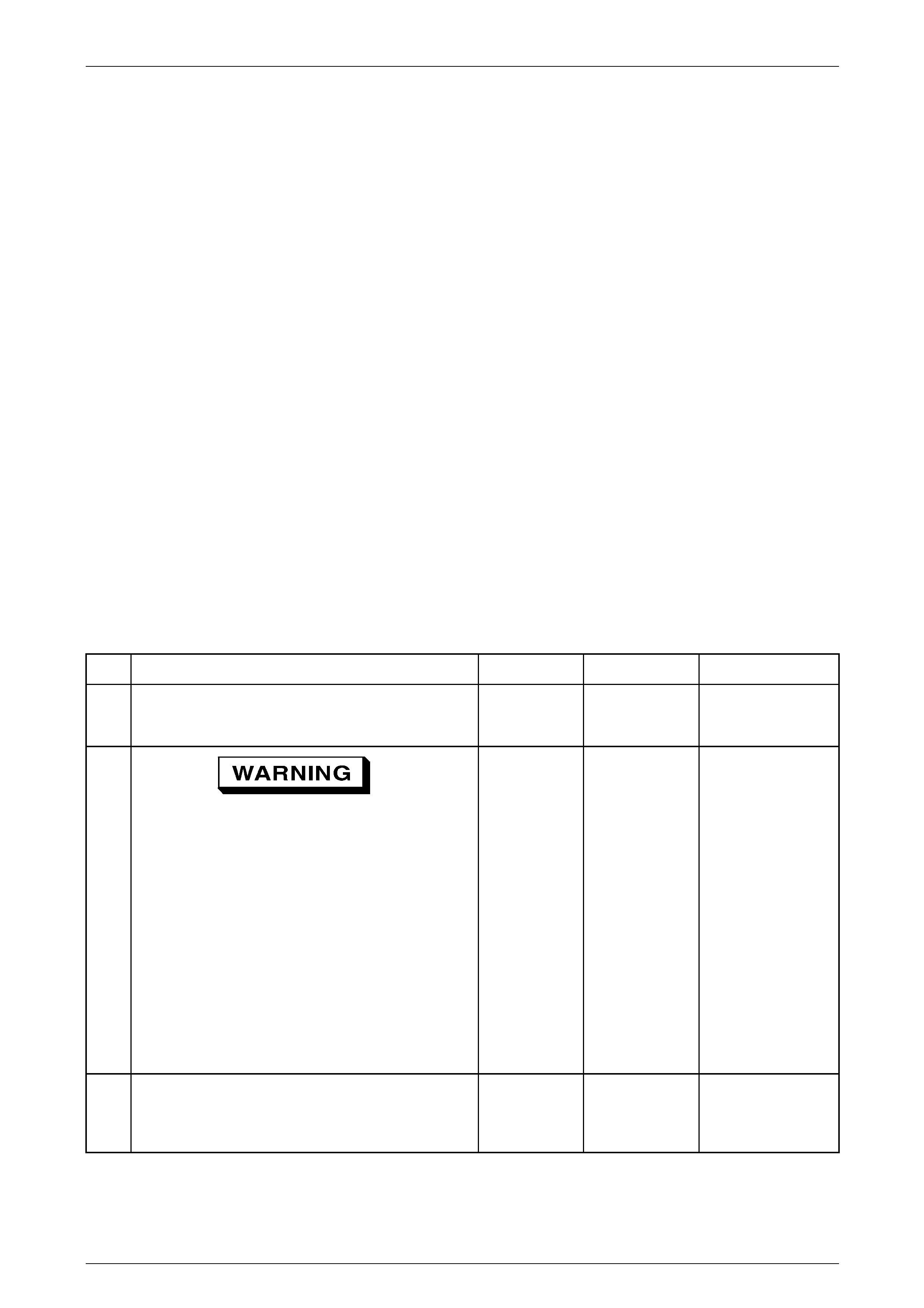
Engine Management – V6 – Diagnostics Page 6C1-2–219
Additional Information
• Refer to Section 6C1-1 Engine Management – V6 – General Information for details of the post catalyst oxygen
sensor operation.
• For an intermittent fault condition, refer to 4.2 Intermittent Fault Conditions in this Section.
• Since a fault condition in a wiring connector may trigger DTCs, always test the connectors related to this diagnostic
procedure for shorted terminals or poor wiring connection before replacing any component. Refer to Section 12P
Wiring Diagrams for information on electrical fault diagnosis.
• To assist diagnosis, refer to 2 Wiring Diagrams and Connector Charts in this Section for the system wiring diagram
and connector charts.
• The lower connector of the ECM is connector X1 and the upper connector of the ECM is connector X2. Refer to 2.2
Connector Chart in this Section for pin and circuit identification.
Test Description
The numbers below refer to the step numbers on the diagnostic table.
2 This step determines if a condition exists.
4 This step is testing for a rear HO2S sensor circuit condition. A circuit condition sets this DTC.
7 This step inspects for the rear sensors being connected to the correct bank of the engine. This condition causes
this DTC to set.
8 This step is testing for an intermittent circuit condition. Thoroughly inspect the HO2S circuits for an intermittent
circuit condition.
9 This step is testing for an intermittent circuit condition. Thoroughly inspect the HO2S circuits for an intermittent
circuit condition.
DTC P2096 or P2098 Diagnostic Table
Step Action Value(s) Yes No
Refer to
3.4 Diagnostic
System Check
1 Has the Diagnostic System Check been completed? — Go to Step 2
2
Refer to 4.17 Road-testing, in 00
Warnings Cautions and Notes.
1 Switch off the ignition for 30 seconds.
NOTE
The rear heated oxygen sensors (HO2S)
must be in Closed Loop for this diagnostic
to run. A road load condition is necessary to
obtain Closed Loop.
2 Operate the vehicle within the conditions for
running the DTC.
3 Using Tech 2, select the DTC display function.
Does DTC P2097 or P2099 fail this ignition cycle?
—
Go to Step 3
Refer to A in this
DTC
dditional
Information
3 Is DTC P0041, P0137, P0138, P0140, P0157, P0158,
or P0160 also set?
—
Go to the
appropriate DTC
Table in this
Section Go to Step 4
Page 6C1-2–219

Engine Management – V6 – Diagnostics Page 6C1-2–220
4
1 Operate the engine above 1,200 rpm for
30 seconds.
2 Use Tech 2 to observe appropriate rear heated
oxygen sensor (HO2S) voltage.
Is the voltage less than the specified value?
1,050 mV
Go to Step 7 Go to Step 5
5
1 Ignition OFF.
2 Disconnect the appropriate HO2S.
3 Ignition ON, engine OFF.
4 Use Tech 2 to observe the oxygen sensor
(HO2S) voltage parameter.
350 – 550 mV
Is the voltage within the specified range? Go to Step 12 Go to Step 6
1 Test the appropriate HO2S signal circuit for a
short to voltage. Refer to Section 12P Wiring
Diagrams. —
6
Did you find and correct the condition? Go to Step 19 Go to Step 14
1 Inspect the rear HO2S for being connected to the
correct bank of the engine. If the sensors are
connected to the incorrect bank, swap the
connectors as necessary. —
7
Did you find and correct the condition? Go to Step 19 Go to Step 8
1 Shake the related HO2S harnesses for the front
sensor between the HO2S harness connector
and the engine control module (ECM) while
monitoring the appropriate HO2S lambda
parameter. —
8
Does the HO2S parameter change abruptly while
moving the related harnesses? Go to Step 15 Go to Step 9
1 Shake the related HO2S harnesses for the rear
sensor between the HO2S harness connector
and the ECM while monitoring the appropriate
HO2S voltage parameter.
9
Does the HO2S parameter change abruptly while
moving the related harnesses?
—
Go to Step 15 Go to Step 10
10
1 Ignition OFF.
2 Disconnect the front and rear HO2S.
3 Inspect the front and rear HO2S for the following
conditions:
− Damaged wiring between the HO2S and the
ECM. An intermittent circuit condition
causes this DTC to set.
− Terminal corrosion or water intrusion in the
HO2S harness connectors.
− The correct terminal tension.
− The HO2S is securely installed.
− Any exhaust leaks. Refer to Section 8B
Exhaust System.
4 Repair as necessary. Refer to Section 12P Wiring
Diagrams.
Did you find and correct the condition?
—
Go to Step 19 Go to Step 11
Page 6C1-2–220

Engine Management – V6 – Diagnostics Page 6C1-2–221
11
1 Disconnect the ECM.
2 Test the appropriate front HO2S circuits for being
shorted together between the HO2S connector
and the ECM. Refer to Section 12P Wiring
Diagrams.
Did you find and correct the condition?
—
Go to Step 19 Go to Step 13
12
1 Test for shorted terminals and for poor
connections at the ECM. Refer to Section 12P
Wiring Diagrams.
Did you find and correct the condition?
—
Go to Step 19 Go to Step 17
13
1 Test for shorted terminals and for poor
connections at the ECM. Refer to Section 12P
Wiring Diagrams.
Did you find and correct the condition?
—
Go to Step 19 Go to Step 16
14
1 Test for shorted terminals and for poor
connections at the ECM. Refer to Section 12P
Wiring Diagrams.
Did you find and correct the condition?
—
Go to Step 19 Go to Step 18
15 1 Repair the circuit as necessary. Refer to
Section 12P Wiring Diagrams.
Did you complete the repair? — Go to Step 19 —
16
1 Replace the appropriate HO2S. Refer to the
Oxygen Sensor 1 procedure, in Section 6C1-3
Service Operations. —
Go to Step 19
Did you complete the replacement? —
1 Replace the appropriate HO2S. Refer to the
Oxygen Sensor 2 procedure, in Section 6C1-3
Service Operations.
Did you complete the replacement?
—
17
Go to Step 19 —
18
1 Replace the ECM. Refer to Engine Control
Module (ECM) Remove, Reinstall and ECM
Reset in Section 6C1-3 Service Operations.
Did you complete the replacement?
—
Go to Step 19 —
19
1 Using Tech 2, clear the DTCs.
2 Switch off the ignition for 30 seconds.
3 Start the engine.
4 Operate the vehicle within the conditions for
running the DTC.
Does DTC P2097 or P2099 fail this ignition cycle?
—
Go to Step 2 Go to Step 20
20 Using Tech 2, select the DTC display function.
Does Tech 2 display any DTCs?
—
Go to the
appropriate DTC
Table in this
Section System OK
When all diagnosis and repairs are completed, clear all DTCs and verify correct operation
Page 6C1-2–221

Engine Management – V6 – Diagnostics Page 6C1-2–222
6.52 DTC P2105
DTC Descriptor
This diagnostic procedure supports DTC P2105 – Throttle Control Forced Engine Shutdown.
Circuit Description
The ECM monitors and evaluates the accelerator pedal position (APP) sensors signal voltage along with other sensor
inputs to determine the desired throttle opening. To control the throttle plate movement, the ECM applies a pulse width
modulated (PWM) signal voltage to the throttle actuator motor through the throttle actuator motor control circuits.
• At engine idle speed or when no current is flowing into the throttle actuator control (TAC) motor, a constant force
return spring holds the throttle plate at a constant seven percent throttle opening position.
• To control the throttle opening, the ECM applies PWM voltage to the TAC motor. The ECM increases this PWM
voltage duty cycle to increase the throttle opening.
To decrease the throttle opening from the seven percent rest position, the ECM reverses the polarity of the TAC motor
control circuit then applies a PWM voltage to the TAC motor.
The ECM monitors the ignition supply voltage to ensure the correct operation of the engine management components
and sensors. DTC P2105 sets if the ECM detects an incorrect ignition voltage.
Conditions for Running the DTC
DTC P2105 runs continuously when the ECM completed the power-down process in the last ignition cycle.
Conditions for Setting the DTC
The ECM detects an incorrect voltage level at the ignition supply circuits.
Conditions for Clearing the DTC
DTC P2105 – Throttle Actuator Control (TAC) Module Internal Circuit is a Type A DTC. Refer to 1.4 Diagnostic Trouble
Codes in this Section for action taken when a Type A DTC sets and conditions for clearing Type A DTC.
Additional Information
• Refer to Section 6C1-1 Engine Management – V6 – General Information for details of the TP actuator operation.
• Since fault condition in a wiring connector may trigger DTCs, always test the connectors related to this diagnostic
procedure for shorted terminals or poor wiring connection before replacing any component. Refer to Section 12P
Wiring Diagrams for information on electrical fault diagnosis.
• For an intermittent fault condition, refer to 4.2 Intermittent Fault Conditions in this Section.
• To assist diagnosis, refer to 2 Wiring Diagrams and Connector Charts in this Section for the system wiring diagram
and connector charts.
DTC P2105 Diagnostic Table
Step Action Yes No
Has the Diagnostic System Check been performed? Refer to
3.4 Diagnostic
System Check
1
Go to Step 2
1 Switch off the ignition for 30 seconds.
2
2 Operate the vehicle within the conditions for running the DTC.
3 Using Tech 2, select the DTC display function.
Go to Step 3
Does DTC P2105 fail this ignition cycle?
Refer to Additional
Information in this
DTC
Page 6C1-2–222

Engine Management – V6 – Diagnostics Page 6C1-2–223
Step Action Yes No
1 Remove the ECM / TCM Fuse 32 from the engine compartment
relay panel assembly.
NOTE
Voltage may be available at both terminals of Fuse 32
because of normal voltage feed back condition. Therefore,
the fuse must be removed prior to testing.
2 Inspect the ECM / TCM Fuse 32 for an open circuit fault
condition.
3
Was any fault found and rectified? Go to Step 7 Go to Step 4
4 1 Remove the engine control relay from the engine compartment
relay panel assembly.
2 Test the ignition circuit of the ECM, from the fuse terminal to the
Engine control relay for a high resistance, open circuit, short to
ground or short to voltage fault condition. Refer to Section 12P
Wiring Diagrams for information on electrical fault diagnosis.
NOTE
The engine control relay supplies ignition voltage to other
components and sensors through the ECM ignition circuit.
A fault condition in this ignition circuit may trigger DTCs on
components or sensors connected to this circuit.
Was any fault found and rectified? Go to Step 7 Go to Step 5
5 Disconnect the vehicle side wiring connector of the ECM. Refer to
Section 6C1-3 Engine Management – V6 – Service Operations.
Test both ignition circuits of the ECM, from the fuse terminal to the
ECM wiring connector for a high resistance, open circuit, short to
ground or short to voltage fault condition. Refer to Section 12P Wiring
Diagrams for information on electrical fault diagnosis.
Was any fault found and rectified? Go to Step 7 Go to Step 6
6 Replace the ECM. Refer to Section 6C1-3 Engine Management – V6 –
Service Operations.
Was the repair completed? Go to Step 7 —
7 1 Using T ech 2, clear the DTCs.
2 Switch off the ignition for 30 seconds.
3 Start the engine.
4 Operate the vehicle within the conditions for running the DTC.
Does DTC P2105 fail this ignition cycle? Go to Step 2 Go to Step 8
8 Using T ech 2, select the DTC display function.
Does Tech 2 display any DTCs?
Go to the
appropriate DTC
Table in this Section System OK
When all diagnosis and repairs are completed, check the system for correct operation.
Page 6C1-2–223

Engine Management – V6 – Diagnostics Page 6C1-2–224
6.53 DTC P2107
DTC Descriptor
This diagnostic procedure supports DTC P2107 – Throttle Control Malfunction.
Circuit Description
The ECM applies 5 V to the throttle position (TP) sensor 1 through the 5 V reference circuit 2701 and the ground through
the low reference circuit 2752. TP sensor 1 and TP sensor 2 share a common 5 V reference circuit and a common low
reference circuit.
The TP sensor 1 and TP sensor 2 have individual signal circuits with opposite functionality. These signal circuits provide
the ECM with a signal voltage that is proportional to the throttle plate movement.
• The TP sensor 1 signal voltage is less than 1 V when the throttle plate is in closed position, which increases to
greater than 4 V when the throttle plate is moved to wide-open throttle.
• The TP sensor 2 signal voltage is greater than 4 V when the throttle plate is in closed position, which decreases to
less than 1 V when the throttle plate is moved to wide-open throttle.
The ECM monitors and evaluates the accelerator pedal position (APP) sensors signal voltage along with other sensor
inputs to determine the desired throttle opening. To control the throttle plate movement, the ECM applies a pulse width
modulated (PWM) signal voltage to the throttle actuator motor through the throttle actuator motor control circuits.
• At engine idle speed or when no current is flowing into the throttle actuator control (TAC) motor, a constant force
return spring holds the throttle plate at a constant seven percent throttle opening position.
• To control the throttle opening, the ECM applies PWM voltage to the TAC motor. The ECM increases this PWM
voltage duty cycle to increase the throttle opening.
To decrease the throttle opening from the seven percent rest position, the ECM reverses the polarity of the TAC motor
control circuit then applies a PWM voltage to the TAC motor.
If the ECM detects the TP sensor 1 amplification output does not correlate with the TP sensor 1 signal voltage during a
predetermined sets of conditions, DTC P2107 sets.
Conditions for Running the DTC
DTC P2107 runs continuously once the following conditions are met:
• The vehicle speed is 0 km/h.
• The engine speed is less than 40 rpm
• The engine coolant temperature is 5 – 60° C.
• The intake air temperature is 5 – 60° C.
• The ignition voltage is greater than 10 V.
• The APP is less than 15 percent.
• The ECM is performing the closed throttle test with the ignition switched on and the engine not running.
Conditions for Setting the DTC
The ECM detects that its internal TP sensor 1 amplification output does not correlate with the TP sensor 1 signal voltage.
Conditions for Clearing the DTC
DTC P2107 – Throttle Actuator Control Module Internal Circuit is a T ype ‘C’ DTC. Refer to 1.4 Diagnostic Tr ouble Codes
in this Section for action taken when a Type ‘C’ DTC sets and conditions for clearing Type ‘C’ DTC.
Additional Information
• Refer to Section 6C1-1 Engine Management – V6 – General Information for details of the TP sensor operation.
• For an intermittent fault condition, refer to 4.2 Intermittent Fault Conditions in this Section.
• Since fault condition in a wiring connector may trigger DTCs, always test the connectors related to this diagnostic
procedure for shorted terminals or poor wiring connection before replacing any component. Refer to Section 12P
Wiring Diagrams for information on electrical fault diagnosis.
• To assist diagnosis, refer to 2 Wiring Diagrams and Connector Charts in this Section for the system wiring diagram
and connector charts.
Page 6C1-2–224

Engine Management – V6 – Diagnostics Page 6C1-2–225
DTC P2107 Diagnostic Table
Step Action Yes No
1 Has the Diagnostic System Check been performed?
Go to Step 2
Refer to
3.4 Diagnostic
System Check
2 1 Switch off the ignition for 30 seconds.
2 Operate the vehicle within the conditions for running the DTC.
3 Using Tech 2, select the DTC display function.
Does DTC P2107 fail this ignition cycle? Go to Step 3
Refer to Additional
Information in this
DTC
3 Replace the ECM. Refer to Section 6C1-3 Engine Management – V6 –
Service Operations.
Was the repair completed? Go to Step 4 —
4 1 Using T ech 2, clear the DTCs.
2 Switch off the ignition for 30 seconds.
3 Start the engine.
4 Operate the vehicle within the conditions for running the DTC.
Go to Step 2 Go to Step 5
Does DTC P2107 fail this ignition cycle?
Using Tech 2, select the DTC display function. Go to the
appropriate DTC
Table in this Section
5
Does Tech 2 display any DTCs? System OK
When all diagnosis and repairs are completed, check the system for correct operation.
Page 6C1-2–225

Engine Management – V6 – Diagnostics Page 6C1-2–226
6.54 DTC P2122, P2123, P2127, P2128 or
P2138
DTC Descriptors
This diagnostic procedure supports the following DTCs:
• DTC P2122 – Accelerator Pedal Position Sensor 1 Voltage Low
• DTC P2123 – Accelerator Pedal Position Sensor 1 Voltage High
• DTC P2127 – Accelerator Pedal Position Sensor 2 Voltage Low
• DTC P2128 – Accelerator Pedal Position Sensor 2 Voltage High
• DTC P2138 – Accelerator Pedal Position Sensor 1 – 2 Correlation
Circuit Description
The ECM applies a separate 5 V reference circuit and low reference circuit to the accelerator pedal position (APP) sensor
1 and sensor 2. The APP sensors produce a signal voltage that represents the accelerator pedal position.
• The APP sensor 1 signal voltage increases from 1 V at rest position to greater than 4 V when the accelerator pedal
is fully depressed.
• The APP sensor 2 signal voltage increases from 0.5 V at rest position to greater than 2 V when the accelerator
pedal is fully depressed.
The ECM monitors and evaluates the APP sensors signal voltage along with other sensor inputs to determine the desired
throttle opening. An APP sensor circuit DTC sets if the signal voltage of the APP sensor is outside the predetermined
range.
Conditions for Running the DTC
DTC P2122, P2123, P2127, P2128 and P2138 runs continuously once the following conditions are met:
• The ignition is switched on.
• The ignition voltage is greater than 7 V.
Conditions for Setting the DTC
DTC P2122
The ECM determines the APP sensor 1 signal voltage is less than 0.84 V.
DTC P2123
The ECM determines the APP sensor 1 signal voltage is greater than 4.82 V.
DTC P2127
The ECM determines the APP sensor 2 signal voltage is less than 0.66 V.
DTC P2128
The ECM determines the APP sensor 2 signal voltage is greater than 4.82 V.
DTC P2138
The ECM detects the difference between the APP sensor 1 and sensor 2 signal voltage is greater than the
predetermined value.
Conditions for Clearing DTC
The APP sensor circuit DTCs are Type ‘A’ DTCs. Refer to 1.4 Diagnostic Trouble Codes in this Section for action taken
when a Type ‘A’ DTC sets and conditions for clearing Type ‘A’ DTCs.
Page 6C1-2–226

Engine Management – V6 – Diagnostics Page 6C1-2–227
Additional Information
• Refer to Section 6C1-1 Engine Management – V6 – General Information for details of the APP sensor operation.
• For an intermittent fault condition, refer to 4.2 Intermittent Fault Conditions in this Section.
• Since fault condition in a wiring connector may trigger DTCs, always test the connectors related to this diagnostic
procedure for shorted terminals or poor wiring connection before replacing any component. Refer to Section 12P
Wiring Diagrams for information on electrical fault diagnosis.
• To assist diagnosis, refer to 2 Wiring Diagrams and Connector Charts in this Section for the system wiring diagram
and connector charts.
Test Description
The following numbers refer to the step numbers in the diagnostic table:
2 Tests the APP sensor internal circuits throughout its range of motion. If the DTC fails while performing this test,
there is an internal fault condition in the APP sensor internal circuitry.
5 Measures the integrity of the TP sensor low reference circuit. Removal of the ECM Fuse 29 enables the ECM to
power down completely prior to the test procedure.
DTC P2122, P2123, P2127, P2128 or P2138 Diagnostic Table
Step Action Yes No
Has the Diagnostic System Check been performed? Refer to
3.4 Diagnostic
System Check
1
Go to Step 2
1 Switch off the ignition for 30 seconds.
2
2 Start the engine.
3 Quickly depress the accelerator pedal to wide-open throttle then
release pedal. Repeat this procedure several times or operate
the vehicle within the conditions for running the DTC.
4 Using Tech 2, select the DTC display function. Refer to Additional
Information in this
DTC
Does DTC P2122, P2123, P2127, P2128 or P2138 fail this ignition
cycle? Go to Step 3
1 Disconnect the APP sensor wiring connector.
3
2 Switch on the ignition with the engine not running.
3 Using a digital multimeter, measure the voltage between the 5 V
reference circuit of the appropriate APP sensor and the ECM
housing.
Go to Step 4 Go to Step 6
Does the multimeter display 4.8 – 5.2 V?
1 Connect a 3 A fused jumper wire between the 5 V reference
circuit and the signal circuit of the appropriate APP sensor.
4
2 Switch on the ignition with the engine not running.
3 Using Tech 2, observe the voltage parameter appropriate APP
sensor.
Does Tech 2 display 4.8 – 5.2 V? Go to Step 5 Go to Step 7
Page 6C1-2–227

Engine Management – V6 – Diagnostics Page 6C1-2–228
Step Action Yes No
5 1 Switch off the ignition.
2 Remove ECM / TCM Fuse 29 from the engine compartment fuse
and relay panel assembly.
3 Using a DMM, measure the resistance between the appropriate
TP sensor low reference circuit and the ECM housing.
NOTE
Install the ECM Fuse 29 to the engine compartment fuse
and relay panel assembly after completing this test.
Does the multimeter display 5 Ω? Go to Step 9 Go to Step 8
6 T est the 5 V reference circuit of the appropriate APP sensor for a high
resistance, open circuit, short to ground or short to voltage fault
condition. Refer to Section 12P Wiring Diagrams for information on
electrical fault diagnosis.
Was any fault found and rectified? Go to Step 11 Go to Step 10
7 T est the signal circuit of the appropriate APP sensor for a high
resistance, open circuit, short to ground or short to voltage fault
condition. Refer to Section 12P Wiring Diagrams for information on
electrical fault diagnosis.
Was any fault found and rectified? Go to Step 11 Go to Step 10
8 T est the low reference circuit of the appropriate APP sensor for a high
resistance or an open circuit fault condition. Refer to Section 12P
Wiring Diagrams for information on electrical fault diagnosis.
Go to Step 11 Go to Step 10
Was any fault found and rectified?
Replace the accelerator pedal assembly. Refer to Section 6C1-3
Engine Management – V6 – Service Operations.
Was the repair completed? Go to Step 11
9
—
10 Replace the ECM. Refer to Section 6C1-3 Engine Management – V6 –
Service Operations.
Was the repair completed? Go to Step 11 —
11 1 Using Tech 2, clear the DTCs.
2 Switch off the ignition for 30 seconds.
3 Start the engine.
4 Operate the vehicle within the conditions for running the DTC.
Does any of the APP Sensor Circuit DTCs fail this ignition cycle? Go to Step 2 Go to Step 12
12 Using Tech 2, select the DTC display function.
Does Tech 2 display any DTCs?
Go to the
appropriate DTC
Table in this Section System OK
When all diagnosis and repairs are completed, check the system for correct operation.
Page 6C1-2–228

Engine Management – V6 – Diagnostics Page 6C1-2–229
6.55 DTC P2177 or P2179
•
•
•
•
•
DTC Descriptors
This diagnostic procedure supports the following DTCs:
• DTC P2177 Fuel Trim System Lean at Cruise or Accel Bank 1
DTC P2179 Fuel Trim System Lean at Cruise or Accel Bank 2
Circuit Description
The engine control module (ECM) controls the air / fuel metering system to provide the best possible combination of
driveability, fuel economy, and emission control. Fuel delivery is controlled differently during Open and Closed Loop.
During Open Loop, the ECM determines fuel delivery based on sensor signals without heated oxygen sensor (HO2S)
input. During Closed Loop, the HO2S inputs are added and used by the ECM to calculate short and long term fuel trim
fuel delivery adjustments. If the HO2S indicates a lean condition, fuel trim values will be above 0 percent. If the HO2S
indicates a rich condition, fuel trim values will be below 0 percent. Short term fuel trim values change rapidly in response
to the HO2S signals. Long term fuel trim makes coarse adjustments to maintain an air / fuel ratio of 14.7:1. If the ECM
detects an excessively lean condition, this DTC sets.
Conditions for Running the DTC
• Before the ECM can report DTC P2177 or P2179 failed, DTCs P0101, P0121, P0122, P0123, P0133, P0153,
P0221, P0222, P0223, P0336, P0338, P0443, P0458, P0459, P0461, P0462, P0463, P2066, P2067, and P2068
must run and pass.
• The fuel system is in closed loop.
• The long fuel trim is active.
• The engine coolant temperature (ECT) is more than 60° C.
• The evaporative emission (EVAP) canister purge solenoid valve is not enabled.
• The intake air temperature (IAT) is less than 60° C.
• The fuel level is more than 11.6 percent.
• The amount of air flow into the engine is more than 7,000 grams.
DTC P2177 and P2179 runs continuously once the above conditions are met for at least 300 seconds.
Conditions for Setting the DTC
• The Total Fuel Trim Avg. is more than 23 percent.
The condition exists for 4 seconds.
Action Taken When the DTC Sets
• The control module illuminates the Check Powertrain icon, or the malfunction indicator lamp (MIL) on the second
consecutive ignition cycle that the diagnostic runs and fails.
The control module records the operating conditions at the time the diagnostic fails. The first time the diagnostic
fails, the control module stores this information in the Failure Records. If the diagnostic reports a failure on the
second consecutive ignition cycle, the control module records the operating conditions at the time of the failure. The
control module writes the operating conditions to the Freeze Frame and updates the Failure Records.
Conditions for Clearing the MIL/DTC
• The control module turns OFF the Check Powertrain icon, or the malfunction indicator lamp (MIL) after
four consecutive ignition cycles that the diagnostic runs and does not fail.
• A current DTC, Last Test Failed, clears when the diagnostic runs and passes.
• A history DTC clears after 40 consecutive warm-up cycles, if no failures are reported by this or any other emission
related diagnostic.
Use Tech 2 to clear the MIL and the DTC.
Page 6C1-2–229

Engine Management – V6 – Diagnostics Page 6C1-2–230
Additional Information
• A fuel system delivery condition causes this DTC to set. Thoroughly inspect all items that cause a lean condition.
• Any un-metered air into the engine causes this DTC to set. Thoroughly inspect all areas of the engine for vacuum
leaks.
• For an intermittent fault condition, refer to 4.2 Intermittent Fault Conditions in this Section.
•
4 If DTC P2177 and P2179 are set at the same time, this indicates that both banks of the engine are operating lean.
Inspect for items that would cause both banks of the engine to operate lean.
No
To assist diagnosis, refer to 2 Wiring Diagrams and Connector Charts in this Section for the system wiring diagram
and connector charts.
Test Description
The numbers below refer to the step numbers on the diagnostic table.
2 This step determines if there is a current condition.
5 Disconnecting the mass air flow (MAF) sensor determines if the MAF sensor signal is skewed. If the Short Term FT
parameter changes more than the specified value, there is a condition with the MAF sensor. A MAF sensor
condition can cause this DTC without setting a MAF DTC. If there is a MAF sensor condition, the MAF sensor
parameters will appear to be within range.
6 A vacuum leak causes DTC P2177 and P2179 to set at the same time. Inspect all areas of the engine for a vacuum
leak. Also inspect the PCV valve for being the correct one for this application. Make sure that the engine oil fill cap
is in place and that it is tight. Verify that the engine oil dip stick is fully seated.
DTC P2177 or P2179 Diagnostic Table
Step Action Value(s) Yes
Refer to
3.4 Diagnostic
System Check
—
1 Has the Diagnostic System Check been completed? Go to Step 2
NOTE
If any DTCs are set, except P2177 or
P2179, refer to those DTCs before
proceeding with this diagnostic.
1 Idle the engine at the normal operating
temperature. 23%
2 2 Check that the fuel system is operating in Closed
Loop.
3 Observe the Total Fuel Trim Avg. parameter for
Bank 1 or bank 2 with a scan tool.
Is the Total Fuel Trim Avg. less than the specified value
indicated? Go to Step 3 Go to Step 4
1 Use Tech 2 to clear the DTC/s.
2 Ignition OFF for 30 seconds.
3 Start the engine. —
3 4 Operate the vehicle within the Conditions for
Running the DTC. Refer to Additional
Information in this
DTC
Does the DTC fail this ignition cycle? Go to Step 4
—
4 Are both banks of the engine operating lean? Go to Step 5 Go to Step 7
Page 6C1-2–230

Engine Management – V6 – Diagnostics Page 6C1-2–231
1 Start the engine.
NOTE
Additional DTCs will set when the MAF
sensor disconnected.
2 Disconnect the mass air flow (MAF) sensor
harness connector while the engine is operating. 20%
5 3 Observe the Short Term FT parameter for Bank 1
and bank 2, using Tech 2.
4 Reconnect the MAF sensor after completing this
step.
Does the Short Term FT parameter for both banks of
the engine change more than the specified value with
the MAF sensor disconnected?
Go to
6.8 DTC P0101,
P0102 or P0103 Go to Step 6
1 Inspect for the following conditions:
− The vacuum hoses for splits, kinks, and
proper connections.
− The throttle body and the intake manifold
for vacuum leaks.
− The crankcase ventilation valve and system
for leaks.
− The air intake system after the MAF sensor
for vacuum leaks.
− Contaminated fuel. Refer to 5.5 Alcohol /
Contaminants in Fuel Diagnosis in this
Section.
− Lean injectors. Refer to 5.2 Fuel Injector
Coil Test in this Section.
6
− The engine control ground points for being
clean, tight, and in the correct locations.
− A high engine oil level condition. A high
engine oil level causes oil residue to form
on the mass air flow (MAF) sensor, causing
a lean indication. The MAF sensor does not
need to be replaced.
− An engine mechanical condition.
Did you find and correct the condition?
—
Go to Step 8
Refer to Additional
Information and Test
Description in this
DTC
7
1 Inspect for the following conditions:
− Vacuum leaks that only affect one bank of
the engine – For example, the intake
manifold, the injector O-rings.
− Lean injectors – refer to 5.2 Fuel Injector
Coil Test in this Section.
− Exhaust leaks, missing or loose exhaust
hardware. Refer to Section 8B Exhaust
System.
− The heated oxygen sensors (HO2S) are
installed securely and the electrical
connectors are not contacting the exhaust
system.
− An engine mechanical condition.
Did you find and correct the condition?
—
Go to Step 8
Refer to Additional
Information in this
DTC
Page 6C1-2–231

Engine Management – V6 – Diagnostics Page 6C1-2–232
8
Using Tech 2, clear the DTCs.
2 Switch off the ignition for 30 seconds.
3 Start the engine.
4 Operate the vehicle within the conditions for
running the DTC.
Did DTC P2177 or P2179 fail this ignition cycle?
—
Go to Step 2 Go to Step 9
9 1 Using Tech 2, select the DTC display function.
Does Tech 2 display any DTCs? — Go to the
appropriate DTC
Table in this Section System OK
When all diagnosis and repairs are completed, clear all DTCs and verify correct operation
Page 6C1-2–232

Engine Management – V6 – Diagnostics Page 6C1-2–233
6.56 DTC P2178 or P2180
DTC Descriptors
This diagnostic procedure supports the following DTCs:
• DTC P2178 Fuel Trim System Rich at Cruise or Accel Bank 1
• DTC P2180 Fuel Trim System Rich at Cruise or Accel Bank 2
Circuit Description
The engine control module (ECM) controls the air / fuel metering system to provide the best possible combination of
driveability, fuel economy, and emission control. Fuel delivery is controlled differently during Open and Closed Loop.
During Open Loop, the ECM determines fuel delivery based on sensor signals without heated oxygen sensor (HO2S)
input. During Closed Loop, the HO2S inputs are added and used by the ECM to calculate short and long term fuel trim
fuel delivery adjustments. If the HO2S indicates a lean condition, fuel trim values will be above 0 percent. If the HO2S
indicates a rich condition, fuel trim values will be below 0 percent. Short term fuel trim values change rapidly in response
to the HO2S signals. Long term fuel trim makes coarse adjustments to maintain an air / fuel ratio of 14.7:1. If the ECM
detects an excessively rich condition, this DTC sets.
Conditions for Running the DTC
• Before the ECM can report DTC P2178 or P2180 failed, DTCs P0101, P0121, P0122, P0123, P0133, P0153,
P0221, P0222, P0223, P0336, P0338, P0443, P0458, P0459, P0461, P0462, P0463, P2066, P2067, and P2068
must run and pass.
• The fuel system is in closed loop.
• The long fuel trim is active.
• The control module records the operating conditions at the time the diagnostic fails. The first time the diagnostic
fails, the control module stores this information in the Failure Records. If the diagnostic reports a failure on the
second consecutive ignition cycle, the control module records the operating conditions at the time of the failure. The
control module writes the operating conditions to the Freeze Frame and updates the Failure Records.
• The engine coolant temperature (ECT) is more than 60° C.
• The evaporative emission (EVAP) canister purge solenoid valve is not enabled.
• The intake air temperature (IAT) is less than 60° C.
• The fuel level is more than 11.6 percent.
• The amount of air flow into the engine is more than 7,000 grams.
• DTC P2178 and P2180 run continuously once the above conditions are met for at least 300 seconds.
Conditions for Setting the DTC
• The Total Fuel Trim Avg. is less than –22 percent.
• The condition exists for 4 seconds.
Action Taken When the DTC Sets
• The control module illuminates the Check Powertrain icon, or the malfunction indicator lamp (MIL) on the second
consecutive ignition cycle that the diagnostic runs and fails.
Conditions for Clearing the MIL/DTC
• The Fuel Trim System circuit DTCs are Type ‘B’ DTCs. Refer to 1.4 Diagnostic Trouble Codes in this Section for
action taken when a Type ‘B’ DTC sets and conditions for clearing Type ‘B’ DTCs.
• Use Tech 2 to clear the Check Powertrain icon, or the MIL and the DTC.
Page 6C1-2–233

Engine Management – V6 – Diagnostics Page 6C1-2–234
Additional Information
• A fuel delivery condition causes this DTC to set. Thoroughly inspect all items that could cause a rich condition.
• For an intermittent fault condition, refer to 4.2 Intermittent Fault Conditions in this Section.
• Since fault condition in a wiring connector may trigger DTCs, always test the connectors related to this diagnostic
procedure for shorted terminals or poor wiring connection before replacing any component. Refer to Section 12P
Wiring Diagrams for information on electrical fault diagnosis.
• To assist diagnosis, refer to 2 Wiring Diagrams and Connector Charts in this Section for the system wiring diagram
and connector charts.
Test Description
The numbers below refer to the step numbers on the diagnostic table.
2 This step determines whether the fault is present.
4 If DTC P2178 and DTC P2180 set at the same time, then both banks of the engine are operating rich. Inspect items
that would cause both banks of the engine to operate rich.
5 Disconnecting the mass air flow (MAF) sensor determines if the MAF sensor signal is skewed. If the Short Term FT
parameter changes more than the specified value, there is a condition with the MAF sensor. A MAF sensor
condition can cause this DTC without setting a MAF DTC. If there is a MAF sensor condition, the MAF sensor
parameters will appear to be within range.
DTC P2178 or P2180 Diagnostic Table
Step Action Value(s) Yes No
Refer to
3.4 Diagnostic
System Check
—
1 Has the Diagnostic System Check been completed? Go to Step 2
NOTE
If any DTCs are set, except P2178 and
DTC P2180, refer to those DTCs before
proceeding with this diagnostic.
1 Idle the engine at the normal operating
temperature.
2
2 Check that the fuel system is in Closed Loop.
3 Observe the Total Fuel Trim Avg. parameter for
Bank 1 and / or bank 2 with Tech 2.
Is the Total Fuel Trim Avg. less than the specified
value?
–22%
Go to Step 3 Go to Step 4
3
1 Observe the Freeze Frame and / or the Failure
records data for this DTC.
2 Turn the ignition OFF for 30 seconds.
3 Start the engine.
4 Operate the vehicle within the Conditions for
Running the DTC. You may also operate the
vehicle within the conditions that you observed
from the Freeze Frame and / or the Failure
records data.
Does the DTC fail this ignition cycle?
—
Go to Step 4
Refer to Additional
Information in this
DTC
4 Are both banks of the engine operating rich? — Go to Step 5 Go to Step 7
Page 6C1-2–234

Engine Management – V6 – Diagnostics Page 6C1-2–235
5
1 Start the engine.
NOTE
Additional DTCs will set when the MAF
sensor is disconnected.
2 Disconnect the mass air flow (MAF) sensor
harness connector while the engine is operating.
3 Observe the Short Term FT parameter for Bank 1
and bank 2 with Tech 2.
4 Reconnect the MAF sensor after completing this
step.
Does the Short Term FT parameter for both banks of
the engine change more than the specified value with
the MAF sensor disconnected?
20%
Go to 6.8 DTC
P0101, P0102 or
P0103 Go to Step 6
6
1 Inspect for the following conditions:
− A collapsed air intake duct
− A restricted air filter element
− The MAF sensor for foreign objects
− Excessive fuel in the crankcase – Change
the oil as necessary.
− Contaminated fuel. Refer to 5.5 Alcohol /
Contaminants in Fuel Diagnosis in this
Section.
− The ECM grounds for being clean, tight,
and in the correct locations
− An engine mechanical condition – refer to
Section 6A1 – Engine Mechanical V6.
Did you find and correct the condition?
—
Go to Step 8
Go to Additional
Information in this
DTC
7
1 Inspect for the following conditions:
− Rich injectors – refer to 5.2 Fuel Injector
Coil Test in this Section.
− Restricted exhaust system – refer to
Section 8B Exhaust System
− An engine mechanical condition – refer to
Section 6A1 – Engine Mechanical V6.
Did you find and correct the condition?
—
Go to Step 8
Go to Additional
Information in this
DTC
8
1 Switch off the ignition for 30 seconds.
2 Using Tech 2, clear the DTCs and reset the fuel
trim system.
3 Operate the vehicle within the Conditions for
Running the DTC. You may also operate the
vehicle within the conditions that you observed
from the Freeze Frame / Failure Records.
Did DTC P2178 and / or P2180 fail this ignition cycle?
—
Go to Step 2 Go to Step 9
9 1 Using Tech 2, select the DTC display function.
Does Tech 2 display any DTCs? — Go to the
appropriate DTC
Table in this Section System OK
Page 6C1-2–235

Engine Management – V6 – Diagnostics Page 6C1-2–236
6.57 DTC P2187 or P2189
DTC Descriptors
This diagnostic procedure supports the following DTCs:
• DTC P2187 Fuel Trim System Lean at Idle Bank 1
• DTC P2189 Fuel Trim System Lean at Idle Bank 2
Circuit Description
The engine control module (ECM) controls the air / fuel metering system to provide the best possible combination of
driveability, fuel economy, and emission control. Fuel delivery is controlled differently during Open and Closed Loop.
During Open Loop, the ECM determines fuel delivery based on sensor signals without heated oxygen sensor (HO2S)
input. During Closed Loop, the HO2S inputs are added and used by the ECM to calculate short and long term fuel trim
fuel delivery adjustments. If the HO2S indicate a lean condition, fuel trim values will be above 0 percent. If the O2S
indicate a rich condition, fuel trim values will be below 0 percent. Short term fuel trim values change rapidly in response to
the HO2S signals. Long term fuel trim makes coarse adjustments to maintain an air / fuel ratio of 14.7:1. If the ECM
detects an excessively lean condition, this DTC sets.
Conditions for Running the DTC
• Before the ECM can report DTC P2187 or P2189 failed, DTCs P0101, P0121, P0122, P0123, P0133, P0153,
P0221, P0222, P0223, P0336, P0338, P0443, P0458, P0459, P0461, P0462, P0463, P2066, P2067, and P2068
must run and pass.
• The fuel system is in closed loop.
• The long fuel trim is active.
• The engine coolant temperature (ECT) is more than 60° C.
• The evaporative emission (EVAP) canister purge solenoid valve is not enabled.
• The intake air temperature (IAT) is less than 60° C.
• The fuel level is more than 11.6 percent.
• The amount of air flow into the engine is more than 7000 grams.
• DTC P2187 and P2189 runs continuously once the above conditions are met for at least 300 seconds.
Conditions for Setting the DTC
• The Total Fuel Trim Avg. is more than 40 percent.
• The LT FT Idle / Decel is more than seven percent.
• The condition exists for 4 seconds.
Action Taken When the DTC Sets
The control module illuminates the Check Powertrain icon, or the malfunction indicator lamp (MIL) on the second
consecutive ignition cycle that the diagnostic runs and fails.
The control module records the operating conditions at the time the diagnostic fails. The first time the diagnostic fails, the
control module stores this information in the Failure Records. If the diagnostic reports a failure on the second consecutive
ignition cycle, the control module records the operating conditions at the time of the failure. The control module writes the
operating conditions to the Freeze Frame and updates the Failure Records.
Conditions for Clearing the MIL/DTC
• The Fuel Trim System circuit DTCs are Type ‘B’ DTCs. Refer to 1.4 Diagnostic Trouble Codes in this Section for
action taken when a Type ‘B’ DTC sets and conditions for clearing Type ‘B’ DTCs.
• Use Tech 2 to clear the Check Powertrain icon, or the MIL and the DTC.
Page 6C1-2–236

Engine Management – V6 – Diagnostics Page 6C1-2–237
Additional Information
• A fuel delivery condition causes this DTC to set. Thoroughly inspect all items that could cause a rich condition.
• For an intermittent fault condition, refer to 4.2 Intermittent Fault Conditions in this Section.
• Since fault condition in a wiring connector may trigger DTCs, always test the connectors related to this diagnostic
procedure for shorted terminals or poor wiring connection before replacing any component. Refer to Section 12P
Wiring Diagrams for information on electrical fault diagnosis.
• To assist diagnosis, refer to 2 Wiring Diagrams and Connector Charts in this Section for the system wiring diagram
and connector charts.
Test Description
The numbers below refer to the step numbers on the diagnostic table.
2 This step determines if there is a current condition.
4 If DTC P2187 and P2189 are set at the same time, this indicates that both banks of the engine are operating lean.
Inspect for items that would cause both banks of the engine to operate lean.
5 Disconnecting the mass air flow (MAF) sensor determines if the MAF sensor signal is skewed. If the Short Term FT
parameter changes more than the specified value, there is a condition with the MAF sensor. A MAF sensor
condition can cause this DTC without setting a MAF DTC. If there is a MAF sensor condition, the MAF sensor
parameters will appear to be within range.
6 A vacuum leak causes DTC P2187 and P2189 to set at the same time. Inspect all areas of the engine for a vacuum
leak. Also inspect the positive crankcase ventilation (PCV) valve for being the correct one for this application. Make
sure that the engine oil fill cap is in place and that it is tight. Verify that the engine oil dip stick is fully seated.
DTC P2187 or P2189 Diagnostic Table
Step Action Value(s) Yes No
1 Has the Diagnostic System Check been completed? — Go to Step 2
Refer to
3.4 Diagnostic
System Check
2
NOTE
If any DTCs are set, except P2187 and
DTC P2189, refer to those DTCs before
proceeding with this diagnostic.
1 Idle the engine at the normal operating
temperature.
2 The fuel system is in Closed Loop.
3 Observe the Total Fuel Trim Avg. parameter for
Bank 1 and / or bank 2 with a scan tool.
Is the Total Fuel Trim Avg. less than the specified
value?
40%
Go to Step 3 Go to Step 4
3
1 Observe the Freeze Frame and / or the Failure
records data for this DTC.
2 Turn the ignition OFF for 30 seconds.
3 Start the engine.
4 Operate the vehicle within the Conditions for
Running the DTC. You may also operate the
vehicle within the conditions that you observed
from the Freeze Frame and / or the Failure
records data.
Does the DTC fail this ignition cycle?
—
Go to Step 4
Refer to Additional
Information in this
DTC
4 Are both banks of the engine operating lean? — Go to Step 5 Go to Step 7
Page 6C1-2–237

Engine Management – V6 – Diagnostics Page 6C1-2–238
5
1 Start the engine.
NOTE
Additional DTCs will set when the MAF
sensor is disconnected.
2 Disconnect the mass air flow (MAF) sensor
harness connector while the engine is operating.
3 Observe the Short Term FT parameter for Bank 1
and bank 2 with Tech 2.
4 Reconnect the MAF sensor after completing this
step.
Does the Short Term FT parameter for both banks of
the engine change more than the specified value with
the MAF sensor disconnected?
20%
Go to
6.8 DTC P0101,
P0102 or P0103 Go to Step 6
6
1 Inspect for the following conditions:
− Vacuum hoses for splits, kinks, and proper
connections.
− The throttle body and the intake manifold
for vacuum leaks.
− The crankcase ventilation valve and system
for leaks.
− Air intake system after the MAF sensor for
vacuum leaks.
− Contaminated fuel – Refer to 5.5 Alcohol /
Contaminants in Fuel Diagnosis in this
Section.
− Lean injectors – Refer to 5.2 Fuel Injector
Coil Test in this Section.
− The ECM grounds for being clean, tight,
and in the correct locations
− A high engine oil level condition. A high
engine oil level causes oil residue to form
on the MAF sensor, causing a lean
indication. The MAF sensor does not need
to be replaced.
− An engine mechanical condition – refer to
Section 6A1 – Engine Mechanical V6.
Did you find and correct the condition?
—
Go to Step 8
Refer to Additional
Information and Test
Description in this
DTC
7
1 Inspect for the following conditions:
− Vacuum leaks that only affect one bank of
the engine – For example, the intake
manifold, the injector O-rings.
− Lean injectors – refer to 5.2 Fuel Injector
Coil Test in this Section.
− Exhaust leaks, missing or loose exhaust
hardware.
− The heated oxygen sensor (HO2S) is
installed securely and the electrical
connector is not contacting the exhaust
system.
− An engine mechanical condition –
Section 6A1 – Engine Mechanical V6.
Did you find and correct the condition?
—
Go to Step 8
Refer to Additional
Information in this
DTC
Page 6C1-2–238

Engine Management – V6 – Diagnostics Page 6C1-2–239
8
Using Tech 2, clear the DTCs.
2 Switch off the ignition for 30 seconds.
3 Start the engine.
4 Operate the vehicle within the conditions for
running the DTC.
Did DTC P2179 or P2189 fail this ignition cycle?
—
Go to Step 2 Go to Step 9
9 1 Using Tech 2, select the DTC display function.
Does Tech 2 display any DTCs? — Go to the
appropriate DTC
Table in this Section System OK
Page 6C1-2–239

Engine Management – V6 – Diagnostics Page 6C1-2–240
6.58 DTC P2188 or P2190
DTC Descriptors
This diagnostic procedure supports the following DTCs:
• DTC P2188 Fuel Trim System Rich at Idle Bank 1
• DTC P2190 Fuel Trim System Rich at Idle Bank 2
Circuit Description
The engine control module (ECM) controls the air / fuel metering system to provide the best possible combination of
driveability, fuel economy, and emission control. Fuel delivery is controlled differently during Open and Closed Loop.
During Open Loop, the ECM determines fuel delivery based on sensor signals without heated oxygen sensor (HO2S)
input. During Closed Loop, the HO2S inputs are added and used by the ECM to calculate short and long term fuel trim
fuel delivery adjustments. If the HO2S indicate a lean condition, fuel trim values will be above 0 percent. If the O2S
indicate a rich condition, fuel trim values will be below 0 percent. Short term fuel trim values change rapidly in response to
the HO2S signals. Long term fuel trim makes coarse adjustments to maintain an air / fuel ratio of 14.7:1. If the ECM
detects an excessively rich condition, this DTC sets.
Conditions for Running the DTC
• Before the ECM can report DTC P2188 or P2190 failed, DTCs P0101, P0121, P0122, P0123, P0133, P0153,
P0221, P0222, P0223, P0336, P0338, P0443, P0458, P0459, P0461, P0462, P0463, P2066, P2067, and P2068
must run and pass.
• The fuel system is in Closed Loop.
• The long fuel trim is active.
• The engine coolant temperature (ECT) is more than 60°C (140°F).
• The evaporative emission (EVAP) canister purge solenoid valve is not enabled.
• The intake air temperature (IAT) is less than 60°C (140°F).
• The fuel level is more than 11.6 percent.
• The amount of air flow into the engine is more than 7 000 grams.
• DTC P2188 and P2190 runs continuously once the above conditions are met for at least 300 seconds
Conditions for Setting the DTC
• The Total Fuel Trim Avg. is less than –40 percent.
• The LT FT Idle / Decel is less than -7 percent.
• The condition exists for 4 seconds.
Action Taken When the DTC Sets
• The control module activates the malfunction indicator lamp (MIL) on the second consecutive ignition cycle that the
diagnostic runs and fails.
• The control module records the operating conditions at the time the diagnostic fails. The first time the diagnostic
fails, the control module stores this information in the Failure Records. If the diagnostic reports a failure on the
second consecutive ignition cycle, the control module records the operating conditions at the time of the failure. The
control module writes the operating conditions to the Freeze Frame and updates the Failure Records.
Conditions for Clearing the MIL/DTC
• The control module turns OFF the Check Powertrain icon, or the malfunction indicator lamp (MIL) after
four consecutive ignition cycles that the diagnostic runs and does not fail.
• A current DTC, Last Test Failed, clears when the diagnostic runs and passes.
• A history DTC clears after 40 consecutive warm-up cycles, if no failures are reported by this or any other emission
related diagnostic.
• Use Tech 2 to clear the Check Powertrain icon, or the MIL and the DTC.
Page 6C1-2–240

Engine Management – V6 – Diagnostics Page 6C1-2–241
Additional Information
• A fuel delivery condition causes this DTC to set. Thoroughly inspect all items that cause a rich condition.
• For an intermittent fault condition, refer to 4.2 Intermittent Fault Conditions in this Section.
• To assist diagnosis, refer to 2 Wiring Diagrams and Connector Charts in this Section for the system wiring diagram
and connector charts.
Test Description
The numbers below refer to the step numbers on the diagnostic table.
2 This step determines whether the fault is present.
4 If DTC P2188 and P2190 set at the same time, then both banks of the engine are operating rich. Inspect items that
would cause both banks to operate rich.
5 Disconnecting the mass air flow (MAF) sensor determines if the MAF sensor signal is skewed. If the Short Term FT
parameter changes more than the specified value, there is a condition with the MAF sensor. A MAF sensor
condition can cause this DTC without setting a MAF DTC. If there is a MAF sensor condition, the MAF sensor
parameters will appear to be within range.
DTC P2188 or P2190 Diagnostic Table
Step Action Value(s) Yes No
1 Has the Diagnostic System Check been completed? — Go to Step 2
Refer to
3.4 Diagnostic
System Check
2
NOTE
If any DTCs are set, except P2188 and
P2190, refer to those DTCs before
proceeding with this diagnostic.
1 Idle the engine at the normal operating
temperature.
2 Check that the fuel system is in Closed Loop.
3 Observe the Total Fuel Trim Avg. parameter for
Bank 1 and / or bank 2 with Tech 2.
Is the Total Fuel Trim Avg. less than the specified
value?
–40%
Go to Step 3 Go to Step 4
3
1 Observe the Freeze Frame and / or the Failure
Records data for this DTC.
2 Turn the ignition OFF for 30 seconds.
3 Start the engine.
4 Operate the vehicle within the Conditions for
Running the DTC. You may also operate the
vehicle within the conditions that you observed
from the Freeze Frame and / or the Failure
Records data.
Does the DTC fail this ignition cycle?
—
Go to Step 4
Go to Additional
Information in this
DTC
4 Are both banks of the engine operating rich? — Go to Step 5 Go to Step
Page 6C1-2–241

Engine Management – V6 – Diagnostics Page 6C1-2–242
5
1 Start the engine.
NOTE
Additional DTCs will set with the mass air
flow (MAF) sensor disconnected.
2 Disconnect the MAF sensor harness connector
while the engine is operating.
3 Observe the Short Term FT parameter for
Bank 1 and Bank 2 with Tech 2.
4 Connect the MAF sensor after completing this
step.
Does the Short Term FT parameter for both banks of
the engine change more than the specified value with
the MAF sensor disconnected?
20%
Go to 6.8 DTC
P0101, P0102 or
P0103 Go to Step 5
6
1 Inspect for the following conditions:
− A collapsed air intake duct
− A restricted air filter element
− Inspect the MAF sensor for foreign objects.
− Excessive fuel in the crankcase – Change
the oil as necessary.
− Contaminated fuel. Refer to 5.5 Alcohol /
Contaminants in Fuel Diagnosis in this
Section.
− The engine control grounds for being
clean, tight, and in the correct locations
− An engine mechanical condition – refer to
Section 6A1 – Engine Mechanical V6.
Did you find and correct the condition?
—
Go to Step 8
Go to Additional
Information in this
DTC
7
1 Inspect for the following conditions:
− Rich injectors – Refer to 5.2 Fuel Injector
Coil Test in this Section.
− Restricted exhaust system – Refer to
Section 8B Exhaust System.
− An engine mechanical condition – refer to
Section 6A1 – Engine Mechanical V6.
Did you find and correct the condition?
—
Go to Step
Go to Additional
Information in this
DTC
8
1 Turn OFF the ignition for 30 seconds.
2 Using Tech 2, clear the DTCs and reset the fuel
trim system.
3 Operate the vehicle within the Conditions for
Running the DTC. You may also operate the
vehicle within the conditions that you observed
from the Freeze Frame / Failure Records.
Did DTC P2188 and / or P2190 fail this ignition cycle?
—
Go to Step 2 Go to Step 9
9 1 Using Tech 2, select the DTC display function.
Does Tech 2 display any DTCs?
—
Go to the
appropriate DTC
Table in this
Section System OK
Page 6C1-2–242

Engine Management – V6 – Diagnostics Page 6C1-2–243
6.59 DTC P2195 or P2197
DTC Descriptors
This diagnostic procedure supports the following DTCs:
• DTC P2195 – B1S1 O2 Sensor – System Too Lean (Bank 1 Sensor 1)
• DTC P2197 – B2S1 O2 Sensor – System Too Lean (Bank 2 Sensor 1)
Circuit Description
The wide band heated oxygen sensor 1 (HO2S1) measures the amount of oxygen in the exhaust system and provides
more information than the switching style HO2S2. The wide band sensor consists of an oxygen sensing cell, an oxygen
pumping cell, and a heater. The exhaust gas sample passes through a diffusion gap between the sensing cell and the
pumping cell. The engine control module (ECM) supplies a voltage to the HO2S and uses this voltage as a reference to
the amount of oxygen in the exhaust system. An electronic circuit within the ECM controls the pump current through the
oxygen pumping cell, maintaining a constant voltage in the oxygen sensing cell.
The ECM monitors the voltage variation in the sensing cell and attempts to keep the voltage constant by increasing or
decreasing the amount of current flow, or oxygen ion flow, to the pumping cell. By measuring the amount of current
required to maintain the voltage in the sensing cell, the ECM can determine the concentration of oxygen in the exhaust.
The HO2S voltage is displayed as a lambda value. A lambda value of 1 is equal to a stoichiometric air fuel ratio of 14.7:1.
Under normal operating conditions, the lambda value will remain around 1. When the fuel system is lean, the oxygen
level will be high and the lambda signal will be high or more than 1. When the fuel system is rich, the oxygen level will be
low, and the lambda signal will be low or less than 1. The ECM uses this information to maintain the correct air / fuel ratio.
Conditions for Running the DTC
• Before the ECM can report DTC P2195 or P2197 failed, DTCs P0137, P0138, P0140, P0141, P0157, P0158,
P0160, P0161, P2270, P2271, P2272, and P2273 must run and pass.
• The front and rear heated oxygen sensors are at operating temperature.
• The rear HO2S voltage signal is more than 850 mV.
• The front HO2S is more than 1.08 lambda.
• The Loop Status for both the front and rear sensors is Closed Loop.
• DTCs P2195 and P2197 run continuously once the above conditions are met.
Conditions for Setting the DTC
Condition 1
• The ECM detects that the front HO2S is operating too lean while the rear HO2S is operating too rich and the ECM
detects that the fuel trim is at maximum control,
OR
• The rear fuel trim, long and short term, is more than a threshold.
• This DTC sets after the air flow coming into the engine accumulates to more than 200 grams and the above
conditions are met for more than 4 seconds.
Condition 2
• The ECM detects that the rear HO2S is operating too rich while the ECM is commanding a lean air / fuel mixture.
• This DTC sets after the air flow coming into the engine accumulates to more than 800 grams and the above
condition is met for more than 4 seconds.
Page 6C1-2–243

Engine Management – V6 – Diagnostics Page 6C1-2–244
Action Taken When the DTC Sets
• The ECM activates the Check Powertrain icon, or the malfunction indicator lamp (MIL) on the second consecutive
ignition cycle that the diagnostic runs and fails.
• The ECM records the operating conditions at the time the diagnostic fails. The first time the diagnostic fails, the
control module stores this information in the Failure Records. If the diagnostic reports a failure on the second
consecutive ignition cycle, the control module records the operating conditions at the time of the failure. The control
module writes the operating conditions to the Freeze Frame and updates the Failure Records.
Conditions for Clearing the MIL/DTC
• The control module turns OFF the Check Powertrain icon, or the malfunction indicator lamp (MIL) after four
consecutive ignition cycles that the diagnostic runs and does not fail.
• A current DTC, Last Test Failed, clears when the diagnostic runs and passes.
• A history DTC clears after 40 consecutive warm-up cycles, if no failures are reported by this or any other emission
related diagnostic.
• Use Tech 2 to clear the Check Powertrain icon, or the MIL and the DTC.
Additional Information
• A HO2S fault condition may cause this DTC to set. Thoroughly inspect all items that could cause a lean condition.
• For an intermittent fault condition, refer to 4.2 Intermittent Fault Conditions in this Section.
• Since a fault condition in a wiring connector may trigger DTCs, always test the connectors related to this diagnostic
procedure for shorted terminals or poor wiring connection before replacing any component. Refer to Section 12P
Wiring Diagrams for information on electrical fault diagnosis.
• To assist diagnosis, refer to 2 Wiring Diagrams and Connector Charts in this Section for the system wiring diagram
and connector charts.
Test Description
The numbers below refer to the step numbers on the diagnostic table.
2 This step determines if a condition exists.
5 This step is testing for a rear HO2S sensor circuit condition. A circuit condition sets this DTC.
8 This step is testing for an intermittent circuit condition. Thoroughly inspect the HO2S circuits for an intermittent
circuit condition.
9 This step is testing for an intermittent circuit condition. Thoroughly inspect the HO2S circuits for an intermittent
circuit condition.
DTC P2195 or P2197 Diagnostic Table
Step Action Value(s) Yes No
1 Has the Diagnostic System Check been completed? — Go to Step 2
Refer to
3.4 Diagnostic
System Check
2
1 Allow the engine to reach operating temperature.
2 Operate the vehicle within the parameters
specified in Conditions for Running the DTC.
3 Observe the diagnostic trouble code (DTC)
information, using Tech 2.
Did DTC P2195 or DTC P2197 fail this ignition?
—
Go to Step 4 Go to Step 3
Page 6C1-2–244

Engine Management – V6 – Diagnostics Page 6C1-2–245
3
1 Observe the Freeze Frame and / or the Failure
records data for this DTC.
2 Turn the ignition OFF for 30 seconds.
3 Start the engine.
4 Operate the vehicle within the Conditions for
Running the DTC. You may also operate the
vehicle within the conditions that you observed
from the Freeze Frame and / or the Failure
records data.
Does the DTC fail this ignition cycle?
—
Go to Step 4
Refer to Additional
Information in this
DTC
4 Is DTC P0041, P0137, P0138, P0140, P0157, P0158,
or P0160 also set?
—
Go to the
appropriate DTC
Table in this
Section Go to Step 5
5
1 Operate the engine above 1,200 RPM
for 30 seconds.
2 Observe the appropriate rear HO2S voltage,
using Tech 2.
Is the voltage more than the specified value?
60 mV
Go to Step 8 Go to Step 6
6
1 Ignition OFF.
2 Disconnect the appropriate rear heated oxygen
sensor (HO2S).
3 Ignition ON, engine OFF.
4 Observe the appropriate rear HO2S voltage
parameter with Tech 2.
Is the voltage within the specified range?
350 – 550 mV
Go to Step 12 Go to Step 7
7
1 Test the appropriate rear HO2S signal circuit for
a short to ground. Refer to Section 12P Wiring
Diagrams.
Did you find and correct the condition?
—
Go to Step 19 Go to Step 14
8
1 Shake the related HO2S harnesses for the front
sensor between the HO2S harness connector
and the engine control module (ECM) while
monitoring the appropriate HO2S lambda
parameter.
Does the HO2S parameter change abruptly while
moving the related harnesses?
—
Go to Step 15 Go to Step 9
9
1 Shake the related HO2S harnesses for the rear
sensor between the HO2S harness connector
and the ECM while monitoring the appropriate
HO2S voltage parameter.
Does the HO2S parameter change abruptly while
moving the related harnesses?
—
Go to Step 15 Go to Step 10
Page 6C1-2–245

Engine Management – V6 – Diagnostics Page 6C1-2–246
10
1 Ignition OFF.
2 Disconnect the front and rear heated oxygen
sensors.
3 Inspect the front and rear heated oxygen sensors
for the following conditions:
− For damaged wiring between the HO2S and
the ECM – An intermittent circuit condition
may cause this DTC to set.
− For terminal corrosion or water intrusion in
the HO2S harness connectors.
− For the correct terminal tension.
− The HO2S is securely installed and not
damaged.
− For any exhaust leaks – Refer to
Section 8B Exhaust System.
8 Repair as necessary. Refer to Section 12P Wiring
diagrams.
Did you find and correct the condition?
—
Go to Step 19 Go to Step 11
11
1 Disconnect the ECM.
2 Test the appropriate front heated oxygen sensor
circuits for being shorted together between the
HO2S connector and the ECM. Refer to
Section 12P Wiring Diagrams.
Did you find and correct the condition?
—
Go to Step 19 Go to Step 13
12
1 Test for shorted terminals and for poor
connections at the HO2S. Refer to Section 12P
Wiring Diagrams.
Did you find and correct the condition?
—
Go to Step 19 Go to Step 17
13
1 Test for shorted terminals and for poor
connections at the ECM. Refer to Section 12P
Wiring Diagrams.
Did you find and correct the condition?
—
Go to Step 19 Go to Step 16
14
1 Test for shorted terminals and for poor
connections at the ECM. Refer to 12P Wiring
Diagrams.
Did you find and correct the condition?
—
Go to Step 19 Go to Step 18
15 1 Repair the circuit as necessary. Refer to
Section 12P Wiring Diagrams.
Did you complete the repair? — Go to Step 19 —
16
1 Replace the HO2S 1. Refer to the Oxygen
Sensor 1 procedure, in Section 6C1-3 Service
Operations.
Did you complete the replacement?
—
Go to Step 19 —
17
1 Replace the HO2S 2. Refer to the Oxygen
Sensor 2 procedure, in Section 6C1-3 Service
Operations.
Did you complete the replacement?
—
Go to Step 19 —
Page 6C1-2–246

Engine Management – V6 – Diagnostics Page 6C1-2–247
18
1 Replace the ECM. Refer to Engine Control
Module (ECM) Remove, Reinstall and ECM
Reset in Section 6C1-3 Service Operations.
Did you complete the replacement?
—
Go to Step 19 —
19
1 Clear the DTCs, using Tech 2.
2 Turn OFF the ignition for 30 seconds.
3 Start the engine.
4 Operate the vehicle within the conditions for
running the DTC.
Does DTC P2195 or P2197 fail this ignition cycle?
—
Go to Step 2 Go to Step 20
20 1 Using Tech 2, select the DTC display function.
Does Tech 2 display any DTC?
—
Go to the
appropriate DTC
Table in this
Section System OK
When all diagnosis and repairs are completed, clear all DTCs and verify correct operation
Page 6C1-2–247

Engine Management – V6 – Diagnostics Page 6C1-2–248
6.60 DTC 2196 or P2198
DTC Descriptors
This diagnostic procedure supports the following DTCs:
• DTC P2196 – B1S1 O2 Sensor – System Too Rich (Bank 1 Sensor 1)
• DTC P2198 – B2S1 O2 Sensor – System Too Rich (Bank 2 Sensor 1)
Circuit Description
The wide band heated oxygen sensor 1 (HO2S1) measures the amount of oxygen in the exhaust system and provides
more information than the switching style HO2S2. The wide band sensor consists of an oxygen sensing cell, an oxygen
pumping cell, and a heater. The exhaust gas sample passes through a diffusion gap between the sensing cell and the
pumping cell. The engine control module (ECM) supplies a voltage to the HO2S and uses this voltage as a reference to
the amount of oxygen in the exhaust system. An electronic circuit within the ECM controls the pump current through the
oxygen pumping cell, maintaining a constant voltage in the oxygen sensing cell.
The ECM monitors the voltage variation in the sensing cell and attempts to keep the voltage constant by increasing or
decreasing the amount of current flow, or oxygen ion flow, to the pumping cell. By measuring the amount of current
required to maintain the voltage in the sensing cell, the ECM can determine the concentration of oxygen in the exhaust.
The HO2S voltage is displayed as a lambda value. A lambda value of 1 is equal to a stoichiometric air fuel ratio of 14.7:1.
Under normal operating conditions, the lambda value will remain around 1. When the fuel system is lean, the oxygen
level will be high and the lambda signal will be high or more than 1. When the fuel system is rich, the oxygen level will be
low, and the lambda signal will be low or less than 1. The ECM uses this information to maintain the correct air / fuel ratio.
Conditions for Running the DTC
• Before the ECM can report DTC P2196 or P2198 failed, DTCs P0137, P0138, P0140, P0141, P0157, P0158,
P0160, P0161, P2270, P2271, P2272, and P2273 must run and pass.
• The front and rear heated oxygen sensors are at operating temperature.
• The rear HO2S voltage signal is more than 150 mV.
• The front HO2S is more than 0.92 lambda.
• The Loop Status for both the front and rear sensors is Closed Loop.
• DTCs P2196 and P2198 run continuously once the above conditions are met.
Conditions for Setting the DTC
Condition 1
• The ECM detects that the front HO2S is operating too rich while the rear HO2S is operating too lean and the ECM
detects that the fuel trim is at minimum control,
OR
• The rear fuel trim, long and short term, is less than a threshold.
• This DTC sets after the air flow coming into the engine accumulates to more than 200 grams and the above
conditions are met for more than 4 seconds.
Condition 2
• The ECM detects that the rear HO2S is operating too lean while the ECM is commanding a rich air / fuel mixture.
• This DTC sets after the air flow coming into the engine accumulates to more than 800 grams and the above
condition is met for more than 4 seconds.
Page 6C1-2–248

Engine Management – V6 – Diagnostics Page 6C1-2–249
Action Taken When the DTC Sets
• The ECM activates the Check Powertrain icon, or the malfunction indicator lamp (MIL) on the second consecutive
ignition cycle that the diagnostic runs and fails.
• The ECM records the operating conditions at the time the diagnostic fails. The first time the diagnostic fails, the
control module stores this information in the Failure Records. If the diagnostic reports a failure on the second
consecutive ignition cycle, the control module records the operating conditions at the time of the failure. The control
module writes the operating conditions to the Freeze Frame and updates the Failure Records.
Conditions for Clearing the MIL/DTC
• The control module turns OFF the Check Powertrain icon, or the malfunction indicator lamp (MIL) after
four consecutive ignition cycles that the diagnostic runs and does not fail.
• A current DTC, Last Test Failed, clears when the diagnostic runs and passes.
• A history DTC clears after 40 consecutive warm-up cycles, if no failures are reported by this or any other emission
related diagnostic.
• Use Tech 2 to clear the Check Powertrain icon, or the MIL and the DTC.
Additional Information
• A HO2S fault condition may cause this DTC to set. Thoroughly inspect all items that could cause a rich condition.
• For an intermittent fault condition, refer to 4.2 Intermittent Fault Conditions in this Section.
• Since a fault condition in a wiring connector may trigger DTCs, always test the connectors related to this diagnostic
procedure for shorted terminals or poor wiring connection before replacing any component. Refer to Section 12P
Wiring Diagrams for information on electrical fault diagnosis.
• To assist diagnosis, refer to 2 Wiring Diagrams and Connector Charts in this Section for the system wiring diagram
and connector charts.
Test Description
The numbers below refer to the step numbers on the diagnostic table.
2 This step determines if a condition exists.
5 This step is testing for a rear HO2S sensor circuit condition. A circuit condition sets this DTC.
8 This step is testing for an intermittent circuit condition. Thoroughly inspect the HO2S circuits for an intermittent
circuit condition.
9 This step is testing for an intermittent circuit condition. Thoroughly inspect the HO2S circuits for an intermittent
circuit condition.
DTC P2196 or P2198 Diagnostic Table
Step Action Value(s) Yes No
1 Has the Diagnostic System Check been completed? — Go to Step 2
Refer to
3.4 Diagnostic
System Check
2
1 Allow the engine to reach operating temperature.
2 Operate the vehicle within the parameters
specified in Conditions for Running the DTC.
3 Observe the diagnostic trouble code (DTC)
information, using Tech 2.
Did DTC P2196 or DTC P2198 fail this ignition?
—
Go to Step 4 Go to Step 3
Page 6C1-2–249

Engine Management – V6 – Diagnostics Page 6C1-2–250
3
1 Observe the Freeze Frame and / or the Failure
records data for this DTC.
2 Turn the ignition OFF for 30 seconds.
3 Start the engine.
4 Operate the vehicle within the Conditions for
Running the DTC. You may also operate the
vehicle within the conditions that you observed
from the Freeze Frame and / or the Failure
records data.
Does the DTC fail this ignition cycle?
—
Go to Step 4
Refer to Additional
Information in this
DTC
4 Is DTC P0041, P0137, P0138, P0140, P0157, P0158,
or P0160 also set?
—
Go to the
appropriate DTC
Table in this
Section Go to Step 5
5
1 Operate the engine above 1,200 RPM
for 30 seconds.
2 Observe the appropriate rear HO2S voltage,
using Tech 2.
Is the voltage less than the specified value?
1,050 mV
Go to Step 8 Go to Step 6
6
1 Ignition OFF.
2 Disconnect the appropriate rear heated oxygen
sensor (HO2S).
3 Ignition ON, engine OFF.
4 Observe the appropriate rear HO2S voltage
parameter with Tech 2.
Is the voltage within the specified range?
350 – 550 mV
Go to Step 12 Go to Step 7
7
1 Test the appropriate rear HO2S signal circuit for
a short to voltage. Refer to Section 12P Wiring
Diagrams.
Did you find and correct the condition?
—
Go to Step 19 Go to Step 14
8
1 Shake the related HO2S harnesses for the front
sensor between the HO2S harness connector
and the engine control module (ECM) while
monitoring the appropriate HO2S lambda
parameter.
Does the HO2S parameter change abruptly while
moving the related harnesses?
—
Go to Step 15 Go to Step 9
9
1 Shake the related HO2S harnesses for the rear
sensor between the HO2S harness connector
and the ECM while monitoring the appropriate
HO2S voltage parameter.
Does the HO2S parameter change abruptly while
moving the related harnesses?
—
Go to Step 15 Go to Step 10
Page 6C1-2–250

Engine Management – V6 – Diagnostics Page 6C1-2–251
1 Ignition OFF.
2 Disconnect the front and rear heated oxygen
sensors.
3 Inspect the front and rear heated oxygen sensors
for the following conditions:
− For damaged wiring between the HO2S and
the ECM – An intermittent circuit condition
may cause this DTC to set.
− For terminal corrosion or water intrusion in
the HO2S harness connectors.
10
− For the correct terminal tension.
− The HO2S is securely installed and not
damaged.
− For any exhaust leaks – Refer to
Section 8B Exhaust System.
8 Repair as necessary. Refer to Section 12P Wiring
diagrams.
Did you find and correct the condition?
—
Go to Step 19 Go to Step 11
11
1 Disconnect the ECM.
2 Test the appropriate front heated oxygen sensor
circuits for being shorted together between the
HO2S connector and the ECM. Refer to
Section 12P Wiring Diagrams.
Did you find and correct the condition?
—
Go to Step 19 Go to Step 13
12
1 Test for shorted terminals and for poor
connections at the HO2S. Refer to Section 12P
Wiring Diagrams.
Did you find and correct the condition?
—
Go to Step 19 Go to Step 17
13
1 Test for shorted terminals and for poor
connections at the ECM. Refer to Section 12P
Wiring Diagrams.
Did you find and correct the condition?
—
Go to Step 19 Go to Step 16
14
1 Test for shorted terminals and for poor
connections at the ECM. Refer to 12P Wiring
Diagrams.
Did you find and correct the condition?
—
Go to Step 19 Go to Step 18
15 1 Repair the circuit as necessary. Refer to
Section 12P Wiring Diagrams.
Did you complete the repair? — Go to Step 19 —
16
1 Replace the HO2S 1. Refer to the Oxygen
Sensor 1 procedure, in Section 6C1-3 Service
Operations.
Did you complete the replacement?
—
Go to Step 19 —
17
1 Replace the HO2S 2. Refer to the Oxygen
Sensor 2 procedure, in Section 6C1-3 Service
Operations.
Did you complete the replacement?
—
Go to Step 19 —
Page 6C1-2–251

Engine Management – V6 – Diagnostics Page 6C1-2–252
18
1 Replace the ECM. Refer to Engine Control
Module (ECM) Remove, Reinstall and ECM
Reset in Section 6C1-3 Service Operations.
Did you complete the replacement?
—
Go to Step 19 —
19
1 Clear the DTCs, using Tech 2.
2 Turn OFF the ignition for 30 seconds.
3 Start the engine.
4 Operate the vehicle within the conditions for
running the DTC.
Does DTC P2196 or P2198 fail this ignition cycle?
—
Go to Step 2 Go to Step 20
20 1 Using Tech 2, select the DTC display function.
Does Tech 2 display any DTC?
—
Go to the
appropriate DTC
Table in this
Section System OK
When all diagnosis and repairs are completed, clear all DTCs and verify correct operation
Page 6C1-2–252

Engine Management – V6 – Diagnostics Page 6C1-2–253
6.61 DTC P2227, P2228 or P2229
DTC Descriptor
This diagnostic procedure supports the following DTCs:
• DTC P2227 – Barometric Pressure Sensor Circuit Range / Performance
• DTC P2228 – Barometric Pressure Sensor Voltage Low
• DTC P2229 – Barometric Pressure Sensor Voltage High
Circuit Description
The ECM applies a positive 5 V reference voltage to the barometric pressure (BARO) sensor through the 5 V reference
circuit and the ground through the low reference circuit.
The BARO sensor provides signal voltage to the ECM that is proportional to the atmospheric pressure changes through
the signal circuit. The ECM uses the BARO signal voltage to maintain the correct fuel delivery at different altitudes.
The ECM monitors and compares the BARO sensor signal voltage against a specified range. A BARO pressure sensor
circuit DTC sets if the ECM detects the BARO sensor signal voltage is outside the specified range.
Conditions for Running the DTC
DTC P2227
Runs continuously once the following conditions are met for 3 seconds:
• DTCs P0121, P0122, P0123, P0221, P0222 or P0223 are not set.
• The engine is running.
DTC P2228 and P2229
Runs continuously once the following conditions are met for 3 seconds:
• DTCs P0101, P0102 or P0103 are not set.
• The engine is running.
Conditions for Setting the DTC
DTC P2227
The ECM detects the BARO pressure changed greater than 5 kPa within 20 seconds or the BARO pressure changed
greater than 30 kPa since the last ignition cycle.
DTC P2228
The ECM detects the BARO sensor signal voltage is less than 0.20 V.
DTC P2229
The ECM detects the BARO sensor signal voltage is greater than 4.8 V for longer than 2.0 seconds.
Conditions for Clearing DTC
The BARO pressure sensor circuit DTCs are Type ‘B’ DTC. Refer to 1.4 Diagnostic Trouble Codes in this Section for
action taken when a Type ‘B’ DTC sets and conditions for clearing Type ‘B’ DTCs.
Page 6C1-2–253

Engine Management – V6 – Diagnostics Page 6C1-2–254
Additional Information
• Refer to Section 6C1-1 Engine Management – V6 – General Information for details of the BARO Sensor operation.
• For an intermittent fault condition, refer to 4.2 Intermittent Fault Conditions in this Section.
• Since fault condition in a wiring connector may trigger DTCs, always test the connectors related to this diagnostic
procedure for shorted terminals or poor wiring connection before replacing any component. Refer to Section 12P
Wiring Diagrams for information on electrical fault diagnosis.
• To assist diagnosis, refer to 2 Wiring Diagrams and Connector Charts in this Section for the system wiring diagram
and connector charts.
Test Description
The following numbers refer to the step numbers in the diagnostic table:
4 Test signal circuit of the BARO sensor. This circuit should display a voltage within the specified range.
5 Measures the integrity of the TP sensor low reference circuit. Removal of the ECM Fuse 29 enables the ECM to
power down completely prior to the test procedure.
DTC P2227 P2228 or P2229 Diagnostic Table
Step Action Yes No
1 Has the Diagnostic System Check been performed?
Go to Step 2
Refer to
3.4 Diagnostic
System Check
2 1 Switch off the ignition for 30 seconds.
2 Operate the vehicle within the conditions for running the DTC.
3 Using Tech 2, select the DTC display function.
Does DTC P2227, P2228 or P2229 fail this ignition cycle? Go to Step 3
Refer to Additional
Information in this
DTC
3 1 Switch off the ignition.
2 Disconnect the BARO sensor wiring connector.
3 Switch on the ignition with the engine not running.
4 Using a digital multimeter, measure the voltage between the
BARO sensor signal circuit and the ECM housing.
Does the multimeter display 4.5 – 5.5 V? Go to Step 4 Go to Step 6
4 1 Switch on the ignition with the engine not running.
2 Using a digital multimeter, measure the voltage between the
BARO sensor 5 V reference circuit and the ECM housing.
Does the multimeter display 4.8 – 5.2 V? Go to Step 5 Go to Step 7
5 1 Switch off the ignition.
2 Remove ECM / TCM Fuse 29 from the engine compartment fuse
and relay panel assembly.
3 Using a digital multimeter, measure the resistance between the
BARO sensor low reference circuit and the ECM housing.
NOTE
Install the ECM Fuse 29 to the engine compartment fuse
and relay panel assembly after completing this test.
Does the multimeter display 5 Ω? Go to Step 9 Go to Step 8
Page 6C1-2–254

Engine Management – V6 – Diagnostics Page 6C1-2–255
Step Action Yes No
6 T est BARO sensor signal circuit for a high resistance, open circuit,
short to ground or short to voltage fault condition. Refer to
Section 12P Wiring Diagrams for information on electrical
fault diagnosis.
Was any fault found and rectified? Go to Step 11 Go to Step 10
7 T est the BARO sensor 5 V reference circuit for an open, short to
ground or high resistance fault condition. Refer to Section 12P
Wiring Diagrams for information on electrical fault diagnosis.
NOTE
The BARO sensor shares the 5 V reference circuit with
other sensors. A fault condition in the 5 V reference circuit
may trigger DTCs on sensors that share this circuit. Refer
to 2 Wiring Diagrams and Connector Charts in this Section
to assist diagnosis.
Was any fault found and rectified? Go to Step 11 Go to Step 10
8 1 Disconnect the ECM wiring connector.
2 Test the BARO sensor low reference circuit for a high resistance
and open circuit fault condition. Refer to Section 12P Wiring
Diagrams for information on electrical fault diagnosis.
Was any fault found and rectified? Go to Step 11 Go to Step 10
9 Replace the BARO sensor. Refer to Section 6C1-3 Engine
Management – V6 – Service Operations.
Was the repair completed? Go to Step 11 —
10 Replace the ECM. Refer to Section 6C1-3 Engine Management – V6 –
Service Operations.
Was the repair completed? Go to Step 11 —
11 1 Using Tech 2, clear the DTCs.
2 Switch off the ignition for 30 seconds.
3 Start the engine.
4 Operate the vehicle within the conditions for running the DTC.
Does any of the BARO pressure sensor circuit DTCs fail this ignition
cycle? Go to Step 2 Go to Step 12
12 Using Tech 2, select the DTC display function.
Does Tech 2 display any DTCs?
Go to the
appropriate DTC
Table in this Section System OK
When all diagnosis and repairs are completed, check the system for correct operation.
Page 6C1-2–255

Engine Management – V6 – Diagnostics Page 6C1-2–256
6.62 DTC P2231, P2232, P2234, P2235, P2251
or P2254
DTC Descriptors
This diagnostic procedure supports the following DTCs:
• DTC P2231 – O2 Sensor Signal Interference by Heater Circuit (Bank 1, Sensor 1)
• DTC P2232 – O2 Sensor Signal Short to Heater Circuit (Bank 1, Sensor 2)
• DTC P2234 – O2 Sensor Signal Interference by Heater Circuit (Bank 2, Sensor 1)
• DTC P2235 – O2 Sensor Signal Short to Heater Circuit (Bank 2, Sensor 2)
• DTC P2251 – O2 Sensor Ground Circuit Malfunction (Bank 1, Sensor 1)
• DTC P2254 – O2 Sensor Ground Circuit Malfunction (Bank 2, Sensor 1)
Circuit Description
The Engine control relay applies positive voltage to the heater ignition voltage circuits of the HO2S. The ECM applies a
pulse width modulated (PWM) ground to the heater control circuit of the HO2S through a device within the ECM called a
Driver, to control the HO2S rate of heating.
O2 Sensor 1
The ECM maintains the voltage between the reference signal circuit and low reference circuit of the HO2S 1 to about 450
mV by increasing or decreasing the oxygen content in the HO2S diffusion gap. To achieve this, the ECM controls the
current applied to the oxygen pumping cell in the HO2S.
• If the air / fuel mixture in the exhaust is balanced (lambda = 1), the oxygen pumping cell current is zero.
• If the exhaust gas in the HO2S 1 diffusion gap is lean, the ECM applies a positive current to the oxygen pumping
cell to discharge oxygen from the diffusion gap.
• If the exhaust gas in the HO2S 1 diffusion gap is rich, the ECM applies a negative current to the oxygen pumping
cell to draw oxygen into the diffusion gap.
The pumping current required to maintain the HO2S 1 signal circuit voltage to about 450 mV is proportional to the level of
oxygen concentration in the exhaust gas. The ECM monitors and evaluates the oxygen pumping current to determine the
level of oxygen concentration in the exhaust.
An HO2S signal circuit shorted to heater control circuit DTC sets if the ECM detects the HO2S signal voltage is
increasing or decreasing at the same rate as the HO2S heater control circuit.
O2 Sensor 2
The ECM applies a voltage of approximately 450 mV between the reference signal circuit and low reference circuit of the
HO2S 2 while the sensor temperature is less than the operating range.
Once the HO2S 2 reaches operating temperature, the sensor varies this reference signal voltage, which constantly
fluctuates between the high voltage output and the low voltage output.
The low voltage output is 0 – 450 mV, which occurs if the air fuel mixture is lean.
The high voltage output is 450 – 1,000 mV, which occurs if the air fuel mixture is rich.
The ECM monitors, stores and evaluates the HO2S 2 voltage fluctuation information to determine the level of oxygen
concentration in the exhaust.
Page 6C1-2–256

Engine Management – V6 – Diagnostics Page 6C1-2–257
Conditions for Running the DTC
DTC P2231 or P2234
Run continuously once the following conditions are met:
• DTCs P0030, P0031, P0032, P0050, P0051, P0052, P0053, P0059, P0130, P0135, P0150 or P0155 are not set.
• The HO2S heater control is enabled.
• The HO2S heater duty cycle is greater than 5 percent.
• The HO2S is at operating temperature for 10 seconds.
• The ECM does not detect an engine misfire fault condition.
• The fuel injectors are enabled.
• The ignition voltage is 10.5 – 18 V.
• The calculated exhaust temperature is less than 800°C.
• The MAF sensor signal output is steady within 3 percent of the airflow into the engine.
DTC P2232 and P2235
Run continuously once the following conditions are met:
• The engine is running.
• The HO2S is at operating temperature for longer than 90 seconds.
• The fuel injectors are enabled.
• The ignition voltage is greater than 10.5 V.
• The calculated exhaust temperature is 250 – 800°C.
DTC P2251 and P2254
Run continuously once the following conditions are met:
• DTCs P0030, P0031, P0032, P0050, P0051 and P0052 ran and passed.
• The HO2S heater control is enabled.
• The ECM internal sensing element resistance is greater than 570 .
• The ECM detects the internal HO2S signal voltage is 1.47 – 1.53 V.
• The HO2S is at operating temperature.
Conditions for Setting the DTC
DTC P2231 or P2234
The ECM detects the following conditions:
• The internal HO2S signal voltage changes greater than 100 mV as the heater control switches.
• The above condition occurs 18 times in the last 10 seconds.
DTC P2232 or P2235
The ECM detects the following conditions:
• The internal HO2S signal voltage switches at the same rate as the heater circuit.
• The above condition occurs four times out of six as the heater is turned off.
DTC P2251 or P2254
The ECM detects the following conditions:
• The internal HO2S signal voltage changes greater than 10 mV as the heater control switches.
• The above condition occurs 20 times in the last 10 seconds.
Page 6C1-2–257

Engine Management – V6 – Diagnostics Page 6C1-2–258
Conditions for Clearing the DTC
The HO2S signal circuit shorted to heater control circuit DTCs are Type ‘B’ DTCs. Refer to 1.4 Diagnostic Trouble
Codes in this Section for action taken when Type ‘B’ DTC sets and conditions for clearing Type ‘B’ DTCs.
Additional Information
• Refer to Section 6C1-1 Engine Management – V6 – General Information for details of the HO2S system operation.
• For an intermittent fault condition, refer to 4.2 Intermittent Fault Conditions in this Section.
• The HO2S must be tightened correctly. A loose HO2S will trigger these DTCs.
• Since fault condition in a wiring connector may trigger DTCs, always test the connectors related to this diagnostic
procedure for shorted terminals or poor wiring connection before replacing any component. Refer to Section 12P
Wiring Diagrams for information on electrical fault diagnosis.
• To assist diagnosis, refer to 2 Wiring Diagrams and Connector Charts in this Section for the system wiring diagram
and connector charts.
DTC P2231, P2232, P2234, P2235, P2251or P2254 Diagnostic Table
Step Action Yes No
1 Has the Diagnostic System Check been performed?
Go to Step 2
Refer to
3.4 Diagnostic
System Check
2 1 Switch off the ignition for 30 seconds.
2 Start the engine.
3 Allow the engine to reach the normal operating temperature.
4 Increase the engine speed to 2,000 rpm for 10 seconds.
5 Using Tech 2, select the DTC display function.
Does DTC P2231, P2232, P2234, P2235, P2251 or P2254 fail this
ignition cycle? Go to Step 3
Refer to Additional
Information in this
DTC
3 1 Disconnect the appropriate HO2S connector.
2 From the HO2S to the sensor wiring connector, test the following
circuit for a shorted to the sensor heater control circuit fault
condition:
• Reference signal circuit,
• low reference circuit,
• pump current,
• input pump current.
Refer to Section 12P Wiring Diagrams for information on
electrical fault diagnosis.
Was any fault found? Go to Step 6 Go to Step 4
Page 6C1-2–258

Engine Management – V6 – Diagnostics Page 6C1-2–259
Step Action Yes No
4 1 Disconnect the ECM and the appropriate HO2S connector.
2 From the HO2S wiring connector to the ECM wiring connector,
test the following circuit for a shorted to the sensor heater control
circuit fault condition:
• Reference signal circuit,
• low reference circuit,
• pump current,
• input pump current.
Refer to Section 12P Wiring Diagrams for information on
electrical fault diagnosis.
Was any fault found and rectified? Go to Step 8 Go to Step 7
6 Replace the appropriate HO2S. Refer to Section 6C1-3 Engine
Management – V6 – Service Operations.
Was the repair completed? Go to Step 8 —
7 Replace the ECM. Refer to Section 6C1-3 Engine Management – V6 –
Service Operations.
Was the repair completed? Go to Step 8 —
8 1 Using T ech 2, clear the DTCs.
2 Switch off the ignition for 30 seconds.
3 Start the engine.
4 Operate the vehicle within the conditions for running the DTC.
Does any of the O2 Sensor Signal Circuit Shorted to Heater Control
Circuit DTCs fail this ignition cycle? Go to Step 2 Go to Step 9
9 Using T ech 2, select the DTC display function.
Does Tech 2 display any DTCs?
Go to the
appropriate DTC
Table in this Section System OK
When all diagnosis and repairs are completed, check the system for correct operation.
Page 6C1-2–259

Engine Management – V6 – Diagnostics Page 6C1-2–260
6.63 DTC P2237, P2238, P2239, P2240, P2241
or P2242
DTC Descriptors
This diagnostic procedure supports the following DTCs:
• DTC P2237 – O2 Sensor Pump Current Circuit Malfunction (Bank 1, Sensor 1)
• DTC P2238 – O2 Sensor Pump Current Circuit Low Voltage (Bank 1, Sensor 1)
• DTC P2239 – O2 Sensor Pump Current Circuit High Voltage (Bank 1, Sensor 1)
• DTC P2240 – O2 Sensor Pump Current Circuit Malfunction (Bank 2, Sensor 1)
• DTC P2241 – O2 Sensor Pump Current Circuit Low Voltage (Bank 2, Sensor 1)
• DTC P2242 – O2 Sensor Pump Current Circuit High Voltage (Bank 2, Sensor 1)
Circuit Description
The engine control relay applies positive voltage to the heater ignition voltage circuits of the HO2S #1. The ECM applies
a pulse width modulated (PWM) ground to the heater control circuit of the HO2S through a device within the ECM called
a Driver, to control the HO2S rate of heating.
The ECM maintains the voltage between the reference signal circuit and low reference circuit of the HO2S #1 to about
450 mV by increasing or decreasing the oxygen content in the HO2S diffusion gap. To achieve this, the ECM controls the
current applied to the oxygen pumping cell in the HO2S.
• If the air / fuel mixture in the exhaust is balanced (lambda = 1), the oxygen pumping cell current is zero.
• If the exhaust gas in the HO2S #1 diffusion gap is lean, the ECM applies a positive current to the oxygen pumping
cell to discharge oxygen from the diffusion gap.
• If the exhaust gas in the HO2S #1 diffusion gap is rich, the ECM applies a negative current to the oxygen pumping
cell to draw oxygen into the diffusion gap.
The pumping current required to maintain the HO2S #1 signal circuit voltage to about 450 mV is proportional to the level
of oxygen concentration in the exhaust gas. The ECM monitors and evaluates the oxygen pumping current to determine
the level of oxygen concentration in the exhaust.
An HO2S pumping current control circuit DTC sets if the ECM detects the HO2S #1 signal voltage is outside the
predetermined range.
Conditions for Running the DTC
Condition 1
Run continuously once the following conditions are met:
• DTCs P0101, P0121, P0122, P0123, P0133, P0135, P0153, P0155, P0221, P0222, P0223, P0336 and P0338 ran
and passed.
• The ECM is commanding the lambda outside the range of 0.97 – 1.03.
• The engine is operating in closed loop.
• The HO2S heater is at operating temperature.
Condition 2
Run continuously once the following conditions are met:
• DTCs P0101, P0121, P0122, P0123, P0133, P0135, P0153, P0155, P0221, P0222, P0223, P0336 and P0338 ran
and passed.
• The ECM is commanding the lambda rich and then lean periodically with a change of greater than 2 percent.
• The ECM detects the internal HO2S signal voltage is 1.48 – 1.52 V.
• The HO2S is 0.97 – 1.03 lambda.
• The engine is operating in closed loop.
• The HO2S heater is at operating temperature.
Page 6C1-2–260

Engine Management – V6 – Diagnostics Page 6C1-2–261
Condition 3
Run continuously once the following conditions are met:
• DTCs P0133 and P0153 ran and passed.
• The HO2S heater is at operating temperature.
Conditions for Setting the DTC
Condition 1
The ECM detects the following conditions:
• The internal HO2S signal voltage change is 1.52 – 1.48 V.
• The above condition exists and 200 grams of exhausts gas has passed.
Condition 2
The ECM stores the fuel trim control values. This DT C sets if the ECM detects a deviation of greater than 10 percent
within 1.5 seconds between the stored value and the current value of the fuel trim.
Condition 3
The ECM detects that 5 seconds after decel fuel shut-off, the internal HO2S signal voltage is less than 1.7 V.
Conditions for Clearing the DTC
The HO2S pumping current control circuit DTCs are Type ‘B’ DTCs. Refer to 1.4 Diagnostic Trouble Codes in this
Section for action taken when Type ‘B’ DTC sets and conditions for clearing Type ‘B’ DTCs.
Additional Information
• Refer to Section 6C1-1 Engine Management – V6 – General Information for details of the HO2S system operation.
• For an intermittent fault condition, refer to 4.2 Intermittent Fault Conditions in this Section.
• Inspect the HO2S wiring harness for contact with the exhaust system.
• The HO2S must be tightened correctly. A loose HO2S will trigger these DTCs.
• Since fault condition in a wiring connector may trigger DTCs, always test the connectors related to this diagnostic
procedure for shorted terminals or poor wiring connection before replacing any component. Refer to Section 12P
Wiring Diagrams for information on electrical fault diagnosis.
• To assist diagnosis, refer to 2 Wiring Diagrams and Connector Charts in this Section for the system wiring diagram
and connector charts.
• The following table illustrates the typical voltages for the HO2S circuits:
HO2S Voltages
Conditions:
• Ignition ON, Engine OFF
• HO2S Disconnected
HO2S Circuit Voltage
Heater Control 4.6 – 5.0 V
Heater Supply Voltage B+
Reference Voltage 2.6 – 3.1 V
Low Reference 2.2 – 2.7 V
Pump Current Less than 0.5 A
Input Pump Current Less than 0.5 A
Page 6C1-2–261

Engine Management – V6 – Diagnostics Page 6C1-2–262
Test Description
The following numbers refer to the step numbers in the diagnostic table:
2 When performing this test, the HO2S should react immediately.
4 Connecting a jumper wire between the HO2S reference signal circuit and the low reference circuit causes the ECM
to apply signal voltage to the pumping current and input pumping current.
DTC P2237, P2238, P2239, P2240 or P2242 Diagnostic Table
Step Action Value(s) Yes No
1 Has the Diagnostic System Check been completed? — Go to Step 2
Refer to
3.4 Diagnostic
System Check
2
1 Switch off the ignition for 30 seconds.
2 Start the engine.
3 Allow the engine to reach the normal operating
temperature.
4 Increase the engine speed to 2,000 rpm for 10
seconds.
5 Using Tech 2, select the DTC display function.
Does DTC P2237, P2238, P2239, P2240, P2241,
P2242, fail this ignition cycle?
—
Go to Step 3
Refer to 4.2
Intermittent Fault
Conditions
3
Are DTCs relating to the reference circuit of the HO2S
also set?
(e.g. 6.12 DTC P0130, P0131, P0132, P0135, P0137,
P0138, P0140, P0141, P0150 P0151, P0152, P0155,
P0157, P0158,
P0160, P0161, P2243, P2247, P2270, P2271, P2272,
P2273, P2297 or P2298)
— Go to the
appropriate DTC
Table in this Section Go to Step 4
4
1 Disconnect the appropriate HO2S wiring
connector.
2 Ignition ON, engine OFF.
3 Using a digital multimeter, measure the voltage
between the input pump current circuit and a
good ground.
Is the voltage more than the specified value?
50 mV
Go to Step 8 Go to Step 5
5
1 Ignition ON, engine OFF.
2 Using a digital multimeter, measure the voltage
between the pump current circuit and a good
ground.
is the voltage display more than the specified value?
50 mV
Go to Step 8 Go to Step 6
6
1 Connect a 3 A fused jumper wire between the
HO2S reference signal circuit and the low
reference circuit.
2 Ignition ON, engine OFF.
3 Using a digital multimeter, measure the voltage
between the input pump current circuit and a
good ground.
Is the voltage reading within the specified range?
4.8 – 5.2 V
Go to Step 7 Go to Step 8
Page 6C1-2–262

Engine Management – V6 – Diagnostics Page 6C1-2–263
7
1 Connect a 3 A fused jumper wire between the
HO2S reference signal circuit and the low
reference circuit.
2 Ignition ON, engine OFF.
3 Using a digital multimeter, measure the voltage
between the pump current circuit and a good
ground.
Is the voltage reading within the specified range?
4.8 – 5.2 V
Go to Step 9 Go to Step 10
8
1 Test the input pump current and the pump current
circuit of the HO2S for a high resistance, open
circuit, short to ground, short to voltage or
shorted together fault condition. Refer to
Section 12P Wiring Diagrams for information
on electrical fault diagnosis.
Was any fault found and rectified?
—
Go to Step 12 Go to Step 11
9
1 Test or inspect for the following conditions that
may cause the HO2S to detect an incorrect
air / fuel mixture:
• Lean or rich fuel injector fuel delivery,
• Contaminated fuel,
• Low fuel line pressure,
• Exhaust leak near the HO2S, and
• Leak in the crankcase or vacuum line.
Was any fault found and rectified?
—
Go to Step 12 Go to Step 10
10
1 Replace the appropriate HO2S. Refer to
Section 6C1-3 Engine Management – V6 –
Service Operations.
Was the repair completed?
—
Go to Step 12 —
11 1 Replace the ECM. Refer to Section 6C1-3 Engine
Management – V6 – Service Operations.
Was the repair completed? — Go to Step 12 —
12
1 Using Tech 2, clear the DTCs.
2 Switch off the ignition for 30 seconds.
3 Start the engine.
4 Operate the vehicle within the conditions for
running the DTC.
Does any of the HO2S pumping current control circuit
DTCs fail this ignition cycle?
—
Go to Step 2 Go to Step 13
12 Using Tech 2, select the DTC display function.
Does Tech 2 display any DTCs? — Go to the
appropriate DTC
Table in this Section System OK
When all diagnosis and repairs are completed, clear all DTCs and verify correct operation
Page 6C1-2–263

Engine Management – V6 – Diagnostics Page 6C1-2–264
6.64 DTC P2626, P2627, P2628, P2629, P2630
or P2631
DTC Descriptors
• DTC P2626 – O2 Sensor Pump Current Trim Circuit Malfunction (Bank 1, Sensor 1)
• DTC P2627 – O2 Sensor Pump Current Trim Circuit Low Voltage (Bank 1, Sensor 1)
• DTC P2628 – O2 Sensor Pump Current Trim Circuit High Voltage (Bank 1, Sensor 1)
• DTC P2629 – O2 Sensor Pump Current Trim Circuit Malfunction (Bank 2, Sensor 1)
• DTC P2630 – O2 Sensor Pump Current Trim Circuit Low Voltage (Bank 2, Sensor 1)
• The engine is operating.
• DTC P2631 – O2 Sensor Pump Current Trim Circuit High Voltage (Bank 2, Sensor 1)
Circuit Description
The wide band heated oxygen sensor (HO2S) measures the amount of oxygen in the exhaust system and provides more
information than the switching style HO2S. The wide band sensor consists of an oxygen sensing cell, an oxygen pumping
cell, and a heater. The exhaust gas sample passes through a diffusion gap between the sensing cell and the pumping
cell. The engine control module (ECM) supplies a voltage to the HO2S and uses this voltage as a reference to the
amount of oxygen in the exhaust system.
An electronic circuit within the ECM controls the pump current through the oxygen pumping cell in order to maintain a
constant voltage in the oxygen sensing cell. The ECM monitors the voltage variation in the sensing cell and attempts to
keep the voltage constant by increasing or decreasing the amount of current flow, or oxygen ion flow, to the pumping cell.
By measuring the amount of current required to maintain the voltage in the sensing cell, the ECM can determine the
concentration of oxygen in the exhaust.
The HO2S voltage is displayed as a lambda value. A lambda value of 1 is equal to a stoichiometric air fuel ratio of 14.7:1.
Under normal operating conditions, the lambda value will remain around 1. When the fuel system is lean, the oxygen
level will be high and the lambda signal will be high or more than 1. When the fuel system is rich, the oxygen level will be
low, and the lambda signal will be low or less than 1. The ECM uses this information to maintain the correct air / fuel ratio.
Conditions for Running the DTC
• Before the ECM can report DTC P2626 or P2629 failed, DTCs P0101, P0121, P0122, P0123, P0221, P0222,
P0223, P0336, and P0338 must run and pass.
• The ignition voltage is between 10.7 – 18.0 volts.
• The fuel system is in fuel shut-off mode.
• The calculated exhaust temperature is less than 750°C.
• The heated oxygen sensors are at operating temperature.
• DTC P2626 and P2629 runs continuously once the above conditions are met.
Conditions for Setting the DTC
• The ECM internal HO2S voltage is more than 4.81 volts.
• The condition exists for more than 4 seconds or 600 seconds if the fuel level is less than 12 percent.
Action Taken When the DTC Sets
• The ECM illuminates the Check Powertrain icon, or the malfunction indicator lamp (MIL) on the second consecutive
ignition cycle that the diagnostic runs and fails.
• The control module records the operating conditions at the time the diagnostic fails. The first time the diagnostic
fails, the control module stores this information in the Failure Records. If the diagnostic reports a failure on the
second consecutive ignition cycle, the control module records the operating conditions at the time of the failure. The
control module writes the operating conditions to the Freeze Frame and updates the Failure Records.
Page 6C1-2–264

Engine Management – V6 – Diagnostics Page 6C1-2–265
Conditions for Clearing the DTC
• The ECM turns OFF the Check Powertrain icon, or the malfunction indicator lamp (MIL) after four consecutive
ignition cycles that the diagnostic runs and does not fail.
• A current DTC, Last Test Failed, clears when the diagnostic runs and passes.
• A history DTC clears after 40 consecutive warm-up cycles, if no failures are reported by this or any other emission
related diagnostic.
• Use Tech 2 to clear the Check Powertrain icon, or the MIL and the DTC.
Additional Information
Use the J 35616 Connector Test Adapter Kit for any test that requires probing the ECM harness connector or a
component harness connector.
•
• The lower connector of the ECM is connector A43-X1 and the upper connector of the ECM is connector A43-X2.
Refer to 2.2 ECM Connector End Views in this Section.
• The front wide band sensors do not toggle or switch like a switching HO2S. The front HO2S signals will be relatively
stable for an idling engine.
• For an intermittent fault condition, refer to 4.2 Intermittent Fault Conditions in this Section.
• Since fault condition in a wiring connector may trigger DTCs, always test the connectors related to this diagnostic
procedure for shorted terminals or poor wiring connection before replacing any component. Refer to Section 12P
Wiring Diagrams for information on electrical fault diagnosis.
• To assist diagnosis, refer to 2 Wiring Diagrams and Connector Charts in this Section for the system wiring diagram
and connector charts.
• The following table illustrates the typical voltages for the HO2S circuits:
HO2S Voltages
Conditions:
• Ignition ON, Engine OFF
• HO2S Disconnected
HO2S Circuit Voltage
Heater Control 4.6 – 5.0 V
Heater Supply Voltage B+
Reference Voltage 2.6 – 3.1 V
Low Reference 2.2 – 2.7 V
Pump Current Less than 0.5 A
Input Pump Current Less than 0.5 A
Test Description
The numbers below refer to the step numbers on the diagnostic table.
2 This step determines if the condition exists. The HO2S lambda parameter should react immediately to the changes
in throttle position when performing this test.
5 This step determines if there is a condition with the pumping current circuit. Connecting a jumper wire between the
reference voltage and the low reference circuits causes the ECM to command the pumping current and the input
pumping current circuits.
Page 6C1-2–265

Engine Management – V6 – Diagnostics Page 6C1-2–266
DTC P2626, P2627, P2628, P2629, P2630 or P2631 Diagnostic Table
Step Action Value(s) Yes No
1 Has the Diagnostic System Check been completed? — Go to Step 2
Refer to
3.4 Diagnostic
System Check
2
1 Start engine and allow to reach operating
temperature.
2 Cycle the throttle from idle to wide open throttle
(WOT), 3 times within 5 seconds.
3 Use Tech 2 to observe the affected HO2S
lambda value
Does the affected HO2S lambda value react
immediately to the above action?
—
Go to Step 3 Go to Step 4
3
1 Observe the Freeze Frame / Failure Records for
this DTC.
2 Turn OFF the ignition for 30 seconds.
3 Start the engine.
4 Operate the vehicle within the Conditions for
Running the DTC. You may also operate the
vehicle within the conditions that you observed
from the Freeze Frame / Failure Records.
Does P2626 P2627, P2628, P2629, P2630 or P2631
fail this ignition?
—
Go to Step 4
Go to Additional
Information in this
DTC
4 Is DTC P0131, P0132, P0151 or P0152 also set? — Go to the
appropriate DTC
Table in this Section Go to Step 5
5
1 Ignition OFF.
2 Disconnect the appropriate heated oxygen sensor
(HO2S).
3 Ignition ON, engine OFF.
4 Connect a 3-amp fused jumper wire between the
reference voltage circuit and the low reference
circuit of the HO2S.
5 Measure the voltage between the pump current
circuit and a good ground.
Is the voltage more than the specified value?
1.0 V
Go to Step 7 Go to Step 6
6 1 Test the pump current circuit of the HO2S for an
open. Refer to Section 12P Wiring Diagrams.
Did you find and correct the condition? — Go to Step 11 Go to Step 8
7
1 Test for an intermittent and for a poor connection
at the appropriate HO2S. Refer to Section 12P
Wiring Diagrams.
Did you find and correct the condition?
—
Go to Step 11 Go to Step 9
8
1 Test for an intermittent and for a poor connection
at the engine control module (ECM). Refer to
Section 12P Wiring Diagrams.
Did you find and correct the condition?
—
Go to Step 11 Go to Step 10
Page 6C1-2–266

Engine Management – V6 – Diagnostics Page 6C1-2–267
9
1 Replace the HO2S. Refer to Refer to
Section 6C1-3 Engine Management – V6 –
Service Operations.
Did you complete the replacement?
—
Go to Step 11 —
10
1 Replace the ECM. Refer to Section 6C1-3 Engine
Management –V6 – Service Operations for
details on replacing the ECM.
Did you complete the replacement?
—
Go to Step 11 —
11
1 Use Tech 2 to clear the DTCs.
2 Turn OFF the ignition for 30 seconds.
3 Start the engine.
4 Operate the vehicle within the Conditions for
Running the DTC. You may also operate the
vehicle within the conditions that you observed
from the Freeze Frame / Failure Records.
Did the DTC fail this ignition?
—
Go to Step 2 Go to Step 12
12 1 Using Tech 2, select the DTC display function.
Does Tech 2 display any DTCs? — Go to the
appropriate DTC
Table in this Section System OK
When all diagnosis and repairs are completed, clear all DTCs and verify correct operation
Page 6C1-2–267

Engine Management – V6 – Diagnostics Page 6C1-2–268
6.65 DTC U0001
DTC Descriptor
This diagnostic procedure supports DTC U0001 – No Communication with CAN-Bus (High Speed).
Circuit Description
The engine control module (ECM) communicates directly with the control modules connected to the GM LAN serial data
communication circuit through the GM LAN protocol.
However, the body control module (BCM) along with control modules connected to the (UART) serial data communication
circuit communicate with each other using the UART protocol. Refer to Section 12J Body Control Module for information
on the UART serial data communication circuit.
Since the GM LAN and UART protocols are not compatible, a powertrain interface module (PIM) is integrated into the
serial data communication system to serve as a gateway. This gateway allows communication between the two protocols.
Refer to Section 6E1 Powertrain Interface Module – V6 for further information on the GM LAN serial data communication
circuit.
DTC U0001 sets if the ECM detects a fault condition in the serial data communication circuit.
Conditions for Running the DTC
DTC U0001 runs continuously when the following conditions are met:
The ignition voltage is 10.0 – 16.0 V.
The vehicle power mode requires serial data communication.
Conditions for Setting the DTC
The ECM detects a specified number of transmitted messages are not valid.
Conditions for Clearing the DTC
The Serial Data Communication Circuit DTCs are Type ‘C’ DTCs. Refer to 1.4 Diagnostic Trouble Codes in this Section
for action taken when a Type ‘C’ DTC sets and conditions for clearing Type ‘C’ DTCs.
Additional Information
• Refer to Section 6C1-1 Engine Management – V6 – General Information for details of the ECM operation.
• Since fault condition in a wiring connector may trigger DTCs, always test the connectors related to this diagnostic
procedure for shorted terminals or poor wiring connection before replacing any component. Refer to Section 12P
Wiring Diagrams for information on electrical fault diagnosis.
• For an intermittent fault condition, refer to 4.2 Intermittent Fault Conditions in this Section.
• To assist diagnosis, refer to 2 Wiring Diagrams and Connector Charts in this Section for the system wiring diagram
and connector charts.
Test Description
The following number refers to the step numbers in the diagnostic table:
1 The following tests are included in the Diagnostic System Check.
• Tests the integrity of the GM LAN serial data communication circuit.
• Tests for fault conditions on the vehicle theft deterrent system stored in the BCM.
Page 6C1-2–268

Engine Management – V6 – Diagnostics Page 6C1-2–269
DTC U0001 Diagnostic Table
Step Action Yes No
1 Has the Diagnostic System Check been performed?
Go to Step 2
Refer to
3.4 Diagnostic
System Check
2 1 Switch off the ignition for 30 seconds.
2 Operate the vehicle within the conditions for running the DTC.
3 Using Tech 2, select the DTC display function.
Does DTC U0001 fail this ignition cycle? Go to Step 3
Refer to Additional
Information in this
DTC
3 Replace the ECM. Refer to Section 6C1-3 Engine Management –
V6 – Service Operations.
Was the repair completed? Go to Step 4 —
4 1 Using T ech 2, clear the DTCs.
2 Switch off the ignition for 30 seconds.
3 Start the engine.
4 Operate the vehicle within the conditions for running the DTC.
Does DTC U0001 fail this ignition cycle? Go to Step 2 Go to Step 5
5 Using T ech 2, select the DTC display function.
Are there any DTCs displayed?
Go to the
appropriate DTC
Table in this Section System OK
When all diagnosis and repairs are completed, check the system for correct operation.
Page 6C1-2–269

Engine Management – V6 – Diagnostics Page 6C1-2–270
6.66 DTC U0101
DTC Description
This diagnostic procedure supports the following DTC:
• DTC U0101 – CAN-Bus No Communication With TCM (Transmission Control Module)
Circuit Description
The engine control module (ECM) communicates directly with the transmission control module (TCM) and other control
modules connected to the GM LAN serial data communication circuit through the GM LAN protocol.
However, the body control module (BCM) along with control modules connected to the universal asynchronous receive
and transmit (UART) serial data communication circuit communicates with each other through the UART protocol. Refer
to Section 12J Body Control Module for information on the UART serial data communication circuit.
Since the GM LAN and UART protocols are not compatible, a powertrain interface module (PIM) is integrated into serial
data communication system to serve as a gateway. This gateway allows communication between the two protocols.
Refer to Section 6E1 Powertrain Interface Module – V6 for further information on the GM LAN serial data communication
circuit.
A serial data communication circuit – TCM DTC sets if the ECM detects an invalid signal from the T CM.
Conditions for Running the DTC
DTC U0101 runs continuously when the following conditions are met:
• The ignition is on for longer than 3 seconds.
• The ignition voltage is 10.0 – 16.0 V.
Conditions for Setting the DTC
The ECM did not receive a valid signal from the TCM within the specified time frame.
Conditions for Clearing the DTC
This Serial Data Communication Circuit DTC is a T ype C DTC. Refer to 1.4 Diagnostic T r ouble Codes in this Section for
action taken when a Type C DTC sets and the conditions required for clearing Type C DTCs.
Additional Information
• Refer to Section 6C1-1 Engine Management – V6 – General Information for details of the ECM operation.
• Since fault condition in a wiring connector may trigger DTCs, always test the connectors related to this diagnostic
procedure for shorted terminals or poor wiring connection before replacing any component. Refer to Section 12P
Wiring Diagrams for information on electrical fault diagnosis.
• For an intermittent fault condition, refer to 4.2 Intermittent Fault Conditions in this Section.
• To assist diagnosis, refer to 2 Wiring Diagrams and Connector Charts in this Section for the system wiring diagram
and connector charts.
Test Description
The following number refers to the step numbers in the diagnostic table:
1 The following tests are included in the Diagnostic System Check.
• Tests the integrity of the GM LAN serial data communication circuit.
• Tests for fault conditions on the vehicle theft deterrent system stored in the BCM.
Page 6C1-2–270

Engine Management – V6 – Diagnostics Page 6C1-2–271
DTC P0864 and U0101 Diagnostic Table
Step Action Yes No
1 Has the Diagnostic System Check been performed?
Go to Step 2
Refer to
3.4 Diagnostic
System Check
2 1 Switch off the ignition for 30 seconds.
2 Operate the vehicle within the conditions for running the DTC.
3 Using Tech 2, select the DTC display function.
Does DTC U0101 fail this ignition cycle? Go to Step 3
Refer to Additional
Information in this
DTC
3 Using T ech 2, attempt to communicate with the PIM.
Does the PIM failed to communicate?
Refer to the
Section 6E1
Powertrain Interface
Module – V6 Go to Step 4
4 Are DT Cs also set in the PIM? Refer to
Section 6E1
Powertrain Interface
Module – V6 Go to Step 5
5 Are DT Cs that may trigger a fault condition in the serial data
communication circuit also set in the TCM? Refer to
Section 7C2
Automatic
Transmission –
4L60E – Electrical
Diagnosis or
Section 7E2
Automatic
Transmission –
5L40E – Electrical
Diagnosis Go to Step 6
6 Replace the T CM, refer to Section 7C4 Automatic Transmission –
4L60E – On-vehicle Servicing or Section 7E4 Automatic Transmission
– 5L40-E – On-vehicle Servicing.
Was the repair completed? Go to Step 7 —
7 1 Using T ech 2, clear the DTCs.
2 Switch off the ignition for 30 seconds.
3 Start the engine.
4 Operate the vehicle within the conditions for running the DTC.
Does any of the serial data communication circuit – TCM DTCs fail
this ignition cycle? Go to Step 2 Go to Step 8
8 Using T ech 2, select the DTC display function.
Does Tech 2 display any DTCs?
Go to the
appropriate DTC
Table in this Section System OK
When all diagnosis and repairs are completed, check the system for correct operation.
Page 6C1-2–271

Engine Management – V6 – Diagnostics Page 6C1-2–272
6.67 DTC U0121 or U0415
DTC Descriptors
This diagnostic procedure supports the following DTCs:
• DTC U0121 – CAN-Bus No Communication With ABS / TC / ESP
• DTC U0415 – CAN-Bus Invalid Data ABS / TC / ESP
Circuit Description
The engine control module (ECM) communicates directly with the ABS / TCS / ESP electronic control unit (ECU) and
other control modules connected to the GM LAN serial data communication circuit through the GM LAN protocol.
However, the body control module (BCM) along with control modules connected to the universal asynchronous receive
and transmit (UART) serial data communication circuit communicate with each other using the UART protocol. Refer to
Section 12J Body Control Module for information on the UART serial data communication circuit.
Since the GM LAN and UART protocols are not compatible, a powertrain interface module (PIM) is integrated into the
serial data communication system to serve as a gateway. This gateway allows communication between the two protocols.
Refer to Section 6E1 Powertrain Interface Module – V6 for further information on the GM LAN serial data communication
circuit.
DTC U0415 – Controller Area Network Invalid Signal from the TCS sets if the ECM detects an invalid signal from the
ABS / TCS / ESP ECU.
Conditions for Running the DTC
DTC U0121 and U0415 runs continuously when the following conditions are met:
• The ignition is on for longer than 3 seconds.
• The ignition voltage is 10.0 – 16.0 V.
Conditions for Setting the DTC
The ECM did not receive a valid signal from the ECU of the ABS / TCS / ESP.
Conditions for Clearing the DTC
The Serial Data Communication Circuit DTCs are Type C DTCs. Refer to 1.4 Diagnostic Trouble Codes in this Section
for action taken when a Type C DTC sets and conditions for clearing Type C DTCs.
Additional Information
• Refer to Section 6C1-1 Engine Management – V6 – General Information for details of the ECM operation.
• Since fault condition in a wiring connector may trigger DTCs, always test the connectors related to this diagnostic
procedure for shorted terminals or poor wiring connection before replacing any component. Refer to Section 12P
Wiring Diagrams for information on electrical fault diagnosis.
• For an intermittent fault condition, refer to 4.2 Intermittent Fault Conditions in this Section.
• To assist diagnosis, refer to 2 Wiring Diagrams and Connector Charts in this Section for the system wiring diagram
and connector charts.
Test Description
The following number refers to the step numbers in the diagnostic table:
1 The following tests are included in the Diagnostic System Check.
− Tests the integrity of the GM LAN serial data communication circuit.
− Tests for fault conditions on the vehicle theft deterrent system stored in the BCM.
Page 6C1-2–272

Engine Management – V6 – Diagnostics Page 6C1-2–273
DTC U0121 or U0415 Diagnostic Table
Step Action Yes No
1 Has the Diagnostic System Check been performed?
Go to Step 2
Refer to
3.4 Diagnostic
System Check
2 1 Switch off the ignition for 30 seconds.
2 Operate the vehicle within the conditions for running the DTC.
3 Using Tech 2, select the DTC display function.
Does DTC U0121 and U0415 fail this ignition cycle? Go to Step 3
Refer to Additional
Information in this
DTC
3 Using T ech 2, attempt to communicate with the PIM.
Does the PIM fail to communicate?
Refer to the
Section 6E1
Powertrain Interface
Module – V6 Go to Step 4
4 Are DT Cs also set in the PIM? Refer to
Section 6E1
Powertrain Interface
Module – V6 Go to Step 5
5 Are DT Cs that may trigger a fault condition in the serial data
communication circuit also set in the ABS / TCS / ESP ECU? Refer to
Section 5 ABS /
TCS / ESP General
Information Go to Step 6
6 Replace the ABS / T CS / ESP ECU. Refer to Section 5B ABS / TCS /
ESP General Information.
Was the repair completed? Go to Step 7 —
7 1 Using T ech 2, clear the DTCs.
2 Switch off the ignition for 30 seconds.
3 Start the engine.
4 Operate the vehicle within the conditions for running the DTC.
Does any of the serial data communication circuit DTCs fail this
ignition cycle? Go to Step 2 Go to Step 8
8 Using T ech 2, select the DTC display function.
Does Tech 2 display any DTCs?
Go to the
appropriate DTC
Table in this Section System OK
When all diagnosis and repairs are completed, check the system for correct operation.
Page 6C1-2–273

Engine Management – V6 – Diagnostics Page 6C1-2–274
6.68 DTC U0155 or U0423
DTC Descriptors
This diagnostic procedure supports the following DTCs:
• DTC U0155 – CAN-Bus No Communication With Gateway
• DTC U0423 – CAN-Bus Invalid Data From Gateway
Circuit Description
The engine control module (ECM) communicates directly with the control modules connected to the GM LAN serial data
communication circuit through the GM LAN protocol.
• For an intermittent fault condition, refer to 4.2 Intermittent Fault Conditions in this Section.
However, the body control module (BCM) along with control modules connected to the universal asynchronous receive
and transmit (UART) serial data communication circuit communicate with each other using the UART protocol. Refer to
Section 12J Body Control Module for information on the UART serial data communication circuit.
Since the GM LAN and UART protocols are not compatible, a powertrain interface module (PIM) is integrated into the
serial data communication system to serve as a gateway. This gateway allows communication between the two protocols.
Refer to Section 6E1 Powertrain Interface Module – V6 for further information on the GM LAN serial data communication
circuit.
A PIM serial data communication circuit DTC sets if the ECM detects an invalid signal from the PIM.
Conditions for Running the DTC
DTCs U0155 and U0423 run continuously when the following conditions are met:
• The engine is running.
• The ignition voltage is 10.0 – 16.0 V.
Conditions for Setting the DTC
The ECM did not receive a valid signal from the PIM within the specified time frame.
Conditions for Clearing the DTC
The PIM serial data communication circuit DTCs are Type C DTCs. Refer to 1.4 Diagnostic Trouble Codes in this
Section for action taken when a Type C DTC sets and conditions for clearing Type C DTCs.
Additional Information
• Refer to Section 6C1-1 Engine Management – V6 – General Information for details of the ECM operation.
• Since fault condition in a wiring connector may trigger DTCs, always test the connectors related to this diagnostic
procedure for shorted terminals or poor wiring connection before replacing any component. Refer to Section 12P
Wiring Diagrams for information on electrical fault diagnosis.
• To assist diagnosis, refer to 2 Wiring Diagrams and Connector Charts in this Section for the system wiring diagram
and connector charts.
Test Description
The following number refers to the step numbers in the diagnostic table:
1 The following tests are included in the Diagnostic System Check.
• Tests the integrity of the GM LAN serial data communication circuit.
• Tests for fault conditions on the vehicle theft deterrent system stored in the BCM.
Page 6C1-2–274

Engine Management – V6 – Diagnostics Page 6C1-2–275
DTC U0155 or U0423 Diagnostic Table
Step Action Yes No
1 Has the Diagnostic System Check been performed?
Go to Step 2
Refer to
3.4 Diagnostic
System Check
2 1 Switch off the ignition for 30 seconds.
2 Operate the vehicle within the conditions for running the DTC.
3 Using Tech 2, select the DTC display function.
Does DTC U0155, or U0423 fail this ignition cycle? Go to Step 3
Refer to Additional
Information in this
DTC
3 Replace the PIM. Refer to Section 6E1 Powertrain Interface Module –
V6.
Was the repair completed? Go to Step 4 —
4 1 Using T ech 2, clear the DTCs.
2 Switch off the ignition for 30 seconds.
3 Start the engine.
4 Operate the vehicle within the conditions for running the DTC.
Does any of the PIM serial data communication circuit DTCs fail this
ignition cycle? Go to Step 2 Go to Step 5
5 Using T ech 2, select the DTC display function.
Does Tech 2 display any DTCs?
Go to the
appropriate DTC
Table in this Section System OK
When all diagnosis and repairs are completed, check the system for correct operation.
Page 6C1-2–275

Engine Management – V6 – Diagnostics Page 6C1-2–276
7 V6 Engine – Tech 2 Functions
7.1 Introduction
Do not use a Tech 2 that displays faulty data;
have the Tech 2 repaired. The use of a faulty
Tech 2 can result in misdiagnosis and the
unnecessary replacement of p arts.
aving selected Diagnostics / 2006 / VZ and WL Series / Engine, the Tech 2 functions for the
ble Codes
ons
F6: Programming
From the Main Menu, h
HFV6 engine, include:
F0: Diagnostic Trou
F1: Data Display
F2: OBD Data
F3: Snapshot
F4: Actuator Test
F5: Additional Functi
Page 6C1-2–276

Engine Management – V6 – Diagnostics Page 6C1-2–277
7.2 Tech 2 Functions
F0: Diagnostic Trouble Codes
When this test mode is initiated, DTCs stored by the ECM can be displayed or cleared. When entered, there are three
additional modes for selection:
F0: Read DTC Information: All DTCs stored in the ECM will be displayed.
F1: Clear Engine & Transmission DTCs: Clears all current DTCs in the ECM and TCM memories.
F2: Freeze Frame / Failure Record s: The ECM records certain vehicle operating conditions when a type ‘A’ or
‘B’ (emission related) DTC is stored as a history DTC. Only one Freeze Frame record is stored for the first
failed test that sets the DTC and activates the MIL.
Because of the limitations of the Freeze Frame, Failure Records have been created to cater for the situation
where multiple DTCS are set or when the DTC is not emission related (type ‘C’). Failure Records have similar
data parameters to the Freeze Frame record.
Refer to Section 0C TECH 2 for more specific information relating to this selection.
F1: Data Display
• Use the Tech 2 Data List under the following conditions:
• The Diagnostic System Check – V6 Engine has been completed.
• The On-Board Diagnostics are functioning correctly.
• No DTCs are present.
NOTE
• Tech 2 values from an engine that is
operating correctly may be used for
comparison with the engine you are
diagnosing. The Tech 2 engine data lists
represent typical values that would be seen
on a normal operating engine.
• The Tech 2 Data Definitions list that follows
the Data Lists, is arranged in alphabetical
order and contains a brief description of all of
the engine related parameters that are
available.
When ‘F1 Data Display’ is selected, there are 13 data lists provided, that can save time when diagnosing symptomatic
conditions.
Engine Data 1
Engine Data 2
EVAP Data
Fuel Trim Data
O2 Sensor Data
TAC Data (Throttle Actuator Control)
Camshaft Position Actuator Data
Cooling/HVAC Data
Cruise/Traction Data
Electrical/Theft Data
Instrument Data
ODM Data (Output Driver Module)
Misfire Data
Page 6C1-2–277

Engine Management – V6 – Diagnostics Page 6C1-2–278
F2: OBD Data
In this test mode, Tech 2 displays engine management data parameters relating to the OBD (On Board Diagnostic) for
the engine being diagnosed. Refer to 7.5 OBD Data for specific detail.
F3: Snapshot
In this test mode, Tech 2 captures data before and after a snapshot triggering event that may or may not set a DTC. For
more specific information relating to the use of this Tech 2 feature, refer to Section 0C TECH 2.
F4: Actuator Test
In this test mode, Tech 2 performs software override commands to the ECM, to assist in problem isolation during
diagnostics. When entering this mode, there are 12 actuators that can be tested for operational integrity. The 12 tests
available are:
CMP Actuator System
Fan Relays
Fuel Pump Relay Test
Electronic Throttle Control Test
A/C Relay Test
Alternator L Terminal
EVAP Purge Solenoid
Int. Manifold Runner Ctrl. Sol. (available for Alloytec 190 / High Output engine only)
Engine Speed Control
Starter Relay Test
Fuel Injector Balance
F5: Additional Functions
When this selection is made from the Tech 2 screen, an additional two choices are provided:
F0: System Identification: In this mode, Tech 2 will display the engine identification screen and the vehicle VIN.
F1: Security Information: When selected, this mode displays various engine management data parameters relating to
the security system.
F6: Programming
Within this selection, there are five programming selections available:
F0: BCM Link to ECM/PIM
F1: Reset ECU
F2: Fuel T rim Reset
F3: Reset Engine Oil Life
F4: Throttle Body Relearn
Page 6C1-2–278

Engine Management – V6 – Diagnostics Page 6C1-2–279
7.3 HFV6 Engine Data Lists
The following ‘typical’ Tech 2 values were recorded under the following conditions:
Ignition ON: Engine Running
• Engine stopped, ignition in the ON position. • Engine running.
• Closed throttle. • Closed throttle.
• Transmission selector in the Park position (Automatic
Transmission) or Neutral (Manual Transmission). • Transmission selector in the Park position (Automatic
Transmission) or Neutral (Manual Transmission).
• Engine, transmission at ambient temperature. • Engine, transmission at normal operating temperature.
• Accessories are OFF. • Accessories are OFF.
• Brake pedal not applied. • Brake pedal not applied.
NOTE
The values quoted in the following data lists are
only intended to provide the Technician with an
indication of the values to be expected.
Engine Data 1
Tech 2 Display Units Displayed Ignition On Engine Running
Engine Speed RPM 0 639
Desired Engine Idle Speed RPM 600 640
Coolant Temperature °C 50 63
Intake Air Temperature °C 29 31
Mass Air Flow g/s 0.00 3.91
Engine Load % 100 25
Volumetric Efficiency % 99 17
Calculated Pedal Position % 0 0
Desired Throttle Position % 4 1
Calculated Throttle Position % 5 1
Barometric Pressure kPa 101 101
Barometric Pressure V 4.86 4.86
Loop Status B1S1 (Bank 1 Sensor 1) Open / Closed Open Closed
Loop Status B2S1 (Bank 2 Sensor 1) Open / Closed Open Closed
B1S1 O2 Sensor (Bank 1 Sensor 1) :1 (= Lambda) 0.99 0.99
B1S2 O2 Sensor (Bank 1 Sensor 2) mV 442 455
B2S1 O2 Sensor (Bank 2 Sensor 1) :1 (= Lambda) 1.00 0.99
B2S2 O2 Sensor (Bank 2 Sensor 2) mV 442 451
B1 Short Term Fuel Trim (Bank 1) % 0 –1
B1 LTFT Idle / Deceleration (Bank 1 Long Term Fuel
Trim) % 2 1
B1 LTFT Cruise / Acceleration (Bank 1 Long Term Fuel
Trim) % 0 0
Page 6C1-2–279

Engine Management – V6 – Diagnostics Page 6C1-2–280
B2 Short Term Fuel Trim (Bank 2) % 0 –1
B2 LTFT Idle / Deceleration (Bank 2 Long Term Fuel
Trim) % 2 1
B2 LTFT Cruise / Acceleration (Bank 2 Long Term Fuel
Trim) % –1 –1
(2) Transmission Gear P-N / In Gear P-N P-N
EVAP Purge Solenoid (Evaporative Emission) % 0 0
Fuel Level L 31 31
Spark Advance °CA 0 9
B1 Knock Sensor Signal (Bank 1) V 3.6 0.9
B2 Knock Sensor Signal (Bank 2) V 3.6 0.8
Knock Retard °CA 0 0
Knock Retard Cylinder 1 °CA 0 0
Knock Retard Cylinder 2 °CA 0 0
Knock Retard Cylinder 3 °CA 0 0
Knock Retard Cylinder 4 °CA 0 0
Knock Retard Cylinder 5 °CA 0 0
Knock Retard Cylinder 6 °CA 0 0
Ignition Accessory Signal Off / On On On
Ignition On Signal Off / On On On
Malfunction Indicator (MI) Off / On / Flashing On Off
Fuel Pump Relay Off / On Off On
(1) IMRC Solenoid (Intake Manifold Runner Control) Off / On Off Off
Engine Control Ignition Relay Off / On On On
Engine Control Ignition Relay Feedback V 12.4 14.1
(2) Actual Gear – With the ignition ON, only ‘5’ will be
displayed in the forward ranges. The display changes to
‘1’ with the engine running, as this is the ‘actual’ gear.
-1- / -2- / -3- / -4- /
-5- / -P/N- / -R- /
-Invalid- -P/N- -P/N-
Brake Lamp Switch Inactive / Active Inactive Inactive
Extended Travel Brake Pedal Switch Inactive / Active Inactive Inactive
Reduced Engine Power Inactive / Active Inactive Inactive
DTC Set This Ignition No DTC / DTC Set No DTC No DTC
Vehicle Speed km/h 0 0
Engine Runtime h:m:s 00:00:00 00:05:54
(3) Clutch Pedal Switch Inactive / Active Inactive Inactive
(1) Alloytec 190 / High Output Engine Only (2) Automatic Transmission Only (3) Manual Transmission Only
Page 6C1-2–280

Engine Management – V6 – Diagnostics Page 6C1-2–281
Engine Data 2
Tech 2 Display Units Displayed Ignition On Engine Running
Engine Speed RPM 0 601
Desired Engine Idle Speed RPM 620 600
Coolant Temperature °C 42 87
Calculated ECT – Closed Loop Fuel Control (Engine
Coolant Temperature) °C 50 49
Calculated ECT – Thermostat Diagnosis (Engine Coolant
Temperature) °C 28 48
Intake Air Temperature °C 33 29
Start Up ECT (Engine Coolant Temperature) °C 42 54
Start Up IAT (Intake Air Temperature) °C –48 36
Mass Air Flow Sensor V 1.00 1.2
Mass Air Flow g/s 0.00 3.45
Engine Load % 100 23
Volumetric Efficiency % 99 15
Power Enrichment No / Yes No No
Dec. Fuel Cutoff (Deceleration) Inactive / Active Inactive Inactive
Calculated Pedal Position % 0 0
Desired Throttle Position % 4 1
Calculated Throttle Position % 5 1
Barometric Pressure kPa 101 101
Barometric Pressure V 4.86 4.86
Loop Status B1S1 (Bank 1 Sensor 1) Open / Closed Open Closed
Loop Status B2S1 (Bank 2 Sensor 1) Open / Closed Open Closed
B1 Short Term Fuel Trim (Bank 1) % 0 0
B1 LTFT Idle / Deceleration (Bank 1 Long Term Fuel
Trim) % 2 1
B1 LTFT Cruise / Acceleration (Bank 1 Long Term Fuel
Trim) % 0 0
B2 Short Term Fuel Trim (Bank 2) % 0 –2
B2 LTFT Idle / Deceleration (Bank 2 Long Term Fuel
Trim) % 2 1
B2 LTFT Cruise / Acceleration (Bank 2 Long Term Fuel
Trim) % –1 –1
Injection Time Cylinder 1 ms 0.00 2.3
Injection Time Cylinder 2 ms 0.00 2.2
Injection Time Cylinder 3 ms 0.00 2.3
Injection Time Cylinder 4 ms 0.00 2.2
Injection Time Cylinder 5 ms 0.00 2.3
Injection Time Cylinder 6 ms 0.00 2.2
Spark Advance °CA 0 10
Page 6C1-2–281

Engine Management – V6 – Diagnostics Page 6C1-2–282
Ignition Accessory Signal Off / On On On
Ignition On Signal Off / On On On
(2) Transmission Gear P-N / In Gear P-N P-N
(2) Actual Gear – With the ignition ON, only ‘5’ will be
displayed in the forward ranges. The display changes to
‘1’ with the engine running, as this is the ‘actual’ gear.
-1- / -2- / -3- / -4- /
-5- / -P/N- / -R- /
-Invalid- -P/N- -P/N-
Fuel Pump Relay Off / On Off On
Fan Relay 1 Off / On Off Off
Fan Relay 2 and 3 Off / On Off Off
A/C Relay (Air Conditioning) Off / On Off Off
(2) Transmission Gear Selector Signal Valid / Invalid Valid Valid
Distance Since DTC Cleared km 1280 1280
Reduced Engine Power Inactive / Active Inactive Inactive
Vehicle Speed km/h 0 0
Engine Runtime h:m:s 00:00:00 00:09:58
(1) Alloytec 190 / High Output Engine Only (2) Automatic Transmission Only (3) Manual Transmission Only
Page 6C1-2–282

Engine Management – V6 – Diagnostics Page 6C1-2–283
EVAP Data
Tech 2 Display Units Displayed Ignition On Engine Running
EVAP Purge Solenoid (Evaporative Emission) % 0 9
Fuel Level L 31 28
Fuel Level Sensor V 2.20 2.27
Time Since Engine Off h:m:s 00:12:30 00:12:30
Engine Speed RPM 0 598
Desired Engine Idle Speed RPM 620 600
Coolant Temperature °C 41 92
Start Up ECT (Engine Coolant Temperature) °C 41 54
Start Up IAT (Intake Air Temperature) °C –48 36
Intake Air Temperature °C 33 29
Mass Air Flow Sensor V 1.0 1.2
Engine Load % 100 23
Volumetric Efficiency % 99 15
Calculated Pedal Position % 0 0
Desired Throttle Position % 4 1
Calculated Throttle Position % 5 1
Barometric Pressure kPa 101 101
Loop Status B1S1 (Bank 1 Sensor 1) Open / Closed Open Closed
Loop Status B2S1 (Bank 2 Sensor 1) Open / Closed Open Closed
B1S1 O2 Sensor (Bank 1 Sensor 1) :1 (=Lambda) 0.99 0.99
B2S1 O2 Sensor (Bank 2 Sensor 1) :1 (=Lambda) 0.99 0.99
B1 Short Term Fuel Trim (Bank 1) % 0 1
B1 LTFT Idle / Deceleration (Bank 1 Long Term Fuel
Trim) % 2 1
B1 LTFT Cruise / Acceleration (Bank 1 Long Term Fuel
Trim) % 0 0
B1 Total Fuel Trim (Bank 1) % 1 7
B2 Short Term Fuel Trim (Bank 2) % 0 –2
B2 LTFT Idle / Deceleration (Bank 2 Long Term Fuel
Trim) % 2 1
B2 LTFT Cruise / Acceleration (Bank 2 Long Term Fuel
Trim) % –1 –1
B2 Total Fuel Trim (Bank 2) % 0 3
Fuel Trim Learn Disabled / Enabled Disabled Disabled
Ignition Accessory Signal Off / On On On
Ignition On Signal Off / On On On
DTC Set This Ignition No DTC / DTC Set No DTC No DTC
Vehicle Speed km/h 0 0
Engine Runtime h:m:s 00:00:00 00:12:44
Fuel Pump Relay Off / On Off On
(1) Alloytec 190 / High Output Engine Only (2) Automatic Transmission Only (3) Manual Transmission Only
Page 6C1-2–283

Engine Management – V6 – Diagnostics Page 6C1-2–284
Fuel Trim Data
Tech 2 Display Units Displayed Ignition On Engine Running
B1 Short Term Fuel Trim (Bank 1) % 0 0
B1 LTFT Idle / Deceleration (Bank 1 Long Term Fuel
Trim) % 2 1
B1 LTFT Cruise / Acceleration (Bank 1 Long Term Fuel
Trim) % 0 0
B1 Total Fuel Trim (Bank 1) % 1 6
B2 Short Term Fuel Trim (Bank 2) % 0 –2
B2 LTFT Idle / Deceleration (Bank 2 Long Term Fuel
Trim) % 2 1
B2 LTFT Cruise / Acceleration (Bank 2 Long Term Fuel
Trim) % 0 –1
B2 Total Fuel Trim (Bank 2) % 1 2
Fuel Trim Learn Disabled / Enabled Disabled Disabled
Loop Status B1S1 (Bank 1 Sensor 1) Open / Closed Open Closed
Loop Status B2S1 (Bank 2 Sensor 1) Open / Closed Open Closed
Injection Time Cylinder 1 ms 0.0 2.2
Injection Time Cylinder 2 ms 0.0 2.2
Injection Time Cylinder 3 ms 0.0 2.2
Injection Time Cylinder 4 ms 0.0 2.2
Injection Time Cylinder 5 ms 0.0 2.2
Injection Time Cylinder 6 ms 0.0 2.2
Requested Torque % 99 99
Catalyst Protection Mode Inactive / Active Inactive Inactive
B1 Catalyst Temperature (Bank 1) °C 300 300
B2 Catalyst Temperature (Bank 2) °C 300 300
B1S1 O2 Sensor (Bank 1 Sensor 1) :1 (= Lambda) 0.99 0.99
B1S2 O2 Sensor (Bank 1 Sensor 2) mV 4442 468
B2S1 O2 Sensor (Bank 2 Sensor 1) :1 (= Lambda) 1.00 0.99
B2S2 O2 Sensor (Bank 2 Sensor 2) mV 442 455
B1 Average Injection Time (Bank 1) ms 0.0 2.1
B2 Average Injection Time (Bank 2) ms 0.0 2.0
Power Enrichment No / Yes No No
Dec. Fuel Cutoff (Deceleration) Inactive / Active Inactive Inactive
EVAP Purge Solenoid (Evaporative Emission) % 0 32
Engine Speed RPM 0 600
Coolant Temperature °C 39 96
Intake Air Temperature °C 32 29
Start Up ECT (Engine Coolant Temperature) °C 39 54
Start Up IAT (Intake Air Temperature) °C –48 36
Mass Air Flow Sensor V 1.0 1.2
Page 6C1-2–284

Engine Management – V6 – Diagnostics Page 6C1-2–285
Engine Load % 100 22
Volumetric Efficiency % 99 15
Calculated Pedal Position % 0 0
Calculated Throttle Position % 5 1
Barometric Pressure kPa 101 101
Barometric Pressure V 4.86 4.86
Spark Advance °CA 0 12
Ignition On Signal Off / On On On
(2) Actual Gear – With the ignition ON, only ‘5’ will be
displayed in the forward ranges. The display changes to
‘1’ with the engine running, as this is the ‘actual’ gear.
-1- / -2- / -3- / -4- /
-5- / -P/N- / -R- /
-Invalid- -P/N- -P/N-
DTC Set This Ignition No DTC / DTC Set No DTC No DTC
Vehicle Speed km/h 0 0
Engine Runtime h:m:s 00:00:00 00:17:50
Ignition Accessory Signal Off / On On On
Mass Air Flow g/s 0.00 3.25
(1) Alloytec 190 / High Output Engine Only (2) Automatic Transmission Only (3) Manual Transmission Only
Page 6C1-2–285

Engine Management – V6 – Diagnostics Page 6C1-2–286
O2 Sensor Data
Tech 2 Display Units Displayed Ignition On Engine Running
Loop Status B1S1 (Bank 1 Sensor 1) Open / Closed Open Closed
Loop Status B2S1 (Bank 2 Sensor 1) Open / Closed Open Closed
Commanded B1S1 O2 Sensor Value (Bank 1 Sensor 1) :1 (= Lambda) 0.99 0.99
Commanded B2S1 O2 Sensor Value (Bank 2 Sensor 1) :1 (= Lambda) 0.99 0.99
B1S1 O2 Sensor (Bank 1 Sensor 1) :1 (= Lambda) 0.99 0.99
B1S2 O2 Sensor (Bank 1 Sensor 2) mV 442 468
B2S1 O2 Sensor (Bank 2 Sensor 1) :1 (= Lambda) 1.00 0.99
B2S2 O2 Sensor (Bank 2 Sensor 2) mV 442 460
B1S1 O2 Sensor Heater (Bank 1 Sensor 1) Ohm 540 78
B2S1 O2 Sensor Heater (Bank 2 Sensor 1) Ohm 540 78
Commanded B1S1 O2 Sensor Heater (Bank 1 Sensor 1) % 0.0 40.8
Commanded B2S1 O2 Sensor Heater (Bank 2 Sensor 1) % 0.0 44.6
B1 Short Term Fuel Trim (Bank 1) % 0 0
B1 LTFT Idle / Deceleration (Bank 1 Long Term Fuel
Trim) % 2 1
B1 LTFT Cruise / Acceleration (Bank 1 Long Term Fuel
Trim) % 0 0
B1 Total Fuel Trim (Bank 1) % 1 7
B2 Short Term Fuel Trim (Bank 2) % 0 –3
B2 LTFT Idle / Deceleration (Bank 2 Long Term Fuel
Trim) % 2 1
B2 LTFT Cruise / Acceleration (Bank 2 Long Term Fuel
Trim) % –1 –1
B2 Total Fuel Trim (Bank 2) % 0 2
Fuel Trim Learn Disabled / Enabled Disabled Disabled
Power Enrichment No / Yes No No
Dec. Fuel Cutoff (Deceleration) Inactive / Active Inactive Inactive
Engine Speed RPM 0 600
Coolant Temperature °C 39 100
Intake Air Temperature °C 32 30
Start Up ECT (Engine Coolant Temperature) °C 39 54
Start Up IAT (Intake Air Temperature) °C –48 36
Mass Air Flow Sensor V 1.0 1.2
Mass Air Flow g/s 0.00 3.50
Engine Load % 100 23
Volumetric Efficiency % 99 15
Calculated Pedal Position % 0 0
Calculated Throttle Position % 5 1
Barometric Pressure kPa 101 101
Barometric Pressure V 4.86 4.86
Spark Advance °CA 0 12
DTC Set This Ignition No DTC / DTC Set No DTC No DTC
Vehicle Speed km/h 0 0
Engine Runtime h:m:s 00:00:00 00:22:04
(1) Alloytec 190 / High Output Engine Only (2) Automatic Transmission Only (3) Manual Transmission Only
Page 6C1-2–286

Engine Management – V6 – Diagnostics Page 6C1-2–287
TAC Data (Throttle Actuator Control)
Tech 2 Display Units Displayed Ignition On Engine Running
Reduced Engine Power Inactive / Active Inactive Inactive
Calculated Pedal Position % 0 0
Desired Throttle Position % 4 1
Calculated Throttle Position % 5 0
APP Sensor 1-2 Correlation (Accelerator Pedal Position
Sensor) Okay / Fault Okay Okay
TP Sensor 1-2 Correlation (Throttle Position) Okay / Fault Okay Okay
APP Sensor 1 (Accelerator Pedal Position) V 1.02 1.02
APP Sensor 2 (Accelerator Pedal Position) V 0.47 0.49
TP Sensor 1 (Throttle Position) V 0.71 0.57
TP Sensor 2 (Throttle Position) V 4.29 4.45
TP Sensor 1 Learned Lower Position (Throttle Position) V 0.53 0.53
TP Sensor 2 Learned Lower Position (Throttle Position) V 4.49 4.49
Electronic Throttle Control Learn Counter Counts 11 11
Brake Lamp Switch Inactive / Active Inactive Inactive
Brake Switch Signal Status Valid / Invalid Valid Valid
Initial Brake Apply Signal Inactive / Active Inactive Inactive
Extended Travel Brake Pedal Switch Inactive / Active Inactive Inactive
Engine Speed RPM 0 601
Desired Engine Idle Speed RPM 650 600
Coolant Temperature °C 38 102
Intake Air Temperature °C 32 30
Mass Air Flow Sensor V 1.0 1.1
Mass Air Flow g/s 0.00 3.22
Barometric Pressure kPa 101 101
Barometric Pressure V 4.86 4.86
Engine Load % 100 22
Volumetric Efficiency % 99 14
Ignition Accessory Signal Off / On On On
Ignition On Signal Off / On On On
Engine Control Ignition Relay Off / On On On
Engine Control Ignition Relay Feedback V 12.4 14.2
Traction Control Active / Inactive Inactive Inactive
Requested Torque % 99 99
DTC Set This Ignition No DTC / DTC Set No DTC No DTC
Vehicle Speed km/h 0 0
Engine Runtime h:m:s 00:00:00 00:23:36
(1) Alloytec 190 / High Output Engine Only (2) Automatic Transmission Only (3) Manual Transmission Only
Page 6C1-2–287

Engine Management – V6 – Diagnostics Page 6C1-2–288
Camshaft Position Actuator Data
Tech 2 Display Units Displayed Ignition On Engine Running
B1 Commanded Intake Camshaft Position (Bank 1) % 0 20
B1 Commanded Intake Camshaft Position (Bank 1) °CA 0.0 0.0
B1 Actual Intake Camshaft Position (Bank 1) °CA 0.0 0.0
(1) B1 Commanded Exhaust Camshaft Position (Bank 1) % 0 20
(1) B1 Commanded Exhaust Camshaft Position (Bank 1) °CA 0.0 0.0
(1) B1 Actual Exhaust Camshaft Position (Bank 1) °CA 0.0 0.2
B2 Commanded Intake Camshaft Position (Bank 2) % 0 20
B2 Commanded Intake Camshaft Position (Bank 2) °CA 0.0 0.0
B2 Actual Intake Camshaft Position (Bank 2) °CA 0.0 0.0
(1) B2 Commanded Exhaust Camshaft Position (Bank 2) % 0 20
(1) B2 Commanded Exhaust Camshaft Position (Bank 2) °CA 0.0 0.0
(1) B2 Actual Exhaust Camshaft Position (Bank2) °CA 0.0 0.0
Engine Speed RPM 0 600
Desired Engine Idle Speed RPM 650 600
Coolant Temperature °C 37 104
Intake Air Temperature °C 32 31
Mass Air Flow g/s 0.00 3.14
Mass Air Flow Sensor V 1.0 1.1
Engine Load % 100 21
Volumetric Efficiency % 99 14
Calculated Pedal Position % 0 0
Calculated Throttle Position % 5 0
Barometric Pressure kPa 101 101
Barometric Pressure V 4.86 4.86
Ignition On Signal Off / On On On
Oil Level Normal / Low Normal Normal
Engine Oil Pressure kPa 24 132
DTC Set This Ignition No DTC / DTC Set No DTC No DTC
Vehicle Speed km/h 0 0
Engine Runtime h:m:s 00:00:00 00:25:51
Ignition Accessory Signal Off / On On On
(1) Alloytec 190 / High Output Engine Only (2) Automatic Transmission Only (3) Manual Transmission Only
Page 6C1-2–288

Engine Management – V6 – Diagnostics Page 6C1-2–289
Cooling/HVAC Data
Tech 2 Display Units Displayed Ignition On Engine Running
Coolant Temperature °C 37 105
Intake Air Temperature °C 32 32
Fan Relay 1 Off / On Off Off
Fan Relay 2 and 3 Off / On Off Off
A/C Request No / Yes No No
A/C Relay (Air Conditioning) Off / On Off Off
A/C Pressure Sensor (Air Conditioning) V 1.1 1.3
A/C Pressure Sensor (Air Conditioning) kPa 822.25 1,016.60
A/C Cutoff Mode (Air Conditioning) Inactive / Pressure /
Max. Acceleration /
Active Inactive Inactive
A/C Disengagement 1st History Refer List Below High
Pressure Engine Speed
A/C Disengagement 2nd History Refer List Below High
Pressure High Pressure
A/C Disengagement 3rd History Refer List Below High
Pressure High Pressure
A/C Disengagement 4th History Refer List Below High
Pressure High Pressure
A/C Disengagement 5th History Refer List Below High
Pressure High Pressure
A/C Disengagement 6th History Refer List Below High
Pressure High Pressure
A/C Disengagement 7th History Refer List Below High
Pressure High Pressure
A/C Disengagement 8th History Refer List Below High
Pressure High Pressure
Start Up ECT (Engine Coolant Temperature) °C 37 54
Start Up IAT (Intake Air Temperature) °C –48 36
Engine Load % 100 21
Volumetric Efficiency % 99 14
Spark Advance °CA 0 11
Knock Retard °CA 0 0
Engine Speed RPM 0 601
Vehicle Speed km/h 0 0
Engine Runtime h:m:s 00:00:00 00:27:32
A/C Disengagement History Units
High Pressure / Engine Speed / Low Battery / Stall Prevention / Full Load / Performance / Engine Temp / Not Present
Page 6C1-2–289

Engine Management – V6 – Diagnostics Page 6C1-2–290
Cruise/Traction Data
Tech 2 Display Units Displayed Ignition On Engine Running
Cruise Control Switch Inactive / Active Inactive Inactive
Cruise Control Active No / Yes No No
Cruise Set / Decel Switch Inactive / Active Inactive Inactive
Cruise Resume / Acceleration Switch Inactive / Active Inactive Inactive
Cruise Control Disengagement Reason Refer List Below Brake Brake
CC Disengagement 1st History (Cruise Control) Refer List Below Cancel Cancel
CC Disengagement 2nd History (Cruise Control) Refer List Below Cancel Cancel
CC Disengagement 3rd History (Cruise Control) Refer List Below Brake Brake
CC Disengagement 4th History (Cruise Control) Refer List Below Brake Brake
CC Disengagement 5th History (Cruise Control) Refer List Below Cancel Cancel
CC Disengagement 6th History (Cruise Control) Refer List Below Cancel Cancel
CC Disengagement 7th History (Cruise Control) Refer List Below Brake Brake
CC Disengagement 8th History (Cruise Control) Refer List Below Brake Brake
Vehicle Speed km/h 0 0
Brake Lamp Switch Inactive / Active Inactive Inactive
Brake Switch Signal Status Valid / Invalid Valid Valid
Initial Brake Apply Signal Inactive / Active Inactive Inactive
Extended Travel Brake Pedal Switch Inactive / Active Inactive Inactive
Calculated Pedal Position % 0 0
Desired Throttle Position % 4 1
Calculated Throttle Position % 5 1
Engine Speed RPM 0 599
(2) Actual Gear – With the ignition ON, only ‘5’ will be
displayed in the forward ranges. The display changes to
‘1’ with the engine running, as this is the ‘actual’ gear.
-1- / -2- / -3- / -4- /
-5- / -P/N- / -R- /
-Invalid- -P/N- -P/N-
Spark Advance °CA 0 10
Traction Control Active / Inactive Inactive Inactive
Requested Torque % 99 99
Cruise Control Disengagement Reason Units
Brake / Cancel / Clutch Diseng / Coasting / Throttle Control / Max. Acceleration / High Decel / High Speed / Illegal
Mode / Low Speed / Not Present / Off / OverSpeed / PCM / Command Error / Traction / Ignition Off / Data Error /
System Error / Engine Runtime / Engine Speed / DTCs Set / Injection Stop / First Gear / Accel Pedal Pos / Voltage Low
/ Manual Neutral / Over Limit
(1) Alloytec 190 / High Output Engine Only (2) Automatic Transmission Only (3) Manual Transmission Only
Page 6C1-2–290

Engine Management – V6 – Diagnostics Page 6C1-2–291
Electrical/Theft Data
Tech 2 Display Units Displayed Ignition On Engine Running
Ignition On Signal Off / On On On
Ignition Accessory Signal Off / On On On
Engine Control Ignition Relay Off / On On On
Engine Control Ignition Relay Feedback V 12.4 14.2
Crank Request Inactive / Active Inactive Inactive
Starter Relay Off / On Off Off
(2) Transmission Gear P/N / In Gear P-N P-N
(2) Actual Gear – With the ignition ON, only ‘5’ will be
displayed in the forward ranges. The display changes to
‘1’ with the engine running, as this is the ‘actual’ gear.
-1- / -2- / -3- / -4- /
-5- / -P/N- / -R- /
-Invalid- -P/N- -P/N-
(2) Actual Gear Valid / Invalid Valid Valid
Alternator L Terminal Duty Cycle % 0 99
Engine Speed RPM 0 599
ECM Immobilized No / Yes No No
(1) Alloytec 190 / High Output Engine Only (2) Automatic Transmission Only (3) Manual Transmission Only
Instrument Data
Tech 2 Display Units Displayed Ignition On Engine Running
Ignition On Signal Off / On On On
Ignition Accessory Signal Off / On On On
Vehicle Speed km/h 0 0
Engine Speed RPM 0 593
(2) Actual Gear – With the ignition ON, only ‘5’ will be
displayed in the forward ranges. The display changes to
‘1’ with the engine running, as this is the ‘actual’ gear.
-1- / -2- / -3- / -4- /
-5- / -P/N- / -R- /
-Invalid- -P/N- -P/N-
Coolant Temperature °C 36 105
Fuel Level L 31 31
Fuel Level Sensor V 2.24 2.24
Engine Oil Pressure Sensor Low / High High High
Engine Oil Pressure kPa 24 132
Engine Oil Life Remaining % 81 81
Oil Level Normal / Low Normal Normal
Oil Temperature Sensor °C 34 89
Malfunction Indicator (MI) Off / On / Flashing On Off
Cruise Control Active No / Yes No No
Reduced Engine Power Inactive / Active Inactive Inactive
ECM Immobilized No / Yes No No
(1) Alloytec 190 / High Output Engine Only (2) Automatic Transmission Only (3) Manual Transmission Only
Page 6C1-2–291

Engine Management – V6 – Diagnostics Page 6C1-2–292
ODM Data (Output Driver Module)
Tech 2 Display Units Displayed Ignition On Engine Running
A/C Relay Status OK / Fault /
Undefined Status Undefined
Status Undefined
Status
Cylinder 1 Injector Circuit Status OK / Fault /
Undefined Status Undefined
Status OK
Cylinder 2 Injector Circuit Status OK / Fault /
Undefined Status Undefined
Status OK
Cylinder 3 Injector Circuit Status OK / Fault /
Undefined Status Undefined
Status OK
Cylinder 4 Injector Circuit Status OK / Fault /
Undefined Status Undefined
Status OK
Cylinder 5 Injector Circuit Status OK / Fault /
Undefined Status Undefined
Status OK
Cylinder 6 Injector Circuit Status OK / Fault /
Undefined Status Undefined
Status OK
EVAP Purge Solenoid Valve Circuit Status (Evaporative
Emission) OK / Fault /
Undefined Status Undefined
Status OK
(1) B1 Exhaust Camshaft Position Solenoid Valve Circuit
Status (Bank 1) OK / Fault /
Undefined Status Undefined
Status OK
B1 Intake Camshaft Position Solenoid Valve Circuit
Status (Bank 1) OK / Fault /
Undefined Status Undefined
Status OK
(1) B2 Exhaust Camshaft Position Solenoid Valve Circuit
Status (Bank 2) OK / Fault /
Undefined Status Undefined
Status OK
B2 Intake Camshaft Position Solenoid Valve Circuit
Status (Bank 2) OK / Fault /
Undefined Status Undefined
Status OK
Fan Relay 1 Circuit Status OK / Fault /
Undefined Status Undefined
Status Undefined
Status
Fan Relay 2 and 3 Circuit Status OK / Fault /
Undefined Status Undefined
Status Undefined
Status
Fuel Pump Relay Circuit Status OK / Fault /
Undefined Status Undefined
Status Undefined
Status
B1S1 O2 Sensor Heater Circuit Status (Bank 1 Sensor 1) OK / Fault /
Undefined Status Undefined
Status Undefined
Status
B1S2 O2 Sensor Heater Circuit Status (Bank 1 Sensor 2) OK / Fault /
Undefined Status Undefined
Status Undefined
Status
B2S1 O2 Sensor Heater Circuit Status (Bank 2 Sensor 1) OK / Fault /
Undefined Status Undefined
Status Undefined
Status
B2S2 O2 Sensor Heater Circuit Status (Bank 2 Sensor 2) OK / Fault /
Undefined Status Undefined
Status Undefined
Status
(1) MRC Solenoid Circuit Status (Intake Manifold Runner
Control) OK / Fault /
Undefined Status Undefined
Status Undefined
Status
Malfunction Indicator (MI) Circuit Status OK / Fault /
Undefined Status Undefined
Status Undefined
Status
Starter Relay Circuit Status OK / Fault /
Undefined Status Undefined
Status Undefined
Status
Engine Runtime h:m:s 00:00:00 00:33:07
(1) Alloytec 190 / High Output Engine Only (2) Automatic Transmission Only (3) Manual Transmission Only
Page 6C1-2–292

Engine Management – V6 – Diagnostics Page 6C1-2–293
Misfire Data
Tech 2 Display Units Displayed Ignition On Engine Running
Cycles of Misfire Counts 0 0 – 3000
(Increments)
Total Misfire Counts 0 0
Misfire Current Cyl. #1 Counts 0 0
Misfire Current Cyl. #2 Counts 0 0
Misfire Current Cyl. #3 Counts 0 0
Misfire Current Cyl. #4 Counts 0 0
Misfire Current Cyl. #5 Counts 0 0
Misfire Current Cyl. #6 Counts 0 0
Misfire History Cyl. #1 Counts 0 0
Misfire History Cyl. #2 Counts 0 0
Misfire History Cyl. #3 Counts 0 0
Misfire History Cyl. #4 Counts 0 0
Misfire History Cyl. #5 Counts 0 0
Misfire History Cyl. #6 Counts 0 0
A/C Relay (Air Conditioning) Off / On Off Off
Barometric Pressure kPa 101 101
B1 Catalyst Temperature (Bank 1) °C 300 300
B2 Catalyst Temperature (Bank 2) °C 300 300
Catalyst Protection Mode Inactive / Active Inactive Inactive
(2) Transmission Gear P-N / In Gear P-N P-N
Coolant Temperature °C 36 108
Engine Load % 100 24
Engine Oil Pressure kPa 24 116
Engine Runtime h:m:s 00:00:00 00:34:40
Ignition On Signal Off / On On On
Injection Time Cylinder 1 ms 0.0 2.3
Injection Time Cylinder 2 ms 0.0 2.2
Injection Time Cylinder 3 ms 0.0 2.1
Injection Time Cylinder 4 ms 0.0 2.1
Injection Time Cylinder 5 ms 0.0 2.1
Injection Time Cylinder 6 ms 0.0 2.1
B1 Average Injection Time (Bank 1) ms 0.0 2.1
B2 Average Injection Time (Bank 2) ms 0.0 2.1
Mass Air Flow Sensor V 1.0 1.2
Mass Air Flow g/s 0.00 3.19
Power Enrichment No / Yes No No
Spark Advance °CA 0 11
Calculated Throttle Position % 5 1
Vehicle Speed km/h 0 0
Volumetric Efficiency % 99 14
(1) Alloytec 190 / High Output Engine Only (2) Automatic Transmission Only (3) Manual Transmission Only
Page 6C1-2–293

Engine Management – V6 – Diagnostics Page 6C1-2–294
7.4 Tech 2 Data Definitions
NOTE
This listing is arranged in alphabetical order and
defines each parameter shown in the Data Lists.
A/C Cutoff Mode (Air Conditioning): This parameter displays whether the control module is commanding the A/C
compressor clutch relay OFF for a number of reasons, among which is; operating pressure outside given parameters or
throttle position at wide open throttle (WOT).
A/C Disengagement 1 – 8 History: The parameter displays the last 8 air conditioning (A/C) compressor disengages in
order from 1 to 8 with 8 being the most recent. There are 8 possible causes listed for the A/C compressor to disengage;
High Pressure, Engine Speed, Battery Voltage, Stall Prevention, Full Load, Performance, Engine Temperature or Signal
not Present. Any of these causes need to be outside calibrated values, to cause the A/C to disengage.
A/C Pressure Sensor (Air Conditioning): This parameter displays the voltage from the A/C high side pressure sensor
signal circuit to the control module.
A/C Pressure Sensor (Air Conditioning): This parameter displays the pressure in kPa from the A/C high side pressure
sensor signal circuit to the control module.
A/C Relay (Air Conditioning): This parameter displays the state of the A/C clutch relay control circuit, either as ‘ON’ or
‘OFF’.
A/C Relay Status: This parameter displays the state of the A/C request input to the control module from the heating,
ventilation, and air conditioning (HVAC) controls.
A/C Request: Represents the commanded state of the A/C clutch control relay. Clutch should be engaged when ON is
displayed.
Actual Exhaust Camshaft Position (Bank 1 or Bank 2): Only on the Alloytec 190 / High Output engine, this parameter
displays the actual exhaust camshaft position in degrees of crankshaft angle.
Actual Gear: This parameter displays the transmission range input to the control module, determined directly from the
decoding of the PRNDL – A, B, C, and P inputs from the transmission internal mode switch (IMS).
Actual Gear: Based on the evaluation of the PRNDL – A, B, C, and P inputs, the ECM determines whether the
parameter is valid or invalid.
Actual Intake Camshaft Position (Bank 1 or Bank 2): T his parameter displays the actual intake camshaft position in
degrees of crankshaft angle.
Alternator L Terminal Duty Cycle: This parameter displays the ECM commanded state of the voltage regulator on the
alternator, expressed as a percentage from 0 to 100.
APP Sensor 1 (Accelerator Pedal Position): This parameter displays the actual voltage on the APP sensor 1 signal
circuit as measured by the ECM, that can range from 0.9 – 4.5 volts.
APP Sensor 2 (Accelerator Pedal Position): This parameter displays the actual voltage on the APP sensor 1 signal
circuit as measured by the ECM, that can range from 0.45 – 2.25 volts.
APP Sensor 1 and 2 Correlation (Accelerator Pedal Position): This parameter displays ‘Okay’ under normal operating
conditions or ‘Fault’ if the control module detects the signal voltage from APP sensor 1 that is not in the correct
relationship to APP sensor 2.
Average Injection Time (Bank 1 or Bank 2): This parameter displays the average pulse width of the fuel injectors for
each bank of the engine as determined by the ECM.
B1/B2 S1 O2 Sensor 1 (Bank 1 or Bank 2 Sensor 1): This parameter displays the lambda output from the HO2S to the
ECM. A lambda below 1.0 indicates a rich exhaust, while a lambda above 1.0 indicates a lean exhaust.
B1/B2 S2 O2 Sensor 2 (Bank 1 or Bank 2 Sensor 2): This parameter displays the mV output from the HO2S to the
ECM. A lower voltage indicates a lean exhaust, while a higher voltage indicates a rich exhaust.
B1/B2 S1 O2 Sensor Heater (Bank 1 or Bank 2 Sensor 1): This parameter displays the resistance of the sensing
element within the ECM. The front sensors are normally regulated to 80 ohms.
B1/B2 S1/S2 O2 Sensor Heater Circuit Status (Bank 1 or Bank 2 Sensor 1 or Sensor 2): The parameter displays
‘Fault’ if the oxygen sensor heater control circuit is open, shorted to ground, or shorted to voltage. The parameter
displays ‘Undefined’ until the circuit has been commanded ON.
Barometric Pressure: This parameter displays the barometric pressure in kPa. The ECM uses the barometric pressure
for fuel control to compensate for altitude differences.
Page 6C1-2–294

Engine Management – V6 – Diagnostics Page 6C1-2–295
Barometric Pressure: This parameter displays the barometric pressure voltage. The control module uses the barometric
pressure for fuel control to compensate for altitude differences.
Brake Lamp Switch: This parameter displays the serial data message of the brake signal from the antilock braking
system, control module (ABS). Regardless of the braking variant (ABS / ABS-TCS or ABS-TCS / ESP) fitted to a V6
engined vehicle, the brake lamp switch signal is sent by the ABS control module.
Brake Sw itch Signal Status: This parameter displays the position of the torque converter clutch (TCC) brake pedal
switch input to the ECM.
Calculated ECT – Closed Loop Fuel Control (Engine Coolant Temperature): This parameter displays the modelled
temperature that the control module calculates from air entering the engine, coolant temperature, and ambient air
temperature. If the actual engine coolant temperature does not reach this calculated temperature within a predetermined
amount of time, a DTC will set.
Calculated ECT – Thermostat Diagnosis (Engine Coolant Temperature): This parameter displays the modelled
temperature that the control module calculates from air entering the engine, coolant temperature, and ambient air
temperature. If the actual engine coolant temperature does not reach this calculated temperature within a predetermined
amount of time, a DTC will set.
Calculated Pedal Position: This parameter displays the angle of the accelerator pedal position (APP) as calculated by
the ECM, using the signals from the APP sensors, as a percentage of throttle opening.
Calculated Throttle Position: This parameter displays the percentage of throttle opening, based on the two TP sensor
inputs to the ECM.
Catalyst Protection Mode: This parameter displays if the control module is commanding catalytic converter protection
or not.
Catalyst Temperature (Bank 1 or Bank 2): This parameter displays the catalytic converter temperature as calculated by
the control module.
Clutch Pedal Sw itch: This parameter displays the state of the clutch pedal as determined by the ECM from the clutch
start switch position.
Clutch Pedal Sw itch: This parameter displays the state of the clutch pedal as determined by the ECM from the clutch
pedal switch.
Commanded Exhaust Camshaft Position (Bank 1 or Bank 2): This parameter displays the exhaust camshaft position
in percent of range as commanded by the control module.
Commanded Exhaust Camshaft Position (Bank 1 or Bank 2): This parameter displays the exhaust camshaft position
in crankshaft degrees, as commanded by the ECM.
Commanded Intake Camshaft Position (Bank 1 or Bank 2): This parameter displays the intake camshaft position in
crankshaft degrees, as commanded by the ECM.
Commanded B1/B2 S1 O2 Sensor Heater (Bank 1 or Bank 2 Sensor 1): This parameter displays the state of the
oxygen sensor heater control circuit, as a percentage.
Commanded B1/B2 S1 O2 Sensor Value (Bank 1 or Bank 2 Sensor 1): This parameter displays the lambda output
from the HO2S to the ECM. A lambda below 1.0 indicates a rich exhaust, while a lambda above 1.0 indicates a lean
exhaust.
Coolant Temperatu re: This parameter displays the temperature of the engine coolant based on input to the control
module from the engine coolant temperature (ECT) sensor.
Crank Request: T his parameter displays whether the ignition switch has been cycled to the crank position, requesting
the ECM to activate the starter relay.
Cruise Control Active: This parameter displays the status of the cruise control system as determined by the ECM.
Cruise Control Switch: T his parameter displays the state of the cruise control on / off switch input to the control module.
Cruise Control Disengagement Reason: The parameter displays which of a possible 28 causes for the cruise control to
disengage.
CC Disengagement 1 – 8 History (Cruise Contro l): The parameter displays the last 8 cruise control disengages in
order from 1 to 8, with 8 being the most recent. There are about 28 possible causes for the cruise control to disengage.
Cruise Resume / Acceleration Switch: This parameter displays the state of the cruise control resume / accel switch
position input to the ECM.
Cruise Set / Decel Switch: This parameter displays the state of the cruise controls set / decel. switch position input to
the ECM.
Cycles of Misfire: This parameter displays the number of misfire tests during 200 engine revolutions.
Page 6C1-2–295

Engine Management – V6 – Diagnostics Page 6C1-2–296
Cylinder 1 – 6 Injector Circuit Status: This parameter displays the state of the fuel injector control circuit. The
parameter displays ‘Fault’ if the fuel injector control circuit is open, shorted to ground, or shorted to voltage. This
parameter displays ‘Undefined Status’ until the control circuit has been commanded ‘On’.
Dec. Fuel Cutoff (Deceleration): This parameter displays the status of the ECM operating mode, used to turn off the
fuel injectors and the evaporative emission (EVAP) canister purge valve during certain deceleration conditions.
Desired Engine Idle Speed: This parameter displays the desired engine idle speed as commanded by the ECM.
Desired Throttle Position: This parameter displays the desired throttle position (TP) angle commanded by the ECM.
Distance Since DTC Cleared: This parameter displays the distance (km) travelled since any diagnostic trouble code
(DTC) has been cleared from the ECM memory.
DTC Set This Ignition: This parameter displays Yes if a DTC set on the current ignition cycle.
ECM Immobilized: This parameter displays ‘Yes’ when an internal control module reset occurs. Tech 2 will display ‘No’
under normal operating conditions.
Electronic Throttle Control Learn Counter: When the ECM performs a throttle body relearn procedure, the throttle
plate is commanded to move from the rest position (7% open) to full closed (0%), then to around 10% open.
At the start of this procedure, the Tech 2 ‘TAC Learn Counter’ parameter should display 0, and then count up to 11 after
the procedure is completed. If the counter did not start at 0 or if the counter did not end at 11, a fault has occurred and a
DTC should set.
Fan Relay 1 Circuit Status: This parameter displays the state of the fan relay control circuit. The parameter displays
‘Fault’ if the fan relay control circuit is open, shorted to ground, or shorted to voltage. The parameter displays ‘Undefined’
until the relay control circuit has been determined as being ‘OK’.
Engine Control Ignition Relay: This parameter displays the state of the control circuit for control module power relay as
commanded by the ECM.
Engine Control Ign ition Relay Feedback: This parameter displays the voltage available at the engine control ignition
relay pin of the control module.
Engine Load: This parameter displays the calculated engine load in percent based on inputs to the control module from
various engine sensors.
Engine Oil Life Remaining: This parameter displays the percentage of engine oil life remaining. The controller
calculates the engine oil life by monitoring engine load, coolant temperature, and engine speed.
Engine Oil Pressure: This parameter displays the oil pressure in kPa from the ECM, developed from the engine oil
pressure (EOP) sensor input.
Engine Oil Pressure Sensor: This parameter displays ‘High’ if the engine oil pressure is within the correct range. If the
ECM detects that the engine oil pressure is not within the correct range, Tech 2 will display ‘Low’.
Engine Runtime: This parameter displays the time elapsed since the engine was started.
Engine Speed: This parameter displays the speed of the engine crankshaft rotation from information received from the
CKP sensor. If there is a CKP sensor DTC, the ECM calculates the engine speed from one of the camshaft position
(CMP) sensors.
EVAP Purge Solenoid (Evaporative Emission): This parameter displays the on-time or duty cycle of the EVAP canister
purge solenoid commanded by the ECM. Zero percent indicates no purge. One hundred percent indicates full purge.
EVAP Purge Solenoid Valve Circuit Status (Evaporative Emission): This parameter displays the state of the EVAP
purge solenoid control circuit. The parameter displays ‘Fault’ if the EVAP purge solenoid control circuit is open, shorted to
ground, or shorted to voltage. The parameter displays ‘Undefined Status’ until the circuit has been established as ‘OK’.
Exhaust Camshaft Position Solenoid Valve Circuit Status (Bank 1 or Bank 2): This parameter displays the state of
the exhaust camshaft actuator solenoid control circuit. The parameter displays Fault if the camshaft actuator solenoid
control circuit is open, shorted to ground, or shorted to voltage. The parameter displays Indeterminate until the circuit has
been commanded ON.
Extended Travel Brake Pedal Switch: This parameter displays the state of the brake pedal as determined by the ECM
from the extended travel brake pedal switch position.
Fan Relay 1: This parameter displays the control module commanded state of the fan relay control circuit.
Fan Relay 2 and 3: This parameter displays the control module commanded state of the fan relay control circuit.
Fan Relay 2 and 3 Circuit Status: This parameter displays the state of the fan relay control circuit. The parameter
displays ‘Fault’ if the fan relay control circuit is open, shorted to ground, or shorted to voltage. The parameter displays
‘Undefined’ until the relay control circuit has been determined as being ‘OK’.
Fuel Level: This parameter displays the amount of fuel in the fuel tank in litres, as calculated by the ECM from data
received from the fuel level sensor.
Page 6C1-2–296

Engine Management – V6 – Diagnostics Page 6C1-2–297
Fuel Level Sensor: This parameter displays the voltage received from the fuel level sensor in the fuel tank, by the ECM.
Fuel Pump Relay Circuit Status: This parameter displays the state of the fuel pump relay control circuit. The parameter
displays ‘Fault’ if the fuel pump relay control circuit is open, shorted to ground, or shorted to voltage. The parameter
displays ‘Undefined’ until the relay control circuit has been determined as being ‘OK’.
Fuel Pump Relay: This parameter displays the ECM commanded state of the fuel pump relay control circuit.
Fuel Trim Learn: This parameter displays ‘Enabled’ when conditions are appropriate for enabling long term fuel trim
corrections. This indicates that the long term fuel trim is adapting continuing amounts of short term fuel trim. If Tech 2
displays ‘Disabled’, then long term fuel trim will not respond to changes in short term fuel trim.
Ignition Accessory Signal: This parameter displays ‘On’ when the control module detects a voltage at the ignition ‘ACC’
terminal, X1-4 of the ignition switch.
Ignition On Signal: This parameter displays ‘On’ when the control module detects a voltage at the ignition ‘IGN’ terminal
X1-3 of the ignition switch.
IMRC Solenoid (Intake Manifold Runner Control): This parameter displays the ECM’s commanded state of the IMRC
solenoid.
IMRC Solenoid Circuit Status (Intake Manifold Runner Control): This parameter displays the state of the intake
manifold runner control (IMRC) circuit. The parameter displays ‘Fault’ if the IMRC circuit is open, shorted to ground, or
shorted to voltage. The parameter displays ‘Undefined Status’ until the circuit has been determined as being ‘OK’.
Initial Brake Apply Signal: This parameter displays the serial data message of the brake signal from the antilock
braking system, control module (ABS). Regardless of the braking variant (ABS / ABS-TCS or ABS-TCS / ESP) fitted to a
V6 engined vehicle, the brake lamp switch signal is sent by the ABS control module.
Injection Time Cylinder 1 – 6: T his parameter displays the amount of fuel injector On-time or pulse width as
commanded by the ECM.
Intake Air Temperature: This parameter displays the temperature of the air entering the air induction system based on
input to the ECM from the intake air temperature (IAT) sensor.
Intake Camshaft Position Solenoi d Valve Circuit Status (Bank 1 or Bank 2): This parameter displays the state of the
intake camshaft actuator solenoid control circuit. The parameter displays ‘Fault’ if the camshaft actuator solenoid control
circuit is open, shorted to ground, or shorted to voltage. The parameter displays ‘Undefined Status’ until the circuit has
been determined as being ‘OK’. This parameter may not change if Tech 2 is used to command the CMP solenoid ON.
Knock Sensor Signal (Bank 1 or Bank 2): This parameters displays the voltage input to the control module from the
knock sensor (KS).
Knock Retard: T his parameter indicates the amount of spark advance in crankshaft degrees that the ECM removes from
the ignition control (IC) spark advance in response to the signal from the knock sensors.
Knock Retard Cylinder 1 – 6: T his parameter displays the knock retard as commanded by the ECM for cylinders 1-6.
Each cylinder is controlled individually based on both knock sensor signal inputs.
Loop Status B1S1 / B2S1 (Bank 1 or Bank 2 Sensor 1): This parameter displays the state of the fuel control system as
commanded by the ECM. ‘Closed’ Loop operation indicates that the ECM is controlling the fuel delivery based on the
oxygen sensors input signal. In ‘Open’ Loop operation the ECM ignores the oxygen sensor input signal and bases the
amount of fuel to be delivered on other sensor inputs.
LTFT Idle / Deceleration (Bank 1 or Bank 2) (Long Term Fuel Trim): This parameter displays the commanded Long
Term Fuel Trim correction by the ECM for Bank 1 or Bank 2 for idle and deceleration conditions.
LTFT Cruise Acceleration (Bank 1 or Bank 2) (Long Term Fuel Trim): This parameter displays the commanded Long
Term Fuel Trim correction by the ECM for Bank 1 or Bank 2 for cruise and acceleration conditions.
Malfunction Indicator (MI): This parameter displays the commanded (‘On, ‘Off’ or ‘Flashing’) state of the malfunction
indicator lamp (MIL) control circuit by the ECM.
Malfunction Indicator (MI) Circuit Status: This parameter displays the state of the MIL control circuit. The parameter
displays ‘Fault’ if the MIL control circuit is open, shorted to ground, or shorted to voltage. This parameter displays
‘Undefined Status’ until the circuit has been determined as being ‘OK’.
Mass Air Flow: This parameter displays the measured quantity (g/s) of air flowing into the engine during all operating
conditions.
Mass Air Flow Sensor: This parameter displays the signal voltage from the mass air flow (MAF) sensor to the ECM.
Misfire Current Cyl. #1 – #6: Tech 2 displays a range of 0 – 200 counts. This parameter displays the number of misfires
that have been detected during the last 200 cylinder firing events. The counters may normally display some activity, but
the activity should be nearly equal for all of the cylinders, and in low numbers.
Page 6C1-2–297

Engine Management – V6 – Diagnostics Page 6C1-2–298
Misfire History Cyl. #1 – #6: Tech 2 displays a range of 0 – 65,535 counts. The misfire history counters display the total
level of misfire that has been detected on each cylinder. The misfire history counters will not update or show any activity
until a misfire DTC P0300 has become active. The misfire history counters will update every 200 cylinder firing events.
Oil Level: When the ECM receives information from the engine oil level switch, where the engine oil level is within preset
parameters, Tech 2 will display ‘Normal’. If not within preset parameters, the display will show ‘Low’.
Oil Temperature Sensor: This parameter displays the engine oil temperature in degrees C.
Pow er Enrichment: This parameter displays the status of the operating mode of the ECM used to increase fuel delivery
during certain acceleration conditions.
Reduced Engine Power: This parameter displays when the ECM is commanding reduced engine power due to a throttle
actuator control (TAC) system condition.
Requested Torque: This parameter displays the calculated amount torque requested of the ECM by the transmission
control module (TCM).
Short Term Fuel Trim (Bank 1 or Bank 2): This parameter displays the short-term correction to the fuel delivery by the
ECM in response to oxygen sensor 1 or 2. If the oxygen sensor indicates a lean air / fuel mixture, the control module will
add fuel, increasing the short term fuel trim above 0. If the oxygen sensor indicates a rich air / fuel mixture, the control
module will reduce fuel decreasing the short term fuel trim below 0.
Spark Advance: This parameter displays the amount of spark advance the ECM is commanding on the ignition control
circuits. The ECM determines the desired advance.
Starter Relay: This parameter displays the Em’s commanded state of the starter motor relay control circuit.
Starter Relay Circuit Status: This parameter displays the state of the starter relay control circuit. The parameter
displays ‘Fault’ if the starter relay control circuit is open, shorted to ground, or shorted to voltage. The parameter displays
Undefined Status’ until the circuit has been determined as being ‘OK’. This parameter may not change if Tech 2 is used
to command the relay control circuit ON.
Start Up ECT (Engine Coolant Temperature): This parameter displays the temperature of the engine coolant on start
up based on input to the ECM from the ECT sensor.
Start Up IAT (Intake Air Temperature): This parameter displays the temperature of the intake air at start in the air
induction system based on input to the ECM from the IAT sensor.
Time Since Engine Off: This parameter displays the amount of time (hours:minutes:seconds) that has elapsed since the
engine was last cycled OFF.
Total Fuel Trim (Bank 1 or Bank 2): This parameter displays the overall fuel trim from the idle / decel cell and the cruise
/ accel cell.
Total Misfire: This parameter displays the total number of cylinder firing events that the control module detected as
misfires for the last 200 crankshaft revolution sample period.
TP Sensor 1 (Throttle Position): This parameter displays the actual voltage on the TP sensor 1 signal circuit as
measured by the ECM.
TP Sensor 1 Learned Lower Position (Throttle Position): This parameter displays the learned minimum value of TP
sensor 1 as recorded by the ECM during the last learn procedure.
TP Sensor 2 (Throttle Position): This parameter displays the actual voltage on the TP sensor 2 signal circuit as
measured by the ECM.
TP Sensor 2 Learned Lower Position (Throttle Position): This parameter displays the learned minimum value of TP
sensor 2 as recorded by the ECM during the last learn procedure.
TP Sensor 1-2 Correlation (Throttle Position): This parameter displays ‘Fault’ when the ECM detects that TP sensor 1
voltage signal is not within the correct relationship to TP sensor 2. Tech 2 displays ‘Okay’ under normal operating
conditions.
Traction Control: This parameter displays ‘Active’ if the ABS / TCS module is commanding traction control.
Transmission Gear: T his parameter displays the position of the transmission gear selector that is transmitted over the
serial data circuit from the TCM.
Transmission Gear Selector Signal: This parameter displays the position of the transmission gear selector that is
transmitted over the serial data circuit from the TCM.
Vehicle Speed: T his parameter displays the speed of the vehicle as calculated by the TCM from information received
from the vehicle speed sensor (VSS).
Volumetric Efficiency: This parameter displays the volumetric efficiency of the engine as calculated by the control
module.
Page 6C1-2–298

Engine Management – V6 – Diagnostics Page 6C1-2–299
7.5 OBD Data
Typical Values
Tech 2 Display Units Displayed Ignition On Engine Running
B1S1 O2 Sensor (Bank 1 Sensor 1) mA 0.008 0
B1S1 Lambda Value (Bank 1 Sensor 1) :1 (= Lambda) 1.000 1.003
B1S2 O2 Sensor (Bank 1 Sensor 2) mV 440 445
B1S2 Short Term Fuel Trim (Bank 1 Sensor 1) % 99.2% 99.2%
B2S1 O2 Sensor (Bank 1 Sensor 1) mA 0.000 0.024
B2S1 Lambda Value (Bank 1 Sensor 1) :1 (= Lambda) 1.003 0.995
B2S2 O2 Sensor (Bank 1 Sensor 2) mV 440 475
B2S2 Short Term Fuel Trim (Bank 1 Sensor 1) % 99.2 99.2
Fuel System 1 Automatic Control Loop — — —
Fuel System 2 Automatic Control Loop — — —
Calculated Load % 100.0 18.8
Engine Coolant Temperature °C 56 90
B1 Short Term Fuel Trim (Bank 1) % 0.0 –0.8
B1 Long Term Fuel Trim (Bank 1) % 0.0 0.0
B2 Short Term Fuel Trim (Bank 2) % 0.0 0.8
B2 Long Term Fuel Trim (Bank 2) % 0.0 0.0
Engine Speed RPM 0 588
Vehicle Speed km/h 0 0
Ignition Timing Advance for Cylinder 1 °CA 0 13
Intake Air Temperature °C 47 32
Mass Air Flow g/s 0.00 2.75
Absolute TP (Throttle Position) % 14.5
OBD Requirements to which Vehicle is Designed EOBD
Distance While MIL is Activated km 0 0
Page 6C1-2–299

Engine Management – V6 – Diagnostics Page 6C1-2–300
7.6 Actuator Test
CMP Actuator System
After selecting this test from the Tech 2, the following four tests are possible:
F0: Intake CMP Actuator Bank 1: This test allows the Technician to control the angle of the Bank 1 Intake
Camshaft Position Actuator Solenoid.
F1: Intake CMP Actuator Bank 2: This test allows the Technician to control the angle of the Bank 2 Intake
Camshaft Position Actuator Solenoid.
F2: Exhaust CMP Actuator Bank 1: This test allows the Technician to control the angle of the Bank 1 Exhaust
Camshaft Position Actuator Solenoid.
F3: Exhaust CMP Actuator Bank 2: This test allows the Technician to control the angle of the Bank 2 Exhaust
Camshaft Position Actuator Solenoid.
Preconditions (All Tests): Engine running, coolant temperature above 80 °C, vehicle speed 0 km/h, transmission in
Park or Neutral.
NOTE
All four tests are only available for the
Alloytec 190 / High Output engine. The Alloytec
engine has access to the two intake camshaft
actuators only.
Fan Relays
Take care that no-one can access the engine
compartment during these tests!
F0: Fan Relay 1: This test allows the Technician to turn fan relay 1, on and off.
F1: Fan Relays 2 and 3: This test allows the Technician to turn fan relays 2 and 3, on and off.
F2 Fan Relays 1, 2 and 3: This test allows the Technician to turn fan relays 1, 2 and 3, on and off.
Preconditions (All Tests): Air conditioning is ‘Off’.
NOTE
Three relays are only fitted to those vehicles with
the 430 Watt cooling fan package.
Fuel Pump Relay Test
This test allows the Technician to turn the fuel pump on and off.
NOTE
To avoid the possibility of engine flooding and
subsequent catalytic converter damage, Tech 2
will deactivate the fuel pump relay after 2
seconds.
Precondition: Ignition ‘On’, engine ‘Off’.
Page 6C1-2–300

Engine Management – V6 – Diagnostics Page 6C1-2–301
Electronic Throttle Control Test
This selection from the Tech 2 Actuator Test menu, provides two parameters; the Calculated Throttle Position and the
Desired Throttle Position. As the Technician increases or decreases the throttle opening in 10% increments, each of the
two parameters should be the same.
Preconditions: Ignition ‘On’, engine ‘Off’, vehicle speed is 0 km/h, there are no vehicle speed DTCs set and the ECM is
not performing a throttle learn procedure.
A/C Relay Test
Allows the Technician to turn the air conditioning relay ‘On’ and ‘Off’.
Precondition: Ignition ‘On’.
Alternator L Terminal
This test allows the Technician to turn ‘On’ and ‘Off’, the commanded state of the voltage regulator in the alternator. ‘On’
displays a commanded state of 99%, while ‘Off’ displays a commanded state of 0%.
Precondition: Engine running.
EVAP Purge Solenoid
This test allows the Technician to control the EVAP purge solenoid valve. The normal commanded state is ‘0%’. The
system will increase or decrease the amount of purge by changing the duty cycle of the purge valve in 10% increments
within a range of 0 – 100%. The system will remain in the commanded state until cancelled by Tech 2.
NOTE
The EVAP Purge Solenoid Command parameter
may not change states when using this output
control.
Precondition: Ignition ‘On’, engine ‘Off’.
Int. Manifold Runner Ctrl. Sol.
This test allows the Technician to turn the IMRC (Intake Manifold Runner Control) ground circuit ‘On’ or ‘Off.
Precondition: Ignition ‘On’, engine ‘Off’.
NOTE
The IMRC is only fitted to the Alloytec 190 / High
Output engine.
Engine Speed Control
Other DTCs may set when the Engine Speed
Control function is used. Disregard those
DTCs that set under this condition.
Allows the increase / decrease of the engine speed in 20 – 30 rpm increments from the base idle speed, up to 1,600 rpm.
NOTE
If the engine coolant temperature is below the
prescribed minimum, a message to that effect is
displayed and access to engine speed control is
blocked.
Preconditions: Engine running, engine temperature above 80°C, transmission in Park or Neutral.
Page 6C1-2–301

Engine Management – V6 – Diagnostics Page 6C1-2–278
F2: OBD Data
In this test mode, Tech 2 displays engine management data parameters relating to the OBD (On Board Diagnostic) for
the engine being diagnosed. Refer to 7.5 OBD Data for specific detail.
F3: Snapshot
In this test mode, Tech 2 captures data before and after a snapshot triggering event that may or may not set a DTC. For
more specific information relating to the use of this Tech 2 feature, refer to Section 0C TECH 2.
F4: Actuator Test
In this test mode, Tech 2 performs software override commands to the ECM, to assist in problem isolation during
diagnostics. When entering this mode, there are 12 actuators that can be tested for operational integrity. The 12 tests
available are:
CMP Actuator System
Fan Relays
Fuel Pump Relay Test
Electronic Throttle Control Test
A/C Relay Test
Alternator L Terminal
EVAP Purge Solenoid
Int. Manifold Runner Ctrl. Sol. (available for Alloytec 190 / High Output engine only)
Engine Speed Control
Starter Relay Test
Fuel Injector Balance
F5: Additional Functions
When this selection is made from the Tech 2 screen, an additional two choices are provided:
F0: System Identification: In this mode, Tech 2 will display the engine identification screen and the vehicle VIN.
F1: Security Information: When selected, this mode displays various engine management data parameters relating to
the security system.
F6: Programming
Within this selection, there are five programming selections available:
F0: BCM Link to ECM/PIM
F1: Reset ECU
F2: Fuel T rim Reset
F3: Reset Engine Oil Life
F4: Throttle Body Relearn
Page 6C1-2–278

Engine Management – V6 – Diagnostics Page 6C1-2–303
7.7 Programming
F0: BCM Link to ECM / PIM: Should the ECM, PIM or BCM be replaced, the modules must be security linked to
each other. If this linking procedure is not performed, the vehicle will not crank nor run. For additional
information relating to Tech 2 and the linking procedure, refer to 12J Body Control Module.
NOTE
After an ECU reset, the ignition switch must be
turned Off for at least 10 seconds and then turned
On for at least one minute, before attempting
communication between Tech 2 and the ECU.
Preconditions: TIS approval (TIS 2000 Security Access) must be obtained, the four digit security number
entered into Tech 2 and the theft deterrent system disarmed. Then the ignition must be turned ‘On’, using a
programmed remote coded key.
F1: Reset ECU: This function erases the security link between the engine control module (ECM) and the
powertrain interface module (PIM). If this procedure is performed, the engine will not crank nor run. A BCM
Link to ECM / PIM procedure will need to be performed. For additional information relating to the BCM Link to
ECM / PIM procedure, refer to 12J Body Control Module.
NOTE
After an ECU reset, the ignition switch must be
turned Off for at least 10 seconds and then turned
On for at least one minute, before attempting
communication between Tech 2 and the ECU.
Preconditions: The four digit security code must be entered into Tech 2 and the theft deterrent system must
be disarmed and the ignition switched ‘On’ with a programmed remote coded key.
F2: Fuel Trim Reset: This function resets the fuel trim data values learned by the ECM.
F3: Reset Engine Oil Life: This function resets the engine oil life parameters into the ECM, following an engine
oil change.
F4: Throttle Body Relearn: In this mode, Tech 2 commands the throttle plate from its rest position to full closed
then to about 10% open. This procedure takes approximately 6 – 8 seconds. At the start of this procedure, the
Tech 2, ‘Electronic Throttle Control Learn Counter’ parameter should display ‘0’ then count up to 11, after the
procedure is completed. If the counter does not start at ‘0’, nor display a count of ‘11’ at the conclusion of the
procedure, a fault has occurred and a DTC will set.
Page 6C1-2–303