
Engine Management GEN IV V8 – Service Operations Page 6C4-3–1
Page 6C4-3–1
Section 6C4–3
Engine Management GEN IV V8 –
Service Operations
ATTENTION
Before performing any Service Operation or other procedure described in this Section, refer to Section 00
Warnings, Cautions and Notes for correct workshop practices with regard to safety and/or property damage.
1 General Information ...............................................................................................................................4
1.1 General Description............................................................................................................................................... 4
1.2 Service Precautions and Notes ............................................................................................................................ 5
2 General Service Operations ..................................................................................................................6
2.1 Service Operations Not Covered In This Section................................................................................................ 6
Fuel System Cleaning............................................................................................................................................ 6
Fuel System Leak and Pressure Test................................................................................................................... 6
Fuel Feed Hose to Fuel Rail .................................................................................................................................. 6
Fuel Line Quick Connect Fittings......................................................................................................................... 6
2.2 Engine Dress Covers............................................................................................................................................. 7
Remove................................................................................................................................................................... 7
Reinstall.................................................................................................................................................................. 7
2.3 Fuel Injector Coil and Balance Test ..................................................................................................................... 8
2.4 Fuel Injector Leak Down Test ............................................................................................................................... 9
3 Component Replacement ....................................................................................................................10
3.1 Components Not Covered In This Section ........................................................................................................ 10
Automatic Transmission Components .............................................................................................................. 10
A/C Pressure Switch............................................................................................................................................ 10
Brake Pedal Switches.......................................................................................................................................... 10
Clutch Pedal Switches......................................................................................................................................... 10
Cruise Control Switch Assembly........................................................................................................................ 10
Evaporative Emission Control Canister............................................................................................................. 10
Fuel Filter.............................................................................................................................................................. 10
Fuel Hose/Pipes ................................................................................................................................................... 10
Fuel Pump Motor Assembly and Fuel Pressure Regulator .............................................................................. 10
Fuel Sender Assembly ........................................................................................................................................ 11
Fuel Tank Pressure Sensor................................................................................................................................. 11
Fuses and Relays................................................................................................................................................. 11
Manual Transmission Components ................................................................................................................... 11
Neutral Start and Back-up Lamp Switch............................................................................................................ 11
Powertrain Interface Module (PIM) ..................................................................................................................... 11
Vehicle Speed Sensor ......................................................................................................................................... 11
3.2 Accelerator Pedal Position (APP) Sensor.......................................................................................................... 12
Remove................................................................................................................................................................. 12
Reinstall................................................................................................................................................................ 13
3.3 Accelerator Pedal Position (APP) Sensor Support Bracket ............................................................................. 14
Remove................................................................................................................................................................. 14
Reinstall................................................................................................................................................................ 14

Engine Management GEN IV V8 – Service Operations Page 6C4-3–2
Page 6C4-3–2
3.4 Air Cleaner Assembly.......................................................................................................................................... 15
Air Cleaner Upper Housing ................................................................................................................................. 15
Remove............................................................................................................................................................ 15
Reinstall ........................................................................................................................................................... 15
Air Cleaner Lower Housing................................................................................................................................. 16
Remove............................................................................................................................................................ 16
Reinstall ........................................................................................................................................................... 16
3.6 Camshaft Position (CMP) Sensor ....................................................................................................................... 17
Removal Procedure ............................................................................................................................................. 17
Installation Procedure ......................................................................................................................................... 18
3.7 Crankshaft Position (CKP) Sensor ..................................................................................................................... 19
Remove................................................................................................................................................................. 19
Reinstall................................................................................................................................................................ 19
3.7 Engine Control Module (ECM) ............................................................................................................................ 20
Remove................................................................................................................................................................. 20
Reinstall................................................................................................................................................................ 21
3.8 Engine Control Module (ECM) Bracket Assembly ............................................................................................ 22
Remove................................................................................................................................................................. 22
Reinstall................................................................................................................................................................ 22
3.9 Engine Coolant Temperature (ECT) Sensor ...................................................................................................... 23
Remove................................................................................................................................................................. 23
Test ....................................................................................................................................................................... 24
Resistance Check ............................................................................................................................................ 24
Reinstall................................................................................................................................................................ 25
3.10 Engine Oil Pressure (EOP) Sensor..................................................................................................................... 26
Remove................................................................................................................................................................. 26
Reinstall................................................................................................................................................................ 26
3.11 EVAP Canister Purge Solenoid Valve ................................................................................................................ 27
Remove................................................................................................................................................................. 27
Reinstall................................................................................................................................................................ 27
3.12 Fuel Rail Assembly .............................................................................................................................................. 28
Remove................................................................................................................................................................. 28
Disassemble..................................................................................................................................................... 29
Reassemble ..................................................................................................................................................... 30
Reinstall................................................................................................................................................................ 30
3.13 Heated O2 Sensors .............................................................................................................................................. 31
Service Precautions............................................................................................................................................. 31
Remove................................................................................................................................................................. 31
Reinstall................................................................................................................................................................ 32
Test ....................................................................................................................................................................... 32
Heater Resistance Check................................................................................................................................. 32
3.14 Ignition Coil / Module........................................................................................................................................... 33
Remove................................................................................................................................................................. 33
Test ....................................................................................................................................................................... 34
Reinstall................................................................................................................................................................ 34
3.15 Intake Air Temperature (IAT) Sensor.................................................................................................................. 35
Test ....................................................................................................................................................................... 35
Resistance Check ............................................................................................................................................ 35
3.16 Knock Sensors..................................................................................................................................................... 36
Remove................................................................................................................................................................. 36
Reinstall................................................................................................................................................................ 36
3.17 Manifold Absolute Pressure (MAP) Sensor ....................................................................................................... 37
Remove................................................................................................................................................................. 37
Reinstall................................................................................................................................................................ 37
3.18 Mass Air Flow (MAF) Sensor and Intake Air Duct ............................................................................................. 38
Remove................................................................................................................................................................. 38
Reinstall................................................................................................................................................................ 39

Engine Management GEN IV V8 – Service Operations Page 6C4-3–3
Page 6C4-3–3
3.19 Spark Plugs .......................................................................................................................................................... 40
Service Precautions............................................................................................................................................. 40
Remove................................................................................................................................................................. 40
Clean, Inspect and Adjust ................................................................................................................................... 41
Spark Plug Inspection ......................................................................................................................................... 41
Poor Spark Plug Performance.......................................................................................................................... 41
Analysis of Spark Plug Condition ..................................................................................................................... 43
Reinstall................................................................................................................................................................ 45
3.20 Spark Plug Leads................................................................................................................................................. 46
Remove................................................................................................................................................................. 46
Inspect .................................................................................................................................................................. 46
Reinstall................................................................................................................................................................ 46
3.21 Throttle Body........................................................................................................................................................ 47
Handling Precautions .......................................................................................................................................... 47
Remove................................................................................................................................................................. 47
Inspect .................................................................................................................................................................. 48
Reinstall................................................................................................................................................................ 49
4 Specifications .......................................................................................................................................50
5 Torque Wrench Specifications............................................................................................................52
6 Special Tools ........................................................................................................................................53
Engine Management GEN IV V8 – Service Operations Page 6C4-3–4
Page 6C4-3–4
1 General Information
1.1 General Description
This Section describes the correct service procedures to repair components of the powertrain management system used
with the GEN IV V8 engine. Emphasis is placed on the proper procedures and repair of components related to this
specific system.
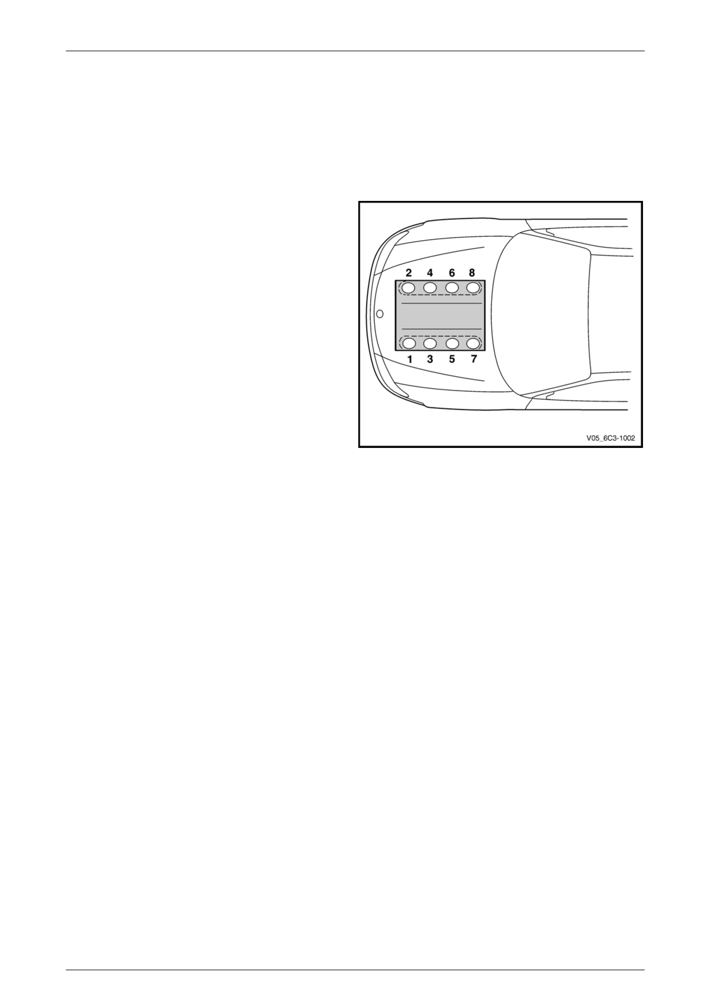
Engine cylinder identification follows the international
standard OBD II. This standard calls for the engine cylinder
bank number one to be identified by the location of cylinder
number one. Therefore the numbering for the GEN IV V8
engine is:
• 1, 3, 5, 7 – Left-hand side (Bank 1),
• 2, 4, 6, 8 – Right-hand side (Bank 2).
The engine firing order is 1, 8, 7, 2, 6, 5, 4, 3.
Figure 6C4-3 – 1

Engine Management GEN IV V8 – Service Operations Page 6C4-3–5
Page 6C4-3–5
1.2 Service Precautions and Notes
The following safety and precautionary
directions must be followed when servicing
the engine management system otherwise
personal injury and/or improper system
operation may occur:
• If working on a vehicle which has been subjected to an under bonnet thermal incident (fire), wear appropriate
protective clothing to prevent personal injury. Components that contain fluoro-elastomer may produce a corrosive
bi-product when subjected to extreme heat.
• Disconnection of the battery affects certain vehicle electronic systems.
Refer to Section 00 Warnings, Cautions and Notes before disconnecting the battery.
• Prior to disconnecting or removal of any components associated with the fuel system, clean the area around any
connection points to avoid possible contamination of the fuel system.
• A depressurised fuel system contains fuel in the fuel system and fuel lines that can be spilled during service
operations. To reduce the chance of personal injury, cover the fittings with a shop towel to absorb any fuel spillage
prior to performing the service operation. Once the service operation has been completed, place the towel in an
approved container for disposal.
• To avoid accidental fuel discharge, it is advisable to disconnect the battery and remove the fuel pump relay if the
fuel line between the fuel pump and the fuel rail is to be disconnected/open for an indefinite period.
• Always tighten fasteners to the correct tightening torque, and where indicated in the service procedure, follow the
correct tightening sequence, precautions and recommendations to prevent premature failure of the fastener or
component, refer to Section 00 Warnings, Cautions and Notes for further information on fasteners.
• Do not use silicone based assembly lubricants as damage to the heated oxygen sensors may result.
• After completing the required service operations, road test the vehicle to ensure correct powertrain management
system operation.
• Before removing the ECM, disconnect the battery ground lead.
• Never start the engine without the battery being solidly connected.
• Never disconnect the battery while the engine is running or when charging the battery.
• Never touch the connector pins of any electronic component, such as an ECM, as Electrostatic Discharge (ESD)
damage may result. For further information, refer to Section 00 Warnings, Cautions and Notes .
• Never subject the ECM to temperatures below -40°C and above 125°C.
• Ensure that all cable harness plugs are connected solidly and that battery terminals are thoroughly clean.
• The engine management system harness connectors are designed to fit only one way; there are indexing tabs and
slots on both halves of the connector. Forcing the connector into place is not necessary if it is being installed with
the correct orientation. Failure to take care to match the indexing tabs and slots correctly can cause damage to the
connector, the module, or other vehicle components or systems.
• Never connect or disconnect a cable harness plug at the ECM, or fuel system component when the ignition is
switched on.
• Before attempting any electric welding on the vehicle, disconnect the battery leads and the ECM connectors.
• When steam cleaning the engine, do not direct the steam cleaning nozzle at the ECM or other engine management
system components. If this happens, corrosion of the terminals can occur.
Use of incorrect electrical test equipment
when performing the engine management
service procedures could result in incorrect
results or damage to ECM system
components.
• Use only the test equipment specified in the diagnostic tables, since other test equipment may either
give incorrect results or damage serviceable components,
refer to Section 6C4-2 Engine Management – GEN IV V8 – Diagnostics.

Engine Management GEN IV V8 – Service Operations Page 6C4-3–6
Page 6C4-3–6
2 General Service Operations
2.1 Service Operations Not Covered In This
Section
Fuel System Cleaning
For the fuel system cleaning procedure, refer to Section 8A1 Fuel System.
Fuel System Leak and Pressure Test
For the fuel system leak and pressure test procedure, refer to Section 8A1 Fuel System.
Fuel Feed Hose to Fuel Rail
For the fuel feed hose to fuel rail replacement service operations, refer to Section 8A1 Fuel System.
Fuel Line Quick Connect Fittings
For fuel line quick connect fittings, refer to Section 8A1 Fuel System.
Engine Management GEN IV V8 – Service Operations Page 6C4-3–7
Page 6C4-3–7
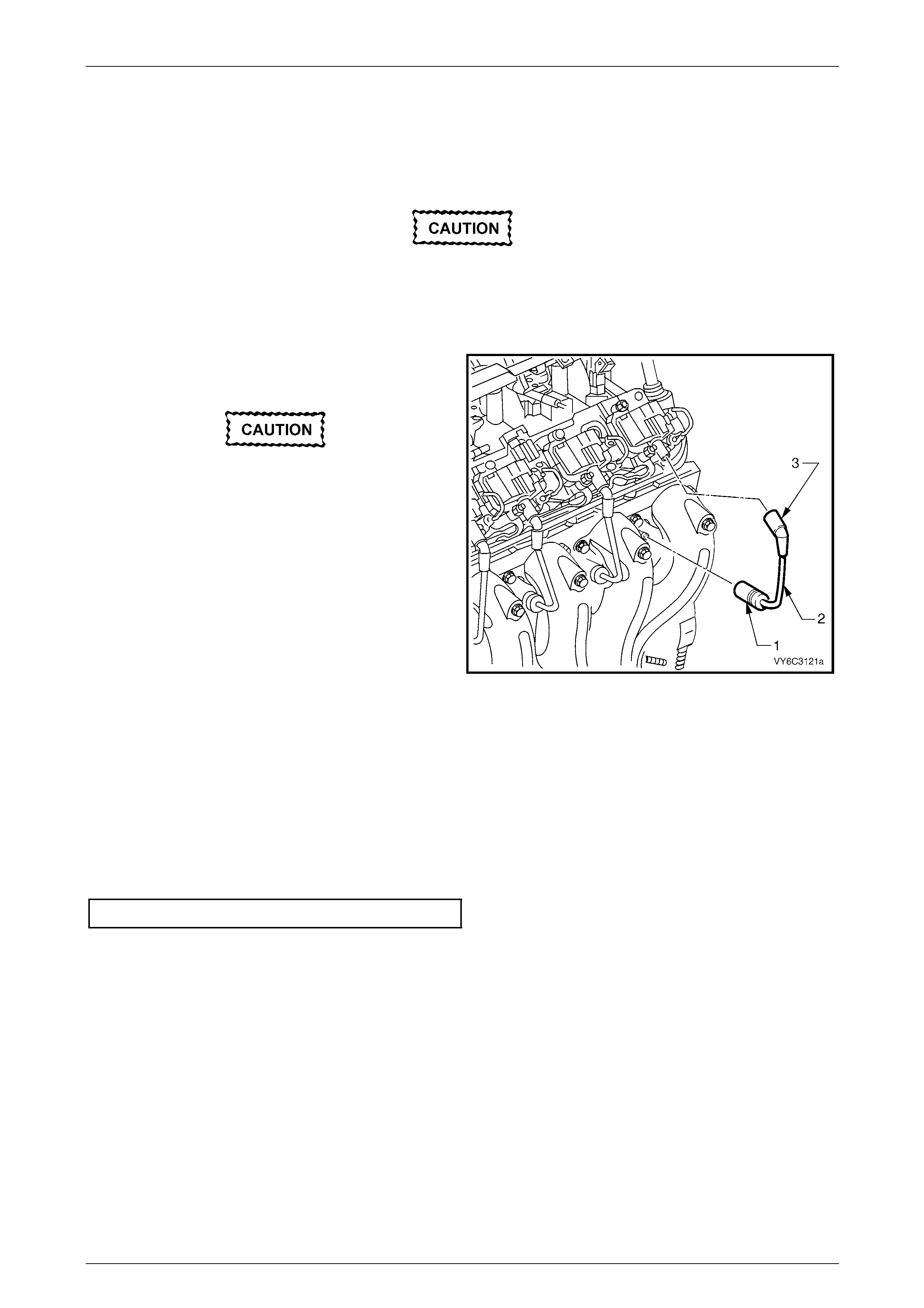
2.2 Engine Dress Covers
Remove
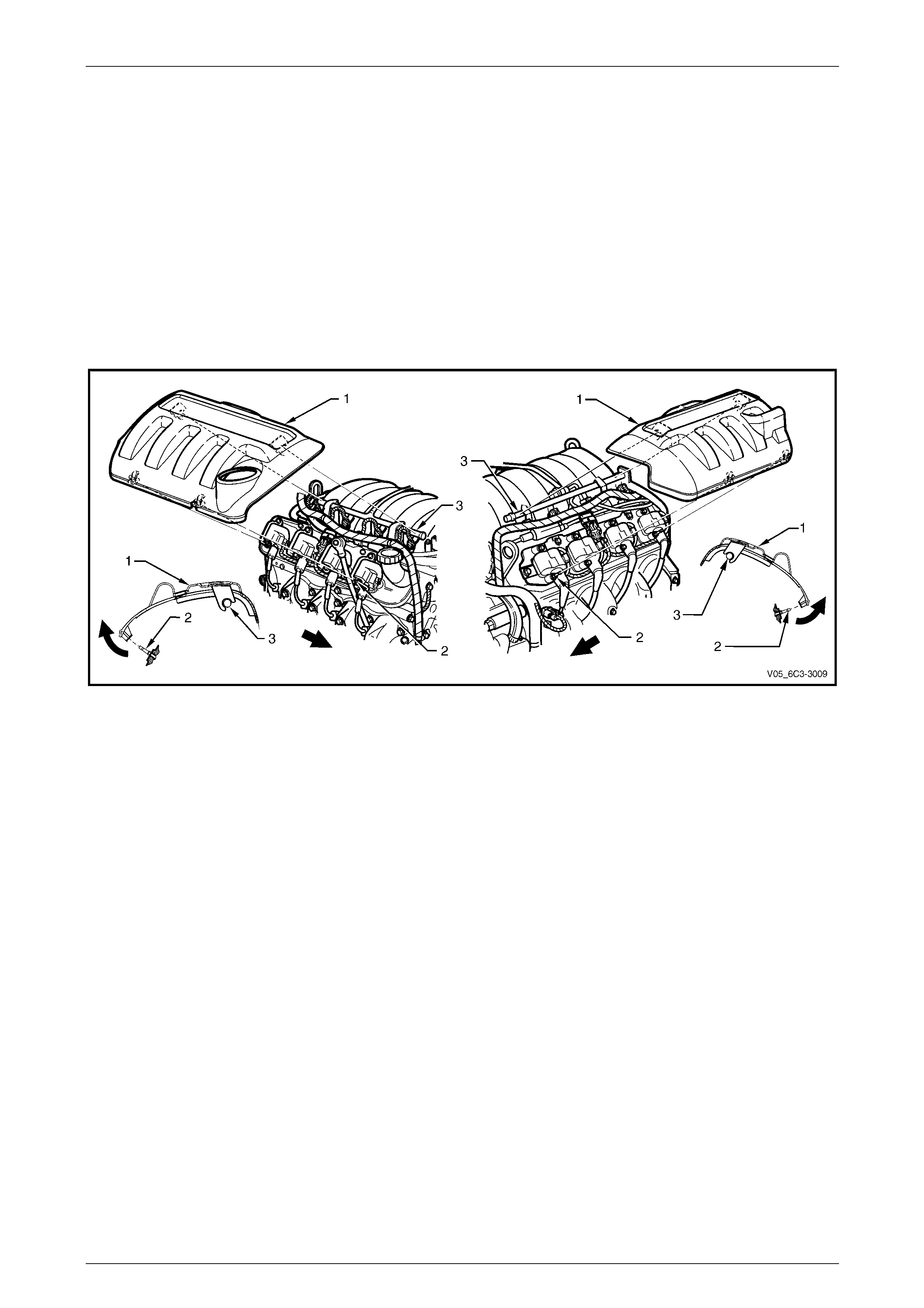
1 Remove either engine dress cover (1) by grasping the lower edge of the cover with the fingers of each hand and
pulling upward to dislodge from the retaining stakes (2), two places.
NOTE
The retaining stakes form part of the double
ended studs securing the ignition coils to the
mounting bracket.
2 Lift the cover upwards, then pull outward to dislodge the clips from the fuel rail (3).
Figure 6C4-3 – 2
3 Repeat Steps 1 and 2 for the other side.
Reinstall
Reinstallation of the engine dress covers is the same as the removal procedure, ensuring the engine dress covers are
securely clipped in place.

Engine Management GEN IV V8 – Service Operations Page 6C4-3–8
Page 6C4-3–8
2.3 Fuel Injector Coil and Balance Test
Information not available at time of publication.
Engine Management GEN IV V8 – Service Operations Page 6C4-3–9
Page 6C4-3–9
2.4 Fuel Injector Leak Down Test
1 Turn the ignition switch off.
NOTE
Do not disconnect the fuel feed hose from the
fuel rail.
Care must be taken when removing the fuel
rail and injector assembly to prevent damage
to the injector spray tips and injector harness
connector terminals.
Support the fuel rail and injector assembly
after removal.
2 Remove the fuel rail assembly, refer to 3.12 Fuel Rail Assembly.
3 Lift up and support the fuel rail and injector assembly.
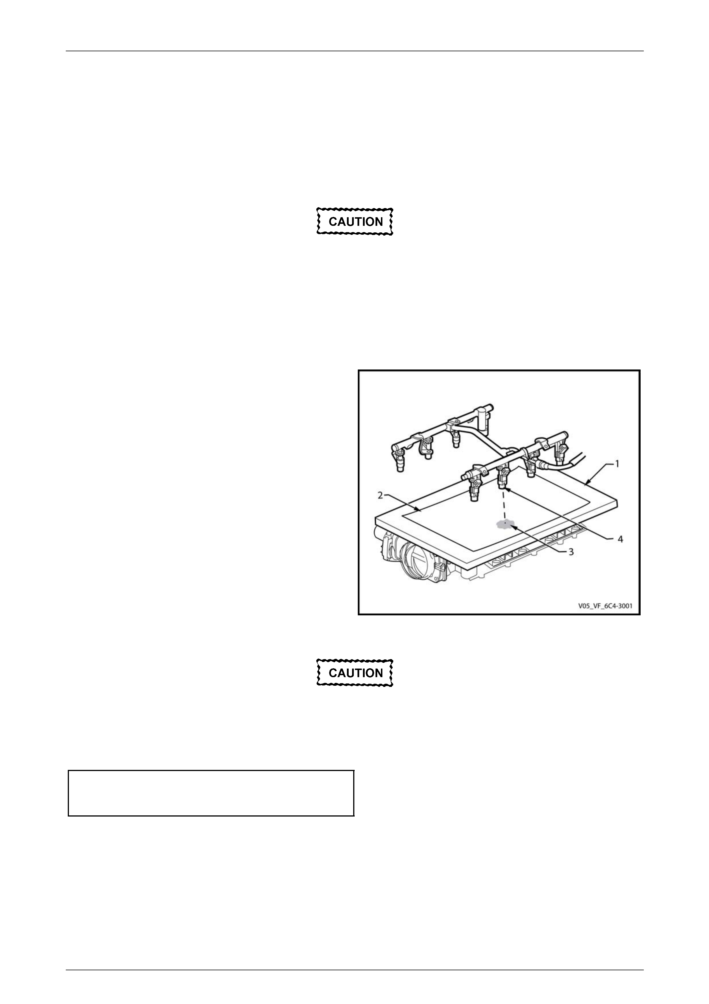
4 Place a board (1) with a sheet of clean paper (2),
preferably white, onto the intake manifold.
5 Using Tech 2, enable the fuel pump to pressurise the
fuel system, refer to Section 0C Tech 2 for this
procedure.
6 Whilst the fuel system is pressurised, check the
following:
• Signs of fuel stains on the paper (3).
• Signs of weeping at the fuel injector spray
tips (4).
7 If any of the above conditions are present,
replace the leaking fuel injector(s), refer to
3.12 Fuel Rail Assembly.
8 Carefully reinstall the fuel rail and injector assembly.
Figure 6C4-3 – 3
Ensure that the fuel injectors are correctly
seated in the lower intake manifold, and that
the fuel rail attaching brackets are correctly
located prior to tightening the attaching bolts.
9 Tighten the bolts attaching the fuel rail to the intake manifold to the correct torque specification.
Fuel rail to intake
manifold attaching bolt
torque specification ..................................8.0 – 12.0 Nm
10 Perform the following procedure to inspect for fuel leaks at the fuel rail:
a Turn the ignition switch on for two seconds.
b Turn the ignition switch off for 10 seconds.
c Turn the ignition switch on.
d Inspect for fuel leaks at the fuel rail.
11 Road test the vehicle and check for correct operation.

Engine Management GEN IV V8 – Service Operations Page 6C4-3–10
Page 6C4-3–10
3 Component Replacement
3.1 Components Not Covered In This
Section
There are cases where components used by the fuel injection system are covered in other sections of the service
documentation. To aid technicians in locating the necessary service procedures for these components, refer to the
following references/links.
Automatic Transmission Components
For automatic transmission sensors and other components,
refer to Section 7E4 Automatic Transmission – 4L65E – On-vehicle Servicing.
A/C Pressure Switch
For the A/C pressure switch service operation,
refer to Section 2B – HVAC Climate Control (Manual A/C) – Servicing and Diagnosis.
Brake Pedal Switches
For extended brake pedal travel switch and stop lamp switch service operations,
refer to Section 5A Service and Park Braking Systems.
Cruise Control Switch Assembly
For the cruise control switch assembly service operations, refer to Section 12E Cruise Control.
Evaporative Emission Control Canister
For the evaporative emission control canister, refer to Section 8A1 Fuel System.
Fuel Filter
For the fuel filter service operations, refer to Section 8A1 Fuel System.
Fuel Hose/Pipes
For the fuel hose/pipes layout, refer to Section 8A1 Fuel System.
Fuel Pump Motor Assembly and Fuel Pressure Regulator
For the fuel pump motor assembly and fuel pressure regulator assembly, refer to Section 8A1 Fuel System.

Engine Management GEN IV V8 – Service Operations Page 6C4-3–11
Page 6C4-3–11
Fuel Sender Assembly
For the fuel sender assembly service operations, refer to Section 8A1 Fuel System.
Fuel Tank Pressure Sensor
For the fuel tank pressure sensor, refer to Section 8A1 Fuel System.
Fuses and Relays
For the fuse and relay locations, refer to Section 12O Fuses, Relays and Wiring Harnesses.
Neutral Start and Back-up Lamp Switch
For the neutral start and back-up lamp switch,
refer to Section 7E4 Automatic Transmission – 4L65E – On-vehicle Servicing.
Powertrain Interface Module (PIM)
For the PIM removal and installation procedure, refer to Section 6E4 Powertrain Interface Module – GEN IV V8 Engine.
Vehicle Speed Sensor
For the vehicle speed sensor service operations,
refer to Section 7E3 Automatic Transmission – 4L65E – On-vehicle Servicing for automatic transmission.
Engine Management GEN IV V8 – Service Operations Page 6C4-3–12
Page 6C4-3–12
3.2 Accelerator Pedal Position (APP) Sensor
Remove
1 Turn the ignition switch off.
2 Remove the driver's side instrument panel lower trim plate assembly,
refer to Section 1A3 Instrument Panel and Console.
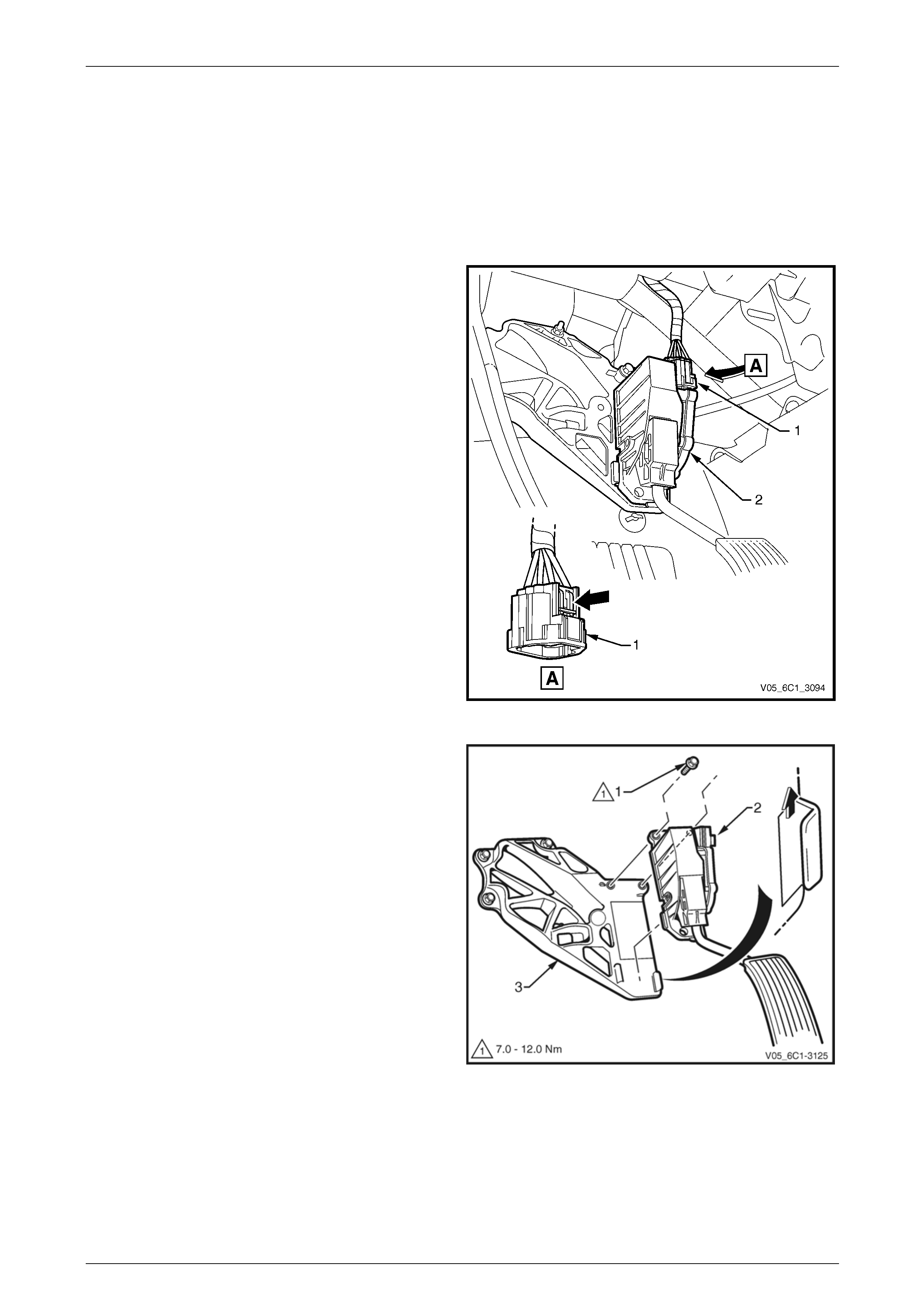
3 Disconnect the wiring harness connector (1) from the
Accelerator Pedal Position (APP) sensor (2) by
depressing the latch in the direction of the arrow.
NOTE
If difficulty is experienced in disconnecting the
harness connector from the APP sensor, remove
the sensor from the APP support bracket and
then disconnect the harness connector.
Figure 6C4-3 – 4
NOTE
If required, the APP sensor can be removed as
an assembly with the APP sensor support
bracket, refer to 3.3 Accelerator Pedal Position
(APP) Sensor Support Bracket.
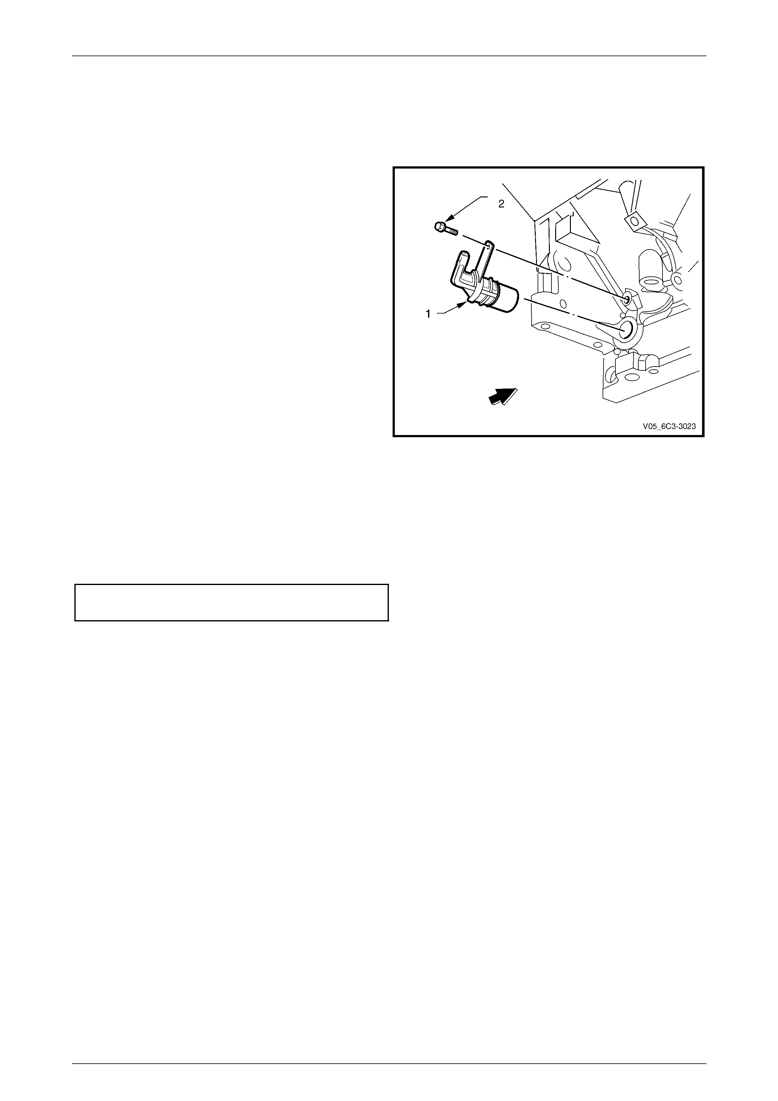
4 Remove the bolt (1) in two places, attaching the APP
sensor (2) to the Accelerator Pedal Position (APP)
sensor support bracket (3).
5 Slide the APP sensor upwards in the direction of the
arrow, to disengage the sensor from the support
bracket.
Figure 6C4-3 – 5

Engine Management GEN IV V8 – Service Operations Page 6C4-3–13
Page 6C4-3–13
Reinstall
Reinstallation of the APP sensor is the reverse of the removal procedure, noting the following:
Make sure that the APP sensor engages
the APP support bracket, refer to
Figure 6C4-3 – 5.
1 Reinstall the bolt, two places, attaching the APP sensor to the support bracket and tighten to the correct torque
specification.
APP sensor attaching bolt
torque specification ...................................7.0 – 12.0 Nm
2 Road test the vehicle and check for correct operation.
Engine Management GEN IV V8 – Service Operations Page 6C4-3–14
Page 6C4-3–14
3.3 Accelerator Pedal Position (APP) Sensor
Support Bracket
Remove
1 Turn the ignition switch off.
NOTE
The APP sensor support bracket may be
removed as an assembly with the APP sensor
attached.
2 If required, remove the Accelerator Pedal Position (APP) sensor,
refer to 3.2 Accelerator Pedal Position (APP) Sensor.
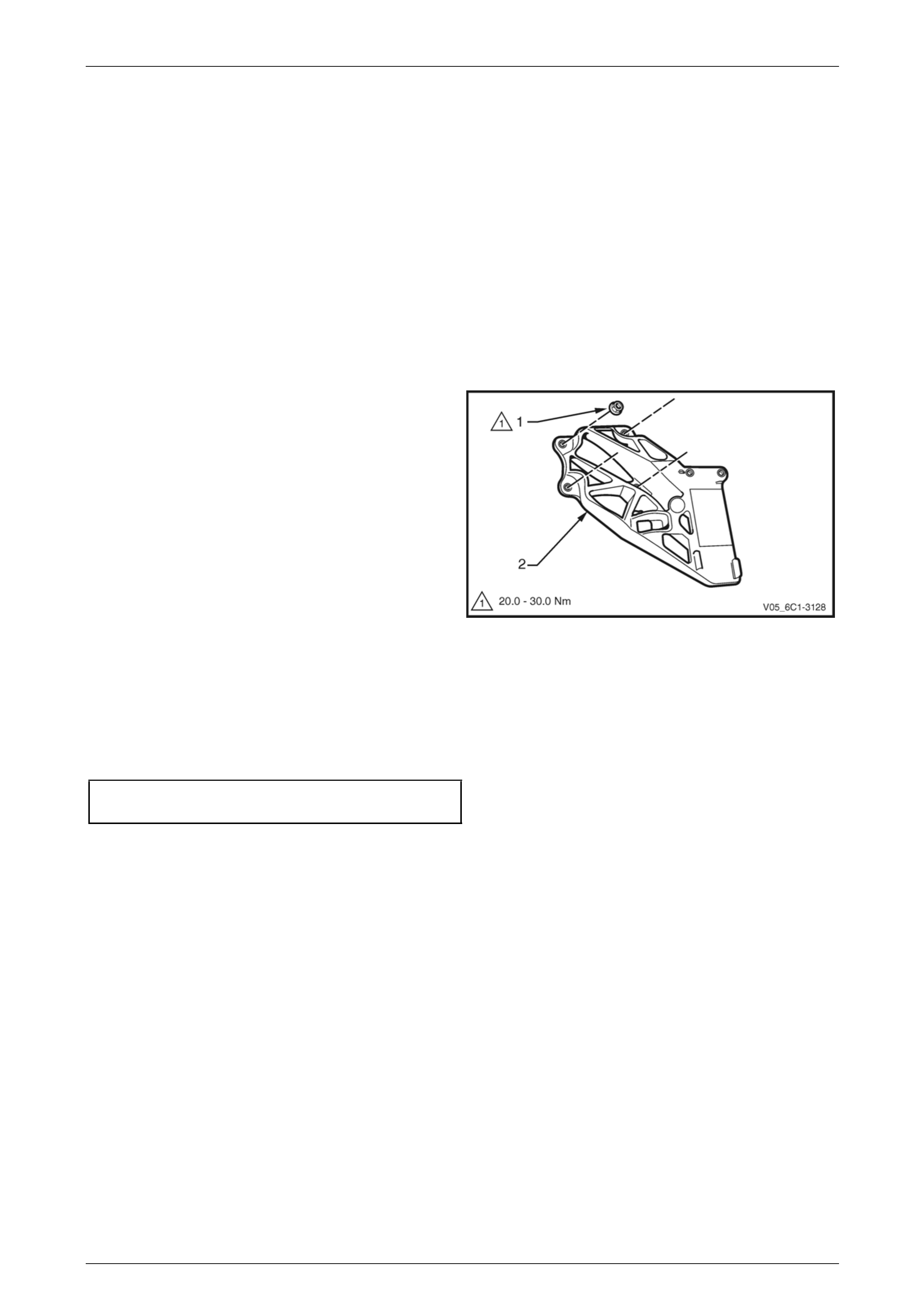
3 Remove the nut (1), in four places, attaching the APP
sensor support bracket (2) to the dash panel and
remove the support bracket.
Figure 6C4-3 – 6
Reinstall
Reinstallation of the APP sensor support bracket is the reverse of the removal procedure, noting the following:
1 Reinstall the nut, in four places, attaching the APP sensor support bracket to the dash panel and tighten to the
correct torque specification.
APP sensor support bracket
attaching nut torque specification............20.0 – 30.0 Nm
2 Road test the vehicle and check for correct operation.
Engine Management GEN IV V8 – Service Operations Page 6C4-3–15
Page 6C4-3–15
3.4 Air Cleaner Assembly
Air Cleaner Upper Housing
Remove
1 Turn the ignition switch off.
2 Remove the upper radiator shroud, refer to Section 6B4 Engine Cooling – GEN IV V8 Engine.
3 Remove the air duct, refer to 3.18 Mass Air Flow (MAF) Sensor and Intake Air Duct.
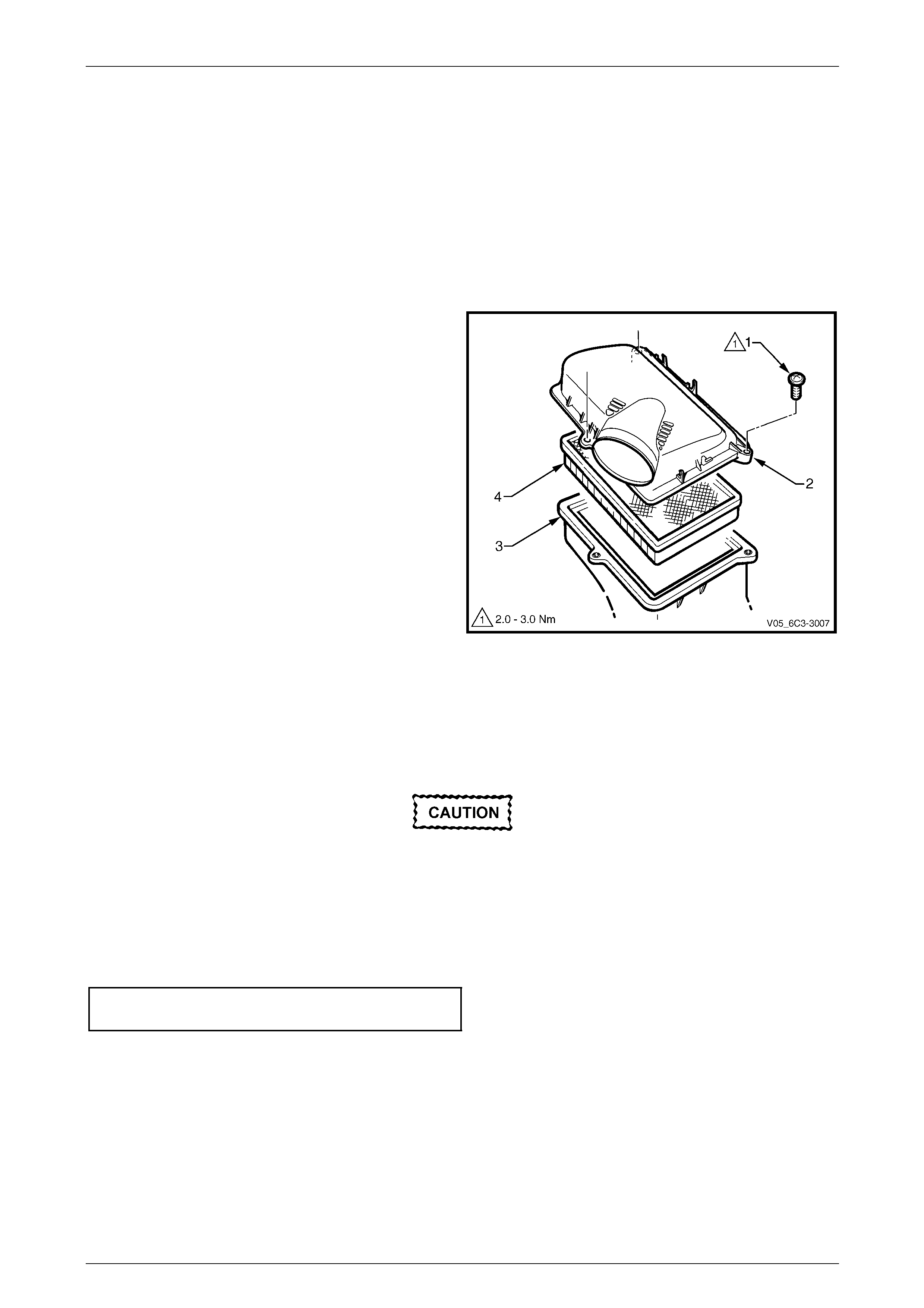
4 Remove the screw (1), three places, attaching the air
cleaner upper housing (2) to the air cleaner lower
housing (3).
5 Remove the upper housing and air cleaner
element (4).
Figure 6C4-3 – 7
Reinstall
Reinstallation of the air cleaner upper housing is the reverse of the removal procedure, noting the following:
1 Reinstall the air cleaner element.
Make sure that the air cleaner sealing rubber
is correctly located in the air cleaner lower
housing during installation. Failure to do this
may result in engine damage due to unfiltered
air entering the engine air intake system.
2 Reinstall the screw, in three places, attaching the air cleaner upper housing to the air cleaner lower housing and
tighten to the correct torque specification.
Air cleaner upper housing attaching
screw torque specification...........................2.5 – 3.0 Nm
3 Road test the vehicle and check for correct operation, taking particular note that no air leaks are evident.
Engine Management GEN IV V8 – Service Operations Page 6C4-3–16
Page 6C4-3–16
Air Cleaner Lower Housing
Remove
1 Turn the ignition switch off.
2 Remove the air cleaner upper housing as described previously.
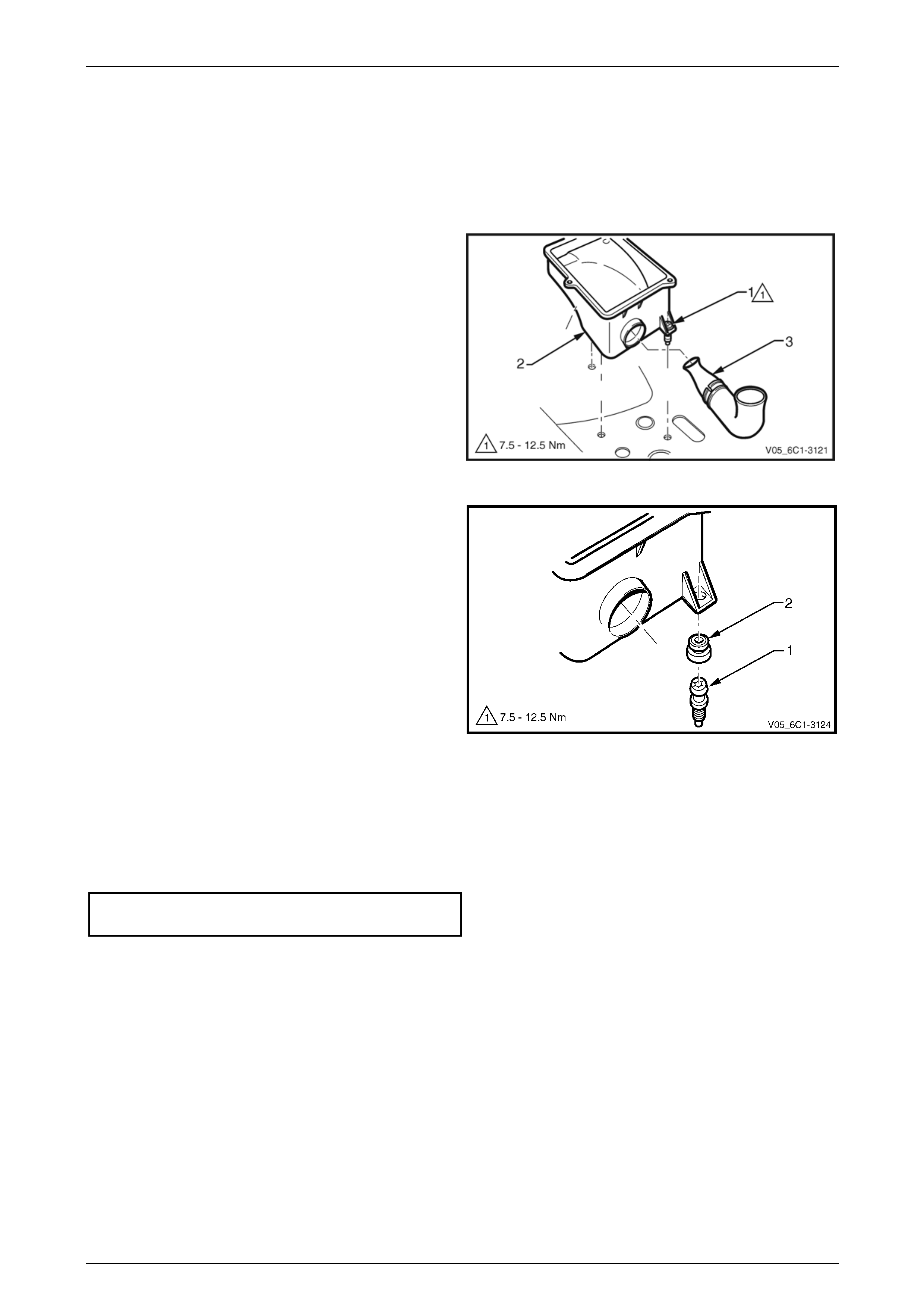
3 Fully loosen the stud (1), three places, attaching the
air cleaner lower housing (2) to the fender inner panel.
NOTE
The stud and air cleaner housing insulator are
removed with the air cleaner housing.
4 Disengage the air cleaner air inlet duct (3) from the
lower housing. Remove the lower housing.
Figure 6C4-3 – 8
5 If required, remove the stud (1) and air cleaner
housing insulator (2) from the air cleaner lower
housing.
Figure 6C4-3 – 9
Reinstall
Reinstallation of the air cleaner assembly is the reverse of the removal procedure, noting the following:
1 Reinstall the stud, three places, attaching the air cleaner lower housing to the fender inner panel and tighten to the
correct torque specification.
Air cleaner lower housing attaching
stud torque specification ...........................7.5 – 12.5 Nm
2 Road test the vehicle and check for correct operation, taking particular note that no air leaks are evident.
Engine Management GEN IV V8 – Service Operations Page 6C4-3–17
Page 6C4-3–17
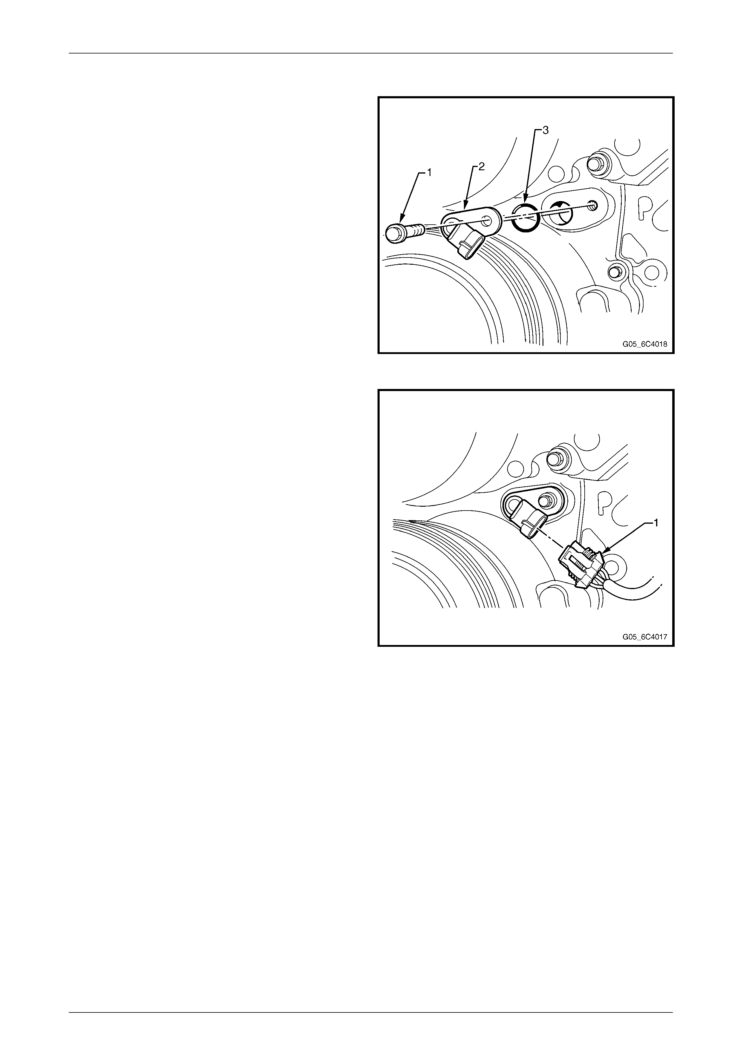
3.6 Camshaft Position (CMP) Sensor
Removal Procedure
1 Remove the generator bracket assembly. Refer to
Generator Bracket Replacement in Engine Electrical.
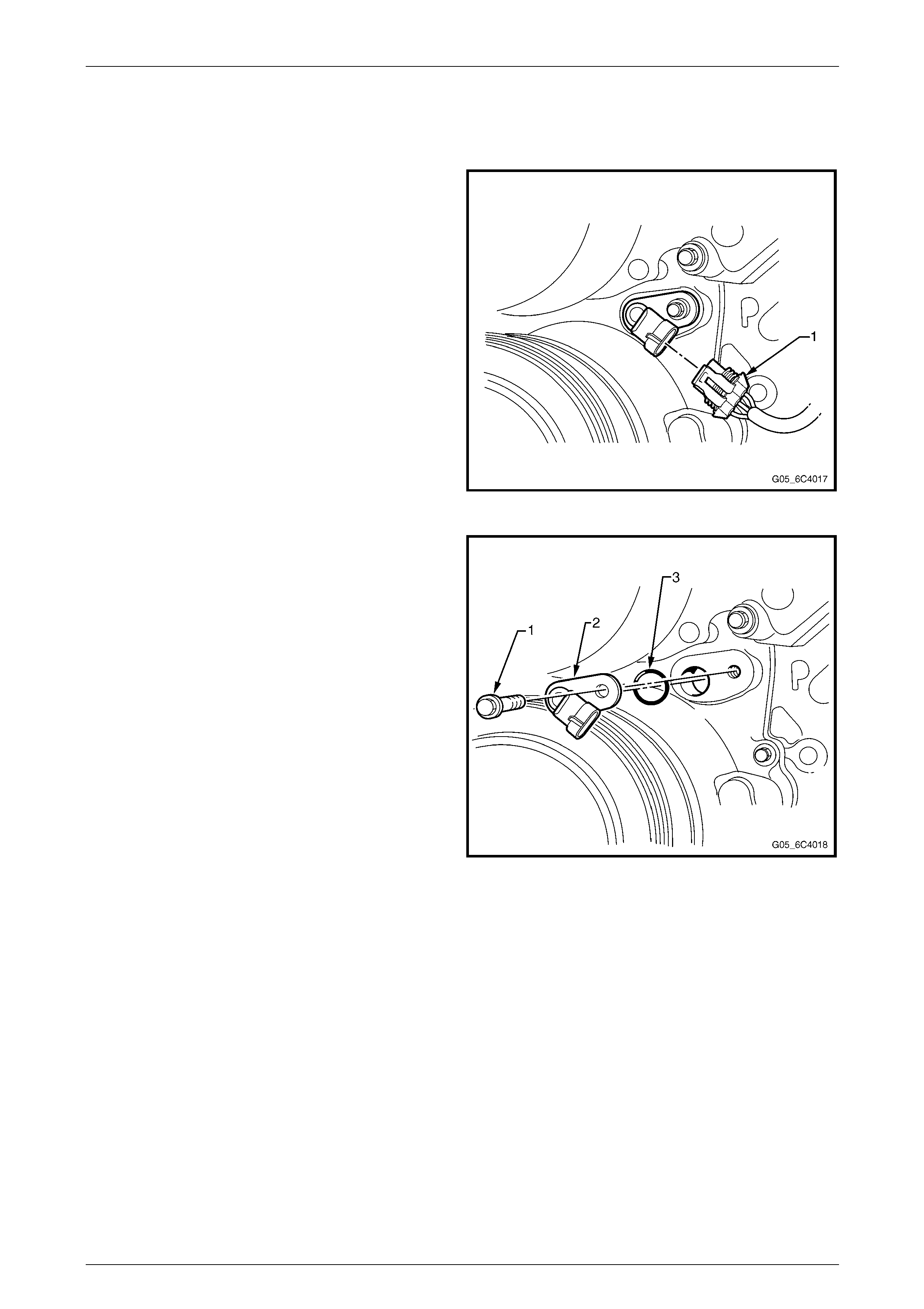
2 Disconnect the camshaft position sensor electrical
connector (1).
Figure 6C4-3 – 10
3 Remove the camshaft position sensor mounting bolt
(1).
4 Remove the camshaft position sensor assembly (2, 3)
from the engine front cover.
Figure 6C4-3 – 11
Engine Management GEN IV V8 – Service Operations Page 6C4-3–18
Page 6C4-3–18
Installation Procedure
Important: Before installing the camshaft sensor assembly,
apply a small amount of clean motor oil to the O-ring (3).
1 If removed, install the O-ring onto the camshaft position
sensor.
2 Install the camshaft position sensor assembly into the
engine front cover.
Notice: Refer to Fastener Notice in Cautions and Notices.
3 Install the camshaft position sensor mounting bolts.
Tighten
Tighten the camshaft position mounting bolts to 25 N·m
(18 lb ft).
Figure 6C4-3 – 12
4 Reconnect the camshaft sensor electrical connector
(1).
5 Install the generator bracket assembly. Refer to
Generator Bracket Replacement in Engine Electrical.
Figure 6C4-3 – 13
Engine Management GEN IV V8 – Service Operations Page 6C4-3–19
Page 6C4-3–19
3.7 Crankshaft Position (CKP) Sensor
Remove
1 Remove the starter motor, refer to Section 6D3-2 Starting System – GEN III V8.
2 Disconnect the electrical connector from the
crankshaft position sensor (1).
3 Remove the crankshaft position retaining bolt (2).
4 Remove the sensor.
Figure 6C4-3 – 14
Reinstall
Reinstallation of the crankshaft position sensor is the reverse of the removal procedure, noting the following:
1 Lubricate the CKP sensor O-ring with clean engine oil prior to installation.
2 Reinstall the crankshaft position retaining bolt and tighten to the correct torque specification.
CKP Sensor Retaining Bolt
Torque Specification .............................................25 Nm
3 Road test the vehicle and check for correct operation.
Engine Management GEN IV V8 – Service Operations Page 6C4-3–20
Page 6C4-3–20
3.7 Engine Control Module (ECM)
Service of the Engine Control Module (ECM) should normally consist of either replacement of the ECM, or ECM
programming. If the diagnostic procedures call for the ECM to be replaced, the ECM should be first checked to ensure it
is the correct part. If it is, replace the faulty ECM.
• Do not touch the ECM connector pins as
Electrostatic Discharge (ESD) damage may
result. For further information on ESD,
refer to Section 00 Warnings, Cautions and
Notes .
• When removing or reinstalling the ECM
harness connector/s, ensure that the
ignition switch is in the OFF position and
that the battery has been disconnected.
Failure to do so may result in damage to
the ECM and/or associated components.
• Disconnection of the battery affects
certain vehicle electronic systems.
Refer to Section 00 Warnings, Cautions
and Notes before disconnecting the
battery.
Remove
1 Turn the ignition switch off.
2 Disconnect the battery, refer to Section 00 Warnings, Cautions and Notes .
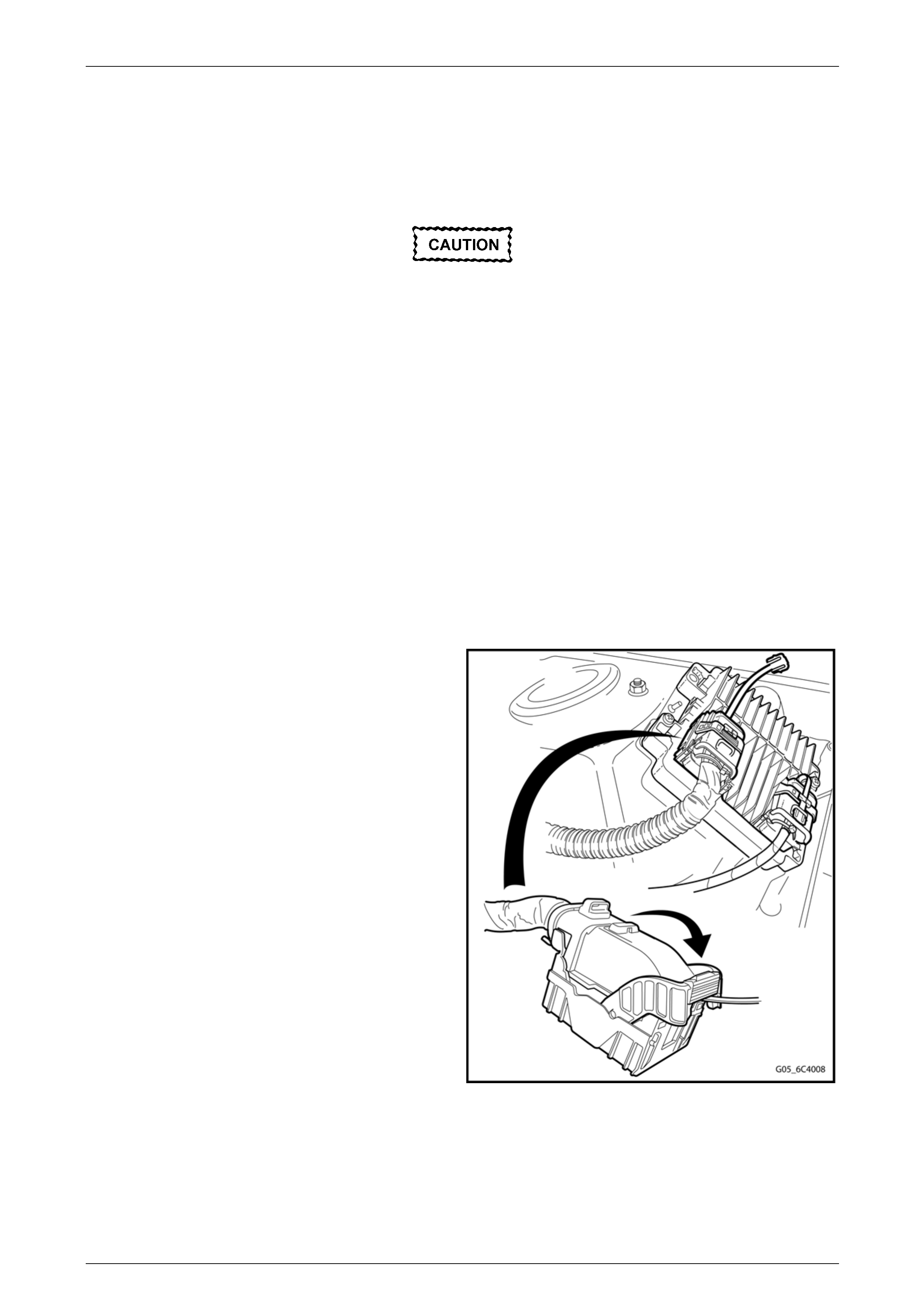
3 Remove the Connector Protection Assurance (CPA)
locks on each ECM electrical connector, then move
the connector lock levers to the unlock position.
4 Disconnect the wiring harness connectors.
Figure 6C4 – 15

Engine Management GEN IV V8 – Service Operations Page 6C4-3–21
Page 6C4-3–21
5 Remove the two screws (1) securing the ECM to the
mounting bracket
6 Remove the ECM.
Figure 6C4 – 16
Reinstall
Reinstallation is the reverse of the removal procedure, noting the following:
1 Reinstall the ECM screws, and tighten to the correct torque specification.
ECM retaining screw torque specification .........1 – 3 Nm
2 If the ECM has been replaced, perform the following procedures:
• ECM service programming, refer to Section 0C Tech 2.
• ECM/PIM/BCM security link, refer to Section 0C Tech 2.
• Main diagnostic functional check.
3 If the ECM has been removed, but not replaced, perform the main diagnostic table functional check.

Engine Management GEN IV V8 – Service Operations Page 6C4-3–22
Page 6C4-3–22
3.8 Engine Control Module (ECM) Bracket
Assembly
Remove
1 Remove the ECM, refer to 3.7 Engine Control Module (ECM).
2 Remove nut (2) securing the ECM bracket (1) to the
body.
3 Remove the ECM mounting bracket by lifting up and
away from the body.
Figure 6C4 – 17
Reinstall
Reinstallation of the ECM mounting bracket is the reverse of the removal procedure, noting the following:
Tighten the nuts attaching the ECM mounting bracket to the body to the correct torque specification.
ECM mounting bracket attaching
nut torque specification .................................15 – 20 Nm
Engine Management GEN IV V8 – Service Operations Page 6C4-3–23
Page 6C4-3–23
3.9 Engine Coolant Temperature (ECT)
Sensor
Remove
To avoid serious personal injury, never
remove the ECT sensor when the engine is
hot. Allow the engine to cool to ambient
temperature (less than 50° C) before
performing this procedure.
1 Raise the vehicle and support on safety stands, refer to Section 0A General Information for the location of jacking
and support points.
2 Drain the engine coolant, refer to Section 6B4 Engine Cooling – GEN IV V8 Engine.
3 Lower the vehicle.
4 Remove the left-hand engine dress cover, refer to 2.2 Engine Dress Covers.
5 Disconnect the electrical connector from the ECT
sensor (1).
6 Remove the No. 1 spark plug lead from the spark plug.
7 Remove the ECT sensor.
Use care when handling the coolant sensor.
Damage to the coolant sensor will affect the
operation of the fuel control system.
Figure 6C4-3 – 18
Engine Management GEN IV V8 – Service Operations Page 6C4-3–24
Page 6C4-3–24
Test
To prevent component damage, use
connector test adaptor kit J 35616-A.
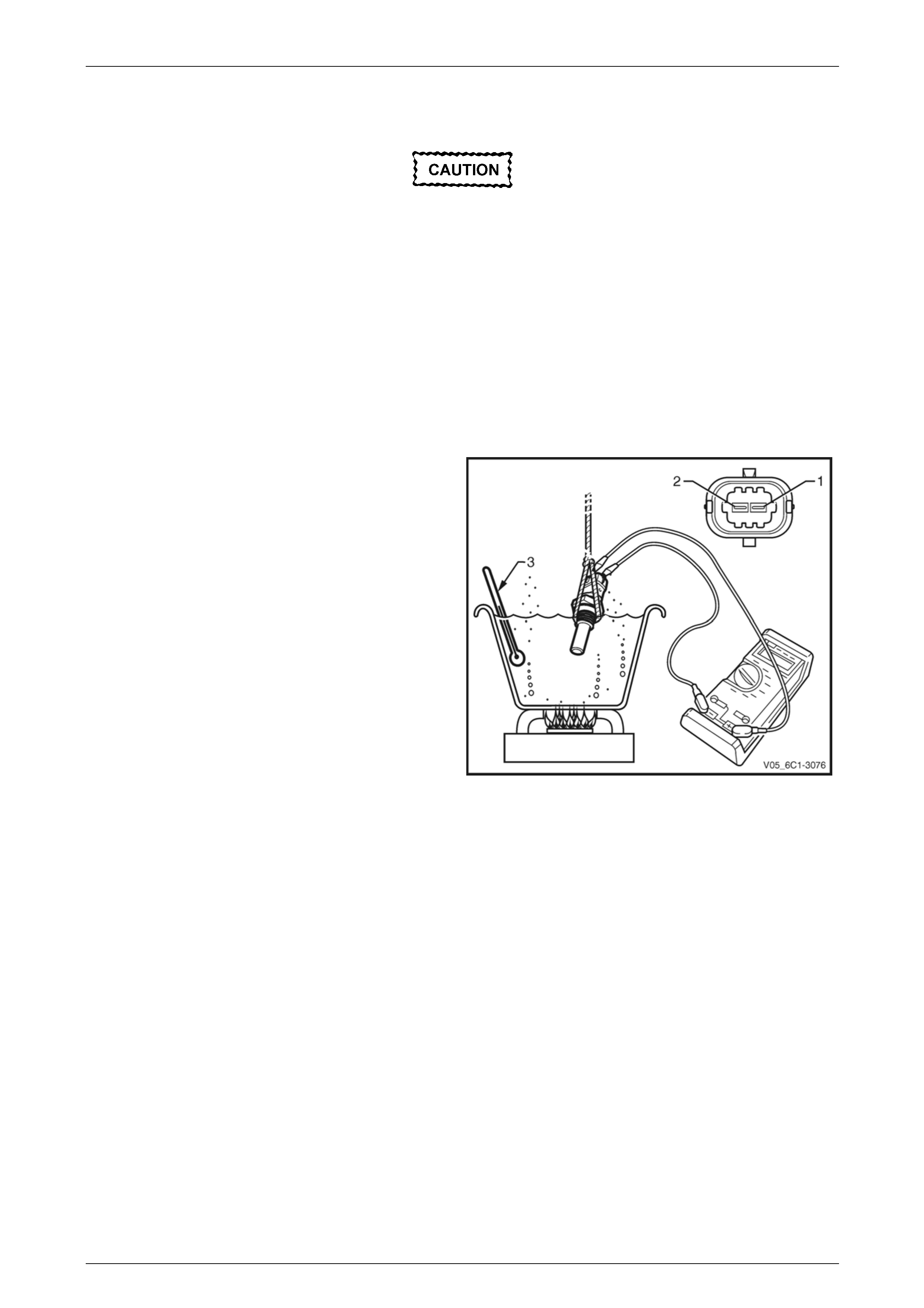
Resistance Check
1 Suspend the ECT sensor and a suitable thermometer in a container of 50/50 DEX-COOL® long life coolant or
equivalent and water.
NOTE
Neither the ECT sensor or thermometer should
rest on the bottom of the container due to an
uneven concentration of heat at this point when
the container is heated.
2 Connect a digital ohmmeter using connector test
adaptor kit J 35616-A to the ECT sensor and measure
the resistance across terminals 1 and 2.
3 Whilst heating the container, observe the resistance
values as the temperature increases and compare the
temperature/resistance change to the specifications.
Figure 6C4-3 – 19
4 If the resistance is not within specifications, replace
the ECT sensor.
Engine Coolant Temperature Vs Resistance
Temperature °C Resistance – Ohms (Ω)
-10 16,180
0 9,420
20 3,520
25 2,796
40 1,459
60 667
80 332
100 177
120 100
140 60

Engine Management GEN IV V8 – Service Operations Page 6C4-3–25
Page 6C4-3–25
Reinstall
Reinstallation of the ECT sensor is the reverse of the removal procedure, noting the following:
1 Coat the Engine Coolant Temperature (ECT) sensor (1) thread with Loctite 242 or equivalent.
2 Tighten the ECT sensor to the correct torque specification.
ECT sensor torque specification ...........................17 Nm
3 Refill the cooling system, refer to Section 6B4 Engine Cooling – GEN IV V8.
4 Road test the vehicle and check for correct operation, taking particular note that there is no coolant leakage.
Engine Management GEN IV V8 – Service Operations Page 6C4-3–26
Page 6C4-3–26
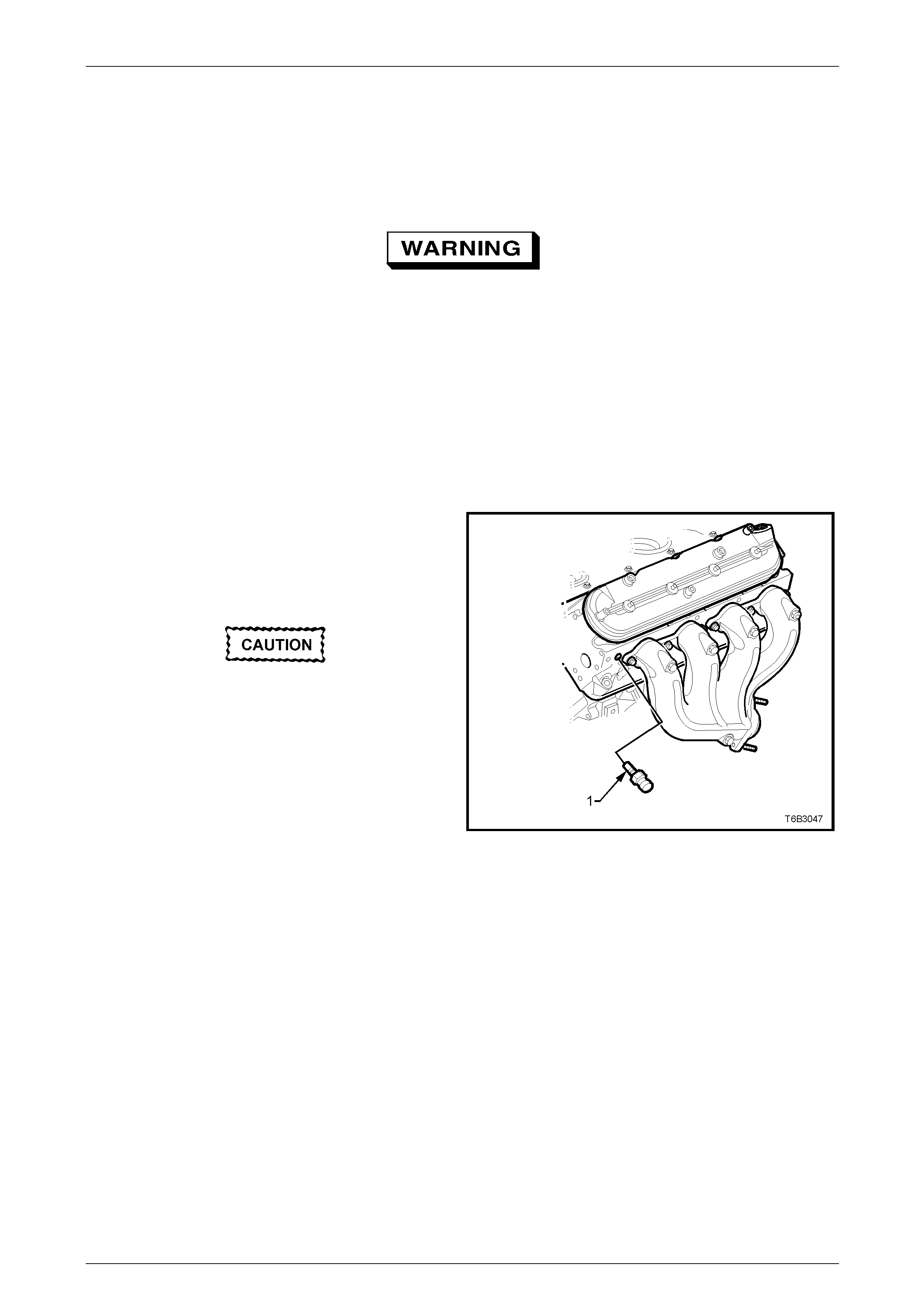
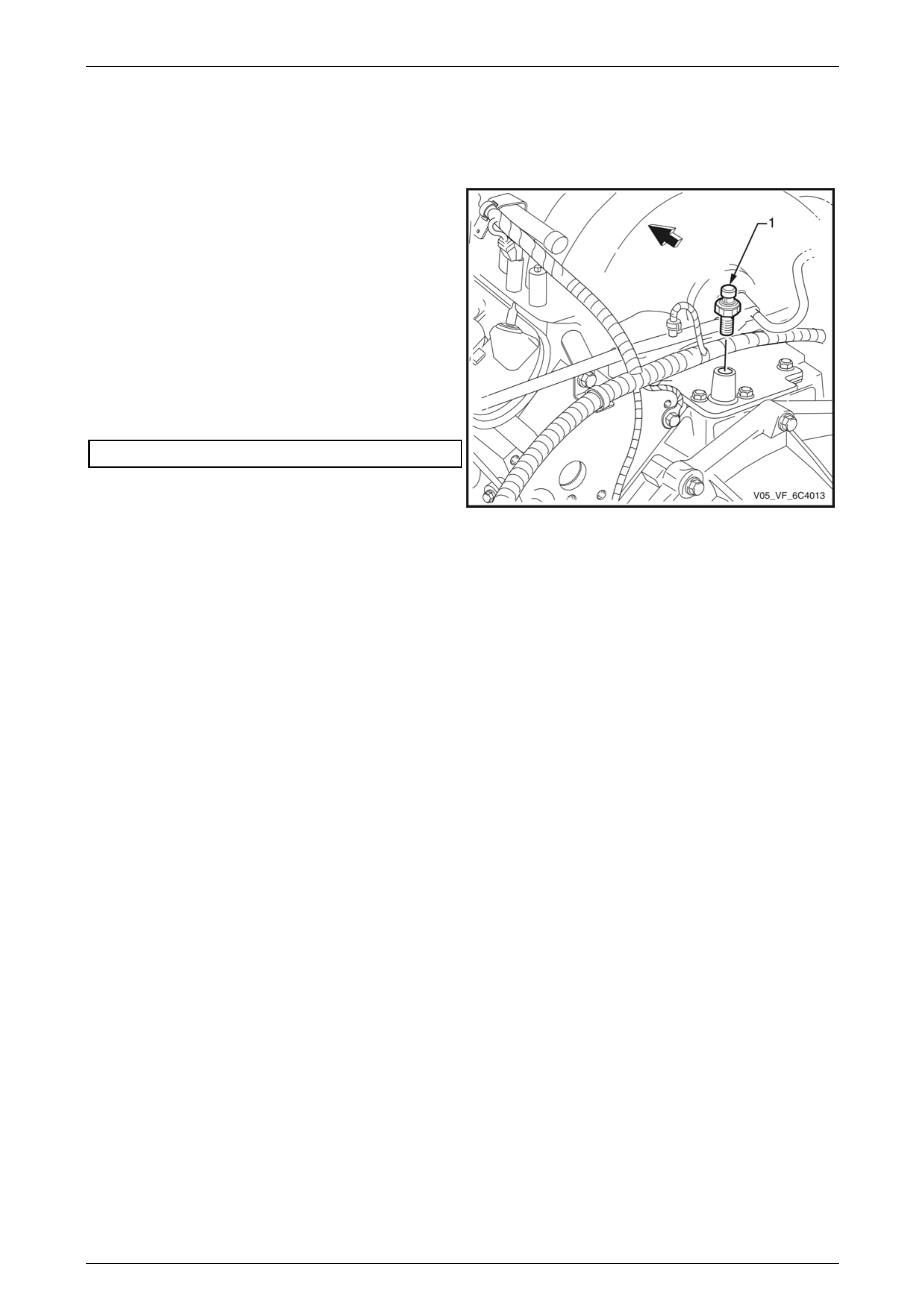
3.10 Engine Oil Pressure (EOP) Sensor
Remove
1 Clean around area of oil pressure sensor (1), so that
no foreign matter will enter the engine.
2 Disconnect the oil pressure sensor electrical
connector.
3 Using tool J 41712, remove the oil pressure sensor.
Reinstall
Reinstallation of the EOP sensor is the reverse of the
removal procedure, noting the following:
1 Reinstall the oil pressure sensor and tighten to the
specified torque.
EOP Sensor Torque Specification ........................20 Nm
2 Check engine oil level and top up if necessary.
3 Start engine and inspect for oil leaks. Figure 6C4-3 – 20
Engine Management GEN IV V8 – Service Operations Page 6C4-3–27
Page 6C4-3–27
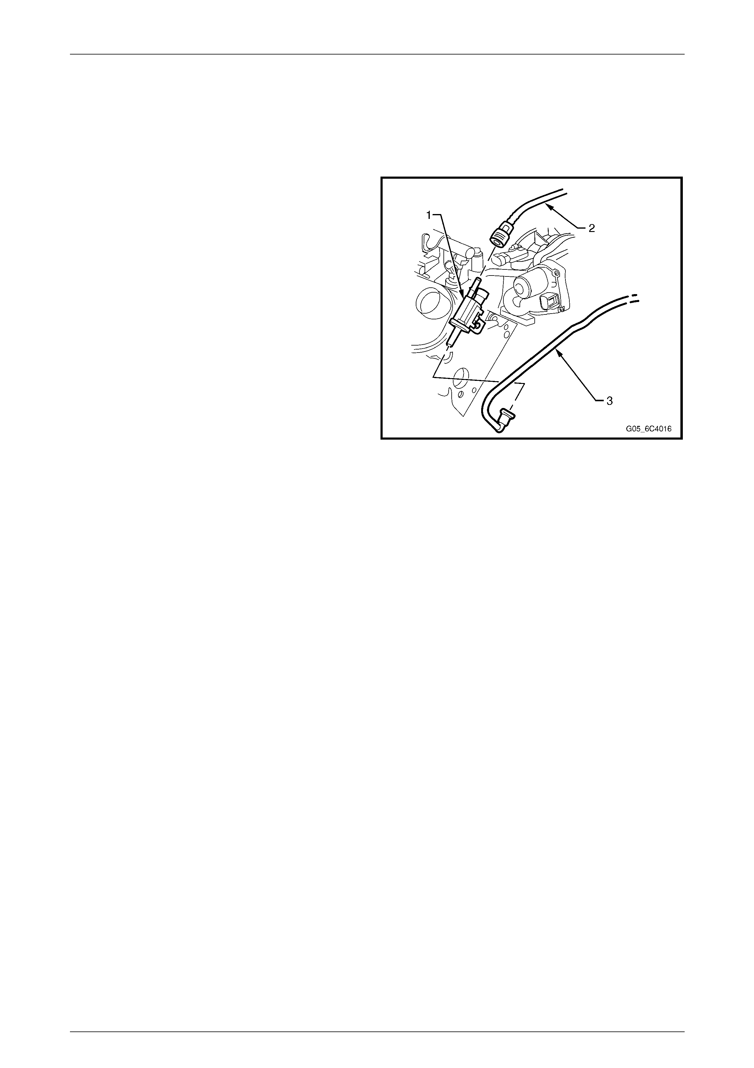
3.11 EVAP Canister Purge Solenoid Valve
Remove
1 Remove the left-hand engine dress cover, refer to 2.2 Engine Dress Covers.
2 Disconnect the electrical connector from the EVAP
purge solenoid.
3 Disconnect the front hose by squeezing the retaining
clip and pulling the hose from the solenoid.
4 Disconnect the hose from the purge solenoid using
tool AU533, refer to Section 8A1 Fuel System.
5 Lift and remove the EVAP purge solenoid from the
mounting bracket.
Figure 6C4-3 – 21
Reinstall
Reinstallation of the EVAP canister purge solenoid valve is the reverse of the removal procedure.

Engine Management GEN IV V8 – Service Operations Page 6C4-3–28
Page 6C4-3–28
3.12 Fuel Rail Assembly
A depressurised fuel system contains fuel in
the fuel system and fuel lines that can be
spilled during service operations, refer to
Section 00 Warnings, Cautions and Notes for
further information on handling fuel.
Remove
1 Remove both engine dress covers, refer to 2.2 Engine Dress Covers.
2 Relieve the fuel system pressure, refer to Section 8A1 Fuel System.
3 Disconnect the negative battery cable.
4 If fitted, remove the front suspension strut brace, refer to Section 1A1 Body.
Wear safety glasses when using compressed
air. Do not blow compressed air onto any
body part, refer to Section 00 Warnings.
Cautions and Notes for correct workshop
practices when using compressed air.
5 If necessary, use compressed air to remove any foreign material from around the area where the fuel injectors
enter the intake manifold.
6 Disconnect the fuel feed hose from the fuel rail, refer to Section 8A1 Fuel System.
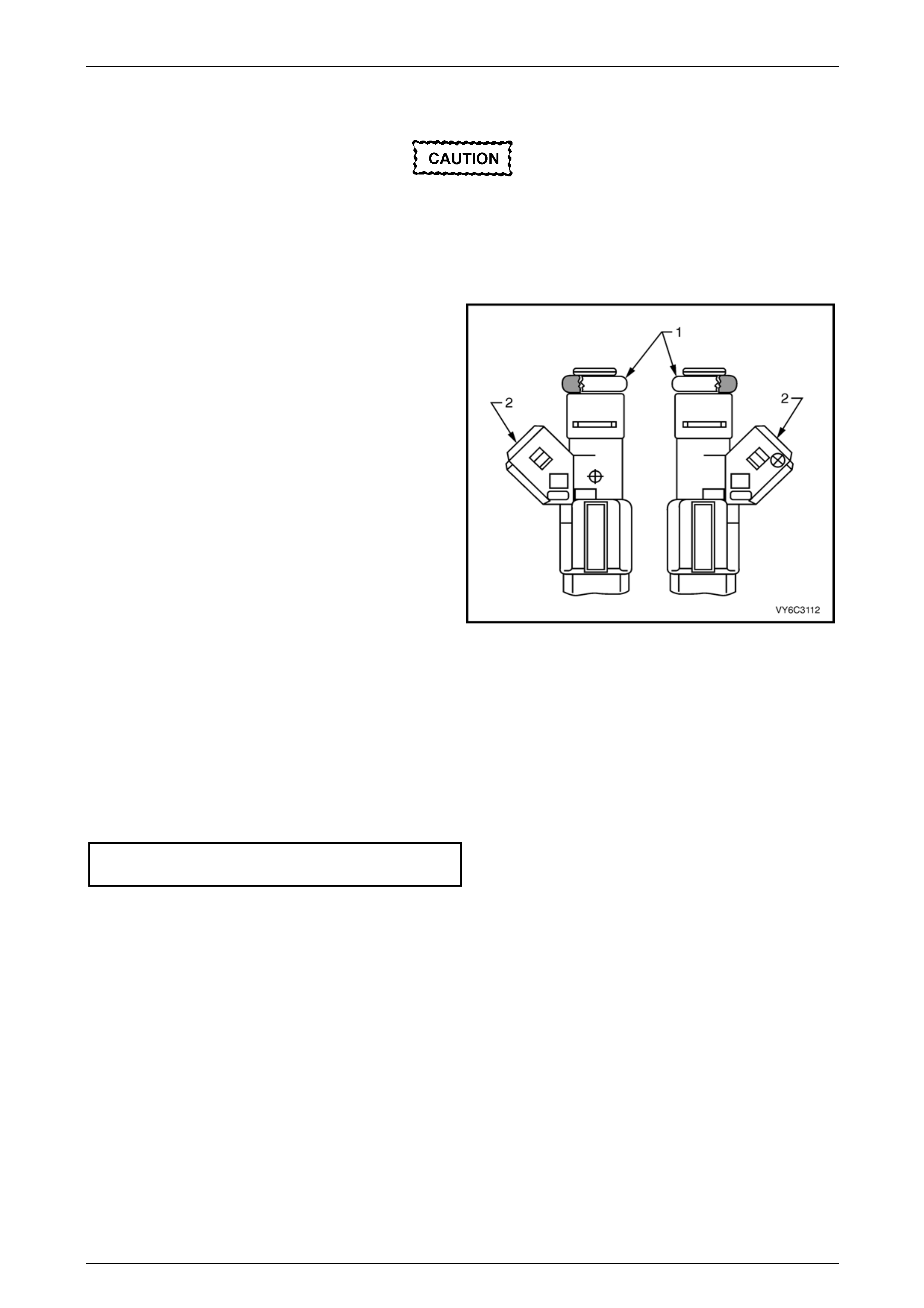
7 Detach the wiring harness clips (1), four places.
8 Disconnect the wiring harness connectors (2) eight
places, from the fuel injectors. Identify the connectors
with their corresponding injectors to ensure correct
sequential injector firing order after reassembly.
Figure 6C4-3 – 22
Engine Management GEN IV V8 – Service Operations Page 6C4-3–29
Page 6C4-3–29
9 Remove the four double ended studs (1) securing the
fuel rail (2) to the intake manifold.
10 Carefully lift the fuel rail and injectors assembly (2)
clear of the intake manifold.
Remove the fuel rail assembly carefully to
avoid damage to the injector electrical
connector terminals and the injector spray
tips. Support the fuel rail after the fuel rail is
removed to avoid damaging the fuel rail
components.
11 Cap the fittings and plug the holes when servicing the
fuel system, to prevent dirt and other contaminants
from entering open pipes and passages.
12 Remove and discard the injector lower O-ring seal
from the spray tip end of each injector. Figure 6C4-3 – 23
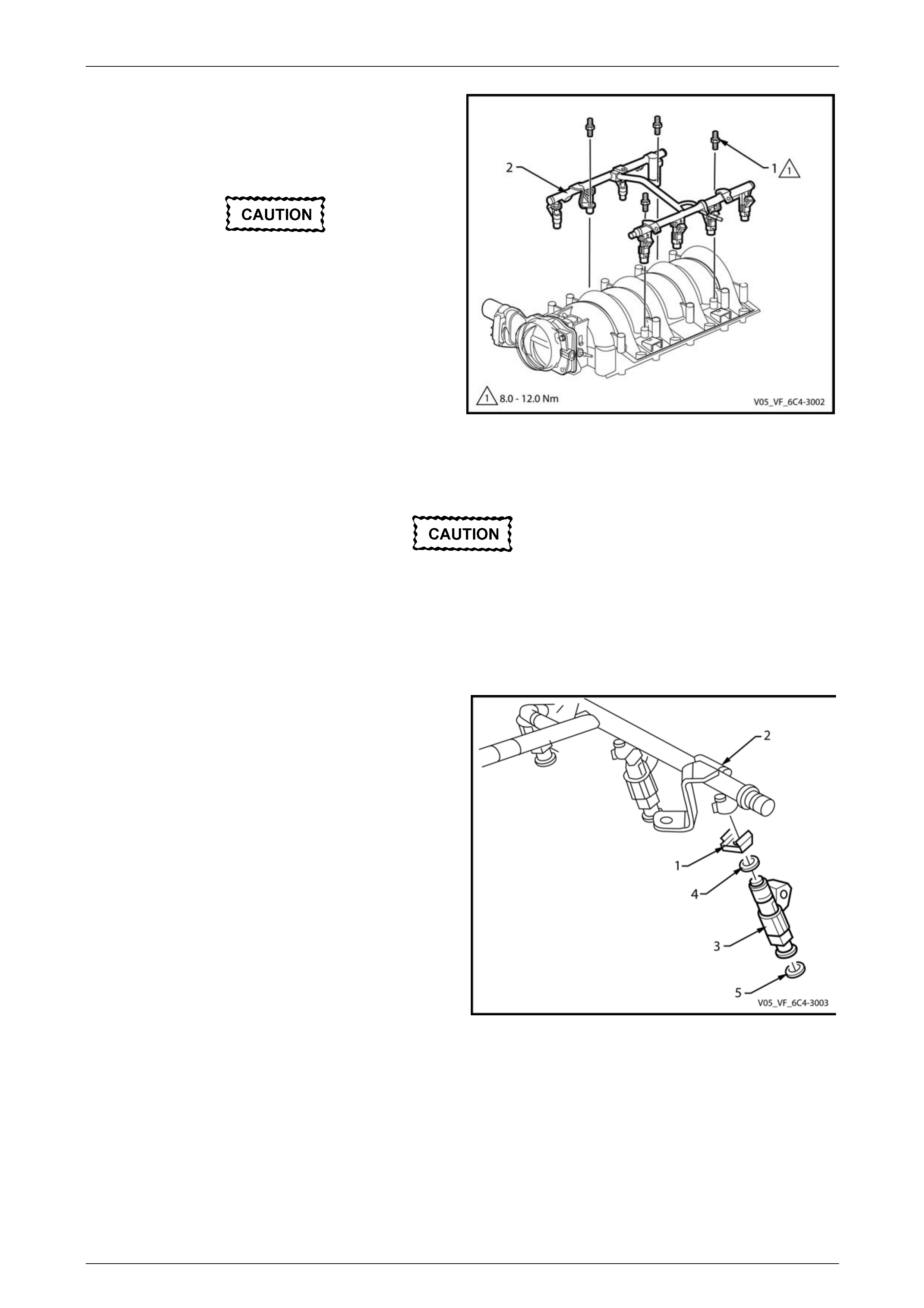
Disassemble
Use care in removing the fuel injectors to
prevent damage to the electrical connector
pins on the injector and to prevent damage to
the nozzle. Service the fuel injector as a
complete assembly only. The fuel injector is
an electrical component. Do not immerse the
fuel injector in any type of cleaner.
1 Pull the injector retainer clip (2) to release the injector
from the fuel rail.
2 Remove the fuel injector (3).
3 Discard the injector retainer clip (2).
4 Remove and discard the injector O-ring seals (4 and
5) from each end of the injector.
Figure 6C4-3 – 24
Engine Management GEN IV V8 – Service Operations Page 6C4-3–30
Page 6C4-3–30
Reassemble
When ordering new fuel injectors, ensure to
order the correct injector for the application
being serviced. The fuel injector assembly is
stamped with a part number identification, a
manufacturing date, a week code, and a
production plant number.
1 Lubricate a new injector O-ring seal (1) with clean
engine oil and install onto each injector.
2 Push the fuel injector into the fuel rail injector socket
with the electrical connector (2) facing outward. The
retainer clip locks on to a flange on the fuel rail injector
socket.
3 Reinstall a new retainer clip to retain each injector.
Figure 6C4-3 – 25
Reinstall
Reinstallation of the fuel rail assembly is the reverse of the removal procedure, noting the following:
1 Install a new O-ring on each fuel injector.
2 Lubricate the fuel injector O-ring seals with clean engine oil.
3 Apply Loctite 242 or equivalent to the cleaned threads of the fuel rail attaching studs, then tighten to the specified
torque.
Fuel Rail Attaching Stud
Torque Specification .............................................10 Nm
4 Connect the injector electrical connectors, ensuring that each connector is installed to the correct injector to ensure
the correct sequential injector firing order.
NOTE
Rotate the injectors as required to avoid
stretching the wire harness.
5 Perform the following procedure to inspect for leaks:
a Turn the ignition switch on for 2 seconds.
b Turn the ignition switch off for 10 seconds.
c Turn the ignition switch on.
d Inspect for fuel leaks at the fuel injectors and fuel feed hose.
6 Road test the vehicle and check for correct operation.
Engine Management GEN IV V8 – Service Operations Page 6C4-3–31
Page 6C4-3–31
3.13 Heated O2 Sensors
To avoid the possibility of personal injury,
allow the exhaust pipe to cool to ambient
temperature (less than 50° C) before
attempting to remove the Heated O2 Sensor.
Service Precautions
• Handle the Heated O2 Sensor carefully. Do not drop it, and keep it free of grease, dirt and other contaminants. Do
not use cleaning solvents of any type on the sensor.
• Do not repair the sensor or any of its parts, including the wiring and connector. Replace the Heated O2 Sensor if
any damage is evident.
• The Heated O2 Sensor may be difficult to remove when the engine is cold. Excessive force may damage the
threads in the exhaust manifold or exhaust pipe.
• It may be necessary to lower the exhaust system to gain sufficient access to a Heated O2 Sensor and/or its
connector, refer to Section 8B Exhaust System.
• If the Heated O2 Sensor has been removed, but not replaced, then anti-seize compound must be applied to the
threads prior to installation. New Heated O2 Sensors will already have the anti-seize compound applied.
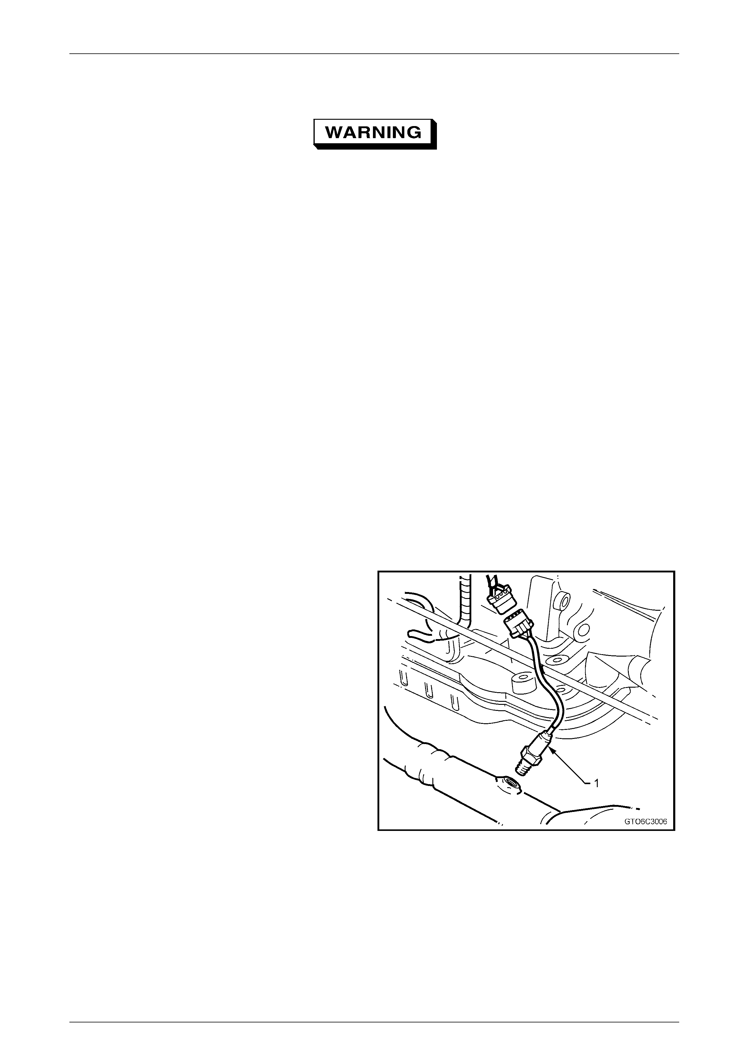
Remove
NOTE
While only one Heated O2 Sensor is shown, the
procedure for the other three Heated O2 Sensors
is similar.
1 Raise the front of vehicle and support on safety
stands, refer to Section 0A General Information for the
location of jacking and support points.
2 Disconnect the Heated O2 Sensor electrical connector
from the sensor to be removed.
3 Loosen and carefully remove the Heated O2 Sensor
from the exhaust pipe.
Figure 6C4-3 – 26
Engine Management GEN IV V8 – Service Operations Page 6C4-3–32
Page 6C4-3–32
Reinstall
Reinstallation is the reverse of the removal procedure, noting the following:
A special anti-seize compound is used on the
heated oxygen sensor threads. New Heated
O2 Sensors will already have the anti-seize
compound applied to the threads.
If a Heated O2 Sensor has been removed, but
not replaced, then anti-seize compound must
be applied to the threads prior to installation.
1 Coat the cleaned threads of the sensor with anti-seize compound, part number 12377953. Specified anti-seize
compound is available from authorised retailer parts outlets as part number 5613695.
2 Tighten the Heated O2 Sensor to the correct torque specification.
Heated O2 Sensor torque specification .............41.0 Nm
3 Road test the vehicle and check for correct operation, taking particular note that no exhaust leakage is evident.
Test
• Under no circumstances should battery
voltage be applied to the Heated O2
Sensor heater.
• To prevent component damage use
connector test adaptor kit J 35616-A.
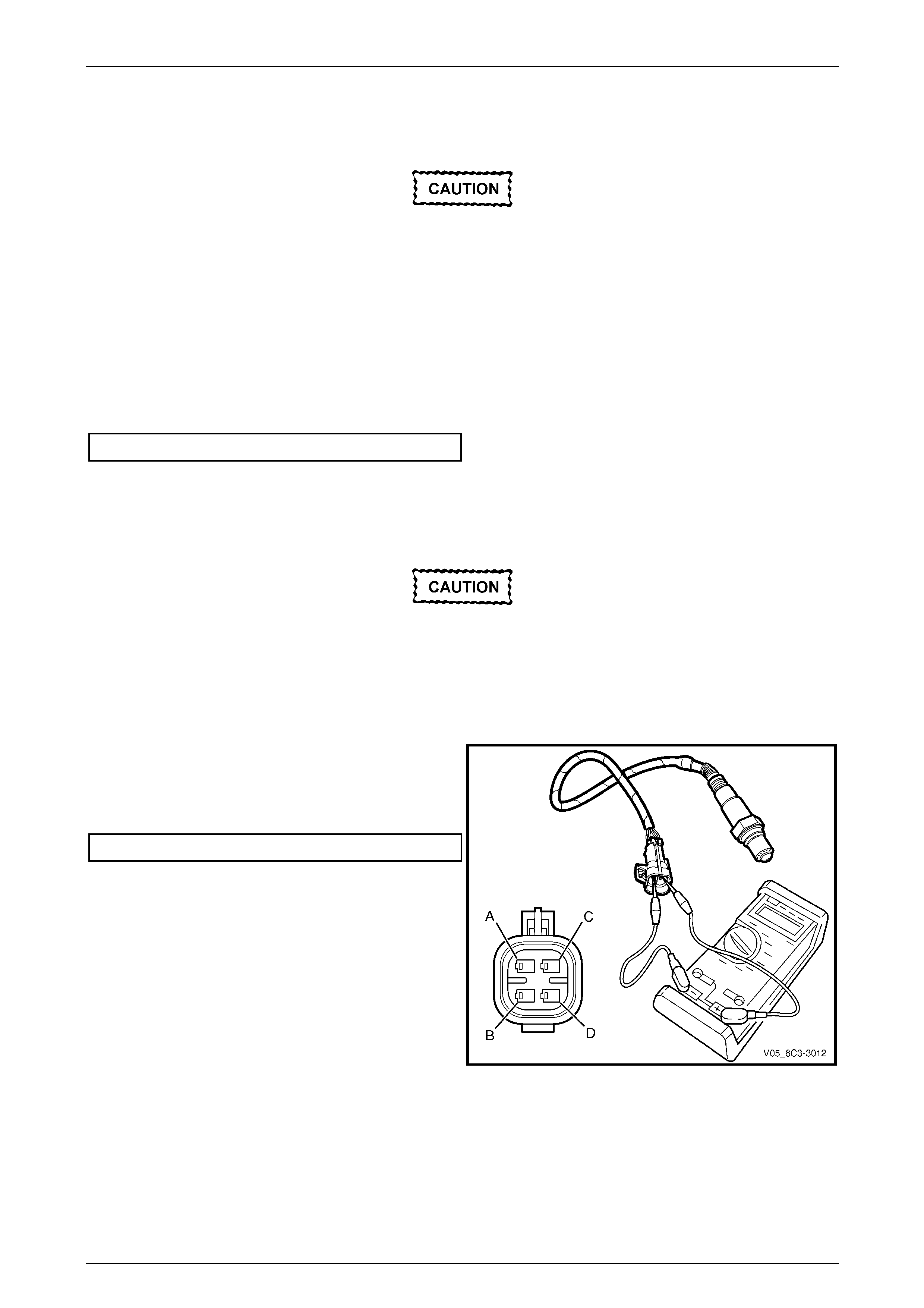
Heater Resistance Check
1 Using a digital ohmmeter and connector test adaptor
kit J 35616-A, measure the resistance across
terminals C and D.
2 Compare the reading against the specification.
Heated O2 Sensor heater resistance @ 20° C ...... 9.0 Ω
3 If the resistance is not within specification, replace the
Heated O2 Sensor.
Figure 6C4-3 – 27
Engine Management GEN IV V8 – Service Operations Page 6C4-3–33
Page 6C4-3–33
3.14 Ignition Coil / Module
NOTE
The ignition module is incorporated into the
ignition coil assembly, and is not serviced
separately.
Remove
1 Turn the ignition switch off.
2 Remove the appropriate engine dress cover(s), refer to 2.2 Engine Dress Covers.
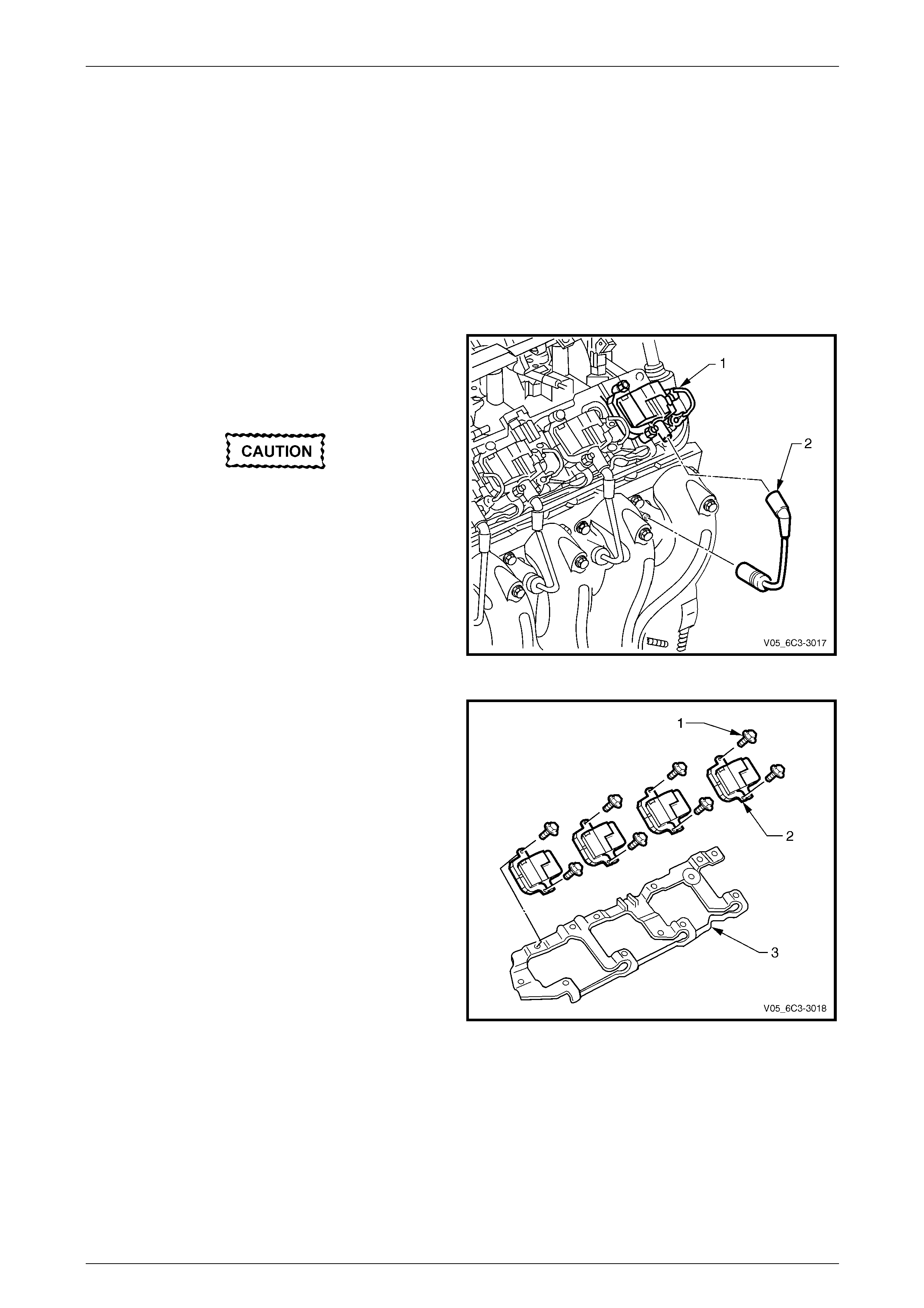
3 Remove the Connector Protection Assurance (CPA)
lock (1) securing the electrical connector to the ignition
coil, then disconnect the wiring harness connector(s)
from the coil(s) being removed.
Never pull on the ignition lead. Grasp the
ignition coil boot and twist to break the seal
before pulling directly from each ignition coil.
4 Disconnect the spark plug wire (2) at the ignition coil.
Figure 6C4-3 – 28
5 Remove each of the ignition coil retaining screws (1).
6 Remove the ignition coil(s) (2) from the mounting
bracket (3).
Figure 6C4-3 – 29
Engine Management GEN IV V8 – Service Operations Page 6C4-3–34
Page 6C4-3–34
Test
Never probe the ignition coil with a 12 Volt
tester as the ignition coil will be damaged.
Due to the internal components of the ignition coil assembly, it is not possible to perform any primary and/or secondary
resistance checks. For further information on the ignition coil operation, refer to
Section 6C4-1 Engine Management – GEN IV V8 – General Information.
Reinstall
Reinstallation of the ignition coil(s) is the reverse of the removal procedure, noting the following:
1 Reinstall the ignition coil retaining screws, and tighten to the correct torque specification.
Ignition coil retaining bolt
torque specification ...............................................12 Nm
2 Road test the vehicle and check for correct operation.
Engine Management GEN IV V8 – Service Operations Page 6C4-3–35
Page 6C4-3–35
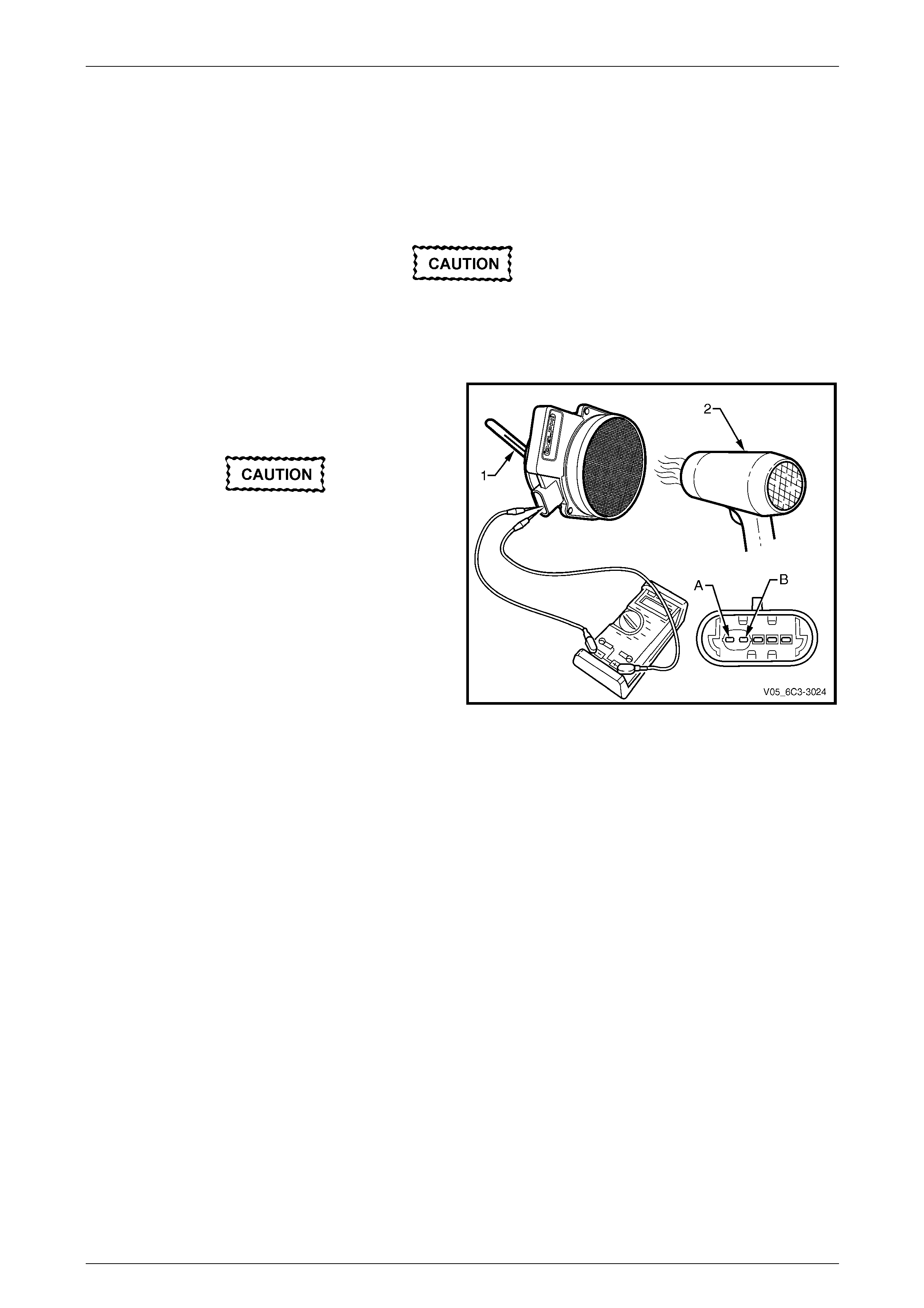
3.15 Intake Air Temperature (IAT) Sensor
The Intake Air Temperature (IAT) sensor is part of the MAF sensor assembly,
refer to 3.18 Mass Air Flow (MAF) Sensor and Intake Air Duct for the replacement procedure.
Test
To prevent component damage use connector
test adaptor kit J 35616-A.
Resistance Check
1 Connect a digital ohmmeter using connector test
adaptor kit J 35616-A to the Mass Air Flow (MAF)
sensor across terminals (A) and (B).
Do not use a high temperature heat gun as
damage to the MAF sensor will result.
2 Whilst holding a thermometer (1), use a commercially
available hair dryer (2) to blow warm air through the
MAF sensor.
Figure 6C4-3 – 30
3 Observe the resistance values as the temperature
increases and compare the temperature/resistance
change to the specifications.
4 If the resistance is not within specifications, replace
the MAF sensor.
Intake Air Temperature Vs Resistance
Temperature °C Resistance – Ohms (Ω)
-10 16,180
0 9,420
20 3,520
25 2,796
40 1,459
60 667
80 332
100 177
120 100
140 60
Engine Management GEN IV V8 – Service Operations Page 6C4-3–36
Page 6C4-3–36
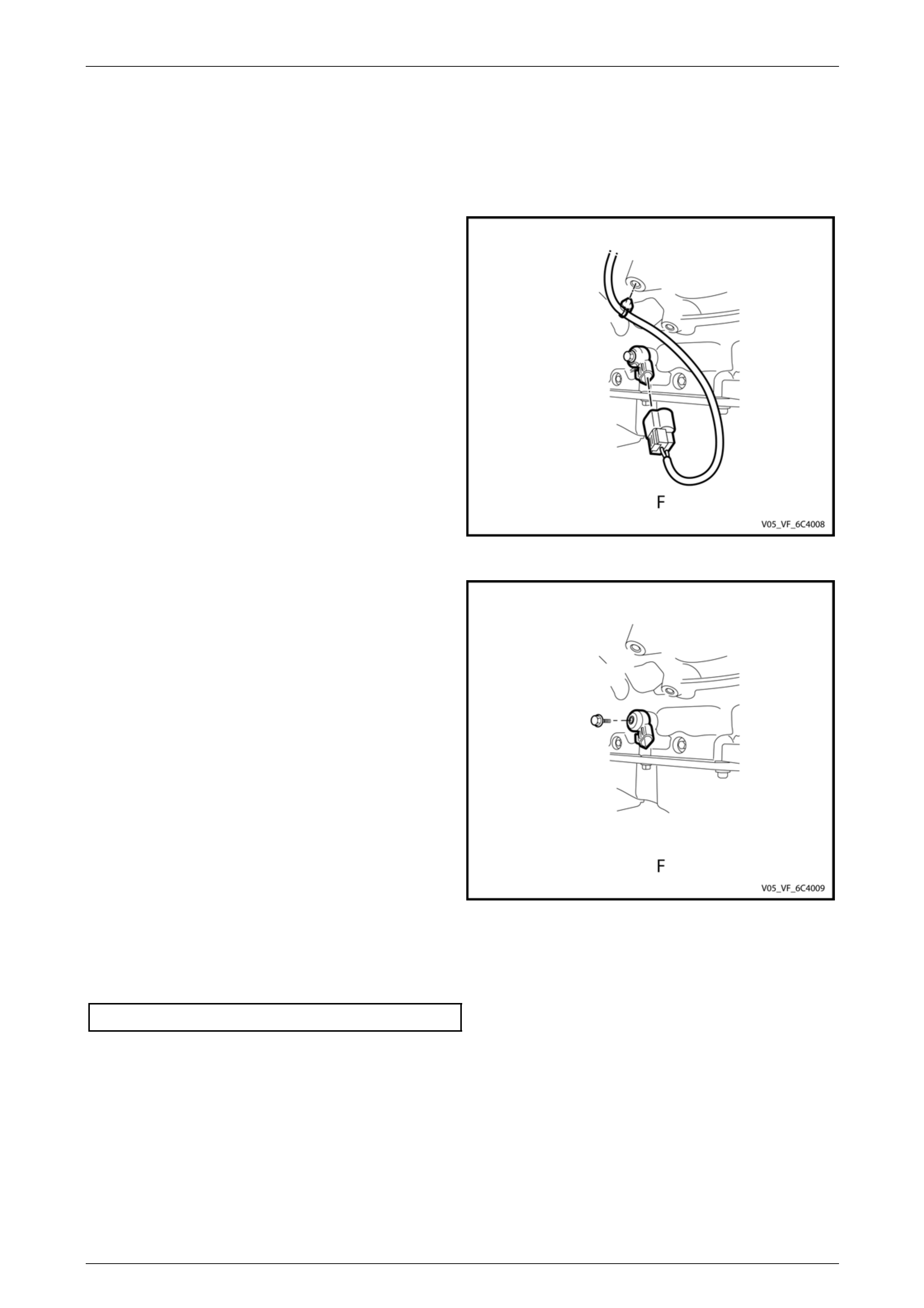
3.16 Knock Sensors
Remove
1 Remove under pan tray
2 Disconnect wiring connector at sensor
NOTE
Only left hand sensor shown
3 Undo retaining bolt
Figure 6C4-3 – 31
Reinstall
NOTE
Ensure the threads for the knock sensor
retaining bolt and block are in good condition
and are free of dirt or contamination. Do not
apply sealant or retaining washers to the
retaining bolt as this will change the operating
frequency of the knock sensor.
1 Fit knock sensor in placed and start bolt by hand
NOTE
Failure to observe the correct tightening
procedure will change the operating frequency of
the knock sensor.
2 Tighten to correct torque
3 Refit connector
Figure 6C4-3 – 32
Knock Sensor Torque Specification ........23Nm +/- 2 Nm
Engine Management GEN IV V8 – Service Operations Page 6C4-3–37
Page 6C4-3–37
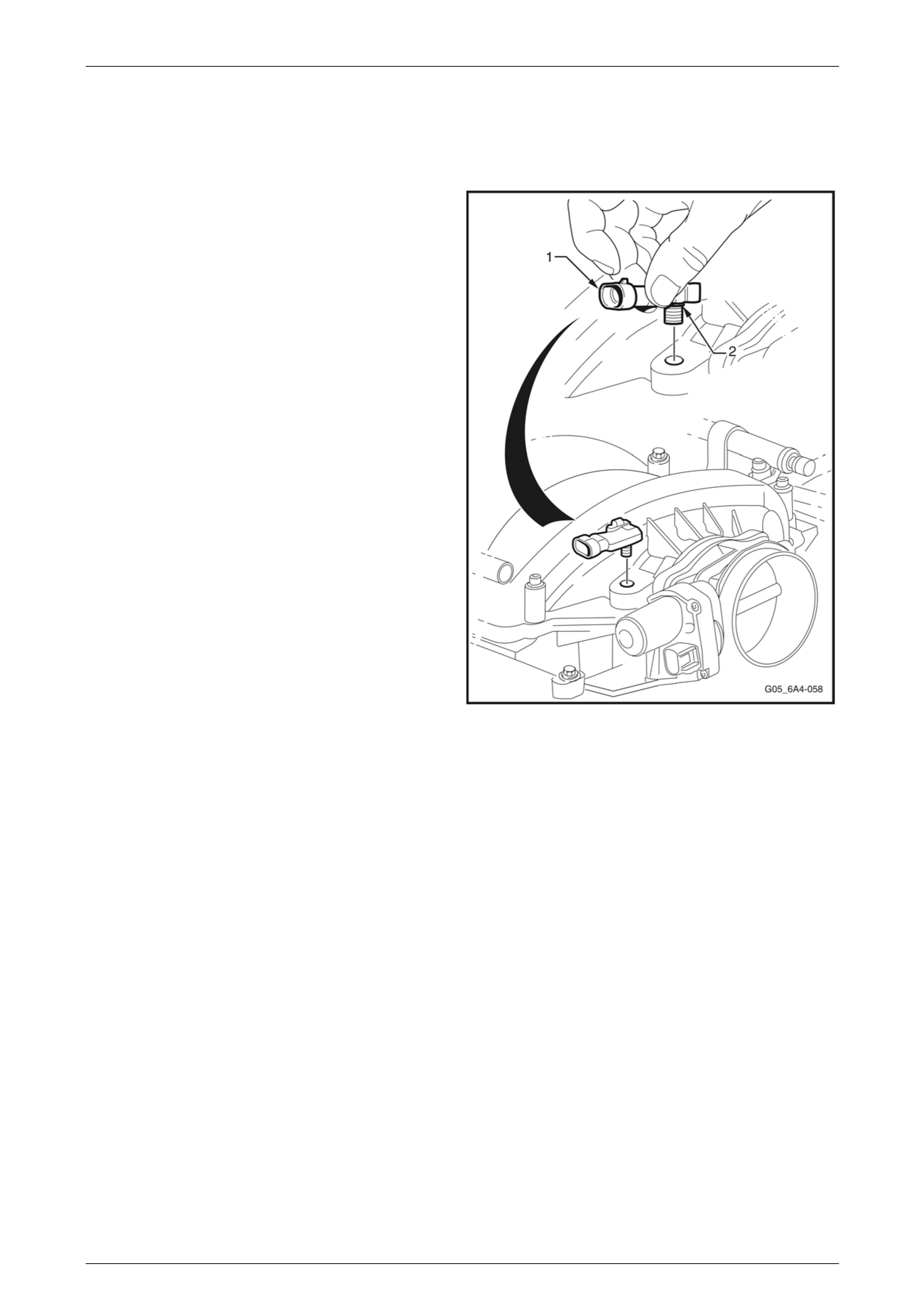
3.17 Manifold Absolute Pressure (MAP)
Sensor
Remove
1 Disconnect the MAP sensor electrical connector (1).
2 Twist the MAP sensor (2) forward to release it from the
intake manifold adaptor.
3 Pull the MAP sensor upward.
Reinstall
Reinstallation of the MAP sensor is the reverse of the
removal procedure, noting the following:
1 Lightly coat the MAP sensor seal with clean engine oil.
2 Start the engine and check for vacuum leaks.
Figure 6C4-3 – 33
Engine Management GEN IV V8 – Service Operations Page 6C4-3–38
Page 6C4-3–38
3.18 Mass Air Flow (MAF) Sensor and Intake
Air Duct
Remove
1 Remove the upper radiator shroud, refer to Section 6B4 Engine Cooling – GEN IV V8 Engine.
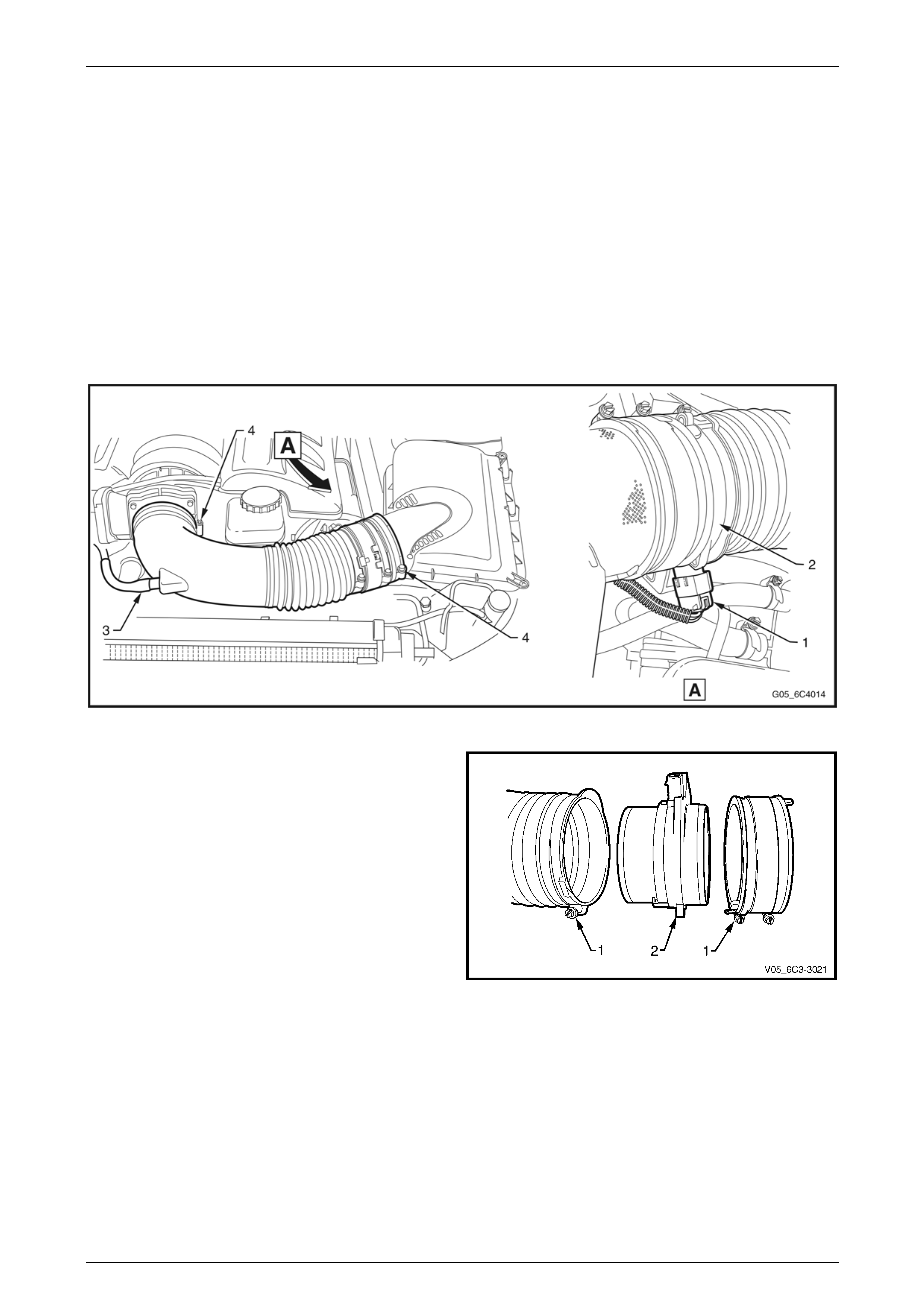
2 Remove the intake air duct:
a Lift up the security tang on the MAF sensor wiring harness connector (1) and remove the connector from
sensor (2).
b Disconnect the PCV hose (3) from the intake air duct.
c Loosen the clamps (4) at each end securing the intake air duct to the throttle body and the air cleaner upper
housing. Remove the duct.
Figure 6C4-3 – 34
3 Loosen the two clamps (1) securing the air intake duct
and the air duct adaptor to the MAF sensor (2).
Figure 6C4-3 – 35

Engine Management GEN IV V8 – Service Operations Page 6C4-3–39
Page 6C4-3–39
Reinstall
Reinstallation of the MAF sensor is the reverse of the removal procedure, noting the following:
NOTE
• The embossed arrows on the MAF sensor
indicate the correct air flow direction. The
arrows must point towards the engine.
• The air duct adaptor (between air cleaner and
MAF sensor), retaining clamps, air duct and
MAF sensor, all have locating notches.
Ensure all notches are aligned.
1 Reinstall the retaining clamps, aligning notches, tighten clamps to the specified torque.
Intake Air Duct Clamp
Torque Specification ...................................1.5 – 2.5 Nm
2 Start vehicle and check for air leaks.
Engine Management GEN IV V8 – Service Operations Page 6C4-3–40
Page 6C4-3–40
3.19 Spark Plugs
Service Precautions
1 Allow the engine to cool (to at least 50° C) before attempting to remove spark plugs. Attempting to remove spark
plugs from a hot engine may cause the plug/cylinder head threads to bind, causing tearing of the alloy cylinder
head threads.
2 Clean the spark plug recess area before removing any spark plug. Failure to do so could result in engine damage
because of dirt or other foreign material entering the cylinder head or by the contamination of the cylinder head
threads. The contaminated threads may then prevent the correct seating of the new or replaced plug. If required,
use a ‘thread chaser’ to clean the threads of any contamination where this is suspected.
3 Only ever handle the spark lug lead boot when removing the ‘near plug’ coil lead from a spark plug. Do not pull on
the lead itself. Twist the boot first, to break the seal then pull to remove.
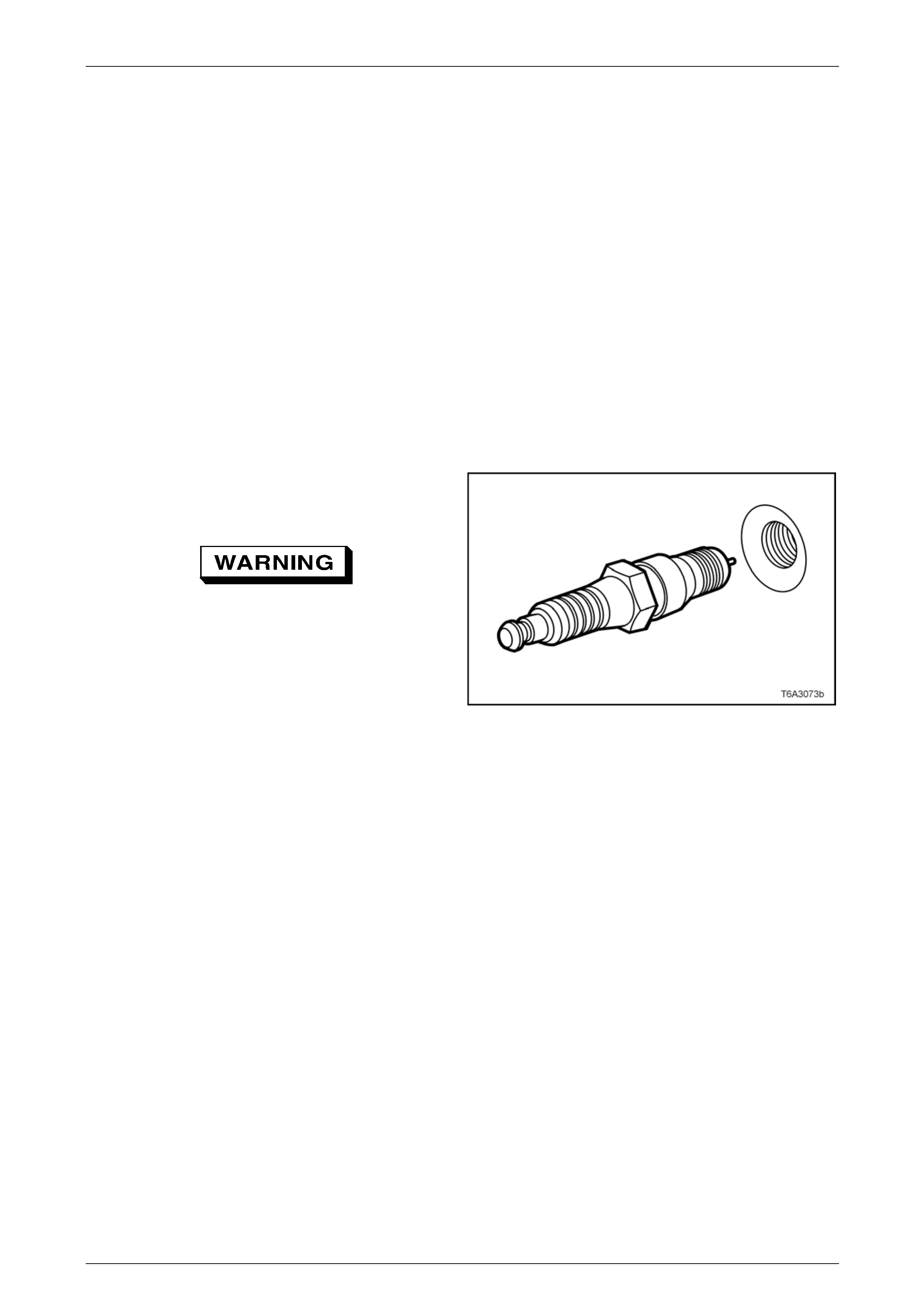
Remove
1 Remove both engine dress covers, refer to 2.2 Engine Dress Covers.
2 Remove the spark plug leads.
3 Using a suitable spark plug socket, loosen the spark
plug/s, then re-tighten to break away any carbon
deposits on the threads.
Wear eye protection to avoid injury.
4 Loosen the spark plug/s once again but, this time, only
one or two turns. Then use compressed air to remove
any foreign material that may otherwise enter the
combustion chamber.
Figure 6C4-3 – 36
NOTE
As each spark plug is removed, place in order.
This will enable any abnormal spark plug
condition to be identified with the correct cylinder.
5 Remove the spark plug.
6 Repeat steps 2 to 5 for each spark plug.

Engine Management GEN IV V8 – Service Operations Page 6C4-3–41
Page 6C4-3–41
Clean, Inspect and Adjust
1 Replace any plug that has cracked insulation, broken insulation or loose electrodes.
2 Clean any oil from the plugs using a degreasing agent.
3 Dry the plugs using compressed air.
4 Clean the spark plugs using a purpose-built machine (sand blasting type).
5 Inspect the spark plugs for defects. Refer to Analysis of Spark Plug Condition in this Section for identification of the
condition of spark plugs.
6 Ensure that the threads are clean and in good order.
7 Use a round wire feeler gauge to check the spark plug
gap.
8 Adjust the gap to the correct specification by gently
bending the outer electrode.
Spark Plug Gap GEN IV V8 Engine .................... 1.5 mm
Figure 6C4-3 – 37
Spark Plug Inspection
Poor Spark Plug Performance
A spark plug can perform poorly due to wear, dirt, carbon fouling, excessive electrode wear, a broken insulator or
excessive gap.
Worn or Dirty Plugs
Worn or dirty plugs can give satisfactory operation while the vehicle is idling, but break down under load.
This can cause:
• Poor fuel economy
• Power loss
• Acceleration loss
• Difficult starting
• Generally poor engine performance
Carbon Fouling
Carbon fouling is indicated by black carbon deposits. The black deposits are usually the result of slow-speed driving and
short runs. In these circumstances, the optimum engine operating temperature is seldom reached.
Fouling can also be caused by:
• Worn piston rings
• Faulty ignition
• Rich fuel mixture
• Spark plugs that are rated too cold

Engine Management GEN IV V8 – Service Operations Page 6C4-3–42
Page 6C4-3–42
Excessive Electrode Wear
This often indicates:
• The engine is operating at high speeds
• The engine is operating at levels that are consistently greater than normal
• A plug that is rated too hot
• Excessively lean fuel mixture
• Plug/s overheating due to insufficient tightening (caused by combustion gases leaking past the threads)
Broken Insulator
Do not use a spark plug with a broken
insulator.
Broken insulators are usually the result of improper installation or carelessness.
Breaks in the upper insulator can result from a poor fitting spark plug socket or an impact. The cracked insulator may not
show up until oil or moisture penetrates the crack. The crack is often just below the crimped part of the shell and may not
be visible.
Breaks in the lower insulator often result from careless re-gapping and are usually visible.
This can also result from the plug operating too hot. For example, in periods of high speed operation or under heavy
loads.
Engine Management GEN IV V8 – Service Operations Page 6C4-3–43
Page 6C4-3–43
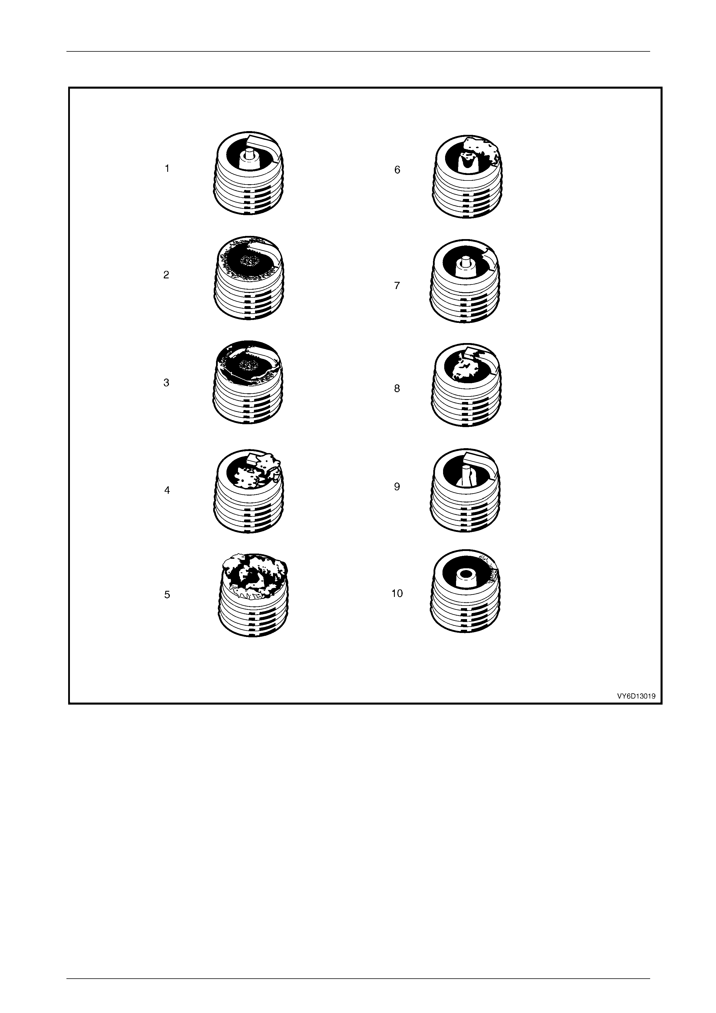
Analysis of Spark Plug Condition
Figure 6C4-3 – 38
Legend
1 Normal
2 Carbon Fouled
3 Oil Fouled
4 Deposit Fouling A
5 Deposit Fouling B
6 Deposit Fouling C
7 Detonation
8 Pre-ignition
9 Heated Shock Failure
10 Insufficient Installation Torque

Engine Management GEN IV V8 – Service Operations Page 6C4-3–44
Page 6C4-3–44
Normal Operation (1)
Brown or greyish-tan deposits and slight electrode wear indicate correct spark plug heat range and mixed periods of high
and low speed driving.
Carbon Fouled (2)
Dry, fluffy black carbon deposits possibly due to poor ignition output, weak coil, faulty spark plug leads, excessive idling
or slow speeds under light load. If spark plug temperatures remain too low for normal combustion, the deposits are not
burned off.
Oil Fouled (3)
Wet, oily deposits with minor electrode wear possibly due to oil leaking past worn piston rings.
Breaking in a new or recently overhauled engine before the rings are fully seated may also result in this condition.
Deposit Fouling A (4)
Red brown, yellow and white coloured coatings on the insulator tip which are by-products of combustion. They come
from the fuel and the lubricating oil which generally contain additives. Most powdery deposits have no adverse effect on
spark plug operation; however, they may cause intermittent missing under severe operating conditions.
Deposit Fouling B (5)
Deposits similar to those identified in Deposit fouling A (4). These are also by-products of combustion from the fuel and
lubricating oil. Excessive valve stem clearances and/or defective intake valve seals allow too much oil to enter the
combustion chamber. The deposits will accumulate on the portion of the spark plug that projects into the chamber and
will be heaviest on the side facing the intake valve. When you detect this condition in only one or two cylinders, check the
valve stem seals.
Deposit Fouling C (6)
Most powdery deposits identified in Deposit fouling A (4) have no adverse effect on the operation of the spark plug as
long as they remain powdery.
Under certain conditions of operation however, these deposits melt and form a shiny glaze coating on the insulator.
When hot, this acts as a good electrical conductor allowing the current to flow along the deposit instead of sparking
across the gap.
Detonation (7)
Commonly referred to as engine knock or ‘pinging’, detonation causes severe shocks inside the combustion chamber
causing damage to parts.
Pre-ignition (8)
Burnt or blistered insulator tip and badly eroded electrodes probably due to the excessive heat.
This is often caused by a cooling system blockage, sticking valves, improperly installed spark plugs or plugs that are the
wrong heat rating (too hot).
Sustained high speed with a heavy load can produce temperatures high enough to cause pre-ignition.
Heat Shock Failure (9)
A rapid increase in spark plug tip temperature under severe operating conditions can cause heat shock and result in
fractured insulators. This is a common cause of broken and cracked insulator tips.
Insufficient Installation Torque (10)
Poor contact between the spark plug and the cylinder head seat.
The lack of proper heat transfer that results from poor seat contact causes overheating of the spark plug. In many cases,
severe damage occurs, as shown.
Dirty threads in the cylinder head can cause the plug to seize before it is seated.
Ensure that the cylinder head and spark plug threads are free of deposits, burrs and scale before installation.
Engine Management GEN IV V8 – Service Operations Page 6C4-3–45
Page 6C4-3–45
Reinstall
Reinstallation of the spark plugs is the reverse of the removal procedure, noting the following:
1 Hand start each spark plug into the cylinder head thread.
Ensure that the spark plug has fully seated on
the cylinder head before the specified torque
is reached.
NOTE
When replacing spark plugs, use genuine spark
plugs or recommended spark plugs of the correct
heat range.
2 Tighten the plugs to the correct torque specification using a spark plug socket and accurate torque wrench.
Spark Plug Torque Specification
New Cylinder Head Only.......................................20 Nm
Existing Cylinder Head..........................................15 Nm
Engine Management GEN IV V8 – Service Operations Page 6C4-3–46
Page 6C4-3–46
3.20 Spark Plug Leads
Remove
Pulling or bending spark plug leads can
cause hidden damage. Follow the removal
steps carefully to avoid such damage.
1 Remove both engine decorative covers, refer to 2.2 Engine Dress Covers.
2 Firmly grasp the boot (1) at the spark plug end of the
lead (2).
Grasp the boot, not the lead.
3 Twist the boot in both directions, to relieve any suction
and to break the seal.
4 Pull the boot straight off the spark plug.
5 Repeat Steps 2 and 3 for the ignition coil end of the
lead (3).
6 Carefully set the lead to one side.
NOTE
As each spark plug lead is removed, place in
order. This will enable any abnormal condition to
be identified with the correct cylinder. Figure 6C4-3 – 39
7 Repeat Steps 2 to 6 for the remaining leads.
Inspect
1 Connect and Ohmmeter, capable of accurately reading to 20 kΩ, to each end of a lead.
2 Record the reading for each lead.
3 Compare the resistance readings taken against the specification.
Spark Plug Lead Resistance................. 700 Ω Maximum
4 Replace any lead that is significantly different from the stated specification.
Reinstall
Reinstallation of the spark plug leads is the reverse of the removal procedure, noting the following:
1 Only ever handle a spark plug lead by the boot at each end. Never the lead itself.
2 Push on the boot until the lead connection is fully engaged with the spark plug terminal. Ensure the actual lead
connection has connected with the spark plug.
3 Repeat this procedure for the coil end of each lead.
4 Start the engine and check for correct operation.
Engine Management GEN IV V8 – Service Operations Page 6C4-3–47
Page 6C4-3–47
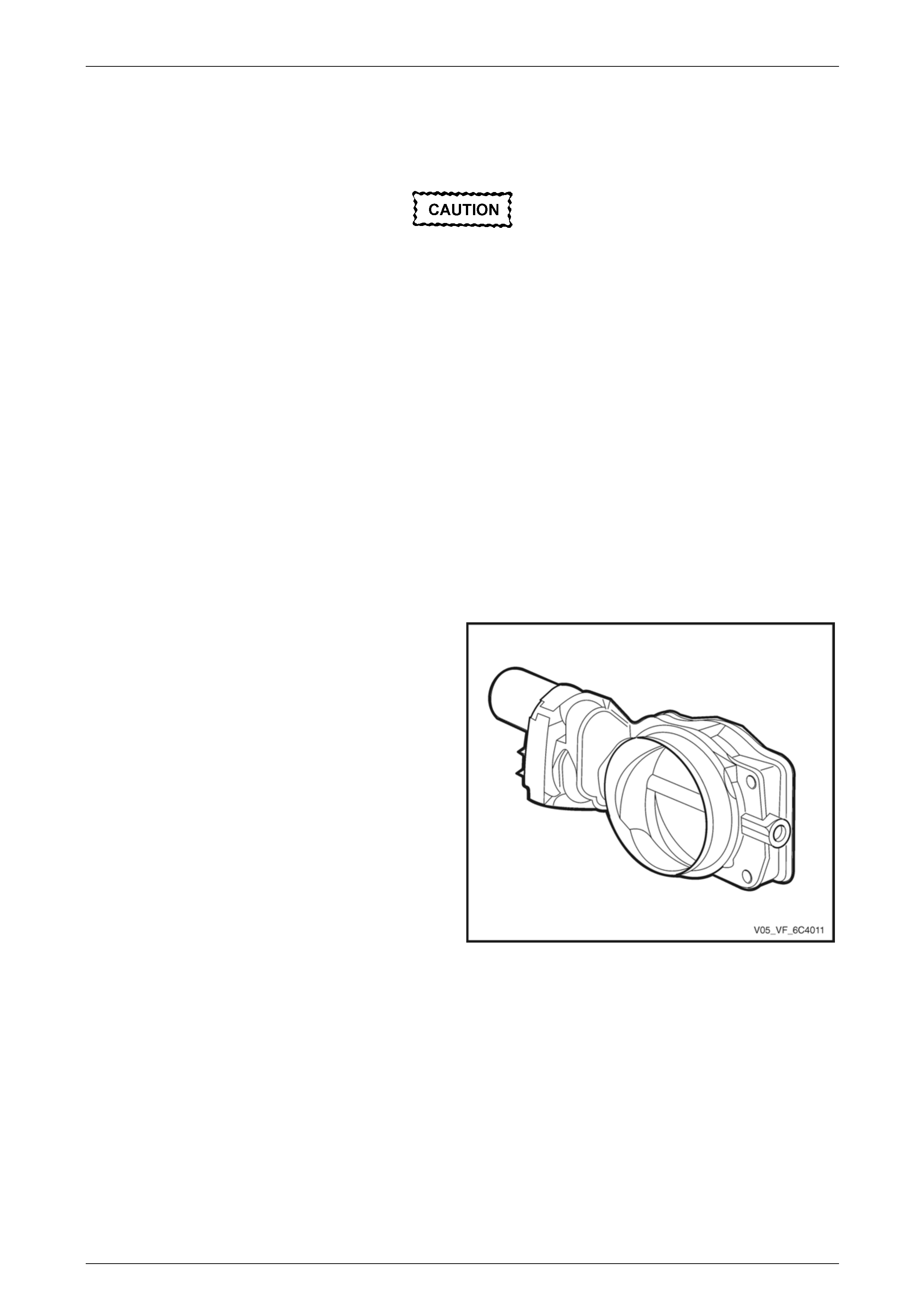
3.21 Throttle Body
Handling Precautions
Under no circumstances should the throttle
body be disassembled. If the throttle body is
disassembled, the vacuum seal between the
cover plate and the throttle body will be
broken. This will allow the ingress of foreign
particles and or moisture and render the
throttle body unserviceable.
The throttle body must not be subjected to
any form of shock such as dropping it. If the
throttle body is subjected to shock, damage
may result to the fragile motor magnets within
the throttle body.
Remove
1 Turn the ignition switch off.
2 Partially drain the cooling system before removing the cooling system hoses at the throttle body,
refer to Section 6B4 Engine Cooling – GEN IV V8.
3 Remove the intake air duct, refer to 3.18 Mass Air Flow (MAF) Sensor and Intake Air Duct.
4 Disconnect the throttle body electrical connector (1).
5 Disconnect the cooling system hoses (2) from the
throttle body.
Figure 6C4-3 – 41
Engine Management GEN IV V8 – Service Operations Page 6C4-3–48
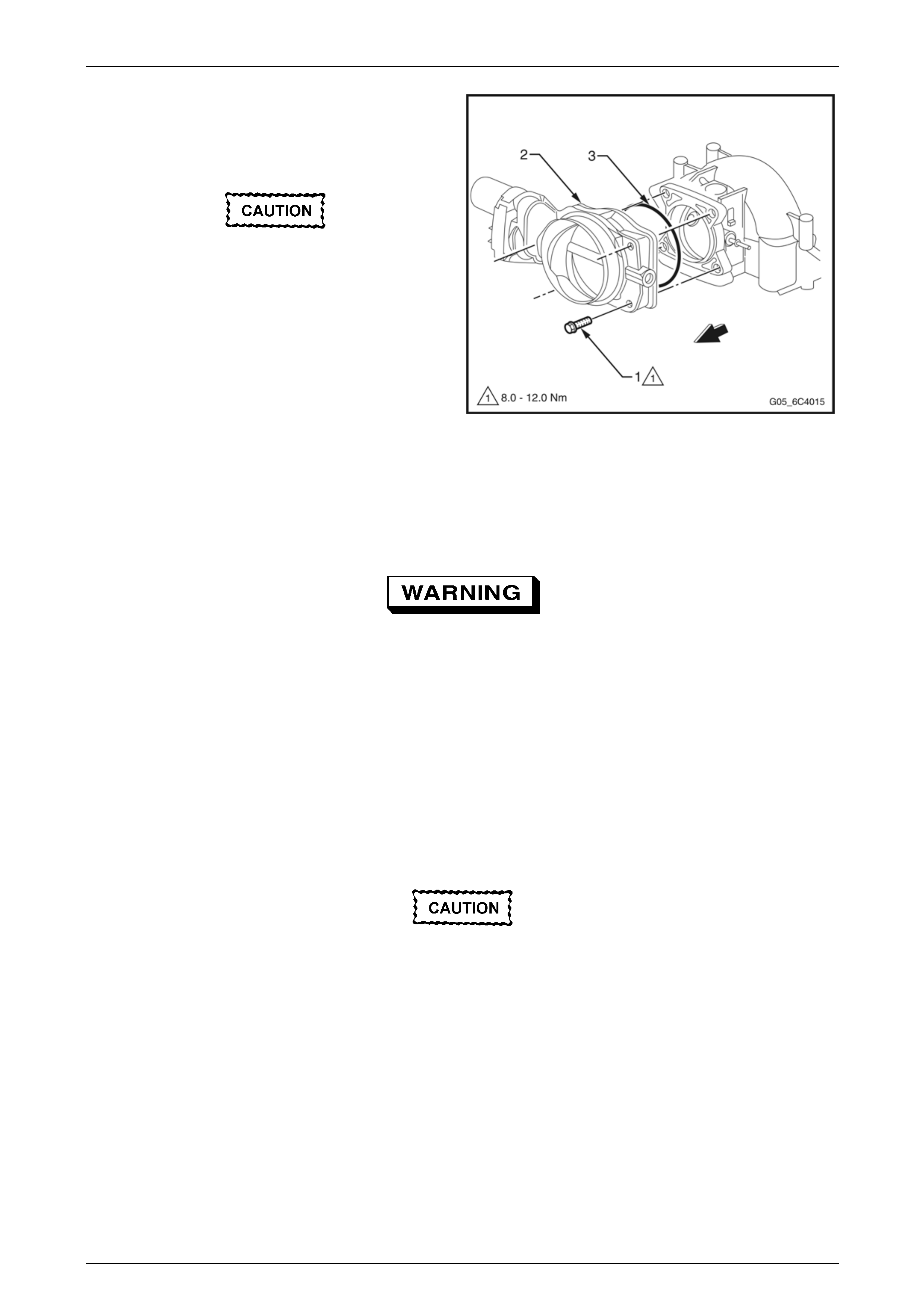
Page 6C4-3–48
6 Remove the throttle body attaching bolts (1).
7 Remove the throttle body (2) and the seal (3).
8 Discard the removed seal.
• To prevent damage to the sealing
surfaces, it is preferred that only plastic
scrapers are used for cleaning deposits
from machined alloy surfaces.
• Do not soak the throttle body in cold
immersion type cleaner. To clean the
throttle body following disassembly, use
a spray type cleaner such as GM 1052626
or equivalent. Use a shop towel to remove
heavy deposits.
• The throttle body contains electrical
components that should not come in
contact with solvent or cleaner, as
damage may result.
9 Clean the both sealing surfaces.
Figure 6C4-3 – 42
Inspect
To avoid serious personal injury, never
attempt to rotate the throttle plate manually
whilst the throttle body harness connector is
connected to the throttle body.
The following throttle body inspection procedure may be carried out with the throttle body installed on the vehicle. Prior to
performing a throttle body on-vehicle inspection, perform the following:
1 Switch the ignition off.
2 Disconnect the throttle body harness connector.
3 Remove the air cleaner intake duct, refer to 3.18 Mass Air Flow (MAF) Sensor and Intake Air Duct.
4 Fully open the throttle plate by hand in order to inspect the throttle body bore and the throttle plate for any deposits.
When cleaning / inspecting the throttle body:
• Do not subject the throttle body assembly
to an immersion cleaner or a strong
solvent. Damage to the throttle position
sensor and / or sealed throttle shaft
bearings will result.
• Never use a wire brush or scraper to clean
the throttle body. A wire brush or sharp
tool may damage the throttle body
components.
5 Use a clean shop towel and GM cleaner 1052626 or equivalent product to clean the throttle body bore and throttle
plate. If necessary, use a parts cleaning brush in order to remove heavy deposits.
6 To inspect the throttle body for a binding throttle plate, fully open and close the throttle plate by hand. The throttle
plate should open and close smoothly.

Engine Management GEN IV V8 – Service Operations Page 6C4-3–49
Page 6C4-3–49
7 Inspect the throttle body for a bent or damaged throttle plate, and cracks, corrosion, or distortion in the throttle body
housing.
NOTE
The throttle body contains no serviceable parts
and should not be disassembled. If the throttle
body is damaged it must be replaced as an
assembly.
8 If the throttle body is affected by any of the above conditions, the throttle body must be replaced.
9 If an on-vehicle throttle body inspection was performed, reinstall the air cleaner intake duct,
refer to 3.18 Mass Air Flow (MAF) Sensor and Intake Air Duct.
10 Road test the vehicle and check for correct operation, taking particular note that no air leaks are evident.
Reinstall
Reinstallation of the throttle body is the reverse of the removal procedure, noting the following:
1 Install a new throttle body seal.
2 Reinstall the throttle body attaching bolts and tighten to the correct torque specification.
Throttle body attaching bolt
torque specification ...............................................12 Nm
3 Refill the cooling system, refer to Section 6B4 Engine Cooling – GEN IV V8.
4 Road test the vehicle and check for correct operation, taking particular note that no air leaks are evident.

Engine Management GEN IV V8 – Service Operations Page 6C4-3–50
Page 6C4-3–50
4 Specifications
Accelerator Pedal Position Sensor 1
Type.....................................................Three wire potentiometer
Accelerator pedal at rest ........................................ Below 1.25 V
Accelerator pedal fully depressed .......................5.0 V maximum
Resistance @ 20° C .............................................................TBA
Accelerator Pedal Position Sensor 2
Type.....................................................Three wire potentiometer
Accelerator pedal at rest ........................................ Below 1.25 V
Accelerator pedal fully depressed .......................5.0 V maximum
Resistance @ 20° C .............................................................TBA
Camshaft Position (CMP) Sensor
Type............................ Twin hall effect, interrupter ring triggered
Air gap ...................................................................0.1 – 1.8 mm
Air gap adjustment ................................................No adjustment
Crankshaft Position (CKP) Sensor
Type............................ Twin hall effect, interrupter ring triggered
Coil resistance @ 20° C......................................... 850 – 1040 Ω
Air gap ....................................................................0.1 – 1.5 mm
Air gap adjustment ............................................... No adjustment
Engine Coolant Temperature Sensor
Type........................ Negative temperature coefficient thermistor
Engine Coolant Temperature Vs Resistance
Temperature °C Resistance – Ohms (Ω)
-10 16,180
0 9,420
20 3,520
25 2,796
40 1,459
60 667
80 332
100 177
120 100
140 60
Evaporative Emission (EVAP) Canister Purge Valve
Type...............................................................................Solenoid
Resistance @ 20° C ....................................................24 – 28 Ω
Operating voltage................................................... 12.0 – 16.0 V
Firing Order .......................................................................1, 8, 7, 2, 6, 5, 4, 3
Fuel Injector
Type...............................................................................Solenoid
Fuel Injector Resistance @ 20° C..........................11.4 – 12.6 Ω
Fuel System Pressure
Regulated Pressure ............................................. 380 – 440 kPa

Engine Management GEN IV V8 – Service Operations Page 6C4-3–51
Page 6C4-3–51
Heated O2 Sensor
Type..........................................Four wire, Zirconia, galvanic cell
Operating range (above 360° C) ........................... 10 – 1000 mV
Closed loop operating range................................. 300 – 600 mV
Heater resistance @ 20° C .................................................9.0 Ω
Intake Air Temperature (IAT) Sensor
Type........................ Negative temperature coefficient thermistor
Intake Air Temperature Vs Resistance
Temperature °C Temperature °C
-10 -10
0 0
20 20
25 25
40 40
60 60
80 80
100 100
120 120
140 140
Knock Sensor
Type........................................................ Piezo ceramic element
Mass Air Flow Sensor
Type...........................................................................HOT WIRE
Spark Plug
Type........................................................................... AC 41-952
Gap ..............................................................1.52 mm ± 0.05 mm
Adjustment........................................................... No adjustment
Spark Plug Lead Resistance
Resistance ................................................... 700 Ohm maximum
Throttle Position Sensor 1
Type.....................................................Three wire potentiometer
Closed throttle....................................................... Below 1.25 V
Wide open throttle...............................................5.0 V maximum
Throttle Position Sensor 2
Type.....................................................Three wire potentiometer
Closed throttle....................................................... Below 1.25 V
Wide open throttle...............................................5.0 V maximum
Vehicle Speed Sensor
Type......................................................Inductive Magnetic Type
Coil Resistance @ 20° C ...................................................945 Ω

Engine Management GEN IV V8 – Service Operations Page 6C4-3–52
Page 6C4-3–52
5 Torque Wrench Specifications
Accelerator Pedal Position Sensor to Accelerator
Pedal Position Sensor Support Bracket Retaining Bolt ............... 7.0 – 12.0 Nm
Accelerator Pedal Position Sensor Support Bracket to
Dash Panel Retaining Nut ......................................................... 20.0 – 30.0 Nm
Air Cleaner Lower Housing Securing Bolts.................................. 7.5 – 12.5 Nm
Air Cleaner Upper Housing Securing Screws................................ 2.0 – 3.0 Nm
A/C Refrigerant Pressure Sensor .............................................................. 6 Nm
Camshaft Position (CMP) Sensor Bolt .................................................... 25 Nm
Crankshaft Position (CKP) Sensor Bolt ................................................... 25 Nm
Engine Coolant Temperature (ECT) Sensor............................................ 20 Nm
Fuel Rail Attaching Studs ........................................................................ 10 Nm
Heated Oxygen Sensor ........................................................................... 41 Nm
Ignition Coil/Module Attaching Screw ...................................................... 12 Nm
Intake Air Duct Clamp................................................................................ 2 Nm
Knock Sensor (Front and Rear)............................................................... 15 Nm
Oil Pressure Sensor ................................................................................ 20 Nm
ECM Mounting Bracket Screws................................................................. 8 Nm
Spark Plugs only with New Cylinder Head .............................................. 20 Nm
Spark Plugs only with Existing Cylinder Head ......................................... 15 Nm
Throttle Body Attaching Bolts ...................................................... 8.0 – 12.0 Nm
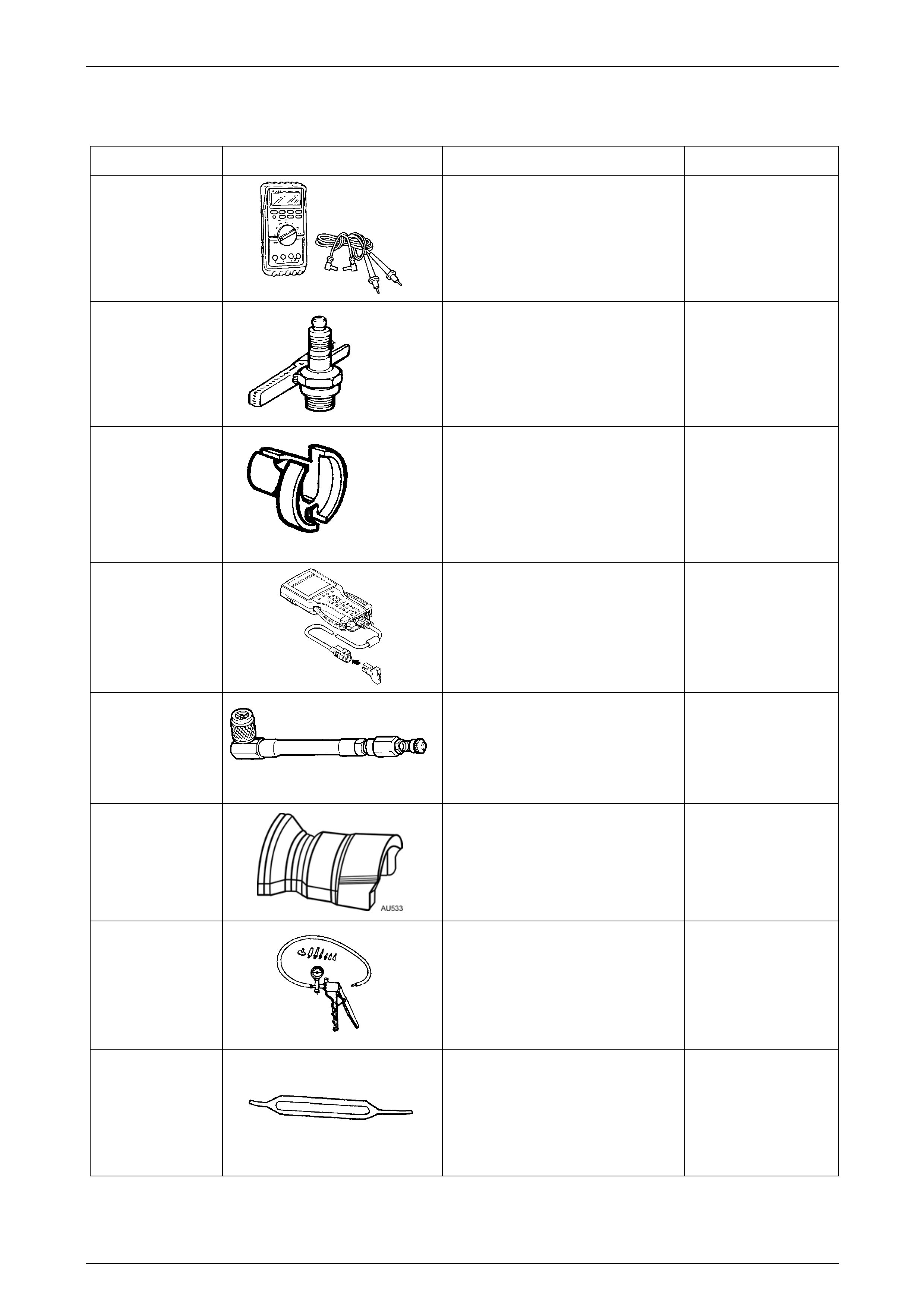
Engine Management GEN IV V8 – Service Operations Page 6C4-3–53
Page 6C4-3–53
6 Special Tools
Tool Number Illustration Description Tool Classification
3588
Digital Multimeter
Used for various measurement
functions as detailed in the text.
Previously released as J 39200, 3545
GM and also commercially available
with a minimum of 10 MΩ impedance.
Available
7230
HEI Tester
Also previously released as ST-125. Mandatory
7371
Quick Connect Release Tool for GEN
IV V8 Engine – 3/8”
Used for releasing the fuel inlet and
return hose quick connects at the
dash panel connections, after
depressurising the fuel system.
Previously released.
Mandatory
7000086I
TECH 2 Scan Tool
Used for diagnosis of vehicle electrical
systems.
Previously released. Mandatory
AU453
Fuel Gauge Schrader Adaptor
Used for checking fuel pressure in
conjunction with AU338 Mandatory
AU533
Quick Connect Release Tool
Used for releasing the quick connect
fittings at the canister purge solenoid
and fuel filter, fuel feed and return
hose connections.
Previously released.
Mandatory
J 23738-A
Vacuum Pump (20 in. Hg Minimum)
Used for many applications where a
controlled vacuum is required to be
applied.
Previously released and also
commercially available
Mandatory
J 33095
Micro-pack Terminal Remover
Used for the safe removal of Micro-
Pack connector terminals.
Previously released. Unique
Engine Management GEN IV V8 – Service Operations Page 6C4-3–54
Page 6C4-3–54
Tool Number Illustration Description Tool Classification
J 34142-A
Unpowered Test Light
Previously released as CT-40-C and
also commercially available
Must have a current draw less than
0.3 Amp.
Mandatory
J 34730-1A
Fuel Pressure Gauge - High Pressure
Used for checking system fuel
pressure in conjunction with adaptor
AU453.
Mandatory
J 34730-2C
Injector Test Light
Used to check for power and the
control circuit of the fuel injector, for
proper operation.
Also previously released as
ST- 8329.
Mandatory
J 35616-A
Connector Test Adaptor Kit
Used when carrying out electrical
diagnostic circuit checks.
Previously released Desirable
J 36400-5
Weather Pack Terminal Remover
Used for the safe removal of Weather-
Pack connector terminals.
Also previously released as
J 36400-5.
Desirable
J 37287
Inlet & Return Fuel Line Shut-off
Adaptors
Used in conjunction with the fuel
pressure gauge for restricting the fuel
supply and return lines for testing
Previously released
Mandatory
J 39021
Fuel Injector Coil/Balance Tester
Used in conjunction with a DMM for
testing the fuel injector coil windings
and for injector balance testing
Previously released
Mandatory
J 35314-A
Exhaust Back Pressure Gauge (with
Adaptor)
Used to check the exhaust system
back pressure.
Unique
Engine Management GEN IV V8 – Service Operations Page 6C4-3–55
Page 6C4-3–55
Tool Number Illustration Description Tool Classification
J 41099
Reverse Lock-out Solenoid Socket
Used to remove/reinstall the Reverse
Lock-Out Solenoid from the M12
Manual Transmission.
Previously released
Desirable
J 41413-200
EVAP Diagnostic Station
Used for various diagnostic tests on
the EVAP system.
New release
Mandatory
J 41413-SPT
High Intensity White Light
Used with J 41413-200 for testing the
EVAP system.
Mandatory
J41415-40
Fuel Tank Cap Adaptor
Used for various diagnostic tests on
the EVAP system.
New release.
Mandatory
J 41712
Oil Pressure Sensor Socket
Used in conjunction with 3/8” drive
socket equipment to remove/reinstall
oil pressure sensor.
Previously released
Desirable
J 44152
Jumper Harness
Used for checking automatic
transmission during diagnostic
checks.
Also previously released as J 39775.
Mandatory
J 44175
Fuel Composition Tester
Used to test for contamination in the
fuel.
New release.
Desirable