SECTION 1A8 - HEADLINING AND INTERIOR TRIM
IMPORTANT
Before performing any Service Operation or other procedure described in this Section, refer to Section
00 CAUTIONS AND NOTES for correct workshop practices with regard to safety and/or property damage.
1. GENERAL INFORMATION
Due to the unique 2- door body styling of V2 Ser ies Models, the headlining, as sociated trim s and covers are unique.
The headlining is a one-piece moulded trim and is of similar design to VX Series I Models.
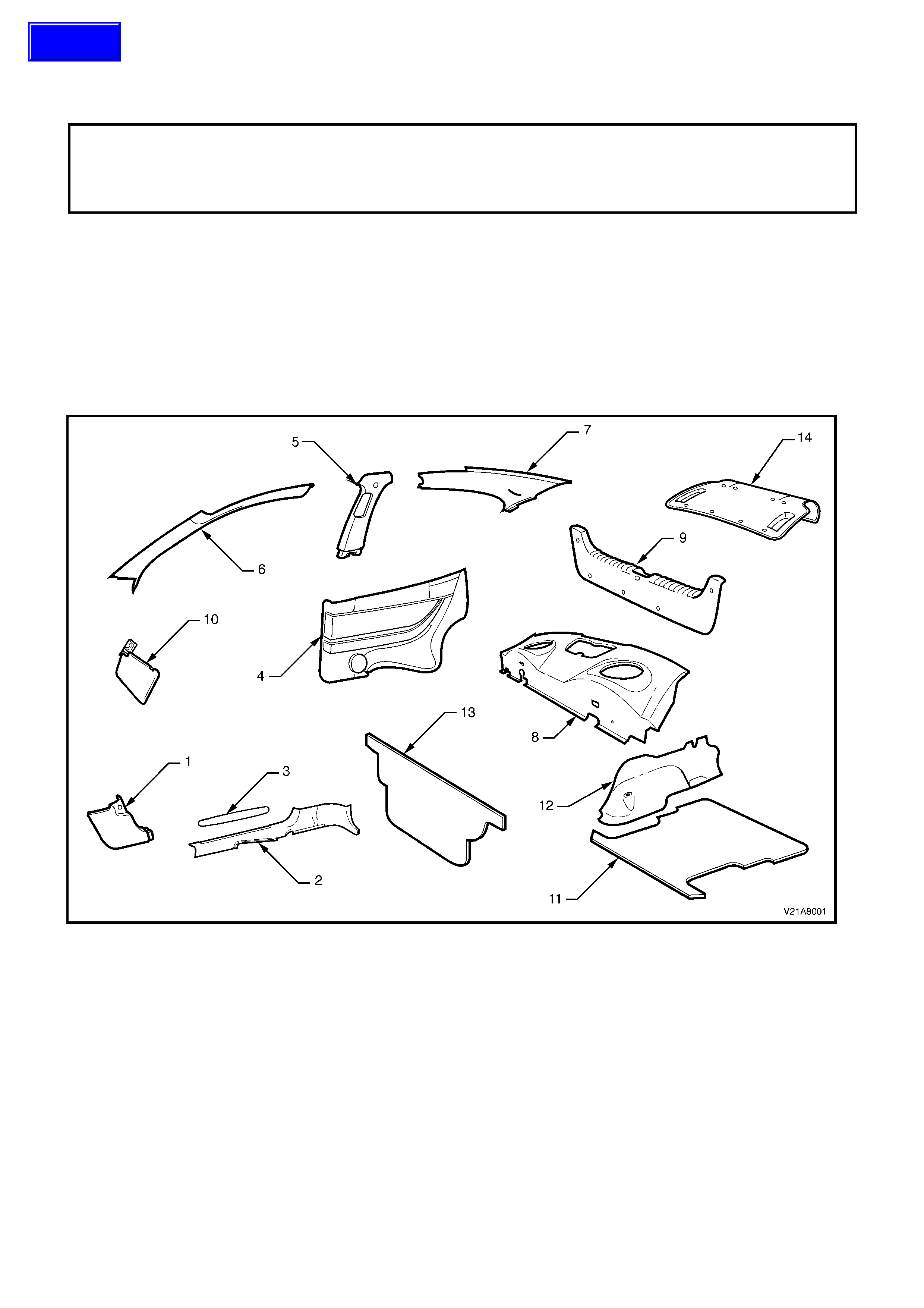
Fig. 1A8-1 shows the interior trim com ponents (other than the floor car pet and headlining assem blies ) for V2 Series
Models that are covered in this Section.
NOTE: Clean hands are essential when working on the body interior trim.
Legend
1. Shroud lower trim
2. Inner rocker panel cover
3. Inner rocker panel cover insert
4. Rear quarter trim
5. B-pillar trim
6. A-pillar trim
7. C-pillar trim
8. Rear parcel shelf assembly
9. Rear compartment crossmember cover
10. Sunvisor assembly
11. Spare wheel cover
12. Rear wheelhouse carpet
13. Rear seat back carpet
14. Rear compartment lid liner
Techline
2. SERVICE OPERATIONS
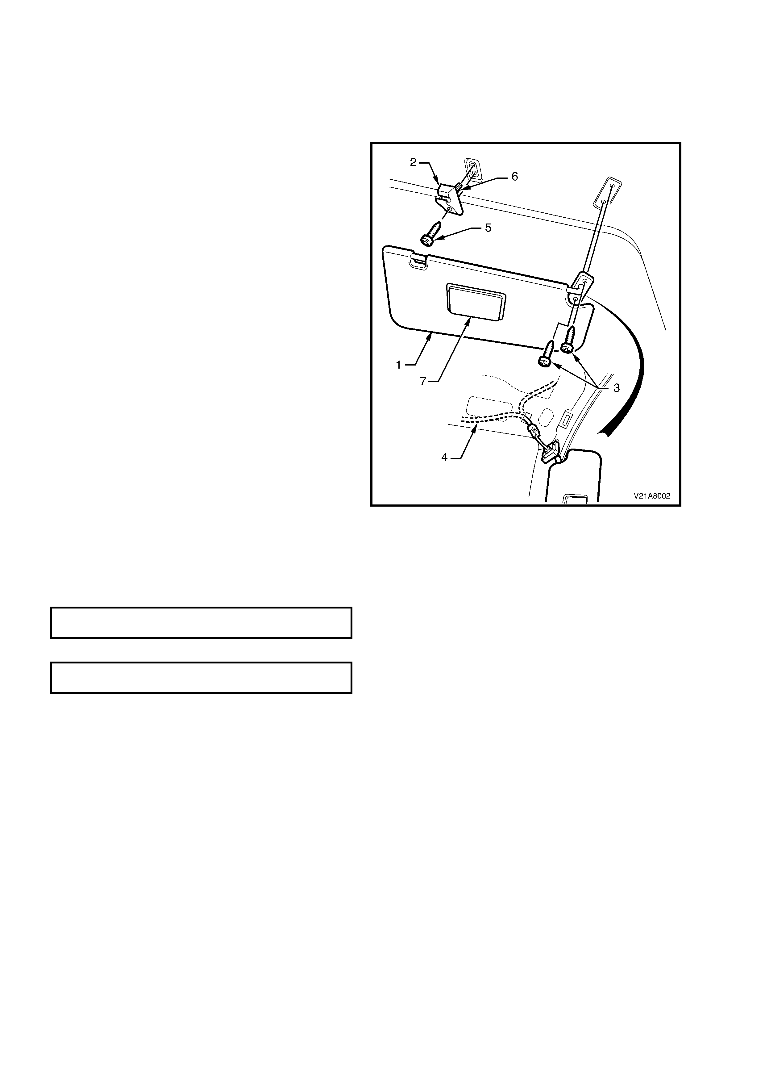
2.1 SUNVISOR ASSEMBLY
REMOVE
1. Disconnect the battery ground cable.
2. Disconnect the sunvisor (1) from the bracket
(2) and rotate to gain access.
3. Remove the two sunvisor attaching screws (3).
4. Pull the sunvisor away from the roof lining and
disconnect the wiring harness (4) to the
illuminated vanity mirrors.
5. Remove the sunvisor.
6. Remove the screws (5) from the bracket and
pull the bracket from the roof lining.
NOTE 1: he illuminated vanity mirrors (7) and the
associated bulbs cannot be from the sunvisor
assembly and are consequently not serviced
separately. If the illuminated mirror or the
associated bulbs require replacement, the
complete sunvisor assembly must be replaced.
NOTE 2: When removing the sunvisor bracket,
ensure that care is taken not to damage the
locating pin (6).
REINSTALL
The installation procedure for the sunvisor is the
reverse of the removal procedure, noting the
following:
• Ensure that the sunvisor bracket locating pin is
engaged before installing the screw.
• Do not exceed the specified torque wrench
setting for the sunvisor and bracket attaching
screws as damage to the roof panel may occur.
SUNVISOR BRACKET ATTACHING SCREW
TORQUE SPECIFICATION 1 - 3 Nm
SUNVISOR ATTACHING SCREW
TORQUE SPECIFICATION 1 - 3 Nm
Figure 1A8-2
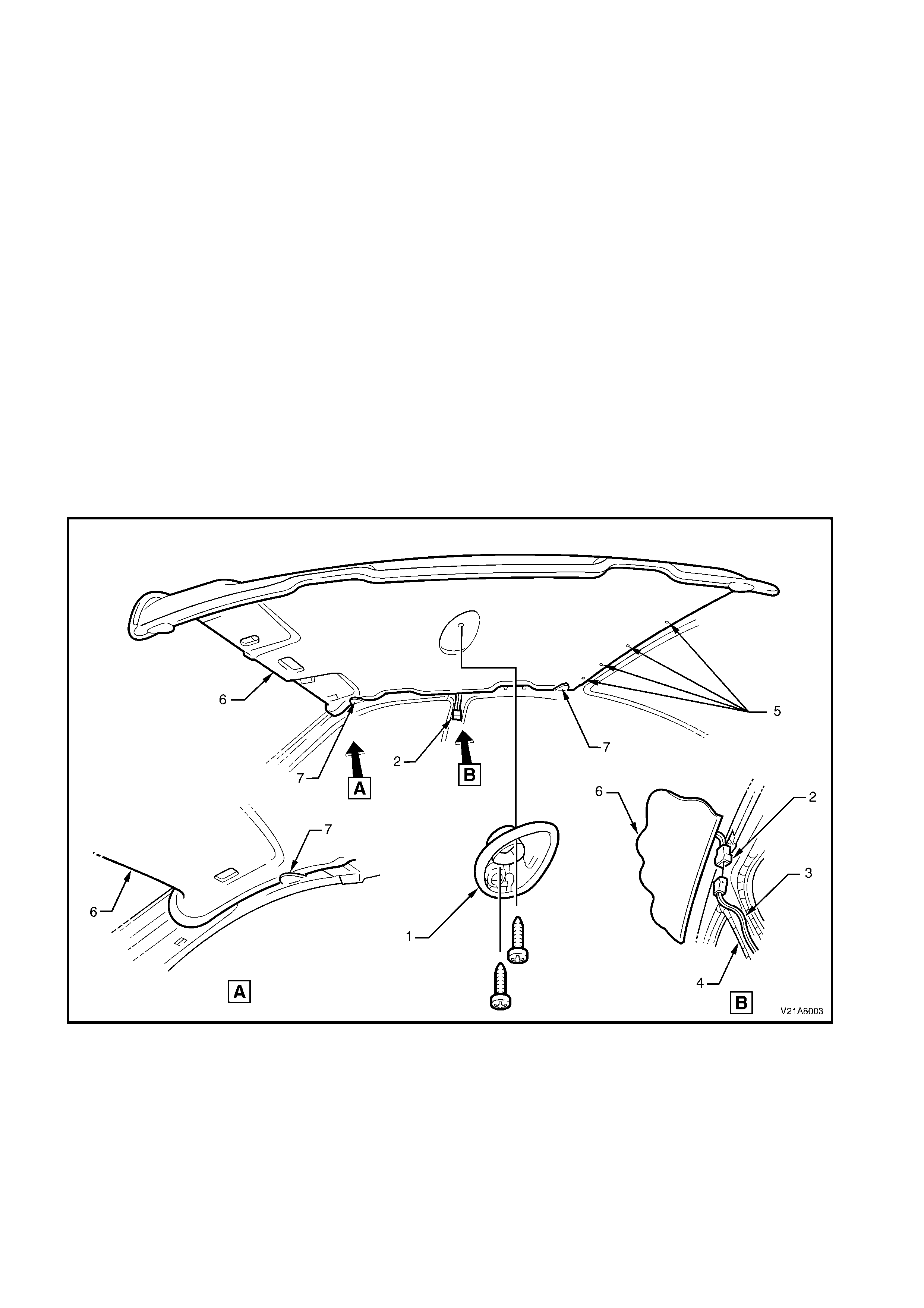
2.2 HEADLINING ASSEMBLY
REMOVE
1. Move both front seats to the rear access position and place protective covering over the interior trim.
2. Disconnect the battery ground cable.
3. Remove the sunvisor assembly; refer to 2.1 SUNVISOR ASSEMBLY in this Section.
4. Remove the rocker panel inner cover; refer to 2.3 INNER ROCKER PANEL COVER AND INSERT in this
Section
5. Remove the rear quarter trim, refer to 2.4 REAR QUARTER TRIM in this Section.
6. Remove the B-pillar trim; refer to 2.5 B-PILLAR TRIM in this Section.
7. Remove the A-pillar trim; refer to 2.6 A-PILLAR TRIM in this Section.
8. Remove the C-pillar trim; refer to 2.7 A-PILLAR TRIM in this Section.
9. Remove the dome lamp (1), refer to Section 12B LIGHTING SYSTEM, in the VT Series Service Information.
10. Disconnect the headlining harness (2) from the body harness connector (3) above and slightly forward of the
right-hand B-pillar (4).
NOTE: It may be necessary to flex the headlining down slightly to gain access to the harness connector.
11. Disengage the four Velcro™ fasteners (5) attaching the rear edge of the headlining assembly (6) by gently
pulling down the headlining assembly in one corner and working across the rear edge.
12. W ith the aid of an assistant, flex the r oof lining to disengage the corners from the four ‘D’ tabs (7) on the sides
of the roof panel.
13. Carefully manoeuvre the headlining assembly from the vehicle.
Figure 1A8-3
REINSTALL
The installation procedure for the headlining assembly is the reverse of the removal procedure.
2.3 INNER ROCKE R PANEL COVER AND INSERT
REMOVE
1. Remove the rear seat cushion, refer to
2.20 REAR SEAT BACK AND CUSHION
ASSEMBLIES in Section 1A7 – SEAT AND
SEAT BELT ASSEMBLIES.
2. Remove the front seat outer guide rail cover,
refer to 2.1 FRONT BUCKET SEAT in Section
1A7 – SEAT AND SEAT BELT ASSEMBLIES.
3. Remove the scrivet (1) attaching the inner
rocker panel cover (2) to the rear quarter trim
(3).
4. Remove the seat belt lower attaching bolt (4).
5. Starting at the front and moving rearwards,
unclip and rem ove the inner rock er panel cover
insert (5).
6. Rem ove the four attaching screws (6) from the
inner rocker panel cover.
7. Carefully disengage the two clips (7) attaching
the rear of the inner rocker panel cover to the
lower edge of the rear quarter trim by pulling
the rear edge of the rocker panel cover towards
the centre of the vehicle.
8. Remove the inner rocker panel cover.
REINSTALL
The installation procedure for the inner rocker
panel cover and ins ert is the r ever se of the removal
procedure, ens uring that the outer edge (8) of inner
rocker panel cover engages the door seal (9).
INNER ROCKER PANEL ATTACHING
SCREW TORQUE SPECIFICATION 1 - 3 Nm
Figure 1A8-4
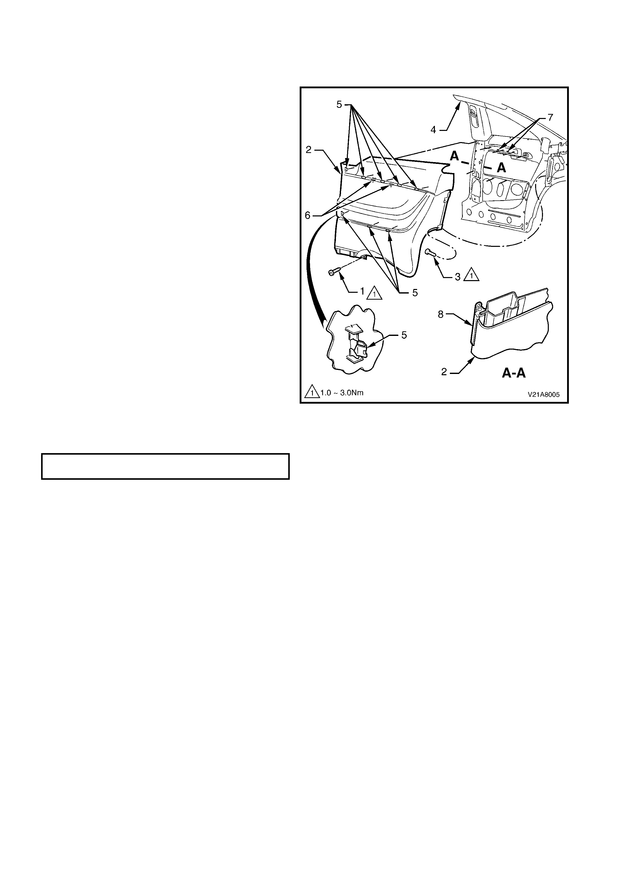
2.4 REAR QUARTER TRIM
REMOVE
1. Remove the inner rocker panel cover; refer to
2.3 INNER ROCKER PANEL COVER AND
INSERT in this Section.
2. Rem ove the rear seat back, refer Section 1A7
SEATS AND SEAT BELT ASSEMBLIES.
3. Remove the screw (1) from the lower edge of
the rear quarter trim (2).
4. Remove the two screws (3) f rom the r ear edge
of the rear quarter trim.
5. Starting at the lower edge of the B-Pillar trim
(4) and moving alternately clockwise and
counter clockwise, disengage the eight rear
quarter trim attaching clips (5) by carefully
manoeuvring trim away from the rear
sheetmetal.
6. Remove the rear quarter trim.
NOTE: When removing the rear quarter trim,
ensure care is taken not to damage the two
locating pins (6).
REINSTALL
The installation procedure for the rear quarter trim
is the reverse of the removal procedure, ensuring
that the locating pins are aligned with the locating
holes (7) before engaging the attaching clips. Also
ensure that the leading edge of the rear quarter
trim engages the door seal (8).
REAR QUARTER TRIM ATTACHING SCREW
TORQUE SPECIFICATION 1 - 3 Nm
Figure 1A8-5
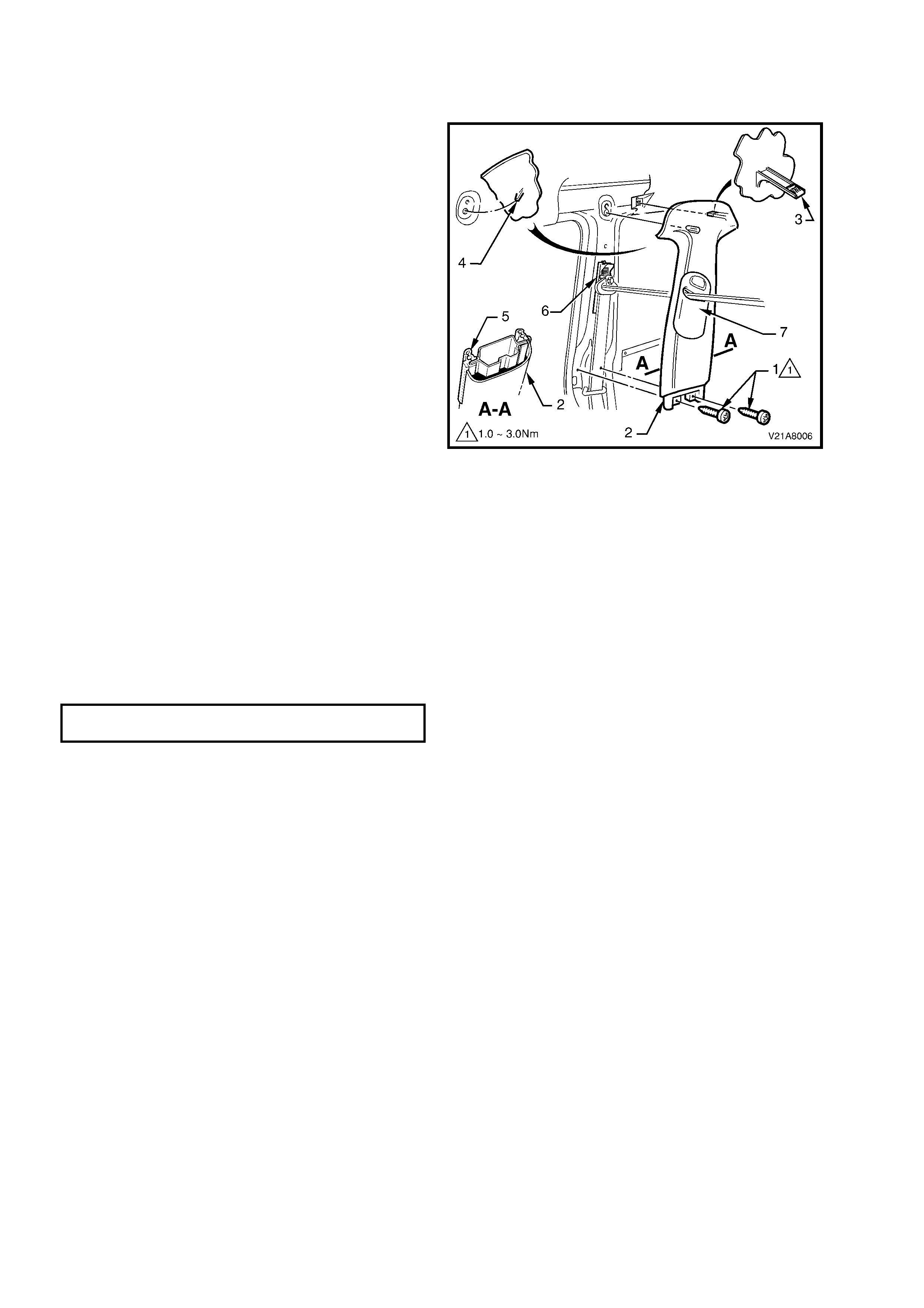
2.5 B-PILLAR TRIM
REMOVE
1. Remove the rear quarter trim, refer to
2.4 REAR QUARTER TRIM in this Section.
2. Remove the two screws (1) securing the B-
pillar trim (2).
3. Pull the upper rear edge of the B-pillar trim
away from the C-pillar trim to disengage the B-
pillar to C-pillar trim attaching clip (3).
4. Remove the B-pillar trim.
NOTE: When removing the B-pillar trim, ensure
care is taken not to damage the locating pin (4)
below the upper attaching screw.
REINSTALL
The ins tallation pr ocedur e f or the B- Pillar tr im is the
reverse of the removal procedure, noting the
following:
• Ensure that the locating pin below the upper
attaching screw is correctly aligned with the
locating hole and the leading edge of the B-
pillar trim engages the door seal (5).
• Ensure that the seat belt height adjuster (6)
and the front seat belt guide (7) are correctly
aligned prior to installation of the B-pillar trim by
adjusting the slide and height adjuster to the
full up position.
• Check seat belt oper ation pr ior to tightening the
B-pillar trim attaching screws.
• Tighten all fasteners to the correct torque
specification.
B-PILLAR TRIM ATTACHING SCREW
TORQUE SPECIFICATION 1 - 3 Nm
Figure 1A8-6
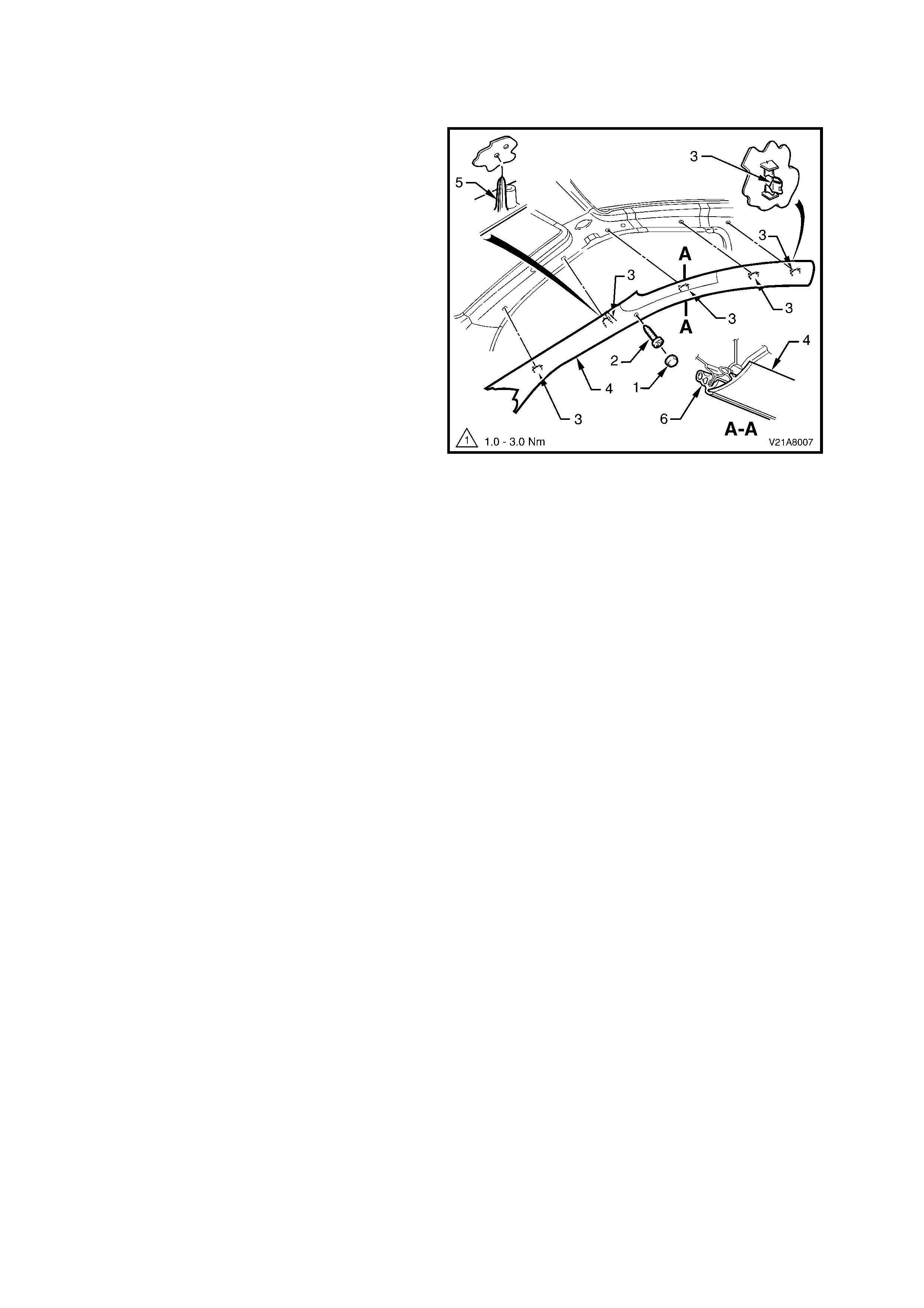
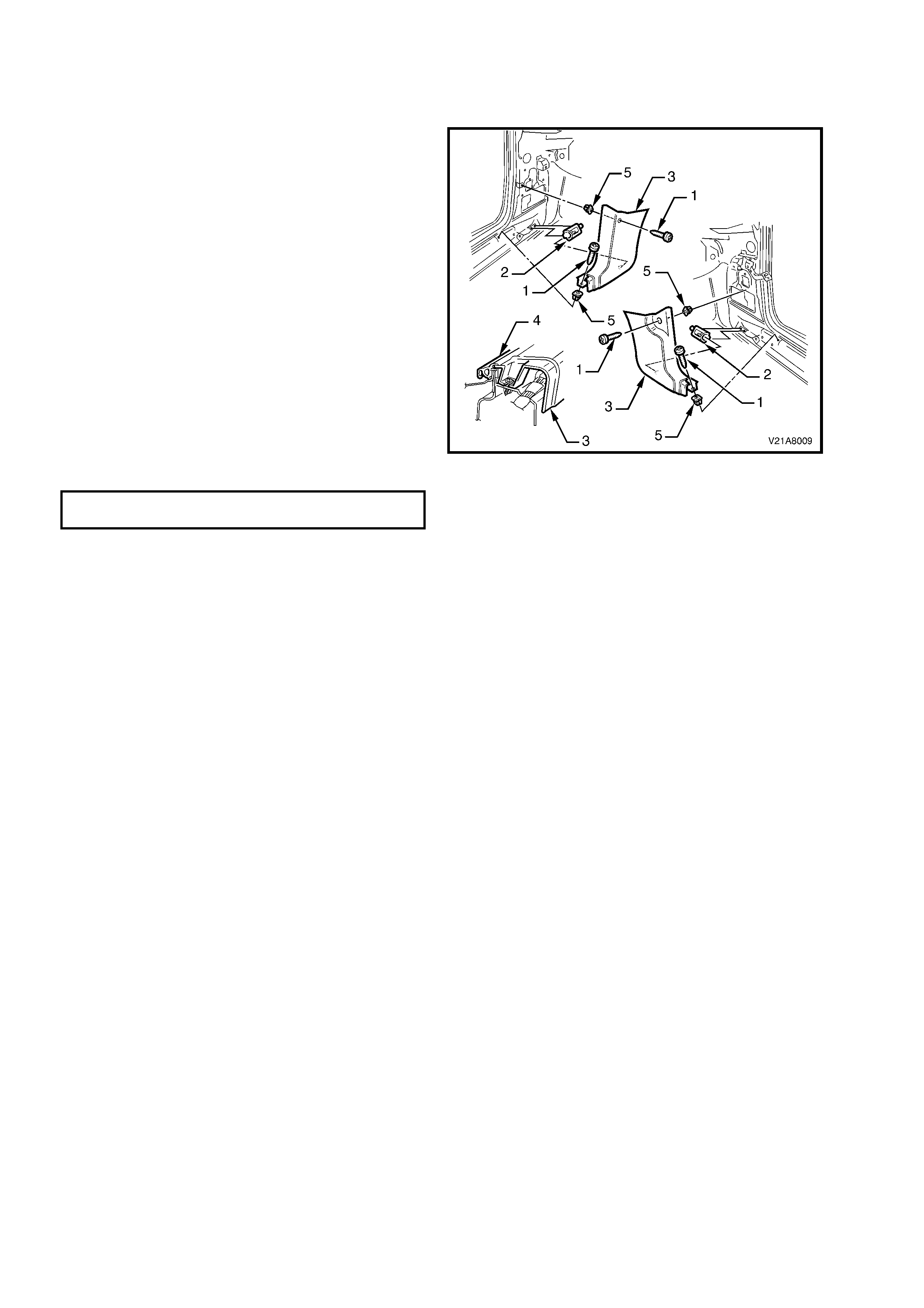
2.6 A-PILLAR TRIM
REMOVE
1. Remove the B-pillar trim, refer to
2.5 B-PILLAR TRIM in this Section.
2. Remove the A-pillar trim attachment cap (1)
3. Remove the A-pillar trim attaching screw (2).
2. Starting at the upper rear edge, disengage the
five A-pillar trim attaching clips (3).
3. Remove the A-pillar trim (4).
NOTE: When removing the A-pillar trim, ensure
care is taken not to damage the two locating pins
(5).
REINSTALL
The ins tallation procedure f or the A-pillar trim is the
reverse of the re moval procedur e, ens uring that the
A-pillar trim loc ating pins are aligned with the holes
in the roof sheetmetal and that the outer edge of
the A-pillar trim is correctly engaged into the door
seal (6).
Figure 1A8-7
2.7 C-PILLAR TRIM
REMOVE
1. Remove the B-pillar trim, refer to
2.5 B-PILLAR TRIM in this Section.
2. Remove the rear seat belt lower attaching bolt
(1).
2. Remove the attac hing screw (2) fr om the lower
edge of the C-pillar trim (3).
3. Taking care not to damage the two pins (4)
locating the trim, pull the front edge of the trim
away from the C-pillar and work rearwards to
disengage the four C-pillar trim attaching clips
(5).
Figure 1A8-8
4. With the C-pillar trim (1) partially removed,
disengage the seat belt guide (2) from the trim
and feed the lower seat belt bracket (3) through
the opening.
5. Remove the C-pillar trim.
REINSTALL
The ins tallation procedur e for the C- pillar trim is the
reverse of the re moval procedur e, ens uring that the
two locating pins are correctly aligned prior to
engaging the attaching clips into the C-pillar.
C-PILLAR TRIM ATTACHING SCREW
TORQUE SPECIFICATION 1 - 3 Nm
REAR SEAT BELT LOWER ATTACHING
BOLT TORQUE SPECIFICATION 35 – 50 Nm
Figure 1A8-9
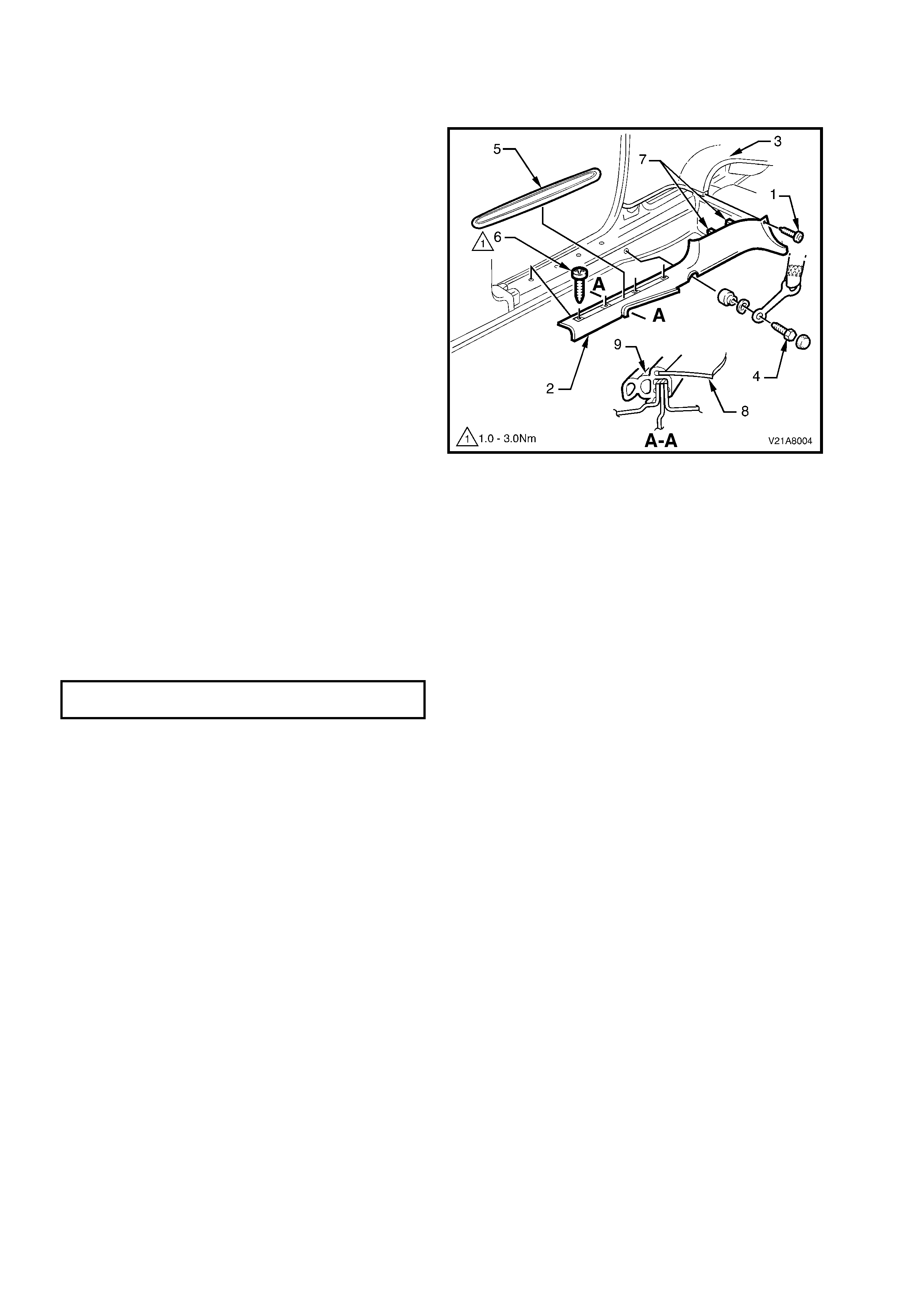
2.8 SHROUD LOWER TRIM
REMOVE
1. Remove the inner rocker panel cover, refer to
2.3 INNER ROCKER PANEL COVER AND
INSERT in this Section.
2. Remove the two attaching screws (1) from the
shroud lower trim.
3. Disengage the shroud lower trim lower aligning
clip (2) by pulling the lower edge of the shroud
lower trim (3) upwards and away from
sheetmetal.
4. Remove the shroud lower trim.
REINSTALL
The installation proc edure f or the shroud lower trim
is the reverse of the removal procedure, ensuring
the aligning clip is correctly engaged, the lower
outer edge is fully engaged into the door seal (4)
and the nutserts (5) are correctly located and in
good condition.
SHROUD LOWER TRIM ATTACHING
SCREW TORQUE SPECIFICATION 0.7 – 1.0 Nm
Figure 1A8-10
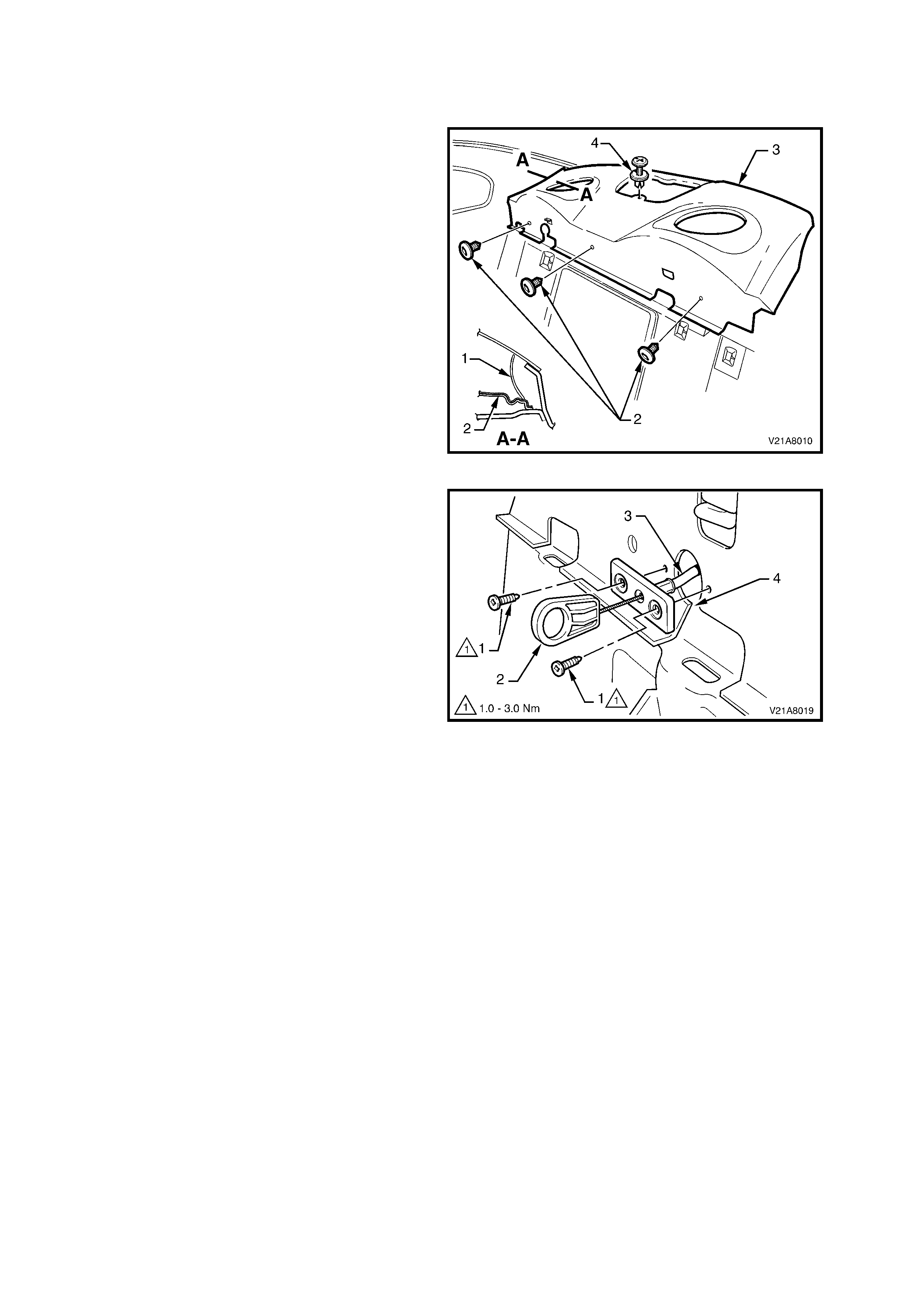
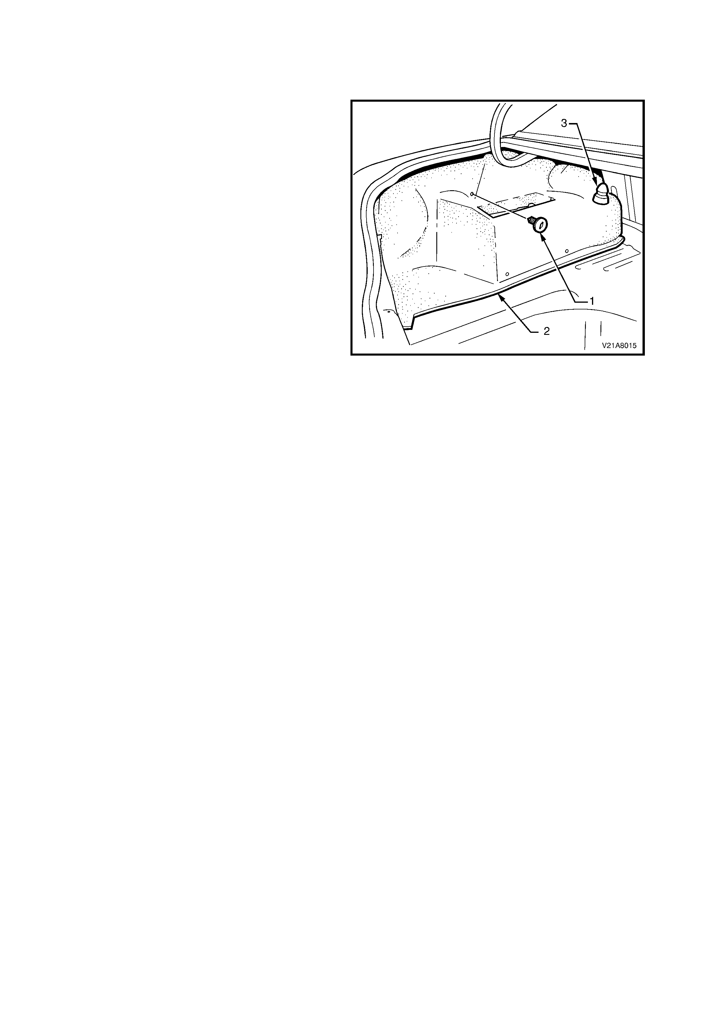
2.9 REAR PARCEL SHELF ASSEMBLY
REMOVE
1. Remove the rear seat back assembly, refer to
Section 1A7 - SEAT AND SEAT BELT
ASSEMBLIES in this Service Information.
2. Remove the C-pillar trim (1), refer to
2.7 C-PILLAR TRIM in this Section.
3. Remove the c entre high mount stop lamp, refer
to 2.11 CENTRE HIGH MOUNT STOP LAMP
ASSEMBLY in Section 12B – LIGHTING
SYSTEM.
4. Remove the three fir tree fasteners (2)
attaching the forward edge of the rear parcel
shelf assembly (3).
5. Remove the scrivet (4) attaching the rear
parcel shelf to the rear sheetmetal.
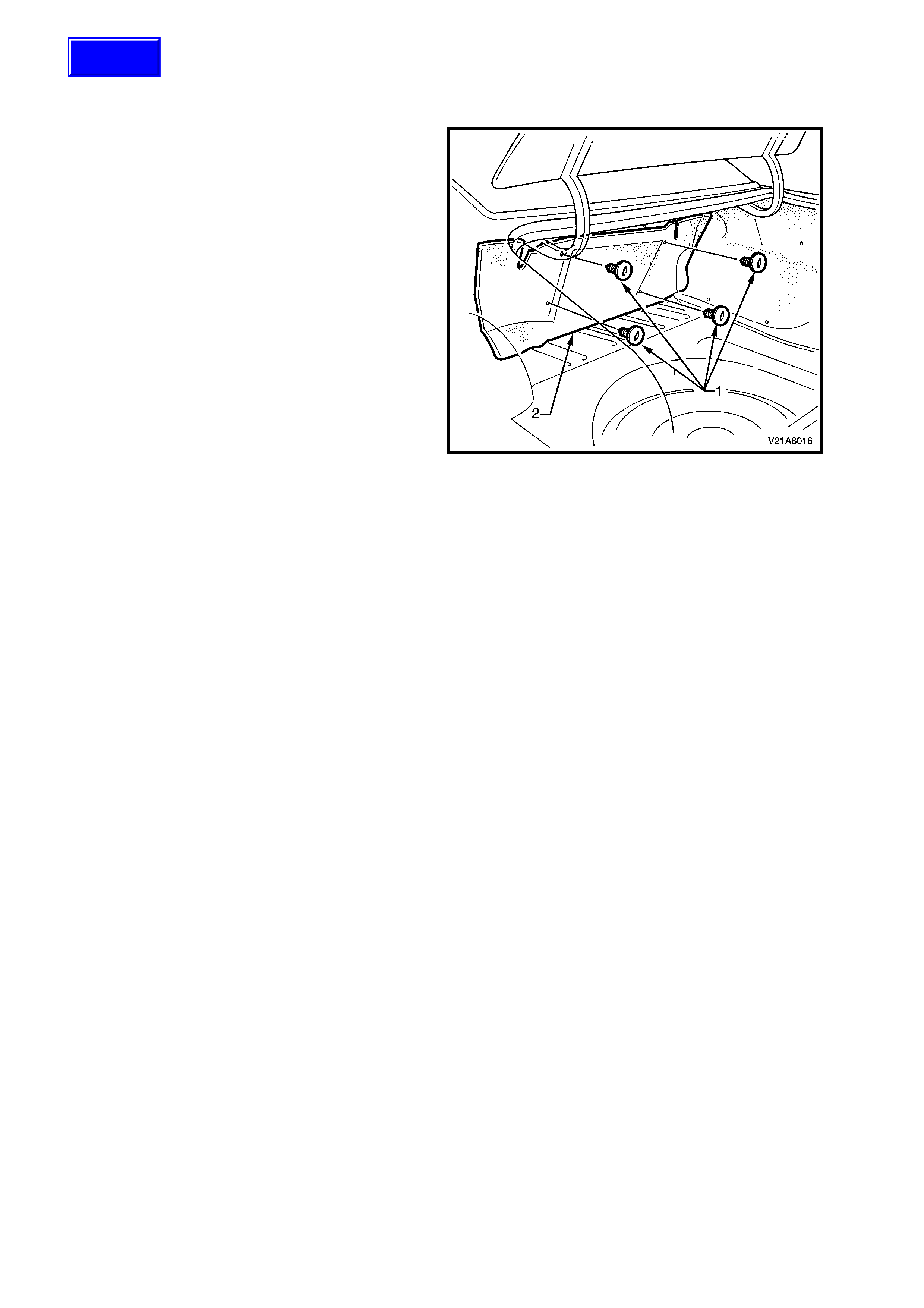
Figure 1A8-11
6. Remove the two screws (1) securing the
emer gency boot release handle (2) and pull the
handle assembly away from the parcel shelf.
7. Lift the front edge of the parcel shelf and feed
the rear compartment lid emergency release
cable (3) through the slot (4) in the parcel shelf.
8. Remove the parcel shelf assembly.
REINSTALL
The installation of the rear parcel shelf trim is the
reverse of the removal procedure, ensure that the
speaker seals (where fitted) do not foul on the
speaker assemblies.
Figure 1A8-12

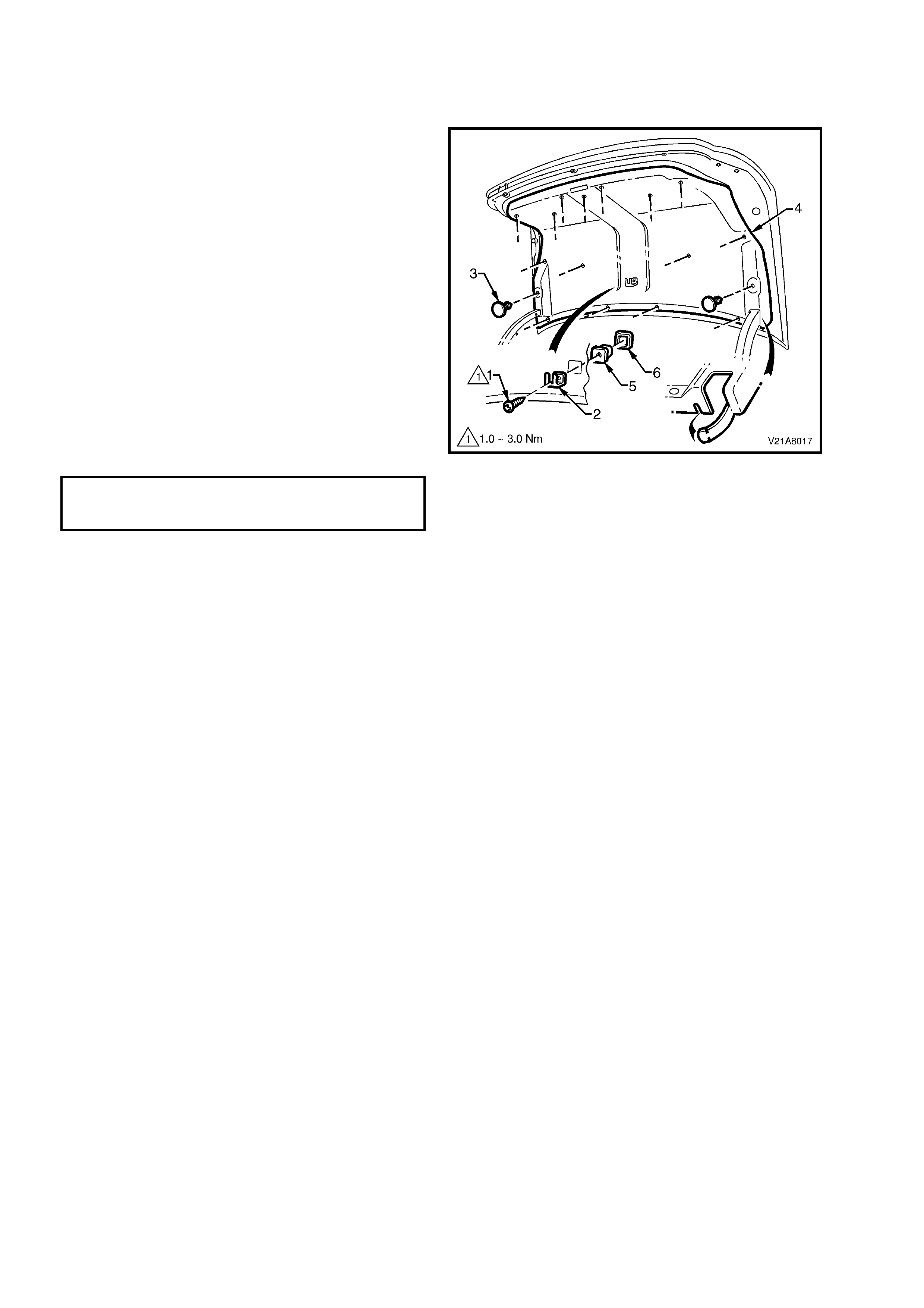
2.10 RE AR COMPARTMENT CROSSMEMBER COVER
REMOVE
1. With the rear compartment lid open, remove
the four attaching screws (1) along the ribbed
upper surface of the rear compartment
crossmember cover (2).
2. Remove the four fir tree clips (3) along the
lower inner edge of the rear compartment
crossmember cover.
3. Remove the two scrivets (4) attaching the
upper sides of the rear compartment
crossmember cover.
4. Carefully lift the crossmember cover over rear
compartment lid latch and clear of rear
compartment.
REINSTALL
The installation procedure for the rear compartment
crossmember cover is the reverse of the removal
procedure, ensuring that the outer edge of
crossmember cover engages the boot
seal (5).
CROSSMEMBER COVER ATTACHING
SCREW TORQUE SPECIFICATION 1 - 3 Nm
Figure 1A8-13
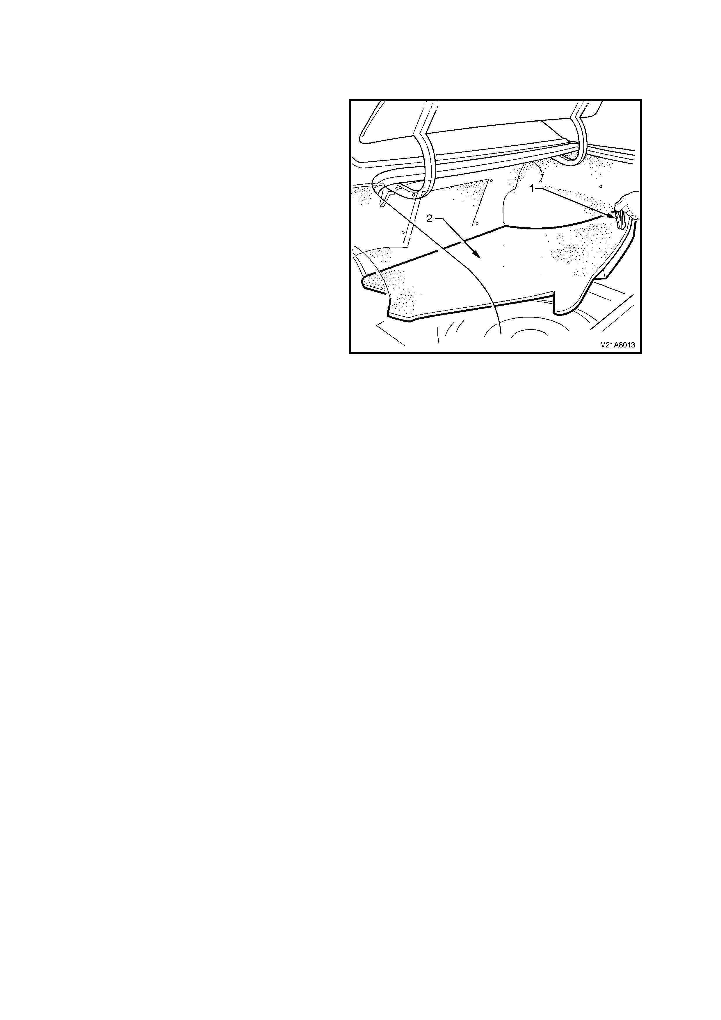
2.11 SPARE WHEEL COVER
REMOVE
1. Open the rear compartment lid.
2. Grasp the handle on the spare wheel cover and
lift the rear edge upwards.
3. Lift the spare wheel cover from the rear
compartment.
REINSTALL
The installation procedure for the spare wheel
cover is the reverse of the removal procedure.
Figure 1A8-14
2.12 RH REAR WHEELHOUSE CARPET
REMOVE
1. Open the rear compartment lid.
2. Remove the rear compartment crossmember
cover, refer to 2.10 REAR COMPARTMENT
CROSSMEMBER COVER in this Section.
3. Remove the spare wheel cover, refer to
2.11 SPARE WHEEL COVER in this Section.
4. Carefully prise off the RH rear shock absorber
end cap.
5. Carefully remove the fir tree fastener away
from the wheelhouse.
6. Unhook the carpet flap from the RH rear
compartment lid hinge bracket and carefully
remove the RH rear wheelhouse carpet.
REINSTALL
The installation procedure for the RH rear
wheelhouse carpet is the reverse of the removal
procedure.
Figure 1A8-15
2.13 LH REAR WHEELHOUSE CARPET
REMOVE
1. Open the rear compartment lid.
2. Remove the rear compartment crossmember
cover, refer to 2.10 REAR COMPARTMENT
CROSSMEMBER COVER in this Section.
3. Remove the spare wheel cover, refer to
2.11 SPARE WHEEL COVER in this Section.
4. Carefully prise off the LH rear shock absorber
end cap.
5. Carefully remove the f ir tree fastener out of the
LH wheelhouse carpet.
6. Unhook the carpet flap from the LH rear
compartment lid hinge bracket.
7. For CV8 Models, lift the LH rear wheelhouse
carpet until the CD changer bezel is clear of the
CD changer bracket.
8. Remove the LH rear wheelhouse carpet from
the rear compartment.
REINSTALL
The installation procedure for the LH rear
wheelhouse and CD changer cover is the reverse
of the removal procedure, ensuring that the CD
changer bezel is correctly located.
Figure 1A8-16
2.14 REAR SEAT BACK CARPET
REMOVE
1. Open the r ear com partment lid and r emove the
spare wheel cover, refer to 2.11 SPARE
WHEEL COVER in this Section.
2. Remove the RH rear wheelhouse carpet, refer
to 2.12 RH REAR WHEELHOUSE CARPET in
this Section.
3. Remove the LH rear wheelhouse and CD
changer cover, refer to 2.13 LH REAR
WHEELHOUSE AND CD CHANGER COVER
in this Section.
4. Carefully remove the four fir tree fasteners out
of the rear seat back carpet.
5. Remove the rear seat back carpet.
REINSTALL
The installation procedure for the rear seat back
carpet is the reverse of the removal operations.
Figure 1A8-17
Techline
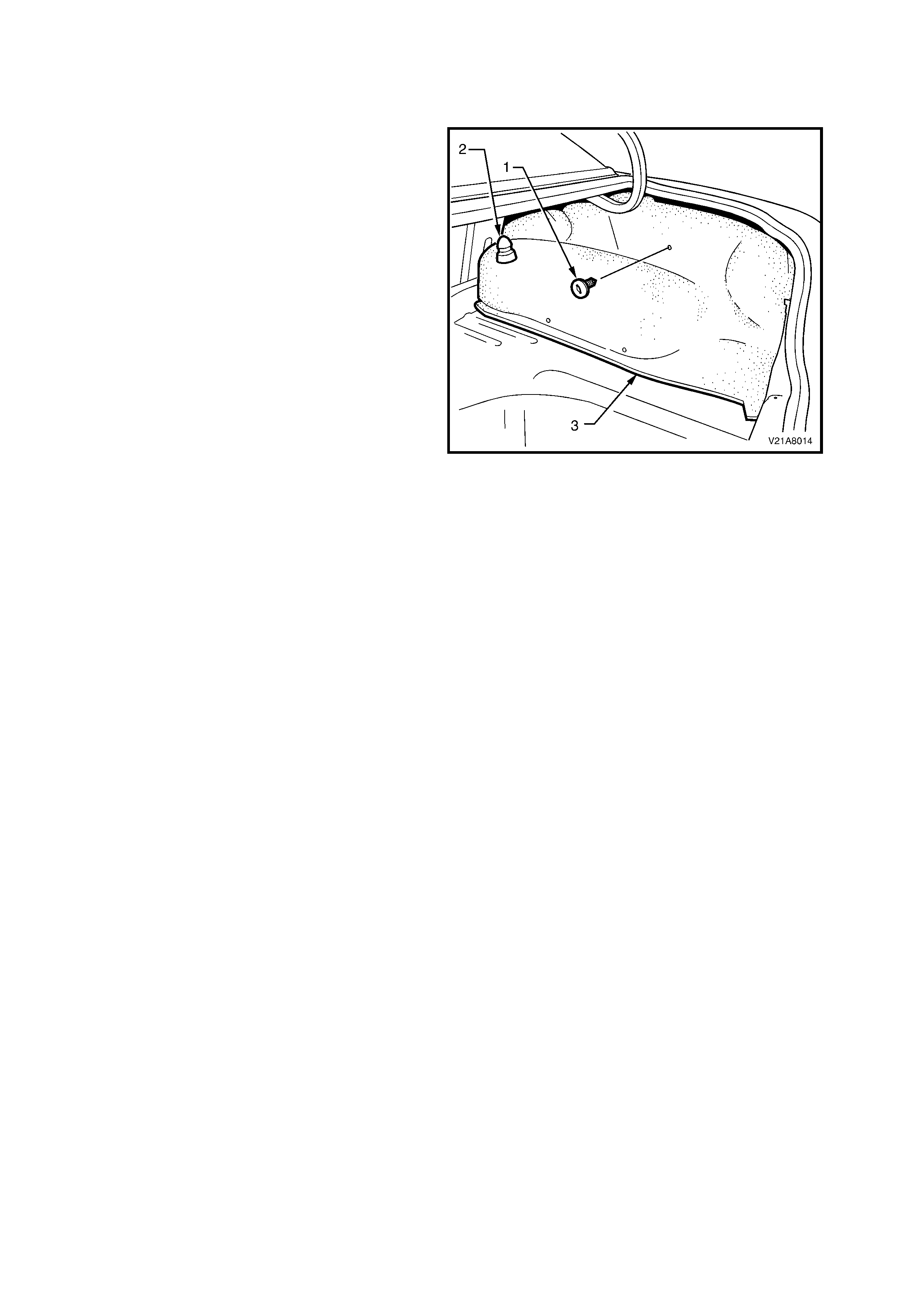
2.15 RE AR COMPARTMENT LID LINER
REMOVE
1. Rem ove the attaching s crew (1) f rom the s pare
wheel cover hook (2).
2. Carefully remove the spare wheel hook from
the rear compartm ent lid liner (4), ensuring not
to dislodge the nutsert (5) and hook aligning
washer (6) from the rear compartment lid.
3. Unhook the Velcro™ tab from behind the rear
compartment lid hinges.
4. Carefully remove the fir tree fasteners (3) out of
the rear compartment lid liner.
5. Remove the rear compartment lid liner.
REINSTALL
The installation procedure for the rear compartment
lid liner is the reverse of the removal procedure,
ensuring that the outer edge of cros sm em ber cover
engages the boot seal (5).
SPARE WHEEL COVER HOOK TO
REAR COMPARTMENT LID ATTACHING 1 - 3 Nm
SCREW TORQUE SPECIFICATION
Figure 1A8-18
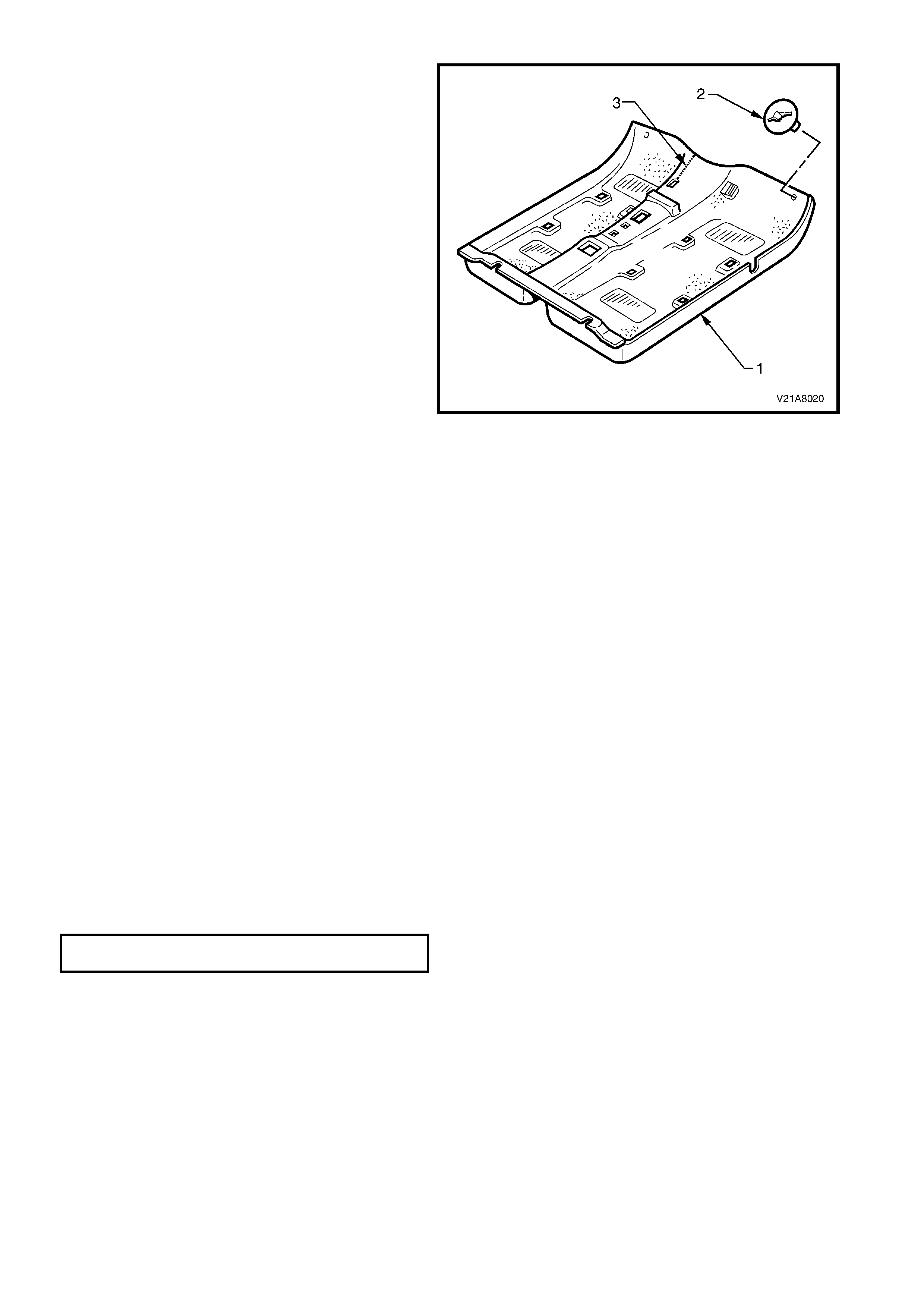
2.16 FLOOR CARPET AND INSULATOR ASSEMBLY
REMOVE
CAUTION: It will be necessary to disable the
SRS (Air Bag) prior to this operation. Refer to
DISABLING THE SRS, Section 12M
SUPPLEMENTAL RESTRAINT SYSTEM in the
VT Series Service Information.
NOTE: Clean hands ar e ess ential when working on
the body interior trim.
1. Remove the rear seat cushion, refer to
2.20 REAR SEAT BACK AND CUSHION in
Section 1A7 SEAT AND SEAT BELT
ASSEMBLIES in this Service Information.
2. Remove both front seats, refer to
2.1 FRONT BUCKET SEAT ASSEMBLY in
Section 1A7 SEAT AND SEAT BELT
ASSEMBLIES in this Service Information.
3. Remove the par k brake lever cover by grasping
the cover firmly by hand and sliding the
coverover the park brake lever, refer to
2.7 PARK BRAKE LEVER in Section 5A
STANDARD BRAKES of the VT Series I
Service Information.
4. Rem ove the front seat belt lower bolts, refer to
2.22 FRONT SEAT BELT RETRACTOR AND
HEIGHT ADJUSTER ASSEMBLY in Section
1A7 SEAT AND SEAT BELT ASSEMBLIES in
this Service Information.
5. Remove the instrument panel compartment,
refer to 1.2 INSTRUMENT PANEL
COMPARTMENT in Section 1A3
INSTRUMENT PANEL AND CONSOLE of the
VT Series I Service Information.
Figure 1A8-19
6. Remove the instrument panel cover RH lower cover, refer to 1.1 INSTRUMENT PANEL LOWER COVER –
RIGHT SIDE in Section 1A3 INSTRUMENT PANEL AND CONSOLE in the VT Series I Service Information.
7. Remove the LH footwell closing panel, refer to 1.6 INSTRUMENT PANEL PAD ASSEMBLY in Section 1A3
INSTRUMENT PANEL AND CONSOLE of the VT Series I Service Information.
8. Rem ove the RH footwell upper closing panel, refer to 1.6 INSTRUMENT PANEL PAD ASSEMBLY in Section
1A3 INSTRUMENT PANEL AND CONSOLE in the VT Series I Service Information.
9. Remove centre console and console side extensions, refer to 1.3 CENTRE CONSOLE in Section 1A3
INSTRUMENT PANEL AND CONSOLE in the VT Series I Service Information.
10. Remove both inner rocker panel covers, refer to 2.3 ROCKER PANEL COVER AND INSERT in this Section.
11. Remove both shroud lower trims, refer to 2.8 SHROUD LOWER TRIM ASSEMBLIES in this Section.
12. Remove the two screws (1) securing the footrest pad (2) to the footrest mounting bracket (3). Remove the
footrest pad.
13. Disconnect the SRS sensing and diagnostic
module wiring harness from the module, refer
to 2.7 SENSING AND DIAGNOSTIC MODULE
(SDM) in Section 12M SUPPLEMENTAL
RESTRAINT SYSTEM (Version 6.2) or
2.4 SENSING AND DIAGNOSTIC MODULE
(SDM) in Section 12M SUPPLEMENTAL
RESTRAINT SYSTEM (Version 8.0 or 8.1) in
the VT Series I Service Information.
14. For vehicles fitted with an automatic
transmission, remove the selector control lever
assembly, refer to 3.3 SELECTOR CONTROL
LEVER ASSEMBLY in Section 7C4 HYDRA-
MATIC 4L60E AUTOMATIC TRANSMISSION
– ON VEHICLE SERVICING in the VT Series I
Service Information.
15. For vehicles fitted with manual transmission,
remove the gearshift lever, refer to
3.6 GEARSHIFT CONTROL LEVER AND
REMOTE SHIFTER SHAFT BOOT in Section
7B3 MANUAL TRANSMISSION – GEN III V8
ENGINE of the VT Series II Service
Information.
Figure 1A8-20
16. Remove the instrument panel carrier to floor mounting bracket bolts, refer to 2.1 COCKPIT MODULE in Section
1E COCKPIT MODULE of the VT Series I Service Information.
17. Rem ove the two carpet and insulator attaching clips (1) from the carpet and insulator assembly (2) by rotating
the clips counter clockwise and lifting clear of the studs.
NOTE: T o assist in the removal and installation of the floor carpet assem bly, it has been perforated f rom the front
edge, through the centre of the evaporator drain cut out to the forward edge of the radio support bracket cut out.
18. From ins ide the LH f ootwell, gras p the edge of the hole in the floor carpet and insulator assembly (4) around the
evaporator drain hose and tear open the perforated line (3) by pulling the carpet away from the transmission
tunnel.
19. Slide the remaining flap of carpet out from under the heating, ventilation and air conditioning (HVAC) unit and
into the RH footwell.
21. Carefully manoeuvre the floor carpet and insulator assembly from vehicle.
REINSTALL
The installation procedure for the floor carpet and insulator assembly is the reverse of the removal procedure,
noting the following:
• Cut along the perforated line in the floor carpet that runs from the forward edge of the carpet, through the
evaporator drain cut-out to the forward edge of the radio support bracket cut-out prior to installing.
• Ens ure that all cut- outs in the car pet are cor rectly aligned and install the eight attachers and front seat belt lower
attaching bolts to secure the carpet prior to installing the seats and console.
• Ensure all fasteners are tightened to the correct torque specifications.
FOOTREST PAD ATTACHING SCREWS
TORQUE SPECIFICATION 2 – 5 Nm
3. SPECIFICATIONS
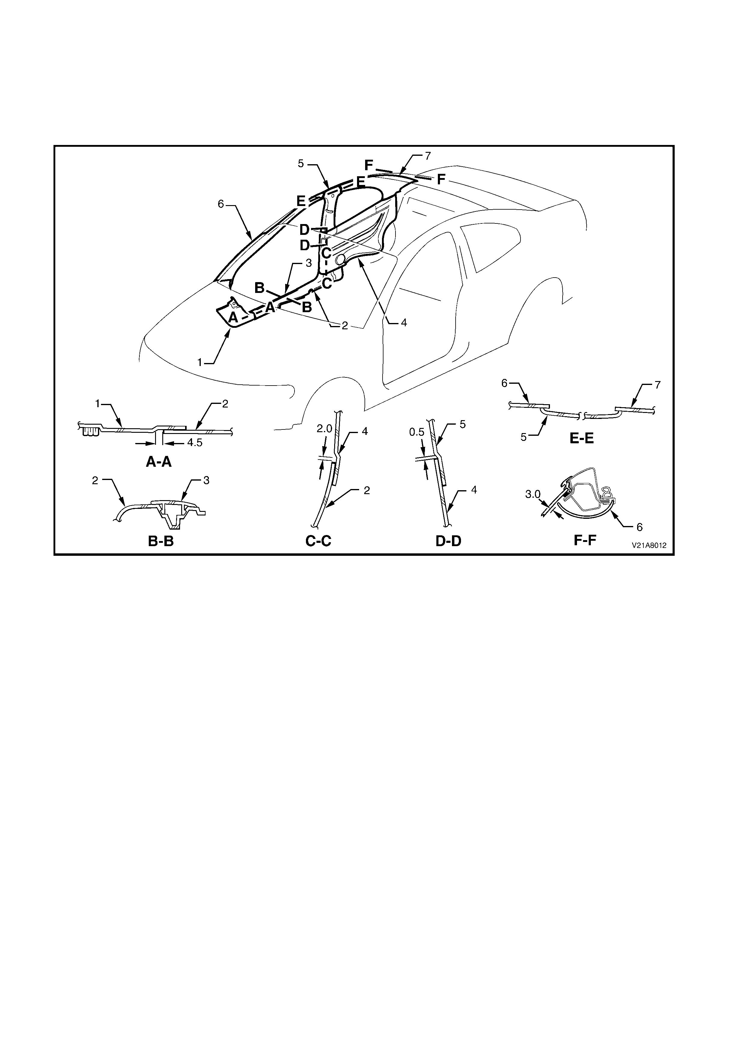
3.1 TRIM CLEARANCES
Fig. 1A8-21 provides the trim clearances for the headlining and associated trims.
NOTE: All measurements are in millimetres.
Figure 1A8-21
Legend
1. Shroud lower trim
2. Inner rocker panel cover
3. Inner rocker panel cover insert
4. Rear quarter trim
5. B-pillar trim
6. A-pillar trim
7. C-pillar trim

4. TORQUE WRENCH SPECIFICATIONS
Nm
Sunvisor Bracket Attaching Screw........................................1 - 3
Sunvisor Attaching Screws...................................................1 - 3
Dome Lamp Attaching Screws .............................................1 - 3
Inner Rocker Panel Cover Attaching Screws........................1 - 3
Rear Quarter Trim Attaching Screws....................................1 - 3
B-Pillar Trim Attaching Screws .............................................1 - 3
C-Pillar Attaching Screws .....................................................1 - 3
Shroud Lower Trim Attaching Screws ..................................0.7 - 1.0
Rear Compartment Crossmember Cover Attaching
Screws..................................................................................1 - 3
Spare Wheel Hook to Rear compartment lid Attaching
Screw....................................................................................1 - 3
Footrest pad attaching screws..............................................2 - 5