
SECTION 6A1-1 - ENGINE MECHANICAL - V6 ENGINE
CAUTION:
This vehicle will be equipped with a Supplemental Restraint System (SRS). A SRS will
consist of either seat belt pre-tensio ners and a driver’s side air bag , or seat belt pre-
tensioners and a driver’s and front passenger’s side air bags. Refer to CAUTIONS,
Section 12M, before performing any service operation on or around SRS
components, the steering mechanism or wiring. Failure to follow the CAUTIONS
could result in SRS deplo yment, resulting in possible p ersonal injury or unnecessary
SRS system repairs.
CAUTION:
This vehicle may be equipped with LPG (Liquefied Petroleum Gas). In the interests of
safety, the LPG fuel system should be isolated by turning 'OFF' the manual service
valve and then draining the LPG serv ice lines, before any service w ork is carried out
on the vehicle. Refer to the LPG leaflet included with the Owner's Handbook for
details or LPG Section 2 for more specific servicing information.
1. GENERAL DESCRIPTI ON
The 1997 Model Year 3.8 litre, 3800 engine (production option LN3) for VT Series Models, is a 90 degree, V6,
overhead valve unit with a 96.52 mm bore and 86.36 mm stroke, displacing 3791 cc with a compression ratio of
9.35:1.
Engine features include, light weight, increased torque and horsepower, and a rigid valve train incorporating beehive
shaped valve springs for greater valve control. All combustion chambers and inlet/exhaust ports are symmetrical for
more even firing pressures, reduced emissions.
An EGR valve has also been introduced to improve emission control.
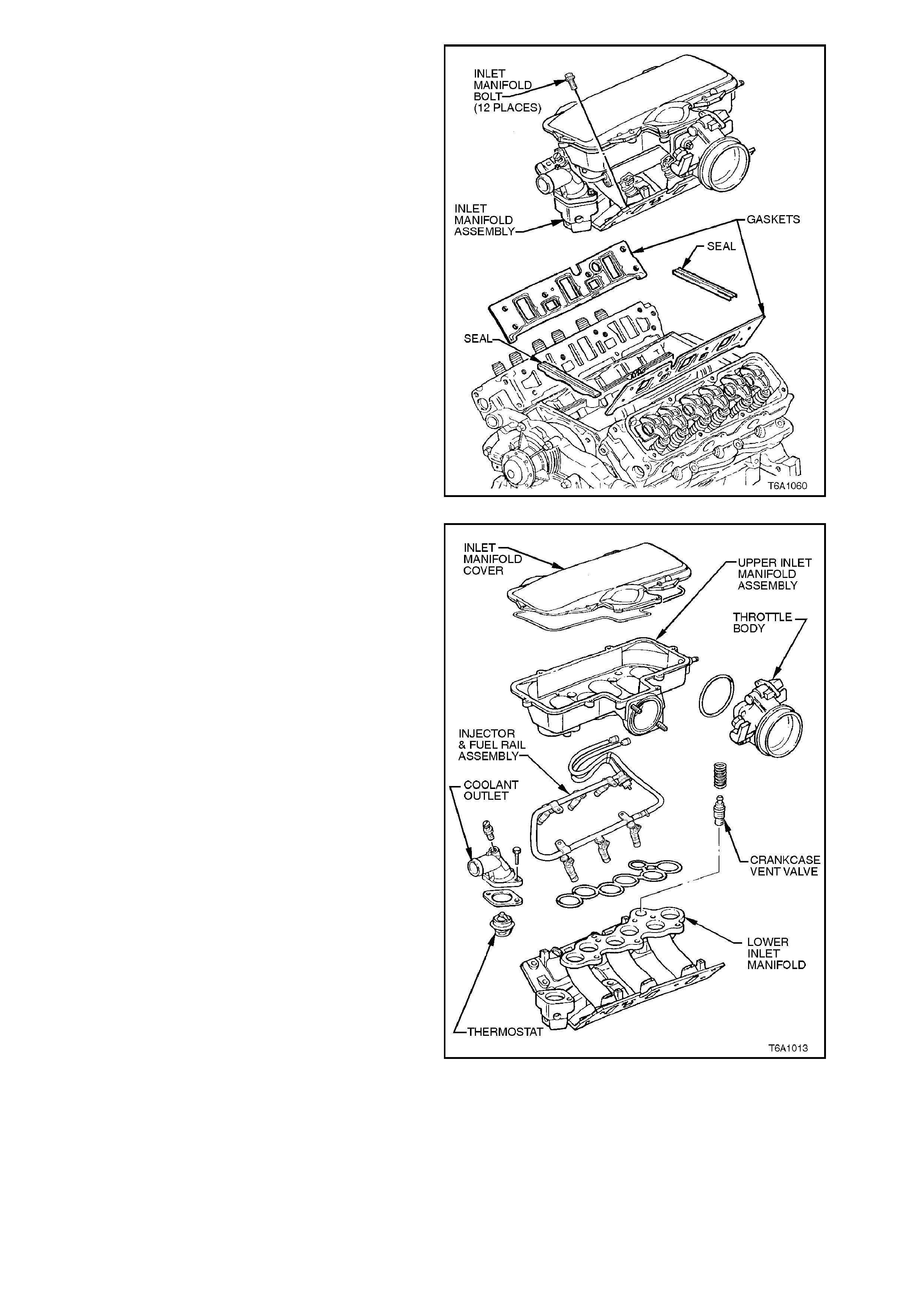
Fuel injection is sequential with an upper and lower inlet manifold, the upper manifold supporting a plenum chamber
with the throttle body mounted on the left hand side
A stiffened engine block and side bolted main bearing caps along with an insulated engine dress cover contribute to
engine quietness.
Techline
Techline
Techline
Techline
Techline
Techline

Figure 6A1-1-1
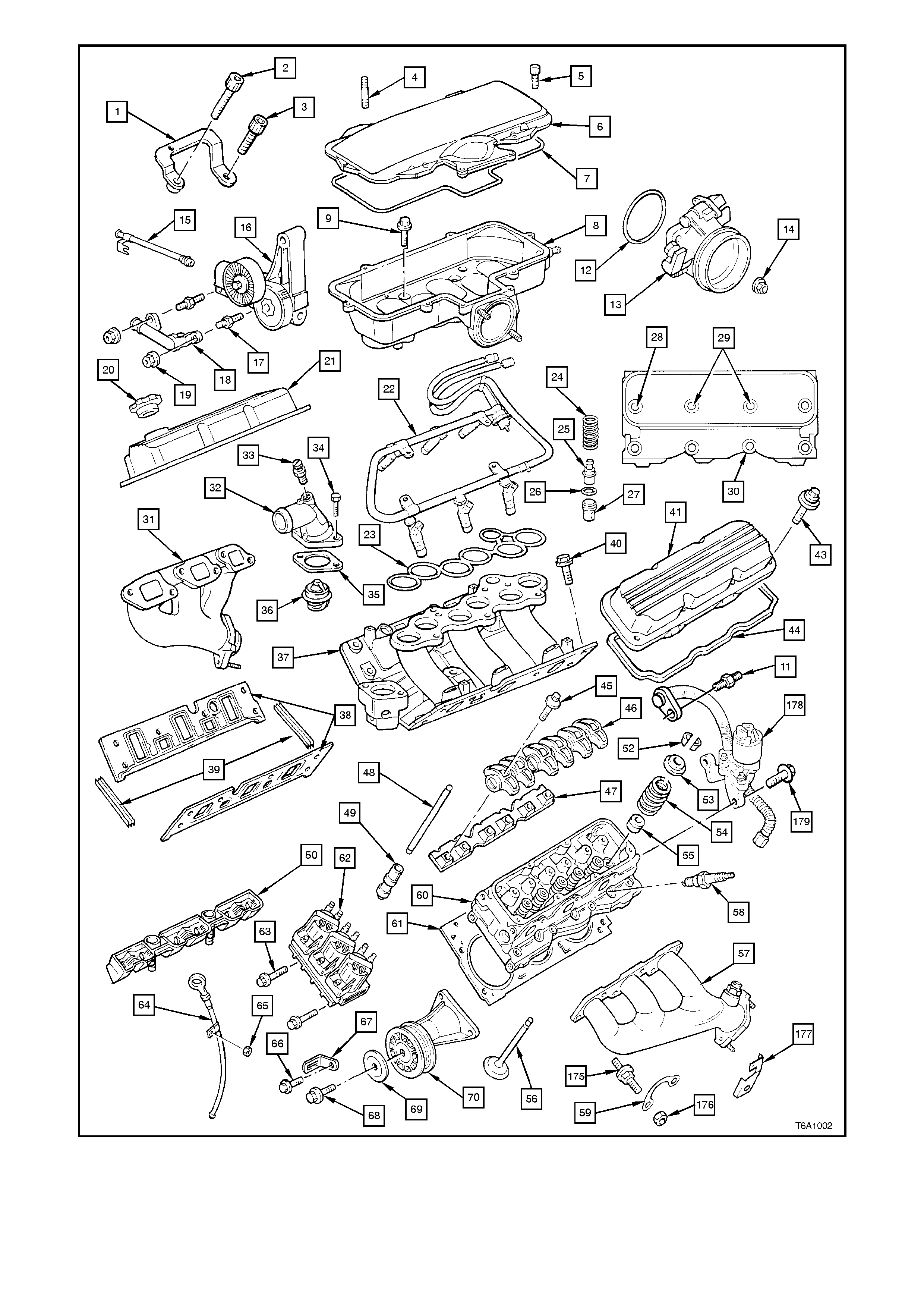
Figure 6A1-1-2

1. Generator brace bracket
2. Bolt
3. Bolt
4. Double ended stud
5. Cover bolt
6. Inlet manifold cover
7. Inlet manifold cover seal
8. Upper inlet manifold
9. Bolt
11. Throttle bracket mounting stud
12. Throttle body to inlet manifold seal
13. Throttle body
14. Nut
15. Heater outlet pipe
16. Drive belt tensioner assembly
17. Stud
18. Water inlet tube
19. Nut
20. Oil filler cap
21. Right hand rocker cover
22. Injector and fuel rail assembly
23. Seal
24. Crankcase vent valve spring
25. Crankcase vent valve
26. Crankcase vent valve seal
27. Oil separation baffle
28. Cylinder head upper outer bolt
29. Cylinder head upper inner bolt
30. Cylinder head lower bolt
31. Right hand exhaust manifold
32. Coolant outlet
33. Air vent valve
34. Bolt
35. Thermostat gasket
36. Thermostat
37. Lower inlet manifold
38. Inlet manifold gasket
39. Inlet manifold seal
40. Bolt
41. Left Hand Rocker cover
43. Rocker cover fastener
44. Rocker cover seal
45. Rocker arm pedestal bolt
46. Rocker arm assembly
47. Rocker arm retainer
48. Rocker arm pushrod
49. Lifter
50. Lifter guide
52. Valve collet
53. Valve spring cap
54. Valve spring
55. Valve stem seal
56. Valve
57. Left Hand exhaust manifold
58. Spark plug
59. Bolt lock plate
60. Cylinder head
61. Head gasket
62. D.I.S. ignition coil/module assembly.
63. Bolt
64. Dipstick tube assembly
65. Nut
66. Housing to cylinder head bolt
67. Engine harness retaining bracket
68. Pulley to housing bolt
69. Idler pulley cover
70. Idler pulley
175. Stud
176. Nut
177. Spark plug lead support bracket
178. EGR Valve
179. Screw
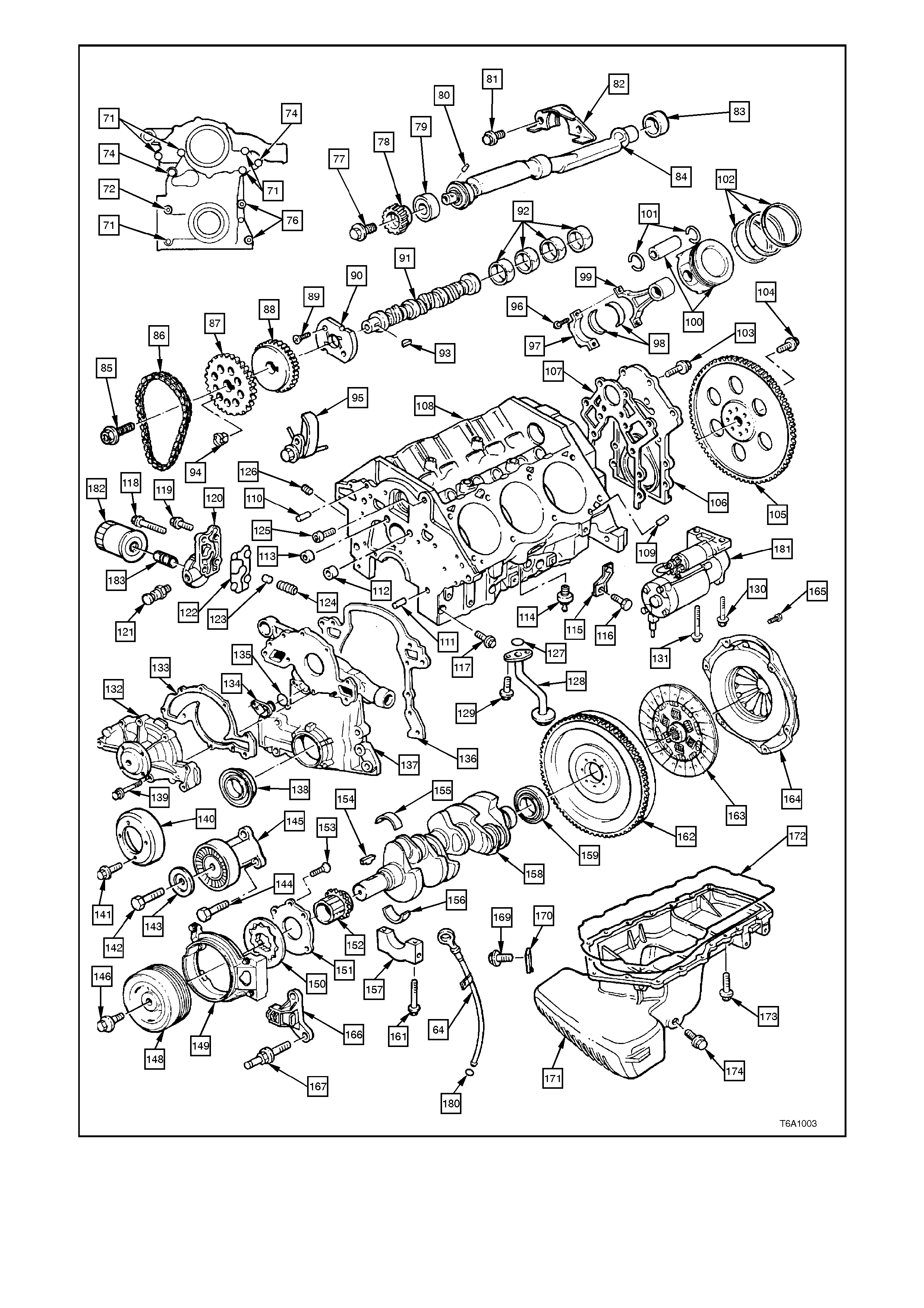
Figure 6A1-1-3

71. Bolts
72. Stud
74. Bolts
76. Studs
77. Bolt
78. Balance shaft driven gear
79. Balance shaft front ball bearing
80. Pin
81. Bolt
82. Balance shaft retainer
83. Balance shaft rear bearing
84. Balance shaft
85. Bolt
86. Timing chain
87. Camshaft sprocket
88. Balance shaft drive gear
89. Screw
90. Camshaft thrust plate
91. Camshaft
92. Camshaft bearings
93. Key
94. Camshaft position sensor magnet
95. Timing chain dampener
96. Cap bolt
97. Cap
98. Connecting rod bearings
99. Connecting rod
100. Piston and pin
101. Circlips
102. Piston rings
103. Bolt
104. Bolt
105. Flexplate
106. Crankshaft rear oil seal housing
107. Crankshaft rear oil seal housing gasket
108. Cylinder block
109. Cylinder head locater pin
110. Engine front cover locater pin
111. Engine front cover locater pin
112. Cup plug
113. Cup plug
114. Knock sensor
115. Knock sensor shield support bracket
116. Bolt
117. Cap bolt
118. Bolt
119. Bolt
120. Oil filter adaptor
121. Oil pressure switch
122. Oil filter adaptor seal
123. Pressure regulator valve
124. Spring
125. Special torque axis screw
126. Plug
127. O - ring
128. Oil suction pipe and screen
129. Bolt
130. Bolt short
131. Bolt long
132. Water pump
133. Water pump gasket
134. Camshaft position sensor
135. O - ring
136. Front cover gasket
137. Front cover
138. Crankshaft front seal
139. Bolt
140. Water pump pulley
141. Bolt
142. Bolt
143. Idler pulley cover
144. Bolt
145. Idler pulley
146. Bolt
148. Balancer
149. Shield
150. Oil pump gears
151. Oil pump cover
152. Crankshaft sprocket
153. Screw
154. Sprocket key
155. Main bearing upper shell
156. Main bearing lower shell
157. Main bearing cap
158. Crankshaft
159. Rear main oil seal
161. Main cap bolt
162. Flywheel
163. Clutch plate
164. Pressure plate and cover assembly
165. Bolt
166. Crankshaft position sensor bracket
167. Crankshaft position sensor stud
169. Bolt
170. Wiring harness support bracket
171. Oil pan
172. Oil pan seal
173. Bolt
174. Drain plug
180. O - ring
181. Starter motor
182. Oil filter
183. Oil filter connector
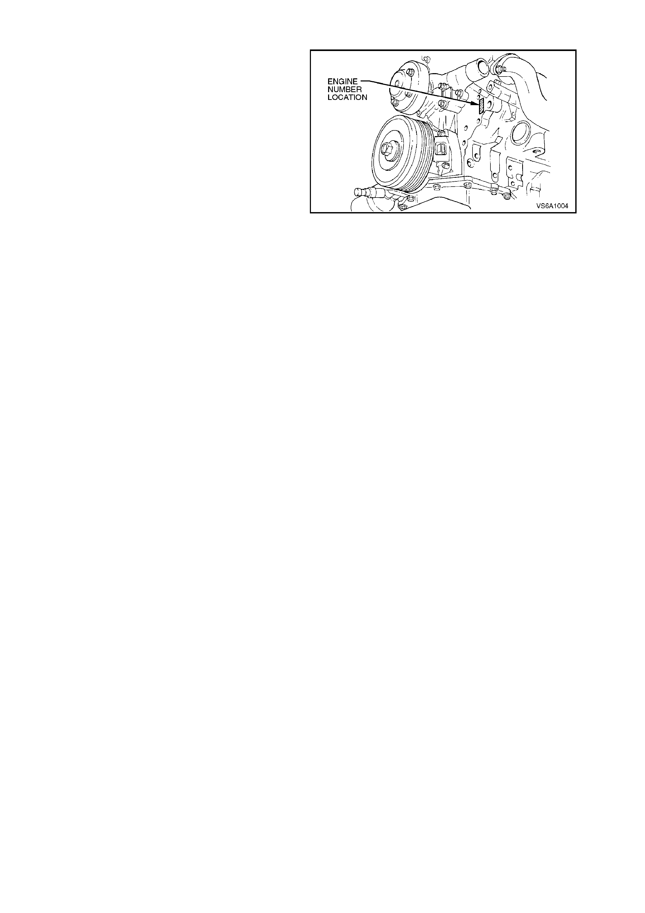
1.1 ENGINE SERIAL NUMBER
The engine serial number is s tamped on the engine
block front left hand face.
The engine number is pr ef ix ed by a two letter c ode:
VH.
Figure 6A1-1-4
1.2 ENGINE CONSTRUCTION
CYLINDER BLOCK
The cylinder block is made of cast iron. It has six
cylinders arranged in a 90 degree V - shape with
three cylinders in each bank.
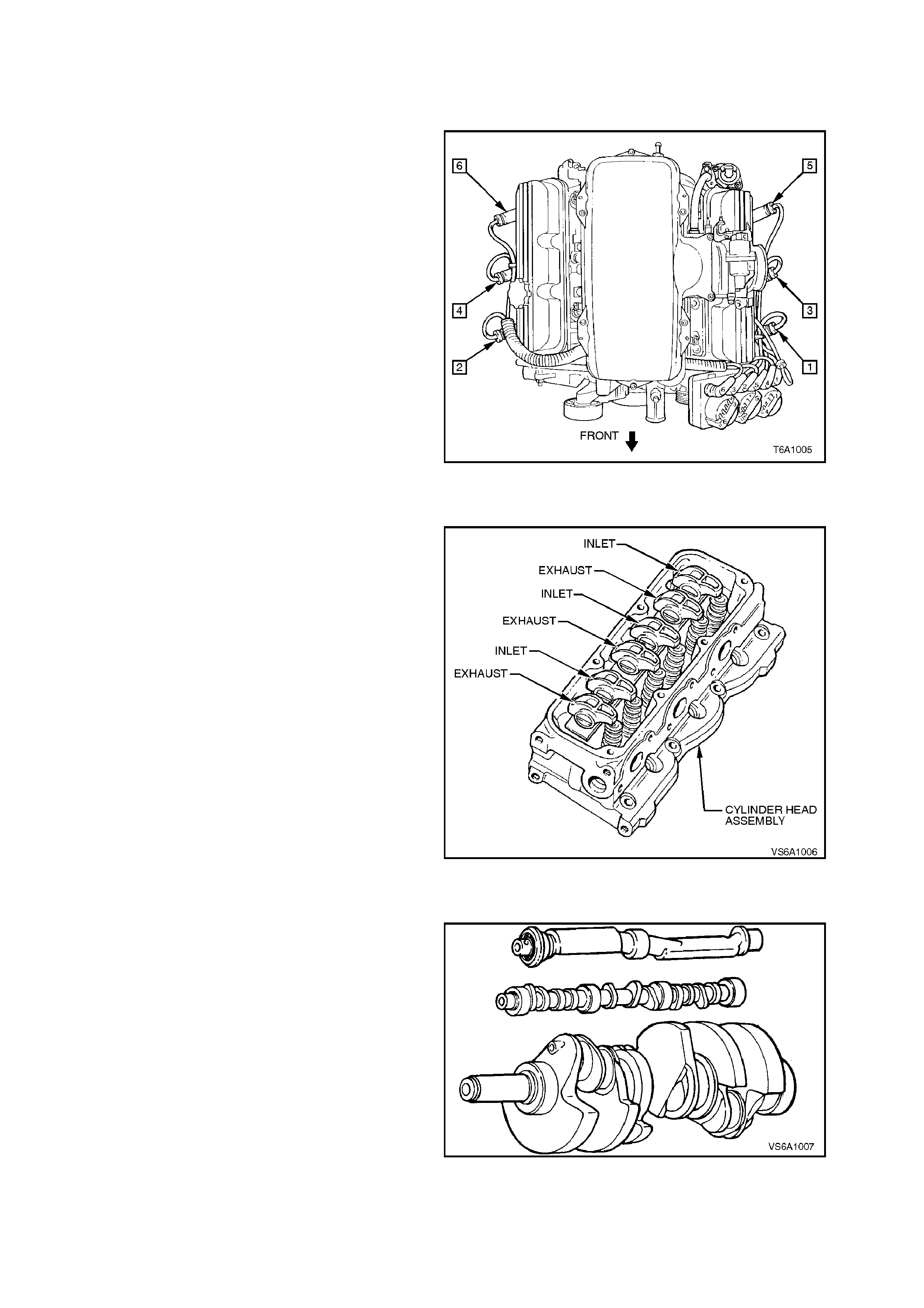
The cylinder numbering is as shown in Fig. 6A1-1-
5. Firing order is 1-6-5-4-3-2.
Four m ain bearings support the crank shaft which is
retained by bearing caps that are machined with
the block for proper alignm ent and clearanc es. T he
three front main bearing caps are side bolted for
increased stiffness. Cylinders are completely
encircled by coolant jackets.
Figure 6A1-1-5
CYLINDER HEADS
Cylinder heads are cast iron and incorporate
integral valve guides and individual exhaust and
inlet ports for each cylinder. The cylinder head
features symmetrical ports and combustion
chambers
Right and left hand cylinder heads are identical and
interchangeable, although in service, it is good
practice to r einstall cylinder heads on the side from
which they are removed.
Figure 6A1-1-6
CRANKSHAFT
The crankshaft is cast nodular iron with rolled
fillets. It is supported by four main bearings, with
each bearing being specific (except No. 1 and No.
4 upper bearing shells having the same design),
with No. 2 main bearing taking crankshaft end
thrust.
The c rank shaf t is counter balanced by weights cast
integral with the crankshaft. Additional counter
balancing is obtained from the flywheel, crankshaft
balancer and a balance shaft which is located in the
cylinder block, above the camshaft. The balance
shaft is gear driven by the camshaft.
Figure 6A1-1-7
The 3800 V6 engine is even-firing, i.e. the cylinder
firing is at equal 120 degree intervals of crankshaft
rotation. The location of the crankpins are
displaced by an included angle of 30 degrees in
order to fire the cylinders at equal 120 degree
intervals of crankshaft rotation.
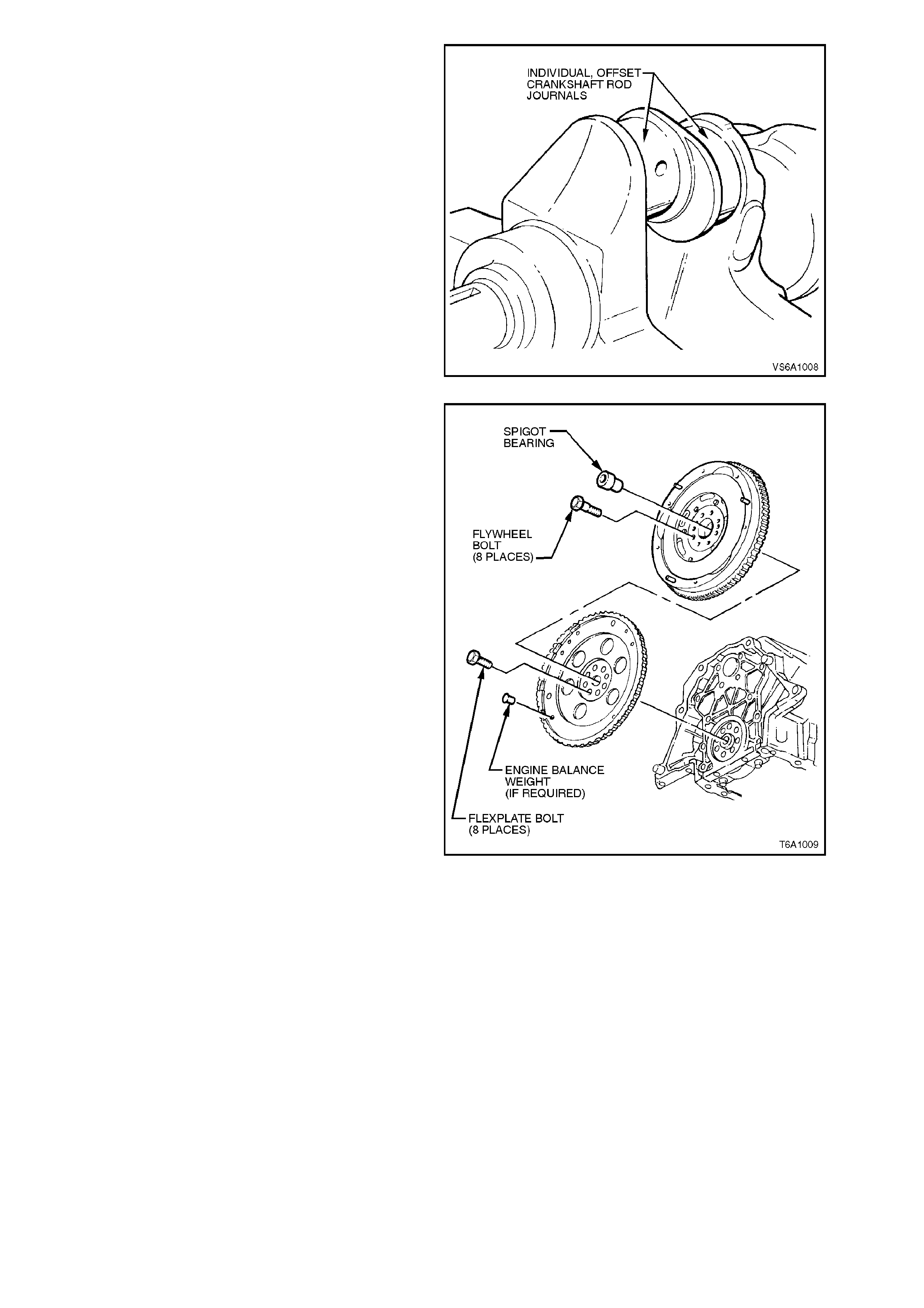
Figure 6A1-1-8
The crankshaft is common for both automatic and
manual transmissions. A spigot bearing and
flywheel locating dowel pins are installed into the
rear of the cr ankshaf t when manual trans miss ion is
used.
The flywheel/flexplate is held to the crankshaft by
eight bolts. One of the bolt holes in the crankshaft
and flywheel/flexplate is off set to allow ass embly to
the crankshaft in one position only.
These bolts are to be used only once, and if
removed, must be replaced.
Figure 6A1-1-9
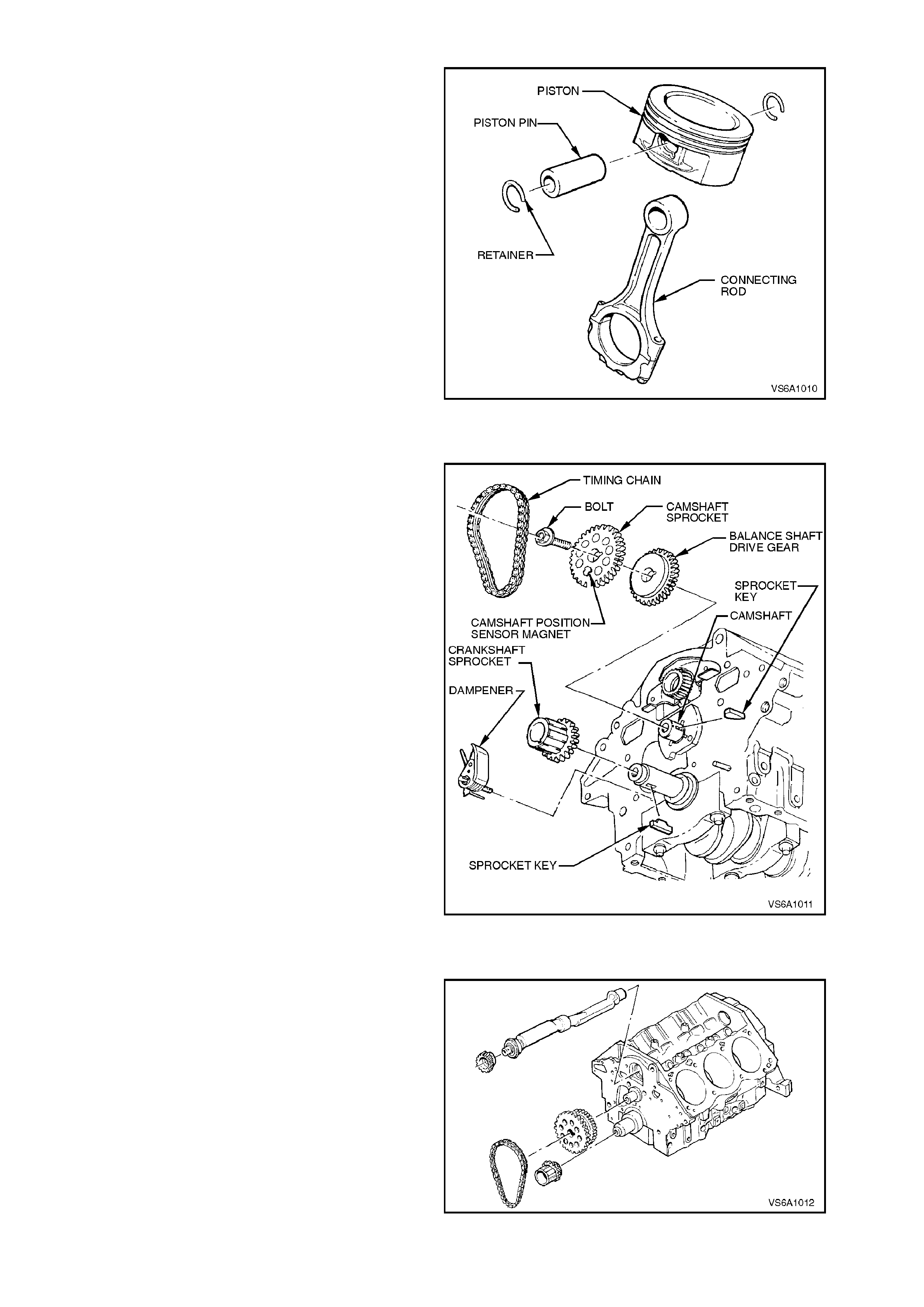
PISTONS AND CONNECTING RODS
Pistons are of a lightweight, low friction short skirt
design with floating pins, dished crowns, and are
cast from aluminium alloy and machined.
Each piston has two com pression rings and one oil
control ring. Two transverse slots in the piston oil
ring grooves extend through the piston wall and
permit drain back of oil collected by the oil ring.
Piston pins are offset toward the major thrust side
of the piston (left hand side, as viewed from the
front of the engine) to provide a gradual change in
thrust pressure against the cylinder wall as the
piston travels its path.
Pistons pins are c as e-hardened and have a floating
fit in the pistons and connecting rod.
Connecting rods are cast malleable iron with a
bushed small end for the floating piston pin.
Bearing caps are held in place on the connecting
rods by attaching bolts. Figure 6A1-1-10
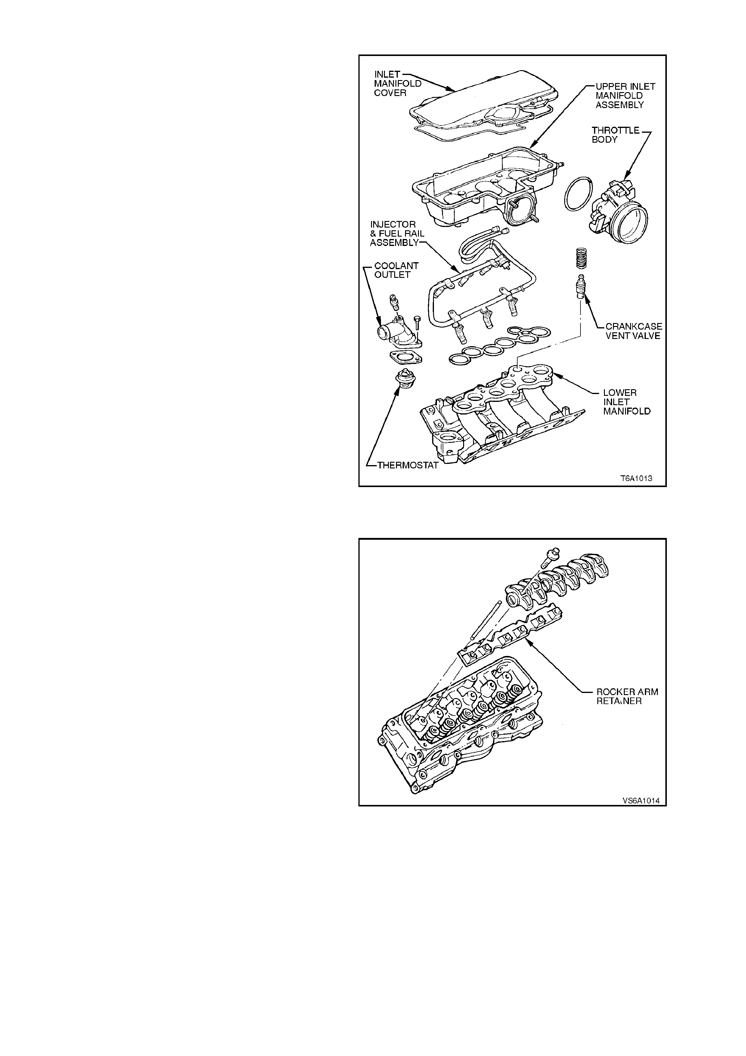
CAMSHAFT AND DRIVE
The camshaft is steel and supported by four steel
backed, babbitt-lined bearings.
It is driven by the crankshaft sprockets and chain
at the front of the engine. Both the crankshaft and
camshaft sprockets have timing marks to set the
correct valve timing.
A magnet, fitted to the camshaft sprocket, is used
by the camshaft sensor, located in the front cover,
to detect the position of the camshaft.
The PCM (Powertrain Control Module) uses this
information to control the fuel injectors. Refer to
Section 6C1 POWERTRAIN MANAGEMENT - V6
ENGINE.
Figure 6A1-1-11
BALANCE SHAFT
A counter rotating cast iron balance shaft is
installed in the cylinder block. It is located in the
lifter valley of the cylinder block above, and parallel
to, the camshaft. The balance shaft is gear driven
by the cam shaf t, at cranks haft speed, and resolves
primary rotational imbalance for improved engine
smoothness. The shaft has a ball bearing at the
front and plain rear bearing journal at the rear.
Figure 6A1-1-12
INLET MANIFOLD
The inlet manifold is a three piece aluminium
construc tion and is bolted to the inner f aces of both
cylinder heads so that it connects with all inlet
ports.
Provision is made for the mounting of the fuel
injectors and fuel rail assembly, throttle body,
thermostat and coolant outlet.
Figure 6A1-1-13
VALVE TRAIN
The valve rocker arms for each bank of cylinders,
pivot on roller bearings. The rocker arms are kept
in alignment by a single retainer on each cylinder
head.
Hydraulic, roller valve lifters and tubular push rods
are used to operate overhead rocker arms and
valves for both banks of cylinders from a single
cam shaft. T his system requires no lash adj ustment
at time of assembly or in service.
Inlet and exhaust valves feature "beehive" shaped
valve springs for greater valve control.
Figure 6A1-1-14
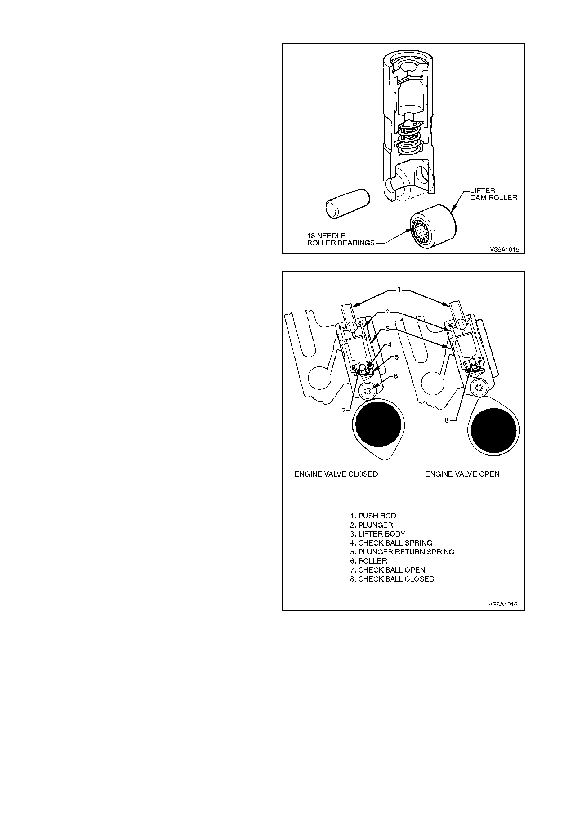
HYDRAULIC VALVE LIFTER OPERATION
In addition to its normal function of a cam follower,
each hydraulic valve lifter also serves as an
automatic adjuster which m aintains zero las h in the
valve train under all operating conditions. By
eliminating all lash in the valve train and also
providing a cushion of oil to absorb operating
shocks, the hydraulic valve lifter promotes quiet
valve operation. It also eliminates the need for
periodic valve adjustment to compensate for wear
of parts.
Oil is supplied to the lif ter through a hole in the s ide
of the lifter body which indexes with a groove and
hole in the lifter plunger. Oil is then metered past
the metering valve in the lifter, through the push
rods to the rocker arms.
Figure 6A1-1-15
W hen the lifter begins to ride up the cam lobe, the
check ball is held against its seat in the plunger by
the check ball sp ring. The c heck ball traps the oil in
the base of the lifter body below the plunger. The
plunger and the lifter body then rise as a unit,
pushing up the push rod to open the valve. The
force of the valve spring, which is exerted on the
plunger through the rocker arm and push rod,
causes a slight amount of leakage between the
plunger and lifter body. This 'leak down' allows a
slow escape of trapped oil in the base of the lifter
body. As the lifter rides down the other side of the
cam lobe and reaches the base circle, or 'valve
closed' position, the plunger spring quickly moves
the plunger back (up) to its original position. This
movement causes the check ball to open against
the ball spring, and oil from within the plunger is
drawn into the base of the lifter. This restores the
lifter to zero lash.
For hydraulic valve lifter diagnosis, refer to
4.5 HYDRAULIC VA LVE LIFTERS in this Section.
Figure 6A1-1-16
EXHAUST MANIFOLDS
Two nodular cast iron exhaust manifolds are used
to direct exhaust gases from the combustion
chambers to the exhaust system.
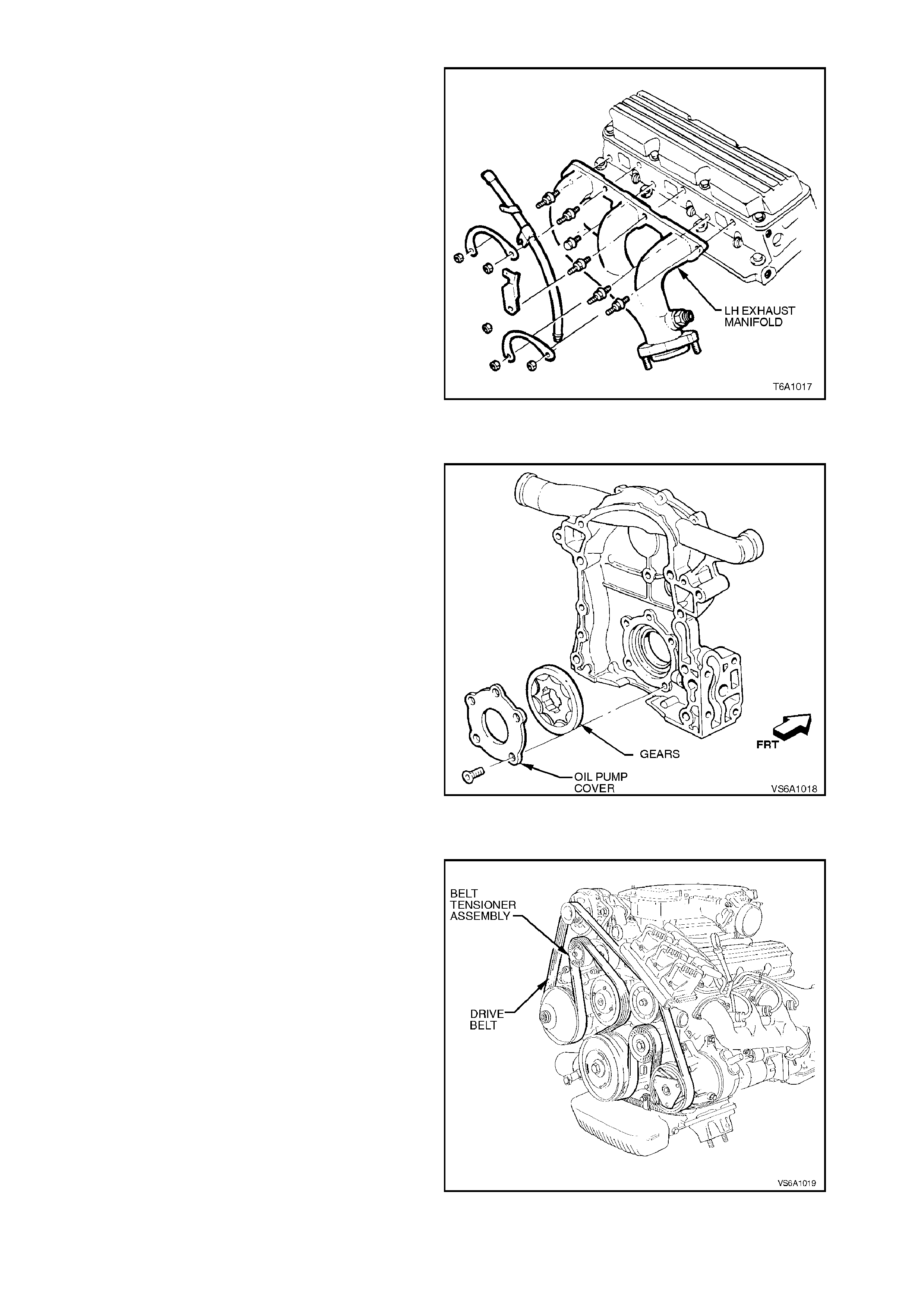
Figure 6A1-1-17
OIL PUMP
The oil pump assem bly is integrated with the front
cover assembly. The oil pump is a "gerotor" type
and is driven by the front end of the crankshaft
sprock et. For details of oil pum p operation, refer to
1.3 LUBRICATION in this Section.
Figure 6A1-1-18
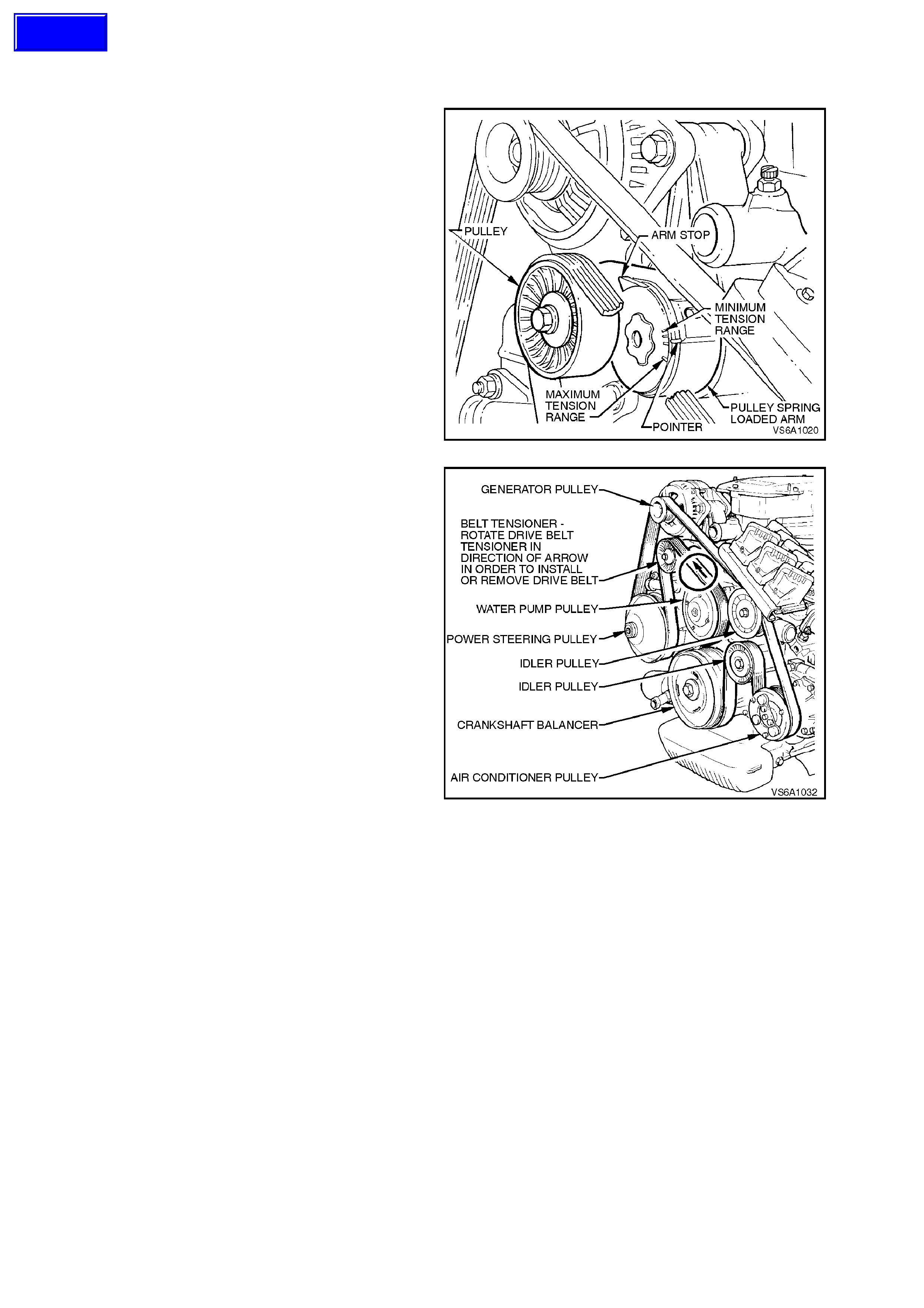
ACCESSORY DRIVE
The 3800 V6 engine employs a single serpentine
belt which drives each of the engine mounted
accessories i.e. water pump, generator, power
steering pump and if fitted, air conditioning
compressor.
Each accessory drive pulley has six grooves which
mate with the contours of the belt inner surface.
The exception to this is the water pump pulley
which is driven of f the outer surf ace of the belt and,
consequently, does not require grooves.
Drive belt tension is provided by a tensioner
assem bly. The tensioner is an idler pulley mounted
on a spring-loaded arm that maintains the dr ive belt
at the proper tension, without imposing undue loads
on the various components.
Figure 6A1-1-19
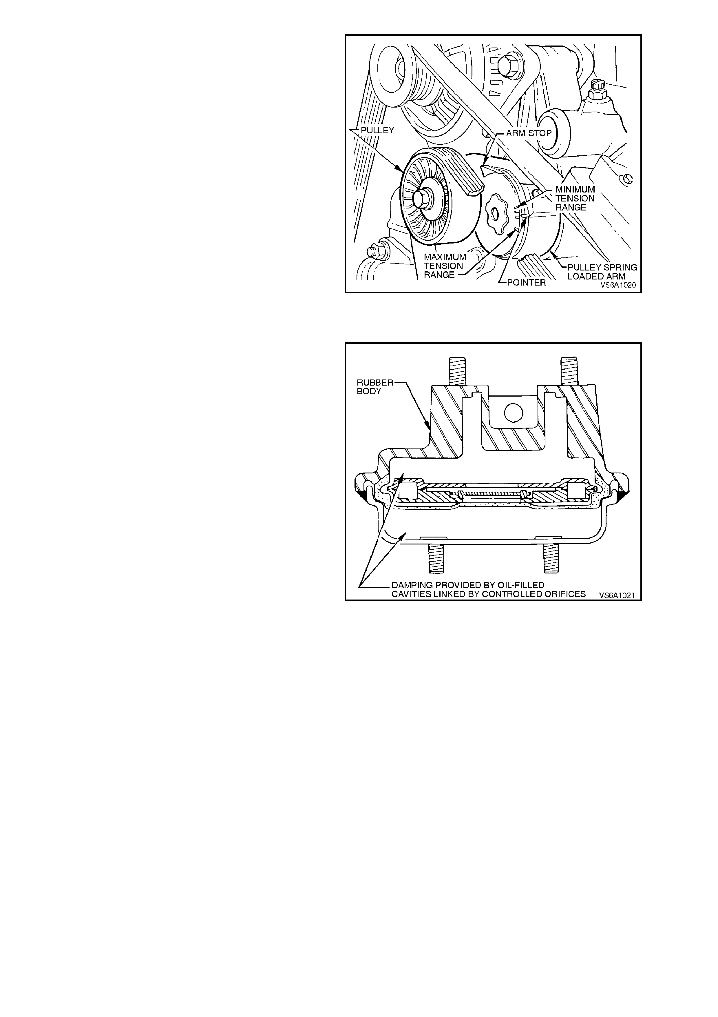
Throughout its functional travel, the tensioner
mechanism will maintain correct belt tension while
compensating for increases in belt wear and
stretch.
When the indicator pointer on the tensioner has
reached m inimum tension range, the tensioner has
reached the f ull extent of its travel and r eplacem ent
of the belt is necessary.
Figure 6A1-1-20
POWERTRAIN MOUNTING
Engine front mounts are a hydraulic design which
incorporate a rubber body and two connected
cavities. These mounts provide engine vibration
damping by allowing oil transfer from one cavity to
another via controlled or ifices , similar in principle to
a hydraulic shock absorber.
Figure 6A1-1-21
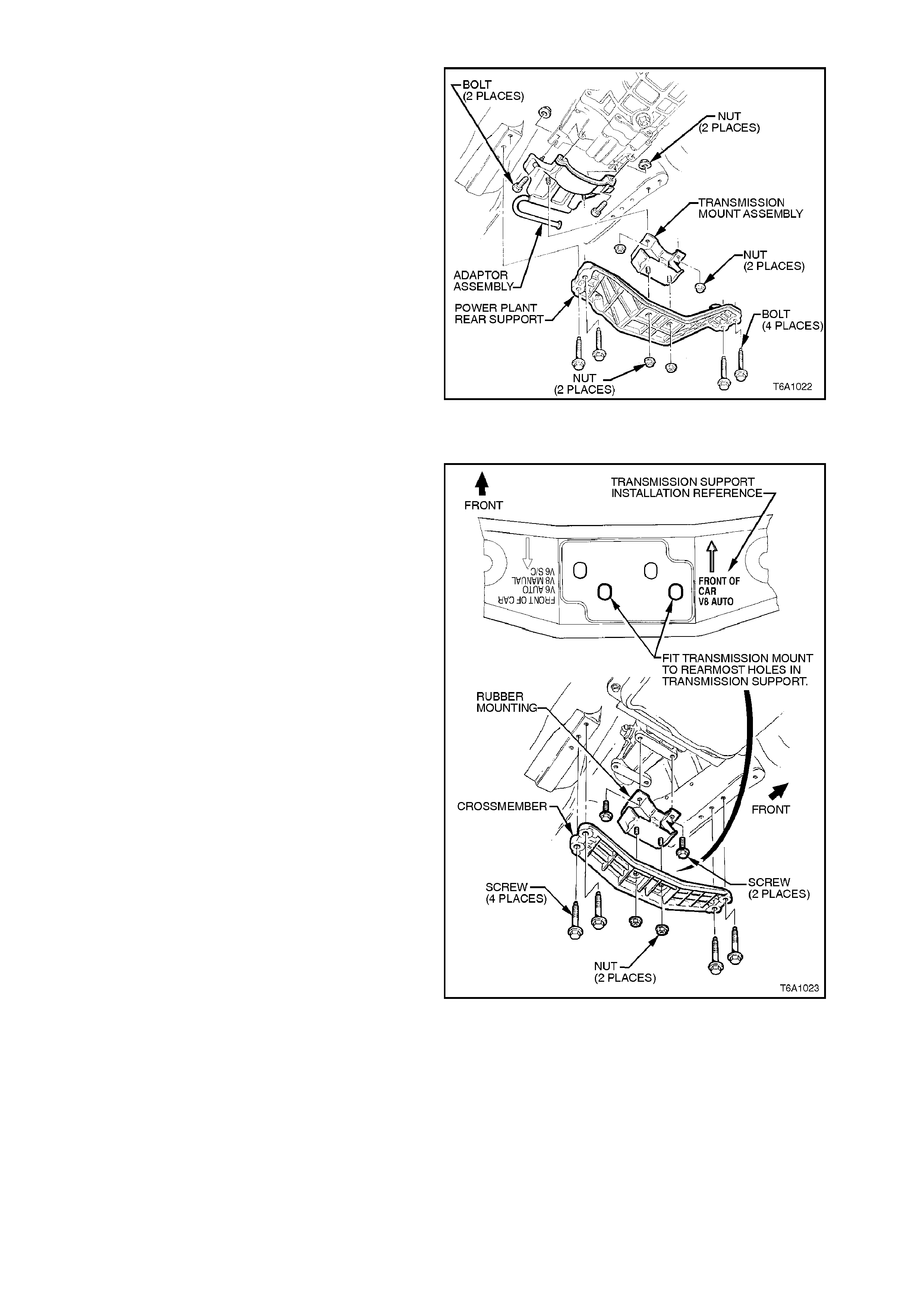
MANUAL TRANSMISSION
For vehicles fitted with manual transmission,
powertrain rear mounting consists of a rubber
mounting attached to the transmission extension,
via an adaptor assembly and to the powerplant rear
support. The rubber mounting is connected to the
powerplant rear support by two attaching nuts.
Figure 6A1-1-22
AUTOMATIC TRANSMISSION
For vehicles fitted with automatic transmission, the
engine rear mounting consists of a rubber mounting
attached to the transmission rear extension. The
rubber mounting is connected to the rear
crossmember by two attaching nuts.
Figure 6A1-1-23
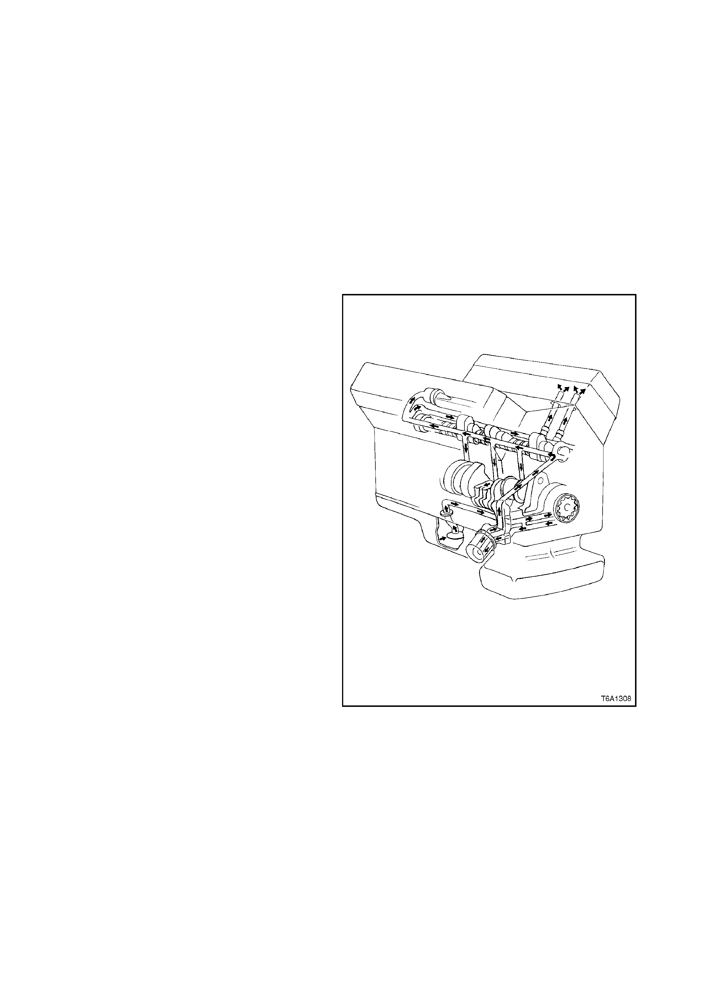
1.3 LUBRICATION
The engine lubrication system is of the force-feed
type in which oil is supplied under full pressure to
the crankshaft, connecting rods, camshaft
bearings, valve lifters and a controlled volume is
supplied to the rocker arms and push rods. The
engine has a pressure fed rear balance shaft
bearing. Oil is fed from the rear of the right oil
gallery through a rear seal housing . The housing
also includes the cross over passage for oil supply
to the left bank. All other moving parts are
lubricated by gravity flow or splash.
The supply of oil is carried in the oil pan which is
filled through a filler opening in the right hand
rocker cover (as viewed from the drivers seat). An
oil level indicator (d ip stic k), loc ated on the front lef t
hand side of the crankcase, (as viewed from the
drivers seat) is provided to check oil level.
The oil pump is located in the engine front cover
and is driven by the cranks haft. It is a 'gerotor' type
pump which is a combination of gear and rotor
pumps . It is c onnected by a passage in the cylinder
crankcase to an oil suction pipe and screen. The
screen is submerged in the oil supply.
Oil is drawn into the pump through the screen and
pipe assembly and the passage in the crankcase
which connects to passages in the front cover. All
oil is discharged from the pump to the oil filter
adaptor assembly which consists of a full flow oil
filter and by-pass valve.
The spring loaded oil pressure regulator valve,
located in the front cover, limits the oil pressure to
approximately 414 kPa. The oil filter by-pass valve
opens when the filter has become clogged. When
approximately 69 kPa pressure difference exits
between the filter inlet and disc harge, oil by-passes
the oil filter and channels unfiltered directly into the
main galleries of the engine.
The main oil galleries run the full length of the
crankcase and connect into the valve lifter guide
holes to supply oil at full pressure to the lifters.
Holes drilled from the crankshaft main bearings to
the main gallery, intersect the camshaft bearing
bores which supply oil to the camshaft bearings.
Holes drilled in the crankshaft, carry oil from the
crankshaft main bearings to the connecting rod
bearings. Pistons and cylinder walls are lubricated
by oil thrown off the crankshaft and by connecting
rod splash. Piston pins are lubricated by splash.
Each rocker arm and valve is supplied with oil
through the tubular push rod. This oil comes from
the inside of the lif ter, passing around the meter ing
valve, up the inside of the push rod and through a
hole in the rocker arm push rod seat.
Figure 6A1-1-24

1.4 SERVICE NOTES
CLEANLINESS AND CARE
A motor vehicle engine is a combination of many machined, honed, polished and lapped surfaces with tolerances
that are measured in thousandths of a millimetre. When any internal engine parts are serviced, care and cleanliness
are important. A liberal coating of engine oil should be applied to friction areas during assembly to protect and
lubricate the surfaces on initial operation. Throughout this Section, it should be understood that proper cleaning and
protection of machined surfaces and friction areas is part of the repair procedure. This is considered standard
workshop practice even if not specifically stated.
Whenever valve train components are removed for service, they should be kept in order. They should be installed in
the same locations, and with the same mating surfaces, as when removed.
Battery terminals should be disconnected before any major work is performed on the engine. Failure to disconnect
terminals may result in damage to wiring harnesses or other electrical components.
THE FOLLOWING INFORMATION ON ENGINE SERVICE SHOULD BE NOTED CAREFULLY, AS IT IS
IMPORTANT IN PREVENTING DAMAGE AND IN CONTRIBUTING TO RELIABLE ENGINE PERFORMANCE.
When raising or supporting the engine for any reason, do not use a jack under the oil pan. The oil pan is of cast
aluminium construction and could be damaged.
Refer to Section 0A GENERAL INFORMATION for location of jacking points, also refer to Section 3 FRONT
SUSPENSION for jacking precautions.
Any time the air flow ducting is removed or disconnected, the intake opening should be covered. This will protect
against accidental entrance of foreign material which could follow the intake passage into a cylinder and cause
extensive damage when the engine is started.
CAUTION:
Do not start engine with engine inlet manifold top cover or throttle body removed, as engine will run at
wide open throttle.
2. MI NOR SERVICE OPERATIONS
2.1 COMPRE SSION CHECK
1. When conducting this check, ensure:
a. Engine is at operating temperature.
b. Battery is at or near full charge.
c. All spark plugs removed.
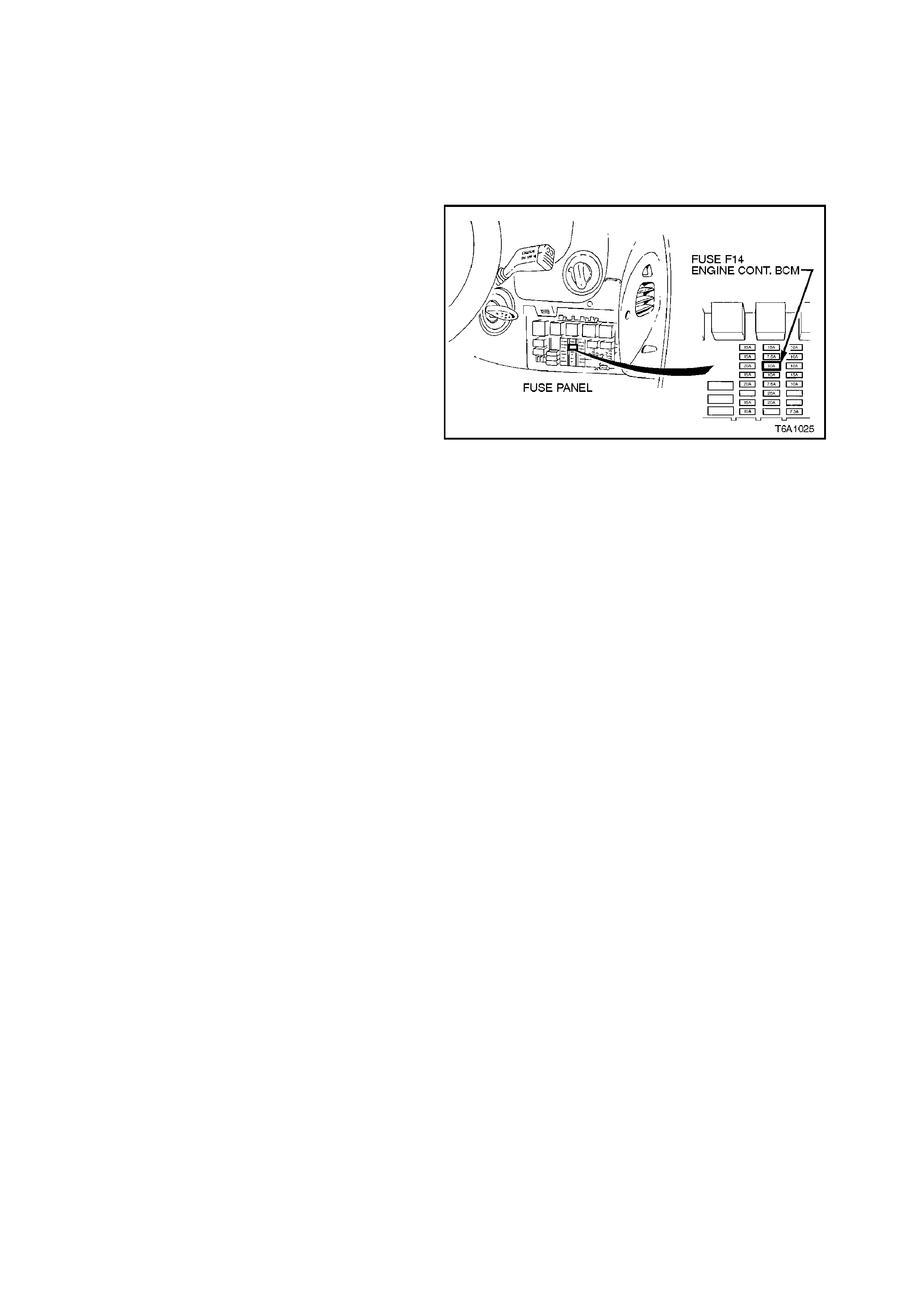
d. Remove fuse F14 which is located in
passenger compartment fuse panel.
Removal of this fuse prevents the fuel
pump and injector s f r om operating dur ing
engine cranking.
2. Install a suitable compression tester.
3. Crank engine. Record compression gauge
indication.
NOTE:
It is important to open the throttle when conducting
a compression test to ensure cylinder filling.
4. Check remaining cylinders.
NOTE:
The lowest reading of any cylinder should not be
less than 70 % of the highest and no cylinder
reading should be less than 689 kPa.
5. If cylinder compression in one or more
cylinders is low, pour a small amount of engine
oil into the cylinders through the spark plug
holes and retest compression.
Figure 6A1-1-25
INTERPRETATION OF COMPRESSION READINGS
NORMAL - Compression builds up quickly and
evenly on each cylinder.
PISTON RINGS - Compression low on first stroke
tending to build up on following strokes, but does
not reach normal. Improves considerably with
addition of oil.
VALVES - Low on firs t strok e and does not tend to
build up on following strokes. Does not improve
much with addition of oil.
HEAD GASKET - If cylinder compression in any
two adjacent cylinders is low, and if adding oil does
not help compression, cylinder head gasket has
blown.
2.2 CHECKING ENGINE OIL P RE S SURE
1. Check engine oil level and add oil as
required.
2. Ensure that engine is at operating
temperature.
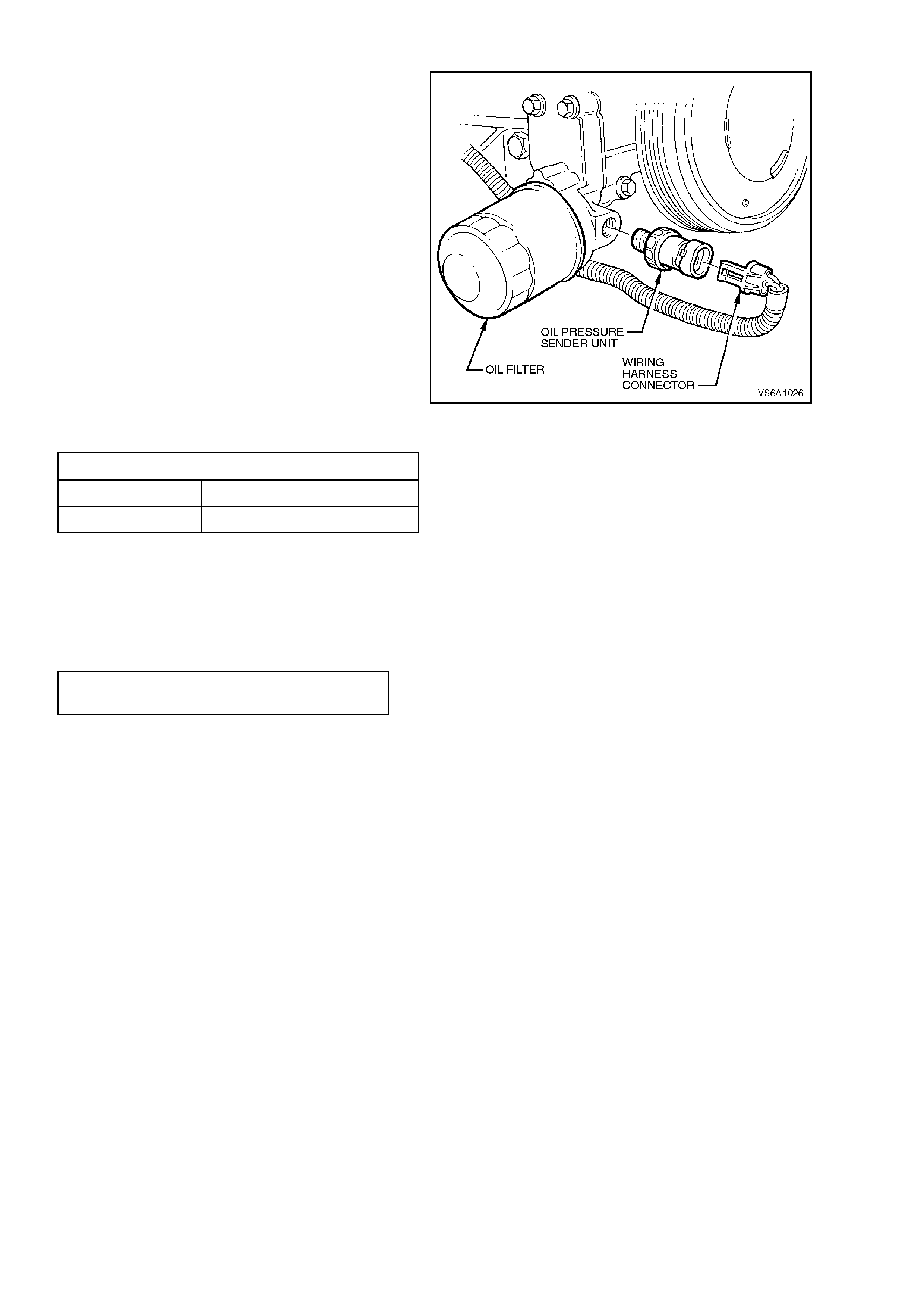
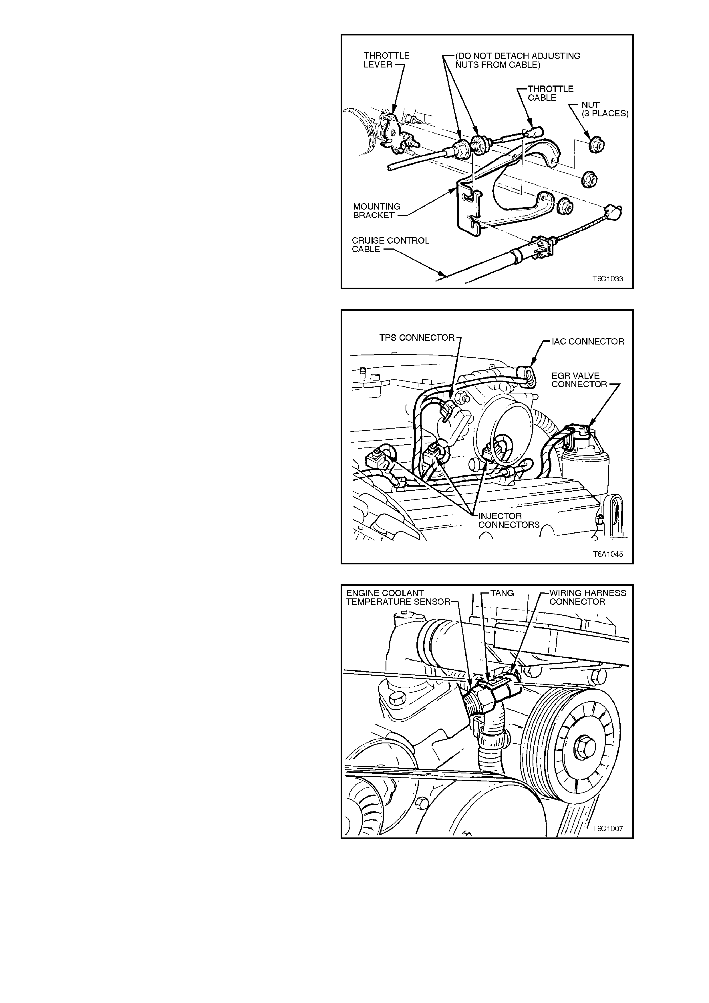
3. Pull out retaining tang on engine harness
connector at oil pressure sender unit and
pull connector from sender unit.
4. Place an oil drain tray beneath engine.
5. Loosen and remove oil pressure sender
unit from oil filter adaptor.
6. Install a suitable oil pressure gauge
assem bly into oil filter adaptor oil pressure
sender unit hole.
7. Start engine and check oil pressure
reading with engine running under no load.
Figure 6A1-1-26
OIL PRESSURE SPECIFICATION
ENGINE RPM OIL PRESSURE READING
1850 and above 375 kPa minimum
8. After completion of test, apply Loctite 242
sealant or equivalent (Holden Specification HN
1256 Class 2, Type 2), to sender unit threads .
Install sender unit and tighten to the correct
torque specification.
OIL PRESSURE SENDER UNIT
TORQUE SPECIFICATION 12 - 14
Nm
9. Reinstall wiring harness connector to sender
unit, start engine and check for oil leaks and
warning lamp operation.
2.3 OIL FILTER
NOTE:
The oil filter should be replaced at the time or
distance intervals specified in the VT Owner's
Handbook or whenever the engine oil is
contaminated by foreign material.
REPLACE
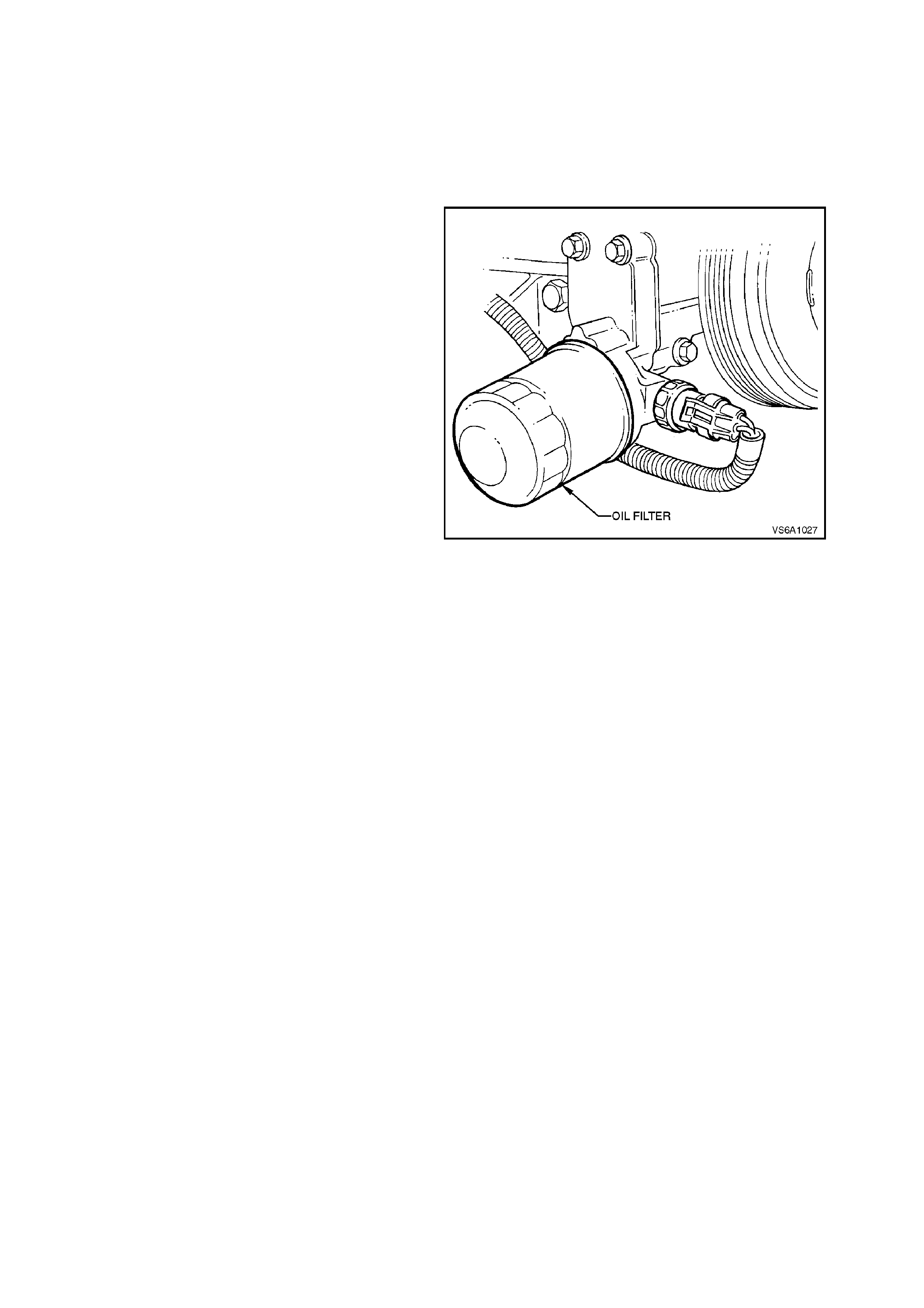
1. Place an oil drain tray beneath engine.
2. Using a suitable oil filter wrench, unscrew oil
filter, remove and discard.
3. Ensure seal is installed correctly in recess of
new filter.
4. Pour som e c lean engine oil into filter until level
remains at approximately 2 cm below top of
filter.
5. Smear some engine oil over filter seal. Screw
filter into place until seal contacts mating
surface of adaptor. Tighten filter through a
further 2/3 of a turn.
6. Clean any excess oil from filter and adaptor.
7. Check oil level. Start engine and check for oil
leaks. Repair as necessary.
NOTE:
The oil level must be rechecked and oil added as
necessar y, after running the engine, to c ompensate
for oil used to refill the oil filter. Figure 6A1-1-27

2.4 OIL LEVEL CHECK
1. Engine must be at normal operating temperature (idle for 10 minutes or equivalent).
2 Park vehicle on level surface (as this will affect the accuracy indicated on dipstick, this is a critical
requirement).
3. Do not check oil level for at least 10 minutes after shut down to allow oil to drain back into the oil pan.
4. Remove dipstick and wipe clean.
5. Reinstall dipstic k with FULL/ADD mar ks f ac ing towards c entr e line of engine. T his as pec t is very im por tant due
to the angle that the dipstick enters the oil in the oil pan.
6. Ensure dipstick is fully seated and slowly r em ove to avoid sm ear ing. Hold horizontally or with lower end slightly
down to avoid oil running along dipstick.
7. Observe the oil level where it passes over the centre line of the dipstick.
8. When topping up the engine oil, allow approximately 10 minutes for the oil added to fully drain into the oil pan.
Alternatively, add 50 ml of oil for each millimetre below the “FULL” mark on the dipstick.
Techline
2.5 OIL FILTER ADAPTOR
REMOVE
1. Place an oil drain tray beneath engine.
2. Disconnect battery earth lead.
3. Remove oil filter, refer to 2.3 OIL FILTER in
this Section.
4. Pull out retaining tang on engine harness
connector at oil pressure sender unit and pull
connector from sender unit.
If necessary, loosen and remove oil pressure
sender unit.
Figure 6A1-1-28
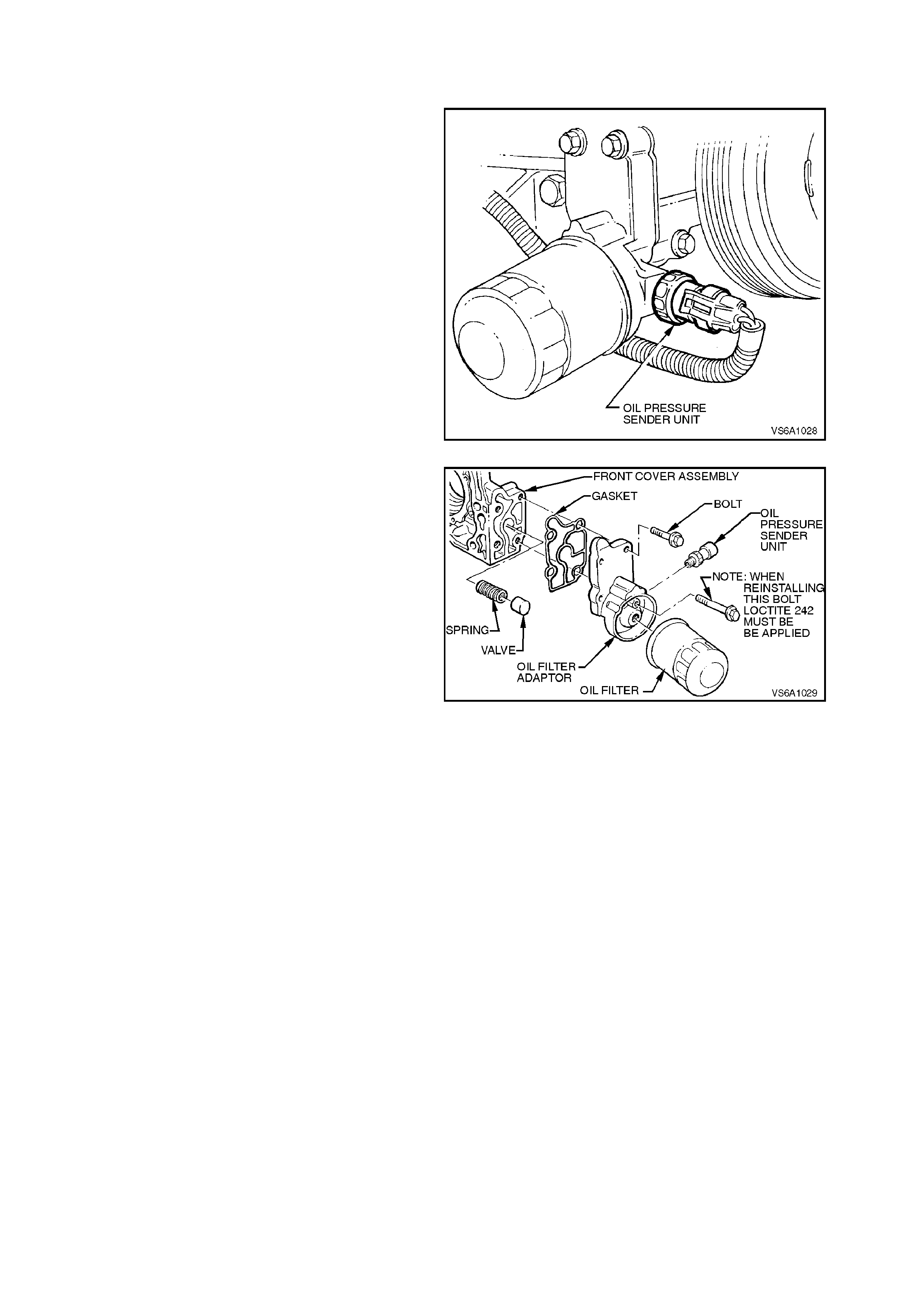
5. Remove oil filter adaptor to front cover
attaching bolts, remove adaptor.
6. Remove oil filter adaptor gasket and discard.
7. Remove oil pressure regulator valve and
spring.
Figure 6A1-1-29
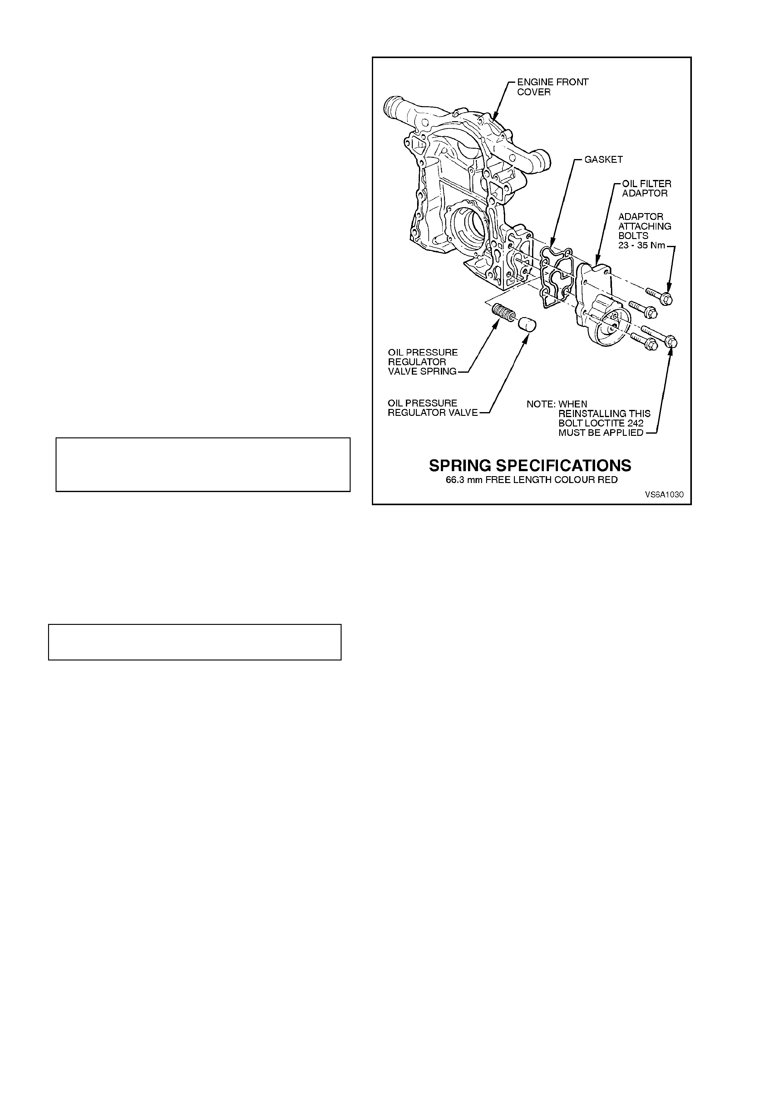
REINSTALL
1. Using a suitable size thread tap, clean adaptor
'long' attaching bolt threads in front cover.
Clean attaching bolt threads.
2. Ensure that oil filter adaptor and front cover
mating surfaces are clean and free of foreign
matter.
3. Inspect oil pressure regulator valve bore in
front cover for scoring or burrs.
Inspect regulator valve spring for tension loss
(compare with new spring) or bending. If in
any doubt, replace spring.
Refer to Fig. 6A1-1-30 for spring identification
details.
4. Install regulator valve spring and valve.
5. Install adaptor and new gasket to front cover.
Install attaching bolts and tighten to the cor rec t
torque specification.
NOTE:
Before installing 'long' adaptor attaching bolt, apply
Loctite 242 sealant or equivalent (Holden
Specification HN 1256, Class 2 Type 2) to bolt
threads.
OIL FILTER ADAPTOR TO FRONT
COVER ATTACHING BOLT 23 - 35 Nm
TORQUE SPECIFICATION
Figure 6A1-1-30
6. If reinstalling oil pressure sender unit, clean
sender unit threads and apply Loctite 242
sealant or equivalent (Holden Specification HN
1256, Class 2, Type 2). Install sender unit and
tighten to the correct torque specification.
OIL PRESSURE SENDER UNIT
TORQUE SPECIFICATION 12 - 14
Nm
7. Install new oil filter, refer to 2.3 OIL FILTER
in this Section.
8. Start engine and check f or oil leak s. Repair as
necessary.
2.6 DRIVE BELT
TENSION CHECK
NOTE:
A belt squeak when the engine is started or
stopped is normal and has no effect on drive belt
durability.
1. Inspect tensioner markings to see if belt is
within operating limits. Replace belt if
excessively worn or outside tensioner
operating range.
Figure 6A1-1-31
2. Run engine with air conditioning (if fitted)
switched off, until engine is warmed up. Switch
engine off and read belt tension with Tool
BT3373-F placed halfway between generator
and air-conditioning compressor. For vehicles
without air-conditioning, read tension between
power steering pump and crankshaft pulley.
Remove tension gauge.
NOTE:
Tool No. BT3373-F must be accurately calibrated
before carrying out drive belt tension check.
3. Start engine with air conditioning (if fitted)
switched off and allow drive belt to stabilis e f or
15 seconds. Turn engine off. Using a 15 mm
ring spanner, apply clockwise for ce (tighten) to
tensioner pulley bolt. Remove ring spanner
and immediately take a tension reading with
Tool No. BT3373-F without disturbing belt
tensioner assembly.
4. Using a 15 mm ring spanner, apply an anti-
clockwise force to tensioner pulley bolt and
raise pulley to 'belt install' position. Slowly
lower pulley to 'at rest' position and take a
tension reading without disturbing belt
tensioner position. Record reading and
remove tool.
5. Average the three readings. If the average of
the three readings is lower than 250 N and the
belt is within tensioner operating range,
replace belt tensioner.
Figure 6A1-1-32
INSPECT
Fig. 6A1-1-33 illustrates the various stages of belt
wear to aid in belt replacement decisions.
Condition of the belt ribs is best judged where the
belt is bent over the water pump pulley.
Techline
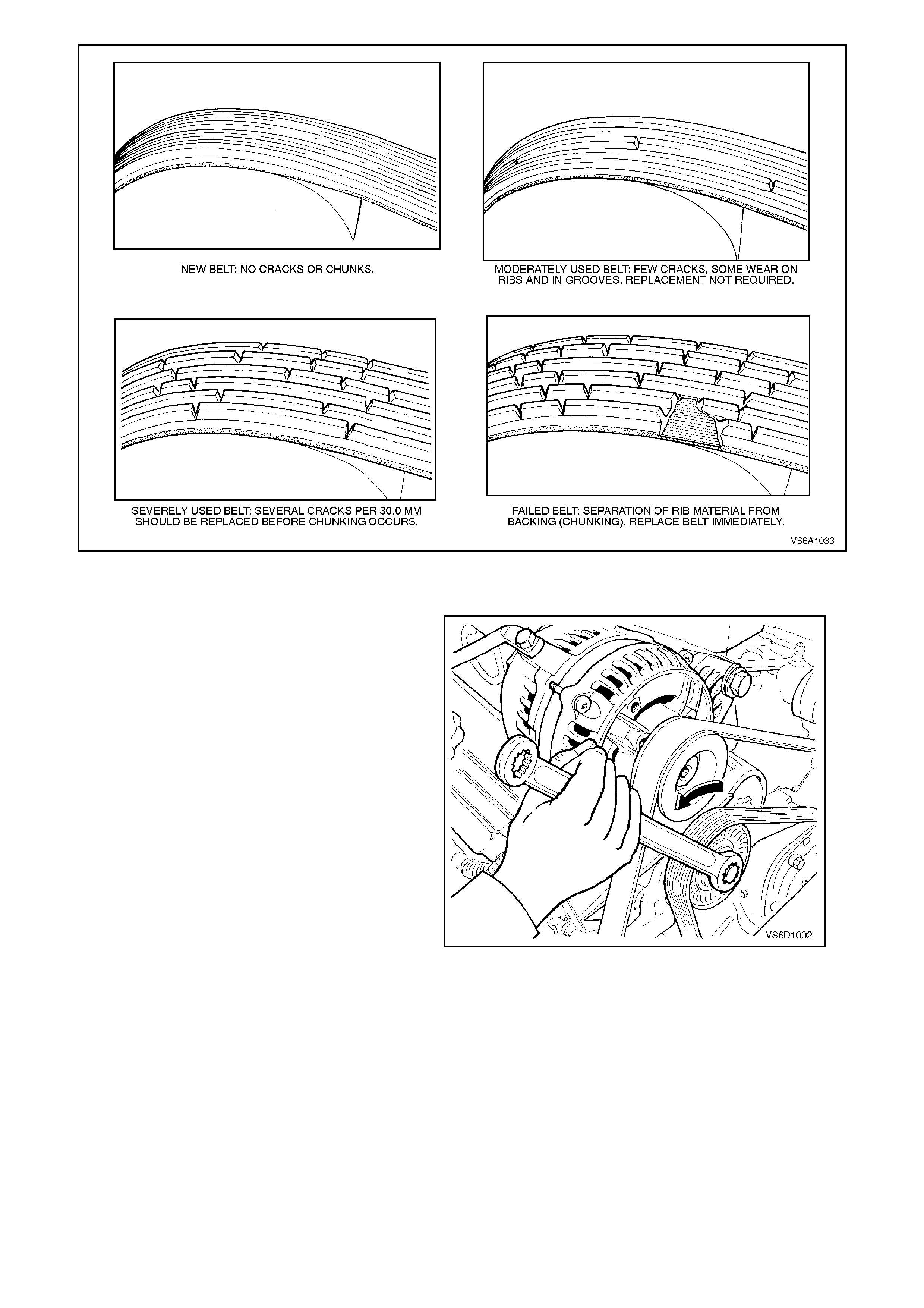
Figure 6A1-1-33
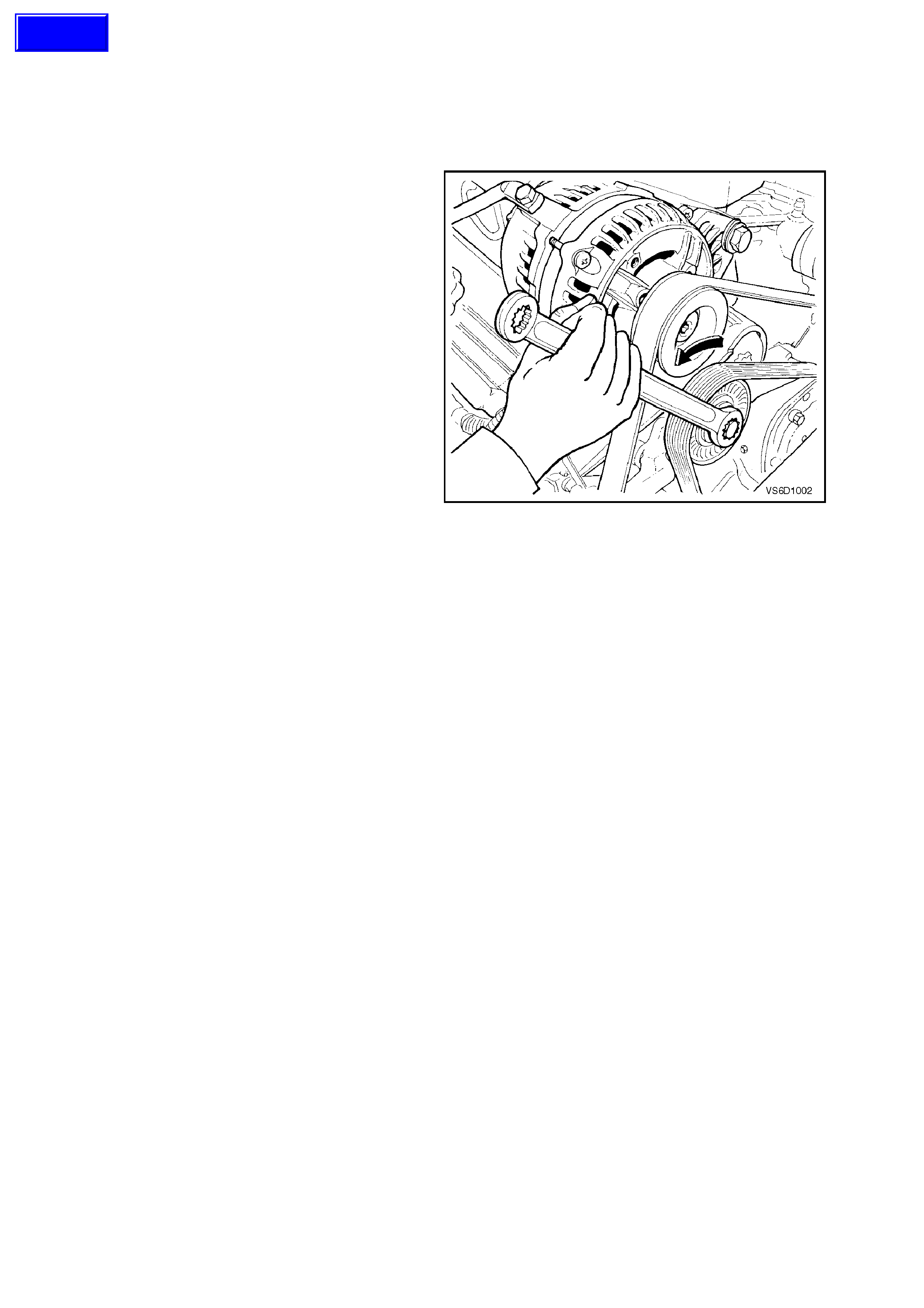
REMOVE
1. Disconnect battery earth lead.
2. Using a 15 mm ring spanner on drive belt
tensioner pulley pivot bolt, rotate tensioner
pulley assembly anti-clockwise and remove
drive belt from water pump pulley. Release
tensioner pulley assembly and remove drive
belt from remaining drive pulleys.
Figure 6A1-1-34
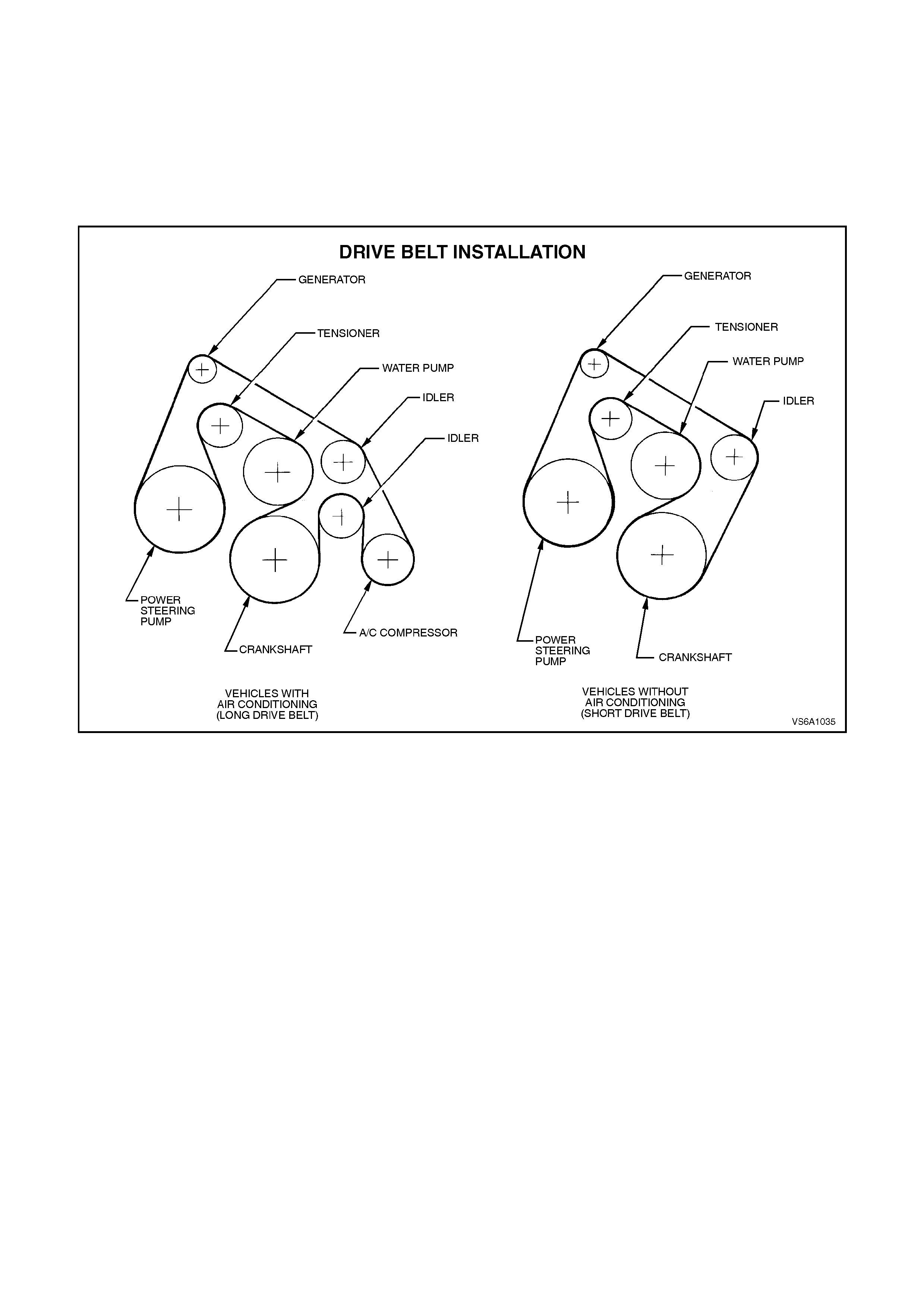
REINSTALL
1. Inspect drive belt condition, refer to Fig. 6A1-1-33.
2. Install drive belt onto accessory drive pulleys refer to Fig. 6A1-1-35.
NOTE:
Ensure that drive belt ribs are aligned into all accessory pulleys and crankshaft balancer drive belt grooves.
3. Using a 15 mm ring spanner, rotate tensioner pulley anti-clockwise and feed drive belt over water pump pulley.
Return tensioner to its normal position.
4. Reconnect battery earth lead, start engine and check drive belt operation.
Figure 6A1-1-35
2.7 DRIVE BELT TENSIONER ASSEMBLY
REMOVE
1. Disconnect battery earth lead.
2. Remove four nuts securing engine dress
cover.
3. Using a 15 mm ring spanner on drive belt
tensioner pulley pivot bolt, rotate tensioner
pulley assembly anti-clockwise and remove
drive belt from water pump pulley. Release
tensioner pulley assembly and remove drive
belt from remaining drive pulleys.
Figure 6A1-1-36
4. Remove radiator cap to release any cooling
system pressure.
WARNING:
To avoid serious personal injury, never remove
the radiator cap when the engine is hot.
Sudden release of cooling system pressure is
very dangerous and could cause personal
injury.
5. Remove generator assembly, refer to
Section 6D1-1 CHARGING SYSTEM - V6
ENGINE.
Techline
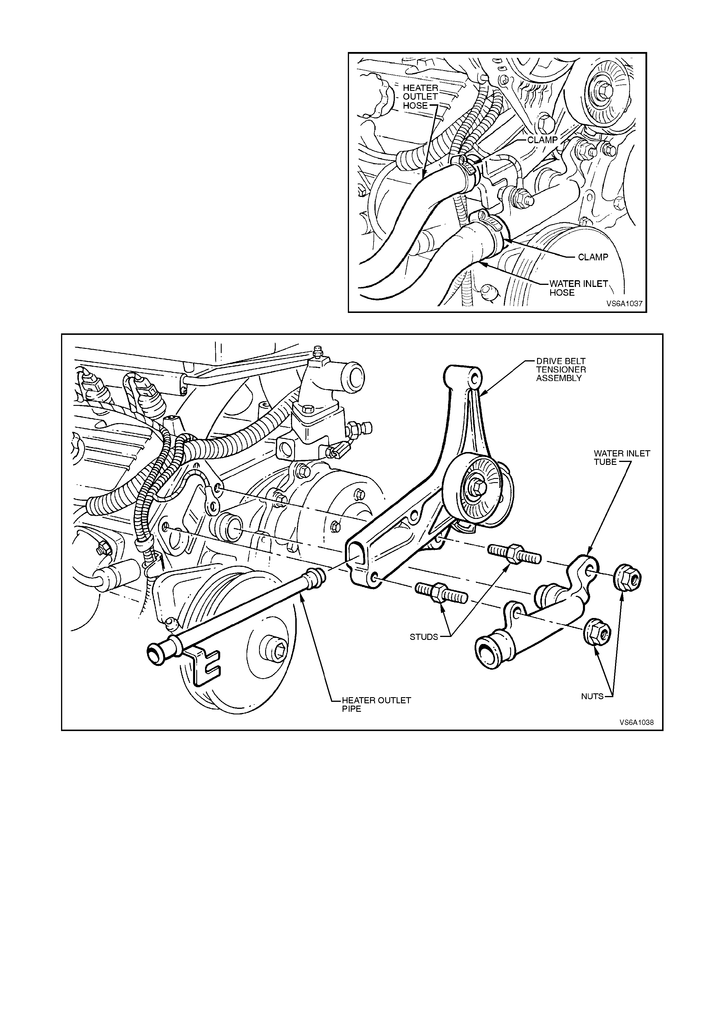
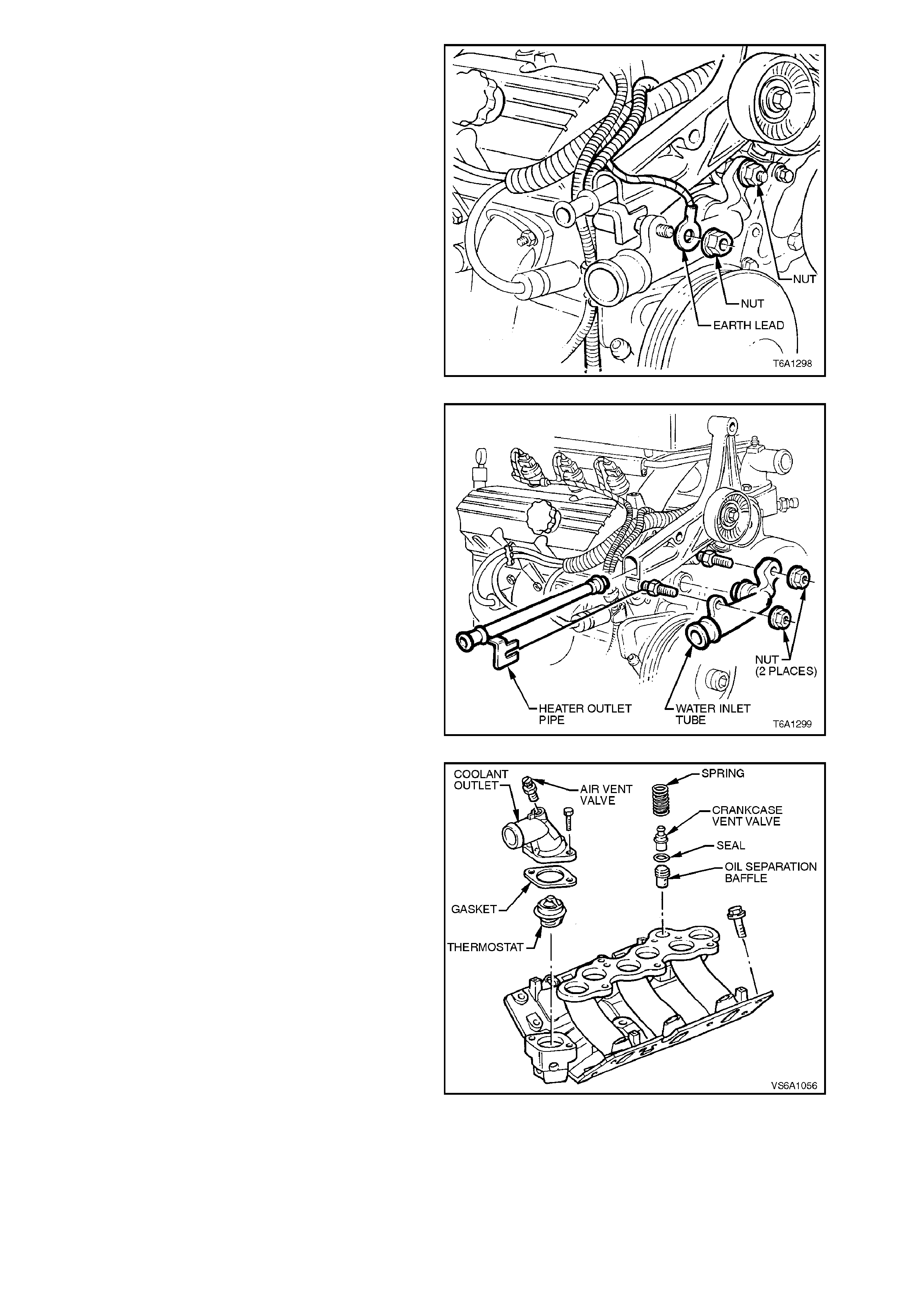
6. Remove nuts and powertrain wiring harness
earth lead from tensioner bracket lower
attaching studs.
7. Loosen hose clamp and remove heater outlet
hose from heater outlet pipe connection.
Figure 6A1-1-37
Figure 6A1-1-38
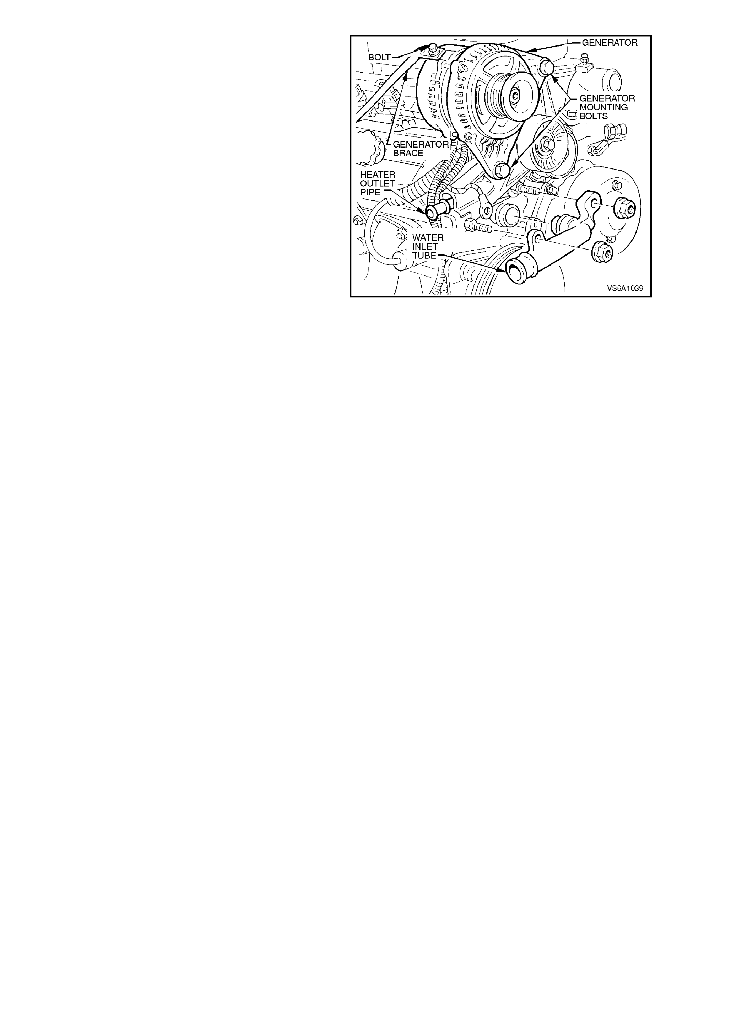
8. Remove water inlet tube assembly.
9. Remove studs securing heater outlet pipe and
drive belt tensioner assembly, pull heater
outlet pipe out from inlet manifold connection
and remove drive belt tensioner assembly.
Figure 6A1-1-39
REINSTALL
Installation of the drive belt tensioner assembly is
the reverse of removal procedures, noting the
following points:
1. Ensure that all fasteners are tightened to the
correct torque specification.
2. Check and inspect O - rings on end of heater
outlet pipe and water inlet tube, replace if
necessary. Lubricate O - rings with petroleum
jelly.
3. Refill cooling system with the correct
concentration of coolant and check for leaks,
refer to Section 6B1 ENGINE COOLING -
V6 ENGINE.
4. Start engine and check drive belt operation
and for power steering fluid or cooling system
leaks.
2.8 UPPER INLET MANIFOLD
REMOVE
1. Disconnect battery earth lead.
2. Depressurise fuel system, refer to
Section 6C1 POWERTRAIN MANAGEMENT
- V6 ENGINE.
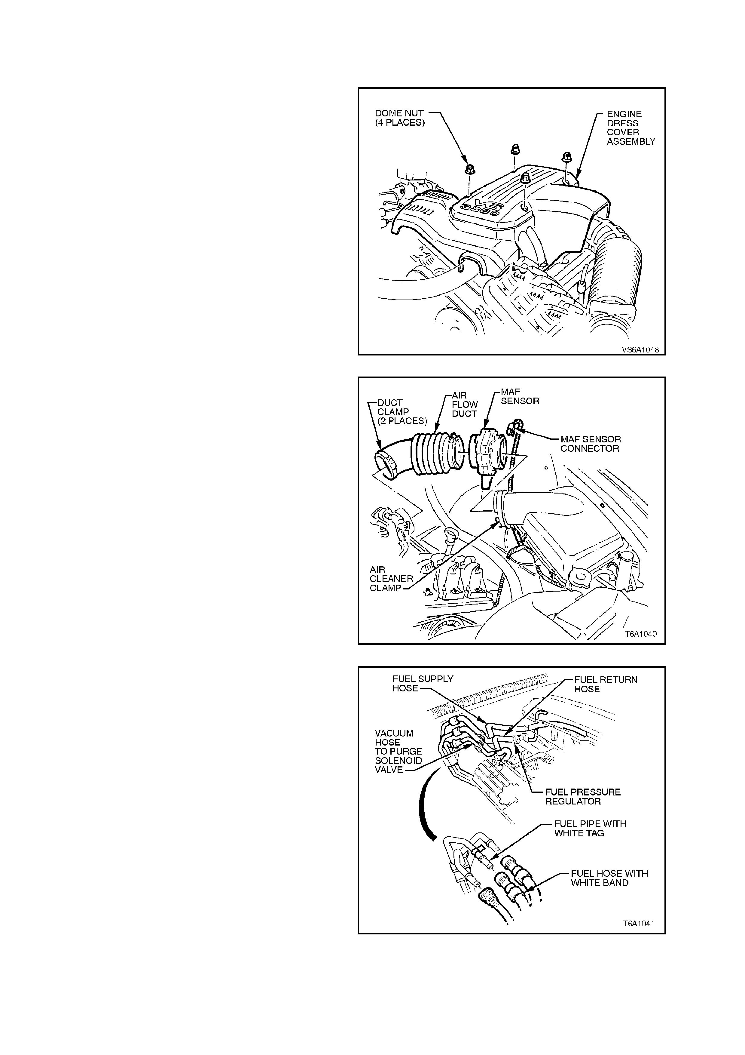
3. Remove four nuts securing engine dress
cover.
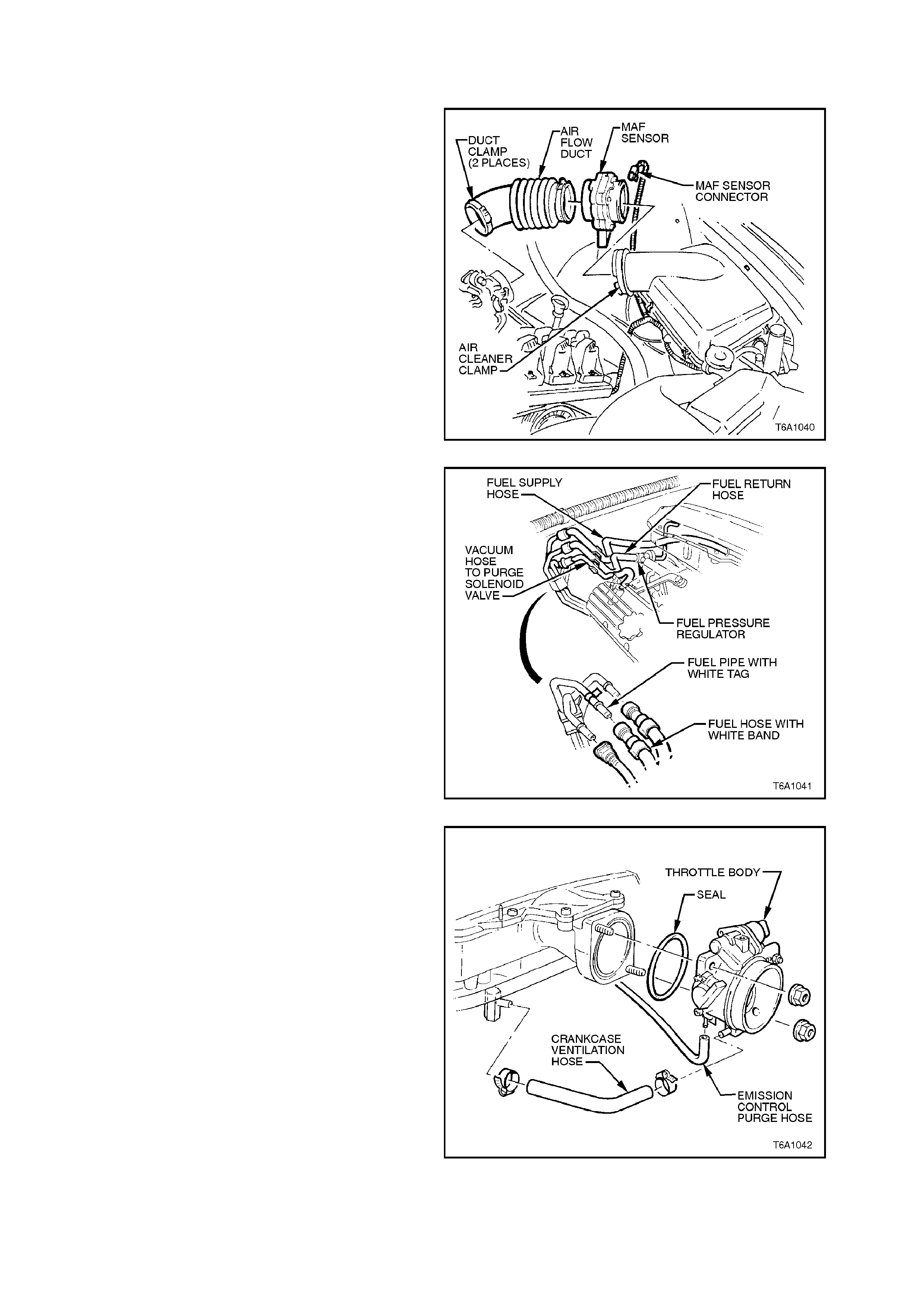
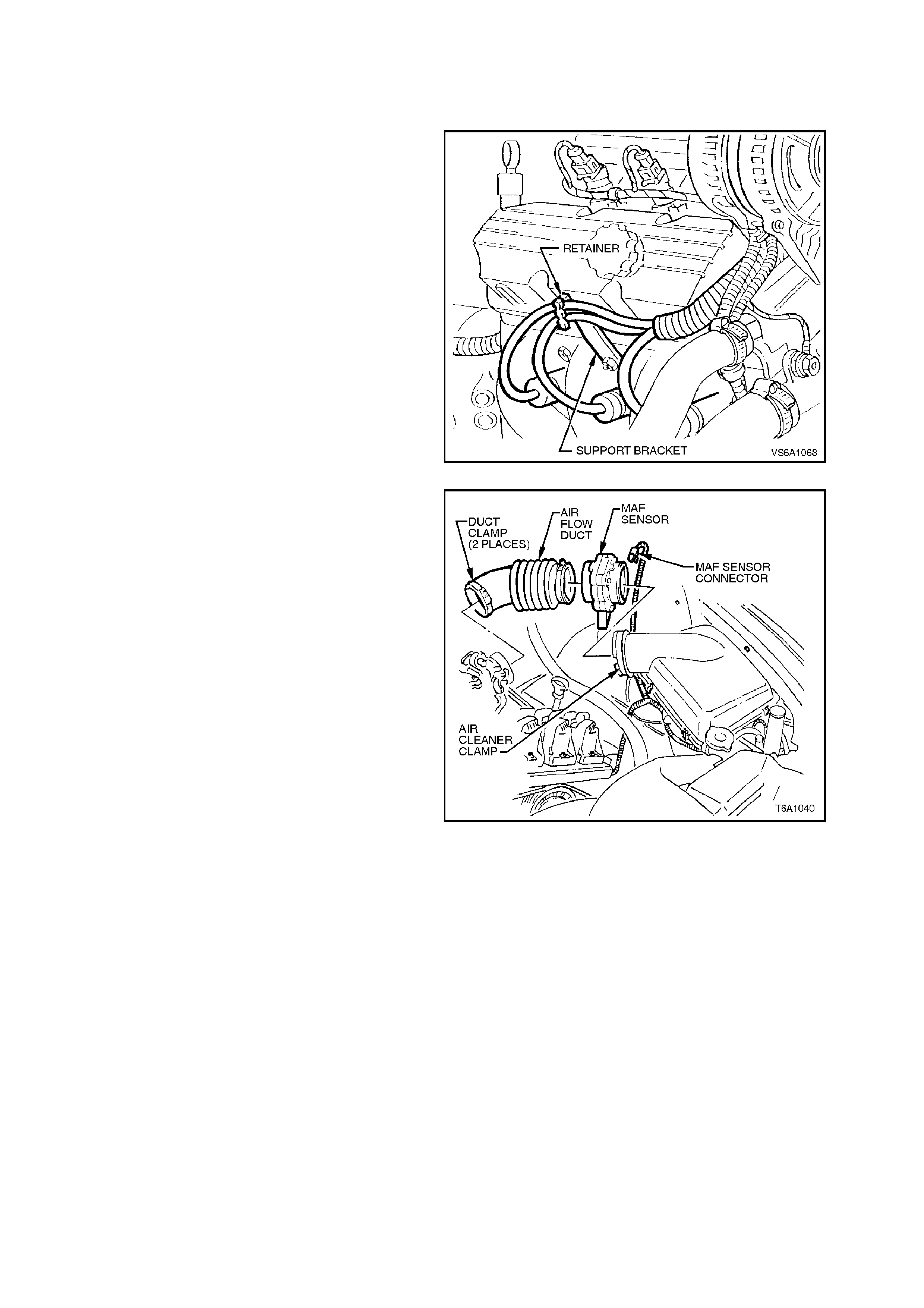
4. Disconnect mass air flow sensor wiring,
loosen air flow duct rubber boot clamps at
throttle body and air cleaner and remove air
flow duct. Carefully place air flow duct and
mass air flow sensor assembly to one side.
Figure 6A1-1-40
5. Using quick connect release tool No. 7370
open tool and install over fuel line.
6. Close 7370 and pull into fuel line quick
connect to release it from fuel inlet line, pull
back on quick connect, disconnect fuel feed,
return and fuel evaporative canister hoses at
quick connects. Plug all openings to prevent
foreign matter entry.
NOTE:
Do not attempt to remove hoses from fuel rail
connections. Once removed from fuel rail
connection, hoses require replacement.
Figure 6A1-1-41
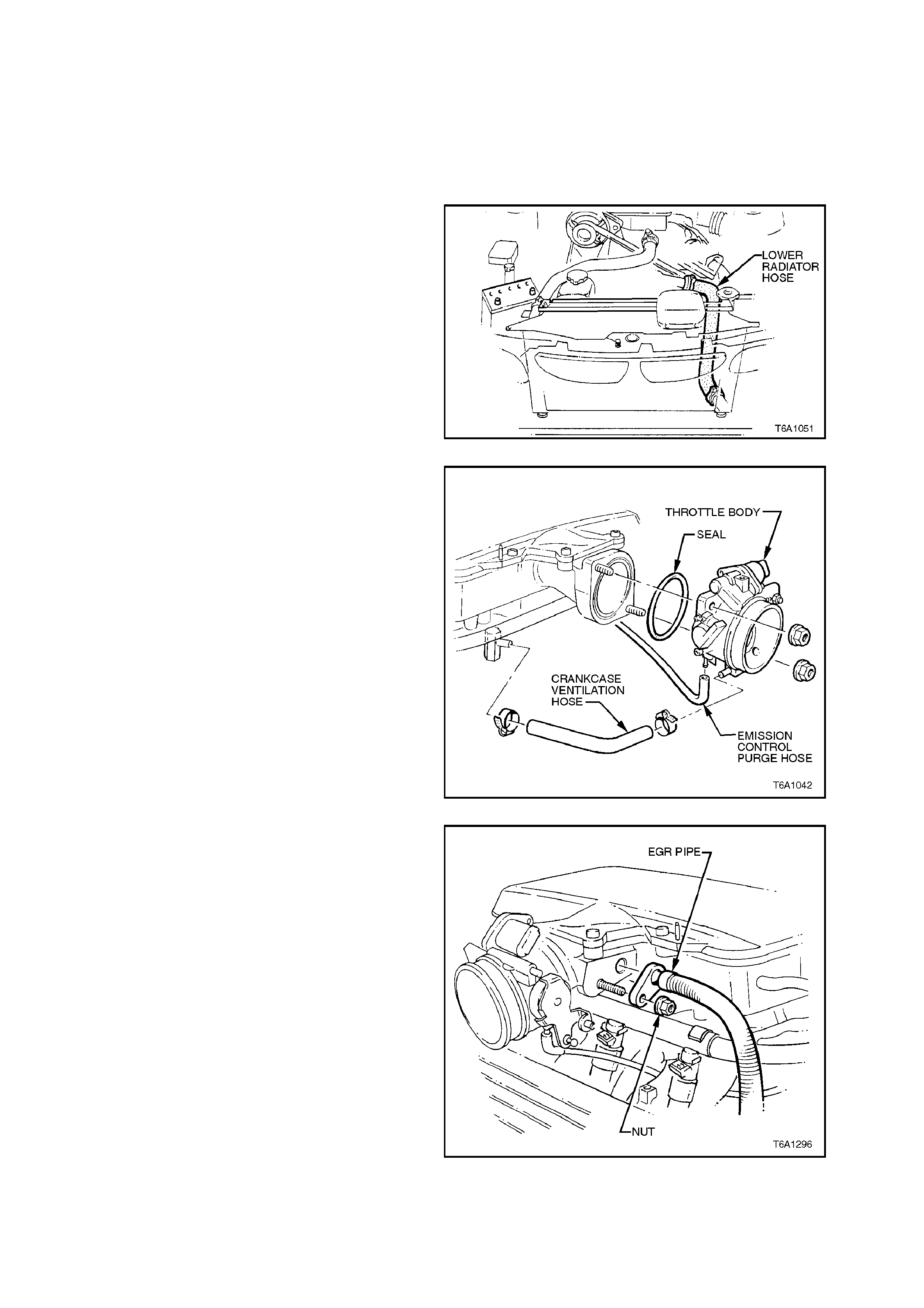
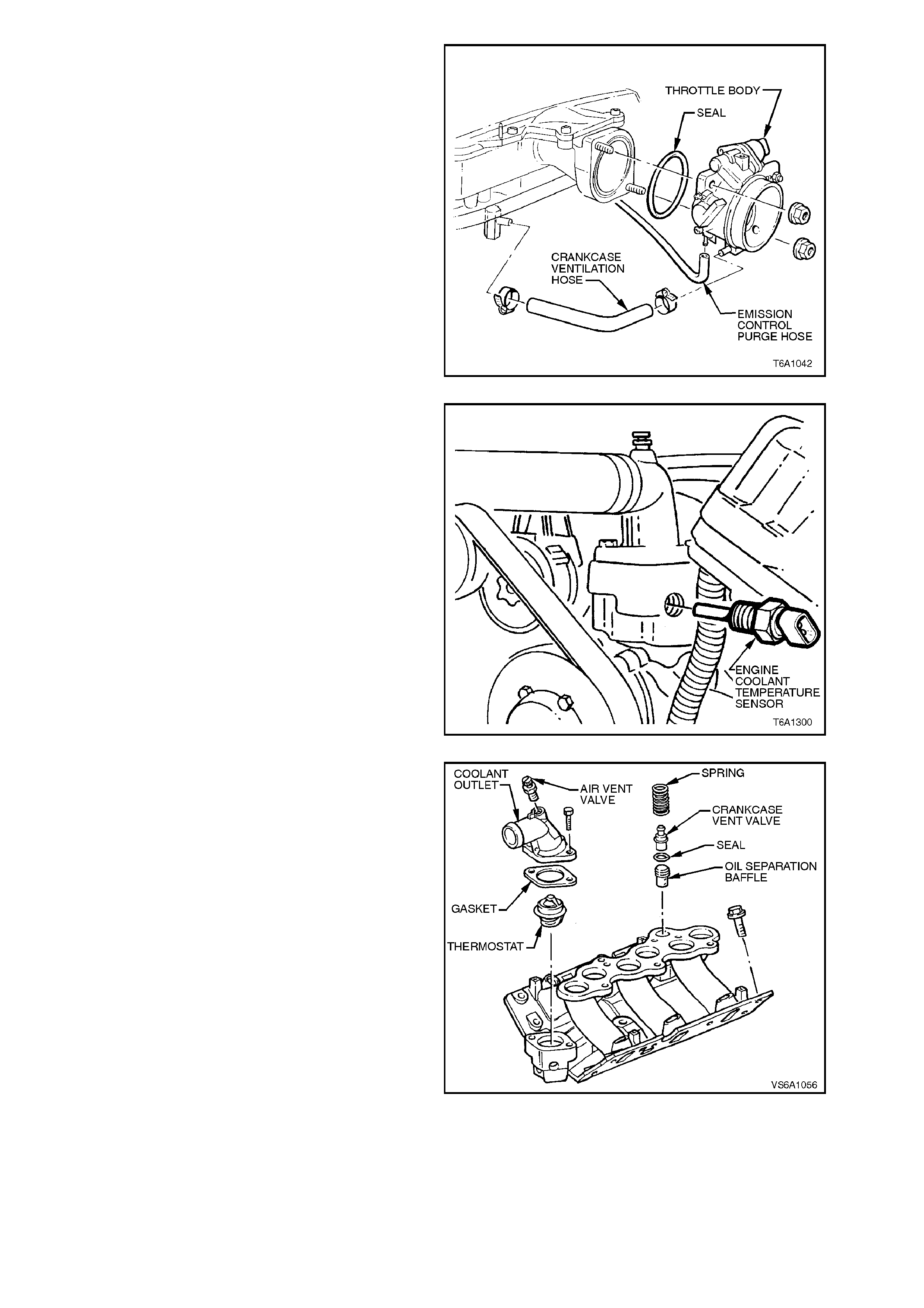
7. Disconnect emission control purge hose from
throttle body connections.
Figure 6A1-1-42
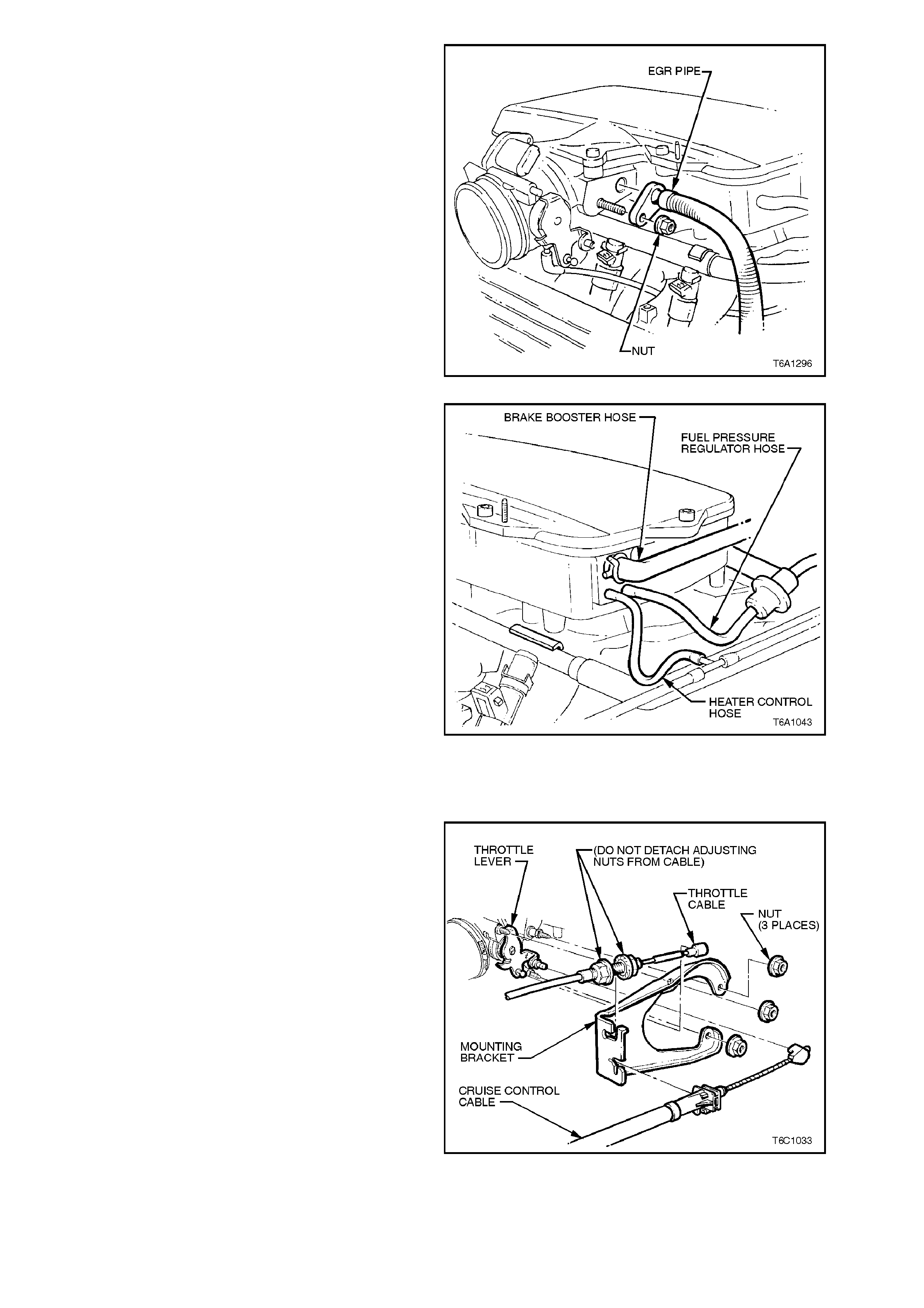
8. Disconnect EGR outlet pipe from upper inlet
manifold.
Figure 6A1-1-43
9. Disconnect brake booster, heater vacuum
control and f uel pressure r egulator hoses f rom
upper manifold connections.
Figure 6A1-1-44
10. Remove generator assembly, refer to
Section 6D1-1 CHARGING SYSTEM - V6
ENGINE.
11. Disconnect throttle inner cable from throttle
body linkage. Loosen throttle outer cable lock
nuts at mounting bracket and lay cable away
from engine.
12. If vehicle is fitted with cruise control,
disconnect cruise control outer cable from
mounting bracket and push inner cable
forward off throttle body linkage.
Figure 6A1-1-45
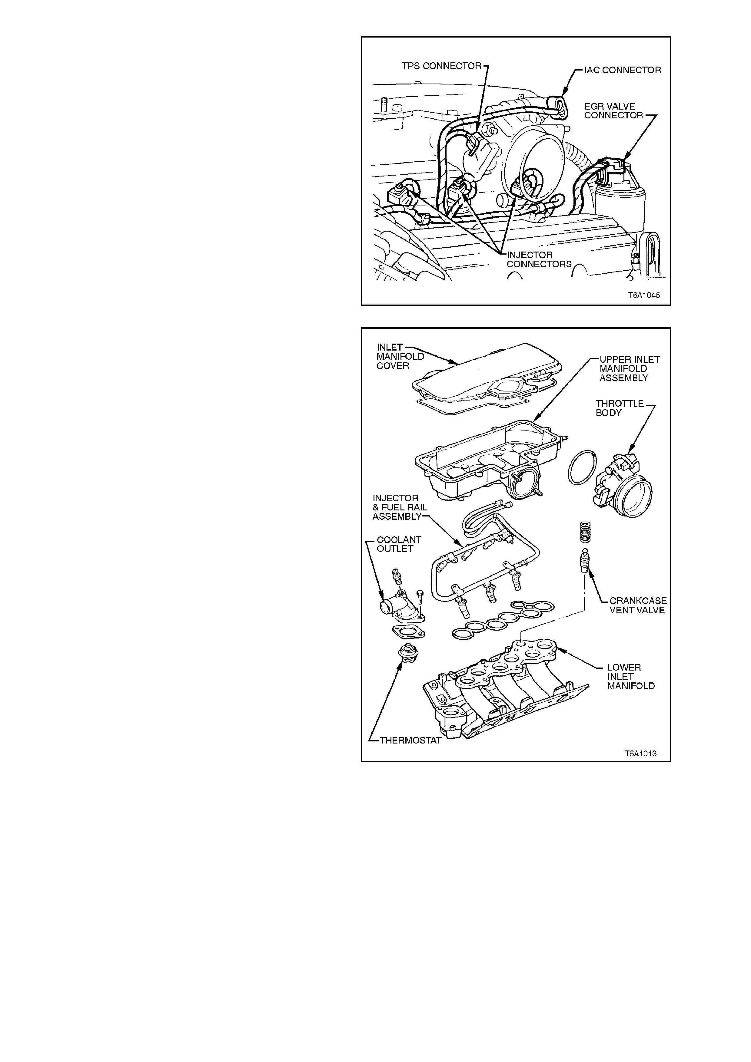
13. Disconnect powertrain wiring harness
connectors from:
a. Throttle Position Switch (TPS)
b. Idle Air Control (IAC) Valve
c. Injectors
d. EGR valve
Figure 6A1-1-46
14. Remove the eight inlet manifold cover
attaching bolts and remove cover.
15. Using a suitable c loth or plug temporar ily block
off lower inlet manifold passages.
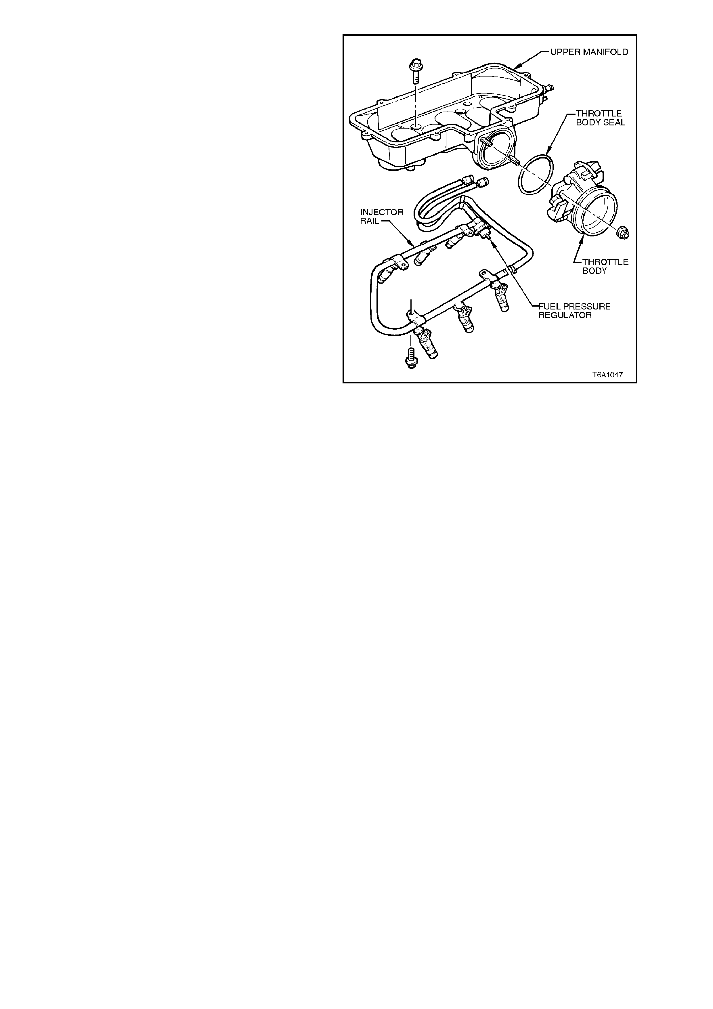
16. Completely loosen the five bolts securing
upper inlet manifold assembly to lower inlet
manifold assembly removing upper inlet
manifold injector and fuel rail assembly.
NOTE:
Upper inlet manifold assembly to lower inlet
manif old bolts are c aptive on a secondary thread in
the upper inlet manifold. Do not screw bolt past
captive feature.
17. Remove and discard upper inlet manifold to
lower inlet manifold seals.
NOTE:
Providing seal has not been removed from seal
groove, seal may be reused. Seal is designed to
swell approx. 20% in use and will be overlong once
removed.
Figure 6A1-1-47
NOTE:
The following operations need only be perform ed if
necessary.
18. Rem ove fuel rail and injector assem bly to inlet
manifold attaching bolts, separate assembly
from inlet manifold.
19. Disconnect crankcase ventilation hose from
inlet manifold connection. Remove throttle
body to manifold attaching nuts, remove
throttle body. Discard all gaskets.
20. Remove vacuum connectors from manifold.
Figure 6A1-1-48
REINSTALL
Installation of the upper inlet manifold is the
reverse of r emoval pr ocedur es , noting the f ollowing
points:
NOTE:
Steps 1-2 are applicable only if the relevant items
were removed from the manifold.
1. Install P.C.V. valve with O - ring and spring,
refer to 2.9 LOWER INLET MANIFOLD -
REINSTALL in this Section.
2. Reinstall fuel rail with injectors and throttle
body assembly. Refer to
Section 6C1 POWERTRAIN MANAGEMENT
- V6 ENGINE.
3. Lubricate injector O - rings with Petroleum
Jelly to Holden Specification HN 1974 or
equivalent and install upper inlet manifold to
lower inlet manifold.
2.9 LOWER INLET MANIFOLD
REMOVE
1. Disconnect battery earth lead.
2. Depressurise fuel system, refer to
Section 6C1 POWERTRAIN MANAGEMENT
- V6 ENGINE.
3. Remove four nuts securing engine dress
cover.
Figure 6A1-1-49
4. Disconnect mass air flow sensor wiring,
loosen air flow duct rubber boot clamps at
throttle body and air cleaner and remove air
flow duct. Carefully place air flow duct and
mass air flow sensor assembly to one side.
Figure 6A1-1-50
5. Using quick connect release tool No. 7370
open tool and install over fuel line.
6. Close 7370 and pull into fuel line quick
connect to release it from fuel inlet line, pull
back on quick connect, disconnect fuel feed,
return and fuel evaporative canister hoses at
quick connects. Plug all openings to prevent
foreign matter entry.
NOTE:
Do not attempt to remove hoses from fuel rail
connections. Once removed from fuel rail
connection, hoses require replacement.
Figure 6A1-1-51
7. Remove radiator cap to release any cooling
system pressure.
WARNING:
To avoid serious personal injury, never remove
the radiator cap when the engine is hot.
Sudden release of cooling system pressure is
very dangerous and could cause personal
injury.
8. Drain engine coolant into a suitable drain tray
by disconnecting radiator lower hose from
front cover connection.
Figure 6A1-1-52
9. Disconnect em ission control purge/ hose from
throttle body connections.
Figure 6A1-1-53
10. Disconnect EGR outlet pipe from upper inlet
manifold.
Figure 6A1-1-54
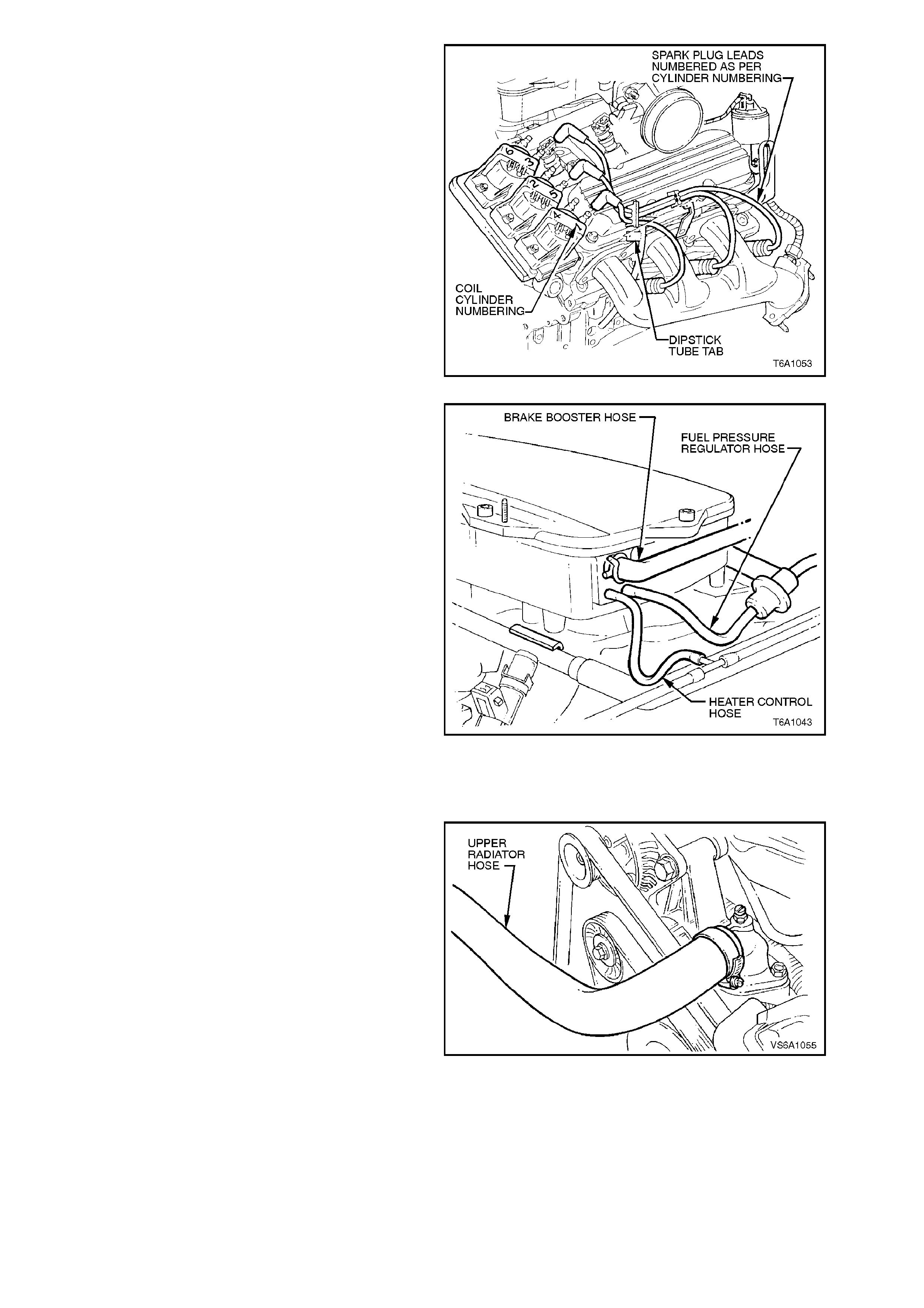
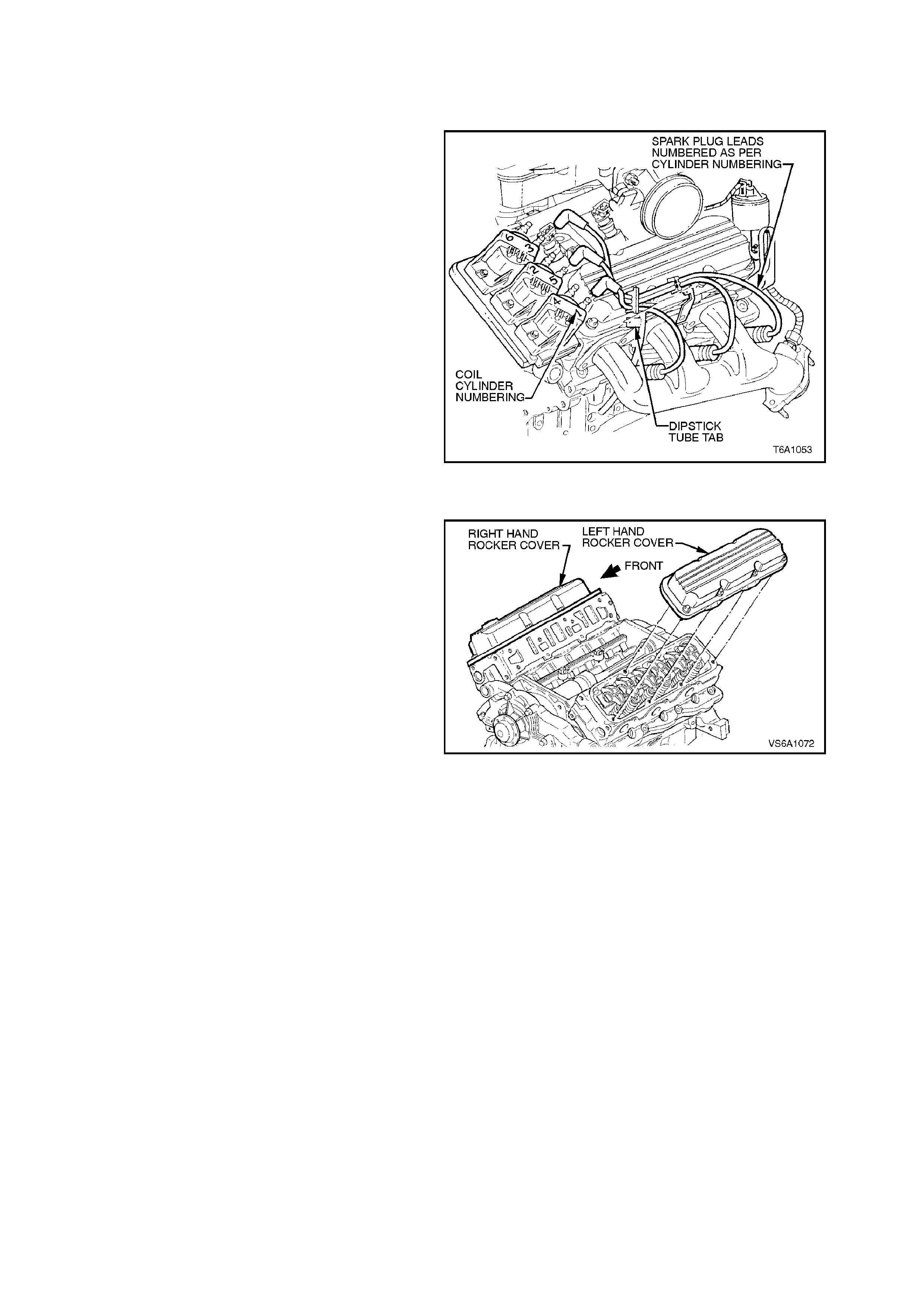
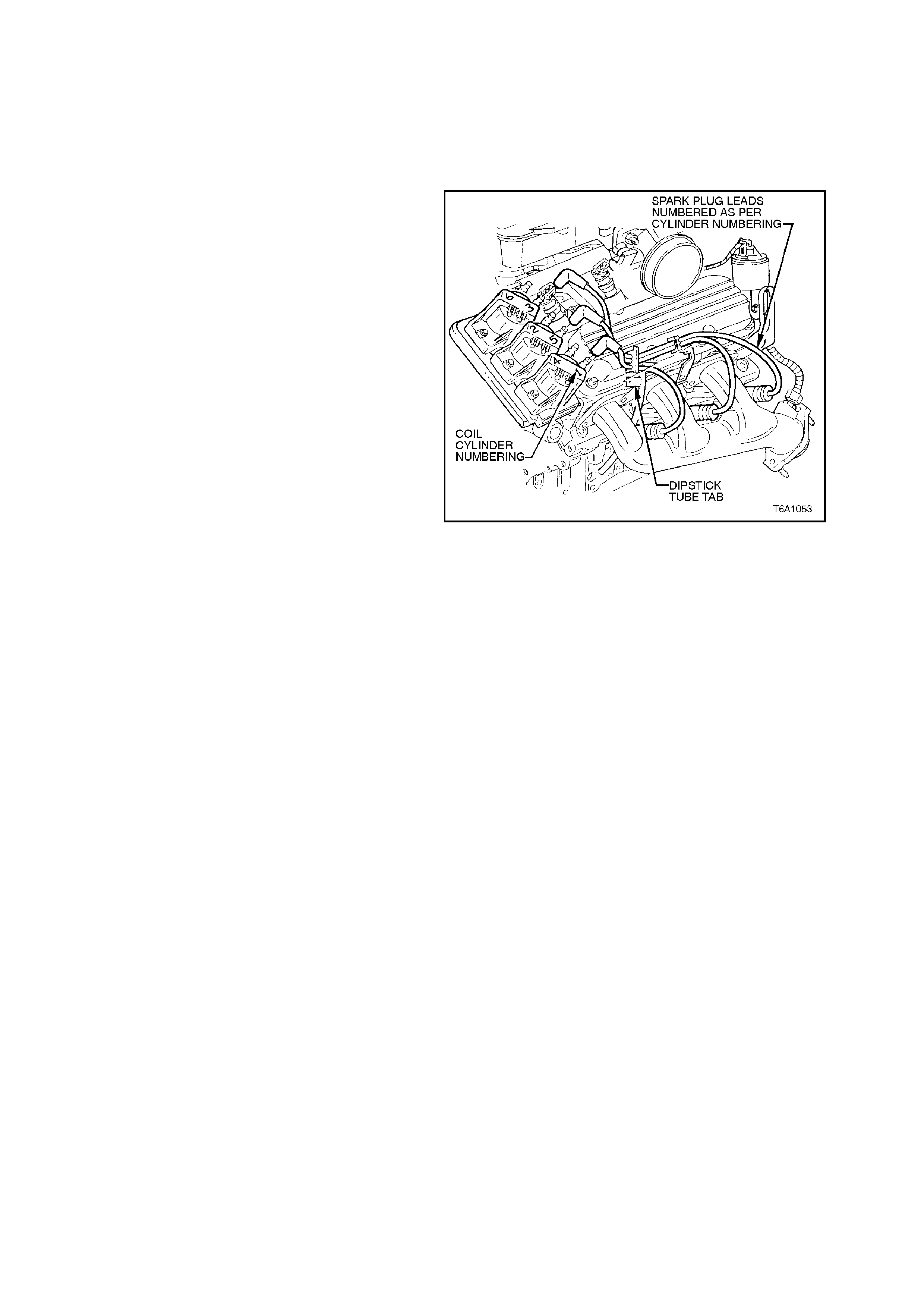
11. Pull right hand side spark plug leads from
spark plug terminals and from retainer
supports at side of cylinder head. Lay spark
plug lead conduit away from the inlet manifold.
NOTE:
All spark plug leads and coil terminals are
numbered to correspond to cylinder numbering.
If cylinder numbering does not appear on top of
any coil assembly, refer to cylinder numbering on
the module (refer to Section 6D1-3 IGNITION
SYSTEM - V6 ENGINE).
Figure 6A1-1-55
12. Disconnect brake booster, heater vacuum
control and f uel pressure r egulator hoses from
upper manifold connections.
Figure 6A1-1-56
13. Remove generator assembly, refer to
Section 6D1-1 CHARGING SYSTEM - V6
ENGINE.
14. Disconnect radiator upper hose from coolant
outlet, lay hose away from engine.
Figure 6A1-1-57
15. Remove nuts and powertrain wiring harness
earth lead from tensioner bracket lower
attaching studs.
Figure 6A1-1-58
16. Remove water inlet tube assembly.
17. Remove s tuds securing heater outlet pipe and
drive belt tensioner assembly, pull heater
outlet pipe out from inlet manifold
Figure 6A1-1-59
18. Remove coolant outlet to manifold attaching
bolts. Pull outlet from manifold, remove and
discard gasket. Remove thermostat from
manifold.
Figure 6A1-1-60
19. Disconnect throttle inner cable from throttle
body linkage. Loosen throttle outer cable lock
nuts at mounting bracket and lay cable away
from engine.
20. If vehicle is fitted with cruise control,
disconnect cruise control outer cable from
mounting bracket and push inner cable
forward off throttle body linkage.
Figure 6A1-1-61
21. Disconnect powertrain wiring harness
connectors from:
a. Throttle Position Switch (TPS)
b. Idle Air Control (IAC) Valve
c. Injectors
d. EGR valve
e. Coolant Temperature Sensor
Figure 6A1-1-62
Figure 6A1-1-63
22. Pull out wiring harness retainers from inlet
manifold posts near injector mountings and
from boss at rear of manifold. Position
harness away from inlet manifold.
23. Remove 12 lower inlet manifold to cylinder
head attaching bolts and remove manifold
assembly.
Remove and discard inlet manifold gaskets
and seals.
Figure 6A1-1-64
NOTE:
The following operations need only be perform ed if
necessary.
24. Remove the eight inlet manifold cover
attaching bolts removing cover.
25. Completely loosen the five bolts securing
upper inlet manifold assembly to lower inlet
manifold assembly removing upper manifold
assembly and fuel rail.
26. Loosen fuel feed hose at fuel rail inlet and
rem ove fuel f eed hose from fuel rail inlet. Plug
all openings to prevent foreign matter entry.
Rem ove fuel rail and injector assem bly to inlet
manifold attaching bolts, separate assembly
from inlet manifold.
Figure 6A1-1-65
27. Disconnect crankcase ventilation hose from
inlet manifold connection. Remove throttle
body to manifold attaching nuts, remove
throttle body. Discard all gaskets.
Figure 6A1-1-66
28. Unscrew and remove coolant temperature
sensor.
Figure 6A1-1-67
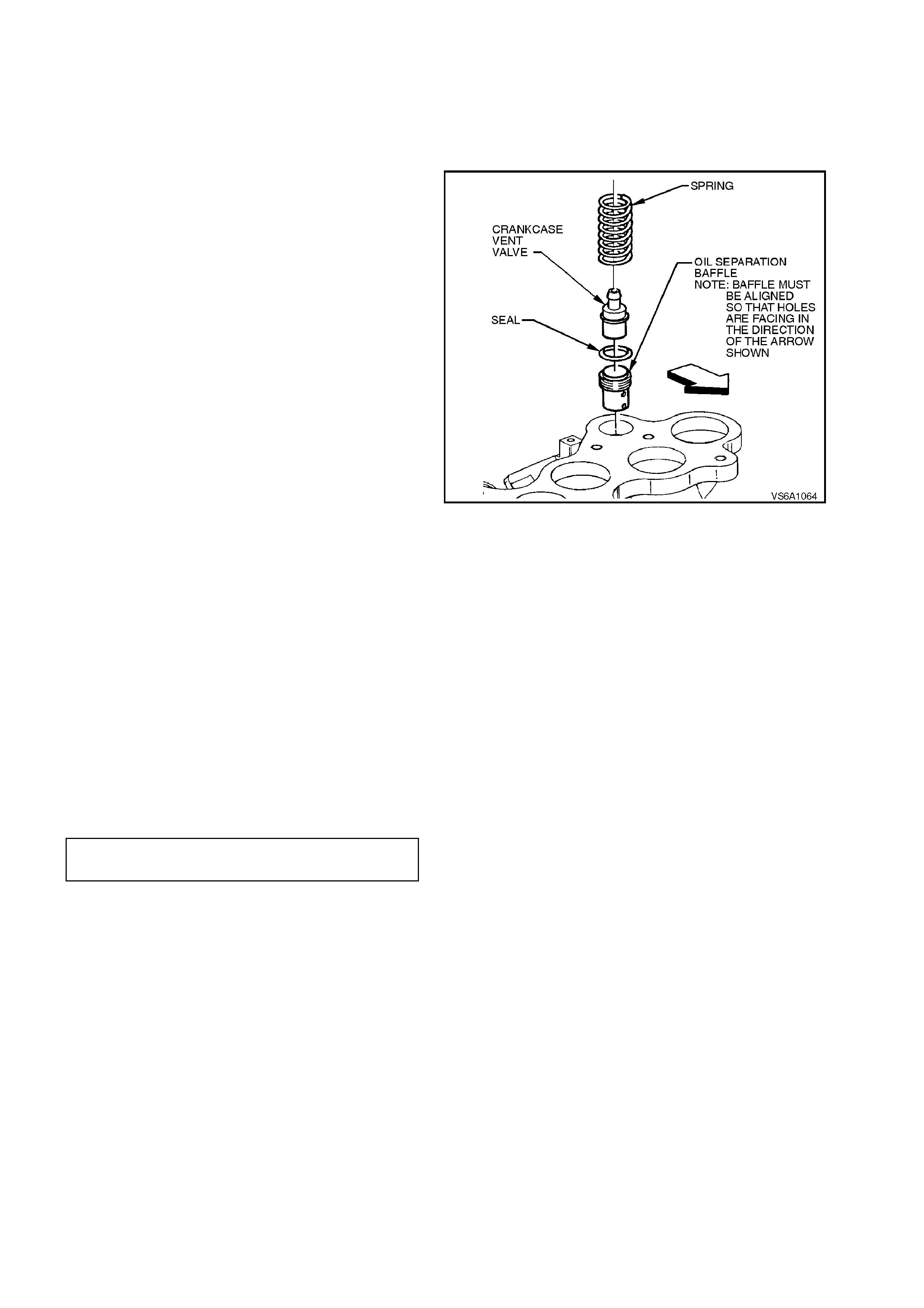
29. Remove P.C.V. valve, spring seal and baffle
from lower inlet manifold.
NOTE:
For P.C.V. valve testing procedures refer to
Section 6E1 EMISSION CONTROL - V6 ENGINE.
30. Remove coolant outlet and thermostat.
Figure 6A1-1-68
REINSTALL
Installation of the inlet manifold is the reverse of
removal procedures, noting the following points:
NOTE:
Steps 1-4 are applicable only if the relevant items
were removed .
1. Install P.C.V. valve with seal baffle and spring.
Figure 6A1-1-69
2. Inspect sealing O - rings on water inlet tube
and heater inlet pipe connectors, replace if
necessary.
Smear O - rings with petroleum jelly, reinstall
water inlet tube and heater inlet pipe
assemblies to the correct torque specification.
3. Reinstall fuel rail with injectors and throttle
body assembly. Refer to
Section 6C1 POWERTRAIN MANAGEMENT
- V6 ENGINE.
4. Apply Loctite 242 sealant or equivalent
(Holden Specification HN 1256 Class 2, Type
2) to coolant temperature sensor threads.
Reinstall coolant sensor and tighten to the
correct torque specification.
COOLANT TEMPERATURE
SENSOR 8 - 12
Nm
5. Clean gasket and seal surfaces on cylinder
block, cylinder heads and inlet m anifold. Take
care not to scratch or gouge machined
surfaces.
Ensure that all gasket sealing surfaces are
clean and dry.
Ensure that manifold attaching bolts and
cylinder head threads are clean and free of
sealant. Use a suitable size thread tap to
clean out threads in cylinder head.
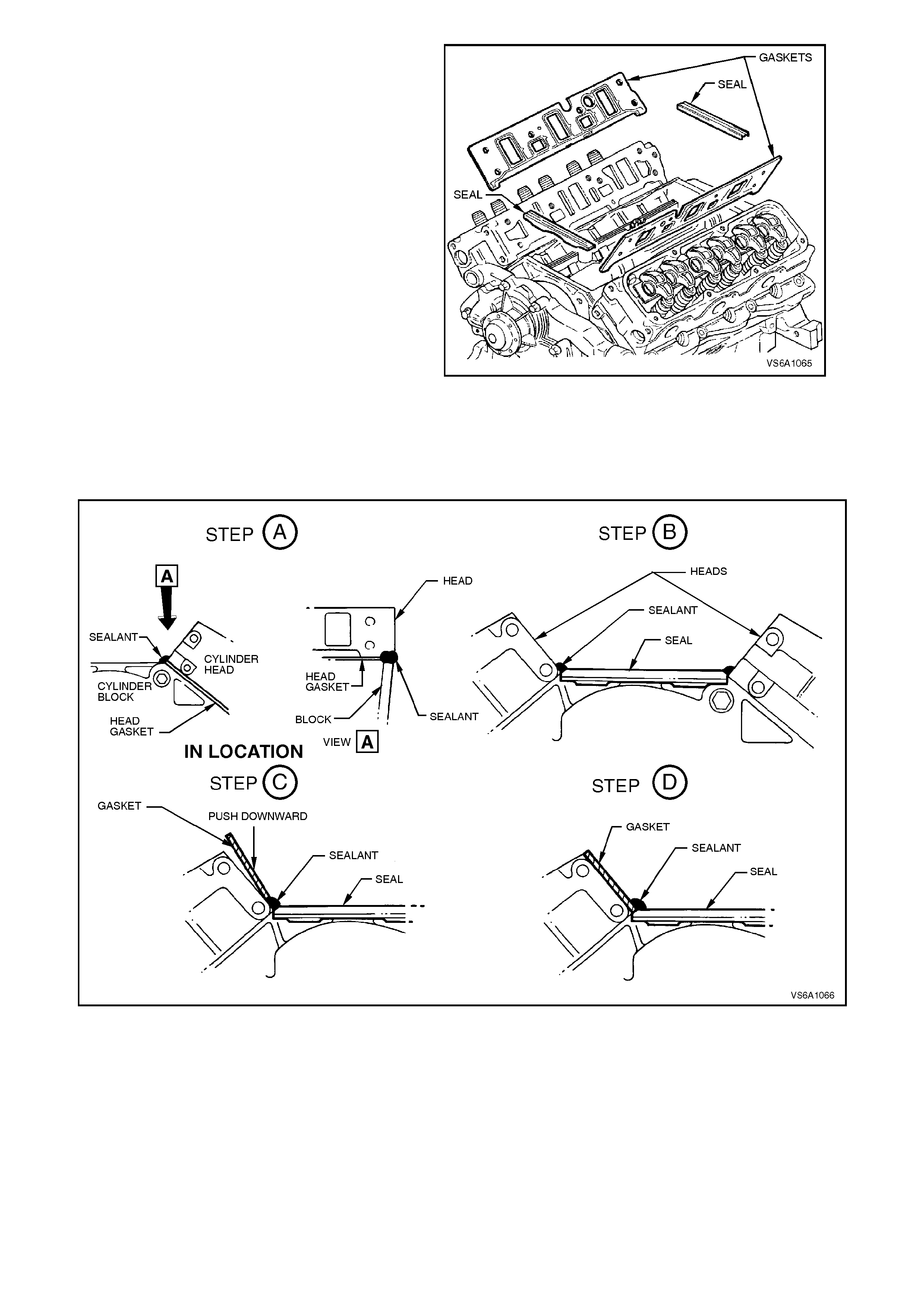
6. Install gaskets in the following manner.
a. Apply RTV 732 sealant or equivalent
(Holden Specification HN 1373) in a 2-3
mm bead to cylinder head to block joints
across edge of head gaskets (four
places).
b. Lay new front and rear manifold seals in
place pushing sealant out towards the
cylinder heads at seal and manifold
gasket join.
NOTE:
Ensure seals are installed with cut out sections
facing to outside of the cylinder block.
c. Slide manifold gaskets into place
ensuring that dowels on each gasket fit
into corresponding holes in cylinder head
ventilation system hole in each cylinder
head.
NOTE:
Both gaskets are identical.
d. Apply a further 2-3 mm diameter bead at
joints of inlet manifold gaskets to seals.
Figure 6A1-1-70
Figure 6A1-1-71
7. Apply Loctite 242 sealant or equivalent
(Holden Specif ication HN 1256, Class 2, Type
2) to lower inlet manifold attaching bolt
threads.
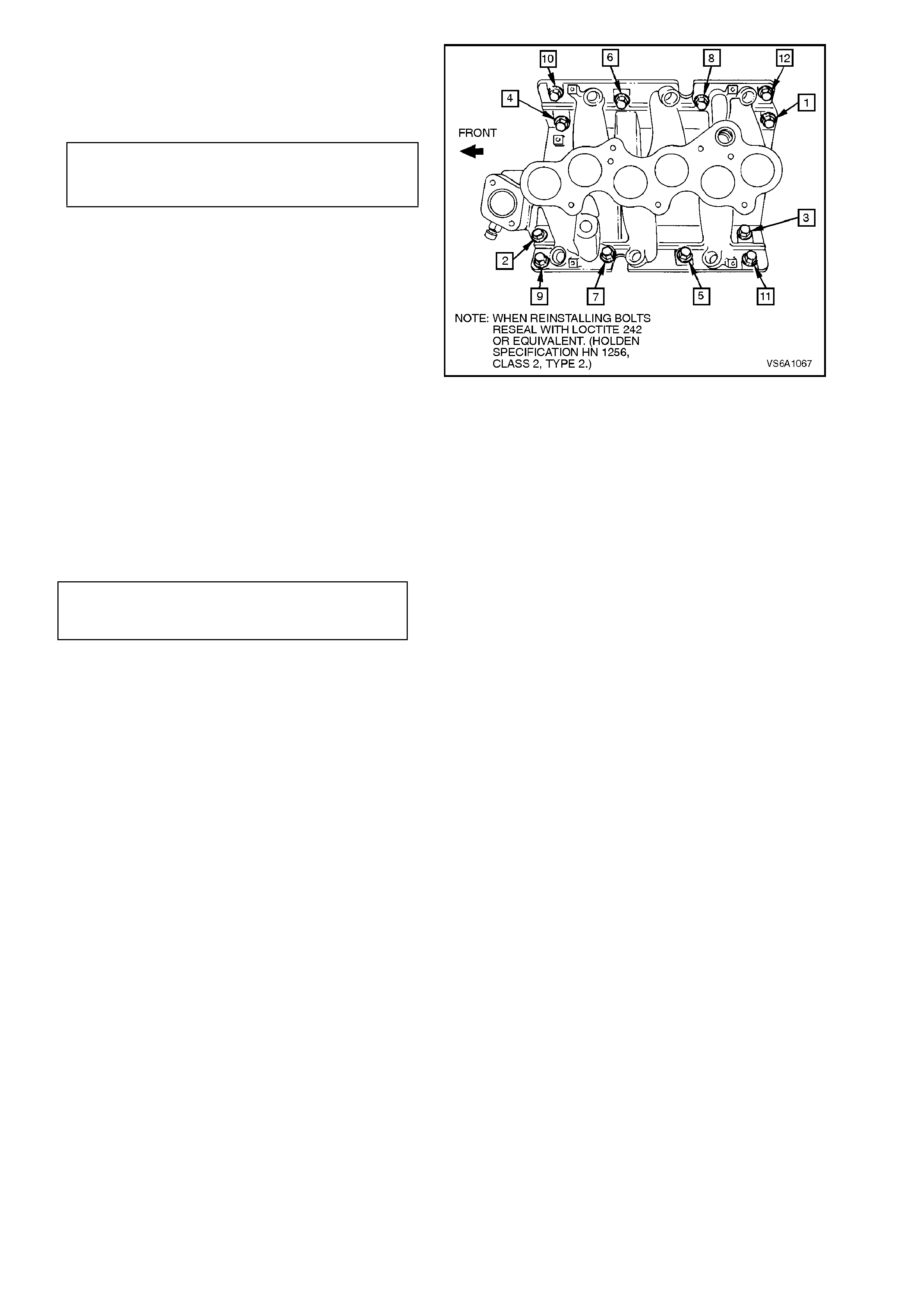
8. Install m anifold and attaching bolts. Seat bolts
to 3 - 6 Nm in the sequence shown. Retorque
bolts to specification again to sequence
shown.
LOWER INLET MANIFOLD 12- 18 Nm
ATTACHING BOLT Refer torque
TORQUE SPECIFICATION sequence
Figure 6A1-1-72
9. Install upper inlet manifold seals.
10. Lubricate injector O - rings with Petroleum
Jelly to Holden Specification HN 1974 or
equivalent and install upper inlet manifold to
lower inlet manifold.
11. Tighten upper inlet manifold to lower inlet
manifold attaching bolts to the correct torque
specification.
UPPER INLET MANIFOLD
ATTACHING BOLT
TORQUE SPECIFICATION 10 - 14 Nm
12. Install components in reverse order of removal
procedures. Ensure that all fasteners are
tightened to the correct torque specification.
13. Adjust throttle cable, refer to
Section 6C1 POWERTRAIN MANAGEMENT
- V6 ENGINE, Service Operations. For cruise
control cable, refer to Section 12E CRUISE
CONTROL.
14. Reinstall air f low duct, rec onnec t mass air f low
sensor electrical connector.
15. Refill cooling system with specified coolant,
refer to Section 6B1 ENGINE COOLING -
V6 ENGINE.
16. Reconnect battery earth lead, star t engine and
check for air, fuel, oil and coolant leaks.
Repair as necessary.
2.10 EXHAUST MANIFOLDS
REMOVE
1. Disconnect battery earth lead.
2. Disconnect spar k plug leads f rom spark plugs,
pull lead retainers from support brackets and
lay leads on top of engine.
Figure 6A1-1-73
3. For left hand side exhaust manifold:
a. Disconnect mass air flow sensor wiring,
loosen air flow duct rubber boot clamps at
throttle body and air cleaner, remove air flow
duct. Carefully place air flow duct and mas s air
flow sensor assembly to one side.
Figure 6A1-1-74
4. Disconnect EGR outlet pipe from exhaust
manifold refer to Fig. 6A1-1-75.
5. Raise front of vehicle and support on safety
stands. Refer to Section 0A GENERAL
INFORMATION for location of jacking points.
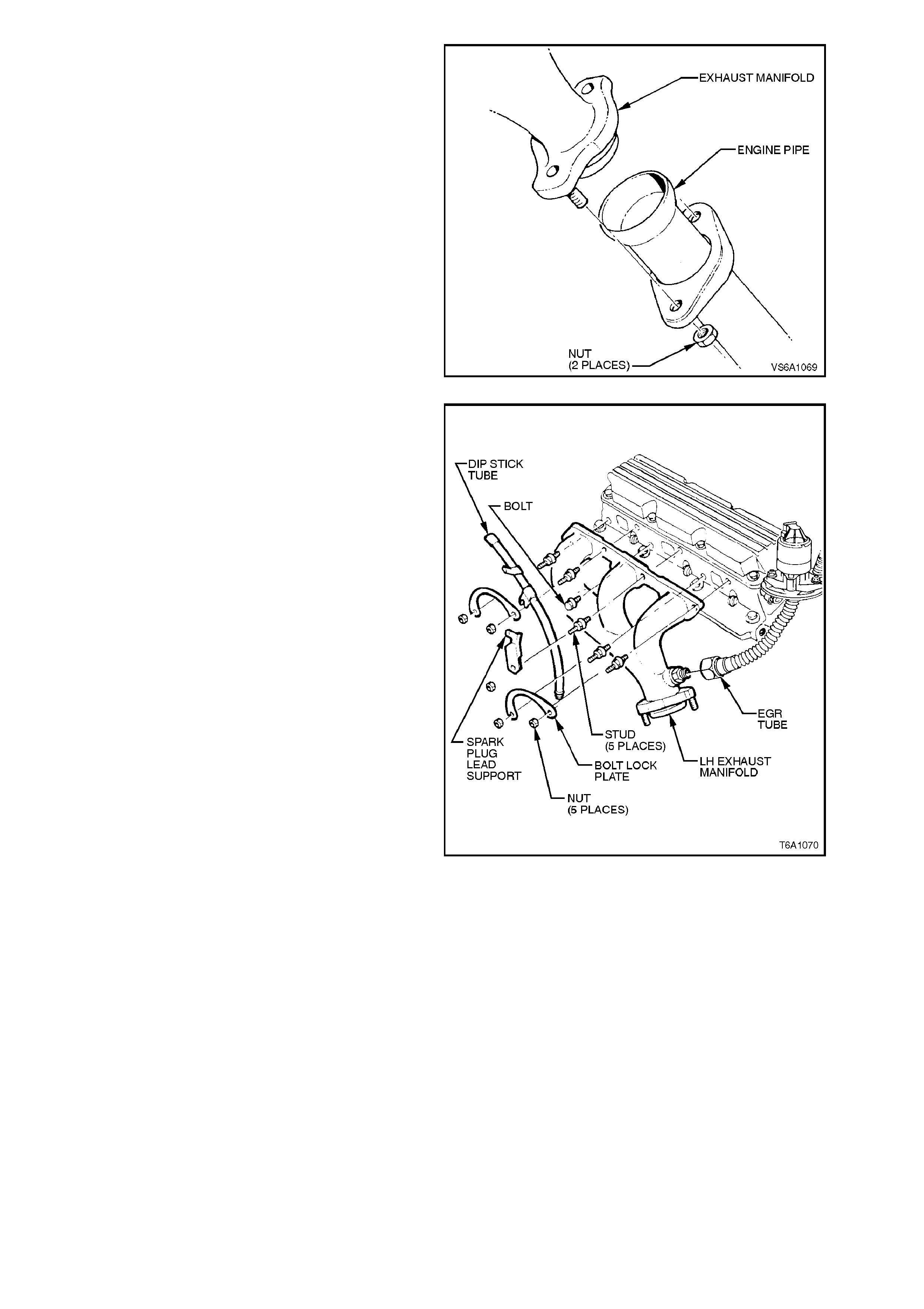
6. Remove engine pipe to manifold stud
attaching nuts.
7. Fold up/down locking tabs to release nuts.
Figure 6A1-1-75
8. Remove the nut securing the dipstick tube to
the exhaust m anifold s tud. Disconnect dipstick
tube from stud and pull assembly from oil pan.
Disconnect EGR tube.
Remove lock nuts and lock plates.
Remove manifold to cylinder head attaching
studs and remove manifold.
Figure 6A1-1-76

REINSTALL
Installation of the exhaust m anifold/s is the r everse
of removal procedures, noting the following points:
1. Ensure that manifold, cylinder head and
engine pipe surfaces are clean.
2. Apply anti-seize compound such as AMPOL
Jet-Lube Kopr-Kote (Holden Specification HN
1325) to exhaust manifold to cylinder head
and engine pipe to manifold attaching studs.
3. Install manifold into position and install
attaching studs.
Connect manifold and engine pipe together
and install attaching nuts.
4. Tighten manifold to cylinder head attaching
studs to the correct torque specification.
EXHAUST MANIFOLD TO
CYLINDER HEAD STUD
TORQUE SPECIFICATION 25 - 35 Nm
5. Tighten engine pipe to manif old stud attaching
nuts to the correct torque specification.
ENGINE PIPE TO MANIFOLD
STUD ATTACHING NUT
TORQUE SPECIFICATION 18 - 35 Nm
NOTE:
Install dipstick tube bracket behind lock plate.
6. Reinstall lock plates, dip stick tube, s park plug
lead bracket and lock nuts. Tighten lock nuts
to the correct torque specifications. Fold tabs
to retain nuts.
EXHAUST MANIFOLD
STUD LOCK NUT
TORQUE SPECIFICATION 20 - 27 Nm
7. Reconnect spark plug lead retainers to
support brackets and leads to spark plugs.
Reinstall air f low duct, rec onnec t mass air f low
sensor electrical connector.
8. Reconnect battery earth lead, star t engine and
check for exhaust leaks. Repair as necessary.
2.11 ROCKER COV ERS AND/OR SEALS
REMOVE
1. Disconnect battery earth lead.
2. For left hand side rocker cover, disconnect
spark plug leads from coil terminals.
Disconnect mass air flow sensor wiring,
loosen air flow duct rubber boot clamps at
throttle body and air cleaner and remove air
flow duct. Carefully place air flow duct and
mass air flow sensor assembly to one side.
Fold up/down locking tabs and rem ove the nut
securing the dipstick tube to the exhaust
manifold stud. Disconnect dipstick tube from
stud and pull assembly from oil pan.
3. Disconnect spark plug lead retainers from
spark plug lead support.
NOTE:
All spark plug leads and coil terminals are
numbered to correspond to the cylinder numbering.
If cylinder numbering does not appear on top of
any coil assembly, refer to cylinder numbering on
the module (refer to Section 6D1-3 IGNITION
SYSTEM - V6 ENGINE).
Figure 6A1-1-77
4. Unscrew rocker cover to cylinder head
fasteners and remove rocker cover from
cylinder head.
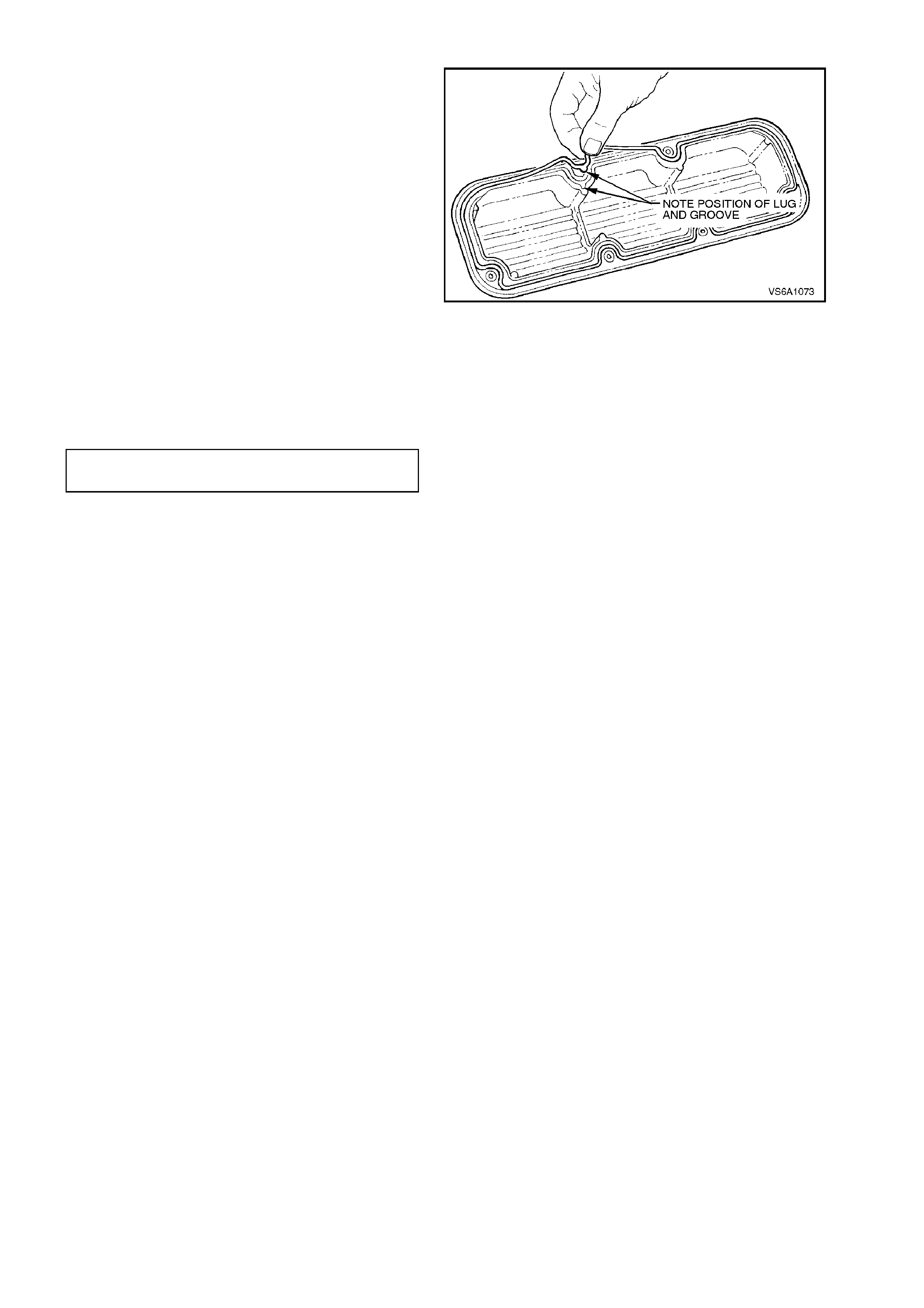
5. If replacing rocker cover seal, remove seal
from cylinder head flange recess in rocker
cover.
6. If necessary, push out fastener and seal
assemblies from rocker cover.
Figure 6A1-1-78
REINSTALL
1. If necessary, install seal in rocker cover
recess. Install rocker cover fastener and seal
assemblies.
NOTE:
Ensure that seal is correctly installed in rocker
cover.
Figure 6A1-1-79
2. Inspect fastener seals and replace any
assembly if damaged.
3. Install rocker cover to cylinder head and
tighten fasteners to the correct torque
specification.
ROCKER COVER FASTENER
TORQUE SPECIFICATION 7 - 11
Nm
4. Refit spark plug lead retainers to support and
leads to spark plugs.
If removed, reinstall spark plug leads to coil
terminals, ensuring correct lead orientation
with coil terminal numbering.
Reinstall dip stick tube and air flow duct,
reconnect mass air flow sensor electrical
connector.
5. Reconnect battery earth lead, star t engine and
check for oil leaks. Repair as necessary.
2.12 ROCKER ARMS AND PUSHRODS
REMOVE
1. Disconnect battery earth lead.
2. Remove rocker covers, refer to
2.11 ROCKER COVERS AND/OR SEALS in
this Section.
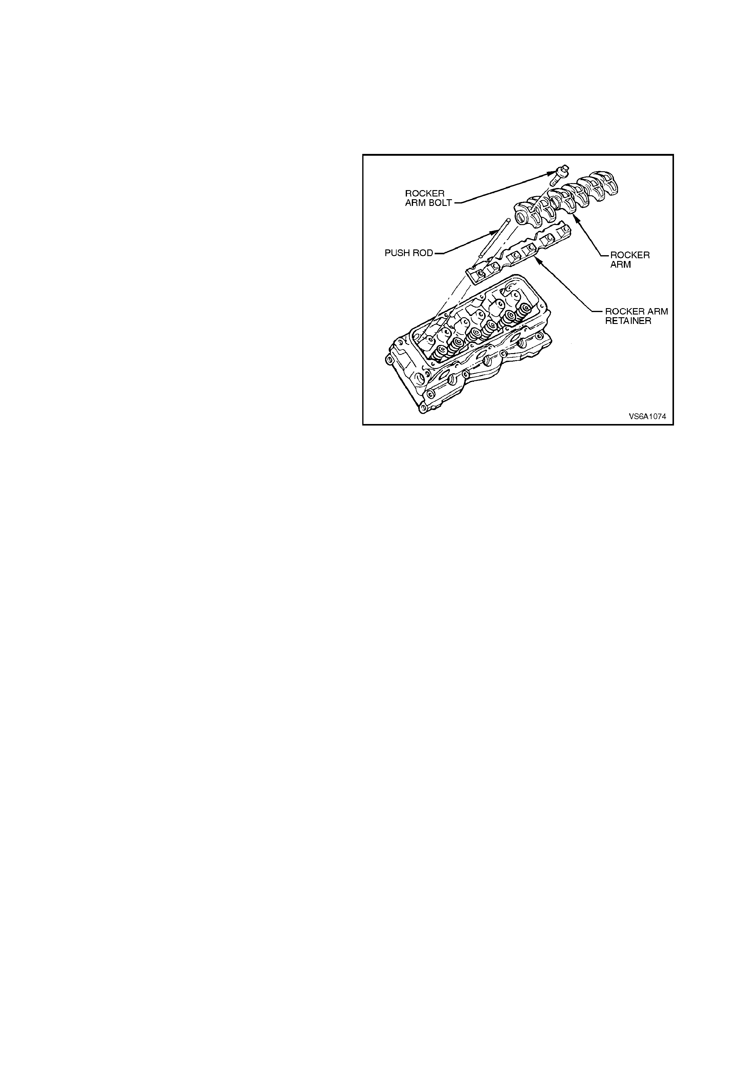
3. Remove rocker arm bolts, rocker arms and
retainers.
NOTE 1:
Once removed, discard rocker arm pedestal bolts.
New bolts must be used on reassembly.
NOTE 2:
It is important that the original location of all
pedestals and rocker arms is retained during
reassem bly. For this reason, place components on
a suitable rack.
4. Remove pushrods.
Figure 6A1-1-80
CLEAN AND INSPECT
Clean all components in a s uitable cleaning solvent
and blow dry with clean dry compressed air.
Inspect all com ponents for wear, chec k rock er arm
pedestal bearings for freedom of movement;
replace as necessary.
If there is excessive wear on spherical surfaces of
pushrod, refer to 4. ENGINE MECHANICAL
DIAGNOSIS - Valve Train Noise in this Section.

REINSTALL
1. Lubricate pushrod contact surfaces with
Lubrizol 6612 or equivalent (Holden
Specification HN 1961) and install pushrods.
2. Install pedestal retainers onto cylinder heads.
3. Lubricate rocker arm pedestal bearings with
clean engine oil.
4. Assemble new rocker arm bolts and rocker
arms in their original positions on each
cylinder head.
5. Tighten pedestal bolts to the correct torque
specification and, at the same time, ensure
that each pedestal base engages into the
retainer squares and that pushrods remain in
contact with each lifter and rocker arm.
ROCKER ARM
PEDESTAL BOLT
TORQUE SPECIFICATION
11 - 19 Nm
+ 87 - 93 deg.
turn angle
6. Reinstall rocker covers, refer to
2.11 ROCKER COVERS AND OR/SEALS in
this Section.
7. Reconnect battery earth lead, star t engine and
check for oil leaks or valve train noise. Repair
as necessary.
2.13 VALVE STEM OIL SEALS
REPLACE
1. Disconnect battery earth lead.
2. Remove rocker cover/s, refer to
2.11 ROCKER COVERS AND/OR SEALS in
this Section.
3. Remove r ocker arm s, ref er to 2.12 RO CKER
ARMS AND PUSHRODS in this Section.
4. Rem ove spark plug from relevant cylinder and
screw air adaptor, Tool No. 6A40A into spark
plug hole. Apply air pressure to hold valves in
closed position.
CAUTION:
Take care, as when air pressure is applied to
cylinder, it may cause the crankshaft to rot ate if
the piston in the cylinder is not at T.D.C or
B.D.C.
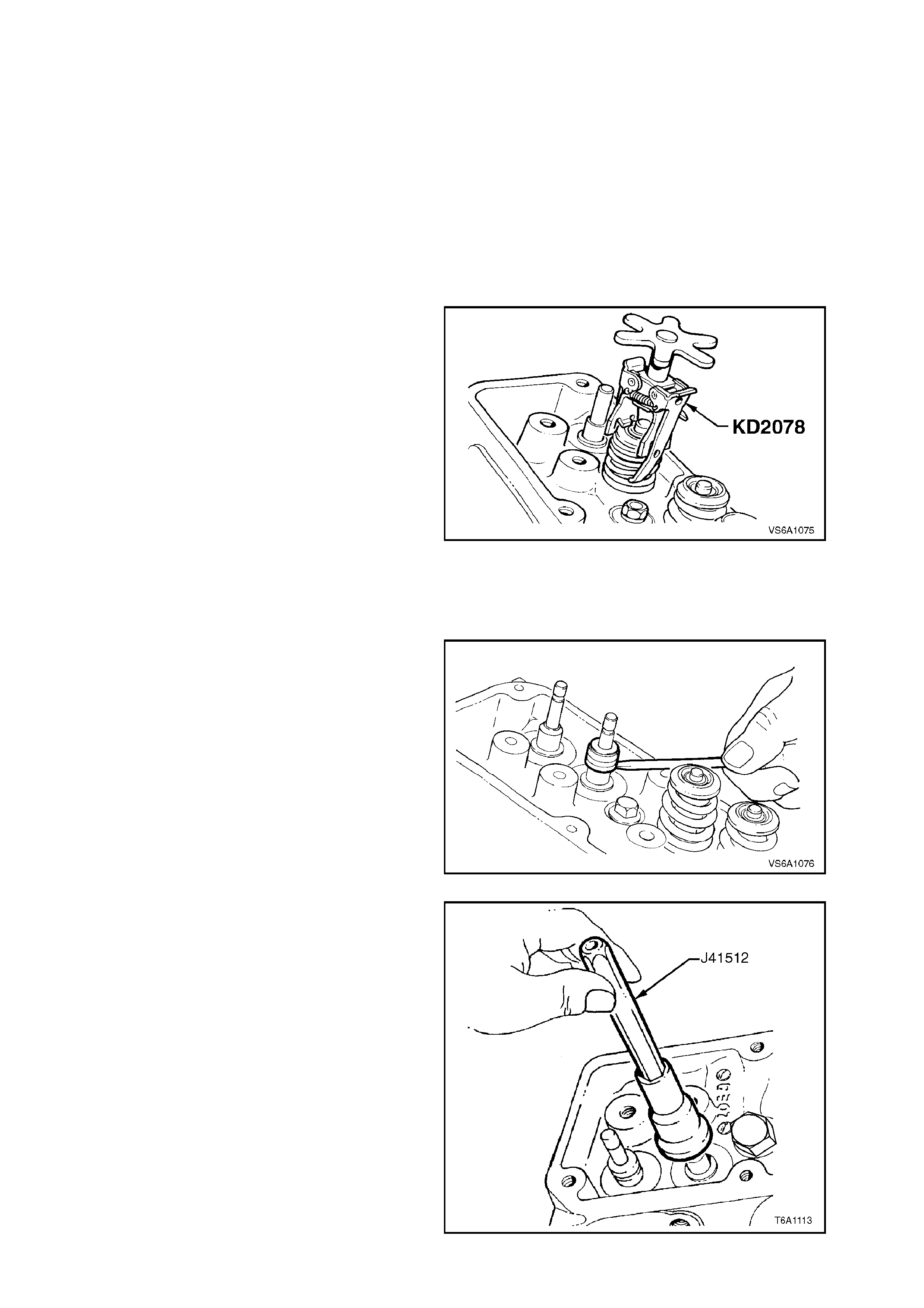
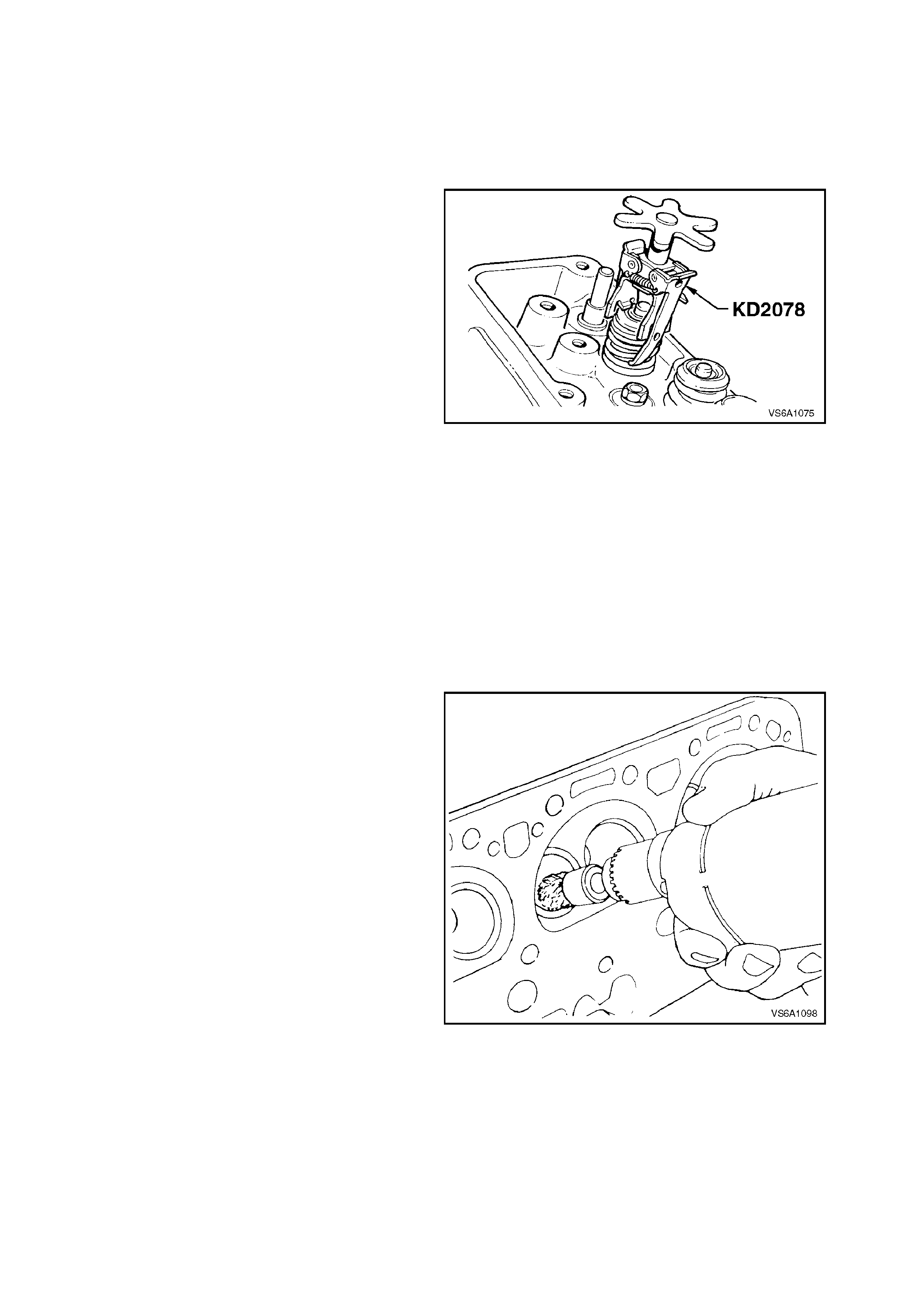
5. Using Tool No. KD2078 or equivalent,
compress valve spring. Remove valve collets.
NOTE:
It is important that only spring compressor tool no.
KD2078 be used as other tools may cause damage
to valve stem collet ‘contact’ area. It may be
necessary to tap top of valve cap with a soft faced
hammer after the spring compressor has been
applied to overcom e the binding of the valve collets
in the valve spring cap.
6. Remove spring, cap and spring compressor
tool as an assembly from cylinder head.
Figure 6A1-1-81
7. Using a screwdriver, lever valve stem oil seal
from valve guide. Remove and discard seal.
Figure 6A1-1-82
8. Thoroughly clean and dry all components.
9. Lubricate valve stems and valve guides
thoroughly with clean engine oil.
10. Lubricate new seal with engine oil and install
over valve with a twisting motion and pus h the
seal down until the rubber jacket touches the
top of guide.
11. Place the valve stem installation tool over the
valve stem seal (flat surfaced end toward the
seal).
12. Lightly tap the top (tapered end of the tool)
lightly with a plastic mallet until the valve stem
seal is resting flush with the top of the valve
guide.
NOTE:
Install seals using valve stem installation tool
No. J41512.
Figure 6A1-1-83
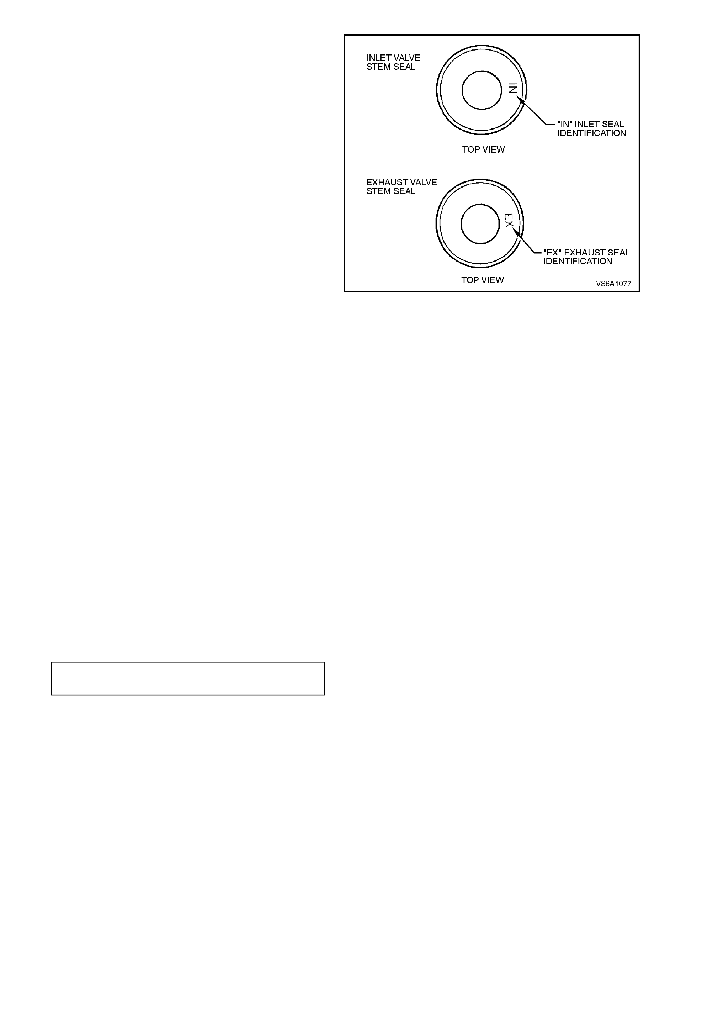
a. There are specific valve stem seals for
inlet and exhaust valves.
b. The colour of the replacement seal may
not be the same colour as the original
seal.
Ensure the correct type of seal is fitted to
the appropriate valve, based on part
number and package description.
Figure 6A1-1-84
13. Install spring with the larger diameter coils
towards the cylinder head spring seat. Install
cap and compressor as an assembly on to
valve stem.
14. Install valve collets, ensuring that they locate
correctly in groove in top end of valve stem.
Slowly release valve spring compressor,
checking that collets seat correctly. A sharp
tap on cap with a soft faced hammer will
ensure correct seating of collets.
Grease may be used to hold collets in place.
15. Disconnect air line to Tool No. 6A40A.
16. Repeat procedure f or rem aining seals that are
to be replaced.
17. Reinstall rocker arms, refer to
2.12 ROCKER ARMS AND PUSHRODS in
this Section.
18. Reinstall rocker cover/s, refer to
2.11 ROCKER COVERS AND/OR SEALS in
this Section.
19. Rem ove Tool No. 6A40A, r einstall spark plugs
and tighten to the correct torque specification.
SPARK PLUG
TORQUE SPECIFICATION 15 - 25
Nm
20. Reinstall spark plug leads and battery earth
lead.
21. Start engine and check for oil leaks and valve
train noise. Repair as necessary.
2.14 VALVE LIFTERS
REMOVE
1. Depressurise fuel lines, refer to
Section 6C1 POWERTRAIN MANAGEMENT
- V6 ENGINE - Service Operations.
2. Disconnect battery earth lead.
3. Remove rocker covers, refer to
2.11 ROCKER COVERS AND/OR SEALS in
this Section.
4. Remove rocker arms and pushrods, refer to
2.12 ROCKER ARMS AND PUSHRODS in
this Section.
5. Remove lower inlet manifold, refer to
2.9 LOWER INLET MANIFOLD in this
Section.
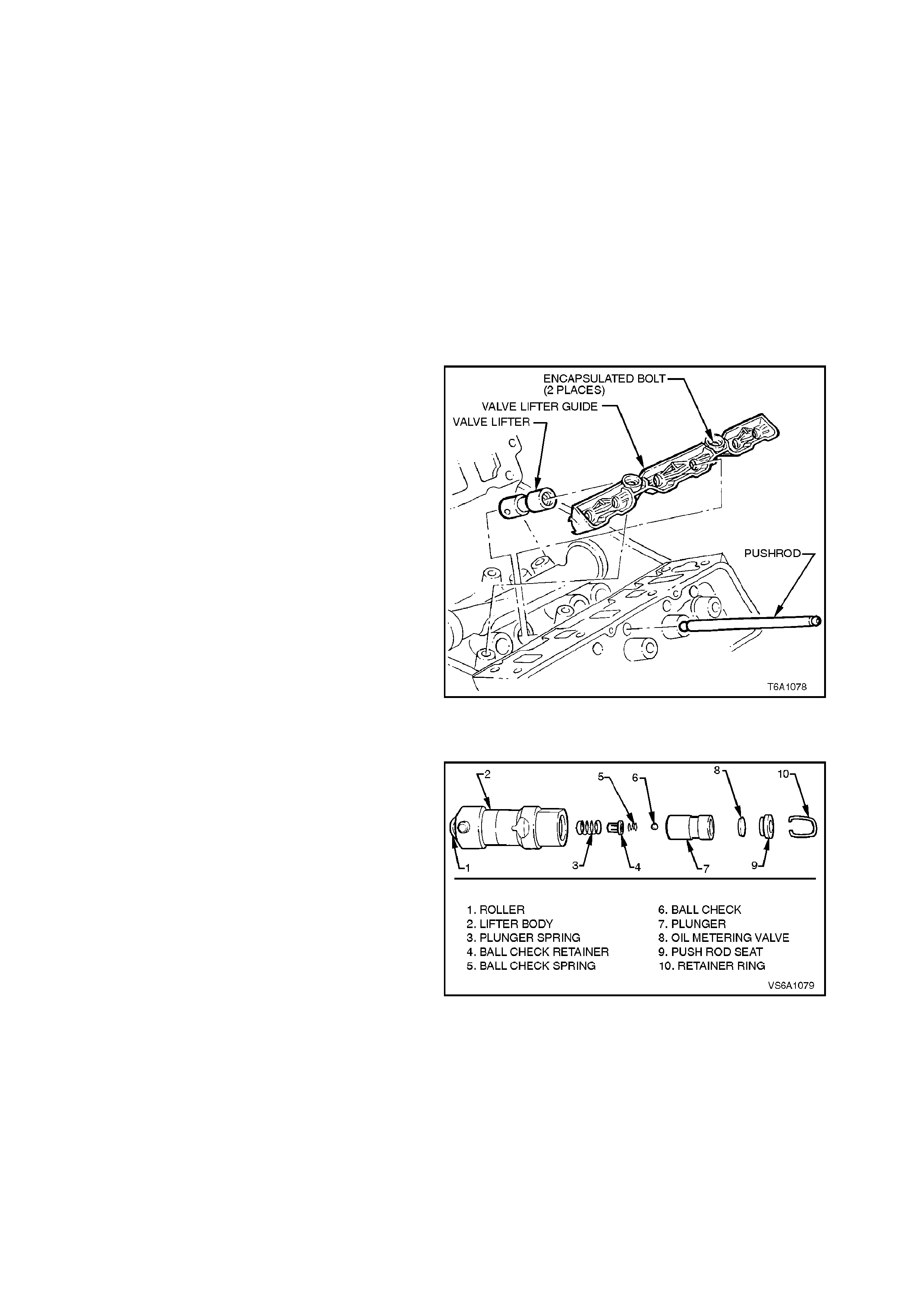
6. From valley in cylinder block, remove two
valve lifter guide attac hing bolts . Remove lif ter
guides.
7. Remove lifters from cylinder block bores and
place in order on rack.
NOTE:
Ensure that all valve train components are kept in
order so they may be reinstalled, if r equired, in their
original locations.
Figure 6A1-1-85
DISASSEMBLE
1. Using a small, fine bladed screwdriver,
remove push rod seat retainer ring.
2. Remove push rod seat, oil metering valve,
plunger assembly and plunger spring from
lifter body.
NOTE:
If the plunger is stuck in the lifter body, turn lifter
body upside down and tap lifter body on a block of
wood.
If plunger cannot be moved, s oak lifter as sembly in
a suitable cleaning fluid.
Figure 6A1-1-86
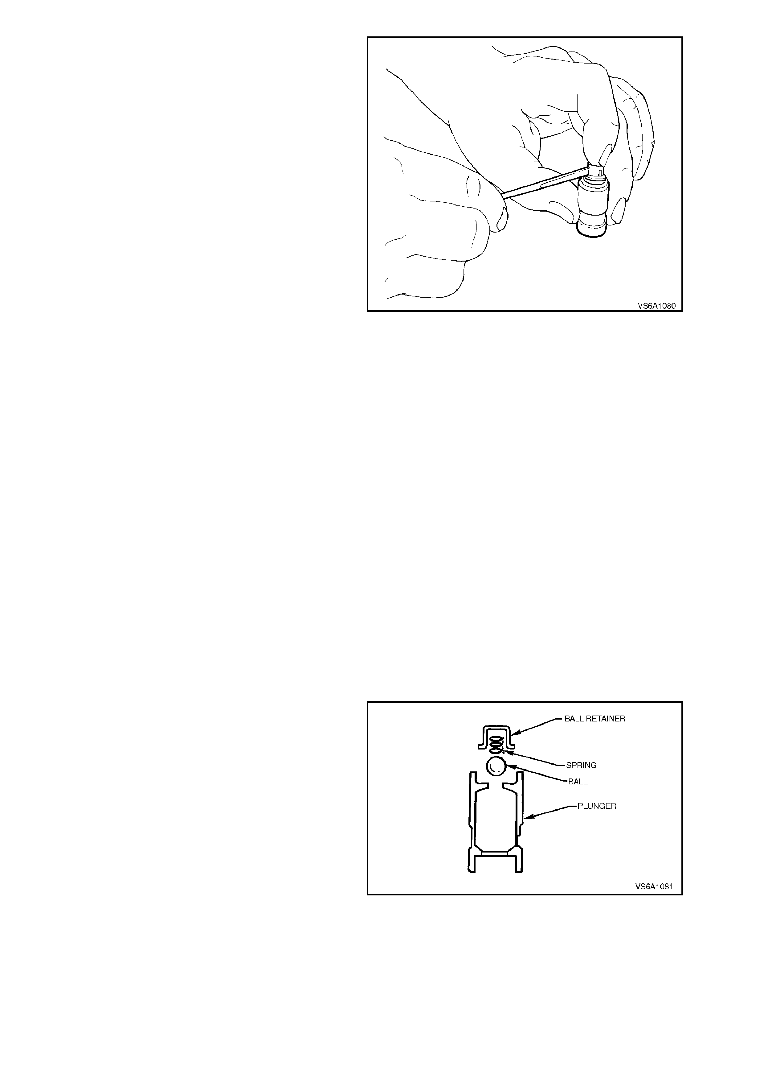
3. Remove check valve retainer, ball check
spring and ball from plunger assembly with a
small, fine bladed screwdriver.
Figure 6A1-1-87
CLEAN AND INSPECT
1. Thoroughly clean all parts in a suitable
cleaning fluid. Blow dry with clean dry
compressed air.
2. Inspect lifter body for;
a. Wear
b. Scuffing. Also inspect lifter bore in
cylinder block.
3. Inspect roller for;
a. Freedom of movement. Replace lifter if
roller binds or roughness can be felt.
b. Excessive looseness in the roller bearing.
c. Flat spots. Replace lifter if roller is worn.
d. Pitting. Replace lifter if roller is pitted.
4. Inspect pushrod seat. If seat is worn, inspect
pushrod. Replace pushrod if worn.
5. If any lifter component is damaged or
excessively worn, replace entire lifter
assembly.
REASSEMBLE
NOTE 1:
Do not attempt to recondition lifter assemblies by
taking parts from other unserviceable lifters.
NOTE 2:
Cleanliness is very important when reassembling
lifters. Lint or dirt can cause the lifters to fail.
1. Place check ball on small hole in plunger.
Figure 6A1-1-88
2. Carefully place check ball spring and retainer
over ball and press retainer into position in
plunger with a small, fine bladed screwdriver.
3. Half fill valve lifter body with test fluid No.
E1151 (previously 361-1-93).
4. Reinstall plunger spring into lifter body.
5. Install plunger assembly in body, taking care to
align oil feed holes.
6. Fill lifter assembly with test fluid.
Figure 6A1-1-89
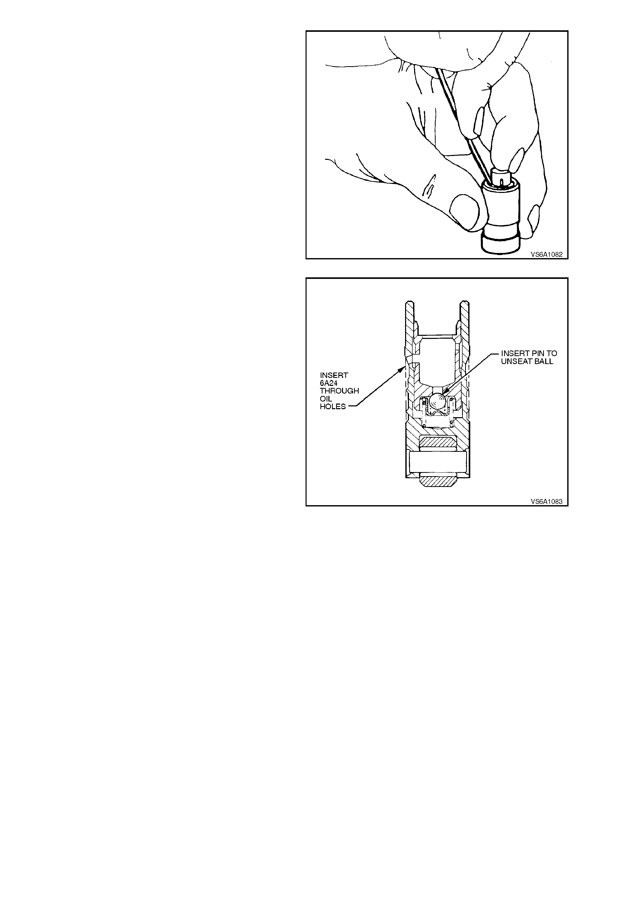
7. Use a 1 m m diameter pin to unseat check ball
in the plunger. Push plunger down to the full
extent of its travel.
8. Use Tool No. 6A24 to align oil feed holes in
body and plunger.
9. Fill lifter assembly with test fluid.
10. Reinstall oil metering valve, push rod seat (cup
side uppermost) and retaining ring.
NOTE:
The hydraulic lifter is now ready for checking as
outlined in the next operation.
Figure 6A1-1-90
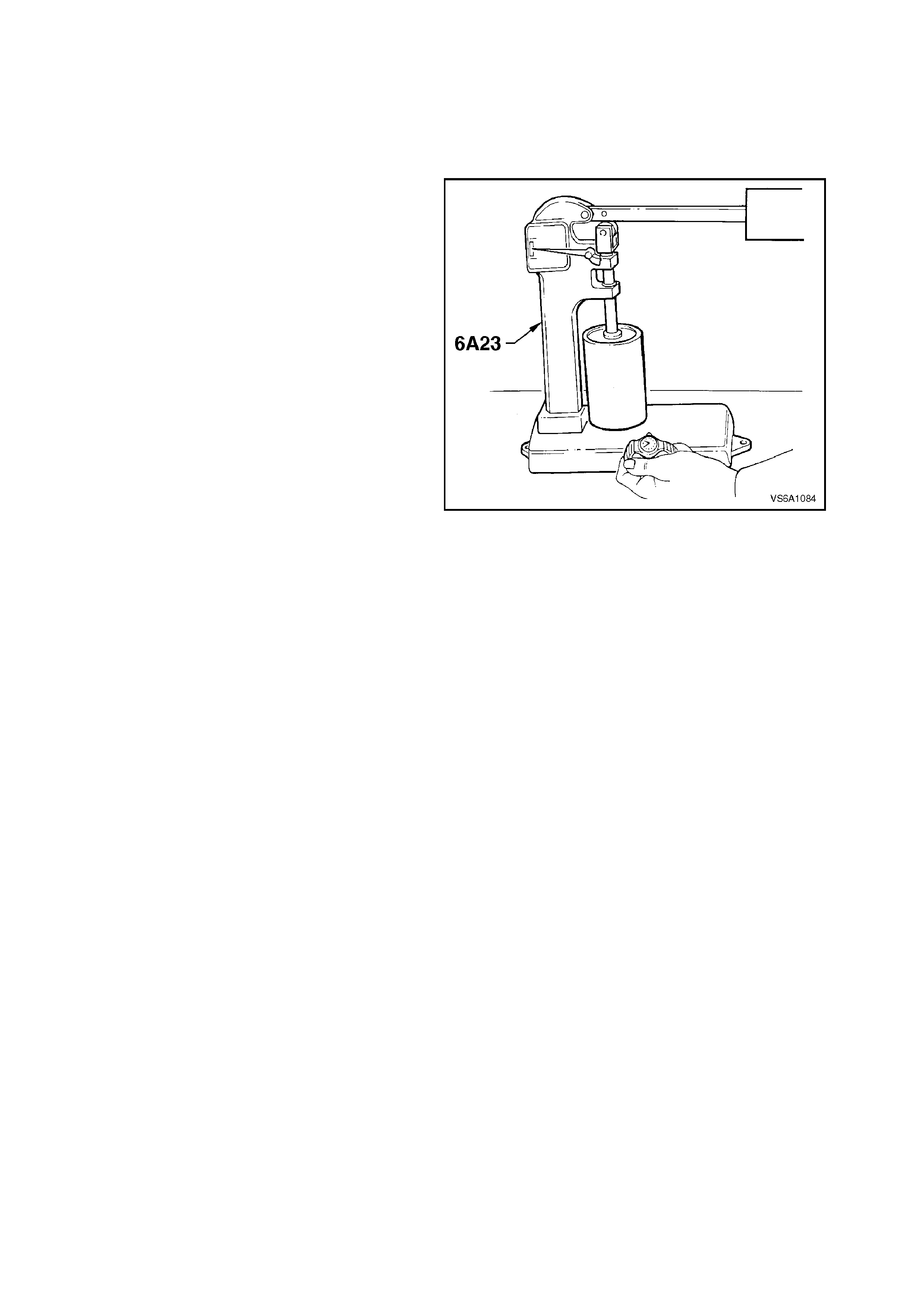
TESTING LIFTER LEAK DOWN RATE
After a hydraulic lifter has been cleaned, inspected
and assembled, it must be tested before it is
reinstalled in the engine. T he lifter test f ixture, Tool
No. 6A23, has been designed to test the leak down
rate of the lifter to determine whether it is within the
limits which assure satisfactory lifter operation.
1. Thoroughly clean cup of tes t f ix tur e. Inst all cup
on fixture and place lifter into cup.
NOTE:
On som e versions of 6A23, it m ay be necessary to
make a small cup/support fixture to hold the base
of the lifter assembly inside the tester cup.
2. Add sufficient test fluid No. E1151 (previously
361-1-93) to completely cover lifter.
3. Place ball bearing supplied with test fixture in
push rod seat of lifter.
4. Lower test fixture ram to rest on ball bearing.
5. Operate lifter plunger through its maximum
travel to force all air out of lifter by using a
vigorous pumping action on test fixture weight
arm. Continue pumping action until
considerable resistance is built up in lifter and
lifter becomes solid.
6. Raise weight arm to allow lifter plunger to
come up to its retainer, then lower arm to rest
on ram.
7. Use a stop watch to check the time required
for the indicator to move from the 'START' to
0.125 in. position on the scale.
8. The leak down rate (time between start and
0.125 in. position) must be between 10 to 30
seconds to assure satisfactory lifter operation.
Figure 6A1-1-91
NOTE:
A doubtful lifter should be tested three or four
times. Any lifter which does not test within the
specified limits should be replaced.
9. After all lifters have been thoroughly tested,
place a cover over the test fixture to keep dirt
out of the cup.
10. Stand tested lifters upright so that fluid does
not drain from oil holes.

REINSTALL
1. Ensure that lifter bodies, rollers and lifter
bores are clean.
2. Lubricate lifter bodies and bores with Lubrizol
6612 or equivalent (Holden Specification HN
1961) and install lifters.
3. Install lifter guides, aligning flats on lifter body
with flats in guide.
4. Install valve lifter guide retainer and attaching
bolts. Tighten bolts to the correct torque
specification.
VALVE LIFTER GUIDE
RETAINER BOLT
TORQUE SPECIFICATION 26 - 34 Nm
5. Install rocker arms and pushrods, refer to
2.12 ROCKER ARMS AND PUSHRODS in
this Section.
6. Install rocker covers, refer to
2.11 ROCKER COVERS AND/OR SEALS in
this Section.
7. Reinstall lower inlet manifold, refer to
2.9 LOWER INLET MANIFOLD in this
Section.
8. Reconnect battery earth lead, star t engine and
check for oil or fuel leaks and valve train
noise. Repair as necessary.
2.15 CYLINDER HEADS
REMOVE
1. Depressurise fuel lines, refer to
Section 6C1 POWERTRAIN MANAGEMENT
- V6 ENGINE.
2. Disconnect battery earth lead.
3. Disconnect spar k plug leads f rom spark plugs.
Remove spark plug leads from retainers.
NOTE:
All spark plug leads and coil terminals are
numbered to correspond to the cylinder numbering.
Figure 6A1-1-92
4. Remove drive belt, refer to
2.6 DRIVE BELT - REMOVE in this Section.
5. Remove radiator cap to release any cooling
system pressure.
WARNING:
To avoid serious personal injury, never remove
the radiator cap when the engine is hot.
Sudden release of cooling system pressure is
very dangerous and could cause personal
injury.
6. Remove lower inlet manifold, refer to
2.9 LOWER INLET MANIFOLD in this
Section.
7. Remove exhaust manifolds, refer to
2.10 EXHAUST MANIFOLDS in this Section.
8. Remove rocker covers, refer to
2.11 ROCKER COVERS AND/OR SEALS in
this Section.
9. Remove rocker arms and pushrods, refer to
2.12 ROCKER ARMS AND PUSHRODS in
this Section.
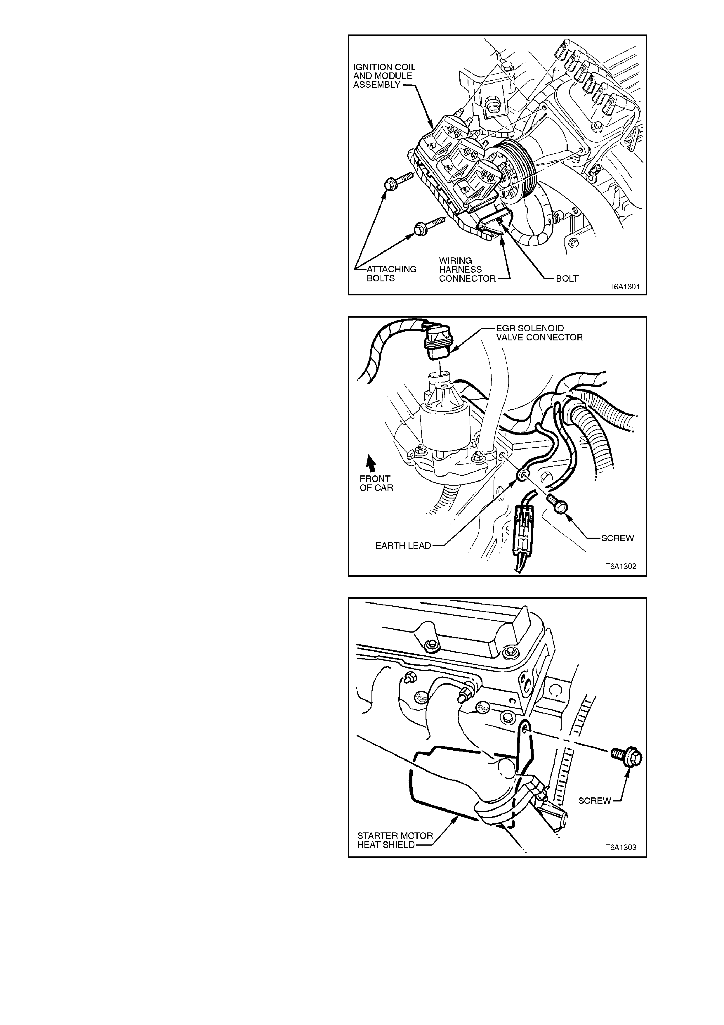
10. For left hand side cylinder head:
a. Disconnect wiring harness connector to
ignition coil module assembly, remove bolts
securing ignition coil and module assembly to
left hand cylinder head.
Figure 6A1-1-93
b. Remove powertrain harness earth connector
at rear of cylinder head and connector from
EGR valve.
Figure 6A1-1-94
c. Remove screw securing starter motor heat
shield to rear of cylinder head, refer to
Fig. 6A1-1-95.
Figure 6A1-1-95
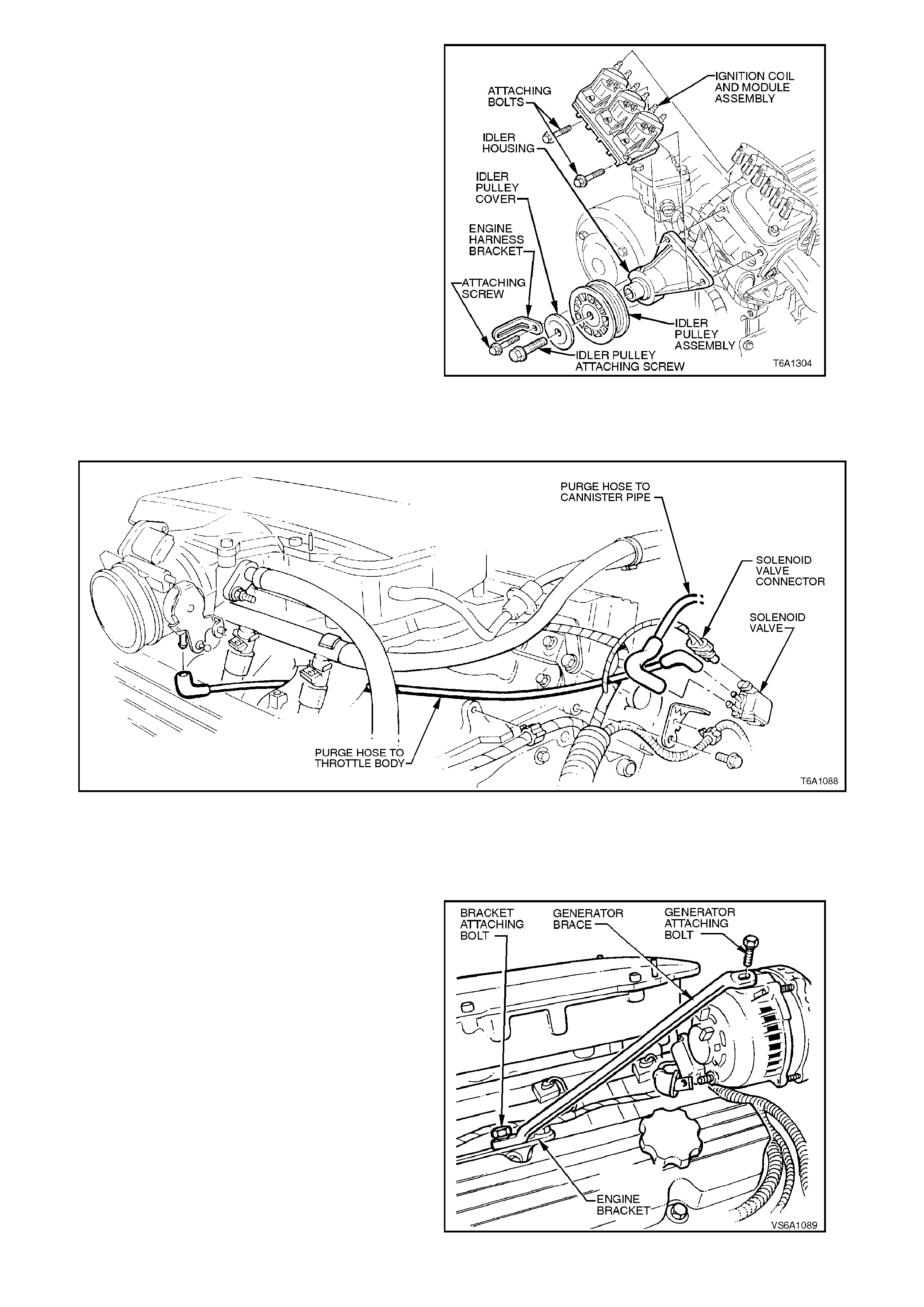
d. Remove bolts securing idler pulley assembly,
refer to 2.25 IDLER ASSEMBLY in this
Section.
Figure 6A1-1-95
e. Disconnect canister purge solenoid vacuum
lines and electrical connector at rear of
cylinder head.
Figure 6A1-1-96
11. For right hand side cylinder head:
a. Remove the drive belt tensioner
assembly refer to 2.7 DRIVE BELT
TENSIONER ASSEMBLY in this Section.
b. Remove generator brac e to cylinder head
bracket bolt and generator brace bracket
to cylinder head bolts.
c. Remove br ace to generator bolt rem oving
brace and bracket assembly.
Figure 6A1-1-97

12. Gradually and progressively slacken cylinder
head bolts in the sequence shown. Remove
rocker covers.
Figure 6A1-1-98
13. Remove cylinder head bolts, remove cylinder
heads and gaskets.
Figure 6A1-1-99
INSPECT
1. Clean mating surfaces of cylinder head and
cylinder block, taking care not to scratch
machined surfaces.
NOTE:
Do not use a motorised wire brush on any gasket
sealing surface.
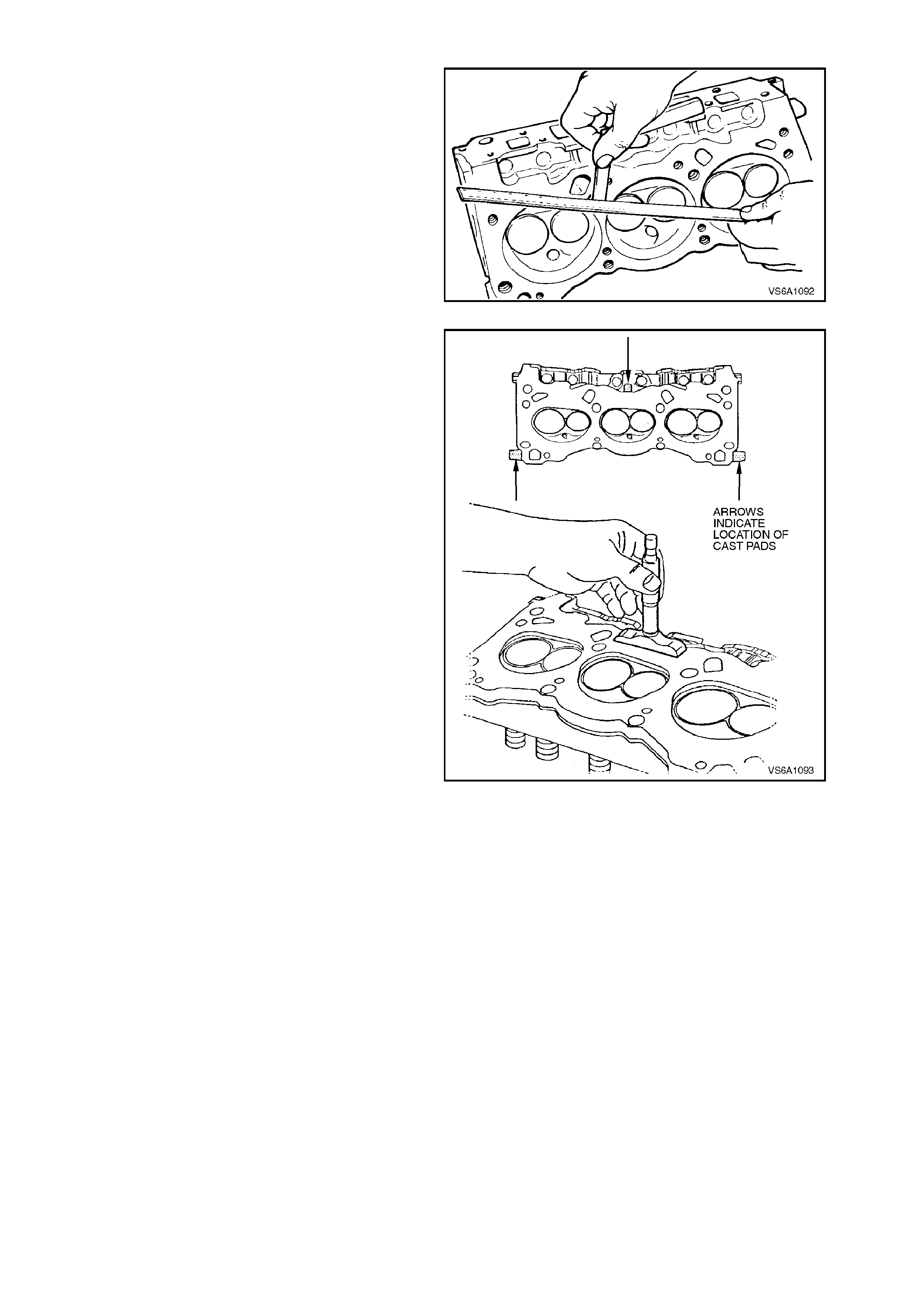
2. Check cylinder head deck, inlet and exhaust
manifold mating surfaces for distortion. These
surfaces may be refaced by parallel grinding. If
more than 0.25 mm must be removed from
any surface, replace cylinder head.
Figure 6A1-1-100
NOTE 1:
To determine if cylinder head has sufficient deck
surface thickness for resurfacing, measure head
height from deck surface to cast pads, refer to
Fig. 6A1-1-101.
NOTE 2:
New cylinder heads measure f rom 1.37 m m to 1.67
mm. The minimum dimension allowed after
resurfacing is 1.12 mm
NOTE 3:
If the cylinder head does not meet the minimum
thickness after resurfacing, the cylinder head must
be replaced.
NOTE 4:
Do not reduce com bustion cham ber volum e below
minimum specified in 5. SPECIFICATIONS in this
Section. Machining 0.15 mm off deck face will
reduce combustion chamber volume 1.00 cm3.
Figure 6A1-1-101

3. Inspect all threaded holes for damage, repair
as required.
4. Inspect coolant jack et welsh plugs for signs of
corrosion, replace plugs as necessary.
If replacing welsh plugs, apply a coating of
Loctite 242 or equivalent (H olden Specification
HN 1256, Class 2 Type 2) around plug sealing
surface.
5. Inspect cylinder head for cracks, especially
between valve seats or exhaust ports.
6. Inspect cylinder head deck surface for
corrosion, casting sand inclusions or blow
holes.
7. Inspect cylinder block deck surface for
distortion, refer to 3.15 CYLINDER BLOCK
in this Section.
8. Clean cylinder head bolt hole threads in
cylinder block using an appr opr iate size thread
tap. Threads may be reconditioned if
necessary with suitable thread inserts. Clean
out bolt holes with an air hose.
NOTE:
Thread size is 7/16 UNC.
9. Clean cylinder head bolts, replace any bolt
that has suspect threads, stretched or
damaged heads caused by improper use of
tools.
REINSTALL
Installation of the cylinder heads is the reverse of
removal procedures, noting the following points:
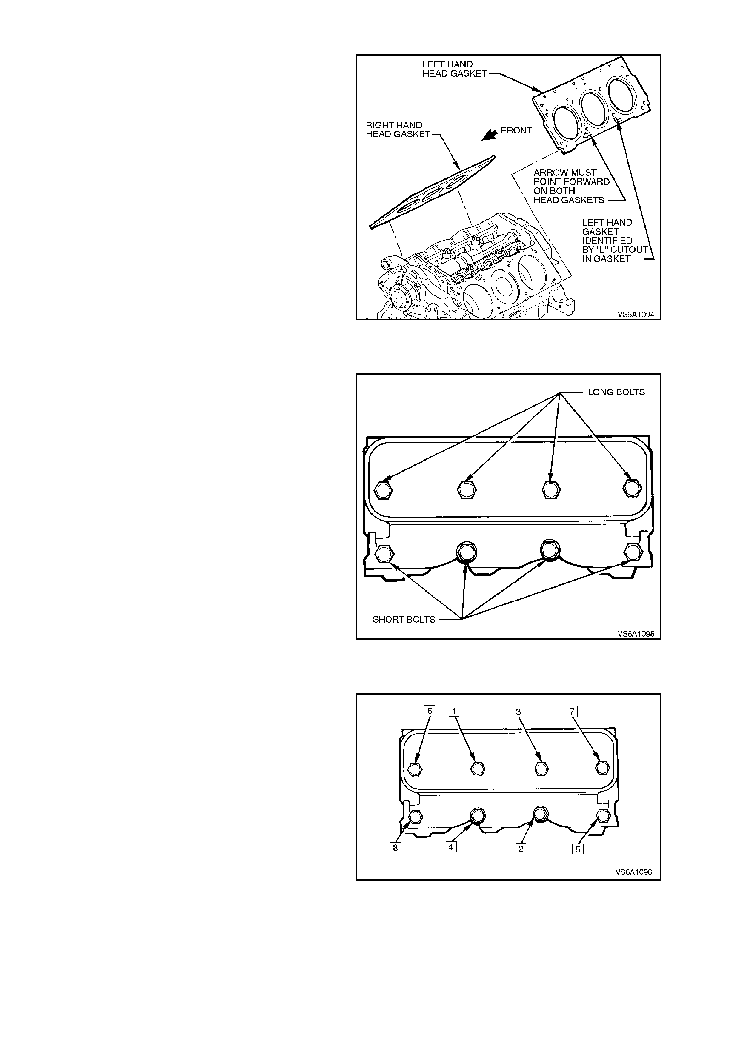
1. Place head gaskets in position over dowel pins
on cylinder block.
NOTE 1:
ENSURE THAT 'ARROW' MARKING ON
GASKETS IS FACING TOWARDS FRONT OF
ENGINE.
NOTE 2:
Head gaskets have a s pecial coating on both sides
and care must be taken when installing head
gaskets so as not to damage this coating.
NOTE 3:
The left hand c ylinder head gasket is identified by a
'L' shaped cut out and the right by a 5.0mm hole.
Both are visible on final engine assembly.
Figure 6A1-1-102
2. Carefully guide cylinder head into place over
dowel pins and onto gasket.
3. Coat threads of cylinder head bolts with Loctite
242 sealant or equivalent (Holden
Specification HN 1256 Class 2, Type 2) and
install finger tight.
NOTE:
Different length head bolts are used, refer to
Fig. 6A1-1-103.
Figure 6A1-1-103
4. Tighten head bolts to the following sequence
and in the order shown in Fig. 6A1-1-104.
NOTE:
It is important to follow the given procedur e to avoid
head gasket failure and possible engine damage.
5. Tighten all cylinder head bolts to 34 Nm.
The next step requires the use of Tool No.
E7115 with the torque wrench.
NOTE:
If a torque of 90 Nm at any time in step 6 is
reached, STOP tightening that particular head bolt.
6. Tighten each bolt 90 degrees in the order
shown.
7. Further tighten all bolts in the specified order
to 90 Nm.
8. The remaining reinstallation of components is
the reverse of removal procedures.
9. Start engine, check for oil, coolant, fuel and
exhaust leaks. Repair as necessary.
Figure 6A1-1-104
2.16 CYLINDE R HEAD RECONDITIONING
NOTE:
Ensure that all valve train components are kept
together and identified so that they can be
reinstalled in their original locations.
DISASSEMBLE
1. Using spring compressor tool No. KD2078,
compress each valve spring in turn and
remove valve collets.
NOTE:
It is important that only spring compressor tool no.
KD2078 be used as other tools may cause damage
to valve stem collet ‘contact’ area. It may be
necessar y to tap top of valve caps with a s oft fac ed
hammer after spring compressor has been installed
to overcome the binding of the valve collets in the
valve spring caps.
2. Remove valve spring caps, springs and valve
stem oil seals.
3. Remove valves from cylinder head.
CAUTION:
Do not force valves out of guides, as
mushroomed valve ends due to rocker arm
wear, or burred valve collet groove, or dirt in
the guides, will damage the guides. Remove
burrs by chamfering aff ected area of v alv e st em
with an oil stone only. During the stoning
process, protect the valve stem/g uide area w ith
rags or grease to prevent any possible ingress
of foreign material.
Figure 6A1-1-105
CLEAN
1. Clean all carbon from combustion chambers,
valve ports etc., using a rotary type carbon
removing wire brush.
NOTE:
Do not wire brush on any gasket sealing surface.
2. Clean cylinder head gasket sur face of cylinder
head.
3. Thoroughly clean valve guides with a suitable
cleaning solvent or a wire brush.
4. Clean valve heads with a buffing wheel.
NOTE:
Do not scratch the valve stem with the buffing
wheel.
Figure 6A1-1-106
5. Thoroughly wash all components in a suitable
cleaning solvent and blow dry with dry
compressed air.

CYLINDER HEAD INSPECTION
1. Inspect cylinder heads for cracks in valve
seats and combustion chambers, and for
external cracks to water jackets.
2. Check cylinder head deck surface for
corrosion.
3. Using a straight edge and f eeler gauge. Chec k
cylinder head deck inlet and exhaust manifold
surfaces for distortion.
Check cylinder head deck surface diagonally,
longitudinally and transversely.
These surfaces may be refaced by parallel
grinding. If more than 0.25 mm must be
removed from any surface, replace cylinder
head.
Figure 6A1-1-107
NOTE 1:
To determine if cylinder head has sufficient deck
surface thickness for resurfacing, measure head
height from deck surface to cast pads, refer to
Fig. 6A1-1-108.
NOTE 2:
New cylinder heads measure from 1.372 mm to
1.676 mm. The minimum dimension allowed after
resurfacing is 1.12 mm
NOTE 3:
If the cylinder head does not meet the minimum
thickness after resurfacing, the cylinder head must
be replaced.
NOTE 4:
Do not reduce com bustion cham ber volum e below
minimum specified in 5. SPECIFICATIONS in this
Section. Machining 0.15 mm off deck face will
reduce combustion chamber volume 1.00 cm3.
Figure 6A1-1-108
4. Inspect all threaded holes for damage, repair
as required.
5. Inspect coolant jack et welsh plugs for signs of
corrosion, replace plugs as necessary.
If replacing welsh plugs, apply a coating of
Loctite 242 or equivalent (H olden Specification
HN 1256, Class 2, Type 2) around plug
sealing surface.
VALVE GUIDES
Clearance Checking
Excessive valve stem to guide bore clearance will
cause lack of power, rough idling and noisy valve
operation. Insufficient clearance will result in noisy
and sticking func tioning of the valve and will dist urb
engine smoothness of operation.
Measure clearance as outlined in the following
steps.
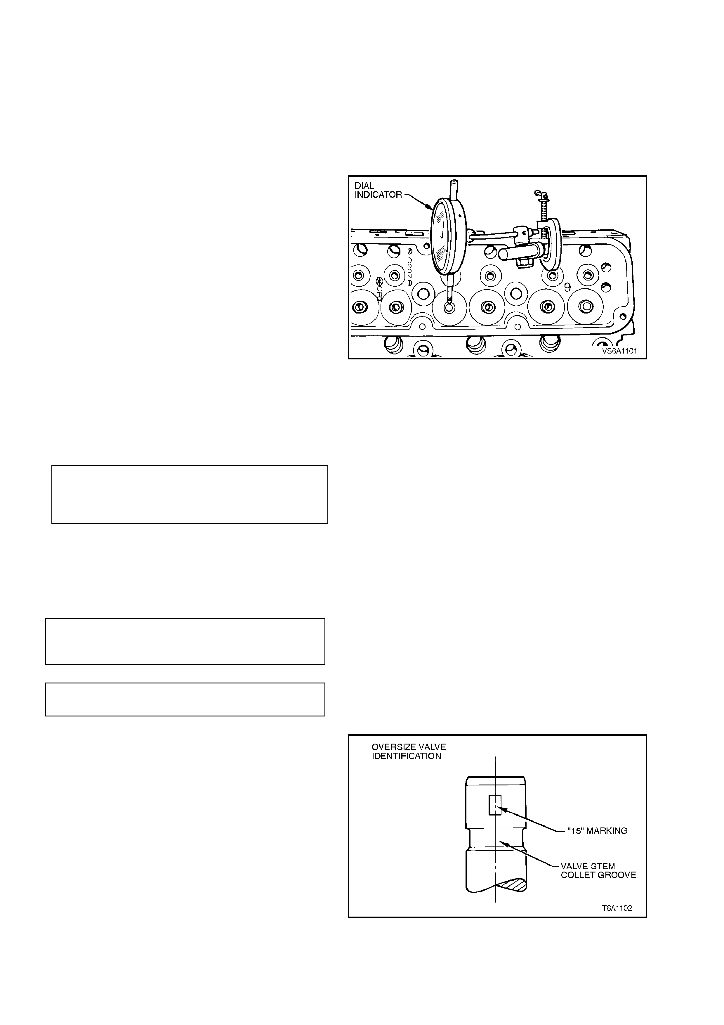
1. Insert valve into its guide.
2. Clamp a dial indicator on one side of cylinder
head rocker cover seating rail, locating the
indicator so that movement of the valve stem
from side to side (crosswise to the head) will
cause a direct movement to the indicator
stem.
The indicator stem must contact the side of
the valve stem, 8 - 12 mm above top of valve
guide.
3. With the valve head dropped approximately 2
mm off its seat, move the stem of the valve
side to side using light force to obtain a
clearance reading. Figure 6A1-1-109
NOTE:
It is important to check the clearance with a new
standard valve bef ore attem pting to ream the valve
guide.
INLET AND EXHAUST
VALVE STEM TO VALVE GUIDE
CLEARANCE SPECIFICATION
0.043 - 0.25
mm
Total Indicated
Reading
The following chart is for valve stem to guide
clearance if checking clearance by measuring
valve stem diameter and subtracting from valve
guide internal diameter measurement.
NEW PARTS SPECIFICATION
INLET VALVE STEM
EXHAUST VALVE STEM
mm
0.033 - 0.066
0.036 - 0.074
MAXIMUM SPECIFICATION ON
WORN PARTS 0.18
If valve stem to valve guide clearance is within
specification when using a new valve, check
original valve stem diameter (refer to VALVES in
this Section) and replace any worn valves as
necessary.
Valve guides m ay be reamed to acc ept an oversize
of 0.254 mm.
Valves with oversize stems are identified as shown
in Fig. 6A1-1-110.
Figure 6A1-1-110
NOTE:
Avoid breaking reamer flutes or jamming the
ream er into the valve guide due to pack ing of chips
or carbon. Clean the valve guides before reaming.
Do not push down on the reamer, and clean and
lubricate the reamer often during use.
VALVE SEATS
Reconditioning the valve seats is very important
because the seating of the valves must be precise
for the engine to deliver the power and
performance built into it.
Another important factor is the cooling of the valve
head. Good contact between each valve and its
seat in the head is imperative to ensure that the
heat in the valve head will be properly carried
away.
Several different types of equipment are available
for reconditioning valve seats with an oscillating
type valve seat grinder being preferred. The
recommendations of the manufacturer of the
equipment being used should be carefully followed
to attain proper results.
Check valve seats for any evidence of pitting or
damage at valve contact surface. If pitting is
evident, the valve seats will need to be
reconditioned.
NOTE:
Since the valve guide serves to support and c entre
the valve seat grinder, it is essential that the valve
guide is serviced before reconditioning the valve
seats.
Refer to Fig. 6A1-1-111 for valve seat angles. If,
after grinding, the seat is too wide, it may be
narrowed by using a 25 degree or 60 degree
grinding stone. The 25 degree stone will lower the
seat and the 60 degree stone will raise the seat.
Figure 6A1-1-111
If the valve seats are reconditioned, the valves
must also be reconditioned (refer to VALVES in
this Section) or replace valves as necessary.
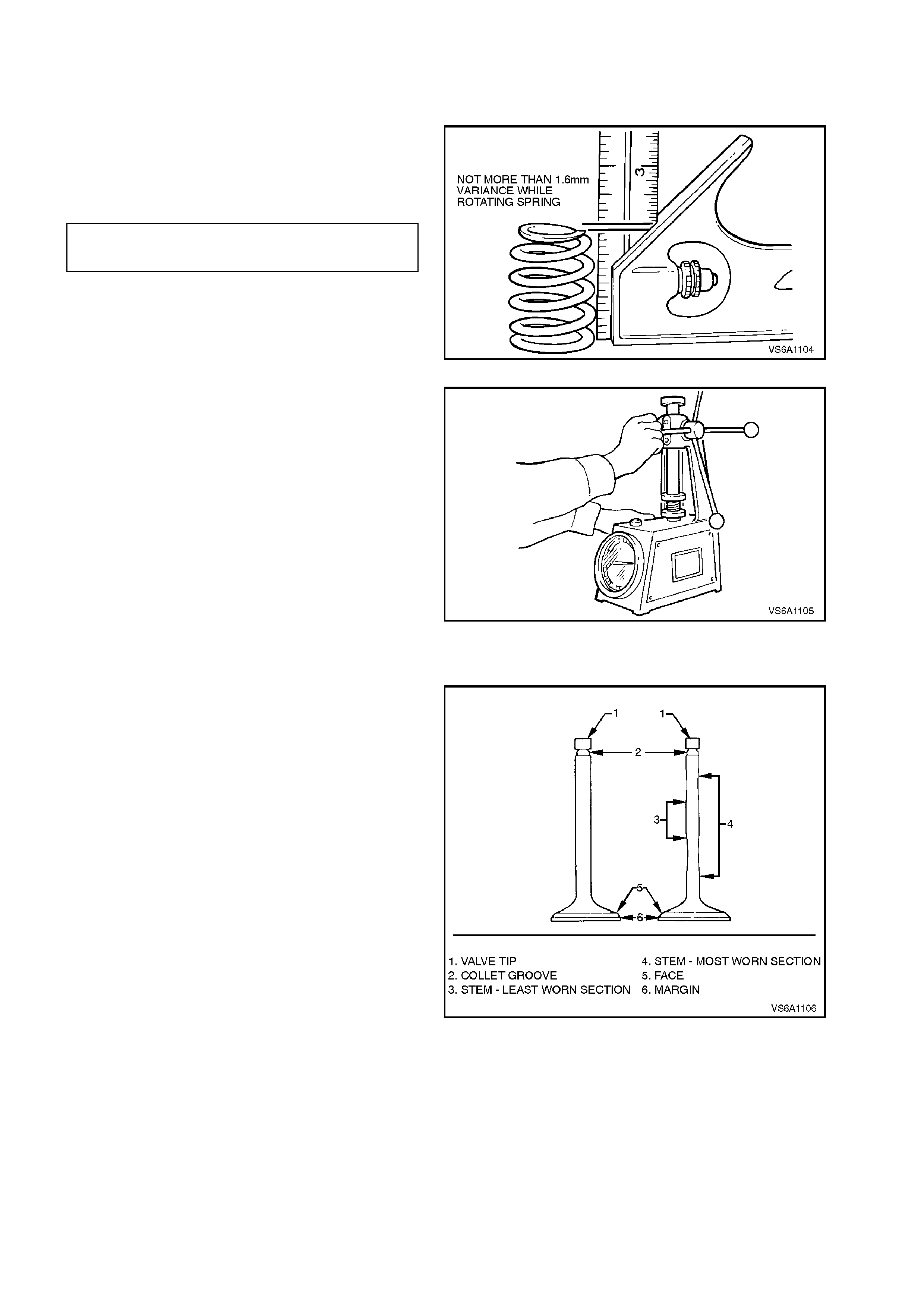
VALVE SPRINGS
1. Inspect valve sp ring surf aces on cylinder head
and valve cap for wear or gouging. Replace
components as necessary.
2. Check spring ends, if they are not parallel, the
spring is bent, refer to Fig. 6A1-1-112.
Replace valve springs that do not meet
specification.
MAXIMUM ALLOWABLE VARIANCE 1.60
IN SPRING END LENGTH mm
Figure 6A1-1-112
3. Check valve spring load with a spring tester.
Springs should be compressed to the
specified height and checked against
specifications.
Replace any valve spring if not to
specification.
VALVE SPRING COMPRESSED LOAD/HEIGHT
SPECIFICATION N/mm
VALVE OPENED HEIGHT 970 - 1059/32.4
ASSEMBLED HEIGHT 316 - 351/43.7
Figure 6A1-1-113
VALVES
1. Inspect valve stem for burrs and scratches.
Burrs and minor scratching may be removed
with an oil stone.
Valves with excessive stem wear or that are
warped should be replaced.
Inspect valve stem tip for wear. The valve tip
may be reconditioned by grinding.
Follow the grinder manufacturer's instructions.
Ensure that new tip surface is at right angles
to the valve stem.
2. Inspect valve stem collet groove for damage.
3. Check valve face for burning or cracking.
If pieces have broken off, inspect
corresponding piston and cylinder head area
for damage.
Figure 6A1-1-114
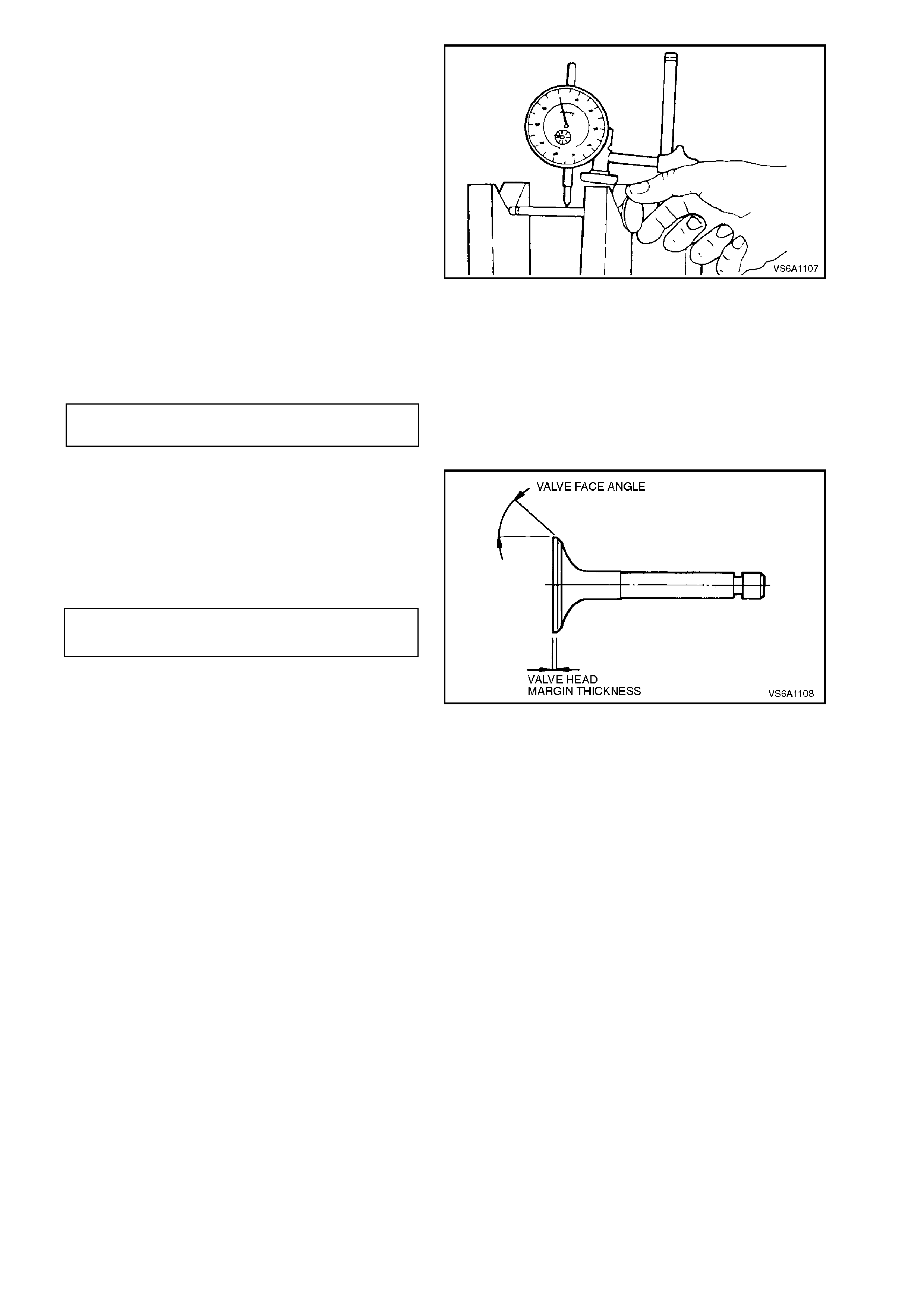
4. Inspect valve stem for straightness and valve
head for bending or distortion. Use V - blocks.
Bent or distorted valves must be replaced.
Figure 6A1-1-115
5. Valves with pitted or grooved faces can be
reconditioned with a valve refacing machine,
ensuring correct relationship between head
and stem.
VALVE FACE
ANGLE 45 degrees
NOTE:
If pitting or grooving is so deep that refacing would
result in a 'knife' edge at the valve head, the valve
must be replaced. Measure valve margin after
refacing valves. If margin is less than minimum
specified, the valve must be replaced.
VALVE HEAD MARGIN 0.63
THICKNESS (MINIMUM) mm
Lightly lap reconditioned valves into valve seat.
NOTE:
New valves must not be lapped. Lapping destroys
the protective coating on the valve face.
Figure 6A1-1-116
After refacing an existing valve or installing a new
valve, check for correct seating as follows:
a. Lightly coat valve face with bearing blue.
b. Insert valve and rotate about 1/6th of a
revolution.
c. Remove valve and check its contact with the
seat
d. If full contact is indicated, valve and seat are
acceptable.
If partial contact is indicated, reinsert valve
and turn through a full revolution. If blue on
seat indicates f ull contact, ref ace valve. If blue
on the seat indicates partial contact, regrind
cylinder head valve seat.
e. Clean all traces of bearing blue from valves
and seats.
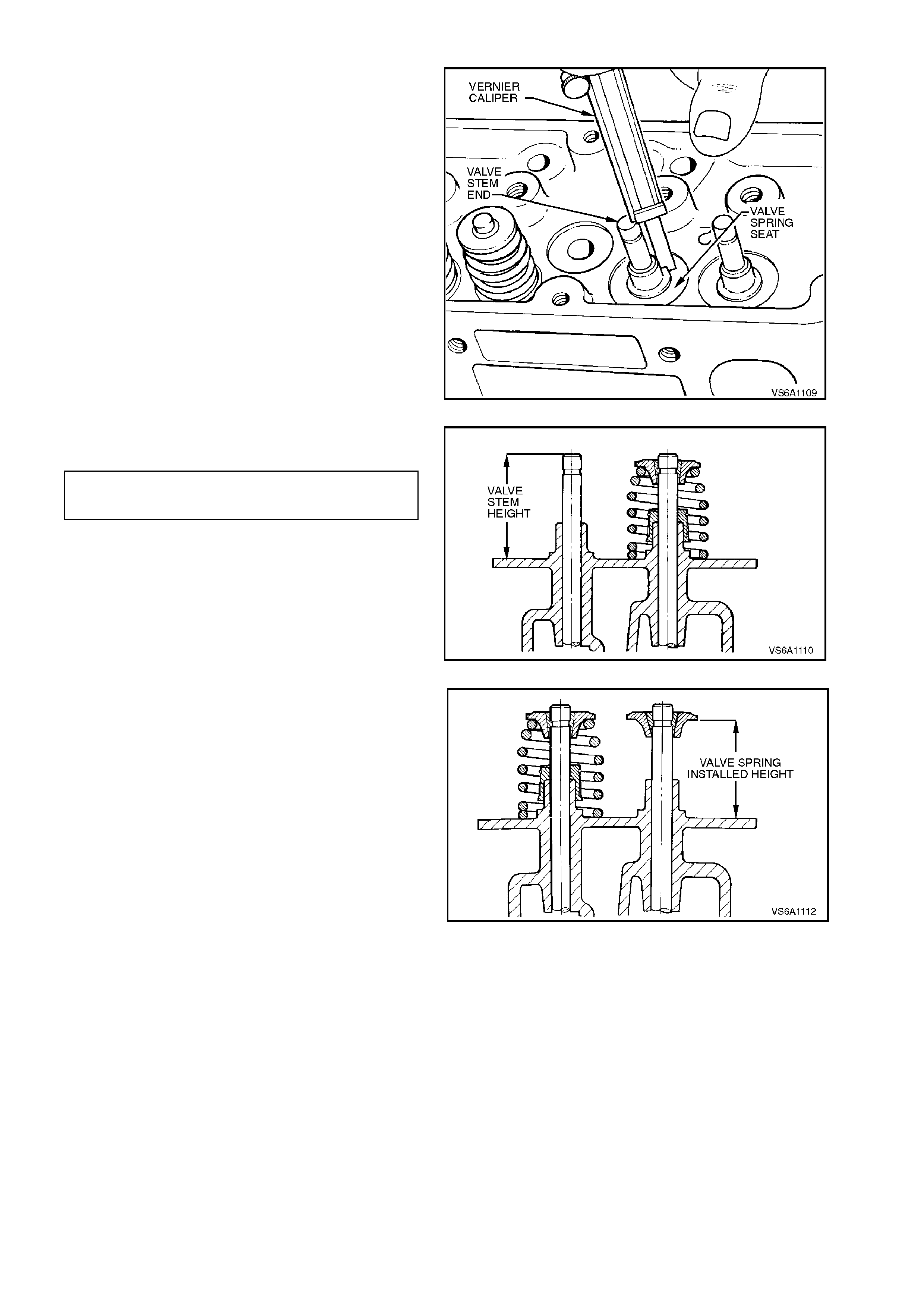
MEASURING VALVE STEM HEIGHT
After rec onditioning valves or valve s eats or when a
new valve is installed, the valve stem height must
be checked to ensure correct hydraulic valve lifter
operation.
1. Place valve in its guide and hold it in the
closed position.
2. Using a vernier calliper, measure from
machined valve spring seat to valve stem end.
Figure 6A1-1-117
3. Measurement should be as specified.
VALVE STEM HEIGHT 49.22 - 50.49
(INSTALLED) SPECIFICATION mm
If measurement is greater than specified,
remove valve and grind end of valve stem to
achieve specified dimension.
NOTE:
Do not grind off any more than is necessary.
Figure 6A1-1-118
4. Using a vernier calliper, measure from
machined valve spring seat to spring side of
cap.
Valve spring installed height should be as
specified.
If any measurement is not as specified, shim valve
spring seat as required.
Figure 6A1-1-119
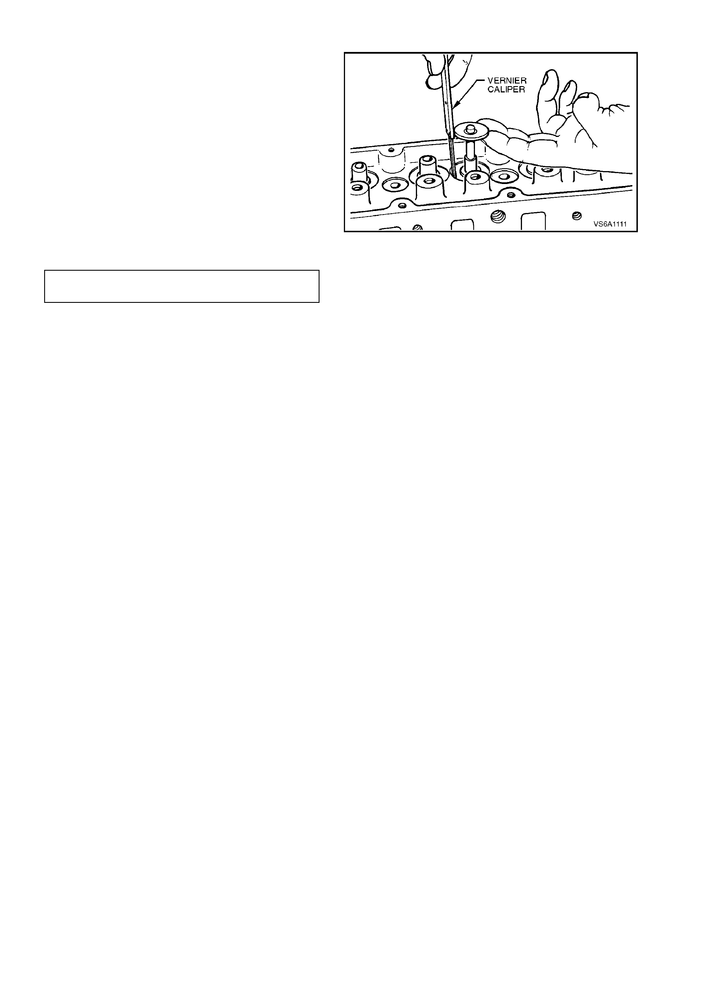
VALVE SPRING INSTALLED HEIGHT
Excessive valve spring installed height, caused by
valve seat wear or valve and seat reconditioning,
must be compensated for by adding shims under
the valve springs.
1. Place valve in its guide.
2. Install valve spring cap and collets.
3. Pull up on valve spring cap to seat collet and
valve.
Figure 6A1-1-120
VALVE SPRING INSTALLED
HEIGHT 43.7 ± 0.5
mm

REASSEMBLE
1. Thoroughly clean and dry all components.
2. Lubricate valve stems and valve guides
thoroughly with clean engine oil. Install valves
in corresponding guides.
3. Lubricate new seal with engine oil and install
over valve with a twisting motion and pus h the
seal down until the rubber jacket touches the
top of guide.
4. Place the valve stem installation tool over the
valve stem seal (flat surfaced end toward the
seal).
5. Lightly tap the top (tapered end of the tool)
lightly with a plastic mallet until the valve stem
seal is resting flush with the top of the valve
guide.
NOTE:
Install seals using valve stem installation tool
No. J41512. Figure 6A1-1-121
NOTE 1:
There are specific valve stem seals for inlet and
exhaust valves. Ensure the correct type is fitted to
the appropriate valve based on part number and
package description.
NOTE 2:
The colour of the replacement s eals may not be the
same colour as the original seals.
Figure 6A1-1-122
6. Place valve spring and cap over valve stem.
7. Compress valve spring with tool No. KD2078.
NOTE:
Compress valve spring only enough to install valve
collets. Excess compression can cause valve
spring cap to damage valve stem oil seal.
8. Install valve collets, ensuring that they locate
correctly in groove in top end of valve stem.
Slowly release valve spring compressor,
checking that collets seat correctly. A sharp
tap on cap with a soft faced hammer will
ensure correct seating of collets.
Grease may be used to hold collets in place.
9. Repeat procedure to install all valve springs,
caps and collets.
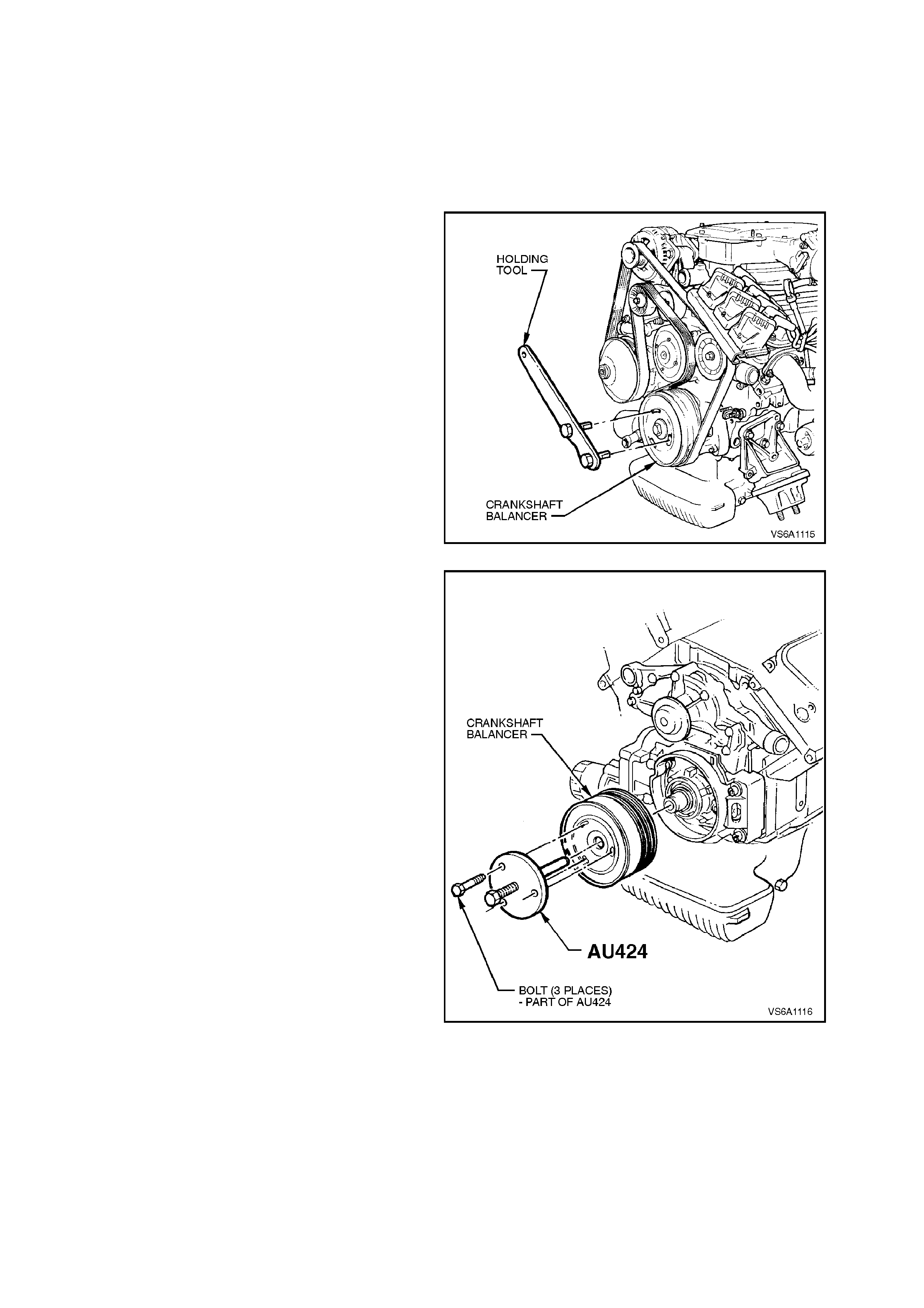
2.17 CRANKSHAFT BALANCER
REMOVE
1. Disconnect battery earth lead.
2. Remove drive belt, refer to 2.6 DRIVE BELT
in this Section.
3. Disconnect the wiring harness connector from
the oil pressure switch.
4. Lock crankshaft against rotation by inserting
the lugs of the cranks haf t balanc er holding tool
No. AU448 into two of the slots in the face of
the crankshaft balancer. Rotate balancer and
lock ing tool by hand resting the arm of the tool
on the R/H side rail.
Figure 6A1-1-123
5. Using a suitable size socket and 'breaker' bar
loosen and remove balancer retaining bolt.
6. Remove crankshaft balancer holding tool from
crankshaft balancer.
7. Install puller, Tool No. AU424, to front of
balancer and remove balancer from
crankshaft.
NOTE 1:
Before ins talling the puller to the balancer, lubric ate
threads and end of puller forcing screw with
grease.
NOTE 2:
When installing the puller to the balancer, ensure
that the locating pin in the front face of the puller
aligns with the indentation between two of the slots
in the front face of the balancer. This is to ensure
correct alignment of the bolt holes in the balancer
and puller.
NOTE 3:
With the introduction of ECOTEC engines the puller
attaching bolts need to be 10 mm longer than thos e
originally supplied with Tool No. AU 424.
NOTE 4:
A series of holes are drilled in the perimeter of the
puller plate to enable the installation of a bar to hold
the puller from rotating while tightening the forcing
screw.
Figure 6A1-1-124

REINSTALL
Installation is the reverse of removal procedures,
noting the following points:
NOTE:
The balancer is serviced only as an assembly.
1. Visually inspect interrupter rings, on rear of
balancer, for any damage or distortion.
2. Lubricate front seal and seal contact surface
of balancer with engine oil. Install balancer,
engaging key on crankshaft with slot in
balancer.
3. Pull crankshaft balancer into position by
tightening retaining bolt. Once balancer has
seated onto front end of crankshaft, lock
crank shaft against rotation by inserting lugs of
crankshaft balancer locking tool No. AU448
into two of the slots on the face of crankshaft
balancer. Rotate balancer and locking tool by
hand so that the arm of the tool rests against
the L/H side rail. Continue to tighten balancer
retaining bolt to the correct torque
specification.
CRANKSHAFT BALANCER
ATTACHING BOLT
TORQUE SPECIFICATION 270 - 325
Nm
4. Rotate Crankshaft and ensure that interrupter
rings do not make contact with crank sensor.
If any part of the interrupter rings touch the
crank sensor then the crank shaft balancer
must be replaced, refer to
2.17 CRANKSHAFT BALANCER.
5. Check drive belt operation.
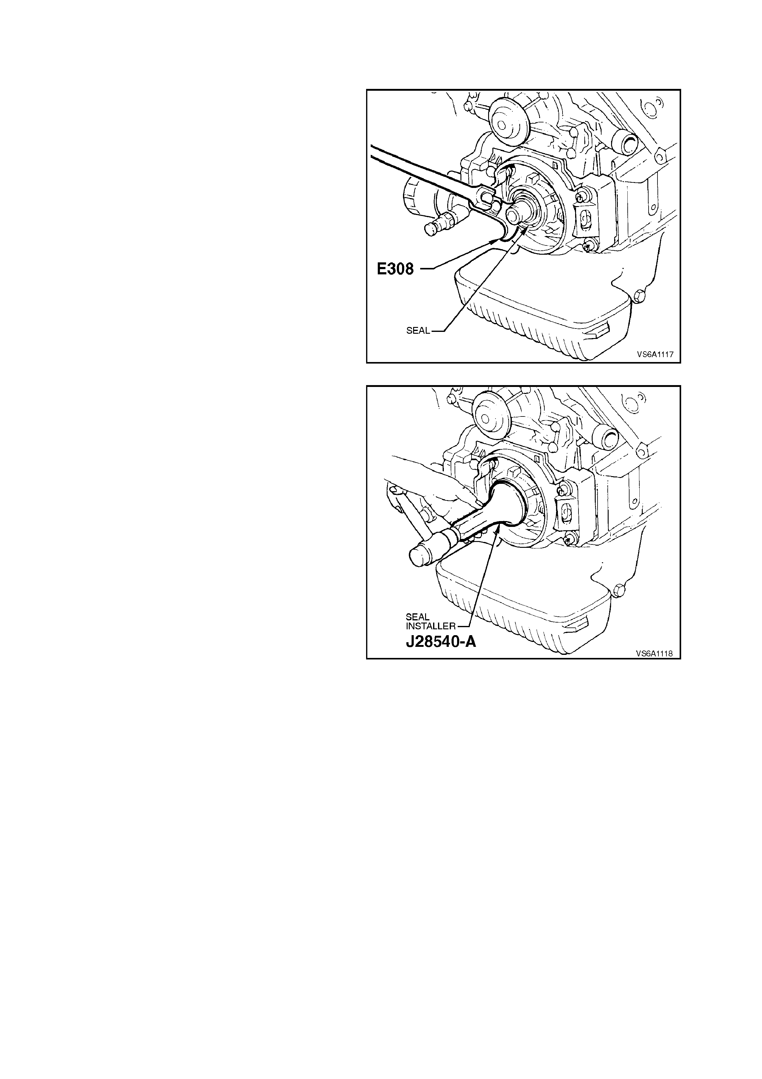
2.18 CRANKSHAFT FRONT SEAL
REPLACE
1. Remove crankshaft balancer, refer to
2.17 CRANKSHAFT BALANCER in this
Section.
2. Using Tool No. E308, remove seal.
Figure 6A1-1-125
3. Using Tool No. J28540-A install new seal.
Figure 6A1-1-126
4. Inspect seal s urface on c ranks haft balancer, if
grooved or damaged, replace balancer.
5. Reinstall crankshaft balancer, refer to
2.17 CRANKSHAFT BALANCER in this
Section.
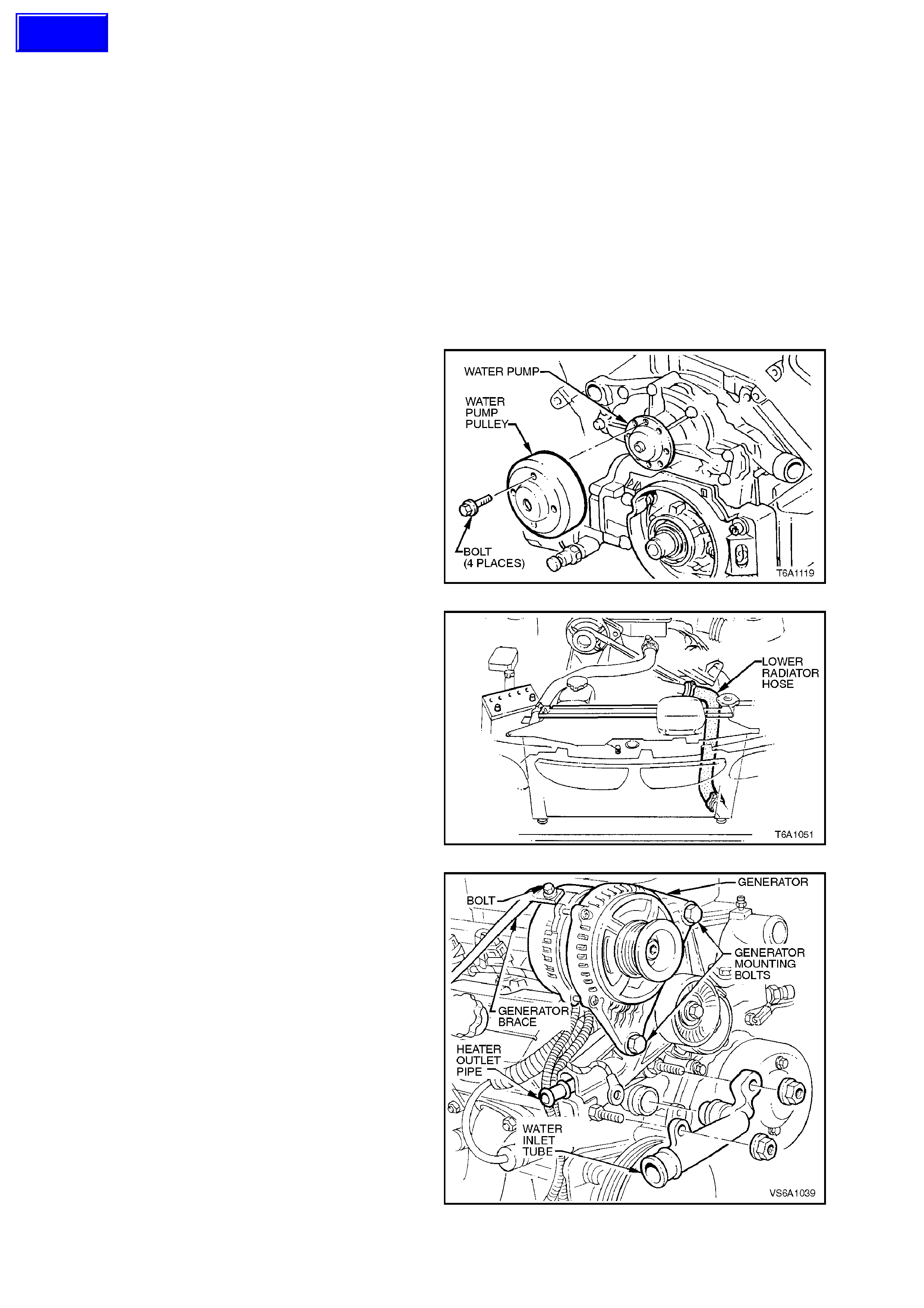
2.19 FRONT COVER AND GASKET
REMOVE
1. Disconnect battery earth lead.
2. Remove radiator cap to release any cooling
system pressure.
WARNING:
To avoid serious personal injury, never remove
the radiator cap when the engine is hot.
Sudden release of cooling system pressure is
very dangerous and could cause personal
injury.
3. Remove crankshaft balancer, refer to
2.17 CRANKSHAFT BALANCER in this
Section.
4. Remove water pump pulley to hub attaching
bolts, remove pulley.
Figure 6A1-1-127
5. Place an oil drain tray beneath engine.
6. Loosen radiator lower hose clamp at front
cover connection, disconnect and remove
hose.
Figure 6A1-1-128
7. Remove two nuts from belt tensioner lower
mounting studs and remove water inlet tube
from front cover.
Figure 6A1-1-129
Techline
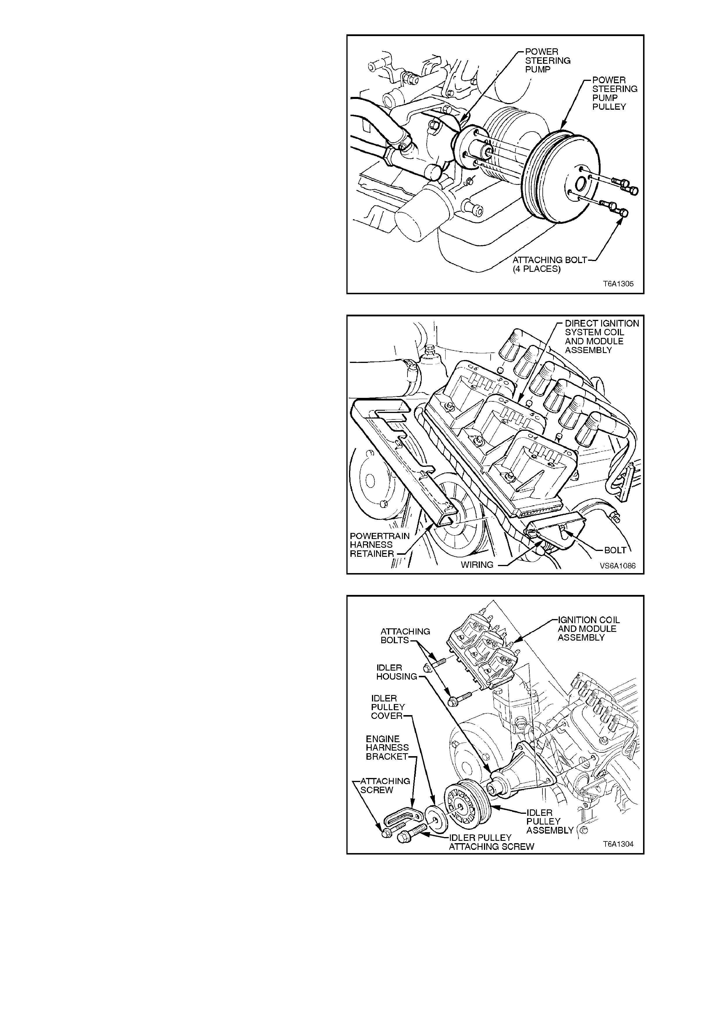
8. Remove power steering pump drive pulley
bolts and remove pulley.
NOTE:
It may be necessary to use a suitable Allen key
inserted in front of power steering pump shaft to
prevent shaft from turning.
Figure 6A1-1-130
9. Rem ove spark plug leads from their sock ets in
coil pack and disconnect electrical connector
from Direct Ignition System Module on coil
pack.
Figure 6A1-1-131
10. Remove bolts securing idler pulley and coil
pack assembly to cylinder head.
Figure 6A1-1-132
11. Remove screws securing battery harness and
transmission cooler pipes refer to Fig. 6A1-1-
133 and move to one side.
12. Bend back tabs securing power train harness.
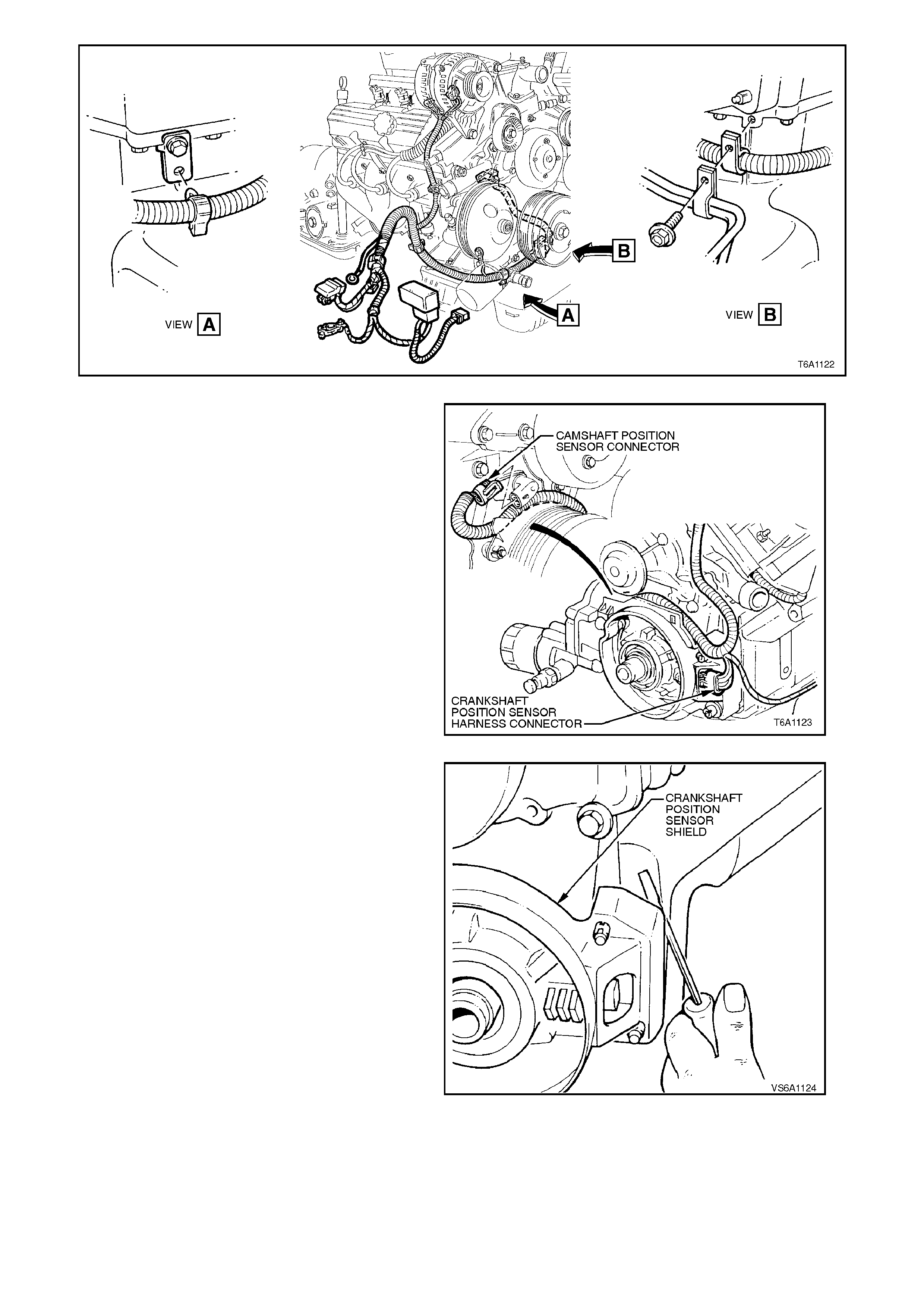
Figure 6A1-1-133
13. Using a fine bladed screwdriver, lever back
power train harness connector retaining tang
from crankshaft position sensor and camshaft
position sensor, pull connector from sensors
and move harness to one side.
Figure 6A1-1-134
14. Using a screwdriver behind c r ank s haf t pos ition
sensor shield, lever each corner of shield fr om
front cover studs, remove shield.
Figure 6A1-1-135
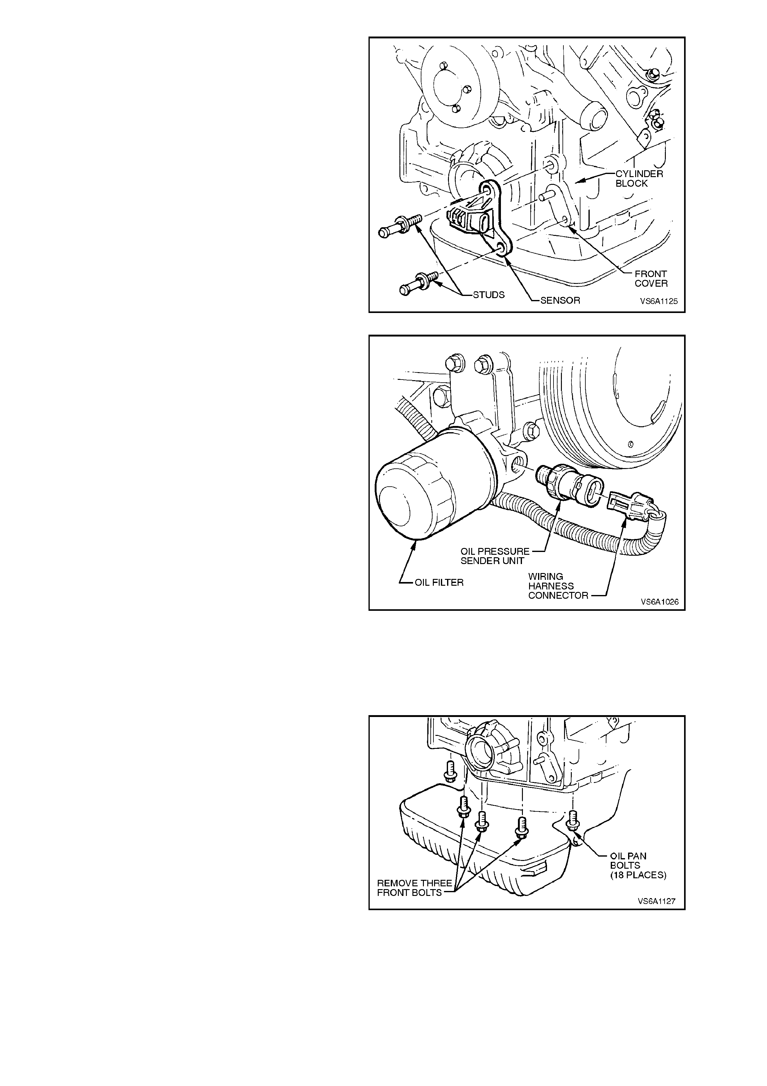
15. Remove crank angle sensor bracket to front
cover attaching studs and remove sensor
assembly.
Figure 6A1-1-136
16. Pull out tang on oil pressure s ender unit wiring
harness connector and pull connector from
sender unit.
Figure 6A1-1-137
17. Raise front of vehicle and support on safety
stands. For location of jacking points refer to
Section 0A GENERAL INFORMATION.
18. Remove beaming brace, refer to
2.24 BEAMING BRACE in this Section.
19. Remove oil pan to front cover attaching bolts.
Loosen oil pan to cylinder block bolts.
Figure 6A1-1-138
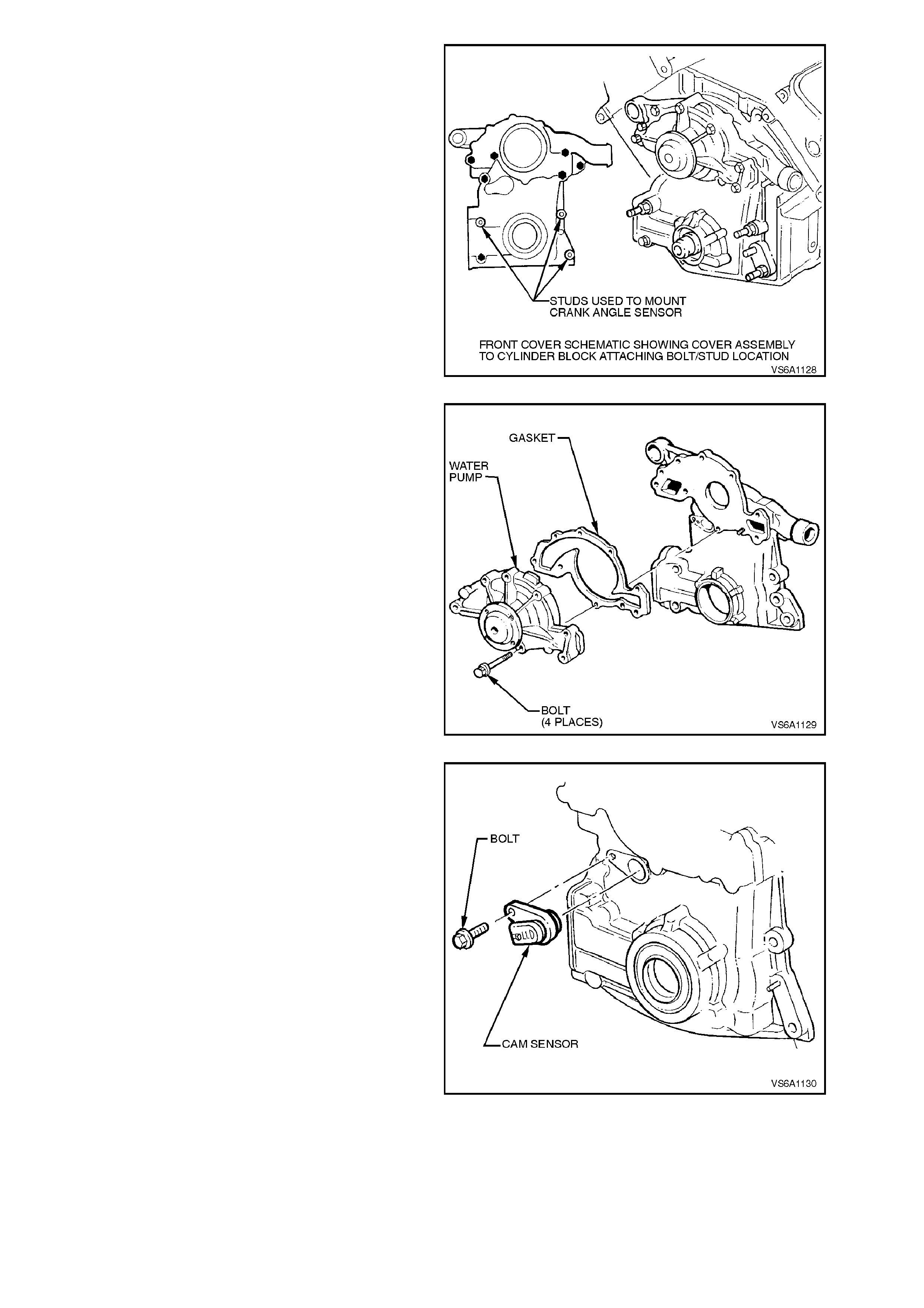
20. Rem ove front cover to cylinder block attac hing
bolts/studs and remove cover. Remove and
discard front cover gasket.
Figure 6A1-1-139
21. If necessary, remove water pump to front
cover attaching bolts and separate pump from
front cover. Remove and discard water pump
gasket.
Figure 6A1-1-140
22. If neces s ary, remove c amshaft position s ensor
to front cover attaching bolt and remove
sensor from front cover.
Figure 6A1-1-141
23. If necessary, remove oil pressure sender unit,
oil filter adaptor and pressure regulator valve
and spring. Refer to 2.5 OIL FILTER
ADAPTOR in this Section.
Remove and discard oil filter adaptor gasket.
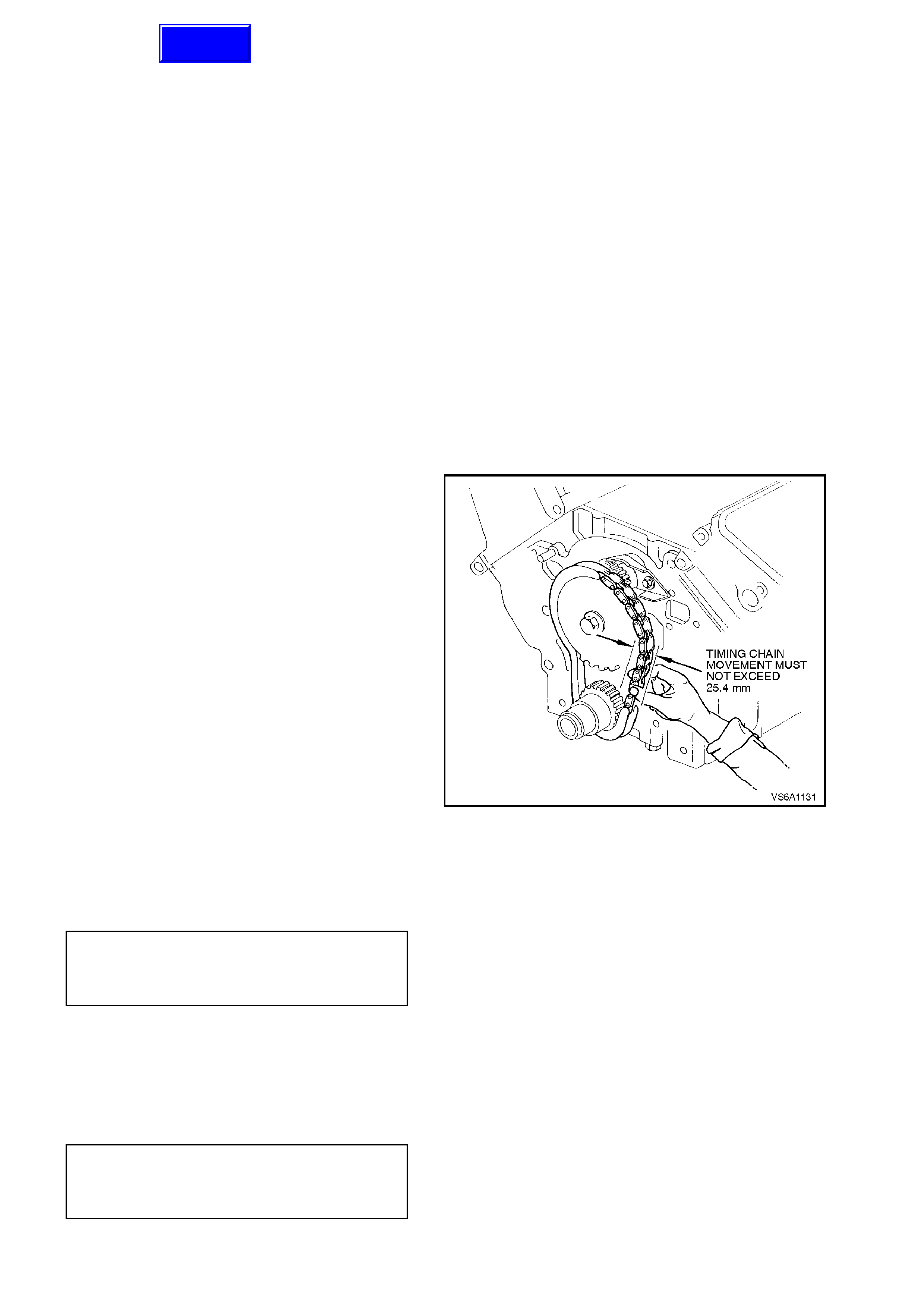
REINSTALL
Installation is the reverse of removal procedures,
noting the following points:
1. Clean threads on all front cover to cylinder
block attaching bolts/studs.
Using a suitable size thread tap, clean front
cover attaching bolt/stud threaded holes in
cylinder block.
Ensure that front cover and cylinder block
surfaces are clean and free of foreign matter.
Ensure oil pan seal is not swollen. If the seal is
excessively swollen, the oil pan must be
removed and the seal replaced, refer to
3.2 OIL PAN AND SEAL in this Section.
If water pump was removed during
disassembly, ensure that water pump to front
cover mating surfaces are clean and free of
foreign matter.
If removed on disassembly, reinstall oil
pressure regulator valve spring and valve, oil
filter adaptor, refer to 2.5 OIL FILTER
ADAPTOR in this Section.
2. Check timing chain for overall 'in and out'
movement and inspect condition of timing
chain sproc kets, ref er to 2.21 TIM ING CHAIN,
TENSIONER, SPROCKETS AND BALANCE
SHAFT GEARS in this Section.
Figure 6A1-1-142
3. If necessary, install water pump with new
gasket to front cover. Install and tighten water
pump attaching bolts to the correct torque
specification.
WATER PUMP TO FRONT
COVER ATTACHING BOLT
TORQUE SPECIFICATION
12 - 18 Nm
plus 76 - 84
degrees angle
turn
4. If necessary, install camshaft position sensor
with new O - ring to front cover. Lubricate O -
ring with petroleum jelly. Install and tighten
camshaft position sensor attaching bolt to the
correct torque specification.
CAMSHAFT POSITION SENSOR
TO FR ONT COVER
ATTACHING BOLT
TORQUE SPECIFICATION
8 - 12
Nm
Techline
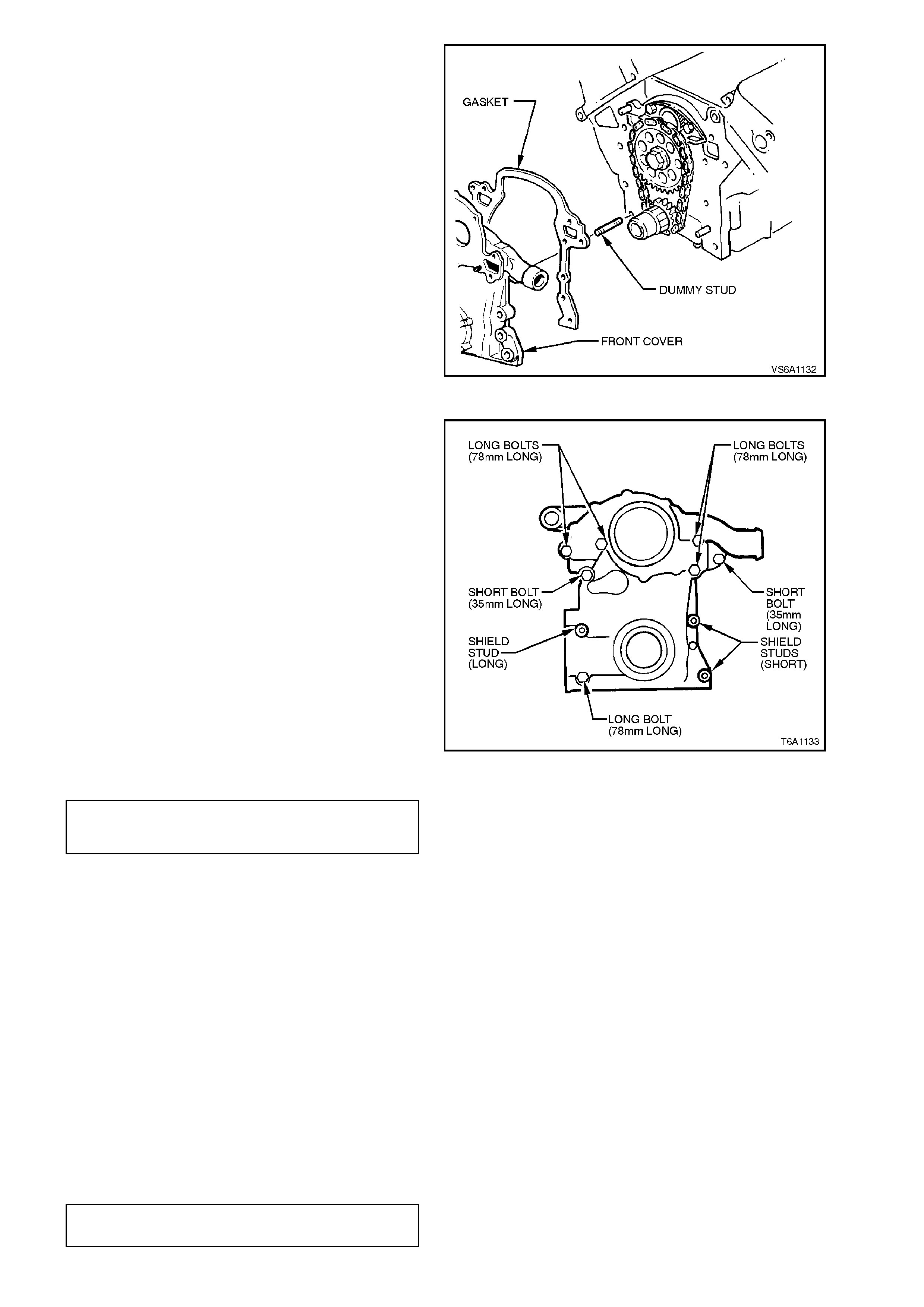
5. Using a dum my stud made f r om a 90 mm long
bolt with a thread of 5/16-18 UNC-2A thread,
and with the head cut off, install into bolt hole
shown in Fig. 6A1-1-143.
NOTE:
This step is im portant to ensure that when the f ront
cover gasket is installed, the oil feed hole in the
cylinder block aligns with the appropriate gasket
hole and is not partially blocked.
6. Install new front cover gasket onto cylinder
block to front cover dowel pins.
NOTE:
Ensure ends of gasket are level to 0.15 m m proud
of the cylinder block oil pan face.
Oil pan face of front c over m ust be aligned with the
block oil pan rail within ±0.2 mm.
7. Install front cover, aligning spline on nose of
crankshaft sprocket gear with spline on oil
pump inner gear. Figure 6A1-1-143
NOTE:
Ensure that oil pan seal is located correctly
between front cover and oil pan surfaces.
8. Coat threads of front cover to cylinder block
attaching bolts with Loctite 242 sealant or
equivalent (Holden Specification HN 1256
Class 2, Type 2). With front cover firmly in
place, rem ove dumm y stud installed at step 5.
Install bolts and tighten to the correct torque
specification.
Figure 6A1-1-144
FRONT COVER ATTACHING
BOLT/STUD
TORQUE SPECIFICATION 20 - 30
Nm
9. Ensure that interrupter rings on crankshaft
balancer do not contact crankshaft position
sensor at any point during crankshaft rotation,
refer to Section 6D1-3 IGNIT ION SYSTEM -
V6 ENGINE.
10. Smear approx . 6.0 mm wide and 0.2 mm thic k
film of Loctite 514 or equivalent (Holden
Specification HN 1823) centrally across the oil
pan rail at front cover to cylinder block joint
both sides, refer to 3.2 OIL PAN AND SEAL
in this Section. Install oil pan to front cover
attaching bolts and tighten all oil pan bolts to
the correct torque specification.
NOTE:
Front cover and oil pan/cylinder block faces must
be aligned to within 0.20 mm
OIL PAN ATTACHING BOLT
TORQUE SPECIFICATION 8 - 12
Nm

11. Reinstall beaming brace, refer to
2.24 BEAMING BRACE in this Section.
12. Check and inspect O - ring on end of water
inlet tube and replace if necessary. Lubricate
O - ring with petroleum jelly.
13. Install tube into front cover, engaging tube
onto belt tensioner bracket attaching studs.
Install nuts to studs and tighten to the correct
torque specification.
WATER INLET TUBE TO BEL T
TENSIONER STUD NUT
TORQUE SPECIFICATION 18 - 25 Nm
14. Ensure that all remaining component
fasteners are tightened to the correct torque
specifications as nominated at the end of this
Section.
15. Fill cooling system with the correct
concentration of coolant, refer to
Section 6B1 ENGINE COOLING - V6
ENGINE.
16. Start engine and check f or oil or c oolant leaks.
Repair as necessary.
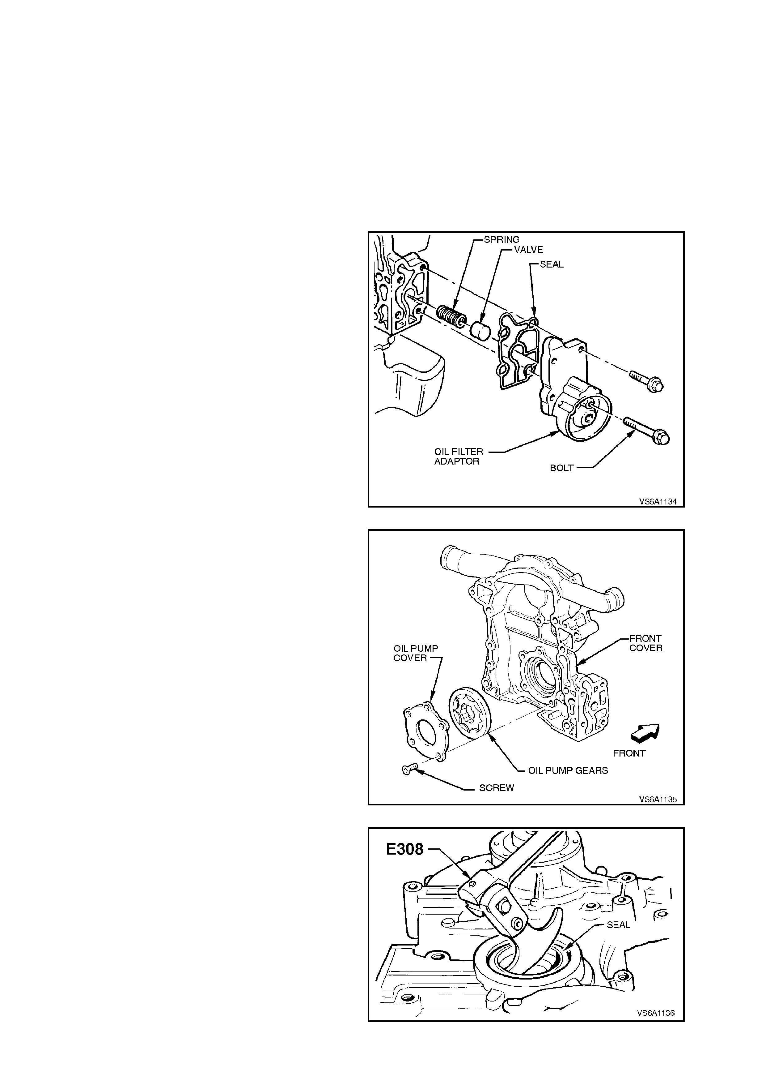
2.20 OIL PUMP
REMOVE
The oil pump is integrated with the front cover
assembly. To gain access to the oil pump, it is
necessary to remove the front cover, refer to
2.19 FRONT COVER AND GASKET in this
Section.
DISASSEMBLE
1. Using a suitable oil filter wrench, remove oil
filter and drain oil from pump.
2. Remove oil filter adaptor to front cover
attaching bolts, remove adaptor.
3. Remove oil pressure regulator valve and
spring from front cover bore.
Figure 6A1-1-145
4. Remove oil pump cover screws, using Tool
No. J25359-4 (Torx bit T30) and a suitable
adaptor.
Remove cover and gears.
Figure 6A1-1-146
5. Using Tool No. E308, remove crankshaft front
seal from front cover.
6. Clean all mating surfaces.
Figure 6A1-1-147
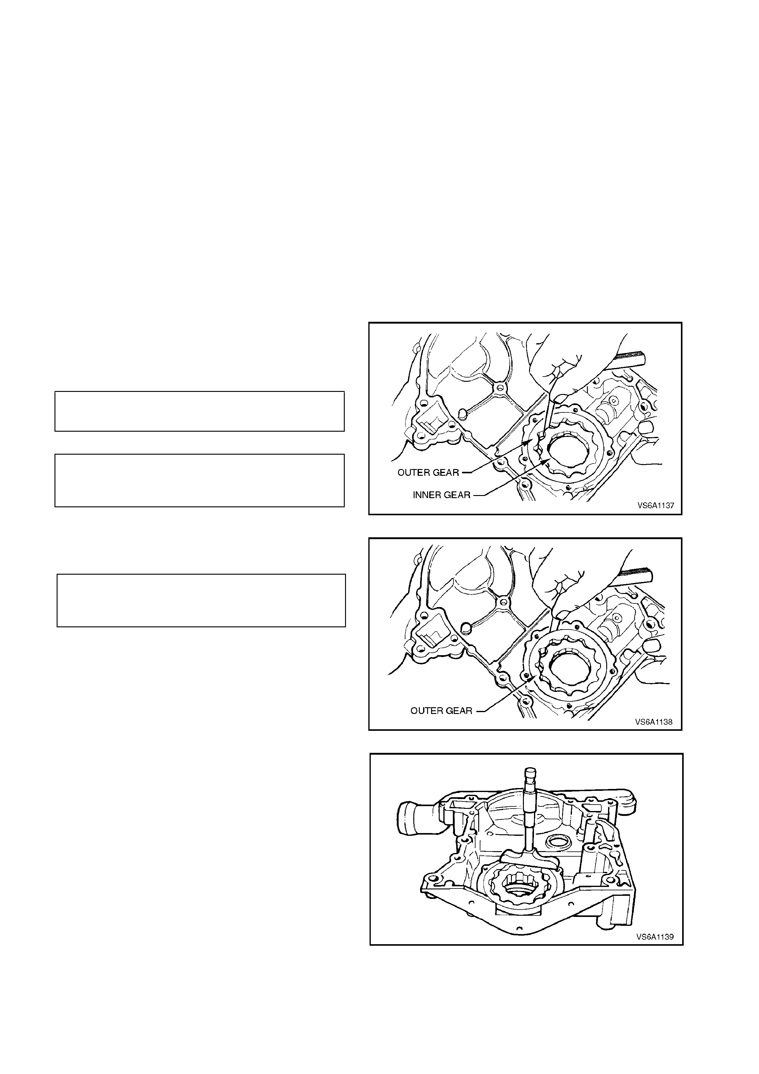
INSPECT
1. Clean all components in a suitable cleaning
solvent and blow dry with clean dry
compressed air.
2. Using a suitable size thread tap, c lean adaptor
'long' attaching bolt threads in front cover.
Clean bolt attaching threads.
3. Inspect front cover and oil pump cover for
cracks, scoring, porous or damaged casting,
damaged threads or excessive wear or
scoring.
4. Check pressure regulator valve for scoring,
stick ing in valve bore or burrs in bore. Inspect
regulator valve spring for tension loss
(compare with new spring) or bending. If in
any doubt, replace spring.
5. Inspect oil pum p gears f or c hipping, scor ing or
excessive wear.
6. Install gears into front cover and check the
following clearances.
a. Inner gear tip to outer gear clearance.
INNER GEAR TIP TO OUTER 0.22 mm
GEAR CLEARANCE SPECIFICATION MAX.
OUTER GEAR TO
HOUSING GEAR 0.05 - 0.089
CLEARANCE SPECIFICATION mm
Figure 6A1-1-148
b. Outer gear to housing clearance.
INNER AND OUTER GEAR END TO
HOUSING CLEARANCE 0.025 - 0.089
SPECIFICATION mm
If any component is excessively worn or
damaged, replace front cover and oil
pump as an assembly.
Figure 6A1-1-149
c. Inner and outer gear end to housing
clearance.
Figure 6A1-1-150
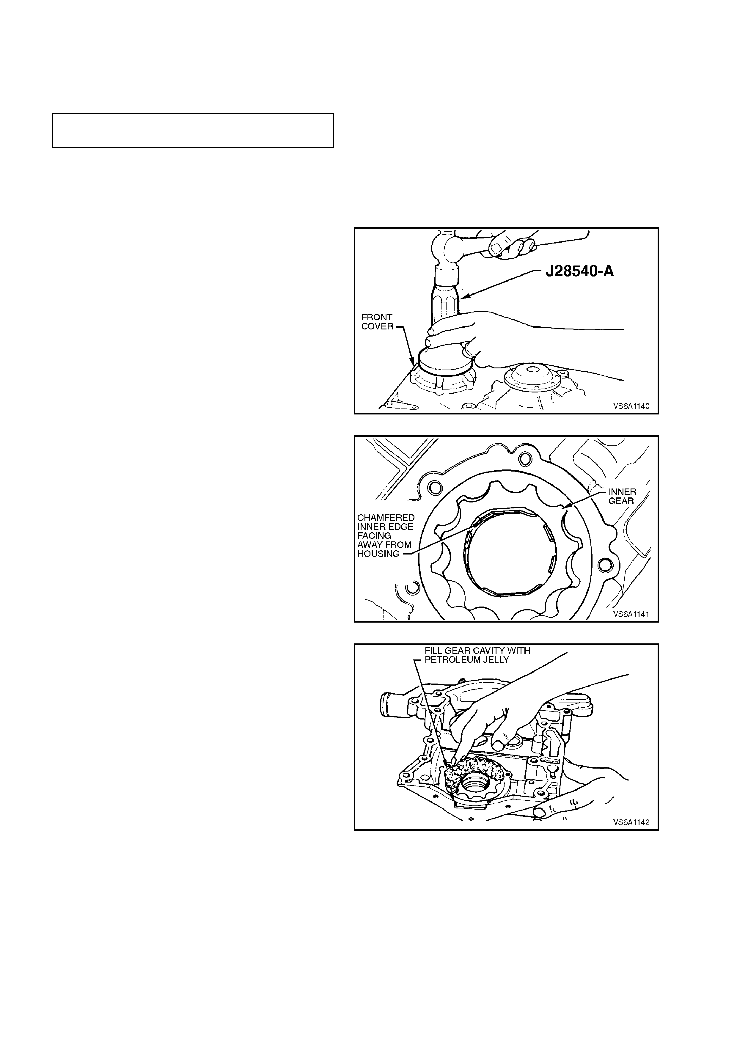
7. Check pressure regulator valve to bore
clearance by measuring valve and bore
diameter s and then subtracting the valve fr om
bore diameters.
PRESSURE REGULATOR VALVE
TO BORE CLEARANCE 0.038 - 0.076
mm
If any clearance specification is not as specified,
replace front cover and oil pump assembly.
REASSEMBLE AND REINSTALL
1. Using Tool No. J 28540-A, install new seal into
front cover.
Figure 6A1-1-151
2. Lubricate oil pump gears with petroleum jelly.
Install gears into housing.
NOTE 1:
Ensure that the inner gear is installed with the
chamfered inner edge facing away from the
housing.
NOTE 2:
The outer gear can be installed into the housing
either way.
Figure 6A1-1-152
3. Completely fill oil pump gear cavity with
petroleum jelly.
NOTE:
This is an important step, as the oil pump may not
begin to pump oil as soon as the engine is started.
Figure 6A1-1-153

4. Install oil pump cover screws. Tighten screws
to the correct torque specification.
OIL PUMP COVER SCREW
TORQUE SPECIFICATION 8 - 14
Nm
5. Install pressure regulator valve spring and
valve.
6. Install oil filter adaptor and new gasket to f ront
cover. Install adaptor attaching bolts and
tighten to the correct torque specification.
NOTE:
Before installing 'long' adaptor attaching bolt, apply
Loctite 242 sealant or equivalent (Holden
Specification HN 1256, Class 2 Type 2) to bolt
threads, refer to Fig 6A1-1-30 in this Section.
OIL FILTER ADAPTOR TO FRONT
COVER ATTACHING BOLT
TORQUE SPECIFICATION 23 - 35 Nm
7. Install front cover, refer to 2.19 FRONT
COVER AND GASKET in this Section.
8. Install new oil filter, refer to 2.3 OIL FILTER
in this Section.
9. Reconnect battery earth lead. Check engine
oil level and add as required. Star t engine and
check for oil or coolant leaks. Repair as
necessary.
NOTE:
The oil level must be checked and oil added as
necessary, after running the engine, to compensate
for oil used to refill the oil filter.
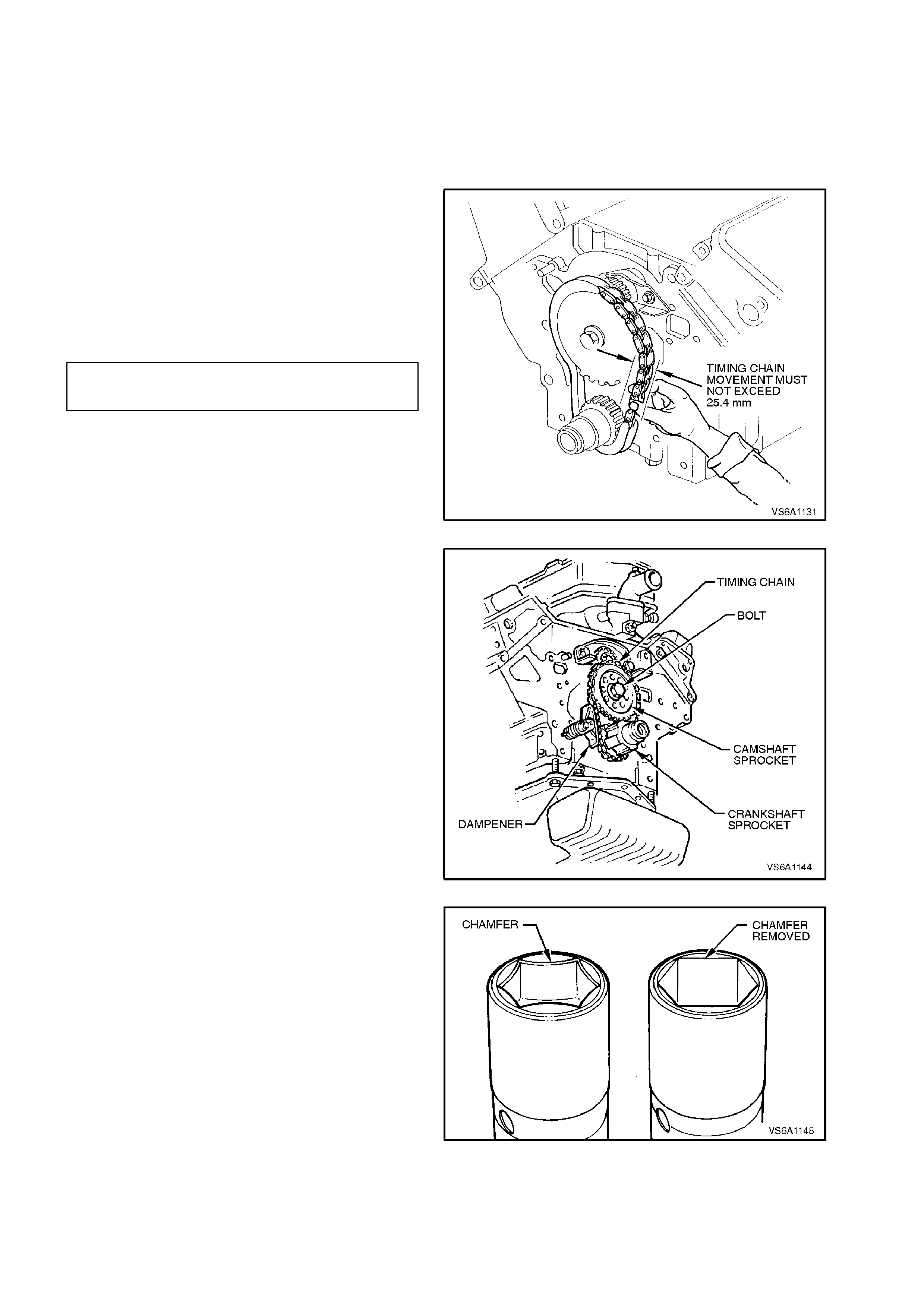
2.21 TIMING CHAIN, TENSIONER, SPROCKETS AND BALANCE SHAFT GEARS
REMOVE
1. Disconnect battery earth lead.
2. Remove front cover, refer to
2.19 FRONT COVER AND GASKET in this
Section.
3. Inspect timing chain for overall 'in and out'
movement between camshaft and crankshaft
sprockets, opposite side from damper
assembly.
Movement should not exceed the following
specif ic ation. If c learanc e is ex ce ss ive, ins pec t
sprockets at disassembly and replace timing
chain.
TIMING CHAIN 'IN AND OUT' 25.4
MOVEMENT SPECIFICATION mm
Figure 6A1-1-154
4. Loosen camshaft sprocket bolt.
NOTE 1:
On vehicles with automatic transmission, prevent
camshaft and crankshaft from rotating while
loosening bolt by replacing crankshaf t balanc er and
retaining bolt. Tighten bolt until balancer is fully
seated against crankshaft sprocket then install
crank s haf t balanc er holding tool No. AU448. Rotate
crankshaft and tool by hand so the arm of the tool
rests on the R/H side rail.
After loosening the camshaft sprocket bolt,
remove crankshaft balancer with crankshaft
balancer puller tool No. AU424. Refer to
2.17 CRANKSHAFT BALANCER in this Section.
On vehicles with manual transmission, to prevent
camshaft and crankshaft from rotating, pull park
brake fully 'ON', transmission in gear and chock
rear wheels. Figure 6A1-1-155
NOTE 2:
Grinding chamfer from top of socket will help in
ensuring f ull engagement over bolt head and assist
in removal and retightening of camshaft sprocket
bolt.
Figure 6A1-1-156
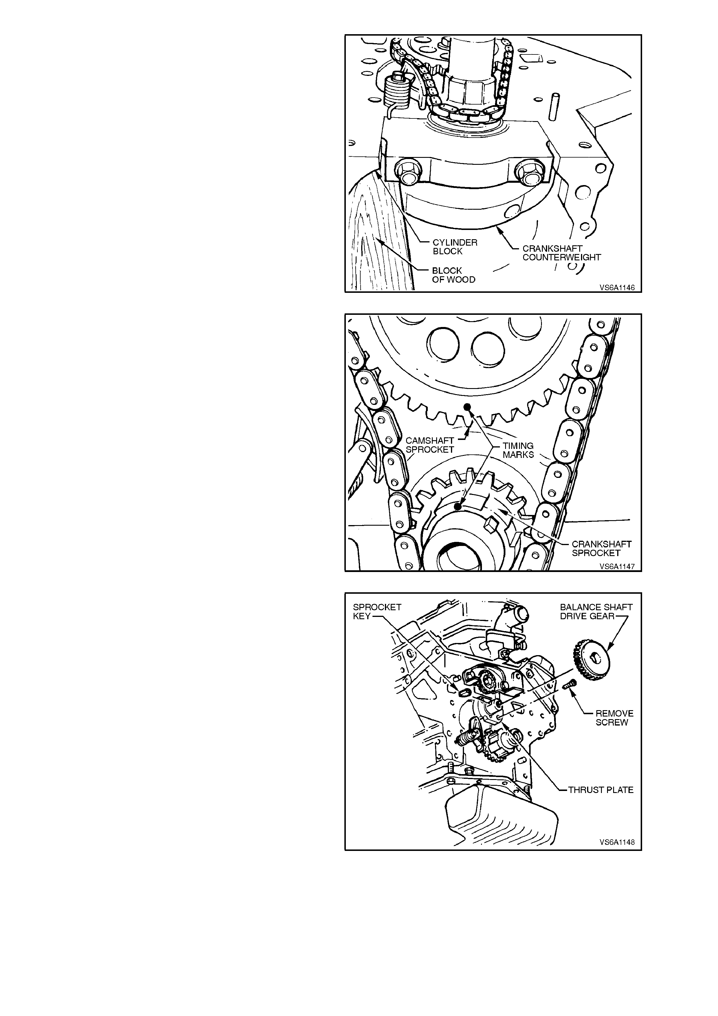
NOTE 3:
If carrying out this operation with the engine
removed from the vehicle, remove oil pan and
prevent camshaft and crankshaft from rotating by
positioning a suitable piec e of wood ( ideally a piece
of wood 50 mm x 75 mm, 150 mm long) between
the right hand inside of the cylinder block and the
crankshaft front counterweights.
Figure 6A1-1-157
5. Rotate crankshaft so that timing marks on
crankshaft and camshaft sprockets are
adjacent to each other (No. 1 T.D.C. position).
Remove camshaft sprocket retaining bolt.
6. Pull dampener away from timing chain and
remove camshaft sprocket and timing chain
taking care not to lose camshaft sensor
magnet due to its loose fit in the camshaft
sprocket.
7. Remove crankshaft sprocket from crankshaft.
8. If necessary, remove dampener attaching bolt
and dampener assembly.
Figure 6A1-1-158
If removing balance shaft gears, proceed as
follows:
9. Remove balance shaft drive gear and sprocket
key from camshaft.
Figure 6A1-1-159
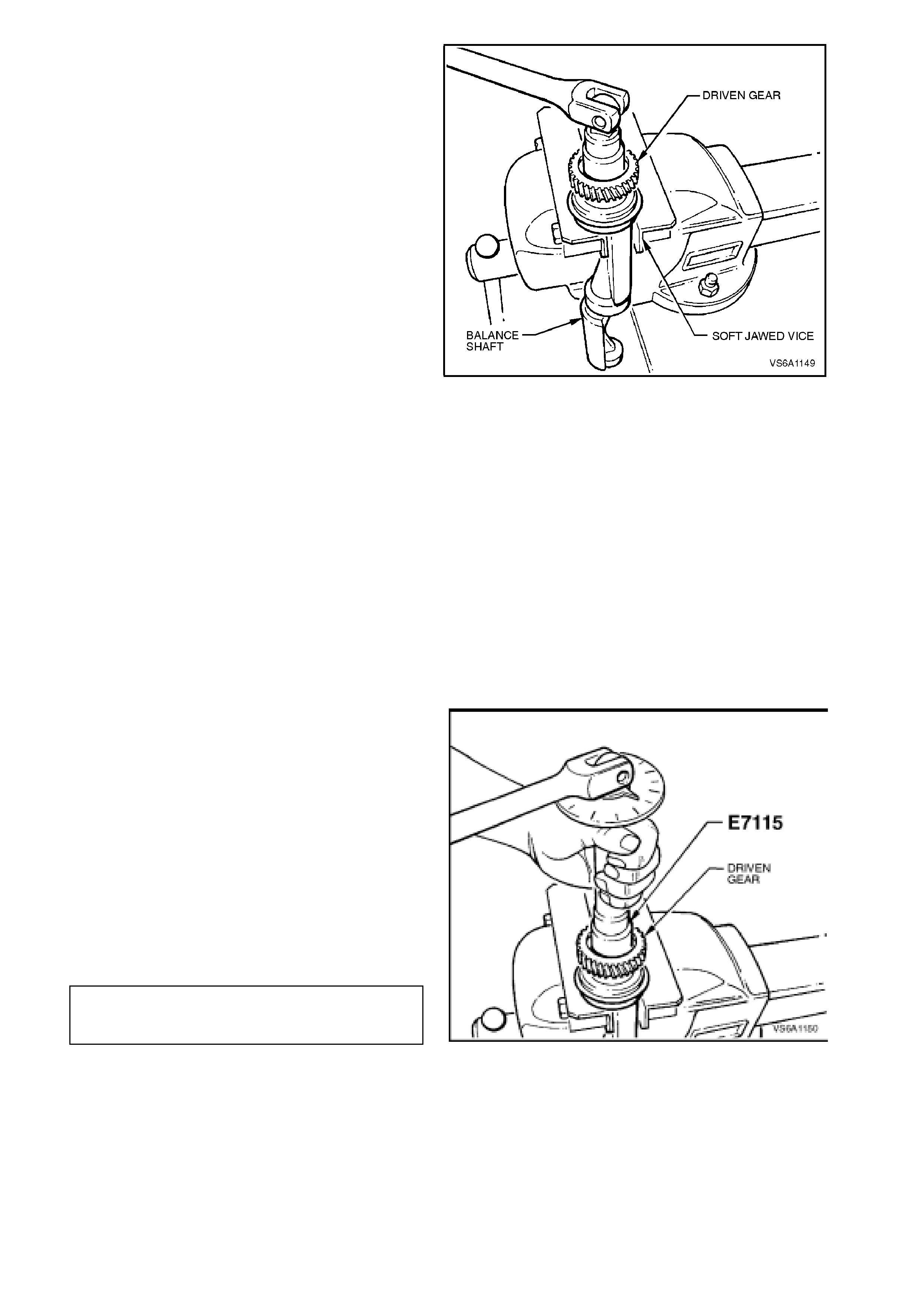
10. Remove balance shaft refer to
3.9 BALANCE SHAFT AND BEARINGS in
this Section.
11. Hold balance shaft in a vice using soft jaws,
take care to ensure that balance shaft front
bearing and rear bearing journal surface are
not damaged
12. Remove balance shaft driven gear retaining
bolt and driven gear.
Figure 6A1-1-160
INSPECT
1. Clean all components in a suitable cleaning
solvent and blow dry with clean dry
compressed air.
2. Using a suitable size thread tap, clean
sprocket retaining bolt threads in front end of
camshaft. Clean retaining bolt threads.
3. If removed, clean balance shaft driven gear
retaining bolt threads in front end of balance
shaft. Clean retaining bolt threads.
4. Inspect all components for wear or damage.
Check chain for excessive wear or stretch at
roller links.
REINSTALL
1. If rem oved, reinstall driven gear, aligning slot on
the inside of gear with pin at front of balance
shaft.
2. Coat threads of balance shaft driven gear
retaining bolt with Loctite 242 sealant or
equivalent (Holden Specif ication HN 1256 Class
2, Type 2). Install driven gear retaining bolt to
balance shaft.
3. Tighten balance shaft driven gear retaining bolt
to the correct torque specification.
NOTE:
Use Tool No. E7115, angle wrench, to achieve
correct turn angle.
BALANCE SHAFT DRIVEN 18 - 26 Nm
GEAR RETAINING BOLT plus 67 - 73 deg.
TORQUE SPECIFICATION turn angle
Figure 6A1-1-161
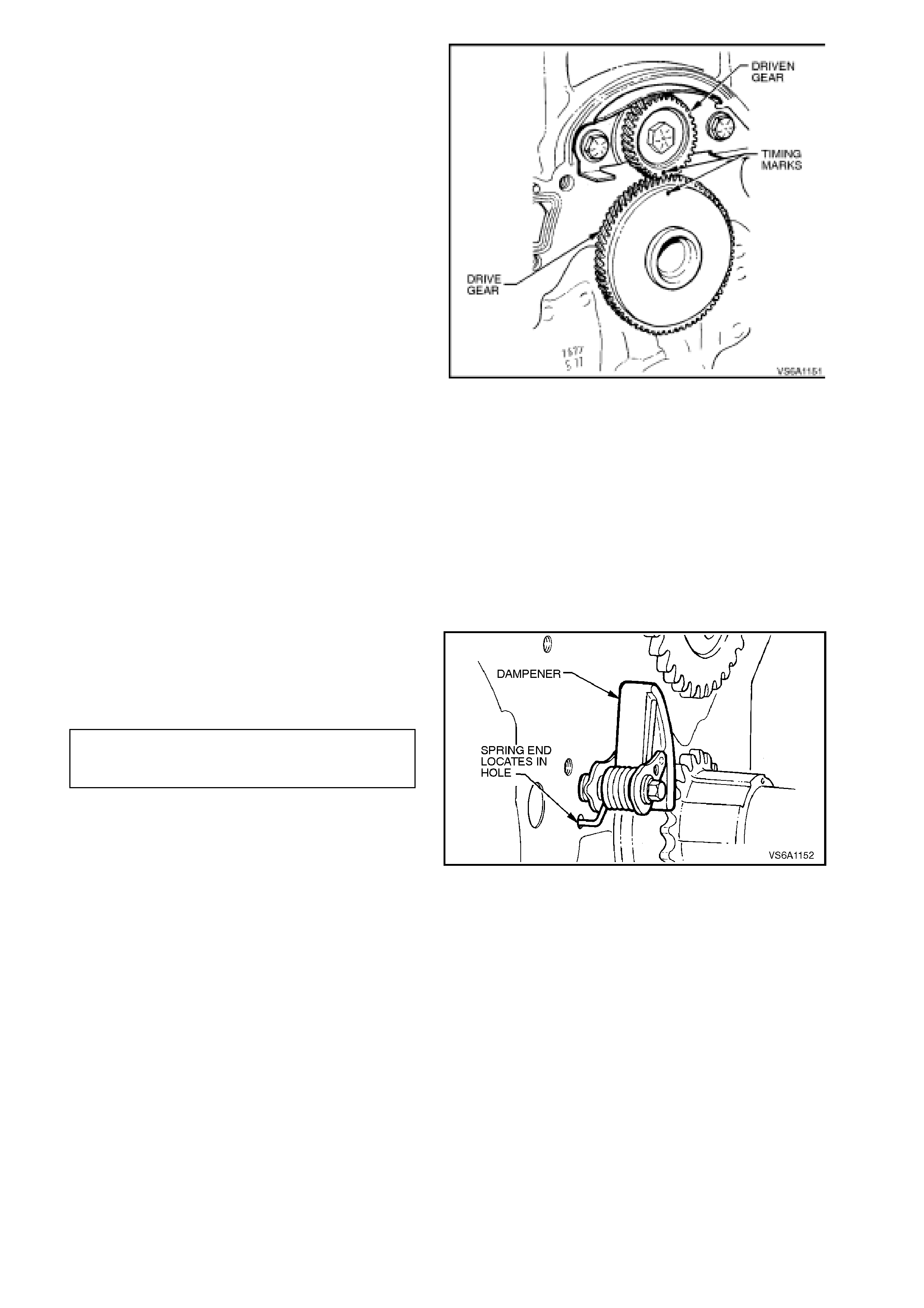
4. Reinstall sprocket key to front end of camshaft.
Reinstall balance shaft drive gear to camshaft,
aligning sprocket key with gear slot and ensuring
that timing marks on each of the balance shaft
gears face together.
It may be necessary to rotate balance shaft
slightly to ensure that balance shaft timing
marks align.
Figure 6A1-1-162
5. Install crankshaft sprocket onto crankshaft,
aligning key slot in sprocket with sprocket key.
With sprocket installed on crankshaft, timing
mark should be facing upward. If not facing
upward, remove piece of wood between
crankshaft and cylinder block, rotate
crankshaft until correct position is reached
(No. 1 piston is at T.D.C.).
6. Temporarily install camshaft sprocket to
camshaft. Turn camshaft so that sprocket
timing mark is facing crankshaft sprocket
timing mark. Remove camshaft sprocket.
7. Install timing chain dampener locating spring
end into cylinder block hole. Inst all and tighten
dampener attaching bolt to the correct torque
specification.
TIMING CHAIN DAMPENER
ATTACHING BOLT 16 - 28 Nm
TORQUE SPECIFICATION
Figure 6A1-1-163
8. Lubricate timing chain and sprockets with
engine oil.
9. Ensure that front cover and cylinder block
mating surfaces are clean and free of foreign
matter. Install front cover, refer to
2.19 FRONT COVER AND GASKET in this
Section.
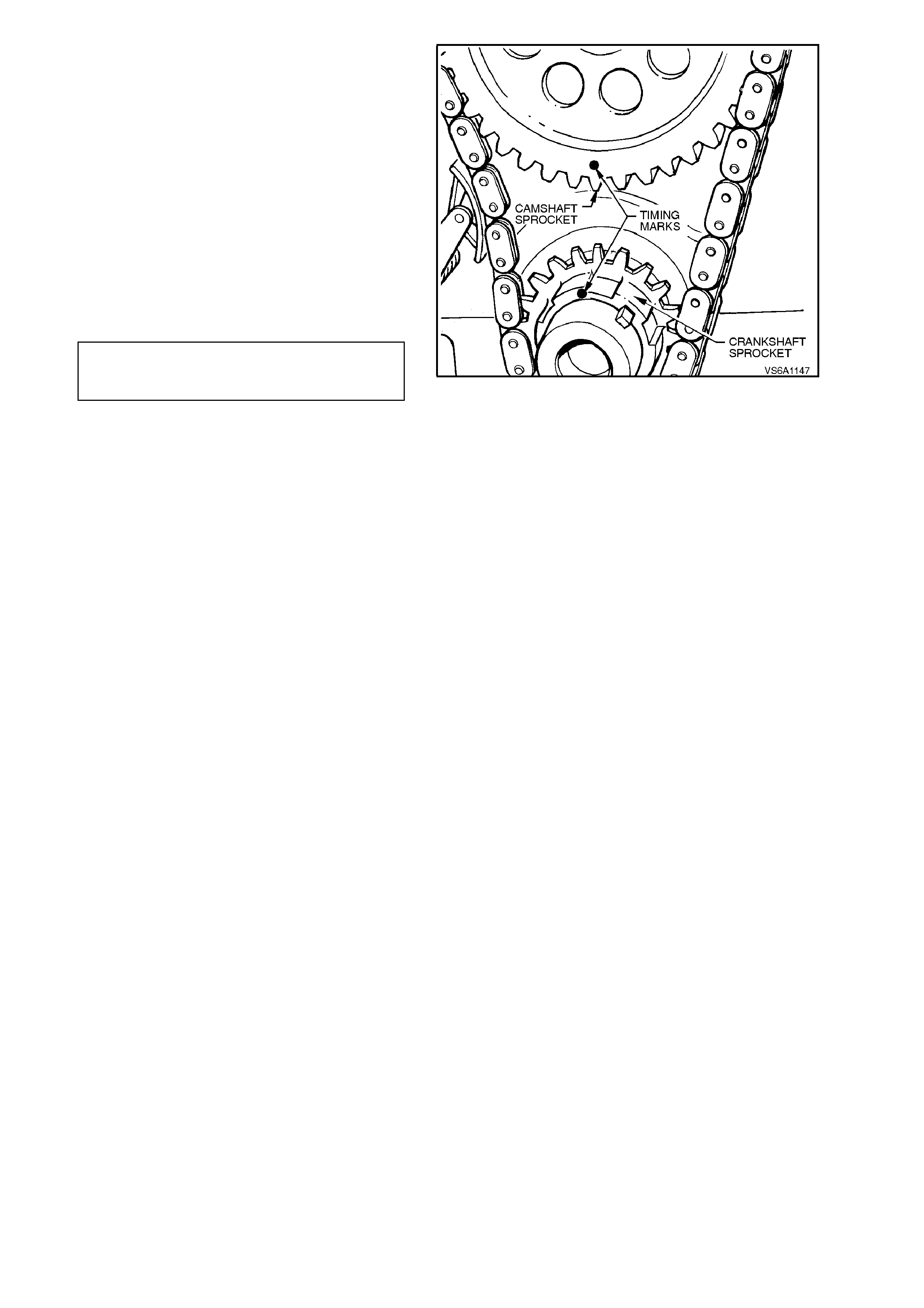
10. Install timing chain and camshaft sprocket
together ensuring that, if fitted, the camshaft
position sensor magnet is in position in the
camshaft sprocket. Pull back timing chain
dampener and install chain around
crankshaft sprocket and fit camshaft
sprocket to camshaft, aligning key slot in
sprocket with sprocket key. Release
dampener and ensure that timing marks on
sprockets are aligned.
11. Apply Loctite 242 sealant or equivalent
(Holden Specif ic ation HN 1256 Clas s 2, Type
2) to camshaft sprocket retaining bolt. Install
and tighten bolt to the correct torque
specification.
CAMSHAFT SPROCKET 90 - 110 Nm
RETAINING BOLT plus 86 - 94
TORQUE SPECIFICATION deg. turn angle Figure 6A1-1-164
12. Reconnect battery earth lead. Start engine
and check for oil or coolant leaks. Repair as
necessary.
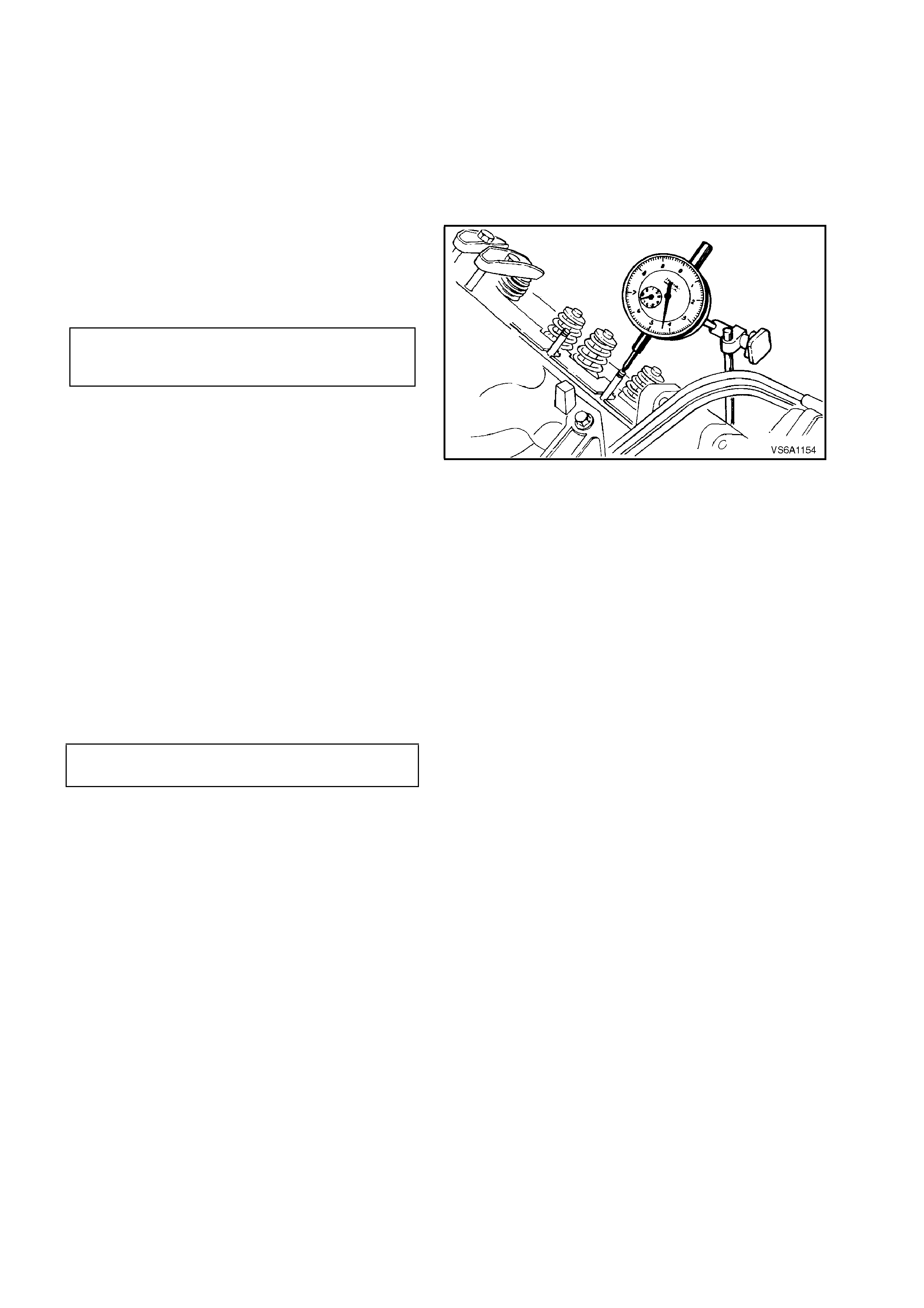
2.22 CAMSHAFT
MEASURING CAMSHAFT LOBE LIFT
1. Remove rocker covers, refer to
2.11 ROCKER COVERS AND/OR SEALS in
this Section. Remove rocker arms, refer to
2.12 ROCKER ARMS AND PUSHRODS in
this Section.
2. Remove spark plugs.
3. Mount a dial indicator so that its stylus is
resting on top end of a pushrod.
4. Rotate crankshaft and measure cam shaft lobe
lift.
CAMSHAFT LOBE LIFT
INLET 6.56 mm
EXHAUST 6.48 mm
Figure 6A1-1-165
5. Repeat steps 3 and 4, above, on the
remaining eleven pushrods.
If any lobe lift is not to specification, remove
and replace camshaft, refer to
2.22 CAMSHAFT in this Section.
6. If cam s haft lobe lif t is s atisf actory, reass em ble
rocker arms, refer to 2.12 ROCKER ARMS
AND PUSHRODS in this Section. Reinstall
rocker covers, refer to 2.11 ROCKER
COVERS AND/OR SEALS in this Section.
7. Reinstall spark plugs and tighten to the c orr ec t
torque specification.
SPARK PLUG
TORQUE SPECIFICATION 15 - 25
Nm
REMOVE
1. Disconnect battery earth lead.
2. Remove radiator cap to release any cooling
system pressure.
WARNING:
To avoid serious personal injury, never remove
the radiator cap when the engine is hot.
Sudden release of cooling system pressure is
very dangerous and could cause personal
injury.
3. Remove cooling fan shroud, cooling fan and
radiator, refer to Section 6B1 ENGINE
COOLING - V6 ENGINE.
4. Remove crankshaft balancer, refer to
2.17 CRANKSHAFT BALANCER in this
Section.
5. Remove front cover, refer to 2.19 FRONT
COVER AND GASKET in this Section.

6. Remove timing chain, camshaft sprocket and
balance shaft drive gear, refer to
2.21 TIMING CHAIN, TENSIONER,
SPROCKETS AND BALANCE SHAFT
GEARS in this Section.
7. Remove rocker covers, refer to
2.11 ROCKER COVERS AND/OR SEALS in
this Section.
8. Remove lower inlet manifold, refer to
2.9 LOWER INLET MANIFOLD in this
Section.
9. Remove rocker arms and pushrods, refer to
2.12 ROCKER ARMS AND PUSHRODS in
this Section.
10. Remove valve lifters, refer to 2.14 VALVE
LIFTERS0 in this Section.
11. Using a T30 Torx bit, Tool No. J25359-4,
remove cam shaft thrust plate to cylinder block
attaching screws, remove thrust plate.
Remove sprocket key from front end of
camshaft.
Figure 6A1-1-166
12. Carefully withdraw camshaft from front of
engine.
NOTE:
W hen rem oving camshaf t, avoid damaging bearing
surfaces.
Figure 6A1-1-167
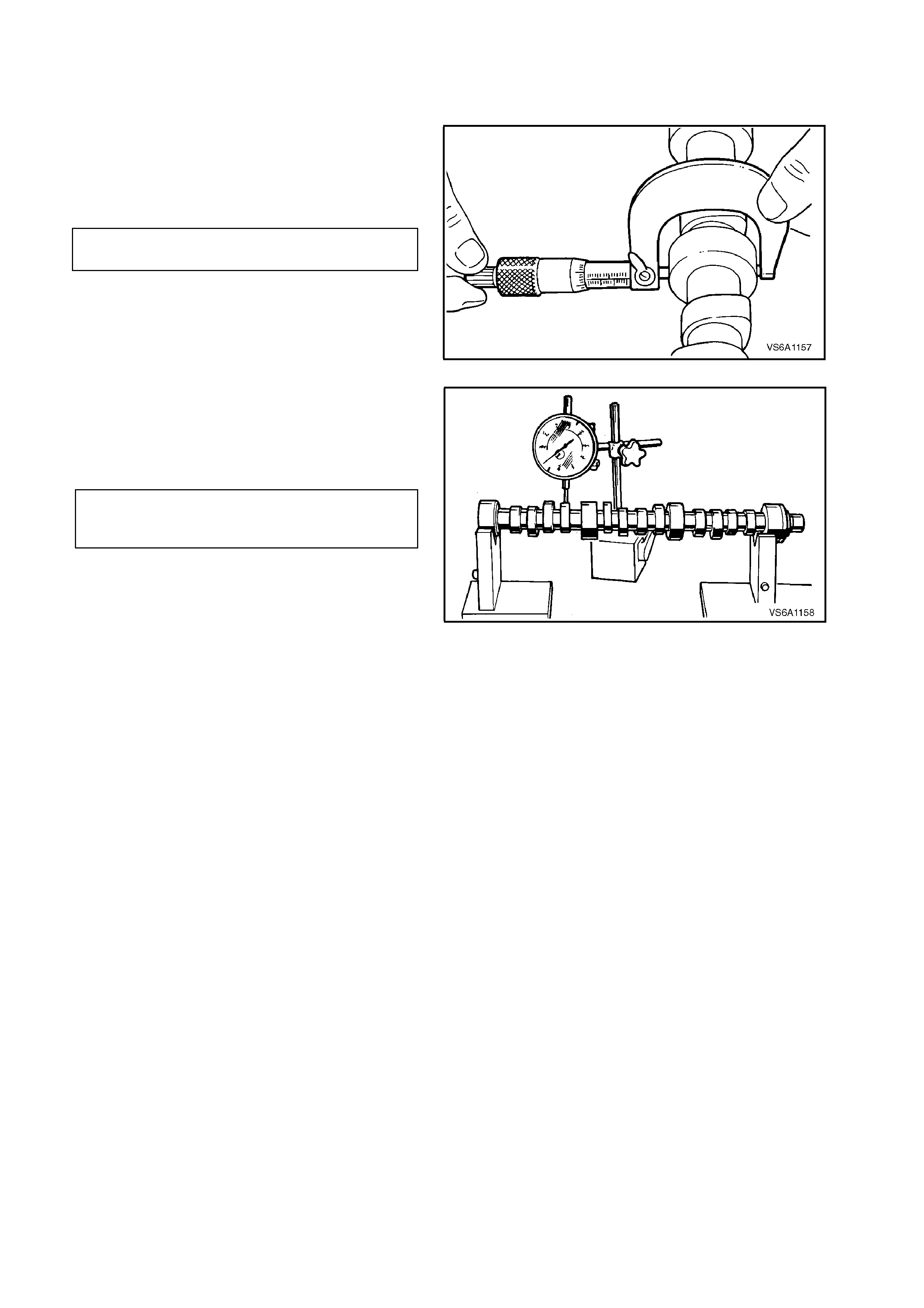
INSPECT
1. Inspect camshaft bearing journals and lobes
for wear, damage or overheating
(discolouration).
2. Check camshaft journal diameter and run-out
with suitable measuring equipment.
If journals are not to specification, replace
camshaft.
CAMSHAFT JOURNAL 46.858 - 46.893
DIAMETER mm
Figure 6A1-1-168
3. Position camshaft on V - blocks and check
each camshaft lobe lift.
If any lobe is not to specification, replace
camshaft.
CAMSHAFT LOBE LIFT
INLET 6.56 mm
EXHAUST 6.48 mm
Figure 6A1-1-169

CAMSHAFT BEARING SERVICE
Slightly scored camshaft bearings will be
satisf actory if the surf aces of cam s haft journals ar e
polished and bearings are cleaned up to remove
burrs, and the fit of the c am shaf t in bearings is f ree
and within specification.
Should the bearings be badly damaged or worn,
the engine assembly must be removed from the
vehicle and the bearings replaced, refer to
3.8 CAMSHAFT BEARINGS in this Section.
REINSTALL
Installation of the camshaft is the reverse of
removal procedures, noting the following points:
1. Clean threads of camshaft thrust plate
attaching screws and mating threads in
cylinder block.
2. Lubricate cams haf t bearing j our nals with clean
engine oil and all lobes with Lubrizol 6612 or
equivalent (Holden Specification HN 1961)
and install camshaft.
3. When installing camshaft, take care not to
disturb lubricant film on camshaft lobes.
4. Apply engine oil to camshaft and thrust plate
contact surfaces.
5. Apply Loctite 242 or equivalent (Holden
Specification HN 1256 Class 2, Type 2) to
thrust plate attaching screws. Install screws
and tighten to the correct torque specification.
CAMSHAFT THRUST PLATE
TO CYLINDER BLOCK
ATTACHING BOLT
TORQUE SPECIFICATION
12 - 18
Nm
6. Lubricate all lifters and lifter bores with
Lubrizol 6612 or equivalent (Holden
Specification HN 1961) before installing.
7. Start engine, check for oil or coolant leaks.
Check for valve train noise. Repair as
necessary.
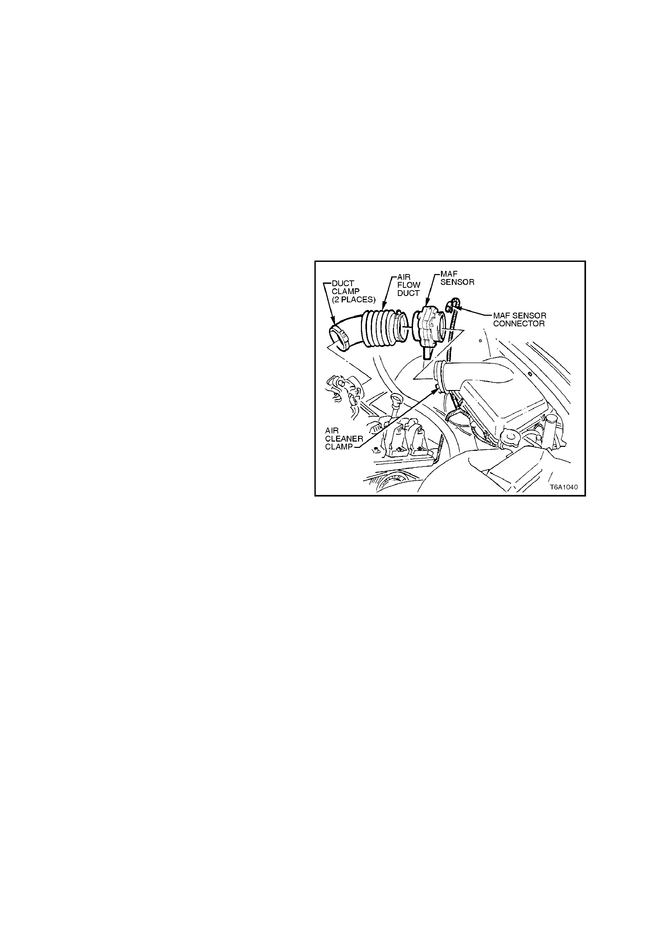
2.23 ENGINE MOUNTS
FRONT MOUNTS
CHECK
1. Check in the area of the mounts for signs of
oil leakage. If oil leakage from a mount is
present, mount is defective and must be
replaced.
2. Using a suitable engine lifting crane, raise
engine to remove weight from mounts and to
place rubber in slight tension.
Check that mounting rubber has not
deteriorated, split or separated from metal
plates.
Replace mount if defective.
REMOVE
1. Disconnect battery earth lead.
2. Disconnect mass air flow sensor wiring,
loosen air flow duct rubber boot clamps at
throttle body and air cleaner and remove air
flow duct. Carefully place air flow duct and
mass air flow sensor assembly to one side.
Figure 6A1-1-170
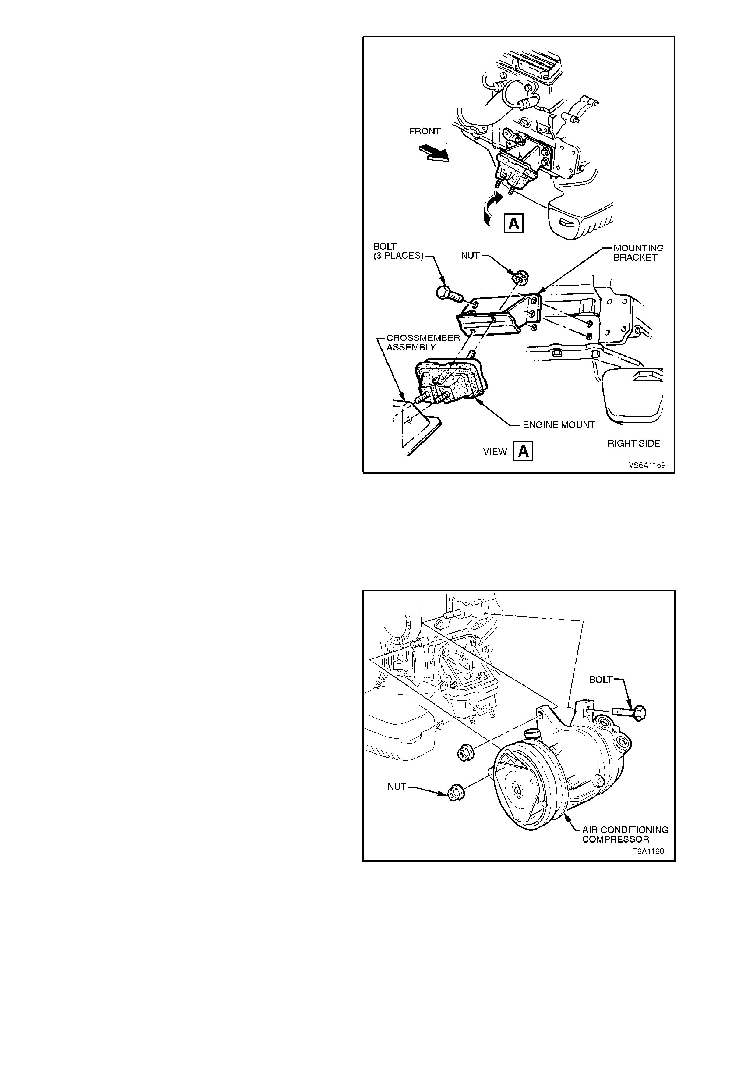
3. Remove engine front mount to front
crossmember attaching nuts.
4. Remove right hand mount as follows:
a. Remove mount to mounting bracket
attaching nuts.
b. Raise engine slightly with a suitable
engine lifting crane to remove weight from
mounts.
c. Remove mounting bracket to cylinder
block attaching bolts, rem ove brac k et and
mount.
Figure 6A1-1-171
5. Remove left hand mount as follows:
a. Raise engine slightly with a suitable
engine lifting crane to remove weight
from mounts and gain access to air
conditioning compressor (if fitted)
attaching bolts.
b. If fitted, remove air conditioning
compressor to left hand engine mounting
bracket attaching bolts. Tie back
compressor from engine block.
Figure 6A1-1-172
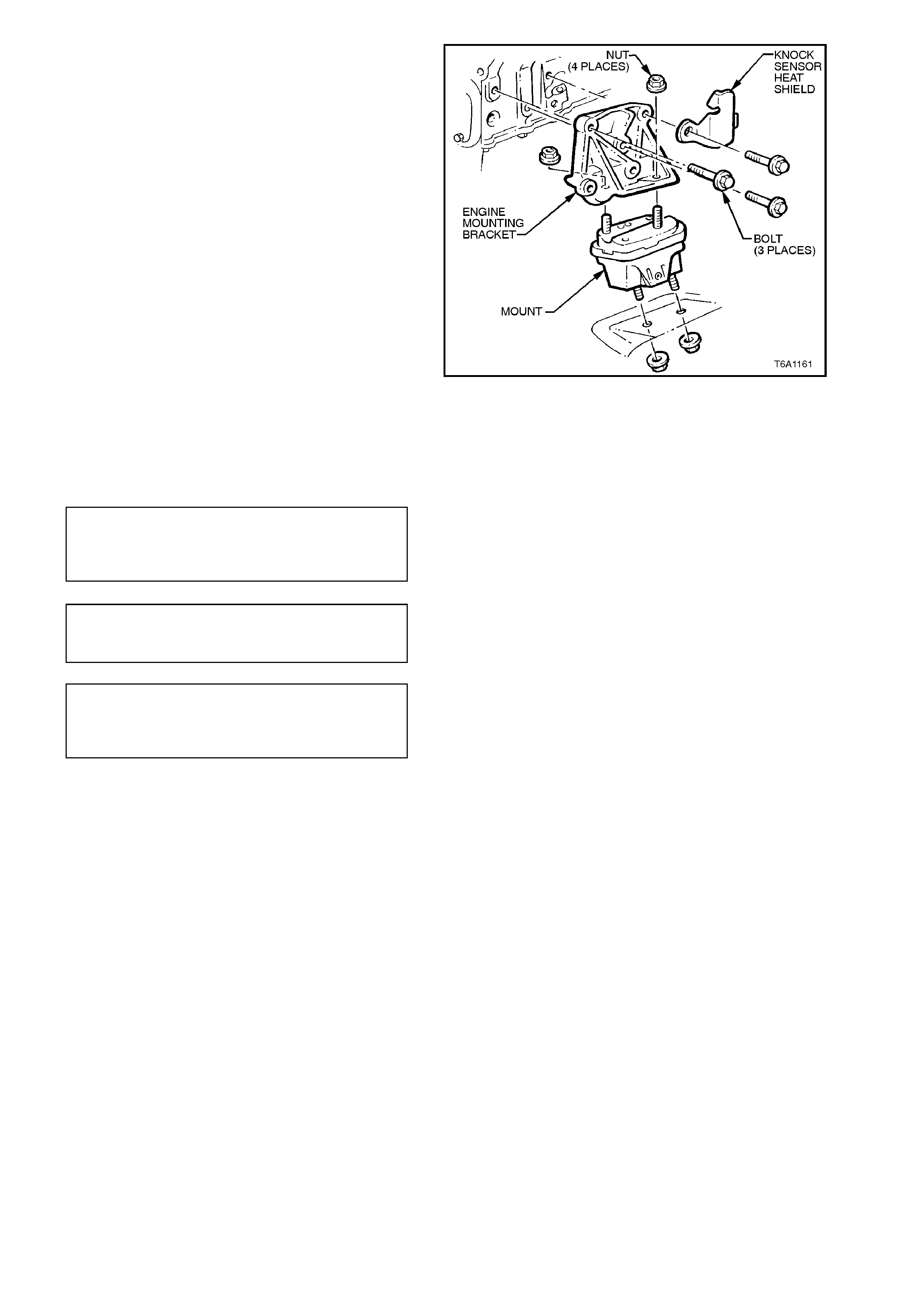
c. Remove mount to mounting bracket
attaching nuts.
d. Remove mount bracket to cylinder block
attaching bolts, remove bracket, knock
sensor heatshield and mount.
Figure 6A1-1-173
REINSTALL
Installation of the engine front mounts is the
reverse of removal procedures, ensuring that all
fasteners are tightened to the specified torque.
ENGINE MOUNT TO MOUNTING
BRACKET AND FRONT
CROSSMEMBER ATTACHING
NUT TORQUE SPECIFICATION
35 - 65
Nm
MOUNTING BRACKET TO
CYLINDER BLOCK ATTACHING
BOLT TORQUE SPECIFICATION 35 - 65 Nm
AIR CONDITIONING
COMPRESSOR TO MOUNTING
BRACKET ATTACHING BOLT
TORQUE SPECIFICATION
35 - 65
Nm
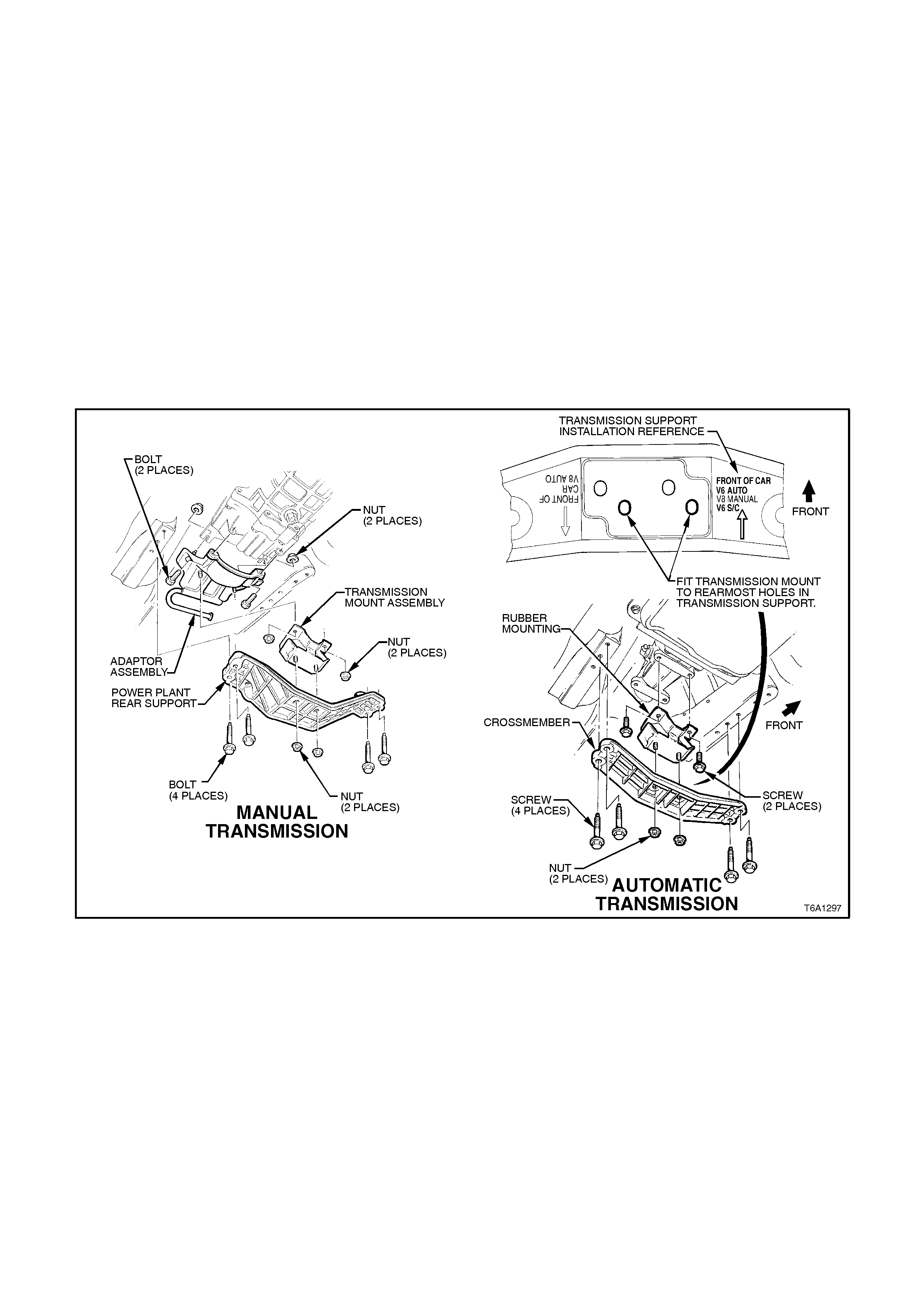
REAR MOUNT
REMOVE
1. Raise vehicle front and rear and place on
safety stands. For location of jacking points,
refer to Section 0A GENERAL
INFORMATION.
2. Support rear of transmission with a garage
jack.
NOTE:
Use a block of wood between transmission and
jack.
3. Remove nuts and washers attaching rear
mount to crossmember.
4. Remove crossmember to frame bolts and
washers, remove crossmember.
5. Remove rear mount to transmission rear
extension attaching bolts/nuts and remove
rear mount.
Figure 6A1-1-174

REINSTALL
1. Reinstall rear mount and attaching bolts to
transmission rear extension. Tighten bolts to
correct torque specification.
AUTOMATIC TRANSMISSION:
REAR MOUNT TO REAR
EXTENSION ATTACHING BOLT
TORQUE SPECIFICATION
35 - 65
Nm
MANUAL TRANSMISSION:
REAR MOUNT TO REAR
ADAPTOR ATTACHING NUT
TORQUE SPECIFICATION
35 - 65
Nm
2. Install crossmember to side frame bolts and
washers. Tighten bolts to correct torque
specification.
CROSSMEMBER TO SIDE
FRAME BOLT
TORQUE SPECIFICATION 35 - 65 Nm
3. Lower garage jack supporting transmission
and tighten crossmember to rear mount
attaching nuts to correct torque specification.
4. Remove safety stands and lower vehicle to
ground.
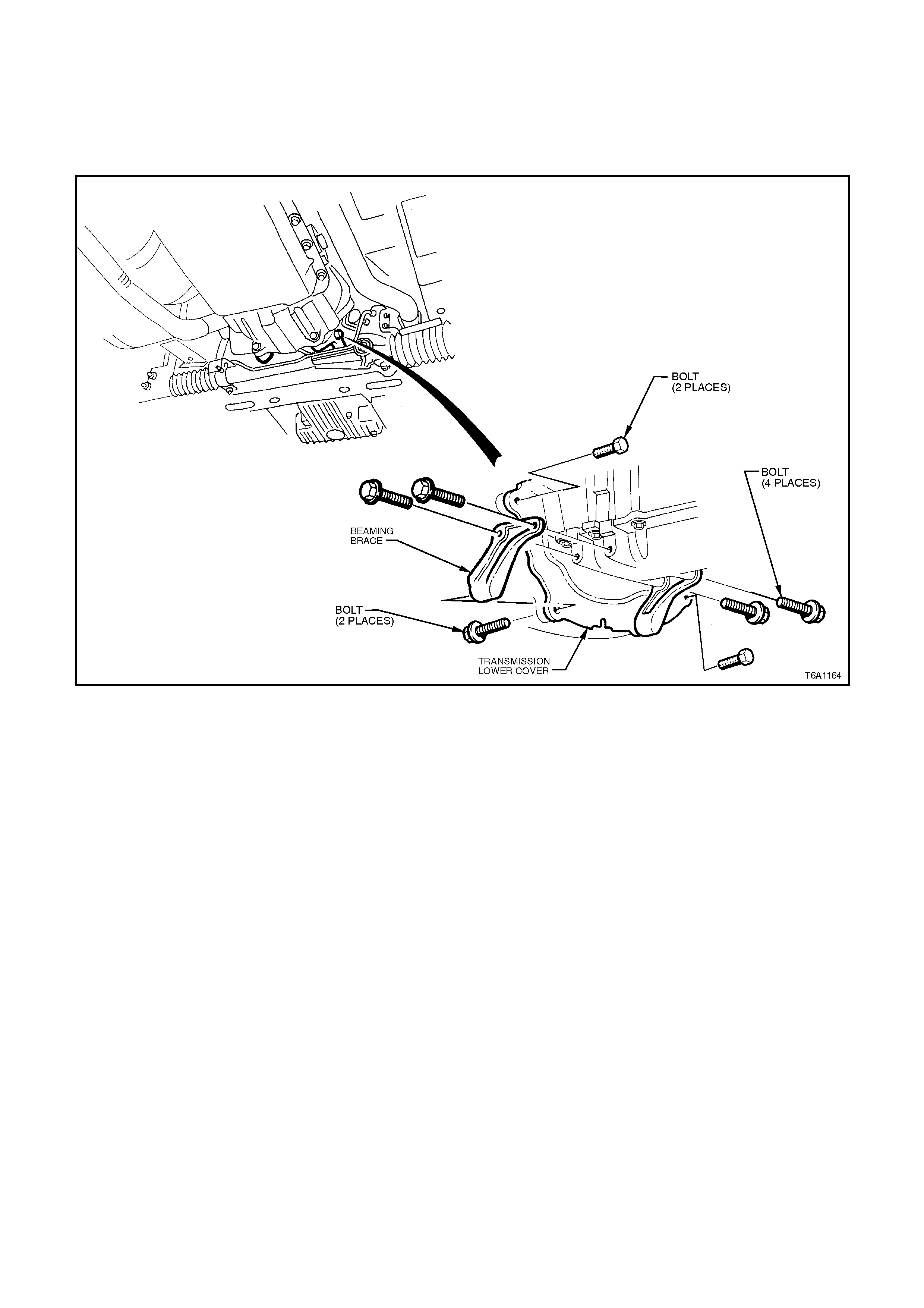
2.24 BE AMING BRACE
REMOVE
1. Disconnect battery earth lead.
2. Remove beaming brace to torque converter/clutch housing to beaming brace bolts.
3. Remove beaming brace to oil pan bolts and remove beaming brace.
Figure 6A1-1-175

REINSTALL
Installation of the beaming brace is the reverse of
removal procedures, noting the following points:
1. Inspect the threads of the four beaming brace
to oil pan attaching bolts and replace any that
are damaged.
2. On vehicles with automatic transmission install
the bolts securing the beaming brace to the
converter housing prior to the beaming brace
to oil pan bolts
CLUTCH HOUSING TO BEAMING
BRACE BOLT
TORQUE SPECIFICATION 50 - 85 Nm
BEAMING BRACE TO TORQUE
CONVERTER HOUSING BOLT
TORQUE SPECIFICATION 50 - 85 Nm
BEAMING BRACE TO OIL PAN
BOLT ATTACHING
TORQUE SPECIFICATION 20 - 35 Nm
TRANSMISSION LOWER COVER
SCREW 3.0 - 5.0
Nm
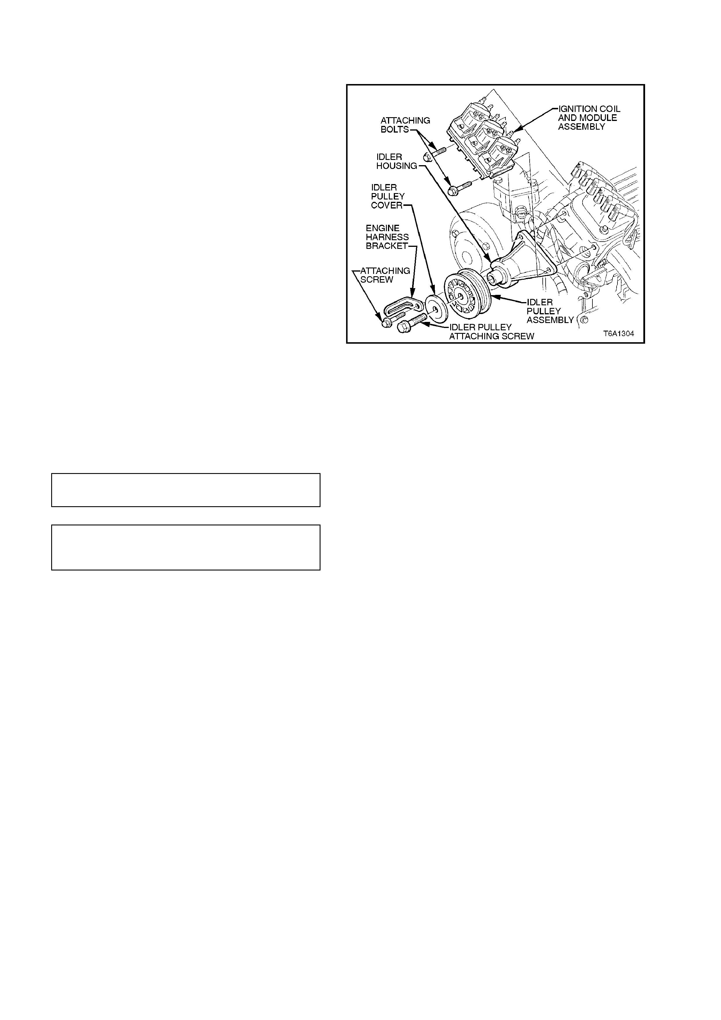
2.25 IDLER ASSEMBLY
REMOVE
1. Disconnect battery earth lead.
2. Loosen the idler pulley attaching bolt.
3. Remove drive belt, refer to 2.6 DRIVE BELT in
this Section.
4. Remove ignition coil module assembly and
idler assembly housing mounting bolts,
remove idler and coil module assembly.
5. Remove the bolt securing the idler pulley
removing the pulley.
Figure 6A1-1-176
REINSTALL
1. Installation is the reverse of removal
operations noting the following points.
2. Tighten all fasteners to the correct torque
specification.
IDLER ASSEMBLY MOUNTING
BOLT TORQUE SPECIFICATION 40 - 50
Nm
IDLER ASSEMBLY PULLEY
ATTACHING BOLT TORQUE
SPECIFICATION 40 - 50 Nm
3. Start engine and check drive belt operation.
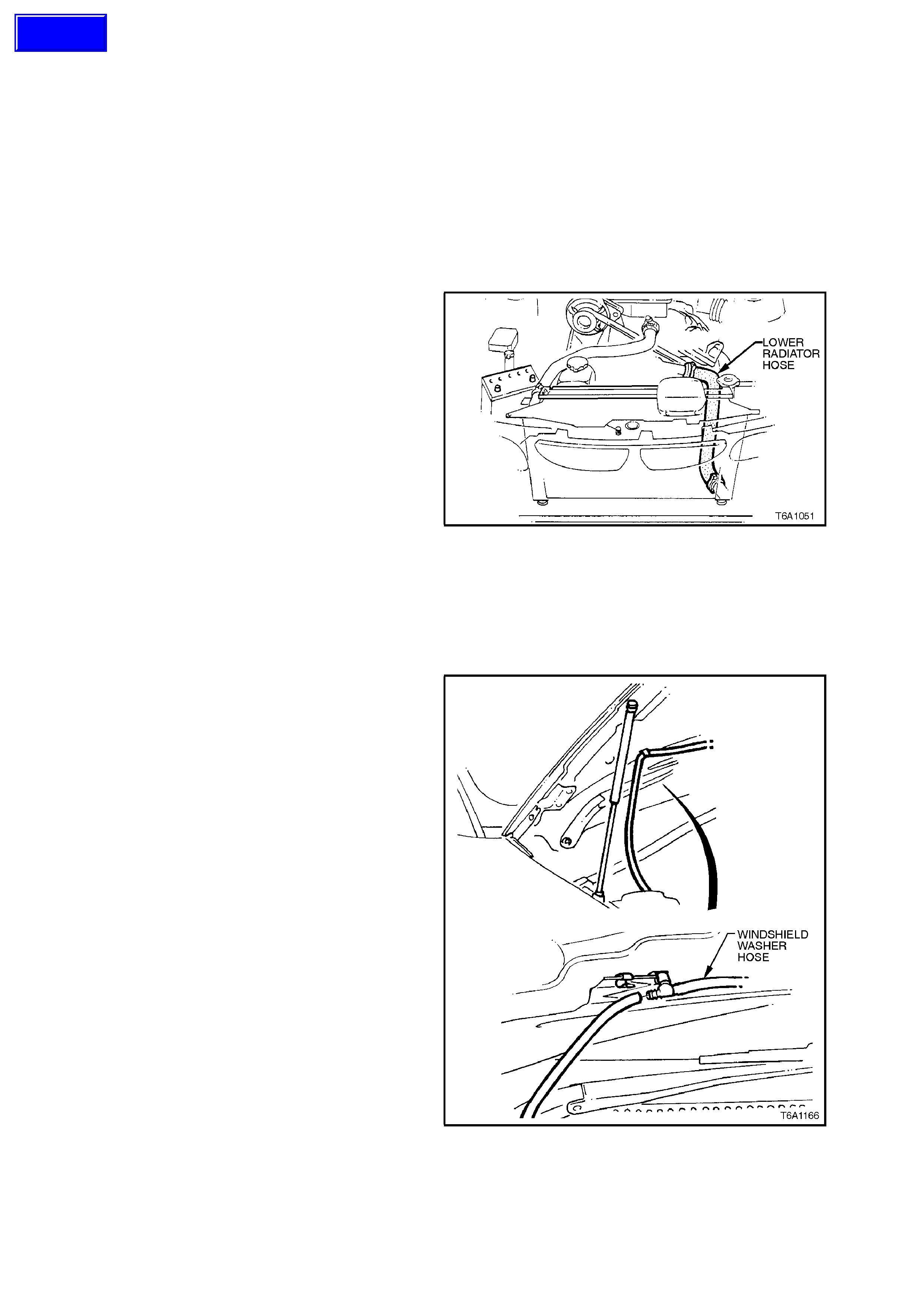
3. MAJOR SERVICE OPERATIONS
3.1 ENGINE ASSEMBLY
REMOVE
1. Depressurise fuel lines, refer to
Section 6C1 POWERTRAIN MANAGEMENT
- V6 ENGINE, Service Operations.
2. Disconnect battery leads from battery
terminals.
3. Remove radiator cap to release any cooling
system pressure.
WARNING:
To avoid serious personal injury, never remove
the radiator cap when the engine is hot. Sudden
release of cooling system pressure is very
dangerous and could cause personal injury.
4. Place an oil drain tray beneath engine.
5. Loosen radiator lower hose clamp at radiator,
disconnect hose and allow coolant to drain.
Loosen hose clamps and disconnect upper
and lower radiator hoses from engine.
Figure 6A1-1-177
6. Remove cooling fan and radiator assembly,
refer to Section 6B1 ENGINE COOLING -
V6 ENGINE.
7. Remove engine oil pan drain plug and allow
engine oil to drain.
Refit drain plug once oil has drained.
8. Disconnect windshield washer hose at the
inline connector located at the rear LH side of
hood.
Figure 6A1-1-178
Techline
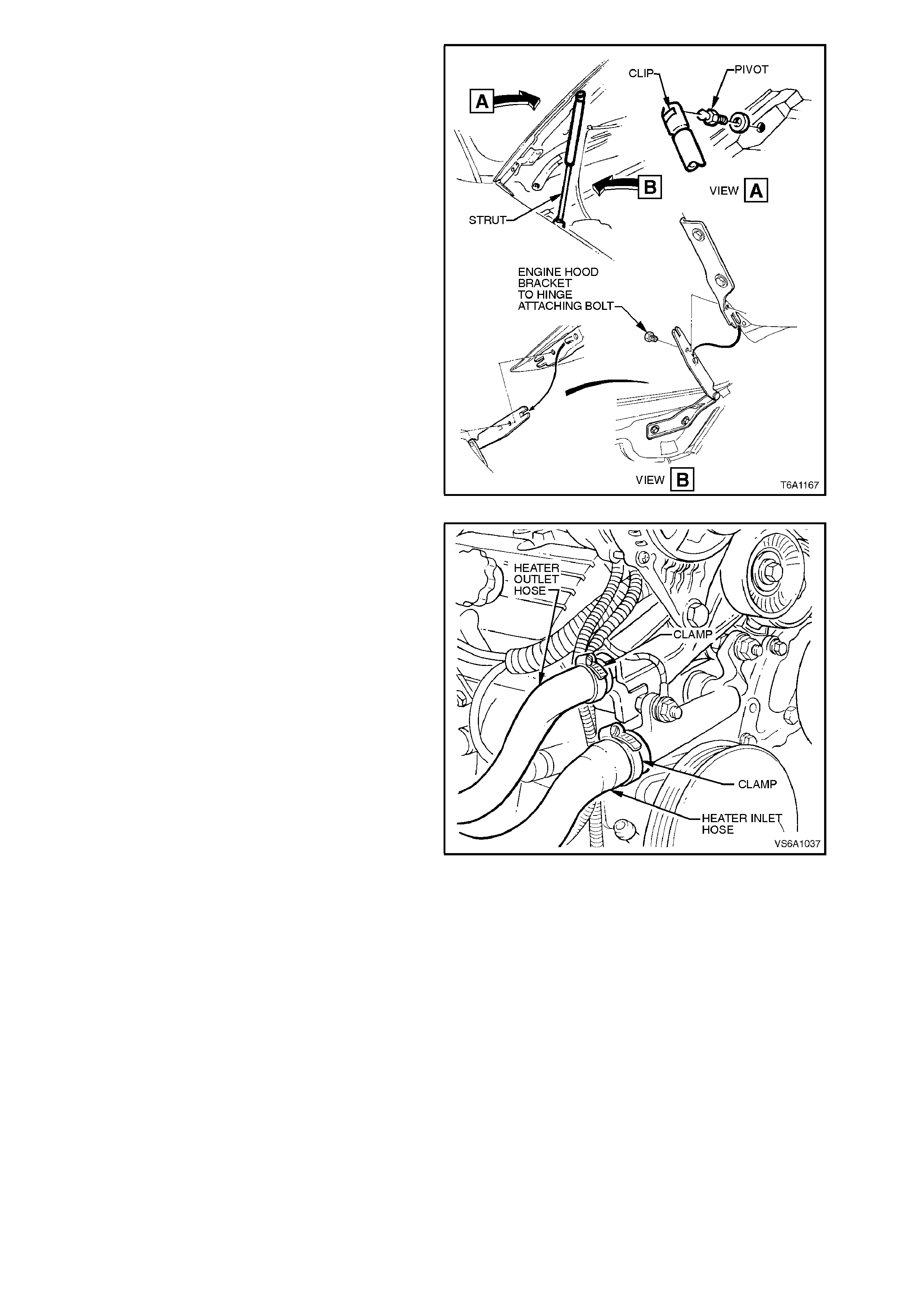
9. With engine hood adequately supported,
remove clips securing upper end of struts to
hood pivots. Disengage struts from hood
pivots and lay strut down on fender inner
panel.
With the aid of an assistant hold hood
assembly, remove engine hood bracket to
hinge attaching bolt removing hood.
Figure 6A1-1-179
10. Loosen heater outlet pipe and water inlet tube
hose clamps, disconnect hoses from heater
outlet pipe and water inlet tube.
Figure 6A1-1-180
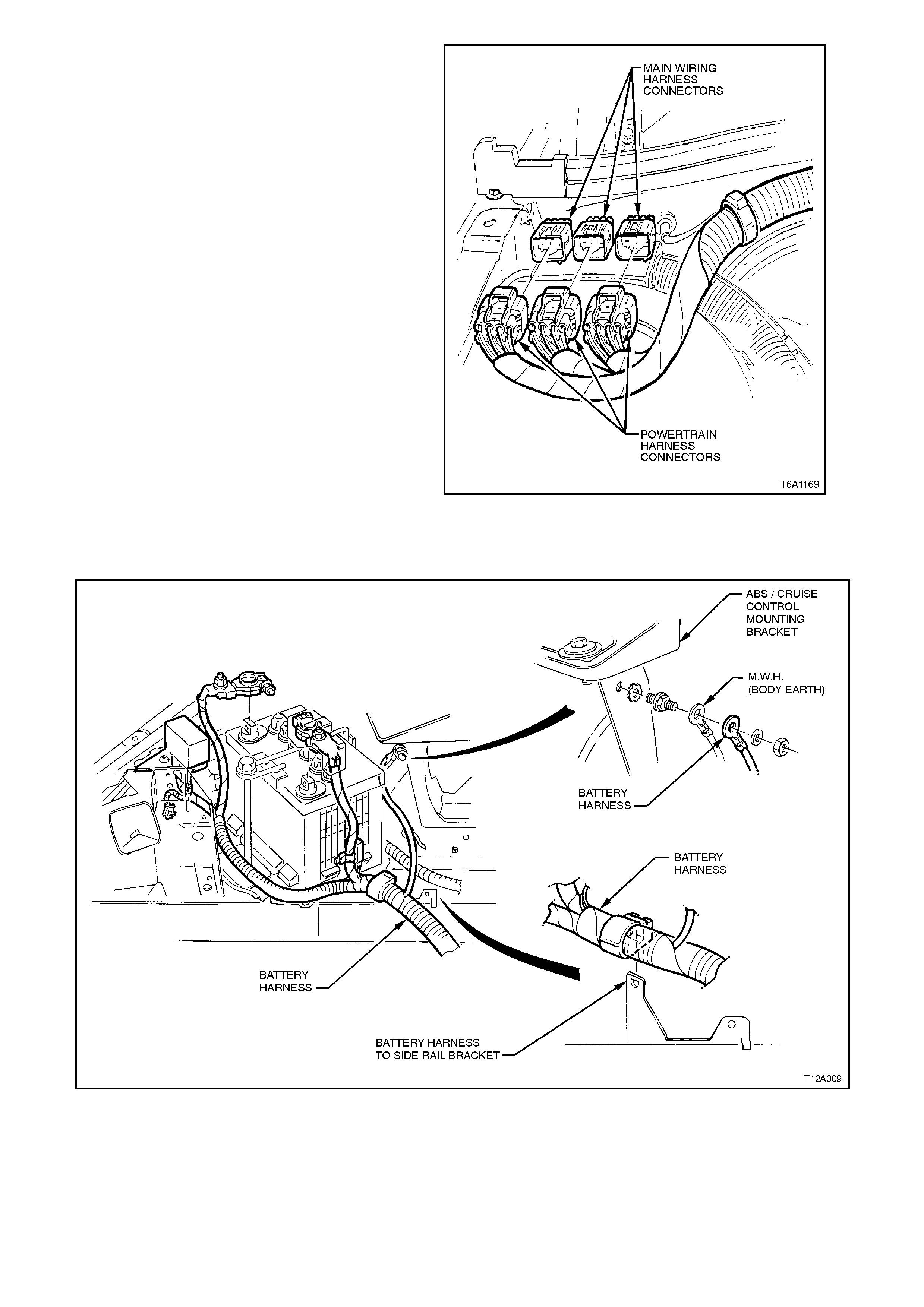
11. Disconnect main wiring harness to powertrain
and battery harness connectors at dash panel.
Figure 6A1-1-181
12. Remove nut securing battery harness earth
terminal from ABS/CRUISE CONTROL
bracket stud.
Figure 6A1-1-182
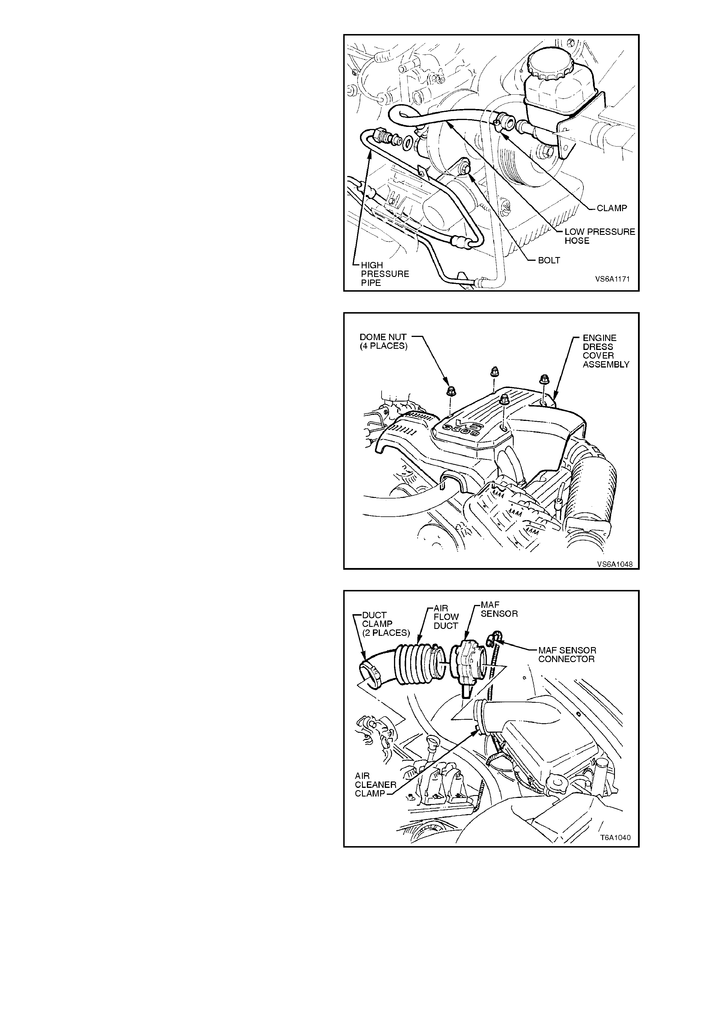
13. Loosen and remove high pressure pipe from
rear of power steering pump. Loosen low
pressure hose clamp at pump reservoir
connection and disconnect hose from
reservoir.
Plug all openings to prevent foreign matter
entry.
Figure 6A1-1-183
14. Remove the four nuts securing engine dress
cover.
Figure 6A1-1-184
15. Disconnect mass air flow sensor wiring,
loosen air flow duct rubber boot clamps at
throttle body and air cleaner and remove air
flow duct. Carefully place air flow duct and
mass air flow sensor assembly to one side.
Figure 6A1-1-185
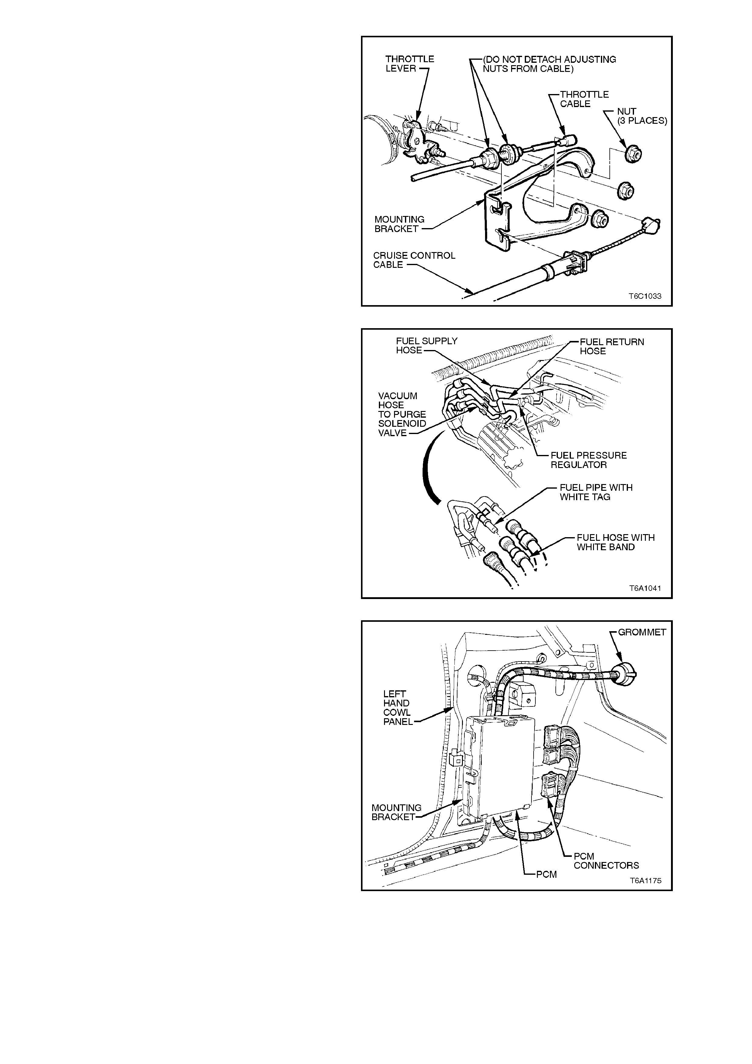
16. Disconnect throttle inner cable from throttle
body linkage. Loosen throttle outer cable lock
nuts at mounting bracket and lay cable away
from engine.
17. If vehicle is fitted with cruise control,
disconnect cruise control outer cable from
mounting bracket and push inner cable
forward off throttle body linkage.
Figure 6A1-1-186
18. Using quick connect release tool No. 7370
open tool and install over fuel line.
19. Close 7370 and pull into fuel line quick
connect to release it from fuel inlet line, pull
back on quick connect, disconnect fuel feed,
return and fuel evaporative canister hoses at
quick connects. Plug all openings to prevent
foreign matter entry.
NOTE:
Do not attempt to remove hoses from fuel rail
connections. Once removed from fuel rail
connection hoses require replacement.
Figure 6A1-1-187
20. From inside vehicle, remove left hand shroud
panel trim, glove box assembly and taking
care to remove the screw beneath the rocker
panel cover the lower left hand side trim
assembly, refer to Section 1A1 BODY.
21. Disconnect engine wiring harness connectors
from PCM. Compress lugs on engine harness
plug at dash panel and push engine harness
and connectors out into engine compartment.
Figure 6A1-1-188

22. From engine compartment release powertrain
harness to dash panel retaining clips,
disconnect intak e air tem peratur e sensor at air
cleaner and air conditioning pressure
transducer connector at air conditioning
condenser, lay wiring harness on top of
engine.
Figure 6A1-1-189
23. Disconnect brake booster, heater control and
fuel pressure regulator hoses from upper
manifold connections.
NOTE:
Do not attempt to remove hoses from fuel rail
connections. Once removed from fuel rail
connection hoses require replacement.
Figure 6A1-1-190
24. Raise vehicle front and rear and place on
safety stands. For location of jacking points,
refer to Section 0A GENERAL
INFORMATION.
25. Remove propeller shaft, refer to
Section 4C PROPELLER SHAFTS AND
UNIVERSAL JOINTS. Install a suitable plug in
end of transmission.
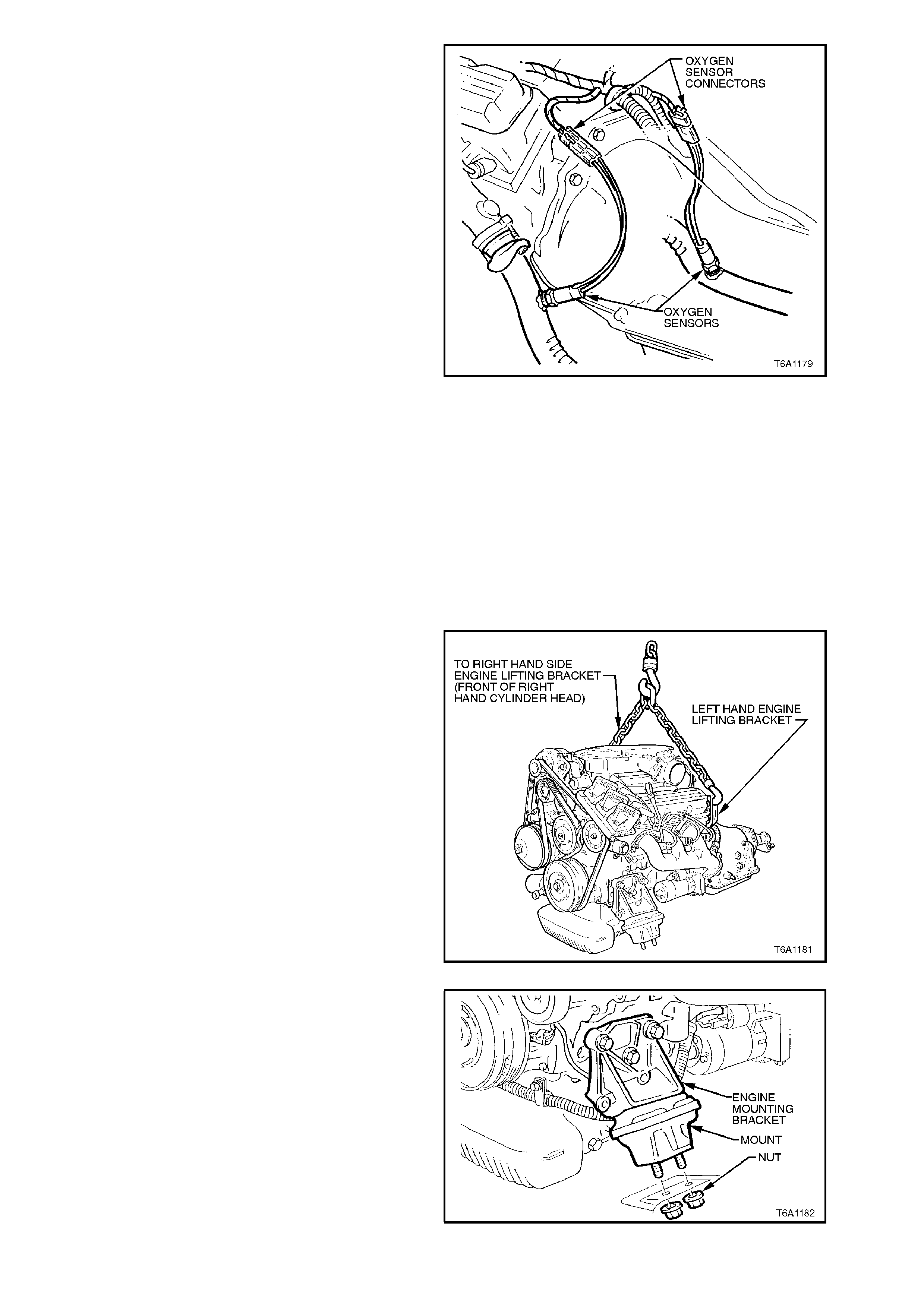
26. Disconnect oxygen sensors from powertrain
harness and left and right hand engine
exhaust pipes from manifold assemblies.
Figure 6A1-1-191
27. Disconnect gear shift control from
transmission. Refer to Section 7B1
MANUAL TRANSMISSION - V6 ENGINE, or
to Section 7C4 AUTOMATIC
TRANSMISSION - ON-VEHICLE
SERVICING. For those vehicles fitted with
column gearshift refer to
Section 9A STEERING.
28. On vehicles with manual transmission,
disconnect the hydraulic line to the clutch
actuating cylinder, refer to
Section 7A CLUTCH.
29. Attach suitable lifting brackets (position at
driver's side front and passenger side rear of
engine), lifting hook and chain to engine, raise
engine slightly to take weight off mounts.
Figure 6A1-1-192
30. Remove engine front mounting to front
suspension crossmember attaching nuts.
Figure 6A1-1-193
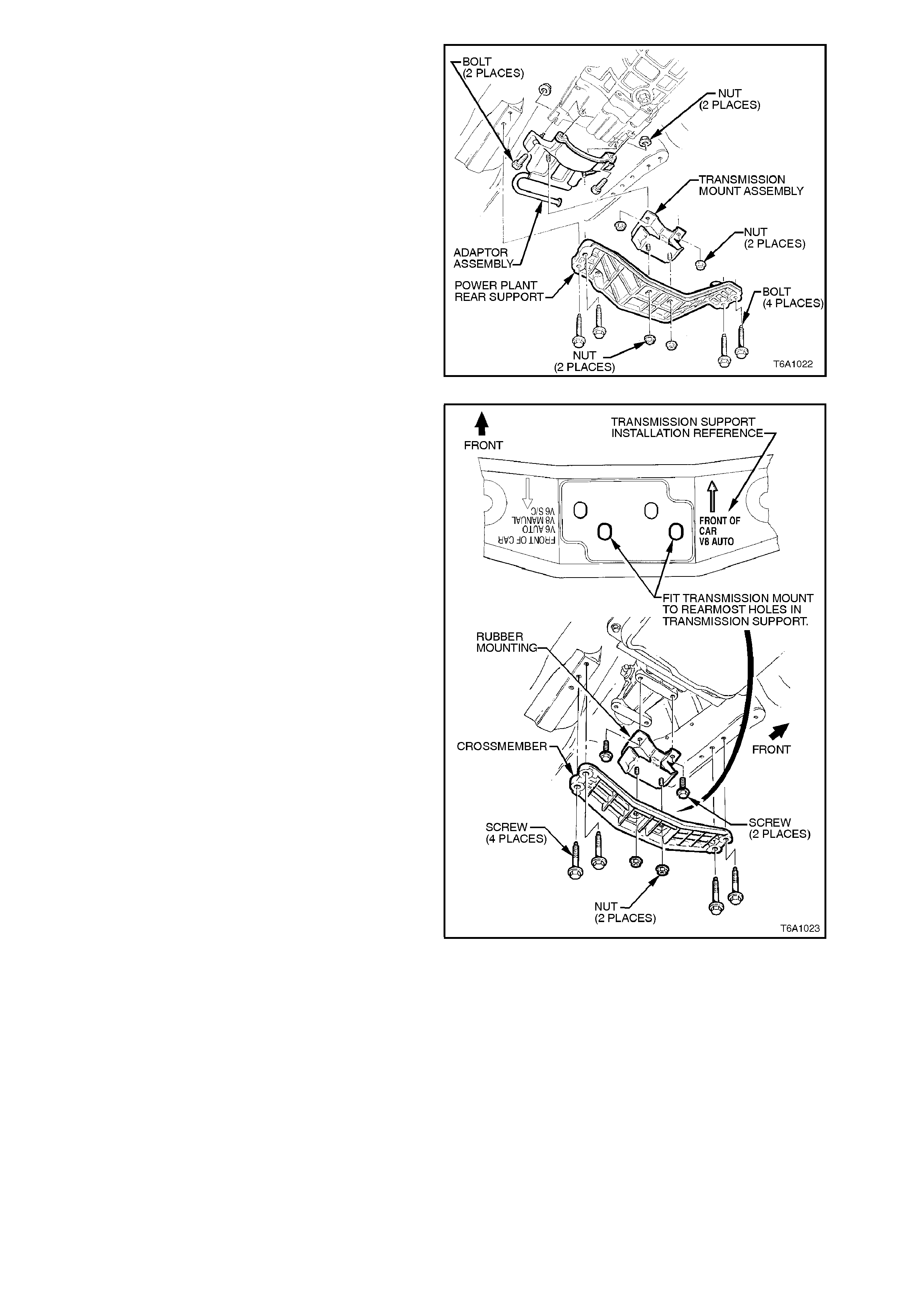
VEHICLES FITTED WITH MANUAL
TRANSMISSION:
31. Remove engine rear power plant support to
frame bolts and washers. Remove support to
mount attaching nuts and remove support.
Figure 6A1-1-194
VEHICLES FITTED WITH AUTOMATIC
TRANSMISSION:
32. Remove engine rear crossmember to frame
bolts and washers. Remove crossmember to
rear mounting attaching nuts and remove
crossmember.
Figure 6A1-1-195
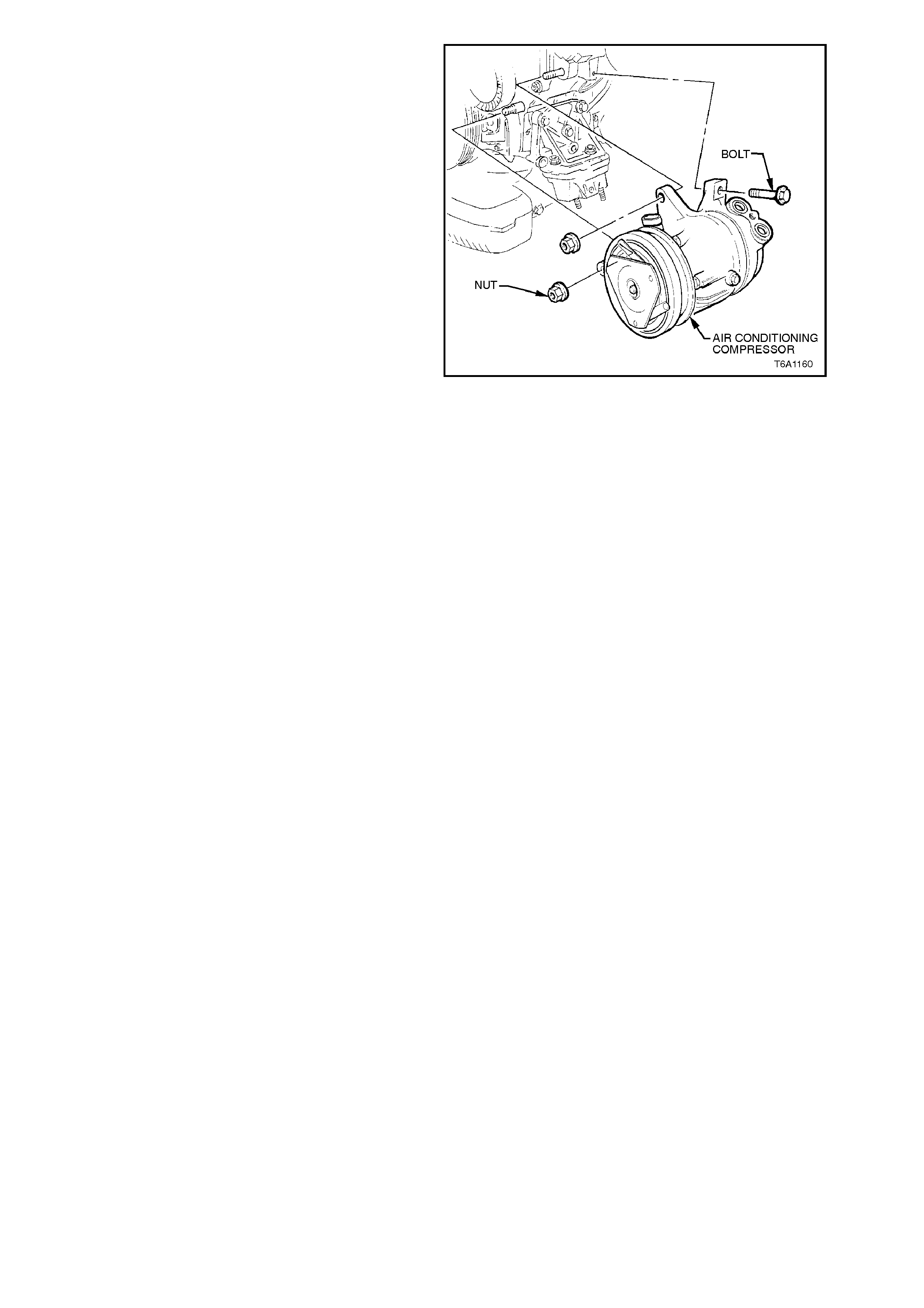
33. On vehicles with air conditioning, disconnect
wiring harness connector from compressor
clutch connector.
Raise engine slightly and remove compressor
to left hand engine mount bracket mounting
bolts. Tie compressor back away from the
engine.
Figure 6A1-1-196
34. Raise engine with front tilted upwards and a
floor jack supporting rear of transmission
assembly, ensure that engine exhaust
manifolds, beaming brace, transmission or
starter motor do not rest on steering gear.
NOTE:
On vehicles with air conditioning, do not allow
engine to swing forward and damage air
conditioning condenser.
35. If necessary, separate engine and
transmission assemblies. Refer to
Section 7B1 MANUAL TRANSMISSION - V6
ENGINE or to Section 7C4 AUTOMATIC
TRANSMISSION.
DISASSEMBLE
1. Mount engine assembly in a suitable engine
stand.
2. Remove the following items as described:
a. Generator and brackets, refer to Section
6D1-1 CHARGING SYSTEM - V6 ENGINE.
b. Starter motor, refer to Section 6D1-2
STARTING SYSTEM - V6 ENGINE.
c. Ignition coil and mounting bracket, high
tension leads and spark plugs, refer to
Section 6D1-3 IGNITION SYSTEM - V6
ENGINE ..
d. EGR Valve assembly, refer to
Section 6E1 EMISSION CONTROL - V6
ENGINE .
3. Remove the following components as
described in this Section:
a. Oil filter and adaptor, refer to
2.3 OIL FILTER and 2.5 OIL FILTER
ADAPTOR.
b. Drive belt, refer to 2.6 DRIVE BELT.
c. Drive belt tensioner, refer to
2.7 DRIVE BELT TENSIONER.
d. Exhaust manifolds, refer to
2.10 EXHAUST MANIFOLDS.
e. Inlet manifold, refer to
2.9 INLET MANIFOLD.

f. Rocker covers, rocker arms and
pushrods, refer to 2.11 ROCKER
COVERS and 2.12 ROCKER ARMS
AND PUSHRODS.
g. Valve lifters, refer to 2.14 VALVE
LIFTERS.
h. Crankshaft balancer, refer to 2.17
CRANKSHAFT BALANCER.
i. Flywheel/flexplate, refer to
3.4 FLYWHEEL/FLEXPLATE.
j. Front cover, refer to 2.19 FRONT
COVER.
k. Timing chain, tensioner, sprockets and
balance shaft gears, refer to 2.21.
l. Camshaft, refer to 2.22 CAMSHAFT.
m. Balance shaft, refer to 3.9 BALANCE
SHAFT.
n. Cylinder heads, ref er to 2.15 CYLINDER
HEADS.
o. Oil pan, refer to 3.2 OIL PAN AND
SEAL.
p. Oil pump suction pipe and screen, refer
to 3.3 OIL PUMP.
q. Piston and connecting rod assemblies,
refer to 3.10 PISTON/CONNECTING
ROD.
r. Crankshaft, refer to
3.12 CRANKSHAFT.
4. Discard all gaskets and seals.
5. For inspection procedures for each
component, refer to the relevant component
description as listed under step 3.
REASSEMBLE
Reassembly is the reverse of disassembly
procedure for each component as outlined in this
Section. The relevant reassembly instructions for
each component is listed under step 3 of
DISASSEMBLE procedure.
REINSTALL
Installation is the reverse of removal procedures,
noting the following points:
1. Ensure that all fasteners are tightened to the
specified torque provided at the end of this
Section.
2. Use specified engine lubricant and coolant
when refilling lubrication and cooling systems.
3. Check transmission fluid level, add lubricant
as required.
4. Check for oil, fuel, coolant and exhaust leaks.
Repair as necessary.
5. Check engine hood alignment.
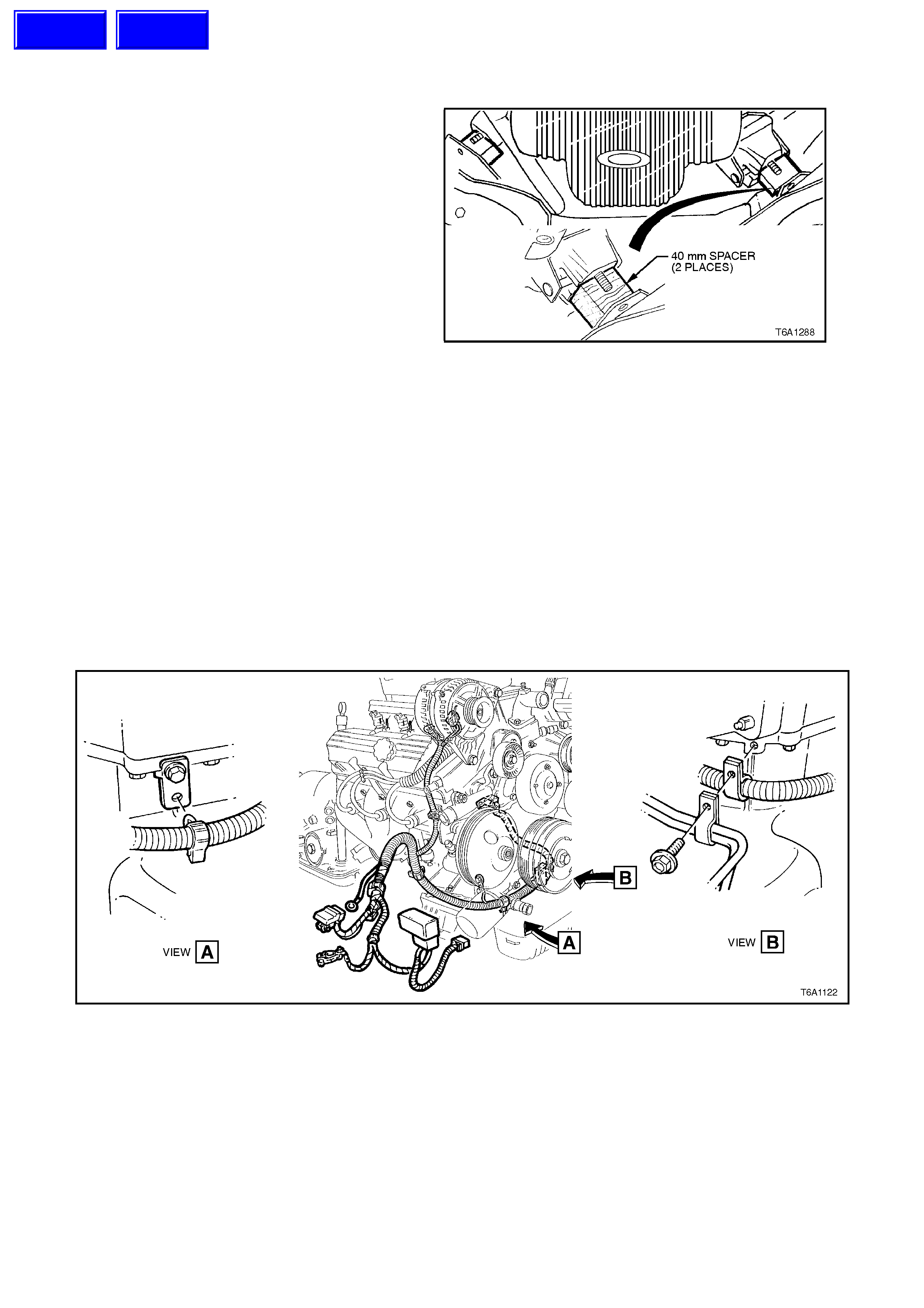
3.2 OIL PAN AND SEAL
REMOVE
1. Disconnect battery earth lead.
2. Remove engine mounting nuts refer to 2.23
ENGINE MOUNTS in this Section.
3. Raise engine 40 mm.
4. Fit 40 mm spacers under engine mounts to
support engine.
Figure 6A1-1-197
NOTE:
Vehicles with supercharged engine it is necessary
to. a. Remove front suspension crossmember,
refer to Section 3 FRONT
SUSPENSION.
b. Use safety stands, located under front
engine mounts, to steady engine
assembly.
5. Drain oil from oil pan.
6. Remove beaming brace, refer to
2.24 BEAMING BRACE in this Section.
7. Remove battery harness and automatic
transmission (if fitted) oil cooler line retainer
attaching screws from front of oil pan.
Figure 6A1-1-198
8. Rem ove oil pan attaching bolts and rem ove oil
pan and seal, discard oil seal.
Techline
Techline
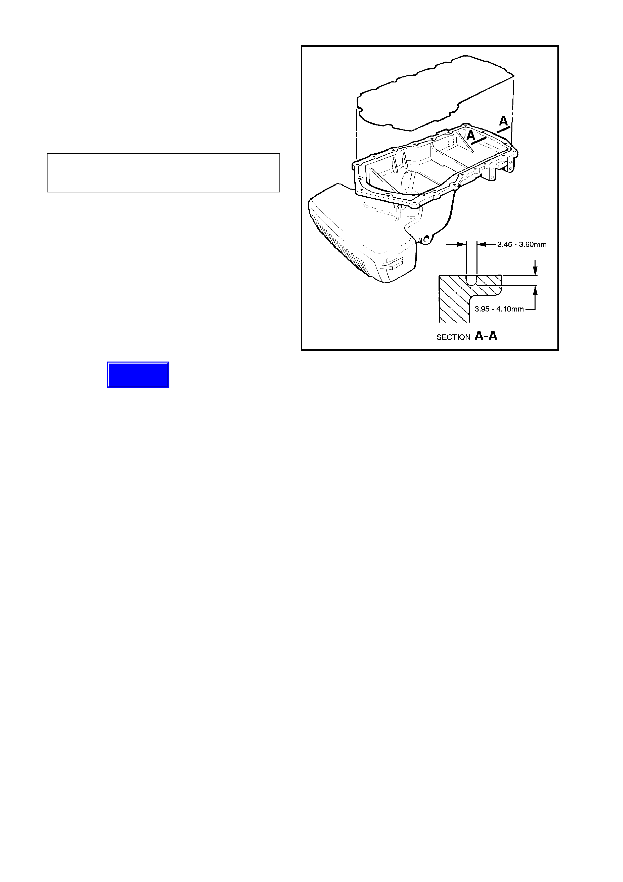
INSPECT
1. Remove oil pan seal and check for porosity in
oil pan or foreign material in oil pan seal
groove. Clean or replace oil pan as required.
2. Check f or cor r ect dimension of the oil pan s eal
groove in several places around the oil pan.
Replace oil pan if oil pan seal groove is not to
specification.
OIL PAN SEAL GROOVE SPECIFICATION
GROOVE DEPTH 3.95-4.10 mm
GROOVE WIDTH 3.45-3.60 mm
Figure 6A1-1-199
REINSTALL
1. Thoroughly clean mating surfaces of oil pan,
front cover, rear oil seal housing and cylinder
block.
IMPORTANT:
Ensure old sealant etc. is removed from oil pan
seal groove.
2. Install new seal onto oil pan rail ensuring the
seal is seated in oil pan groove.
3. Apply Permatex “the Right Stuff” as a bead 6
mm wide and 0.4 - 0.2 mm thick to cylinder
block in the area of the rear oil seal housing
and front cover joints (refer to Fig. 6A1-1-200).
NOTE:
Do not apply excessive sealer, this may prevent
free movement of seal within oil pan groove.
Thickness of sealer can be controlled by first
applying 0.25 mm thick adhesive tape onto block,
using a scraper fill to thickness of tape then
remove tape.
Techline
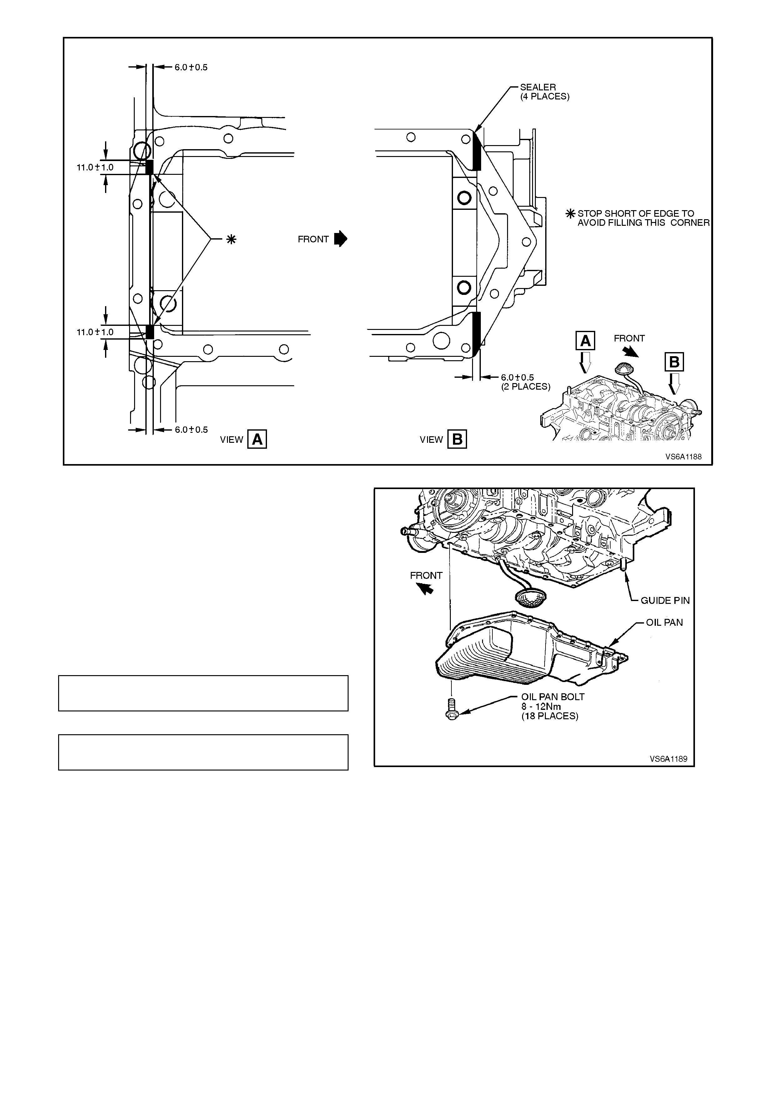
Figure 6A1-1-200
4. Install oil pan and seal to cylinder block using
temporary guide pins to prevent smearing
sealer.
5. Install oil pan bolts and tighten to the correct
torque specification.
NOTE:
Oil pan must be torqued down within 5 minutes of
sealant application.
6. Ensure oil pan drain plug is tightened to the
correct torque specification.
OIL PAN ATTACHING BOLT 8 - 12
TORQUE SPECIFICATION Nm
OIL PAN DRAIN PLUG 30 - 60
TORQUE SPECIFICATION Nm Figure 6A1-1-201

7. Install battery harness and automatic
transmission (if fitted) oil cooler line retainer
attaching screws and tighten to the correct
torque specification.
BATTERY HARNESS AND OIL
COOLER LINE RETAINER TO OIL
PAN ATTACHING SCREW
TORQUE SPECIFICATION
3 - 5
Nm
8. Reinstall beaming brace, refer to
2.24 BEAMING BRACE.
9. If removed, reinstall front suspension
crossmember, refer to Section 3 FRONT
SUSPENSION.
10. Refill oil pan with the cor r ect amount of engine
oil, refer to Section 0B LUBRICATION AND
SERVICE.
11. Start engine and check f or oil leak s. Repair as
necessary.
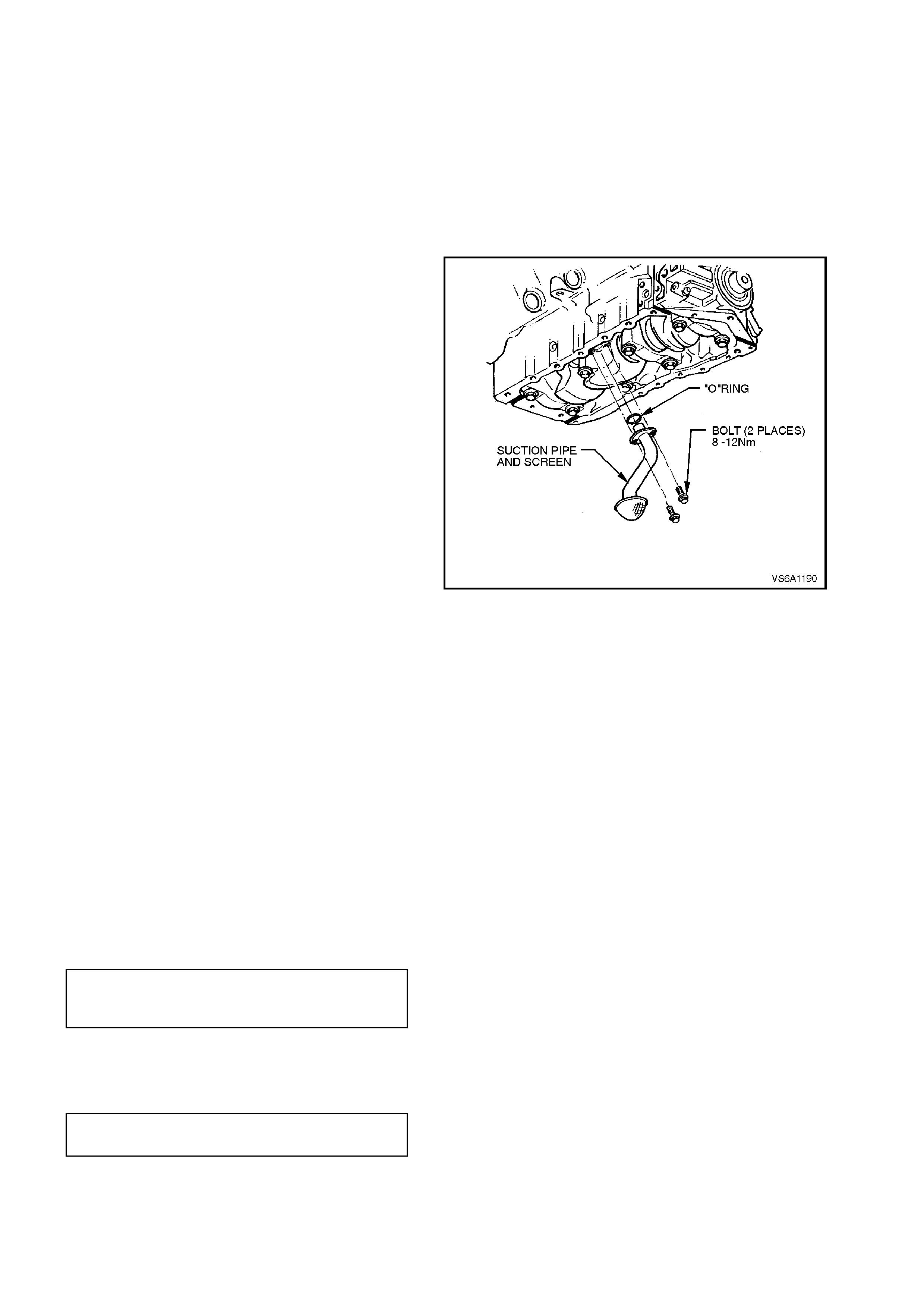
3.3 OIL PUMP SUCTION PIPE AND SCREEN
REMOVE
1. Disconnect battery earth lead.
2. Remove oil pan drain plug and drain oil from
oil pan.
Refit drain plug once oil has drained.
3. Remove oil pan, refer to 3.2 OIL PAN AND
SEAL in this Section.
4. Remove two bolts securing s uction pipe flange
to cylinder block and remove pipe and screen
assembly.
5. Rem ove suction pipe to c ylinder bloc k O - ring
and discard.
Figure 6A1-1-202
REINSTALL
Installation is the reverse of removal procedures,
noting the following points:
1. Ensure that screen is cleaned of any foreign
matter.
2. Clean suction pipe flange and cylinder block
mating surfaces.
3. Clean threads of suction pipe securing bolts
and mating threads in cylinder block with a
suitable size thread tap.
Apply Loctite 242 or equivalent (Holden
Specific ation HN 1256 Class 2, T ype 2) to bolt
threads.
4. Use a new O - ring between suction pipe
flange and cylinder block. Install and tighten
bolts to the correct torque specification.
OIL PUMP SUCTION PIPE FLANGE
TO CYLINDER BLOCK BOLT
TORQUE SPECIFICATION 8 - 12 Nm
5. Ensure oil pan drain plug is tightened to the
correct torque specification.
OIL PAN DRAIN PLUG
TORQUE SPECIFICATION 30 - 60
Nm
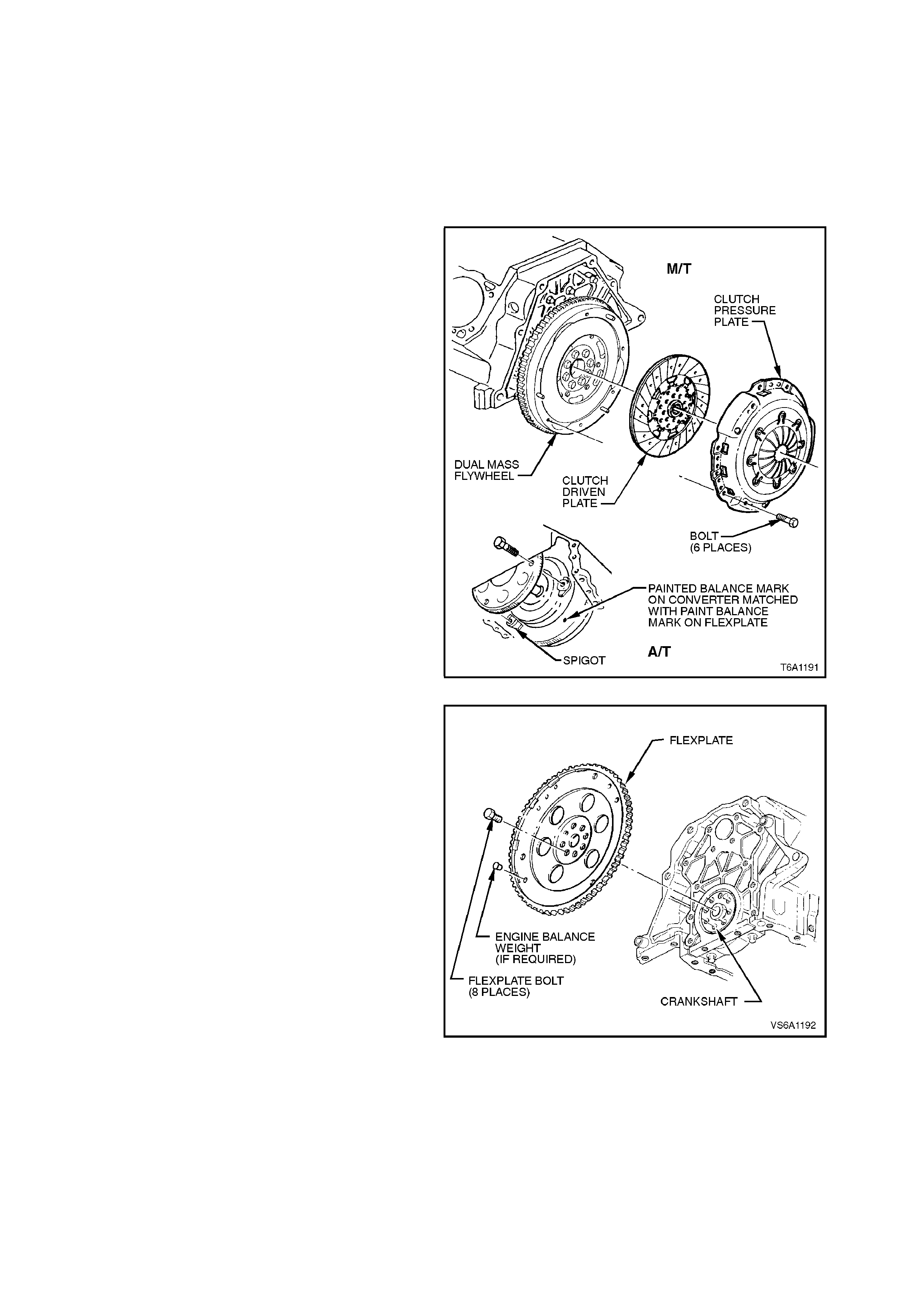
3.4 FLYWHEEL/FLEXPLATE
REMOVE
1. Disconnect battery earth lead.
2. Remove transmission, refer to
Section 7B1 MANUAL TRANSMISSION - V6
ENGINE, or Section 7C4 AUTOMATIC
TRANSMISSION - ON-VEHICLE
SERVICING.
3. For vehicles with manual transmission,
remove clutch pressure plate and driven plate,
refer to Section 7A CLUTCH.
NOTE:
Before removing the flexplate and torque converter,
note the position of paint aligning marks. If 0not
visible, scribe aligning marks on both components.
Figure 6A1-1-203
4. Using a screwdriver or suitable locking tool,
block flywheel/flexplate from rotating. Remove
flywheel/flexplate to crankshaft attaching bolts,
remove flywheel/flexplate.
Figure 6A1-1-204
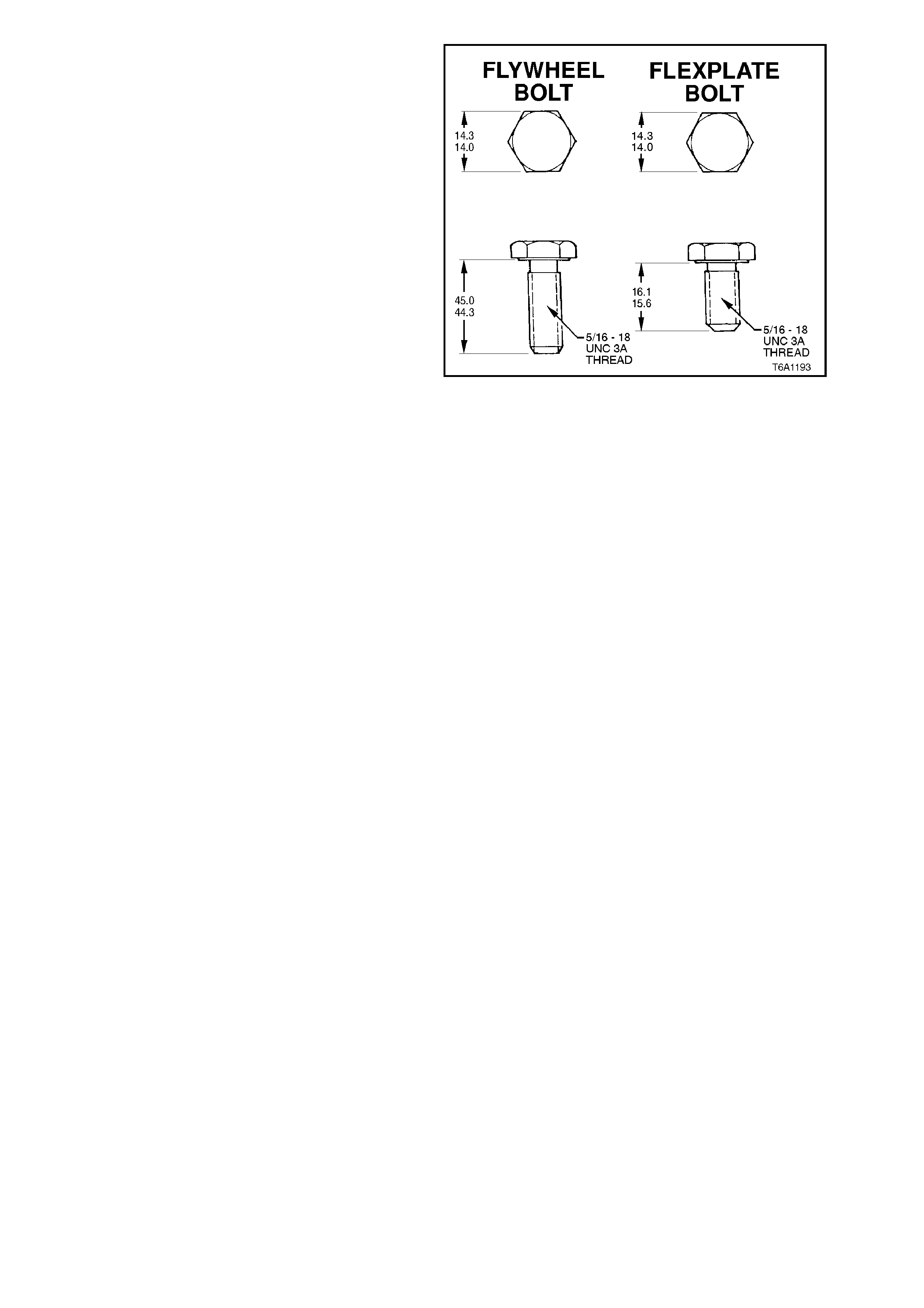
NOTE:
Once removed, discard flywheel/flexplate attaching
bolts. New bolts must be used on reassembly.
There are specific bolts for flywheel and flexplate
attachment to the crankshaft.
Figure 6A1-1-205
INSPECT
1. Inspect flywheel/flexplate ring gear for
cracked, badly worn or damaged teeth.
If ring gear is damaged it will be necessary to
replace flywheel assembly or flexplate. For
flexplate replacement refer to
3.4 FLYWHEEL/FLEXPLATE in this Section.
For flywheel Service Operations refer to
Section 7A CLUTCH.
If ring gear teeth are dam aged, inspect starter
motor pinion gear for damage. Refer to
Section 6D1-2 STARTING SYSTEM - V6
ENGINE.
Check flexplate retainer plate for any damage.
2. Check crankshaft and flywheel/flexplate
mating surfaces for burrs. Remove burrs, if
present, with a fine mill file.
NOTE:
No attempt should be made to rebalance the
flywheel or flexplate these are non serviceable
units.
3. Using a 5/16 UNC thread tap, clean
flywheel/flex plate attaching bolt threads in rear
of crankshaft.
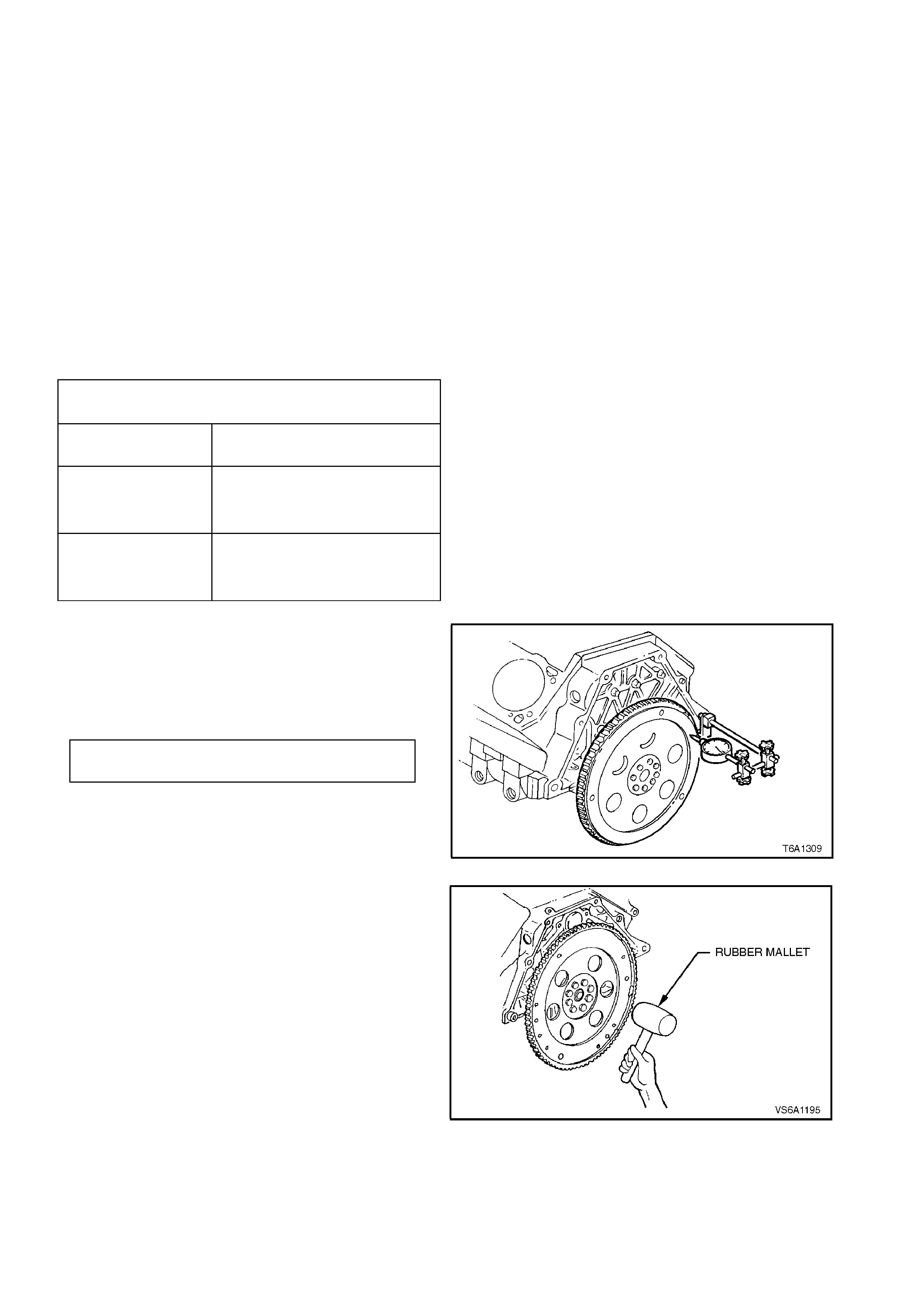
REINSTALL
Installation is the reverse of removal procedures,
noting the following points:
1. Vehicles with manual transmission align
flywheel dowel pin holes with crankshaft
flange dowel pins and install flywheel onto
crankshaft flange, tighten new attaching bolts
to the correct torque specification.
2. Vehicles with automatic transmission install
flexplate to crankshaft flange and tighten new
attaching bolts to the correct torque
specification.
NOTE:
Bolt holes are unevenly spaced so all
flywheel/flexplate bolts can only be installed with
the flywheel/flexplate in the correct position.
FLYWHEEL/FLEXPLATE BOLT TIGHTENING
SEQUENCE
STEP No. 1 TORQUE ALL
BOLTS TO 18 - 22 Nm
STEP No. 2
MANUAL
TRANSMISSION
TIGHTEN ALL BOLTS A
FURTHER 80 - 90 DEGREES
TURN ANGLE
STEP No. 2
AUTOMATIC
TRANSMISSION
TIGHTEN ALL BOLTS A
FURTHER 47 - 53 DEGREES
TURN ANGLE
3. On vehicles with automatic transmission,
mount a dial indicator on the rear of cylinder
block. Check flexplate run-out at the three
torque converter mounting bolt holes. Run-out
should not exceed the following specification.
FLEXPLATE RUN-OUT 0.38 mm
SPECIFICATION Max.
Figure 6A1-1-206
4. If runout exceeds specifications, attempt to
correct by tapping high side with a mallet. If
this condition cannot be corrected, replace
flexplate.
Figure 6A1-1-207
5. Check starter motor operation.

3.5 RING GEAR
REPLACE
On vehicles with automatic transmission, the ring gear is welded to the flexplate and is serviced only as an
assembly.
On vehicles with manual transmission, the ring gear is welded to the flywheel and if damaged will require
replacement of the flywheel assembly.
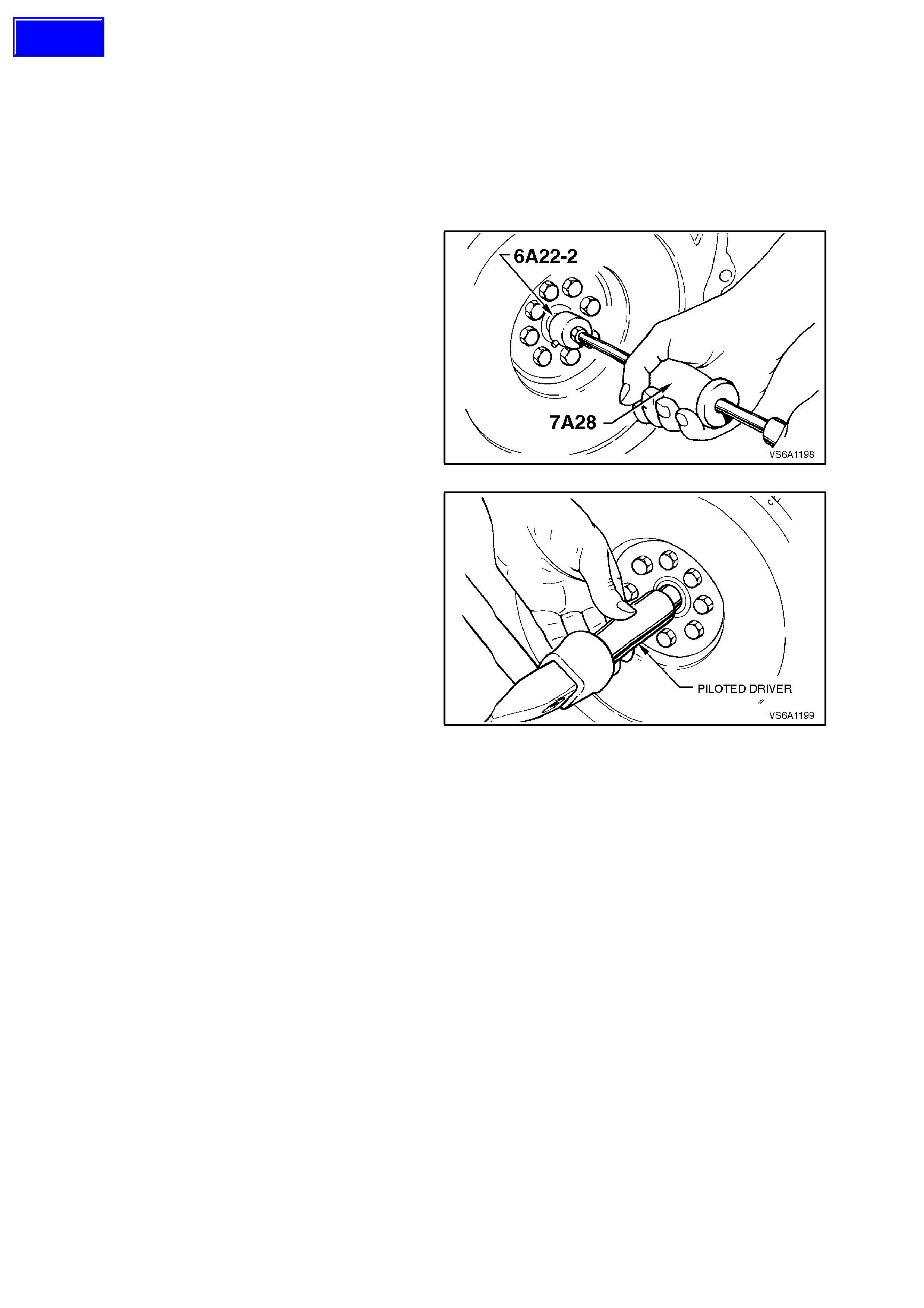
3.6 SPIGOT BEARING
REPLACE
1. Disconnect battery earth lead.
2. Remove transmission, refer to
Section 7B1 MANUAL TRANSMISSION - V6
ENGINE.
3. Remove clutch pressure plate and driven
plate, refer to Section 7A CLUTCH.
4. Using suitable spigot bearing removal tools,
such as Tool No. 6A22-2 with slide hammer
7A28 (AU354 or J6125-1) or Tool No. E6668,
remove spigot bearing.
Figure 6A1-1-208
5. In replacing spigot bearing, use a piloted
driver. Place new bearing on pilot of tool with
radius in bore of bearing next to shoulder on
tool. Drive bearing into crank shaf t until bearing
shoulder contacts crankshaft boss.
Figure 6A1-1-209
6. Lubricate bearing with several drops of SAE
90 Gear Oil.
7. Reinstall clutch assembly and transmission,
refer to Section 7A CLUTCH and to
Section 7B1 MANUAL TRANSMISSION - V6
ENGINE.
8. Reconnect battery earth lead, star t engine and
check clutch operation.
Techline
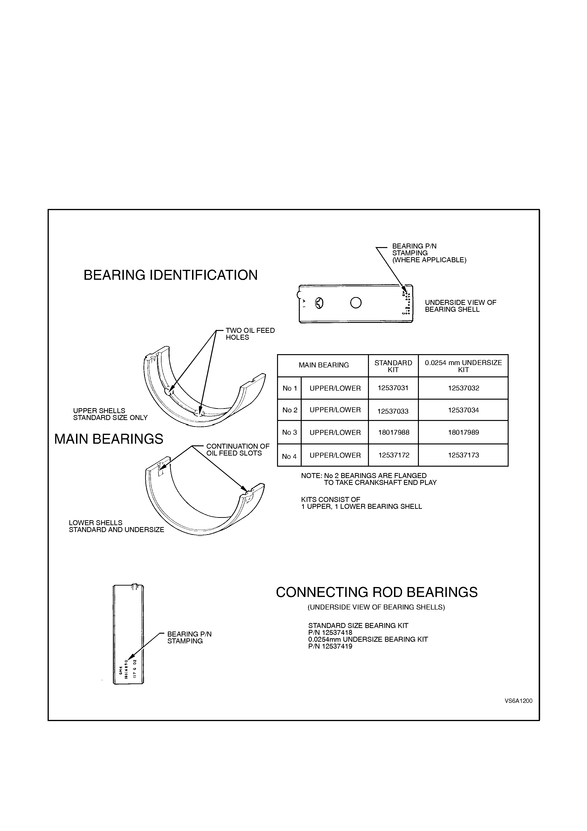
3.7 MAIN AND CONNECTING ROD BEARINGS
Each crankshaft main bearing journal has two bearing halves or shells which are not alike and not interchangeable
in the bearing cap or cylinder block, (except No. 1 and No. 4 upper bearing shells). The upper (cylinder block) shell
has two oil feed holes and is grooved to supply oil to the connecting rod bearing, with the lower bearing shells
having a continuation of this groove in each end of the shell. The two bearing shells on each journal must not be
interchanged. The No. 2 bearing shells are flanged to take end thrust.
Each connecting rod bearing consists of two bearing halves or shells which are interchangeable in the rod and cap.
Bearing shells are of the precision insert ty pe and do not require reaming to size or utilise shims for adjustment.
When shells are placed in the cylinder block or connecting rod and bearing cap, the ends extend slightly beyond the
parting surfaces so that when the cap bolts are tightened, the shells clamp tightly in place to ensure positive seating
and to prevent turning.
The ends of the bearing shells must never be filed flush with parting surfaces of the cylinder block, connecting rod
or bearing cap.
Service replacement main bearings are available in standard and 0.0254 mm undersize.
Figure 6A1-1-210

MAIN BEARINGS - INSPECT
1. With engine removed from vehicle refer to
3.1 ENGINE ASSEMBLY in this Section,
mount in a suitable stand and invert engine
assembly.
2. Remove oil pan, refer to 3.2 OIL PAN AND
SEAL in this Section.
3. Remove oil pump suction pipe and screen,
refer to 3.3 OIL PUMP SUCTION PIPE AND
SCREEN in this Section.
4. Remove main bearing cap bolts and main
bearing cap side bolts.
NOTE 1:
New main bearing cap side bolts must be used to
ensure bolts remain oil tight to cylinder block.
NOTE 2:
Main bearing caps are press fit and special care is
required when removing the caps. J41348 has
been designed to work in conjunction with J6125-B
in order to prevent damage to bearing and/or cap.
J41348 m ust be ins talled cor rectly into bolt holes of
caps and J6125-B attached in order to properly
remove main bearing cap without damage to the
cap and/or bearing. Deviation from this procedure
may cause damage to the cap and/or bearing
resulting in engine damage.
5. Install J41348 into main bearing cap bolt
holes.
6. Tighten bolts to 11 Nm.
7. Install J6125-B to J41348.
8. Using the slide hammer motion of J6125-B
remove main bearing cap.
Figure 6A1-1-211
9. Inspect lower bearing shells and crankshaft
journals. If journal sur face is heavily scored or
ridged, replace crankshaft, refer to
3.12 CRANKSHAFT in this Section.
To ensure satisfactory engine operation, new
bearing shells must be installed, refer to
MAIN BEARINGS and if necessary,
CONNECTING ROD BEARINGS in this
Section.
Check inner surface of bearing shells for
wear, gouges or imbedded foreign material. If
foreign material is found, determine its nature
and source. Inspect outer surface of bearing
shells for surface wear (indicates movement
of shell or high spot in surrounding material),
overheating (discolouration) or looseness or
rotation (flattened tangs and wear grooves).
Inspect thrust surfaces of thrust bearing shell
for wear or grooving. Grooves are caused by
irregularities in the crankshaft thrust surfaces
or dirt refer to 3.12 CRANKSHAFT in this
Section.
If condition of lower bearing shells and
crankshaft journals is satisfactory, check
bearing clearance as follows:
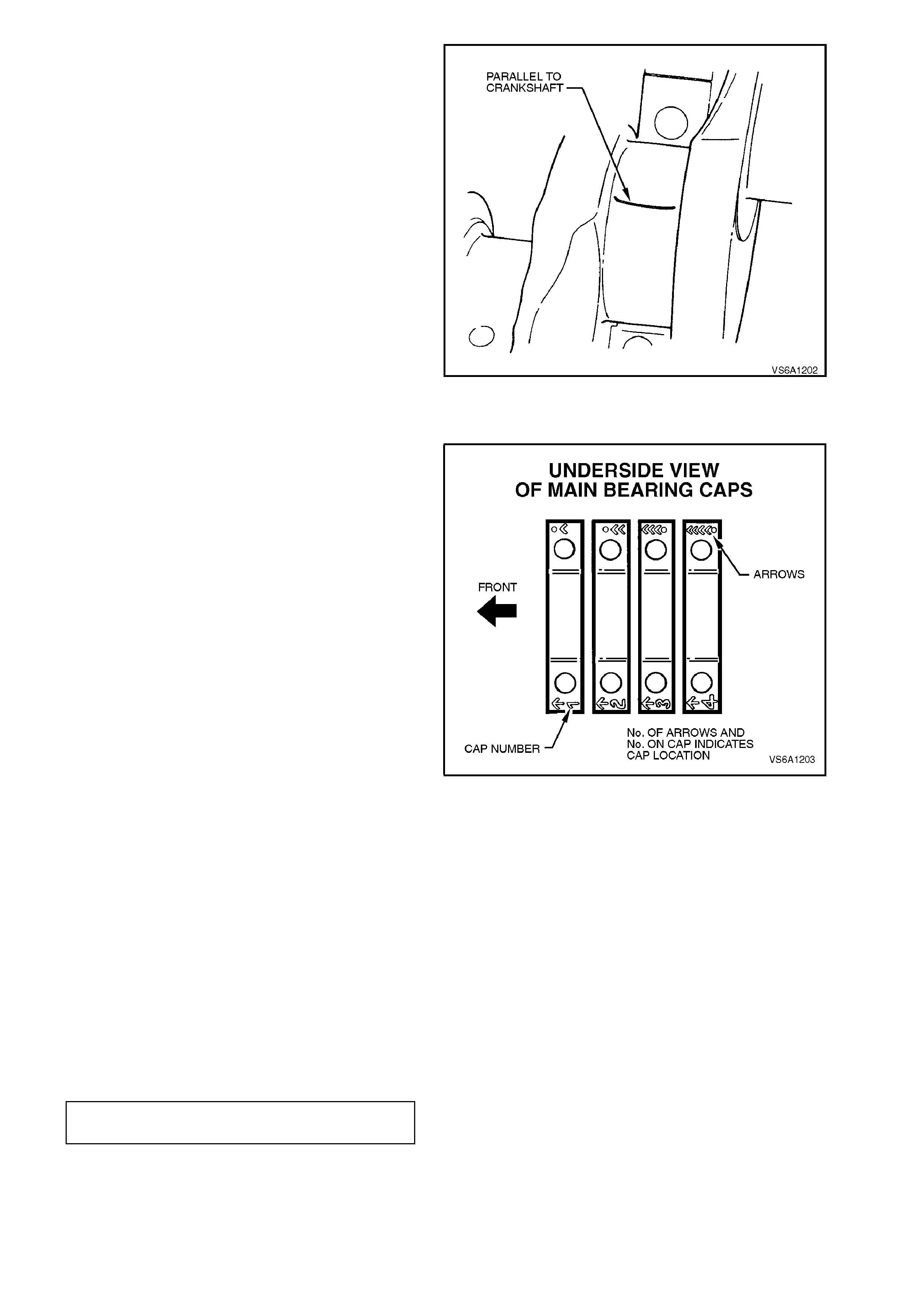
10. W ipe oil fr om c ranks haft journal and inner and
outer surfaces of lower bearing shell.
Reinstall bearing shell in original position in
bearing cap.
11. Place a piece of Plas tigage acros s f ull width of
crankshaft journal, parallel to crankshaft
centreline.
NOTE:
Ensure Plastigage will not seat across oil hole in
journal.
Figure 6A1-1-212
12. Install bearing cap and bolts into cylinder
block.
NOTE 1:
Ensure that the bearing cap is installed into the
crankcase correctly.
13. Before final installation of cap bolts, determ ine
if bolts have stretched by comparing with a
new bolt. Replace bolt/s as necessary.
Reinstall main bearing caps, hand start main
bearing cap bolts, on each bearing c ap in turn,
tighten cap bolts half a turn at a time to
carefully seat cap.
NOTE 2:
Do not tighten one cap completely at a time,
progressively tighten all four caps to one step of
procedure before moving to next stage of torque.
Torque m ain bearing cap bolts to 70 Nm to fully
seat cap.
Loosen cap bolts 360° then torque all cap bolts
to 20 Nm and then 40 Nm.
Tighten cap bolts in steps of 35° + 35° + 35° to
a total of 105°.
Torque m ain bearing cap side bolts 12 - 18 Nm
+42 - 48°.
Figure 6A1-1-213
NOTE 1:
In order to prevent the possibility of cylinder block
or bearing cap damage, do not install bearing cap
using a soft faced hammer. Use cap bolts to pull
bearing cap into position. Failure to observe this
procedure may damage cylinder block or bearing
cap.
NOTE 2:
Ensure that crankshaft does not turn with
Plastigage installed.
MAIN BEARING CAP BOLT
TORQUE SPECIFICATION Refer above
procedure
NOTE 3:
Use an angle wrench such as E7115 to ensure
accurate turn angle.
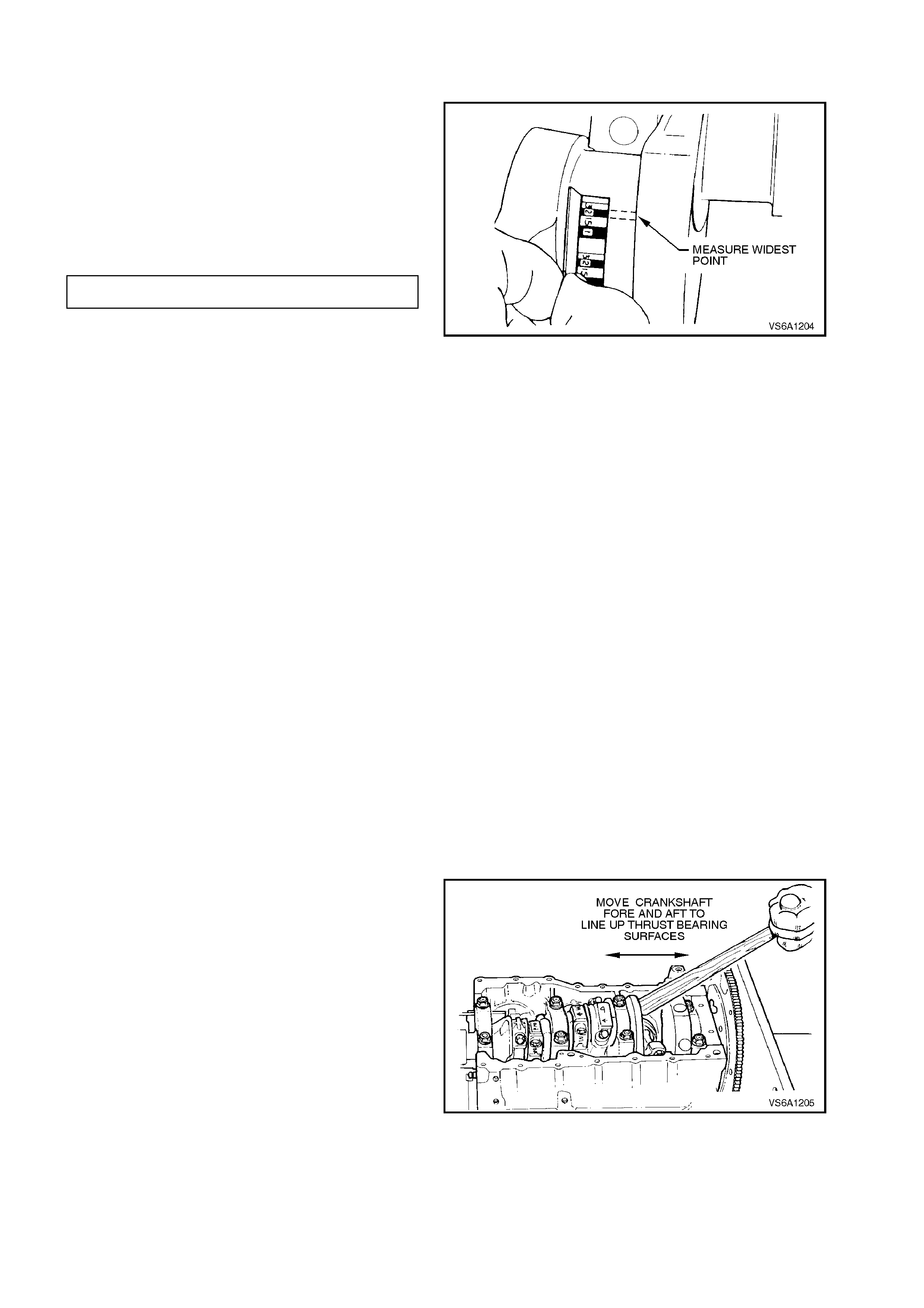
14. Remove bearing cap bolts, remove cap. Look
for flattened Plastigage adhering to either
crankshaft or bearing shell in bearing cap.
15. Determine bearing clearance by comparing
width of flattened Plastigage at widest point
with graduation on Plastigage envelope. The
number within the graduation on the envelope
indicates the clearance.
Clearance between each main bearing and
crankshaft journal should not exceed
specification.
MAIN BEARING CLEARANCE 0.023 - 0.053 mm
Figure 6A1-1-214
NOTE:
This method of checking main bearing clearance
does not give any indication of crankshaft journal
taper or out-of-round.
To measure taper, undersize or out-of-round, the
crankshaft must be removed from the cylinder
block, refer to 3.12 CRANKSHAFT in this Section.
16. If bearing clearance exceeds specification, it is
advisable to install new bearing shells and
recheck clearance as previously described.
NOTE:
If lower bearing shell is a standard size, install a
0.0254 mm undersize shell and recheck clearance.
If clearance is still not to specification, remove
crankshaft, and measure crankshaft journals, refer
to 3.12 CRANKSHAFT in this Section.
17. Ensure that main bearing cap bolt threads and
cylinder block threads are clean and dry. Apply
some engine oil to the cap bolt threads.
NOTE:
Before final installation of cap bolts, determine if
bolts have stretched by com paring with a new bolt.
Replace bolt/s as necessary.
18. W ith m ain bearing caps installed ( refer to s tep
13), install and tighten cap bolts to the correct
torque specification.
19. If the thrust bearing shell is disturbed or
replaced, apply engine oil to thrust surfaces.
Also, it is necessary to line up the thrust
surfaces of the bearing shells before the cap
bolts are tightened. To do this, move the
crankshaft fore and aft the length of its travel
several times (last movement forward) with the
thrust bearing cap bolts finger tight.
Figure 6A1-1-215

20. Push crankshaft forward and measure
crankshaft end float between front of No. 2
main bearing and crankshaft thrust faces with
a feeler gauge.
If clearance is excessive, replace No. 2 main
bearing shells, refer to the following
replacement procedures.
CRANKSHAFT END FLOAT 0.08 - 0.28
SPECIFICATION mm
Figure 6A1-1-216
MAIN BEARINGS - REPLACE
The main bearing shells can be replaced with or
without the crankshaft installed.
WITH CRANKSHAFT INSTALLED
1. With engine removed from vehicle refer to
3.1 ENGINE ASSEMBLY in this Section,
mount in a suitable engine stand and invert
engine assembly.
2. Remove oil pan, refer to 3.2 OIL PAN AND
SEAL in this Section.
3. Remove oil pump suction pipe and screen,
refer to 3.3 OIL PUMP SUCTION PIPE AND
SCREEN in this Section.
4. Remove spark plugs.
5. Remove main bearing cap bolts and main
bearing cap side bolts.
NOTE 1:
New main bearing cap side bolts must be used to
ensure bolts remain oil tight to cylinder block.
NOTE 2:
Main bearing caps are press fit and special care is
required when removing the caps. J41348 has
been designed to work in conjunction with J6125-B
in order to prevent damage to bearing and/or cap.
J41348 m ust be ins talled cor rectly into bolt holes of
caps and J6125-B attached in order to properly
remove main bearing cap without damage to the
cap and/or bearing. Deviation from this procedure
may cause damage to the cap and/or bearing
resulting in engine damage.
6. Install J41348 into main bearing cap bolt
holes.
7. Tighten bolts to 11 Nm.
8. Install J6125-B to J41348.
9. Using the slide hammer motion of J6125-B
remove main bearing cap.
Remove bearing shell from bearing cap.
Figure 6A1-1-217
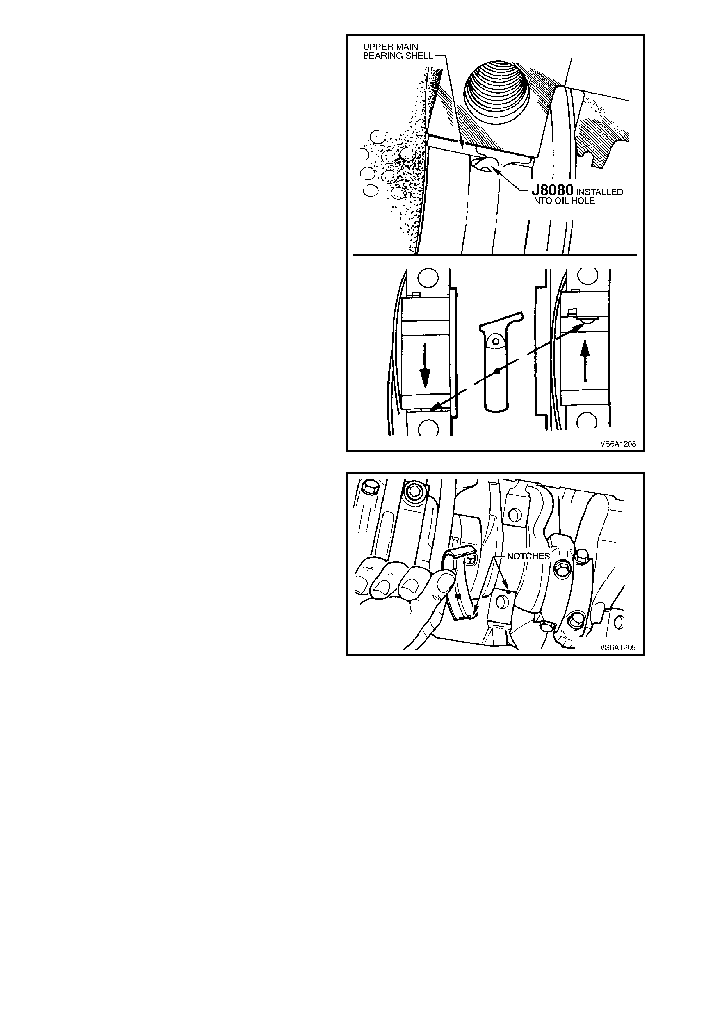
10. Remove upper bearing shell as follows:
a. Install Tool No. J8080 in the oil hole of the
crankshaft journal.
NOTE:
As an alternative to J8080, use a cotter pin.
b. Rotate crankshaft anti-clockwise as
viewed from front of engine. This will roll
upper shell out of cylinder block.
Remove Tool No. J8080 (or cotter pin).
11. Thoroughly clean crankshaft journal, cylinder
block bearing seat and bearing cap.
12. Lubricate new selected upper bearing.
Figure 6A1-1-218
13. Insert unnotched end of shell between
crank s haf t j ournal and notc hed s ide of c ylinder
block.
NOTE:
Ensure that the correct bearing shell is fitted
between the crankshaft journal and cylinder block
(refer to Fig. 6A1-1-220 for bearing shell
identification details).
Figure 6A1-1-219
14. Rotate bearing shell into place using
crankshaft and J8080 (or cotter pin).
15. Remove J8080 (or cotter pin) from crankshaft.
16. Check bearing to crankshaft clearance with
Plastigage as outlined in MAIN BEARING in
this Section.
17. Lubricate journal and bearing shells with
engine oil.
NOTE:
If replacing No. 2 main bearing shells, lubricate
thrust surfaces with engine oil.
18. Ensure that main bearing cap bolt threads and
cylinder block threads are clean and dry. Apply
some engine oil to the cap bolt threads.
19. Reinstall bearing cap and tighten all bearing
cap bolts to the correct torque specification.

NOTE:
Ensure that the bearing cap is installed into the
crankcase correctly and is parallel to bottom of
channel.
20. Before final ins tallation of cap bolts, determ ine
if bolts have stretched by comparing with a
new bolt. Replace bolt/s as necessary.
Reinstall main bearing caps, hand start main
bearing cap bolts, on eac h bearing cap in tur n,
tighten cap bolts half a turn at a time to
carefully seat cap.
Hand start main bearing cap side bolts.
Due to the thrust bearing shells being
disturbed, it is necessary to line up the thrust
surfaces of the bearing shells before the cap
bolts are tightened. To do this, move the
crankshaft fore and aft the length of its travel
several times (last movement forward).
NOTE 1:
Do not tighten one cap completely at a time,
progressively tighten all four caps to one step of
procedure before moving to next stage of torque.
Torque main bearing cap bolts to 70 Nm to
fully seat cap.
Loosen cap bolts 360° then torque all cap
bolts to 20 Nm and then 40 Nm.
Tighten cap bolts in steps of 35° + 35° + 35° to
a total of 105°.
Torque main bearing cap side bolts 12 - 18
Nm +42 - 48°.
NOTE 2:
New main bearing cap side bolts must be used to
ensure bolts remain oil tight to cylinder block.
Figure 6A1-1-220
NOTE 3:
Use an angle wrench such as E7115 to ensure
accurate turn angle.
MAIN BEARING CAP BOLT
TORQUE SPECIFICATION
Refer procedure
following
NOTE 1:
21. If the thrust bearing shell is disturbed or
replaced, it is necessary to line up the thrust
surfaces of the bearing shells before the cap
bolts are tightened. To do this, move the
crankshaft fore and aft the length of its travel
several times (last movement forward) with the
thrust bearing cap bolts finger tight.
Figure 6A1-1-221
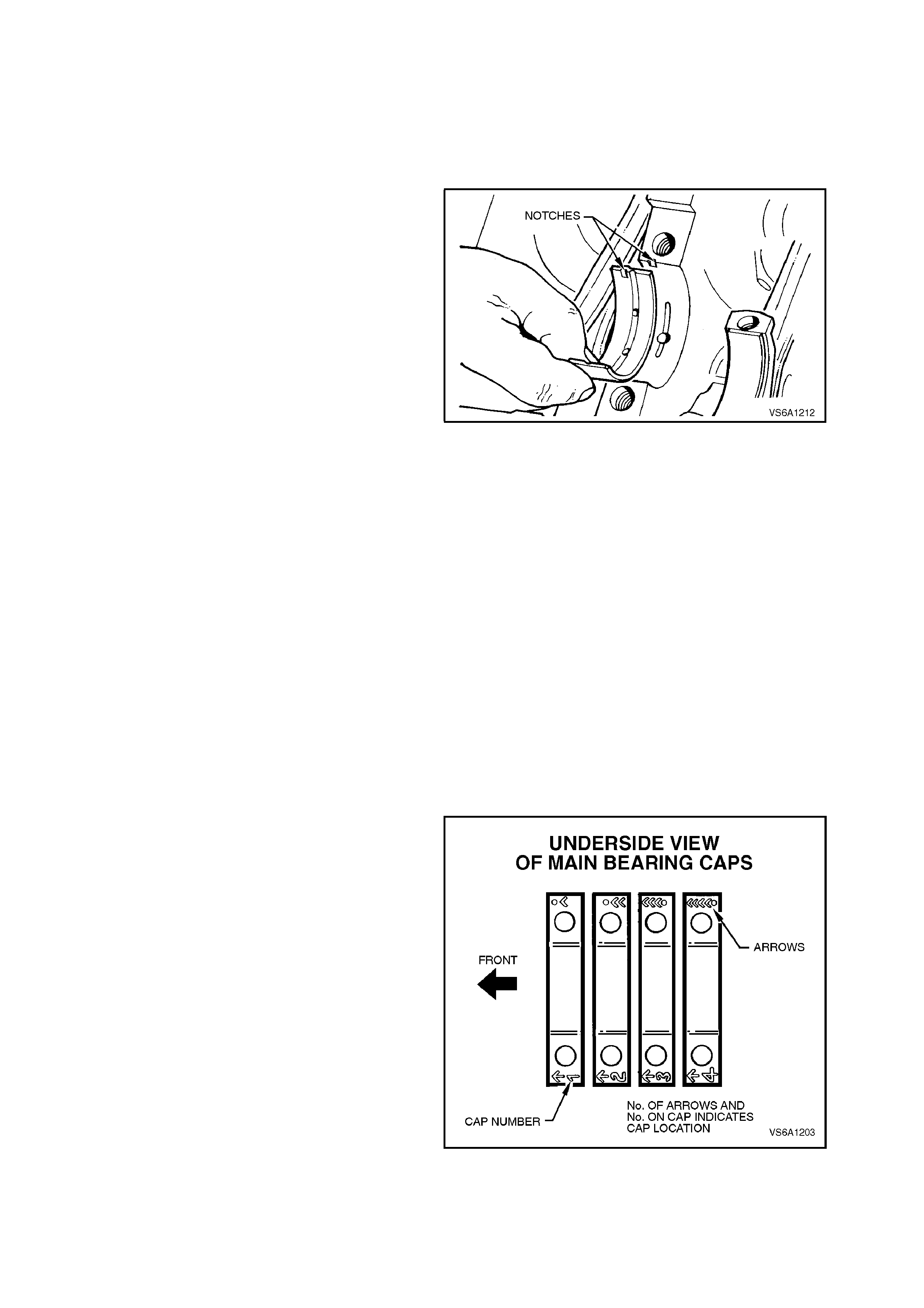
WITH CRANKSHAFT REMOVED
1. Remove crankshaft, refer to
3.12 CRANKSHAFT in this Section.
2. Remove bearing shells from cylinder block
and bearing caps.
3. Thoroughly clean crankshaft journals, bearing
caps and cylinder block bearing shell seats.
4. Install new bearing upper shells in cylinder
block, ensuring notches in bearing shells align
with recesses in cylinder block.
Figure 6A1-1-222
NOTE:
Ensure the correct bearing shells are fitted into the
appropriate cylinder block bearing seat (refer to
Fig. 6A1-1-210 in this Section for bearing shell
identification details).
5. Lubricate No. 2 main bearing shell thrust
surfaces with engine oil.
6. Lay crankshaft in upper bearing shells, taking
care not to damage crankshaft thrust flange
and No. 2 main bear ing thrus t f ac es . Als o tak e
care not to contact connecting rod journals
with connecting rods.
7. Install lower bearing shells in bearing caps,
ensuring the notches in the shells align with
the recesses in the caps and the correct
bearing shell is installed in the appropriate
cap.
8. Measure bearing to crankshaft clearances as
outlined in MAIN BEARINGS in this Section.
NOTE:
Ensure that bearing c ap is ins talled into the c ylinder
block correctly.
Figure 6A1-1-223
9. If clearances are satisfactory, continue
reassembly of crankshaft, refer to
3.12 CRANKSHAFT in this Section.
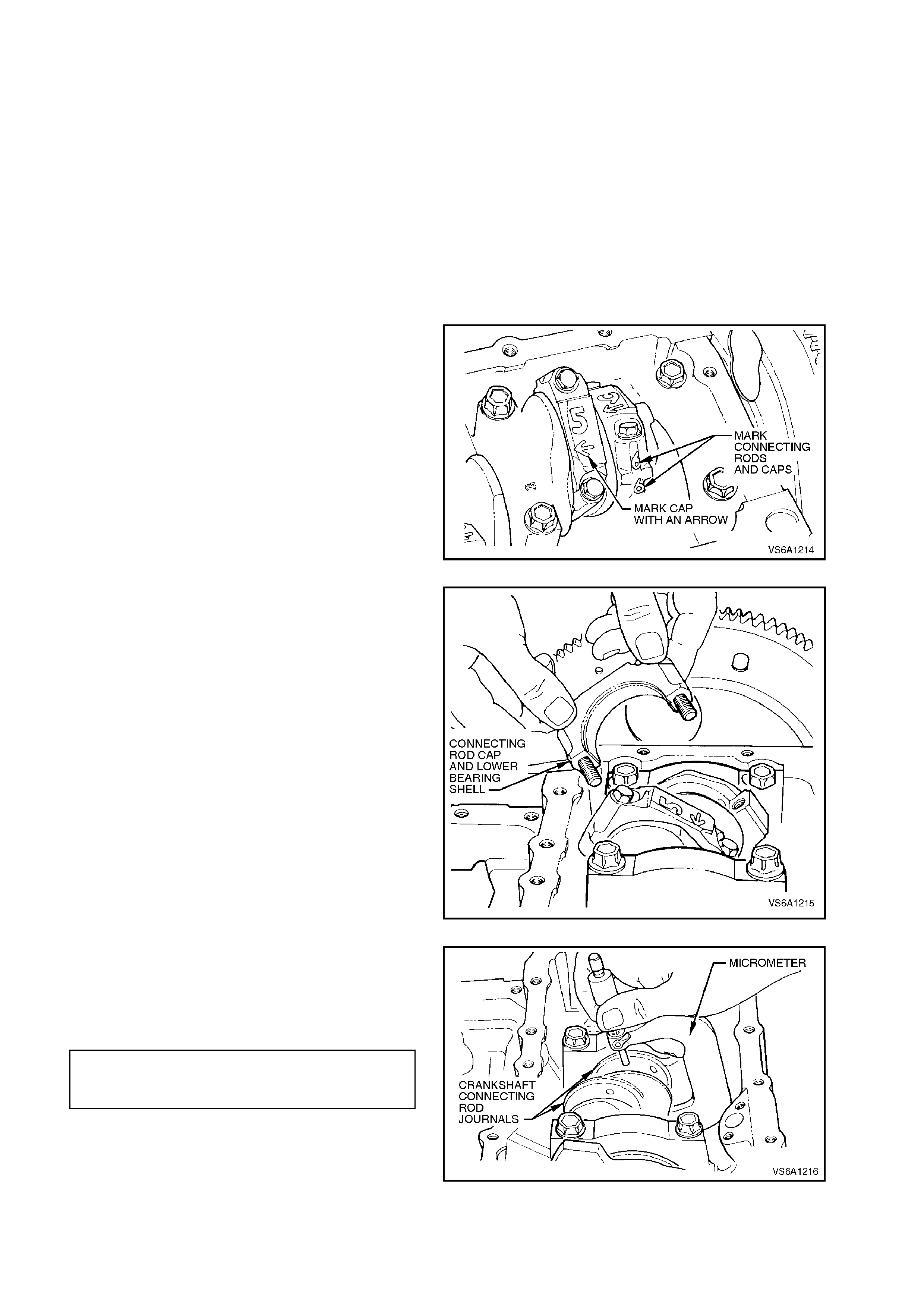
CONNECTING ROD BEARINGS - INSPECT AND REPLACE
Connecting rod bearings can be replaced without
removing the rod and piston assembly from the
engine.
1. With engine removed from vehicle refer to
3.1 ENGINE ASSEMBLY in this Section,
mount in a suitable engine stand and invert
engine assembly.
2. Remove oil pan, refer to 3.2 OIL PAN AND
SEAL in this Section.
3. Remove oil pump suction pipe and screen,
refer to 3.3 OIL PUMP SUCTION PIPE AND
SCREEN in this Section.
4. Remove spark plugs.
5. Mark connecting rods and caps with an
etching marker or felt tipped pen to indicate
cylinder number and orientation of cap.
Figure 6A1-1-224
6. Remove connecting rod cap securing bolts
and remove cap and lower bearing shell.
7. Push piston and connecting rod up cylinder
bore, so that connecting rod is free from
crank shaft jour nal. Remove bearing s hell from
connecting rod.
Figure 6A1-1-225
8. Clean crank shaft journal and measure for out-
of-round or taper with a micrometer.
If not to spec ification, replac e crank shaft, ref er
to 3.12 CRANKSHAFT in this Section.
CRANKSHAFT CONNECTING
ROD BEARING 57.117 - 57.147
JOURNAL DIAMETER mm
Figure 6A1-1-226
9. W ipe oil f rom both inner and outer s urfaces of
bearing shells.
10. Check inner surface of bearing shells for
wear, gouges or imbedded foreign material.
If foreign material is found, determine its
nature and source.
Inspect outer surface of bearing shell for
surface wear (indicates movement of shell or
high spot in surrounding m ater ial), over heating
(discolouration) or looseness or rotation
(flattened tangs and wear grooves).
If uneven side to side wear is found, the
crankshaft may be bent or have tapered
bearing journals. If necessary, remove
crankshaft, refer to 3.12 CRANKSHAFT -
REMOVE in this Section and check crankshaft
for bend or journal taper.
IMPORTANT:
Bearing failure, other than normal wear, must be
investigated carefully. With crankshaft removed,
inspect all connecting rod and crankshaft bearing
bores.
To inspect the bearing bores:
a. Install bearing caps without bearing shells
installed. Tighten cap bolts to the
specified torque.
CONNECTING ROD CAP BOLT
TORQUE SPECIFICATION
24 - 30 Nm
plus 47 - 53
degree turn
angle
b. Measure bearing bores for taper and out -
of-round.
Replace any component if not to
specification, refer to the relevant
component description in this Section.
CONNECTING ROD BEARING
BORE DIAMETER 60.295 -
60.312 mm
MAXIMUM OUT-OF-ROUND 0.008 mm
MAXIMUM TAPER 0.008 mm
11. If inspection reveals that crankshaft is OK,
reinstall bearing shells in original positions in
connecting rod and cap.
12. Pull connecting rod onto crankshaft so that
upper bearing is seated against crankshaft
journal.
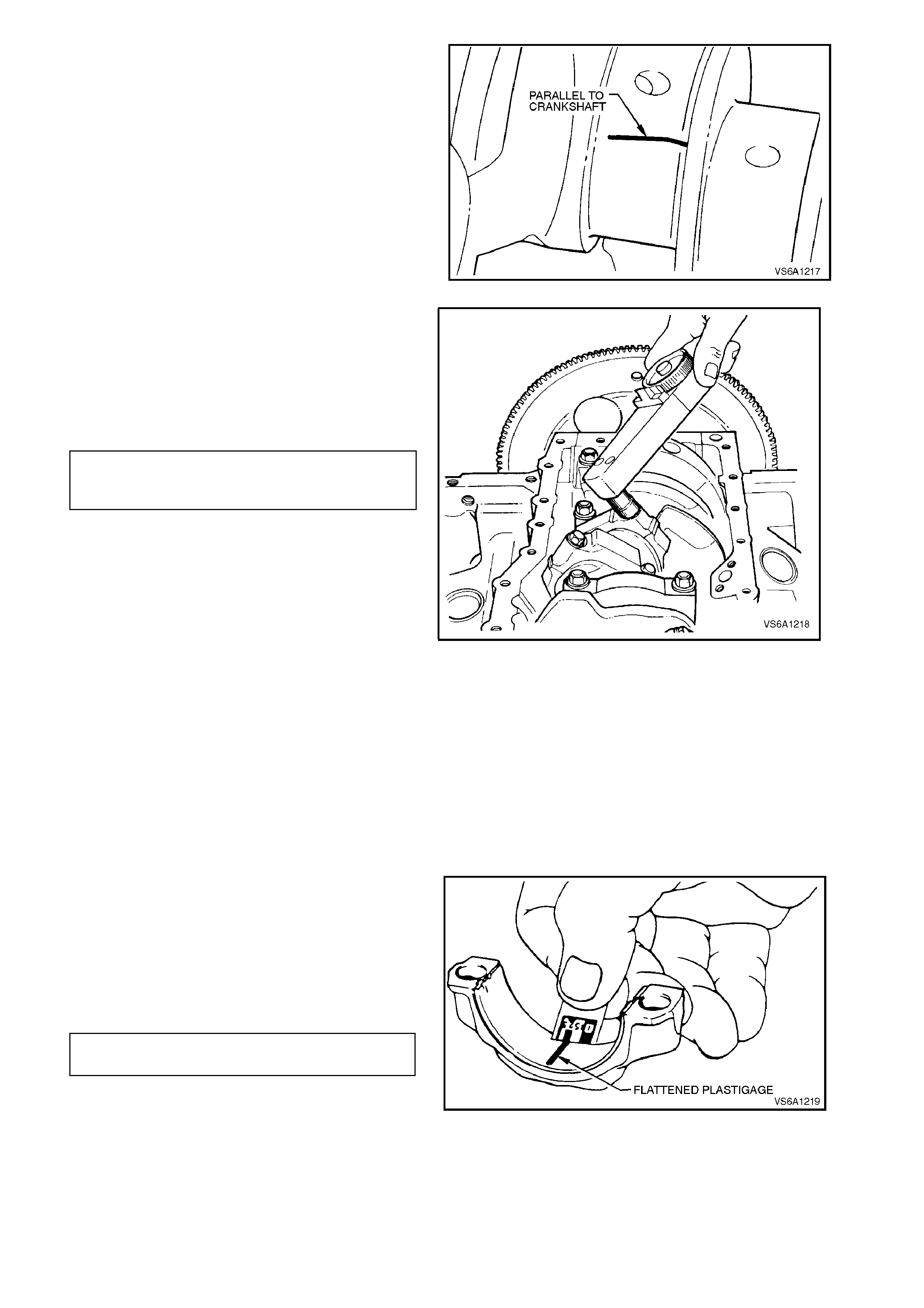
13. Place a piece of Plastigage across width of
bearing journal, parallel to crankshaft
centreline.
NOTE:
Ensure Plastigage is not placed across oil hole in
journal.
Figure 6A1-1-227
14. Reinstall connecting rod cap in original position
as noted in step 5. T ighten bolts to the correct
torque specification.
NOTE:
Ensure that crankshaft does not turn with
Plastigage installed.
CONNECTING ROD 24 - 30 Nm
CAP BOLT plus 47 - 53
TORQUE SPECIFICATION degree turn angle
NOTE:
Use an angle wrench such as E7115 to ensure
accurate turn angle.
Figure 6A1-1-228
15. Remove connecting rod cap bolts, remove
cap. Look for flattened Plastigage adhering to
either crankshaft or bearing shell in cap.
16. Determine bearing clearance by comparing
width of flattened Plastigage at widest point
with graduation on Plastigage envelope. The
number within the graduation on the envelope
indicates the clearance.
Clearance between connecting rod bearings
and crankshaft should not exceed
specification.
NOTE:
If a bearing is being fitted to an out-of-round
journal, be sure to fit Plastigage to the maximum
diameter of the j ournal. If the bearing is f itted to the
minimum diameter, and the journal is out-of-round
0.008 mm, interference between the bearing and
journal will result in rapid bearing failure.
CONNECTING ROD BEARING 0 .023 - 0.053
CLEARANCE mm
Figure 6A1-1-229
17. Ensure that connecting rod cap bolt threads
and connecting rod thr eads are clean and dry.
Apply some engine oil to the cap bolt threads.
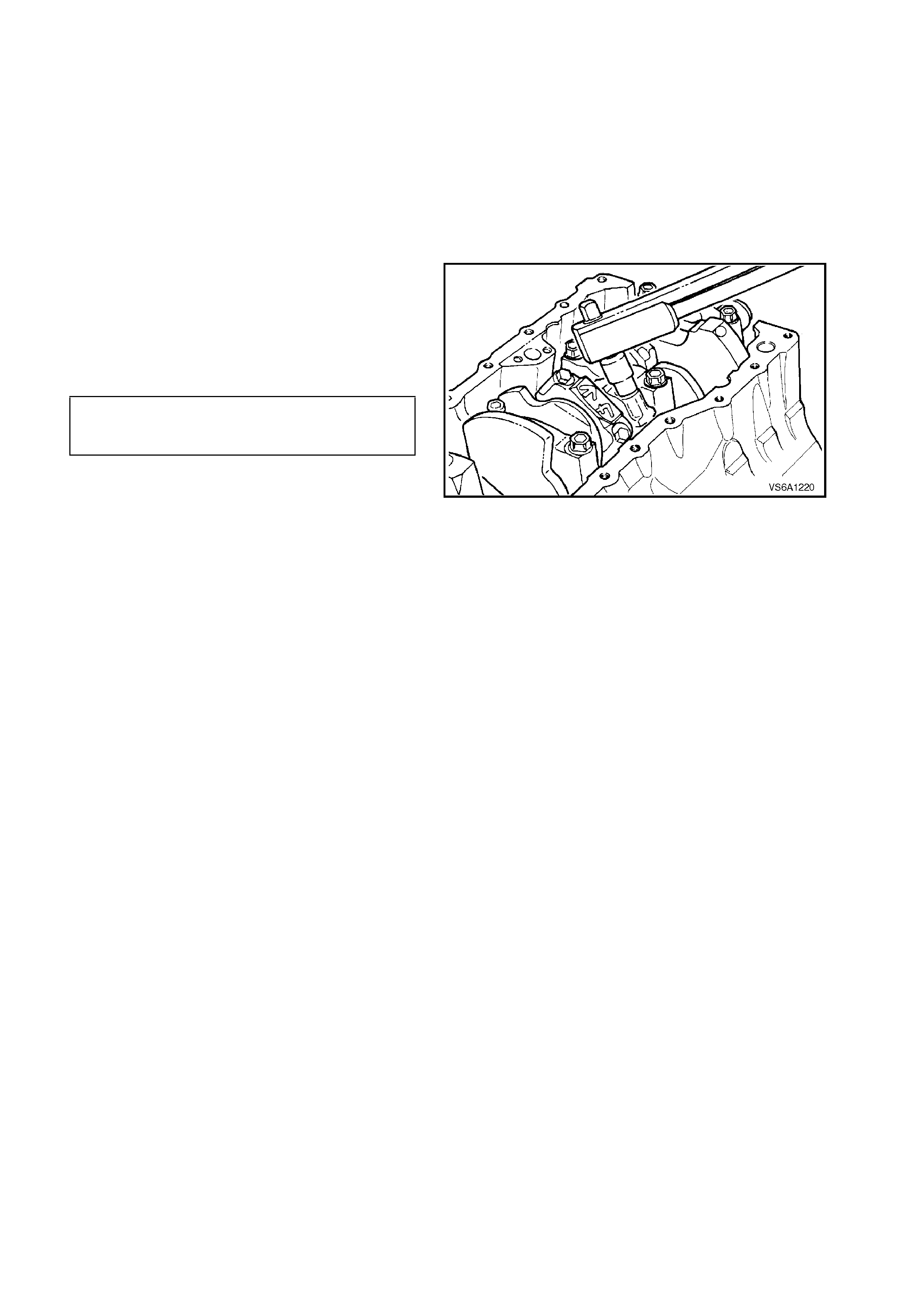
NOTE:
Before final installation of cap bolts, determine if
bolts have stretched by com paring with a new bolt.
Replace bolt/s as necessary.
18. Install bearing shells in connecting rod and
cap, ensuring notches in shells match up with
recesses in connecting rod and cap.
Check clearance of new bearing with
Plastigage as previously described.
19. Remove all traces of Plastigage after
measuring.
20. Lubricate bearing s hells and jour nal with clean
engine oil. Reinstall connecting rod cap in
original position as noted in step 5. Tighten
bolts and then loosen one full turn. Finally
tighten cap bolts to the correct torque
specification.
CONNECTING ROD 24 - 30 Nm
CAP BOLT plus 47-53
TORQUE SPECIFICATION degree turn angle
NOTE:
Use an angle wrench such as E7115 to ensure
accurate turn angle. Figure 6A1-1-230
21. With bearing shells installed and cap bolts
tightened, it should be possible to move
connecting rod back and forth on crankshaft
journal as allowed by end clearance. Als o, the
crankshaft should rotate without binding.
If connecting rod binds on crankshaft journal,
loosen and re-tighten bearing cap bolts.
If rod still cannot be moved or crankshaft
binds, check bearing cap to rod orientation,
bearing clearance or connecting rod
alignment.
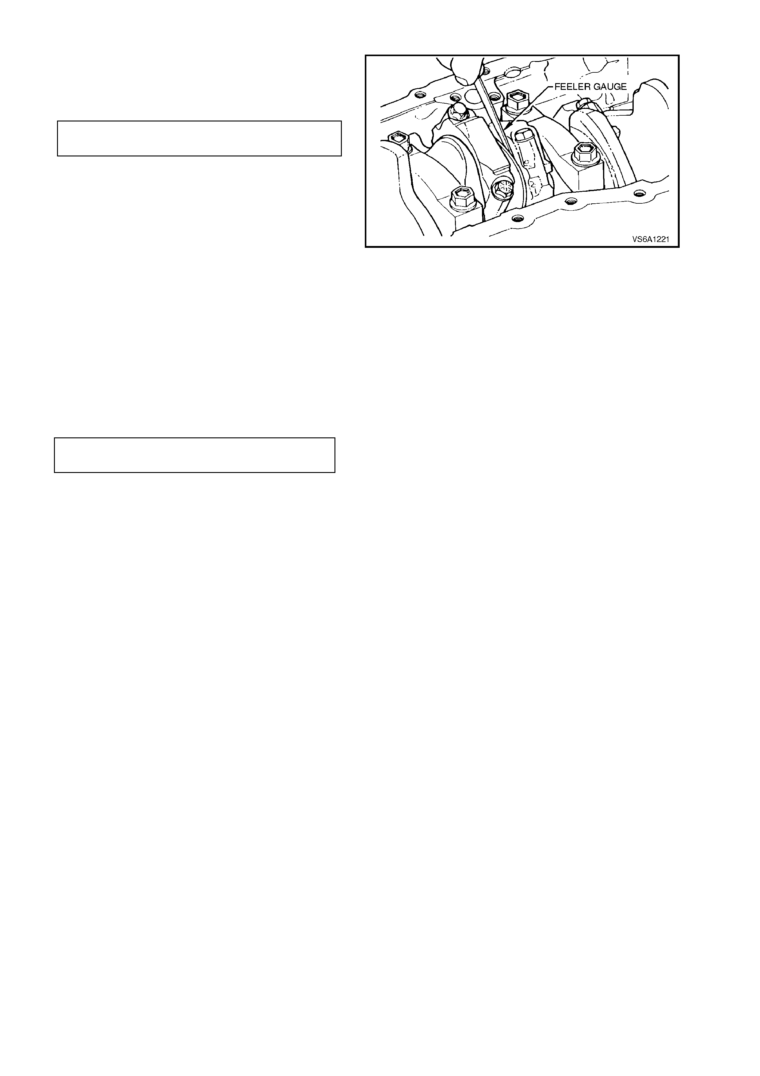
22. Measure clearance between connecting rods
and crankshaft journal flanges with a feeler
gauge.
CONNECTING ROD 0.10 - 0.50
SIDE CLEARANCE mm
Figure 6A1-1-231
23. Reinstall oil pump suction pipe and screen,
refer to 3.3 OIL PUMP SUCTION PIPE AND
SCREEN in this Section.
24. Reinstall oil pan, refer to 3.2 OIL PAN AND
SEAL in this Section.
25. Reinstall rear main oil seal, refer to
3.13 REAR MAIN OIL SEAL in this Section.
26. Reinstall spark plugs and tighten to the c orr ec t
torque specification.
SPARK PLUG
TORQUE SPECIFICATION 15 - 25
Nm
27. Refill oil pan with the cor r ect amount of engine
oil, refer to Section 0B LUBRICATION.
28. Reinstall engine assembly. Start engine and
check for oil leaks. Repair as necessary.
29. Check engine oil pressure, refer to
2.2 CHECKING ENGINE OIL PRESSURE in
this Section.
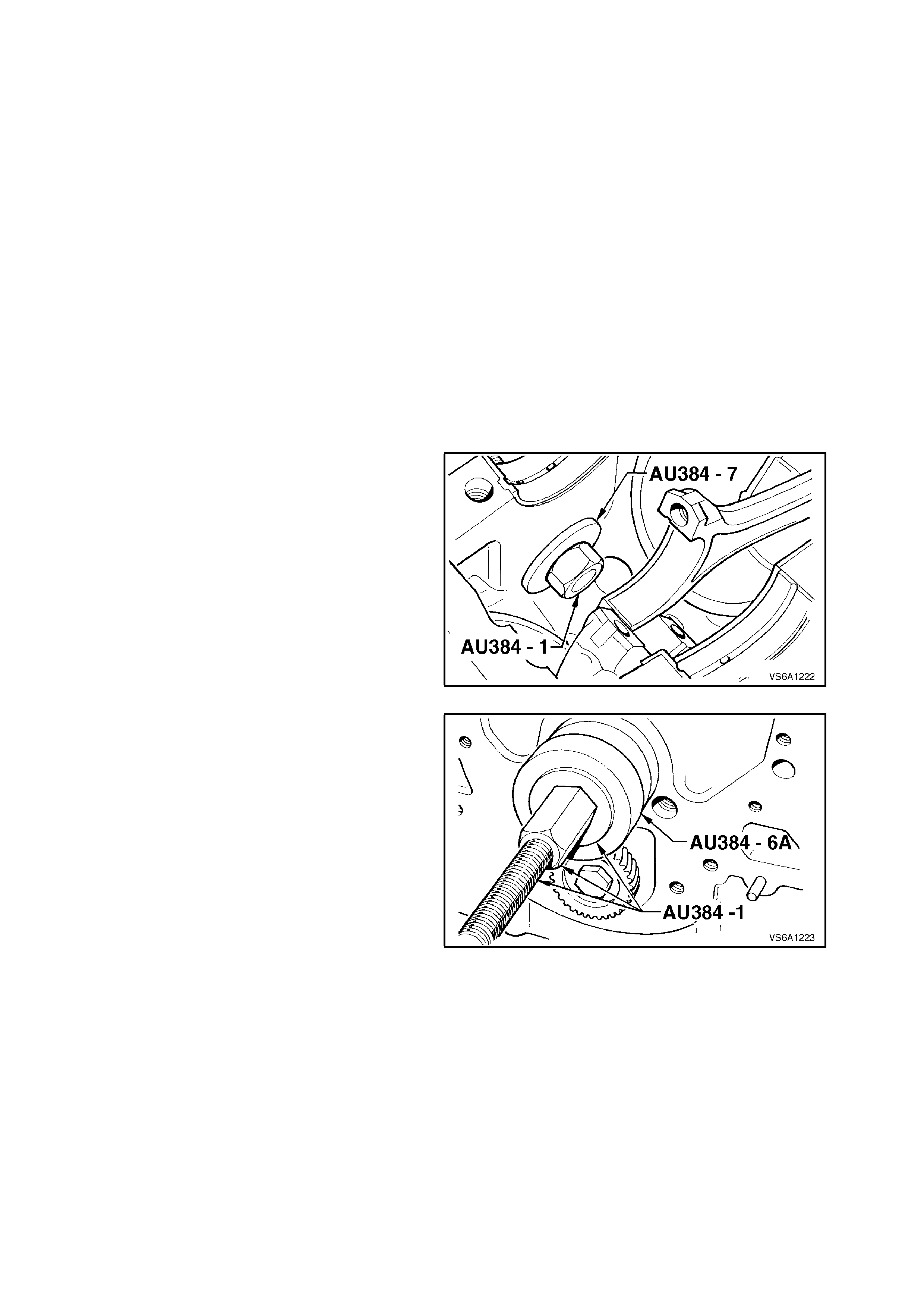
3.8 CAMSHAFT BEARINGS
REPLACE
Care must be exercised during bearing removal
and installation, not to damage bearings that are
not being replaced.
The following operations involve the use of Tool
No. AU384-B and finished sized camshaft
bearings. If installing unfinished sized bearings,
installation must be carried out by a specialist
machine shop and then line bored to correct final
size.
1. With engine removed from vehicle, refer to
3.1 ENGINE ASSEMBLY in this Section and
mounted in a suitable stand, remove
camshaft, refer to 2.22 CAMSHAFT in this
Section.
Inspect camshaft and lifters for contact
damage.
2. Remove crankshaft, refer to
3.12 CRANKSHAFT in this Section.
3. Install Tool No. AU384-7 into camshaft
bearing and assemble puller screw, Tool No.
AU384-1, into AU384-7. Install receiving
sleeve AU384-6A, washer and puller screw
nut onto puller screw.
Figure 6A1-1-232
4. Tighten nut and pull bearing from bore.
Figure 6A1-1-233
5. With bearing released from its bore,
disassemble remover tool and remove
bearing.
6. Remove all bearings in the same manner.
7. Install new bearing onto AU384-7 and install
into cylinder block, aligning oil hole/s in
bearing with holes in cylinder block.
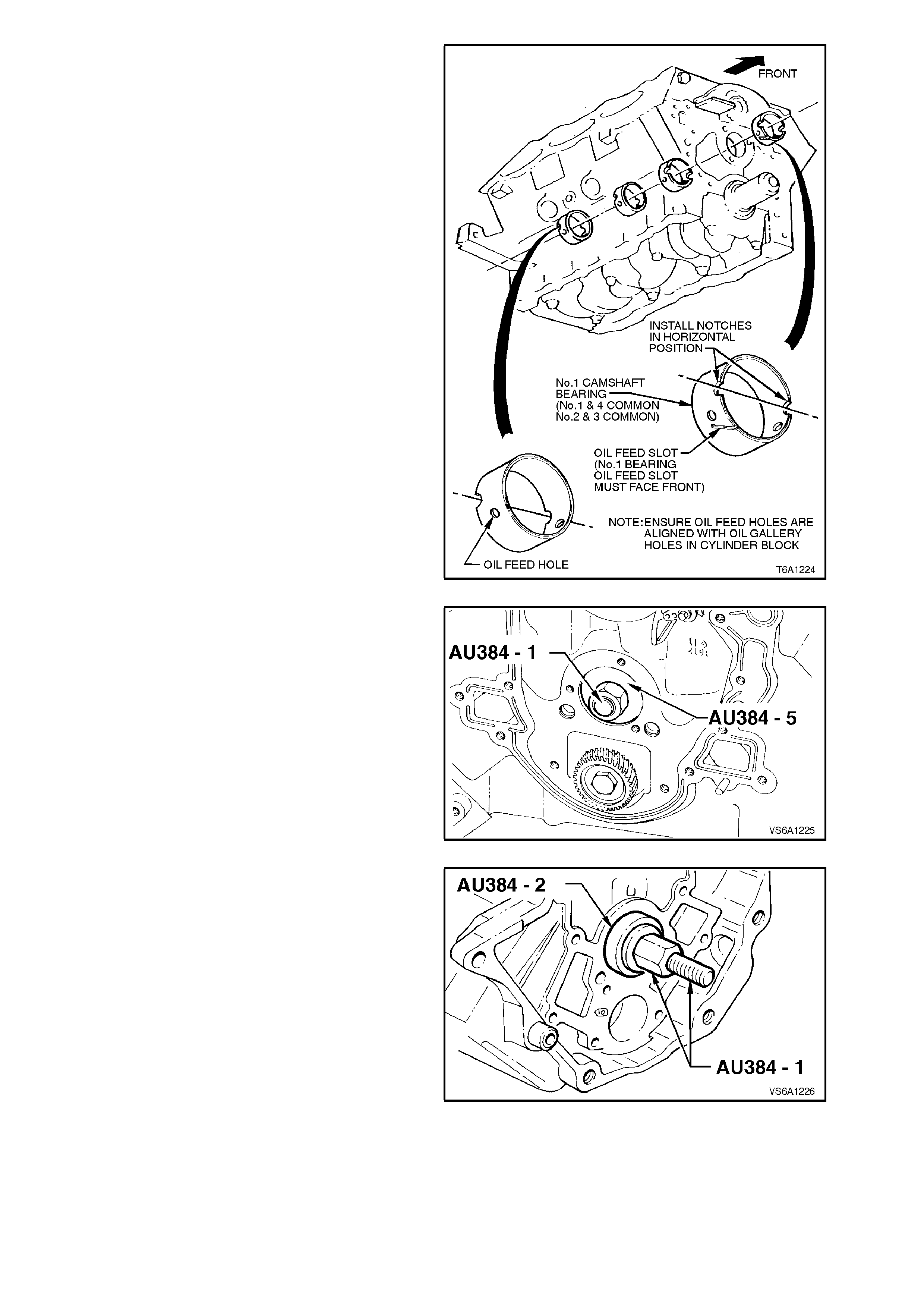
NOTE 1:
The new bearing is a loose fit on Tool No. AU384-
7. As the bearing is installed into its bore, the
bearing will 'collapse' to the correct installed size.
The bearing must be installed with the notches in
the horizontal position as shown in Fig. 6A1-1-234
to ensure correct oil gallery alignment.
NOTE 2:
The camshaft bearings for journals 1 and 4 are
common, with 2 and 3 being common.
NOTE 3:
The bearings for journals 1 and 4 are identified by
having an oil feed slot on the outer surface.
NOTE 4:
Ensure that when installing No. 1 cams haf t bear ing,
the oil feed slot faces in the direction indicated in
Fig. 6A1-1-234.
Figure 6A1-1-234
8. Install puller screw, receiving sleeve, Tool No.
AU384-2, washer and puller nut.
Figure 6A1-1-235
9. Tighten nut until bearing is installed into the
correct position.
10. Install all bearings in the same manner.
Figure 6A1-1-236
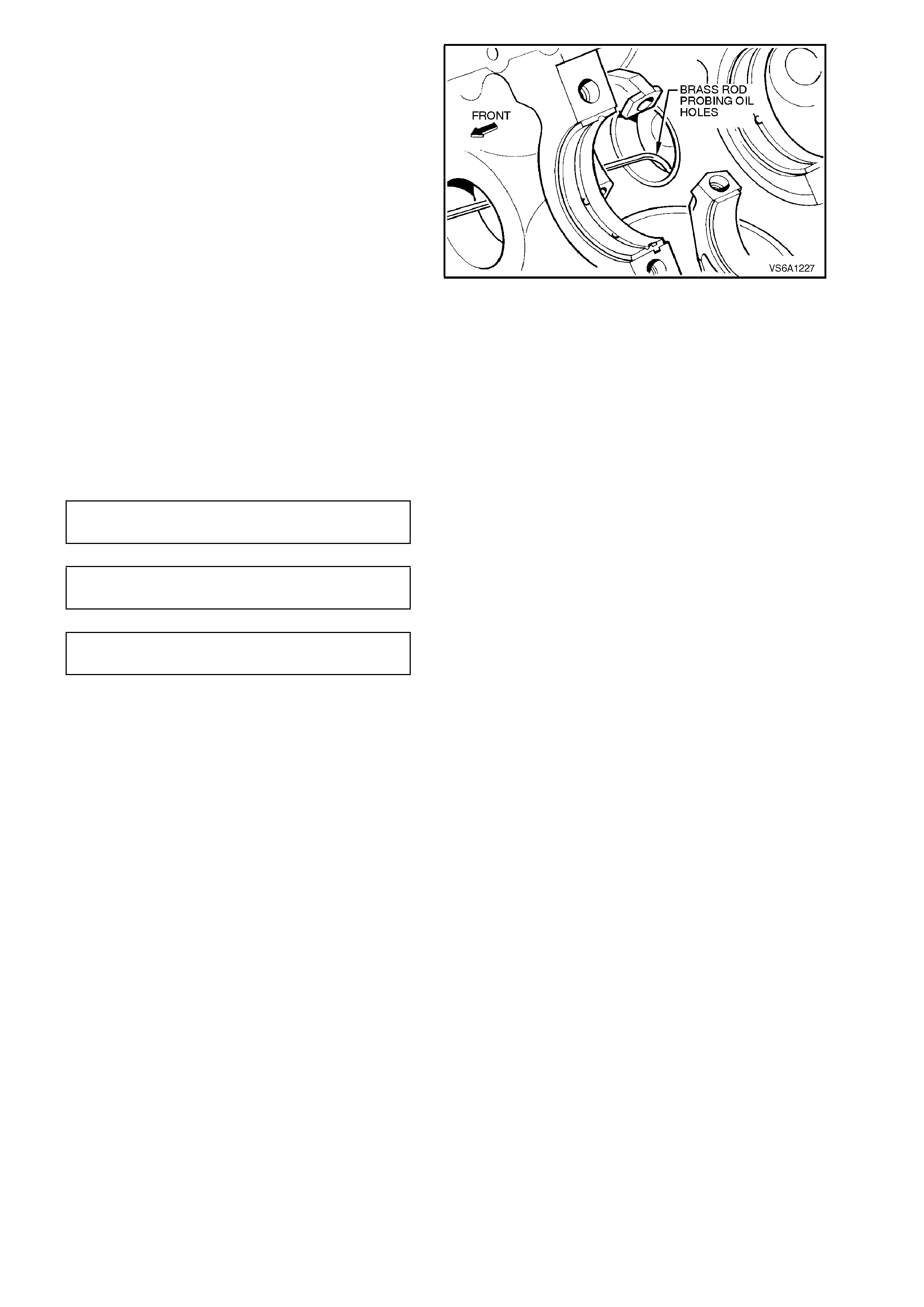
11. With a piece of 2.4 mm diameter brass rod
with a 90 degree bend at the end, probe the
camshaft bearing oil holes to verify that they
are properly aligned with oil feed holes in
cylinder block.
NOTE:
Proper alignment of the oil holes is critical.
Restriction of the oil flow will cause severe engine
damage.
Figure 6A1-1-237
12. Lubricate camshaft bearings and journals with
clean engine oil. Temporarily install camshaft.
Ensure camshaft rotates without binding.
If camshaft binds, remove camshaft, inspect
bearings for high spots or incorrect
installation. Remove any burrs if present.
Check camshaft journal to bearing clearance.
If camshaft bearing journals are not within
specification, replace camshaft.
CAMSHAFT JOURNAL
DIAMETER 46.858 -
46.893 mm
CAMSHAFT BEARING
DIAMETER (INSTALLED) Refer to
SPECIFICATIONS
CAMSHAFT BEARING TO
JOURNAL CLEARANCE Refer to
SPECIFICATIONS
13. Reinstall camshaft and valve train
com ponents , refer to 2.22 CAMSHAFT in this
Section.
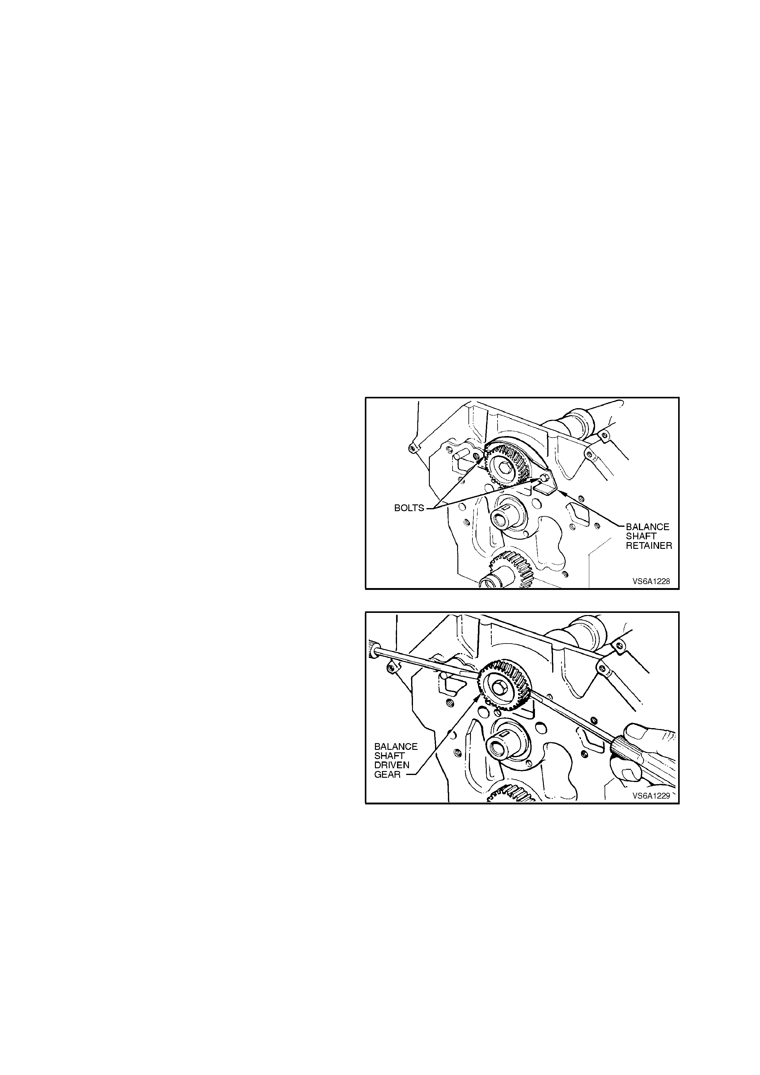
3.9 BALANCE SHAFT AND BE ARINGS
REMOVE
NOTE:
The balance shaft and both bearings are serviced
as a complete package.
1. With the engine removed from the vehicle,
refer to 3.1 ENGINE ASSEMBLY in this
Section, mount it in a suitable engine stand.
2. Remove lower inlet manifold, refer to
2.9 LOWER INLET MANIFOLD in this
Section.
3. Remove front cover, refer to
2.19 FRONT COVER AND GASKET in this
Section.
4. Remove rear main oil seal and housing, refer
to 3.13 REAR MAIN OIL SEAL in this
Section.
5. Remove tim ing chain, sproc kets and cam s haft
gear, refer to 2.21 TIMING CHAIN,
TENSIONER, SPROCKETS AND BALANCE
SHAFT GEARS in this Section.
6. Remove balance s haft retainer attaching bolts,
remove retainer.
Figure 6A1-1-238
7. Using two screwdrivers, positioned behind
balance shaft driven gear, lever balance shaft
until front bearing area is free from its bore.
NOTE 1:
Ensure that screwdrivers lever behind the step on
the gear, behind the gear teeth. Do not lever
against the gear teeth.
NOTE 2:
If the balance shaft cannot be removed from
cylinder block in this method, remove driven gear
retaining bolt and gear. Install slide hammer, Tool
No. AU354, into balance shaft gear bolt hole and
remove balance shaft. Figure 6A1-1-239
8. Remove balance shaft from cylinder block.
9. Remove balance shaft driven gear, refer to
2.21TIMING CHAIN, TENSIONER,
SPROCKETS AND BALANCE SHAFT
GEARS in this Section.
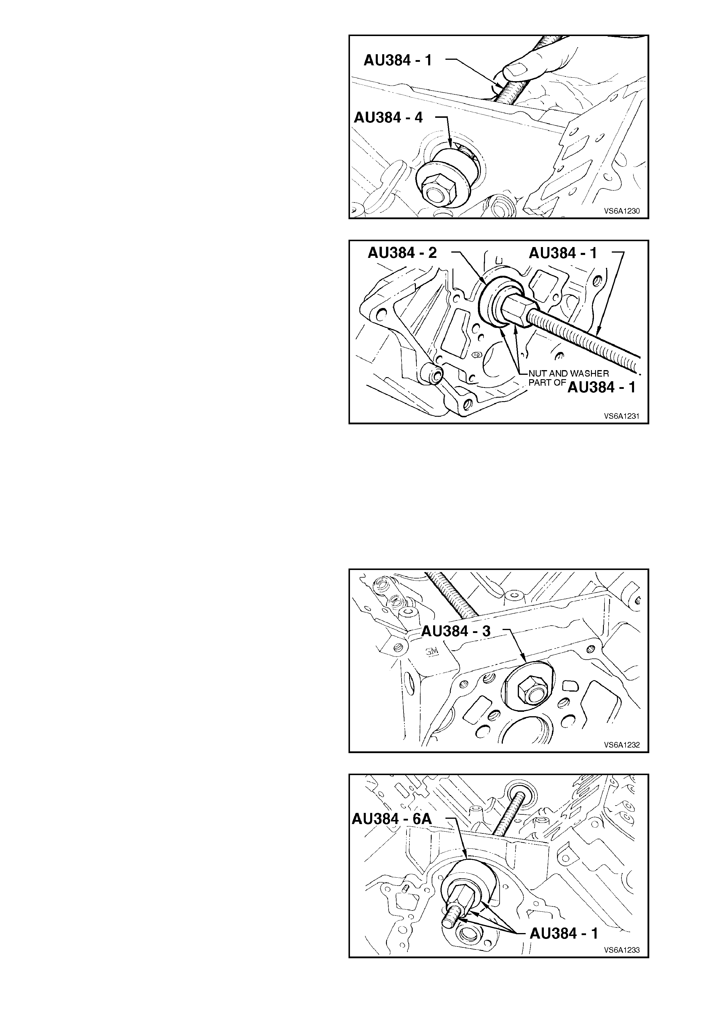
10. Install Tool No. AU384-4 onto puller screw
AU384-1 and assemble into balanc e s haf t rear
bearing.
Figure 6A1-1-240
11. Install receiving Tool No. AU384-2 into rear of
bearing bore. Install washer and puller nut to
puller screw.
12. Tighten nut to remove rear bearing.
Figure 6A1-1-241
13. With bearing released from its bore,
disassemble remover tools and remove
bearing and discard.
REINSTALL
1. Dip new rear bearing in clean engine oil.
2. Install new rear bearing onto AU384-3 and
install into bearing bore.
3. Install puller screw into AU384-3.
Figure 6A1-1-242
4. Assem ble receiving sleeve AU384-6A, washer
and nut to puller screw.
5. Tighten nut to draw bearing into bore, at the
same time ensure that the flats on Tool No.
AU384-3 are at right angles to the bosses on
rear of cylinder block refer Fig 6A1-1-243.
Continue to tighten nut until the curved rear
section of AU384-3 just contacts the
transmission to cylinder block boss.
Figure 6A1-1-243
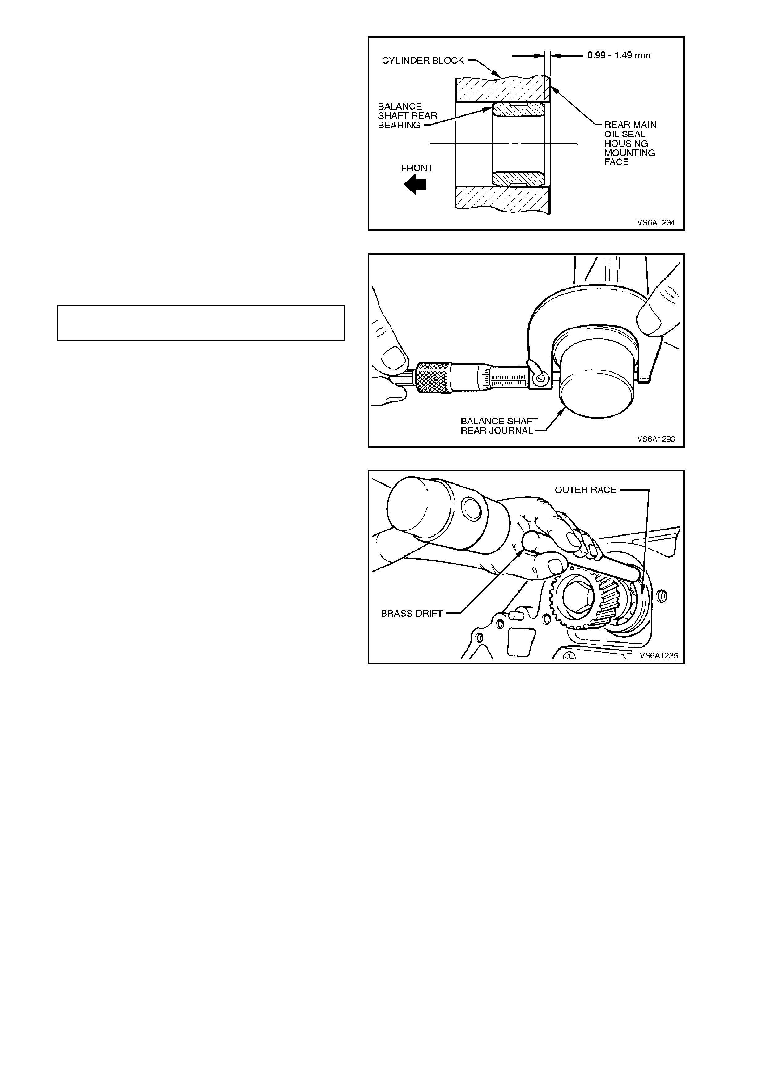
6. Remove bearing installation tools and check
that bearing is installed to the correct
dimension .
Figure 6A1-1-244
7. Check balance shaft rear bush clearance
specification.
REAR BUSH CLEARANCE 0.025 - 0.130
SPECIFICATION mm
Figure 6A1-1-245
8. Lubricate balance shaft front and rear
bearings and rear bearing journal with clean
engine oil.
9. Reinstall balance shaft driven gear (refer to
2.21 TIMING CHAIN, TENSIONER,
SPROCKETS AND BALANCE SHAFT
GEARS in this Section).
10. Install balance shaft into bearing bores. Using
a brass drift and a soft faced hammer, lightly
tap on balance shaft front bearing outer race
until front bearing is fully installed in bore
(bearing outer snap ring seated against
cylinder block). Figure 6A1-1-246
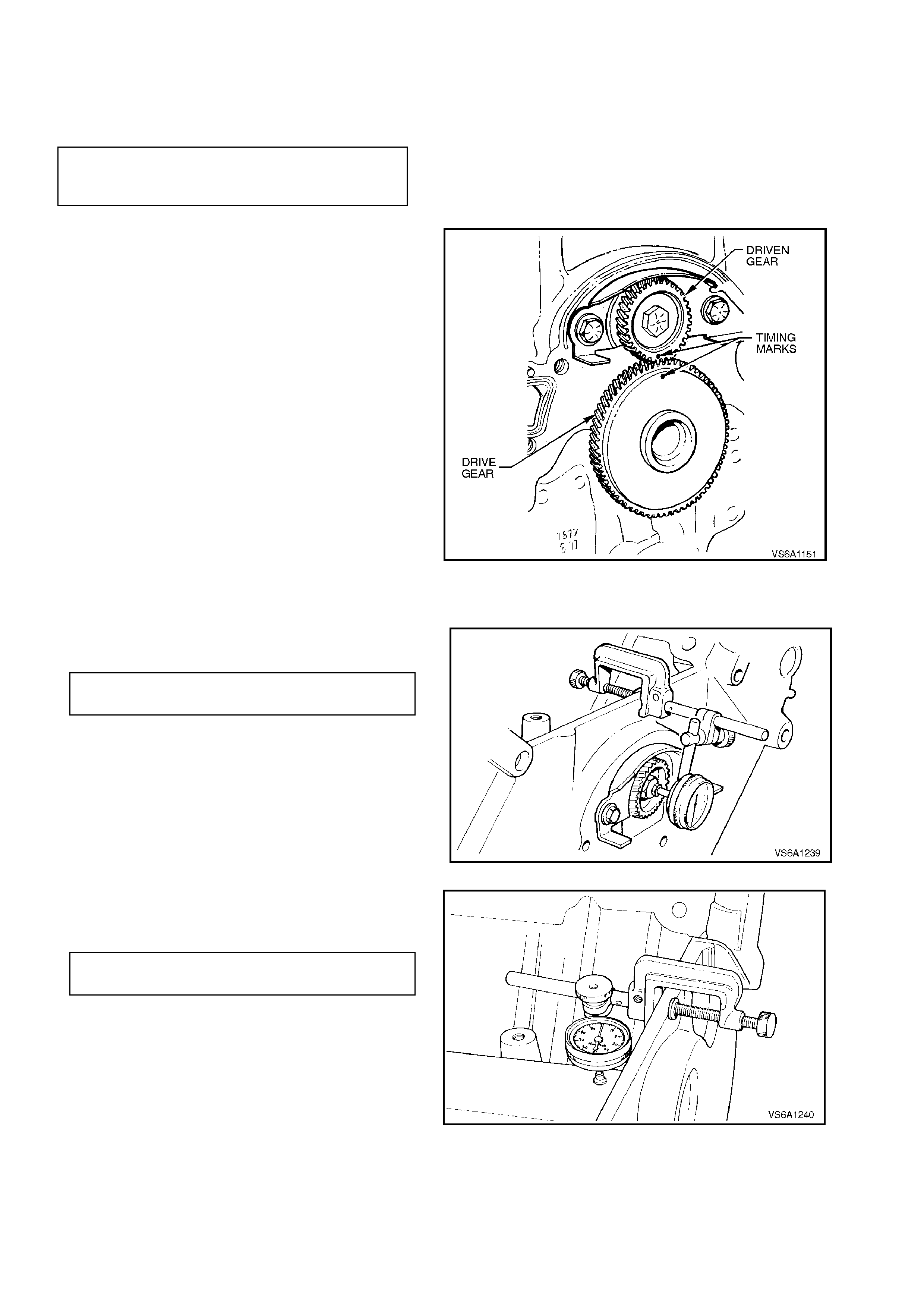
11. Install balance shaft retainer and attaching
bolts.
Tighten retainer attaching bolts to the correct
torque specification.
BALANCE SHAFT RETAINER
ATTACHING BOLT
TORQUE SPECIFICATION 26 - 34 Nm
12. Rotate balance shaft by hand and ensure that
it spins freely.
13. Reinstall sprocket key to front end of
camshaft.
Reinstall balance shaf t drive gear to cam shaf t,
aligning sprocket key with gear slot and
ensuring that timing marks on each of the
balance shaft gears face together.
It may be necessary to rotate balance shaft
slightly to ensure that balance shaft timing
marks align.
Figure 6A1-1-247
14. With balance shaft installed, carry out the
following balance shaft checks.
a. Measure balance shaft end play
BALANCE SHAFT END PLAY 0 - 0.203
SPECIFICATION mm
Figure 6A1-1-248
b. Measure balance shaft front and rear
radial play.
FRONT RADIAL PLAY 0 - 0.028
SPECIFICATION mm
Figure 6A1-1-249
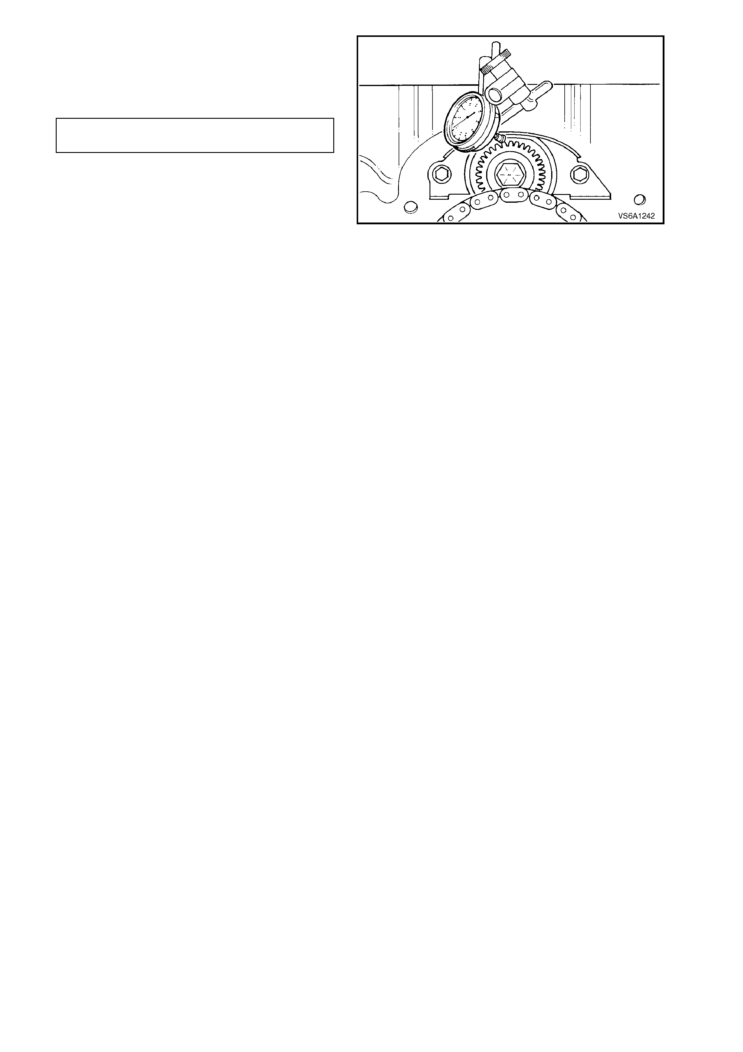
15. Carry out the following procedure to measure
balance shaft drive gear lash:
a. Measure balance shaft gear lash at four
locations (every 1/4 turn).
BALANCE SHAFT GEAR LASH 0.050 - 0.127
SPECIFICATION mm
b. If gear lash exceeds specifications,
replace drive gears.
Figure 6A1-1-250
16. Reinstall balance shaft drive gear, timing
chain and camshaft sprocket, refer to
2.21 TIMING CHAIN, TENSIONER,
SPROCKETS AND BALANCE SHAFT
GEARS in this Section.
17. Reinstall lower inlet manifold, refer to
2.9 LOWER INLET MANIFOLD in this
Section.
18. Reinstall front cover, refer to 2.19 FRONT
COVER AND GASKET in this Section.
19. Reinstall rear main oil seal and housing, refer
to 3.13 REAR MAIN OIL SEAL in this
Section.
20. Start engine and check for oil, fuel or coolant
leaks. Repair as necessary.
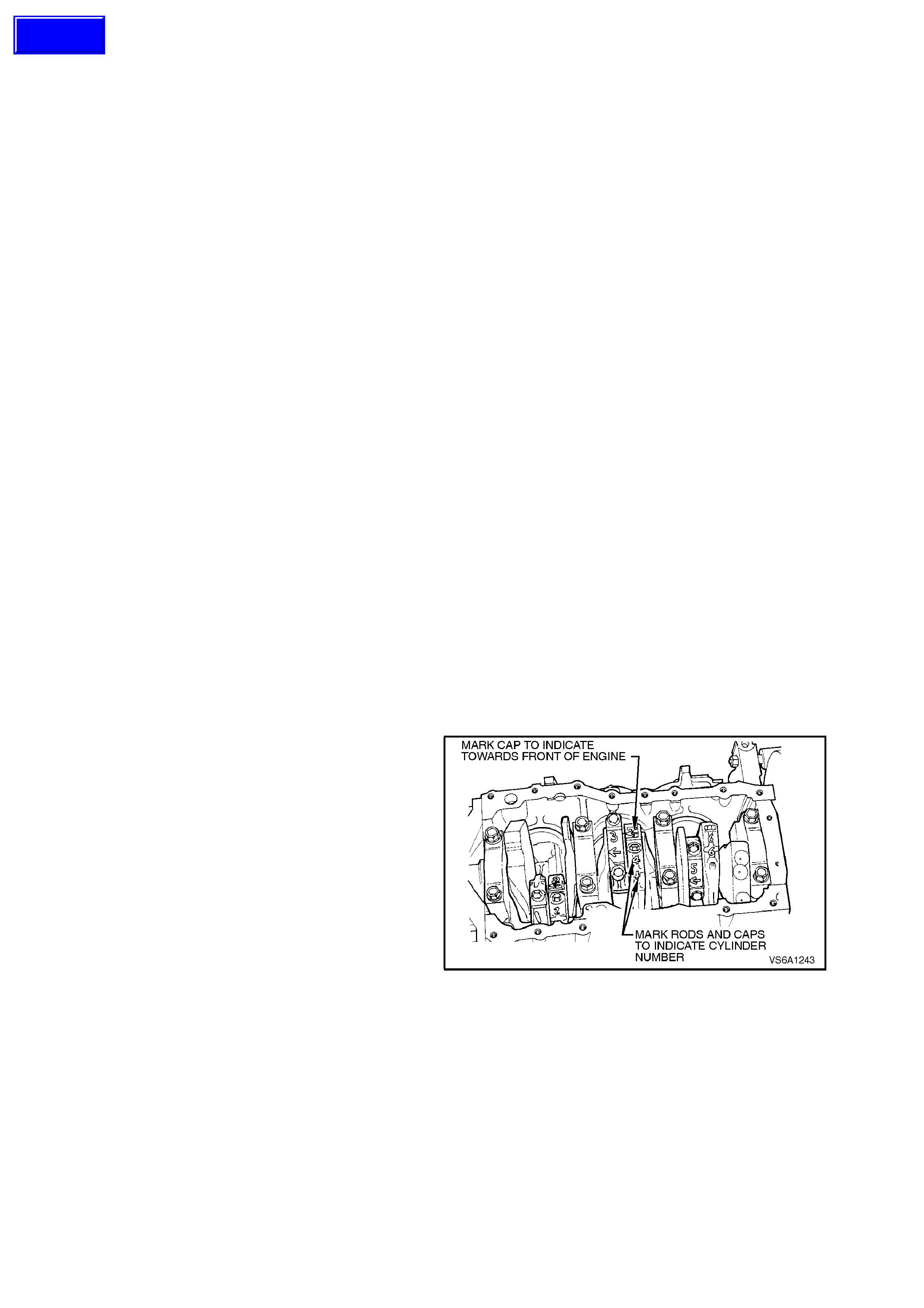
3.10 PISTON AND CONNECTING ROD ASSEMBLY
The piston and connecting rod assemblies can be
removed without the engine being removed.
If the cylinder bore requires mac hining, rem ove the
engine assembly, refer to
3.1 ENGINE ASSEMBLY in this Section, and
remove piston and connecting rod assemblies.
Piston and pin assemblies/piston ring sets are
available in std. and 0.508 mm oversizes.
When fitting pistons, both piston and cylinder bore
condition must be considered together. Production
and service pistons have the same nominal weight
and can be intermixed without affecting engine
balance. If necessary, used pistons may be fitted
selectively to any cylinder of the engine, providing
they are in good condition.
NOTE:
Do not machine oversize pistons down or engine
balance will be affected.
REMOVE
1. Disconnect battery earth lead.
2. Remove cylinder heads, refer to
2.15 CYLINDER HEADS in this Section.
3. Remove oil pan, refer to 3.2 OIL PAN AND
SEAL in this Section.
4. Remove oil pump suction pipe and screen,
refer to 3.3 OIL PUMP SUCTION PIPE AND
SCREEN in this Section.
5. Examine cylinder bores above piston ring
travel. If bores are worn so that a shoulder or
ridge exists, remove using a ridge remover.
For each cylinder, rotate crankshaft so that
piston is at bottom of stroke and cover piston
with a cloth to collect cuttings.
6. Mark all pistons, connecting rods and caps
with an etching marker or felt tipped pen to
indicate cylinder identification.
Figure 6A1-1-251
Techline
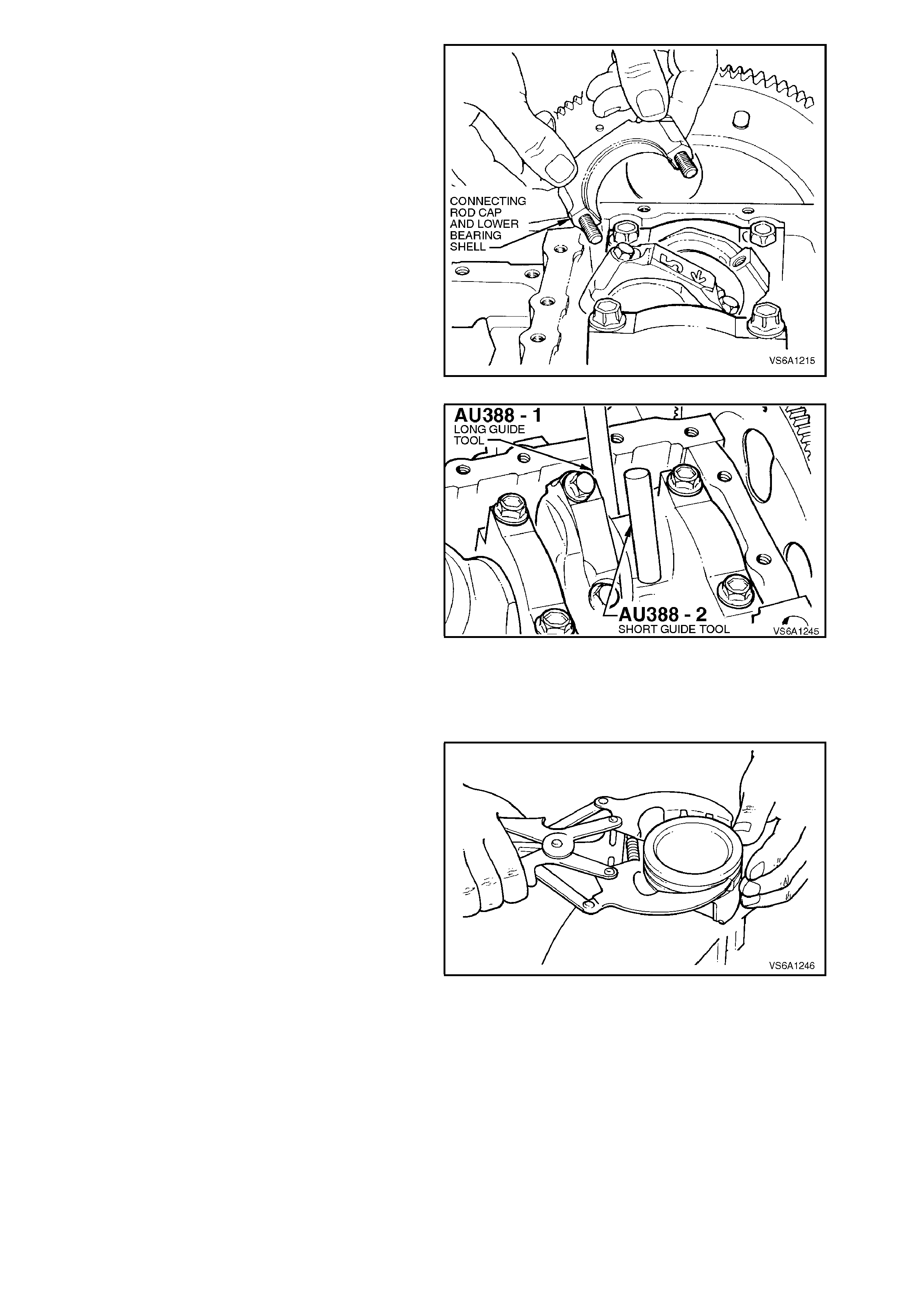
7. Remove piston and rod assemblies as follows:
a. With connecting rod crankshaft journal at
bottom of its tr avel (Bottom Dead Centre) ,
remove connecting rod cap bolts and
remove cap with bearing shell.
Figure 6A1-1-252
b. Install the 'short' connecting rod guide tool
AU388-2, into connecting rod inner bolt
hole.
c. Install 'long' connecting r od guide AU388-
1, into opposite bolt hole.
Turn guides down fully to hold upper
bearing shell in place.
d. Using a hammer handle, push on long
guide to remove piston and connecting
rod from cylinder. Remove guides and
reinstall cap and bolts to connecting rod.
Figure 6A1-1-253
8. Remove all other piston and connecting rod
assemblies in the same manner.
DISASSEMBLE
1. Remove piston rings by expanding them and
sliding them off pistons, and then discarding.
NOTE:
Take care when removing piston rings as worn
rings may have sharp edges.
Figure 6A1-1-254
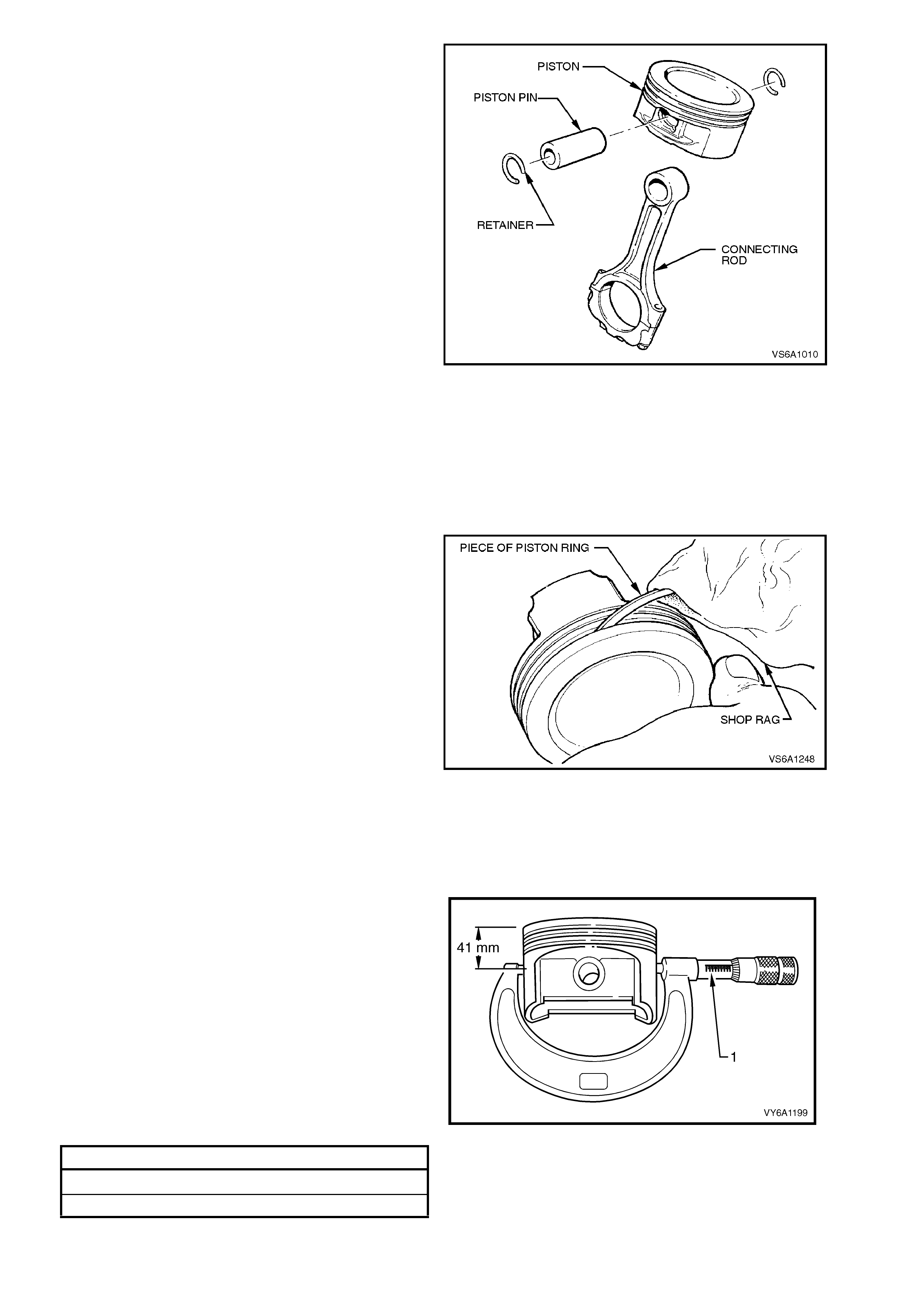
2. Remove two piston pin retainers.
NOTE:
Piston pin retainers may be reused if not damaged.
Figure 6A1-1-255
INSPECT
1. Inspect cylinder walls for scoring, roughness,
or ridges which indicate excessive wear.
Check cylinder bores for taper and out-of-
round with an accurate cylinder gauge at top,
middle and bottom of bore, both parallel and
at right angles to centreline of engine. Refer to
3.15 CYLINDER BLOCK in this Section.
2. Clean carbon from piston heads. Clean carbon
from ring grooves with suitable tool or a piece
of piston ring and remove any gum or varnish
from piston skirts with suitable cleaning
solvent.
Figure 6A1-1-256
3. Carefully examine piston skirt for rough or
scored surfaces, cracks in skirt or crown,
broken ring lands, chipping or uneven wear
which would cause rings to seat improperly or
have excessive clearance in ring grooves.
Damaged or faulty pistons should be replaced.
The pistons are cam ground, which means
that the diameter at right angles to the piston
pin is greater than the diameter parallel to the
piston pin. When a piston is checked for size,
it must be done at a point 90° to the piston pin
bore, 41 mm from top of piston.
Figure 6A1-1-257
PISTON SIZE SPECIFICATIONS
STANDARD 96.482 - 96.497 mm
AVAILABLE OVERSIZE 0.508 mm
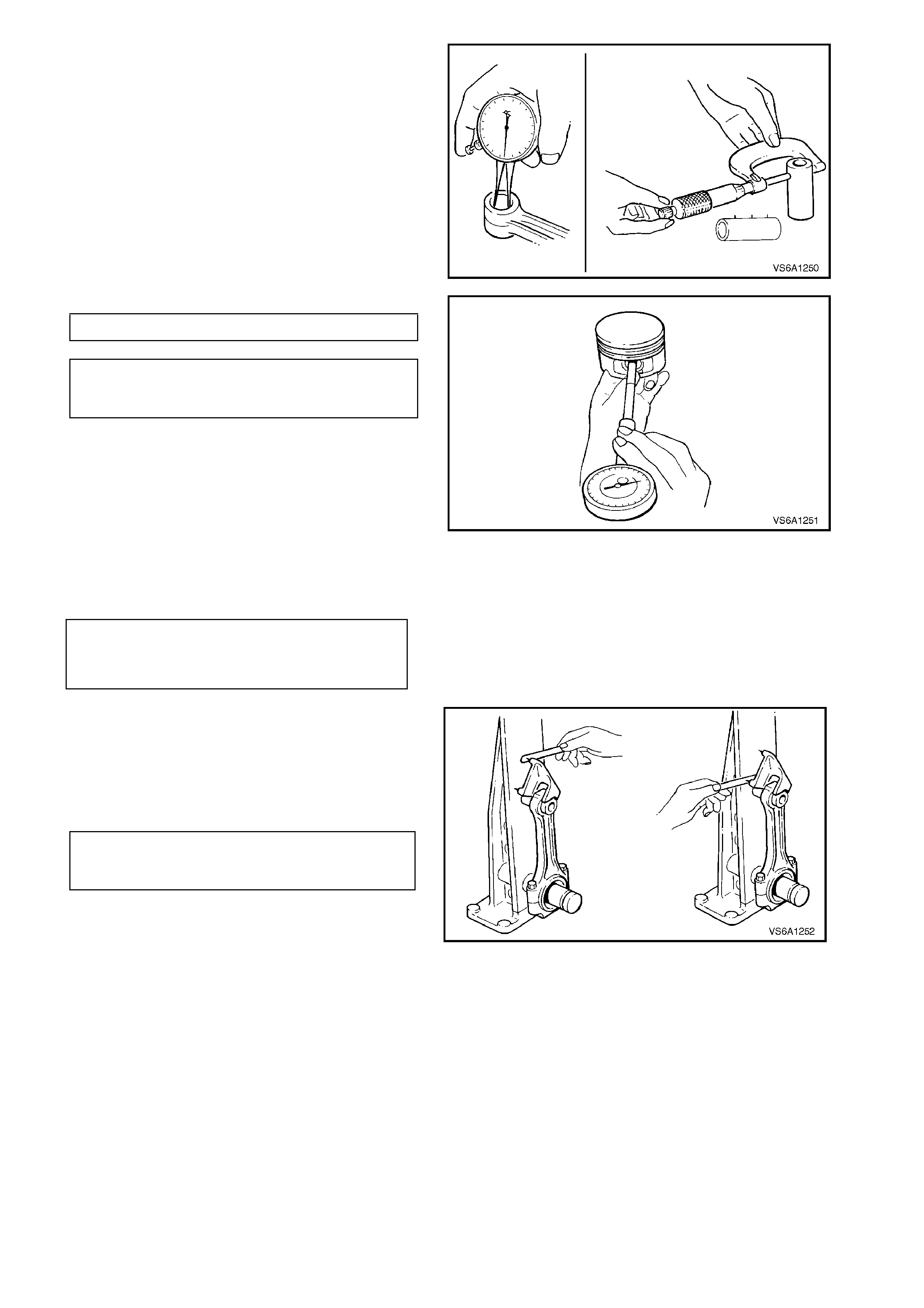
4. Inspect piston pin bores and piston
pins/bushes for wear. Piston pin bores and
piston pins must be free of varnish or scuffing
when being measured. The piston pin should
be measured with a micrometer and piston pin
bore should be measured with a dial bore
gauge or an inside micrometer. If clearance is
not to specification, piston and pin should be
replaced.
If piston pin bush requires replacement
remove and install using suitable press and
plates. Honing of the bush prior to pin
installation may be necessary.
Figure 6A1-1-258
PISTON PIN DIAMETER 21.995 - 22.000 mm
PISTON PIN CLEARANCE
IN PISTON 0.002 - 0.013 mm
IN CONNECTING ROD 0.007 - 0.022 mm
Figure 6A1-1-259
5. Remove bearing shells from connecting rod,
install cap and bolts. Tighten bolts to the
correct torque specification.
CONNECTING ROD
CAP BOLT
TORQUE SPECIFICATION
24 - 30 Nm
plus 47 - 53
degree turn
angle
6. Place connecting rod assembly on a checking
fixture and check rod for bend or twist.
Do not attempt to straighten rod if bent or
twisted, replace it.
Check new connecting rods in the same
manner before using them.
CONNECTING ROD ALIGNMENT SPECIFICATION
BEND: 0.020mm/25.4 mm
TWIST: 0.038mm/25.4 mm
Figure 6A1-1-260
7. Inspect outside of connecting rod bearing
shells and internal diameter of connecting rod
big end for wear indicating high spots in rod
big end.
8. Remove cap bolts and check bolts for
stretching by comparing them with a new bolt.
Replace bolt/s if stretched.
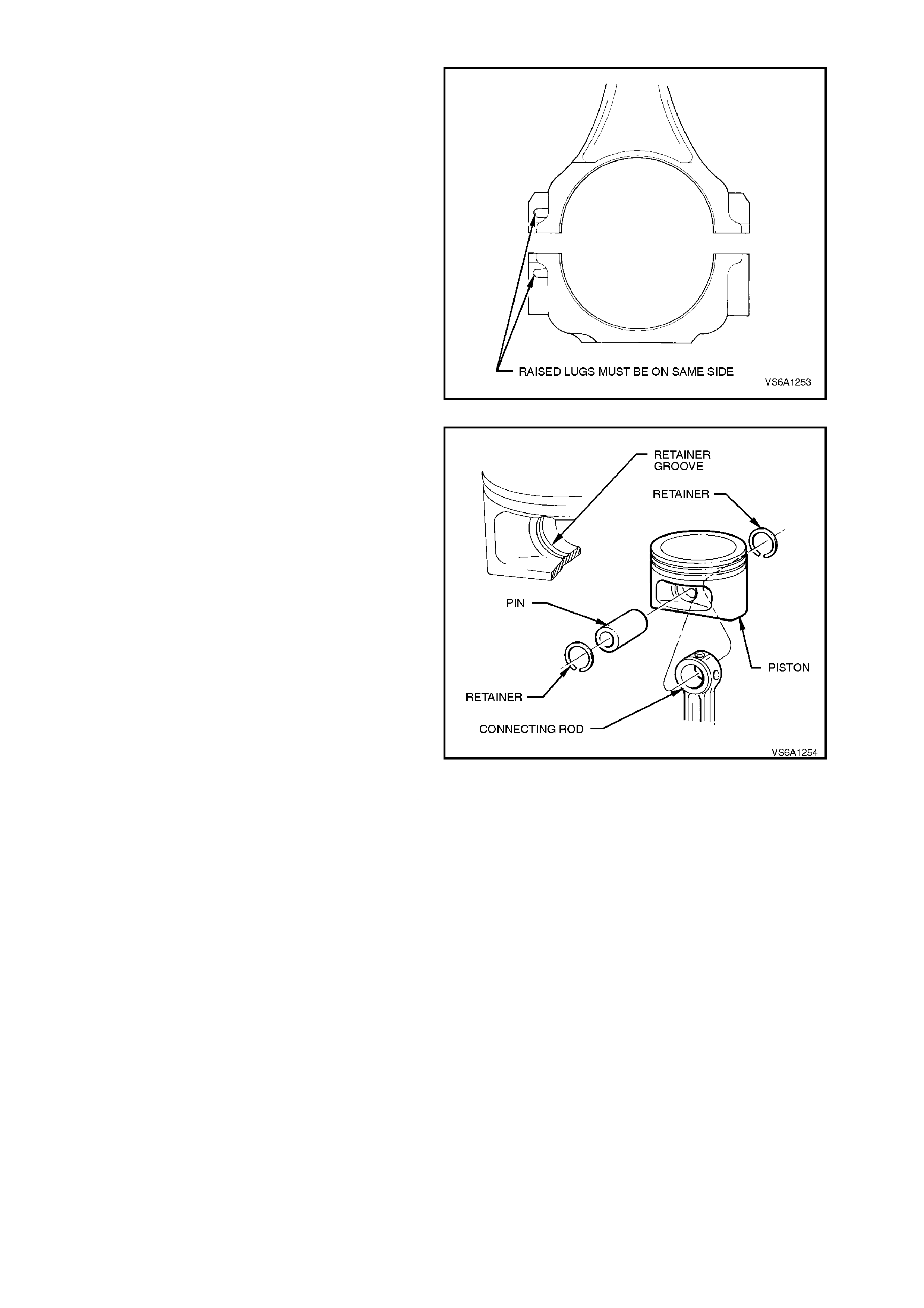
REASSEMBLE AND REINSTALL
NOTE:
The connecting r od can be ass em bled to the piston
either way.
In production, the connecting rods are assembled
with the small raised dimple on the cap and rod on
the same side, and facing forward.
Figure 6A1-1-261
1. Lubricate piston pin bore and piston pin with
engine oil.
2. Install one piston pin retainer by starting one
side of r etainer in r etaining groove and r otating
retainer until fully seated in groove.
3. Assem ble connecting rod and piston pin, push
piston pin until it bottoms on installed retainer.
4. Install remaining retainer using procedure
outlined in step 2.
Figure 6A1-1-262
5. Install piston rings, refer to
3.11 PISTON RINGS in this Section.
6. Ensure cylinder bores, pistons, connecting r od
bearing shells and crankshaft journals are
absolutely clean, then coat cylinder bores and
all bearing surfaces with clean engine oil.
7. Before installation of a piston and rod
assembly in its bore, position the crankpin
straight down.
8. Remove cap, and with bearing upper shell
seated in connecting rod, install the 'short'
guide tool into inner bolt hole. Install 'long'
guide tool in the other bolt hole.
These guides hold upper bearing shell in
place and protect crankshaft journal from
damage during installation of connecting rod
and piston assembly.
9. Ensure piston ring gaps are separated as
detailed in 3.11 PISTON RINGS in this
Section.
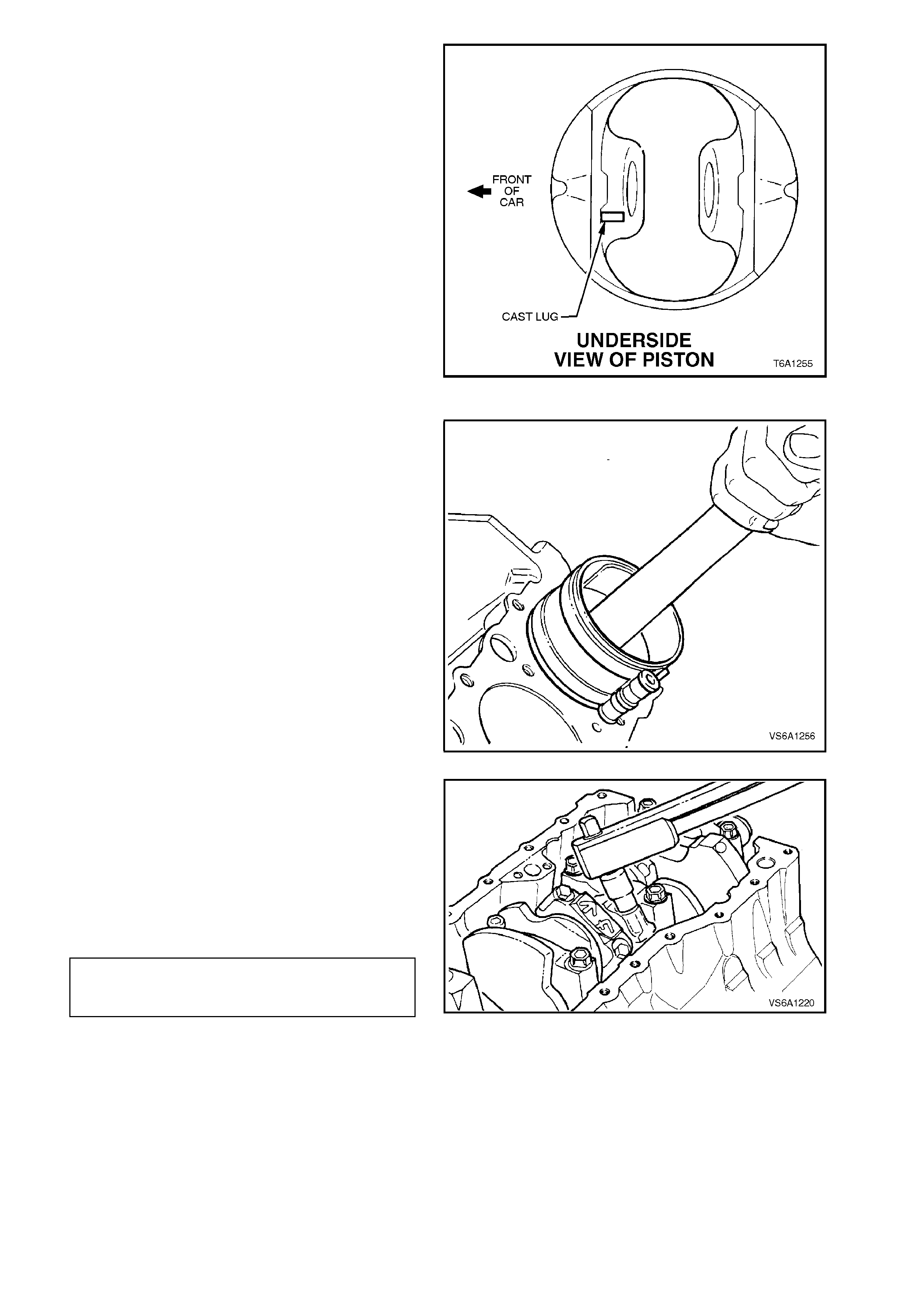
10. Lubricate piston and rings with clean engine
oil. Using a suitable ring compressor to
compress rings, install each piston and
connecting rod assembly into its cylinder bore.
NOTE:
Ensure arrow on piston crown is facing forward.
Figure 6A1-1-263
11. Using a hammer handle, lightly tap piston into
its bore while holding ring compressor firmly
against cylinder block until all pistons rings
have entered bore.
12. Push piston down bore until connecting rod
seats against crankshaft journal.
Figure 6A1-1-264
13. Rem ove connecting rod guides. Install bear ing
cap and lower bearing shell assembly. Install
cap bolts and tighten and then loosen one full
turn. Finally tighten the cap bolts to the corr ect
specification.
NOTE:
Ensure correct orientation of cap with connecting
rod.
CONNECTING ROD 24 - 30 Nm
CAP BOLT plus 47 - 53
TORQUE SPECIFICATION degree turn angle
NOTE:
Use an angle wrench such as E7115 to ensure
accurate turn angle.
Figure 6A1-1-265
14. Rotate cranks haft to ensure f ree m ovement of
crankshaft and connecting rod. If crankshaft
binds, recheck bearing cap to rod orientation,
bearing clearance or connecting rod
alignment.
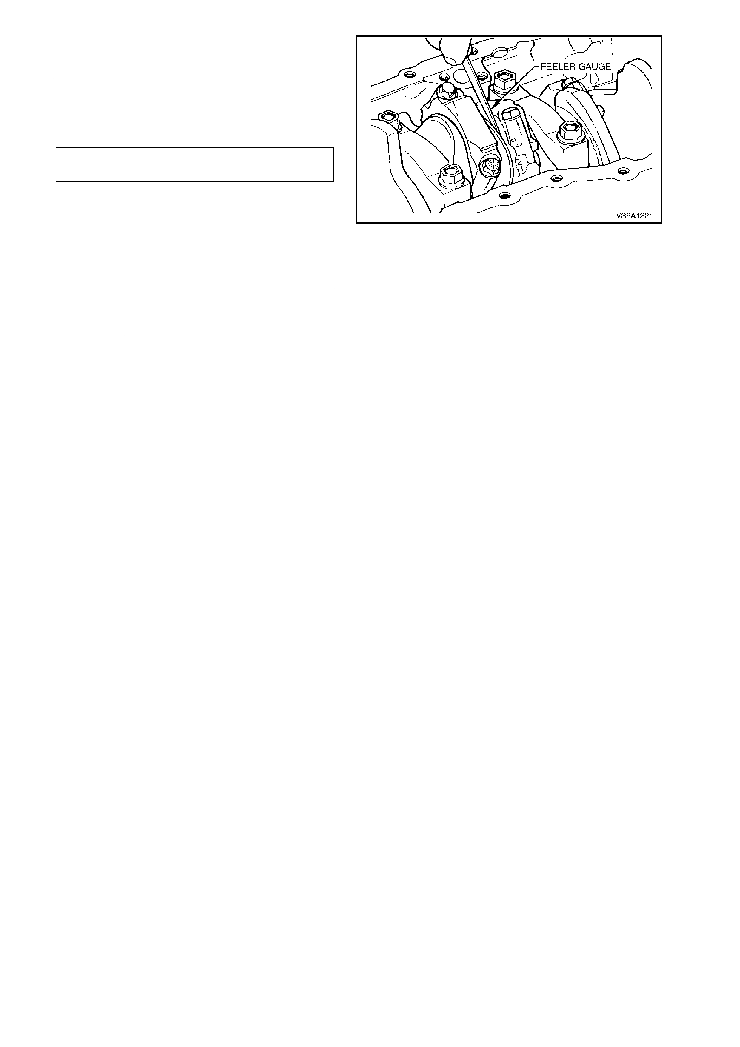
15. Measure side clearance between connecting
rod and crankshaft journal.
If clearance is insufficient check bearing
clearance, refer to 3.7 MAIN AND
CONNECTING ROD BEARINGS in this
Section, or connecting rod alignment.
CONNECTING ROD SIDE 0.10 - 0.50
CLEARANCE mm
Figure 6A1-1-266
16. Install remaining piston and connecting rod
assemblies in the same manner.
17. Reinstall cylinder heads, refer to
2.15 CYLINDER HEADS in this Section.
18. Reinstall oil pump suction pipe and screen,
refer to 3.3 OIL PUMP SUCTION PIPE AND
SCREEN in this Section.
19. Reinstall oil pan, refer to 3.2 OIL PAN AND
SEAL in this Section.
20. Start engine and check f or oil leak s. Repair as
necessary.

3.11 PISTON RINGS
INSTALL
NOTE:
The pistons have three rings (two compression
rings and one oil ring). The top ring is a steel,
molybdenum filled, balanced section, barrel lapped
type. The second ring is a inverted torsional taper
faced type. The oil ring is of three piece design,
comprising two segments and a spacer.
1. Select a set of rings com parable in size to the
piston being used.
2. Install compression ring in relevant cylinder
bore, then using the head of a piston, press
ring down into bore approximately 50 mm.
NOTE 1:
Using a piston in this way will place ring square with
cylinder wall.
NOTE 2:
Be careful not to distort the ring during this
operation, or it may bind in the piston ring groove.
Fit each ring separ ately to the cylinder in which it is
going to be installed.
Figure 6A1-1-267
3. Measure gap between ends of ring with a
feeler gauge.
If the gap between the ends of a c ompress ion
ring is below specif ication, r em ove ring and try
another for size.
COMPRESSION RING END GAP SPECIFICATION
TOP RING 0.305 - 0.559 mm
SECOND RING 0.762 - 1.016 mm
4. Check gap between ends of each oil control
ring rail.
OIL RING RAIL END GAP
SPECIFICATION 0.254 - 0.762
mm
5. W hen fitting rings to a piston that has been in
service, carefully remove all traces of carbon
from ring grooves in piston and inspect
grooves for any burrs or chips that might
cause ring to bind.
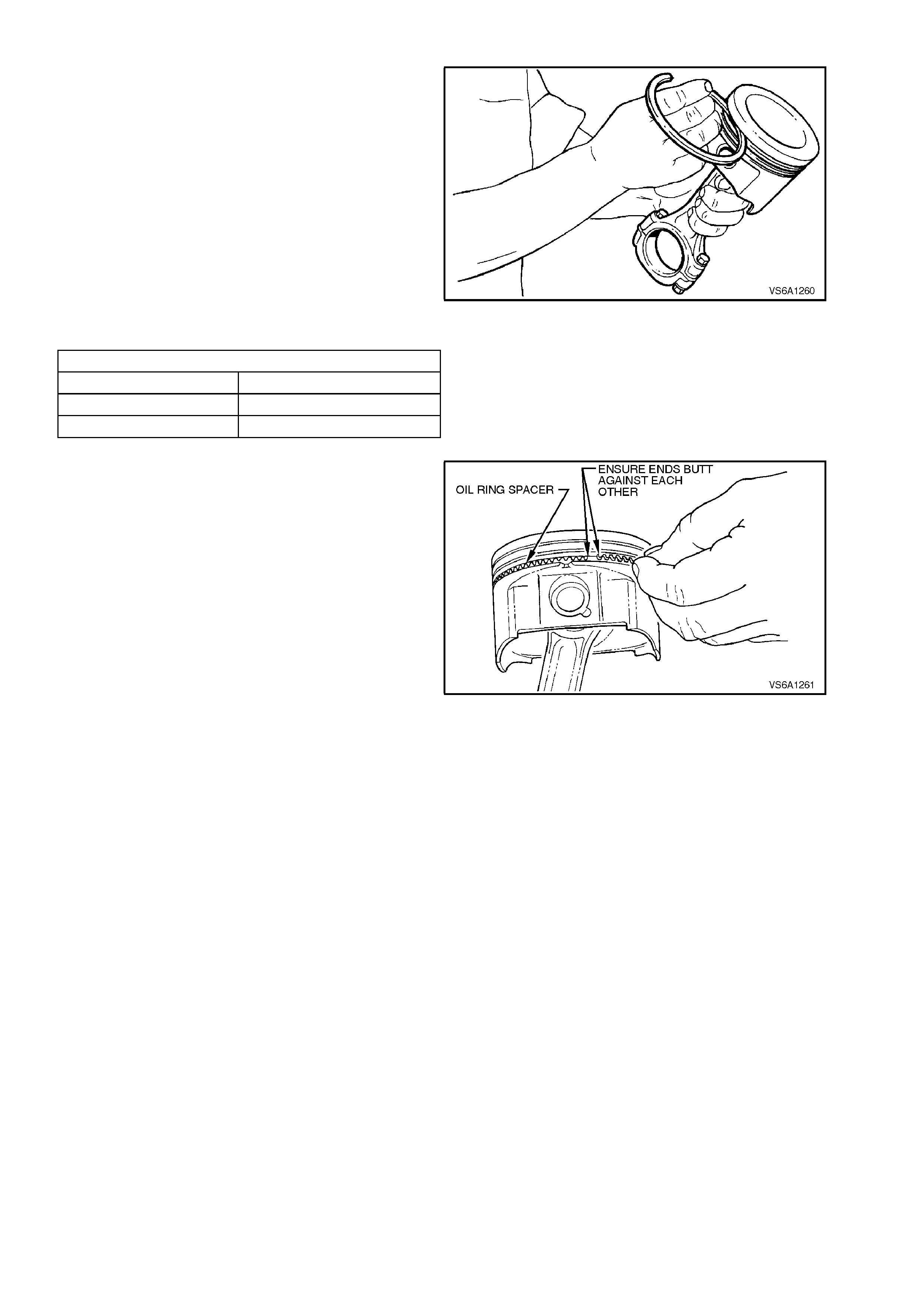
6. Slip outer surface of each com pression ring in
respective piston ring groove and roll ring
entirely around groove to check that ring is
free.
Also measure ring to piston groove side
clearance.
If the ring is too tight, try another ring.
NOTE:
Do not attempt to cut the piston ring groove,
although high spots in the ring groove may be
cleaned up by careful use of a fine file.
Figure 6A1-1-268
PISTON RING TO GROOVE CLEARANCE
TOP RING 0.039 - 0.079 mm
SECOND RING 0.039 - 0.079 mm
OIL CONTROL RING 0.023 - 0.201 mm
7. Install oil ring spacer in bottom piston ring
groove.
NOTE:
The ends of the spacer butt against each other.
Figure 6A1-1-269
8. Install one steel rail from top of piston
downward into oil ring groove.
9. Install remaining steel rail from bottom of
piston skirt upwards into the oil ring groove.
10. Install compression rings in second and first
grooves of each piston.
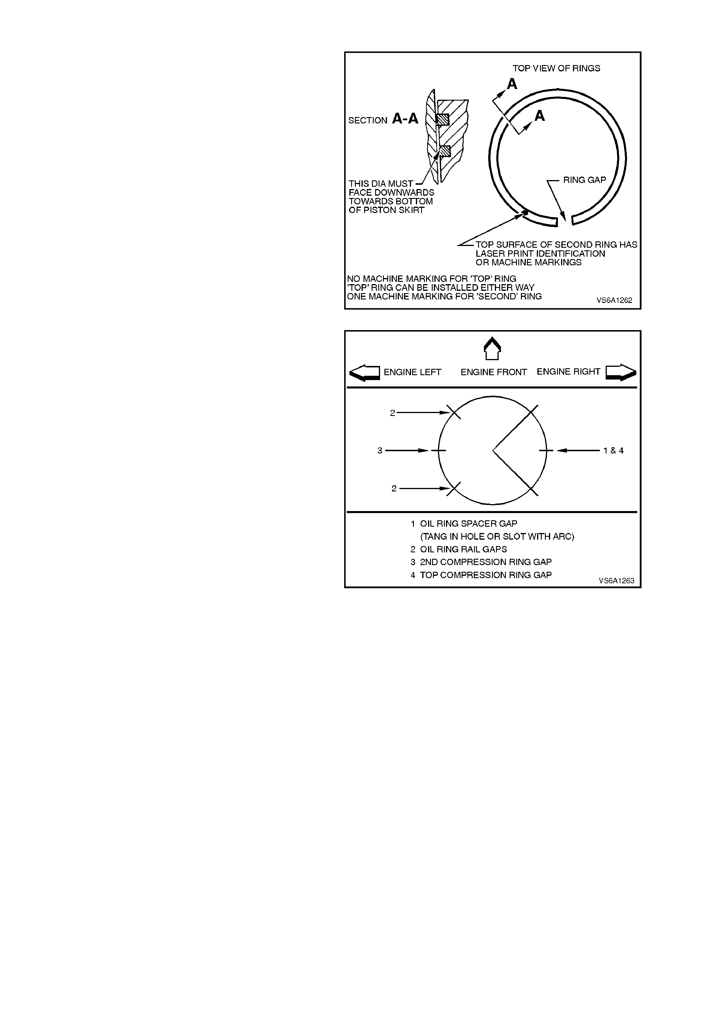
NOTE 1:
Ensure the correct compression rings are installed
in the first and second grooves, with the second
compression ring fitted and the correct way up.
NOTE 2:
The upper compression ring can be installed into
the first groove either way.
Figure 6A1-1-270
11. Make a final test of ring fit in piston grooves.
Separate ends as shown.
NOTE:
Never install piston with ring gaps in line, as this will
allow compression leakage at this point.
Figure 6A1-1-271
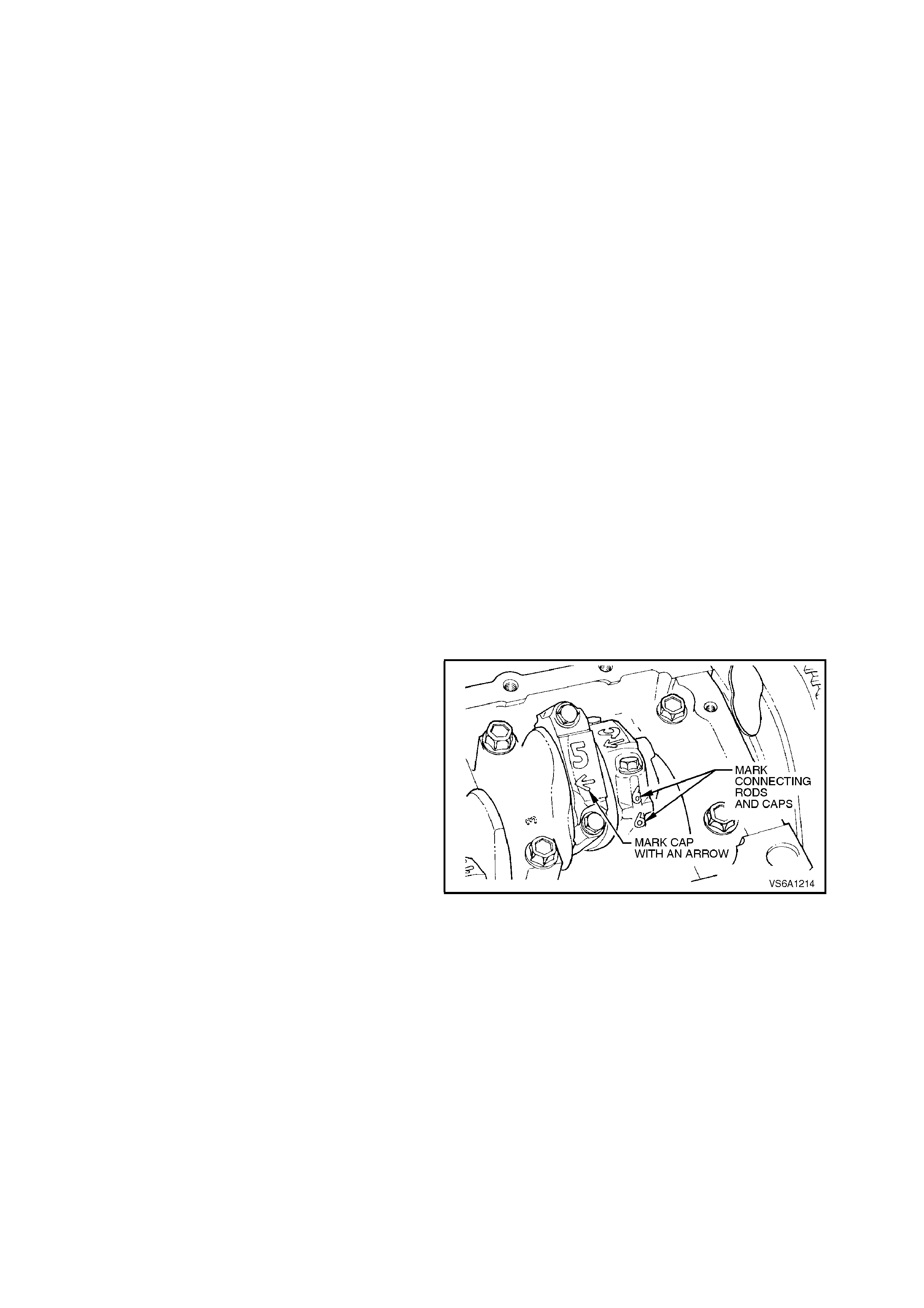
3.12 CRANKSHAFT
REMOVE
NOTE 1:
It is recommended that bearing clearance be
checked before removing crankshaft from cylinder
block, refer to 3.7 MAIN AND CONNECTING
ROD BEARINGS in this Section.
NOTE 2:
The crankshaft in this engine has rolled fillets and
the journals can be repolished up to 0.025 mm
undersize. If any more is required for refinishing,
the crankshaft must be replaced.
1. With engine removed from vehicle and
mounted in a suitable stand, remove oil pan,
refer to 3.2 OIL PAN AND SEAL in this
Section.
2. Remove oil pump suction pipe and screen,
refer to 3.3 OIL PUMP SUCTION PIPE AND
SCREEN in this Section.
3. Remove rear main oil seal housing refer to
3.13 REAR MAIN OIL SEAL HOUSING in this
Section.
4. Remove crankshaft balancer, refer
2.17 CRANKSHAFT BALANCER in this
Section.
5. Remove spark plugs.
6. Remove tim ing c hain and c rankshaf t s pr ocket,
refer to 2.21 TIMING CHAIN, TENSIONER,
SPROCKETS AND BALANCE SHAFT
GEARS in this Section.
7. Mark connecting rod caps with an etching
marker or felt tipped pen to indicate cylinder
number and orientation of cap.
Figure 6A1-1-272
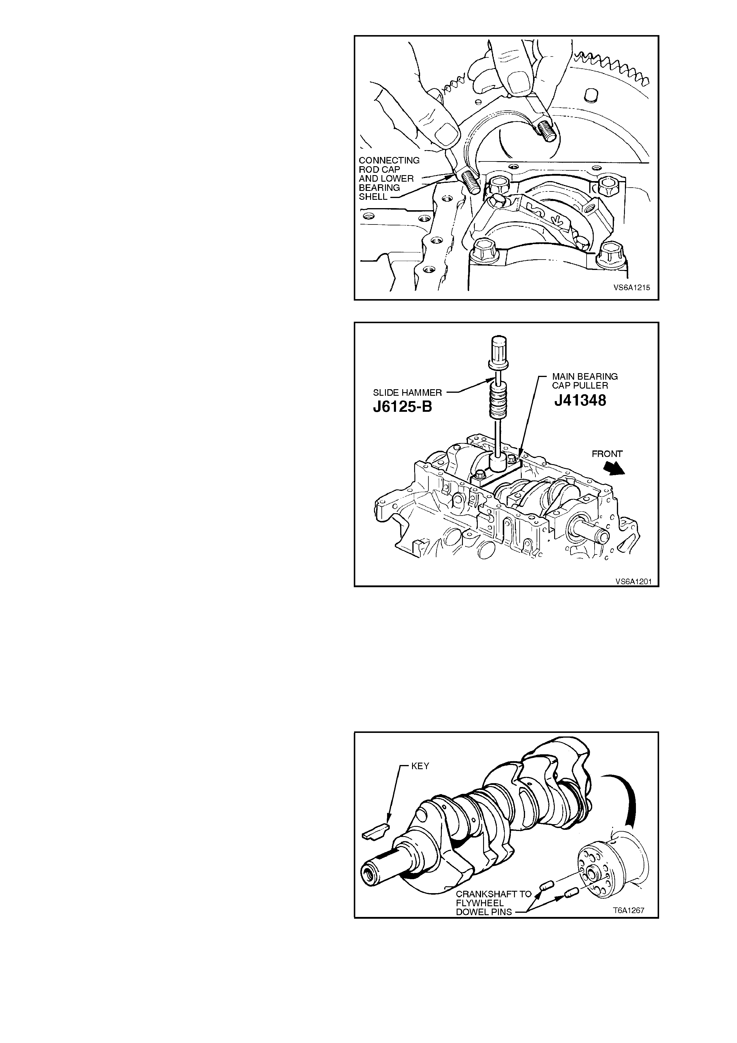
8. Remo ve connecting rod cap bolts and rem ove
caps. Push connecting rods away from
crankshaft.
Figure 6A1-1-273
9. Remove main bearing cap bolts and main
bearing cap side bolts.
NOTE 1:
New main bearing cap side bolts must be used to
ensure bolts remain oil tight to cylinder block.
NOTE 2:
Main bearing caps are press fit and special care is
required when removing the caps. J41348 has
been designed to work in conjunction with J6125-B
in order to prevent damage to bearing and/or cap.
J41348 m ust be ins talled corr ectly into bolt holes of
caps and J6125-B attached in order to properly
remove main bearing cap without damage to the
cap and/or bearing. Deviation from this procedure
may cause damage to the cap and/or bearing
resulting in engine damage.
10. Install J41348 into main bearing cap bolt
holes.
11. Tighten bolts to 11 Nm.
12. Install J6125-B to J41348.
13. Using the slide hammer motion of J6125-B
remove main bearing cap.
Figure 6A1-1-274
14. Lift crankshaft from cylinder block.
15. Remove flywheel/flexplate to crankshaft
attaching bolts, remove flywheel/flexplate and
discard bolts.
16. If necessary, remove sprocket key from front
end of crankshaft using a suitable punch and
hammer.
17. If necessary, remove crankshaft to flywheel
dowel pins from c ranks haft rear f lange using a
suitable removal tool.
Figure 6A1-1-275
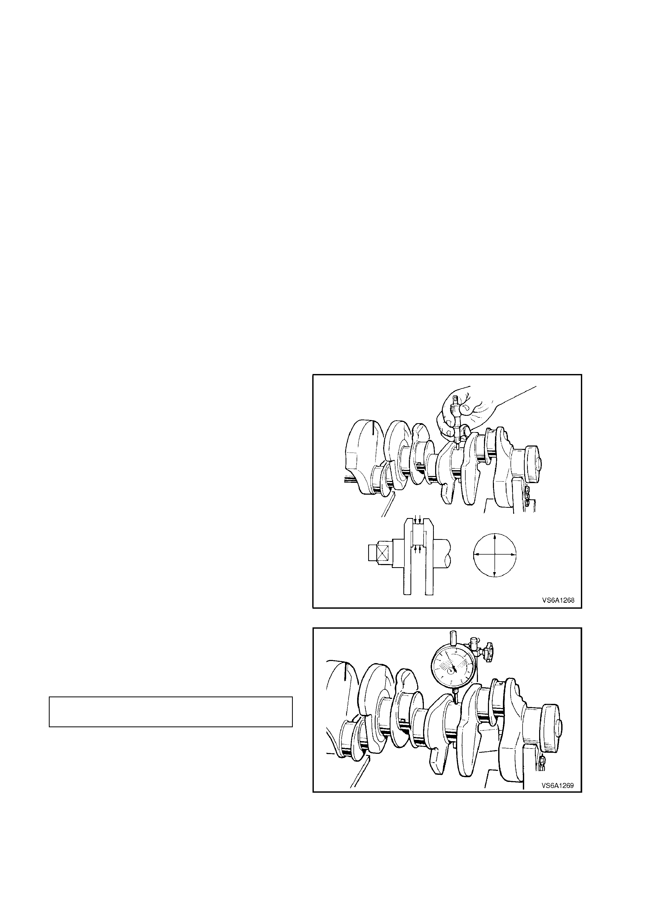
INSPECT
1. Wash crankshaft in suitable cleaning solvent
and dry with compressed air.
2. Inspect crankshaft oil passages for
obstructions.
3. Inspect all bearing journals, thrust surfaces
and rear main oil seal contact surfaces for;
a. Cracks
b. Chips
c. Gouges
d. Roughness
e. Grooving
f. Overheating (Discolouration)
If crankshaft has any cracks, severe gouging
or burned spots, the crankshaft must be
replaced. Slight roughness may be removed
with fine polishing cloth soaked in clean
engine oil. Burrs may be removed with a fine
oil stone.
4. Inspect connecting rod and main bearing
shells for imbedded foreign material and
determine its source.
5. Measure bearing journals with a micrometer
for taper, out-of-round or excessive wear.
MAIN BEARING JOURNAL DIAMETER
STANDARD 63.470 - 63.495 mm
TAPER 0.008 mm MAX.
OUT-OF-ROUND 0.008 mm MAX.
CONNECTING ROD JOURNAL DIAMETER
STANDARD 57.117 - 57.147 mm
TAPER 0.008 mm MAX.
OUT-OF-ROUND 0.008 mm MAX.
Figure 6A1-1-276
6. Check crankshaft for run-out by supporting
front and rear main bearing journals in V -
blocks and checking No. 2 and No. 3 journals
with a dial gauge.
CRANKSHAFT RUN-OUT 0.008
SPECIFICATION mm
Figure 6A1-1-277
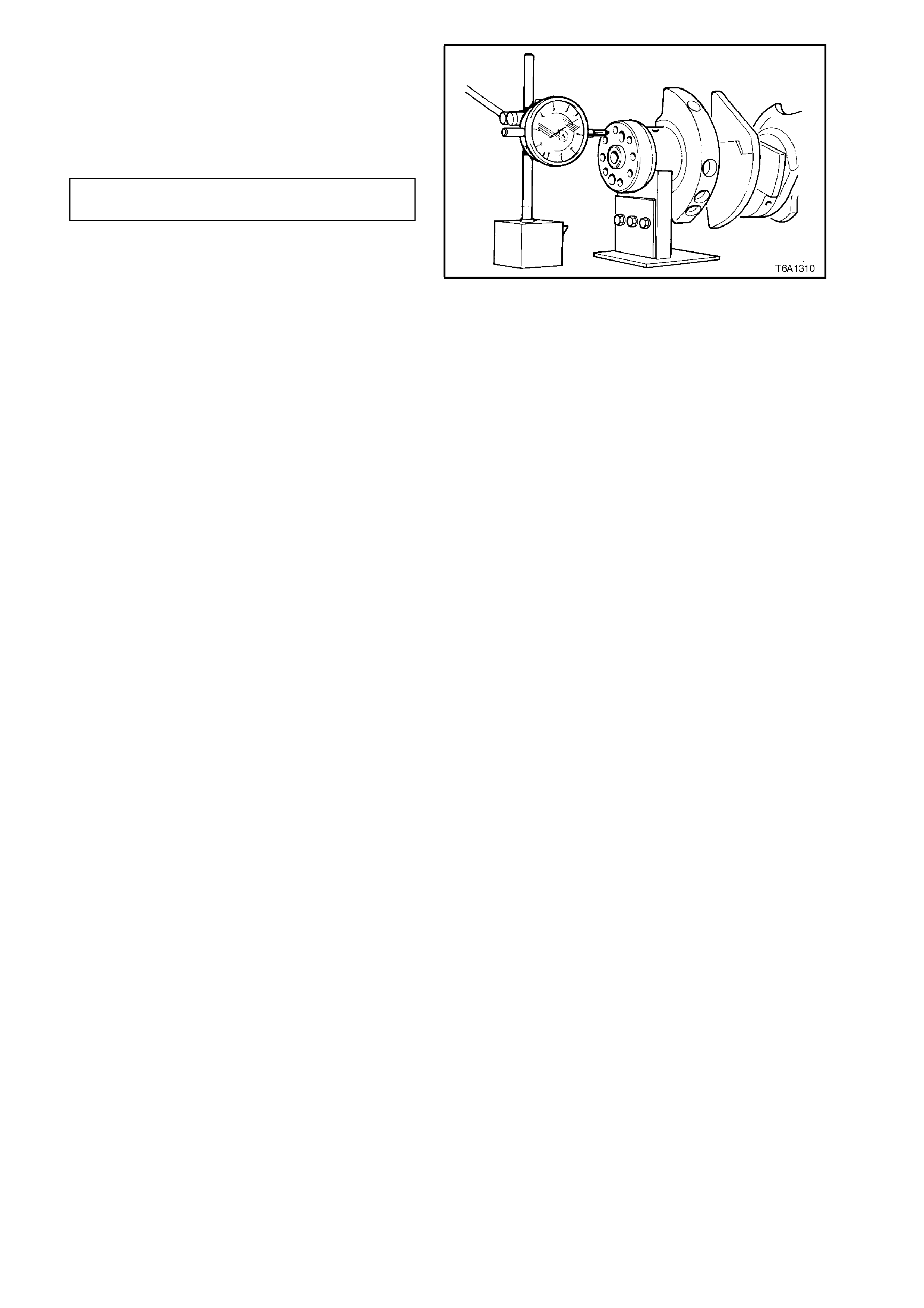
7. Position a dial gauge at crank shaft rear flange
and check rear flange run-out. During this
check , ensure that crank shaft is thrust for ward
on V - blocks so that there is no possibility of
crankshaft end float affecting dial gauge
reading.
CRANKSHAFT REAR FLANGE 0.05 mm
RUN-OUT MAX
Figure 6A1-1-278
8. Replace crankshaft if not within specifications.
9. Using a 5/16" thread tap, clean
flywheel/flex plate attaching bolt thread holes in
rear of crankshaft.
10. Clean all traces of sealant from cylinder block.
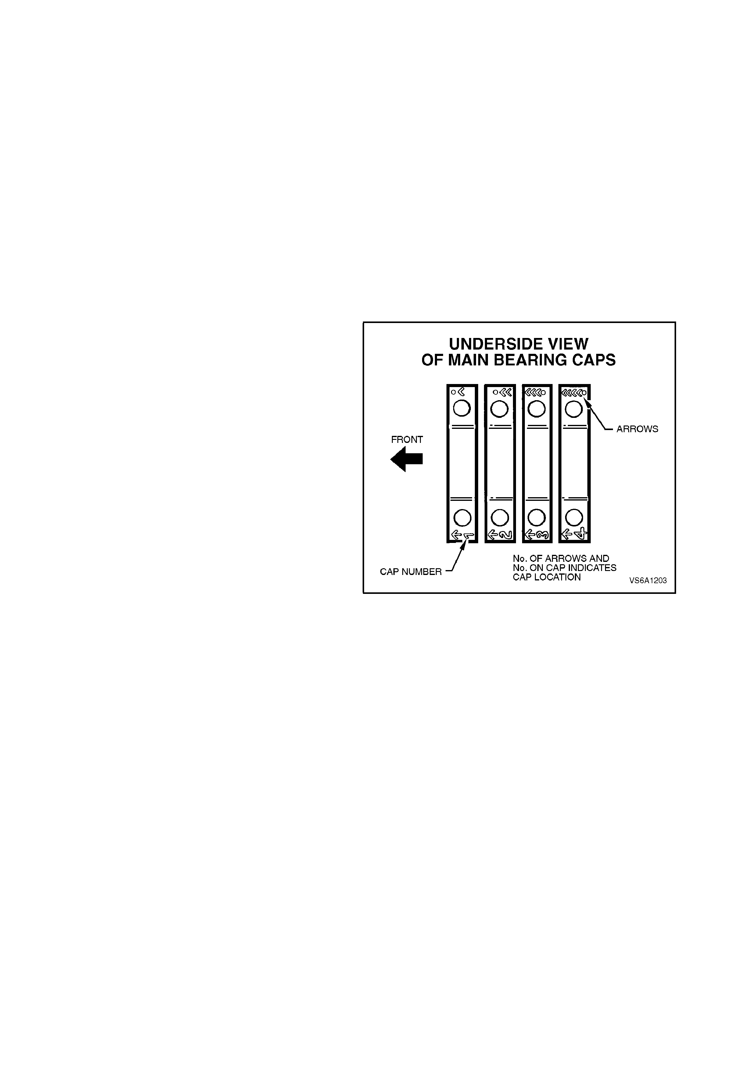
REINSTALL
1. If necessary, install sprocket key to front end
of crankshaft.
2. Lubricate all crankshaft journals and main
bearing upper shells in cylinder block with
clean engine oil.
3. Lay crankshaft in place in main bearing upper
shells in cylinder block. Take care not to
damage crankshaft thrust flange and No. 2
main bearing thrust faces. Also take care not
to contact connecting rod journals with
connecting rods.
4. If necessary, check main bearing clearance,
refer to 3.7 MAIN AND CONNECTING ROD
BEARINGS in this Section.
5. Ensure that main bearing cap bolt threads and
cylinder block threads are clean and dry. Apply
some engine oil to the cap bolt threads.
NOTE:
Ensure that the bearing cap is installed into the
crankcase correctly.
6. Before final installation of cap bolts, determ ine
if bolts have stretched by comparing with a
new bolt. Replace bolt/s as necessary.
Reinstall main bearing caps, hand start main
bearing cap bolts, on each bearing c ap in turn,
tighten cap bolts half a turn at a time to
carefully seat cap.
Hand start main bearing cap side bolts.
Due to the thrust bearing shells being
disturbed, it is necessary to line up the thrust
surfaces of the bearing shells before the cap
bolts are tightened. To do this, move the
crankshaft fore and aft the length of its travel
several times (last movement forward).
NOTE 1:
Do not tighten one cap completely at a time,
progressively tighten all four caps to one step of
procedure before moving to next stage of torque.
Torque main bearing cap bolts to 70 Nm to
fully seat cap.
Loosen cap bolts 360° then torque all cap
bolts to 20 Nm and then 40 Nm.
Tighten cap bolts in steps of 35° + 35° + 35° to
a total of 105°.
Torque main bearing cap side bolts 12 - 18
Nm + 42 - 48°.
NOTE 2:
New main bearing cap side bolts must be used to
ensure bolts remain oil tight to cylinder block.
Figure 6A1-1-279

MAIN BEARING CAP BOLT Refer procedure
TORQUE SPECIFICATION following
NOTE: 1
Figure 6A1-1-280
NOTE 3:
In order to prevent the possibility of cylinder block
or bearing cap damage, do not install bearing cap
using a soft faced hammer. Use cap bolts to pull
bearing cap into position. Failure to observe this
procedure may damage cylinder block or bearing
cap.
NOTE 4:
Use an angle wrench such as E7115 to ensure
accurate turn angle.
7. Force crankshaft forward and measure
crankshaft end float between front of No. 2
main bearing s hell and crankshaf t thrust fac es
with a feeler gauge.
If clearance is excessive, replace No. 2 main
bearing shells.
CRANKSHAFT END FLOAT 0.08 - 0.28
SPECIFICATION mm
Figure 6A1-1-281
8. Install new rear main oil seal, refer to
3.13 REAR MAIN OIL SEAL in this Section.
9. Install flywheel/flexplate to crankshaft, install
and tighten new attaching bolts to the correct
torque specification refer to
3.4 FLYWHEEL/FLEXPLATE in this Section.
NOTE:
Bolt holes are unevenly spaced so
flywheel/flexplate bolts can only be installed with
the flywheel/flexplate and retainer plate in the
correct position.
Figure 6A1-1-282
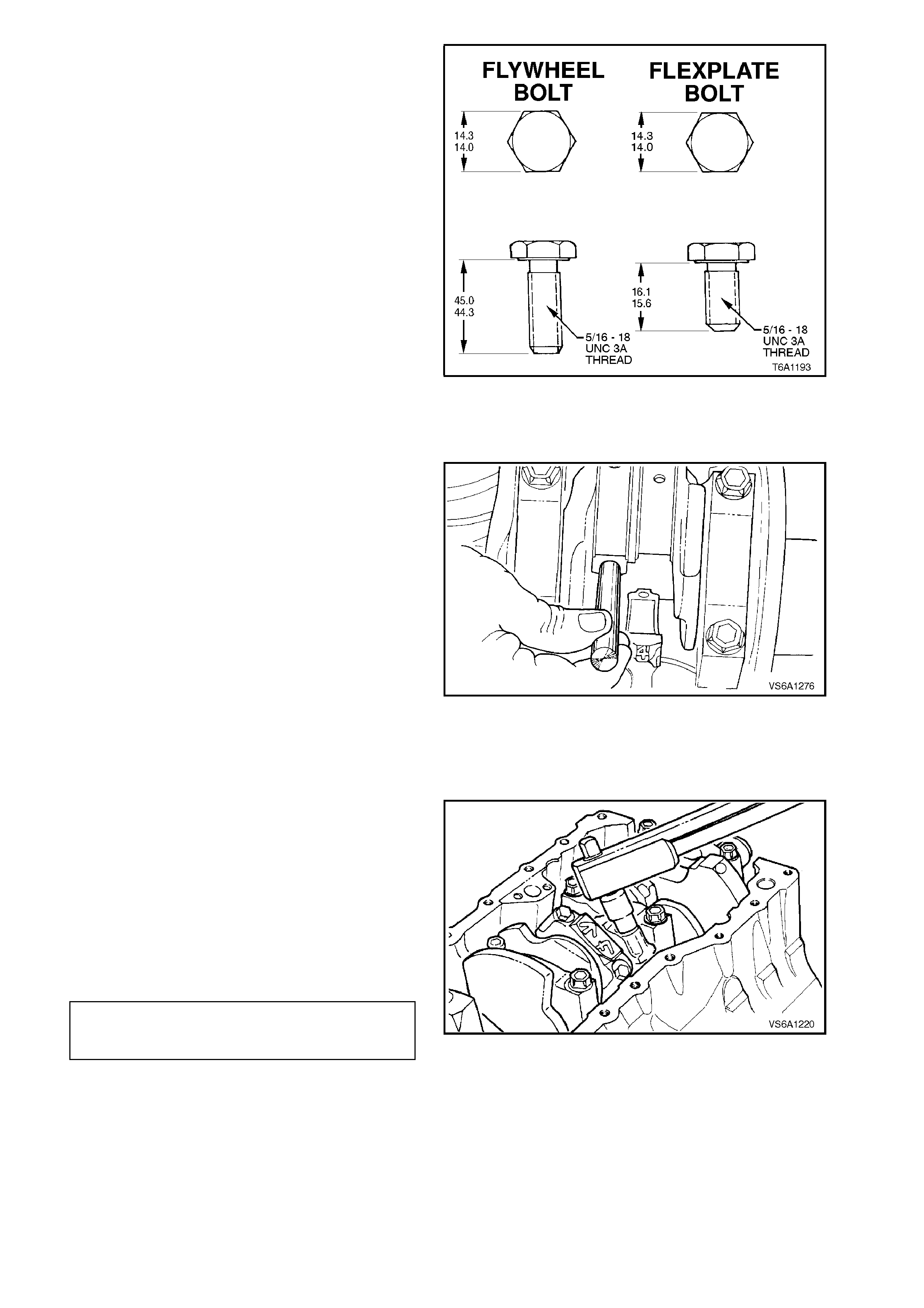
NOTE:
There are specific bolts for flywheel and flexplate
attachment to the crankshaft.
FLYWHEEL/FLEXPLATE BOLT TIGHTENING
SEQUENCE
STEP NO. 1 TORQUE ALL BOLTS
TO 18 - 22 NM
STEP NO. 2
MANUAL TIGHTEN ALL BOLTS
TRANSMISSION A FURTHER 80 - 90
DEGREES TURN ANGLE
STEP NO. 2
AUTOMATIC TIGHTEN ALL BOLTS
TRANSMISSION A FURTHER 47 - 53
DEGREES TURN ANGLE
Figure 6A1-1-283
10. For vehicles with manual transmission,
reinstall clutch pres su re plate and dr iven plate,
refer to Section 7A CLUTCH.
11. Using guide pin tools, (AU388) pull connecting
rods up to crankshaft journals.
Figure 6A1-1-284
12. If necessary, check connecting rod bearing
clearances, refer to 3.7 MAIN AND
CONNECTING ROD BEARINGS in this
Section.
13. Lubricate crankshaft connecting rod journals
and bearings, install connecting rod caps and
bolts.
14. Tighten connecting rod cap bolts and then
loosen one full turn. Tighten bolts to the
correct torque specification.
NOTE:
Use an angle wrench such as E7115 to ensure
accurate turn angle.
CONNECTING ROD CAP BOLT 24-30 Nm
TORQUE SPECIFICATION plus47-53
degree turn angle Figure 6A1-1-285
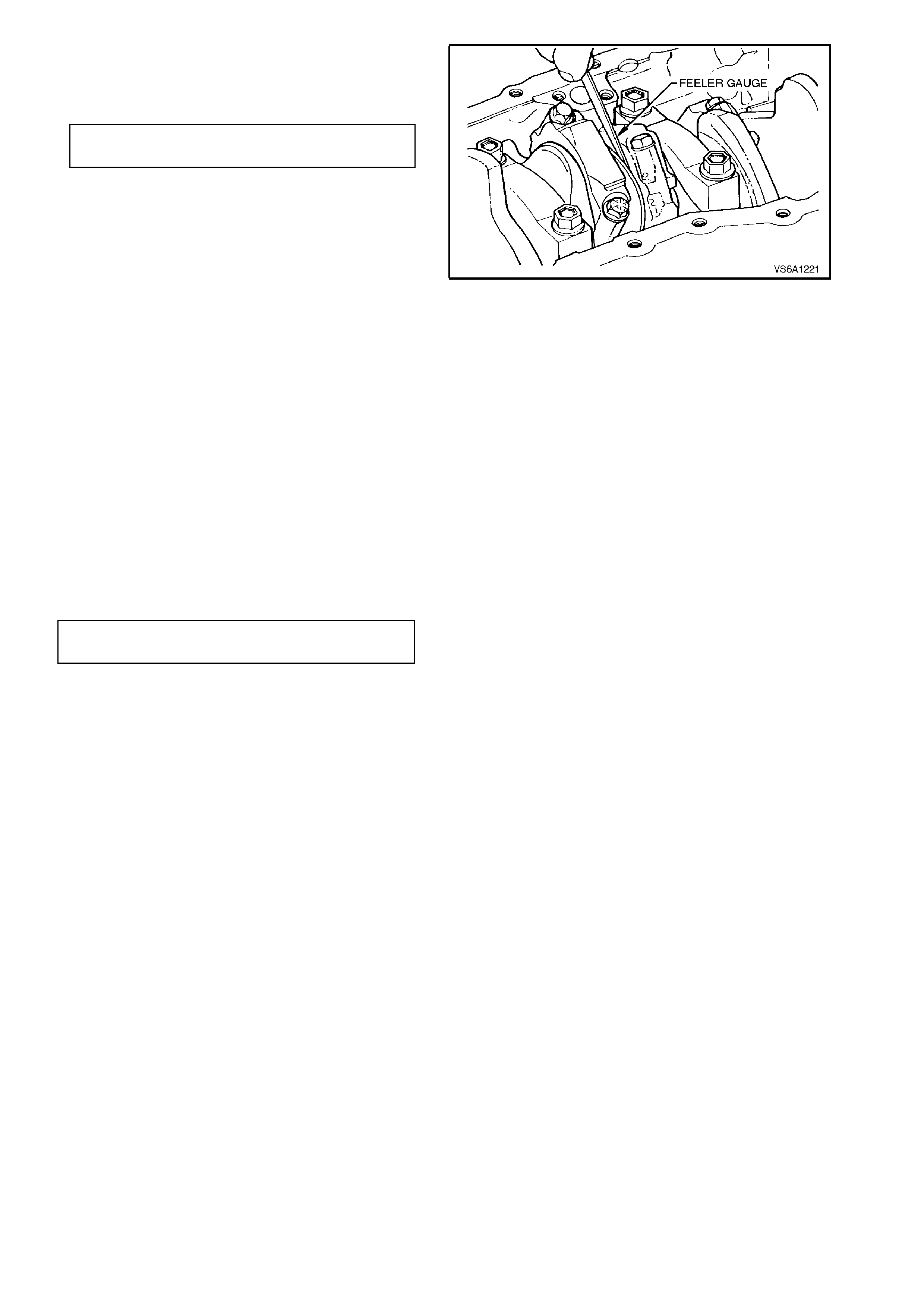
15. Measure clearance between connecting rods
and crankshaft journal flanges with a feeler
gauge.
CONNECTING ROD SIDE 0.10 - 0.50
CLEARANCE mm
Figure 6A1-1-286
16. Rotate cranks haft to ensure f ree m ovement of
crankshaft and connecting rods.
If crankshaft binds, check orientation of
bearing caps, correct fitting of bearing caps
(mains and connecting rods) or fitting of
bearing shells or bearing clearance.
17. Reinstall crankshaft sprocket, timing chain,
and front c over, r ef er to 2.21 T IM ING CHAIN,
TENSIONER, SPROCKETS AND BALANCE
SHAFT GEARS in this Section.
18. Reinstall crankshaft balancer, refer to
2.17 CRANKSHAFT BALANCER in this
Section.
19. Reinstall spark plugs and tighten to the c orr ec t
torque specification.
SPARK PLUG TORQUE
SPECIFICATION 15 - 25
Nm
20. Reinstall oil pump suction pipe and screen,
refer to 3.3 OIL PUMP SUCTION PIPE AND
SCREEN in this Section.
21. Reinstall oil pan, refer to 3.2 OIL PAN AND
SEAL in this Section.
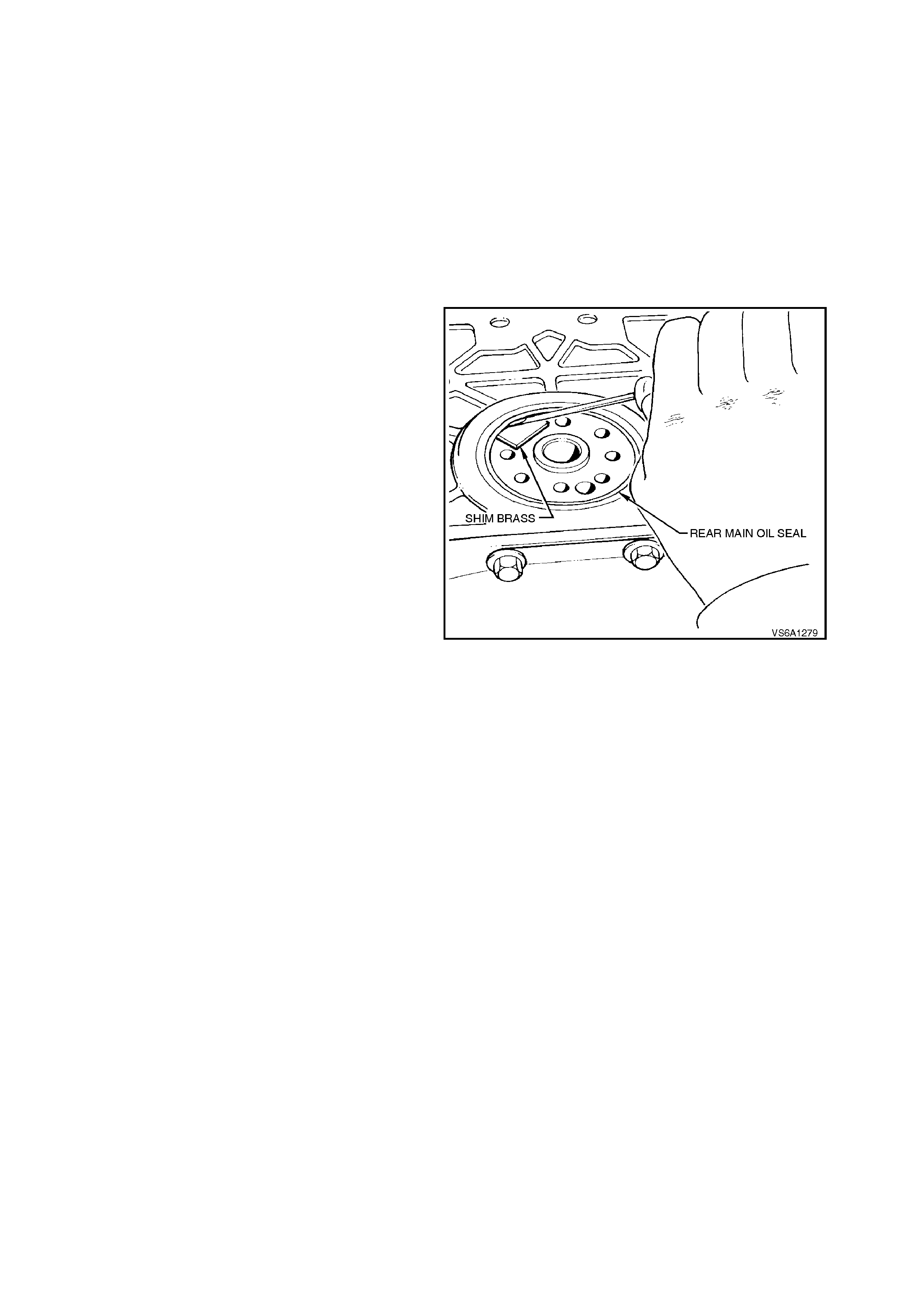
3.13 REAR MAIN OIL SEAL
REPLACE
1. Disconnect battery earth lead.
2. Remove transmission, refer to
Section 7B1 MANUAL TRANSMISSION - V6
ENGINE, or Section 7C4 AUTOMATIC
TRANSMISSION.
3. Remove flywheel/flexplate, refer to
3.4 FLYWHEEL/FLEXPLATE in this Section.
4. On vehicles with manual transmission,
remove spigot bearing, refer to
3.6 SPIGOT BEARING in this Section.
5. Position a piece of shim brass between seal
lips and crankshaft. This is necessary to
protect the crankshaft seal surface.
6. Using a suitable lever, pry out seal, levering
against shim brass strip and remove seal.
7. Check seal bore in rear main oil seal housing
for nicks or burrs, correct as required.
Figure 6A1-1-287
8. Wipe the crank sealing surface carefully and
inspect for signs of dam age. In addition check
the area at the rear of the crankshaft that the
seal will slide past during ins tallation to ensur e
that there are no defects that will damage the
seal during installation. Repair or replace the
crankshaft as necessary.
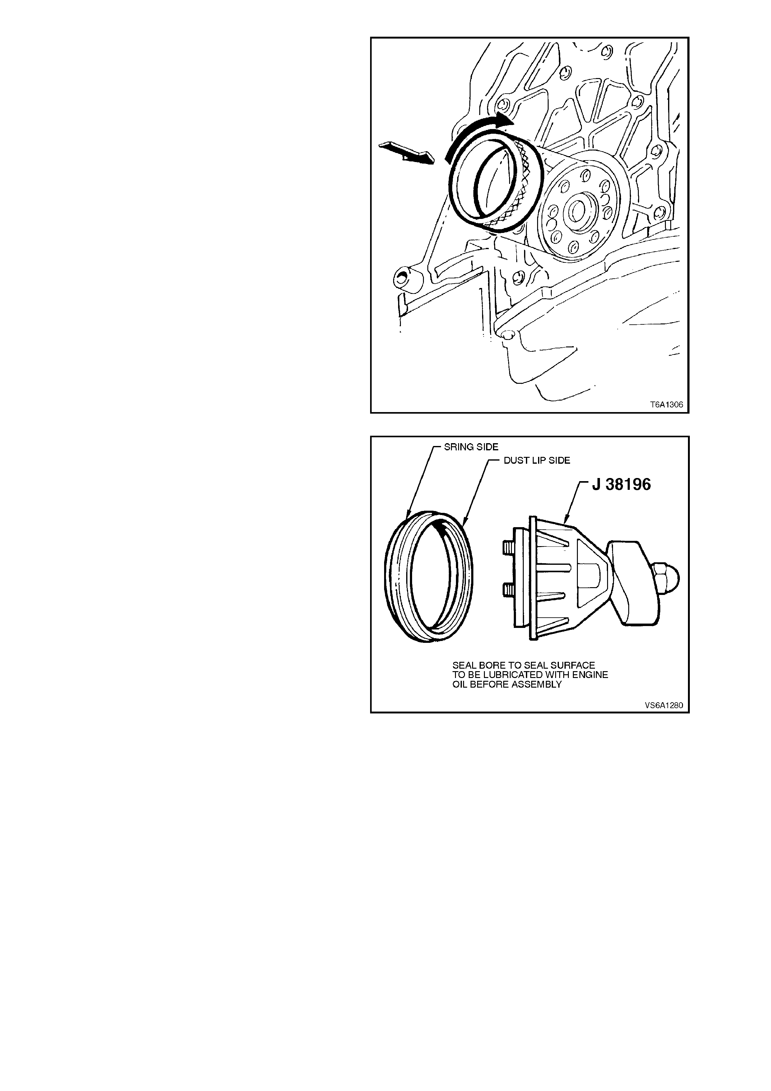
9. Lubricate rear main oil seal housing and
crankshaft flange plus I.D. and O.D. of
J41349. Install r ear m ain s eal hous ing aligning
tool J41349 tapered end first to crankshaft
flange and rotate tool. Tool should turn evenly
without binding or tight spots if housing is
correctly aligned.
Figure 6A1-1-288
10. Apply engine oil to new seal inner and outer
diameter.
Apply a thin film of clean engine oil to the
surface of the crankshaft over which the seal
will slide during installation.
NOTE:
Do not apply petroleum jelly or grease to seal lip.
These substances can prevent correct seal
operation.
NOTE:
Seal installation using Tool No. J38196
Ensure that T-handle of Tool No. J38196 is
loosened right off. Slide seal over mandrel of
Tool No. J38196 until it bottoms squarely
against outer collar of tool.
CAUTION:
Inspect tool J38196 for damage to the seal lip
area. If damage is evident, the tool should be
replaced. Figure 6A1-1-289
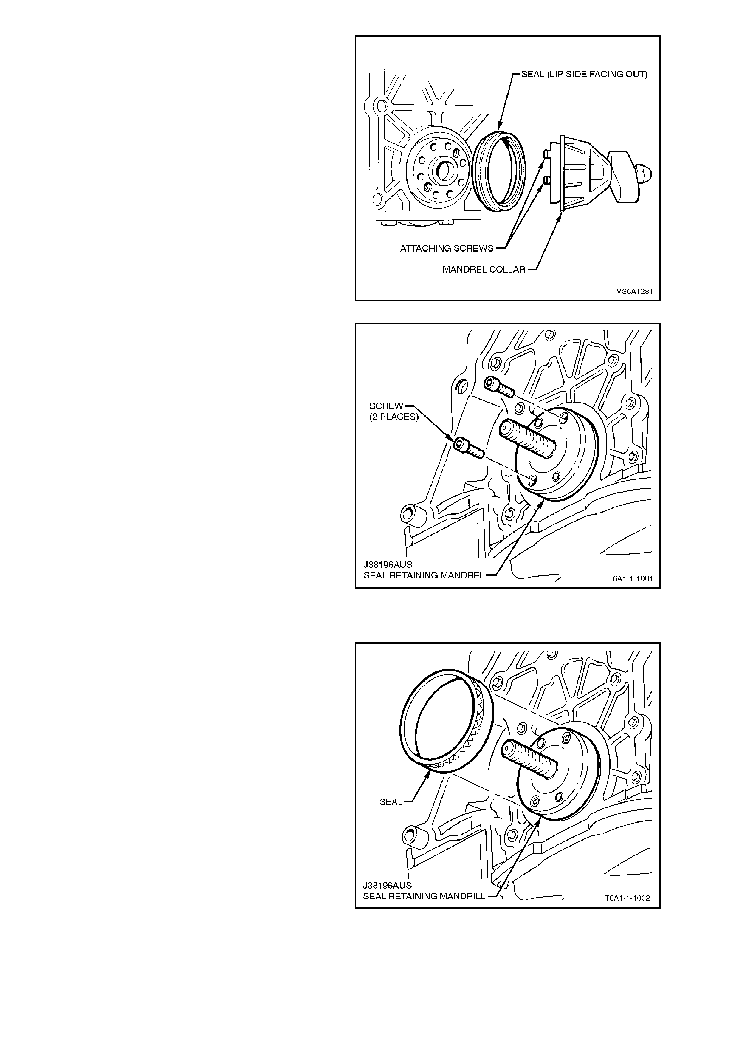
11. Attach tool to rear of crankshaft by tightening
the two knurled attaching screws until tight.
It is important when using the seal installation
tool that the correc t holes in the c rankshaf t ar e
used.
One of the holes in the crankshaft is offset, if
this hole is one of the pair used then it can
result in the seal being installed incorrectly.
12. Turn T-handle of tool so that outer collar
pushes seal into its bore and continue to turn
handle until additional resistance is felt. Do not
over tighten T- handle other wise dam age to the
tool may result.
Figure 6A1-1-290
NOTE:
Seal installation using Tool No. J38196AUS
Separate tool by removing nut, and place
mandrel collar to one side.
CAUTION:
Inspect seal retaining mandrel for damage to
the seal lip area. If damage is evident, the tool
should be replaced.
13. Attach seal retaining mandrel to rear of
crankshaft by fitting two attaching screws until
tight.
It is important when using the seal installation
tool that the correc t holes in the c rankshaf t ar e
used.
Clearance holes are provided to avoid
interference with crankshaft dowel pins if
fitted.
One of the holes in the crankshaft is offset, if
this hole is one of the pair used then it can
result in the seal being installed incorrectly.
Figure 6A1-1-291
14. Install seal onto seal retaining m andrel, noting
that seal lips are facing out.
Figure 6A1-1-292
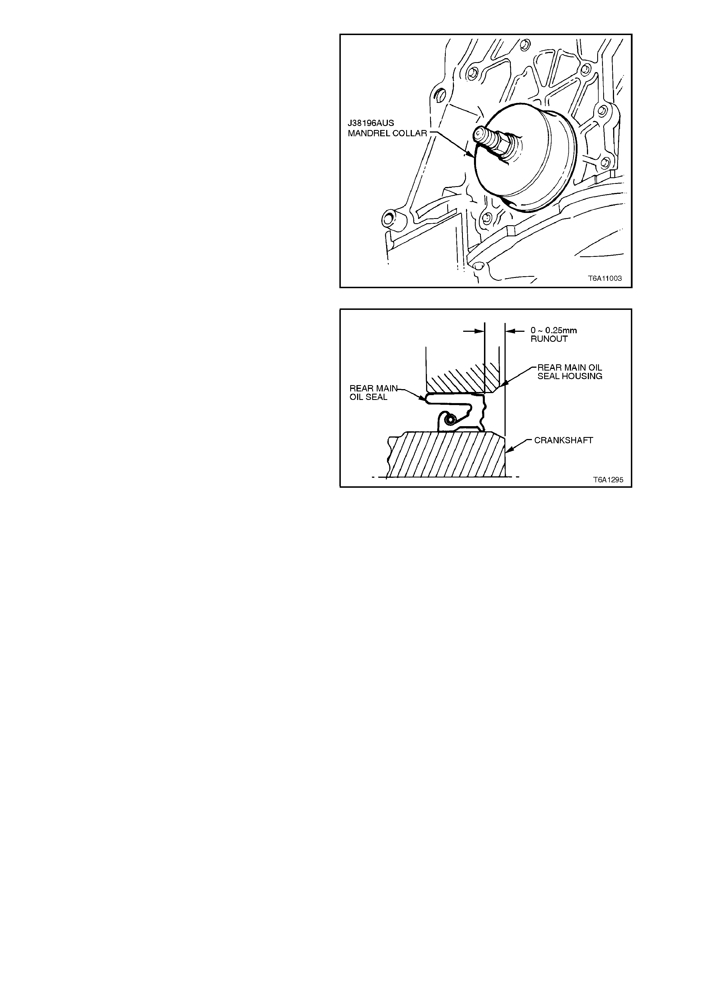
15. Install mandrel collar over seal retaining
mandrel.
16. Install nut onto seal retaining mandrill and
tighten nut until seal is seated into rear main
oil seal housing.
Figure 6A1-1-293
The seal must be installed parallel to the
crankshaft rear flange.
The crankshaft rear flange to seal dimension
should not vary more than 0.25 mm when
measured at different points around the
circumference of the crankshaft rear flange.
NOTE:
Dimension is shown with crankshaft in fully
rearward position.
Figure 6A1-1-294
IMPORTANT:
If the above dimension varies more than 0.25 mm
reattach tool J38196 / J38196AUS to rear of
crankshaft and turn t-handle until resistance is felt.
With tool in this position, remove spark plugs and
rotate engine slowly for two full revolutions.
Remove tool and recheck seal is parallel to
crankshaft flange.
If the crankshaft rear flange to seal dimension still
varies more than 0.25 mm, replace tool J38196 /
J38196AUS.
17. Remove seal installing tool from crankshaft.
18. If necessary, reinstall spigot bearing, refer to
3.6 SPIGOT BEARING in this Section.
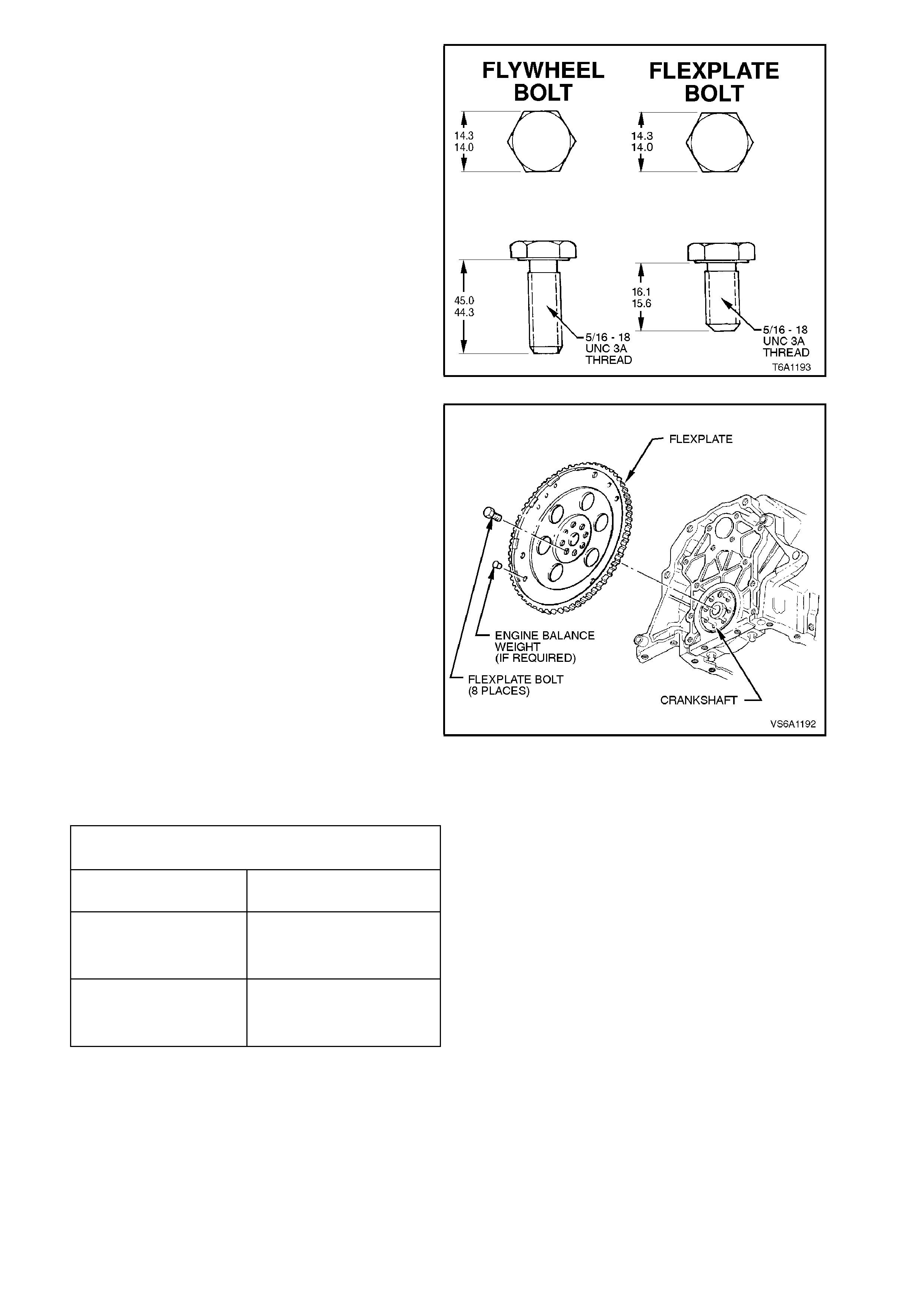
Figure 6A1-1-295
19. Clean flywheel/flexplate attaching bolt threads
in rear of crankshaft using a 5/16 UNC thread
tap.
Reinstall flywheel/flexplate using new bolts
refer to 3.4 FLYWHEEL/FLEXPLATE in this
Section.
Figure 6A1-1-296
20. Reinstall transmission, check engine and
transmission lubricant levels.
FLYWHEEL/FLEXPLATE BOLT TIGHTENING
SEQUENCE
STEP No. 1 TORQUE ALL BOLTS TO 18
- 22 Nm
STEP No. 2
MANUAL
TRANSMISSION
TIGHTEN ALL BOLTS A
FURTHER 80 - 90
DEGREES TURN ANGLE
STEP No. 2
AUTOMATIC
TRANSMISSION
TIGHTEN ALL BOLTS A
FURTHER 47 - 53
DEGREES TURN ANGLE
21. Road test vehicle and check for lubricant
leaks.
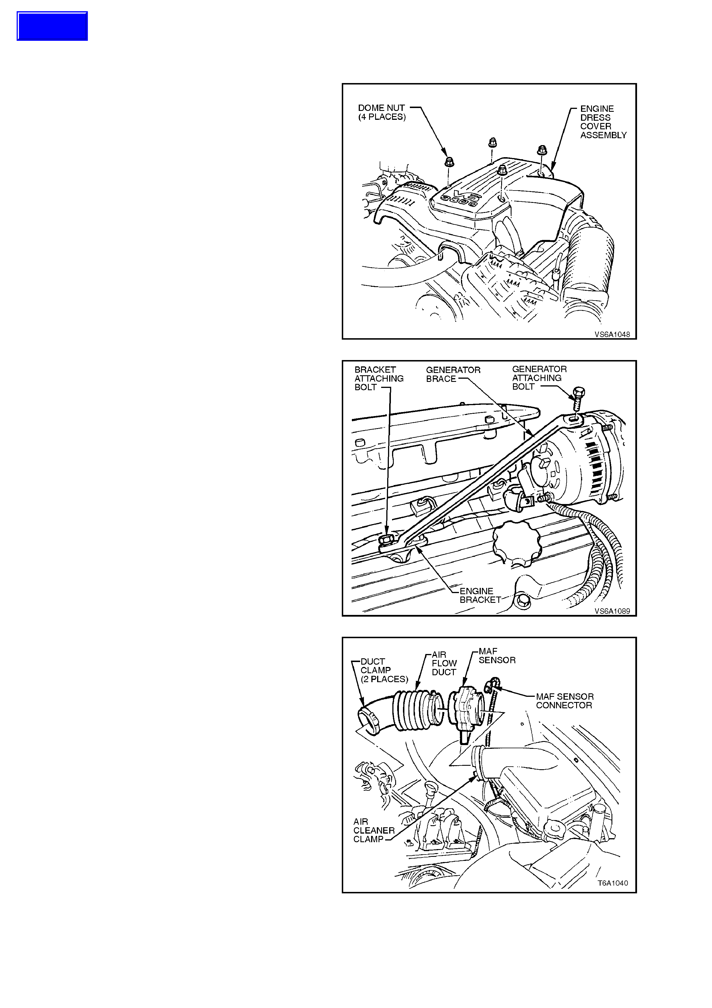
3.14 REAR MAIN OIL SEAL HOUSING
REMOVE
1. Disconnect battery earth lead.
NOTE:
If performing this operation with engine installed
drain cooling system refer to
Section 6B1-1 ENGINE COOLING - V6 ENGINE.
2. Remove the four nuts securing engine dress
cover.
Figure 6A1-1-297
3. Remove bolts securing generator brace.
Figure 6A1-1-298
4. Disconnect mass air flow sensor wiring,
loosen air flow duct rubber boot clamps at
throttle body and air cleaner and remove air
flow duct. Carefully place air flow duct and
mass air flow sensor assembly to one side.
Figure 6A1-1-299
Techline
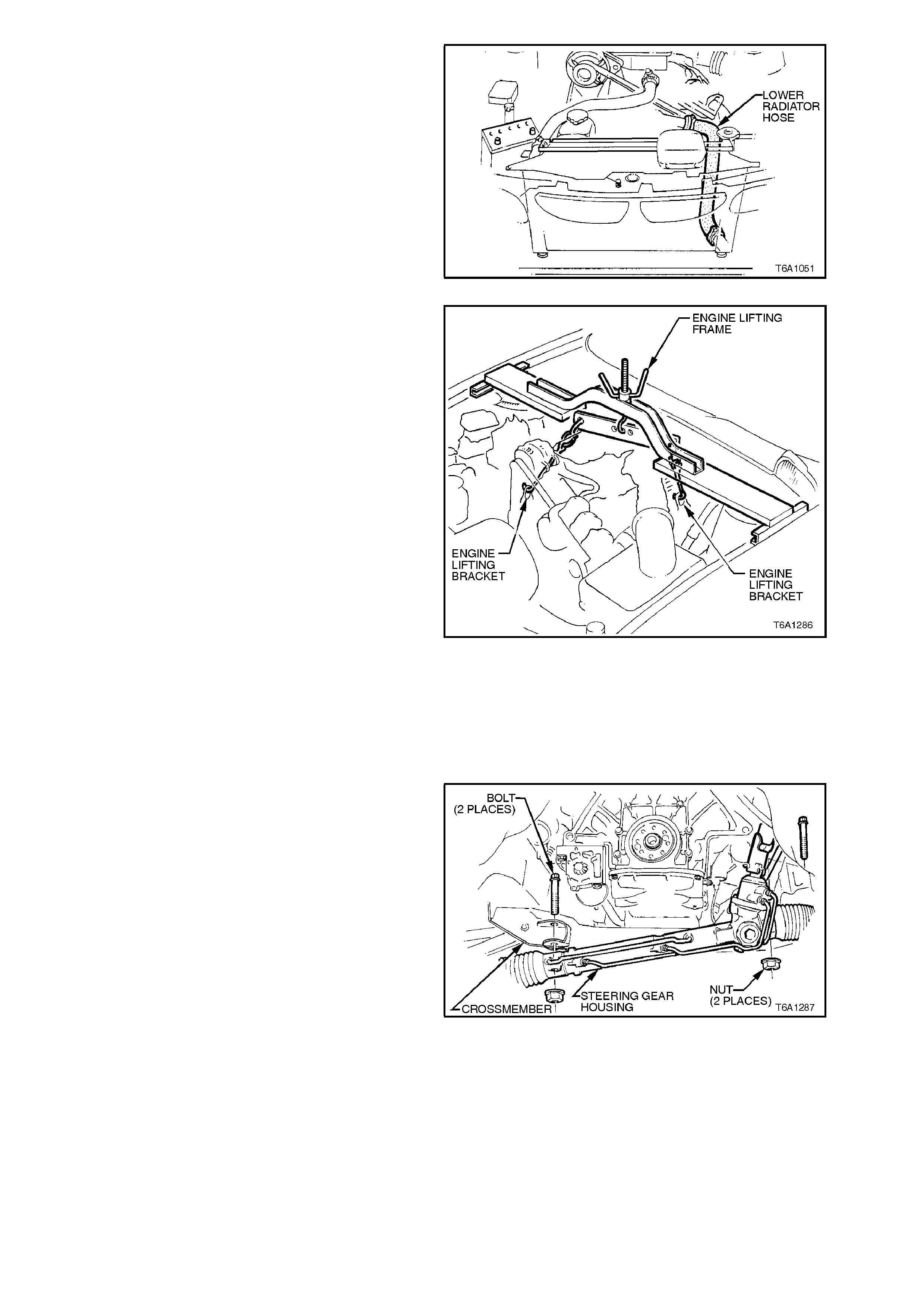
5. Remove lower radiator hose and drain coolant.
Figure 6A1-1-300
6. Remove the engine hood assembly, refer to
Section 1B SHEET METAL.
7. Install engine lifting brack ets and engine lifting
frame to engine.
NOTE:
Ensure adequate clearance between lifting
equipment and engine components.
Figure 6A1-1-301
8. Remove transmission, refer to
Section 7B1 MANUAL TRANSMISSION - V6
ENGINE, or to Section 7C4 AUTOMATIC
TRANSMISSION.
9. Remove flywheel/flexplate, refer to
3.4 FLYWHEEL/FLEXPLATE in this Section.
10. Remove steering rack mounting bolts, lower
steering rack to improve access.
Figure 6A1-1-302
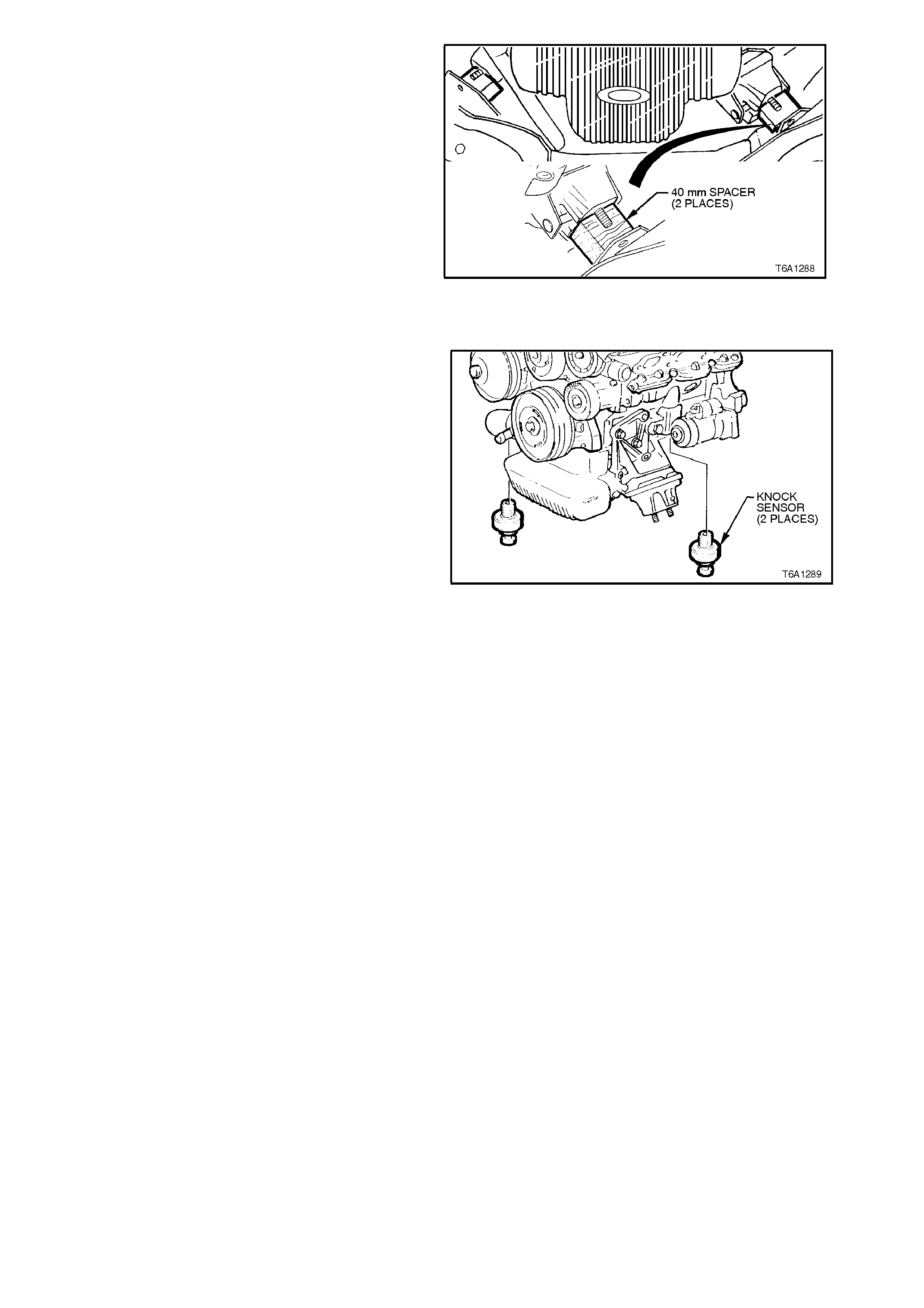
11. Remove engine mounting to front
crossmember attaching nuts.
12. Raise engine 40 mm.
13. Fit 40 mm spacers between engine mounts
and crossmember to support engine.
Figure 6A1-1-303
14. Drain engine oil.
15. Remove the engine oil pan.
16. Disconnect wiring harness to knock sensors.
17. Drain remaining coolant by removing both
knock sensors from engine block.
18. Remove rear main oil seal housing to cylinder
block bolts, remove housing.
Figure 6A1-1-304
19. Thoroughly clean all mating surfaces using a
scraper and solvent.
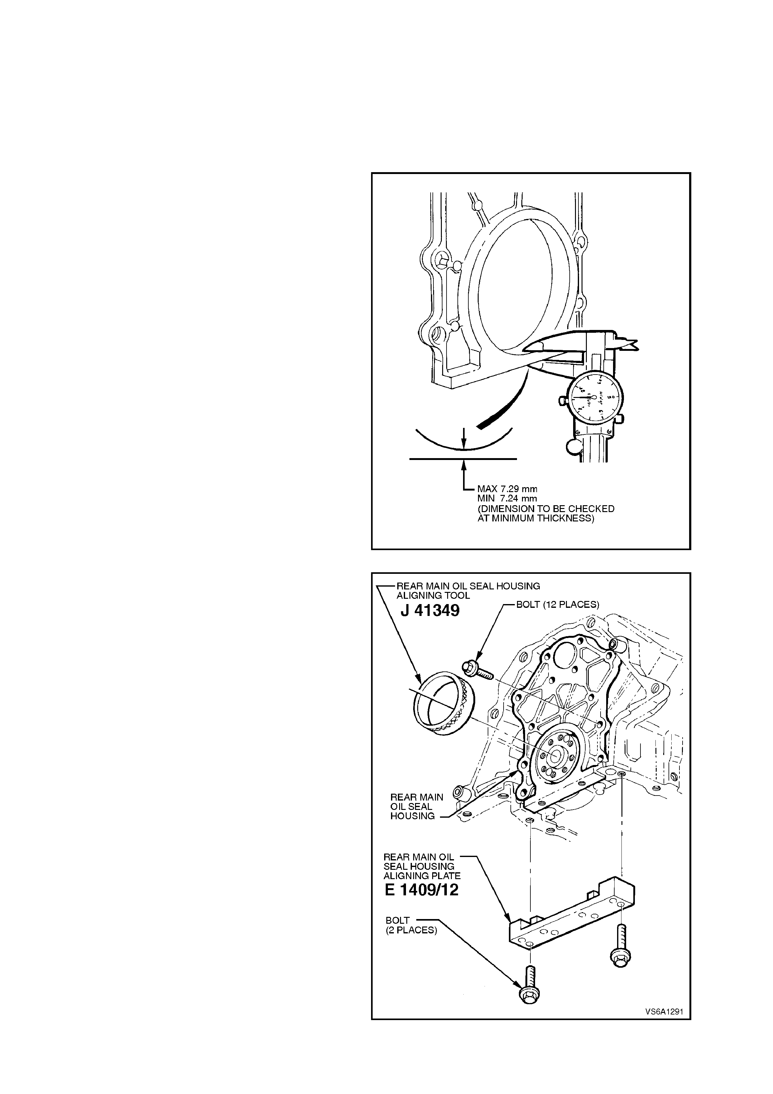
REINSTALL
Installation is the reverse of removal procedures
noting the following points.
NOTE:
Ensure block face is clean of oil and water before
reinstalling housing. Approximately 15 minutes is
required for oil to drain suff iciently to achieve an oil
free surface.
1. Prior to reinstallation of rear main oil seal
housing, check thic k ness of housing as shown
in Fig. 6A1-1-305. If dimension is not within
specification of 7.24 - 7.29 mm, replace rear
main oil seal housing.
Figure 6A1-1-305
2. Fit rear main seal housing aligning tool
E1409/12 to oil pan rail.
3. Loosely reinstall rear main oil seal housing
and gasket to rear of cylinder block.
NOTE:
Rear main oil seal housing to block bolts are
torque-to-yield bolts and must not be reused.
4. Lubricate rear main oil seal housing and
crankshaft flange plus I.D. and O.D. of
J41349. Install r ear m ain s eal hous ing aligning
tool J41349 tapered end first to crankshaft
flange and rotate tool. Tool should turn evenly
without binding or tight spots if housing is
correctly aligned.
NOTE:
If correct location of housing cannot be achieved,
nylon inserts in housing may be removed.
Figure 6A1-1-306
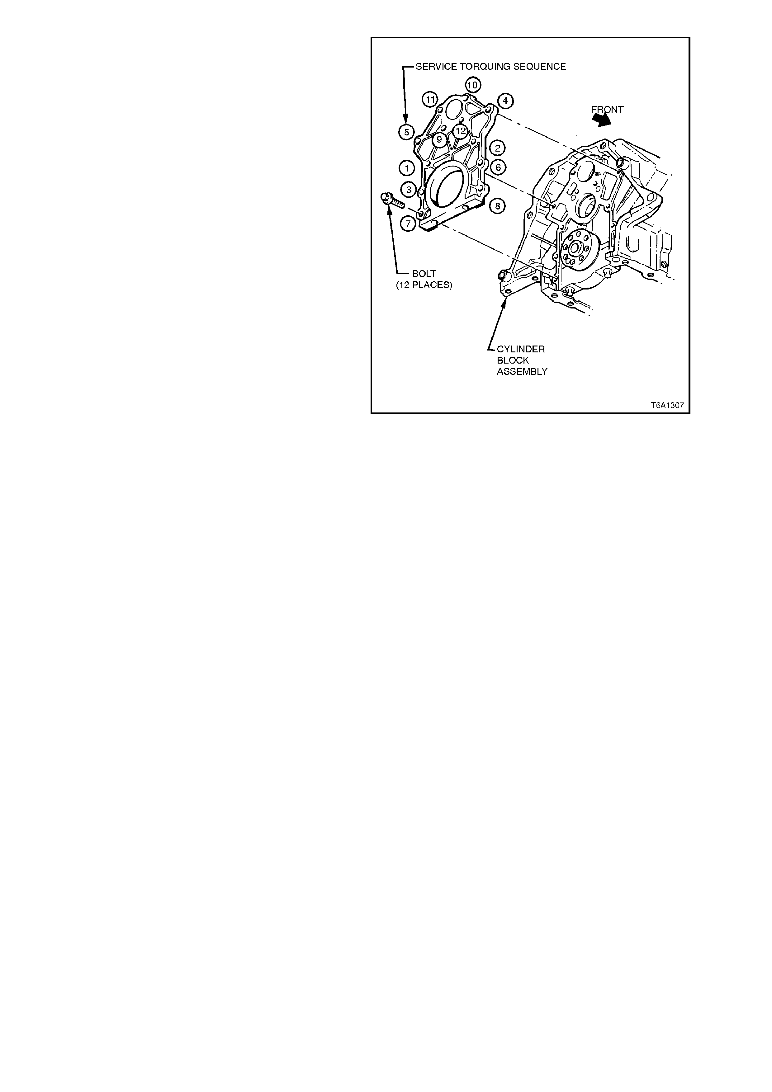
5. Torque all bolts to 12-18 Nm + 47-53° in
sequence.
CRANKSHAFT REAR MAIN OIL SEAL HOUSING
TORQUE SPECIFICATION
STEP 1. 12 - 18 Nm
STEP 2.. 47 - 53 Degrees
Figure 6A1-1-307
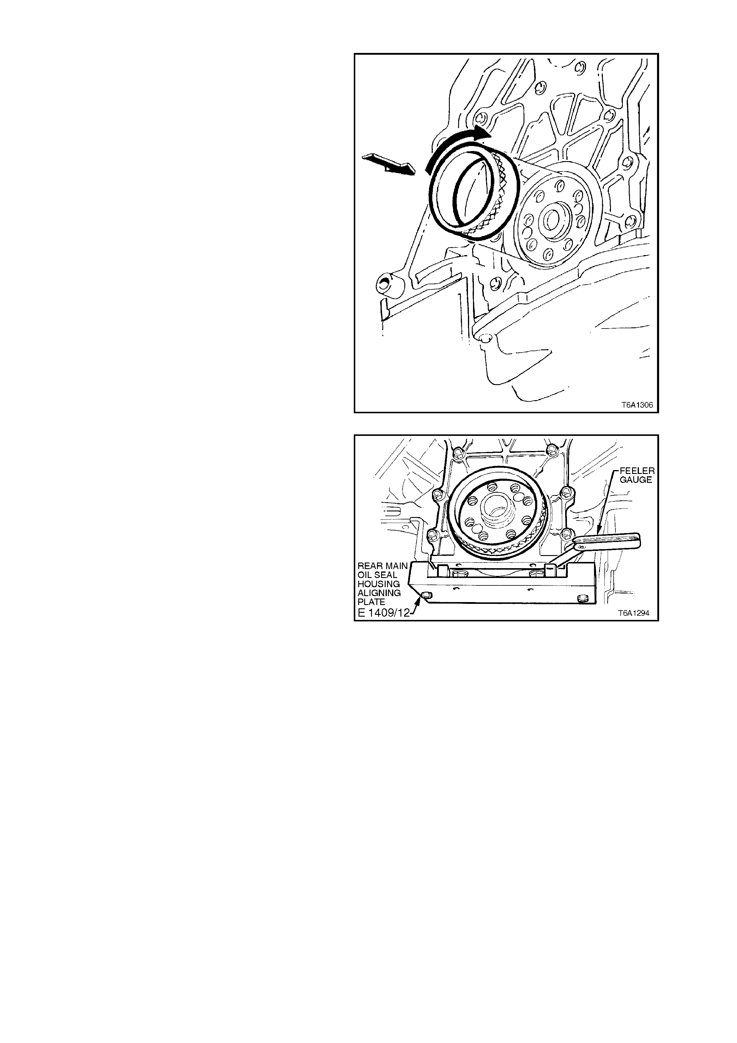
6. Recheck location of housing by rotating tool
J41349 on crank shaft. Tool s hould turn evenly
without binding or tight spots.
Figure 6A1-1-308
7. Using feeler gauge and E1409/12, check
height of rear main oil seal housing to oil pan
rail. Housing must be even to - 0.10 mm to oil
pan rail. If not, replace rear main oil seal
housing assembly and install as from step 1.
Above.
8. Remove tools J41349 and E1409/12.
Figure 6A1-1-309
9. Reinstall rear main oil seal refer to
3.13 REAR MAIN OIL SEAL in this Section.
10. Reinstall flywheel/flexplate using new bolts
refer to 3.4 FLYWHEEL/FLEXPLATE in this
Section. For flywheel Service Operations ref er
to Section 7A CLUTCH.
11. Fill and bleed cooling system refer to
Section 6B1-1 ENGINE COOLING - V6
ENGINE.
12. Refill engine with oil.
13. Road test vehicle and check for oil leaks.
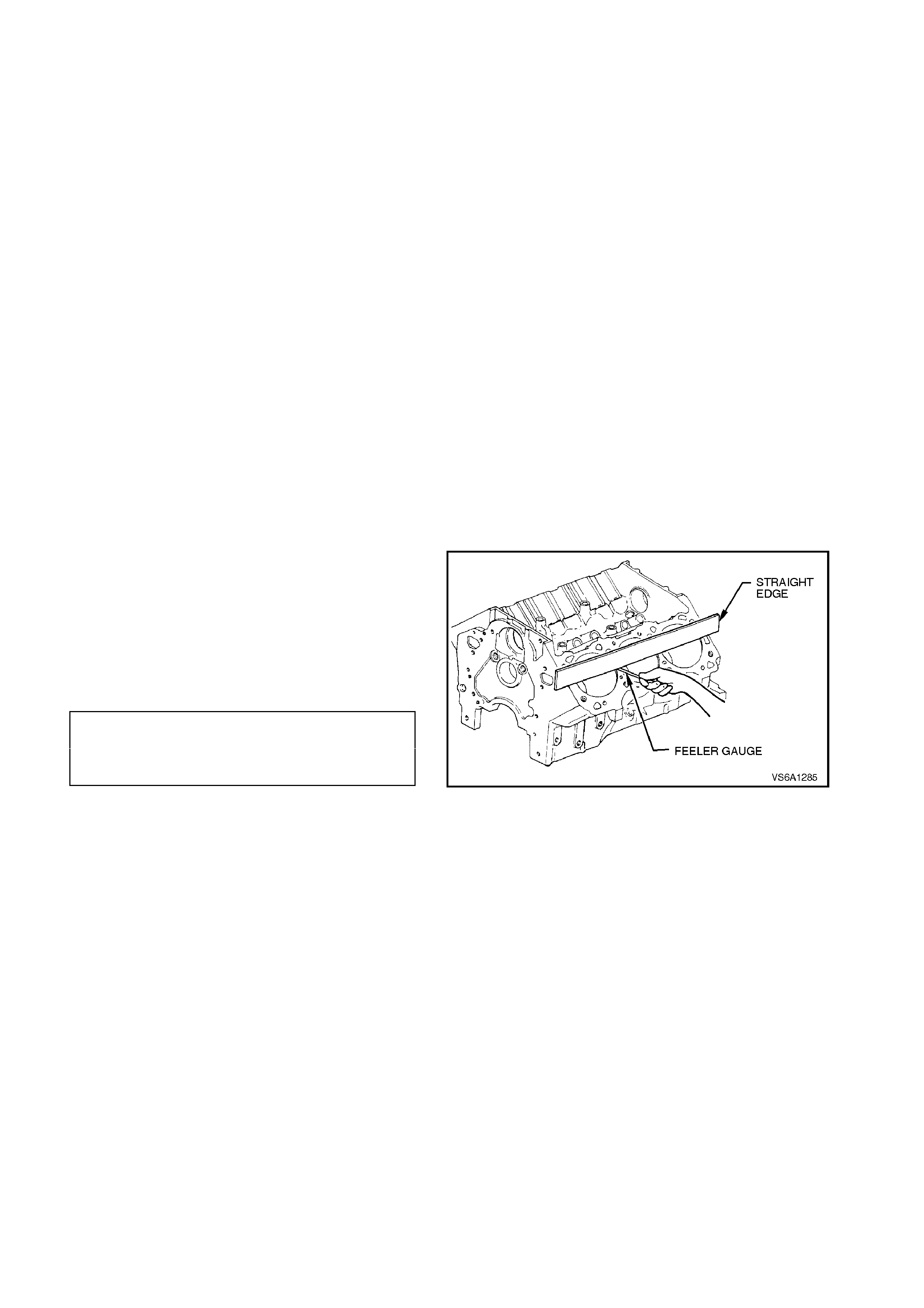
3.15 CYLINDER BLOCK
INSPECT
1. With engine removed from vehicle refer to
3.1 ENGINE ASSEMBLY in this Section and
mounted in a suitable engine stand, remove
all components as outlined under the
appropriate component heading in this
Section.
2. Clean all cylinder block gasket surfaces.
3. If necessary, remove all coolant jacket welsh
plugs, oil gallery screw plugs, knock sensors,
refer to Fig. 6A1-1-310 and camshaft
bearings, refer to 3.8 CAMSHAFT
BEARINGS in this Section.
4. Thoroughly clean cylinder block in a suitable
cleaning solution. Flush with clean water or
steam. Spray or wipe cylinder bores and
machined surfaces with engine oil.
NOTE:
Caustic cleaning solutions destroy all bearing and
alloy materials. All bearing and alloy components if
not removed before cleaning, must be replaced. Do
not clean bearing material or alloy parts with
caustic solutions.
5. Inspect all oil passages for restriction.
6. Check cylinder block deck surface for f latness
using a straight edge and feeler gauge.
Cylinder block deck s urface m ay be m achined
if any irregularity or distortion is less than
specified.
If irregularity or distortion exceeds
specifications, replace cylinder block.
CYLINDER BLOCK 0.013 mm PER
DECK SURFACE 25.4 mm OR
FLATNESS SPECIFICATION 0.08 mm MAX.
OVERALL
Figure 6A1-1-310
7. Inspect oil pan and front cover attaching area
for damage or burrs.
Minor irregularities may be cleaned up with a
fine mill file.
8. Inspect all threaded holes. If necessary clean
with a suitable threaded tap or drill out and
install thread insert.
The f ollowing cylinder block ins pections r equire the
main bearing caps to be installed and bolts
tightened to the correct torque specification. Refer
to 3.12 CRANKSHAFT in this section.
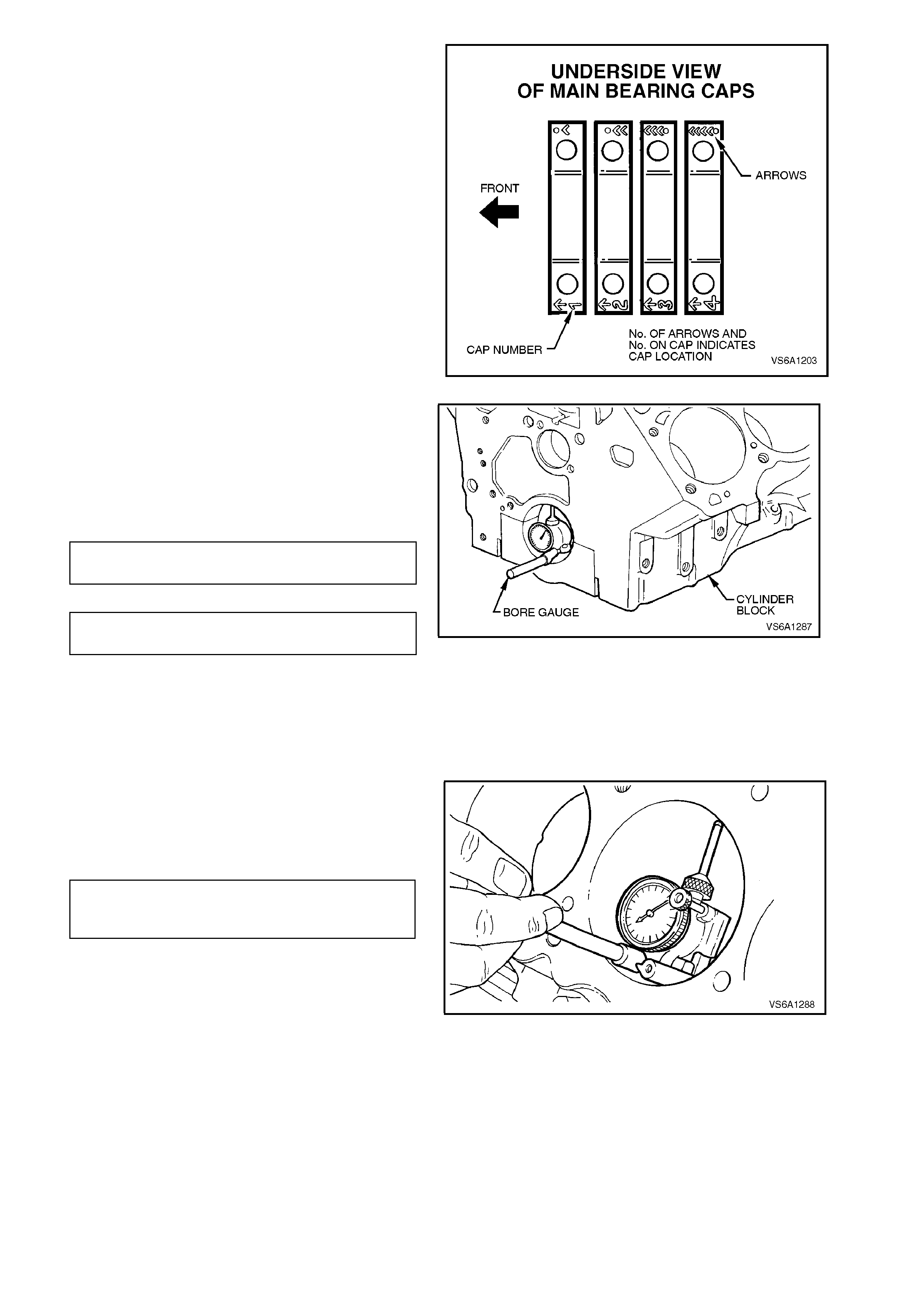
NOTE 1:
Use an angle wrench such as E7115 to ensure
accurate turn angle.
NOTE 2:
Ensure that the m ain bearing caps are installed into
the crankcase correctly.
NOTE 3:
In order to prevent the possibility of cylinder block
or bearing cap damage, do not install bearing cap
using a soft faced hammer. Use cap bolts to pull
bearing cap into position. Failure to observe this
procedure may damage cylinder block or bearing
cap.
Figure 6A1-1-311
9. Measure crankshaft and camshaft bearing
bores, check for concentricity and alignment.
If outside specification, replace cylinder block.
If examination of the outside of the bearing
shells indicates m inor high spots, rem ove high
spots from bearing seats with a fine mill file.
CRANKSHAFT BEARING BORE 0.008
MAXIMUM OUT-OF-ROUND mm
CAMSHAFT BEARING BORE 0.013
MAXIMUM OUT-OF-ROUND mm Figure 6A1-1-312
10. Measure cylinder bore walls for taper, out-of-
round, oversize and excessive ridging.
If bore is worn beyond limits, it may be
rebored, honed and fitted with oversize
pistons.
The smallest available oversize piston should
be selected, refer to
CYLINDER RECONDITIONING AND PISTON
FITTING in this Section.
STANDARD BORE DIAMETER 96.507-96.533 mm
MAX TAPER 0.013 mm
MAX OUT-OF-ROUND 0.010 mm
Figure 6A1-1-313

CYLINDER RECONDITIONING AND PISTON FITTING
If one or m ore cylinder bores are rough, scor ed, or
worn beyond limits, it will be necessary to smooth
or true up such bores to fit new pistons.
If relatively few bores require correction it will not
be necessary to rebore all cylinders to the same
oversize in order to m aintain engine balance, since
all oversize service pistons are held to the same
weight as standard size pistons.
No attempt should be made to machine oversize
pistons to fit cylinder bores, as this will destroy the
surface treatment and affect the weight. The
smallest possible oversize service pistons should
be used and the cylinder bores should be honed to
size for proper clearances.
Before the honing or reboring operation is started,
measure all new pistons at right angles to the
piston pin bore, 39 mm from top of piston.
Figure 6A1-1-314
If cylinder bore wear does not exc eed specif ication,
honing is recomm ended for truing the bore. If wear
or out-of-round exceeds specification, the bore
should be trued up by boring and then hone
finished.
When reboring cylinder bores, all crankshaft
bearing caps must be in place and tightened to
specified torque to prevent distortion of bores in
final assembly.
When taking the final cut with boring bar, leave
0.025 mm on the diameter for final honing to give
the specified clearance.
When cylinders are to be honed, follow the Hone
Manufactur er' s r ecommendations f or the us e of the
hone, cleaning and lubrication during honing.
When finish honing, pass the hone through the
entire length of cylinder bore at the rate of
approximately 60 cycles per minute. This should
produce the desired 45 degrees cross hatch
pattern on cylinder walls which will ensure
maximum ring life and minimum oil consumption.
During the final honing, each piston must be fitted
individually to the bore in which it will be installed
and marked to ensure correct assembly. After the
final honing and before the piston is c heck ed f or fit,
each cylinder bore must be washed and dried
thoroughly to remove all traces of abrasive and
then allowed to cool. Apply clean engine oil to
cylinder bores. The pis tons and c ylinder block mus t
be at a common temperature before checking.
When new piston rings are installed without
reboring cylinders, the glazed cylinder walls should
be slightly dulled, but without increasing the bore
diameter, by means of the finest grade of stone in
a cylinder hone.

To check piston to cylinder bore clearance,
proceed as follows:
1. Wipe cylinder walls and pistons with a clean
cloth. Apply clean engine oil to cylinder bores.
2. Accurately measure the bore with an inside
micrometer.
3. Measure piston diameter.
4. Subtract piston diameter from cylinder bore
diameter to determine piston-to-bore
clearance.
PISTON TO BORE
CLEARANCE 0.010 - 0.051
mm
5. Mark each piston with cylinder number to
which it will be fitted and proceed to hone
cylinders and fit pistons.
CAUTION:
Handle the pistons with care and do not
attempt to force them through the cylinder until
cylinder has been honed to correct size, as
pistons can be distorted through careless
handling.
Reassemble components as outlined under the
appropriate component heading in this Section.
If coolant and oil gallery plugs were removed on
disassembly, coat new plugs with sealant (or its
equivalent) as specified in Fig. 6A1-1-315 and
install.
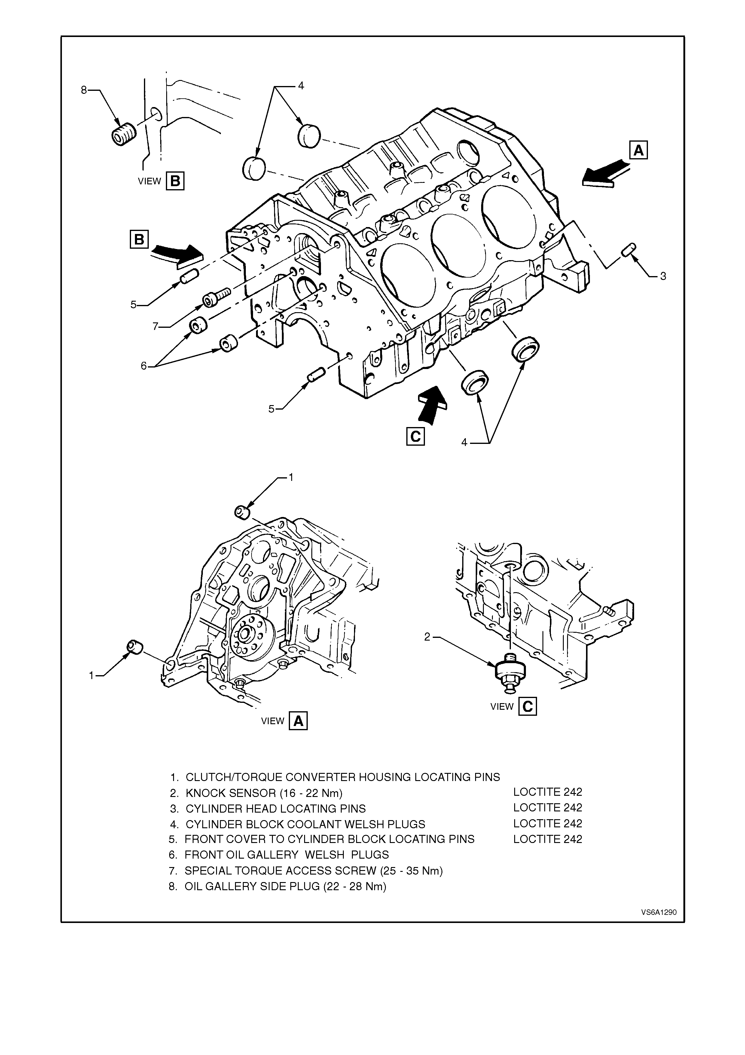
Figure 6A1-1-315

4. ENGINE MECHANICAL DIAGNOSIS
The following diagnostic information covers common problems and possible causes. When the proper diagnosis is
made, the problem should be corrected by adjustment, repair or part replacement as required. Refer to the
appropriate section for these procedures.
In the mechanical procedures described in this section, generally no references will be made to the removal of
optional equipment such as power steering pump, air conditioning compressor, etc.
Should it become necessary to remove any such item to perform other service, refer to the appropriate section for
specific information.
4.1 EXCESSIVE OIL LOSS
Excessive oil consumption (not due to leaks) is the use of 2 litres or more of engine oil within 10,000 km after the
engine has completed at least 10,000 km.
Excessive oil loss may result from one or more of the following conditions:
1. External oil leaks. Tighten bolts and/or replace gaskets and seals as necessary.
2. Improper reading of oil indicator (dipstick). Check oil with car on a level surface and allow adequate drain-down
time.
3. Continuous high speed driving, and/or severe usage such as towing, will normally cause increased oil
consumption.
4. P.C.V. system malfunctioning.
5. Improper oil viscosity. Use recommended S.A.E. viscosity for prevailing temperatures. Refer to
Section 0B LUBRICATION.
6. Valve guides and/or valve stem seals worn, or seals omitted. Ream guides and install oversize service valves
and/or new valve stem seals.
7. Piston rings improperly installed, broken, worn, or not seated. Allow adequate time for rings to seat. Replace
broken or worn rings as necessary.
8. Piston improperly installed or misfitted.
OIL LEAK DIAGNOSIS
Most oil leaks are easily located and repaired by visually finding the leak and replacing or repairing the necessary
parts. On some occasions, an oil leak may be difficult to locate or repair. The following procedure may help in
locating and repairing most leaks.
FINDING THE LEAK
1. Identify the fluid, determine whether it is engine oil, transmission lubricant, power steering fluid, etc.
2. To determine where the fluid is leaking, run the car at normal operating temperature, park the car over a large
sheet of paper. After a few minutes, the approximate location of the leak should be able to be found by
observing the oil spots on the paper.
3. Visually check around the suspected component. Check all gasket mating surfaces. A mirror may be used to
find leaks in hard to reach areas.
4. If the leak still cannot be found, it may be necessary to clean the suspected area with a degreaser, steam or
spray solvent. Operate the car for several kilometres at normal operating temperature and varying speed. After
operating the car, visually check the suspected component. If the location of the leak still cannot be found, try
using the following powder or black light and dye method.
POWDER METHOD
1. Clean the suspected area.
2. Apply an aerosol-type powder (such as foot powder) to the suspected area.
3. Operate the car under normal conditions.
4. Visually inspect the suspected component. Trace the leak path over the white powder surface to the source.
BLACK LIGHT AND DYE METHOD
Various dye and light kits are available for finding leaks. Refer to the kit manufacturer's directions when using the
kit.
1. Pour specified amount of dye into leaking component.
2. Operate the car under normal operating conditions as directed in the kit.
3. Direct the light toward the suspected area. The dyed fluid will appear as a yellow path leading to the source.
Techline
Techline
Techline

REPAIRING THE LEAK
Once the leak has been pinpointed and traced back to its source, the cause of the leak must be determined in order
for it to be repaired properly. If a gasket is replaced, but the sealing flange is bent, the new gasket will not repair the
leak. The bent flange must be repaired also. Before attempting to repair a leak, check to be sure that the following
conditions are correct as they may cause a leak.
GASKETS-INSPECT
1. Fluid level/pressure is too high.
2. Plugged ventilation filter or valve.
3. Improperly tightened fasteners or dirty/damaged threads.
4. Scratches, burrs or other damage to the sealing surface.
5. Warped flanges or sealing surfaces.
6. Damaged or worn gasket.
7. Cracking or porosity of the component.
8. Improper sealant used (where applicable).
SEALS-INSPECT
1. Fluid level/pressure is too high.
2. Plugged ventilation filters, or valve.
3. Damaged seal bore (scratched, burred or nicked).
4. Damaged or worn seal.
5. Improper installation.
6. Cracks in component.
7. Shaft surface scratched, nicked or damaged.
8. Loose or worn bearing causing excess seal wear.

4.2 LOW OIL PRESSURE
Oil pressure that is below 375 kPa at engine speeds above 1850 rpm is considered low and may result from one or
more of the following conditions:
1. Low oil level. Fill to mark on oil level indicator.
2. Incorrect or malfunctioning oil pressure sender or gauge.
3. Improper oil viscosity for expected temperature, or oil diluted with moisture or unburned fuel mixtures.
4. Oil pump worn or dirty.
5. Blocked oil filter.
6. Oil pump suction pipe screen blocked.
7. Hole in oil pump suction pipe.
8. Excessive bearing clearance.
9. Cracked, porous or blocked oil galleries. Repair or replace block.
10. Gallery plugs missing or misinstalled. Install plugs or repair as necessary.
11. Sticking pressure regulator (idle).

4.3 ENGINE NOISE DIAGNOSIS
There are four steps to diagnosing engine noise.
The following should be determined:
1. Type of noise.
2. Under which operating conditions the noise exists.
3. At what rate, and at what location in the engine.
4. Is the noise due to normal operation. Compare the sounds to that in other engines to make sure you are not
trying to correct a normal condition.
Identify the type of noise, for example, a light rattle or low rumble. Determine the exact operating conditions under
which the noise appears.
Engine noises are generally synchronised to either engine speed (caused by the crankshaft, connecting rods or
pistons) or one half the engine speed (valve train noises). Try to determine the rate at which the noise is occurring.
MAIN BEARING NOISE
Damaged or worn main bearing noise is revealed by dull thuds or knocks which happen on every engine revolution,
and this noise is loudest when the engine is under heavy load.
Excessive crankshaft end play is indicated by an intermittent rap or knock sharper than a worn main bearing. Cause
of main bearing noises include:
1. Low oil pump pressure.
2. Thin diluted or dirty oil and/or oil filter.
3. Excessive main bearing clearance.
4. Excessive crankshaft end play.
5. Out-of-round crankshaft journals.
6. Excessive belt tension.
7. Loose crankshaft pulley.
8. Loose flywheel or torque converter.
9. Loose main bearing cap.
CONNECTING ROD BEARING NOISE
A damaged or worn connecting rod bearing will produce a knock under all speeds. During the early stages of wear,
connecting rod noise may be confused with piston slap or loose piston pins. Connecting rod knock noise increase in
volume with engine speed and is at its loudest on deceleration. Cause of connecting rod bearing noise include:
1. Excessive bearing clearance.
2. Worn crankshaft connecting rod journal.
3. Thin, diluted or dirty oil and/or oil filter.
4. Low oil pressure.
5. Crankshaft connecting rod journals out of round.
6. Misaligned connecting rod.
7. Connecting rod bolts not correctly torqued.
8. Wrong bearing inserts or misaligned bearing half.
TIMING CHAIN AND SPROCKETS
Engines equipped with timing chain and sprockets can produce different noises. The most common noise is a high
frequency, light knocking sound. This sound will generally be the same in intensity whether the engine is idling,
operating at high speeds, or under load.
Causes of timing chain and sprocket noises include:
1. Worn timing chain and/or sprockets.
2. Misaligned sprockets.
3. Stretched or damaged timing chain.
4. Worn or faulty timing chain damper.
5. Sprocket loose or improperly seated on shaft.
6. Damaged sprocket.
7. Too much end play in camshaft or crankshaft.

PISTON NOISES
Piston pin, piston and connecting rod noises are difficult to separate. A loose piston pin, for example, causes a
sharp double knock usually heard when the engine is idling, or during sudden acceleration then deceleration of the
engine. A piston pin that has been improperly fitted will emit a light ticking noise that is more noticeable with no load
on the engine.
Excessive piston to cylinder bore clearance will cause piston slap noise. The noise is similar to a metallic knock, as
if the piston were "slapping" the cylinder wall during its stroke. As with most engine noises, understanding the cause
of the noise will help you imagine what the noise sounds like. An indication of piston slap is a decrease in noise as
the engine warms up. When the engine is cold, the piston to bore clearance is greater and piston slap will be louder.
Causes of piston noises include:
1. Worn or loose piston pin or bushing.
2. Improper fit of pin.
3. Excessive piston to cylinder bore clearance.
4. Lack of lubrication.
5. Carbon deposits on top of piston striking cylinder head.
6. Worn or broken piston ring land.
7. Broken or cracked piston.
8. Misaligned connecting rods.
9. Worn or damaged rings.
10. Worn or out-of-round cylinder walls.
11. Excessive ring land clearance.
12. Insufficient ring end gap clearance.
13. Piston 180 degrees out of position.
14. Incorrect piston cam grind.
VALVE TRAIN
A light tapping at one half engine speed, or any varying frequency, can indicate a valve train problem. These tapping
noises increase with engine speed.
Before attempting to judge valve train noises, thoroughly warm up engine. By doing this you will bring all engine
components to a normal state of expansion. Also run the engine at various speeds and listen for engine noise with
the hood closed while sitting in the drivers seat.
If the valve mechanism is abnormally noisy, remove rocker arm covers and use a stethoscope to determine which
valves or valve train parts are causing the noise.
Valve train noises may be caused by one or more of the following:
1. Broken or weak valve springs.
2. Sticking or warped valves.
3. Bent push rods.
4. Dirty, stuck or worn valve lifters.
5. Damaged or improperly machined camshaft lobes.
6. Insufficient or poor oil supply to valve train (low oil pressure).
7. Excessive valve stem to guide clearance.
8. Worn valve guides.
9. Worn push rods.
10. Worn rocker arms.
11. Broken rocker arm stud.
12. Loose or worn rocker arm attachments.
13. Missing or mis-positioned lifter guides.

4.4 ENGINE KNOCK DIAGNOSIS
KNOCKS WHEN ENGINE COLD AND CONTINUES FOR TWO OR THREE MINUTES
Increases with torque
1. Loose or broken balancer or drive pulleys. Tighten or replace as necessary.
2. Excessive piston to bore clearance. Replace piston.
Cold engine piston knock usually disappears when the cylinder is grounded out. Cold engine piston knock which
disappears in 1.5 minutes should be considered acceptable.
3. Bent connecting rod.
4. Rod bearing; oil supply at start-up.
HEAVY KNOCK HOT WITH TORQUE APPLIED
This condition may be caused by one or more of the following:
1. Broken balancer or pulley hub. Replace parts as necessary.
2. Loose torque converter to flexplate attaching bolts.
3. Exhaust system contacting underbody. Reposition as necessary.
4. Flywheel/flexplate cracked.
5. Excessive main bearing clearance.
6. Excessive connecting rod bearing clearance.
7. Low fuel quality.
LIGHT KNOCK HOT
This condition may be caused by one or more of the following:
1. Detonation or spark knock. Check fuel quality.
2. Loose torque converter to flexplate attaching bolts.
3. Exhaust leak at manifold.
4. Excessive connecting rod bearing clearance.
KNOCKS ON INITIAL START-UP BUT ONLY LASTS A FEW SECONDS
This condition may be caused by one or more of the following:
1. Improper oil viscosity . Use proper oil viscosity for expected temperatures. Refer to
Section 0B LUBRICATION.
2. Hydraulic lifter bleed down.
When the engine is stopped, some valves will be open. Spring force against lifters will tend to bleed lifter down.
Attempts to repair should be made only if the problem is consistent.
3. Excessive crankshaft end float. Replace crankshaft thrust bearing shells.
4. Excessive front main bearing clearance. Replace worn parts.
5. Excessive piston or rod clearance. Replace worn parts.
6. Timing chain tensioner malfunction. Clean, inspect and replace if required.

KNOCKS AT IDLE, ENGINE HOT
This condition may be caused by one or more of the following:
1. Loose or worn drive belt. Check tension and/or replace as necessary .
2. Air conditioning compressor or generator bearing noisy. Replace as necessary.
3. Worn valve train components. Replace parts as necessary.
4. Improper oil viscosity . Use proper viscosity oil for expected temperature. Refer to Section 0B LUBRICATION.
5. Excessive piston pin clearance. Replace piston and pin.
6. Connecting rod alignment. Check and replace rods as necessary.
7. Insufficient piston to bore clearance. Hone bore and fit new piston.
8. Loose crankshaft balancer. Torque retaining bolt and/or replace worn balancer.
9. Piston pin offset to wrong side. Install piston correctly.
VALVE TRAIN NOISE
This condition may be caused by one or more of the following:
1. Low oil pressure. Repair as necessary (refer to diagnosis for low oil pressure).
2. Loose rocker arm attachments. Inspect and repair as necessary.
3. Worn rocker arm, pivot, and/or pushrod.
4. Broken valve spring.
5. Sticking valves.
6. Lifters worn, dirty, or defective.
7. Camshaft worn, or faulty machining. Replace camshaft.
8. Worn valve guides.

4.5 HYDRAULIC VALV E LIFTERS
Hydraulic valve lifters seldom require attention. The lifters are extremely simple in design, readjustments are not
necessary and servicing of the lifters requires only that care and cleanliness be exercised in the handling of parts.
The easiest method for locating a noisy valve lifter is by use of a piece of garden hose near the end of each inlet
and exhaust valve with the other end of the hose to the ear.
In this manner, the sound is localised, making it easy to determine which lifter is at fault.
Another method is to place a finger on the face of the valve spring retainer. If the lifter is not functioning properly, a
distinct shock will be felt when the valve returns to its seat.
The general types of valve lifter noise are as follows:
1. Momentary noise when car is started:
This condition is normal. Oil drains from the lifters which are holding the valves open when the engine is not
running. It will take a few seconds for the lifter to fill after the engine has started.
2. Intermittently noisy on idle only, disappearing when engine speed is increased:
Intermittent clicking may be an indication of a flat or pitted ball, or it may be caused by dirt.
Correction: Clean the lifter and inspect. If ball is defective, replace lifter.
3. Noisy at slow idle or with hot oil, quiet with cold oil or as engine speed is increased:
Insert a 0.375 mm feeler gauge between the rocker arm and valve stem. If noise momentarily disappears and
then re-appears after a few seconds, the lifter leak-down rate is too fast.
Correction: The lifter must be replaced.
4. Noisy at high car speeds and quiet at low speeds.
a. High oil level. Oil level above the FULL mark allows crankshaft counterweights to churn the oil into foam.
When foam is pumped into the lifters, they will become noisy since a solid column of oil is required for
proper operation.
Correction: Drain oil until proper level is obtained.
b. Low oil level. Oil level below the ADD mark allows the pump to pump air at high speeds which results in
noisy lifters.
Correction: Fill until proper oil level is obtained.
c. Oil pan bent on bottom or oil suction screen and pipe loose, repair or replace as necessary.
5. Noisy at idle becoming louder as engine speed is increased to 1500 rpm.
a. This noise is not connected with lifter malfunction and is caused by one or more of the following:
- Badly worn or scuffed valve tip and rocker arm pad.
- Excessive valve stem to guide clearance.
- Excessive valve seat run-out.
- Off square valve spring.
- Off square rocker arm pad.
- Excessive valve face run-out.
- Valves noisy regardless of engine speed.
This condition can be caused by foreign particles or valve lash.
Check for lash by turning engine so the piston in that cylinder is on top dead centre of firing stroke. If valve lash
is present, the pushrod can be freely moved up and down a certain amount with rocker arm held against valve.
If this occurs, replace suspected valve lifters
Valve lash indicates one of the following:
a. Worn pushrod.
b. Worn rocker arm.
c. Lifter plunger stuck in down position due to dirt or carbon.
d. Faulty lifter.
When checking the above items
1. Look at the upper end of pushrod. Excessive wear of the spherical surface indicates one of the following
conditions:
a. Improper hardness of pushrod ball. The pushrod and rocker arm must be replaced.
b. Improper lubrication of pushrod and rocker arm. The oiling system to the pushrod should be checked.
2. If pushrod appears in good condition and has been properly lubricated, replace rocker arm and recheck for
valve lash.
3. If valve lash exists and pushrod and rocker arm are OK, trouble is in the lifter. Lifter should be replaced.

5. SPECIFICATIONS
GENERAL
Engine Model Year 1997
Type 90 degree V6, OHV
Displacement 3791 cc
Compression ratio 9.35:1
Number of cylinders 6
Firing order 1-6-5-4-3-2
Cylinder numbering-front to rear
Left bank 1-3-5
Right bank 2-4-6
Taxable horsepower (RAC or SAE) 34.6
Power - kilowatts 147 @ 5200 rpm
Torque - Newton meters 304 @ 3600 rpm
Bore and stroke (nominal) 96.52 x 86.36 mm
Fuel research octane rating 91
Fuel requirement Unleaded
CYLINDER BLOCK
Bore diameter 96.507 - 96.533 mm
Bore out-of-round 0.010 mm max.
Bore taper 0.013 mm max.
Cylinder block to cylinder head surface
flatness 0.08 mm max. overall or
0.13 mm per 25.4 mm
Crankshaft bearing bore maximum out-of-
round 0.08 mm
Camshaft bearing bore maximum out-of-
round 0.013 mm
CRANKSHAFT
Material Cast Nodular Iron
Main bearing journals
Diameter 63.470 - 63.495 mm
Out-of-round 0.08 mm max.
Taper 0.08 mm max.
Cylinder block bore 68.250 - 68.270 mm
Crankshaft end clearance 0.08 - 0.28 mm
Bearing clearance 0.023 - 0.053 mm
End thrust Against main bearing No. 2
Connecting rod journals
Diameter 57.117 - 57.147 mm
Out-of-round 0.08 mm max.
Taper 0.08 mm max.
Connecting rod bore 60.295 - 60.312 mm
Bearing clearance 0.023 - 0.053 mm
Side clearance 0.10 - 0.50 mm
Crankshaft rear flange run-out 0.05 mm max.
CONNECTING RODS
Type Malleable Cast Iron 'I' Section
Length (centre to centre) 145.90 - 145.80 mm
Alignment Bend 0.020/25.4 mm,
Twist 0.038/25.4 mm

PISTONS
Material Cast Aluminium Alloy
Piston diameter (45.7 mm from top of
piston) 96.482 - 96.497 mm
Piston to bore clearance 0.010 - 0.051 mm
Piston pin bore offset and direction 0.25 - 0.55 mm, Major thrust side
Piston and pin assemblies serviced Std and 0.508 Oversize
Ring groove widths
Compression ring upper 1.230 - 1.255 mm
Compression ring lower 1.530 - 1.555 mm
Oil control ring 2.030 - 2.055 mm
PISTON PINS
Material Steel - Case Hardened
and Tempered
Length 65.0 - 65.5 mm
Diameter 21.995 - 22.000 mm
Pin to piston clearance 0.002 - 0.013 mm
Pin to rod clearance 0.007 - 0.022 mm
PISTON RINGS
Compression ring upper
Type Steel, Balanced Section
Molybdenum Filled, Barrel Lapped.
Width 1.176 - 1.191 mm
Gap 0.305 - 0.559 mm
Piston ring to groove clearance 0.039 - 0.079 mm
Compression ring lower
Type Inverted Torsional Taper Faced Type
Width 1.476 - 1.491 mm
Gap 0.762 - 1.016 mm
Piston ring to groove clearance 0.039 - 0.079 mm
Oil control ring type Segmented with Circumferential -
Expander Type Spacer
Width (ring assembly) 1.854 - 2.007 mm
Ring assembly to groove clearance 0.023 - 0.201 mm
Rail gap 0.254 - 0.762 mm

CAMSHAFT
Material 5150 Steel
Bearing journal
Diameter 46.858 - 46.893 mm
Number 4
Bearing diameter (installed)
Numbers 1 and 4 46.934 - 46.970 mm
Numbers 2 and 3 46.942 - 46.977 mm
Clearance in bearings
Numbers 1 and 4 0.041 - 0.112 mm
Numbers 2 and 3 0.049 - 0.119 mm
Camshaft end float (gear and bolt installed) 0.04 - 0.26 mm
Camshaft lobe lift
Inlet 6.56 mm
Exhaust 6.48 mm
Valve timing
Inlet
Opens - BTC 29.5 degrees
Closes - ABC 115 degrees
Duration 324.5 degrees
Exhaust
Opens - BBC 76.5 degrees
Closes - ATC 78.5 degrees
Duration 335 degrees
CYLINDER HEAD
Thickness (refer Fig 6A1-1-101 in this
Section) 1.12 mm minimum
Minimum combustion chamber volume
(with valves and spark plugs installed) 60 cc
VALVE - INLET
Material High Manganese Medium
Carbon Steel
Diameter head 45.59 - 45.85 mm
Diameter stem 7.955 - 7.968 mm
Angle valve face 45 degrees
Angle valve seat (in head) 45 degrees
Width valve seat (in head) 1.78 mm
Valve seat run-out 0.05 mm
Clearance in guide 0.04 - 0.25 mm
Valve installed height 49.22 - 50.49 mm
(from valve tip to spring seat)
Valve head margin thickness 0.63 mm minimum
Valve oversize available 0.25 mm

VALVE - EXHAUST
Material High Alloy Exhaust Valve Steel
Diameter head 38.48 - 38.74 mm
Diameter stem 7.948 - 7.965 mm
Angle valve face 45 degrees
Angle valve seat (in head) 45 degrees
Width valve seat (in head) 2.16 mm
Valve seat run-out 0.05 mm
Clearance in guide 0.04 - 0.25 mm
Valve installed height 49.22 - 50.49 mm
(from valve tip to spring seat)
Valve head margin thickness 0.63 mm minimum
Valve oversize available 0.25 mm
VALVE SPRINGS
Valve spring force
At assembled height 316 - 351 N @ 43.7 mm
At valve opened height 970 - 1059 N @ 32.4 mm
Valve spring at installed height 43.7 ± .5 mm
Valve spring allowable variance in
spring end length 1.6 mm
BALANCE SHAFT
End play 0 - 0.203 mm
Front radial play 0 - 0.028 mm
Rear bush clearance 0.025 - 0.130 mm
Drive gear lash 0.050 - 0.127 mm
Front bearing bore diameter 51.973 - 51.999 mm
Rear bearing inside diameter 38.12 - 38.19 mm
Installation depth of rear bearing from
rear seal cover mounting face 0.99 - 1.49 mm
FLEXPLATE
Flexplate Run out 0.38 mm

TIMING CHAIN
Timing chain movement 25.4 mm max.
LUBRICATION SYSTEM
Type of lubrication
Main bearings Pressure
Connecting rod bearings Pressure
Piston pins Splash
Camshaft bearings Pressure
Timing chain Splash
Balance shaft front bearing Splash
Balance shaft rear bearing Pressure
Cylinder walls Splash
OIL PUMP
Oil pump type Gerotor
Oil pressure regulator Approx 414 kPa
Oil pressure hot 375 kPa minimum @ 1850 RPM and
above
Oil filter by-pass valve Unseats at approx. 69 kPa pressure
differential
Oil pump gears
Inner gear tip to outer gear clearance 0.22 mm max.
Outer gear to housing clearance 0.05 - 0.13 mm max.
Inner and outer gear end to housing
clearance 0.025 - 0.089 mm
Gear Pocket
Depth 9.89 - 9.92 mm
Diameter 88.70 - 88.75 mm
Pressure regulator valve to bore clearance 0.038 - 0.076 mm
Oil pressure warning
Switch setting contacts open (light off) Less than 41.4 kPa (pressure
increasing)
Switch setting contacts close (light on) More than 13.8 kPa (pressure
decreasing)
Oil pan capacity (less filter) 4.5 litres
Oil filter
Type Full flow disposable canister
Capacity 0.3 litres

SEALANTS
Inlet manifold front and rear seal corners RTV 732 Holden Specification
HN 1373
Cylinder block coolant welsh plugs Loctite 242 Holden Specification
HN 1256 Class 2, Type 2
Right and left hand knock sensors to
cylinder block Loctite 242 Holden Specification
HN 1256 Class 2, Type 2
Oil gallery plug at lower front right hand
side of cylinder block Loctite 242 Holden Specification
HN 1256 Class 2, Type 2
Two oil gallery welsh plugs at frontface of
cylinder block Loctite 242 Holden Specification
HN 1256 Class 2, Type 2
Three idler pulley mounting studs into front
left hand side of cylinder block Loctite 242 Holden Specification
HN 1256 Class 2, Type 2
Oil pressure switch into oil filter adaptor Loctite 242 Holden Specification
HN 1256 Class 2, Type 2
Coolant temperature sender units to lower
inlet manifold Loctite 242 Holden Specification
HN 1256 Class 2, Type 2
Brake booster vacuum fitting to upper inlet
manifold Loctite 242 Holden Specification
HN 1256 Class 2, Type 2
Front cover to cylinder block attaching bolt
threads Loctite 242 Holden Specification
HN 1256 Class 2, Type 2
Cylinder head bolt threads Loctite 242 Holden Specification
HN 1256 Class 2, Type 2
Alternator brace bracket front bolt into right
hand cylinder head Loctite 242 Holden Specification
HN 1256 Class 2, Type 2
Plug into left hand cylinder head on inlet
manifold mounting face Loctite 242 Holden Specification
HN 1256 Class 2, Type 2
Inlet manifold to cylinder head bolts Loctite 242 Holden Specification
HN 1256 Class 2, Type 2
Oil suction pipe attaching bolt threads Loctite 242 Holden Specification
HN 1256 Class 2, Type 2
Oil filter adaptor long bolt threads Loctite 242 Holden Specification
HN 1256 Class 2, Type 2
Main bearing cap side bolts Recommend replacement with new
bolts, to ensure bolt under head
sealing to cylinder block
Four corners of oil pan to cylinder block Permatex “the Right Stuff”
LUBRICANTS
Engine internal components during
overhaul (unless specified) SG or SH Quality Engine Oil
Camshaft lobes Lubrizol 6612 Holden Specification
HN 1961
Hydraulic valve lifters and bores Lubrizol 6612 Holden Specification
HN 1961
Pushrod contact surfaces Lubrizol 6612 Holden Specification
HN 1961
Oil pump gears and pump cavity Petroleum Jelly
Techline

6. TORQUE WRENCH SPECIFI CATIONS
Nm
Engine Dress cover 4 - 6
Coil Securing Screws 4 - 5
Idler pulley housing/coil mounting bolts to
cylinder head 40 - 50
Idler pulley bolt 40 - 50
Crank Angle Sensor to Front Cover
Attaching Studs 20 - 30
Crankshaft Balancer Attaching Bolt 270 - 325
Camshaft Sprocket Bolt 90 - 110 Nm plus
86 - 94 degree turn angle
Camshaft Thrust Plate to Cylinder Block
Attaching Bolt 12 - 18
Camshaft Position Sensor to Front Cover
Attaching Bolt 8 - 12
Balance Shaft Retainer Bolts 26 - 34
Balance Shaft Driven Gear Retaining Bolt 18 - 26 Nm plus
67 - 73 degree turn angle
Connecting Rod Cap Bolts 24 - 30 Nm plus
47 - 53 degree turn angle
Coolant Temperature Sender 8 - 12
Coolant Temperature Sensor 18 - 12
Brake booster vacuum fitting to upper inlet
manifold 11 - 14
Main Bearing Cap Bolts Refer to 3.12
CRANKSHAFT in this
Section
Main Bearing Cap Side Bolts 12 - 18 Nm plus
42 - 48 degrees turn angle
Rear Main Oil Seal Housing bolts 12 - 18 Nm plus
47 - 53 degrees torque turn.
Refer torquing sequence.
Knock Sensors to Cylinder Block 16 - 22
Knock Sensor Shield to cylinder block bolt
Right Hand Side 40 - 45
Knock Sensor Shield Bracket to cylinder
block Left Hand Side 20 - 27
Knock Sensor Shield to Bracket Left Hand
Side 8 -10
Cylinder Head Bolts Refer to 2.15 CYLINDER
HEADS in this Section
Exhaust Manifold to Cylinder Head Studs
and one bolt 25 - 35
Exhaust Manifold Stud Lock Nuts 20 - 27
Engine Pipe to Manifold Nuts 18 - 35
Flywheel/Flexplate Attaching Bolts Refer to 3.4 FLYWHEEL /
FLEXPLATE in this Section
Front Cover Attaching Bolts/Studs 20 - 30
Fuel Rail to Inlet Manifold Bolts 8 - 11
Lower Inlet Manifold Attaching Bolts 12 - 18 refer 2.9 LOWER
INLET MANIFOLD torquing
sequence
Upper to Lower Inlet Manifold Bolts 10 - 14
Inlet Manifold Cover Bolts 8 - 11
Oil Filter Adaptor to Front Cover Attaching
Bolts 23 - 35

Oil Pressure Sender Unit 12 - 14
Rocker Cover Fasteners 7 - 11
Rocker Arm Pedestal Bolts 11 - 19 Nm plus 87 - 93
degree turn angle.
Valve Lifter Guide Retaining Bolts 26-34
Water Pump to Front Cover Attaching Bolts 12 - 18 Nm plus
76 - 84 degrees angle turn
Water Inlet Tube to Belt Tensioner Stud
Nut 18 - 25
Oil Pump Cover Screws 8 - 14
Timing Chain Dampener Attaching Bolt 16 - 28
Starter Motor Attaching Bolts 36 - 50
Oil Pan Attaching Bolts 8 - 12
Oil Pan Drain Plug 30 - 60
Oil Pump Suction Pipe Flange to Cylinder
Block Bolts 8 - 12
Clutch Pressure Plate to Flywheel Bolts 20 - 30
Water Pump Pulley Bolts 10 - 16
Belt Tensioner Attaching Studs 40 - 60
Lower Belt Idler Housing Mounting Nuts
(Air Conditioning only) 20 - 30
Lower Idler Pulley Bolt (Air Conditioning
only) 40 - 50
Coolant Outlet to Inlet Manifold Bolts 20 - 34
Canister Purge Solenoid Bracket Attaching
Bolts 15 - 20
Upper Left Hand Side Screw
Plug (Cylinder block front face) 25 - 35
Oil Gallery Screw Plug (Front right hand
side cylinder block) 22 - 28
Throttle Cable Support Mounting Nuts 6 - 14
Throttle Cable Support Bracket Stud into
Manifold 20 - 25
Throttle Body Attaching Nuts 15 - 20
Front Engine Mount to Mounting Bracket
and Front Crossmember Attaching Nuts 36 - 65
Front Mounting Bracket to Cylinder Block
Attaching Bolts 35 - 65
Air Conditioning Compressor to Mounting
Bracket Bolts 35 - 65
Engine Rear Mounting to Rear Adaptor
Nuts 35 - 65
Engine Rear Mounting to Rear Extension
Bolt s (A/Trans) 50 - 65
Rear Crossmember to Side Frame Bolts 50 - 65
Cross Member to Rear Mounting Nuts 20 - 30
Clutch Housing to Beaming Brace Bolts 15 - 20
Beaming Brace to Torque Converter
Housing Bolts 15 - 20
Beaming Brace to Oil Pan Bolts 3 - 5
Battery Harness Retaining Bracket to Oil
Pan Bolt 3 - 5
Oil Cooler Line Retainer to Oil Pan Bolt 3 - 5
Generator Brace Bracket to Cylinder Head
Bolt 40 - 60
Spark Plugs 15 - 25
Harness mounting bracket to lower 5 - 10

manifold bolt
EGR Valve adaptor to head bolts 40 - 60
EGR Valve adaptor to exhaust manifold nut 20 - 30
EGR Valve to adaptor attaching nuts 20 - 27
EGR Pipe outlet to adaptor attaching bolt 25 - 35
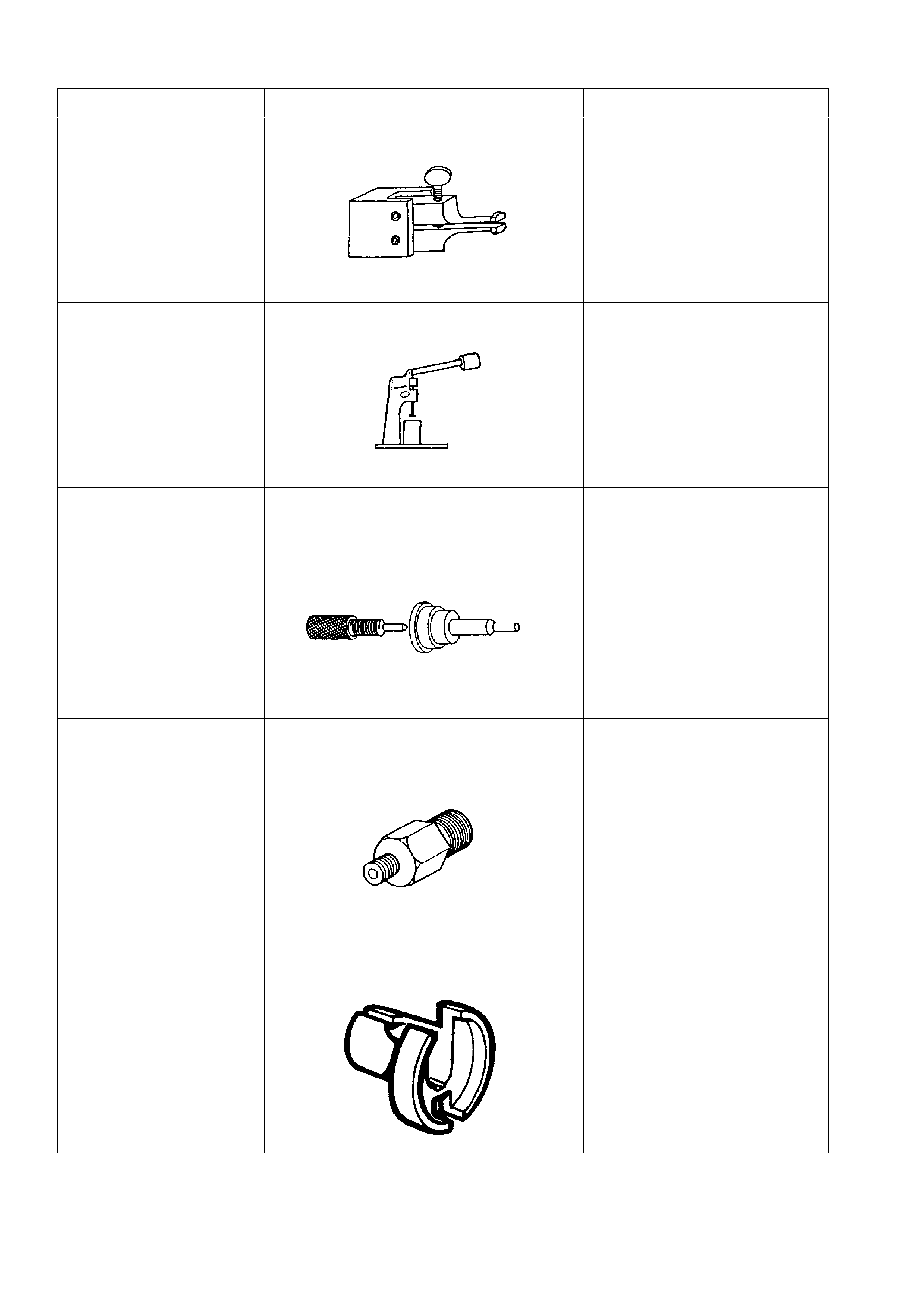
7. SPECIAL TOOLS
TOOL NO. REF IN TEXT TOOL DESCRIPTION COMMENTS
6A22-2 SPIGOT BEARING REMOVER ALTERNATIVELY, USE J23907
OR E6668 WHICH INCLUDES
ITS OWN SLIDE HAMMER
6A23 VALVE LIFTER TESTER USED IN CONJUNCTION WITH
TESTING FLUID KENT MORE
NO. E1151
(PREVIOUSLY 361-1-93)
6A24 HYDRAULIC VALVE LIFTER ASSEMBLY
TOOLS
6A40A AIR LINE ADAPTOR - 14MM (CYLINDER
INFLATOR)
7370 QUICK CONNECT RELEASE TOOL USED FOR RELEASING THE
FUEL RETURN HOSE QUICK
CONNECTS AT THE DASH
PANEL AND FUEL RAIL
CONNECTIONS ONCE THE
FUEL SYSTEM HAS BEEN
DEPRESSURISED
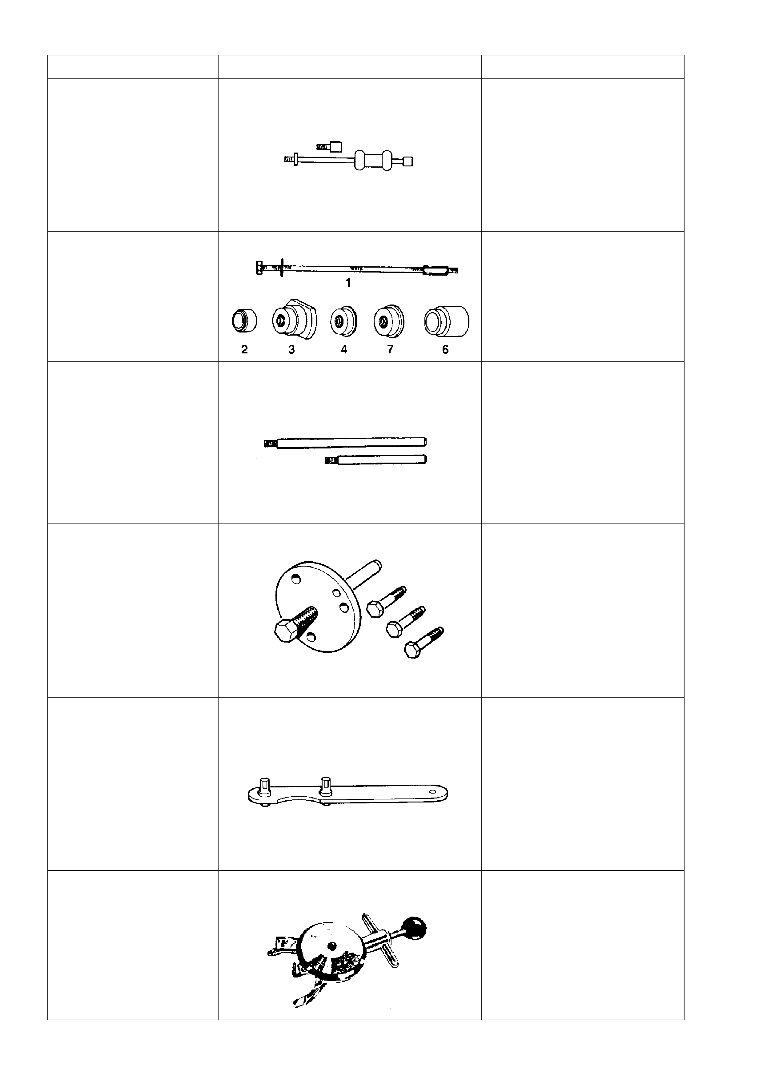
TOOL NO. REF IN TEXT TOOL DESCRIPTION COMMENTS
AU354 SLIDE HAMMER USED IN CONJUNCTION WITH
6A22-2 TO REMOVE SPIGOT
BEARING. TO REMOVE REAR
BEARING CAP, TWO AU354’S
MUST BE USED.
AU384-B PULLER SCREW USED IN CONJUNCTION WITH
AU384-2, AU384-3, AU384-4,
AU384-7 AND AU384-6A
AU388 CONNECTING ROD GUIDE TOOLS USED IN CONJUNCTION WITH
AU388-1 AND AU388-2
AU424 CRANKSHAFT BALANCER PULLER
AU448 CRANKSHAFT BALANCER HOLDING
TOOL
BT3373-F BELT TENSION GAUGE
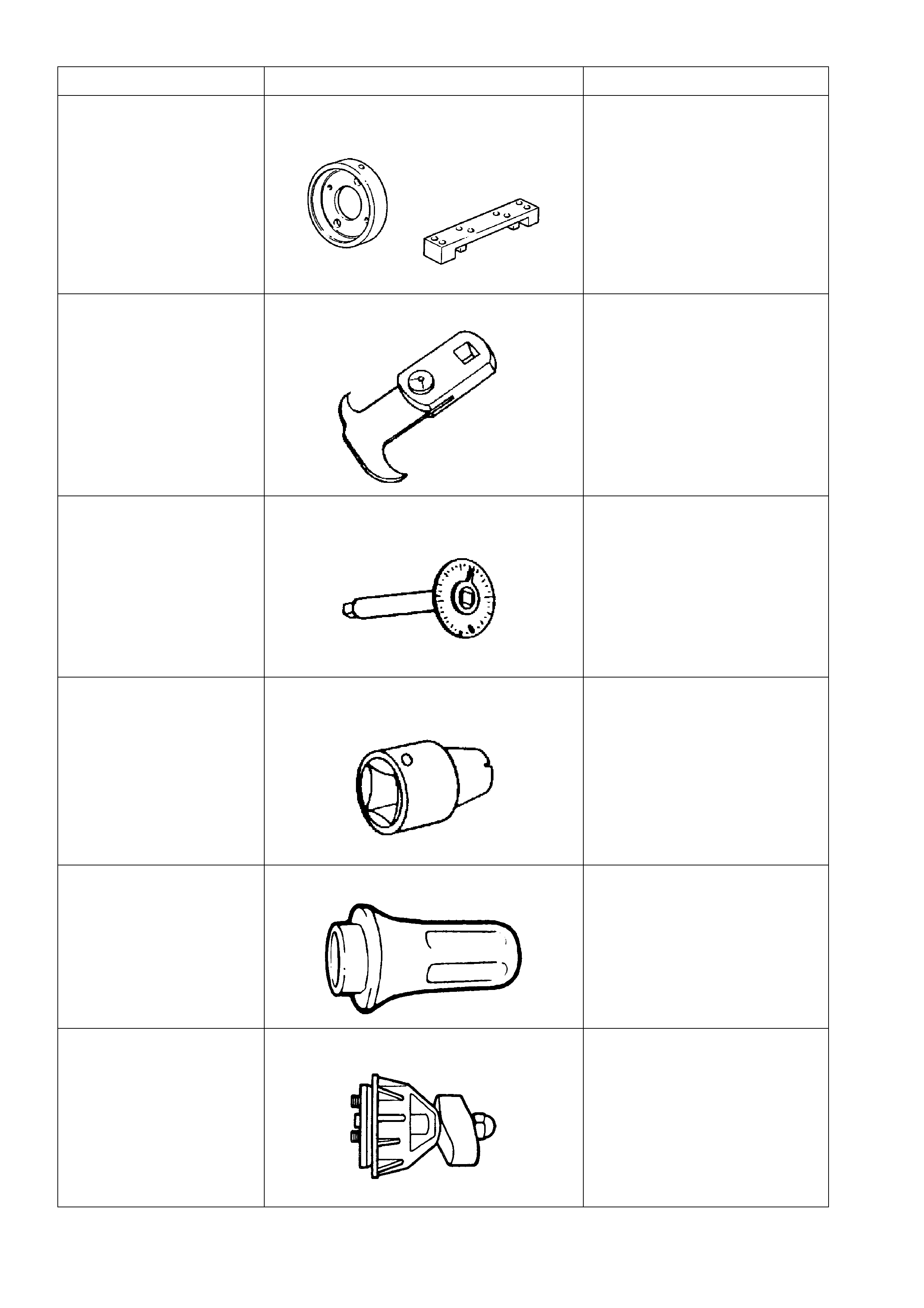
TOOL NO. REF IN TEXT TOOL DESCRIPTION COMMENTS
E1409 REAR MAIN SEAL HOUSING ALIGNING
TOOL
E308 SEAL REMOVER
E7115 ANGLE WRENCH USED TO TIGHTEN
COMPONENT FASTENERS
WHEN ANGLE TORQUE IS
REQUIRED.
J25359-8 TORX BIT HOLDER USED WITH ETX30H TORX BIT
J28540-A SEAL INSTALLER
J38196 SEAL INSTALLATION TOOL
TOOL NO. REF IN TEXT TOOL DESCRIPTION COMMENTS
J38196-AUS MANDREL COLLAR
J41348 MAIN BEARING CAP PULLER USED IN CONJUNCTION WITH
J6125-B
J41349 REAR MAIN HOUSING ALIGNING TOOL
J41512 VALVE STEM INSTALLATION TOOL
J6125-B SLIDE HAMMER USED TO REMOVE INNER
AXLE SHAFTS FROM THE
FINAL DRIVE ASSEMBLY.
USED IN CONJUNCTION WITH
J41348
J8080 BEARING REMOVER AND INSTALLER
KD2078 VALVE SPRING COMPRESSOR