SECTION 6A2 ENGINE MECHANICAL - V8 ENGINE
CAUTION:
This vehicle will be equipped with a Supplemental Restraint System (SRS). A SRS will
consist of either seat belt pre-tensio ners and a driver’s side air bag , or seat belt pre-
tensioners and a driver’s and front passenger’s side air bags. Refer to CAUTIONS,
Section 12M, before performing any service operation on or around SRS
components, the steering mechanism or wiring. Failure to follow the CAUTIONS
could result in SRS deplo yment, resulting in possible p ersonal injury or unnecessary
SRS system repairs.
1. GENERAL DESCRIPTI ON
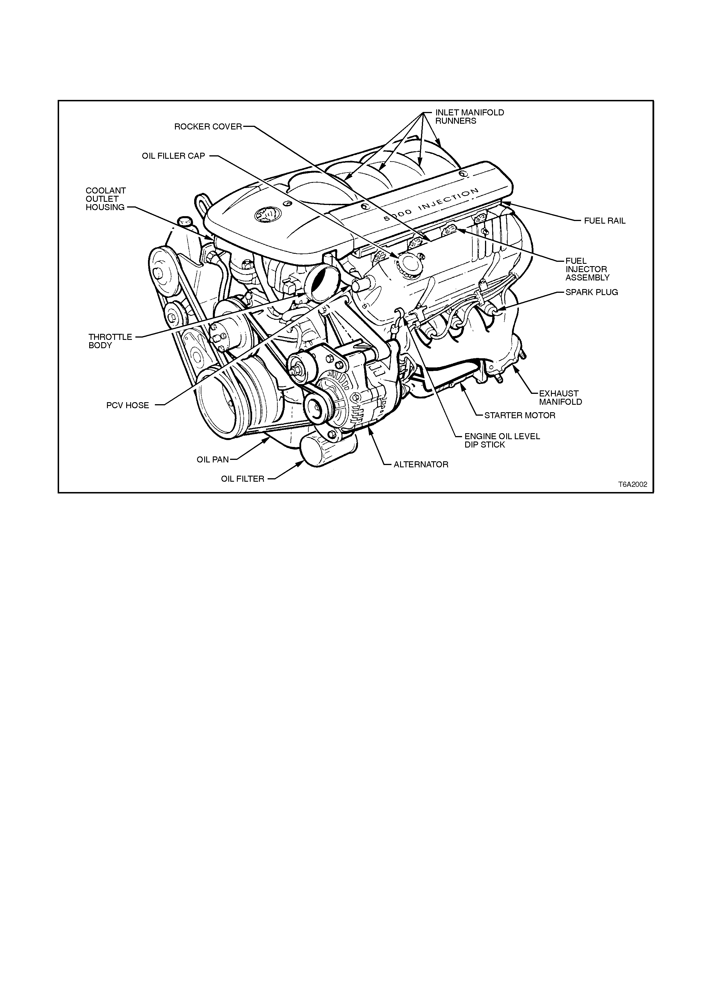
The 5.0 litre engine fitted to VT range of vehicles, known as production option LB9, is a port fuel injected eight
cylinder, overhead valve engine. The following text and illustrations describe the main design features of the engine.
1.1 ENGINE IDENTIFICATION
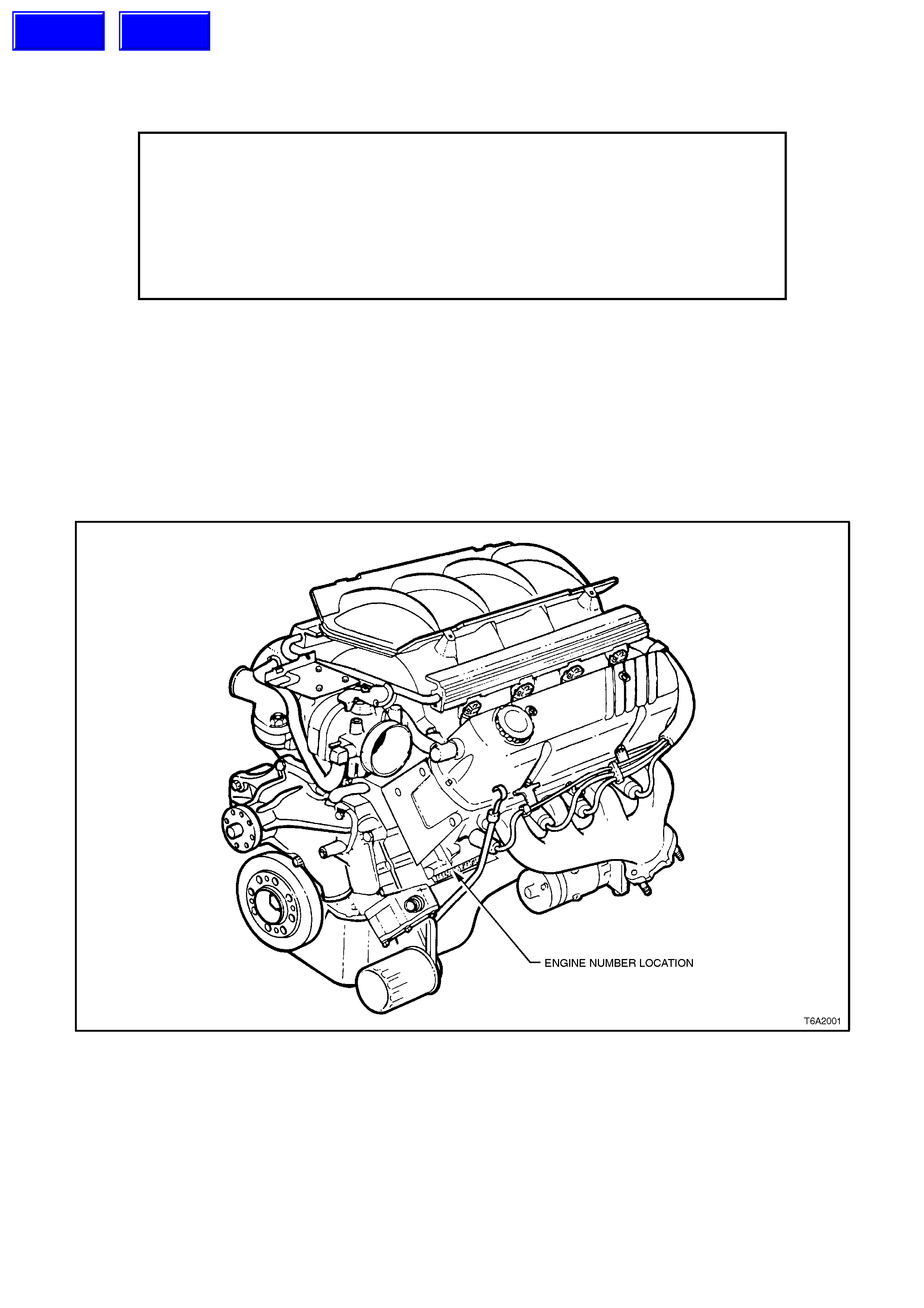
Identification of the 5.0 litre engine fitted to VT vehicles, is provided by the black colouring and the engine number
stamping which is prefixed by the letters VM. The engine number is located on a cylinder block pad, forward of the
left hand side engine mount and directly above the oil pump, as shown in Fig. 6A2-1.
Figure 6A2-1
Techline
Techline
1.2 CYLINDER BLOCK
The cylinder block is made of cast iron and has two banks of cylinders arranged in a 90° 'V' configuration with four
cylinders in each bank. Five main bearings support the crankshaft. The cylinders are completely encircled by water
jackets.
Figure 6A2-2

1.3 CYLINDE R HEADS
The cast iron cylinder heads have integral valve guides and induction hardened exhaust valve seats. The inlet and
exhaust valve arrangement has been designed to complement the port fuel injection system.

1.4 CRANKSHAFT
The crankshaft is cast nodular iron supported by five main bearings. The end thrust is taken on number five rear
main bearing. The precision type tri-metal bearings are of removable babbitt lined copper-lead, steel backed
construction.

1.5 PIS TONS AND CONNECTING RODS
The pistons are of strutless design and made of cast, high silicone content aluminium alloy. Each piston is fitted with
two compression rings and one oil control ring. The piston pins are offset 1.5 mm towards the thrust side to provide
a gradual change in thrust pressure against the cylinder wall, as the piston travels up and down the cylinder bore.
This also provides for quieter engine performance. The piston pins are a floating fit in the pistons and a press fit in
the connecting rods.
The connecting rods are made of forged steel. Full pressure lubrication is directed to the connecting rod bearings by
drilled oil passages from the adjacent main bearing journals.
A tapered strengthening rib over the big end bearing area is provided for additional bearing support.
1.6 CAMSHAFT AND DRIVE
The steel camshaft is supported by five steel
backed lead Babbitt bearings and driven by the
crank shaf t through a tim ing chain at the fr ont of the
engine. Both the crankshaft and camshaft
sprockets have timing marks which, when aligned
with marks (bright links) on the timing chain,
provide the correct valve timing. Cast as integral
components of the camshaft, two helical gears are
provided at the front and rear of the camshaft to
provide drive for the oil pump and distributor,
respectively.
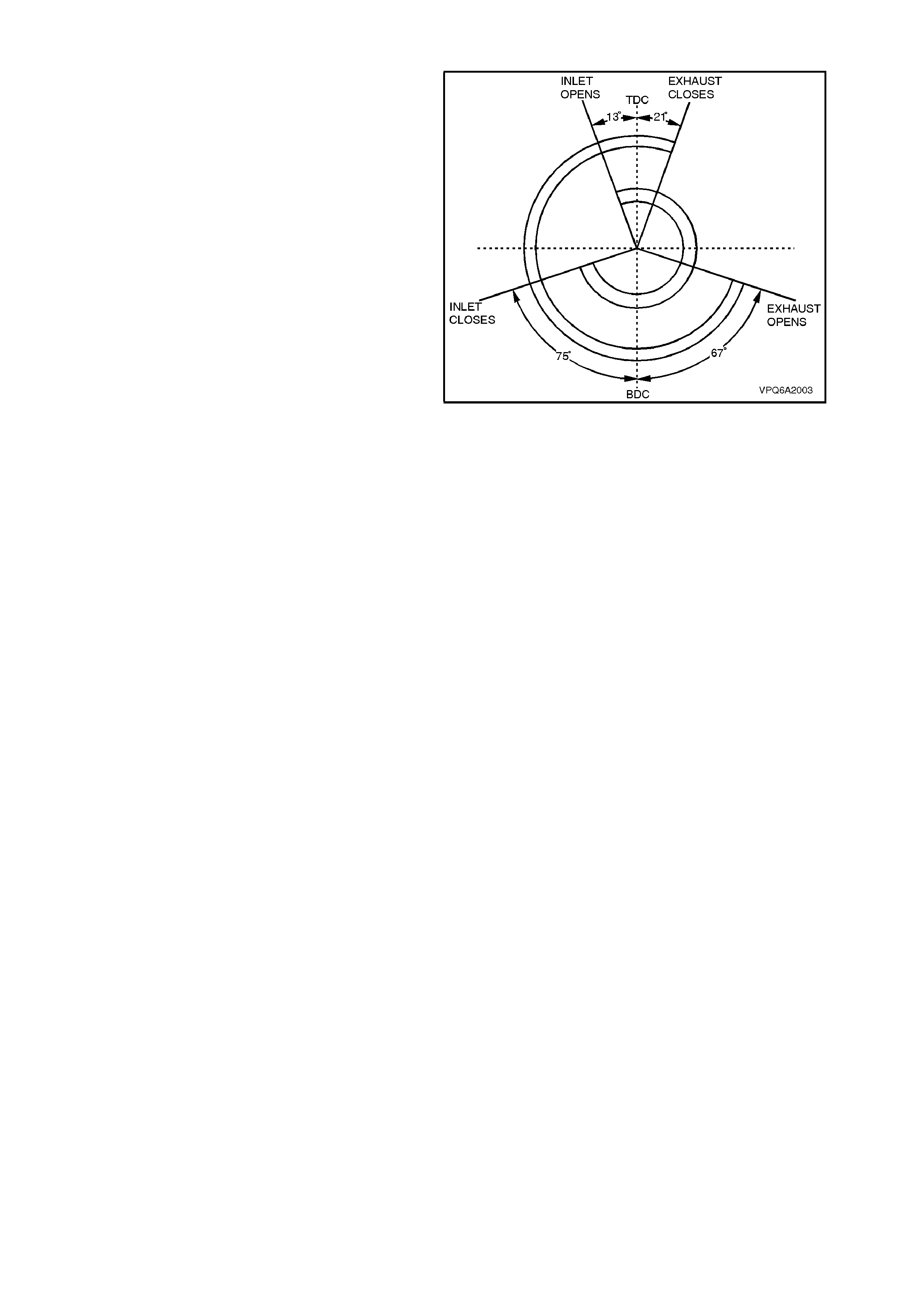
The cam s haft valve timing diagram is shown in Fig.
6A2-3.
Figure 6A2-3
1.7 VALVE TRAIN
The valve train is push rod operated with non-
adjustable rocker arm pivots and hydraulic roller
valve lifters.
External shields are fitted to the inlet and exhaust
valve springs to reduce the amount of oil splashed
against the valve stem. Damper springs are fitted
inside both inlet and exhaust valve springs.
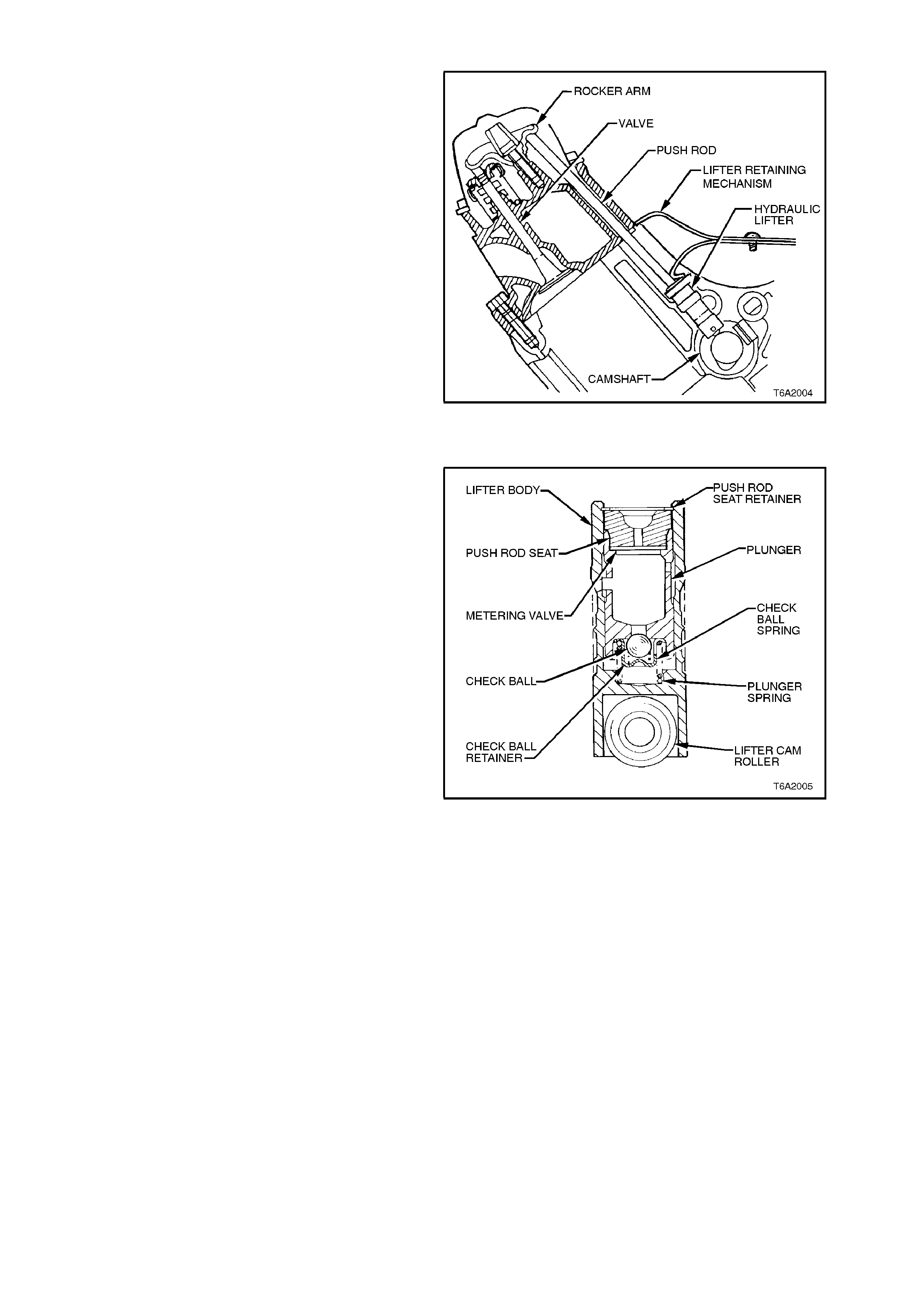
Figure 6A2-4
HYDRAULIC VALVE LIFTER OPERATION
Oil is supplied to each lifter through a hole in the
side of the lifter body that aligns with a groove and
hole in the lifter plunger. Oil is then metered past
the oil metering valve in the base of the lifter,
through the hollow push rods to the rocker arms.
W hen the lifter begins to ride up the cam lobe, the
check ball is held against its seat in the plunger by
the check ball spring, trapping the oil in the bas e of
the lifter body below the plunger. The plunger and
the lifter body then rise as a unit, pushing up the
push rod to actuate the rocker arm and open the
valve. The force of the valve spring which is
exerted on the plunger through the rocker arm and
push rod causes a slight amount of leakage
between the plunger and lifter body. This 'leak
down' allows a slow escape of trapped oil in the
base of the lifter body. As the lifter rides down the
other side of the cam lobe and reaches the base
circle or 'valve closed' position, the plunger spring
quickly moves the plunger back (up) to its original
position. This movement causes the check ball to
open against the check ball spring, oil from within
the plunger is then drawn into the base of the lifter,
restoring the lifter to zero lash.
Figure 6A2-5
1.8 INLET AND EXHAUST MANIFOLDS
For a desc ription of the fuel inj ection com ponents,
refer to Section 6C2 POWERTRAIN
MANAGEMENT - V8 ENGINE.
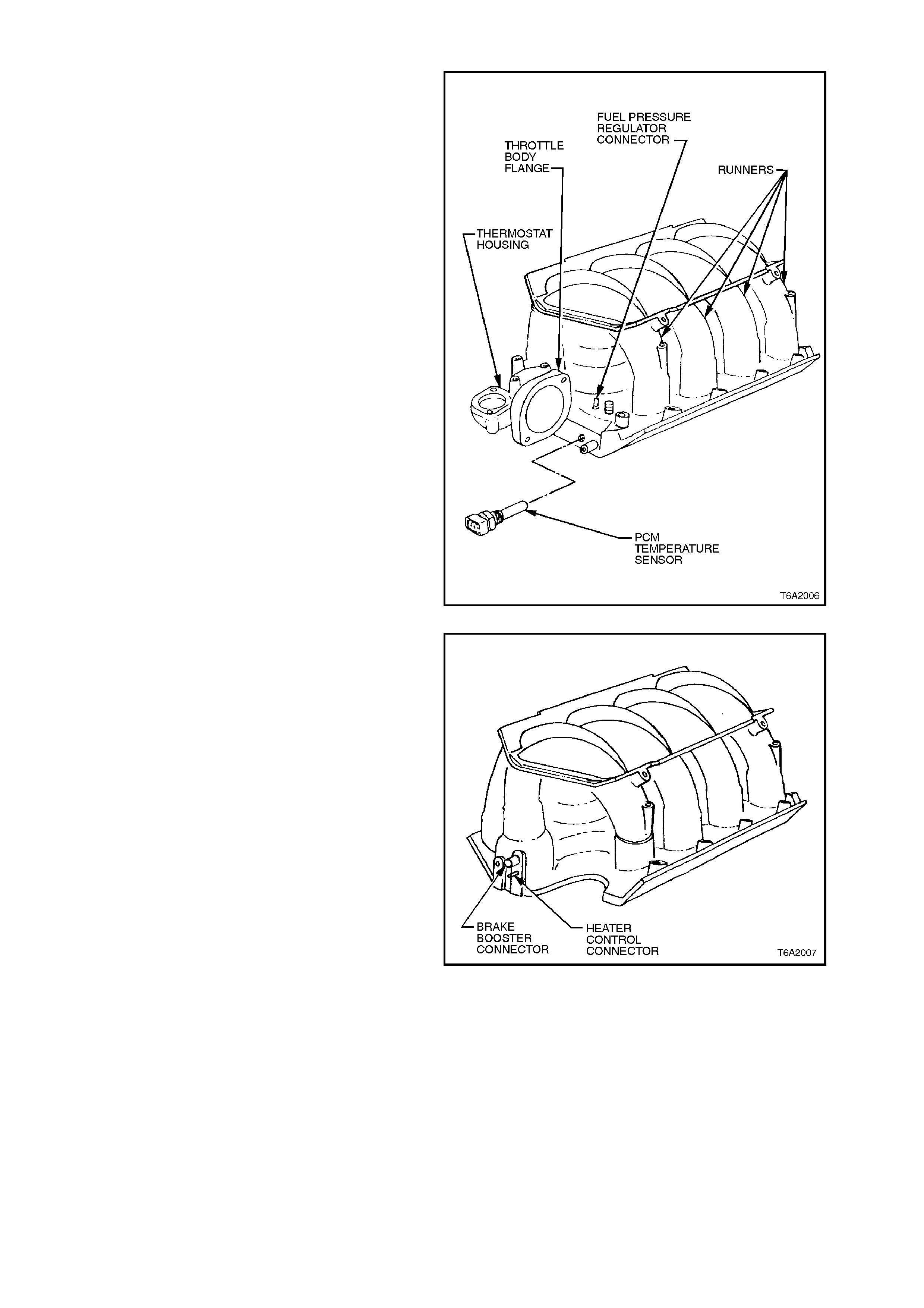
The inlet manifold is a one piece alloy casting with
eight tuned length runners and a single plenum
cham ber. Vacuum c onnectors for the fuel pressure
regulator and MAF sensor are located on the inlet
manifold adjacent to throttle body.
The PCM temperature sensor and the cooling
system thermostat are mounted at the front of the
inlet manifold.
Figure 6A2-6
The vacuum connections for the brak e booster and
heater controls at the rear of the manifold are
shown in Fig. 6A2-7.
Figure 6A2-7

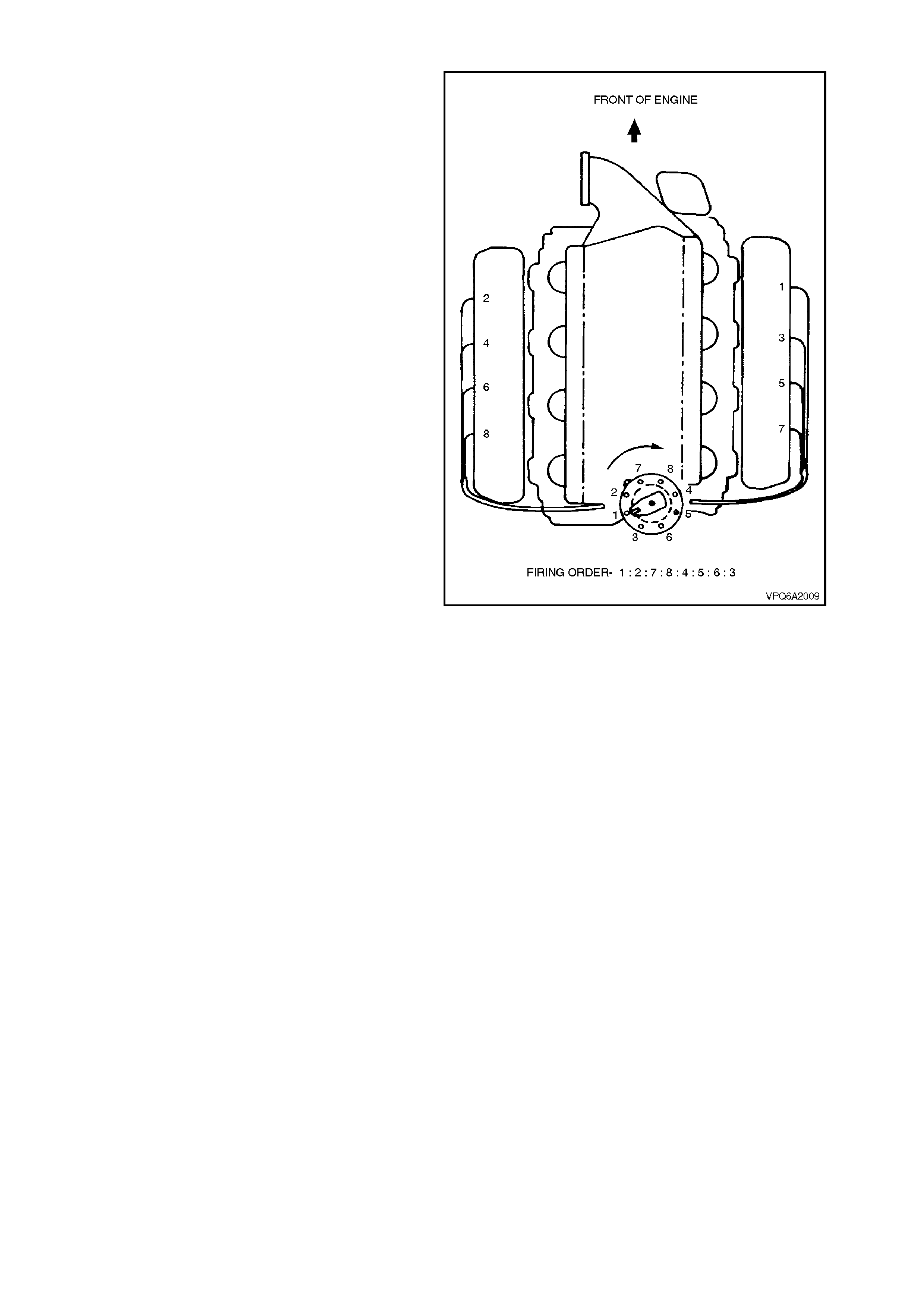
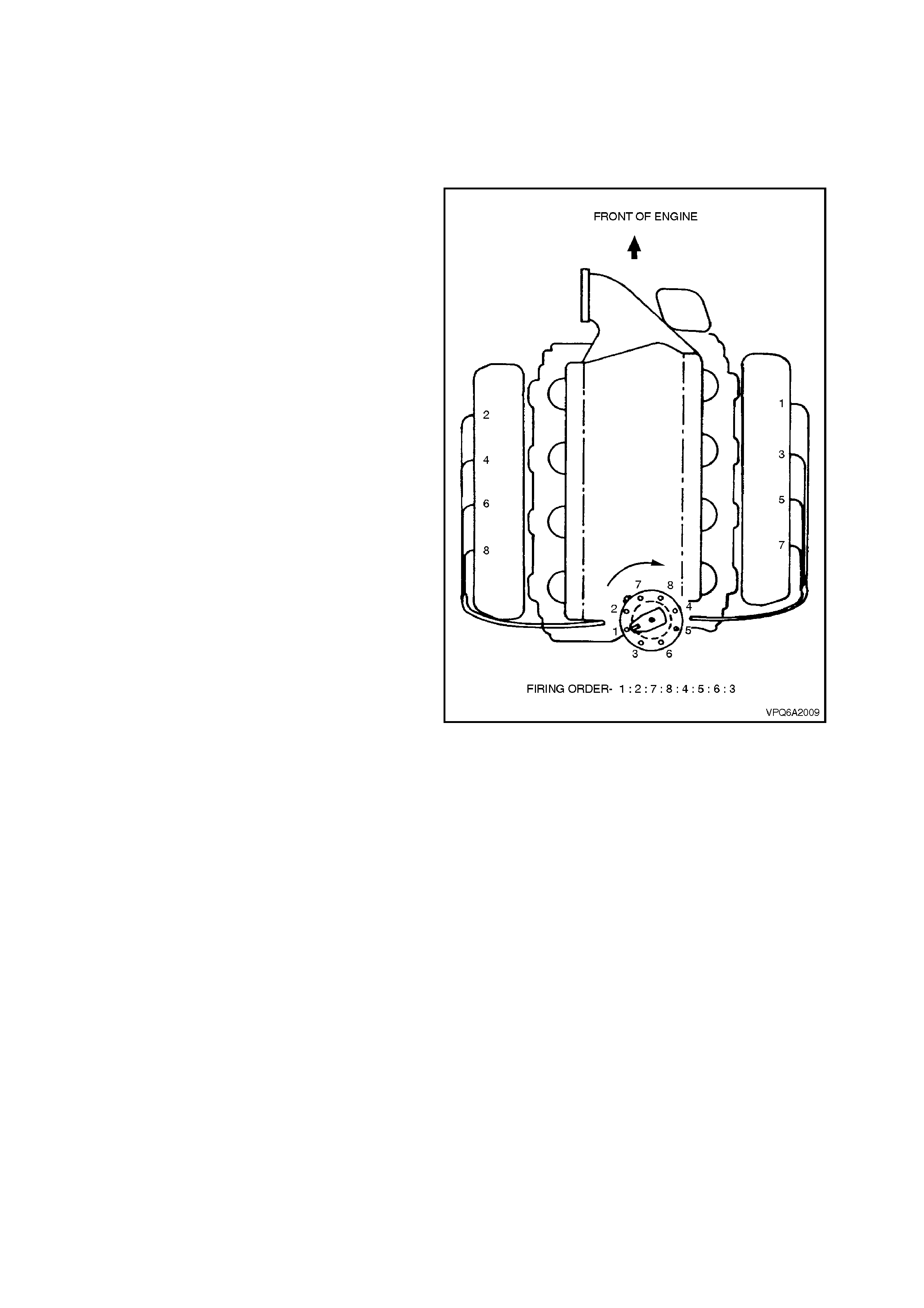
1.9 CYLINDER NUMBERING
The cylinder numbering sequence and firing order
are shown in Fig. 6A2-9.
Figure 6A2-9

1.10 LUBRICATION
Pressurised lubrication (refer to Fig. 6A2-10) for engine internal components is provided by a positive displacement
gear type oil pump, which is driven by a short drive shaft, and a helical gear located on the front of the camshaft. Oil
from the reserve held in the oil pan is drawn through the screen and suction pipe to the low pressure (suction) side
of the oil pump via drillings in the cylinder block. Oil under pressure from the oil pump passes through a replaceable
full flow oil filter cartridge, where foreign debris and impurities are trapped within the filter elements.
Clean oil is supplied via drillings in the oil pump body and the cylinder block transfer passage, to the left hand (main)
oil gallery, which is interconnected to the right hand oil gallery by a groove and drilling in the No.4 camshaft support
webbing. The oil galleries are located above and adjacent to the camshaft.
The No.1 camshaft bearing oil supply is provided by the right hand gallery, and the No.1 crankshaft bearing oil
supply comes from the transfer passage. All the other camshaft and crankshaft bearings are supplied by the main
oil gallery, via a series of grooves and drillings in the cylinder block.
A metering nozzle pressed into a drilling that intersects the supply passage to No.1 crankshaft bearing, discharges
oil where the timing chain engages the crankshaft sprocket. Distributor drive lubrication is provided by an overflow
pressure relief aperture in the No.5 (rear) camshaft journal.
The rocker and overhead gear are lubricated through hollow push rods, using oil supplied from the hydraulic lifters.
The adjacent oil gallery supplies each bank of lifters. Excess oil drains from the overhead gear through apertures in
the cylinder block back into the oil pan.
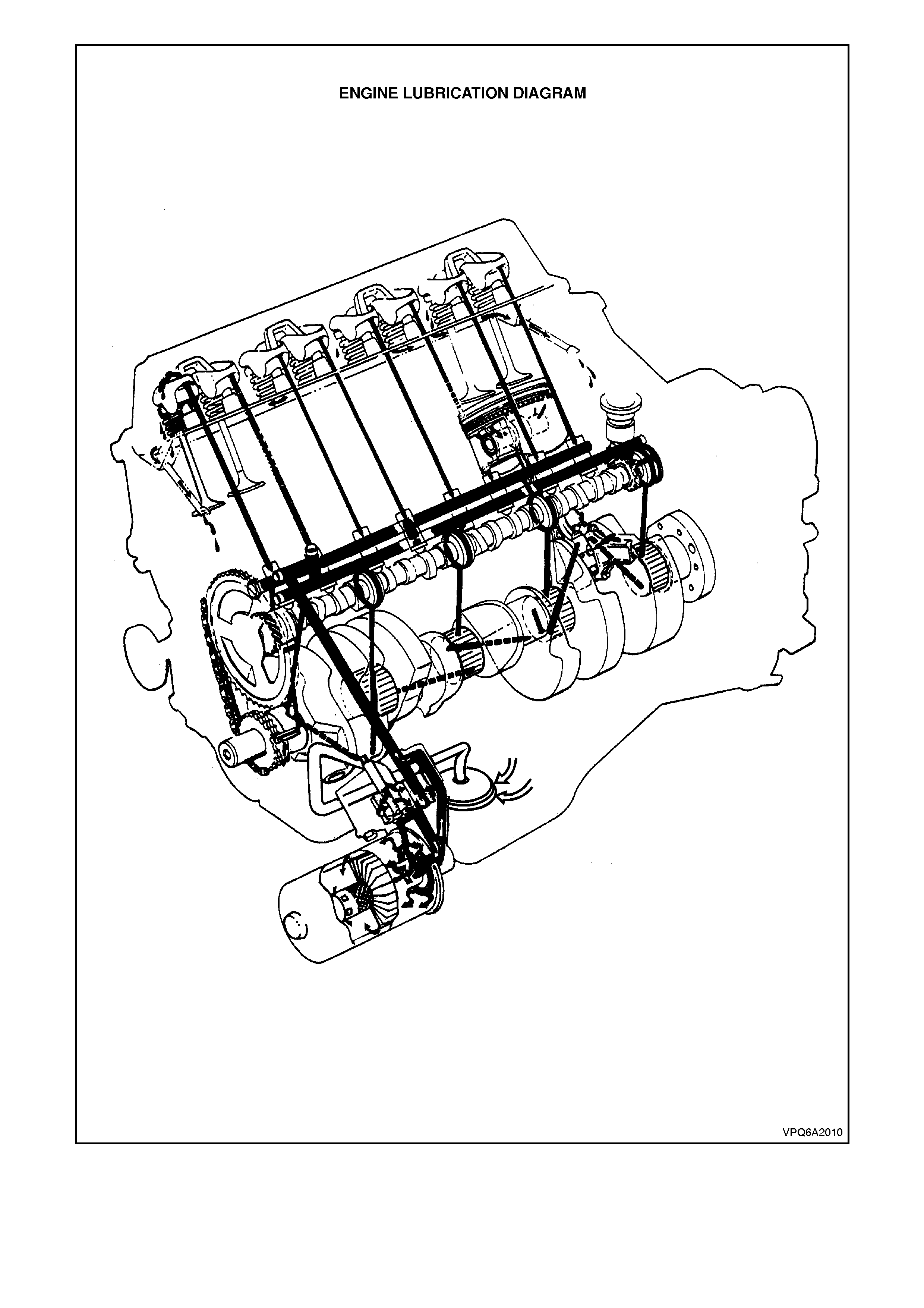
Figure 6A2-10

OIL PUMP
The oil pump (refer to Fig. 6A2-11) consists of a drive shaft, two spur gears, a pressure relief valve and a bypass
valve enclosed in a two-piece aluminium body. The internal spur gears are driven by a helical gear mounted on the
pump drive shaft which in turn is driven by a mating gear on the front of the camshaft. The pump is mounted
externally on the left hand side of the cylinder block assembly and secured by four bolts. Two shorter bolts are used
to secure the pump body to the housing for assembly purposes.
Figure 6A2-11
The pr essure regulator valve regulates oil press ure
to 276 - 414 kPa at 2000 r pm. The bypass valve is
positioned between the high pressure (transfer
passage) and low pressure (suction) sides of the
oil pump. Should the full flow oil filter become
restr icted, full press ure oil distribution to the engine
is not affected. The oil filter bypass valve operates
at 62 - 76 kPa pressure differential.
Correct oil pressures for a new pump are as
follows:
ENGINE SPEED OIL PRESSURE
(Hot: approx. 71° C)
500 rpm
2000 rpm 48 kPa minimum
276 - 414 kPa

1.11 ENGINE MOUNTS
The engine and transmission assembly is supported at two front points and one rear point by steel backed rubber
mounts. The front mounts bolt to the front crossmember and are attached to the engine by means of brackets. The
rear mount, bolts directly to the rear of the transmission and to the rear crossmember.
2. MI NOR SERVICE OPERATIONS
SAFETY AND CAUTIONARY NOTE FOR VEHICLES FITTED WITH ABS
Whenever any component that forms part of the ABS or ABS/ETC (if fitted), is
disturbed during Service Operations, it is vital that the complete ABS or ABS/ETC
system is checked, using the procedure as detailed in 4 DIAGNOSIS, ABS or
ABS/ETC FUNCTION CHECK, in Section 12L ABS & A BS/ETC.
2.1 INLET MANIFOLD
REMOVE
1. Disconnect battery earth cable from battery.
2. Drain cooling system, refer to
Section 6B2 ENGINE COOLING - V8
ENGINE.
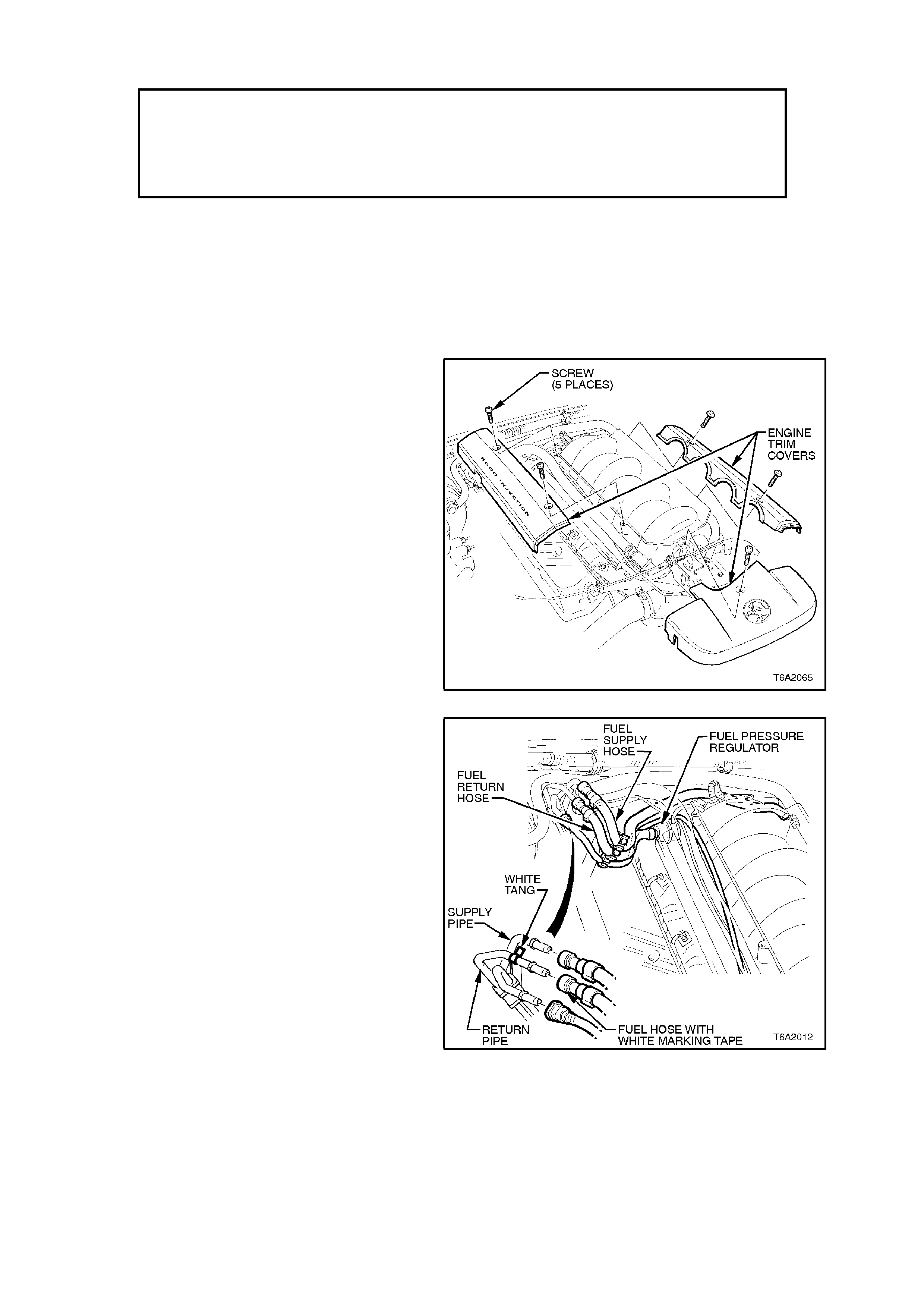
3. Remove engine trim covers.
4. Depressurise fuel rail, refer to
Section 6C2 POWERTRAIN M ANAGEM ENT
- V8 ENGINE.
Figure 6A2-12
5. Using quick connect release tool No. 7370
open tool and install over fuel line.
6. Close 7370 and pull into fuel line quick
connect to release it from fuel inlet line, pull
back on quick connect, disconnect fuel feed,
return and fuel evaporative canister hoses at
quick connects. Plug all openings to prevent
foreign matter entry.
NOTE:
Do not attempt to remove hoses from fuel rail
connections. Once removed from fuel rail
connection hoses require replacement.
Figure 6A2-13
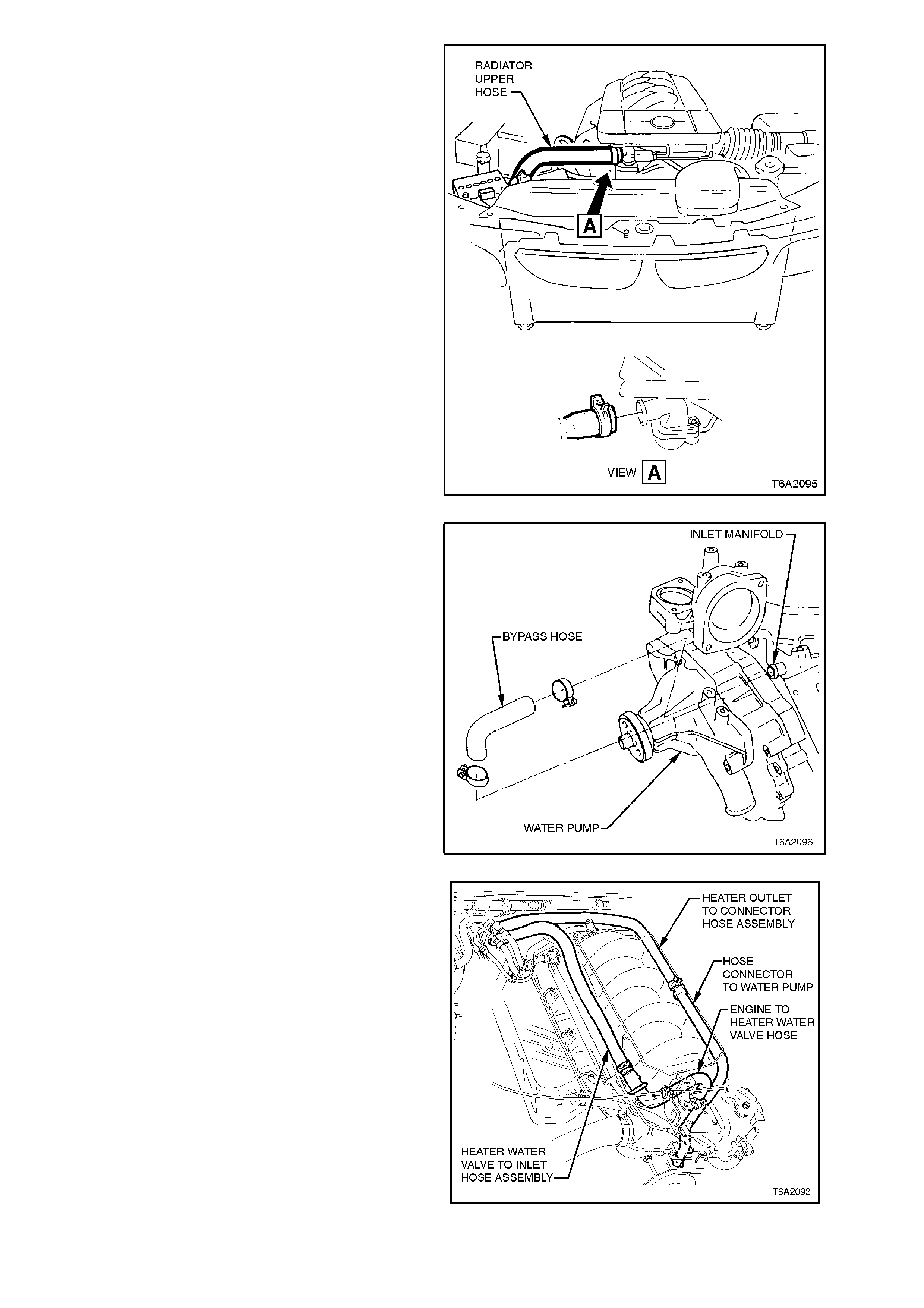
7. Disconnect upper radiator hose from
thermostat housing outlet cover.
Figure 6A2-14
8. Disconnect coolant bypass hose from inlet
manifold.
Figure 6A2-15
9. Disconnect heater hoses from inlet manifold
and water pump. Unbolt hose brackets from
fuel rail and secure heater hoses to one side.
Figure 6A2-16
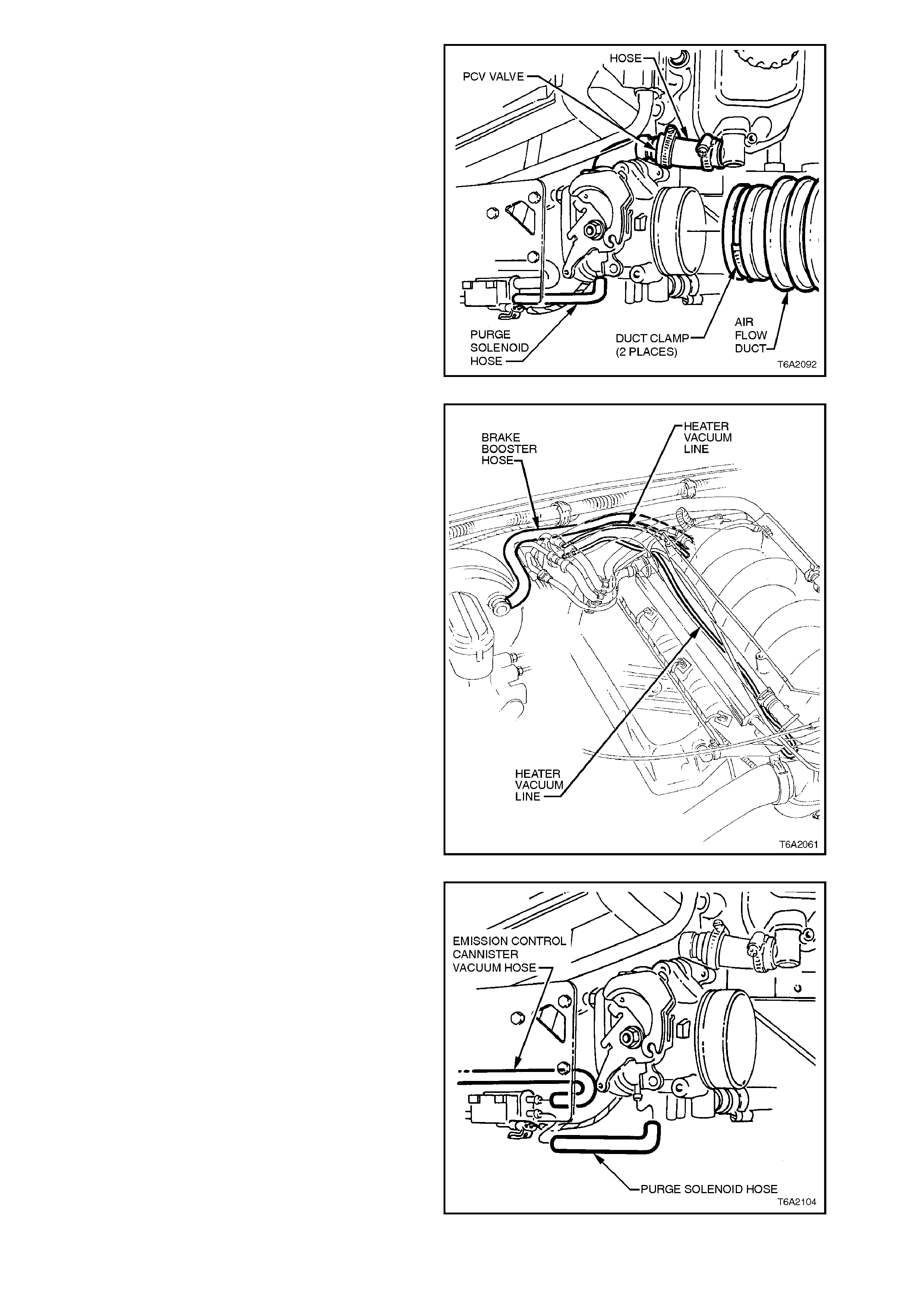
10. Disconnect inlet air duct from throttle body.
11. Disconnect PCV hoses from throttle body.
Figure 6A2-17
12. Disconnect the brake booster supply and
heater control hoses from the rear left hand
side of inlet manifold.
Figure 6A2-18
13. Disconnect emission control canister vacuum
hoses from purge solenoid and disconnect
purge hose from throttle body. Refer to
Section 6C2-3 SERVICE OPERATIONS - V8
ENGINE - CANISTER PURGE SOLENOID.
Figure 6A2-19
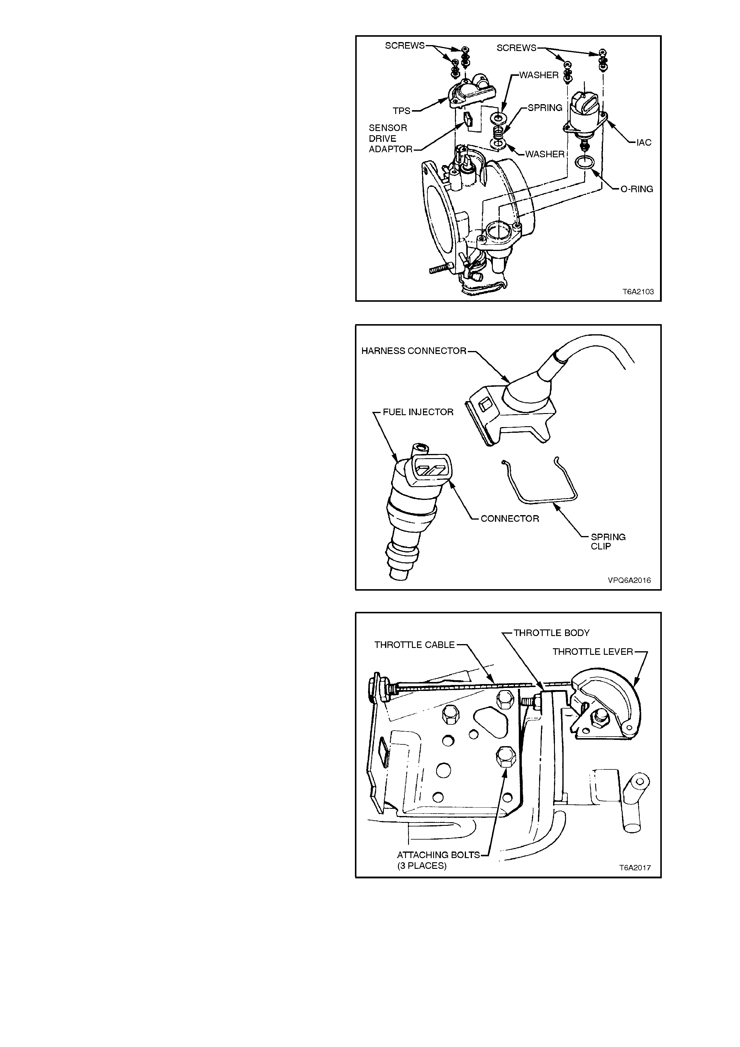
14. Disconnect Idle Air Control (IAC) motor and
Throttle Position Sensor (TPS) electrical
connectors from throttle body. Refer to
Section 6C2-3 SERVICE OPERATIONS - V8
ENGINE - THROTTLE POSITION (TP)
SENSOR.
Figure 6A2-20
15. Disconnect fuel injector electrical connectors
and unclip connector harnesses from fuel rail.
Figure 6A2-21
16. Disconnect throttle cable and cruise control
cable (where fitted) from throttle body.
17. Remove throttle bracket attaching bolts and
secure bracket and cable assembly to one
side.
Figure 6A2-22
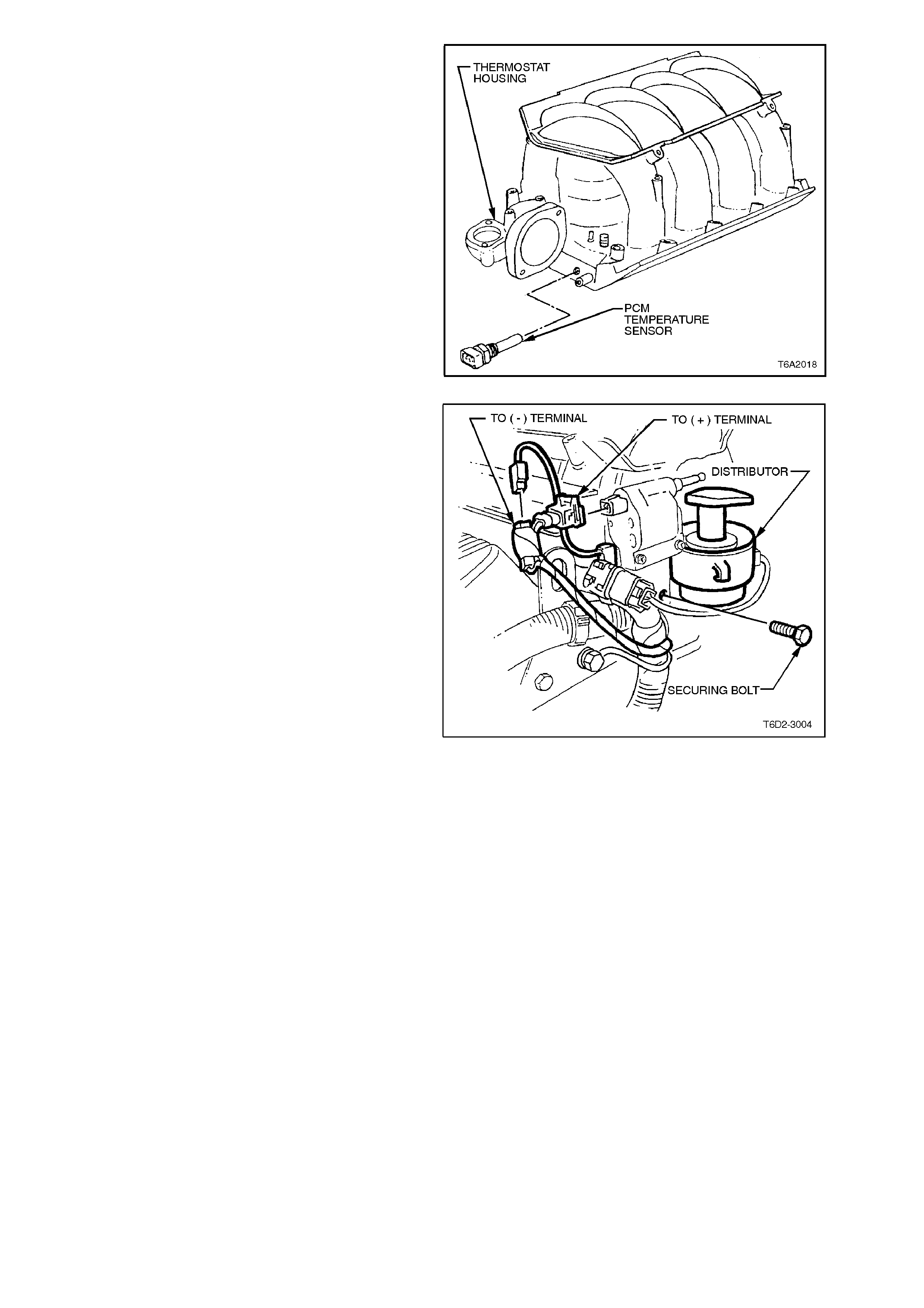
18. Disconnect PCM tem per ature sens or electr ical
connectors.
Figure 6A2-23
19. Remo ve bolt securing ignition coil as sembly to
inlet manifold.
Figure 6A2-24
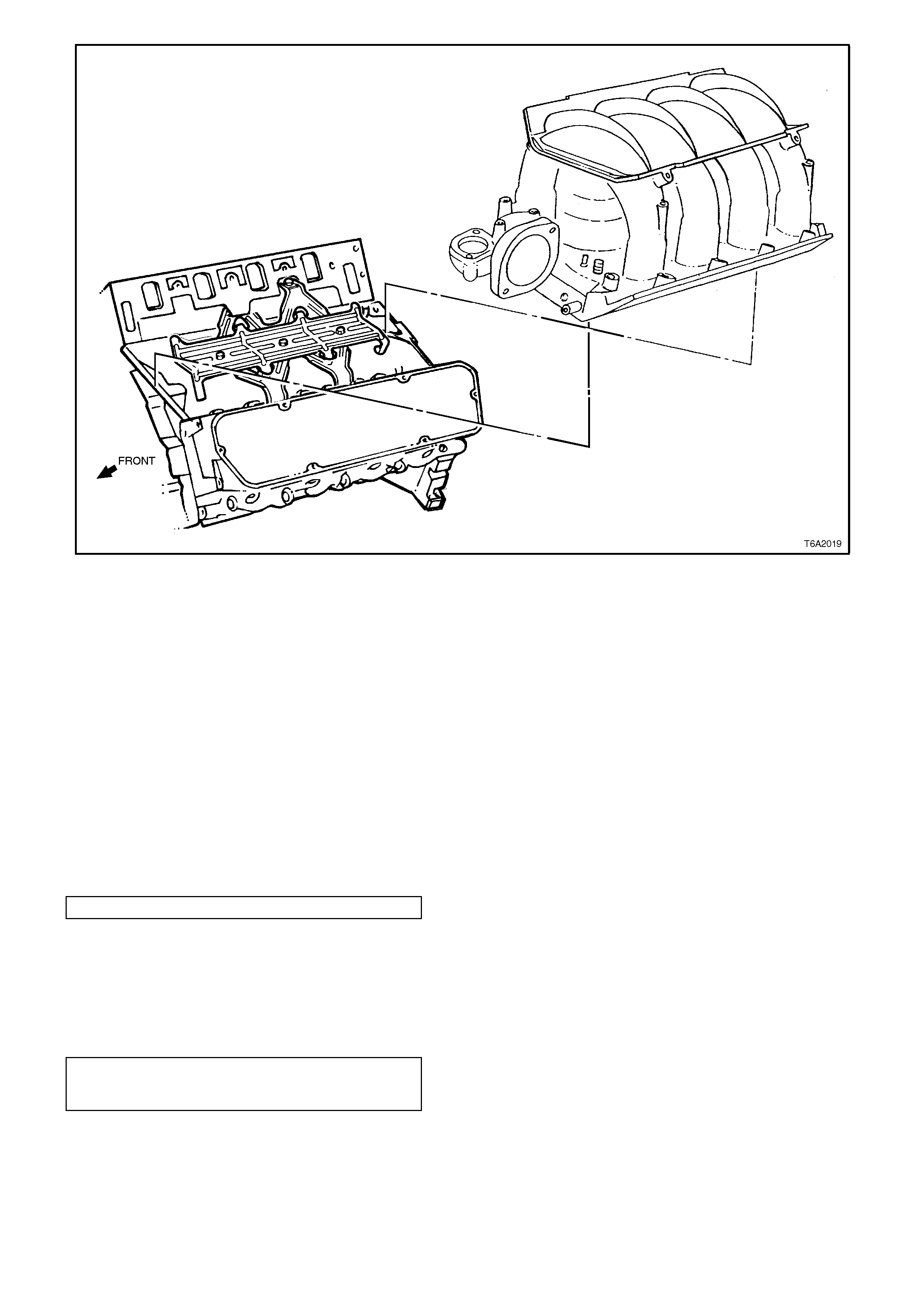
Figure 6A2-25
20. Remo ve inlet manif old bolts, then rem o ve inlet
manifold.
21. Where it is required to remove the fuel rail,
fuel injectors and throttle body, refer to
Section 6C2 POWERTRAIN MANAGEMENT
- V8 ENGINE.
REINSTALL
1. If thermostat was removed, clean contact
surfaces and place thermostat and housing in
position. Fit a new O - ring and tighten
thermostat housing bolts to specified torque.
NOTE:
Purge solenoid locates on f ront therm ostat housing
bolt.
TORQUE SPECIFICATION 20 - 27 Nm
2. If the sensor was removed, apply pipe thread
sealant, such as Loctite 567 or equivalent
(Holden Specification HN 1584) to threads of
PCM temperature sensor. Reinstall, then
tighten to the specified torque.
PCM COOLANT
TEMPERATURE SENSOR
TORQUE SPECIFICATION 12 Nm
3. Clean gasket and seal surfaces on engine
block and manifold. Take care not to damage
any machined surfaces.
4. To avoid extrusion of the manifold front and
rear seals, the contact surfaces on the
cylinder block must be free of oil or any
sealing compound.
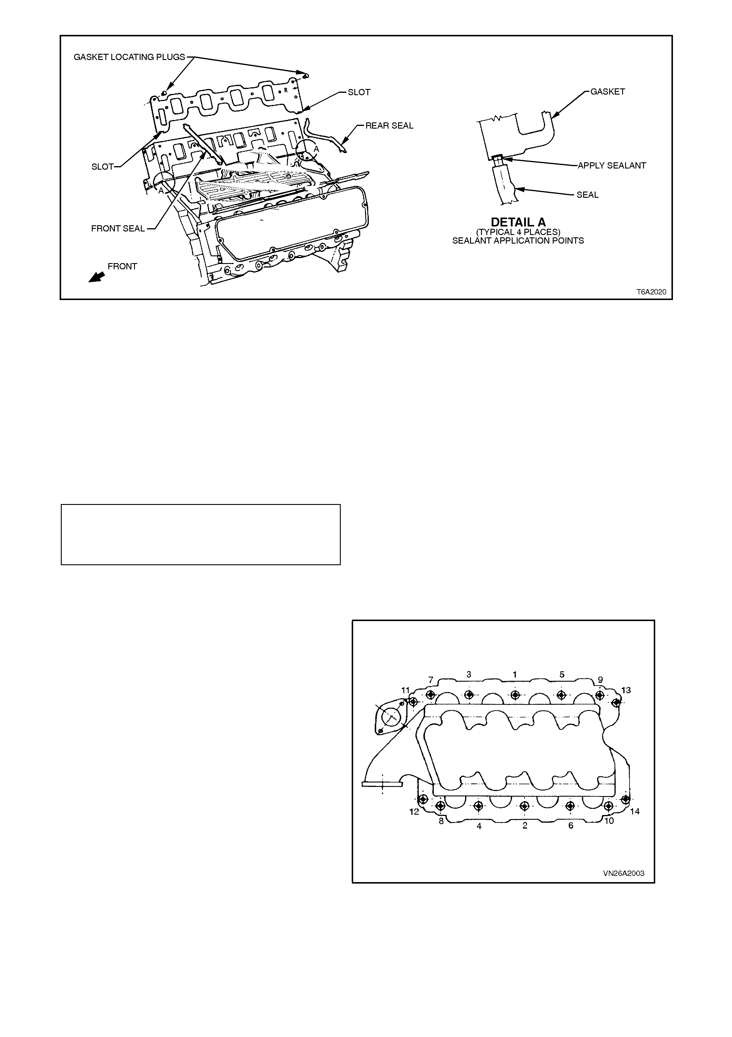
Figure 6A2-26
5. Install new manifold gaskets. Use plastic
retainers to locate gaskets. Note the 'R'
punched mark on the gasket must point to
rear of engine, on each side.
6. Apply RTV 732 sealant (Holden Specification
HN 1373) to the inlet manifold gasket slots, in
four places as indicated in Fig. 6A2-26.
7. Install new manifold front and rear seals on
engine block, ensuring that the ends of both
the front and rear seals are within the inlet
manifold gasket slots.
INLET MANIFOLD
SECURING BOLT
TORQUE SPECIFICATION:
STAGE 1
12 - 17 Nm
STAGE 2
34 - 41 Nm
NOTE:
The single lug on the front seal faces forward.
8. Reinstall manifold and tighten bolts to the
torque figures specified, in two stages and in
the sequence shown in Fig. 6A2-27.
Figure 6A2-27
9. Reinstall remaining components in reverse
order to removal.
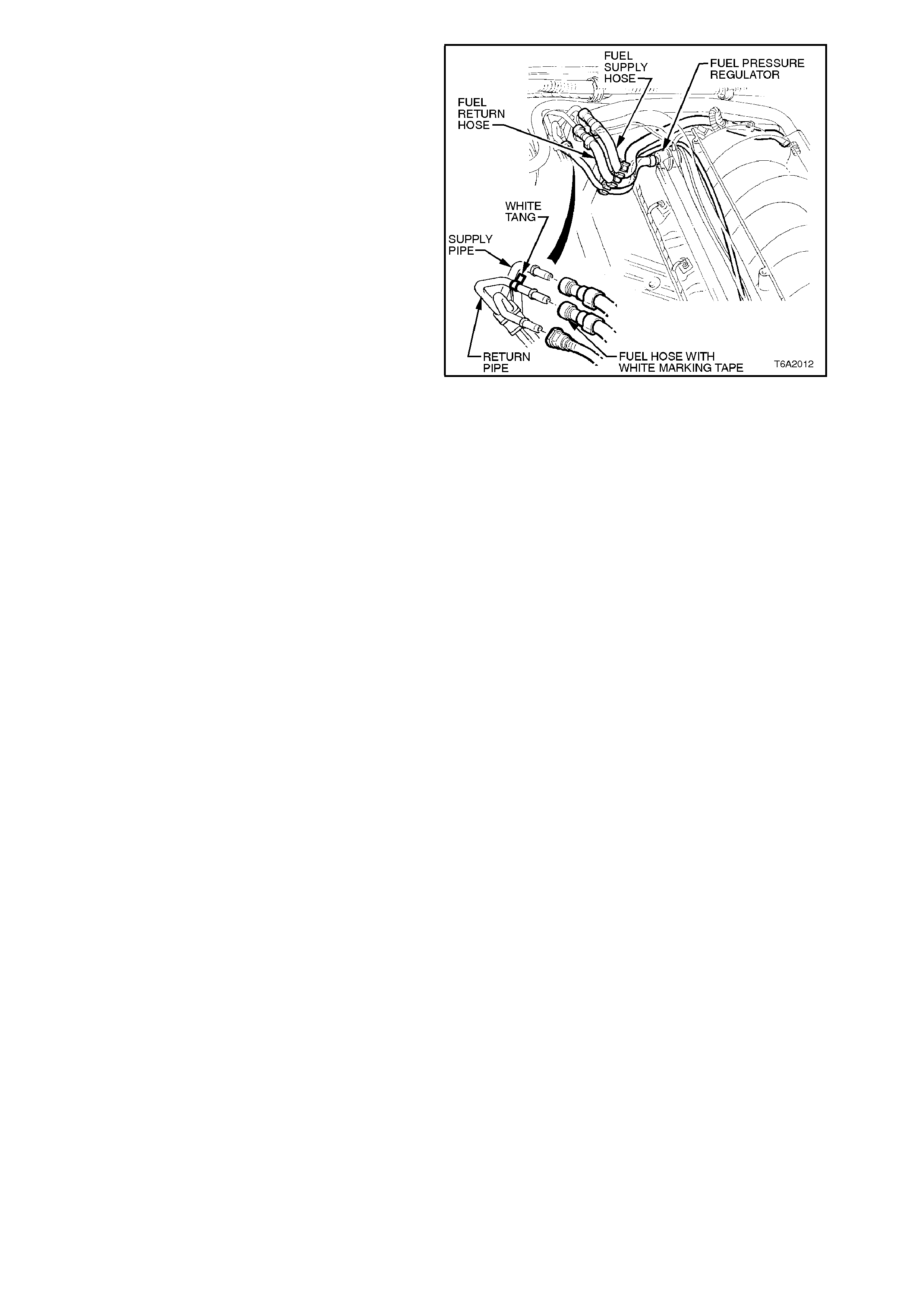
NOTE:
Reconnect the fuel supply, refer to Fig. 6A2-28.
10. Adjust the throttle cable
Section 6C2 POWERTRAIN MANAGEMENT
- V8 ENGINE and cruise contr ol cables (where
fitted) Section 12E CRUISE CONTROL.
11. Refill cooling system with specified coolant, in
the correct proportion as detailed in
Section 6B2 ENGINE COOLING - V8
ENGINE.
12. Start engine and check for correct operation.
Figure 6A2-28
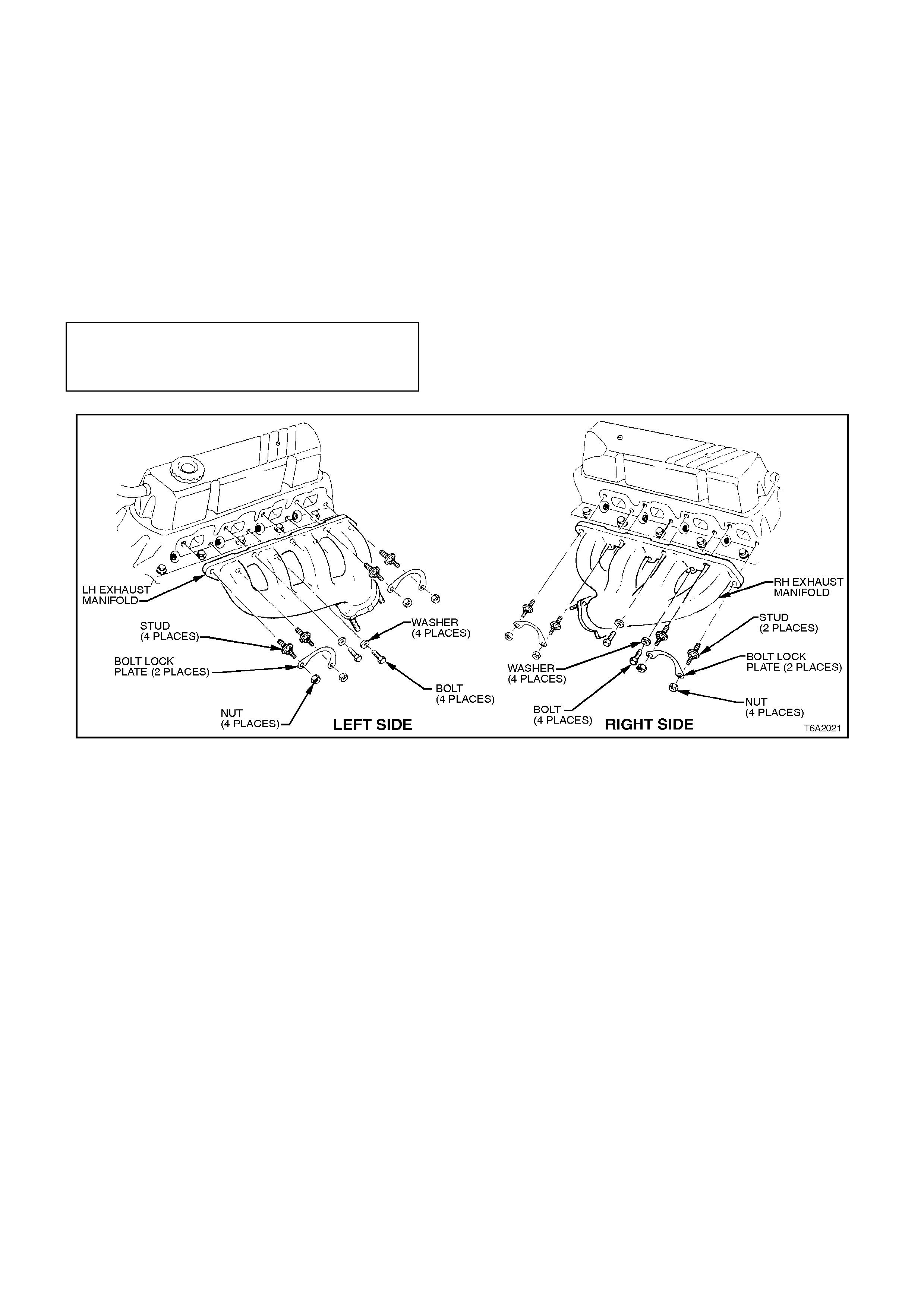
2.2 EXHAUST MANIFOLD
REMOVE
1. Disconnect battery earth cable from battery.
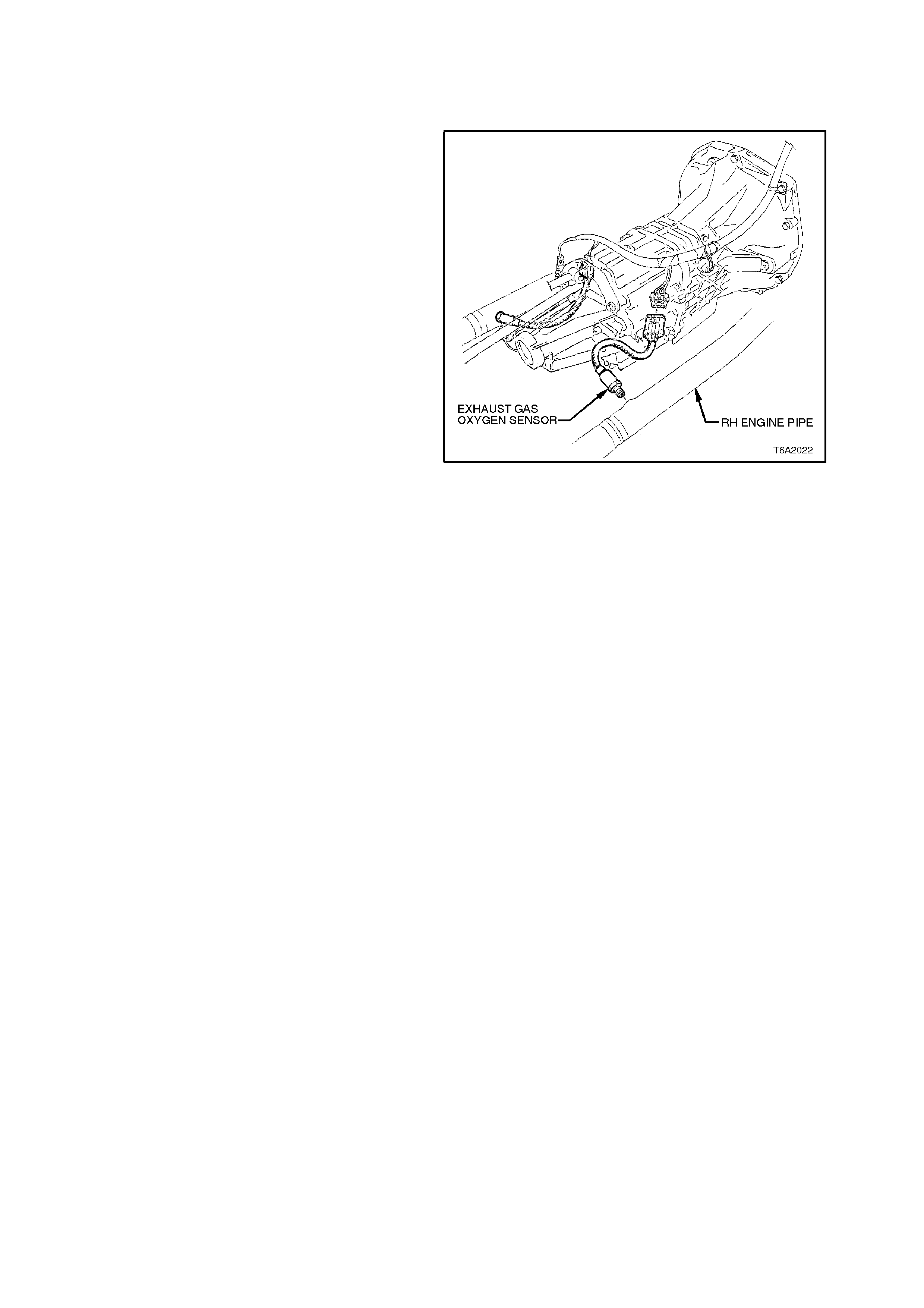
2. Disconnect oxygen sensor harness
connectors.
3. Remove the exhaust pipe to manifold flange
nuts, then lower the exhaust system assembly.
Figure 6A2-29
4. Remove spark plugs.
5. Unscrew retaining bolt lock nuts (four places
each side), then remove lock plates, refer to
Fig. 6A2-30.
6. Unscrew manifold retaining studs and bolts,
then remove exhaust manifold/s.
REINSTALL
1. Clean mating surfaces on manifold/s and
head/s. Take care not to damage machined
surfaces.
2. Installation is the reverse of removal
procedure, except for the following:
a. Apply anti-seize com pound s uc h as Kopr -
Kote or equivalent (Holden Specification
HN 1325) to the threads of exhaust pipe
to manifold attaching studs before
assembly.
b. Tighten manifold nuts evenly to specified
torque.
EXHAUST MANI F OLD STUDS A ND BOLTS
EXHAUST MANIF O LD LOCK PLAT E NUT S
OXYGEN SENSOR TO EXHAUST PIPE
EXHAUST PIPE TO MANIFOLD
20 - 28 Nm
15 - 20 Nm
38 - 46 Nm
15 - 35 Nm
Figure 6A2-30
2.3 ROCKE R ARMS
REMOVE
1. Disconnect battery earth cable from battery.
2. Tag and disconnect spark plug leads from
spark plugs and support brackets.
3. Remove the engine trim covers, refer to
2.15 ENGINE TRIM COVERS in this Section.
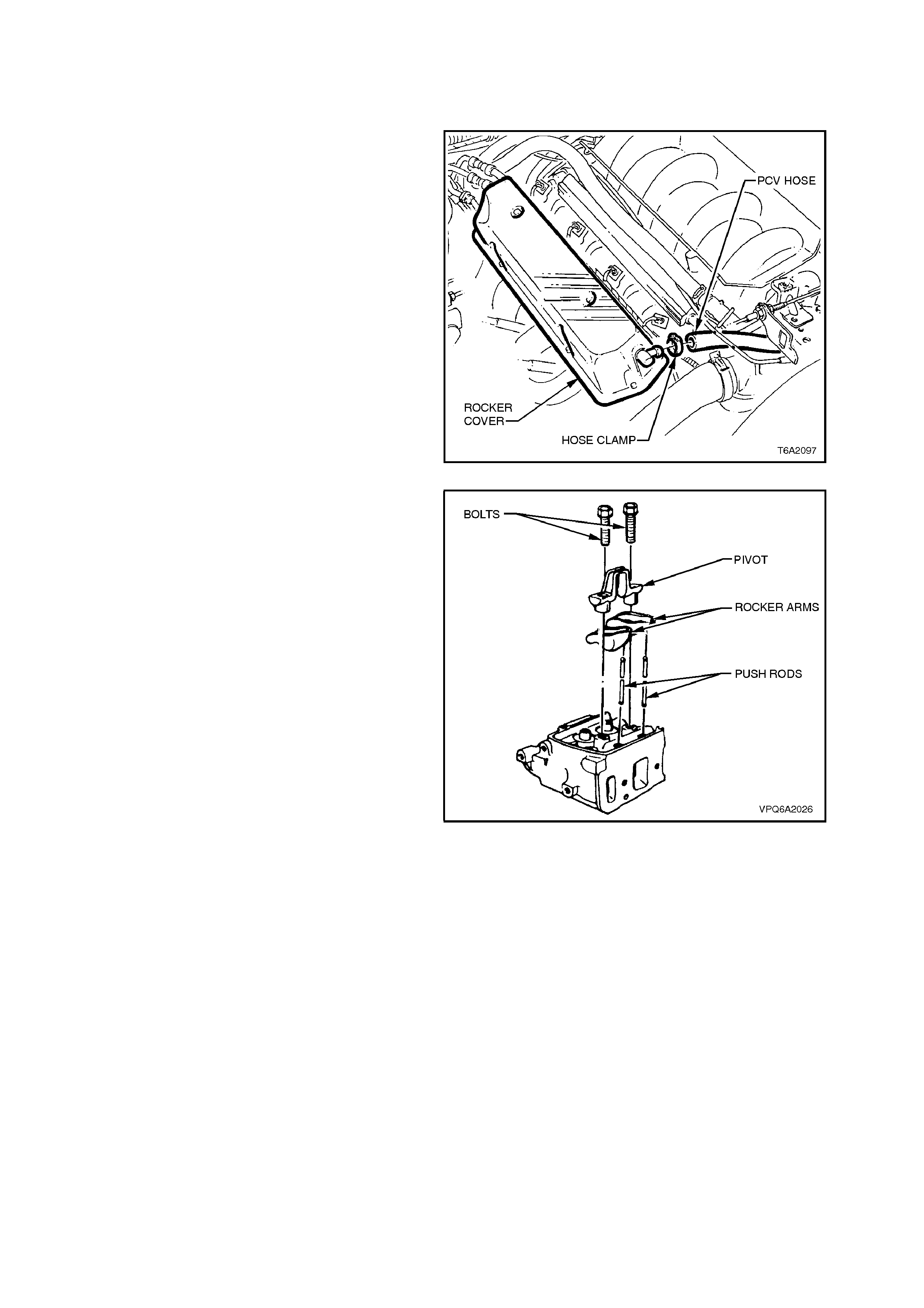
4. Disconnect engine ventilation hose and
Positive Crankcase Ventilation (PCV) valve
hose from rocker covers.
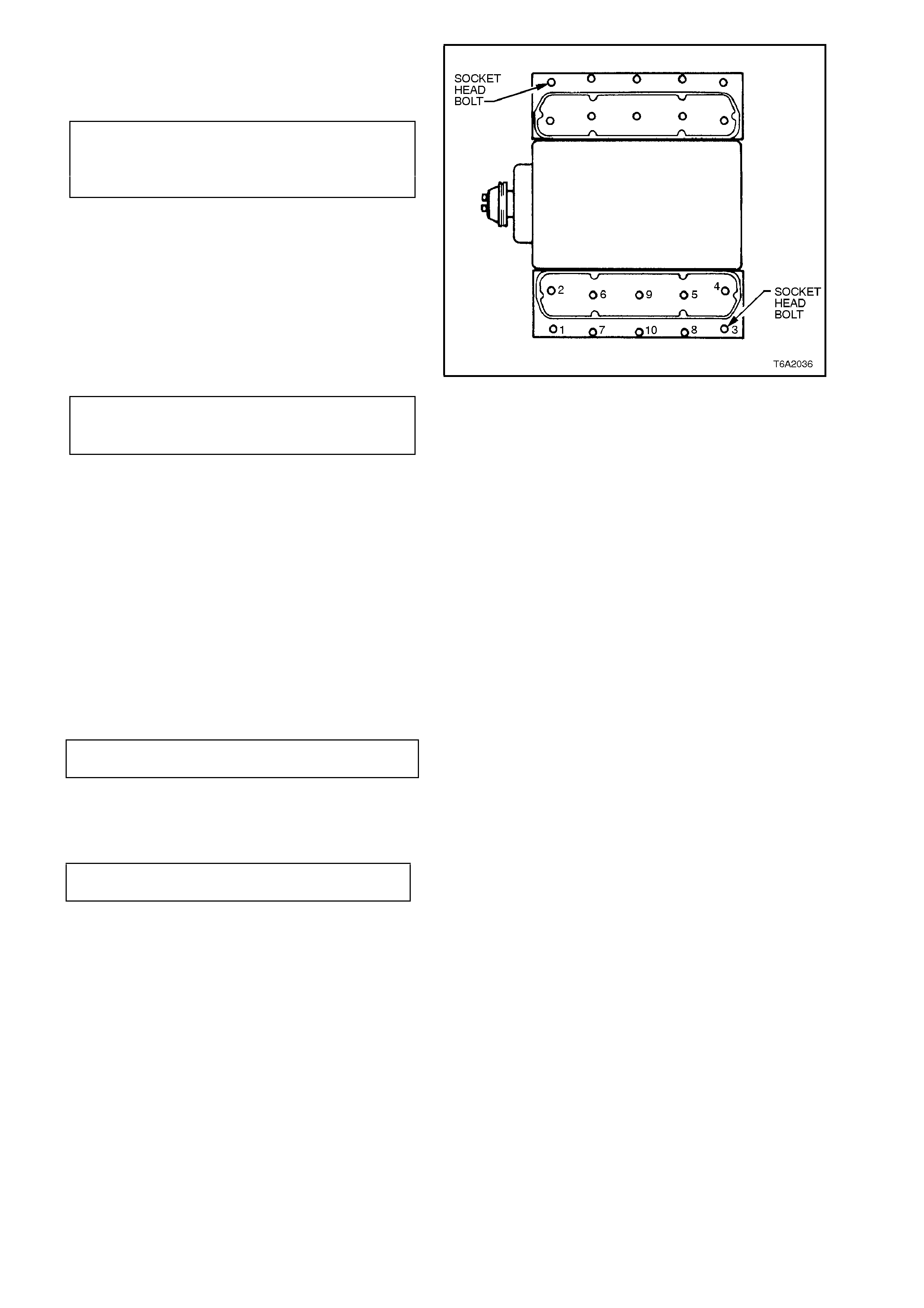
5. Using a suitable Allen key, remove rocker
cover socket head retaining bolts, washers,
and seals f rom beneath the top bolts . Remove
spark plug lead brackets which are also
secured by the rocker cover bolts.
6. Remove rocker covers.
Figure 6A2-31
7. Remove rocker arm pivot bolts, pivots and
rocker arms.
NOTE:
Remove the rocker arms and pivots from each
cylinder as a set. It is important that the original
location of all pivots and arms is maintained for
reassembly. For this reason, parts should be
placed in a special rack.
Figure 6A2-32
REINSTALL
1. Coat rocker arm pivots and contact surfaces
with Molybdenum Disulphide grease (Holden
Specification HN 1271) before assembly.
2. Remove distributor cap.
3. Remove spark plugs for ease of crankshaft
rotation.
4. Rotate crankshaft by hand until distributor
rotor is in No.1 cylinder position, (refer to Fig.
6A2-33) i.e. both No.1 cylinder pushrods are
retracted (both valves closed).
Figure 6A2-33
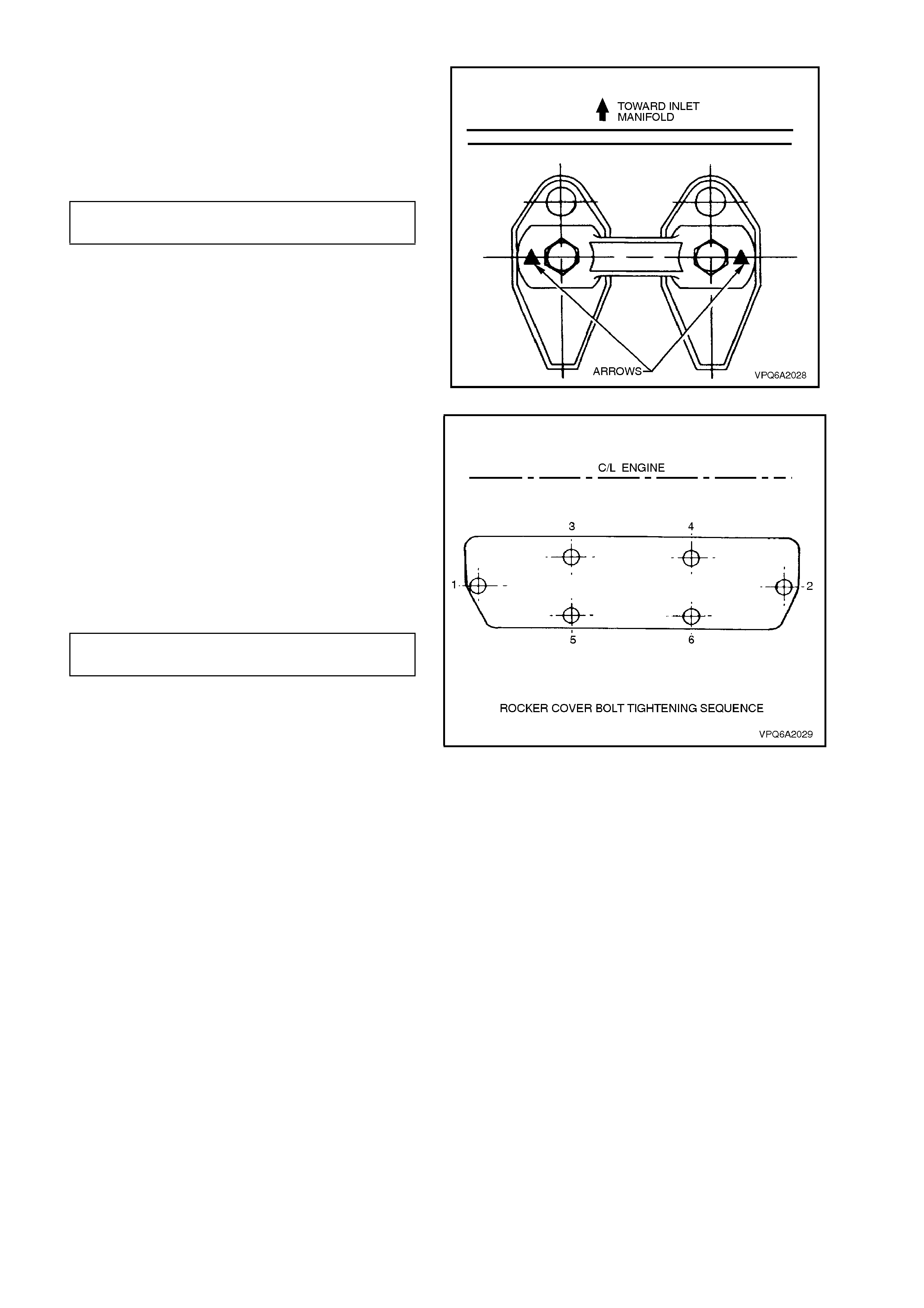
5. Assemble No.1 cylinder rocker arms and
rocker arm pivots in their original locations with
the arrows on the rocker arm pivots pointing
towards the inlet manifold.
6. Install rocker arm pivot bolts and tighten to
specified torque.
ROCKER COVER BOLT 3 - 6
TORQUE SPECIFICATION Nm
7. Rotate crankshaft to next cylinder in the firing
order. Ensure that the push rods are fully
retracted (both valves closed), then install the
rocker arm set. Repeat this procedure for the
remaining cylinders.
Figure 6A2-34
8. Reinstall remaining components in reverse
order of removal procedure noting the
following:
a. Use new rocker cover gaskets.
b. Ensure spark plug leads are routed
correctly, refer Section 6D2-3 IGNIT ION
SYSTEM - V8 ENGINE.
c. Tighten rocker cover bolts to specified
torque and in the sequence s hown in Fig.
6A2-35.
ROCKER ARM PIVOT BOLTS 24 - 32
TORQUE SPECIFICATION Nm
Figure 6A2-35
2.4 VALVE TIMING CHECK
1. Remove No.1 cylinder rocker arm pivot
and rocker arms as described in
2.3 ROCKER ARMS in this Section.
2. Remove spark plugs for ease of crankshaft
rotation.
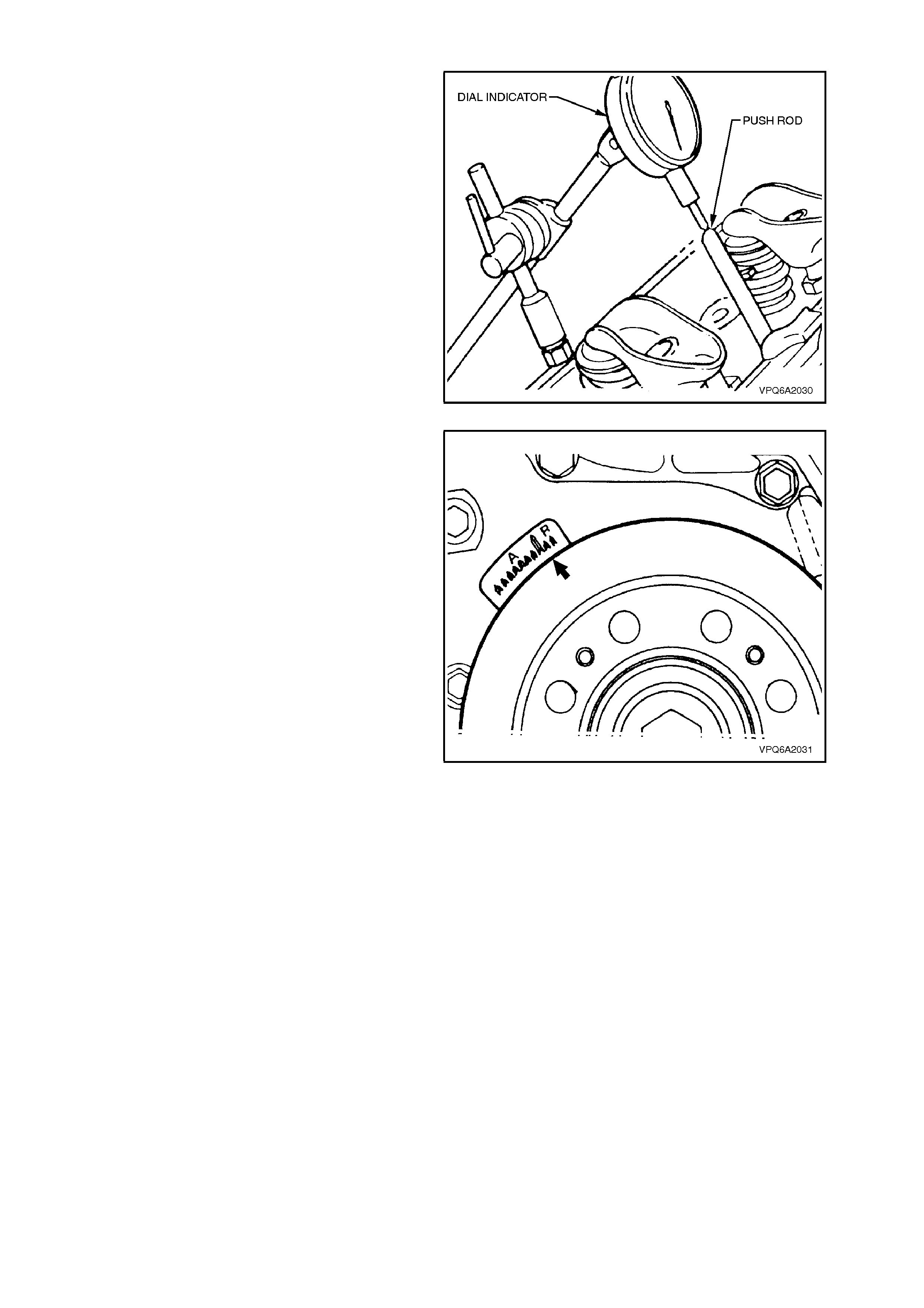
3. Mount a dial indicator with the plunger resting
on the top of the No.1 cylinder exhaust push
rod. The rocker arm pivot bolt holes (5/16
inches U.N.C. thread) can be used to mount
the dial indicator. Note that the exhaust push
rod is the f orem ost of the two push rods in this
instance.
4. Rotate the crankshaft by hand until the No.1
piston is at the top of its compression stroke
and both push rods are fully retracted (both
valves closed).
5. Set the dial indicator to zero.
Figure 6A2-36
6. Rotate the crankshaft in a clockwise direction
one revolution, until the timing mark on the
torsional damper is aligned at the T.D.C.
position (refer to Fig. 6A2-37).
7. Note the maximum lift that occurs while
rotating the crankshaft.
Maximum lift occurs approximately two thirds
turn after T.D.C. and should be 6.62 mm ±
0.13 mm.
8. With the timing mark aligned at T.D.C. the lift
should be 0.45 mm.
9. Repeat the procedure on the No.1 cylinder
inlet valve push rod. The maximum lift should
be 6.62 mm ± 0.13 mm, and lift at T.D.C.
should be 0.40 mm.
10. Remove the dial indicator.
11. Reinstall components as described in
2.3 ROCKER ARMS in this Section. Figure 6A2-37
2.5 VALVE SPRING AND OIL SEAL
REMOVE
1. Remove relevant valve rocker arm pivot and
rocker arms as described in
2.3 ROCKER ARMS in this Section.
2. Remove both push rods.
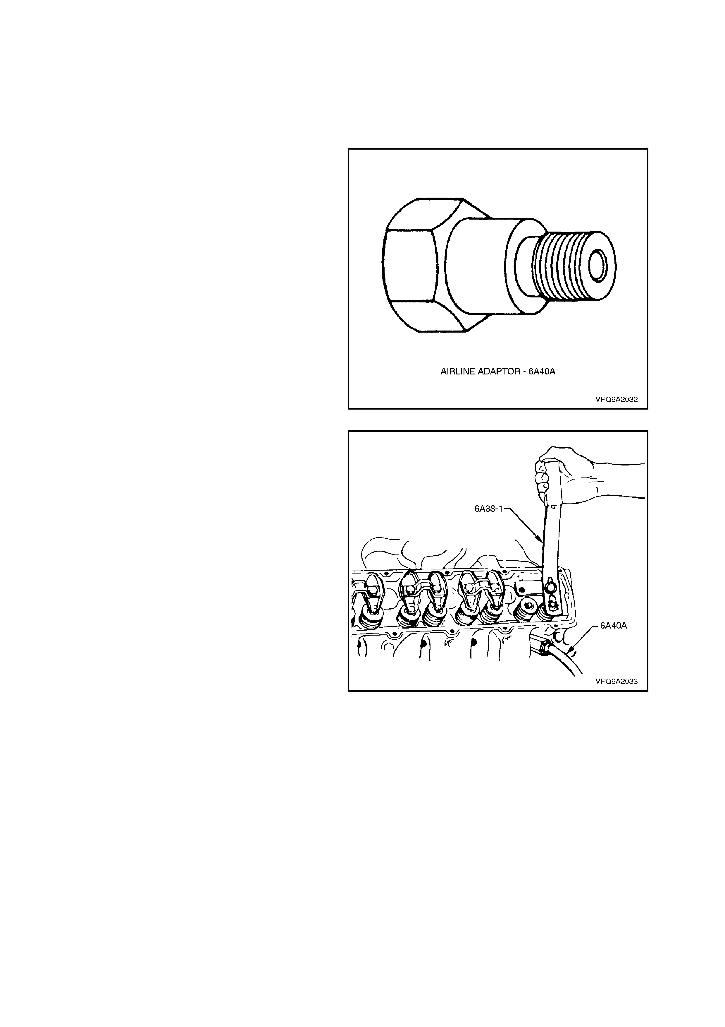
3. Rem ove spark plug f rom relevant cylinder and
install air line adaptor, Tool No. 6A40A, into
the spark plug hole. Apply air pressure of
approximately 850 kPa to hold valves in
closed position.
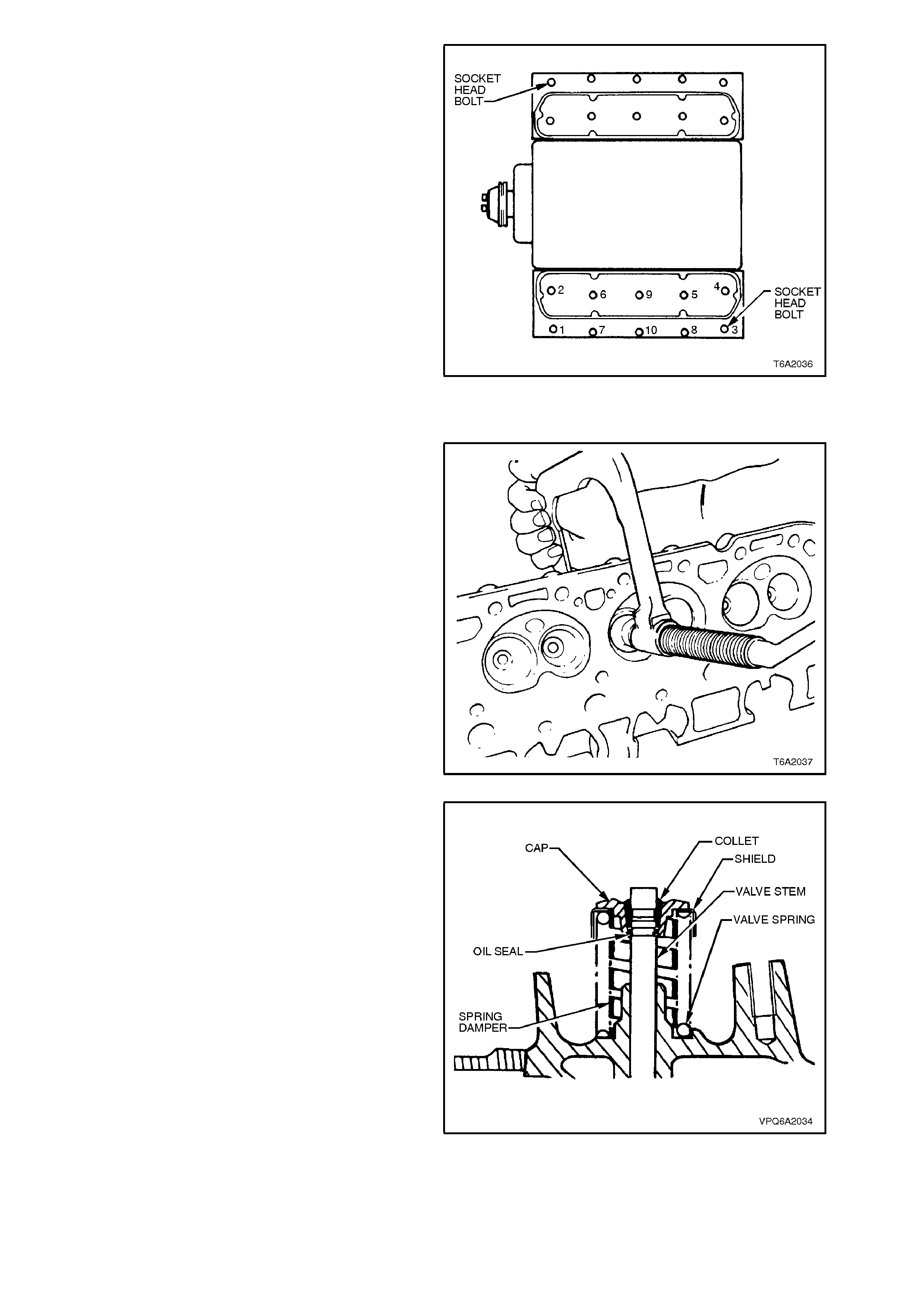
Figure 6A2-38
4. Install valve spring compressor, Tool No.
6A38-1, using a 5/16 x 2-1/4 inch U.N.C. bolt
with a large, flat washer. The bolt is installed
into the rocker arm pivot bolt hole.
5. Use valve spring compressor to compress
valve spring. Remove valve stem collets.
NOTE:
It may be necessary to tap the valve end of the
spring compressor using a soft faced hammer, to
overcome binding of the valve stem collets.
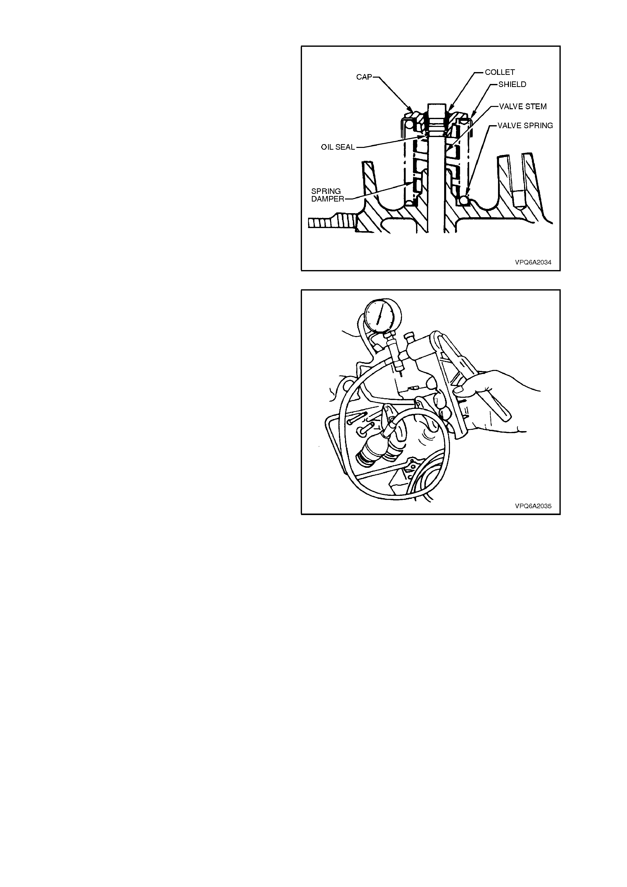
6. Slowly release tool and remove cap, shield,
spring, damper and oil seal.
Figure 6A2-39
REINSTALL
1. Place damper, valve spring, shield and cap
over valve stem.
2. Use valve spring compressor, Tool No. 6A38-
1, to compress and hold valve spring in a
compressed condition.
3. Install new oil seal in lower groove of valve
stem. Ensure the seal is seated properly and
not twisted.
4. Reinstall valve collets, ensuring they locate
correctly in top groove of valve stem. Slowly
release valve spr ing com pre ssor check ing that
the collet s seat correctly.
NOTE:
Grease may be used to hold collets in place.
5. Remove valve spring compressor.
Figure 6A2-40
6. Rem ove air pressur e fr om air line adaptor and
remove air line adaptor from spark plug hole.
7. Using a suitable suction cup or a vacuum hand
pump and appr opriate fittings, apply a vacuum
to the valve cap. If the vac uum is lost, then the
seal is faulty. Replace the seal as necessary.
8. Reinstall push rods.
9. Reinstall roc ker arm com ponents as descr ibed
in 2.3 ROCKER ARMS in this Section.
Figure 6A2-41
2.6 CYLINDE R HEADS
REMOVE
1. Disconnect battery earth cable from battery.
2. Remove inlet manifold, refer to
2.1 INLET MANIFOLD in this Section.
3. Remove exhaust manifolds, refer to
2.2 EXHAUST MANIFOLD in this Section.
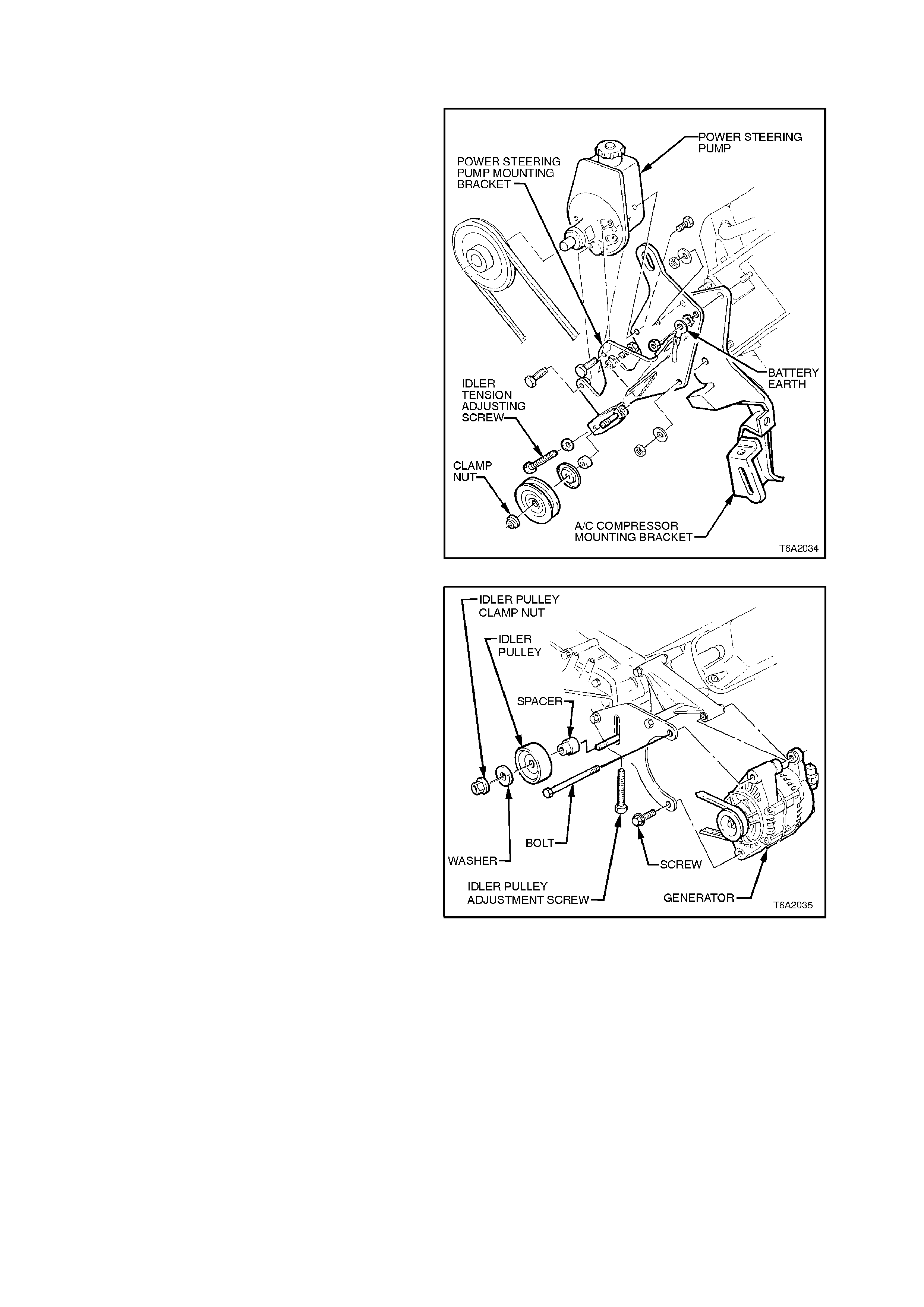
4. For R.H. Cylinder Head:
a. Release tension on power steering and
air conditioning drive belts and remove
belts.
b. Remove the three nuts securing the
power steering pump m ounting brack et to
the cylinder head, slide the bracket
forward off the mounting studs and m ove
to one side. Where fitted, remove the
lower bolt securing the air conditioning
compressor mounting bracket, this will
release the air conditioning compressor
mounting bracket. Slide the bracket
forward off mounting studs and move to
one side.
Figure 6A2-42
5. For L.H. Cylinder Head:
a. Remove the generator and mounting
brackets (refer to Section 6D2-1
CHARGING SYSTEM - V8 ENGINE).
Figure 6A2-43
6. Remove rocker arm pivots, rocker arms and
push rods, refer to 2.3 ROCKER ARMS in
this Section.
NOTE:
Each cylinder head is secured with nine internal
hexagon headed bolts and one socket head bolt.
7. With engine at ambient temperature (below
50o C), progressively loosen cylinder head
bolts in sequence shown in Fig. 6A2-44.
8. Remove cylinder head bolts, cylinder heads
and gaskets.
Figure 6A2-44
DISASSEMBLE
1. Using a conventional valve s pring c ompres s or ,
compress valve springs in turn and remove
valve collets.
NOTE:
It may be necessary to tap the cap of the spring
compressor using a soft faced hammer to
overcome binding of the valve stem collets.
Figure 6A2-45
2. Remove valve spring caps, shields, springs,
dampers and oil seals.
3. Remove valves from heads and place them in
a rack in sequence so they can be reinstalled
in their original positions.
CAUTION:
Do not force valves out of guides as
mushroomed ends or dirt in the guide and seal
grooves will damage guide. First remove any
burrs or dirt from end of valve stem.
Figure 6A2-46
CLEAN
1. Clean all carbon from combustion chambers,
valve ports, etc., using a soft rotary wire brush.
2. Thoroughly clean valve guides with solvent.
3. Clean valves with a buffing wheel.
4. Wash all parts in a cleaning agent and dry
thoroughly.
Figure 6A2-47
INSPECT
1. Inspect cylinder heads for cracks in valve
seats and combustion chambers, and for
external cracks to water jackets.
2. Inspect valves for burned or cracked faces or
damaged stems.
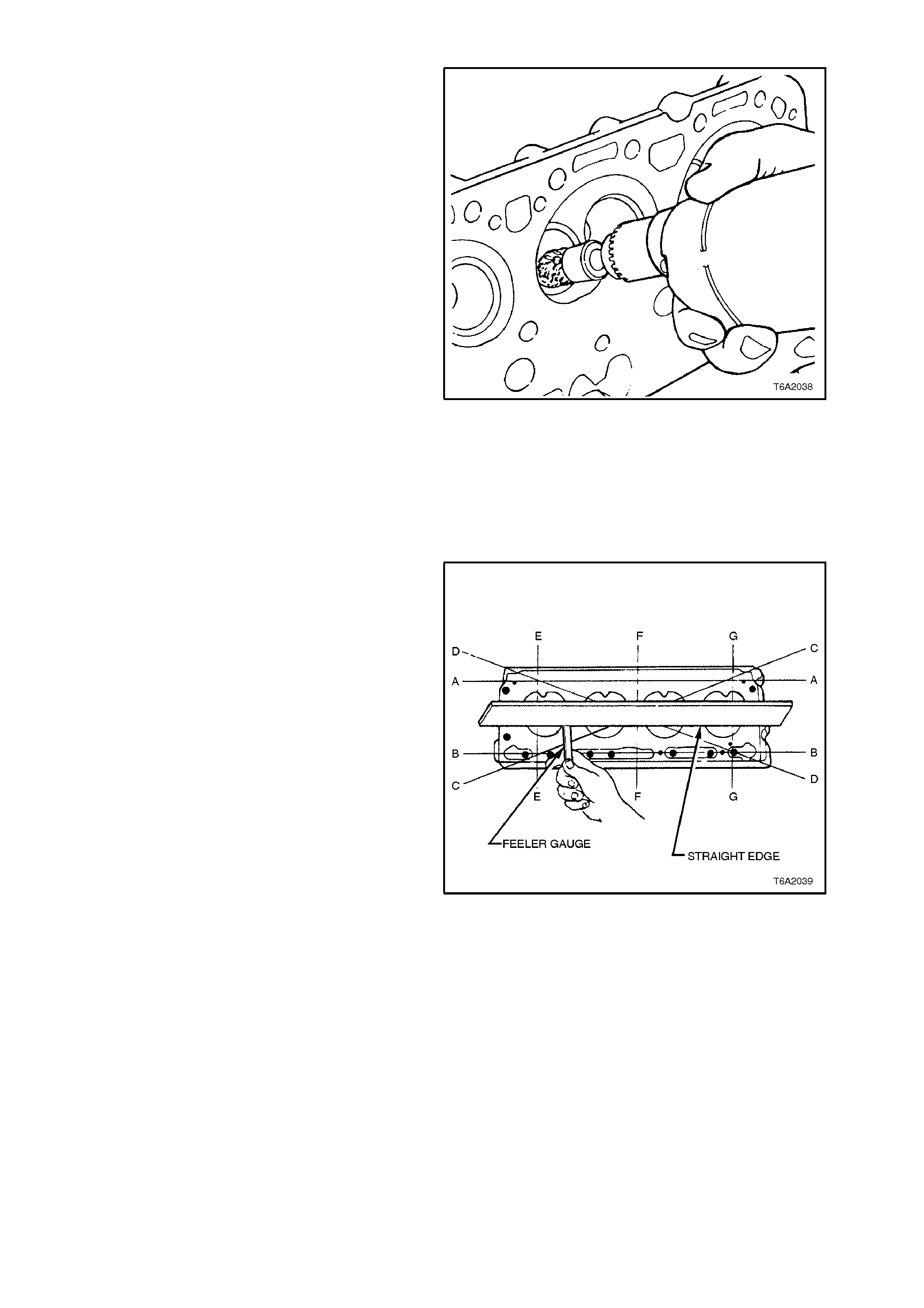
3. Check cylinder head surf ace for distor tion with
a straight edge and feeler gauge. Check
longitudinally, diagonally and transversely, as
shown by the alphabetical order in Fig. 6A2-
48.
4. If distortion exceeds allowable tolerance (refer
to 5. SPECIFICATIONS at the end of this
Section), machine head.
Figure 6A2-48
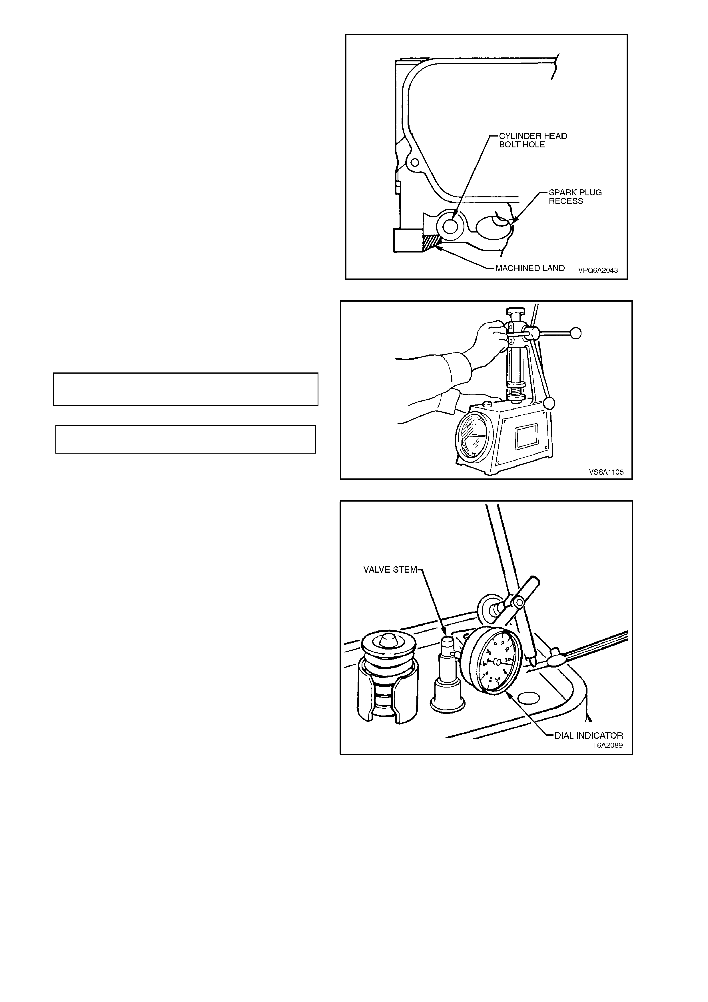
NOTE:
To determine if head has been machined
previously, measure distance from flat surface of
the combustion chamber side to top of machined
land on exhaust side of head (two lands at front,
two at rear of head). Refer to Fig. 6A2-49. The
minimum dimension for a standard head is 25.95
mm.
Figure 6A2-49
5. Check valve springs with a valve spring tes ter.
Compress springs (without dampers) to
specified height and read load. Replace
springs if outside specifications.
VALVE SPRING 51.56 mm
FREE LENGTH approx
VALVE SPRING 338 - 373 N
TENSION @ 45.2 mm
Figure 6A2-50
6. Measure valve stem clearance as detailed in
the following procedure:
a. Secure a dial indicator on the cylinder
head rocker c over gas ket rail, loc ating the
indicator so that movement of the valve
stem from side to side (across the head)
will cause a direct movement of the
indicator plunger. The indicator plunger
must contact the side of the valve stem
just above the valve guide.
b. With the valve head dropped
approximately 1.6 mm off the valve seat,
move the stem of the valve from side to
side, using a light force to obtain a
clearance reading.
c. Where clearance exceeds 0.094 mm for
inlet valves or 0.119 mm for exhaust
valves, recheck with a new standard size
valve.
d. If the clearance still exceeds
specification, ream the valve guides for
installation of oversize valves.
Figure 6A2-51
RECONDITION VALVE SEATS
NOTE:
5.0 litre VT Series engines feature induction
hardened exhaust valve seats. Use suitable
reconditioning equipment and carefully follow
equipment manufacturer's recommendations to
ensure satisfactory results.
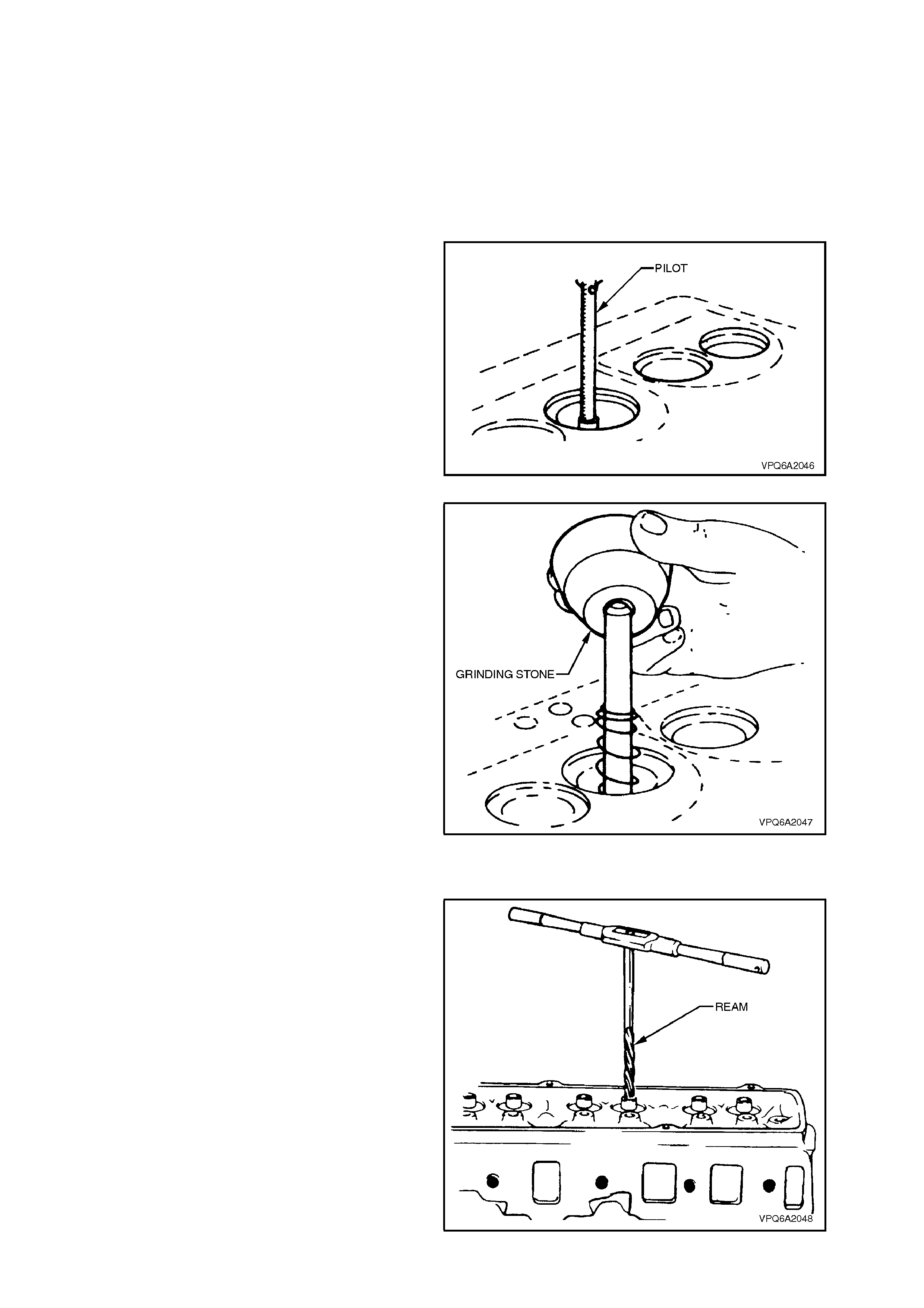
1. Remove all carbon and dirt from valve guide
bores to ensure correct centring of pilot in
guide.
2. Secure expanding pilot in valve guide bores.
Figure 6A2-52
3. Use a 46º angle stone to cut exhaus t and inlet
valve seats.
4. Prior to cutting valve s eats, dress stone with a
diamond dressing tool in a suitable fixture.
5. Narrow down valve seats to specified width,
using a 30º or 60º grinding stone as
appropriate.
a. The inlet valve seat width should be
0.90 - 1.30 mm.
b. The exhaust valve seat width should be
0.97 - 1.35 mm.
Figure 6A2-53
REAM VALVE GUIDES
Inlet and exhaust valves are available with the
following oversize diameter valve stems: 0.04, 0.08,
0.20, 0.38 and 0.76 mm.
Use a suitable fixed blade reamer to enlarge the
bores of the valve guides when installing new
valves.
Check valve seating as outlined in the following
text.
Do not lap new valves into seats as the aluminised
valve surface will be removed.
Check valve stem height (as described in
MEASURE VALVE STEM HEIGHT) when valves
are installed.
Figure 6A2-54
RECONDITION VALVES
Valves that are warped or have excessive stem
wear should be replaced. Pitted valves can be
refaced with a valve refacing machine, ensuring
correct relationship between head and stem.
Several different types of equipment are available
for refacing valves. To obtain satisfactory results,
follow the instructions and recommendations of the
equipment manufacturer.
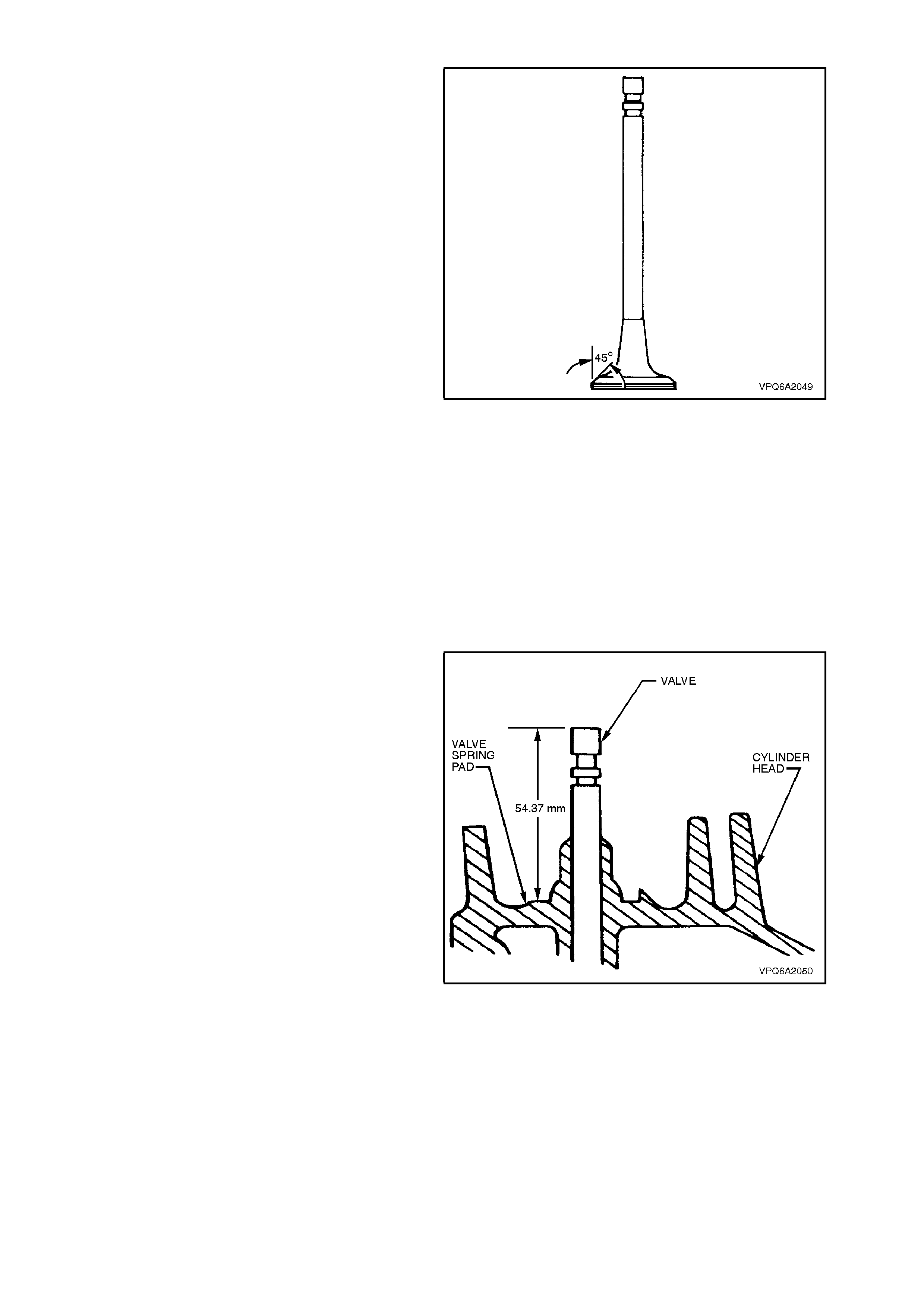
Set the valve refacing equipment to 45º to reface
both the inlet and exhaust valves.
After refacing a valve, check for correct seating as
follows:
1. Coat valve face with bearing blue.
2. Insert valve and rotate approximately 1/6th of
a revolution.
3. Remove valve and check for full surface
contact.
4. If part contact is indicated, insert valve again
and rotate through a full revolution. If blue on
seat indicates full contact, regrind face of
valve; if part contact is still indicated, cut valve
seat.
5. Measure valve stem height as outlined in the
following text.
Figure 6A2-55
MEASURE VALVE STEM HEIGHT
After reconditioning valves, valve seats or when
installing a new valve, measure the valve stem
height using the following procedure:
1. Hold valve firmly against its seat.
2. Measure distance from valve spring pad to
valve stem end.
3. If measurement exceeds 54.37mm, remove
valve from cylinder head and grind valve stem
end to achieve this dimension. Do not gr ind off
any more than is necessary.
4. After grinding the valve stem, assemble the
valve and spring assembly as outlined in the
following REASSEMBLE procedure.
Figure 6A2-56
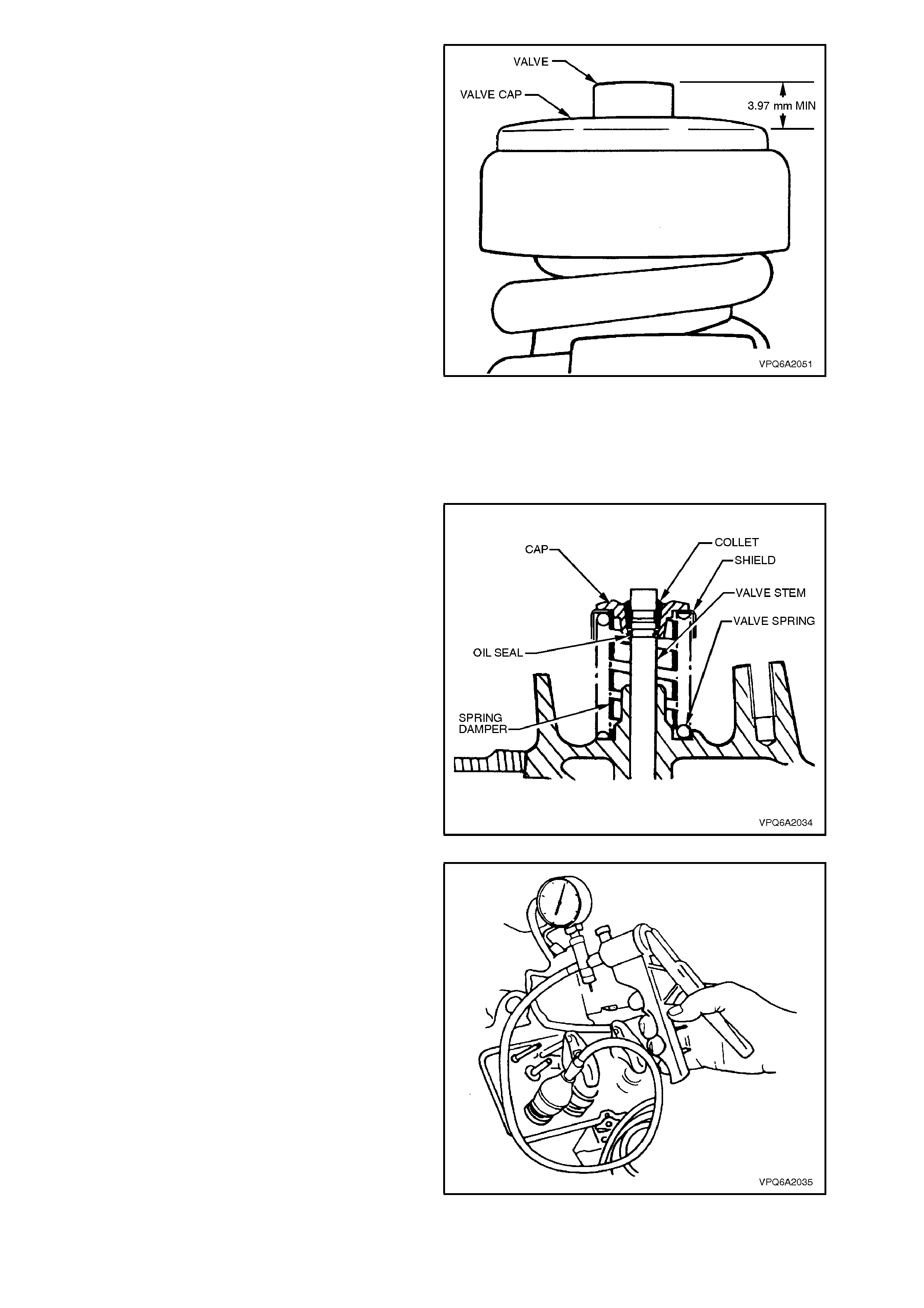
5. Measure distance between outer edge of valve
cap and top of valve stem.
6. If dimension is less than 3.97mm, replace the
valve.
Figure 6A2-57
REASSEMBLE
1. Thoroughly clean and dry all components.
2. Lubricate valve stem thoroughly with oil and
reinstall valve in corresponding guide.
3. Install new oil seal in lower groove of valve
stem. Ensure the seal is seated correctly and
not twisted.
4. Place damper, valve spring, shield and cap
over valve stem.
5. Compress the valve spring with a suitable
valve spring compressor.
6. Reinstall valve collets ensuring they locate
correctly in top groove of valve stem. Slowly
release valve compressor checking that collets
seat correctly.
NOTE:
Grease may be used to hold collets in place.
Figure 6A2-58
7. Using a suitable suction cup or a vacuum hand
pump and appr opriate fittings, apply a vacuum
to the valve cap. If the vac uum is lost, then the
seal is faulty . Replace the seal as necessary.
Figure 6A2-59
REINSTALL
1. Clean mating surfaces of cylinder block and
head taking care not to gouge or scratch
machined finish.
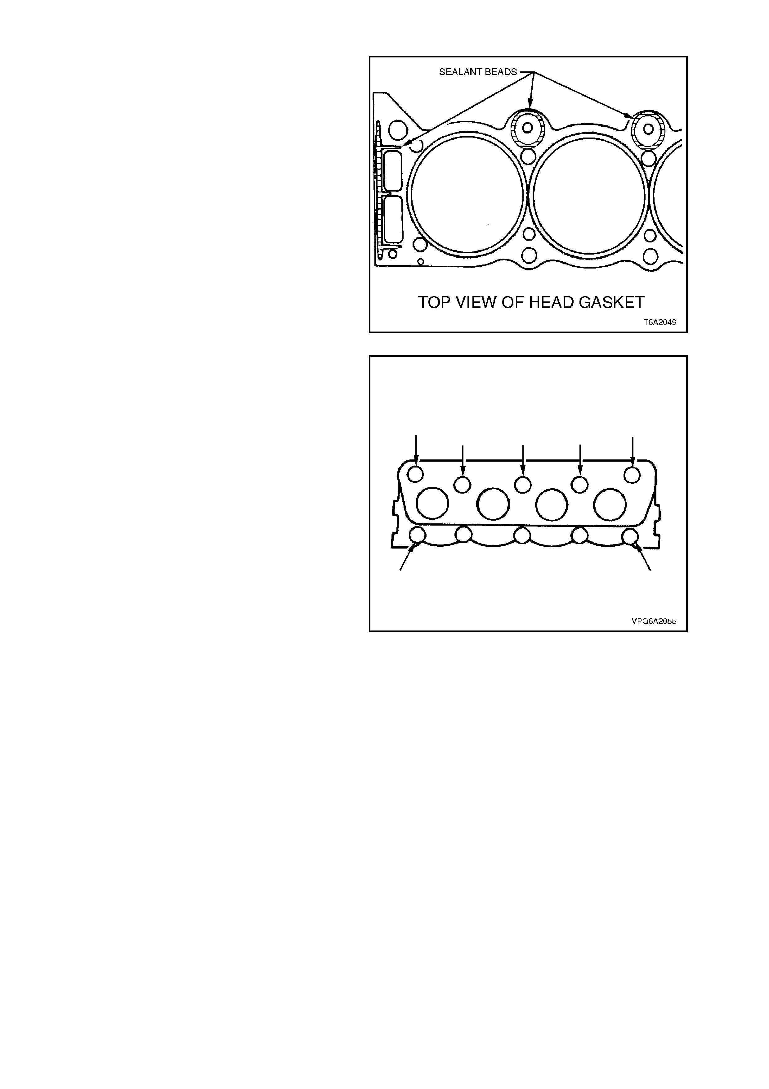
2. Place gasket in position over dowel pins with
the bead or side marked 'T OP' facing upward.
This can be confirmed by the fact that sealant
beads are applied to this surface of the
gasket, as shown in Fig. 6A2-60.
3. Carefully guide cylinder head into place over
dowel pins and gasket.
Figure 6A2-60
4. Apply a thin film of sealing compound Loctite
242 or equivalent (Holden Specification HN
1256) to the cylinder head bolt threads
entering the water jacket (refer to Fig. 6A2-
61), then install the bolts finger tight.
Figure 6A2-61
5. Tighten the cylinder head bolts to specified
torque in two stages, using the sequence
shown in Fig. 6A2-62.
STAGE 1
CYLINDER HEAD BOLT 50 - 55 Nm
TORQUE SPECIFICATION STAGE 2
77 - 83 Nm
6. Reinstall rocker arm pivots, rocker arms
and push rods as described in
2.3 ROCKER ARMS in this Section.
7. Remove engine lifting bracket if previously
fitted, reinstall power steering pump bracket
and air conditioning com pres sor brace br acket
(where fitted), tightening attaching nuts to the
specified torque.
POWER STEERING PUMP MOUNTING
BRACKET ATTACHING NUTS 15 - 20 Nm
TORQUE SPECIFICATION
8. Reinstall power steering pump and generator,
refer to Sections 9A STEERING and
Section 6D2-1 CHARGING SYSTEM - V8
ENGINE
9. Reinstall exhaust manifolds, refer to
2.2 EXHAUST MANIFOLD in this Section.
10. Reinstall inlet manifold, refer to
2.1 INLET MANIFOLD in this Section.
Figure 6A2-62
11. If a NEW cylinder head has been fitted, it will
be necessary to tighten the spark plugs to the
following torque specification, to 'coin' the
spark plug sealing seat in the cylinder head.
SPARK PLUG 'COINING'
TORQUE SPECIFICATION 20 - 28
Nm
Otherwise install spark plugs and tighten to
the specified torque.
SPARK PLUG
TORQUE SPECIFICATION 20
Nm
2.7 HYDRAULIC VALVE LIFTERS
REMOVE
1. Depressurise fuel lines, refer to
Section 6C2 POWERTRAIN MANAGEMENT
- V8 ENGINE - SERVICE OPERATIONS.
2. Disconnect battery earth lead.
3. Remove rocker arms and pushrods, refer to
2.3 ROCKER ARMS in this Section.
4. Remove inlet manifold, refer to
2.1 INLET MANIFOLD in this Section.
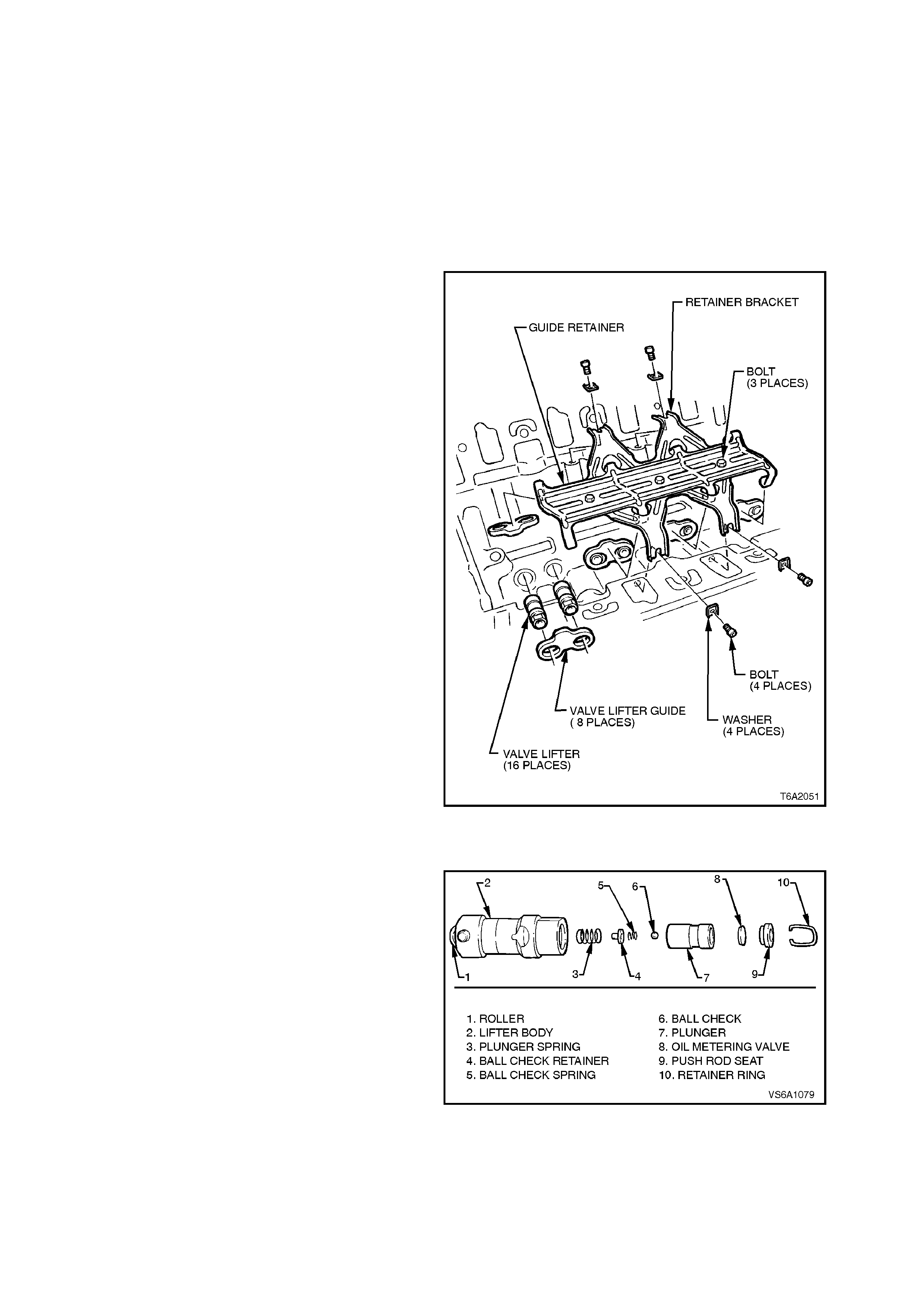
5. From valley in cylinder block, remove valve
lifter guide retainer bracket attaching bolts,
valve lifter guide retainer and valve lifter guide
assembly.
6. Remove lifters from cylinder block bores and
place in order on rack.
NOTE:
Ensure that all valve train components are kept in
order so they may be reinstalled, if required, in their
original locations.
REINSTALL
1. Reverse removal operations.
Figure 6A2-63
DISASSEMBLE
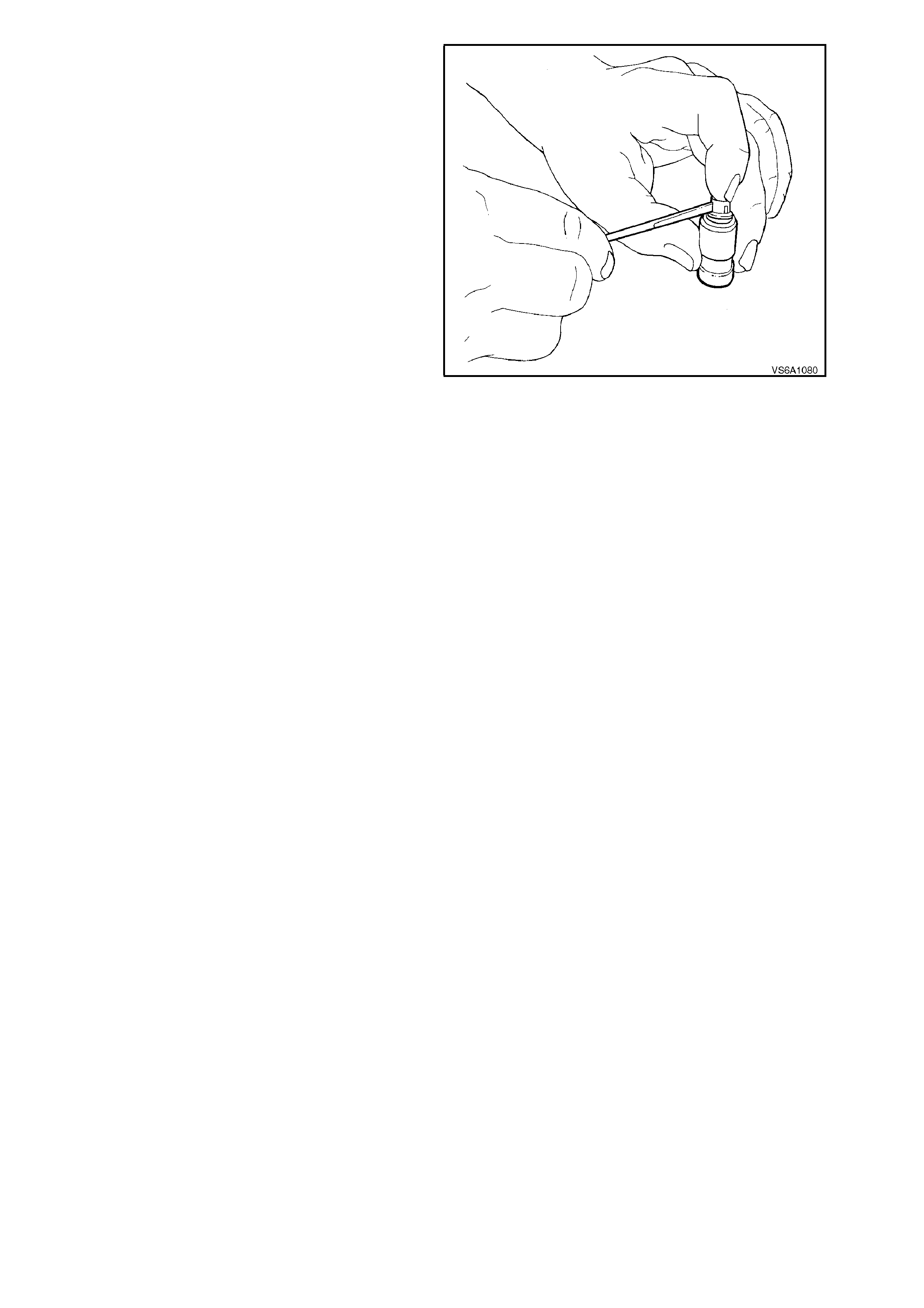
1. Using a small, fine bladed screwdriver,
remove push rod seat retainer ring.
2. Remove push rod seat, oil metering valve,
plunger assembly and plunger spring from
lifter body.
NOTE:
If the plunger is stuck in the lifter body, turn lifter
body upside down and tap on a block of wood.
If plunger c annot be moved, soak lifter assem bly in
a suitable cleaning fluid.
Figure 6A2-64
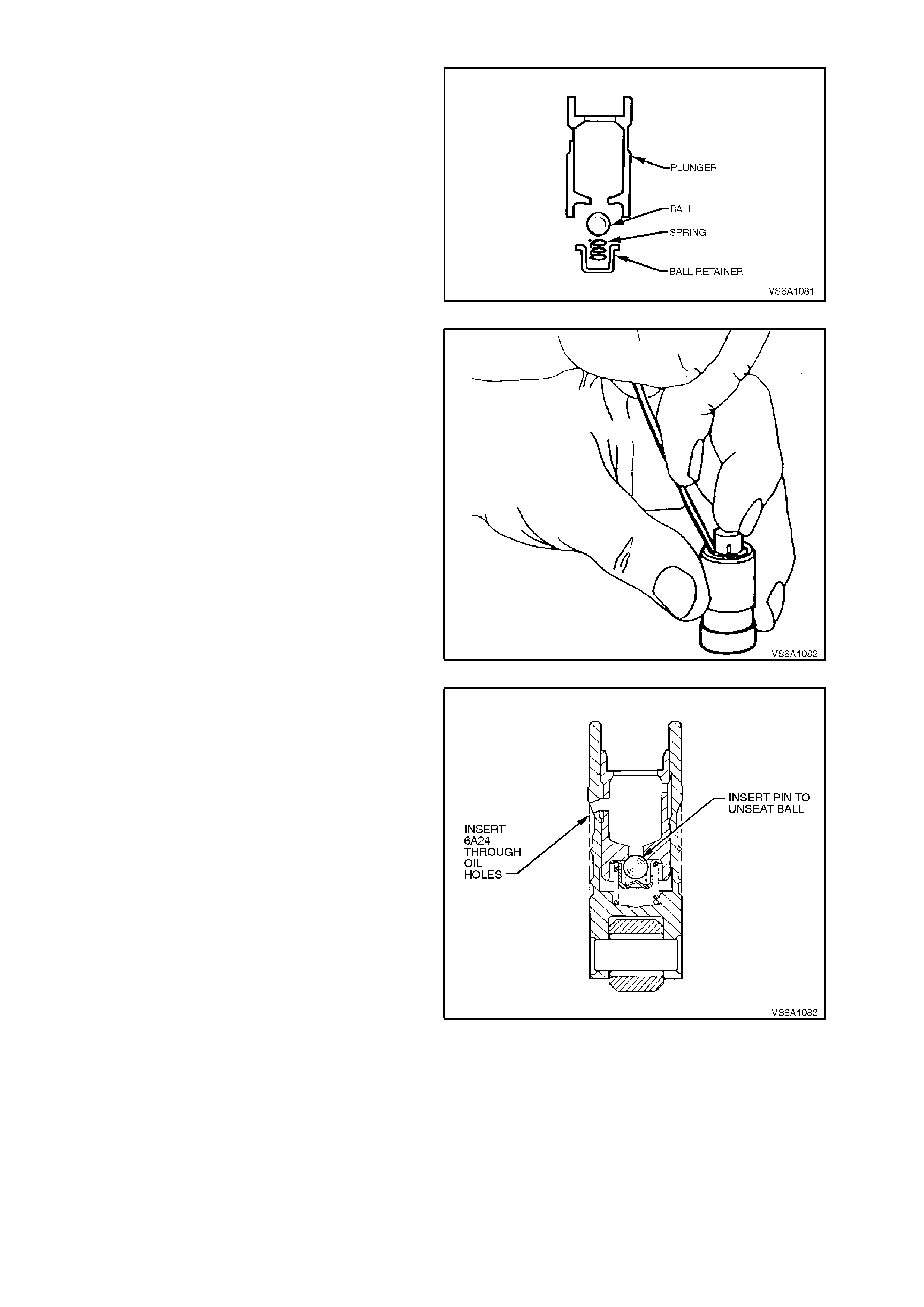
3. Remove check valve retainer, ball check
spring and ball from plunger assembly with a
small, fine bladed screwdriver.
Figure 6A2-65
CLEAN AND INSPECT
1. Thoroughly clean all parts in a suitable
cleaning fluid. Blow dry with clean dry
compressed air.
2. Inspect lifter body for;
a. Wear
b. Scuffing. Also inspect lifter bore in
cylinder block.
3. Inspect roller for;
a. Freedom of movement. Replace lifter if
roller binds or roughness can be felt.
b. Excessive looseness in the roller bearing
c. Flat spots. Replace lifter if roller is worn.
d. Pitting. Replace lifter if roller is pitted.
4. Inspect pushrod seat. If seat is worn, inspect
pushrod. Replace pushrod if worn.
5. If any lifter component is damaged or
excessively worn, replace entire lifter
assembly.
REASSEMBLE
NOTE 1:
Do not attempt to recondition lifter assemblies by
taking parts from other unserviceable lifters.
NOTE 2:
Cleanliness is very important when reassembling
lifters. Lint or dirt can cause the lifters to fail.
1. Place check ball on small hole in plunger.
Figure 6A2-66
2. Carefully place check ball spring and retainer
over ball and press retainer into position in
plunger with a small, fine bladed screwdriver.
3. Half fill valve lifter body with test fluid No.
E1151 (previously 361-1-93).
4. Reinstall plunger spring into lifter body.
5. Install plunger assembly in body, taking care to
align oil feed holes.
6. Fill lifter assembly with test fluid.
Figure 6A2-67
7. Use a 1 m m diameter pin to unseat check ball
in the plunger. Push plunger down to the full
extent of its travel.
8. Use Tool No. 6A24 to align oil feed holes in
body and plunger.
9. Fill lifter assembly with test fluid.
10. Reinstall oil metering valve, push rod seat (cup
side uppermost) and retaining ring.
NOTE:
The hydraulic lifter is now ready for checking as
outlined in the next operation.
Figure 6A2-68
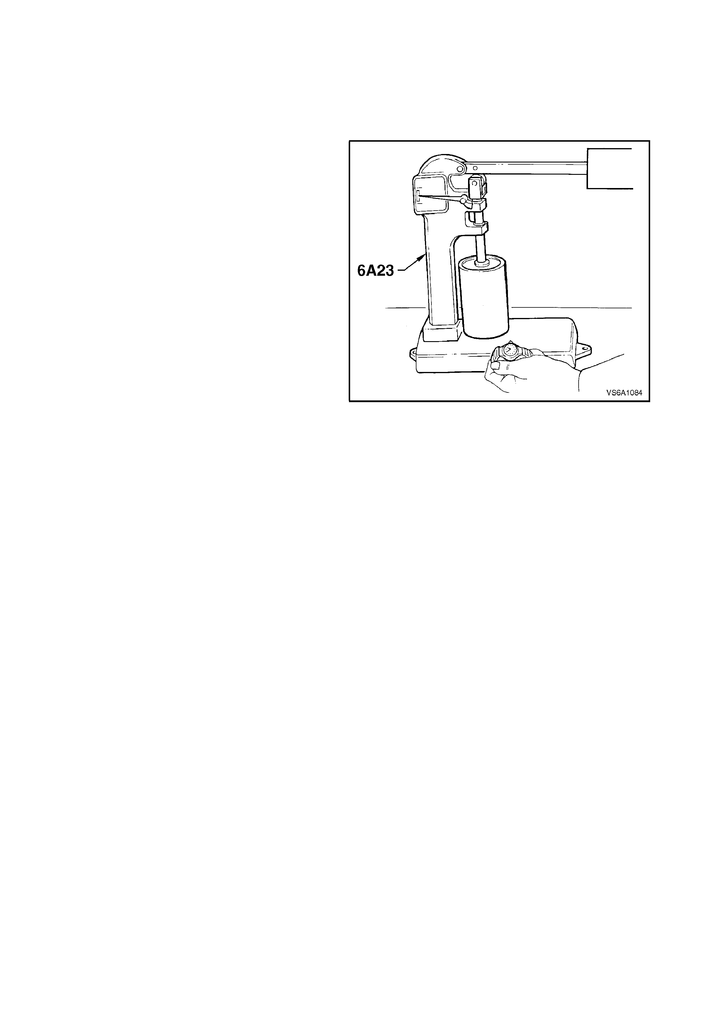
TESTING LIFTER LEAK DOWN RATE
After a hydraulic lifter has been cleaned, inspected
and assembled, it must be tested before it is
reinstalled in the engine. T he lifter test f ixture, Tool
No. 6A23, has been designed to test the leak down
rate of the lifter to determine whether it is within the
limits which assure satisfactory lifter operation.
1. Thoroughly clean cup of tes t fixture. Ins tall c up
on fixture and place lifter into cup.
NOTE:
On some versions of 6A23, it m ay be necessary to
make a small cup/support fixture to hold the base
of the lifter assembly inside the tester cup.
2. Add sufficient test fluid No. E1151 (previously
361-1-93) to completely cover lifter.
3. Place ball bearing supplied with test fixture in
push rod seat of lifter.
4. Lower test fixture ram to rest on ball bearing.
5. Operate lifter plunger through its maximum
travel to force all air out of lifter by using a
vigorous pumping action on test fixture weight
arm. Continue pumping action until
considerable resistance is built up in lifter and
lifter becomes solid.
6. Raise weight arm to allow lifter plunger to
come up to its retainer, then lower arm to rest
on ram.
7. Use a stop watch to check the time required
for the indicator to move from the 'START' to
0.125 in. position on the scale.
8. The leak down rate (time between start and
0.125 in. position) must be between 20 to 90
seconds to assure satisfactory lifter operation.
Figure 6A2-69
NOTE:
A doubtful lifter should be tested three or four
times. Any lifter which does not test within the
specified limits should be replaced.
9. After all lifters have been thoroughly tested,
place a cover over the test fixture to keep dirt
out of the cup.
10. Stand tested lifters upright so that fluid does
not drain from oil holes.

REINSTALL
1. Ensure that lifter bodies, rollers and lifter bores
are clean.
2. Lubricate lifter bodies and bores with Lubrizol
6612 or equivalent (Holden Specification HN
1961) and install lifters.
3. Install lifter guides, aligning flats on lifter body
with flats in guide.
4. Install valve lifter guide retainer and attaching
bolts. Tighten bolts to the correct torque
specification.
VALVE LIFTER GUIDE
RETAINER BOLT
TORQUE SPECIFICATION 26 - 34 Nm
5. Install rocker arms and pushrods, refer to
2.3 ROCKER ARMS in this Section.
6. Reinstall inlet manifold, refer to
2.1 INLET MANIFOLD in this Section.
7. Reconnect battery earth lead, start engine and
check for oil or fuel leaks and valve train
noise. Repair as necessary.
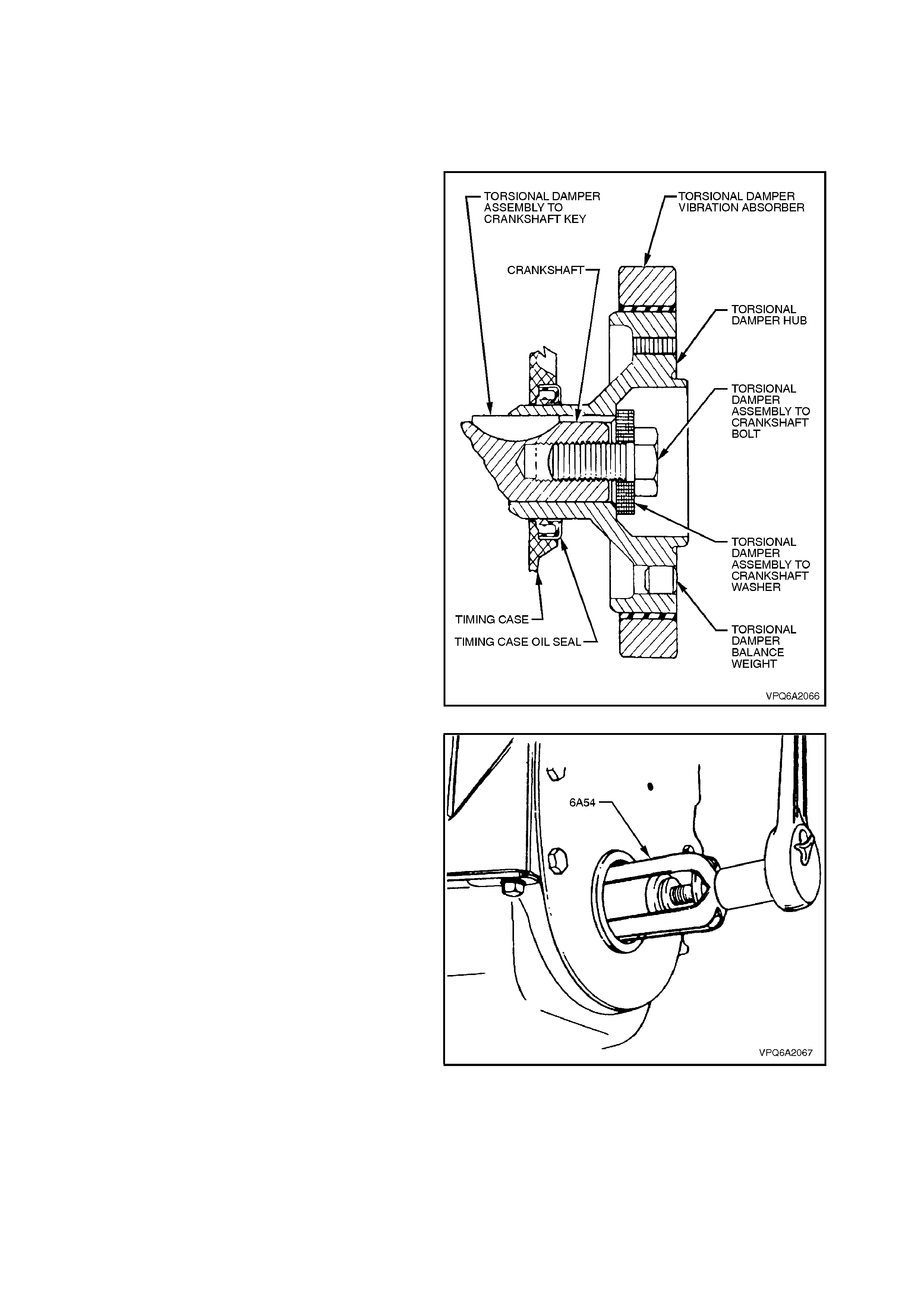
2.8 CRANKSHAFT FRONT SEAL
REPLACE
1. Disconnect battery earth lead.
2. Remove all drive belts fitted to crankshaft
drive belt pulley, refer to 2.13 DRIVE BELTS.
3. Remove torsional damper assembly to
crankshaft bolt and washer, then remove
torsional damper.
Figure 6A2-70
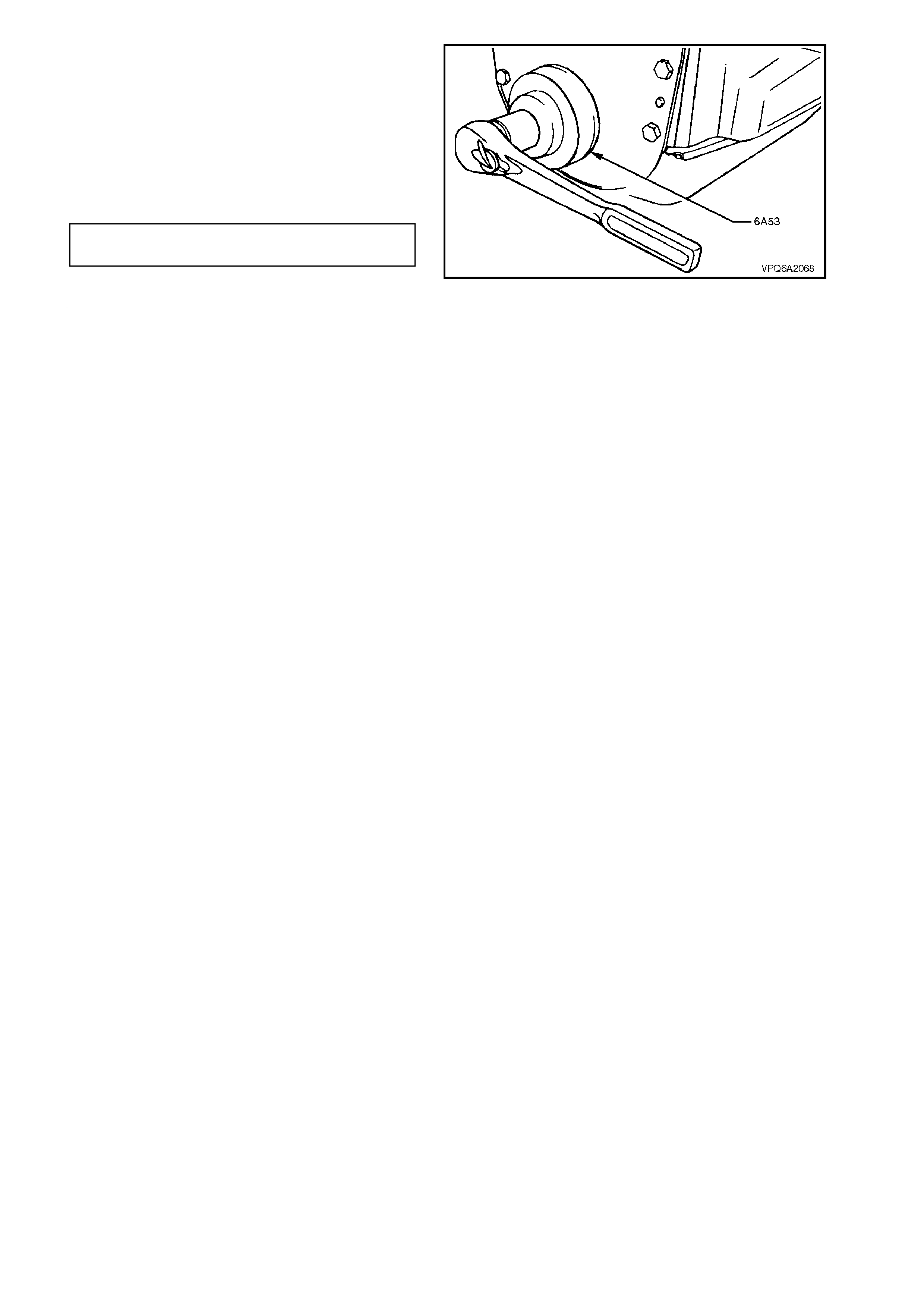
4. Using Tool No. 6A54, remove oil seal.
Figure 6A2-71
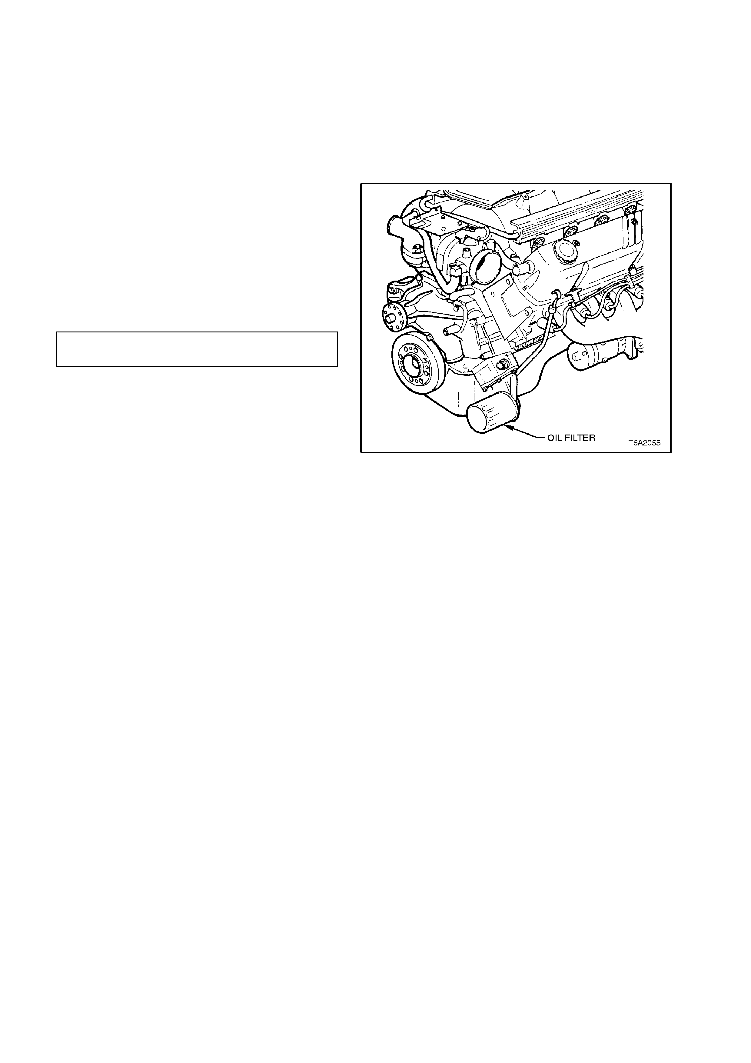
5. Install new oil seal with open end facing
inwards, using Special Tool No. 6A53.
6. Lubricate torsional damper hub bore with
hypoid lubricant and lubric ate seal s ur f ac e with
engine oil.
7. Position torsional damper on crankshaft and
install hub bolt and washer.
8. Tighten bolt to specification.
TORSIONAL DAMPER BOLT 190 Nm
TORQUE SPECIFICATION minimum
9. Reinstall pulley. Reinstall drive belts, then
adjust tensions of drive belts, refer to
2.13 DRIVE BELTS in this Section.
Figure 6A2-72
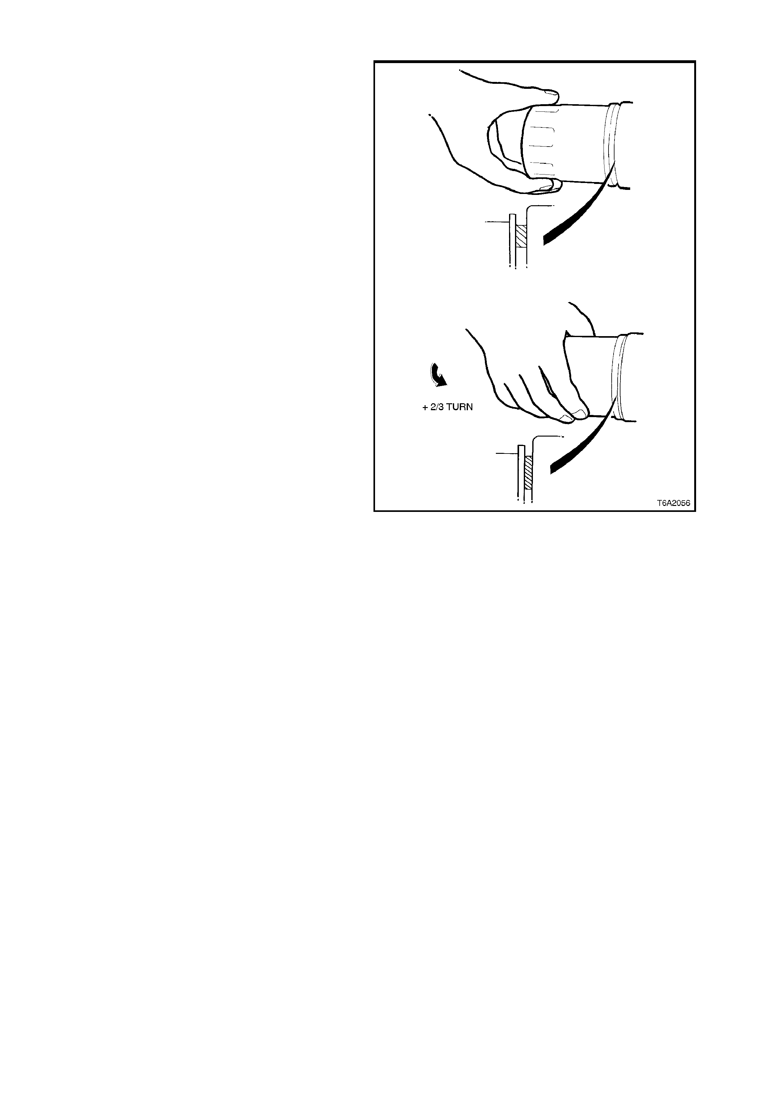
2.9 OIL FILTER
NOTE:
The oil filter should be replaced at the time
or distance intervals specified in
Section 0B LUBRICATION & SERVICE, or
whenever the engine oil is contam inated by foreign
material.
REMOVE
CAUTION:
To av oid the possibility of scalding, ensure that
the engine temperature is below 50°C, before
draining engine oil.
1. Place a suitable container below the oil pan,
and remove drain plug.
2. Allow the contents of the oil pan to drain, then
replace and tighten drain plug.
OIL PAN DRAIN PLUG 30 - 60
TORQUE SPECIFICATION Nm
3. Using a suitable oil filter loosen oil filter at the
oil filter adaptor in a counter-clockwise
direction, then remove and discard the oil
filter..
Figure 6A2-73
REINSTALL
1. Ensure new seal is correctly located in filter
recess, then apply a light film of clean engine
oil to the seal surface.
2. Install filter and rotate clockwise until seal
contacts mating face of pump body, then
tighten filter an additional two thirds (2/3) of a
turn.
Figure 6A2-74
NOTE:
Ensure that the drain plug is secured in position
before refilling the oil pan.
3. Refill the engine to correct level with clean
engine oil. Refer to Section 0B
LUBRICATION & SERVICE.
4. Fully depress the accelerator pedal, crank the
engine for a few seconds with starter motor,
then release the accelerator pedal and start
the engine. Check for oil leaks and rectify as
necessary.

2.10 OIL LEVEL CHECK
1. Engine must be at normal operating temperature (idle for 10 minutes or equivalent).
2. Park vehicle on level surface (as this will affect the accuracy indicated on dipstick, this is a critical
requirement).
3. Do not check oil level for at least 10 minutes after shut down to allow oil to drain back into the oil pan.
4. Remove dipstick and wipe clean.
5. Reinstall dipstic k with FULL/ADD m ar ks f ac ing towards c entr e line of engine. T h is as pec t is very im por tant due
to the angle that the dipstick enters the oil in the oil pan.
6. Ensure dipstick is fully seated and slowly rem ove to avoid sm ear ing. Hold horizontally or with lower end slightly
down to avoid oil running along dipstick.
7. Observe the oil level where it passes over the centre line of the dipstick.
8. When topping up the engine oil, allow approximately 10 minutes for the oil added to fully drain into the oil pan.
Alternatively, add 50 ml of oil for each millimetre below the “FULL” mark on the dipstick.
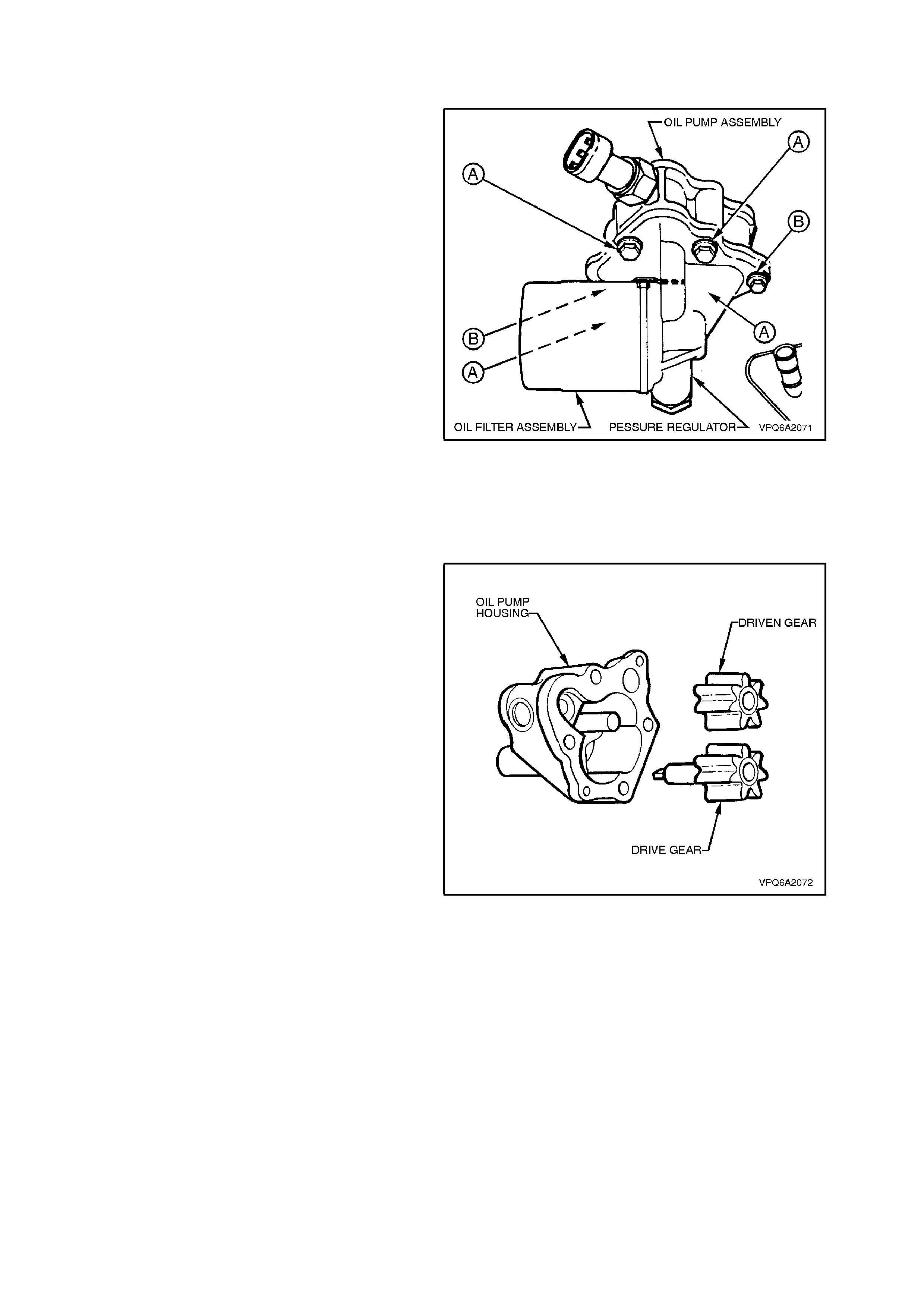
2.11 OIL PUMP
REMOVE
1. Remove oil filter, refer to 2.9 OIL FILTER in
this Section.
2. Remove electrical connector from oil pressure
switch.
3. Remove four bolts securing oil pump to
cylinder block. The bolts are labelled 'A' in Fig.
6A2-75.
4. Remove oil pump assembly.
Figure 6A2-75
DISASSEMBLE
1. Remove two bolts securing pump cover to
pump housing. The bolts are labelled 'B' in
Fig. 6A2-75. Remove body and gasket.
2. Match-mark the pump gears for subsequent
reinstallation.
3. Remove pump gears.
Figure 6A2-76
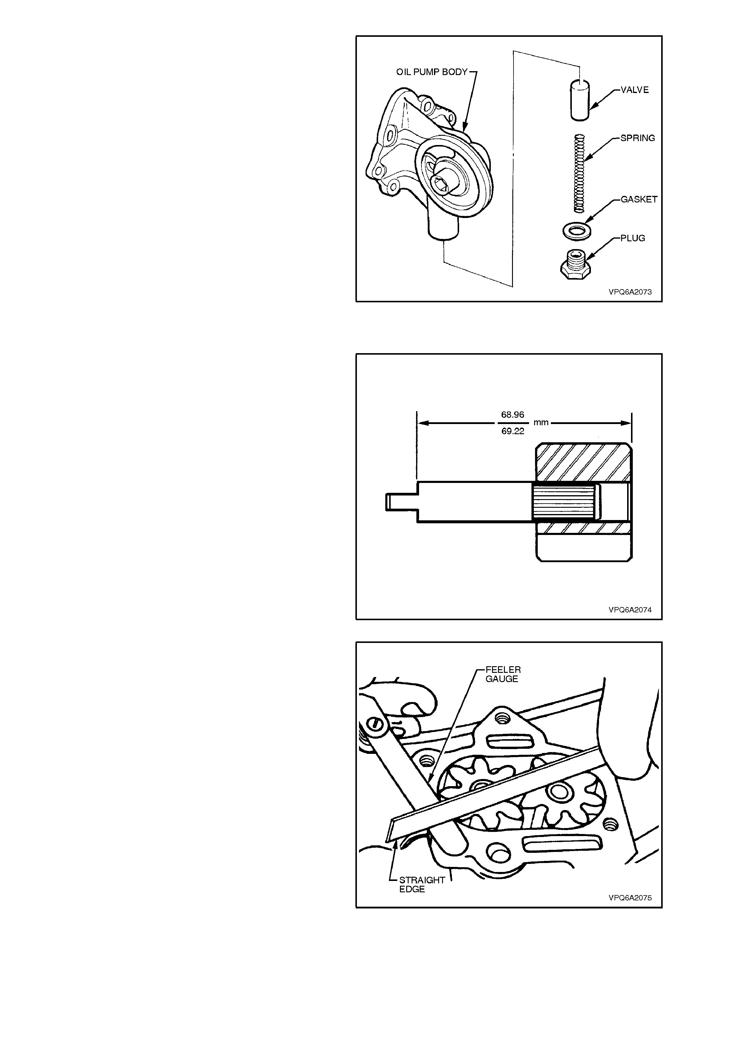
4. Unscrew and remove the plug retaining the
pressure regulator spring and valve.
Figure 6A2-77
INSPECT
1. Clean all components.
2. Inspect pump housing, driven gear shaft and
pump body for wear.
3. Check that drive shaft is tightly pressed into
drive gear.
4. Measure the distance from the shoulder on the
shaft to the outer face of the gear . The c orrect
dimension is 68.96 - 69.22 mm.
5. Inspect gears and drive shaft for wear.
Figure 6A2-78
6. Reinstall gears (as match-marked) and check
end of gear to pump housing face clearance
using a straight edge and feeler gauge. The
gears should protrude from the pump housing
0.051 - 0.153 mm.
7. Check that the gear backlash is within 0.229 -
0.381 mm.
8. Check fit of regulator valve in bore. It should
be a free sliding fit with a minimum of
clearance.
9. Check that the regulator valve spring is not
collapsed, worn or broken.
10. The free length of the spring should be
approximately 82.5 mm. The length of the
spring under a load of 4.76 kg should be 63.5
mm.
11. Visually inspect the bypass valve ass embly fo r
damage.
12. Replace any damaged or worn parts as
necessary.
Figure 6A2-79

REASSEMBLE
1. Reinstall pressure regulator spring and valve
and tighten plug to specified torque.
REGULATOR VALVE PLUG
TORQUE SPECIFICATION 34 - 41
Nm
2. Liberally coat the gears with clean engine oil
and reinstall in original positions relative to
one another as noted in disassembly.
3. After pre-filling a new oil filter, screw on to oil
pump body. Turn a further 2/3 turn after the
gasket contacts the oil pump body face.
4. While holding the oil pump assembly at
approximately 45°, near fill the chamber with
new oil of the recommended specification.
NOTE:
This operation is necessary to prime the oil pump
to reduce oil pressure build-up time on initial
engine start.
5. Install a new, genuine Holden's pump gasket,
to ensure correct clearance between gears
and pump.
6. Reinstall pump body and tighten two securing
bolts to specified torque, (bolts 'B' in
Fig. 6A2-75).
OIL PUMP BODY BOLTS
TORQUE SPECIFICATION 5 - 8
Nm
REINSTALL
Reinstallation is the reverse of the removal
procedure, note the following:
1. While maintaining the oil pump assembly at an
angle of 45º, fit a new gasket between pump
housing and cylinder block. Avoid wetting the
gasket with engine oil during fitment.
OIL PUMP BOLTS
TORQUE SPECIFICATION 23 - 30
Nm
2. Progressively tighten bolts to specified torque.
3. Rem ove the oil pressure switch and pr ime the
oil pump with clean engine oil, reinstall switch
and tighten to specified torque.
OIL PRESSURE SWITCH
TORQUE SPECIFICATION 12 - 14
Nm
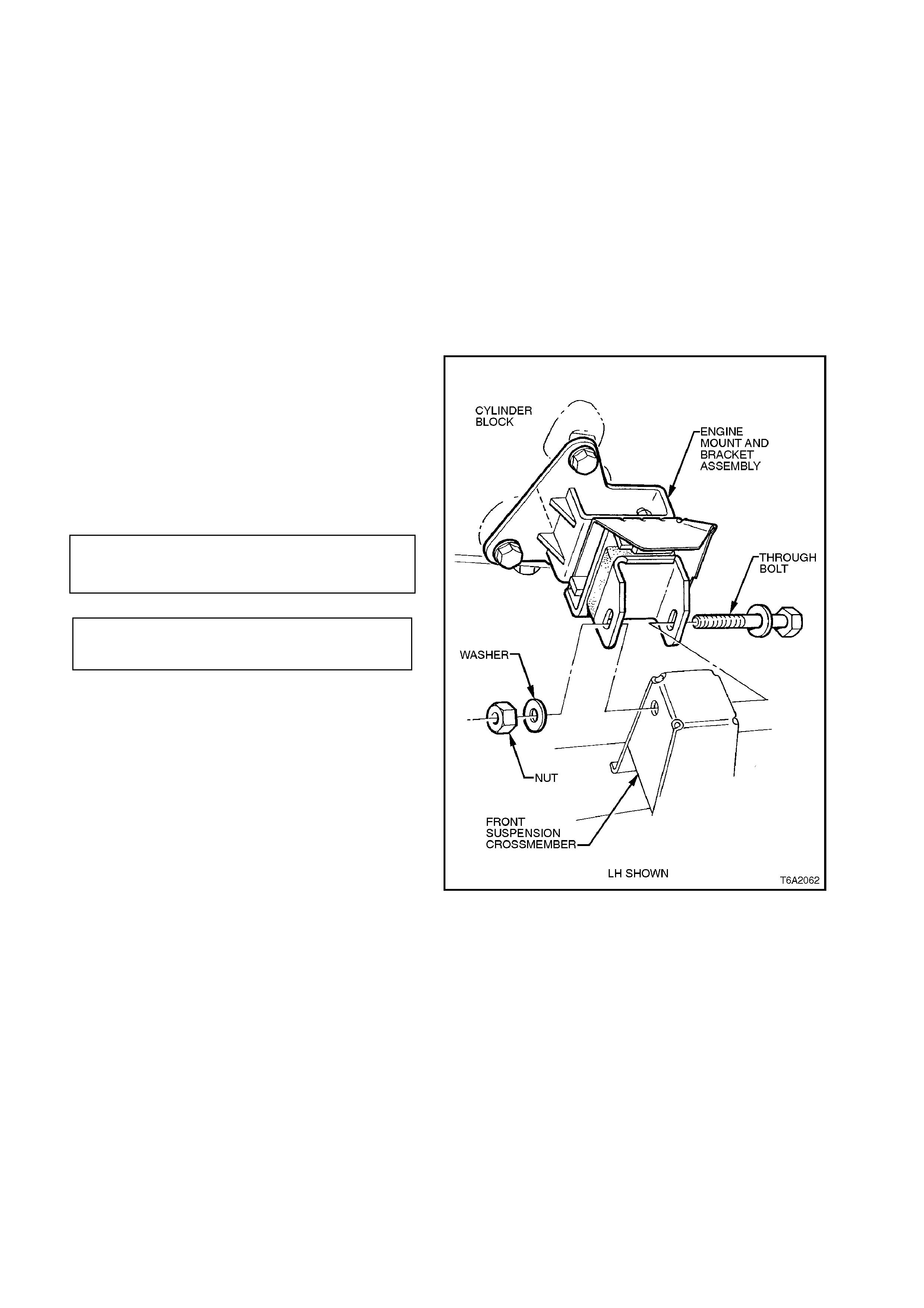
2.12 ENGINE MOUNTS
FRONT MOUNT
CHECK
Place a piece of wood between a suitable jack and
the oil pan, then raise the engine sufficiently to
check that rubber has not deteriorated, split or
separated from metal plates.
REPLACE
1. Raise front of vehicle and place on safety
stands. Refer to Section 0A GENERAL
INFORMATION.
2. Place a piece of wood between a suitable j ack
and the oil pan, then raise the engine
sufficiently to remove the weight from the
engine mounts.
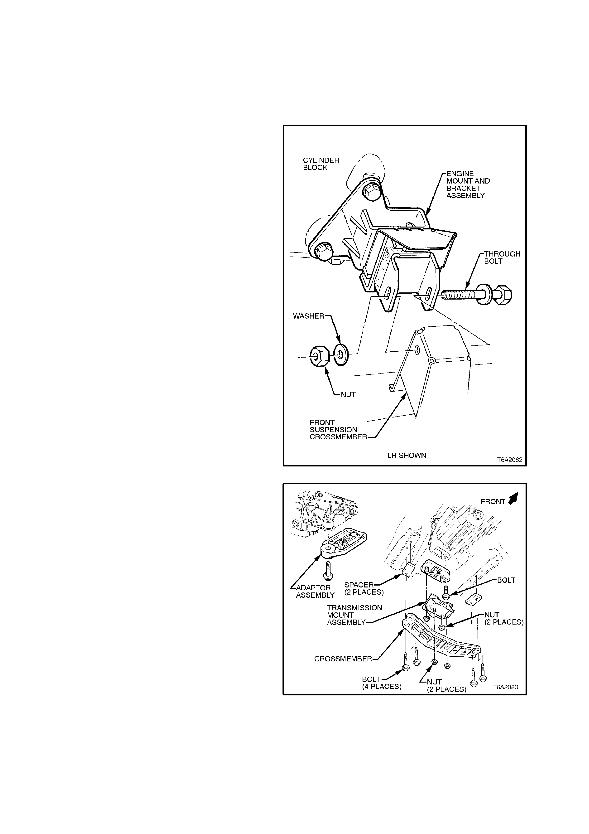
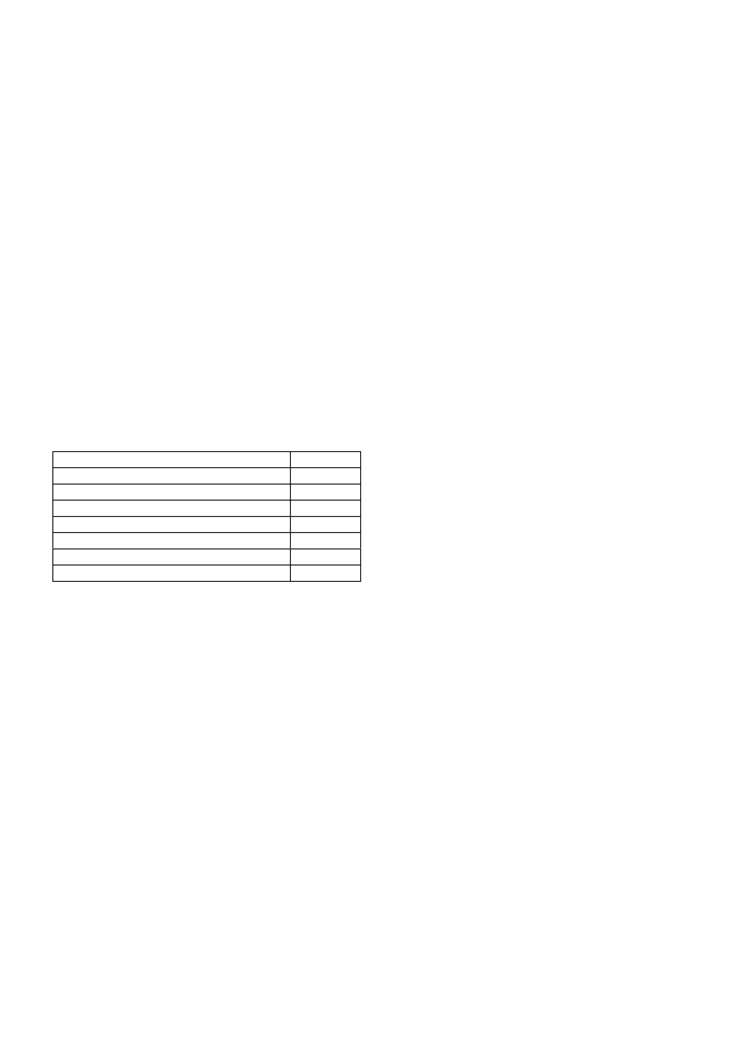
3. Remove engine mount to crossmember
through bolt.
4. Using a shortened ring spanner remove nuts
securing engine mount to engine bracket.
5. Remove engine mount.
6. Install new mount in reverse order of the
removal procedure and tighten nuts and bolts
to specified torque.
ENGINE MOUNT TO ENGINE
BRACKET NUTS 20 - 28 Nm
TORQUE SPECIFICATION
REMAINING ENGINE MOUNT
NUTS & BOLTS 34 - 46 Nm
TORQUE SPECIFICATION
Figure 6A2-80
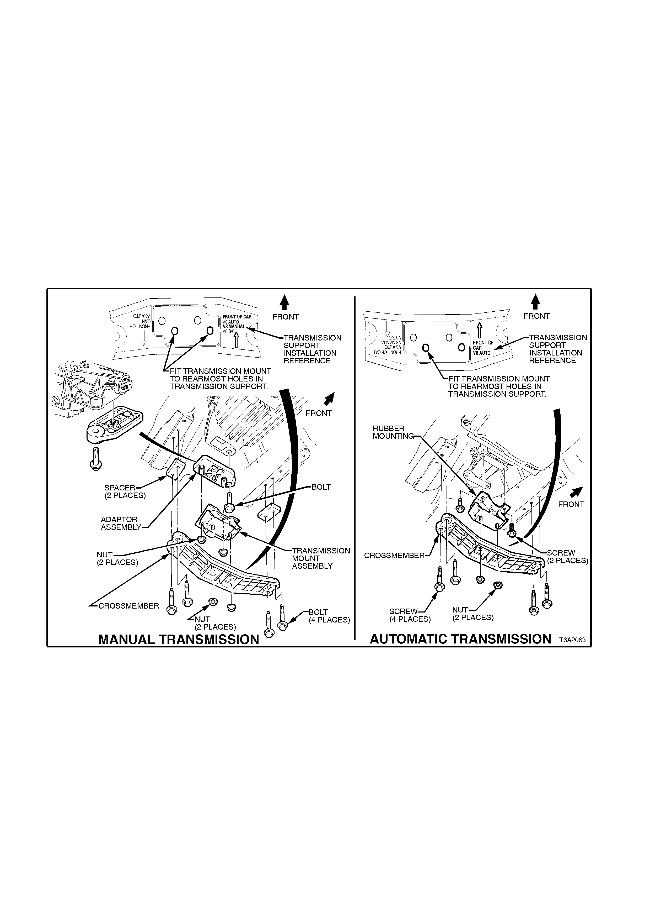
REAR MOUNT
REMOVE
1. Raise vehicle front and rear and place on
safety stands. For location of jacking points,
refer to Section 0A GENERAL
INFORMATION.
2. Support rear of transmission with a garage
jack.
NOTE:
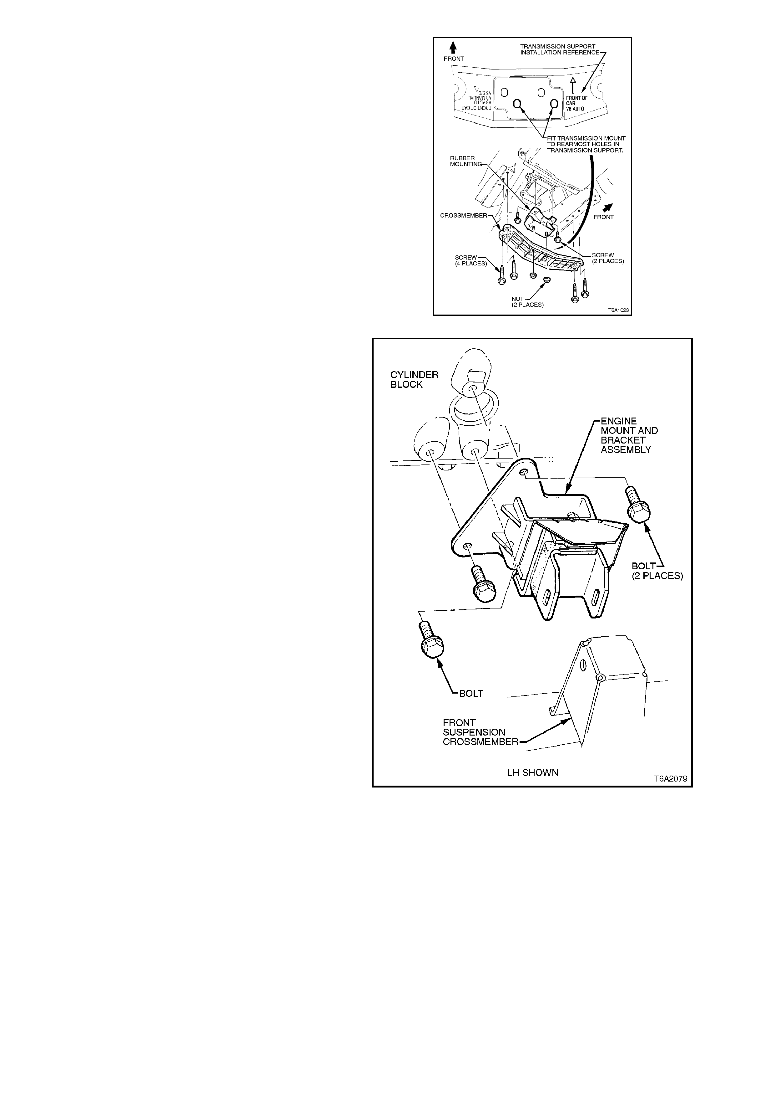
Use a block of wood between transmission and
jack.
3. Remove nuts and washers attaching rear
mount to crossmember.
4. Remove crossmember to frame bolts and
washers, remove crossmember.
5. Remove rear mount to transmission rear
extension attaching bolts and remove rear
mount.
Figure 6A2-81

REINSTALL
1. Reinstall rear mount and attaching bolts to
transmission rear extension. Tighten bolts to
correct torque specification.
REAR MOUNT TO REAR
EXTENSION ATTACHING BOLT
TORQUE SPECIFICATION 35 - 65 Nm
2. Install crossmember to side frame bolts and
washers. Tighten bolts to correct torque
specification.
CROSSMEMBER TO SIDE
FRAME BOLT
TORQUE SPECIFICATION 35 - 65 Nm
3. Lower garage jack supporting transmission
and tighten crossmember to rear mount
attaching nuts to correct torque specification.
4. Remove safety stands and lower vehicle to
ground.
2.13 DRIVE BELTS
TENSION ADJUSTMENT
NOTE 1:
Belt tensions are specified as 'strand tension', and
measured with a suitable gauge, such as BT3373-
F.
NOTE 2:
A belt is to be considered used after 10 minutes
running.
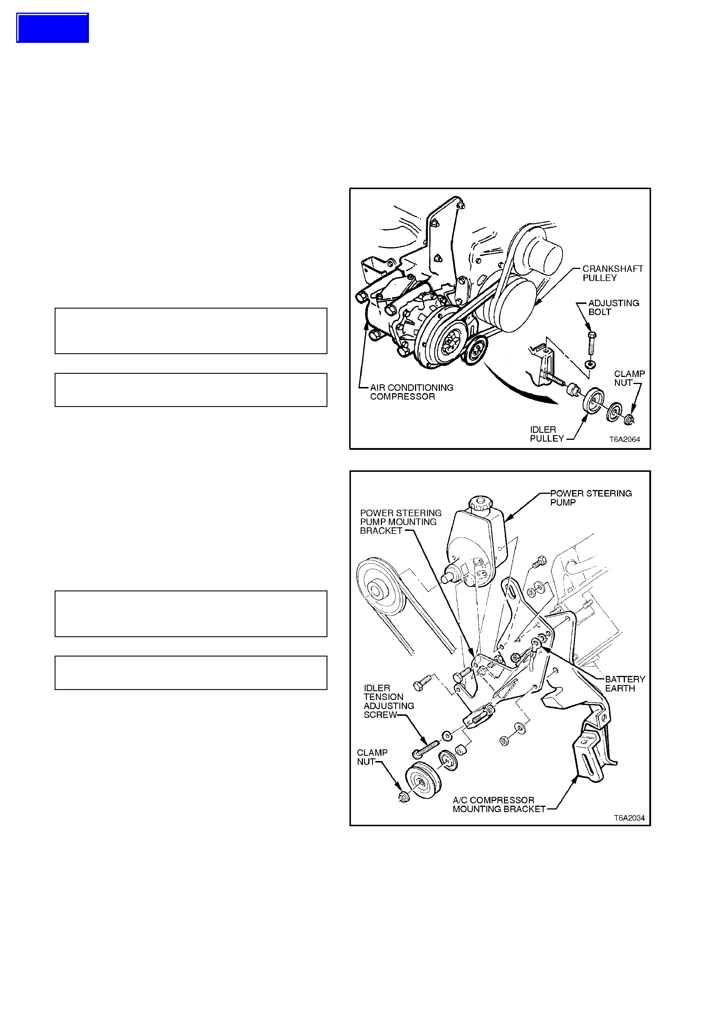
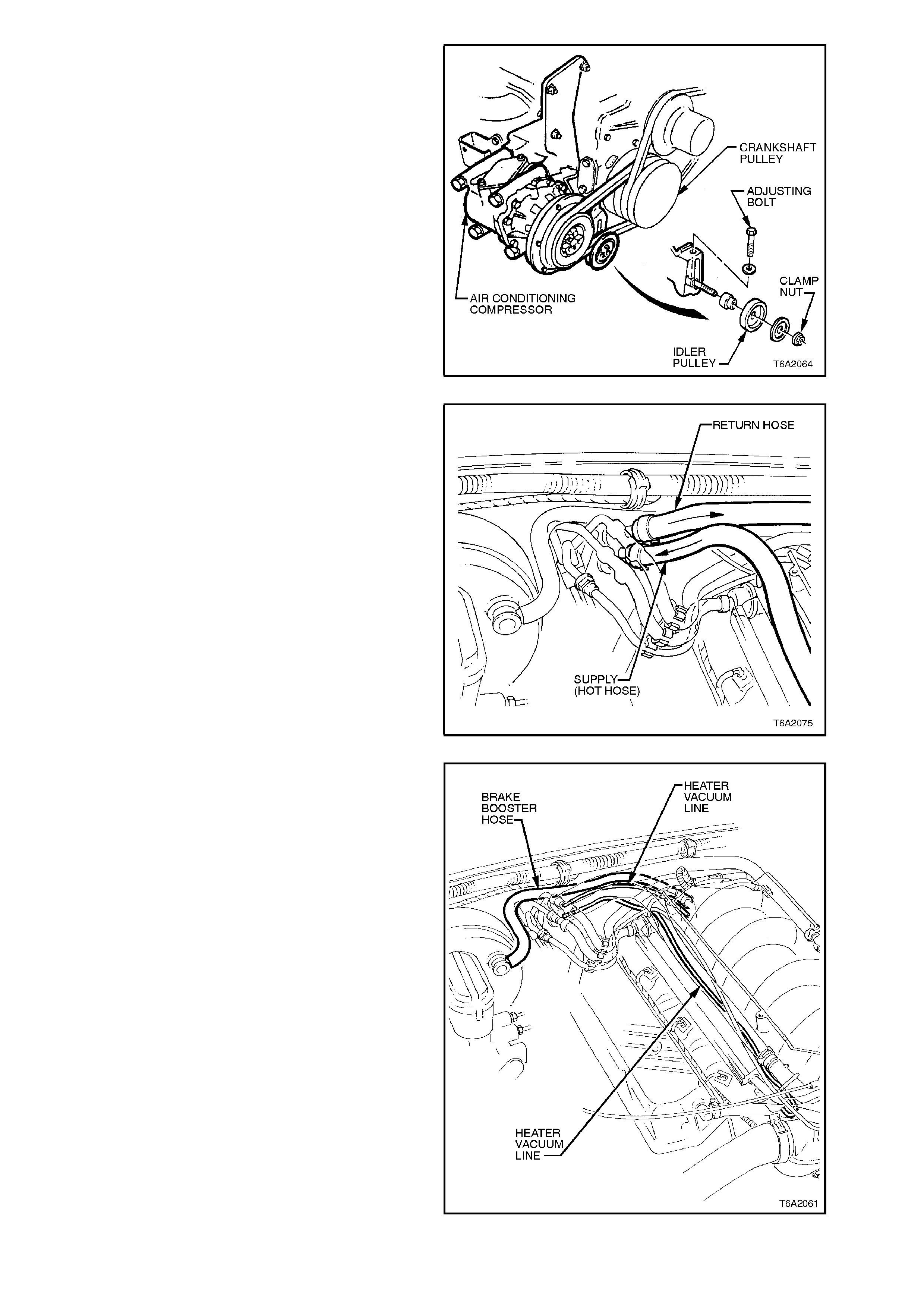
1. Loosen air conditioning compressor drive belt
idler pulley clamp nut.
2. Use the idler pulley adjusting bolt to achieve
specified belt tension, then tighten clamp nut
to specified torque. Belt tension can be
checked by using Tool No. BT3373-F, or
similar.
AIR CONDITIONER
COMPRESSOR BELT 64 kg New
TENSION SPECIFICATION 43 kg Used
IDLER PULLEY CLAMP NUT 35 - 65
TORQUE SPECIFICATION Nm
Figure 6A2-82
3. Loosen power steering pump drive belt idler
pulley clamp nut.
4. Use the idler pulley adjusting bolt to achieve
specified belt tension, then tighten clamp nut
to specified torque. Belt tension can be
checked by using Tool No. BT3373-F, or
similar.
POWE R STEERING
PUMP BELT 57 kg New
TENSION SPECIFICATION 34 kg Used
IDLER PULLEY CLAMP NUT 35 - 65
TORQUE SPECIFICATION Nm
Figure 6A2-83
Techline
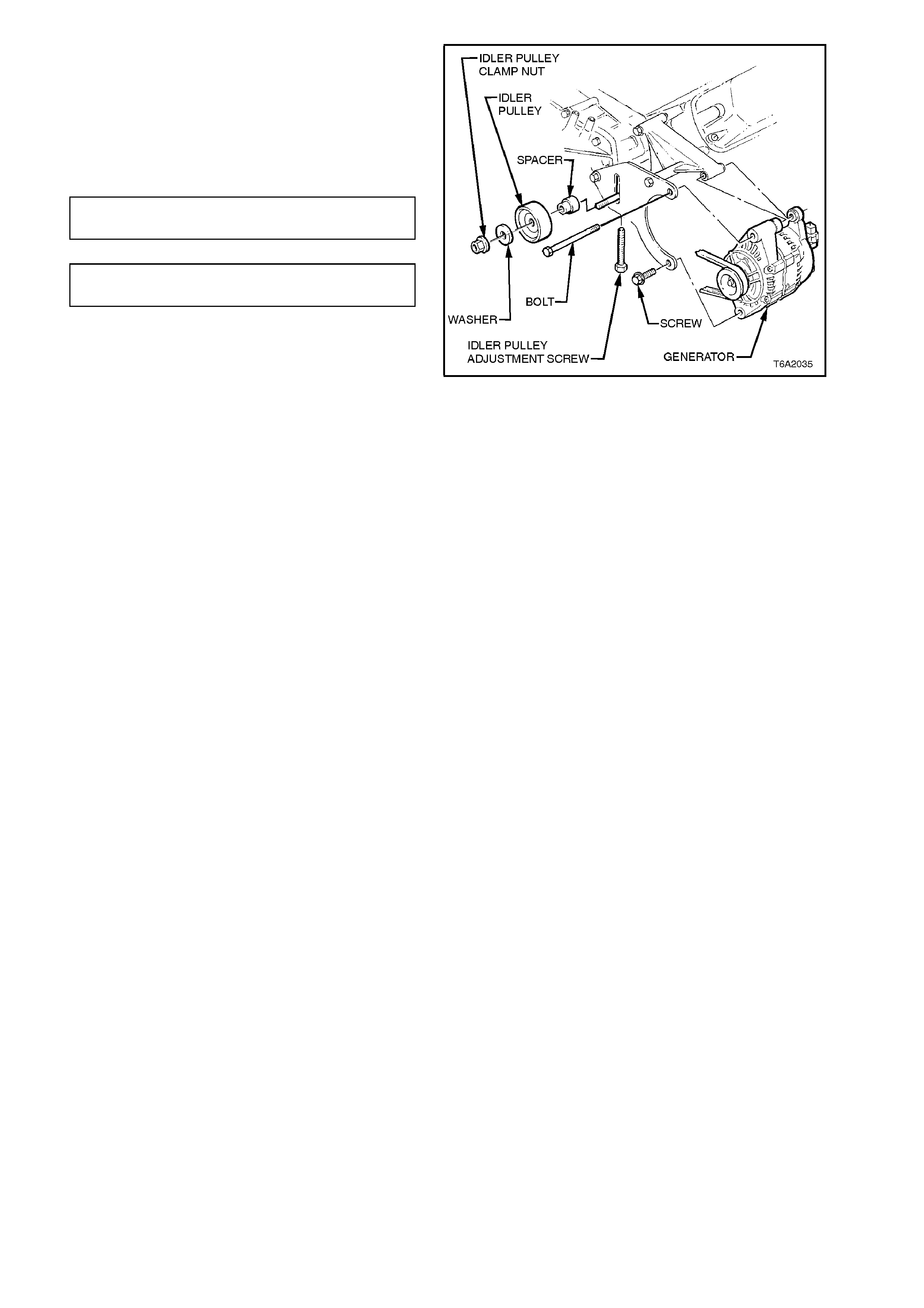
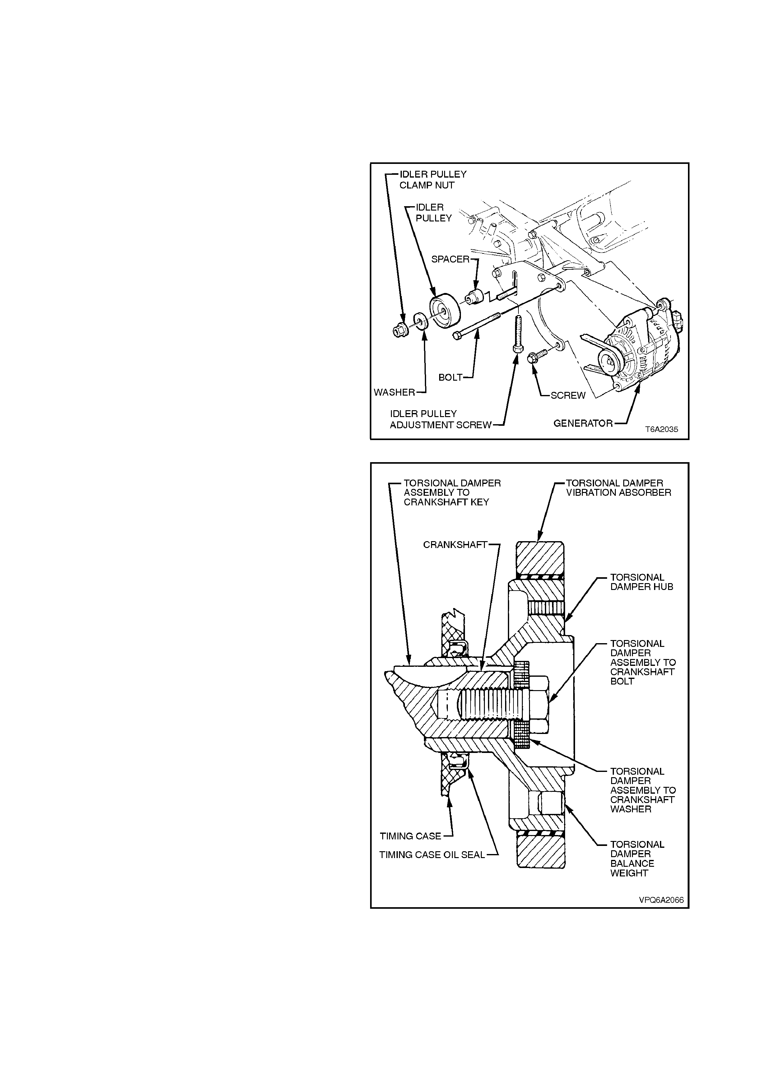
5. Loosen generator drive belt idler pulley clamp
nut.
6. Use the idler pulley adjusting bolt to achieve
specified belt tension, then tighten clamp nut
to specified torque. Belt tension can be
checked by using Tool No. BT3373-F, or
similar.
GENERATOR BELT 64 kg Ne w
TENSION SPECIFICATION 43 kg Used
IDLER PULLEY CLAMP NUT 35 - 65
TORQUE SPECIFICATION Nm
Figure 6A2-84
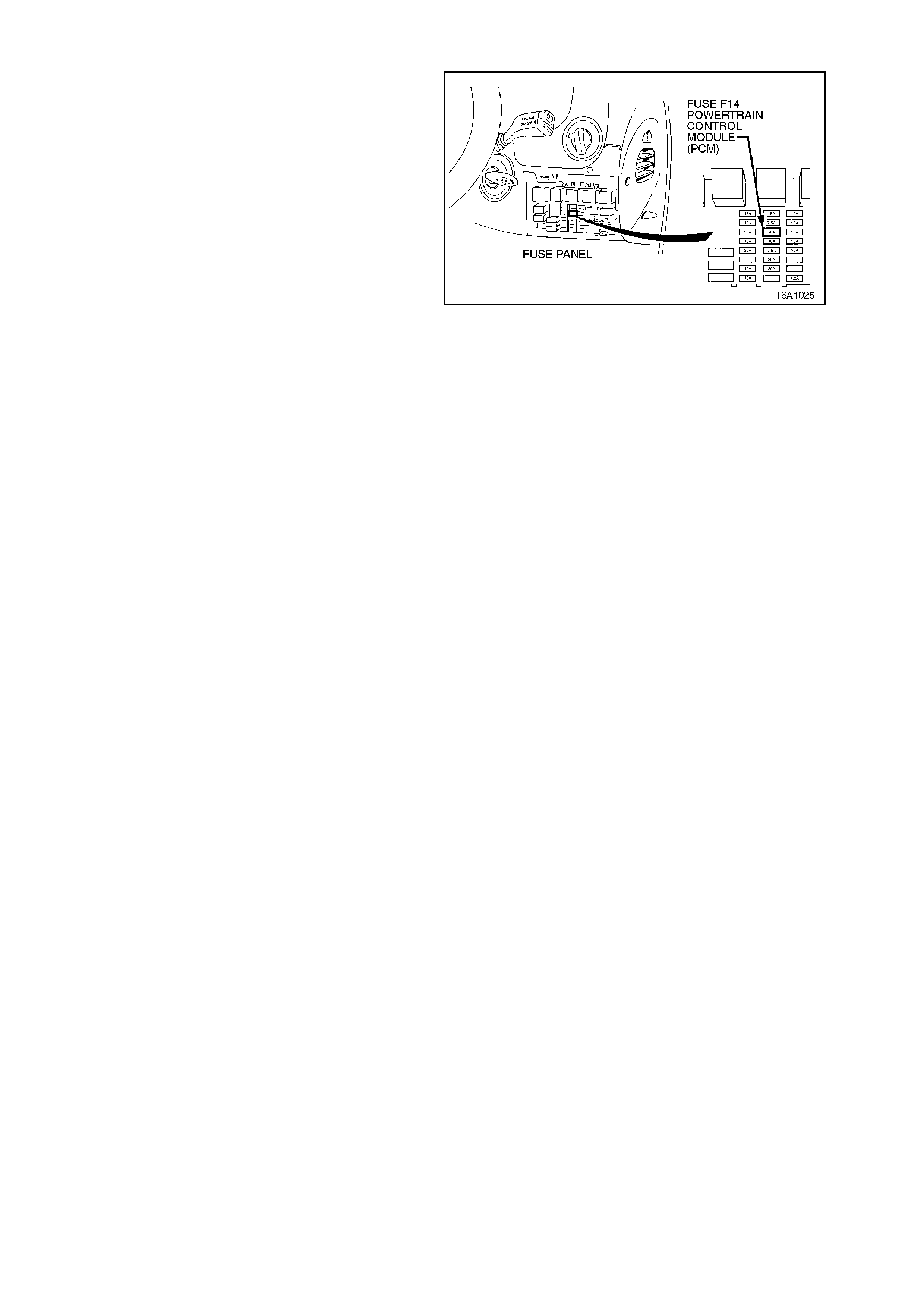
2.14 COMP RESSION CHECK
1. Before conducting this check, ensure that the
following conditions are met.
a. Engine is at operating temperature.
b. Battery is at or near to full charge.
c. All spark plugs are removed.
d. Fuse F14 is removed.
NOTE:
Removal of this fuse prevents both fuel injection
and ignition during crank ing operations. T his action
is necessary to prevent possible catalytic converter
damage.
e. Throttle fully opened.
f. Transmission is in the Neutral position
and the park brake is firmly applied.
2. Install a suitable compression tester.
3. Crank the engine and note the cylinder
pressure.
4. Repeat this process for the remaining
cylinders.
For satisfactory engine performance, the variation
between the highest and lowest cylinder
compression reading should be less than 138 kPa.
Figure 6A2-85
INTERPRETING COMPRESSION READINGS
Normal
Compression builds up quickly and evenly on
each cylinder.
Piston Rings; Faulty, Worn or Broken
Compression low on first stroke tending to
build up on subsequent strokes. Improves
considerably with the addition of oil into the
cylinder, via the spark plug hole.
Valves; Burnt or Incorrect Seating
Low on first stroke and does not tend to build
up on subsequent strokes. No significant
improvement occurs with the addition of oil to
the cylinder.
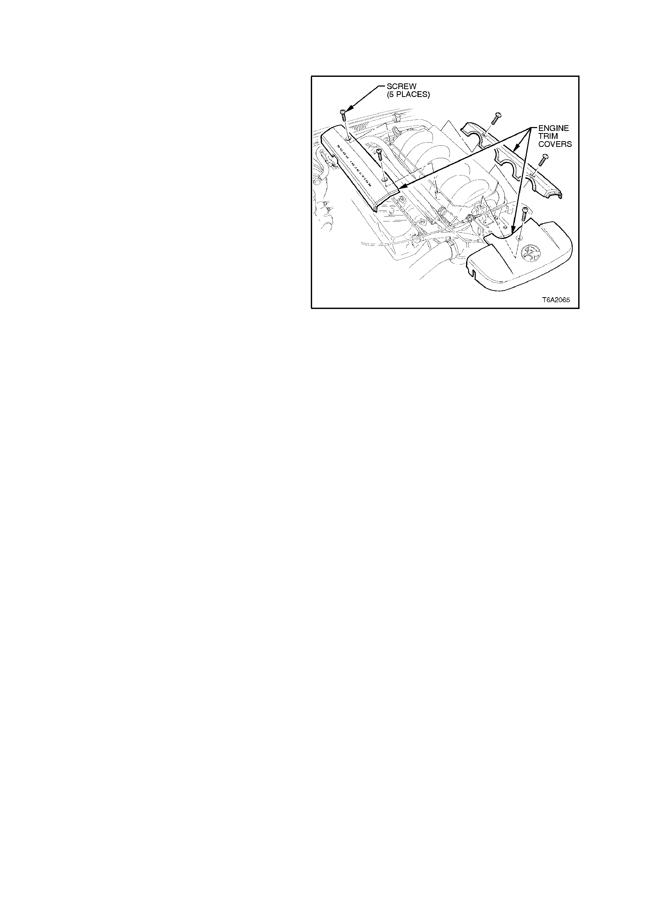
2.15 ENGINE TRIM COVERS
REMOVE
1. Remove the two screws securing the engine
trim covers to the inlet manifold, then remove
the trim covers.
2. Remove the screw securing the trim cover to
the throttle cable support bracket, then remove
the trim cover.
Figure 6A2-86
REINSTALL
Installation is the reverse of the removal procedure.
3. MAJOR SERVICE OPERATIONS
SAFETY AND CAUTIONARY NOTE FOR VEHICLES FITTED WITH ABS
Whenever any component that forms part of the ABS or ABS/ETC (if fitted), is
disturbed during Service Operations, it is vital that the complete ABS or ABS/ETC
system is checked, using the procedure as detailed in 4 DIAGNOSIS, ABS or
ABS/ETC FUNCTION CHECK, in Section 12L ABS & A BS/ETC.
3.1 ENGINE ASSEMBLY
REMOVE
1. Disconnect battery earth cable from battery.
2. Remove radiator cap to release any cooling
system pressure.
WARNING:
TO AVOID SERIOUS PERSONAL INJURY,
NEVER REMOVE THE RADIATOR CAP WHEN
THE ENGINE IS HOT. SUDDEN RELEASE OF
COOLING SYSTEM PRESSURE IS VERY
DANGEROUS AND COULD CAUSE PERSONAL
INJURY.
3. Place an oil drain tray beneath engine.
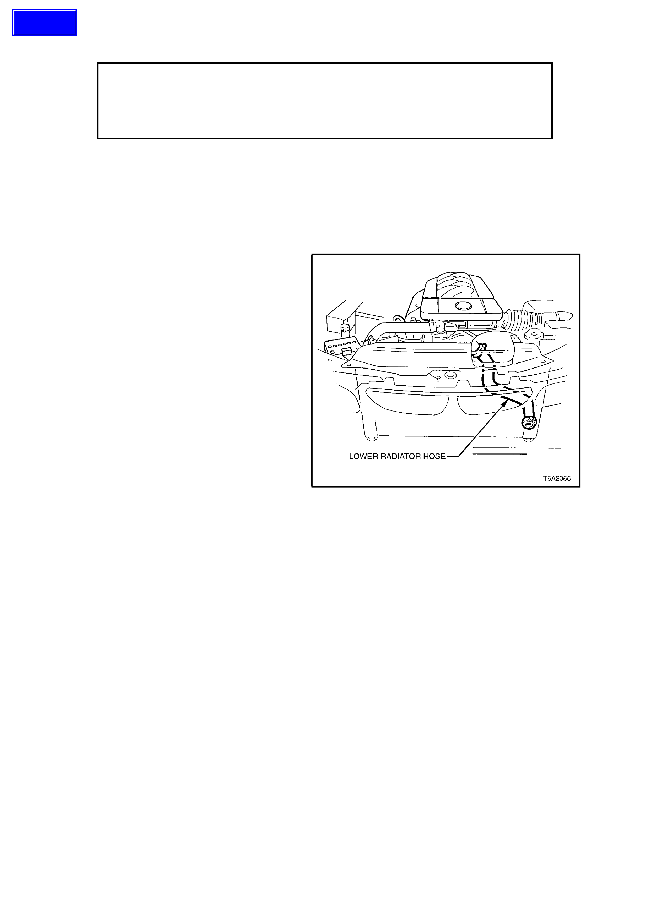
4. Loosen radiator lower hose clamp at radiator,
disconnect hose and allow coolant to drain.
Loosen hose clamps and disconnect radiator
hoses from engine.
Figure 6A2-87
5. Remove cooling fan and radiator assembly,
refer to Section 6B2 ENGINE COOLING -
V8 ENGINE.
6. Remove engine oil pan drain plug and allow
engine oil to drain.
Refit drain plug once oil has drained.
Techline
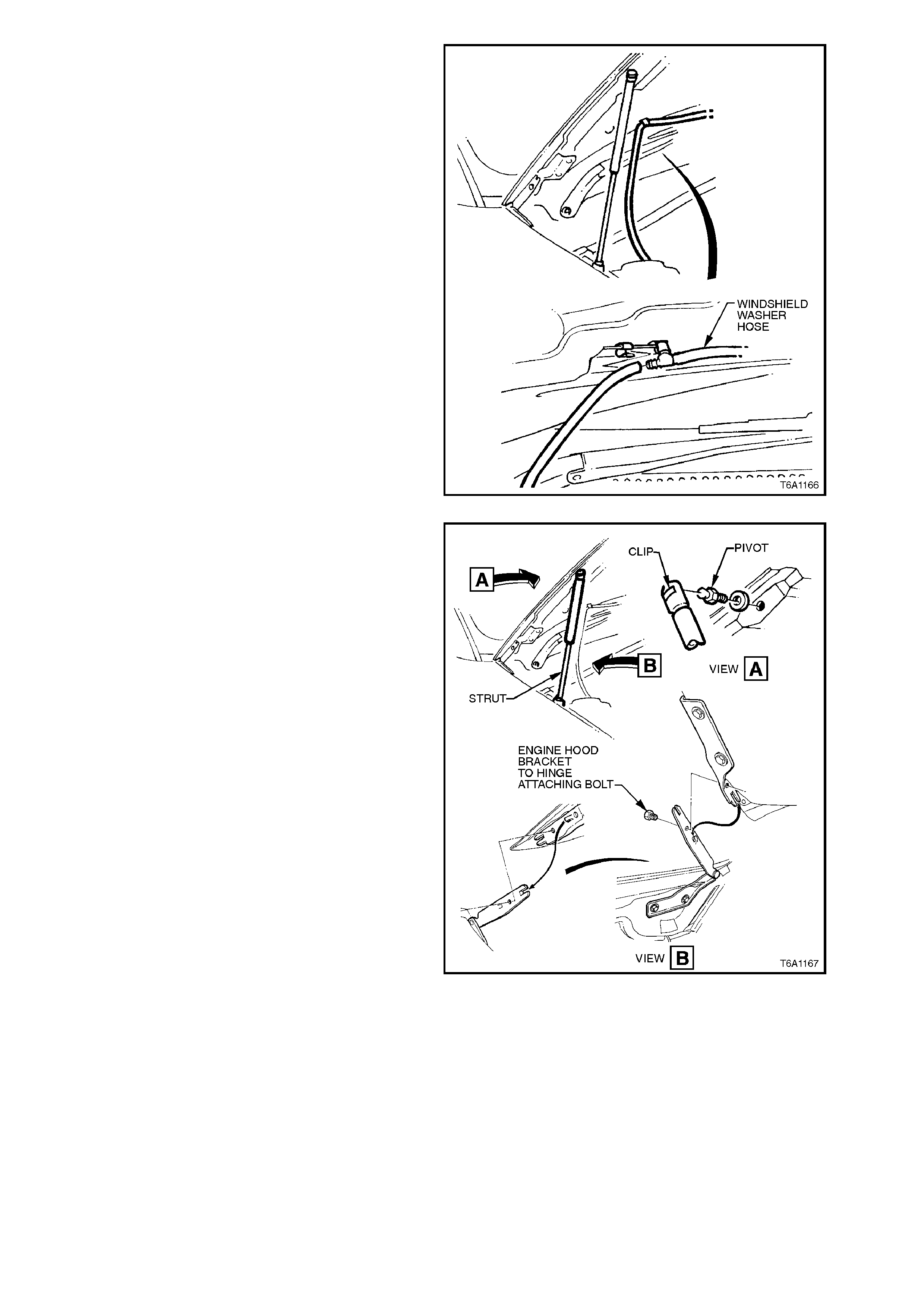
7. Disconnect windshield washer hose at the
inline connector located at the rear LH side of
hood.
Figure 6A2-88
8. With engine hood adequately supported,
remove clips securing upper end of struts to
hood pivots. Disengage struts from hood
pivots and lay strut down on fender inner
panel.
With the aid of an assistant hold hood
assembly, remove engine hood bracket to
hinge attaching bolt removing hood.
Figure 6A2-89
9. Remove engine trim covers, refer to
2.15 ENGINE TRIM COVERS in this Section.
10. Depressurise fuel lines, refer to
Section 6C2 POWERTRAIN MANAGEMENT
- V8 ENGINE.
11. Using quick connect release tool No. 7370
open tool and install over fuel line.
12. Close 7370 and pull into fuel line quick
connect to release it from fuel inlet line, pull
back on quick connect, disconnect fuel feed,
return and fuel evaporative canister hoses at
quick connects. Plug all openings to prevent
foreign matter entry.
NOTE:
Do not attempt to remove hoses from fuel rail
connections. Once removed from fuel rail
connection hoses require replacement.
Figure 6A2-90
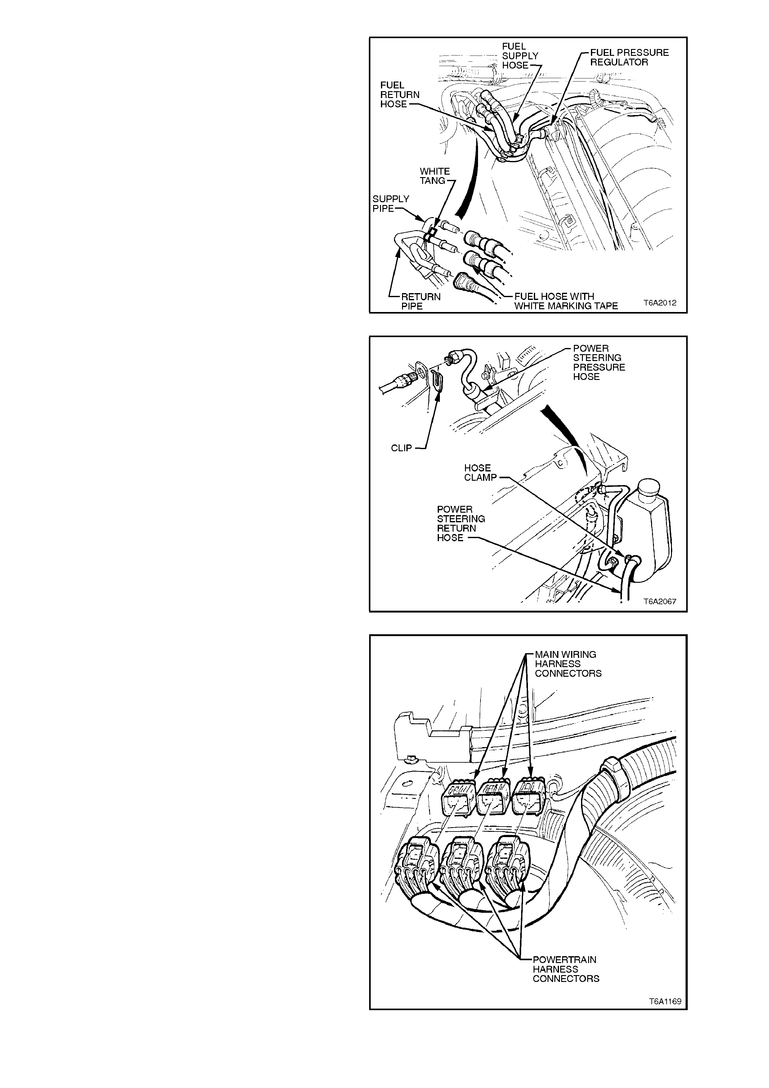
13. Disconnect power steering high pressure pipe
connection from front of power steering pump.
Loosen low pressure hose clamp at rear of
pump reservoir connection and disconnect
hose from reservoir refer to
Section 9A STEERING.
NOTE 1:
Ensure all hose connections are plugged.
Alternatively rem ove the power steer ing pum p drive
belt and the nuts secur ing the power steer ing pump
brack et assem bly, tie the power steering pum p and
bracket assembly clear of the engine.
NOTE 2:
Using the alternative method will necessitate the
installation of an engine lifting bracket to the front of
the engine.
Figure 6A2-91
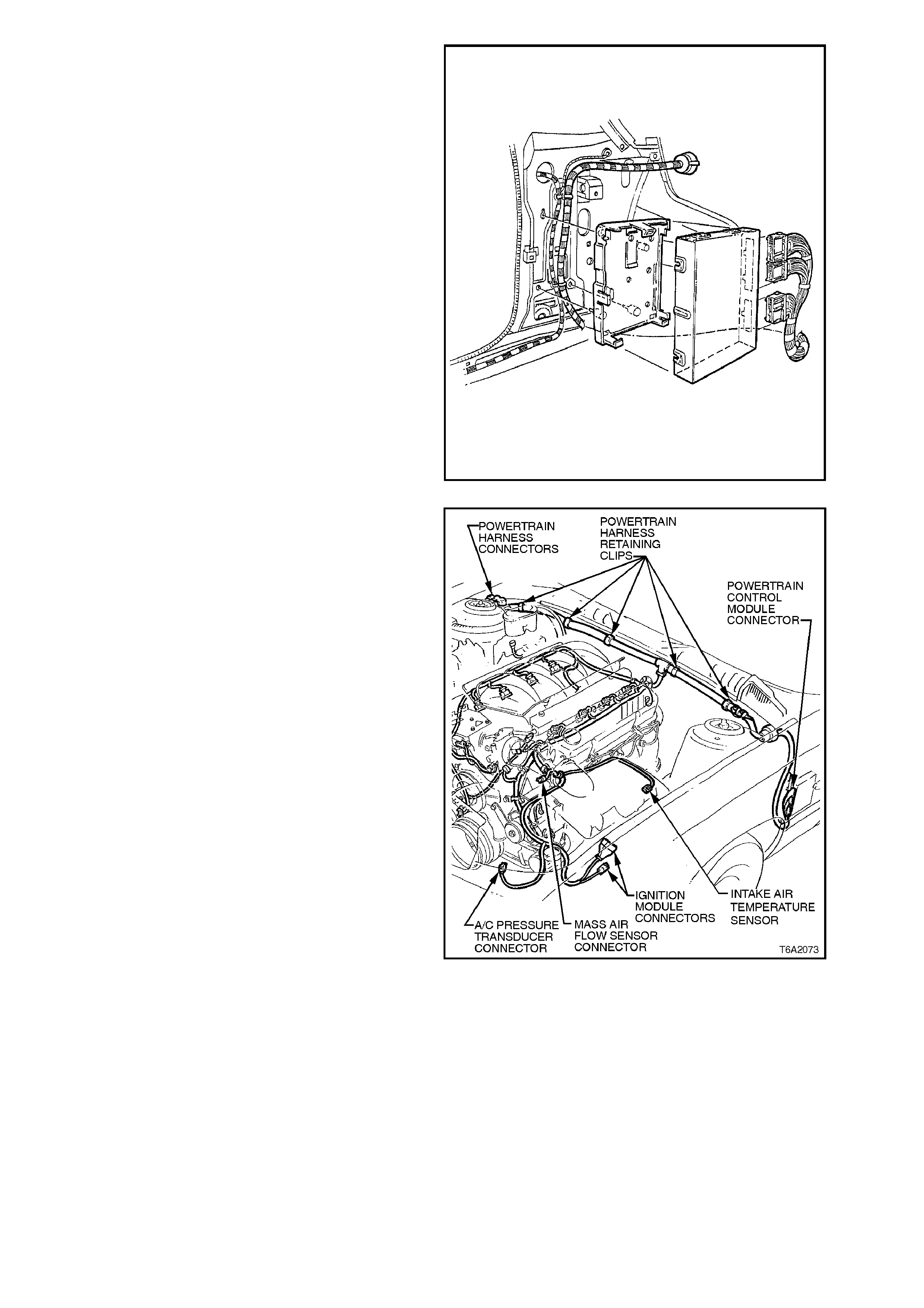
14. Disconnect main wiring harness to powertrain
and battery harness connectors at dash panel.
Figure 6A2-92
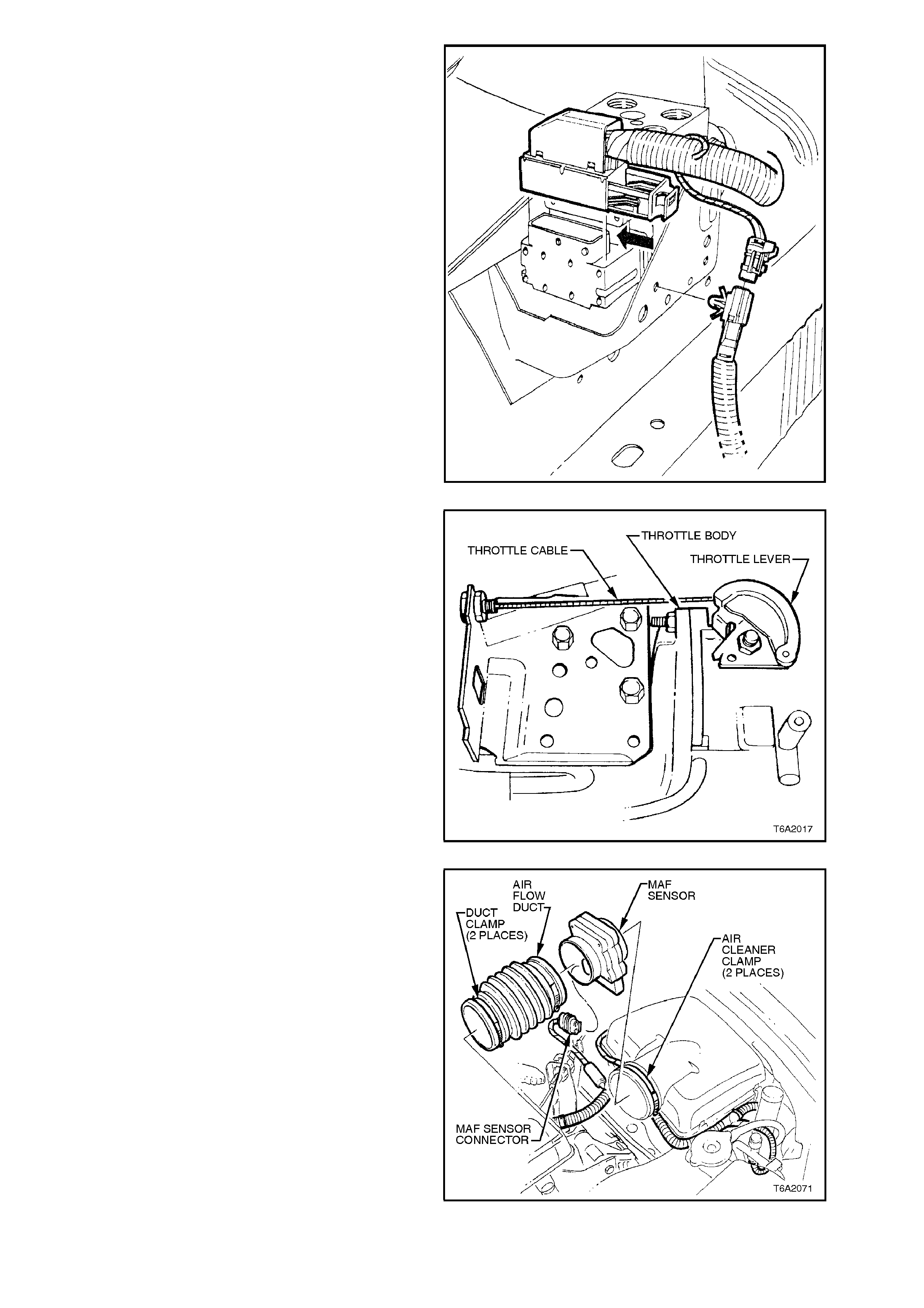
15. Remove wiring harness connector from ABS
modulator . Disconnec t power steering har ness
connector and remove clip from ABS
modulator bracket, and lay wiring harness
aside.
Figure 6A2-93
16. Remove throttle body and cruise control
cable, (where fitted) refer to
Section 6C2 POWERTRAIN MANAGEMENT
- V8 ENGINE.
Figure 6A2-94
17. Disconnect mass air flow sensor wiring,
loosen air flow duct rubber boot clamps at
throttle body and air cleaner, remove air flow
duct. Carefully place air flow duct and mas s air
flow sensor assembly to one side.
Figure 6A2-95
18. From inside vehicle, remove left hand cowl
panel trim, glove box assembly and taking
care to remove the screw beneath the rocker
panel cover, the lower left hand side trim
assembly, refer to Section 1A1 BODY.
19. Disconnect engine wiring harness
connectors from PCM. Refer to
Section 6C2 POWERTRAIN MANAGEMENT
- V8 ENGINE. Compress lugs on engine
harness plug at dash panel and push engine
harness and connectors out into engine
compartment.
Figure 6A2-96
20. From engine compartment release powertrain
harness to dash panel retaining clips,
disconnect intake air temperature sensor,
ignition module, idle air control motor
connectors at air cleaner and air conditioning
pressure transducer connector at air
conditioning condenser (where fitted), lay
wiring harness on top of engine.
Figure 6A2-97
21. Where fitted disconnect air conditioning
electrical connector from air conditioning
compressor, unbolt air conditioning
com press or from the brac k et assem bly, move
to one side without disconnecting hoses, refer
to Section 2B AIR CONDITIONING -
REMOVAL AND INSTALLATION.
NOTE:
When the alternative m ethod is used in step 13 the
air conditioning compressor and bracket assembly
(where fitted) can also be rem oved and tied c lear of
the engine.
Figure 6A2-98
22. Tag and disconnect heater supply and return
hoses from dash panel.
Figure 6A2-99
23. Disconnect the brake booster vacuum hose
from brake booster.
24. Disconnect heater control vacuum line from
union at side of inlet manifold and at heater
water tap.
25. Raise vehicle and place on safety stands.
Figure 6A2-100
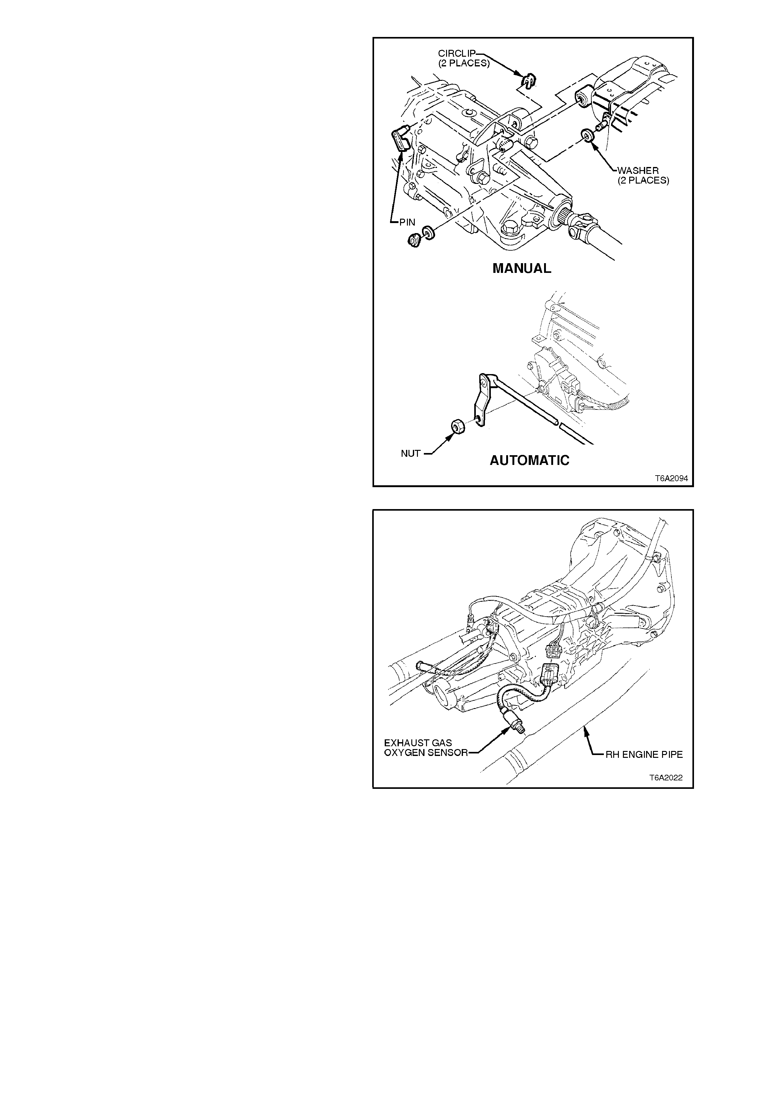
26. Disconnect control linkage from automatic or
manual transmission.
Figure 6A2-101
27. Disconnect the oxygen sensor wiring harness
connectors. Disconnect the exhaust pipes
from exhaust manifolds.
Figure 6A1-1-102
28. On vehicles with manual transmission,
disconnect the hydraulic line to the clutch
actuating cylinder, refer to
Section 7A CLUTCH.
29. Remove propeller shaft as described in
Section 4C PROPELLER SHAFT &
UNIVERSAL JOINTS.
30. Support engine with overhead lifting device
and raise slightly to take weight off engine
mounts.
NOTE:
Due to the routing of the spark plug leads to
cylinders 2, 4, 6 and 8, there is a c hance that these
leads may become damaged when lifting the
engine with an overhead lifting device. Therefore,
to prevent damage to these leads occurring during
this procedure, temporarily reposition spark plug
leads behind the rear engine lifting hook.
31. Remove engine front mount to crossmember
through bolts.
Figure 6A2-103
Vehicles fitted with manual transmission:
32. Remove engine rear power plant support to
frame bolts and washers. Remove support to
mount attaching nuts and remove support.
Figure 6A1-1-104
Vehicles fitted with automatic transmission:
33. Remove engine rear crossmember to frame
bolts and washers. Remove crossmember to
rear mounting attaching nuts and remove
crossmember.
Figure 6A1-1-105
34. Remove bolts securing left hand side engine
mount to crankcase and remove mount.
35. Raise front of engine until top of transmission
case almost contacts the floor pan.
36. Tilt the right hand side of engine upward, until
the right hand side engine mount clears
crossmember.
37. Move engine forward until engine mounts are
clear.
38. Raise engine with front tilted upwards and lift
engine and transmission out of vehicle.
CAUTION:
With air conditioned vehicles, do not allow
engine to swing forward and damage air
conditioning condenser or pipes.
Figure 6A2-106
DISASSEMBLE
1. Remove transmission (and clutch, if fitted)
referring to
Sections 7A CLUTCH, or
Section 7B1 M ANUAL TRANSMISSION - V6
ENGINE or
Section 7B2 M ANUAL TRANSMISSION - V8
ENGINE or
Section 7C4 AUTO TRANS. - ON-VEHICLE
SERVICING as appropriate.
2. Mount engine on a suitable engine stand.

3. Remove the following items as described in
the relevant Operation or Section.
-Generator and brackets, refer to
Section 6D2-1 CHARGING SYSTEM - V8
ENGINE.
-Starter motor, refer to Section 6D2-2
STARTING SYSTEM - V8 ENGINE.
-Water pump, refer to Section 6B2
ENGINE COOLING - V8 ENGINE.
-Oil pump assembly, refer to
2.11 OIL PUMP in this Section.
-Distributor, spark plugs and spark plug
leads, refer to Section 6D2-3 IGNITION
SYSTEM - V8 ENGINE.
-Inlet manifold, refer to
2.1 INLET MANIFOLD in this Section.
-Exhaust manifolds, refer to
2.2 EXHAUST MANIFOLD in this Section.
-Rocker arms, rocker arm pivots and push
rods, refer to 2.3 ROCKER ARMS in this
Section.
-Hydraulic valve lifters, refer to
2.7 HYDRAULIC VALVE LIFTERS in this
Section.
-Cylinder heads, refer to
2.6 CYLINDER HEADS in this Section.
-Oil pan, refer to 3.2 OIL PAN in this
Section.
-Oil pump suct ion pipe and screen, ref er to
3.7 OIL PUMP SUCTION PIPE AND
SCREEN in this Section.
- Crankcase front cover, refer to
- 3.3 CRANKCASE FRONT COVER in this
Section.
-Cams haft, refer to 3.6 CAMSHAFT in this
Section.
-Piston and connecting rod assemblies,
refer to 3.12 PISTON AND CONNECTING
ROD ASSEMBLY in this Section.
-Crankshaft, refer to 3.14 CRANKSHAFT
in this Section.
4. Discard all gaskets and seals.
5. For inspection procedures, refer to service
operations for each component as previously
listed.
REASSEMBLE
Reassembly is the reverse of the disassembly
procedure.
CAUTION:
Carefully follow the reinstallation procedure for
each component as outlined in the relevant
Operation. The relevant Operation or Section
for each component is referred to in the
disassembly procedure.
NOTE:
The rear m ain oil seal r eplacem ent is described in
3.9 REAR MAIN BEARING OIL SEAL in this
Section.
REINSTALL
Installation is the reverse of the r emoval proc edur e,
except for the following:
1. Apply anti-seize compound, such as Kopr-
Kote or equivalent (Holden Specification HN
1325), to the exhaust manifold stud threads
before reinstalling exhaust pipes.
2. Adjust drive belt tensions, refer to
2.13 DRIVE BELTS in this Section.
3. Tighten all fasteners to specified torque’s, as
listed.
OIL PAN DRAIN PLUG 30 - 60 Nm
REAR CROSSMEMBER BOLTS 35 - 65 Nm
ENGINE REAR MOUNT/CROSSMEMBER BOLT 20 - 45 Nm
EXHAUST PIPE TO MANIFOLD NUTS 15 - 35 Nm
CONTROL LINKAGE TO AUTO. TRANS 11 - 15 Nm
ENGINE FRONT MOUNT THROUGH BOLT 34 - 46 Nm
POWER STEERING PUMP BRACKET NUT 15 - 20 Nm
ENGINE HOOD HINGE BOLT 18 - 24 Nm
4. Use specified lubricant and coolant when
refilling lubrication and cooling systems.
5. Check transmission fluid level.
6. Install engine hood, checking alignment.
3.2 OIL PAN
REMOVE
1. Remove front crossmember, refer to
Section 3 FRONT SUSPENSION.
2. Drain contents of oil pan, then replace and
tighten drain plug.
3. Support engine on safety stands at engine
mounts.
4. Remove starter motor, refer to
Section 6D2-2 STARTING SYSTEM - V8
ENGINE. This is necessary to access oil pan
bolts if a special, thin socket spanner is not
available.
5. Rem ove oil pan attaching bolts and rem ove oil
pan.
Figure 6A2-107
REINSTALL
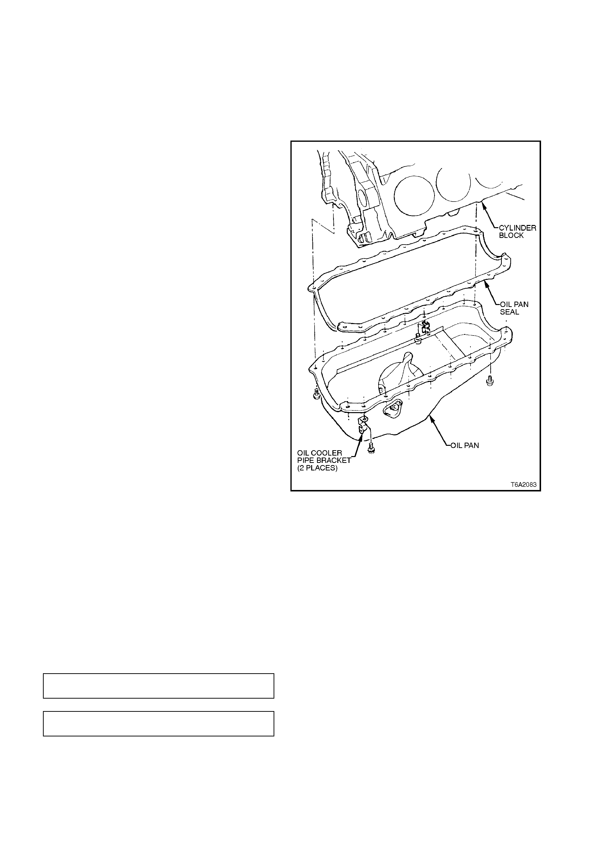
1. Remove old seal and thoroughly clean mating
surfaces of oil pan and cylinder block.
2. Apply a 1 - 2 m m bead of s ealant, s uch as 3M
EC776 or equivalent (Holden Specification
HN 2054), to the cylinder block to front cover
interface. Refer to Fig. 6A2-107 for specific
details.
3. Install seal taking care to align bolt holes
correctly.
4. Reinstall oil pan and tighten bolts to specified
torque.
OIL PAN DRAIN PLUG
TORQUE SPECIFICATION 30 - 60
Nm
OIL PAN BOLTS
TORQUE SPECIFICATION 8 - 10
Nm
5. Reinstall starter motor, refer to Section 6D2-
2 STARTING SYSTEM - V8 ENGINE.
6. Reinstall engine assembly, refer to
3.1 ENGINE ASSEMBLY in this Section.
7. Refill the engine to correct level with
specified engine oil. Refer to
Section 0B LUBRICATION & SERVICE.
3.3 CRANKCASE FRONT COV ER
REMOVE
1. Drain cooling system, refer to Section 6B2
ENGINE COOLING - V8 ENGINE.
2. Remove engine cooling fan and pulley, refer to
Section 6B2 ENGINE COOLING - V8
ENGINE.
3. Remove all drive belts fitted to crankshaft
drive belt pulley, refer to Section
2.13 DRIVE BELTS in this Section.
4. Disconnect and remove generator, refer to
Section 6D2-1 CHARGING SYSTEM - V8
ENGINE.
5. Remove generator brackets.
Figure 6A2-108
6. Remove torsional damper assembly to
crankshaft bolt and washer, then remove
torsional damper assembly.
Figure 6A2-109
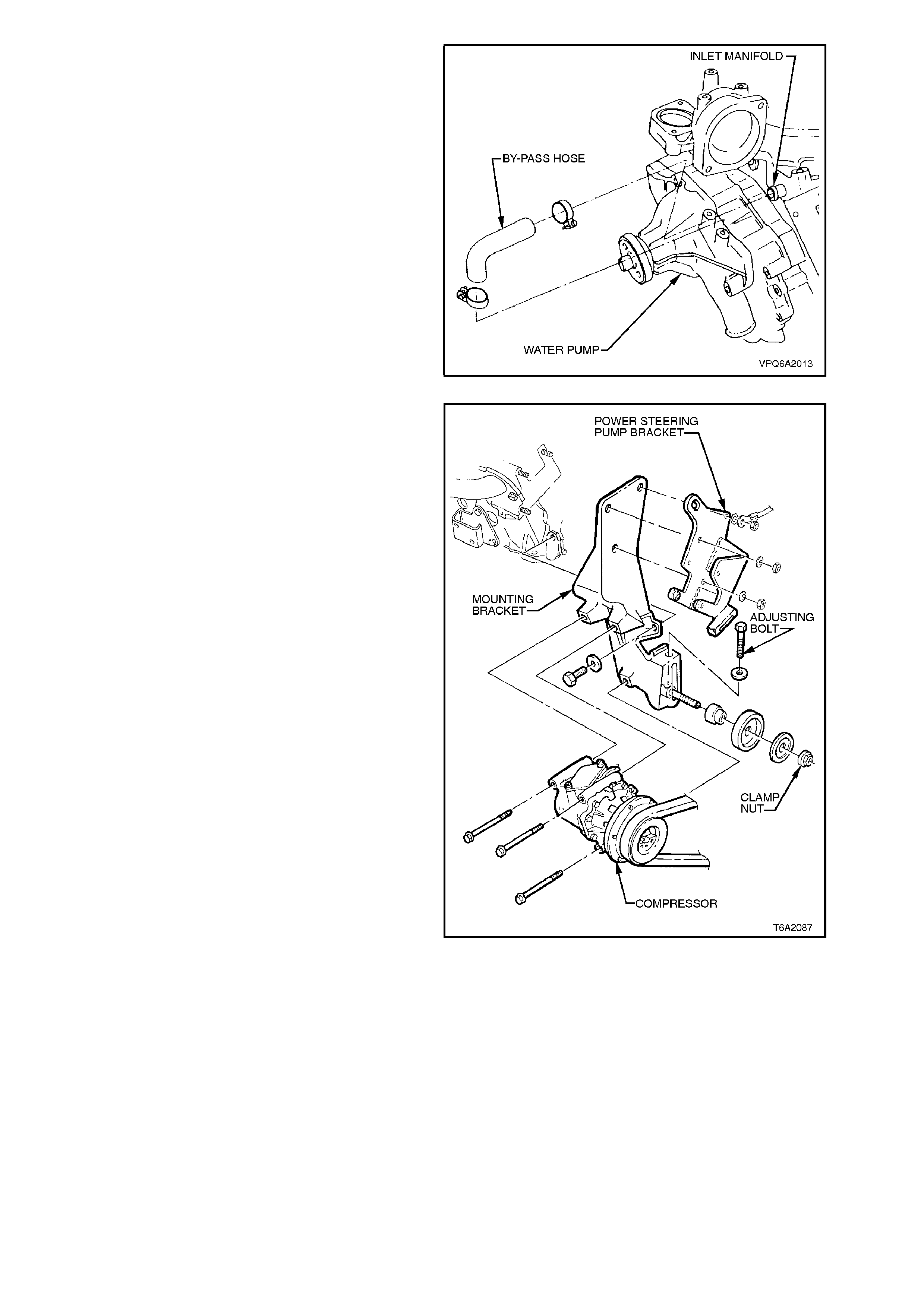
7. Disconnect heater hos e and bypass hose from
water pump.
Figure 6A2-110
8. Remove the three nuts and bolt securing air
conditioning compressor bracket and power
steering assembly and move to one side
without disconnecting hoses, refer to
Section 2B AIR CONDITIONING - REMOVAL
AND INSTALLATION.
9. Remove oil pan, refer to 3.2 OIL PAN in this
Section.
10. Remove crankcase front cover attaching bolts.
NOTE:
Engine harness brack ets are also s ecured by these
bolts.
11. Remove front cover and water pump
assembly.
Figure 6A2-111
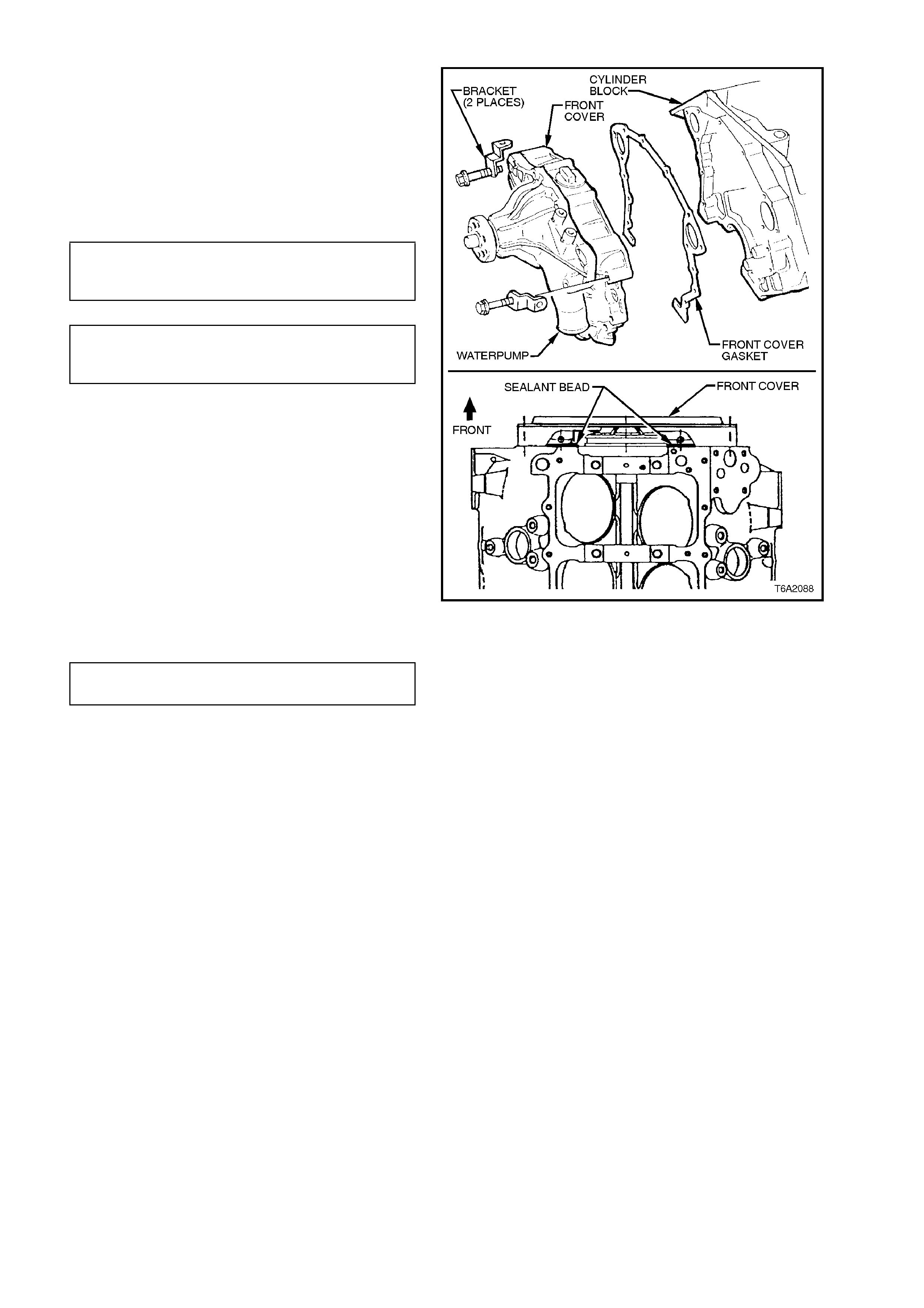
REINSTALL
1. Thoroughly clean mating surfaces on cylinder
block and front cover.
2. Install front cover gasket on cylinder block.
Lubricate seal lip with engine oil.
3. Reinstall front cover and water pump
assembly, engine harness brackets and
generator brace. Tighten all bolts to specified
torque.
CRANKCASE FRONT
COVER BOLTS 23 - 30 Nm
TORQUE SPECIFICATION
GENERATOR BRACE BOLT
TO FR ONT COVER 17 - 24 Nm
TORQUE SPECIFICATION
4. Apply a 1 - 2 m m bead of sealant, such as 3M
E776 or equivalent (to Holden Specification
HN2054) to the front cover to engine block
interface as shown in Fig. 6A2-112.
5. Reinstall oil pan, refer to 3.2 OIL PAN in this
Section.
6. Lubricate torsional damper hub bore with
hypoid lubricant and lubric ate seal s ur f ac e with
engine oil.
7. Align keyway in damper with key on
crankshaft. reinstall torsional damper and
tighten bolt to specified torque.
TORSIONAL DAMPER BOLT 190 Nm
TORQUE SPECIFICATION minimum
8. Reinstall engine water pump pulley, refer to
Section 6B2 ENGINE COOLING - V8
ENGINE.
9. Reinstall and adjust all drive belts, refer to
2.13 DRIVE BELTS in this Section.
10. Reins tall generator m ounting br ack ets, ref er to
Section 6D2-1 CHARGING SYSTEM - V8
ENGINE.
11. Reinstall and reconnect generator, refer to
Section 6D2-1 CHARGING SYSTEM - V8
ENGINE.
12. Reconnect coolant and heater hoses to water
pump.
13. Refill engine cooling system with specified
coolant, refer to Section 6B2 ENGINE
COOLING - V8 ENGINE.
Figure 6A2-112
3.4 TIMING CHAIN AND SPROCKETS
REMOVE
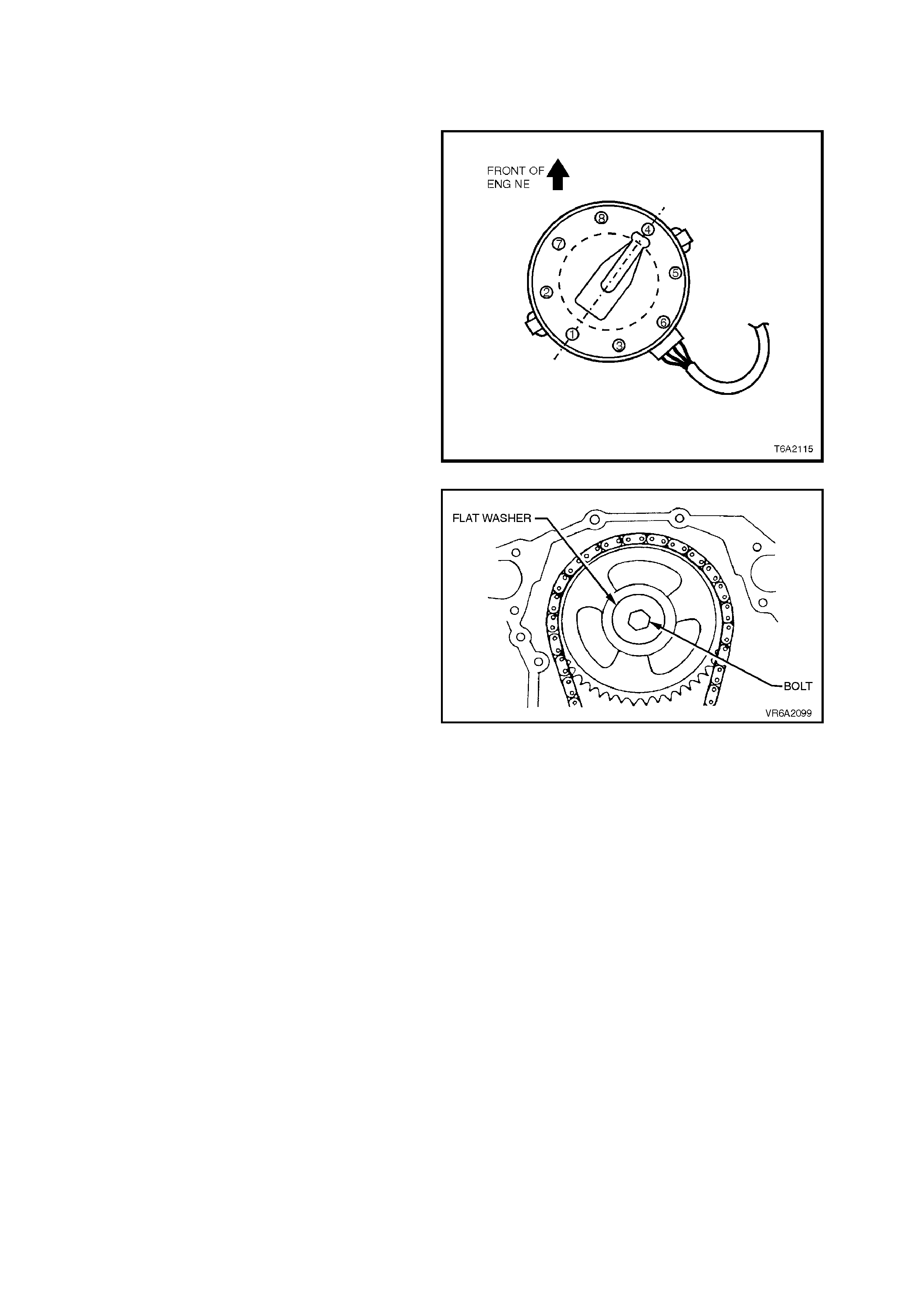
1. Rotate the crankshaft by hand until the
distributor rotor is in the number 4 cylinder
position (i.e. number 4 piston is at the top of its
compression stroke with both valves closed,
valves for number 1 cylinder ‘rocking’).
2. Remove crankcase front cover, refer to
3.3 CRANKCASE FRONT COVER in this
Section.
NOTE:
Ensure crankshaft does not move during this
operation.
Figure 6A2-113
3. Remove bolt securing flat washer and
camshaft sprocket to camshaft.
4. Withdraw sprockets and timing chain. The
crankshaft sprocket is a push fit on the
crankshaft.
NOTE:
Do not rotate the crankshaft after removing the
timing chain and sprockets.
Figure 6A2-114
REINSTALL
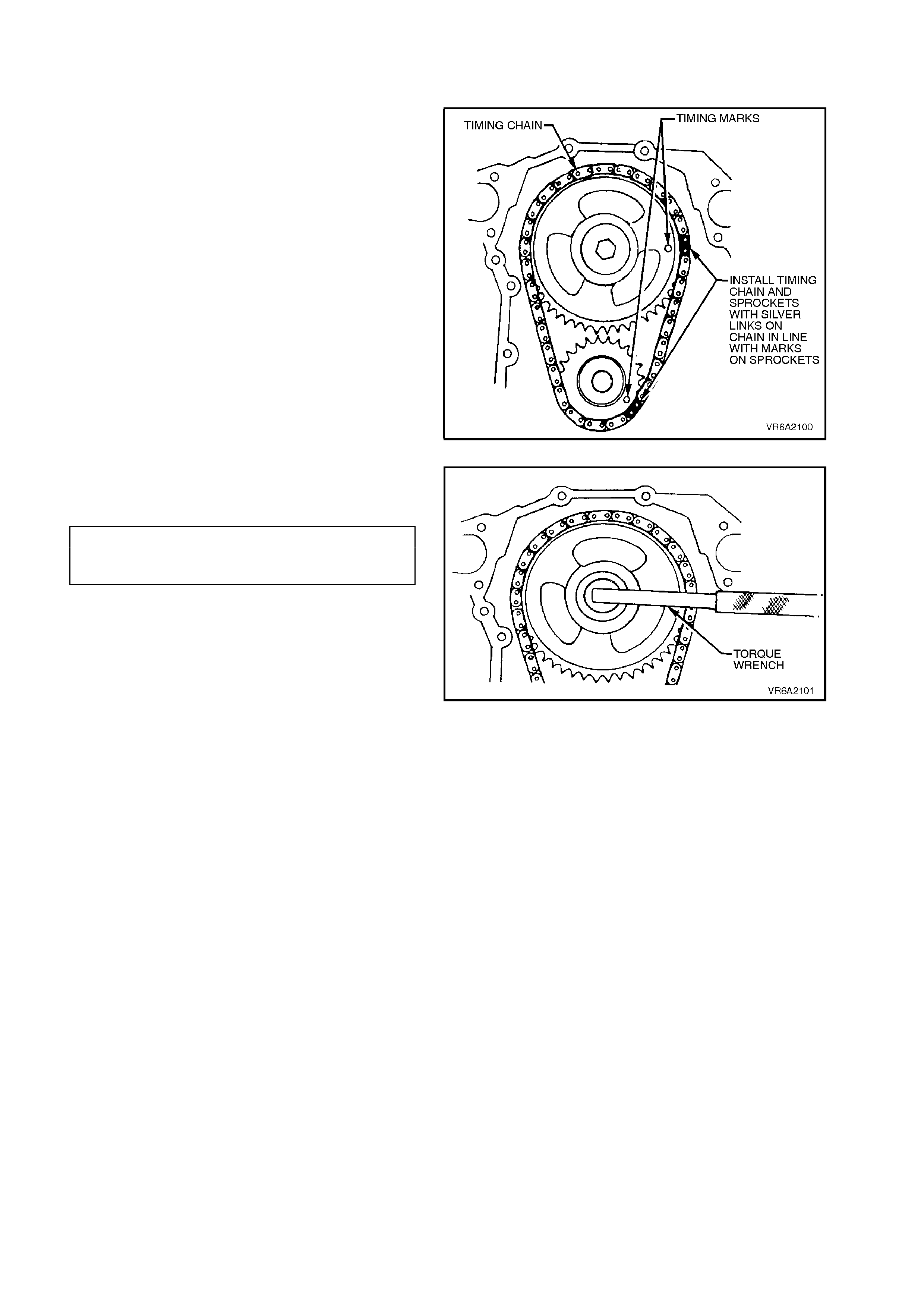
1. Check that the number 4 cylinder is at T.D.C.
and both valves are closed.
2. Align dots on sprockets with silver links on
chain and reinstall sprockets and chain. Align
keyway in crankshaft sprocket with key on
crankshaft.
Figure 6A2-115
3. Reinstall flat washer and camshaft sprocket
retaining bolt. Tighten bolt to specified torque.
CAMSHAFT SPROCKET
RETAINING BOLT 61 - 74 Nm
TORQUE SPECIFICATION
4. Lubricate timing chain with engine oil.
5. Reinstall crankcase front cover, refer to
3.3 CRANKCASE FRONT COVER in this
Section.
Figure 6A2-116
3.5 TIMING CHAIN LUBRICATION NOZZLE
REMOVE
1. Remove crankcase front cover, refer to
3.3 CRANKCASE FRONT COVER, in this
Section.
2. Using a pair of combination pliers or similar,
grasp the nozzle and pull with a twisting
motion.
REINSTALL
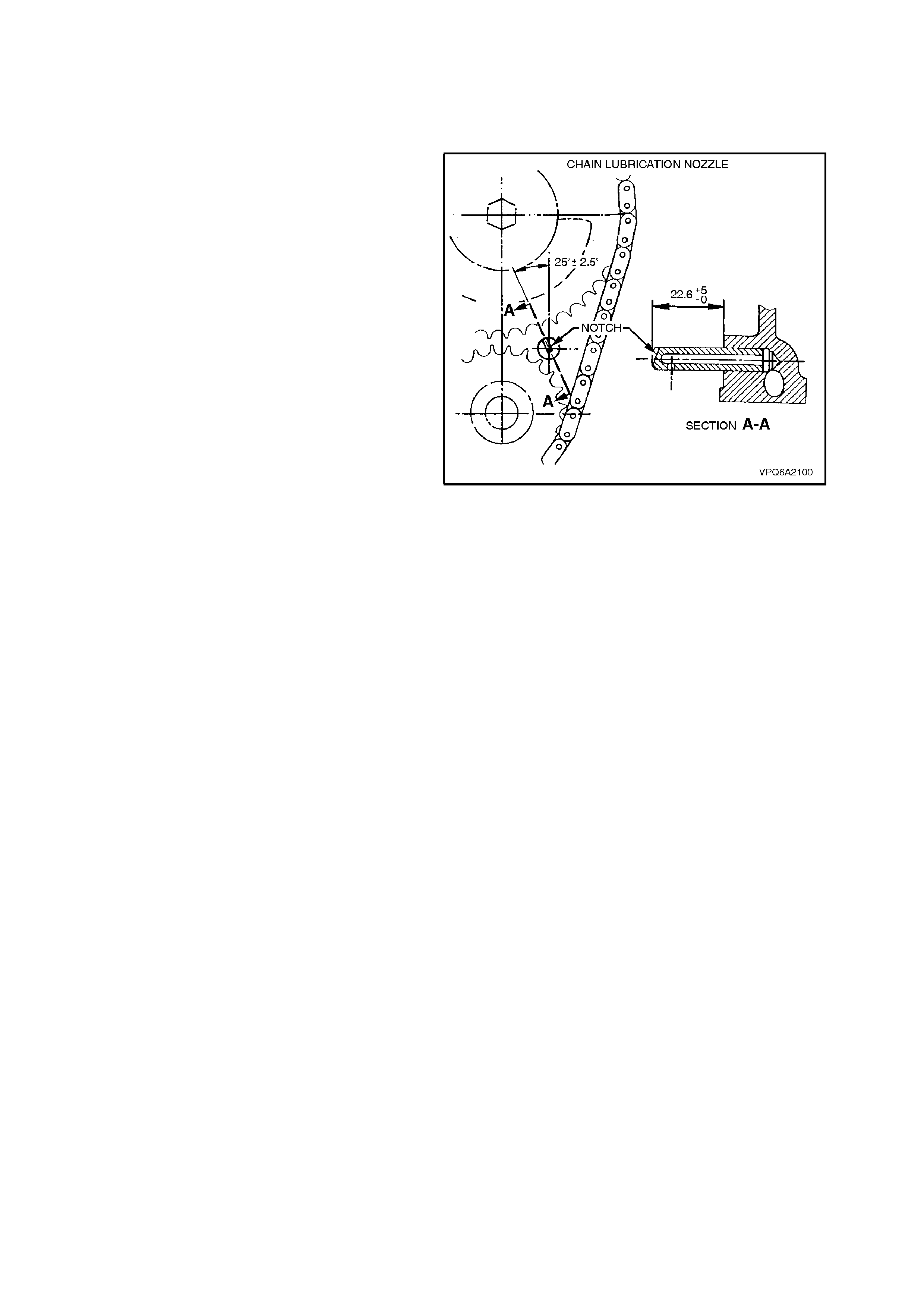
1. Align the oil hole of a new nozzle as shown in
Fig. 6A2-117, and drive into the cylinder block
using a suitable punch.
2. Ensure that the nozzle is only installed to the
depth shown in Fig. 6A2-117.
Figure 6A2-117

3.6 CAMSHAFT
REMOVE
1. With engine removed from vehicle and
mounted on an engine stand, remove timing
chain and sprockets, refer to
3.4 TIM ING CHAIN AND SPROCKETS in this
Section.
2. Remove hydraulic valve lifters, refer to
2.7 HYDRAULIC VALVE LIFTERS in this
Section.
3. Remove bolt securing camshaft locater and
remove locater.
4. Carefully withdraw camshaft from front of
engine.
Figure 6A2-118
INSPECT
NOTE 1:
The camshaft is supported on five steel-backed
Babbitt lined bearings which are pressed into the
cylinder block and then line reamed to size. Since
this operation requires special reaming equipment,
the original bearings should be retained unless they
are severely damaged.
NOTE 2:
Slightly scored camshaft bearings will be
satisf actory if the surf ace of the c ams haft journal is
polished and the bearings are cleaned to remove
burrs.
NOTE 3:
Bend a piece of 5 mm diameter rod at 90°, then
use the rod to probe the No.1 camshaft bearing oil
hole. Ensure that the oil hole and gallery are
correctly aligned, and that no obstruction is
present.
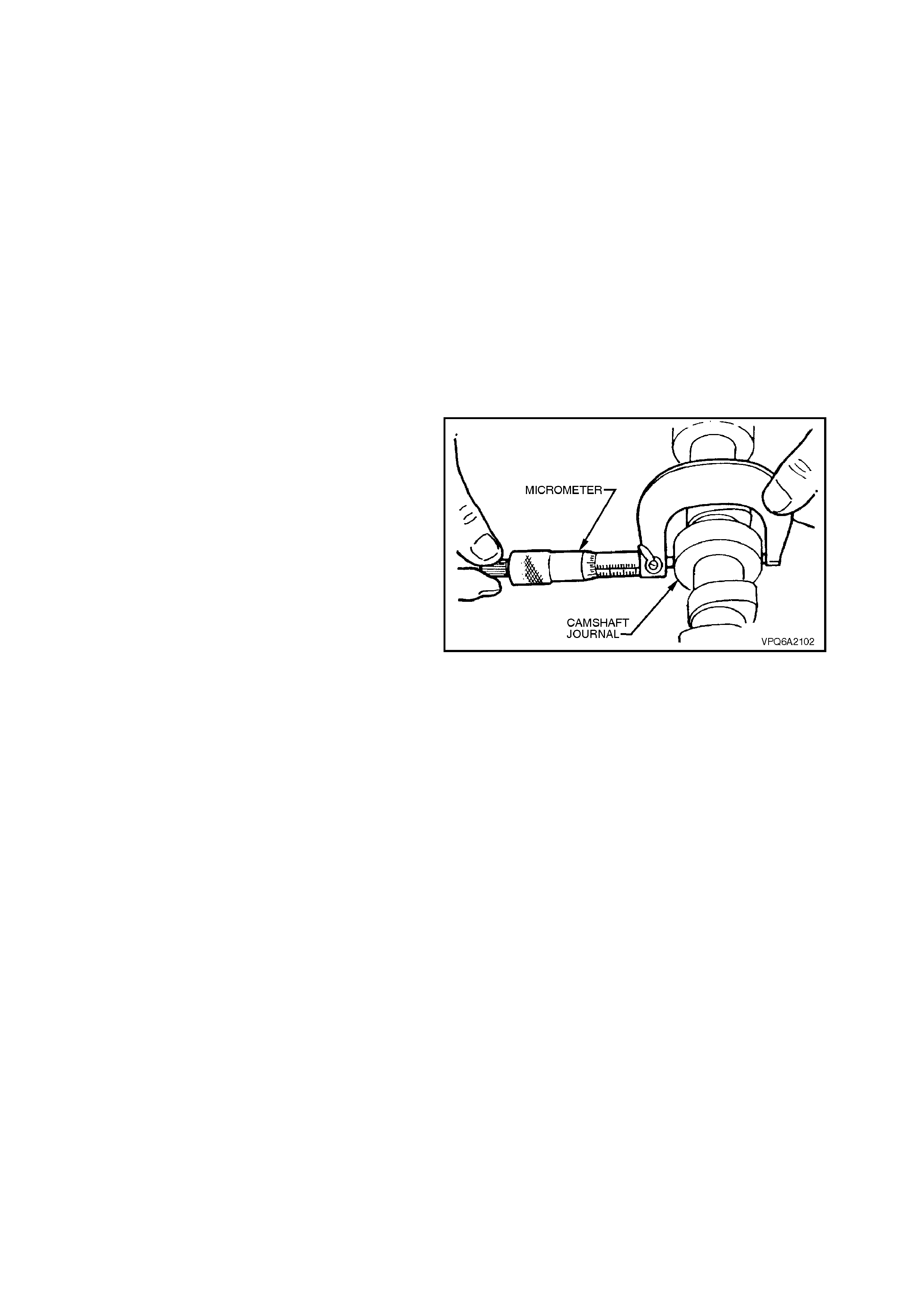
Check camshaft journals for misalignment using V
- block s and a dial indicator . Chec k for out-of-round
with a micrometer. If misalignment or out-of-round
exceeds 0.05 mm, replace camshaft.
Figure 6A2-119

REINSTALL
Installation of the camshaft is the reverse of
removal procedures, noting the following points:
1. Clean threads of camshaft thrust plate
attaching screws and mating threads in
cylinder block.
2. Lubricate cams haf t bearing j our nals with c lean
engine oil and all lobes with Lubrizol 6612 or
equivalent (Holden Specification HN 1961)
and install camshaft.
3. When installing camshaft, take care not to
disturb lubricant film on camshaft lobes.
4. Apply engine oil to camshaft contact surfaces.
5. Reinstall camshaft locater and tighten bolt to
specified torque.
CAMSHAFT LOCATER BOLT
TORQUE SPECIFICATION 68 - 81 Nm
6. Lubricate all lifters and lifter bores with
Lubrizol 6612 or equivalent (Holden
Specification HN 1961) before installing.
7. Reinstall hydraulic valve lifters, refer to
2.7 HYDRAULIC VALVE LIFTERS in this
Section.
8. Reinstall timing chain and sprockets, refer to
3.4 TIM ING CHAIN AND SPROCKETS in this
Section.
9. Start engine, check for oil or coolant leaks.
Check for valve train noise. Repair as
necessary.
3.7 OIL PUMP SUCTION PIPE AND SCREEN
REMOVE
1. Remove oil pan, refer to 3.2 OIL PAN in this
Section.
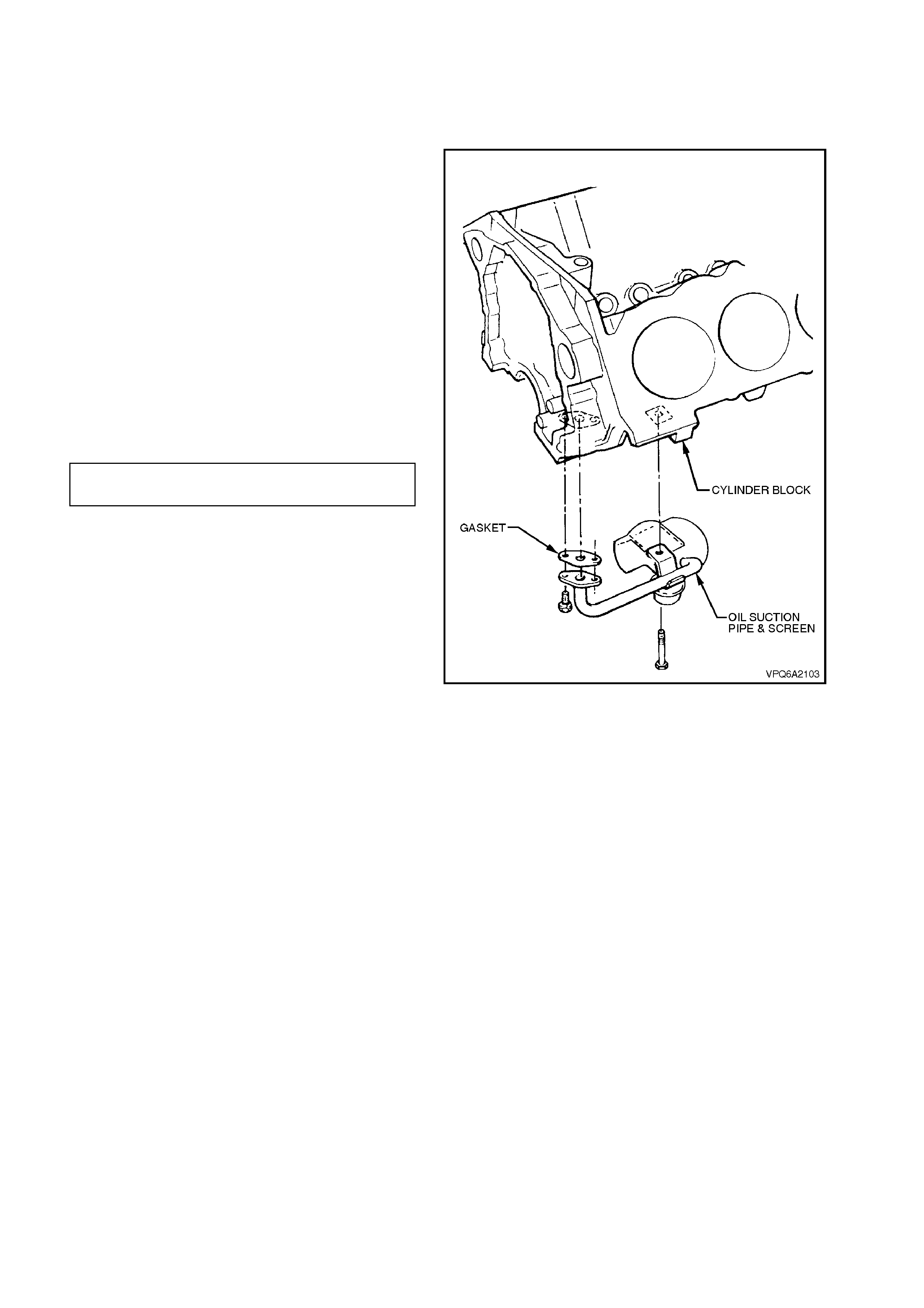
2. Remove two bolts securing s uction pipe f lange
to crankcase.
3. Remove bolt securing support bracket to
cylinder block remove oil suction pipe and
screen assembly.
REINSTALL
Installation is the reverse of the r em oval proc edure,
note the following:
1. Check that the suction pipe flange and
crankcase are clean, smooth and flat. Use a
new gasket between suction pipe flange and
cylinder block.
2. Tighten bolts to specified torque.
OIL PUMP SUCTION PIPE BOLT 8 - 11
TORQUE SPECIFICATION Nm
Figure 6A2-120
3.8 OIL PUMP DRIVE GEAR, SHAFT AND BUSH
REMOVE
1. Remove timing chain and sprockets, refer to
3.4 TIM ING CHAIN AND SPROCKETS in this
Section.
2. Remove oil pump, refer to 2.11 OIL PUMP in
this Section.
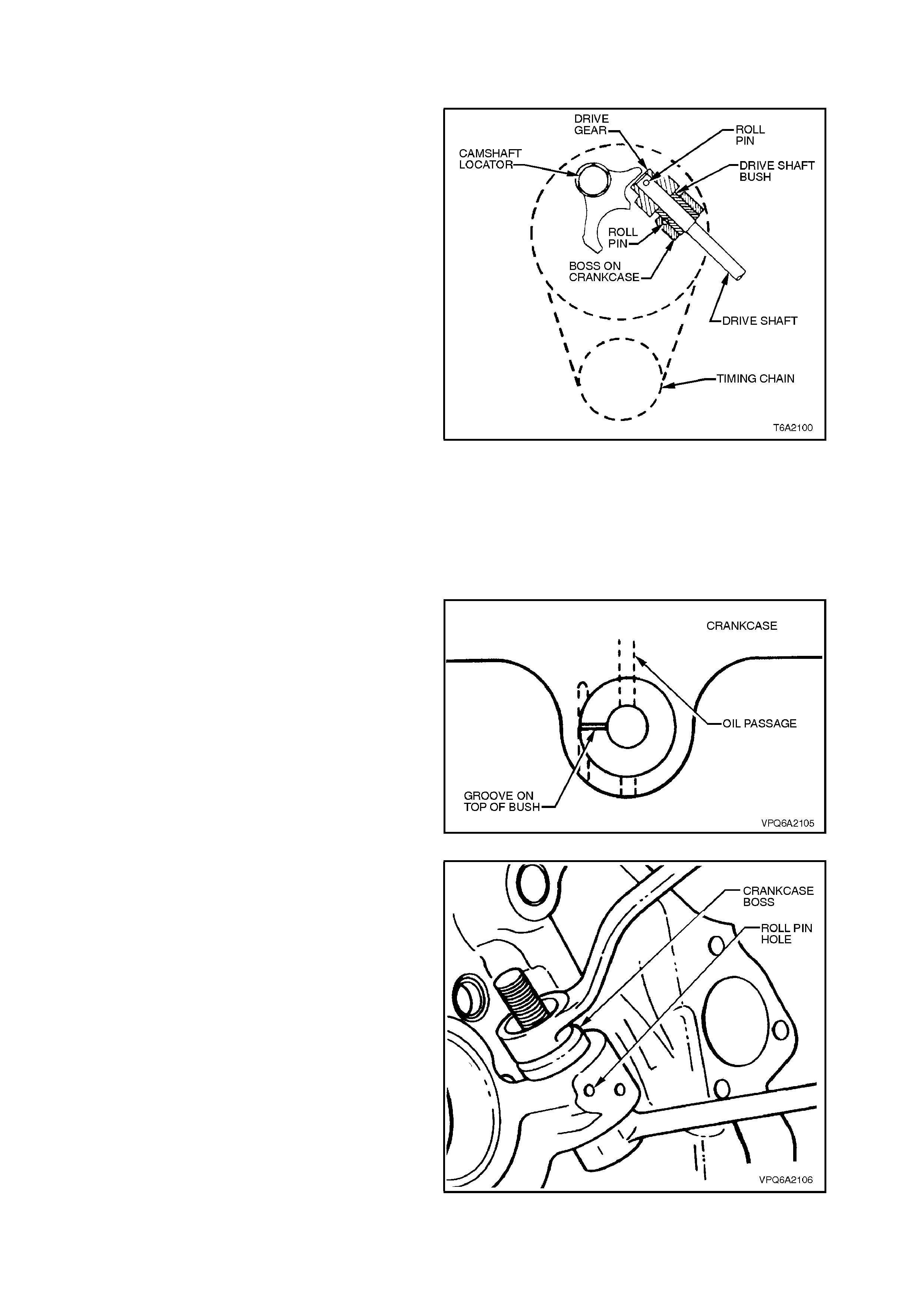
3. Remove roll pin securing the oil pump drive
gear to drive shaft.
4. Remove drive gear and withdraw drive shaft
downwards.
5. Use a suitable self tapping sc rew attached to a
slide ham mer to rem ove roll pin secur ing drive
shaft bush to crankcase.
6. Drive bush from crankcase boss with a
suitable drift and hammer.
Figure 6A2-121
INSPECT
Measure diameter of shaft in contact with bush. If
shaft diameter is less than 12.22 mm, replace
shaft. Inspect gear for wear.
REINSTALL
1. Install new bush, grooved face uppermost,
ensuring that the hole in bush aligns with oil
passage in crankcase behind bush.
Figure 6A2-122
2. Use a suitable bolt and washers to aid
installation. Install bus h until lower f ac e is f lus h
with lower face of boss.
Figure 6A2-123
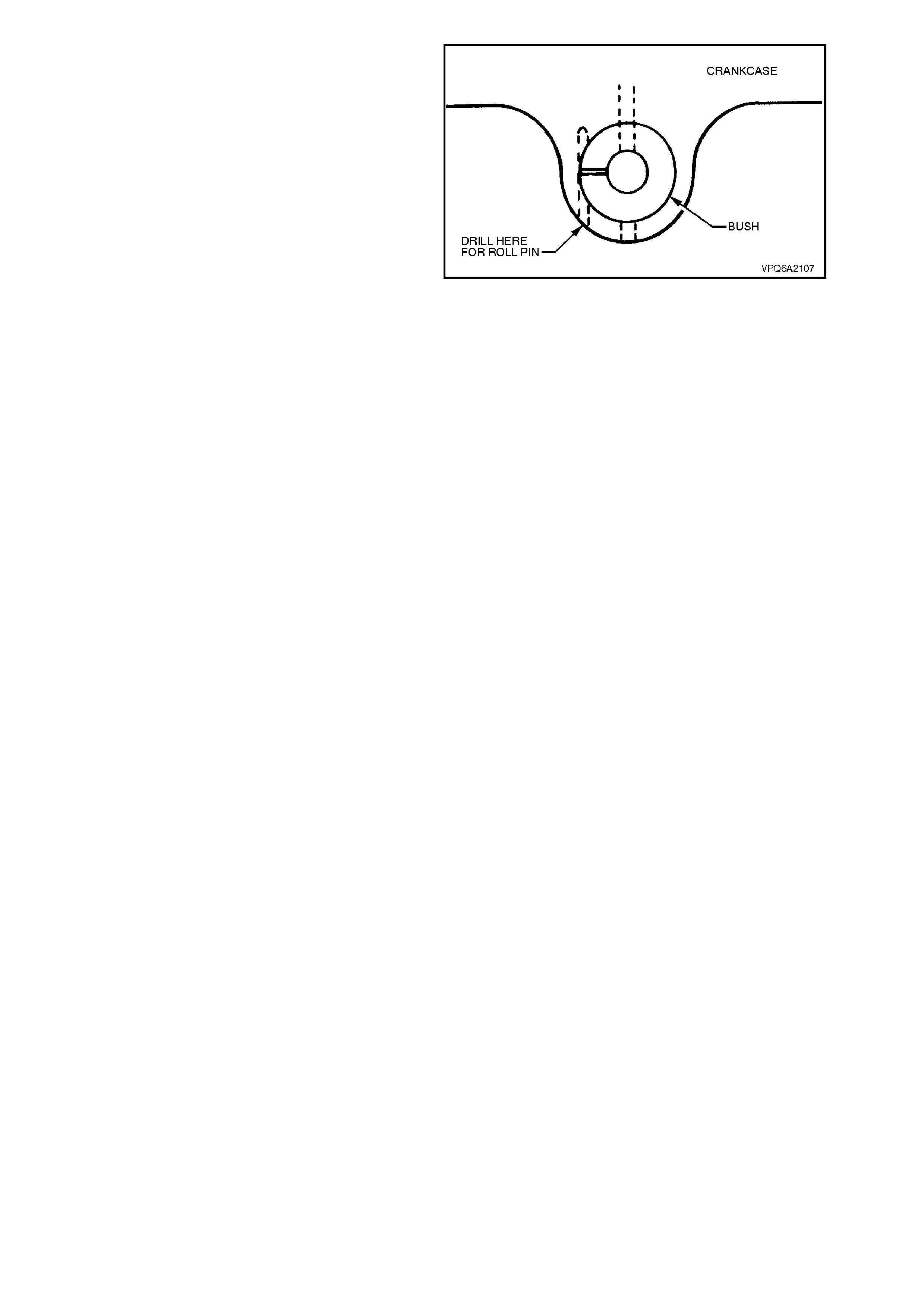
3. Using a 4.7 mm drill bit, drill through the roll
pin hole to notch the new bush.
CAUTION:
Do not drill more than 19 mm deep. Take care
not to enlarg e diamet er of th e hol e in crankcase
boss.
4. Reinstall roll pin securing drive shaft bush to
crankcase.
5. Reinstall drive shaft, drive gear and roll pin
securing drive gear to shaft. Lubricate shaft
and gear with engine oil.
6. Reinstall timing chain and sprockets, refer to
3.4 TIM ING CHAIN AND SPROCKETS in this
Section.
7. Reinstall oil pump, refer to 2.11 OIL PUMP in
this Section.
Figure 6A2-124
3.9 REAR MAIN BEARING OIL SEAL
REPLACE
1. Remove crankshaft, refer to
3.14 CRANKSHAFT in this Section.
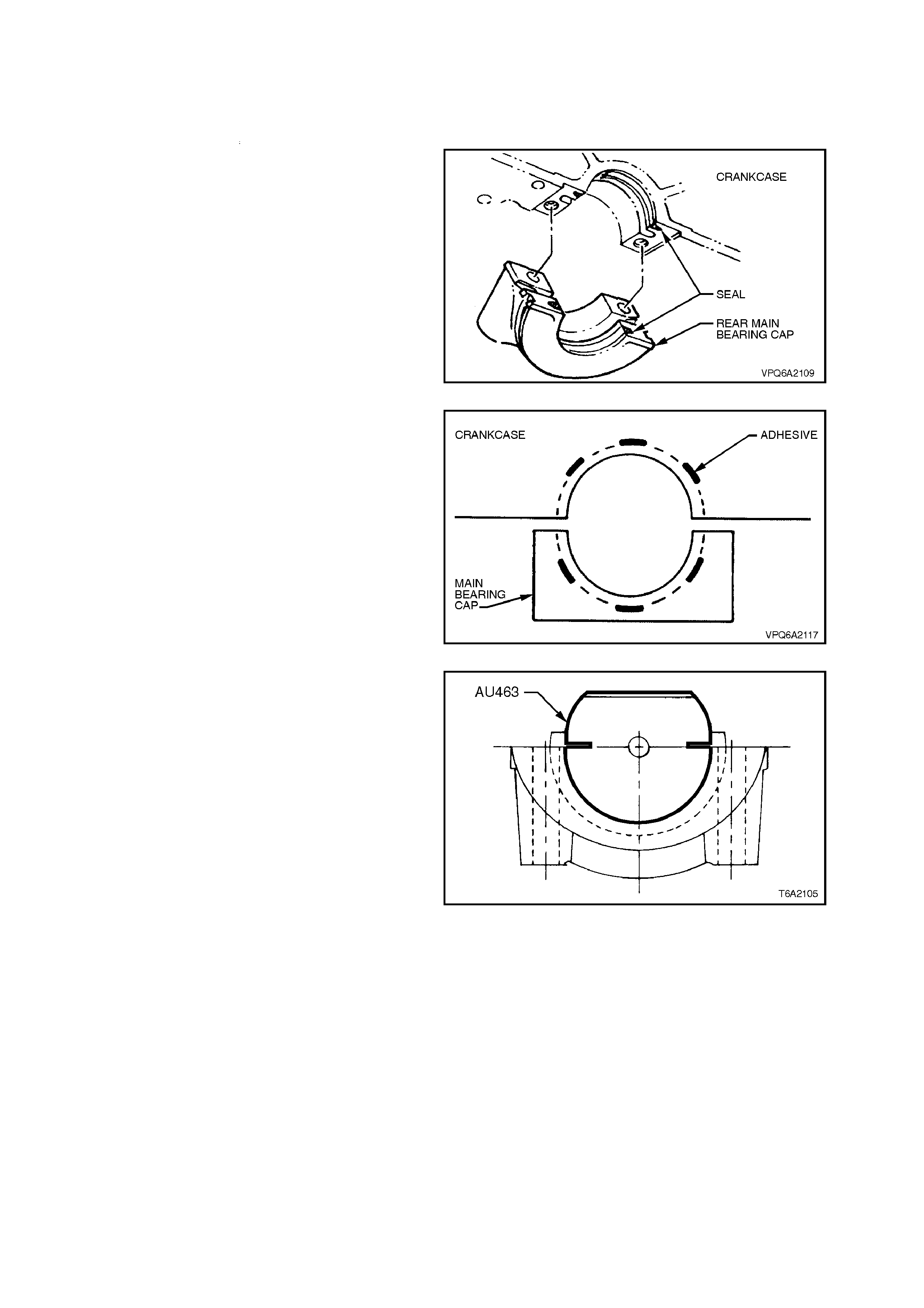
2. Remove old rear main bearing oil seal from
crankcase and rear main bearing cap. Ensure
seal groove is clean and free of foreign matter.
Figure 6A2-125
3. Apply cyanoacrylate adhesive (Holden
specif ication HN 1539 Type 4 or equivalent) to
bearing cap and crankcase seal grooves as
shown in Fig. 6A2-126.
Figure 6A2-126
4. Fit seal into the seal groove of bearing cap,
with the sharper edge of the seal facing toward
the flywheel. Confirm that seal ends are
protruding equally at both sides.
5. Using hand press and seal installation tool no.
AU463, push seal into the bearing cap seal
groove to full stop
6. Using sharp cutting tool, trim the protruding
ends of the seal flush with cap. The edges of
the trimm ed seal should be neat, without burrs
or debris.
7. Remove cap from press, and apply sealant
such as Loctite 515 Master Gasket or
equivalent (Holden Specification HN 1581)
around the area next to the s eal on the parting
plane on the cap only.
NOTE:
Do not apply sealant near crankshaft oil thrower.
Figure 6A2-127
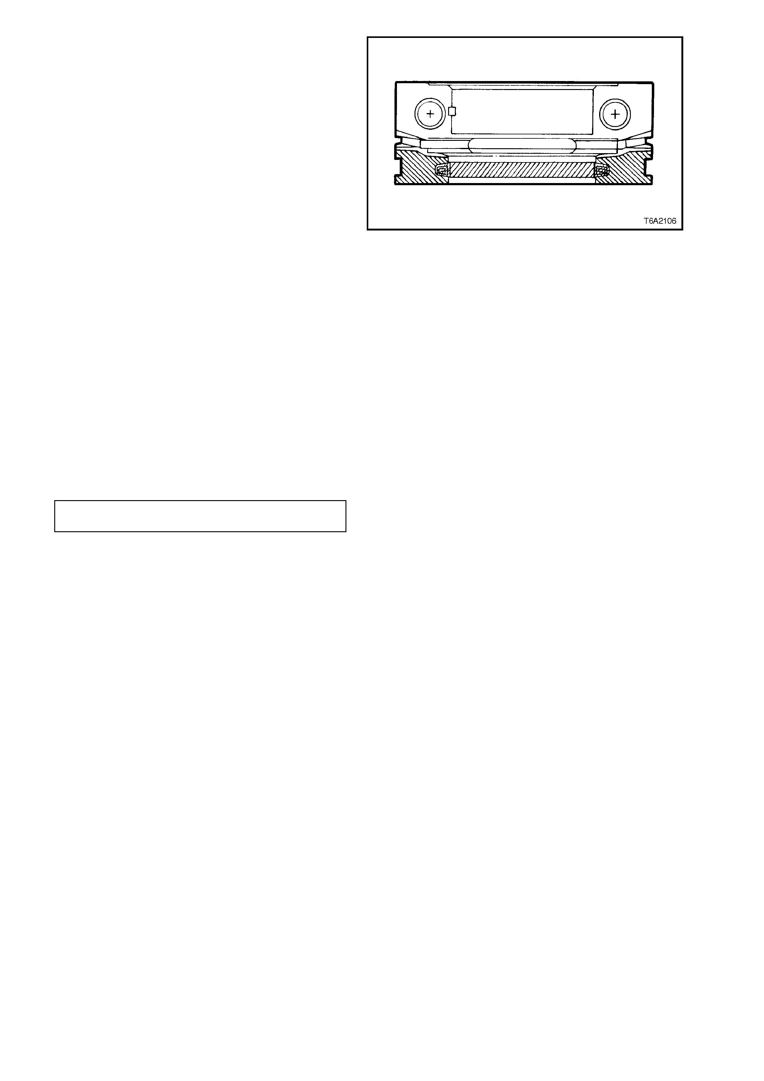
8. Fit seal into the seal groove of engine
crankcase, with the sharper edge of the seal
facing toward the flywheel. Confirm that seal
ends are protruding equally at both sides.
9. Using seal installation tool no. AU463, push
seal into the seal groove to full stop.
10. Using sharp cutting tool, trim the protruding
ends of the seal flush with crankcase. The
edges of the trimmed seal should be neat,
without burrs or debris.
11. Apply film of engine oil on whole length of rear
seal lip in the bearing cap and engine
crankcase prior to installation of crankshaft.
12. Reinstall crankshaft, refer to
3.14 CRANKSHAFT in this Section.
Figure 6A2-128
13. Reinstall bearing caps. The base of each cap
displays the bearing number and an arrow
which must point towards the front of the
engine. Tighten bolts finger tight.
14. After tightening the rear main bearing cap
bolts to an approximate pre-torque of 3 - 5
Nm, firmly thrust the crankshaft rearward to
set and align the bearing caps.
Then firmly thrust the crankshaft forward, to
align the rear faces of the rear main bearing
halves.
Tighten all m ain bearing bolts to the f ull torque
setting, as specified.
REAR MAIN BEARING CAP BOLT
TORQUE SPECIFICATION 81 - 95
Nm

3.10 MAIN BEARINGS
REMOVE
NOTE:
Replacement main bearing sets are available in
STANDARD (STD) size and 0.001, 0.002, 0.010,
0.020 and 0.030 inch undersize.
1. Drain contents of oil pan, then reinstall and
tighten drain plug.
2. Remove engine assembly from vehicle, refer
to 3.1 ENGINE ASSEMBLY in this Section.
3. Mount and invert engine (oil pan facing
upward) in a suitable stand.
4. Remove the oil pan assembly, refer to
3.2 OIL PAN in this Section.
5. Remove oil pump suction pipe and screen,
refer to 3.7 OIL PUMP SUCTION PIPE AND
SCREEN in this Section.
6. Remove crankcase front cover, refer to
3.3 CRANKCASE FRONT COVER in this
Section.
7. Remove timing chain and sprockets, refer to
3.4 TIM ING CHAIN AND SPROCKETS in this
Section.
8. Remove flywheel/flexplate, refer to
3.15 FLYWHEEL/FLEXPLATE in this Section.
9. Remove the main bearing caps.
10. Place a piece of Plas tigage acros s f ull width of
bearing journal, parallel to crankshaft.
11. Reinstall bearing cap and tighten bolts to
specified torque. Note that base of cap
displays cap number and an arrow that must
point towards front of engine.
MAIN BEARING CAP BOLT 81 - 95
TORQUE SPECIFICATION Nm
12. Remove the bearing cap. Look for flattened
Plastigage adhering to either crankshaft or
bearing cap.
13. Determine bearing clearance by comparing
width of flattened Plastigage at widest point
with graduation on Plastigage container. The
number within the graduation on the container
indicates the clearance.
14. Clearance between each main bearing and
crankshaft should not exceed specification.
NEW BEARINGS 0.020 - 0.061 mm
MAXIMUM SERVICE 0.100 mm
15. Measure the crankshaft end play, using the
following procedure:
Figure 6A2-129
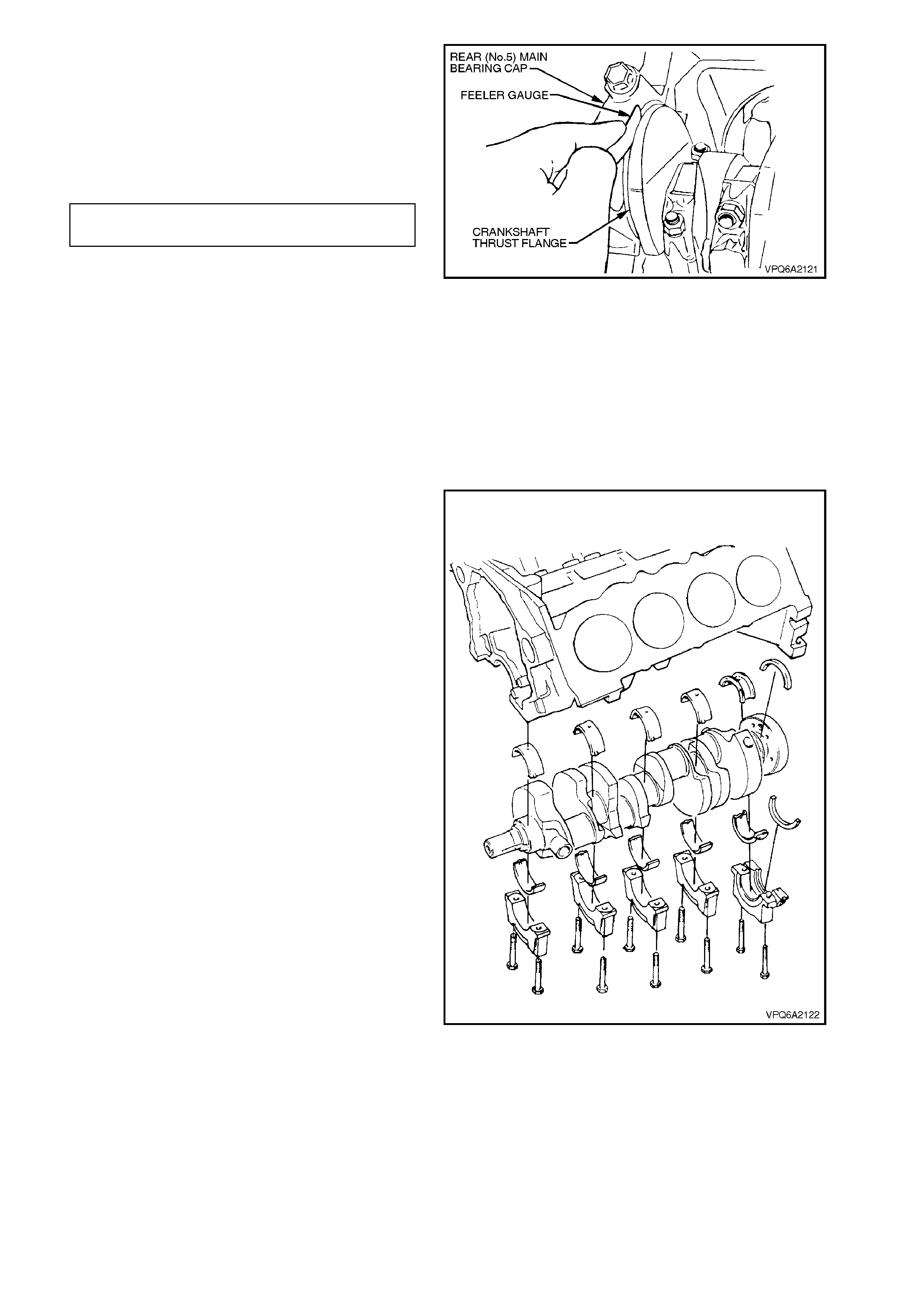
a. Lever crankshaft toward front of engine
using a piece of wood.
b. Using feeler gauges, measure the
clearance between forward face of number
five bearing cap and crankshaft thrust face.
c. Crankshaft end play should be within the
following specification.
NEW BEARINGS 0.051 - 0.153 mm
MAXIMUM SER VICE 0. 25 mm
d. Recondition crankshaft or replace main
bearing set as necessary.
16. Remove the connecting rod bearing caps,
refer to 3.11 CONNECTING ROD BEARINGS
in this Section.
17. Loosen main bearing cap retaining bolts
progressively to prevent distorting the
crankshaft.
18. Lightly tap each side of bearing cap using a
copper faced hammer, until cap can be
removed.
Figure 6A2-130
19. Remove crankshaft from cylinder block.
20. Wipe oil from bearing shells and number
positions using a felt tipped pen, then remove
the bearing shells from cylinder block and
bearing caps.
Figure 6A2-131
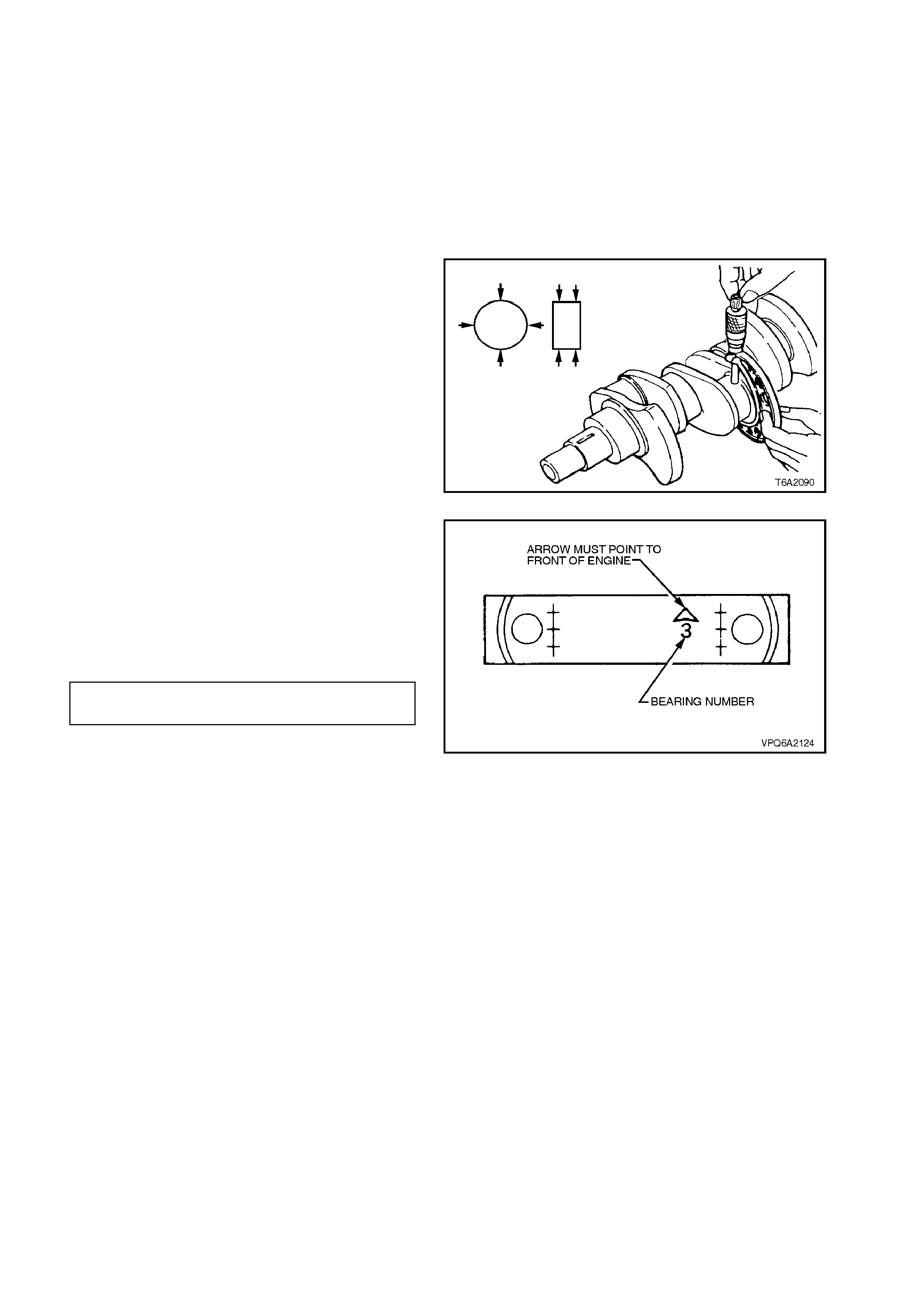
CLEAN AND INSPECT
1. Remove any Babbitt or other bearing material
from the crankshaft journals using a suitable
scraping tool as necessary.
2. Clean crankshaft using a suitable cleaning
agent, then blow through the oil galleries with
compressed air. Ensure that the oil galleries
are free of any restriction or obstruction.
3. Inspect the jour nals for dam age, sc oring, over
heating and cracks. Replace or recondition the
crankshaft as necessary.
4. Measure the main bearing journal diameters,
in two places 90° apart at each end of the
journal. Where the diameter, out-of-round or
taper exceeds specification (see
5. SPECIFICATIONS at the end of this
Section), replace or recondition crankshaft as
required.
Figure 6A2-132
5. Reinstall the bearing caps without bearing
shells.
NOTE:
The base of each cap is marked with a position
number , and an arrow which must point toward the
front of the engine.
6. Tighten bolts to specified torque.
MAIN BEARING CAP BOLT 81 - 95
TORQUE SPECIFICATION Nm
7. Wipe any oil from the bearing bore surfaces
using a clean, dry lint free cloth.
8. Measure and note the inside diameter of the
cylinder block main bearing bores, using an
inside micrometer or bore gauge with imperial
(inches) graduations.
9. Compare the dimension of the crankshaft
journals and cylinder block main bearing bore
with the following chart. Select the appropriate
size bearings to suit. Where a crankshaft is
not within the dimension shown, recondition
the crankshaft to the next available undersize.
Figure 6A2-133
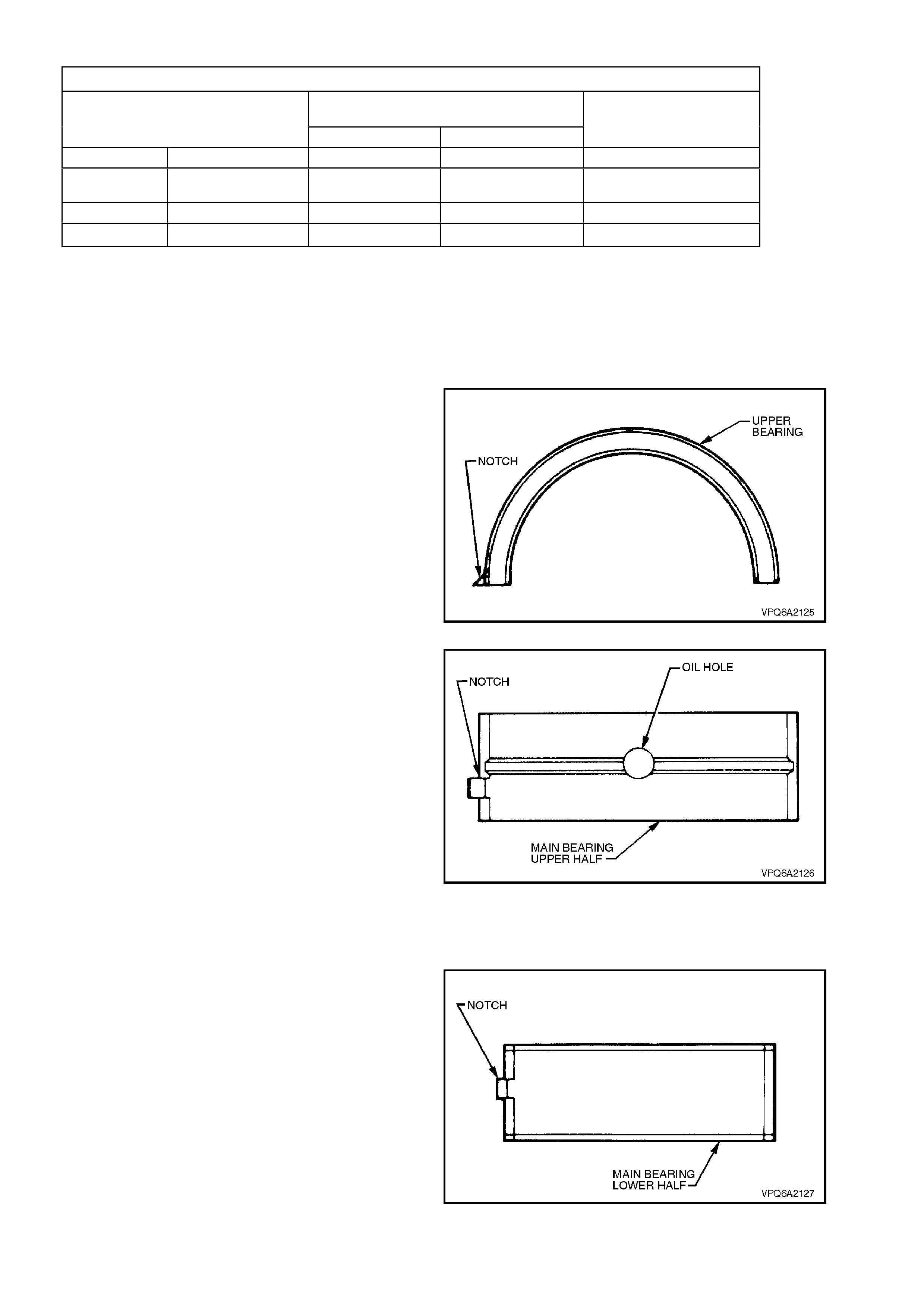
MAIN BEARING SHELL SELECTIVE FITMENT
CYLINDER BL OCK MAIN BEARING
BORE DIAM.
2.5906 - 2.5911 i n. 2.5911 - 2.5916 in. BEARING LOCATION
CRANKSHAFT 2.3978 - 2.3983 in. STANDARD 0.001 in. UNDERSIZE UPPER
JOURNAL 0.001 in.
UNDERSIZE 0.001 in. UNDERSIZE LOWER
DIAMETER 2.3983 - 2.3988 in. STANDARD 0.001 in. UNDERSIZE UPPER
STANDARD STANDARD LOWER
10. Inspect the connecting rod journals as outlined
in 3.11 CONNECTING ROD BEARINGS in
this Section.
11. Remove the main bearing caps.
REINSTALL
1. Replace the rear m ain bearing oil s eal, refer to
3.9 REAR MAIN BEARING OIL SEAL in this
Section.
2. Install the main bearing upper shells in the
cylinder block. Ensure that the bearing notch
aligns with recess in the cylinder block.
Figure 6A2-134
NOTE 1:
The main bearing upper shells are identified by an
oil groove and hole.
NOTE 2:
When installing a mixed size set of bearing shells,
(i.e. STD. s ize upper and 0.001 in. unders ize lower)
check the location of the undersize shell in the
preceding chart before installation, or premature
crankshaft failure could occur.
3. Lubricate the crankshaft journals and upper
bearing shell surfaces with clean engine oil,
then install the crankshaft into position.
CAUTION:
When inst alling th e crankshaft , avoid damag ing
the crankshaft thrust flange on the cylinder
block.
Figure 6A2-135
4. Install the lower bearing shells into the main
bearing caps, then apply a liberal coat of clean
engine oil to the bearing surfaces.
NOTE 1:
Check that all threads and bolt holes are free of oil
and other debris before installing the main bearing
cap bolts.
NOTE 2:
Discard any bearing cap bolts not in perfect
condition.
Figure 6A2-136
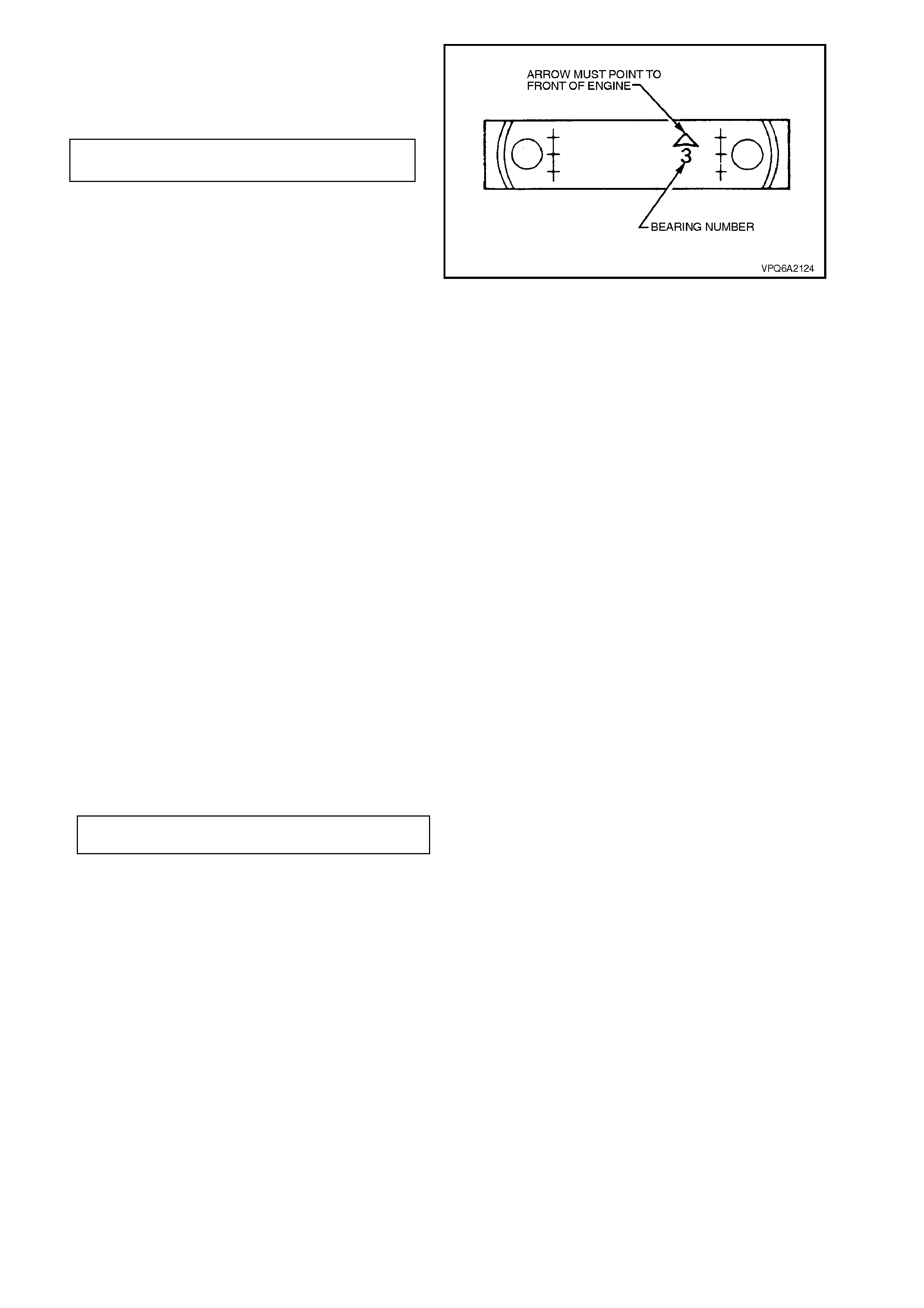
5. Reinstall the bearing caps. The base of each
cap is marked with a position number, and an
arrow which must point toward the front of the
engine. Tighten the bolts to specified torque.
MAIN BEARING CAP BOLT 81 - 95
TORQUE SPECIFICATION Nm
6. Reinstall the connecting rod bearing caps,
refer to 3.11 CONNECTING ROD BEARINGS
in this Section.
7. Reinstall the oil pump suc tion pipe and s cr een,
refer to 3.7 OIL PUMP SUCTION PIPE AND
SCREEN in this Section.
8. Reinstall oil pan assembly, refer to
3.2 OIL PAN in this Section.
9. Reinstall timing chain and sprockets, refer to
3.4 TIM ING CHAIN AND SPROCKETS in this
Section.
10. Reinstall crankcase front cover, refer to
3.3 CRANKCASE FRONT COVER in this
Section.
11. Replace the crankshaft front oil seal, refer to
2.8 CRANKSHAFT FRONT SEAL in this
Section.
Figure 6A2-137
12. Reinstall the flywheel/flexplate, refer to
3.15 FLYWHEEL/FLEXIPLATE in this
Section.
13. Remove the spark plugs, to measure engine
rotation torque.
14. Temporarily install the torsional damper bolt
and washer to the crankshaft and, using a
torque wrench, measure the torque required to
rotate the crankshaft. Where binding occ ur s or
the torque requirement exceeds 102 Nm,
rectify the cause prior to proceeding with
installation.
15. Reinstall the spark plugs to specified torque.
SPARK PLUG
TORQUE SPECIFICATION 20 - 28
Nm
16. Replace the oil filter, refer to
2.9 OIL FILTER in this Section.
NOTE:
Do not reuse an oil filter after an engine overhaul.
17. Remove the engine from stand, and reinstall
in vehicle, refer to 3.1 ENGINE ASSEMBLY
in this Section.
18. Refill the engine to correct level with clean
engine oil. Refer to
Section 0B LUBRICATION & SERVICE.
19. Start the engine and allow to reach normal
operating tem perature, check for oil leak s and
test drive the vehicle. Rectify any faults found.
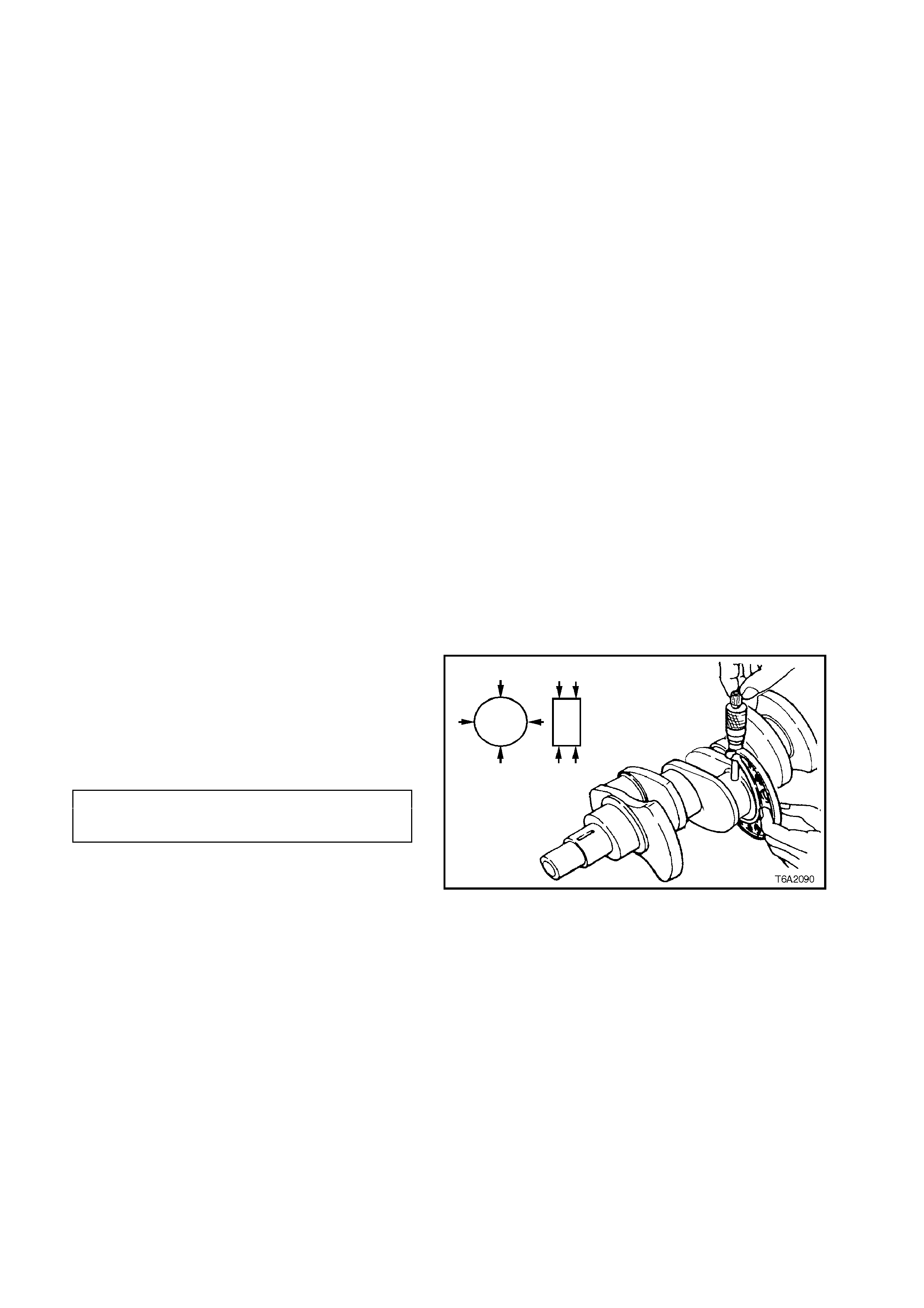
3.11 CONNECTING ROD BE ARINGS
INSPECT AND REPLACE
NOTE 1:
The connecting rod bearings are of the precision
insert type and do not use shims for adjustment.
NOTE 2:
DO NOT FILE rods or caps. If clearances are
found to be excessive, a new bearing is required.
Bearings are available in Standard (STD) size and
0.001 or 0.002 inch undersize for use with standar d
sized crankshafts, and 0.010 and 0.020 inch
undersize for use with reconditioned crankshafts.
NOTE 3:
Selective fitting of connecting r od bearing ins erts is
done in production, to obtain close tolerances. For
this reason it is possible to have one half of a
standard insert and one half of a 0.001 in., or one
half of a 0.001 in. and one half of a 0.002 in.
undersize insert fitted to a connecting rod journal.
Connecting rod bearings can be replaced without
removing the rod and piston assembly from the
engine.
1. Remove oil pan, refer to 3.2 OIL PAN in this
Section.
2. Remove oil pump suction pipe and screen,
refer to 3.7 OIL PUMP SUCTION PIPE AND
SCREEN in this Section.
3. Mark connecting rod caps with felt tipped pen
to indicate cylinder identification number and
orientation of cap.
4. Unscrew connecting rod cap securing nuts
and remove cap.
5. Measure clean crankshaft journal for out-of-
round or taper with a micrometer. If not within
specifications, replace or recondition the
crankshaft.
DIAMETER 53.950 - 53.975mm
MAXIMUM OUT-OF-ROUND 0.0381 mm
MAXIMUM TAPER 0.0254 mm
6. W ipe oil fr om both inner and outer surfaces of
bearing shells.
7. Visually inspect bearing for damage and
replace as required. Install bearing shells in
original positions in connecting rod and cap.
Figure 6A2-138
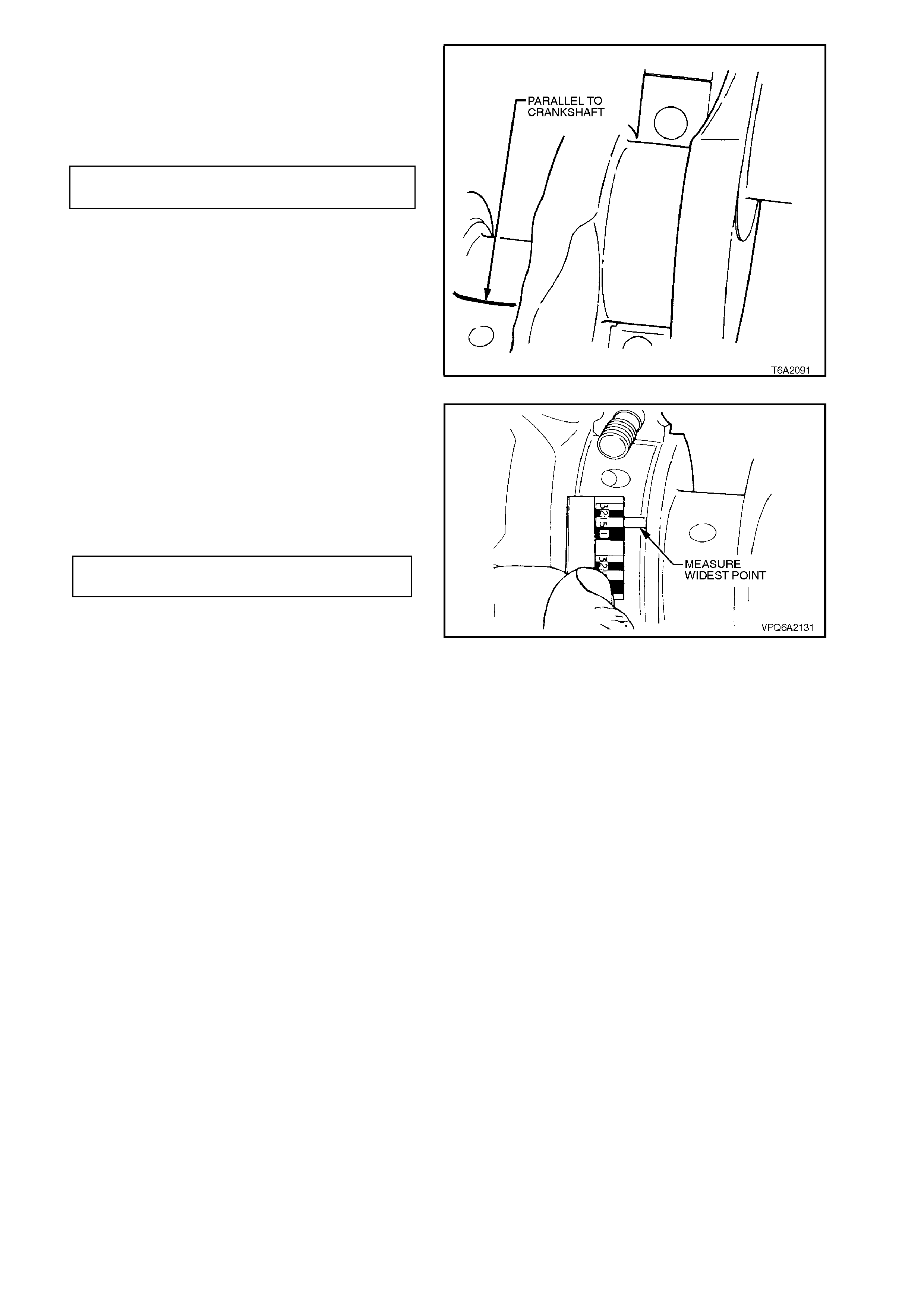
8. Place a piece of Plastigage across width of
bearing journal, parallel to crankshaft.
9. Reinstall connecting rod cap in original
position as noted in Step 3.
Tighten nuts to specified torque.
CONNECTING ROD CAP NUT 56 - 64
TORQUE SPECIFICATION Nm
10. Remove connecting rod cap. Check for
flattened Plastigage adhering to either
crankshaft or cap.
Figure 6A2-139
11. Determine bearing clearance by comparing
width of flattened Plastigage at widest point
with graduation on Plastigage container. The
number within the graduation on the container
indicates the clearance.
12. Connecting rod bearing clearance should not
exceed the following dimensions.
NEW BEARINGS 0.18 - 0.056 mm
MAXIMUM SERVICE 0. 09 mm
13. Select new correct size bearing if required.
NOTE:
If a bearing is being fitted to a within specification,
out-of-round journal, ensure that the bearing is
sized to the maximum diam eter of the j ournal. If the
bearing is sized to the minimum diameter, and the
journal is out-of-round 0.0254 mm, interference
between the bearing and journal will result in rapid
bearing failure.
Figure 6A2-140
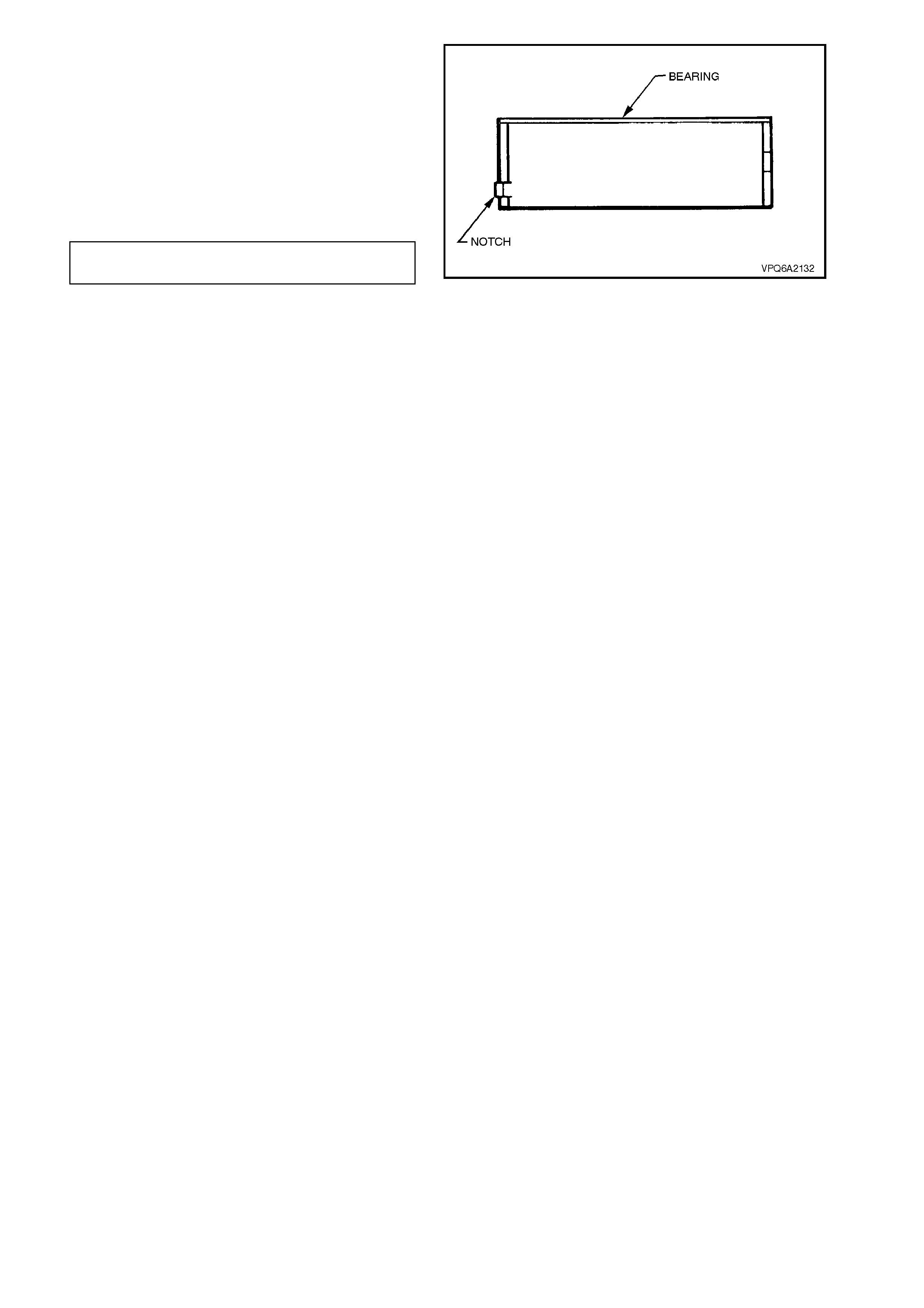
14. Install bearing halves in connecting rod and
cap ensuring notches in bearings match up
with recesses in connecting rod and cap.
15. Check clearance of new bearing with
Plastigage as previously described.
16. Lubricate bearing and journal with engine oil.
17. Reinstall connecting rod cap in original
position as noted in step 3. Tighten nuts to
specified torque.
CONNECTING ROD CAP NUT 56 - 64
TORQUE SPECIFICATION Nm
18. Temporarily install the torsional damper bolt
and washer to the crankshaft and, using a
torque wrench, measure torque required to
rotate crankshaft with spark plugs removed.
Torque should not exceed 102 Nm.
19. Reinstall oil pump suction pipe and screen,
refer to 3.7 OIL PUMP SUCTION PIPE AND
SCREEN in this Section.
20. Reinstall oil pan, refer to 3.2 OIL PAN in this
Section.
21. Refill engine with specified lubricant. Refer to
Section 0B LUBRICATION AND SERVICE.
22. Start the engine and allow to reach normal
operating temperature, check f or oil leaks and
test drive the vehicle. Rectify any faults found.
Figure 6A2-141
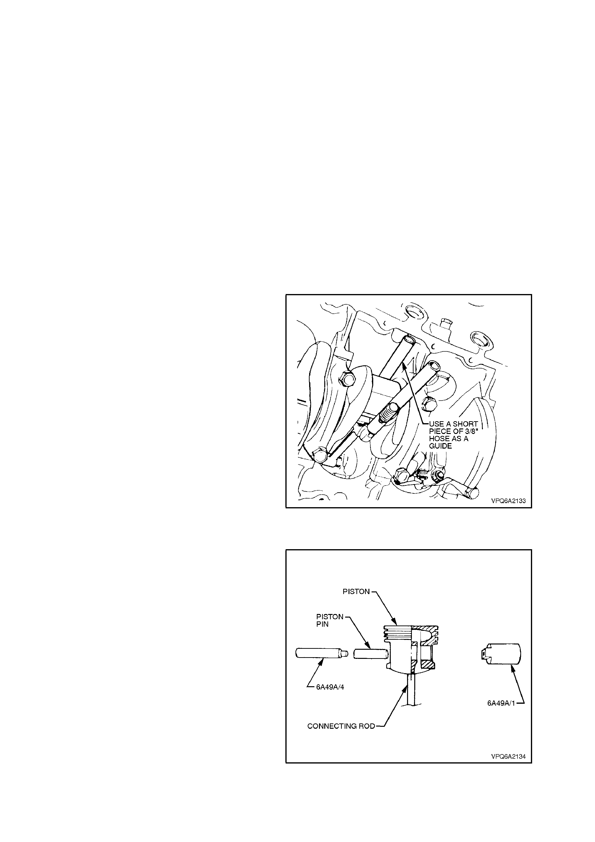
3.12 PISTON AND CONNECTING ROD ASSEMBLY
REMOVE
NOTE:
This operation can be perform ed with the engine in
the vehicle. However, if a new piston or rings are to
be fitted, it is advisable to hone the c ylinder(s). This
would require the engine to be removed from the
vehicle.
1. Remove oil pan, refer to 3.2 OIL PAN in this
Section.
2. Remove cylinder heads, refer to
2.6 CYLINDER HEADS in this Section.
3. Remove any ridge and/or deposits f rom upper
end of the cylinder bores with a ridge reamer.
For each cylinder, first push piston to bottom
of stroke and cover with a cloth to collect
cuttings.
4. Mark connecting rod caps with felt tipped pen
to indicate cylinder identification number and
orientation of cap.
5. Unscrew connecting rod cap securing nuts
and remove cap.
6. Install a suitable piece of hose over each
connecting rod bolt to prevent damage to
crankshaft journals.
7. Push connecting rod and piston assemblies
out of crankcase. Identify each assembly by
cylinder number with a felt tipped pen.
Figure 6A2-142
DISASSEMBLE
1. Install mandrel (Tool No. 6A49A/4) in piston
pin.
2. Carefully locate piston on support (Tool No.
6A49A/1) and press piston pin out of
connecting rod.
3. Remove assembly from press. Remove pin
from support and remove mandrel from piston
and connecting rod.
Figure 6A2-143
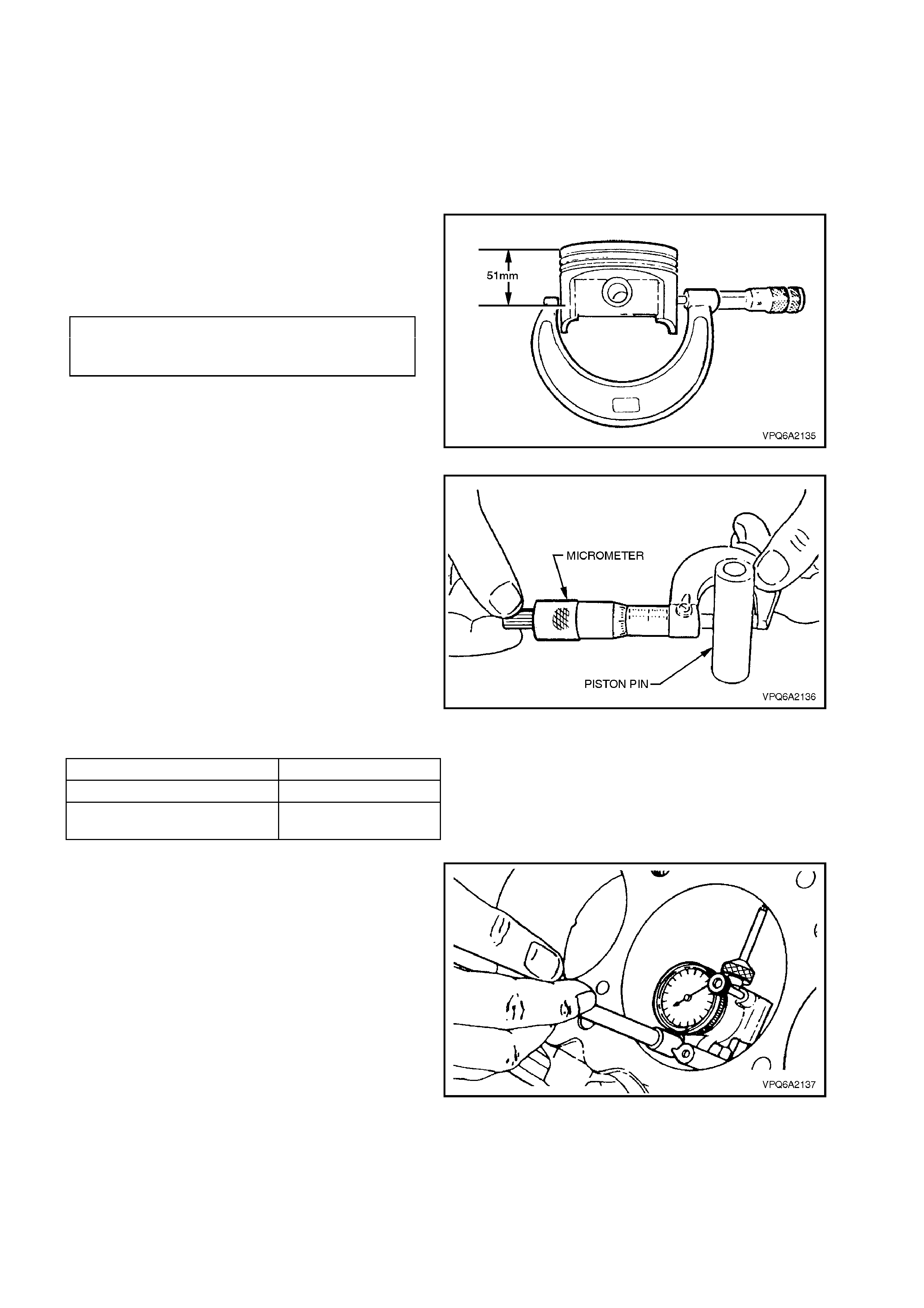
INSPECT
1. Remove piston rings from pistons. Clean
varnish from piston skirts. Do not wire brush
any part of the piston. Clean the ring grooves
with a groove cleaner or a piece of broken
piston ring and make sure oil ring holes and
slots are clean. Inspect the ring grooves for
any nicks or burrs that might cause the rings
to bind.
2. Measure piston diameter with a micrometer at
90o from piston pin hole, 65 mm down from
the top of the piston.
3. If not within specification, replace piston.
PISTON DIAMETER
(Measured 65 mm down from 101.572 -
top of piston at 90° to piston pin) 101.648 mm
Figure 6A2-144
4. Inspect piston pin bores and piston pins for
wear.
Piston pin bores and piston pins must be free
of varnish or scuffing when being measured.
The piston pin should be measured with a
micrometer and the piston pin bore should be
measured with a dial bore gauge or an inside
micrometer. If clearance is in excess of the
wear limit, the piston and piston pin assembly
must be replaced.
Figure 6A2-145
DIAMETER 23.50 - 23.55 mm
CLEARANCE IN PISTON 0.0038 - 0.0064mm
INTERFERENCE FIT IN
CONNECTING ROD 0.0203 - 0.0406mm
5. Measure the inside diam eter, out-of-round and
taper of cylinder bores using a suitable inside
micrometer or bore gauge. Rebore and hone
the cylinder to accommodate the next
appropriate oversize piston and ring set as
necessary.
Figure 6A2-146
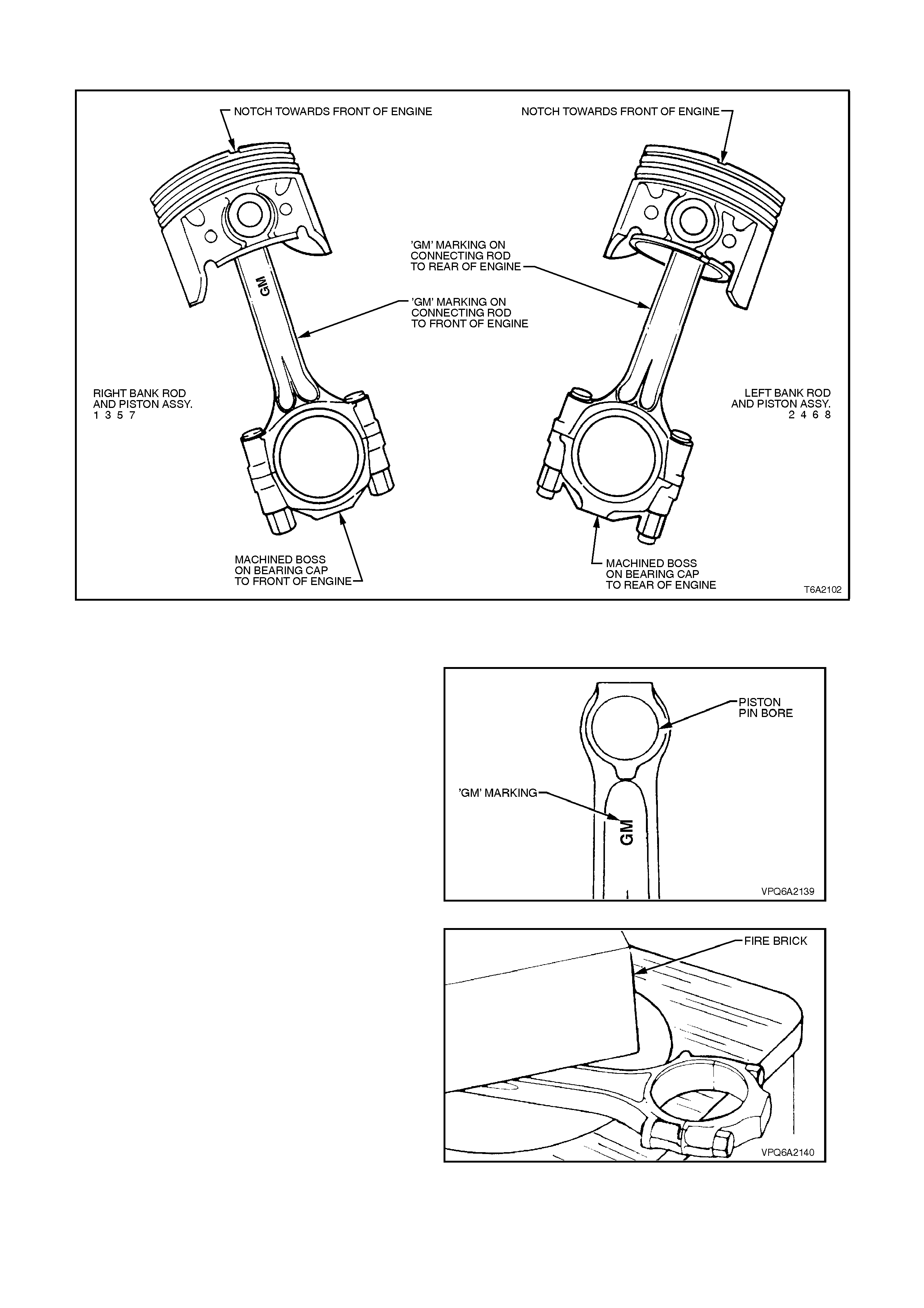
REASSEMBLE
Figure 6A2-147
1. Note correct orientation of connecting rod,
relative to the piston, refer Fig. 6A2-148.
NOTE:
The connecting rods for cylinders 1, 3, 5 and 7 are
installed with the 'GM' marking facing the front of
the engine (the front of each piston has a notch in
the top).
The connecting rods for cylinders 2, 4, 6 and 8 are
installed in the reverse manner with the 'GM'
mar king facing toward the rear of the engine (away
from the piston notch).
2. Lubricate piston pin bore and piston pin with
engine oil.
3. Install piston pin on mandrel (Tool No.
6A49A/4). Figure 6A2-148
4. Heat connecting rod and guide (Tool No.
6A49A/3) to 280° C. Use temperature
indicating crayon such as Faber-Castell
Thermochrom 2815/280°C. to indicate
temperature.
NOTE:
Support rod as shown in Fig. 6A2-150. Using a f ire
brick prevents excessive heat loss. If the
connecting rod s mall end is laid f lat on the hotplate,
heat flow is more even and rapid.
Figure 6A2-149
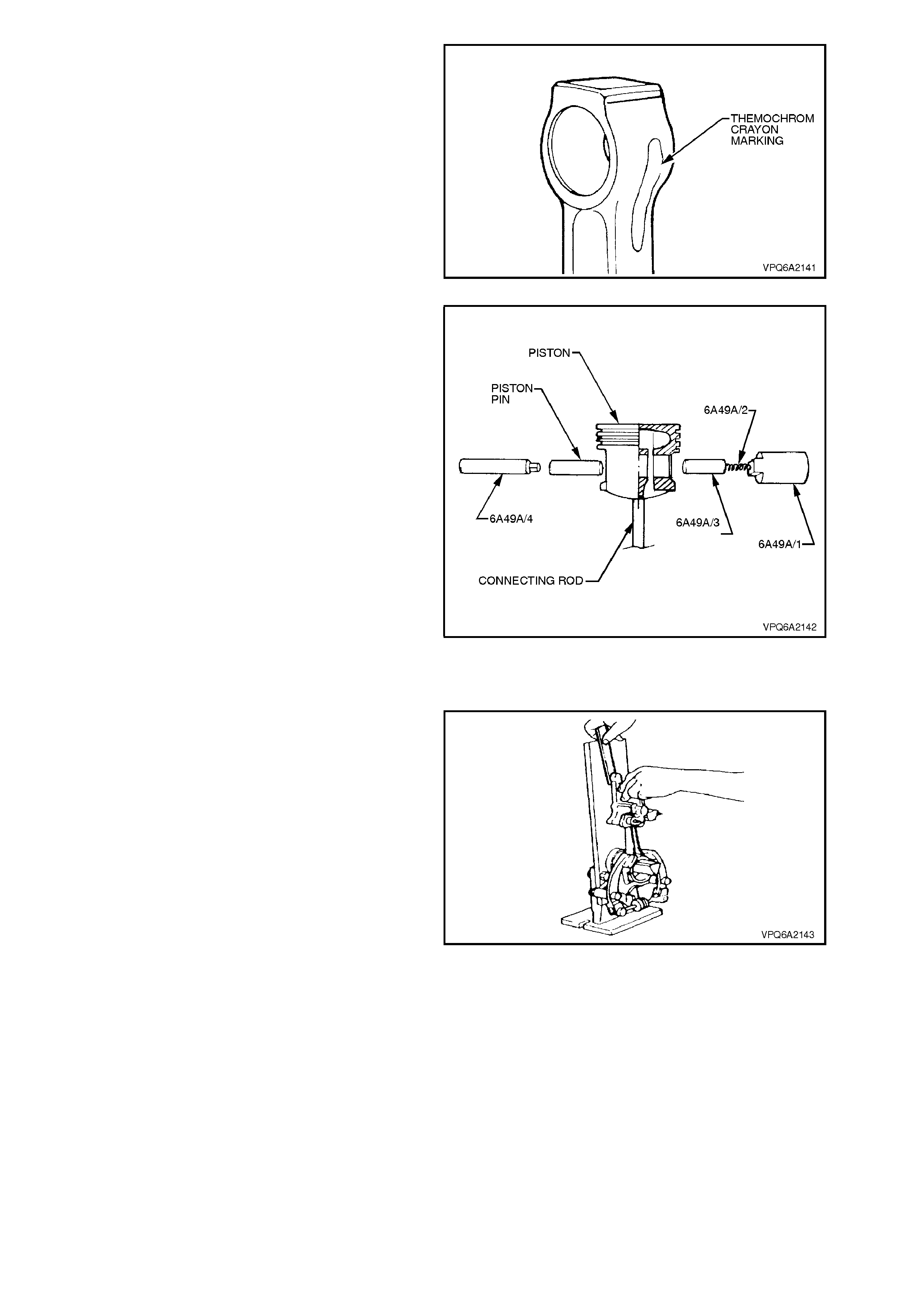
5. When the desired temperature (280° C.) is
reached, the green colour of the crayon will
turn black.
6. Pick up guide (Tool No. 6A49A/3) with heat-
proof gloves.
Figure 6A2-150
7. Quickly install guide over spring (Tool No.
6A49A/2) and locate in support (Tool No.
6A49A/1).
8. Pick up connecting rod with heat proof gloves.
9. Quickly install piston and connecting rod,
correctly orientated (refer to Step 1), over
guide (Tool No. 6A49A/3).
10. Quickly push piston pin into place using
mandrel (Tool No. 6A49A/4) until piston pin
bottoms on guide.
NOTE:
Piston pin should be installed within 3-4 seconds
once connecting rod has been removed from
hotplate. It may be necessary to have an assistant
help by holding components in order to perform
operation within this time constraint. After
approximately four seconds the pin will jam in the
connecting rod necessitating the use of a hydraulic
press.
11. Check that connecting rod and piston are
correctly orientated, refer to Step 1.
Figure 6A2-151
12. Check alignment of piston and connecting rod
assembly on suitable test equipment as per
manufacturer recommendations.
13. For piston ring installation, refer to
3.13 PISTON RINGS in this Section.
Figure 6A2-152

REINSTALL
1. Lubricate bearings, pistons, piston rings and
cylinder walls lightly with engine oil.
2. Install a suitable piece of plastic tubing over
each connecting rod bolt to prevent damage
occurring to crankshaft journals.
3. Ensure piston rings are installed correctly,
refer to 3.13 PISTON RINGS in this Section.
Figure 6A2-153
4. Using a suitable piston ring compressor to
compress rings, install each piston and
connecting rod assembly into its original
cylinder bore with notch in piston to front of
engine. Use a hammer handle to lightly tap
piston into bore. Hold ring compressor firmly
against crankcase until all piston rings have
entered bore.
NOTE:
Pistons are installed with notch on top of piston
pointing to front of engine, refer Fig. 6A2-147.
5. Remove protective tubing from the connecting
rod bolts.
6. Ensure that the connecting rod bearings are
correc tly installed in connec ting rods and c aps,
refer to 3.11 CONNECTING ROD BEARINGS
in this Section.
Figure 6A2-154
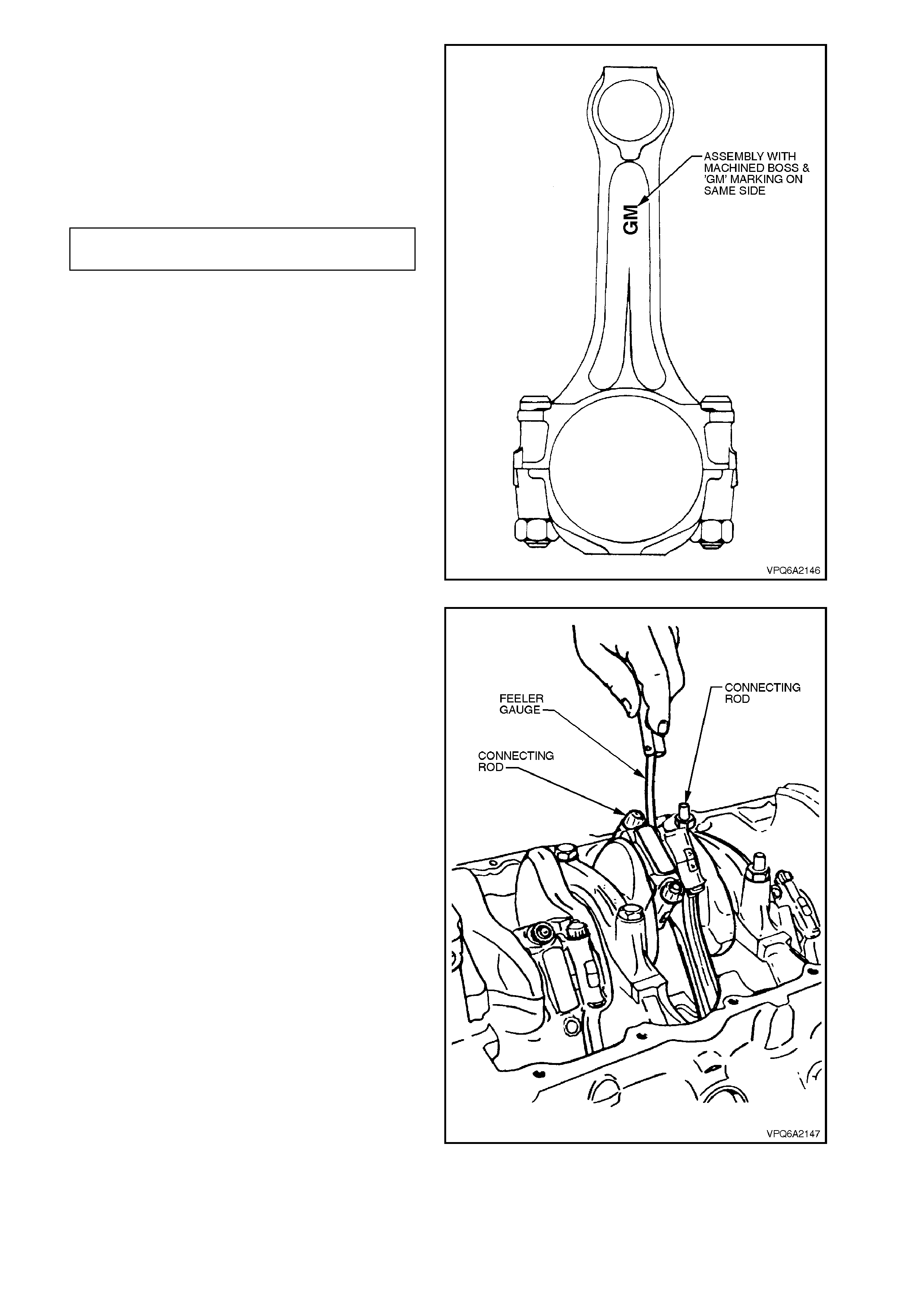
7. Reinstall caps on original connecting rods.
Check for correct orientation.
NOTE:
The machined boss on each connecting rod cap
faces the same way as the 'GM' marking on the
corresponding connecting rod.
8. Tighten connecting rod cap nuts to specified
torque.
CONNECTING ROD CAP NUT 56 - 64
TORQUE SPECIFICATION Nm
Figure 6A2-155
9. Measure side clearance between connecting
rod caps with a feeler gauge. Clearance
should be 0.203 - 0.356 mm. If clearance is
insufficient, check bearing for correct size and
connecting rod assembly for alignment.
10. Temporarily install the torsional damper bolt
and washer to the crankshaft and, using a
torque wrench, measure torque required to
rotate crankshaft. Torque should not exceed
61 Nm.
11. Reinstall cylinder heads, refer to
2.6 CYLINDER HEADS in this Section.
12. Reinstall oil pan, refer to 3.2 OIL PAN in this
Section.
Figure 6A2-156
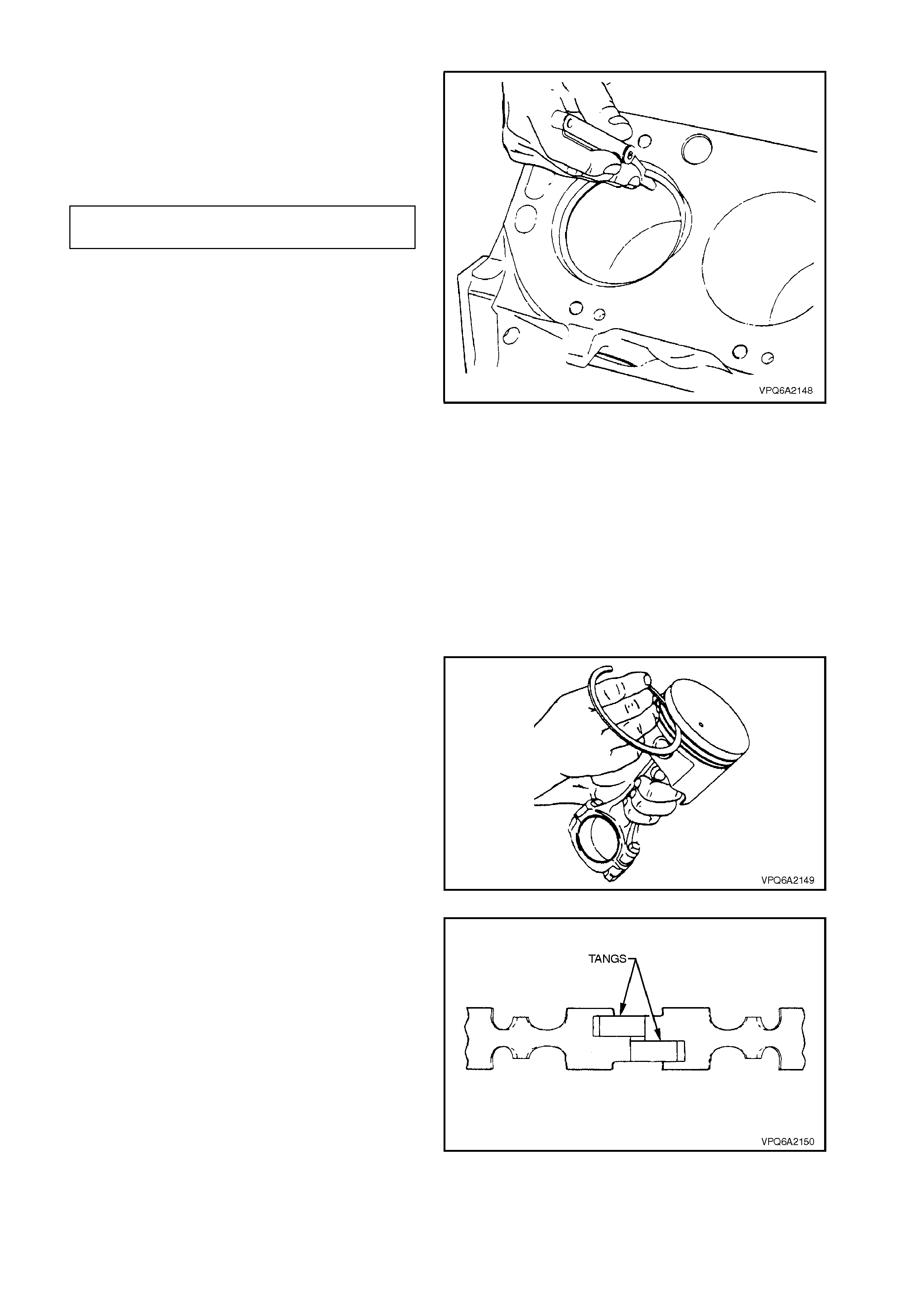
3.13 PISTON RINGS
1. Install compression ring in relevant cylinder
bore as shown in Fig. 6A2-157. Ensure ring is
square with bore.
2. Measure gap between ends of ring with a
feeler gauge. The gap should be as detailed
here.
TOP PISTON RING 0.279 - 0.533 mm
SECOND PISTON RING 0.254 - 0.508 mm
3. If gap is less than the minimum specified,
remove ring and try another for fit, or enlarge
gap with a piston ring file.
4. In a similar manner, check gap between ends
of each oil control ring segment. The gap
should be 0.38 - 1.39 mm.
5. W hen fitting rings to a piston that has been in
service, carefully remove all traces of carbon
from ring grooves in piston and inspect
grooves for any burrs or chips that might
cause ring to bind.
Figure 6A2-157
NOTE:
The pistons have three rings (two compression
rings and one oil control ring). The top ring is a
molybdenum filled, balanced section, barrel lapped
type. The second ring is a reverse torsion taper
face ring. The control oil ring is of a three piece
design comprising two segments and an expander.
INSTALL
6. Slip outer surface of each compression ring
into respective piston ring groove and roll ring
entirely around groove to check that ring is
free. If binding occurs at any point, rectify by
dressing the piston ring groove with a fine cut
file, or if the binding is caused by a distorted
ring, replace the ring.
Figure 6A2-158
7. Insert oil ring expander in bottom piston ring
groove.
NOTE:
The tangs overlap on the end of the oil ring
expander, refer to Fig. 6A2-159.
8. Install oil ring upper segment over top of piston
into oil ring groove.
9. Install oil ring lower segment from bottom of
piston, into the oil ring groove.
Figure 6A2-159
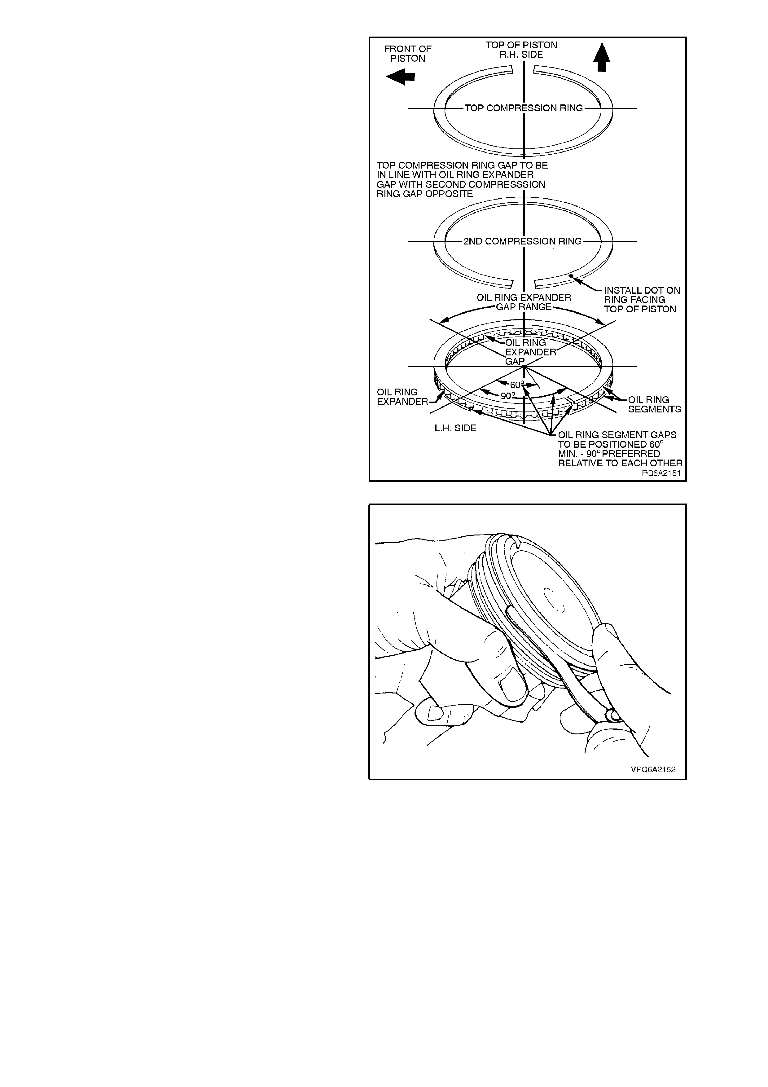
10. Arrange oil ring expander and segment gaps
as shown in Fig. 6A2-160.
11. Flex the oil ring assembly to ensure ring is
free. If binding occurs at any point, rectify by
dressing the piston ring groove with a fine cut
file, or if binding is caused by a distorted ring,
replace the ring.
12. Install second compression ring with dot on
ring facing upwards. Align ring gap as shown
in Fig. 6A2-160.
13. Install top compression ring. Align ring gap as
shown in Fig. 6A2-160.
Figure 6A2-160
14. Measure clearance between compression
rings and piston r ing lands with a feeler gauge.
Clearance f or both rings should be 0.03 - 0.08
mm. If clearance is excessive, replace piston.
Figure 6A2-161
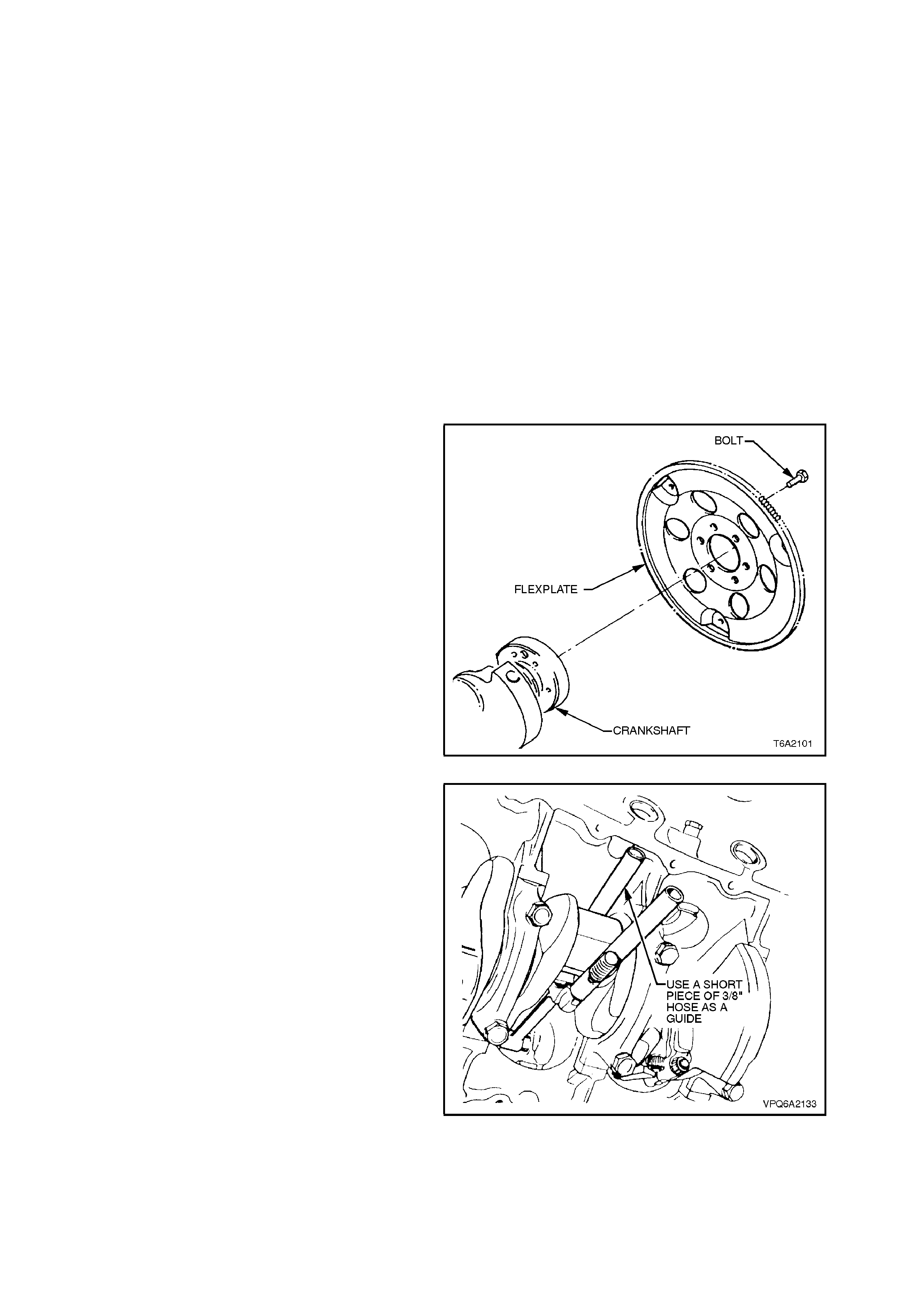
3.14 CRANKSHAFT
REMOVE
NOTE:
It is recommended that bearing clearances be
checked before removing crankshaft from
crankcase, refer to 3.10 MAIN BEARINGS and
3.11 CONNECTING ROD BEARINGS in this
Section.
1. With engine removed from vehicle and
mounted on an engine stand, remove timing
chain and sprockets, refer to
3.4 TIM ING CHAIN AND SPROCKETS in this
Section.
2. Remove Woodruff key from crankshaft.
3. Remove oil pump suction pipe and screen,
refer to 3.7 OIL PUMP SUCTION PIPE AND
SCREEN in this Section.
4. Remove spark plugs.
5. Unscrew bolts securing torque converter
flexplate or f lywheel to crank shaft and remove
flexplate or flywheel.
6. Mark connecting rod caps with felt tipped pen
to indicate cylinder identification number and
orientation of cap.
7. Unscrew connecting rod cap securing nuts
and remove caps.
Figure 6A2-162
8. Install a suitable piece of hose over each
connecting rod bolt to prevent damage to
crankshaft journals.
Figure 6A2-163
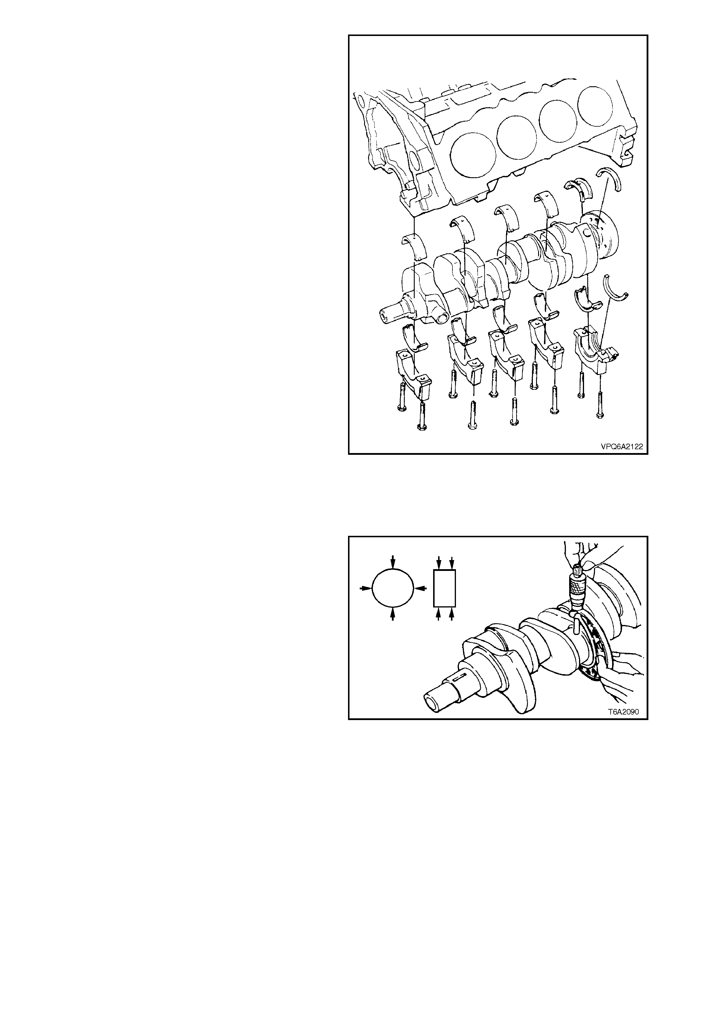
9. Slacken the main bearing cap bolts
progressively, to avoid distorting the
crankshaft.
10. Lightly tap each side of the bearing caps,
using a copper faced hammer, until the
bearing caps can be removed.
11. Lift crankshaft out of crankcase.
Figure 6A2-164
INSPECT
1. Wash crankshaft in solvent and dry with
compressed air.
2. Measure bearing journal diameters with a
micrometer. Check for taper, out-of-round and
undersize.
3. Check crankshaft for runout by supporting
front and rear main bearing journals in V-
blocks. Check front and rear intermediate
journals with a dial indicator.
4. Replace or recondition crankshaft if not within
specif ication, (refer to 5. SPECIFICATIONS at
the end of this Section).
5. Visually inspect condition of spigot bearing and
replace if necessary, refer to
3.17 SPIGOT BEARING in this Section. Figure 6A2-165
REINSTALL
1. Replace rear main bearing oil seal, refer to
3.9 REAR MAIN BEARING OIL SEAL in this
Section.
2. Push each piston to the top of its stroke.
Check that pieces of hose are still fitted to
connecting rod bolts.
3. Lubricate upper and lower main bearing
halves and crankshaft journals with engine oil.
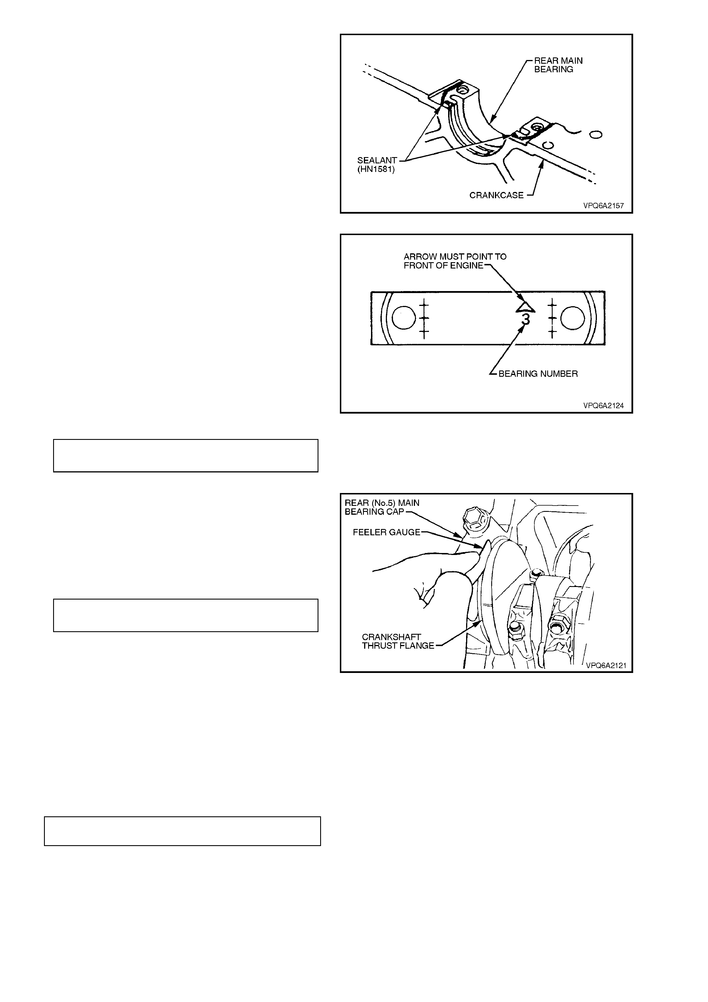
4. Lay crankshaft in place in main bearing upper
halves in crankc ase. Tak e care not to dam age
crank shaft thr ust flange and rear m ain bear ing
thrust faces.
Apply a 1.0 - 1.5 mm bead of Loctite 515
Master Gasket or equivalent sealant (to
Holden Specification HN1581), to the
crankcase rear main bearing joint face as
shown in Fig. 6A2-166.
NOTE:
Use minimal amount of sealant, and avoid sealant
in crankshaft oil thrower area.
Figure 6A2-166
5. Reinstall bearing caps. The base of each cap
displays the bearing number and an arrow
which must point towards the front of the
engine. Tighten bolts finger tight.
6. After tightening the rear main bearing cap
bolts to an approximate pre-torque of 3 - 5
Nm, firmly thrust the crankshaft rearward to
set and align the bearing caps.
Then firmly thrust the crankshaft forward, to
align the rear faces of the rear main bearing
halves.
Tighten all m ain bearing bolts to the f ull tor que
setting, as specified.
MAIN BEARING CAP BOLT 81 - 95
TORQUE SPECIFICATION Nm
Figure 6A2-167
7. Check that the crankshaft is fully forward
before measuring the clearance between front
face of rear main bearing and crankshaft
thrust face with a feeler gauge.
8. If clearance is excessive, replace rear main
bearing.
NEW BEARINGS 0.051 - 0.153 mm
MAXIMUM SERVICE 0. 25 mm
9. Temporarily install the torsional damper bolt
and washer to the crankshaft and, using a
torque wrench, measure torque required to
rotate crankshaft. Torque should not exceed
14 Nm.
10. Remove hose pieces from connecting rod
bolts and reinstall connecting rod caps in
original positions as noted in Step 6 of removal
procedure.
11. Tighten nuts to specified torque.
Figure 6A2-168
CONNECTING ROD CAP NUT
TORQUE SPECIFICATION 56 - 64
Nm

12. Measure clearance between connecting rod
caps with a feeler gauge. Clear ance should be
0.203 - 0.356 mm. Where clearance is
insufficient, check bearing for correct size and
connecting rod alignment.
13. Temporarily install the torsional damper bolt
and washer to the crankshaft and, using a
torque wrench, measure torque required to
rotate crankshaft. Torque should not exceed
61 Nm.
14. Reinstall flywheel or flexplate to crankshaft
and tighten bolts to specified torque.
FLYWHEEL/FLEXPLATE BOLT 81 - 88
TORQUE SPECIFICATION Nm
15. Reinstall oil pump suction pipe and screen,
refer to 3.7 OIL PUMP SUCTION PIPE AND
SCREEN in this Section.
Figure 6A2-169
16. Clean timing c hain sprock et Woodruf f k ey and
crankshaft keyway. Apply RTV 732 sealer
(Holden Specification HN1373) to keyway.
17. Reinstall Woodruff key in crankshaft keyway.
Tap key into place with a soft faced hammer.
18. Reinstall timing chain and sprockets, refer to
3.4 TIM ING CHAIN AND SPROCKETS in this
Section.
19. Reinstall spark plugs and tighten to specified
torque.
SPARK PLUG 20 - 28
TORQUE SPECIFICATION Nm
20. Reinstall engine assembly, refer to
3.1 ENGINE ASSEMBLY in this Section.
Figure 6A2-170

3.15 FLYWHEEL/FLEXPLATE
REMOVE
1. Remove manual transmission and clutch or
automatic transmission and torque converter
from engine, refer to Section 7A CLUTCH,
Section 7B-1 MANUAL TRANSMISSION -
V6 ENGINE or Section 7B-2 MANUAL
TRANSMISSION - V8 ENGINE or
Section 7C4 AUTO TRANS. - ON-VEHICLE
SERVICING as appropriate.
2. Unscrew bolts s ecuring f lywheel or flex plate to
crankshaft and remove flywheel/flexplate.
REINSTALL
1. Clean mating surfaces of crankshaft and
flywheel/flexplate and ensure there are no
burrs.
2. Reinstall flywheel/flexplate and tighten bolts to
specified torque.
FLYWHEEL/FLEXPLATE BOLT
TORQUE SPECIFICATION 81 - 88
Nm
3. Reinstall clutch and/or transmission, refer to
Section 7A CLUTCH, Section 7B1 MANUAL
TRANSMISSION - V6 ENGINE or
Section 7B2 M ANUAL TRANSMISSION - V8
ENGINE or Section 7C4 AUTO TRANS. -
ON-VEHICLE SERVICING as appropriate.

3.16 RING GEAR
REPLACE
AUTOMATIC TRANSMISSION
The ring gear is welded to the flexplate and is serviced only as an assembly, refer to
3.15 FLYWHEEL/FLEXIPLATE in this Section.
MANUAL TRANSMISSION
1. Remove flywheel, refer to 3.15 FLYWHEEL/FLEXIPLATE in this Section.
2. Drill an 8 mm diameter hole through ring gear between two teeth.
3. Split ring gear at this point with a chisel to remove from flywheel.
4. Heat new ring gear on a hot plate to between 288 and 315° C.
NOTE:
Before heating, polish several spots on ring gear with emery cloth. When the polished metal turns dark blue, the
ring gear temperature is approximately 316° C.
CAUTION:
Do not heat ring gear excessively. If heated until polished spots turn dull red (just visible), ring gear heat
treatment is destroyed.
5. With ring gear at required temperature, install ring gear on flywheel with identification facing pressure plate.
Allow to cool slowly.
6. Reinstall flywheel as per 3.15 FLYWHEEL/FLEXIPLATE in this Section.

3.17 SPIGOT BEARING
REPLACE
1. Remove transmission, refer to Section 7B1 MANUAL TRANSMISSION - V6 ENGINE or Section 7B-2
MANUAL TRANSMISSION - V8 ENGINE or Section 7C4 AUTO TRANS. - ON-VEHICLE SERVICING as
appropriate.
2. Remove clutch from manual transmission vehicles, refer to Section 7A CLUTCH.
3. Insert Tool No. 6A22-2 through bearing and expand feet of tool to engage front face of bearing.
4. Remove bearing from rear of crankshaft using a slide hammer in conjunction with Tool No. 6A22-2.
Techline

4. DIAGNOSIS
4.1 ENGINE ME CHANICAL DIAGNOSIS
The following diagnostic information covers common problems and possible causes. When the proper diagnosis is
made, the problem should be corrected by adjustment, repair or part replacement as required. Refer to the
appropriate section for these procedures.
Techline

4.2 EXCESSIVE OIL LOSS
1. External oil leaks. Tighten bolts and/or replace gaskets and seals as necessary.
2. Improper reading of oil indicator (dipstick). Check oil with car on a level surface and allow adequate drain-down
time.
3. Continuous high speed driving, and/or severe usage such as towing, will normally cause increased oil
consumption.
4. PCV system malfunctioning.
5. Improper oil viscosity. Use recommended S.A.E. viscosity for prevailing temperatures. Refer to
Section 0B LUBRICATION AND SERVICE for details.
6. Valve guides and/or valve stem seals worn, or seals omitted. Ream guides and install oversize service valves
and/or new valve stem seals.
7. Piston rings improperly installed, broken, worn, or not seated. Allow adequate time for rings to seat. Replace
broken or worn rings as necessary.
8. Piston improperly installed or misfitted.
FINDING THE LEAK
1. Identify the fluid, determine whether it is engine oil, transmission lubricant, power steering fluid, etc.
2. At what point is the fluid leaking? After running the car at normal operating temperature, park the car over a
large sheet of paper. After a few minutes, you should be able to find the approximate location of the leak by the
oil spots on the paper.
3. Visually check around the suspected component. Check around all gasket mating surfaces for leaks. A mirror
is useful for finding leaks in areas that are hard to reach.
4. If the leak still cannot be found, it may be necessary to clean the suspected area with a degreaser, steam or
spray solvent. Operate the car for several kilometres at normal operating temperature and varying speed. After
operating the car, visually check the suspected component. If you still cannot locate the leak, try using the
following powder or black light and dye method.
POWDER METHOD
1. Clean the suspected area.
2. Apply an aerosol-type powder (such as foot powder) to the suspected area.
3. Operate the car under normal operating conditions.
4. Visually inspect the suspected component. Trace the leak path over the white powder surface to the source.
BLACK LIGHT AND DYE METHOD
Holden strongly recommends the use of the black and light dye method to diagnose fluid leaks. This method of leak
detection is a proven, reliable method that identifies the specific leak source and/or location. The black light kit can
be used for various types of leak detection and when used with the appropriate tracer dye it can be used for
detecting water leaks, engine and transmission fluid leaks, R12 & R134A leaks and coolant leaks. The following is a
summary of the steps involved in detecting a transmission fluid leak using black light and dye.
1. Pour specified amount of dye into the engine through rocker cover.
2. Road test the vehicle under normal operating conditions.
3. Direct the light towards the suspected area. The fluid leak will appear as a brightly coloured path leading to the
source.
4. NOTE: The colour of the dyed fluid can be checked on the dipstick.
5. Repair fluid leak and recheck to ensure that the leak has been rectified.
6. Refer to the manufacturer’s directions when using this method.
Techline
Techline

REPAIRING THE LEAK
Once the leak has been pinpointed and traced back to its source, the cause of the leak must be determined in order
for it to be repaired properly. If a gasket is replaced, but the sealing flange is bent, the new gasket will not repair the
leak. The bent flange must be repaired also. Before attempting to repair a leak, check to be sure that the following
conditions are correct as they may cause a leak.
GASKETS - INSPECT
1. Fluid level/pressure is too high.
2. Plugged ventilation filter or valve.
3. Improperly tightened fasteners or dirty/damaged threads.
4. Scratches, burrs or other damage to the sealing surface.
5. Warped flanges or sealing surfaces.
6. Damaged or worn gasket.
7. Cracking or porosity of the component.
8. Improper sealant used (where applicable).
SEALS - INSPECT
1. Fluid level/pressure is too high.
2. Plugged ventilation filters, or valve.
3. Damaged seal bore (scratched, burred or nicked).
4. Damaged or worn seal.
5. Improper installation.
6. Cracks in component.
7. Shaft surface scratched, nicked or damaged.
8. Loose or worn bearing causing excess seal wear.

4.3 LOW OIL PRESSURE
1. Low oil level. Fill to mark on oil level indicator.
2. Incorrect or malfunctioning oil pressure sender.
3. Improper oil viscosity for expected temperature, or oil diluted with moisture or unburned fuel mixtures.
4. Oil pump worn or dirty.
5. Blocked oil filter.
6. Oil pump suction pipe screen blocked.
7. Hole in oil pump suction pipe.
8. Excessive bearing clearance.
9. Cracked, porous or blocked oil galleries. Repair or replace engine block.
10. Gallery plugs missing or poorly installed. Install plugs or repair as necessary.

4.4 ENGINE KNOCK DIAGNOSIS
KNOCKS WHEN ENGINE COLD AND CONTINUES FOR TWO OR THREE MINUTES
Increases With Torque
1. Loose or broken balancer or drive pulleys. Tighten or replace as necessary.
2. Excess piston to bore clearance. Replace piston.
Cold engine piston knock usually disappears when the cylinder is grounded out. Cold engine piston knock
which disappears in 1.5 minutes should be considered acceptable.
3. Bent connecting rod.
HEAVY KNOCK HOT WITH TORQUE APPLIED
1. Broken balancer or pulley hub. Replace parts as
necessary.
2. Loose torque converter to flexplate attaching
bolts.
3. Exhaust system contacting underbody.
Reposition as necessary.
4. Flywheel/flexplate cracked.
5. Excessive main bearing clearance.
6. Excessive connecting rod bearing clearance.
LIGHT KNOCK HOT
1. Detonation or spark knock. Check fuel quality.
2. Loose torque converter to flexplate attaching
bolts.
3. Exhaust leak at manifold.
4. Excessive connecting rod bearing clearance.
KNOCKS ON INITIAL START-UP BUT ONLY LASTS A FEW SECONDS
1. Incorrect oil viscosity. Install correct viscosity oil for expected temperature. Refer to
Section 0B LUBRICATION & SERVICE.
2. Hydraulic lifter bleed down. When the engine is stopped, some valves will be open. Spring force against lifters
will tend to bleed lifter down. Attempts to repair should be made only if the problem is consistent.
3. Excessive crankshaft end play. Replace crankshaft thrust bearing shells.
4. Excessive front main bearing clearance. Replace worn parts.
KNOCKS AT IDLE - ENGINE HOT
1. Loose or worn drive belt. Check tension and/or replace as necessary.
2. Air conditioning compressor or generator bearing noisy. Replace as necessary.
3. Worn valve train components. Replace parts as necessary.
4. Incorrect oil viscosity. Install correct viscosity oil for expected temperature. Refer to
Section 0B LUBRICATION & SERVICE.
5. Excessive piston pin clearance. Replace piston and pin.
6. Connecting rod alignment. Check and replace rods as necessary.
7. Insufficient piston to bore clearance. Hone bore and fit new piston.
8. Loose crankshaft balancer. Torque and/or replace worn parts.
9. Piston pin offset to wrong side. Install piston correctly.
VALVE TRAIN NOISE
1. Low oil pressure. Repair as necessary (refer to diagnosis for low oil pressure).
2. Loose rocker arm attachments. Inspect and repair as necessary.
3. Worn rocker arm, pivot, and/or pushrod.
4. Broken valve spring.
5. Sticking valves.
6. Lifters worn, dirty, or defective.
7. Camshaft worn, or faulty machining. Replace camshaft.
8. Worn valve guides.
9. Finger plate (retainer) mechanism loose, allowing valve lifters to rotate. Tighten finger plate (retainer).

4.5 HYDRAULIC VALVE LIFTERS
Hydraulic valve lifters very seldom require attention. The lifters are extremely simple in design, readjustments are
not necessary and servicing of the lifters requires only that care and cleanliness be exercised in the handling of
parts. The easiest method for locating a noisy valve lifter is by use of a piece of garden hose near the end of each
inlet and exhaust valve with the other end of the hose to the ear.
In this manner, the sound is localised, making it easy to determine which lifter is at fault.
Another method is to place a finger on the face of the valve spring retainer. If the lifter is not functioning properly, a
distinct shock will be felt when the valve returns to its seat.
The general types of valve lifter noise are as follows:
1. Momentary noise when car is started:
This condition is normal. Oil drains from the lifters which are holding the valves open when the engine is not
running. It will take a few seconds for the lifter to fill after the engine has started.
2. Intermittently noisy on idle only, disappearing when engine speed is increased:
Intermittent clicking may be an indication of a flat or pitted ball, or it may be caused by dirt.
Correction:
Clean the lifter and inspect. If ball is defective, replace lifter.
3. Noisy at slow idle or w ith hot oil, quiet with cold oil or as engine speed is increased:
Insert a 0.375 mm feeler gauge between the rocker arm and valve stem. If noise momentarily disappears and
then re-appears after a few seconds, the lifter leak-down rate is too fast.
Correction:
The lifter must be replaced.
4. Noisy at high car speeds and quiet at low speeds.
a. High oil level. Oil level above the FULL mark allows crankshaft counterweights to churn the oil into foam.
When foam is pumped into the lifters, they will become noisy since a solid column of oil is required for
proper operation.
Correction:
Drain oil until proper level is obtained.
b. Low oil level. Oil level below the ADD mark allows the pump to pump air at high speeds which results in
noisy lifters.
Fill until proper oil level is obtained.
c. Oil pan bent on bottom or oil suction screen and pipe loose, repair or replace as necessary.
5. Noisy at idle becoming louder as engine speed is increased to 1500 rpm.
This noise is not connected with lifter malfunction and is caused by one or more of the following:
- Badly worn or scuffed valve tip and rocker arm pad.
- Excessive valve stem to guide clearance.
- Excessive valve seat runout.
- Off square valve spring.
- Off square rocker arm pad.
- Excessive valve face runout.
6. Valves noisy regardless of engine speed.
This condition can be caused by foreign particles or valve lash.
Check for lash by turning engine so the piston in that cylinder is on top dead centre of firing stroke. If valve lash
is present, the pushrod can be freely moved up and down a certain amount with rocker arm held against valve.
If OK, replace suspected valve lifters.
Valve lash indicates one of the following:
a. Worn pushrod.
b. Worn rocker arm.
c. Lifter plunger stuck in down position due to dirt or carbon.
d. Faulty lifter.
When checking the above items:
1. Look at the upper end of pushrod. Excessive wear of the spherical surface indicates one of the following
conditions:
a. Improper hardness of pushrod ball. The pushrod and rocker arm must be replaced.
b. Improper lubrication of pushrod and rocker arm. The oiling system to the pushrod should be checked.
2. If pushrod appears in good condition and has been properly lubricated, replace rocker arm and recheck for
valve lash.
3. If valve lash exists and pushrod and rocker arm are OK, trouble is in the lifter. Lifter should be replaced.

5. SPECIFICATIONS
GENERAL
Type 90 degree V8, OHV
Displacement 4988 cm³
Compression ratio 8.8:1
Number of cylinders 8
Firing order 1-2-7-8-4-5-6-3
Cylinder numbering-front to rear
Left bank 1-3-5-7
Right bank 2-4-6-8
Taxable horsepower (RAC or SAE) 51.2
Power - kilowatt (kW) 180 @ 4800 rpm
Torque - Newton metre (Nm) 400 @ 3600 rpm
Compression (Hot cranking) To be within 142 kPa
Bore and stroke (nominal) 101.6 x 76.835 mm
Fuel research octane rating 91
Fuel requirement Unleaded
CYLINDER BLOCK
Bore diameter 101.600 - 101.676 mm
Bore out-of-round
Maximum new 0.0254 mm
Maximum service 0.0762 mm
Bore taper 0.013 mm max.
Maximum new 0.0127 mm
Maximum service 0.1270 mm
CRANKSHAFT
Material Cast Nodular Iron
Main bearing journals
Diameter 60.90 - 60.93 mm
Out-of-round
Maximum new 0.005 mm
Maximum service 0.0254 mm
Taper
Maximum new 0.005 mm
Maximum service 0.0254 mm
Crankshaft end clearance
New 0.051 - 0.153 mm
Maximum service 0.250 mm
Bearing clearance
New 0.020 - 0.061 mm
Maximum service 0.100 mm
Main bearings serviced Standard and 0.001, 0.002, 0.010,
0.020, 0.030 inches undersize
End thrust Against main bearing No.5
Run-out 0.03 mm maximum
Connecting rod journals
Diameter 53.950 - 53.975 mm
Out-of-round
Maximum new 0.013 mm
Maximum service 0.0381 mm
Bearing clearance
Maximum new 0.018 - 0.056 mm
Maximum service 0.09 mm
Side clearance 0.203 - 0.356 mm
Connecting rod bearings serviced Standard and 0.001, 0.002, 0.010,
0.020 inches undersize.

PISTONS
Piston diameter (measured 65 mm
down from top of piston) 101.572 - 101.648 mm
Piston skirt to bore clearance 0.020 - 0.036 mm
Piston pin bore offset 1.397 - 1.651 mm
Piston and pin assemblies serviced Standard, Standard High Limit, 0.001,
0.002, 0.020, 0.030 inches
PISTON PINS
Diameter 23.5 - 23.55 mm
Pin to piston clearance 0.0038 - 0.0064 mm
Pin to connecting rod fit 0.0203 - 0.0406 mm interference
PISTON RINGS
Top compression ring
Type Balanced Section Molybdenum
Filled Cast Iron
Width 1.956 - 1.981 mm
Gap 0.279 - 0.533 mm
Piston ring to groove clearance 0.03 - 0.08mm
Second compression ring
Type Tapered Face Torsional,
Reverse Twist
Width 1.956 - 1.981 mm
Gap 0.254 - 0.508 mm
Piston ring to groove clearance 0.03 - 0.08 mm
Oil control ring
Type Segmented with Circumferential
Expander Type Spacer
Segment gap 0.38 - 1.39 mm
CAMSHAFT
Bearing journal diameter
No. 1 and 2 47.960 - 47.978 mm
No. 3 and 4 47.452 - 47.478 mm
No. 5 40.107 - 40.132 mm
Number 5
Maximum misalignment and/or out-of-round 0.05 mm
Clearance
New 0.04 - 0.09 mm
Maximum service 0.06 - 0.14 mm
Bearing diameter (installed) 45.390 - 45.441 mm
Camshaft end play 0.051 - 0.356 mm
Thrust taken on Locater bracket on cylinder block face
Valve timing
Inlet Excluding Ramps Including Ramps
Opens - BTDC 13°26°
Closes - ABDC 75°108°
Duration 268°314°
Exhaust
Opens - BBDC 67°80°
Closes - ATDC 21°54°
Duration 268°314°
CYLINDER HEAD
Sealing surface flatness Within 0.10 mm
Minimum Head dimensions (after machining)
(refer to Fig. 6A2-49) 25.95 mm

VALVE - INLET
Diameter head 49.28 - 49.53 mm
Diameter stem 8.661 - 8.679 mm
Stem Height
(refer to Fig. 6A2-56 in this Section) 54.37 mm
Minimum distance between Cap and Stem
(refer to Fig. 6A2-57 in this Section) 3.97 mm
Angle valve face 45°
Angle valve seat (in head) 46°
Width valve seat (in head) 0.90 - 1.30 mm
Clearance in guide
(refer to Fig. 6A2-51 in this Section) 0.025 - 0.068 mm
Maximum service 0.094 mm
Overall length 131.96 - 132.46 mm
VALVE - EXHAUST
Diameter head 40.64 - 40.89 mm
Diameter stem 8.66 - 8.68 mm
Angle valve face 45°
Angle valve seat (in head) 46°
Width valve seat (in head) 0.97 - 1.35 mm
Clearance in guide
(refer to Fig. 6A2-51 in this Section) 0.0254 - 0.068 mm
Maximum service 0.119 mm
Overall length 132.02 - 132.54 mm
VALVE SPRINGS
Free length 51.56 mm approx.
Valve spring force 338 - 373 N @ 45.2 mm
LUBRICATION SYSTEM
Oil pump
Oil pressure regulator Approx. 414 kPa
Oil pressure hot 48 kPa minimum @ 500 rpm
276 - 414 kPa @ 2000 rpm
Oil filter bypass valve Unseats Under 62 - 76 kPa
Drive Gear and Shaft dimensions 68.96 - 69.22 mm
Oil pump gears
Backlash 0.2286 - 0.3810 mm
End clearance - both gears 0.051 - 0.153 mm proud of pump
body face
Oil pressure warning
Switch setting contacts open Less than 41.4 kPa (pressure
decreasing)
Switch setting contacts closed More than 13.8 kPa (pressure
increasing)
Oil pan capacity (excluding filter) 4.8 litres
Oil pan capacity (including filter) 5.1 litres
Oil filter
Type Full flow disposable canister with
non-return valve
Capacity 0.3 litres

ENGINE DRIVE BELT TENSIONS
Air conditioning compressor
New 64 kg
Used 43 kg *
Power steering pump
New 57 kg
Used 34 kg *
Generator/Water pump
New 57 kg
Used 34 kg *
* A belt is considered used after 10 minutes running.
SEALANTS
Inlet manifold front and rear seal corners RTV 732 Holden Specification
HN 1373
Crankshaft balancer keyway slot RTV 732 Holden Specification
HN 1373
Rear main bearing oil seal (in cap
and cyl. block) Cyanoacrylate adhesive to Holden
Specification HN 1539 Type 4
Main bearing cap to cylinder block Loctite 515 Master Gasket
Holden Specification HN 1581
Cylinder block coolant drain plug threads Loctite 242 Holden Specification
HN 1256 Class 2, Type 2
Coolant temperature sender Loctite 242 Holden Specification
HN 1256 Class 2, Type 2
Cylinder head bolt threads Loctite 242 Holden Specification
HN 1256 Class 2, Type 2
Cylinder block to front cover interface 3M sealant EC776 or equivalent, to
Holden Specification HN 2054
LUBRICANTS
Engine internal components during overhaul
(unless otherwise specified) SG or SH Quality Engine Oil
Camshaft lobes and Hydraulic valve lifter bases Molybond 122L spray (or equivalent),
then smear Molybond Formula 2/5 (or
equivalent), after one hour.
Rocker arm and pedestal contact surfaces Molybdenum Disulphide (To Holden
Specification HN 1271)
Anti-seize compound Kopr-Kote or equivalent (To Holden
Specification HN 1325)

6. TORQUE WRENCH SPECIFI CATIONS
Nm
Thermostat housing attaching bolt 20 - 27
Engine coolant gauge sender 10
Coolant temperature sensor 12
Inlet manifold attaching bolt Stage 1: 12 - 17
Stage 2: 34 - 41
Throttle body to inlet manifold 15 - 18
Throttle cable bracket bolt 8 - 11
Fuel rail to inlet manifold 8 - 11
Exhaust manifold studs and bolts 20 - 28
Exhaust manifold lock plate nuts 15 - 20
Exhaust pipe to manifold nuts 15 - 35
Oxygen sensor to exhaust pipe 38 - 46
Rocker arm pivot bolts 24 - 32
Rocker cover bolt 3 - 6
Cylinder head bolt Stage 1: 50 - 55
Stage 2: 77 - 83
Engine lifting bracket to cylinder head bolt - rear 28 - 30
Engine lifting bracket to cylinder head nut - front 15 - 20
Torsional damper bolt 190 minimum
Oil pan drain plug 30 - 60
Oil pan bolts 8 - 10
Oil pump cover to body bolts 5 - 8
Oil pump assembly bolts 23 - 30
Oil pressure regulator valve plug 34 - 41
Oil pressure switch 12 - 14
Oil filter adaptor to oil pump 17 - 22
Oil filter Tighten 2/3 turn after
contacting gasket
Oil gallery plug - rear 27 - 34
Front engine mount to engine bracket nuts 20 - 28
Front engine mount through bolt and nut 34 - 46
Remaining front engine mount nuts and bolts 34 - 46
Rear engine mount to transmission bolts 35 - 65
Rear engine mount to crossmember bolts 20 - 45
Rear crossmember attaching bolts 35 - 65
Underbody centre crossmember brace attaching bolts 15 - 35
A/C compressor idler pulley clamp nut 35 - 65

Power steering idler pulley clamp nut 35 - 65
Power steering pump attaching bolts 20 - 28
Power steering pump mounting bracket attaching nuts 15 - 20
Generator bracket to cylinder head bolts 35 - 41
Generator upper attaching bolts and nuts 35 - 41
Generator lower attaching bolt 12 - 16
Generator brace to crankcase front cover bolt 17 - 24
Generator idler pulley 35 - 65
Automatic transmission control linkage 11 - 15
Engine hood hinge bolt 18 - 24
Crankcase front cover bolts 23 - 30
Water pump to front cover bolts 17 - 22
Water pump pulley and fan to hub 17 - 22
Camshaft sprocket retaining bolt 61 - 74
Camshaft locater bolt 68 - 81
Valve lifter guide retainer bolt 26 - 34
Oil pump suction pipe bolt 8 - 11
Main bearing cap bolts 81 - 95
Connecting rod cap nuts 56 - 64
Flywheel/flexplate bolt 81 - 88
Spark plug 'uncoined' seat 20 - 28 ∇
Spark plug 'coined' seat 20 ∇
Distributor clamp bolt 10 - 16
Ignition coil mounting bolt 17 - 23
Starter motor attaching bolt 24 - 32
Starter motor brace attaching bolt 12 - 16
∇ Refer to 2.6 CYLINDER HEADS - REINSTALL
7. SPECIAL TOOLS
TOOL NO. REF IN TEXT TOOL DESCRIPTION COMMENTS
6A22-2 SPIGOT BEARING REMOVER ALTERNATIVELY, USE J23907
OR E6668 WHICH INCLUDES
ITS OWN SLIDE HAMMER
6A23 HYDRAULIC VALVE LIFTER TESTER USED IN CONJUNCTION
WITH TESTING FLUID KENT
MOORE NO. E1151
(PREVIOUSLY 361-1-93)
6A24 HYDRAULIC VALVE LIFTER ASSEMBLY
TOOLS
6A40A AIR LINE ADAPTER - 14MM (CYLINDER
INFLATOR)
6A49A PISTON PIN TOOLS THIS TOOL INCLUDES TWO
PISTON PIN GUIDES: ONLY
USE 6A49A/3 FOR THE 5
LITRE ENGINE.
TOOL NO. REF IN TEXT TOOL DESCRIPTION COMMENTS
6A53 TIMING CASE OIL SEAL INSTALLER
6A54 TIMING CASE OIL SEAL REMOVER
7370 QUICK CONNECT RELEASE TOOL USED FOR RELEASING THE
FUEL RETURN HOSE QUICK
CONNECTS AT THE DASH
PANEL AND FUEL RAIL
CONNECTIONS ONCE THE
FUEL SYSTEM HAS BEEN
DEPRESSURISED
AU100 REAR MAIN OIL SEAL INSTALLER
ROPE SEAL
TOOL NO. REF IN TEXT TOOL DESCRIPTION COMMENTS
AU463 REAR MAIN OIL SEAL INSTALLER
STEEL BACKED SEAL
BT3373-F BELT TENSION GAUGE
J42220 BLACK LIGHT LEAK DETECTION LAMP
J28431-B PETROL & DIESEL ENGINE FLUID AND
TRANSMISSION TRACER DYE
NO GRAPHIC AVAILABLE