
SECTION 6C1-3 – SERVICE
OPERATIONS - V6 ENGINE
CAUTION:
This vehicle will be equipped with a Supplemental Restraint System (SRS). A SRS will consist of either seat
belt pre-tensioners and a driver’s side air bag, or seat belt pre-tensioners and a driver’s and front
passenger’s side air bags. Refer to CAUTIONS, Section 12M, of the VT Series I Service Information before
performing any service operation on or around SRS components, the s teering mechanism or wiring.
Failure to follow the CAUTIONS could result in SRS deployment, resulting in possible personal injury or
unnecessary SRS system repairs.
CAUTION:
This vehicle may be equipped with LPG (Liquefied Petroleum Gas). In the interests of safety, the LPG fuel
sys tem should be isolated by turning 'OFF' the manual service valve and then draining the LPG service
lines, before any service work is carried out on the vehicle. Refer to the LPG leaflet included with the
Owner's Handbook for details or the appropriate section of this Service Information CD for more specific
servicing information.
GENERAL INFORMATION
NOTE: When fasteners are removed, always reinstall them at the same location from which they were removed. If
a fastener needs to be replaced, use the correct part number fastener for that application. If the correct part
number fastener is not available, a fastener of equal size and strength (or stronger) may be used. Fasteners that
are not to be reused, or those requiring thread locking compound will be identified. The correct torque value must
be used when installing fasteners that require it. If the above conditions are not followed, parts of system damage
could result. WHA T THIS SECTION CONTAINS
This Section describes the proper service procedures to repair components of the Powertrain Management
Systems. Emphasis is placed on the proper procedures and repair of components related to the systems.
Techline
Techline
Techline
3.1 SERVICE PRECAUTIONS
The following requirements must be observed when working on vehicles:
1. Before removing any PCM system component, disconnect the battery earth lead.
2. Never start the engine without the battery being solidly connected.
3. Never disconnect the battery from the on board electrical system while the engine is running.
4. When charging the battery, disconnect it from the vehicle's electrical system.
5. Never subject the PCM to temperatures above 80 degrees C i.e. paint oven. Always remove PCM first if this
temperature is to be exceeded.
6. Ensure that all cable harness plugs are connected solidly and that battery terminals are thoroughly clean.
7. The engine management system harness connectors are designed to fit in only one way; there are indexing
tabs and slots on both halves of the connector. Forcing the connector into place is not necessary if it is being
installed with the proper orientation. Failure to take care to match the indexing tabs and slots to ensure the
connector is being installed correctly can cause damage to the connector, the module, or other vehicle
components or systems.
8. Never connect or disconnect cable harness plug at the PCM when the ignition is switched "ON."
9. Before attempting any electric arc welding on the vehicle, disconnect the battery leads and the PCM
connectors.
10. When steam cleaning engines, do not direct the steam cleaning nozzle at PCM system components. If this
happens, corrosion of the terminals can take place.
11. Use only the test equipment specified in the diagnostic charts, since other test equipment may either give
incorrect results or damage good components.
12. All voltage meas ur ements us ing a voltmeter must us e a digital voltmeter with an internal im pedanc e r ating of at
least 10 million ohms per volt (10 megohm/volt).
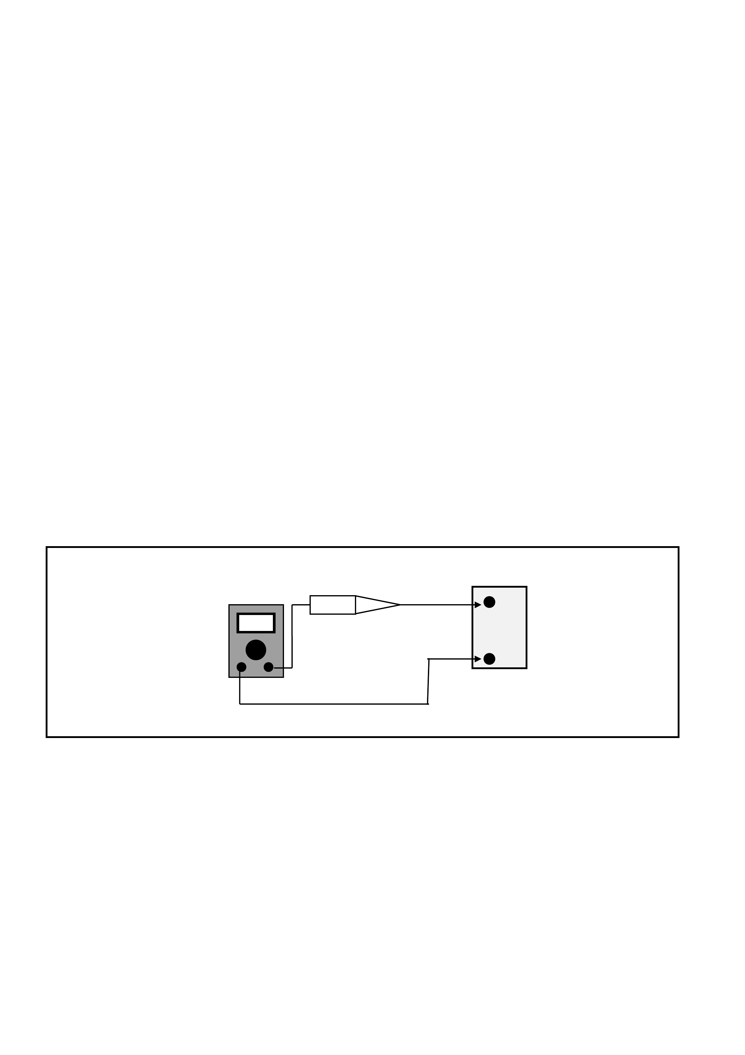
13. When a test light is specified, a "low-power" test light must be used. Do not use a high - wattage test light.
W hile a particular brand of test light is not suggested, a s imple test on any test light will ensure it to be OK for
PCM circuit testing. Connect an accurate ammeter (such as the high-impedance digital multimeter) in series
with the test light being tested, and power the test light-ammeter circuit with the vehicle battery.
Figure 6C1-3-1 Test Light Check
If the ammeter indicates than 3/10 amp current
flow (0.3 A or 300 mA), the test light is OK to use. If the ammeter indicates than 3/10 amp current flow (0.3
A or 300 mA), the test light is NOT OK to use.
+
BATTERY
-
DC AMPS
TEST LIGHT
3.2 POWERTRAIN CONTROL MODULE
Service of the Powertrain Control Module (PCM)
should normally consist of either replacement of
the PCM or PROM assembly.
If the diagnostic procedures call for the PCM to be
replaced, the PROM and PCM should be checked
first to see if they are the correct parts. If they are,
remove the PROM from the faulty PCM and install
it in the new service PCM. THE SERVICE PCM
WILL NOT CONTAIN A PROM. Trouble Code 51
indicates the PROM is installed improperly or has
malfunctioned. When Code 51 is obtained, check
the PROM installation for not being fully seated in
the socket. If it is installed correctly and Code 51
still shows, replace the PROM. Once the PCM is
replaced, you must then perform the Security Link
procedure. Refer to this section for the Security
Link procedure.
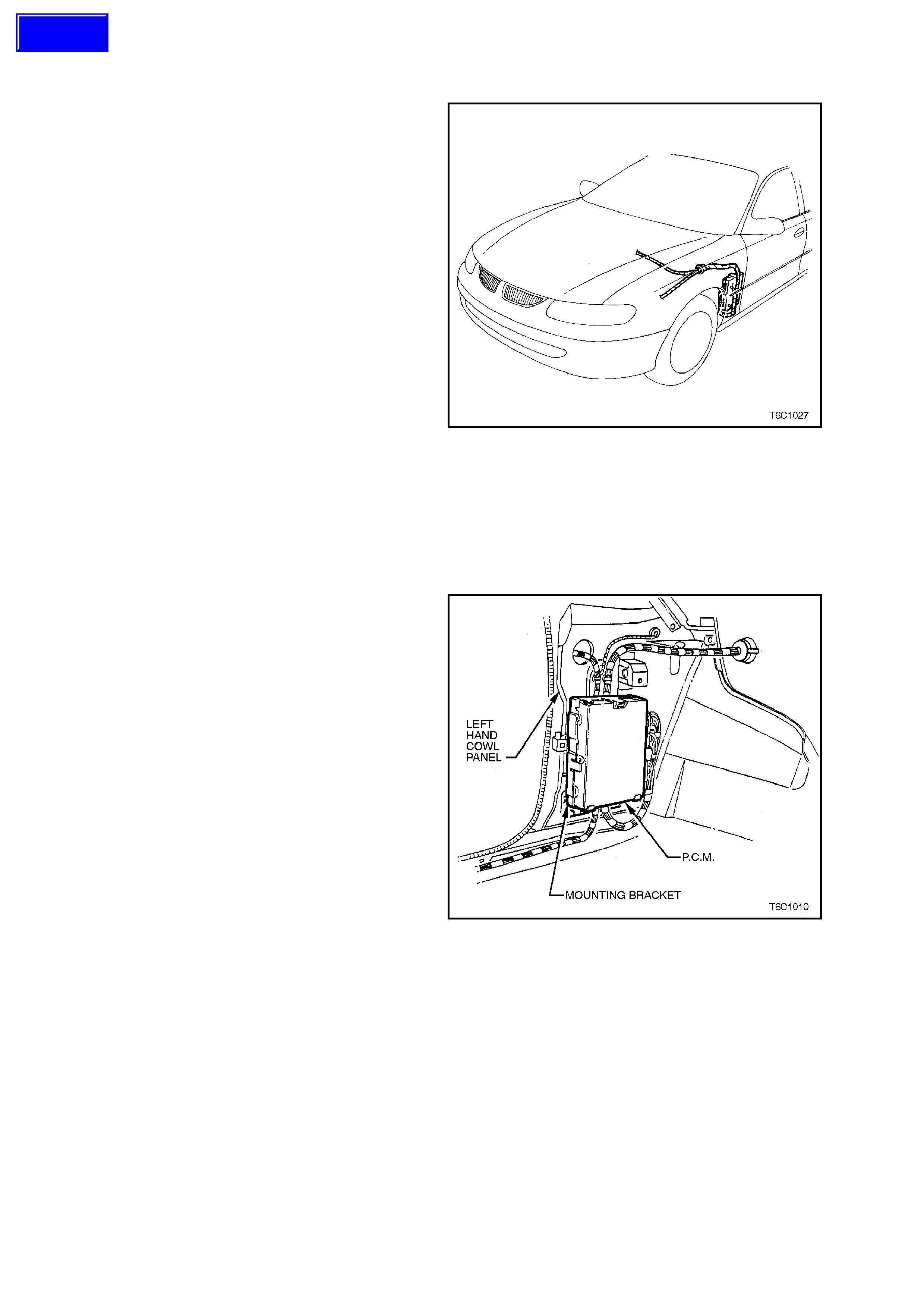
Figure 6C1-3-2 PCM Location
IMPORTANT:
• When replacing the production PCM with a
service PCM (controller), it is important to
transf er the broadcas t code and production PCM
number to the service PCM label. This will allow
positive identification of PCM parts throughout
the service life of the vehicle.
IMPORTANT:
• To prevent internal PCM damage, the ignition
must be "OFF" when disconnecting or
reconnecting power to PCM (for example,
battery cables, PCM connectors, PCM fuse
F31, jumper cables, etc.).
Figure 6C1-3-3 PCM Mounting
Techline
REMOVE
1. Disconnect battery earth lead.
2. Remove left hand f ront shroud panel lower trim
assem bly (cowl panel trim ), refer Section 1A2,
BODY DIMENSIONS in the VT Service
Information.
3. Lift up mounting bracket to PCM upper
retaining tang, pull PCM out then up to remove
it from the mounting bracket.
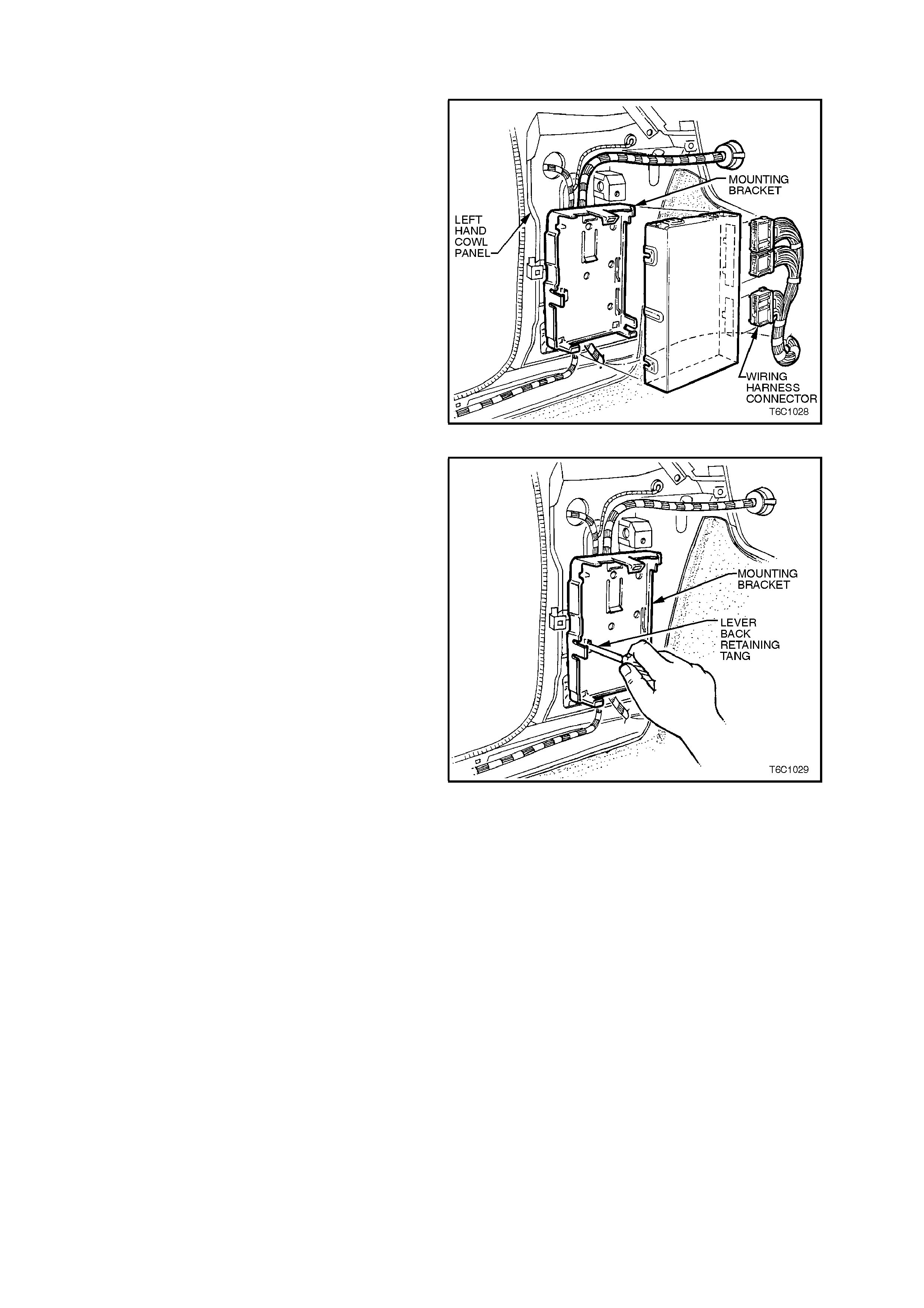
4. Remove wiring harness connectors from PCM,
remove PCM from vehicle.
5. If necessary, remove PCM PROM, refer 3.3,
PROM UNIT - REMOVE, in this Section.
IMPORTANT: Replacement controllers are
supplied without a PROM so care should be taken
when removing the PROM from the defective
controller as it will be reused in the new controller.
Do not rem ove the plastic cover of the PROM. Use
of unapproved removal methods may cause
damage to the PROM or PROM socket.
Figure 6C1-3-4 PCM Removal
6. If required, remove PCM mounting bracket by
inserting a screwdriver into the retaining tang
slot, lever screwdriver to release tang. Pull
brack et out then down to releas e from the cowl
nel.
Figure 6C1-3-5 PCM Mounting Bracket Removal

REINSTALL
1. If removed, reinstall PCM mounting bracket,
engaging bracket leg into slotted hole in cowl
panel. Lift up bracket and engage bracket
lower retainers and retaining tang into cowl
panel.
2. If required, install PROM into new PCM, refer
3.3, PROM UNIT - REINSTALL, in this
Section.
3. Reconnect wiring harness connectors to PCM
4. Assemble PCM into mounting bracket,
ensuring wiring harness is routed in fr ont of the
mounting bracket.
5. Reinstall cowl panel trim, refer to Section 1A1
- BODY in the VT Service Information.
6. Reconnect battery earth lead, start vehicle and
allow to idle. Check vehicle for correct
operation.
PCM SECURITY LINK
Once the PCM and or BCM have been replaced,
the new PCM and or BCM must be security linked
to each other. If this procedure is not performed,
the vehicle will not crank.
The PCM to BCM linking procedure is as follows:
Connect TECH 2 to DLC and select:
Diagnostic / (V) 1997 / VT Commodore / Body /
Body Control Module / Secur ity / BCM Link to PCM
and follow TECH 2 instructions.
For additional information regarding TECH 2 and
TECH 2 test modes (including this linking
procedure), refer to TECH 2 DIAGNOSIS FOR
BCM in Section 12J-1 L OW SERIES BCM or 12J-
2 HIGH SERIES BCM in the VT Service
Information.
Figure 6C1-3-6 PCM Mounting Bracket Reinstallation
3.3 PROM UNIT
DTC 51 indicates a faulty PROM, or incorrect
installation.
IMPORTANT:
The IG NITION SHO ULD ALW AYS BE "OFF" when
installing or removing the PCM connectors.
REMOVE
1. Remove PCM from passenger compartment,
refer 3.2, POWERT RAIN CONTROL MO DULE
- REMOVE, in this Section.
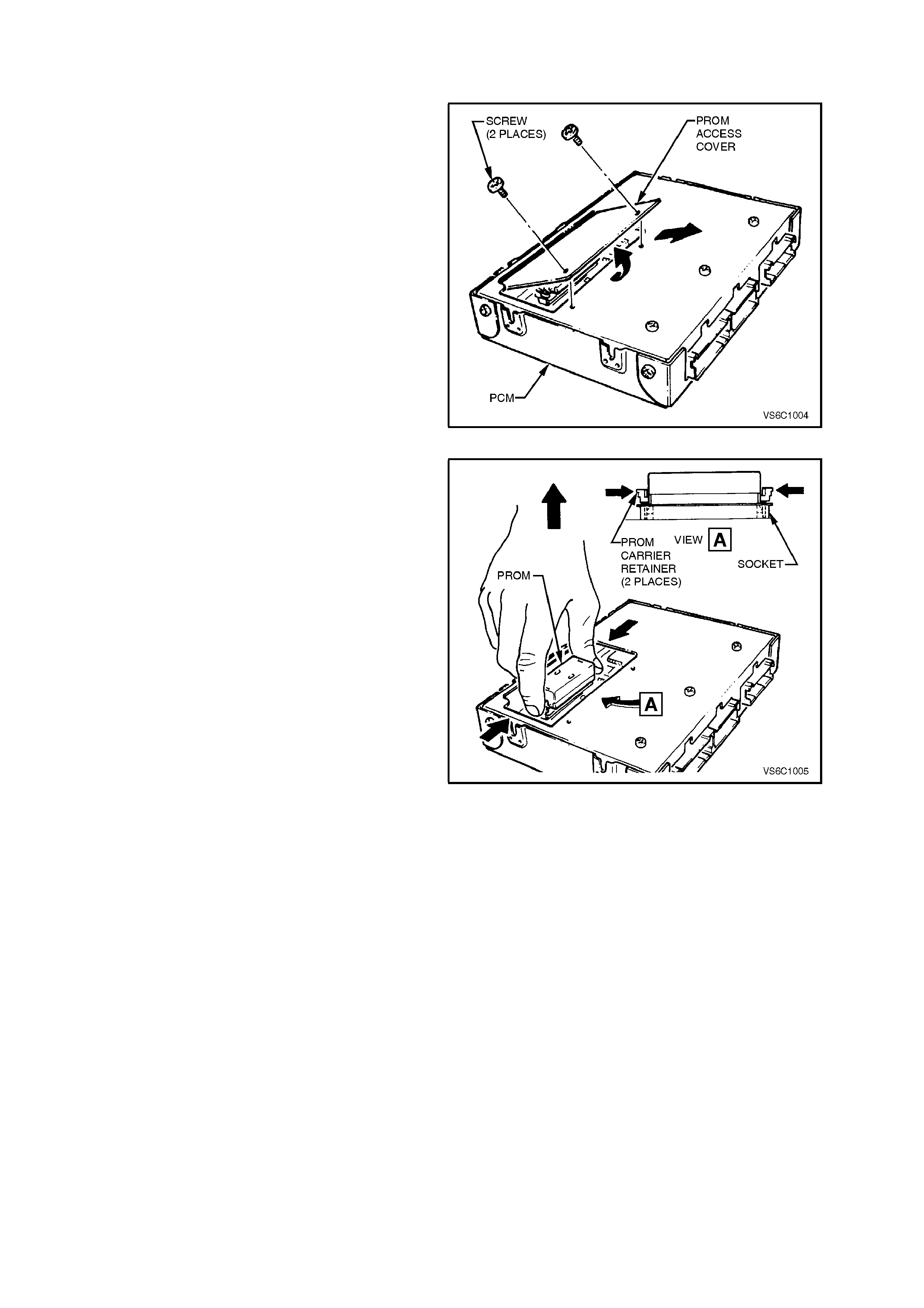
2. Using a No.15 torx bit such as Tool No.
J25359-19, remove PCM PROM access cover
screws, remove acce ss cover.
IMPORTANT:
• DO NOT remove any of the other screws.
Figure 6C1-3-7 Access Cover Removal
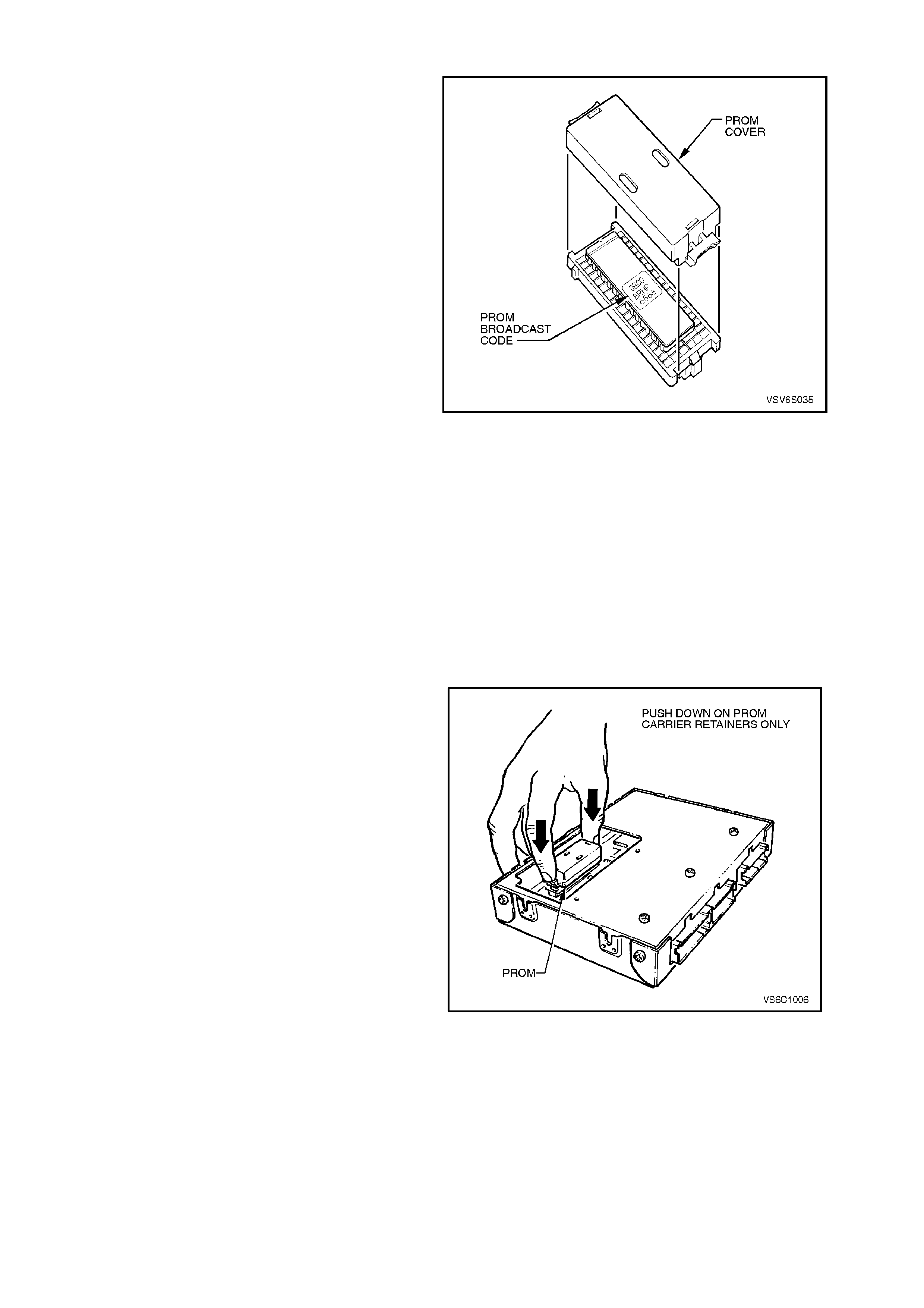
3. Rem ove PROM fr om PCM by using thumb and
finger to push retaining clips in towards the
PROM, then lift the PROM straight up and out
of the socket.
IMPORTANT:
DO NOT remove cover of the PROM. Use of
unapproved PROM removal methods will
cause damage to the PROM or PROM socket.
Figure 6C1-3-8 PROM Removal
REINSTALL
1. Remove new PROM from its packaging and
check the part number making sure it is the
correct replacement component.
2. Install PROM in PROM socket, ensuring that
sm all notches in the PROM align with the sm all
notches in the PROM socket.
3. Gently press down on the ends of the PROM
until the retaining clips click into the PROM
socket.
4. Reinstall PROM access cover onto PCM. Use
No.15 T orx bit ( Tool No. J 25359-19) to r einstall
and tighten access cover screws securely5.
Reinstall PCM, refer 3.2, POWERTRAIN
CONTROL MODULE - REINSTALL, in this
Section.
FUNCTIONAL CHECK
1. Turn ignition "ON."
2. Earth DLC diagnostic "test" terminal.
A. DTC 12 should flash four times. (No other
codes present.) This indicates the PROM is
installed properly.
B. If diagnostic trouble DTC 51 occurs or if
the "check powertrain lamp" (MIL) is on
constantly with no DTC's, the PROM is not fully
seated or is defective. In this event, remove or
reinstall the PROM as per previous
instructions.
Figure 6C1-3-9 PROM Identification
Figure 6C1-3-10 PROM Reinstallation
3.4 CAMSHAFT POSITION SENSOR
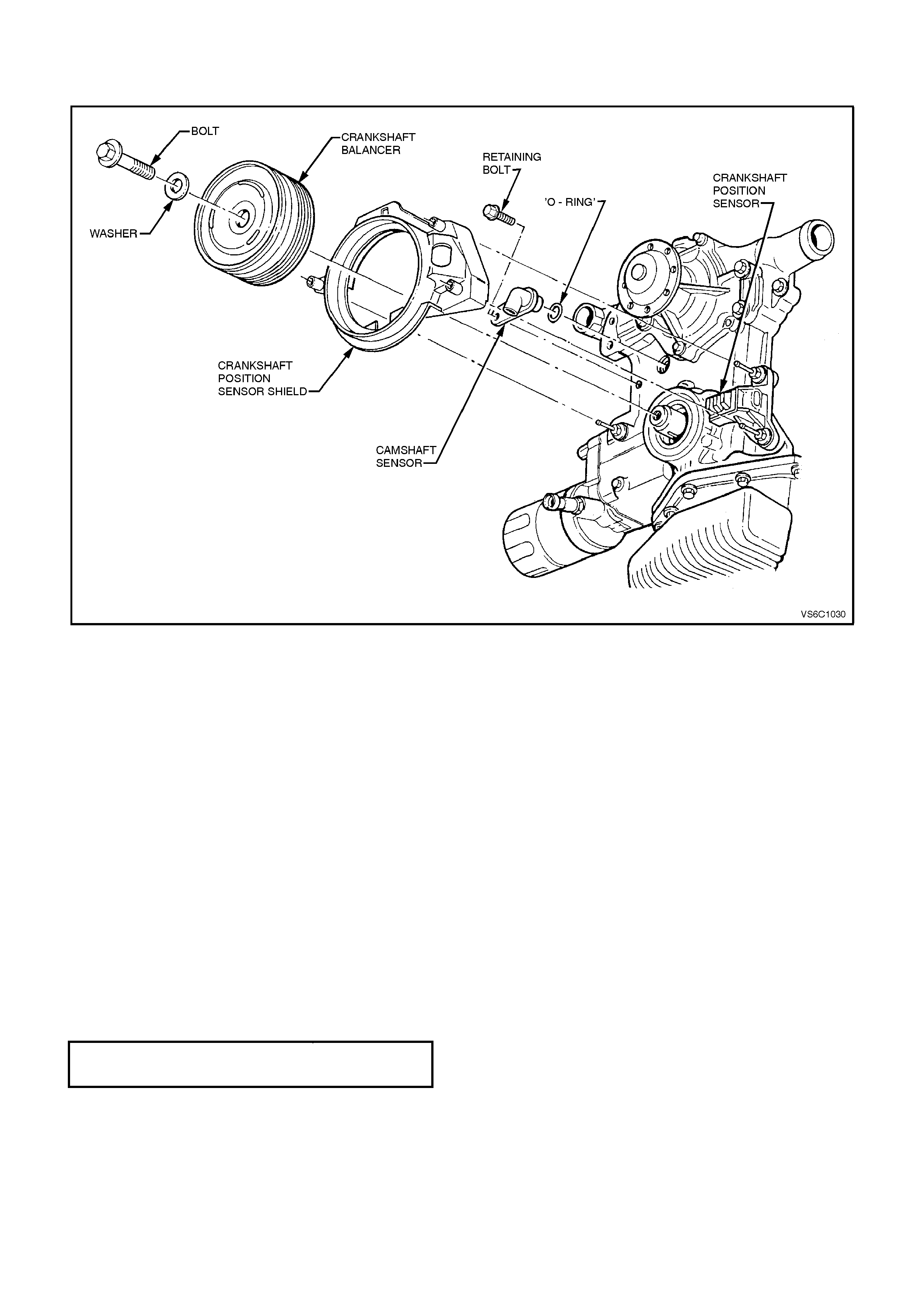
Figure 6C1-3-11 Camshaft/Crankshaft Position Sensors
REMOVE
1. Disconnect battery earth lead.
2. Lift up retaining tang and disconnect wiring
harness connector from camshaft position
sensor.
3. Remove camshaft position sensor to front cover
retaining bolt.
4. Remove camshaft position sensor and O-ring
from front cover.
REINSTALL
1. Apply light engine oil to O-ring on new camshaft
position sensor.
2. Assemble camshaft position sensor into front
cover hole.
3. Install camshaft position sensor to front cover
retaining bolt and tighten to the correct torque
specification.
CAMSHAFT POSITION SENSOR
RETAINING BOLT
TORQUE SPECIFICATION
11 Nm
3. Reconnect wiring harness connector to camshaft
position sensor.
4. Reconnect battery earth lead.

3.5 ENGINE COOLANT TEMPERATURE (ECT) SENSOR
SUPERCHARGED ENGINE
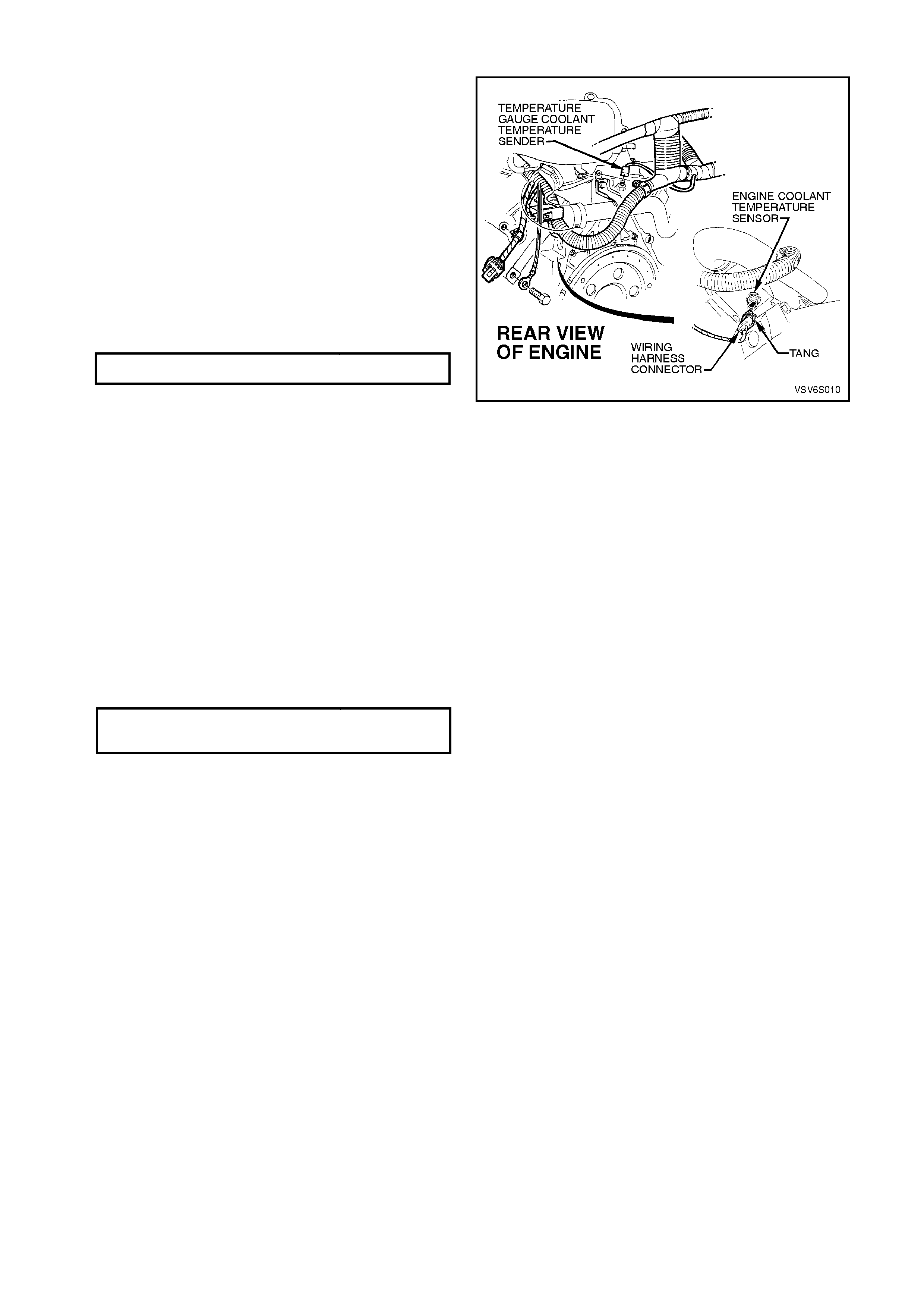
IMPORTANT:
• Care must be taken when handling PCM
engine coolant sensor. Damage to sensor
will affect the operation of the engine
management system. Ensure that the
correct sensor is located before service is
attempted. There are different engine
coolant temperature sensors: for the PCM,
the instrument panel gauge, and/or warning
lights. Sensors are located in the rear of the
inlet manifold below the engine thermostat
housing.
CAUTION: The Engine Coolant Temperature
(ECT) sensor is installed into a "wet" engine
coolant passage (in the inlet manifold, below the
thermostat housing). Drain the engine coolant
before removing the ECT sensor from the engine.
Position a coolant drain pan appropriately, then
loosen lower radiator hose at the radiator to drain
the coolant.
REMOVE
1. Disconnect battery earth lead.
2. Depressurize engine cooling system by
removing radiator cap in two stages.
CAUTION: DO NOT REMOVE RADIA TOR CAP
WHILE THE ENGINE COOLANT TEMPERATURE
IS ABOVE 50 DEGREES C.
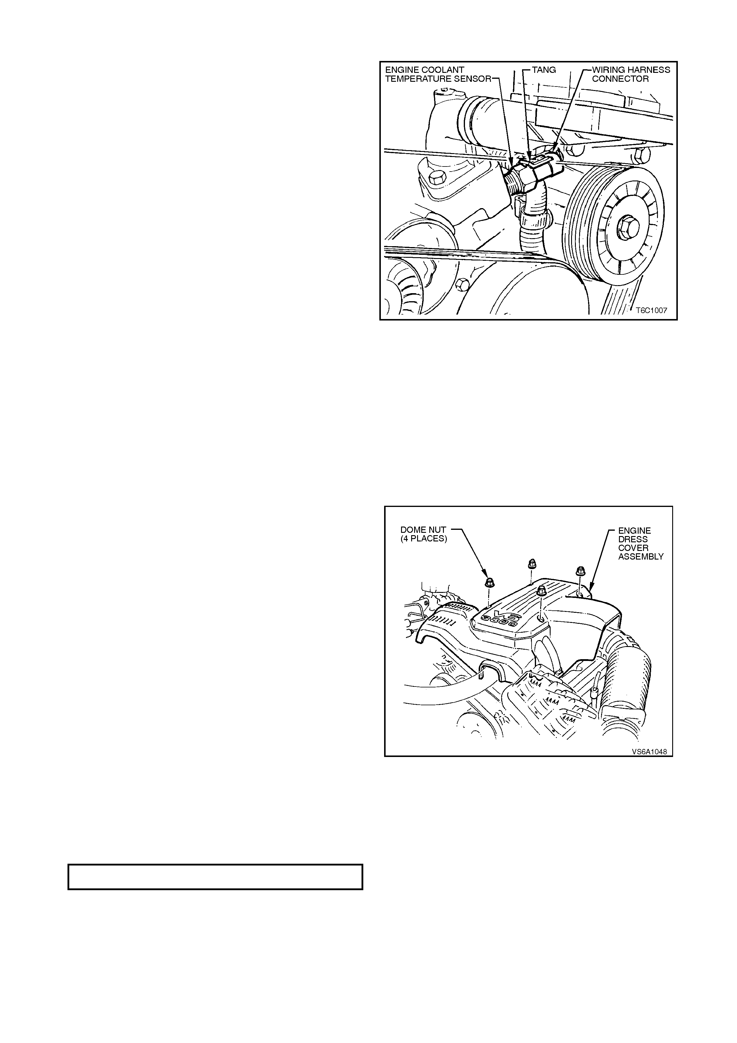
3. Remove four dome nuts securing the engine
dress cover assembly to the inlet manifold
studs, lift off and remove the cover assembly.
4. Position a coolant drain pan appropriately
beneath the vehicle, then loosen lower radiator
hose at the radiator to drain the engine coolant.
5. Lift up retaining tang and disconnect wiring
harness connector from PCM ECT sensor. Lift
connector up away from sensor.
Figure 6C1-3-12 V6 Supercharged Engine Dress Cover
6. Carefully move powertrain wiring harness
down under the ECT sens or so as to allow tool
access to the sensor.
7. Using a 19 mm ring spanner, carefully loosen
and remove PCM engine coolant temperature
sensor.
Reinstall
1. Apply Loctite 242 (Holden's Specification
HN1256 Class 2, Type 2) sealant to sensor
threads.
2. Install ECT sensor into inlet manifold and
tighten to the correct torque specification.
3. Reconnect wiring harness connector onto ECT
sensor,
IMPORTANT: Recheck that wiring harness
connector and harness are correctly positioned.
The accessory drive belt passes very close to the
temperature sensor connectors. Future damage to
the harness could occur if not correctly positioned
now.
4. Reconnect battery earth lead.
5. Refill the engine coolant system, refer to
Section 6B1, ENGINE COOLING - V6
ENGINE in the VT Service Information.
6. Reinstall engine dress cover to the inlet
manif old, ensuring that s tud gromm ets in dress
cover remain in place. Tighten securing dome
nuts to the correct torque specification.
ECT SENSOR TO INLET MANIFOLD
TORQUE SPECIFICATION 15 - 20
Nm
Figure 6C1-3-13 ECT Sensor Location Supercharge
ENGINE DRESS COV E R SECURING
DOME NUT TO INLET MANIFOLD
TORQUE SPECIFICATION
4 - 6 Nm
NON-SUPERCHARGED ENGINE
IMPORTANT:
• Care must be taken when handling PCM
engine coolant sensor. Damage to sensor
will affect the operation of the engine
management system. Ensure that the
correct sensor is located before service is
attempted. There are different engine
coolant temperature sensors: for the PCM,
the instrument panel gauge, and/or warning
lights. Sensors are located in the front of
the inlet manifold below the engine
thermostat housing.
CAUTION: The Engine Coolant Temperature
(ECT) sensor is installed into a "wet" engine
coolant passage (in the inlet manifold, below
the thermostat housing). Drain the engine
coolant before removing the ECT sensor from
the engine. Position a coolant drain pan
appropriately, then loosen lower radiator hose
at the radiator to drain the coolant.
Remove
1. Disconnect battery earth lead.
2. Depressurize engine cooling system by
removing radiator cap in two stages.
CAUTION: DO NOT REMOVE RADIA TOR CAP
WHILE THE ENGINE COOLANT TEMPERATURE
IS ABOVE 50 DEGREES C.
Figure 6C1-3-14 ECT Sensor Location Non-Supercharge
3. Remove four dome nuts securing the engine
dress cover assembly to the inlet manifold
studs, lift off and remove the cover assembly.
4. Position a coolant drain pan appropriately
beneath the vehicle, then loosen lower radiator
hose at the radiator to drain the engine coolant.
5. Lift up retaining tang and disconnect wiring
harness connector from PCM ECT sensor. Lift
connector up away from sensor.
6. Carefully move powertrain wiring harness
down under the ECT sens or so as to allow tool
access to the sensor.
7. Using a 19 mm ring spanner, carefully loosen
and remove PCM engine coolant temperature
sensor.
Reinstall
1. Apply Loctite 242 (Holden's Specification
HN1256 Class 2, Type 2) sealant to sensor
threads.
2. INSTALL ECT SENSOR INTO INLET
MANIFOLD AND TIGHTEN TO THE CORRECT
TORQUE SPECIFICATION.
Figure 6C1-3-15 Engine Dress Cover
V6 Non-Supercharged Engine
ECT SENSOR TO INLET MANIFOLD
TORQUE SPECIFICATION 15 - 20
Nm
3. Reconnec t wiring harness connec tor onto ECT
sensor,
IMPORTANT: Recheck that wiring harness
connector and harness are correctly positioned.
The accessory drive belt passes very close to the

temperature sensor connectors. Future damage to
the harness could occur if not correctly positioned
now.
4. Reconnect battery earth lead.
5. Refill the engine coolant system, refer to
Section 6B1-1, ENGINE COOLING - V6
ENGINE the VT Service Information.
6. Reinstall engine dress cover to the inlet
manifold, ensuring that stud grommets in
dress cover remain in place. Tighten securing
dome nuts to the correct torque specification.
ENGINE DRESS COV E R SECURING
DOME NUT TO INLET MANIFOLD
TORQUE SPECIFICATI O N 4 - 6
Nm
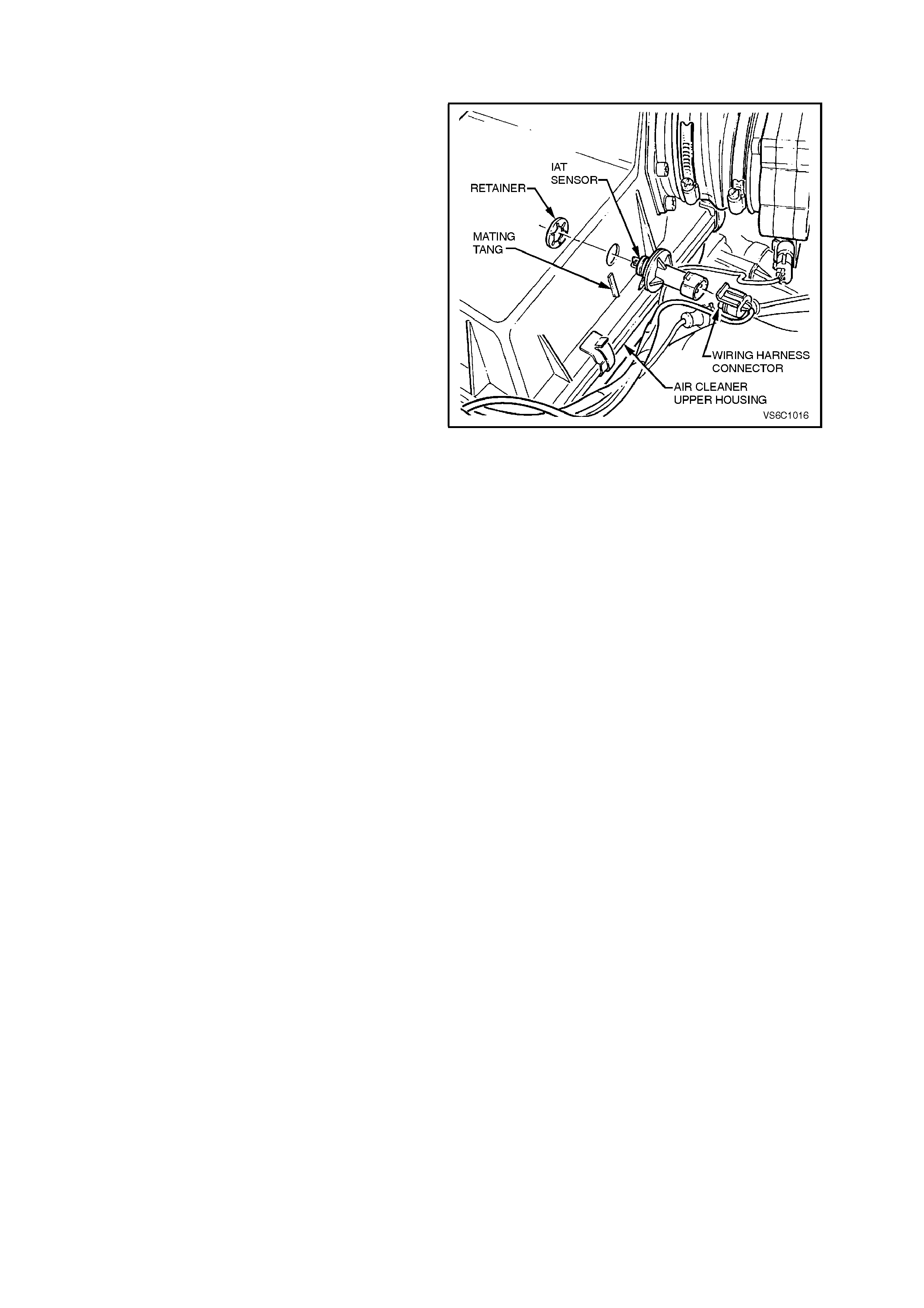
3.6 INTAKE AIR TEMP ERATURE (IAT) SENSOR
IMPORTANT:
• Care must be taken when handling IAT
Sensor. Damage to IAT sensor will affect
proper operation of the fuel control system.
REMOVE
1. Disconnect battery earth lead.
2. Lift up tang on IAT sensor wiring harness
connector and pull connector from sensor.
3. Loosen intake air duct adapter clamp that is
located closest to air cleaner assembly.
4. Disconnect air duct, with mass air flow sensor
attached, from air cleaner upper housing.
5. Unclip 5 retaining clips holding the air cleaner
upper housing in place.
6. Separate the upper and lower air cleaner
housings.
NOTE: Air filter should remain in the lower
housing.
7. Remove air cleaner upper housing and place
on bench.
8. Using a pair of side cutters, cut across the IAT
sensor retainer to remove it. Once removed,
discard retainer.
9. Pull out IAT sensor from air cleaner upper
housing.
Figure 6C1-3-16 IAT Sensor Removal
REINSTALL
1. Push new IAT sensor into air cleaner upper
housing, with triangular tang on the mounting
flange locating on the mating rib of the air
cleaner upper housing.
2. Pos ition the upper air cleaner housing assem bly,
with the IAT sensor on the work bench, pushing
up into the air cleaner upper housing.
Position new retainer onto IAT sensor and then
using a 20 mm socket, push the retainer fully
onto the IAT sensor.
3. Assemble the air filter element into the air
cleaner upper housing and place the upper
housing onto the air cleaner lower air cleaner
housing, ensuring that air filter element remains
in position.
4. Snap 5 retainer clips up into place over the top
of the air cleaner upper housing.
5. Reconnect wiring harness connector to IAT
sensor.
6. Carefully assemble intake air duct and mass air
flow sensor onto air cleaner upper housing.
NOTE: Align notch on air cleaner housing adapter
with notch in air duct adapter and notch in clamp.
7. Tighten air duct clamp securely.
8. Check that mass air flow sensor wiring harness
connector has remained firmly in place.
9. Reconnect battery earth lead.
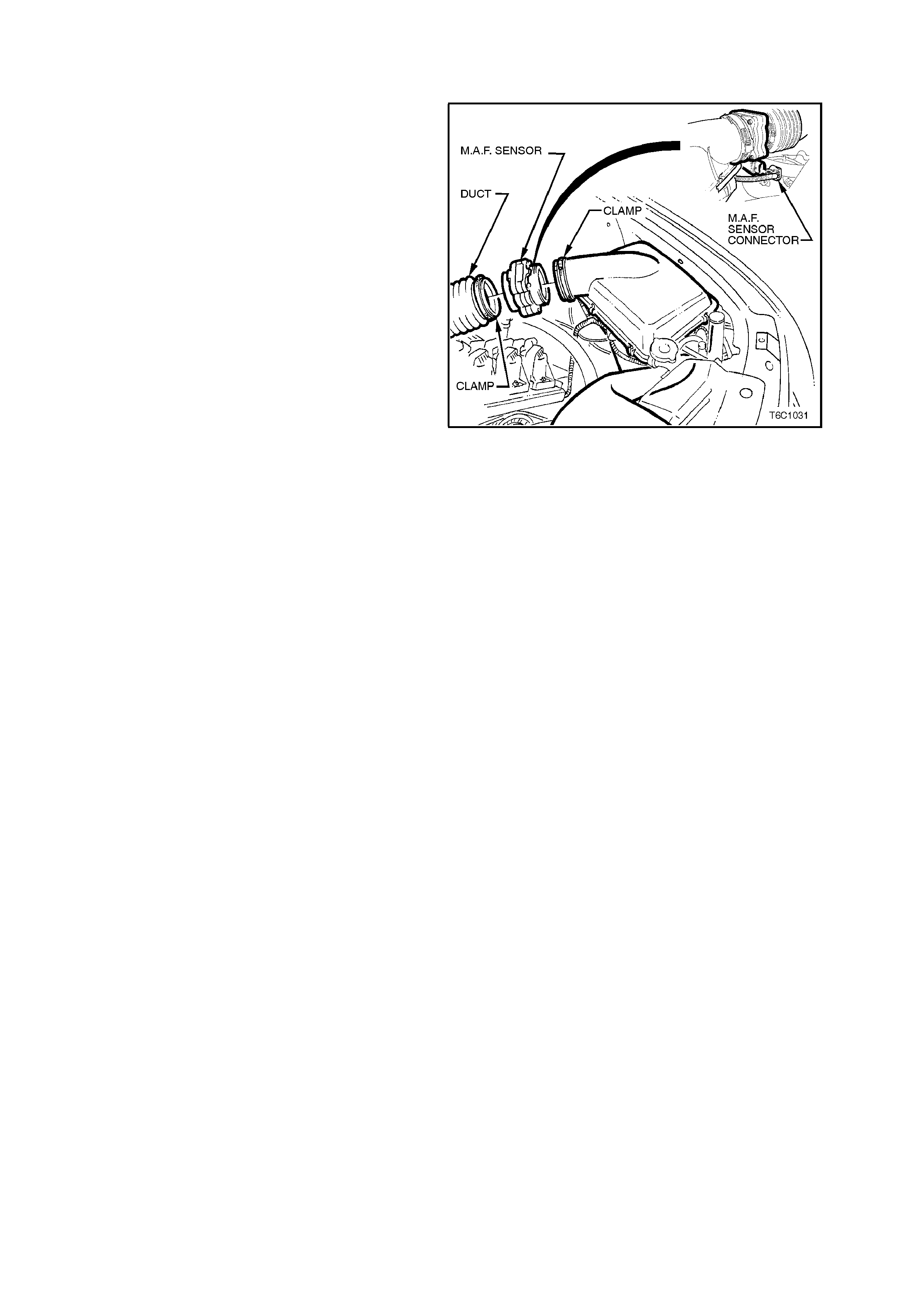
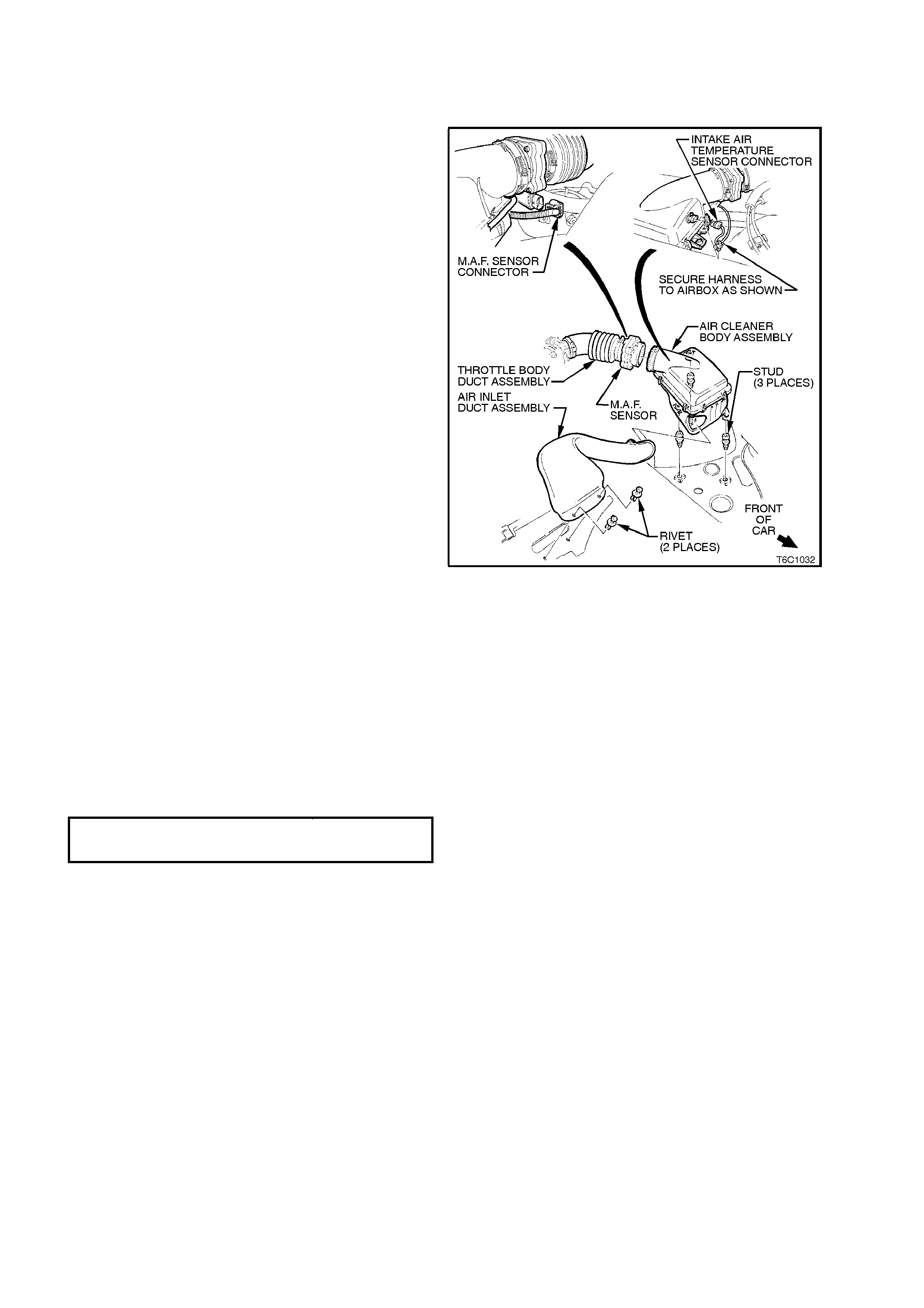
3.7 MASS AIR FLOW (MAF) SENSOR
IMPORTANT:
Care must be taken when handling MAF sensor.
Damage to MAF sensor will aff ect proper operation
of PCM control.
REMOVE
1. Disconnect battery earth lead.
2. Lift up tang on MAF sensor wiring harness
connector and pull connector from sensor.
3. Loosen clamp on air duct adapter, closest to
MAF sensor.
4. Loosen clamp on air duct at MAF sensor and
pull back air duct from sensor.
NOTE: Air duct adapter (between air cleaner and
MAF sensor), both clamps, air duct and MAF
sensor itself have locating notches.
5. Remove MAF sensor from air duct adapter.
REINSTALL
1. Ins tall MAF sensor into air duc t adapter and air
duct, aligning all notches. Install clamps,
aligning notches, tighten clamps securely.
2. Reconnect MAF sensor wiring harness
connector
3. Reconnect battery earth lead.
4. Start vehicle and check for air leaks.
Figure 6C1-3-17 MAF Sensor Removal
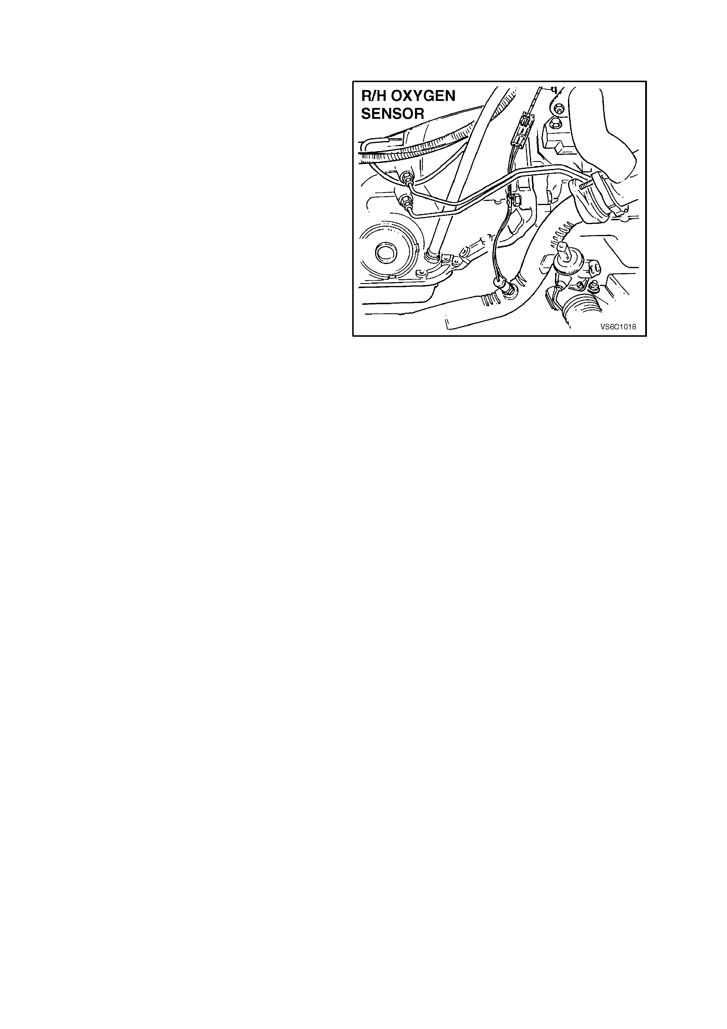
3.8 OXYGEN SENSOR
IMPORTANT:
• The oxygen sensor uses a permanently
attached pigtail and connector. This pigtail
should not be removed fr om the oxygen
sensor. Damage or removal of the pigtail or
connector will affect proper operation of the
oxygen sensor.
• Take care when handling the oxygen
sensor. The in-line electrical connector and
louvered end must be kept free of grease,
dirt or other c ontaminants. Avoid using any
cleaning solvents. Do not drop or roughly
handle the oxygen sensor.
NOTE: The oxygen sensor may be difficult to
remove when engine temperature is below 60
degrees Celsius. Excessive force may damage
threads in exhaust pipe, or on the sensor.
NOTE: The Supercharger application requires a
four wire heated oxygen sensor. Be sure only a
four wire heated sensor is used for the
Supercharger application.
REMOVE
1. Disconnect battery earth lead.
2. Lift up retaining tang on oxygen sensor wiring
harness connector and pull connector from
sensor pigtail connector.
For R.H sens or, the connector is located at the
rear of the R.H cylinder head and is accessed
from the rear of the engine compartment. The
sensor pigtail leads are further retained by a
clip attached to the torque converter housing.
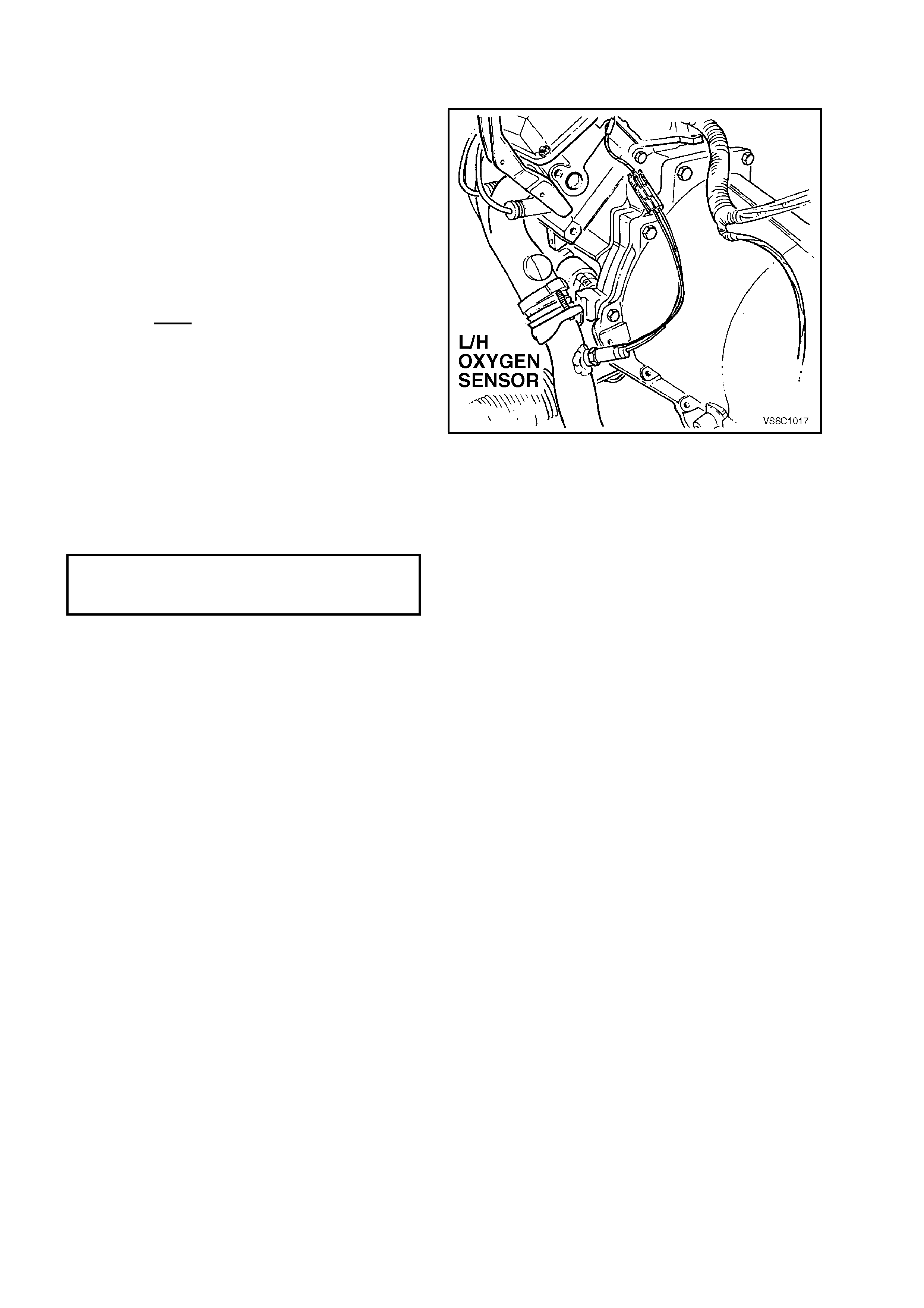
For L.H sensor, the connector is located at the
rear of the L.H cylinder head and is accessed
from the rear of the engine compartment.
3. Raise vehicle and place on suitable safety
stands. Refer to Section 3, FRONT
SUSPENSION, in the VT Service Information.
4. Carefully unscrew oxygen sensor from exhaust
pipe referring to previous NOTE.
Figure 6C1-3-18 R.H. Sensor Location (Two wire sensor)
REINSTALL
IMPORTANT:
• A special anti-seize compound is used on
the oxygen sensor threads. The compound
consists of a liquid graphite and very sma ll
glass beads. The graphite will burn away,
but the glass beads will remain, making the
sensor easier to remove.
• Genuine replacement sensors will already
have the compound applied to the threads.
If a sensor is r emoved from an engine, and,
if for any reason it is to be reinstalled, the
threads must have the specified anti-seize
compound applied before reinstallation.
Specified anti-seize compound is available from
authorized Holden Parts Outlets as part number
5613695.
1. If necessary, coat threads of oxygen sensor
with
specified anti-seize compound.
2. Install oxygen sensor into exhaust pipe and
tighten to the correct torque specification.
OXYGEN SENSOR TO
EXHAUST
MANIFOLD TO RQUE
SPECIFICATION
40-50
Nm
3. Remove safety stands and lower the vehicle.
4. Reconnect oxygen sensor wiring harness
connector.
NOTE: Ensure that the R.H sensor pigtail leads are
retained by a clip attached to the torque converter
housing
5. Reconnect battery earth lead.
Figure 6C1-3-19 L.H Sensor Location (Two wire sensor)
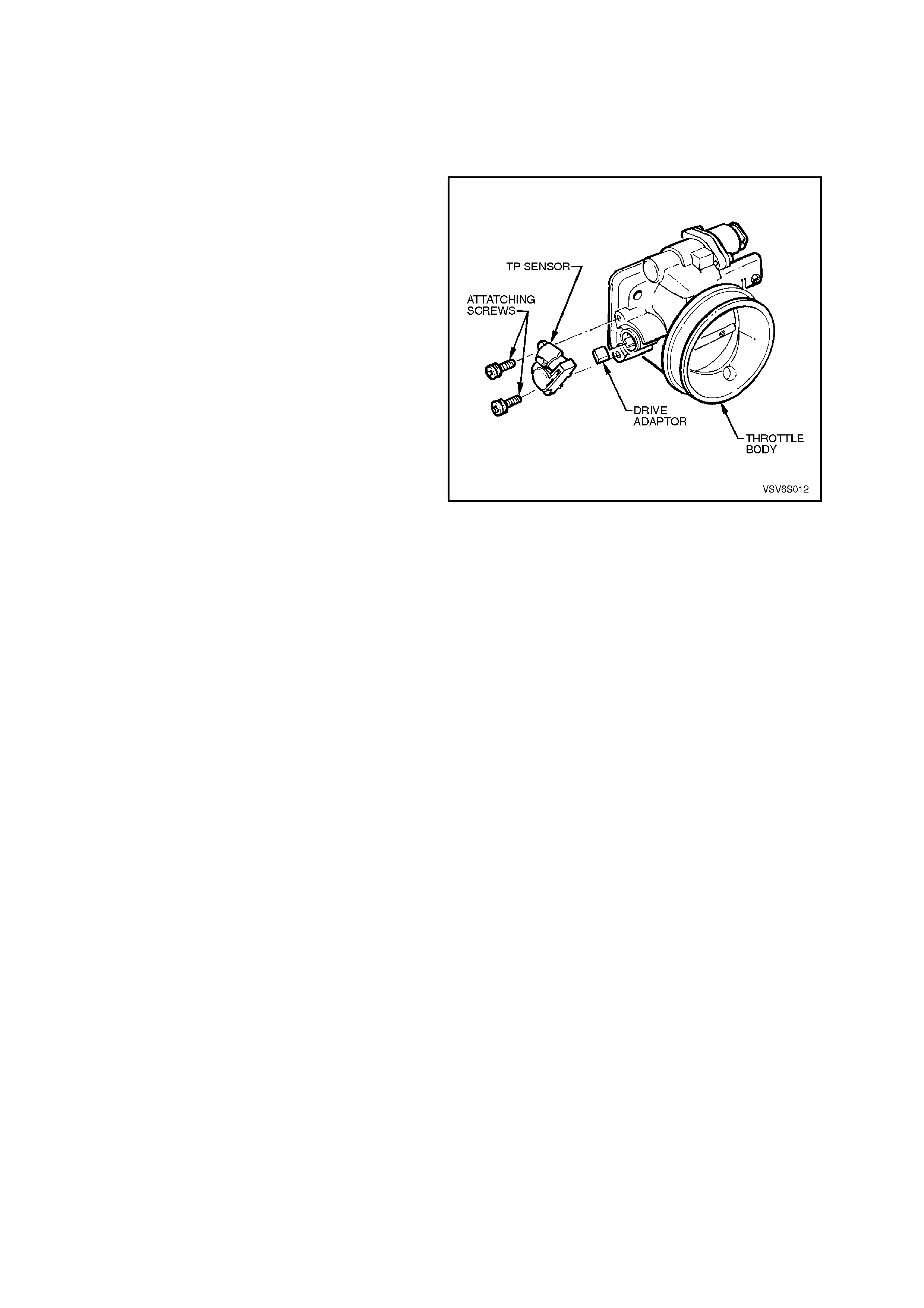
3.9 THROTTLE POSITION (TP) SENSOR
SUPERCHARGED ENGINE
Remove
1. Disconnect battery earth lead.
2. Remove four dome nuts securing the engine
dress cover assembly to the inlet manifold
studs, lift off and remove the cover assembly.
3. Loosen rear air duct c lamp to throttle body and
remove air duct.
4. Disconnect throttle cable, and if fitted cruise
control cable from throttle body linkage.
5. Remove the three (3) retaining nuts to throttle
cable bracket on side of throttle body.
6. Rem ove the two (2) throttle body retaining nuts
and throttle body.
7. Lift up retaining tang on TP sensor wiring
harness connector and pull connector from
sensor.
8. Remove the two (2) TP sensor to throttle body
attaching screws.
9. Remove sensor from throttle body taking care
not to lose the driver adapter.
NOTE: The "drive adapter" is a plastic cover that
loosely slides over the end of the throttle shaft, on
the TP sensor side of the throttle body. It is
captured in place when the TP sensor is in position
on the throttle body. The drive adapter could fall
from the throttle shaft after the TP sensor is
removed. Ensure that the drive adapter is not lost.
Figure 6C1-3-20 TP Sensor Removal Supercharge
Reinstall
1. Check that the drive adapter is in place on the
throttle valve shaft, refer to previous NOTE.
2. With throttle valve in the normally closed idle
position, install TP sensor on to throttle valve
shaft and throttle body at a position 30 degrees
clockwise past throttle body attaching screw
holes.
3. Rotate TP sensor anti-clockwise on throttle body,
and install TP sensor attaching screws and
tighten to the correct torque specification.
TP SENSOR TO THROTTLE BODY
ATTA CHI NG SCREW T O RQUE
SPECIFICATION
1 - 1.5 Nm
4. Install throttle body and two (2) attaching nuts.
THROTTLE BODY ATTACHING NUTS 15-20 Nm
5. Install Throttle Body cable attaching bracket.
THROTTLE CABLE BRACKET
ATTACHING NUTS
2-5 Nm
6. Install air cleaner duct to Throttle Body, and
tighten clamp.
7. Reconnect TP sensor wiring harness
connector.
8. Reinstall engine dress cover to the inlet
manifold, ensuring that stud grommets in the
dress c over remain in plac e . T ighten securing
dome nuts to the correct torque specification.
ENGINE DRESS COV E R SECURING
DOME NUT TO INLET MANIFOLD
TORQUE SPECIFICATI O N 4 - 6
Nm
9. Reconnect battery earth lead.
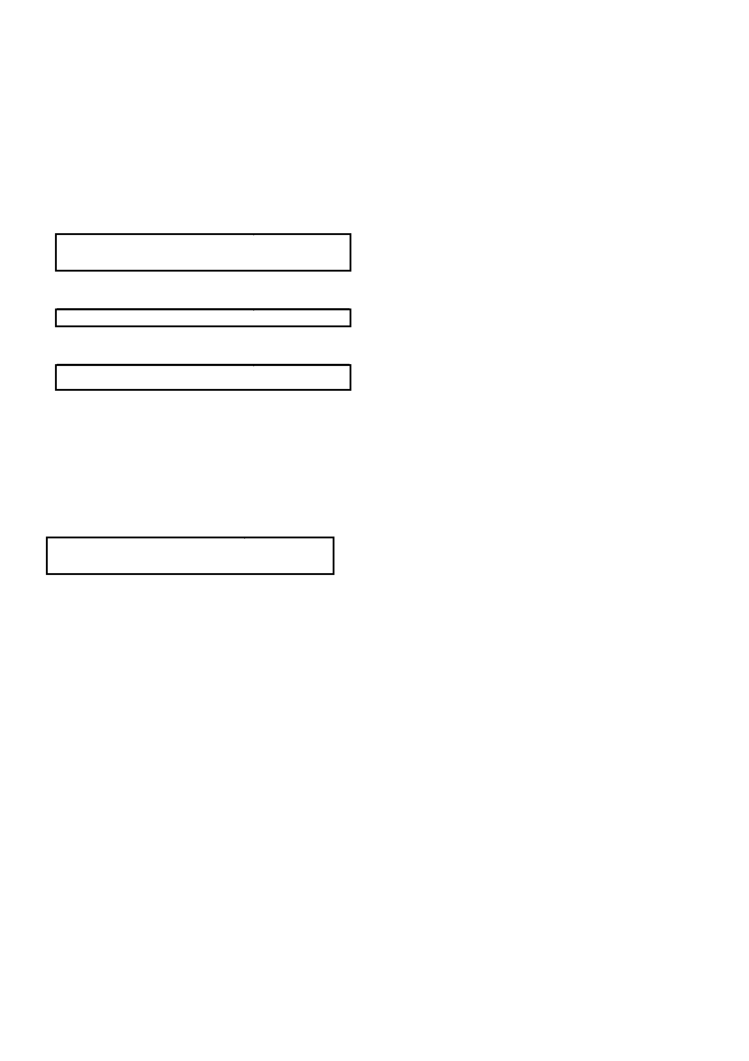
NON-SUPERCHARGED ENGINE
Remove
1. Disconnect battery earth lead.
2. Remove four dome nuts securing the engine
dress cover assembly to the inlet manifold
studs, lift off and remove the cover assembly .
Refer to Figure 6C1-3-15.
3. Lift up retaining tang on TP sensor wiring
harness connector and pull connector from
sensor.
4. Remove the two TP sensor to throttle body
attaching screws.
5. Remove sensor from throttle body taking care
not to lose the drive adapter
NOTE: The "drive adapter" is a plastic cover that
loosely slides over the end of the throttle shaft, on
the TP sensor side of the throttle body. It is
captured in place when the TP sensor is in position
on the throttle body. The drive adapter could fall
from the throttle shaft after the TP sensor is
removed. Ensure that the drive adapter is not lost.
Figure 6C1-3-21 TP Sensor Removal Non-Supercharge
Reinstall
1. Check that the drive adapter is in place on the
throttle valve shaft, refer to previous NOTE.
2. With throttle valve in the normally closed idle
position, install TP sensor on to throttle valve
shaft and throttle body at a position 30 degrees
clockwise past throttle body attaching screw
holes.
3. Rotate TP sensor anti-clockwise on throttle body,
and install TP sensor attaching screws and
tighten to the correct torque specification.
TP SENSOR TO THROTTLE BODY
ATTA CHI NG SCREW T O RQUE
SPECIFICATION
1 - 1.5 Nm
4. Reconnect TP sensor wiring harness connector.
5. Reinstall engine dress cover to the inlet manifold,
ensuring that stud grommets in the dress cover
remain in place . Tighten securing dome nuts to
the correct torque specification.
ENGINE DRESS COVER SECURING
DOME NUT TO INLET MANIFOLD
TORQUE SPECIFICATION
4 - 6 Nm
6. Reconnect battery earth lead.
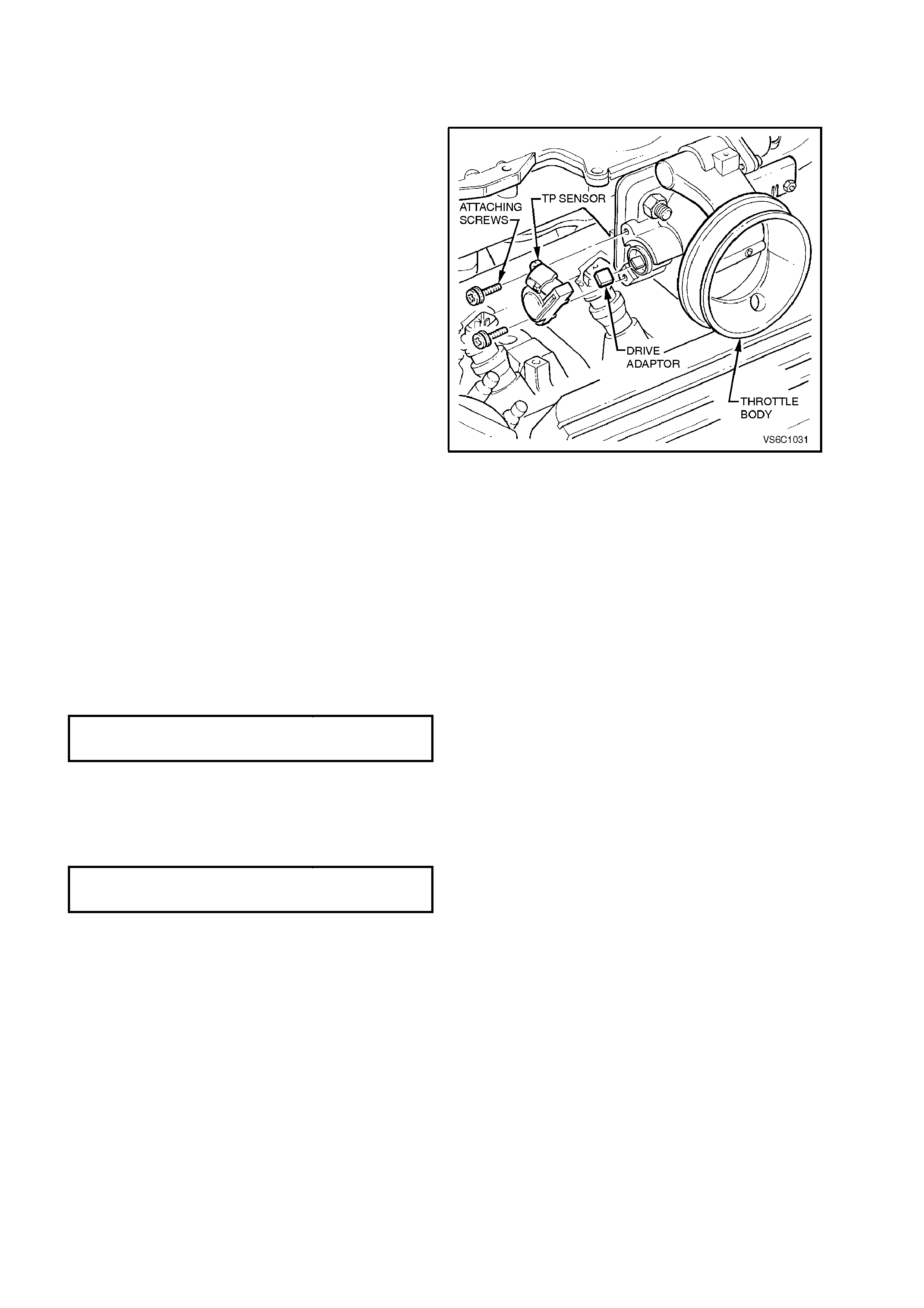
3.10 VEHICLE SPEED SENSOR
AUTOMATIC TRANSMISSION
Remove
1. Jack up rear of vehicle and support on safety
stands. For location of jacking points, refer to
Section 0A, GENERAL INFORMATION in the
VT Service Information.
2. Lift up tang on VSS wiring harness connector
and pull connector from VSS
3. Remove VSS to transmission extension
housing bolt.
4. Remove VSS and O-ring seal from extension
housing by slowly prying out sensor with a flat
screwdriver.
Reinstall
1. Coat the VSS O-ring seal with a thin film of
transmission fluid.
2. Install new VSS and O-ring into transmission
extension housing.
3. Install retaining bolt and tighten to the correct
torque specification.
4. Reconnect wiring harness connector to VSS.
Remove safety stands and lower vehicle.
VSS RE T AINING BO LT T ORQUE
SPECIFICATION 11 Nm
Figure 6C1-3-22 VSS Location Automatic Transmission
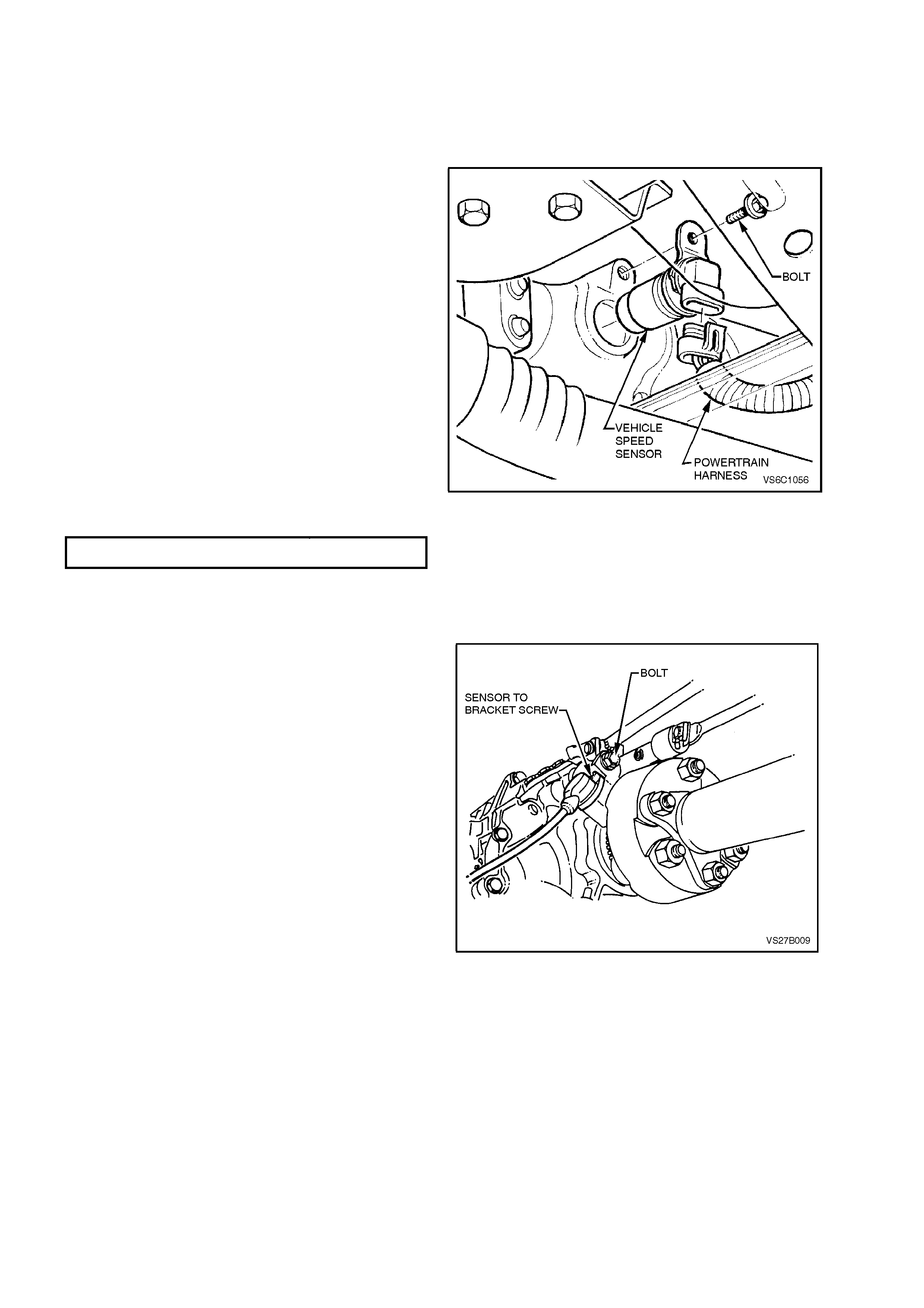
MANUAL TRANSMISSION For vehicle speed sensor removal and
reinstallation, refer to Section 7B-1 MANUAL
TRANSMISSION - V6 in the VT Service
Information.
Figure 6C1-3-23 VSS Location Manual Transmission
3.11 FUEL CONTROL SYSTEM
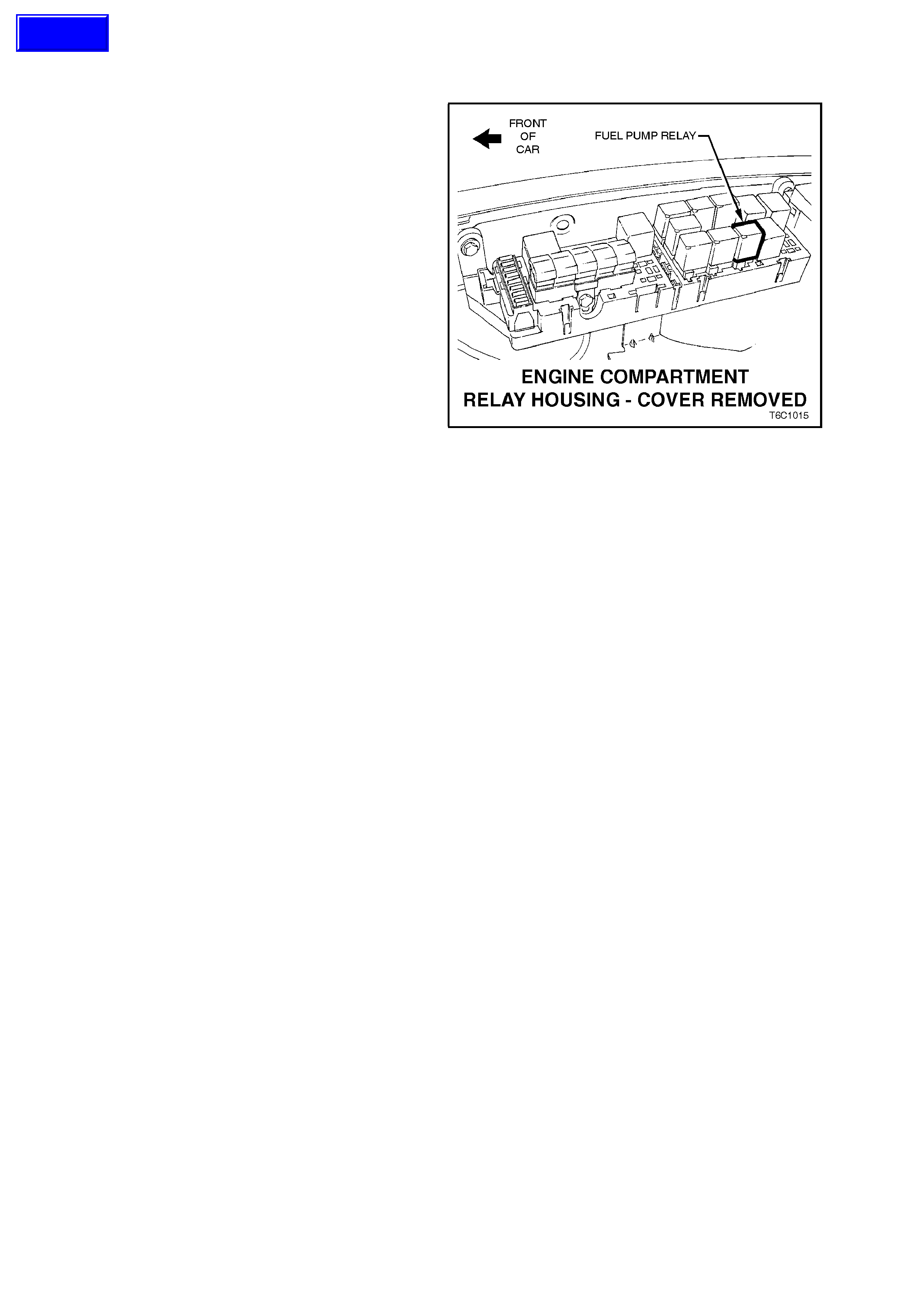
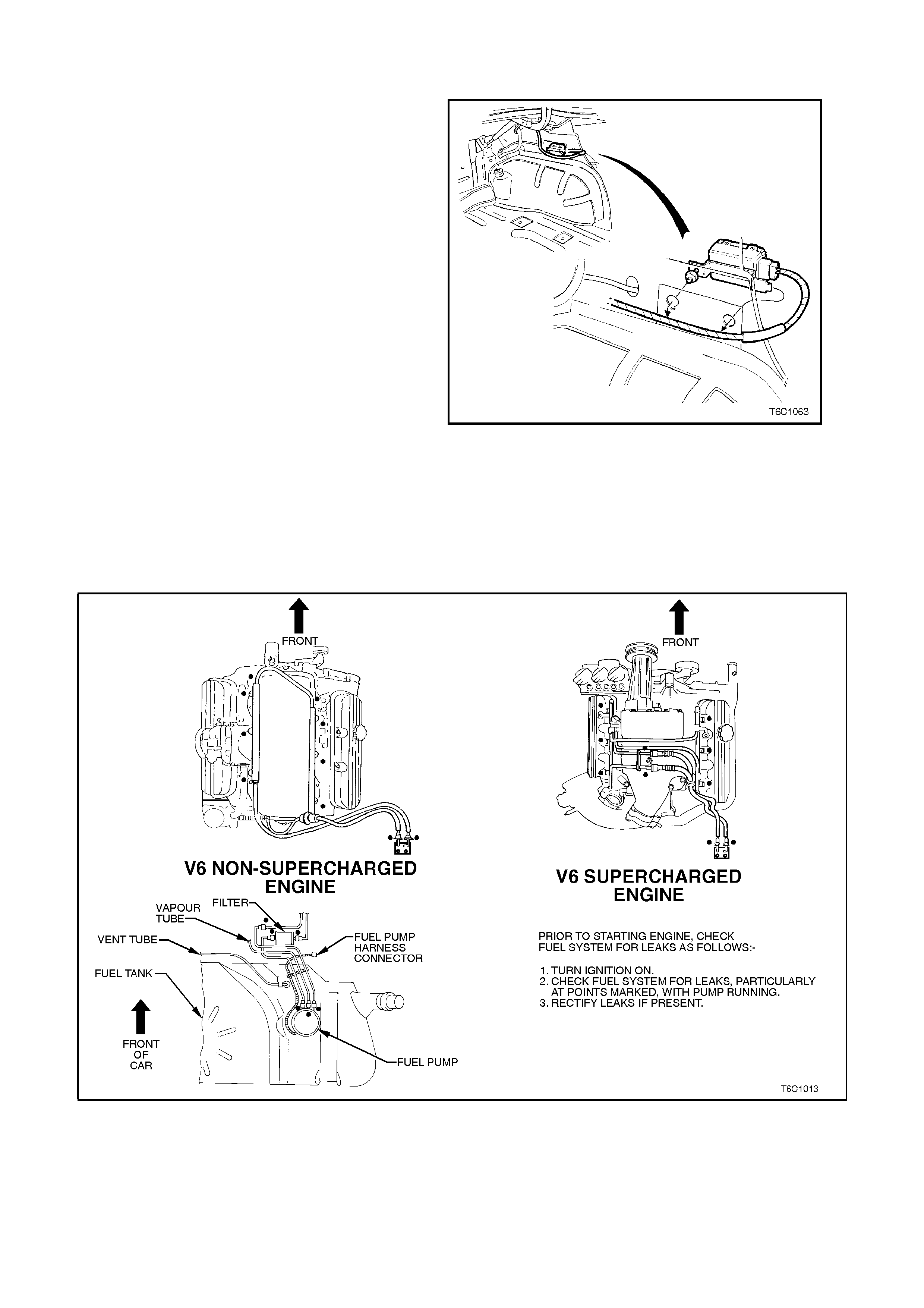
FUEL PUMP RELAY
The fuel pump relay is located in a relay housing,
in the engine compartment. The relay housing is
positioned forward of the right side (driver's side)
strut tower, in front of the cooling system coolant
recovery reservoir. Other than checking for loose
connectors, the only service possible is
replacement.
FUEL PRESSURE RELIEF PROCEDURE
NOTE:If the following procedure is not taken
before servicing fuel lines or connections, fuel
spray into the engine compartment could occur.
1. Remove "Fuel Pump Relay" from engine
compartment relay housing.
2. With throttle closed, crank engine - engine may
start and idle until fuel supply remaining in fuel
line is exhausted. W hen engine stops, engage
starter again for 10 seconds to ensure
dissipation of any remaining fuel pressure.
3. Refit fuel pump relay.
Figure 6C1-3-24 Fuel Pump Relay Location
Techline
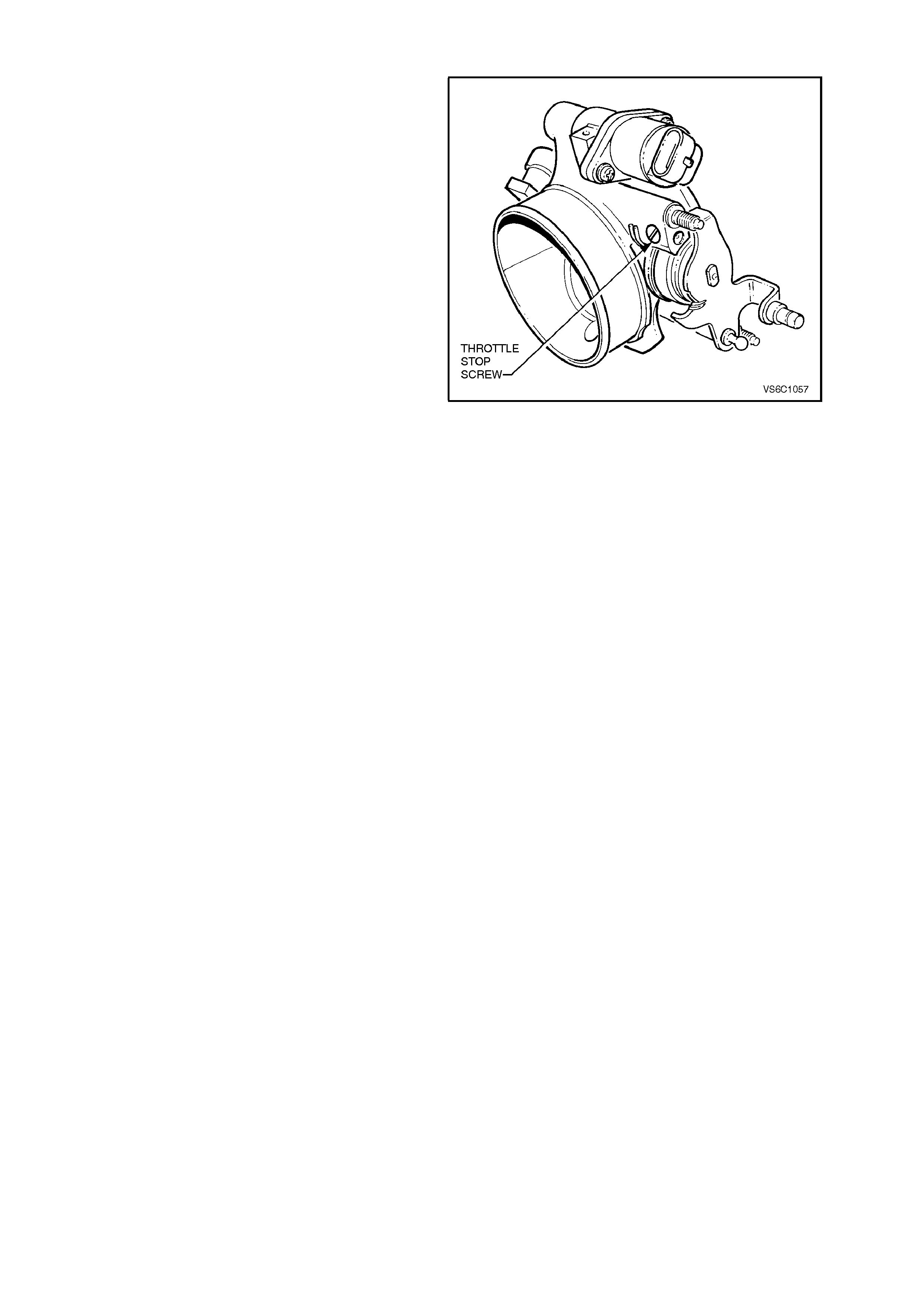
THROTTLE STOP SCREW - RESET
PROCEDURE
IMPORTANT:
• The Throttle Stop Screw controls the
minimum throttle opening (nominal "Closed
throttle" position). It is preset at the factory
and must not be reset unless:
1. The screw is known to have been
inadvertently reset,
-OR-
2. Clearly instructed to do so by a diagnostic
chart.
• Engine idle speed, which will vary with
engine temperature, is PCM - controlled and
is not adjustable.
PCM - Controlled idle speed and
Throttle stop screw setting
ARE NOT THE SAME!
• Throttle stop screw setting (RPM) must
always be less than the PCM controlled idle
speed, and is checked only after
temporarily disabling the PCM's method of
controlling idle speed, the Idle Air Control
system. The throttle stop screw setting is
the least likely cause of an abnormal idle
condition, therefore resetting the screw
should only be considered as a last resort.
An incorrect setting is likely to cause a
deterioration in idle stability.
• Before any adjustments are made, ensure
that no vacuum leaks exist. Check all
vacuum hoses, MAF air ducts, inlet
manifold gasket, throttle body-to-manifold
attachment, and any vacuum-operated
devices. The engine must be at normal
operating temperature before any checking
or rese tting is attempted.
• With this engine control system, any
vacuum leak will result in a low/rough idle
speed.
Figure 6C1-3-25 Throttle Stop Screw Location
CHECK OR RESET
1. Before performing this procedure, perform the
On-Board Diagnostic System Check, and
follow it upto and including step 9 action
column. Refer to Chart A - On Board
Diagnostic System Check, in Section 6C1-2A,
DIAGNOSTIC CHARTS – V6 ENGINE in the
VT Ser vice Inf ormation. If values are norm al or
within typical ranges proceed to step 2 below
2. Ensure that the IAC system is functioning
properly. Refer to Diagnostic Chart A-7.1 V6
PCM - IAC system in Section 6C1-2A,
DIAGNOSTIC CHARTS - V6 ENGINE in the
VT Service Information, and follow it to step
3"NO TROUBLE FOUND WITH IAC
SYSTEM".
3. Remove four dome nuts securing the engine
dress cover assembly to the inlet manifold
studs, lift off and remove the cover assembly.
IMPORTANT: Verify that the throttle cable and
throttle linkage are not binding. The throttle lever
attached to the throttle butterfly shaft must be able
to open fully, and shut fully and freely every time
the accelerator pedal is fully depressed and slowly
released. If throttle cable adjustment is required,
refer to THROTTLE CABLE in this Section of the
VT Service Information.
4. Engine must be at normal operating
temperature (above 90 degrees C), it is
preferable to achieve by driving the vehicle for
at least 15 minutes, before continuing.
5. Set parking brake and block drive wheels.
Ensure transmission is in `Park' (auto) or
neutral (manual).
6. Ignition "ON," ensure that all electrical loads
are turned "OFF," i.e. air conditioning, lights
etc. "OFF."
7. Connect TECH 2 to DLC and select:
Diagnostics / Appropriate Model Year / VT
Comm odore / Engine / V6 / Confirm Prom I.D. etc.
/ Misc ellaneous tests / IAC system / Bas e Idle / and
follow TECH 2 instructions.
IMPORTANT:If engine stalls while following TECH
2 instructions, turn the throttle stop screw ½ a turn
in the clockwise direction and repeat the base idle
checking procedure. If adjustment of the throttle
stop screw is necessary, adjust screw to obtain an
engine speed of 450 – 550 RPM.
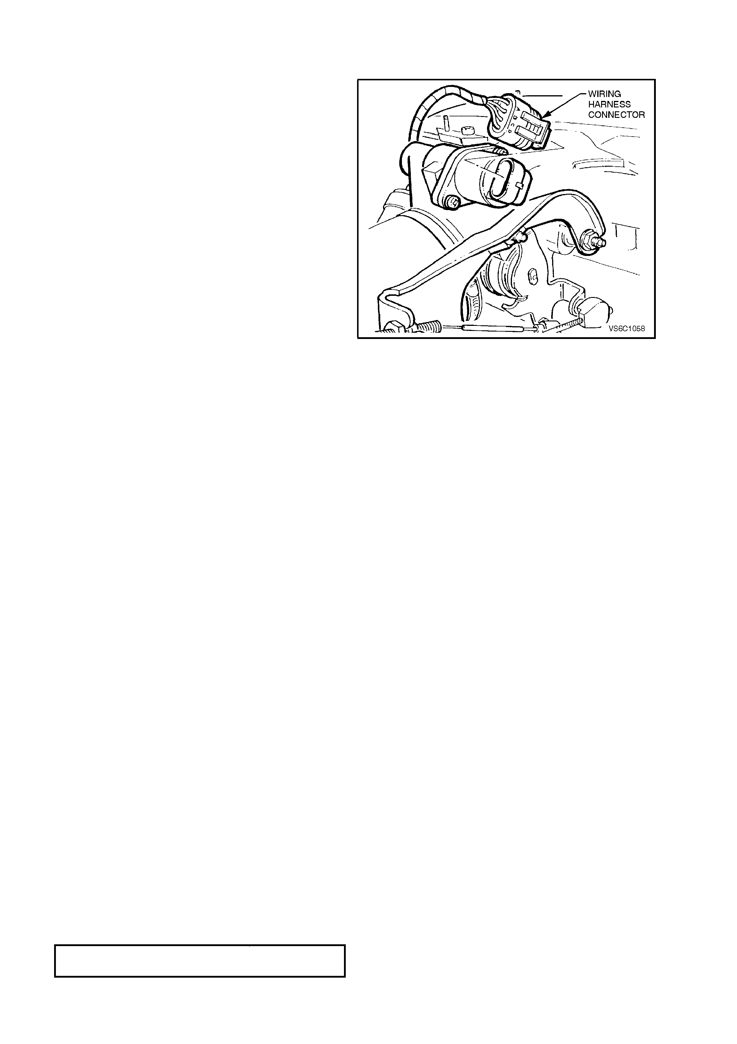
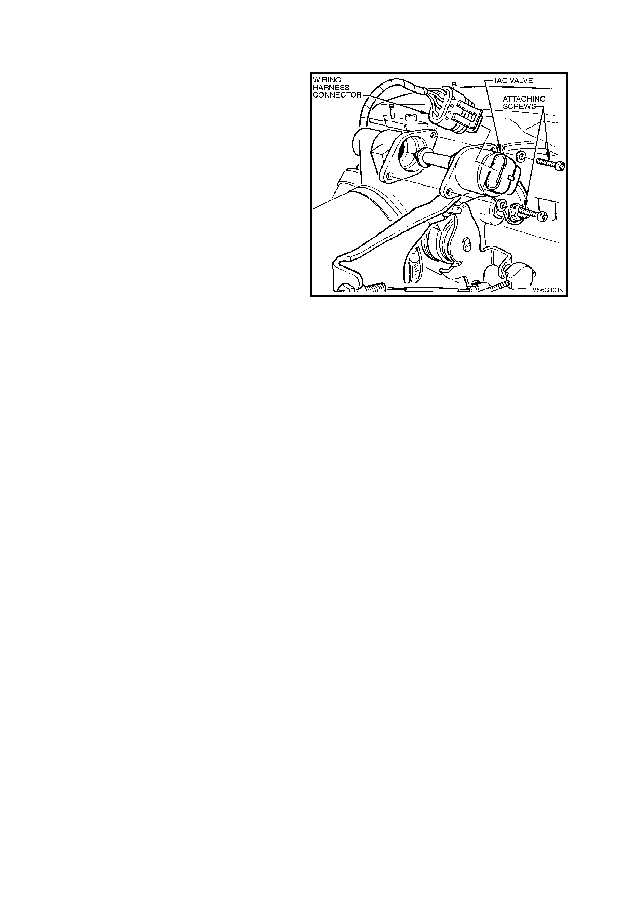
Figure 6C1-3-26 IAC Valve Harness Removed
8. Reset IAC. To do this, either:
Start engine, use TECH 2 scan tool and select
IAC reset, and follow TECH 2 instructions.
-OR-
Start engine, allow engine to run for 5 seconds,
then turn engine "OFF" for 10 seconds to
“Reset” the IAC valve.Restart engine and check
for proper idle.
9. Reinstall engine dress cover to the inlet
manifold, ensuring that stud grommets in the
dress cover remain in place. Tighten securing
dome nuts to the correct torque.
ENGINE DRESS COVER SECURING
DOME NUT TO INLET MANIFOLD
TORQUE SPECIFICATION
4 - 6 Nm
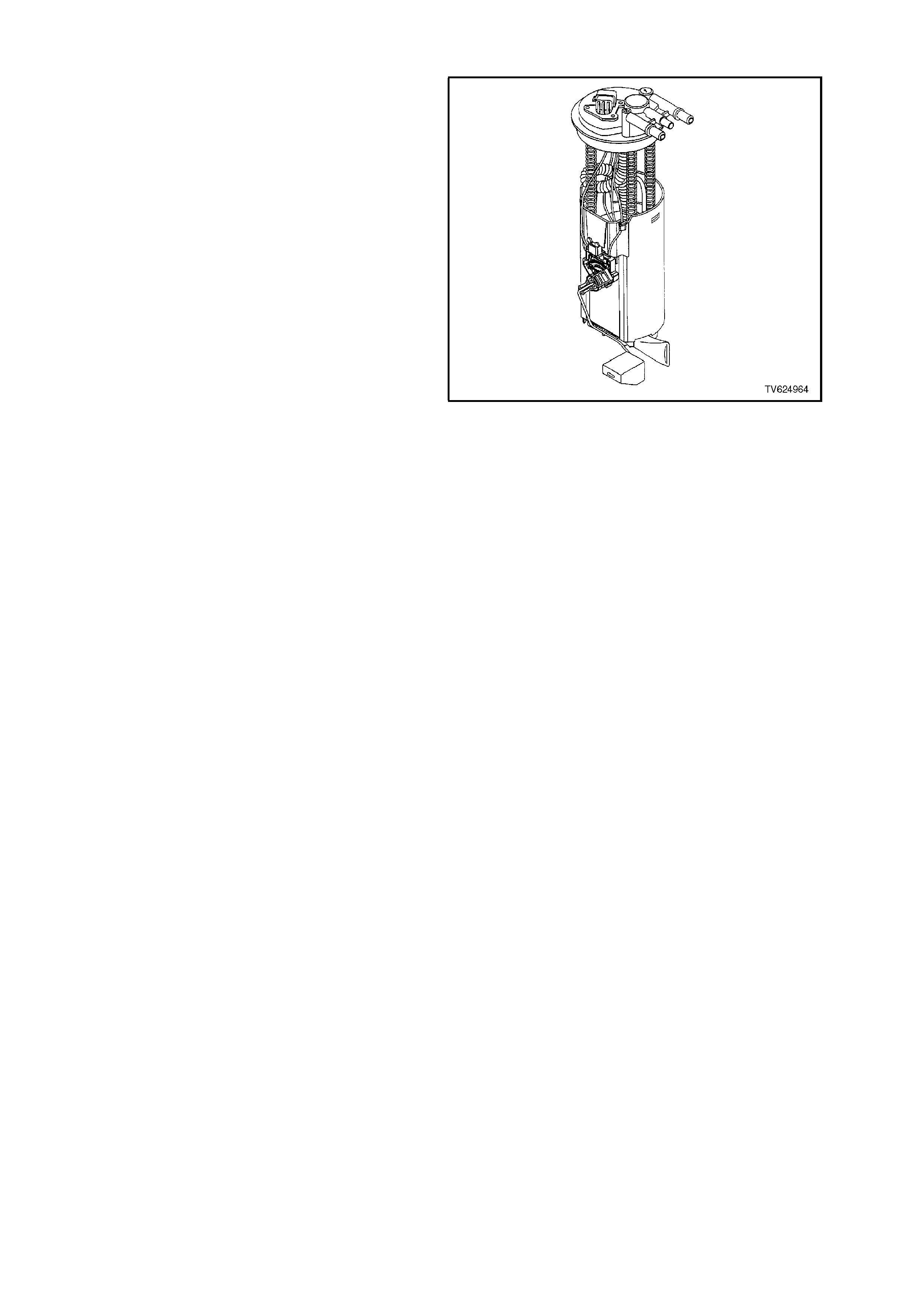
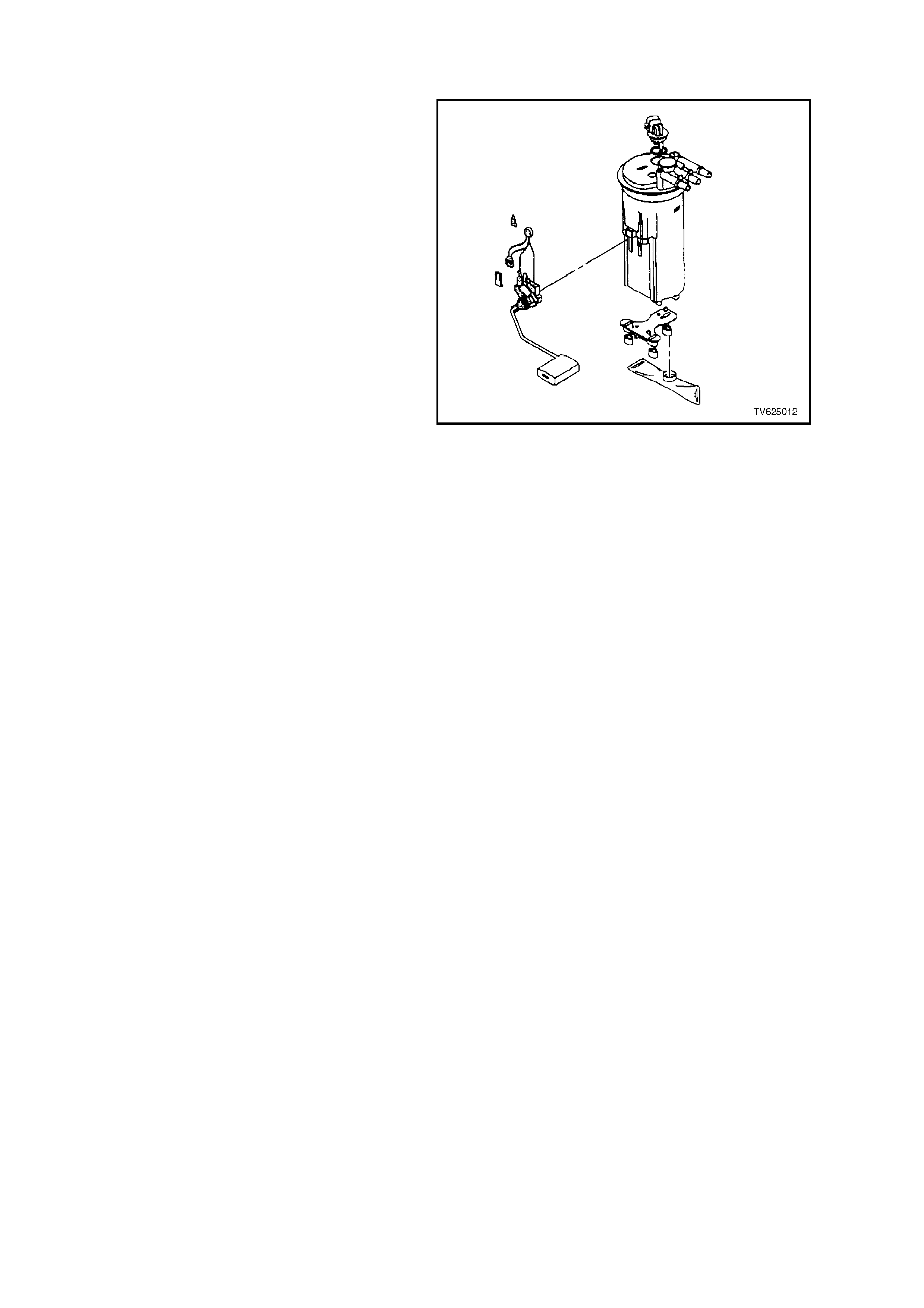
MODULAR FUEL SENDER ASSEMBLY
REMOVE
TOOL REQUIRED
J 39765, FUEL SENDER LOCKNUT WRENCH
NOTE: Do not handle the modular fuel sender
assembly by the fuel pipes.
1. Relieve the fuel system pressure. Refer to the
FUEL PRESSURE RELIEF PROCEDURE in
this Section of the VT Service Information.
2. Disconnect battery earth lead.
3. Remove fuel tank, refer to Section 8A, FUEL
TANK, in the VT Service Information.
4. Remove the modular fuel sender retaining ring
using the J 39765 Fuel Sender Locknut
Wrench.
IMPORTANT: When removing the modular fuel
sender assembly from the fuel tank, the reservoir
bucket on the fuel sender assembly is full of fuel.
The modular fuel sender assembly must be tipped
slightly during removal in order to avoid damage to
the float. Place any remaining fuel into an
approved container once the modular fuel sender
assembly is removed from the fuel tank.
IMPORTANT: The modular fuel sender assembly
will spring-up when the locking ring is removed.
5. Pull the modular fuel sender straight up while
draining the fuel from the reservoir.
6. Clean the fuel sender assembly O-ring sealing
surface.
7. Inspect the fuel sender assembly O-ring
sealing surface.
Figure 6C1-3-27 Modular Sender Assembly
REINSTALL IMPORTANT: Always replace the fuel sender O-ring
when reinstalling the fuel sender assembly.
1. Position the new fuel sender ass embly O-ring on the fuel tank. IMPORTANT: Care should be taken not to fold over
or twist the fuel pump strainer when installing the
fuel sender assembly, as this will restrict fuel flow.
Also, assure that the fuel pump strainer does not
interfere with full travel of float arm.
2. Install the fuel sender assembly and the fuel
sender ass em bly retainer ring using the J 39765
Fuel Sender Locknut Wrench.
3. Reinstall fuel tank, refer to Section 8A FUEL
TANK, in the VT Service Information.
4. Reconnect battery earth lead.
5. Inspect system for leaks.
MODULAR FUEL SENDER ASSEMBLY (SERVICEABLE FUEL LEVEL SENSOR)
REMOVE
NOTICE: Do not handle the modular fuel sender
assembly by the fuel pipes.
1. Relieve the fuel system pressure. Refer to the
FUEL PRESSURE RELIEF PROCEDURE in
this section.
2. Disconnect battery earth lead.
3. Remove fuel tank, refer to Section 8A, FUEL
TANK, in the VT Service Information.
4. Remove modular fuel sender assembly. Refer
to MODULAR FUEL PRESSURE ASSEMBLY
Removal procedure in this Section of the VT
Service Information.
DISASSEMBLE
1. Remove the CPA (connector position
assurance) clip from the fuel level sensor
assembly electrical connectors, then remove
the electrical connectors from the fuel pump
and the fuel sender cover assembly.
2. Compress the fuel level sensor retaining tangs
and remove the fuel level sensor assembly
from the fuel pump reservoir housing.
Figure 6C1-3-29 Fuel Level Sensor Assembly
Assemble
1. Ass emble the f uel level sensor ass embly to the
fuel pump reservoir housing.
2. Assemble the electrical connectors to the fuel
pump and cover assembly.
3. Assemble the CPA (connector position
assurance) clip to the fuel level sensor assembly
electrical connectors.
4. Assemble the rubber pad on the bottom of the
modular fuel sender assembly.
Reinstall
1. Install the fuel sender assembly. Refer to
MODULAR FUEL SENDER ASSEMBLY
Reinstall in this Section of the VT Service
Information.
2. Reinstall fuel tank refer to Section 8A, FUEL
TANK, in the VT Service Information.
3. Reconnect battery earth lead.
4. Inspect system for leaks.

MODULAR FUEL SENDER ASSEMBLY (FUEL PUMP NON-SUPERCHARGED ENGINE)
NOTICE: The fuel pump for the Supercharge V6 is not replaceable, the complete Modular Fuel Sender Assembly
must be replaced for the Supercharge engine.
REMOVE
1. Remove the MODULAR FUEL SENDER ASSEMBLY. Refer to this section for removal procedure.
2. Remove external fuel strainer .
3. Remove CPA #8 ( connector position ass urance) fr om electric al connector and disconnect fuel pum p electric al
connector. Refer to figure 6C1-3-30.
4. Gently release tabs on side of fuel sender to cover assembly. Begin by squeezing the sides of the reservoir
and releas ing the tab opposite the fuel level sens or. Move clockwise to r elease the second and third tab in the
same manner. Refer to figure 6C1-3-31.
5. Lift cover assembly out far enough to disconnect the fuel pump electrical connection.
6. Carefully pry snap ring (#21) out of groove on fuel pump outlet. Refer to figure 6C1-3-30 view B.
7. Rotate f uel pump baffle (#18) counterclock wise and rem ove baffle pum p assem bly f rom retainer ( #7). Refer to
figure 6C1-3-30.
8. Replace the fuel pump seal/dampener. Refer to figure 6C1-3-33.
9. Install fuel pump outlet retainer (#21) on fuel pump outlet (#20). Index the snap ring so that the ends are
positioned in the groove (#22) facing the fuel pump electrical connector. Refer to figure 6C1-3-30 view A and B.
10. Install new f uel pump and baff le assembly onto reservoir retainer (#7) and rotate clockwise until seated. Refer
to figure 6C1-3-30.
11. Place fuel pump outlet (#20) over retainer (#7) so that snap ring ends (#21) face fuel pump electrical
connection and press firmly into place making certain the snap ring is seated and over each tab on outlet.
Refer to figure 6C1-3-30.
12. Lower retainer assembly (#7) partially into reservoir. Line up all three sleeve tabs.
13. Install fuel pump connector and CPA #8 to fuel sender cover (#7). Refer to figure 6C1-3-30.
14. Install new external fuel strainer (#14). Refer to figure 6C1-3-30.
15. Reinstall Modular Fuel Sender Assem bly to fuel tank as outlined in MO DULAR FUEL SENDER ASSEM BLY in
this section, and reinstall fuel tank.
16. Inspect fuel system for leaks.
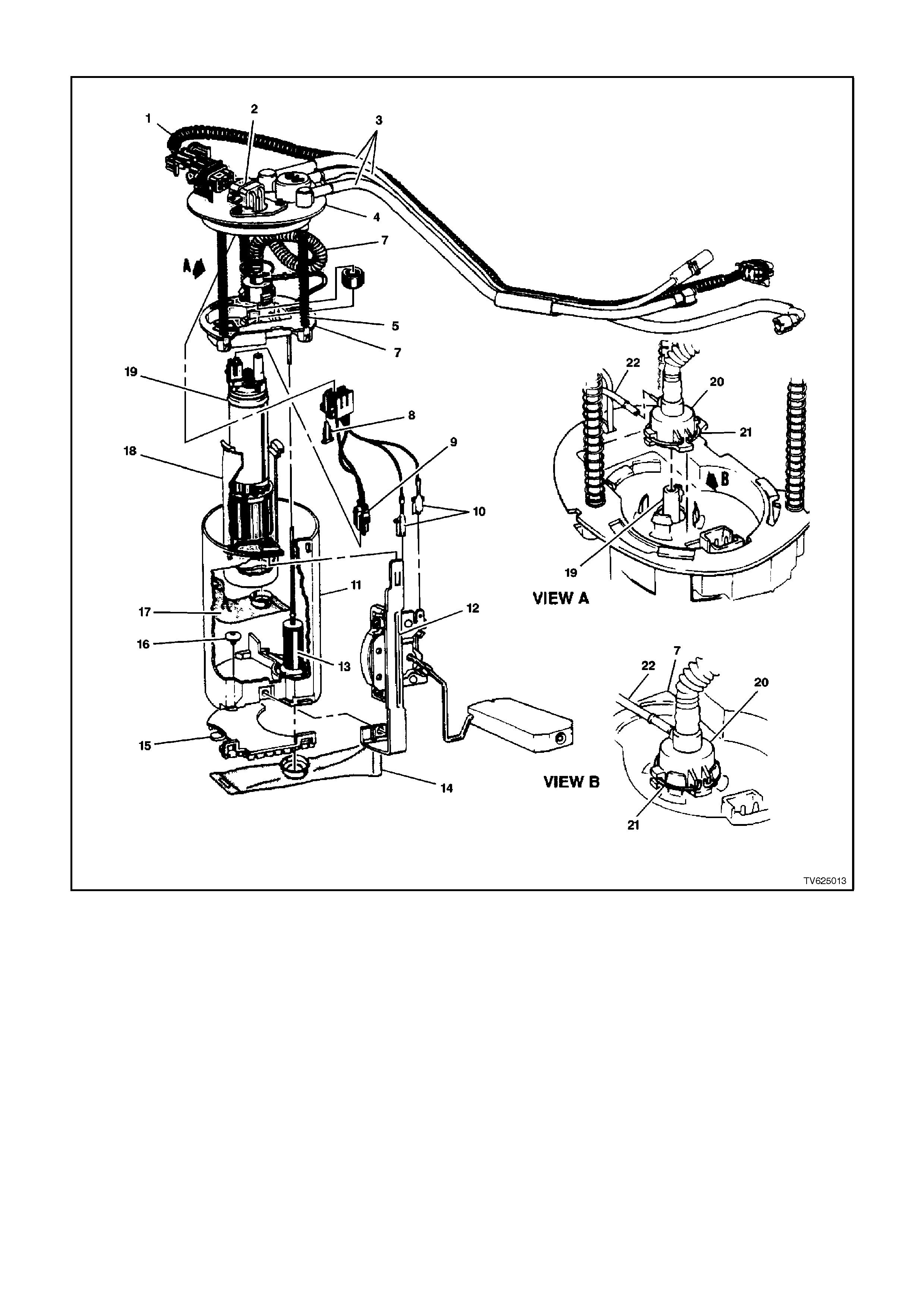
Figure 6C1-3-30 Modular Fuel Sender Assembly Expanded View
Below are the descriptions that correlate to the figure 6C1-3-30 above.
1. Harness Assembly (Above Cover) - Fuel Pump
And Fuel Sender Wiring.
2. Connector Assembly - Fuel Sender Wiring.
3. Fuel Pipes (3).
4. Cover Assembly - Fuel Sender.
5. Pipe (Convoluted) - Fuel Sender Outlet.
6. Support Assembly (Hallow Support Or Guide
Pipes)
- Fuel Pump Reservoir.
7. Retainer - Fuel Pump Reservoir.
8. Connector Position Assurance (Cpa).
9. Harness Assembly (Below Cover) - Fuel Pump.
10. Harness Assembly (Below Cover) - Fuel Level
Sender.
11. Reservoir - Fuel Pump Fuel.
12. Sensor Assembly - Fuel Level.
13. Pump Assembly ( Jet Pump Assembly) - Fuel
Pump Reservoir.
14. Strainer (External) - Fuel Sender.
15. Pad (Bumper) - Fuel Sender.
16. Valve (Secondary Umbrella Valve) - Fuel Pump
Reservoir Inlet Check.
17. Strainer - Fuel Pump Fuel.
18. Baffle (Isolator Cup) - Fuel Pump.
19. Pump Assembly (Turbine) - Fuel.
20. Outlet - Fuel Pump.
21. Snap Ring - Fuel Pump Outlet.
22. Pipe - Jet Pump.
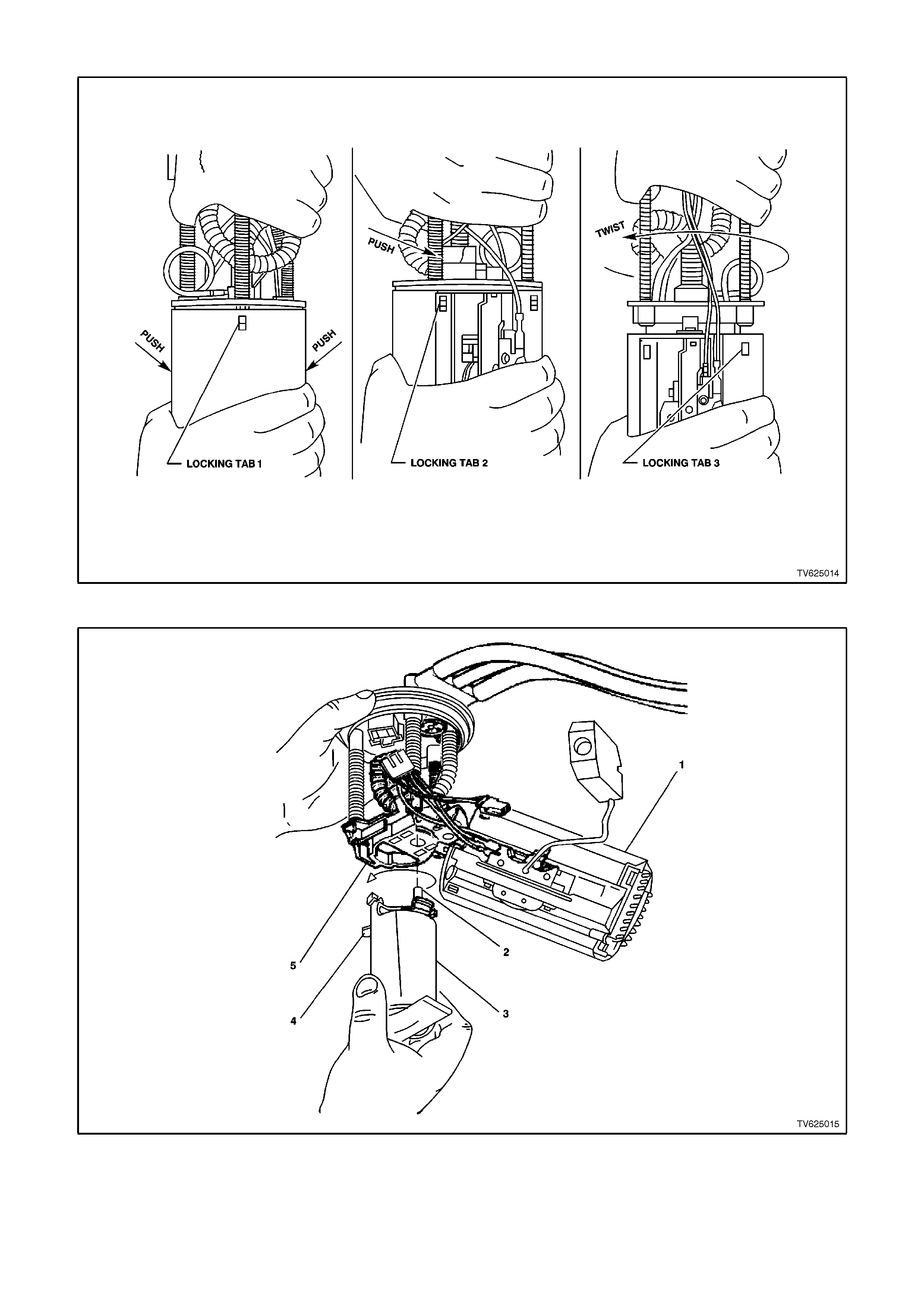
Figure 6C1-3-31 Modular Fuel Sender Assembly Grasping View
Figure 6C1-3-32 Fuel Pump Removed From Modular Sender Assembly
Below are the descriptions that correlate to the figure 6C1-3-32 above.
1. RESERVOIR ASSEMBLY 2. OUTLET TUBE 3. FUEL PUMP ASSEMBLY 4. FLEX MEMBER
5. RETAINER - FUEL PUMP RESERVOIR
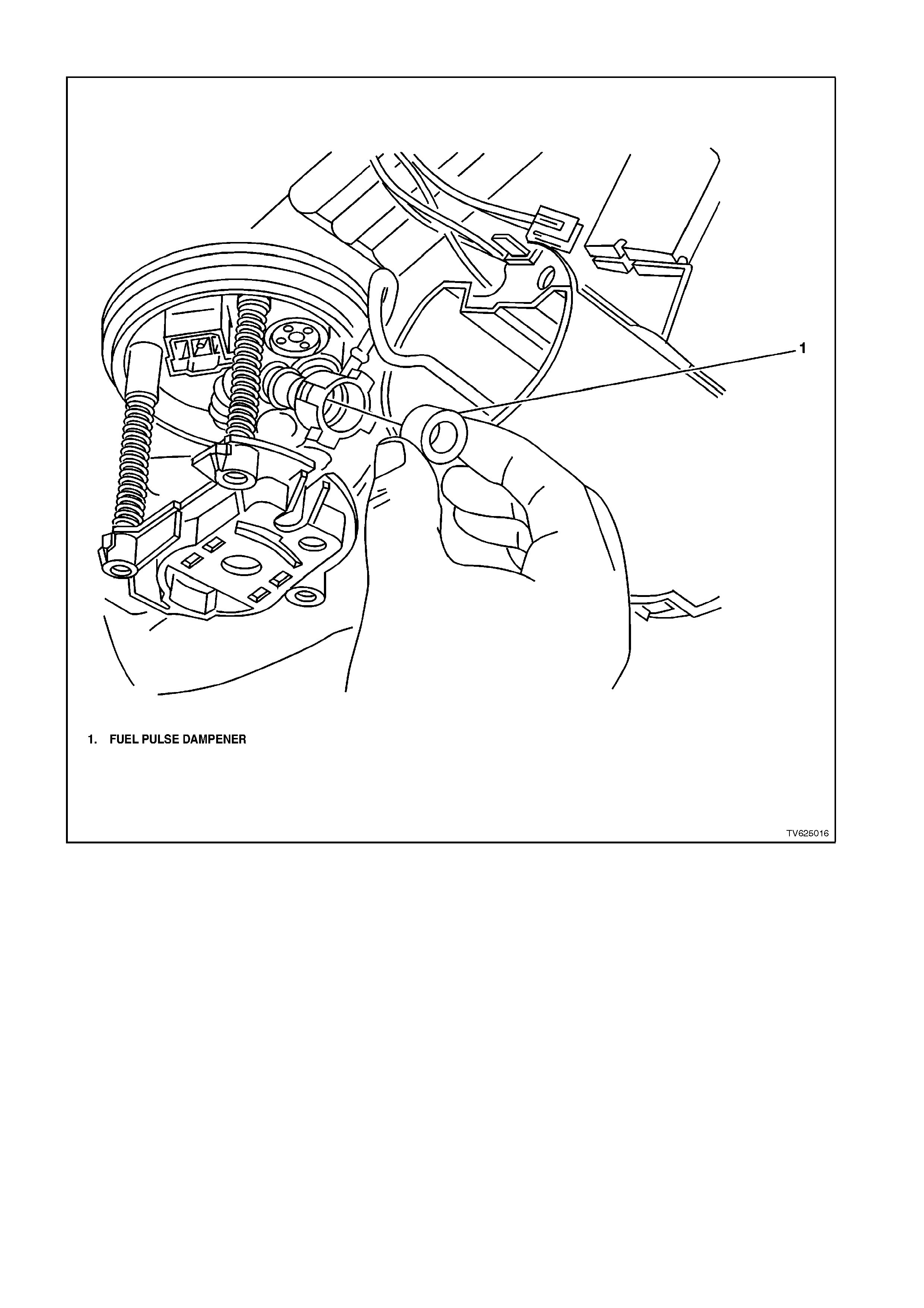
Figure 6C1-3-33 Fuel Pump Seal/Dampener
FUEL SYSTEM PRESSURE TEST
A Fuel System Pressure Test is part of several of
the Diagnostic Charts and Symptom checks. To
perform this test, follow this procedure:
CAUTION: To reduce the risk of fire or personal
injury, it is necessary to relieve fuel system
pressure before performing this test. See "FUEL
PRESSURE RELIEF PROCEDURE" in this
Section.
WARNING: AT NO TIME MUST THE FUEL INLET
HOSE OR RETURN LINE HOSE BE CLAMPED
OR BENT OVER AS THIS WILL CAUSE A
PERMANENT KINKING OF THE INNER
SECTION OF THE HOSE ASSEMBLY AND WILL
RESULT IN RESTRICTED FUEL FLOW.
1. Relieve fuel pressure, refer to 3.11, FUEL
CONTROL SYSTEM - Fuel Pressure Relief
Procedure, in this Section of the VT Service
Information.
2. Turn ignition "OFF."
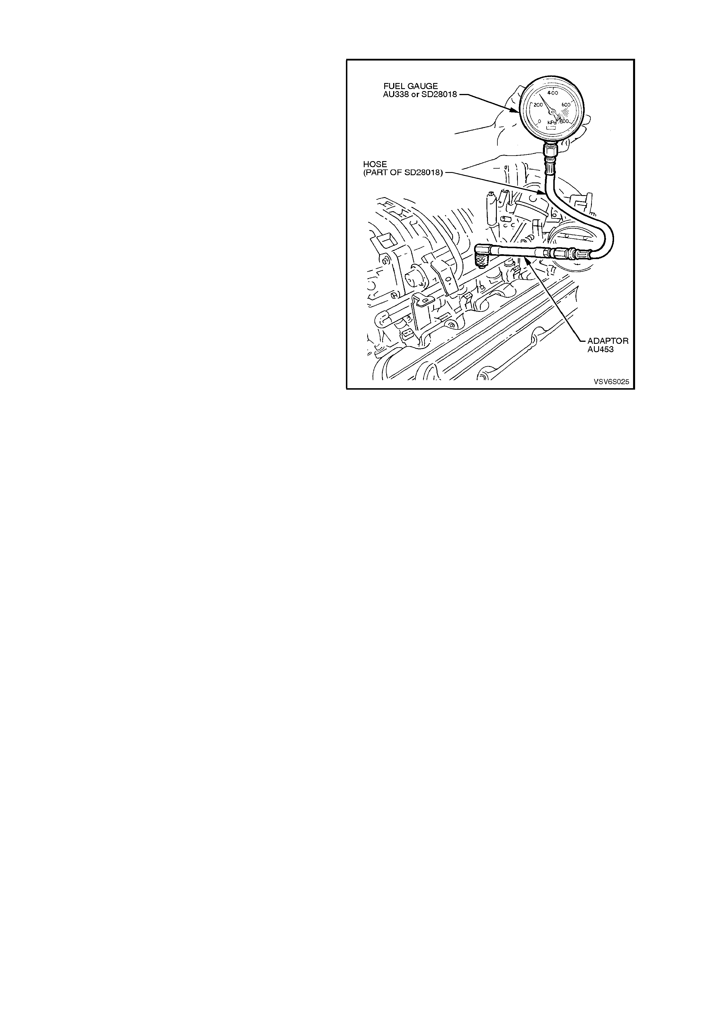
NOTE: Supercharged Engine
For Supercharger application, use fuel pressure
gauge AU338 or SD28018 with tool AU453
schrader fitting adapter. Remove schrader valve
cap. Connect the schrader valve fitting adapter to
the schrader valve fitting located on Supercharge
fuel rail. Connect fuel gauge to schrader valve
adapter, then proceed to step 7.
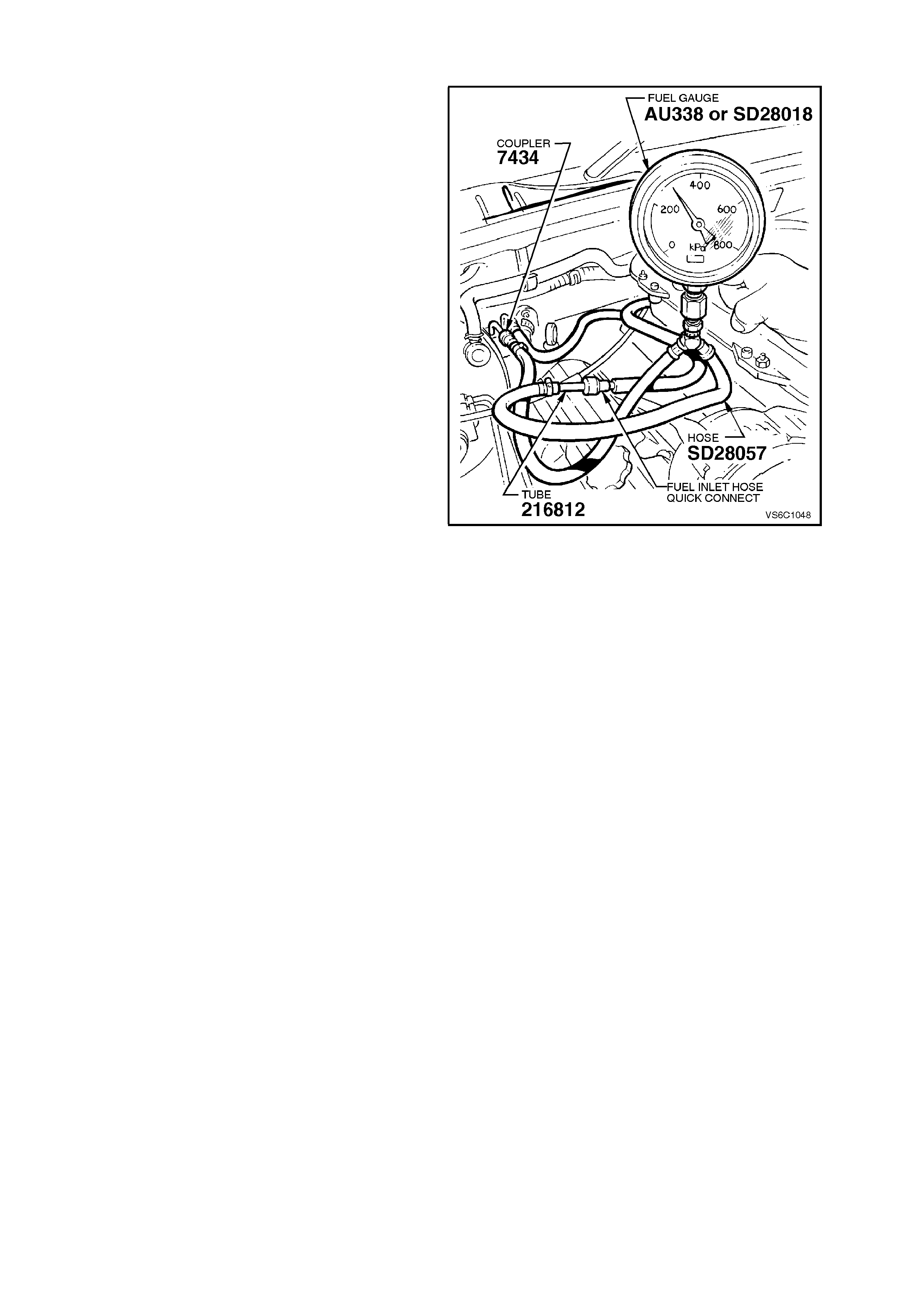
NOTE: Non-Supercharged Engine
For Non Supercharger application, proceed to step
3.
3. Remove four dome nuts securing the engine
dress c over ass em bly to the mounting brack ets
studs, lift off and remove the cover assembly.
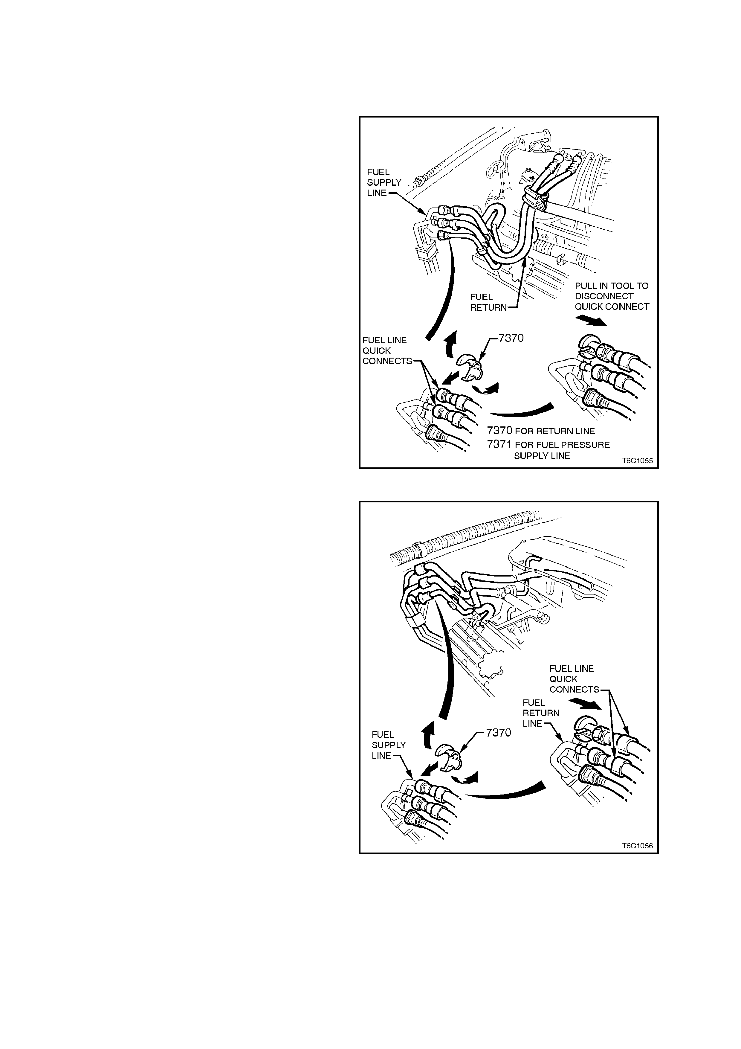
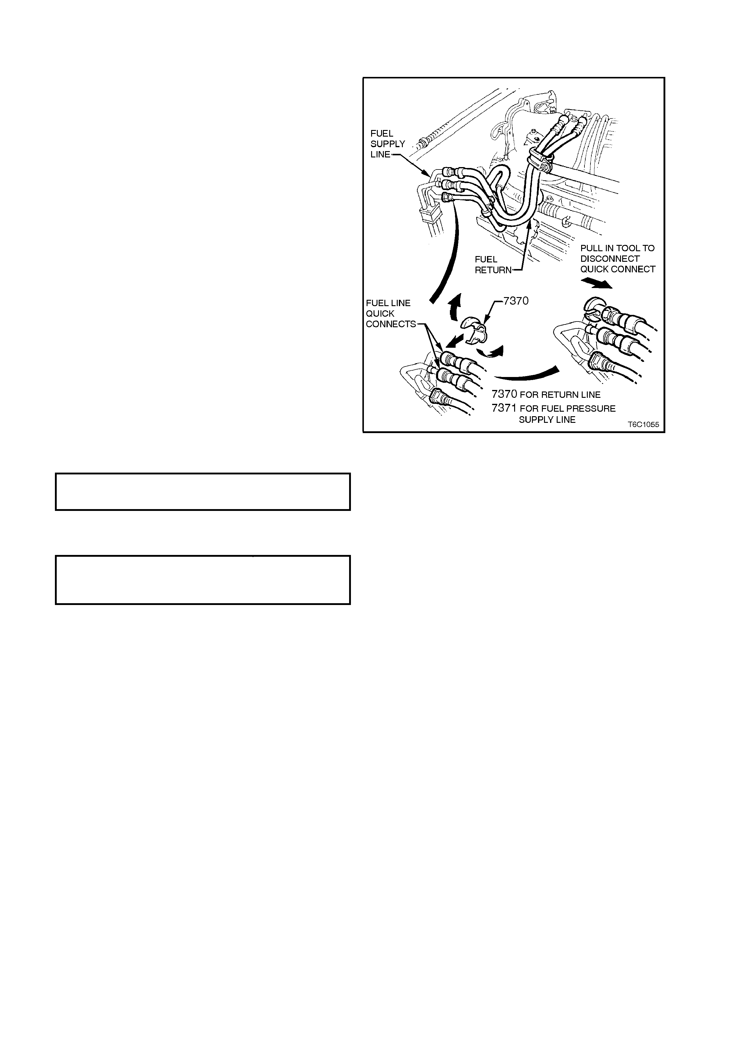
4. Open Tool No. 7370 and install over fuel inlet
line.
5. Close 7370 and pull into fuel line quick connect
to release it f rom the f uel inlet line, pull back on
quick connect.
NOTE: Before conducting the next step, inspect
tube adapter (P/N 216812) on fuel pressure gauge
hose to ensure that it is free from any damage or
burrs. This is necessary so as to ensure that the
tube does not damage the sealing ring in the quick
connect. If the sealing ring becomes damaged, fuel
leakage will occur.
Figure 6C1-3-35 Non-Supercharged Engine
6. Install fuel pressure gauge AU338 or SD28018
& hose SD28057 fitted with Coupler 7434 and
tube 216812 in the pressure line, between the
fuel inlet line and the fuel inlet hose quick
connect.
Measure
7. Using TECH 2 scan tool , enable fuel pum p so
that the "fuel pump" can pressurize the system.
8. Fuel gauge reading should be 270 - 350 kPa
for NON-SUPERCHARGE application, and
290 - 410 kPa for SUPERCHARGE
application. If not, refer to Chart A-4.1 for
NON-SUPERCHARGE, and Chart A-4.1-1 for
SUPERCHARGE in Section 6C1-2A,
DIAGNOSTIC CHARTS - V6 ENGINE in the
VT Service Information.
9. Relieve fuel pressure, refer to 3.11, FUEL
CONTROL SYSTEM - Fuel Pressure Relief
Procedure, in this Section of the VT Service
Information.
10. Remove fuel pressure gauge and adapter.
11. Turn ignition “OFF”.
12. Reinstall fuel line (V6 Non-Supercharged
Engine) or install schrader valve cap (V6
Supercharged Engine).
13. Check for fuel leaks, refer to 3.11, FUEL
CONTROL SYSTEM - Leak Testing, in this
Section of the VT Service Information.
Figure 6C1-3-36 Supercharged Engine
FUEL FILTER
REMOVE
IMPORTANT Relieve the fuel system pressure
before servicing any fuel system connection. Refer
to the Fuel Pressure Relief Procedure in
3.11, FUEL CONTROL SYSTEM in this Section.
1. Relieve fuel pressure as described in
3.11, FUEL CONTROL SYSTEM - Fuel
Pressure Relief Procedure in this Section.
2. Disconnect batt er y earth lead.
3. Raise rear of vehicle and support on safety
stands, refer to Section OA, GENERAL
INFORMATION in the VT Service Information.
4. Place a drain tray beneath fuel filter.
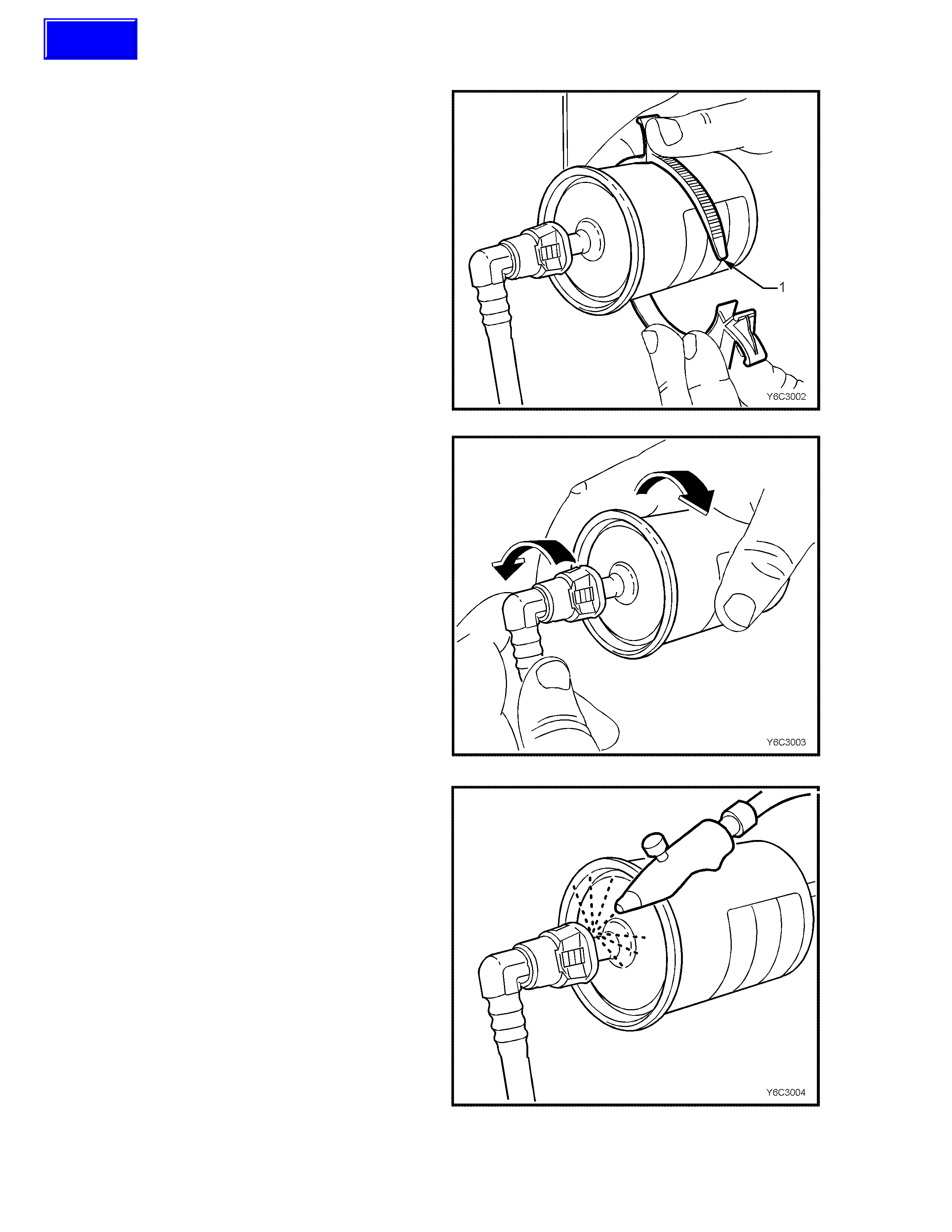
5. Remove the fuel filter from the retaining
brack et (1) with the fuel lines still connected to
the fuel filter to allow easier access.
Figure 6C1-3-37
QUICK CONNECT FITTINGS
(PLASTIC COLL AR)
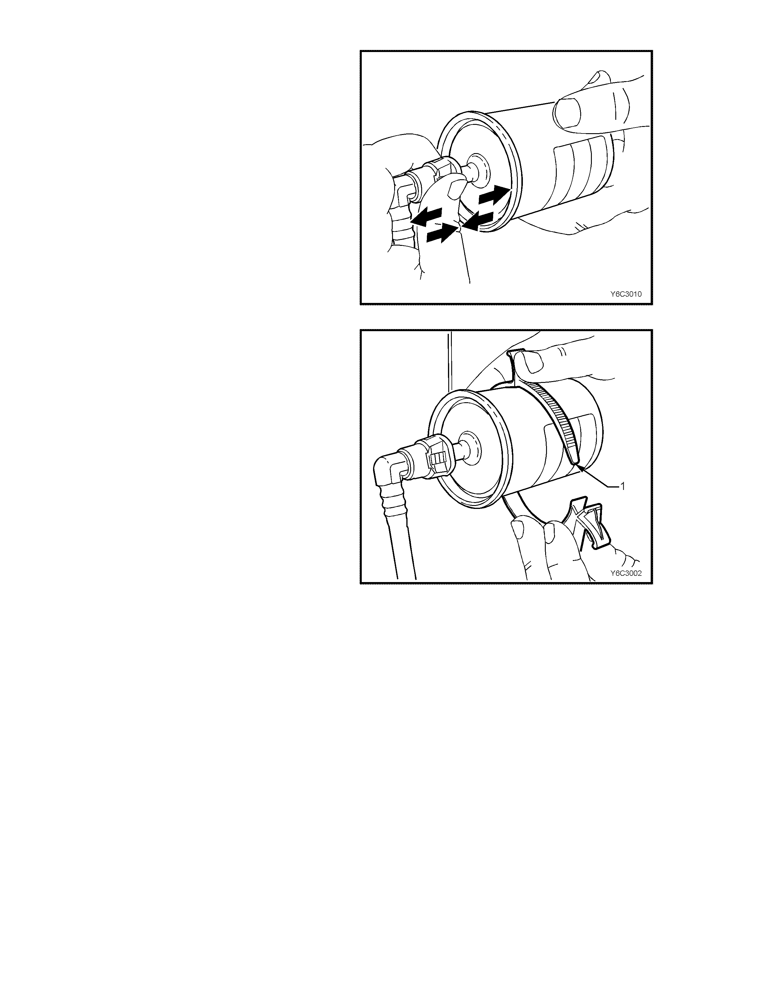
6. Grasp the quick-connect fittings both sides of
the fuel filter. Twist the female connectors 1/4
turn in each direction in order to loosen any dirt
within the quick-connect fitting.
Figure 6C1-3-38
7. Using compressed air, blow any dirt out of the
quick-connect fitting to aid the release of any
tension or binding on the release tabs .
IMPORTANT
W ear safety glas ses whe n using com pres sed air in
order to prevent eye injury.
Figure 6C1-3-39
Techline
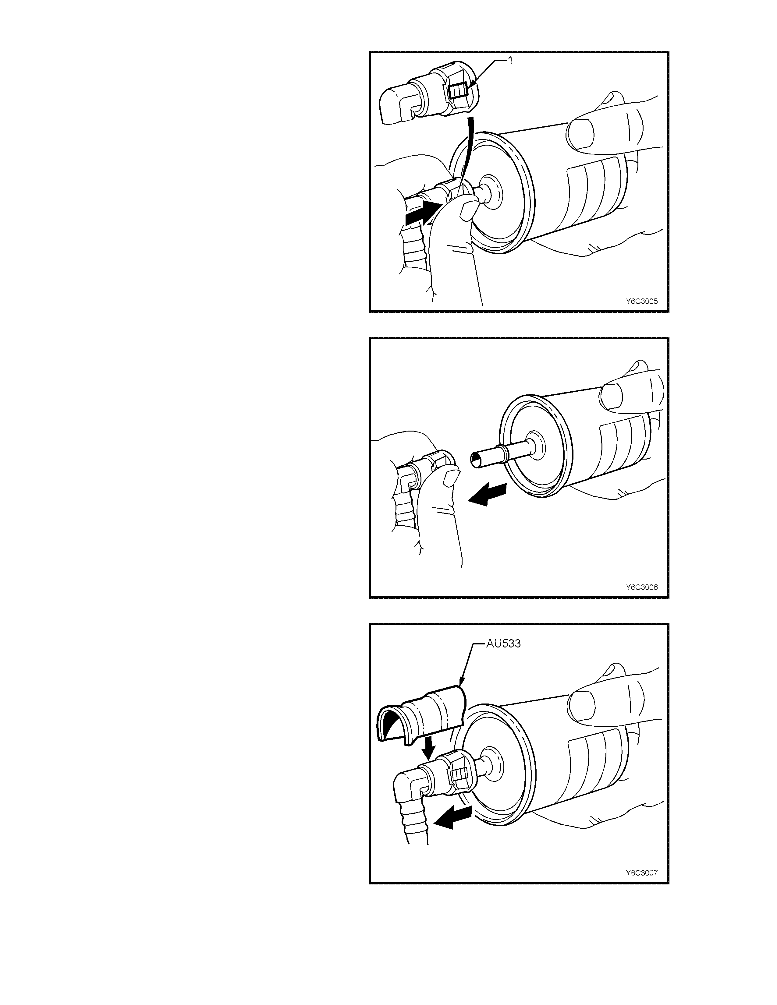
8. Hold t he fuel filt er firm ly in one hand t o support
the filter.
9. Using your ot her hand, gra sp one of the quick -
connect fittings.
10. Squeeze the plastic retainer release tabs (1)
on each side of the fitting while pushing the
fitting fir mly toward the fue l filter to rele ase any
tension on the release tabs.
Figure 6C1-3-40
11. With the tension release tabs still held in the
squezed position, move the complete quick-
connect fitting away from the fuel filter to
separate the connector fitting from the fuel
filter.
12. Apply the same method from step 8 to 11 for
the remaining quick-connect fitting.
Figure 6C1-3-41
13. Alt ernatel y for steps 8 to 11, us e tool AU533 t o
squeeze the release tabs, release the quick
connect fittings and rem ove both fuel pressure
hoses from the fuel filter.
14. Remove fuel filter from vehicle and disguard
safely remembering that some fuel will still
remain in the filter.
Figure 6C1-3-42

REINST ALL
IMPORTANT The fuel filter must be installed with
the flow arrow (6) on its body pointing in the same
direction as the fuel flow to the front of the vehicle.
Figure 6C1-3-43 Fuel Filter Installation
IMPORTANT Before connecting fuel filter quick-
connect fittings, always apply a few drops of clean
engine oil to the male ends of the fuel filter.
This will ens ure proper rec onnection and pr event a
possible fuel leak.
During normal operation, the O-ring located in the
fem ale connec tor will s wel l and ma y prevent proper
reconnection if not lubr icated.
1. Apply a few drops of clean engine oil to each
male fuel filter end.
Figure 6C1-3-44
2. Push both the quick-connect fitting and the fuel
filter together in order to cause the retaining
tabs to snap into place. Apply this method to
both ends of the fuel filter and the respective
quick-connect fittings.
Figure 6C1-3-45
3. Onc e installed, pull and p ush on bo th the quic k-
connect fitting and the fuel filter in order to
make sure the connection is secure. Apply
method this to both ends of the fuel filter and
the respective quick-connect fittings.
Figure 6C1-3-46
4. Install a new fuel filter to a new retaining bracket
(1).
5. Connect battery earth lead.
6. Check for fuel leaks, refer to
3.11, FUEL CONTROL SYSTEM – Leak
Testing in this Section of the VT Service
Information.
7. Remove safety stands and lower vehicle.
Figure 6C1-3-47
LEAK TESTING
Prior to starting the engine, following the installation of any fuel system component, check the fuel system for leaks
using the following procedure:
1. Check to ensure that there is a sufficient level of fuel in the fuel tank.
2. Use sc an tool "Output T est" for "Fuel Pum p." Enablin g the output t est will acti vate the f uel pum p to press urize the
fuel system.
3. Check fuel system for leaks, particularly at points marked in figure 6C1-3-49 and 6C1-3-50.
FUEL PUMP CONTROL MODULE (SUPERCHARGED ENGINE ONLY)
Remove
1. Disconnect battery earth lead.
2. Move r ight rear upper wheelhouse trim c over to
gain access to fuel pump control module
retaining bolt.
3. Remove retaining bolt.
4. Remove module from upper wheelhouse
brace, disengage module cover front tab from
brace locating hole.
5. Disconnect body harness connector from
module.
Reinstall
1. Reconnect body wiring harness connector to
module.
2. Install module to upper wheelhouse brace,
engaging module front tab to brace locating
hole.
3. Install retaining bolt.
4. Install right rear upper wheelhouse trim cover.
5. Connect battery earth lead.
IMPORTANT: If necessary, check fuel pump
control module operation. Refer to Chart A-4.1-1
V6 PCM - Fuel Pump Electrical Circuit
(Supercharged Engine) in Section 6C1-2A,
DIAGNOSTIC CHARTS - V6 ENGINE in the VT
Service Information.
Figure 6C1-3-48 Fuel Pump Control Module Location
Figure 6C1-3-49 Leak Testing Non-Supercharged Engine
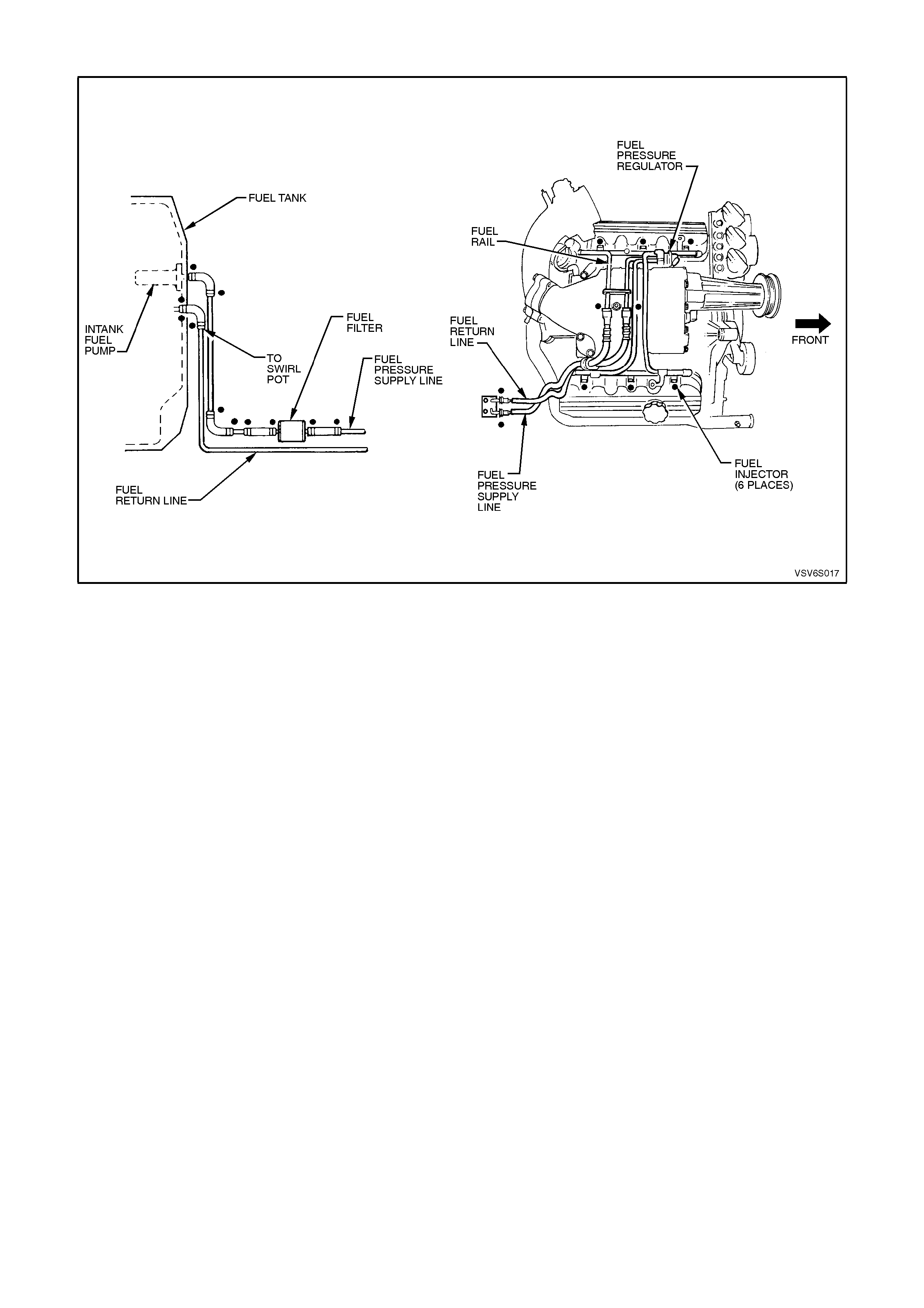
Figure 6C1-3-50 Leak Testing Supercharged Engine
FUEL PRESSURE REGULATOR
SUPERCHARGED ENGINE
1. Relieve fuel pressure as described in 3.11,
FUEL CONTROL SYSTEM - Fuel Pressure
Relief Procedure in this Section.
2. Disconnect battery earth lead.
3. Remove four dome nuts securing the engine
dress cover assembly to the inlet manifold
studs, lift off and remove cover assembly.
Refer to Figure 6C1-3-12.
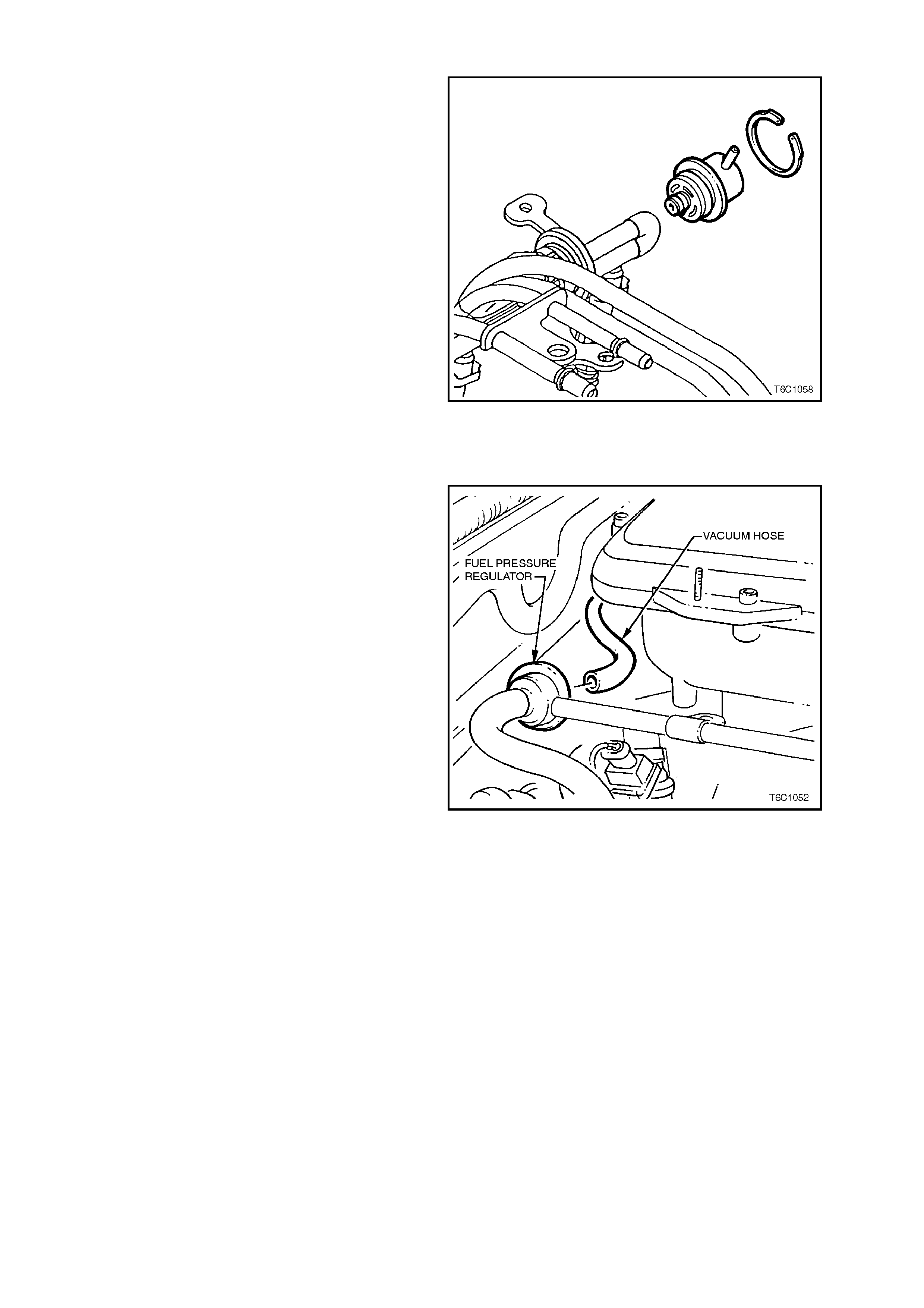
4. Disconnect vacuum hose from fuel pressure
regulator.
5. Clean any dirt from the fuel pressure regulator
retaining ring.
6. Using snap ring tool, remove snap ring from
fuel pressure regulator.
Figure 6C1-3-51 Supercharged Engine Fuel Pressure
Regulator Location
7. Using a s hop towel to catc h any spilled f uel, lift
and twist the fuel pr essure regulator in or der to
remove the fuel pressure regulator from the
fuel pressure regulator housing.
8. Cover the fuel pressure regulator housing to
prevent contamination from entering the fuel
system.
9. Using Tool No. 7371 for supercharged engine
application, disconnect fuel return hose quick
connect at dash panel connection, only if
replacing fuel pressure regulator.
REINSTALL
1. New O-rings on the fuel press ure regulator, if a
new fuel pressure regulator is not being
installed. lubricate the O-rings lightly with
clean engine oil.
2. T he fuel press ure regulator in the f uel pressure
regulator housing.
3. Install the retaining snap ring to the fuel
pressure regulator using the snap ring tool.
4. The vacuum hose to the fuel pressure
regulator.
5. Fuel return hose quick connect to dash panel
connector.
6. Reconnect battery earth lead.
7. Check for fuel leaks as described in 3.11,
FUEL CONTROL SYSTEM - LEAK TESTING
in this section.
8. Reinstall engine dress cover to the inlet
manif old, ensuring that s tud gromm ets in dress
cover remain in place. Tighten securing dome
nuts to the correct torque specification.
NOTE: Compressed air must never be used to test
or clean a fuel pressure regulator, as damage to
the fuel pressure regulator may result.
In order to prevent damage to the fuel pressure
regulator do not immerse in solvent.
Figure 6C1-3-52 Supercharge Fuel Pressure Regulator
Removal From Fuel Rail
NON-SUPERCHARGED ENGINE
1. Relieve fuel pressure as described in 3.11,
FUEL CONTROL SYSTEM - Fuel Pressure
Relief Procedure in this Section.
2. Disconnect battery earth lead.
3. Remove four dome nuts securing the engine
dress cover assembly to the inlet manifold
studs, lift off and remove cover assembly.
Refer to Figure 6C1-3-15.
4. Rem ove f uel rail ass em bly, refer to FUEL RAIL
AND INJECTORS in this section.
5. Disconnect vacuum hose from fuel pressure
regulator.
6. Clean any dirt from the fuel pressure regulator
retaining ring.
7. Using snap ring tool, remove snap ring from
fuel pressure regulator.
8. Using a s hop towel to catc h any sp illed fuel, lift
and twist the fuel pr essure regulator in or der to
remove the fuel pressure regulator from the
fuel pressure regulator housing.
9. Cover the fuel pressure regulator housing to
prevent contamination from entering the fuel
system.
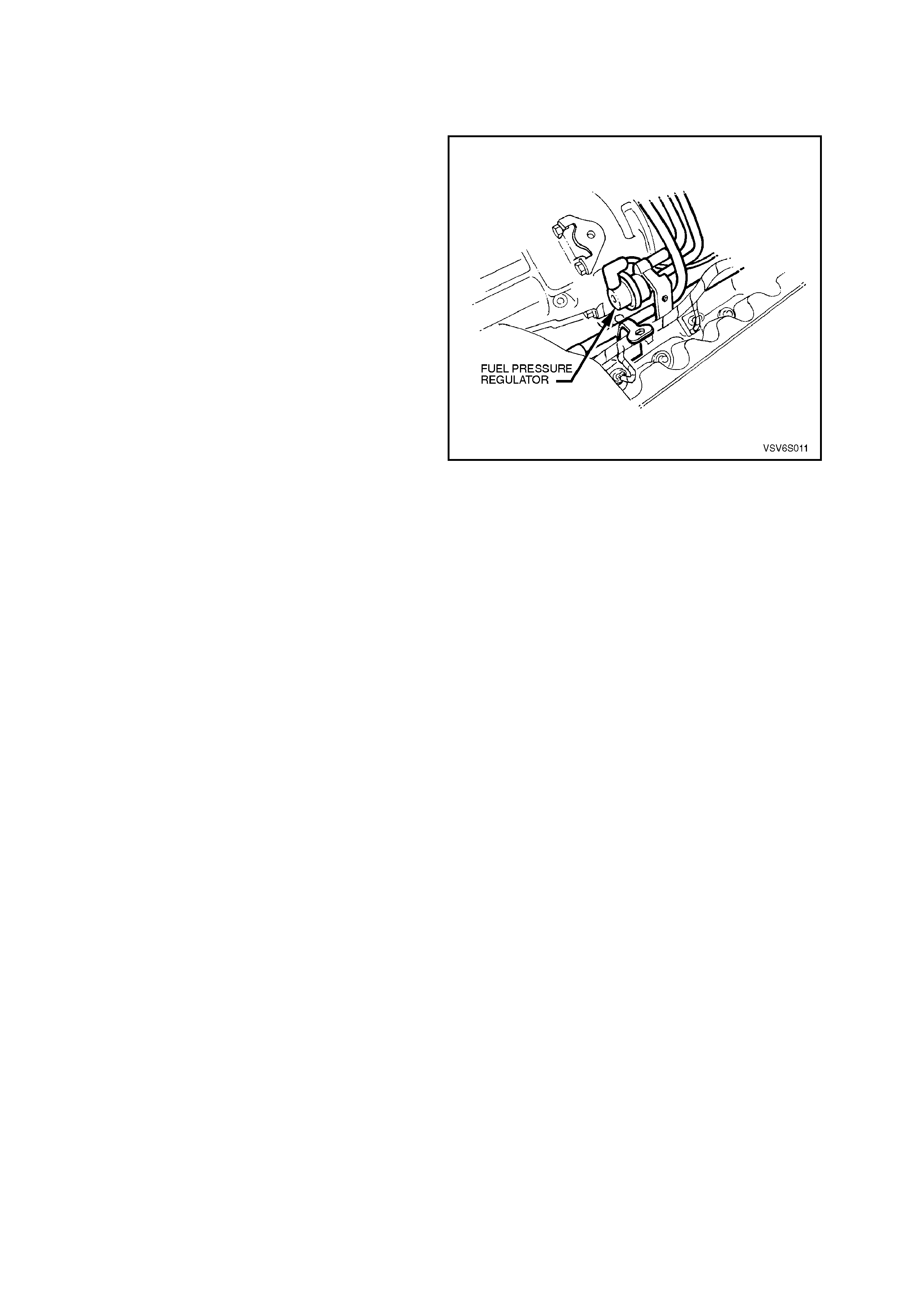
Figure 6C1-3-53 Non-Supercharged Engine Fuel Pressure
Regulator Location
10. Using Tool No. 7370 for Non-Supercharger
application, disconnect fuel return hose quick
connect at dash panel connection, only if
replacing fuel pressure regulator.
Reinstall
1. New O-rings on the fuel press ure regulator, if a
new fuel pressure regulator is not being
installed. lubricate the O-rings lightly with
clean engine oil.
2. T he fuel press ure regulator in the f uel pressure
regulator housing.
3. Install the retaining snap ring to the fuel
pressure regulator using the snap ring tool.
4. Install the fuel rail. Refer to FUEL RAIL AND
INJECTOR for installation.
5. The vacuum hose to the fuel pressure
regulator.
6. Fuel return hose quick connect to dash panel
connector.
7. Reconnect battery earth lead.
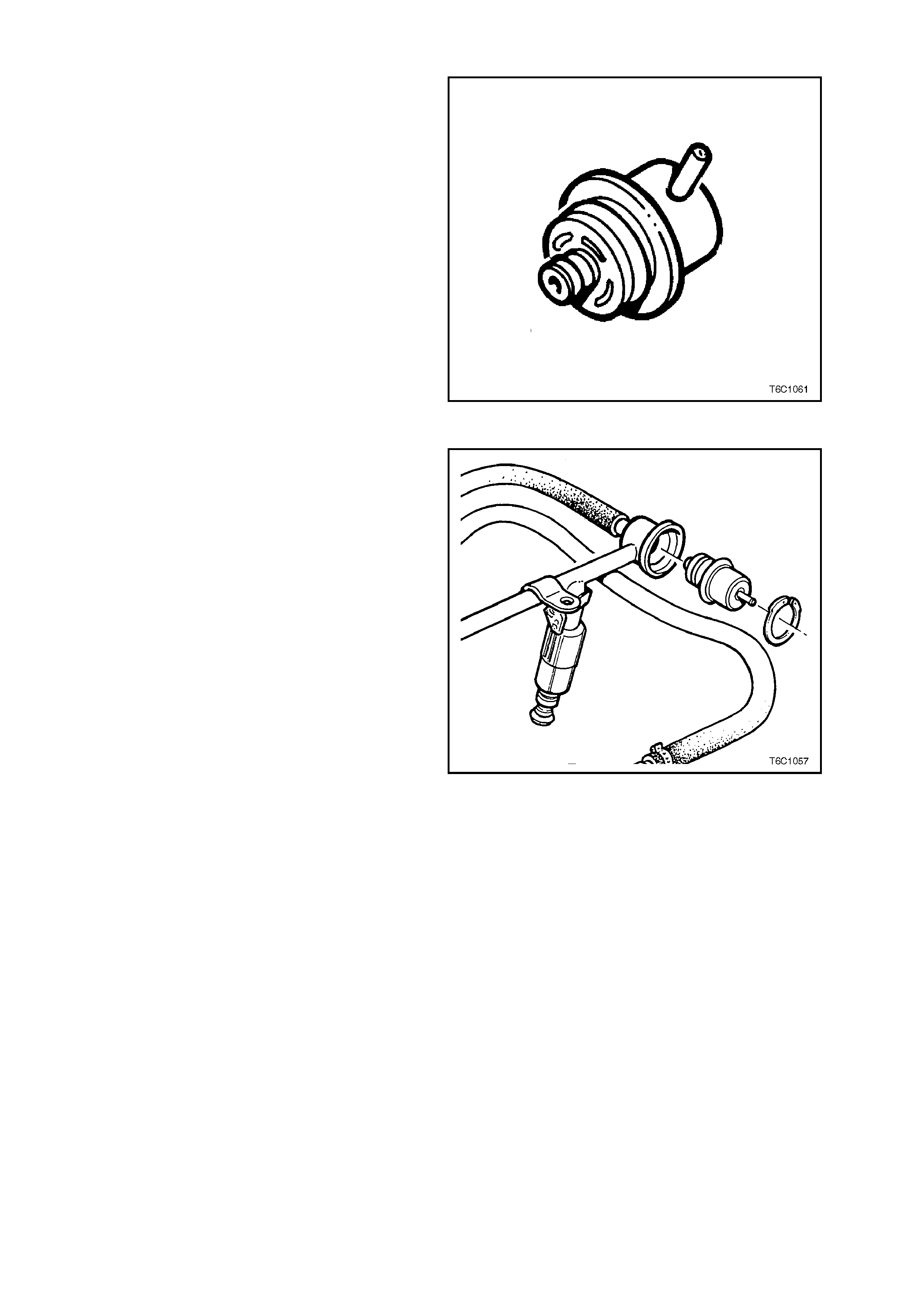
Figure 6C1-3-54 Fuel Pressure Regulator
8. Check for fuel leaks as described in 3.11,
FUEL CONTROL SYSTEM - LEAK TESTING
in this section.
9. Reinstall engine dress cover to the inlet
manif old, ensuring that s tud gromm ets in dress
cover remain in place. Tighten securing dome
nuts to the correct torque specification.
NOTE: Compressed air must never be used to test
or clean a fuel pressure regulator, as damage to
the fuel pressure regulator may result.
In order to prevent damage to the fuel pressure
regulator, do not immerse in solvent.
Figure 6C1-3-55 Non-Supercharged Engine Fuel Pressure
Regulator Removal From Fuel Rail
FUEL RAIL
SUPERCHARGED ENGINE
NOTE: T he f uel inlet and return hos es are s erviced
separately from the fuel rail.
NON-SUPERCHARGED ENGINE
NOTE: The fuel inlet and return hoses are an
assembly with the fuel rail. Both components are
NOT serviced separately. For removal or
replacem ent of the fuel r ail assembly refer to FUEL
RAIL AND INJECTORS in this section.
Figure 6C1-3-56 Supercharged Engine
Figure 6C1-3-57 -Non-Supercharged Engine
AIR CLEA NER ASSEMBLY
Remove
1. Loosen air duct adapter located closest to air
cleaner assembly.
2. Disconnect air duct from air cleaner assembly.
3. Pull up retaining tang on IAT sensor wiring
harness connector and pull connector from
sensor.
4. Unclip 5 clips holding the air cleaner upper
housing in place.
5. Remove air cleaner upper housing and air
cleaner element assembly.
6. Remove three nuts securing air cleaner lower
housing to fender inner panel insulators.
7. Disengage air cleaner lower inlet assembly
from lower housing. Remove air cleaner lower
housing.
Reinstall
1. Assemble air cleaner lower housing on to
mounting insulators.
2. Install securing nuts and tighten to the correct
torque specification.
3. Assemble the air cleaner element into the air
cleaner upper housing and place the upper
housing onto the air cleaner lower air cleaner
housing, ensuring that air filter element
remains in position.
4. Snap 5 r etainer clips up into place over the top
of the air cleaner upper housing.
5. Reconnect wiring harness connector to IAT
sensor.
6. Carefully assemble air duct adapter onto air
cleaner upper housing.
NOTE: Align notch on air cleaner housing adapter
with notch in air duct adapter and notch in clamp.
7. Tighten air duct clamp securely.
8. Check that mass air f low sensor wiring harness
connector has remained firmly in place.
9. Reconnect battery earth lead.
Figure 6C1-3-58 Air Cleaner Housing Removal
Non-Supercharge
AIR CLEANER LOWE R HOUSING
SECURING NUT T ORQUE
SPECIFICATION
5 - 7 Nm
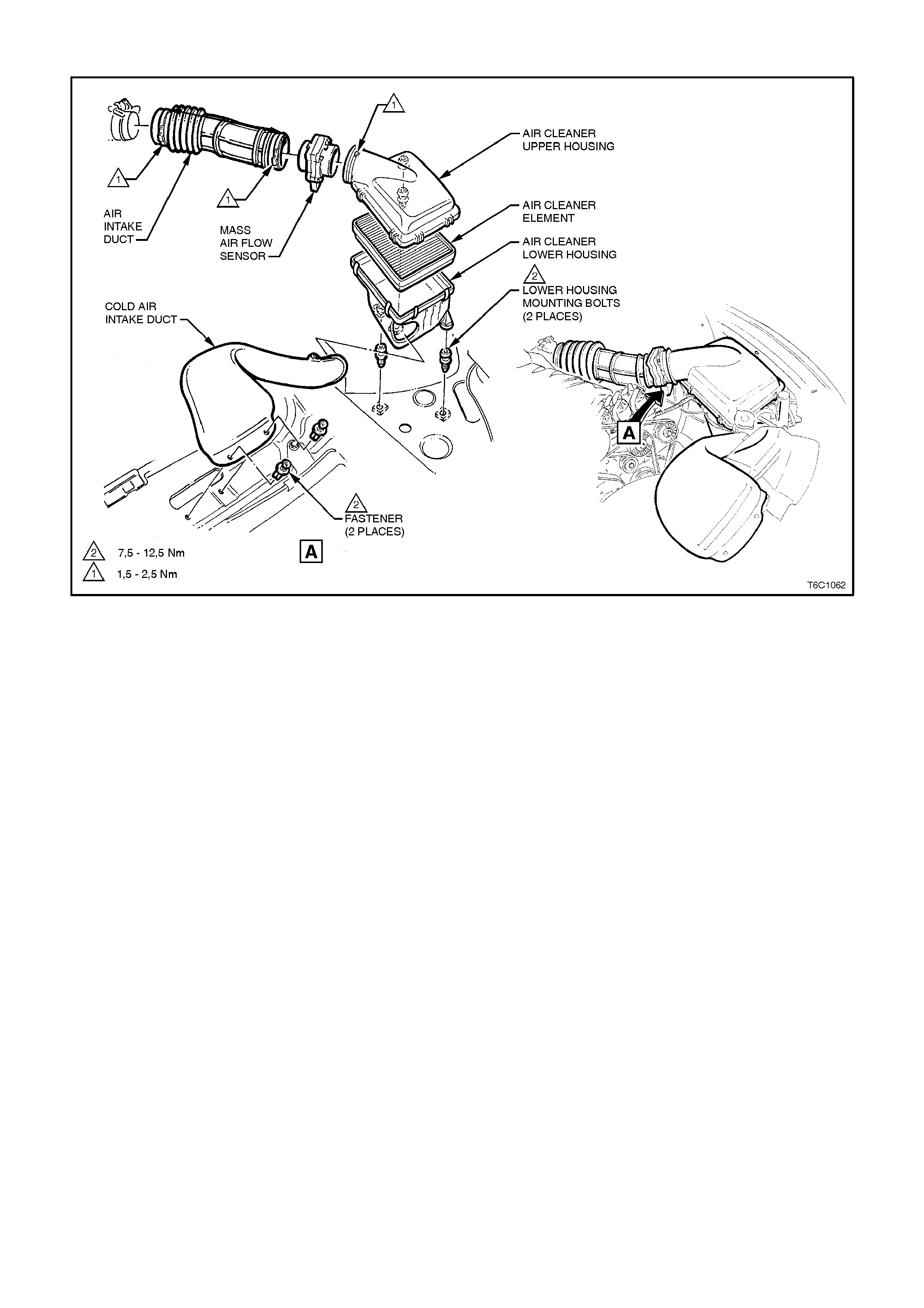
Figure 6C1-3-59 Air Cleaner Housing Removal Supercharge
THROTTLE CABLE
Remove
1. Remove four dome nuts securing the engine dress
cover assembly to the inlet manifold studs, lift off
and remove the cover assembly.
2. Loosen outer cable lock nuts at throttle body mounting bracket.
3. Remove inner cable from throttle body linkage.
4. Disconnect outer cable from mounting bracket.
5. Remove instrument panel lower right side trim assembly retainers and lower trim, refer to Section 1A3,
INSTRUMENT PANEL, in the VT Service information.
6. Disconnect inner cable plastic spacer from throttle pedal lever.
7. Withdraw cable assembly from engine compartment.
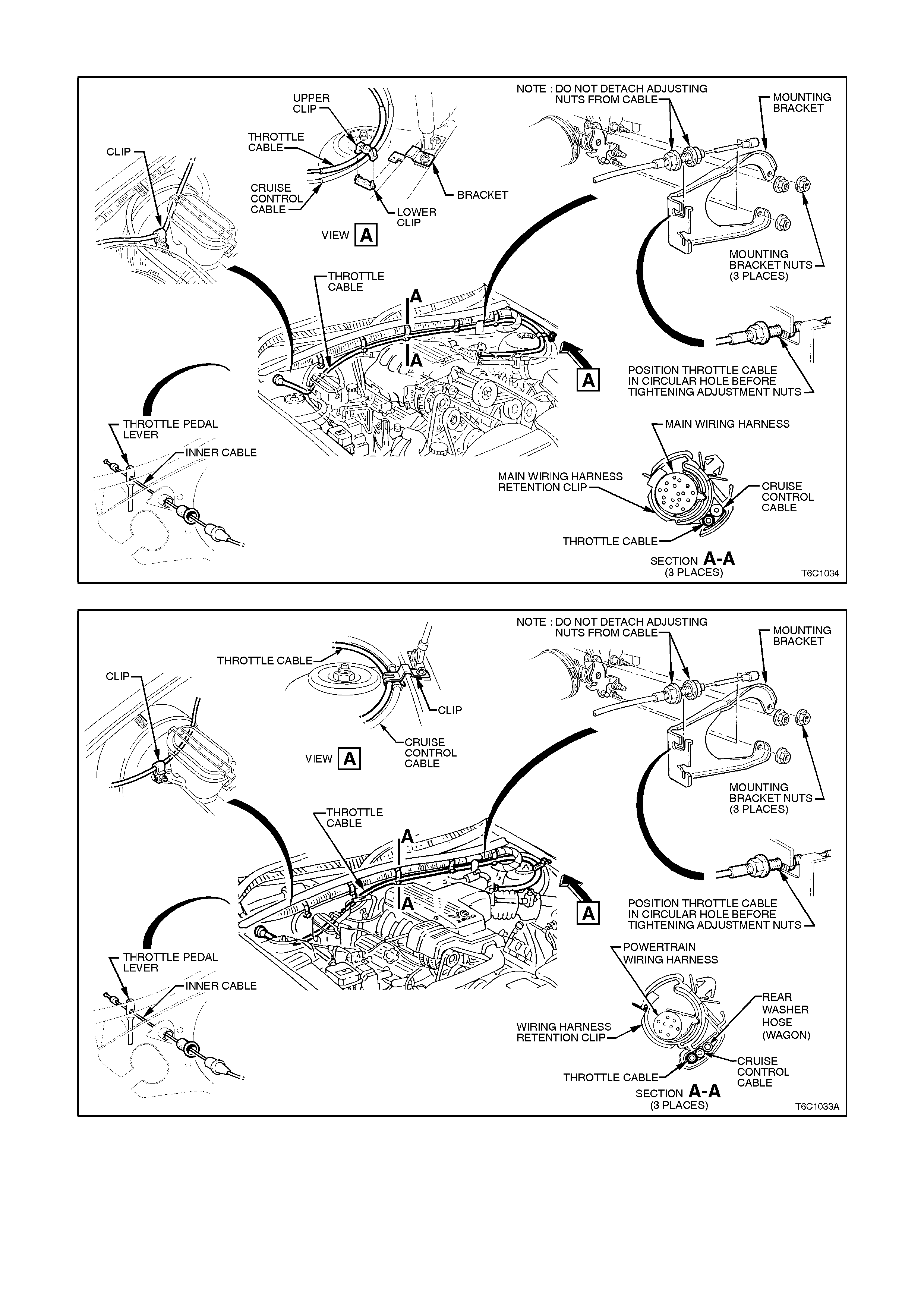
Figure 6C1-3-60 Throttle Cable Supercharged Engine
Figure 6C1-3-61 Throttle Cable Non-Supercharge
Reinstall
1. Assemble outer cable into dash panel.
2. Attach inner cable to throttle pedal lever.
3. Install outer cable to mounting bracket.
4. Attach inner cable to throttle body linkage.
5. Adjust cable as in following instructions.
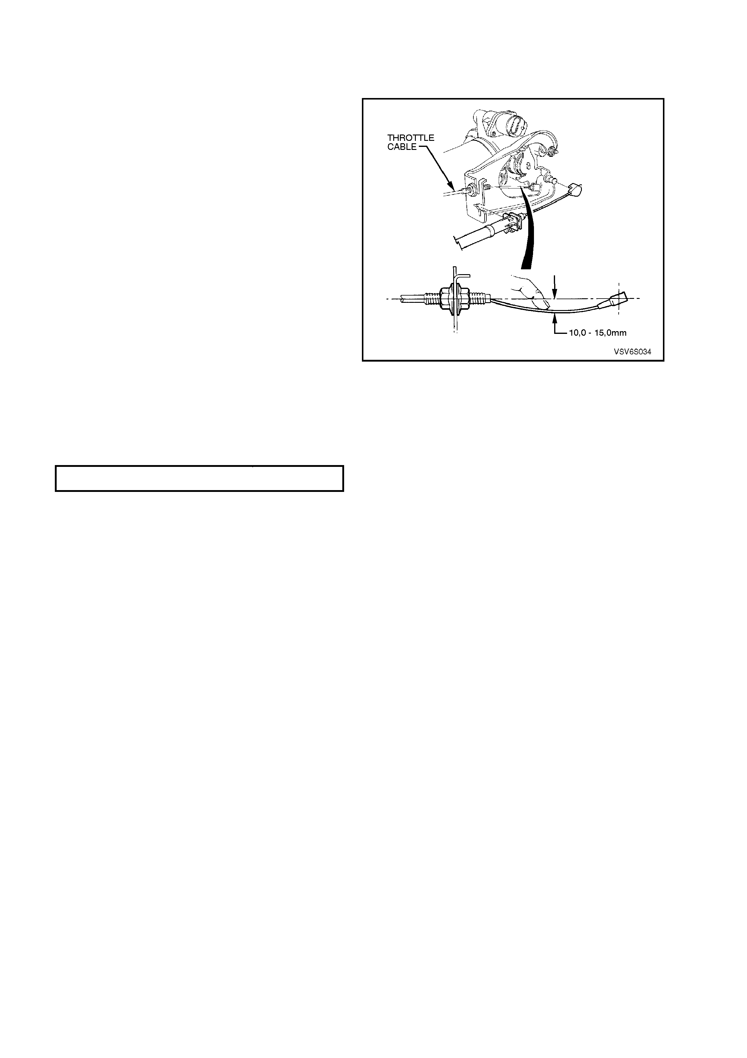
Adjust
1. Remove instrument panel lower right side trim
(if not already removed, refer to Section 1A3,
INSTRUMENT PANEL, in the VT Service
Information).
2. Ensure throttle pedal is free to move from
closed to f ully open position. Check that throttle
pedal comes to rest at the correct closed
throttle position (against pedal stop).
3. Adjust outer cable lock nuts s o that inner cable
is tensioned with a deflection of 10 to 15 mm
without moving throttle linkage from idle stop.
4. Tighten cable lock nuts to the correct torque
specification.
5. Check for Wide Open Throttle and smooth
operation of throttle pedal.
6. Reinstall engine dress cover to the inlet
manif old, ensuring that s tud gromm ets in dress
cover remain in place. Tighten securing dome
nuts to the correct torque specification.
7. Refit instrument panel lower right side trim,
refer to Section 1A3, INSTRUMENT PANEL &
CONSOLE, in the VT Service Information.
Figure 6C1-3-62 Throttle cable adjustment
THROTTLE OUTER CABLE LOCK NUT
TORQUE SPECIF I CATION 2 - 5
Nm
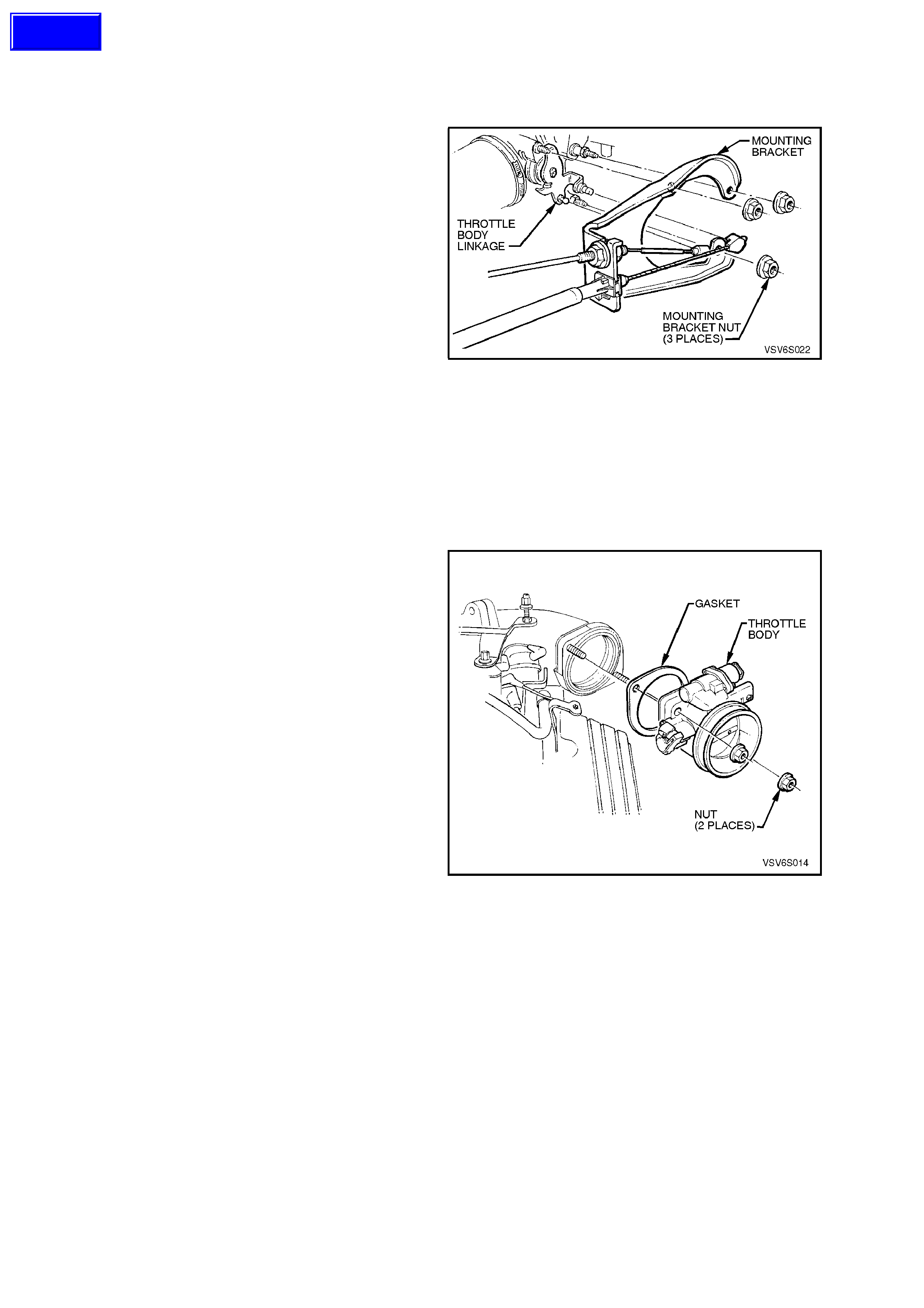
THROTTLE BODY
Supercharged Engine
Remove
1. Disconnect battery earth lead.
2. Remove four dome nuts securing the engine
dress cover assembly to the inlet manifold
studs, lift off and remove the cover assembly .
Refer to Figure 6C1-3-11.
3. Disconnect wiring harness connectors from
IAC valve and TP sensor.
4. Loosen air duct clamp at throttle body.
5. Remove air flow duct from throttle body.
6. Remove engine positive crankcase ventilation
hose from throttle body union.
7. Remove canister purge hose from throttle
body.
8. Disconnect inner throttle cable from throttle
body linkage.
9. If vehicle is fitted with cruise control, remove
cruise control cable from throttle body linkage.
10. Remove throttle cable mounting bracket
attaching nut (3).
11. Remove throttle body to inlet manifold
attaching nuts.
Figure 6C1-3-63
12. Remove throttle body and seal from manifold.
Clean
Gasket surfaces on throttle body and manifold.
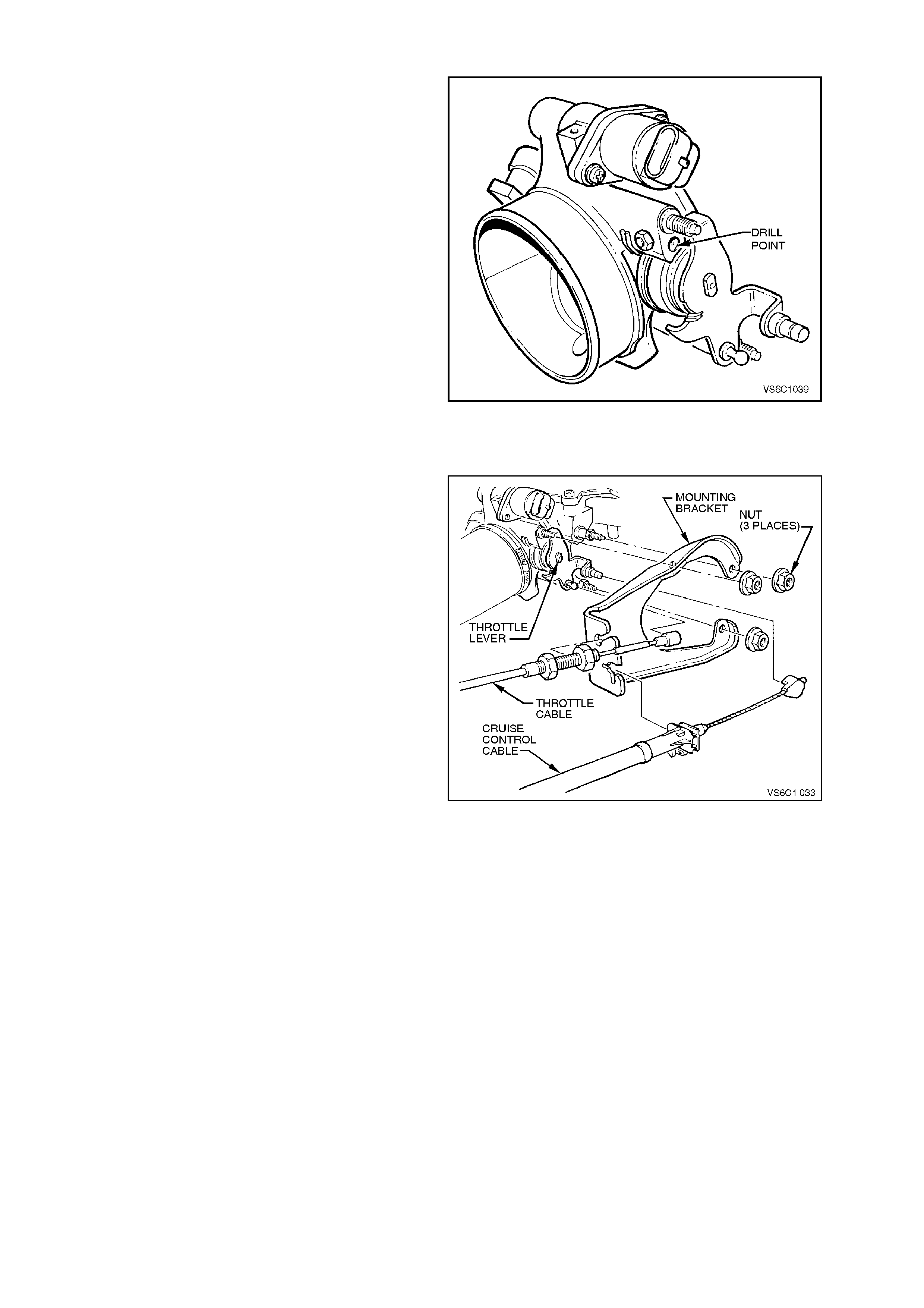
Reinstall
There are specific throttle body assemblies for
vehicles with automatic and manual transmissions.
If replacing a throttle body, ensure that the correct
type is fitted. Identification is by a drill point
marking on the throttle body used for vehicles with
manual transmission.
1. Install throttle body seal and throttle body to
inlet manifold.
2. Install throttle body attaching nuts and tighten
to the correct torque specification.
3. Reinstall canister purge control hose to throttle
body.
4. Reinstall engine positive crankcase ventilation
hose to throttle body union.
5. Reinstall wiring harness connectors to IAC
valve and TP Sensor.
6. Reinstall throttle cable mounting bracket
attaching nut (1) and bolts (2).
Figure 6C1-3-64
Techline
7. Reconnect inner throttle cable to throttle body
linkage.
8. If vehicle is fitted with cruise control, reinstall
cruise control cable to throttle body linkage.
9. Install air duct onto throttle body, align clamp
and air duct locating notches. Tighten air duct
clamp at throttle body securely
10. Reconnect battery earth lead.
11. Start engine then look and listen for air leaks.
12. Check throttle cable adjustment, refer 3.11,
FUEL CONTROL SYSTEM - Throttle Cable
Adjust in this Section.
Check cruise control cable adjustm ent, refer to
Section 12E, CRUISE CONTROL in the VT
Service Information.
13. Reinstall engine dress cover to the inlet
manifold, ensuring that stud grommets in the
dress cover remain in place. Tighten securing
dome nuts to the correct torque specification.
Figure 6C1-3-65 Throttle Body Identification
Non-Supercharged Engine
Remove
1. Disconnect battery earth lead.
2. Remove four dome nuts securing the engine
dress cover assembly to the inlet manifold
studs, lift off and remove the cover assembly.
3. Disconnect wiring harness connectors from
IAC valve and TP sensor.
4. Loosen air duct clamp at throttle body.
5. Remove air flow duct from throttle body.
6. Remove engine positive crankcase ventilation
hose from throttle body union.
7. Remove canister purge hose from throttle
body.
8. Disconnect inner throttle cable from throttle
body linkage.
9. If vehicle is fitted with cruise control, remove
cruise control cable from throttle body linkage.
10. Remove throttle cable mounting bracket
attaching nut (1) and bolts (2).
11. Remove throttle body to inlet manifold
attaching nuts.
12. Remove throttle body and seal from manifold.
CLEAN
Gasket surfaces on throttle body and manifold.
Figure 6C1-3-66
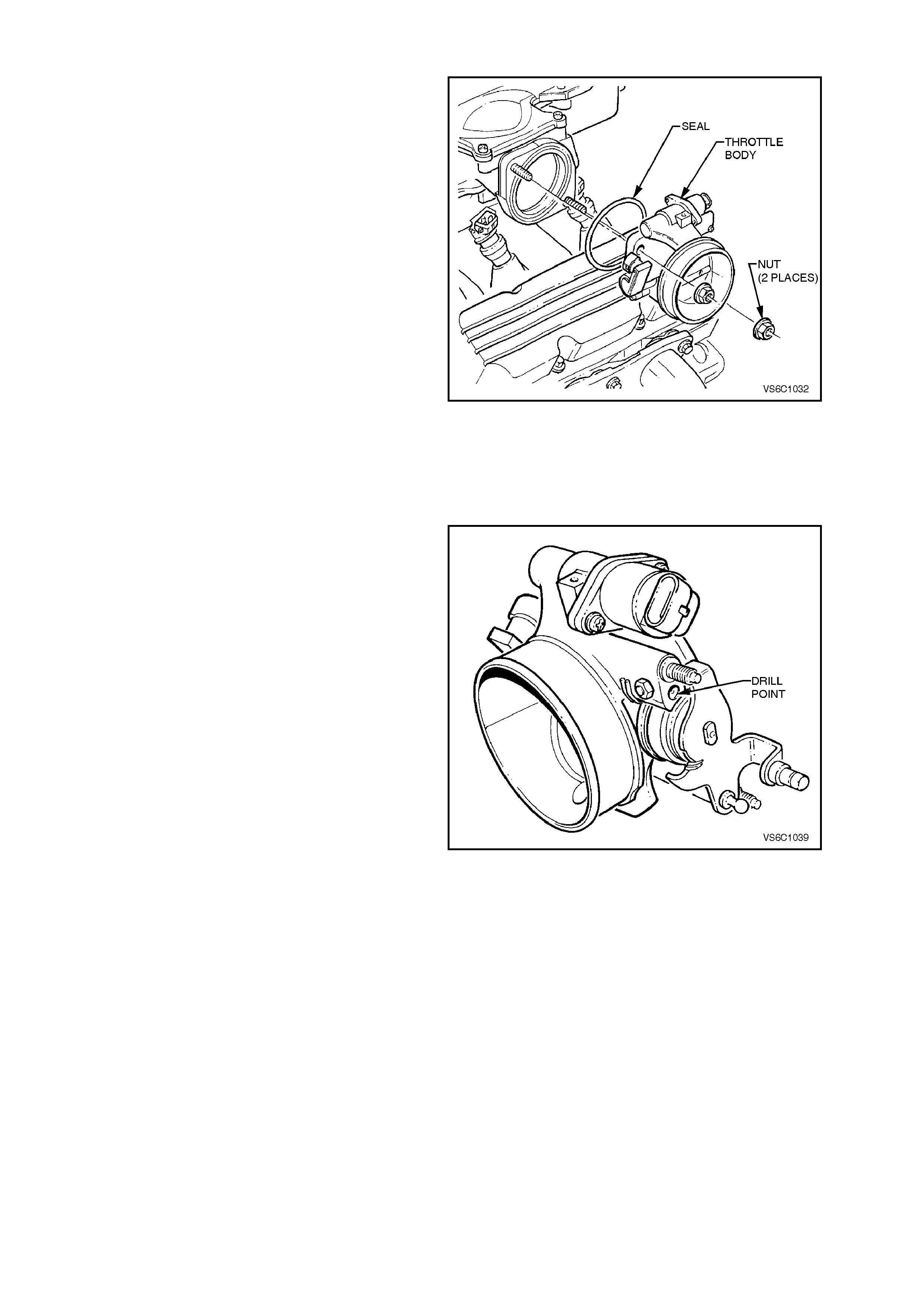
Reinstall
There are specific throttle body assemblies for
vehicles with automatic and manual transmissions.
If replacing a throttle body, ensure that the correct
type is fitted. Identification is by a drill point
marking on the throttle body used for vehicles with
manual transmission.
1. Install throttle body seal and throttle body to
inlet manifold.
2. Install throttle body attaching nuts and tighten
to the correct torque specification.
3. Reinstall canister purge control hose to throttle
body.
4. Reinstall engine positive crankcase ventilation
hose to throttle body union.
5. Reinstall wiring harness connectors to IAC
valve and TP Sensor.
6. Reinstall throttle cable mounting bracket
attaching nut and bolts.
7. Reconnect inner throttle cable to throttle body
linkage.
8. If vehicle is fitted with cruise control, reinstall
cruise control cable to throttle body linkage.
Figure 6C1-3-67
9. Install air duct onto throttle body, align clamp
and air duct locating notches. Tighten air duct
clamp at throttle body securely
10. Reconnect battery earth lead.
11. Start engine then look and listen for air leaks.
12. Check throttle cable adjustment, refer 3.11,
FUEL CONTROL SYSTEM - Throttle Cable
Adjust in this Section.
Check cruise control cable adjustm ent, refer to
Section 12E, CRUISE CONTROL in the VT
Service Information.
13. Reinstall engine dress cover to the inlet
manifold, ensuring that stud grommets in the
dress cover remain in place. Tighten securing
dome nuts to the correct torque specification.
Figure 6C1-3-68 Throttle Body Identification
FUEL RAIL AND INJECTORS
Supercharged Engine
Remove
1. Relieve fuel pressure as described in "FUEL
PRESSURE RELIEF PROCEDURE" in this
Section.
2. Disconnect battery earth lead.
IMPORTANT: Thoroughly clean around injector to
inlet manifold ports.
3. Remove four dome nuts securing the engine
dress cover assembly to the inlet manifold
studs, lift off and remove the cover assembly.
4. Remove alternator bracket.
5. Remove vacuum hose from Fuel Pressure
Regulator.
6. Disconnect fuel pressure regulator from fuel
rail. Refer to FUEL PRESSURE REGULATOR
in this section.
7. Using Tool No. 7371 for Supercharger
application, disconnect fuel inlet hose quick
connect at dash panel connection.
Figure 6C1-3-69 Supercharged Engine Fuel Rail
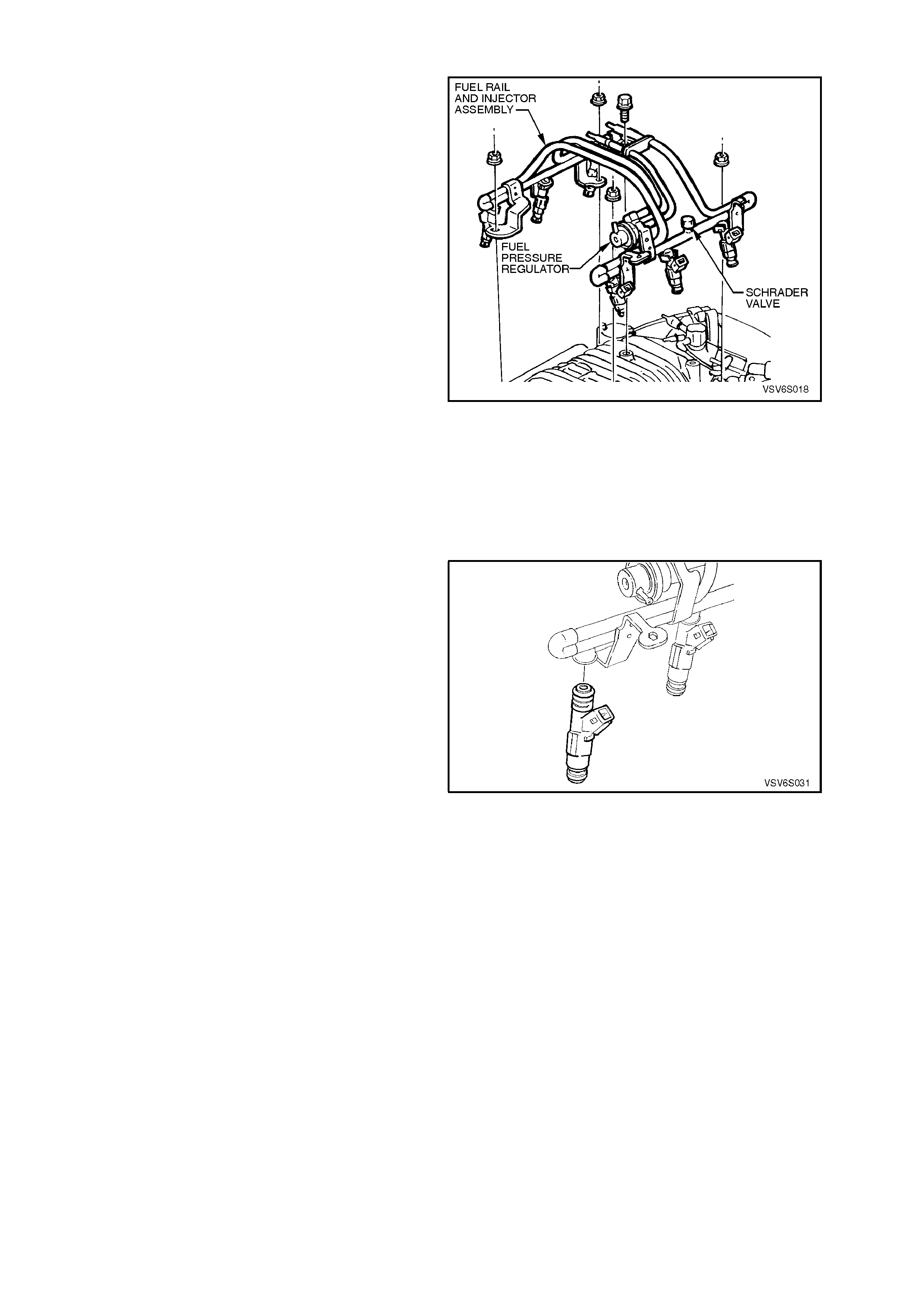
8. Disconnect electrical connectors from injectors.
9. Remove four (4) nuts, and one (1) bolts
securing Fuel Rail to intake plemun.
10. Remove fuel rail from intake plenum.
11. Remove injector retaining clips. Withdraw
injectors from fuel rail.
IMPORTANT: When servicing the fuel rail
assembly, precautions must be taken to prevent
dirt and other contaminants from entering the fuel
passages. It is recommended that fittings be
capped, and holes plugged, during servicing.
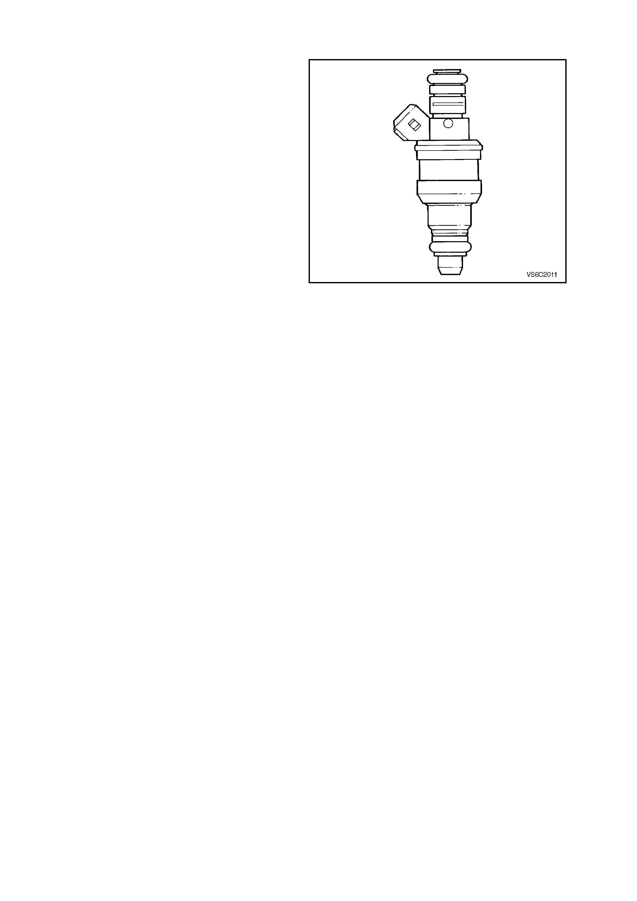
Figure 6C1-3-70 Supercharged Engine Fuel Injector
Installation
Reinstall
1. Fuel Rail to Fuel Injectors.
2. Four nuts and one bolt securing Fuel Rail to
intake Plenum.
3. Electrical connector to Injectors.
4. Fuel inlet hose quick connect to dash panel
connector.
5. Pressure regulator to fuel rail.
6. Fuel return hose quick connect to dash panel
connector.
5. Vacuum hose to Fuel Pressure Regulator.
6. Alternator bracket.
7. Reinstall engine dress cover to the inlet
manifold, ensuring that stud grommets in the
dress cover remain in place. Tighten securing
dome nuts to the correct torque specification.
8. Battery earth cable to battery.
9. Turn ignition "ON" and inspect fuel system for
leaks.
ENGINE DRESS COVER
SECURING DOME NUT TO
INLET MANIFOLD ATTACHING
NUT TORQUE SPECIFICATION
4 - 6
Nm
Figure 6C1-3-71
Non-Supercharged Engine
NOTE: The fuel inlet and return hoses are serviced
as an assembly with the fuel rail. Both components
are NOT serviced separately.
Remove
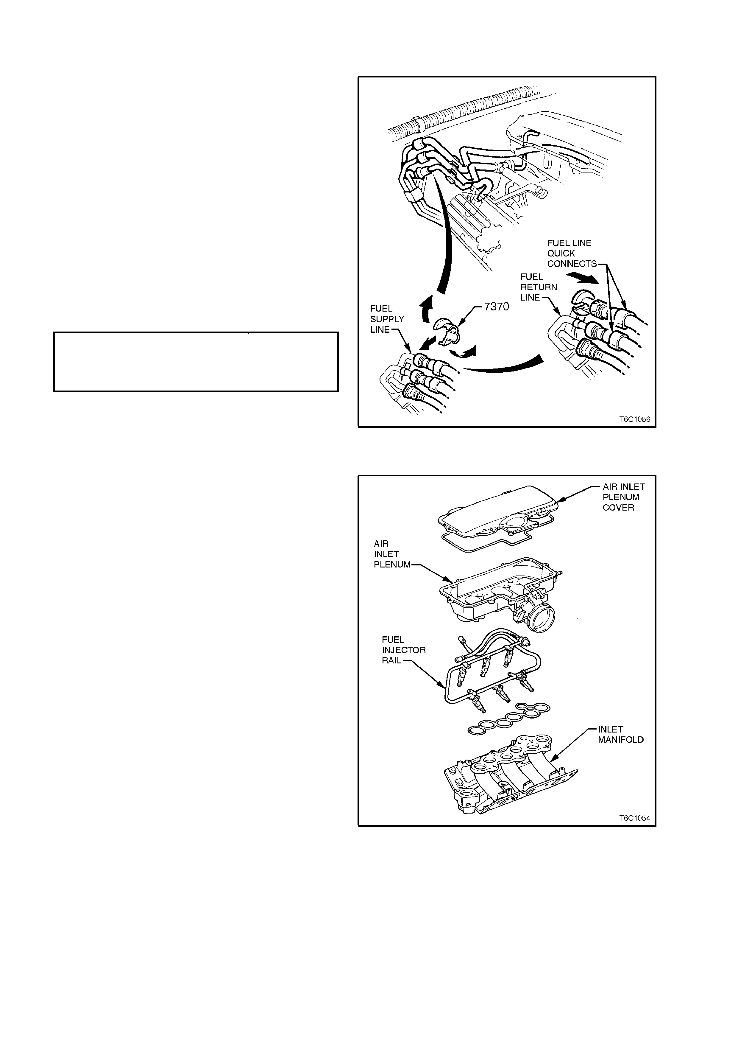
NOTE: The fuel rail and injectors are attached to
the bottom of the two-piece air inlet plenum. The
top of the air inlet plenum must be removed to gain
access to the bolts that secure the inlet plenum to
the inlet manifold. The inlet plenum is then
removed, bringing with it the attached fuel rail and
injectors.
1. Relieve fuel pressure as described in "FUEL
PRESSURE RELIEF PROCEDURE" in this
Section.
2. Disconnect battery earth lead.
3. Remove four dome nuts securing the engine
dress cover assembly to the inlet manifold
studs, lift off and remove the cover assembly.
IMPORTANT: Thoroughly clean around injector to
inlet manifold ports.
4. Remove the intake air duct from the throttle
body.
5. Remove the purge hose and crankcase vent
hose from the throttle body.
6. Remove the brake booster vacuum hose, and
two small vacuum hoses, from the air inlet
plenum.
7. Dis connec t electrical c onnectors fr om inject ors,
TP sensor, and Idle Air Control valve.
Figure 6C1-3-72
8. Remove eight hex - head bolts securing
plenum cover to air inlet plenum. Lift and
remove cover.
NOTE: Plenum cover uses a soft o-ring - style
gasket between the cover and the air inlet plenum.
Gasket should remain attached in the cover.
IMPORTANT: After removing plenum cover,
BE VERY CAREFUL TO NOT DROP ANYTHING
INTO THE EXPOSED INLET MANIFOLD PORTS
!!
NOTE: Anything dropped into these ports can, and
most likely will, cause serious engine damage due
to foreign objects being ingested into the engine
combustion chambers through the intake valves.
9. Remove vacuum hose from fuel pressure
regulator.
10. Using Tool No. 7370 for Non-Supercharger
application, disconnect fuel inlet hose quick
connect at dash panel connection.
11. Disconnect fuel pressure regulator from fuel
rail. Refer to FUEL PRESSURE REGULATOR
in this section.
12. Using Tool No. 7370 for Non-Supercharger
application, disconnect fuel return hose quick
connect at dash panel connection.
13. Fully loosen (but do not remove) five bolts
securing inlet plenum to inlet manifold.
14. Carefully lift air plenum (and attached fuel rail
with injectors) from inlet manifold. Careful
rotate the front of the inlet plenum up and
towards the windscreen. Gently lower the
plenum assembly to rest on the inlet manifold,
with the fuel rail and injectors facing forward
and tilted slightly up.
Figure 6C1-3-73
IMPORTANT: Place a clean piece of cardboard
between the inlet manifold and plenum assembly,
to prevent foreign objects from entering inlet
manifold ports.
15. Remove injector retaining clips. Withdraw
injectors from fuel rail. Remove fuel rail from air
inlet plenum ONLY if replacement of fuel rail is
needed.
IMPORTANT: When servicing the fuel rail
assembly, precautions must be taken to prevent
dirt and other contaminants from entering the fuel
passages. It is recommended that fittings be
capped, and holes plugged, during servicing.
IMPORTANT: Any time the fuel sy stem is opened
for service, the O-ring seals used with related
component(s) should be replaced, including those
used between the air inlet plenum and inlet
manifold, and between the plenum and it's cover.
Reinstall
1. Injectors using new O-rings, coat O-rings with
engine oil.
2. Injector retaining clips.
3. Air inlet plenum assembly (containing fuel rail
assembly and throttle body) onto intake
manifold, carefully placing injectors into intake
manifold ports. Tighten five bolts to the correct
torque specification.
Figure 6C1-3-74
AIR INLET PLENUM ASSEMBLY TO
INLET MANIFOLD ATTACHING BOLT
TORQUE SPECIF I CATION
15 Nm
4. Air inlet plenum cover to inlet plenum. Tighten
bolts to the correct torque specification.
AIR INLET PLENUM COVER TO AIR
INLET PLENUM ASSEMBLY
ATTACHING BOLT TORQUE
SPECIFICATION
10 Nm
5. Vacuum hoses:
- Brake booster vacuum hose to inlet plenum.
- Crankcase vent hose to throttle body.
- Purge vacuum supply hose to bottom of
throttle body.
- HVAC vacuum hose (small hose) to back of
inlet plenum.
6. Pressure regulator to fuel rail.
7. Fuel return hose to dash quick connector.
8. Fuel inlet hose to dash quick connector.
9. Electrical connectors to fuel injectors, TP sensor,
and Idle Air Control valve.
10. Reinstall engine dress cover to the inlet manifold,
ensuring that stud grommets in the dress cover
remain in place. Tighten securing dome nuts to
the correct torque specification.
11. Negative battery cable.
12. Check for fuel leaks as described in 3.11, "LEAK
TESTING" in this Section of the VT Service
Information.
3.12 IDLE AIR CONTROL VALVE
REMOVE
1. Disconnect battery earth lead.
2. Remove four dome nuts securing the engine
dress cover assembly to the inlet manifold
studs, lift off and remove the cover assembly.
3. Lift up retaining tang on IAC valve wiring
harness connector and pull connector from
valve.
4. Remove IAC valve to throttle body attaching
screws.
5. Remove IAC valve from throttle body.
CLEAN
IAC valve sealing surfaces on throttle body, to
assure proper seal of O-ring and contact of IAC
valve flange.
IMPORTANT: When installing a new IAC valve, be
sure it has the correct part number.
NOTE: Before installing a new IAC valve, measure
distance "A" between tip of valve pintle and the
flange mounting surface. If it is greater than 28
mm, it must be reduced to prevent damage to the
valve when it is installed. Exert firm pressure on
valve pintle to retract it. (A slight side-to-side
movement may be helpful).
Refer to Figure 6C1-3-60.
Figure 6C1-3-75 IAC Valve Removal

REINSTALL
1. Lubricate IAC valve O-ring with light engine oil.
If necessary, install on to valve assembly.
2. Reinstall IAC valve into throttle body with
wiring harness connector facing up.
3. Install IAC valve attaching screws and tighten
to the correct torque specification.
4. Reconnect IAC valve wiring harness connector
5. Reconnect battery earth lead.
6. If required, clear any DTCs us ing TECH 2 sc an
tool.
7. Connect TECH 2 Scan Tool to DLC and select:
Diagnostics / Appropriate Model Year / VT
Commodore / Engine / V6 / Confirm Prom I.D.
etc. / Miscellaneous tests / IAC system / IAC
Reset / and follow TECH 2 instructions.
OR
Start engine, and allow engine to run for 5
seconds, then turn engine "OFF" for 10
seconds to "Reset" the IAC valve. Restart
engine and check for proper idle.
8. Reinstall engine dress cover to the inlet
manifold, ensuring that stud grommets in the
dress cover remain in place. Tighten securing
dome nuts to the correct torque specification.
IAC VALVE TO THROTTLE BODY
ATTACHING SCREWS
TORQUE SPECIFICATI O N
1-1.5 Nm
Figure 6C1-3-76 IAC Measured
Distance
Figure 6C1-3-77 IAC Retraction Method
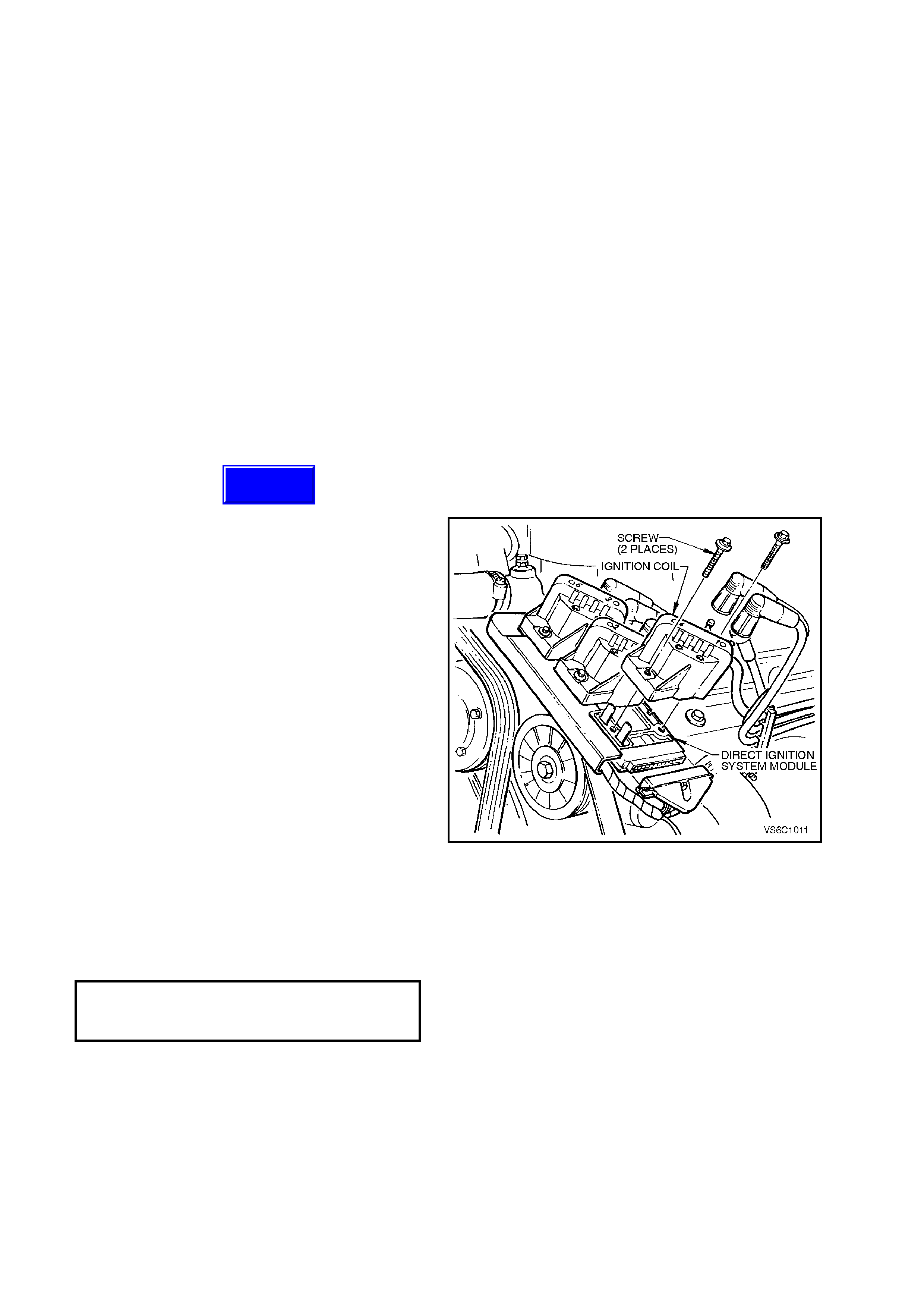
3.13 DIRECT IGNITION SYSTEM (DIS)
TIMING ADJUSTMENT
The Direct Ignition System (DIS) system fully controls
the spark timing. No adjustment for spark timing is
provided. There are no timing marks on the
crankshaft balancer or engine.
CHECKING EST SPARK TIMING OPERATION
The PCM will force the Electronic Spark Timing (EST)
spark advance to 10 degrees BTDC when the TECH
2 scan tool is connected to the DLC and By-Pass
Spark mode is selected. To check for EST operation,
run the engine with the throttle fixed at a steady 1600-
1800 RPM, then enter the "By-Pass Spark" mode of
operation with the TECH 2 scan tool. If the RPM
changes (drops), EST spark timing is operating. An
EST system fault will set a DTC. To correctly
diagnose the EST system use the proper DTC chart
in Section 6C1-2A of the VT Service Information.
IGNITION COIL (S)
Remove
1. Disconnect battery earth lead.
2. Remove spark plug leads from coil towers,
noting lead numbering with reference to coil
tower numbers.
NOTE: 1. Slightly twist spark plug leads before
removing from coil towers
NOTE: 2. All spark plug leads and coil terminals
are numbered to correspond to the cylinder
numbering. On service replacement coils the
cylinder numbering does not appear on top of any
coil assembly, refer to cylinder numbering on the
module.
3. Remove screws securing coil(s) to module
and mounting plate.
4. Pull coil(s) from module, taking care not to
bend module terminals.
Reinstall
1. Install coil(s) onto module, aligning module
terminals with mating slots on underside of
coil.
2. Install coil securing screws and tighten to the
correct torque specification.
DIS COIL T O MOUNTING
PLATE SECURING
SCREW TORQUE
SPECIFICATION
4 - 5 Nm
3. Reconnect spark plug leads to coil terminals,
ensuring correct lead to coil terminal
relationship.
4. Reconnect battery earth lead, start engine
and ensure engine operates correctly.
Figure 6C1-3-78 Ignition Coils To Module
Techline
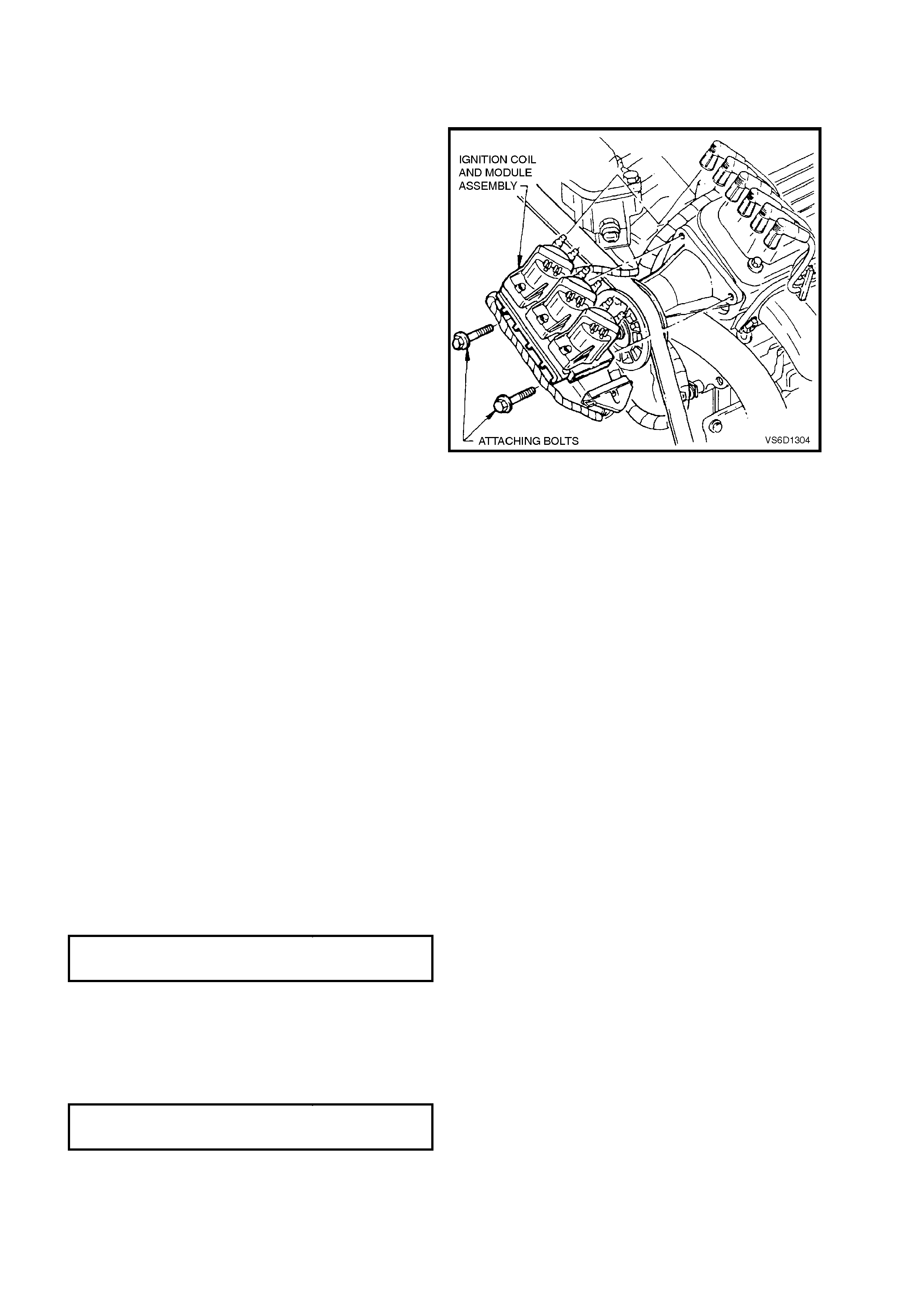
DIS MODULE
Remove
1. Disconnect battery earth lead.
2. Remove all spark plug leads from coil towers,
noting lead numbering with reference to coil
towers numbers.
3. From beneath powertrain harness retainer at
front of coil and module assembly, gently pull
down on the retainer lower locating tangs and
pull retainer from coil and module assembly.
NOTE: 1. Slightly twist spark plug leads before
removing from coil towers
NOTE: 2. All spark plug leads and coil terminals
are numbered to correspond to the cylinder
numbering. On service replacement coils the
cylinder numbering does not appear on top of any
coil assembly, refer to cylinder numbering on the
module.
4. Loosen bolt attaching 14-pin wiring harness
connector to module until you can pull
connector from module.
5. Remove screws securing coils.
6. Remove coils from module, taking care not to
bend module terminals.
7. Remove ignition module assembly.
Figure 6C1-3-79 Ignition Module Removed
Reinstall
1. When replacing module assembly, remove
module to coil terminal and 14 pin wiring harness
connector terminal seals from original module.
Install seals onto new module, taking care not to
damage seals. If any seal(s) is damaged in any
way, install new seal(s).
2. Place coils onto module, aligning module
terminals with mating slots on underside of coil.
3. Reinstall ignition module assembly to mounting
plate, locating raised lugs (2) on both module and
plate together.
NOTE: The lugs on the underside of the module will
mate with the mounting plate holes in one way only to
ensure correct assembly relationship.
4. Reinstall screws securing coils and module to
mounting plate and tighten to the correct torque
specification.
DIS COIL T O MOUNTING PLAT E
SECURING SCREW TO RQUE
SPECIFICATION
4 - 5 Nm
5. Reconnect spark plug leads to coil terminals,
ensuring correct lead to coil terminal relationship.
6. Reconnect 14-pin wiring harness connector to
module as sembly and tighten attaching bolt to the
correct torque specification.
WIRI NG HARNESS CONNECTOR TO
DIS MODULE ATTACHING BOLT
TORQUE SPECIF I CATION
0.6 - 1.2 Nm
7. Snap powertrain wiring harness retainer onto coil
and module assembly and it's mounting plate.
8. Reconnect battery earth lead.

9. Start engine and ensure engine operates
correctly.
CRANKSHAFT SENSOR
Remove
1. Disconnect battery earth lead.
2. Using a 15 mm ring spanner on drive belt
tensioner pulley pivot bolt, rotate tensioner
pulley assembly anti-clockwise and remove
drive belt from generator drive pulley. Release
drive belt tensioner and remove drive belt.
3. Remove crankshaft balancer, refer to Section
6A1, ENGINE MECHANICAL - V6 ENGINE in
the VT Service Information.
4. Lift up retaining tang on crankshaft sensor
engine wiring harness connector and pull
connector from sensor assembly.
5. Using a prying device behind crankshaft
position sensor shield, lever each corner of the
shield from front cover studs, remove shield.
6. Remove crankshaft sensor bracket to front
cover attaching studs and remove sensor
assembly.
Reinstall
1. Install crankshaft sensor assembly onto front
cover dowel pin.
2. Install and tighten s ensor brack et to fr ont cover
attaching studs to the correct torque
specification.
CRANKSHAFT POSITION SENSOR
T O F RONT COVER ATTA CHING 20 - 30 Nm
STUD TORQUE SPECIFICATION
3. Reinstall crank shaft position sensor shield onto
front cover studs, ensuring deflector retainers
fully engage over ends of studs.
4. Reconnect wiring harness connector to
crankshaft sensor.
5. Reinstall crankshaft balancer, refer to Section
6A1, ENGINE MECHANICAL - V6 ENGINE in
the VT Service Information.
NOTE: Do not reinstall drive belt at this stage.
6. Rotate crankshaft so as to check that
interrupter rings do not contact sensor.
NOTE: If the interrupter rings contac t the sensor at
any point during balancer rotation, the interrupter
rings have excessive runout and the balancer
assembly must be replaced.
7. Reinstall serpentine belt.
8. Reconnect battery earth lead.
9. Start engine and ensure engine operates
correctly.
Figure 6C1-3-80
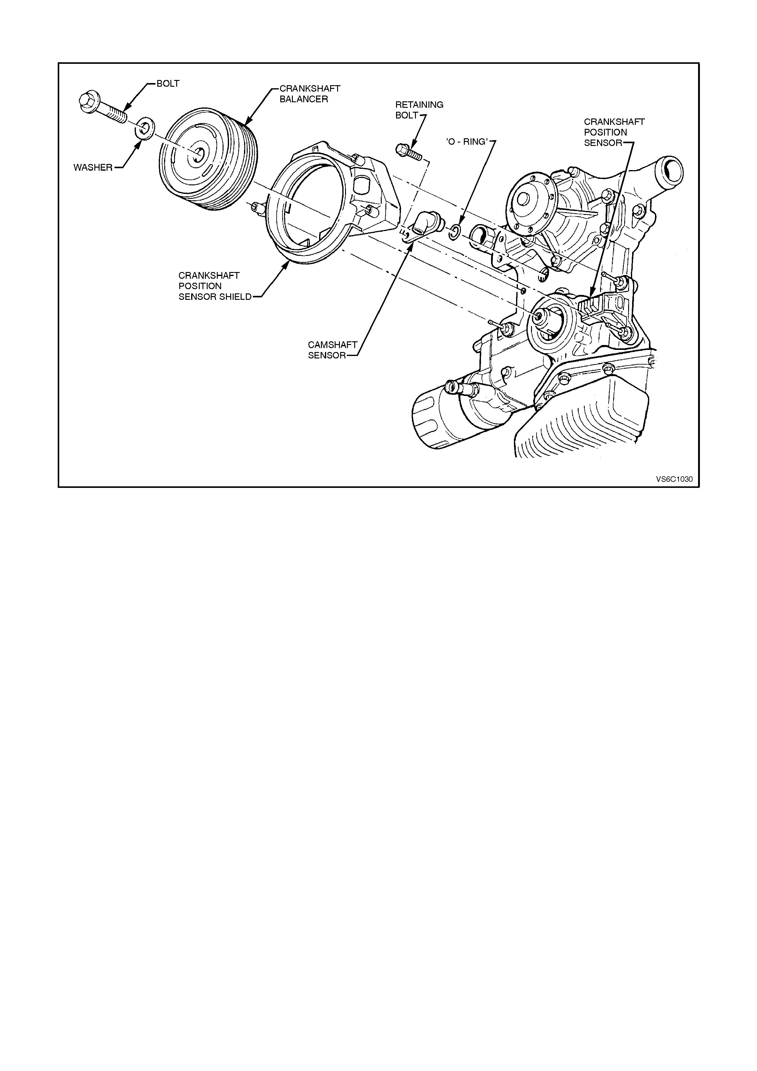
Figure 6C1-3-81 Camshaft/Crankshaft Position Sensors

3.14 1-2 SHIFT SOLENOID
Figure 6C1-3-82 1-2 Shift Solenoid Location
REMOVE
1. Disconnect battery earth lead.
CAUTION: To avoid personal injury from accidental hot oil spillage, perform fluid change only when
transmission fluid is cold.
2. Raise vehicle and support on safety stands. Refer to Section 0A, GENERAL INFORMATION in the VT
Service Information.
3. Clean all dirt from around oil pan and transmission case.
4. Place drain tray under transmission.
5. Loosen two bolts at the rear and one at the front of the oil pan. Remove the rem aining bolts. W hile holding oil
pan, allow the front of the oil pan to drop away, emptying oil into a drain tray.
6. Remove remaining bolts, then lower pan and empty fluid from pan.
7. Remove old oil pan gasket and discard.
8. Disconnect 1-2 shift solenoid (367A) electrical connector.
9. Remove solenoid retainer (379) by using a small flat blade screwdriver. Pry the retainer down until it can be
grasped.
NOTE: Solenoid has a slight spring pressure behind it, and may pop out on its own after retainer is removed.
10. Remove solenoid assembly (367A) with O-ring seal. Ensure that 1-2 shift valve (366) remains in place.

REINSTALL
1. Push solenoid assembly (367A) into valve body.
2. Hold solenoid in place with finger pressure while
installing retainer (379)
3. Reconnect 1-2 shift solenoid (367A) electrical
connector.
4. Clean oil pan and case mating surfaces. Check
that magnet is still magnetized, and attached to
the oil pan.
5. Install new gasket and reinstall oil pan. Tighten
bolts to the correct torque specification.
TRANSMISSION OIL PAN BOLT
TORQUE SPECIF I CATION 11
Nm
6. Lower vehicle and add approximately 4.8 litres of
DEXRON III automatic transmission fluid.
7. Reconnect battery earth lead.
8. Check transmission fluid level. Refer to 4L60E
Transmission Fluid Checking Procedure in
Section 6C1-2A, DIAGNOSTIC CHARTS - V6
ENGINE in the VT Service Information
.
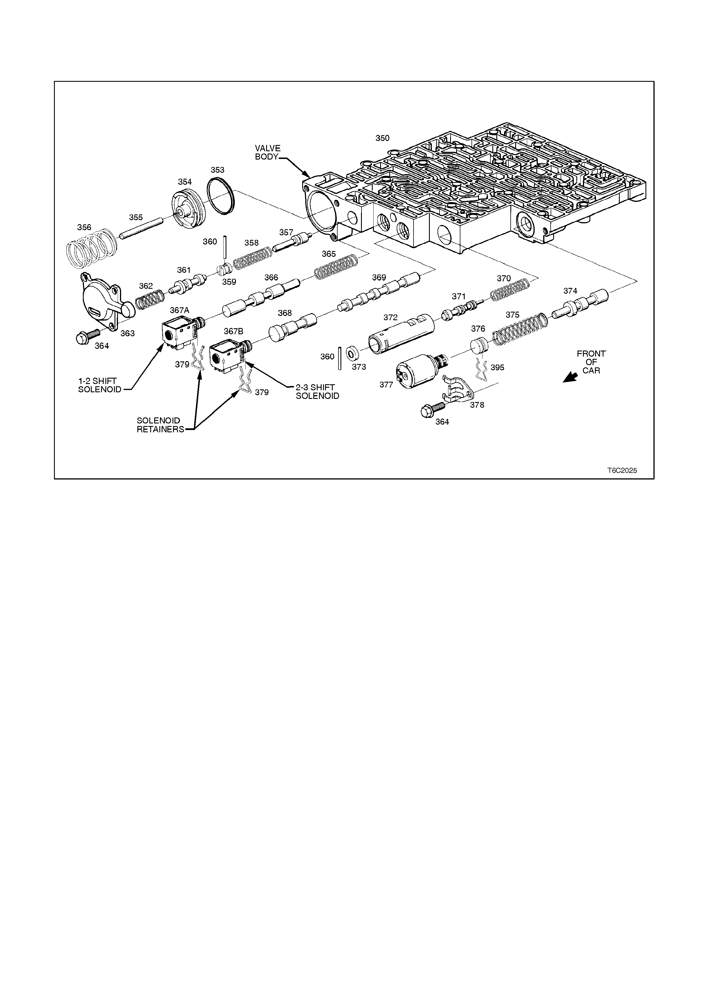
3.15 2-3 SHIFT SOLENOID
Figure 6C1-3-83 2-3 Shift Solenoid Location
REMOVE
1. Disconnect battery earth lead.
CAUTION: To avoid personal injury from accidental hot oil spillage, perform fluid change only when
transmission fluid is cold.
2. Raise vehicle and support on safety stands. Refer to Section 0A, GENERAL INFORMATION in the VT
Service Information.
3. Clean all dirt from around oil pan and transmission case.
4. Place drain tray under transmission.
5. Loosen two bolts at the rear and one at the front of the oil pan. Remove the rem aining bolts. W hile holding oil
pan , allow front of oil pan to drop away, emptying oil into a drain tray.
6. Remove remaining bolts, then lower oil pan and empty fluid from pan.
7. Remove old oil pan gasket and discard.
8. Disconnect 2-3 shift solenoid (367B) electrical connector.
9. Remove solenoid retainer (379) by using a small flat blade screwdriver. Pry the retainer down until it can be
grasped
10. Remove solenoid assembly (367B) with O-ring seal. Ensure that 2-3 shuttle valve 369 remains in place.

REINSTALL
1. Push solenoid assembly with O-ring seal (367B)
into valve body
2. Install solenoid retainer (379).
3. Reconnect 2-3 shift solenoid electrical connector.
4. Clean oil pan and case mating surfaces. Check
that magnet is still m agnetized and attached to the
oil pan.
5. Install new gasket and reinstall oil pan. Tighten
bolts to the correct torque specification.
TRANSMISSION OIL PAN BOLT
TORQUE SPECIF I CATION 11
Nm
6. Lower vehicle and add approximately 4.8 litres of
DEXRON III automatic transmission fluid.
7. Reconnect battery earth lead.
8. Check transmission fluid level. Refer to 4L60E
Transmission Fluid Checking Procedure in
Section 6C1-2A, DIAGNOSTIC CHARTS - V6
ENGINE in the VT Service Information

3.16 3-2 CONTROL SOLENOID
Figure 6C1-3-84 3-2 Shift Solenoid Location
REMOVE
1. Disconnect battery earth lead.
CAUTION: To avoid personal injury from accidental hot oil spillage, perform fluid change only when
transmission fluid is cold.
2. Raise vehicle and support on safety stands. Refer to Section 0A, GENERAL INFORMATION in the VT
Service Information.
3. Clean all dirt from around oil pan and transmission case.
4. Place drain tray under transmission.
5. Loosen two bolts at the rear and one at the front of the oil pan. Remove the rem aining bolts. W hile holding oil
pan, allow the front of the oil pan to drop away, emptying oil into a drain tray.
6. Remove remaining bolts, then lower pan and empty fluid from pan.
7. Remove old oil pan gasket and discard.
8. Remove strainer.
8. Disconnect 3-2 control solenoid (394) electrical connector.
9. Remove solenoid retainer (379) by using a split ring puller or similar hooked tool.
NOTE: Solenoid has spring pressure behind it and may pop out after retainer is removed.
10. Remove solenoid assembly (394) with O-ring seal.

REINSTALL
1. Push solenoid assembly with O-ring seal (394)
into valve body
2. Hold solenoid firmly in place with finger pressure
while installing retainer (379).
3. Reconnect 3-2 control solenoid electrical
connector.
4. Install strainer.
5. Clean oil pan and case mating surfaces. Check
that magnet is still magnetized, and attached to
the oil pan.
6. Install new gasket and reinstall oil pan. Tighten
bolts to the correct torque specification.
TRANSMISSION OIL PAN BOLT
TORQUE SPECIF I CATION 11
Nm
7. Lower vehicle and add approximately 4.8 litres of
DEXRON III automatic transmission fluid.
8. Reconnect battery earth lead.
9. Check transmission fluid level. Refer to 4L60E
Transmission Fluid Checking Procedure in
Section 6C1-2A, DIAGNOSTIC CHARTS - V6
ENGINE in the VT Service Information.
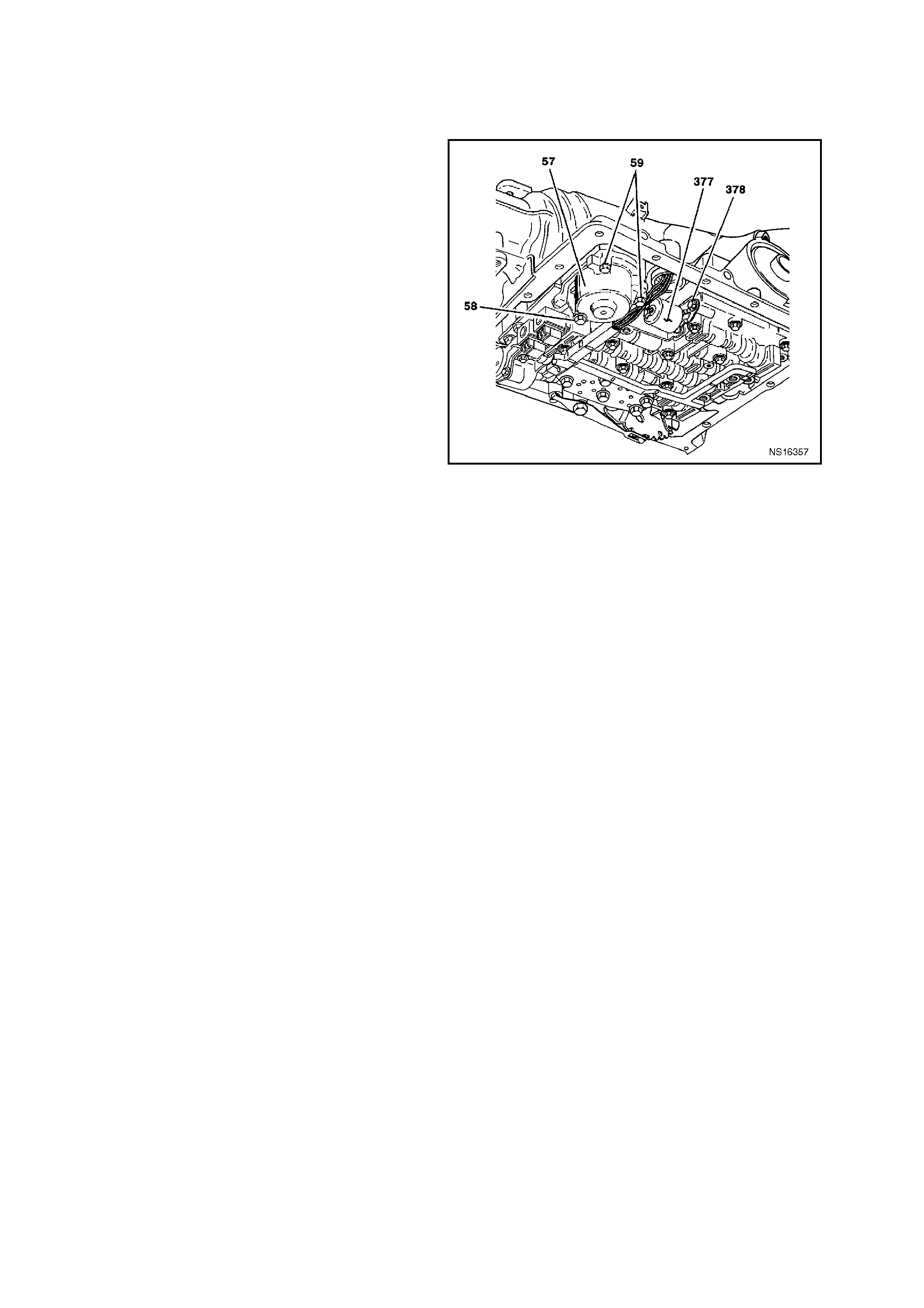
3.17 PRE S SURE CONTROL SOLENOID
REMOVE
1. Disconnect battery earth lead.
CAUTION: To avoid personal injury from
accidental hot oil spillage, perform fluid change
only when transmission fluid is cold.
2. Raise vehicle and support on safety stands.
Refer to Section 0A, GENERAL
INFORM ATION in the VT Service Information.
3. Clean all dirt from around oil pan and
transmission case .
4. Place drain tray under transmission.
5. Loosen two bolts at the rear and one at the
front of the oil pan. Remove the remaining
bolts. While holding oil pan, allow the front of
the oil pan to drop away, emptying oil into a
drain tray.
6. Remove remaining bolts, then lower pan and
empty fluid from pan.
7. Remove old oil pan gasket and discard.
8. Remove strainer.
9. Rem ove three 1- 2 accum ulator cover bolts (58)
(59)
NOTE: Accumulator will be full of fluid.
10. Remove 1-2 accumulator cover assembly (57).
11. Remove pressure control solenoid (377)
electrical connector.
12. Remove pressure control solenoid retainer bolt
(364), then retainer (378).
13. Remove pressure control solenoid assembly
(377).
Figure 6C1-3-85 Pressure Control Solenoid Location

REINSTALL
1. Install solenoid assembly (377). Note: Solenoid
has a flat cut out on one side of it's retaining
flange. Flat cutout goes toward retaining bolt.
Solenoid retainer has a matching flat to allow
retainer to be properly installed
2. Install solenoid retainer (378).
3. Install solenoid retainer bolt (364). Tighten bolt to
the correct torque specification.
SOLENOID RETAINER BOLT TORQUE
SPECIFICATION 11
Nm
4. Install pressure control solenoid electrical
connector.
5. Install 1-2 accumulator cover assembly (57).
6. Install accumulator cover bolts (58) (59) and
tighten to the correct torque specification.
ACCUMULATOR COVE R B O LT
TORQUE SPECIF I CATION 11
Nm
7. Install new strainer.
8. Clean oil pan and case mating surfaces. Check
that magnet is still magnetized, and attached to
the oil pan.
9. Install new gasket and reinstall oil pan. Tighten
bolts to the correct torque specification.
TRANSMISSION OIL PAN BOLT
TORQUE SPECIF I CATION 11
Nm
10. Lower vehicle and add approximately 4.8 litres of
DEXRON III automatic transmission fluid.
11. Reconnect battery earth lead.
12. Check transmission fluid level. Refer to 4L60E
Transmission Fluid Checking Procedure in
Section 6C1-2A, DIAGNOSTIC CHARTS - V6
ENGINE in the VT Service Information
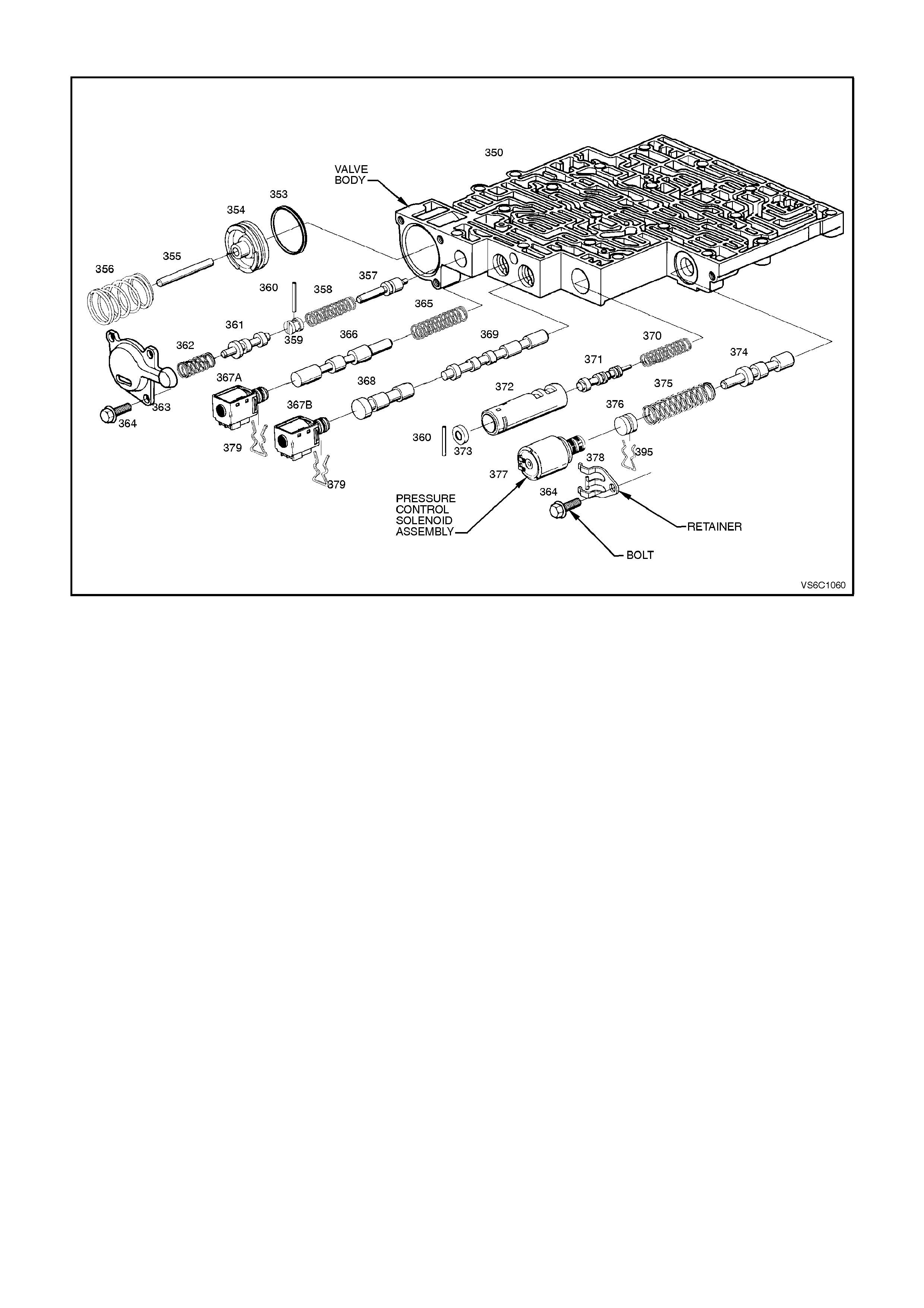
Figure 6C1-3-86 Pressure Control Solenoid Assembly
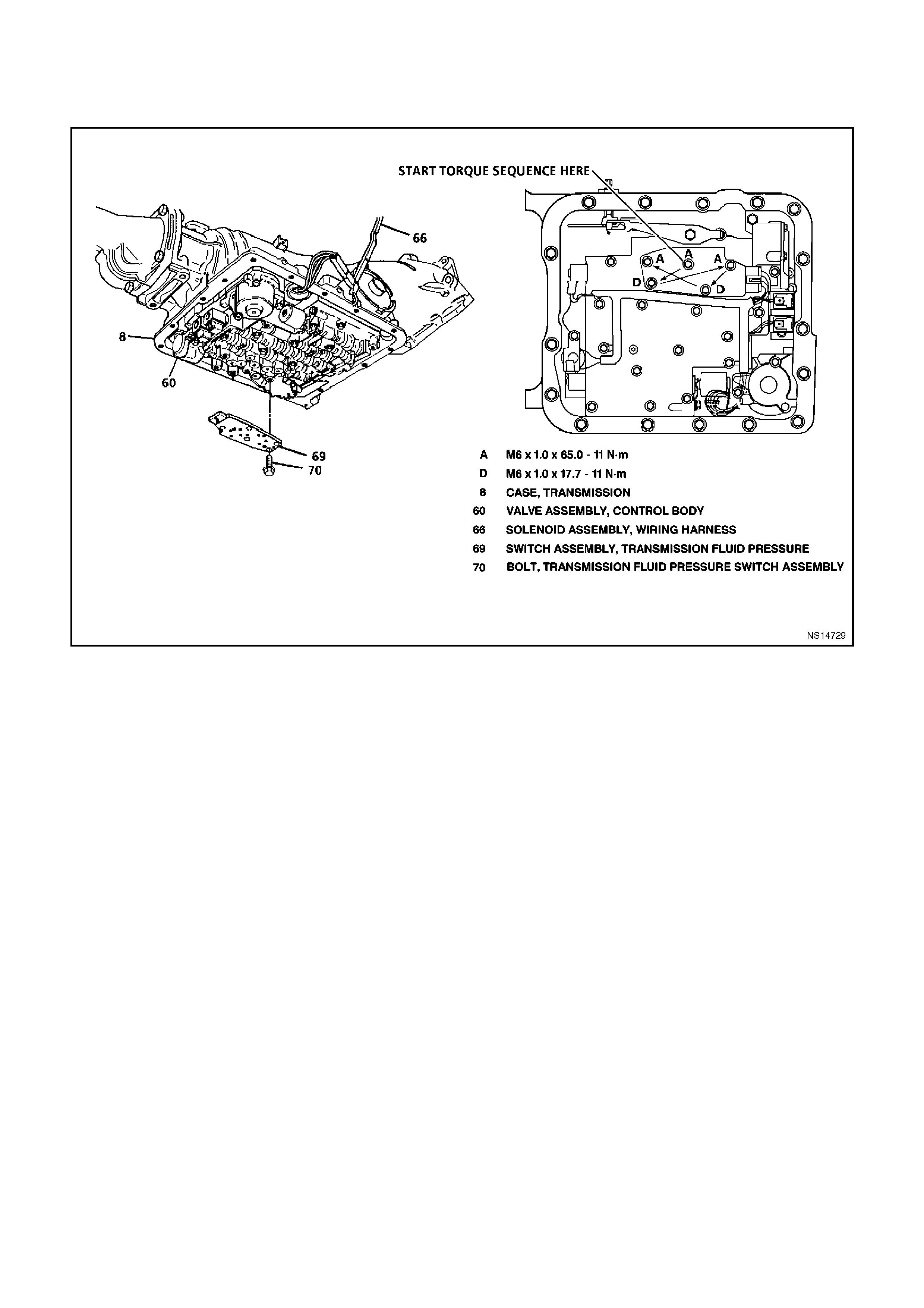
3.18 TRANSMISSION FLUID PRESSURE SWITCH ASSEMBLY (TFP) AND TRANSMISSION
FLUID TEMPERATURE (TFT) SENSOR
Figure 6C1-3-87 Transmission Fluid Pressure Switch Assembly (TFP)
REMOVE
1. Disconnect battery earth lead.
CAUTION: To avoid personal injury from accidental hot oil spillage, perform fluid change only when
transmission fluid is cold.
2. Raise vehicle and support on safety stands. Refer to Section 0A, GENERAL INFORMATION in the VT
Service Information.
3. Clean all dirt from around oil pan and transmission case.
4. Place drain tray under transmission.
5. Loosen two bolts at the rear and one at the front of the oil pan. Remove the rem aining bolts. W hile holding oil
pan, allow the front of the oil pan to drop away, emptying oil into a drain tray.
6. Remove remaining bolts, then lower pan and empty fluid from pan.
7. Remove old oil pan gasket and discard.
8. Remove strainer.
9. Disconnect trans fluid pressure switch assembly electrical connector.
10. Remove five (5) trans fluid pressure switch assembly to valve body bolts (68 and 70).
11. Remove trans fluid pressure switch assembly (69).

REINSTALL
1. Install trans fluid pressure switch assembly (69).
2. Install f ive (5) trans f luid pressur e switch assem bly
retaining valve body bolts (68 and 70). Tighten
bolts to the correct torque specification
TRANSMISSION FLUID PRESSURE
SWITCH ASSEM BLY ( TFP) RETAINING
VALVE BODY B OLT T O RQUE
SPECIFICATION
11
Nm
3. Reconnect trans fluid pressure switch assembly
electrical connector.
4. Reinstall strainer.
5. Clean oil pan and case mating surfaces. Check
that magnet is still magnetized, and attached to
the oil pan.
6. Install new gasket and reinstall oil pan. Tighten
bolts to the correct torque specification.
TRANSMISSION OIL PAN BOLT
TORQUE SPECIF I CATION 11
Nm
7. Lower vehicle and add approximately 4.8 litres of
DEXRON III automatic transmission fluid.
8. Reconnect battery earth lead.
9. Check transmission fluid level. Refer to 4L60E
Transmission Fluid Checking Procedure in
Section 6C1-2A, DIAGNOSTIC CHARTS - V6
ENGINE in the VT Service Information.
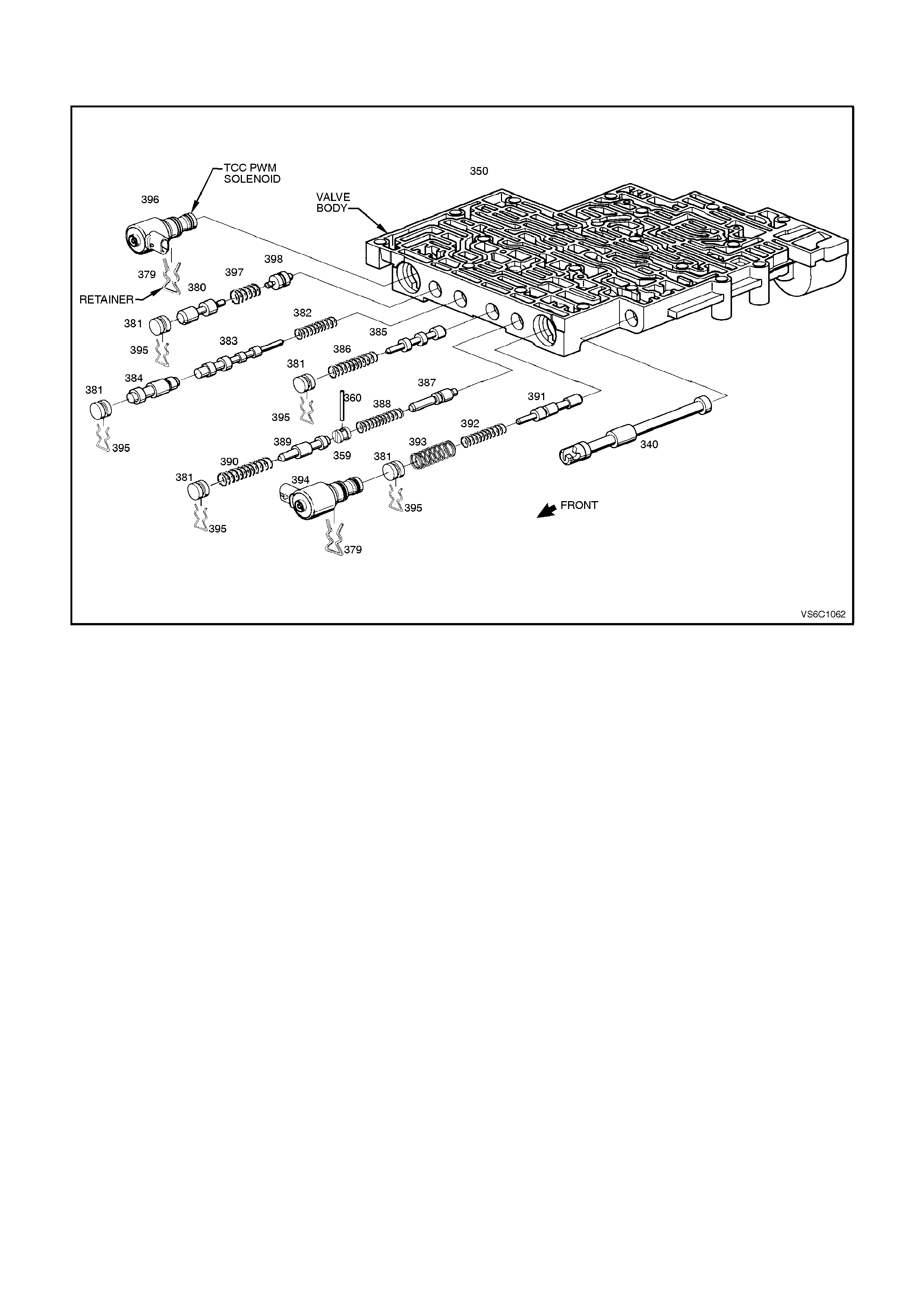
3.19 TCC "PWM" SOLENOID
Figure 6C1-3-88
REMOVE
1. Disconnect battery earth lead.
CAUTION: To avoid personal injury from accidental hot oil spillage, perform fluid change only when
transmission fluid is cold.
2. Raise vehicle and support on safety stands. Refer to Section 0A, GENERAL INFORMATION in the VT
Service Information.
3. Clean all dirt from around oil pan and transmission case.
4. Place drain tray under transmission.
5. Loosen two bolts at the rear and one at the front of the oil pan. Remove the rem aining bolts. W hile holding oil
pan, allow the front of the oil pan to drop away, emptying oil into a drain tray.
6. Remove remaining bolts, then lower pan and empty fluid from pan.
7. Remove old oil pan gasket and discard.
8. Remove strainer.
9. Remove TCC "PWM" solenoid (396) electrical connector.
10. Remove Solenoid retainer (379) by using a split ring puller or similar hooked tool.
11. Remove TCC "PWM" Solenoid assembly (396) with O-ring seal.

REINSTALL
1. Ins tall TCC "PW M" Solenoid with O-ring assem bly
(396).
2. Install TCC "PWM" Solenoid retainer (379).
3. Install TCC "PWM" solenoid electrical connector.
4. Install strainer
5. Clean oil pan and case mating surfaces. Check
that magnet is still magnetized, and attached to
the oil pan.
6. Install new gasket and reinstall oil pan. Tighten
bolts to the correct torque specification.
TRANSMISSION OIL PAN BOLT
TORQUE SPECIF I CATION 11
Nm
7. Lower vehicle and add approximately 4.8 litres of
DEXRON III automatic transmission fluid.
8. Reconnect battery earth lead.
9. Check transmission fluid level. Refer to 4L60E
Transmission Fluid Checking Procedure in
Section 6C1-2A, DIAGNOSTIC CHARTS - V6
ENGINE in the VT Service Information.
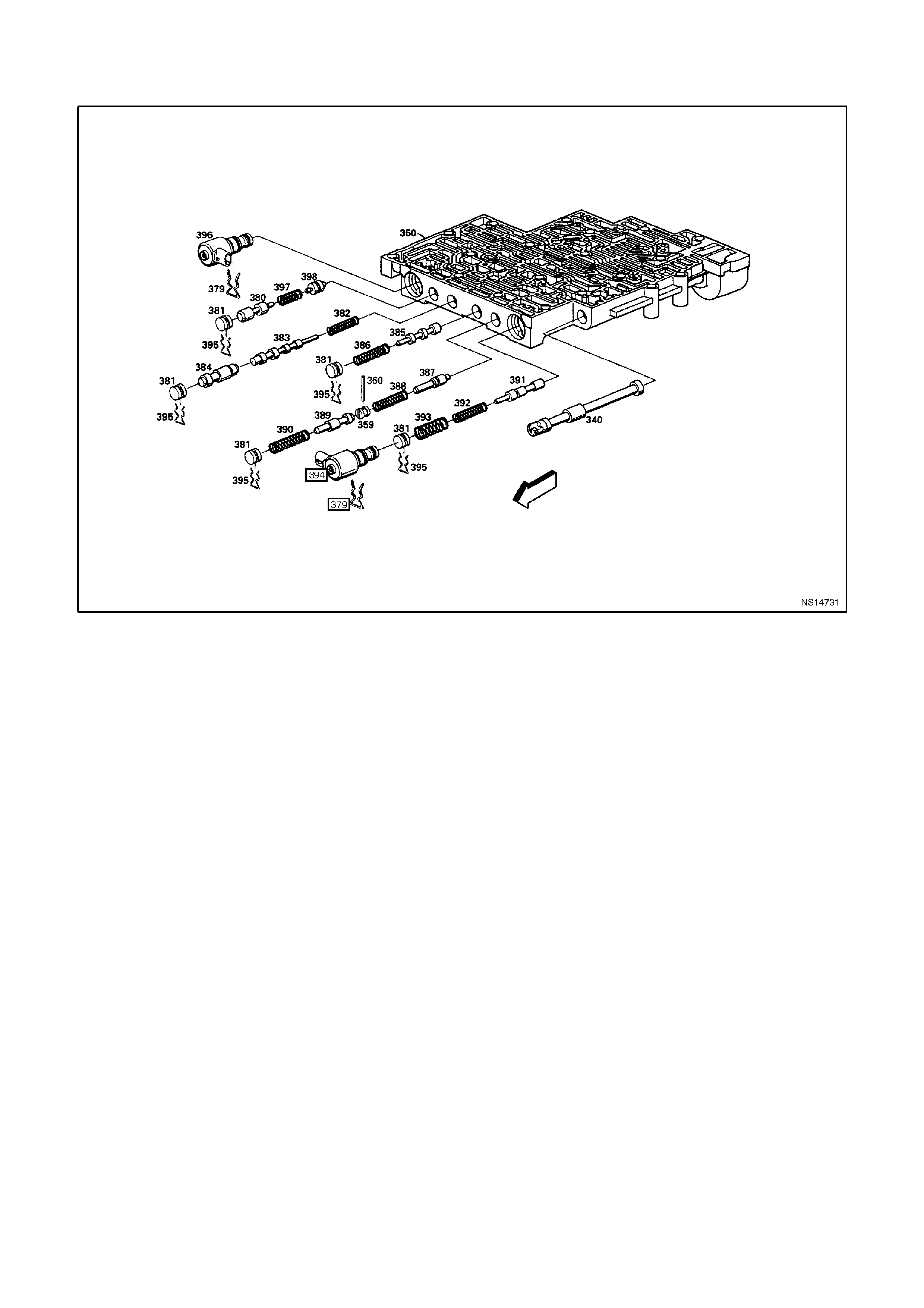
3.20 TCC ENABLE SOLENOID
Figure 6C1-3-89
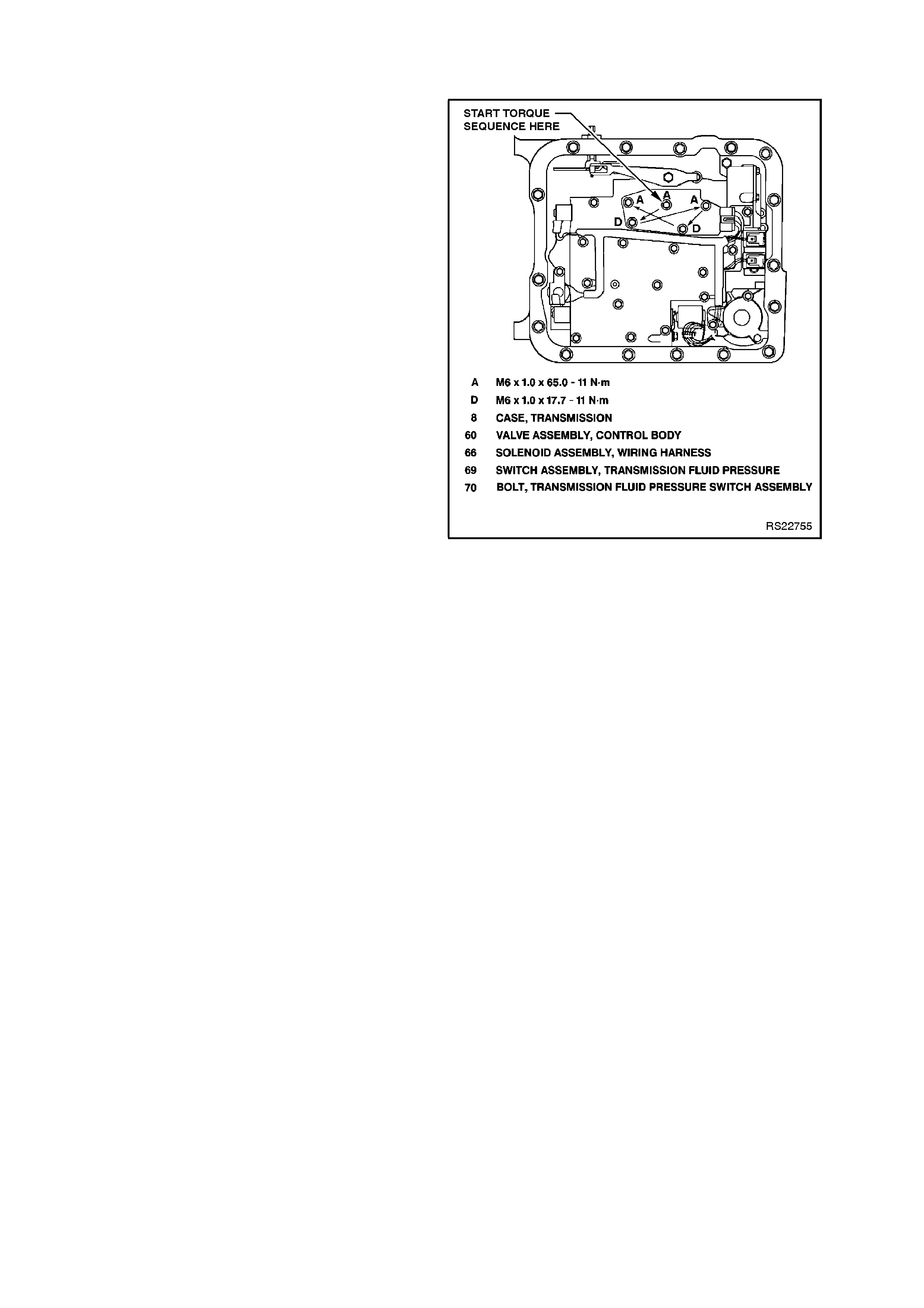
REMOVE
1. Disconnect battery earth lead.
CAUTION: To avoid personal injury from
accidental hot oil spillage, perform f luid change
only when transmission fluid is cold.
2. Raise vehicle and support on safety stands.
Refer to Section 0A, GENERAL
INFORM ATION in the VT Service Information.
3. Clean all dirt from around oil pan and
transmission case .
4. Place drain tray under transmission.
5. Loosen two bolts at the rear and one at the
front of the oil pan. Remove the remaining
bolts. While holding oil pan, allow the front of
the oil pan to drop away, emptying oil into a
drain tray.
6. Remove remaining bolts, then lower pan and
empty fluid from pan.
7. Remove old oil pan gasket and discard.
8. Remove strainer.
9. Remove TCC "PWM" solenoid (396) electrical
connector.
10. Remove TCC "PWM" solenoid retainer (379)
by using a split ring puller or similar hooked
tool.
11. Remove TCC "PW M" solenoid assembly (396)
with O-ring seal.
12. Remove TCC ENABLE solenoid assembly
bolts (68).
13. Remove T CC ENABLE solenoid assem bly (66)
with O-ring seal.
14. Remove all electrical connectors from
components.
Figure 6C1-3-90
15. Remove the three valve body bolts retaining the
transmission wiring harness.
16. Remove three 1-2 accumulator cover bolts (58)
(59).
17. Remove 1-2 accumulator cover assembly (57).
18. Rem ove pressure control solenoid (377) electrical
connector.
19. Remove pressure control solenoid retainer (378).
20. Remove pressure control solenoid assembly
(377).
21. Place a 12 point 1-5/16" deep well sock et (or 34.5
mm I.D. pipe with a slight chamfer on the inside)
over the top of the transmission pass-thru
connector.
NOTE: This may be difficult due to the clearance of
the floor pan transmission tunnel and the transmission
case.
22. Pry downward on the top of the socket or pipe
Using a prybar or similar shaped tool, push the
pass thru connector down through and out of the
transmission case .
REINSTALL
1. Coat TCC ENABLE Solenoid O-ring with
petroleum jelly then install new wiring harness
assembly (containing new TCC ENABLE
solenoid) into transmission case.
2. Install pressure control solenoid assembly (377).
NOTE: Solenoid has a flat cut out on one side of it's
retaining flange. Flat cutout goes toward retaining bolt.
Solenoid retainer has a matching flat to allow retainer
to be properly installed
3. Install pressure control solenoid retainer (378).
NOTE: Ensure that flat of the retainer is correctly
placed into the cutout on the solenoid flange. Tighten
retainer bolt to 11 N m.
4. Install pressure control solenoid (377) electrical
connector.
5. Install 1-2 accumulator cover assembly (52).
6. Install three 1-2 acc umulator c over bolts (58) ( 59).
Tighten to the correct torque specification.
1-2 ACCUMULATOR COVER B OLT
TORQUE SPECIF I CATION 11
Nm
7. Install TCC "ON-OFF" solenoid assembly (66).
8. Install T CC "ON-O FF" solenoid bolts (68). Tighten
to the correct torque specification.
TCC SOLENOID B OLT TORQUE
SPECIFICATION 11
Nm
9. Install TCC "PWM" Solenoid assembly (396).
10. Install TCC "PWM" Solenoid retainer (379).
11. Install TCC "PWM" solenoid electrical connector.
12. Install three valve body bolts retaining wiring
harness. Tighten to the correct torque
specification.
VALVE BODY WIRING HA RNESS
RETAI NI NG B O LT T ORQUE
SPECIFICATION
11
Nm
13. Install all electrical connectors onto components.
14. Install new strainer and seal.
15. Clean oil pan and case mating surfaces. Check
that magnet is still m agnetized, and attached to the
oil pan within the square marked.
16. Install new gasket and reinstall oil pan. Tighten
bolts to the correct torque specification.
TRANSMISSION OIL PAN BOLT
TORQUE SPECIF I CATION 11
Nm
17. Lower vehicle and add approximately 4.8 litres of
DEXRON III automatic transmission fluid.
18. Reconnect battery earth lead.
19. Check transmission fluid level. Refer to 4L60E
Transmission Fluid Checking Procedure in
Section 6C1-2A, DIAGNOSTIC CHARTS - V6
ENGINE in the VT Service Information.
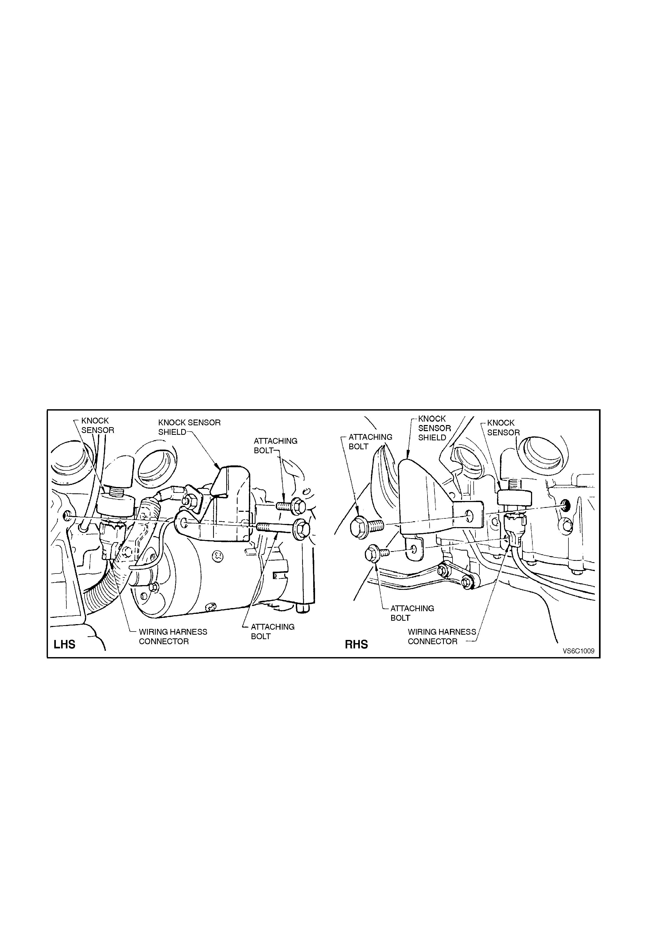
3.21 KNOCK SENSOR
CHECKING KNOCK SENSOR OPERATION
The PCM's knock sensor input will reduce the EST spark advance when detonation is present. This sensor signals
the PCM of engine noise, and the PCM determines if the noise is detonation, or normal mechanical noise. The
PCM can be "tricked" into thinking that detonation is present by lightly `rapping' on the engine with a small hammer.
To check the "knock retard" function of the ignition system, run the engine with the DLC diagnostic test terminal
NOT earthed. With the throttle fixed at a steady 1600 - 1800 RPM, quickly and repeatedly `rap' on the engine block,
cylinder head, or inlet manifold with a small hammer. The RPM should drop, due to the timing advance being
reduced. When you stop `rapping' on the engine, the RPM should come back to the original starting point.
CAUTION: Both knock sensors are threaded into the engine block cylinder cooling jackets, which is a "wet" area of
the engine coolant system. When either knock sensor is removed from the engine block engine coolant will drain
out. ALLOW ENGINE TO FULLY COOL DOWN TO AMBIENT TEMPERATURE BEFORE SERVICING KNOCK
SENSOR. Make sure to have a drain pan available to catch engine coolant.
REMOVE
1. Allow engine to cool to ambient temperature (less than 50 degrees Celsius), then remove radiator cap.
2. Disconnect battery earth lead.
3. Raise vehicle and support on safety stands. Refer to Section 0A, GENERAL INFORMATION in the VT
Service Information.
4. Squeeze together 'wide ends' on sensor wiring harness connector (connector is oval shaped) and pull
connector from sensor.
NOTE: To achieve this step it may be necessary to remove the knock sensor heat shield attaching bolts and heat
shields.
F
Figure 6C1-3-91
5. Place a suitable drain tray beneath the knock sensor location.
6. Using a 22 mm socket, universal joint and suitable length socket bars, loosen and remove knock sensor from
the cylinder block, taking extreme care to avoid any draining coolant if it is hot.
REINSTALL
1. Ensure that the threads in the sensor mounting
hole in cylinder block are clean.
2. If reinstalling original sensor, inspect sealant on
sensor thr eads. If worn away, apply a light coating
of Loctite 242 (Holden's Specification HN1256
Class 2, Type 2) to sensor threads.
NOTE: On a new sensor, do not apply sealant to
threads as threads are coated with a sealant during
production. Applying additional sealant will affect the
sensor's ability to detect engine knock.
3. Install sensor and tighten to the correct torque
specification.
NOTE: Ensure that knock sensor is never over
tightened as damage to the sensor can occur.
KNOCK SENS OR TIGHTENING
TORQUE SPECIF I CATION 16 - 22
Nm
4. Reconnect wiring harness connector to sensor.
Ensure that connector is securely fitted onto
sensor.
5. If removed, r einstall knock sensor heat shield and
attaching bolts. Tighten bolts to the correct
torque specification.
KNOCK SENSOR HEAT SHIELD
ATTACHING BOLT TORQUE
SPECIFICATION
25 - 35 Nm
6. Refill cooling system and pressure test for leaks,
refer Section 6B1, ENGINE COOLING - V6
ENGINE in the VT Service Information.
7. Reconnect battery earth lead.
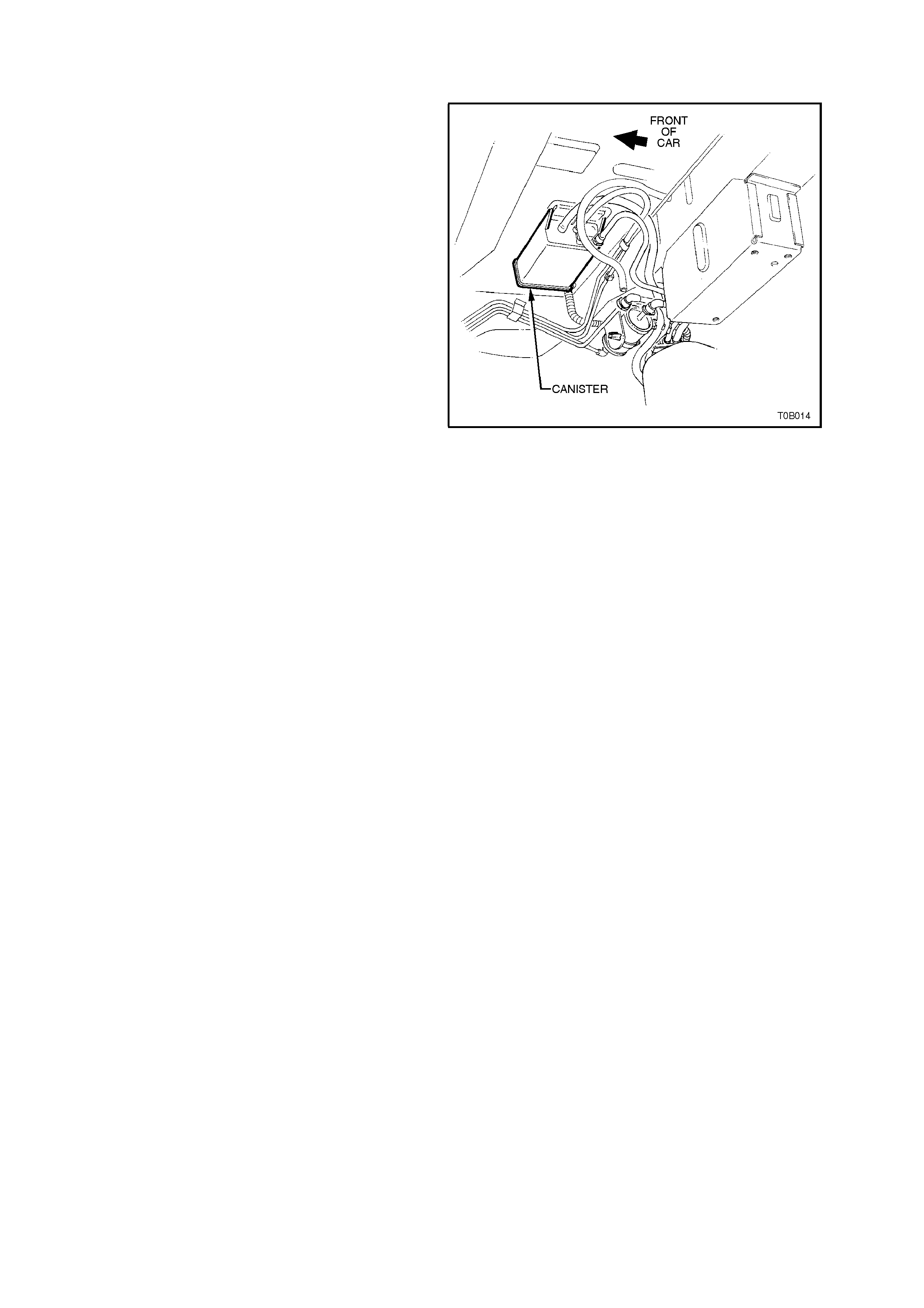
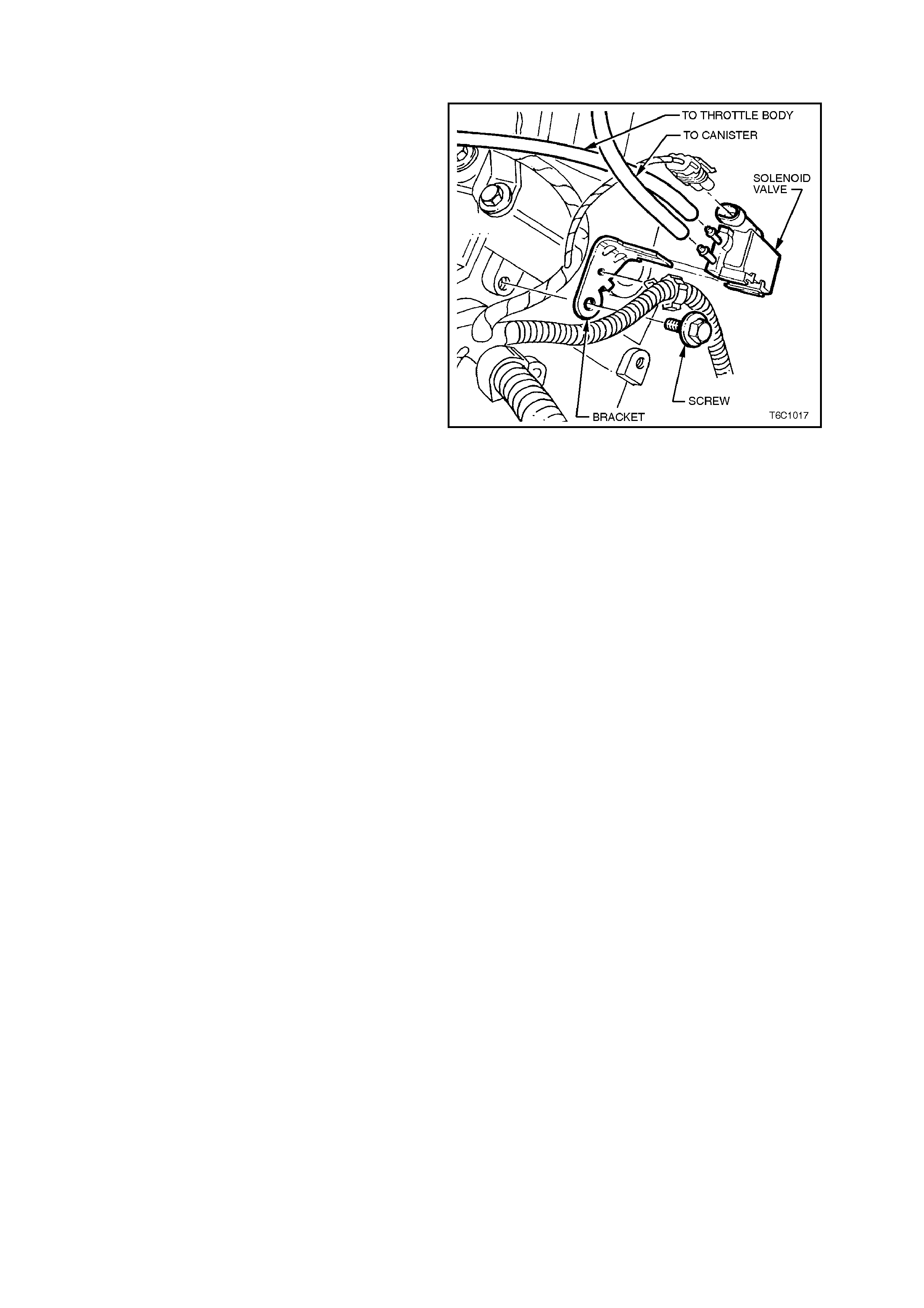
3.23 CANISTER PURGE SOLENOID
REMOVE
1. Disconnect battery earth lead.
2. Mark hoses on canister purge solenoid (top,
bottom), and pull hoses from solenoid.
3. Pull up on solenoid wiring harness connector
and pull connector from solenoid.
4. Remove bolt from solenoid bracket. This bolt
attaches to the rear of the right hand cylinder
head, remove solenoid.
REINSTALL
1. Reinstall canister purge solenoid to rear of
cylinder head and install bracket bolt. Tighten
bolt to the correct torque specification.
2. Reconnect hoses and wiring harness
connector to canister purge solenoid, ensuring
connections are correct.
3. Reconnect battery earth lead.
Figure 6C1-3-93
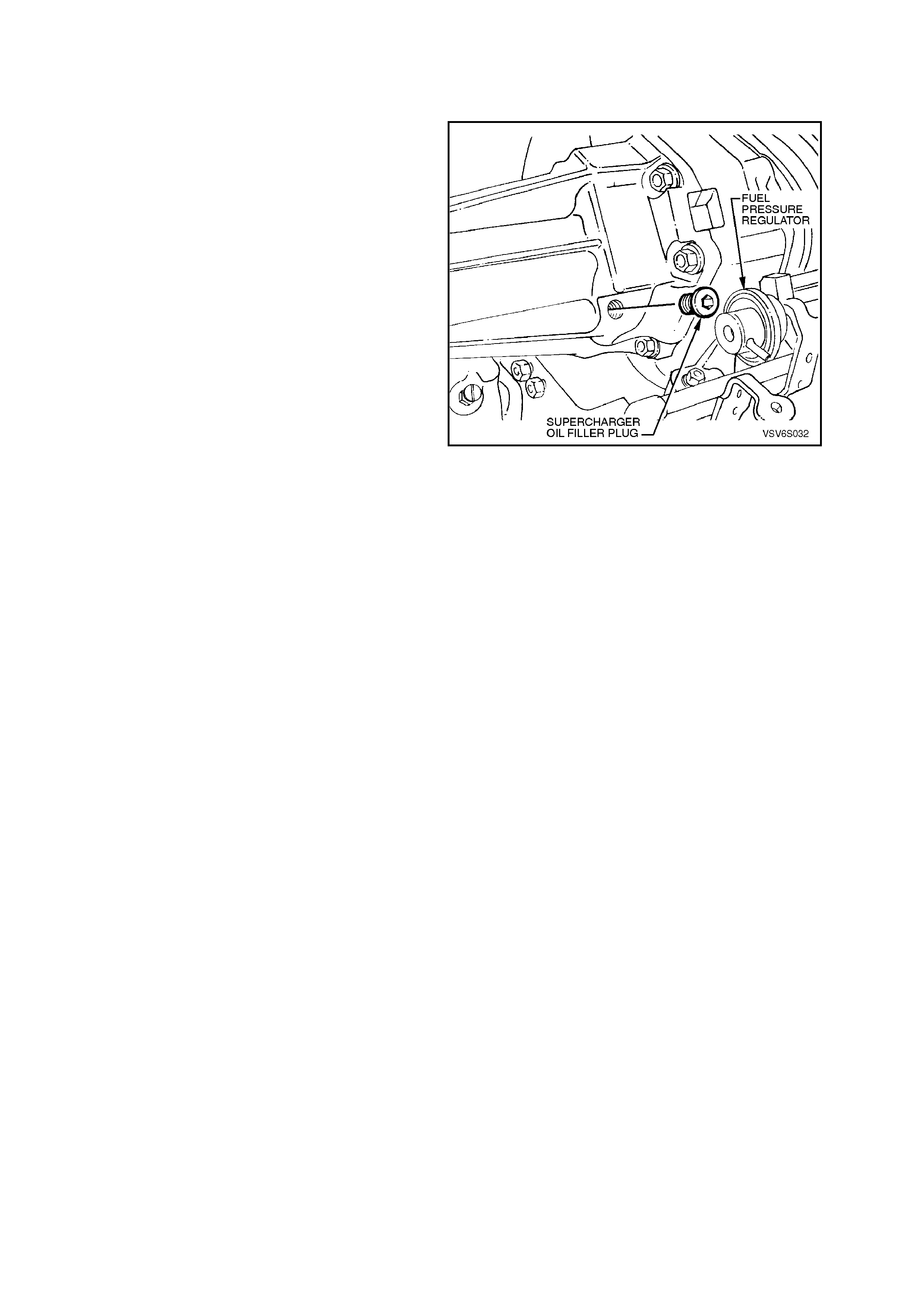
3.24 S UP ERCHARGER SYSTEM
CAUTION: To minimize the chances of unwanted
fuel spray and underhood fuel spill, always
depressurize the fuel pipes before performing
service that requires removing or disconnecting of
any portion of the fuel system, refer 3.11, FUEL
CONTROL SYSTEM - Fuel Pressure Relief
Procedure, in Section 6C1-3 SERVICE
OPERA TIONS in the VT Service Information.
SUPERCHARGER OIL LEVEL CHECK
NOTICE: A small amount of oil weepage through
the front seal, (behind the pulley) of the
supercharger assembly is a normal condition. This
oil weepage is caused by minute traces of oil
escaping around the seal due to normal pressure
build up in the oil cavity within the supercharger
assembly. A build up of belt dust and/or airborne
dust can adhere to the thin oil film, which causes
the oil weepage to appear worse than it really is.
The supercharger assembly should not be
replaced due to the weepage described. If the
supercharger oil is visually dripping or puddling
from the supercharger front seal, the supercharger
assembly will need to be replaced. Refer to
Section 6A1-2, ENGINE MECHANICAL V6
SUPERCHARGED ENGINE in the VT Service
Information.
Figure 6C1-3-94
CAUTION: Do not remove the oil plug when the
engine is warm. The engine should be cool to the
touch. Approximately 2-3 hours after running.
Removing the oil plug at warm engine temperature
can cause hot oil to overflow. This could result in oil
loss and possible personal injury.
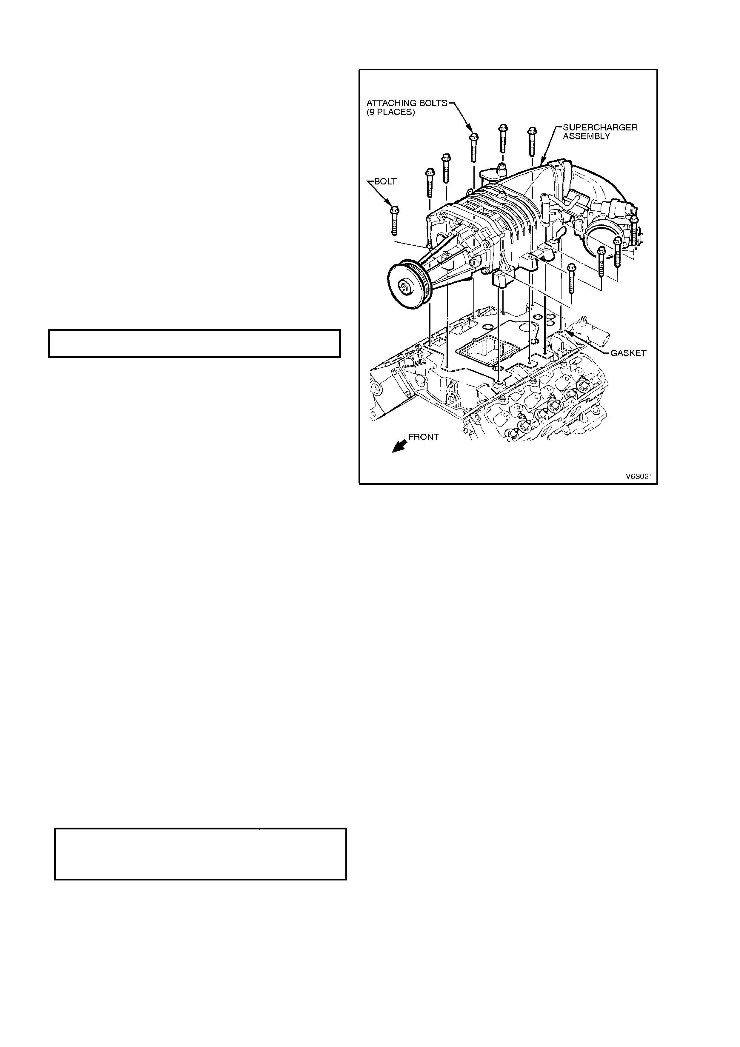
1. Remove four dome nuts securing the engine
dress cover assembly to the inlet manifold
studs, lift off and remove the cover assembly .
Refer to Figure 6C1-3-11.
NOTICE: To prevent contamination of the
supercharger oil, clean the area around the oil fill
plug before removing.
2. Using a 3/16" allen key socket, remove
supercharger oil filler plug.
3. Check oil level.
INSPECT: The oil level should be maintained to a
level at the bottom of threads in the oil filler plug
inspection hole in the supercharger housing.
IMPORTANT: DO NOT USE PETROLEUM
BASED OIL. USE ONLY GM P/N 12345982
SYNTHETIC OIL. USE OF ANY OTHER OIL MAY
CAUSE SUPERCHARGER FAILURE.
4. Reinstall oil filler plug, ensuring sealing O
ring is in place on plug. Tighten plug to the
correct torque specification.
SUPERCHARGED OIL FIL L PL UG 10
TORQUE SPECIFICATION Nm
5. Reinstall engine dress cover to the mounting
brackets, ensuring that stud grommets in the
dress cover remain in place. Tighten securing
dome nuts to the correct torque specification.
SUPERCHARGER
For Supercharger removal and reinstallation
instructions, refer Section 6A1-2, ENGINE
MECHANICAL V6 SUPERCHARGED ENGINE in
the VT Service Information.
Figure 6C1-3-95
IMPORTANT: The supercharger oil level should be
checked at the specified service intervals outlined in
the Owner's Handbook.
BOOST CONTROL SOLENOID REMOVE
1. Remove four dome nuts securing the engine
dress cover assembly to the inlet manif old studs,
lift off and remove the cover assembly.
2. Boost source and signal hose from solenoid
Ports.
3. Pull back retaining tang on wiring harness
connector and remove connector from solenoid.
4. Remove solenoid bracket to cylinder head
attaching bolt and remove solenoid.
REINSTALL
1. Assembly solenoid to cylinder head, install and
tighten attaching bolt to the correct torque
specification.
BOOST CONTROL SOLENOID BRACKET
TO CYLINDER HEAD A T T ACHING BOLT
TORQUE SPECIF I CATION 8 Nm
2. Connect boost sourc e and signal hos e to solenoid
ports.
3. Reconnect wiring harness connector to solenoid.
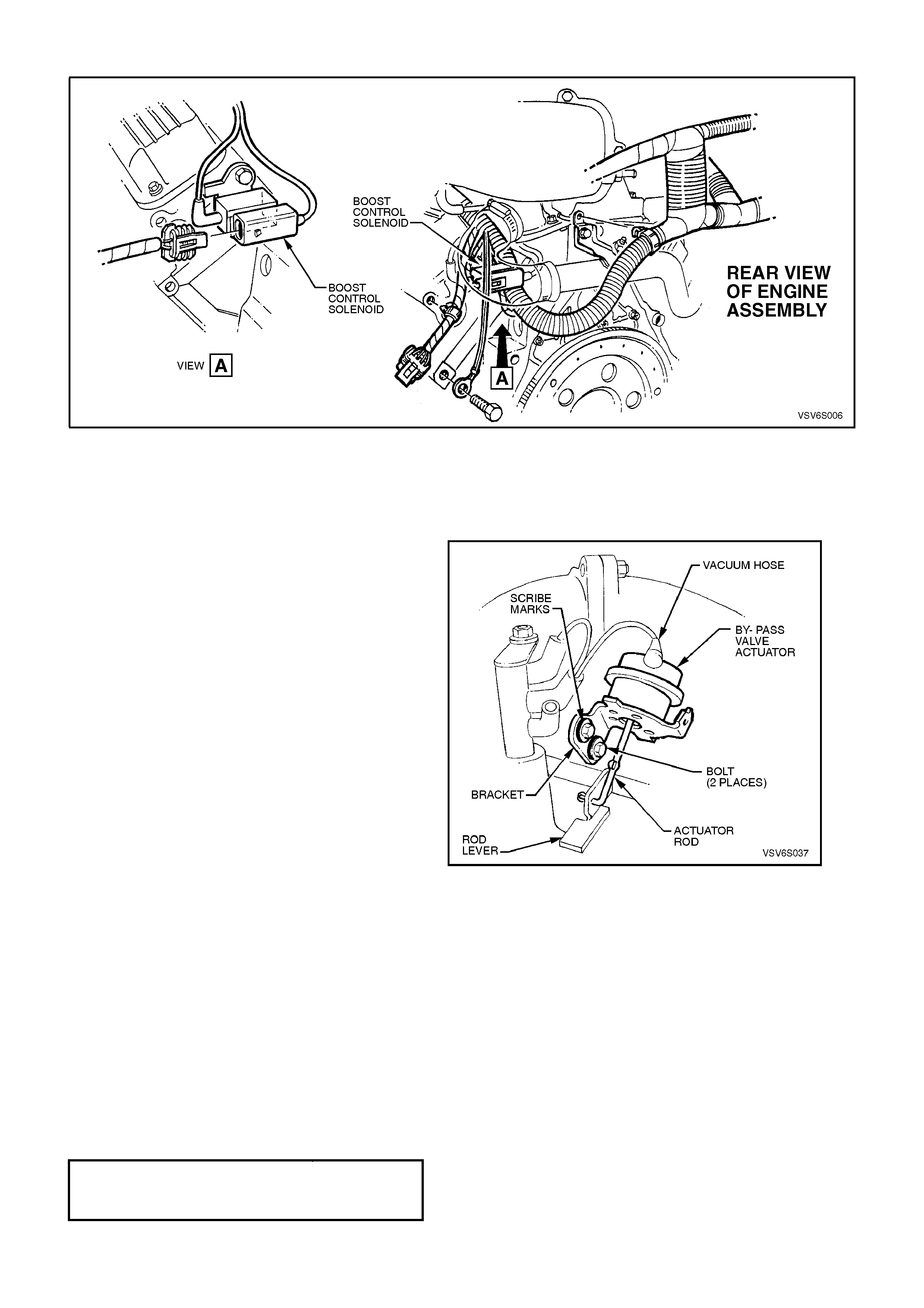
Figure 6C1-3-96 Boost Control Solenoid Location
BY-PASS VALVE ACTUATOR
REMOVE
1. Remove four dome nuts securing the engine
dress cover assembly to the inlet manifold
studs, lift off and remove the cover assembly.
Refer to Figure 6C1-3-11.
2. Remove vacuum hose from by-pass valve
actuator port.
3. Using a pointed scribe, mark position of
actuator mounting bracket around head of
securing bolts. This will aid in reinstallation so
as to ensure that actuator is assembled in the
same position.
4. Remove two (2) bolts s ecur ing actuator brac ket
to supercharger housing.
5. Lift actuator assembly upwards and then down
so as to rotate by-pass valve to actuator rod
lever clock wise through 180 degr ees f rom its at
rest position. Disengage actuator rod from the
lever by sliding out the crimped end of the rod
from slot in the lever, remove actuator.
REINSTALL
Reinstallation of the by-pass valve actuator is the
reverse of removal procedures, noting the following
points:
1. If reinstalling original by-pass valve actuator,
ensure that aligning marks made on actuator
bracket on removal are realigned before final
tightening of bolts.
2. If necessary check by-pass valve actuator
adjustment as per the following procedure.
Figure 6C1-3-97 By-Pass Valve Actuator
BY-PASS VALVE ACTUATOR
BRACKET TO SUPERCHARGER
HOUSING SE CURING BOLT TO RQUE
SPECIFICATION
26 Nm
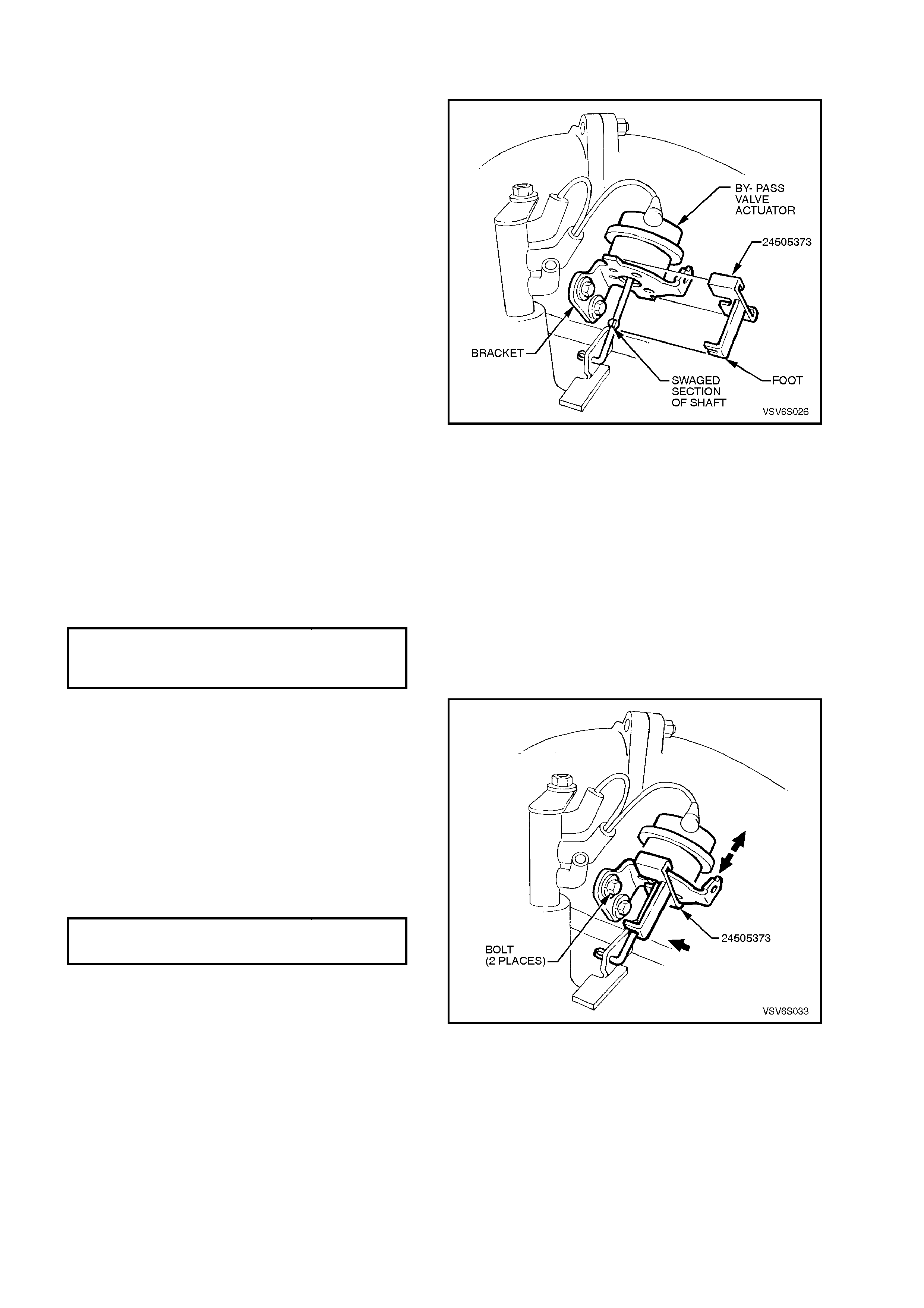
CHECKING ADJUSTMENT OF BY-PASS VALVE ACTUATOR
1. With ignition "OFF".
2. Remove four dome nuts securing the engine
dress cover assembly to the inlet manifold
studs, lift off and remove the cover assembly.
Refer to Figure 6C1-3-11.
3. Install tool 24505373 onto By-Pass Valve
Actuator.
NOTE: If tool 24505373 will not fit properly onto
By-Pass Valve Actuator, the Actuator bracket
and/or linkage may be bent, and need adjustment.
Once the adjustment is made, and the tool is
properly installed onto the valve, remove the tool
and check for proper operation of the By-Pass
Valve Actuator. Refer to step 21, chart 2.6 V6 PCM
–Boost Control System Functional Check in
Section 6C1-2C, FUNCTIONAL CHECKS – V6
ENGINE in the VT Service Information.
4. If swaged section of actuator rod does not rest
on f oot of 24505373, loosen ac tuator brac ket to
supercharger housing bolts and slide actuator
up or down until the correct position is reached.
Tighten bracket to supercharger bolts without
moving actuator position. Remove tool
24505373.
6. Tighten actuator to supercharger housing
securing bolts to the correct torque
specification.
BY-PASS VALVE ACTUATOR
BRACKET TO SUPERCHARGER
HOUSING SE CURING BOLT TO RQUE
SPECIFICATION
26 Nm
Figure 6C1-3-98 By-Pass Valve Actuator Tool Installation
6. Once the adjustment has been checked and
corrected check for proper operation of the by-
pass valve actuator . Refer to chart 2.6 V6 PCM
–Boost Control System Functional Check in
Section 6C1-2C, FUNCTIONAL CHECKS –
V6 ENGINE in the VT Service Information.
7. Reinstall engine dress cover to the mounting
brack ets, ensuring that s tud gromm ets in dress
cover remain in place. Tighten securing dome
nuts to the correct torque specification. Refer
to Figure 6C1-3-11.
ENGINE DRESS COVER SECURING
DOME NUT TO MOUNTING BRACKE T
TORQUE SPECIFICATI O N
4 - 6 Nm
Figure 6C1-3-99 By-Pass Valve Actuator Adjustment
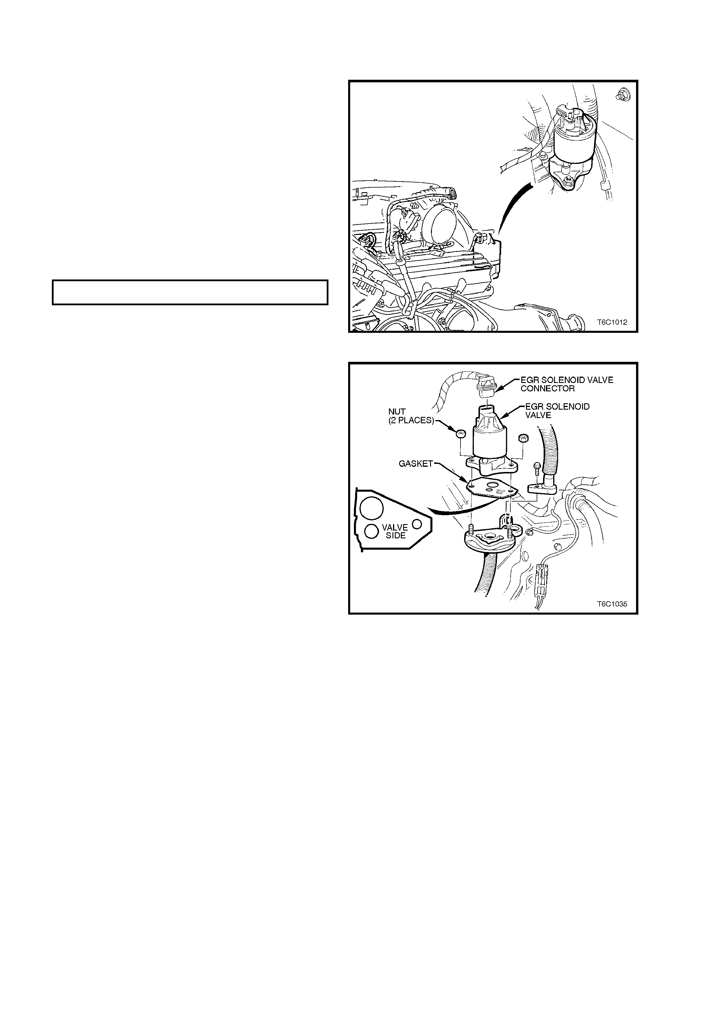
3.25 EX HAUST GAS RECIRCULATION (EGR) VALVE
REMOVE
1. Remove engine dress cover.
2. Electrical connector at EGR valve.
3. Two EGR valve retaining nuts.
4. EGR valve assembly.
5. Gasket.
REINSTALL
1. Install gasket.
2. Install EGR valve assembly and two retaining
nuts.
3. Install electrical connector.
4. Reinstall engine dress cover.
EGR RETAINING NUT T O RQUE
SPECIFICATION 30 Nm
Figure 6C1-3-100 EGR Valve Location
Figure 6C1-3-101 EGR Valve Removal View
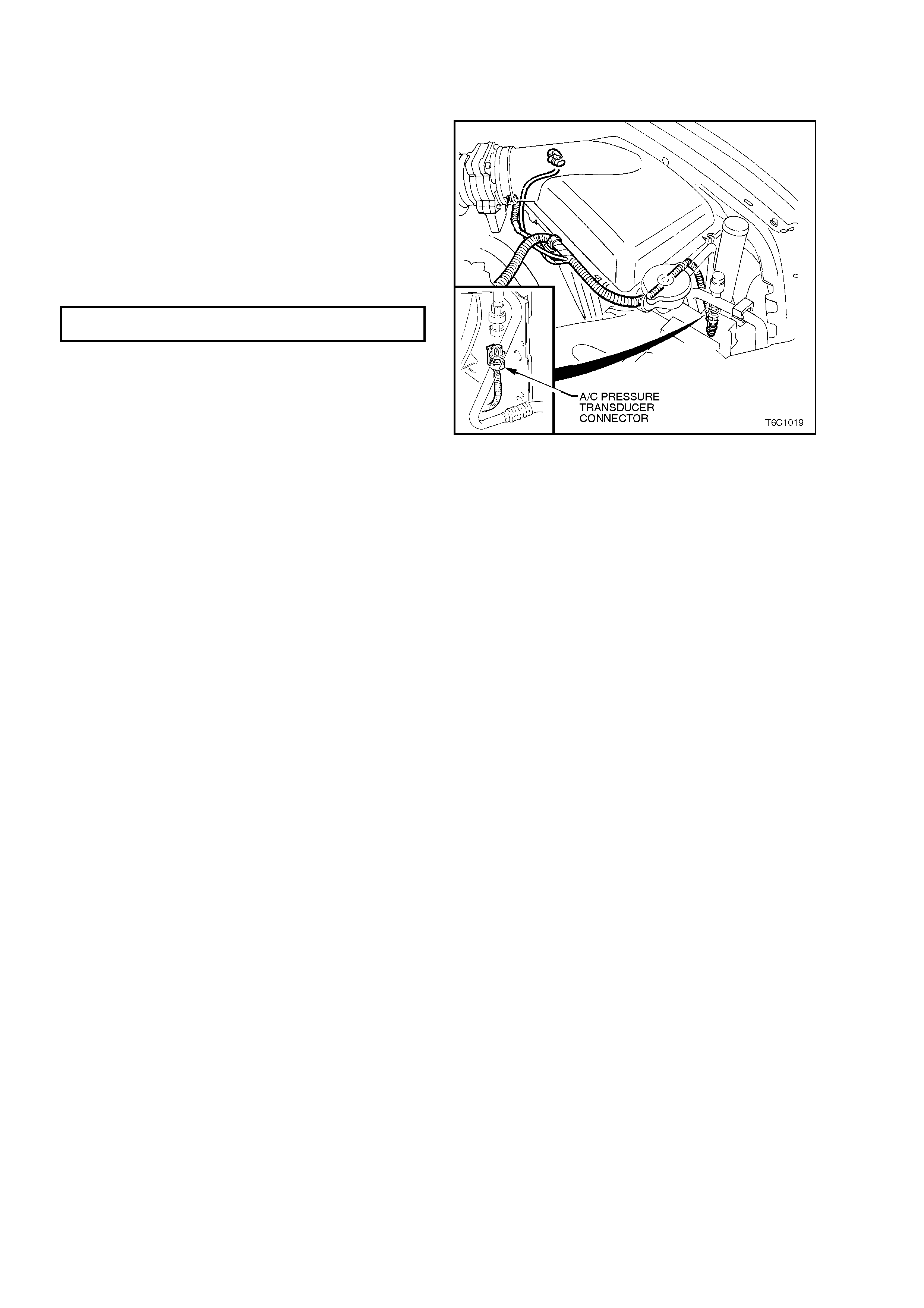
3.26 A/C REFRIGERANT PRESSURE SENSOR
REMOVE
1. Electrical connector at sensor.
2. Sensor from High pressure line.
REINSTALL
1. Install sensor to high pressure line, and tighten.
A/C REFRIGERANT COMPRESSOR 5 - 7
SENSORTORQUE SPE CIFICATI O N Nm
2. Install electrical connector to sensor.
Figure 6C1-3-102 A/C Refrigerant
Pressure Sensor Location