
SECTION 6A3 - ENGINE MECHANICAL -
GEN III V8 ENGINE
CAUTION:
This v ehicle will be equipped with a Supplemental Restraint System (SRS). An SRS will consist of either
seat belt pre-tensioners and a driver's air bag, seat belt pre-tensioners and a driver's and front
passenger's air bags or seat belt pre-tensioners, driver’s and front passen ger’s air bag and lef t and right
hand side air bags. Refer to SAFETY PRECAUTIONS, Section 12M , Supplemental Restraint System of the
VT Series I Service Information before performing any service operation on, or around any SRS
components, the steering mechanism or wiring. Failure to follow the SAFETY PRECAUTIONS could
result in SRS deployment, resulting in possible personal injury or unnecessary SRS system repairs.
CAUTION:
Whenever any component that forms part of the ABS or ABS/ETC (if fitted), is disturbed during Service
Operations, it is vital that the complete ABS or ABS/ETC system is checked, using the procedure as
detailed in 4. DIAGNOSIS, ABS or ABS/ET C FUNCTION CHECK, in Section 12L ABS & ABS/ET C, in either
VT Series I Service Information (V6 Engine) or 12L ABS & ABS/ETC of the VT Series II Service Information
(GEN III V8 Engine).
1. GENERAL DESCRIPTI ON
The 1999 Model Year 5.7 litre, GEN III, V8 engine ( produc tion option LS1) , is a 90°, V8, overhead valve des ign with
a bore of 99.00 mm and stroke of 92.00 mm. Displacement is 5,667 cm3 and compression ratio is 10.1:1.
Engine features include an aluminium cylinder block and heads, with cast iron sleeves cast into the cylinder block
during production. F our ‘torque to yield’ cylinder head bolts per cylinder have their thread boss es located deep into
the cylinder block to m inim ise distortion at the top of the bore. T he deep s kirt cylinder block also f eatures five m ain
bearings with each cap being secured by six bolts.
Powdered metal valves guides and seats are fitted to each cylinder head. The connecting rods are also
manufactured from forged powdered metal and the rodcap is separated during the manufacturing process, using
the ‘fractured’ method. This creates a stronger, visually seamless rod to cap union.
The five bearing camshaft is machined from 5150 steel billet and is drilled through the centre to reduce weight. A
reluctor ring for the cam position sensor is located between the fourth and fifth bearing journals.
The crank shaft is m anufactur ed from nodular cast iron and is dr illed through the centre of m ain bearing journals 2,
3, 4, and 5, also to reduce weight. A reluctor wheel is installed onto the rear of the crankshaft for the crankshaft
position sensor.
The firing order of 1-8-7-2-6-5-4-3, assists in achieving a smoother engine operation.
Techline
Techline
Techline
Techline
Techline
Techline
Techline
Techline
Techline
Techline
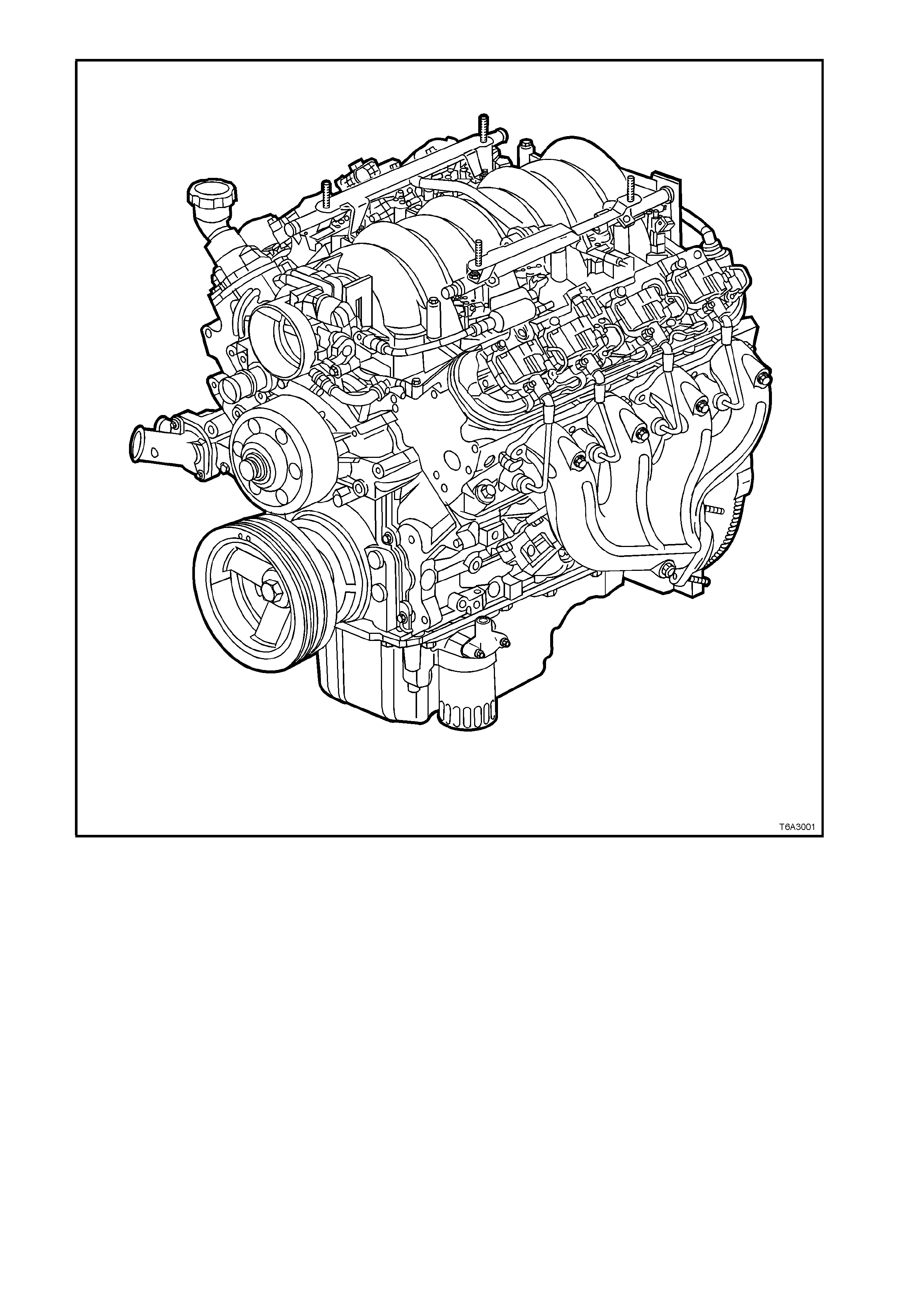
Figure 6A3-1
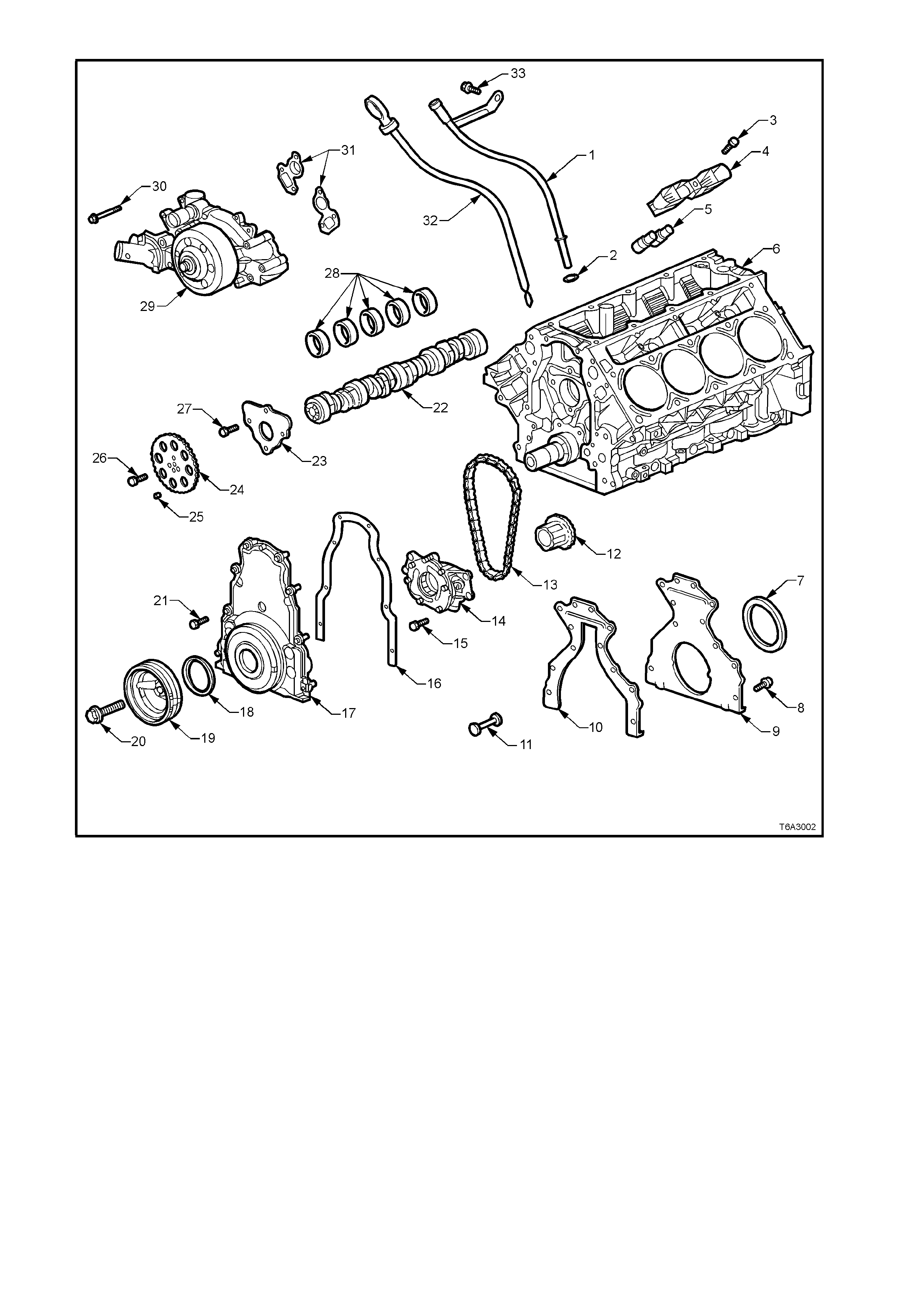
Figure 6A3-2 - Lower Front of Engine
Legend
1. Tube - Oil Level Indicator 18. Oil Seal - Crankshaft Front
2. O-ring Seal - Oil Lever Indicator Tube 19. Balancer - Crankshaft
3. Bolt - Valve Lifter Guide 20. Bolt - Crankshaft Balancer
4. Guide - Valve Lifter 21. Bolt - Engine Front Cover
5. Lifter - Valve 22. Camshaft
6. Engine Block 23. Retainer - Camshaft
7. Oil Seal - Crankshaft Rear 24. Sprocket - Camshaft
8. Bolt - Engine Rear Cover 25. Locating Pin - Camshaft Sprocket
9. Cover - Engine Rear 26. Bolt - Camshaft Sprocket
10.Gasket - Engine Rear Cover 27. Bolt - Camshaft Retainer
11.Plug - Engine Block Rear Oil Gallery 28. Bearings - Camshaft
12.Crankshaft Sprocket 29. Coolant Pump
13.Chain - Camshaft Timing 30. Bolt - Coolant Pump
14.Oil Pump Assembly 31. Gaskets - Coolant Pump
15.Bolt - Oil Pump Assembly 32. Indicator - Oil Level
16.Gasket - Engine Front Cover 33. Bolt - Oil Level Indicator Tube
17.Engine Front Cover
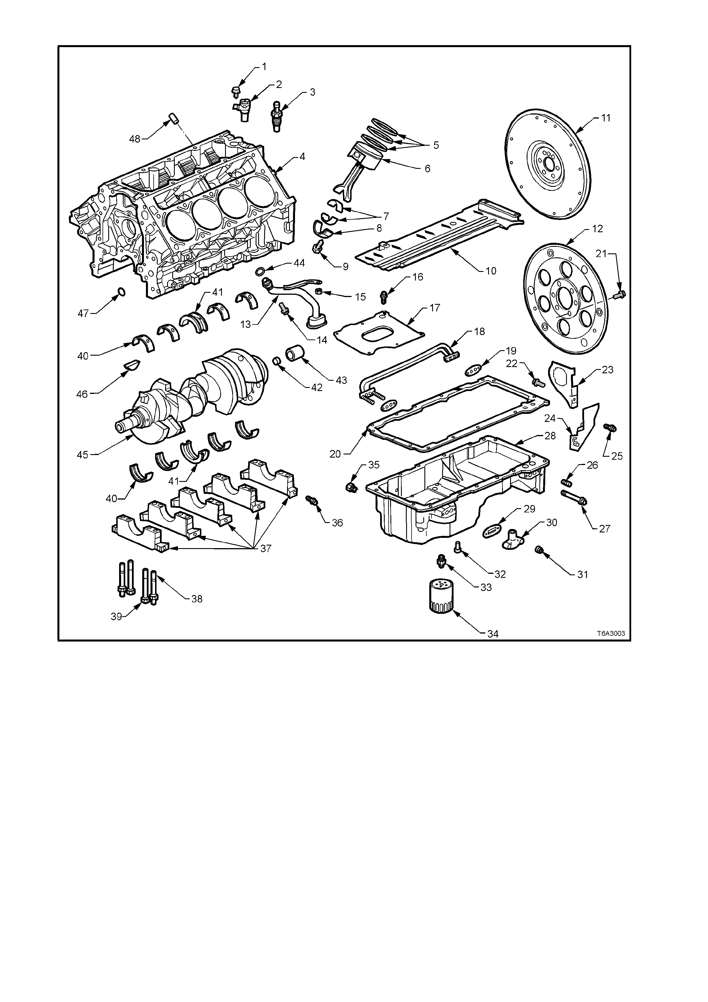
Figure 6A3-3 - Lower Engine Assembly
Legend
1. Bolt - Camshaft Position Sensor 17. Baffle - Oil Pan 33. Adaptor - Oil Filter
2. Cams haf t Position Sensor 18. Tube - Oil Transfer 34. Oil Filter
3. Sensor - Oil P ressure 19. Gasket - Oi l Transfer Tube 35. Plug - Drain
4. Engine Block 20. Gasket - Oi l P an 36. Bolt - Crank shaft B eari ng Cap Side
5. Pist on Rings 21. Bolt - E ngi ne Fl ywheel/F l explate 37. Caps - Cranks haft Main Bearing
6. Piston and Connecti ng Rod A ss’y 22. Bolt - Oi l P an Cl oseout Cover (RHS) 38. Stud - Main Beari ng Cap
7. Connecting Rod Bearings 23. Cover - Oil Pan Closeout (RHS) 39. Bolt - Main B eari ng Cap
8. Connecting Rod Cap 24. Cover - Oil Pan Closeout (LHS) 40. Bearings - Crankshaft Main
9. Bolt - Connecting Rod 25. Bolt - Oi l P an Cl oseout Cover (LHS) 41. Bearings - Crankshaft Main Thrust
10. Crankshaf t Oil Deflector 26. Plug - Oil P an Gal l ery 42. Plug - Rear Crankshaft
11. Engine Flywheel (Man. Trans.) 27. Bolt - Oil P an Transfer Tube 43. Bush - Manual Transmis sion Spigot
12. Engine Flexplate (Aut o. Trans.) 28. Oil Pan 44. O-Ring Seal - Oil Pump P i ck-up
13. Screen and Pi pe - Oi l P ump Pi ck-up 29. Gasket - Oi l Transfer Cover 45. Crankshaft
14. Screw - Oil Pump Pick-up to Pump 30. Cover - Oil Transf er 46. Key - Cranks haft Sproc ket
15. Nut - Oil Defl ector and Oil Pump P i ck-up 31. Nut - Oil Trans f er Cover 47. Plug - Engine Block Front Oi l Gal l ery
16. Bolt - Oil Pan Baff l e 32. Valve - Oil B ypas s 48. Plug - Cyli nder B l ock in Unused Hole
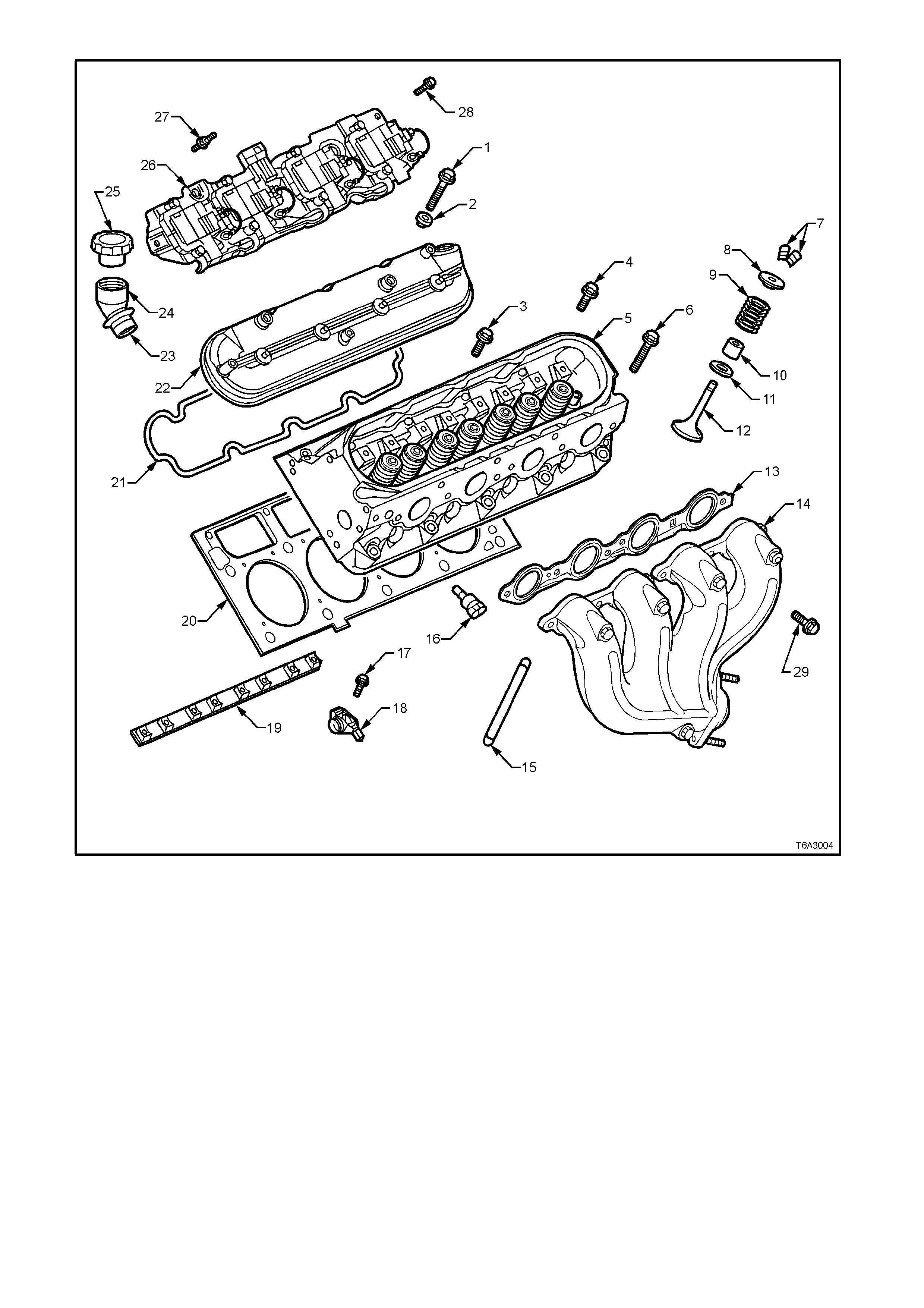
Figure 6A3-4 - Cylinder Head/Upper Engine
Legend
1. Bolt - Valve Rocker Arm Cover 16. Pushrod
2. Grommet - Valve Rocker Arm Cover 17. Sensor - Coolant Temperature
3. Bolt - Cylinder Head (Short) 18. Bolt - Valve Rocker Arm
4. Bolt - Cylinder Head (Medium) 19. Arm - Valve Rocker
5. Cylinder Head 20. Support - Valve Rocker Arm Pivot
6. Bolt - Cylinder Head (Long) 21. Gasket - Cylinder Head
7. Collets - Valve Stem Keys 22. Gasket - Valve Rocker Arm Cover
8. Cap - Valve Spring 23. Cover - Valve Rocker Arm
9. Spring - Valve 24. Tube - Oil Fill
10.Oil Seal - Valve Stem 25. Cap - Oil Fill Tube
11.Shim - Valve Spring 26. Assembly - Ignition Coil and Bracket
12.Valve 27. Stud - Ignition Coil Bracket Assembly
13.Gasket - Exhaust Manifold 28. Screw - Ignition Coil Bracket Assembly. Rear on each side
14.Manifold - Exhaust 29. Bolt - Exhaust Manifold
15.Bolt - Exhaust Manifold Heat Shield
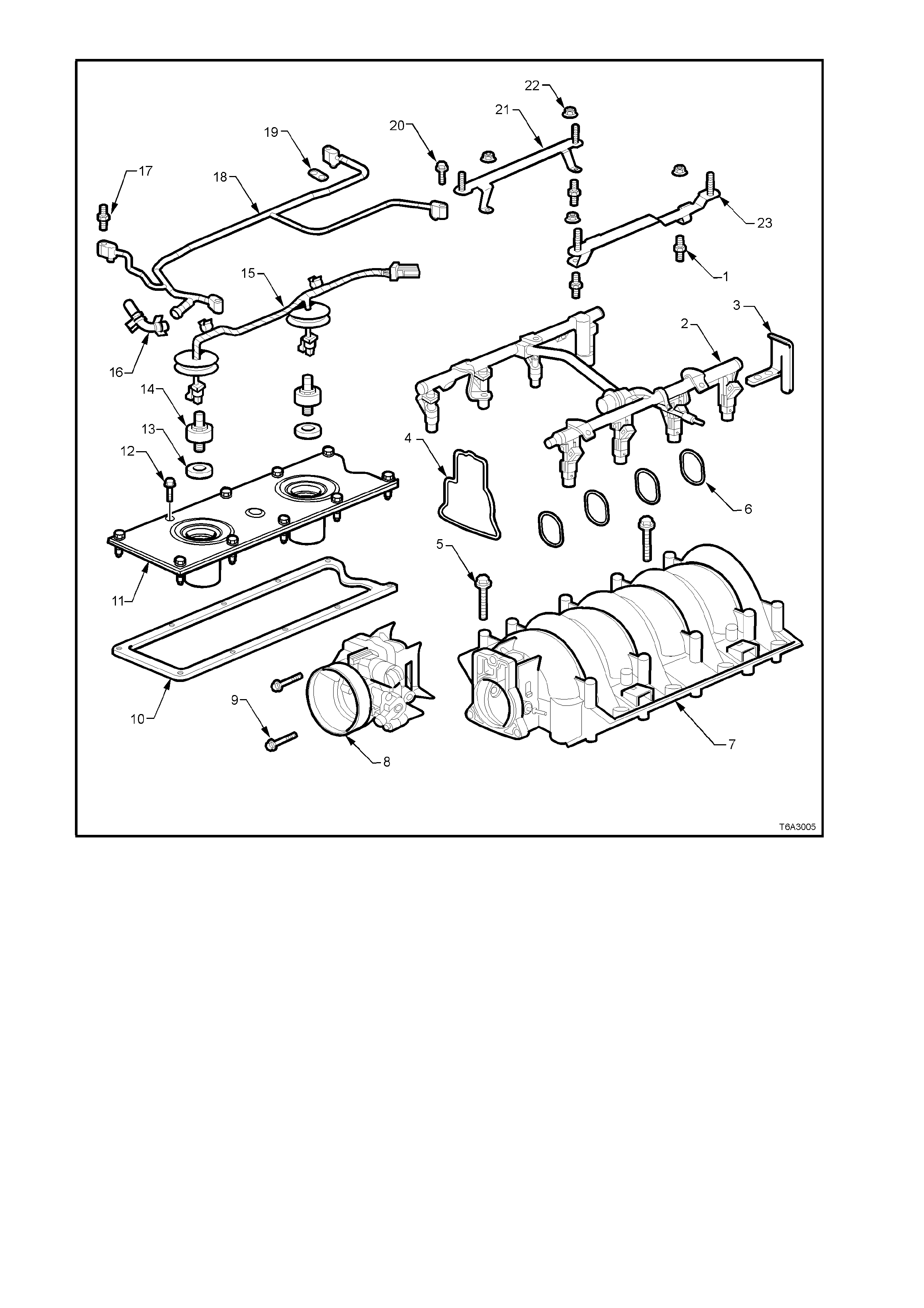
Figure 6A3-5 - Intake Manifold/Upper Engine
Legend
1. Stud - Fuel Rail 13. Oil Seal - Knock Sensor
2. Fuel Rail (with Injectors) 14. Knock Sensor
3. Bracket - Fuel Rail Stop 15. Knock Sensor Wire Harness
4. Gasket - Throttle Body 16. Hose - Vapour Vent Tube
5. Bolt - Intake Manifold 17. Stud - Vapour Vent Tube
6. Gaskets - Intake Manifold 18. Vapour Vent Tube
7. Intake Manifold 19. Gasket - Vapour Vent Tube
8. Throttle Body 20. Bolt - Vapour Vent Tube
9. Bolt - Throttle Body 21. Bracket - Engine Dress Cover, Right Hand Side
10.Gasket - Valley Cover 22. Nut - Engine Dress Cover Bracket
11.Valley Cover 23. Bracket - Engine Dress Cover, Left Hand Side
12.Bolt - Valley Cover
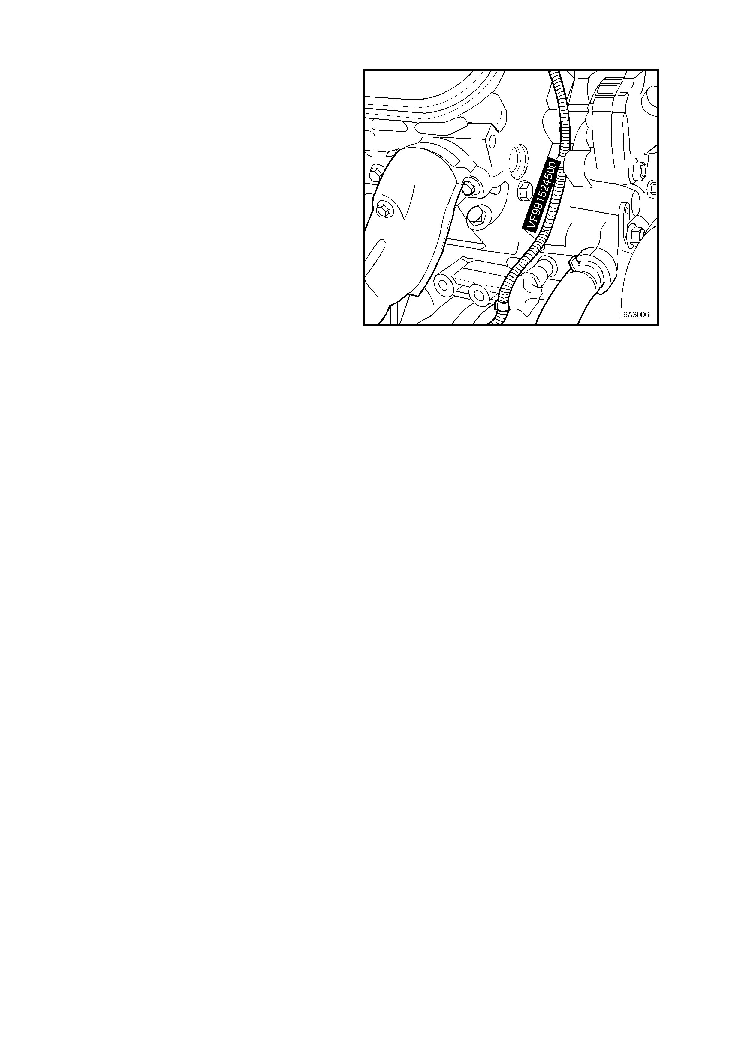
1.1 ENGINE SERIAL NUMBER
The engine number is stamped on the right hand
side front of the engine cylinder block, as shown.
The number is prefixed by the letters ‘VF’.
A breakdown of the engine numbering system,
using and example of ‘VF991524500’, is;
• First two numbers (‘99’) indicates the engine
model year.
• Next three numbers (‘152’) is the Julian date
(day of the year), the engine was
manufactured.
• Next four numbers are the daily, sequential
build number.
Figure 6A3-6
1.2 ENGINE CONSTRUCTION
CYLINDER BLOCK
The engine cylinder block is a cam-in-block, deep
skirt, 90° ‘V’ configuration with five crankshaft
bearing caps, manufactured from forged powdered
metal. The engine block is aluminium with cast in
place, cast iron cylinder bore liners. The f ive cr os s-
bolted crankshaft bearing caps each have four
vertical M10 (2, 3, 4, and 5) and two horizontal M8
(1 and 6) mounting bolts. Only cylinder honing is
permitted.
The c rankcas e s k ir t length, bear ing cap width, deck
width and upper rails have been optimised for
strength, using finite element analysis.
The camshaft is supported by five camshaft
bearings pressed into the block.
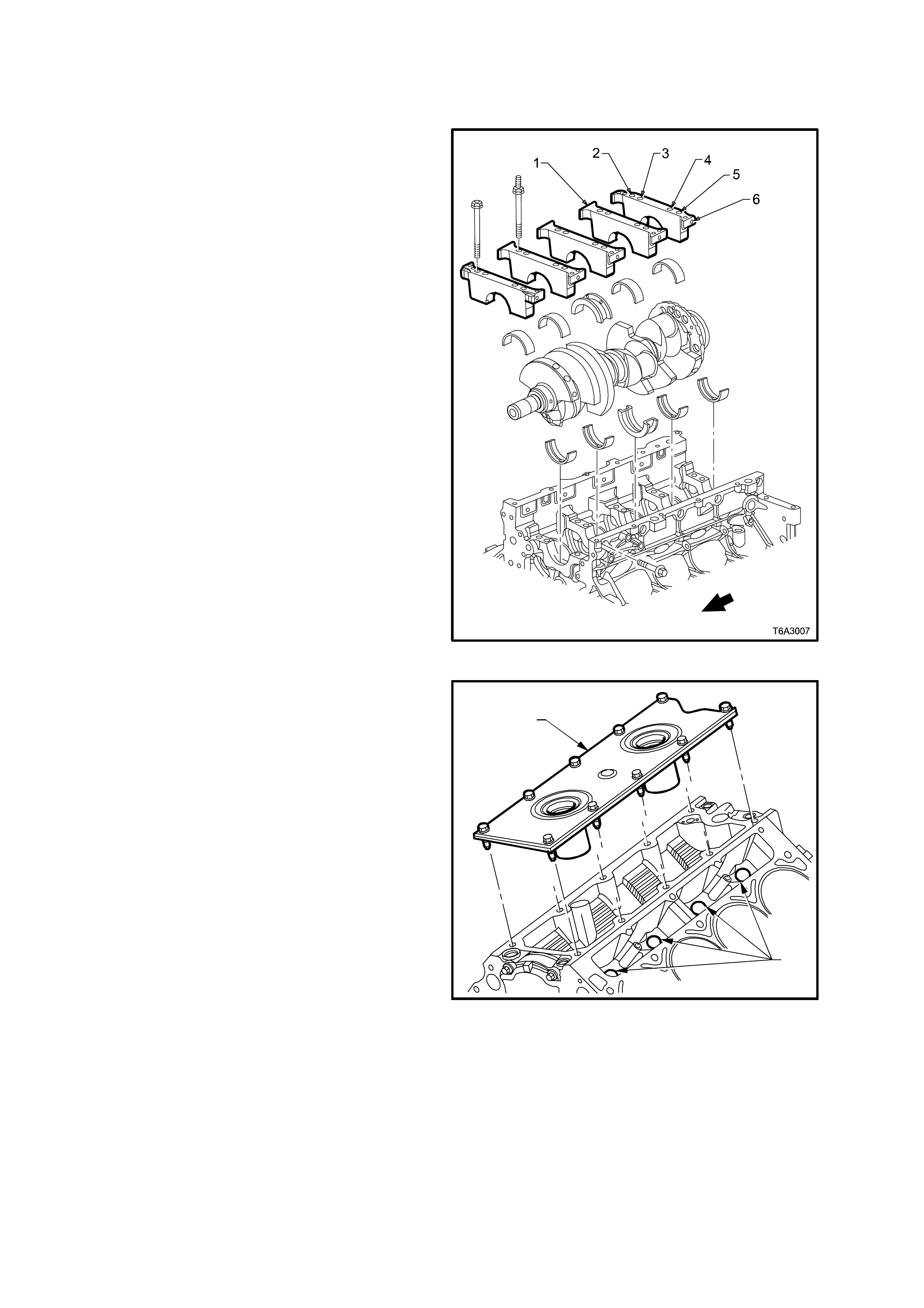
Figure 6A3-7
The cylinder block incorporates enclosed valve
lifter bores (2) under each cylinder head, that
results in a more stiff structure with quiet operation.
Utilising a struct ural die c as t aluminium valley cover
(1), ties both cylinder banks together, increasing
the block’s torsional and bending frequencies.
Having a closed valley area also prevents hot oil
from contacting the lower surface of the intake
manifold, allowing cooler air to enter the cylinders.
Overall, the cylinder block cons truction weighs 48%
less than an equivalent cast iron block and the
structural design features, coupled with the
inherently light cylinder heads, combine into an
engine with unique stiffness and light weight.
T6A3008
2
1
Figure 6A3-8

CYLINDER HEADS
The cylinder head assemblies are cast aluminium
and have pressed in place, powdered metal valve
guides and valve seats.
Intake and exhaust ports are identical for each
cylinder, ensuring a balanced air-flow distribution
for balanced combustion, resulting in a smoother
running engine.
The cylinder head is attached using a four bolt per
cylinder, deep threaded arrangement for minimal
bore distortion, allowing low friction pistons and
rings for reduced fuel consumption.
Cylinder head gaskets are made of a steel core
between layers of graphite and features stainless
steel PTFE coated flanges and lacing. Cylinder
head gaskets are unique for right and left hand
sides with preferential coolant flow.
Legend
1. Cylinder Head
2. Valve Stem Collets
3. Valve Spring Cap
4. Valve Spring
5. Valve Stem Oil Seal
6. Valve Spring Shim
7. Cylinder Head Core Plugs
8. Exhaust Valve
9. Intake Valve Figure 6A3-9
The intake ports are very tall, which enhances fuel
injector targeting. As air flows down to the valve
guide, it widens and shortens to the size of the
intake valve seat.
Figure 6A3-10
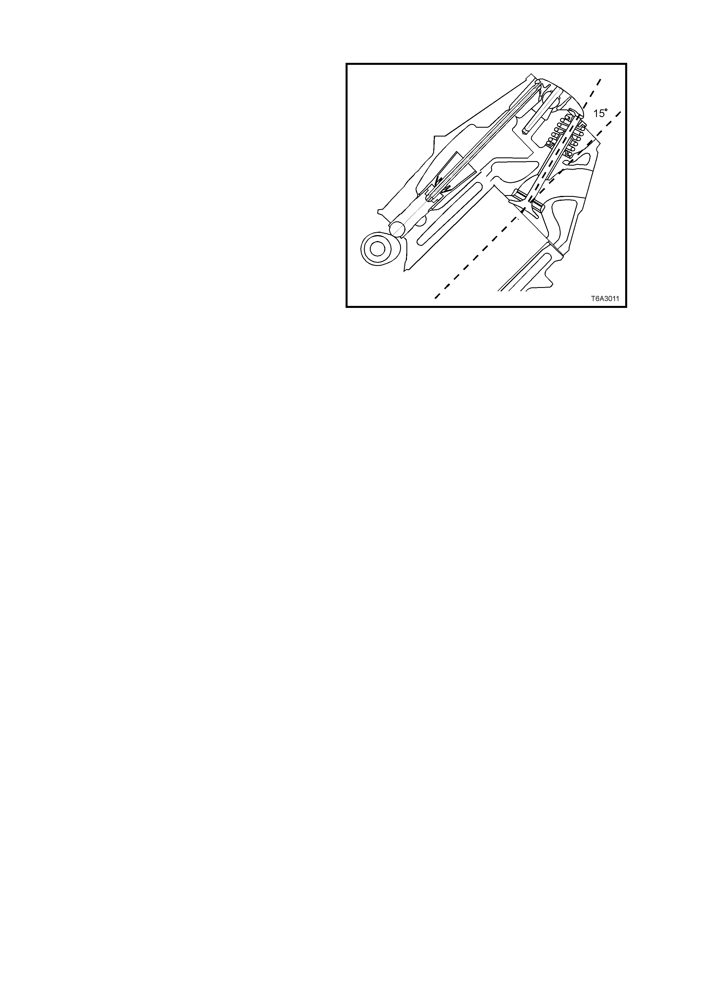
VALVE TRAIN
Motion is transmitted from the camshaft through
the hydraulic roller valve lifters and tubular
pushrods to the rocker arms. The valve lifter
guides position and retain the roller hydraulic valve
lifters. The valve rocker arms for each bank of
cylinders are mounted on pedestals (pivot
supports) . Eac h ro cker ar m is retained on the pivot
support and cylinder head by a bolt. Valve lash is
adjusted automatically each cycle by the hydraulic
valve lifters.
Both valves are angled at 15° to the cylinder bore
centreline, which creates a shallow combustion
chamber and a flat top piston, creating a
compression ratio of 10.1:1.
Both the exhaust and intake valve seat angles are
45° with an intake valve head diameter of 50.8 mm
and exhaust of 39.4 mm.
Valve springs ar e conical or ‘beehive’ in s hape and
made from chromium Silicone wire. The springs
are double shot peened to provide maximum
reliability. The reduced diameter end coils allows a
smaller diameter, lower mass, steel spring retainer
to be used, with single bead, valve stem k eys. T his
spring design also reduces spring mass and,
coupled with the increased stiffness in the valve
train, results in a reduction in the valve spring pre-
load, thereby reducing friction and valve train noise.
The roc k er arm s are m ade of investm ent cast steel
and have a ratio of 1.7:1, that allows a lower cam
lobe lift, resulting in lower valve train loading and
less noise.
The valve rocker arm covers are cast aluminium
and use a pre-moulded silicone gasket for sealing.
Mounted to each rocker cover are four individual
ignition coils. Incorporated into the covers are the
oil fill tube, the Positive Crankcase Ventilation
(PCV) system passages, and the engine fresh air
passages.
Figure 6A3-11
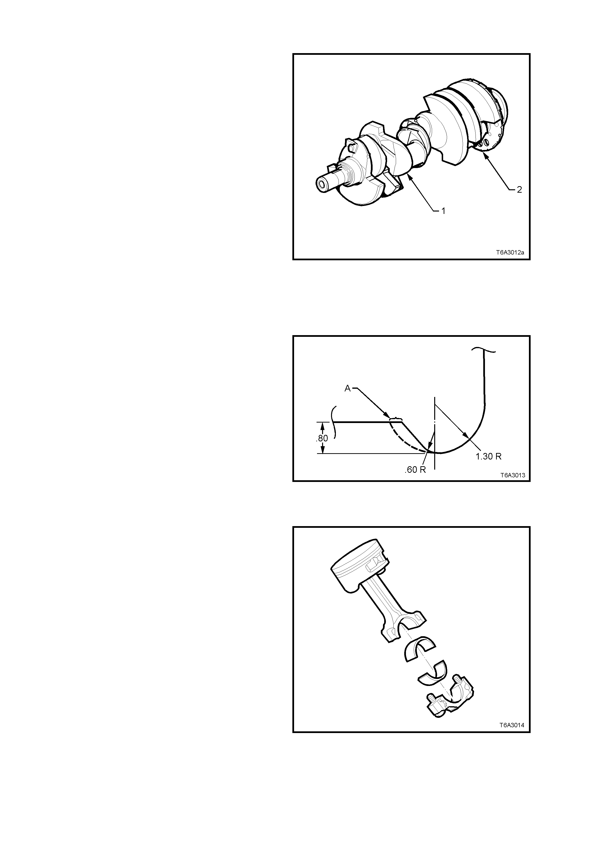
CRANKSHAFT
Manufactured from cast nodular iron, the
crankshaft (1) is supported by five crankshaft
bearings and are retained by 6 bolt crankshaft
bearing caps. The main bearing caps are machined
with the engine block for the proper alignment and
clearance.
A 24X crankshaft position reluctor ring (2) is
mounted at the r ear of the num ber eight crank shaf t
counter weight. The reluctor ring is not serviced
separately.
Crankshaft thrust is taken by the centre (No. 3)
main bearing. This location is used to reduce the
expansion differences between the cast iron
crankshaft and the aluminium cylinder block.
By adopting a firing order of 1, 8, 7, 2, 6, 5, 4, 3,
crank throw stresses are reduced and main bearing
performance is improved.
The crankshaft has a drilled 25.4 m m hole through
the centre of main journals 2, 3, 4 and 5. Apart
from a reduction in crankshaft weight, this also
achieves engine breathing enhancement at low
speeds.
Figure 6A3-12
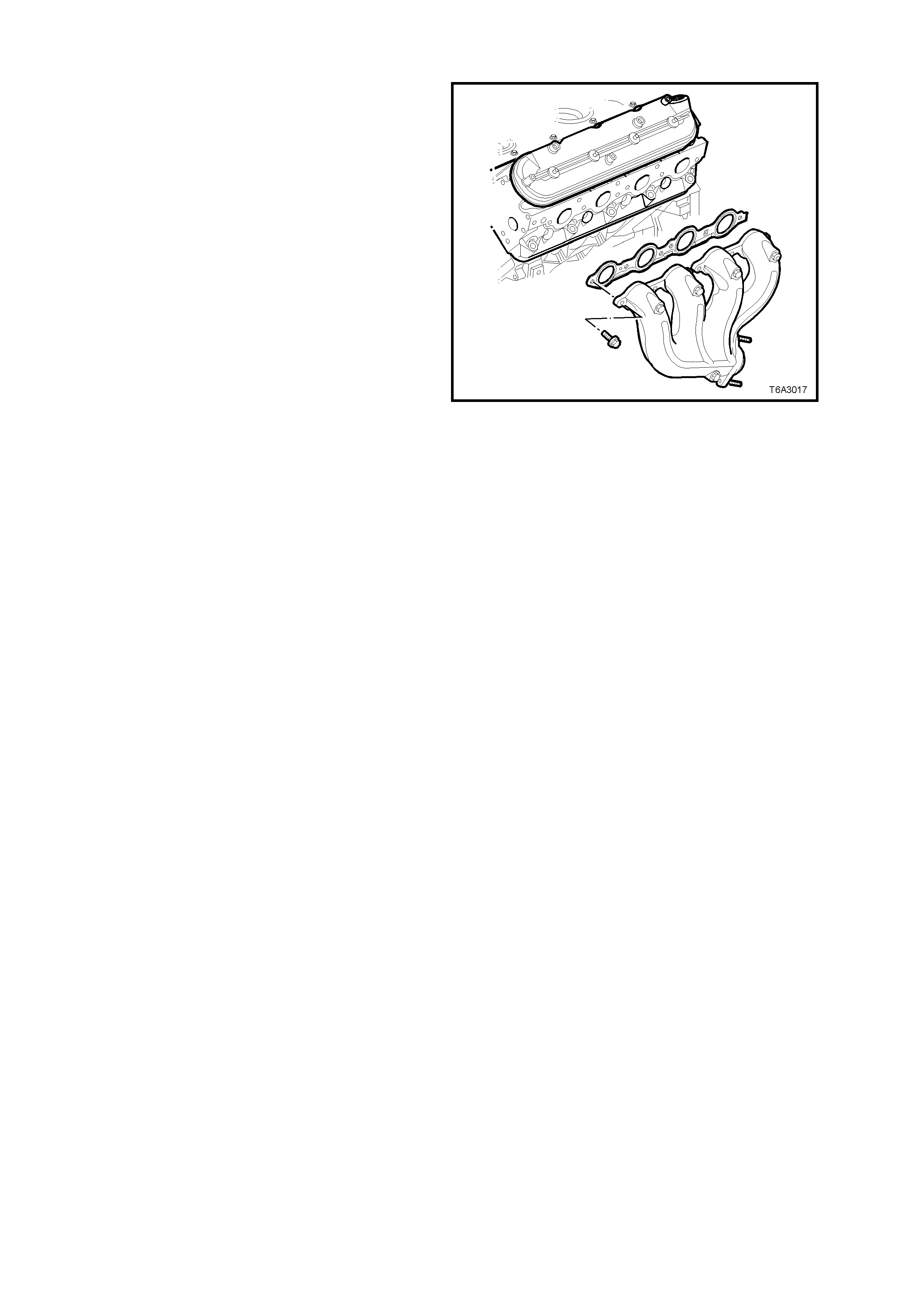
A variable radii undercut increases the effective
bearing widths by 0.4 m m eac h side (A), com pared
to a uniform undercut and rolled fillets are utilised
for improved fatigue strength.
Figure 6A3-13
PISTONS AND CONNECTING RODS
The pistons are cast aluminium and have two
compression rings and one oil control ring
assembly fitted. Piston rings are of a thin, low
fric tion design, with the top ring located close to the
top of the piston crown to reduce hydrocarbon
emissions. The piston is a low friction, lightweight
design with a flat top and barrel shaped skirt.
Piston pins are c hr omium steel and ar e a f loating f it
in the piston and a press fit in the connecting rod.
The connecting rods are forged powdered metal.
The connecting rod cap is separated during the
manufactur ing proc ess , us ing the ‘f r act ure’ method.
This creates a stronger, visually seamless rod to
cap union. The reassembled rod is then machined
for the proper clearance.
A 0.25 mm oversize piston and piston ring set are
available for service, should cylinder honing be
required. Figure 6A3-14

CAMSHAFT AND DRIVE
A billet steel, one piece camshaft is supported by
five bearings pressed into the engine block. The
cam s haf t has a machined c amshaft sens or r eluctor
ring incorporated between the fourth and fifth
bearing journals. To reduce vale train noise, both
the intake and exhaust cam lobes have slow
closing velocity ramps.
To reduc e weight, the cam shaft has a 17 m m gun-
drilled hole down its length.
The c amshaf t (1) is driven by a traditional 9.52 m m
pitch roller chain (2) and powdered metal timing
sprockets mounted to the front of the camshaft (3)
and crankshaft (4). The crankshaft sprocket (4) is
splined and drives the oil pump driven gear. A
retaining plate (5) mounted to the front of the
engine block maintains the camshaft location. No
chain tensioner is required.
Figure 6A3-15
INTAKE MANIFOLD
The intake manifold (1) is a one piece composite
design that incorporates metal threaded inserts for
mounting the fuel rail (2), throttle cable bracket, and
throttle body.
The intak e manif old is sealed to the c ylinder heads
by eight separate non-reusable silicone sealing
gaskets which press into the grooves of the intake
housing.
The cable-actuated throttle body assembly bolts to
the front of the intake manifold (A). The throttle
body is sealed to the intake manifold by a one
piece, push-in-place silicone gasket.
The fuel rail assembly (2) with eight separate fuel
injectors (3) is retained to the intake manifold by
four bolts (4). The injectors are seated in their
individual manifold bores with O-ring seals to
provide sealing. The fuel pressure regulator (5) is
incorporated into the fuel rail design. A fuel rail
stop bracket is retained at the rear of the left fuel
rail by the intake manifold mounting bolts (not
shown).
The Manifold Absolute Pressure (MAP) sensor is
installed in the snap fit MAP sensor housing that is
mounted at the rear of the manifold and sealed by
an O-ring seal (not shown).
There are no coolant passages within the intake
manifold.
Figure 6A3-16
EXHAUST MANIFOLD
The exhaust manifolds are one piece, of high
temperature silicone molybdenum cast iron and
direct exhaust gases from the combustion
chambers to the exhaust system.
Each m anifold also has an externally mounted dual
wall heat shield attached, that is made of
aluminiumised steel.
Figure 6A3-17
ACCESSORY DRIVE
The engine accessory drive consists of dual
serpentine belts, that decouple the generator and
air conditioning compressor for improved noise
isolation. Using dual belts also provides design
flexibility to optimise structural stiffness of support
brackets.
The system includes two automatic belt tensioners
with a low static tension for increased belt and
bearing life.
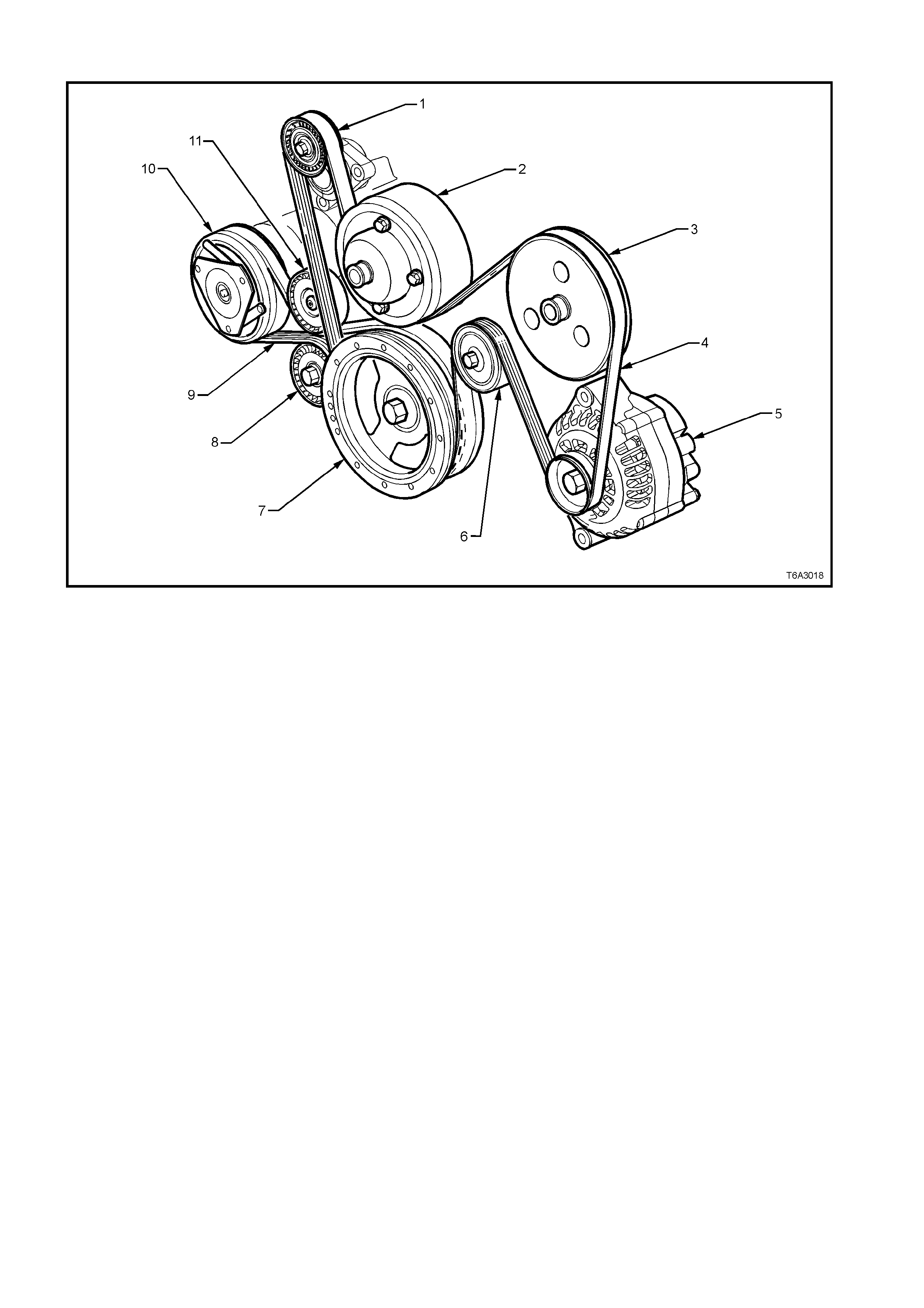
Figure 6A3-18
Legend
1. Accessory Drive Belt, Automatic Tensioner 7. Crankshaft Balancer Pulley
2. Water Pump Pulley 8. Air Conditioning Compressor Drive Belt Automatic Tensioner
3. Power Steering Pump Pulley 9. Air Conditioning Compressor Drive Belt
4. Engine Accessory Drive Belt 10. Air Conditioning Compressor
5. A.C. Generator 11. Air Conditioning Compressor Drive Belt, Idler Pulley
6. Accessory Drive Belt, Idler Pulley

OIL PAN
The oil pan (1) is cast aluminium and forms a
structural part of the powertrain, by providing a
360° mounting for the transmission, whether it be
Manual or Automatic.
Cast-in dams incorporated into the oil pan design,
minim ise oil m igration during br aking and cor nering
manoeuvr es and oil is guided to the pick -up sc reen
(2), via strategically placed openings in the dam
walls.
Incorporated into the design are the oil filter
mounting boss (3), an opening for the drain plug
(4), and a stamped, oil pan baffle (6).
The oil pan baf f le ( 6), maintains an area ar ound the
pick-up screen to prevent oil starvation/aeration.
A crankshaft oil deflector (7) mounted to the main
bearing caps controls windage, sc rapes oil f r om the
crankshaft, facilitates drainback and reduces
aeration.
The oil pan gasket (8), is a controlled com pression
aluminium carrier gasket with silicone used as the
sealing agent.
Figure 6A3-19
1.3 ENGINE LUBRICATION SYSTEM
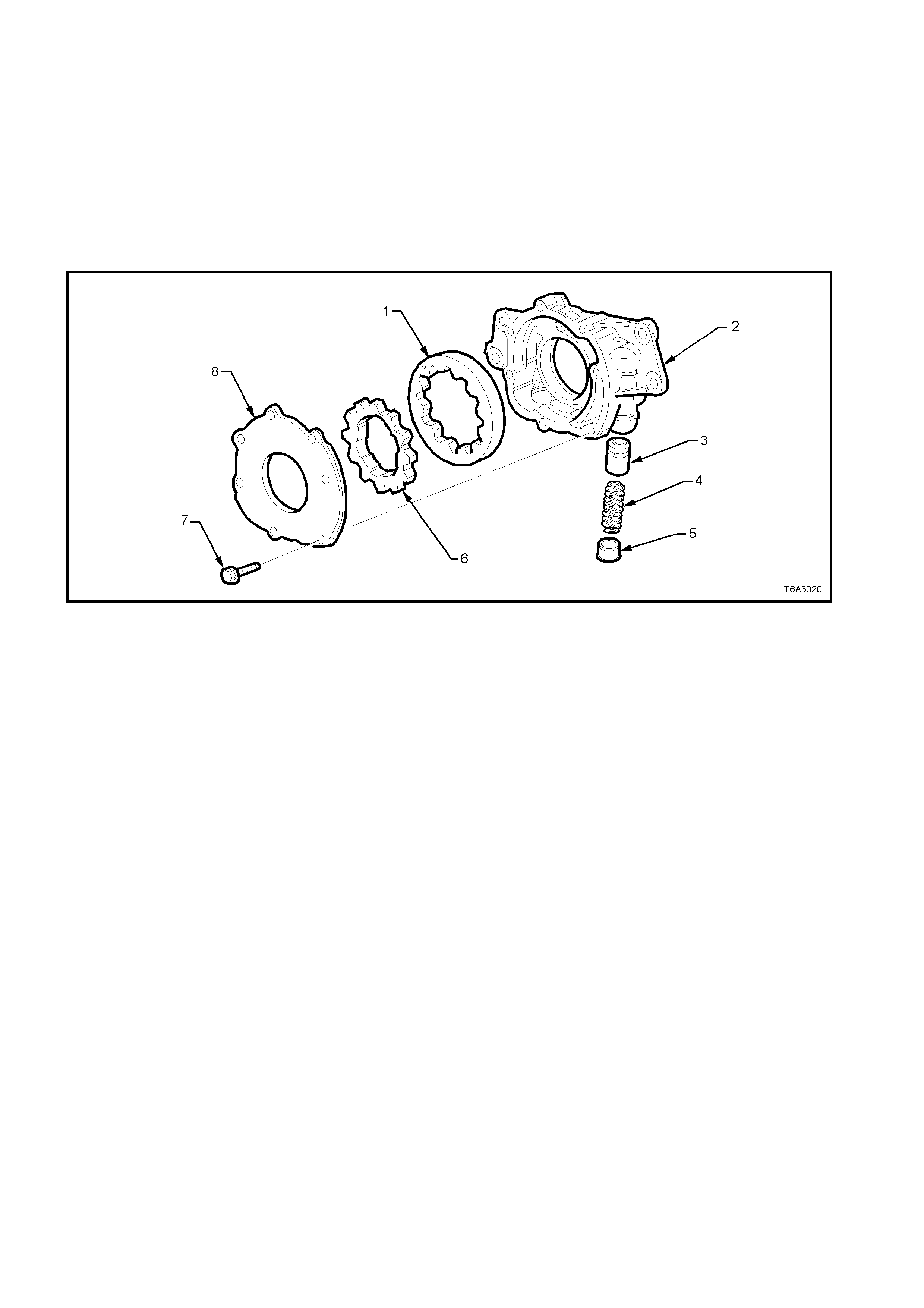
OIL PUMP
Engine lubrication is supplied by a “gerotor” type oil pump assembly. The pump is mounted on the front of the
engine block and driven directly by the crankshaft sprocket. The pump gears rotate and draw oil from the oil pan
sum p through a pick - up scr een and pipe. The oil is press urised as it pass es through the pum p and is sent through
the engine block oil galleries.
Contained within the oil pump assembly is a pressure relief valve that maintains oil pressure within a specified
range. Pressurised oil is directed through the lower gallery to the full flow oil filter where harmful contaminants are
removed. A bypass valve is incorporated into the oil filter that still allows oil to flow in the event that the filter
becomes blocked.
Figure 6A3-20 - Oil Pump Assembly
Legend
1. Driven Gear 4. Spring - Pressure Relief Valve 7. Bolt - Cover
2. Oil Pump Housing 5. Plug 8. Cover
3. Pressure Relief Valve 6. Drive Gear
At the rear of the block, oil is directed to the upper main oil galleries which are drilled just above the camshaft
assem bly. From there, oil is then direc ted to the crank s haft and c am shaf t bearings. O il that has enter ed the upper
ma in oil galleries also pres surises the valve lif ter ass emblies and is then pumped thr ough the pushrods to lubricate
the valve rocker arms and valve stems.
Oil returning to the pan is directed by the crankshaft oil deflector.

Figure 6A3-21 - Lubrication Flow Schematic
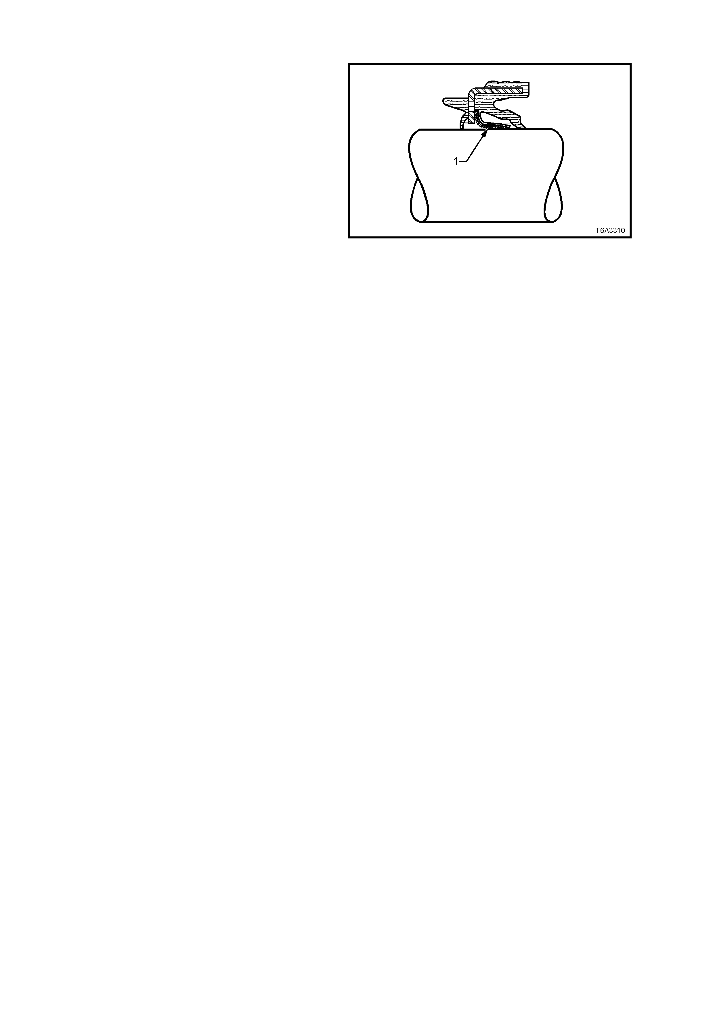
CRANKSHAFT OIL SEALS
The GEN III V8 engine uses a multiple lip
crankshaft rear main oil seal, designed for long life
operation.
The s eal includes a PTFE (Tef lon®) centre lip (1) to
m inimise a m ajor cause of r ear m ain oil seal leak s.
The anti-fric tion proper ties of the PT F E reduc es the
chances of “chok ing” or build-up of degraded oil on
the lip (causing the lip to lif t off the shaft), resulting
in a leak.
Like the rear main oil seal, the front crankshaft oil
seal also incorporates a PTFE lip.
Service implications for this seal material are that
no lubricant is to be added to the seal lip on
installation, as this will prevent correct ‘break-in’ of
the seal. T he PT F E is ac tually deposited on the dry
crankshaft seal surface during initial operation by
the heat generated from the rotating shaft.
The outside of the seal m ay be lubr icated sparingly
to ease installation.
Figure 6A3-22
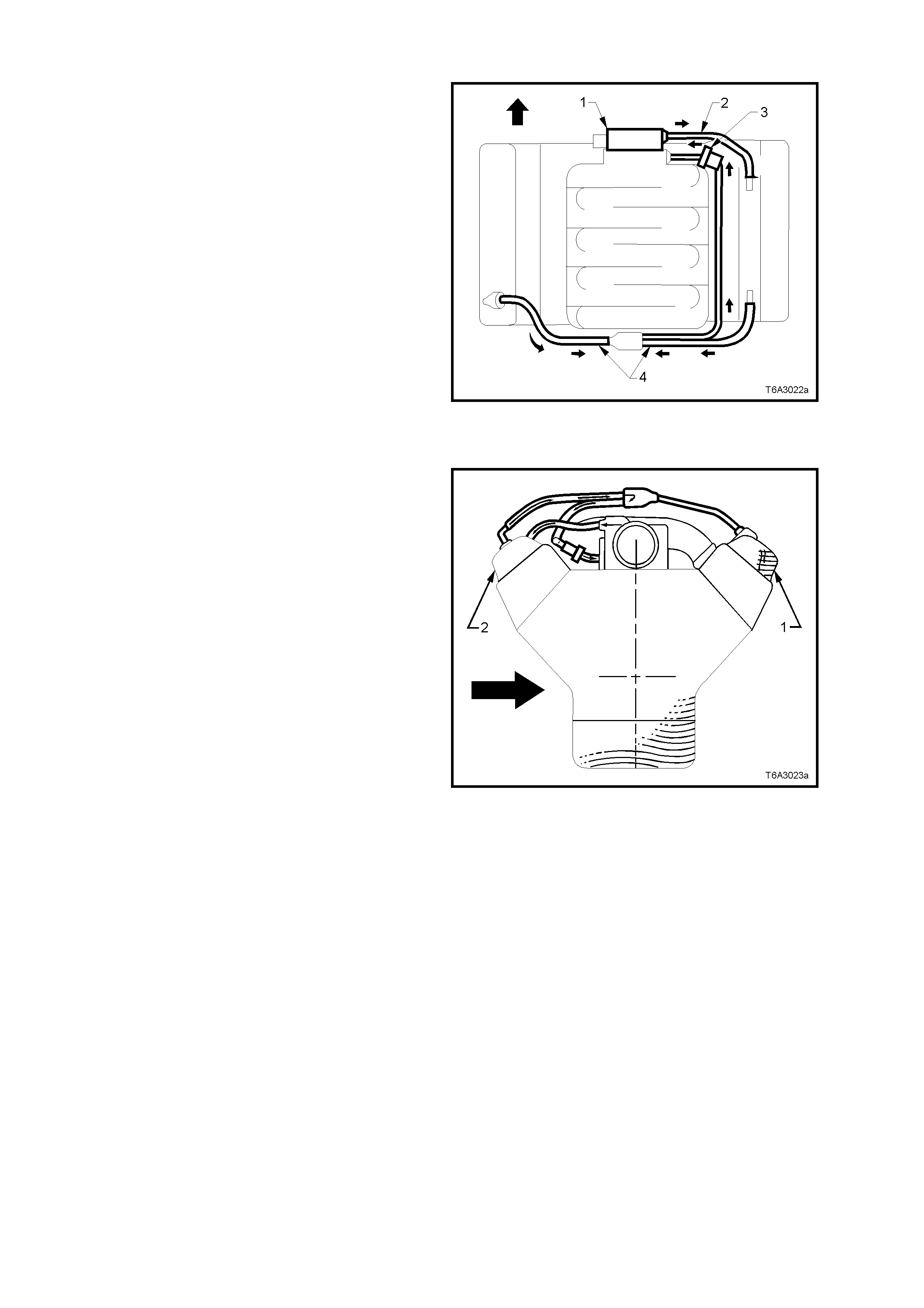
POSITIVE CRANKCASE VENTILATION SYSTEM
The engine ventilation system was developed to
minimise oil consumption and ensure that oil
ingestion could not occur during severe vehicle
handling manoeuvres.
Filtered fresh air is routed from upstream of the
throttle blade to the front of the right rocker cover
via a formed rubber hose (2). To reduce the
potential of oil pullover into the throttle bore area
due to back flow of the ventilation system, the fitting
in the right side rocker cover is located in a “quiet”
area located between, and shielded from, the
rocker arms. Crankcase blowby gases are routed
from the rear of both rocker covers, through
moulded nylon lines to a tee fitting, located on the
centreline of the engine at the rear of the intake
manifold (4). From there, a single hose carries
crankcase vapours through an externally mounted,
horizontal PCV valve (3) and enters the intake
manifold behind the throttle body (1).
The hoses are foam insulated and the PCV valve
(3) is conduction-heated from the cylinder block.
Figure 6A3-23
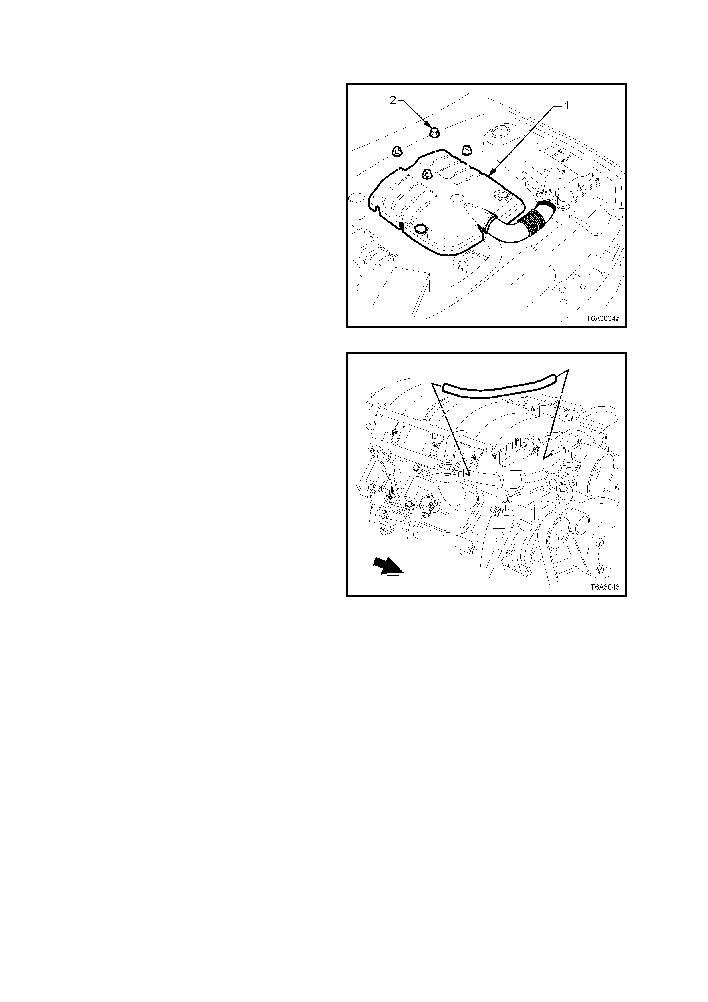
This “dual draw system” was developed to meet
high ‘g’ forces (bold arrow) incurred during severe
cornering m anoeuvres . During sust ained m aximum
lateral accelerations, the outboard rocker cover (1)
may fill with oil.
The “dual draw” system “passively switches”,
allowing the PCV valve to draw on the rock er cover
with the least resis tance. This res ults in the system
drawing on the air filled, or inboard, rocker cover
(2) and eliminates oil pullover that would result from
drawing on the oil filled outboard rocker cover.
Sectioned view shown is look ing rearward f rom the
engine front.
Figure 6A3-24

1.4 SERVICE NOTES
CLEANLINESS AND CARE
• Throughout this Section, it must be understood that proper cleaning and protection of machined surfaces and
friction areas is a part of the repair procedure. This is considered standard Workshop practice, even if not
specifically stated.
• When any internal engine parts are serviced, care and cleanliness is important.
• When components are removed f or s ervice, they should be mar ked, or ganised or r etained in a specif ic or der for
reassembly. Refer to; ’Separating Parts’ below.
• At the time of installation, components should be installed in the same location and with the same mating
surface as when removed.
• Any engine is a combination of many machined, honed, polished and lapped surfaces with tolerances that are
measured in hundredths of millimetres. These surfaces should be covered or protected to avoid component
damage.
• A liberal coating of clean engine oil should be applied to f ric tion areas dur ing assem bly, as proper lubr ication will
protect and lubricate friction surfaces during the initial engine start-up.
REPLACING ENGINE GASKETS
• Re-using gaskets and applying sealants.
− Do not reuse any gasket unless specified.
− Gaskets that can be reused will be identified in the service procedure.
− Do not apply sealant to any gasket or sealing surface unless called out in the service information.
• Separating components
− Use a rubber mallet to separate components.
− Bump the part sideways to loosen the components.
− Bumping should be done at bends or reinforced areas to prevent distortion of parts.
• Cleaning gasket surfaces
− Remove all gasket and sealing material from the part using a plastic or wood scraper (if required).
− Care must be used to avoid gouging or scraping the sealing surfaces.
− Do not use any other method or technique to remove sealant or gasket material from a part.
− Do not use abrasive pads, sand paper, or power tools to clean the gasket surfaces.
∗ These methods of cleaning can cause damage to the component sealing surfaces.
∗ Abrasive pads also produce a fine grit that the oil filter cannot remove from the oil.
∗ This grit is abrasive and has been known to cause internal engine damage.
• Assembling components
− When assembling components, use only the sealant specified or equivalent in the service procedure.
− Sealing surfaces should be clean and free of debris or oil.
− Specific components such as crankshaft oil seals or valve stem oil seals may require lubrication during
assembly.
− Components requiring lubrication will be identified in the service procedure.
− When applying sealant to a component, apply the amount specified in the service procedure.
− Do not allow the sealant to enter into any blind threaded holes, as it may prevent the bolt from clamping
properly or cause component damage when tightened.
− Only ever tighten bolts to specifications. Do not overtighten.

USE OF RTV AND ANAEROBIC SEALER
Important: A number of sealant types are commonly used in engines. Examples are; Room Temperature
Vulcanising (RTV) sealer, anaerobic gasket eliminator sealer, anaerobic thread sealant and pipe joint compound.
The correct sealant and amount must be used in the specified location to prevent oil leaks. DO NOT interchange
the different types of sealers. Use only the specific sealer or the equivalent as recommended in the service
procedure.
Pipe Joint Compound
• Pipe joint com pound is a pliable sealer that does not completely harden. T his type of s ealer is us ed where two
non-rigid parts (such as pressed steel and machined surfaces) are assembled together.
• Do not use pipe joint compound in areas where extreme temperatures are expected. These areas include:
exhaust manifold, head gasket, or other surfaces where gasket eliminator is specified.
• Follow all safety recommendations and directions that are on the container.
• To remove the sealant or the gasket material, refer to ’Replacing Engine Gaskets’ in this Section.
• Apply the pipe joint compound to a clean surface. Use a bead size or quantity as specified in the procedure.
Run the bead to the inside of any boltholes. Do not allow the sealer to enter any blind threaded holes, as it m ay
prevent the bolt from clamping properly or cause component damage when the bolt is tightened.
• Apply a continuous bead of pipe joint compound to one sealing surface. Sealing surfaces to be resealed must
be clean and dry.
• Tighten the bolts to specifications. Do not overtighten.
Exam ples of locations where a pipe s ealant type material suc h as Loctite 565 ( or other c om m ercial equivalent) is to
be used, are:
• Engine block coolant and oil gallery plugs.
• Oil pressure sensor threads.
• Engine block oil pan surface.
RTV Sealer
• Room T emperature Vulcanis ing (RT V) sealant hardens when exposed to air. T his type of s ealer is used where
two non-rigid parts (such as the intake manifold and the engine block) are assembled together.
• Do not use RTV sealant in areas where extrem e temperatures are experienced. These areas include: exhaust
manifold, head gasket, or other surfaces where a gasket eliminator is specified.
• Follow all safety recommendations and directions that are on the container.
• To remove the sealant or the gasket material, refer to Replacing Engine Gaskets.
• Apply RTV to a clean surface. Use a bead size as specified in the service procedure. Run the bead to the
inside of any bolt holes. Do not allow the sealer to enter any blind threaded holes, as it may prevent the bolt
from clamping properly or cause damage when the bolt is tightened.
• Assemble components while RTV is still wet (within 3 minutes). Do not wait for RTV to skin over.
• Tighten bolts to specifications. Do not overtighten.

Anaerobic Sealer
• Anaerobic gask et elim inator or thread sealant, hardens in the absence of air. T his type sealer is us ed where two
rigid parts (s uch as c astings ) are ass em bled together or where f asteners are subj ected to vibration or where the
holes are not blind. W hen two rigid parts are disassembled and no sealer or gasket is readily noticeable, the
parts were probably assembled using a gasket eliminator.
• Follow all safety recommendations and directions that are on the container.
• To remove the sealant or the gasket material, refer to Replacing Engine Gaskets in this Section.
• Apply a continuous bead of gasket eliminator to one f lange or on the bolt/s tud thr ead. All s urf ac es must be c lean
and dry.
• Spread the sealer evenly with your finger to get a uniform coating on the sealing surface.
• Do not allow the sealer to enter any blind threaded holes, as it may prevent the bolt from clamping properly or
cause damage when tightened.
Important: Anaerobic sealed joints that are partially torqued and allowed to cure more than five minutes may
result in incorrect shimming and sealing of the joint.
• Only ever tighten bolts to specification. Do not overtighten.
• After properly tightening the fasteners, remove the excess sealer from the outside of the joint.
Exam ples where thread locking sealants suc h as Loc tite 242 or Loctite 272 ( or other c ommerc ial equivalents ) ar e to
be used, are the fasteners for:
• Fuel rail. .................................... ‘242’
• Intake manifold.......................... ‘242’
• Cylinder head M8...................... ‘242’
• Exhaust manifold. ..................... ‘272’
SEPARATING PARTS
Important: Many internal engine components will develop specific wear patterns on their friction surfaces. So, when
disassembling the engine, internal components MUST be separated, marked, or organised in a way to ensure
reinstallation to their original location and position.
Separate, mark, or organise the following components:
− Piston and the piston pin.
− Piston to the specific cylinder bore.
− Piston rings to the specific piston.
− Connecting rod to the crankshaft journal.
− Connecting rod to the bearing cap.
− Crankshaft main and connecting rod bearings.
− Camshaft and valve lifters.
− Valve lifters, guides, pushrods, pivot supports and rocker arms.
− Valve to the valve guide.
− Valve spring and shim to the cylinder head location.
− Engine block main bearing cap location and direction.
− Oil pump drive and driven gears.
TOOLS AND EQUIPMENT
Special tools are listed and illustrated throughout this Section with a complete listing at the end of the Section.
These tools (or their equivalents) are specially designed to quickly and safely accomplish the operations for which
they are intended. The use of these special tools will also minimise possible damage to engine components. Some
precision m easuring tools are required for inspection of certain critical components. Torque wrenches and torque
angle tools are necessary for the proper tightening of various fasteners.
To properly service the engine assembly, the following items should be readily available:
− Approved eye protection and safety gloves.
− A clean, well-lit, work area.
− A suitable parts cleaning tank.
− A compressed air supply.
− Trays or storage containers to keep parts and fasteners organised.
− An adequate set of hand tools.
− Approved engine repair stand.
− An approved engine lifting device that will adequately support the weight of the components.
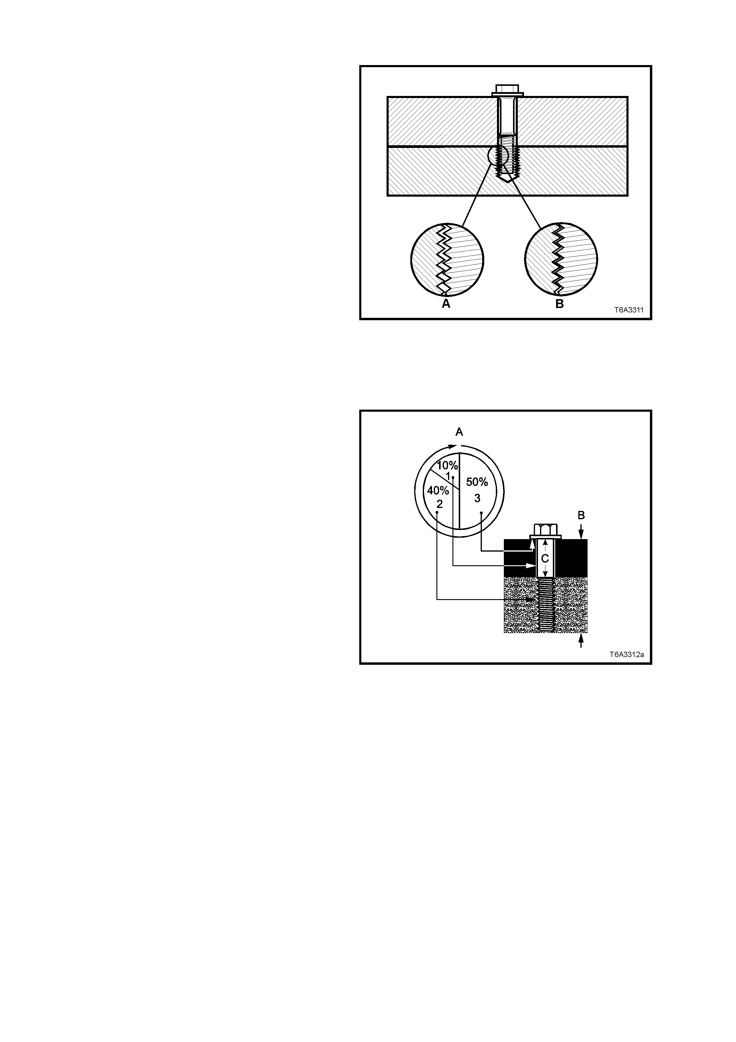
FASTENERS
Fasteners are central to the reliable operation of
any engine and the GEN III V8 engine is no
exception.
Whenever any bolt or any other threaded
component is removed from the engine, it is
necess ary to first allow the engine to cool ( inset ‘B’)
before attempting fastener removal.
Because of the greater thermal expansion of
aluminium , bolt threads will change dimension to a
greater extent when hot with this m ater ial (ins et ‘A’)
when compared to cast iron.
If a bolt or other threaded component is removed
before the engine is allowed to cool to at least
50° C, threads could be pulled from the cylinder
block or cylinder head.
Also, DO NOT use impact tools to remove bolts
during engine disassembly. While this may be
common practice with cast iron engine
components, use of these tools is more likely to pull
the aluminium threads in the cylinder bloc k or head
of this engine.
Figure 6A3-25
Clamp Load
When torque is applied to a fastener, the fastener
stretches and the joint compresses. The force
developed in the fastener due to its s tre tch is c alled
tension (‘C’), while the force applied to the joint is
called “clamp load” (‘B’).
As shown, only a small portion of the applied torque
(‘A’) is transferred to the clamp load (inset ‘1’).
Friction under the bolt head (inset ‘3’) and in the
threads (inset ‘2’) absorbs much of the applied
torque (‘A’). Typically, only 10% (inset ‘1’) of the
torque is available to develop st retch (or tens ion) in
the fastener and clamp load in the joint.
Therefore, a slight variation in friction in the thread
or under the bolt head, results in a wide variation in
the clamp load applied to the joint.
Torque Angle and Torque to Yield Fasteners
The torque angle method of applying torque to a
fastener has been developed to overcome the
effects of friction variation in fastener applications.
The application of the torque angle method does
not always mean that the fastener has to be
replaced after loosening. It is only when the
fastener has been angle tightened to the extent that
the “yield” point has been exceeded, that the
fastener must be replaced.
Examples in the GEN III V8 engine are the main
bearing caps that are angle tightened but the bolts
can be re-used, whereas the M11 cylinder head
bolts that are “T orque to Yield” fastener s, MUST be
replaced after loosening.
Figure 6A3-26

2. MI NOR SERVICE OPERATIONS
2.1 ENGINE OIL LEVEL CHECK
1. Engine must be at normal operating temperature (drive the vehicle for 15 minutes).
2. Park vehicle on level surface (as this will affect the accuracy indicated on dipstick:- this is a critical
requirement).
3. Do not check oil level for at least 10 minutes after engine shut down to allow oil to drain back into the oil pan.
4. Remove dipstick and wipe clean.
5. Reinstall dipstick, with the “ADD/FULL” marks facing towards the centre of the engine, ensuring that it is fully
seated. After leaving for several seconds, slowly remove to avoid sm earing, then hold horizontally to avoid oil
running along dipstick.
6. Observe the oil level where it passes over the centre line of the dipstick.
7. When topping up the engine oil, allow approxim ately 15 minutes f or the oil added to fully drain into the oil pan.
Alternatively, add 55 ml of oil for each millimetre below the “FULL” mark on the dipstick.
2.2 ENGINE OIL - CHANGE
NOTE 1: Quicker and more complete draining will
occur if the engine oil is at operating temperature.
However, care must be taken to avoid scalding
from the hot oil.
NOTE 2: While the oil pan is aluminium, they are
fitted with steel thread inserts to increase durability
of the thread and to avoid thread tearing when the
drain plug is removed from the hot engine.
NOTE 3: It is als o r ec ommended that the oil f ilter is
changed at each engine oil change, refer
2.3 ENGINE OIL FILTER & ADAPTOR, in this
Section.
1. Raise the engine hood and remove the oil fill
cap.
2. Raise the vehicle front and rear to maintain a
level attitude and support with safety stands.
This is to ensure complete draining. Refer to
0A GENERAL INFORMATION in of the VT
Series I Service Information.
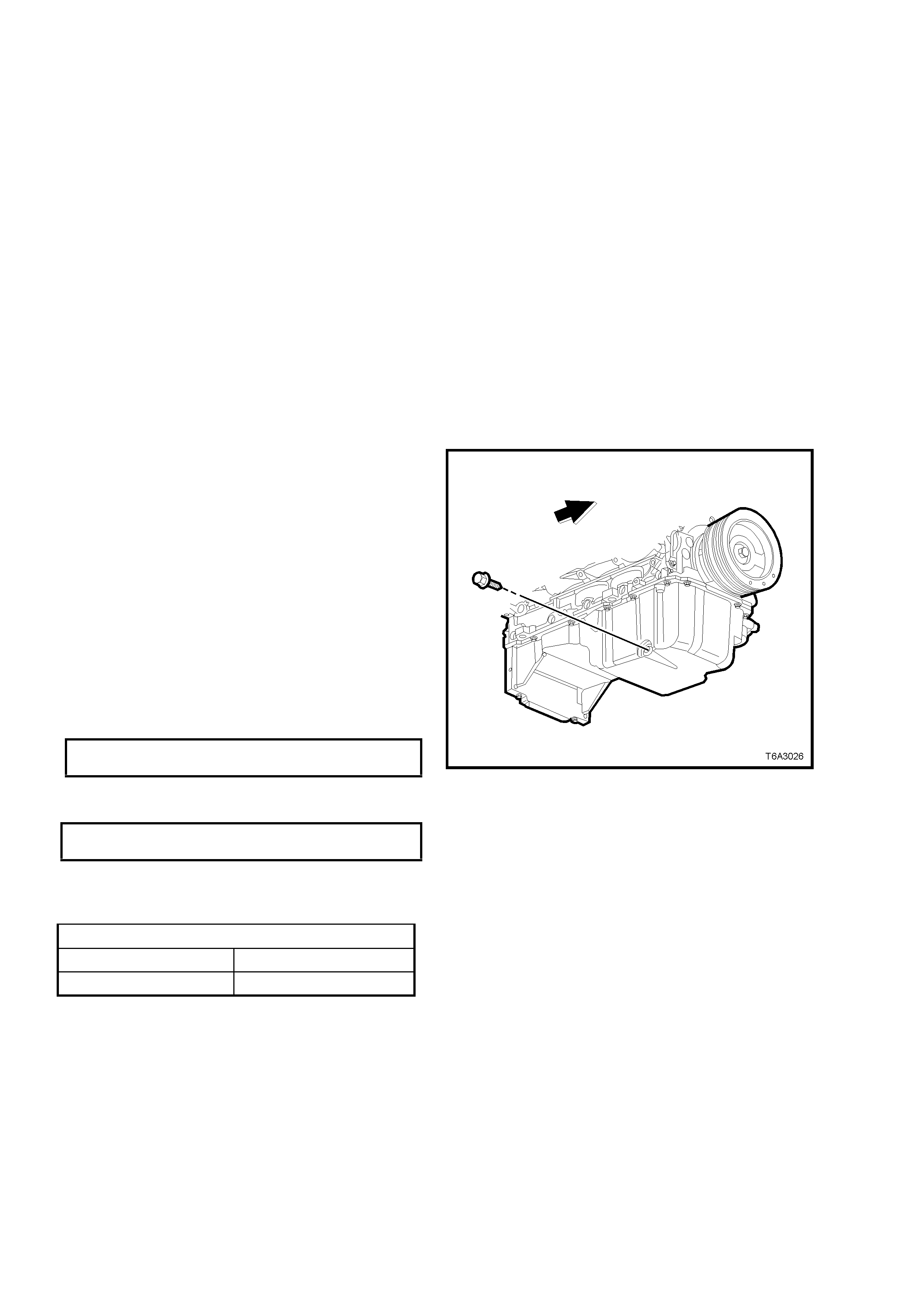
3. Remove the four bolts securing the oil pan
under-tray.
4. Clean any foreign m aterial from around the oil
pan drain plug.
5. Place an oil drain tray beneath the engine.
6. Using a 15 mm ring spanner, remove the
drain plug, taking care to avoid scalding with
the hot waste oil.
7. W hen the oil has drained sufficiently, reinstall
the drain plug, after inspecting and cleaning
the threads and inspecting the magnetic plug
end for f er rous material. T he dr ain plug O -r ing
seal may be re-used if not cut or damaged.
Tighten the drain plug to the correct torque
specification.
ENGINE OIL PAN DRAIN PLUG
TORQUE SPECIFICATION 25 Nm
8. Reinstall the oil pan under - tray and tighten the
four bolts to the correct torque specification.
OIL PAN UNDER-TRAY BOLT
TORQUE SPECIFICATION 30 - 35 Nm
9. Lower the vehicle and fill the crankcase with
the required amount of 10W - 30 SJ GF2
lubricant.
Figure 6A3-27
ENGINE OIL CAPACITY
Without Oil Filter Change 4.7 litres
With Oil Filter Change 5.0 litres
NOTE: Synthetic oils of this viscosity are also an
acceptable engine lubricant.
10. Start the engine and check for oil leaks.
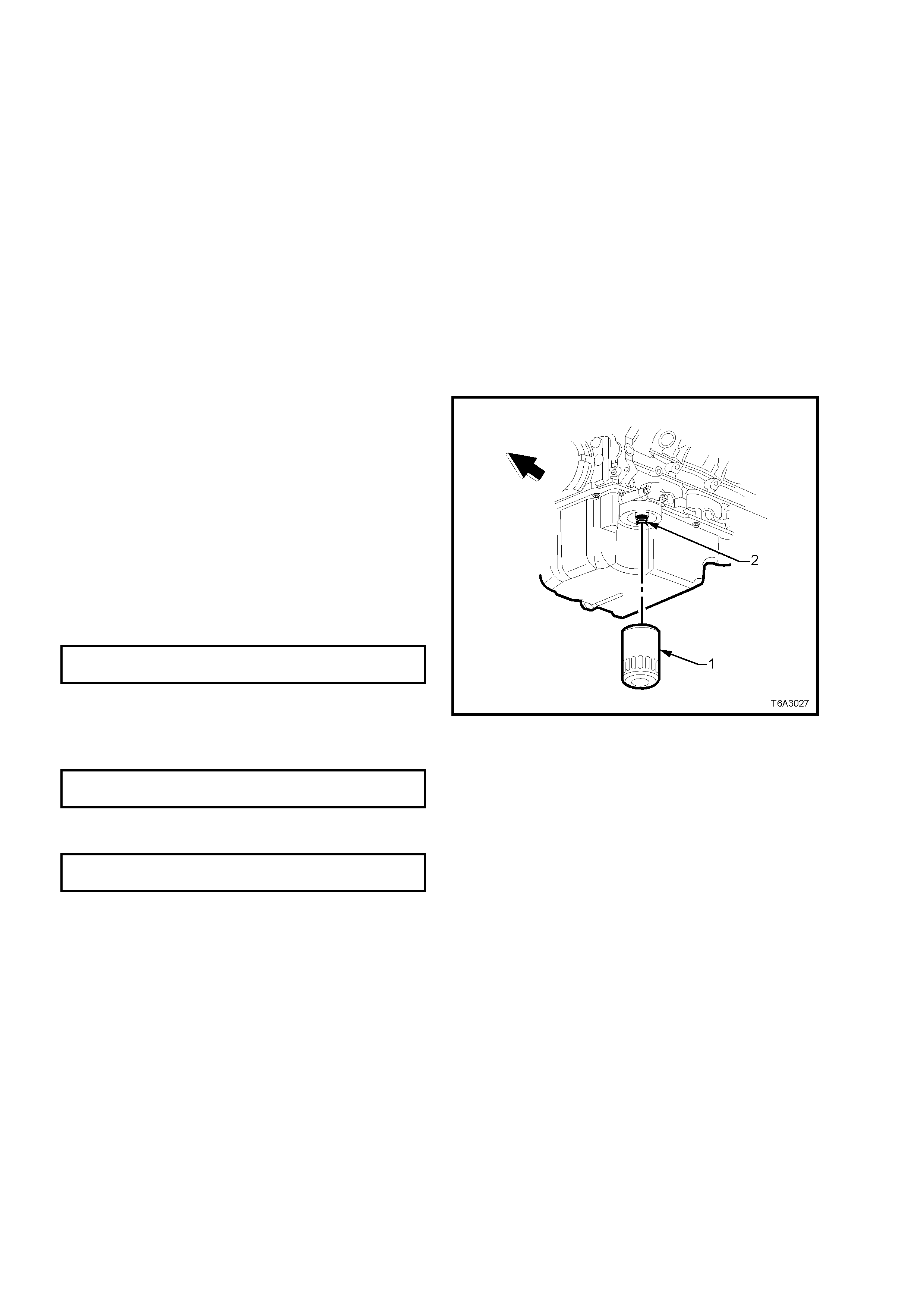
2.3 ENGINE OIL FILTER & ADAPTOR
NOTE: The oil filter should be replaced at the time
or distance intervals, specified in the Owner’s
Handbook or whenever the engine oil is changed.
REPLACE
1. Raise the engine hood and remove the oil fill
cap.
2. Raise the vehicle front and rear to maintain a
level attitude and support with safety stands.
This is to ensure complete draining. Refer to
0A GENERAL INFORMATION in of the VT
Series I Service Information.
3. Remove the four bolts securing the oil pan
under-tray.
4. Drain the engine oil as detailed in
2.2 ENGINE OIL - CHANGE, in this Section.
5. Remove the oil filter (1), using a commercially
available tool, taking care to avoid being
scalded with the hot waste oil.
6. Should it be required, remove the oil filter
adaptor (2) from the oil pan filter mounting
flange, using a suitable socket.
7. After checking that the filter seal has not
adhered to the oil pan flange, inspect the oil
filter sealing surface for scratches or other
damage and check the oil filter adaptor
threads for damage.
8. If removed, reinstall the oil filter adaptor and
tighten to the correct torque specification.
OIL FILTER ADAPTOR
TORQUE SPECIFICATION 55 Nm
9. Sm ear s om e new engine oil onto the new f ilter
seal, then install filter assembly to engine.
10. Tighten oil filter to the correct torque
specification.
ENGINE OIL FILTER
TORQUE SPECIFICATION 30 Nm
11. Reinstall the oil pan under- tray and tighten the
four bolts to the correct torque specification.
OIL PAN UNDER-TRAY BOLT
TORQUE SPECIFICATION 30 - 35 Nm
12. Lower the vehicle and fill the crankcase with
the required amount of recommended, new
lubricant. Refer to 2.2 ENGINE OIL -
CHANGE, in this Section for the
recommended procedure.
13. Start the engine and check for oil leaks.
Figure 6A3-28
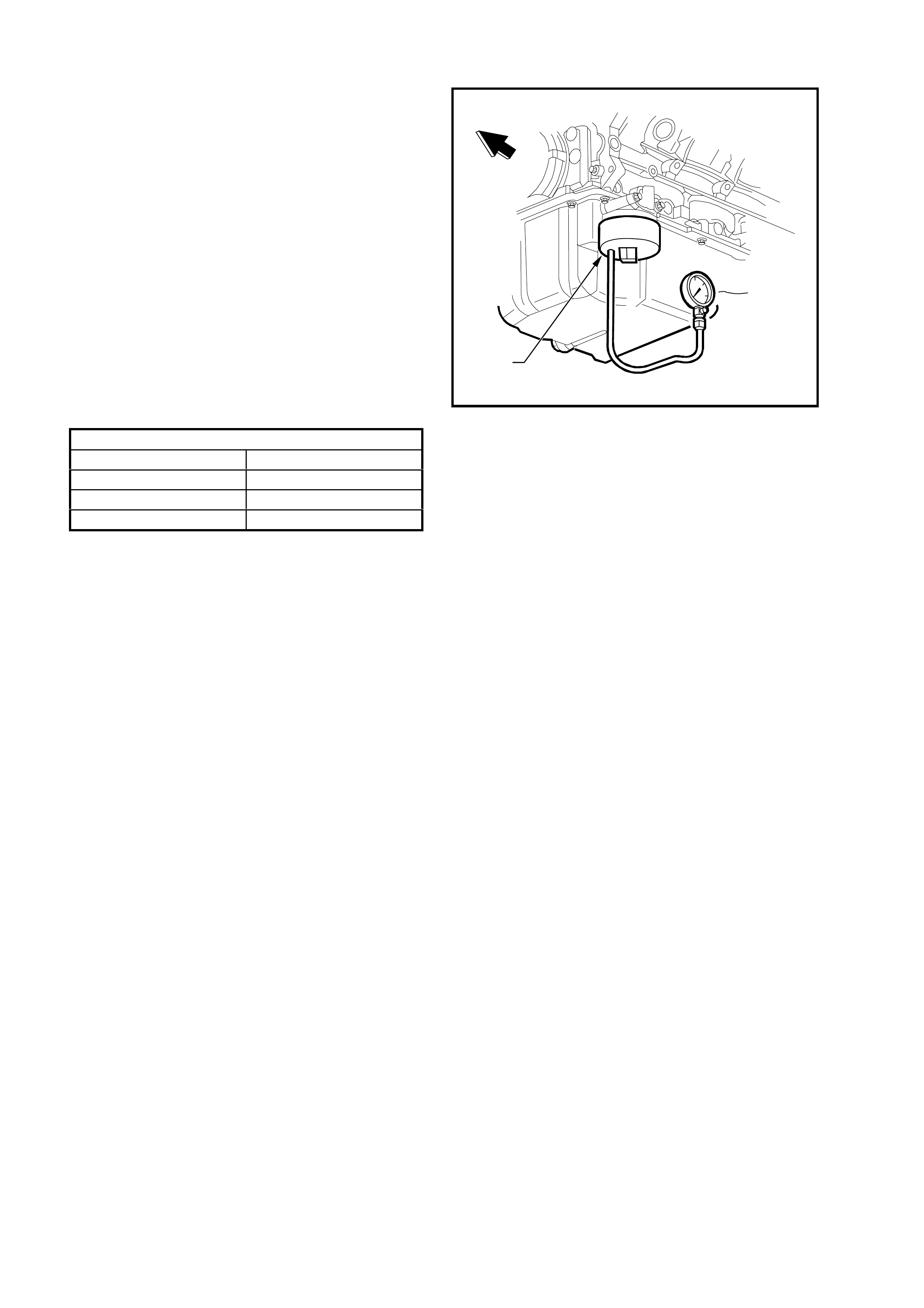
2.4 ENGINE OIL PRESSURE - CHECK
1. Ensure that engine is at operating
temperature. Driving a cold vehicle for 15
minutes, should be sufficient to normalise the
temperature.
2. Remove oil filter, as detailed in Operation 2.3.
3. Install adaptor J 42907 to the oil filter adaptor.
4. On a level surface, check engine oil level and
top up as required. See Operation 2.2 in this
Section.
5. Install commercially available, accurate oil
pressure gauge (capable of reading 800 kPa
or higher) and suitably rated pres sure hose, to
adaptor J 42907.
6. Start the engine and check the oil pressure
with the engine running with no load.
7. Check that the oil pressure is within the
following specifications.
NOTE: If the oil pressure check indicates that the
oil pressure is not to specification, then refer to
4.5 OIL PRESSURE DIAGNOSIS, in this Section.
T6A3082a
J 42907
Figure 6A3-29
8. After completing the pressure check, stop the
engine and remove the oil pressure gauge
and adaptor assembly.
9. Install the oil filter. Refer 2.3 ENGINE OIL
FILTER & ADAPTOR, in this Section.
10. Top up engine oil level as required.
ENGINE OIL PRESSURE SPECIFICATION
ENGINE SPEED OIL PRESSURE READING
1,000 rpm 50 kPa (Minimum , Hot)
2,000 rpm 125 k P a (Mini mum, Hot)
4,000 rpm 165 k P a (Mini mum, Hot)
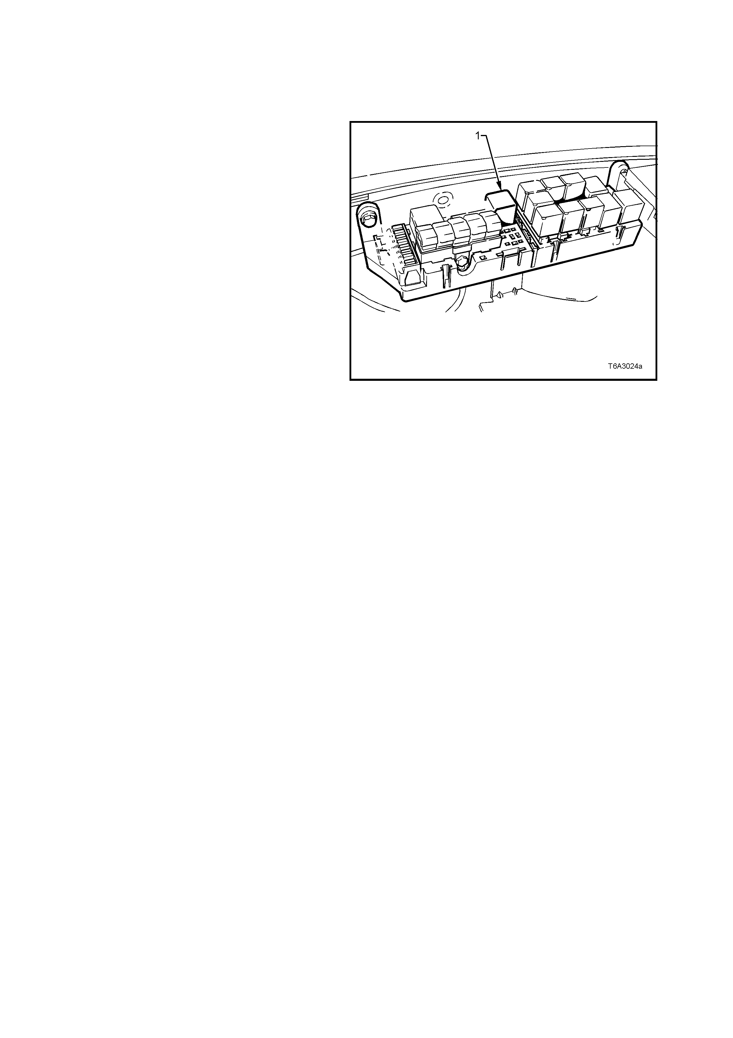
2.5 COMPRE SSION CHECK
1. Before conducting this check, ensure that the:
a. Engine is at operating temperature.
b. Battery is at or near a full state of charge.
c. Spark plugs are all removed.
d. Throttle plate is held wide open.
2. With the ignition switched OFF, disable the
ignition system and f uel injectors, by rem oving
the EFI relay (1), located in the engine
compartment.
3. Install a suitable, commercially available and
accurate, compression tester, that has been
reset to zero.
4. Crank the engine through approximately four
compression strokes (four ‘puffs’). Record the
reading.
5. Repeat this compression check for each
cylinder. Again, record each reading.
6. If a cylinder has low compres sion, inject about
15 ml (one tablespoon) of engine oil into the
combustion chamber through the spark plug
hole.
7. Recheck the compression and record the
reading.
Figure 6A3-30
INTERPRETING COMPRESSION READINGS
The minimum compression in any one cylinder
should not be less than 70% of the highest
cylinder. No cylinder should read less than 690
kPa. For example, if the highest pressure in any
one cylinder is 1035 kPa, the lowest allowable
pressure for any other cylinder would be 725 kPa.
(1,035 x 70% = 725).
NORMAL - Compression builds up quickly and
evenly to the specified compression for each
cylinder.
PISTON RINGS LEAKING - Compression is low on
the first stroke. Compression then builds up with
the following strokes but does not reach normal.
Comp ression im proves cons iderably when you add
oil.
VALVES LEAKING - Compression is low on the
first strok e. Compression usually does not build up
on the following strokes. Compression does not
improve much when you add oil.
CYLINDER HEAD GASKET LEAKING - If two
adjacent cylinders have lower than normal
compression and injecting oil into the cylinders
does not increas e the com pres sion, the c ause m ay
be a head gasket leaking between the cylinders.
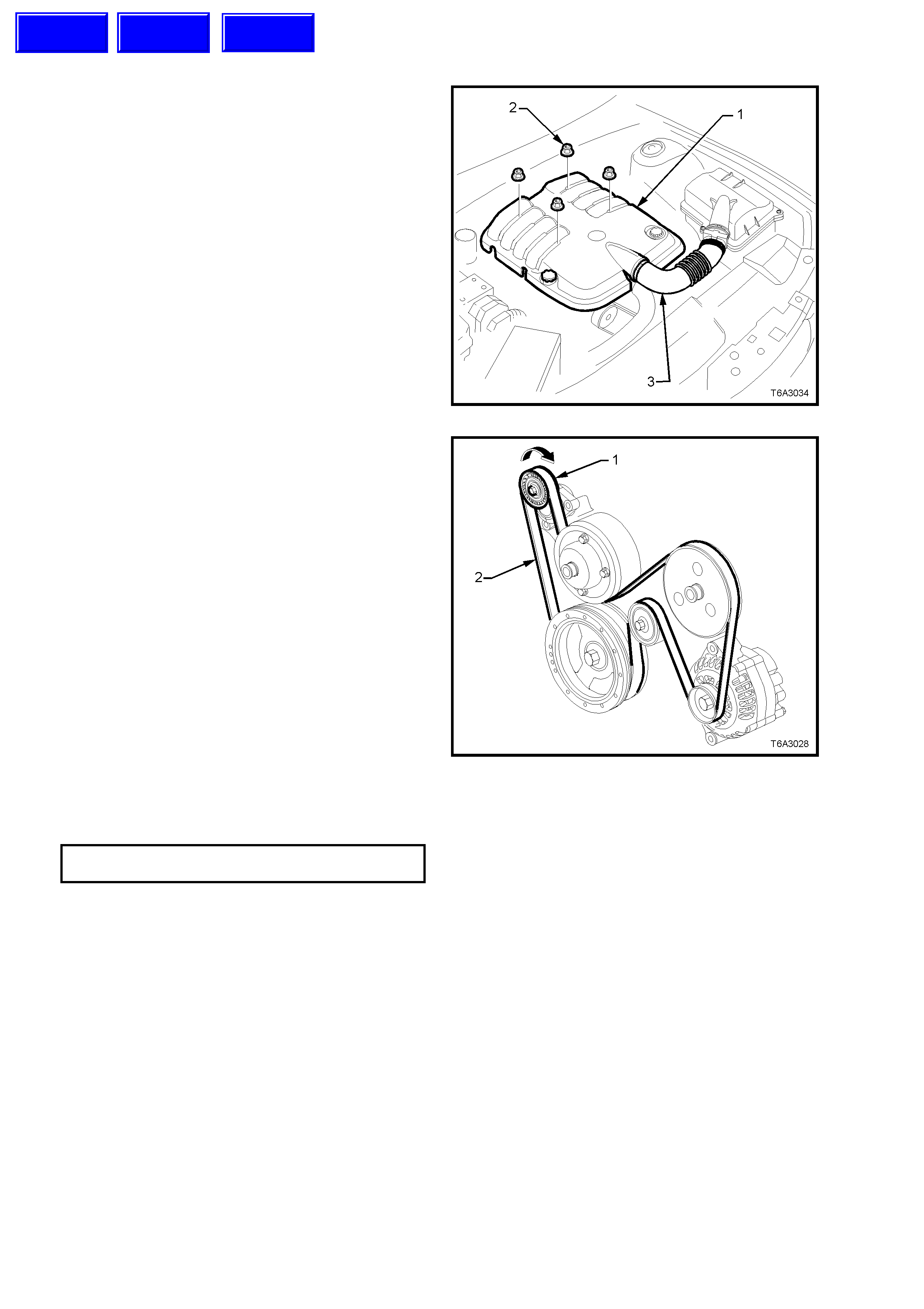
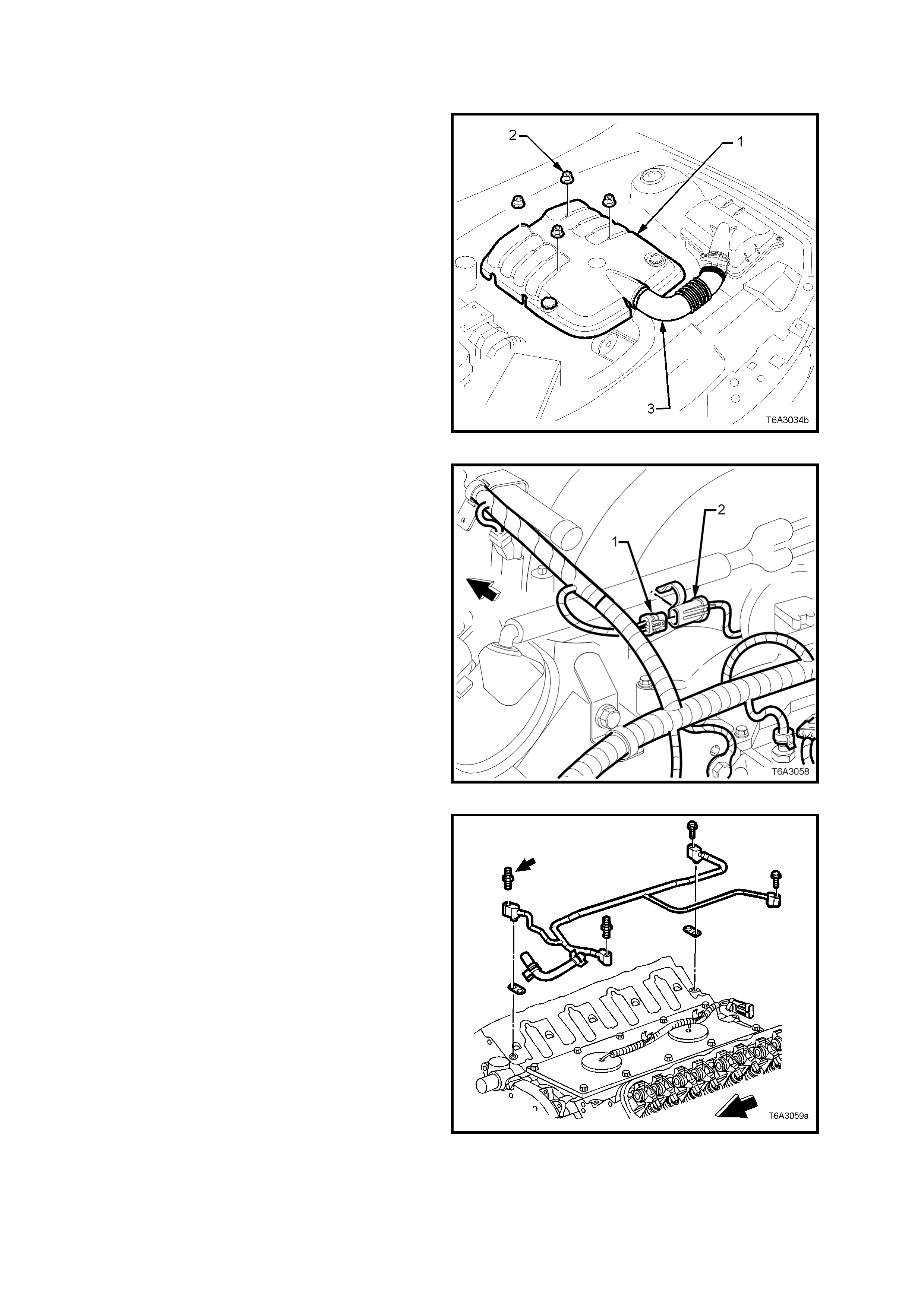
2.6 ENGINE DRIVE BELTS - REPLACE
1. Remove the four engine dress cover
decorative nuts (2), then remove the dress
cover (1) from the engine.
2. Loosen both hose clamps securing the intake
hose (3) to the MAF sensor and the throttle
body. Remove the hose from the engine.
Figure 6A3-31
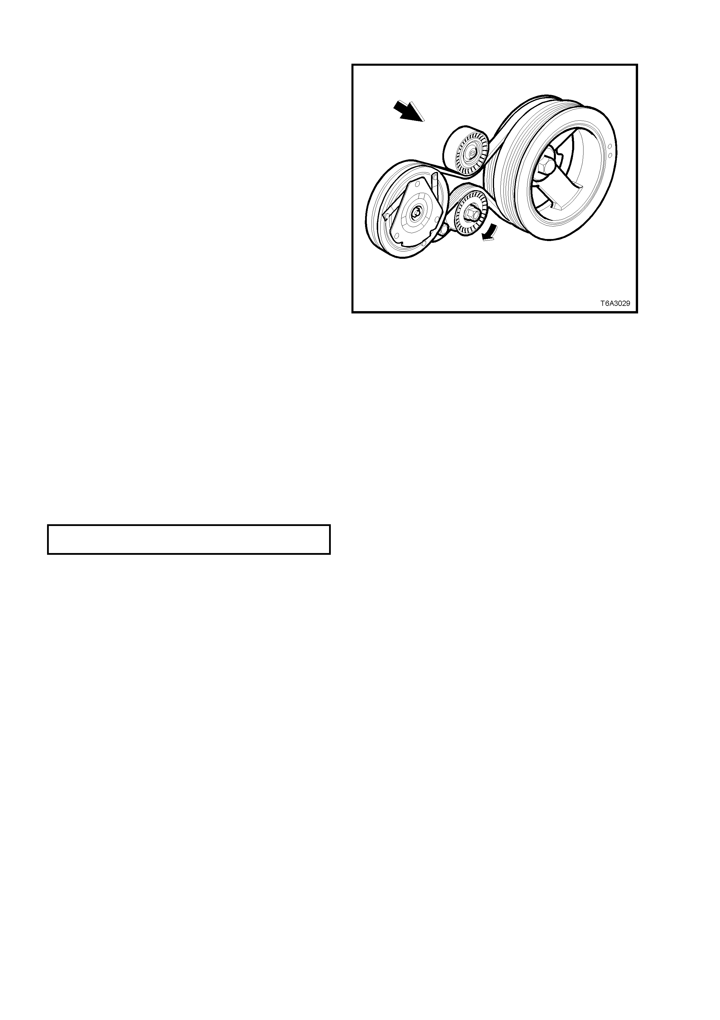
ENGINE A CCESSORY DRIVE BELT
3. Using a 15 mm ring spanner, rotate the
acces sor y automatic drive belt tens ioner ( 1) , in
the direction indicated, to reduce belt tension.
4. While holding the tensioner in the reduced
tension position, remove the accessory drive
belt (2), taking note of the belt routing.
NOTE: Use an assistant to maintain the tensioner
in the required position.
5. Clean the accessory drive belt running
surfaces and inspect the belt for damage.
6. While rotating the accessory drive belt
tensioner (1) in the direction indicated, install
the drive belt (2) over the pulleys, routing the
belt correctly, as shown.
7. Inspect the installation to ensure that the belt
is correctly aligned on all pulleys.
8. Reinstall the engine dres s cover , secur ing with
the four decorative nuts and tightening to the
correct torque specification.
ENGINE DRESS COVER NUT
TORQUE SPECIFICATION 8.0 - 12 Nm
9. Start the engine to ensure correct operation.
Figure 6A3-32
Techline
Techline
Techline
AIR CONDITIONING COMPRESSOR BELT
NOTE: The accessory drive belt must be
removed first to allow access to this belt. Refer
to the previous operation for details.
1. Raise the vehicle and support with safety
stands. Refer to Section 0A GENERAL
INFORMATION in of the VT Series I Service
Information.
2. Remove the four bolts securing the oil pan
under-tray.
3. From under the vehicle, rotate the A/C drive
belt tensioner in the direction shown, using a
15 mm set spanner, to relieve belt tension.
4. While using an assistant to maintain the
tensioner in the required position, remove the
drive belt from the pulleys.
NOTE: An alternative to using an assistant,
would be to secure the spanner using tie wire.
5. Clean the A/C drive belt running surfaces and
inspect the belt for damage.
6. While holding the A/C drive belt tensioner in
the direction indicated, install the drive belt
over the pulleys, routing the belt correctly, as
shown.
7. Inspect the installation to ensure that the belt
is correctly aligned on all pulleys.
Figure 6A3-33
8. Reinstall the ac c es sor y drive belt as des cr ibed
in the previous operation.
9. Start the engine to ensure correct operation.
10. Reinstall the oil pan under- tray and tighten the
bolts to the correct torque specification.
OIL PAN UNDER-TRAY BOLT
TORQUE SPECIFICATION 30 - 35 Nm
11. Lower the vehicle and test for correct
operation.
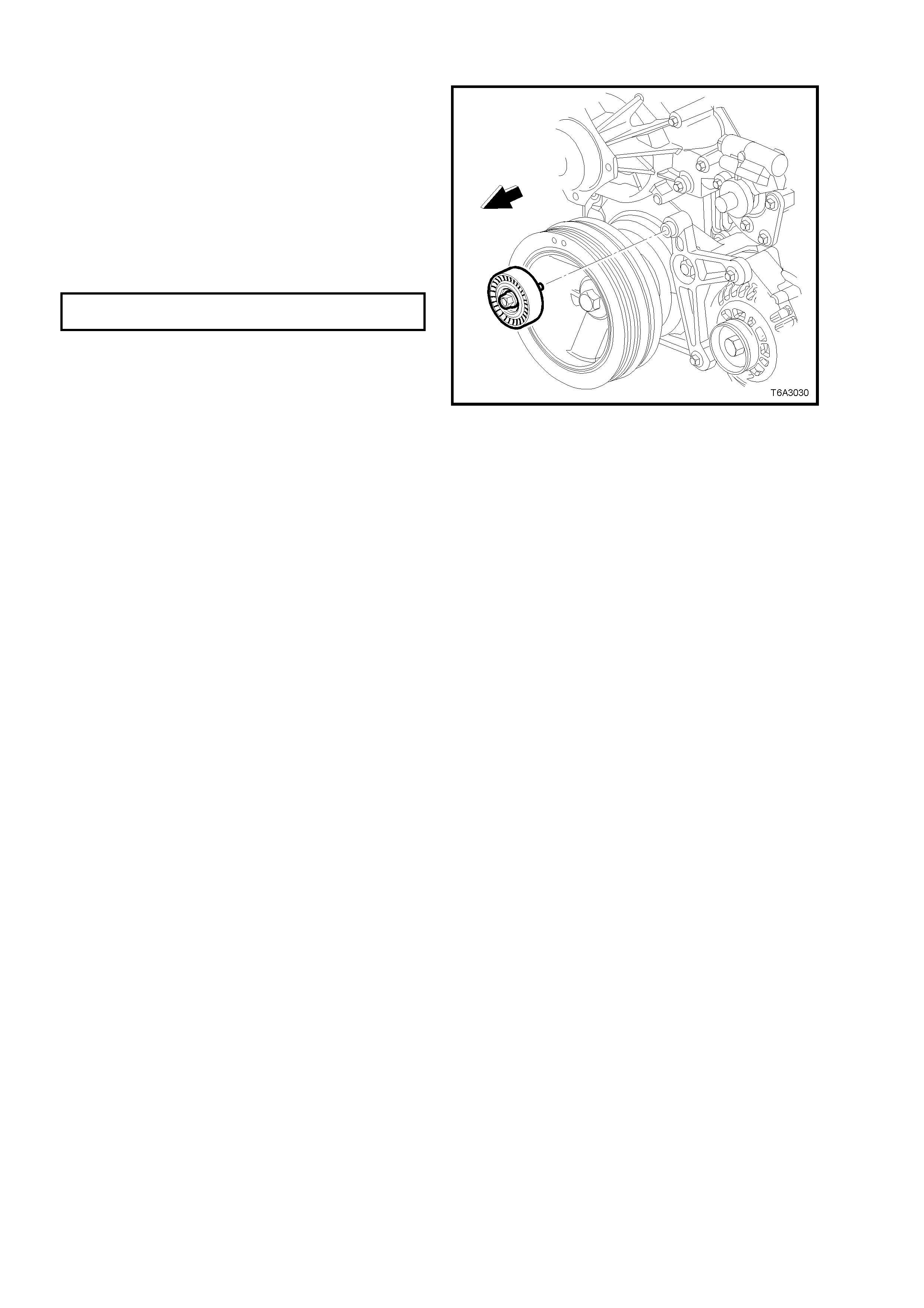
2.7 ACCESSORY BELT IDLER PULLEY
REPLACE
1. Remove the engine accessory drive belt.
Refer to Operation 2.6 in this Section for the
necessary procedure.
2. Remove the idler pulley retaining bolt, then
remove the pulley from its mounting boss, on
the generator mounting bracket.
3. Install the idler pulley to its mounting boss.
4. Install the idler pulley retaining bolt and tighten
to the correct torque specification.
ACCESSORY BELT IDLER PULLEY
BOLT TORQUE SPECIFICATION 40 - 60 Nm
5. Install the engine accessory drive belt. Refer
to Operation 2.6 in this Section for the
necessary procedure.
Figure 6A3-34

2.8 A/C BELT IDLER PULLEY
REPLACE
1. Raise the vehicle and support with safety
stands. Refer to 0A GENERAL
INFORMATION of the VT Series I Service
Information.
2. Remove the four bolts securing the oil pan
under-tray.
3. From under the vehicle, rotate the A/C drive
belt tensioner in the direction shown in Figure
6A3-33, using a 15 m m s et s panner, to relieve
belt tension.
4. While using an assistant to maintain the
tensioner in the required position, remove the
drive belt from the pulleys but leave hanging
on the crankshaft pulley.
NOTE: An alternative to using an assistant, would
be to secure the spanner using tie wire.
5. Using a commercially available Torx bit T50,
remove the bolt securing the A/C compressor
drive belt idler pulley to its mounting boss on
the coolant pump housing, then remove the
pulley assembly.
6. Install the idler pulley to its mounting boss.
7. Install the idler pulley retaining bolt and tighten
to the correct torque specification.
A/C COMPRESSOR BELT
IDLER PULLEY BOLT 40 - 60 Nm
TORQUE SPECIFICATION
8. Install the A/C compressor drive belt. Refer to
Operation 2.6 in this Section for the
necessary procedure.
9. Reinstall the oil pan under -tray and tighten the
bolts to the correct torque specification.
OIL PAN UNDER-TRAY BOLT
TORQUE SPECIFICATION 30 - 35 Nm
10. Lower the vehicle and test for correct
operation.
Figure 6A3-35
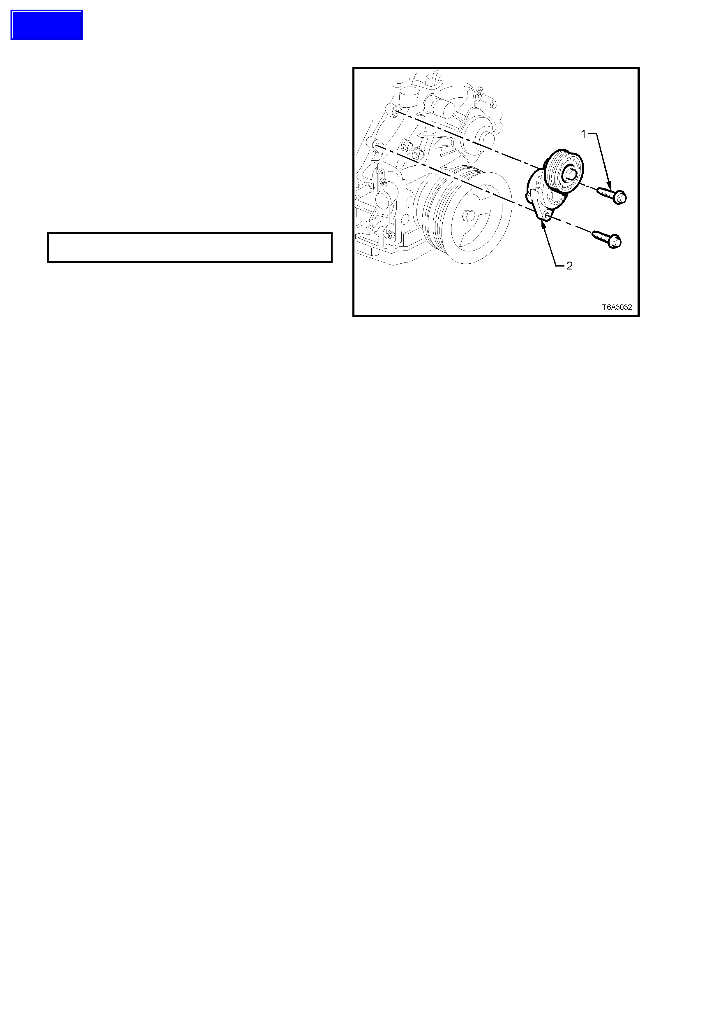
2.9 ACCESSORY BELT TENSIONER
REPLACE
1. Remove the engine accessory drive belt.
Refer to Operation 2.6 in this Section for the
necessary procedure.
2. Remove the tensioner pulley bracket retaining
bolts (1), then remove the assembly (2).
3. Install the tensioner assembly (2) and the two
mounting bolts.
4. Tighten both mounting bolts (1) to the correct
torque specification.
ACCESSORY BELT TENSIONER
BOLT TORQUE SPECIFICATION 40 - 60 Nm
5. Install the engine accessory drive belt. Refer
to Operation 2.6 in this Section for the
necessary procedure.
Figure 6A3-36
Techline
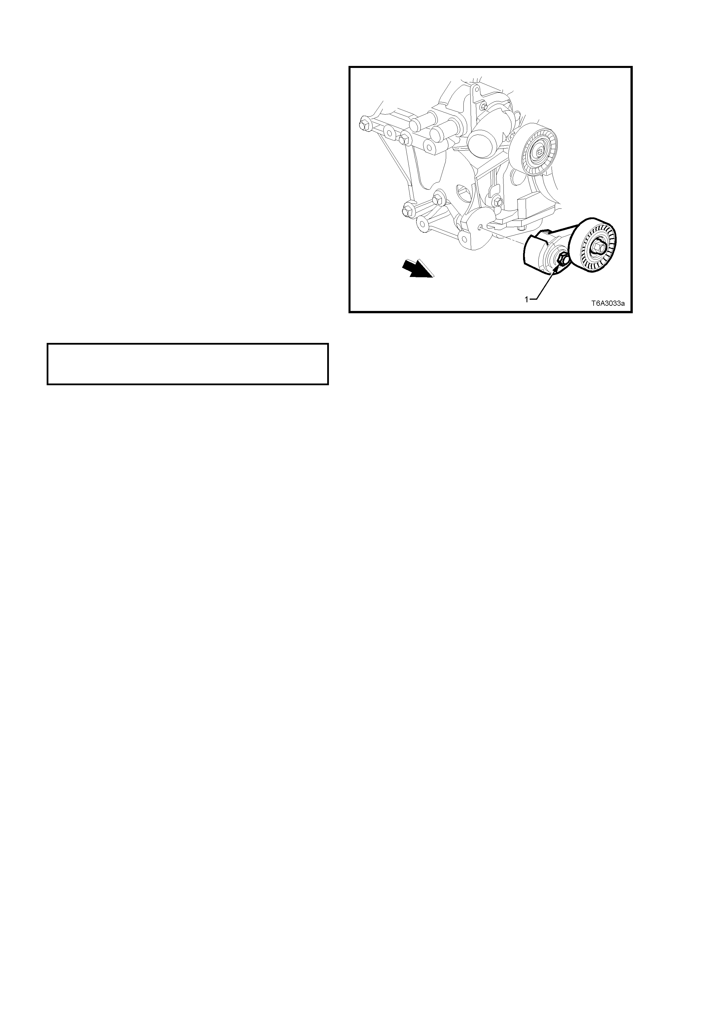
2.10 A/C BELT TENSIONER
REPLACE
1. From under the vehicle, rotate the A/C drive
belt tensioner in the direction shown in Figure
6A3-33, using a 15 m m s et s panner, to relieve
belt tension.
2. While using an assistant to maintain the
tensioner in the required position, remove the
drive belt from the pulleys but leave hanging
on the crankshaft pulley.
NOTE: An alternative to using an assistant,
would be to secure the spanner using tie wire.
3. Remove the bolt (1) securing the A/C
compressor drive belt tensioner, then remove
the assembly.
4. Install the tensioner assembly and the
mounting bolt.
5. Tighten the tensioner mounting bolt to the
correct torque specification.
A/C COMPRESSOR BELT
TENSIONER BOLT 21 - 29 Nm
TORQUE SPECIFICATION
6. Install the A/C compressor drive belt. Refer to
Operation 2.6 in this Section for the necessary
procedure.
Figure 6A3-37
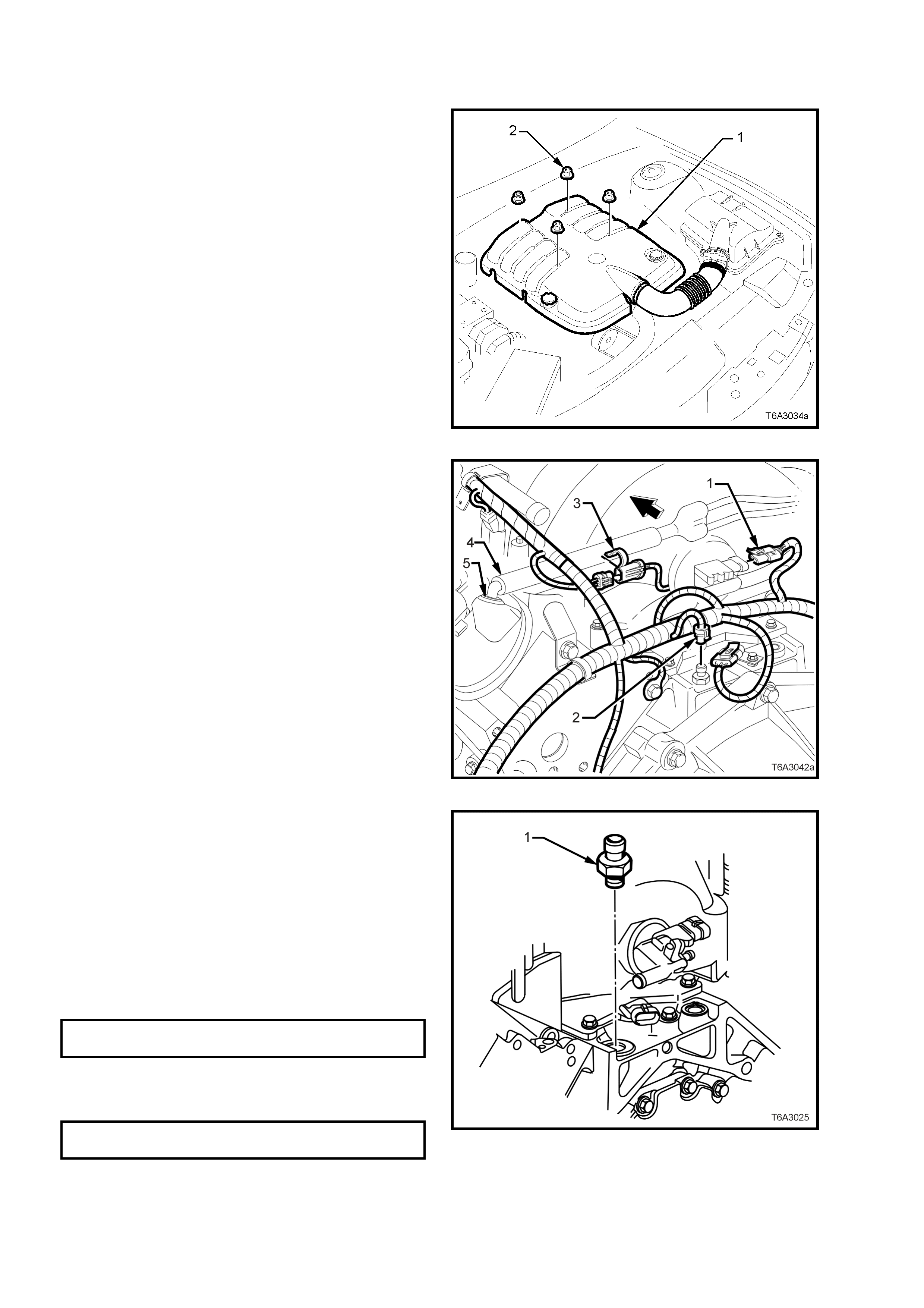
2.11 OIL PRESSURE SENSOR
REPLACE
1. Remove the four engine dress cover
decorative nuts (2), then remove the dress
cover (1) from the engine.
Figure 6A3-38
2. Release the wiring harness connector locking
tang from the oil pressure sensor, then
remove the connector (2) from the sensor.
Figure 6A3-39
3. Using T ool No. J 41712 and suitable 3/8” drive
sock et equipm ent, remove oil pressur e sens or
(1) from the left hand rear of the engine
cylinder block.
4. Prior to reinstallation apply Loctite 565 sealant
(or equivalent) to the cleaned oil pressure
sensor threads.
5. Reinstall the oil pressure sensor (1) and
tighten with Tool No. J 41712 and suitable 3/8”
drive socket equipment, to the correct torque
specification.
OIL PRESSURE SENSOR
TORQUE SPECIFICATION 20 Nm
6. Reinstall the engine dres s cover , secur ing with
the four decorative nuts and tightening to the
correct torque specification.
ENGINE DRESS COVER NUT
TORQUE SPECIFICATION 8.0 - 12 Nm
7. Start the engine to ensure correct operation.
Figure 6A3-40
2.12 MANIFOLD ABSOLUTE PRESSURE SENSOR
REPLACE
1. Remove the four engine dress cover
decorative nuts (2), then remove the dress
cover (1) from the engine.
Figure 6A3-41
2. Release the wiring harness connector locking
tang (1) from the manifold absolute pressure
(MAP) sensor, then remove the connector
from the sensor.
Figure 6A3-42
3. Grasp the MAP sensor (1) at the rear of the
intake manifold and twist back and forth while
pulling upward, to remove.
4. Check the silicone r ubber seal (2) on the MAP
sensor to ensure it is not torn or damaged.
5. Reinstall the MAP sensor by pushing it down,
into the fitting at the rear of the intake
manifold.
6. Reinstall the wiring harness connector to the
MAP sensor, ensuring that the lock ing tab is in
place.
7. Reinstall the engine dres s cover , secur ing with
the four decorative nuts and tighten to the
correct torque specification.
ENGINE DRESS COVER NUT
TORQUE SPECIFICATION 8.0 - 12 Nm
8. Start the engine to ensure correct operation. Figure 6A3-43
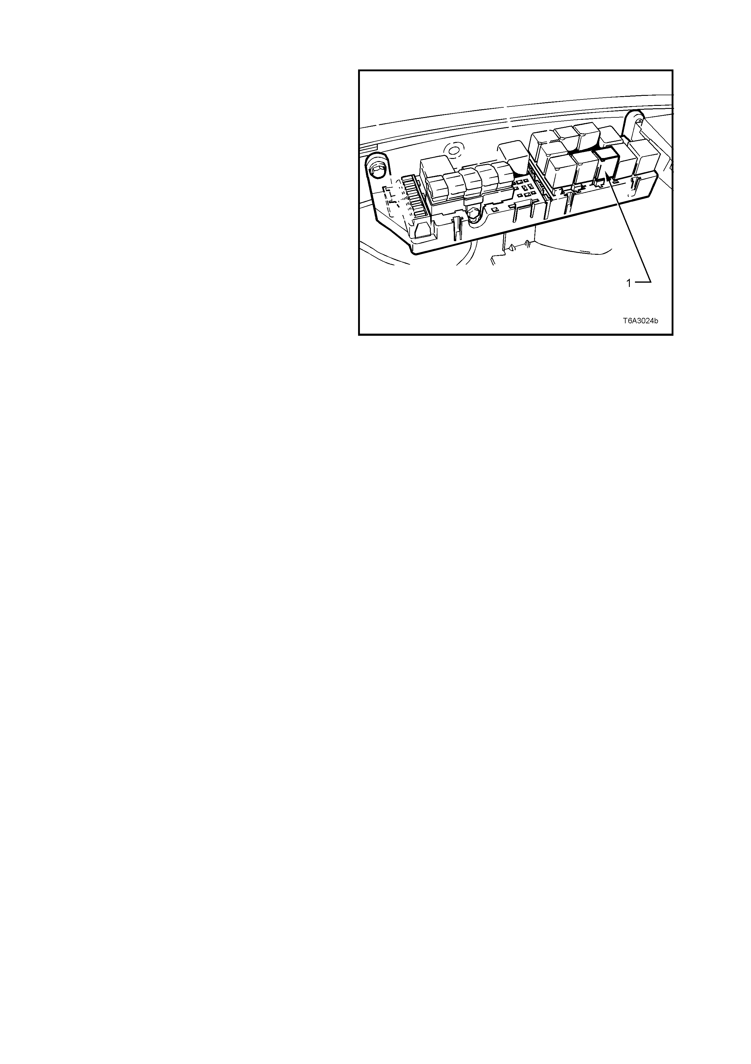
2.13 FUEL SYSTEM PRESSURE RELIEF
1. After removing the cover from the engine
compartment relay housing, remove the fuel
pump relay (1).
2. With the throttle closed, crank the engine.
NOTE: The engine may start and run until the fuel
supply remaining in the fuel delivery system is
burned.
3. When the engine stops, re-engage the starter
motor for 10 seconds to ensure that the line
pressure has been fully relieved.
4. Reinstall the fuel pump relay, taking care that
the wiring harness relay connector is not
dislodged and that the relay is fully installed.
CAUTION: Unless this procedure is followed
before servicing the fuel lines or fuel
connections, fuel spray into the engine
compartment could occur!
Figure 6A3-44
2.14 INTAKE MANIFOLD
NOTE: Unless individual components such as the
throttle body, fuel injection rail and/or injectors are
to be removed as individual components, then it is
recommended that the complete intake manifold
assembly is removed, as described in this service
operation.
REMOVE
1. Disconnect the battery earth cable from the
battery.
2. Drain the cooling system. Refer to
Section 6B3 ENGINE CO OLING - GEN III V8
ENGINE.
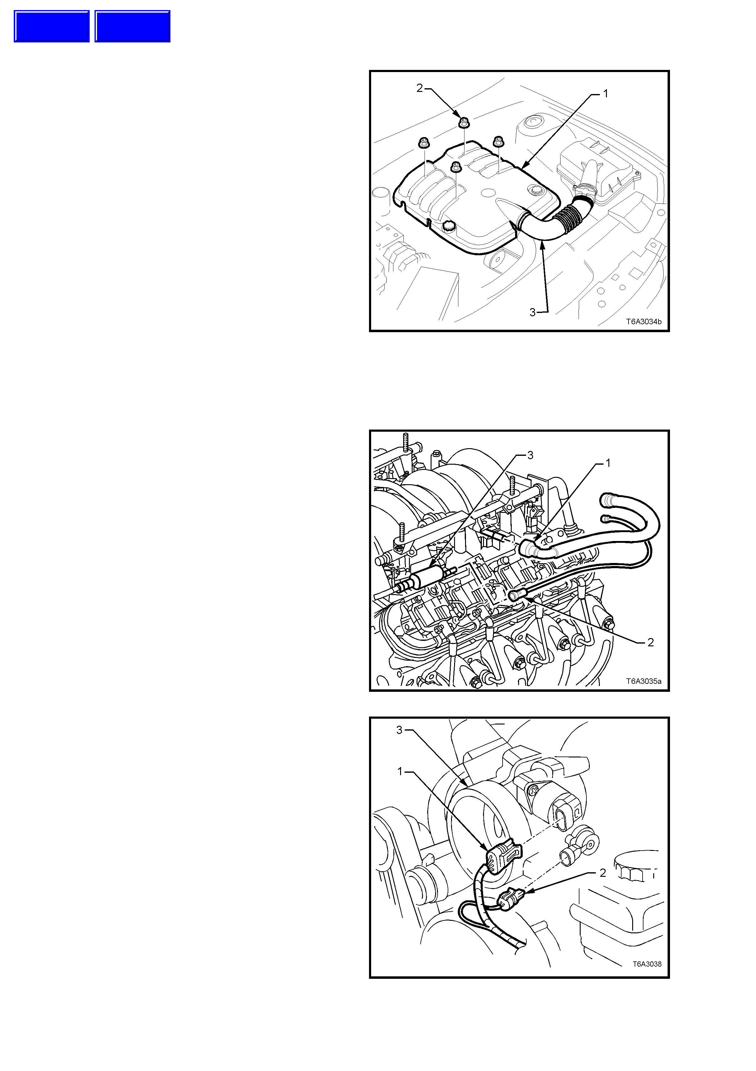
3. Rem ove the engine dress cover retaining nuts
(2), then remove the cover (1).
4. Loosen the two clam ps securing the air intake
duct (3) to the thr ottle body and Mas s Air Flow
(MAF) sensor.
5. Remove air intake duct (3) assembly from
throttle body and MAF sensor.
6. De-pressurise fuel rail. Refer to
Operation 2.13, in this Section.
Figure 6A3-45
7. Using quick connect release Tool No. 7371,
install over fuel line.
8. While holding the fuel line quick connect (1),
push on Tool 7371 to release the quick
connect fitting (1) from the fuel rail. Pull back
on the quick connect and remove.
9. Disconnect the vapour line connector (2) from
the EVAP purge valve (3).
Important: Cap the fuel line fittings and plug the
holes after separating the fuel lines to prevent fuel
leaking and/or dirt and other contaminants from
entering the fuel system.
Figure 6A3-46
10. Disconnect wiring harness connector (1) from
the Intake Air Control (IAC) motor, at the
throttle body (3).
11. Disconnect the wiring harness connector (2)
from the Throttle Position (TP) sensor at the
throttle body (3).
Figure 6A3-47
Techline
Techline
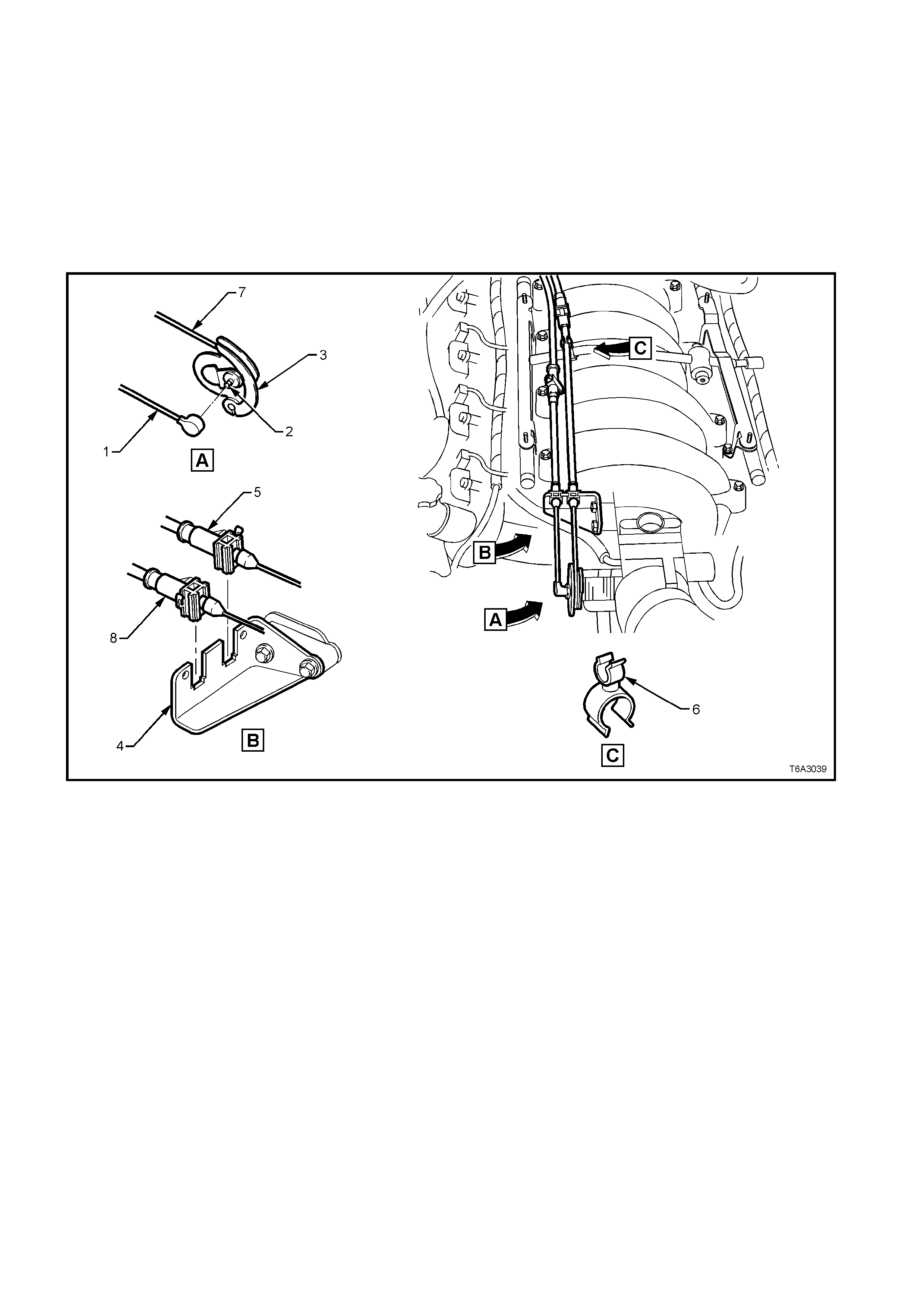
12. Disconnect the cruise control cable (1) (if
fitted) from the stud (2) on the throttle body
valve lever (3), then remove the outer cable
(8) from the retainer bracket (4). Refer Figure
6A3-48.
13. Lift the throttle cable (5) from the clip at the
fuel rail crossover pipe (6), then lift the cable
(5) from the retainer bracket (4).
14. Remove the inner throttle cable (7) from the
throttle body valve lever (3).
15. Set the cable/s to one side.
Figure 6A3-48
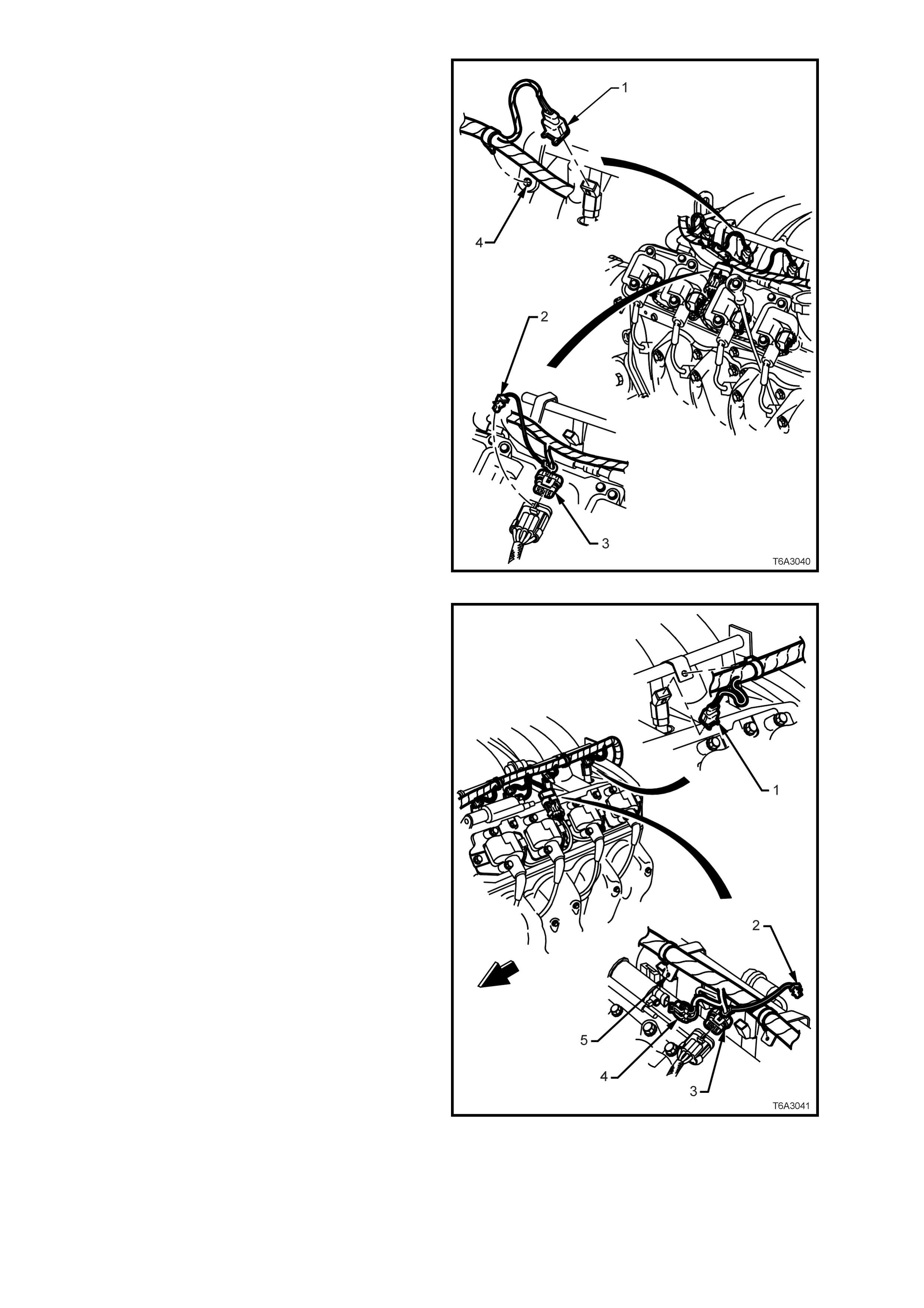
16. Disconnect the fuel injector wiring harness
connectors (1) from the right bank of fuel
injectors (4 places).
17. Rem ove the CPA lock (2) f rom the ignition coil
main connector (3) on the right hand side,
remove the connector (3), then the harness
securing clips from the fuel rail brackets (4)
and set the harness to one side.
Figure 6A3-49
18. Disconnect the fuel injector wiring harness
connectors (1) from the left bank of fuel
injectors (4 places).
19. Rem ove the CPA lock (2) f rom the ignition coil
main connector (3) on the left hand side, then
remove the wiring harness connector (3).
20. Remove the wiring harness connector from
the canister purge valve (4).
21. Remove the harness securing clips from the
fuel rail brackets (5) and set the harness to
one side.
Figure 6A3-50
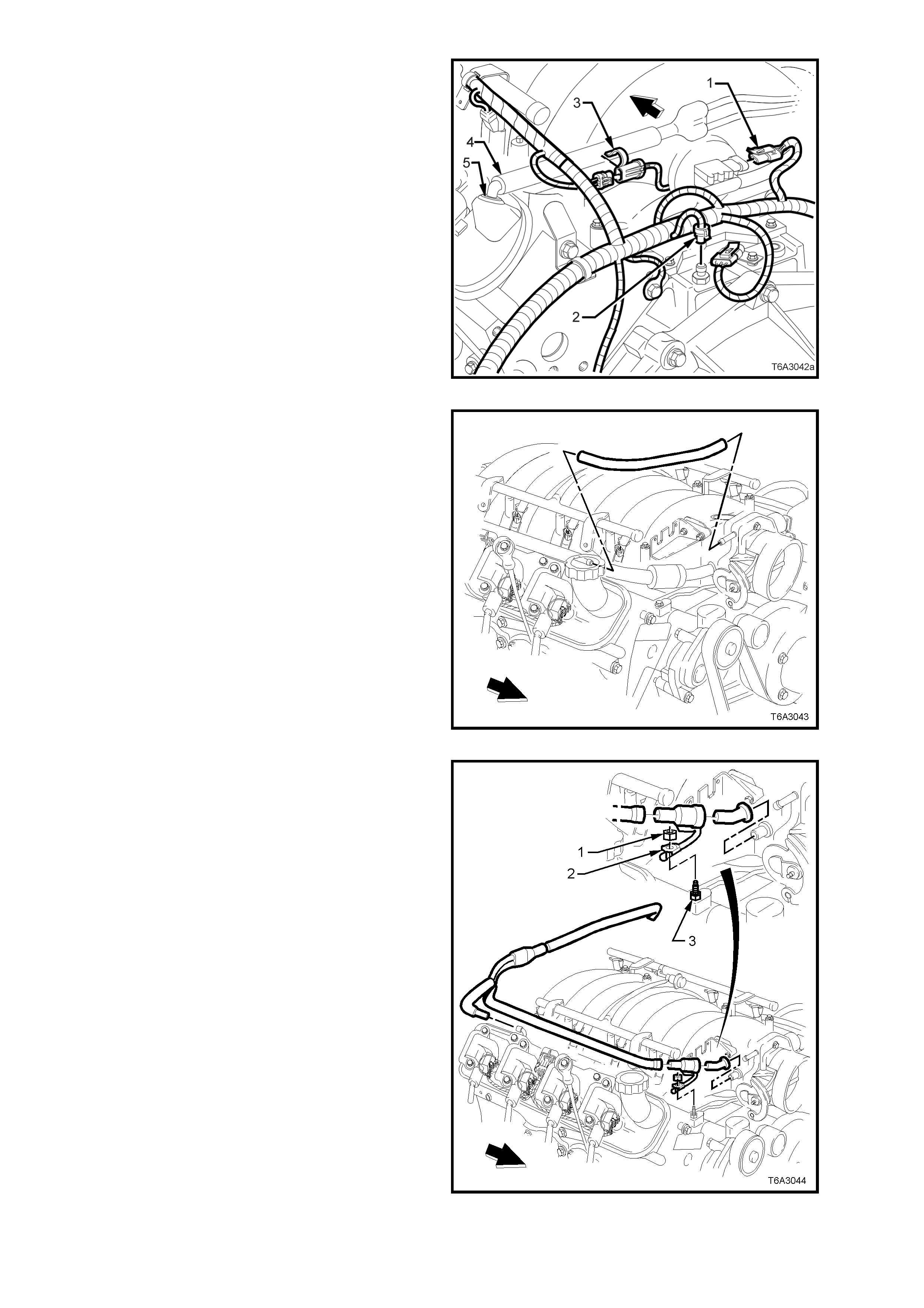
22. Disconnect the wiring harness connector (1)
from the MAP sensor, located at the rear of
the intake manifold.
23. Remove the knock sensor patch harness
connector r etaining clip (3) fr om the PCV hose
and disconnect the wiring harness connector.
24. Remove the PCV hose (4) from the PCV vent
valve grommet (5) (left bank).
Figure 6A3-51
25. Remove the fresh air hose from the front fitting
of the rocker cover and the throttle body.
Figure 6A3-52
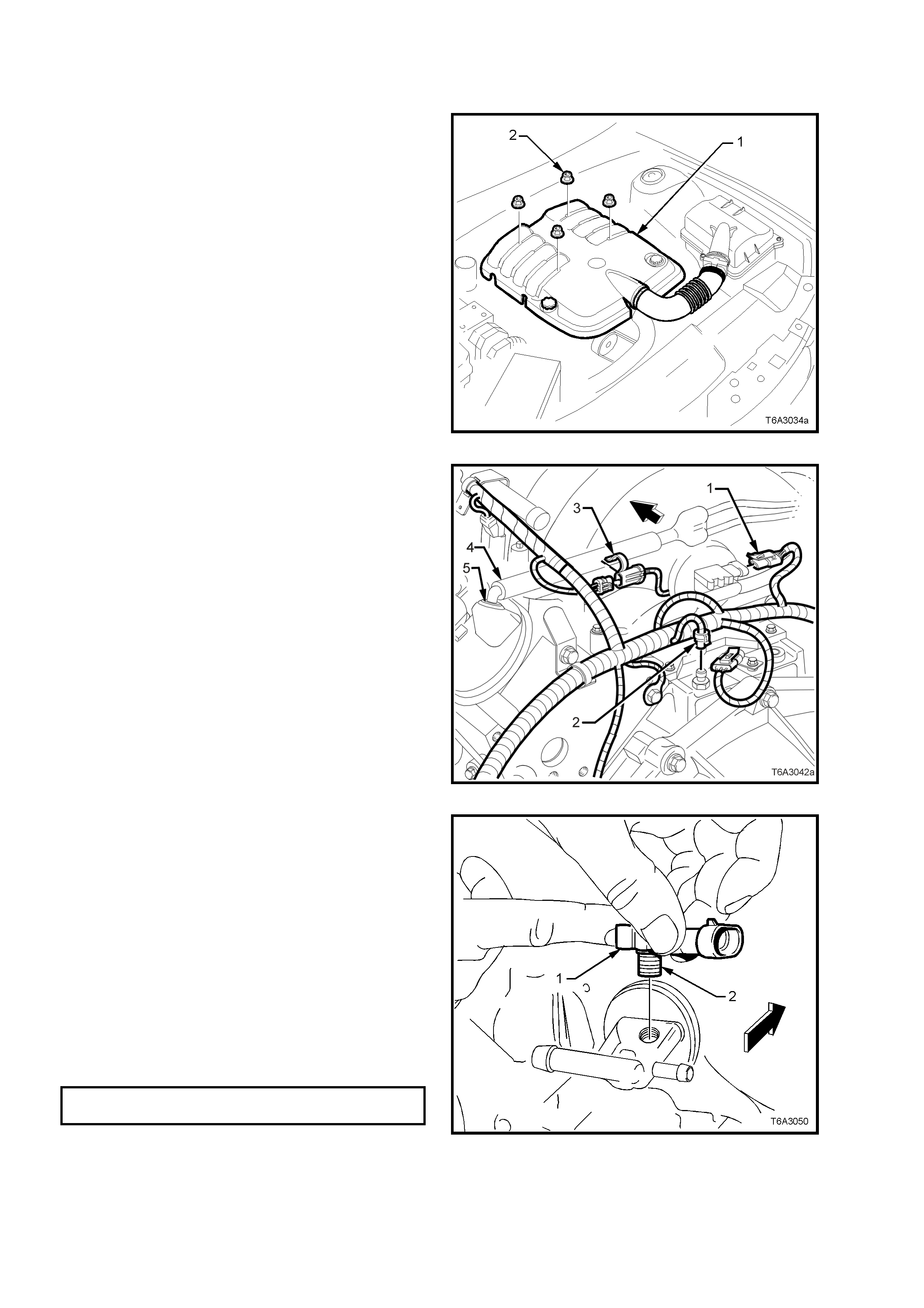
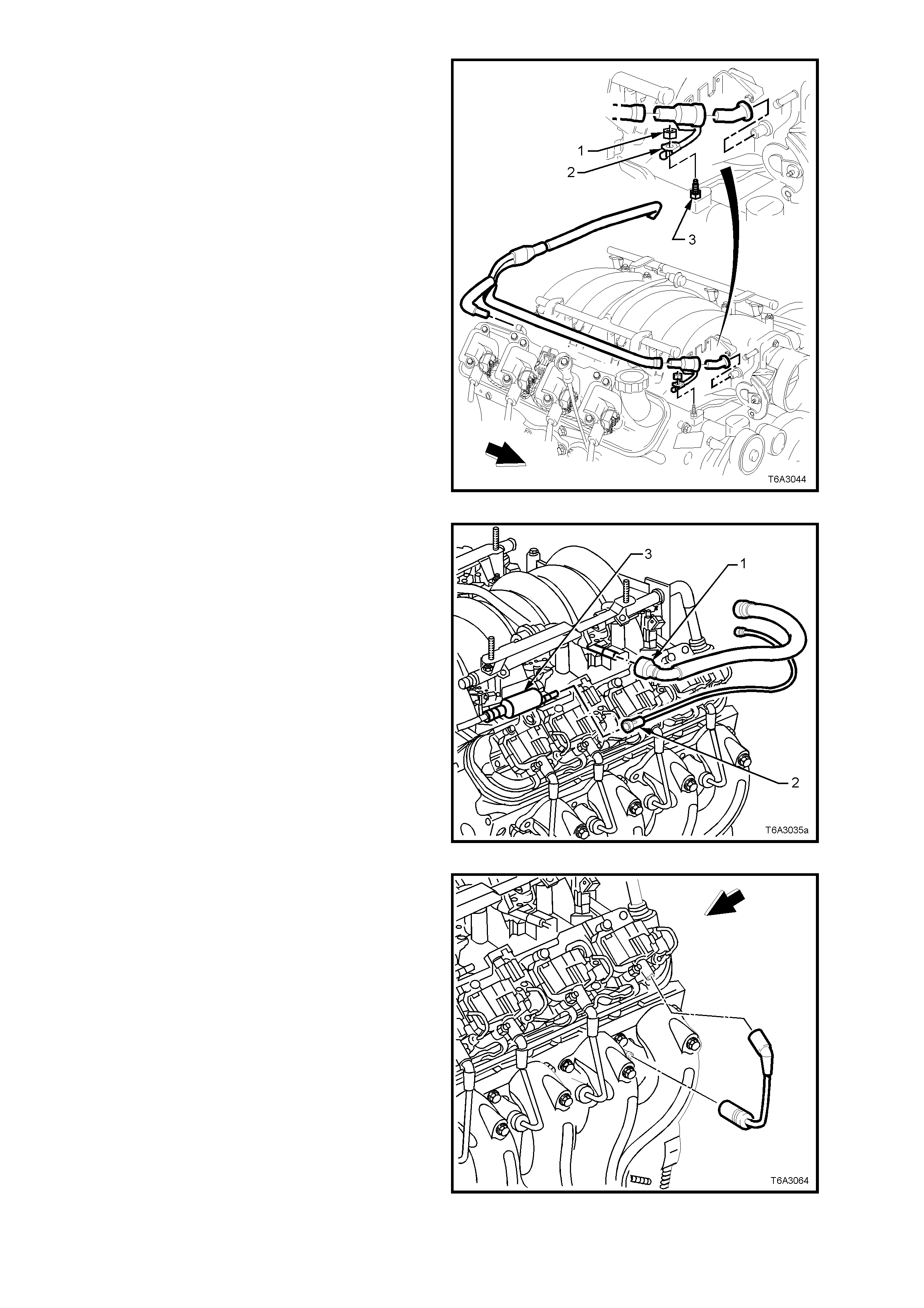
26. Remove the nut (1) securing the PCV valve,
heat conducting strap (2) from the front right
hand vapour pipe screw (3).
27. Remove the PCV valve hose from the throttle
body and right hand rocker cover, rear fitting.
28. Remove the PCV valve and hose assembly
from the left hand rocker cover clip, then lift
hoses and valve assembly from the engine.
Figure 6A3-53
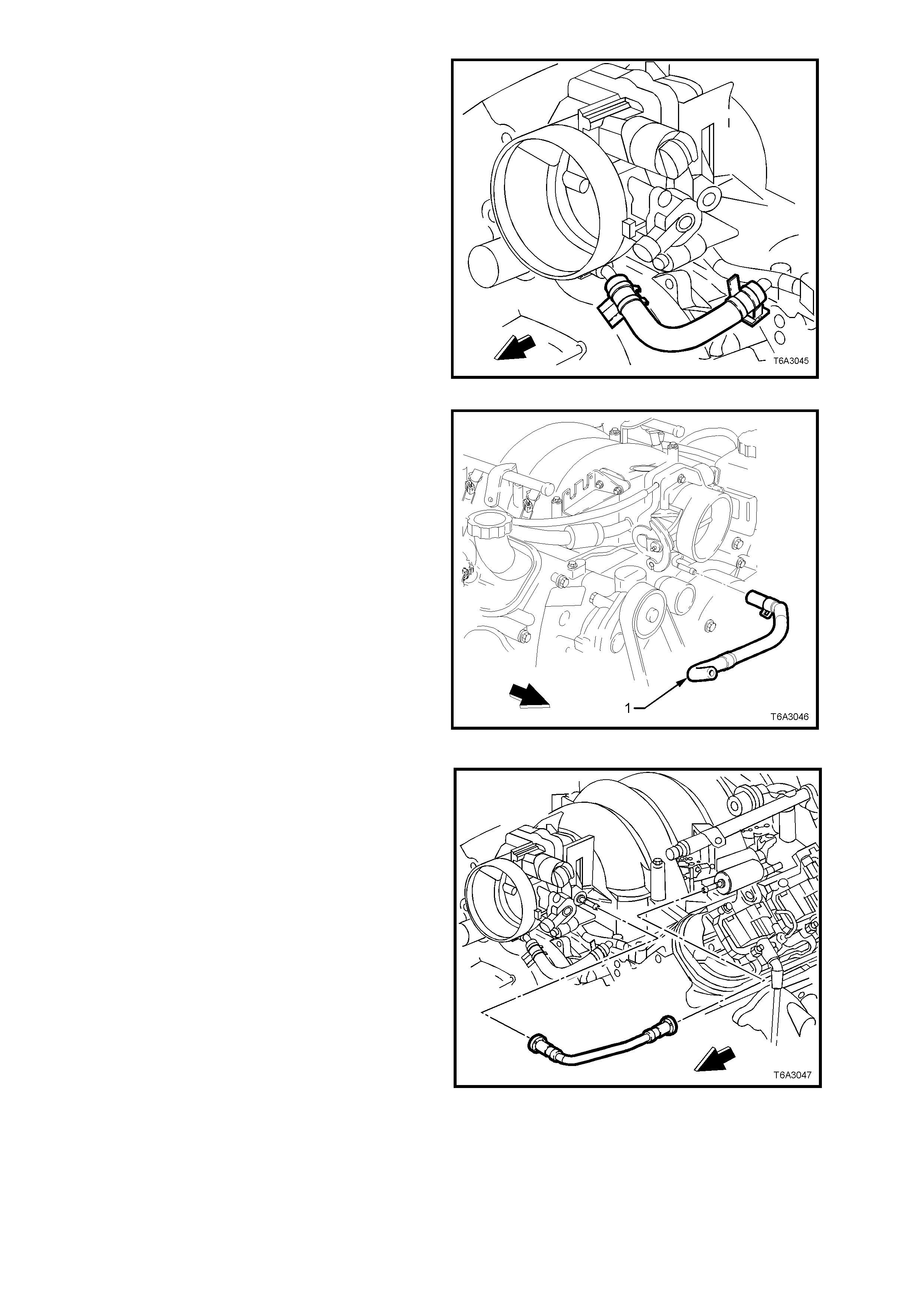
29. Remove the engine coolant, vapour vent hose
from the throttle body and the vapour vent
pipe.
Figure 6A3-54
30. Remove the engine coolant vapour vent outlet
hose (1) from the throttle body and left hand
radiator tank.
Figure 6A3-55
31. Remove the evaporative (EVAP) canister
purge valve tube fr om the purge valve and the
throttle body.
Figure 6A3-56
32. Remove the EVAP canister purge valve and
bracket from the intake manifold.
Figure 6A3-57
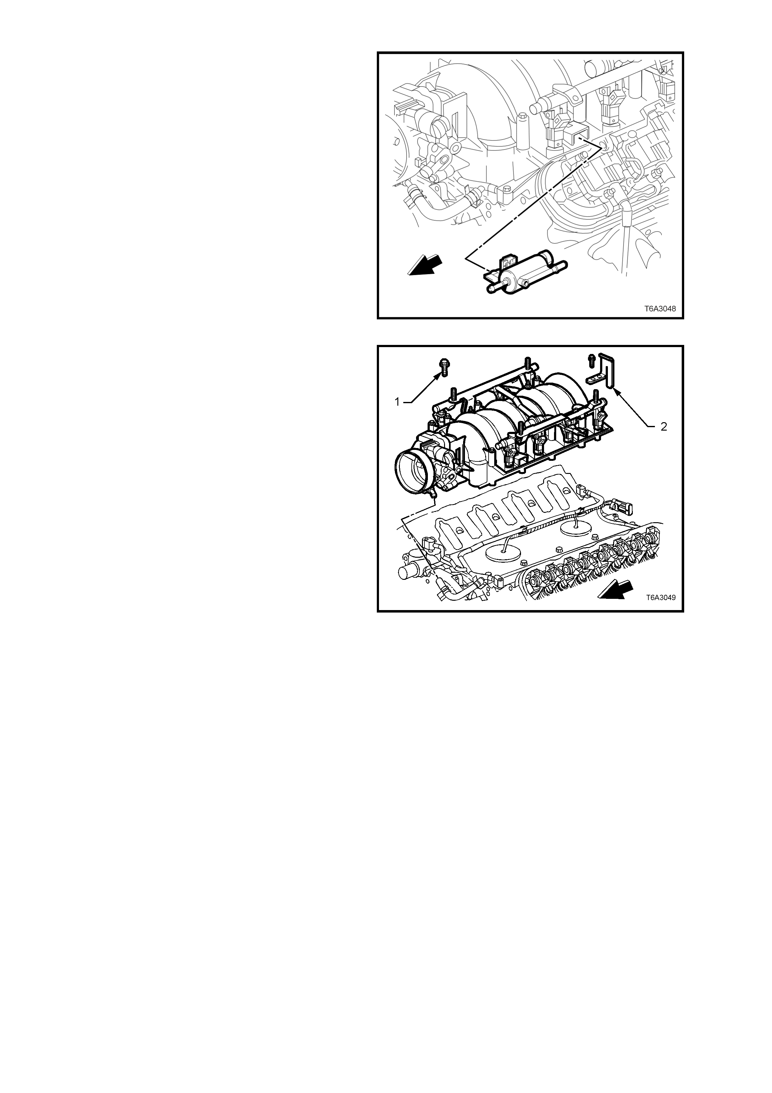
33. Progressively loosen the 10 intake manifold
retaining bolts (1), working diagonally from
outside to inside.
34. Remove the fuel rail stop bracket (2) with the
two, left rear bolts and set to one side.
35. Carefully bump the intake manifold to break
the gasket seal, then lift from the engine.
36. Remove the intake manifold to cylinder head
gaskets and discard.
Figure 6A3-58

DISASSEMBLE
If required, the following components can be
removed from the intake manifold:
1. Remove the Manifold Absolute Pressure
(MAP) sensor (1) from the fitting at the rear of
the intake manifold by twisting back and forth
while pulling on the sensor.
2. Check the silicone r ubber seal (2) on the MAP
sensor to ensure that it is not torn or
damaged.
Figure 6A3-59
3. Remove the throttle body retaining bolts, then
the throttle body and gasket. Discard the
gasket.
Figure 6A3-60
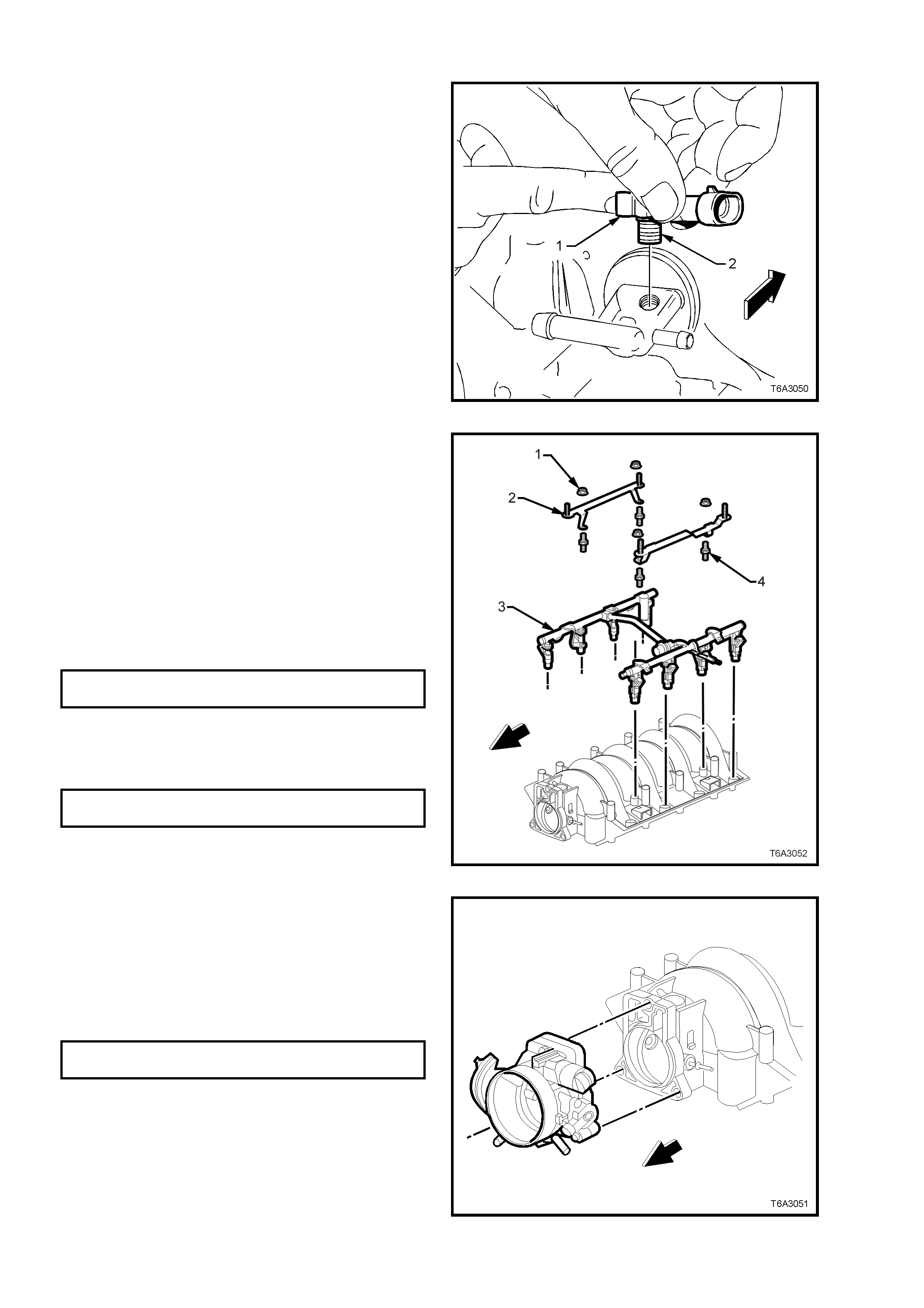
4. Remove the four nuts (1) securing the engine
dress cover brackets (2) to the fuel rail (3),
then lift the two brackets from the fuel rail.
5. Remove the studs (4) securing the fuel rail
and injectors to the intake manifold, then
carefully remove the fuel rail and injectors as
an assembly.
Should further disassembly of the fuel injectors be
required, refer to Section 6C3 POWERTRAIN
MANAGEMENT - GEN III V8 ENGINE.
Figure 6A3-61

CLEAN AND INSPECT
1. Af ter cleaning the intake m anifold in a s uitable
solvent, dry off manifold using compressed
air.
CAUTION: Wear safety glasses to avoid eye
injury.
2. Ensure that the intake manifold gasket
grooves and vacuum passages in the rear of
the intake manifold are all clean and clear.
3. Inspec t throttle body and fuel r ail bolt ins ert s in
the composite intake manifold, for looseness
and/or damaged threads.
4. Inspect the intake manifold for cracks or
damage, including the areas between the
intake runners.
5. Inspect the fuel injector bores for excessive
scoring or damage.
6. Inspect the intake manifold to cylinder head
faces for warpage, as follows:
a. Locate a straight edge across each of the
two surfaces and check for warpage,
using feeler gauges.
b. An intake manif old with warpage in excess
of 0.5 mm, must be replaced.
REASSEMBLE
Manifold Absolute Pressure (MAP) Sensor
If removed, install the MAP sensor as follows:
1. Check the MAP sensor seal (2) to ensure it is
seated correctly on the sensor.
2. Install the Manifold Absolute Pressure (MAP)
sensor (1) into the fitting at the rear of the
intake manifold by pushing the sensor into the
fitting.
Figure 6A3-62
Fuel Rail and Injectors
1. Lubric ate NEW injector O -r ing seals with clean
engine oil.
2. Install the NEW O-rings to the fuel injectors.
3. Install the fuel rail (with injectors) into the
intake manifold, pressing evenly on each side
until the injectors are all seated in their bores.
4. Apply a 5 mm band of thread sealant such as
Loctite 242 (or other c ommerc ial equivalent) to
the cleaned threads of the fuel rail attaching
studs (4) and install, tightening to the correct
torque specification.
FUEL RAIL ATTACHING BOLTS
TORQUE SPECIFICATION 8 - 12 Nm
5. Install the engine dress cover attaching
brack ets (2) to the fuel r ail attaching studs (4),
fit the retaining nuts (1) and tighten to the
correct torque specification.
ENGINE DRESS COVER BRACKET
NUT TORQUE SPECIFICATION 4 - 6 Nm
Figure 6A3-63
Throttle Body
1. Install a NEW throttle body gasket to the
intake manifold.
2. Install the throttle body and bolts to the intake
manifold.
3. Tighten the throttle body bolts to the correct
torque specification.
THROTTLE BODY BOLT
TORQUE SPECIFICATION 12 Nm
Figure 6A3-64
REINSTALL
1. Install NEW intake manifold to cylinder head
gaskets, then install the intake manifold.
2. Apply a 5 mm band of thread sealant such as
Loctite 242 (or equivalent to Holden
Specification HN 1256, Type 2, Class 2), to
the cleaned threads of the 10 intake manifold
attaching bolts (1).
Figure 6A3-65
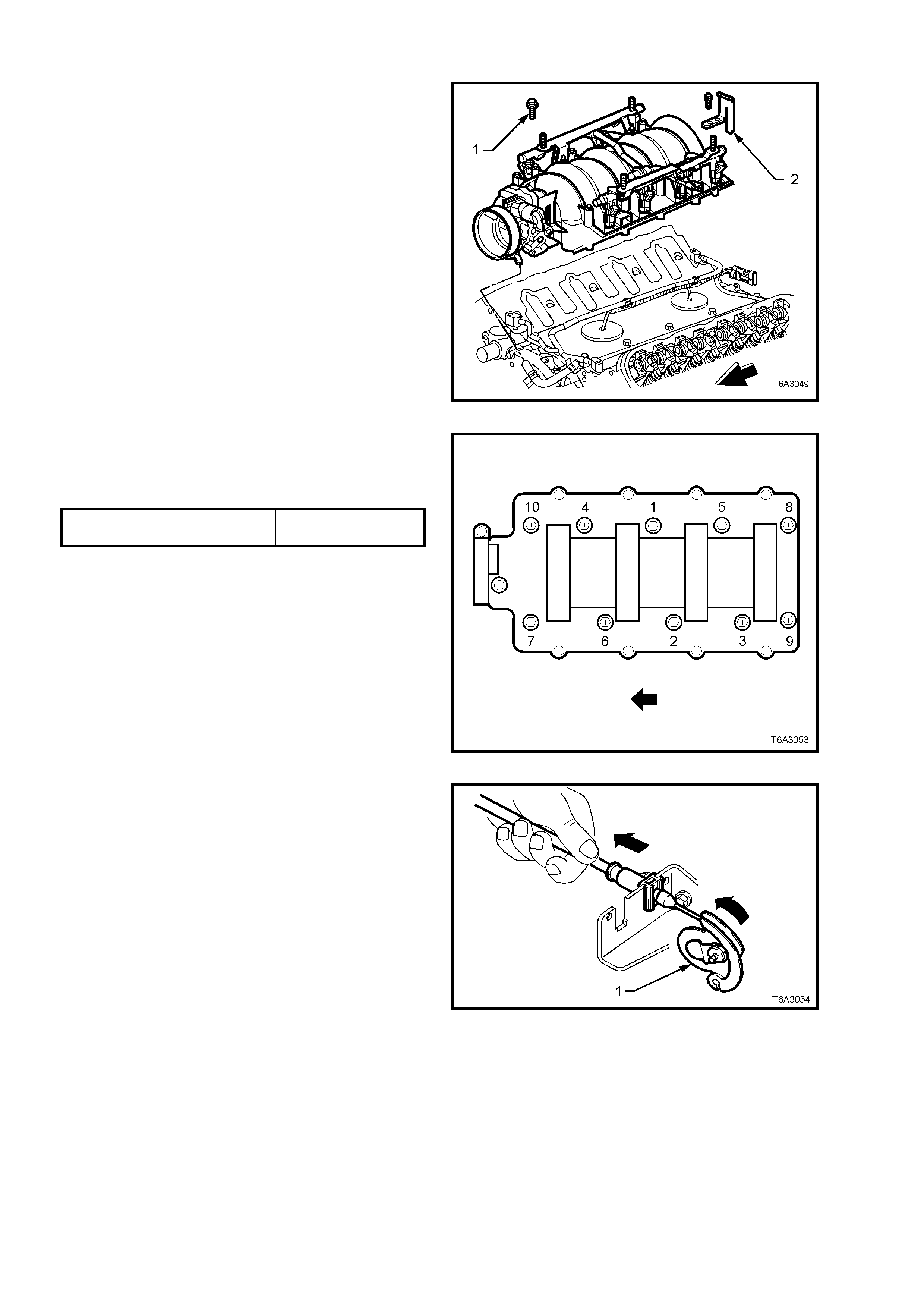
3. Install, the intake manifold bolts and fuel rail
stop bracket, tightening the bolts in two
stages, in the sequence shown, to the correct
torque specification.
INTAKE MANIFOLD BOLTS Stage 1 - 5 Nm
TORQUE SPECIFICATION Stage 2 - 8 Nm
CAUTION: Do not overlook installing the fuel
stop bracket. The stop bracket serves as a
protective shield for the fuel rail in the event of
a vehicle frontal collision. If the fuel stop
bracket is not installed and the vehicle is
involved in a collision, fuel could be sprayed,
possible causing a fire and personal injury from
burns.
Figure 6A3-66
The remainder of the installation process is the
reverse of the removal operations, except for the
following;
4. After installation, the throttle cable is to be
adjusted, as detailed:
a. Attach all cable fittings.
b. With the outer cable adjuster unlocked,
apply a tension to the adjuster, until the
throttle cam (1) begins to move.
Figure 6A3-67
c. Release the tension on the adjuster until
the throttle cam is back at rest (1), then
slightly compres s the adjuster (2) about 1
mm to lock.
Figure 6A3-68
5. If fitted, the cruise control cable must be
adjusted, as follows:
a. Connect the inner cable ( 1) to the s tud ( 2)
on the throttle cam (3), then slide the
outer cable into position in the throttle
cable bracket (4).
Figure 6A3-69
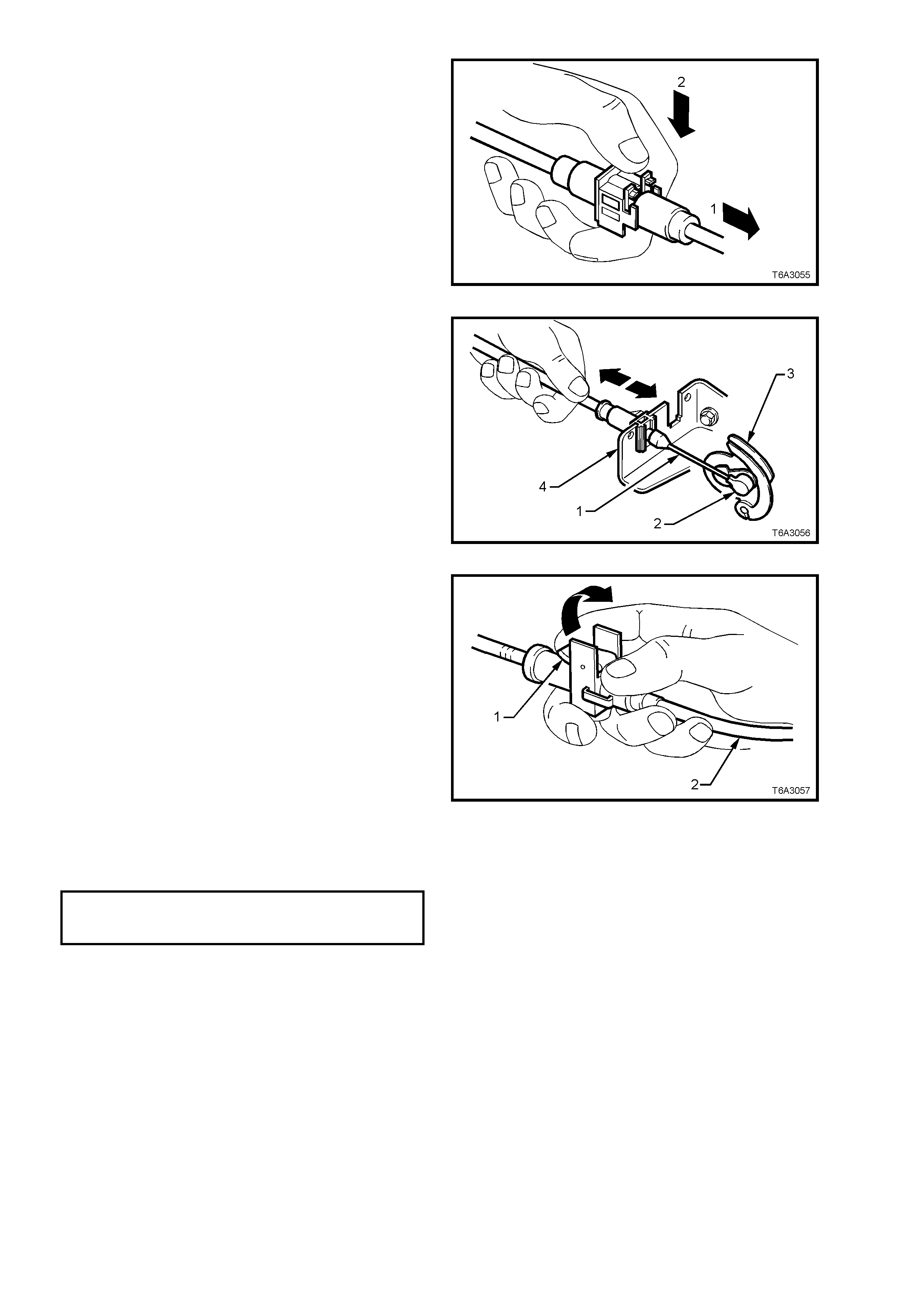
b. Unlock the adjustment locking lever (1).
c. Ensure that the throttle is fully closed,
then adjust the outer cruise control cable
(2), to achieve minimum slac k in the inner
cable.
d. Flip the adjustment lever (1) to lock the
outer cable (2) into position.
Figure 6A3-70
6. Install engine dress cover and the four
retaining nuts and tighten to the cor rect torque
specification.
ENGINE DRESS COVER
RETAINING NUT 8 - 12 Nm
TORQUE SPECIFICATION
7. Fill the cooling system. Refer to
Section 6B3 ENGINE CO OLING - G EN III V8
ENGINE.
8. Start engine check for leaks and normal
operation.
2.15 VAPOUR VENT PIPE
REMOVE
1. Disconnect the battery earth cable from the
battery.
2. Drain the cooling system. Refer to
Section 6B3 ENGINE CO OLING - GEN III V8
ENGINE.
3. Rem ove the engine dress cover retaining nuts
(2), then remove the cover (1).
4. De-pressurise fuel rail. Refer to
Operation 2.13, in this Section.
5. Loosen both hose clamps securing the intake
hose (3) to the MAF sensor and the throttle
body. Remove the hose from the engine.
Figure 6A3-71
6. Remove intake manifold. Refer to
Operation 2.14 INTAKE MANIFOLD.
7. Rem ove the wiring harnes s connec tor (1) f rom
the knock sensor patch harness (2).
Figure 6A3-72
8. Unclip the knock sensor wiring harness clips
from the vapour vent pipe.
9. Remove the vapour vent pipe retaining
studs/bolts.
NOTE: Both front studs are double sided, with the
right hand one (arrow) being used to secure the
PCV valve braided strap, disconnected during the
intake manifold removal operation.
10. Remove the vapour vent pipe and gaskets
from the cylinder heads.
11. Remove the vapour vent pipe gaskets and
discard.
Figure 6A3-73
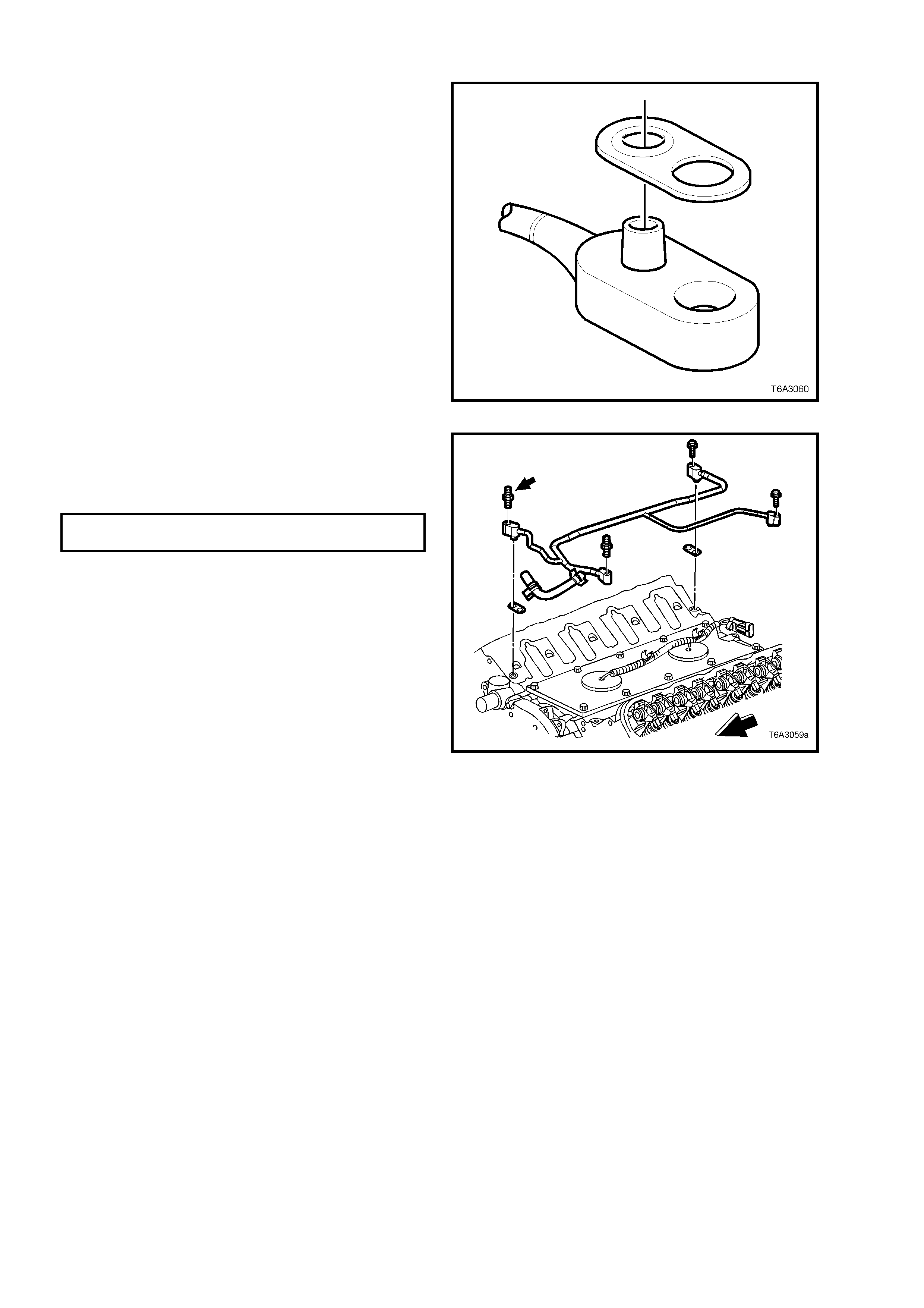
REINSTALL
1. Correctly install NEW vapour pipe gaskets by
fitting the O-ring seal part, over the pipe fitting
nipple, as shown.
Figure 6A3-74
2. Install the vapour vent pipe and gaskets to the
cylinder heads.
3. Install the vapour vent pipe bolts/studs and
tighten to the correct torque specification.
VAPOUR VENT PIPE BOLT/STUD
TORQUE SPECIFICATION 12 Nm
4. Secure the knock sensor wiring harness clips
to the vapour vent pipe.
5. Install the intake manifold, as described in
2.14 INTAKE MANIFOLD - REINSTALL, in
this Section.
6. Install the vapour vent hose to the throttle body
and install the hose clamp securely.
Figure 6A3-75

2.16 ENGINE VALLEY COVER
REMOVE
1. Disconnect the battery earth cable from the
battery.
2. Drain the cooling system. Refer to
Section 6B3 ENGINE CO OLING - GEN III V8
ENGINE.
3. Rem ove the engine dress cover retaining nuts
(2), then remove the cover (1).
4. De-pressurise fuel rail. Refer to
Operation 2.13, in this Section.
5. Loosen both hose clamps securing the intake
hose (3) to the MAF sensor and the throttle
body. Remove the hose from the engine.
6. Remove intake manifold. Refer to
Operation 2.14 INTAKE MANIFOLD.
7. Remove vapour vent pipe. Refer to
Operation 2.15 VAPOUR VENT PIPE.
Figure 6A3-76
8. To remove the knock sensor wiring harness,
carefully lift each sealing plug from the valley
cover, release each knock sensor harness
connector locking tab, then remove each
connector. Lift the knock sensor wiring
harness from the engine.
Figure 6A3-77
9. Remove both knock sensors, using a
commercially available, 22 mm deep socket.
NOTE: Unless a deep socket is used, damage to
the sensor connector will result.
Figure 6A3-78
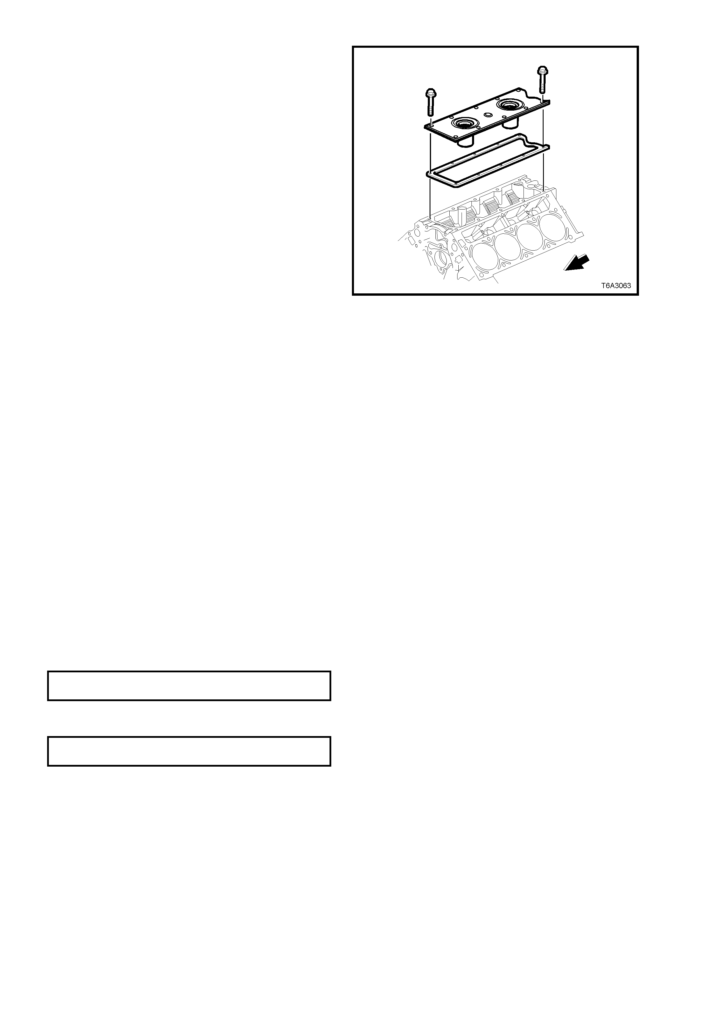
10. Remove the valley cover retaining bolts.
11. Remove the valley cover and gasket from the
cylinder block. Discard the gasket.
Figure 6A3-79
CLEAN AND INSPECT
1. Remove both knock sensor oil seals from the
valley cover.
2. Clean the valley cover in suitable solvent and
dry off with compressed air
CAUTION: Wear safety glasses to avoid eye
injury.
3. Inspect the valley cover sealing surfaces and
oil seal bores for ex cessive scr atches or other
damage.
REINSTALL
Reinstallation is the reverse of rem oval operations,
except for the following items.
1. Install NEW knock sensor oil seals into the
valley cover and lubricate with clean engine
oil.
2. Fit a NEW gasket to the valley cover and
install cover to the engine (refer to Figure 6A3-
79).
3. Install valley cover bolts and tighten to the
correct torque specification.
VALLEY COVER BOLT
TORQUE SPECIFICATION 25 Nm
4. Install the knock sensors and tighten to the
correct torque specification.
KNOCK SENSOR
TORQUE SPECIFICATION 20 Nm
2.17 VALVE ROCKER ARM COVER
REMOVE
1. Disconnect the battery earth cable from the
battery.
2. Rem ove the engine dress cover retaining nuts
(2), then remove the cover (1).
Figure 6A3-80
3. For the right hand rocker cover, remove the
fresh air hose from the front fitting of the
rocker cover and from the throttle body.
Figure 6A3-81
4. Remove the PCV hose connection from the
rear fitting at the end of the rocker cover,
being removed.
Figure 6A3-82
5. Using quick connect release Tool No. 7371,
install over fuel line.
6. While holding the fuel line quick connect (1),
push on Tool 7371 to release the quick
connect fitting (1) from the fuel rail. Pull back
on the quick connect and remove.
7. Disconnect the vapour line connector (2) from
the EVAP purge valve (3).
Important: Cap the fuel line fittings and plug the
holes after separating the fuel lines to prevent fuel
leaking and/or dirt and other contaminants from
entering the fuel system.
Figure 6A3-83
8. Remove the spark plug leads.
NOTE: Handle the boot only. DO NOT pull on the
lead. Twist the boot firs t to break the s eal, then pull
to remove.
Figure 6A3-84
9. Rem ove the CPA lock ( 4) f rom the ignition coil
main connector on the rocker cover being
removed, then remove the wiring harness
connector (3).
10. Remove the 4 studs (1) and one screw
securing the ignition coil mounting bracket (2)
to the rocker c over being r emoved, then lif t the
ignition coils, wiring and bracket from the
engine.
NOTE: The rear attaching bolt on each coil
assem bly (arrow) is a conventional scr ew and not a
stepped stud. Fitment of this screw in the correct
position on reassembly is important to avoid
possible chaffing.
Figure 6A3-85
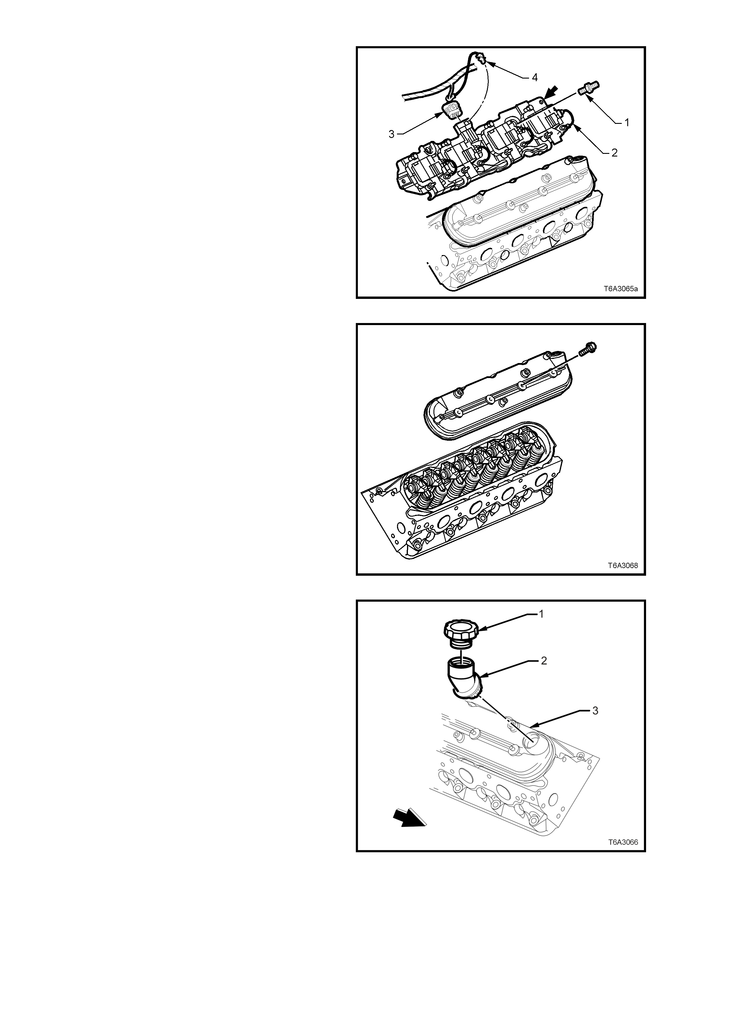
11. Remove the 4 valve rocker cover bolts, then
rem ove the cover and gasket f rom the cylinder
head.
NOTE: Do not rem ove the oil fill tube f rom the right
hand rocker cover unless replacement is required.
Figure 6A3-86
12. If required, remove the oil fill cap(1) and/or fill
tube (2) from the right hand rocker cover (3).
Discard the oil fill tube (2), as permanent
damage will occur on removal.
Figure 6A3-87
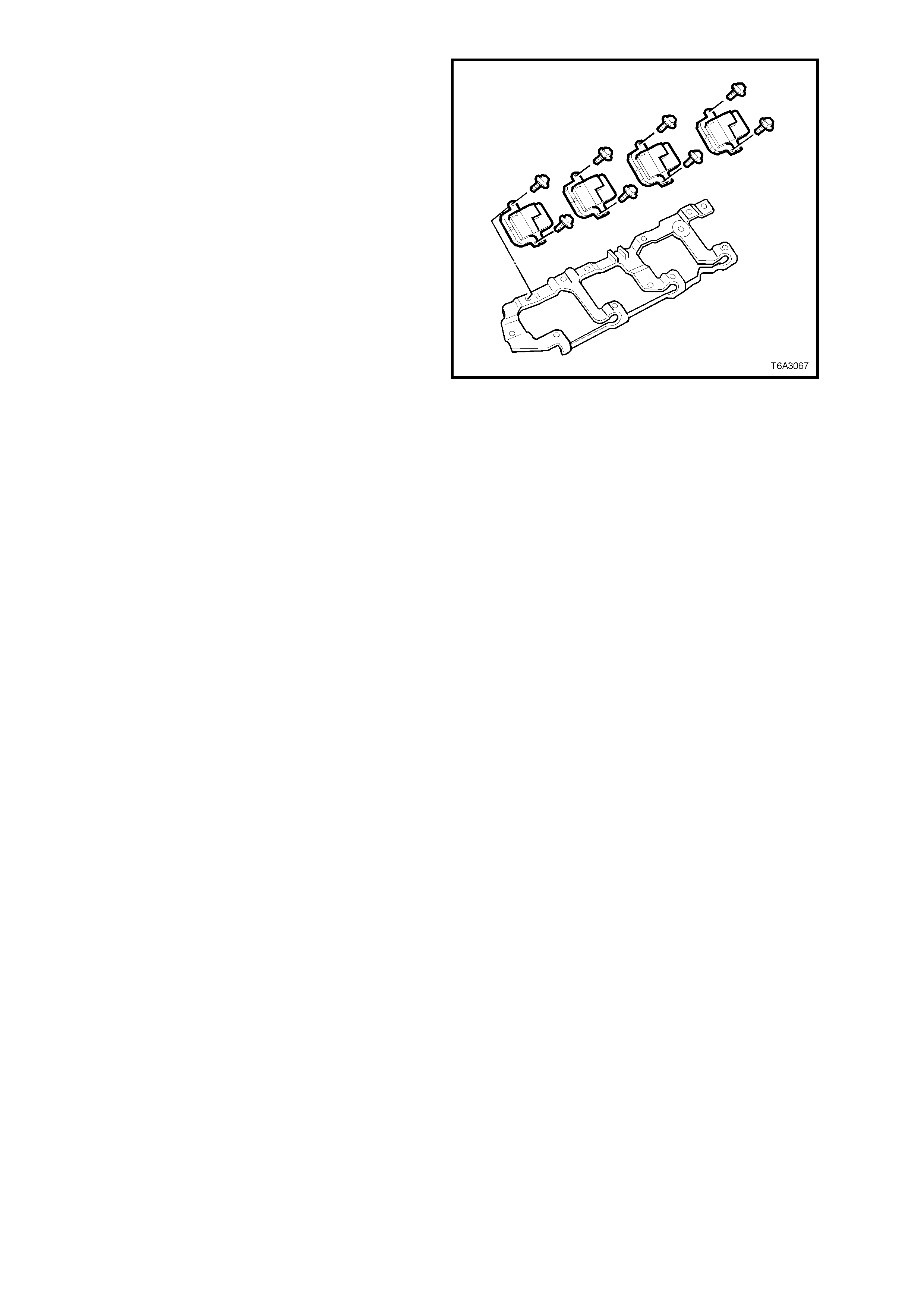
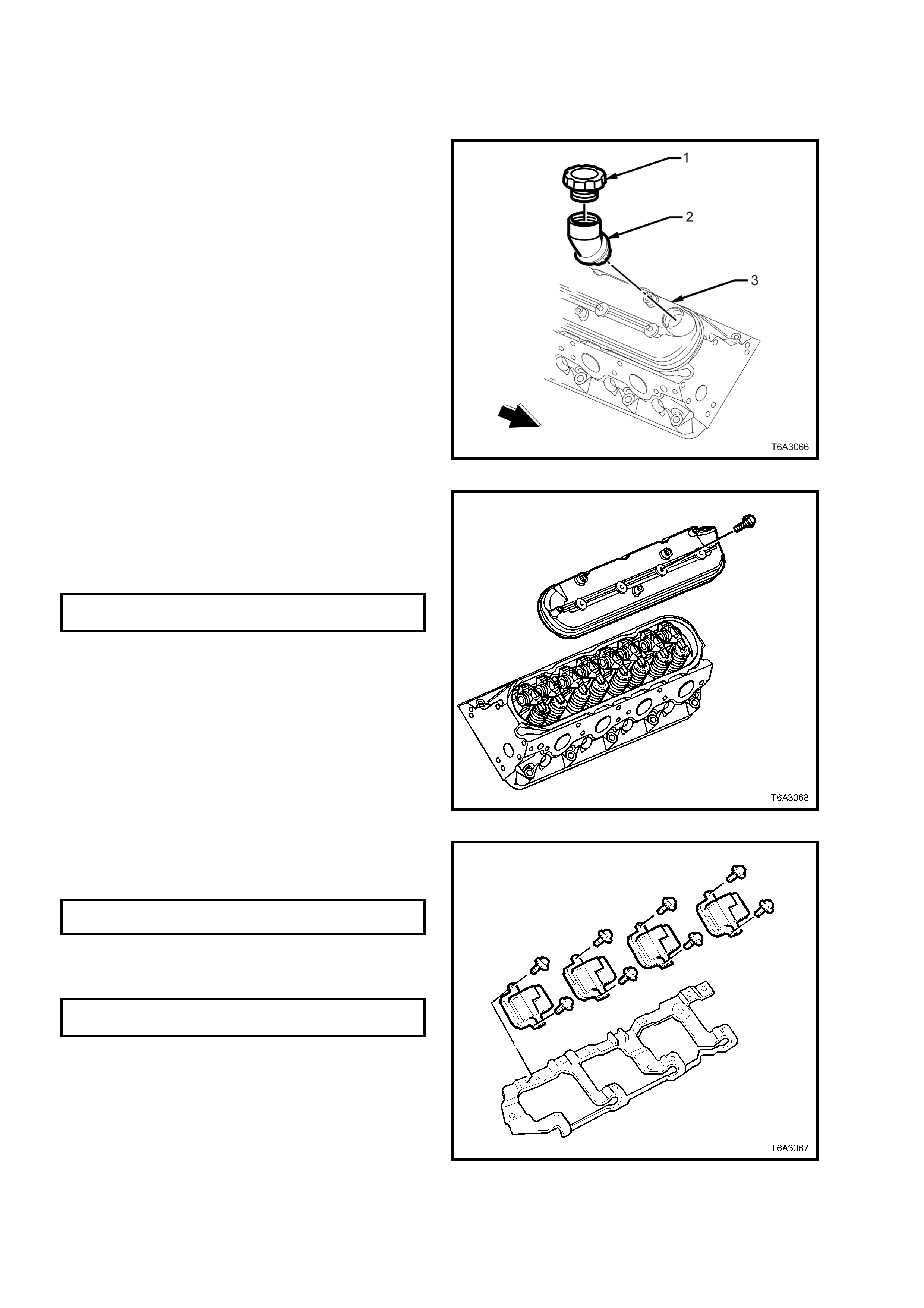
13. Remove the bolts securing the ignition coils to
the mounting bracket and remove the coils
and wiring harness.
Figure 6A3-88
CLEAN AND INSPECT
1. Clean the rocker cover in a suitable solvent
and dry off with compressed air.
CAUTION: Wear safety glasses to avoid eye
injury.
2. Inspect the ventilation system passages for
restriction.
3. Inspect the rocker cover gasket groove for
damage.
4. Inspec t the ignition coil m ounting boss thr eads
for damage.
REINSTALL
Reinstallation of the rocker cover is the reverse to
the removal procedure except for the following
items.
1. If the oil fill tube (2) was removed from the
right hand rocker cover (3), it must be
replaced with a NEW part ( when installed, it is
permanent).
2. Lubricate the O-ring seal of the NEW oil fill
tube (2) with clean engine oil.
3. Install the oil fill tube into the rocker cover (3),
rotating the tube clockwise until locked into the
correct position.
4. Install the oil fill cap (1), rotating clockwise until
locked into place.
Figure 6A3-89
5. Install a NEW gasket to the rocker cover.
6. Install the rocker cover bolts.
7. Install the rocker cover onto the cylinder head
and tighten the rocker cover studs to the
correct torque specification.
ROCKER COVER BOLT
TORQUE SPECIFICATION 12 Nm
Figure 6A3-90
8. Install the ignition coils and coil wiring harness
to the mounting bracket and tighten the studs
and bolts to the correct torque specification.
IGNITION COILSTUD/ BOLT
TORQUE SP ECIFI CA T ION 12 Nm
9. Install the ignition coils and bracket assembly
to the rock er c over, and tighten the bolts to the
correct torque specification.
IGNITION COIL BRACKET BOLT
TORQUE SPECIFICATION 12 Nm
NOTE: The rear, left hand c oil brack et f astener is a
plain screw and not a stepped stud as are the
others. Fitment of this screw in the correct position
is important to avoid fuel/vapour line chaffing.
10. After installation of the ignition coil main
harness connector, install the CPA lock,
ensuring it is fitted securely. Figure 6A3-91
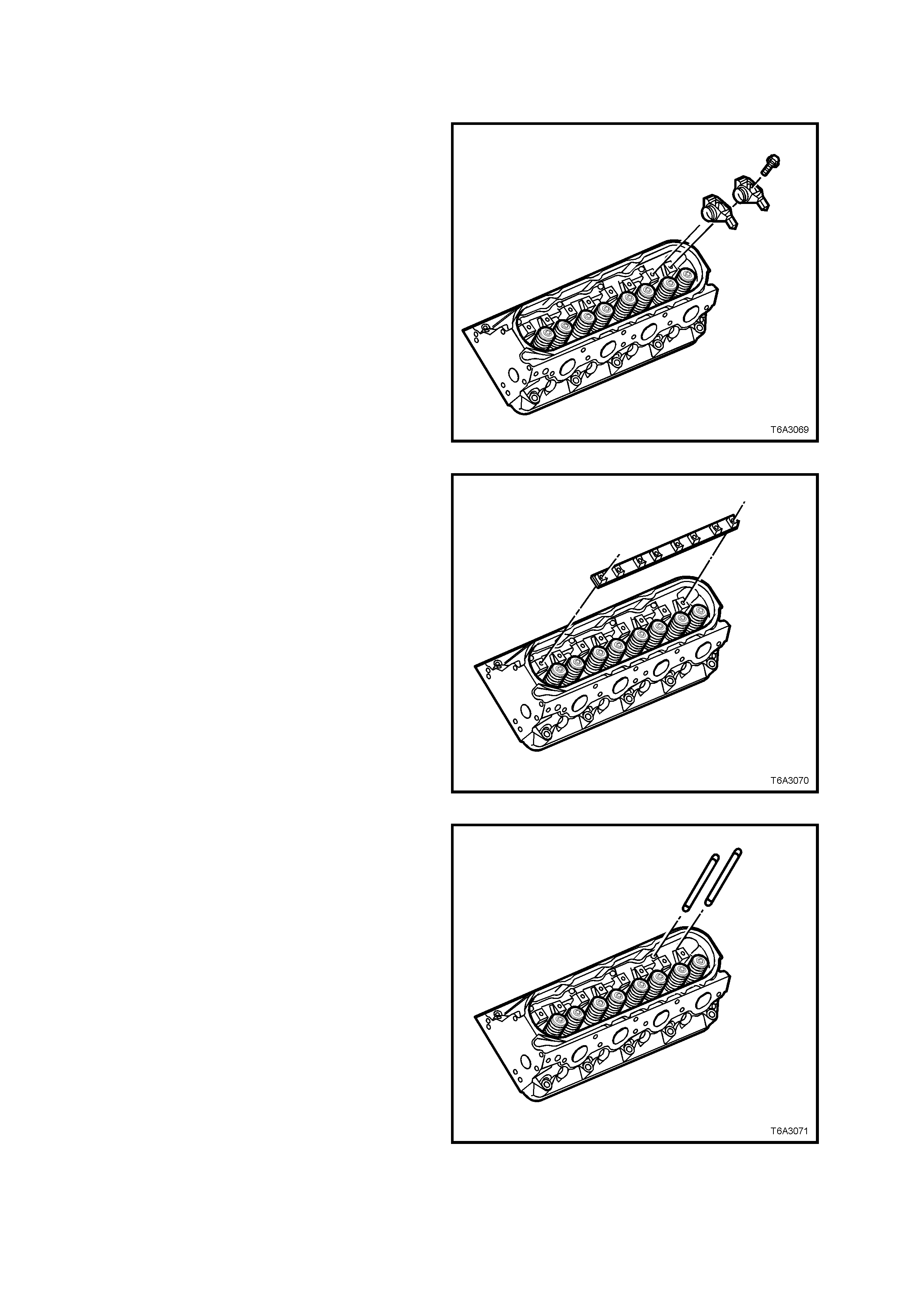
2.18 V ALVE ROCKER ARMS AND PUSH RODS
REMOVE
NOTE: While some views may show a cylinder
head that is not specif ic to the one required, unless
noted, it can be assumed that the operation is the
same for either cylinder head.
1. Rem ove the valve rock er arm cover/s. r efer to
2.17 VALVE ROCKER ARM COVER.
Important: Store all removed valve operating
mechanism com ponents in a suitable rack to avoid
being mixed. This will ensure that parts reinstalled
will be in the same relationship as on removal.
2. Remove all the rocker arm bolts on the
specific cylinder head.
3. Remove associated valve rockers arms.
Figure 6A3-92
4. Remove the valve rocker arm pivot support.
Figure 6A3-93
5. Remove the push rods.
Figure 6A3-94
CLEAN AND INSPECT
1. Mark, sort or organise removed parts to retain in order removed.
2. Clean parts in a suitable solvent, then dry with compressed air.
CAUTION: Wear safety glasses to avoid eye injury.
3. Inspect parts, as follows:
a. Valve rocker arm bearings for binding or
roughness.
b. Valve rocker arm push rod sockets and
valve stem mating s ur f aces f or wear and/or
roughness.
c. Pushrods for worn or scored ends.
d. Also check for bent pushrods by rolling on
a flat surface.
e. Pushrod oil passages for restrictions.
f. Pivot supports for cracks, wear or other
damage.
REINSTALL
While the reinstallation process is the reverse of the
removal procedure, there are some specific
operations that must be complied with, and are
detailed here.
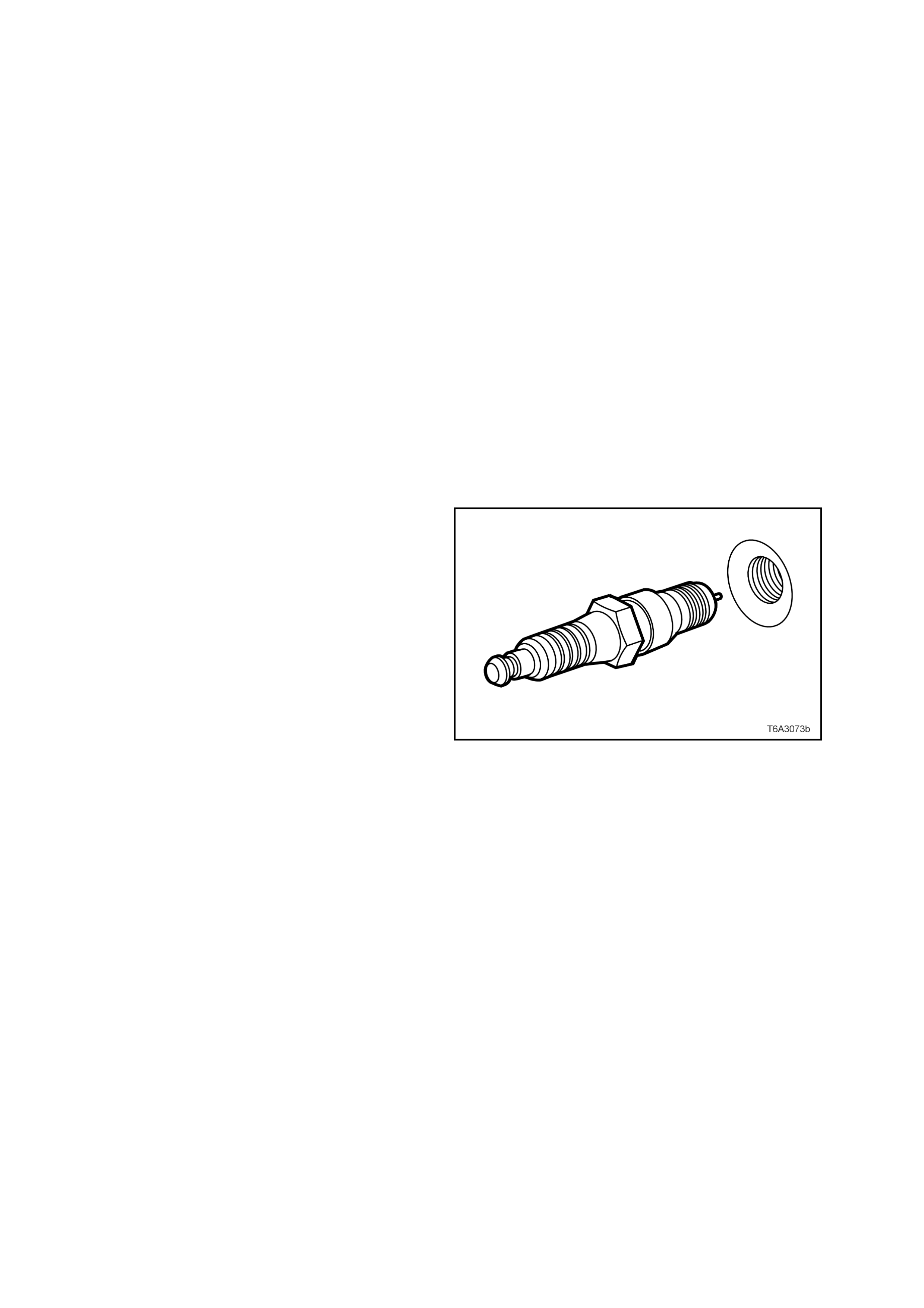
1. To reduc e the effor t required to tur n the engine
over by hand, remove the spark plugs, taking
note of the following;
a. The engine MUST be cold to at least
50° C. If not, then the spark plug and
cylinder head threads may bind, causing
the cylinder head threads to be torn.
b. When removing spark plug leads, only
handle the boot on each lead, twist to
break the seal, them pull to remove. DO
NOT pull on the lead itself.
c. Loosen the spark plug/s, then re-tighten to
break away any carbon deposits on the
threads.
d. Loosen the spark plug/s once again but,
this time, only one or two turns. Then use
compressed air to remove any foreign
material that may otherwise enter the
combustion chamber.
CAUTION: Wear eye protection to avoid injury.
e. Continue to remove the spark plug/s.
Figure 9A-95
2. Lubricate the following parts in clean engine oil
before installation:
a. All valve rocker arms and pushrods.
b. The flanges of all rocker arm bolts.
3. Install all push rods, checking that each seats
correctly to the hydraulic valve lifter sockets.
4. Install all rocker arms, bearings and NEW
retaining bolts but DO NOT TIGHTEN fully at
this time.
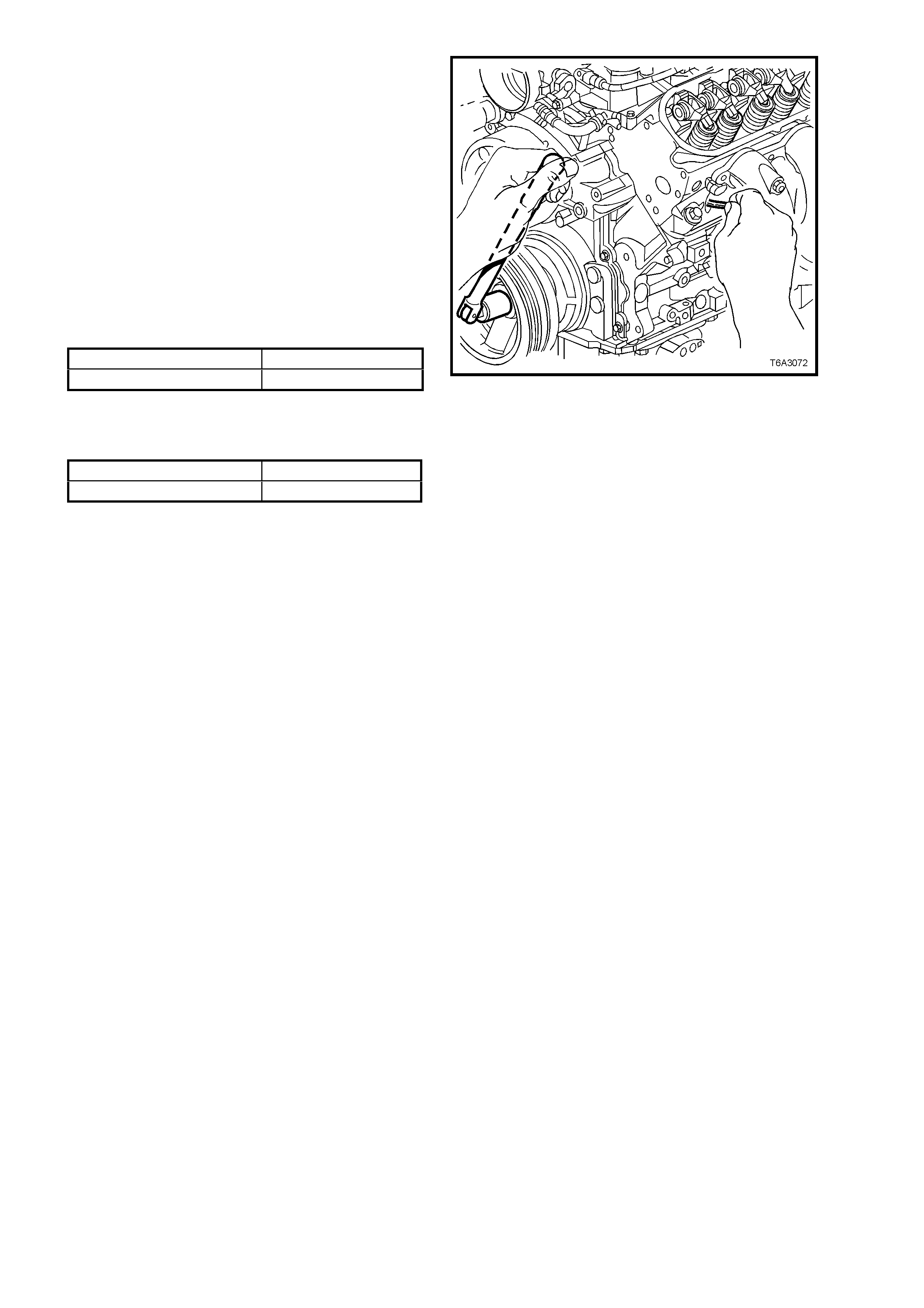
5. Rotate the crankshaft until No. 1 piston is at
Top Dead Centre (TDC), on the compression
stroke.
NOTE 1: Inserting a finger into the spark plug hole
will determine if the piston is rising on the
compression stroke, by the compressed air
escaping. Finally, a suitable piece of wire can be
used as shown, to determine when the piston is at
TDC.
NOTE 2: The engine firing order is 1, 8, 7, 2, 6, 5,
4, 3 and cylinder num bers are 1, 3, 5, 7, on the left
bank and 2, 4, 6, 8, are on the right bank.
6. W ith No. 1 piston on TDC com pression stroke,
tighten the following rocker arm bolts to the
correct torque specification:
7. Rotate the crankshaft 360°.
8. Tighten the following rocker arm bolts to the
correct torque specification:
9. Reinstall the rocker cover/s. See Operation
2.14 for the necessary procedure.
Figure 6A3-96
Exhaust Valve, Cylinder No. 3, 4, 5 and 6, to 30 Nm
Intake Valve, Cylinder No. 2, 6, 7 and 8, to 30 Nm
Exhaust Valve, Cylinder No. 1 , 2, 7 and 8, to 30 Nm
Intake Valve, Cylinder No. 1, 3, 4 and 5, to 30 Nm
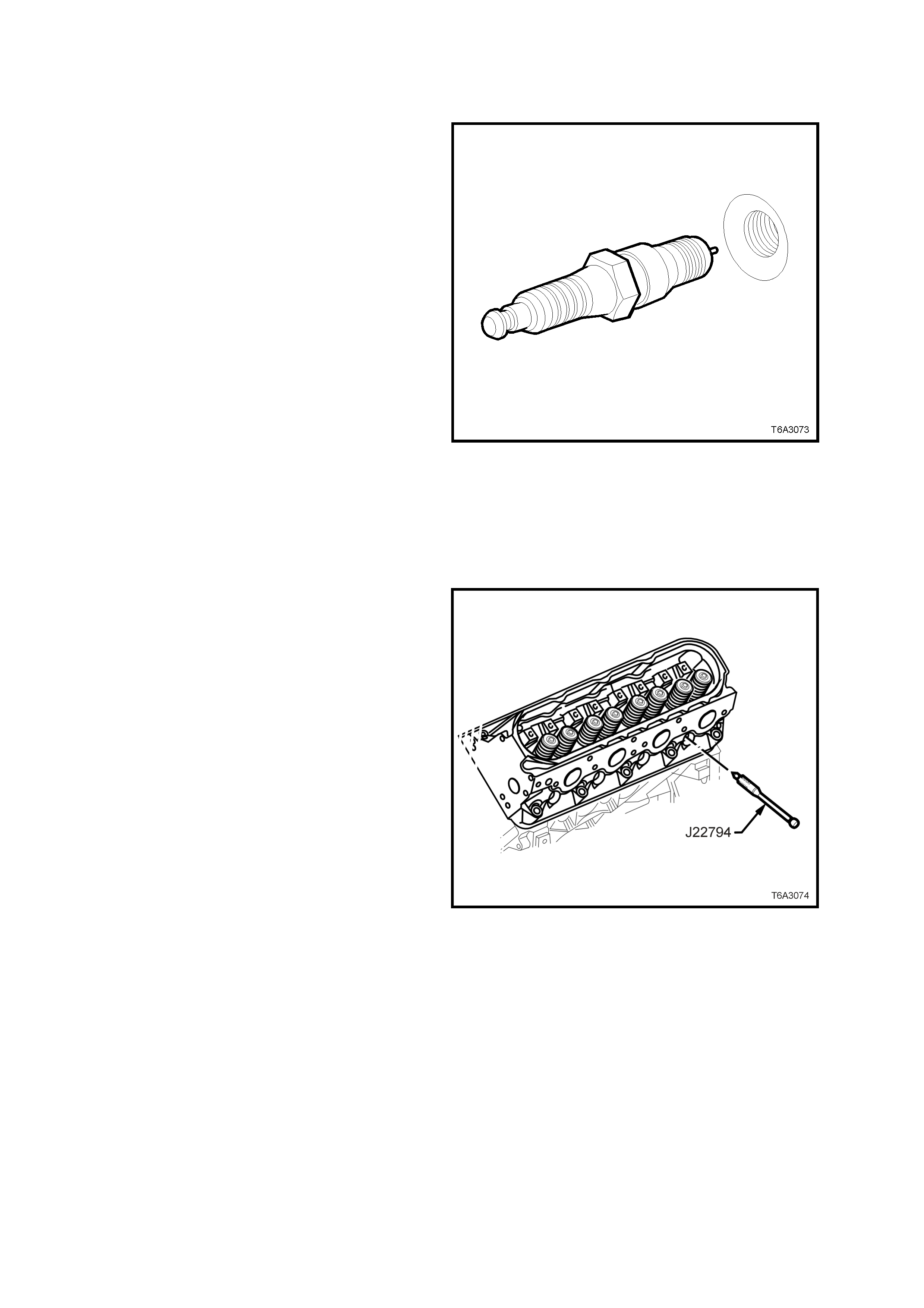
2.19 VALVE STEM OIL SEAL AND/OR VALVE SPRING
REPLACE
1. Remove the spark plugs from the cylinder/s
being serviced, taking note of the following;
a. The engine MUST be cold to at least
50° C. If not, then the spark plug and
cylinder head threads may bind, causing
the cylinder head threads to be torn.
b. When removing spark plug leads, only
handle the boot on each lead, twist to
break the seal, them pull to remove. DO
NOT pull on the lead itself.
c. Loosen the spark plug/s, then re-tighten to
break away any carbon deposits on the
threads.
d. Loosen the spark plug/s once again but,
this time, only one or two turns. Then use
compressed air to remove any foreign
material that may otherwise enter the
combustion chamber.
CAUTION: Wear eye protection to avoid injury.
e. Continue to remove the spark plug/s.
2. Remove the valve rocker arms, valve rocker
arm pivot support, and valve pushrods. Refer
to 2.18 VALVE ROCKER ARMS & PUSH
RODS.
Figure 6A3-97
2. Insert a suitable piece of wire into the spark
plug hole and turn the crank shaf t balancer bolt
until the piston is at or near Top Dead Centre
(TDC).
3. Install Spark Plug Port Adaptor Tool J 22794
or a commercial equivalent to the spark plug
hole of the cylinder being serviced.
4. Using suitable adaptors, attach a compressed
air line to J 22794 and apply a cons tant supply
of compressed air to the cylinder being
serviced.
Figure 6A3-98
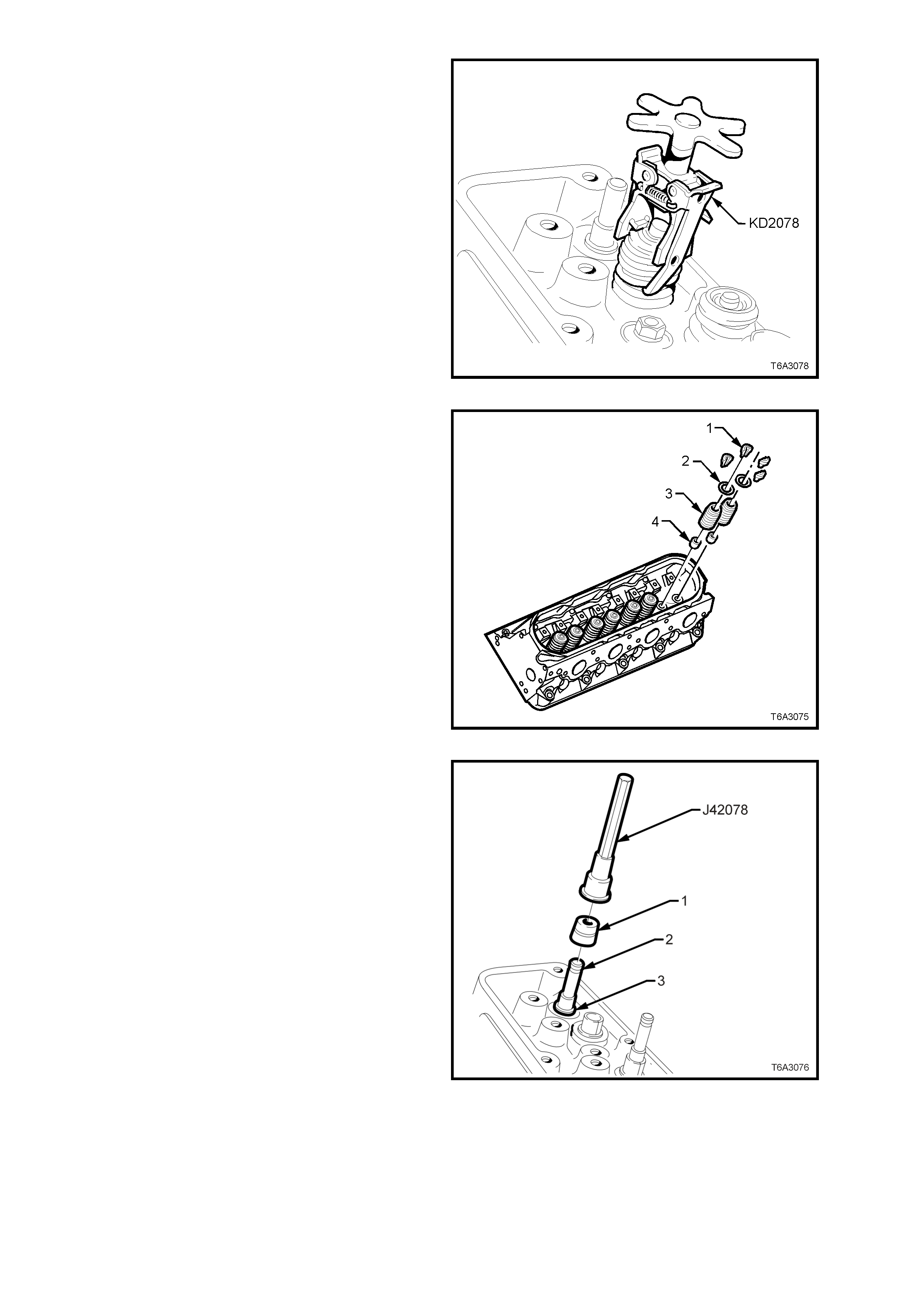
5. Compress one of the valve springs, using
valve spring compressor, KD2078.
Figure 6A3-99
6. Remove valve stem collets (1).
7. Release the valve spring compressor and
remove:
a. Valve spring cap (2).
b. Valve spring (3).
c. Valve spring oil seal (4) (if being
replaced).
Figure 6A3-100
Important: The valve stem oil seal alignment and
position on the valve stem is critical. An im properly
installed valve stem oil seal will lead to excessive
oil consumption and increased exhaust emissions.
8. Install the valve stem oil seal onto the valve
guide using the following method.
a. Lubricate the valve stem oil seal (1) and
the valve stem (2), with clean engine oil.
b. Install the lubricated valve stem oil seal
(1), over the valve stem. Push down
firmly until the seal contacts the valve
guide.
c. Using valve stem seal installer Tool J
42078, push or lightly tap the tool until the
tool bottoms against the valve spring
shim (3).
Figure 6A3-101
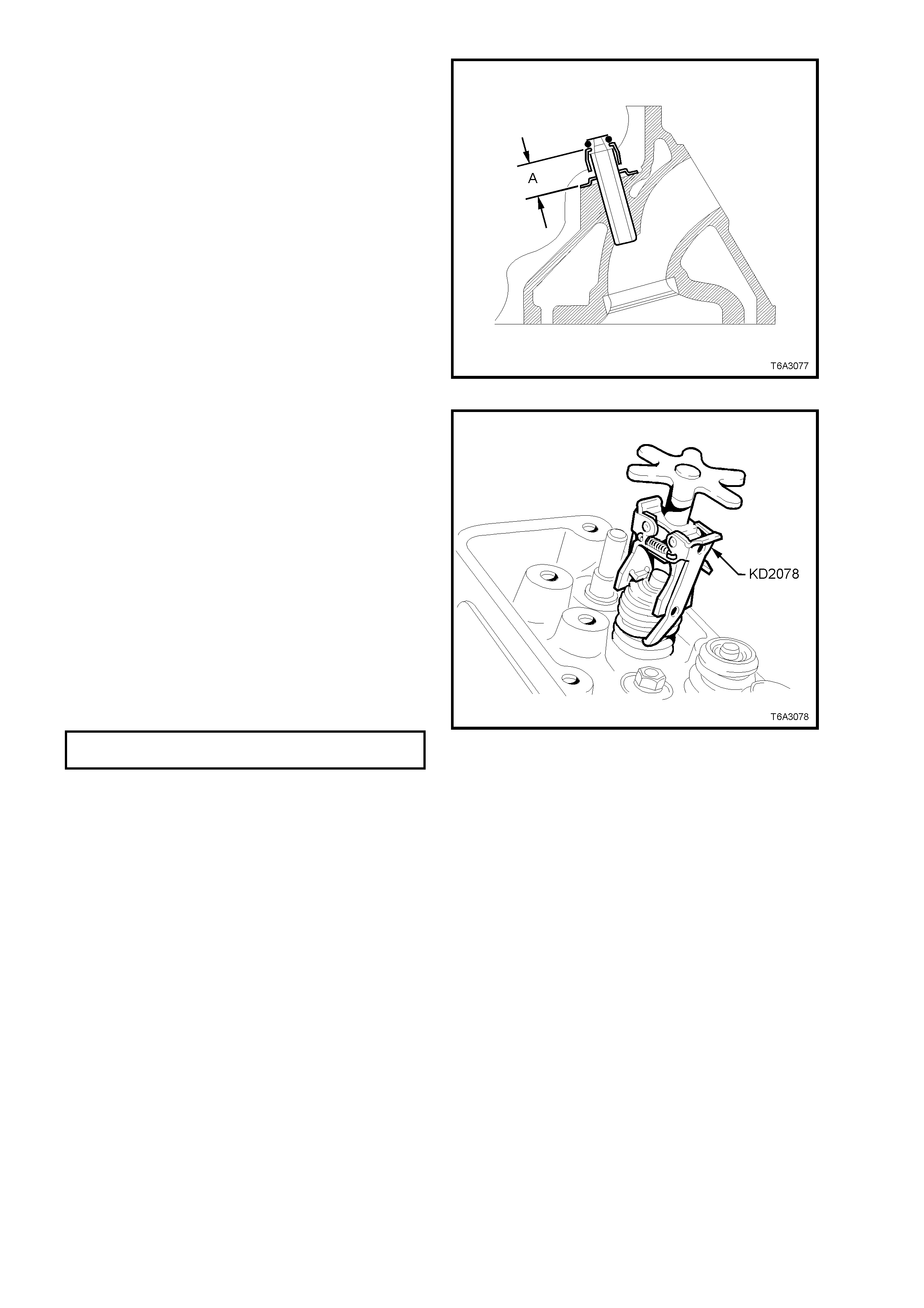
9. Measure the installed height of the valve stem
oil seal with vernier calipers. There should be
a gap (A) of 18.1 - 19.1 mm between the top
edge of the oil seal body and the top of the
spring shim surface.
Figure 6A3-102
10. Install the valve spring with the smaller wound
coils facing up, then install the spring cap.
11. Compress the spring using Tool No. KD2078
until sufficient space is allowed for the valve
collets to be installed.
12. Install both valve stem collets, using clean
grease or petroleum jelly to retain.
13. Release the valve spring compressor,
checking that both valve stem collets are
seated correctly.
14. Lightly tap the valve stem with a soft faced
hammer to ‘seat’ the valve stem collets.
15. Remove the compressed air supply.
16. Remove the spark plug adaptor, Tool J22794.
17. Install the spark plug, tightening to the correct
torque specification.
SPARK PLUG
TORQUE SPECIFICATION 15 Nm
18. Reverse the removal procedure to complete
this operation.
Figure 6A3-103

2.20 OIL LEVEL INDICATOR AND TUBE
REMOVE AND REINSTALL
1. Remove the oil level indicator from the tube.
2. Remove the oil level indicator tube bracket bolt
from the right hand exhaust manifold
3. Remove the tube from the engine, then
remove the O-ring.
NOTE: If the tube is not to be reinstalled
immediately, plug the opening in the engine
block to prevent dirt entry.
4. After cleaning the tube, inspect the O-ring,
which can be re-used if undam aged. Install O-
ring to the lower end of the tube
5. Install the tube to the engine and rotate to the
correct position.
6. Install the oil level indicator tube bracket bolt
and tighten in two stages, to the correct tor que
specification.
OIL LEVEL TUBE RETAINING
BOLT TORQUE SPECIFICATION 25 Nm
7. Install the oil level indicator to the tube.
Figure 6A3-104
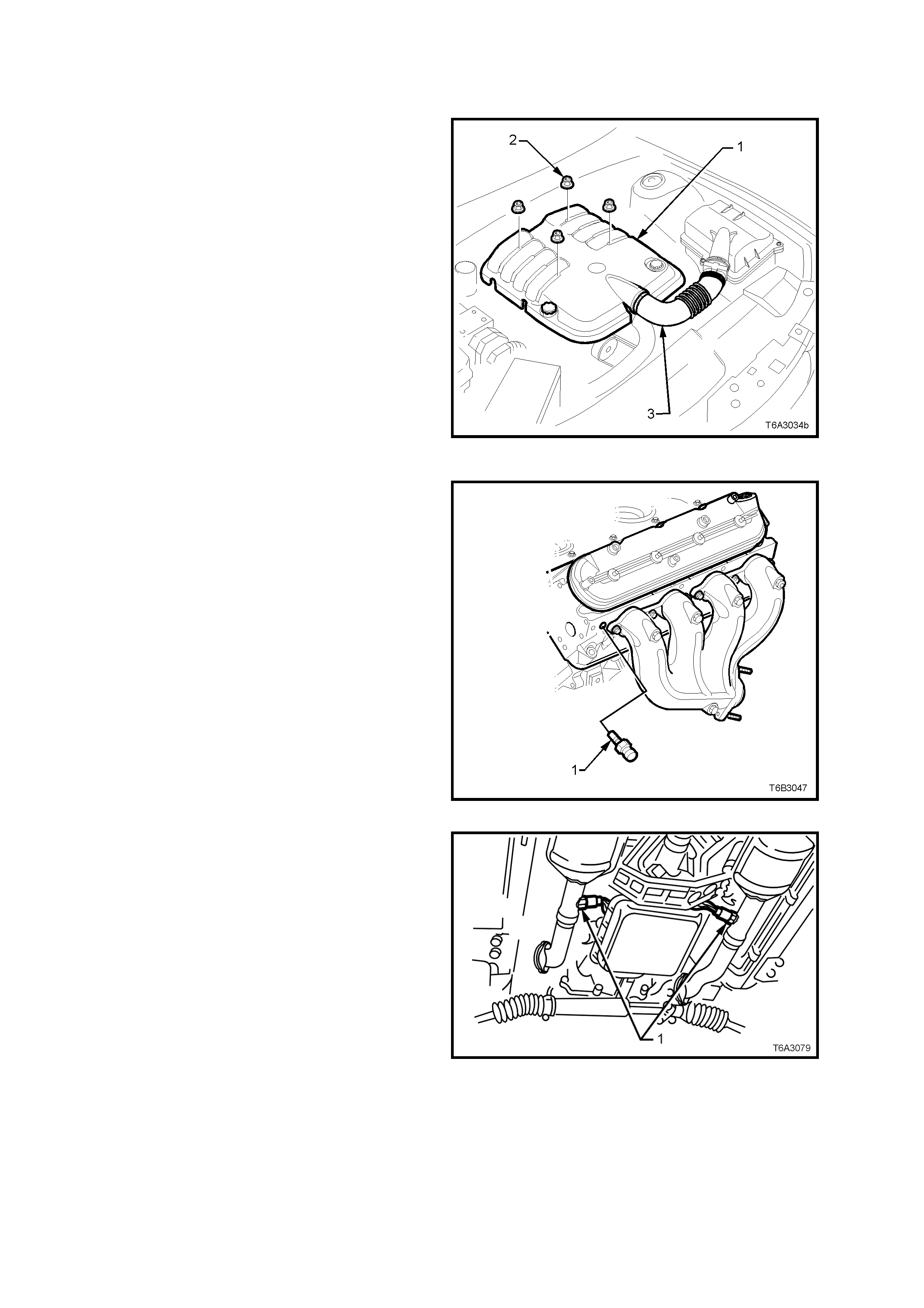
2.21 EXHAUST MANIFOLD
REMOVE
1. Disconnect the battery earth cable from the
battery.
2. Rem ove the engine dress cover retaining nuts
(2), then remove the cover (1).
3. Loosen the two clam ps securing the air intake
duct (3) to the thr ottle body and Mas s Air Flow
(MAF) sensor.
4. Remove air intake duct (3) assembly from
throttle body and MAF sensor.
5. De-pressurise fuel rail. Refer to
Operation 2.13, in this Section.
6. For the right hand side exhaust manifold:
a. Remove the engine oil level indicator and
tube. Refer to 2.20 OIL LEVEL
INDICATOR AND TUBE, in this Section.
b. Plug the opening in the cylinder block to
prevent entry of foreign matter. Figure 6A3-105
7. For the left hand side exhaust manifold:
a. Remove the engine coolant temperature
sensor (1) f rom the cylinder head to avoid
possible dam age during ex haust m anifold
removal.
8. Raise the front of the vehicle and place on
safety stands. Refer to Sect ion 0A GENERAL
INFORMATION for location of jacking and
support points.
Figure 6A3-106
9. While not essential, it is recommended that
the oxygen sensor/s (1) are rem oved from the
exhaust pipe/s, to avoid accidental damage.
a. Disconnect the wiring harness
connector/s from the oxygen sensor/s.
b. Remove the oxygen sensor/s from the
exhaust pipe/s.
Figure 6A3-107
10. Rem ove the exhaust manif old to exhaus t pipe
flange nuts.
11. Lower vehicle to the ground.
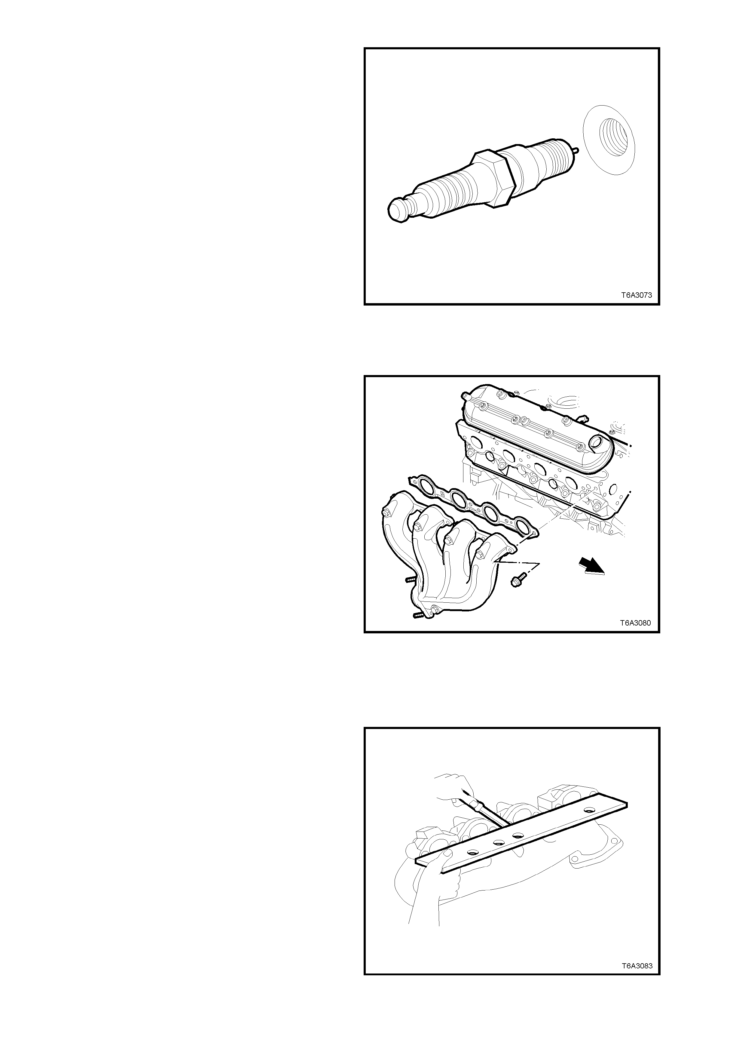
12. Rem ove the spark plug from the cylinder head
on the exhaust manifold side being removed,
taking note of the following;
a. The engine MUST be cold to at least
50° C. If not, then the spark plug and
cylinder head threads may bind, causing
the cylinder head threads to be torn.
b. When removing spark plug leads, only
handle the boot on each lead, twist to
break the seal, them pull to remove. DO
NOT pull on the lead itself.
c. Loosen the spark plug/s, then re-tighten to
break away any carbon deposits on the
threads.
d. Loosen the spark plug/s once again but,
this time, only one or two turns. Then use
compressed air to remove any foreign
material that may otherwise enter the
combustion chamber.
CAUTION: Wear eye protection to avoid injury.
e. Continue to remove the spark plug/s.
Figure 6A3-108
13. Progressively loosen, then remove exhaust
manifold bolts, working from the outside in to
the centre.
14. Remove exhaust manifold and gasket from
the cylinder head.
15. If required, remove the heat shield retaining
bolts and the heat shield from the magnified.
NOTE: While the right hand side exhaust manifold
is shown, the left hand side arrangement is similar.
Figure 6A3-109
INSPECT
1. Inspect for a loose or damaged heat shield.
2. Inspect the exhaust pipe flange stud threads
for damage.
3. Inspect the exhaust pipe flange stud threads
for damage.
4. Inspect exhaust manifold to cylinder head
mounting surface for scratches or damage.
5. Using a straight edge and feeler gauges,
check that the cylinder head mounting face of
the exhaust manifold does not exceed the
maximum distortion specification of 0.25 mm.
An exhaust manifold exceeding this maximum,
must be machined to correct the
misalignment.
Figure 6A3-110
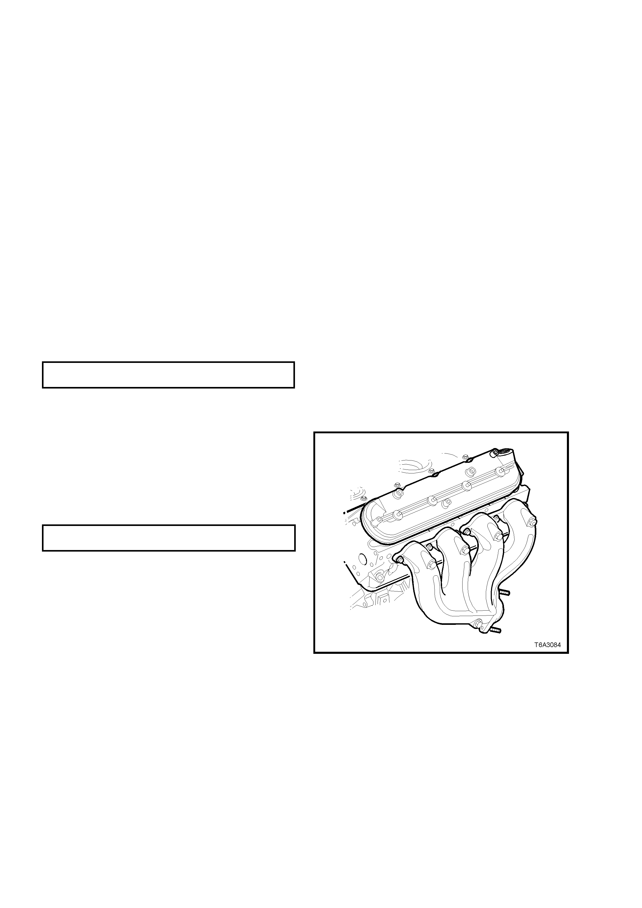
REINSTALL
The reinstallation procedure is the reverse of the
removal operation, except for the following items:
NOTE 1: Correct installation of the exhaust
manifold gaskets and the adherence to the
specified tightening sequence and torque applied
to the exhaust m anifold attaching bolts is critical to
ensure a gas tight seal and compliance with
emission regulations.
NOTE 2: The exhaust manifold bolt hole threads
must be clean and free of debris or threadlocking
compound.
NOTE 3: All gaskets, O-rings and seals must be
replaced with new parts on assembly.
NOTE 4: Do not apply thread sealant to the first
three threads of any exhaust manifold mounting
bolt.
1. If the heat shield was removed, apply an anti-
seize com pound such as Am pol Kopr-Kote ( or
equivalent to Holden’s Specification HN 1325)
to the cleaned heat shield bolt threads,
reinstall the heat shield and bolts to the
exhaust manifold and tighten the retaining
bolts to the correct torque specification.
EXHAUST MANIFOL D HEAT SHIELD
BOLT TORQUE SPECIFICATION 9 Nm
2. Apply a 5 mm wide band of Loctite 272 thread
sealant (or equivalent), to the threads of the
exhaust manifold mounting bolts.
3. Install a NEW exhaust manifold to cylinder
head gasket, install the manifold and bolts.
4. Tighten the exhaust manifold bolts to the
specified, two stage torque specification,
beginning with the centre two bolts, then
alternate from side to side, to the outside
bolts.
EXHAUST MANIFOLD BOLT Stage 1 - 15 Nm
TORQUE SPECIFICATION Stage 2 - 25 Nm
5. Using a flat punch, bend over the exposed
edge of the exhaust manifold gasket at the
front of the right hand cylinder head and the
rear of the left hand cylinder head.
6. If removed, ins tall the ox ygen sensor/s into the
exhaust pipe/s.
Important: A special anti-seize compound is used
on the oxygen sensor threads. New or service
sensors will already have the compound applied to
the threads. If an oxygen s ensor is re moved and is
to be reinstalled, then the threads must have the
specified anti-seize compound applied before
reinstallation.
This specific anti-seize compound is available
through Holden Service Parts Operations (HSPO),
as Part Number 5613695 and is to be applied to
the cleaned threads of the oxygen sensor.
Figure 6A3-111
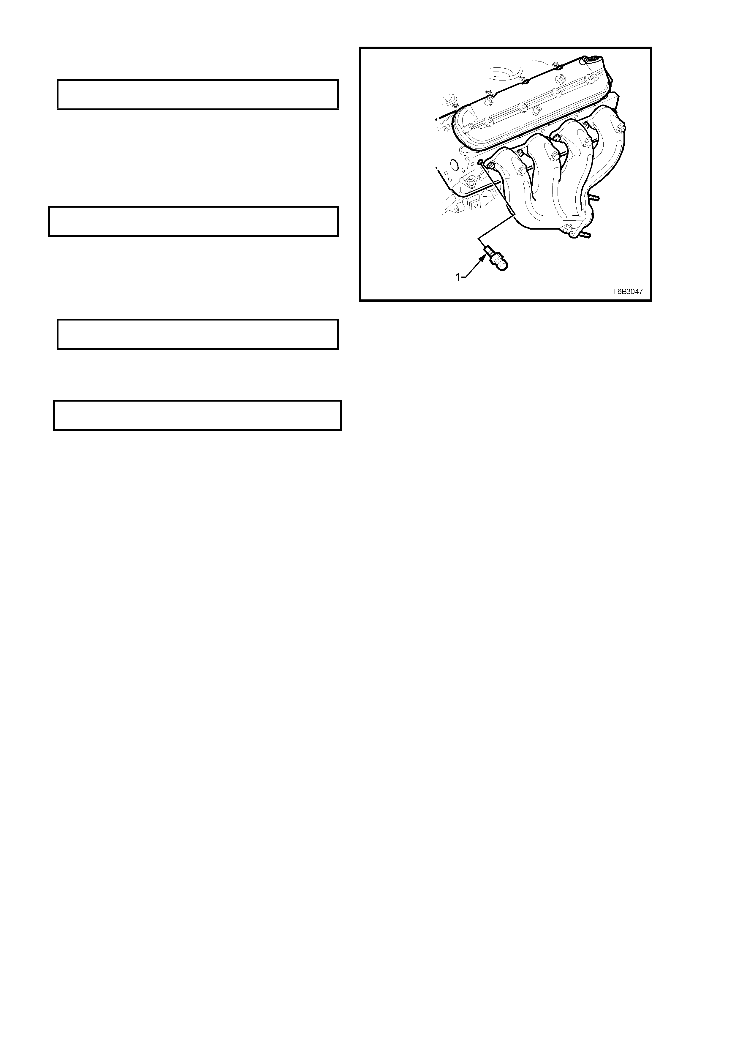
7. Tighten the oxygen sensor/s to the correct
torque specification.
OXYGEN SENSOR
TORQUE SPECIFICATION 41 Nm
8. Apply an anti-seize compound such as Ampol
Kopr-Kote (or equivalent to Holden’s
Specific ation HN 1325) to the c leaned ex haust
pipe flange stud threads.
9. Install and tighten the ex haus t pipe to manif old
flange nuts to the correct torque specification.
EXHAUST PIPE FLANGE NUT
TORQUE SPECIFICATION 20 - 35 Nm
10. Apply thread sealant such as Loctite 565 (or
other commercial equivalent), to the cleaned
threads of the coolant temperature sensor (1).
11. Install and tighten the coolant temperature
sensor (1) to the correct torque specification.
COOLANT TEMPERATURE
SENSOR TORQUE SPECIFICATION 20 Nm
12. Reinstall spark plugs tightening to the correct
torque specification, then reinstall the spark
plug leads.
SPARK PLUG
TORQUE SPECIFICATION 15 Nm
Figure 6A3-112
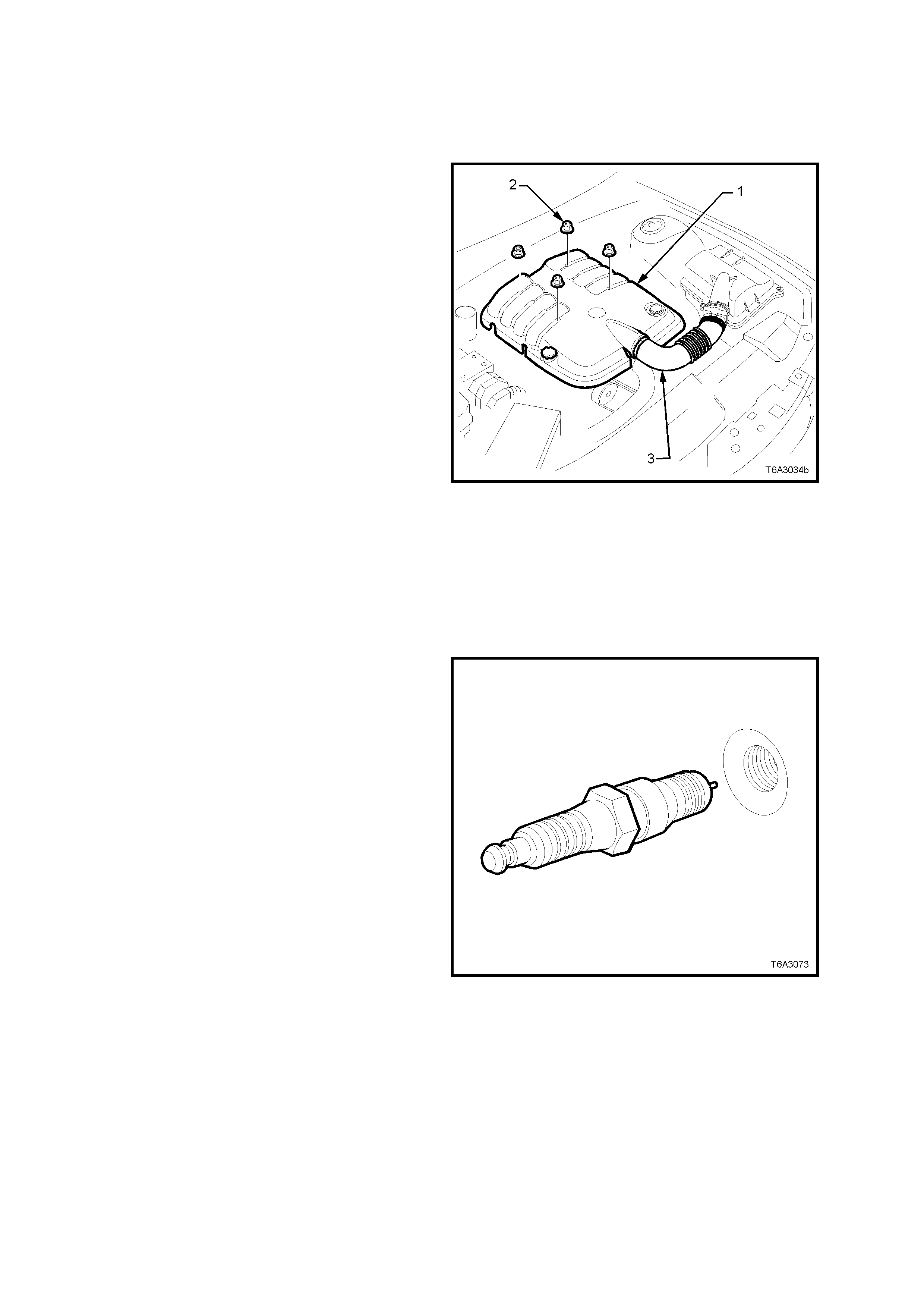
2.22 CYLINDER HEAD
REMOVE
1. Disconnect the battery earth cable from the
battery.
2. Rem ove the engine dress cover retaining nuts
(2), then remove the cover (1).
3. Loosen the two clam ps securing the air intake
duct (3) to the thr ottle body and Mas s Air Flow
(MAF) sensor.
4. Remove air intake duct (3) assembly from
throttle body and MAF sensor.
5. De-pressurise fuel rail. Refer to
Operation 2.13, in this Section.
6. Remove the engine accessory drive belt.
Refer to 2.6 ENGINE DRIVE BELTS, in this
Section.
7. Remove intake manifold. Refer to
2.14 INTAKE MANIFOLD, in this Section.
8. Remove vapour vent pipe. Refer to
2.15 VAPOUR VENT PIPE, in this Section.
9. Remove valve rocker arm cover on the
cylinder head to be removed. Refer to
2.17 VALVE ROCKER ARM COVER, in this
Section.
.
Figure 6A3-113
10. Remove valve rocker arms and push rods on
the cylinder head to be removed. Refer to
2.18 VALVE ROCKER ARMS AND PUSH
RODS, in this Section
11. Rem ove the spark plug from the cylinder head
being removed, noting the following;
a. The engine MUST be cold to at least
50° C. If not, then the spark plug and
cylinder head threads may bind, causing
the cylinder head threads to be torn.
b. When removing spark plug leads, only
handle the boot on each lead, twist to
break the seal, them pull to remove. DO
NOT pull on the lead itself.
c. Loosen the spark plug/s, then re-tighten to
break away any carbon deposits on the
threads.
d. Loosen the spark plug/s once again but,
this time, only one or two turns. Then use
compressed air to remove any foreign
material that may otherwise enter the
combustion chamber.
CAUTION: Wear eye protection to avoid injury.
e. Continue to remove the spark plug/s.
12. For the right hand side cylinder head, first
rem ove the engine oil level indicator and tube.
Refer to 2.20 OIL LEVEL INDICATOR AND
TUBE, in this Section.
13. Remove the exhaust manifold on the cylinder
head to be removed. Refer to 2.21 EXHAUST
MANIFOLD, in this Section.
Figure 6A3-114
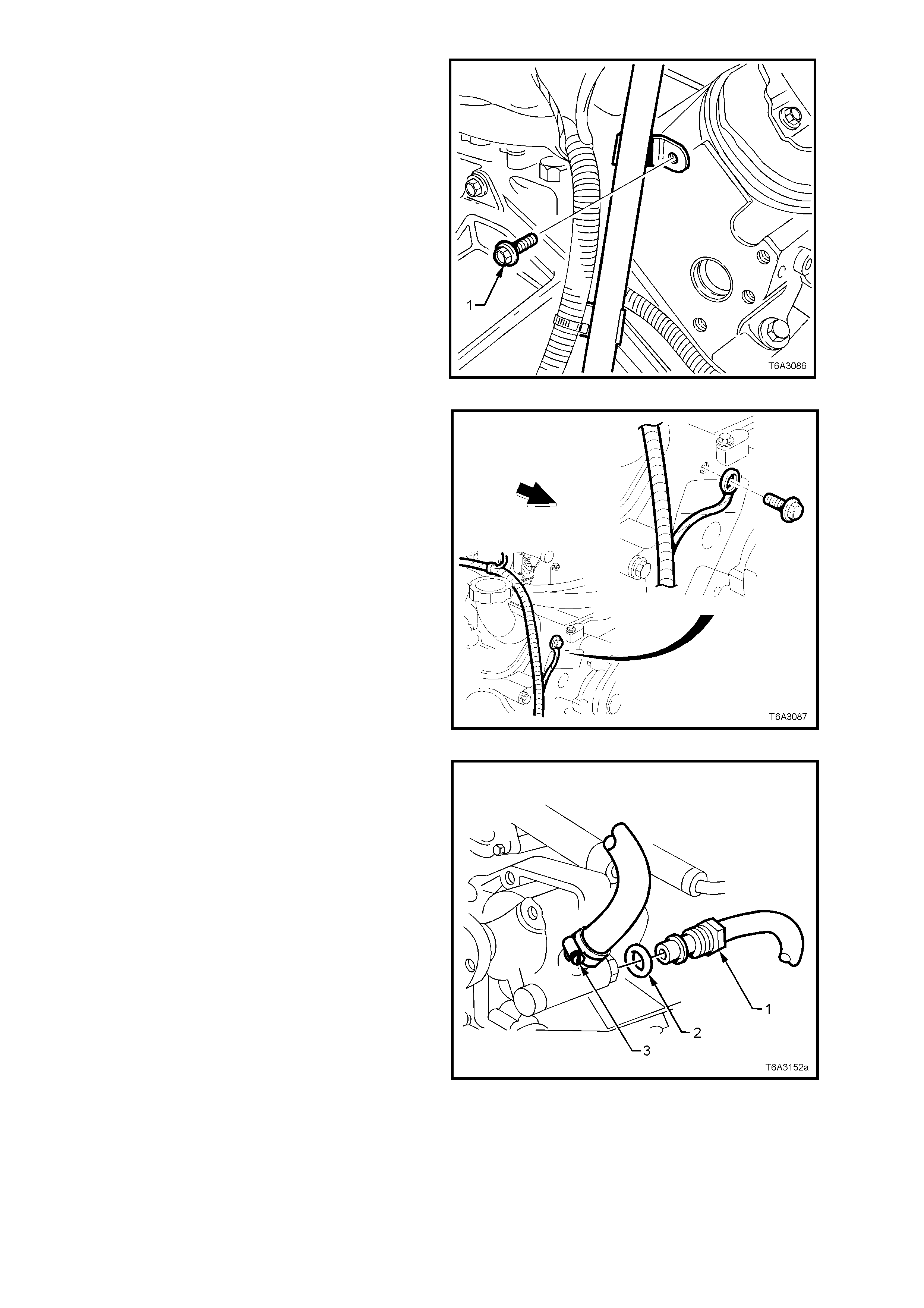
14. For the right hand cylinder head:
a. Remove the bolt securing the automatic
transmission dipstick tube bracket bolt
from the rear of the cylinder head (if
required).
Figure 6A3-115
b. Remove the bolt securing the powertrain
harness earth strap from the front of the
right hand cylinder head.
Figure 6A3-116
15. For the left hand cylinder head:
a. Place a drain tray beneath power steering
pump assembly.
b. Rem ove the power steer ing f luid r eser voir
from its bracket by levering the bracket
locking tab with a screwdriver or similar
lever, to release the reservoir. Refer to
Section 9A STEERING, of this Service
Information CD.
c. Loosen and remove high pressure line
flare nut (1) and O-ring (2) from pump
outlet fitting, using a back-up spanner on
the pump outlet fitting.
NOTE: Fluid will drain from the reservoir so
have a suitable container available.
d. Loosen low pressure hose clamp (3) and
remove hose from pump inlet fitting.
NOTE: Plug or tape the pump and hose
fittings to prevent dirt entry. Figure 6A3-117
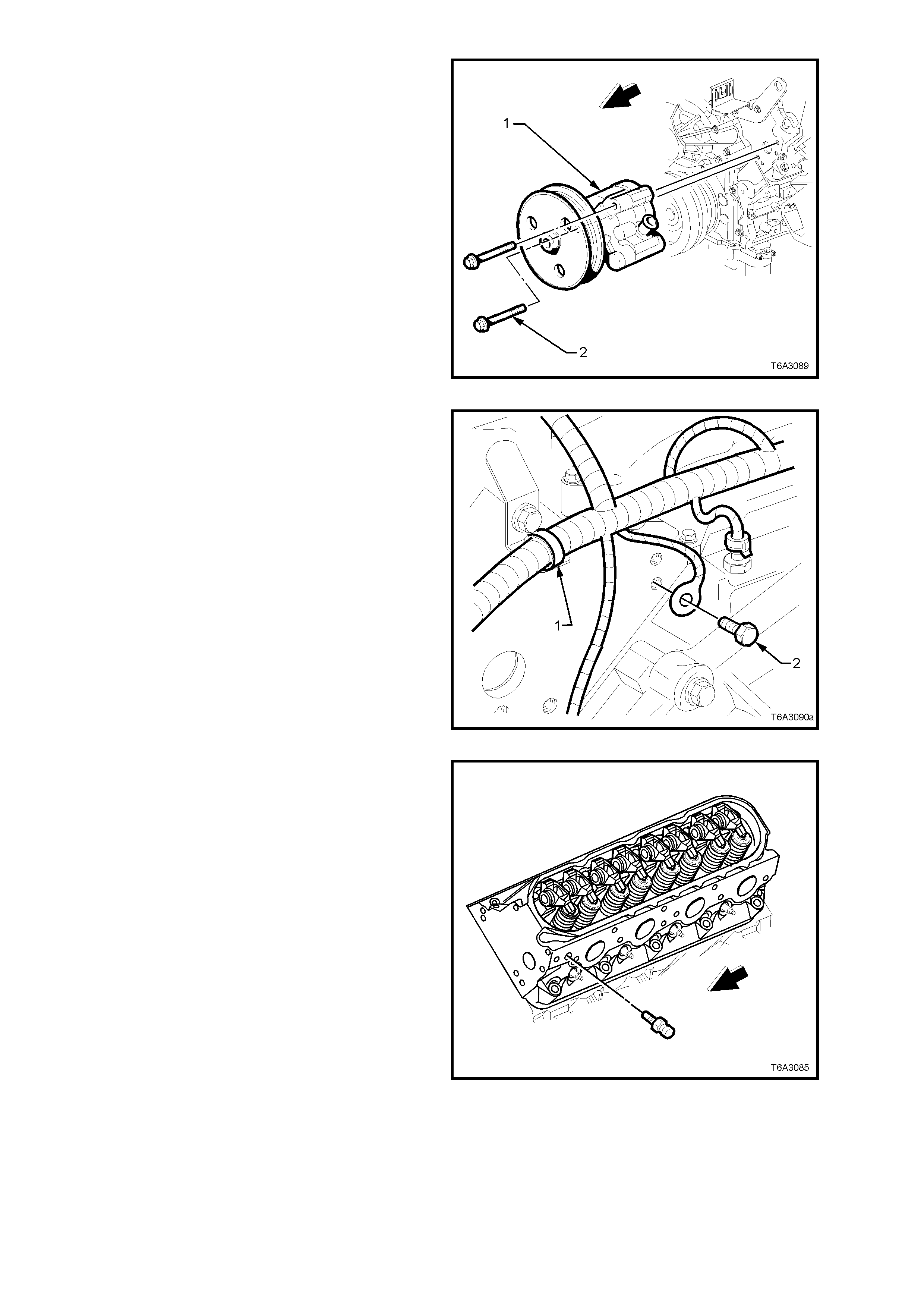
e. Remove both bolts (2) securing the power
steering pump (1) to the front of the left
hand cylinder head.
NOTE: Access to the two bolts can be made
through the pulley holes, using a suitable
socket and extension.
f. Secure the reservoir and pump to one
side, using tie wire or similar.
Figure 6A3-118
g. Remove the powertrain wiring harness
strap (1) from the bracket at the rear of
the cylinder head.
h. Remove the bolt (2) securing the
powertrain harness earth cable at the rear
of the cylinder head.
Figure 6A3-119
i. Remove the coolant temperature sensor
(1).
NOTE: This step is necessary to allow the lower
left cylinder head bolt to be removed and to avoid
the risk of accidental damage to the sensor.
Figure 6A3-120
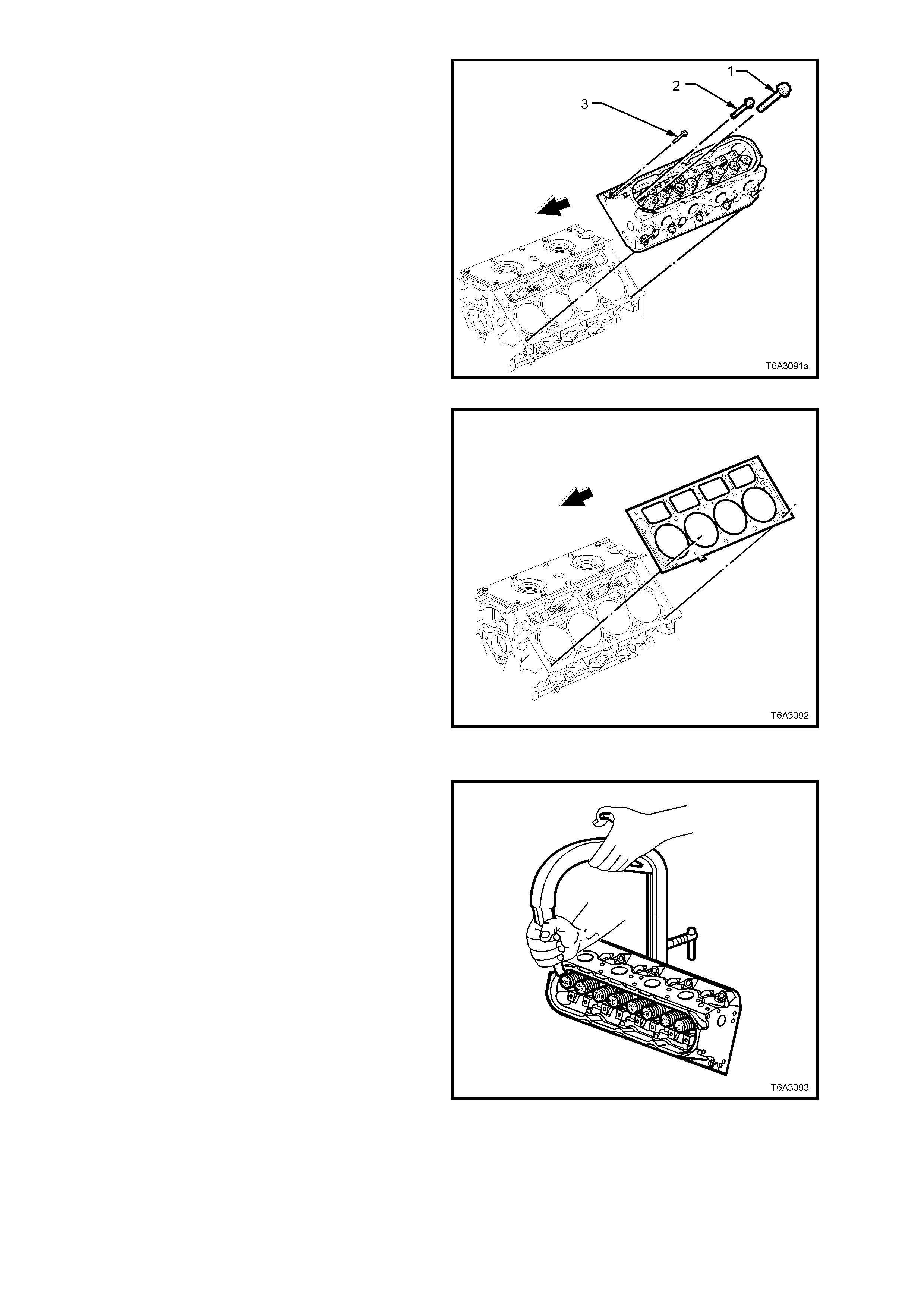
16. Progressively loosen cylinder head bolts
starting with the M8 bolts (3) first, working
from the outside to the centre.
NOTE: Discard all M11 bolts (1 and 2) after
removal, as these are ‘torque to yield’ bolts. Also
note the location of the two shorter, M11 bolts (2).
The M8 bolts (3) can be re-used.
17. Remove the cylinder head from the cylinder
block and place on two blocks of wood. This is
most important to avoid scratching the
machined surface.
Figure 6A3-121
18. Remove and discard the cylinder head gasket.
Figure 6A3-122
DISASSEMBLE
NOTE: Do not m ix r emoved c omponents. O rganis e
all parts in the order removed, to ensure that parts
reinstalled are fitted to their original locations.
1. Use a commercially available valve spring
compressor to compress the valve spring.
NOTE: It may be necessary to tap the valve spring
end of the compr essor with a plastic fac ed ham m er
to loosen jammed valve collets.
Figure 6A3-123
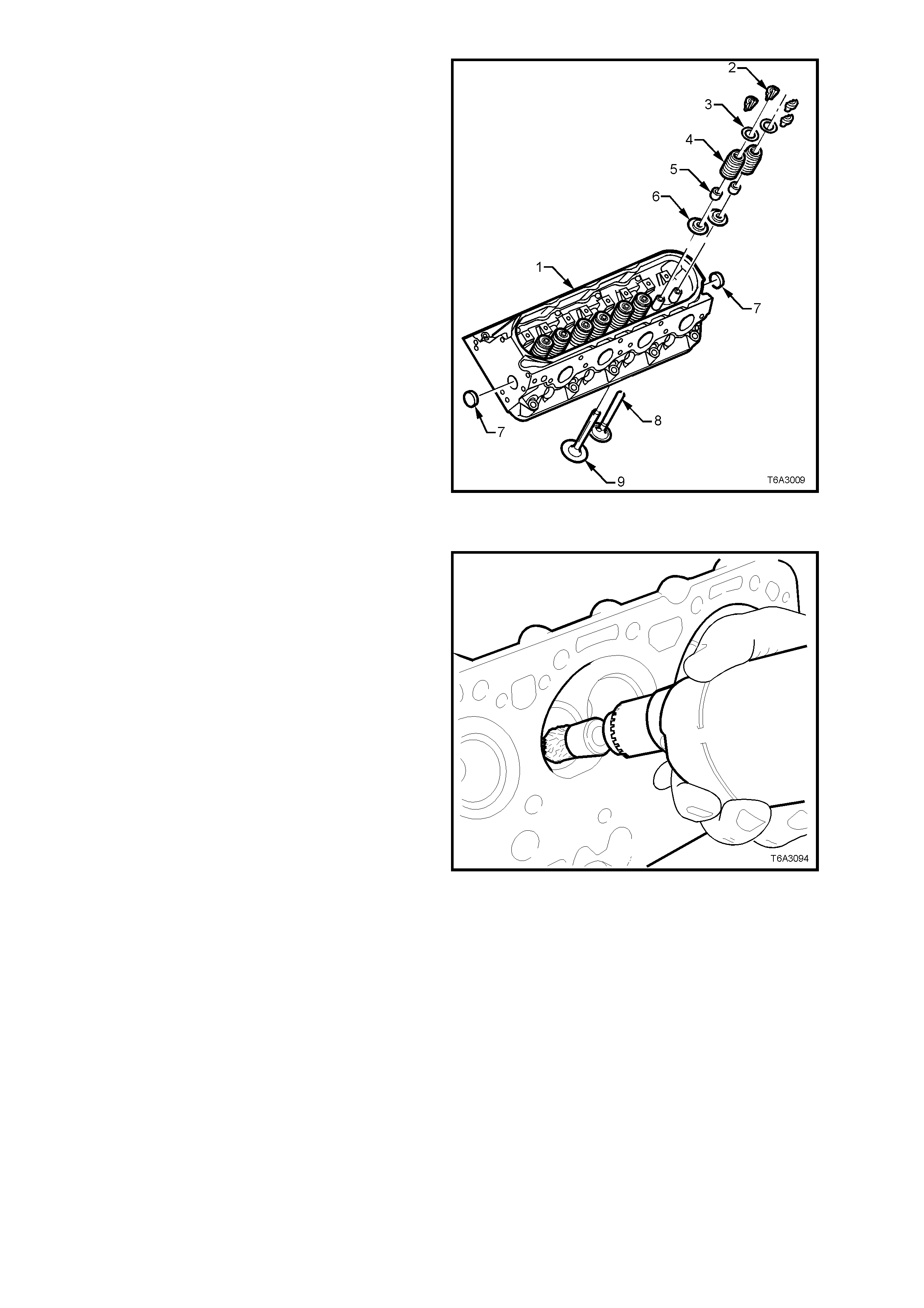
2. Remove the following components:
a. Valve stem collets (2).
b. Valve spring cap (3).
c. Valve spring (4).
d. Valves (8, 9).
e. Valve stem oil seal (5).
f. Valve spring shim (6).
NOTE: Do not remove coolant core plugs (7)
unless servicing is required.
Figure 6A3-124
CLEAN
1. Use a commercially available rotary wire
brush, clean all carbon deposits from the
combustion chambers and valve ports, taking
care not to scuff or damage the aluminium
cylinder head surfaces.
CAUTION: Wear safety glasses to avoid eye
injury.
2. Clean carbon deposits from valve stems and
heads on a buffing wheel.
3. Check all bolt threads for dam age and rem ove
all threadlocking compound from both the
threaded holes and bolts.
Figure 6A3-125
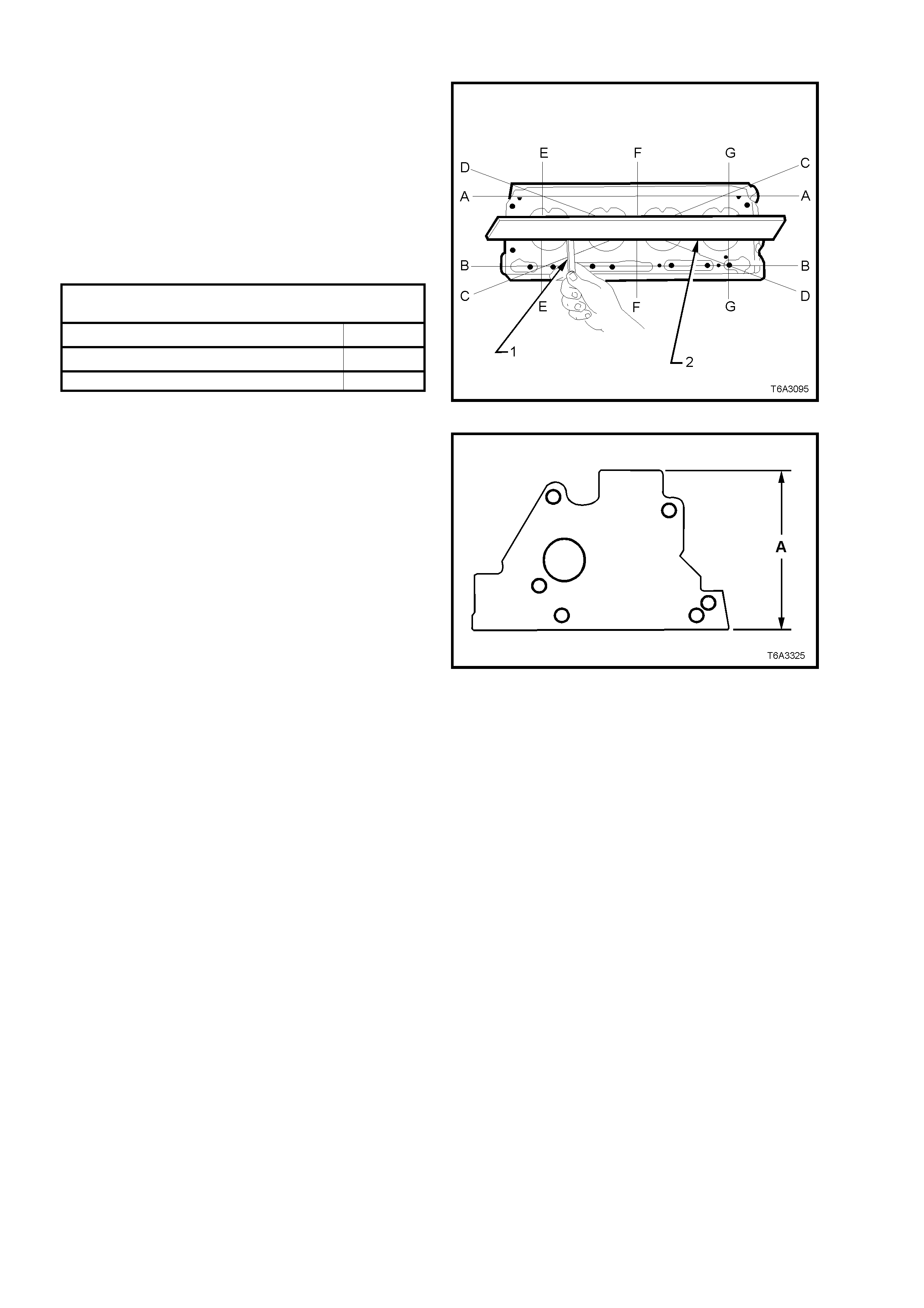
INSPECT
Cylinder Head
1. Check cylinder head deck, inlet and exhaust
manifold mating surfaces for distortion, using
a straight edge (2) and feeler gauges (1).
Check lengthwise, diagonally and crosswise,
as shown by the alphabetical order, in Figure
6A3-125.
2. Check the cylinder head deck to exhaust
manifold the cylinder head deck to intake
manifold surfaces for flatness.
CYLINDER HEAD FLA T NE SS SPECIFICATI ON
(Measured Over the Cylinder Head Lengt h)
CYLINDER HEAD, E NGI NE BLOCK DE CK 0.22 m m
CYLINDER HEAD, EXHAUST MANIFO LD DECK 0.22 m m
CYLINDER HEAD, INTAKE MANIFOLD DECK 0.22 m m
Figure 6A3-126
NOTE: If any of these surfaces are outside
specification, the cylinder head may be machined,
provided the minimum overall height of 120.2 mm
(dimension ‘A’) is not exceeded.
3. Inspect all threaded holes for damage,
repairing as required with suitable thread
inserts. Refer to 3.16 THREAD REPAIR, in
this Section for more information
4. Clean any resisdue of cylinder head bolt
thread sealant from the cylinder block thr eads,
using installer, Tool No. J-42385-107 (this tool
is part of the thread repair kit, J-42385).
Important: Do not use anything but this thread
tool to clean the cylinder head threads in the
cylinder block.
5. Use compressed air to clean all residue from
bolt holes.
CAUTION: Wear safety glasses to avoid eye
injury.
6. Inspect coolant jacket expansion plugs for
signs of corrosion, replace plugs as
necessary.
NOTE: If replacing expansion plugs, apply a
coating of Loctite 242 or equivalent (Holden
Specification HN 1256, Class 2, Type 2) around
plug sealing surface.
7. Inspect cylinder head for cracks, especially
between valve seats or exhaust ports.
8. Inspect cylinder block deck surface for
distortion, refer to 3.15 CYLINDER BLOCK.
9. Clean the M8 cylinder head bolt threads,
replacing any bolt that has suspect threads,
stretched or damaged heads caused by
improper use of tools.
NOTE: Discard all M11 bolts after removal, as
these are “torque to yield” bolts.
Figure 6B3-127
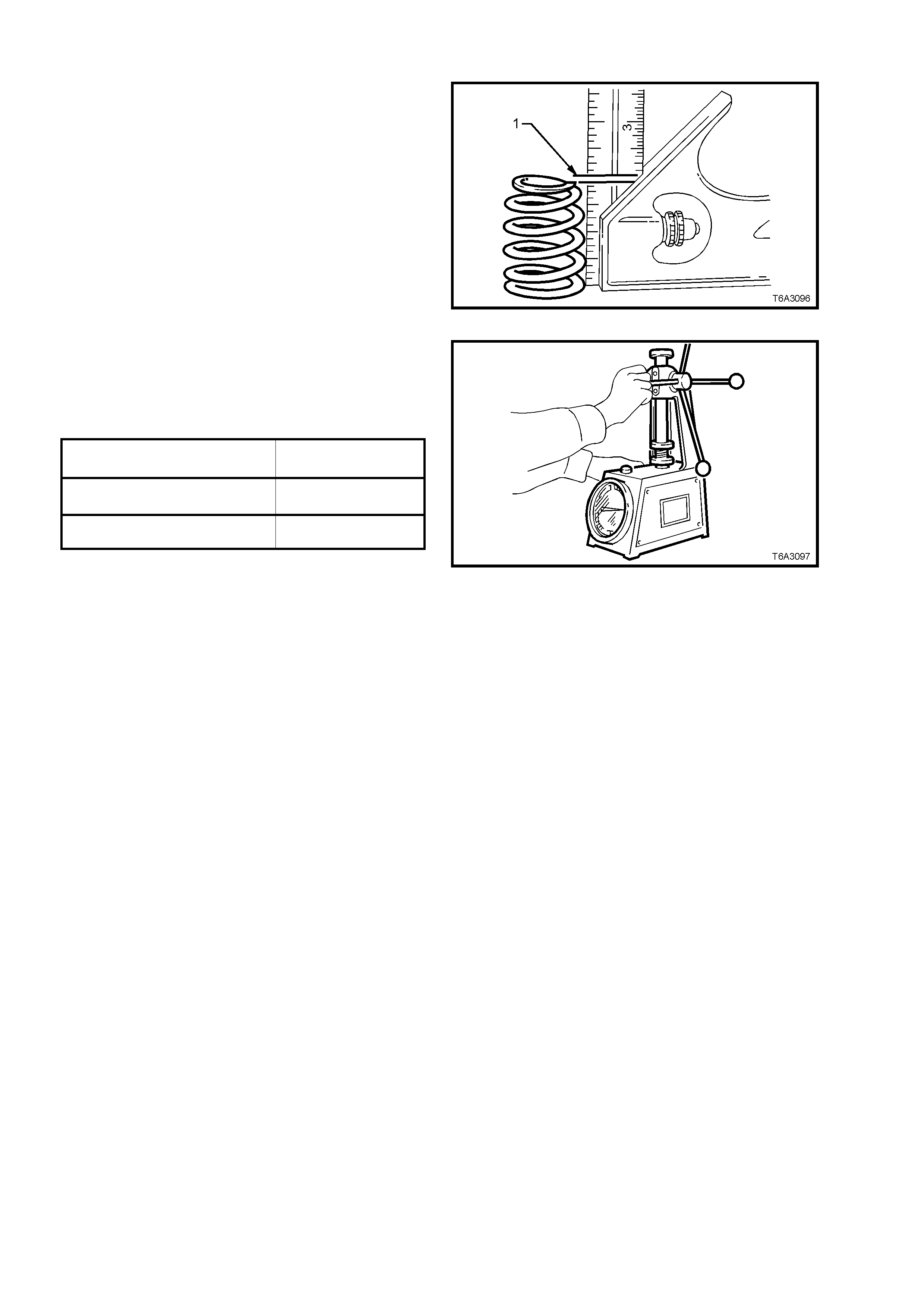
Valve Springs
1. Check all valve springs for distortion. There
should be no more than 1.6 mm variance
(distance ‘1’) of the spring end, while the
spring is being rotated on a flat surface.
Replace springs that exceed this specification.
Figure 6A3-128
2. Use a commercially available valve spring
tester to measure each valve spring free
height and tension.
3. Discard any spring that does not conform to
specification.
VALVE SPRING FREE HEIGHT
(INTAKE and EXHAUST 52.9 m m
VALVE SPRING TE NS ION 310 N at 45.75 mm
SPECI F ICATION (Closed Val ve, Mini mum )
VALVE SPRING TENSION 980 N at 33.55 mm
SPECI F I CA T ION (Open Valve, Minimum)
Figure 6A3-129
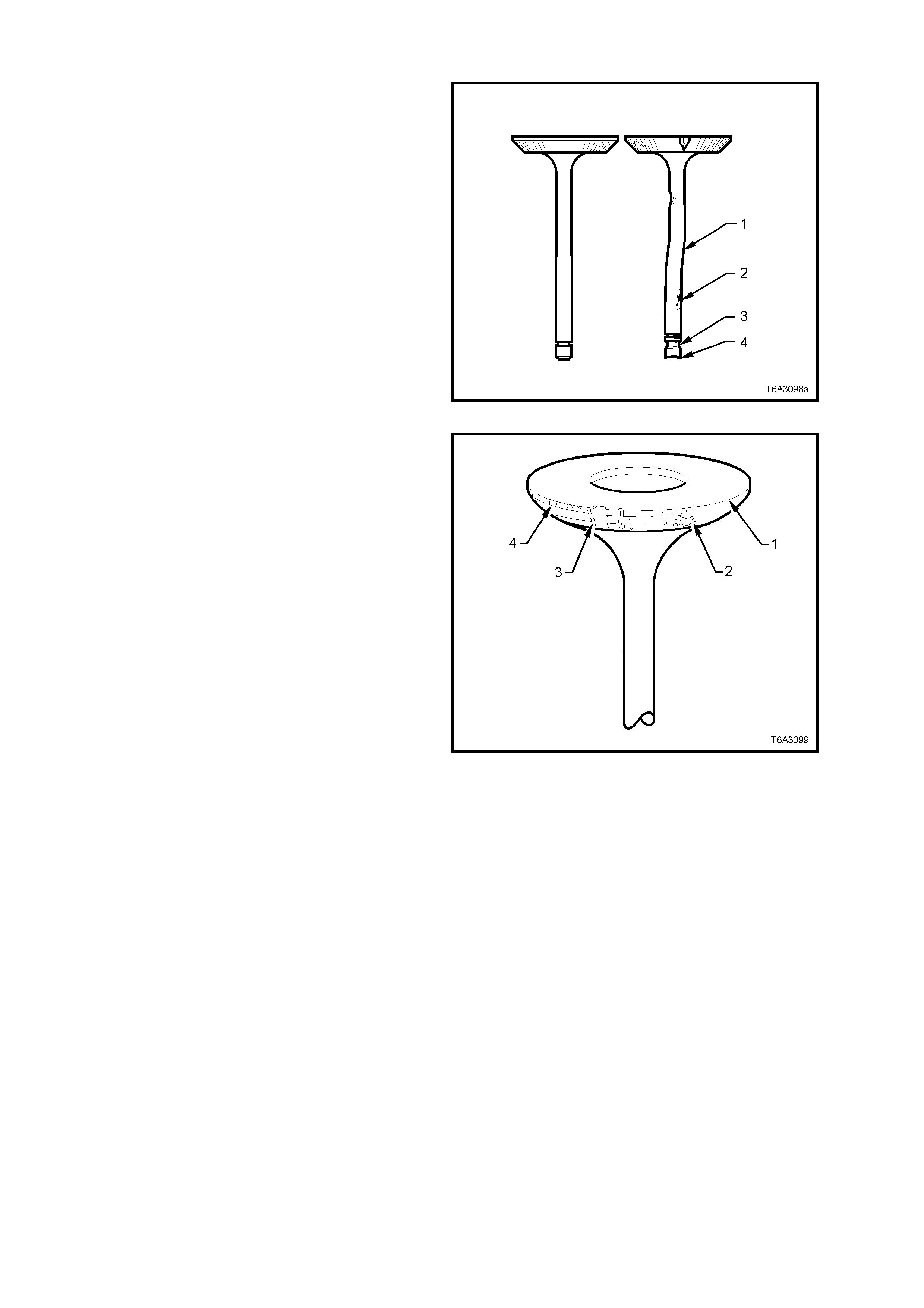
Valves
1. Inspec t valve stem s for burr s and scratc hes. If
minor, these can be removed with an oil stone.
Valves with excessive stem wear or that are
warped (1 and 2), should be replaced.
Inspect the valve stem end (4) for wear. If
required wear can be corrected by grinding,
provided the stem end is ground at right
angles to the valve stem.
2. Inspect valve stem collet groove (3) for wear
or damage.
Figure 6A3-130
3. Check valve face for the following:
Either no margin (1) or less than 1.25 mm
after grinding (4).
Excessive pitting (2).
Burnt or corroded areas (3).
4. If an exhaust valve is to be reconditioned, the
face can be ground, using a valve refacing
machine. The valve seat angle is 45°.
The equipment manufacturer’s recommendations
must be carefully followed to achieve the required
standard of finish.
NOTE: If an ex haust valve face is r eground, it m ay
be necessary to shim the valve spring to achieve
the correct spring installed height. Refer to
Cylinder Head Reassemble in this Section, for
details.
Important: Intake valve faces must not be
refaced. Intake valves that are worn or have
face damage MUST be replaced.
Figure 6A3-131
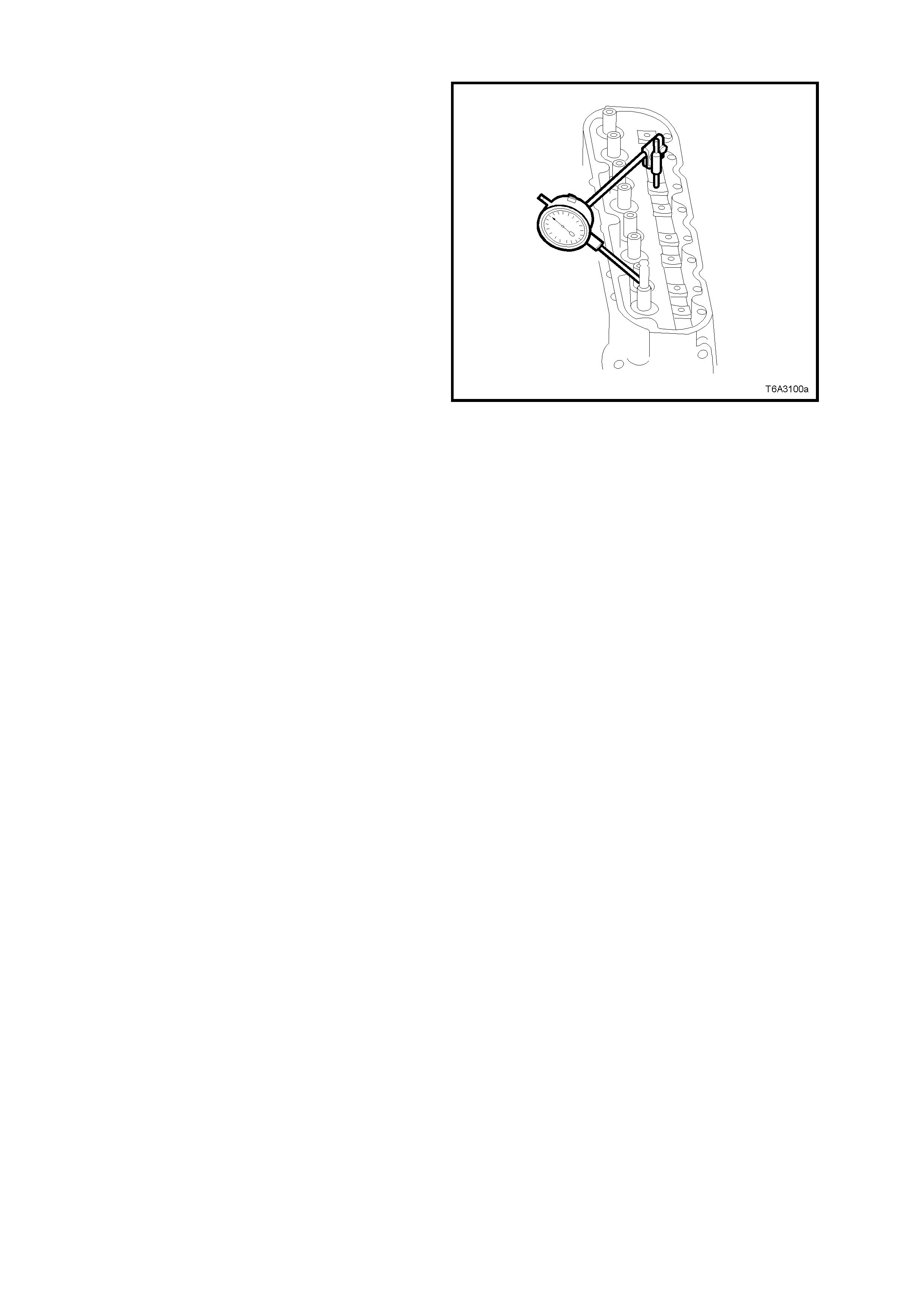
Valve Guides
Excessive valve stem to guide clearance may
cause a noisy valve train, prem ature valve stem oil
seal wear, component dam age and/or ex cess ive oil
consumption.
Insuff icient valve s tem to guide c learance will res ult
in noisy or sticking valves. Valves that are too tight
may disturb engine smoothness or lead to
component damage.
Measure clearance as outlined in the following
steps.
1. Insert valve into its guide.
2. Clamp a dial indicator to a valve rocker arm
bolt that has been temporarily installed, in a
position where sideways movement of the
valve stem will cause movement of the
indicator needle.
To obtain a correct indication of wear, the
indicator stem must contact the side of the
valve stem , from 8 - 12 mm above top of valve
guide.
3. With the valve head dropped approximately 2
mm off its seat, move the stem of the valve
side to side against the dial indicator using
light force, to obtain a clearance reading.
NOTE: Should any clearance measurement
exceed 0.093 mm (either intake or exhaust), the
cylinder head must be replaced.
Figure 6A3-132

Valve Seats
Reconditioning the valve seats is very important
because the seating of the valves must be precise
for the engine to deliver the power and
performance built into it.
Another important factor is the cooling of the valve
head. Good contact between each valve and its
seat in the head is imperative to ensure that the
heat in the valve head will be transferred efficiently.
Several different types of equipment are available
for reconditioning valve seats with an oscillating
type valve seat grinder being preferred. The
recommendations of the manufacturer of the
equipment being used should be carefully followed
to attain proper results.
1. Check valve seats for any evidence of pitting
or damage at valve contact surface. If pitting
is evident, the valve seats will need to be
reconditioned.
NOTE: Since the valve guide serves to support and
centre the valve seat grinder, it is essential that
valve guide wear is checked, as detailed in the
previous operation.
Both the intake and exhaust valve seat angles are
46° and seat width should not exceed specification.
VALVE SEAT WIDTH SPECIFICATION
INTAKE ................................................ 1.02 mm maximum
EXHAUST............................................. 1.78 mm maximum
If valve seats are reconditioned and the exhaust
valve faces ground, then light lapping will ensure a
gas tight seal when closed.
NOTE: New valves m ust not be lapped, as this will
destroy the protective coating on the valve face.
After refacing an existing valve or installing a new
valve, correct seating must be checked as follows:
a. Lightly coat valve face with bearing (Prussian)
blue.
b. Insert the valve and rotate about 1/6th of a
turn.
c. Remove valve and check its contact with the
seat.
d. If full contact is indicated, valve and seat are
acceptable.
However, if only partial contact is shown,
reinstall the valve and rotate f or one full turn. If
blue now indicates a f ull c ontac t then the valve
must be refaced or replaced. If the blue
contact still only shows partial contact then
regrind the valve seat.
e. Clean all traces of blue from the valves and
seats, then clean thoroughly before applying
clean engine oil to both surfaces to protect
from rusting.
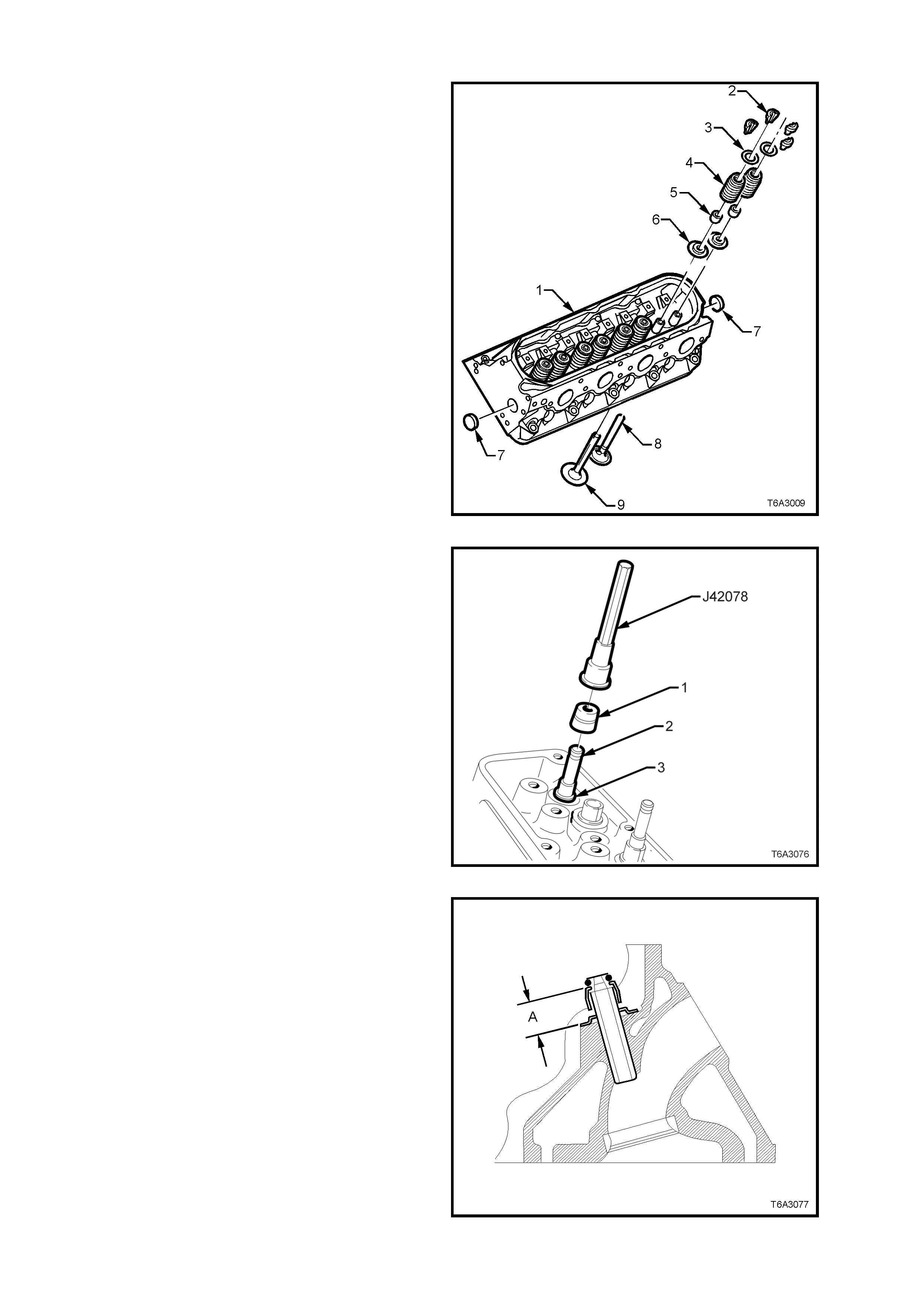
REASSEMBLE
NOTE: Ensure that all r e-used parts are reinstalled
to their original locations.
1. Lubricate all valve stems, guides and valve
faces with clean engine oil, then install valves
(8 and 9) to their correct ports.
2. Install valve spring shims (6).
Figure 6A3-133
3. Install valve stem oil seals (1) to each guide,
as follows:
a. Lubricate each valve stem (2) and valve stem
oil seal (1), with clean engine oil.
b. Install the valve stem oil seal (1) to the guide
and push down until the s eal contac ts the valve
guide.
c. Use Tool No. J 42078 to install the valve stem
oil seal, by pushing or lightly tapping until the
tool bottoms on the valve spring shim (3).
Figure 6A3-134
4. Measure the valve stem oil seal height above
the oil seal body and the valve spring shim
surf ace, as shown. Correct dis tance ‘A’ should
be between 18.1 - 19.1 mm
Figure 6A3-135
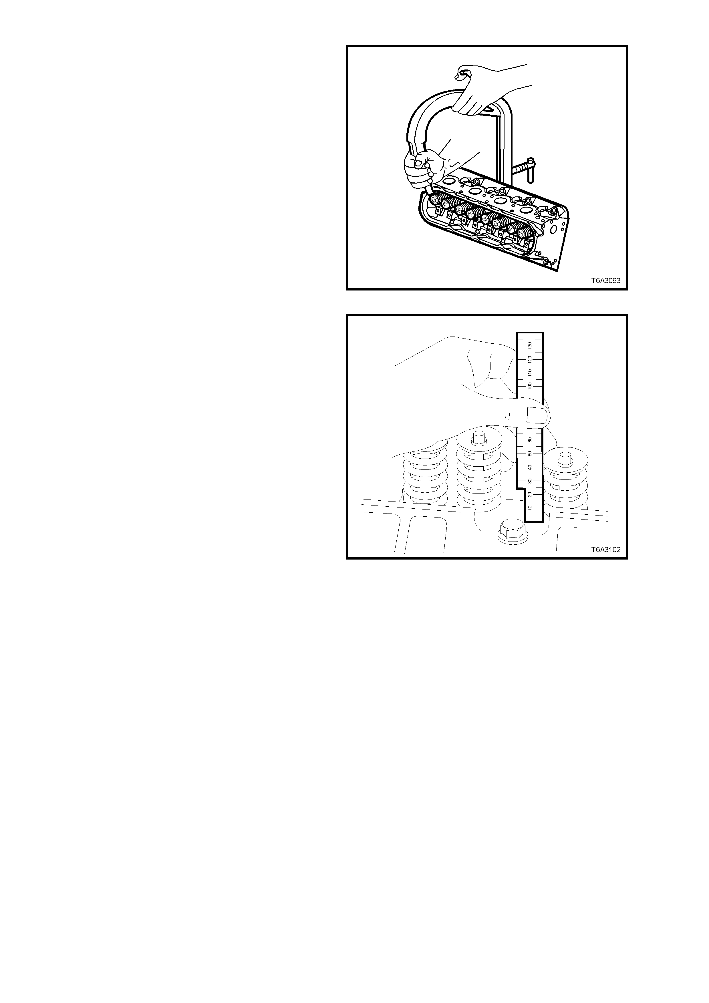
5. Install the valve springs and caps to each
valve stem.
6. Use a commercially available valve spring
compressor to compress the valve spring.
7. Install valve stem collets, retaining with
petroleum jelly if required.
8. Ensure that the both collets are correctly
located before releasing the valve spring
compressor.
9. Tap the end of each installed valve stem, with
a plastic faced hammer to seat the collets.
Figure 6A3-136
10. Measure the valve spring installed height
using a ruler or vernier caliper s. Measurem ent
is to be taken from the base of the valve
spring to the top.
11. If the measurement exceeds 46.25 mm, the
valve spring shim must be changed to one that
is approxim ately 0.5 mm thic k er to achieve the
required spring height.
NOTE 1: Do not shim the valve spring to obtain
less than the specified height.
NOTE 2: Do not assemble the valve spring
components without a spring shim at the cylinder
head.
NOTE 3: If a spring shim requires changing, the
valve stem oil seal must also be replaced.
12. Install the rem aining valves, springs and other
com ponents, c heck ing each spr ing height as it
is assembled.
13. If the cylinder head core plugs were removed,
install with sealant such as Loctite 565 (or
equivalent) before plug installation.
Figure 6A3-137
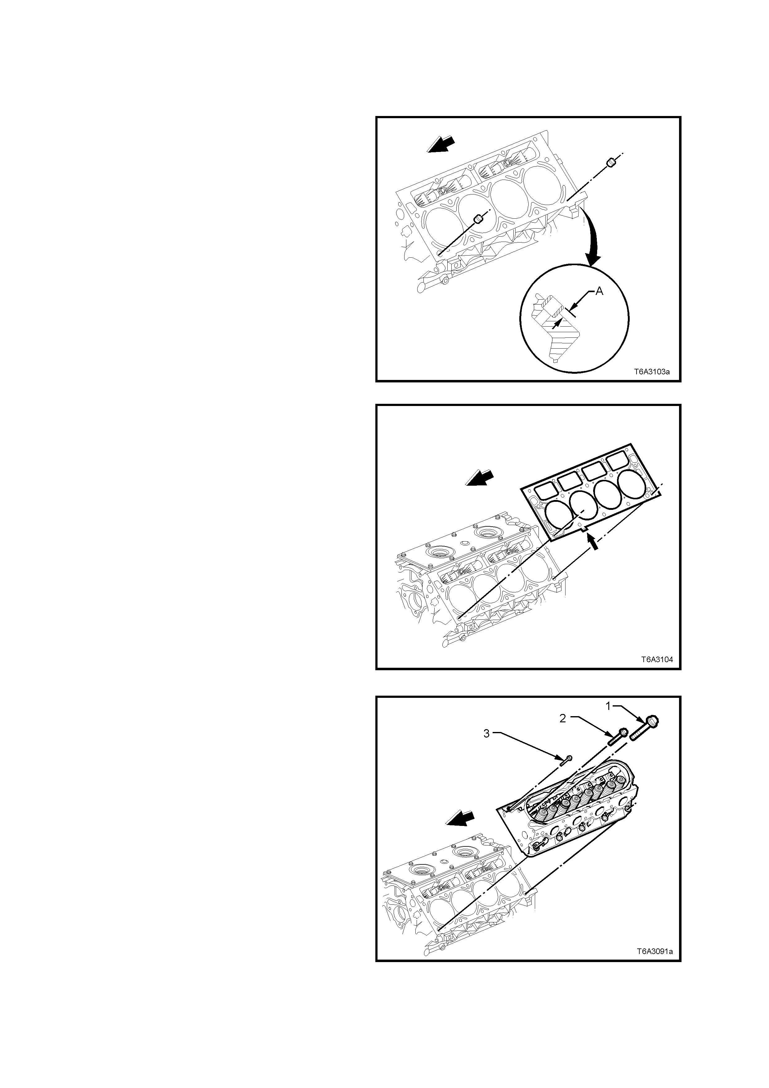
REINSTALL
Reinstallation of either or both cylinder heads is the
reverse to the removal procedure, except for the
following points.
NOTE 1: Do not refit removed M11 cylinder head
bolts. Always use NEW bolts when installing a
cylinder head.
NOTE 2: Do not use any sealant on the cylinder
head gask et, nor threadlock com pound on the M11
cylinder head bolts.
1. Check the cylinder head locating sleeves for
correct installation. Dimension ‘A’ is to be 6
mm.
Figure 6A3-138
2. Install a NEW cylinder head gasket correctly
over the locating sleeves.
NOTE: W hen correctly installed, the tab (arrow) on
the cylinder head gasket will be located to the front
half point (small arrow). This applies with either
cylinder head gasket.
Figure 6A3-139
3. Install the cylinder head over the locating
sleeves and the previously installed gasket.
4. Apply a 5 mm band of threadlock such as
Loctite 242 (or equivalent to Holden
Specification HN 1256, Class 2 Type 2), ONLY
to the threads of the M8 bolts (3).
5. Install the M8 cylinder head bolts (3), then
loosely install NEW M11 bolts (1 and 2).
Figure 6A3-140
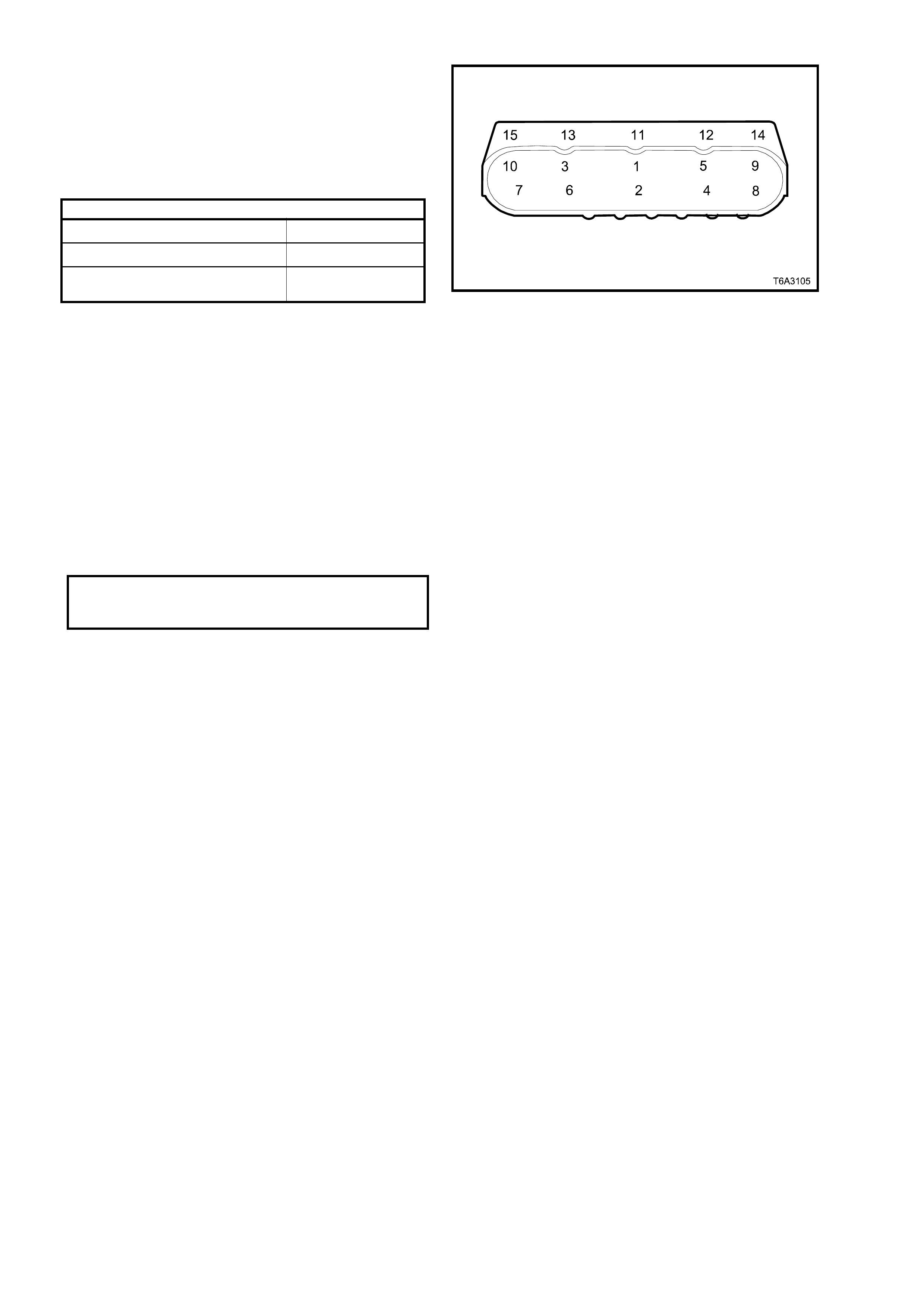
6. Tighten the cylinder head bolts in the
sequence shown and to the correct torque
specification.
NOTE 1: Use a tor que angle meter s uc h as E 7115
to achieve an accurate turn angle reading.
NOTE 2: Bolt numbers 1 to 10 inclusive are the
M11 bolts, while bolts 11 to 15 are the M8 bolts.
CYLINDER HEAD BOLT TORQUE SPECIFICATION
Stage 1 (All M11 and M8 Bolts) 30 Nm
Stage 2 (Al l M11 Bol ts only) 90° turn angle
Stage 3 (M11 Bolts 1 to 8 only) 90° turn angle
(M11 Bolts 9 and 10 onl y) 50° turn angle
For the rem ainder of r einstallation process , refer to
the following procedures, in the order listed:
2.18 VALVE ROCKER ARMS AND PUSH RODS.
2.17 VALVE ROCKER ARM COVER.
2.15 VAPOUR VENT PIPE.
2.14 INTAKE MANIFOLD.
2.21 EXHAUST MANIFOLD/S.
NOTE: If a cylinder head is replaced, the initial
spark plug torque specification, must be amended
to:
SPARK PLUG
TORQUE SPECIFICATION 20 Nm
NEW CYLINDER HEAD
2.20 OIL LEVEL INDICATOR AND TUBE.
Figure 6A3-141
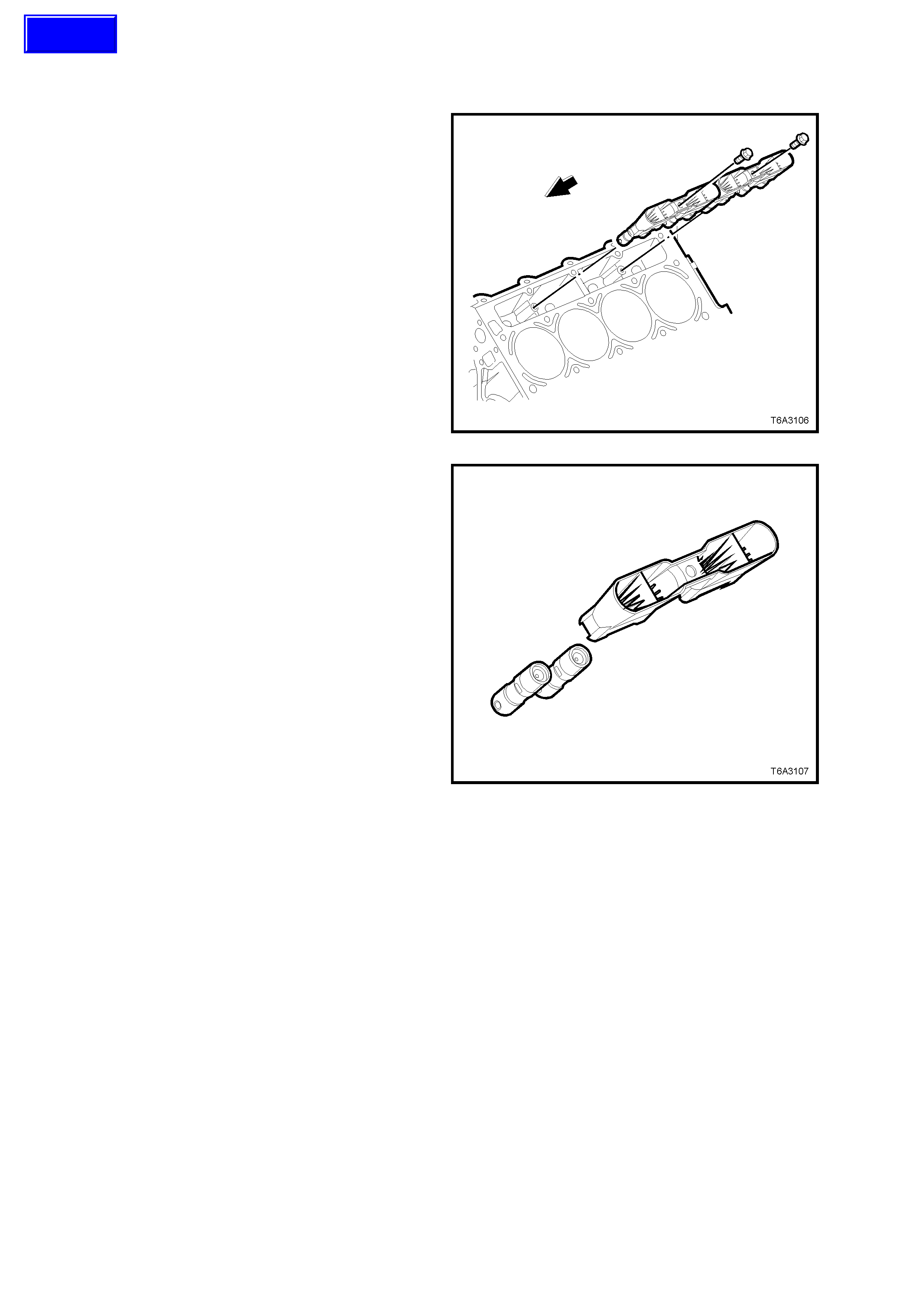
2.23 VALVE LIFTERS
REMOVE
NOTE: Ensure that all valve train components are
kept in order so they may be reinstalled, if required,
in their original locations.
1. Remove the cylinder head on the side
requiring hydraulic lifter removal. Refer
2.22 CYLINDER HEAD - REMOVE, in this
Section.
2. Remove both valve lifter guide retaining bolts.
3. Remove valve lifters and guides.
Figure 6A3-142
4. Remove the valve lifters from the guide/s.
Figure 6A3-143
Techline
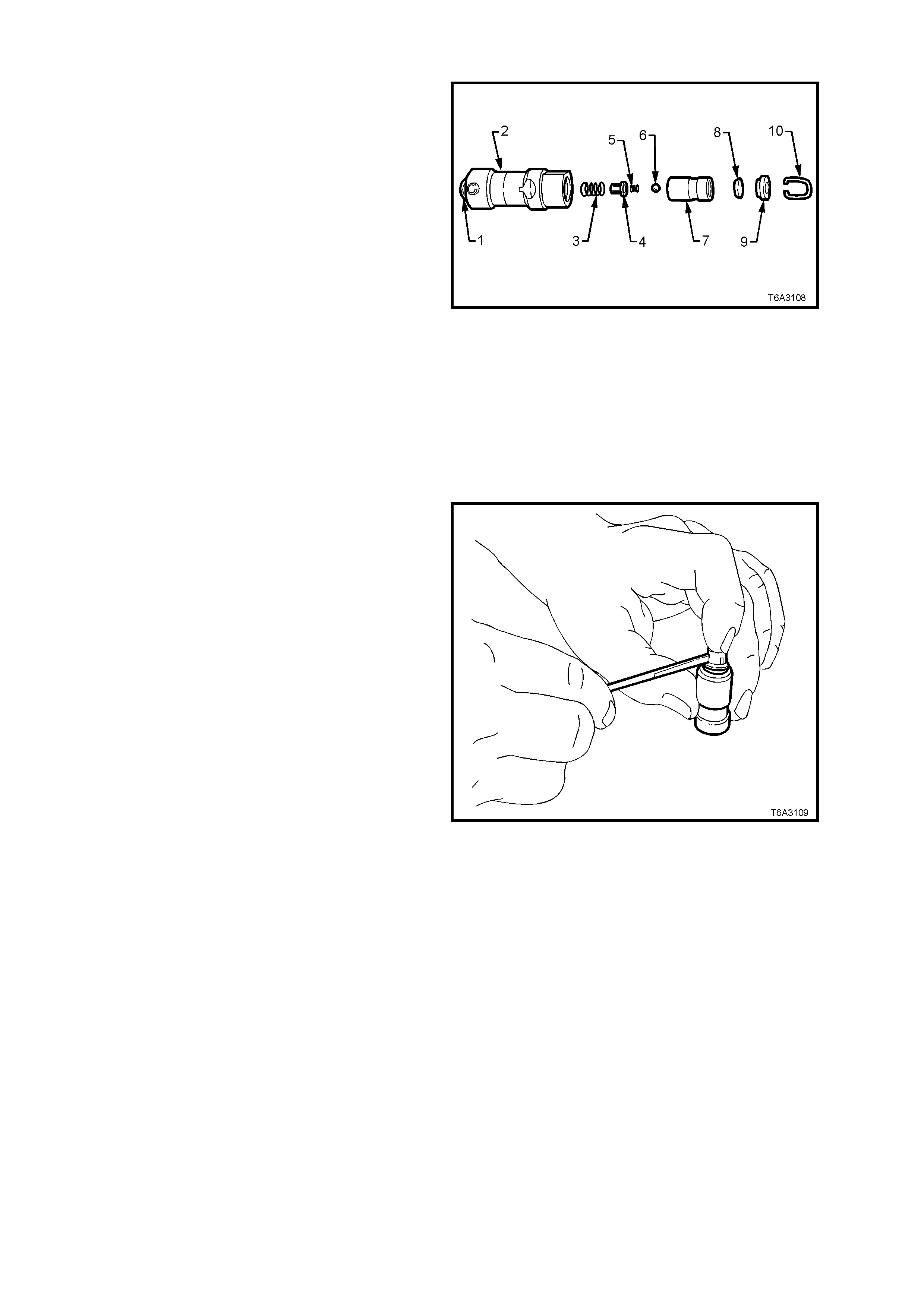
DISASSEMBLE
1. Using a small, fine bladed screwdriver,
remove push rod seat retaining clip (10).
2. Remove push rod seat (9), oil metering valve
(8), plunger assembly (7) and plunger spring
(3) from lifter body (2).
NOTE: If the plunger is stuck in the lifter body, turn
lifter body upside down and tap lifter body on a
block of wood. If this is not effective, soak lifter
assembly in a suitable cleaning fluid.
Legend:
1. Roller.
2. Lifter Body.
3. Plunger Spring.
4. Ball Check Retainer.
5. Ball Check Spring.
6. Ball Check.
7. Plunger.
8. Oil Metering Valve.
9. Push Rod Seat.
10.Push Rod Seat Retaining Clip.
Figure 6A3-144
3. Remove ball check retainer (4), ball check
spring (5) and ball (6) from the plunger (7).
Figure 6A3-145
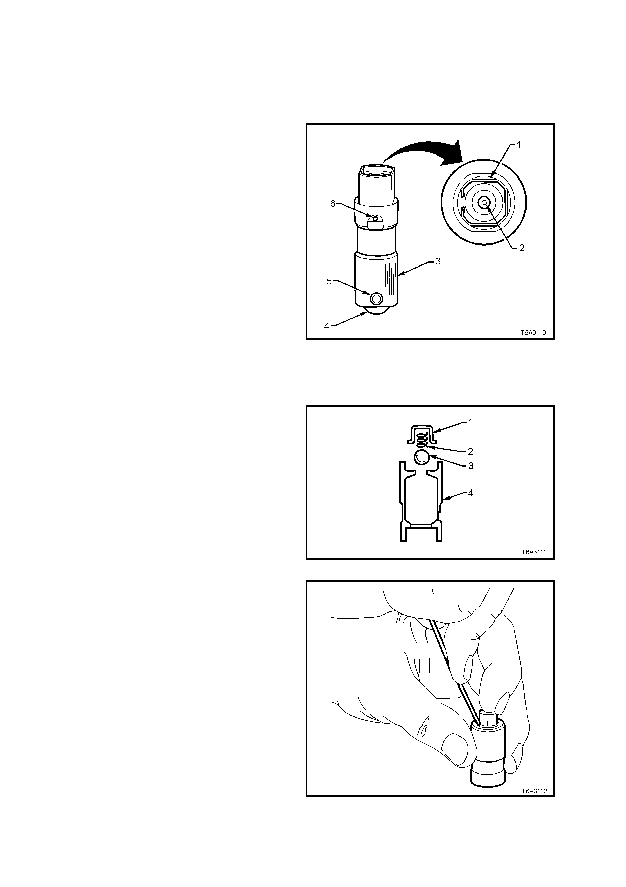
CLEAN AND INSPECT
1. Thoroughly clean all parts in a suitable
cleaning fluid. Blow all parts dry with
compressed air.
CAUTION: Wear safety glasses to avoid eye
injury.
2. Inspect valve lifters for:
a. Bent or broken clip (1).
b. Worn pushrod socket (2). If the seat is worn,
inspect the matching push rod. Replace the
push rod if worn.
c. Scuffed or worn lifter body (3). Also inspect
lifter bore in the cylinder block.
d. Flat spots on roller (4). Replace lifter if the roller
is worn.
e. Loose or damaged pin (5).
f. Partially blocked oil hole (6).
g. W orn or damaged roller bearing. Replace lifter
if roller binds or roughness can be felt.
3. Inspect valve lifter guides for;
Cracks or damage.
Excessive wear in the lifter mounting bores. Figure 6A3-146
REASSEMBLE
NOTE 1: Do not attempt to recondition a lifter by
taking parts from other unserviceable lifters.
NOTE 2: Cleanliness is extremely important when
handling valve lifters. Lint or dirt can result in a
failed lifter.
1. Place check ball (3) on the small hole in the
plunger (4).
Figure 6A3-147
2. Carefully place check ball spring and retainer
over ball and press retainer into position in the
plunger with a small bladed screwdriver.
3. Half fill valve lifter body with test fluid No.
E1151.
Figure 6A3-148
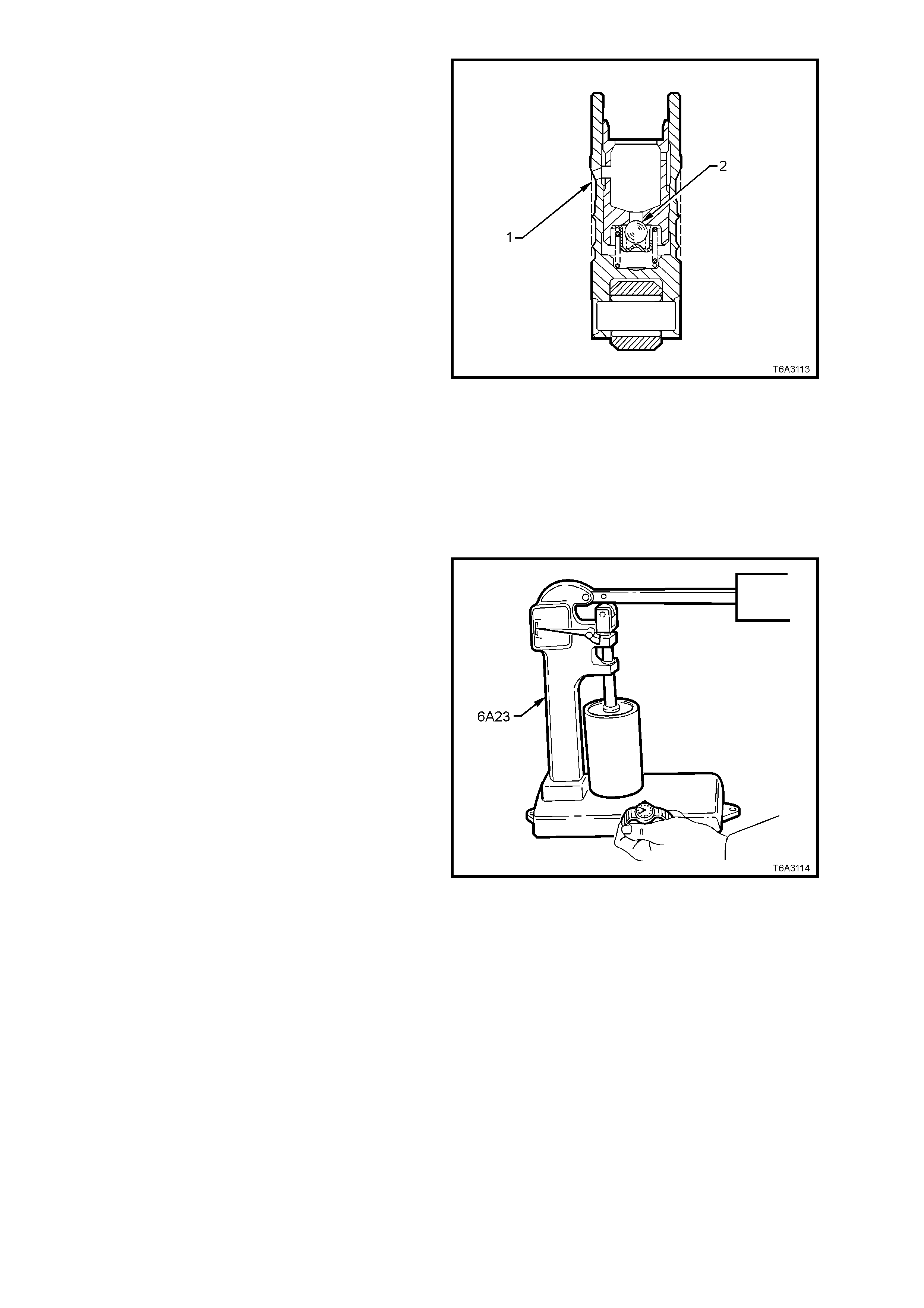
4. Reinstall plunger spring into the lifter body.
5. Install plunger assembly in body, taking care
to align oil feed holes
6. Using a 1 mm diameter pin punch or similar,
unseat the check ball (2) in the plunger, then
push plunger down to the full extent of its
travel.
7. Use T ool 6A24 (or a suitable sized pin punch)
to align the oil feed holes (1) in the body and
plunger.
8. Fill the lifter with test fluid.
9. Reinstall the oil metering valve, push rod seat
(cup side facing out) and the retaining clip.
Figure 6A3-149
TESTING LIFTER LEAKDOWN RATE
After an hydraulic lifter has been cleaned,
inspected and reassembled, it must be tested
before being reinstalled. Lifter test fixture, Tool No
6A23 has been designed to test the leakdown rate
of the lifter, to ensure that the lifter will operate as
intended, when reinstalled.
1. Ensur e the test cup is c lean. Install the cup on
the fixture and place the lifter in the cup.
NOTE: Some versions of Tool No. 6A23 may
require modification to hold the base of the lifter
inside the tester cup.
2. Add test fluid, No. E1151 to completely cover
the lifter.
3. Place ball bearing supplied with test fixture in
the push rod seat of the lifter.
4. Lower test fixture ram to rest on ball bearing.
5. Operate lifter plunger through its maximum
travel to force all air out of lifter by using a
vigorous pumping action on test fixture weight
arm. Continue pumping action until
considerable resistance is built up in lifter and
lifter becomes solid.
6. Raise weight arm to allow lifter plunger to
come up to its retainer, then lower arm to rest
on ram.
7. Use a stop watch to measure the time
required for the indicator needle on the tester
to travel from 'START' to the 0.125" position
on the scale.
Figure 6A3-150
8. The leak down rate (time between 'Start' and
the 0.125" position) m ust be between 10 to 30
seconds to assure satisfactory lifter operation.
NOTE 1: A doubtful lifter should be tested several
times before being discarded.
NOTE 2: Clean cup and refill with fresh test fluid
after several lifters have been tested.
9. Stand tested lifters upright so that fluid does
not drain from oil holes.
10. After all lif ter s have been tes ted, plac e a c over
over the test f ixture to keep dirt and dust f rom
the cup.

REINSTALL
NOTE: Ensure that reinstalled lifters are fitted to
the original locations.
1. Check that all valve lifter bores and adjacent
areas are clean.
2. Lubricate valve lifter bodies and their bores
with Lubrizol 6612 (or equivalent to Holden
Specification HN1961), then install lifters.
3. Install valve lif ters into the guides, aligning the
flat area at the top of the lifter with the flats in
the lifter guide bore. Push the lifter completely
into the guide bore
4. Install the valve lif ters and guide as sem bly into
the engine block.
5. Install each valve lifter guide retaining bolt/s
and tighten to the correct torque specification.
VALVE LIFTER GUIDE BOLT
TORQUE SPECIFICATION 12 Nm
6. Reinstall the cylinder head/s. Refer to
2.22 CYLINDER HEAD – REINSTALL in this
Section.
Figure 6A3-151
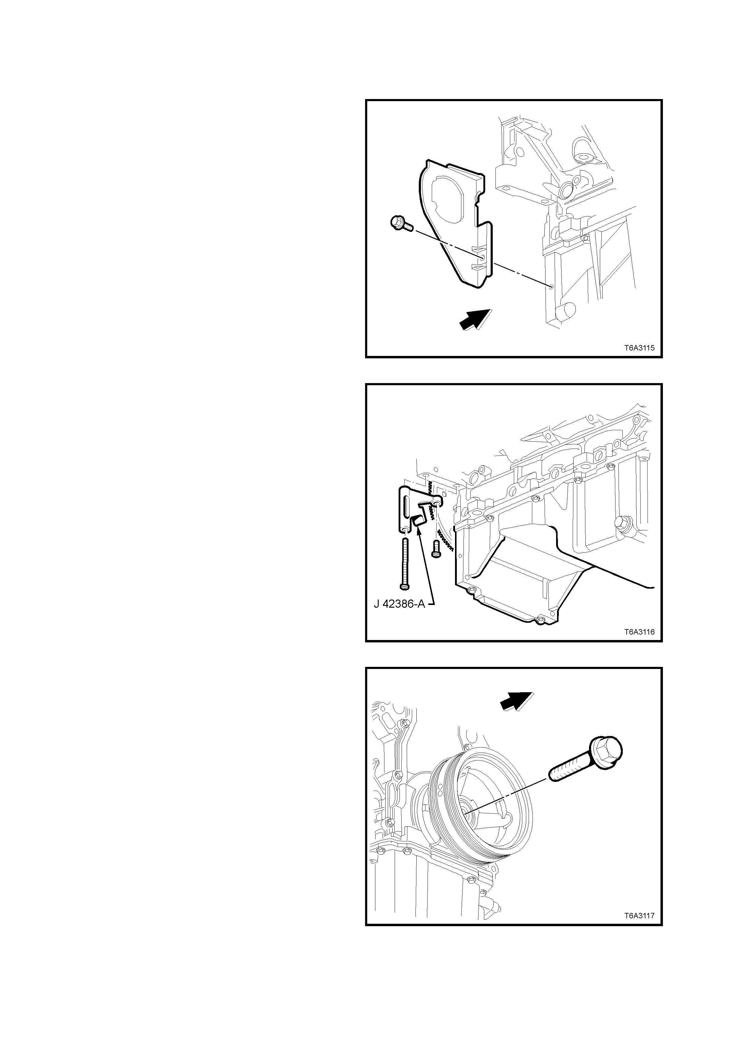
2.24 CRANKSHAFT BALANCER
REMOVE
1. Disconnect the battery earth cable from the
battery.
2. Remove radiator, refer Section 6B3 ENGINE
COOLING – GEN III V8 ENGINE of this
Service Information CD.
3. Remove the engine accessory and air
conditioning compressor drive belts. Refer
2.6 ENGINE DRIVE BELTS – REPLACE, in
this Section.
4. Remove the starter motor. Refer to
Section 6D3-2 STARTING SYSTEM of this
Service Information CD.
5. Remove the right hand side close-out cover
retaining bolt, then the cover.
Figure 6A3-152
6. Using the two starter motor bolts, install ring
gear holding Tool No. J 42386-A and tighten
fasteners to 50 Nm.
NOTE: Ensure that the teeth of the holding tool
engage correctly with the ring gear, before
tightening the fasteners.
Figure 6A3-153
7. Remove the crankshaft balancer bolt. Do not
discard bolt as it will be required for the
reinstallation process.
Figure 6A3-154
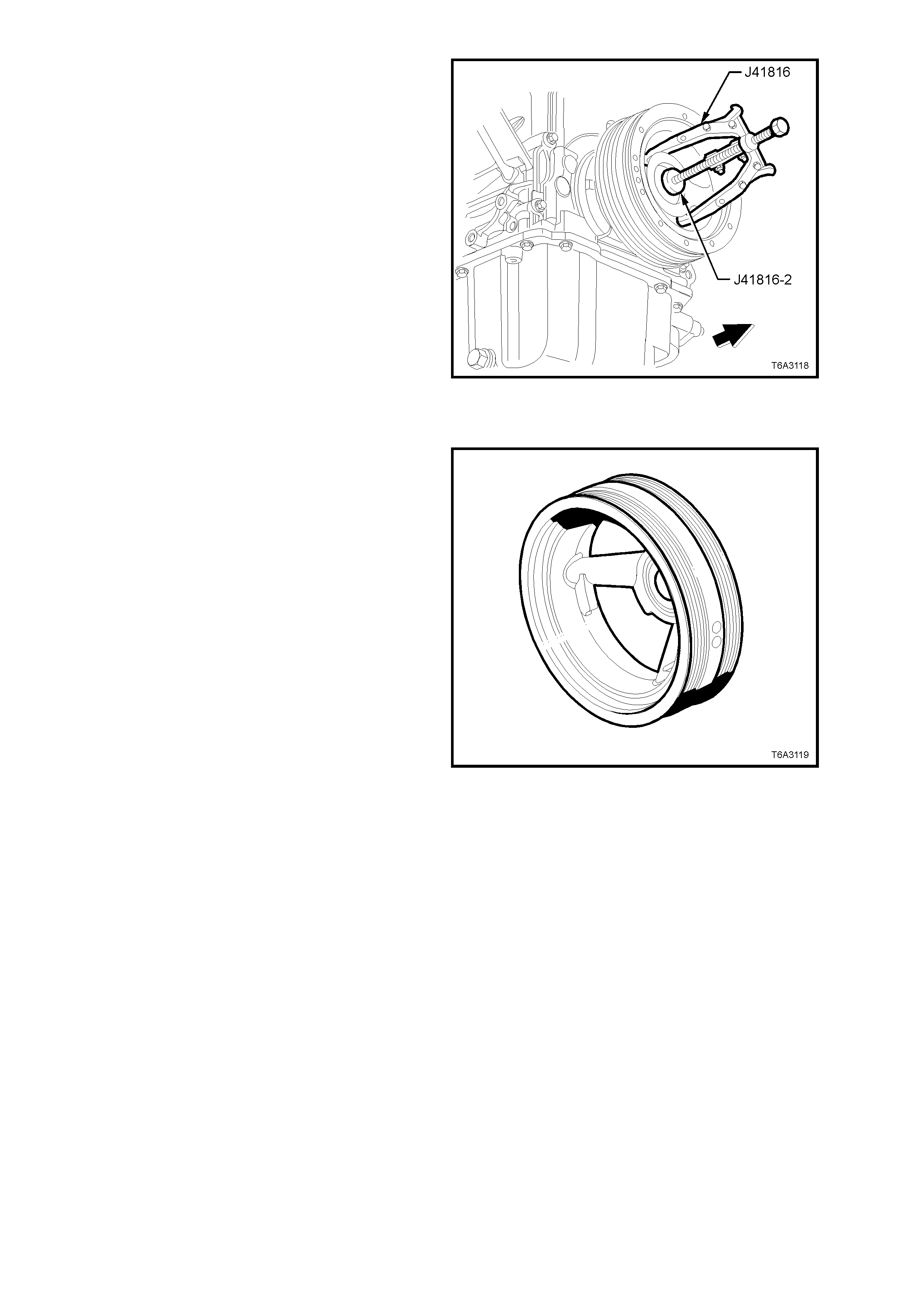
8. Use crankshaft end protector J 41816-2 and
puller J41816 (or three legged commercial
equivalent), to remove the crankshaft
balancer.
Figure 6A3-155
CLEAN AND INSPECT
1. Clean the crankshaft balancer in suitable
solvent.
2. Clean the belt grooves of all dirt or debris with
a wire brush.
3. Dry the crankshaft balancer with compressed
air.
4. Inspect the crankshaft balancer for the
following:
Worn, grooved, or damaged hub seal surface.
• A crankshaft balancer hub seal surface with
excessive scoring, grooves, rust or other
damage must be replaced.
• Minor imperfections on the hub seal surface
may be removed with polishing compound or
fine grade emery cloth.
• Dirty or damaged belt grooves.
• The balancer belt grooves should be free of
any nicks, gouges, or other damage that may
not allow the belt to track properly.
• Minor imperfections may be removed with a
fine file.
Important: In order for the belt to track properly,
the belt grooves should be free of all dirt or debris.
• Worn, c hunking or deter iorated r ubber between
the hub and pulley.
Figure 6A3-156
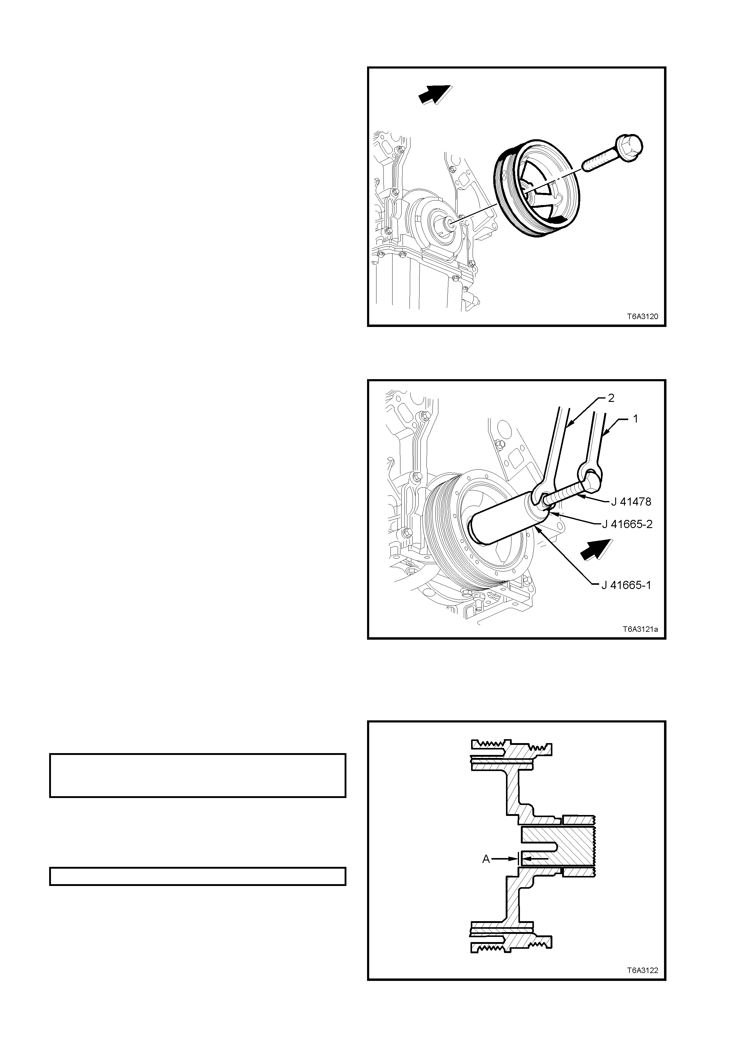
REINSTALL
Important: The crankshaft balancer reinstallation
and bolt tightening involves a multi- stage tightening
process . T he firs t pass ens ures that the balanc er is
installed completely onto the crankshaft. The
rem aining passes tighten the new bolt to the proper
torque.
The us ed crank shaf t balancer bolt will be used only
during the first pass of the balancer installation
procedure. Only install a NEW crank shaf t balancer
bolt and tighten as described in the remaining
passes of the balancer bolt tightening procedure.
1. Ensure that the teeth of the ring gear locking
Tool No. J 42386-A are correctly engaged.
2. Apply a smear of clean engine oil onto the seal
surface of the balancer, then install the
balancer onto the end of the crankshaft.
Important: The balancer s hould be positioned onto
the end of the crankshaft as straight as possible,
before to tool installation.
Figure 6A3-157
3. Use installer, Tool No. J 41665 to install the
crankshaft balancer, as follows:
a. Select the threaded rod, nut, washer and
installer, from tool J 41478.
b. Insert the installer sleeve, J 41665-1 into the
front of the balancer and back up with the
plate, J 41665-2.
NOTE: Insert the stepped end of sleeve J 41665-1
into the balancer, in this initial stage.
c. Use a set spanner (1) to hold the hexagonal
end of the threaded rod.
d. Use a second spanner (2) to rotate the
installation tool nut clockwise until the balancer
is started onto crankshaft.
e. Remove the stepped sleeve of J 41665-1 and
reverse it, s o that the lar ger end of the ins taller
is against the front of the balancer.
f. Repeat steps ‘a.’ through ‘d.’ above, until the
balancer is installed onto the crankshaft.
g. Remove the balancer installation tool.
Figure 6A3-158
4. Install the used crankshaft balancer bolt and
tighten to the specified torque.
CRANKSHAFT BALANCER
INSTALLATION TORQUE 330 Nm
SPECIFICATION
5. Remove the used balancer bolt and discard.
6. Measure the distance the balancer protrudes
from the crankshaft nose and check that
dimension ‘A’ is to specification.
DISTANCE ‘A’ 2.40 - 4.48 mm
7. If the dimension is not correct, reinstall Tool J
41665 and repeat the installation procedure.
Figure 6A3-159
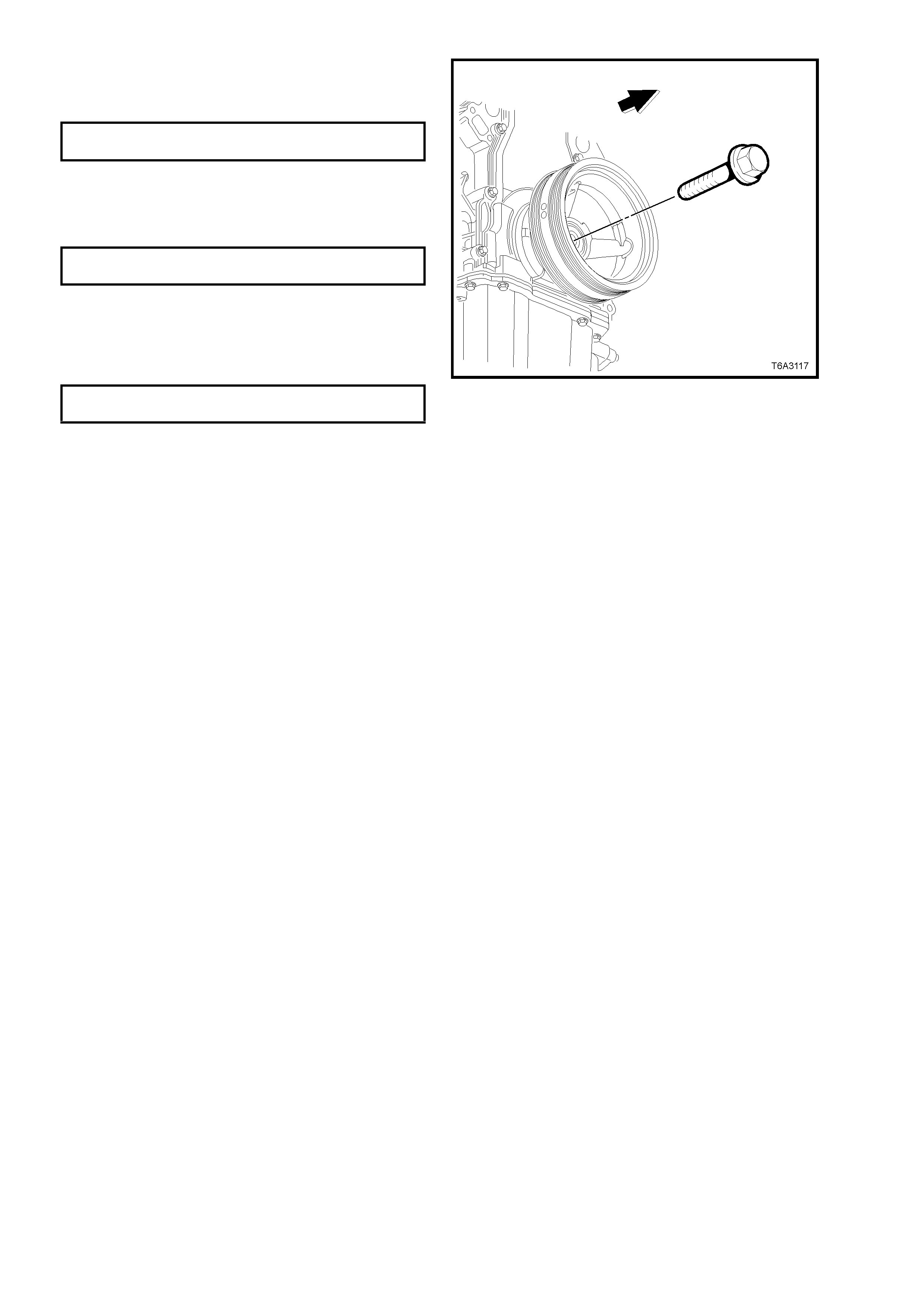
8. Install a NEW crankshaft balancer bolt.
9. Tighten the crankshaft balancer bolt to the
correct torque specification, in two stages.
CRANKSHAFT BALANCER BOLT Stage 1: 50 Nm
TORQUE SPECIFICATION Stage 2: 140° Turn angle
10. Remove the ring gear locking tool No. J
42386-A.
11. Reinstall the close-out cover and tighten the
bolt to the correct torque specification.
RIGHT HAND CLOSE-OUT COVER
BOLT TORQUE SPECIFICATION 10 Nm
12. Install the starter motor. Refer to
Section 6D3-2 STARTING SYSTEM, of this
Service Information CD and tighten the
mounting bolts to the correct torque
specification.
STARTER MOTOR MOUNTING
BOLT TORQUE SPECIFICATION 40 - 55 Nm
13. Reinstall the radiator, refer
Section 6B3 ENGINE COOLING – GEN III V8
ENGINE of this Service Information CD.
Figure 6A3-160
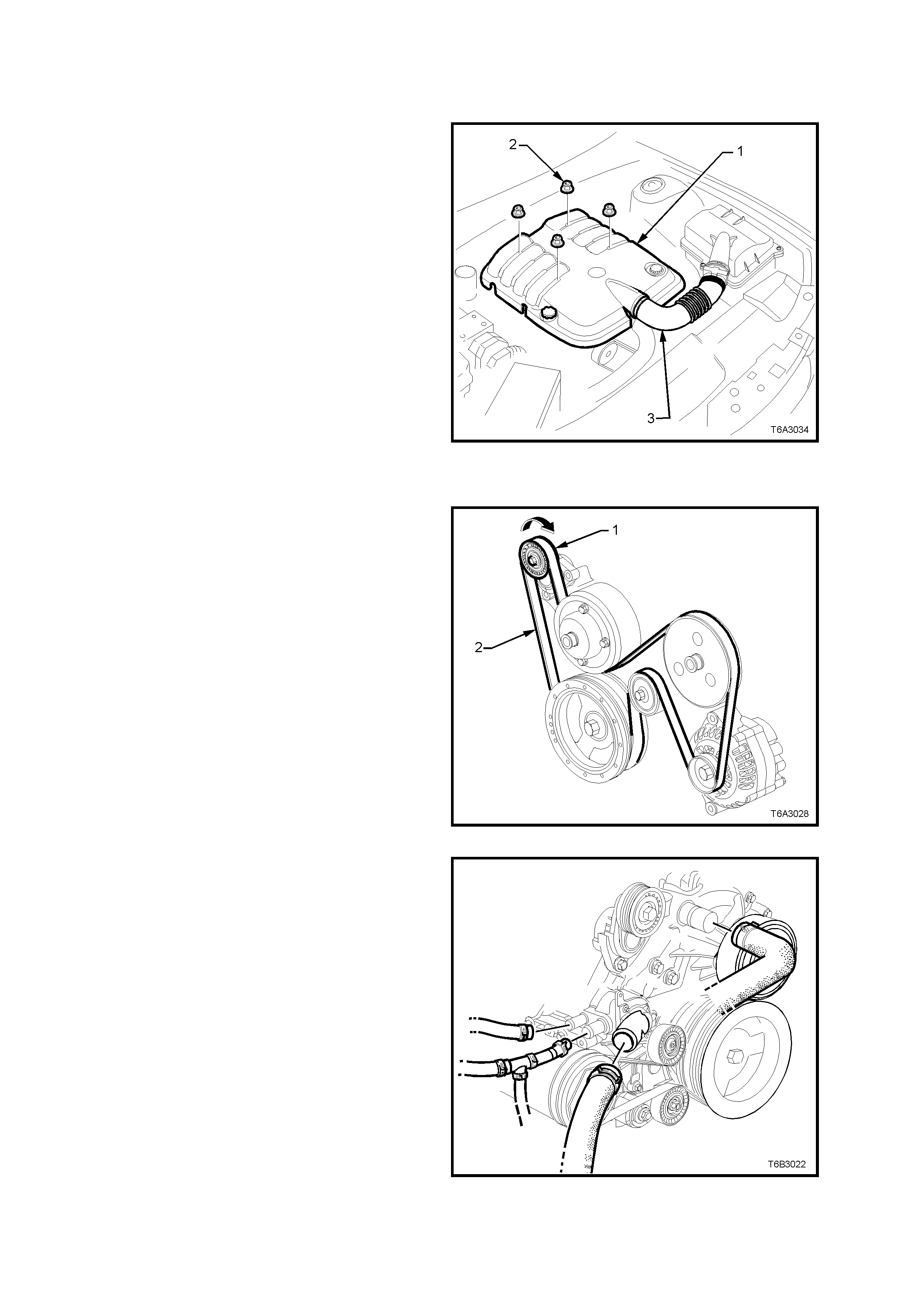
2.25 COOLANT PUMP
REMOVE
NOTE: Apart from the rear cover, O-ring and
thermostat assembly, the coolant pump is not
serviceable and if found to be faulty must be
replaced as an assembly.
1. allow engine to cool to ambient temperature
(less than 50°C), then s lowly rem ove sc rew-on
pressure cap from the coolant reservoir.
CAUTION: DO NOT REMOVE SCREW-ON
PRESSURE CAP WHILE THE ENGINE
COOLANT TEMPERATURE IS ABOVE 50°
°°
°C, AS
PERSONAL INJURY MAY RESULT.
2. Disconnect battery earth lead.
3. Remove engine dress cover decorative nuts
(2), then remove the cover (1).
4. Loosen the two intake hose clamps, then
remove the hose (3).
5. Loosen coolant pump drive pulley bolts. Figure 6A3-161
6. Rem ove engine acc esso ry drive belt (2) , us ing
a 15 mm ring spanner, refer to 2.6 ENGINE
DRIVE BELTS – REPLACE, in this Section.
Figure 6A3-162
7. Drain engine coolant. Refer to 2.3 DRAINING
AND FILLING COOLING SYSTEM, in
Section 6B3 ENGINE COOLING of this
Service Information CD.
8. Disconnect both heater hoses, the outlet and
inlet hoses from the coolant pump.
CAUTION: ALWAYS WEAR PROTECTIVE
SAFETY GLASSES WHEN WORKING WITH
SPRING TYPE HO SE CLAMPS. F AIL URE TO DO
SO COULD RESULT IN EYE INJURY.
Figure 6A3-163
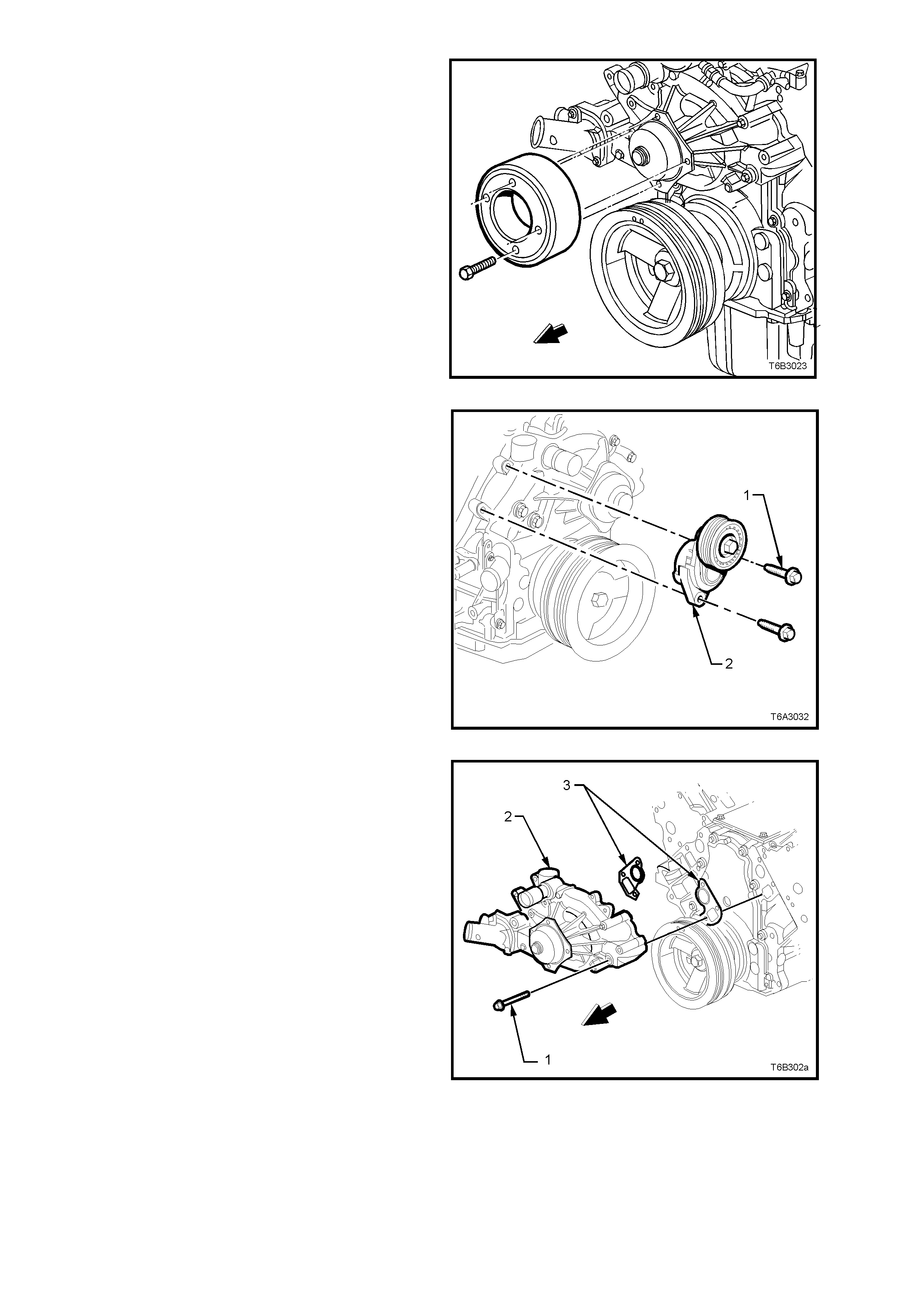
9. Remove the loosened four bolts securing the
coolant pump pulley to the hub. Remove
pulley.
Figure 6A-164
10. Remove the two bolts (1) securing the drive
belt tensioner (2) to the coolant pump housing
and set the tensioner to one side.
Figure 6A-165
11. Loosen, then rem ove the s ix bolts (1) secur ing
the coolant pump (2) to the cylinder block (3).
12. If necessary, use a soft faced hammer to
lightly tap coolant pump housing (2) to
dislodge it from the cylinder block.
13. Remove coolant pump gaskets (3) and
discard.
Figure 6A-166
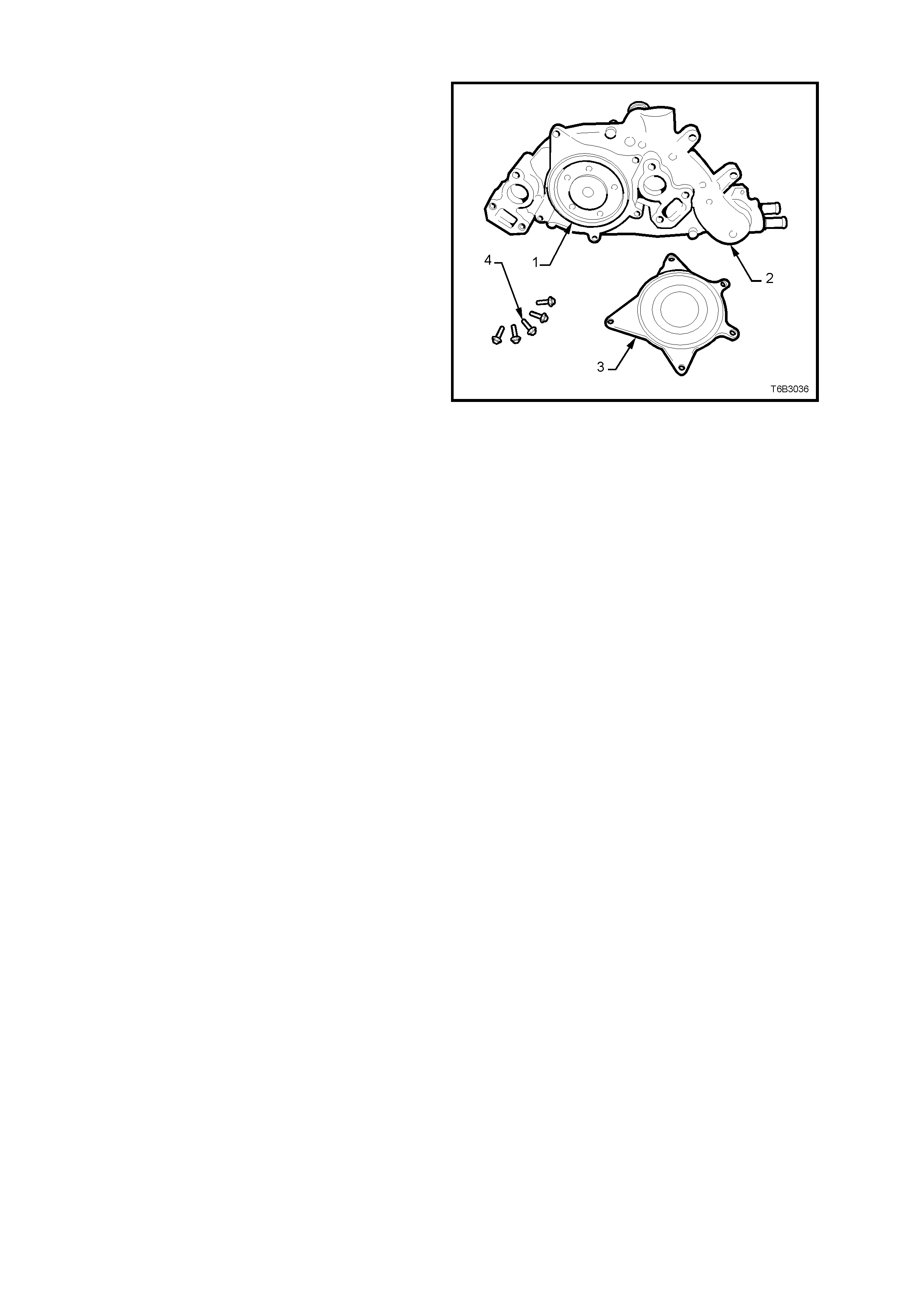
DISMANTLE
NOTE: Apart f rom the s ervic e operations des c ribed
here, there are no other serviceable parts in the
coolant pump assembly and if required, then the
assembly must be replaced as a complete unit.
1. If required, remove the five bolts (4) securing
the rear cover (3) to the coolant pum p (2). T ap
with a soft faced hammer to dislodge the cover
from the pump body.
2. Remove the sealing O-ring (1) from the
coolant pump body (2).
3. For thermostat remove, test and reinstall
procedures, refer to 2.9 THERMOSTAT, in
Section 6B3 ENGINE COOLING of this
Service Information CD.
Figure 6A-167
CLEAN AND INSPECT
1. Remove the old gasket or gasket material
from the coolant pump sealing surfaces and
cylinder block, taking care not to scratch the
machined surfaces.
2. Clean all dirt and debris from the coolant
pump housing.
3. Inspect the coolant pump for the following:
• Gasket surfaces for excessive scratches or
gouging.
• Hose sealing surfaces for scratches, gouging
or corrosion.
• Restrictions, corrosion or evidence of cavitation
within the internal coolant passages or on the
pump impeller.
• Excessive side-to-side play in the pulley shaft.
• A loose belt pulley or a pulley with excessive
wear or scoring on the belt tracking area.
• Evidence of coolant leakage at the coolant
outlet housing or rear cover gasket (if these
parts have not been removed).
• Leakage at the coolant pump vent hole. A st ain
around the vent hole is acceptable. If leakage
occurs (dripping) with the engine running and
the cooling system pressurised, replace the
coolant pump.

REASSEMBLE
1. Install a new O-ring seal to the cleaned groove
in the pump housing, then install the cover
and retaining bolts.
2. Gradually tighten every second bolt until the
correct torque specification is reached.
COOLANT PUMP REAR COVER
BOLT TORQUE SPECIFICATION 13 - 15 Nm
REINSTALL
Installation is the r everse to rem oval except for the
following items:
1. Ensure that the coolant pump and cylinder
block surfaces are clean and dry.
2. Using two bolts ins erted into the coolant pum p
on each side as guides, install NEW gaskets
over them and install the coolant pump to the
cylinder block.
3. Install remaining bolts and tighten to the
correct torque specification, in two stages.
COOLANT PUMP BOLT Stage 1: 15 Nm
TORQUE SPECIFICATION Stage 2: 30 Nm
4. Install the coolant pump pulley and attaching
bolts, tightening to the correct torque
specification.
COOLANT PUMP PULLEY BOLT
TORQUE SPECIFICATION 15 Nm
5. Install the engine accessory drive belt
tensioner and attaching bolts , tightening to the
correct torque specification.
ENGINE ACCESSORY DRIVE BELT
TENSIONER BOLT 40 - 60 Nm
TORQUE SPECIFICATION
6. Install all removed radiator hoses and clamps.
CAUTION: ALWAYS WEAR PROTECTIVE
SAFETY GLASSES WHEN WORKING WITH
SPRING TYPE HOSE CLAMPS. FAILURE TO DO
SO COULD RESULT IN EYE INJURY.
7. Install the engine accessory drive belt. Refer
2.6 ENGINE DRIVE BELTS - REPLACE in
this Section.
8. Refill cooling system, refer to 2.3 DRAINING
AND FILLING COOLING SYSTEM in
Section 6B3 ENGINE COOLING of this
Service Information CD.
9. Check for cooling system leaks, refer to
2.8 PRESSURE TESTING in
Section 6B3 ENGINE COOLING of this
Service Information CD.
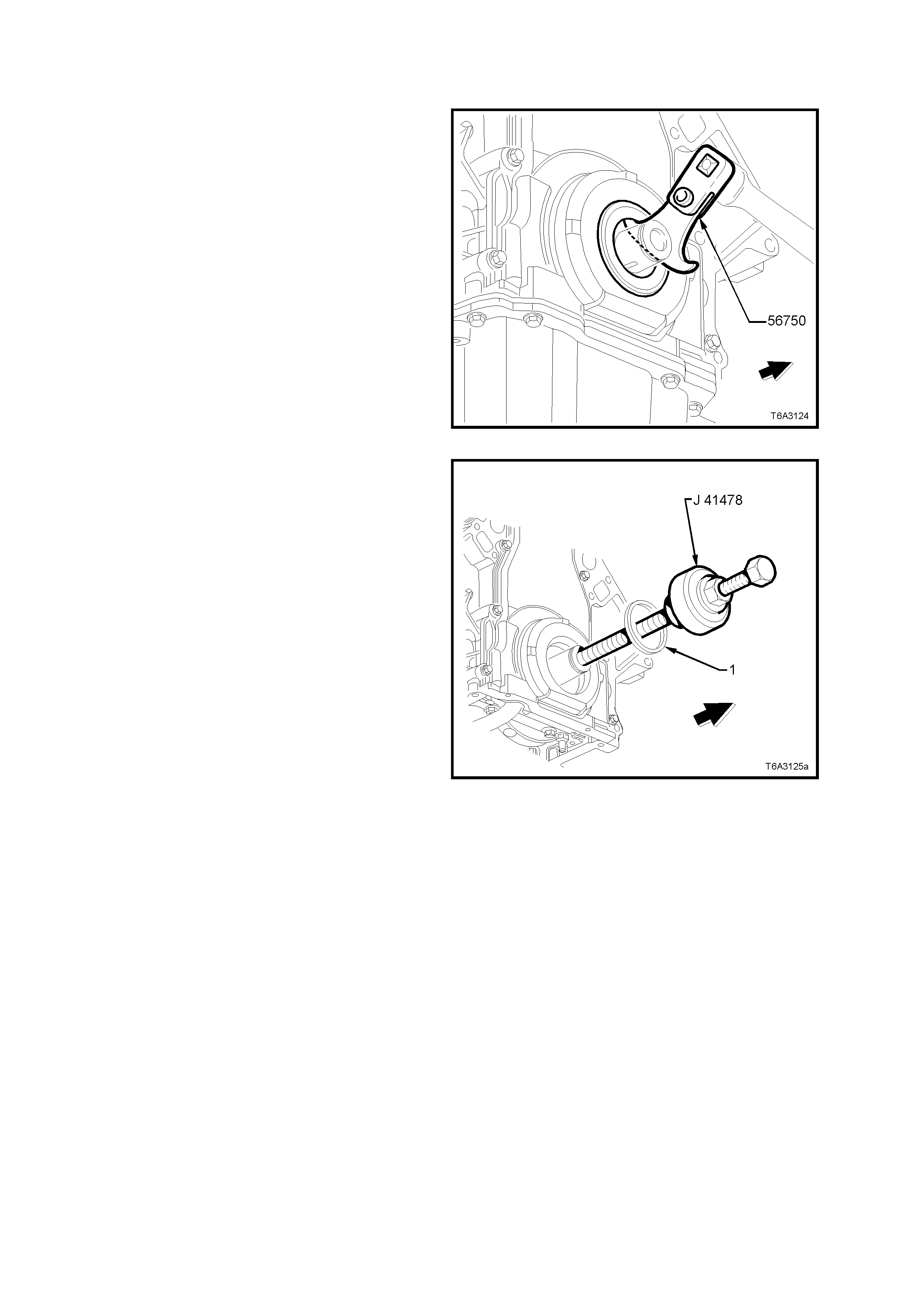
2.26 CRANKSHAFT FRONT OIL SEAL
REPLACE
1. Remove the crankshaft balancer. Refer
2.24 CRANKSHAFT BALANCER in this
Section.
2. Using Tool No. 56750 (or commercial
equivalent) remove seal from the front cover.
Figure 6A3-168
3. Lubric ate the outer edge of a NEW oil seal ( 1)
and the front cover oil seal bore with clean
engine oil.
Important: Do not lubricate the oil seal sealing
surface.
4. Install the crankshaft front oil seal (1) onto the
guide of Tool No. J 41478.
5. Install the threaded rod (with nut, washer,
guide, and oil seal) of Tool No. J 41478 into
the end of the crankshaft.
6. Using a set spanner, hold the head of the
installer bolt, then rotate the installer nut
clockwise, using a second set spanner, until
the seal bottoms in the cover bore.
7. Remove the tool from the crankshaft.
8. Inspec t the oil seal for c orrect ins tallation. The
oil seal should be installed evenly and
completely into the front cover bore.
9. Install the crankshaft balancer, refer
2.24 CRANKSHAFT BALANCER, in this
Section.
Figure 6A3-169
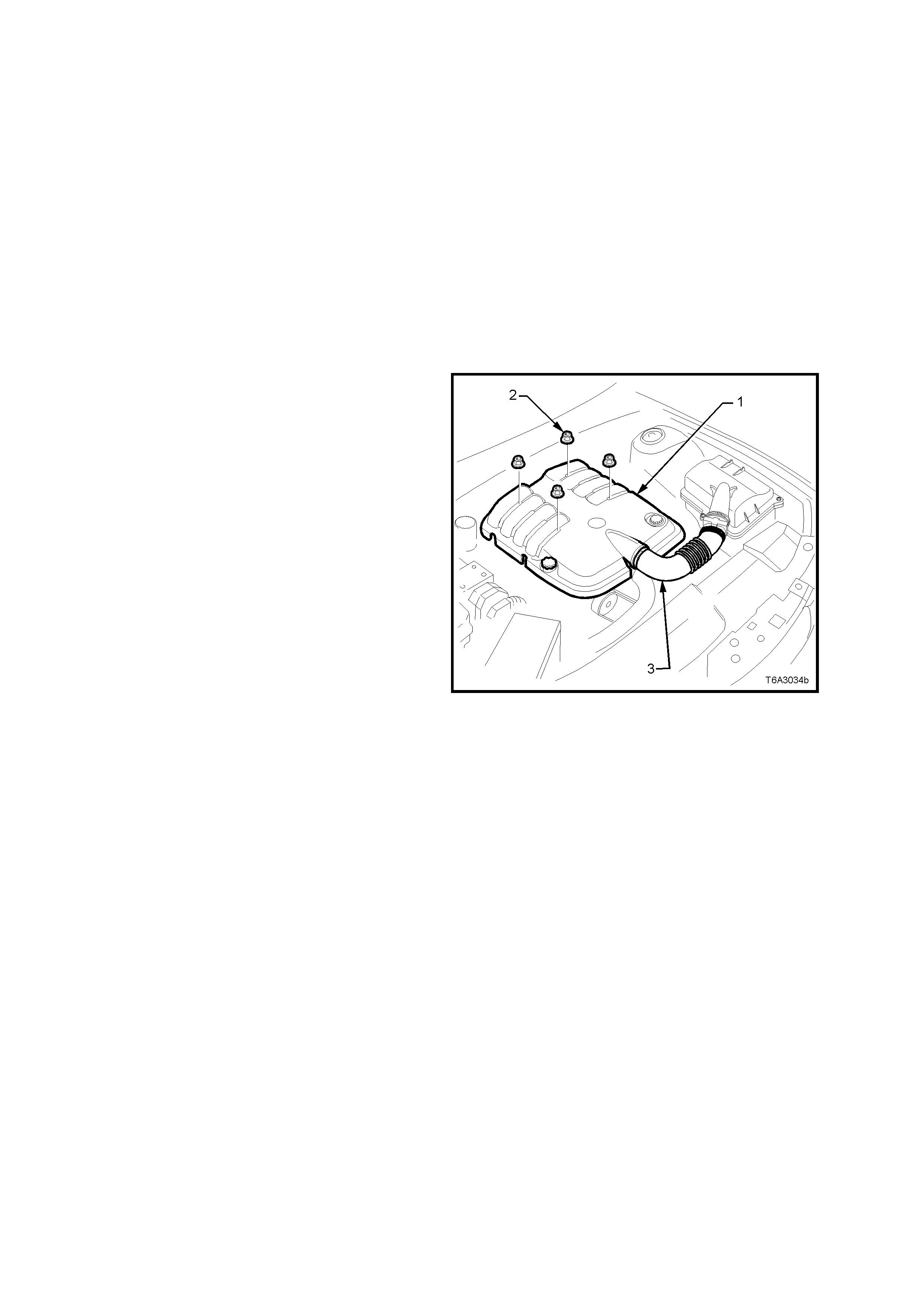
2.27 ENGINE MOUNTS
CHECK
1. Check in the area of the mounts for signs of
fluid leakage. If oil leakage from a mount is
visible, the mount is defective and must be
replaced.
2. Using a suitable engine lifting crane, raise the
engine to remove the weight from the mounts
and to place rubber in slight tension.
Check that the mounting rubber has not
deteriorated, split or separated from its metal
plates.
Replace mount if found to be defective.
REMOVE
1. Disconnect the battery earth cable from the
battery.
2. Drain the cooling system. Refer to
Section 6B3 ENGINE CO OLING - GEN III V8
ENGINE.
3. Rem ove the engine dress cover retaining nuts
(2), then remove the cover (1).
4. Loosen the two clam ps securing the air intake
duct (3) to the thr ottle body and Mas s Air Flow
(MAF) sensor.
5. Raise front of vehicle and place on safety
stands. For location of jacking and support
points, refer to Section 0A GENERAL
INFORMATION.
6. Remove the exhaust pipe to manifold flange
nuts on the engine mount side to be removed.
7. From under the vehicle, remove the lower
mounting to crossmember nut for both
mounts.
NOTE: A commercially available, 18 mm deep
socket will be required for this operation.
8. Lower the vehicle to the ground, then remove
the exhaust manifold on the engine mounting
side to be removed. Refer to
2.21 EXHAUST MANIFOLD - REMOVE, in
this Section.
Figure 6A3-170
9. Use suitable engine lifting equipment to raise
the engine, removing the weight from the
engine mounts.
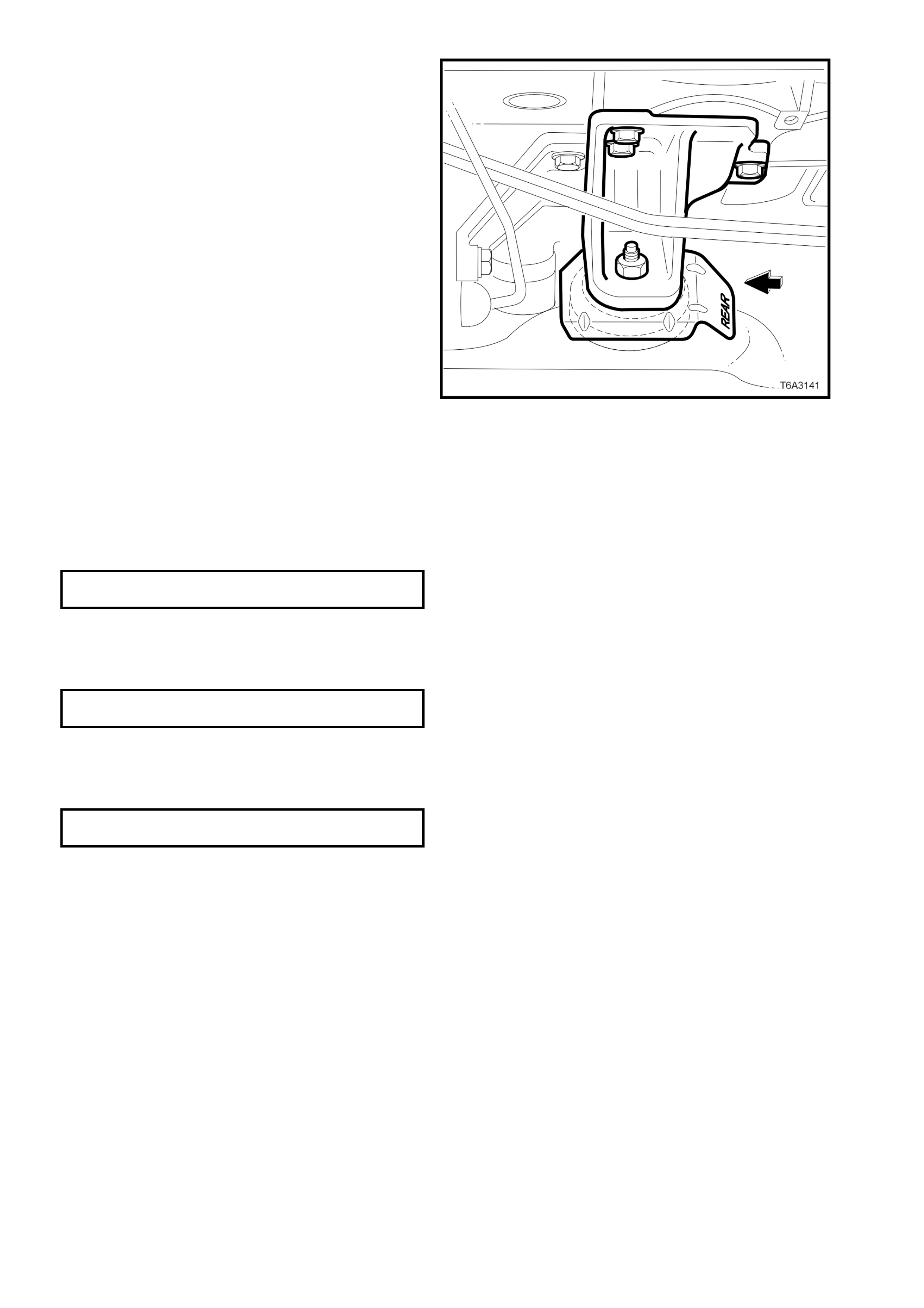
10. Remove the mount bracket to engine block
bolts.
11. Lift the mount and bracket assembly from the
crossmember and remove from the vehicle.
12. Remove the engine mount to bracket nut and
separate the heat shield and mount from the
bracket.
NOTE: While the left hand mount is shown, the
operation is similar for either engine mount except
that, for the right hand engine mount, remove the
battery harness bracket bolt, before removing the
mounting bracket to engine block bolts.
Figure 6A3-171
REINSTALL
Reinstallation of either or both engine mounts is the
reverse to removal, except for the following points.
1. If removed from the bracket, reinstall the
engine mount and heat s hield, then tighten the
nut to the correct torque specification.
ENGINE MOUNT TO BRACKET NUT
TORQUE SPECIFICATION 70 - 90 Nm
2. Install the engine mount stud into the
crossmember, then install the bracket to
cylinder block bolts and tighten to the correct
torque specification.
ENGINE MOUNTING BRACKET BOLT
TORQUE SPECIFICATION 40 - 60 Nm
3. Lower the engine allowing the weight to settle
on the crossmember, install both engine
mount nuts and tighten to the correct torque
specification.
ENGINE MOUNT TO CROSSMEMBER
NUT TORQUE SPECIFICATION 70 - 90 Nm
4. Install exhaust manifold. Refer to
2.21 EXHAUST MANIFOLD - REINSTALL in
this Section.
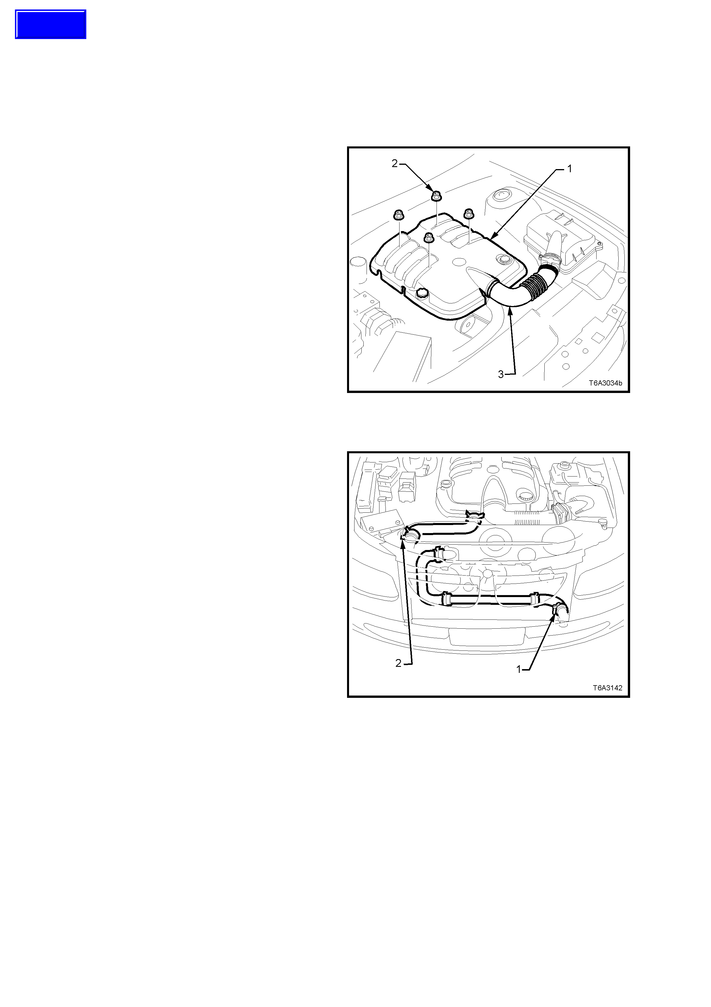
3. MAJOR SERVICE OPERATIONS
3.1 ENGINE ASSEMBLY
REMOVE
1. Disconnect the battery earth cable from the
battery.
2. Loosen the screw-on pressure cap on the
coolant surge tank to relieve any system
pressure, then remove cap.
CAUTION: To avoid serious personal injury,
never remove the screw-on pressure cap when
the engine is hot. Sudden release of cooling
system pressure is very dangerous and could
cause personal injury.
3. Rem ove the engine dress cover retaining nuts
(2), then remove the cover (1).
4. Loosen the two clam ps securing the air intake
duct (3) to the thr ottle body and Mas s Air Flow
(MAF) sensor.
5. Remove air intake duct (3) assembly from
throttle body and MAF sensor.
6. De-pressurise fuel rail. Refer to
Operation 2.13, in this Section. Figure 6A3-172
7. Remove the screw-on pressure cap from the
surge tank.
8. Place a s uitable drain tray beneath the engine,
then loosen the worm drive hose clam p (1) on
the lower hose at the left hand radiator tank,
remove the hose and drain the coolant.
9. Loosen the spring clamp securing the lower
left hand hose to the tr ansf er tube and rem ove
the lower left hand hose from the vehicle.
CAUTION: Wear safety glasses to avoid eye
injury.
NOTE: If access to the transfer tube hose clamp is
poor, then disconnect the lower hose from the
radiator, left hand tank. After the radiator is
removed (Step 10), the transfer tube and all lower
hoses can then be removed as an assembly.
10. Loosen top radiator hose (2) clamps and
remove hose from the engine.
11. Remove the engine cooling fans and radiator.
Refer to Section 6B3, ENGINE COOLING –
GEN III V8 ENGINE.
Figure 6A3-173
Techline

12. Recover refrigerant charge, refer to Section
2C AIR CONDITIONING - SERVICING AND
DIAGNOSIS.
13. Remove the suction/discharge hose pad (2)
retaining nut (1) from the com pressor (3), then
remove O-rings (4) and immediately cap or
plug all openings to prevent moisture entry
from the atmosphere.
Figure 6A3-174
14. After removing the four oil pan under-tray
bolts, remove the tray from the vehicle.
15. Rem ove oil pan drain plug and drain engine oil
into a suitable container.
Reinstall drain plug once oil has drained
sufficiently.
16. Disconnect windshield washer hose (1) at the
in-line connector located at the rear, left hand
side of the engine hood.
Figure 6A3-175
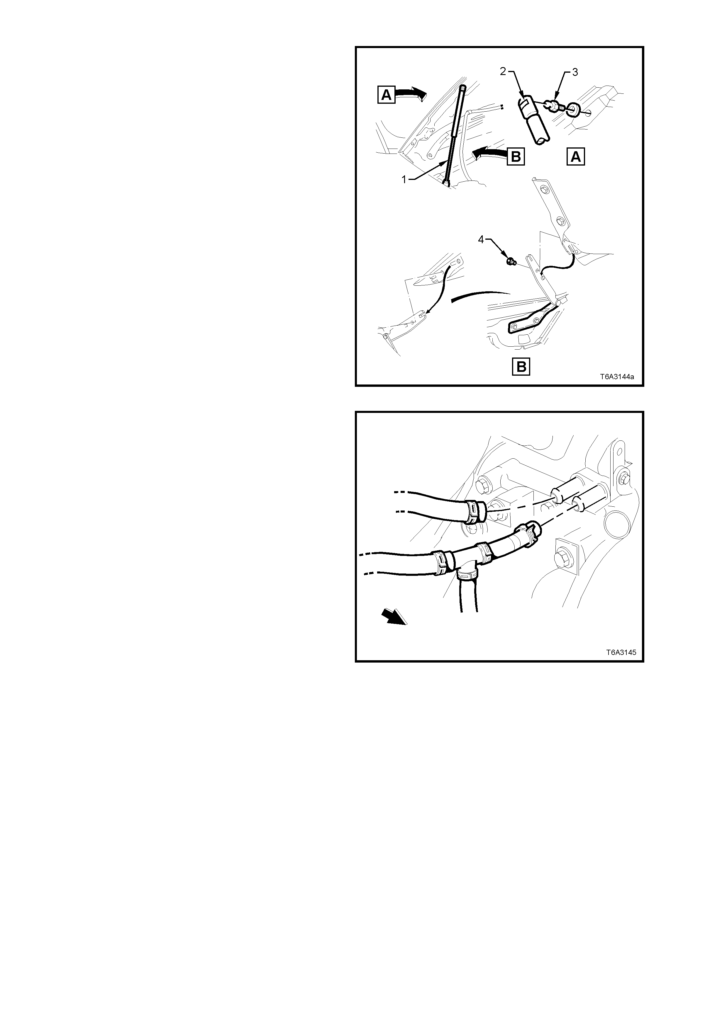
17. With engine hood adequately supported,
remove clips (2) securing upper ends of struts
(1) to hood pivots (3).
Disengage struts (1) from hood pivots (3) and
lay struts onto inner fender panel.
18. Using an ass istant to hold the hood assem bly,
remove the engine hood bracket to hinge
attaching bolts (4) , as shown, then caref ully lift
the hood assembly clear of the vehicle.
Figure 6A3-176
19. Remove both heater hose clamps at the
engine water pump, taking note of the hose
layout. Plug open ends to prevent dirt entry.
Figure 6A3-177
20. Remove the nut (1) securing the battery
harness earth terminal (2) from ABS/CRUISE
CONTROL bracket stud (4).
21. Remove the engine cooling fan relay
assembly (7), then disconnect the engine fan
wiring harness connector (8) from the relay
and battery harness.
22. Remove the clip holding the battery harness
(5) to the side rail bracket (6) and lay the
harness on the engine.
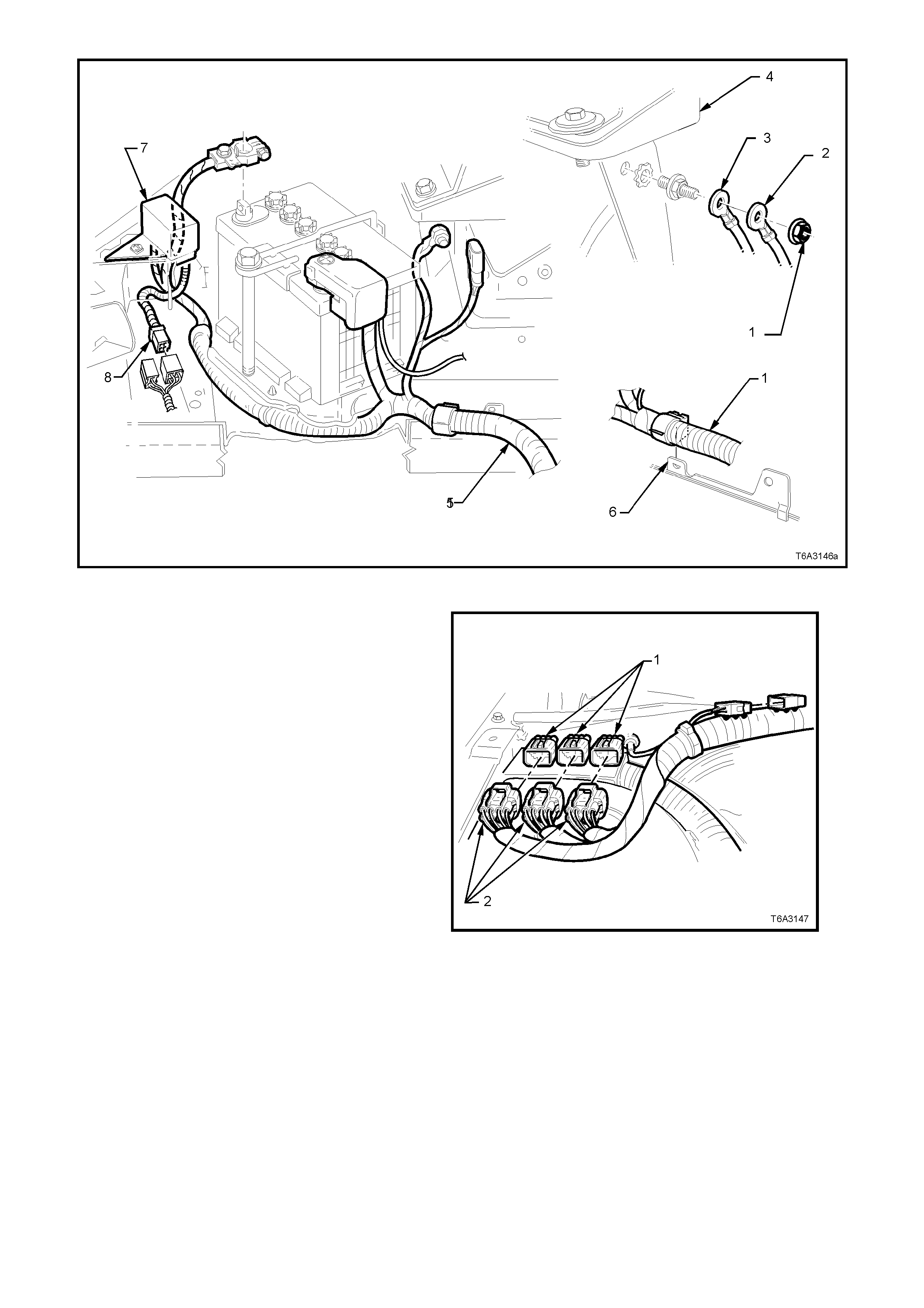
Figure 6A3-178
23. Disconnect main wiring harness to powertrain
and battery harness connectors (2) from the
main wiring harness connectors (1), at the
dash panel.
Figure 6A3-179
24. Disconnec t powertrain wiring harnes s clips (6)
from the engine compartment dash panel
retaining bracket (‘5’, view D), refer Figure
6A3-180.
25. Disconnect powertrain wiring harness
connectors from the:
• Surge tank, low coolant switch (‘1’, view
A).
• Theft deterrent horn (‘4’, view C).
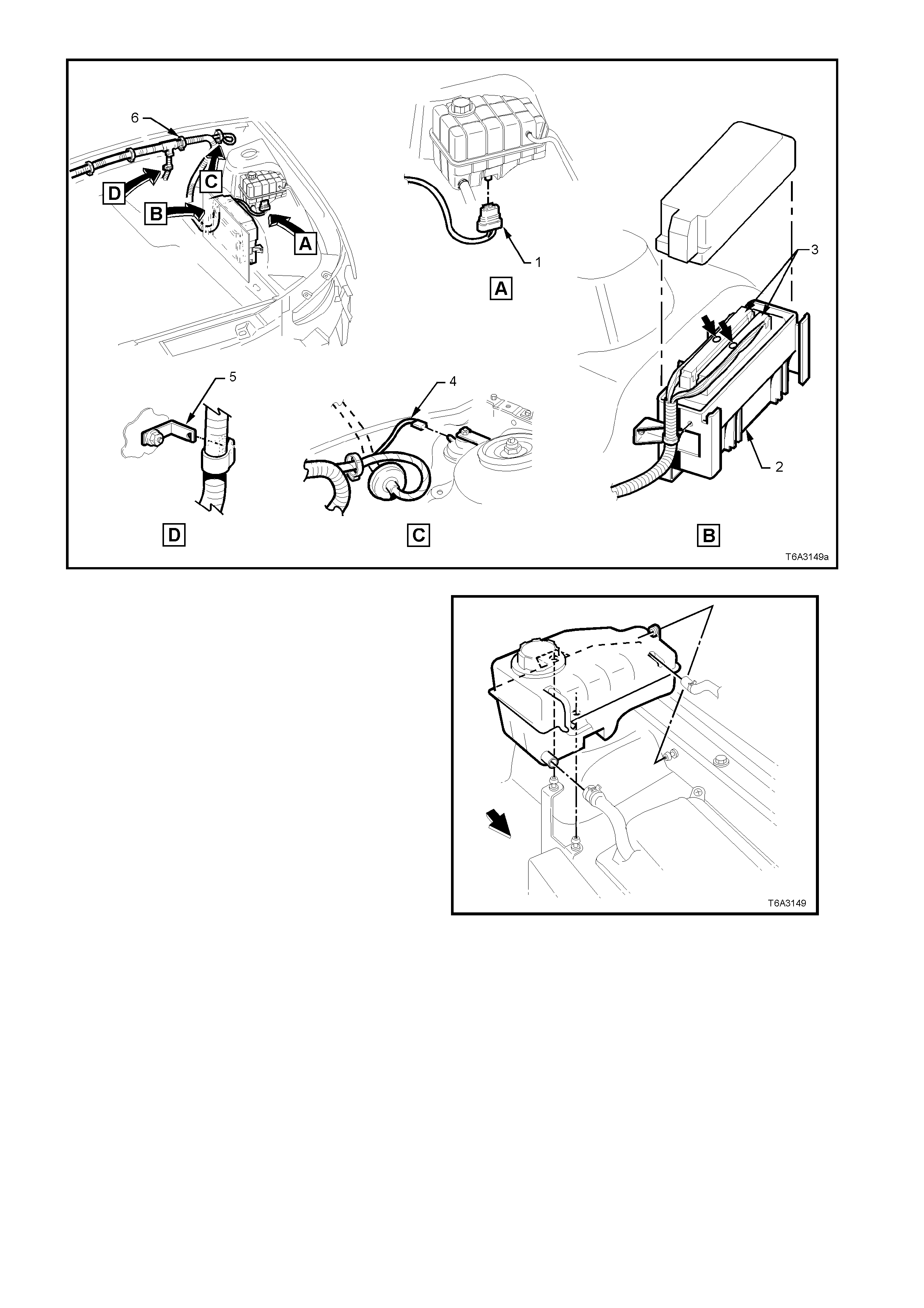
Figure 6A3-180
26. Loosen hose clamps and remove hoses from
the coolant surge tank. Then grasp the surge
tank and firmly pull to remove it from the
retaining pegs.
27. Rem ove the c over f r om the Powertrain Contr ol
Module (PCM).
28. Rem ove both PCM c onnector s (s ee ‘3’, view B
in Figure 6A3-180) in the engine bay, after
removing the retaining screw (bold arrows)
from each connector.
29. Rem ove the PCM wiring harness r etaining clip
from the PCM container, to free the harness.
Figure 6A3-181
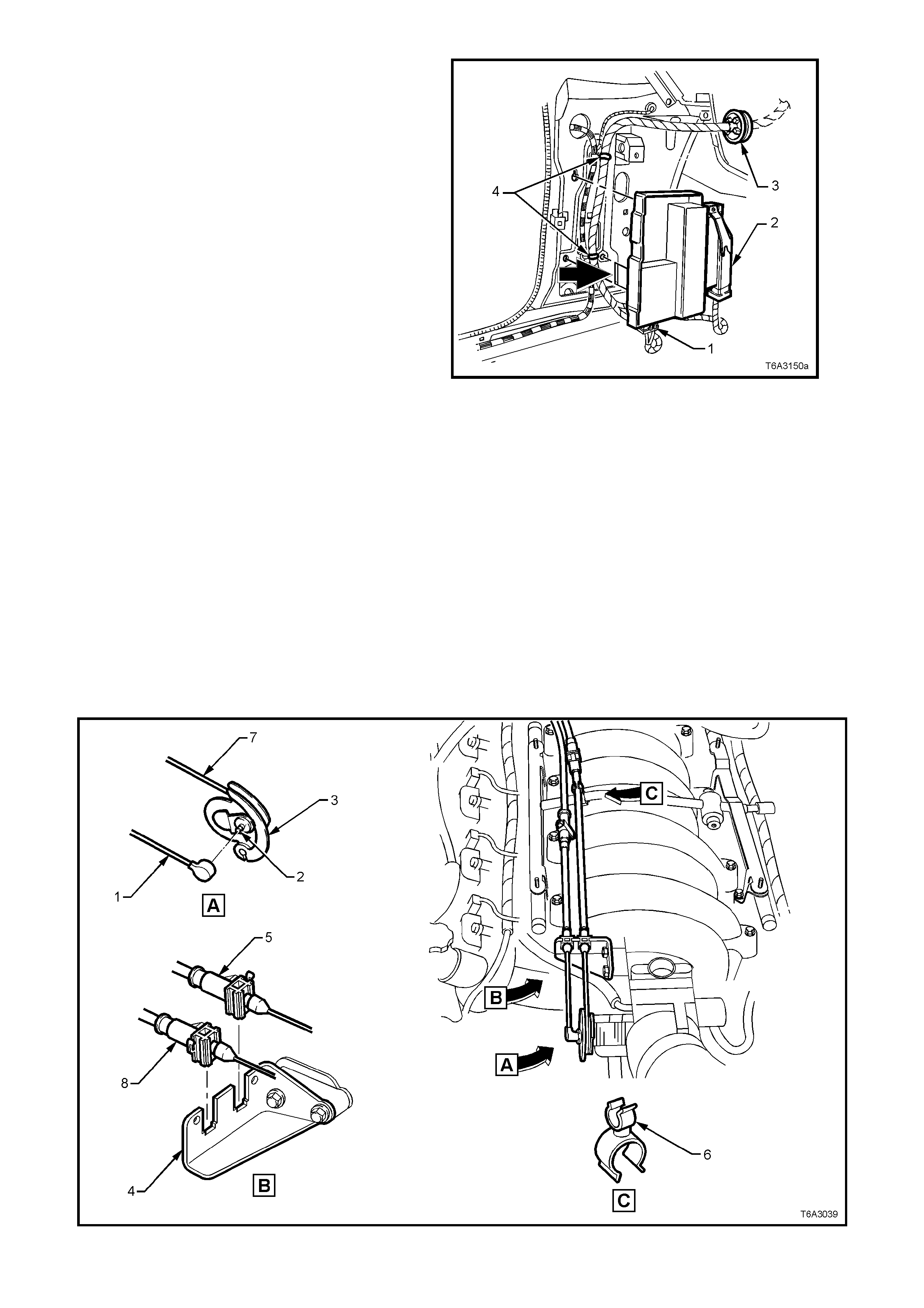
30. From inside the passenger compartment of
the vehicle, remove the lef t hand shroud panel
trim, and glove box assembly. For details,
refer Section 1A1 and Section 1A3,
respectively, of the VT Series I Service
Information.
31. Rem ove the wiring harness c onnec tor ( 1) f r om
the Powertrain Interface Module (PIM).
32. Remove the Throttle Relaxer Module (TRM)
connector (2) (if fitted), as follows:
Lift the locking lever on the TRM connector (2),
pivot down and remove the c onnec tor f r om the
lower hook.
33. To remove the PIM, either use the fingers (or
a flat bladed screwdriver) to push on and
dislodge the retaining hook (bold arrow), then
remove the PIM and TRM as an assembly.
34. Cut the wiring harness straps (4) and discard.
35. Release the harness to dash panel grommet
(3) and feed the harness and connectors out
into the engine bay.
36. Lay the powertrain wiring harness on top of the
engine.
Figure 6A3-182
37. Disconnect the cruise control cable (1) (if
fitted) (r efer Figure 6A3- 183) from the stud (2)
on the throttle body valve lever (3), then
remove the outer cable (8) from the retainer
bracket (4).
38. Lift the throttle cable ( 5) f r om the clip ( 6) at the
fuel rail crossover pipe, then lift the cable (5)
from the retainer bracket (4).
39. Remove the inner throttle cable (7) from the
throttle body valve lever (3).
40. Set the cable/s to one side.
Figure 6A3-183
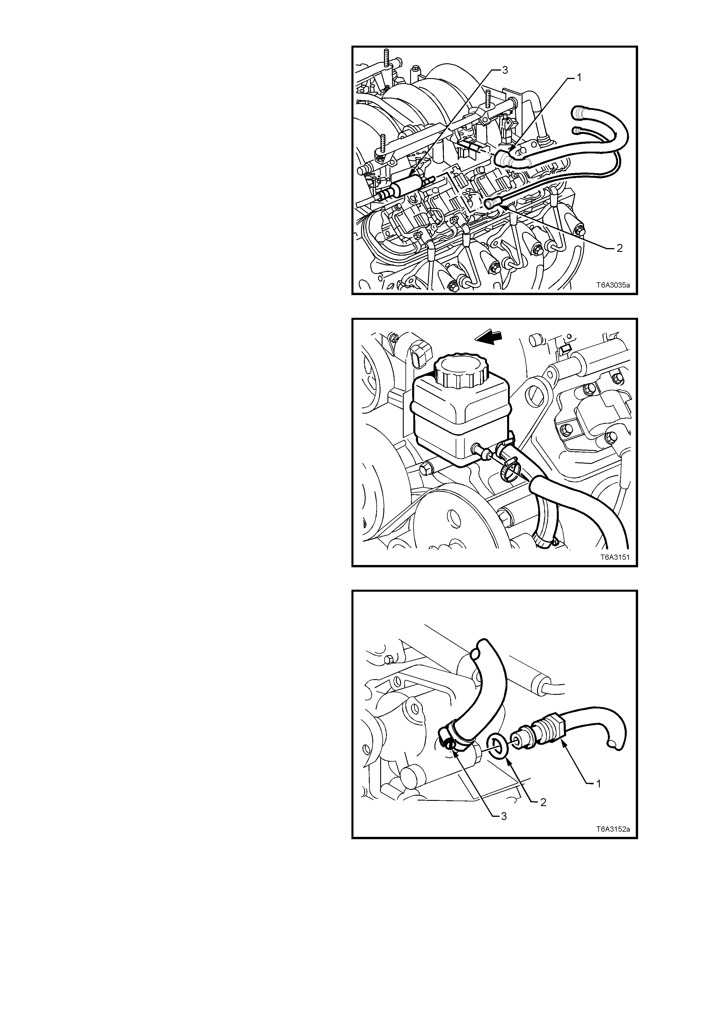
41. Using quick connect release Tool No. 7371,
open tool and install over fuel rail line.
42. Close 7371 and pull into fuel rail line quick
connect (1) to release it from the fuel rail, pull
back on the quick connect (1), to remove.
Remove the quick connect release tool from
the fuel rail line.
43. Disconnect the vapour line (2) connection to
the EVAP purge control valve (3) and set to
one side.
Important: Plug all openings to prevent fuel
leaking and dir t/contaminants f r om entering the f uel
system.
Figure 6A3-184
44. Loosen the hose clamp on the return hose at
the power steering reservoir end.
45. After placing a suitable container under the
reservoir, remove the hose and drain the
reservoir fluid.
Important: Plug both openings to prevent dirt
entry.
46. Using tie wire or similar, secure the hose to
one side.
Figure 6A3-185
47. Loosen and remove the high pressure line
flare nut (1) and O-ring (2) from the pump
outlet fitting at the rear of the power steering
pump. Use a back-up spanner on the outlet
fitting when loosening the flare nut.
Important: Plug both openings to prevent fluid loss
and/or dirt entry.
Figure 6A3-186
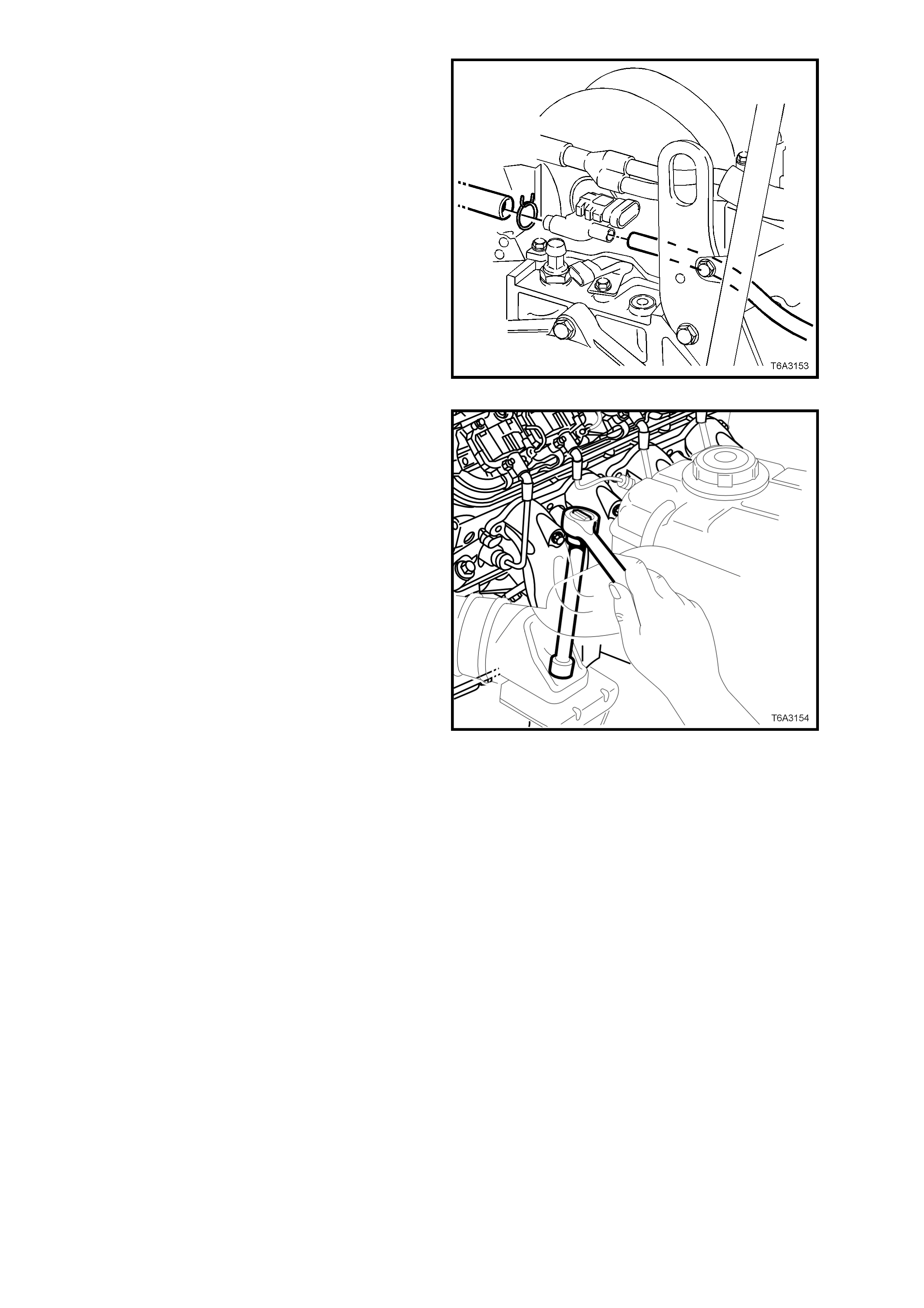
48. Disconnect the brake booster and heater
control, vacuum hoses from the rear of the
intake manifold.
Figure 6A3-187
49. Remove number 3 spark plug lead and plug
from the left bank, then remove the upper left
engine mount to engine bracket nut, using a
socket, universal joint, long extension and
ratchet.
50. For the right hand engine mount, repeat the
above process by removing the number 2
spark plug lead and plug (or number 4 spark
plug), to gain access to the upper, right hand
engine mount nut.
NOTE: To improve access to these two nuts, an
alternative method is to remove both exhaust
manifolds. Refer to 2.21 EXHAUST MANIFOLD, in
this Section, for the necessary procedure, if
required.
Figure 6A3-188
51. Raise vehicle front and rear and support on
safety stands. For location of jacking and
support points, r ef er to Section 0A GENERAL
INFORMATION.
52. Remove propeller shaft, refer to Section 4C
PROPELLER SHAFT AND UNIVERSAL
JOINTS, in of the VT Series II Service
Information. Install a suitable plug in the rear
of the transmission.
53. Disconnect the gear shift control from the
transm ission. Refer to Section 7B3 M ANUAL
TRANSMISSION - GEN III V8 ENGINE, or
Section 7C4 AUT OM ATIC TRANSMISSION -
ON-VEHICLE SERVICING, in of the VT
Series II Service Information.
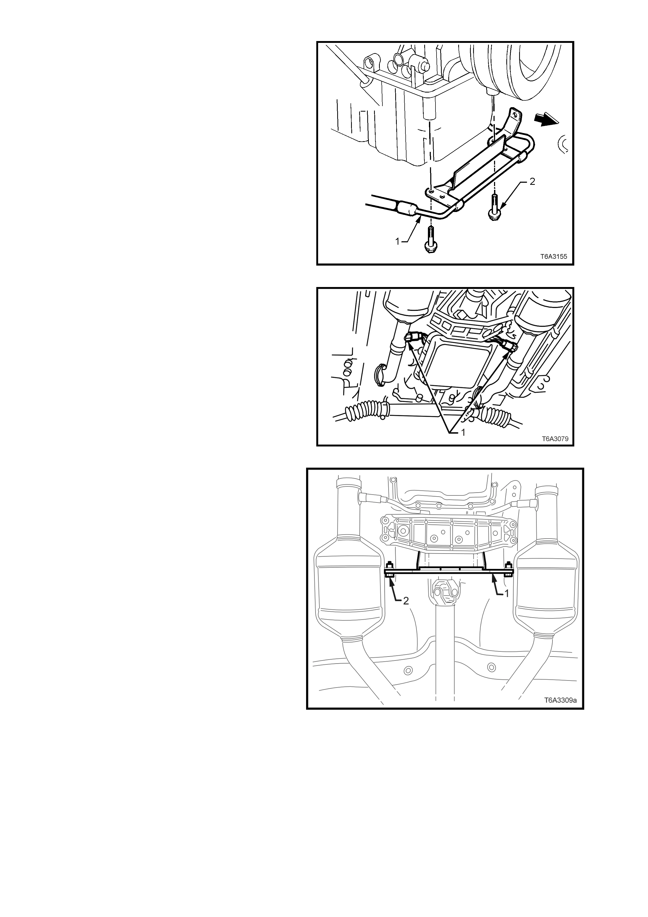
54. From under the front of the vehicle, remove
the oil pan under-tray. Refer 6B3 ENGINE
COOLING - GEN III V8 ENGINE, of this
Service Information CD.
55. Remove the two bolts holding the power
steering, high pressure line brackets to the oil
pan.
Figure 6A3-189
56. While not essential, it is recommended that
the oxygen sensors (1) are removed from the
exhaust pipes, to avoid accidental damage.
a. Disc onnect the wiring har nes s c onnec tors
from each oxygen sensor.
b. Remove both oxygen sensors from the
exhaust pipes.
c. Plug openings in exhaust pipes.
57. Remove both exhaust pipe to manifold flange
nuts.
Figure 6A3-190
58. Remove the two bolts (2) securing the catalytic
converter bracket (1).
NOTE: While Figure 6A3-191 shows an automatic
transm ission equipped vehicle, this operation is the
same for manual transmission vehicles as well.
59. Lower the vehicle to the ground.
Figure 6A3-191
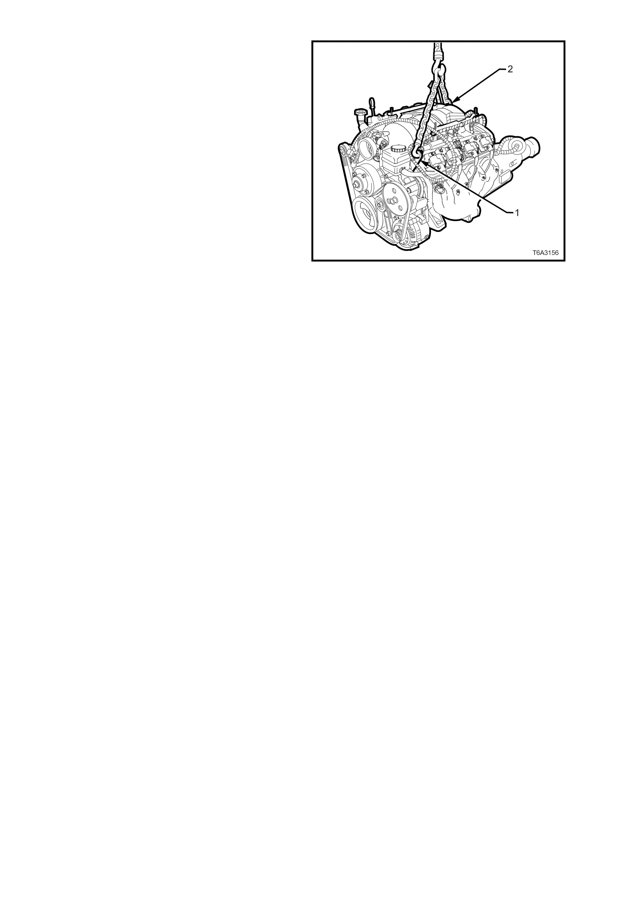
60. Attach a suitable lif ting chain and hooks to the
engine lifting brackets located at the left hand
front (1) and right hand rear (2) of the engine.
61. Using a suitable lifting crane, raise the engine
slightly to take the weight off the engine
mounts.
Figure 6A3-192
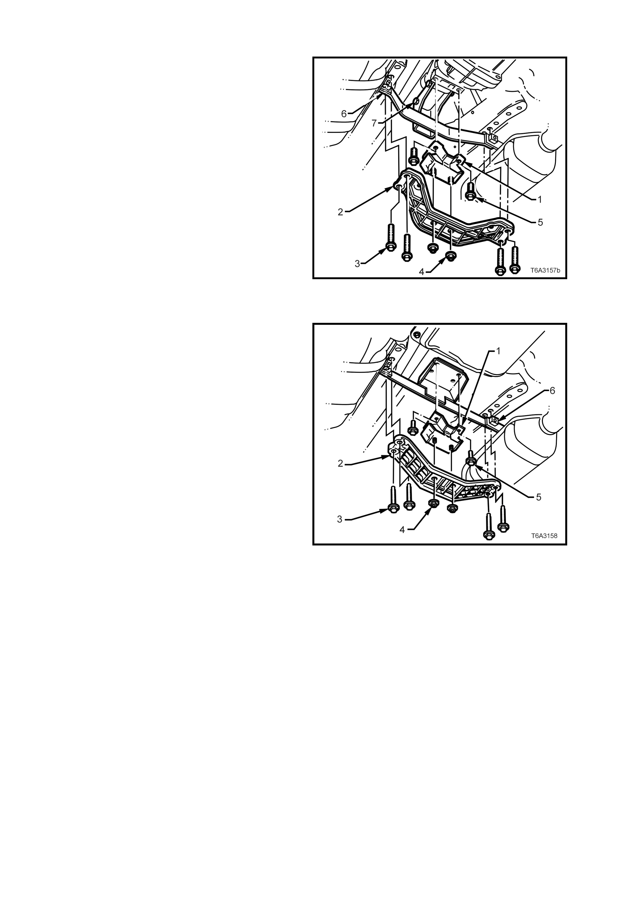
Vehicles with Manual Transmission
62. Mark the relationship of the engine rear
crossmember (2) to the frame, to assist with
alignment on reassembly.
63. Remove the four bolts (3) holding the rear
crossmember (2) to the frame, remove the
rear mounting to crossmember nuts (4), then
remove the crossmember from the vehicle.
64. Remove the catalytic converter bracket to
transmission extension bolts (7) and nuts, then
remove the bracket (6) from the vehicle and
set to one side.
Figure 6A3-193
Vehicles with A utomatic Transmission
65. Using a scriber or similar, mark the
relationship of the engine rear crossmember
(2) to the frame, to assist with alignment on
reassembly.
66. Remove the four bolts (3) holding the rear
crossmember (2) to the frame, remove the
rear support to crossmember nuts (4), then
remove the crossmember from the vehicle.
67. Remove the rear mount to transmission
extension housing bolts (5), then remove the
mount (1) and the catalytic converter bracket
(6).
Figure 6A3-194
68. Raise engine and transmission assembly with
front tilted upward and a floor jack supporting
the rear of the transmission assembly.
Important: Take care when removing engine and
transmission assembly, that no part of the
assembly is allowed to rest on the power steering
rack.
NOTE: Do not allow the engine to swing forward
and damage the air conditioning condenser (if
fitted).
69. Continue to lift and m anoeuvre the engine and
transmission assembly clear of the engine
bay.

DISASSEMBLE
1. Remove the wiring harness connectors and
earth connections from the engine and
transmission assembly and carefully set the
wiring harness to one side.
2. Remove the transmission and mount the
engine assembly in a suitable engine stand.
The m os t practic al position over all, is to mount
the engine on the side, using the engine
mount bolt holes.
Important: If the engine is to be dism antled and in
particular, the camshaft is to be rem oved, then the
cam shaf t lobe lift check should be car ried out, prior
to the removal of the cylinder heads. See
Operation 3.2 for details.
3. Drain engine oil into a suitable, clean
container.
4. Remove the following components, as
described in either this Section or other,
designated Sections:
a. Oil filter, refer to Operation 2.3.
b. Engine drive belts, refer to Operation 2.6.
c. Air conditioning compressor, refer
Section 2B, AIR CONDITIONING -
REMOVAL AND INSTALLATION
d. Engine accessory drive belt idler and
tension pulley assemblies, refer to
Operation 2.7 and 2.9.
e. Air conditioning drive belt idler and
tension pulley assemblies, refer to
Operation 2.8 and 2.10.
f. Generator and mounting brackets, refer
Section 6D3-1 CHARGING SYSTEM -
GEN III V8 ENGINE, of this Service
Information CD.
g. Intake manifold, refer to Operation 2.14.
h. Vapour vent pipe, refer to Operation 2.15.
i. Engine valley cover, refer to Operation
2.16.
j. Valve rocker arm covers, refer to
Operation 2.17.
k. Valve rocker arm s and push rods , refer to
Operation 2.18.
l. Oil level indicator and exhaust manifolds
(if not already removed), refer to
Operation 2.20 and 2.21. Plug the oil
level indicator hole in the oil pan to avoid
dirt entry.
m. Cylinder heads and valve lifters, refer to
Operation 2.22 and 2.23
n. Starter motor, refer Section 6D3-2
STARTING SYSTEM - GEN III V8
ENGINE, of this Service Information CD.
o. Crankshaft balancer, refer to Operation
2.24.
p. Coolant pump assembly, refer to
Operation 2.25.

REASSEMBLE
Reassembly of the components listed in step 4. of
the DISASSEMBLE description above, is the
reverse of the disassembly procedures, except for
specific points stated in each description for that
component.
For other engine components that are detailed in
this Section of MAJOR SERVICE OPERATIONS,
the reassembly process is also detailed.
REINSTALL, SETUP AND TESTING
Installation of the engine assembly is the reverse of
removal procedures, noting the following points:
1. Ensure that all fasteners are tightened to the
correct torque specifications, as detailed in
6. TORQUE SPECIFICATIONS, at the end of
this Section.
2. Use only the specified engine lubricant type
and quantity. It is recommended that a
fluoresc ent oil dye, such as that contained in J
28481-B, be added to assist in any future oil
leak diagnosis.
3. Fill the cooling system with the proper quantity
and grade of coolant. Refer Section 6B3
ENGINE COOLING - GEN III V8 ENGINE,of
this Service Information CD.
4. Check transmission fluid level, topping up as
required, using the specified lubricant for the
transmission fitted. Refer Section 7C4
AUTOMATIC TRANSMISSION - ON-
VEHICLE SERVICING, of this Service
Information CD.
5. Disable the ignition system. Refer to
2.5 COMPRESSION CHECK, for details.
6. Crank the engine several tim es. Listen for any
unusual noises or evidence that parts are
binding.
7. Enable the ignition system, start the engine
and listen for unusual noises.
8. Check the vehicle oil pressure gauge or
warning lamp and confirm that the engine has
acceptable oil pressure. If necessary, install
an oil pressure gauge and measure the
engine oil pressur e. Refer to 2.4 ENGINE OIL
PRESSURE - CHECK, in this Section.
9. Run the engine speed at about 1,000 rpm until
the engine has reached normal operating
temperature.
10. Listen for sticking lifters and other unusual
noises.
11. Check for oil, fuel, coolant and exhaust leaks
while the engine is running, correcting as
required.
12. Perform a final inspection for the proper engine
oil and coolant levels.
13. Check engine hood alignment.
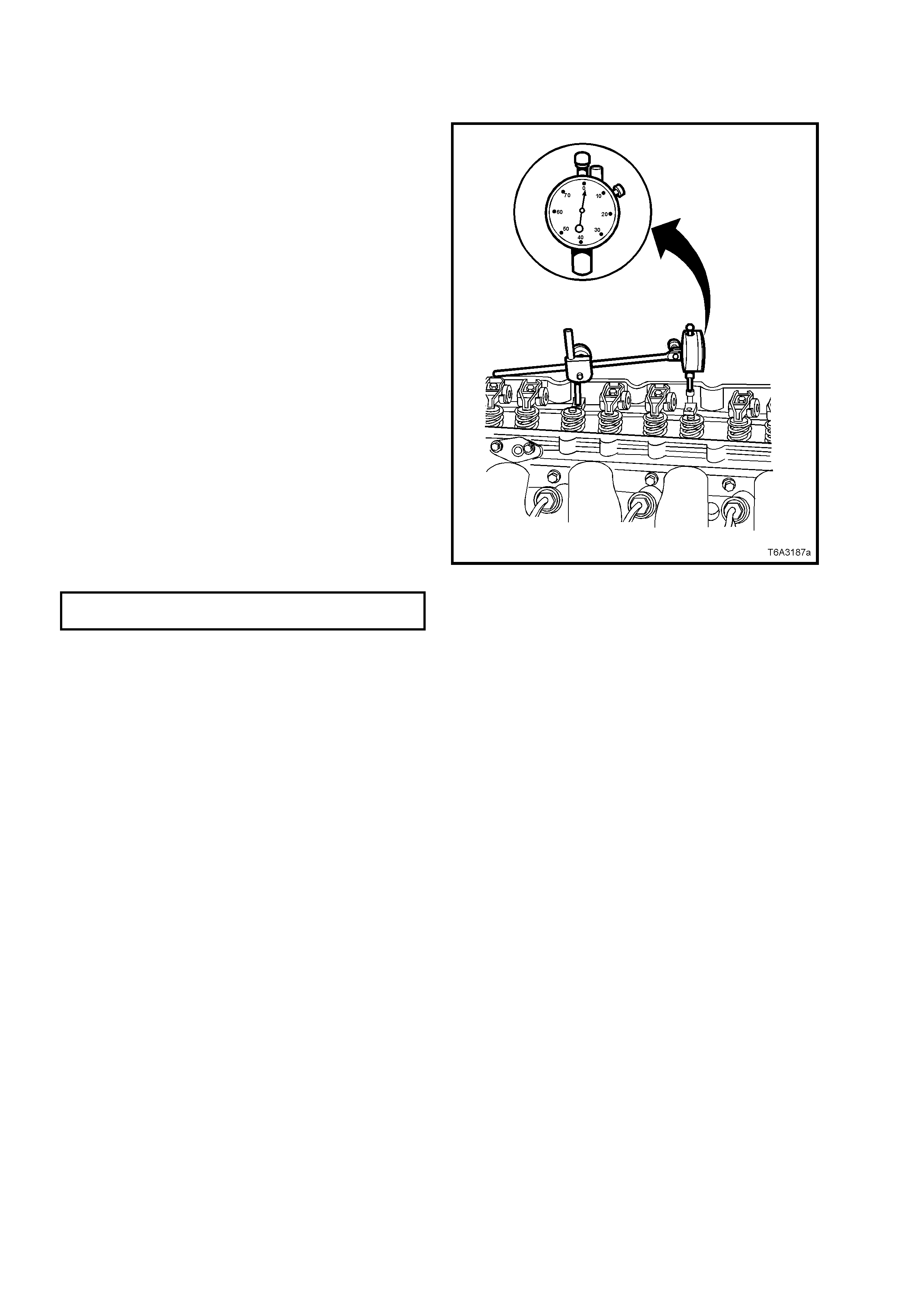
3.2 CAMSHAFT LOBE LIFT
MEASURE
Important: Measuring camshaft lobe lift is a
procedure used to determine if the camshaft lobes
have worn. This test is to be performed prior to
engine disassembly and with the camshaft, push
rods and valve lifters installed in the engine.
1. T o measure the c amshaf t lobe lift, proceed as
follows:
a. Remove the valve rocker arm s and bolts.
Refer Operation 2.18, in this Section.
b. Install an M8 x 1.25 dial indicator
mounting stud into the valve rocker arm
bolt hole.
c. Assemble the components of a
commercially available dial indicator (or
Tool J 8520) and position onto the
installed stud, as shown.
d. Position the shaf t of the dial indic ator onto
the end of the pushrod.
e. Zero the dial indicator dial.
f. Slowly rotate the crankshaft clockwise
until the dial indicator obtains its highest
and lowest readings.
g. Repeat for all valves and compare the
readings obtained against specifications.
CAMSHAFT LOBE LIFT Intake Lobe 7.43 mm
SPECIFICATION Exhaust Lobe7.43 mm
NOTE: If the readings are not within specification,
then the camshaft lobes are worn and require
further investigation when the camshaft is removed.
Figure 6A3-195
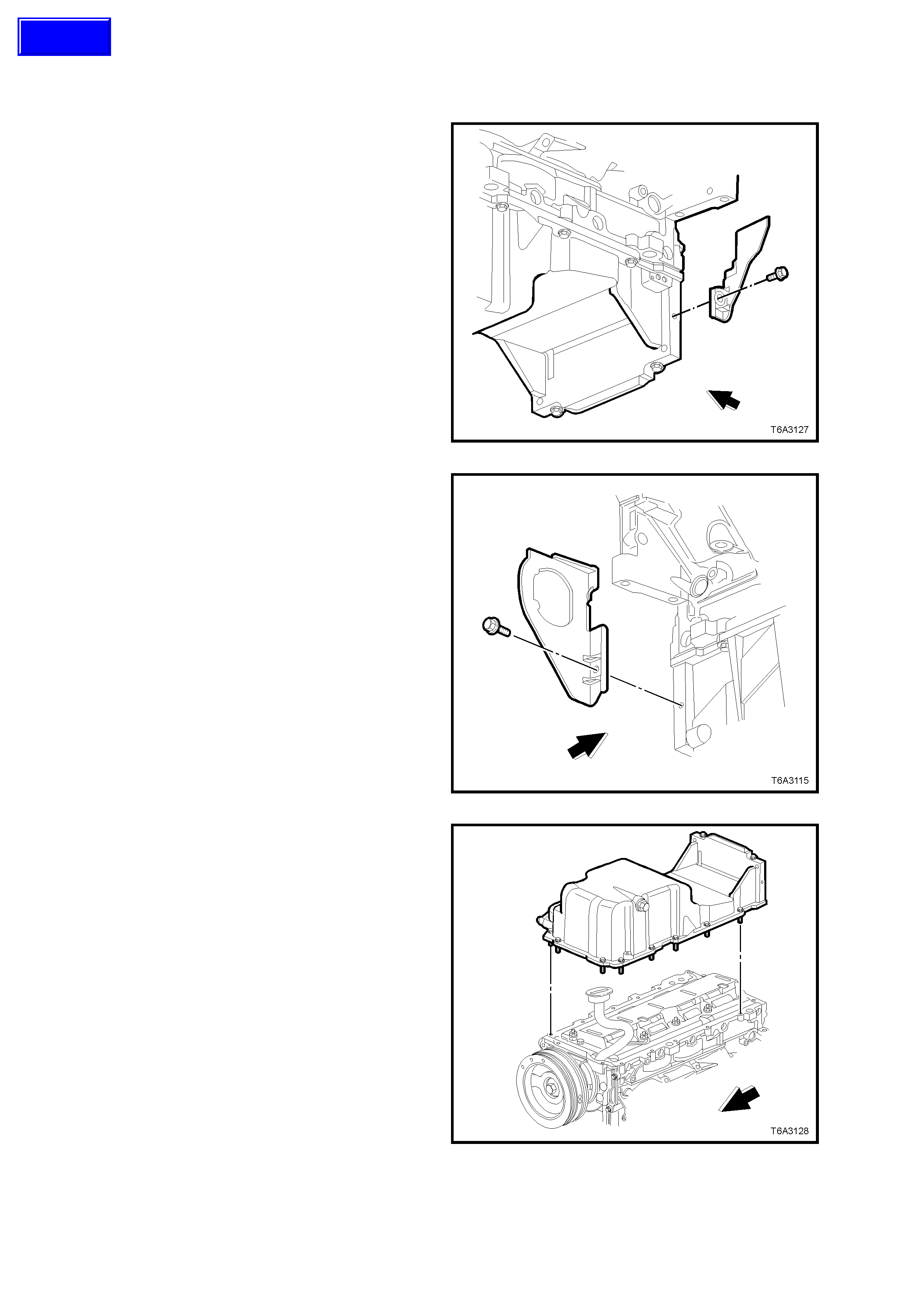
3.3 OIL PAN
REMOVE
Important: Because of critical alignment
procedures required for oil pan installation, it is
strongly recom mended that the engine as sembly is
removed from the vehicle, before oil pan removal.
1. Remove the left close-out cover and bolt.
Figure 6A3-196
2. Remove the right close-out cover and bolt.
Figure 6A3-197
3. Invert the engine assembly.
4. Remove the oil pan bolts, loosening gradually
from the ends and work ing inwards toward the
centre.
5. Bump the oil pan sideways with the heel of a
hand or a rubber hammer, to dislodge the
seal.
Figure 6A3-198
Techline
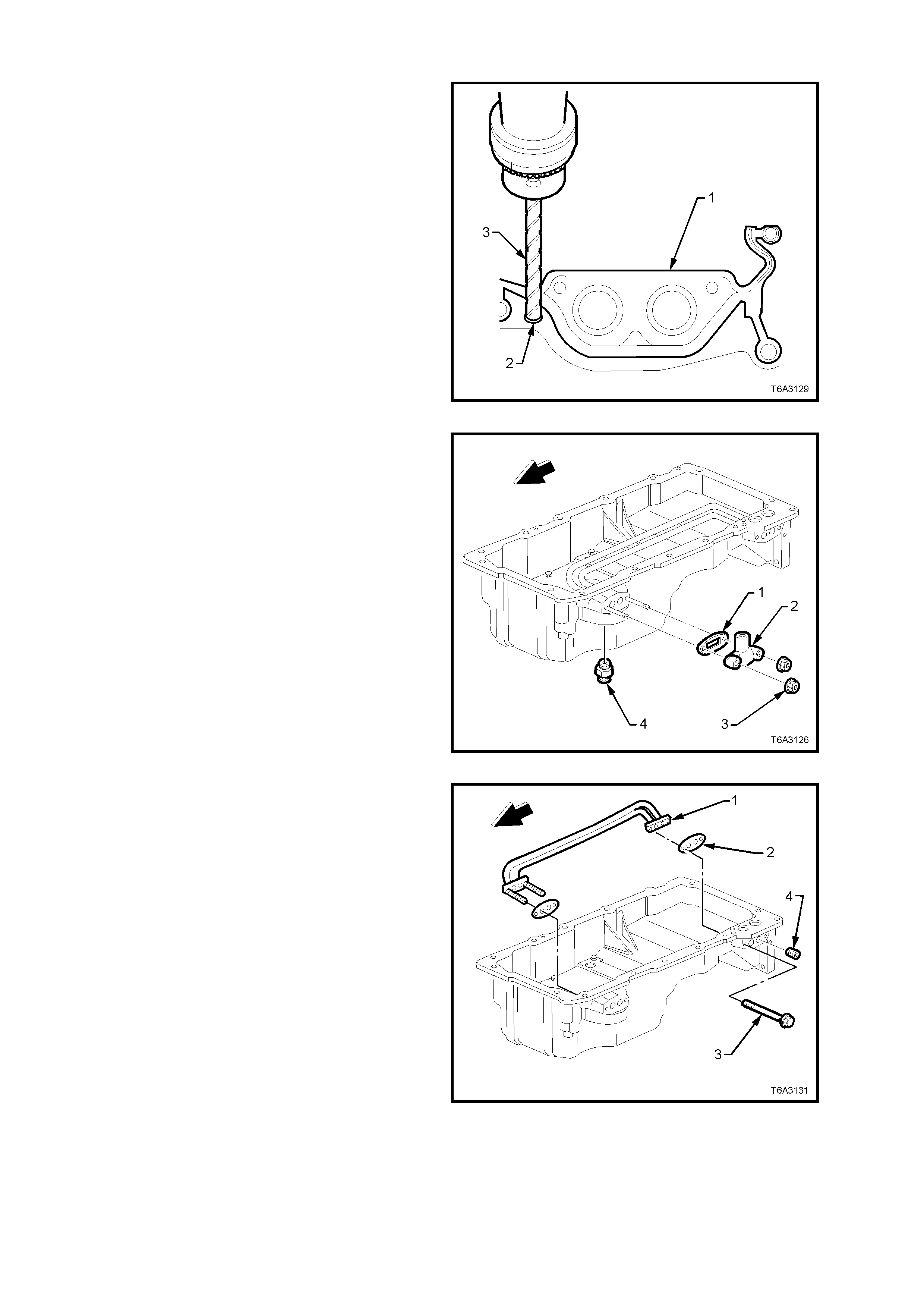
DISASSEMBLE
NOTE: The original oil pan gasket is retained and
aligned to the oil pan by rivets. When installing a
new gasket as a service replacement, it is not
necessary to install new oil pan gasket rivets.
Important: Do not allow metal shavings or other
foreign material to enter the oil passages in the oil
pan during gasket removal. Plug all openings
before commencing drilling operations.
1. Use a sharp twist drill (3) to drill out each of
the retaining rivets (2), as required.
2. Remove the oil pan gasket (1) from the oil
pan.
3. Discard the gasket and rivets.
Figure 6A3-199
4. Remove the oil transfer cover nuts (3), cover
(2), and gasket (1). Discard the gasket (1).
5. Remove the oil filter adaptor (4) if required.
NOTE: If removal of the oil transfer cover nuts (3)
is required while the oil pan is still installed (e.g.
during fitment of an external oil cooler), the studs
MUST NOT be removed. Otherwise the transfer
pipes and gasket inside the oil pan, may become
dislodged.
Figure 6A3-200
6. Remove the two oil filter transfer tube bolts
(3).
7. Remove the oil filter transfer tubes (1) and
discard the gaskets (2).
8. If required, use an Allen key sock et to r emove
the oil gallery plugs (4).
NOTE: Because of thread sealant applied to the
threads, it is recom mended that the front studs are
left attached to the transfer tube assembly and the
whole assembly withdrawn from inside the oil pan.
Figure 6A3-201
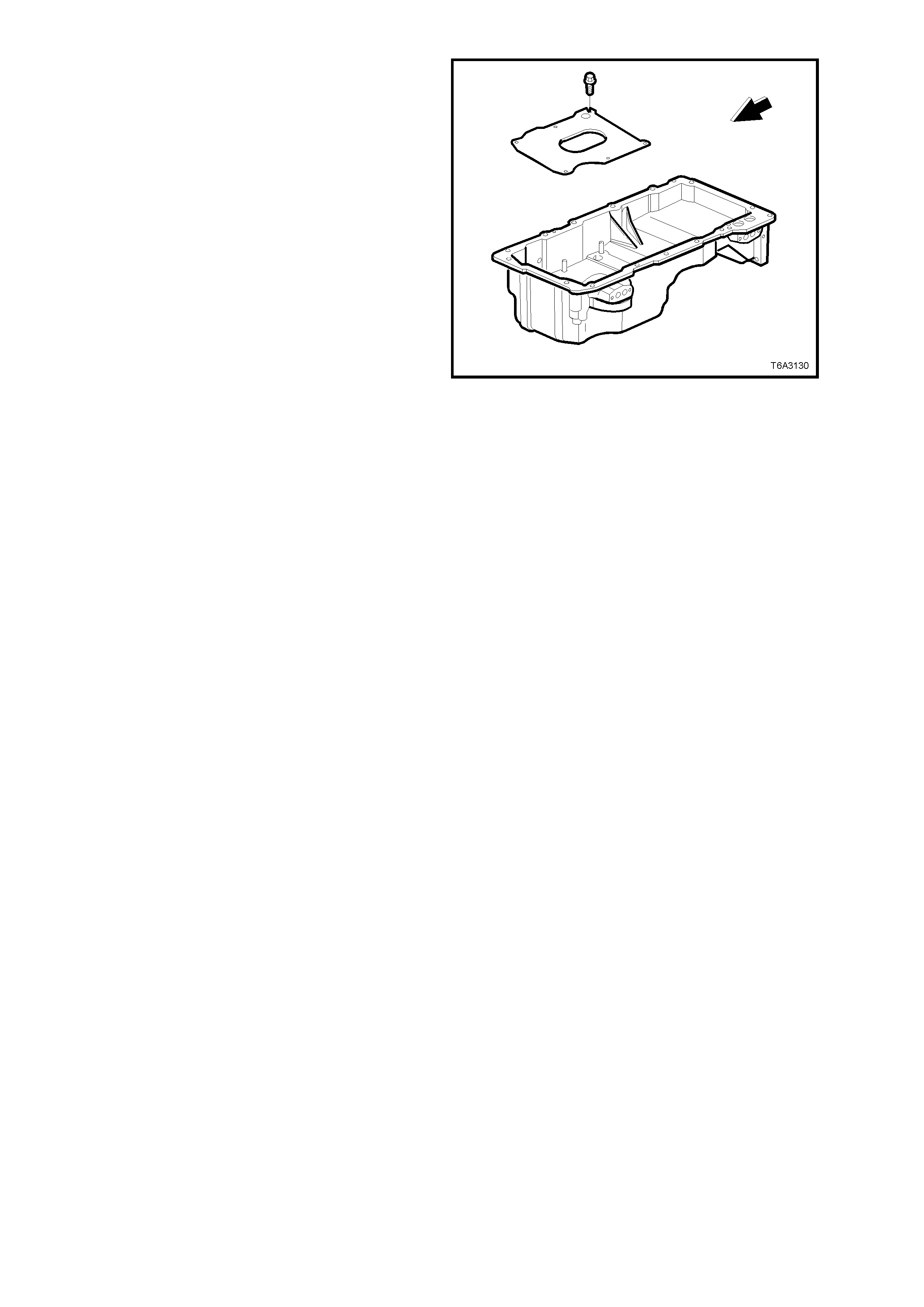
9. Remove the oil pan baffle bolts (six places)
and baffle.
Figure 6A3-202
CLEAN AND INSPECT
1. Clean the oil pan in a suitable solvent. Ensure
that all oil passages and recesses are
thoroughly cleaned.
2. Clean the oil pan gasket surfaces, using a
plastic scraper to avoid scratching or
damaging the machined surfaces.
3. Dry the oil pan with compressed air.
CAUTION: Wear safety glasses to avoid eye
injury.
4. Inspect the oil pan for the following:
a. Gasket sealing surfaces for excessive
scratches or gouging.
b. Oil pan drain plug and threaded drain hole
for damaged threads. The drain plug O-
ring seal may be reused if not cut or
damaged.
c. Oil filter sealing surface for scratches or
gouging.
d. Oil f ilter adaptor for a loos e f it or damaged
threads.
e. Oil passages for restrictions.
f. Oil f ilter bypass valve in the oil filter f lange
for proper operation Lightly push the
bypass valve into the bore. The valve
spring should reseat the valve to the
proper position.
5. Inspect the oil transfer tube for damage or
restrictions.
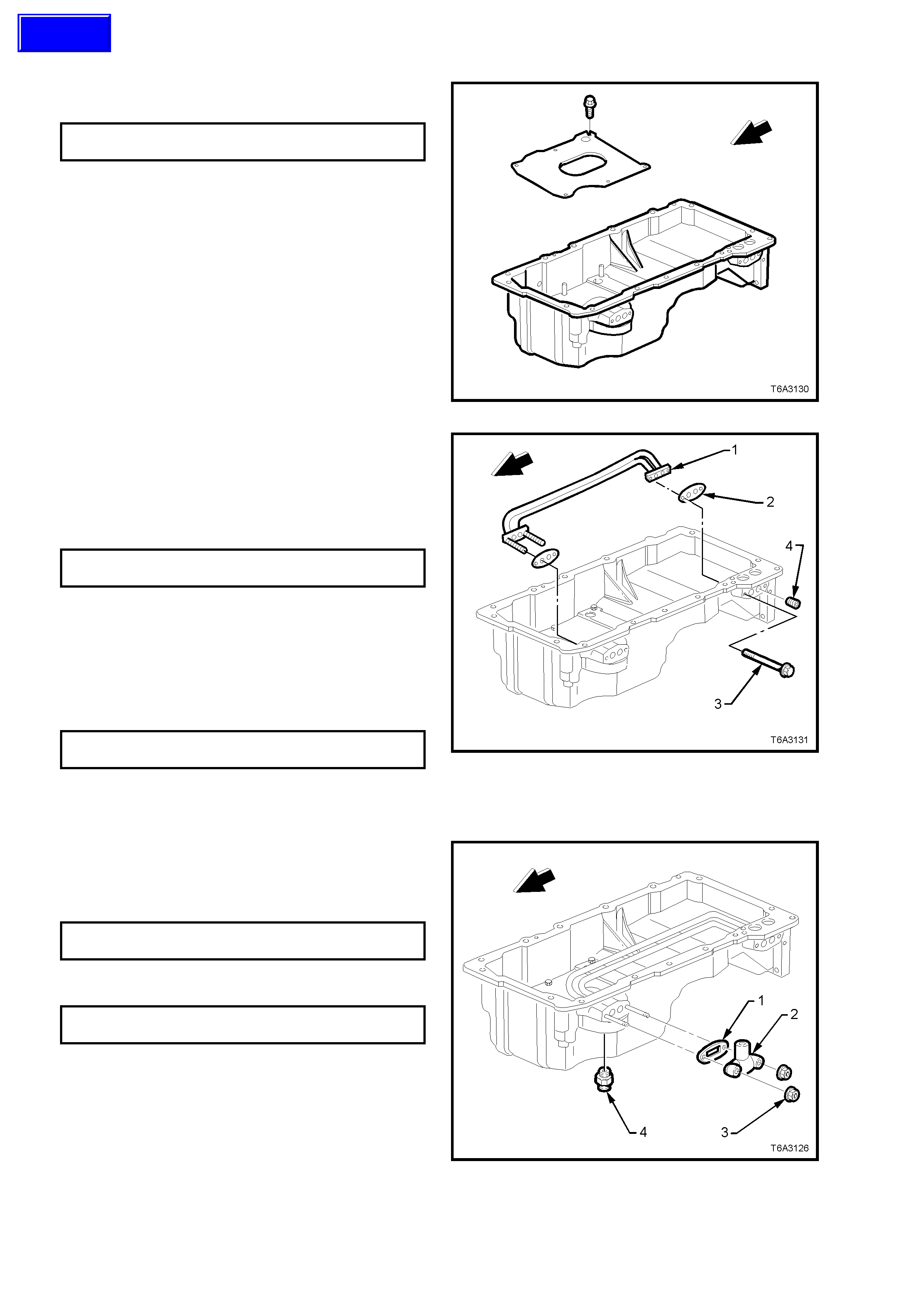
REASSEMBLE
1. Install the oil pan baffle and r etaining bolts and
tighten to the correct torque specification.
OIL PAN BAFFLE BOLT
TORQUE SPECIFICATION 12 Nm
Figure 6A3-203
2. If removed, apply thread lock com pound suc h
as Loctite 242 (or equivalent) to the cleaned
threads of the oil gallery plugs (4).
3. Use an Allen key socket and tighten the oil
gallery plugs to the correct torque
specification.
OIL GALLERY PLUG
TORQUE SPECIFICATION 25 Nm
4. Apply thread lock compound such as Loctite
242 (or equivalent) to the cleaned threads of
the oil transfer tube bolts (3)
5. Using NEW gaskets (2), install the oil filter
transfer tubes (1).
6. Install the two bolts (3) and tighten to the
correct torque specification.
OIL FILTER TRANSFER TUBE
BOLT TORQUE SPECIFICATION 12 Nm Figure 6A3-204
7. Install NEW oil pan transfer cover gasket (1),
cover (2) and nuts (3).
8. Tighten the nuts to the correct torque
specification.
OIL PAN TRANSFER COVER NUT
TORQUE SPECIFICATION 12 Nm
9. If removed, install the oil filter adaptor and
tighten to the correct torque specification.
OIL FILTER ADAPTOR
TORQUE SPECIFICATION 55 Nm
Figure 6A3-205
Techline

REINSTALL
Important: The alignment of the structural oil pan
is critical. T he rear bolt hole locations of the oil pan
provide mounting points for the transmission bell
housing. To ensure the rigidity of the powertrain
and correct transmission alignment, it is important
that the rear of the engine block and the rear of the
oil pan are flush. The rear of the oil pan must
NEVER protrude beyond the engine block and
transmission bell housing plane.
NOTE 1: Do NOT reuse the oil pan gasket.
NOTE 2: It is not necessary to rivet the NEW
gasket to the oil pan.
1. Apply a 5 mm wide bead of sealant such as
Loctite 565 or equivalent, 20 mm long to the
engine block, as shown. Apply the sealant
directly onto the tabs of the front cover gasket
that protrude into the oil pan surface.
Figure 6A3-206
2. Apply a 5 mm wide bead of sealant such as
Loctite 565 or equivalent, 20 mm long, to the
engine block, as shown. Apply the sealant
directly onto the tabs of the rear cover gasket
that protrude into the oil pan surface.
Figure 6A3-207
3. Pre-assemble the oil pan gasket to the oil pan.
Important: Be sure to align the oil gallery passages
in the oil pan and engine block properly with the oil
pan gasket.
4. Install the oil pan bolts to the pan and through
the gask et. Install the oil pan, gask et and bolts
to the engine block. Tighten bolts finger tight.
Do not over-tighten.
5. Place a straight edge across the rear of the
engine block and the rear of the oil pan at the
transmission bell housing mounting surfaces.
Figure 6A3-208
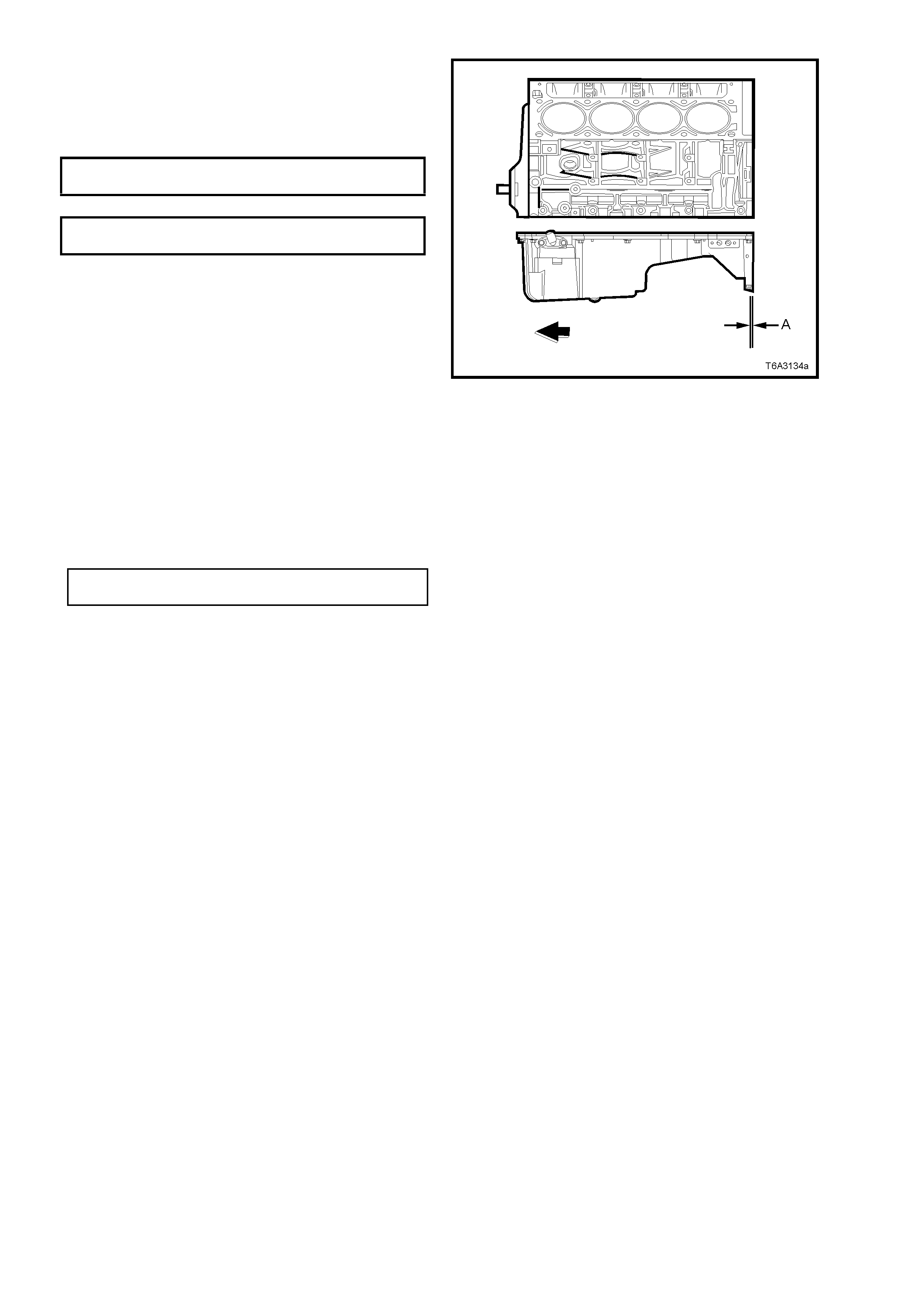
6. Align the oil pan until the rear of engine block
and rear of oil pan are flush or even.
7. Install the oil pan to front cover bolts and the
oil pan to rear cover bolts, tighten to the
correct torque specifications.
OIL PAN TO FRONT COVER
BOLT TORQUE SPECIFICATION 25 Nm
OIL PAN TO REAR COVER BOLT
TORQUE SPECIFICATION 12 Nm
NOTE: T his prelim inary step is required to avoid oil
pan ‘creep’ and create a misalignment condition.
8. Place a straight edge across the rear of the
engine block and rear of oil pan at the
transmission bell housing mounting surfaces.
9. Insert a feeler gauge between the straight
edge and the oil pan transm iss ion bell housing
mounting s ur f ac e and chec k to make sur e that
the oil pan is flus h to no more than a 0.25 m m
gap between the pan and straight edge
(dimension ‘A’).
Important: The rear of the oil pan must NEVER
protrude beyond the engine block and transm ission
bell housing mounting surfaces.
10. Install remaining oil pan to cylinder block bolts
and tighten to the correct torque specifications.
OIL PAN TO CYLINDER BLOCK
BOLT TORQUE SPECIFICATION 25 Nm
If the oil pan alignment is not within specification,
remove the oil pan and repeat the above
procedure.
Figure 6A3-209
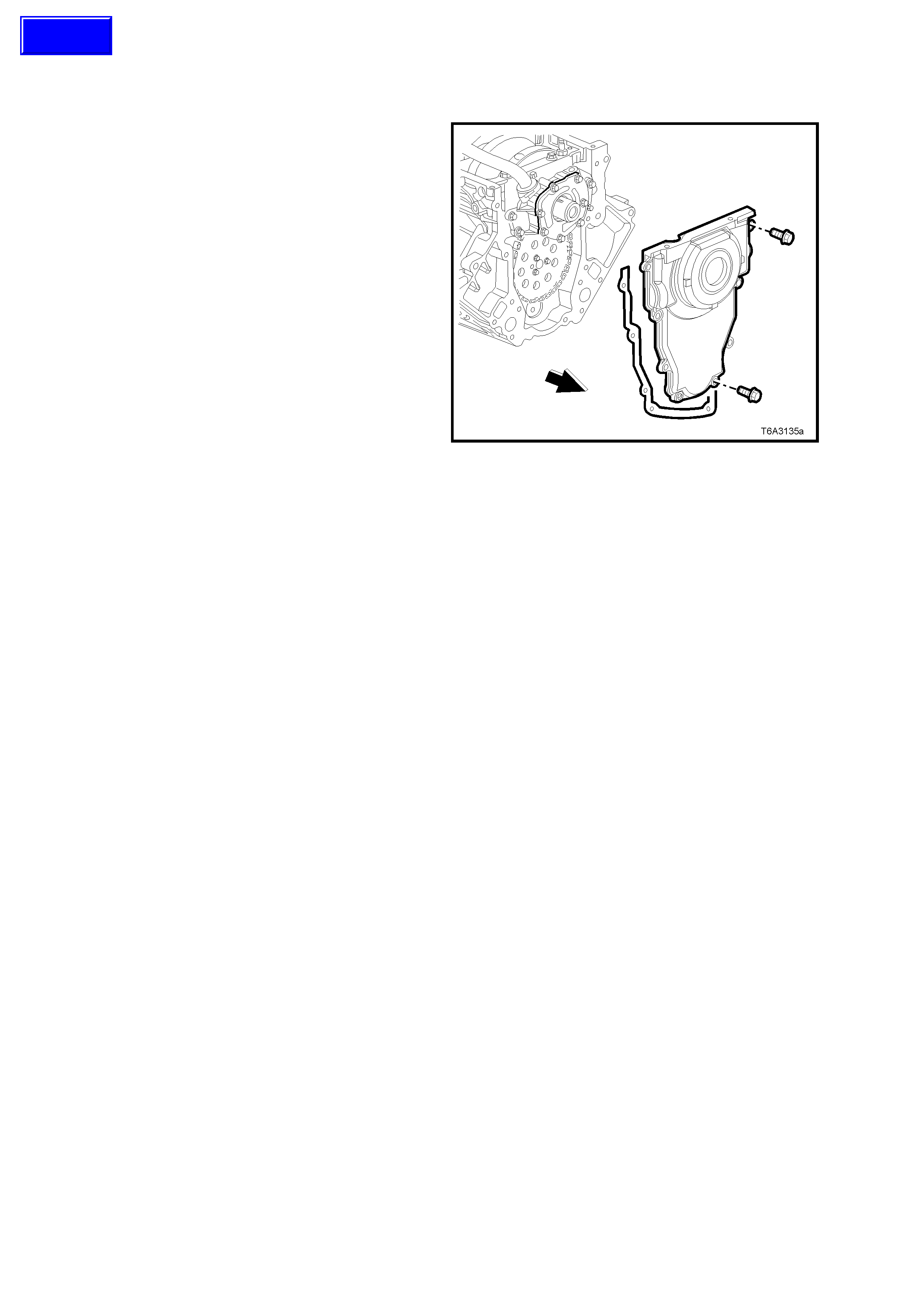
3.4 ENGINE FRONT COVER
REMOVE
Important: Because of critical alignment
procedures required for the reinstallation of the
front cover and oil pan, it is strongly recomm ended
that the engine assembly is removed from the
vehicle, before oil pan removal.
1. Remove the crankshaft balancer. Refer
2.24 CRANKSHAFT BALANCER - REMOVE,
of this Service Information CD.
2. Remove the front cover bolts.
3. Remove the front cover and gasket. If the
gasket is undamaged, it may be re-used.
Figure 6A3-210
CLEAN AND INSPECT
1. Prise the old oil seal from the front cover and
discard.
2. Clean the front cover in a suitable solvent and
blow dry.
CAUTION: Wear safety glasses to avoid eye
injury.
3. Inspect the front cover sealing surfaces for
excessive scratches and/or gouges.
4. Inspect the front cover gasket for damage to
the membrane or distortion to the aluminium
carrier.
5. Inspect the front cover to oil pan threaded
holes for damaged threads or debris. Refer to
3.16 THREAD REPAIR, in this Section, if
rectification is required.
6. Inspect the cover crankshaft oil seal bore for
damage.
REINSTALL
NOTE 1: Do not reuse the crankshaft oil seal if
inspection shows it t o be damaged in nay way.
NOTE 2: Do not apply any type sealant to the front
cover gasket.
NOTE 3: The special tools in this procedure are
used to properly align the engine front cover at the
oil pan surface and to centre the crankshaft front oil
seal.
NOTE 4: All gasket surfaces should be free of oil
or other foreign material during assembly.
Techline
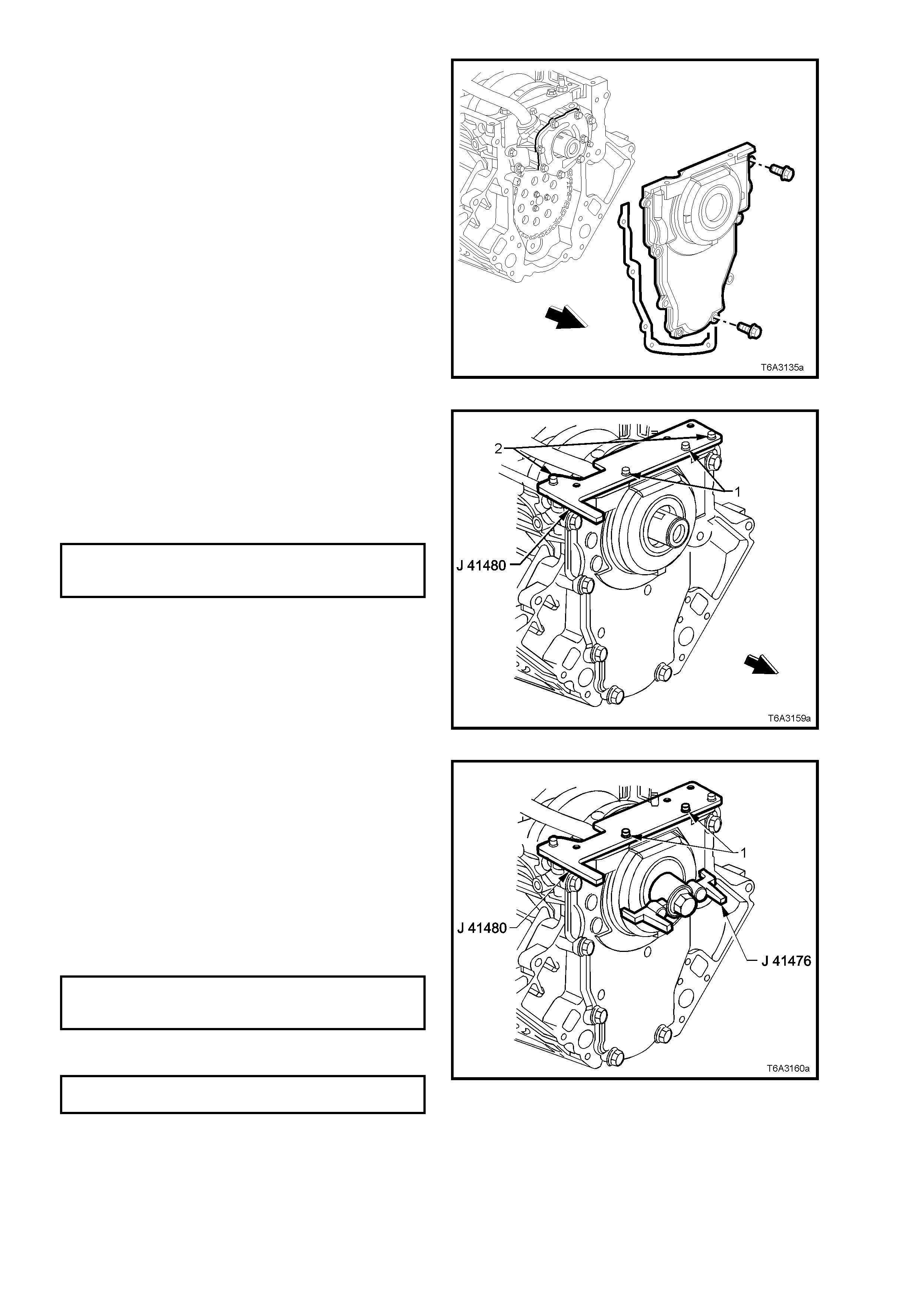
NOTE 5: The crankshaft front oil seal MUST be
centred in relation to the crankshaft. The oil pan
sealing surf ace at the front cover and engine block
MUST also be aligned within specifications.
NOTE 6: An improperly aligned front cover may
cause premature front oil seal wear and/or engine
assembly oil leaks.
1. Install the front cover gasket, cover, and bolts
onto the engine.
2. Tighten the cover bolts finger tight only. Do
not tighten.
Figure 6A3-211
3. Assemble alignment tool J 41480 to front
cover and install bolts (1) (part of Tool J
41480), in the locations shown but do not
tighten.
4. Install the alignm ent tool bolts (2) (part of Tool
J 41480) to the engine block and tighten to the
specified torque.
FRONT COVER ALIGNMENT TOOL
BOLT TO ENGINE BLOCK 25 Nm
TORQUE SPECIFICATION
Figure 6A3-212
5. Install c entralising T ool J 41476 as shown and
hold in position by hand.
NOTE: DO NOT install the crank shaf t balancer bolt
to retain. If the bolt is installed and over tightened
the alignment tool will be destroyed.
Important: Align the tapered legs of the tool with
the machined alignment surfaces on the front
cover.
6. Tighten the two bolts (1) securing Tool J
41480 to the front cover, to the specified
torque.
ALIGNMENT TOOL TO FR ONT
COVER BOLT 25 Nm
TORQUE SPECIFICATION
7. Tighten the engine front cover bolts to the
correct torque specification.
ENGINE FRONT COVER BOLT
TORQUE SPECIFICATION 25 Nm
8. Remove the alignment tools.
Figure 6A3-213

9. Measure the oil pan surface to front cover for
flatness, as follows:
a. Place a straight edge across the engine
block and front cover oil pan sealing
surf aces . Avoid c ontact with the portion of
the gasket that protrudes into the oil pan
surface.
b. Insert a feeler gauge between the front
cover and the straight edge tool. The
cover must be flush with the oil pan
surface or no more than 0.25 mm below
flush (dimension ‘A’).
c. If the front cover-to-engine block oil pan
surface alignment is not within
specif ications, repeat the cover alignm ent
procedure.
10. If the correct front cover to engine block
alignment cannot be obtained, replace the
front cover.
Figure 6A3-214
CRANKSHAFT FRONT OIL SEAL - INSTALL
Important: Do not lubricate the oil seal sealing
surface.
11. Lubricate the outer edge of the oil seal (1) and
the front cover oil seal bore with clean engine
oil.
12. Install the crank shaft front oil seal (1) onto the
guide of Tool No. J 41478.
13. Install the threaded rod (with nut, washer,
guide, and oil seal) of Tool No. J 41478 into
the end of the crankshaft.
14. Using a set spanner, hold the head of the
installer bolt, then rotate the installer nut
clockwise, using a second set spanner, until
the seal bottoms in the cover bore.
15. Remove the tool from the crankshaft.
16. Inspect the oil s eal for co rrect inst allation. The
oil seal should be installed evenly and
completely into the front cover bore.
17. Install the crankshaft balancer, refer
2.24 CRANKSHAFT BALANCER, in this
Section.
18. Reinstall oil pan. Refer 3.3 OIL PAN -
REINSTALL, in this Section.
Figure 6A3-215
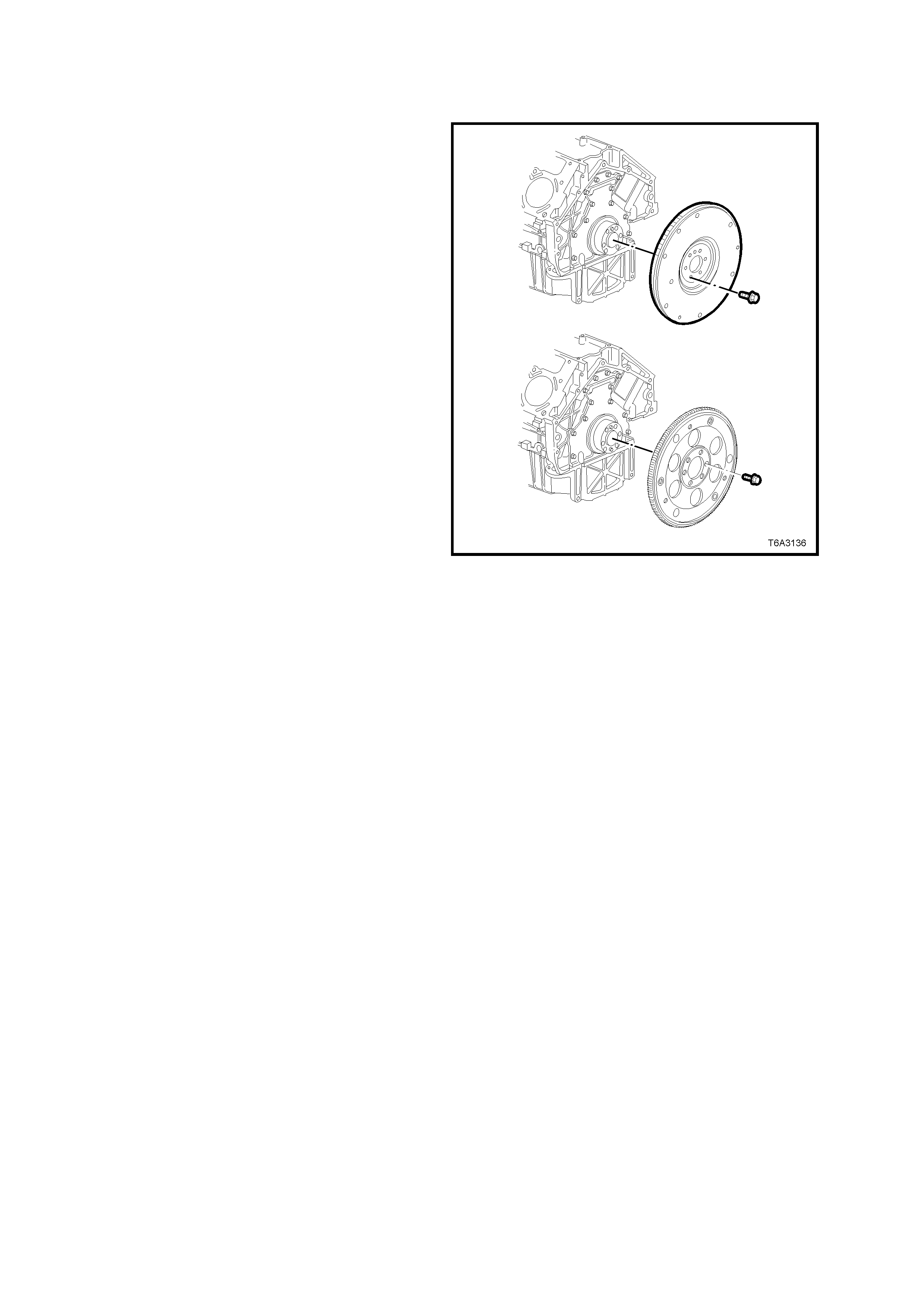
3.5 ENGINE FLYWHEEL/FLEXPLATE
REMOVE
Important: Note the position and direction of the
engine flywheel before removal. The flywheel does
not use a locating pin f or alignment. Mark or sc ribe
the end of the crankshaft and the flywheel before
component removal. The engine flywheel must be
reinstalled to the original position and dir ec tion. The
engine flywheel will not initially seat against the
crankshaft flange, but will be pulled onto the
crankshaft by the engine flywheel bolts. This
procedure requires a three stage tightening
process.
If replacing a flywheel, note the location of any
existing balance weight pins (relative to the pos ition
of the flywheel locating hole). If replacing the
flywheel and balance weight pins are installed in
the original flywheel, then use a suitable pin punch
and rem ove the pins f rom the old f lywheel and then
reinstall them in the same relative location in the
replacement part.
NOTE 1: Balance weight pins will only be fitted to
some engines that may have been dynamically
balanced at manufacture, where balance weight
pins are required to balance the crankshaft/flywheel
assembly, hence the need to reinstall them to a
new flywheel, in the same position.
NOTE 2: A correctly installed balance weight pin
will be either flush or below f lush with the mac hined
surface of the flywheel.
1. If this operation is to be carried out with the
engine installed in the vehicle, remove the
transmission and c lutch as s embly (if requir ed).
Refer Section 7B3 MANUAL
TRANSMISSION - GEN III V8 ENGINE,
Section 7A1 CLUTCH - GEN III V8
ENGINE or Section 7C4 AUTOMATIC
TRANSMISSION, of this Service Information
CD.
2. Mark the end of the crankshaft and the
flywheel/ flexplate, using a felt tipped pen or
similar. Remove the engine flywheel/ flexplate
bolts.
3. Remove the engine flywheel/flexplate.
Figure 6A3-216
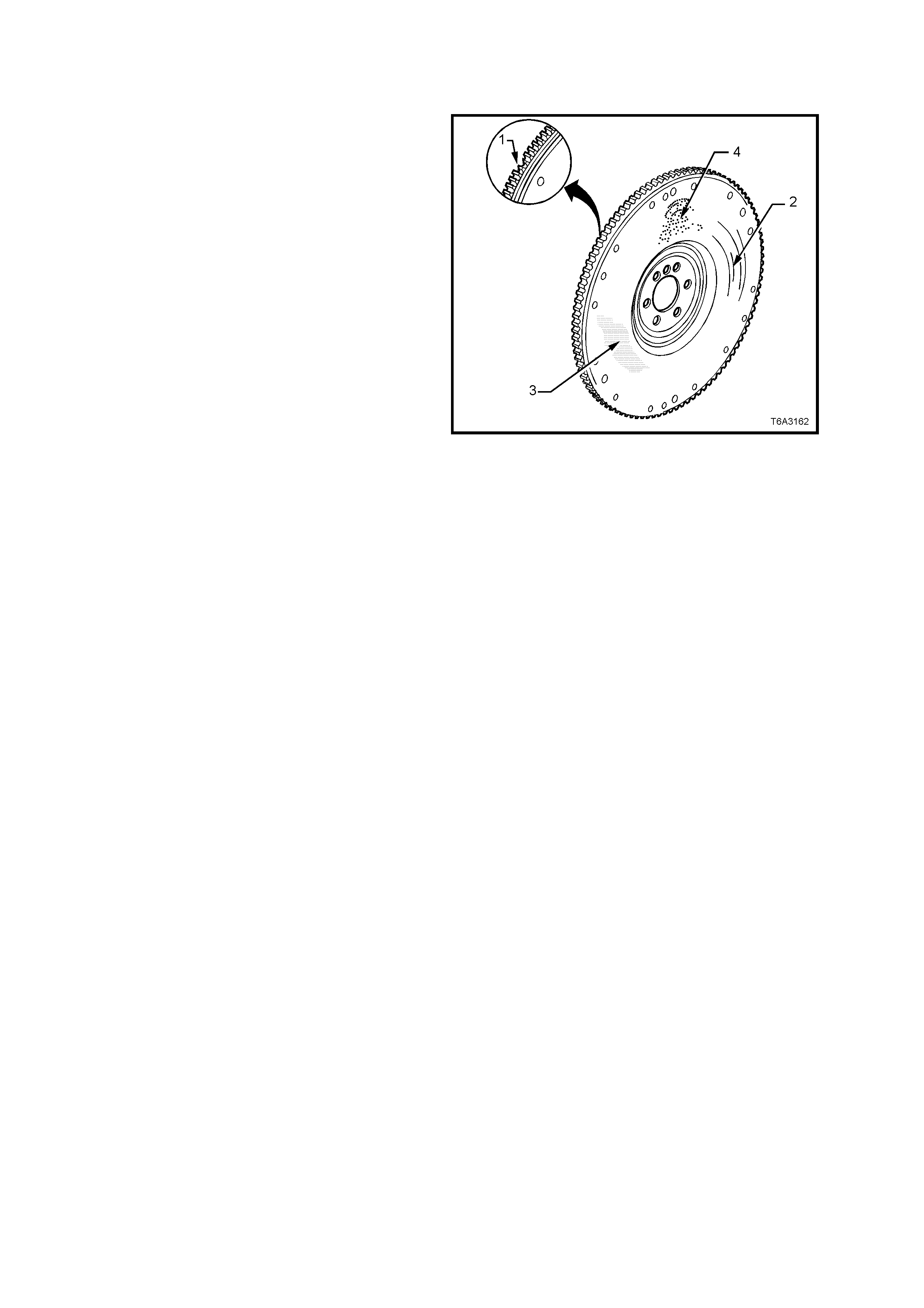
CLEAN AND INSPECT
Flywheel
1. Clean the flywheel in a suitable solvent and
blow dry with compressed air.
Important: In order to maintain the proper
com ponent balanc e, contac t s urf ac e taper and heat
transf er, m anual trans m ission flywheels are NOT to
be machined.
CAUTION: Wear safety glasses to avoid eye
injury.
2. Inspect the flywheel for loose or improperly
installed balance weights (if applicable). A
correctly installed balance weight should be
either flush or below the machined surface of
the flywheel.
3. Inspect the flywheel for the following:
a. Damaged ring gear teeth (1).
b. Grooves or scoring (2).
c. Rusted surface (3).
d. Pitted surfaces (4).
e. Loose or incorrectly positioned ring gear.
The ring gear is an interference fit onto the
flywheel and should be positioned
completely against the flange of the
flyw heel.
f. Missing, bent or damaged pressure plate
locating pins. The two locating pins are
pressed into the flywheel and are spaced
170° apart.
Figure 6A3-217

Flexplate
4. Inspect the flexplate for the following:
a. Damaged ring gear teeth.
b. Stress cracks around the crankshaft bolt
hole locations.
c. Welded areas that retain the ring gear to
the flexplate.
Important: Do not attempt to repair any welded
areas that retain the ring gear to the flexplate.
Replace the flexplate assembly if welds are
cracked.
Figure 6A3-218
REINSTALL
1. If replacing a flywheel;
a. Install any balance weights, as required, in
the same locations as noted on the old
flywheel. Location is important, as the
presence of balance weight pins in the old
flywheel are an indication that the
crankshaft and flywheel were balanced as
a complete unit in original manufacture.
b. Use the flywheel locating hole as refer ence
and scribe an alignment mark
corresponding to the one on the original
flywheel.
2. Install the flywheel/flexplate, aligning the
scribed marks on the crankshaft and
flywheel/flexplate.
Figure 6A3-219
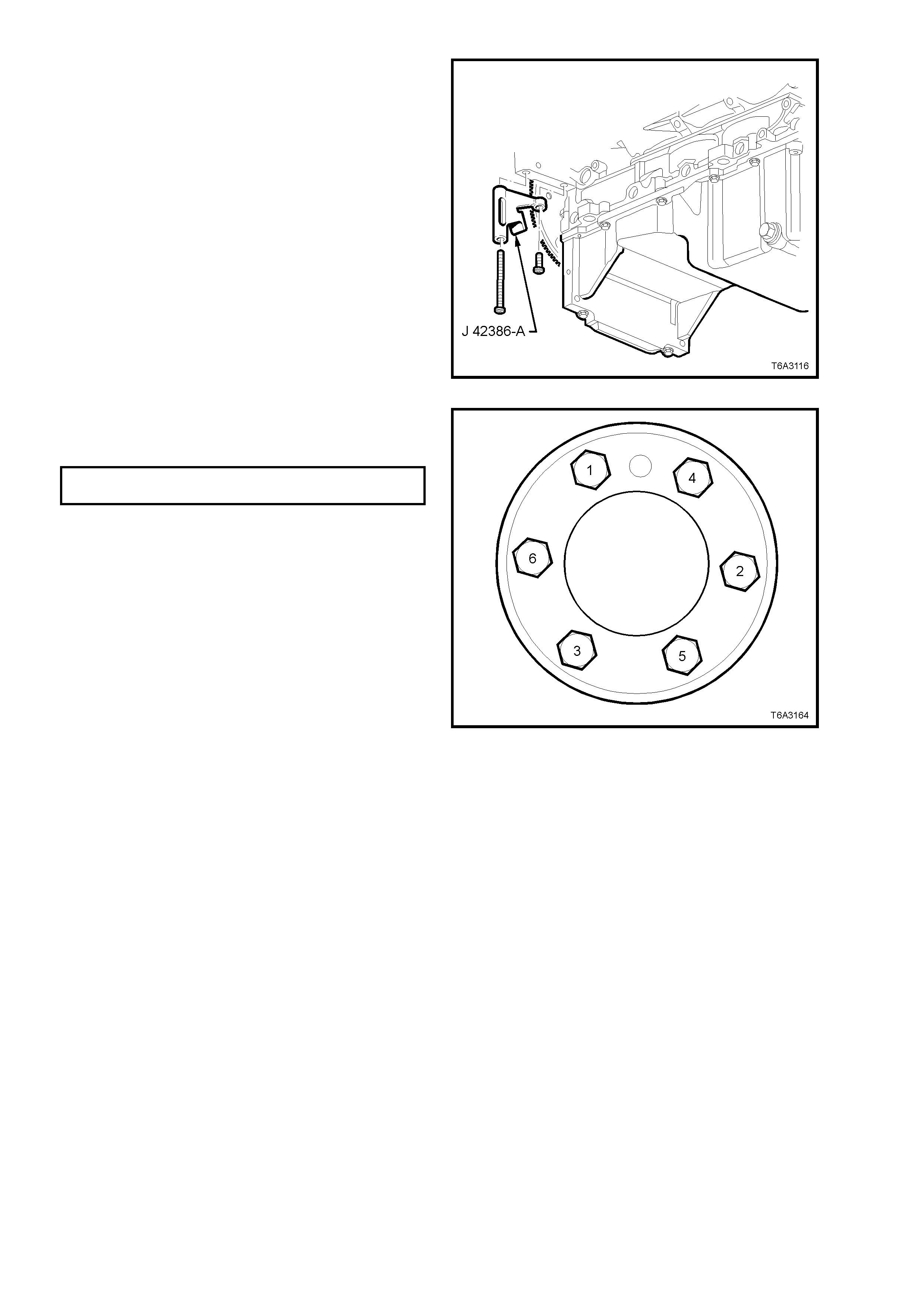
3. Loosely install NEW flywheel/flexplate bolts,
tightening in the sequence shown in Figure
6A3-221, to an initial torque specif ication of 20
Nm.
4. Install the ring gear holding Tool No. J 42386-
A, using the two starter motor bolts. Tighten
both bolts to 50 Nm.
NOTE: Ensure that the teeth of the holding tool
engage correctly with the ring gear teeth , before
tightening the fasteners.
Figure 6A3-220
5. Continue to tighten the flywheel/flexplate bolts
in the sequence shown, in two additional
stages and to the correct torque specification.
FLYWHEEL/FLEXPLATE BOLTS Stage 2: 50 Nm
TORQUE SPECIFICATION Stage 3: 100 Nm
6. Reinstall clutch and transm ission, as required.
Refer 7A1 CLUTCH - GEN III V8 ENGINE,
7B3 MANUAL TRANSMISSION - GEN III V8
ENGINE or 7C4 AUTOMATIC
TRANSMISSION, of this Service Information
CD.
Figure 6A3-221
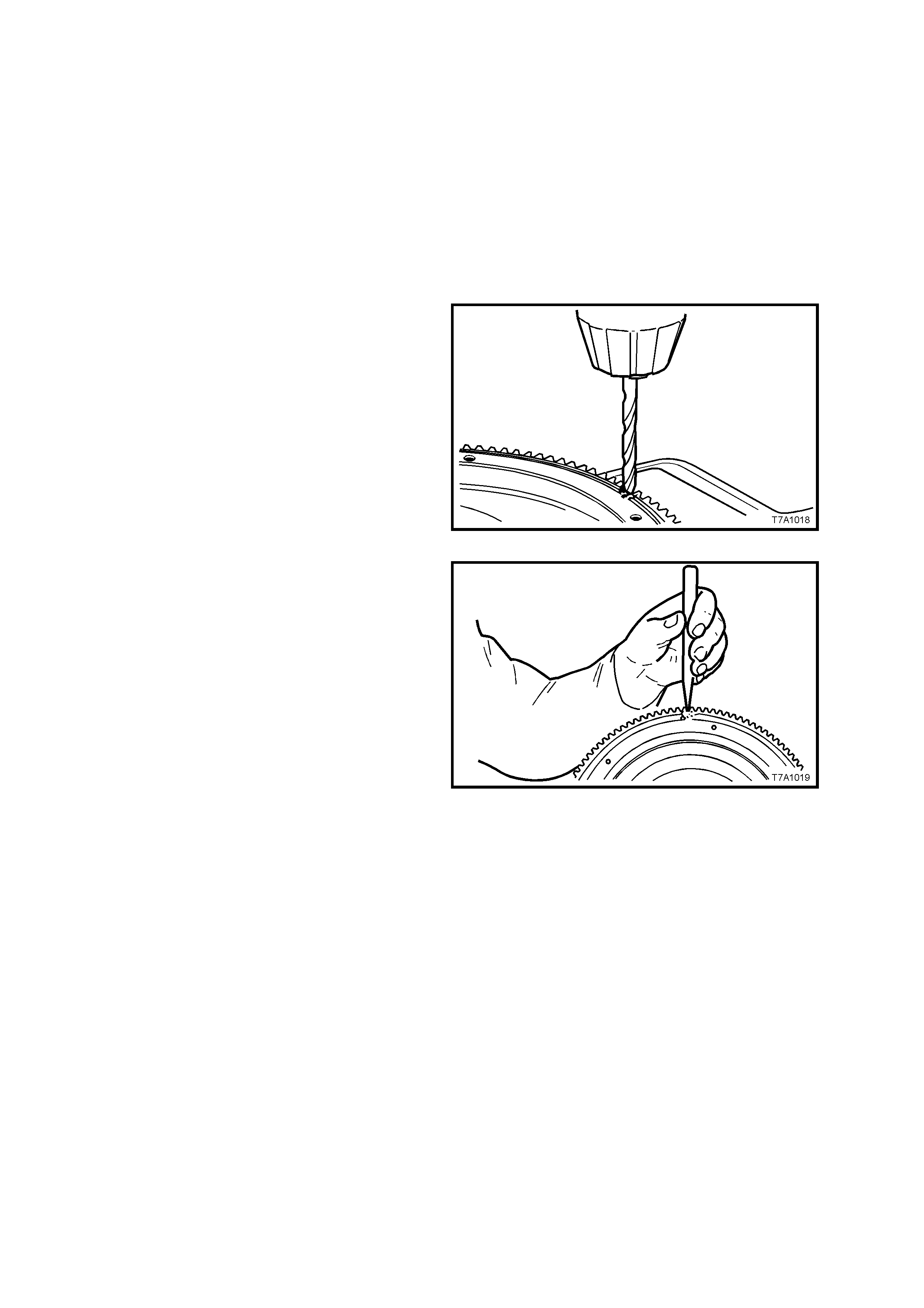
3.6 ENGINE FLYWHEEL RING GEAR
REPLACE
Automatic Transmission:
The ring gear is welded to the flexplate and is
serviced only as an assembly. Refer to
3.5 ENGINE FLYWHEEL/FLEXPLATE, in this
Section.
Manual Transmission:
1. Remove flywheel, refer to
3.5 ENGINE FLY WHEEL /FLEXPLATE, in this
Section.
2. After marking with a centre punch and
hammer, drill an 8 mm diameter hole through
the ring gear, between two teeth.
Figure 6A3-222
3. Secure the flywheel in a vice fitted with soft
jaws, then use a sharp cold chisel and
hamm er to split the ring gear at the drill point.
Remove the ring gear from the flywheel.
Figure 6A3-223
4. Check that there are no burrs or foreign
material on the new ring gear and flywheel
mating surfaces. If present, burrs can be
removed with a fine mill file.
5. Heat and shrink the replacement ring gear,
using either one of the next two methods;
1.1 Heat the new ring gear, uniformly in an
oven to a temperature between 180 -
230° C. This temperature can be
achieved by using a thermal indicating
crayon such as Faber-Castell
Thermocrom 2815-200.
2.1 Polish several places on the ring gear
using emery cloth.
2.2 Use a hot plate or a slowly moving torch
to heat the ring gear until the polished
spots turn blue (approximately 300° C).
NOTE: Heating the ring gear above 427° C
will destroy the ring gear teeth heat treatment.
6. Using protective gloves and two pairs of pliers ,
quick ly place the ring gear against the f lywheel
shoulder. Allow the ring gear to cool until it
contracts and is firmly held in place.

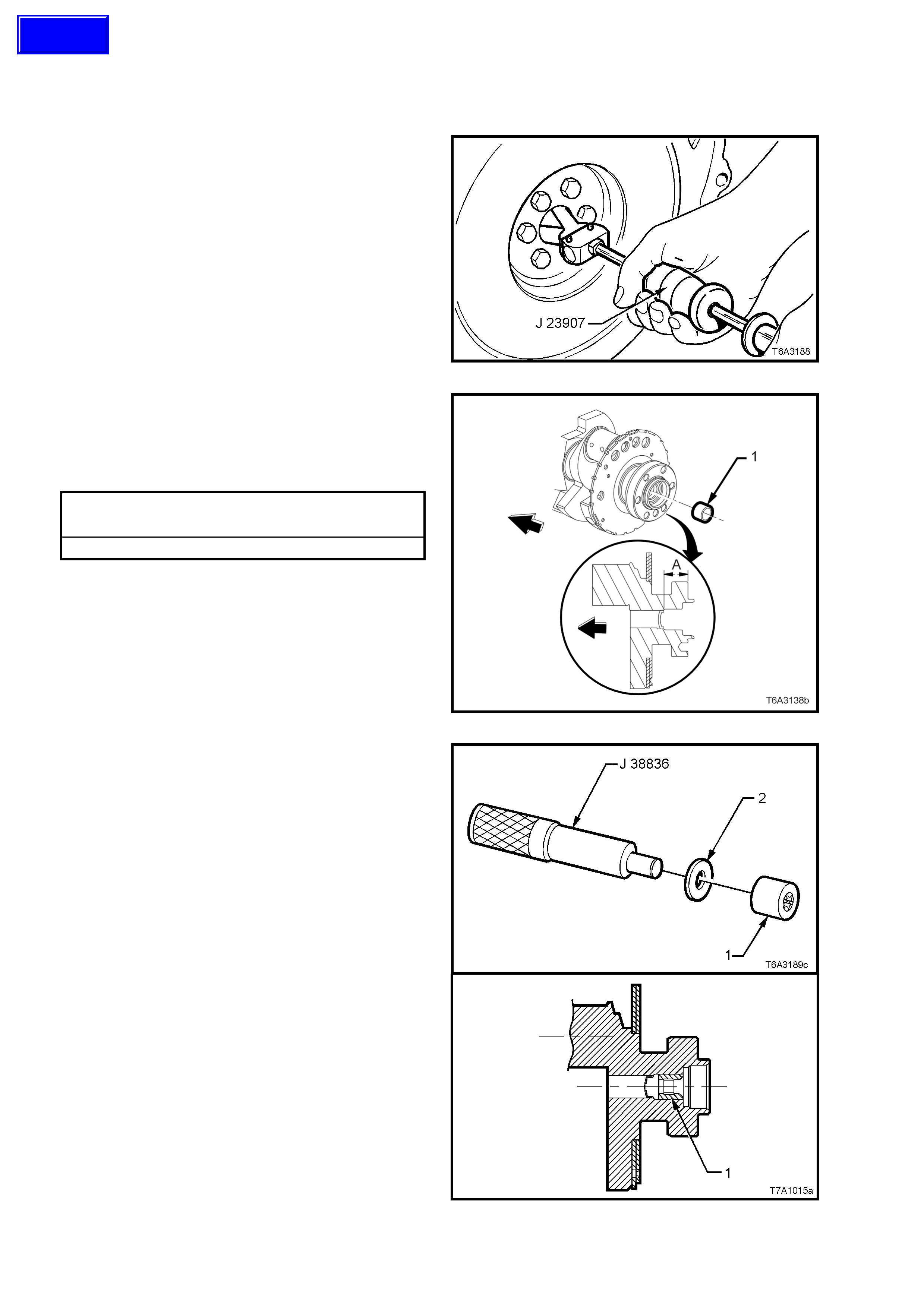
3.7 CRANKSHAFT SPIGOT BUSH
REPLACE
1. Disconnect battery earth lead.
2. Remove manual transmission and the clutch
assembly, refer to 7B3, MANUAL
TRANSMISSION - GEN III V8 ENGINE of this
Service Information CD and 7A1 CLUTCH -
GEN III V8 ENGINE in this Section.
3. Using Tool J 23907, (also released as Tool
6A22-2 and slide hammer 7A28) or
commercial equivalent, remove the spigot
bush from the rear of the crankshaft.
Figure 6A3-224
4. Check that the crankshaft rear oil gallery plug
is not a loose fit, damaged or leaking.
5. If replacement is required, apply sealant such
as Loctite 242 or equivalent, to the sides of a
new plug (1) and install to the correct depth.
Crankshaft Rear Oil gallery Plug Depth
Specification
Distance ‘A’......................... 31.2 - 31.6 mm
Figure 6A3-225
6. Using a suitable, stepped (or piloted ) driver
such as Tool J 38836 and flat washer (2),
install a replacem ent bush ( 1) to the rear of the
crankshaft, until flush with the crankshaft
counter-bore, as shown.
7. Lubricate the bearing with a small amount of
SAE 90 gear oil.
8. Reinstall clutch assembly and manual
transmission, refer to 7A1 CLUTCH - GEN III
V8 ENGINE and 7B3 MANUAL
TRANSMISSION - GEN III V8 ENGINE of this
Service Information CD.
9. Reinstall the starter motor. Refer 6D3-2
STARTING SYSTEM - GEN III V8 ENGINE of
this Service Information CD.
10. Reconnect battery earth lead.
11. Check starter motor operation and road test
vehicle to check transmission and clutch
operation.
Figure 6A3-226
Techline
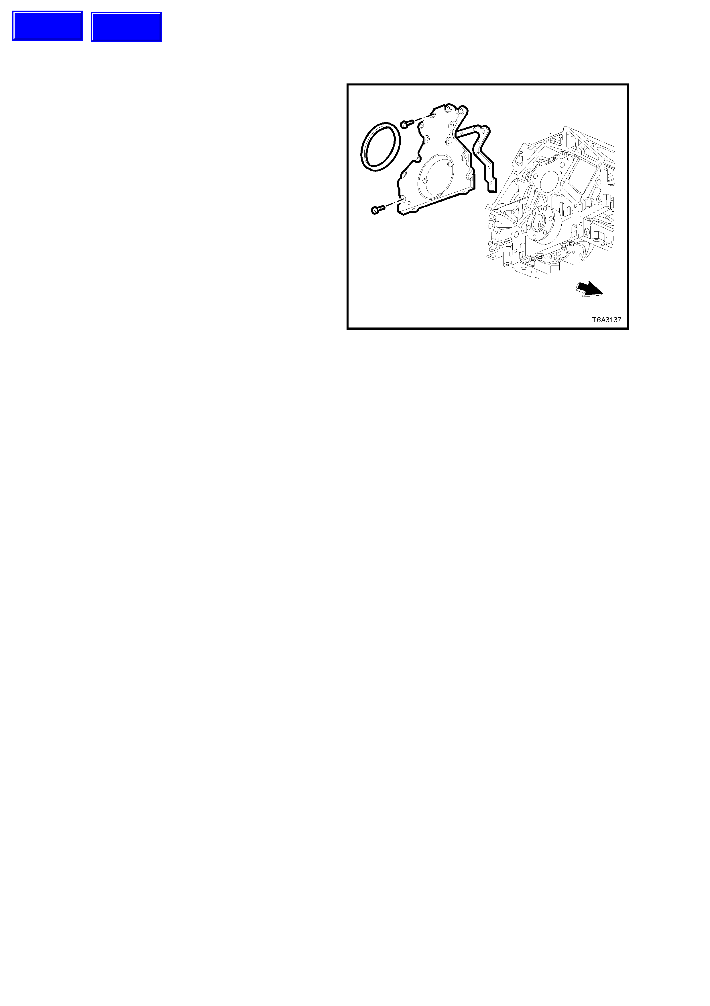
3.8 ENGINE REAR COVER
REMOVE
Important: Because of critical alignment
procedures required f or the r eins tallation of the rear
cover and oil pan, it is strongly recommended that
the engine assembly is removed from the vehicle,
before oil pan removal.
1. With the flywheel/flexplate removed, refer
3.5 ENGINE F LYWHEEL /FLEXPLATE, in this
Section, remove the rear cover bolts.
2. Remove the rear cover and gasket. If the
gasket is undamaged, it may be re-used.
3. Prise the rear main oil seal from the housing,
taking care not to distort the rear cover nor
scratch the oil seal bore in the rear housing.
Figure 6A3-227
CLEAN AND INSPECT
1. Clean the cover in a suitable solvent and blow
dry with compressed air.
CAUTION: Wear safety glasses to avoid eye
injury.
2. Inspect the gasket sealing surface for
excessive scratching or gouging.
3. Inspect the gasket for damage to the seal
membrane or distortion to the aluminium
carrier.
4. Inspec t the cover to oil pan threaded holes f or
debris or damage. Refer to 3.16 THREAD
REPAIR, in this Section, if rectification is
required.
5. Inspect the rear main oil seal bore for
damage.
Techline
Techline
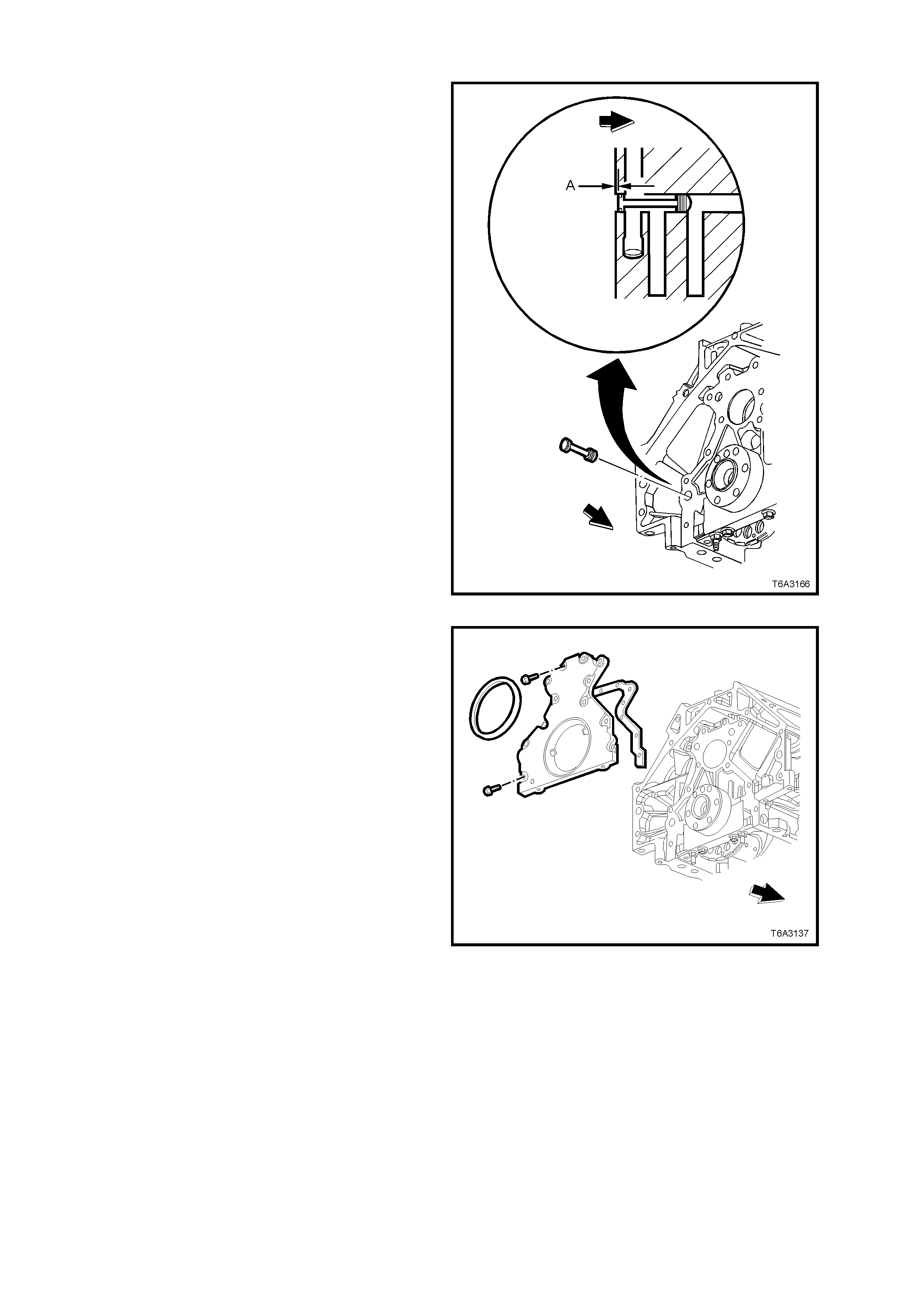
REINSTALL
NOTE 1: Do not reuse the crankshaft rear oil seal.
NOTE 2: Do not apply any type of sealant to the
rear cover gasket.
NOTE 3: The special tools in this procedure are
used to properly align the engine rear cover at the
oil pan surface and to centre the crankshaft rear
main oil seal.
NOTE 4: All gasket surfaces should be free of oil or
other foreign material during assembly.
NOTE 5: The crankshaft rear main oil seal MUST
be centred in relation to the c ranks haft and is to be
installed after the rear cover installation. The oil pan
sealing surface at the rear cover and engine block
MUST also be aligned within specifications.
NOTE 6: An improperly aligned rear cover may
cause premature oil seal wear and/or engine
assembly oil leaks.
1. If removed, inspect the rear main oil gallery
plug and ensure that is installed below the
engine block machined surface by dimension
‘A’, which is between 0.08 - 1.4 mm.
Figure 6A3-228
2. Install the rear cover gasket, the rear cover
and bolts.
NOTE: If undamaged, the original cover gasket can
be re-used.
3. Only tighten the rear cover bolts finger tight.
Do not overtighten.
Figure 6A3-229
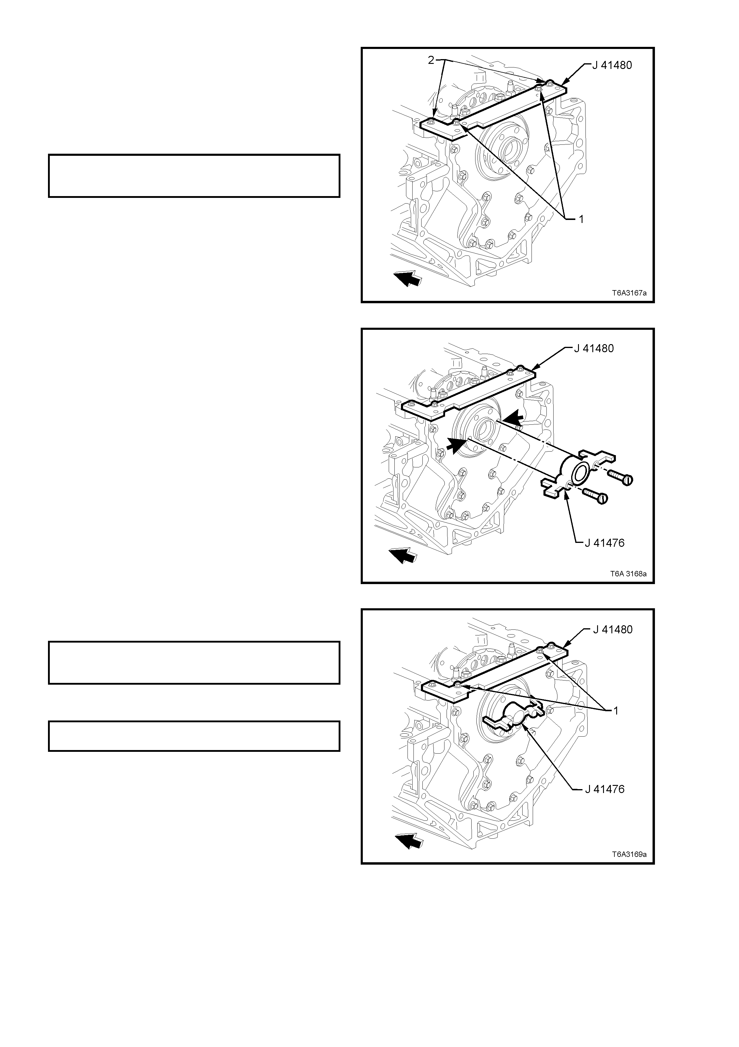
4. Assemble the alignment tool J 41480 to rear
cover and install bolts (1) (part of Tool J
41480) in the locations shown but do not
tighten.
5. Install bolts (2) (part of Tool J 41480) to the
engine block and tighten to the specified
torque.
REAR COVER ALIGNMENT TOOL
BOLT TO ENGINE BLOCK 25 Nm
TORQUE SPECIFICATION
Figure 6A3-230
6. Rotate the crankshaft until two opposing
flywheel/ flexplate mounting bolt holes are
parallel to the oil pan surface of the engine
block (arrows).
7. Install alignment Tool J 41476 to the rear of
the crankshaft.
NOTE: The taper ed legs of the alignm ent tool m ust
enter the rear cover oil seal bore.
8. Install the two screws supplied with Tool J
41476 and tighten with a screwdriver until
snug. Do not over-tighten.
Figure 6A3-231
9. Tighten the alignment Tool J 41480 bolts (1) to
the rear cover to the specified torque.
REAR COVER ALIGNMENT TOOL
BOLT TO REAR COVER 12 Nm
TORQUE SPECIFICATION
10. Tighten the engine rear cover bolts to the
correct torque specification.
ENGINE REAR COVER BOLT
TORQUE SPECIFICATION 25 Nm
11. Remove the alignment tools.
Figure 6A3-232
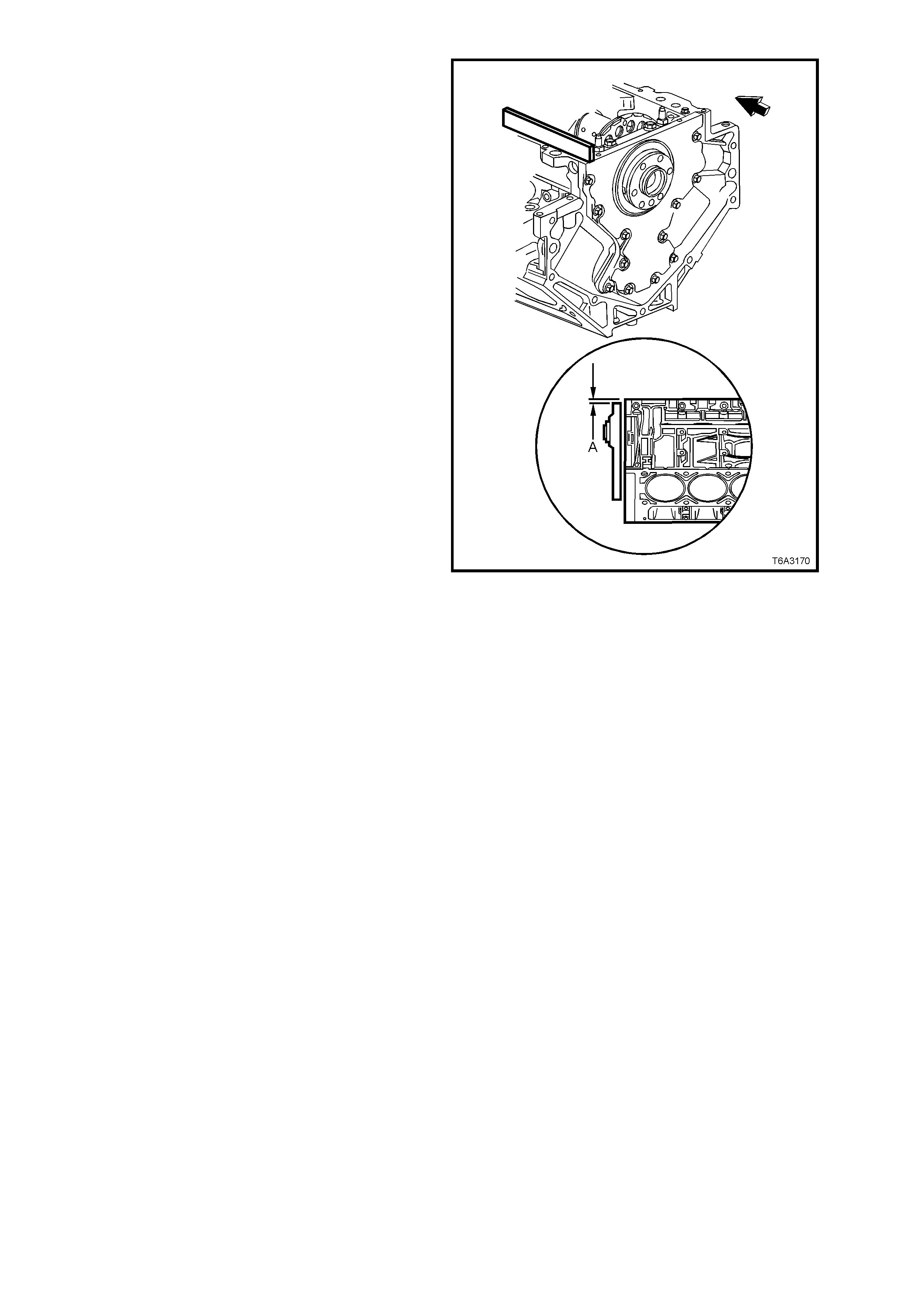
12. Measure the oil pan surface to rear cover for
flatness, as follows:
a. Place a straight edge across the engine
block and rear cover oil pan sealing
surf aces . Avoid c ontac t with the portion of
the gasket that protrudes into the oil pan
surface.
b. Insert a feeler gauge between the rear
cover and the straight edge tool. The
cover must be flush with the oil pan
surface or no more than 0.25 mm below
flush (dimension ‘A’).
c. If the rear cover-to-engine block oil pan
surface alignment is not within
specif ications, repeat the cover alignm ent
procedure.
13. If the correct rear cover to engine block
alignment cannot be obtained, r eplace the r ear
cover.
Figure 6A3-233
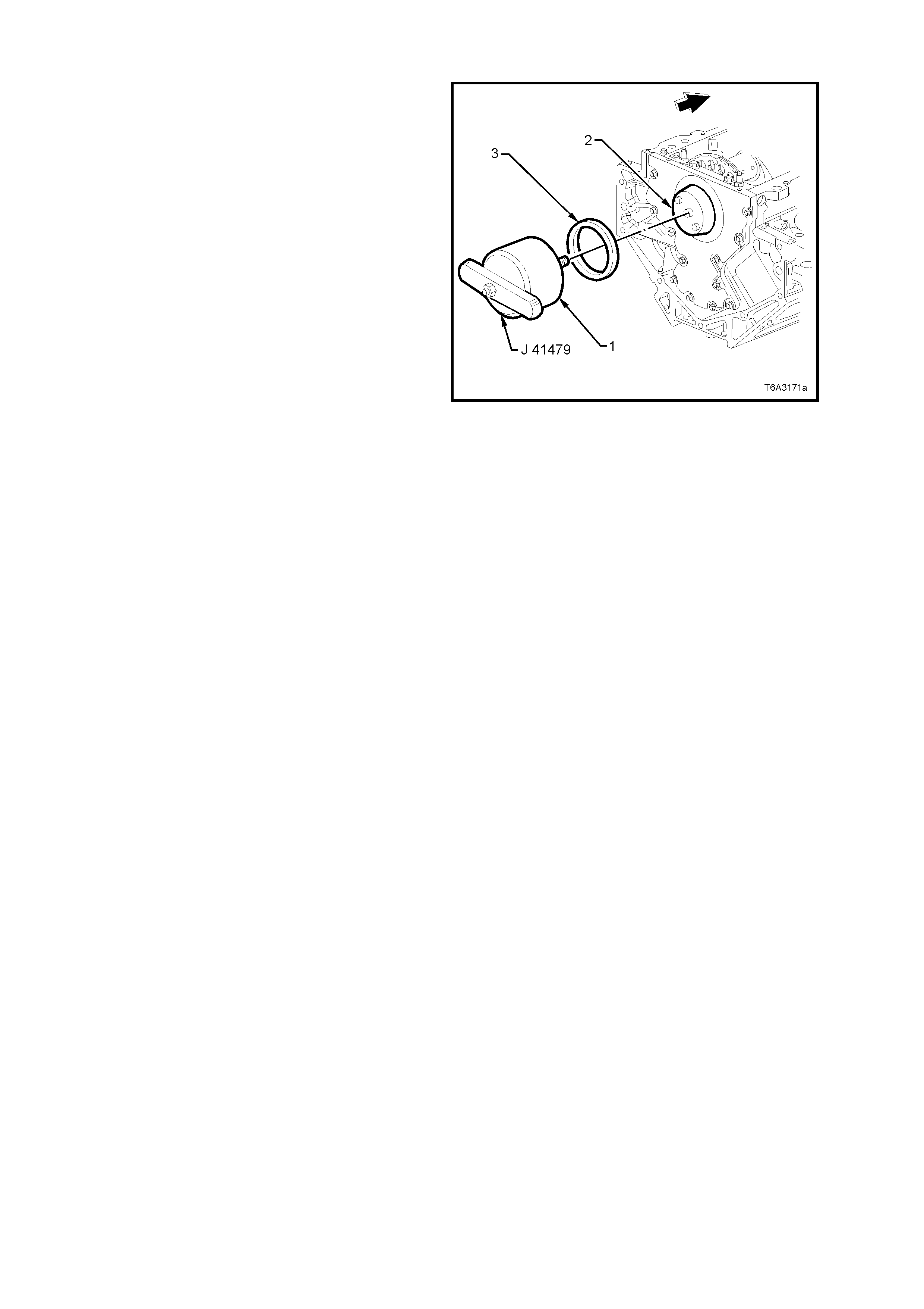
CRANKSHAFT REAR OIL SEAL - INSTALL
Important: Do not lubricate the oil seal inside
diameter (ID) nor the crankshaft seal surface
1. Lubricate the outer edge of the oil seal (OD)
with clean engine oil.
DO NOT allow oil or other lubricants to come
into contact with the seal surface.
2. Lubricate the rear cover oil seal bore (2) with
clean engine oil.
DO NOT allow oil or other lubricants to come
into contact with the crankshaft seal surface.
3. Install the cone (2) of installation Tool No. J
41479 with bolts, to the rear of the crank shaft.
Tighten the bolts until snug. Do not over-
tighten.
4. Install a NEW oil s eal (3) onto the taper of the
installation tool (2) and push the seal to the
rear cover bore.
5. Install the threaded rod of the installation Tool
No. 41479 (1), into the tapered part (2), until
the tool contacts the oil seal.
6. Align the oil seal (3) with the tool, then rotate
the handle of the tool (1) clockwise until the
seal enters then bottoms into the rear cover
bore.
7. Remove both parts of the installation tool.
8. Reinstall flywheel. Refer to 3.5 ENGINE
FLYWHEEL/FLEXPLATE, in this Section.
9. Reinstall clutch and transm ission, as required.
Refer 7A1 CLUTCH - GEN III V8 ENGINE,
7B3 MANUAL TRANSMISSION - GEN III V8
ENGINE or 7C4 AUTOMATIC
TRANSMISSION, of this Service Information
CD.
Figure 6A3-234
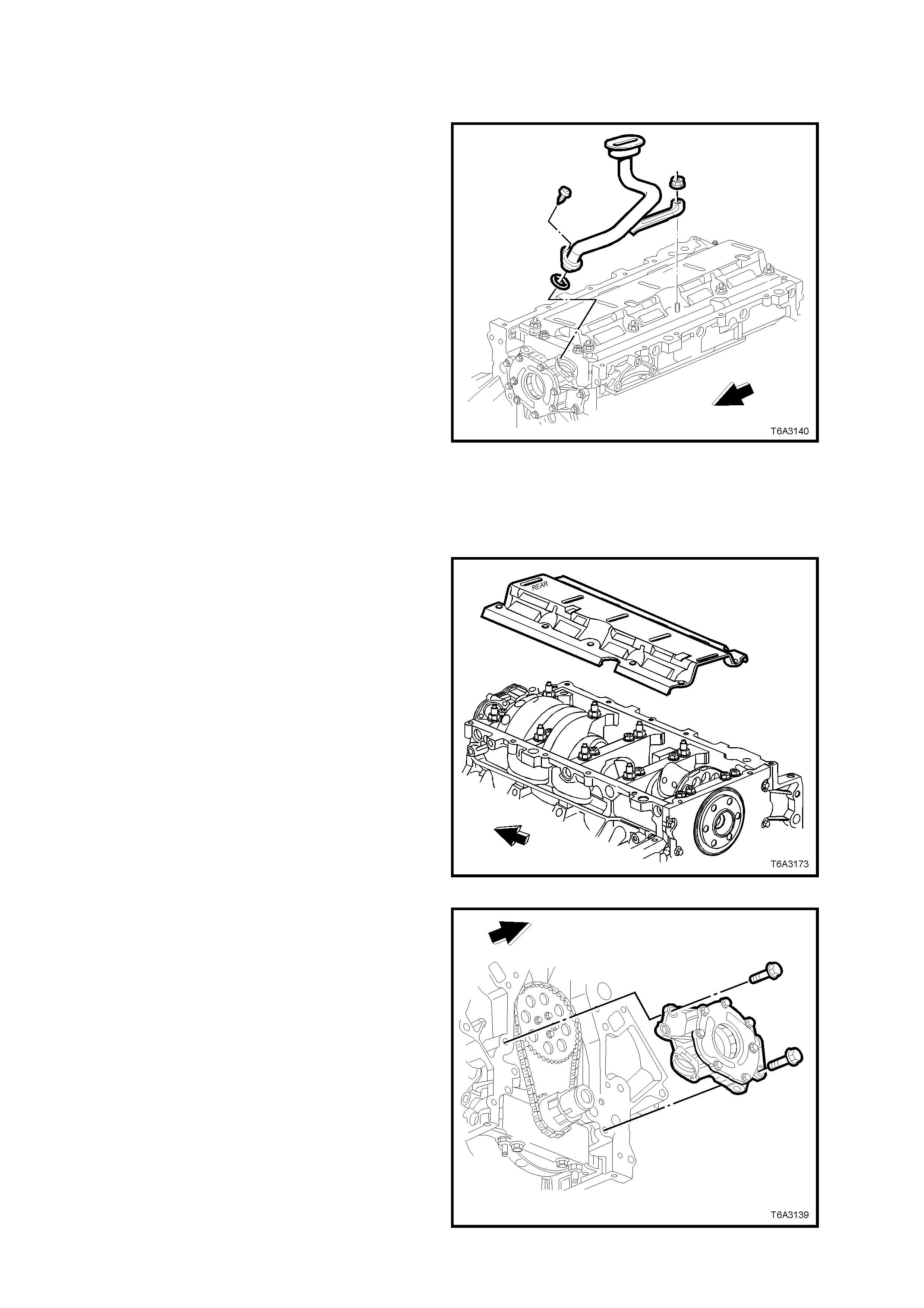
3.9 OIL PUMP, PUMP SCREEN, AND DEFLECTOR
REMOVE
Important: Because of critical alignment
procedures required for the reinstallation of the
front cover and oil pan, it is strongly recomm ended
that the engine assembly is removed from the
vehicle, before this service operation is carried out.
1. Remove oil pan, refer 3.3 OIL PAN -
REMOVE, in this Section.
2. If the harmonic balancer and front cover have
not already been removed, refer to
2.24 HARMONIC BALANCER - REMOVE and
3.4 ENGINE FRONT COVER - REMOVE, in
this Section.
3. Remove the oil pump pick-up screen bracket
nut from the crankshaft oil deflector and the
tube retaining screw from the oil pump body.
4. Remove the oil pump screen and tube
assembly, and the O-ring seal from the oil
pump bore.
Discard the O-ring. Figure 6A3-235
5. Rem ove the remaining crankshaft oil deflector
nuts.
6. Remove the crankshaft oil deflector, noting
that the cover orientation is stamped ‘REAR’ to
assist in correct installation.
Figure 6A3-236
7. Remove the four bolts securing the oil pump to
the front of the engine, then remove the oil
pump from the crankshaft.
8. If the oil pump is not being opened, plug all
openings to avoid the entry of dirt or debris or
wrap in a plastic bag.
Figure 6A3-237
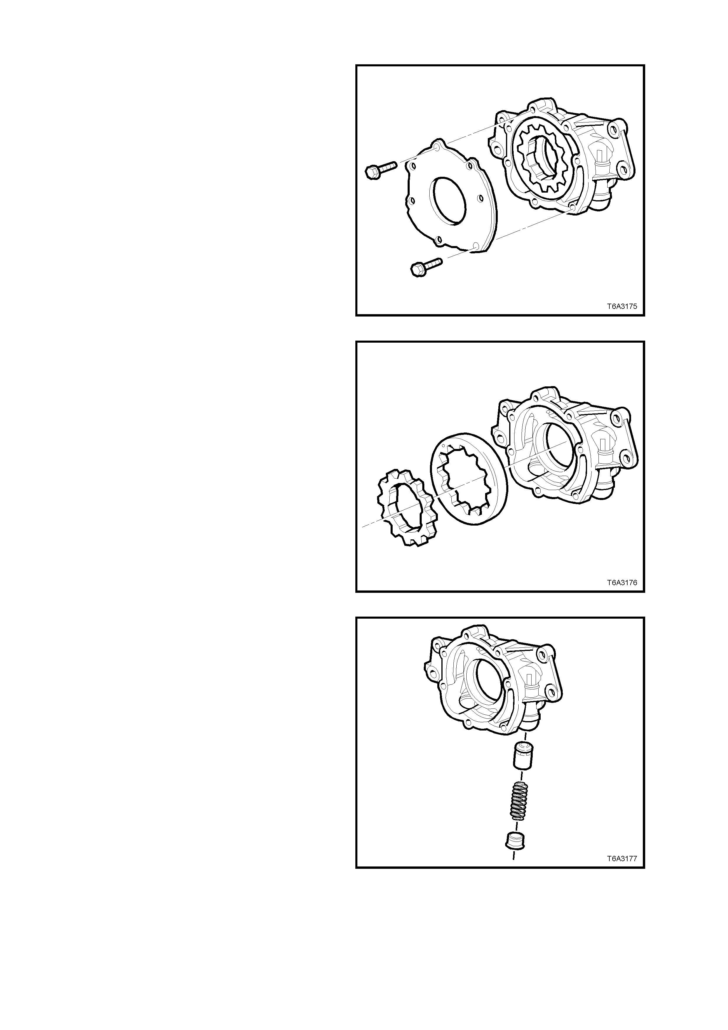
OIL PUMP DISASSEMBLE
1. Remove oil pump cover bolts, then remove the
cover.
Figure 6A3-238
Important: Mark or identify the relationship of the
gears for reassembly.
2. Remove the inner drive gear and outer driven
ring, from the oil pump body.
Figure 6A3-239
3. Unscrew the oil pressure relief valve plug and
remove spring and valve from the oil pump
body.
Figure 6A3-240

CLEAN AND INSPECT
NOTE: Apart from the oil pressure relief valve
spring, there are no other parts of the oil pum p nor
the oil pump pick-up screen and pipe that are
serviced s eparately. If either com ponent is f ound to
be worn or damaged, then that assembly must be
replaced. Do not attempt any repairs to either
component.
1. Clean all parts in a suitable solvent and blow
dry with compressed air.
CAUTION: Wear safety glasses to avoid eye
injury.
2. Inspect the oil pump housing for cracks,
excessive wear, scoring or casting
imperfections.
3. Inspect the oil pump housing to engine block
oil gallery surface for scratches or gouging.
4. Inspec t the oil pump housing f or damaged bolt
hole threads. See Section 3.16 THREAD
REPAIR, if required.
5. Inspec t the oil pum p relief valve plug and bore
for scratched or damaged surfaces and the
screw thread for damage. The pressure relief
valve must move freely in its bore with no
restrictions.
6. Inspect the oil pump internal oil passages for
restrictions.
7. Inspec t the drive and driven gears for chipping
galling or wear. Minor burrs or imperfections
on the gears can be removed with a fine oil
stone.
8. Inspect the inner gear drive splines for
excessive wear.
Replace the oil pump assembly if any of the
above conditions are observed.
9. Inspect the oil pump pick-up screen for
clogging with debris or restriction.
10. Inspect the screen mesh for broken or loose
strands.
Replace the oil pump pick-up screen and pipe
assembly as required.
OIL PUMP REASSEMBLE
Reassembly is the reverse of the disassembly
process, except for the following items:
1. Liberally coat all oil pump components with
clean engine oil before assembly.
2. Take note of the relationship of the inner to
the outer oil pump gears when assembling.
3. Tighten the oil pump cover screws to the
correct torque specification.
OIL PUMP COVER TO BODY SCREW
TORQUE SPECIFICATION 12 Nm
4. Install a NEW pressure relief valve spring.
5. Tighten the pressure relief valve plug to the
correct torque specification.
OIL PUMP PRESSURE RELIEF PLUG
TORQUE SPECIFICATION 12 Nm
6. Rotate the assembled pump, checking for
smoothness of operation by rotating the inner
drive gear.
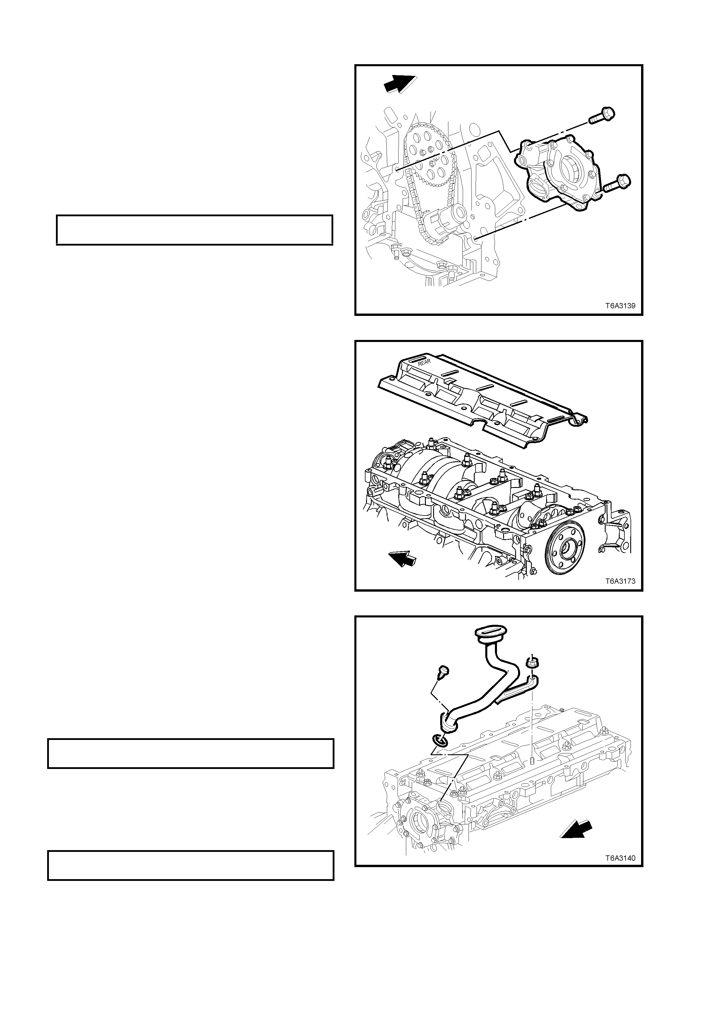
REINSTALL
1. Check the oil pump and engine block oil
gallery passages to ensure that any debris is
removed.
2. Align the splined surfaces of the crankshaft
sprocket and the oil pump drive gear and
install the oil pum p onto the sprocket, until the
pump housing contacts the face of the engine
block.
3. Install the oil pump bolts and tighten to the
correct torque specification.
OIL PUMP BOLT
TORQUE SPECIFICATION 25 Nm
Figure 6A3-241
4. Install the crankshaft oil deflector, noting that
the ‘REAR’ stamping on the deflector is
located at the rear of the engine.
Figure 6A3-242
5. Lubric ate a NEW oil pum p pick -up tube O-r ing
with clean engine oil and install onto the oil
pump pick-up tube.
6. Fully install the pick-up tube into the oil pump
housing, aligning the support bracket with the
main bearing cap stud.
7. Install the pick-up tube screw and tighten to
the correct torque specification.
OIL PUMP PICK-UP TUBE SCREW
TORQUE SPECIFICATION 12 Nm
NOTE: Ensure that the pick-up tube is fully
installed before tightening the retaining screw.
8. Install all the crankshaft oil deflector nuts to
the main bearing cap studs and tighten to the
correct torque specification.
CRANKCASE OIL DEFLECTOR
NUT TORQUE SPECIFICATION 25 Nm
9. Reinstall the oil pan, refer to 3.3 OIL PAN -
REINSTALL, in this Section.
10. Reinstall the front cover, refer to 3.4 ENGINE
FRONT COVER - REINSTALL and
2.24 HARMONIC BALANCER - REINSTALL,
in this Section.
Figure 6A3-243
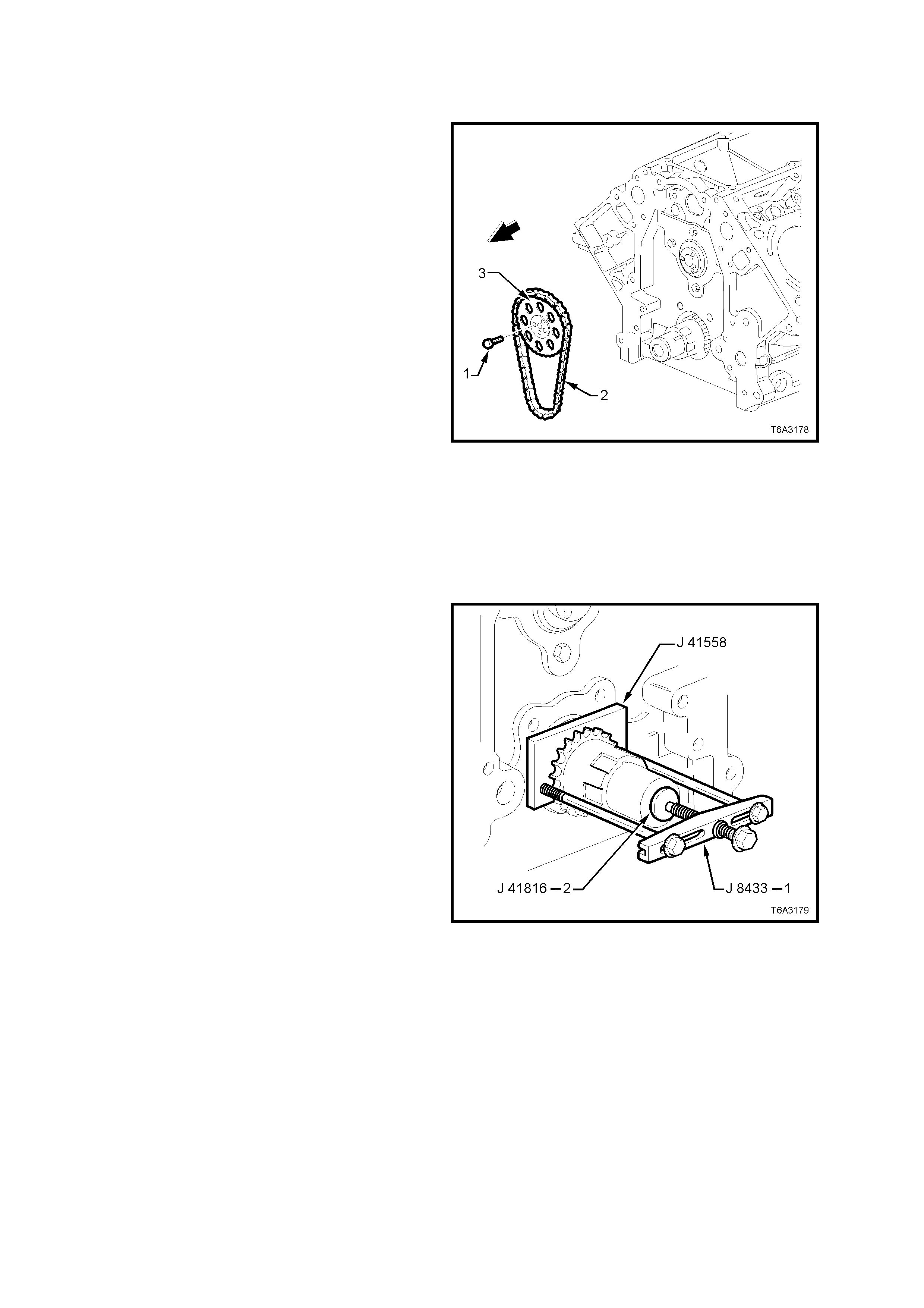
3.10 TIMING CHAIN AND SPROCKETS
REMOVE
Important: Because of critical alignment
procedures required for the reinstallation of the
front cover and oil pan, it is strongly recomm ended
that the engine assembly is removed from the
vehicle, before this service operation is carried out.
1. Remove oil pan, refer 3.3 OIL PAN -
REMOVE, in this Section.
2. If the harmonic balancer and front cover have
not already been removed, refer to
2.24 HARMONIC BALANCER - REMOVE and
3.4 ENGINE FRONT COVER - REMOVE, in
this Section.
3. Remove the oil pump, refer 3.9 OIL PUMP,
PUMP SCREEN AND DEFLECTOR, in this
Section.
NOTE: If the c ylinder heads and valve tr ain are s till
installed, temporarily install the harmonic balancer
bolt and turn engine until the timing marks on the
camshaft and crankshaft sprockets are aligned,
refer Figure 6A3-246. Remove the harmonic
balancer bolt.
4. Remove the camshaft sprocket bolts (1), then
remove the sprocket (2) and chain (3) from the
camshaft and crankshaft sprocket.
Figure 6A3-244
5. Use Tool No’s J 41558, J 41816-2, the bolts
from J 21427-01 and puller J 8433-1,
assemble as shown and remove the
crankshaft sprocket from the nose of the
crankshaft
6. Remove the crankshaft sprocket drive key
from the crankshaft nose, if required.
Figure 6A3-245

CLEAN AND INSPECT
1. Clean the sprockets and timing chain in
suitable solvent and blow dry with compr esse d
air.
CAUTION: Wear safety glasses to avoid eye
injury.
2. Inspect the timing chain for binding or wear.
Figure 6A3-246
3. Inspect the camshaft and crankshaft
sprockets for:
a. Worn teeth (1).
b. Damaged teeth (2).
c. Chipped teeth (3).
d. Worn valleys between the sprocket teeth.
Figure 6A3-247
4. Inspec t the crankshaf t sprock et keyway (1) f or
wear.
5. Inspec t the crankshaf t sprock et oil pump drive
splines (2) for wear.
Figure 6A3-248
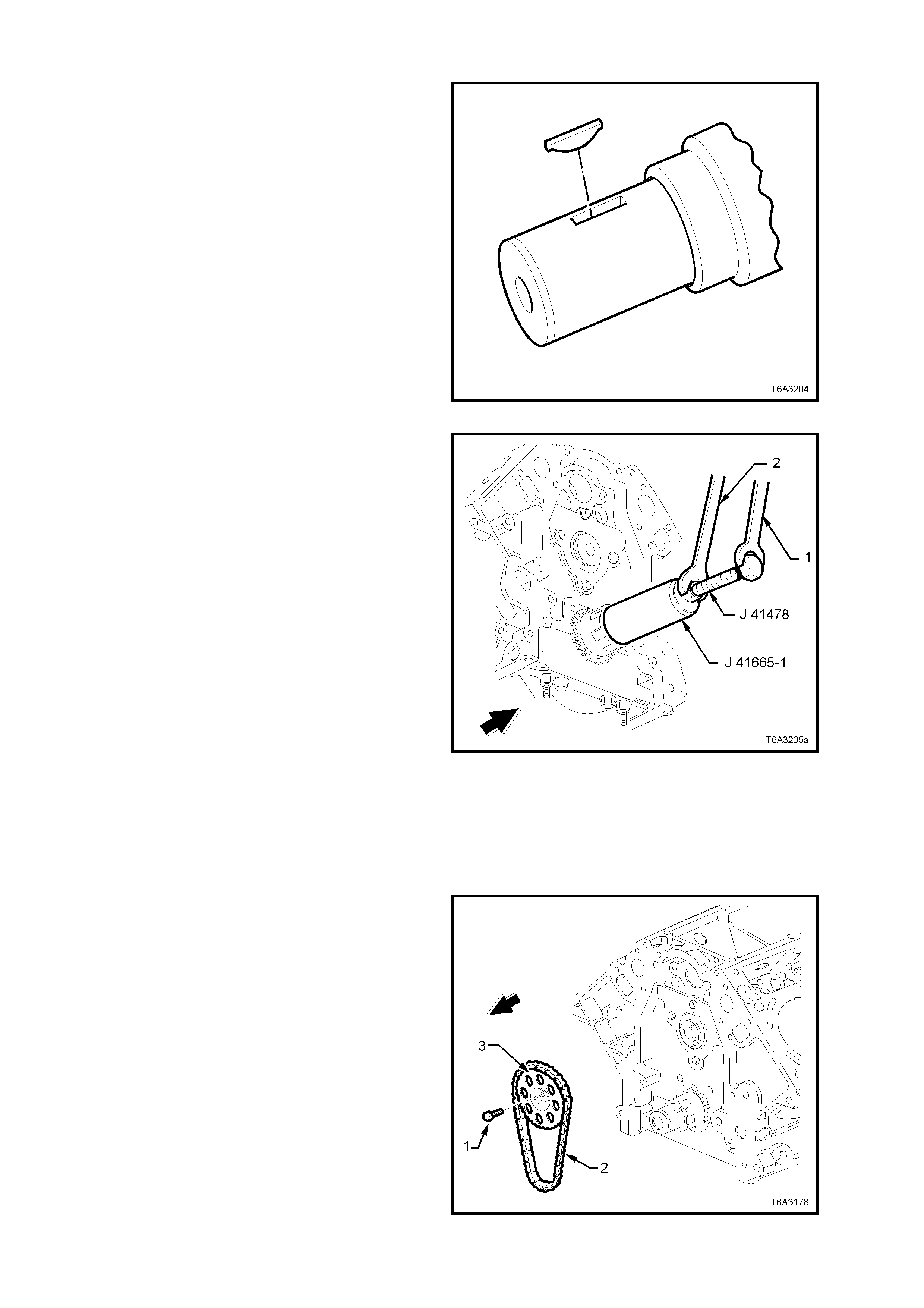
REINSTALL
1. If removed, install the crankshaft sprocket
drive key into the crankshaft.
The key should be tapped into place until eac h
end bottoms on the crankshaft.
Figure 6A3-249
2. Install the crankshaft sprocket onto the
crankshaft nose, aligning the keyway with the
key.
3. Use installer J 41665 to install the crankshaft
sprocket, as follows:
a. Install the threaded bolt, nut and flat
washer from Tool J 41478) through the
end plate and stepped sleeve of Tool J
41665.
b. Screw threaded bolt into the crankshaft,
using set spanner (1).
c. While holding the threaded bolt with set
spanner (1), turn the nut on the threaded
bolt with a second set spanner (2),
m oving installer J 41665 to fully install the
crankshaft sprocket onto the crankshaft
nose.
d. W hen crankshaft sprocket has been fully
installed, remove installation tools.
4. If required, temporarily install the harmonic
balancer bolt and rotate the crankshaft until
the timing alignment mark is at the 12 o’clock
position. Refer Figure 6A3-252.
Figure 6A3-250
5. Install the camshaft sprocket (3), aligning the
peg on the camshaft with the sprocket hole.
Check that the timing mark is at the 6 o’clock
position. Refer Figure 6A3-252.
6. If required, temporarily install the camshaft
sprocket bolts and use a suitable lever to
rotate the camshaft sprocket until the timing
ma rk is c or re ctly aligned. Remove the bolts ( 1)
and sprocket (3).
7. Install the timing chain (2) to the camshaft
sprocket (3), align the camshaft peg with the
cam shaft sproc ket hole by eye, then ins tall the
timing chain to the crankshaft sprocket.
8. Install the camshaft sprocket over the
camshaft peg.
Figure 6A3-251
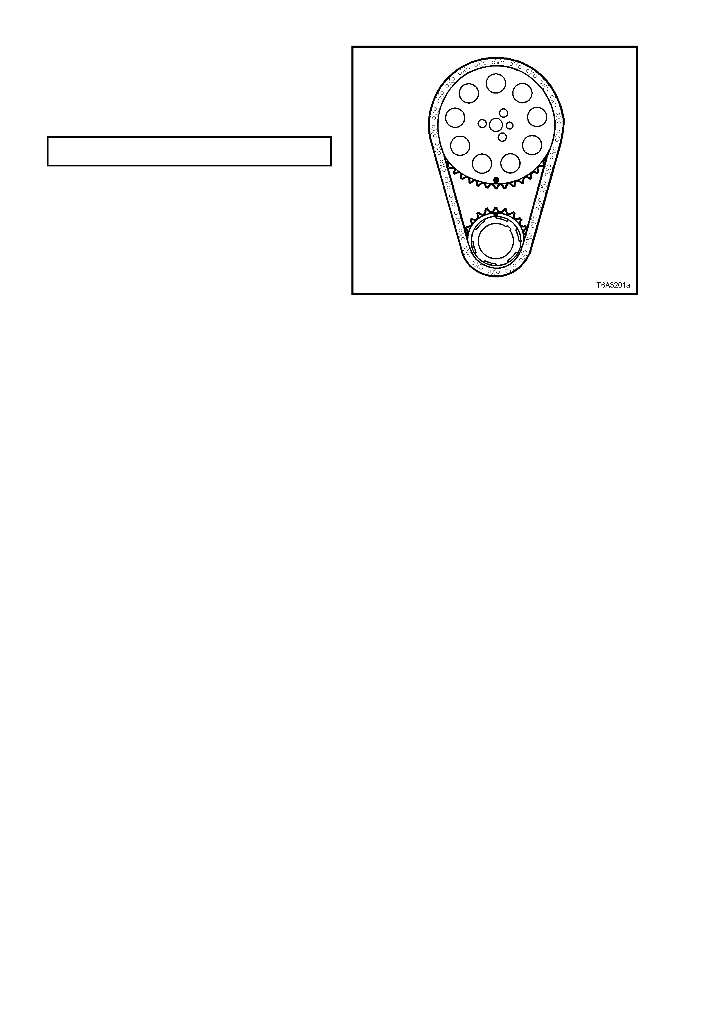
9. Before installing the camshaft sprocket bolts
(1 in Figure 6A3-251), check that the timing
marks are aligned as shown. If not, repeat
Steps 4 to 8 above.
10. Install the cam shaft sprocket bolts and tighten
to the correct torque specification.
CAMSHAFT SPROCKET BOLT
TORQUE SPECIFICATION 35 Nm
11. Reinstall the oil pump, refer 3.9 OIL PUMP,
PUMP SCREEN AND DEFLECTOR, in this
Section.
12. Reinstall oil pan, refer 3.3 OIL PAN -
REMOVE, in this Section.
13. Reinstall the front cover and harmonic
balancer. Refer 3.4 ENGINE FRONT COVER
- REINSTALL and 2.24 HARMONIC
BALANCER - REINSTALL, in this Section. Figure 6A3-252

3.11 CAMSHAFT
REMOVE
Important: Because of critical alignment
procedures required for the reinstallation of the
front cover and oil pan, it is strongly recomm ended
that the engine assembly is removed from the
vehicle, before this service operation is carried out.
1. Remove the intake manifold assembly, if this
operation has not already been carried out.
Refer 2.14 INTAKE MANIFOLD - REMOVE,
in this Section.
2. Remove the camshaft sensor bolt and sensor
from the engine block.
Figure 6A3-253
3. Remove oil pan, refer 3.3 OIL PAN -
REMOVE, in this Section.
4. If the harmonic balancer and front cover have
not already been removed, refer to
2.24 HARMONIC BALANCER - REMOVE and
3.4 ENGINE FRONT COVER - REMOVE, in
this Section.
5. Remove the oil pump, refer 3.9 OIL PUMP,
PUMP SCREEN AND DEFLECTOR, in this
Section.
6. Remove the camshaft chain and sprocket.
Refer 3.10 TIMING CHAIN AND
SPROCKETS - REMOVE in this Section.
7. Remove the camshaft retainer bolts then
remove the retainer and gasket.
Figure 6A3-254
8. Install three, M8 x 1.25 x 100 mm bolts (e.g.
removed water pump bolts) in the front of the
camshaft and use as a handle to rotate and
remove the camshaft from the engine block.
NOTE: As all camshaft bearing journals are the
same size, care must be taken when removing the
camshaft, to avoid damaging the bearings.
9. Remove the three bolts from the camshaft.
Figure 6A3-255
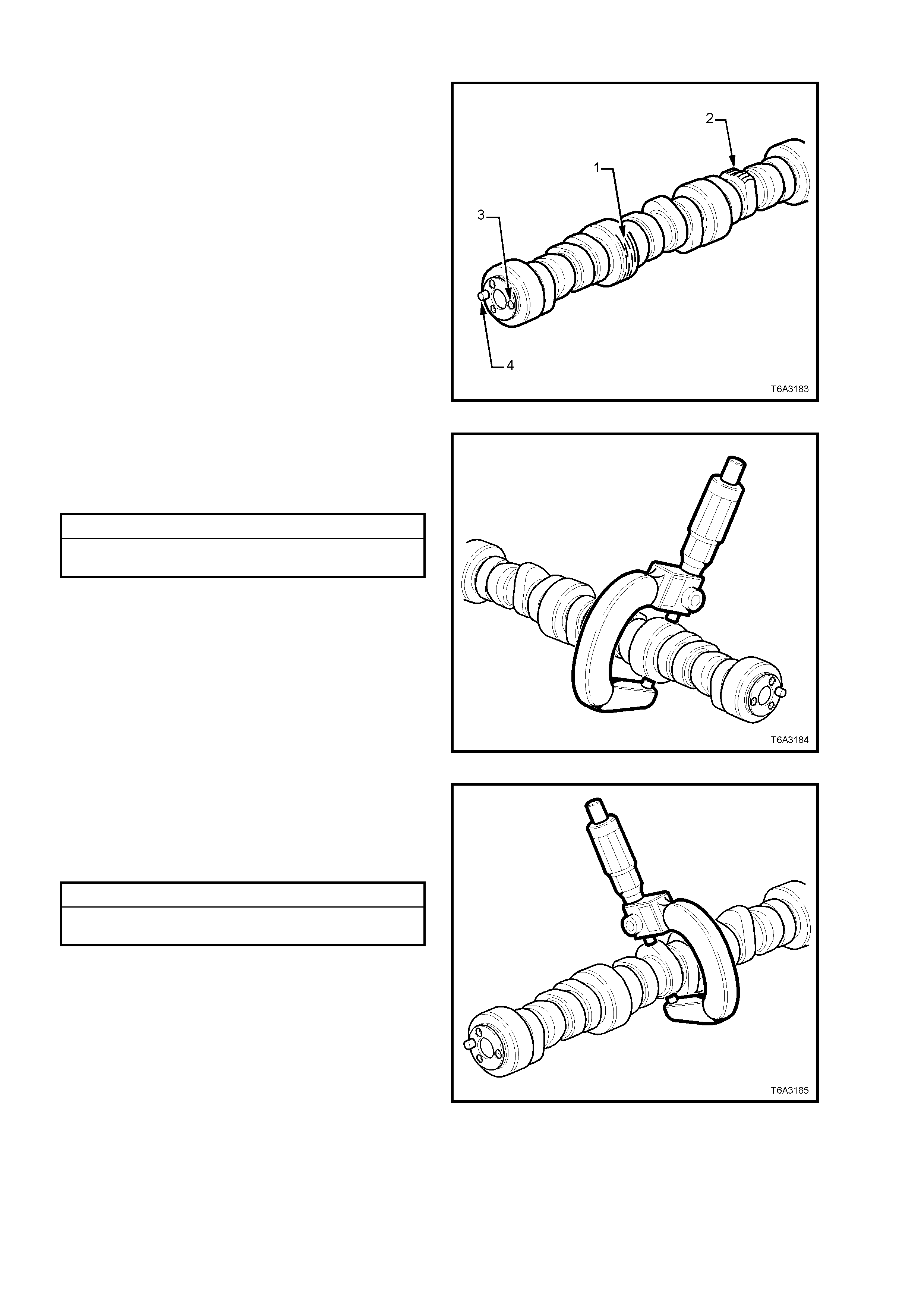
CLEAN AND INSPECT
1. Clean all components with a suitable solvent
and blow dry with compressed air.
CAUTION: Wear safety glasses to avoid eye
injury.
2. Inspect the camshaft for:
a. Scoring or excessive wear to the bearing
journals (1).
b. Scoring or excessive wear to the
camshaft lobes (2).
c. Damaged threads (3) or debris in
threaded holes.
d. Damage to the camshaft sprocket pin (4).
e. Nicks or dam age to the c am shaf t pos ition
reluctor ring.
Figure 6A3-256
3. Measure the camshaft journals for wear and
out-of-round, using a micrometer.
Replace the camshaft if either of these
measurements is outside specification.
Camshaft Journal Specifications
Cams haft Journal Out-of-Round ..... .... .. 0. 025 mm Maximum
Cams haft Bearing Journal Diameter.. ... 54.99 mm Minimum
Figure 6A3-257
4. Measure camshaft lobes for wear, using a
micrometer
Replace the camshaft when the cam lobe
dimension is to the minimum specification or
less, for either the intake or exhaust lobes.
Camshaft Lobe Specifications
Intake Lobe Height................................ 46.67 mm Minimum
Exhaust Lobe Height............................. 46.67 mm Minimum
Figure 6A3-258

5. Mount the camshaft either in Vee blocks or
between centres.
6. Using a suitable dial indicator mounted as
shown, rotate the camshaft and check the
runout on the centre bearing journal.
Replace the camshaft if the runout exceeds
the specification.
Camshaft Runout Specification
Camshaft Runout.................................. 0.05 mm Maximum
7. Inspec t the cams haft retainer plate for wear or
a damaged sealing gasket.
If the gasket is not cut or damaged, it may be
re-used. Figure 6A3-259
REINSTALL
NOTE: If the c amshaf t r eplac ement is r equired, the
valve lifters must also be renewed.
1. Lubricate camshaft journals and the bearings
with clean engine oil.
2. Install thr ee M8 x 1.25 x 100 m m bolts into the
camshaft front journal.
3. Using the bolts as a handle, carefully install
the camshaft into the engine block.
NOTE: As all the cams haft bear ing journals are the
same size, care must be taken to avoid bearing
damage during camshaft installation.
4. Remove the three bolts after camshaft
installation.
Figure 6A3-260
5. Ensure that the engine block surface is clean
and free of debris, then install the camshaft
retainer plate with the sealing gasket facing
the engine block.
6. Install the camshaft retainer bolts and tighten
to the correct torque specification.
CAMSHAFT RETAINER BOLT
TORQUE SPECIFICATION 25 Nm
Figure 6A3-261
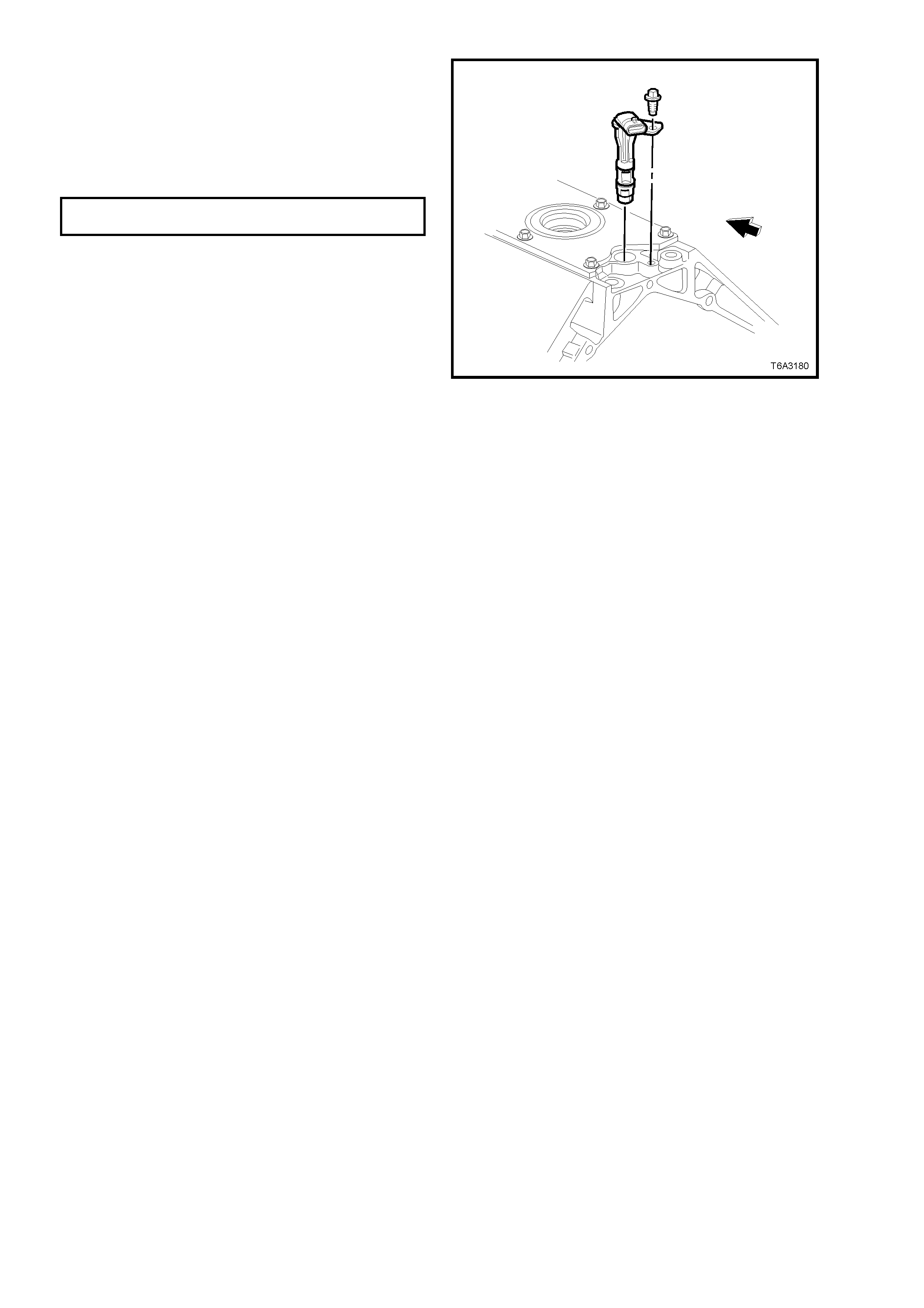
7. Inspect the camshaft position sensor O-ring,
renewing if it is cut or damaged.
8. Lubricate the O-ring with clean engine oil,
install to the sensor.
9. Install the camshaft position sensor and the
retaining bolt and tighten to the correct torque
specification.
CAMSHAFT POSITION SENSOR
BOLT TORQUE SPECIFICATION 25 Nm
10. Reinstall the camshaft chain and sprocket.
Refer 3.10 TIMING CHAIN AND
SPROCKETS, in this Section.
11. Reinstall the oil pump, refer 3.9 OIL PUMP,
PUMP SCREEN AND DEFLECTOR, in this
Section.
12. Reinstall the front cover and harmonic
balancer. Ref er 2.24 HARMONIC BALANCER
and 3.4 ENGINE FRONT COVER, in this
Section.
13. Remove oil pan, refer 3.3 OIL PAN -
REMOVE, in this Section.
14. If required, reinstall the intake manifold
assembly. Refer 2.14 INTAKE MANIFOLD, in
this Section.
Figure 6A3-262
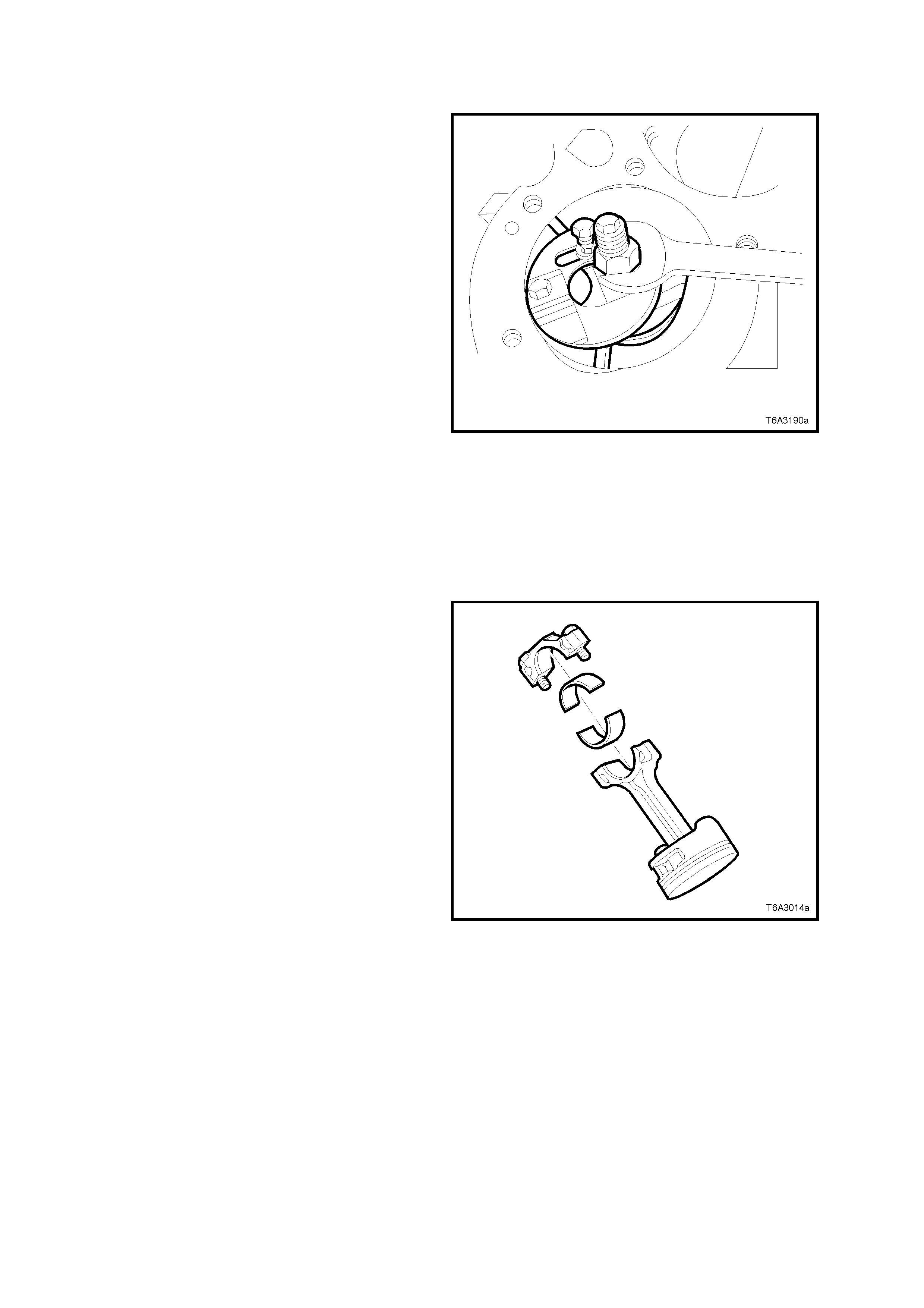
3.12 PI STON, CONNECTING ROD AND BEARING
REMOVE
Important: Because of critical alignment
procedures required for the reinstallation of the oil
pan, it is strongly recommended that the engine
assembly is removed from the vehicle, before this
service operation is carried out.
1. Remove both cylinder heads. Refer
2.22 CYLINDER HEAD - REMOVE, in this
Section.
2. Remove oil pan, pump screen and deflector,
refer 3.3 OIL PAN - REMOVE and
3.9 OIL PUMP, PUMP SCREEN AND COVER
- REMOVE, in this Section.
3. If required, use a commercially available
cylinder ridge rem over, to remove any cylinder
ridge present, adopting the following
procedure:
a. Rotate the crankshaft until the piston is at the
bottom of its stroke (BDC).
b. Place a cloth on top of the piston.
c. Use the cylinder ridge remover to remove the
cylinder ridge.
d. Again rotate the crankshaft until the piston is
at the top of its stroke (TDC).
e. Remove the cloth and any metal shavings
from the piston crown.
Figure 6A3-263
4. Using a paint stick or etching tool, matchmark
each connecting rod and its cap. The
connecting rod caps MUST be assembled to
the original position and direction.
DO NOT apply a stamping m ar k on the side of
the connecting rod and/or cap as this may
affect alignment and the geometry of the
assembly.
5. Mark the top of each piston to identify its
specific bore.
6. Remove the connecting rods bolts, loosening
progressively from side to side.
Important: Ensure that the connecting rod
bearings are organised so they will be installed in
the original position and location.
7. Remove each connecting rod cap.
Figure 6A3-264
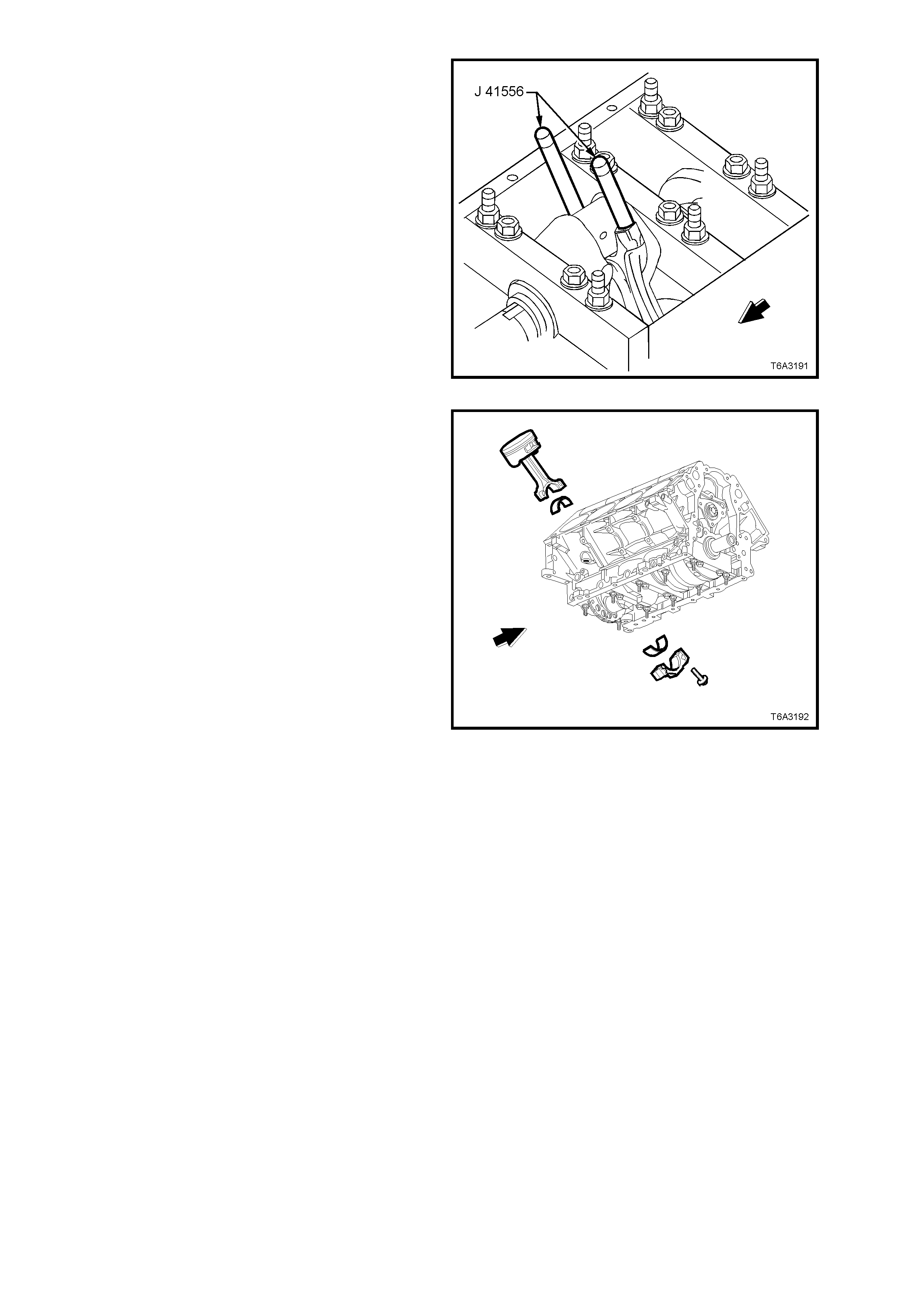
8. Install guide pins Tool J 41556 to the
connecting rod to be removed.
Figure 6A3-265
9. Use a hamm er handle to tap lightly on the end
of the guide pin Tool J 41556 and remove the
piston and connecting rod from the cylinder
bore.
10. Once removed, assemble the connecting rod
cap, bearing shells and bolts to the matching
connecting rod.
Figure 6A3-266

DISASSEMBLE
1. Remove the piston rings from the piston.
Figure 6A3-267
2. Insert fork insert J 24086-905 onto the bridge
of Tool J 24086-C. Mount the piston assem bly
so that the fork insert is between the
connecting rod and the piston. Install pin
remover J 24086-8A.
3. Place the assembly under an hydraulic press
and remove the piston pin f rom the piston and
connecting rod assembly.
NOTE: The piston and pin are a matched set and
are not serviced separately. Mark the pin to piston
to ensure correct reas sembly if original parts ar e to
be re-used.
Figure 6A3-268
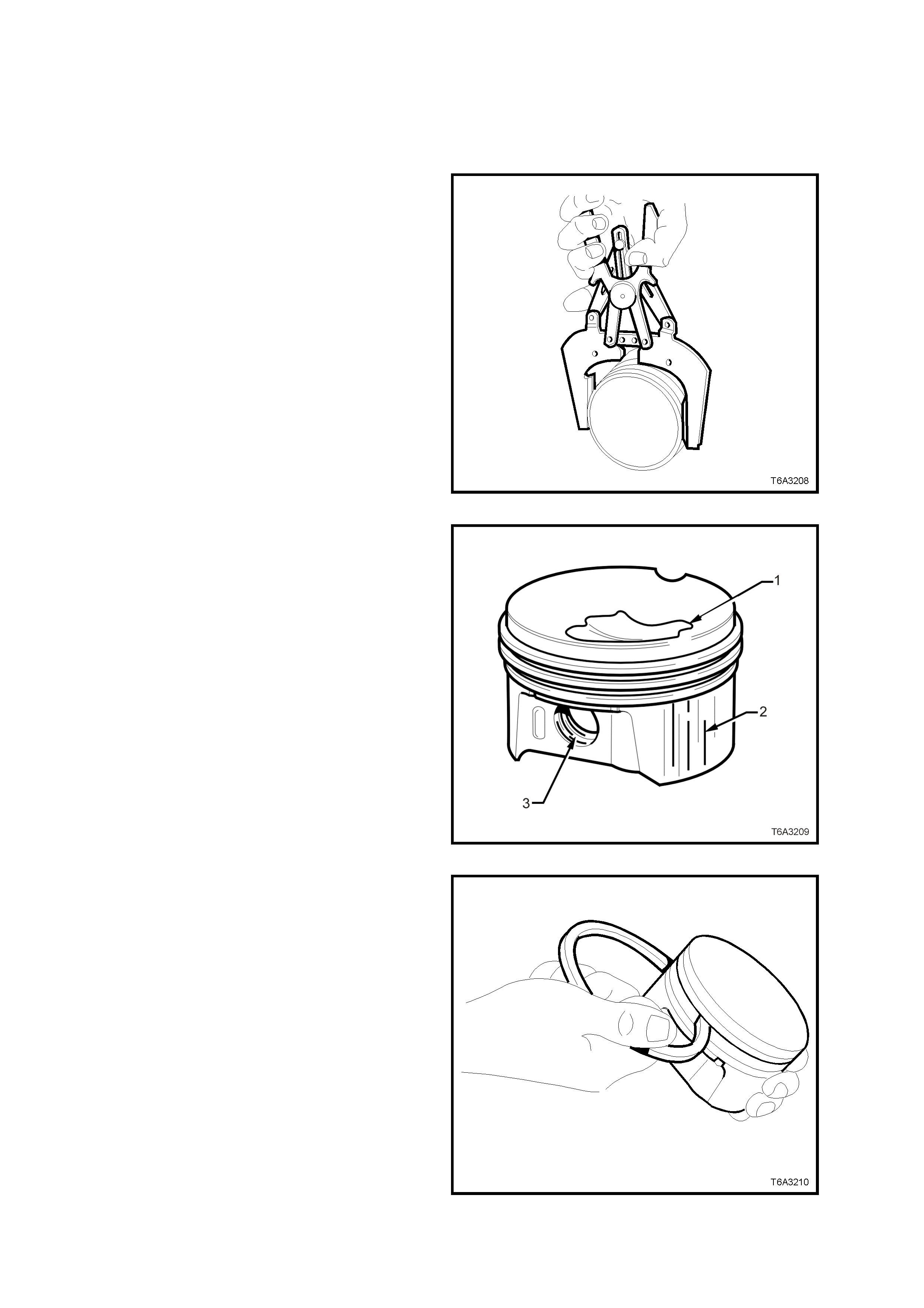
CLEAN AND INSPECT
Piston and Pin
1. Clean any varnish from the piston and pin,
with a suitable cleaning solvent. DO NOT use
a wire brush for this process.
2. Dry the cleaned parts with compressed air.
CAUTION: Wear safety glasses to avoid eye
injury.
3. Clean the piston ring grooves with a
commercially available tool.
4. Clean the oil lubrication holes and slots in the
ring grooves.
Figure 6A3-269
5. Inspect each piston and pin for the following:
a. Cr acks in the piston lands, sk irt or the pin
bosses.
b. Piston ring grooves for nicks, burrs or
warpage which may cause the piston r ing
to bind. MINOR imperfections may be
removed by using a fine file.
c. Eroded areas on top of the piston (1).
d. Scuffed or damaged skirts (2).
e. Scoring to the piston pin bore (3) or the
piston pin.
Figure 6A3-270
6. Measure the piston ring to piston groove side
clearance, as follows:
a. Insert the edge of a NEW piston ring into
the correct piston ring groove.
b. Roll the piston ring around the groove.
NOTE 1: If binding is caused by a distorted piston
ring groove, MINOR ring gr oove imperfec tions m ay
be removed with a fine file.
NOTE 2: If binding is caused by a distorted piston
ring, replace the ring.
Figure 6A3-271
NOTE: For each of the following measurements,
ensure that the micrometer zeroing has been
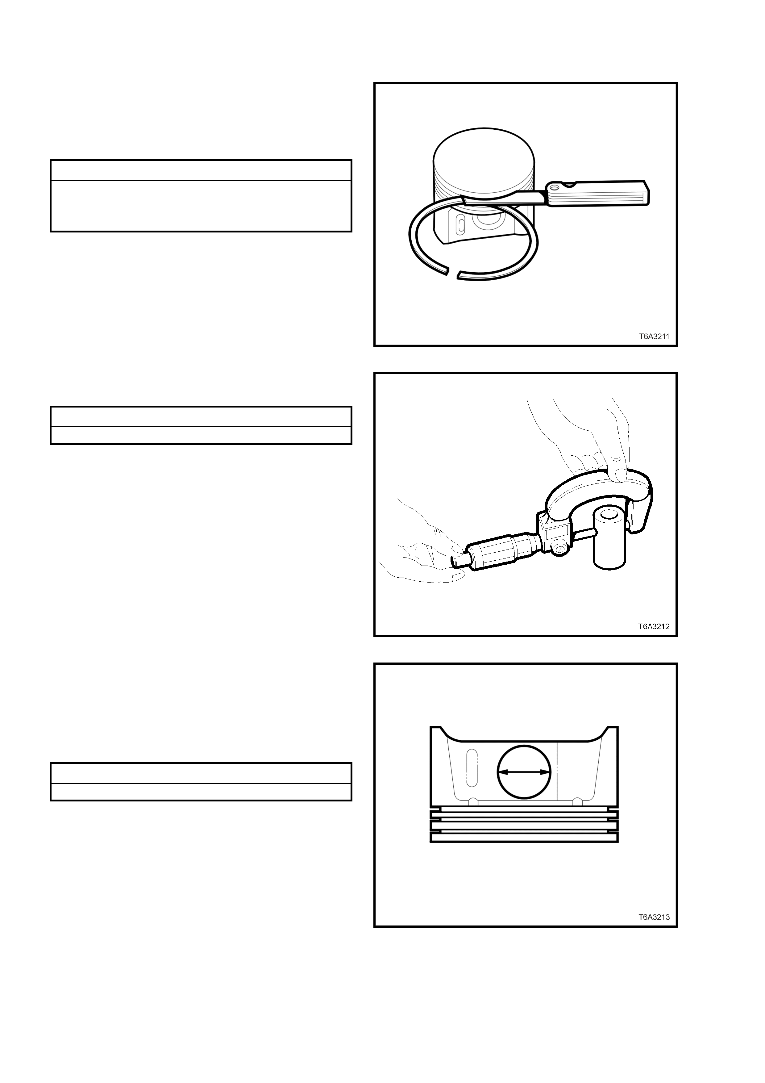
carried out and the measurements are all taken
with components at room temperature.
7. Again using a new piston ring in the correct
location, check the side clearance using a
feeler gauge. If side clearance exceeds
specif ication, try another piston r ing set before
condemning the piston.
Piston Ring Side Clearance Specification
Top compression ring .................... 0.040 - 0.085 mm
Second compression ring .............. 0.040 - 0.080 mm
Oil control ring................................ 0.010 - 0.220 mm
8. If the piston ring side clearance exceeds
specification, the piston and pin assembly
must be replaced.
Figure 6A3-272
9. To measure the pin-to-bore clearance, first
measure the pin with a micrometer.
Piston Pin Specification
Piston Pin Diameter.................... 23.997 - 24.000 mm
Figure 6A3-273
10. Using a suitable inside micrometer, measure
the matching piston pin bore on each side.
11. Subtract the piston pin dimension from the
piston pin bore size to obtain the clearance.
12. If the clearance exceeds specification, the
piston and pin assembly must be replaced.
Piston Pin to Bore Clearance Specification
Piston pin clearance (Maximum).... 0.010 - 0.020 mm
Figure 6A3-274
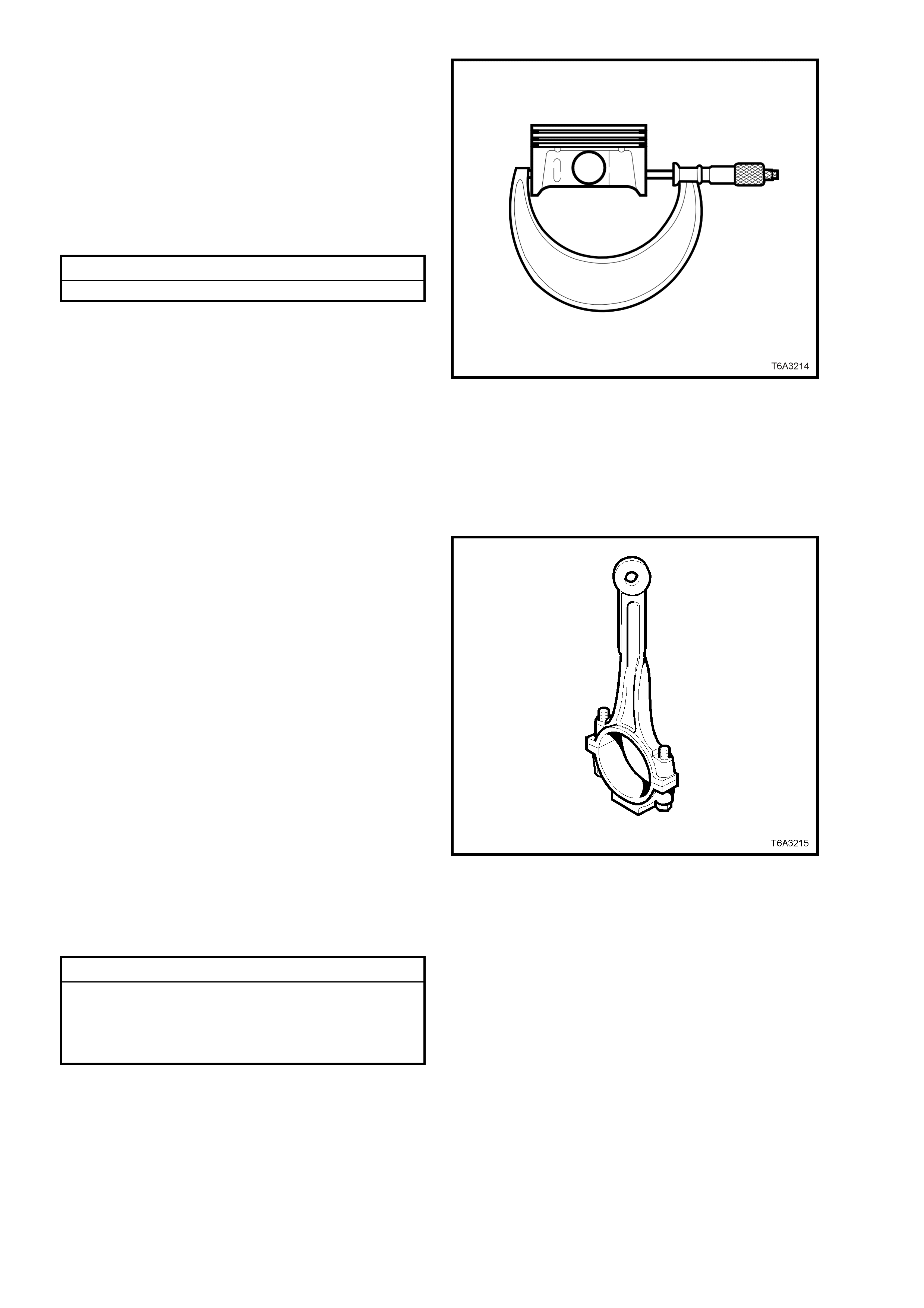
13. Measure the piston for out-of-round, as
follows:
a. With a suitable sized micrometer at right
angles to the piston pin bore, measure
the piston skirt dimension, 11 mm above
the bottom of the skirt.
b. Measure the piston at two different points
and compare the readings
c. If the difference exceeds specification,
then replace the piston and pin assembly.
Piston Skirt Out-of Round Specification
Piston skirt dimension variation .. 0.018 mm Maximum
Figure 6A3-275
Connecting Rods and Bea rings
NOTE: The powdered metal connecting rod and
cap are machined for the correct clearances. The
connecting rod and the cap must be used as an
assembly, with no repairs or modifications carried
out to either mating surface.
1. Clean each connecting rod and matching cap
in a suitable solvent.
2. Clean the connecting rod bolt threads and
inspect for damage. Do not attempt to repair
damaged threads in this location. Replace the
connecting rod, cap and bolts as an assembly
if thread damage is found.
3. Blow parts dry using compressed air.
CAUTION: Wear safety glasses to avoid
eye injury.
4. Inspect the connecting rod for the following
defects:
a. Twisting, using commercially available
alignment equipment.
b. Bending. Check length with suitable
measuring equipment.
c. Nicks or gouging in the bearing bore.
d. Damage to the bearing locating slots in
the bearing bore.
e. Correct fit of the connecting rod and cap
mating surfaces.
Connecting Rod Specification
Centre to Centre Length.............. 154.90 ± 0.02 mm
Width........................................... 24.00 ± 0.05 mm
Twist............................................ 0.010 mm Maximum
Bend............................................ 0.02 mm Maximum
Figure 6A3-276
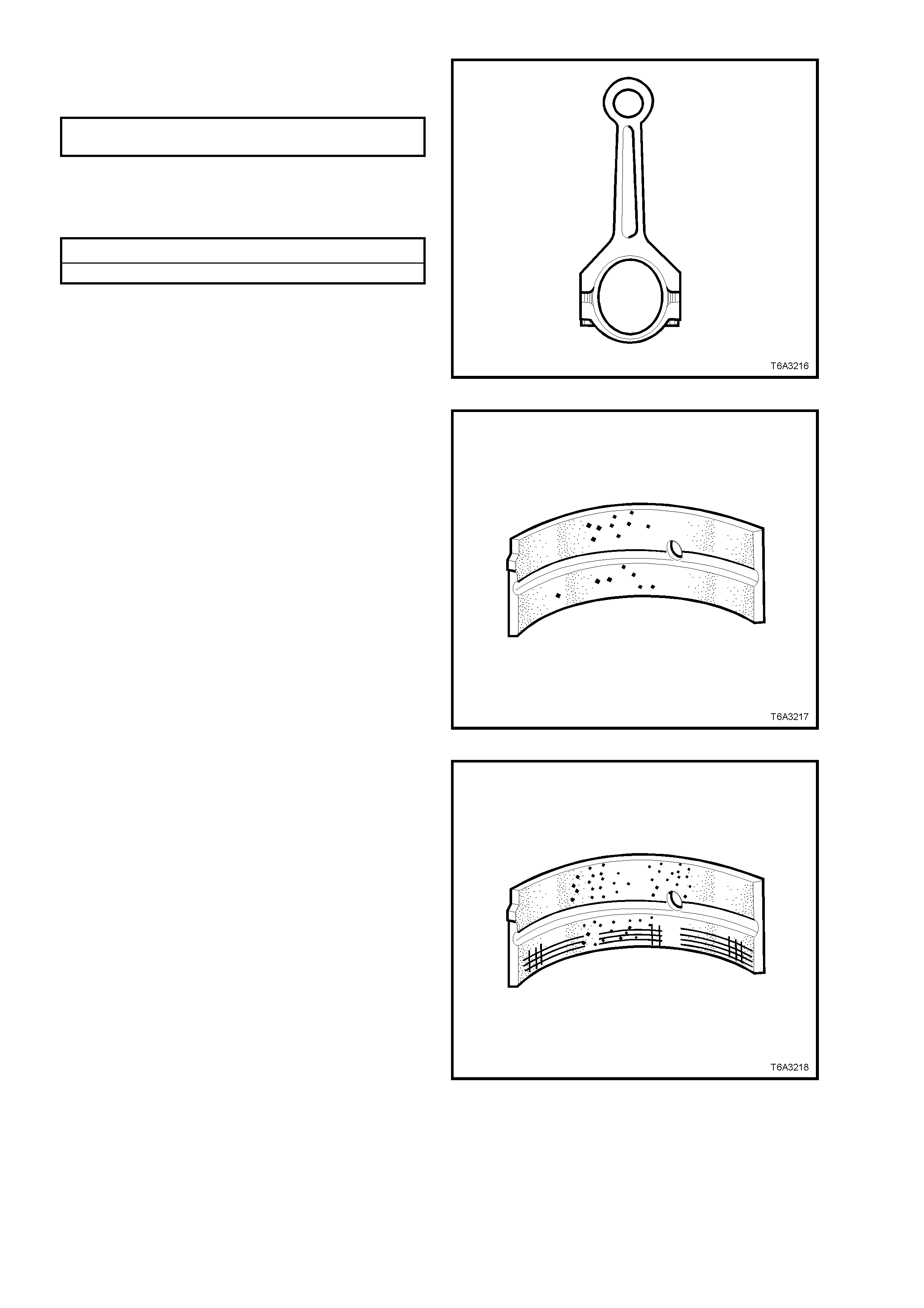
5. Reinstall the connecting rod big end cap and
bolts. Tighten bolts to the correct torque
specification.
CONNECTING ROD CAP BOLT Stage 1: 20 Nm
TORQUE SPECIFICATION Stage 2: 60° turn angle
6. Measure the connecting rod big end bore,
using a suitable inside micrometer, checking
for ovality. Replace any connecting rod
assembly that exceeds specification.
Connecting Rod Big End Ovality Specification
Connecting rod big end ovality.... 0.008 mm Maximum
Figure 6A3-277
7. Inspect connecting rod bearing halves for
craters or pockets. Flattened sections on the
bearing halves also indicate fatigue.
Figure 6A3-278
8. Inspect connecting rod bearing halves for
excessive scoring or discolouration.
9. Inspect the connecting rod bearings for dirt or
debris embedded into the bearing material or
backing metal.
Figure 6A3-279
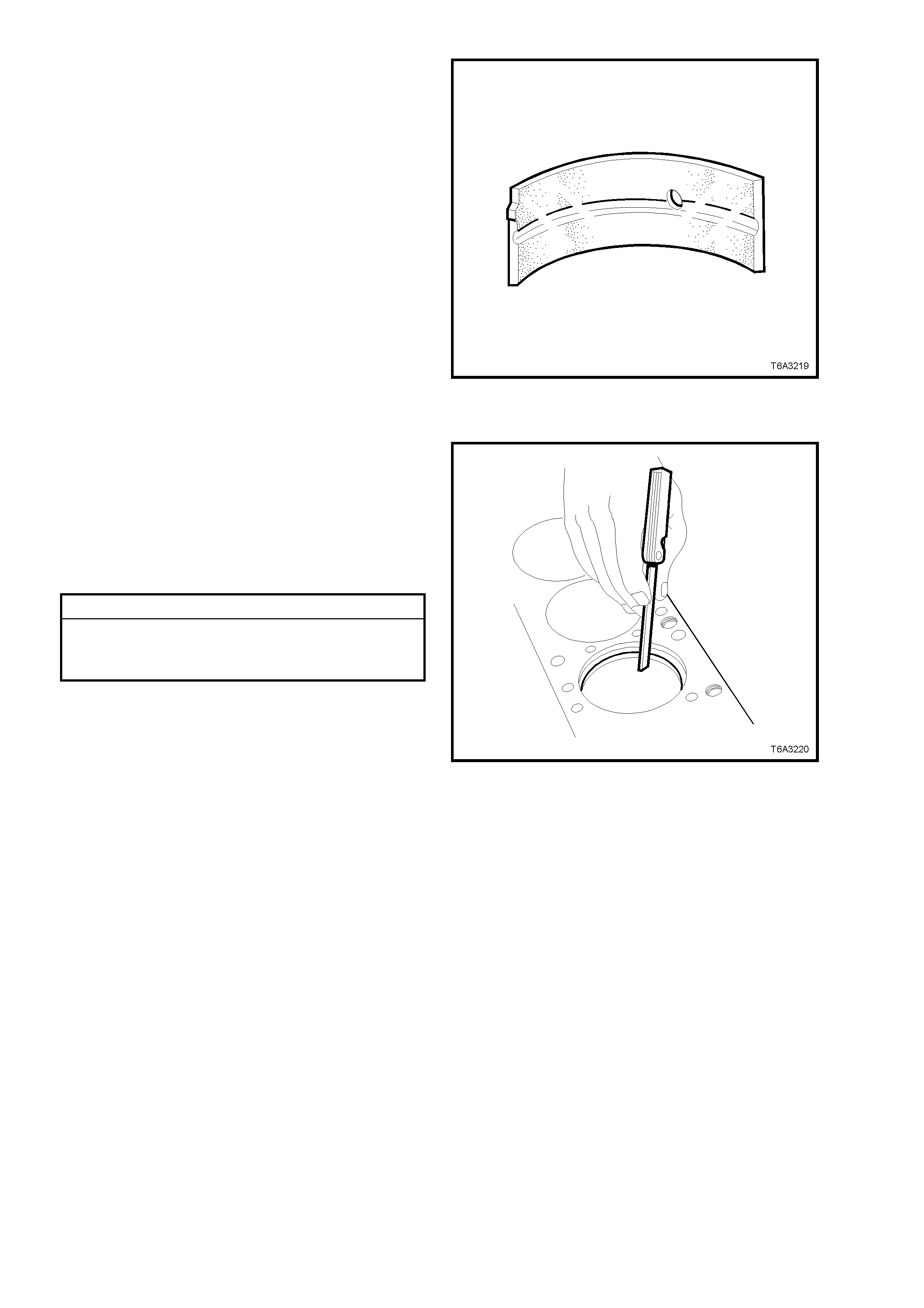
10. Inspect connecting rod bearing halves for
improper seating, indicated by bright, polished
section/s on the bearing material.
Figure 6A3-280
Measuring Piston Ring End Gap
1. Insert a new piston ring into the bore that it is
to be fitted and push it down the bore, using
the piston, inverted in the bor e, until the ring is
approximately 6.5 mm below the piston ring
travel area.
2. Insert a feeler gauge and measure the piston
ring end gap. End gap specifications are as
follows:
Piston Ring End Gap Specifications
Top compression ring .................... 0.230 - 0.380 mm
Second compression ring .............. 0.440 - 0.640 mm
Oil control ring................................ 0.180 - 0.690 mm
Figure 6A3-281
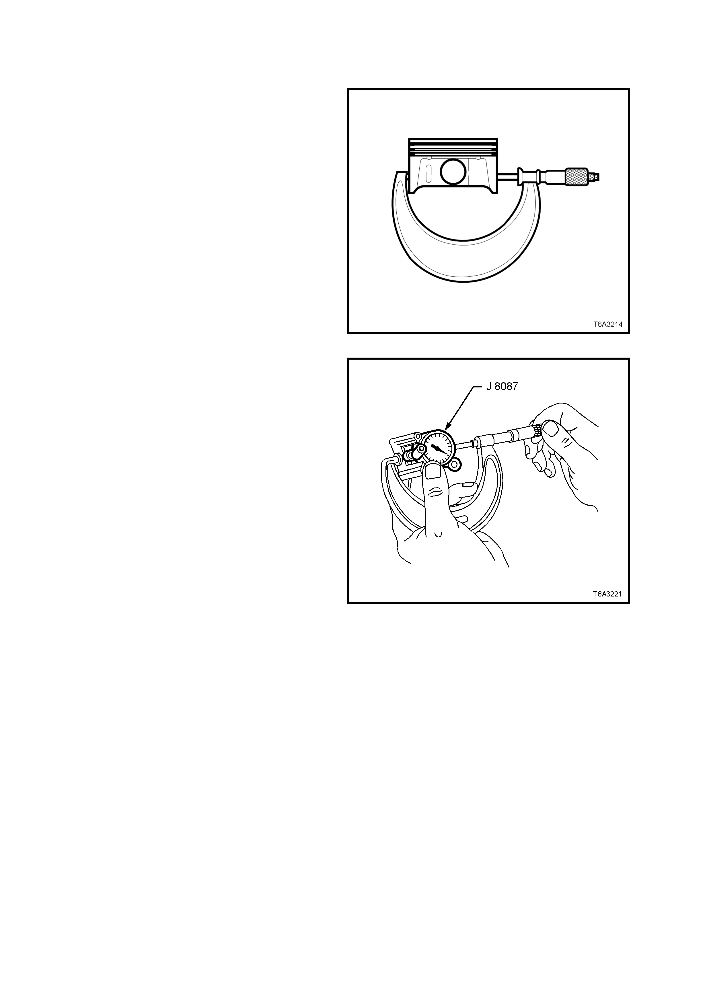
REASSEMBLE
Piston Selection
NOTE 1: All measurements should be taken at
normal room temperature.
NOTE 2: A used piston and pin set may be
reinstalled if, after cleaning and inspection, they are
both within specification.
1. With a microm eter at right angles to the piston
pin bore, measure the piston skirt at 11 mm
from the lower edge.
2. Record the piston diameter.
Figure 6A3-282
3. Check that the micrometer is at the recorded
piston diameter.
4. With Tool J 8087 (or commercial equivalent),
held between the micr ometer anvils as shown,
zero the dial indicator.
Figure 6A3-283
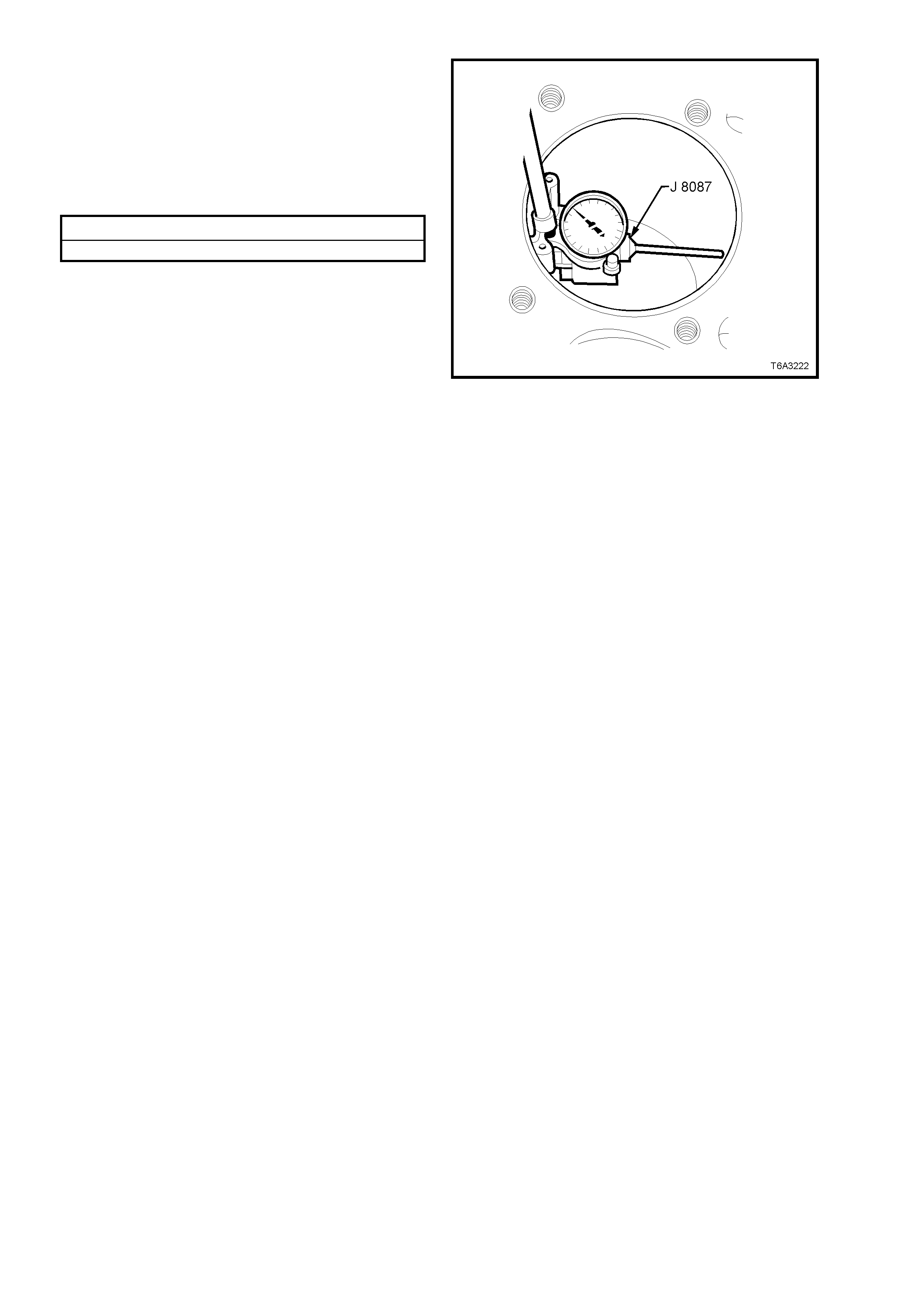
5. Use bore gauge J 8087 (or commercial
equivalent), measure the cylinder bore
diameter , at a point 57 mm fr om the top of the
bore.
6. Record the cylinder bore diameter.
7. Subtract the piston diameter from the cylinder
bore measurement, in order to determine the
piston to bore clearance.
Piston to Bore Clearance Specification
Clearance range ............................ 0.018 - 0.054 mm
8. If the clearance is outside this specification,
select another piston and measure it and re-
calculate the clearance. If the correct
clearance cannot be obtained using this
method, then the cylinder bore may require
honing for an oversize piston fitment, or the
cylinder block will need to be replaced.
9. When the correct piston to bore clearance is
obtained, mark the piston crown for correct
installation.
NOTE: The cylinder bore must be checked for
ovality and taper bef ore this oper ation is attempted.
Refer 3.15 CYLINDER BLOCK - Cylinder Block
Clean, Inspect and Measure, in this Section.
Figure 6A3-284
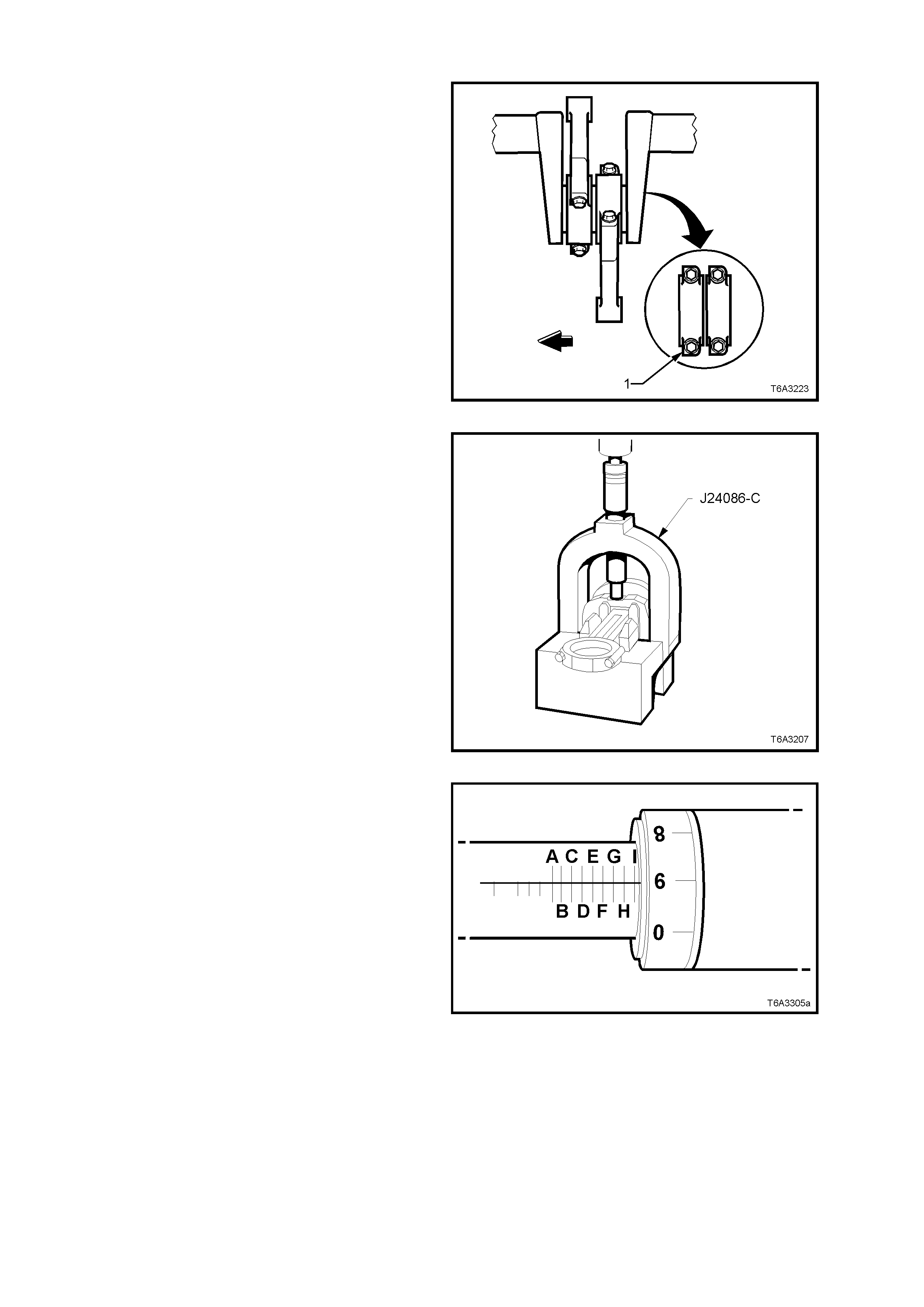
Piston to Connecting Rod
NOTE: Take particular care when assembling the
piston to the connecting rod, that component
matching and orientation is correct.
1. The connecting rod alignment should be with
the flat portion of the bolt flange (1) facing
forward. Also note that the piston alignment
mark has the correct orientation.
2. Lubricate the piston pin bore and piston pin
with clean engine oil.
Figure 6A3-285
3. With the connecting rod inserted with the
correct orientation into the piston, insert the
Black piston pin guide, J 24086-1A from Tool J
24086-C, into the lower piston pin boss to pre-
align the piston and connecting rod pin holes.
4. Insert fork insert J 24086-905 between the
piston and connecting rod, around the piston
pin guide J 24086-1A, then mount the
assembly into the fork bridge of
Tool J 24086-C.
Figure 6A3-286
5. Adjus t installer, J 24086-9, to a setting of “I-9”,
as shown. Lock this position with the knurled
ring.
Figure 6A3-287
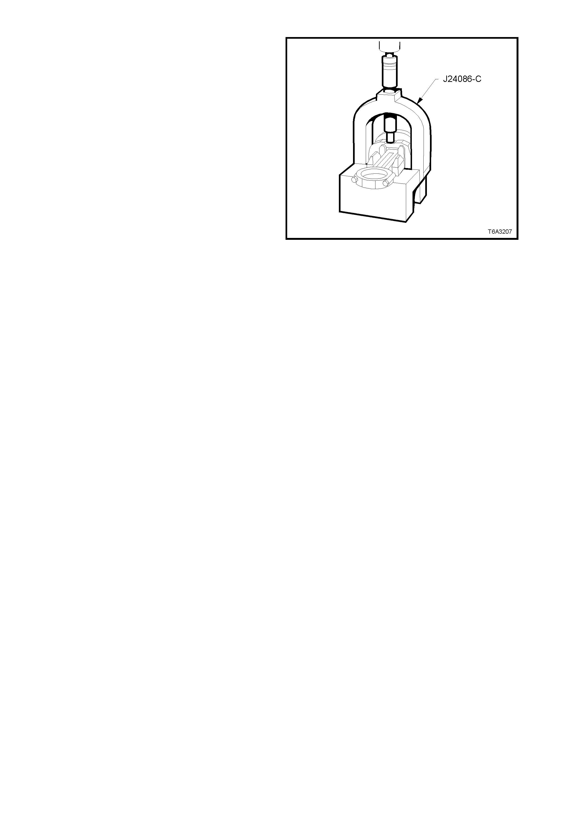
6. Insert the adjusted installer to Tool J 24086-C
and press the piston pin into the connecting
rod, until the installer bottoms out.
7. Check that the piston pin has been installed
correctly.
The piston pin will be installed correctly, if the
piston pin is centred in the piston and the
connecting rod is also centred between the
piston pin bosses, i.e. the connecting rod
should have equal spacing on each s ide of the
piston pin boss.
Figure 6A3-288
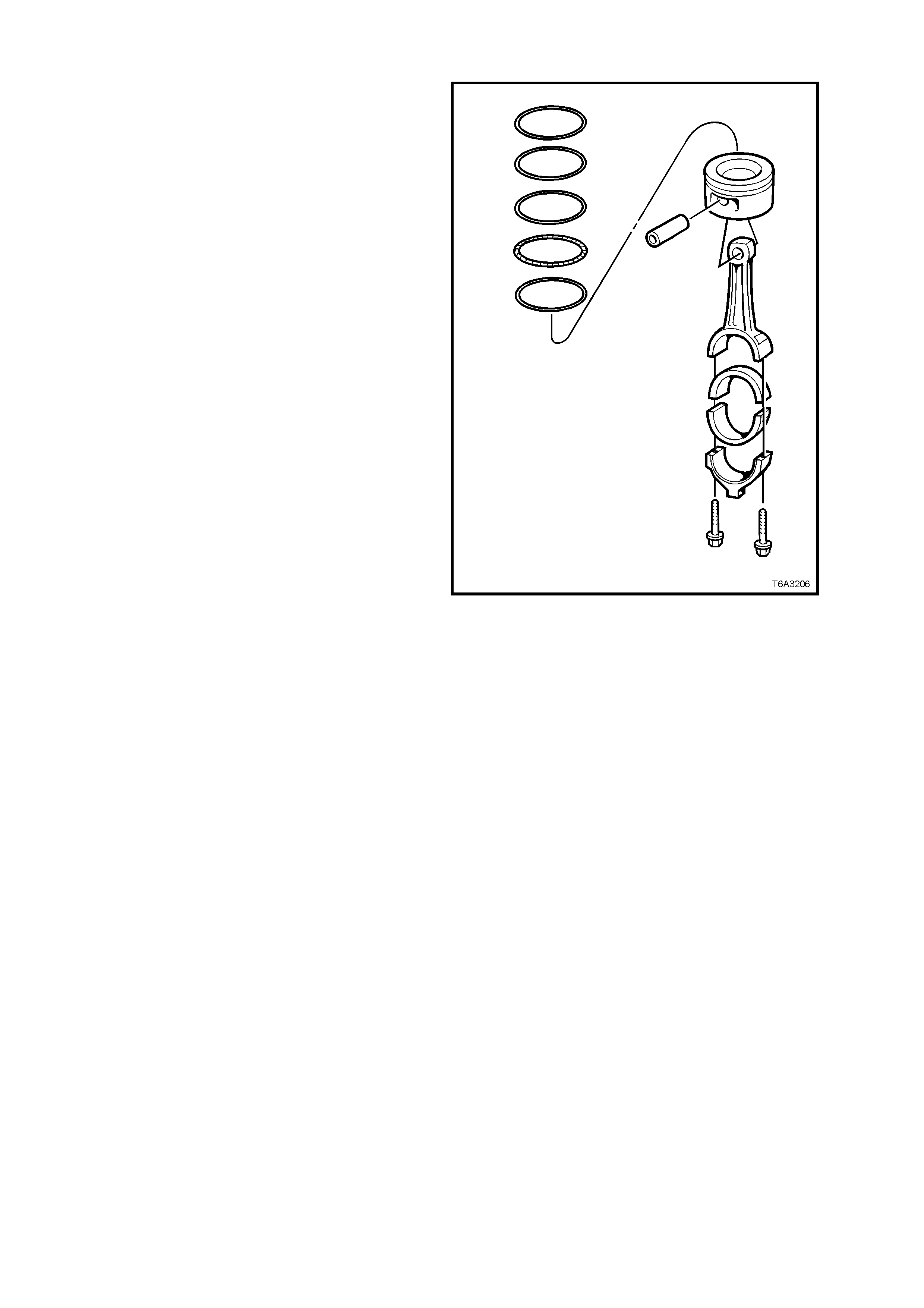
Piston Rings
NOTE: Use commercially available piston rings
pliers and only expand the piston ring suff iciently to
slide over the piston. Excessive expansion will
permanently distort the piston ring.
1. Install the piston rings to each piston, in the
following manner:
a. Install the oil control spacer to the lower
ring groove. Ensure that the ends do not
overlap.
b. Install the lower oil control ring segment.
There are no identifying mark s, indicating
orientation, as this ring may be installed in
either direction.
c. Install the upper oil control ring segment
in a similar manner.
d. Stagger the ends of the three oil control
ring components by at least 90°.
e. Using commercially available piston ring
pliers, install the second compression
ring, noting that the dimple or orientation
mark must face upwards to the piston
crown.
f. Using commercially available piston ring
pliers, install the top compression ring.
This ring has no orientation marks and
may be installed in either direction.
g. Stagger the compression ring gaps a
minimum of 25 mm. Figure 6A3-289
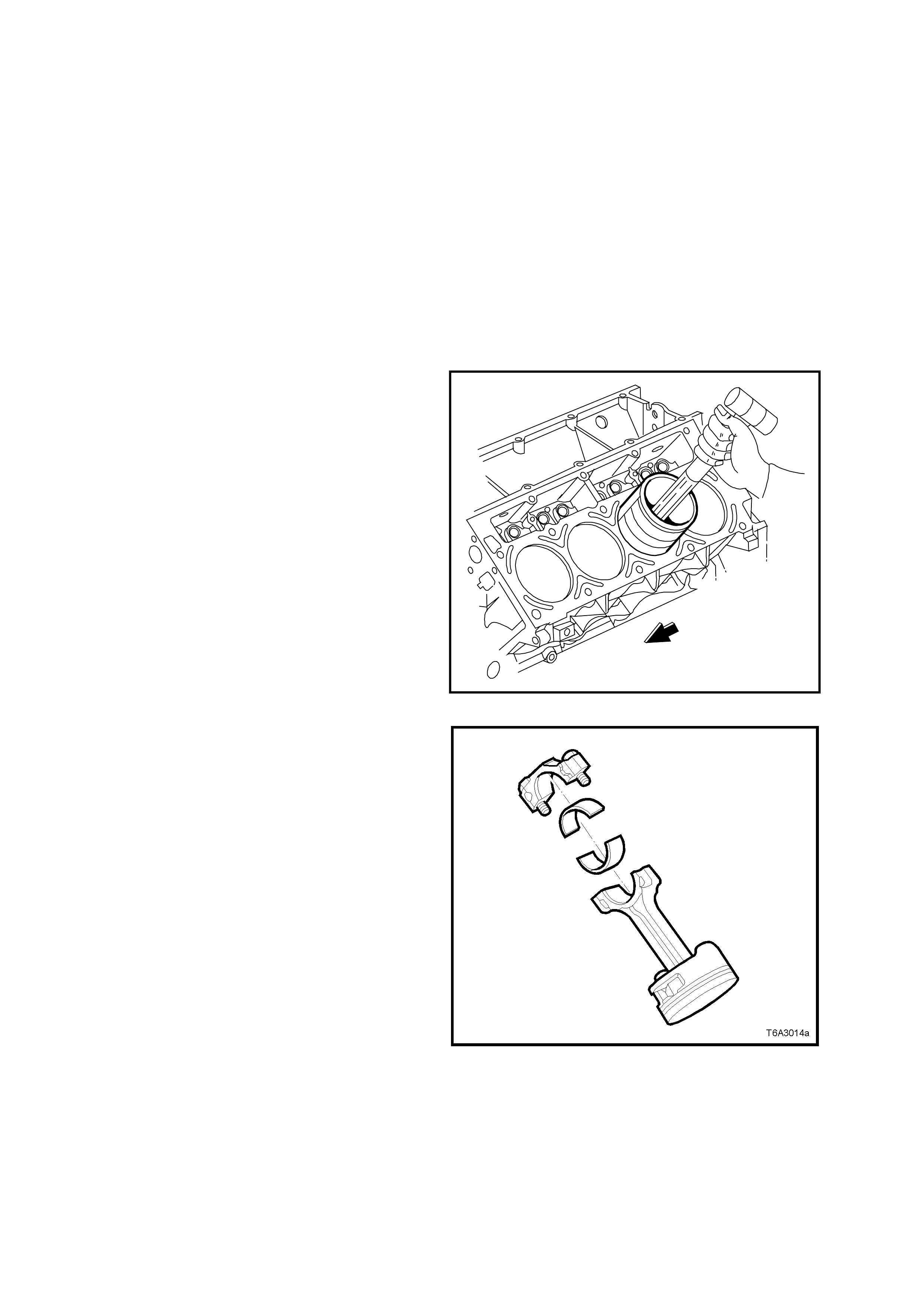
REINSTALL
NOTE 1: Before installation, check that the piston
ring end gaps are staggered correctly and that the
piston has been assembled to the connecting rod
in the correct manner.
NOTE 2: Before honing the cylinders, refer to
3.15 CYLINDER BLOCK, Boring and Honing, in
this Section for important information, relating to
this task.
1. Lightly lubricate the piston, cylinder bore,
piston rings and bearing surfaces with clean
engine oil.
2. Remove the connecting rod cap and bearing
shell from the connecting rod being installed
and install the connecting rod guide pins , Tool
J 41556.
3. Install a commercially available piston ring
compressor over the piston rings and
compress.
4. Install the pis ton and connecting rod assem bly
into the correct cylinder bore, checking that the
piston alignm ent m ark is f acing the f ront of the
engine.
5. While holding the piston ring compressor
squarely and firmly against the engine block,
gently tap the piston into the bore, using a
wooden hammer handle, until all piston rings
have entered the bore.
6. Com plete installation by using the pins, Tool J
41556 to guide the connecting rod onto the
crankshaft journal.
T6A3274a
Figure 6A3-290
7. Remove connecting rod guides, Tool J 41556
and check that the upper bearing shell is
correctly installed in the connecting rod. Apply
clean engine oil to the upper bearing shell.
8. Install lower connecting rod bearing into the
cap, lubricate with clean engine oil and install,
ensuring that the cap orientation is correct.
Refer Figure 6A3-285.
Important: The bearing oil clearance must be
checked before final installation of the connecting
rod caps. Refer to 3.13 CRANKSHAFT AND
BEARINGS, Main Bearing Oil Clearance - Check,
in this Section.
Figure 6A3-291
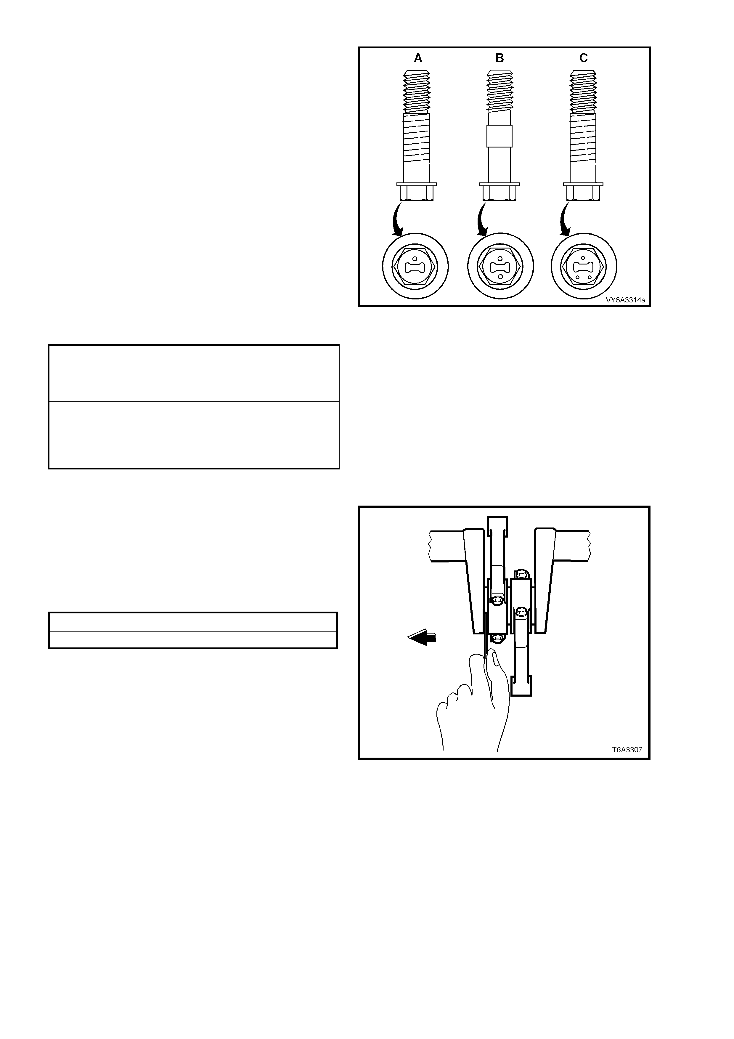
9. Install NEW connecting rod cap bolts and
tighten in two stages, to the correct torque
specification.
NOTE: Since inception, there have a been a
number of changes to the connecting rod bolts.
Regardless of when the engine was built, the
critical aspect relating to connecting rod bolts is
that a ‘matched pair’ must be used on each
connecting rod.
The most visible identification of a ‘matched pair’
can be determined by the presence of 'dimples' on
the bolt head, witnessed by one, two or three, as
shown.
IMPORTANT: As bolt design 'A' has a different
torque specification than bolts 'B' and 'C',
replacement connecting rod bolts, MUST be of the
same design for each connecting rod. Using
diff erent design bolts on the one connecting rod will
apply uneven clamp loads and/or connecting rod
bore distortion.
DESIGN 'A' CONNECTING ROD CAP
BOLT TORQUE SPECIFICATION Stage 1: 20 Nm
Stage 2: 60°
turn angle
DESIGNS 'B' and 'C'
CONNECTING ROD CAP
BOLT TORQUE SPECIFICATION Stage 1: 20 Nm
Stage 2: 75°
turn angle
NOTE: Use torque angle meter Tool E7115 to
achieve the second reading.
Figure 6A3-292
10. With a pair of connecting rods installed onto
the same crankshaft journal, use a plastic
faced hammer to lightly tap each connecting
rod sideways to settle and ensure that side
clearance exists.
11. Using feeler gauges c heck that the connecting
rod side clearance is to specification.
Connecting Rod Side Clearance Specification
Side Clearance ....................... 0.11 - 0.51 mm
NOTE: If side clearance is insufficient, re-check
bearing oil clearance and/or connecting rod
alignment.
12. Reinstall oil deflector, oil pump screen and oil
pan, refer 3.9 OIL PUMP, PUMP SCREEN
AND COVER - REINSTALL and 3.3 OIL PAN
- REINSTALL, in this Section.
13. Reinstall both cylinder heads. Refer
2.22 CYLINDER HEAD - REINSTALL, in this
Section.
Figure 6A3-293
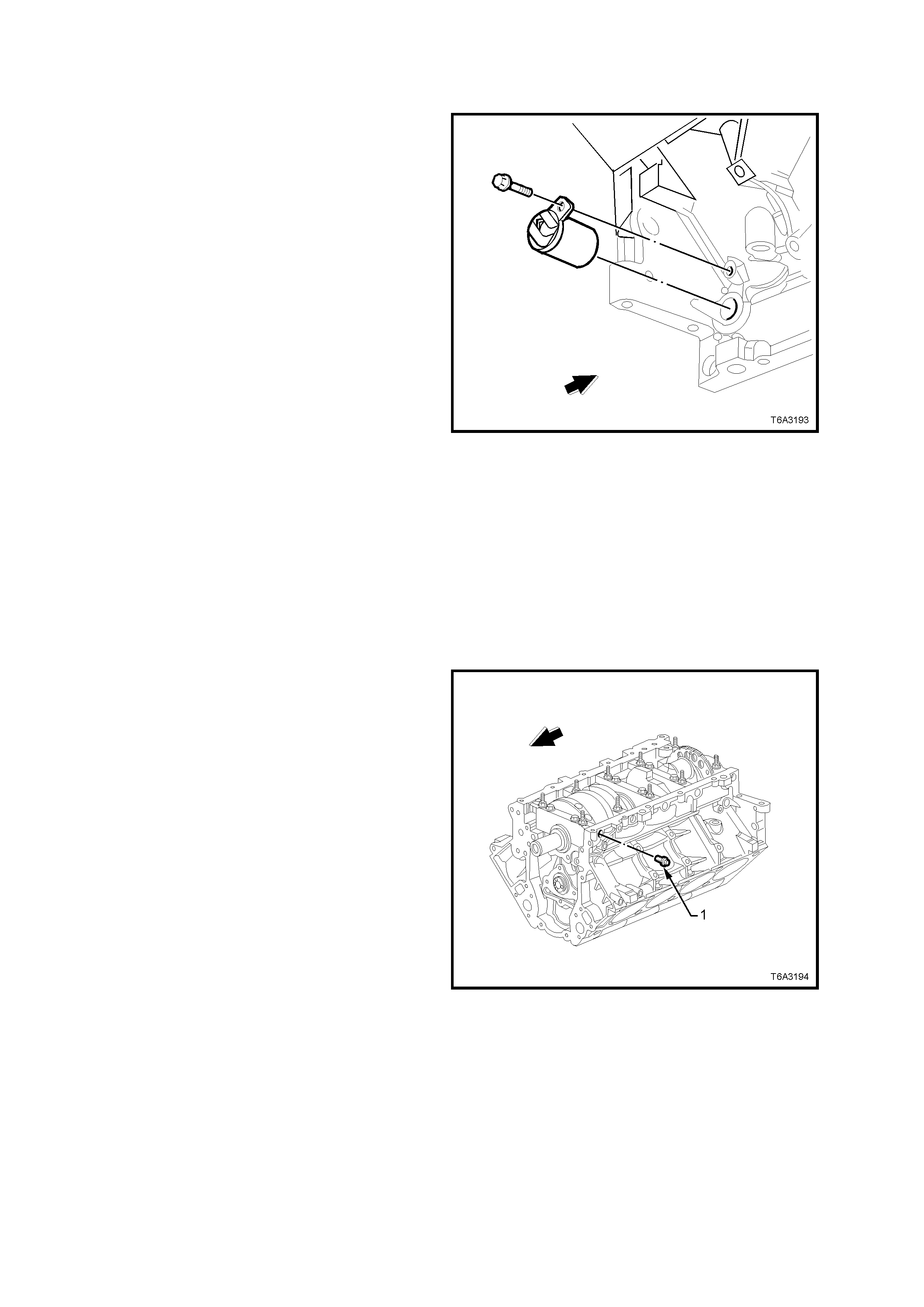
3.13 CRANKSHAFT AND BEARINGS
REMOVE
1. Remove engine from vehicle, refer
3.1 ENGINE ASSEMBLY - REMOVE, in this
Section.
2. Remove the following items from the engine
assembly;
a. Starter motor, refer 6D3-2 STARTING
SYSTEM – GEN III V8 ENGINE, of this
Service Information CD.
b. Oil pan, refer 3.3 OIL PAN, in this
Section.
c. Crankshaft balancer, refer
2.24 CRANKSHAFT BALANCER, in this
Section.
d. Front cover, refer 3.4 FRONT COVER, in
this Section.
e. Oil pump, screen and deflector, refer
3.9 OIL PUMP, PUMP SCREEN AND
DEFLECTOR, in this Section.
f. Timing chain, refer 3.10 TIMING CHAIN
AND SPROCKETS, in this Section.
g. Flywheel/Flex plate, refer
3.5 FLYWHEEL/ FLEXPLATE, in this
Section.
h. Rear cover, refer 3.8 ENGINE REAR
COVER, in this Section.
3. Remove the crankshaft position sensor
retaining bolt, then remove the sensor from
the cylinder block.
Figure 6A3-294
4. Remove the crankshaft main bearing cap M8
side bolts (1). While these bolts must be
renewed on final as sem bly, place the rem oved
bolts to one side, as they will be required when
checking the main bearing oil clearance.
5. Remove the main bearing cap M10 bolts and
studs, loosening each pair gradually. Take
note of the stud positions for reassembly.
Figure 6A3-295
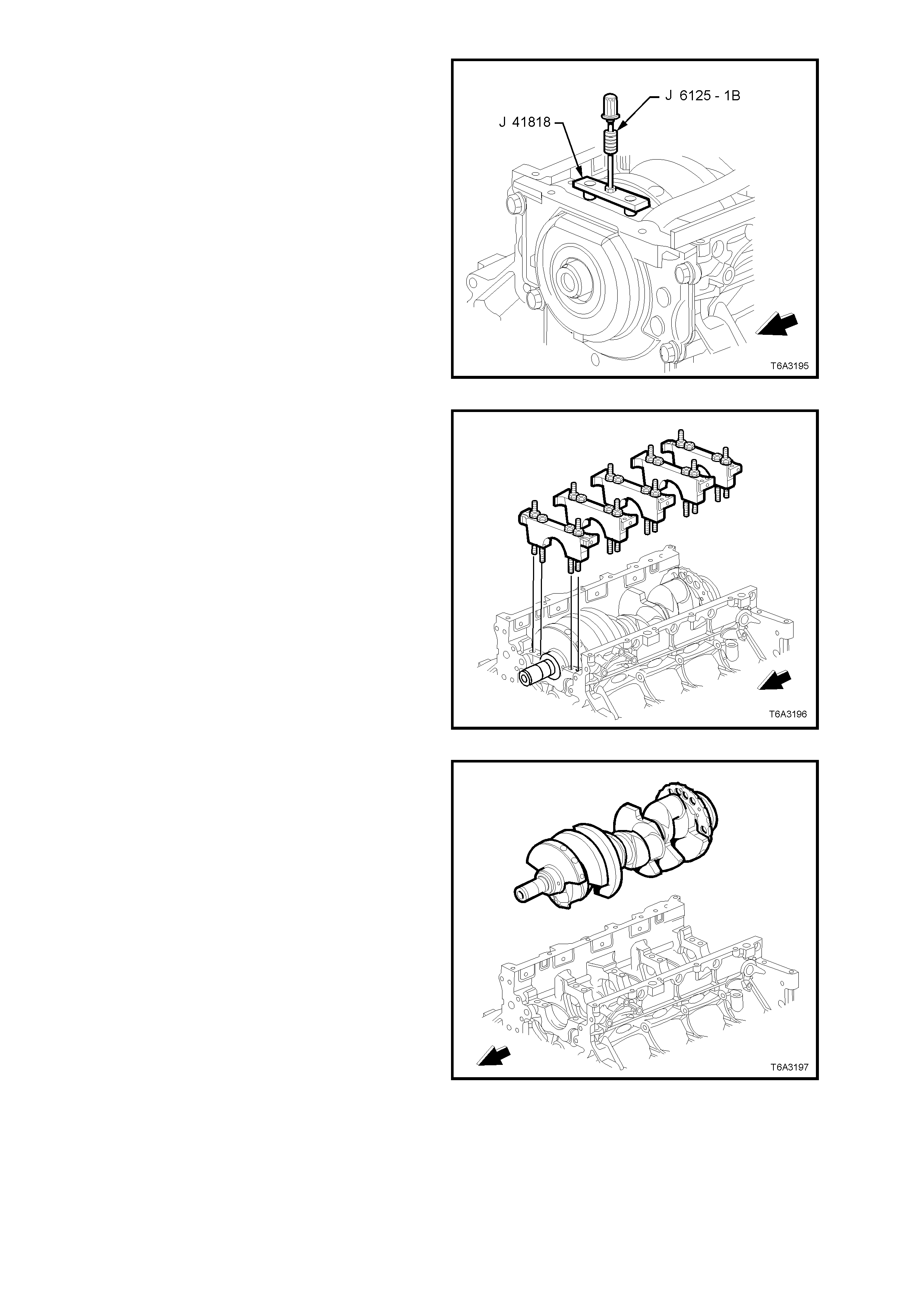
6. Loosen the bolts of m ain bearing rem oval T ool
J 41818 to separate the chamfered collets.
Then install the chamfered sections into each
main bear ing c ap bolt hole, aligning the f lats of
the collets with those in the holes.
7. Tighten the bolts of Tool J 41818 to 11 Nm.
8. Install slide hammer, Tool J 6125-1B to J
41818 and remove main bearing cap.
Figure 6A3-296
9. Remove the remaining main bearing caps in
the same way. Check that the lower main
bearing shells are also removed with each
cap.
Figure 6A3-297
10. Remove the crankshaft from the cylinder
block, lifting evenly to avoid jamming against
the main thrust bearing.
Figure 6A3-298
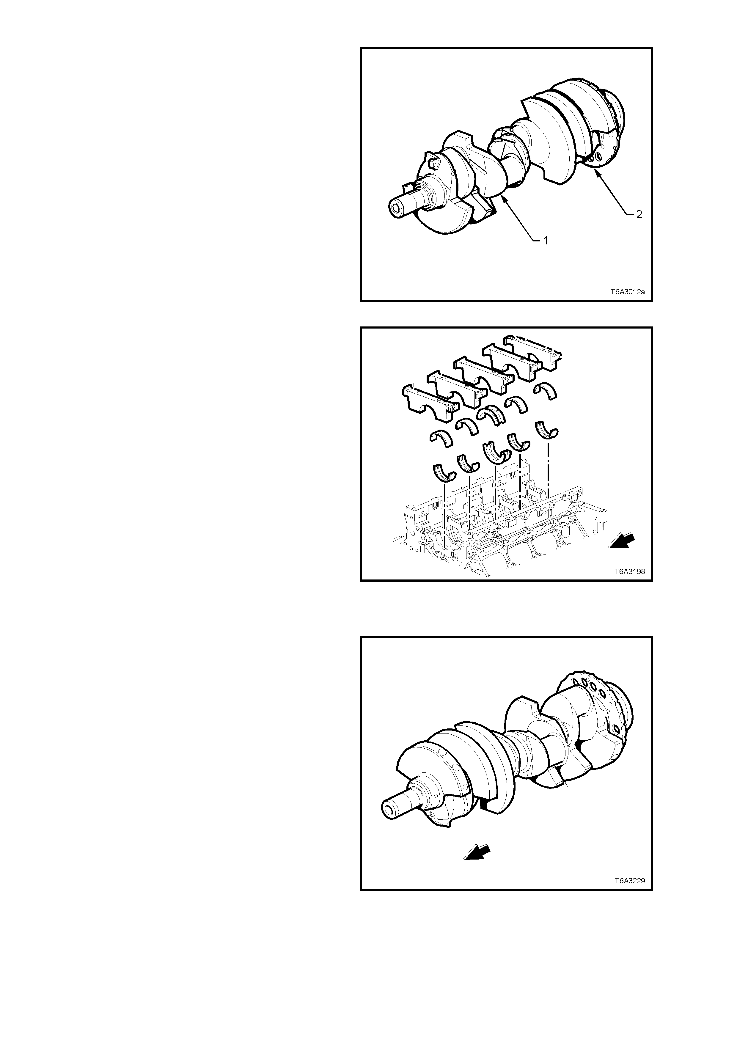
Important: When the crankshaft (1) has been
removed, take particular care that the reluctor ring
(2) is not damaged, as this part is an integral part of
the crankshaft and is not serviced separately.
Therefore, it is suggested that the removed
crankshaft be supported on two wooden ‘V’ blocks
or other suitable soft surface.
Figure 6A3-299
11. Remove the crankshaft main bearings from
the cylinder block and the main bearing caps.
NOTE: Tak e particular care to organis e all parts so
they can be reinstalled in their original positions.
Figure 6A3-300
CLEAN AND INSPECT
Important: Take care not to damage the reluctor
ring on the crankshaft, as this part is non-
serviceable.
1. Clean the crankshaft with a suitable solvent.
2. Thoroughly clean all oil passages and inspect
for restrictions or burrs.
3. Blow dry with compressed air.
CAUTION: Wear safety glasses to avoid eye
injury.
4. Carry out a visual inspection of the crankshaft
for damage.
5. Inspect the crankshaft reluctor ring lobes for
damage. The reluctor ring teeth should not
have imperfections on either the rising or
falling edges.
Figure 6A3-301
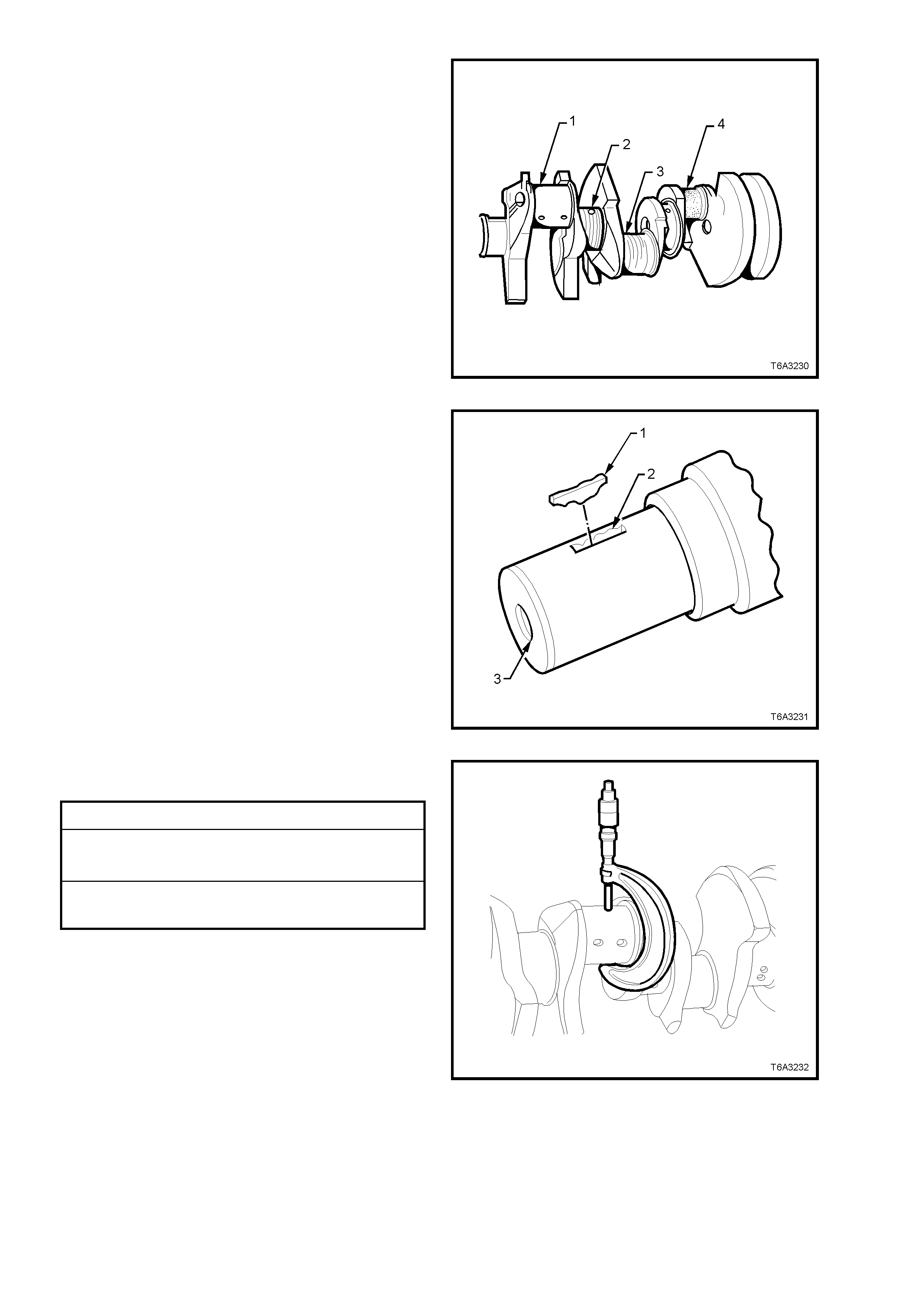
6. Inspect the crankshaft journals for wear (1).
Journals should be smooth with no signs of
scoring, wear or damage.
7. Inspect the crankshaft journals for grooves or
scoring (2).
8. Inspect the crankshaft journals for scratches
or wear (3).
9. Inspect the crankshaft journals for pitting or
embedded bearing material (4).
Figure 6A3-302
10. Inspect the c ranks haft key (1), k eyway ( 2) and
threaded hole (3) for damage.
Figure 6A3-303
11. Meas ure all cranks haft journals f or wear and
out-of-round.
Crankshaft Journal Specifications
Connecting Rod Journal Diameter.... .... .... . 53.308 mm Min.
Connecting Rod Journal Out-of-Round. .... . 0.010 mm Max.
Connecting Rod Journal Taper.... .... .... . .... . 0.010 mm Max.
Main Bearing Journal Di ameter.... .... .... .... .. 64.993 mm Min.
Main Bearing Journal Out-of-Round.... .... ... 0.008 mm Max.
Main Bearing Journal Taper....................... 0.020 m m Max.
Figure 6A3-304
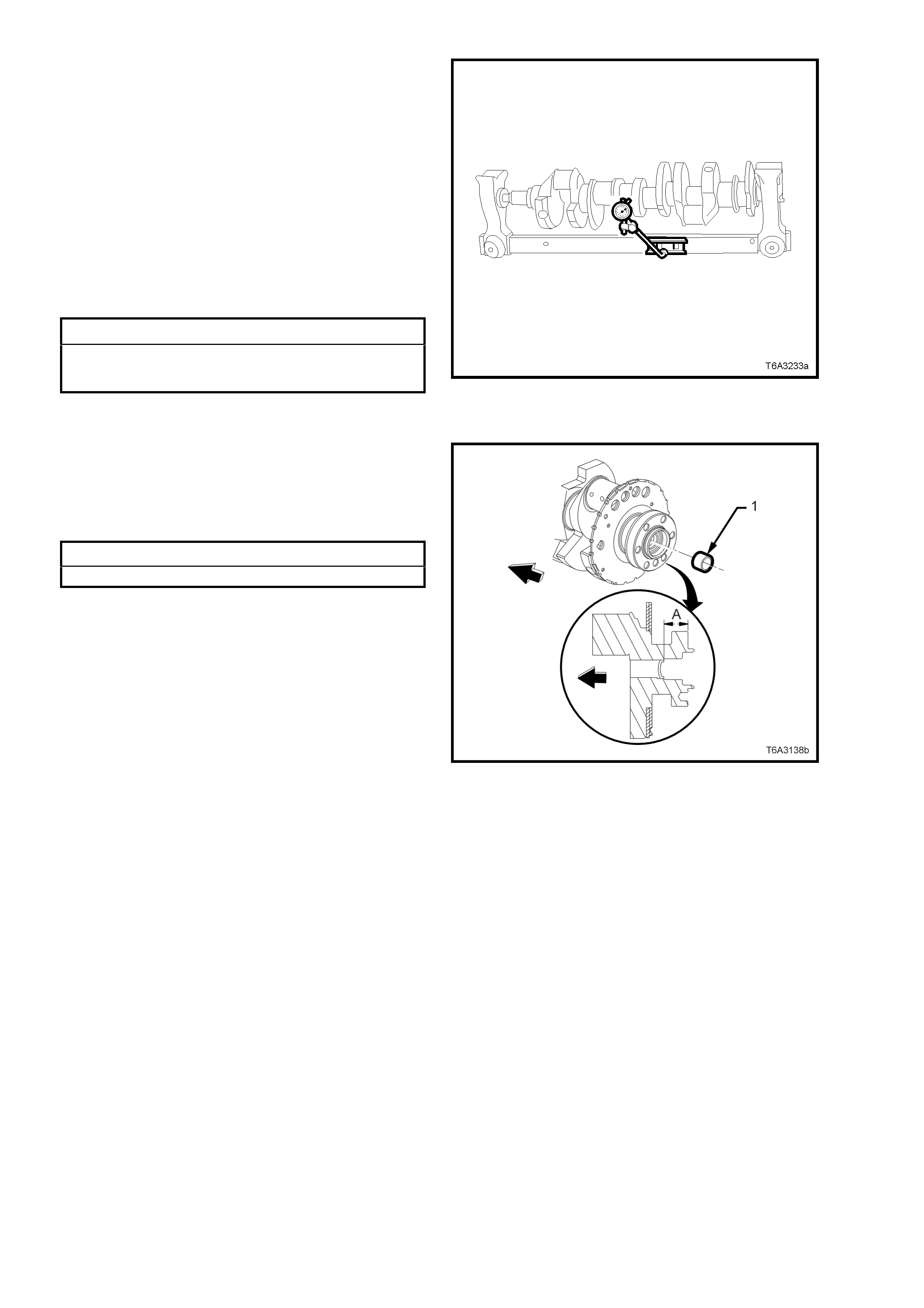
12. Support the crankshaft, either on ‘V blocks on
a flat surface or in a commercial jig as shown.
13. Using a commercially available dial indicator,
mounted to a magnetic stand, measure the
following crankshaft main bearing journal
runout dimensions:
Crankshaft runout at the front and rear,
intermediate main bearing journals.
Crankshaft rear flange.
Reluctor ring (measured 1.00 mm below the
minimum tooth diameter), at the rear surface.
Crankshaft thrust wall at the centre main
bearing.
Main Bearing Journal Runout Specifications
Reluctor Ring Lateral Runout............. 0.250 m m Maximum
Crankshaf t Thrust Wal l Runout...... .... 0.025 mm Maximum
Crankshaft Rear Flange Runout..... .... 0.050 mm Maximum Figure 6A3-305
14. Check the rear cr ankshaf t oil gallery plug for a
loose fit or leaking.
15. If replacement is required, apply sealant such
as Loctite 242 or equivalent, to the sides of a
new plug (1) and install to the correct depth.
Crankshaft Rear Oil gallery Plug Depth Specification
Distance ‘A’............................. 31.2 - 31.6 mm
NOTE: If a manual transmission is fitted to the
vehicle, it will be necessary to first remove the
spigot bush. Refer to 3.7 CRANKSHAFT SPIGOT
BUSH - REPLACE, in this Section.
Figure 6A3-306
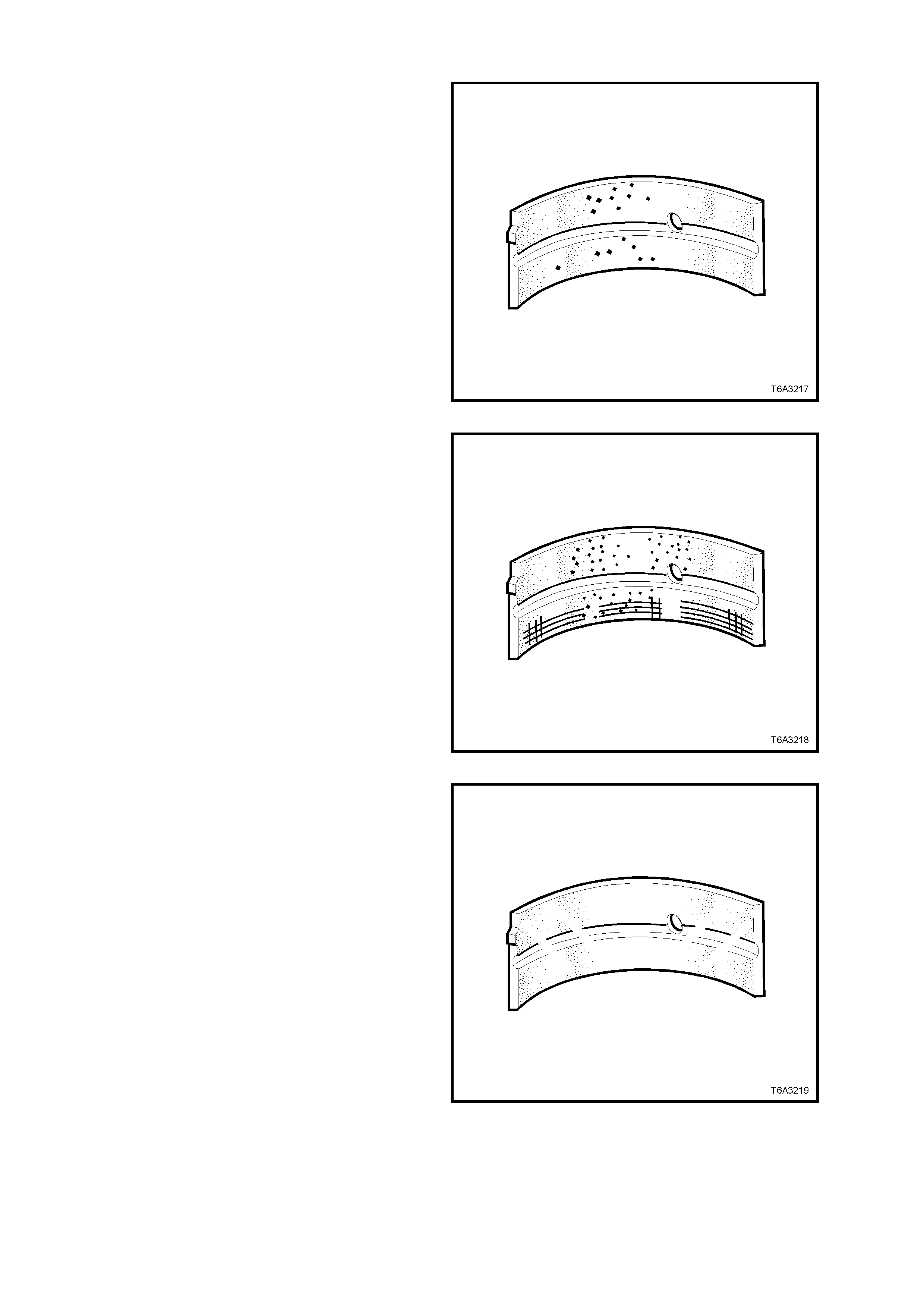
Main Bearings - Inspect
1. Inspect connecting rod bearing halves for
craters or pockets. Flattened sections on the
bearing halves also indicate fatigue.
Figure 6A3-307
2. Inspect connecting rod bearing halves for
excessive scoring or discolouration.
3. Inspect the connecting rod bearings for dirt or
debris embedded into the bearing material or
backing metal.
Figure 6A3-308
4. Inspect connecting rod bearing halves for
improper seating, indicated by bright, polished
section/s on the bearing material.
Figure 6A3-309
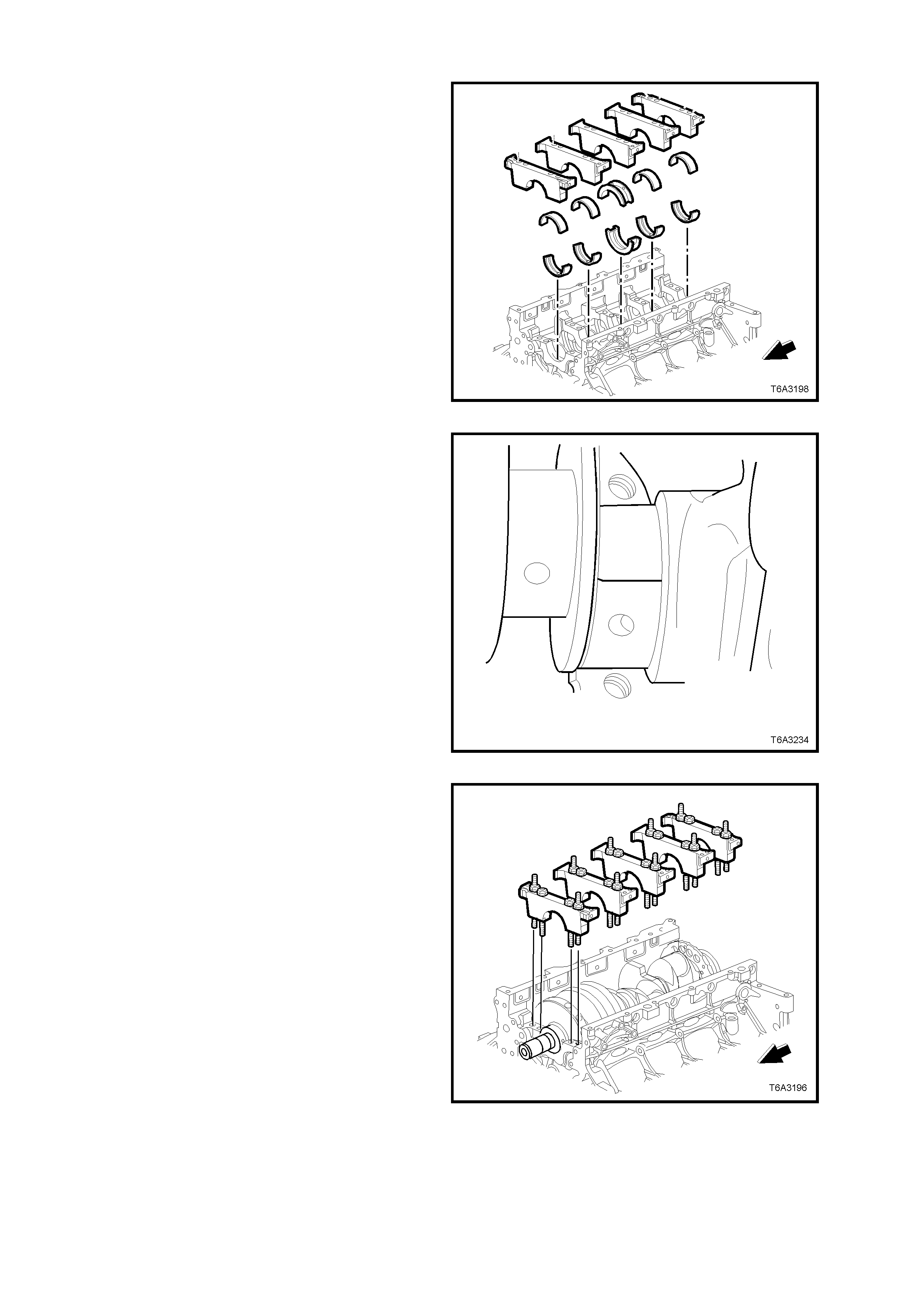
Main Bearing Oil Clearance - Check
1. After thoroughly cleaning all relevant parts,
install bearing halves into the cylinder block
and main bearing caps.
Figure 6A3-310
2. Install crankshaft to cylinder block, ensuring
that the crankshaft is held square to avoid
jamming/ damaging the centre main thrust
bearing.
3. Install a small strip of plastic gauging material
across the full width of the main bearing
journal.
NOTE 1: Do not place the gauging material across
an oil feed hole.
NOTE 2: Ensure that the crankshaft does not
rotate during this process.
Figure 6A3-311
4. Install m ain bearings, caps, bolts and studs in
the same order as removal.
Figure 6A3-312
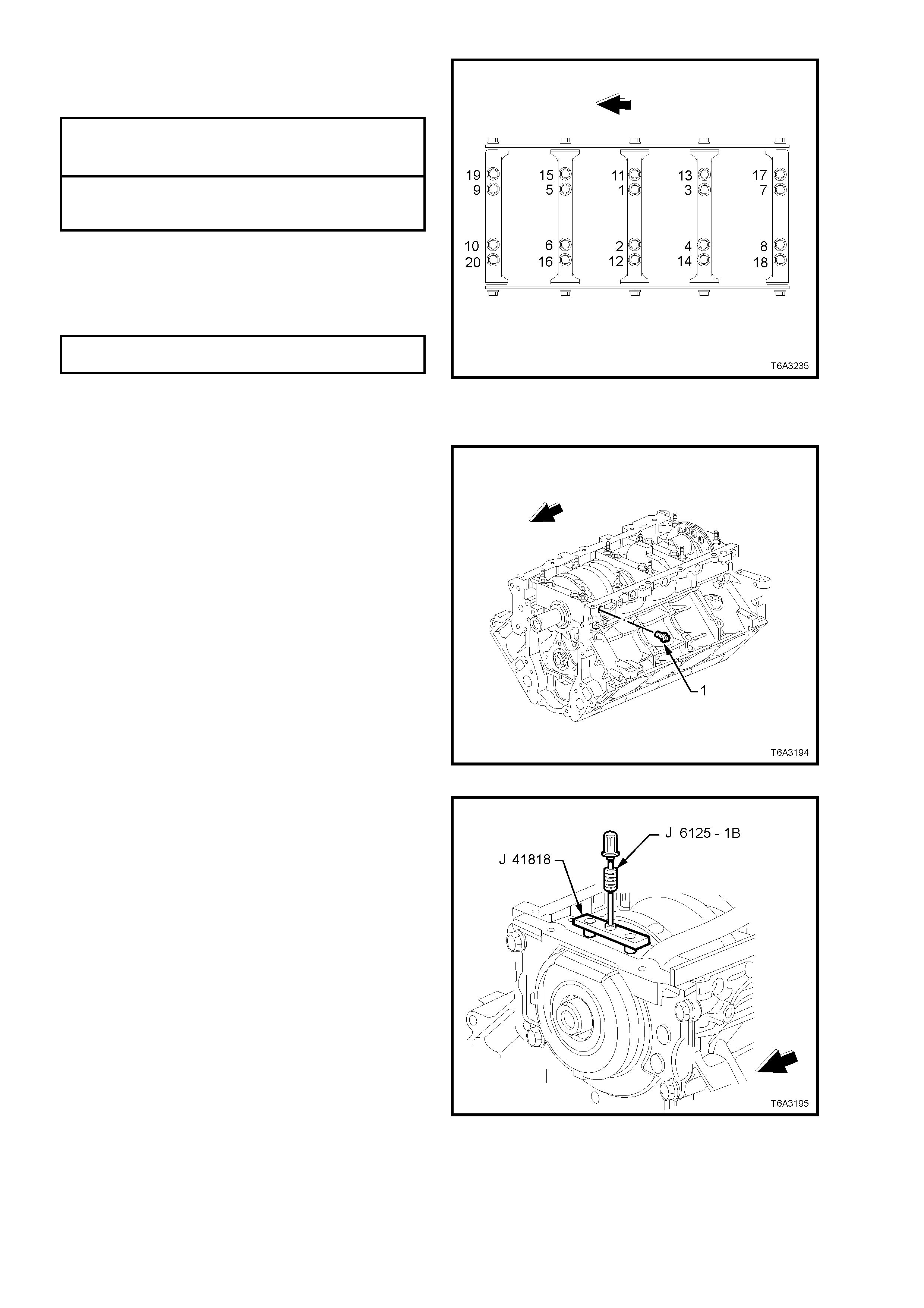
5. Tighten main bearing cap bolts and studs to
the correct torque specification and in the
correct sequence.
MAIN BEARING INNER BOLTS Stage 1: 20 Nm
(1 - 10) TORQUE SPECIFICATION Stage 2:
80° turn angle
MAIN BEARING OUTER STUDS Stage 1: 20 Nm
(11 - 20) TORQUE SPECIFICATION Stage 2:
53° turn angle
NOTE: Use torque angle meter E7115 to achieve
an accurate second reading.
6. T ighten the side c ap bolts to the c or rec t torque
specification, first on one side, then on the
other.
MAIN BEARING CAP SIDE BOLTS
TORQUE SPECIFICATION 25 Nm
Figure 6A3-313
7. Remove the main bearing cap M8 side bolts
(1) and disc ard, as new bolts m us t be used on
final assembly.
Figure 6A3-314
8. Loosen the bolts of m ain bearing rem oval T ool
J 41818 to separate the chamfered collets,
then install the chamfered sections into each
main bear ing c ap bolt hole, aligning the f lats of
the collets with those in the holes.
9. Tighten the bolts of Tool J 41818 to 11 Nm.
10. Install slide hammer, Tool J 6125-1B to J
41818 and remove main bearing caps.
Figure 6A3-315
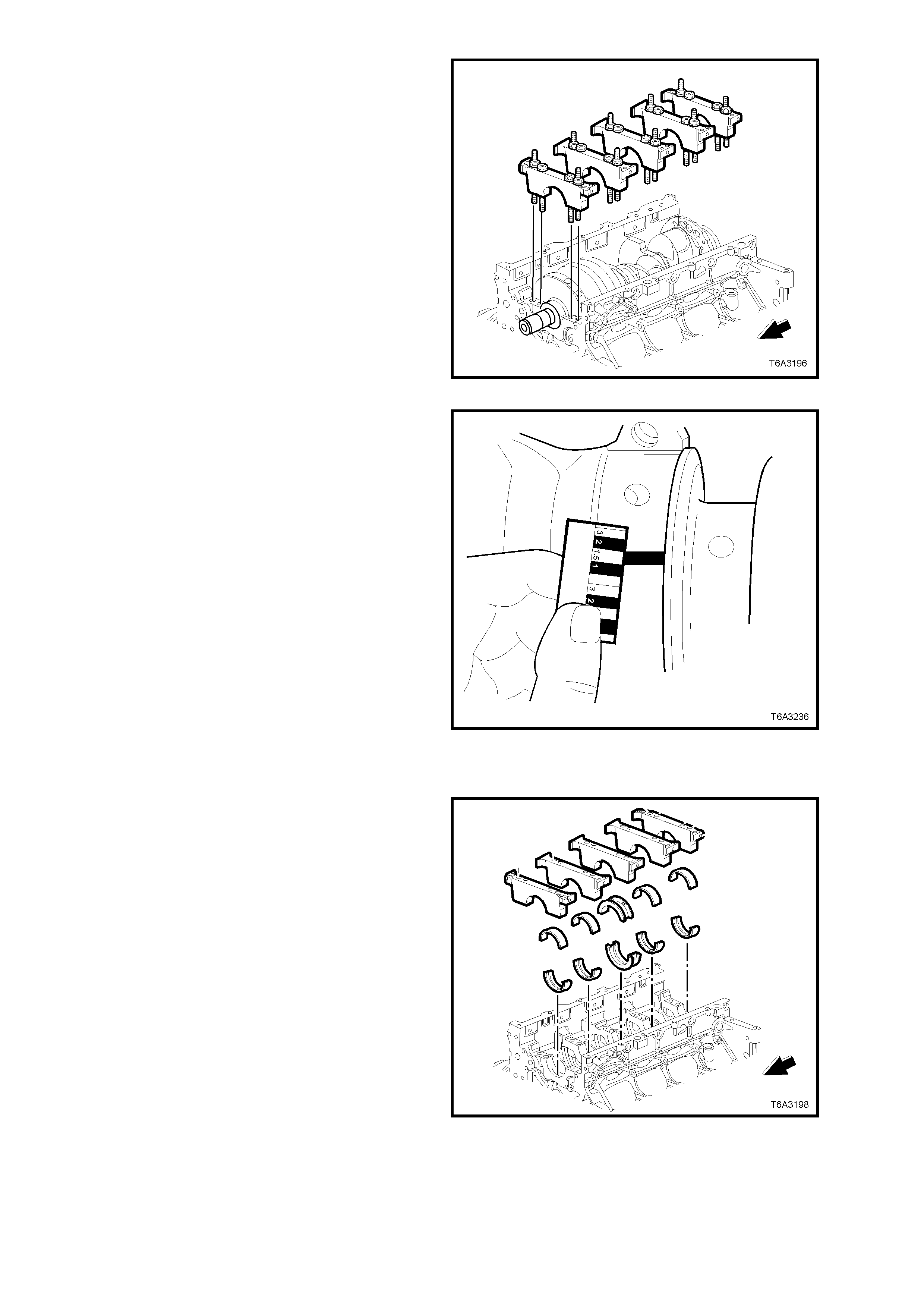
11. Remove the remaining main bearing caps in
the same way.
Figure 6A3-316
12. Using the scale supplied with the gauging
plastic, measure the deformed plastic at its
widest part.
• If the deformed strip shows an irregularity
in the journal exceeding 0.025 mm,
remove the crankshaft and measure the
journal with a micrometer.
• If the bearing clearance is greater than
0.054 mm, select and install an
undersized bearing set, then re-check the
oil clearance.
• If clearance specification cannot be
obtained, the crankshaft must be reground
for use with the next under-sized bearings.
Figure 6A3-317
REINSTALL
1. Apply clean engine oil to the bearing halves
and crankshaft journals.
Figure 6A3-318
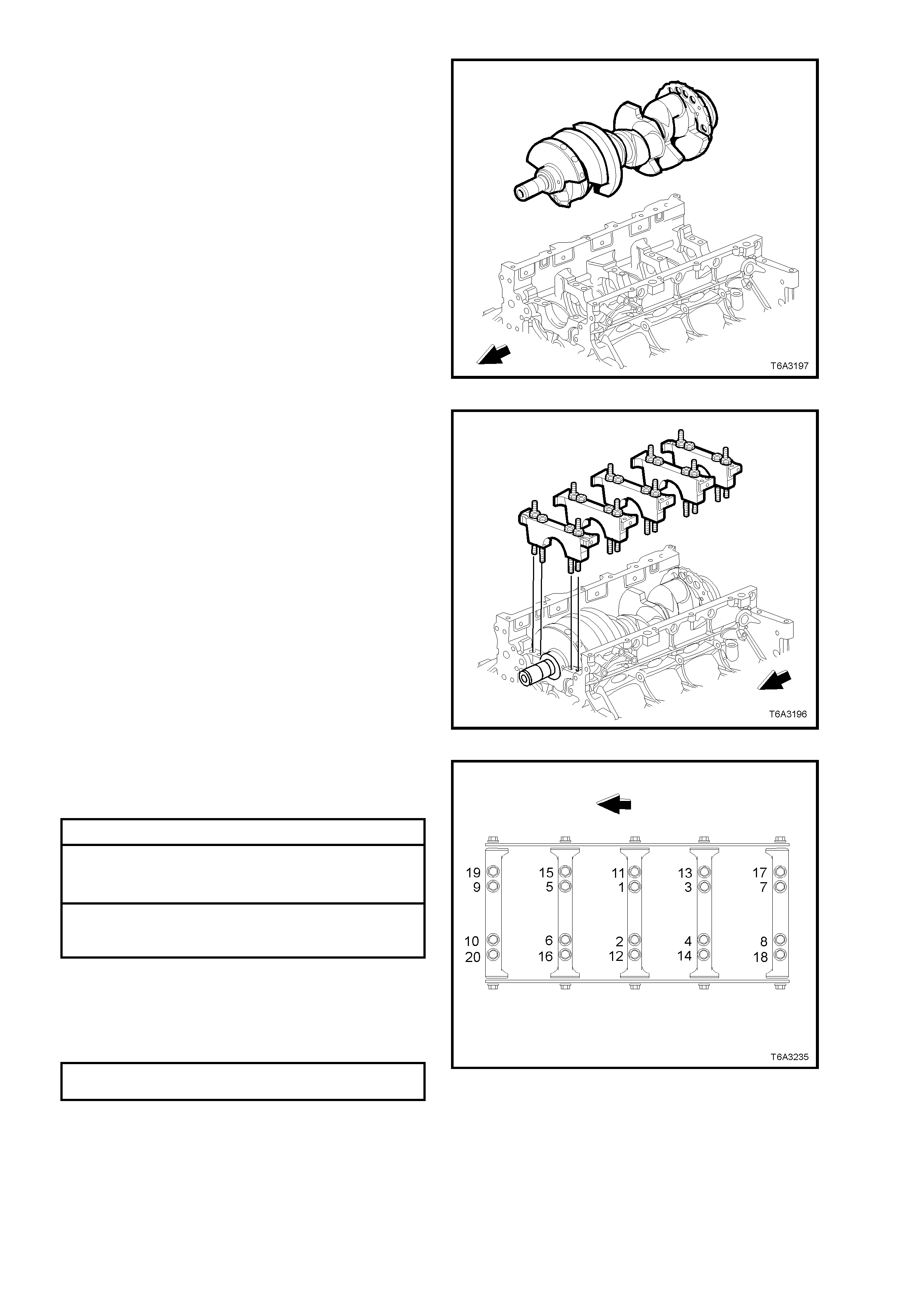
2. Install crankshaft to cylinder block, ensuring
that the crankshaft is held square to avoid
jamming/ damaging the centre main thrust
bearing.
Figure 6A3-319
3. Install main bearings, caps, bolts and studs in
the correct order.
NOTE: All m ain bearing c aps are num ber ed from 1
to 5 (front to rear). The numbers on the first four
caps are on one side while the rear main bearing
cap number is on the opposite side.
Also, the crankshaft bearing half locating notches
are on opposite sides, top to lower bearing, for all
main bearings.
Figure 6A3-320
4. Tighten main bearing cap bolts and studs to
the correct torque specification, in the correct
sequence.
ALL MAIN BEARING BOLTS Stage 1: 20 Nm
MAIN BEARING INNER BOLTS
(1 - 10) TORQUE SPECIFICATION Stage 2:
80° turn angle
MAIN BEARING OUTER STUDS
(11 - 20) TORQUE SPECIFICATION Stage 2:
53° turn angle
NOTE: Use torque angle meter E7115 to achieve
an accurate second reading.
5. Install NEW M8 main bearing cap side bolts
and tighten to the correct torque specification,
first on one side, then on the other.
MAIN BEARING CAP SIDE BOLTS
TORQUE SPECIFICATION 25 Nm
NOTE: New main bearing cap side bolts have a
sealant patch applied to the bolt flange.
Figure 6A3-321
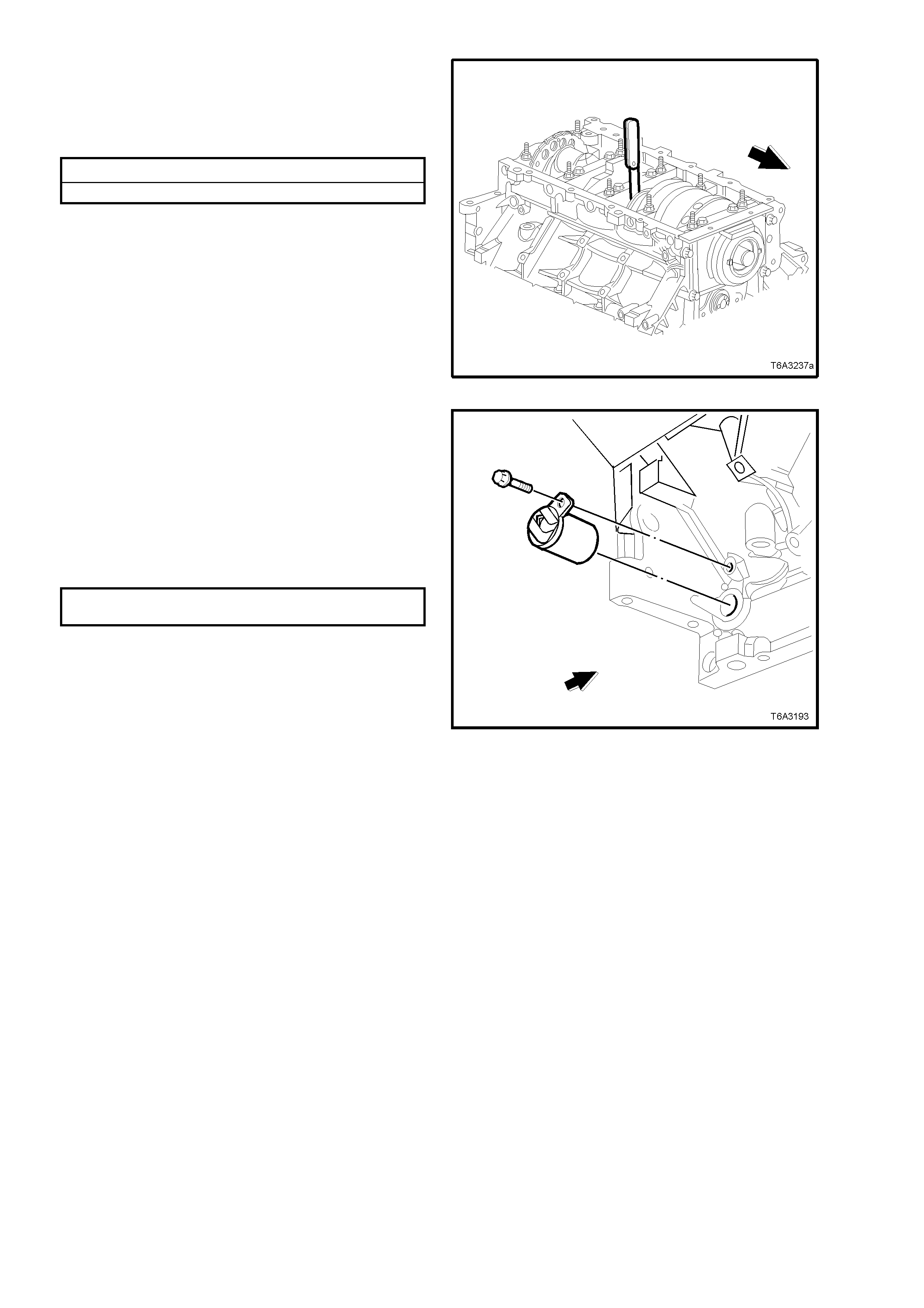
6. Thrust the crankshaft rearward then forward,
using a suitable lever.
7. Inser t a feeler gauge between the centr e main
bearing and the crankshaft thrust bearing
surface.
Crankshaft End Play Specification
Crankshaft End Play............... 0.040 - 0.20 mm
NOTE 1: If the bearing clearance is not within
specification, inspect the thrust surfaces for nicks,
gouges or rais ed metal. Minor imperf ec tions c an be
removed with a fine stone.
NOTE 2: After measuring crankshaft end float,
leave the crankshaft in the forward position.
Particularly when a manual transmission if fitted to
the engine, this will lessen bearing shock when the
engine is started and the clutch is first released.
Figure 6A3-322
8. Inspect the crankshaft position sensor O-ring
for nicks, cuts or other damage. If
undamaged, the O-ring may be re-used.
9. Coat the O-ring with clean engine oil.
10. Install the sensor, aligning the retaining
bracket notch with the threaded holed in the
cylinder block.
11. Install the retaining bolt, tightening to the
correct torque specification.
CRANKSHAFT POSITION SENSOR
BOLT TORQUE SPECIFICATION 25 Nm
12. Reinstall the following items to the engine
assembly;
a. Rear cover and flywheel/Flex plate, refer
3.8 ENGINE REAR COVER and
3.5 FLYWHEEL/ FLEXPLATE, in this
Section
b. Timing chain, refer 3.10 TIMING CHAIN
AND SPROCKETS, in this Section.
c. Oil pump, screen and deflector, refer
3.9 OIL PUMP, PUMP SCREEN and
DEFLECTOR, in this Section.
d. Front cover and crankshaft balancer,
refer 3.4 FRONT COVER and
2.24 CRANKSHAFT BALANCER in this
Section.
e. Oil pan, refer 3.3 OIL PAN, in this
Section.
f. Starter motor, refer Section 6D3-2
STARTING SYSTEM - GEN III V8
ENGINE.
13. Reinstall engine into vehicle, refer
3.1 ENGINE ASSEMBLY - REMOVE, in this
Section.
Figure 6A3-323
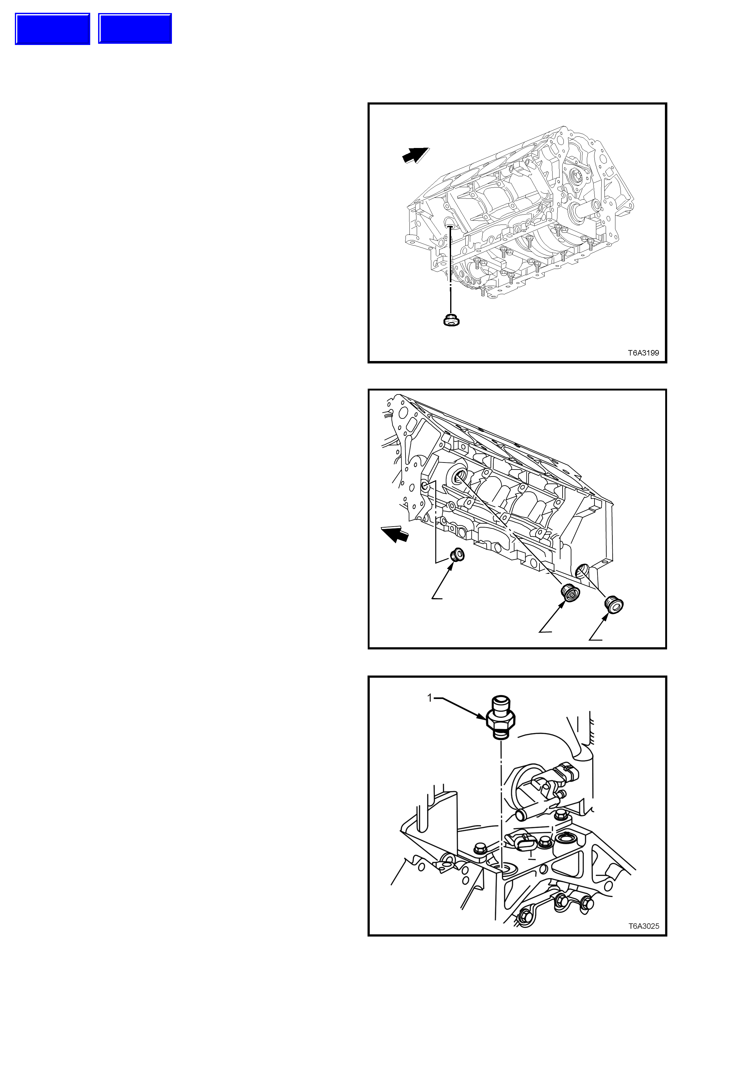
3.14 ENGINE BLOCK P LUGS
REMOVE
1. Using an 8 mm Allen key socket and bar,
remove the coolant drain plug from the right
hand rear of the cylinder block.
Figure 6A3-324
2. Remove the three plugs from the left hand
side of the c ylinder block, using an 8 mm Allen
key socket and bar for plugs ‘1‘ and ‘3’ and a
17 mm Allen key socket for plug ‘2’.
T6A3200a
3
1
2
Figure 6A3-325
3. If not removed in previous operations, rem ove
the oil pressure sensor (1) from the top of the
cylinder block, at the lef t hand rear, using T ool
J 41712 and suitable 3/8” drive socket bar.
Figure 6A3-326
Techline
Techline
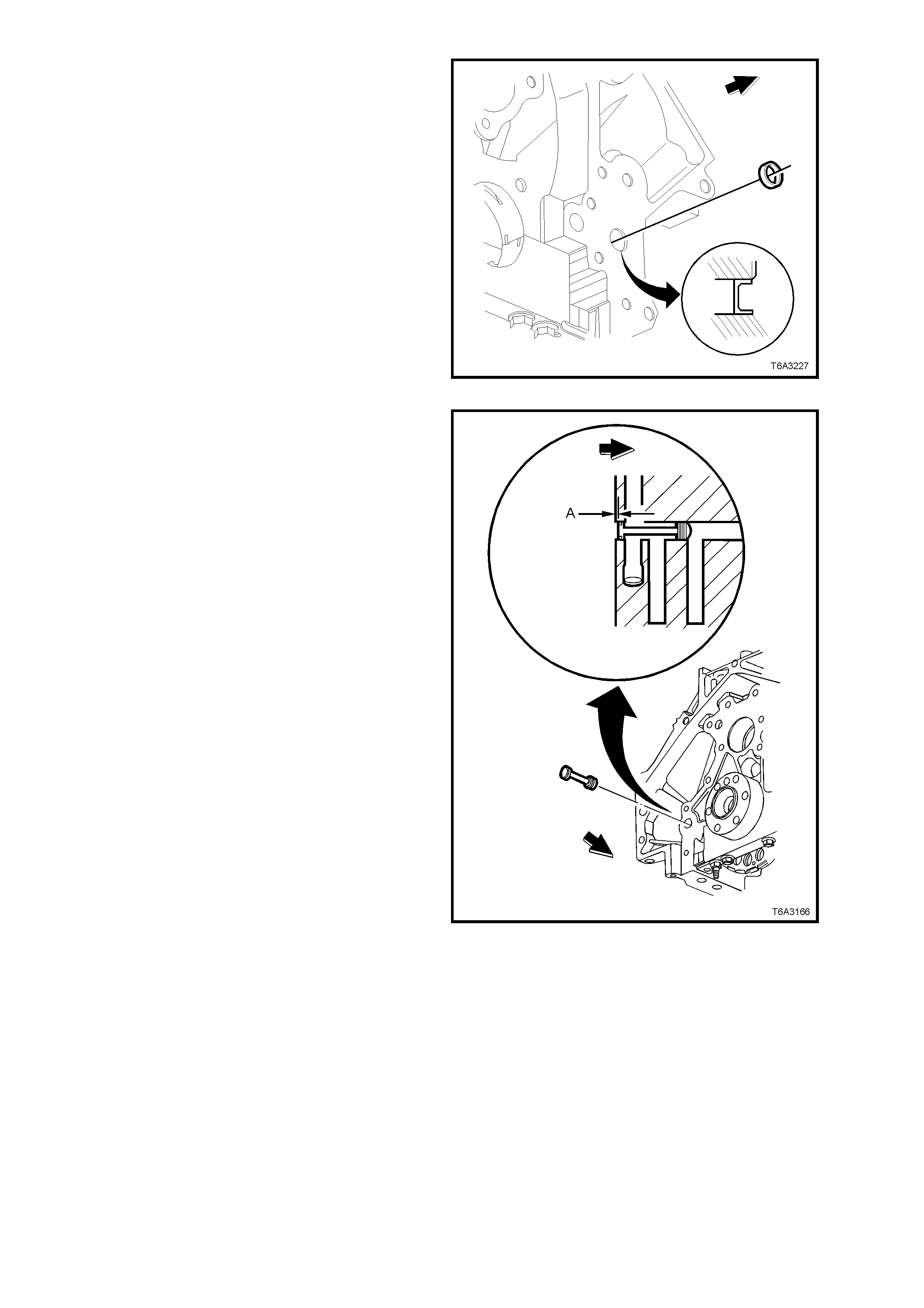
NOTE: Only remove the plug from the front of the
engine block, if replacement is required.
4. Remove the engine block, front oil gallery
plug.
Figure 6A3-327
5. Remove the engine block, rear oil gallery plug.
6. Inspect the O-ring seal and, if undamaged it
may be re-used during assembly.
Figure 6A3-328
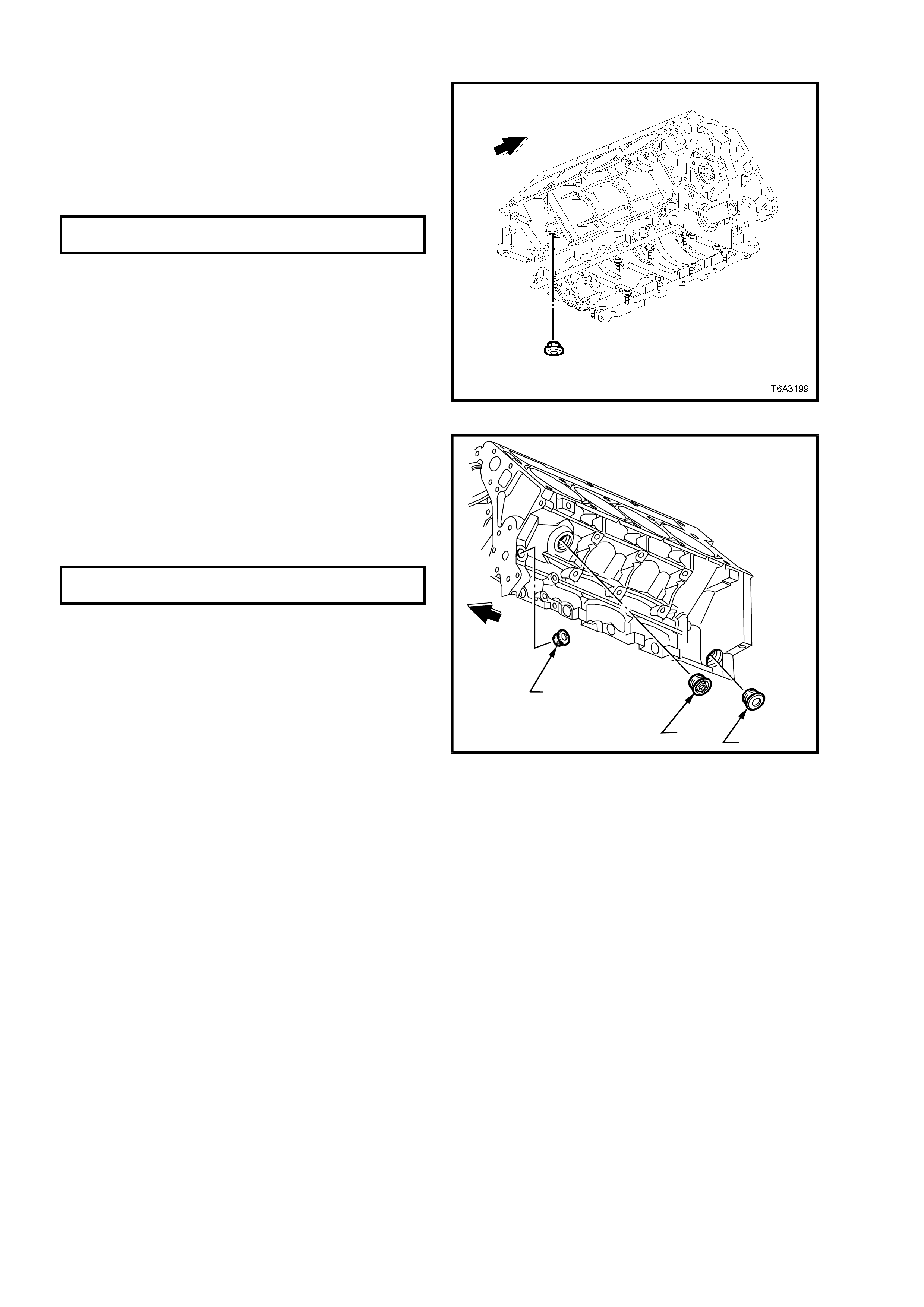
REINSTALL
1. Apply a 3 mm bead of sealant such as Loctite
565 or equivalent, to the right hand rear,
engine block coolant drain plug sealing
washer.
2. Install the plug and tighten to the correct
torque specification, using an 8 mm Allen key
socket.
COOLANT DRAIN PLUG
TORQUE SPECIFICATION 60 Nm
Figure 6A3-329
3. Apply a 3 mm bead of sealant such as Loctite
565 or equivalent, to the sealing washer on
each of the left hand side engine block plugs.
4. Install each plug and tighten to the correct
torque specification, using an 8 mm Allen key
sock et for plugs ‘1’ and ‘3’ and a 17 mm Allen
key socket for plug ‘2’.
COOLANT DRAIN PLUG - ALL
TORQUE SPECIFICATION 60 Nm
T6A3200a
3
1
2
Figure 6A3-330
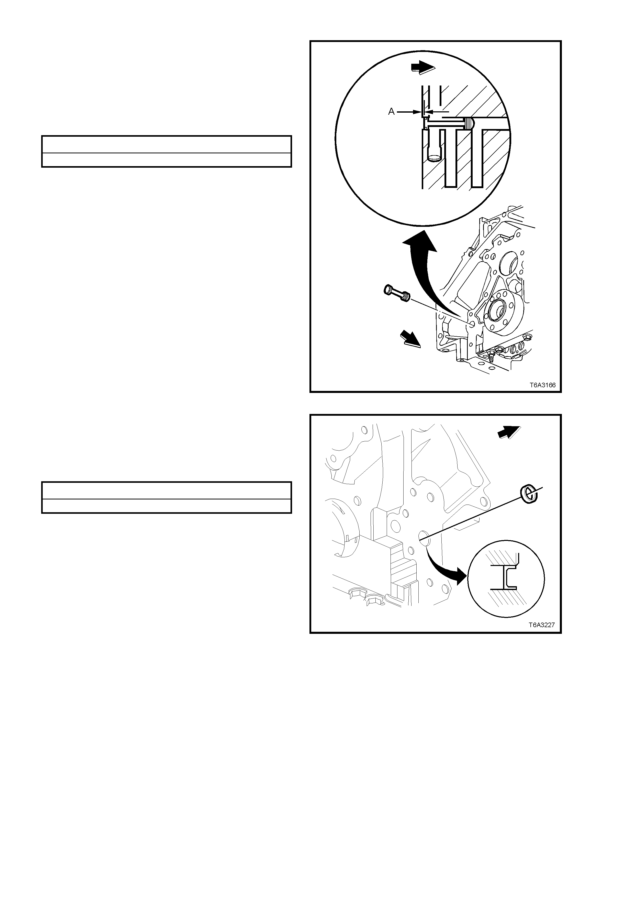
5. Inspect the O-ring seal and, if undamaged it
may be re-used.
6. Lubricate the O-ring seal with clean engine oil
and install on the engine block rear oil galley
plug.
7. Install the rear oil gallery plug to the oil galley,
to the specified depth.
Rear Oil Gallery Plug Installation Specification
Distance ‘A’............................. 0.8 - 1.4 mm
Figure 6A3-331
8. Apply a sealant such as Loctite 242 or
equivalent to the side of a NEW front oil
gallery plug.
9. Install the NEW, front oil gallery plug to the
engine block to the specified depth.
Front Oil Gallery Plug Installation Specification
Below Flush ............................ 2.2 - 2.8 mm
Figure 6A3-332
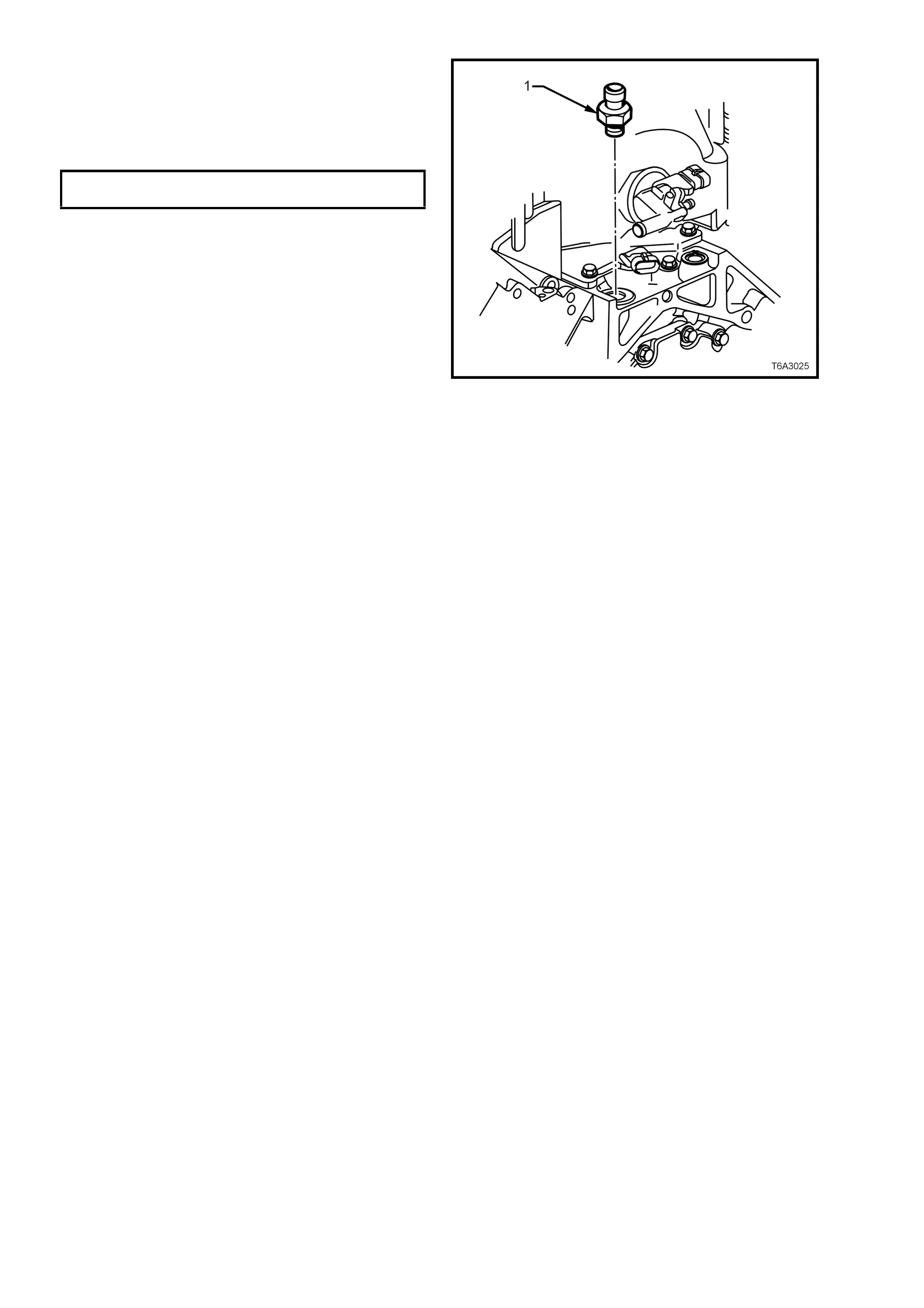
10. Apply sealant such as Loctite 565 or
equivalent to the cleaned threads of the oil
pressure sensor (1) and reinstall, using Tool
No. J 41712 and suitable 3/8” drive socket
equipment. Tighten to the correct torque
specification.
OIL PRESSURE SENSOR
TORQUE SPECIFICATION 20 Nm
Figure 6A3-333
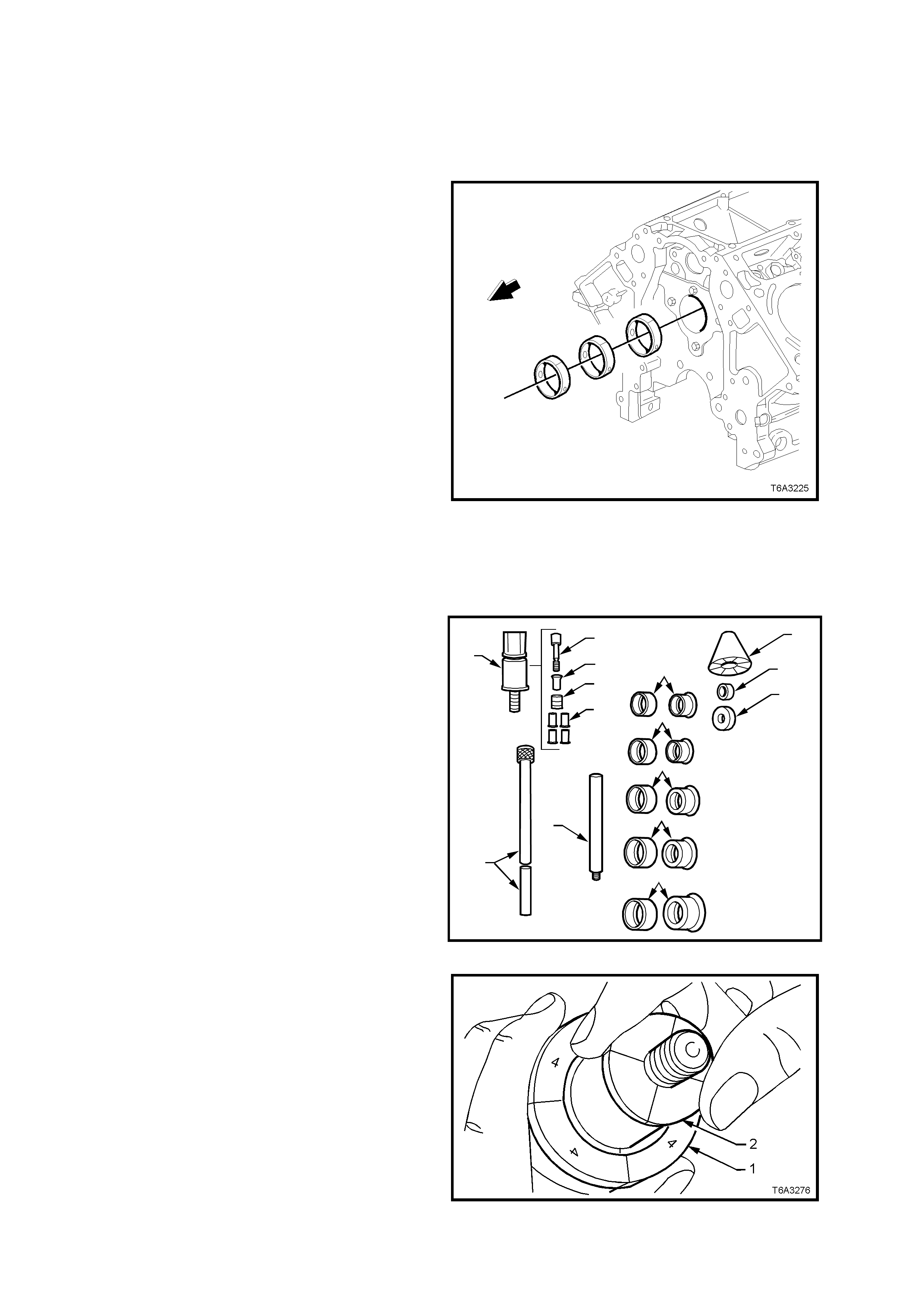
3.15 CYLINDER BLOCK
CAMSHAFT BEARINGS - REPLACE
NOTE 1: Care must be taken during bearing
removal and installation, not to damage bearings
that are not being replaced.
NOTE 2: The following operations involve the use
of universal camshaft bearing remover/installer,
Tool J 33049 and finished size camshaft bearings.
If installing unfinished size bearings, installation
must be carried out by a specialist machine shop
and then line bored to the correct finished size.
NOTE 3: While it is preferred that the camshaft
bearings are removed and installed in a bare
cylinder block, the operation can be carried out by
removing the crankshaft and the camshaft, even
though it is difficult to negotiate the tool past the
connecting rod big end journals.
The camshaft can be removed without having to
firs t remove the c ylinder heads and hydraulic lif ter s .
By removing the push rods and inverting the
engine, the hydraulic lifters will drop sufficient to
clear the camshaft journals.
1. Prior to bearing removal, inspect all camshaft
bearings for a loose fit in the engine block
bearing bores.
NOTE: If a bearing is found to be loose, it may
have been caused by an enlarged, out of round or
damaged engine block bearing bore.
Figure 6A3-334
2. The universal camshaft bearing
remover/installer, Tool J 33049, consists of the
following components;
Nylon Guide Cone (1).
Small Driving Washer (2).
Large Driving Washer (3).
Expanding Drivers and Rubber Sleeves (4 - 8).
Driver Extension Bar (9).
Driver Bar (10).
Expander Assembly (15). Consists of parts 11 - 14.
3. T o replace the cam shaft bearings on the GEN
III V8 engine, select the following components
from Tool J 33049:
Nylon Guide Cone (1).
Large Driving Washer (3).
Expanding Drivers and Rubber Sleeve (7).
Driver Bar (10).
Expander Assembly (15).
T6A3275a
9
10
11
12
13
14
15 4
5
6
7
8
1
2
3
Figure 6A3-335
4. Install expanding driver with its rubber sleeve
(1), over the expander assembly (2), with the
numbered flanges of the expanding driver
facing the threaded end of the expander
assembly (2), as shown.
Figure 6A3-336
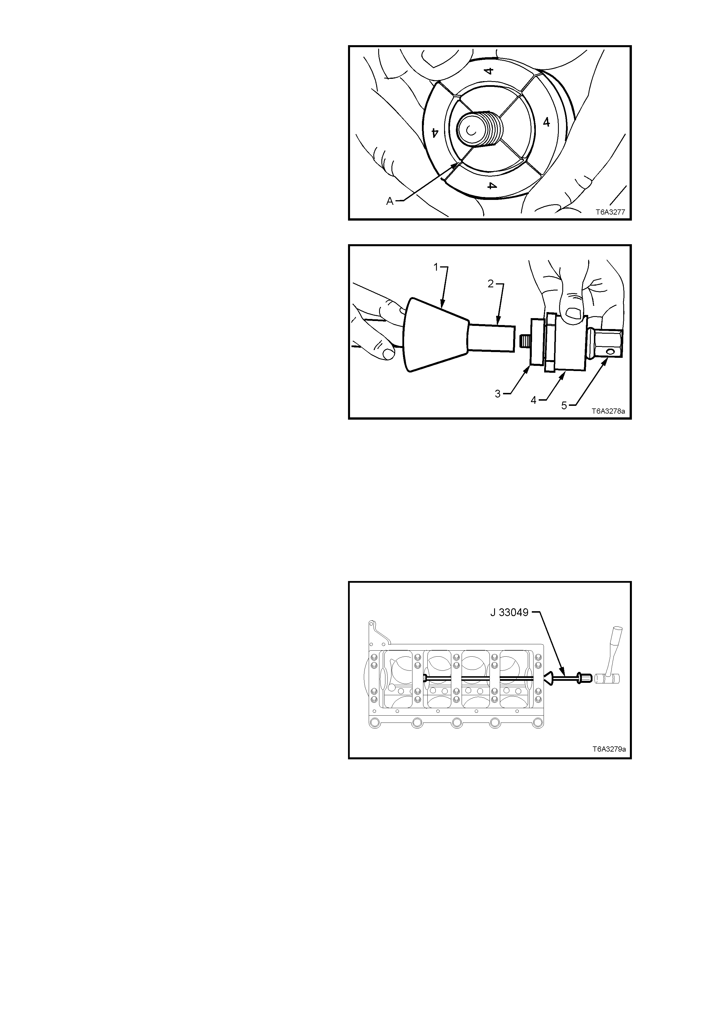
5. Once installed, ensure that the separations in
the expander ass embly segments, are aligned
with those of the expanding driver as shown
(‘A’).
Figure 6A3-337
6. Manoeuvre the assembly into the cylinder
block, in front of the bearing to be removed,
then install the large driving washer (3) over
the threaded end of the expander assembly
(5).
7. Slide the nylon cone (1) over the driver bar (2)
with the smaller diameter toward the cylinder
block.
NOTE: The components shown in Figure 6A3-337
are shown removed from the cylinder block for
clarity.
8. Carefully insert the driving bar through the
camshaft bearings, from the front of the
cylinder block and screw the bar to the
expander assembly.
9. With the expander assembly inserted into the
camshaft bearing, hold the hexagonal end of
expander assembly (5) with a spanner and
hand tighten the driver bar until the expanding
driver (4) is tight in the bearing shell.
Important: Do not overlook fitting the driving
washer over the threaded end of the expander
assembly before installing the driver bar.
Figure 6A3-338
10. Push the guide cone into the front camshaft
bearing to align the driver bar.
11. While holding the guide cone in place with one
hand, drive the bearing from the cylinder
block.
12. Repeat this process with the remaining
bearings being removed.
Figure 6A3-339
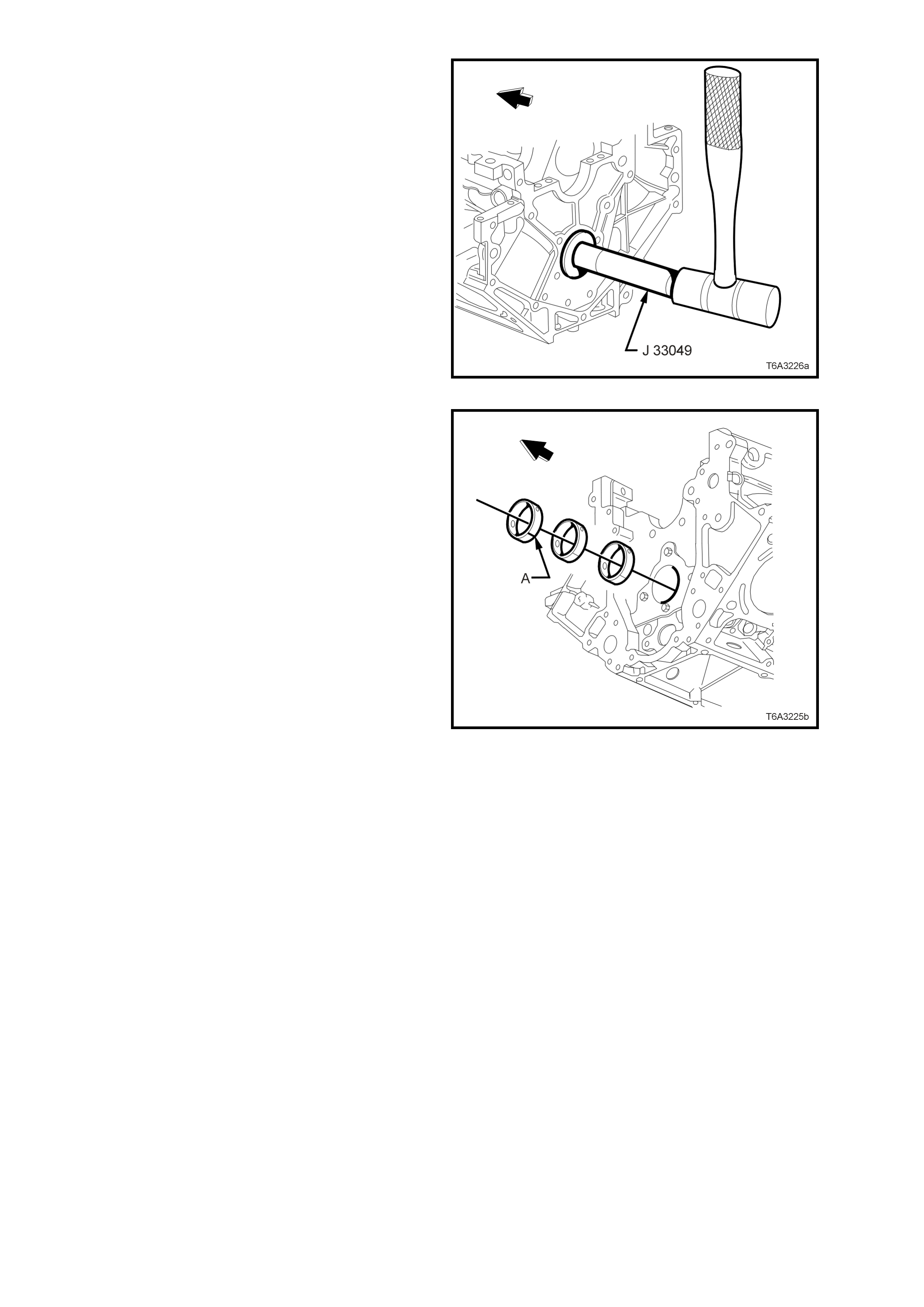
NOTE: To remove the front bearing, install the
driver bar from the rear of the cylinder block, using
the guide cone in the rear camshaft bearing bore,
as shown in Figure 6A3-339.
Figure 6A3-340
13. To install a new bearing, proceed in a similar
way to bearing removal, except for the
following items:
• The j oin in the new cam shaf t bearing ( ‘A’)
mus t be aligned with the top of the engine
block. To assist with alignment, use a felt
tip pen to mark the back of the bearing,
180° from the join, as this will be visible
when installing the bearing.
• While the oil feed is generous in length
and allows some degree of hole
misalignment, as much care as possible
must be made during installation.
• Install each bearing until it is centrally
located in the cylinder block bore, then
use a thin piece of wire to ensure that the
oil feed passage is not obstructed in any
way.
• To install the front camshaft bearing,
install the driver bar into the rear bearing
and use the guide cone at that location.
Important: Take care when installing the
driver bar through the newly installed bearings
to avoid damage.
Figure 6A3-341

CYLINDER BLOCK, CLEAN, INSPECT AND MEASURE
Clean
NOTE 1: Do not use a caustic solution to clean the aluminium engine block.
NOTE 2: When cleaning an engine block in a thermal type oven, do not exceed 450° F (232° C).
1. Clean the engine block in a suitable solvent, to remove all sludge, dirt, or debris.
2. Dry the block with compressed air.
CAUTION: Wear safety glasses to avoid eye injury.
3. Clean all gasket surfaces, taking care to only use a plastic scraper to avoid damaging machined surfaces.
4. After removing all engine block plugs (Refer 3.14 ENGINE BLOCK PLUGS, in this Section), clean all coolant
passages and oil galleries.
5. Clean the main bearing caps, taking care not to mix them from their original order.
6. Clean any residue of cylinder head bolt thread sealant fr om the c ylinder block threads, using ins taller, T ool No.
J-42385-107 (this tool is part of thread repair kit, J-42385).
Important: Do not use anything but this thread tool to clean the cylinder head threads in the cylinder block.
7. Use compressed air to clean all residue from bolt holes.
CAUTION: Wear eye protection to prevent injury
Inspect
Inspect the following areas:
1. The cylinder walls for excessive scratches, gouging, or ring ridge.
2. The coolant jacket for cracks.
3. The valve lifter bores for excessive scoring or wear.
4. The crankshaft bearing webs for cracks.
5. The gasket sealing surfaces for excessive scratches or gouging.
6. The oil galleries for restrictions.
7. All threaded bolt holes for damage.
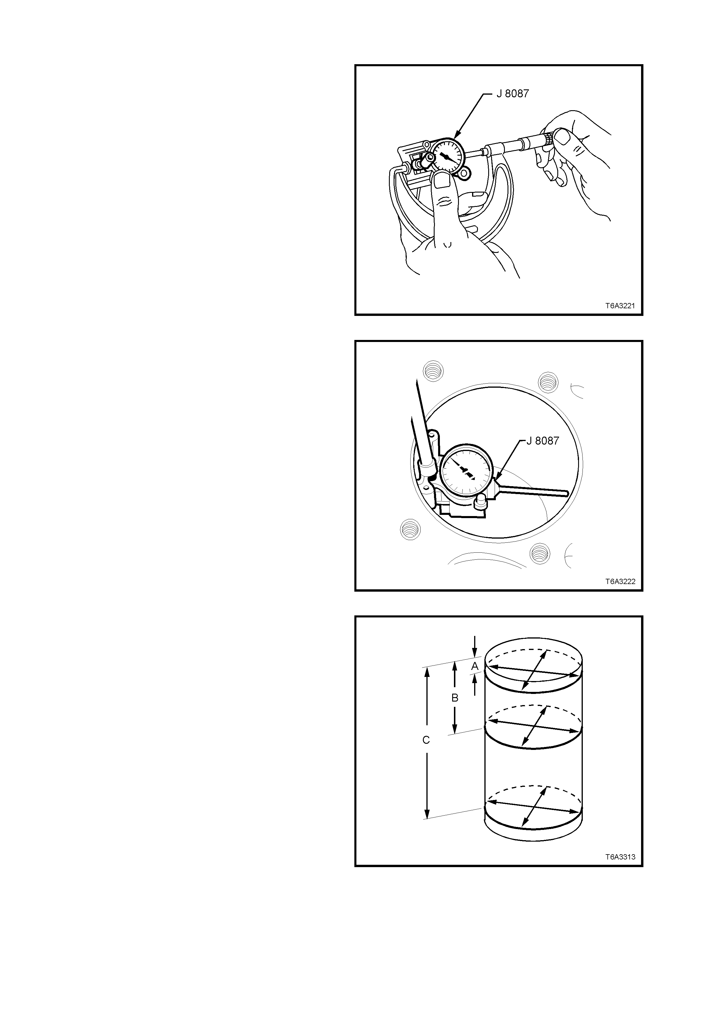
Measure Cylinder Bore
1. Adjust the micrometer to 96.0 mm.
2. Insert the bore gauge into the micrometer and
zero the bore gauge dial, Tool J 8087 (or
commercial equivalent).
Figure 6A3-342
3. Use a bore gauge and measure the cylinder
bore for taper.
• Slide the bore gauge up and down
throughout the length of the cylinder bore.
Check the bore both parallel and
perpendicular to the centreline of the
crankshaft.
• Recondition cylinders with less than 0.018
mm taper with a hone. Refer CYLINDER
BORING AND HONING, in this Section.
• Cylinders with more than 0.018 mm taper
must be fitted with an oversize piston.
Figure 6A3-343
4. Use a bore gauge and measure the cylinder
bore for out-of-round:
• Measure the bore, both in line with the
centreline and perpendicular to the engine
centreline. Check f or bore out- of-r ound at a
depth of 9 mm (‘A’), 57 mm (‘B’) and 127
mm (‘C’) from the cylinder head surfaces.
• Calculate the difference between the two
measurements at each location. The
results will indicate any out-of-round bore
condition.
• Cylinders with more than 0.018 mm out-of-
round must be honed and fitted with an
oversize piston.
Figure 6A3-344
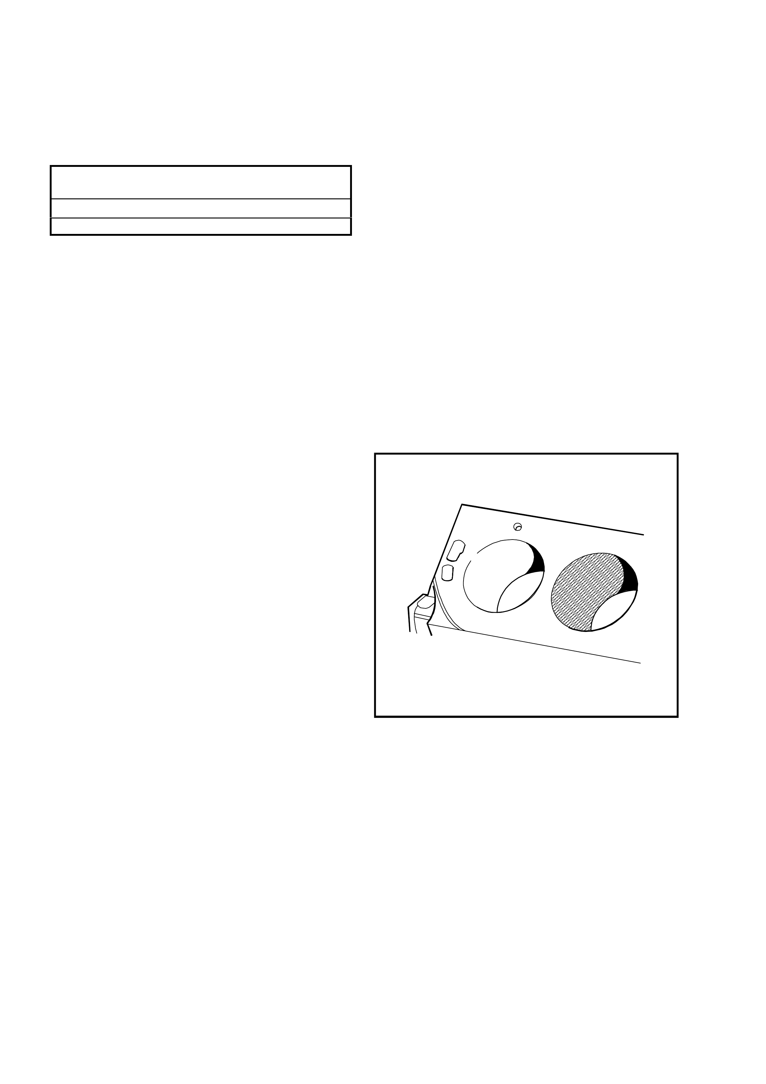
Measure Engine Block Cylinder Head Deck
1. Using a straight edge and feeler gauges,
check the flatness of the engine block,
cylinder head deck surfaces.
If found to be outside specification, the engine
block must be replaced, as machining is not
recommended.
Engine Block Cylinder Head Deck Flatness
Specification
Measured within a 150 mm area..0.11 mm Maximum
Measured over block length......... 0.22 mm Maximum
CYLINDER BORING AND HONING
Boring Pr ocedure
1. Oversize service piston and piston ring sets
are available in 0.25 mm.
Important: GEN III V8 Cylinder boring is not
permitted.
2. It is recommended to hone the cylinder to
achieve proper fit for the oversize piston.
Refer to the Cylinder Honing information for
the proper honing procedure.
Honing Procedure
1. When honing the cylinders, follow the
manufacturer's recommendations for
equipment use, cleaning, and lubrication. Use
only clean, sharp stones of the proper grade
for the amount of material you remove. Dull,
dirty stones cut unevenly and generate
excess ive heat. Do not hone to final clearance
with a coarse or medium-grade stone. Leave
suff icient m etal so that all stone m ark s m ay be
removed with fine-grade stones. Perform final
honing with a fine-grade stone, honing the
cylinder to the proper clearance.
2. During the honing operation, thoroughly clean
the cylinder bore. Repeatedly check the
cylinder bore for f it with the selected pis ton. All
measurements of the piston or the cylinder
bore should be made with the components at
normal room temperature.
3. When honing a cylinder for fit to an oversize
piston, first perform the preliminary honing with
a 100 grit stone.
4. Perform final cylinder honing with a 240 grit
stone and obtain a 45 degree cross hatch
pattern.
5. A 240 grit stone is preferred for final honing. If
a 240 grit stone is not available, a 220 grit
stone may be used as a substitute.
6. When honing to elim inate taper in the c ylinder,
ma ke fu ll strok es for the c om plete bore length.
Repeatedly check the measurement at the
top, the middle, and the bottom of the bore.
T6A3228
Figure 6A3-345
7. The finish marks should be clean but not
sharp. The finish marks should also be free
from embedded particles and torn or folded
metal.

8. By measuring the s elected piston at the sizing
point and by adding the average of the
clearance specification, the final cylinder
honing dimension required, can be
determined.
9. When finished, the reconditioned cylinder
bores should have less than or meet the
specified out-of-round and taper requirements.
10. After final honing and before the piston is
checked for fit, clean the cylinder bores with
hot water and detergent. Scrub the bores with
a stiff bristle brush and rinse the bores
thoroughly with hot water. Do not allow any
abrasive material to remain in the cylinder
bores. This abrasive material may cause
premature wear of the new piston rings and
the cylinder bores. Abrasive material will also
contaminate the engine oil and may cause
prem ature wear of the bearings . After washing
the cylinder bore, dry the bore with a clean
rag.
11. Perform final measurements of the piston and
the cylinder bore.
12. Perm anently m ark the top of the piston f or the
specific cylinder to which it has been fitted.
13. Apply clean engine oil to each cylinder bore in
order to prevent rusting.
Deglazing Procedure
Using a ball type or self centring honing tool,
deglaze the cylinder bore lightly. Deglazing should
be done only to remove any deposits that may
have formed. Use a 240 grit stone of silicone
carbide or equivalent m aterial when perform ing the
deglazing procedure.
A 240 grit stone is preferred for final honing. If a
240 grit stone is not available, a 220 grit s tone m ay
be used as a substitute.
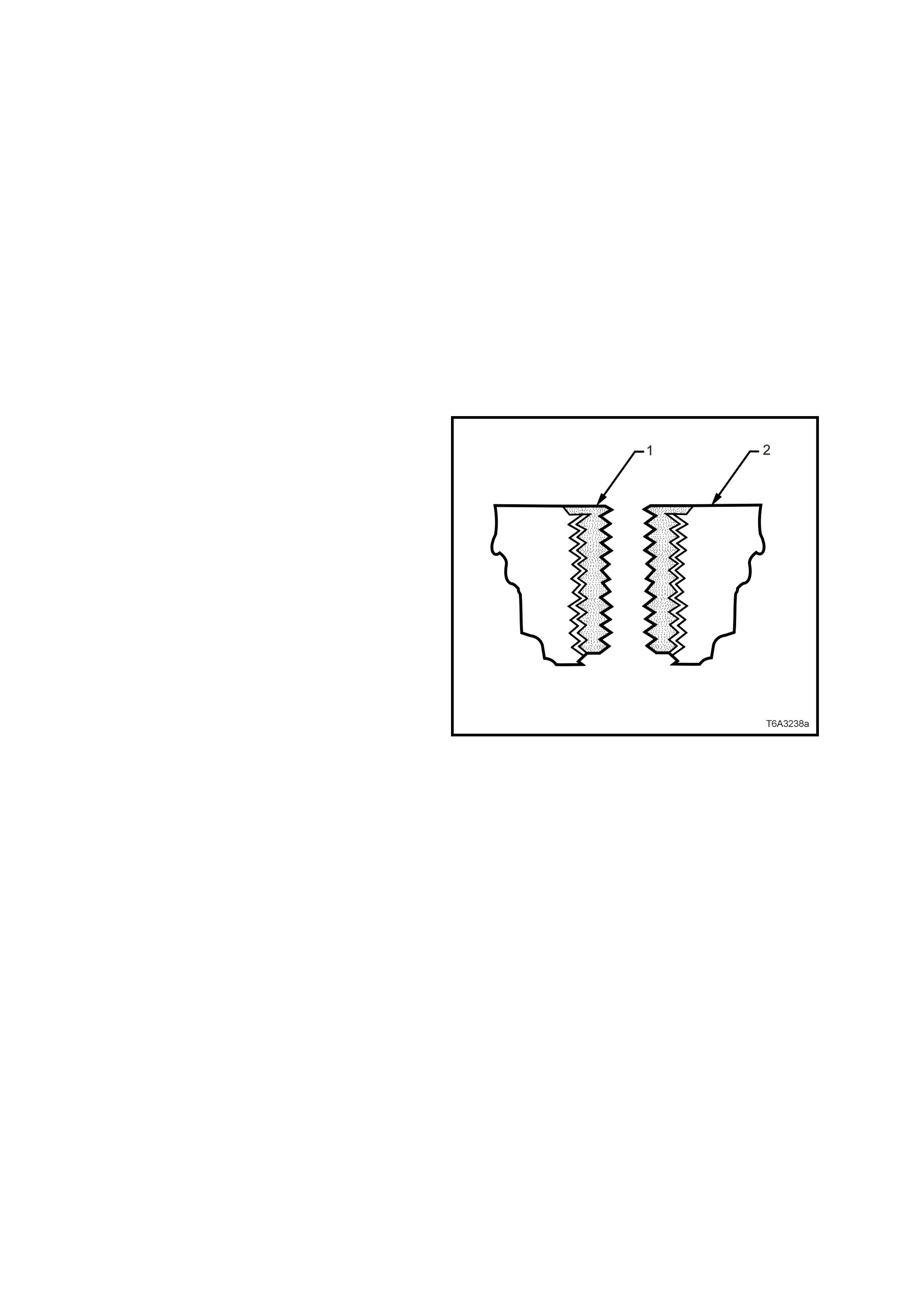
3.16 THREAD REPAIR
GENERAL INFORMATION
With the extensive use of aluminium alloy in the
construc tion of the GEN III V8 engine, thread repair
skills are required to repair damaged threads
caused by careless handling or over-torquing of
fasteners.
This Section describes the recommended method
of repairing threads in three specific areas of the
engine;
• General Thread Repair.
• Cylinder Head Bolt Hole Thread Repair.
• Main Cap Bolt Hole Thread Repair.
Section 3.17 THREAD REPAIR
SPECIFICATIONS in this Section, contains
detailed descriptions of all thread specifications
used in this engine.
The available Thread Repair Kit, Tool J
42385/100/200/ 300, uses the Time Sert thread
repair process that involves a solid, thin walled,
self-locking, carbon steel, bushing type insert (1).
During the bushing installation process, the driver
tool expands the bottom external threads of the
insert into the base material (2). This action
mechanically locks the insert in place.
Also, when installed to the proper depth, the flange
of the insert will be seated against the counterbore
of the repaired hole.
CAUTION: Wear safety glasses to avoid eye
injury.
Important: The use of a cutting type fluid GM P/N
1052864, (or WD 40, or equivalent) is
recommended when performing the drilling,
counterboring, and tapping procedures.
Driver oil MUST be used on the installer driver tool.
The tool kits are designed for use with either a
suitable tap wrench or drill motor.
Figure 6A3-346
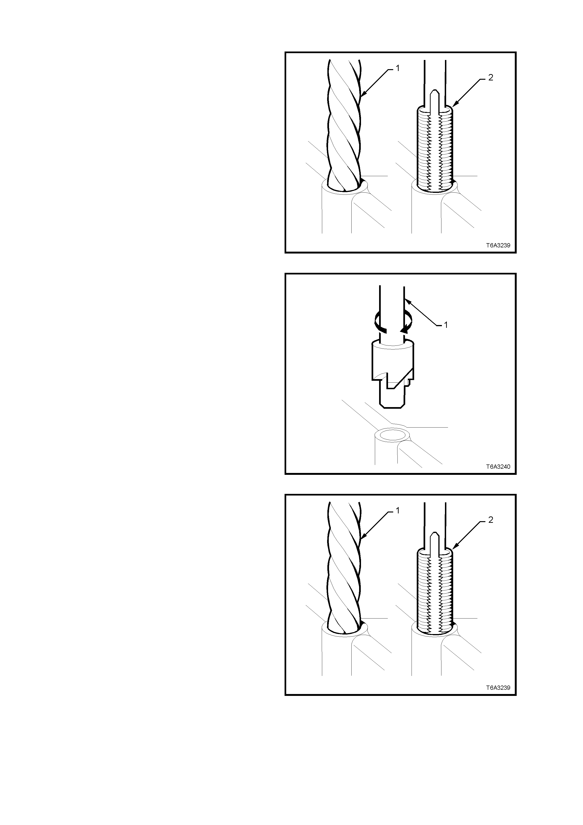
GENERAL THREAD REPAIR
1. Drill out the threads of the damaged hole (1) to
the correct depth for the thread being repaired:
• M6 inserts require a m inimum drill depth of
15 mm.
• M8 inserts require a m inimum drill depth of
20 mm.
• M10 inserts require a minimum drill depth
of 23.5 mm.
2. Using compressed air, clean out any chips.
CAUTION: Wear safety glasses to avoid eye
injury.
Figure 6A3-347
3. Counterbore the hole to the full depth
permitted by the tool (1).
4. Using compressed air, clean out any chips.
CAUTION: Wear safety glasses to avoid eye
injury.
Figure 6A3-348
5. Using a tap wrench (2), tap the threads of the
drilled hole to the correct depth for the thread
being repaired.
• M6 inserts require a minimum tap depth of
15 mm.
• M8 inserts require a minimum tap depth of
20 mm.
• M10 inserts require a minimum tap depth
of 23.5 mm.
6. Using compressed air, clean out any chips.
7. Spray a suitable cleaner such as GM P/N
12346139, P/N 12377981 or equivalent, into
the hole.
Important: Do not use any cleaning agents that
contain Trichloralethane, as this is harmful to
aluminium.
8. Using compressed air, clean any cutting oil
and chips out of the hole.
CAUTION: Wear safety glasses to avoid eye
injury.
Figure 6A3-349
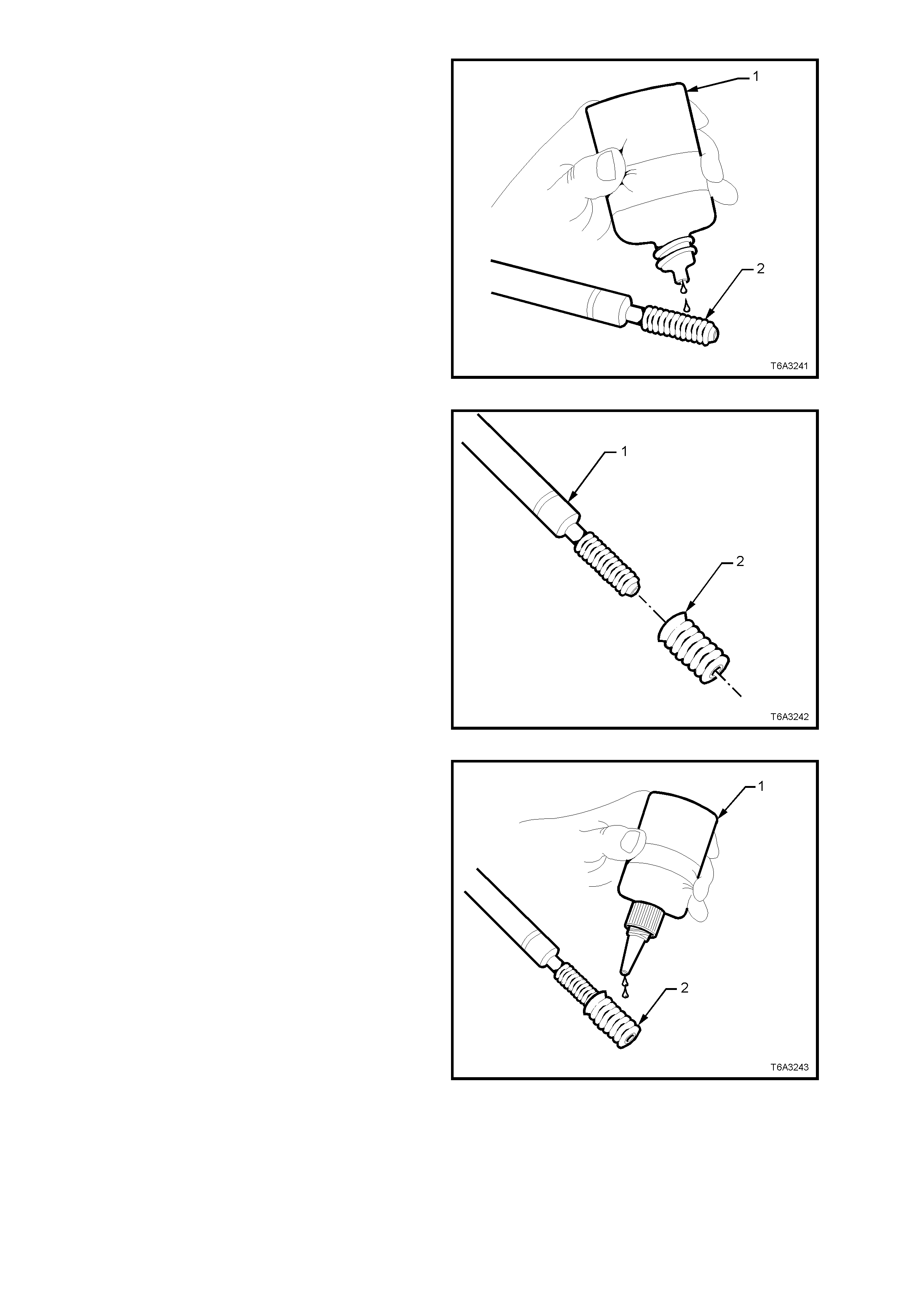
9. Lubricate the threads of the installer tool (2)
with the driver oil (1).
Important: Do not allow oil or other foreign
mater ial to contac t the outs ide diam eter ( OD) of the
insert.
Figure 6A3-350
10. Install the insert (2) onto the driver tool (1).
Figure 6A3-351
11. Apply threadlock Loctite 272 (1) or equivalent
(GM P/N 12345493) to the insert OD threads
(2).
Figure 6A3-352
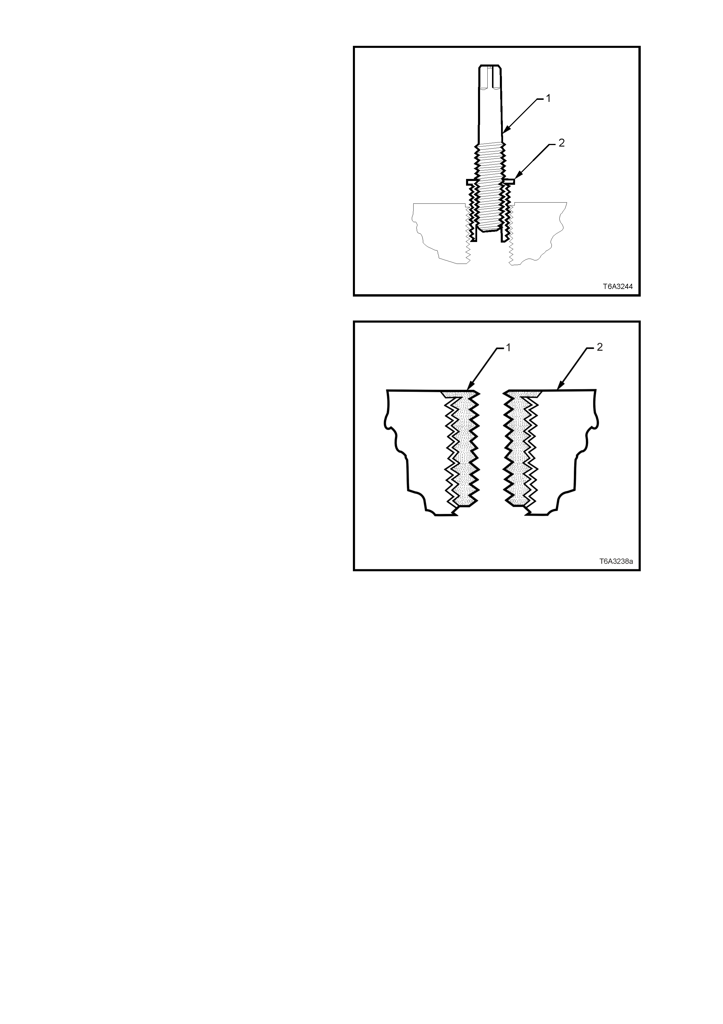
12. Using the inst aller tool (1), install the ins ert (2)
into the hole.
13. Continue to install the insert until the flange of
the insert contacts the counterbored surface.
14. Continue to rotate the installer tool (1) through
the insert. The installer tool (1) will tighten up
before screwing completely through the insert.
This is normal s ince the bottom threads of the
insert are being formed and mechanically
locked into the hole.
15. Remove the driver. The repair is complete.
Figure 6A3-353
16. Inspect the insert for proper installation into
the hole.
17. A properly installed insert (1) will be either
flush or slightly below flush with the surface of
the base material (2).
Figure 6A3-354
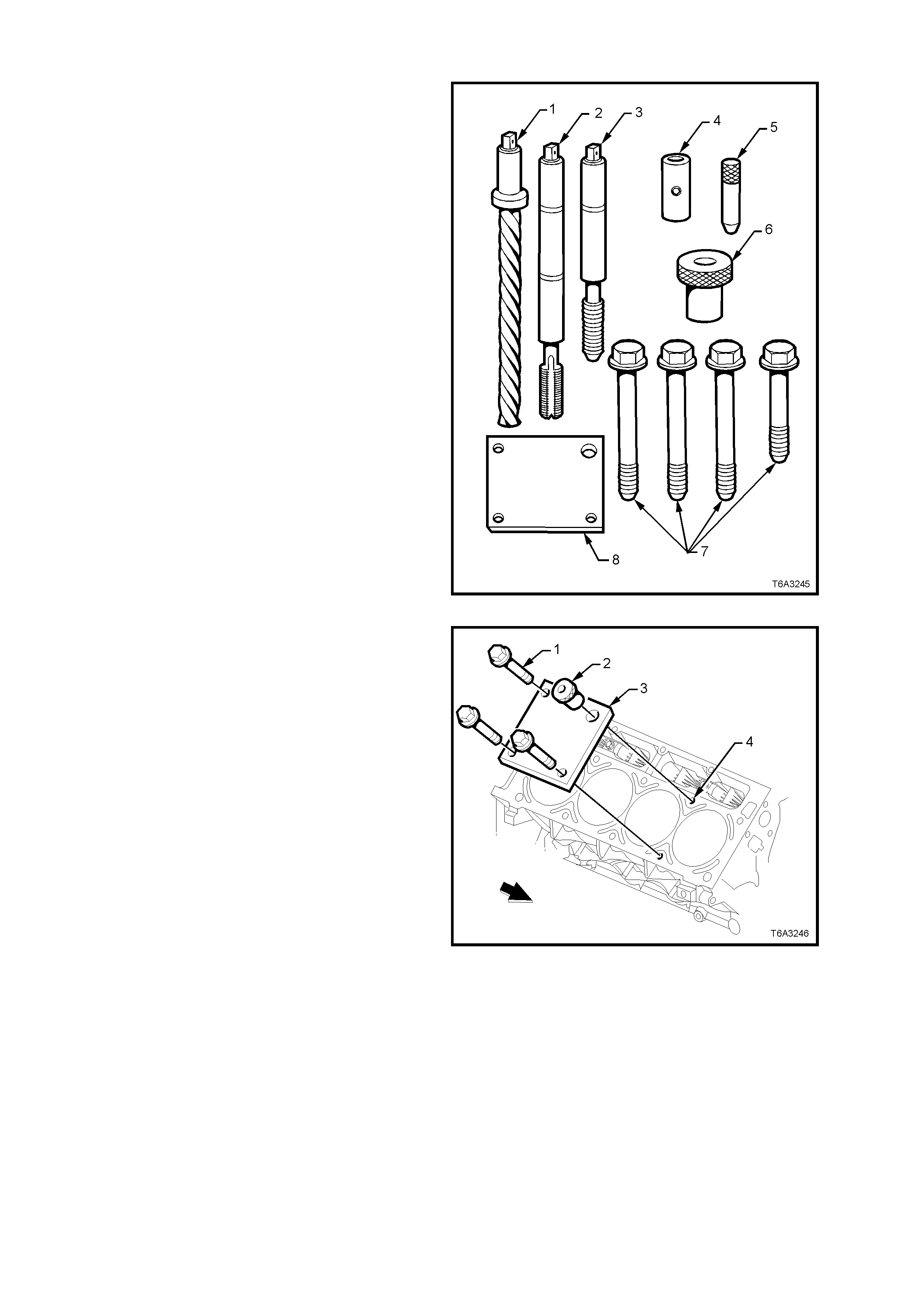
CYLINDER HEAD BOLT HOLE THREAD REPAIR
The cylinder head bolt hole thread repair kit
consists of the following items:
1. Drill
2. Tap
3. Installer
4. Sleeve
5. Alignment Pin
6. Bushing
7. Bolts
8. Fixture Plate
Figure 6A3-355
CAUTION: Wear safety glasses to avoid eye
injury.
Important: The use of a cutting type fluid GM P/N
1052864, (or WD 40, or equivalent) is
recommended when performing the drilling,
counterboring, and tapping procedures.
Driver oil MUST be used on the installer driver tool.
The tool kits are designed for use with either a
suitable tap wrench or drill motor.
1. Install the fixture plate (3), bolts (1), and
bushing (2) onto the engine block deck.
2. Position the fixture plate and bushing over the
hole that is to be repaired (4).
Figure 6A3-356
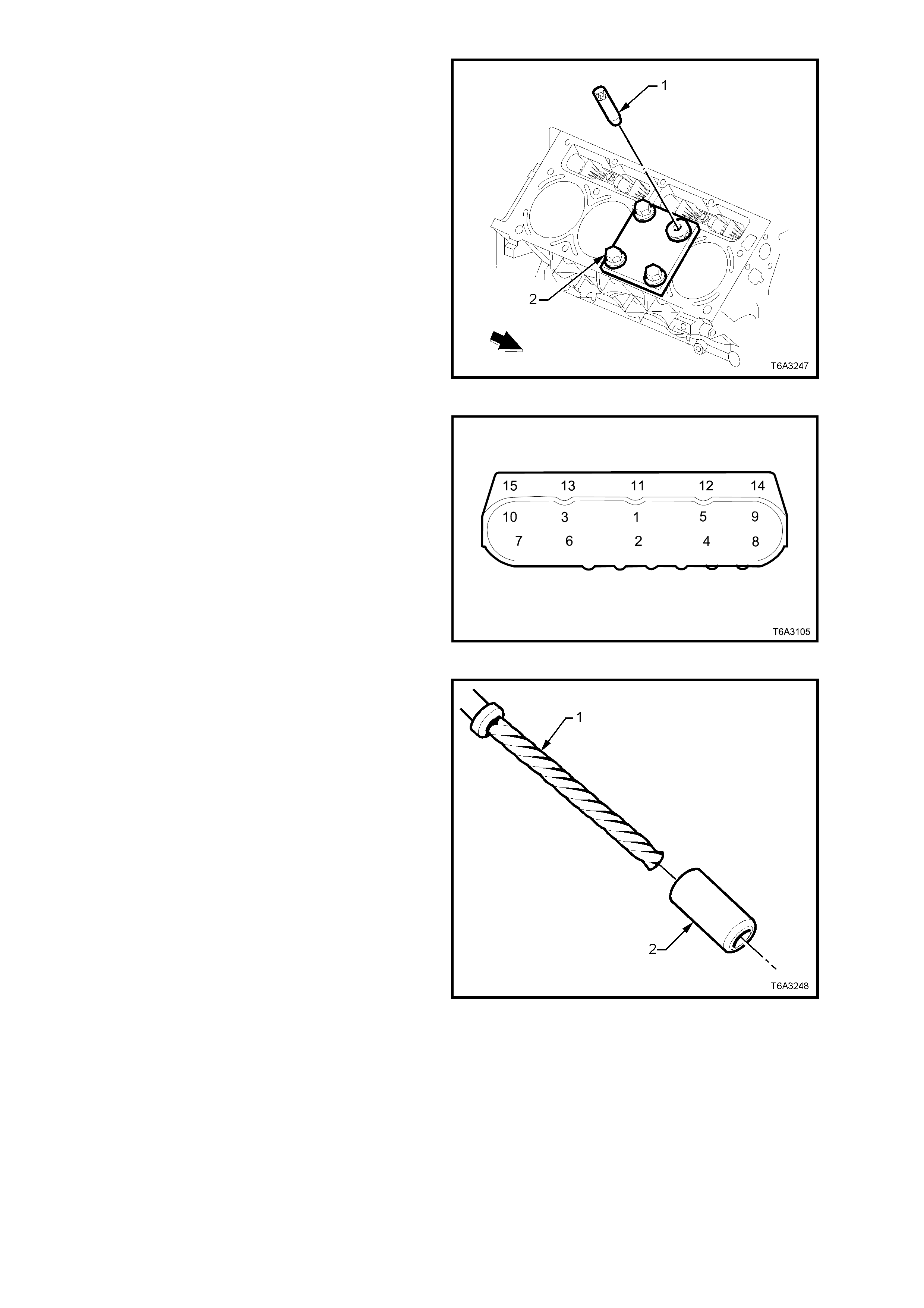
3. Position the alignment pin (1) through the
bushing and into the hole.
4. With the alignment pin in the desired hole,
tighten the fixture retaining bolts (2).
5. Remove the alignment pin from the hole.
Figure 6A3-357
6. Cylinder head bolt holes 1-8 are the deep
holes and will be drilled without the drill sleeve.
7. Cylinder head bolt holes 9 and 10 are the
more shallow holes, so drilling MUST be done
with the drill sleeve in place
Figure 6A3-358
8. Install the sleeve (2) onto the drill (1) (if
required).
Figure 6A3-359
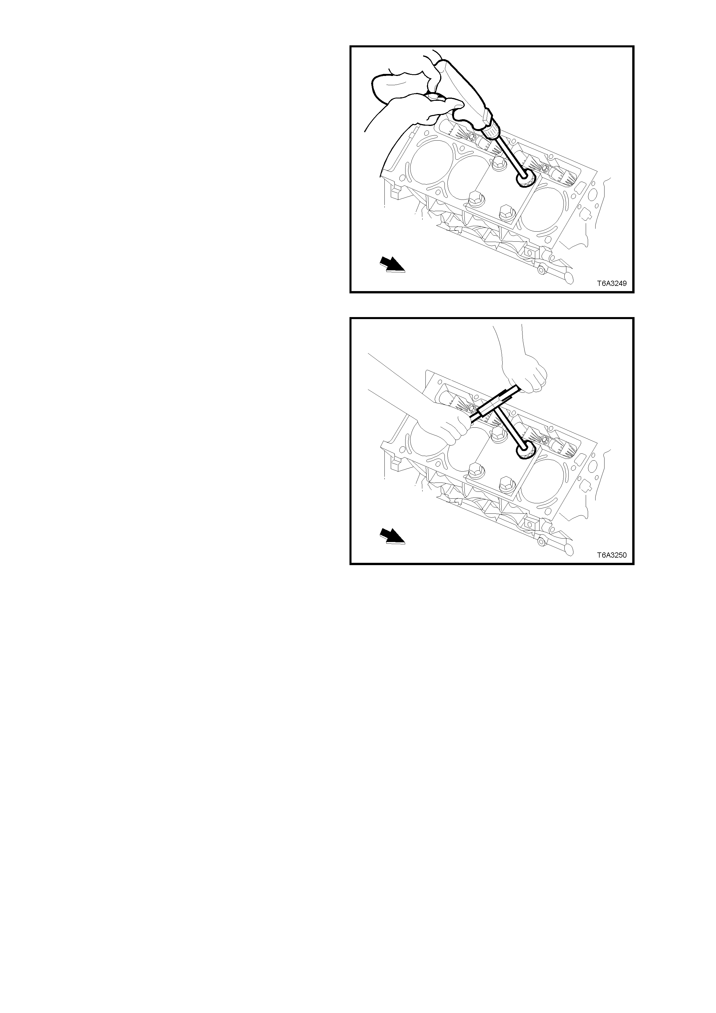
9. Drill out the threads of the damaged hole.
10. Drill the hole until the stop collar of the drill bit
or the sleeve contacts the bushing.
11. Using compressed air, clean out any chips.
CAUTION: Wear safety glasses to avoid eye
injury.
Figure 6A3-360
12. Using a tap wrench, tap the threads of the
drilled hole.
Figure 6A3-361
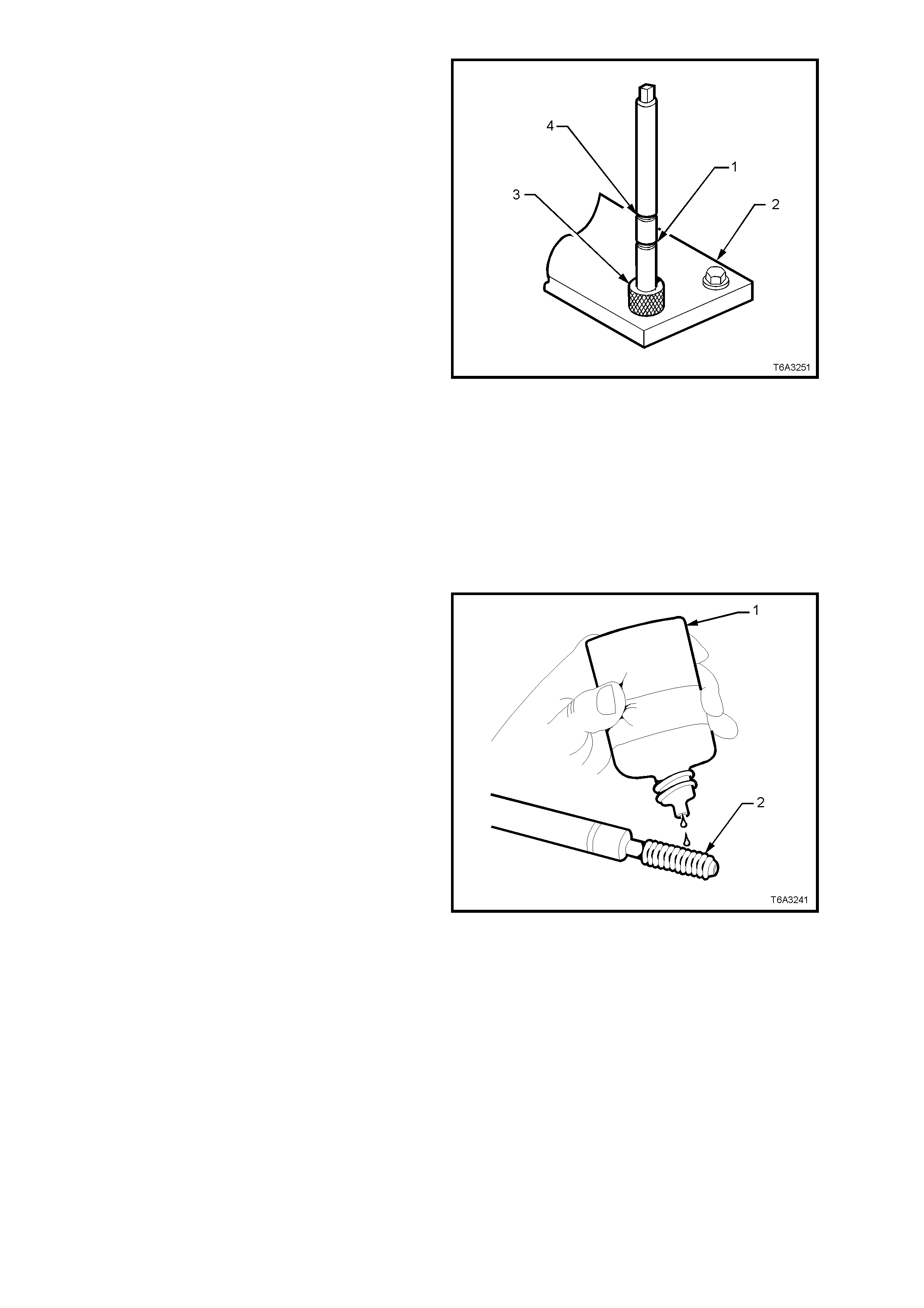
13. In order to tap the new threads to the proper
depth, rotate the tap into the hole until the
marks (1 or 4) on the tap align with the top of
the drill bushing (3), as follows:
• For the deeper cylinder head bolt holes
(1-8), rotate the tap until the upper mark
on the tap (4) aligns with the top of the
drill bushing.
• For the shallower cylinder head bolt holes
(9 and 10), rotate the tap until the lower
mark on the tap (1) aligns with the top of
the drill bushing.
14. Remove the fixture plate (2), bushing (3), and
bolts.
15. Using compressed air, clean out any chips.
16. Spray a suitable cleaner such as GM P/N
12346139, P/N 12377981 or equivalent, into
the hole.
Important: Do not use any cleaning agents
that contain Trichloralethane, as this is harmful
to aluminium.
17. Using compressed air, clean any cutting oil
and chips out of the hole.
CAUTION: Wear safety glasses to avoid eye
injury.
Figure 6A3-362
18. Lubricate the threads of the installer tool (2)
with the driver oil (1).
Important: Do not allow oil or other foreign
mater ial to contac t the outs ide diam eter ( OD) of the
insert.
Figure 6A3-363
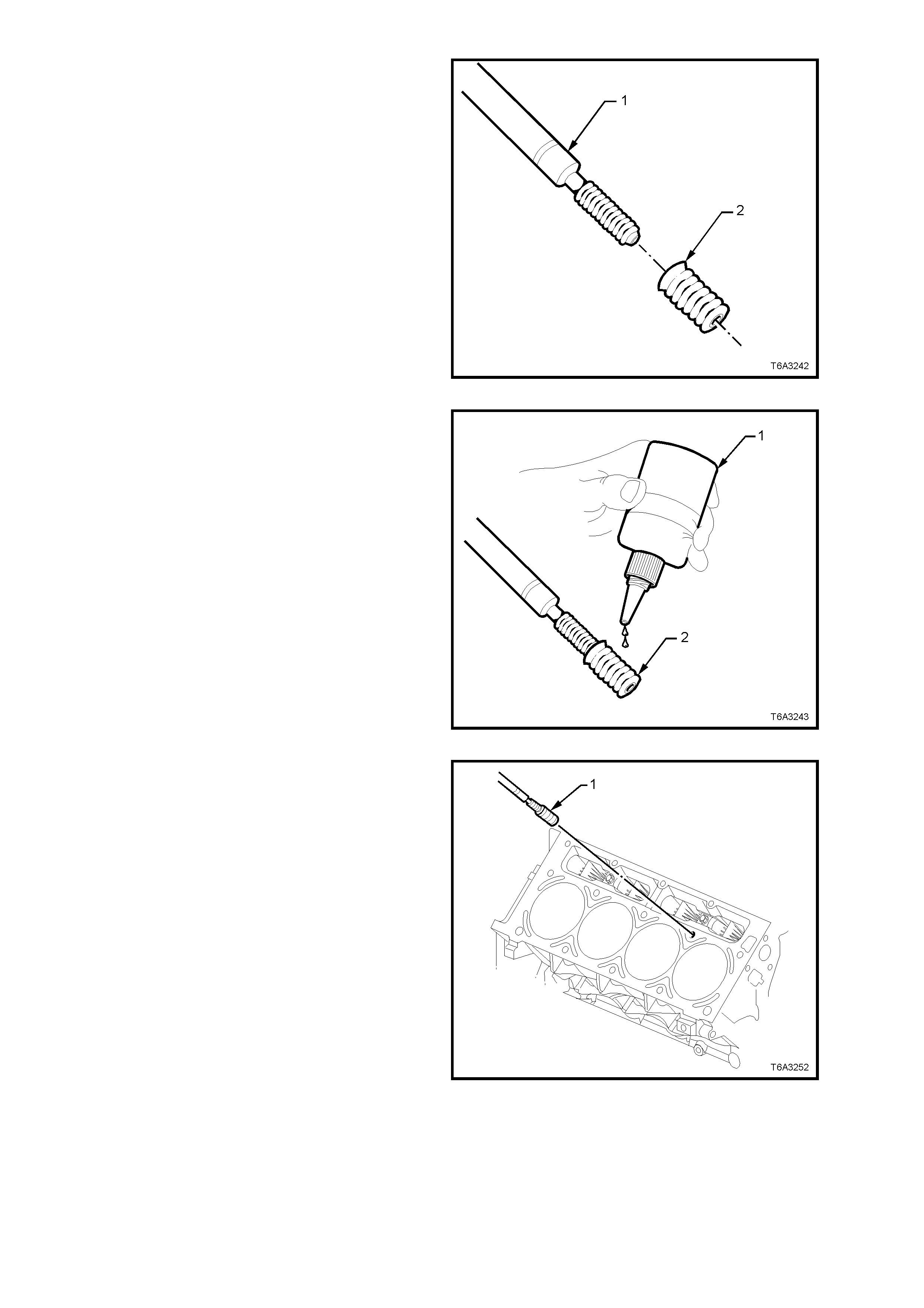
19. Install the insert (2) onto the driver tool (1).
Figure 6A3-364
20. Apply threadlock Loctite 272 (1) or equivalent
(GM P/N 12345493) to the insert OD threads
(2).
Figure 6A3-365
21. Install the insert and driver (1) into the hole.
22. Continue to install the insert until the flange of
the insert contacts the counterbored surface.
23. Continue to rotate the installer tool (1) through
the insert. The installer tool (1) will tighten up
before screwing completely through the insert.
This is normal s ince the bottom threads of the
insert are being formed and mechanically
locked into the hole.
24. Remove the driver. The repair is complete.
Figure 6A3-366
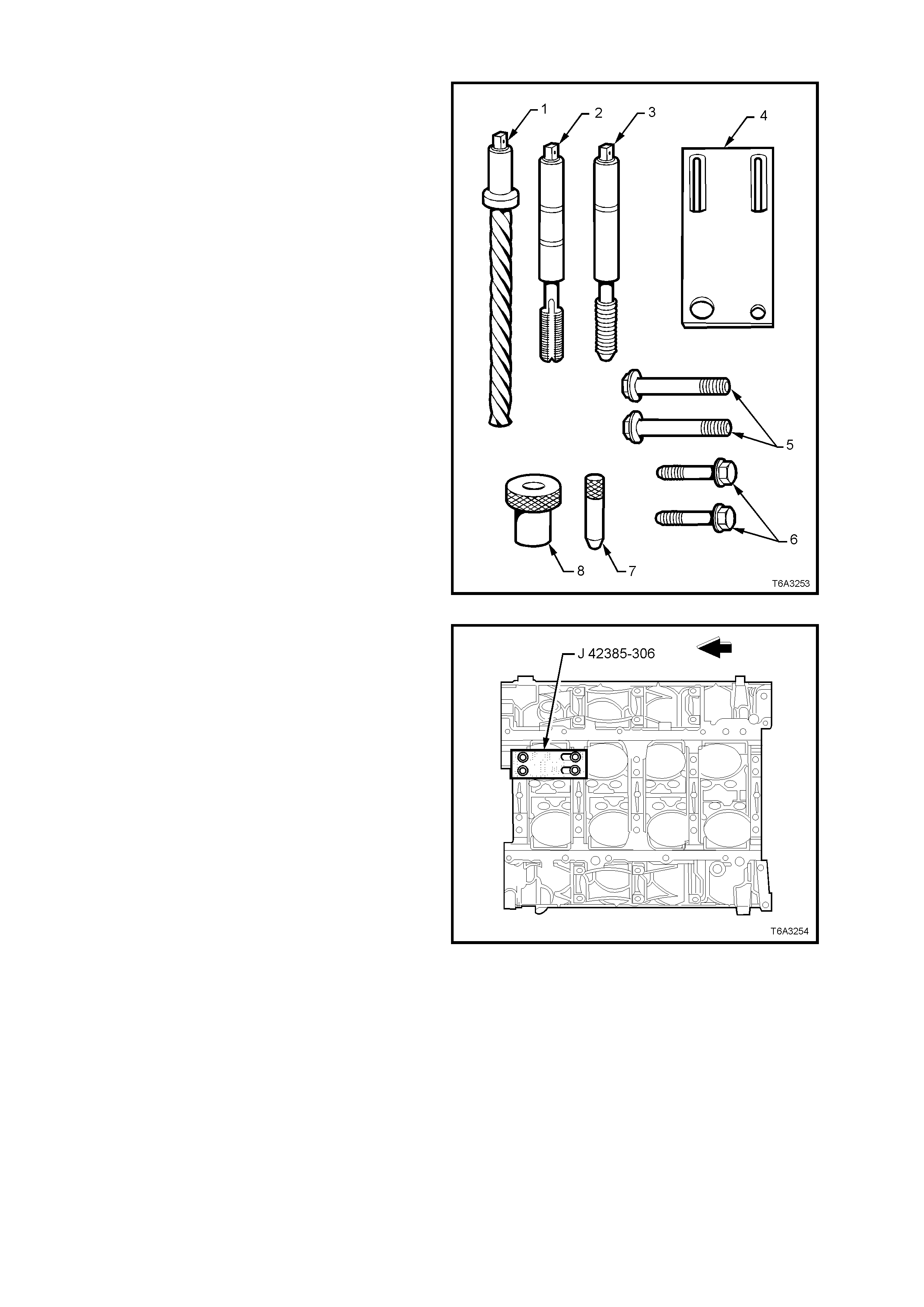
MAIN CAP BOLT HOLE THREAD REPAIR
The m ain cap bolt hole thread r epair kit consists of
the following items:
1. Drill
2. Tap
3. Installer
4. Fixture Plate
5. Long Bolts
6. Short Bolts
7. Alignment Pin
8. Bushing
Figure 6A3-367
CAUTION: Wear safety glasses to avoid eye
injury.
Important: The use of a cutting type fluid GM P/N
1052864, (or WD 40, or equivalent) is
recommended when performing the drilling,
counter-boring, and tapping procedures.
Driver oil MUST be used on the installer driver tool.
The tool kits are designed for use with either a
suitable tap wrench or drill motor.
1. Position the fixture plate and bushing over the
hole that is to be repaired. Position the
alignment pin in the desired hole and tighten
the fixture retaining bolts.
Figure 6A3-368
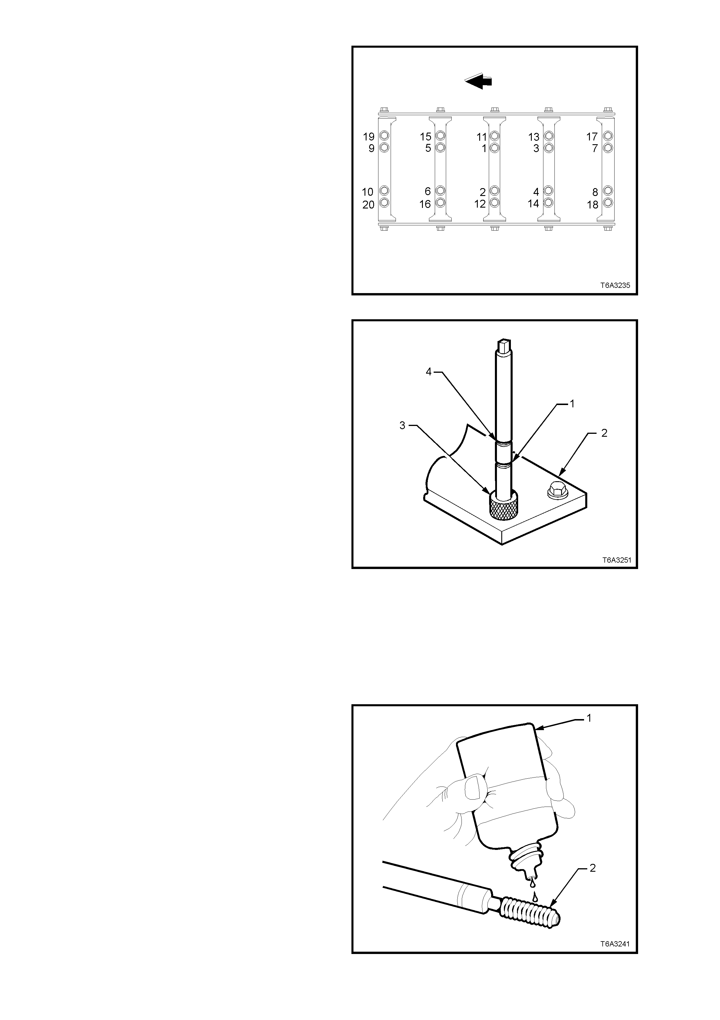
2. Drill out the damaged hole.
NOTE: The outer bolt hole locations (11-20) have
the shallower counter-bores. Use bushing (8), J
42385-316 with the drill.
3. Drill until the stop collar of the drill bit or the
sleeve contacts the bushing.
4. Using compressed air, clean out any chips.
CAUTION: Wear safety glasses to avoid eye
injury.
Figure 6A3-369
5. In order to tap the new threads to the proper
depth, rotate the tap into the hole until the
marks (1 or 4) on the tap align with the top of
the drill bushing (3), as follows:
• For the deeper main cap holes (1-10),
rotate the tap until the upper mark (4) on
the tap aligns with the top of the bushing
(3).
• For the shallower main cap holes (11-20),
rotate the tap until the lower mark (1) on
the tap aligns with top of the bushing (3).
6. Remove the fixture plate (2), bushing (3), and
bolts.
7. Using compressed air, clean out any chips.
8. Spray a suitable cleaner such as GM P/N
12346139, P/N 12377981 or equivalent, into
the hole.
Important: Do not use any cleaning agents that
contain Trichloralethane, as this is harmful to
aluminium.
9. Using compressed air, clean any cutting oil
and chips out of the hole.
CAUTION: Wear safety glasses to avoid eye
injury.
Figure 6A3-370
10. Lubricate the threads of the installer tool (2)
with the driver oil (1).
Important: Do not allow oil or other foreign
mater ial to contac t the outs ide diam eter ( OD) of the
insert.
Figure 6A3-371
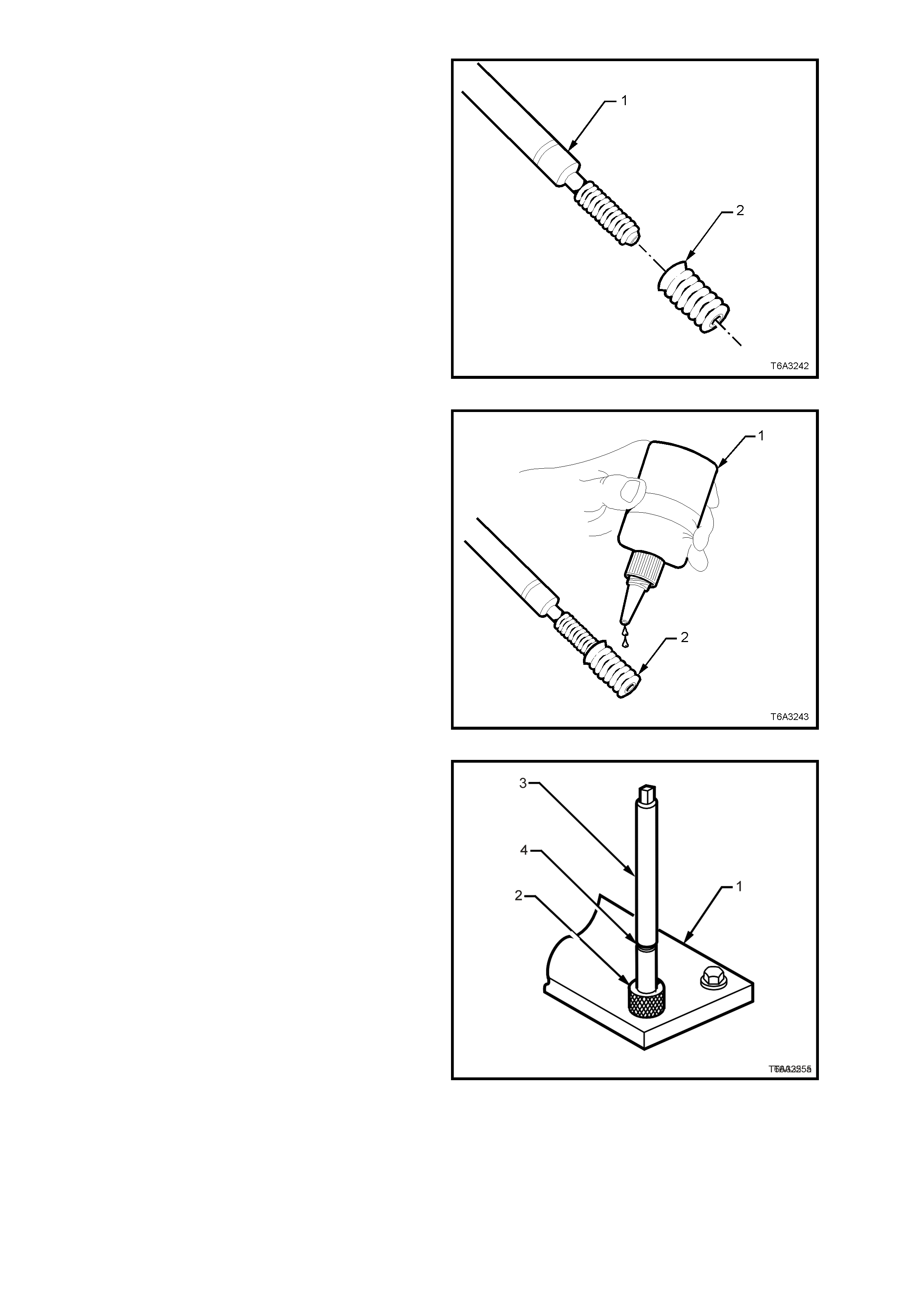
11. Install the insert (2) onto the driver tool (1).
Figure 6A3-372
12. Apply threadlock Loctite 272 (1) or equivalent
(GM P/N 12345493) to the insert OD threads
(2).
Figure 6A3-373
Important: The fixture plate (1) and bushing (2)
remains installed onto the engine block during the
insert installation procedure.
13. Install the insert and driver (3) through the
fixture plate and bushing and into the hole.
14. Rotate the driver tool until the m ar k on the tool
(4) aligns with the top of the bushing (2).
NOTE: The installer tool will tighten up before
screwing completely through the insert. This is
normal since the bottom threads of the insert are
being formed and mechanically locked into the
hole.
15. Remove the driver. The repair is complete.
Figure 6A3-374
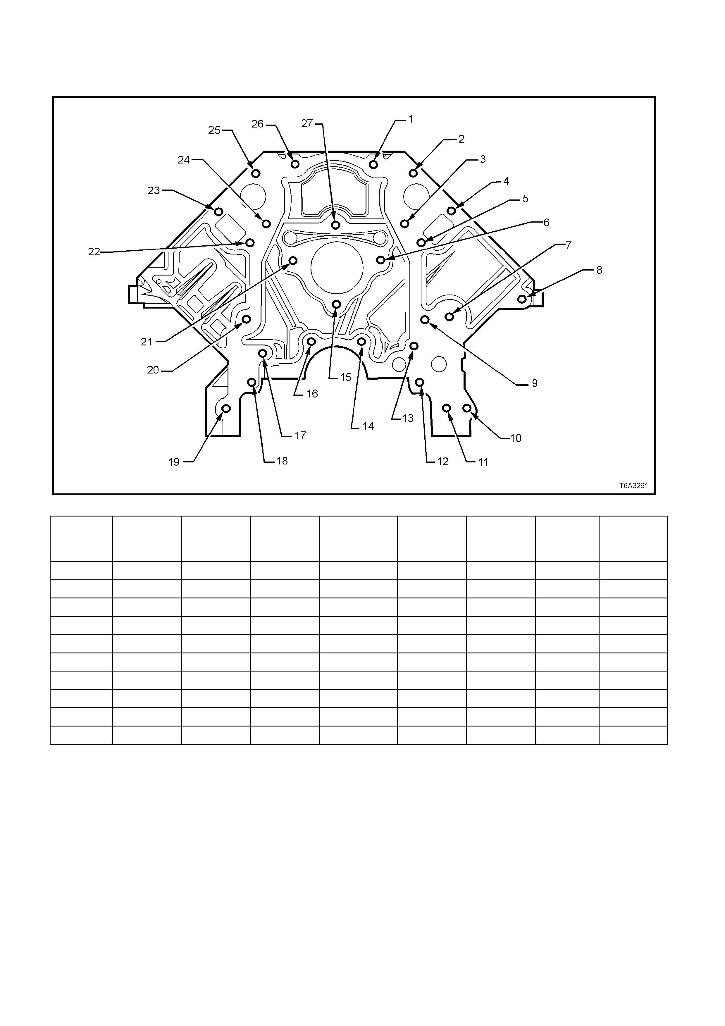
3.17 THREAD REPAIR SPECIFICATIONS
ENGINE BLOCK - FRONT VIEW
Figure 6A3-375
Hole Thread Size Insert Drill Counterbore
Tool Tap Driver Maximum
Drill Depth
mm
Maximum
Tap Depth
mm
1-6 M8 x 1.25 J 42385-210 J 42385-206 J 42385-207 J 42385-208 J 42385-209 22.5 17.5
7 M10 x 1.5 J 42385-215 J 42385-211 J 42385-212 J 42385-213 J 42385-214 25.0 19.5
8 M10 x 1.5 J 42385-215 J 42385-211 J 42385-212 J 42385-213 J 42385-214 32.5 25.0
9 M8 x 1.25 J 42385-210 J 42385-206 J 42385-207 J 42385-208 J 42385-209 22.5 17.5
10 M10 x 1.5 J 42385-215 J 42385-211 J 42385-212 J 42385-213 J 42385-214 Through Through
11-13 M8 x 1.25 J 42385-210 J 42385-206 J 42385-207 J 42385-208 J 42385-209 22.5 17.5
14 M8 x 1.25 J 42385-210 J 42385-206 J 42385-207 J 42385-208 J 42385-209 Through 18.0
15 M8 x 1.25 J 42385-210 J 42385-206 J 42385-207 J 42385-208 J 42385-209 22.5 17.5
16 M8 x 1.25 J 42385-210 J 42385-206 J 42385-207 J 42385-208 J 42385-209 Through 18.0
17-27 M8 x 1.25 J 42385-210 J 42385-206 J 42385-207 J 42385-208 J 42385-209 22.5 17.5
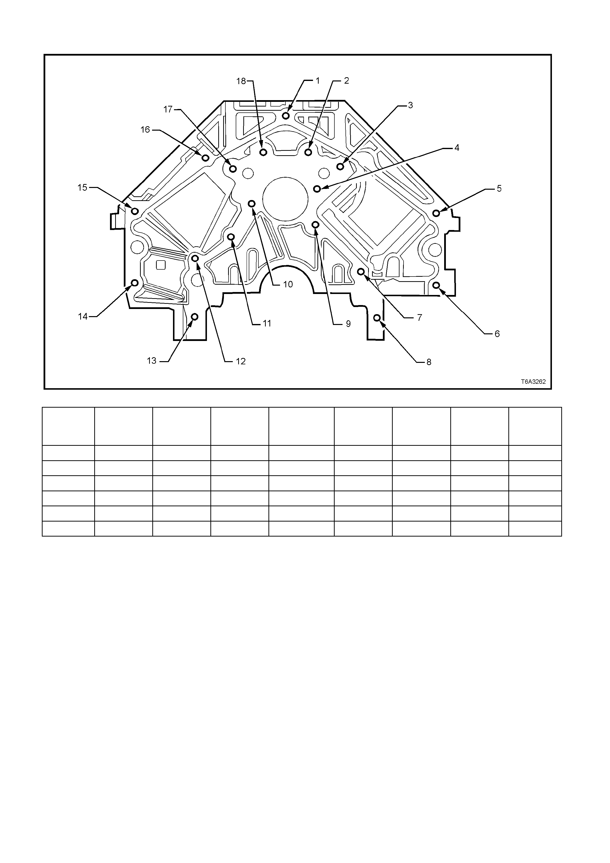
ENGINE BLOCK - REAR VIEW
Figure 6A3-376
Hole Thread Size Insert Drill Counterbore
Tool Tap Driver Maximum
Drill Depth
mm
Maximum
Tap Depth
mm
1 M10 x 1.5 J 42385-215 J 42385-211 J 42385-212 J 42385-213 J 42385-214 27.0 21.5
2-4 M8 x 1.25 J 42385-210 J 42385-206 J 42385-207 J 42385-208 J 42385-209 22.5 17.5
5-6 M10 x 1.5 J 42385-215 J 42385-211 J 42385-212 J 42385-213 J 42385-214 27.0 21.5
7-13 M8 x 1.25 J 42385-210 J 42385-206 J 42385-207 J 42385-208 J 42385-209 22.5 17.5
14-16 M10 x 1.5 J 42385-215 J 42385-211 J 42385-212 J 42385-213 J 42385-214 27.0 21.5
17-18 M8 x 1.25 J 42385-210 J 42385-206 J 42385-207 J 42385-208 J 42385-209 22.5 17.5
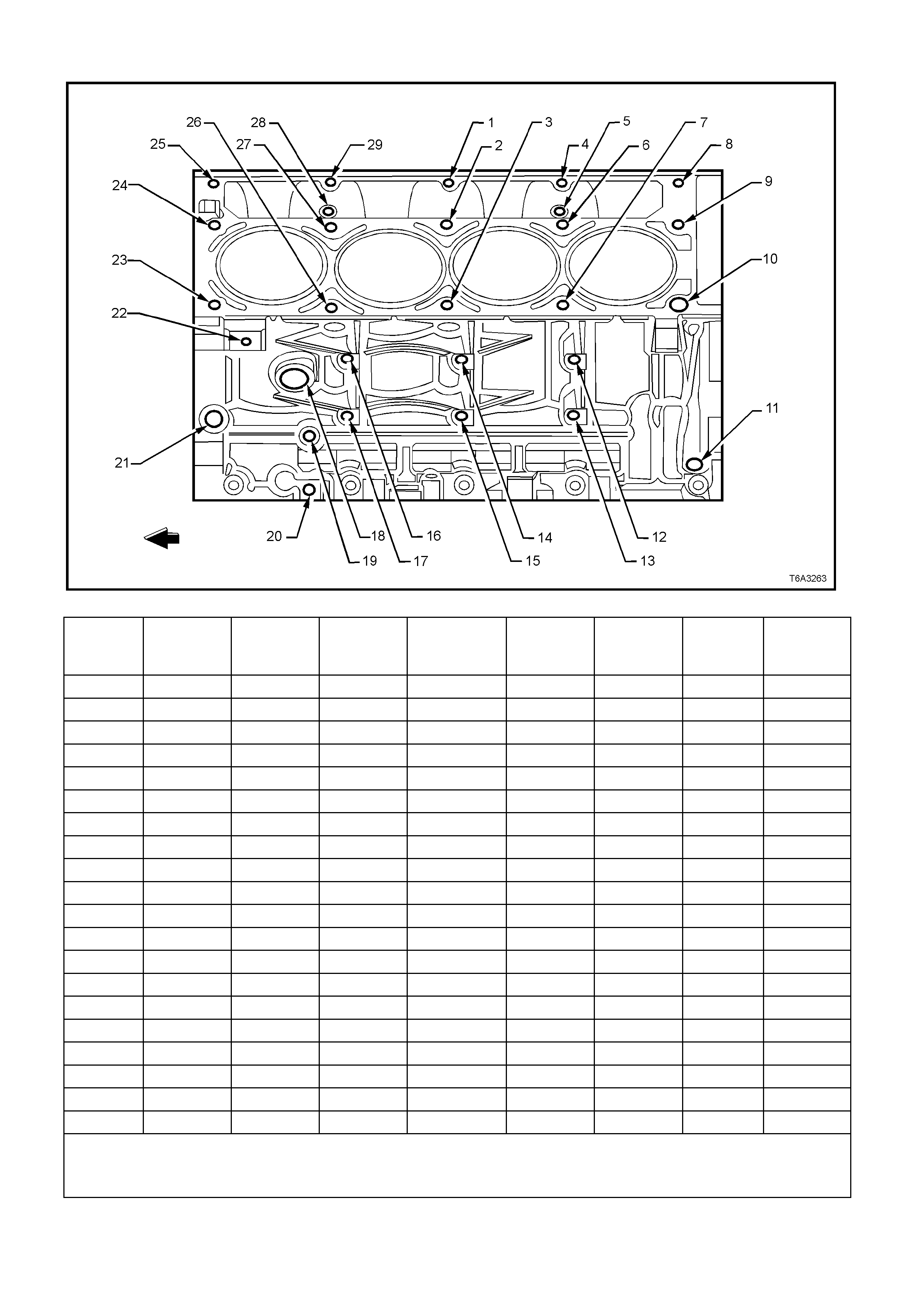
ENGINE BLOCK - LEFT SIDE VIEW
Figure 6A3-377
Hole Thread Size Insert Drill Counterbore
Tool Tap Driver Maximum
Drill Depth
mm
Maximum
Tap Depth
mm
1 M8 x 1.25 J 42385-210 J 42385-206 J 42385-207 J 42385-208 J 42385-209 26.5 19.0
2-3 M11 x 2.0 J 42385-108 J 42385-105 J 42385-106 J 42385-107 124.0 115.0
4 M8 x 1.25 J 42385-210 J 42385-206 J 42385-207 J 42385-208 J 42385-209 26.5 19.0
5 M6 x 1.0 J 42385-205 J 42385-201 J 42385-202 J 42385-203 J 42385-204 22.5 16.0
6-7 M11 x 2.0 J 42385-108 J 42385-105 J 42385-106 J 42385-107 124.0 115.0
8 M8 x 1.25 J 42385-210 J 42385-206 J 42385-207 J 42385-208 J 42385-209 26.5 19.0
9 M11 x 2.0 J 42385-108 J 42385-105 J 42385-106 J 42385-107 69.0 60.0
10 M11 x 2.0 J 42385-108 J 42385-105 J 42385-106 J 42385-107 124.0 115.0
11
12-17 M10 x 1.5 J 42385-215 J 42385-211 J 42385-212 J 42385-213 J 42385-214 29.0 23.0
18 M28 x 1.25
19-20 M8 x 1.25 J 42385-210 J 42385-206 J 42385-207 J 42385-208 J 42385-209 21.0 16.0
21 M16 x 1.5
22 M10 x 1.5 J 42385-215 J 42385-211 J 42385-212 J 42385-213 J 42385-214 27.0 21.5
23 M11 x 2.0 J 42385-108 J 42385-105 J 42385-106 J 42385-107 124.0 115.0
24 M11 x 2.0 J 42385-108 J 42385-105 J 42385-106 J 42385-107 69.0 60.0
25 M8 x 1.25 J 42385-210 J 42385-206 J 42385-207 J 42385-208 J 42385-209 26.5 19.0
26-27 M11 x 2.0 J 42385-108 J 42385-105 J 42385-106 J 42385-107 124.0 115.0
28 M6 x 1.0 J 42385-205 J 42385-201 J 42385-202 J 42385-203 J 42385-204 22.5 16.0
29 M8 x 1.25 J 42385-210 J 42385-206 J 42385-207 J 42385-208 J 42385-209 26.5 19.0
• Bolt holes 2, 3, 6, 7, 10, 23, 26, and 27 have a 85 mm counterbore included in the 124.0 mm drill depth.
• Bolt holes 9 and 24 have a 30 mm counterbore included in the 69.0 mm drill depth. Use sleeve J 42385-315 with the drill
and tap.

ENGINE BLOCK - RIGHT SIDE VIEW
Figure 6A3-378
Hole Thread Size Insert Drill Counterbore
Tool Tap Driver Maximum
Drill Depth
mm
Maximum
Tap Depth
mm
1 M8 x 1.25 J 42385-210 J 42385-206 J 42385-207 J 42385-208 J 42385-209 26.5 19.0
2-3 M11 x 2.0 J 42385-108 J 42385-105 J 42385-106 J 42385-107 124.0 115.0
4 M8 x 1.25 J 42385-210 J 42385-206 J 42385-207 J 42385-208 J 42385-209 26.5 19.0
5 M6 x 1.0 J 42385-205 J 42385-201 J 42385-202 J 42385-203 J 42385-204 22.5 15.0
6-7 M11 x 2.0 J 42385-108 J 42385-105 J 42385-106 J 42385-107 124.0 115.0
8 M8 x 1.25 J 42385-210 J 42385-206 J 42385-207 J 42385-208 J 42385-209 26.5 19.0
9 M11 x 2.0 J 42385-108 J 42385-105 J 42385-106 J 42385-107 69.0 60.0
10 M11 x 2.0 J 42385-108 J 42385-105 J 42385-106 J 42385-107 124.0 115.0
11-14 M10 x 1.5 J 42385-215 J 42385-211 J 42385-212 J 42385-213 J 42385-214 27.0 21.5
15-19 M10 x 1.5 J 42385-215 J 42385-211 J 42385-212 J 42385-213 J 42385-214 29.0 23.0
20 M16 x 1.5
21 M8 x 1.25 J 42385-210 J 42385-206 J 42385-207 J 42385-208 J 42385-209 22.5 17.5
22 M11 x 2.0 J 42385-108 J 42385-105 J 42385-106 J 42385-107 124.0 115.0
23 M11 x 2 J 42385-108 J 42385-105 J 42385-106 J 42385-107 69.0 60.0
24 M8 x 1.25 J 42385-210 J 42385-206 J 42385-207 J 42385-208 J 42385-209 26.5 19.0
25-26 M11 x 2.0 J 42385-108 J 42385-105 J 42385-106 J 42385-107 124.0 115.0
27 M6 x 1.0 J 42385-205 J 42385-201 J 42385-202 J 42385-203 J 42385-204 22.5 15.0
28 M8 x 1.25 J 42385-210 J 42385-206 J 42385-207 J 42385-208 J 42385-209 26.5 19.0
• Bolt holes 2, 3, 6, 7, 10, 22, 25, and 26 have a 85 mm counterbore included in the 124.0 mm drill depth.
• Bolt holes 9 and 23 have a 30 mm counterbore included in the 69.0 mm drill depth. Use sleeve J 42385-315 with the drill
and tap.
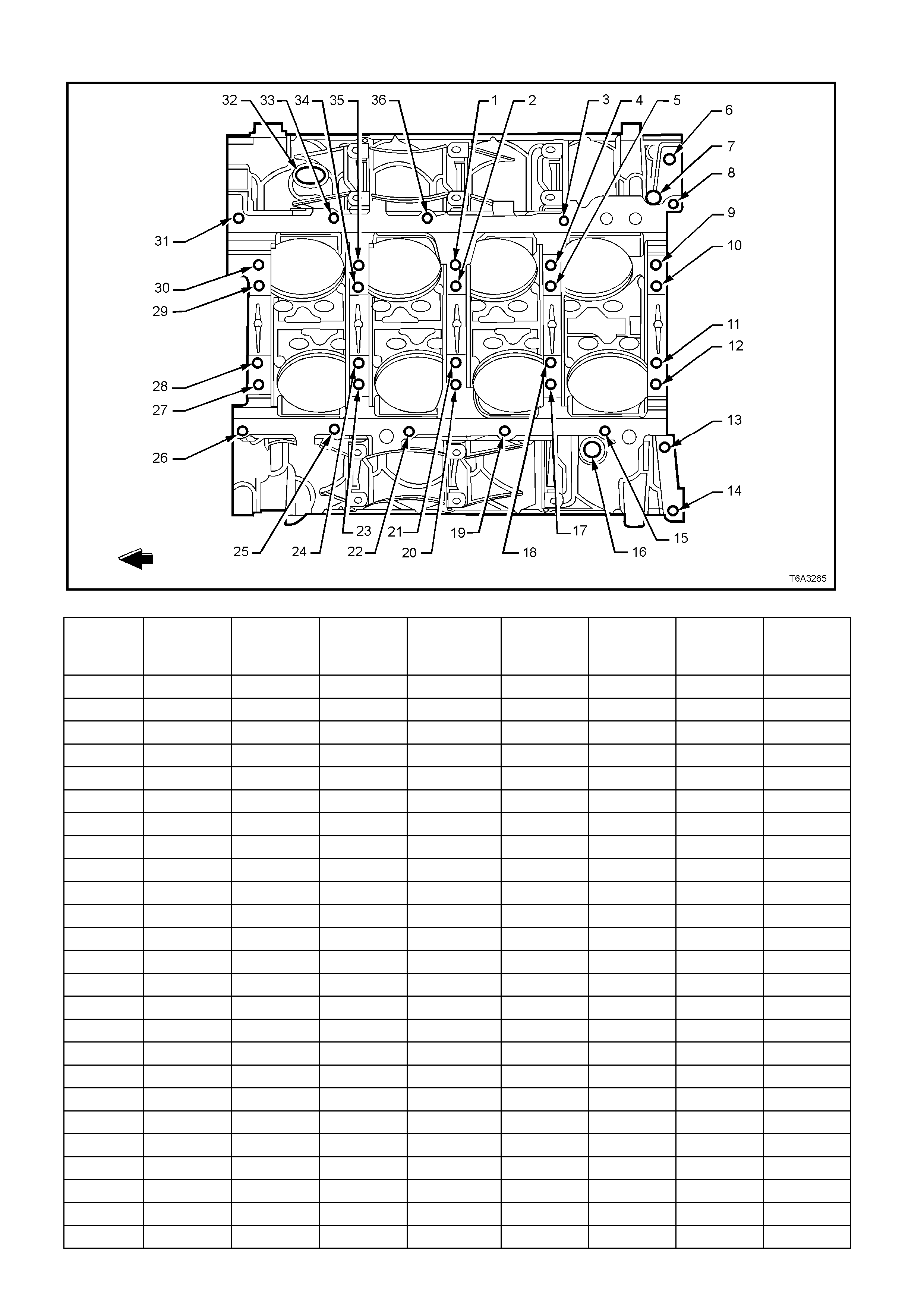
ENGINE BLOCK - BOTTOM VIEW
Figure 6A3-379
Hole Thread Size Insert Drill Counterbore
Tool Tap Driver Maximum
Drill Depth
mm
Maximum
Tap Depth
mm
1 M10 x 2.0 J 42385-104 J 42385-101 J 42385-102 J 42385-103 31.0 25.5
2 M10 x 2.0 J 42385-104 J 42385-101 J 42385-102 J 42385-103 53.5 44.0
3 M8 x 1.25 J 42385-210 J 42385-206 J 42385-207 J 42385-208 J 42385-209 22.5 17.5
4 M10 x 2.0 J 42385-104 J 42385-101 J 42385-102 J 42385-103 31.0 25.5
5 M10 x 2.0 J 42385-104 J 42385-101 J 42385-102 J 42385-103 53.5 44.0
6 M16 x 1.5
7N/A
8 M8 x 1.25 J 42385-210 J 42385-206 J 42385-207 J 42385-208 J 42385-209 22.5 17.5
9 M10 x 2.0 J 42385-104 J 42385-101 J 42385-102 J 42385-103 31.0 25.5
10-11 M10 x 2.0 J 42385-104 J 42385-101 J 42385-102 J 42385-103 53.5 44.0
12 M10 x 2.0 J 42385-104 J 42385-101 J 42385-102 J 42385-103 31.0 25.5
13-14 M10 x 1.5 J 42385-215 J 42385-101 J 42385-213 J 42385-214 42.5 37.0
15 M8 x 1.25 J 42385-210 J 42385-206 J 42385-207 J 42385-208 J 42385-209 22.5 17.5
16 M16 x 1.5
17 M10 x 2.0 J 42385-104 J 42385-101 J 42385-102 J 42385-103 53.5
18 M10 x 2.0 J 42385-104 J 42385-101 J 42385-102 J 42385-103 31.0 25.5
19 M8 x 1.25 J 42385-210 J 42385-206 J 42385-207 J 42385-208 J 42385-209 22.5 17.5
20 M10 x 2.0 J 42385-104 J 42385-101 J 42385-102 J 42385-103 53.5 44.0
21 M10 x 2.0 J 42385-104 J 42385-101 J 42385-102 J 42385-103 31.0 25.5
22 M8 x 1.25 J 42385-210 J 42385-206 J 42385-207 J 42385-208 J 42385-209 22.5 17.5
23 M10 x 2.0 J 42385-104 J 42385-101 J 42385-102 J 42385-103 31.0 25.5
24 M10 x 2.0 J 42385-104 J 42385-101 J 42385-102 J 42385-103 53.5 44.0
25-26 M8 x 1.25 J 42385-210 J 42385-206 J 42385-207 J 42385-208 J 42385-209 22.5 17.5
27 M10 x 2.0 J 42385-104 J 42385-101 J 42385-102 J 42385-103 31.0 25.5
28-29 M10 x 2.0 J 42385-104 J 42385-101 J 42385-102 J 42385-103 53.5 44.0

Hole Thread Size Insert Drill Counterbore
Tool Tap Driver Maximum
Drill Depth
mm
Maximum
Tap Depth
mm
30 M10 x 2.0 J 42385-104 J 42385-101 J 42385-102 J 42385-103 31.0 25.5
31 M8 x 1.25 J 42385-210 J 42385-206 J 42385-207 J 42385-208 J 42385-209 22.5 17.5
32 M28 x 1.25
33 M8 x 1.25 J 42385-210 J 42385-206 J 42385-207 J 42385-208 J 42385-209 22.5 17.5
34 M10 x 2.0 J 42385-104 J 42385-101 J 42385-102 J 42385-103 53.5 44.0
35 M10 x 2.0 J 42385-104 J 42385-101 J 42385-102 J 42385-103 31.0 25.5
36 M8 x 1.25 J 42385-210 J 42385-206 J 42385-207 J 42385-208 J 42385-209 22.5 17.5
• Bolt holes 2, 5, 10, 11, 18, 21, 24, 28, 29, and 34 have a 20.5 mm counterbore included in the 53.5 mm drill depth.
• Bolt holes 1, 4, 9, 12, 17, 20, 23, 27, 30, and 35 have a 1.5 mm counterbore included in the 31.0 mm drill depth. Use
sleeve J 42385-316 with the drill and tap..
• Bolt holes 13 and 14 have a 11.5 mm counterbore included in the 42.5 mm drill depth. Use sleeve J 42385-311 with the
drill and tap.
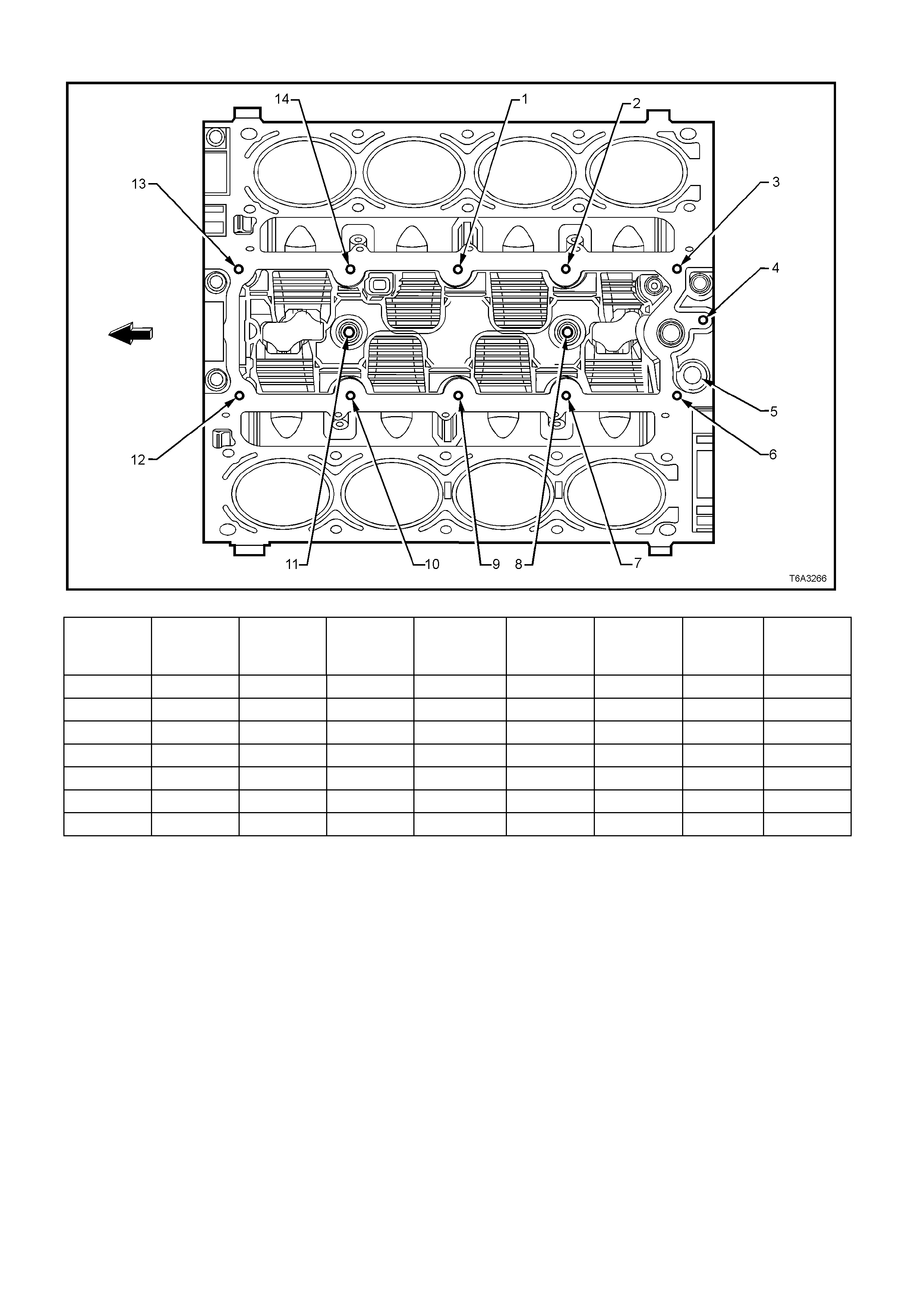
ENGINE BLOCK - TOP VIEW
Figure 6A3-380
Hole Thread Size Insert Drill Counterbore
Tool Tap Driver Maximum
Drill Depth
mm
Maximum
Tap Depth
mm
1-4 M8 x 1.25 J 42385-210 J 42385-206 J 42385-207 J 42385-208 J 42385-209 26.5 19.0
5 M16 x 1.5
6-7 M8 x 1.25 J 42385-210 J 42385-206 J 42385-207 J 42385-208 J 42385-209 26.5 19.0
8 M10 x 1.5 J 42385-216 J 42385-211 J 42385-212 J 42385-213 J 42385-214 22.5 17.0
9-10 M8 x 1.25 J 42385-210 J 42385-206 J 42385-207 J 42385-208 J 42385-209 26.5 19.0
11 M10 x 1.5 J 42385-216 J 42385-211 J 42385-212 J 42385-213 J 42385-214 22.5 17.0
12-14 M8 x 1.25 J 42385-210 J 42385-206 J 42385-207 J 42385-208 J 42385-209 26.5 19.0
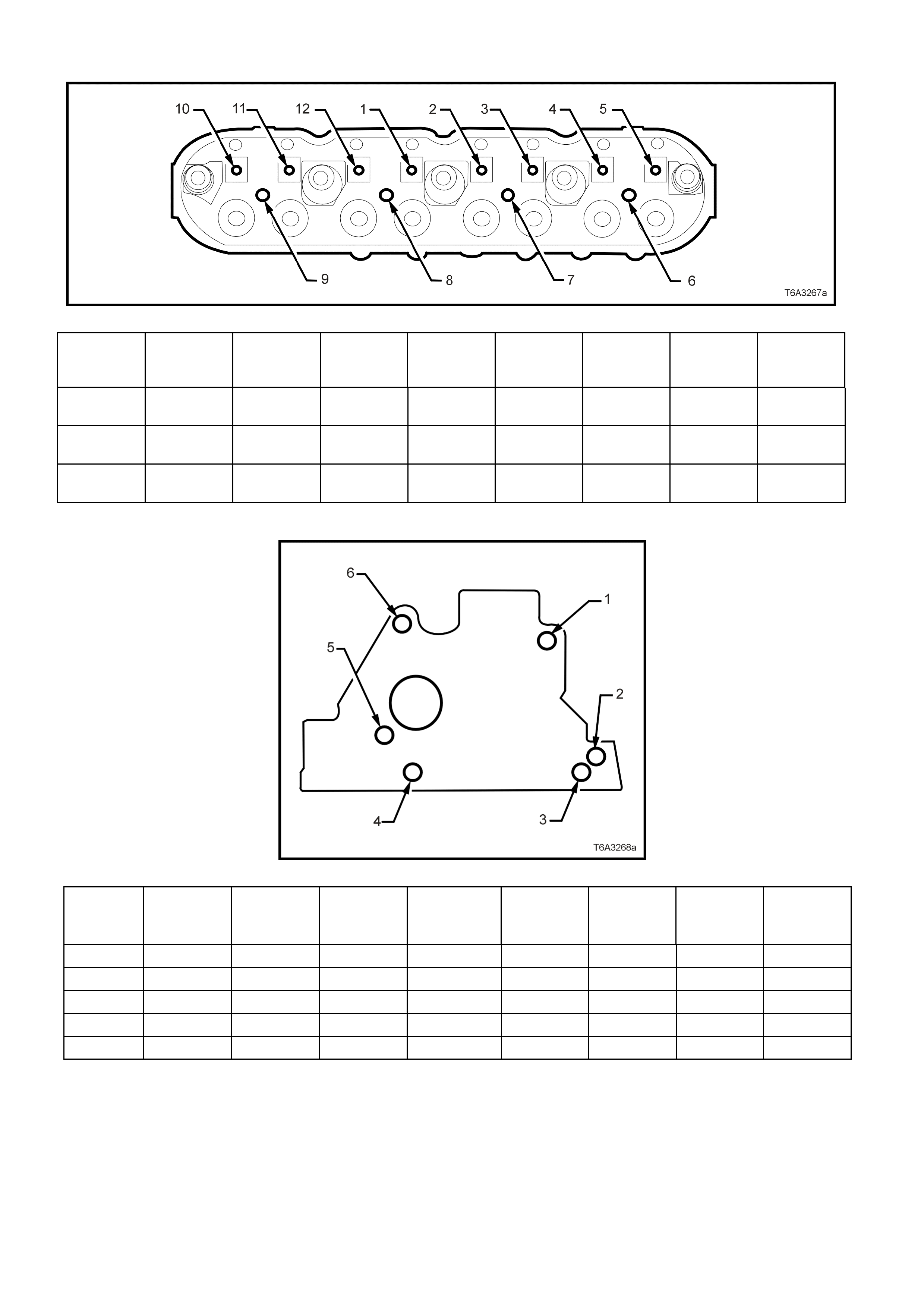
CYLINDER HEAD - TOP VIEW
Figure 6A3-381
Hole Thread
Size Insert Drill Counterbo
re Tool Tap Driver Maximum
Drill Depth
mm
Maximum
Tap Depth
mm
1-5 M8 x 1.25 J 42385-
210 J 42385-
206 J 42385-
207 J 42385-
208 J 42385-
209 26.5 19.0
6-9 M6 x 1.0 J 42385-
205 J 42385-
201 J 42385-
202 J 42385-
203 J 42385-
204 20.05 16.05
10-12 M8 x 1.25 J 42385-
210 J 42385-
206 J 42385-
207 J 42385-
208 J 42385-
209 26.5 19.0
CYLINDER HEAD - END VIEW
Figure 6A3-382
Hole Thread Size Insert Drill Counterbore
Tool Tap Driver Maximum
Drill Depth
mm
Maximum
Tap Depth
mm
1 M10 x 1.5 J 42385-215 J 42385-211 J 42385-212 J 42385-213 J 42385-214 28.0 20.0
2N/A
3 M10 x 1.5 J 42385-215 J 42385-211 J 42385-212 J 42385-213 J 42385-214 28.0 20.0
4N/A
5-6 M10 x 1.5 J 42385-215 J 42385-211 J 42385-212 J 42385-213 J 42385-214 28.0 20.0
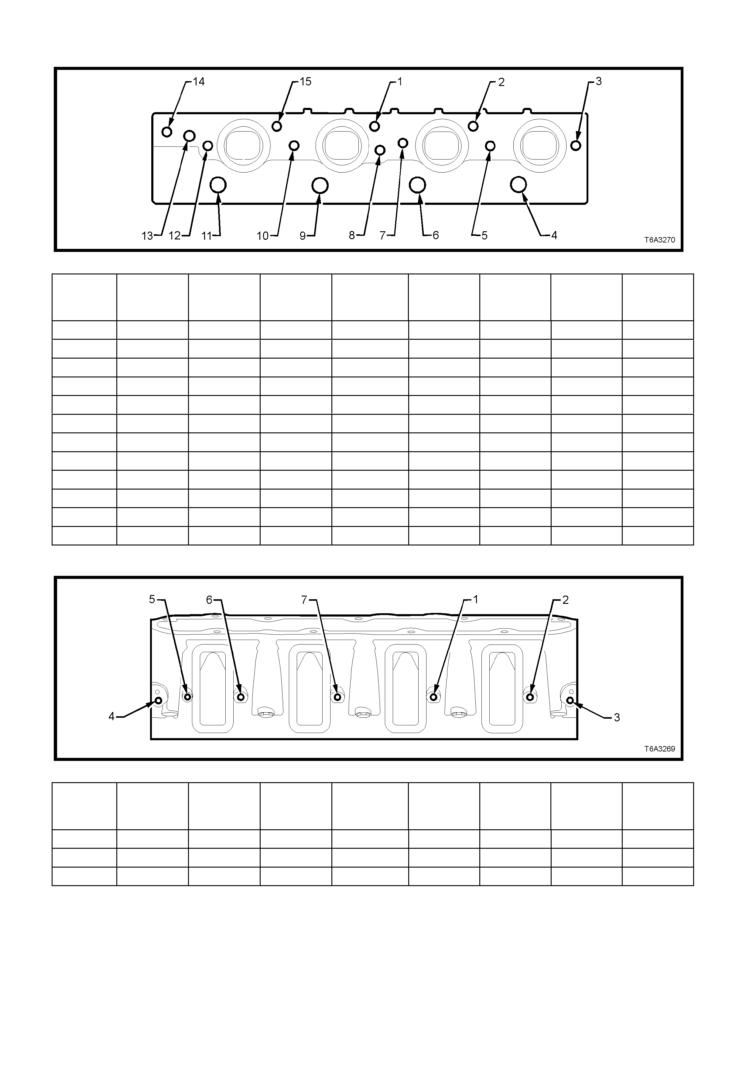
CYLINDER HEAD - EXHAUST MANIFOLD SIDE VIEW
Figure 6A3-383
Hole Thread Size Insert Drill Counterbore
Tool Tap Driver Maximum
Drill Depth
mm
Maximum
Tap Depth
mm
1-2 M10 x 1.5 J 42385-215 J 42385-211 J 42385-212 J 42385-213 J 42385-214 28.0 20.0
3 M8 x 1.25 J 42385-210 J 42385-206 J 42385-207 J 42385-208 J 42385-209 21.0 16.0
4 M14 x 1.25
5 M8 x 1.25 J 42385-210 J 42385-206 J 42385-207 J 42385-208 J 42385-209 21.0 16.0
6 M14 x 1.25
7-8 M8 x 1.25 J 42385-210 J 42385-206 J 42385-207 J 42385-208 J 42385-209 21.0 16.0
9 M14 x 1.25
10 M8 x 1.25 J 42385-210 J 42385-206 J 42385-207 J 42385-208 J 42385-209 21.0 16.0
11 M14 x 1.25
12 M8 x 1.25 J 42385-210 J 42385-206 J 42385-207 J 42385-208 J 42385-209 21.0 16.0
13 M12 x 1.5
14-15 M10 x 1.5 J 42385-215 J 42385-211 J 42385-212 J 42385-213 J 42385-214 28.0 20.0
CYLINDER HEAD - INTAKE MANIFOLD SIDE VIEW
Figure 6A3-384
Hole Thread Size Insert Drill Counterbore
Tool Tap Driver Maximum
Drill Depth
mm
Maximum
Tap Depth
mm
1-2 M6 x 1.0 J 42385-205 J 42385-201 J 42385-202 J 42385-203 J 42385-204 Through Through
3-4 M6 x 1.0 J 42385-205 J 42385-201 J 42385-202 J 42385-203 J 42385-204 22.5 15.0
5-7 M6 x 1.0 J 42385-205 J 42385-201 J 42385-202 J 42385-203 J 42385-204 Through Through

4. DIAGNOSIS
4.1 BASIC ENGINE MISFIRE DIAGNOSIS
GENERAL INFORMATION
1. Engine perf ormanc e diagnosis procedures ar e covered in Section 6C3 POWERTRAIN MANAGEMENT GEN
III V8 ENGINE, of the VT Series II Service Information and should be referred to for diagnosis of any
Driveability, Emissions, or Check Powertrain Lamp concerns.
2. The following diagnosis covers common concerns and possible causes.
3. When the proper diagnosis is m ade, the concern should be c orrected by adjustm ent, repair or replacem ent as
required.
4. Refer to the appropriate section of this Service Information CD for each specific procedure.
5. This diagnostic table will assist in engine misfire diagnosis due to a mechanical concern such as a faulty
camshaft, worn or damaged bearings or bent pushrod.
6. This table will not isolate a crossed injector wire, faulty injector or any other driveability component failure that
may cause a misfire.
7. The Powertrain On-Board Diagnostic System checks must be performed first. Refer to Section 6C3-2A
POWERTRAIN MANAGEMENT GEN III V8 ENGINE, DIAGNOSTIC CHARTS, of the VT Series II Service
Information.
8. W hen using this table to make a Base Engine Misfire diagnosis, begin with the preliminary information below
and then proceed to the specific category.
DIAGNOSTIC PROCEDURE
Checks Action
Preliminary 1. Perform a visual inspection of the following:
• A loose or improperly installed engine flywheel or crankshaft balancer.
• Worn, damaged, or misaligned accessory drive system components.
2. Listen to the engine for any abnormal internal engine noises.
3. Inspect the engine for acceptable oil pressure. Refer to 2.4 ENGINE OIL
PRESSURE - CHECK in this Se ction.
4. Verify if the engine has excessive oil consumption. Refer to 4.4 OIL
CONSUMPTION DIAGNOSIS, in thi s Section.
5. Verify if the engine has coolant consumption.
6. Perform a compression test on the engine.
Intake Manifold Leaks 1. An intake manifold that has a vacuum leak may cause a misfire.
2. Inspect for the following:
• Improperly installed or damaged vacuum hoses.
• Faulty or improperly installed intake manifold and/or gaskets.
• Cracked or damaged intake manifold.
• Inspect the areas between the intake runners.
• Improperly installed or damaged Manifold Absolute Pressure (MAP) sensor
housing (located at the rear of the intake manifold).
• Improperly installed or damaged MAP sensor housing O-ring seal.
• Improperly installed MAP sensor.
• The sealing grommet of the MAP sensor should not be torn or damaged.
• Improperly installed throttle body or damaged gasket.
• Warped intake manifold.
• Warped or damaged cylinder head sealing surface.
Techline

Checks Action
Coolant Consumption 1. Coolant consumption may or may not cause the engine to overheat. Inspect for
the following:
• External coolant leaks.
• Faulty cylinder head gasket.
• Warped cylinder head.
• Cracked cylinder head.
• Damaged engine block.
Oil Consumption 1. Oil consumption may or may not cause the engine to misfire. Remove the spark
plugs and inspect for an oil fouled spark plug.
2. Perform a cylinder compression test. Refer to 2.5 COMPRESSION CHECK in
this Section.
3. If the compression test indicates worn valves or valve guides, inspect for the
following:
• Worn valve guides.
• Worn valve stems.
• Worn or burnt valves or valve seats.
• Worn, brittle, or improperly installed valve stem oil seals.
4. If the compression test indicates worn or damaged piston rings, inspect the
following:
• Broken or improperly seated piston rings.
• Excessive piston ring end gap.
• Excessive cylinder bore wear or taper.
• Cylinder damage.
• Piston damage.
Abnormal Internal Engine Noises 1. With the engine running, try and determine if the noise is timed to camshaft
speed or crankshaft speed.
NOTE: Using a timing light, two knocks per flash is crankshaft speed and one knock
per flash is camshaft speed.
2. If the noise is timed to camshaft speed, inspect the following:
• Missing or loose valve train components.
• Worn or loose valve rocker arms.
• Worn or bent pushrods.
• Faulty valve springs.
• Bent or burnt valves.
• Worn camshaft lobes.
• Worn or damaged timing chain and/or sprockets.
Important: A slight COLD knock or piston slapping noise could be considered
normal if not present after the engine has reached normal operating temperatures.
3. If the knock is timed to crankshaft speed, inspect the following:
• Worn crankshaft main or connecting rod bearings.
• Piston or cylinder damage.
• Worn piston or piston pin.
• Damaged or faulty connecting rod.
• Excessive carbon build-up on the top of the piston.
No Abnormal Internal Engine Noise 1. Inspect for a worn or improperly installed timing chain and/or sprockets.
2. Remove the valve rocker arm cover on the side of the engine with the cylinder
that is misfiring.
3. Inspect for the following:
• Loose valve rocker arm bolts.
• Bent push rods.
• Faulty valve springs.
• Faulty valve lifters (bleeding down).
• Worn or improperly seated valves.
• Worn camshaft lobes.

4.2 ENGINE NOISE DIAGNOSIS
There are four steps to diagnosing engine noise. You must determine the following:
The type of noise. For example, is the noise a light rattle/tapping or a low rumble/knocking?
The exact operating condition under wh ich the noise exists. Note f actor s suc h as the ambient tem per ature, the
amount of engine warm-up time, the engine temperature, engine speed other specifics.
At what rate the noise occurs, and at what location in the engine. Remember, engine noises are generally
synchronised to either engine speed (crankshaft, flywheel, connecting rods, balancer, or pistons and related
com ponents ) or one-half engine speed (valve train noise such as r oc k er ar ms, valve lif ter s , and timing chain). Try to
determine the rate at which the noise is occurring.
Compare the engine sounds to other engines. This is required to make sure you are not trying to correct a
normal condition.
Checks Action
Noise on Start-Up but Only Lasts a
Few Seconds • Improper oil viscosity. Install the recommended oil viscosity for the expected
temperatures.
• Incorrect oil filter without the anti-drainback feature.
• Worn or dirty hydraulic valve lifters.
• Excessive piston to bore clearance.
• Excessive piston pin to piston clearance.
• Excessive crankshaft bearing clearance.
Knocks Cold and Continues for 1 to
2 Minutes • Loose or broken crankshaft balancer or accessory drive components.
• Excessive piston to bore clearance.
• A cold piston knock which disappears in 1.5 minutes should be considered
acceptable.
• A cold engine knock usually disappears when the specific cylinders secondary
ignition circuit is earthed.
Intermittent Noise on Idle,
Disappearing When Engine Speed
is Increased
• Improper oil viscosity. Install the recommended oil viscosity for the expected
temperatures.
• Lower than specified oil pressure. Install an oil pressure gauge and measure the
engine oil pressure.
• Dirty or worn hydraulic valve lifter.
Valve Train Noise (Rattle/Tapping) 4. The following conditions may cause valve train noise:
• Lower than specified oil pressure.
• Worn or faulty oil pump.
• Loose oil pump-to-engine block bolts.
• Loose or damaged oil transfer tube and/or gaskets.
• Loose valve rocker arm attachments.
• Worn valve rocker arm bearings.
• Worn valve rocker arm and/or pushrod.
• Broken valve spring.
• Sticking valves.
• Worn, dirty, or faulty hydraulic valve lifters.
• Worn camshaft lifter lobes.
• Worn valve guides or valve stems.
• Bent, broken, or damaged timing chain sprocket teeth.

Checks Action
Knocks at Idle Hot
(Rumble/Knocking) 1. The following conditions may cause a knocking noise:
• Malfunctioning accessory drive system components.
• Loose or broken crankshaft balancer.
• Detonation or spark knock.
• Check for proper operation of the cooling, knock, and ignition control
components.
• Refer to diagnostic information in 6C3 POWERTRAIN MANAGEMENT - GEN III
V8 ENGINE, of the VT Series II Service Information.
• Excessive connecting rod bearing clearance.
• Excessive piston pin to bore clearance.
• Bent connecting rod.
• Excessive crankshaft main or thrust bearing clearance.
• Loose torque converter bolts.
• Cracked or damaged flywheel.
• Exhaust leak at the manifold.
Exhaust System Noise and/or
Leakage 1. Exhaust system noise and/or leakage may be caused by the following
conditions:
• Improperly installed or misaligned exhaust system components.
• A cracked or broken exhaust manifold.
• Damaged or worn gaskets and/or seals.
• Burned or rusted out exhaust system components.
• A broken or loose exhaust clamp and/or bracket.

4.3 VALVE TRAIN DIAGNOSIS
GENERAL INFORMATION
• A light tapping noise at one-half engine speed, or any varying frequency, may indicate a valve train problem.
These tapping noises will typically increase with engine speed.
• Before attempting to diagnose valve train noise, check for the proper oil level and thoroughly warm up the
engine. By doing this you will bring all engine components to a normal state of expansion.
• While sitting in the drivers seat, run the engine at various speeds and listen for any abnormal engine noise.
• Whenever Valve Lifter Diagnosis is neces sary, always use a listening devic e s uch as a stethos cope. T ools s uch
as this will help to isolate any lifter noise and identify noises that could be mis-diagnosed as lifter noise.
DIAGNOSTIC PROCEDURE
Checks Action
A light tapping noise similar to
valve train noise. 1. This light type of noise mat be caused by the following components:
• Fuel injectors.
• Evaporative emission (EVAP) purge solenoid.
• Detonation.
• Loose heat shields.
Causes of Valve Train Noise 1. Any or a combination of the following can cause valve train noise:
• Poor oil quality caused by water contamination, aeration, or fuel dilution.
• Low engine oil pressure.
• Worn or faulty oil pump.
• A loose or plugged oil pump screen.
• Loose or damaged oil transfer tube.
• Loose valve rocker arm attachments (causing excessive valve lash).
• Worn or damaged valve rocker arm bearings.
• Worn valve rocker arm and/or pushrod.
• Broken valve spring.
• Sticking valves.
• Valve lifters worn, dirty, or faulty.
• Broken valve lifter guide.
• Camshaft valve lifter lobes worn.
• Worn valve guides or valve stems.
• Worn, damaged, or missing valve keys.
• Bent pushrods.
• Excessive play in the camshaft timing chain.
• Bent, broken, or damaged timing chain sprocket teeth.

DIAGNOSTIC TA BLE
DEFINITION: A light tapping noise at one half engine speed, or any varying frequency.
Step Action Value(s) Yes No
1Is there valve train noise? −Go to Step 2 System OK
2Check for a high engine oil level. A engine with the oil level
above the FULL mark allows the crankshaft counterweights to
churn the oil into foam. When foamy oil is pumped into the
lifters, the lifters become noisy. A solid column of oil ensures
proper lifter operation.
Is the oil level too high?
−Go to Step 3 Go to Step 4
3Drain engine oil until level is correct.
Is there valve train noise? −Go to Step 4 System OK
4Check for a low engine oil level. A engine with the oil level
below the ADD mark may allow the oil pump to pump air at
high engine speeds.
Is the oil level too low?
−Go to Step 5 Go to Step 6
5Add oil as required.
Is there valve train noise? −Go to Step 6 System OK
6Check for proper engine oil pressure. Refer to 2.4 ENGINE
OIL PRESSURE - CHECK, in this Section.
Is the engine oil pressure within specifications?
−Go to Step 7 Go to Step 7
7Check the oil pump screen for damage or a loose fit to the oil
pump.
Inspect for a missing or damaged oil pump screen O-ring seal.
Is the oil pump screen loose or is the screen or O-ring seal
damaged?
−Go to Step 8 Go to Step 9
8Repair as required.
Is there valve train noise? −Go to Step 9 System OK
9Check for a damaged oil pump or loose mounting bolts. Refer
to Oil Pump Clean and Inspect, in this Section.
Is the oil pump damaged or are the fasteners loose?
−Go to Step 10 Go to Step 11
10 Repair as required.
Is there valve train noise? −Go to Step 11 System OK
11 Remove and inspect the valve lifters, guides, rocker arms,
and pushrods. Refer to Valve Rocker Arm and Push Rods
Clean and Inspect and Valve Lifters and Guides Clean and
Inspect, in this Section.
Are components worn or damaged?
−Go to Step 12 Go to Step 13
12 Repair as required.
Is there valve train noise? −Go to Step 13 System OK
13 Perform a camshaft lobe lift test. Refer to 3.2 CAMSHAFT
LOBE LIFT - Measure in this Section.
Is the test within specification?
Go to Step 17 Go to Step 14
14 Remove the engine front cover and inspect the timing chain
and sprockets for excessive wear or damage. Refer to 3.8
TIMING CHAIN AND SPROCKETS, in this Section.
Important: Pushrod engines are designed so that a timing
chain more than one tooth improperly positioned will cause
valve interference with the piston.
Are the components worn or damaged, or improperly
positioned?
−Go to Step 15 Go to Step 16
15 Replace components as required.
Is there valve train noise? −Go to Step 16 System OK
16 Replace camshaft and/or bearings and all hydraulic valve
lifters. Refer to 3.9 CAMSHAFT, in this Section.
Is there valve train noise?
−Go to Step 17 System OK
17 Perform a complete disassembly of the engine and inspect all
components.
Are components worn or damaged?
−Go to Step 18 System OK
18 Replace the worn/damaged components as required. −System OK −

4.4 OIL CONSUMPTION DIAGNOSIS
DEFINITION: Excessive oil consumption (not due to leaks) is the use of 0.95 litres or more of engine oil within
2,500 kilometres.
Checks Action
Preliminary 1. The causes of excessive oil consumption may include the following conditions:
• External oil leaks. Refer to 4.5 OIL LEAK DIAGNOSIS in this Section.
• Incorrect oil level or improper reading of the oil level indicator. With the
vehicle on a level surface, run the engine for a few minutes, allow adequate
drain down time (2-3 minutes) and check for the correct engine oil level.
• Improper oil viscosity. Refer to the vehicle Owners Manual and use the
recommended SAE grade and viscosity for the prevailing temperatures.
• Continuous high speed driving and/or severe usage.
• Crankcase ventilation system restrictions or malfunctioning components.
• Worn valve guides and/or valve stems.
• Worn or improperly installed valve stem oil seals.
• Piston rings broken, worn, not seated properly. Allow adequate time for the
rings to seat. Replace worn piston rings as necessary.
• Piston and rings improperly installed or incorrectly fitted to the cylinder bore.
• Excessive piston to bore clearance.
Techline
Techline

4.5 OIL PRESSURE DIAGNOSIS
Conduct an oil pressure check, as detailed in 2.4 ENGINE OIL PRESSURE - CHECK, in this Section
Checks Action
Oil Pressure Below Specification 1. Inspect the engine for one or more of the following:
• Oil pump worn or dirty.
• Oil pump to engine block bolts loose.
• Oil pump screen loose, plugged or damaged.
• Oil pump screen O-ring seal missing or damaged.
• Malfunctioning oil pump oil pressure relief valve.
• Excessive bearing clearances.
• Cracked, porous or restricted oil galleries.
• Oil gallery plugs leaking, missing or incorrectly installed.
• Broken/malfunctioning hydraulic valve lifters.
Oil Pressure Above Specification 1. Inspect for one or more of the following:
• Plugged or incorrect oil filter fitted.
• Malfunctioning oil by-pass valve.
• Malfunctioning oil pressure gauge or sensor.
Techline

4.6 OIL LEAK DIAGNOSIS
NOTE: Most fluid leaks can be repaired by visually locating the leak, repairing or replacing the component, or by
resealing the gasket surface.
When a leak has been located, determine the cause of the leak. Otherwise the leak will most probably re-occur.
Step Action Value(s) Yes No
1 1. Operate the vehicle until it reaches normal operating
temperature.
2. Park the vehicle on a level surface, over a large sheet of
paper or other clean surface.
3. Wait for at least 15 minutes.
4. Check for oil drips.
Are oil drips present?
−Go to Step 2 Go to Step 3
2 Identify the type of fluid and the approximate location of the
leak.
Can you identify the type of fluid and the approximate location
of the leak?
−Go to Step 10 Go to Step 3
3 1. Visually inspect the suspected area. Use a small mirror to
assist in looking at hard to see areas.
2. Check for leaks at the following locations:
• Sealing surfaces.
• Fittings
• Cracked or damaged components.
Can you identify the source of the leak?
−Go to Step 10 Go to Step 4
4 1. Completely clean the entire engine and surrounding
components.
2. Operate the vehicle for several miles at normal operating
temperature and at varying speeds.
3. Park the vehicle on a level surface, over a large sheet of
paper or other clean surface.
4. Wait for at least 15 minutes.
5. Identify the type of fluid, and the approximate location of
the leak.
Can you identify the type of fluid and the approximate location
of the leak?
−Go to Step 10 Go to Step 5
5 1. Visually inspect the suspected area. Use a small mirror to
assist in looking at hard to see areas.
2. Check for leaks at the following locations:
• Sealing surfaces.
• Fittings.
• Cracked or damaged components.
Can you identify the source of the leak?
−Go to Step 10 Go to Step 6
6 1. Completely clean the entire engine and surrounding
components.
2. Apply an aerosol-type powder (baby powder, foot powder,
etc.) to the suspected area.
3. Operate the vehicle for several miles at normal operating
temperature and at varying speeds.
4. Identify the type of fluid, and the approximate location of
the leak, from the discolorations in the powder surface.
Can you identify the type of fluid and the approximate location
of the leak?
−Go to Step 10 Go to Step 7
7 1. Visually inspect the suspected area. Use a small mirror to
assist in looking at hard to see areas.
2. Check for leaks at the following locations:
• Sealing surfaces.
• Fittings.
• Cracked or damaged components.
Can you identify the source of the leak?
−Go to Step 10 Go to Step 8
Techline

Step Action Value(s) Yes No
8 Using the Dye and Black Light Kit, Tool J 42220, identify the
type of fluid, and the approximate location of the leak. Refer to
the manufacturer's instructions when using the tool.
Can you identify the type of fluid and the approximate location
of the leak?
−Go to Step 10 Go to Step 9
9 1. Visually inspect the suspected area. Use a small mirror to
assist in looking at hard to see areas.
2. Check for leaks at the following locations:
• Sealing surfaces.
• Fittings.
• Cracked or damaged components.
Can you identify the source of the leak?
−Go to Step 10 System OK
10 1. Check for the following conditions:
• Higher than recommended fluid levels.
• Higher than recommended fluid pressures.
• Plugged or malfunctioning fluid filters or pressure
bypass valve.
• Plugged or malfunctioning engine ventilation system.
• Improperly tightened or damaged fasteners.
• Cracked or porous components.
• Improper sealants or gaskets where required.
• Improper sealant or gasket installation.
• Damaged or worn gaskets or seals.
• Damaged or worn sealing surfaces.
2. Is there mechanical damage to the engine?
−Go to Step 11 −
11 Repair or replace all damaged components. −Go to Step 1 −

5. SPECIFICATIONS
GENERAL
Engine Type....................................................................... V8 OHV
Displacement ..................................................................... 5.7 litre (5,667 cm3 - 346 in3)
Bore.................................................................................... 99.0 mm
Stroke................................................................................. 92.0 mm
Compression Ratio............................................................. 10.1:1
Firing Order........................................................................ 1-8-7-2-6-5-4-3
Spark Plug Type................................................................. AC 41-952
Spark Plug Gap.................................................................. 1.5 mm
LUBRICATION SYSTEM
Oil Capacity (without Oil Filter Change) ............................. 4.7 litres
Oil Capacity (with Oil Filter Change) .................................. 5.0 litres
Oil Pressure (Minimum-Hot)............................................... 45 kPa @ 1,000 rpm
125 kPa @ 2,000 rpm
165 kPa @ 4,000 rpm
Oil Type.............................................................................. 10W - 30 SJ GF2 (Service Refill)
CAMSHAFT
End Play............................................................................. 0.025 - 0.305 mm
Journal Diameter................................................................ 54.99 - 55.04 mm
Journal Diameter Out-of-Round......................................... 0.025 mm (Maximum)
Lobe Lift (Intake and Exhaust)........................................... 7.43 mm
Lobe Height (Intake and Exhaust)...................................... 46.67 mm (Minimum)
Runout (Measured at the Intermediate Journals)............... 0.050 mm
CONNECTING ROD
Centre to Centre Length..................................................... 154.90 ± 0.02 mm
Width.................................................................................. 24.00 ± 0.05 mm
Bearing Bore Diameter....................................................... 56.505 - 56.525 mm
Bearing Bore Out-of-Round (Production)........................... 0.004 mm
Bearing Bore Out-of-Round (Service Limit) ...................... 0.008 mm
Bearing Clearance (Production)......................................... 0.015 - 0.063 mm
Bearing Clearance (Service Limit) ..................................... 0.015 - 0.076 mm
Side Clearance................................................................... 0.110 - 0.510 mm
Twist................................................................................... 0.010 mm Maximum
Bend................................................................................... 0.02 mm Maximum
CRANKSHAFT
Bearing Clearance (Production)......................................... 0.018 - 0.054 mm
Connecting Rod Journal
Diameter (Production)................................................... 53.318 - 53.338 mm
Diameter (Service Limit) ............................................... 53.308 mm (Minimum)
Taper (Production)........................................................ 0.005 mm (Maximum for 1/2 of the Journal Length)
Taper (Service Limit)..................................................... 0.01 mm (Maximum)
Out-of-Round (Production)............................................ 0.005 mm
Out-of-Round (Service Limit) ........................................ 0 0.01 mm
End Play........................................................................ 0.04 - 0.2 mm
Main Journal
Diameter (Production)................................................... 64.993 - 65.007 mm
Diameter (Service Limit) ............................................... 64.993 mm (Minimum)
Out-of-Round (Production)............................................ 0.003 mm
Out-of-Round (Service Limit) ........................................ 0.008 mm
Taper (Production)........................................................ 0.010 mm
Taper (Service Limit)..................................................... 0.020 mm (Maximum)
Reluctor Ring Runout
(Measured 1.0 mm below Tooth Diameter) .................. 0.250 mm (Maximum)
Runout (at Rear Flange)..................................................... 0.050 mm (Maximum)
Thrust Wall Runout ............................................................ 0.025 mm
Thrust Wall Width (Production).......................................... 26.14 - 26.22 mm
Thrust Wall Width (Service)............................................... 26.32 mm (Maximum)

CYLINDER BORE
Cylinder Bore Diameter...................................................... 99.0 - 99.018 mm
Cylinder Bore Taper and Out-of-Round ............................. 0.018 mm (Maximum)
CYLINDER HEAD
Engine Block Deck Flatness
(Measured within a 150 mm area) ................................ 0.110 mm
Engine Block Deck Flatness
(Measured over Full Length of Cylinder Head)............. 0.220 mm
Exhaust Manifold Deck Flatness........................................ 0.220 mm
Intake Manifold Deck Flatness........................................... 0.220 mm
Height (Measured from the Cylinder Head Deck to
the Valve Rocker Arm Cover Seal Surface).................. 120.2 mm (Minimum)
ENGINE BLOCK
Camshaft Bearing Bore Diameter...................................... 55.063-55.088 mm
Cylinder Head Deck Surface Flatness
(Measured within a 150 mm area) ................................ 0.110 mm
(Measured over Full Length of Block Deck).................. 0.220 mm
Cylinder Head Deck Height
(Measured from Crankshaft centreline to Deck Face).. 234.57-234.82 mm
Main Bearing Bore Diameter (Production) ......................... 69.871-69.889 mm
Main Bearing Bore Out-of-Round....................................... 0.050 mm
Valve Lifter Bore Diameter (Production) ............................ 21.417-21.443 mm
INTAKE MANIFOLD
Intake Manifold Cylinder Head Deck Flatness
(Measured at Gasket Sealing Surfaces)....................... 0.50 mm
OIL PAN AND FRONT/REAR COVER ALIGNMENT
Oil Pan to Rear of Engine Block Alignment
(at Transmission Housing Mounting Surface)............... 0.000 - 0.250 mm (Maximum)
Front Cover Alignment (at Oil Pan Surface)....................... 0.00 - 0.50 mm
Rear Cover Alignment (at Oil Pan Surface) ....................... 0.00 - 0.50 mm
PISTON
Piston Outside Diameter (at Size Point)................................ 98.964-98.982 mm
Piston Skirt, Dimensional Variation....................................... 0.018 mm (Maximum)
Piston to Bore Clearance (Production).................................. 0.018-0.054 mm
Piston to Bore Clearance (Service Limit) .............................. 0.018-0.054 mm (Maximum)
Piston Pin
Pin Clearance to Piston Bore (Production) ................... 0.010 - 0.020 mm
Pin Clearance to Piston Bore (Service Limit)................ 0.010 - 0.020 mm (Maximum)
Pin Diameter ................................................................. 23.997 - 24.0 mm
Pin Fit in Connecting Rod ............................................. 0.020 - 0.043 mm (Interference)
Piston Rings
Top Compression Ring End Gap (Production)
(Measured in Cylinder Bore) ......................................... 0.230 - 0.380 mm
2nd Compression Ring End Gap (Production)
(Measured in Cylinder Bore) ......................................... 0.440 - 0.640 mm
Oil Control Ring End Gap (Production)
(Measured in Cylinder Bore) ......................................... 0.180 - 0.690 mm
Top Compression Ring End Gap (Service)
(Measured in Cylinder Bore) ......................................... 0.230 - 0.380 mm (Maximum)
2nd Compression Ring End Gap (Service)
(Measured in Cylinder Bore) ......................................... 0.440 - 0.640 mm (Maximum)
Oil Control Ring End Gap (Service)
(Measured in Cylinder Bore) ......................................... 0.180 - 0.690 mm (Maximum)
Top Compression Ring Groove Clearance (Production) ... 0.040 - 0.085 mm
2nd Compression Ring Groove Clearance (Production).... 0.040 - 0.080 mm
Oil Control Ring Groove Clearance (Production)............... 0.010 - 0.220 mm
Top Compression Ring Groove Clearance (Service)......... 0.040 - 0.085 mm (Maximum)
2nd Compression Ring Groove Clearance (Service)......... 0.040 - 0.080 mm (Maximum)
Oil Control Ring Groove Clearance (Service Limit)............ 0.010 - 0.220 mm (Maximum)

VALVE SYSTEM
Valve Lifter ............................................................................ Hydraulic Roller
Valve Rocker Arm Ratio........................................................ 1.70:1
Valve Lash............................................................................. Net Lash-No Adjustment
Valve Face Angle .................................................................. 45 degrees
Valve Seat Angle................................................................... 46 degrees
Valve Seat
Runout................................................................................ 0.050 mm (Maximum)
Width (Intake)..................................................................... 1.020 mm (Maximum)
Width (Exhaust).................................................................. 1.780 mm (Maximum)
Valve Stem
Clearance (Production-Intake)........................................... 0.025 - 0.066 mm
Clearance (Production-Exhaust)........................................ 0.025 - 0.066 mm
Clearance (Service-Intake) ................................................ 0.093 mm (Maximum)
Clearance (Service-Exhaust) ............................................. 0.093 mm (Maximum)
Diameter (Production)........................................................ 7.955 - 7.976 mm
Diameter (Service) ............................................................. 7.95 mm (Minimum)
Valve Spring
Free Length........................................................................ 52.9 mm
Pressure (Closed Valve) .................................................... 310 N at 45.75 mm (Minimum)
Pressure (Open Valve)....................................................... 980 N at 33.55 mm (Minimum)
Installed Height (Intake) ..................................................... 45.75 mm
Installed Height (Exhaust).................................................. 45.75 mm
Valve Lift
Intake.................................................................................. 11.99 mm
Exhaust .............................................................................. 12.15 mm
Valve Guide Installed Height
(From Cylinder Head Spring Seat Surface to
Top of the Valve Guide)................................................ 17.32 mm
Valve Stem Oil Seal Installed Height
(From Valve Spring Shim to Top Edge of Seal Body)........ 18.10 - 19.10 mm
SEALANTS AND ADHESIVES
Coolant Sensor Threads ....................................................... Loctite 565 or equivalent (GM P/N 12346004)
Crankshaft Rear Oil Gallery Plug.......................................... Loctite 242 or equivalent (GM P/N 12345382)
Cylinder Head Core Hole Plugs............................................. Loctite 242 or equivalent (GM P/N 12345382)
Cylinder Head Expansion Plugs............................................ Loctite 242 or equivalent (GM P/N 12345382)
Cylinder Head M8 Bolt Threads ............................................ Loctite 242 or equivalent (GM P/N 12345382)
Engine Block Front Oil Gallery Plug...................................... Loctite 242 or equivalent (GM P/N 12345382)
Engine Block Coolant Drain Plug Sealing Washers.............. Loctite 565 or equivalent (GM P/N 12346004)
Exhaust Manifold Bolt Threads ............................................. Loctite 272 or equivalent (GM P/N 12345493)
Fuel Rail Bolt Threads........................................................... Loctite 242 or equivalent (GM P/N 12345382)
Intake Manifold Bolt Threads................................................. Loctite 242 or equivalent (GM P/N 12345382)
Oil Pan Surface at Front and Rear Covers............................ Loctite 565 or equivalent (GM P/N 12378190)
Oil Pressure Sensor Threads................................................ Loctite 565 or equivalent (GM P/N 12346004)
Oil Transfer Tube Bolts and Stud Threads............................ Loctite 242 or equivalent (GM P/N 12345382)

6. TORQUE WRENCH SPECIFI CATIONS
Nm
Air Conditioning Compressor Drive Belt Idler Pulley Bolt............................... 40 - 60
Air Conditioning Compressor Drive Belt Tensioner Bolt................................. 21 - 29
Air Conditioning Compressor Mounting Bracket to Cylinder Block Bolts ....... 40 - 60
Air Conditioning Compressor to Mounting Bracket Bolts ............................... 40 - 60
Accelerator Control Cable Bracket Bolts........................................................ 10
Accessory Drive Belt Idler Pulley Bolt............................................................. 40 - 60
Accessory Drive Belt Tensioner Bolt.............................................................. 40 - 60
Alternator Bracket to Cylinder Block Bolts...................................................... 40 - 60
Alternator Support Bracket to Cylinder Block Bolts........................................ 20 - 35
Catalytic Converter Bracket Bolts to Catalytic Converters ............................. 25
Catalytic Converter Bracket Bolts/Nuts to Manual Transmission Extension.. 40 - 60
Camshaft Retainer Bolts ................................................................................ 25
Camshaft Position Sensor Bolt....................................................................... 25
Camshaft Sprocket Bolts................................................................................ 35
Close-out Cover Retaining Bolt (Each Side) .................................................. 10 - 14
Connecting Rod Bolts
Design ‘A’
Stage 1....................................................................... 20
Stage 2....................................................................... 60 degrees turn angle
Design ‘B’ and ‘C’
Stage 1....................................................................... 20
Stage 2....................................................................... 75 degrees turn angle
Coolant Temperature Sensor......................................................................... 20
Coolant Inlet Housing Bolts ............................................................................ 15
Coolant Pump Bolts First Pass...................................................................... 15
Final Pass ..................................................................... 30
Coolant Pump Pulley Bolts............................................................................. 15
Crankshaft Balancer Bolt: Stage 1 with replacement NEW Bolt..................... 50
Stage 2 with replacement NEW Bolt..................... 140 degrees turn angle
Crankshaft Main Bearing Cap Bolts (Inner Bolts - Stage 1 in Sequence) ...... 20
(Inner Bolts - Stage 2 in Sequence) ...... 80 degrees turn angle
Cap Side Bolts....................................................... 25
Cap Studs (Outer Studs - Stage 1 in Sequence) .. 20
(Outer Studs - Stage 2 in Sequence).. 53 degrees turn angle
Crankshaft Oil Deflector Nuts......................................................................... 25
Crankshaft Position Sensor Bolt..................................................................... 25
Cylinder Head Bolts (in Sequence)
Stage 1 - all M11 and M8 Bolts ............................................... 30
Stage 2 - all M11 Bolts ............................................................ 90 degrees turn angle
Stage 3 - all M11 Bolts - Except Medium Length Bolts ........... 90 degrees turn angle
Stage 3 - M11 - Medium Length Bolts..................................... 50 degrees turn angle
Cylinder Head Coolant Plug ........................................................................... 20
Cylinder Head Core Hole Plug........................................................................ 20
Engine Block Coolant Drain Plugs.................................................................. 60
Engine Block Oil Gallery Plugs....................................................................... 60
Engine Dress Cover Bracket Nut ................................................................... 4 - 6
Engine Dress Cover Retaining Nut................................................................. 8 - 12
Engine Flywheel/Flexplate Bolts (in Sequence) Stage 1.............................. 20
Stage 2.............................. 50
Stage 3.............................. 100
Engine Front Cover Bolts ............................................................................... 25
Engine Mount to Bracket or Crossmember Nut ............................................. 70 - 90
Engine Mount Bracket to Cylinder Block Bolt................................................. 40 - 60
Engine Rear Cover Bolts................................................................................ 25
Engine Rocker Cover Bolts ............................................................................ 12

Nm
Engine Service Lift Bracket M10 Bolts ........................................................... 50
Engine Service Lift Bracket M8 Bolt............................................................... 25
Engine Valley Cover Bolts.............................................................................. 25
Exhaust Manifold Heat Shield Bolt................................................................. 9
Exhaust Manifold Bolts Stage 1..................................................................... 15
Stage 2..................................................................... 25
Fuel Rail Bolts ................................................................................................ 8 - 12
Ignition Coil-to-Bracket Bolts.......................................................................... 12
Ignition Coil Bracket-to-Valve Rocker Arm Cover Bolts ................................. 12
Intake Manifold Bolts (in Sequence) Stage 1 ............................................... 5
Stage 2................................................ 8
Knock Sensors ............................................................................................... 20
Oil Filter .......................................................................................................... 30
Oil Filter Adaptor............................................................................................. 55
Oil Level Indicator Tube Bolt ......................................................................... 25
Oil Pan Blanking Screw Plug.......................................................................... 25
Oil Pan Baffle Bolts......................................................................................... 12
Oil Pan Closeout Cover Bolt (Either Side)...................................................... 8 - 12
Oil Pan Drain Plug.......................................................................................... 25
Oil Pan Gallery Screw Plug ............................................................................ 25
Oil Pan M8 Bolts (Oil Pan to Engine Block and to Front Cover)..................... 25
Oil Pan M6 Bolts (Oil Pan-to-Rear Cover)...................................................... 12
Oil Pan Transfer Cover Nut............................................................................ 12
Oil Pan Under-Tray Bolt ................................................................................. 30 - 35
Oil Pressure Sensor ....................................................................................... 20
Oil Pump-to-Engine Block Bolts ..................................................................... 25
Oil Pump Cover Bolts..................................................................................... 12
Oil Pump Relief Valve Plug ............................................................................ 12
Oil Pump Pick-Up Tube to Oil Pump Screw................................................... 12
Oil Transfer Cover Nuts.................................................................................. 12
Oil Transfer Tube Bolts .................................................................................. 12
Oil Transfer Tube Nuts................................................................................... 12
Oxygen Sensor............................................................................................... 41
Spark Plugs (New Cylinder Head - ‘Coining’))................................................ 20
Spark Plugs .................................................................................................... 15
Starter Motor Bolt ........................................................................................... 40 - 55
Throttle Body Bolts ......................................................................................... 12
Transmission Crossmember to Side Frame Bolts ......................................... 20 - 30
Transmission Support to Crossmember Nuts................................................ 50 - 65
Transmission Support to Transmission Extension Housing Bolts.................. 20 - 30
Valve Lifter Guide Bolts.................................................................................. 12
Valve Rocker Arm Bolts ................................................................................. 30
Vapour Vent Pipe Bolts and Studs ................................................................. 12
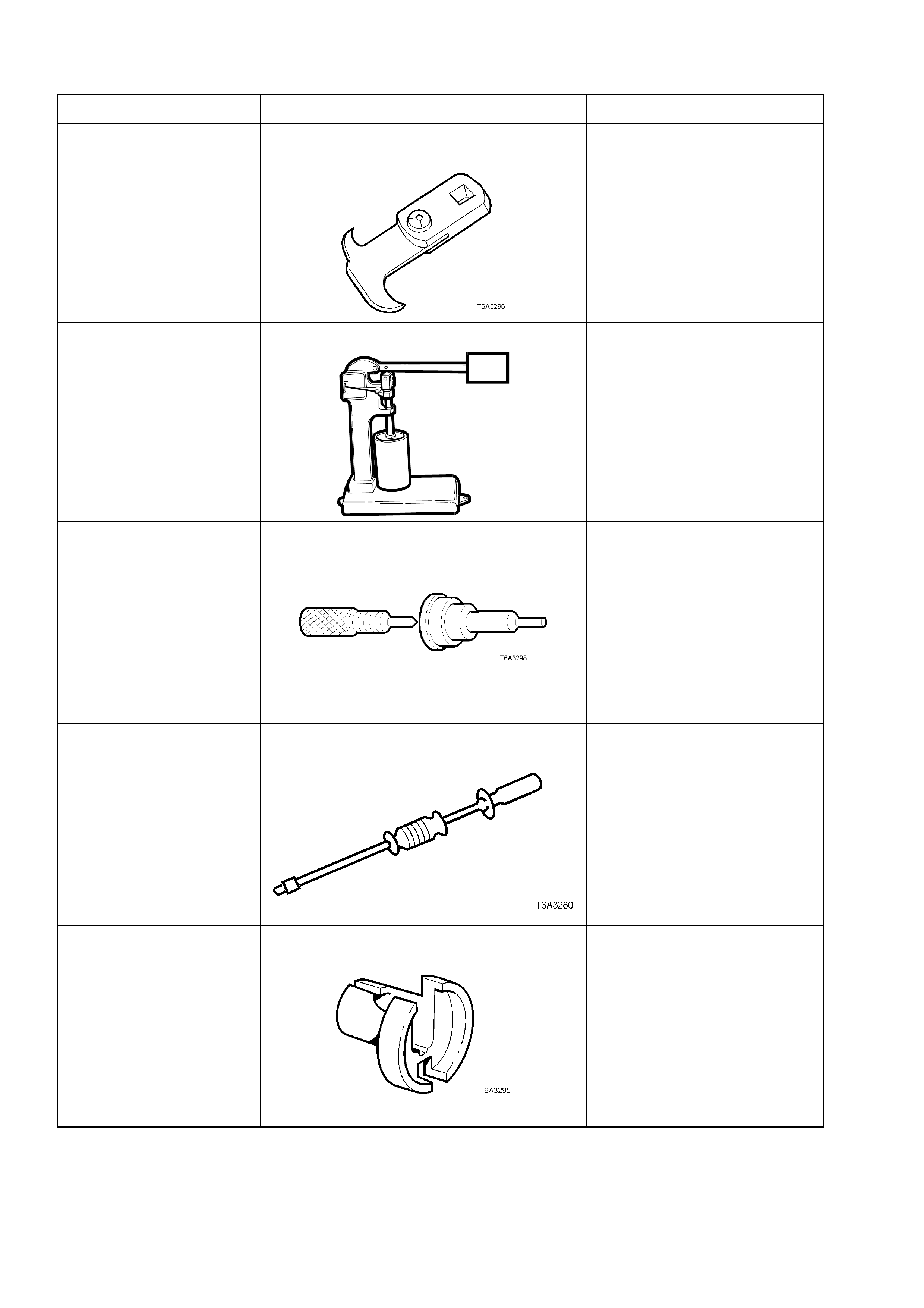
7. SPECIAL TOOLS
TOOL No. REF. IN TEXT TOOL DESCRIPTION COMMENTS
56750 SEAL REMOVER Previously released.
Also numbered, E308.
6A23 HYDRAULIC VALVE LIFTER TESTER
T6A3114b
Previously released.
Used in conjunction with testing
fluid SPx No. E1151
6A24 VALVE LIFTER ASSEMBLY TOOLS Previously released.
Used to assist in assembly of
the hydraulic valve lifters.
J6125-1B SLIDE HAMMER Previously released.
Used in conjunction with J
41818 to remove main bearing
caps.
7371 QUICK CONNECT RELEASE TOOL Previously released for
releasing fuel line quick
connects on V6 supercharged
engine after fuel system has
been de-pressurised.
Used on GEN III V8 engine for
the same purpose
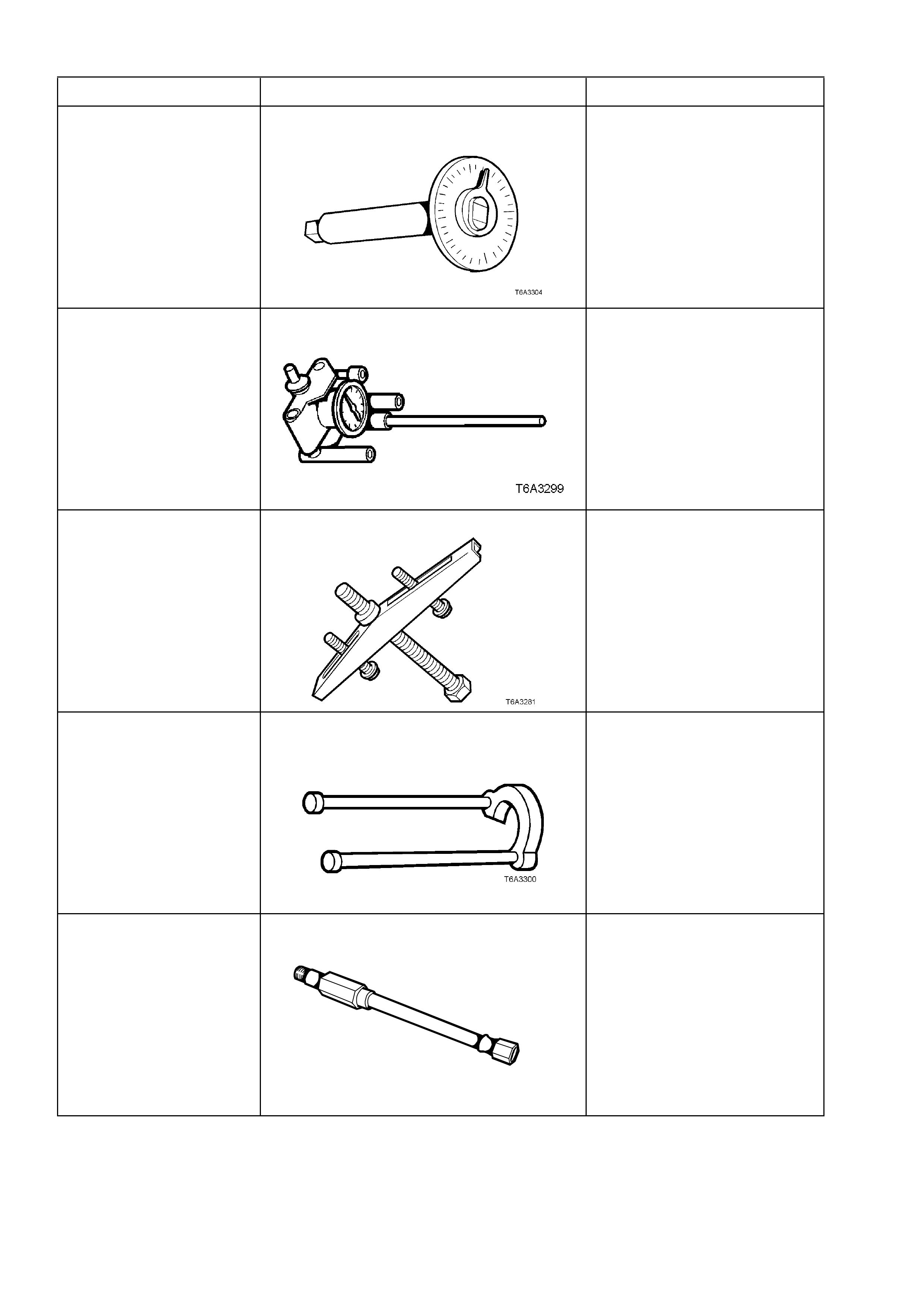
TOOL No. REF. IN TEXT TOOL DESCRIPTION COMMENTS
E 7115 TORQUE ANGLE WRENCH Previously released.
Used to accurately tighten
fasteners when an angle torque
is required.
J 8087 CYLINDER BORE CHECKING GAUGE New release.
Also as a commercial
equivalent.
J 8433-1 PULLEY PULLER Previously released.
Used to remove GEN III V8
engine crankshaft timing gear
sprocket, in conjunction with
J 41558 and J 41816-2
J 21427-01 PULLER ADAPTOR Previously released to remove
automatic transmission speed
sensor ring.
Used in conjunction with J
8433-1, J 41558 and J 41816-2
to remove crankshaft timing
gear sprocket.
J 22794 ADAPTOR
T6A3256a
New release.
Used to facilitate the application
of air pressure to a cylinder
when replacing a valve spring or
valve stem oil seal with the
cylinder head installed.
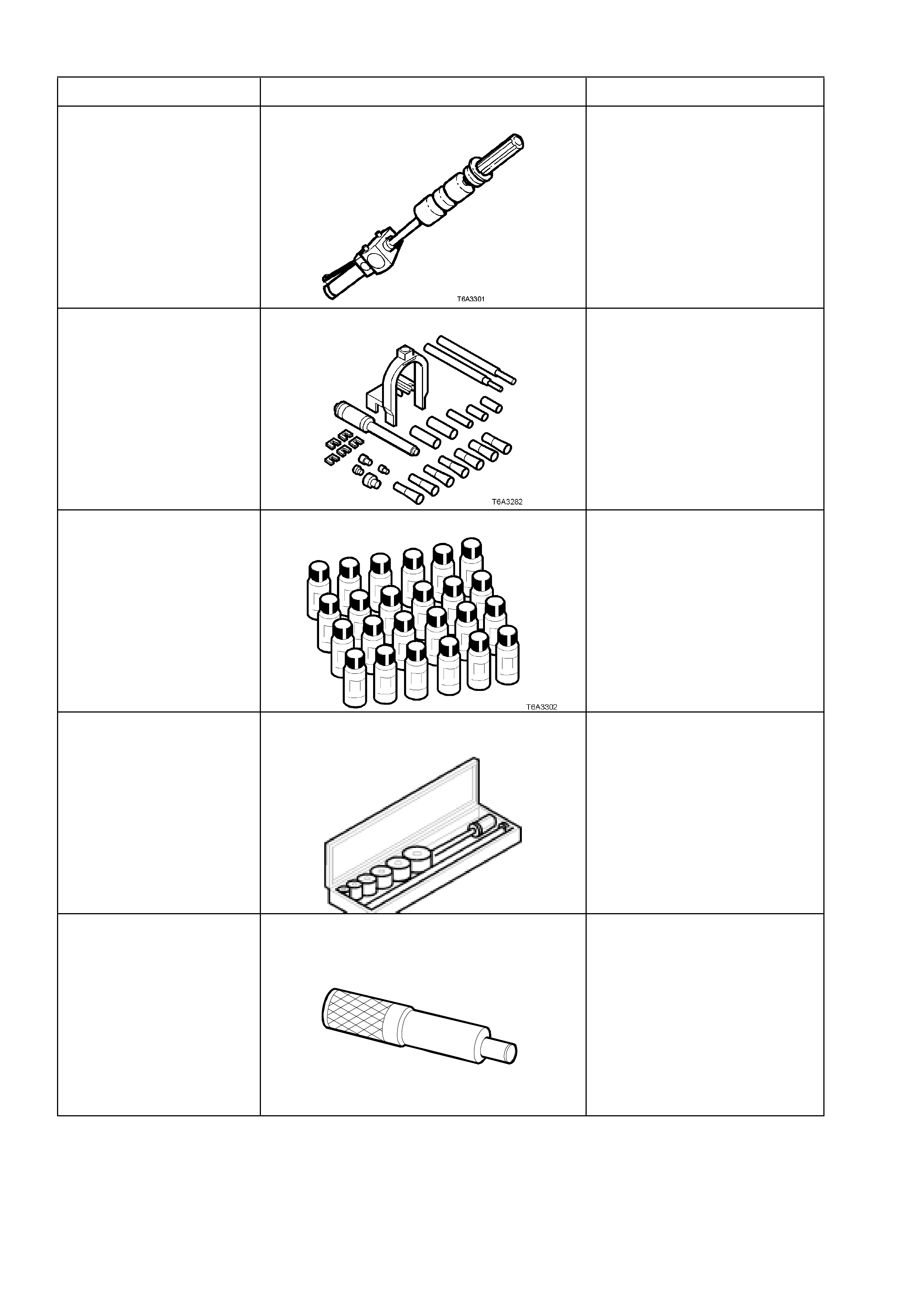
TOOL No. REF. IN TEXT TOOL DESCRIPTION COMMENTS
J 23907 SLIDE HAMMER Previously released.
Also released as remover,
6A22-2 and slide hammer
7A28.
J 24086-C PISTON PIN REMOVER/INSTALLER New release.
Universal tool containing
selective components to suit
multiple engine applications.
J 28431-B FLUID DYE Previously released.
Supplied in packs of 24, 1
ounce bottles.
Used in conjunction with black
light, leak detection lamp
J 42220 to locate various types
of vehicle fluid leaks.
J 33049 CAMSHAFT BEARING
REMOVER/INSTALLER New release.
Universal tool containing
selective components to suit
multiple engine applications.
J 38836 PILOTED DRIVER
T6A3 189b
New release.
Used to install the spigot bush
in the crankshaft.
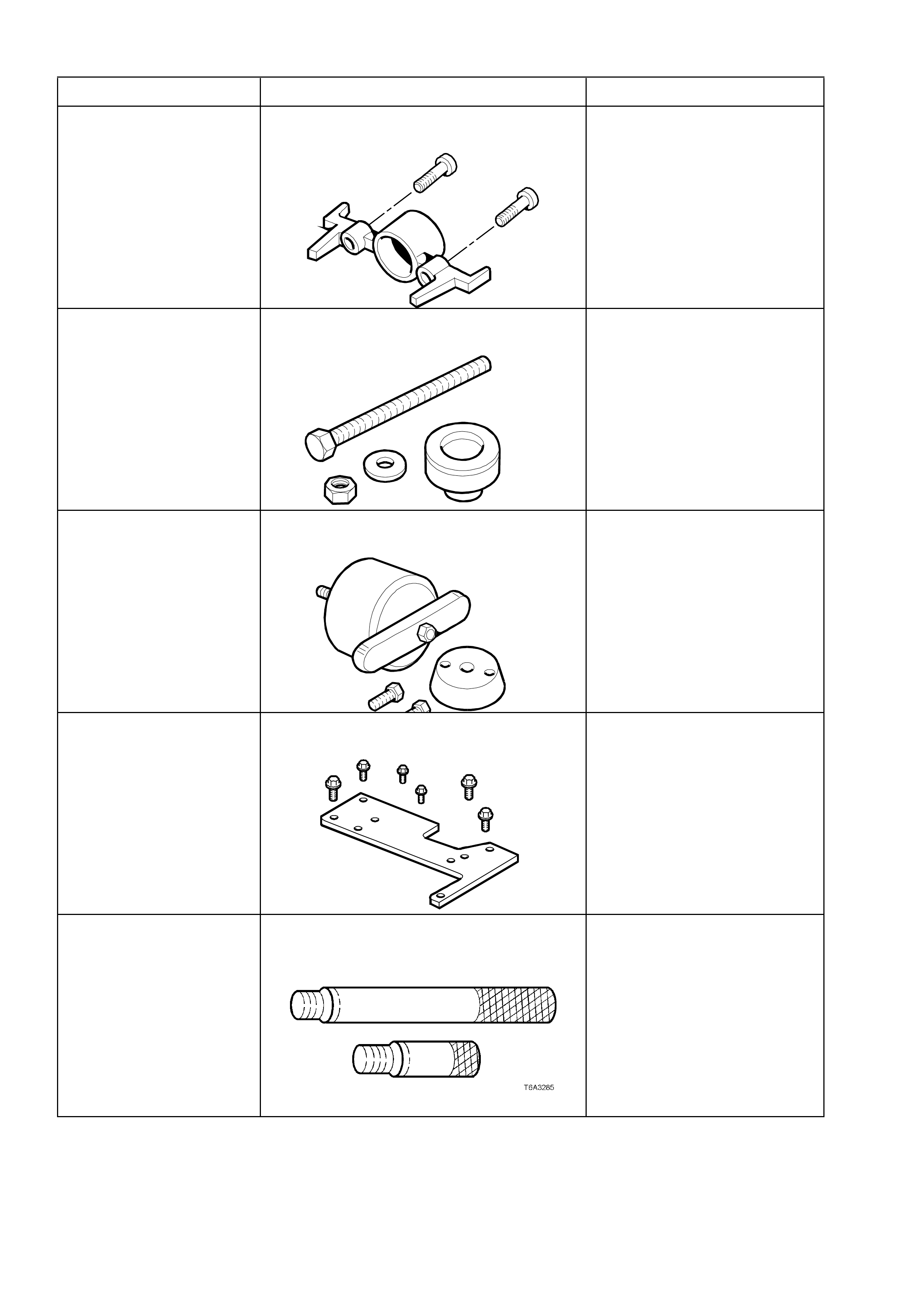
TOOL No. REF. IN TEXT TOOL DESCRIPTION COMMENTS
J 41476 FRONT AND REAR COVER ALIGNMENT
TOOL
T6A3257a
New release.
Used to align both the front and
rear engine covers during
installation.
J 41478 CRANKSHAFT FRONT OIL SEAL
INSTALLER
T6A3258a
New release.
Threaded bolt, nut and washer
are also used in conjunction
with
J 41665 to install the crankshaft
balancer.
J 41479 CRANKSHAFT REAR OIL SEAL
INSTALLER New release.
J 41480 FRONT AND REAR COVER ALIGNMENT
TOOL
T6A3260a
New release.
Used in conjunction with
alignment tool J 41476, to
correctly align the front and rear
engine covers.
J 41556 CONNECTING ROD GUIDES New release.
Used to assist in piston and
connecting rod installation.
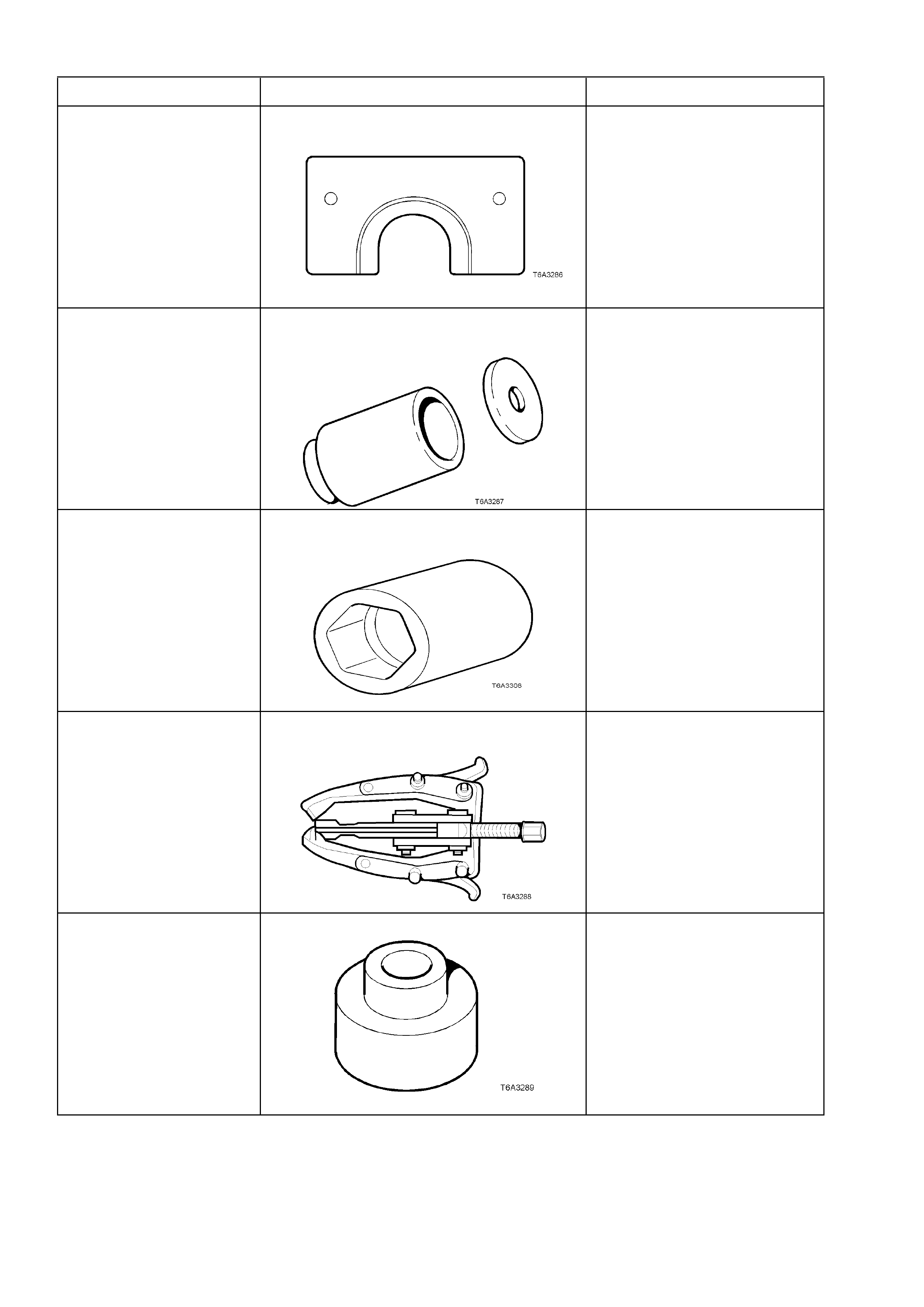
TOOL No. REF. IN TEXT TOOL DESCRIPTION COMMENTS
J 41558 CRANKSHAFT SPROCKET REMOVER New release.
Used in conjunction with the
bolts from J 21427-01 and
pulley puller J 8433, to remove
the crankshaft sprocket.
J 41665 CRANKSHAFT BALANCER INSTALLER New release.
Comprises stepped sleeve, J
41665-1 and end plate J 41665-
2.
Used in conjunction with the
threaded bolt, nut and washer
of Tool J 41478, to install the
crankshaft balancer and
crankshaft sprocket.
J 41712 OIL PRESSURE SENSOR SOCKET New release.
Used in conjunction with 3/8”
drive socket equipment to
remove/reinstall oil pressure
sensor.
J 41816 THREE LEGGED PULLER New release.
Also commercially available.
Used in conjunction with J
41816-2 to remove crankshaft
balancer.
J 41816-2 ADAPTOR New release.
Used in conjunction with puller J
41816 to remove crankshaft
balancer.
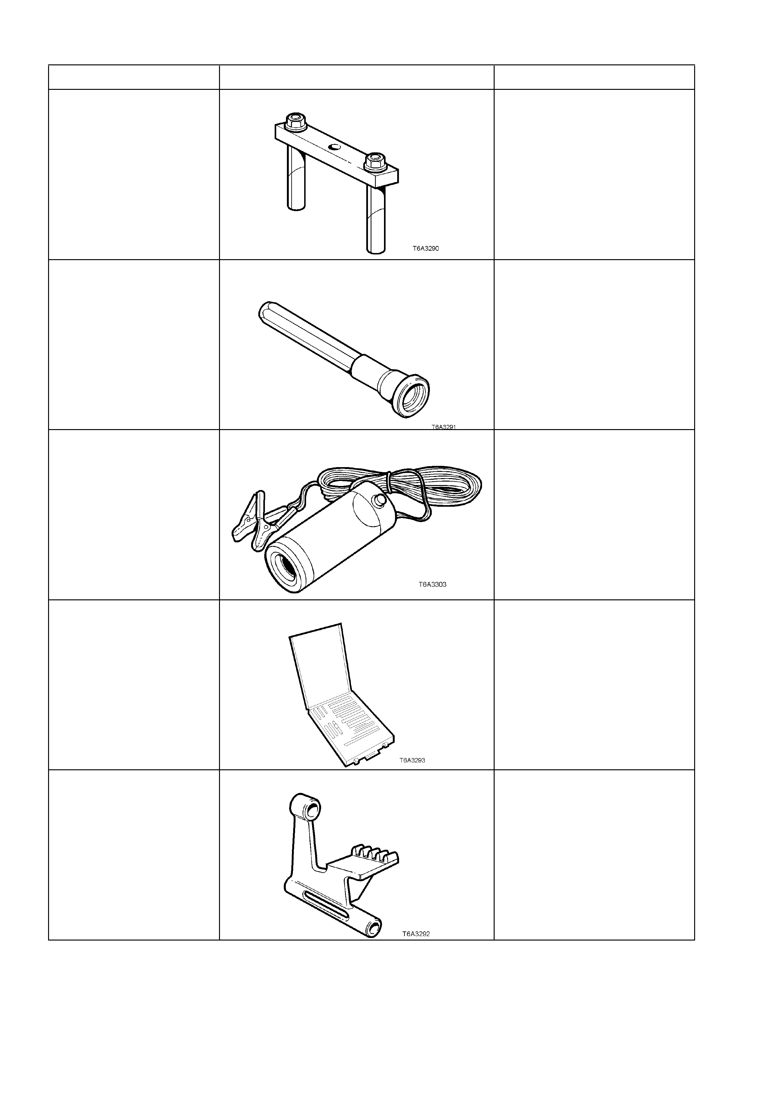
TOOL No. REF. IN TEXT TOOL DESCRIPTION COMMENTS
J 41818 CRANKSHAFT BEARING CAP REMOVER New release.
Used in conjunction with slide
hammer J 6125-1B to remove
main bearing caps.
J 42078 VALVE STEM OIL SEAL INSTALLER New release.
J 42220 BLACK LIGHT, LEAK DETECTION LAMP Previously released.
Used with dye, Tool J 28431-B
to locate the source of various
vehicle fluid leaks.
J 42385 THREAD REPAIR KIT New release.
Comprises;
Cylinder Head/Rear Main
Bearing Cap Kit .... J 42385-100
General Kit ........... J 42385-200
Fixtures/Hardware KitJ 42385-30
0
J 42386 FLYWHEEL HOLDING TOOL New release.
TOOL No. REF. IN TEXT TOOL DESCRIPTION COMMENTS
J 42907 OIL PRESSURE ADAPTOR New release.
Fitted to the oil filter adaptor
and used in conjunction with a
commercially available oil
pressure gauge and hose.
KD 2078 VALVE SPRING COMPRESSOR Previously released for the V6
engine.
Used to remove valve springs
with cylinder head/s installed.
Used in conjunction with spark
plug adaptor J 22794.