
SECTION 7C3 - HYDRA-MATIC 4L 60-E AUTOMATIC
TRANSMISSION: HYDR AULIC / MECHANI CAL
DIAGNOSIS
CAUTION:
This vehicle will be equipped with a Supplemental Restraint System (SRS). A SRS will consist of either
seat belt pre-tensioners and a driver's air bag, seat belt pre-tensioners and a driver's and front
passenge r's air bags or seat b elt pre-t ensio ners, d river’s and f ront p asseng er’s a ir bag and lef t and right
hand side air bags. Refer to SAFETY PRECAUTIONS, Section 12M, Supplemental Restraint System
before performing any service operation on, or around any SRS components, the steering mechanism o r
wiring. Failure to follow the SAFETY PRECAUTIONS could result in SRS deployment, resulting in
possible personal injury or unnecessary SRS system repairs.
CAUTION:
This vehicle may be equipped with LPG (Liquefied Petroleum Gas). In the interests of safety, the LPG
fuel system should be isolated by turning ‘OFF’ the manual service valve and then draining the LPG
service lines , before an y serv ic e work is c ar ried ou t o n t he v eh icl e. R ef er to th e L PG le aflet inclu ded w it h
the Owner's Handbook for details or the appropriate Section of this Service Information CD for more
specific servicing information.
CAUTION:
Whenever any component that forms part of the ABS or ABS/ETC (if fitted), is disturbed during Service
Operations, it is vital that the complete ABS or ABS/ETC system is checked, using the procedure as
detailed in 4. DIAGNOSIS, ABS or ABS/ETC FUNCTION CHECK, in Section 12L ABS & ABS/ETC, (V6
Engine) or (GEN III V8 Engine) of this Service Information CD.
1. GENERAL INFORMATION
1.1 HOW TO USE THIS SECTION
This Section contains an updated description of the HYDRA-MATIC 4L60-E procedures for diagnosing the
hydraulic/mechanical aspects of this transmission. When diagnosing any condition on the 4L60-E HYDRA-MATIC
transmission, ALWAYS begin with the “FUNCTIONAL TEST PROCEDURE” detailed in this Section.
NOTE: The diagnosis described here is not complete and must be read in conjunction with
Section 7C3 HYDRAULIC/ MECHANICAL DIAGNOSIS, of the VT Series I Service Information.
After the cause of a condition has been determined, refer to Section 7C4 ON-VEHICLE SERVICING or
Section 7C5 UNIT REP AIR, of the VT Series I Service Inf orm ation or Section 7C4 ON-VEHICLE SERVICING or
Section 7C5 UNIT REPAIR, of the VT Series II Service Information, for the necessary procedures.
Alternatively, if the condition is considered to be electrical/electronic in nature, then refer to either
Section 6C1, POWERTRAIN MANAGEMENT – V6 ENGINE, of the VT Series I Service Information or
Section 6C3, POW ERT RAIN M ANAGEM ENT – GEN III V8 ENGINE, of the VT Series II Service Information.
Techline
1.2 TRANSMISSION GENERAL DESCRIPTION
The Hydra-Matic 4L60-E is a fully automatic, four speed, rear wheel drive transmission. It consists primarily of a
four element torque converter, two planetary gear sets, various clutches, an oil pump and a control valve body.
The f our element torque converter co ntains a pum p, a turbine, a press ure plate s plined to the turbine and a stator
assembly. The torque converter acts as a fluid coupling to transmit power smoothly from the engine to the
transm ission. It also provides additional hydraulic torque m ultiplication when re quired. When applied, the pr essure
plate provides a mechanical direct drive (or ‘locked’) coupling of the engine to the transmission.
The two planetary gear sets provide the four forward gear ratios and reverse. Changing of the gear ratios is fully
automatic and is accomplished through the use of various electronic sensors that provide input signals to the
Powertrain Control Module (PCM).
The PCM interprets these signals to send current to the various solenoids inside the transmission. By using
electronics, the PCM controls shift points, shift feel and torque converter clutch apply and release, to provide proper
gear ranges for maximum fuel economy and vehicle performance.
Five multiple -dis c clu tc hes , o ne r o ller c lutch, a spr a g c lutch an d a br ake band pro vid e th e f r ic tion el ements r equired
to obtain the various ratios with the planetary gear sets.
An hydraulic system (the control valve body), pressurised by a vane type pump, provides the working pressure
needed to operate the clutch pistons, band servos and automatic controls.
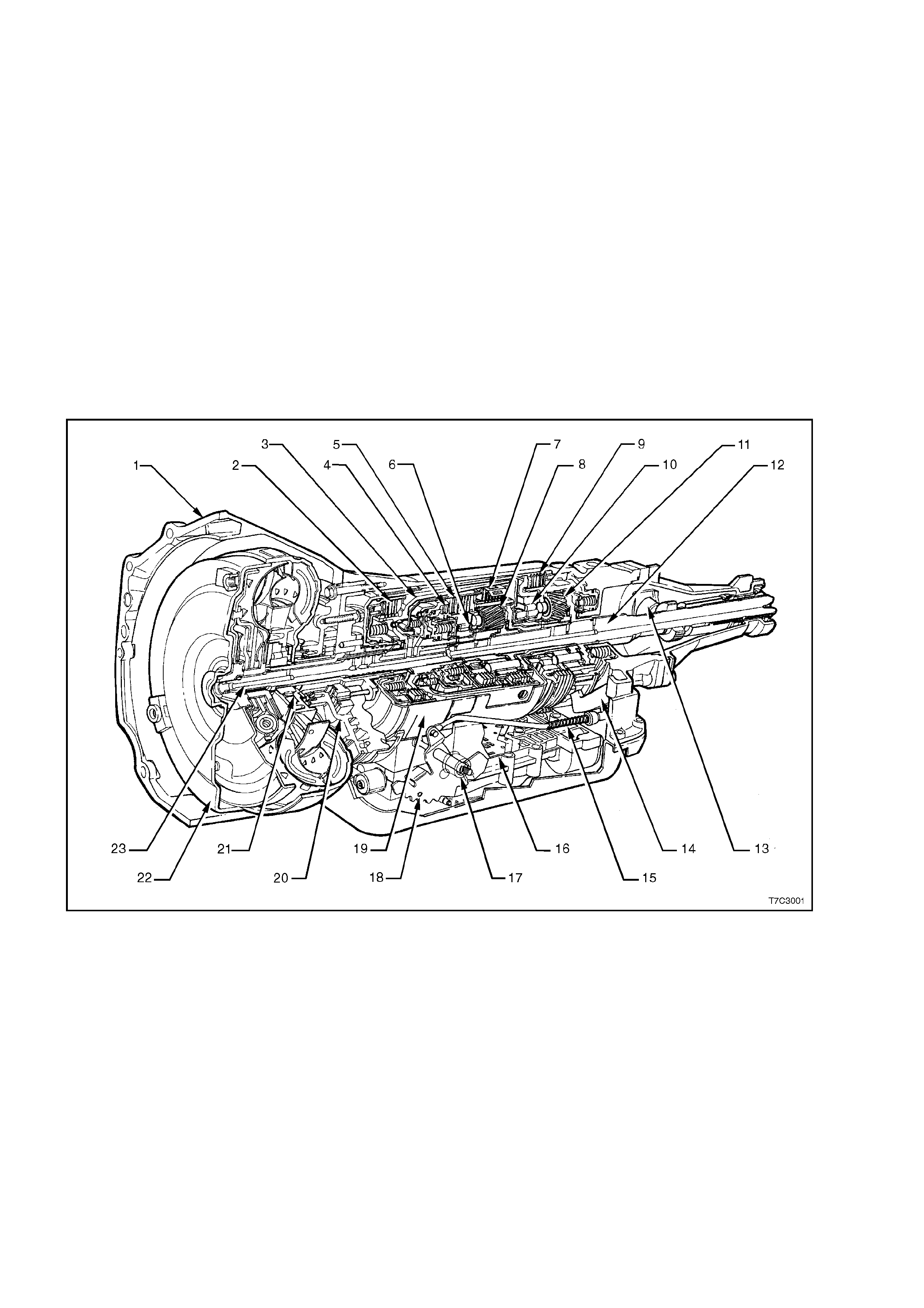
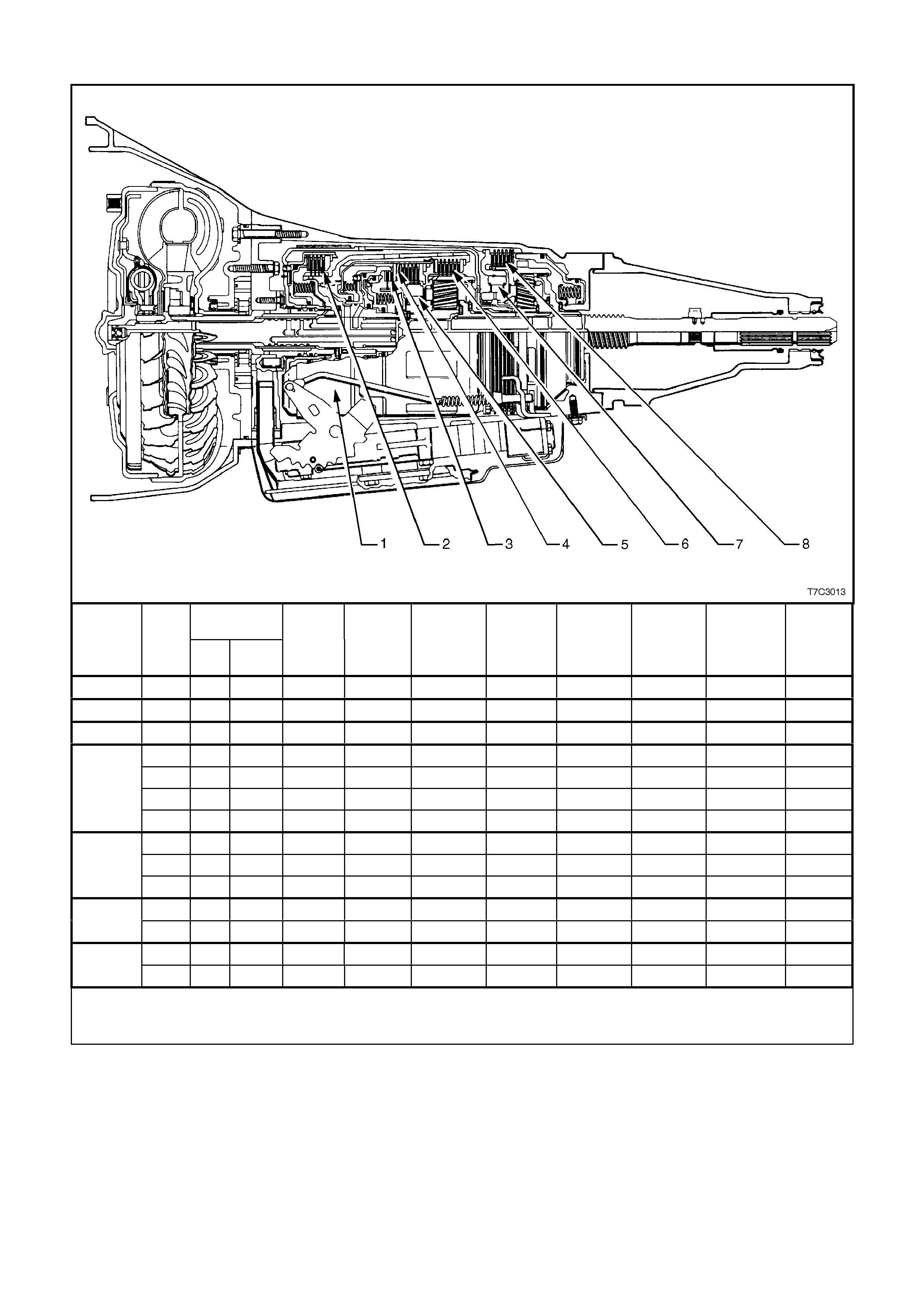
The general arrangement of both the majority of mechanical and hydraulic components is as shown.
1. Case Assembly 9. Low and Reverse Clutch 17. Manual Shaft
2. Reverse Input Cl utch 10. Low Roller Clutch Assem bl y 18. Inside Detent Lever
3. Input Clutc h Housing 11. Reaction Planetary Gear Set 19. 2 – 4 Band Assembly
4. Overrun Clutch 12. Output Shaft 20. Pump Assembly
5. Forward Clutch 13. Speed Sensor 21. Stator Roller Clutch
6. Forward Clutch Sprag Assembly 14. Parking Pawl 22. Torque Converter Assembly
7. 3 – 4 Clutch 15. Parking Lock Actuat or Assem bly 23. Turbine Shaft
8. Input Planetary Gear Set 16. Control Valve Assembly
Figure 7C3-1

1.3 TRANSMISSION DEFINITIONS AND ABBREVIATIONS
The following Definitions and Abbreviations are provided to establish a common language for describing
transmission related conditions. Taking the few minutes required to read this information may easily overcome
unnecessary waste of time by being familiar with the terminology used within this Diagnosis Section.
THROTTLE POSITIONS
Minimum Throttle – the least amount of throttle opening required for an upshift.
Light Throttle – approximately ¼ of accelerator pedal travel (25% Throttle Position).
Medium Throttle – approximately ½ of accelerator pedal travel (50% Throttle Position).
Heavy Throttle – approximately ¾ of accelerator pedal travel (75% Throttle Position).
Wide Open Throttle (WOT) – full travel of the accelerator pedal ( 100% Throttle Position).
Full Throttle Detent Downshift – a quick apply of the accelerator pedal to its full travel, forcing a downshift.
Zero Throttle Coastdown – a full release of the accelerator pedal while the car is in motion and in drive range.
Engine Braking – a condition where the engine is used to slow the car by manually downshifting during a zero
throttle coastdown.
SHIFT CONDITIONS
Bump – a sudden and forceful apply of a clutch or band.
Chuggle – a buck ing or jerk ing ma y be mos t noticeab le when the c onverter clutc h is eng age d; sim ilar to the f eel of
towing a trailer.
Delayed – a condit ion where a shift is expecte d but does n ot occur for a per iod of tim e. Exam ples of this coul d be
described as clutch or band engagem ent that does not occur as quickly as expected during a part throt tle or wide
open throttle apply of the accelerator or, when manually downshifting to a lower range. Also defined as “LATE” or
“EXTENDED”.
Double Bump (Double Feel) – two sudden and forceful applications of a clutch or band.
Early – a condition where the shift occurs before the car has reached proper speed. Tends to labour the engine
after the upshift.
End Bump – a firm er feel at the e nd of a shif t, compared to t he feel at the s tart of the sh ift. Also def ined as “END
FEEL” or “SLI P BUM P”.
Firm – a noticeably quick apply of a clutch or band that is considered normal with a medium to heavy throttle.
Should not be confused with “HARSH” or “ROUGH”.
Flare – a quic k increas e in eng ine r pm along wit h a m om entar y loss of tor que. T his m os t general ly occur s durin g a
shift. Also defined as ‘SLIPPING’’.
Harsh (Rough) – a more noticeable apply of a clutch or band as compared with “FIRM”. This condition is
considered undesirable at any throttle position.
Hunting – a repeating quick series of upshif ts and downshifts that causes a noticeable change in engine rpm . An
example could be described as a 4-3-4 shift pattern. Also defined as “BUSYNESS”.
Initial Feel – a distinct firmer feel at the start of a shift as compared to the finish of the shift.
Late – a shift that occurs when the engine is at a higher than normal rpm for a given amount of throttle.
Shudder – a repeating jerking condition similar to “CHUGGLE” but more severe and rapid. This condition may be
most noticeable during certain ranges of car speed.
Slipping – a notice able increase in engine rpm without a car speed increase. A slip usually occurs during or after
initial clutch or band apply.
Soft – a slow, almost unnoticeable clutch or band apply with very little shift feel.
Surge – a repeating engine related condition of acceleration and deceleration that is less intense than
“CHUGGLE”.
Tie-Up – a conditi on where two opposing clutch es and/or b ands are attem pting to appl y at th e same time causing
the engine to labour with a noticeable loss of engine rpm.

NOISE CONDITIONS
Planetary Gear Noise – a whine related to car speed most noticeable in first gear or reverse. Becomes less
noticeable after an upshift.
Pump Noise – a high pitch whine that increases with engine rpm.
ABBREVIATIONS
PCM - Powertrain Control Module.
TCC - Torque Converter Clutch.
TP Sensor – Throttle Position Sensor.
ECT Sensor – Engine Coolant Temperature Sensor
VS Senso r – Vehicle Speed Sensor.
TFP VAL. POSITION SW. – Transmission Fluid Pressure Manual Valve Position Switch
PSA - Transmission Range (TR) Pressure Switch Assembly.
TTS – Transmission Fluid Temperature Sensor.

2. DIAG NOSIS
2.1 BASIC KNOWLEDGE REQUIRED
You must be fam iliar with som e basic electronics to use this section of the Service Inform ation. They will help you
to follow diagnostic procedures.
NOTE: A lack of basic knowledge of this powertrain when performing diagnostic procedures, could result in
incorrec t diagnostic p erform ance or damage to po wertrain com ponents. Do no t, under an y circum stances, attempt
to diagnose a powertrain problem without this basic knowledge.
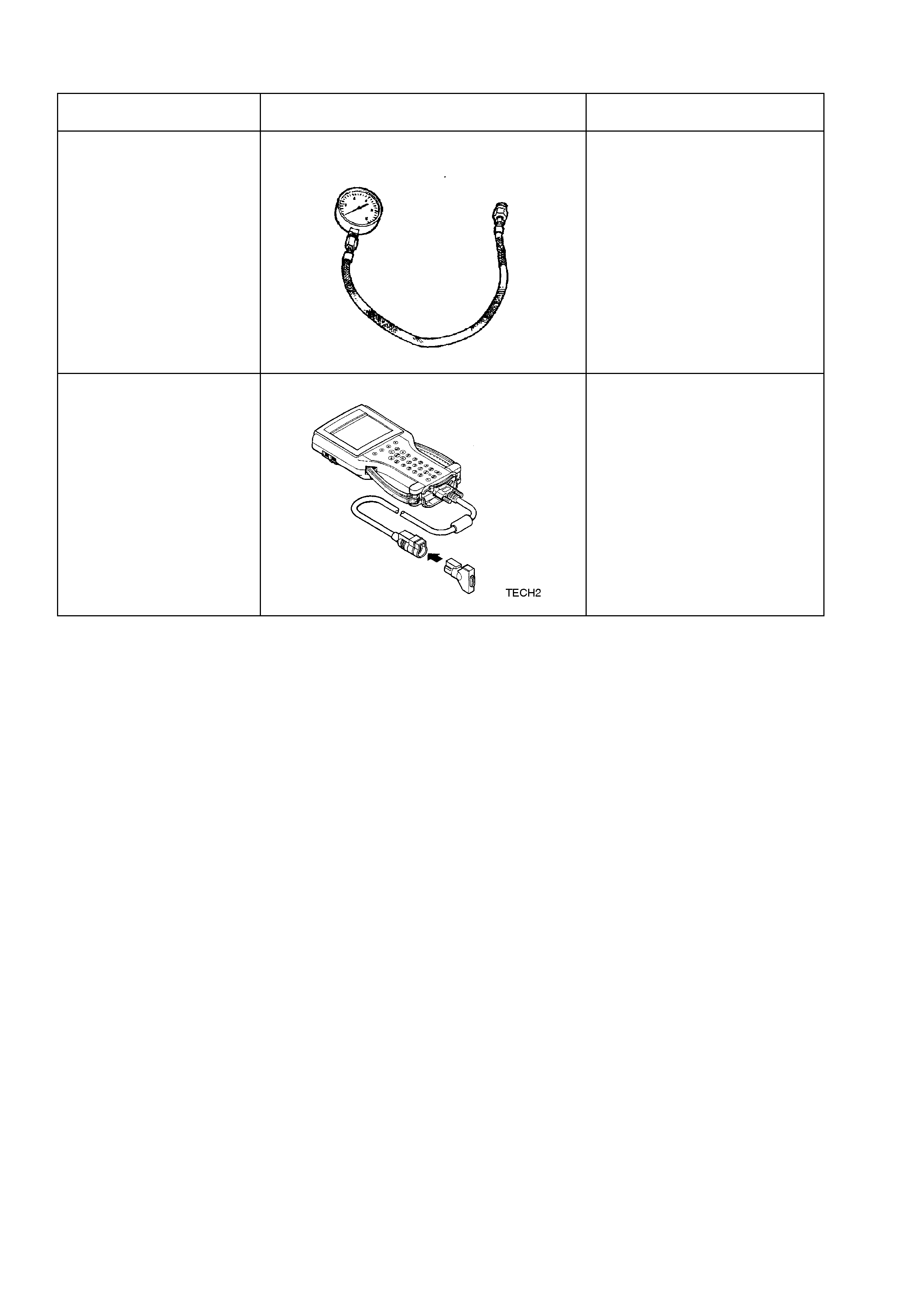
SPECIAL TOOLS
You should be abl e to us e a break out b ox, a D igital Volt M eter ( DVM), a c irc uit tes ter, jum per wires or leads a nd a
line pressure gauge set. Having access to and the ability to use the TECH 2 scan tool would also be a distinct
advantage, as many aspects of transmission diagnosis requires the use of this instrument.
The Functional Test Procedure detailed next, is designed to verify the correct operation of components in the
transmission and to identify whether a condition is electrical in nature, or not. This will eliminate the unnecessary
removal of transmission components and time loss in rectification.

2.2 FUNCTIONAL TEST PROCEDURE
When diagnosing any HYDRA-MATIC – 4L60-E related condition, ALWAYS begin with the Functional Test
Procedure detailed next. This procedure will indicate the proper path of diagnosing the transmission, by describing
the basic checks and then referencing the locations of specific checks.
The Functional Test Procedure is the first step in diagnosing mechanical or hydraulic transmission conditions. The
Functional Test provides procedures and references to the Symptom Diagnosis table for specific diagnostic information.
STEP ACTION YES NO
1.
Important: Engine performance can greatly affect transmission
performance. Ensure that the complaint is not the result of poor
engine performance before continuing.
Verify the customer complaint.
Has the customer complaint been verified?
Go to Step 2
–
2.
Has the Powertrain On Board Diagnostic (OBD) System Check been
performed?
Important: If a DTC fault is detected, the transmission may activate
default actions that could be interpreted as being a transmission
concern.
Go to Step 3 Go to Powertrain
On Board
Diagnostic
(OBD) System
Check in Section
6C1-2A (V6) or
6C3-2A (GEN III
V8)
3. • Perform a visual inspection. Look for the following conditions:
Vehicle damage.
Transmission oil pan damage. Refer to 7C4, On-Vehicle Service
Operations of the VT Series II Service Information or 7C4, On-
Vehicle Service Operations of the VT Series I Service Information.
• Worn or damaged suspension parts. Refer to 3. Front Suspension,
of the VT Series I Service Information.
• Worn or damaged steering parts. Refer to 9 Steering, of the VT
Series I Service Information.
• Transmission range selector linkage damaged or out of
adjustment. Refer to Selector Linkage Adjustment in 7C4 On-
Vehicle Service Operations of the VT Series I Service Information..
• Loose, worn, damaged or missing:
− Mounts or struts
− Brackets
− Mounting hardware
Refer to Transmission Assembly Removal in 7C4 On-Vehicle
Service Operations of the VT Series I Service Information.
• Transmission cooler or cooler line restrictions. Refer to
Transmission Cooler Reverse Flush and Flow Rate Check in 7C4
On-Vehicle Service Operations of the VT Series II Service
Information
• Fluid leaks. Refer to Fluid Leak Diagnosis in 7C4 On-Vehicle
Service Operations of the VT Series I Service Information.
Was an item identified that needs service?
Go to the
Appropriate
Repair or
Diagnosis
Section Go to Step 4
4. Perform the Transmission Fluid Checking Procedure in this Section.
Is the procedure complete? Go to Step 5 Go to
Transmission
Fluid Checking
Procedure
5. Perform the Road Test Procedure detailed in this Section.
Did the vehicle exhibit any objectionable condition? Go to Step 6 System OK
6. Did the vehicle exhibit objectionable torque converter operation? Go to Step 15 Go to Step 7
7. Did the vehicle exhibit a noise condition? Go to (Noise and
Vibration
Diagnosis), in
this Section. Go to Step 8
8. Did the vehicle exhibit a vibration condition? Go to Step 9 Go to Step 10
9. Did the vibration occur only during TCC apply or release? Go to Step 15 Go to 3.
Symptom
Diagnosis (Noise
and Vibration
Diagnosis), in
this Section.

STEP ACTION YES NO
10. Did the vehicle exhibit a shift speed condition such as low or high
shift speeds? Go to 3. Symptom
Diagnosis (Shift
Speed Diagnosis), in
this Section. Go to Step 11
11. Did the vehicle exhibit any of the following shift quality (feel)
conditions?
• Harsh, soft, delayed or no engagement.
• Harsh, soft or delayed shifts.
• Shift shudder, flare or tie-up. Go to Step 12 Go to Step 13
12. Perform the Line Pressure Check Procedure, detailed in this
Section.
Is the line pressure within specification?
Go to 3. Symptom
Diagnosis (Shift
Quality Feel
Diagnosis), in this
Section.
Go to
Transmission
Fluid Checking
Procedure
13. Did the vehicle exhibit any of the following shift pattern conditions?
• No upshift or downshift
• Only one or two forward gears
• No First gear, no Second gear, no Third gear or no Fourth gear
• Slipping
• Non-first gear start Go to (Shift Pattern
Diagnosis) Go to Step 14
14. Did the vehicle exhibit any of the following range performance
conditions?
• No PARK, REVERSE or DRIVE
• No engine braking
• No gear selection
• Incorrect gear select ion
Go to 3. Symptom
Diagnosis (Range
Performance
Diagnosis), in this
Section. System OK
15. Refer to Torque Converter Diagnosis Procedure, in this Section.
Did the vehicle exhibit any of the following TCC conditions?
• Stuck on or off
• Early or late engagement
• Incorrect apply or release
• Soft or harsh apply
• Clunk or shudder
• No torque multiplication
• Excessive slip
• Poor acceleration
• Engine stalls
Go to 3. Symptom
Diagnosis Torque
Converter Diagnosis,
in this Section. System OK

2.3 TRANSMISSION FLUID CHECKING PROCEDURE
1. Start engine and drive vehicle for a distance of 24 km, or unti l transmiss ion normal oper ating tem perature (82
– 94° C) is reached.
NOTE: As temperature affects transmission fluid levels, this operation must only be carried out with the
transm iss ion at norm al oper ating t em perature. If the veh icle is not at norm al oper ating tem per ature, a nd t he proper
checking procedures are not followed, the result could be a false reading of the fluid level on the dipstick.
2. Park vehicle on level ground.
3. Move gear selector to ‘PARK’ position.
4. Apply park brak e.
5. Let engine idle for three minutes with accessories turned off.
6. Lift the coloured dipstick locking lever, remove dipstick and check fluid colour, condition and level.
7. If the fluid level is low, add only enough Dexron® III to bring the level into the “HOT” area.
Inaccura te f lu id level r ea di ngs will res ult if chec ked im m ediate ly after the v eh ic le has be en oper a ted un der any
or all of the following conditions:
a. In high ambient temperatures above 32° C.
b. At sustained high speeds.
c. In heavy city traffic during hot weather.
d. Towing.
e. In commercial use (e.g. taxi).
If the vehicle has been operated under these conditions, switch the engine off and allow the vehicle to ‘cool’ for
approximately thirty minutes. After the cool-down period, re-start the vehicle and continue from step 2, above.

TRANSMISSION FLUID CHECKING PROCEDURE
STEP ACTION YES NO
1. Check the fluid colo ur.
Is the fluid colour red? Go to Step 2 Go to Step 11
2. Is the fluid level satisfactory? Go to Step 20 Go to Step 3
3. Check the fluid.
Is the fluid foamy? Go to Step 8 Go to Step 4
4. Check the fluid level. The correct fluid level should be in the middle of
the cross-hatch on the dipstick.
Is the level high?
Go to Step 9 Go to Step 5
5. Fluid will be low.
Add fluid to the correct fluid level.
Is the fluid level satisfactory?
Go to Step 6 Go to Step 1
6. Check for external leaks.
Were any leaks present? Go to Step 7 Go to Step 20
7. Correct the fluid leak condition.
Is action complete? Go to Step 20 Go to Step 6
8. Is the fluid level too high? Go to Step 9 Go to Step 10
9. Remove excess fluid to adjust to the correct fluid level.
Is action complete? Go to Step 20 Go to Step 8
10. 1. Check for contaminants in the fluid.
2. Drain the fluid to determine the source of contamination.
Is action complete?
Go to Step 15 Complete Action,
as described.
11. Is the fluid colour a non-transparent pink? Go to Step 12 Go to Step 13
12. Replace the leaking cooler.
Is the action complete? Go to Step 15
13. The fluid colour sho uld be ligh t brown.
NOTE: Transmission fluid may turn dark with normal use. This does not
always indicate oxidation or contamination.
Is the fluid colour light brown?
Go to Step 14 Go to Step 1
14. Drain the fluid to determine if the fluid is contaminated.
NOTE: A very small amount of material in the bottom of the oil pan is a
normal condition, but larger pieces of metal or other material in the
bottom of the oil pan are not and the transmi ssi on requires an overhaul .
Was the fluid contaminated?
Go to Step 15 Go to Step 18
15. Overhaul the transmission or fit a SRTA unit. Refer to Section 7C5 Unit
Repair of the VT Series I Service Information. For Transmission
replacement, refer to 7C4, On-Vehicle Servicing of the VT Series I
Service Information.
Is action complete?
Go to Step 16 Complete Action,
as described.
16. Flush the cooler/s.
Is action complete? Go to Step 17 Complete Action,
as described.
17. Add new fluid.
Is action complete? Go to Step 19 Complete Action,
as described.
18. Change the fluid and filter.
Is action complete? Go to Step 19 Complete Action,
as described.
19. Is the fluid level satisfactory? If not, correct as necessary.
Is action complete? Go to Step 20 Complete Action,
as described.
20. Refer to 2.2 Functional Test Procedure, in this Section of the Service
Information.
Is action complete?
Fluid Checking
Procedure
Completed
Complete Action,
as described.

2.4 LINE PRE SSURE CHECK
PRELIMINARY INFORMATION
Line pressures are calibrated for two sets of gear ranges – Drive/Park/Neutral and Reverse. This allows the
transmission line pressure to be appropriate for two different pressure needs in different gear ranges:
Gear Range Line Pressure Range
Drive, Park or Neutral 380 – 1,300 kPa
Reverse 440 – 2,235 kPa
Before performing a line pressure check, verify that the pressure control (PC) solenoid is receiving the correct
electrical signal from the PCM, as follows:
1. Install the TECH 2 scan tool. Refer to Section 0C TECH 2 of the VT Series I Service Information or
Section 0C TECH 2 of the VT Series II Service Information, for the necessary procedure.
2. Start the engine and firmly apply the park brake.
3. Check for stored diagnostic trouble code/s (DTC) and in particular, for a pressure control solenoid DTC.
4. Rectify as necessary.
NOTE: The transmission may experience harsh, soft or mushy shifts for up to two days after this procedure.
PROCEDURE
1. Check engine and transmission fluid levels.
2. Check manual linkage for correct adjustment
and wear.
3. If not previously carried out, install a TECH 2
scan tool to the vehicle. Refer to
Section 0C TECH 2 of the VT Series I
Service I nform ation or Section 0C TECH 2 of
the VT Series II Service Information.
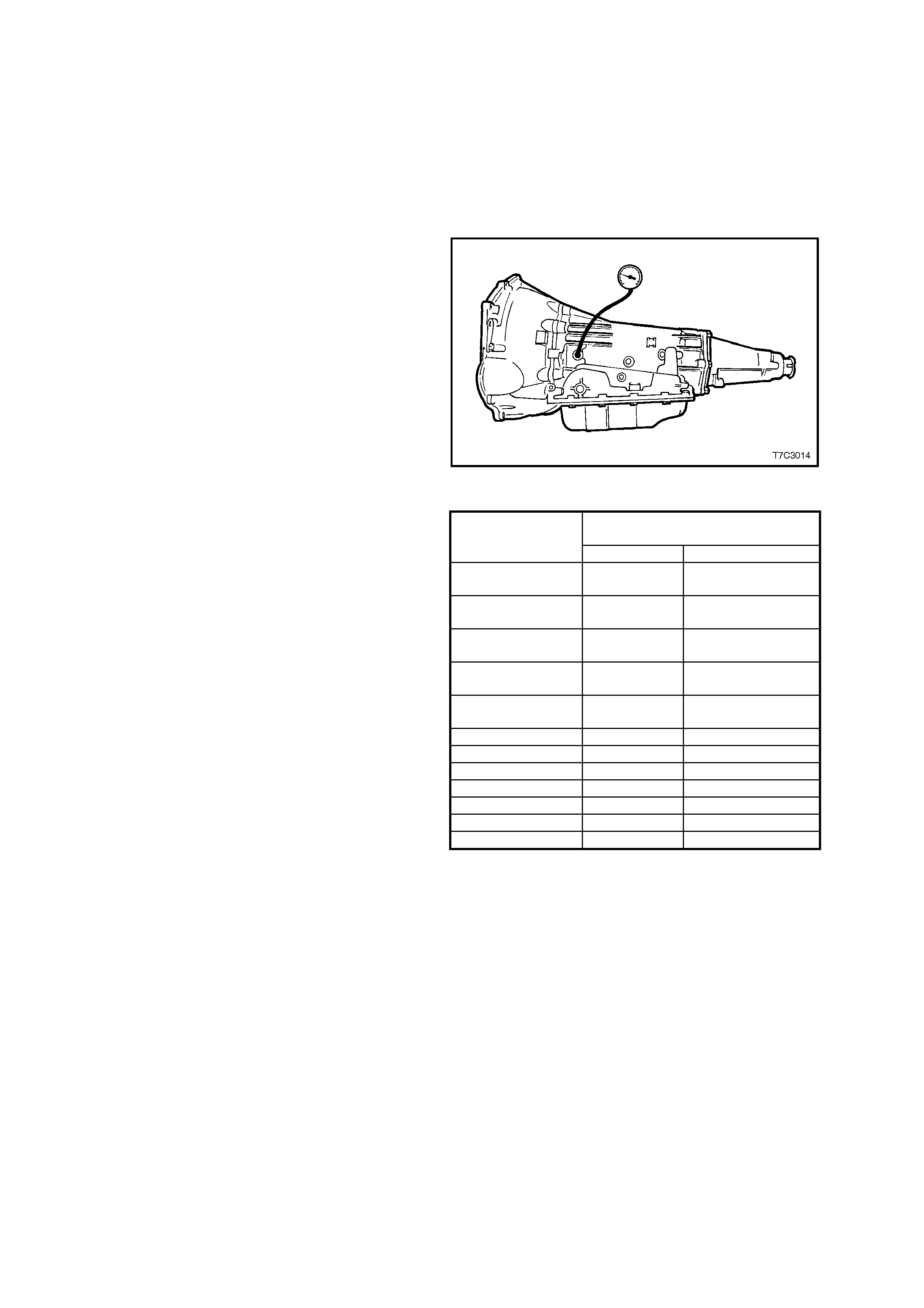
4. Install an oil pressure gauge such as Tool
J21867 or commercial equivalent, to the line
pressur e tapping point on the tr ansm ission, as
shown.
5. Select ‘P’ (Park) range and firmly apply the
park brake.
6. Start the engine and allow to warm up, at idle.
7. Access ‘Miscellaneous Tests’ on TECH 2,
then the “PCS CONTROL” test.
8. Increase “ACTUAL PCS” in 0.1 Amp
increm ents on the T ECH 2 scan tool and r ead
the corresponding line pressure reading on
the fluid pressure gauge. (Allow the pressure
to stabilise for 5 seconds after each current
change.
9. Compare the pressure readings against the
charts shown next.
Important: Total test running time should not
exceed 2 minutes or transmission damage could
occur.
NOTE 1: Pressures are to be taken at an engine
speed of 1,500 rpm and a temperature of 66° C.
Line pressure drops as temperature increases.
NOTE 2: If pressure readings differ greatly from
the line pressure chart, refer to the Diagnostic
Section in Section 6C1 POWERTRAIN
MANAGEMENT – V6 ENGINE of the VT Series I
Service Information or Section 6C3
POWERTRAIN MANAGEMENT – GEN III V8
ENGINE of the VT Series II Service Information.
NOTE 3: TECH 2 is only able to control the PC
solenoid in Park, and Neutral, with the vehicle
stopped. This protects the clutch packs from
extremely high or low pressures in Drive or
Reverse ranges.
Figure 7C3-2
Pressure Control
Solenoid Current Line Pressure
(kPa)
(Amp) V6 Engine GEN III V8 Engine
0.00 1,186 –
1,324 1,400 – 1,537
0.10 1,179 –
1,317 1,393 – 1,530
0.20 1,144 –
1,282 1,344 – 1,482
0.30 1,103 –
1,241 1,303 – 1,441
0.40 1,041 –
1,179 1,213 – 1,351
0.50 956 – 1,103 1,124 – 1,262
0.60 876 – 1,013 1,007 – 1,144
0.70 758 – 896 862 – 1,000
0.80 627 – 765 703 – 841
0.90 483 – 620 517 – 655
1.00 400 – 538 407 – 545
1.10 352 – 490 352 – 490
Figure 7C3-3

2.5 ROAD TEST PROCEDURE
PRELIMINARY INFORMATION
Important: The Road Tes t Procedure shoul d be perf ormed onl y as part of the F unctiona l Test Pr ocedure. R efer to
Functional Test Procedure, in this Section.
The following test provides a method of evaluating the condition of the automatic transmission. The test is
structured so that most driving conditions would be achieved. The test is divided into the following parts:
1. Electrical Function Check
2. Upshift Control and Torque Converter Clutch (TCC) Apply Part Throttle Detent Downshifts
3. Full Throttle Detent Downshifts Manual Downshifts
4. Coasting Downshifts
5. Manual Gear Range Selection
− REVERSE
− Manual FIRST
− Manual SECOND
− Manual THIRD
Important: Complete the test in the sequence given. Incomplete testing cannot guarantee an accurate evaluation.
Before the road test, ensure the following:
• The engine is performing properly.
• Transmission fluid level is correct. Refer to 2.3 Transmission Fluid Checking Procedure in this Section.
• Tyre pressures are correct.
During the road test:
• Perform the test only when traffic conditions permit.
• Operate the vehicle in a controlled, safe manner.
• Observe all traffic regulations.
• Take an assistant to view the TECH 2 data while conducting this test.
• Observe any unusual sounds or smells.
After the road test, check the following:
• Transmission fluid level. Refer to the 2.3 Transmission Fluid Checking Procedure, in this Section.
• Diagnostic Trouble Codes (DTC’s) that may have set during the testing. Refer to the applicable DTC, in
Section 6C1 POWERTRAIN MANAGEMENT – V6 ENGINE, of the VT Series I Service Information or
Section 6C3 POW ERT R AIN M ANAGEMENT – GEN III V8 ENGINE, of the VT Series II Service Information.
• TECH 2 data for any abnormal readings or information.

ELECTRICAL FUNCTION CHECK
Perform this check first, in order to ensure the electronic transmission components ar e connected and functioning
properly. If these components are not checked, a simple electrical condition could be mis-diagnosed.
1. Connect the TECH 2 scan tool.
2. Ensure the gear selector is in PARK and set the parking brake.
3. Start the engine.
4. Verify that the following TECH 2 scan tool data can be obtained and is functioning properly.
Refer to Transmis sion Scan Tool Data V al ues , f or t ypica l da ta va lues . Data tha t is q ues ti ona ble ma y indic at e a
concern. Refer to Section 6C1 POWERTRAIN MANAGEMENT – V6 ENGINE, of the VT Series I Service
Information or Section 6C3 POWERTRAIN MANAGEMENT – GEN III V8 ENGINE, of the VT Series II
Service Information.
• Engine Speed
• Transmission output speed
• Vehicle speed
• TFP manual valve position switch
• Transmission range (engine list)
• Commanded gear (current gear)
• PC solenoid reference current
• PC solenoid actual current
• PC solenoid duty cycle
• Brake switch
• Engine coolant temperature
• Transmission fluid temperature
• Throttle angle
• Ignition voltage
• 1-2 shift solenoid (A)
• 2-3 shift solenoid (B)
• TCC solenoid duty cycle
• TCC slip speed
5. Monitor the brake switch signal while depressing and releasing the brake pedal. The scan tool should display:
• Closed when the brake pedal is released.
• Open when the br ak e pedal is depr ess ed.
6. Check the garage shifts.
• Apply the brake pedal and ensure that the parking brake is set.
• Move the gear selector through the following ranges:
− PARK to REVERSE
− REVERSE to NEUTRAL
− NEUTRAL to DRIVE
• Pause two to three seconds in each gear position.
• Verify the gear engagements are immediate and not harsh.
Important: Harsh engagement may be caused by any of the following conditions:
• High idle speed. Compare engine idle speed to desired idle speed.
• Commanded low PC solenoid current. Compare PC solenoid reference current to PC solenoid actual
current.
• A default condition caused by certain DTC’s that result in maximum line pressure to prevent slippage.
Important: Soft or delayed engagement may be caused by any of the following conditions:
• Low idle speed. Compare engine idle speed to desired idle speed.
• Low fluid level.
• Commanded high PC solenoid current. Compare PC solenoid reference
• Current to PC solenoid actual current.
• Cold transmission fluid. Check for low transmission fluid temperature.

7. Monitor transmission range on the scan tool (engine list).
• Apply the brake pedal and ensure the parking brake is set.
• Move the gear selector through all ranges.
• Pause two to three seconds in each range.
• Return gear selector to PARK.
• Verify that all selector positions match the scan tool display.
8. Check throttle angle input.
• Apply the brake pedal and ensure that the parking brake is set.
• Ensure the gear selector is in PARK.
• Mon itor throttle ang le while increas ing and decr easing eng ine s peed with the t hrott le ped al. The s can t ool
throttle angle should increase and decrease with engine speed.
If any of the above checks do not perform properly, record the result for reference after completion of the road test.

UPSHIFT CONTROL AND TORQUE CONVERTER CLUTCH (TCC) APPLY
The PCM calculates the upshift points based primarily on two inputs: throttle angle and vehicle speed. W hen the
PCM determines that condit io ns are met f or a s hif t to oc cur , th e P CM c om mands the s hif t by clos ing or o pen ing the
earth circuit for the appropriate solenoid.
Perform the following steps:
1. Refer to the Shift Speed Chart in this Section and choose a throttle position of 6.25%, 50% or 100%. All
throttle angles shown should be tested to cover the normal driving range.
2. Monitor the following TECH 2 scan tool parameters:
• Throttle angle
• Vehicle speed
• Engine speed
• Output shaft speed
• Commanded gear
• Slip speed
• Solenoid states
3. Place the gear selector in the OVERDRIVE position.
4. Accelerate the vehicle using the chosen throttle angle. Hold the throttle steady.
5. As the transm is sion upsh if ts , note the vehicle s pe ed when the s h if t oc cur s f or eac h gear ch ang e. There s ho uld
be a noticeable shift feel or engine speed change within one to two seconds of the commanded gear change.
6. Compare the shift speeds to the Shift Speed Chart. Shift speeds may vary slightly due to transmission fluid
temperature or hydraulic delays in responding to electronic controls.
Note any harsh, soft or delayed shifts or slipping.
Note any noise or vibration.
7. Repeat steps 1 through 6 to complete all throttle angles.
Important: The TCC will not engage unt il the engin e is in clos ed lo op oper atio n and t he veh icle speed is as sh own
in the Shift Speed table, in this Section. The vehicle must be in a near-cruise condition (not accelerating or
coasting) and on a level road surface.
8. Check for TCC apply in THIRD and FOURTH gear.
• Note the TCC ap ply point. When the TCC app lies , th er e should be a notic e ab le drop in e ng ine s p ee d an d
a drop in slip speed to below 100 RPM. If the TCC apply can not be detected:
• Check for DTC’s.
• Refer to 2.6 Torque Converter Diagnosis Procedure, in this Section.
• Refer to the Shift Speed table in this Section for the correct apply speeds.
• Lightly tap and release the brake pedal. The TCC will release on most applications.
PART THROTTLE DETENT DOWNSHIFT
1. Place the gear selector in the OVERDRIVE position.
2. Accelerate the vehicle to 64-88 km/h in FOURTH gear.
3. Quick l y increase throttle angle to greater tha n 50% .
4. Verify the following:
• The TCC releases
• The transmission downshifts immediately to THIRD gear
FULL THROTTLE DETENT DOWNSHIFT
1. Place the gear selector in the OVERDRIVE position. Accelerate the vehicle to speeds of 64-88 km/h in
FOURTH gear.
2. Quickly increase thrott le angle to 100% (WOT).
3. Verify the following:
• The TCC releases
• The transmission downshifts immediately to SECOND gear

MANUAL DOWNSHIFTS
The shift solenoid valves do not control the initial downshift for the 4-3 or the 3-2 manual downshifts as these are
hydraulic.
The 2-1 manual downshift however, is electronic. The solenoid states should change during or shortly after a
manual downshift is selected.
Manual 4-3 Downshift
1. Place the gear selector in the OVERDRIVE position.
2. Accelerate the vehicle to 64-88 km/h in FOURTH gear.
3. Release the throttle while moving the gear selector to THIRD.
4. Verify the following:
• The TCC releases
• The transmission downshifts immediately to THIRD gear
• The engine slows the vehicle
Manual 4-2 Downshift
1. Place the gear selector in the OVERDRIVE position.
2. Accelerate the vehicle to 64-72 km/h.
3. Release the throttle while moving the gear selector to SECOND. Verify the following:
• The TCC releases
• The transmission downshifts immediately to SECOND gear
• The engine slows the vehicle
Manual 4-1 Downshift
1. Place the gear selector in the OVERDRIVE position.
2. Accelerate the vehicle to 48 km/h.
3. Release the throttle while moving the gear selector to FIRST.
4. Verify the following:
• The TCC releases
• The transmission downshifts immediately to FIRST gear.
• The engine slows the vehicle.
COASTING DOWNSHIFTS
1. Place the gear selector in the OVERDRIVE position.
2. Accelerate the vehicle to FOURTH gear with the TCC applied. Release the throttle and lightly apply the
brakes.
3. Verify the following:
• The TCC releases
• Downshifts occur at speeds shown in the Shift Speed table, in this Section.

MANUAL GEAR RANGE SELECTION
The shift solenoids control the upshifts in the manual gear ranges.
Perform the following tests using 10 to 15% throttle angle.
Reverse
1. With the vehicle stopped, move the gear selector to REVERSE.
2. Slowly accelerate th e vehicl e.
3. Verify that there is no noticeable slip, noise or vibration.
Manual First
1. With the vehicle stopped, move the gear selector to FIRST.
2. Accelerate the vehicle to 32 km/h.
3. Verify the following:
• No upshifts o ccur
• The TCC does not apply
• There is no noticeable slip, noise, or vibration
Manual Second
1. With the vehicle stopped, move the gear selector to SECOND.
2. Accelerate the vehicle to 57 km/h.
3. Verify the following:
• The 1-2 shift occurs
• The 2-3 shift does not occur
• There is no noticeable slip, noise or vibration
Manual Third
1. With the vehicle stopped, move the gear selector to THIRD.
2. Accelerate the vehicle to 64 km/h.
3. Verify the following:
• The 1-2 shift occurs
• The 2-3 shift occurs
• There is no noticeable slip, noise or vibration

2.6 TORQUE CONVE RTE R DIAGNOSIS PROCEDURE
The T or que Con verter C lutc h (TCC) is ap pl ied by fluid pr ess ur e, which is c ontrolled b y a PWM solenoid v al ve. T his
solenoid val ve is loc ated inside of the autom atic transm ission assem bly and is co ntrolled thro ugh a com bination of
computer controlled switches and sensors.
TORQUE CONVERTER STATOR
The torque converter stator roller clutch can have two different malfunctions:
• The stator assembly freewheels in both directions.
• The stator assembly remains locked up at all times.
Poor Acceleration at Low Speed
If the stator is freewheeling at all times, the car tends to have poor acceleration from a standstill but at speeds
above 50-55 km/h, the car may act normally.
For poor acceler ation, you shou ld first determ ine that the exhaust s ys tem is not block ed, and the trans mis sion is in
First gear when starting out.
If the engine freely accelerates to high RPM in NEUTRAL, you can assume that the engine and the exhaust system
are norm al. Check for poor perf ormanc e in DRIVE and R EVERSE to help determ ine if the st ator is f reewheel ing at
all times.
Poor Acceleration at High Speed
If the stator is locked up at all times, performance is normal when accelerating from a standstill but engine RPM
and car spe ed are l imited or res tricted a t high sp eeds. Vis ual exam ination of the converter m ay re veal a bl ue co lor
from overheating.
If the converter h as be en removed f r om the tr ansmis sion, you c an ch ec k the stator r o ller clutch b y ins ert ing a finger
into the splined inner race of the roller clutch and trying to turn the race in both directions. You should be able to
freel y turn the inner race cloc kwise, but you sho uld ha ve diff icult y in m oving the in ner rac e co unter clock wise or yo u
may be unable to move the race at all.
NOISE
Important: Do not confus e this no ise with pum p whine n oise, which is us uall y noticeable in P ARK, N EUTRAL and
all other gear ranges. Pump whine will vary with line pressure.
You may notice a torque converter whine when the vehicle is stopped and the transmission is in DRIVE or
REVERSE. This noise will increase as you increase the engine RPM. The noise will stop when the vehicle is
moving or when the torque converter clutch is applied, because both halves of the converter are turning at the
same speed.
Perform a stall test to make sure the noise is actually coming from the converter:
1. Place your foot on the brake.
2. Put the gear selector in DRIVE.
3. Depress the accelerator to approximately 1,200 RPM for no more than six seconds.
NOTE: You may damage the transmission if you depress the accelerator for more than six seconds.
A torque converter noise will increase under this load.
TORQUE CONVERTER CLUTCH SHUDDER
The key to diagnosing Torque Converter Clutch (TCC) shudder is to note when it happens and under what
conditions.
TCC shudder which is caused by the transmission should only occur during the apply or the release of the
converter clutch. Shudder should never occur after the TCC plate is fully applied.
If Shudder Occurs During TCC Apply or Release
If the shudder occurs while the TCC is applying, the problem can be within the transmission or the torque
converter. Something is causing one of the following conditions to occur:
• Something is not allowing the clutch to become fully engaged.
• Something is not allowing the clutch to release.
• The clutch is releasing and applying at the same time.
One of the following conditions may be causing the problem to occur:
• Leaking turbine shaft seals
• A restricted release orifice
• A distorted clutch or housing surface due to long converter bolts
• Defective friction material on the TCC plate

If Shudder Occurs After TCC has Applied
If shudder occurs after the TCC has applied, most of the time there is nothing wrong with the transmission!
The T CC is not l ik el y to s lip af ter th e T CC has be en app li ed. En gin e pr o bl ems m ay go unn otic e d u nder li ght t hr ott le
and load, b ut they become noticeable af ter the TCC appl y when going up a hill or accelerating. This is due to the
mechanical coupling between the engine and the transmission.
Once TCC is applied, there is no torque converter (fluid coupling) assistance. Engine or driveline vibrations could
be unnoticeable before TCC engagement.
Inspect the foll owing components in order t o avoid mis diagnosis of T CC shudder. An inspection wi ll also avoid the
unnecessary disassembly of a transmission or the unnecessary replacement of a torque converter.
• Spark plugs – Inspect for cracks, high resistance or a broken insulator.
• Plug wires – Look in each end. If there is red dust (ozone) or a black substance (carbon) present, then the
wires are bad. Also look for a white discoloration of the wire. This indicates arcing during hard acceleration.
• Coils – Look for a black discoloration on the bottom of each coil. This indicates arcing while the engine is
misfiring.
• Fuel injectors – A filter may be plugged.
• Vacuum leak – The engine will not get a correct amount of fuel. The m ixture m ay run rich or lean depending
on where the leak occur s.
• EGR valve (V6 engines only) – T he valve ma y let in too much or too little unburnable exhaust gas and could
cause the engine to run rich or lean.
• MAP/MAF sensor – Like a vacuum leak, the engine will not get the correct amount of fuel for proper engine
operation.
• Carbon on the intake valves – Carbon restricts the proper flow of air/fuel mixture into the cylinders.
• Flat cam – Valves do not open enough to let the proper fuel/air mixture into the cylinders.
• Oxygen sensor – This sensor may command the engine too rich or too lean for too long.
• Fuel pressure – This may be too low.
• Engine mounts – Vibration of the mounts can be multiplied by TCC engagement.
• Propeller shaft and driveshaft/s – Check for vibration.
• TP Sensor – The TCC apply a nd release depends on the TP Sensor in m any eng ines. If the TP Sens or is out
of specification, TCC may remain applied during initial engine loading.
• Cylinder balance – Bad piston rings or poorly sealing valves can cause low power in a cylinder.
• Fuel contamination – This causes poor engine performance.
Replace the torque converter if any of the following conditions exist:
• External leaks appear in the hub weld area.
• The converter hub is scored or damaged.
• The converter pilot is broken, damaged, or fits poorly into the crankshaft.
• You discover steel particles after flushing the cooler and the cooler lines.
• The pump is damaged, or you discover steel particles in the converter. The vehicle has TCC shudder and/or
no TCC app l y. Replace th e torque co nverter onl y after a ll h ydraulic and e lectrica l dia gnoses have b een m ade.
The converter clutch material may be glazed.
• The converter has an imbalance which cannot be corrected. Refer to Torque Converter Vibration T est, in this
Section.
• For V6 engines, refer to Section 7C4 ON-VEHICLE SERVICING, of the VT Series I Service Information or
Section 7C4 ON-VEHICLE SERVICING of the VT Series II Service Information for the GEN III V8 engine.
• The converter is contaminated with engine coolant which contains antifreeze.
• An internal failure occurs in the stator roller clutch.
• You notice excessive end play.
• Overheating produc es hea vy debris in the clutc h.
• You disco ver steel par ticles or clutc h lining mater ial in the flu id filter or o n the m agnet, when no int ernal par ts
in the unit are worn or damaged. This condition indicates that lining material came from the converter.
Do Not Replace the Torque Converter if you discover any of the following symptoms:
• The oil has an odour or the oil is discolored, even though metal or clutch facing particles are not present.
• The threads i n one or mor e of the converter bolt hol ds are d amaged. Corr ect the condition with a new thr ead
insert.
• Tr ansmission f ailure d id not displa y evidence of dam aged or wor n internal parts, s teel particles or c lutch plate
lining material in the unit and inside the fluid filter.

• The vehicle has been exposed to high mileage only. An exception may exist where the lining of the torque
converter clutch dampener plate has seen excess wear by vehicles operated in heavy and/or constant traffic,
such as taxi, delivery, or police use.
TORQUE CONVERTER VIBRATION TEST
For this procedure with V6 engines, refer to Section 7C4 ON-VEHICLE SERVICING, of the VT Series I Service
Information or for the GEN III V8 engine, refer to Section 7C4 ON-VEHICLE SERVICING of the VT Series II
Service Information.

2.7 NOISE AND VIBRATION ANALYSIS
A noise or vibration that is noticeable when the vehicle is in motion MAY NOT be the result of the transmission.
If noise or vibration is noticeable in PARK and NEUTRAL with the engine at idle, but is less noticeable as RPM
increases, the cause may be from poor engine performance.
• Inspect the tyres for the following:
− Uneven wear
− Imbalance
− Mixed sizes
− Mixed radial tyre tread pattern. Refer to Section 10. WHEELS AND TYRES of the VT Series II Service
Information.
• Inspect the suspension components for the following:
− Alignment and wear
− Loose f astener s. Refer to Section 3 FRONT SUSPENSION and Section 4 R EAR SUS PENSION, of the
VT Series I Service Information.
• Inspect the engine and transmission mounts for damage and loose bolts.
• Inspect the transmission case mounting holes for the following:
− Missing bolts, nuts, and studs
− Stripped threads
− Cracks
• Inspect the flexplate for the following:
− Missing or loose bolts
− Cracks
− Imbalance
• Inspect the torque converter for the following:
− Missing or loose bolts or lugs
− Missing or loose balance weights
− Imbalance

2.8 CLUTCH PLATE DIAGNOSIS
COMPOSITION PLATES
Dry the plates and inspect each, for the following conditions:
• Pitting
• Flaking
• Wear
• Glazing
• Cracking
• Charring
• Chips or metal particles embedded in the lining
Replace the set, if any composition plate shows any of the above conditions.
STEEL PLATES
Important: If the clutch shows evidence of extreme heat or burning, replace the release springs.
Wipe the plates dry and check the plates for heat discoloration. If the surfaces are smooth, even if color smear is
indicate d, you can reuse the plate. If the plate is discolored wit h heat spots or if the sur face is sc uffed, replace th e
plate.
Causes of Burned Clutch Plates
The following conditions can result in a burned clutch plate:
• Incorrect usage of clutch plates
• Low line pressure
• Valve body conditions, such as:
− The valve body face is not flat
− Porosity between channels
− The valve bushing clips are improperly installed
− The checkballs are misplaced
• The Teflon® seal rings are worn or damaged.
• Engine coolant in the transmission fluid
• A cracked clutch piston
• Damaged or missing seals

2.9 ENGINE COOLANT IN TRANSMISSION
NOTE: The antifreeze in the engine coolant will cause both the Viton O-ring seals and the glue that bonds the
clutch material to the pressure plate, to deteriorate. Both conditions may cause damage to the transmission.
If the transmission oil cooler has deve loped a leak, allowing engine coolant to enter the transm ission, perform the
follo wing oper ati ons :
1. Disassemble the transmission.
2. Replace all of the rubber type seals. (The coolant will attack the seal material which will cause leakage.)
3. Replace the composition-faced clutch plate assemblies. (The facing material may separate from the steel
center portion.)
4. Replace all of the nylon parts (washers).
5. Replace the torque converter.
6. Thoroughly clean and rebuild the transmission, using new gaskets and oil filter.
7. Flush the cooler lines after the transmission cooler has been properly repaired or replaced.

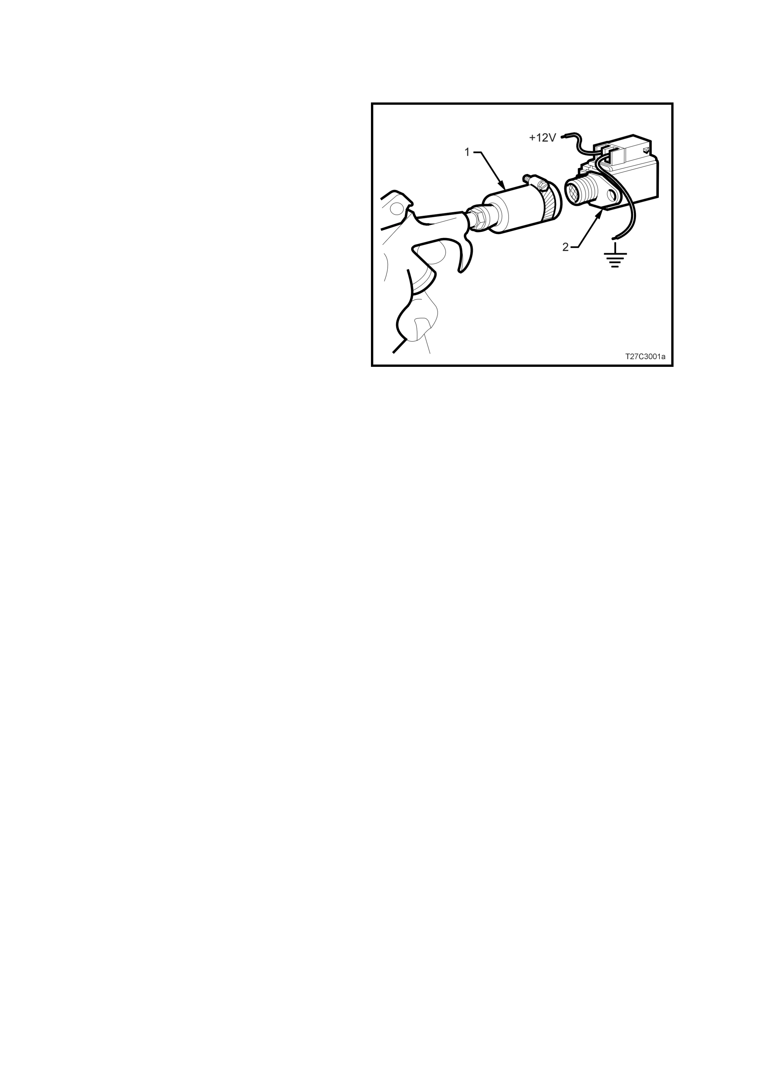
2.11 SHIFT SOLENOID LEAK TEST
Should a shift solenoid be suspected of leaking,
perform the following test.
1. Clamp a piece of 12 mm I.D. rubber hose (1)
over the fluid inlet end of the solenoid (2).
2. Connect a wire from one of the solenoid
terminals to the negative terminal (ground) of
the battery.
3. Apply compressed air to the rubber hose. Do
not use air pressure in excess of 825 kPa.
Excessive pressure will not allow the solenoid
ball check valve to seat properly.
4. Connect a wire from the other solenoid
terminal to the positive terminal (12 volts) of
the battery.
5. Observe air flow through the solenoid.
Replace the solenoid if there is an air leak
when the solenoi d is energis ed.
Figure 7C3-4

2.12 SYMPTOM DIAGNOSIS
The following table consists of seven diagnostic categories that are located in the left-hand column. Using this
column, choose the appropriate category based on the operating conditions of the vehicle or transmission. The
tables that follow, provide more specific information relating to each of the symptoms listed.
After selecting a category, use the right-hand column to locate the specific symptom diagnostic information.
Important: The Functional T est Procedure should be performed before beginning an y diagnosis. If this procedure
has not already been performed, refer to Functional Test Procedure, in this Section.
SYMPTOM DIAGNOSIS TABLE
Diagnostic Category Diagnostic Information
FLUID DIAGNOSIS
This category contains the following topics:
• Fluid condition (appearance, contaminants, smell,
overheating)
• Line pressure (high or low)
• Fluid leaks
• Refer to 2.3 Transmission Fluid Checking Procedure, in
this Section.
• Refer to Oil Pressure High or Low.
• Refer to Fluid Leak Diagnosis (procedure).
• Refer to Oil Out the Vent .
• Refer to Front Oil Leak.
Noise and Vibration Diagnosis
This category contains the following topics:
• Ratcheting noise
• Noise (drive gear, final drive, whine, growl, rattle, buzz,
popping)
• Vibration
• Refer to Ratcheting Noise.
• Refer to Vibration in Reverse and Whining Noise in Park.
Range Performance Diagnosis
This category contains the following topics: Drives in Neutral
• No Park
• No Reverse
• No Drive
• No engine braking
• Refer to Drives in Neutral.
• Refer to No Park.
• Refer to No Reverse or Slips in Reverse.
• Refer to No Drive in All Ranges.
• Re fer to No Drive in Drive Range.
• Refer to No Overrun Braking - Manual 3-2-1.
SHIFT QUALITY (FEEL) DIAGNOSIS
This category contains the following topic:
• Harsh, soft or slipping shifts
• Harsh, soft or delayed engagement
• Shift shudder, flare or tie-up
• Refer to Harsh Shifts.
• Refer to Slipping or Rough 1-2 Shift.
• Refer to No 2-3 Shift or 2-3 Shift Slips, Rough or
Hunting.
• Refer to No 3-4 Shift, Slips or Rough 3-4 Shift.
• Refer to Harsh Garage Shift.
• Refer to Dela y in Drive and Reverse.
• Refer to 3-2 Flare or Tie-Up.
SHIFT PATTERN
This category contains the following topics:
• One forward gear only
• Two forward gears only gear missing or slipping
• No upshift or slipping upshift
• No downshifts
• Non-First gear start
• Refer to 1st Gear Range Only - No Upshift.
• Refer to Third Gear Only.
• Refer to 2nd/3rd Gear Only or 1st/4th Gears Only.
• Refer to Slips in 1st Gear.
• Refer to Slipping or Rough 1-2 Shift.
• Refer to No 2-3 Shift or 2-3 Shift Slips, Rough or
Hunting.
• Refer to No 3-4 Shift, Slips or Rough 3-4 Shift.
• Refer to No Part Throttle or Delayed Downshifts.
• Refer to 2nd Gear Start.
SHIFT SPEED DIAGNOSIS
This category contains the following topic:
• Inaccurate or inconsis tent sh ift point s
• Refer to Inaccurate Shift Points.
TORQUE CONVERTER DIAGNOSIS
This category contains the following topics:
• Torque converter diagnosis
• TCC does not apply
• TCC does not release
• TCC apply/release quality
• Refer to Torque Converter Diagnosis Procedure.
• Re fer to No TCC Apply.
• Re fer to No TCC Release.
• Refer to Torque Converter Clutch Shudder.

OIL PRESSURE HIGH OR LOW
Checks Causes
Oil Pump Assembly • Pressure regulator valve stuck
• Pressure regulator valve spring
• Rotor guide omitted or misassembled
• Rotor cracked or broken
• Reverse boost valve or sleeve stuck, damaged or incorrectly assembled
• Orifice hole in pressure regulator valve plugged
• Sticking slide or excessive rotor clearance
• Pressure relief ball not seated or damaged
• Porosity in pump cover or body
• Wrong pump cover
• Pump faces not flat
• Excessive rotor clearance
Oil Filter • Intake pipe restricted by casting flash
• Cracks in filter body or intake pipe
• O-ring seal missing, cut or damaged
• Wrong grease used on rebuild
Control Valve Body • Manual valve scored or damaged
• Spacer plate or gaskets incorrect, misassembled or damaged
• Face not flat
• 2-3 Shift valve stuck
• Checkballs omi tted or misas sem ble d
Pressure Control Solenoid • Damage to pins
Transmission Fluid Pressure
Manual Valve Position Switch • Contamination
• Damaged seals
Case • Case to control valve body face not flat
System Voltage • 12 volts not supplied to transmission
• Electrical short (pinched solenoid wire)
• Solenoid not grounded
HARSH SHIFTS
Checks Causes
Throttle Position Sensor • Open or shorted circuit
Vehicle Speed Sensor • Open or shorted circuit
Pressure Switch Assembly • Contamination
• Damaged seals
Trans Fluid Temperature Sensor • Open or shorted circuit
Engine Coolant Temperature
Sensor • Open or shorted circuit
Pressure Control Solenoid • Damage to pins
• Contamination

IN ACCURATE SHIFT POINTS
Checks Causes
Oil Pump Assembly • Stuck pressure regulator valve
• Sticking pump slide
Valve Body Assembly • Spacer plate or gaskets misassembled, damaged or incorrect
Case • Porous or damaged valve body pad
• 2-4 Servo Assembly
− 2-4 accumulator porosity
− Damaged servo piston seals
− Apply pin damaged or improper length
• 2-4 Band Assembly
− Burned
− Anchor pin not engaged
Throttle Position Sensor • Disconnected
• Damage
Vehicle Speed Sensor • Disconnected
• Damaged
• Bolt not tightened
FIRST GEAR RANGE ONLY – NO UPSHIFT
Checks Causes
Control Valve Body • The 1-2 shift valve is sticking
• The spacer plate or gaskets are mispositioned or damaged
Case • The case to valve body face is damaged or is not flat
Shift Solenoid Valves • Stuck or damaged
• Faulty electrical connection
2-4 Servo Assembly • The apply passage case is restricted or blocked
• Nicks or burrs on the servo pin or on the pin bore in the case
• Fourth servo piston is installed backwards
2-4 Band Assembly • The 2-4 band is worn or damaged
• The band anchor pin is not engaged

SLIPS IN FIRST GEAR
Checks Causes
Forward Clutch Assembly • Clutch plates worn
• Porosity or damage in forward clutch piston
• Forward clutch piston inner and outer seals missing, cut or damaged
• Damaged forward clutch housing
• Forward clutch housing retainer and ball assembly not sealing or damaged
Forward Clutch Accumulator • Piston seal missi ng, cut or dama ged
• Piston out of its bore
• Porosity in the piston or valve body
• Stuck abuse valve
Input Housing and Shaft Assembly • Turbine shaft seals missing, cut or damaged
Valve Body • 1-2 Accumulator valve stuck
• Face not flat, damaged lands or interconnected passages
• Spacer plate or gaskets incorrect, mispositioned or damaged
Low Roller Clutch • Damage to lugs to inner ramps
• Rollers not free moving Inadequate spring tension Damage to inner splines Lube
passage plugged
Torque Converter • Stator roller clutch not holding
1-2 Accumulator Assembly • Porosity in piston or 1-2 Accumulator cover and pin assembly
• Damaged ring grooves on piston
• Piston seal missi ng, cut or dama ged
• Valve body to spacer plate gasket at 1-2 Accumulator cover, missing or damaged
• Leak between piston and pin
• Broken 1-2 Accumulator spring
Line Pressure • Refer to Oil Pressure High or Low, in this Section.
2-4 Servo Assembly • 4th Servo piston in backwards
SLIPPING OR ROUGH 1 – 2 SHIFT
Checks Causes
Valve Body Assembly • 1-2 Shift valve train stuck
• Gaskets or spacer plate incorrect, mispositioned or damaged
• 1-2 Accumulator valve stuck
• Face not flat
2-4 Servo Assembly • Apply pin too long or too short
• 2nd servo apply piston seal mis si ng, cut or dama ged
• Restricted or missing oil passages
• Servo bore in case damaged
2nd Accumulator • Porosity in 1-2 accumulator housing or piston
• Piston seal or groove damaged
• Nicks or burrs in 1-2 accumulator housing
• Missing or restricted oil passage
2-4 Band • Worn or mispositioned
Oil Pump Assembly or Case • Faces not flat
NO 2–3 SHIFT OR SHIFT SLIPS, ROUGH OR HUNTING
Checks Causes
Converter • Internal damage
Oil Pump • Stator shaft sleeve scored or off location
Valve Body Assembly • 2-3 Shift valve train stuck
• Gaskets or spacer plate incorrect, mispositioned or damaged
• 2-3 Accumulator valve stuck
• Face not flat
Input Housing Assembly • 3-4 clutch or forward clutch plates worn
• Excessive clutch plate travel
• Cut or damaged 3-4 clutch or forward clutch piston seals
• Porosity in input clutch housing or piston
• 3-4 clutch piston checkball stuck, damaged or not sealing
• Restricted apply passages
• Forward clutch piston retainer and ball assembly not seating
• Sealing balls loose or missing
Case • 3rd accumulator retainer and ball assembly not seating
2-4 Servo Assembly • 2nd apply piston seals missing, cut or damaged
2ND/3RD GEAR ONLY OR 1ST/4TH GEARS ONLY
Checks Causes
Shift Solenoid Valves • Sediment is in the valves
• The electrical conn ect ion is faulty
• Damaged seal
THIRD GEAR ONLY
Checks Causes
System Voltage • 12 volts not supplied to transmission
• Electrical short (pinched solenoid wire) Solenoid not grounded
3-2 Control Solenoid • Shorted or damaged
• Contamination
• Damaged Seal
3-2 FLARE OR TIE-UP
Checks Causes
3-2 Control Solenoid Shorted or damaged
Contamination
Damaged Seal

NO 3-4 SHIFT, SLIPS OR ROUGH 3-4 SHIFT
Checks Causes
Oil Pump Assembly • Pump cover retainer and ball assembly omitted or damaged
• Faces not flat
Valve Body Assembly • Valves stuck
− 2-3 Shift valve train
− Accumulator valve
− 1-2 Shift valve train
− 3-2 Control valve
• Spacer plate or gaskets incorrect, mispositioned or damaged
2-4 Servo Assembly • Incorrect band apply pin
• Missing or damaged servo seals
• Porosity in piston, cover or case
• Damaged piston seal grooves
• Plugged or missing orifice cup plug
Case • 3rd Accumulator retainer and ball assembly leaking
• Porosity in 3-4 accumulator piston or bore
• 3-4 Accumulator piston seal or seal grooves damaged
• Plugged or missing orifice cup plug
• Restricted oil passage
Input Housing Assembly • Refer to Slipping 2-3 Shift, in this Section
2-4 Band Assembly • Worn or misassembled
NO REVERSE OR SLIPS IN REVERSE
Checks Causes
Input Housing Assembly • 3-4 Apply ring stuck in applied positi on
• Forward clutch not releasing
• Turbine shaft seals missing, cut or damaged
Manual Valve Link • Disconnected
Valve Body Assembly • 2-3 Shift valve stuck
• Manual linkage not adjusted
• Spacer plate and gaskets incorrect, mispositioned or damaged
• Lo overrun valve stuck
• Orificed cup plug restricted, missing or damaged
Reverse Input Clutch Assembly • Clutch plate worn
• Reverse input housing and drum assembly cracked at weld
• Clutch plate retaining ring out of groove
• Return spring assembly retaining ring out of groove
• Seals cut or damaged
• Restricted apply passage
• Porosity in piston
• Belleville plate installed incorrectly
• Excessive clutch plate travel
• Oversized housing
Lo and Reverse Clutch • Clutch plates worn
• Porosity in piston
• Seals damaged
• Return spring assembly retaining ring mispositioned
• Restricted apply passage

NO PART THROTTLE OR DELAYED DOWNSHIFTS
Checks Causes
Input Housing Assembly • 3-4 Apply ring stuck in applied positi on
• Forward clutch not releasing
• Turbine shaft seals missing, cut or damaged
Manual Valve Link • Disconnected
Valve Body Assembly • 2-3 Shift valve stuck
• Manual linkage not adjusted
• Spacer plate and gaskets incorrect, mispositioned or damaged
• Lo overrun valve stuck
• Orificed cup plug restricted, missing or damaged
Reverse Input Clutch Assembly • Clutch plate worn
• Reverse input housing and drum assembly cracked at weld
• Clutch plate retaining ring out of groove
• Return spring assembly retaining ring out of groove
• Seals cut or damaged
• Restricted apply passage
• Porosity in piston
• Belleville plate installed incorrectly
• Excessive clutch plate travel
• Oversized housing
Lo and Reverse Clutch • Clutch plates worn
• Porosity in piston
• Seals damaged
• Return spring assembly retaining ring mispositioned
• Restricted apply passage
HARSH GARAGE SHIFT
Checks Causes
Valve Body Assembly • Orifice cup plug mis si ng
• Checkball missing
NO OVERRUN BRAKING - MANUAL 3-2-1
Checks Causes
External Linkage • Not adjusted properly
Valve Body Assembly • 4-3 Sequence valve stuck
• Checkball mispositioned
• Spacer plate and gaskets incorrect, damaged or mispositioned
Input Clutch Assembly • Turbine shaft oil passages plugged or not drilled
• Turbine shaft seal rings damaged
• Turbine shaft sealing balls loose or missing
• Turbine shaft sealing balls loose or missing
• Porosity in forward or overrun clutch piston
• Overrun piston seals cut or dama ged
• Overrun piston checkball not sealing

NO TORQUE CONVERTER CLUTCH APPLY
Checks Causes
Electrical • 12 volts not supplied to transmission
• Outside electrical connector damaged
• Inside electrical connector, wiring harness or solenoid damaged
• Electrical short (pinched solenoid wire)
• Solenoid not grounded
Torque Converter Clutch • Internal damage
Oil Pump Assembly • Converter clutch valve stuck or assembled backwards
• Converter clutch valve retaining ring mispositioned
• Pump to case gasket mispositioned
• Orifice cup plug restricted or damaged
• Solenoid O-ring seal cut or damaged
• High or uneven bolt torque (pump body to cover)
Input Housing and Shaft • Turbine shaft O-ring seal cut or damaged
• Incorrect O-ring fitted (e.g. 300 mm torque converter O-ring on 258 mm converter)
• Turbine shaft retainer and ball assembly restricted or damaged
Transmission Fluid Pressure
Manual Valve Position Switch • Contamination
• Damaged seals
Control Valve Body Assembly • TCC signal valve stuck
• Solenoid O-ring leaking
Solenoid Screen • Blocked
TCC Solenoid Valve • Internal damage
Engine Speed Sensor • Internal damage
Engine Coolant Temperature
Sensor • Internal damage
Automatic Transmission Fluid
Temperature Sensor • Internal damage
Brake Switch • Internal damage
TORQUE CONVERTER CLUTCH SHUDDER
Checks Causes
Electrical • 12 volts not supplied to transmission
• Outside electrical connector damaged
• Inside electrical connector, wiring harness or solenoid damaged
• Electrical short (pinched solenoid wire)
• Solenoid not grounded
Converter • Internal damage
Oil Pump Assembly • Converter clutch valve stuck or assembled backwards
• Converter clutch valve retaining ring mispositioned
• Pump to case gasket mispositioned
• Orifice cup plug restricted or damaged
• Solenoid O-ring seal cut or damaged
• High or uneven bolt torque (pump body to cover)
Input Housing and Shaft • Turbine shaft O-ring seal cut or damaged
• Turbine shaft retainer and ball assembly restricted or damaged
Pressure Switch Assembly • Contamination
• Damaged seals
Valve Body Assembly • TCC signal valve stuck Solenoid O-ring leaking
Solenoid Screen • Blocked
NO TORQUE CONVERTER CLUTCH RELEASE
Checks Causes
TCC Solenoid Valve • External ground
• Clogged exhaust orifice
Converter • Internal damage
Valve Body Assembly • The converter clutch apply valve is stuck in the apply position
Oil Pump Assembly • The converter clutch valve is stuck
PCM • External ground
DRIVES IN NEUTRAL
Checks Causes
Forward Clutch • The clutch does not release
Manual Valve Link • Disconnected
Case • The face is not flat
• Internal leakage exists
2ND GEAR START
Checks Causes
Forward Clutch Sprag Assembly • The sprag assembly is installed backwards
NO PARK
Checks Causes
Parking Linkage • Actuator rod assembly bent or damaged
• Actuator rod spring binding or improperly crimped
• Actuator rod not attached to inside detent lever
• Parking lock bracket damaged or not torqued properly
• Inside detent lever not torqued properly
• Parking pawl binding or damaged
OIL OUT THE VENT
Checks Causes
Oil Pump • Chamber in pump body rotor pocket porous
Miscellaneous • Fluid level-overfilled
VIBRATION IN REVERSE AND WHINING NOISE IN PARK
Checks Causes
Oil Pump • Chamber in pump body rotor pocket porous
Miscellaneous • Fluid level-overfilled
RATCHETING NOISE
Checks Causes
Parking Pawl • The parking pawl return spring is weak, damaged, or misassembled
NO DRIVE IN ALL RANGES
Checks Causes
Torque Converter • The converter to flex plate bolts are missing
NO DRIVE IN DRIVE RANGE
Checks Causes
Torque Converter • The stator roller clutch is not holding
• The converter is not bolted to the flexplate

FRONT OIL LEAK
Checks Causes
Torque Converter • The welded seam is leaking
• The converter hub is damaged
Torque Converter Seal • The seal assembly is damaged
• The garter spring is missing
DELAY IN DRIVE AND REVERSE
Checks Causes
Torque Converter • Converter drainback
2.13 RANGE REFERENCE CHART
RANGE GEAR SHIFT
SOLENOID 2-4 BAND REVERSE
INPUT OVERRUN
CLUTCH FORWARD
CLUTCH FORWARD
SPRAG CL. 3-4 CLUTCH LOW/
ROLLER LOW/
REVERSE
1 - 2 2 - 3 (#1) CLUTCH
(#2) (#3) (#4) ASSEMBLY
(#5) (#6) CLUTCH
(#7) CLUTCH
(#8)
PARK On * On * APPLIED
REVERSE On * On * APPLIED APPLIED
NEUTRAL On * On *
1ST On On APPLIED HOLDING HOLDING
D2NDOFF On APPLIED APPLIED HOLDING
3RD OFF OFF APPLIED HOLDING APPLIED
4TH On OFF APPLIED APPLIED APPLIED
1ST On On APPLIED HOLDING HOLDING
32NDOFF On APPLIED APPLIED HOLDING
3RD OFF OFF APPLIED APPLIED HOLDING APPLIED
21STOn On APPLIED APPLIED HOLDING HOLDING
2ND OFF On APPLIED APPLIED APPLIED HOLDING
11STOn On APPLIED APPLIED HOLDING HOLDING APPLIED
2ND ** OFF On APPLIED APPLIED APPLIED HOLDING
* SHIFT SOLENOID STATE IS A FUNCTION OF VEHICLE SPEED AND MAY CHANGE I F A VEHICLE SPEED INCRE ASES SUFFICIE NTLY IN P ARK,
REVERSE OR NE UTRAL. HOWEV ER, tHIS DOES NOT AFF ECT TRANSMISSI ON OPERATIO N.
** IN MANUAL FIRST, SEC OND GEA R IS ONLY AVAILABLE ABOVE APPROXI M ATELY 48 – 56 KM/ H TO PREVENT ENGINE OVERSPEEDING.
Figure 7C3-5

2.14 1999 MY 4L60-E SHIFT SPEED CHART
UPSHIFTS
SHIFT CLOSED THROTTLE -
6.25% - (km/h) PART THRO TTLE -
50% - (km/h) WIDE OPEN THROTTLE -
100% - (km/h)
MODE 1 - 2 2 - 3 3 - 4 1 - 2 2 - 3 3 - 4 1 - 2 2 - 3 3 - 4
ECONOMY 19 32 73 43 72 205 64 119 205
HFD
(V6 ENGINE) POWER 21 35 89 52 92 205 64 119 205
CRUISE N/A N/A 81 N/A 84 205 N/A 119 205
HND ECONOMY 19 33 71 45 81 200 65 122 200
(V6
SUPERCHARGED POWER 21 35 93 55 97 200 64 121 200
ENGINE) CRUISE N/A N/A 93 N/A 97 200 N/A 119 200
HPD ECONOMY 10 27 45 35 68 108 64 127 209
(GEN II I V8 ENGINE) POWER 19 31 62 52 92 202 64 127 213
CRUISE N/A N/A 58 52 90 185 60 118 185
DOWNSHIFTS
SHIFT CLOSED THROTTLE -
6.25% - (km/h) PART THRO TTLE -
50% - (km/h) WIDE OPEN THROTTLE -
100% - (km/h)
MODE 4 - 3 3 - 2 2 - 1 4 - 3 3 - 2 2 - 1 4 - 3 3 - 2 2 - 1
ECONOMY 68 29 16 84 48 16 204 109 46
HFD
(V6 ENGINE) POWER 79 32 18 97 61 18 204 109 46
CRUISE 72 N/A N/A 93 67 N/A 204 109 N/A
HND ECONOMY 64 31 16 77 56 16 188 113 51
(V6
SUPERCHARGED POWER 85 34 18 101 64 18 188 113 51
ENGINE) CRUISE 85 N/A N/A 101 64 N/A 188 105 N/A
ECONOMY 39 24 2 77 33 2 177 109 49
HPD
(GEN II I V8 ENGINE) POWER 55 27 16 113 63 16 185 116 52
CRUISE 47 N/A N/A 66 N/A N/A 177 77 N/A

MI SCELLANEOUS SHIFTS
MANU AL LOW WOT MIN TCC APPLY Coastdown Information
2-1 Downshift 3-1 Downshift 3rd Gear 3-1 3-2
HFD (V6 ENGINE) 58 46 53 N/A 32
HND (V6 SUPERCH ARGED ENGINE) 56 46 55 N/A 33
HPD (GEN III V8 ENG INE) 58 49 60 2 27
NOTE 1. This publication does not include all possible throttle positions and the corresponding shift point
information.
NOTE 2. All speeds are indicated in kilometres per hour (km/h).
NOTE 3. Actual shift points may vary in accordance with transmission build variations.
3. SPECIAL TOOLS
TOOL No. REF. IN TEXT TOOL DESCRIPTION COMMENTS
J21867 PRESSURE GAUGE AND HOSE
ASSEMBLY Previously released.
TECH 2 TECH 2 DIAGNOSTIC TOOL Previously released.