
SECTION 1E - COCKPIT MODULE
IMPORTANT
Before performing any Service Operation or other procedure described in this Section, refer to Section 00
CAUTIONS AND NOTES for correct workshop practices with regard to safety and/or property damage.
1. GENERAL I NFORMATI ON
The cockpit module assembly on WH Series Models essentially carries over from VT Series Models, with the
introduction of the GEN III V8 engine, except for some changes to the procedure for removing the cockpit module
assembly.
The cockpit module panel is clearly visible in the engine bay and is painted gloss black with the glue track apparent
where the panel joins to the floor and A-pillars.
The module consists of a sub-assembly comprising the dashboard, air conditioner, radio, pedals, steering column,
instruments etc. After completion of the-sub assembly, the operation of the electrical components is tested before
fitting to the vehicle.
The sub-assembly is retained in a channel (glue track) filled with a special silicone adhesive in the front floor
extension and inner shroud panels of the body shell. Refer to 1.2 GENERAL PRECAUTIONS, as under repair
conditions the glue track must be free of refinishing paint.
The module locates on self-centering dimples, two bolts, installed through the A-pillar, and two bolts, installed in the
plenum area. These points maintain the location until the adhesive cures. After installation and when the adhesive is
fully cured, the module becomes an integral part of the body structure.
Prior to removal of the module, the vehicle should be mounted in a jigging system to ensure that the body structure
is fully supported and cannot move.
The upper section of the module forms the base for the front windshield, which is bonded to the module using a
urethane adhesive.
The Vehicle Identification Number (VIN) plate is secured to the left side of the module by unique rosette headed
rivets. As a theft deterrent, the VIN number is visible through the front windshield.
The silicone adhesive in the glue track is suited for the high temperature conditions generated in the engine
compartment. The silicone also has excellent bonding, sealing and longevity characteristics.
Techline

1.2 GENERAL PRECAUTIONS
Unless repairing a crack or tear in the glue track, only two-part silicone adhesive should be used when refitting the
cockpit module.
NOTE: Remove as much of the old adhesive as possible from the glue track before installing the cockpit module.
As the cockpit module panel forms part of the vehicle structure, where the module panel has any damage or cracks
in the sheet metal, or if fire damage has occurred, the module must be removed and replaced.
Tears, separation or splitting in the adhesive exceeding 300 mm in length requires removal and complete reglueing
of the module.
The silicone adhesive, Part Number 92140052 used in the glue track must not be replaced with any other type of
adhesive or sealant other than that which is recommended by Holden Ltd.; urethanes, epoxies, acrylic etc. are not
suitable for use in this application. Failure to correctly seal the cockpit module panel to the vehicle may allow
exhaust, fuel or other fumes to enter the passenger compartment.
INSTALLATION PRECAUTIONS
IMPORTANT: To obtain a satisfactory bond between the two parts, the following procedures must be observed.
1. Remove as much of the remaining adhesive as possible from the glue track prior to reinstallation of the panel.
2. After r epairing the s heet metal work , if all the r emaining adhesive has been thor oughly removed, apply a coat of
primer inside the glue track. Do not apply primer over any remaining adhesive.
NOTE: The finish on the front floor extension and shroud panel service parts will not require priming before applying
the adhesive to the glue track.
3. W hen reinstalling a m odule after a repair, ensure that no re-finishing paint or over spray is in the glue track or
on the remaining adhesive.
Apply a layer of masking tape to the track before painting, and install the module after oven baking the paint
(where appropriate).
4. Do not use an adhesive other than that, which is recommended by Holden Ltd.
5. Body shell assemblies are available (at the time of publication) in white enamel finish with the cockpit module
installed.
6. Before commencing installation of the module, thoroughly read 2.1 COCKPIT MODULE - MIXING SILICONE
ADHESIVE.
7. Although the cockpit m odule is installed as an assembly on the production line, this m ethod is not practical for
repairing the vehicle. Service Operation 2.1 COCKPIT MODULE describes the cockpit module disassembly
and reassembly procedure in the vehicle.
SAFETY PRECAUTIONS
The silicone adhesive used in the glue track, once cured requires no special precautions. However, when mixing
the adhesive compound with the catalyst, the precautions listed below should be observed.
1. Do not swallow–the catalyst is a toxic substance, keep away from children.
2. Safety glasses should be worn to avoid contact with eyes. If eye contact occurs, wash the area in clean water
only, and seek immediate medical advice.
3. Wear protective gloves when handing the adhesive and catalyst, as they may cause skin irritation. If irritation
occurs, wipe the adhesive/catalyst off with a clean cloth and wash the affected area thoroughly in clean water.
4. Vapour produced by the adhesive and catalyst may cause breathing difficulties, use only in a well ventilated
area.
5. The catalyst is combustible, keep away from sparks and flame.

2. SERVICE OPERATIONS
2.1 COCKPIT MODULE
REMOVE
CAUTION: Disable the SRS (Air Bag). Refer to
DISABLING THE SRS, Section 00 CAUTIONS
AND NOTES.
NOTE: This procedure describes the minimum
disassembly required to remove the components
attached to the cockpit module. Where
replacement of individual parts is necessary, refer
to appropriate Section in this Supplement.
IMPORTANT: As a theft deterrent, WH series
vehicles are fitted with a security coded audio
system. After the power supply is interrupted, the
radio will rem ain inoperative af ter reinstallation until
the pin number is entered into the system. The
procedure is described in the glove box literature
accompanying the Owner’s Handbook.
1. If the battery cables have not already been
disconnected, disconnect the battery negative
and positive cables.
2. Drain engine cooling system, refer to Section
6B1-1 ENGINE COOLING - V6 ENGINE,
Section 6B1-2 ENGINE COOLING - V6
SUPERCHARGED or Section 6B3 ENGINE
COOLING - GEN III V8 ENGINE.
3. Where fitted discharge the air conditioning
system, refer to Section 2C AIR
CONDITIONING - SERVICING AND
DIAGNOSIS.
4. Depressurise the fuel system, refer to Section
6C1 POWERTRAIN MANAGEMENT - V6
ENGINE or Section 6C3 POWERTRAIN
MANAGEMENT - GEN III V8 ENGINE.
5. Unclip duct cover flap on right hand side of foot
well upper closing panel left side. Dis engage the
locating lugs to passenger side shroud lower.
Grasp c losing panel firm ly and detach by pulling
left side down first, then disengage right side
clip and remove panel.
6. Remove passenger side shroud lower trim
assembly, refer to Section 1A1 BODY.
T21E063
Figure 1E-1
Techline
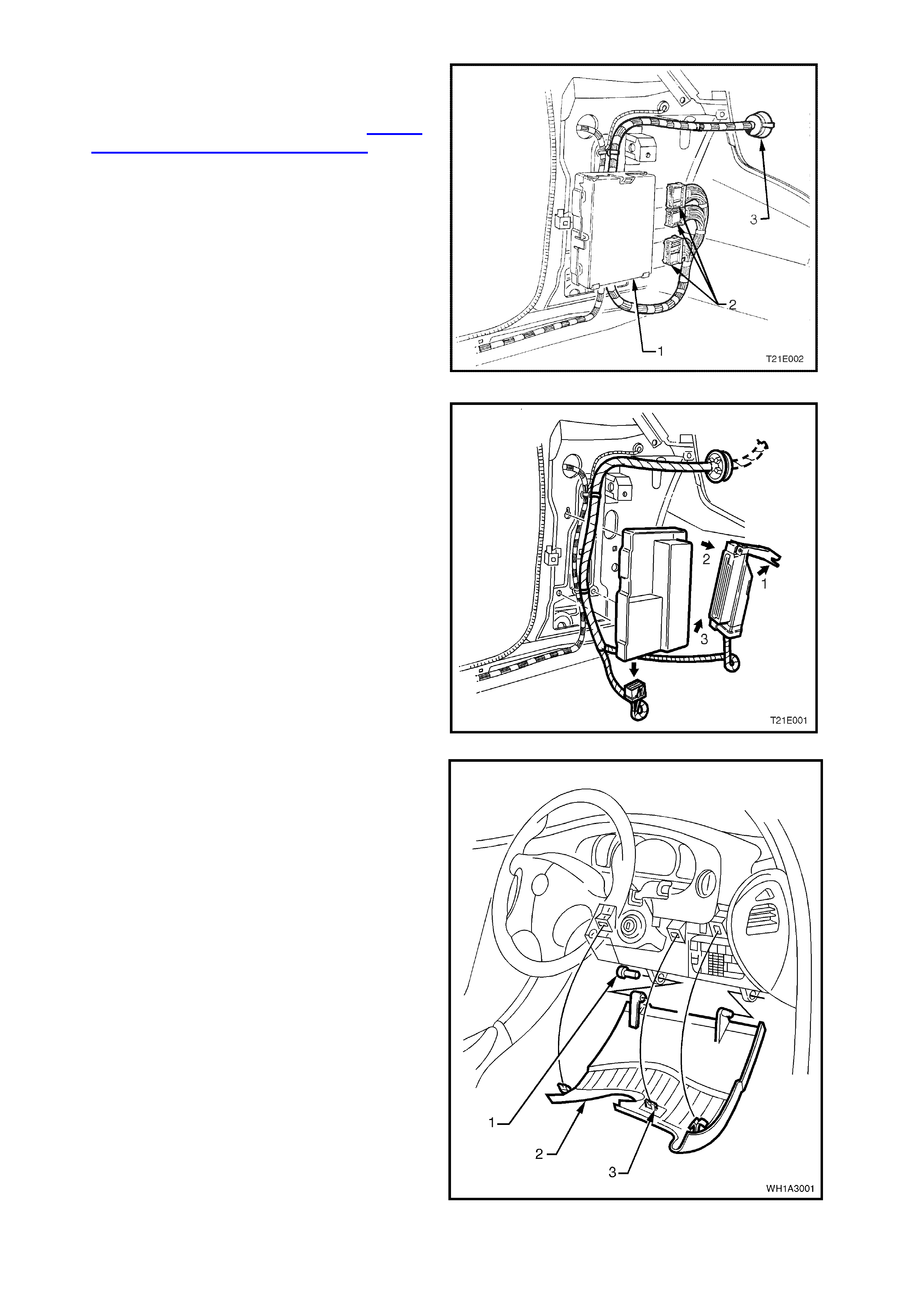
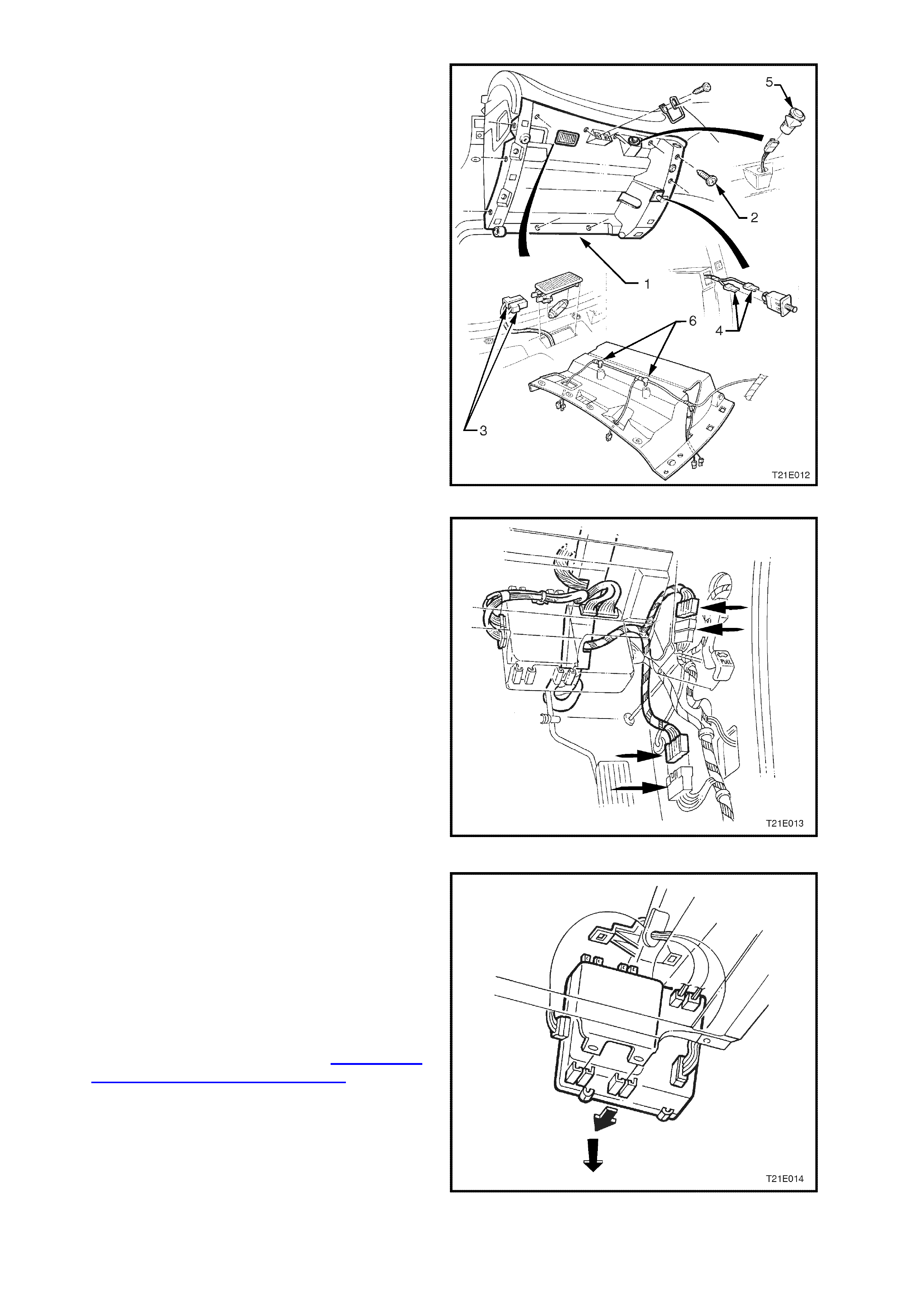
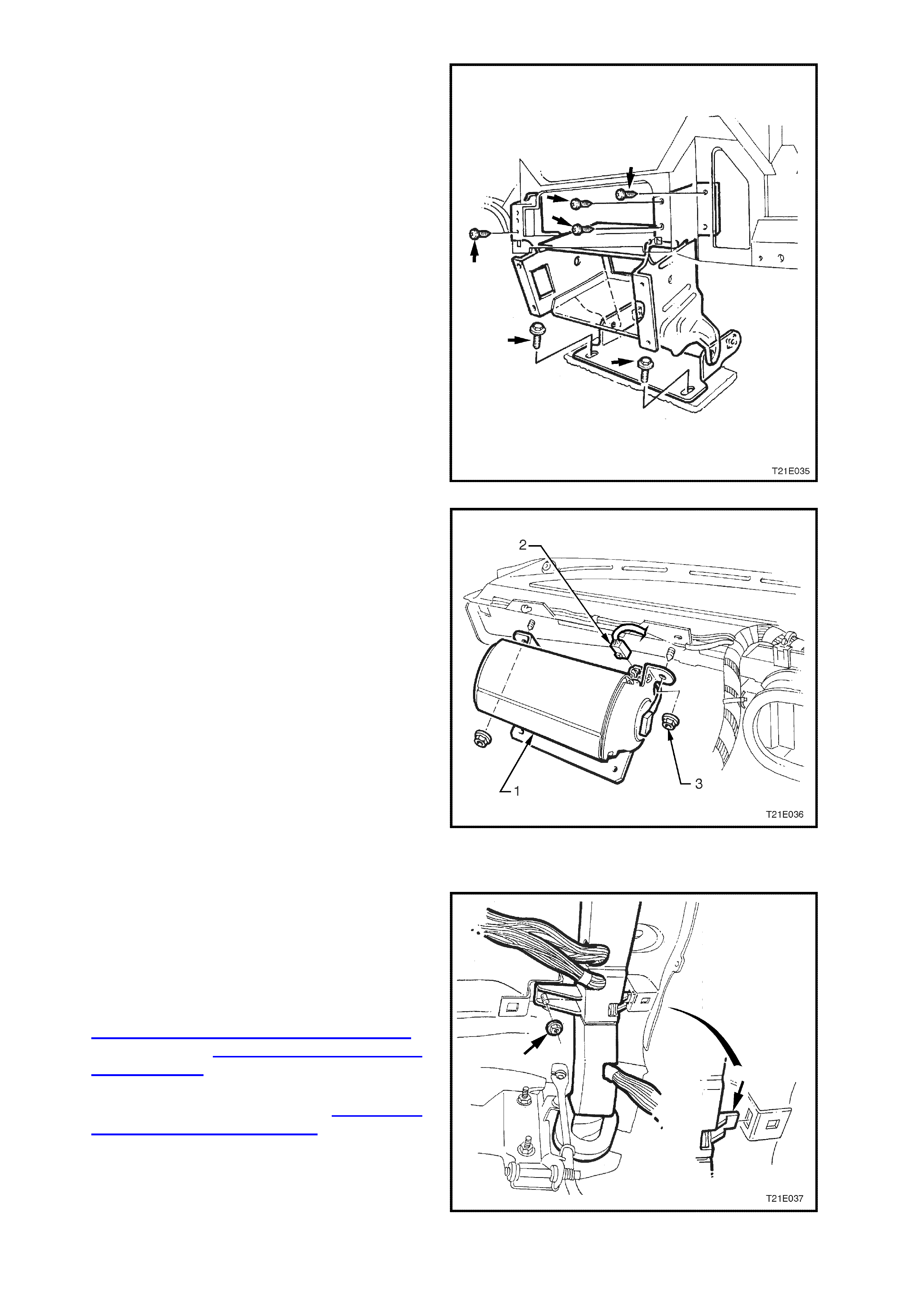
7. On a vehicle with V6 or V6 supercharged
engine, disconnect the powertrain control
module harness connection (2) from the
powertrain control module (1), refer to Section
6C1 POWERTRAIN MANAGEMENT - V6
ENGINE. The module should be removed from
the vehicle to prevent damage occurring.
Compress lugs on powertrain harness grom met
(3) and push powertrain harness and
connectors out into the engine compartment.
Figure 1E-2
8. On a vehicle with a GEN III V8 engine,
disconnect the powertrain harness connector
from the throttle relaxer control module as per
the following:
1. Lift the locking lever upwards.
2. Pull the top of the connector out away from
the control module.
3. Lift the wiring harness connector up to
disengage it from the control module.
9. On a vehicle with a GEN III V8 engine,
disconnect the powertrain harness connector (4)
from the Powertrain Interface Module (PIM).
Compress lugs on powertrain harness grom met
and push powertrain harness and connectors
out into the engine compartment.
Figure 1E-3
10. Adjust steering wheel to upper most position.
Grasp the right hand side of the instrument
panel lower cover panel (1) firmly and pull
towards rear of vehicle releasing locating clip
(3). Repeat the procedure for the left hand side
of the cover.
Using a flat bladed screwdriver, prise the left
hand instrument panel lower cover panel hinge
pin (1) out.
Tilt the instrument panel lower cover down on
the left side and dis engage the right hand hinge
pin. Remove panel.
Figure 1E-4
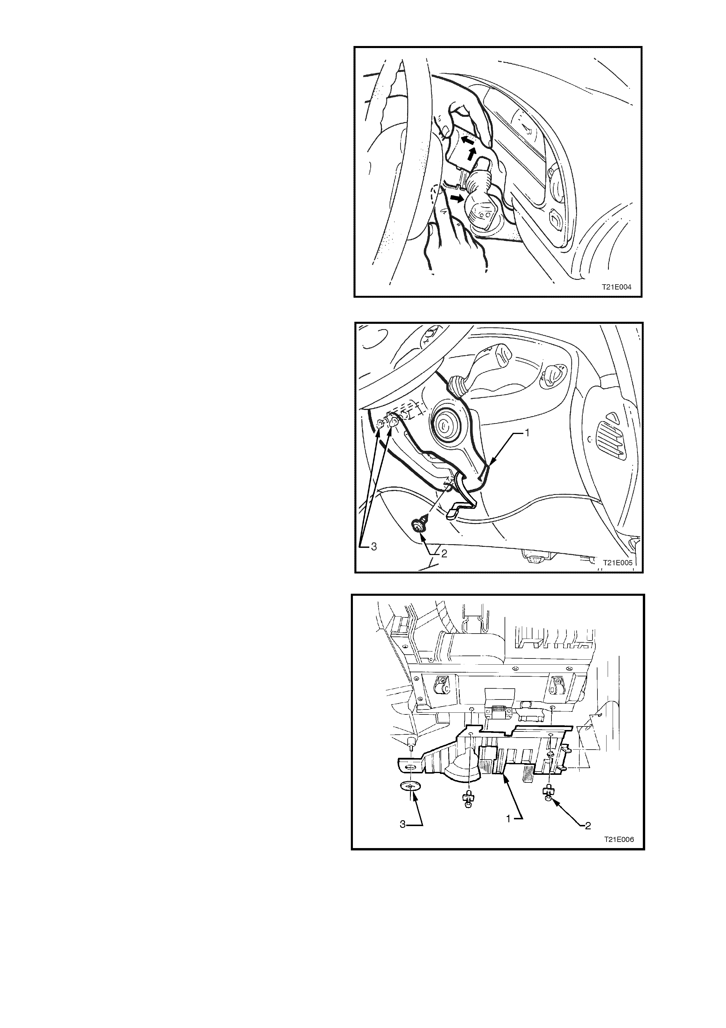
11. Release the steering column height adjuster,
completely lower steering column and leave
lever in the released position.
12. Insert f inger between the steer ing wheel and the
lower cover as shown in Fig. 1E-5 and apply a
small amount of pressure (pushing towards the
instrument cluster) while lifting the upper cover
upwards.
Figure 1E-5
13. Rem ove screw (2) securing the lower cover (1)
to the steering column.
14. Slide lower cover toward the steering wheel to
release cover from the two retaining tangs (3)
on the steering column.
15. While feeding the key reader outer surround
from lower cover, remove co ver.
Figure 1E-6
16. Remove the two scrivets (2) securing the
footwell upper closing panel (1).
Prise off the retaining button (3) and detach the
footwell upper closing panel.
W her e fitted disconnect front f ootwell lamp f rom
footwell upper closing panel.
Figure 1E-7
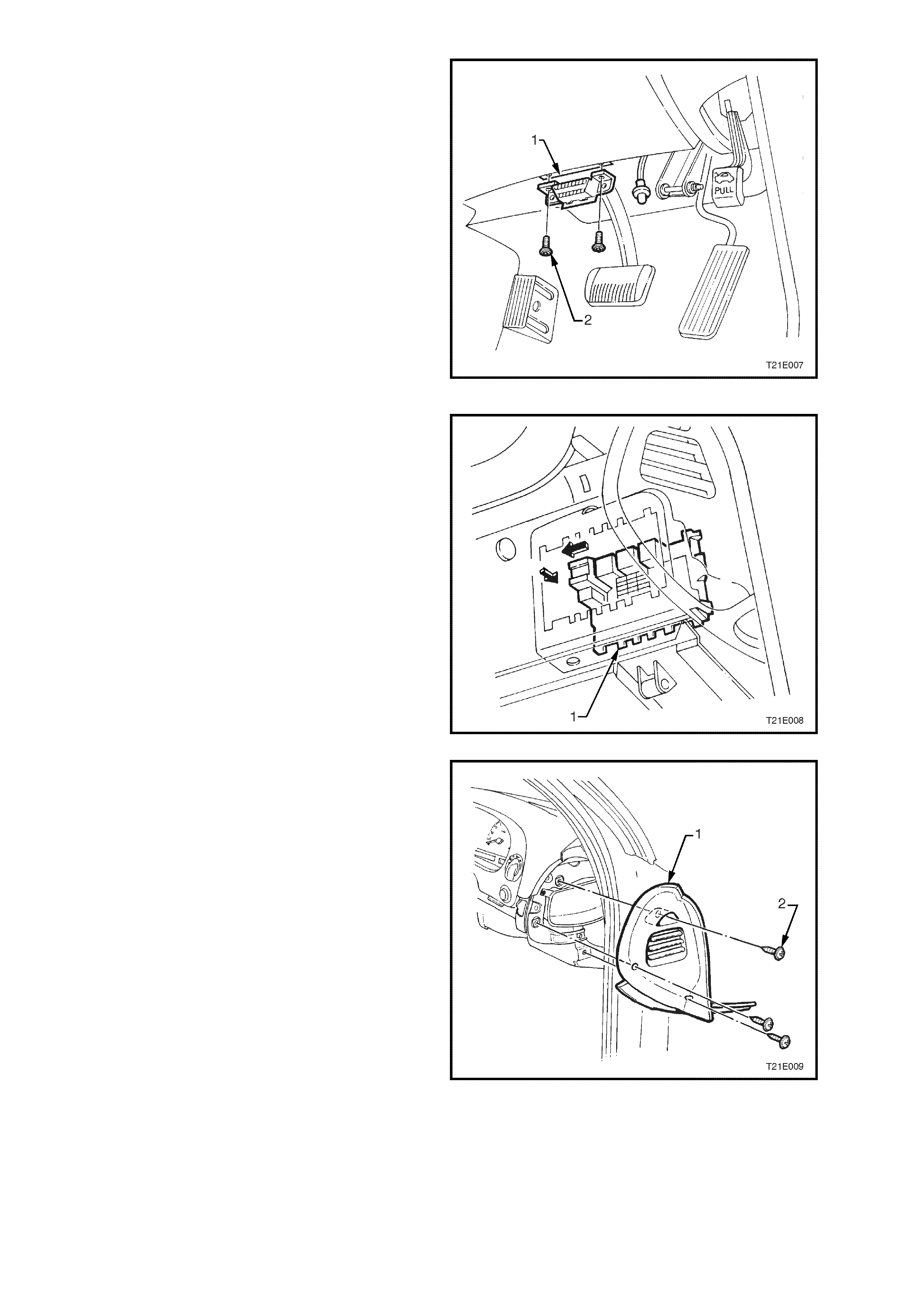
17. Remove two screws (2) securing the diagnostic
link connector (1) to the instrument panel lower
trim right side assembly.
Figure 1E-8
18. Slide the passenger compartment relay and
fuse block (1) to the left, push through support
panel and withdraw towards front of vehicle.
Figure 1E-9
19. Remove the three screws (2) securing the right
hand instrument panel end cap (1) to the
instrument panel and remove end cap.
Figure 1E-10
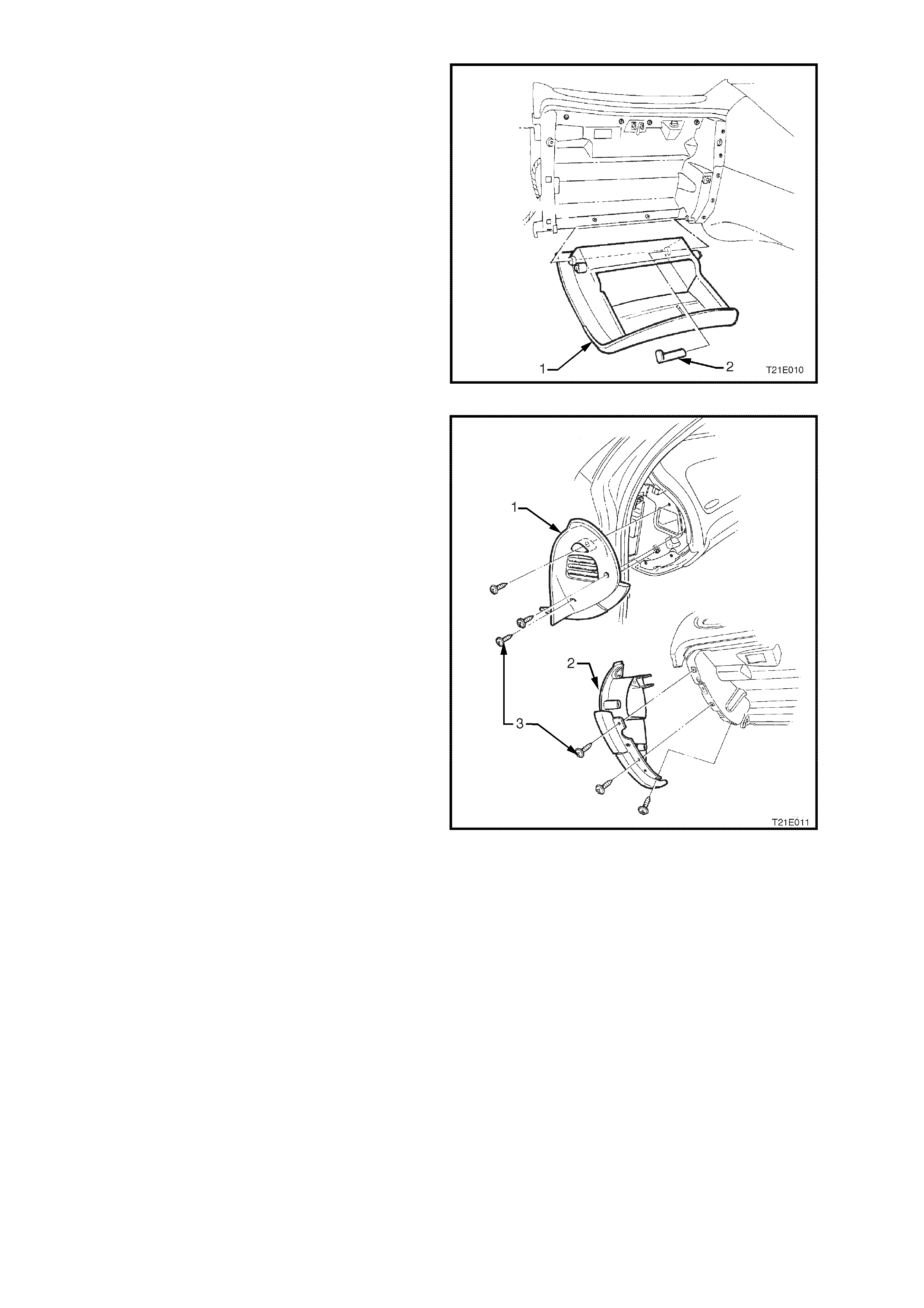
20. Open the instrument panel compartment (1),
and lever the hinge pin (2) f rom the right side of
the compartment. Lower compartment and
withdraw the pin. Disengage right hand travel
limiting peg f rom slot in ins trum ent panel roof by
deforming plastic tang.
Figure 1E-11
21. Remove the six screws (3) securing the left
hand instrument panel end cap cover (1) and
end cap (2) to the instrum ent panel and rem ove
end cap cover and end cap.
Figure 1E-12
22. Remove the 11 retaining screws (2) from
instrument panel compartment roof (1) and
screw securing Instrument facia side extension
to console. Disconnect the instrument panel
compartment lamp (3) and switch (4)
connectors, disconnect the luggage
compartment lock switch connector (5) and
unclip instrument panel compartment wiring
harness (6).
Figure 1E-13
23. Remove drivers side shroud lower trim
assembly.
24. Disconnect body harness to main wiring
harness connectors (arrows) at the right hand
cowl panel.
Figure 1E-14
25. Remove Body Control Module (BCM) from
mounting br ackets by pushing the bottom of the
BCM towards the front of the vehicle until the
BCM disengages from the lower mounting
bracket.
NOTE: The wiring harnesses are still connected.
Grasp the BCM, and gently pull the BCM down
disengaging it from the upper mounting bracket.
26. Remove the transmission console and detach
console wiring harness, refer to Section 1A3
INSTRUMENT PANEL & CONSOLE.
Figure 1E-1
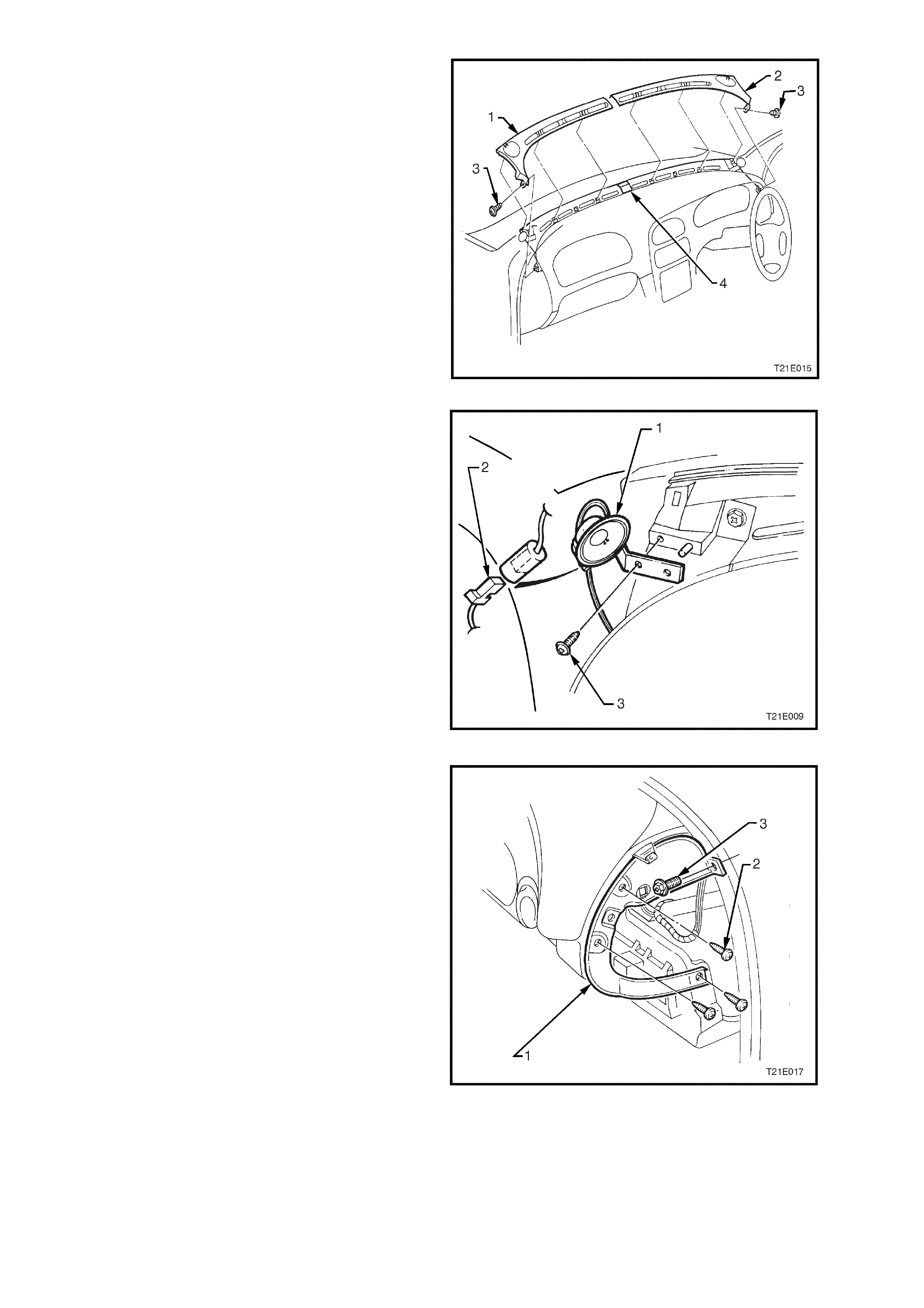
27. Remove the two retaining screws (3) from the
left (1) and right (2) hand demist nozzle grilles
and, taking care not to damage the solar
sensor / remote receiver module, remove both
demist nozz le grilles.
Figure 1E-16
28. Disconnect the left and right front instrument
panel speaker wiring harness connectors (2).
Using a Phillip’s head screwdriver, remove the
two screws (3) (one each side) attaching front
instrum ent panel speakers (1) and rem ove both
speakers.
Figure 1E-17
29. Remove the four retaining screws (2 & 3) from
the instrument panel carrier end panel (1) right
side and remove panel.
Figure 1E-18

30. Remove the four attaching screws (2) securing
instrument panel carrier end panel (1) left side
and three bolts (3) attaching the passenger air
bag support rail, lower lef t side r ail, and rem ove
panel.
Figure 1E-19
31. Remove screws (3) retaining the instrument
facia (2) and instrument facia storage
compartment assembly (4).
32. Remove instrument facia storage compartment
and pull instrument facia escutcheon (1) from
retaining clips.
33. Remove instrument facia (2) by pulling facia
from retaining clips.
NOTE: Care must be taken to disconnect the
headlamp switch, fog lamp switch, trip computer
switch, clock and hazard switch from the main
wiring harness connectors.
Figure 1E-20
34. Remove left hand centre facia side extension
refer to Section 1A3 INSTRUMENT PANEL
AND CONSOL.
35. Unclip antenna leads from inboard end of
glovebox lower rail.
NOTE: This is necessary to provide enough
antenna cable to pull radio forward.
36. Remove service tool hole covers (2) and
remove radio/cassette/CD from instrument
panel using service tool 179 1308 0000 (1).
Figure 1E-21
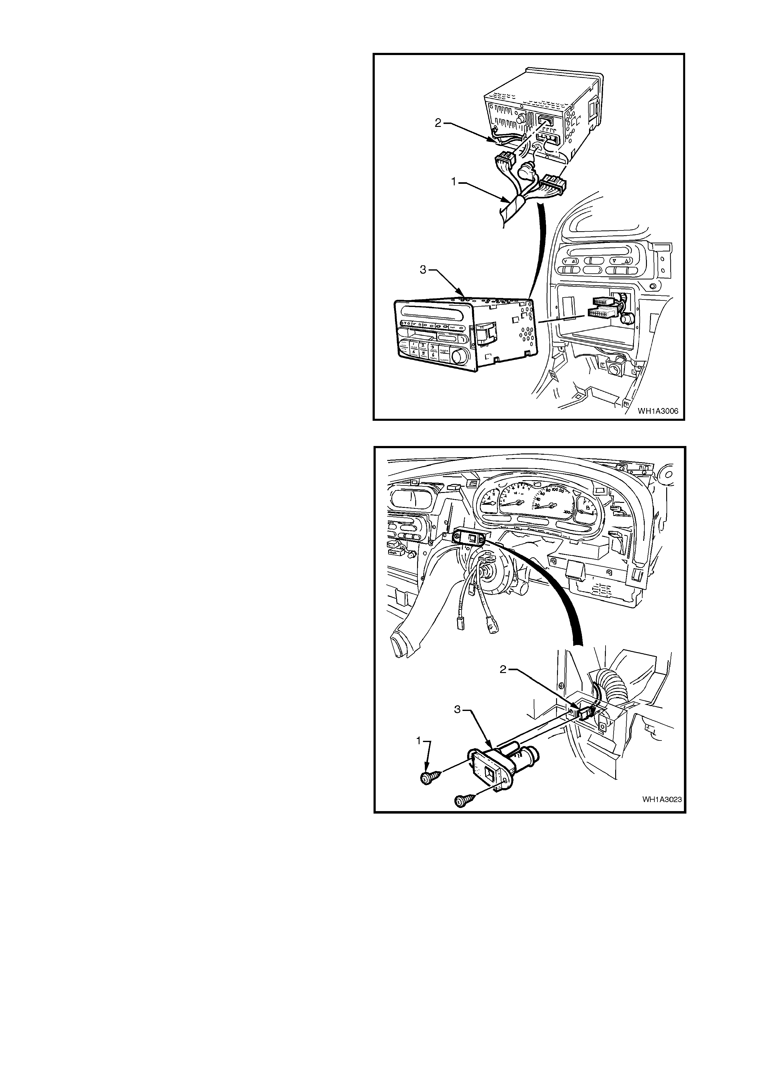
37. Disconnect radio/cassette harness and CD
connector (1). Disconnect antenna and diversity
antenna (2) and remove Radio/Cassette/CD (3).
Figure 1E-22
38. Disconnect the wiring harness connector (2)
and aspirator tube from the in-car temperature
sensor (3). Remove the screws (1) securing
the in-car tem per ature sens or to the ins trum ent
panel and remove the in-car sensor.
Figure 1E-23
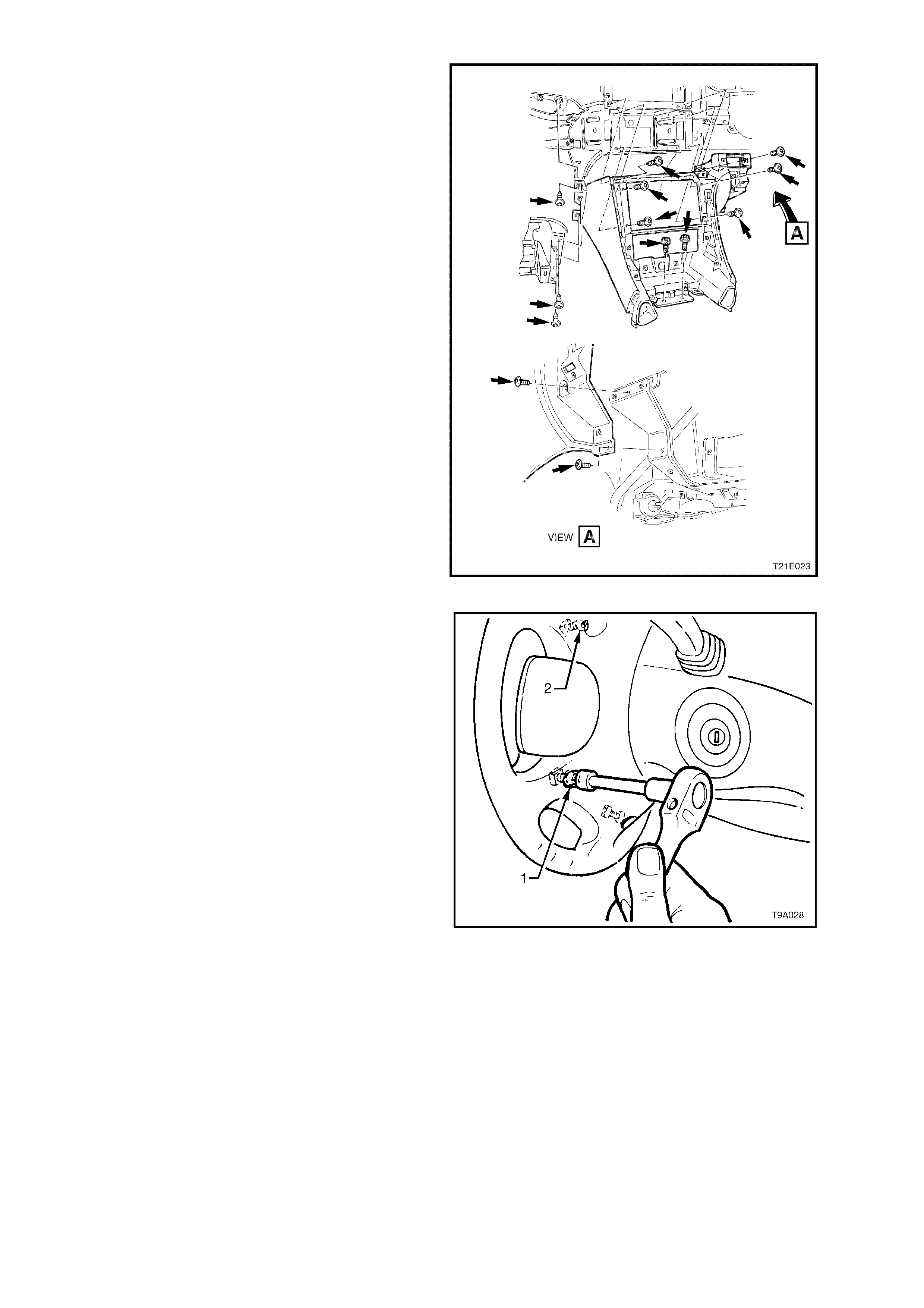
39. Remove the 13 screws secur ing the centr e f ac ia
assembly to the instrument panel and remove
centre facia assembly.
Figure 1E-24
40. Using a number T30H Torx bit (1),
commercially available or Tool No. ETX30H
and a suitable holder suc h as T ool No. J 25359-
8, loosen and remove four screws (2) from the
rear of steering wheel securing the horn bar
and air bag inflator module assembly to the
steering wheel.
Figure 1E-25
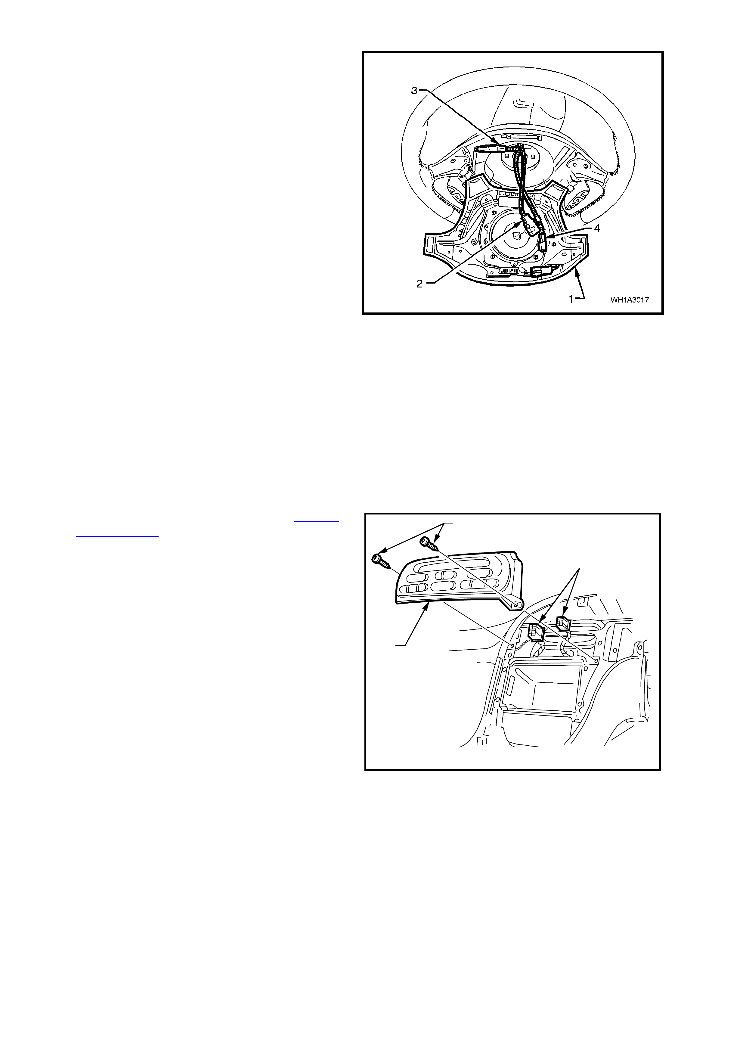
41. Lift up horn bar and air bag inflator module
assembly (1) from the steering wheel, remove
the yellow clock spring to inflator assembly
connection (2) and disconnect wiring harness
connectors (3 and 4) from rear of assembly.
NOTE: Take extrem e care when disconnecting the
left hand horn pad connector (3) from the stereo
control wiring connector otherwise, damage to the
stereo control wiring could result.
42. Remove horn bar and air bag inflator module
assembly.
CAUTION: When carrying a live (undeployed)
horn bar and air bag inflator module assembly,
make sure the bag opening in the horn bar is
pointed away from you. Never carry the horn
bar and air bag inflator module assembly by the
horn bar wires or connectors on the underside
of the assembly. In case of an accidental
deployment, the bag will then deploy with
minimal chance of injury.
When placing a live horn bar and air bag
inflator module assembly on a bench or other
surface, always face the bag and horn bar up,
away from the surface. Never rest the horn bar
and air bag inflator module assembly with the
horn bar f ace down . This is necessary so th at a
free space is provided to allow the air bag to
expand in the unlikely event of accidental
deployment. Otherwise, personal injury may
result.
Figure 1E-26
43. Remove the steering wheel, refer to Section
9A STEERING.
44. Remove the screws (2) securing the ECC
module (1) to the instrument panel.
45. Pull module from instrument panel, disconnect
the wiring harness connections (3), and remove
module.
T21E029
1
2
3
Figure 1E-27
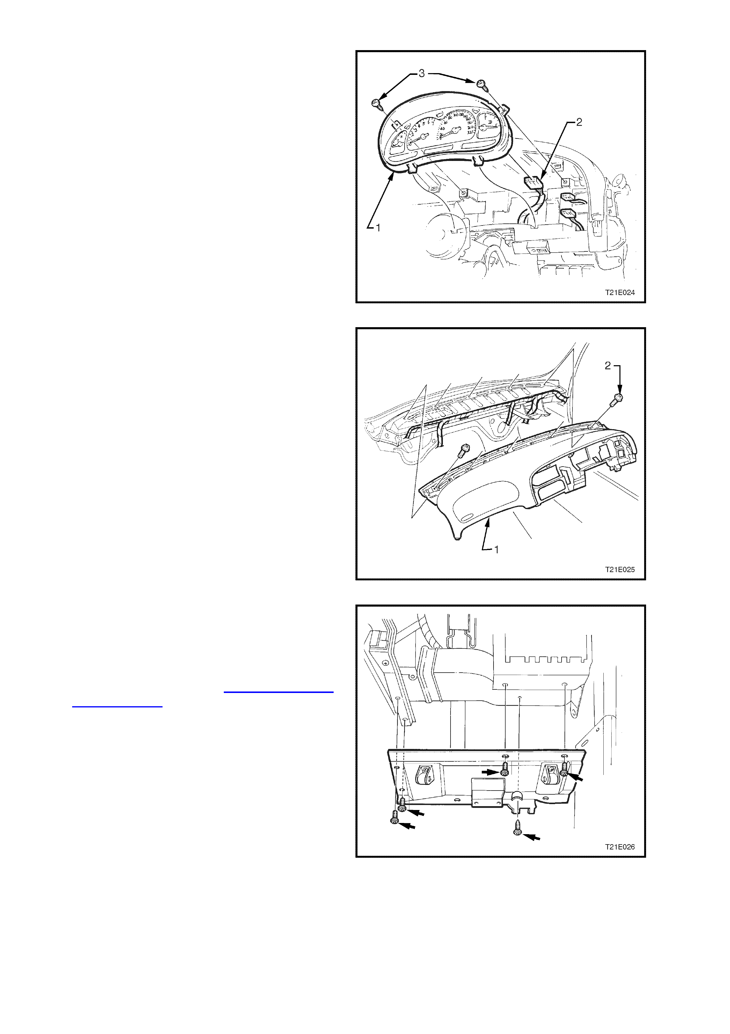
46. Remove the two screws (3) securing the
instrument cluster assembly (1).Lift instrument
cluster assembly from instrument panel and
disconnect wiring harness connector (2) from
rear of cluster, remove cluster.
Figure 1E-28
47. Remove the five retaining screws (2) along top
edge of instrument panel pad (1).
Figure 1E-29
48. Remove the five screws attaching the fuse and
BCM panel to the instrument panel, remove
panel.
49. Remove HVAC unit to door outer right hand
side and HVAC unit to door vent inner right
hand side. Refer to Section 2B AIR
CONDITIONING - ECC REMOVAL AND
INSTALLATION.
Figure 1E-30
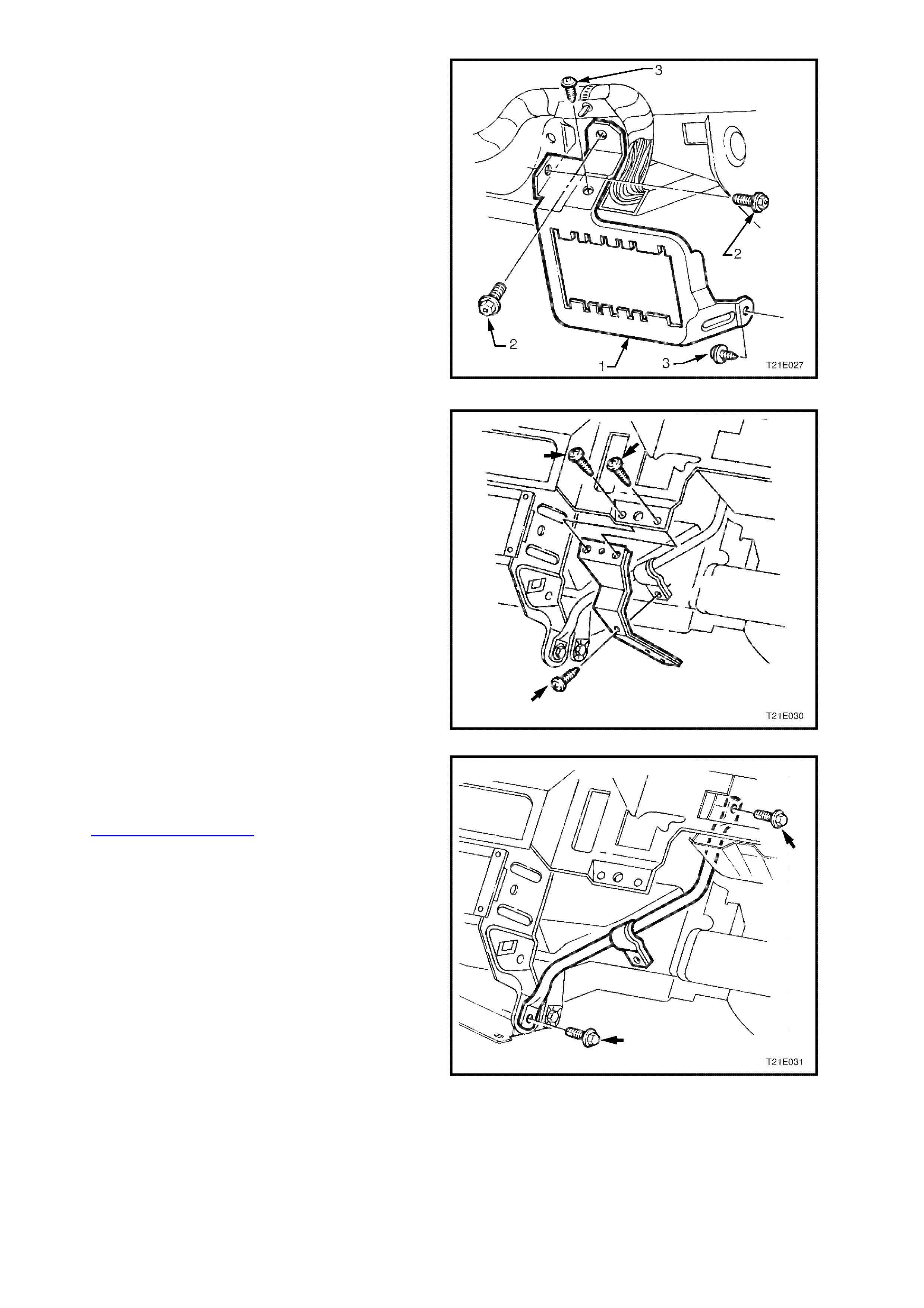
50. Remove four screws (2 & 3) securing the
steering column bracket outer support (1),
remove support.
Figure 1E-31
51. Remove the three screws securing the centre
facia support rail to the instrument panel,
remove support rail.
Figure 1E-32
52. Remove the support steering column bracket
inner attaching screws, remove bracket.
53. Remove the steering column assembly, refer to
Section 9A STEERING.
Figure 1E-33
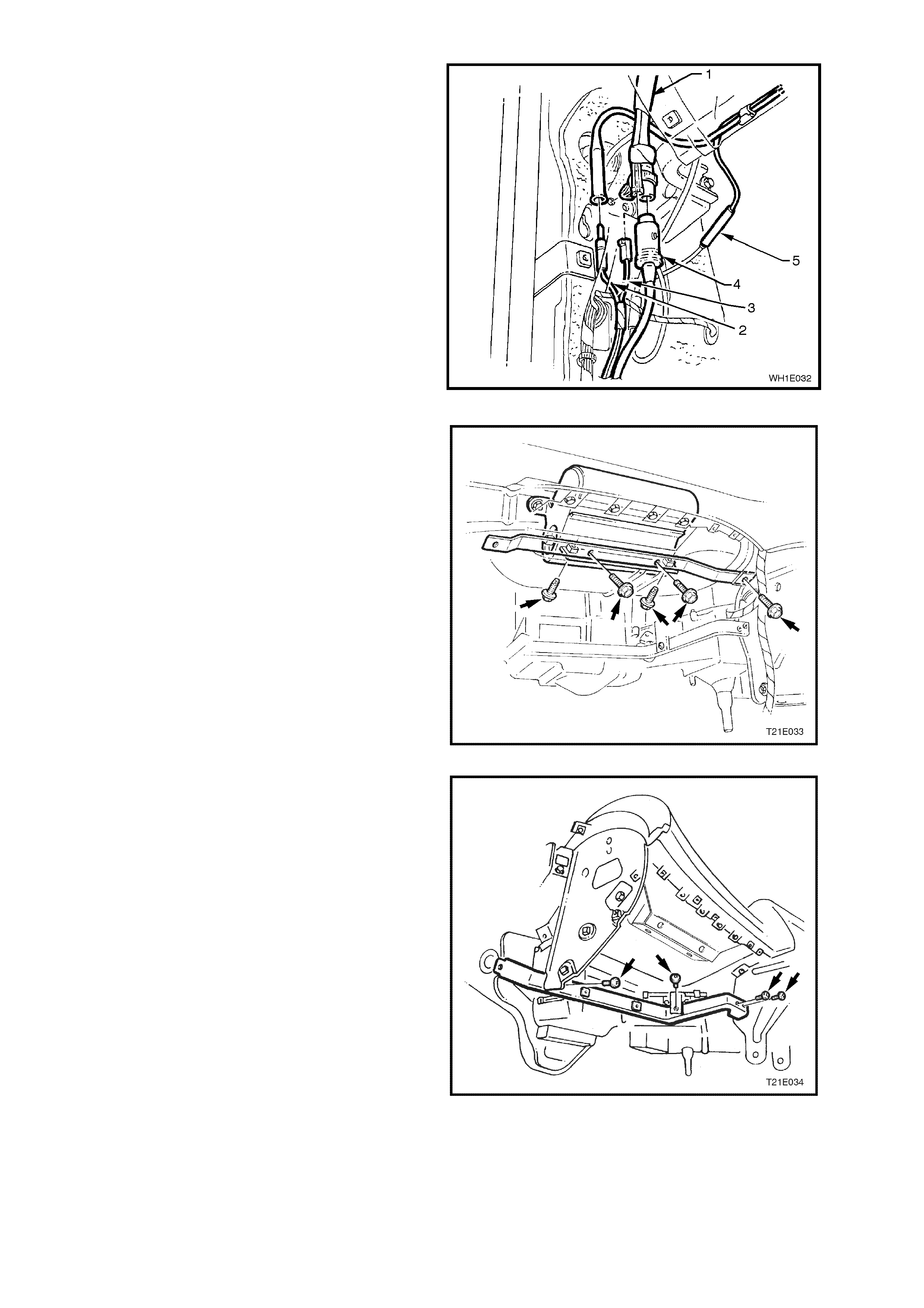
54. At the left hand cowl panel disconnect diversity
antenna leads (2 and 3), CD changer harness
connector (4) from main wiring harness
connector (1) and power antenna connector (5).
Figure 1E-34
55. Remove the five scr ews sec ur ing the passenger
air bag support rail assembly, remove rail.
Figure 1E-35
56. Remove the four screws retaining the lower left
side ra il, remove rail.
Figure 1E-36
57. Remove the six instrument panel carrier rail
assembly retaining screws and remove carrier
rail.
Figure 1E-37
58. Disconnect passenger air bag connector (2)
located on the right hand side of air bag (1).
Remove two nuts (3) attaching air bag to
instrument panel assembly.
CAUTION: When carrying a live (undeployed)
front passenger's air bag inflator module
assembly, make sure the b ag openin g is poin ted
away from you. In case of an accidental
deployment, the bag will then deploy with
minimal chance of injury. When placing a live
front passenger's air bag inflator module
assembly on a bench or other surface, always
face with the air bag up, away from the surface.
Never rest the air bag inflator module assembly
wit h the air bag f ace down . This is necessary so
that a free space is provided t o allow t he air bag
to expand in the unlikely event of accidental
deployment. Otherwise, personal injury may
result. Figure 1E-38
59. Remove main wiring harness cabin protector
attaching nut and disengage the protector from
the slot in the retaining bracket.
60. Remove the throttle cable from the accelerator
pedal through to the throttle body or if fitted,
through to the throttle relaxer, refer to the
relevant Section in this Service Information;
Section 6C1 POWERTRAIN MANAGEMENT -
V6 ENGINE or Section 6C3 POWERTRAIN
MANAGEMENT - GEN III V8 ENGINE.
61. If fitted, remove the throttle relaxer assembly
from the cockpit module, refer to Section 6C3
POWERTRAIN MANAGEMENT - GEN III V8
ENGINE.
Figure 1E-39
62. Disconnect the blower motor wiring harness
connector (1) and fan speed control wiring
harness connector (2) from the HVAC unit (3).
Detach wiring harness retaining clip (4) from
HVAC unit.
Figure 1E-40
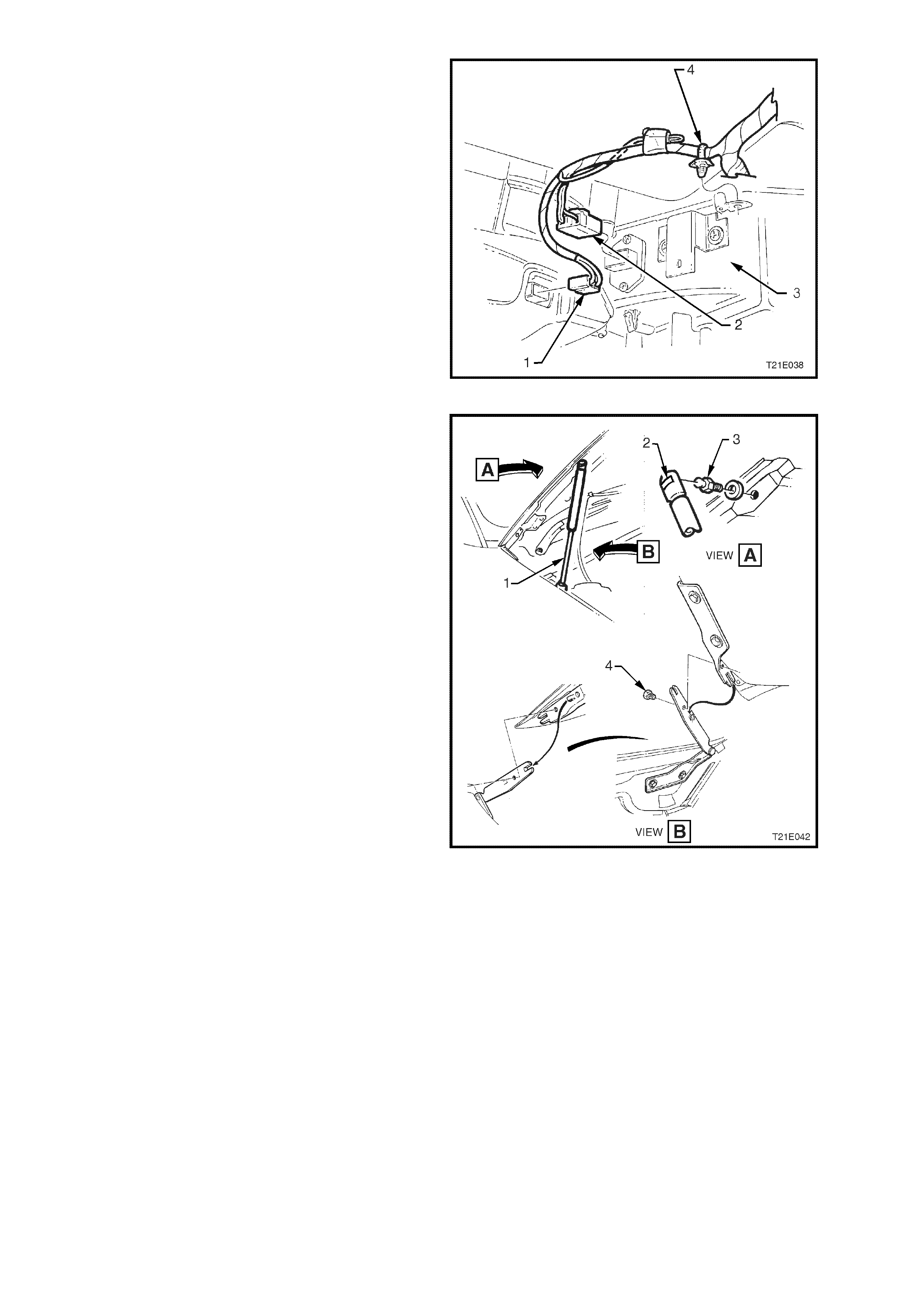
63. Disconnect windshield washer hose from engine
hood and with engine hood adequately
supported, remove clips (2) securing upper end
of struts ( 1) to hood pivots (3). Dis engage struts
from hood pivots and lay strut down on fender
inner panel.
With the aid of an assistant hold hood
assem bly, remove engine hood brac ket to hinge
attaching screws (4), and remove hood.
Figure 1E-41
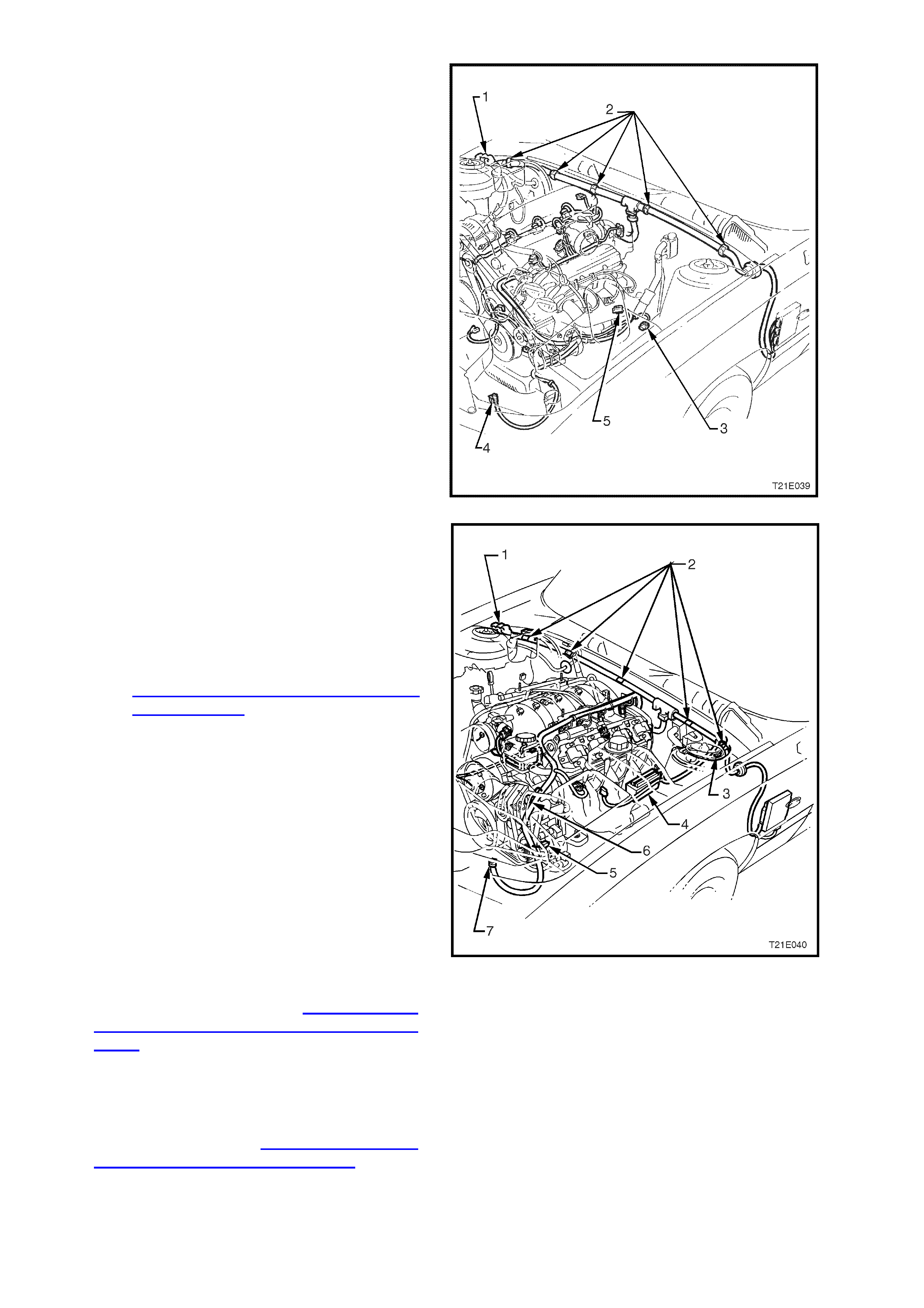
64. On vehicles with V6 engine; release powertrain
harness to cockpit module retaining clips (2)
and disconnect the following wiring harness
connectors:
1. The three powertrain harness to main
wiring harness connectors.
3. Intake air temperature sensor at air
cleaner.
4. Air conditioning pressure transducer
connector at air conditioning condenser.
5. Mass Air Flow (MAF) sensor.
Theft deterrent horn (if fitted).
Lay wiring harness on top of engine.
Figure 1E-42
65. On vehicles with GEN III V8 engine; release
powertrain harness to cockpit module retaining
clips (2) and disconnect the following wiring
harness connectors:
1. The three powertrain harness to main
wiring harness connectors.
3. Theft deterrent horn (if fitted).
4. Powertrain control module, refer to
Section 6C3 POWERTRAIN
MANAGEMENT - GEN III V8 ENGINE.
5. Intake air temperature sensor at air
cleaner.
6. Mass Air Flow (MAF) sensor.
7. Air conditioning transducer.
Lay wiring harness on top of engine.
Figure 1E-43
66. Remove the front wiper motor and linkage
assembly, refer to Section 12C
INSTRUMENTS, WIPERS / WASHERS &
HORN.
67. Disconnect the main wiring harness from the
engine compartment electrical equipment.
68. Tag and remove all relays, fusible links, and
fuses from the relay housing in the engine
compartment, refer to Section 12N FUSES,
RELAYS & WIRING HARNESSES for the
location and terminal assignments.
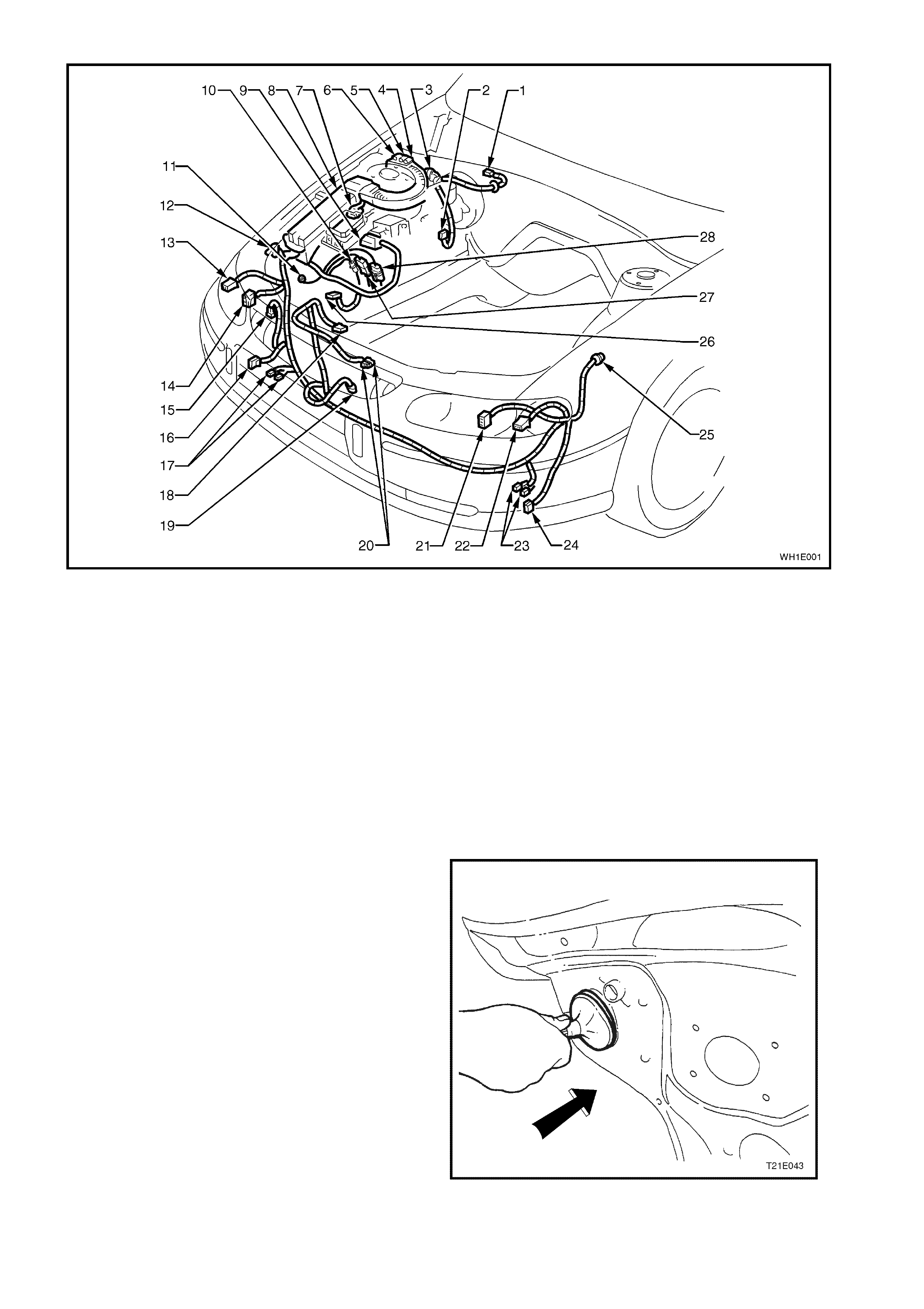
Figure 1E-44
Legend
1. Wiper Motor 11. Body Earth 21. LH Front Headlamp
2. Brake Failure Warning Switch 12. Body Earth 22. LH Front Turn Signal Lamp
3. Diagnostic Interconnect 13. RH Front Turn Signal Lamp 23. LH Horn (2 connections)
4. Powertrain Harness (1) 14. RH Front Headlamp 24. LH Fog Lamp
5. Powertrain Harness (2) 15. Washer Pump 25. LH Front Wheel Speed Sensor
6. Powertrain Harness (3) 16. RH Fog Lamp 26. Battery Harness
7. Cruise Control Actuator 17. RH Horn (2 connections) 27. Battery Harness
8. Relay Box 18. Cooling Fan Motor 28. Power Steering Solenoid
9. ABS ABS/ETC Control Module 19. Ambient Sensor
10. RH Front Wheel Speed Sensor 20. Theft Deterrent Hood Switch (2
connections)
69. Release engine compartment harness tie down
clips, then push the main wiring harness
grommet into the cabin.
Figure 1E-45
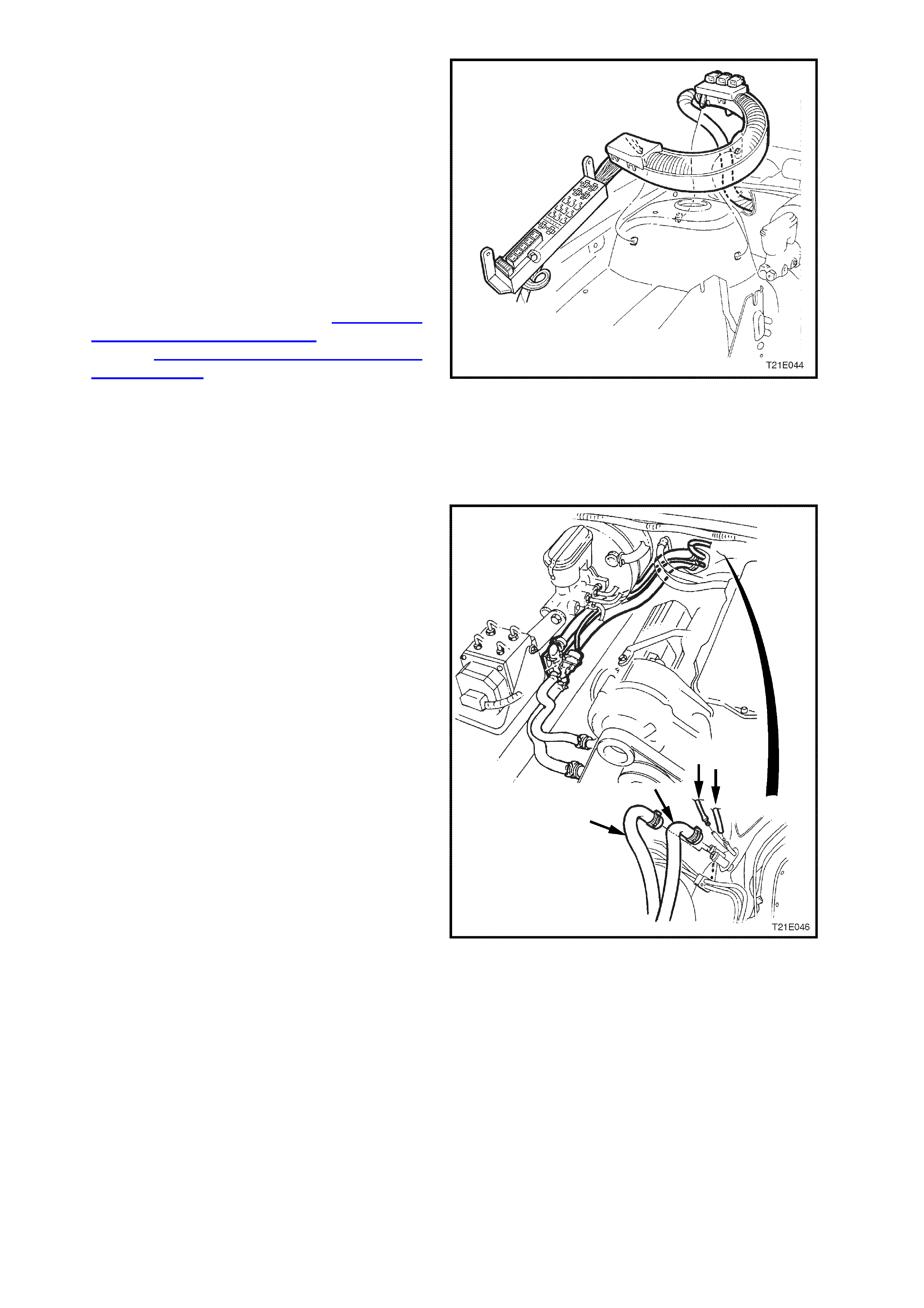
70. If the vehicle is fitted with cruise control,
disconnect the cruise control actuator
connector, located under the main wiring
harness protector.
71. Unclip main wiring harness protector retaining
clips from the strut tower. Pass engine
compartment relay block and main wiring
harness assembly through the cockpit module
panel opening.
IMPORTANT: Take extreme care not to damage
the wiring harness while performing this
operation.
72. Disconnect the fuel feed, return and vacuum
hoses at quick connects, refer to Section 6C1
POWERTRAIN MANAGEMENT - V6 ENGINE
OR Section 6C3 POWERTRAIN
MANAGEMENT - GEN III V8 ENGINE. Plug all
openings to prevent foreign matter entry.
NOTE: Do not attempt to remove hoses from fuel
rail connections. Once removed from fuel rail
connection hoses require replacement.
73. Unscrew fuel pipe retaining bracket from the
cockpit module.
Figure 1E-46
74. Tag and disconnect the heater hoses and
vacuum lines at the cockpit module, refer Fig.
1E-47 (V6 application) or Fig. 1E-48 (GEN III V8
application).
Figure 1E-47
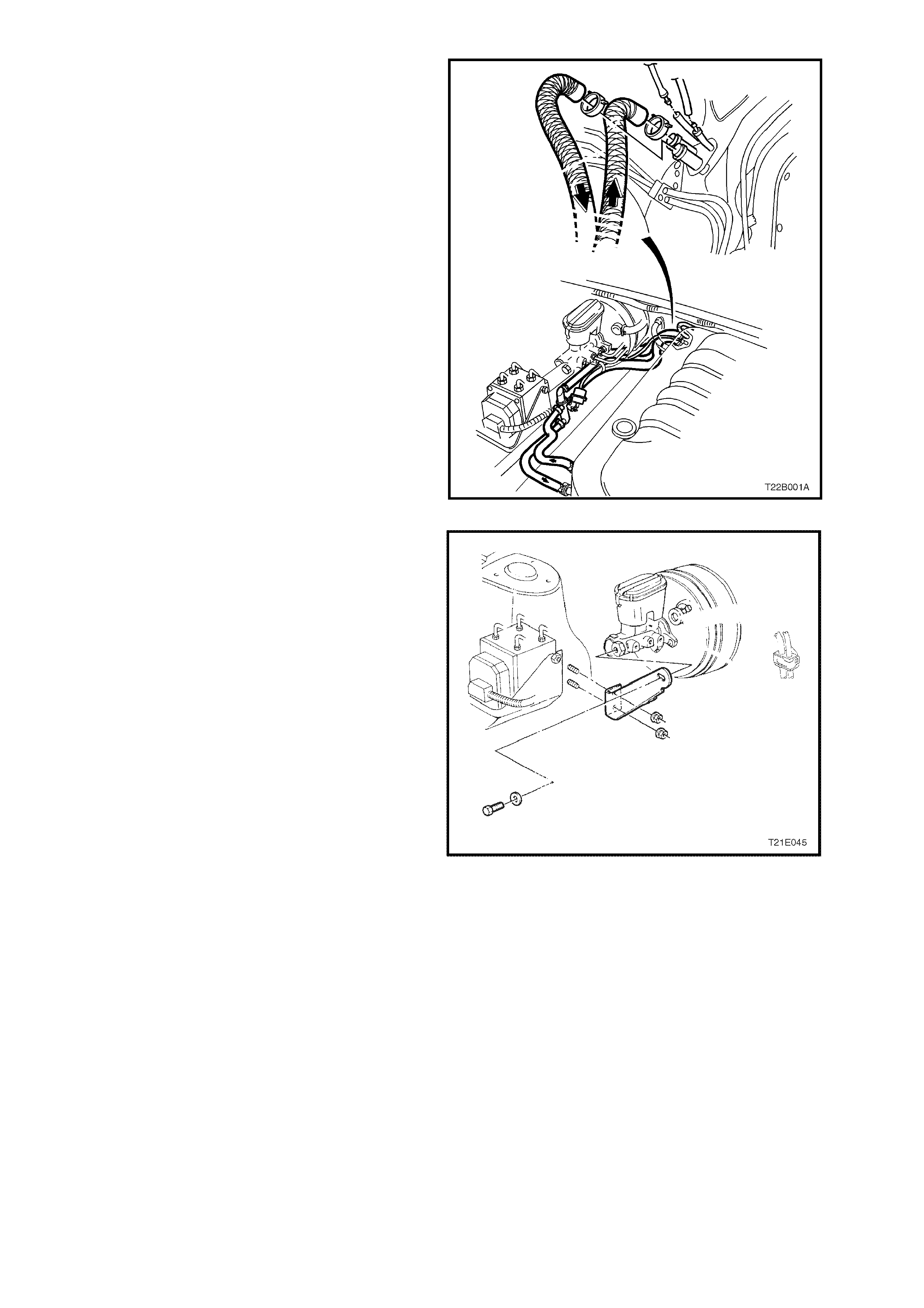
Figure 1E-48
75. Remove nuts and bolt securing the master
cylinder to strut tower brace, remove brace.
Figure 1E-49
76. Tag and disconnect the brake lines, vacuum
hose and electrical harness from the brake
booster, ABS modulator and master cylinder
assembly. Seal all apertures with suitable plastic
plugs.
Remove the two nuts securing the brak e m as ter
cylinder to the brake booster and remove the
brake master cylinder.
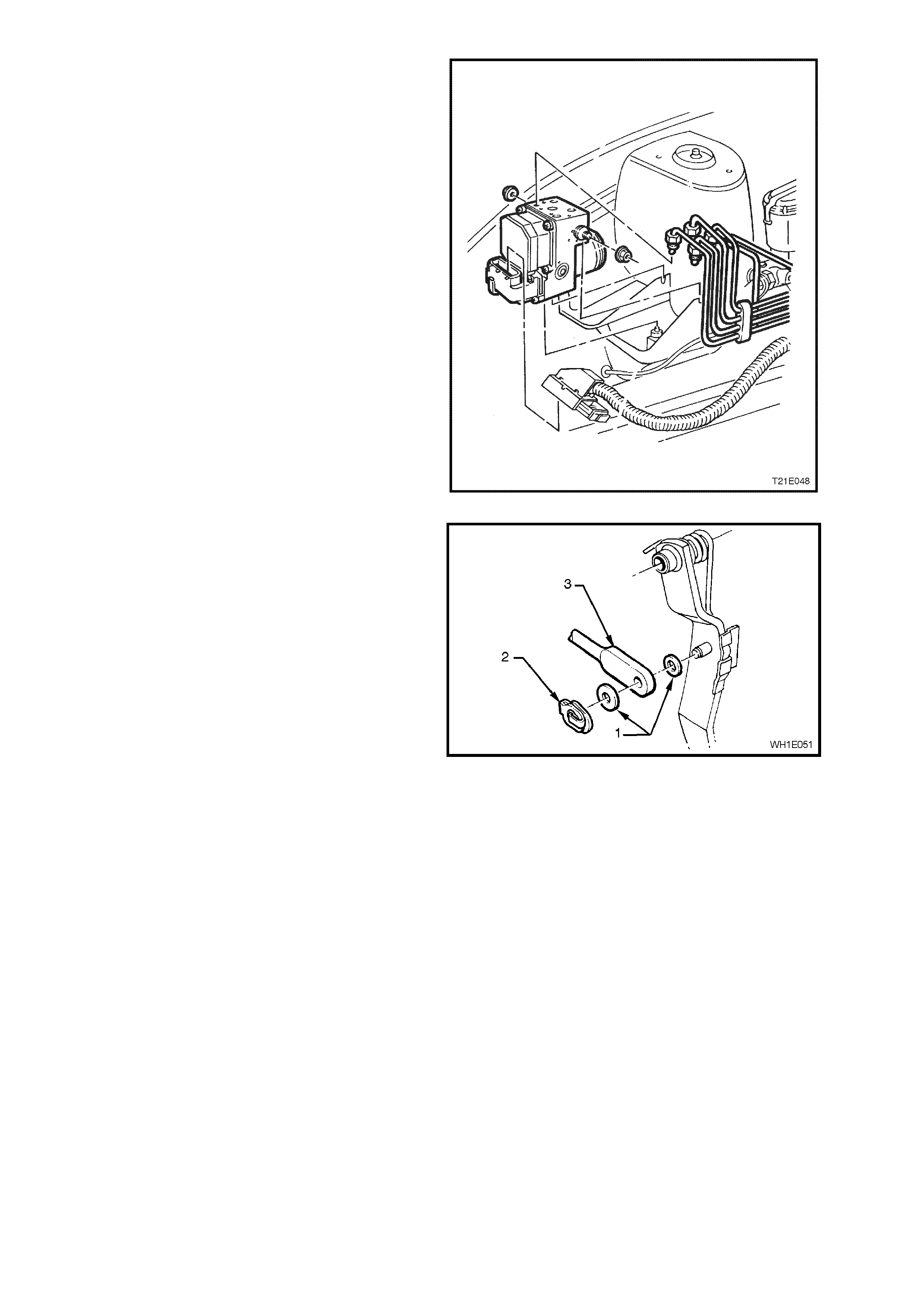
77. Remove the nuts from the blanking plate
adjacent to the brake booster.
Figure 1E-50
78. Remove the retaining clip (2), washers (1) and
brake booster pushrod (3) from the brake pedal.
Figure 1E-51
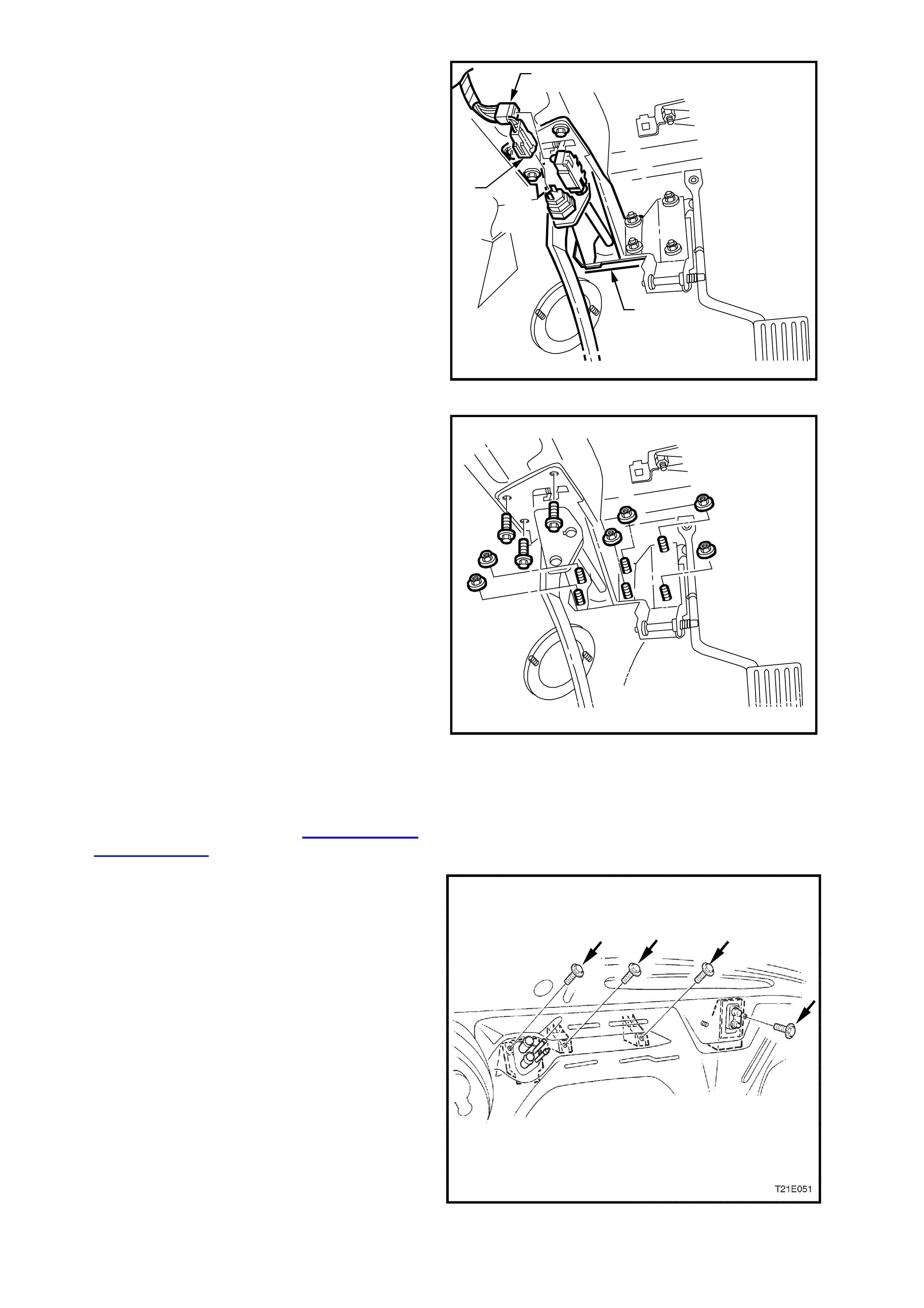
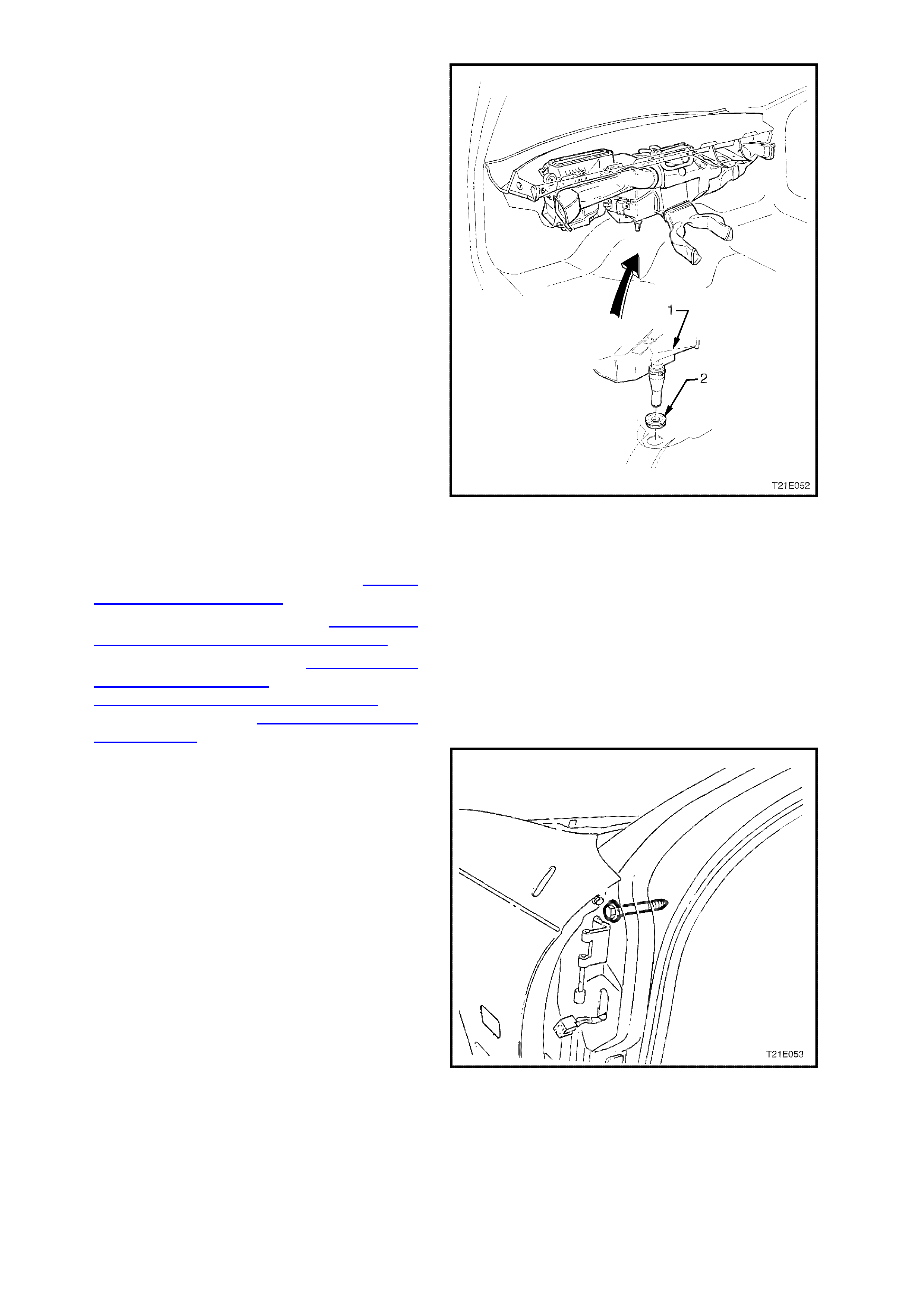
79. Remove stop lamp switch harness connector
(3) and if fitted, cruise control cancel switch
harness connector (2) from the brake pedal
assembly (1).
T21E049
1
2
3
Figure 1E-52
80. Remove the four nuts securing the accelerator
pedal assembly to the cockpit module and
remove accelerator pedal assembly.
81. Remove the remaining two nuts securing the
brake pedal, brake booster to the cockpit
module, and remove the brake booster
assembly.
82. Remove the three screws securing the brake
pedal assembly to the cockpit module and
remove the brake pedal assembly.
T21E050
Figure 1E-53
83. Remove the air conditioning compressor to
thermal expansion valve and condenser to
thermal expansion valve line and hose, then
plug all the fittings. Refer to Section 2B AIR
CONDITIONING - ECC REMOVAL AND
INSTALLATION.
84. From within the engine compartment, remove
the four screws securing the heater case
assembly to the cockpit module.
Figure 1E-54
85. Remove the HVAC unit (1) from the vehicle by
disengaging the drain grommet (2) and easing
the assem bly from the vehicle tak ing c are not to
strain the heater core tubes.
Figure 1E-55
86. Remove the grommets and insulation panels
from cockpit module.
87. Remove the front windshield, refer to Section
1A6 STATIONARY GLASS.
88. Remove the front doors, refer to Section 1A5
FRONT AND REAR DOOR ASSEMBLIES.
89. Remove engine, refer to Section 6A1-1
ENGINE MECHANICAL - V6 ENGINE or
Section 6A1-2 ENGINE MECHANICAL - V6
SUPERCHARGED or Section 6A3 ENGINE
MECHANICAL - GEN III V8 ENGINE.
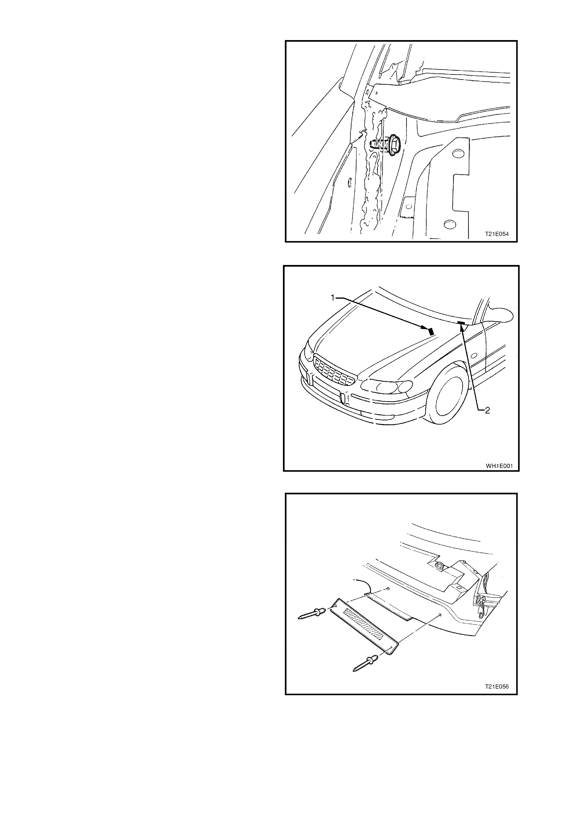
90. Remove the two cockpit module retaining bolts
(one each side) from the A pillar.
Figure 1E-56
91. From within the plenum chamber, remove the
two cockpit module retaining bolts (one each
side).
Figure 1E-57
92. Locate VIN plate (2) and compliance plate (1)
on passenger side of cockpit module panel.
Using a drill and suitable size drill bit, drill out
retaining rivets.
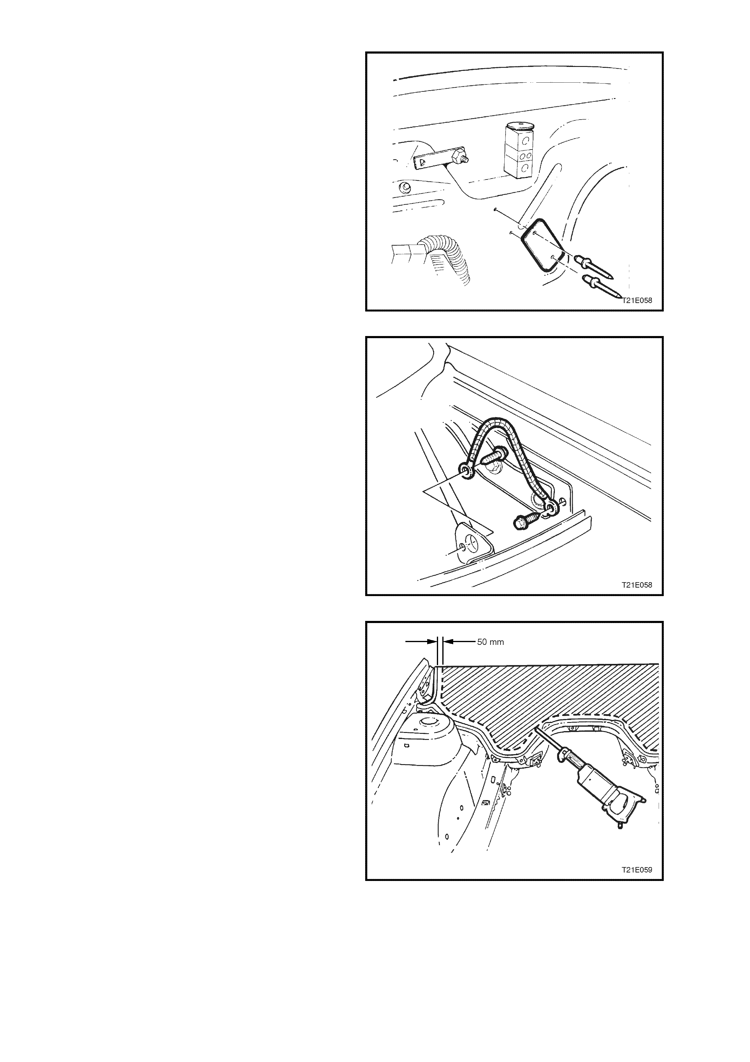
Figure 1E-58
93. Transfer the VIN plate onto the new cockpit
module panel. Using commercially available
hand rivet tool and new rosette headed rivets
(two off each plate) secure the VIN plate to the
new cockpit module panel.
Figure 1E-59
94. Transfer the compliance plate onto new cockpit
module panel. Using commercially available
hand rivet tool and new rosette headed rivets
(two off each plate) secure the safety
compliance plate to the new cockpit module
panel.
Figure 1E-60
95. Remove the two screws retaining cockpit
module to body earth strap and remove from
vehicle.
Figure 1E-61
96. Using a power saw, cut the module panel
approximately 50 mm above the glue track.
CAUTION: Sparks may ignite p etrol in th e fuel or
emission cont rol lines if du e precau tio ns are n ot
taken.
Figure 1E-62
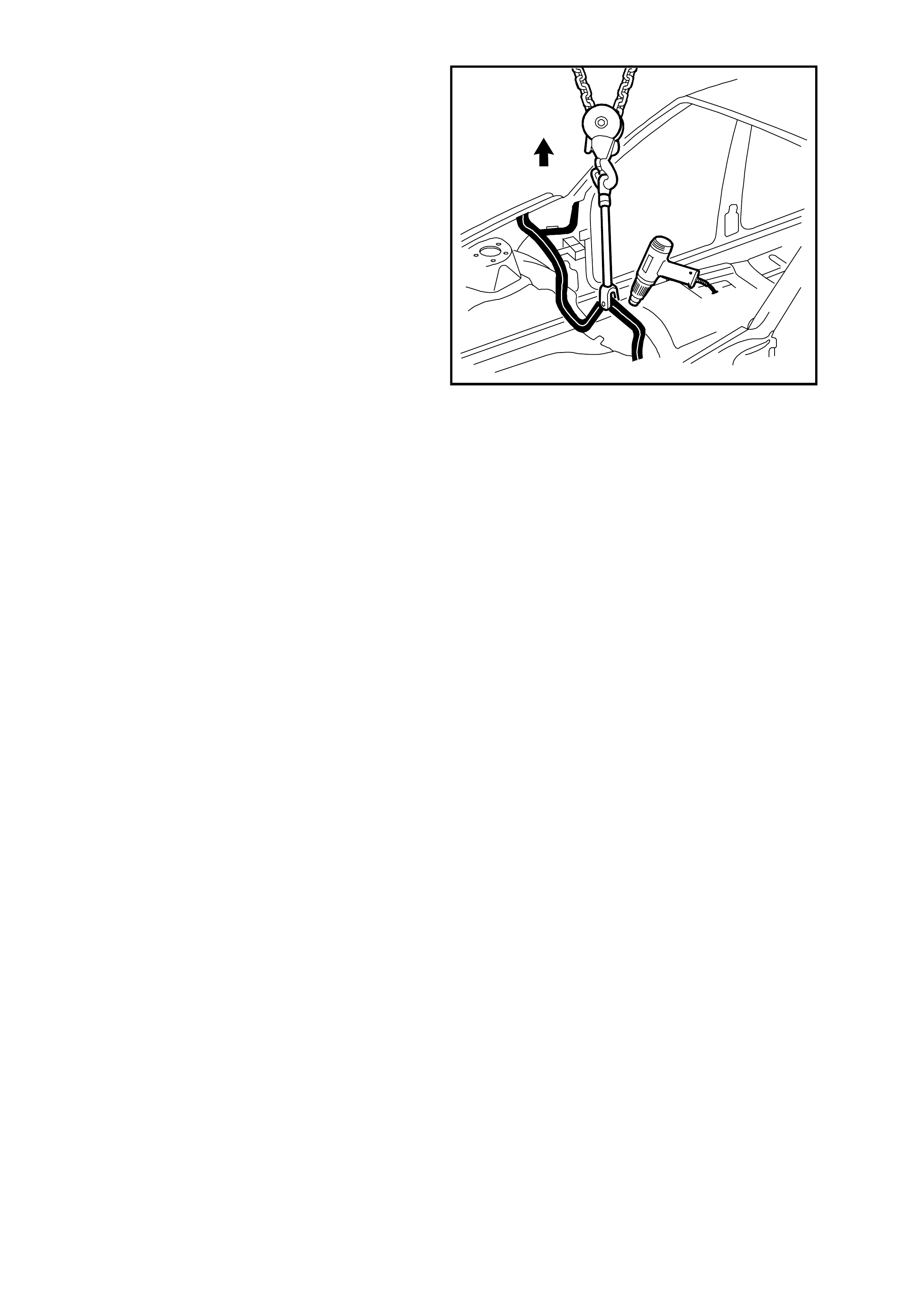
97. Drill a hole in the f lange above the trans mission
tunnel, and attach a chain block and a clevis.
98. Apply and maintain a light tension to the
rem aining part of the module. Heat the adhesive
using a heat gun and pull the panel from the
glue track . Alternatively, cut the adhesive with a
hot knife.
99. Clean the excess adhesive from the glue track
using a hot knife or a heat gun and tool.
CAUTION: To avoid fire, Do Not attempt to burn
the remaining adhesive from the glue track
using an oxygen / acetylene torch.
T21E060
Figure 1E-63

MIXING SILICONE ADHESIVE
Surface Preparation
Clean any remaining adhesive from the glue track using a hot knife or heat gun and tool if necessary .
The vehicle should be painted before installation of the cockpit module. Before painting the vehicle, apply masking
tape to prevent paint entering the glue track.
The adhesive will not properly adhere to paint, over spray, oils, grease etc. The glue track must be free of dirt, dust,
grease, oils and paint or over spray.
Wipe the glue track with a suitable cleaning agent such as “Prepsol”, then clean any residue from the area with a
clean, dry, lint free cloth.
Avoid fitment problems by temporarily installing the cockpit module panel, prior to mixing the adhesive, rectify any
faults found, then remove the panel from the vehicle.
Before mixing the adhesive, it is necessary to have the application gun available. All parts must be clean of any
previous adhesive.
Refer to the latest WH Series Spare Parts Information, for details of where to obtain an applicator gun.
Mixing Adhesive and Catalyst
IMPORTANT: This is a two-part mix, fast cure adhesive, ensure that the panel is ready for installation before mixing
the adhesive. The working time is less than 20 minutes.
Part A : The Adhesive compound, yellow in colour and supplied in a 1.4 kilogram container.
Part B: The Catalyst, used to accelerate the “Cure” time of the adhesive compound and is supplied in a 120 gram
tube.
The contents of the Adhesive Kit, Part Number 92140052 is sufficient to install the module panel in a vehicle.
CAUTION: The vapour from the adhesive may cause breathing difficulties, use only in a well ventilated
area. In case of eye contact, flush immediately with clean water.
COMBUSTIBLE – keep away from spark and flame.
Refer to Safety Precautions in 1.2 GENERAL PRECAUTIONS.
1. Remove the lid from the adhesive compound container.
2. Remove the c ap from the catalyst and pierc e the end of the tube, then squeeze the entire contents of the tube
into the adhesive compound container.
3. Hold the container securely, and mix the catalyst into the adhesive using a paint mixer or a flat clean wooden
utensil.
4. Continue to mix until the adhesive is a consistent grey colour without any streaks.
5. Place the follower plate supplied with the applicator gun into the adhesive container.
6. Remove the front end cap and disposable nozzle from the applicator gun.
7. Cut the tip from the nozzle.
8. Place the applicator gun front end over the hole in the follower plate.
NOTE: The easiest method of drawing the adhesive into the gun is to proceed slowly, allow the downward pressure
on the plate and the suction of the gun to draw the compound.
9. Simultaneous ly push down on the gun and plate with maxim um pr essure, press the gun’s release plate inward
and slowly pull the T-bar (piston) outward. This procedure will slowly suck the mixed adhesive into the
applicator gun.
10. Wipe any excess adhesive from the applicator gun, screw the end cap onto the applicator gun, and then
reinstall the nozzle.
11. Proceed immediately with installing the panel.
IMPORTANT: After mixing the silicone adhesive, installation of the cockpit module panel should be completed
within 15 - 20 minutes. Under normal conditions, the adhesive will begin to cure in about 25 - 30 minutes. After
installation, the module panel should not be moved or disturbed until the adhesive is fully cured (about 3 hours).

Checklist
Before mixing the adhesive and installing the cockpit module the following items should be checked:
• Familiarise yourself with the precautions in 1.2 GENERAL PRECAUTIONS.
• Ensure the adhesive being used is the material recommended by Holden Ltd.
• The vehicle surface should be finished and the paint fully dry before installation.
• Clean any over spr ay, greas e, oil, dirt, etc. fr om the glue trac k us ing an agent such as ‘Prepsol’ and A CLEAN,
DRY, LINT FREE CLOTH.
• Test fit the module panel in the glue track BEFORE MIXING THE ADHESIVE.
• Is the adhesive applicator gun clean and ready for use?
• Install the main wiring harness plate in position on the module panel.
• Are the cockpit module bolts readily accessible?
COCKPIT MODULE PANEL INSTALLATION
1. Clean any remaining adhesive from the glue
track using a hot knife or heat gun and tool if
necessary.
2. Temporarily install the cockpit module without
adhesive to check fit. Panel should sit in the
centre of the glue track. Rectify any faults
found, then remove from vehicle.
3. Install the harness side plate onto the right
hand side of the module panel.
4. Check each item in CHECKLIST, MIXING
SILICONE ADHESIVE.
5. Mix the silicone adhesive and fill the applicator
gun as described in ‘Mixing Silicone Adhesive’
in this Section.
6. Begin filling the glue track from the lowest
points to prevent air bubbles forming in the
adhesive. Completely fill the channel in a
continuous bead.
7. Apply a patch of adhesive approximately
50 mm diameter to the base or the windshield
pillar.
Figure 1E-64
IMPORTANT: The glue track or any adhesive
remaining within, must be thoroughly clean and free
of grease, dirt, dust, paint over spray or other
foreign material.
NOTE: Do not attempt to install a fully built-up
cockpit module assembly.
8 Have an assistant help install the cockpit
module panel.
9. Push the panel firmly into the glue track
channel until mounting bolt holes align. Check
to ensure that the section above the main
wiring harness hole is correctly installed.
10. Using two new bolts, install the two cockpit
module retaining bolts in the plenum chamber
and tighten to the correct torque specification.
COCKPIT MODULE TO PLE NUM
CHAMBER RETA I NING BOLT 15 - 35 Nm
TORQUE SPECIFICATION
11. Using two new bolts, install the two cockpit
module retaining bolts in the A pillar and tighten
to the correct torque specification.
COCKPIT MODULE TO A PILLAR
RETAINI NG B OLT 35 - 65 Nm
TORQUE SPECIFICATION
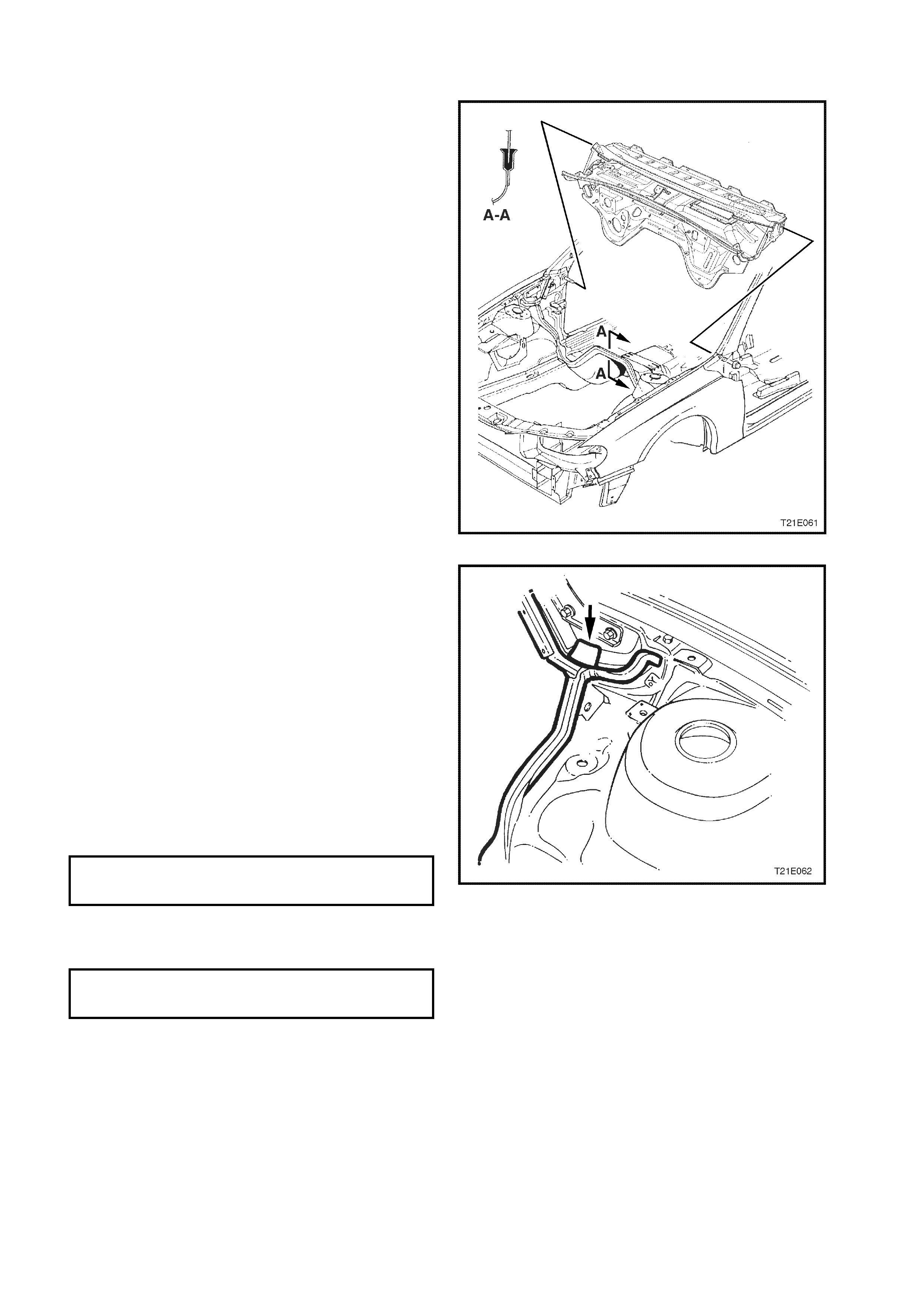
12. Wipe any excess adhesive from the plenum
drain holes and shroud panel areas (T he arrow
in Fig. 1E-65 shows the location of the LHS
plenum drain hole).
13. After installing the cockpit module panel,
immediately wipe the exces s adhesive f rom the
applicator gun and follower plate.
Figure 1E-65

REINSTALL
Reinstallation of the cockpit module and
components is the reverse of the removal
procedure, noting the following.
1. Ensure all the rubber grommets and insulation
materials are installed onto the cockpit module
panel.
2. Ensure all fasteners are tightened to the correct
torque specification, refer 3. TORQUE
WRENCH SPECIFICATIONS at the end of this
Section.
3. Ensure the HVAC unit drain tube is correctly
installed.
4. Use new O - rings when installing air
conditioning components.
5. Ensure that all wiring harnesses are correctly
retained and routed correctly, refer to Section
12N FUSES, RELAYS & WIRING
HARNESSES.
6. Re-charge and leak test air conditioning
system, refer to Section 2C AIR
CONDITIONING - SERVICING AND
DIAGNOSIS.
7. Ensure stop lamp switch and cruise control
release switches are adj usted c orrectly, refer to
Section 12B LIGHTING SYSTEM and Section
12E CRUISE CONTROL.
8. Top up and bleed brake hydraulic systems,
refer to the Section 5A – STANDARD
BRAKES or Section 5B – ABS AND ABS/ETC
of this Service Information CD.
9. Refill cooling system with the specified coolant
and pressure test cooling system, refer to
Section 6B1-1 ENGINE COOLING - V6
ENGINE, Section 6B1-2 ENGINE COOLING -
V6 SUPERCHARGED or Section 6B3
ENGINE COOLING - GEN III V8 ENGINE.
10. Ensure throttle and cruise control cables are
routed and adjusted correctly, depending on
engine variant, refer to the relevant Sections of
this Service Information CD.
IMPORTANT: Enable the SRS system. Refer to
ENABLING THE SRS Section 00 Cautions and
Notes.

3. TORQUE WRENCH SPECIFI CATIONS
Nm
Accelerator pedal bracket securing nut ................................ 20 - 30
Air conditioning compressor suction and discharge hose
pad retaining nut................................................................... 28 - 42
Air conditioning fitting to FDR ............................................... 7.5 - 12.5
Blanking plate securing nut................................................... 20 - 30
Brake line connections.......................................................... 8.0 - 11
Brake master cylinder bracket attaching nut......................... 15 - 20
Brake master cylinder retaining nut ...................................... 15 - 20
Brake pedal assembly securing nut...................................... 20 - 30
Brake pedal assembly securing screw ................................. 20 - 30
Centre console bin retaining nut........................................... 1.0 - 3.0
Centre console securing screw............................................. 1.0 - 3.0
Centre facia assembly securing screw ................................. 1.0 - 3.0
Centre facia support rail attaching screw.............................. 1.0 - 3.0
Cockpit module to A pillar retaining bolt................................ 22*
Cockpit module to plenum chamber retaining bolt................ 25 - 30*
Demist nozzle retaining screw .............................................. 1.0 - 3.0
Diagnostics Link Connector (DLC) attaching screw ............. 1.0 - 2.0
Earth strap retaining screw to cockpit module...................... 2.0 - 4.0
ECC securing screw ............................................................. 1.0 - 3.0
Engine hood bracket retaining screw.................................... 10 - 25
Front wiper arm attaching nut............................................... 20 - 25
Front wiper motor and linkage assembly securing screw..... 4.0 - 6.0
Front wiper motor linkage securing screw............................ 7.0 - 9.0
Heater and air conditioning controls securing screw ............ 1.0 - 3.0
Heater case assembly to cockpit module securing screw.... 6.0 - 14
Horn bar and air bag assembly to steering wheel securing
screw..................................................................................... 10 - 14
In-car temperature sensor retaining screw........................... 8.0 - 11.3
Instrument cluster assembly securing screw........................ 1.0 - 3.0
Instrument facia assembly retaining screw........................... 1.0 - 3.0
Instrument panel carrier end panel attaching bolt................. 3.0 - 5.0
Instrument panel carrier end panel attachment screw.......... 1.0 - 3.0
Instrument panel carrier rail assembly securing screw......... 1.0 - 3.0
Instrument panel compartment attaching screw................... 1.0 - 3.0
Instrument panel compartment lock striker attaching screw 1.0 - 3.0
Instrument panel end cap cover attaching screw ................. 1.0 - 3.0
Instrument panel fuse and BCM panel retaining screw........ 1.0 - 3.0
Instrument panel pad retaining screw................................... 7.0 - 12
Instrument panel speaker .................................................... 1.0 - 3.0
Lower left side rail connecting screw.................................... 1.0 - 3.0
Lower steering column cover screw ..................................... 0.5 - 2.0
Main wiring harness cabin protector securing nut................. 6.0 - 14
Passenger air bag securing nut............................................ 15 - 25
Passenger air bag support rail securing screw..................... 7.0 - 12
Receiver drier to TXV connecting bolt - V6........................... 7.5 - 12.5
Steering column bracket outer support securing screw........ 3.0- 5.0
Steering column clevis cam bolt........................................... 23 - 30
Steering column retaining nut (at base of column) .............. 15 - 30
Steering column upper mounting screw ............................... 15 - 30
Steering wheel securing screw............................................. 40 - 50
Support steering column bracket inner securing screw........ 3.0 - 5.0
Thermal expansion valve plate retaining bolt........................ 7.5 - 12.5
Throttle relaxer to cockpit module retaining nut.................... 2.0 - 3.0
Transmission console retaining screw.................................. 1.0 - 3.0
* Use new bolts
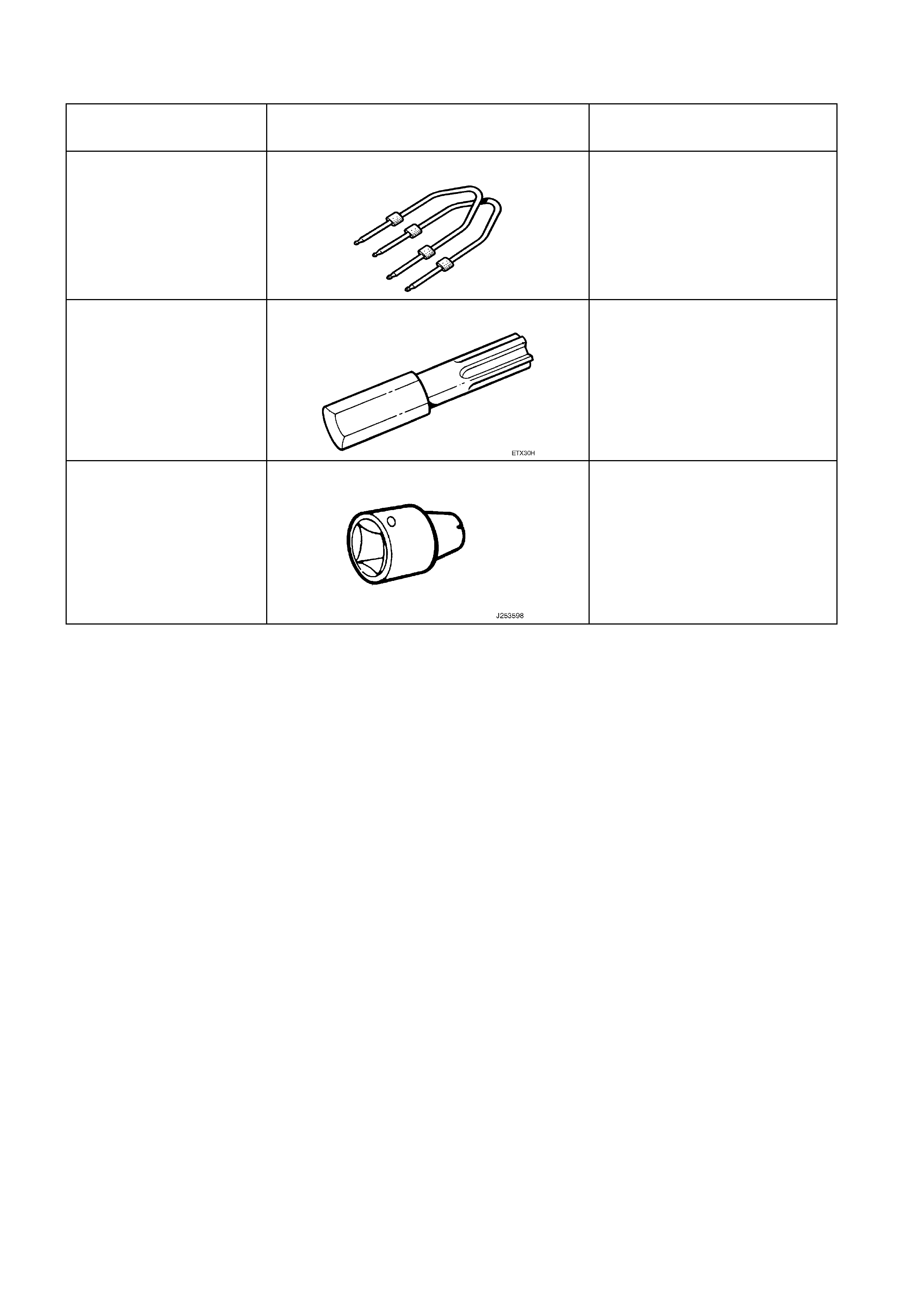
4. SPECIAL TOOLS
TOOL NO. REF IN TEXT TOOL DESCRIPTION COMMENTS
179 1308 0000 RADIO REMOVAL TOOL Previously released for ‘T’ cars.
ETX30H TORX BIT
J25359-8 TORX BIT HOLDER