
2
20
00
02
2
S
SE
ER
RV
VI
IC
CE
E
T
TE
EC
CH
HL
LI
IN
NE
ES
S
© 2006 GM Holden LTD. A.B.N. 84 006 893 232
Service Department
A “HOLDEN” Product.
BRISBANE SYDNEY MELBOURNE ADELAIDE PERTH
For the latest and/or any missing Techline bulletins,
please refer to Holden Lionheart
HOLDEN SERVICE TECHLINE_________________________________________________________FEBRUARY, 2002
Turn Signal Switch Does Not Cancel
XC BARINA excluding SRi
(Group 12) TL0201-1201
PROBLEM DESCRIPTION
On some vehicles the turn signal switch (non
cruise control type) does not cancel after
turning steering wheel back to straight ahead.
On vehicles with this condition the cancelling
cam loses contact with the flange on the
airbag contact unit.
PRODUCTION RECTIFICATION
Revised turn signal switches p/n 09185413
have been fitted to vehicles from:
ISOVIN: Build Date:
W0L0XCF6824004516 24/08/01
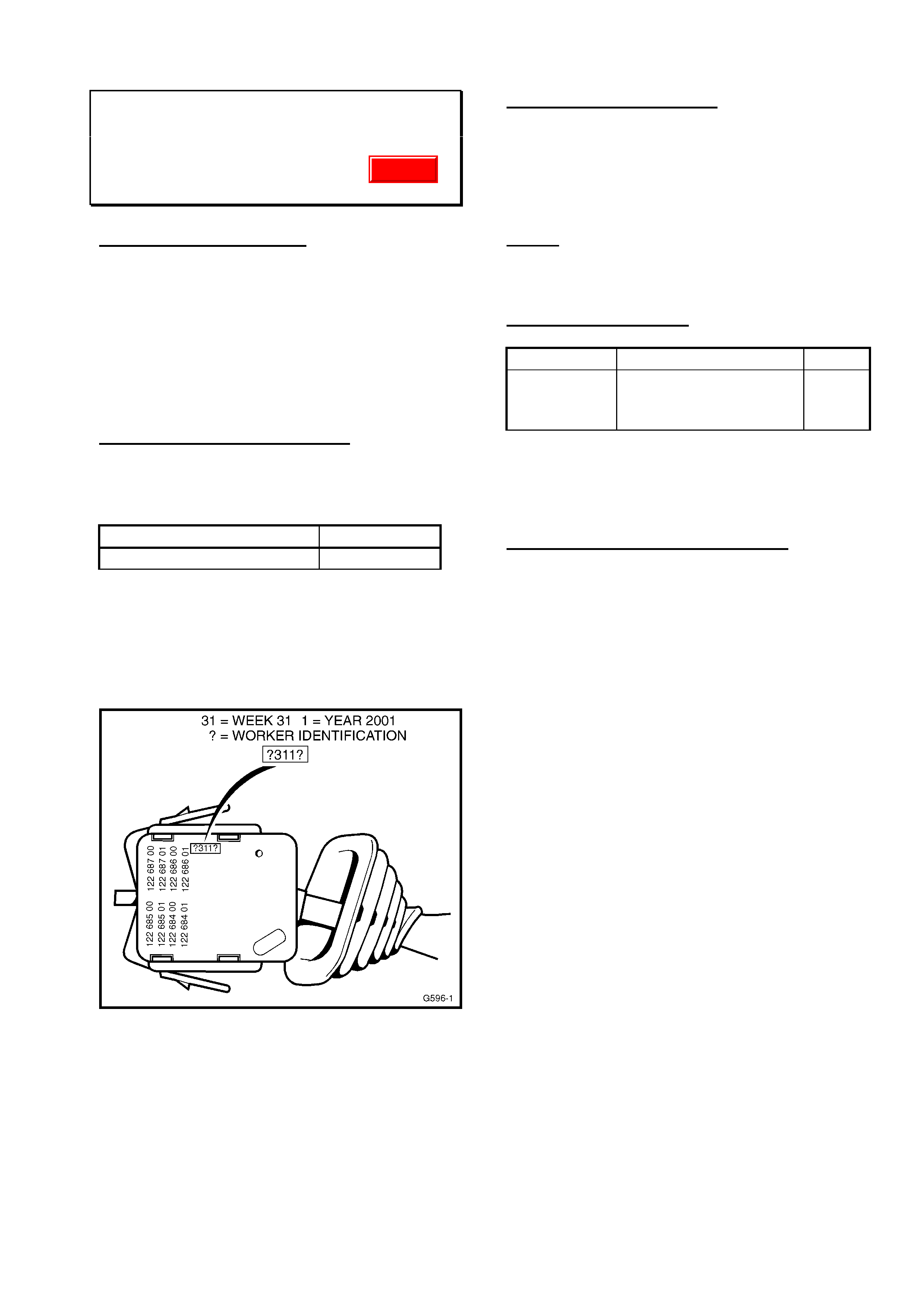
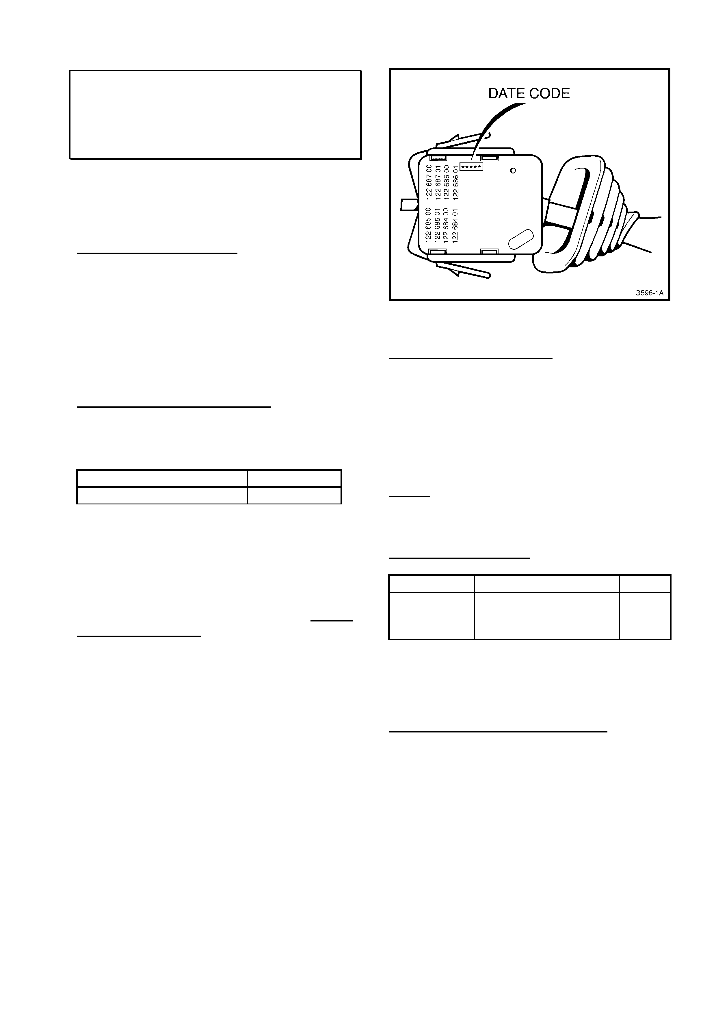
NOTE: Revised switches did not change part
number but can be identified from the date
code as shown in figure 1. Switches
manufactured after “-311-” (week 31, 2001)
have been revised.
Figure 1.
SERVICE RECTIFICATION
On vehicles with the above condition fit a new
turn signal switch manufactured after the date
code shown in Figure 1.
All HSPO stocks of turn signal switches are of
the revised type.
NOTE: DO NOT REPLACE THE DRIVERS
AIRBAG CONTACT UNIT FOR THIS
CONDITION.
PARTS INFORMATION
Part No.: Description: Qty:
09185413 Switch turn signal –
without cruise
control.
1
Attention Parts Managers. Any switches with
a pre-breakpoint date code should be
returned to HSPO for credit.
WARRANTY CLAIM INFORMATION
Use existing Labour Times information in
Warranty Information section of current SIP
CD
Update
HOLDEN SERVICE TECHLINE_________________________________________________________FEBRUARY, 2002
Boot Carpet Sagging
V2 Monaro
(Group 1) TL0201-0101
PROBLEM DESCRIPTION
Some customers may complain about boot
carpet sagging behind the rear seat.
PRODUCTION RECTIFICATION
Additional fasteners have been added to the
boot carpet to provide more support from:
ISOVIN: Build Date:
6H8V2X37F2L814274 09/01/02
SERVICE RECTIFICATION
Summary: Fit two (2) additional trim retainers
to increase boot carpet retension.
1. Remove the existing trim retainers from the
carpet behind the rear seat.
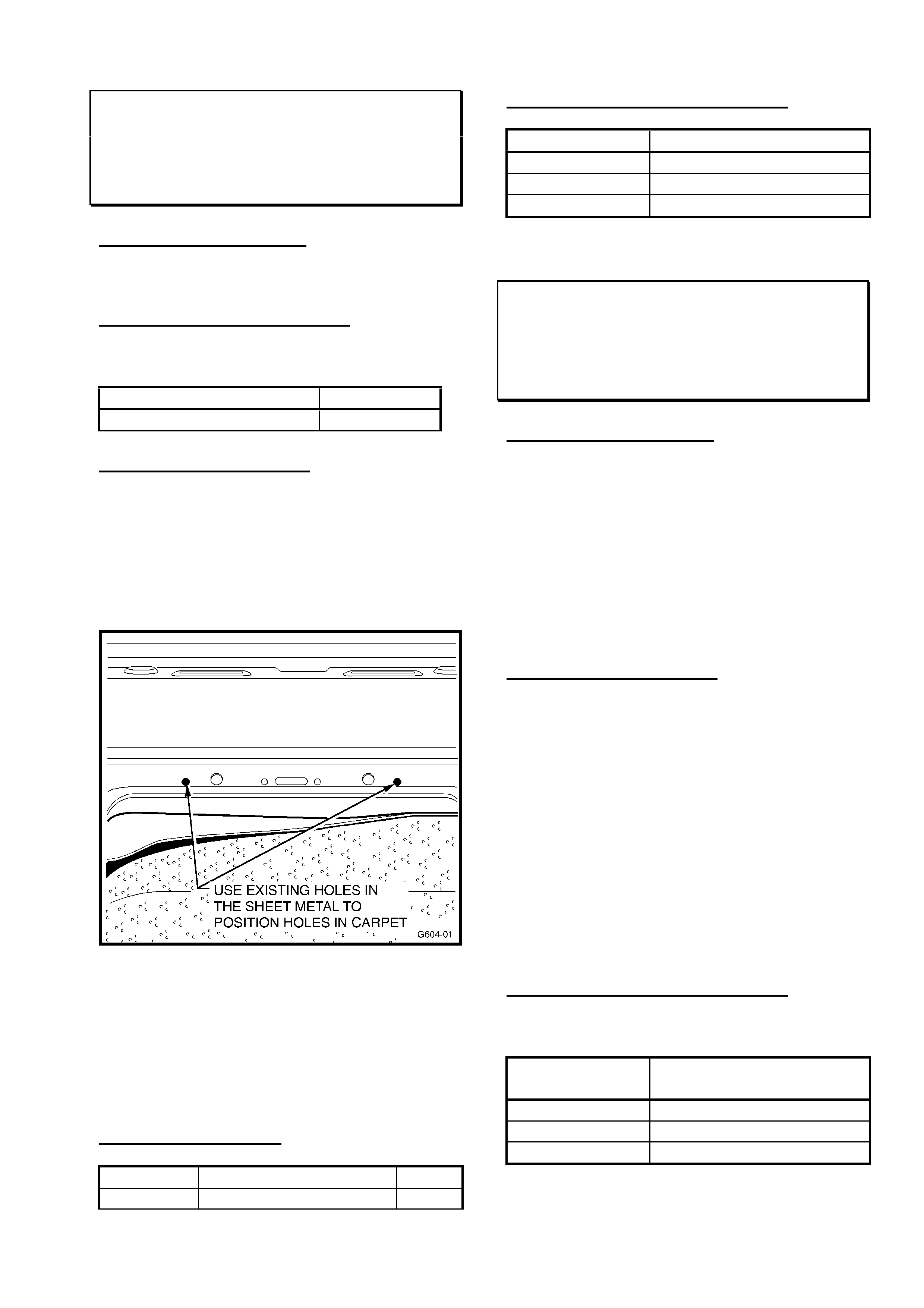
2. Identify the existing holes in the sheet metal
behind the rear seat as shown in Figure 1.
Figure 1
3. Align the boot carpet and mark the position
of the sheet metal holes on the carpet.
4. CAREFULLY pierce the carpet and fit two
additional trim fasteners. Refit any other
retainers removed during the rework.
PARTS INFORMATION
Part No.: Description: Qty:
92136478 Retainer – Trim 2
WARRANTY CLAIM INFORMATION
Description Carpet – Rear Seat Back
Labour Op. No. C431300
Time 0.3 hr
Failure Code 25
Rear Speaker (RHS) Inoperative
V2 Monaro
(Group 12) TL0201-1206
PROBLEM DESCRIPTION
On some vehicles the right hand side rear
speaker may cease to operate.
This condition could be caused by the
terminals on the rear of the speaker coming
into contact with the rear quarter body panel.
NOTE: This condition is not applicable to the
left hand side speaker.
SERVICE RECTIFICATION
Summary: Rotate speaker in mounting to
provide additional clearance to terminals.
For detailed procedures not supplied refer to
current SIP CD.
1. Remove the speaker.
2. Check speaker terminals. Look for
evidence of terminal touching on body.
3. Rotate speaker clockwise to next
mounting position (120 deg.). In this new
position there is increased clearance
between the speaker terminals and body.
Please submit PIRs for this condition.
WARRANTY CLAIM INFORMATION
Use existing Labour Times information in
Warranty Information section of current SIP
CD
Description Rotate RHS rear
speaker
Labour Op. No. N000366
Time 0.6hr
Failure Code 49
HOLDEN SERVICE TECHLINE_________________________________________________________FEBRUARY, 2002
Throttle Body To Surge Tank Coolant
Hose Damage
TS (X18XE1 & Z18XE Engines)
(Group 12) TL0201-1201
PROBLEM DESCRIPTION
The Throttle Body to Surge Tank Coolant
Hose can foul either the positive battery
terminal protective cap or the positive battery
cable. If undetected this condition could result
in hose failure and coolant loss.
PRODUCTION RECTIFICATION
Clearance between the coolant hose, battery
cable and protective cap has been revised
from model year 2002 vehicles:
ISOVIN:
W0L0TGF4825000001
SERVICE RECTIFICATION
Summary: Adjust clearances by trimming
protective terminal cap and coolant hose, and
orient the battery cable correctly
If this fouling is discovered during service or
battery replacement the technician should
follow these steps to rectify the problem:
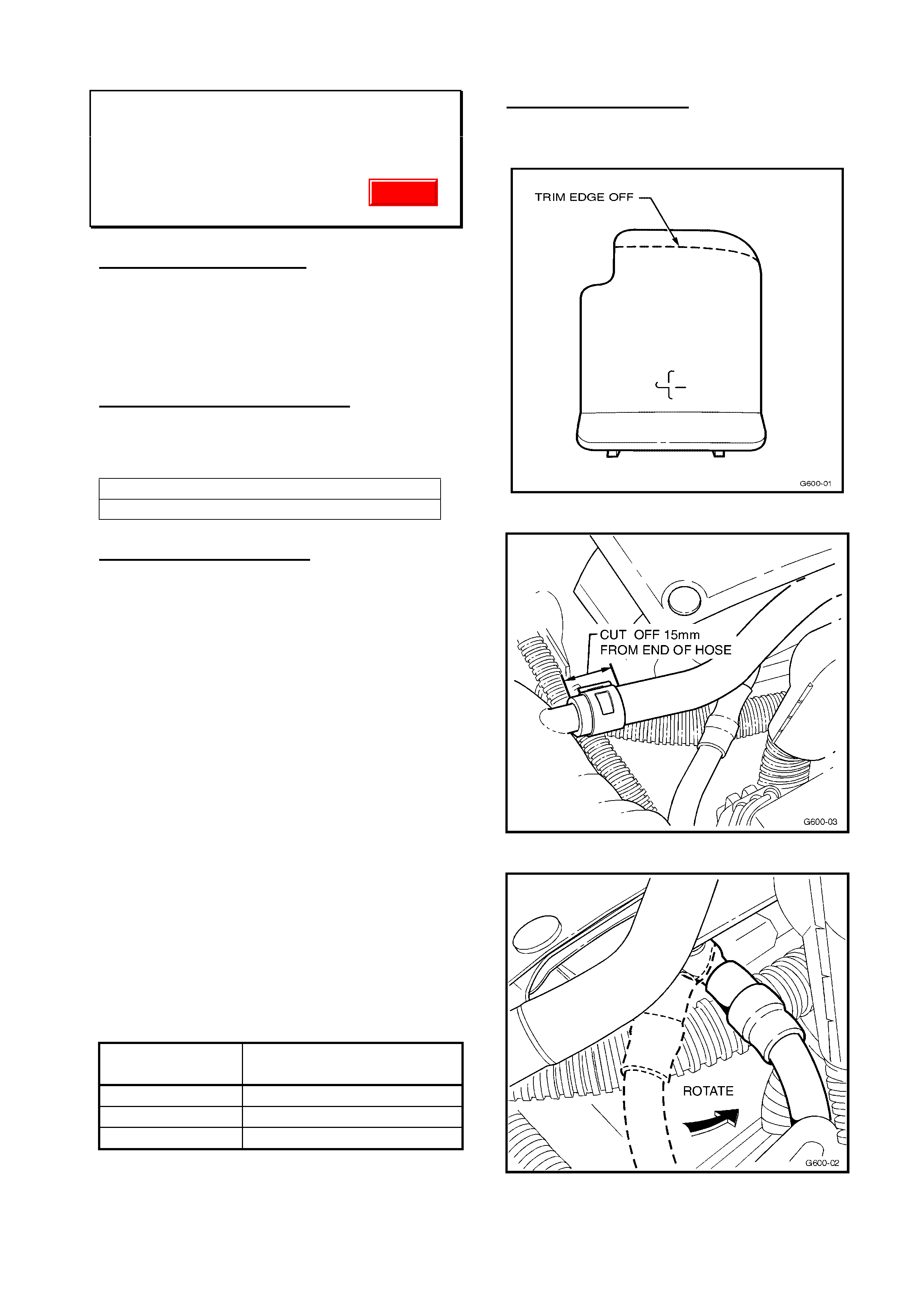
1. Trim the cap as shown in Figure 1 in order
to provide 10mm clearance between the
cap and the hose.
2. With engine switched off, disconnect the
coolant hose at the surge tank end.
3. Cut off 15mm of hose and refit the hose.
This will move the bend of the hose away
from the battery cable. See Figure 2.
4. Loosen the battery cable attaching nut, and
rotate the cable anti-clockwise so that there
is 10mm clearance between the cable and
the coolant hose, then tighten cable
attaching nut. See Figure 3.
WARRANTY CLAIM INFORMATION
Description Rework Battery
Cable/Coolant Hose
Labour Op. No. N000363
Time 0.4 hr
Failure Code 26
PARTS INFORMATION
Refer to Partfinder® if parts replacement is
required.
Figure 1
Figure 2.
Figure 3
Update
HOLDEN SERVICE TECHLINE_________________________________________________________FEBRUARY, 2002
Auto Transmission - Harsh Upshifts
VX & VU Series I, WH A8A upgrade,
with Gen 3 Auto
(Group 7B) TL0201-7B01
NOTE: This Techline does not apply to VTII or
WH (pre A8A) models. A service fix for these
models is expected in May 2002.
PROBLEM DESCRIPTION
A typical complaint transmission will exhibit a
harsh 1-2 shift with “end of shift bump” and a
harsh 2-3 shift.
PRODUCTION RECTIFICATION
Revisions to improve the transmission shift
quality were introduced at start of production
of VX,VU & WH, Series 2.
ISOVIN: Build Date:
VXII - 6H8VXK69F2L763647 23/08/01
VUII - 6H8VUK80F2L763676 24/08/01
WHII - 6H8WHY19F2L763313 24/08/01
SERVICE RECTIFICATION
Summary: - Install revised 1-2 accumulator
and reflash PCM with latest software.
Step 1. Replace 1-2 Accumulator
NOTE: For detailed procedures refer SIP CD,
VX, Section 7C5.
1.1 Check ISOVIN to ensure vehicle is Model
Year 2001.
1.2 Place vehicle on hoist.
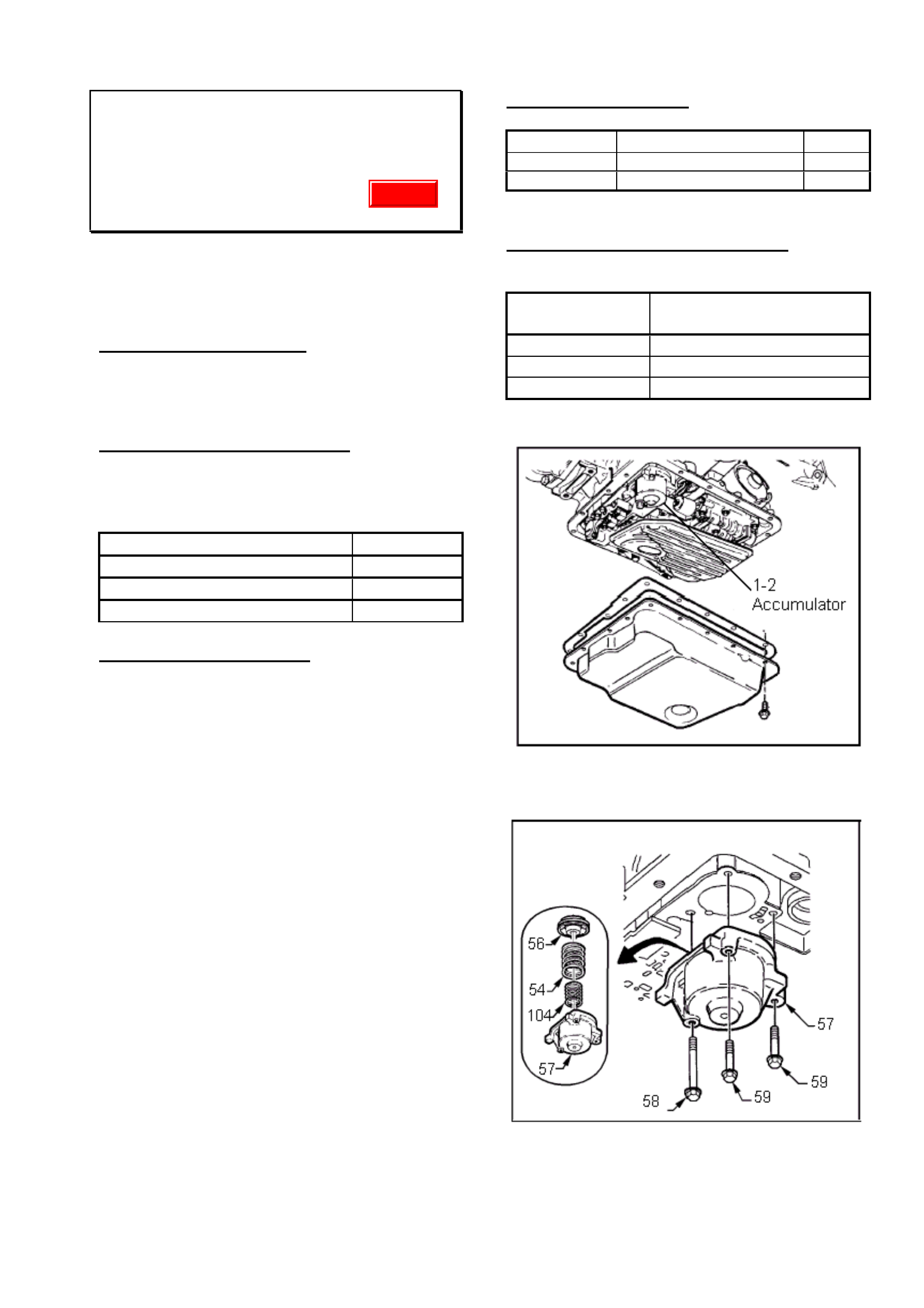
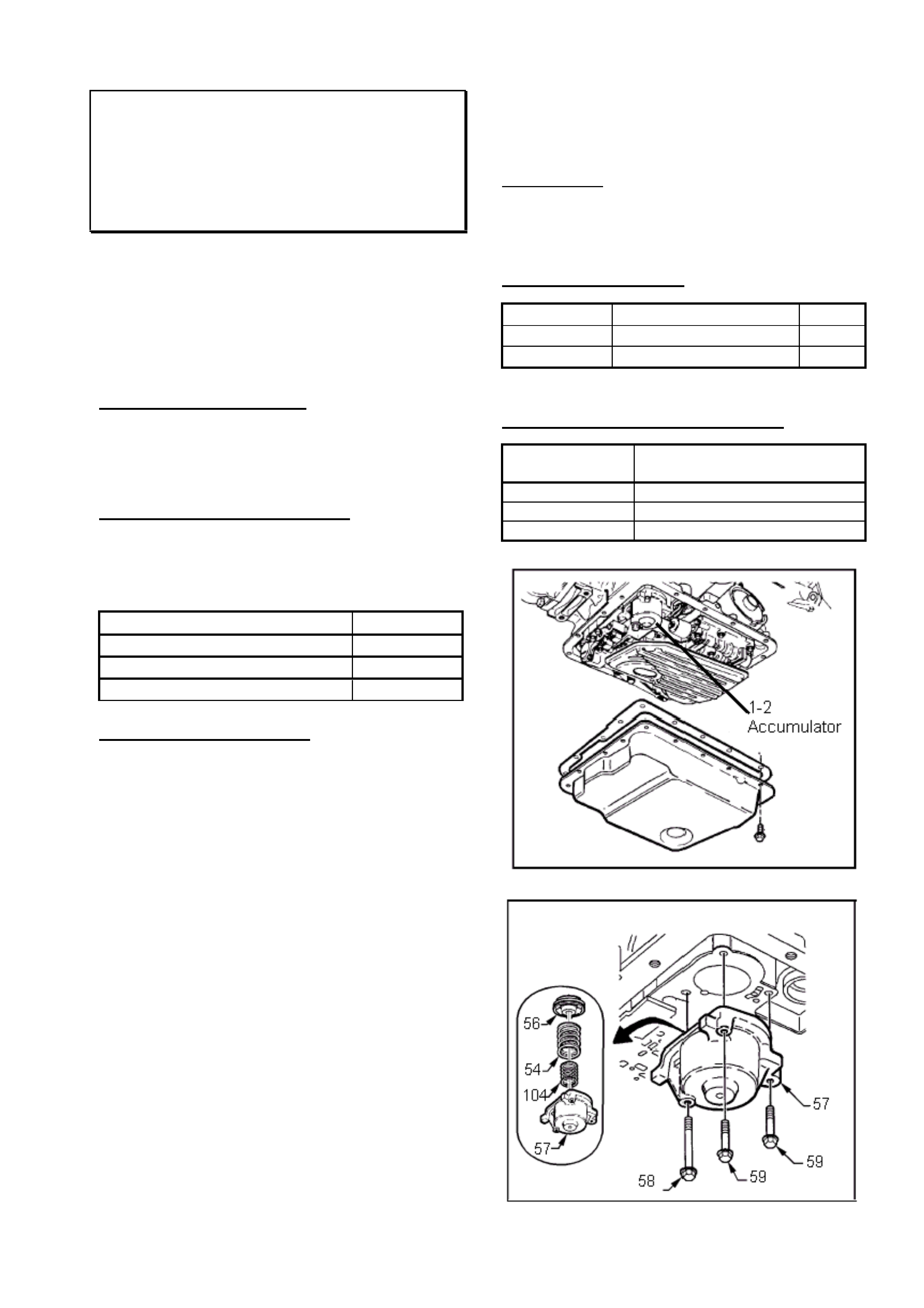
1.3 Remove Transmission oil pan. Figure 1.
1.4 Remove 1-2 Accumulator. Figure 2.
1.5 Install new 1-2 Accumulator part number
24220143. Ensure that accumulator
piston is in position. Tighten bolts (58
and 59) to 8-14 Nm.
1.6 Reinstall transmission oil pan with new
gasket.
1.7 Lower vehicle and refill transmission with
specified fluid.
Step 2. Reflash PCM
Reflash PCM with the latest software
calibration for VX, VU and WH, Series 2
models from TIS 2000 CD version 28.0.
PARTS INFORMATION
Part No.: Description: Qty:
24220143 1-2 Accumulator 1
24208576 Gasket oil pan 1
WARRANTY CLAIM INFORMATION
For warranty claims use the following:
Description Replace 1-2 Accumulator
& reflash PCM
Labour Op. No. K000276
Time 0.8hr
Failure Code 43 (shifts hard)
Figure 1.
Figure 2. (Number references are from SIP CD)
Update
HOLDEN SERVICE TECHLINE_________________________________________________________FEBRUARY, 2002
New Control Valve Body, Spacer Plate & Gaskets For 4L60-E Auto. Trans.
All V & W with 4L60-E
(Group 7B) TL0201-7B01
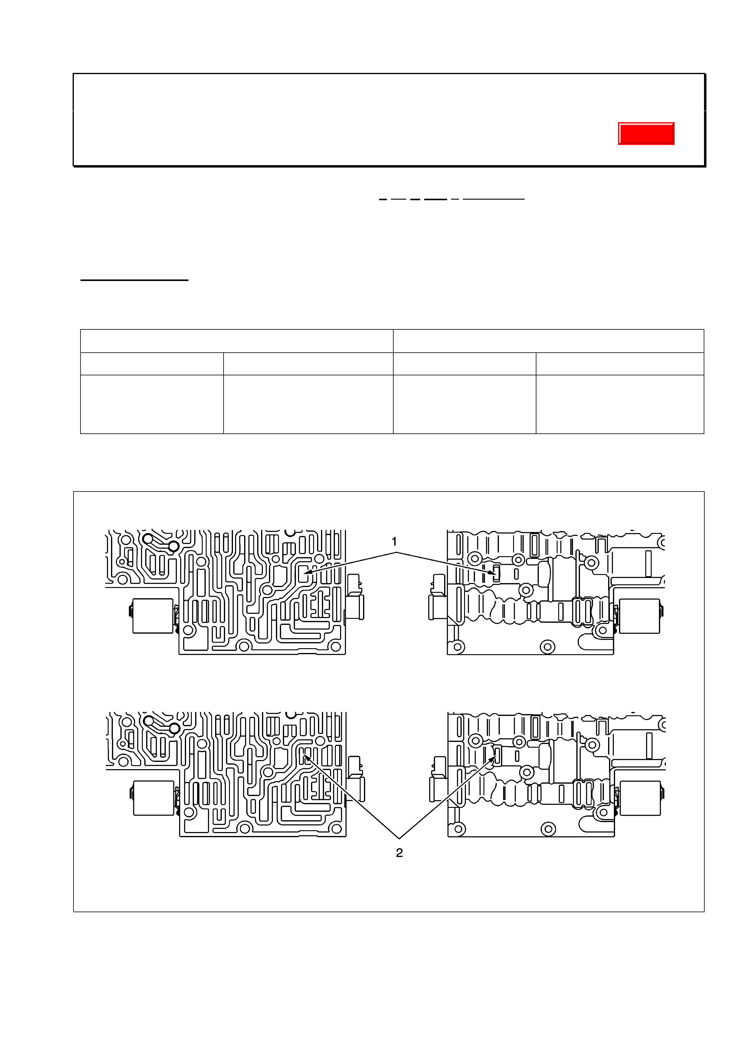
All 4L60-E transmissions built after Julian Date “1 ?? D 002 ? ????????” are fitted with a revised
valve body, spacer plate and valve body gaskets. The old and new design valve bodies, spacer
plates and gaskets are shown in Figures 1 to 5. An explanation of the “Julian Date” is given in
Figure 6.
SERVICE NOTE:
Whenever repairing transmissions it is vital that the correct spacer plates and gaskets are used. Do
not mix plates and gaskets from different kits. Refer to the following table for correct kit usage.
4L60-E built prior to Julian Date 1 002 4L60-E built from Julian Date 1 002
Valve Body Part No. Spacer plate & gasket kit Valve Body Part No. Spacer plate & gasket kit
24210320 - V6
24210321 - V6 S/C
24210317 - Gen3
24221137
or
24221350
24218187 - V6
24218188 - V6 S/C
24218186 - Gen 3
24221137
Item 1 Previous Design - shows the wide exhaust port on the TCC regulator valve.
Item 2 Later Design - shows the narrow exhaust port on the TCC regulator valve.
Figure 1. Differences between Earlier and Later Design Valve Bodies.
Update
HOLDEN SERVICE TECHLINE_________________________________________________________FEBRUARY, 2002
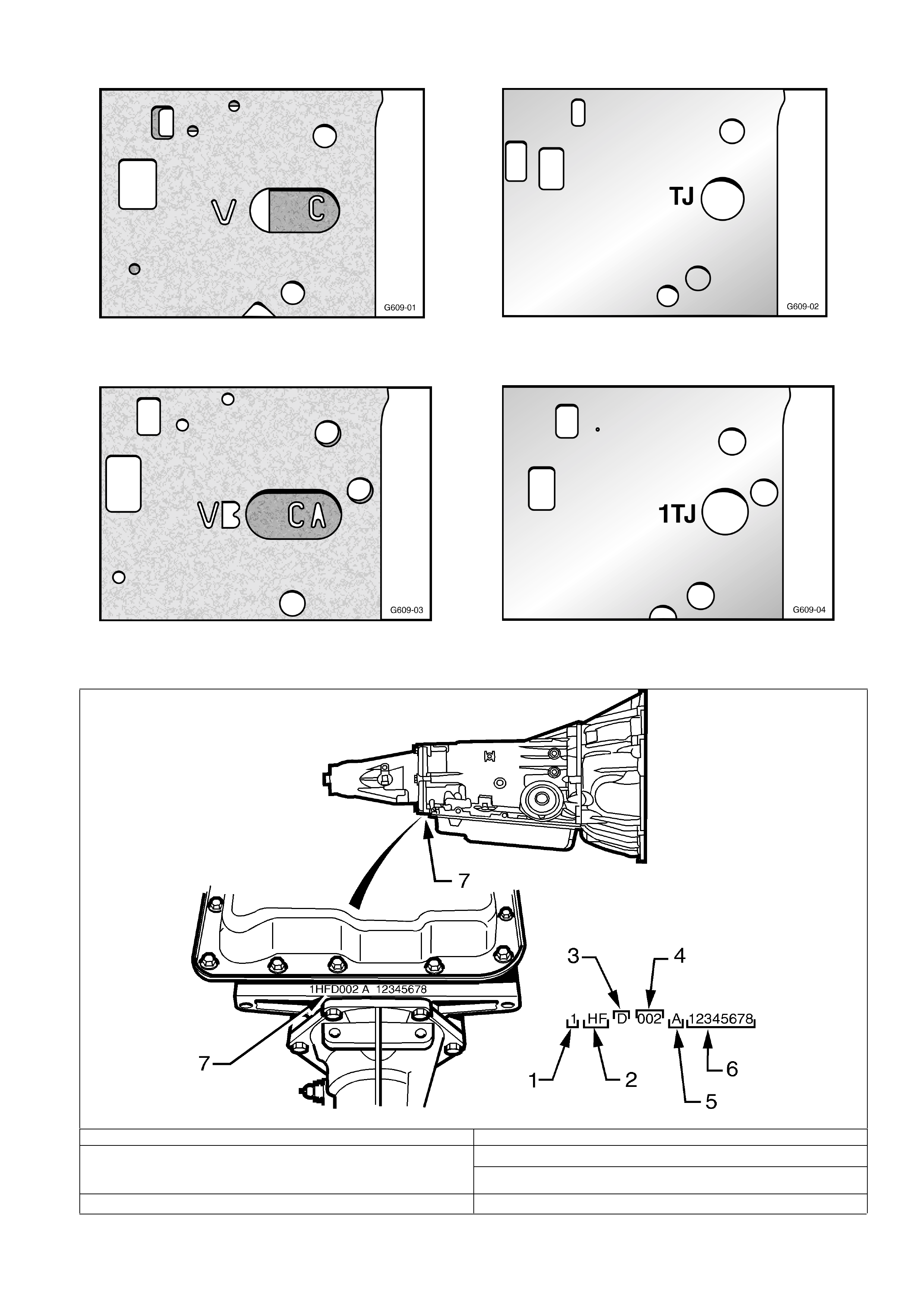
Figure 2. Pre change gasket identifications – “V” for
valve body gaskets and “C” for case gasket.
Figure 4. Post change identification. – “VB” for
valve body gasket & “CA” for case gasket
Figure 3. Pre change spacer plate identification. 2
letter code
Figure 5. Post change spacer plate identification.
“1” is added to the 2 letter code.
1. Model Year (1= 2001) 4. Julian Date (Day of the year)
5. Shift built (A,B,J=first shift, C,H,W = second shift) 2. Model: V6 3.8 litre……………………….……HF
V6 Supercharged……………………HN
Gen3 V8………………………………HP 6. Individual transmission serial no.
3. Transmission Identifier (D = 4L60E) 7. Location of Transmission Identification No.
Figure 6 JULIAN DATE EXPLANATION

HOLDEN SERVICE TECHLINE_________________________________________________________FEBRUARY, 2002
Body Control Module- Lock Up
VTII, VX (I & II)
(Group 12) TL0201-1202
This Techline supersedes the previous
Techlines on this topic:
Issue 1/2001, page 11 (replace BCM)
Issue 3/2001, page 13 (replace BCM and
install patch harness in key reader circuit )
PROBLEM DESCRIPTION
Symptoms of BCM Lockup condition are loss
of all BCM security related functions resulting
in engine wont start, no central locking, etc.
This is usually accompanied by a ‘buzzing’
noise emitted from the BCM.
When the BCM ‘locks up’ the microprocessor
inside the BCM starts its own self test routine
where part of this test includes switching all
BCM internal relays - hence the ‘buzzing’
sound.
Investigations have found the ‘lock up’
condition is caused by a static voltage
discharge that enters the BCMs’ internal
circuitry which in turn causes the BCM to
malfunction.
PRODUCTION RECTIFICATION
BCMs with revised software to prevent “lock-
up” have been fitted to VX2 vehicles from:
BCM Mid Series (p/n 92109212)
ISOVIN: Build Date:
6H8VXK35A2L811439 12/12/01
BCM Low Series (p/n 92109213)
ISOVIN: Build Date:
6H8VXK69A2L812036 13/12/01
SERVICE RECTIFICATION
When presented with a vehicle that has, or is
reported as having, all of the symptoms
described above (engine no start, central
locking inoperative and a buzzing sound from
BCM), proceed as follows:
1. Request a replacement BCM via a Warranty
Changeover Request Form. Refer to All
Dealer Letter 79/00, or SIP, for a copy of the
form which is to be faxed to Australian
Arrow. The form must be completed with
all detail as requested. Also record the
customer comments prior to the failure (if
applicable).
2. Temporarily return the vehicle to service by
removing Fuse 31 to reset the BCM.
NOTE: Installation of a patch harness as
described in Service Techline Issue 3/2001 is no
longer necessary. Australian Arrow will only
send Retailers (Dealers) a BCM with revised
software.
PARTS INFORMATION
The following BCMs all have the revised
software to prevent lockup.
Part No.: Description: Qty:
92109212 Body Control Module-
VXII Mid Series
1
92109213 Body Control Module-
VXII Low Series
1
92145251 Body Control Module-
VTII, VXI Mid Series
1
92145250 Body Control Module-
VTII, VXI, Low Series
1
WARRANTY CLAIM INFORMATION
Use existing information in SIP Warranty
Information/Labour Times as shown:
Description Module Body Control Replace
Labour Op. N506600
Time 0.5 hr
Failure Code 50

HOLDEN SERVICE TECHLINE_________________________________________________________FEBRUARY, 2002
Belt “Chirp” Under Hard Acceleration
All V & W with Gen 3 and Auto Trans.
(Group 6A) TL0201-6A01
PROBLEM DESCRIPTION
Under hard acceleration, some vehicles may
experience a momentary chirp or squeal from
the drive belt during the 1-2 shift.
Investigations have shown that increasing the
damping of the belt tensioner reduces this
condition.
NOTE. For complaints of continuous belt
squeal, refer to Techline in Issue 5/2001 that
deals with misalignment of the drive belt
pulleys.
PRODUCTION RECTIFICATION
Revised belt tensioners with increased
damping have been fitted to vehicles from:
ISOVIN: Build Date:
6H8V2X37F2L818822 24/01/02
NOTE: Whilst the above ISOVIN describes a
V2 Monaro, L818822 sets the breakpoint for all
VXII,WHII and V2 vehicles.
SERVICE RECTIFICATION
Where customers complain of the above
symptom fit a new tensioner as listed in Parts
Information.
PARTS INFORMATION
Part No.: Description: Qty:
92111701 Tensioner 1
WARRANTY CLAIM INFORMATION
Use existing Labour Times information in
Warranty Information section of current SIP
CD.
Mirror Switch Replacement
JR & early build JS
(Group 12) TL0201-1205
BACKGROUND
Mirror switch part number 90363312 was
fitted to all JR vehicles and JS vehicles built up
to the following:
ISOVIN: Build Date:
W0L0JBF68X7007783 March/1999
All vehicles built after this breakpoint were
fitted with an improved design switch
09226864.
HSPO has now superceded the earlier switch
90363312 with the later switch 09226864.
SERVICE NOTE
To fit the later switch 09226864 to vehicles
built prior to the above breakpoint, a patch
harness 92112089 must be installed between
the vehicle harness and the new switch .
PARTS INFORMATION
Obtain following parts from HSPO.
Part No.: Description: Qty:
09226864 Switch mirror adjust 1
92112089 Patch harness 1
NOTE: Quantities of the patch harness are
scheduled for delivery into HSPO 3rd week of
Feb.
WARRANTY CLAIM INFORMATION
Use existing Labour Times information in
Warranty Information section of current SIP
CD

HOLDEN SERVICE TECHLINE_________________________________________________________FEBRUARY, 2002
Blaupunkt Audio Units Replaced For
Complaint of Erratic Volume
JS, TS, TT, XC, SB
(Group 12) TL0201-1203
PROBLEM DESCRIPTION
Blaupunkt Audio units 420, 520, and 2020 as
fitted to the above models are being replaced
for complaints of volume increasing or
decreasing automatically. Analysis of these
units by the supplier (Bosch) shows No Fault
Found.
The following feature of these audio units is
the most likely explanation for this
unnecessary replacement.
SPEED CONTROLLED VOLUME
Blaupunkt audio units 420, 520, and 2020
have a vehicle speed controlled volume
function. With this function, as the car
increases in speed, the volume of the radio
increases to compensate for the increase in
driving noise.
Sensitivity Adjustment
NOTE: To cope with all the variable factors
such as road surface, wind noise, engine
speed etc. there are 5 different levels of
compensation available. Customers are then
able to find the level of compensation that best
suits their average driving conditions.
The sensitivity can be set between 0 (off) and
5 (maximum compensation) as per procedure
from Blaupunkt 520 Audio System) Handbook
1. Press LOC button (7) for at least 3 seconds
until you hear a confirmation beep. The display
shows the current setting , eg ‘SD-VOL 2’.
2. Press tuning button within 8 seconds to select
the desired setting between ‘SD-VOL 0’ and
‘SD-VOL 5’.
3. To store the selected setting, press LOC button
(7) again for at least 3 seconds until you hear a
confirmation beep. If you don’t store the new
setting within 8 seconds after the last press of a
button, it will not be stored.
4. To turn this feature off, select and save ‘SD-
VOL 0’.
Please explain this feature to customers who
complain that their radio volume changes
automatically while they are driving.
AM Reception Interference Caused By
Rear Windscreen Tinting
JR, JS Sedan
(Group 12) TL0201-1204
Refer to previous Techlines on AM reception
issues in JR and JS:
Sep 1998 Group 12 & Feb 2000 Group 12.
Further to the above Techlines, investigations
into customer complaints of poor AM radio
reception has highlighted that metallic window
tinting dramatically reduces the AM reception
capability for above models.
Only the sedan body style is affected as this
has the antenna in the rear windscreen.
Holden does not recommend metallic window
tinting of the above models due to the
significantly reduced AM reception
performance. Holden Retailers(Dealers)
should advise customers of this position.

HOLDEN SERVICE TECHLINE_________________________________________________________FEBRUARY, 2002
LHS O2 Sensor Connector - Water Entry
VTII, VX, VU, WH – All with GEN3 & A/T
(Group 6C) ISSUE 2 TL0201-6C01
This Techline is revised by adding check for correct
sealing of O2 connector. The previous Techline
(Issue 9, 2001 page 16) should be discarded.
Thanks to Steve Tennant of Golden City Motors for a
PIR which initiated this reissue.
PROBLEM DESCRIPTION
The proximity of the left hand side (LHS) oxygen
sensor wiring to the HVAC drain can result in O2
sensor malfunctioning. An oxygen sensor
connector that has had water ingress causing
terminal corrosion may result in the check
engine lamp illuminating while driving &/or a
noticeable loss in performance. Typical
symptoms of a malfunctioning LHS oxygen
sensor will be the logging one of the following
DTCs:
P0131
P0132
P0134
SERVICE RECTIFICATION
On any vehicle where the LHS O2 sensor has
logged the above trouble codes it is
recommended that as well as fitting a new O2
sensor, the sensor harness connector should be
relocated as per the following procedure.
1. Remove old / damaged sensor on the
LHS ONLY. Inspect & verify the condition of the
electrical terminals on the harness. Harness
replacement may be necessary if terminals are
corroded.
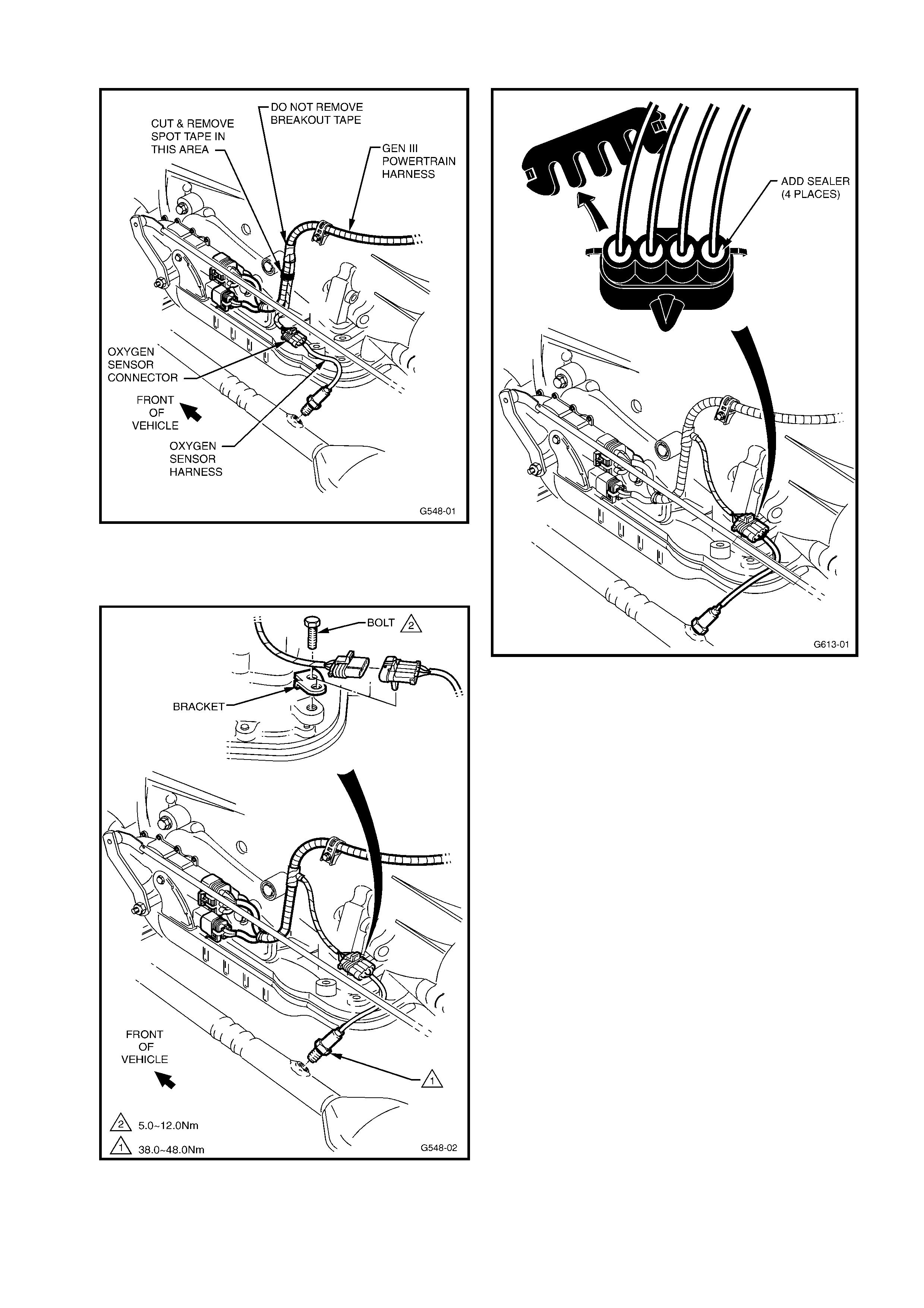
2. Carefully slice the spot tape that keeps
the Neutral Start Back Up Switch & the Oxygen
sensor wiring branches together. Ensure not to
slice through the convoluted tubing as wiring
damage may occur. Refer Figure 1.
HINT. Access to the harness to cut the spot
tape is improved by pulling the harness through
the spring clip to take up any slack.
3. Mount the bracket & the bolt from kit
92145044 to the spare threaded boss on the
LHS rear of the transmission (Refer Figure 2).
Bolt torque should be 5 - 12 Nm. The bracket
has an anti-rotation tab.
4. Mount the new O2 sensor into the
exhaust and tighten between 38 - 48 Nm. Route
wiring as illustrated in Figure 2.
5. Check the connector on the vehicle
harness side for the presence of sealing
grommets as shown in Figure 3. To view the
grommets, which are white or green in colour,
first remove the connector cover. To ensure
watertight sealing of the connector add sealer
such as silicone rubber RTV 732 p/n 92140051
around each of the wires in the 4 cavities.
6. Connect the O2 sensor plug to the
connector on the vehicle wiring harness.
7. Mount the sensor connector to the new
bracket via the arrow head clip.
8. Clear fault DTCs & complete testing for
further fault DTCs.
PARTS INFORMATION
Part No.: Description: Qty
92145044 Mounting Kit –
contains bracket & bolt
1
25326439 O2 sensor asm LHS 1
92140051 Silicone rubber sealer
RTV 732
1
WARRANTY CLAIM INFORMATION
For vehicles repaired under warranty use:
Description Fit LHS O2 sensor &
relocate harness connector.
Labour Op. No. J000692
Time 0.5 hr
HOLDEN SERVICE TECHLINE_________________________________________________________FEBRUARY, 2002
Figure 1
Figure 2
Figure 3
HOLDEN SERVICE TECHLINE_________________________________________________________FEBRUARY, 2002
Tensioner Rattle/Noise
TR Astra with C16SE, C18SEL, X20XEV
engine
(Group 6Y) TL0201-6Y01
PROBLEM DESCRIPTION
On some vehicles the following symptoms may
be observed:
• Rattle noisy from front of motor at idle.
• Belt tensioner vibrates excessively up &
down.
Investigations show that the alternator induces
a high oscillating load through the accessory
belt and tensioner. This in turn causes the
tensioner damping nylon ring to wear
prematurely thus reducing the damping and
causing the tensioner to oscillate and rattle.
The condition is more noticeable when the
engine is cold.
SERVICE RECTIFICATION
Summary: Remove standard alternator pulley
and replace with “decoupler pulley”.
Procedure:
1. Remove alternator assembly from vehicle
using procedure in TIS CD.
2. Remove alternator pulley nut with an
impact gun.
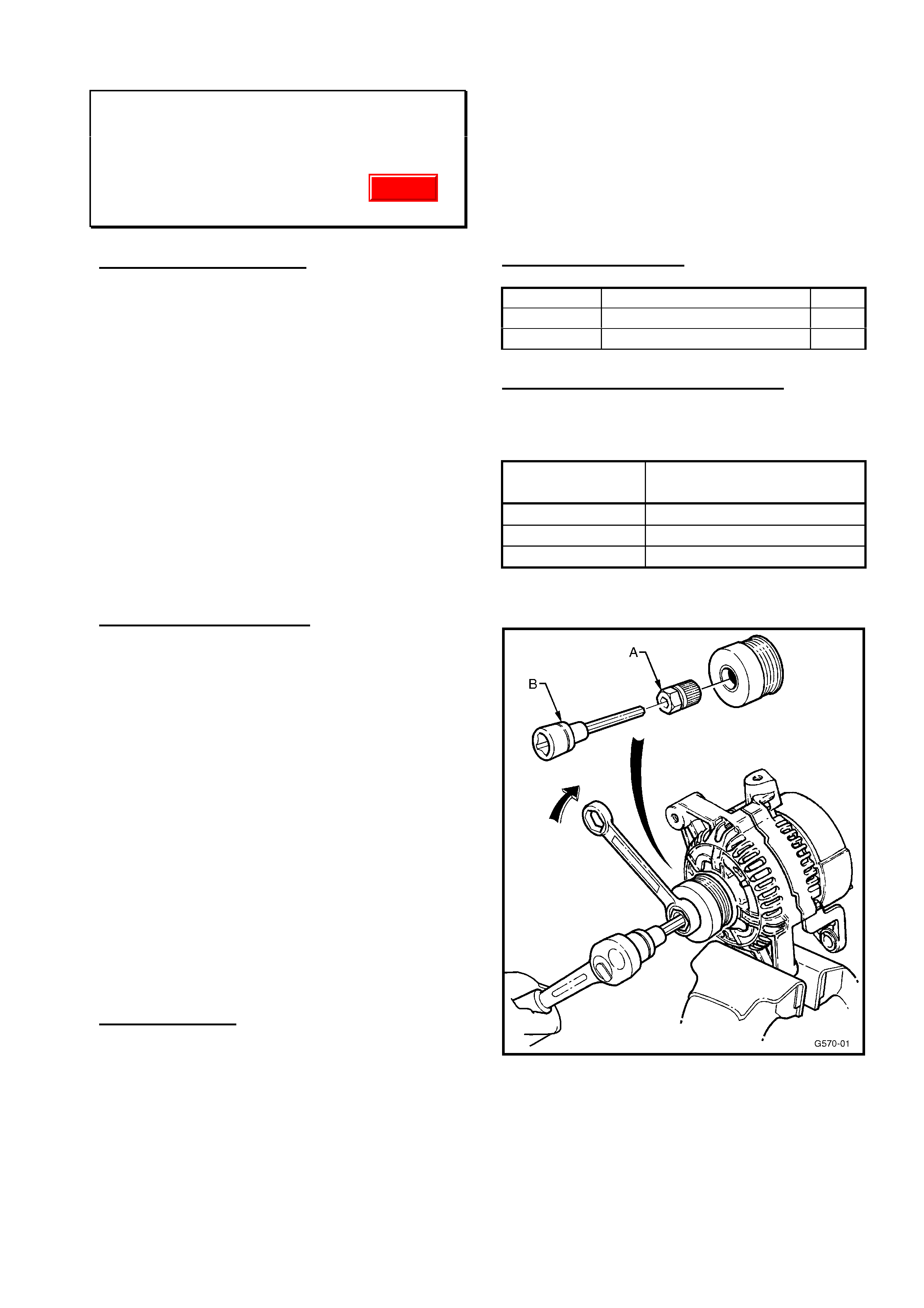
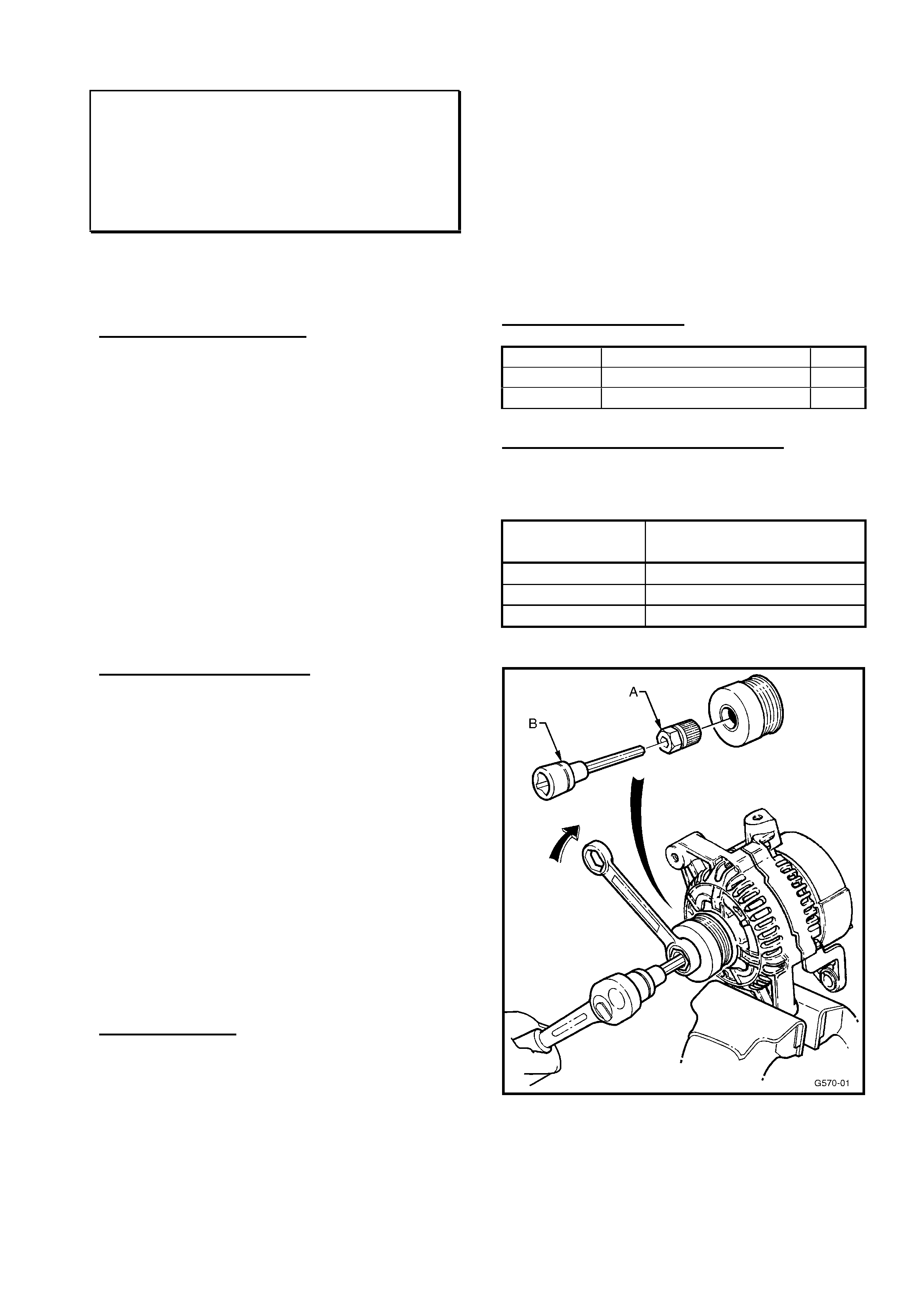
3. Install decoupler pulley using special tools
A and B as shown in Figure1.
4. Torque pulley attaching nut to 80 – 100
Nm.
5. Press cap plug into decoupler pulley. It is
important this cap is fitted to prevent the
entry of foreign material.
6. Reinstall alternator to vehicle.
SPECIAL TOOLS
Tool A. - Hazet Tool No. 2592 (Adapter)
Tool B. - Hazet Tool No. 2751 (long hexdrive
socket)
NOTE: These tools can be obtained on loan
from your Zone Service office.
OR
For dealerships wishing to purchase their own
tools contact PB Baumann Tools Australia who
will direct you to the closest Hazet tool Agent.
PB Baumann Tools Australia
Telephone: 02 9816 1233.
Email: info@pbtools.com.au
PARTS INFORMATION
Part No.: Description: Qty
92145105 Decoupler pulley 1
92145244 Plug, sealing cap 1
WARRANTY CLAIM INFORMATION
For vehicles outside of warranty use case type
“08”
Description Install Alternator
Decoupler pulley
Labour Op. No. J000698
Time 1.0hr
Failure Code 28 Rattles
Figure 1.
Update

HOLDEN SERVICE TECHLINE_________________________________________________________FEBRUARY, 2002
DTC P0335 Misfire/Crank Rev. Sensor
Malfunction Diagnosis and Correction
TS with Z18XE Engine
(GROUP 6C) TL0201-6C02
This Techline item is supplied to assist in the
diagnosis of DTC P0335 (crank sensor fault
code) and it’s associated DTC’s – P0700,
P1700 and P1895.
The information is provided so technicians can
carry out diagnosis to determine and correct
the most likely cause of these codes.
PROBLEM DESCRIPTION
Customer complains of engine misfire and
Code P0335 is found during diagnosis of
complaint.
SERVICE RECTIFICATION
Summary: Check for fuel contamination, good
terminal connections, replace Crank Sensor,
Re-flash where required.
1. Check fuel filter for water entry to fuel
system. Replace filter if required.
2. Carry out a terminal security, condition and
retention check on both ECU and Crank
Revolutions Sensor terminals. Correct any
terminal problems that may be found.
NOTE: use Special Tools KM-609-20 and
KM-609-21 for ECU terminals.
3. Carry out a continuity check between the
Crank Revolutions Sensor and ECU, and
correct any problems that are defined by
this check.
4. Replace Crank Revolutions Sensor.
5. If the ECU is not already flash
programmed with ECU Software Version
09 158 670 1280 – re-flash the ECU using
TIS CD 23 or later.
Should DTC P0335 re-occur after the above
process – contact TAS for further instructions.
Additional Diagnosis Hints & Information:
• Misfire codes are also induced by
interruptor ring problems, P0335 will
sometimes log with these codes.
• Special Tools – KM-609-20 & KM-609-21
comprise 3 each terminal test leads for
ECU. It is recommended you order one of
each of these test lead kits for ECU
terminal checking. The complete KM-609
Kit contains a comprehensive range of test
leads for all you dealership’s wiring test
needs.
• Most important terminals to look at for this
condition are 5 & 37 on the X58 connector.
• When checking DTC P0335 with Tech2,
the causes {the “identifiers”(1), (4) or (8) as
shown by Tech2} may be one of the
following:
(1) - ONE of the crank wires is open
circuit.
(4) - No crank signal found (probably both
wires open circuit).
(8) - Number of teeth not plausible (could
be wiring or an engine problem).
• FIP (Fault Isolation Process) C-06 in
TIS2000 – is your normal DTC diagnosis
procedure.
PARTS INFORMATION
Refer to PartFinder for current Crank
Revolutions Sensor part number.
WARRANTY CLAIM INFORMATION
Description Diagnose/Correct P0335
Labour Op. No. J000707
Time 1.0 hr
Failure Code 47
Update

HOLDEN SERVICE TECHLINE_________________________________________________________FEBRUARY, 2002
HVAC Module Whistle
VT/VX/VU/V2/WH
(GROUP 2) TL0201-0201
PROBLEM DESCRIPTION
A number of PIRs have been submitted to
Holden describing a whistle noise from the
HVAC module
Dealer investigation has revealed the fresh
recirc door has not closed completely,
resulting in the whistle noise.
PRODUCTION RECTIFICATION
Engineering are investigating design changes
to the blower housing to eliminate this
complaint. Breakpoints will be advised once
they have been struck.
SERVICE RECTIFICATION
In the interim, dealers are able to contact the
HVAC supplier for a service fix to address this
complaint in customer’s vehicles. This fix
involves installing a self adhesive foam pad
that seals the fresh recirc door completely.
If a customer presents their vehicle with this
complaint, please contact:
Air International P/L
Phone: 1300 632 316
and request a Service Fix pack for this
complaint.
PARTS INFORMATION
Contact Air International directly on the
number above and refer to Air International
Service Bulletin HMC-92.
WARRANTY CLAIM INFORMATION
Description Fit HVAC Whistle Fix Kit
Labour Op. No. D000330
Time 0.5 hr
Failure Code 40
Cruise Control Inoperative – Incorrect
Software in ECU
TS Astra SRi with Manual Trans.
(Group 6C) TL0201-6C07
PROBLEM DESCRIPTION
Some vehicles may exhibit symptoms of the
cruise control being inoperative.
Investigations have shown that some M/T
vehicle engine ECU’s have been programmed
with A/T engine ECU software.
SERVICE RECTIFICATION
On complaint vehicles the ECU will need to be
reprogrammed with manual transmission
software.
Before proceeding ensure your Tech 2 is
updated with latest software from TIS2000 CD.
Reprogram the vehicles ECU using the TIS
Service Programming System (SPS).
WARRANTY CLAIM INFORMATION
Use existing Labour Times information in
Warranty Information section of current SIP
CD
Update

HOLDEN SERVICE TECHLINE_________________________________________________________FEBRUARY, 2002
Telematics Service Requirements
All Models with Telematics
(GROUP 12) TL0201-1208
The purpose of this Techline item is to remind
Holden Service personnel of the need to
ensure the Telematics System is placed into
“Service Mode” prior to commencing any vehicle
servicing or repairs.
The Holden Assist call centre have received a
number of Unauthorised Entry and Battery
Removal alerts simply because Retailers
(Dealers) have not placed the Telematics
Module into Service Mode.
To prevent alerts of this nature being
transmitted to the Holden Assist call centre,
dealers should:
• Using Tech 2, check the Telematics system
operating mode.
• If not in Service Mode, use Tech 2 to enable
“Service Mode”.
• Carry out vehicle servicing or repairs.
• On completion of servicing or repairs,
use Tech 2 to disable “Service Mode”.
This will automatically place the module
in “Active Mode”.
Failure to disable “Service Mode” will result
in the status light (on rear view mirror)
flashing red and green for 30 seconds plus 5
beeps each time ignition is turned ON.
HOLDEN SERVICE TECHLINE_____________________________________________________________MARCH, 2002
6
Turn Signal Switch Does Not Cancel
XC BARINA excluding SRi
(GROUP 12) REVISED TL205A-0202
This techline is revised(
♠
) by clarifying how to
interpret the date code. The previous Techline
in Issue 1/2002 should be discarded.
PROBLEM DESCRIPTION
On some vehicles the turn signal switch (non
cruise control type) does not cancel after
turning steering wheel back to straight ahead.
On vehicles with this condition the cancelling
cam loses contact with the flange on the
airbag contact unit.
PRODUCTION RECTIFICATION
Revised turn signal switches p/n 09185413
have been fitted to vehicles from:
ISOVIN: Build Date:
W0L0XCF6824004516 24/08/01
NOTE: Revised switches did not change part
number but can be identified by referring to the
date code as shown in figure 1.
Date Code Interpretation. (♠
♠♠
♠)
Looking at the five digit date code, the 3 digits
after the numeral “5” signify the week and the
year of manufacture.
Some possible date code examples are:
A5311 Worker A week 31 year 2001
5311k Worker K week 31 year 2001
53112 Worker 2 week 31 year 2001
Revised Switches were manufactured from:
“week 31, 2001”
Figure 1.
SERVICE RECTIFICATION
On vehicles with the above condition fit a new
turn signal switch manufactured after the date
code referred to in Figure 1.
All HSPO stocks of turn signal switches are of
the revised type.
NOTE: DO NOT REPLACE THE DRIVERS
AIRBAG CONTACT UNIT FOR THIS
CONDITION.
PARTS INFORMATION
Part No.: Description: Qty:
09185413 Switch turn signal –
without cruise
control.
1
Attention Parts Managers! Any switches with
a pre-breakpoint date code should be returned
to HSPO for credit.
WARRANTY CLAIM INFORMATION
Use Labour Times information in Warranty
Information section of current PV SIP.

HOLDEN SERVICE TECHLINE_____________________________________________________________MARCH, 2002
7
Speedo Drops Out Whilst Driving –
Resumes After Ignition Cycled
TS with ABS
(GROUP 12) TL221-0202
PROBLEM DESCRIPTION
On some vehicles the speedo may cease
operating whilst driving and then resume after
the ignition is cycled.
This condition can result if the vehicle has
mistakenly been fitted with a “Control Unit -
Speed Sensor Signal Convertor” in production.
PRODUCTION RECTIFICATION
100% inspection in assembly plant to ensure
the “Control Unit - Speed Sensor Signal
Convertor” is not fitted from:
ISOVIN: Build Date:
W0L0TGF4825076018 16/11/01
SERVICE RECTIFICATION
Summary: Remove “Control Unit - Speed
Sensor Signal Convertor” if fitted.
1. Confirm the vehicle is fitted with ABS.
These vehicles are identified by the 5
wheel studs. Non ABS have 4 wheel
studs.
2. Check the vehicle build date to confirm
vehicle is pre-breakpoint
3. Inspect the relay box to check if the
“Control Unit - Speed Sensor Signal
Convertor” is fitted. The relay box is
located under the steering column.
Affected part number is 09185826, is
orange in colour, and is located in the top
left hand corner of the relay box.
4. Remove if installed.
5. If not installed, continue with normal
diagnosis applicable to the complaint
condition present.
Please submit a PIR if:-
• Removal of control unit fails to rectify this
condition or
• The control unit is found fitted to a post
breakpoint vehicle.
PARTS INFORMATION
Part No.: Description: Qty:
09185826 Control Unit – Speed
Sensor Signal
Convertor
1
WARRANTY CLAIM INFORMATION
Description Remove Control Unit –
Speed Sensor Signal
Convertor
Labour Op. No. N000369
Time 0.2 hr
Failure Code 54 (wrong part fitted)

HOLDEN SERVICE TECHLINE_____________________________________________________________MARCH, 2002
8
Introduction Of Improved Air
Conditioning Compressor
XC Barina, TS Astra except Z22SE
engine
(GROUP 02) TL239-0202
An improved, more durable compressor has
been introduced for the above models. The
main change is the replacement of the bronze
coated steel swashplate with a solid bronze
swashplate.
PRODUCTION RECTIFICATION
Revised compressors have been fitted to
vehicles from start of Model Year 2002:
ISOVIN: Build Date:
XC
W0L0XCF0824002194
27/8/2001
TS
W0L0TGF3522030146
31/8/2001
PARTS INFORMATION
All stocks of HSPO compressors are of the
improved type.
The compressor part number remains
unchanged at 09165714.
Part No.: Description: Qty:
09165714 Compressor air
conditioning
1
Steering Column Upper Bearing
Excessive Movement
VT, VX, VU, WH
(GROUP 9) TL212-0202
PROBLEM DESCRIPTION
Some customers may complain the steering
wheel has excessive freeplay.
Investigation of complaint vehicles shows balls
from the upper steering column bearing have
dislodged from their cage.
PRODUCTION RECTIFICATION
New steering columns with a double-sided
metal cage (instead of a single sided plastic
cage) are expected to enter vehicle production
in early March.
Production breakpoints will be published in the
Breakpoint Summary in the next issue of
Service Techlines.
SERVICE RECTIFICATION
Order and install a new steering column to the
affected vehicle. These columns are available
from HSPO.
PARTS INFORMATION
Part No.: Description: Qty:
92145394 Column Asm - RHD 1
WARRANTY CLAIM INFORMATION
Use Labour Times information in Warranty
Information section of current PV SIP.
Update
HOLDEN SERVICE TECHLINE_____________________________________________________________MARCH, 2002
9
Auto Transmission - Harsh Upshifts
VX & VU Series I, WH A8A upgrade, with
Gen 3 Auto
(Group 7B) REVISED TL195A-0202
This Techline is revised to correct the oil pan gasket
part number and to expand on step 2. -reflashing
PCM. The previous Techline in Issue 1/2002
should be discarded.
NOTE: This Techline does not apply to VTII or WH
pre A8A models. A service fix for these models is
expected in May 2002.
PROBLEM DESCRIPTION
A typical complaint transmission will exhibit a
harsh 1-2 shift with “end of shift bump” and a
harsh 2-3 shift.
PRODUCTION RECTIFICATION
Revisions to improve the transmission shift
quality were introduced at start of production
of VX,VU & WH, Series 2.
ISOVIN: Build Date:
VXII - 6H8VXK69F2L763647 23/08/01
VUII - 6H8VUK80F2L763676 24/08/01
WHII - 6H8WHY19F2L763313 24/08/01
SERVICE RECTIFICATION
Summary: - Install revised 1-2 accumulator
and reflash PCM with latest software.
Step 1. Replace 1-2 Accumulator
NOTE: For detailed procedures refer to
PV SIP, VX, Section 7C5.
1.1 Check ISOVIN to ensure vehicle Model
Year is 2001.
1.2 Place vehicle on hoist.
1.3 Remove Transmission oil pan. Figure 1.
1.4 Remove 1-2 Accumulator. Figure 2.
1.5 Install new 1-2 Accumulator part number
24220143. Ensure that accumulator
piston is in position. Tighten bolts (58 and
59) to 8-14 Nm.
1.6 Reinstall transmission oil pan with new
gasket.
1.7 Lower vehicle and refill transmission with
specified fluid.
Step 2. Reflash PCM
Reflash PCM with the latest software
calibration for VX, VU and WH, Series 2
models from TIS 2000 version 28.0 or later.
IMPORTANT: Until TIS 2000 version 30.0 is
released it is strongly recommended that the
Gen3 PCM Flash Programming Hint given in
the following Service Techline be applied.
PARTS INFORMATION
Part No.: Description: Qty:
24220143 1-2 Accumulator 1
08654799 Gasket oil pan 1
WARRANTY CLAIM INFORMATION
Description Replace 1-2 Accumulator &
reflash PCM
Labour Op.No. K000276
Time 0.8hr
Failure Code 43 (shifts hard)
Figure 1.
Figure 2. (Number references are from SIP CD)
HOLDEN SERVICE TECHLINE_____________________________________________________________MARCH, 2002
10
Flash Programming Hint for Gen 3 PCM
VX, VU, V2, WH(A8A)
(GROUP 6C) TL241-0202
PROBLEM DESCRIPTION
When flash programming the PCM in above
models “electrical noise” (generated on the
class 2 communications circuit between Tech
2 and the PCM) may cause the process to
slow or stop altogether.
SERVICE HINT
To avoid the above problem the following
procedure is required:
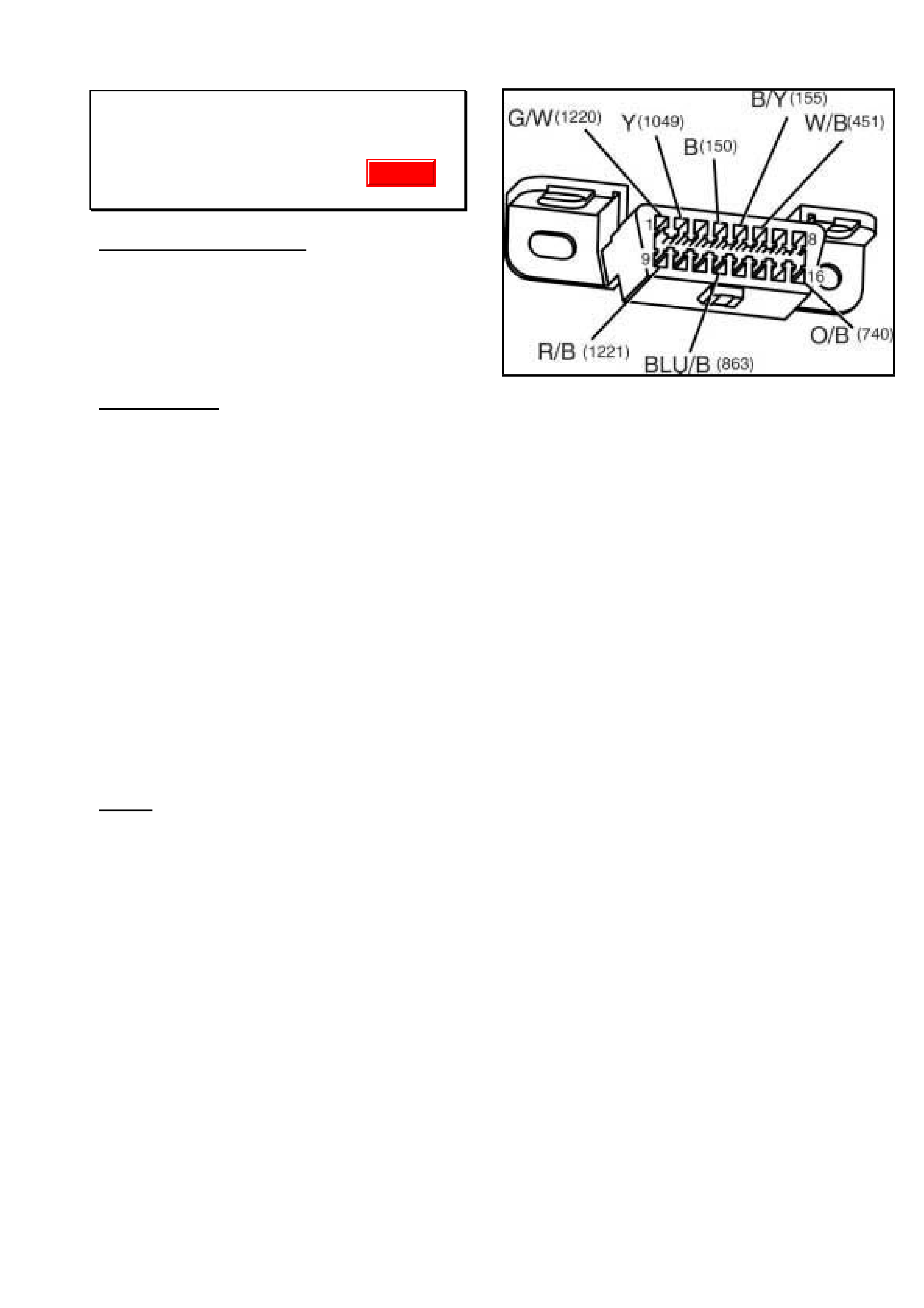
• Just before the downloading phase (from
Tech 2 to PCM) install a 200 to 250 ohm
resistor into the rear of the Data Link
Connector bridging the terminals 2 (Y-1049)
and 5 (B/Y-155). Refer Figure 1.
• With resistor in place, use multimeter to
check resistance between terminals 2 and 5.
Reading should be somewhere between
170 and 220 ohm.
• Continue with programming.
• Remove resistor on completion.
Notes:
If programming PCM (without resistor) and
process slows or stops, it is possible to
proceed normally once the resistor is installed
provided that Tech 2 has not been
disconnected.
If you still have difficulties with flash
programming even with the resistor installed
as above have a nominated representative
contact TAS.
The use of the resistor for flash programming
Gen 3 in above models will not be required
when TIS 2000 version 30.0 becomes
available.
Figure 1.
Update
HOLDEN SERVICE TECHLINE_____________________________________________________________MARCH, 2002
11
Tensioner Rattle/Noise
TR Astra with C16SE, C18SEL, X20XEV
engine
(Group 6Y) REVISED TL192A-0202
This techline is revised by changing the case type in
warranty claim information. Please discard
previous bulletin in Issue 1/2002.
.
PROBLEM DESCRIPTION
On some vehicles the following symptoms may
be observed:
• Rattle noisy from front of motor at idle.
• Belt tensioner vibrates excessively up &
down.
Investigations show that the alternator induces
a high oscillating load through the accessory
belt and tensioner. This in turn causes the
tensioner damping nylon ring to wear
prematurely thus reducing the damping and
causing the tensioner to oscillate and rattle.
The condition is more noticeable when the
engine is cold.
SERVICE RECTIFICATION
Summary: Remove standard alternator pulley
and replace with “decoupler pulley”.
Procedure:
1. Remove alternator assembly from vehicle
using procedure in TIS CD.
2. Remove alternator pulley nut with an impact
gun.
3. Install decoupler pulley using special tools A
and B as shown in Figure1.
4. Torque pulley attaching nut to 80 – 100 Nm.
5. Press cap plug into decoupler pulley. It is
important this cap is fitted to prevent the
entry of foreign material.
6. Reinstall alternator to vehicle.
SPECIAL TOOLS
Tool A. - Hazet Tool No. 2592 (Adapter)
Tool B. - Hazet Tool No. 2751 (long hexdrive
socket)
For dealerships wishing to purchase their own
tools, contact PB Baumann Tools Australia
who will direct you to the closest Hazet tool
Agent.
Telephone: 02 9816 1233.
Email: info@pbtools.com.au
NOTE: These tools can also be obtained on
loan from your Zone Service office.
PARTS INFORMATION
Part No.: Description: Qty
92145105 Decoupler pulley 1
92145244 Plug, sealing cap 1
WARRANTY CLAIM INFORMATION
For vehicles outside of warranty use case type
“07.”
Description Install Alternator
Decoupler pulley
Labour Op. No. J000698
Time 1.0hr
Failure Code 28 Rattles
Figure 1.

HOLDEN SERVICE TECHLINE_____________________________________________________________MARCH, 2002
12
Noisy Front Bearings – Diagnosis Hints
ALL V & W
(GROUP 3) TL231-0202
PROBLEM DESCRIPTION
Front Hubs returned to REPAC for complaints
of “Noisy” are often No Fault Found by the
supplier.
SERVICE RECTIFICATION
The following information is supplied to assist
in the diagnosis of front bearing noise
complaints:
1. Inspect for signs of impact damage to tyres,
wheels, wheel covers etc. Note: impact
damge is not covered by warranty.
2. Road test the vehicle in an attempt to
reproduce the customer’s complaint:
a) Ensure the complaint is not tyre noise. If
in doubt, compare with a known good
vehicle.
b) Use the smoothest road in your local
area.
c) Reduce cabin noise level as much as
possible (close windows, switch radio
and blower off).
d) Drive at the maximum allowable limit on
the chosen road.
e) Leave the vehicle in Drive (for
automatics) or the current gear (for
manuals) and allow the car to coast
down.
f) Listen for noise from the front of the
vehicle that changes as vehicle speed
decreases.
If the road is not long enough, this may
need to be done in stages (ie starting
speed of second run is the end speed of
the first run)
g) If no noise is apparent try driving
around bends or swerve within the
lane to induce a side load on the
bearing
3. Given that it can be hard to determine which
side the noise is coming from, it may be
necessary to remove the road wheels and
brake discs and rotate the hubs by hand. A
noisy bearing will feel “gritty” or rough when
turned by hand compared to a new bearing
or the hub on the other side of the vehicle.
4. When the failed/noisy bearing has been
identified, replace it only. DO NOT replace
the other hub at the same time! It is very
uncommon for both hubs to fail at the same
time.
WARRANTY CLAIM INFORMATION
Use Labour Times information in Warranty
Information section of current PV SIP.
HOLDEN SERVICE TECHLINE_____________________________________________________________MARCH, 2002
13
Door Cladding - Chrome Strip Detaches
At Ends, Material Delaminates
WH
(GROUP 01) TL226-0202
PROBLEM DESCRIPTION
The large door mouldings (cladding) have a
chrome moulding strip adhered in a channel
along the upper edge. On some vehicles this
chrome moulding may experience
delamination of the clear outer layer which
looks unsightly. The ends of the chrome
moulding may also become detached from the
door cladding.
The cause of the delamination is moisture
ingress into the end of the chrome moulding.
This has been been rectified in production by
improving the process which applies sealer to
the ends of the chrome strip
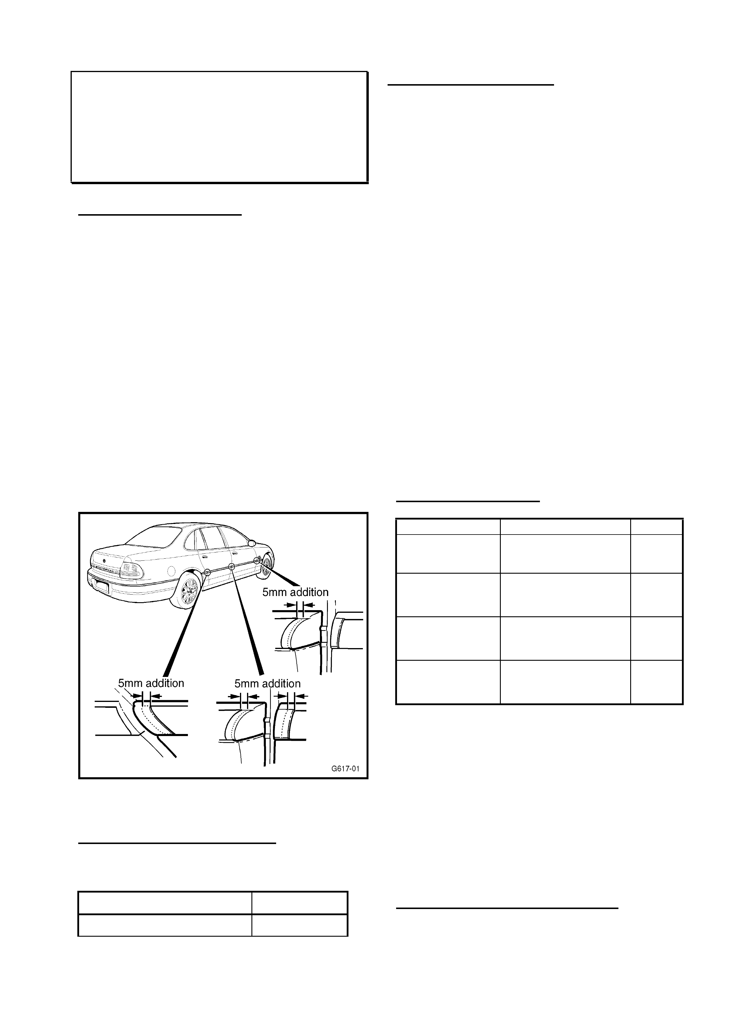
To prevent the chrome strip detaching at the
ends, an additional 5mm material has been
added to the door moulding “end caps”. Refer
Figure 1.
Figure 1.
PRODUCTION RECTIFICATION
Revised door mouldings with 5mm longer end
caps have been fitted to vehicles from:
ISOVIN: Build Date:
6H8WHZ19FXL820671 25/01/02
SERVICE RECTIFICATION
Summary:
1. Replace chrome strip if damaged .
2. Re-adhere chrome strip if not damaged but
is detached/curled at ends.
3. Replace door cladding if end caps are
damaged or broken.
Notes on Replacing Chrome strip.
• Peel chrome strip from door cladding
slowly in order to remove as much of the
adhesive as possible.
• Remove any remaining adhesive and wipe
channel with prepsol or similar.
• Install new chrome strip with double sided
tape provided.
• To improve retention of the ends of the
chrome strip, apply a small amount of
urethane p/n 92143609 to adhere the strip
to the door panel. Ensure any excess
urethane is removed with appropriate
solvent.
For all other procedures on removing and
replacing door mouldings refer to PV SIP.
PARTS INFORMATION
Part No.: Description: Qty
92143209 Old
92145245 New
Moulding Asm
Front Door (RH).
1
92143211 Old
92145247 New
Moulding Asm
Rear Door (RH).
1
92143210 Old
92145246 New
Moulding Asm
Front Door (LH)
1
92143212 Old
92145248 New
Moulding Asm
Rear Door (LH)
1
Parts Notes: Old = pre-breakpoint parts.
New = post-breakpoint parts
When existing HSPO stocks of old level door
cladding are exhausted they will be
superceded by the new design parts (5mm
longer end caps).
The door mouldings (cladding) are primed
only, and will require painting.
The chrome moulding strips must be ordered
separately.
WARRANTY CLAIM INFORMATION
Use Labour Times information in Warranty
Information section of current PV SIP.
HOLDEN SERVICE TECHLINE_____________________________________________________________MARCH, 2002
14
Interior Dome Light Stays On or Fuse
Blows
V2 Monaro
(GROUP 12) TL229-0202
PROBLEM DESCRIPTION
Some vehicles may experience the following
symptoms:
• The interior dome light remains on
regardless of switch position.
• Interior light fuse blows when light switched
on.
• Interior lights flash erratically at times.
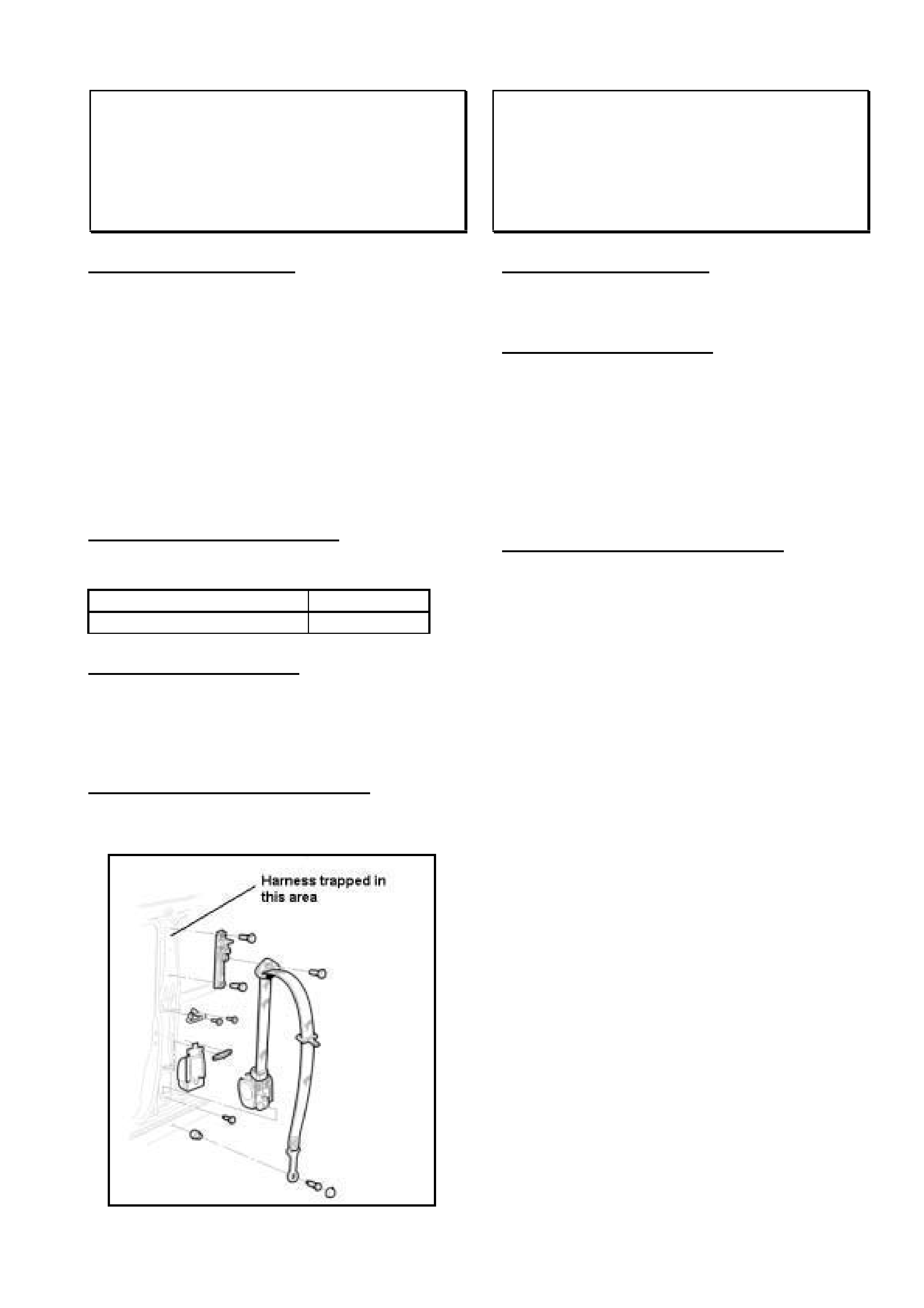
The above symptoms may be caused by the
wiring harness in the drivers side B pillar being
trapped/damaged by the upper seatbelt anchor
point. Refer Figure 1.
PRODUCTION RECTIFICATION
Production process revised to prevent damage
to B Pillar wiring harness from:
ISOVIN: Build Date:
6H8V2X37F2L819421 25/1/02
SERVICE RECTIFICATION
On complaint vehicles check for trapped wiring
harness under the RHS upper seat belt anchor
point.
Repair any damaged wiring as required.
WARRANTY CLAIM INFORMATION
For wiring and connector warranty claim
submission information refer to current PV SIP.
Figure 1.
Noisy Rear Door Checklinks – Reduced
Service Interval
VT, VX, WH
(GROUP 1) TL233-0202
PROBLEM DESCRIPTION
Some customers may complain of noisy rear
door checklinks.
SERVICE RECTIFICATION
Rear door checklinks should be cleaned of dirt
or debris and lubricated at every service.
Previously the service interval for lubricating
checklinks was every 20,000km.
Apply NLGI No. 2 Polyurea Grease(Mineral Oil
Base) to the checklink arm. Refer to PV SIP-
VTII, Section 0B, group 9 &10 for details.
WARRANTY CLAIM INFORMATION
This is a retail operation and should be
conducted as part of vehicle scheduled
servicing.

HOLDEN SERVICE TECHLINE_____________________________________________________________MARCH, 2002
15
Gearshift Lever Knob Rattle/Buzz
VTII, VX, VU, V2, Gen 3 Manual Trans.
(GROUP 7A) TL225-0202
PROBLEM DESCRIPTION
The gearshift knob vibrates to the point where
it can generally be heard in 3rd or 4th gear at
wide open throttle between 2500 to 4000 rpm.
This condition is a result of excessive
clearance between the shifter knob and the
shifter lever.
PRODUCTION RECTIFICATION
Transmissions with gearshift knobs glued to
the gearshift lever will be fitted to vehicles in
early March. The breakpoint for this change
will be published in the Breakpoint Summary in
the next issue of Techlines.
SERVICE RECTIFICATION
Summary: Glue gearshift knob to lever.
1. Remove the gearshift knob and gearshift
lever boot. Refer to PV SIP.
2. With the boot inverted back over the knob,
apply one of the following adhesives to the
insert of the shifter knob:
♦ A urethane adhesive such as Holden p/n
92143609 or
♦ A silicone based adhesive/sealer such as
Loctite Black Max 5900 or Dow Corning 7135
The quantity of adhesive should be sufficient
to result in a small excess squeezing out past
the tangs when the knob is refitted to the
shifter lever. This excess should be cleaned
away. Note: The customer should be
advised not to apply excessive force to the
knob until full strength bonding is achieved in
about 24 hours.
3. Reinstall the boot to the console. Refer to
PV SIP.
PARTS INFORMATION
Urethane adhesive p/n 92143609 can be
purchased from HSPO.
Loctite “BlackMax 5900” and Dow Corning
7135 may be purchased from most bearing
suppliers or engineering products retail outlets.
WARRANTY CLAIM INFORMATION
Description Glue gearshift knob to
lever.
Labour Op. No. K000279
Time 0.3 hr
Failure Code 36 (vibrates)
SERVICEABILITY OF THE GEARSHIFT
LEVER BOOT
A Service Techline will be published in the
near future which provides details on
serviceability of the gearshift lever boot when
the knob is glued to the lever.
HOLDEN SERVICE TECHLINE_____________________________________________________________MARCH, 2002
16
Alloy Wheel Centre Cap Dislodges
Easily
TS - Alloy Wheel 09117922 (6 spoke, 5
bolt holes)
(GROUP 10) TL208-0202
PROBLEM DESCRIPTION
On some vehicles fitted with the alloy wheel
part number 09117922, the centre cap may
dislodge while the vehicle is being driven.
Investigations have traced this problem to a
batch of wheels which were not machined to
specification. The suspect wheels all have the
marking “SM” cast into the wheel centre, and
were manufactured during the period January
to June 2001.
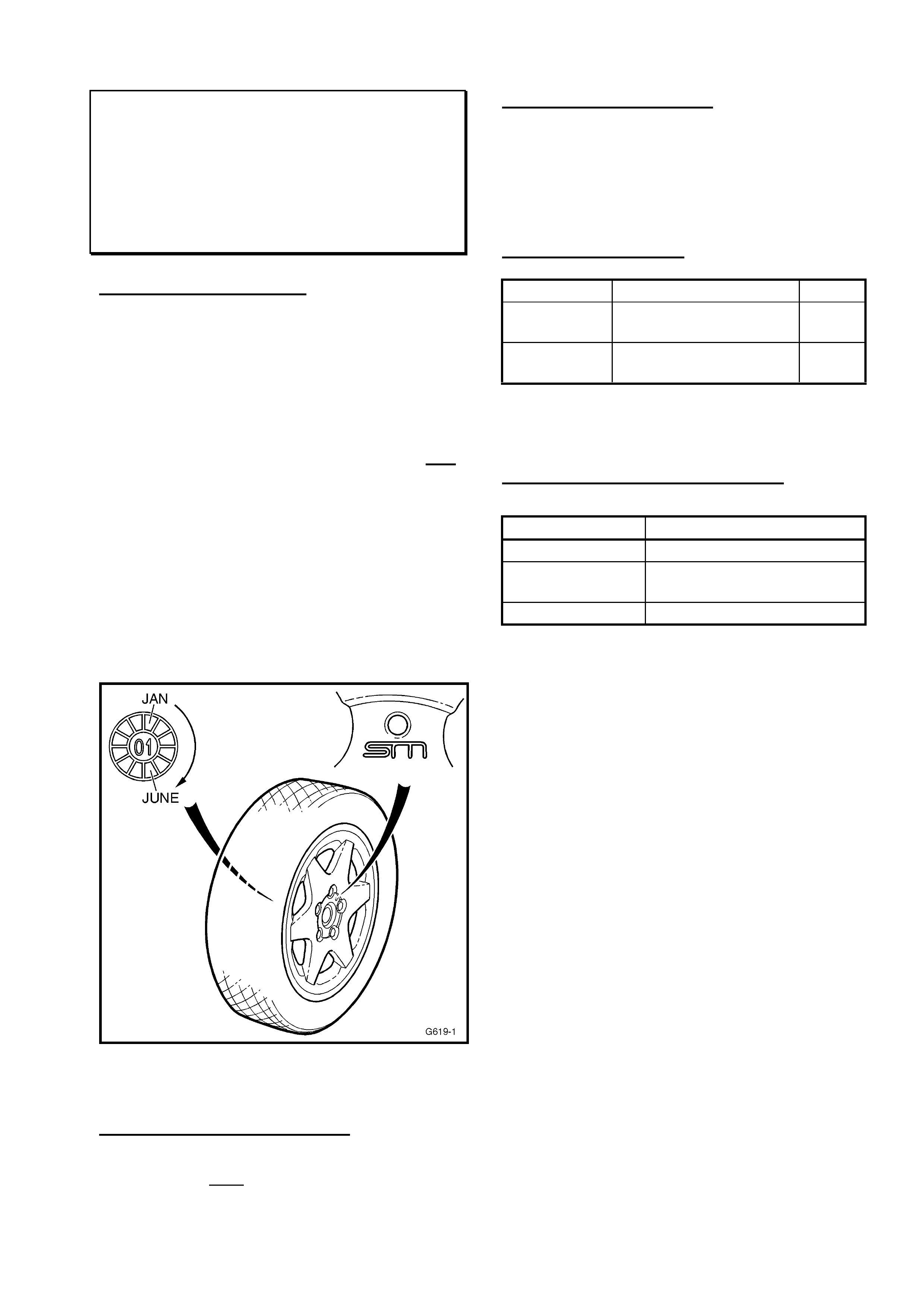
Figure 1 shows the location of the marking
“SM” as well as the date of manufacture on a
small “clockface” cast into one of the spokes
on the inside of the wheel. The two numbers
in the centre represent the year. The small
raised dot appearing in one of the 12
segments represents the month.
Figure 1.
PRODUCTION RECTIFICATION
All Alloy wheels with the supplier marking “SM”
manufactured from July 2001 are ok.
SERVICE RECTIFICATION
On any complaint wheel where the centre cap
falls off, inspect the wheel markings as shown
in Figure 1. Any complaint wheel with the
marking “SM” which was manufactured
between Jan to June 2001 should be replaced.
PARTS INFORMATION
Part No.: Description: Qty:
09117922 Wheel alloy 6Jx15 (5
bolt hole)
1
90539447 Cap asm wheel
centre
1
NOTE: Alloy wheels with the supplier marking
“BOH” are not affected.
WARRANTY CLAIM INFORMATION
Description Alloy Wheel - Replace
Labour Op.No. E000358
Time 0.4 hr (add 0.3 for each
extra wheel)
Failure Code 31 (Poor Matching)
HOLDEN SERVICE TECHLINE_____________________________________________________________________APRIL, 2002
6
Engine Vibration – Loose Engine Mount
Bolt
TS
(GROUP 6A) TL247-0203
PROBLEM DESCRIPTION
PIR’s have been received that mention
engine/transmission vibration – and diagnosis
has shown that a loose/missing rear powerplant
mounting bolt was the cause.
SERVICE RECTIFICATION
Summary: Refit/Replace bolt and Apply Loctite
243.
Should diagnosis of a “vibration” complaint define
that a rear powerplant mounting bolt is:
a/. Loose – remove the mating nut, apply Loctite
243 (or equivalent) to the bolt threads and refit
the nut, and torque to 55Nm.
OR
b/. Missing – Fit a new bolt and nut (from
HSPO), apply Loctite 243 (or equivalent) before
installation and torque to 55Nm.
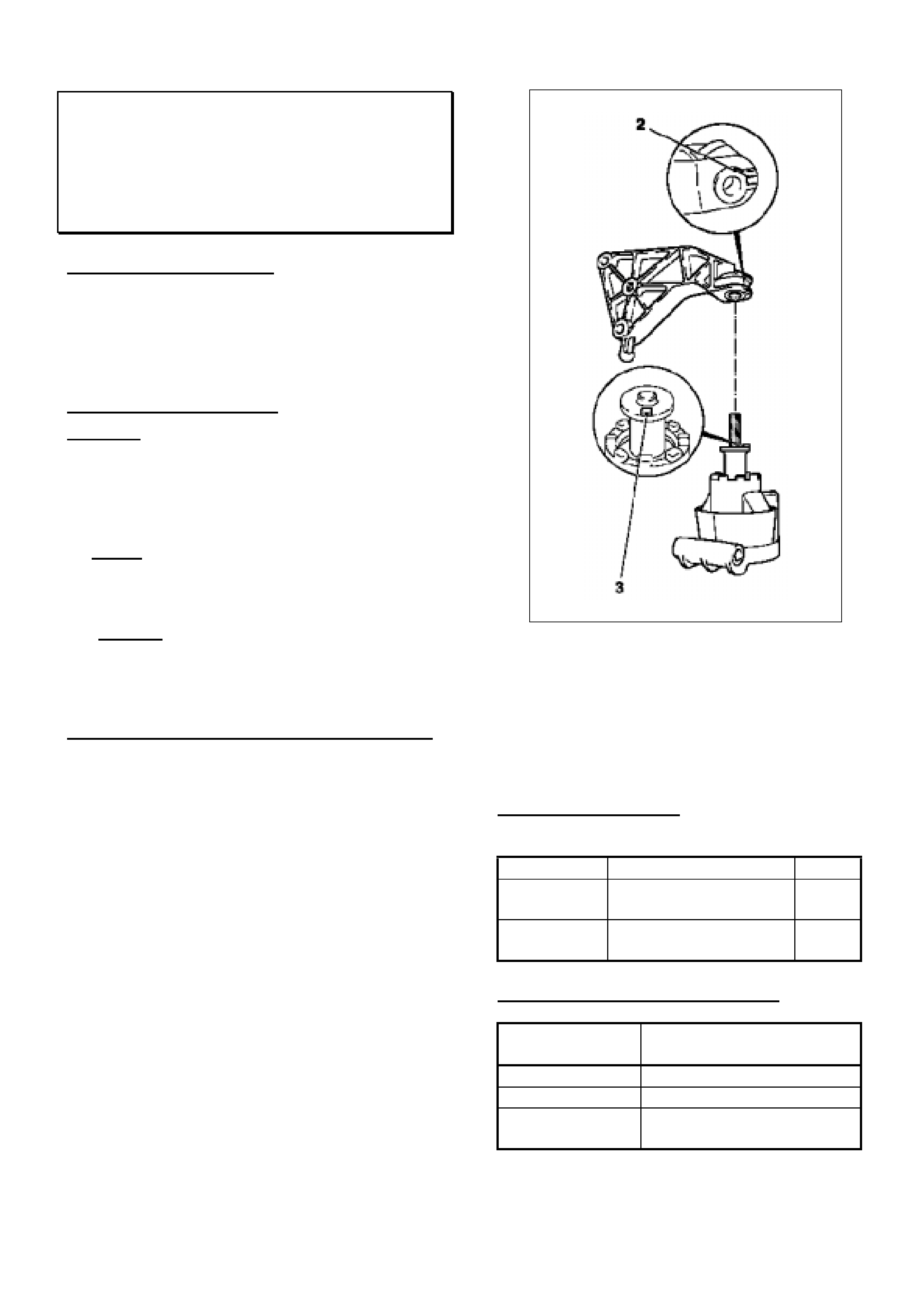
Rear Engine Mounting Assembly Precaution.
Note: when attaching the damper block to the
(upper) bracket – ensure the raised “key” section
(3) of the damper is located in the recess (2) in
the bracket, as shown in Figure 1.
Figure 1.
For Reference: The above diagram is taken from
TIS 2000 – Refer to the relevant TIS 2000
section when replacing engine/powertrain
mounts.
PARTS INFORMATION
Use the following parts ONLY when replacement
of missing parts is required:
Part No.: Description: Qty:
11098991 Bolt – Damper to
Bracket.
1
11098811 Nut – Damper to
Bracket.
1
WARRANTY CLAIM INFORMATION
Description Engine mount bolt/nut -
Replace
Labour Op. No. J000704
Time 0.3 hr
Failure Code 27 (Loose) or
29 (Part Missing)
HOLDEN SERVICE TECHLINE_____________________________________________________________________APRIL, 2002
7
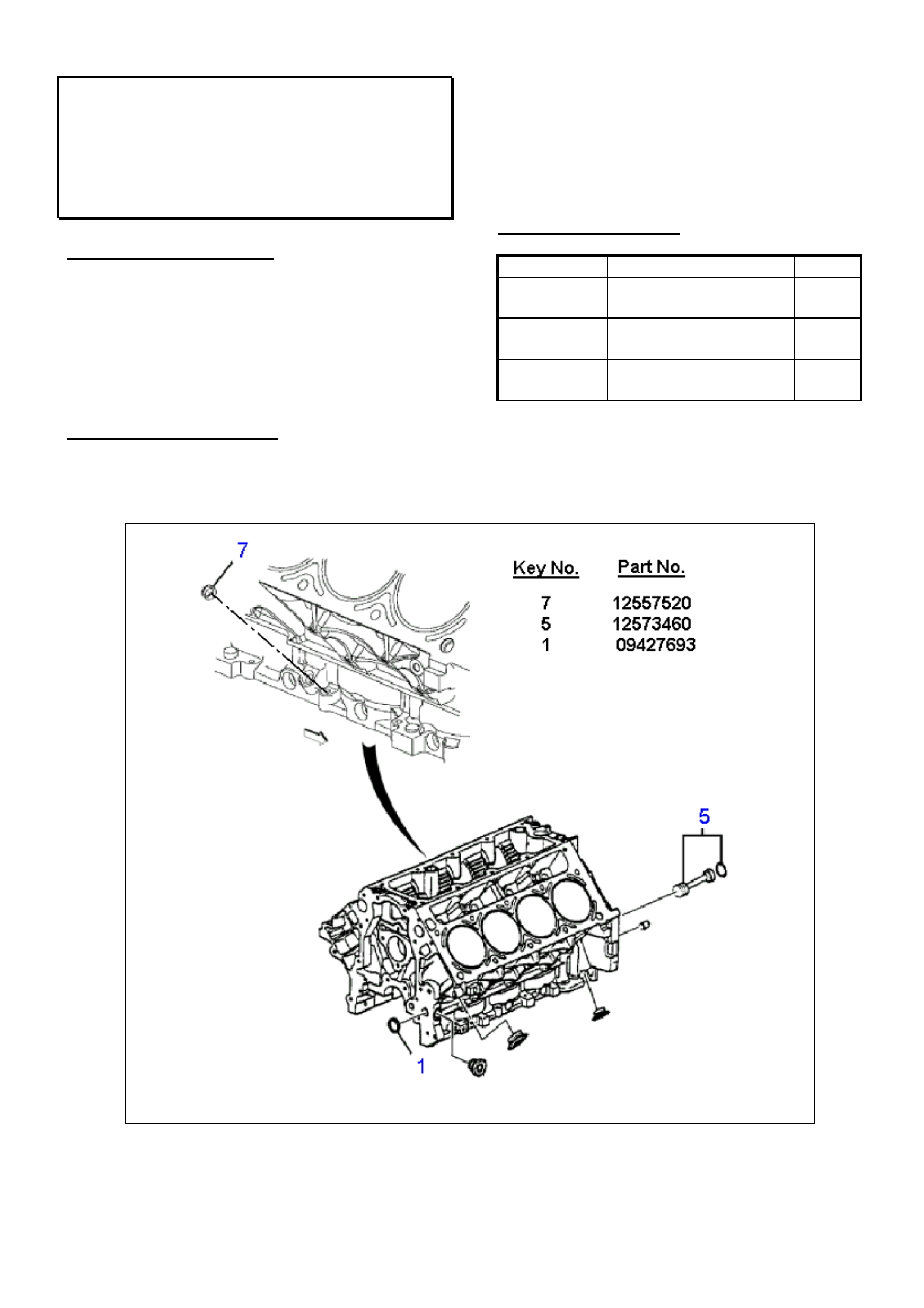
Welch Plug Requirement - During Engine
Block Replacement
All with Gen III Engine
(GROUP 6A) TL248-0203
PROBLEM DESCRIPTION
When replacing a Gen III engine block –
replacement blocks are NOT fitted with three
welch plugs. Refer key nos. 1, 5 and 7 in Figure
1.
The fitting of these welch plugs can easily be
overlooked, and will result in oil leakage or lack
of oil pressure on start-up.
SERVICE RECTIFICATION
The welch plugs should be ordered when
ordering the engine block and fitted during the
replacement.
Order one each of the welch plugs shown in
Parts Information. Locations for fitting the welch
plugs are shown in Figure 1.
Refer to PV SIP, VTII, Section 6A3, Item 3.14
for procedures on removing and installing these
plugs.
PARTS INFORMATION
Part No.: Description: Qty:
12557520 Plug – Oil Level
Indicator Hole
1
12573460 Plug – Oil Gallery,
Rear
1
09427693 Plug – Oil Gallery,
Front
1
Figure 1.

HOLDEN SERVICE TECHLINE_____________________________________________________________________APRIL, 2002
8
Steering Knock/Rattle
JS Vectra
(GROUP 9) TL252-0203
Refer to the two previous Techlines on this
subject in PV SIP, Service Techlines, 1998,
Group 9.
Many steering columns, and steering gear
assemblies replaced under warranty for noise
complaints cannot be faulted.
The replacement of steering columns and
steering gears to rectify knock/rattle condition is
not generally recommended as there are no
known problems with these components.
Intermediate shafts however, have had a known
rattle condition and should be replaced to rectify
complaint vehicles. it is important to note that
the new intermediate shaft will still
rattle/knock unless the upper and lower pinch
bolts are tightened to specification.
SERVICE RECTIFICATION
Whenever presented with a customer complaint
of steering knock/rattle we strongly recommend
that only the intermediate shaft be replaced.
For intermediate shaft replacement procedure
refer to previous Techline in PV SIP, Service
Techlines, 1998, Group 9.
IMPORTANT: The “new” upper and lower pinch
bolts must be tightened to:
22Nm(16 lbf.ft) + 45º + 15º
Brake Squeal Rectification
TS – Non-ABS models only
(GROUP 5) REVISED TL259-0203
This Techline which now supercedes the previous
one, is revised by adding a special labour
operation number to Warranty Claim Information.
PROBLEM DESCRIPTION
Some non-ABS equipped TS Astra vehicles may
exhibit a squeal noise under braking.
New front brake pads have been released to
address this squeal.
The new pads have the leading and trailing edges
of the friction material chamfered to move the
squeal frequency outside the audible range.
PRODUCTION RECTIFICATION
The revised brake pads have been fitted in
production from March 2002. When they become
available, breakpoints will be published in the
Service Techline Breakpoint Summary.
SERVICE RECTIFICATION
To address customer complaints, fit the revised
brake pads. These brake pads are available from
HSPO.
PARTS INFORMATION
Part No.: Description: Qty:
93171035 Pad Set-Front Brake 1
WARRANTY CLAIM INFORMATION
Description Pads, disc brake, both
front wheels - replace
Labour Op. No. H000222
Time 0.9 hr
Failure Code 40
Update
Update

HOLDEN SERVICE TECHLINE_____________________________________________________________________APRIL, 2002
9
Water Leak Between Top Edge Of Door
Glass and Door Frame Seal
V2 Monaro
(GROUP 1) TL258-0203
PROBLEM DESCRIPTION
Some vehicles may experience water leaking into
the vehicle over the top of the door glass. The
area of concern occurs over a distance of about
100mm forward from the rear vertical edge of the
glass.
SERVICE RECTIFICATION
On any vehicle with the above complaint,
1. Check for correct installation of the door frame
weatherstrip. (Item 1 in Figure 1.)
2. Check window regulator and window
glass adjustment. Refer to PV SIP, V2,
Section 1A5, Item 2.9
3. Confirm if leak is still present.
4. If leak is still present, install a new Weatherstrip
Assembly. Refer to PV SIP, V2,
Section 1A5, Item 2.10 After new
weatherstrip asm. is installed, ensure that the
window glass tucks up under the sealing lip of
the weatherstrip as shown in section AA of
Figure 1.
PARTS INFORMATION
Part No.: Description: Qty:
92092896 Weatherstrip Asm. -
Felt Front Door
Glass (RH)
1
92092895 Weatherstrip Asm. -
Felt Front Door
Glass (LH)
1
WARRANTY CLAIM INFORMATION
Use Labour Times information in Warranty
Information section of current PV SIP CD
Figure 1
HOLDEN SERVICE TECHLINE_____________________________________________________________________APRIL, 2002
10
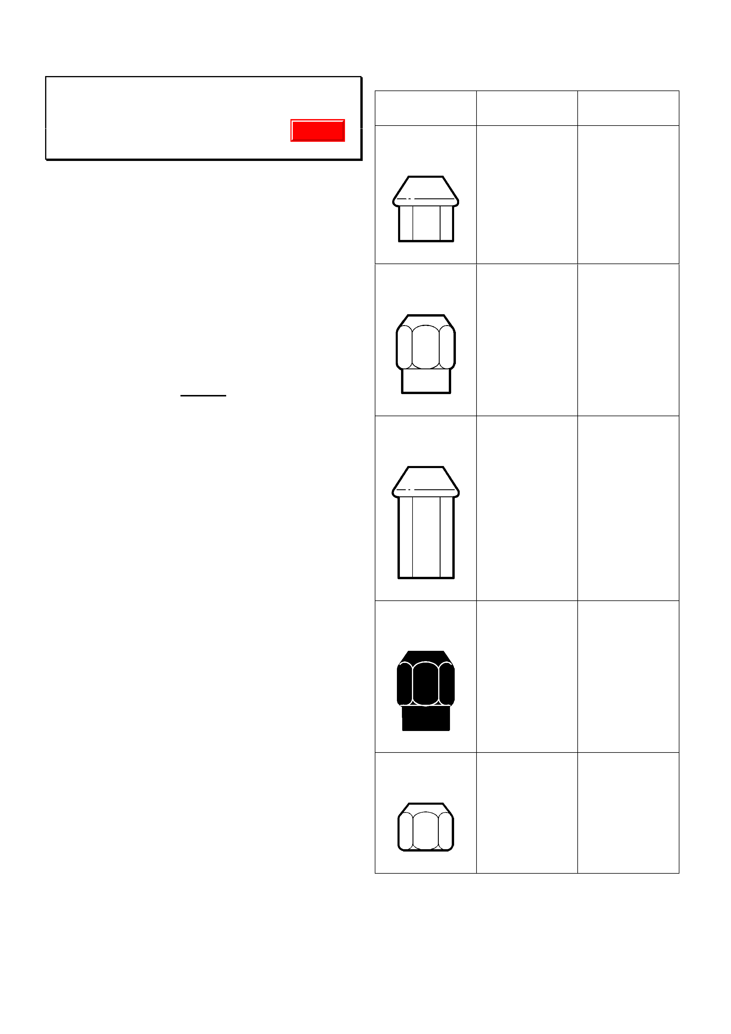
Wheel Nut Usage - Alloy And Steel Wheels
All V & W
(GROUP 10) TL255-0203
The purpose of this Techline is to highlight the
importance of only using those wheel nuts that
are specified for the type of wheel fitted to the
vehicle.
Originally, alloy wheels had steel nut-seats.
However, in most current design alloy wheels the
steel nut-seats have been deleted and the wheel
nuts now bear directly onto the alloy. The wheel
nuts designed for use on alloy wheels without
steel nut-seats have a much larger taper to
provide increased clamping area.
NOTE :
1. Do not use nuts that are specified for use
with steel wheels to retain alloy wheels.
2. Do not use nuts that are specified for use
with alloy wheels to retain steel wheels.
If wheel nuts designed for use with steel wheels
are used on alloy wheels without steel nut-seats,
there is potential for the following problems to
occur:
1. Lack of sufficient clamp load.
2. Localised nut bite into the alloy nut-seat.
3. Potential fatiguing of the wheel studs.
4. Potential fatigue and/or cracking of the alloy
wheel nut seats.
The following table shows the various nuts
specified in Partfinder with the model usage.
Remember to always refer to Partfinder to
determine which nut is specified for the wheels
concerned.
Part Number
For use on
wheel:
Models
22526184
Alloy wheel
(No steel nut
seat)
V2,VX,WH,VU,
VS,VT
92037665
Alloy wheel
(steel nut seats)
WH, VT, VS
92100089
Alloy wheel
(No steel nut
seats)
V2
92045082
Steel wheel VX,VU,VT,VS,
VP, VR,
92015262
Steel wheel VX,VT,VS,VP,
VR, VQ, VB
Update
HOLDEN SERVICE TECHLINE_____________________________________________________________________APRIL, 2002
11
Centre High Mount Stop Light Rattle
V2 Monaro
(GROUP 12) TL240-0203
PROBLEM DESCRIPTION
Some customers may complain of a rattle coming
from the rear parcel shelf area.
On some vehicles the cause of this rattle has
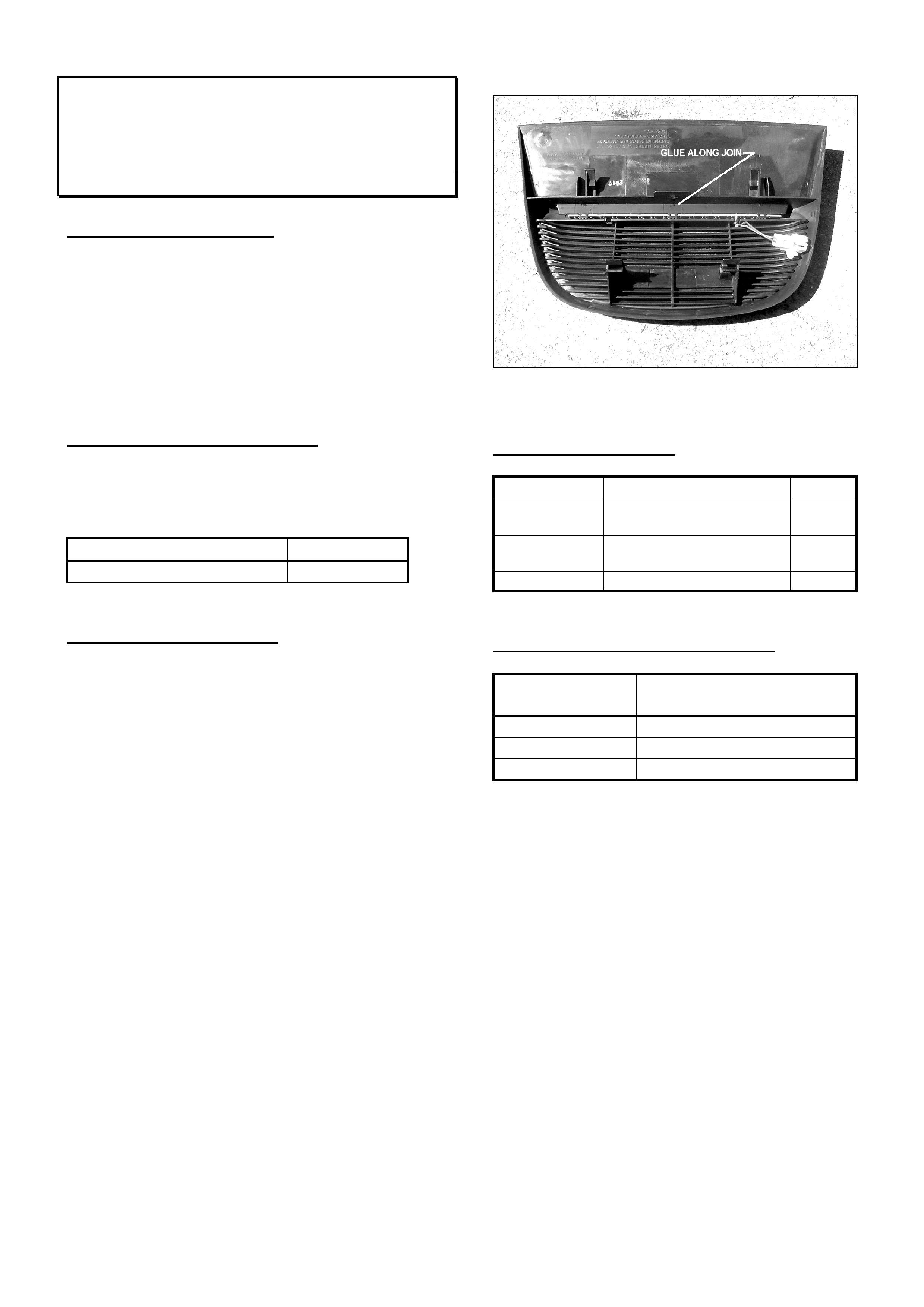
been traced to the Centre High Mount Stop Light
(CHMSL). Under certain driving conditions the
LED assembly vibrates within the CHMSL
housing resulting in a rattle.
PRODUCTION RECTIFICATION
CHMSL’s with the LED/lens assembly glued to
the housing as shown in Figure 1, have been
fitted to vehicles from:
ISOVIN: Build Date:
6H8V2X37F2L827493 12/02/02
SERVICE RECTIFICATION
Summary: Glue LED assembly to CHMSL
housing
To rectify complaint vehicles proceed as follows:
1. Remove CHMSL (refer to PV SIP CD).
2. Glue the LED/lens assembly to the main
housing as shown in Figure 1. Use a
cyanoacrylate adhesive such as Loctite 406.
Ensure that any excess does not show on
external surface of housing.
3. Reinstall CHMSL. (refer to PV SIP CD).
NOTE: On vehicles where the LED assembly has
been glued to the CHMSL housing; it will be
necessary to break the glue bond if the LED
assembly requires replacement. If this cannot be
done successfully then replace the complete
CHMSL assembly.
Figure 1.
PARTS INFORMATION
Part No.: Description: Qty:
92094523 Centre High Mounted
Stop Lamp Assembly
1
92144531 Bulb, LED, Printed
circuit board & harness
1
92144530 Lens 1
WARRANTY CLAIM INFORMATION
Description Glue LED/lens assembly
to CHMSL housing
Labour Op. No. N000378
Time 0. 4hr
Failure Code 28 rattles

HOLDEN SERVICE TECHLINE_____________________________________________________________________APRIL, 2002
12
Engine Oil Consumption Information
All
(GROUP 6A) TL260-0203
This Techline is provided for general information.
All engines require oil to lubricate and protect the
load bearing and internal moving parts from wear
including cylinder walls, pistons and piston rings.
When a piston moves down its cylinder, a thin film
of oil is left on the cylinder wall. During the power
stroke, part of this oil layer is consumed in the
combustion process. As a result, varying rates of
oil consumption are accepted as normal in all
engines.
Many external factors, such as owner driving habits
and vehicle maintenance, can affect the rate of oil
consumption.
The following are some important items affecting
oil consumption which must be taken into account
when evaluating customer complaint vehicles.
Gasket and External Leaks
Inspect the oil pan and engine covers for leakage
due to over-tightened, damaged, or out of place
gaskets. Inspect oil lines and fittings for signs of
leakage.
Improper Reading of the Oil Level Indicator
(Dipstick)
Verify that the dipstick tube is fully seated in the
block. When checking the oil level, make sure the
dipstick is wiped clean before taking an oil level
reading and fully
depress the dipstick until the shoulder bottoms out
on the dipstick tube. The dipstick should be the
proper part number for the engine/vehicle that is
being checked.
Not Waiting Long Enough After Running Engine
to Check Oil Level
The vehicle should be allowed to sit for at least 10
minutes after the engine has been shut off, before
taking an oil level reading to assure the oil has had
enough time to drain back into the crankcase. In
order to ensure accurate results, the temperature
of the oil should be close to the same temperature
as the last time the oil level was checked.
Improper Oil Fill After an Oil Change
Following an oil change, verify that the proper
amount and type of oil was put in the engine and
that the oil level on the dipstick is not above the full
mark or below the add marks. Refer to the
Owner's Manual or Service Manual for information
on recommended oil quantity, viscosity, and
quality.
High Speed or High RPM Driving
Continuous driving at high speeds/high RPMs may
increase oil consumption. Because this may not
always be an everyday occurrence, it is hard to
determine exactly how much the oil economy will
be affected.
Towing or Heavy Usage
Towing a trailer will increase oil consumption and
may cause oil consumption to fall below the normal
accepted rate referenced in this bulletin for an
unloaded vehicle in a personal use application.
Large frontal area trailers will further increase the
work required from the engine, especially at
highway speeds, and thus increases the rate of oil
consumption.
Crankcase Ventilation System
Verify that the positive crankcase ventilation (PCV)
system is operating properly. Incorrect PCV
valves, blockages, restrictions, or damage to the
PCV system can result in increased oil use.
Oil Dilution (Fuel and Water)
On vehicles that are usually driven short distances,
less than 8 km, especially in colder weather,
unburned fuel and condensation generated from
cold engine operation may not get hot enough to
evaporate out of the oil. When this occurs, the
dipstick may indicate that the oil level is over-full.
Subsequent driving on a trip where the engine is at
normal operating temperature for 30 minutes or
more, will vaporize excess moisture and fuel, and
may give the customer the impression of excessive
oil consumption if the oil level is checked
immediately after.

HOLDEN SERVICE TECHLINE_____________________________________________________________________APRIL, 2002
13
Engine Temperature
If an engine is run at overheated temperatures (see
Owner's Manual or Service Manual) for more than
brief periods, oil will oxidize at a faster than normal
rate. In addition, gaskets may distort, piston rings
may stick, and excessive wear may result. Verify
that all cooling system components are in proper
working order.
Engine Wear
Piston scuffing, excessive piston-to-wall clearance,
tapered or out of round cylinders, worn, damaged
or improperly installed valve guides, seals and
piston rings will all cause an increase in oil
consumption.
Interior Rattle Noise Diagnosis
All Models Fitted With Melbourne CityLink
e-Tag device
(GROUP 1) HINT TL261-0203
This techline was first issued in 2000. It is
reissued due to ongoing cases of noise mis-
diagnosis.
When investigating instrument panel “rattle”
complaints, where a vehicle is fitted with an “e-
TAG” unit (electronic signal transmitter for use on
the Melbourne CityLink electronic tollway system),
first remove the e-TAG unit.
Any rattle that may emanate from the “e-TAG”
unit could lead to misdiagnosis of the noise, in the
belief that interior trim or components in the
instrument panel may be the cause.
NOTE: “e-TAG’s” are normally attached to the
inside of the front windscreen behind the rear
view mirror, via a mounting bracket, and are
detachable. The “e-TAG” can be detached from
the bracket by gripping the “e-TAG” and rotating
the top rearwards and downward.
Should an “e-TAG” be defined as the cause of a
rattle noise – the customer should be advised that
the rattle is emanating from the “e-TAG”, not the
vehicle.
HOLDEN SERVICE TECHLINE_____________________________________________________________________APRIL, 2002
14
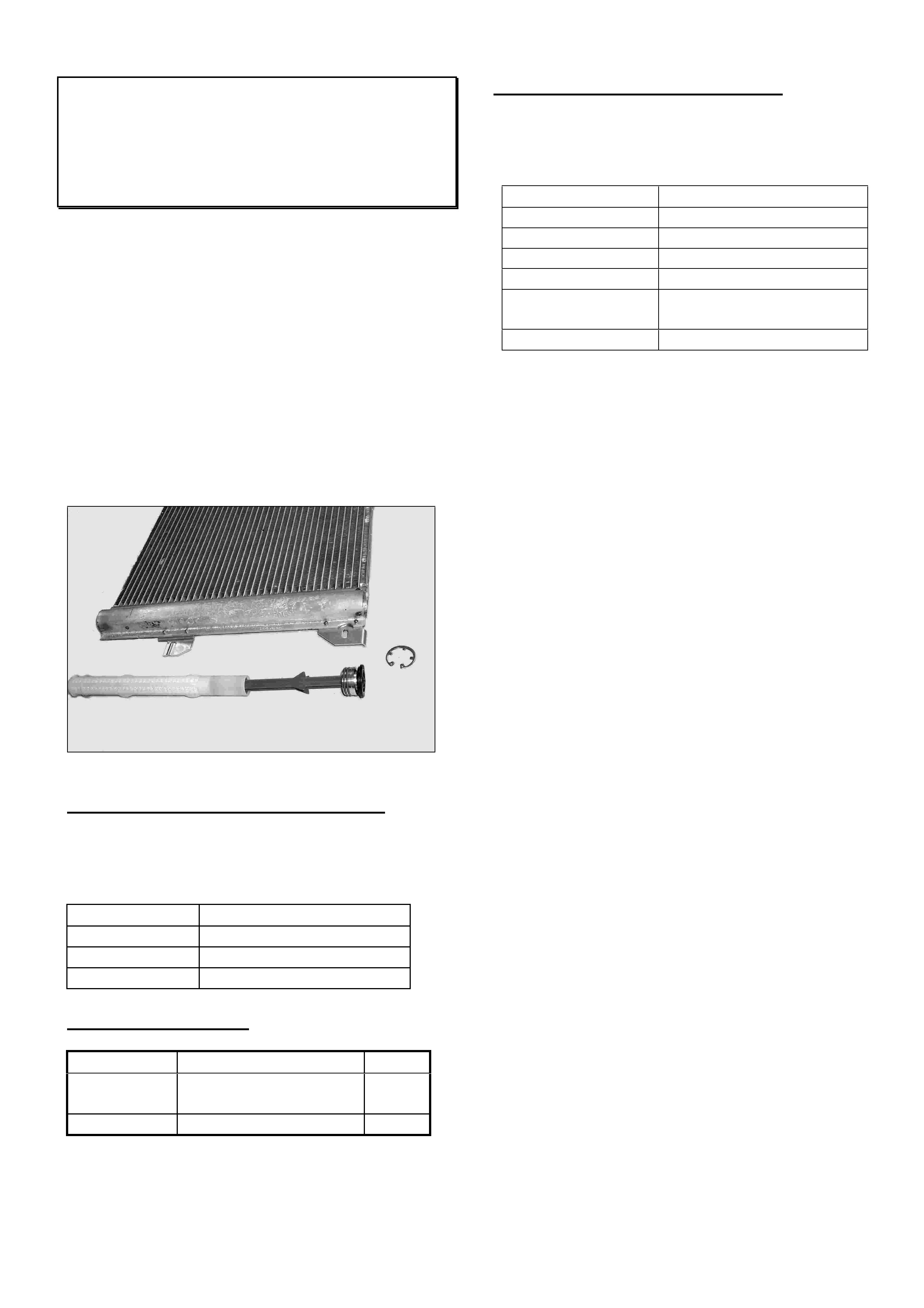
Design Changes To Condensor and
Receiver Dryer
TS and TT Model Year 2002
(GROUP 2) TL249-0203
The receiver dryer on the above models is now
integrated into the side tank of the condensor.
This design enables replacement of a cartridge
containing the drying granules instead of
replacing the complete receiver dryer as in
previous models. Figure 1 shows the cartridge
removed from the condensor.
NOTE: The quantity of R134A refrigerant in the
A/C system has been reduced as a result of this
design change. Refer to the label in the engine
compartment or to TIS for specified quantities of
R134A.
Figure 1
PRODUCTION CHANGE INFORMATION
The new design condensor with integral receiver
dryer has been fitted to vehicles from
commencement of Model Year 02:
Model ISOVIN:
TS Hatch W0L0TGF4825003949
TS Sedan W0L0TGF6925010206
Zafira W0L0TGF752H000000
PARTS INFORMATION
Part No.: Description: Qty:
93170609 Receiver Dryer
(cartridge)
1
93170608 Condener asm. 1
SERVICING THE RECEIVER DRYER
To replace the Drying Agent Cartridge refer to
procedure in TIS 2000 CD. To find procedure in
TIS follow the path as shown in table:
Item Select
Sales Make Opel
Type of Info. Standard Information
Vehicle Data Astra-G or Zafira, 2002
Assembly Group (D) HVAC
Application Repair(Remove,Install,
Adjust)
Document List Document No. 25 of 126
HOLDEN SERVICE TECHLINE_____________________________________________________________________APRIL, 2002
15
Excessive Gear or Road Noise from M/T
Shifter Area
VTII, VU, VX,V2 with 6 speed M/T (MM6)
(GROUP 7A) TL227-0203
PROBLEM DESCRIPTION
Some customers may complain of excessive
noise coming from the transmission shifter area.
This condition may be caused by:
a) Inner boot torn or split as a result of
excessive wear, or
b) Retainer plate loose.
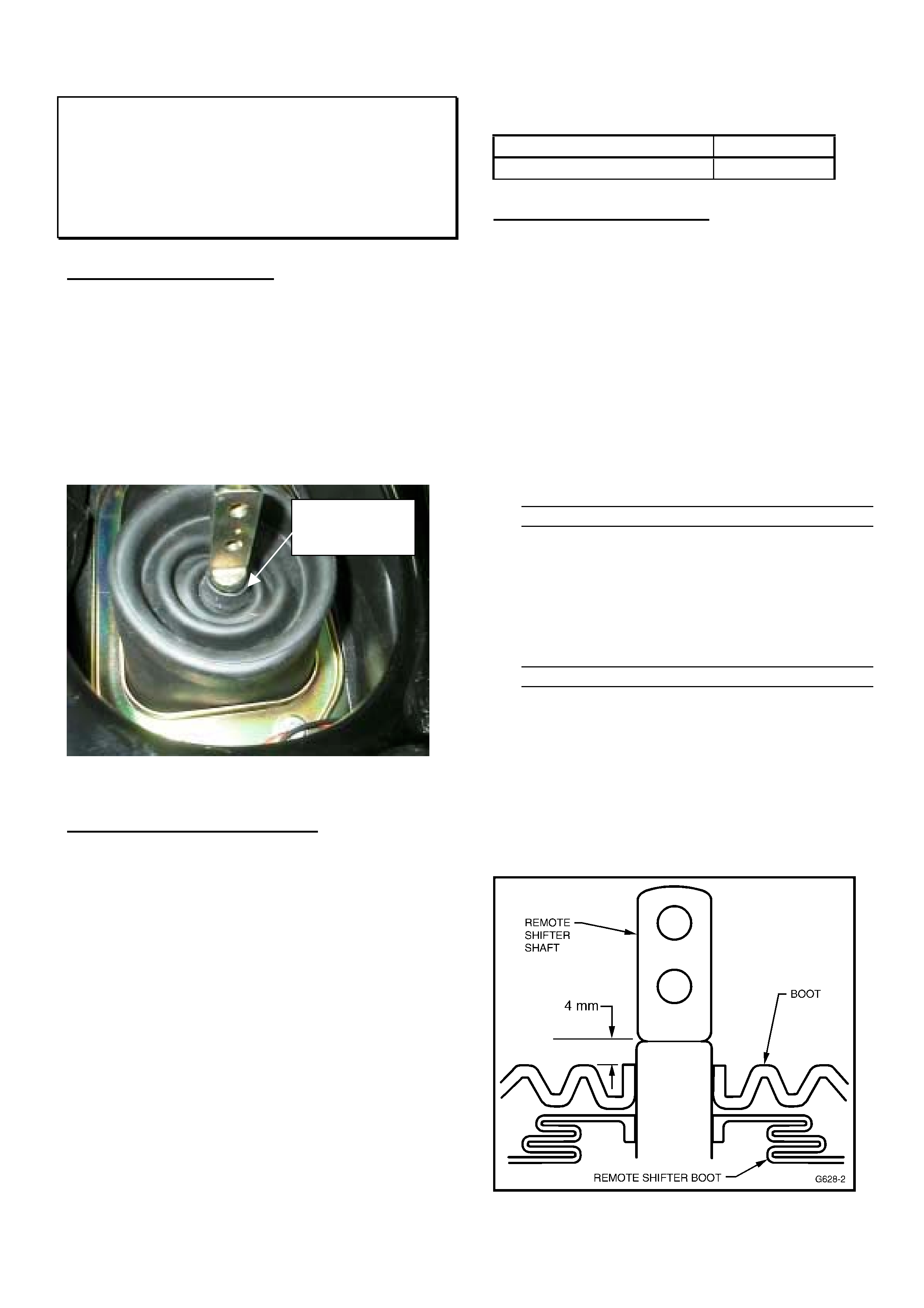
Note: A boot collar turned upwards as shown in
Figure 1 can contribute to excessive wear of the
boot convolutions.
Figure 1. Problem of upturned boot collar
PRODUCTION RECTIFICATION
To improve both the product and the assembly
process, the following revisions have been made:
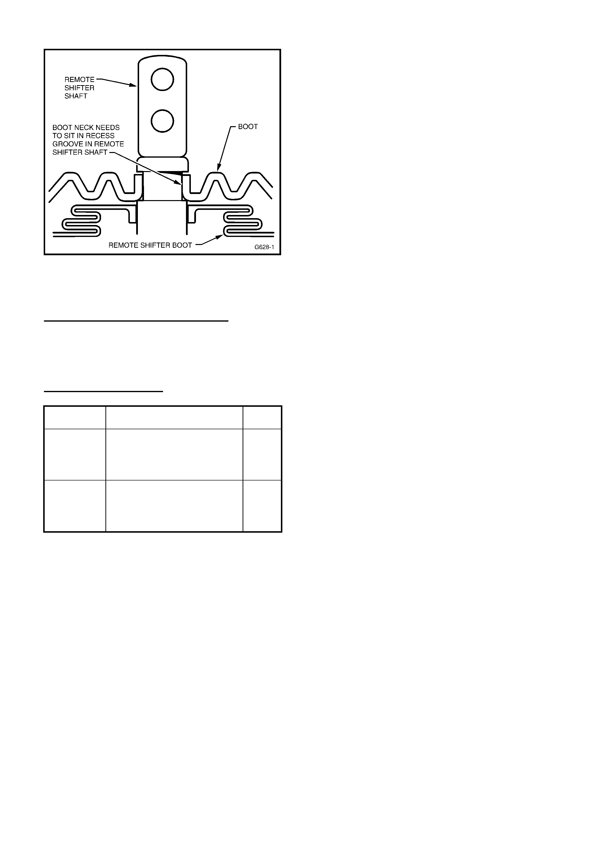
• The boot collar has been revised to fit into a
recessed groove in the remote shifter lever.
Note the new collar is now upturned. These
changes provide positive location for the boot
collar. Refer Figure 2.
• The boot material has been changed for
improved durability. The new boot material is
white in colour.
• The boot asm. attachment method has been
revised. The retainer plate now has 4 welded
on studs. The previous nutserts retained in
the sheetmetal have been replaced with 4
nuts applied from below the vehicle during
assembly.
Transmissions with the above changes have been
fitted to vehicles from:
ISOVIN: Build Date:
6H8VUK80F2L832048 21/02/2002
SERVICE RECTIFICATION
Summary: Check boot for condition and
installation. Install new boot as required.
1. Remove gearshift knob and outer trim boot
assembly. For procedure refer to PV SIP,
VTII, Section 7B3, Item 3.5.
2. Check the inner boot for tears, splits or
excessive wear. If damaged, replace with
new boot asm. If boot is okay, but collar is
upturned as in Figure 1, the boot should be
removed and reinstalled with the collar turned
downwards.
3. Installation of new design boot asm. on
vehicles built prior to breakpoint.
After installing new design boot asm.
92145520(without studs), the collar of the
boot must be glued to the remote shifter lever
4mm below the step as shown in Figure 2.
Use a “super glue” such as Loctite 406.
4. Installation of new design boot asm. on
vehicles built after breakpoint.
When installing new design boot asm.
92065868(with studs) it is not necessary to
glue the boot collar to the remote shifter lever
(refer step 3) as it will be positively retained in
the recessed groove as shown in Figure 3.
The four attaching nuts applied from
underneath the vehicle are to be torqued to 12
–18 Nm.
Figure 2.
Boot colla
r
upturned
HOLDEN SERVICE TECHLINE_____________________________________________________________________APRIL, 2002
16
Figure 3.
WARRANTY CLAIM INFORMATION
Use Labour Times information in Warranty
Information section of current PV SIP.
PARTS INFORMATION
Part No.: Description: Qty:
92065868
Use From L832048
Boot Asm. M/T Control
Lever (4 studs in retainer
plate)
1
92145520
Use Prior to L832048
Boot Asm M/T Control
Lever (4 holes in retainer
plate – no studs)
1
NOTE: When you first receive this Techline the
above parts may not be immediately available.
However, orders may still be placed.

HOLDEN SERVICE TECHLINE___________________________________________________________________ MAY, 2002
6
Revised TX Valve
SB Barina with A/C
(GROUP 2) TL232-0203
Ongoing product improvement has resulted in an
improved durability, replacement Thermal
Expansion Valve (TXV) becoming available for
the above model.
The new TXV (92144973) is visually the same as
the previous one (52464434).
SERVICE RECTIFICATION
Whenever a TX valve replacement is required, fit
a new part as shown in Parts Information.
PARTS INFORMATION
Part No.: Description: Qty:
92144973 Thermostatic
expansion valve kit.
1
NOTE: Quantities of 92144973 are not expected to be
available from HSPO until mid May, however orders
may still be placed.
Front Wiper Blades Noisy, Shudders
XC Barina
(GROUP 1) UPDATE TL237-0204
This Techline supersedes the previous Techline
on this topic in Issue 9, Sep 2001, which should
be destroyed.
PROBLEM DESCRIPTION
Windscreen wiper blade operating noise
excessive, as a result of wiper blade judder.
Investigations have shown the wiper blade profile
and material causes an incorrect attack angle and
high noise level as a result of blade deformation.
PRODUCTION BREAKPOINT
Ongoing improvements to the wiper blade design
on this model has resulted in a change of
suppliers. Bosch wiper blades have been fitted to
XC Barina vehicles from:
ISOVIN: Build Date:
W0L0XCF6824071208 07/11/01
SERVICE RECTIFICATION
On vehicles with complaint of noisy front wiper
blades:
1. Clean windscreen glass and rubber wiper blade
to remove all pollution deposits and foreign
material contamination.
2. Operate wipers (with running water) and listen
for wiper blade noise.
3. If this fails to provide satisfactory wiper blade
noise levels, replace blades with new parts.
PARTS INFORMATION
The part number of the new Bosch wiper blades
is:
Part No. Description: Qty:
93171135 Set – Front
windscreen wiper
blades.
1

HOLDEN SERVICE TECHLINE___________________________________________________________________ MAY, 2002
7
A/C TX Valve Noise
VTII, VX, VU, V2, WH, with Gen III
(GROUP 2) TL272-0204
PROBLEM DESCRIPTION
Some owners may complain of a rumble type
noise coming from the dash area with the A/C
operating.
Investigations show the TX valve can be the
source of this type of noise.
NOTE: There are reports that some dealers have
replaced compressors for this noise only to find
that the TX valve was actually at fault.
PRODUCTION RECTIFICATION
To reduce A/C noise, revised TX Valves p/n
92116220 (Eaton brand) have been fitted to
vehicles from:
ISOVIN: Build Date:
6H8VXK69F2L813616 09/01/02
A further breakpoint is expected in June for fitting
a new TX Valve, p/n 92117402 (TGK brand)
which is the same valve that was introduced into
V6 models from L854345 on April 11th,2002..
SERVICE RECTIFICATION
If available, use an electronic listening device to
determine where the A/C rumble noise is coming
from. If it is loudest at the low pressure pipe out
of the TX valve, then replace valve with revised
part as shown in Parts Information.
PARTS INFORMATION
Part No.: Description: Qty:
92117402 TX Valve 1
WARRANTY CLAIM INFORMATION
Use Labour Times information in Warranty
Information section of current PV SIP CD
Tech 2 DTC Symptom Descriptors
Simtec Engine Management Systems
(GROUP OB) TL271-0204
TAS often receive queries about the number in
brackets appearing in line 3 of the Tech 2 DTC
Display. For Example;
Line 1. - P0115
Line 2. - Coolant Temperature etc.
Line 3. - (0)
The number in line 3, “(0)” represents the specific
symptom descriptor for the DTC displayed.
A list of the most frequently used symptom
descriptors is shown in the following table.
NOTE: Sometimes, symptom descriptors not
listed in the table may appear on Tech 2. These
descriptors will be specific to a particular part
manufacturer and will normally be listed in the
diagnosis chart.
(0) = "No fault symptom available for this
DTC"
Used if the DTC identified does not require any
additional fault symptom (E.g. defective
EEPROM).
(1) = "Above Maximum Threshold"
Could be either "High Input" or "High Voltage"
"Too Rich".
(2) = "Below Minimum Threshold"
Could be either "Low Input" or "Low Voltage" or
"Too Lean".
(4) = "No Signal"
Could be either "Range/Performance" or "No
Activity".
(8) = "Invalid Signal"
Could be either "Incorrect Ratio" or "Number of
Teeth Not Plausible".
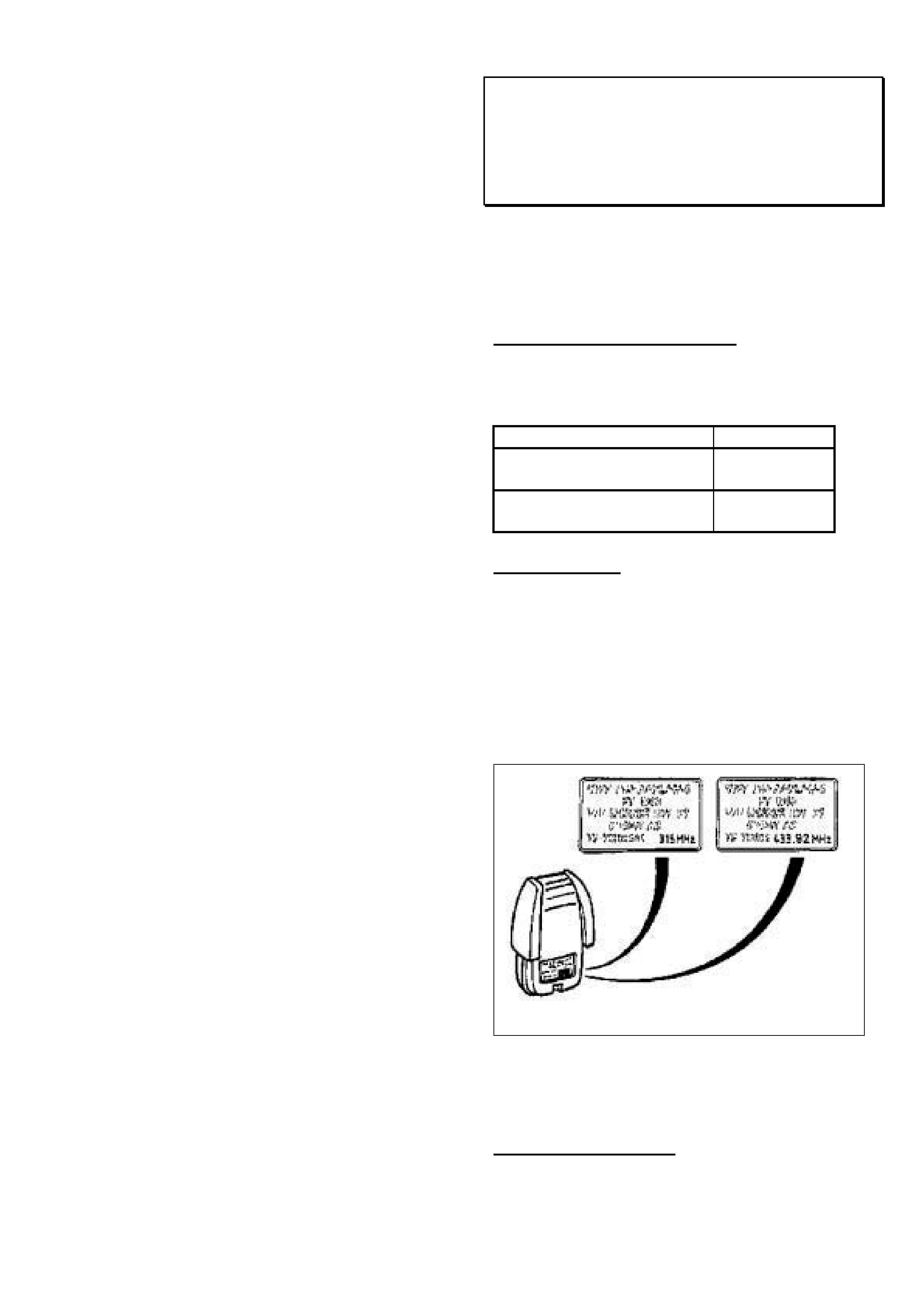
HOLDEN SERVICE TECHLINE___________________________________________________________________ MAY, 2002
8
Some examples of DTC’s with their specific
symptom descriptors are:
DTC 0335 (8)
"Crankshaft Position Sensor Malfunction"
(Number of Teeth Not Plausable).
DTC 0335 (4)
"Crankshaft Position Sensor Malfunction" (No
Signal / Signal Line Open).
Remote Sender Unit (Key Head) Operating
Frequency Revised From 315 to 433 MHz
TS Astra
(GROUP 12) TL269-0204
To improve the operating range of the remote
sender unit (key head), the operating frequency
has been revised from 315 MHz to 433 MHz. The
breakpoint for this change is shown below.
PRODUCTION BREAKPOINTS
Remote sender operating frequency of 433 MHz
fitted to vehicles from:
ISOVIN: Build Date:
Convertible -
W0L0TGF672B009028 30/01/02
All except convertible -
W0L0TGF4825156920 21/02/02
SERVICE NOTE
Whenever replacing senders or modules it is vital
that the same frequency replacement parts are
used. Do not use a 315 MHz sender with a 433
MHz module and vice versa.
Identification of senders.
The frequency of the sender is shown on the
sender as depicted in following figure.
Identification Of Modules.
Module identification can be performed in the
vehicle with a Tech 2.
PARTS INFORMATION
Refer Holden Partfinder for part numbers of all
service replacement senders and modules.

HOLDEN SERVICE TECHLINE___________________________________________________________________ MAY, 2002
9
Improved Air Conditioning Compressor
XC Barina, TS Astra Z18XE engine only
(GROUP 02) REVISED TL239A-0204
This techline is revised by redefining the TS
models affected. The previous Techline in Issue
2, 2002 should be destroyed.
An improved, more durable compressor has been
introduced for the above models. The main
change is the replacement of the bronze coated
steel swashplate with a solid bronze swashplate.
PRODUCTION RECTIFICATION
Revised compressors have been fitted to vehicles
from start of Model Year 2002:
ISOVIN: Build Date:
XC
W0L0XCF0824002194
27/8/2001
TS
W0L0TGF3522030146
31/8/2001
PARTS INFORMATION
All stocks of HSPO compressors are of the
improved type.
The compressor part number remains unchanged
at 09165714.
Part No.: Description: Qty:
09165714 Compressor air
conditioning
1
Camshaft Cover Seal Leaks
JR(C20SEL), JS (C22SEL), UES (X22SE)
TR (C18SEL & X20XEV)
(GROUP 6A) TL266-0204
PROBLEM DESCRIPTION
Oil weep from camshaft cover seal area.
SERVICE RECOMMENDATION
Summary: Install a bead of RTV sealant in
addition to a new camcover gasket.
• Remove camshaft cover.
• Clean sealing surfaces before applying the
RTV sealant (P/N: 92144969)
Use a white spirit based cleaning solvent to
clean sealing surface.
Do not use abrasive pad/bristle devices which
will produce fine grit)
Do not gouge or scratch any engine sealing
surface during the cleaning process.
Do not allow any RTV residue to fall in the
engine.
• Apply a constant 2.0 mm bead of RTV sealant
to the cylinder head along the centre of the
cam cover sealing flange. Refer Figure 1 for
routing of bead.
• Reassemble the camshaft cover and new
gasket and torque fasteners within 5-10
minutes after sealant is applied to cylinder
head. Ensure the camshaft cover does not
slide around once in position as the RTV
sealant may be wiped off flange and fall into
engine.
• Allow the sealant to cure for a minimum of 1
Hour before running the engine.
Detailed service procedures:
For UES refer to LCV SIP.
For other models refer to TIS 2000.
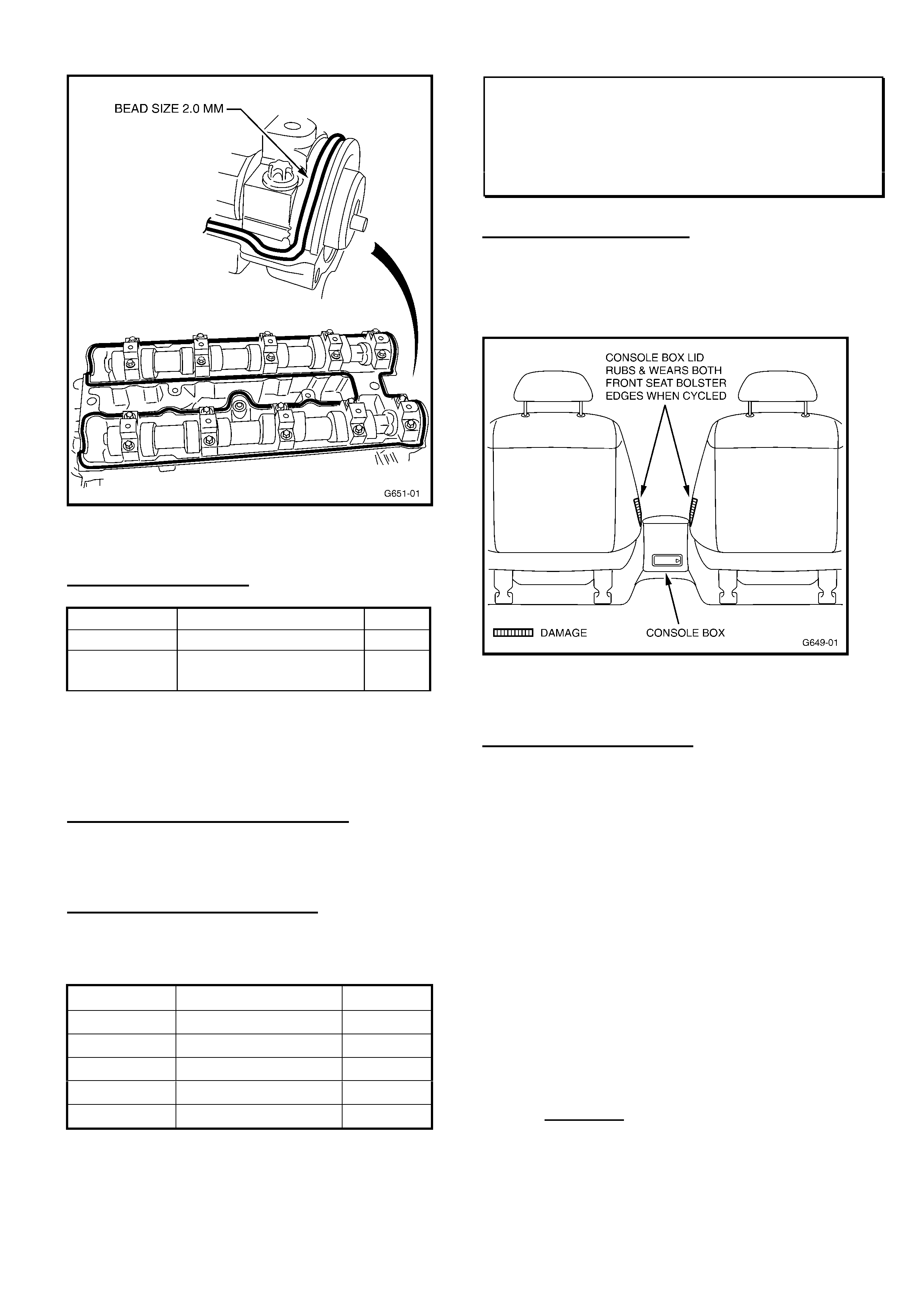
HOLDEN SERVICE TECHLINE___________________________________________________________________ MAY, 2002
10
Figure 1.
PARTS INFORMATION
Part No.: Description: Qty:
92144969 RTV sealant - tube 1
90501944 Gasket – camshaft
cover
1
NOTE: The sealant 92144969 is not expected to be
available from HSPO until mid May, however orders
may still be placed.
WARRANTY CLAIM INFORMATION
Use Labour Times information in Warranty
Information section of current PV or LCV SIP CD.
PRODUCTION RECTIFICATION
Bead of sealer added to cam cover gasket in
engines from:
Engine Eng. No. Date
C18SEL C18SEL 039419 March 01
C20SEL C20SEL 25033858 March 01
C22SEL C22SEL 25027168 March 01
X20XEV X20XEV 25038994 March 01
X22SE X22SE 25053552 March 01
Seat Squab Worn By Console Lid
JR & JS Series I Vectra CD models
(GROUP 1) TL251-0204
PROBLEM DESCRIPTION
The piping on the front seat bolsters contacts the
centre console box lid when the lid is
opened/closed. This may result in wearing of the
velour trim as shown in Figure 1.
Figure 1.
SERVICE RECTIFICATION
Summary: Install extra springs to front seat
bolsters to pull bolsters inwards.
Procedure for fitting springs:
1. Cut 15mm lengths of 4mm diameter heat
shrinkable plastic tubing and apply these to
each end of the spring as shown in Figure 2.
This is to prevent any metallic squeaking
noises.
2. Detach upholstery from the front seat back.
(Refer to Figure 3).
3. Carefully detach the foam as shown in Figure 3
to expose the lower horizontal crossmember of
the seat back frame.
4. On each side of the lower horizontal cross
member, drill a 3mm diameter hole 60mm
inwards from the seat cover side edge and
8mm below the top edge (just below the first
rib). Refer Figure 4.
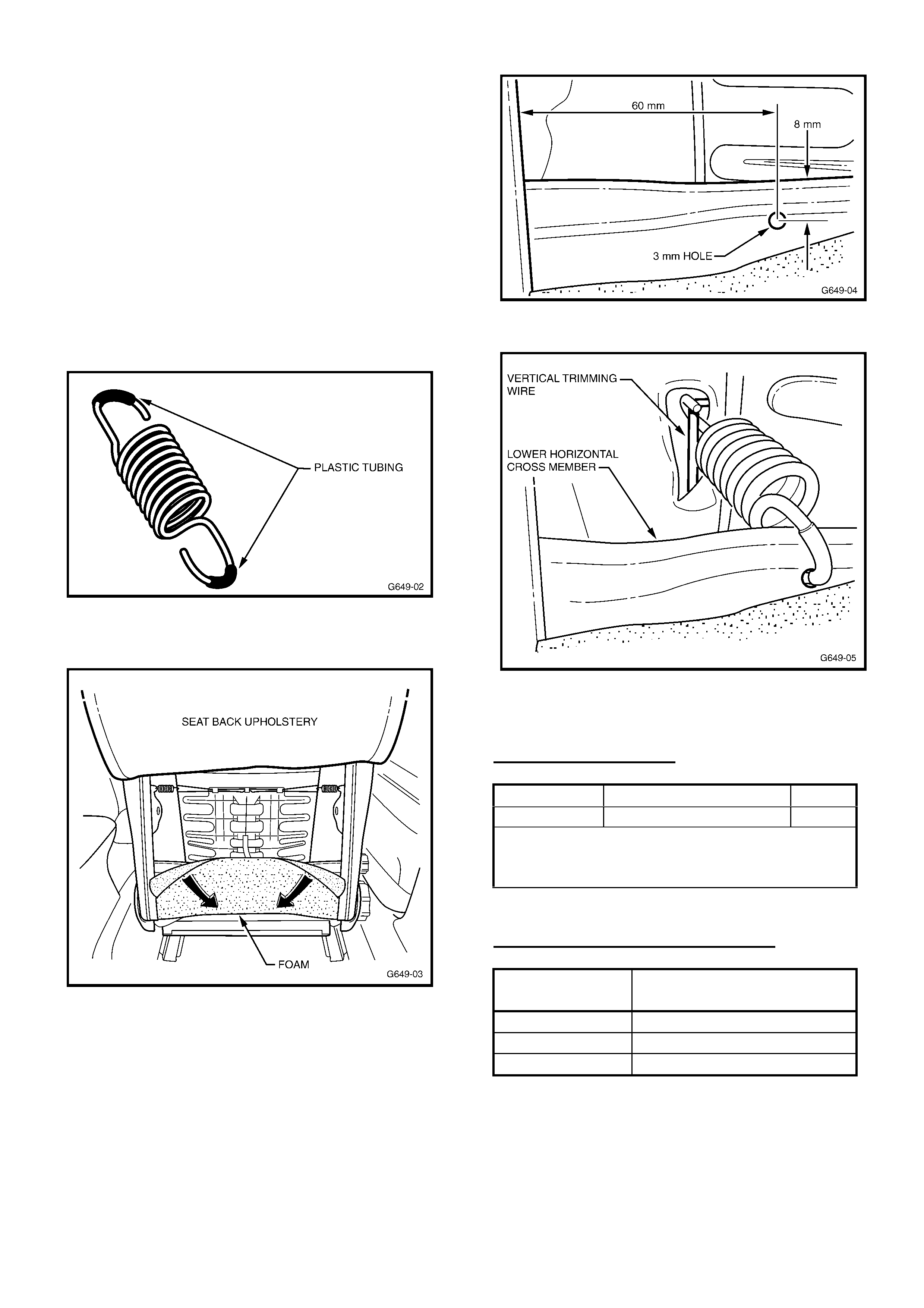
HOLDEN SERVICE TECHLINE___________________________________________________________________ MAY, 2002
11
5. At each side of seat, attach one end of the
spring to the seat back vertical trimming wire
(located through existing hole in the rubber hair
seat back), then, attach the other end to the
drilled hole in the lower horizontal cross
member. Refer figure 5.
6. Re-adhere foam to frame cross member with a
contact adhesive.
7. Reinstall upholstery to seat back.
8. Above procedure applies to both front seats.
Figure 2.
Figure 3.
Figure 4
Figure 5.
PARTS INFORMATION
Part No.: Description: Qty:
90569760 Spring 4
Obtain 4mm diam. heat shrinkable tubing
from your nearest electrical supplies
retailer.
WARRANTY CLAIM INFORMATION
Description Install extra springs to
bolsters on both front seats
Labour Op.No. C000451
Time 1.5 hr
Failure Code 62
NOTE: For vehicles out of warranty, approval
must be obtained from your Holden Aftersales
Business consultant to perform this work.

HOLDEN SERVICE TECHLINE___________________________________________________________________ MAY, 2002
12
Backlash “Clunk” Noise - Information
VS with IRS, VT/VU/VX/V2/WH
(GROUP 4) TL277-0204
PROBLEM DESCRIPTION
A significant number of IRS differentials are
being replaced for backlash “clunk” noise
complaints. When tested, these differentials
all meet the suppliers backlash specification.
This Techline is provided to ensure
technicians thoroughly diagnose such
complaints and determine whether any
complaint noises are characteristic, and
exactly which component is the noise source
– before attempting any differential
replacement.
Owners may comment that their vehicle
exhibits a “clunk” noise while driving, when
the accelerator is quickly depressed and then
released, especially during gear changes.
Whenever there are two or more gears interacting
with one another, there must be a certain amount
of clearance between those gears in order for the
gears to operate properly. This clearance or
freeplay (also known as lash) can translate into a
clunk noise whenever the gear is loaded and
unloaded quickly, or whenever the direction of
rotation is reversed. The more gears you have in
a system, the more freeplay the total system will
have.
The clunk noise that owners sometimes hear may
be the result of a buildup of freeplay (lash)
between the components in the driveline.
For example, the potential for a driveline clunk
would be greater in a 4-wheel drive or all-wheel
drive vehicle than a 2-wheel drive vehicle. This is
because, in addition to the freeplay from the rear
axle gears, the universal/constant velocity joints,
and the transmission (common to both types of
vehicles), the 4-wheel drive transfer case gears
(and their associated clearances) provide
additional freeplay to the driveline.
In service, retailers are discouraged from
attempting to repair driveline clunk conditions for
the following reasons:
• Comments of driveline clunk are almost never
the result of one individual component with
excessive lash, but rather the result of the
added affect of freeplay (or lash) present in all
of the driveline components. Because all of the
components in the driveline have a certain
amount of lash by design, changing driveline
components may not result in a satisfactory
lash reduction.
• While some owners may find the clunk noise
objectionable, this will not adversely affect
durability or performance.
SERVICE ACTION
Whenever presented with a customer concern of
driveline “clunk” ensure that the customer is made
aware of the above facts.
Also ensure that before replacing any
components in the vehicle that a full and proper
assessment is made of:
- age of vehicle,
- engine/trans. combination,
- kms travelled,
- customer driving style,
- distance travelled,
- WHERE or WHICH PART the noise generated
from,
Retailers may also wish to allow the customer to
drive a “like” vehicle (same body style, engine,
trans.) to confirm similarity of condition – where
the condition may be characteristic, and not
necessarily complaint level. This can provide an
understanding of the condition, as some
customers may be overly concerned about
‘noises’ that emanate from vehicle components.
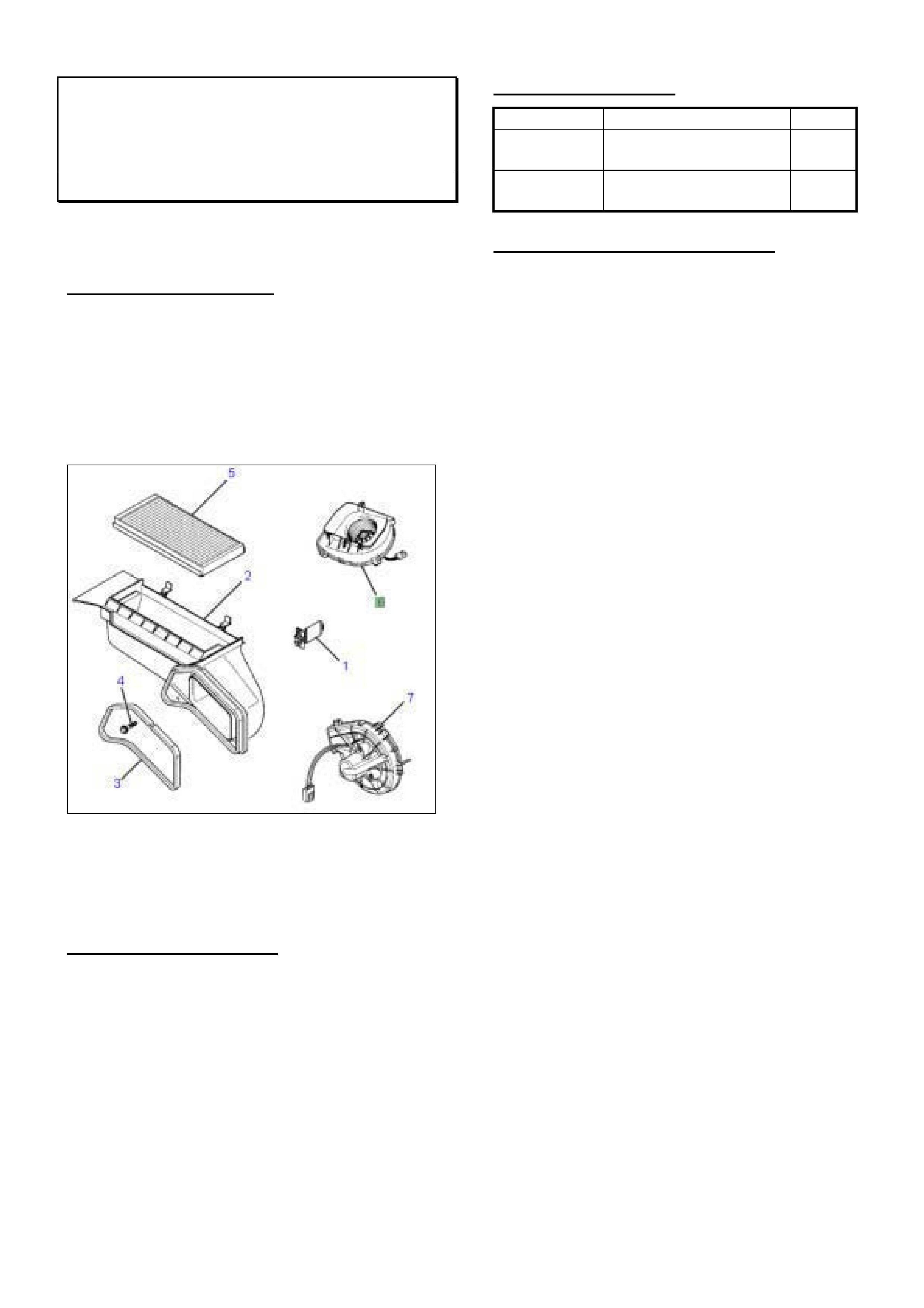
HOLDEN SERVICE TECHLINE___________________________________________________________________ MAY, 2002
13
Blower Fan Motor/Resistor Diagnosis Hint
XC Barina with Air Conditioning
(GROUP 2) HINT TL278-0204
Thanks to Tony Luppino of Parker Brothers
for a PIR describing the cause of this problem.
PROBLEM DESCRIPTION
Customers may complain of partial or no
operation of the airconditioning fan.
Investigations have shown that, in some vehicles,
water may be entering the blower motor via the
filter housing to dash panel seal (item 3) shown in
Figure 1.
Figure 1
Some blower motors returned to REPAC which
show signs of water entry is further evidence of
this condition.
SERVICE RECTIFICATION
If a vehicle is presented with an inoperative
blower motor and water entry is evident (from rust
or moisture in the blower case), check the filter
housing to dash panel seal. Replace seal if
required.
PARTS INFORMATION
Part No.: Description: Qty:
09115349 Seal – Filter Housing
to Dash Panel
1
90535115 Fan Motor &
Housing asm. (C60)
1
WARRANTY CLAIM INFORMATION
Use Labour Times information in Warranty
Information section of current PV SIP CD.
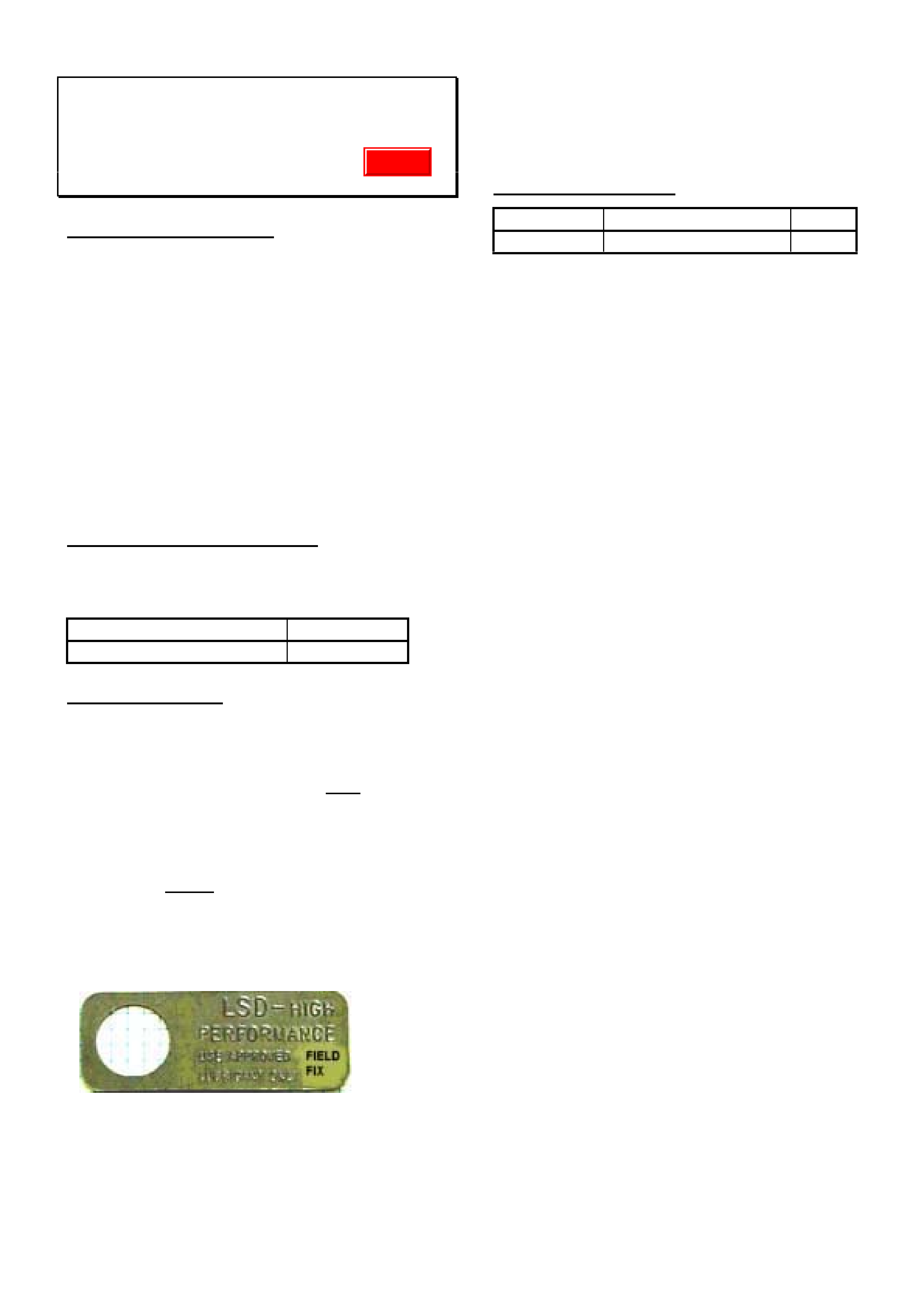
HOLDEN SERVICE TECHLINE___________________________________________________________________ MAY, 2002
14
LSD Additive Availability For Servicing
VS/VT/VX/VU/WH with IRS LSD
(GROUP 04) TL279-0204
PROBLEM DESCRIPTION
Many vehicles have had LSD additive and a
revised seal installed for a “chatter” condition
(Refer to Retailer Letter DL 30/02 which has
superseded Dealer Letter DL 54/01).
Until now, the additive has not been available for
differentials that require oil replenishment or top-
up following a repair.
This additive is now available from HSPO.
Before use of this additive, ALL Service personnel
should familiarise themselves with the guidelines
in below.
PRODUCTION RECTIFICATION
Final drives with the additive and revised seal
included have been fitted to vehicles from:
ISOVIN: Build Date:
6H8VXK69F1L762226 20/08/01
SERVICE ACTIONS
This additive is ONLY for use in replenishment of
oil, following repairs to final drive units that:
(a). are fitted to any vehicle built after breakpoint
L762226;
OR
(b). are built before breakpoint L762226 and have
had the additive and the seal (as per DL 54/01 or
RL 30/02). These vehicles are identified by a
metal ID tag fitted to the rear of the differential,
carrying the words “Field Fix”, as shown here:
LSD “CHATTER”:
LSD “chatter” complaints must still be corrected in
vehicles covered by warranty – Refer to Retailer
Letter DL 30/02 (which supersedes DL 54/01).
PARTS INFORMATION
Part No.: Description: Qty:
92145121 Additive Kit 1
This kit consists of:
- 1 bottle, 100ml LSD Additive,
- Material Safety Data Sheet (for additive),
- ID Tag (in case of original tag damage.
This additive is NOT suitable for use in
differentials not fitted with the revised seal and
additive – as seal degradation and failure will
result.
Update
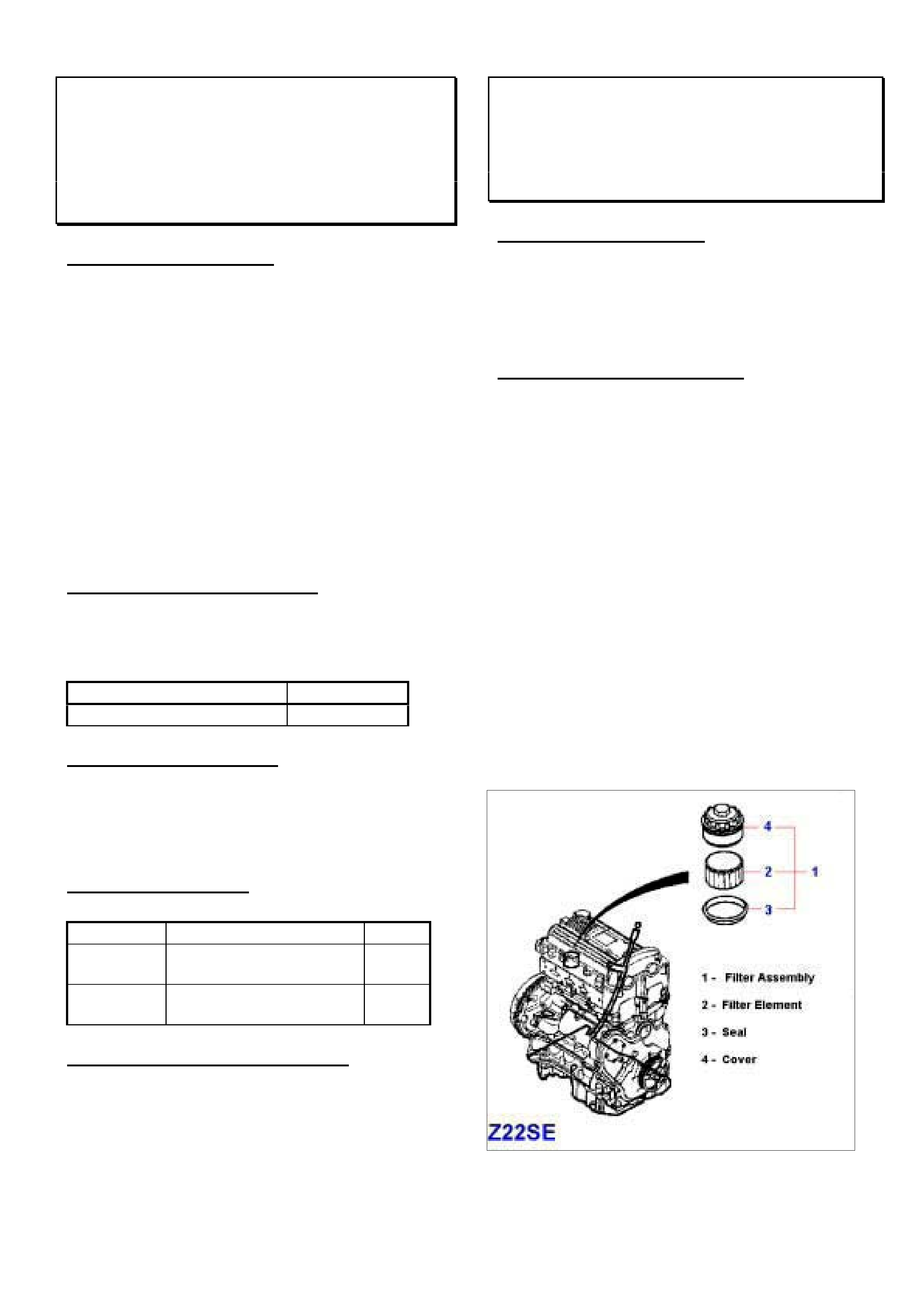
HOLDEN SERVICE TECHLINE____________________________________________________________________ JUNE, 2002
6
Engine Hard To Start (DTC P1615, P1616);
Doors hard to open with Remote Key;
DTC B1485 Set
XC Barina
(GROUP 12) TL222-0205
PROBLEM DESCRIPTION
Vehicle may have one or more of the following
symptoms.
• Engine hard to start. SVS telltale flashes
while starting. DTCs P1615 and/or P1616
are stored.
• Difficulty in unlocking the car doors with the
remote control at first attempt. Several
attempts are usually needed to unlock the
doors. No problems are reported when
locking the car.
• DTC B1485 stored. No symptoms evident.
The above symptoms have been traced to a fault
in the -BCM software.
PRODUCTION RECTIFICATION
BCM’s with revised software to overcome the
above conditions were fitted to vehicles from start
of Model Year ‘02.
ISOVIN: Build Date:
W0L0XCF0824002194 27/08/01
SERVICE RECTIFICATION
On any vehicle with one or more of the above
symptoms built prior to the breakpoint, replace
the BCM with the latest part as shown in Parts
Information.
PARTS INFORMATION
Part No.: Description: Qty:
24467904 Body Control Module -
Australia
1
24467903 Body Control Module
- New Zealand
1
WARRANTY CLAIM INFORMATION
Use Labour Times information in Warranty
Information section of current PV SIP CD.
Suspect Quality Oil Filter Elements
Z22SE engine - TT, TS Sri & Convertible
(GROUP 6A) TL287-0205
PROBLEM DESCRIPTION
Suspect quality oil filter elements which
potentially could fail, resulting in particles
blocking oil galleries in the cylinder head, leading
to oil starvation and possible camshaft seizure.
SERVICE RECOMMENDATION
Important!
The following part numbers should not be used
anymore:
oil filter assy. 93 171 211 H
HH
H
oil filter assy. 09 194 745 H
HH
H
oil filter assy. 09 198 748 H
HH
H
oil filter element 09 194 746 H
HH
H
Parts Managers Note:
The above parts should be returned to HSPO for
credit via the CRRM system.
For all vehicle specified oil changes, ensure that
only the following oil filter elements are used.
oil filter assy. 93 173 660 =
==
=
oil filter element 93 171 212 >
>>
>
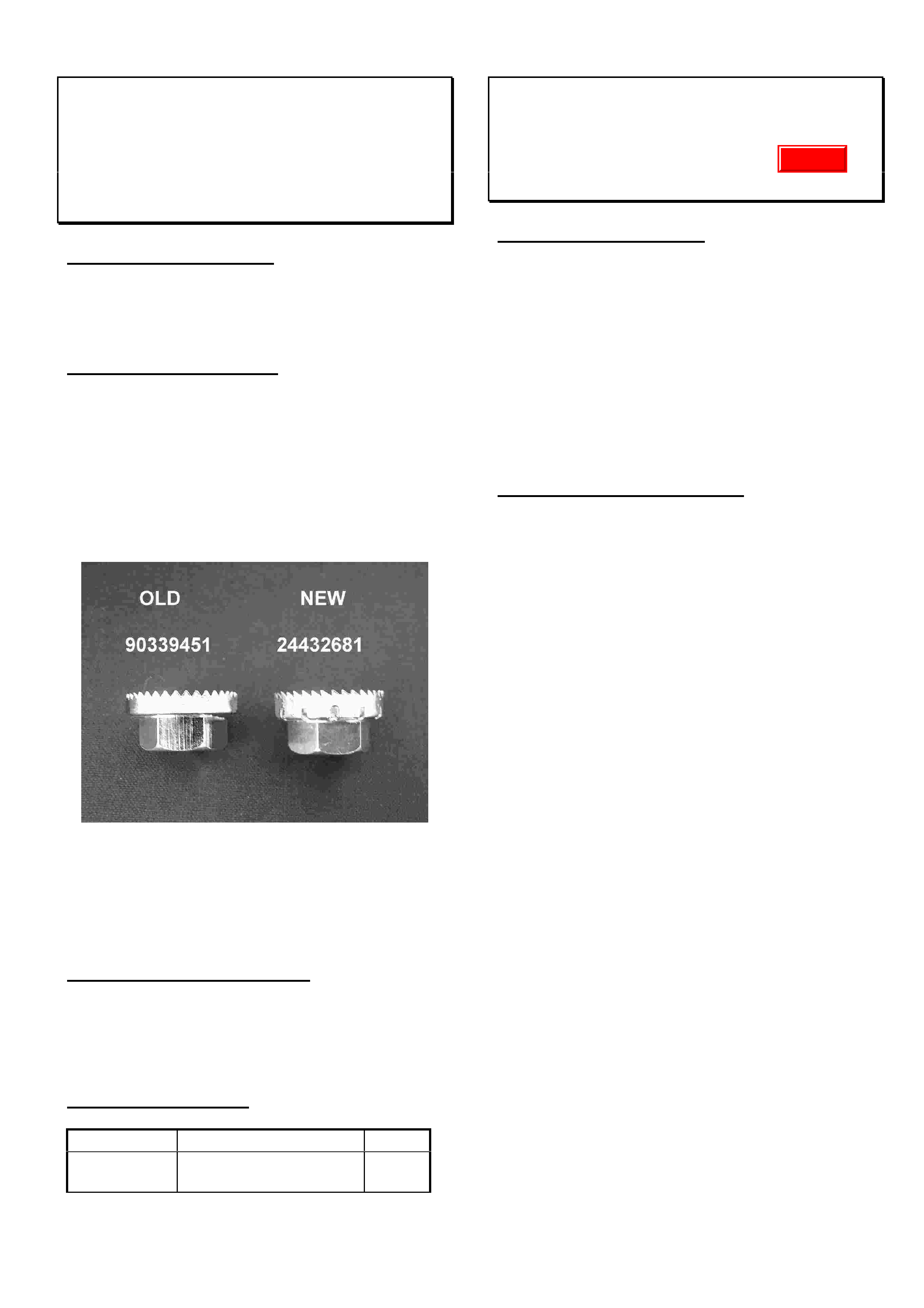
HOLDEN SERVICE TECHLINE____________________________________________________________________ JUNE, 2002
7
Poor Radio Reception - Roof Mounted
Antenna Base Nut Loose
JR Hatch, JS Wagon/Hatch, TS, TT, TR, SB
(GROUP 12) HINT TL281-0205
PROBLEM DESCRIPTION
Poor Radio reception in many cases is caused by
the roof-mounted antenna-base attaching nut
being loose.
SERVICE RECTIFICATION
Whenever replacing antenna components or
diagnosing poor radio reception on above
models, always ensure the antenna base is
firmly secured to the roof with the latest serrated
nut p/n 24432681. This nut has revised
serrations to resist loosening. Refer photograph
for differences between old and new nuts.
When reinstalling torque nut to 7 – 8 Nm.
NOTE: Good radio reception is dependant on
the serrated nut piercing the paint on the inside
of the roof panel.
PRODUCTION BREAKPOINTS
The new serrated nut 24432681 was fitted to
models as follows:
XC Barina from: Start of Production.
TS Astra from: W0L0TGF4815114312.
PARTS INFORMATION
Part No.: Description: Qty:
24432681 Nut – Antenna Base
to roof
1
Clutch Fluid Discolouration
VX, VU, V2
(GROUP 7A) TL202-0205
PROBLEM DESCRIPTION
It may be observed on some vehicles that the
clutch fluid darkens in colour after being in
service for a period of time.
Cause
This is a phenomenon that occurs with time due
to the interraction between clutch system rubber
parts with hydraulic fluid. The level of
discolouration will vary with factors such as
driving conditions, underhood temperatures etc.
SERVICE RECOMMENDATION
Laboratory investigations of returned fluid
samples shows that discolouration does not
detrimentally affect performance of the fluid.
Field reports indicate that where clutch system
components and fluid have been replaced for this
condition, the discolouration has reoccurred as
before.
Discoloured clutch fluid should not be replaced in
a normally operating system prior to the interval
specified in the maintenance schedule in the
owners handbook.
Update
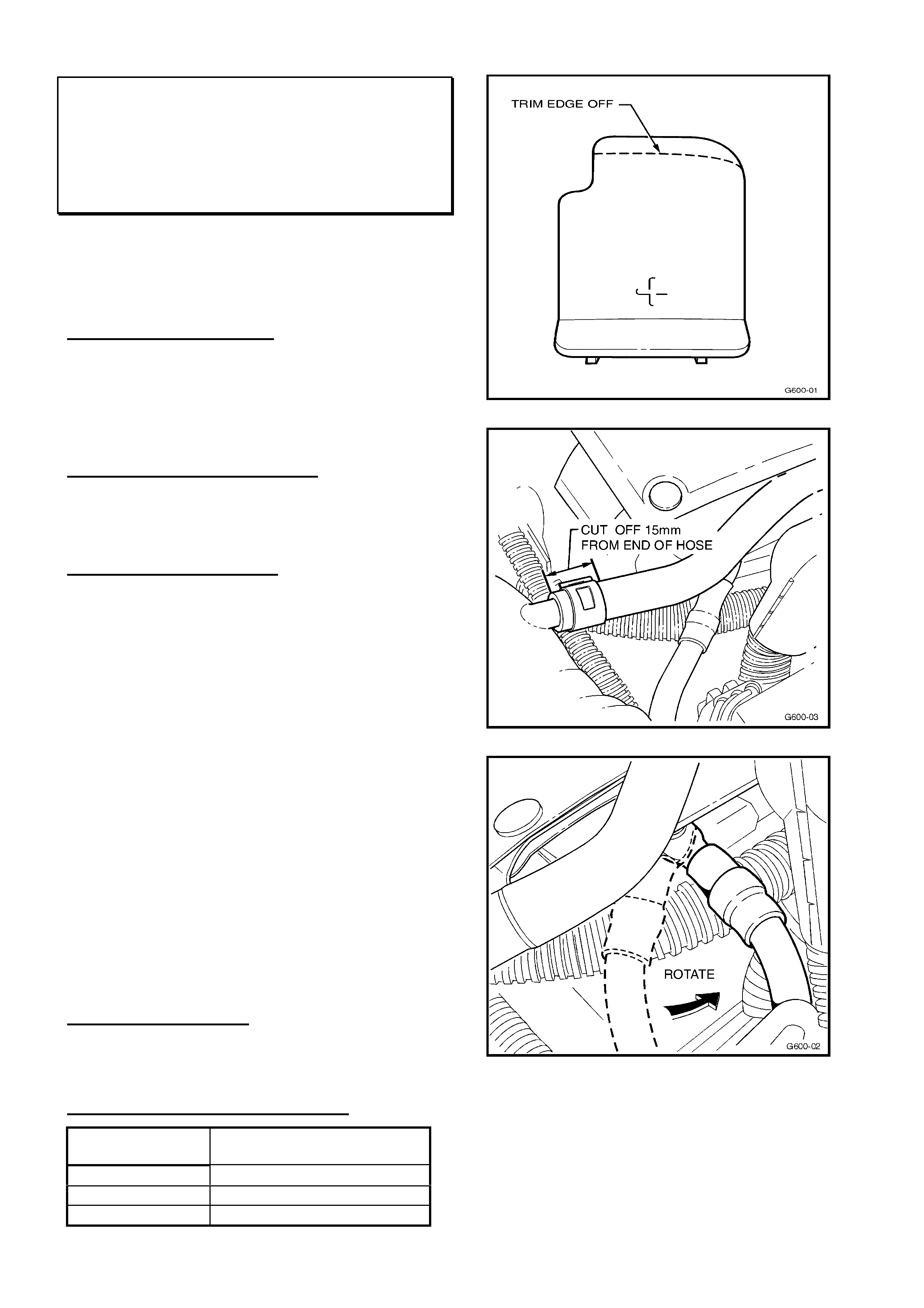
HOLDEN SERVICE TECHLINE____________________________________________________________________ JUNE, 2002
8
Throttle Body To Surge Tank Coolant
Hose Damage
TS (X18XE1 & Z18XE ENGINES)
(Group 6K) REVISED TL206A-0205
This Techline is revised by restating the
Production Rectification information. The
previous Techline in Issue 1, 2002 should be
destroyed.
PROBLEM DESCRIPTION
The Throttle Body to Surge Tank Coolant Hose
can foul either the positive battery terminal
protective cap or the positive battery cable. If
undetected this condition could result in hose
failure and coolant loss.
PRODUCTION RECTIFICATION
The previous breakpoint published in Issue
1/2002 was ineffective. Production rectification is
still pending.
SERVICE RECTIFICATION
Summary: Adjust clearances by trimming
protective terminal cap and coolant hose, and
orient the battery cable correctly
On any vehicle where fouling is observed
perform steps 1 to 4 to rectify the problem.
1. Trim the cap as shown in Figure 1 in order to
provide 10mm clearance between the cap and
the hose.
2. With engine switched off, disconnect the
coolant hose at the surge tank end.
3. Cut off 15mm of hose and refit the hose. This
will move the bend of the hose away from the
battery cable. See Figure 2.
4. Loosen the battery cable attaching nut, and
rotate the cable anti-clockwise so that there is
10mm clearance between the cable and the
coolant hose, then tighten cable attaching nut.
See Figure 3.
PARTS INFORMATION
Refer to Partfinder if part/s replacement is
required.
WARRANTY CLAIM INFORMATION
Description Rework Battery
Cable/Coolant Hose
Labour Op. No. N000363
Time 0.4 hr
Failure Code 26
Figure 1.
Figure 2.
Figure 3
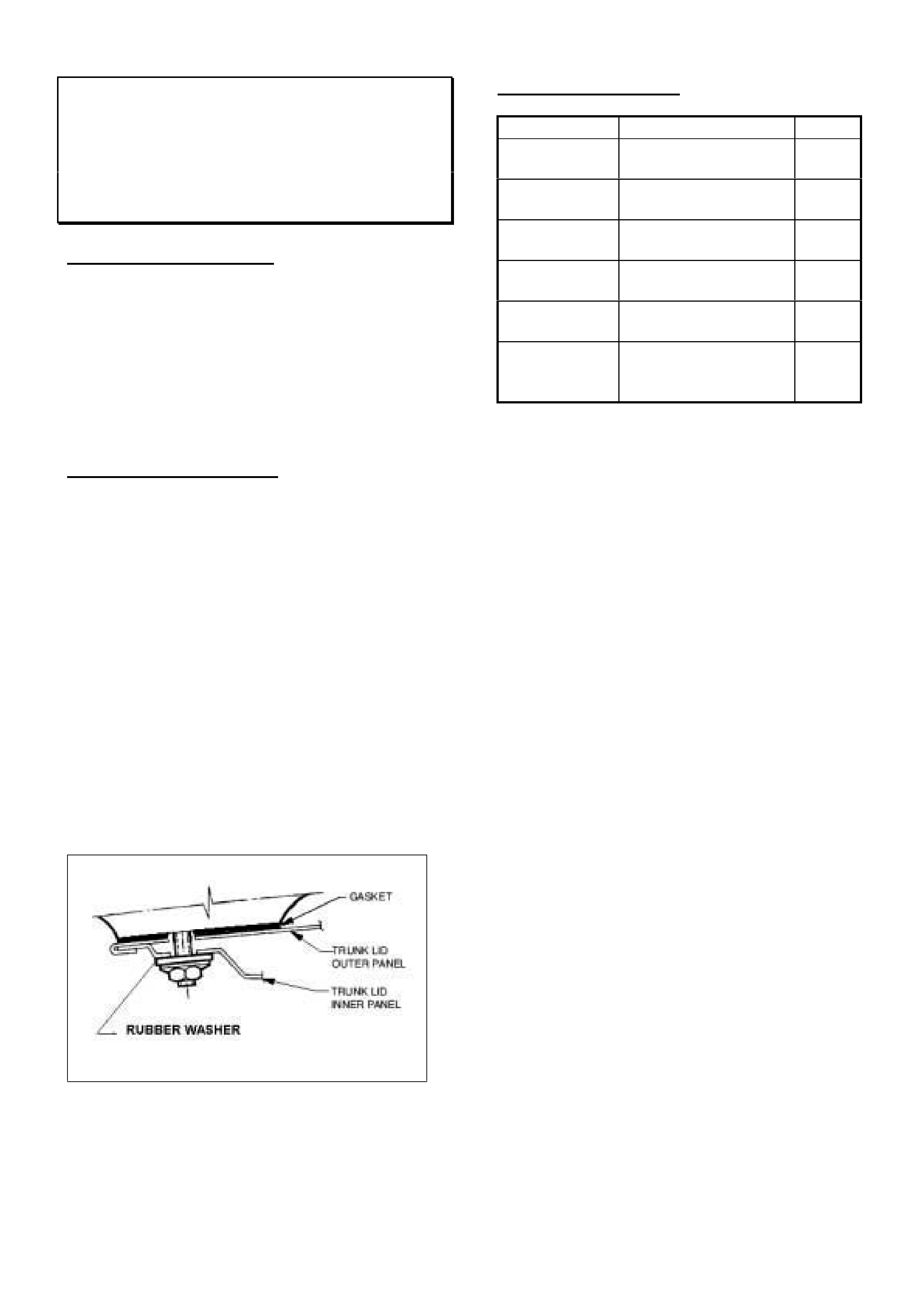
HOLDEN SERVICE TECHLINE____________________________________________________________________ JUNE, 2002
9
Water Leaks Into Decklid via Spoiler
Mounting Holes
VT, VX, WH
(GROUP 1) HINT TL274-0205
PROBLEM DESCRIPTION
Water leaks into the decklid assembly.
Often these leaks are found to be caused by a
defect in the spoiler to decklid mounting gasket.
This allows water to track between the inner and
outer skin of the decklid panel assembly.
Eventually this water will collect and drip into the
boot when the decklid is opened.
SERVICE RECTIFICATION
If water ingress into the decklid/decor is reported
on any vehicle fitted with a decklid spoiler, prior
to removing the décor panel, remove and visually
check the spoiler sealing gaskets and all
attachments. If the gasket on the spoiler has
significantly distorted or is broken, a new gasket
should be fitted. Obtain original equipment
spoiler replacement gaskets from HSPO. The
spoiler should be re-fitted and attaching bolts
torqued to 2-5 Nm.
For genuine accessory dealer fitted spoilers
follow the supplier’s fitting instructions when
installing new gaskets. If not already fitted, it is
recommended that rubber washer part number
92043323 is fitted to all attaching bolts to seal
the bolt head to the decklid inner panel.
Figure 1. Shows typical spoiler mounting to
decklid
PARTS INFORMATION
Part No.: Description: Qty:
92144151 Gasket Spoiler to
decklid – S Pack
2
92144153 Gasket Spoiler to
decklid - Lumina
2
92144150 Gasket Spoiler to
decklid – SS Pack
2
E09-970601 Gasket Spoiler to
decklid - WH
2
E09-970602 Gasket Spoiler to
decklid – V2
2
92043323 Seal spoiler to
decklid (rubber
washer)
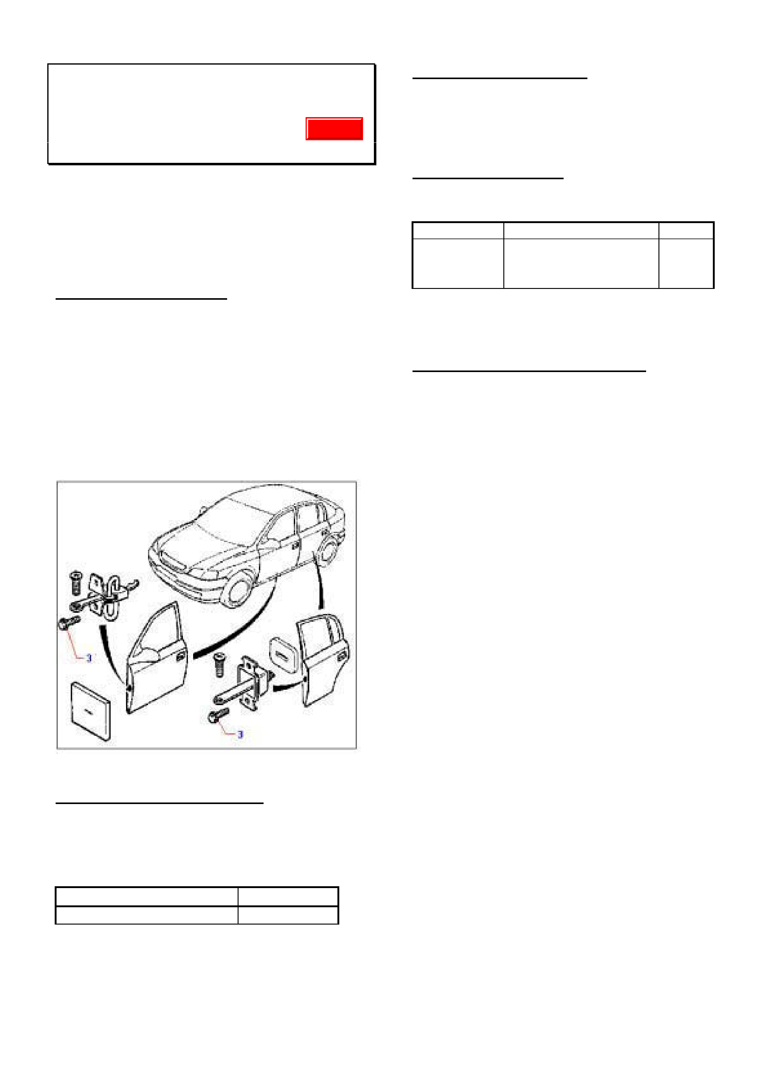
HOLDEN SERVICE TECHLINE____________________________________________________________________ JUNE, 2002
10
Door Checklink Bolts Loose
TS Astra
(GROUP 1) REPEAT TL285-0205
This Techline was first published in Issue
10/2001. It is repeated due to the high number
of PIRs still being received on this problem.
NOTE: PIRs are only required on complaint
vehicles built after the published breakpoint.
PROBLEM DESCRIPTION
Door checklink attaching bolts loosen.
Investigations show root causes to be:
• Attaching bolts (item 3 in Figure 1) not to
specification
• Relaxation of clamping torque ex factory.
• Stripped threads caused by overtightening of
bolts (above 6.5Nm)
Figure 1.
PRODUCTION RECTIFICATION
Revised checklink attaching bolts with closer
controls on tightening torque have been fitted to
vehicles from:
ISOVIN: Build Date:
W0L0TGF4815283442 05/06/2001
SERVICE RECTIFICATION
On complaint vehicles fit revised checklink
attaching bolts part number 13104167 and
torque to 4.5 to 5.0 Nm.
PARTS INFORMATION
Obtain following parts from HSPO:
Part No.: Description: Qty:
13104167 Bolt Checklink to
door.
2
per
door
Note: These same bolts are also now used on
TT, JS and XC models.
WARRANTY CLAIM INFORMATION
Use existing Labour Times information in
Warranty Information section of current PV SIP
CD
Update

HOLDEN SERVICE TECHLINE____________________________________________________________________ JUNE, 2002
11
Engine Cover Rattle Noise
VTII, VX, VU, V2 & WH with LS1 (Gen III)
(GROUP 6A) REVISED TL199A-0205
This Techline supersedes the previous Techline on
this topic (Issue 11, Nov.2001) which should be
discarded. This latest update removes the
requirement for spacer nuts when fitting new
support brackets due to the latest brackets being
fitted with a larger bumper.
PROBLEM DESCRIPTION
Engine cover “rattle” at idle, or just above idle
speed.
This rattle is caused by the main engine cover
contacting the coil/bracket, at the rear of the
engine.
PRODUCTION RECTIFICATION
Stage 1. Additional engine cover support
brackets 92087580 & 92087581 were fitted to
vehicles from:
ISOVIN: Build Date:
6H8VTL35FYL579679 10/04/00
Stage 2. Spacer nuts added underneath
each support bracket to increase preload on cover.
Fitted to vehicles from:
ISOVIN: Build Date:
6H8VXL69F1L750721 3/7/2001
Stage 3. Support brackets fitted with large
bumpers (92138641) thereby removing need for
spacer nuts. Fitted to vehicles from:
ISOVIN: Build Date:
6H8WHY19F2L863282 11/5/2002
SERVICE RECTIFICATION
Summary: Engine covers must be supported with
the two additional brackets fitted with large
bumpers. Also ensure clearance between cover
and IAC valve.
.
Scenario (A) For complaints of “engine cover
rattle” noise on any Gen III V8 vehicle built prior to
the Stage 1 breakpoint (L579679 built 10/04/00),
additional support brackets should be added as
per the following procedure:
1. Remove four engine cover retaining nuts and
remove the engine cover.
2. Fit engine cover support bracket P/N 92087580
to RH front coil mounting studs as shown in
Figure 1. Attach with two new nuts P/N
09440004, and torque to 4 – 6 Nm.
3. Fit engine cover support bracket P/N 92087581
to LH front coil mounting studs. Attach with two
new nuts P/N 09440004, and torque to
4 – 6 Nm.
4. Remove four foam pads from RH and LH
underside of engine cover. (Pads are not
required as new brackets have insulating
bumpers).
5. Ensure that foam insulator 92086029 is in place
on the engine cover in the location just above
the IAC valve as shown in Figure 1, view A. If
foam insulator is badly damaged due to contact
with the IAC valve it should be replaced. Prior
to fitting new insulator, remove 2 mm of
material from the cover as shown in Figure 1,
view A.
NOTE: Engine covers (p/n 92091015) with
increased clearance to IAC valve were fitted to
vehicles from: Tag No. L794821 Build Date
8/11/01
6. Re-fit main engine cover. Torque retaining nuts
to 8-12Nm.
7. Ensure that the cover does not contact
surrounding parts such as engine oil level
indicator, engine and power steering filler caps
and clutch master cylinder hose.
Scenario (B) On any complaint vehicle which has
support brackets fitted and no spacer nuts, (build
range L579679 – L750721) replace the support
bracket bumpers with the new bumpers
92138641.
Check engine cover as per step 5
Scenario (C) On any complaint vehicle which has
support brackets and spacer nuts fitted, discard
the spacer nuts and fit the larger bumpers
92138641 to the brackets.
Check engine cover as per step 5.
Update
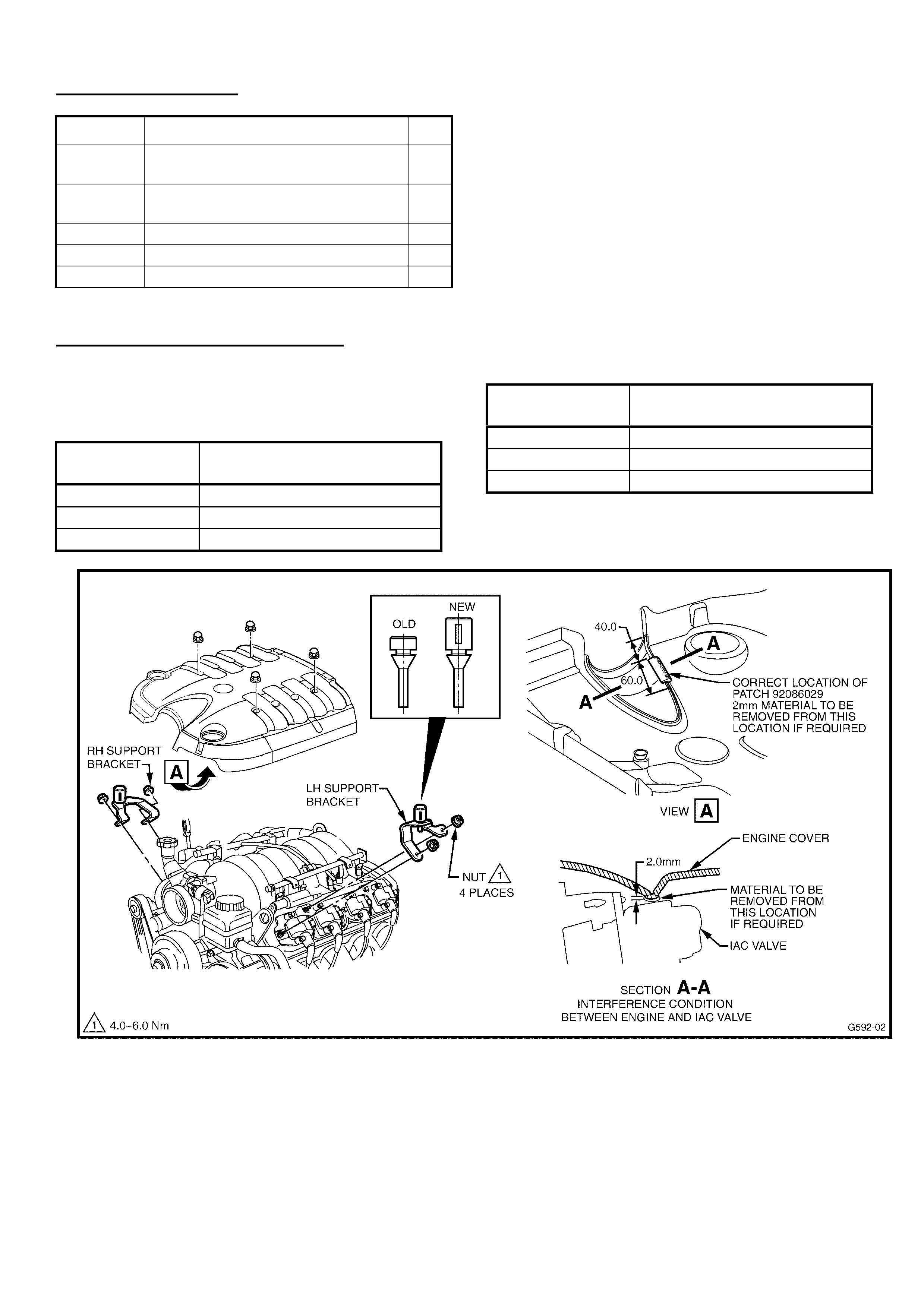
HOLDEN SERVICE TECHLINE____________________________________________________________________ JUNE, 2002
12
PARTS INFORMATION
Part No.: Description: Qty
92087580 Support Bracket, Engine Cover RH
(includes new bumper 92138641)
1
92087581 Support Bracket, Engine Cover LH
(includes new bumper 92138641)
1
92138641 Bumper (15mm high , slotted) 1
09440004 Nut 1
92086029 Insulator-Engine dress cover (front) 1
NOTE: The part numbers of the support brackets
fitted with the latest bumper 92138641 have not
changed. For this reason, always check that new
brackets (obtained from your Parts Store) are
fitted with the new, larger type bumper. The
difference between old and new bumpers is shown
in Figure 1.
WARRANTY CLAIM INFORMATION:
Use the following information, for vehicles built
without additional support brackets; i.e. built prior
to the Stage 1 breakpoint (6H8VTL35FYL579679):
Description Add additional engine cover
support brackets LH & RH
Labour Op. No. J000651
Time 0.3 hr
Failure Code 28 (Rattle)
Use the following for vehicles that already have
brackets fitted where only the bumper is replaced.
Description Replace bumper in existing
support brackets.
Labour Op. No. J000710
Time 0.2 hr
Failure Code 28 (Rattle)
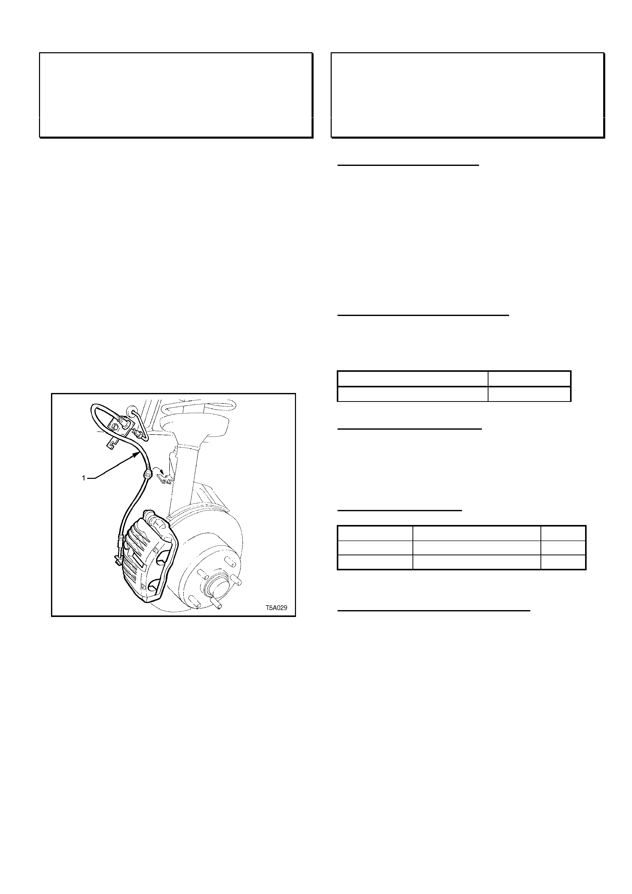
HOLDEN SERVICE TECHLINE____________________________________________________________________ JUNE, 2002
13
Front Brake Hose Retention Precaution
VT, VX, VU, V2, WH
(GROUP 5) REPEAT TL288-0205
This Techline was first published in Feb. 2000. It is
repeated here as a reminder to Technicians.
This Techline item is a precautionary note to
ensure correct reinstallation procedures are carried
out whenever front suspension, steering, or front
brake work is carried out on a vehicle.
Whenever front brake hose/s are removed from
their retaining clip/s (on front suspension strut
body) during any service work, the brake hose/s
must be refitted into their retaining clip/s.
Refer to the sketch below for brake hose (1)
location, showing its method of location in the strut
mounted clip.
Door Striker Creak or Rattle
TS
(GROUP 1) TL283-0205
PROBLEM DESCRIPTION
Creaking noise from door(s) when driving on
rough or uneven roads, over driveways, etc.
Cause
This condition can be caused by relative
movement between the plastic coating on the
door lock latch and the plastic sleeve on the
striker.
PRODUCTION RECTIFICATION
Strikers with a revised plastic sleeve have been
fitted to vehicles from:
ISOVIN: Build Date:
W0L0TGF4825152533 18/02/02
SERVICE RECTIFICATION
To rectify vehicles with the above complaint install
revised striker part number 13116662 with new
attaching screws 09175119.
PARTS INFORMATION
Part No.: Description: Qty:
13116662 Striker – Door Lock 1
09175119 Screw 2
WARRANTY CLAIM INFORMATION
Use Labour Times information in Warranty
Information section of current PV SIP CD
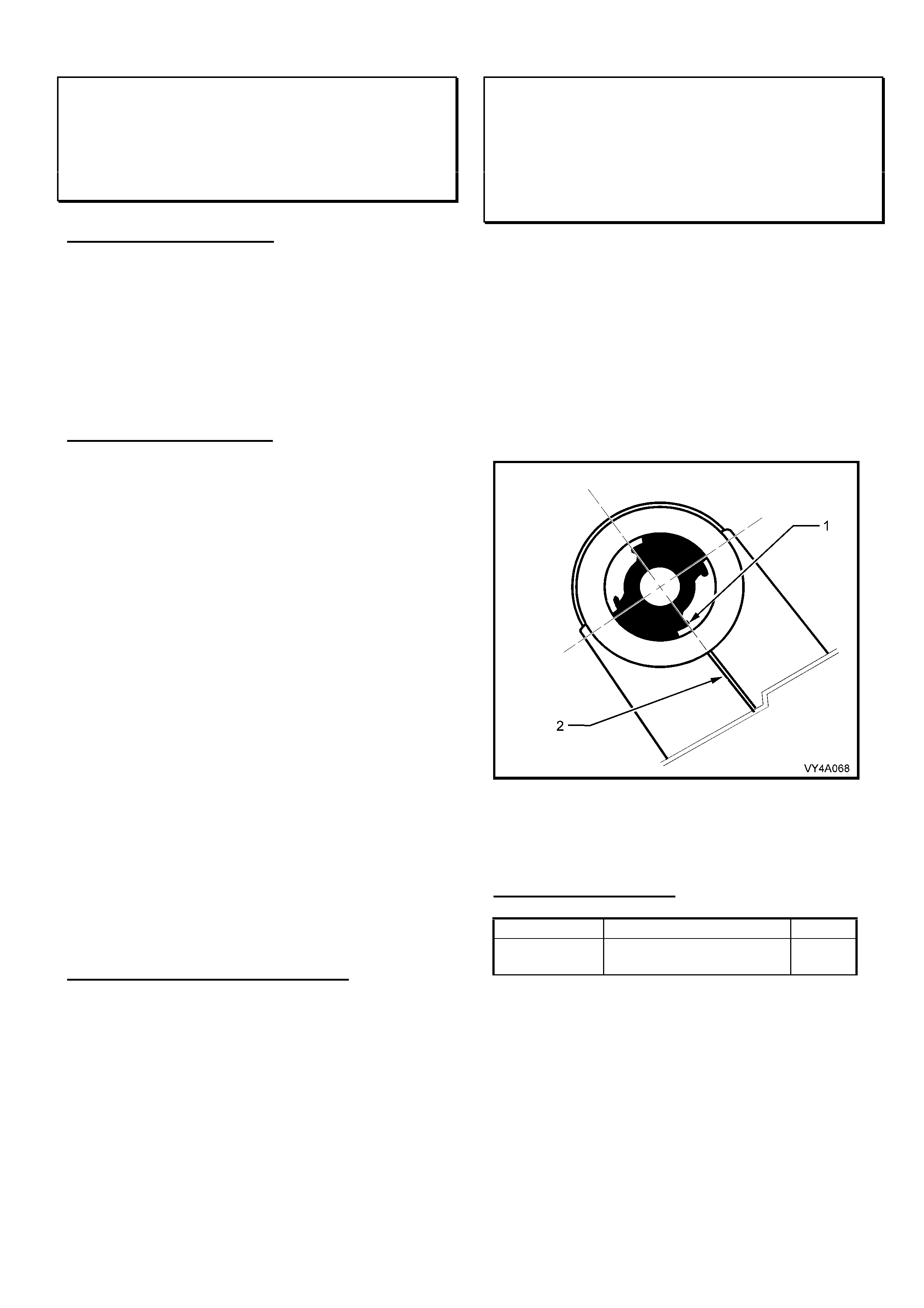
HOLDEN SERVICE TECHLINE____________________________________________________________________ JUNE, 2002
14
A/T Shifter Button Removal
WH, VX, VU, V2
(GROUP 7B) TL280-0205
PROBLEM DESCRIPTION
A/T shifter buttons returned via Repac have been
found to be damaged by incorrect removal. Marks
have been found around the shifter button top
edge – indicating that technicians believe the
button may be removed by levering the button
from the top edge of the shifter lever. This is not
possible!
SERVICE REQUIREMENT
When replacing a shifter button for any reason –
the SIP procedure must be adhered to. To
access the procedure in SIP refer following path:
VT Series II Commodore, Calais Service
Information
↓ Clutch, Transmission & Drivetrain
↓ Section7C4 - 4L60E On Vehicle Servicing
Operations
↓ 3. On Vehicle Servicing Operations
↓ 3.1 Selector Control Lever Assembly
The procedure in Section 3.1 is summarised as
follows:
- Remove centre console insert (Section 1A3 in
SIP);
- Disconnect wiring to shifter;
- Disconnect shifter control rod, under vehicle
(Section 7C4 in SIP);
- Remove shifter retaining bolts;
- Remove shifter from console;
- Disassembly of the shifter button from the
shifter is then fully detailed in SIP instructions.
WARRANTY CLAIM INFORMATION
Shifter buttons/levers damaged by attempted
removal via the top of the shifter lever/button will
no longer be accepted by Repac.
Semi Trailing Arms – Voided Inner Bush
Orientation
VXII, WHII, V2 - Multi Link Suspension
(GROUP 4) TL290-0205
With the introduction of multi-link suspension in
the above models the inner bushes of the rear
semi trailing arms were changed to voided type.
The correct orientation of these bushes in the
arms is shown in Figure 1.
Whenever bushes are replaced, ensure to align
the edge of one of the voids (1) in the bush with
the welded seam in the trailing arm (2).
Figure 1
NOTE: The above information will be added to
the Passenger Vehicle SIP CD due in June.
PARTS INFORMATION
Part No.: Description: Qty:
90334925 Bush asm. Control
Arm Mounting - Inner
1
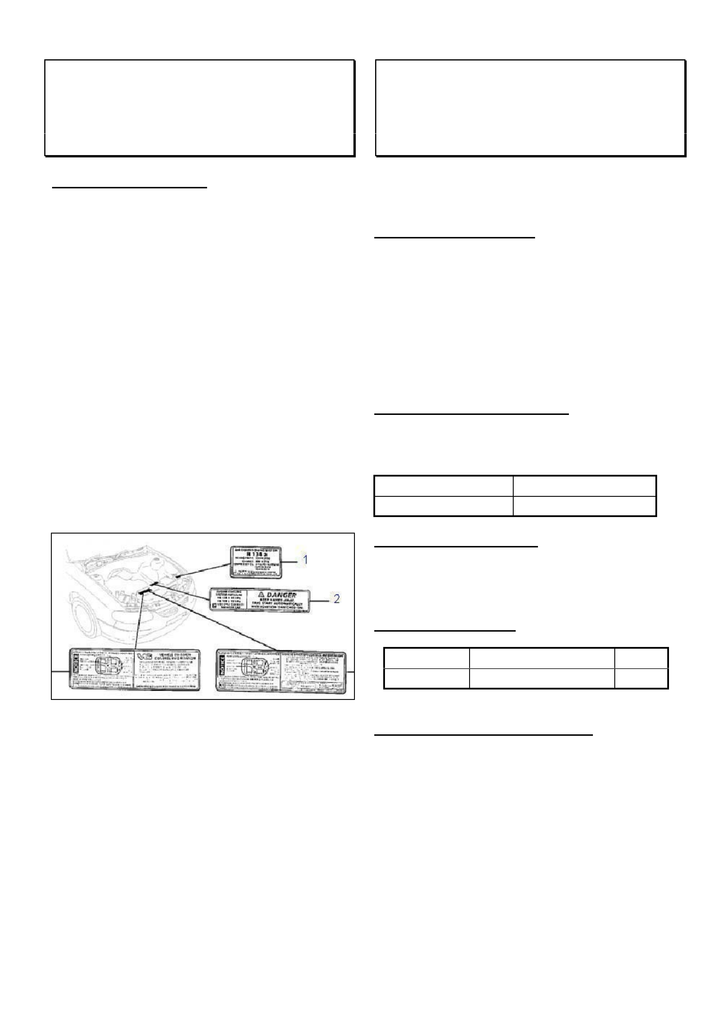
HOLDEN SERVICE TECHLINE____________________________________________________________________ JUNE, 2002
15
Refrigerant Label Location
All V & W with Gen III Engines
(GROUP 2) TL292-0205
SERVICE INFORMATION
Warranty Administration are receiving claims for
missing HVAC decals on the radiator shroud of
Gen III Engines (shown as “1” in the drawing
below).
The radiator shroud contains a recess to suit the
Refrigerant label, however a label is not fitted on
new vehicles.
The Refrigerant label on a current Gen III vehicle
is located UNDERNEATH the radiator shroud.
The recess in the radiator shroud will be fitted
with a Refrigerant label when an engineering
change is made later this year. The label
underneath the shroud will be deleted at this time.
Warranty Administration will not accept claims for
Refrigerant labels fitted to the top of radiator
shrouds of Gen III vehicles.
Brake Squeal Rectification
TS – Non-ABS models only
(GROUP 5) REVISED TL259B-0209
This Techline supercedes the previous one in
Issue 5/2002. It is revised by adding Production
Breakpoint for revised pads.
PROBLEM DESCRIPTION
Some non-ABS equipped TS Astra vehicles may
exhibit a squeal noise under braking.
New front brake pads have been released to
address this squeal.
The new pads have the leading and trailing edges
of the friction material chamfered to move the
squeal frequency outside the audible range.
PRODUCTION RECTIFICATION
Revised brake pads have been fitted in production
from:
ISOVIN Build Date
W0L0TGF482520462 14/6/02
SERVICE RECTIFICATION
To address customer complaints, fit the revised
brake pads. These brake pads are available from
HSPO.
PARTS INFORMATION
Part No.: Description: Qty:
93171035 Pad Set-Front Brake 1
WARRANTY CLAIM INFORMATION
As brake pads are a consumable wear item, and
would normally be charged to the customer, the
following policy applies:
If pad material thickness remaining is greater than
5mm, Holden will accept 100% of the parts and
labour charge for the repair.

HOLDEN SERVICE TECHLINE____________________________________________________________________ JUNE, 2002
16
If pad material thickness remaining is less than
5mm, Holden will accept 100% of the parts only
charge for the repair. The labour is to be
charged to the customer.
NOTE: ZONE APPROVAL IS REQUIRED FOR
CLAIMS TO BE PROCESSED.
Contact your dealer business consultant for
authorisation!
To measure the remaining pad material, simply
place the end of a steel ruler on the backing plate
and read the pad material height to the nearest
millimetre at the area of minimum material
thickness.
Description Pads, disc brake, both front
wheels - replace
Labour Op. No. H000222
Time 0.9 hr
Failure Code 40
Please note that warranty data will be monitored to
ensure this labour operation is only performed once
per vehicle.
Engine Stall At Idle Or High Engine Idle
Speed
JR, JS, C20SEL, C22SEL
(GROUP 6C) REVISED TL293-0205
This Techline supersedes the previous one in Issue
10, October, 2001. It is revised by adding a
checking/cleaning procedure to ensure there are
no idle concerns or DTC P0100 set after IACV
fitment.
PROBLEM DESCRIPTION
Some owners may complain of the following
symptoms:
With vehicle speed less than 3km/hr or vehicle
stationary, the engine idle is too high; e.g. 1000
RPM+, and engine may later stall or the idle may
remain high.
This is caused by a build-up of engine by-pass
gases and IACV solenoid shaft/bearing wear
particles on the IACV solenoid shaft, which causes
the IACV to stick at any point in its operating range.
This will result in either too high or too low IACV air
entry to the throttle body and engine.
When the IACV subsequently “unsticks” and
returns to normal operation, the result may be a
stall or higher than normal idle RPM. It is not
possible to effectively clean the IACV to correct this
condition.
PRODUCTION RECTIFICATION
Revised Idle Air Control Valves (IACV’s) have been
fitted to all vehicles despatched from Port Of Entry
facilities commencing 24th Sep. 2001.
GENERAL MAINTENANCE NOTE
The need to carry out careful checks of all engine
compartment hoses at regular maintenance
services is stressed to all Technicians, to ensure
continued, efficient vehicle operation. This
includes checking the engine PCV and air intake
hoses.
SERVICE RECTIFICATION
Summary: Fit revised IACV, Flash Program as
required, check/clean PCV port, check hoses.
On vehicles with the above symptoms perform
diagnosis to determine if the IACV is in fact the
cause of the problem. Refer to previous Techline
item in Issue 10/2001 titled “Engine Stall Diagnosis
Update
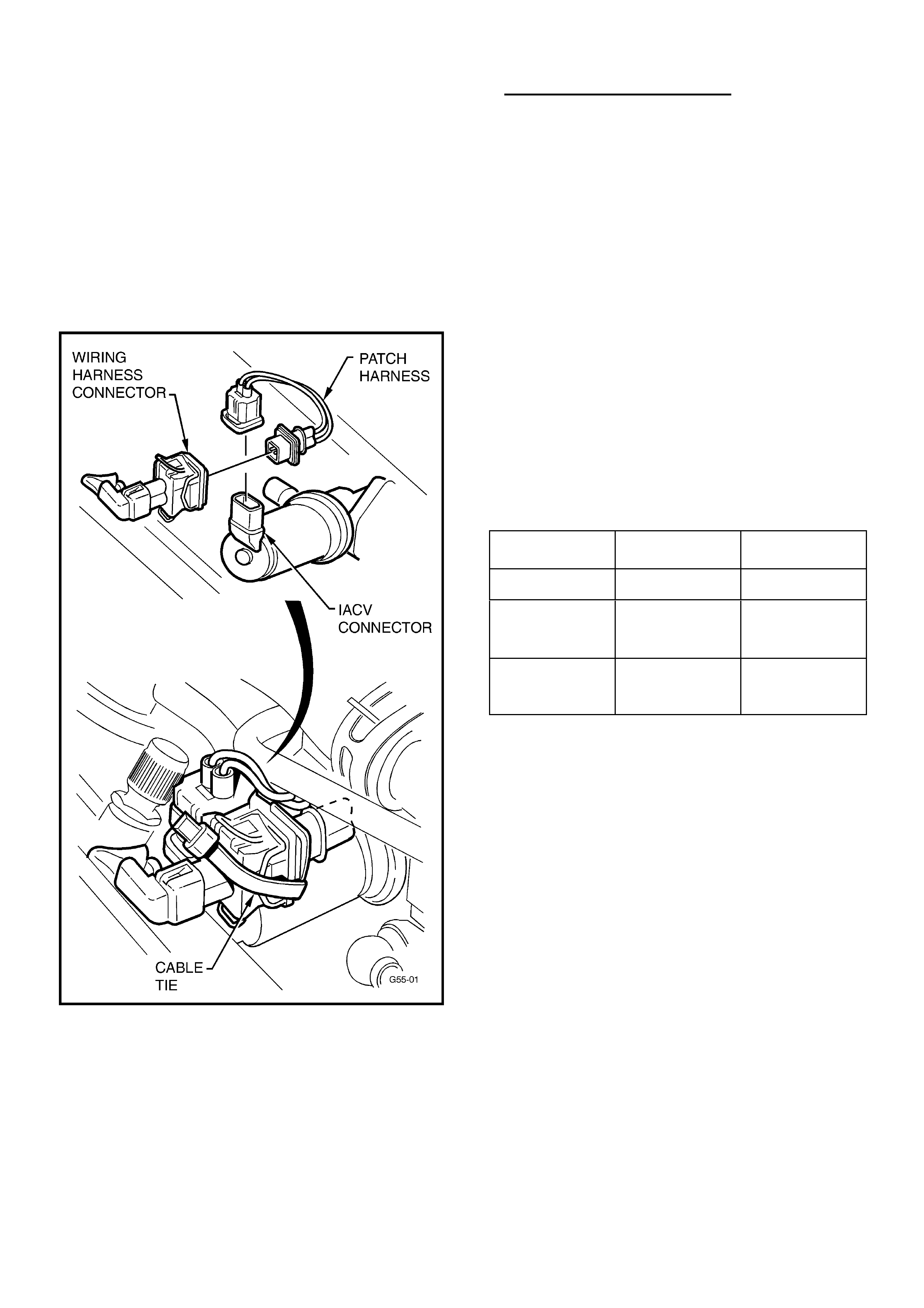
HOLDEN SERVICE TECHLINE____________________________________________________________________ JUNE, 2002
17
- Non IACV related causes”. After confirming that
nothing else is causing the stall, proceed to fit the
latest “diaphragm type” IACV using the following
procedure.
1. Remove old IACV and install new diaphragm
type IACV and gasket as per procedures
shown in TIS CD.
2. Fit the patch harness (refer Figure 1) – this is
an interface patch harness to connect the
existing vehicle wiring harness to the new
IACV.
Figure 1.
3. Use a tie strap to firmly bind the wiring harness
connector to the IACV connector as shown in
Figure 1. Cut off any excess strap.
4. Use TIS 2000 CD version 23 or later (and
Tech 2 Software Version 10.300 or later), to
flash program the “New IACV” calibration into
the vehicle via TIS Service Programming
System (SPS). Refer to Flash Programming
Details and Calibration Part Numbers below.
Flash programming Details:
Select the vehicle parameters that apply to the
vehicle being programmed.
For example: Holden; VECTRA-B; 2000;
C22SEL Engine,
THEN, for “Type of Idle Air Control Valve” select
“New IACV (PN.: 92 065 903)”,
THEN, select the “Type of Transmission”.
When type of Trans. is selected, if you are
prompted for either “Short Y” or “Long Y” types
of exhaust system:
“Short Y” exhaust front engine pipe has a “Y” (2
into 1) joint directly below the front of the engine
block; “Long Y” exhausts have the Y joint
further rearward approximately in line with the
sump plug.
NOTE. “Short Y” is used with F18 M/T. “Long
Y” is used with later F23 M/T introduced in JSII
from L482379 22/7/99.
Model: Old
Calibration
New
Calibration
JR & JS C20SEL 90569364.**** 92066071.2657
JS 1, C22SEL
(Short Y front
pipe)
92059405.**** 92066073.2658
JS 2, C22SEL
(Long Y front
pipe)
92085493.2659 92066074.2660
(**** = any Number )
After reprogramming is completed proceed as
follows.
5. CHECK FOR AND REMOVE PREVIOUSLY
SET BASE IDLE AS PER FOLLOWING
STEPS (a) to (d).
Failure to remove any previously set base idle
could affect the operating characteristics of the
new IACV.
(a). With Tech 2 connected select the Data
Display screen, start the vehicle and allow it to
come to operating temperature (greater than 70
deg C coolant and inlet air temp between 20 -
30 deg C) with moderate to high underbonnet
temperatures)
(b). With A/C OFF check "IACV steps" at idle. If
"IACV steps" is less than 20 a base idle was
previously applied. If greater than 20 steps no
adjustment is required.
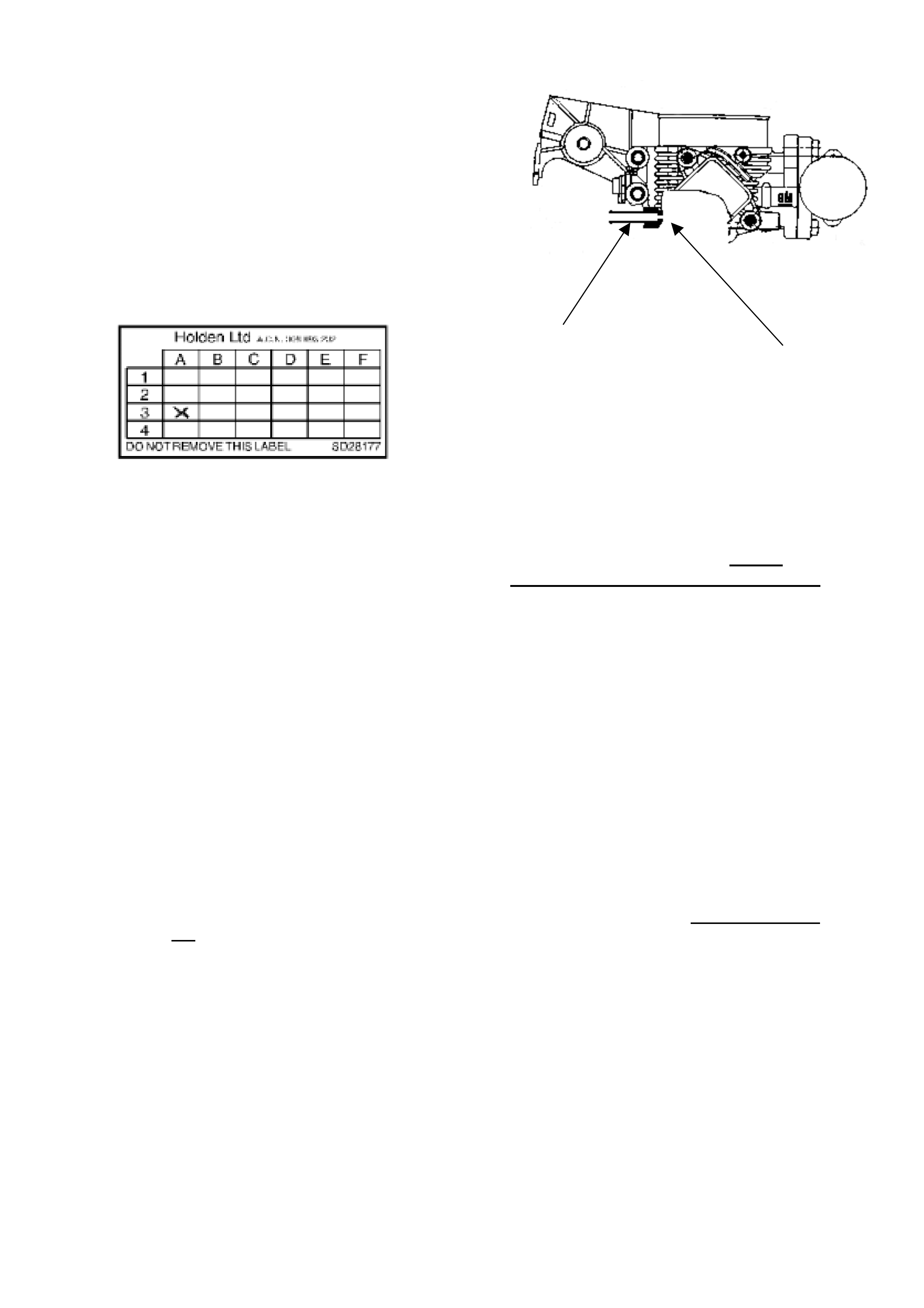
HOLDEN SERVICE TECHLINE____________________________________________________________________ JUNE, 2002
18
(c). Loosen the idle screw and decrease the
Throttle Position until the IACV steps are
above 20-25 steps with the A/C OFF.
(d). Re-tighten idle screw and conduct a final
check of the IACV steps.
6. Apply a Service History Label (SD-28177) to
the back of the fuse panel cover (lower left
corner) and mark the A-3 co-ordinate on the
label.
7. The following PCV hose/port check and clean
procedure must be carried out to all vehicles up
to WOLOJBF19YL557427, Build Date 16/02/00
(Breakpoint for introduction of a revised PCV
system that feeds PCV gasses into the lower
part of the inlet manifold.). This check and
clean (where required) ensures no poor
idle/stall/DTC P0100 will result due to
blockages, after IACV fitting.
Blockage of the PCV hose/port will cause the
engine to run on IACV air only at times. Engine
system calibration is based on specific air flow
through the PCV port PLUS IACV air at high
vacuum times (idle/decel) and thus, loss of air
flow through the hose/port can result in poor
idle and possibly stall.
Checking for blockages in PVC hose and port:
While engine is idling, remove the PCV hose from
the cam cover and check if there is vacuum at the
free end of the hose.
If vacuum is not present, remove the PCV hose
from the throttle body port connection and check
if there is vacuum at the port.
(A) - If vacuum is present at the port – replace the
PCV hose. No further action required.
(B) – If there is no vacuum at port then proceed to
clean the port as follows.
The port is shown in the cross section diagram
below, looking from rear of throttle body:
Contamination builds
up in PCV connector. Blocks calibrated hole.
This port may become blocked by contaminants
carried in PCV gas and, over time, the build-up
will block the small calibrated hole in the throttle
body.
This hole can be carefully cleaned out as follows:
1. Obtain a 1.5mm Diameter, long drill bit from an
engineering supplies outlet. NOTE: this drill bit
MUST not be larger than 1.5 mm Dia., as the
hole is calibrated. Enlarging the hole will result
in incorrect air flow, and cause driveability or
further code setting problems.
2. Remove the main air intake hose from the
throttle body;
3. Using the 1.5mm Dia. drill bit, carefully insert
the drill into the connection and rotate the drill
bit BY HAND until the deposits in the
connection are dislodged and the drill freely
passes through the calibrated hole into the
throttle body inlet passage.
4. Check this by: removing the drill bit from the
throttle body port completely, then open the
throttle blade fully and hold it fully open, insert
the drill bit until it protrudes from the calibrated
hole – then remove drill bit and then close
throttle blade.
5. Clean the connection with a solvent or spray
cleaner and remove any debris left in the
connection hole and throttle body;
6. Re-check that the hole is clear using the drill
bit, and re-assemble previously removed
components.

HOLDEN SERVICE TECHLINE____________________________________________________________________ JUNE, 2002
19
PARTS INFORMATION
Obtain following IACV kit from HSPO.
Part No.: Description: Qty:
92066066 IACV Kit 1
WARRANTY CLAIM INFORMATION
Use the following information to claim for the
installation of the new IACV and flash
programming the ECU.
Description Replace IACV
Labour Op. No. J000686
Time 0.6 hr
Failure Code 84
Note: this Labour Operation is useable for
vehicles within and outside new vehicle warranty
with the above noted idle/stall conditions.
DTC P0100/Poor Idle/Engine Stall
Diagnosis (Non - IACV Related Causes)
JR, JS, C20SEL, C22SEL
(GROUP 6C) TL289-0205
PROBLEM DESCRIPTION
PIR’s have been received advising that vehicles
have not responded to the fitting of new IAC
Valves – as described in Techline of October,
2001 entitled “Engine Stall at Idle or High Engine
Idle Speed”.
These reports mention that vehicles have a DTC
P0100 (MAF Sensor Voltage Low) set and the
vehicles have unstable idle or may stall at odd
times.
The cause of this condition has been investigated
and a number of possible causes have been
found:
• Blocked PCV hose/port in throttle body;
• Loose elbow in air intake duct (above
throttle body);
• Damaged TPS housing on the throttle body;
• Damage/deterioration to secondary PCV hose;
• Purge valve hoses fitted in reverse.
Most of these component concerns should be
found during general checks at scheduled
maintenance services, as technicians check the
general condition of engine compartment hoses.
The need to carry out careful checks of all engine
compartment hoses is stressed, in the interests of
continued, efficient vehicle operation.
As a general rule, any stall that occurs above
4km/h is not IACV related, and requires diagnosis
to ensure a cause is found and corrected.
SERVICE RECTIFICATION
Summary: Check PCV port and hose for
blockage. Replace hose or clean port as
required.
NOTE: The hose/port recommendations below
apply to JR/JS C22SEL engined vehicles built
prior to introduction of a revised PCV system that
feeds PCV gas into the lower part of the inlet
manifold – these were built from:
WOLOJBF19YL557427, Build Date 16/02/00,
Engine No.: C22SEL25015395.
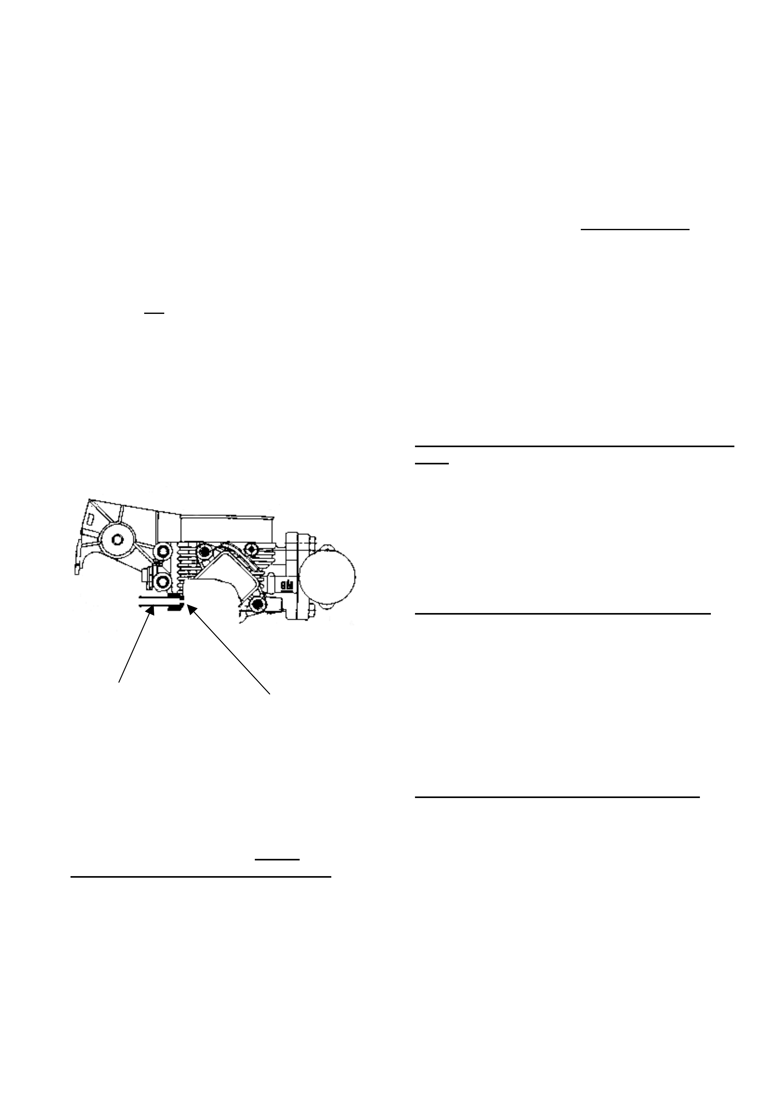
HOLDEN SERVICE TECHLINE____________________________________________________________________ JUNE, 2002
20
Blocked PCV Hose/Port in Throttle Body
Blockage of the PCV hose/port causes the engine
to run on IACV air only. Engine system calibration
is based on specific air flow through the PCV port
PLUS IACV air at high vacuum times (idle/decel)
and thus, loss of air flow through the hose/port
can result in poor idle and possibly stall.
Checking for blockages in PVC hose and port:
While engine is idling, remove the PCV hose from
the cam cover and check if there is vacuum at the
free end of the hose.
If vacuum is not present, remove the PCV hose
from the throttle body port connection and check
if there is vacuum at the port.
(A) If vacuum is present at the port replace the
PCV hose. No further action is required.
(B) If there is no vacuum at port then proceed
to clean the port as follows.
This port is shown in the cross section diagram
below, looking from rear of throttle body:
Contamination builds
up in PCV connector. Blocks calibrated hole.
This port may become blocked by contaminants
carried in PCV gas and over time, the build-up will
block the small calibrated hole in the throttle
body.
This hole can be carefully cleaned out as follows:
1. Obtain a 1.5mm Diameter, long drill bit from an
engineering supplies outlet. NOTE: this drill bit
MUST not be larger than 1.5 mm Dia., as the
hole is calibrated. Enlarging the hole will result
in incorrect air flow, and causing driveability or
further code setting problems.
2. Remove the main air intake hose from the
throttle body;
3. Using the 1.5mm Dia. drill bit, carefully insert
the drill into the connection and rotate the drill
BY HAND until the deposits in the connection
are dislodged and the drill freely passes
through the calibrated hole into the throttle
body inlet passage.
4. Check this by: removing the drill bit from the
throttle body port completely, then open the
throttle blade fully and hold it fully open, insert
the drill bit until it protrudes from the calibrated
hole – then remove drill bit and then close
throttle blade.
5. Clean the connection with a solvent or spray
cleaner and remove any debris left in the
connection hole and throttle body;
6. Re-check that the hole is clear using the drill
bit, and re-assemble previously removed
components.
Loose elbow in air intake duct (above throttle
body
Should this elbow be “loose” in the main air intake
duct, the additional un-metered air entering the
system can cause driveability problems, poor idle,
and a P0100 to set.
If the elbow is loose – replace the inlet duct
(containing the elbow).
Damaged TPS housing on the throttle body
While this should be a rare occurrence - if the
TPS housing has been damaged in some way
that allows air/water/dust, etc to enter the body,
the resulting contamination can cause incorrect
operation/readings. EG: Damage during any
service operations, engine/trans. removal, etc.
Any TPS found with damage to the external body
must be replaced with a new TPS.
Damaged/Degraded Secondary PCV Hose
Stalling may be caused if the secondary PCV
hose (Item 2 shown in the diagram below) is split
or torn, or the inner hose walls deteriorate:
Damage (split or torn):
Allows air to by-pass the mass airflow sensor,
leading to incorrect airflow readings which affect
the engine fuel ratio (runs lean). A DTC P0100
may be set.
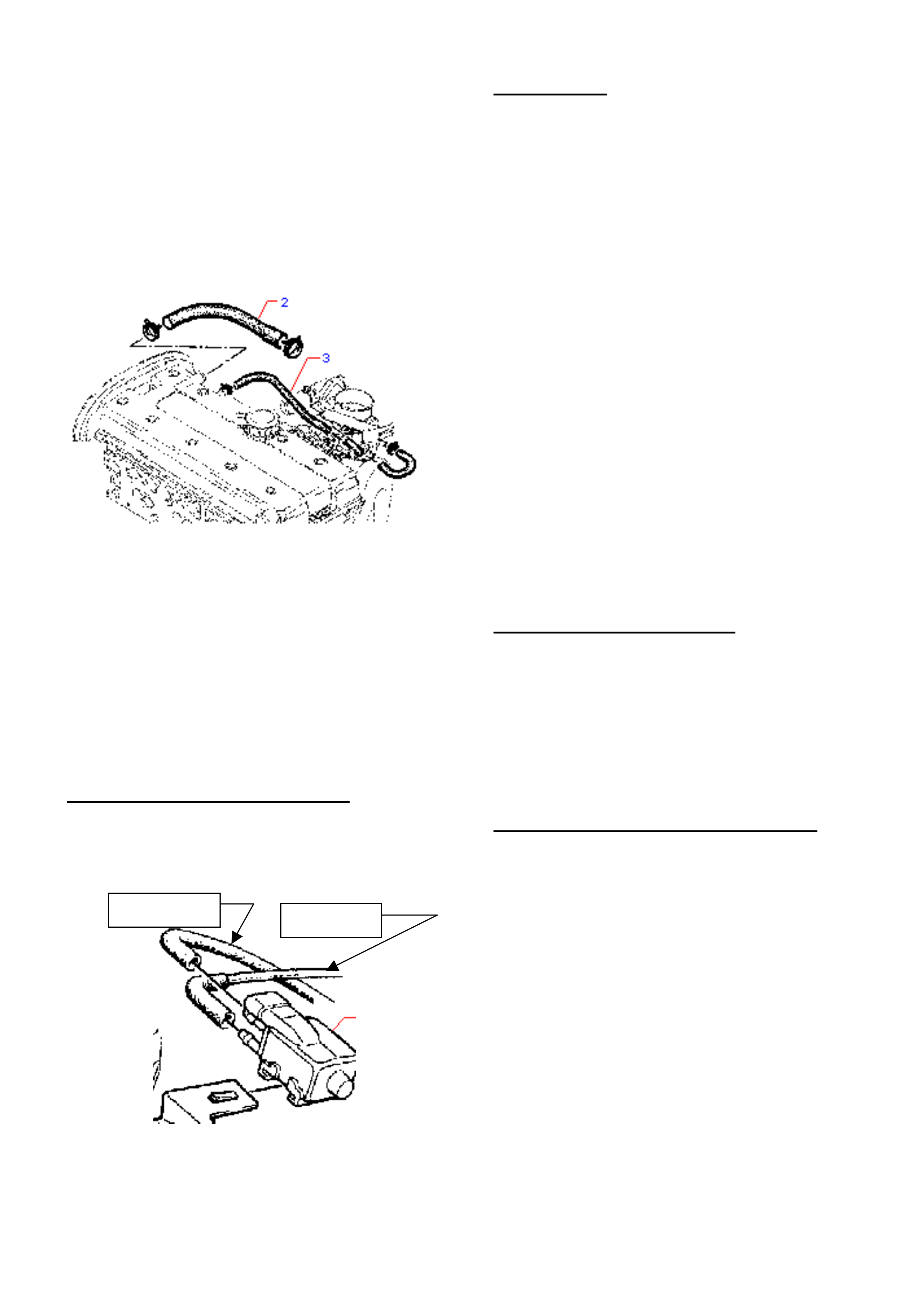
HOLDEN SERVICE TECHLINE____________________________________________________________________ JUNE, 2002
21
Degraded:
Degradation of the hose can result from age and
exposure to PCV gases, and external
contaminants which affect the hose. The hose
should be carefully examined for physical
degradation, EG: softness, cracking, hardness,
etc, and replaced if necessary. Extreme build-up
of PCV contaminants to the point where the hose
is blocked or cleaning is uneconomical also
dictates that the hose should be replaced.
Deterioration of hose inner walls:
Allows particles of the deteriorated hose material
to separate from the hose, and these may
become lodged in the ‘early design’ or “old” IACV
leading to a stall. This will not occur with the ‘later
design’ or “new” IACV – however, the hose
should be examined and replaced where
necessary.
NOTE: kinking, or clamping any other
components to the secondary PCV hose is NOT
permitted.
Purge valve hoses fitted in reverse
The hoses at the canister purge valve must be
fitted the correct way – with the throttle body hose
at the top purge valve fitting – as shown below:
If these hoses are reversed – damage to the
purge valve may result – if this has occurred it is
recommended that the purge valve be replaced.
MAF SENSOR
The following information is repeated from a
previous Techline on Non-IACV related stall – for
reference, should a cause to P0100 not be found
with the above information.
Stalling associated with the MAF Sensor can
occur either while vehicle is moving or stationary.
Usually a DTC P0100 is set. (this DTC may also
be set by a fluctuating idle, so correct diagnosis
of type of stall is required).
Some findings on failed MAF Sensors have been:
♦ Fretting corrosion of the MAF Sensor
terminals. (Replace suspect terminals.)
♦ Connectors not fully or correctly installed.
(Check connections and re-install if required.)
♦ Incorrect routing or attachment of sensor
wiring. (Check wiring against a known OK
vehicle to ensure the wiring is not run in an
incorrect routing, so it does not pick up any
‘stray’ electrical signals from other wiring or
components.)
RELAY INCORRECT FITMENT
If the “Fuel pump” or “injection valves” relays are
not properly fitted – with their terminals fully
engaged in the mating connector/wiring, a stall
may be caused. Check relays for full and proper
connection, re-install if required. Some relays are
a very tight fit and may not have been fully seated
on fitting or subsequent replacement.
CRANKSHAFT OR CAMSHAFT SENSOR
Refer to Techline bulletins of February and
March, 2000 relating to these sensors – available
on your SIP CD. Replace any pre-breakpoint
parts.
To Canister
To Manifold
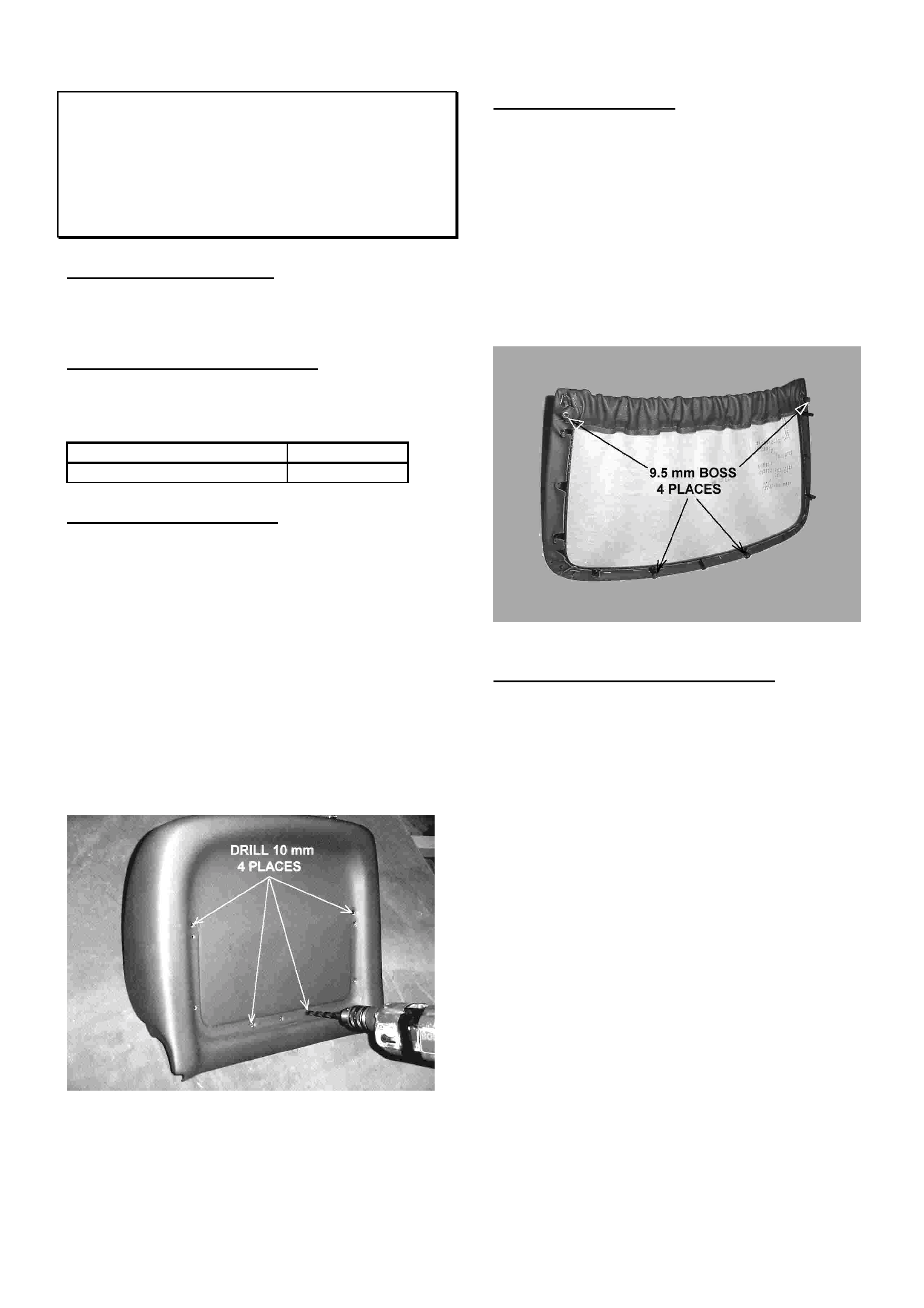
HOLDEN SERVICE TECHLINE_______________________________________________________________JULY, 2002
6
Front Seat Map-Pocket Detaches From
Seat- Back
VT, VX, WH
(GROUP 1) TL273-0206
PROBLEM DESCRIPTION
Map pocket detaches from front seat back due to top
mounting bosses breaking.
PRODUCTION RECTIFICATION
Revised map pockets with larger diameter (9.5mm)
mounting bosses have been fitted to vehicles from:
ISOVIN: Build Date:
6H8VXK69F2L844401 20/03/02
SERVICE RECTIFICATION
Summary: Fit revised map pocket with larger diameter
mounting bosses.
For removal and reinstallation procedures for front seat
back cover refer to Passenger Vehicle SIP CD. Path:-
VT Series 1, Section 1A7, Procedure 2.6
NOTE: When fitting a revised map pocket to a vehicle
built prior to the above breakpoint, a foul condition will
occur between the four bosses on the map pocket and
the corresponding mounting holes in the front seat
back cover. To eliminate this foul condition, use a
10mm drill bit to enlarge the holes in the cover. The
drill should be applied from the vinyl side.
Figure 1.
PARTS INFORMATION
• The part numbers of the revised map pockets (larger
diameter mounting bosses) have not changed.
• For all map pocket part numbers refer to Partfinder.
• All stocks of map pockets in HSPO are now of the
revised type.
• NOTE: To ensure the map pocket you are fitting is
the latest type, check that the diameter of the
mounting bosses is 9.5mm. Refer Figure 2.
Figure 2.
WARRANTY CLAIM INFORMATION
Use Labour Times information in Warranty Information
section of current PV SIP CD

HOLDEN SERVICE TECHLINE_______________________________________________________________JULY, 2002
7
Poor AM Band Radio Reception
TS Astra Hatch & Sedan
(GROUP 12) TL250-0206
PROBLEM DESCRIPTION
Some customers may complain of poor reception on the
AM radio band in certain environments.
SERVICE RECTIFICATION
Summary: Do basic checks listed in A and B. If
unsuccessful, disconnect the original two piece lead and
install new one piece lead.
A. Perform basic continuity checks on major radio
system components as described in SIP 2001
Service Techlines, Group 12, “Radio Problem
Diagnosis Guide”.
B. Check the antenna lead connection in roof cavity
as described in Issue 6/2002, Group 12,
“Poor AM Radio Reception – Loose roof antenna
connector.”. Also, ensure that the antenna mast
base to roof attaching nut (serrated type) is tight.
If the checks in (A) and (B) do not provide any
improvement in AM reception, install a one piece
antenna lead as per the following procedure. Refer to
Parts Information for antenna lead part number.
1. Remove radio and radio cradle from Instrument
panel.
2. Disconnect existing antenna from cradle connection
and tie back to harness with a plastic tie strap. Refer
view A. This prevents the original lead from fouling
when the cradle with re-routed antenna lead is
reinserted.
3. Remove, detach or loosen the following components
to allow installation of the one piece antenna lead.
• Remove the Lower Trim panel below steering
column.
• Remove RH Side Kick panel.
• Fold rear seat base forward.
• Fold down RHS rear seat back.
• Remove rear parcel shelf.
• Remove C pillar trim.
• Remove rear interior light/hand grip fittings from
headlining.
• Lower the head lining at rear edge to allow
access to antenna base connection.
NOTE: Failure to remove the rear light/grip
fittings could result in the headlining being
fractured whilst trying to access the antenna
base connection in the roof cavity.
4. Connect one end of new antenna lead to connection
on radio cradle and feed other end down through
RHS of opening in instrument panel and route
across top of air duct above drivers feet. Refer view
A & B.
5. Continue to feed lead downwards to the right of the
engine hood lever and adjacent to door opening
seal. Refer view C.
6. Tie strap lead to air duct - 2 places. View B.
7. Route the antenna lead along the rocker panel and
up C pillar. Ensure cable is spot taped to sheet
metal every 200mm to avoid rattles. Refer views D,
E & F.
8. Feed lead into the roof cavity and withdraw through
opening immediately below antenna mast. Refer
views G, and H.
9. Remove foam tape from around connector in roof.
Undo the existing antenna lead and tie back on itself
using a tie strap. Refer view H. NOTE: From
Model Year 2002, the antenna lead connector in the
roof is a plug-in type. Prior to MY 2002 this was a
screw fitting.
10. Connect the new antenna lead to the antenna mast
connector. ENSURE THIS CONNECTION IS
TIGHT. Wrap several turns of foam tape around
connector to prevent rattles in roof.
11. Coil up excess length of lead and tie strap coil firmly
to C pillar to avoid rattles. Refer view G.
12. Reinstall all components.
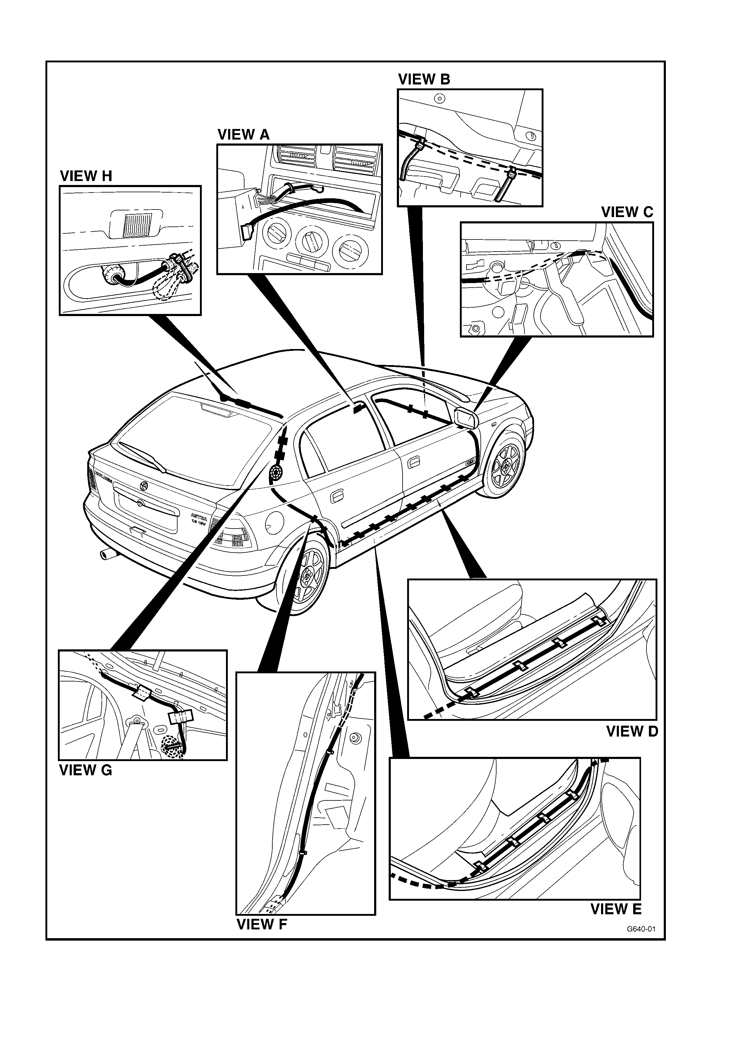
HOLDEN SERVICE TECHLINE_______________________________________________________________JULY, 2002
8

HOLDEN SERVICE TECHLINE_______________________________________________________________JULY, 2002
9
PARTS INFORMATION
Part No.: Description: Qty
:
90513340 Antenna lead one piece
(Sed/hatch up to end
MY01) –screw connection
1
93160448 Antenna lead one piece
(sed/hatch from MY02)
– plug in connection
1
90148142 Foam tape - roll 1
WARRANTY CLAIM INFORMATION
Description Install one piece antenna
lead
Labour Op. No. N000381
Time 1.5 hr
Failure Code 33 weak
DTC P1870 - Trans. Slipping
WH, VX, V2, VU with A/T
(GROUP 7B) TL270-0206
PROBLEM DESCRIPTION
A small number of vehicles have been presented
to Retailers with DTC P1870 (Transmission
slipping) set. These codes are most often set
during lengthy trips.
Retailer diagnosis, without transmission
teardown, has been carried out, but no faults
have been found.
Reports show that after diagnosis is carried out
and the code is cleared, the vehicle may remain
in service without the code re-occuring, or may
return some time later (typically a month or more)
with the same DTC set.
SERVICE RECTIFICATION
Events such as this are likely to be caused by
minor transmission internal problems that lead to
fluid pressure reduction. As the causes of this
pressure reduction will require extensive
investigation and possible teardown, it is
recommended that a SRTA transmission be fitted.
UNTIL FURTHER NOTICE – whenever a vehicle
is presented with DTC P1870 in memory, the
following is recommended:
• Carry out the basic checks in Section 6C1-2A
of VX Series 1 in SIP (without dismantling the
transmission).
• Should no fault be found after basic
diagnosis, transmission replacement is
required.
This course of action is recommended to ensure
minimal disturbance to customers.
From investigations into any returned
transmissions – a future Techline may be
produced to enable Retailer repair if necessary.
WARRANTY CLAIM INFORMATION
Use existing information to claim for diagnosis
and/or replacement of transmissions.
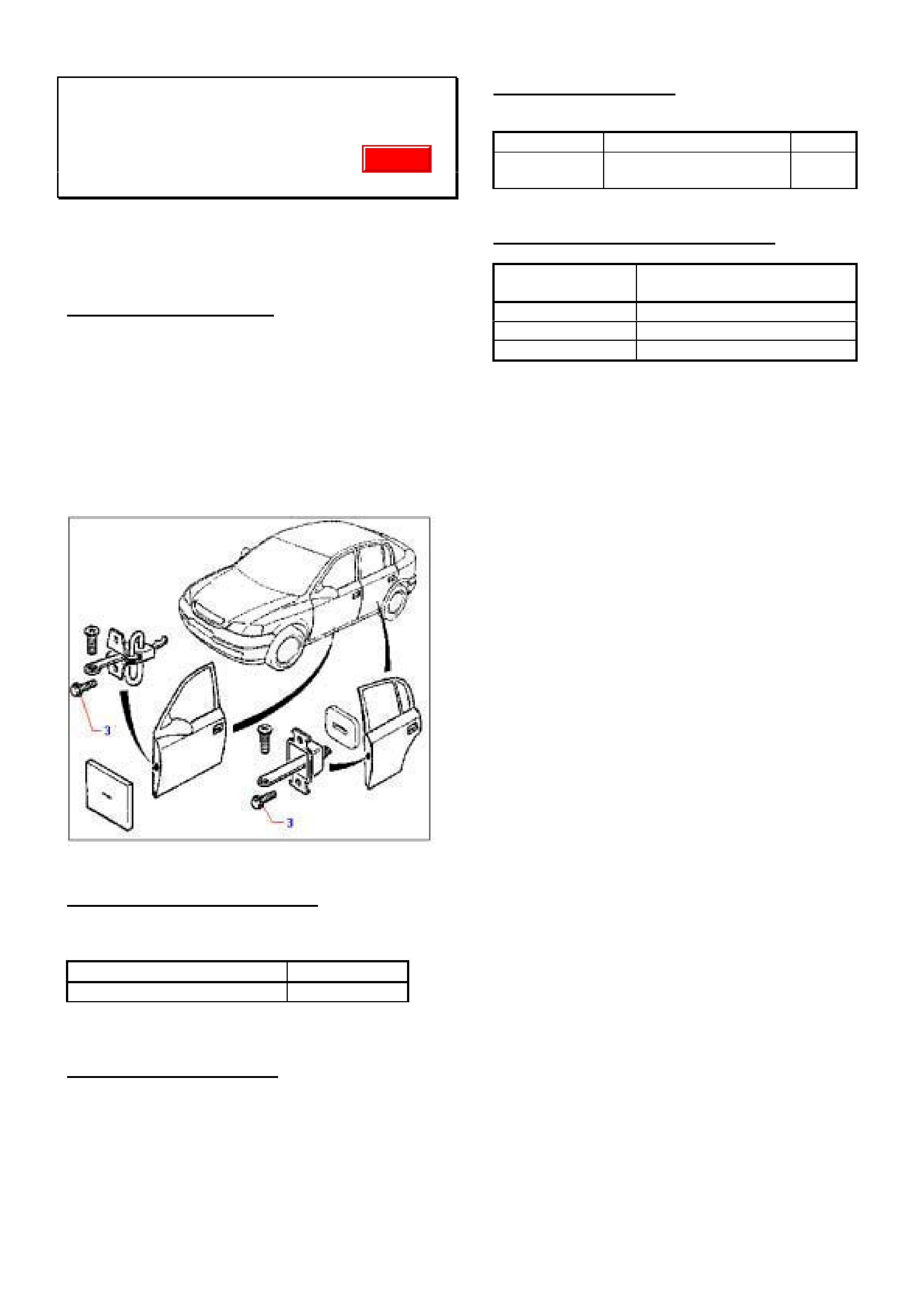
HOLDEN SERVICE TECHLINE_______________________________________________________________JULY, 2002
10
Door Checklink Bolts Loose
TS, TT, JS, XC
(GROUP 1) REVISED TL285A-0206
This Techline supercedes the previous one in Issue
5/2002. It is revised by:- adding new Labour Op. No.
for replacing checklink bolts on all 4 doors and
expanding vehicle model range.
PROBLEM DESCRIPTION
Door checklink attaching bolts loosen.
Investigations show root causes to be:
• Attaching bolts (item 3 in Figure 1) not to
specification
• Relaxation of clamping torque ex factory.
• Stripped threads caused by over tightening of bolts
(above 6.5Nm)
Figure 1.
PRODUCTION RECTIFICATION
Revised checklink attaching bolts with closer controls
on tightening torque have been fitted to vehicles from:
ISOVIN: Build Date:
W0L0TGF4815283442 05/06/2001
SERVICE RECTIFICATION
On complaint vehicles fit revised checklink attaching
bolts part number 13104167 and torque to 4.5 to 5.0
Nm.
PARTS INFORMATION
Obtain following parts from HSPO:
Part No.: Description: Qty:
13104167 Bolt Checklink to door. 2 per
door
WARRANTY CLAIM INFORMATION
Description Bolt/pin check asm. all four
doors - Replace
Labour Op. No. C634000
Time 0.5 hr
Failure Code 40 (Noisy)
If replacing checklink bolts on individual doors, use
Labour Times information in Warranty Information
section of current PV SIP CD
Update

HOLDEN SERVICE TECHLINE_______________________________________________________________JULY, 2002
11
A/T Electrical Connector Removal &
“Limited” Repair Procedure
VR, VS, VT, VX, VU, V2, WH
(GROUP 7B) TL310-0206
The information below on removal of connectors was
previously issued in Service Techline September 2000,
Issue 8. For repair of harness – refer to Service
Techline September 2000, Issue 8, Page 17.
PROBLEM DESCRIPTION
Some neutral start & back-up switch connector/s may
be “hard to remove”. This may occur in vehicles that
have been in service for a long time, and subjected to
long periods of idling. Heat build-up causes the internal
heat sink material in the switch to ‘migrate’ into the
electrical connectors and to act like a glue between the
switch body and the connector.
SERVICE RECTIFICATION
CONNECTOR REMOVAL:
Should this “hard to remove” situation occur in any
vehicle, the method of removal suggested is:
Apply heat (with a commercially available heat gun) to
the connector area of the neutral start & back-up switch
where it mates with the vehicle harness connector.
Only apply sufficient heat to soften the “glue-like”
material in the connections – IE: repeatedly heat and
check the connection for looseness, until the
connection loosens and can be removed.
After removal of the connector/s:
• Clean terminals in the vehicle harness. Should the
neutral start & back-up switch connector be heavily
contaminated, the switch should be replaced.
• After switch replacement, check switch operation in
workshop, then road test vehicle to ensure the
switch has not been damaged during the above
procedure.
CONNECTOR REPAIR:
In addition to the above removal procedure, for
vehicles that are out of warranty, a repair method is
offered as a cost-effective repair for customers, should
damage occur to the vehicle’s harness connectors
during removal as noted above.
As the above procedure is recognised as being for
higher kilometer and older vehicles, the repair
procedure is not to be used for vehicles in warranty.
Flash Programming - Gen3 PCM
VX, VU, V2, WH(A8A)
(GROUP 6C) TL315-0206
The previous Service Techline on this subject in Issue
2/2002, Group 6C, described the need to use a 200
ohm resistor during the downloading phase from Tech
2 to PCM.
This procedure is no longer required provided you
are using TIS 2000 from version 31.5 onwards.

HOLDEN SERVICE TECHLINE_______________________________________________________________JULY, 2002
12
Squeaks and Rattles
◆
◆◆
◆ Instrument Panel Facia
◆
◆◆
◆ Engine Hood Insulator Fasteners
VT,VX,VU,V2,WH
(GROUP 1) TL275-0205
PROBLEM DESCRIPTION
Customers may complain of any of the following
conditions:
1. A buzz around the headlight switch or the centre
vents when travelling at 60 km/h or faster on
slightly rough bitumen surface
2. A creak/crack from the HVAC control area when
travelling over road cracks or rough road.
3. A chirping noise when driving over road
imperfections at most speeds and appearing to
come from the dash.
Causes
Condition 1 can be caused by relative movement
between the instrument facia and the instrument panel
pad.
Condition 2 can be caused by relative movement
between the instrument facia and the HVAC controls.
Condition 3 can be caused by the hood insulator
fastener rubbing on the fender catwalk flange.
Typically, a vehicle with this condition will show a
witness mark in the paint on the catwalk flange in the
positions shown in Figure 2. A corresponding witness
mark can also be seen on the hood insulator fastener.
SERVICE RECTIFICATION
Summary: Apply specified anti- squeak tapes to
designated areas.
For vehicles with Condition 1 and 2.
1. Remove the IP facia from the vehicle.
2. Lay the facia (face down) on a soft surface such as
a clean towelling cloth
3. Apply flocked tape (92145740) to the edge of the
facia in the areas shown in Figure 1 ensuring that
the tape is not visible after reassembly of the facia
to the instrument panel (utilise the edge feature line
as an alignment guide).
4. Refit the facia panel to the vehicle.
For vehicles with condition 3.
1. Measure back from the front of the fender and
mark the four locations (2 per side) where the
fastener may contact the flange. Refer Figure 2.
2. Cut a 30 mm length of clear polyurethane tape
(92145618). Clean the area that the tape will
cover. Apply the tape centrally over the marked
area ensuring that the edge of the fender flange is
covered and the tape is wrapped around the edge
of the flange.
3. Repeat the tape application at the other three
locations.
PARTS INFORMATION
Part No.: Description: Qty:
92145740 Anti squeak tape –
flocked (11 metre roll)
1
92145618 Anti squeak tape –
clear polyurethane (11
metre roll)
1
Note: At Techline publication some tapes may not be
immediately available however orders may still be
placed.
WARRANTY CLAIM INFORMATION
Description Add anti-squeak tape to
Instrument Panel facia
Labour Op. No. C000457
Time 0.5 hr
Failure Code 90
NOTE: To claim the cost of tape used in this
procedure, claim for the cost of 1.0 metres per car.
(Approx. 10 cars per roll)
Description Add anti-squeak tape to
front fender flange(catwalk)
Labour Op. No. C000460
Time 0.2 hr
Failure Code 90
NOTE: To claim the cost of tape used in this
procedure, claim for the cost of 0.12 metres per car.
(Approx. 80 cars per roll)
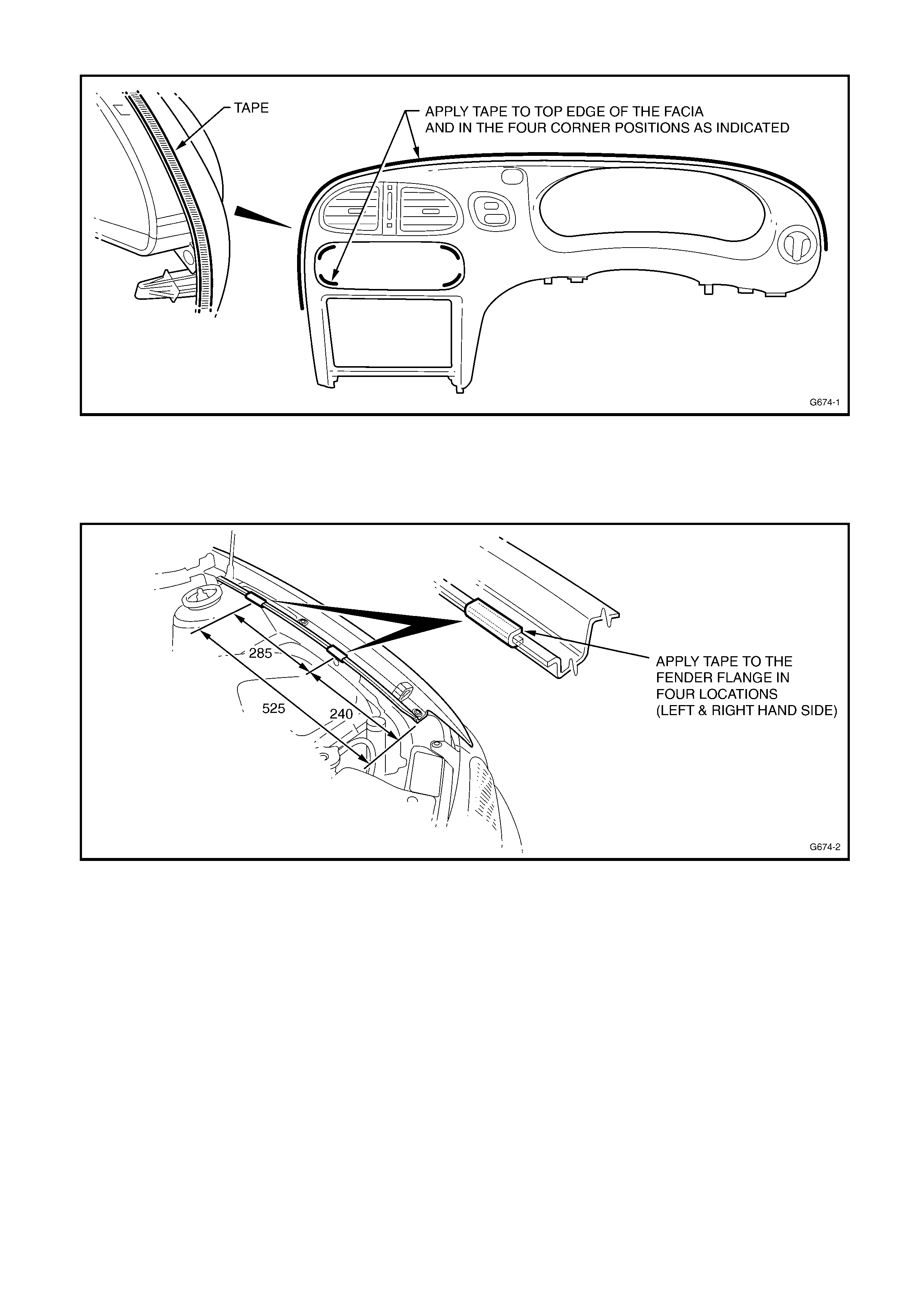
HOLDEN SERVICE TECHLINE_______________________________________________________________JULY, 2002
13
Figure 1.
Figure 2.
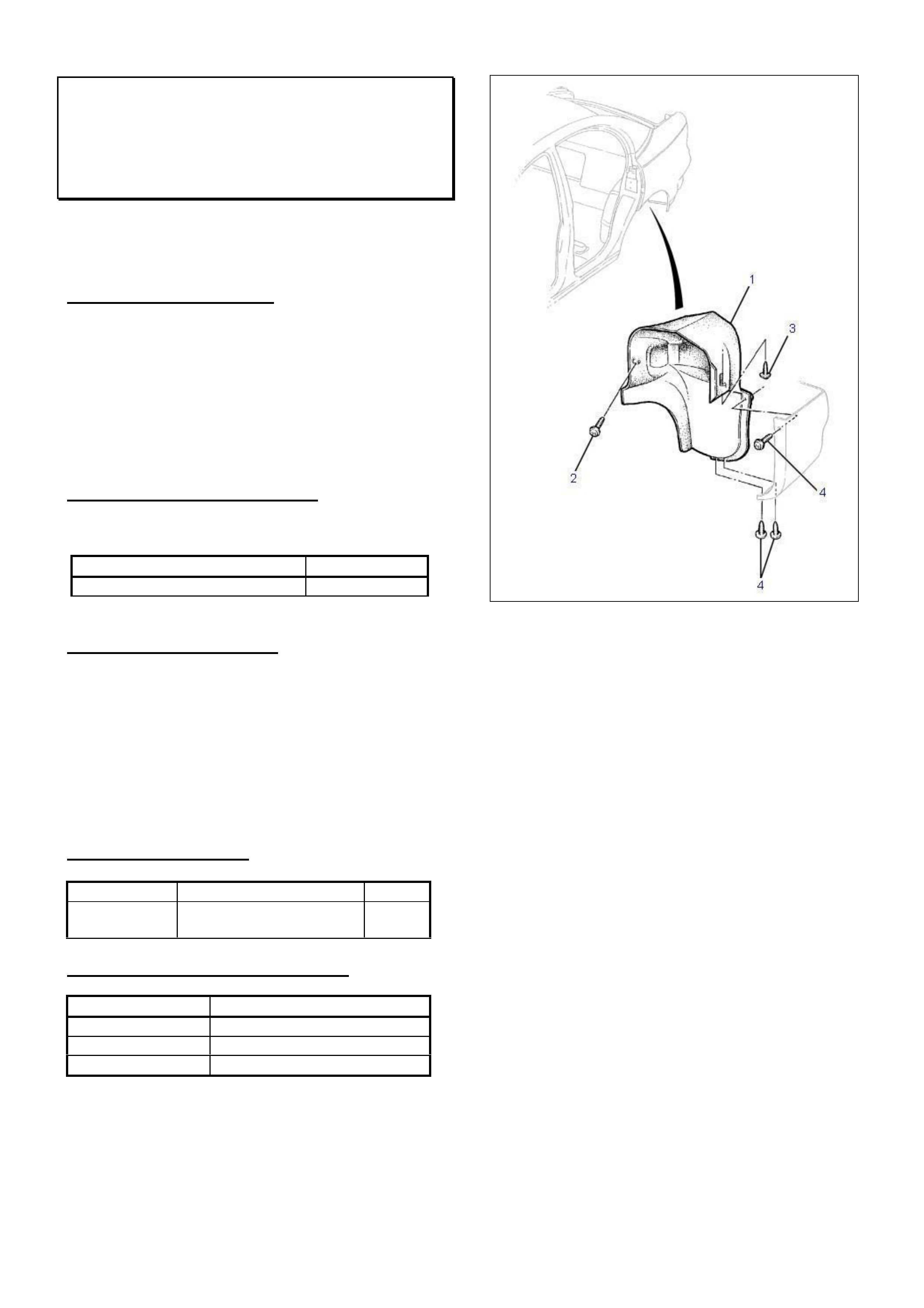
HOLDEN SERVICE TECHLINE_______________________________________________________________JULY, 2002
14
Rear Facia Loose Left Hand Side
VX Sedan
(GROUP 1) REVISED TL302A-0209
This Techline supercedes the previous one in Issue 6,
2002. It is revised by adding Production Rectification
breakpoint information.
PROBLEM DESCRIPTION
Rear bumper facia loose at left hand rear wheelhouse.
This particular condition can affect vehicles built from
October 2001 which is when the method of attaching
the liner to wheelhouse (Left Hand Side) was changed
from a screw to a scrivet. Due to a tolerance stackup
on some vehicles the scrivet may have insufficient
clamping load.
PRODUCTION RECTIFICATION
The LHS scrivet and scrivet hole were revised from:
ISOVIN: Build Date:
6H8VXL69A2L885020 29/06/02
SERVICE RECTIFICATION
Summary: Install self tapping screw to retain liner.
1. Raise vehicle on 2 post hoist so that rear
suspension hangs.
2. Leaving the scrivet in position, install screw part
number 92138310 into existing hole located to left
of the tab when looking into wheelhouse area.
Refer position “2” shown in Figure 1.
PARTS INFORMATION
Part No.: Description: Qty:
92138310 Screw liner to
wheelhouse
1
WARRANTY CLAIM INFORMATION
Description Whatever Asm - Replace
Labour Op. No. C000470
Time 0.3 hr
Failure Code 27
Figure 1.
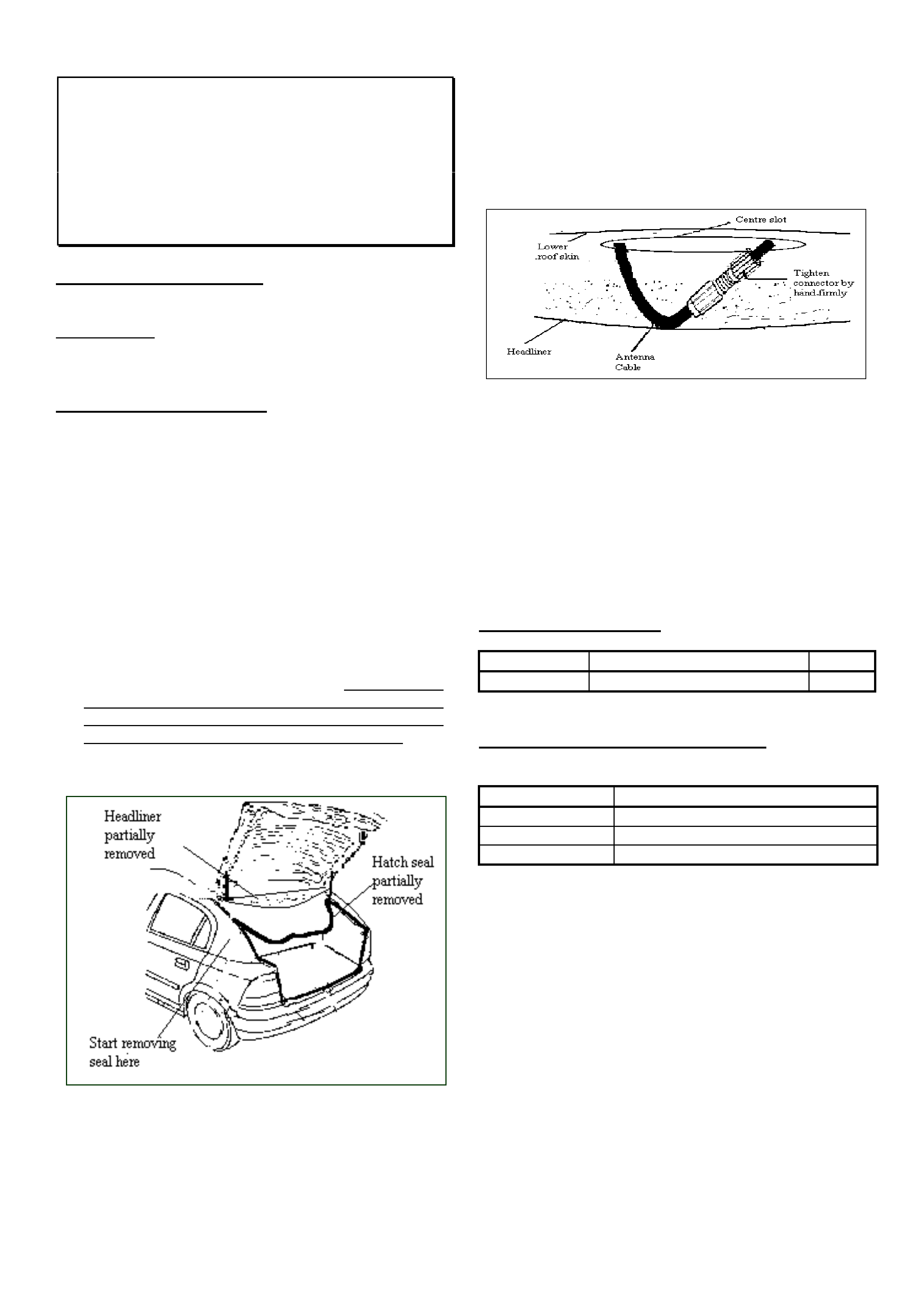
HOLDEN SERVICE TECHLINE_______________________________________________________________JULY, 2002
15
Poor “AM” Radio Reception – Loose Roof
Antenna Connector
TS, TT, JS wagon/hatch, JR Hatch, TR
GSi, SB
(GROUP 12) TL308-0207
PROBLEM DESCRIPTION
Investigation of complaint vehicles has shown that the
primary cause of poor “AM” radio reception on vehicles
with roof mounted antenna is a loose antenna
connection in the roof cavity.
SERVICE RECTIFICATION
Rectification can be achieved by tightening the antenna
connector as per the following procedure.
Although this procedure is for a TS Hatch, it will be
similar for most other models.
1. Access To Antenna Connection
• Remove rear parcel shelf.
• Partially remove the weather seal from the upper
section of the hatch opening. Refer Figure 1.
• Remove rear interior light/hand grip fittings from
headlining both sides.
• Lower the head lining at rear edge to allow access
to antenna base connection. NOTE: Failure
to remove the rear light/grip fittings could result in
the headlining being fractured whilst trying to access
the antenna base connection in the roof cavity.
Figure 1
2. Tightening Connector
• Locate the antenna connector inside the centre slot
of the lower roof skin. Refer Figure 2
• Remove all the foam tape from around the connector
and then tighten threaded type fitting firmly by hand.
Figure 2
3. Re-Assembly And Final Checks
• Start the engine, set radio to the AM band and check
that the reception is clear. Confirm reception is still
clear when wriggling the connector.
• Apply several turns of foam tape to connector prior to
reinstalling in roof cavity.
• Refit all remaining components.
PARTS INFORMATION
Part No.: Description: Qty:
90148142 Foam tape - roll 1
WARRANTY CLAIM INFORMATION:
For vehicles covered by warranty use the following:
Description Roof Antenna Connector -Tighten
Labour Op. No. N000315
Time 0.5 Hrs
Failure Code 27
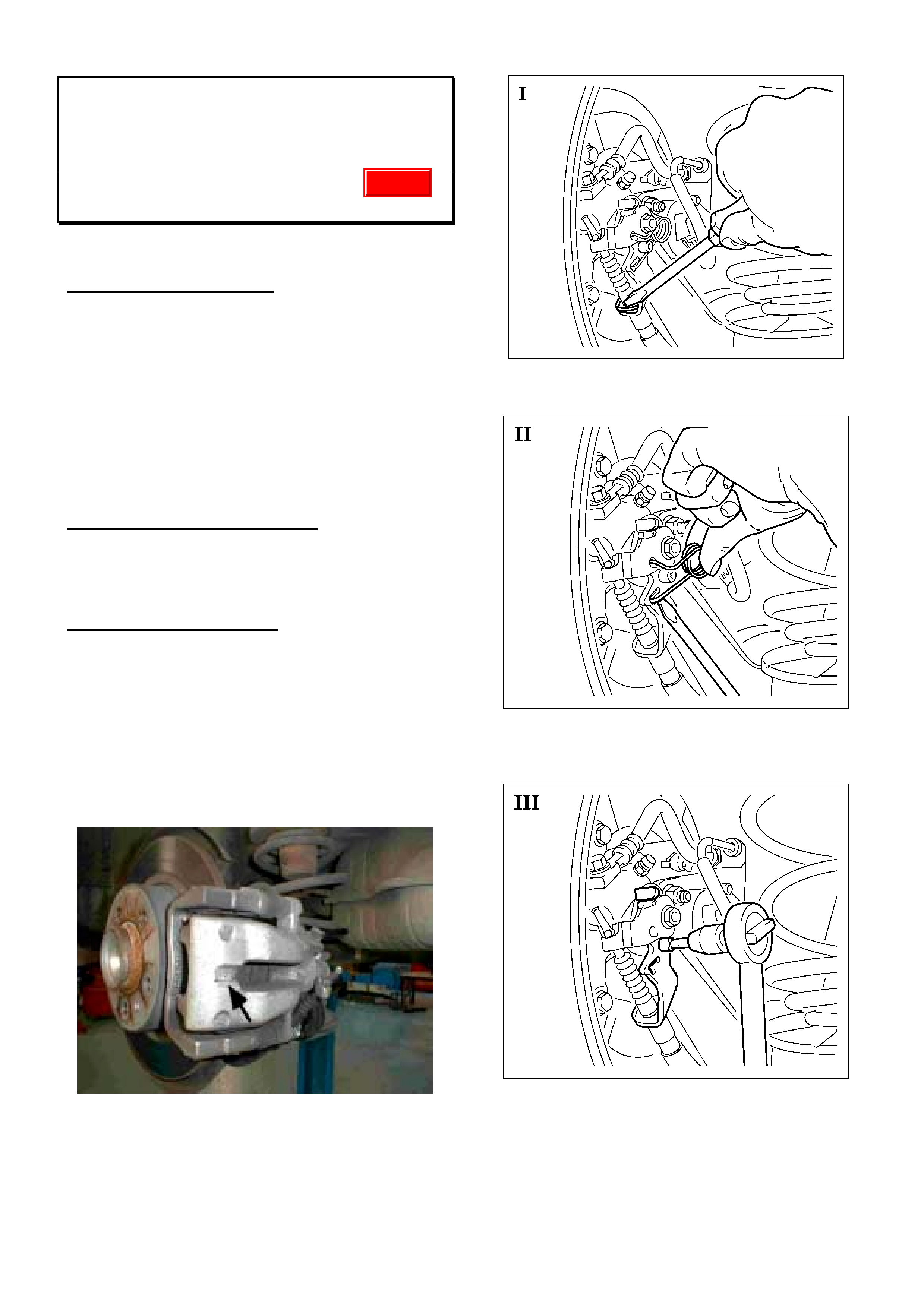
HOLDEN SERVICE TECHLINE_______________________________________________________________JULY, 2002
16
Rear Brake Groan/Graunch Noise
TS & TT Model Year 2002 Fitted with
LUCAS Calipers
(GROUP 5) REVISED TL294A-0206
This Techline supercedes the previous one in Issue 6, July,
02. It is revised by adding Production Rectification
information.
PROBLEM DESCRIPTION
A groan/graunch noise coming from rear of vehicle on
brake application or takeoff at carpark speeds: viz;
• in reverse on application of brakes
• in drive on application of brakes
• in drive on release of brakes
This noise should not be confused with a squeal..
Squeal is high frequency, a groan/ graunch is low
frequency.
Cause
Brake caliper excitation at low vehicle speeds.
PRODUCTION RECTIFICATION
Vehicles have been fitted with revised parking brake
cable guides (mass damper type) from ISOVIN:
W0L0TGF3535043736
SERVICE RECTIFICATION
Summary: On complaint vehicles, install revised
parking brake cable guides (with mass damper) onto
rear “LUCAS” brake calipers.
NOTE: This fix is not applicable to the BOSCH
calipers.
Procedure:
Before proceeding, confirm the vehicle has LUCAS
calipers. The name LUCAS is cast into the caliper in
the location shown with arrow in following photograph.
1. Remove parking brake cable retaining clip. Refer
Figure 1.
2. Remove actuating lever return spring. Refer Figure II.
3. Loosen parking brake cable guide attaching screw.
Refer Figure III.
Update
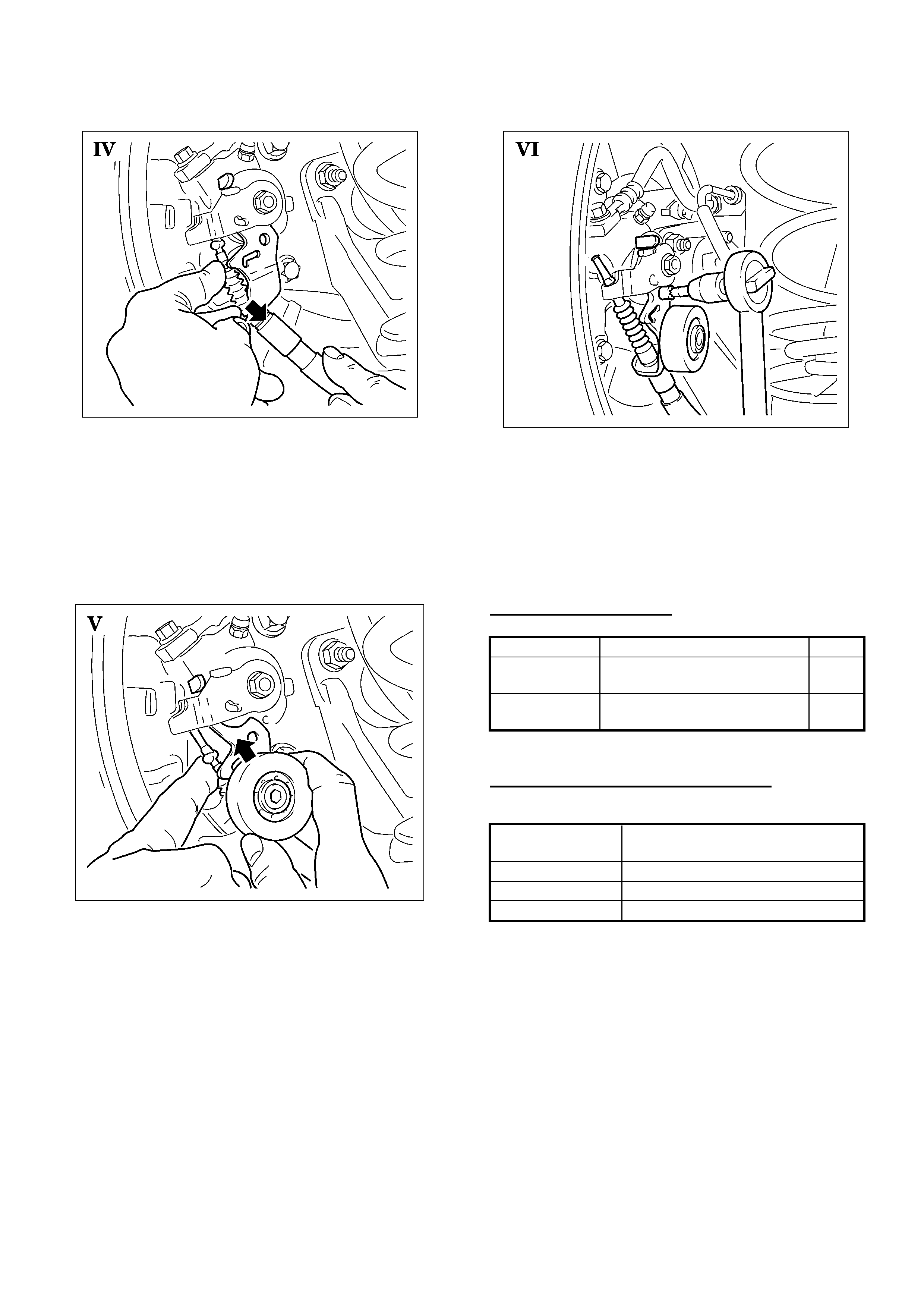
HOLDEN SERVICE TECHLINE_______________________________________________________________JULY, 2002
17
4. Release parking brake cable guide with parking
brake cable from caliper. Refer Figure IV.
5. Pull parking brake cable out of parking brake cable
guide.
6. Install parking brake cable into new parking brake
cable guide with mass damper.
7. Install new guide and parking brake cable onto
brake caliper as shown in Figure V.
8. Install new attaching screw to caliper.
Torque - 9-11 Nm. Refer Figure VI.
9. Reinstall return spring of actuating lever.
10. Reinstall securing clip onto parking brake cable.
11. Lower vehicle.
12. Check adjustment of parking brake as per procedure
in TIS. Adjust as required.
PARTS INFORMATION
Part No.: Description: Qty
93174517 Parking brake cable guide
with damper - left side .
1
93174518 Parking brake cable guide
with damper - right side .
1
WARRANTY CLAIM INFORMATION
For warranty claims use following:
Description Install Park Brake Cable Guide -
Mass Damper Type – both sides
Labour Op. No. H000237
Time 0.4 hr
Failure Code 40
HOLDEN SERVICE TECHLINE_______________________________________________________________JULY, 2002
18
“Moan” Noise From Rear Cross Member
at 105–110 km/h
VX with Gen III V8 & A/T
(GROUP 4) TL311-0206
NOTE: Zone authorisation is required before
replacing a cross member for the condition
described in this bulletin.
PROBLEM DESCRIPTION
Some vehicles may exhibit a “moan” or “drone” noise
at 105-110km/h, which is similar to an exhaust
resonance or “cavity boom”.
This noise may be caused by excitation of the rear
suspension cross member by input of various
drivetrain and tyre related vibrations.
PRODUCTION RECTIFICATION
Revised cross members with vibration dampers are to
be fitted to vehicles (with Gen III V8) in production.
At the time of release of this bulletin, no breakpoint
information was available. Breakpoint advice will be
provided in future Breakpoint Summary.
SERVICE RECTIFICATION
Positive rectification of this condition relies on good
diagnosis.
The “moan” or “drone” noise occurs:
- between 105km/h and 110km/h
- at constant throttle for some distance
- travelling on a straight road.
When the condition occurs, steer the vehicle from side
to side – within the lane the vehicle is travelling in – if
the condition varies significantly, the condition is
confirmed.
The condition should not be confused with any exhaust
or other driveline vibration or resonance that will NOT
be reduced by this steering input!
On confirmation of this condition – contact TAS for
loading of a case, and availability of a revised cross
member (Refer Parts Information for details).
TAS will confirm diagnosis, and if required, arrange the
supply of a revised cross member.
Once TAS have confirmed the need for a cross
member – you MUST contact your Zone Office for
authorisation to carry out this task.
After obtaining Zone authorisation, fitting the cross
member, and road testing to confirm that the condition
is corrected – contact TAS immediately to close the
TAS case.
PARTS INFORMATION
At the time of release of this bulletin, a specially
manufactured cross member (fitted with vibration
dampers) is available only from TAS. This cross
member will only be made available through TAS, after
a TAS case is loaded, and the condition is confirmed.
When production parts are available, an updated
bulletin will be released providing part numbers of the
new cross member assemblies, cross member service
parts, and service information.
When replacing cross members observe the
procedures outlined in the SIP CD.
WARRANTY CLAIM INFORMATION
When fitting the cross member described above
(supplied via TAS) use the following information:
NOTE: ZONE AUTHORISATION IS REQUIRED
Description Cross Member - Replace
Labour Op. No. F000179
Time 3.6 hrs
Failure Code 36
Update
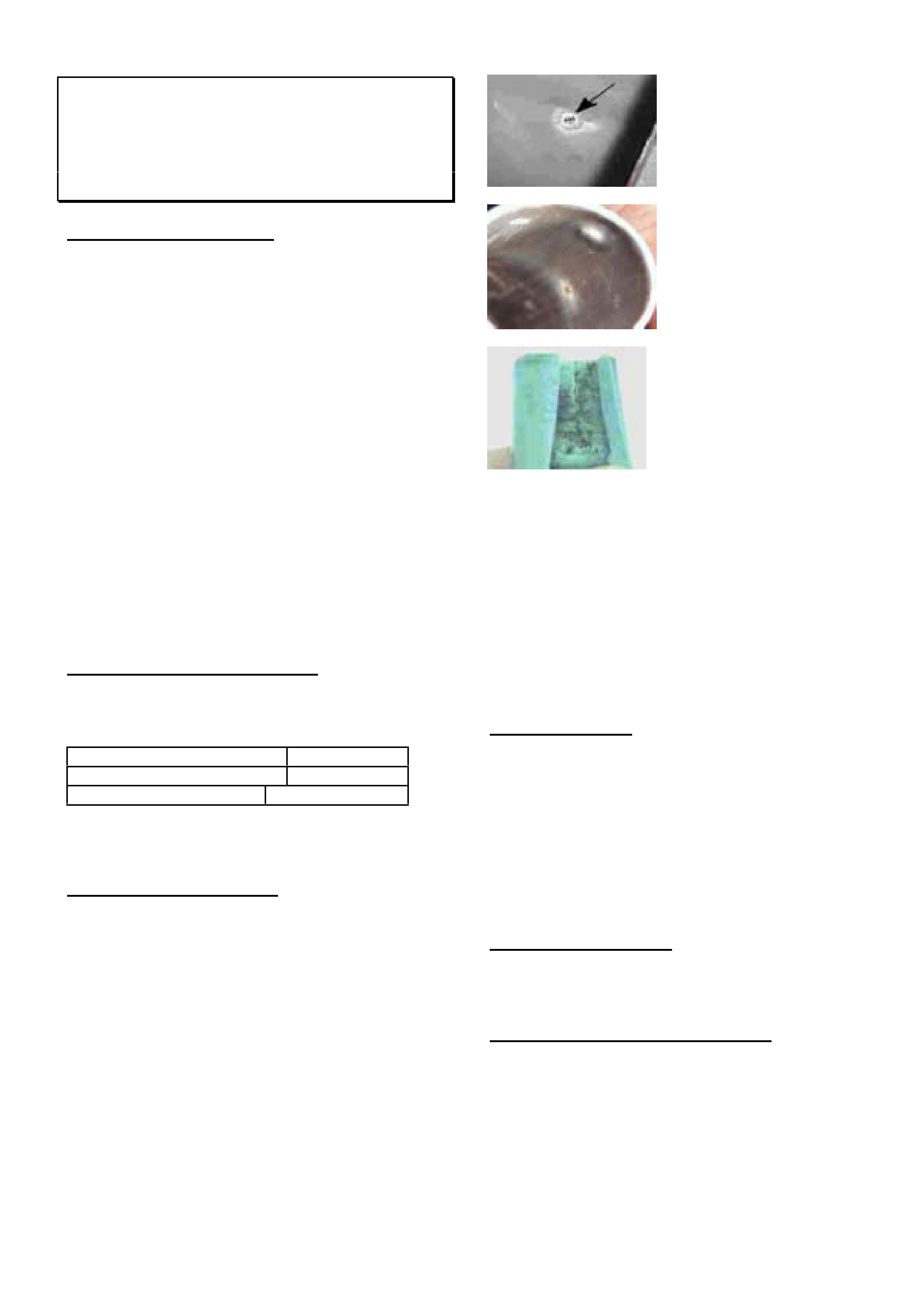
HOLDEN SERVICE TECHLINE_______________________________________________________________JULY, 2002
19
Spark Plug Lead Revisions
WH, VX, VU, V2 – All with V6 Engine
(GROUP 6Y) TL312-0206
PROBLEM DESCRIPTION
Complaints of misfire have been received. These have
been caused by arcing of the high tension lead to
cylinder head as a result of:
- Grease breaking down boot material, resulting
in lead shorting/arcing to heat shield;
and/or
- Excessive boot distortion from the spark plug
lead heat shield spring retaining tabs and
locating dimples
To overcome these conditions, a new grease and
revised heat shields have been introduced.
The new grease is green in colour, and its composition
will not degrade the boot material as the previous
grease did.
The heat shield has been revised in several areas to
improve performance in:
- fit to the spark plug boot,
- pressure applied to the boot,
- heat shield spring position.
PRODUCTION RECTIFICATION
Spark plug leads with the revised heat shields have
been fitted to vehicles from:
ISOVIN: Build Date:
6H8VXK69R2L851016 05/04/02
For Ref – Engine No.: VR213384
NOTE: The upgraded grease was added earlier at
L700356, 05/03/01 prior to heat shield changes.
SERVICE RECTIFICATION
When investigating misfire complaints, if the cause is
not immediately evident,:
1. Inspect the spark plug boots for holes/cracks inside
the boots ( photos 1 & 2) as well as for “tracking”
inside boot (photo 3).
Photo 1. View of inside
of plug boot, showing
boot pin hole.
Photo 2. View of inside
of heat shield, showing
shield arcing witness
marks
Photo 3. Boot cut open
to show “tracking”
2. When arcing marks, holes in boots and/or boot
“tracking” are found – replace the full set of spark
plug leads.
3. Inspect spark plugs for carbon “tracking” – black lines
etched into the porcelain of the plug If these tracking
marks will not clean off with a clean rag – replace the
spark plugs that are affected.
NOTE: Should any engine be found with a number of
the latest design spark plug leads fitted – replace only
the earlier design leads!
Lead Identification:
For identification of the latest design spark plug leads
(via heat shield revisions) refer to the photographs on
following page.
Earlier design heat shields, Type 1 and Type 2 were
used as an interim “fix” until the latest design heat
shields were available. Spark plug leads only need to
be replaced as described in “Service Rectification”
above.
PARTS INFORMATION
HSPO now carry stock of the revised spark plug leads.
Part numbers of spark plug leads have not changed.
WARRANTY CLAIM INFORMATION
Use Labour Times information in Warranty Information
section of current PV SIP CD.
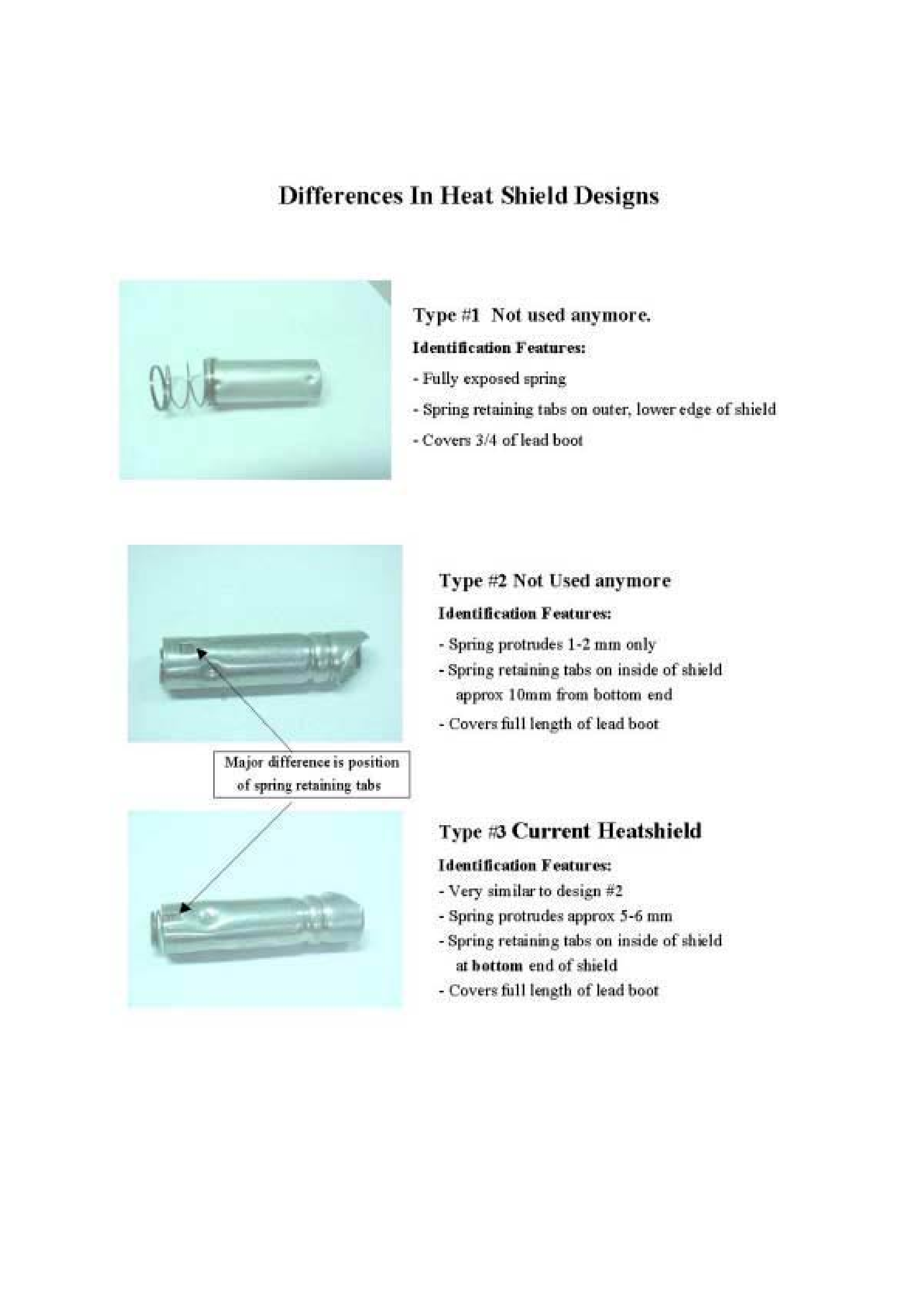
HOLDEN SERVICE TECHLINE_______________________________________________________________JULY, 2002
20
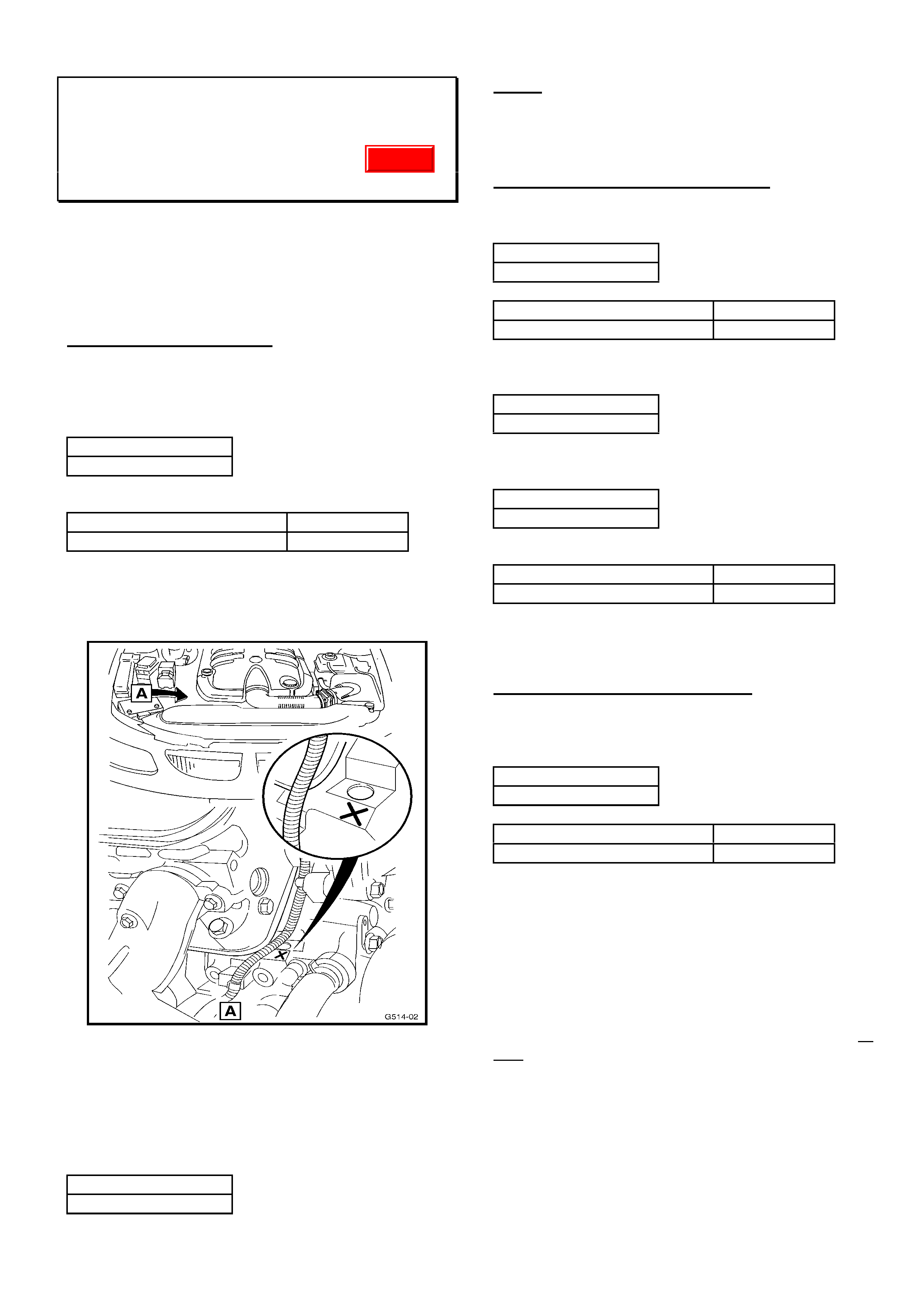
HOLDEN SERVICE TECHLINE_______________________________________________________________JULY, 2002
21
Engine Improvements
Gen III V8
(GROUP 6A) TL296-0296
This bulletin provides information on the major
improvements and revisions made to Gen III V8
engines.
This information will be found useful during service and
repair of these engines.
Revised Oil Pick-up Tube
M/T engines (only) were fitted with a revised oil pick-up
tube; and a revised low oil pressure warning lamp
calibration was applied to vehicles from:
Engine No.:
VF002021193
For Reference, this engine was used in:
ISOVIN: Build Date:
6H8VXK69F1L656328 02/11/00
These M/T engines (and any M/T engines fitted with
the revised pick-up in service) are identified by the “X”
mark, stamped on the cylinder block, as shown below:
The revised oil pick-up is now the only oil pick-up
available from HSPO.
All engines (IE: M/T & A/T) were fitted with revised oil
pick-up tube, and revised low oil pressure warning
lamp calibration from:
Engine No.:
VF011010001
No ISOVIN is available for this engine.
NOTE: From Engine No. VF011010001 – the “X”
stamp mark identifier was no longer used, as all
engines from that breakpoint contain the revised oil
pick-up.
Revised Oil Dipstick & Oil Volume
M/T 225kW/255kW engines were fitted with an
additional 0.5 litre of oil and a revised oil dipstick from:
Engine No.:
VF002700933
For Reference, this engine was used in:
ISOVIN: Build Date:
6H8VXK69F1L675354 13/12/00
All M/T & A/T 225kW/255kW engines carried these
revisions from:
Engine No.:
VF011080001
No ISOVIN is available for this engine.
All 300kW engine carried these revisions from:
Engine No.:
VF002850599
For Reference, this engine was used in:
ISOVIN: Build Date:
6H8VXL69F1L671675 08/12/00
The revised dipstick can be identified by part number
92065825 stamped on the dipstick.
Revised Pistons & Piston Rings
Engines with M/T were fitted with revised pistons (with
a friction resistant coating) and piston rings with revised
ring tension from:
Engine No.:
VF012350476
For Reference, this engine was used in:
ISOVIN: Build Date:
6H8VUK80F2L785247 15/10/01
These pistons are identified by a plain aluminium piston
finish and two rectangular friction coating patches on
the skirts.
The piston rings are identified by a small groove in the
underside of the second compression ring (earlier rings
were a plain rectangular section).
Note: a small number of engines were built with an
alternative design piston with a grey colour finish all
over, and two rectangular friction coating patches on
the skirts).
If repairing an engine for any reason, it is
recommended that these pistons be replaced with the
latest design pistons ex-HSPO.
Update
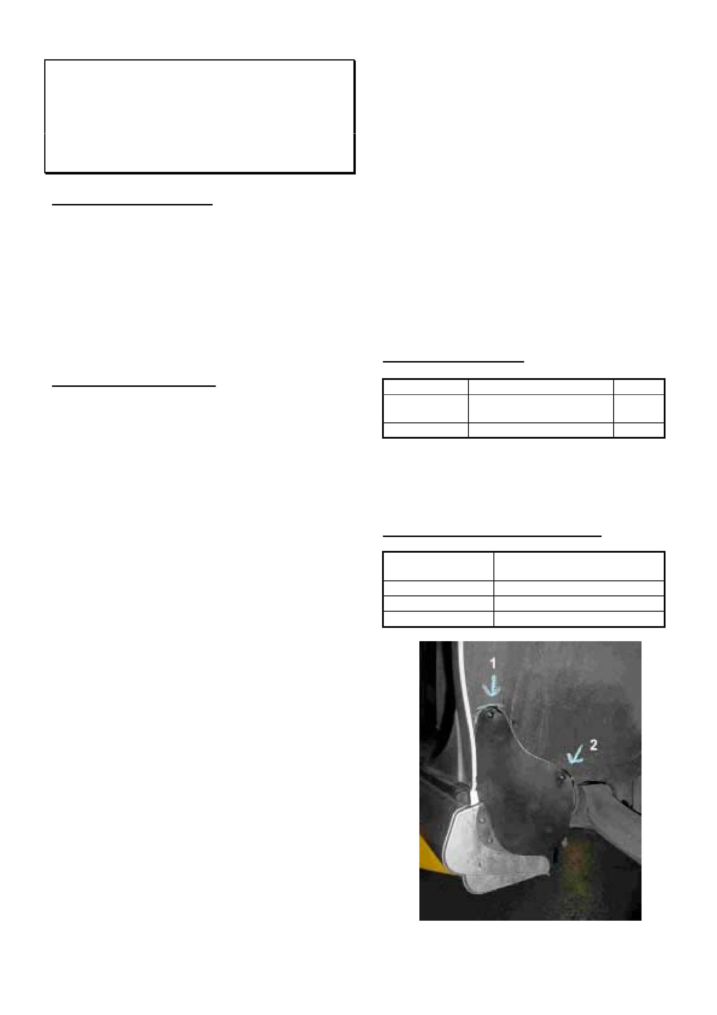
HOLDEN SERVICE TECHLINE_______________________________________________________________JULY, 2002
22
Stone Entry into Rocker Panel Skirts -
Sports Body Kit
VT, VX, “S” and “SS” models
(GROUP 1) TL284-0206
PROBLEM DESCRIPTION
There have been isolated customer complaints of a
“sliding rock” type noise under heavy braking or
acceleration.
The cause of this condition is stones/road debris
thrown up in the rear wheel arch which bypass the
rocker skirt end caps. Once inside the rocker skirts,
they may move about under heavy braking or
acceleration.
SERVICE RECTIFICATION
Summary: Install rubber covers in rear wheel arch.
1. Raise vehicle on hoist.
2. Remove rear wheels.
3. Remove rocker skirt rear endcap.
4. Remove rocker skirt forward end attaching screws
5. Remove all stones /debris from the inside area of the
rocker skirt. This can be done by hosing out with
water or compressed air from the forward end.
Removal of debris could be improved by lowering
the vehicle to the ground and then raising the front
only so that gravity assists.
6. Clean the wheelhouse inner panel in area where
rubber cover will be fitted. Use water and a brush.
Location is shown in Figure 1.
7. Using template provided (refer page 23), cutout two
stone covers from sheets of EPDM rubber as
specified in Parts Information. NOTE, the same
shape is reversed to form the opposite hand
wheelhouse cover.
8. After surface has dried from step 6, wash cleaned
area with Prepwash or equivalent.
9. Place the Left Hand cutout cover into position and
install the end cap and endcap screws to hold
cover in position.
10. Mark outline of cover onto wheelhouse liner with
chalk. Refer Figure 1.
11. Pull back cover and apply a continuous bead of
urethane 20mm in from the chalk outline.
12. Press cover into bead of urethane and apply two
attaching screws 92138399 in two places as shown
in Figure 1. Screw 1 is into body (apply urethane
to screw head to seal). Screw 2 goes through
flange. Apply urethane to head of screw 1. Pilot
holes should carefully be drilled for both screws.
13. Smooth off any urethane that squeezes out.
14. Insert narrow flap into rocker panel cavity as shown
in Figure 2.
15. Align lower edge of end cap to end of rocker skirt
and fix in position (2 places) with self tapper screw
92138399. Refer Figure 2.
16. Repeat process for opposite side wheelhouse.
17. Reinstall all components.
PARTS INFORMATION
Part No.: Description: Qty:
92143609 Urethane – 300ml
tube.
1
92138399 Screw self tapper 8
EPDM rubber sheets 300 x 210 x 3mm thick can be
obtained from most Blackwood/A.E. Baker & Co.
stores.
WARRANTY CLAIM INFORMATION
Description Fit rocker skirt stone covers
to rear wheelhouse liner.
Labour Op. No. C000467
Time 1.0 hr
Failure Code 28
Figure 1.

HOLDEN SERVICE TECHLINE_______________________________________________________________JULY, 2002
23
Figure 2.
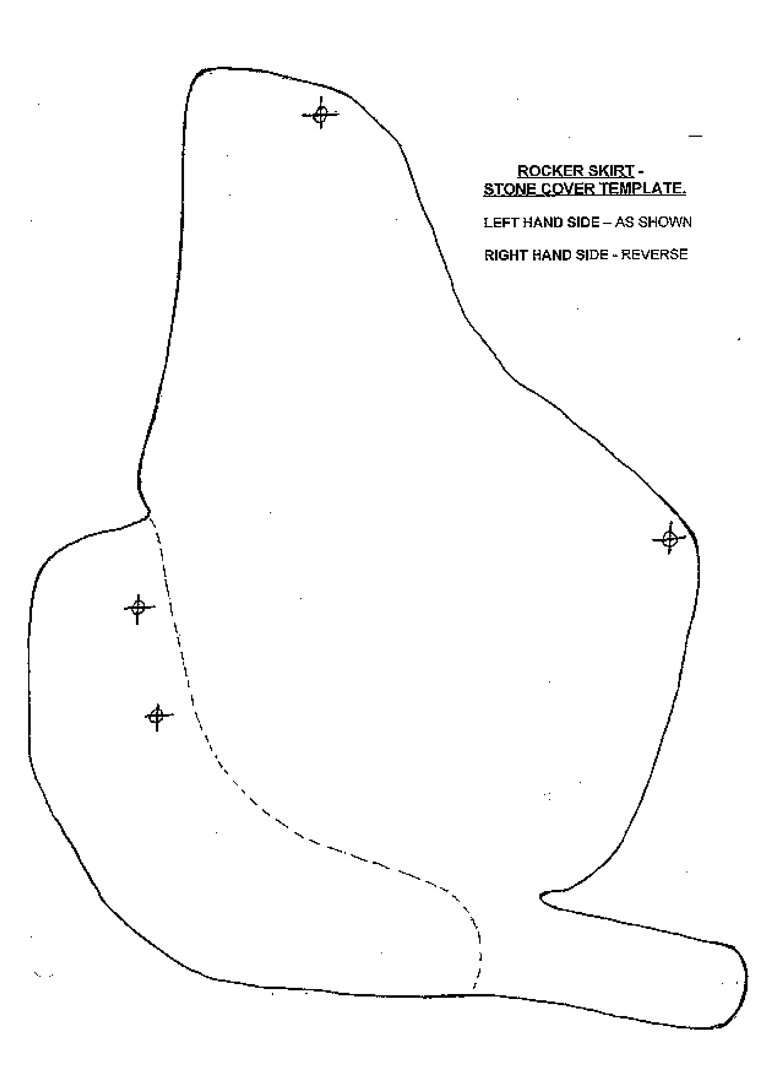
HOLDEN SERVICE TECHLINE_______________________________________________________________JULY, 2002
24

HOLDEN SERVICE TECHLINE_______________________________________________________________JULY, 2002
25
Electronic Modules - Resetting Procedure
TS, TT, XC, JS (Y26SE)
(GROUP 6C) TL317-0206
This Service Techline supersedes the previous Techline
on this topic (Issue 10, December, 1999 page 11) with
additional models, procedure application and warranty
caution.
For the attention of Technicians & Warranty
Administrators:
A number of Repac returned ECU’s, BCM’s and
Instruments have not been reset’ as per the reset
procedure below. This makes it impossible for correct
testing to be carried out.
When the need arises to replace an engine control
module in these vehicles, technicians should be aware of
the requirement to reset the security feature of the
module prior to removing it from the vehicle.
If the module is not reset prior to removing it, the module
remains security linked to that specific vehicle and
cannot be reprogrammed until reset accordingly.
This procedure is necessary on warranty replaced
modules – which must be reset to allow Holden to
investigate cause of failure.
Similarly, the same procedure should be followed when
installing a module from another vehicle, or where
dealership stock is used to confirm diagnosis.
This procedure applies to the following engine types:
X18XE1
Z18XE
Z14XE
Y26SE
Z22SE
This resetting requirement must also be applied to XC
Body Control Module (BCM) and Instruments before
return to Repac.
Engine Control Module Resetting Procedure
The engine control unit must always be reset in the
vehicle it was initially programmed to.
1. Connect TECH 2 and select the following.
2. F0: Diagnostics/Model year/✷✷✷✷✷/F3: Body/
Immobiliser
(at “/✷✷✷✷✷/” - select vehicle model)
3. F3: Additional Functions
4. F2: Reset Engine Control Module
5. When security code is requested, enter security
code and press enter.
6. When you have entered the correct security code
press okay to proceed.
7. The following warning will appear, “Warning: Engine
will not start after reset! Do this only before replacing
the Engine Control Module” . Press the CONFIRM
soft key at the base of the TECH 2 screen to
continue.
8. Program Completed, the engine control module is
now reset, press the CONFIRM soft key at the base
of the TECH 2 screen to exit.
WARRANTY CLAIM INFORMATION
ECU’s, BCM’s and Instruments NOT reset using the
above procedure will no longer be accepted by Repac.

HOLDEN SERVICE TECHLINE________________________________________________________________ AUGUST, 2002
6
Thump Noise From HVAC Case - (Mode
Door Slamming)
VT, WH with 5-Pack Vacuum Solenoid
Modules
(GROUP 2) TL309-0207
This Techline is only for those vehicles fitted with the 5-
pack vacuum solenoid module.
For vehicles fitted with the 6-pack vacuum solenoid
module refer to Techline in Issue 11, November 2001.
PROBLEM DESCRIPTION
A light “thump” or “bang” noise may be heard from the
HVAC case when the ECC system automatically
changes mode or when manually operated , and is
more pronounced in the face to foot mode change. It is
also noticeable when the ignition is turned off.
The cause of this “thump” noise is the rapid closing of
the mode door.
SERVICE RECTIFICATION
Summary: After confirming vehicle is built with 5-pack
solenoid vacuum module, install vacuum delay kit part
number 92144219.
To confirm if vehicle is fitted with 5-pack or 6-pack
solenoid vacuum module, refer to the following
breakpoint information:
NOTE: All vehicles built up to the following breakpoints
were fitted with the 5-pack solenoid vacuum modules.
VT Berlina: (Single zone system)
ISOVIN: Build Date:
6H8VTL69HYL514226 07/10/99
VT Calais & WH (Dual Zone system)
ISOVIN: Build Date:
6H8VTX69HYL513521 06/10/99
All vehicles built after the above breakpoints were fitted
with the 6 solenoid vacuum module.
After confirming vehicle has 5-pack solenoid module
proceed to fit Vacuum delay kit 92144219 as follows.
1. Remove console side covers.
2. Locate the floor vacuum actuator on underside of
HVAC with the orange and red(pink) vacuum
tubes.
3. Cut the red(pink) vacuum tube on an angle. Cut
the supplied rubber vacuum hose into 30mm
lengths and attach to the delay valve ports.
Connect the valve between the cut vacuum tubes
with the white side of the delay valve facing
towards the vacuum actuator. Refer to Figure 1.
4. Locate the Face vacuum actuator on underside of
HVAC with the white and green vacuum tubes.
5. Cut the white vacuum tube on an angle. Install the
delay valve between the cut white tubes as shown
in Figure 1. Ensure the white side of the delay
valve is facing towards the vacuum actuator.
6. Ensure that installed parts do not interfere with any
actuating rods or levers.
7. Refit all removed components and retest.
PARTS INFORMATION
Obtain following parts from HSPO:
Part No.: Description: Qty
92144219 Vacuum delay pack (2 delay
valves, tube & instructions)
1
WARRANTY CLAIM INFORMATION
Description Install vacuum delay valves
to mode actuators
Labour Op. No. D000333
Time 0.8 hr
Failure Code 40
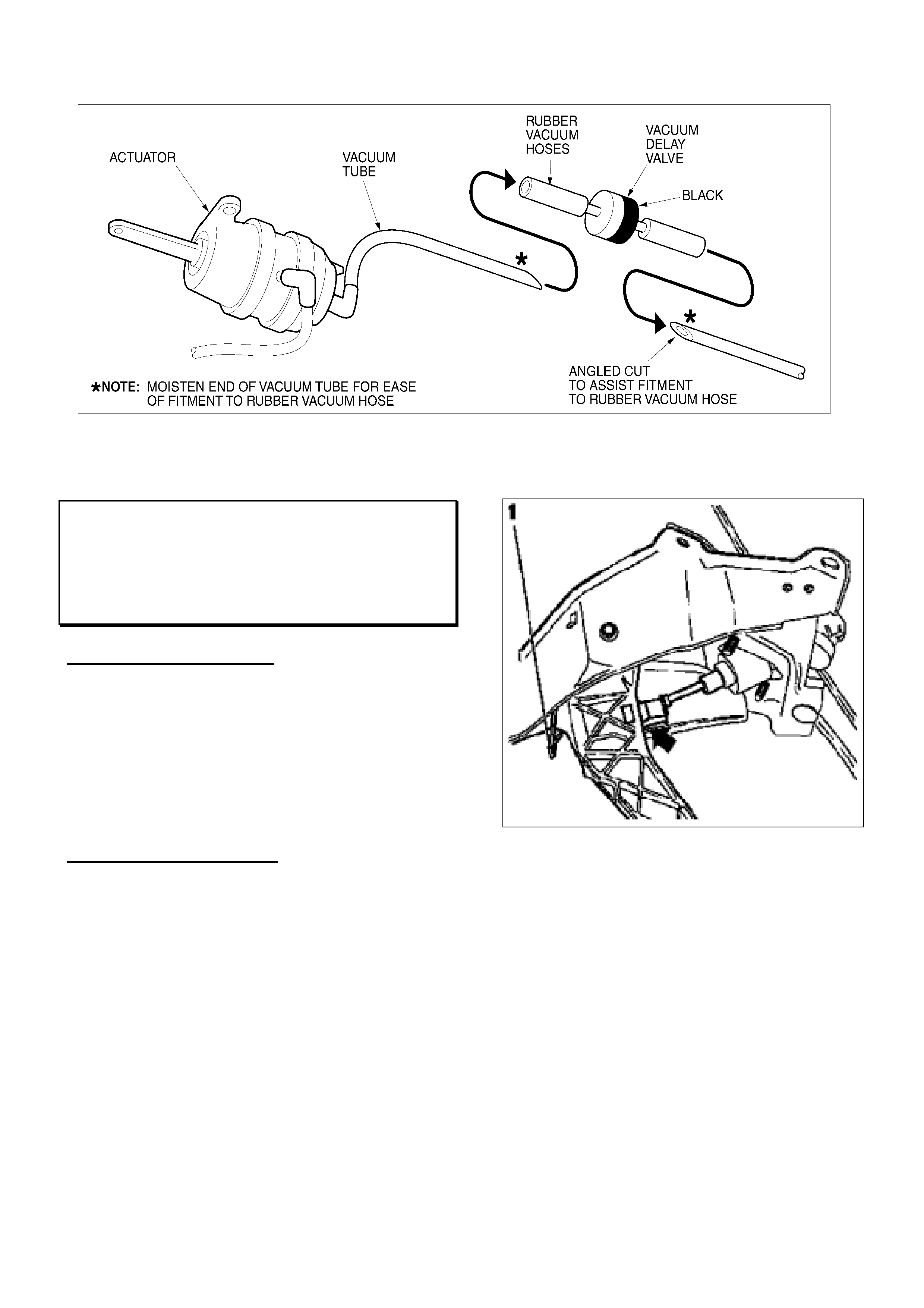
HOLDEN SERVICE TECHLINE________________________________________________________________ AUGUST, 2002
7
Figure 1.
Clutch Pedal Squeak
XC Barina
(GROUP 7A) HINT TL304-0207
PROBLEM DESCRIPTION
Clutch pedal squeaks when it is depressed.
Investigation of complaint vehicles has shown the main
causes for this condition are:
A. Lack of lubrication in push-rod/clutch pedal pivot.
B. Loose attaching nuts – clutch pedal support
bracket to bulkhead and/or clutch master cylinder.
SERVICE RECTIFICATION
Summary: Lubricate pivot and check tightness of
attaching nuts.
A. Lubrication of push-rod / pedal pivot.
Use a directional nozzle on a container of lithium spray
grease part number M39760 to apply a liberal amount
of grease to the white nylon pivot which houses the
master cylinder push-rod. Refer arrow in Figure1.
Figure 1.
B. Check attaching nuts (Refer Figure 2)
• clutch pedal support bracket to bulkhead. (Nut # 5
– three places)
• clutch master cylinder to support bracket. (Nut # 6
– two places)
Torque all nuts to 20 Nm.
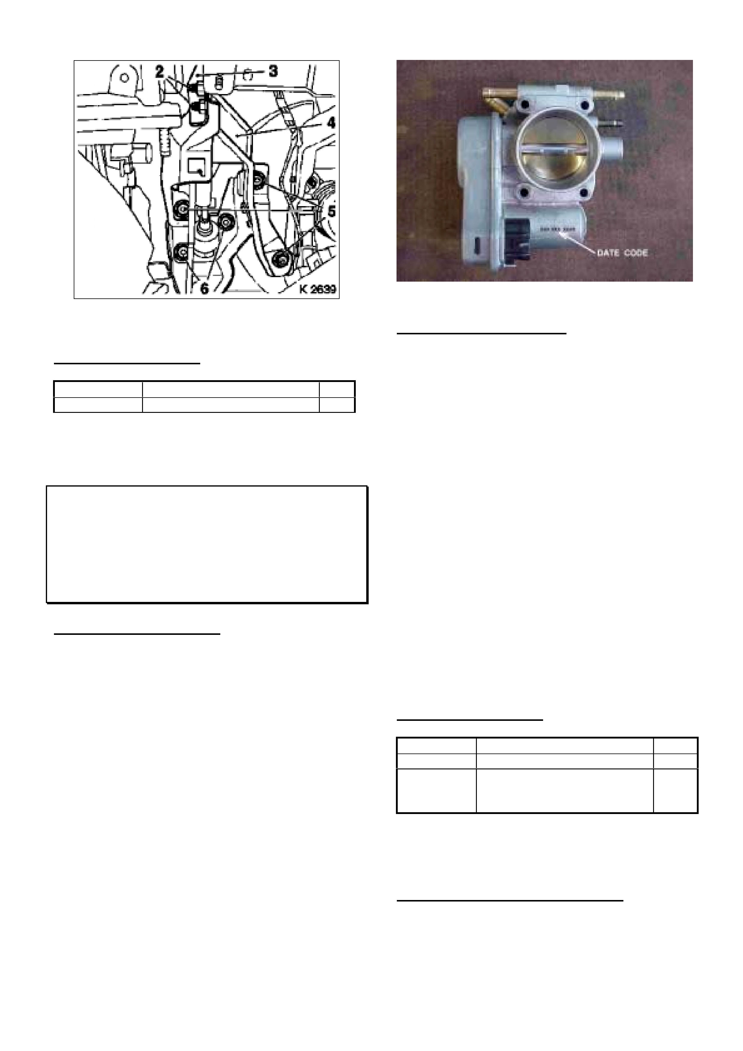
HOLDEN SERVICE TECHLINE________________________________________________________________ AUGUST, 2002
8
Figure 2.
PARTS INFORMATION
Part No.: Description: Qty
M39760 Spray Grease -350gm can 1
Throttle Control Malfunction – DTC’s
P0120, P1500, P1550
XC, TS, (Z14XE , Z18XE engines)
(GROUP 6C) TL257-0207
PROBLEM DESCRIPTION
Complaints of Engine will not rev, no throttle response,
or engine stalling in conjunction with one or more of
the following trouble codes stored in the ECU:
• P1500: Electronic throttle control motor failure.
• P1550: Electronic throttle control reduced power,
forced idle, power management or engine stop.
• P0120: Throttle position sensor circuit #1 voltage
high/low.
The above conditions may occur in throttle bodies with
a manufacturing date code prior to “354- 01B”.
Where: 354 = day of year
01 = Year
B = shift
Figure 1 shows the position of the date code markings.
NOTE: The 4 digits after the date code are to be
ignored.
Figure 1.
SERVICE RECTIFICATION
On any vehicle with above symptoms proceed as
follows:
1. Check throttle body date code as shown in
Figure 1. If date code is prior to 354-01B, proceed
to step 2.
NOTE: Some examples of date codes prior to 354-
01B are 256-01A, 357-00B etc.
If the date code is later than 354-01B contact TAS
for assistance.
2. Clear all Diagnostic Trouble Codes from ECU.
3. Remove old throttle body as per procedure in TIS.
4. Install new throttle body with production date code
after 354-01B. Ensure new gasket is installed.
5. Reset learnt values in ECU.
6. Ensure no new diagnostic trouble codes are stored
in ECU.
PARTS INFORMATION
Part No. Description Qty
09192122 Throttle body asm. Z14XE 1
09196357 Throttle body asm. Z18XE 1
90572766 Gasket Z14XE 1
90543950 Gasket Z18XE 1
NOTE: All stocks of throttle bodies in HSPO are
manufactured after the breakpoint date code.
WARRANTY CLAIM INFORMATION
Use Labour Times information in Warranty Information
section of current PV SIP CD
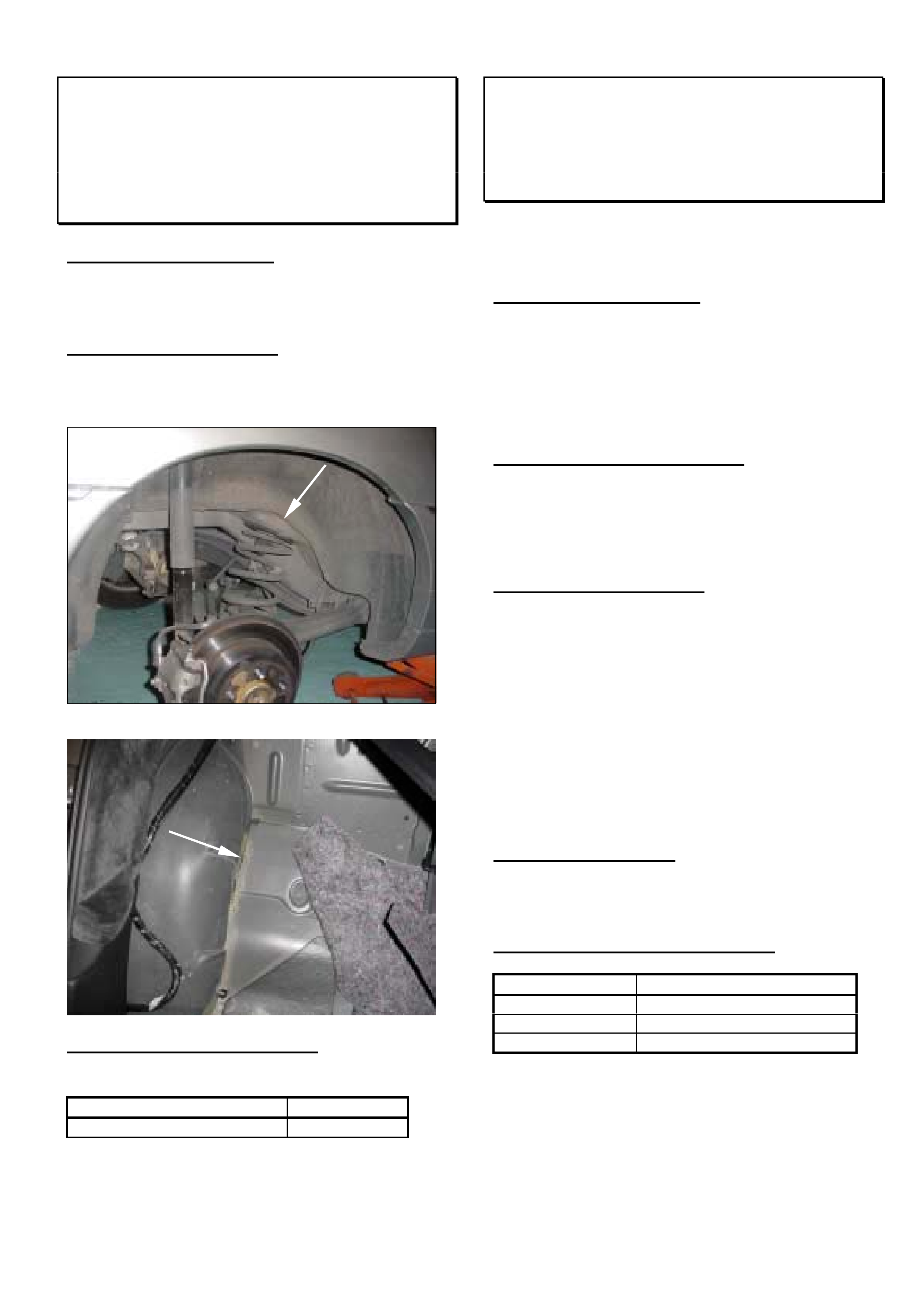
HOLDEN SERVICE TECHLINE________________________________________________________________ AUGUST, 2002
9
Water Leaks – Rear Wheelhouse Body
Seams
WH
(GROUP 1) “HINT” TL327-0207
PROBLEM DESCRIPTION
Some customers may complain of a damp rear seat
cushion
SERVICE RECTIFICATION
Remove the rear wheel, rear seat cushion and rear
seat back and inspect the following body seams for
possible water entry locations. Add sealer as required.
PRODUCTION RECTIFICATION
Additional spot welds have been added to the seam
from.
TAG: Build Date:
L893835 17/07/02
Please report via PIR any complaints seen after this
breakpoint.
HVAC Case Whistle
VT/VX/VU/V2/WH
(GROUP 2) REVISED TL213A - 0207
This Techline supersedes the previous one in Issue
1/2002. It is revised by correcting the phone number
for Air International.
PROBLEM DESCRIPTION
A number of PIRs have been submitted to Holden
describing a whistle noise from the HVAC case.
Dealer investigation has revealed the fresh recirc door
has not closed completely, resulting in the whistle
noise.
PRODUCTION RECTIFICATION
Engineering are investigating design changes to the
blower housing to eliminate this complaint.
Breakpoints will be advised once they have been
struck.
SERVICE RECTIFICATION
In the interim, dealers are able to contact the HVAC
supplier for a service fix to address this complaint in
customer’s vehicles. This fix involves installing a self
adhesive foam pad that seals the fresh recirc door
completely.
If a customer presents their vehicle with this complaint,
please contact:
Air International Pty Ltd
Phone: 1800 673 716
and request a Service Fix pack for this complaint.
PARTS INFORMATION
Contact Air International directly on the number above
and refer to Air International Service Bulletin HMC-92.
WARRANTY CLAIM INFORMATION
Description Fit HVAC Whistle Fix Kit
Labour Op. No. D000330
Time 0.5 hr
Failure Code 40
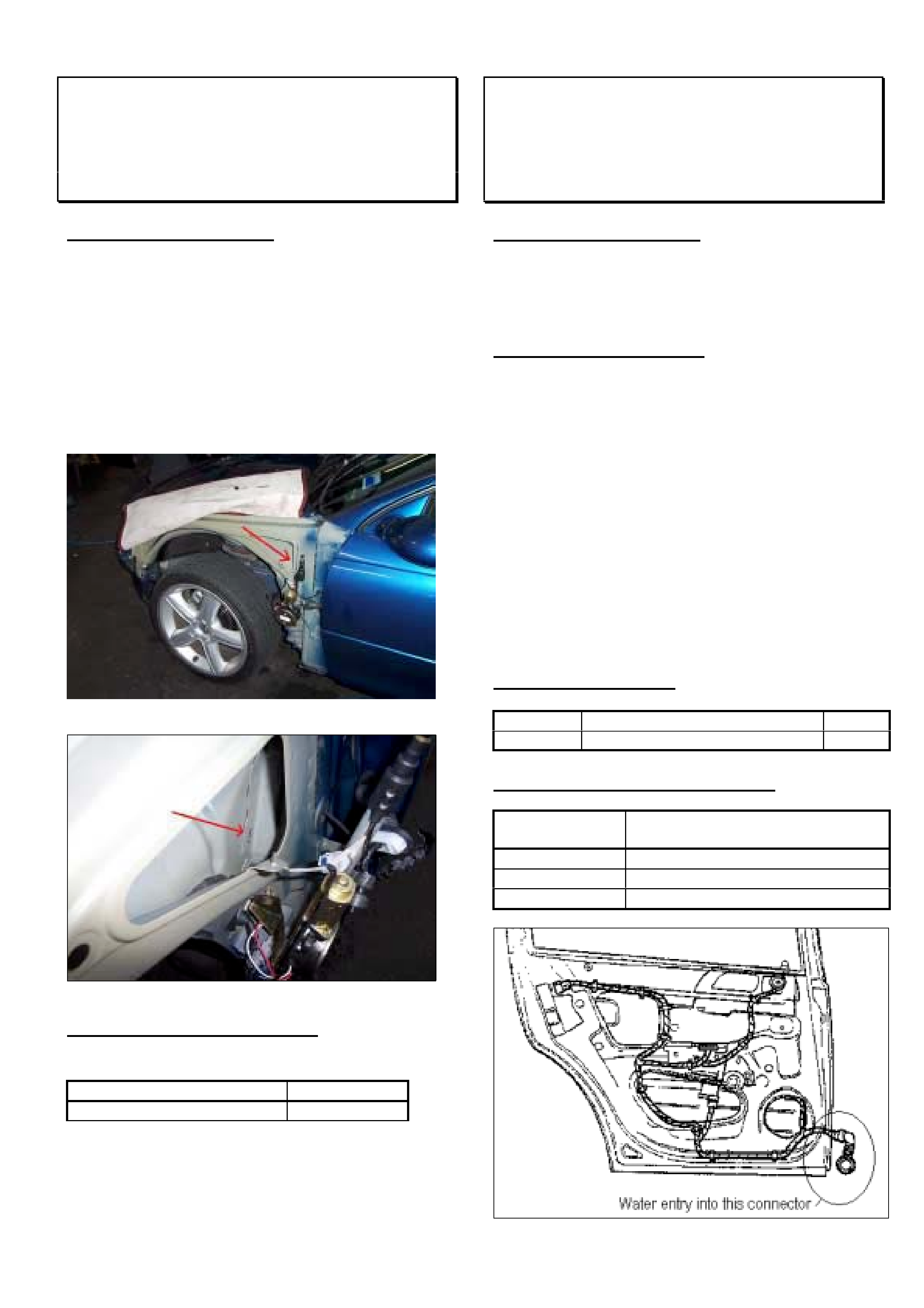
HOLDEN SERVICE TECHLINE________________________________________________________________ AUGUST, 2002
10
Passenger Side Rocker Panel Water Entry
V2 MONARO
(GROUP 1) HINT TL328-0207
PROBLEM DESCRIPTION
Some customers may complain of a “sloshing” sound
from the passenger side rocker panel/sill while
accelerating or braking
Investigation of complaint vehicles showed water entry
to rocker sill via the panel seams as shown in the
following photographs.
If you have a vehicle with the above condition remove
the left-hand guard and inspect for gaps in the seam as
shown in photographs. Fill any gaps with sealer.
PRODUCTION RECTIFICATION
The body sealing process in the area shown above was
modified from:
ISOVIN: Build Date:
6H8V2X37F2L881204 19/06/02
Please report via PIR any complaints seen after this
breakpoint.
Rear Power Windows Malfunction – Water
In Door Connector
TS Astra CD Model
(GROUP 12) TL319-0207
PROBLEM DESCRIPTION
There have been isolated reports of inoperative rear
power windows on the above model which has been
traced to water entry into the rear door connector
located as shown in Figure below.
SERVICE RECTIFICATION
Summary: Remove water from connector and seal
with electrical insulating grease.
1. On complaint vehicles remove water from the
connector halves using compressed air. If
possible, use a hair dryer to remove all traces of
moisture from the connectors. DO NOT USE a
heat gun for this procedure.
2. Apply grease M40347 (No 4 Electrical Insulating
Compound) to both halves of connector.
3. Reconnect connector and check window operation.
If windows fail to operate the connector may be
corroded in which case the harness will require
replacement.
PARTS INFORMATION
Part No.: Description: Qty
M40347 Silicone Grease - 150g tube 1
WARRANTY CLAIM INFORMATION
Description Dry connector and seal with
specified grease – both rear doors
Labour Op. No. N000390
Time 0.3 hr
Failure Code 51 electrical connector problem
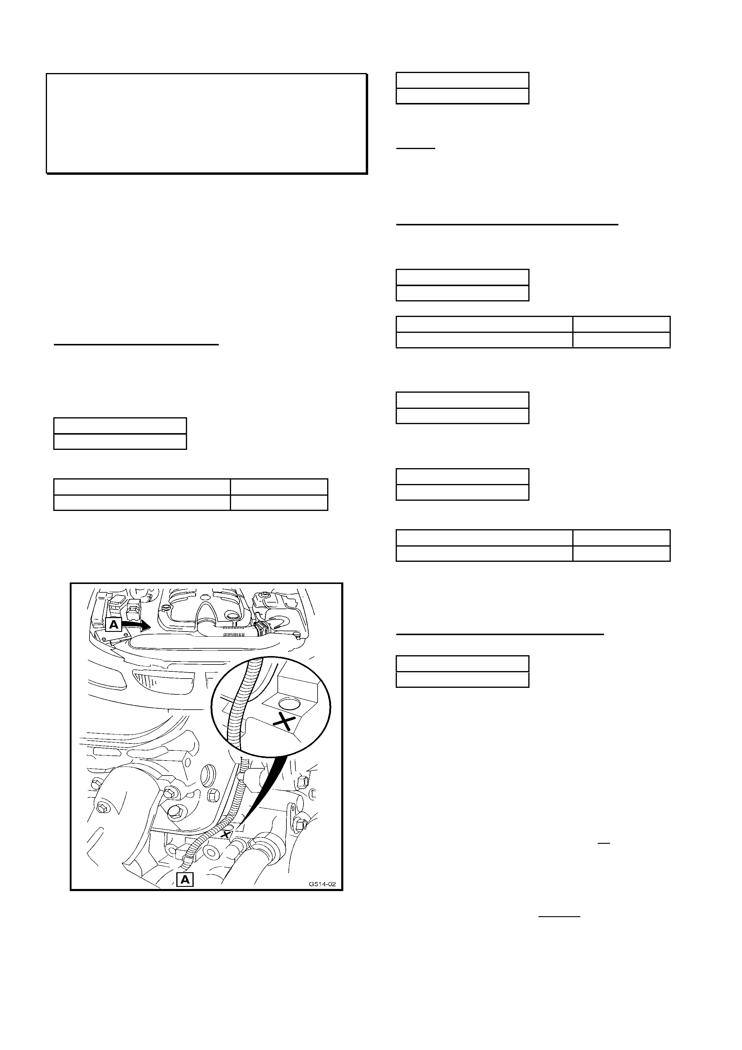
HOLDEN SERVICE TECHLINE_______________________________________________________________SEPTEMBER, 2002
7
Engine Improvements
Gen III V8
(GROUP 6A) “REVISED” TL296A-0208
This Techline supercedes the previous one in Issue 6,
2002. It is revised by clarifying the breakpoint for
engines with revised pistons and rings.
____________________________
This bulletin provides information on the major
improvements and revisions made to Gen III V8
engines.
This information will be found useful during service and
repair of these engines.
Revised Oil Pick-up Tube
M/T engines (only) were fitted with a revised oil pick-up
tube; and a revised low oil pressure warning lamp
calibration was applied to vehicles from:
Engine No.:
VF002021193
For Reference, this engine was used in:
ISOVIN: Build Date:
6H8VXK69F1L656328 02/11/00
These M/T engines (and any M/T engines fitted with
the revised pick-up in service) are identified by the “X”
mark, stamped on the cylinder block, as shown below:
The revised oil pick-up is now the only oil pick-up
available from HSPO.
All engines (IE: M/T & A/T) were fitted with revised oil
pick-up tube, and revised low oil pressure warning
lamp calibration from:
Engine No.:
VF011010001
No ISOVIN is available for this engine.
NOTE: From Engine No. VF011010001 – the “X”
stamp mark identifier was no longer used, as all
engines from that breakpoint contain the revised oil
pick-up.
Revised Oil Dipstick & Oil Volume
M/T 225kW/255kW engines were fitted with an
additional 0.5 litre of oil and a revised oil dipstick from:
Engine No.:
VF002700933
For Reference, this engine was used in:
ISOVIN: Build Date:
6H8VXK69F1L675354 13/12/00
All M/T & A/T 225kW/255kW engines carried these
revisions from:
Engine No.:
VF011080001
No ISOVIN is available for this engine.
All 300kW engine carried these revisions from:
Engine No.:
VF002850599
For Reference, this engine was used in:
ISOVIN: Build Date:
6H8VXL69F1L671675 08/12/00
The revised dipstick can be identified by part number
92065825 stamped on the dipstick.
Revised Pistons & Piston Rings
All engines from:
Engine No.:
VF012350476
were fitted with revised pistons (with a friction resistant
coating) and piston rings with revised ring tension.
These pistons are identified by a plain aluminium piston
finish and two rectangular friction coating patches on
the skirts.
The piston rings are identified by a small groove in the
underside of the second compression ring (earlier rings
were a plain rectangular section).
This upgraded engine was introduced in manual trans.
vehicles from 15/10/01 and in all vehicles from
18/12/01.
Note: a small number of engines were built, earlier than
the above breakpoint, with an alternative design piston
with a grey colour finish all over, and two rectangular
friction coating patches on the skirts).
If repairing an engine for any reason, it is
recommended that these pistons be replaced with the
latest design pistons ex-HSPO.
HOLDEN SERVICE TECHLINE_______________________________________________________________SEPTEMBER, 2002
8
“Moan” Noise From Rear Cross Member at
105–110 km/h
WH, VX with Gen III V8 & A/T
(GROUP 4) REVISED TL311A-0208
This Techline supersedes the previous one in Issue
6/2002. It is revised by adding WH model and
production breakpoint.
NOTE: ZONE AUTHORISATION IS REQUIRED
BEFORE REPLACING A CROSS MEMBER FOR THE
CONDITION DESCRIBED IN THIS BULLETIN.
PROBLEM DESCRIPTION
Some vehicles may exhibit a “moan” or “drone” noise at
105-110km/h, which is similar to an exhaust resonance
or “cavity boom”.
This noise may be caused by excitation of the rear
suspension cross member by input of various drivetrain
and tyre related vibrations.
PRODUCTION RECTIFICATION
Revised cross members with vibration dampers have
been fitted to vehicles (with Gen III V8) from:
ISOVIN: Build Date:
6G1HM52FX3L908900 23/08/02
SERVICE RECTIFICATION
Positive rectification of this condition relies on good
diagnosis.
The “moan” or “drone” noise occurs:
- between 105km/h and 110km/h
- at constant throttle for some distance
- travelling on a straight road.
When the condition occurs, steer the vehicle from side
to side – within the lane the vehicle is travelling in – if
the condition varies significantly, the condition is
confirmed.
The condition should not be confused with any exhaust
or other driveline vibration or resonance that will NOT
be reduced by this steering input!
On confirmation of this condition – contact TAS for
loading of a case, and availability of a revised cross
member (Refer Parts Information for details).
TAS will confirm diagnosis, and if required, arrange the
supply of a revised cross member.
Once TAS have confirmed the need for a cross
member – you MUST contact your Zone Office for
authorisation to carry out this task.
After obtaining Zone authorisation, fitting the cross
member, and road testing to confirm that the condition
is corrected – contact TAS immediately to close the
TAS case.
PARTS INFORMATION
At the time of release of this bulletin, a specially
manufactured cross member (fitted with vibration
dampers) is available only from TAS. This cross
member will only be made available through TAS, after
a TAS case is loaded, and the condition is confirmed.
When production parts are available, an updated
bulletin will be released providing part numbers of the
new cross member assemblies, cross member service
parts, and service information.
When replacing cross members observe the
procedures outlined in the SIP CD.
WARRANTY CLAIM INFORMATION
When fitting the cross member described above
(supplied via TAS) use the following information:
NOTE: ZONE AUTHORISATION IS REQUIRED
Description Cross Member - Replace
Labour Op. No. F000179
Time 3.6 hrs
Failure Code 36
Update

HOLDEN SERVICE TECHLINE_______________________________________________________________SEPTEMBER, 2002
9
Rear Wheel Bearing Failure
SB Barina
(GROUP 4) TL337-0208
PROBLEM DESCRIPTION
Some isolated reports of rear wheel bearing failure
after servicing have been received from the field.
SERVICE RECTIFICATION
Ensure the service procedure in TIS2000 is followed
precisely.
The grease packing and adjustment of this wheel
bearing are critical to its performance.
Poor packing or excessive preload on the bearing will
cause bearing failure in service.
To locate the procedure for adjusting the wheel
bearings in TIS2000 follow the path shown in table:
TIS Screen ê
êê
ê Select the following ê
êê
ê
Service Information Standard Information
Model Corsa-B
Year select model year for vehicle concerned
Eng. -
Vehicle
Data
Trans. -
Assembly
Group
+ F Rear axle and rear wheel suspension
+ Rear Axle Front Wheel Drive
✓
Rear wheel hub
Standard
Informati
on.
Application Repair (Remove,Install,Adjust)
Document List Adjustment operations, wheel bearing play,
adjust
ABS Modulator Damage When Replacing
Brake Pads
All Carlines with ABS
(GROUP 5) HINT TL331-0208
PROBLEM DESCRIPTION
Some complaints have been received from retailers
describing ABS Modulators internal seal damage
during replacement of brake pads.
SERVICE RECTIFICATION
When pushing brake pistons back into the caliper,
extreme care must be taken!
Caliper piston diameter is relatively large compared to
master cylinder piston diameter. This means the
caliper piston, when forced back into the caliper, is
pumping a large quantity of brake fluid back through
the system at high velocity and pressure.
In some cases, fluid under these conditions can cause
damage to ABS modulator seals.
It is essential that caliper piston retraction be done
slowly and carefully. It is preferable to use a pad
spreading tool. If using a G-clamp, an example of a
suitable slow speed would be one-quarter turn of the
handle per second.
Service Literature (SIP and TIS2000) for pad
replacement also states fluid reservoir level will
increase when pushing back caliper pistons. It is
important not to allow fluid to overflow and spill onto
paintwork.
It has been suggested that loosening the bleed nipple
on the caliper is one method of avoiding both ABS
Modulator damage and fluid overflow.
Holden does not endorse this practice for the following
reasons:
1. Customers will be charged unnecessarily for fluid
replacement if the reservoir needs to be topped up
2. Attempting to loosen the bleed nipple
unnecessarily exposes Service Departments to
associated costs if, for example, the nipple is
broken due to corrosion.
Remember – paint, caliper or ABS modulator damage
as a result of piston retraction is not a warrantable
defect and repair costs are carried by your Service
Department!
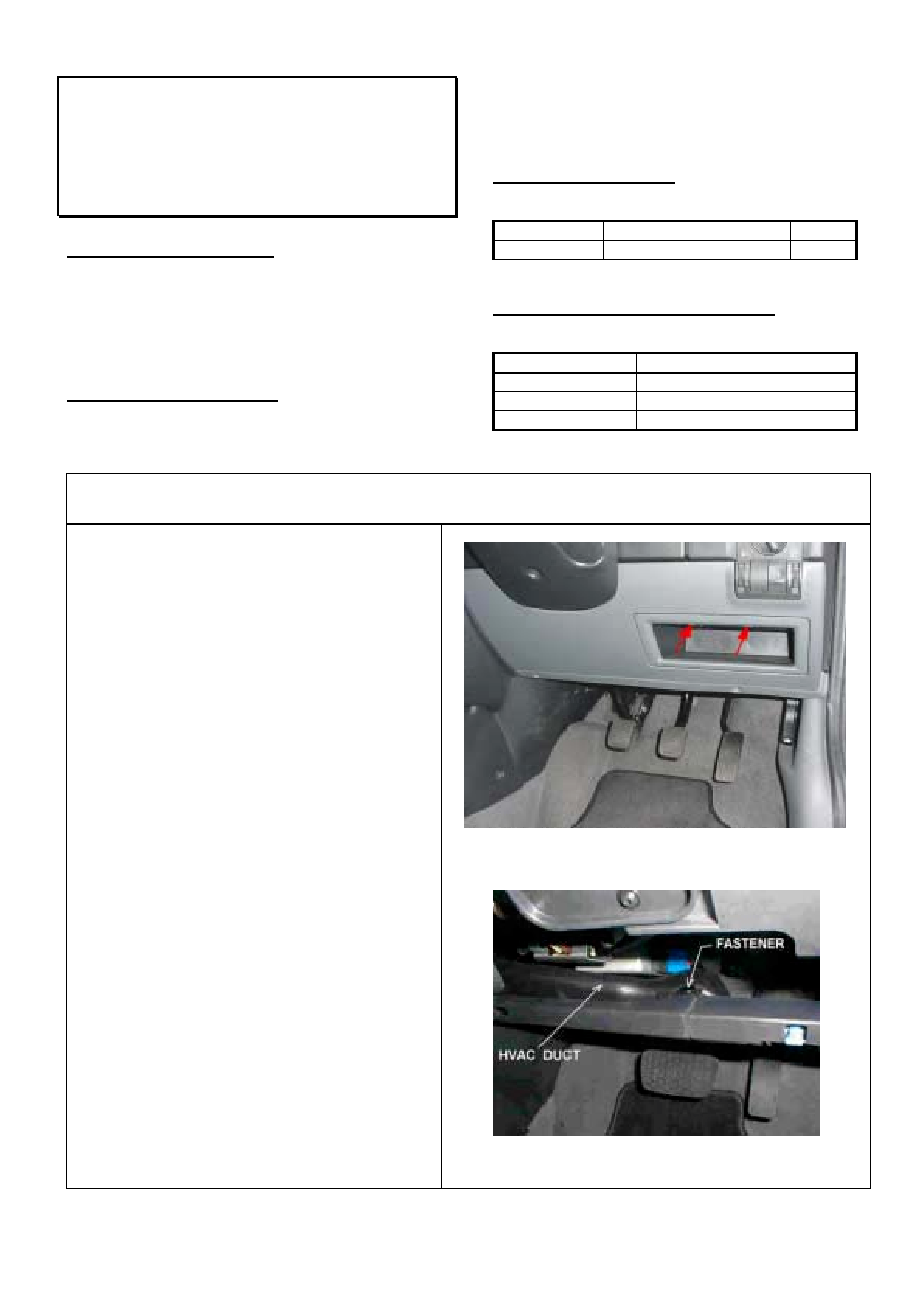
HOLDEN SERVICE TECHLINE_______________________________________________________________SEPTEMBER, 2002
10
AM Radio Reception Interference from
Electronic Power Steering Unit
XC
(GROUP 12) TL207-0208
PROBLEM DESCRIPTION
Some customers may complain of interference on the
AM radio band which is related to steering wheel
operation.
The most likely cause of this condition is “electrical
noise" generated as a result of inadequate earthing of
the Electronic Power Steering (EPS) unit .
SERVICE RECTIFICATION
On complaint vehicles, check if Service Earth Lead p/n
24462766 is fitted. If not, then install as per following
procedure.
NOTE: Please report by PIR all cases after vehicle
W0L0XCF6814141463 which require a Service Earth
Lead to rectify the complaint.
PARTS INFORMATION
Obtain the following part from HSPO.
Part No.: Description: Qty:
24462766 Earth Lead. 1
WARRANTY CLAIM INFORMATION
For vehicles covered by warranty use the following:
Description Replace EPS earth lead.
Labour Op. No. N000384
Time 0.9 hr
Failure Code 33
Procedure For Installation Of EPS Service Earth Lead 24462766
1. Trim Removal at Drivers Side.
Refer Figure 1.
a) Remove storage pocket. Insert a thin blade
screw driver into the front of each of the two
tangs (refer arrows) and lever downwards.
b) Remove RHS lower dash.
c) Remove RHS lower shroud panel.
d) Remove RHS kick panel.
2. Lower HVAC Duct Removal
a) Remove the black plastic fastener using a flat
blade screw driver. Refer Figure 2
b) Push duct slightly forward and at the same time
pull on the right hand side of the duct in a
downwards motion to the rear of the vehicle.
Figure 1– Working Environment
Figure 2 – HVAC Duct
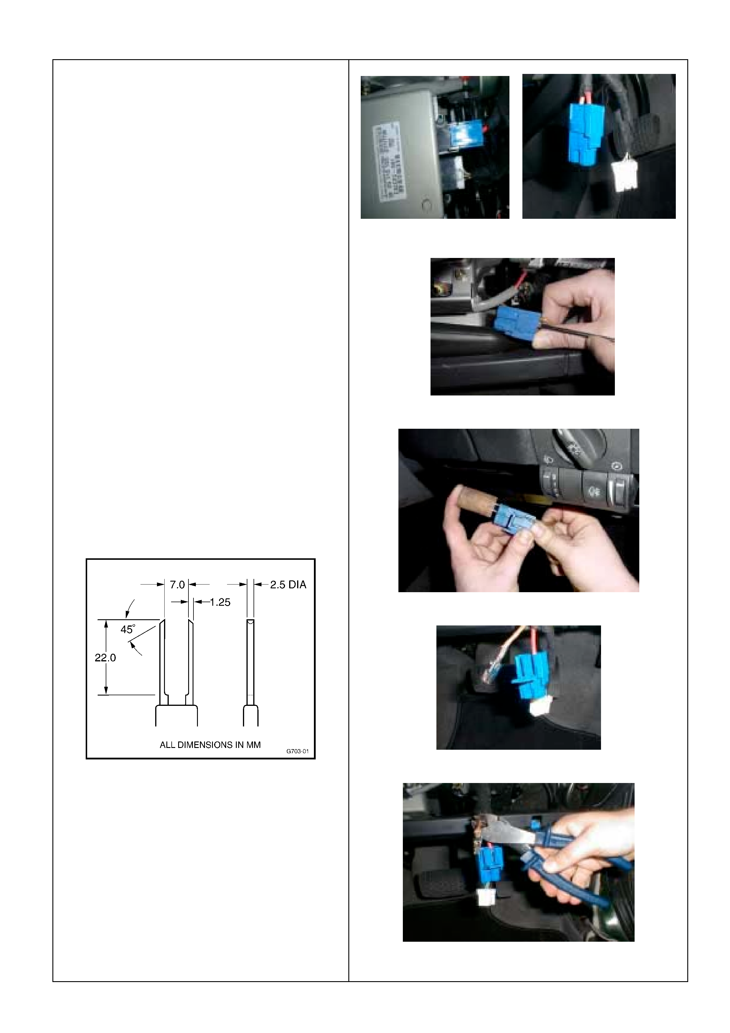
HOLDEN SERVICE TECHLINE_______________________________________________________________SEPTEMBER, 2002
11
3. Revised Earth Lead Fitment To
Electronic Power Steering (EPS)
Module.
a) Remove the blue and white plastic connectors
from the EPS module. This is done by
pressing down on the respective tangs at the
base of each connector.
Figure 3 shows in car position of EPS.
Figure 4 shows connectors detached.
b) Prise open the secondary catch of the blue
connector with a flat head screw driver. Refer
Figure 5A
c) Remove the brown (earth) wire terminal from
the blue connector using a two prong tool to
release the 2 locking tangs. Refer Figure 5B.
A handmade tool made to the following
dimensions can be used for this job. The top
section of an antenna mast is ideal for the
prongs. The prongs can then be mounted in a
piece of wooden dowel 25mm dia. by force
fitting into blind holes a little smaller than the
wire diam.
d) Cut the brown earth wire with suitable wire
cutters, just ahead of the tape.
Refer Figure 6.
Figure 3 Figure 4
Figure 5A – Open Secondary catch
Figure 5B – Releasing terminal with handmade tool
Figure 5C – Earth Wire Removed From EPS Connector
Figure 6 – Cutting earth wire
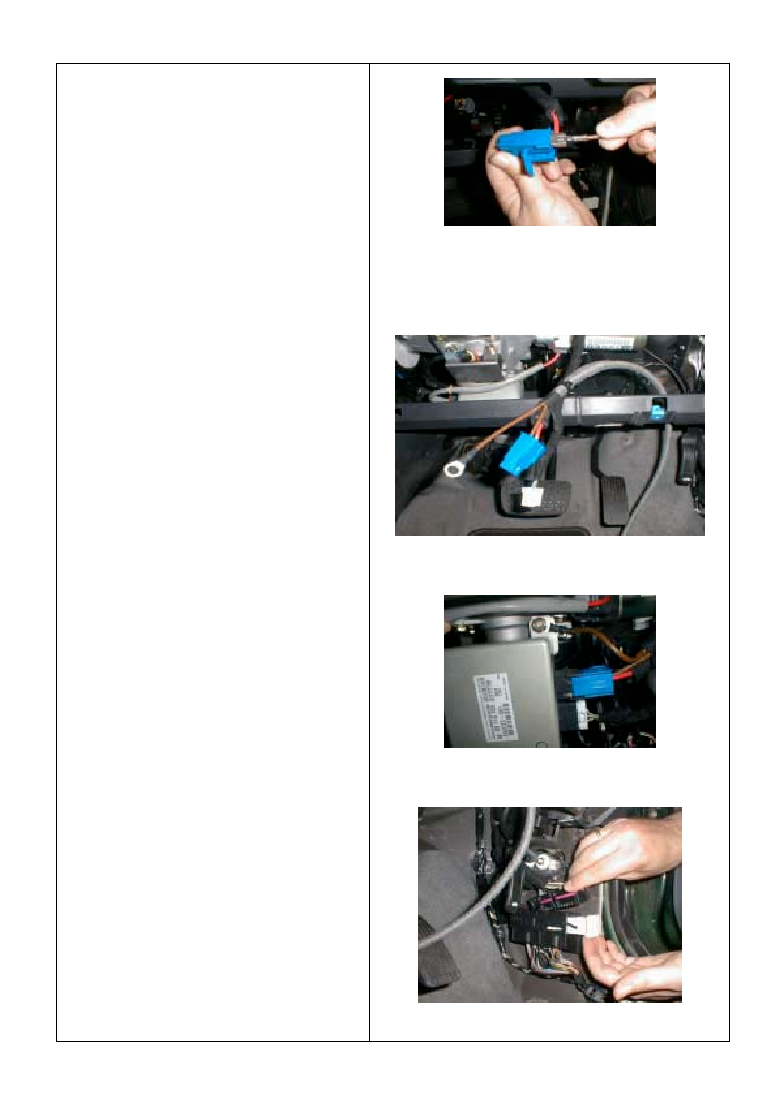
HOLDEN SERVICE TECHLINE_______________________________________________________________SEPTEMBER, 2002
12
3 continued.
e) Insert the revised earth lead connection, part
number 24462766, into the EPS connector.
Refer Figure 7.
f) Where the original earth lead is fitted to the
EPS module, remove the screw with a 10 mm
socket. Remove the brown earth lead and cut
just prior to tape. Retorque earth lead
attaching screw to 20 Nm.
g) Position the revised earth lead behind cross
beam and fix to existing wiring harness using
one (1) cable tie.
Refer Figure 8.
h) Remove the other EPS module screw and fit
earth ring terminal of revised earth lead.
Torque EPS screw to 20 Nm. Refit blue and
white EPS connectors to EPS module. Refer
Figure 9.
4. Fitment Of Revised Earth Lead To Right
Hand Kick Panel Ground
a) Release the harness connector at the right kick
panel to expose the earth nut behind the hood
release lever.
Refer Figure 10.
Figure 7 – Inserting revised earth into EPS connector
Figure 8 – Revised earth lead positioning
Figure 9 – EPS Module With Revised Earth Connected
Figure 10 – Releasing Harness Connector
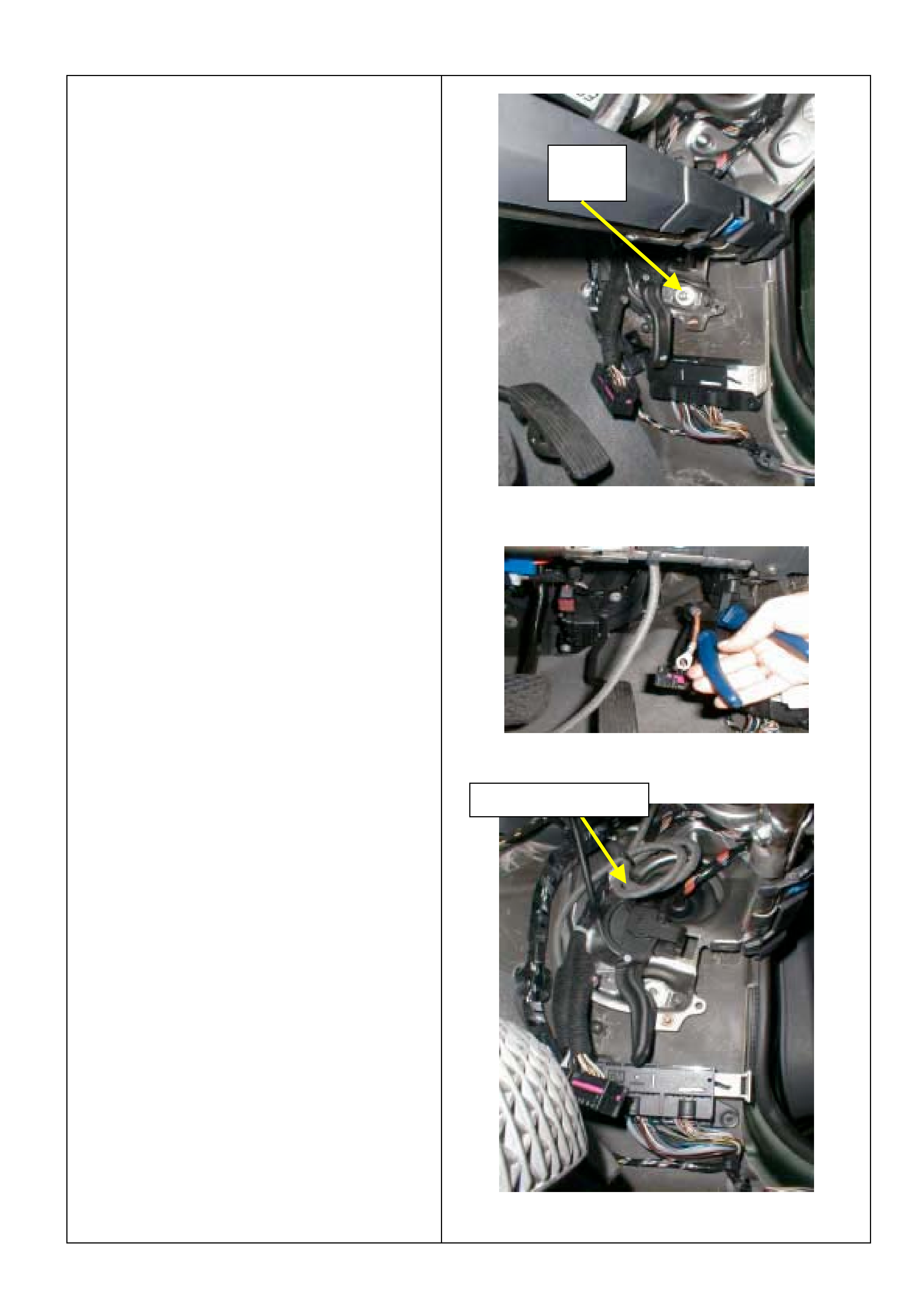
HOLDEN SERVICE TECHLINE_______________________________________________________________SEPTEMBER, 2002
13
4 continued.
b) Remove the earth nut and original earth lead
(brown wire) using a 13 mm socket and ¼ inch
drive. Refer Figure 11.
c) Cut the original earth lead with suitable wire
cutters near the junction.
Refer Figure 12.
d) Route revised earth lead along original wiring
harness and loop. Secure earth lead with cable
ties. Four (4) cable ties should be sufficient.
Refer Figure 13.
Position revised earth ring terminal at screw
location and refit nut using a 13 mm socket and
¼ inch drive.
Torque to 15 Nm (range 12 – 20 Nm).
e) Refit the harness connector and lock in position.
5. Reassemble All Trim Components
Figure 11 – Earth Screw/Lead Removal
Figure 12 – Cut Original Earth Lead At RH Kick Panel
Figure 13. Revised Earth Wire Routing
Earth
N
u
t
Revised Earth Lead

HOLDEN SERVICE TECHLINE_______________________________________________________________SEPTEMBER, 2002
14
Oil Filter Cap – Care During Removal and
Replacement (Cartridge Type)
TS & XC (X18XE1 or Z18XE Engines)
(GROUP 6A) TL342-0208
PROBLEM DESCRIPTION
PIR’s have reported damage to the oil filter cap used
on cartridge type oil filters.
Damage (cracking) will occur on oil filter housing caps
during removal if the cap is over-torqued when a filter
cartridge is replaced.
Ensure only 15Nm is applied to the filter cap
when an oil filter cartridge is replaced.
All X18XE engines are fitted with cartridge type oil
filters.
Z18XE1 engines are fitted with two types of oil filters:
• Cartridge type – which requires the removal of the
filter housing cap to remove and replace the filter
element;
• Screw-on type – which requires only the filter
assembly to be removed and replaced.
Screw-on type oil filters were introduced to
Z18XE engines from: engine No
Z18XE20V00605
SERVICE RECTIFICATION
Summary: Adhere to correct torque specification and
ONLY use the tools recommended below.
TORQUE SPEC.:
Do NOT over-torque the oil filter cap when fitting a
new oil filter cartridge.
Ensure only 15Nm is applied to the filter cap
when an oil filter cartridge is replaced.
REMOVAL TOOLS:
When removing filter housing caps on engines with
the cartridge type filter, use ONLY a 24mm ring
spanner or socket. This fully supports the cap
material and allows removal without damage to the
cap.
TIS 2000 drawings showing the use of a ratchet
handle and square drive special tool – these are
shown ONLY for the screw-on type oil filter fitted to
engines after the breakpoint shown above.
Auto Trans Shift Quality
VTII & WH (pre A8A) with Gen III
(GROUP 7B) TL333-0208
This Service Techline only applies to VTII and WH
(pre A8A) vehicles built prior to tag L626038 (start of
VX production).
For complaints on VXI & VUI, & WH with A8A - refer
to Techline in Issue 2, Mar/2002.
PROBLEM DESCRIPTION
A typical complaint transmission will exhibit a long 1-2
and/or 2-3 shift with a harsh engagement “bump” at
end of the shift.
The cause of these conditions has been traced to a
software deficiency with the calibration for the above
models.
SERVICE RECTIFICATION
On complaint vehicles, flash the latest PCM
calibration from TIS CD 32.0B or later.
WARRANTY CLAIM INFORMATION
Description Reflash PCM
Labour Op. No. J000713
Time 0.4 hr
Failure Code 43 (Shifts hard)

HOLDEN SERVICE TECHLINE_______________________________________________________________SEPTEMBER, 2002
15
Hotmelt Glue Protrudes From Under Rear
Windscreen Upper Moulding
VX, WH, V2
(GROUP 1) TL338-0208
PROBLEM DESCRIPTION
There have been isolated reports of small amounts of
hotmelt glue protruding from under the rear screen
upper moulding in high ambient conditions.
Note: This glue is used as a production assembly aid
for upper moulding retention. It is not related to the
sealing of the windscreen, therefore, windscreens
should not be removed to rectify this condition.
SERVICE RECTIFICATION
Remove bulk of glue from glass using a razor blade
mounted in a suitable holder. (e.g. paint scraper).
Take care to avoid contacting the moulding with the
razor blade.
If required, wipe any remaining residue from the
glass with Prepsol.
Dex-Cool® Coolant Name Change
All Models Using Dex-Cool®
(GROUP 6K) TL352-0208
The Dex-Cool® coolant (Holden part number
12377912) referred to in Part Finder, Owner
Handbooks, PV SIP and LCV SIP has been
superseded to the following:
"Extended life anti-freeze coolant".
Part Number 92145527 (5 litre container)
Conforms to GM specification 6277M.
The change has occurred because HSPO now obtain
this product from a local supplier. The colour of the
new coolant may vary slightly from Dex-cool but
essentially remains unchanged i.e. orange/red.
Owner Handbooks and SIP will be revised to reflect
the above change.
LSD Chatter Noise
VX, VU, WH with V6 Engine & LSD
(GROUP 4) TL339-0208
PROBLEM DESCRIPTION
LSD chatter may be heard when the vehicle is turning
left or right when travelling in a forward or reverse
direction, and is most pronounced when negotiating
tight corners at low speeds and parking manoeuvres
where differential action is initiated. Chatter may also
be experienced by the driver as a “grabbing” feel
during the operation of the LSD.
The chatter noise is caused by reduced sliding
lubrication qualities of the LSD cone friction surfaces
within the final drive unit (using the existing oil).
PRODUCTION RECTIFICATION
Differentials with revised LSD cones are scheduled to
be fitted to vehicles in early September. Vehicle
breakpoint details will be published in a future
Breakpoint Summary.
SERVICE RECTIFICATION
IMPORTANT: Do not attempt to rectify
complaint vehicles by using the V8 LSD
Chatter Kit as described in Retailer Letter
30/02.
On complaint vehicles request a changeover unit
through Spicer Axle Australia (SAA) via the
SAA will provide an exchange axle unit that has
revised LSD cones, Mobilube SHC ID synthetic oil, oil
additive and compatible seals. The supplied unit will
have an identification tag that reads “LSD USE
APPROVED LUBRICANT AND FRICTION
MODIFIER”.
established procedure.
Update
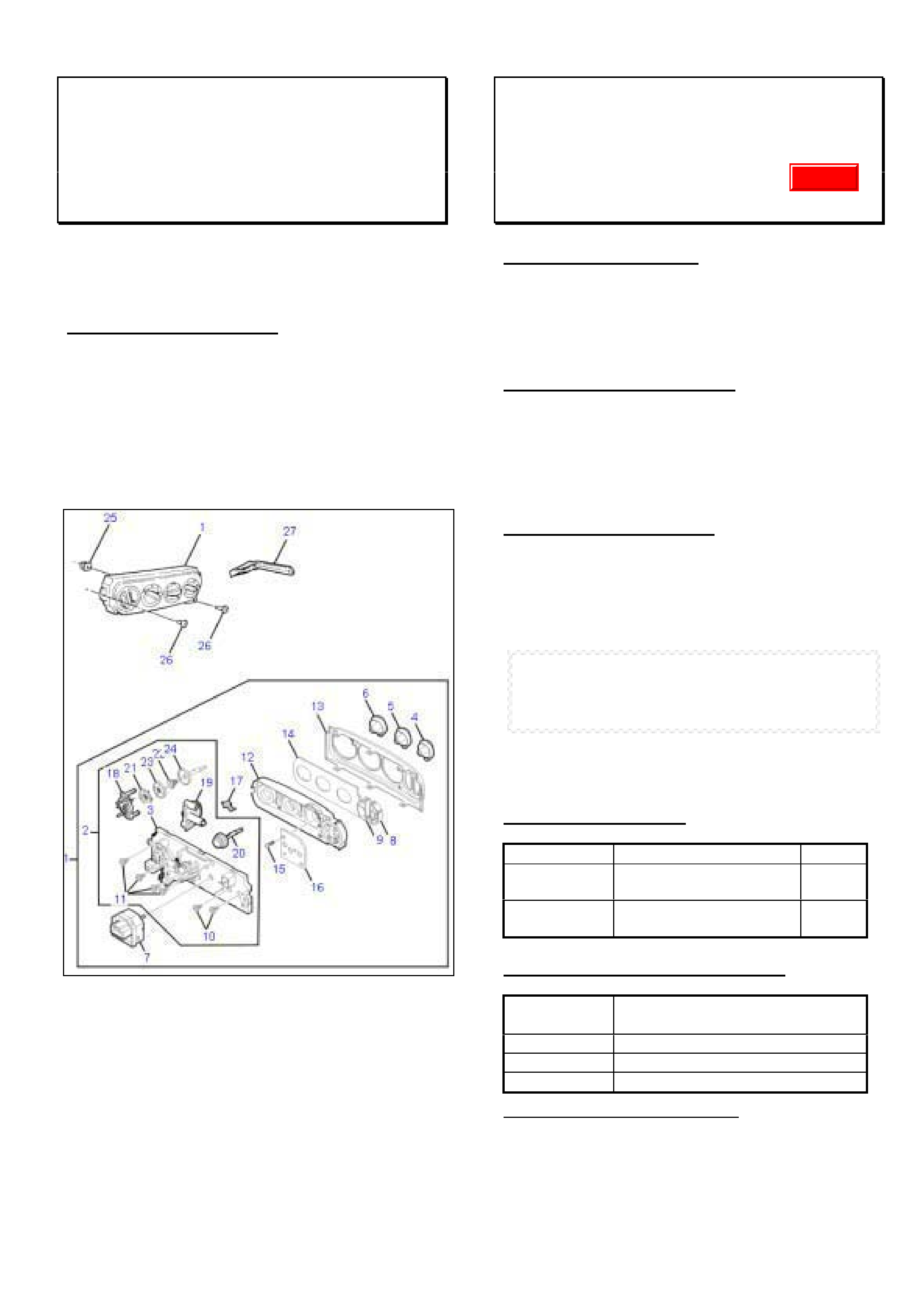
HOLDEN SERVICE TECHLINE_______________________________________________________________SEPTEMBER, 2002
16
HVAC Manual Control Unit - Parts
Serviceability
VT, VX, VU with C60 (HVAC) Option
(GROUP 2) TL343-0208
Complete HVAC manual control units are often
returned to Air International when serviceable
components should have been replaced.
SERVICE RECTIFICATION
Be aware that many components for HVAC manual
control units are serviced separately. The following
diagram is taken from PartFinder and shows the
components available.
Warranty claims for complete manual control units will
not be accepted if a serviceable component is
available and should have been replaced.
Revised Centre High Mounted Stop Lamp
(CHMSL)
VU SS
(GROUP 12) TL276-0208
CHANGE DESCRIPTION
The Centre High Mounted Stop Lamp (CHMSL) on
the above model has been resourced to a new
supplier. Because the new CHMSL is a slightly
different design to the previous part, the rear roof
moulding has been revised to suit.
PRODUCTION BREAKPOINT
The new CHMSL with revised rear roof mouldings is
being introduced progressively into vehicle production
on a colour by colour basis. This process
commenced from tag L899802, build date 2/8/02.
When all colours have been introduced, this techline
will be republished with final breakpoint details.
SERVICE RECTIFICATION
On vehicles where the old design CHMSL (p/n
92082683) has failed, install the new design CHMSL
together with the new revised roof moulding:
The CHMSL replacement procedure in Holden PV
SIP is found by the following path.
Select - VU Series
Select - Section 12B – Lighting System
Select - 2. Service Operations
Select - 2.1 high Level Stop Lamp
NOTE: The new centre rear roof moulding 92120003
will require painting in vehicle body colour.
PARTS INFORMATION
Part No.: Description: Qty:
92120002 Lamp Asm. Stop –
Centre High Mount
1
92120003 Moulding Asm. roof
rear centre(unpainted)
1
WARRANTY CLAIM INFORMATION
Description Replace CHMSL & Rear
Centre Roof Moulding
Labour Op. N000399
Time 0.3 hr
Failure Code 50
Claim For Painting Roof Moulding:
If sublet, claim as net items expense as normal.
If painted In-house, add up to 0.7hrs to Time and up
to $25 materials cost in net items.
Update
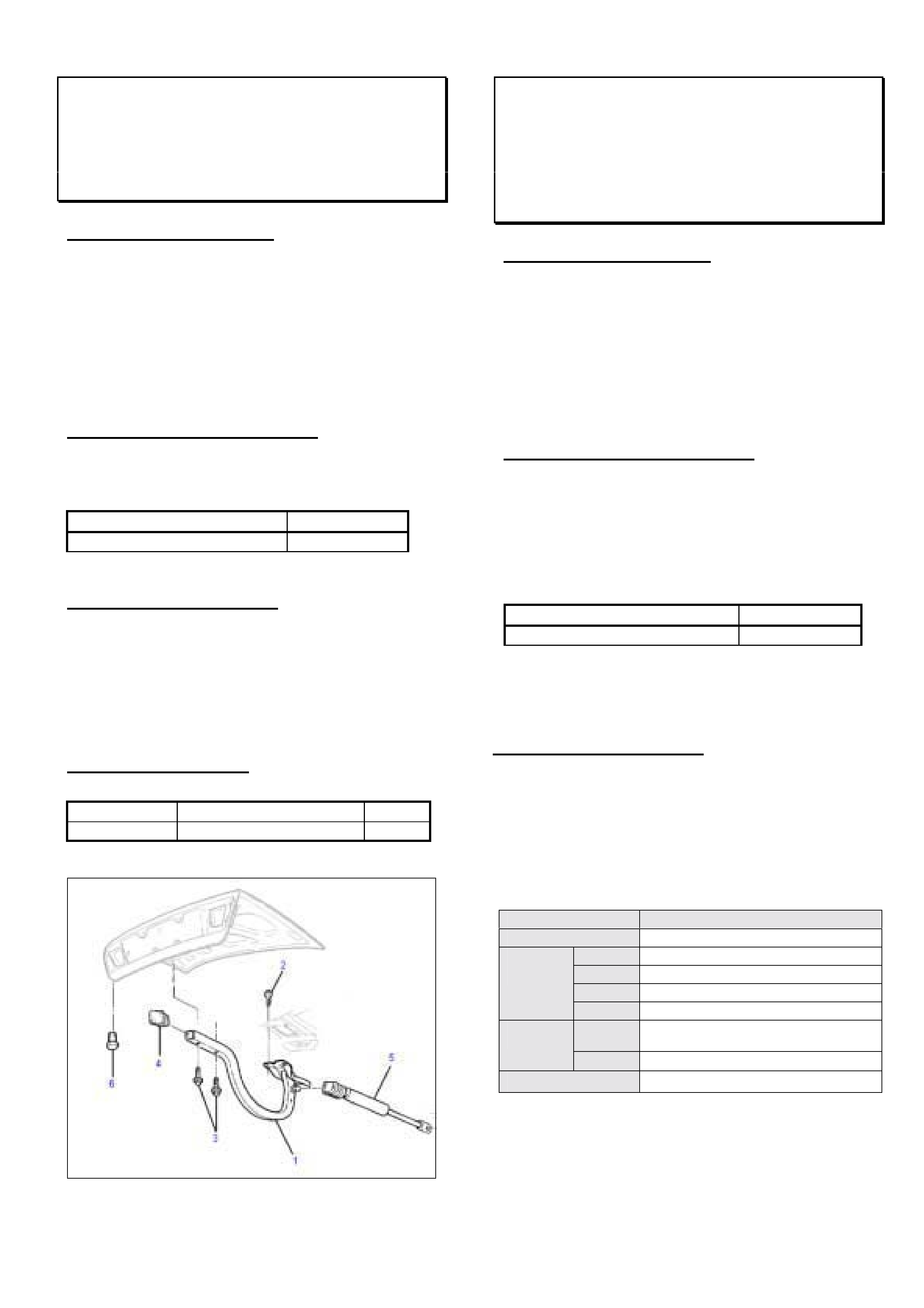
HOLDEN SERVICE TECHLINE_______________________________________________________________SEPTEMBER, 2002
17
Decklid to Hinge Attachment
V2
(GROUP 1) TL256-0208
PROBLEM DESCRIPTION
There have been reports from retailers that when
attempting to retighten the bolts which attach the
decklid to the hinge, they cannot achieve sufficient
clamp load.
Investigations show this condition is caused by
deformation of the captive washer under the head of
the bolt.
PRODUCTION RECTIFICATION
Revised decklid to hinge bolts (hardened steel captive
washers) have been fitted to vehicles from:
ISOVIN: Build Date:
6H8V2X37F2L905347 15 Aug 2002
SERVICE RECTIFICATION
1. On vehicles with the complaint condition, replace
the four existing decklid to hinge bolts with latest
bolts part number 92138683.
2. Torque bolts to 9 ±
±±
± 1.5 Nm.
PARTS INFORMATION
Part No.: Description: Qty:
92138683 Bolt decklid to hinge 4
Figure 1. Decklid to hinge attaching bolts - item #3.
Instrument Cluster - Intermittent
Operation
XC
(GROUP 12) TL318-0208
PROBLEM DESCRIPTION
Complaints such as dash lights and gauges become
inoperative and Engine Management Light comes on.
When engine is switched off it may not restart. Above
conditions can occur intermittently.
The above conditions can be caused by fretting
corrosion of the instrument cluster connector.
PRODUCTION RECTIFICATION
Stage 1. A tie strap was added to eliminate wiring
harness movement in March 2001.
Stage 2. A new wiring harness connector (grey colour)
with reduced tolerances between male/female
connections was introduced from:
ISOVIN: Build Date:
W0L0XCF6824115006. 07/01/02
Stage 3. Nyogel grease to be added to connector from
Model Year 2003. Breakpoint to be advised.
SERVICE RECTIFICATION
Summary: Add electrical grease to wiring harness
connector and secure harness with cable tie.
Procedure:
1. Remove instrument assembly – Procedure is
found in TIS as follows:
TIS Screen ê
êê
ê Select the following ê
êê
ê
Service Information Standard Information
Model Corsa-C
Year 2002
Eng. -
Vehicle
Data
Trans. -
Assemb.
Group
N (Elect. Eqpt. & Instruments)
➨
Instruments & Telltales
Standard
Information
Applicn. Repair (Remove,Install,Adjust)
Document List Instrument Assembly, Remove & Install
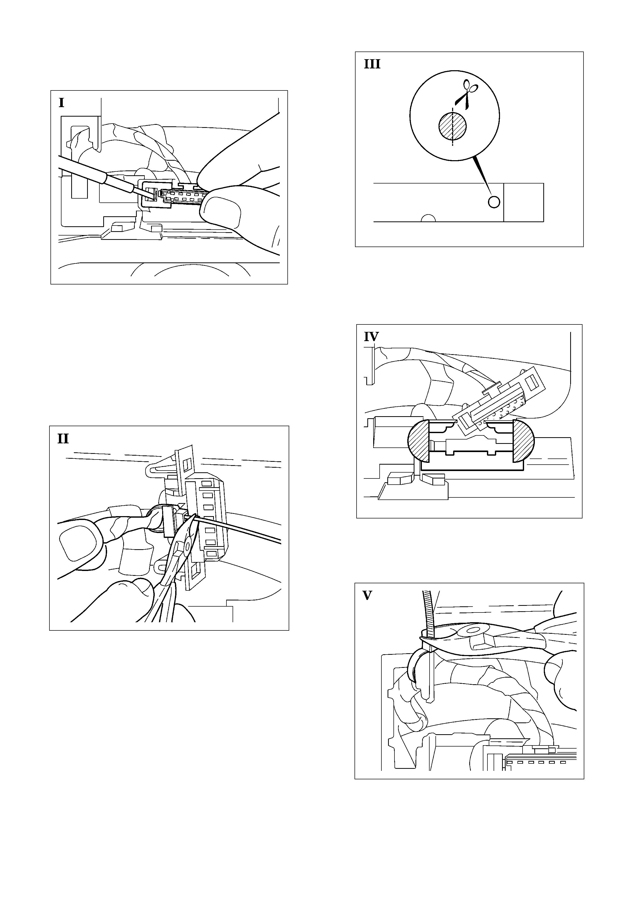
HOLDEN SERVICE TECHLINE_______________________________________________________________SEPTEMBER, 2002
18
2. Remove wiring harness from Instrument panel by
use of a suitable tool (picture I).
3. If the wiring harness is already fixed to the wiring
harness connector with a cable tie, go to step 5. If not,
go to step 4.
4. Attach wiring harness to wiring harness connector
with cable tie (picture II). Suitable dimensions for cable
tie are: length = 142mm, width = 2.5mm, thickness
= 1.1mm.
5. Obtain two 25 mm lengths of double-sided tape from
workshop. An alternative (if available), is to use the
circular push-out section of the “number plate bonding
pad” (in glovebox of new XC, TS, TT vehicles for
attaching the number plates). If you are using the
“number plate bonding pad” cut in half along dashed
line with scissors (picture III).
6. Stick double-sided tape/bonding pads at left and
right side of the instrument cluster where the wiring
harness connector attaches (picture IV).
7. Attach wiring harness to instrument panel with cable
tie (picture V).
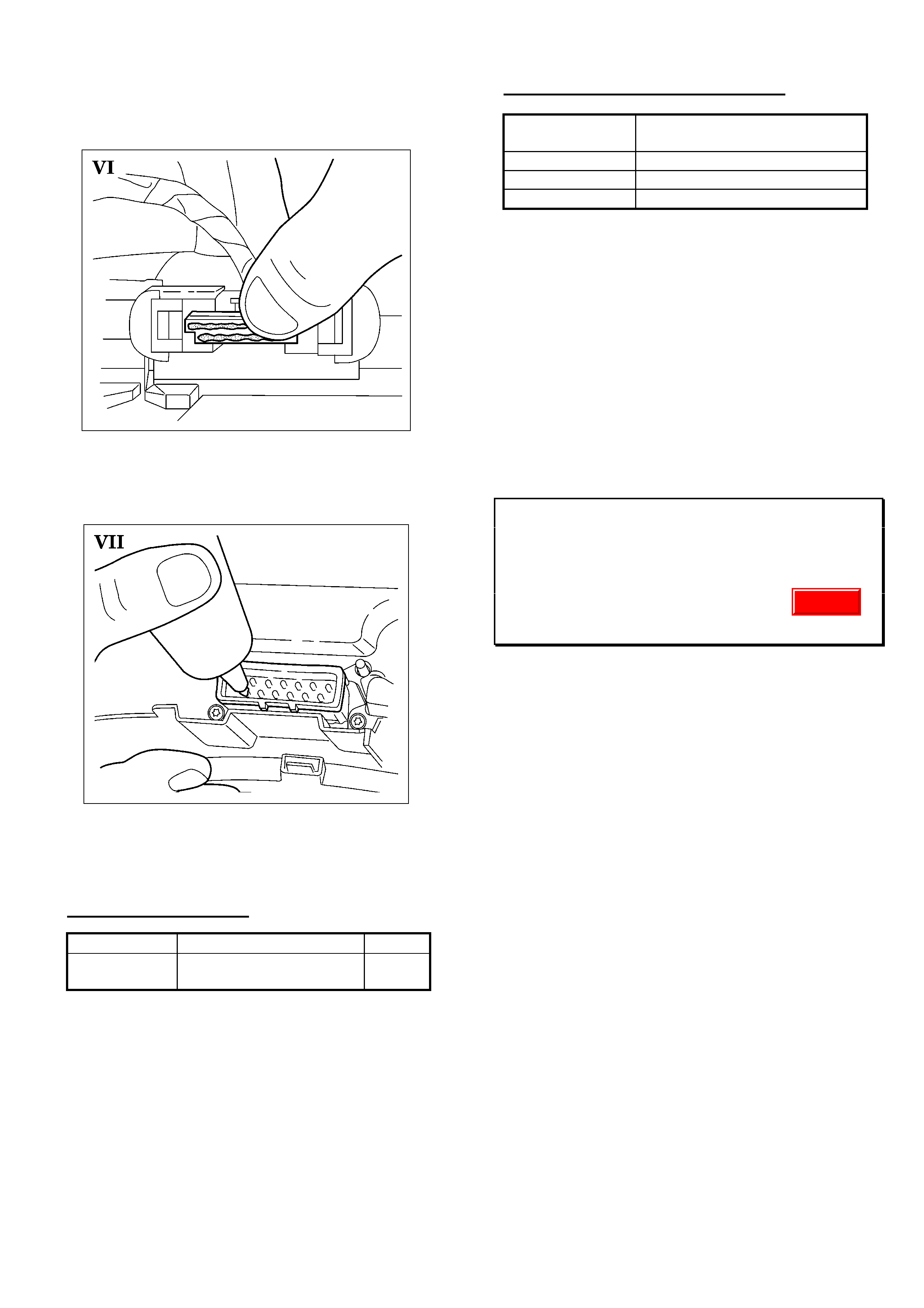
HOLDEN SERVICE TECHLINE_______________________________________________________________SEPTEMBER, 2002
19
8. Apply grease p/n 92146329 on wiring harness
connector by pushing grease with thumb into female
connector (picture VI).
9. Apply grease to each individual pin of instrument
assembly (picture VII).
10. Reinstall instrument assembly – refer TIS
procedure.
PARTS INFORMATION
Part No.: Description: Qty:
92146329 Nye Nyogel 760G
Grease - 30cc Syringe
1
This is the only grease recommended for this
application. Do not use electrical grease containing
silicone.
WARRANTY CLAIM INFORMATION
Description Instrument cluster connector
– add tie strap & grease
Labour Op. No. N000396
Time 0.9 hr
Failure Code 51 Electrical Connector Problem
NOTE: Claim only for the cost of the amount of
grease used and place in net items.
Modular Reservoir Assembly (MRA)
Replacement and Fuel Gauge Calibration
VXII, WHII, VUII, V2
(GROUP 12) CAUTION TL352-0208
When replacing the Modular Reservoir Assembly
(MRA) in one of the above models, DO NOT
recalibrate the fuel gauge using the function available
in Tech 2.
This calibration function has no effect in these
vehicles, and may introduce other errors which could
lead to unnecessary replacement of the instrument
cluster.
If instrument cluster codes are evident after
replacement of the MRA, have your Nominated
Contact phone Holden Technical Assistance for
further guidance.
CANCELLED
Update
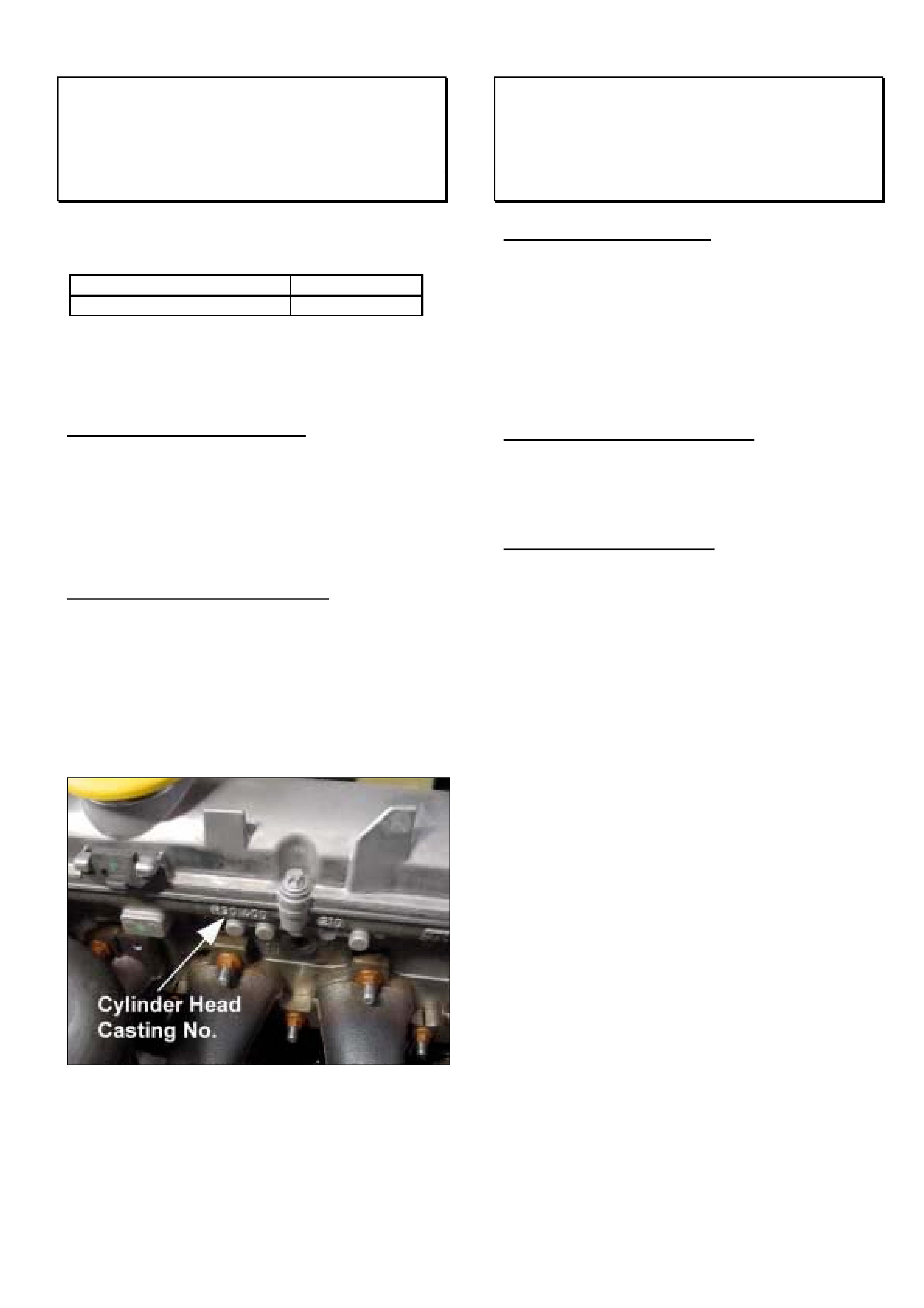
HOLDEN SERVICE TECHLINE_______________________________________________________________SEPTEMBER, 2002
20
Revised Cylinder Head
XC with Z14XE
(GROUP 6C) TL335-0208
A revised cylinder head with modified EGR ports was
fitted to engines from:
Engine No: Build Date:
20Y65461 23 May 02
20 = Manufacturing plant (SZENTGOTTHARD)
Y65461 = serial number. When 99,999 is reached the Y
will change to the next letter of the alphabet.
IMPORTANT SERVICE NOTE:
Whenever the latest revised type cylinder head
(part number 93175328) is fitted to an earlier
engine (prior to eng. no. 20Y65461) the ECU must
be updated with software No. 12223620.1 which
has been available from TIS 32.0 onwards.
Notes On Cylinder Head Identification:
Cylinder heads can be identified by their casting
number which is cast into the head just above where
the exhaust manifold is bolted. Refer photograph
below.
Latest cylinder head casting number “ 13 106 674”
Earlier cylinder head casting number “ 90 400 210”
Note: Photo shows engine cover and exhaust
manifold heat shield removed.
Drive Shaft Seal Installation Precautions
TS with F17 M/T
(GROUP 7A) TL345-0208
PROBLEM DESCRIPTION
Minor oil leaks have been reported from transmission
drive shaft seal area.
The cause has been defined as seal damage during
the vehicle assembly process.
As seal installation is a delicate process, the
possibility of seal damage also exists during seal
replacement in service.
PRODUCTION RECTIFICATION
A revised seal design is under consideration for this
application. Any change in seal design will be advised
in future Breakpoint Summary pages.
SERVICE RECTIFICATION
Summary: Fit a new seal – CAREFULLY - using the
correct tool.
During fitting of a new drive shaft seal,
- the seal recess should be carefully inspected for any
burrs – which should be removed before seal fitting;
- the drive shaft end should be inspected for any
burrs, damage or sharp edges – these should be
corrected before seal fitting - sharp edges on the
drive shaft end can be removed with a fine hone
stone and the shaft end carefully cleaned.
- use only the special tool KM 446 (sourced from SPx
Australia).
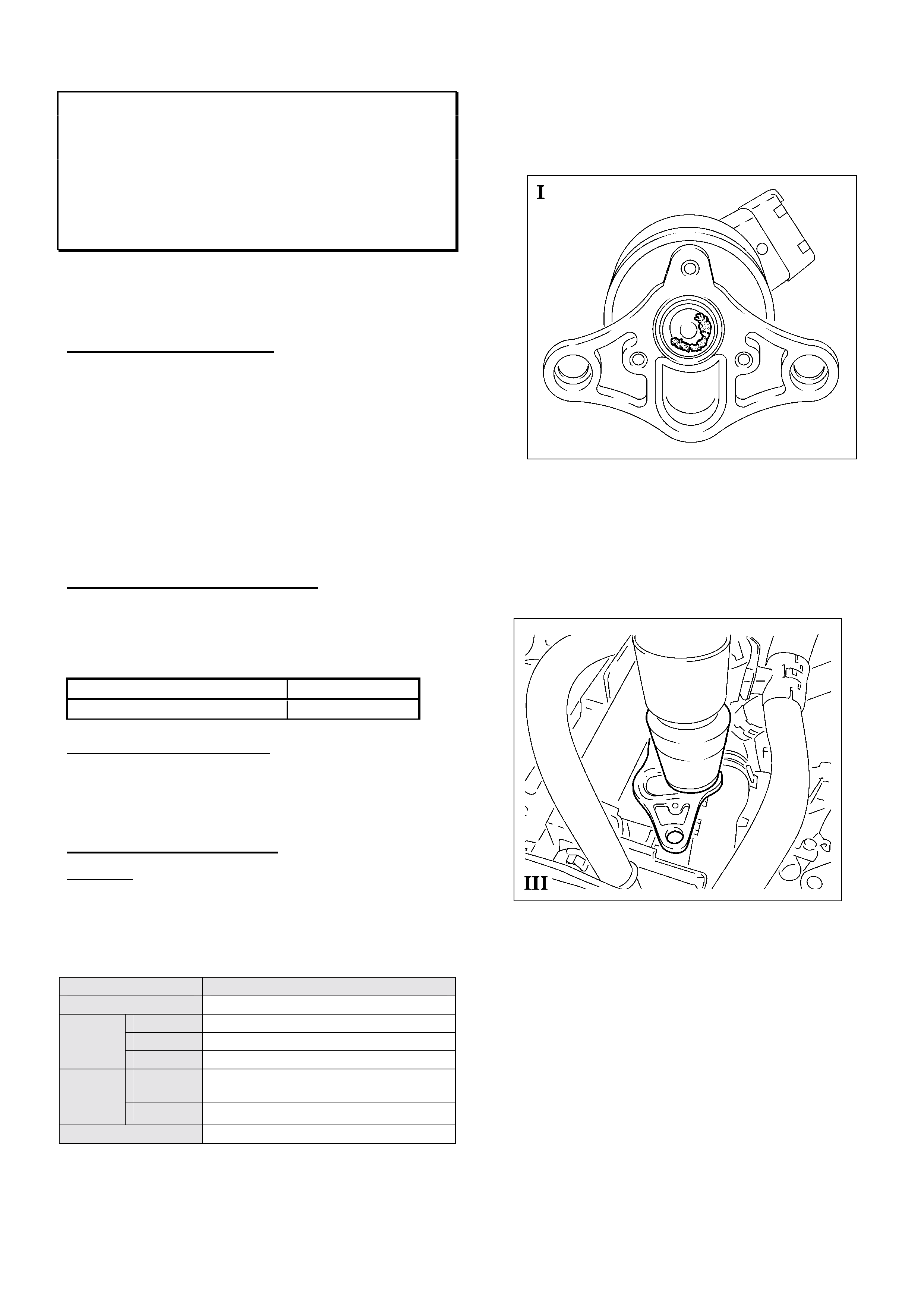
HOLDEN SERVICE TECHLINE_____________________________________________________________OCTOBER, 2002
7
Rough Idle, Loss Of Power, Stall During
Idle and Hard To Restart - DTC P0400,
P1405 Set
XC with Z14XE engine
(GROUP 6C) REVISED TL356-0209
This Techline supercedes the previous techline in Issue
11, Nov, 2001. It is revised by updating the EGR
cleaning procedure.
PROBLEM DESCRIPTION
Some vehicles may experience rough idle, loss of
power, stalling during idle, hard to start after a stall
condition. Tech 2 may also show the following DTC’s
present:
P0400 – EGR Circuit Range/Performance or EGR flow
excessive.
P1405 – Exhaust gas recirculation sensor circuit high/low
Vehicles with these symptoms generally have been
found to have EGR valves contaminated with foreign
particles.
PRODUCTION RECTIFICATION
The ECU software was reprogrammed to provide a
“self cleaning” (low frequency shake) routine to the
EGR valve. Engines with this revised ECU software
(p/n 09353469.9) were produced from:
Engine No: Build Date:
20W68679 15/11/01
Engine Number Identification:
20 = Manufacturing plant (SZENTGOTTHARD)
W68679 = serial number. When 99,999 is reached
the W will change to the next letter of the alphabet.
SERVICE RECTIFICATION
Summary: On complaint vehicles remove and clean
EGR valve and reflash ECU with revised software
(EGR shaking routine).
1. Remove the EGR valve. Procedure is found in TIS
as follows.
TIS Screen Selection
Service Information Standard Information
Model Corsa-C
Year 2001 or 2002
Vehicle
Data
Eng. Z14XE
Assembly
Group
L Fuel and Exhaust System
➨
Exhaust System
➨
EGR system
Standard
Informati
on Application Repair (Remove, Install, Adjust)
Document List EGR valve remove and install
2. Inspect valve for foreign material that may be holding
valve open. Remove any foreign material from
valve/seat area with a brass-brush or similar.
Refer Figure I.
3. To confirm if EGR valve is opening and closing
correctly, reconnect it to the wiring loom and operate
valve with Tech 2.
4. Remove any loose foreign material from ports in
EGR to engine adapter plate with a vacuum cleaner .
Refer Figure III.
NOTE: DO NOT replace EGR valve unless foreign
material cannot be removed or valve has been
damaged. Also, DO NOT replace catalytic converter or
exhaust manifold with new parts for this condition.
5. Reinstall EGR valve with new gasket. Ensure all
sealing surfaces are clean.
6. If engine is prior to Eng. No. 20W68679, reprogram
the vehicle ECU with software part number
09353469.9 which is available from TIS 25.0B
onwards. This software includes an EGR shaking
routine for cleaning purposes.
Note: Engines after Eng. No. 20W68679 will already
have the latest EGR shaking routine software
already installed.
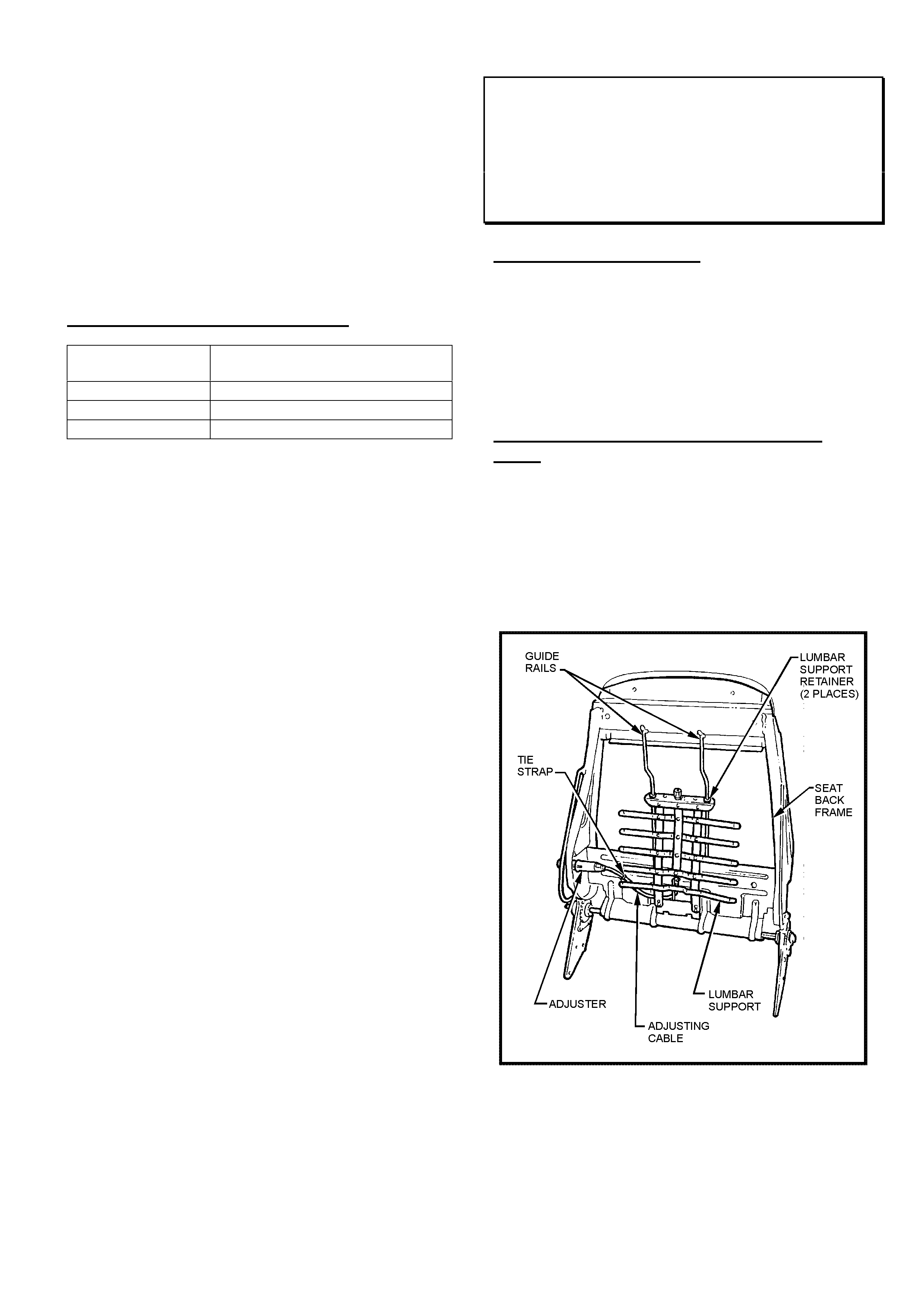
HOLDEN SERVICE TECHLINE_____________________________________________________________OCTOBER, 2002
8
Programming Note:
When reprogramming the ECU, Tech 2 will ask if
vehicle is fitted with old or new cylinder head ?
For engines prior to Engine No. 20Y65461 the
correct answer is - “Old” cylinder head. The reason
for this is that a revised cylinder head was fitted
in production from Engine No. 20Y65461. For
detailed information on the introduction of
revised cylinder heads on Z14XE engines refer
to Techline in Group 6C, Issue 8/2002.
WARRANTY CLAIM INFORMATION
Description Remove, clean, reinstall EGR
valve & reflash ECU
Labour Op. No. J000701
Time 0.7 hr
Failure Code 12 “Foreign Material”
Front Seat Lumbar Support Replacement
Guidelines
VX,VU,V2
(GROUP 1) TL348-0209
PROBLEM DESCRIPTION
Some retailers are still replacing complete seat back
frames under warranty when only the lumbar support is
faulty.
NOTE: The lumbar support has been available as a
replacement part for the models listed above since mid
2000.
WARRANTY ADMINISTRATORS PLEASE
NOTE
Warranty claims will not be accepted for replacement
of the complete seat back frame when only the lumbar
support is faulty.
For lumbar support replacement procedure refer to
previous Service Techline in Group 1, 2000, titled
“VT,VX,WH – Front Seat Lumbar Support Asm.
Replacement Procedure”
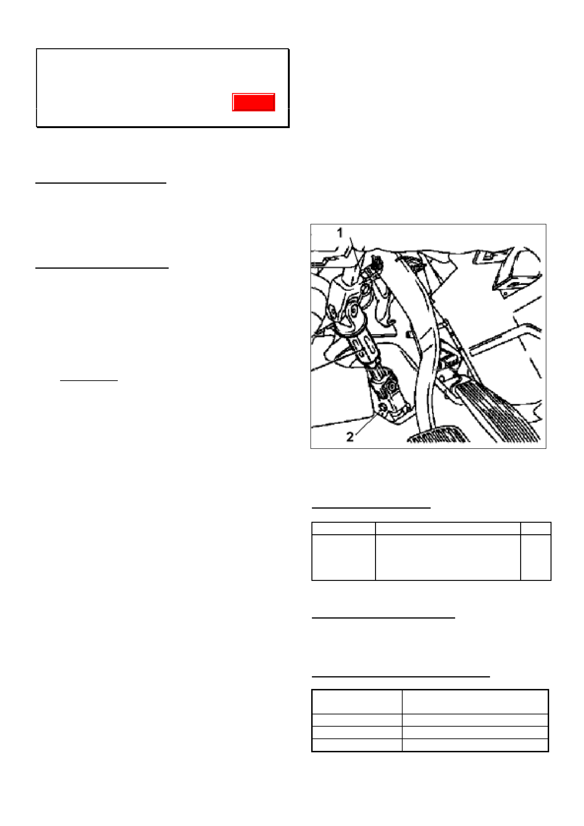
HOLDEN SERVICE TECHLINE_____________________________________________________________OCTOBER, 2002
9
Intermediate Steering Shaft Knock
JR, JS
(GROUP 9) TL362-0209
This Service Techline supersedes the previous techlines
on this topic; refer PV SIP Group 9, 1998 & 2002.
PROBLEM DESCRIPTION
On some vehicles, a knocking noise can be heard in the
area of the steering column when turning. The knocking
noise is caused by slight play in the securing flanges
(upper and lower) of the steering intermediate shaft.
SERVICE RECTIFICATION
Summary: On complaint vehicles, replace the
intermediate steering shaft with the new revised part as
described below.
Removal And Replacement Of Intermediate
Steering Shaft:
1. IMPORTANT: Disconnect the battery and wait at
least 1 minute for the capacitor in the control unit to
discharge. (Airbag safety precautions as outlined in
service manual Volume 1 must be observed).
2. Centre the steering wheel.
3. Remove foot well panels and air ducting.
4. Loosen the pinch bolts of the steering intermediate
shaft (Nos.1 and 2) and engage the steering lock,
see Figure 1.
5. Compress the steering intermediate shaft and
remove.
6. Fit the new steering intermediate shaft Part
Number - 09119322, release the steering lock,
then secure the shaft using new pinch bolts (Torx
screws) and an appropriate thread locking sealant.
7. Torque the upper and lower pinch bolts to
22 Nm/16 lbf.ft + 45° + 15° Failure to
tighten these bolts correctly may result in not
eliminating the knock condition.
8. Refit air ducting and foot well panels.
9. Mark the steering wheel position and remove
the steering wheel using special tool
Puller KM 210-A.
10. Offset the steering wheel 2 teeth to the right.
11. If necessary, with a screwdriver, depress the clock
spring locking tab and move the clockspring until
the driving lugs on the steering wheel locate
correctly into the clockspring.
12. Refit the steering wheel and secure the fastening
nut with the locking plate supplied. Torque to
25 Nm/18 Ibf.ft.
13. Refit the air ducts and foot well panels.
14. Reconnect the battery.
15. Test drive the vehicle and ensure that the steering
is centered.
Figure 1.
PARTS INFORMATION:
Part No. Description Qty.
09119322 Repair Kit - Steering Coupling
Joint (consists of revised shaft,
2 Torx screws, 1 locking
washer)
1
SPECIAL TOOL REQUIRED:
KM-210-A Puller
WARRANTY CLAIM INFORMATION
Description Repair Kit - Steering
Coupling Joint Replace
Labour Op. No. E000302
Time 0.8 hr
Failure Code 28 rattle
Update

HOLDEN SERVICE TECHLINE_____________________________________________________________OCTOBER, 2002
10
Buzzing Noise From Fuel Tank Pressure
Relief Valve
SB with C14SE engine
(GROUP 8) TL363-0209
PROBLEM DESCRIPTION
Some customers may complain of a buzzing noise
heard inside the cabin during conditions of high
ambient temperature (usually above 35 deg C) in
stop/start traffic.
SERVICE RECTIFICATION
On complaint vehicles replace fuel cap with the
lockable vented fuel cap p/n 92117453. Note; this cap
comes with its own set of keys.
PARTS INFORMATION
Part No.: Description: Qty:
92117453 cap – fuel filler 1
Exterior Lamp Lens Care Guidelines
All
(GROUP 12) TL303-0208
Most late model vehicles have polycarbonate lenses in
the exterior lamps. This material has been selected
because of its many positive attributes in this
application. However, it is very sensitive to a wide
range of chemicals, which can cause crazing or
cracking of the lens. In these cases the entire lamp
housing must be replaced.
Whenever treating a vehicle with any type of chemical,
such as those sometimes used for rail dust removal
etc., avoid contact with all exterior lamps.
Also, lamps should never be covered with any material
(rags, guard protectors etc) whilst they are turned on.
The heat build up within the lamp has the potential to
permanently damage the lens and housing.
Driver’s Seat Belt Length
TT ZAFIRA
(GROUP 1) TL361-0209
PROBLEM DESCRIPTION
Some customers may complain the driver’s seat belt is
too short.
PRODUCTION RECTIFICATION
Revised drivers seat belt assemblies with longer
webbing have been fitted to vehicles from:
ISOVIN: Build Date:
W0L0TGF752H031619 03/07/02
SERVICE RECTIFICATION
Summary: If owner complains, fit the longer seat belt
assembly.
Refer to the instructions in TIS2000 to remove and
install the front seat belt. The following table shows the
path in TIS2000 to find the required information.
TIS Screen ê
êê
ê Select the following ê
êê
ê
Service Information Standard Information
Model Zafira
Year 2002
Eng. -
Vehicle
Data
Trans. -
Assembly
Group
+ C Body Equipment
+ Seat, Upholstery, Inner Trim Panels
✓
Seat Belt
Standard
Info.
Application Repair (Remove, Install, Adjust)
Document List Seat Belt - Front, Remove & Install
PARTS INFORMATION
Part No.: Description: Qty:
90560636 Belt-Front Seat RH 1
WARRANTY CLAIM INFORMATION
Description Belt Asm, RH Front, Replace
Labour Op. No. C451100
Time 0.5 hr
Failure Code 55 Poor Fit
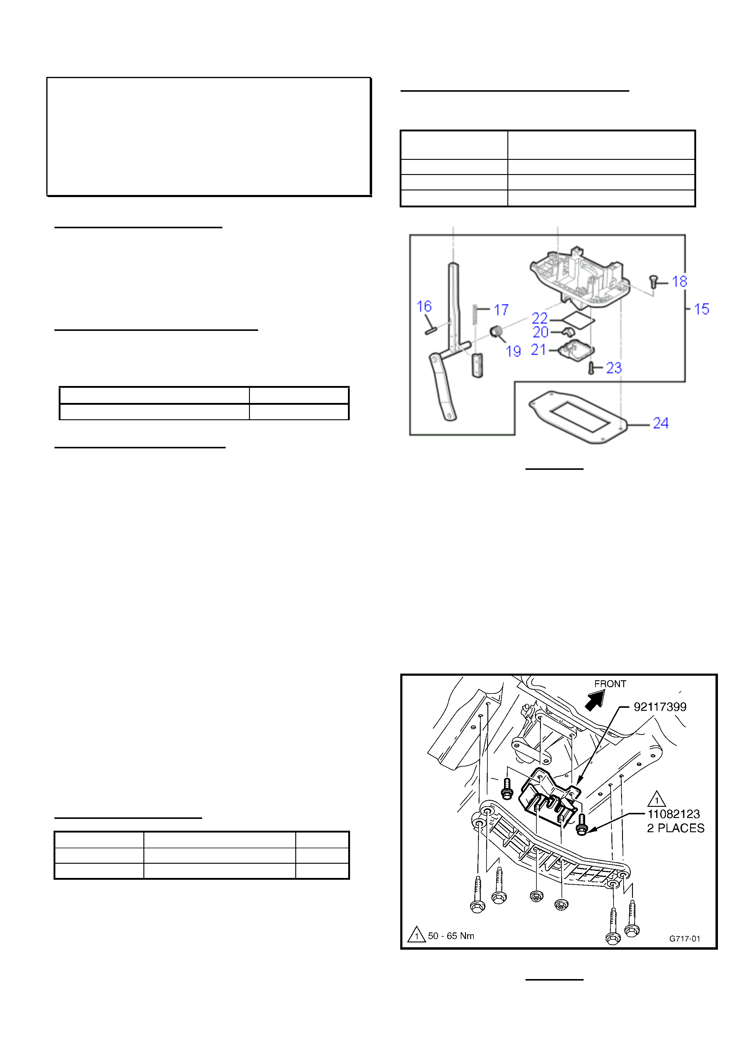
HOLDEN SERVICE TECHLINE_____________________________________________________________OCTOBER, 2002
11
A/T Shifter Base Damaged By Contact
With Prop Shaft Front Coupling
VX, VU, V2, WH (All with V6 & A/T)
(GROUP 7B) TL351-0209
PROBLEM DESCRIPTION
Auto Transmission (A/T) shifter base may be damaged
by the prop shaft front coupling if vehicles are
subjected to extreme rough road usage (possibly in
combination with high torque loading).
PRODUCTION RECTIFICATION
A revised engine/trans. rear mount, that includes a
travel limiting bracket, has been introduced in vehicle
production from:
ISOVIN: Build Date:
6H8VXK69A2L912000 30/08/02
SERVICE RECTIFICATION
Summary: On pre-Breakpoint (V6) vehicles, repair A/T
shifter base with available service part/s and fit revised
engine/trans. rear mount.
On presentation of a V6 A/T equipped vehicle where
the A/T shifter base has been damaged by contact with
the prop shaft front coupling, carry out the following
rectification procedure:
1. Define extent of shifter base damage and replace
parts as required. Refer to Figure 1 for parts
availability – parts shown are as per Partfinder CD.
2. Remove existing eng/trans rear mount, bolts and
spacer plate. (these parts will NOT be re-used).
3. Fit new eng/trans rear mount (p/n 92117399) as
shown in Figure 2 using new bolts (p/n 11082123),
torqued to 50-65Nm.
IMPORTANT:
• DO NOT re-fit the spacer plate originally fitted
between the mount and the trans.
• DO NOT re-use the bolts originally retaining the
original mount to the trans.
PARTS INFORMATION
Part No.: Description: Qty:
92117399 Mount Asm., Trans. 1
11082123 Bolt, Trans. Mount 2
WARRANTY CLAIM INFORMATION
Use information as follows:
Description Repair A/T Shifter, Replace
Trans. Mount.
Labour Op. No. J000716
Time 1.1 hr
Failure Code 62 (Improper Clearance)
Figure 1.
Item #15 - Base assembly – A/T shift control
#16 - Pin, Handle
#17 - Spring-Button
#18 - Attaching Stud
#19 - Split Bush
#20 - Bush
#21 - Cap Lower Base
#22 - Seal O Ring
#23 - Screw Cap Retainer
#24 - Seal
Figure 2.
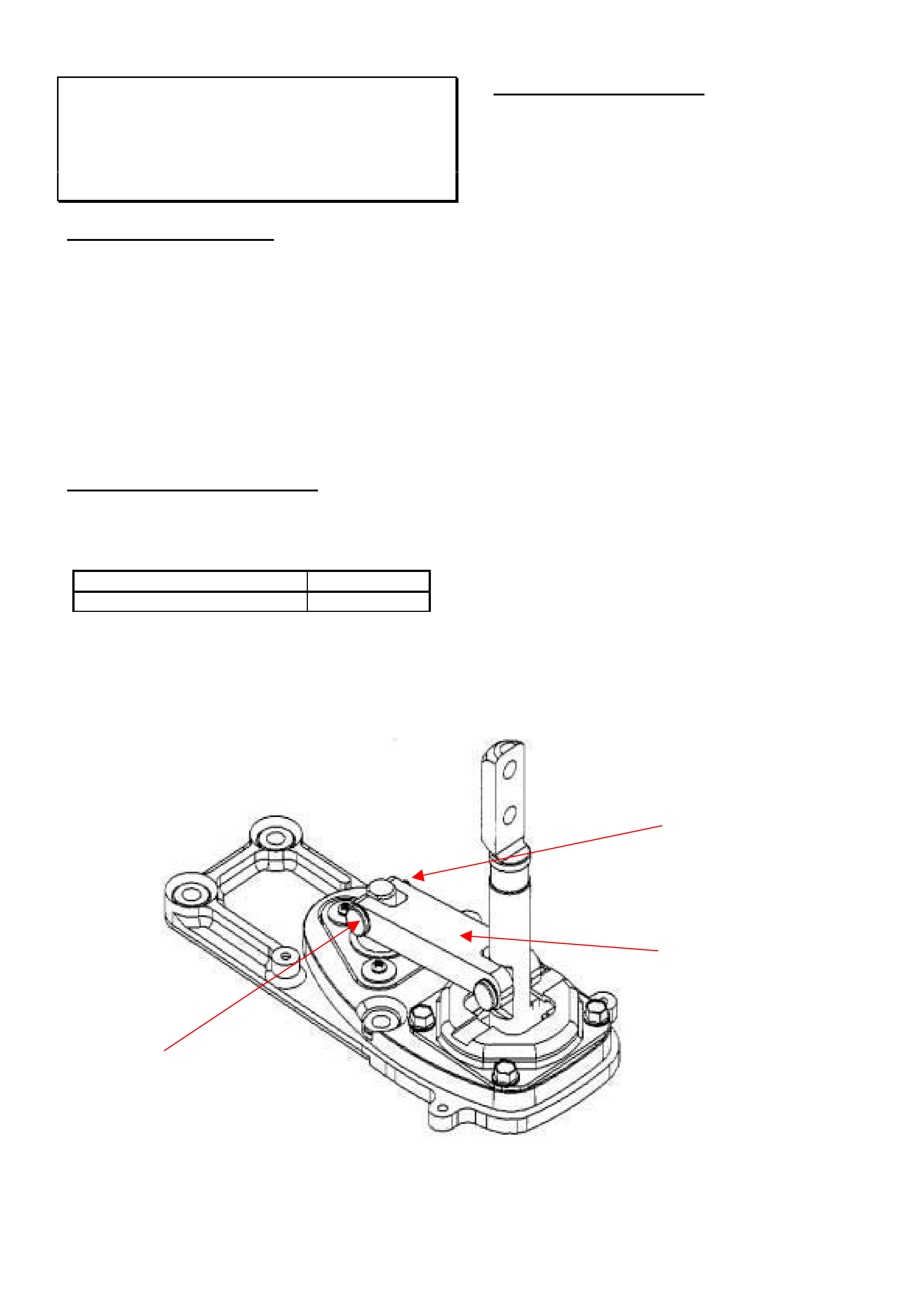
HOLDEN SERVICE TECHLINE_____________________________________________________________OCTOBER, 2002
12
Insufficient Engagement Of Reverse Gear
VTII, VX, VU, V2 with Gen III M/T
(GROUP 7A) TL357-0209
PROBLEM DESCRIPTION
A customer may complain that sometimes when
selecting reverse gear, the selector does not go fully
into reverse. When the clutch is released, grinding of
the gears can be heard. Also, the gear selector needs
to be physically held in reverse to use the gear.
Investigation of one transmission with the above
condition has shown the cause was a circlip missing
from the forward pivot of the shifter rail. Refer figure
below. The missing circlip allowed the pin to partially
disengage and become loose.
PRODUCTION RECTIFICATION
Transmission shifters which have been confirmed by
the supplier to have the circlips fitted were installed in
vehicles from:
ISOVIN: Build Date:
6H8VUK80F2L882370 25/6/02
SERVICE RECTIFICATION
On vehicles with above complaint, remove
transmission shift lever cover and confirm that circlips
are fitted.
If circlips are missing, TAS have a limited number
available on request.
Please submit PIR’s on any complaint vehicle built after
vehicle 6H8VUK80F2L882370 (built 25/6/02).
Pivot
Pin
Shifter Rail
Circlip missing
from this side
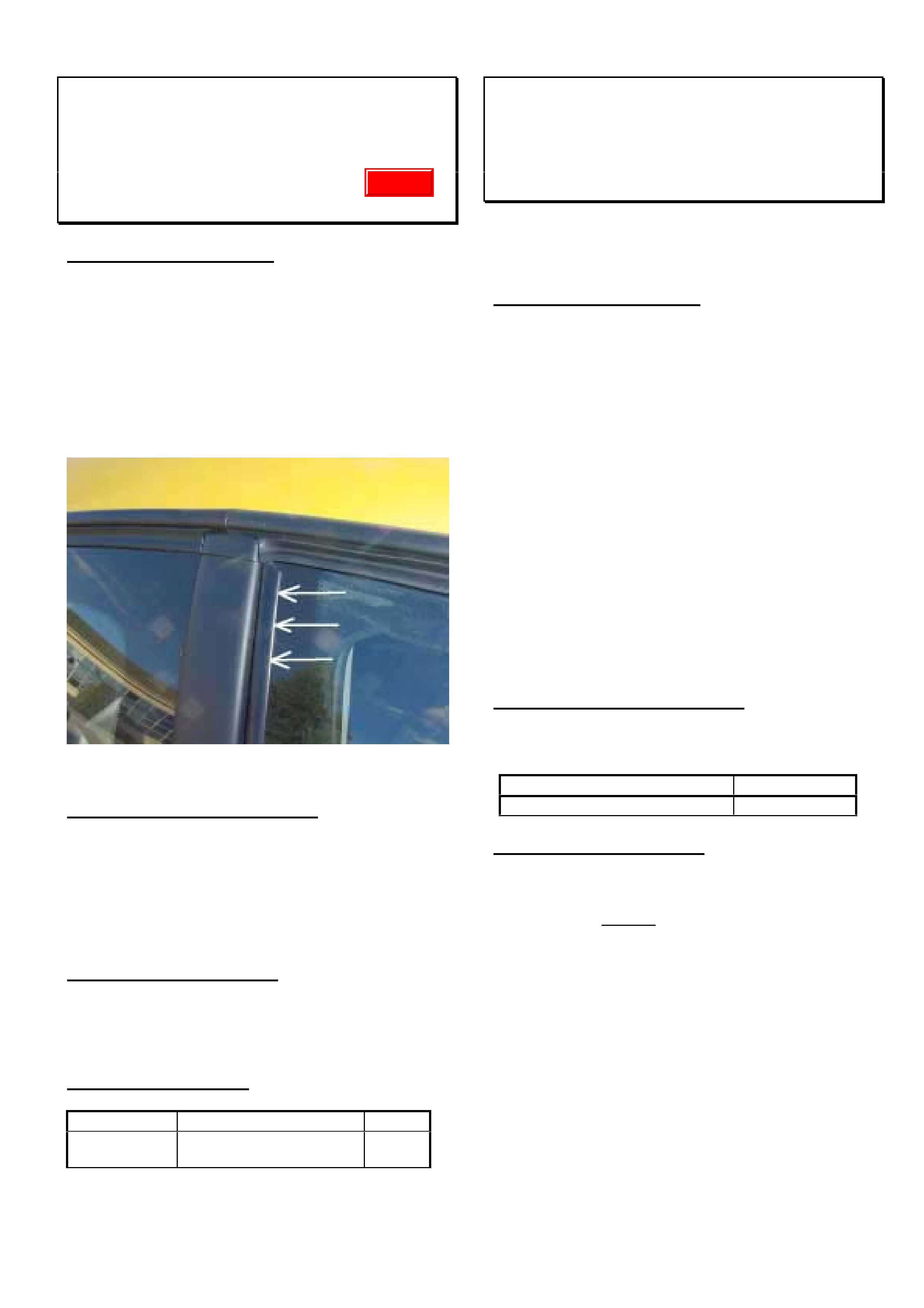
HOLDEN SERVICE TECHLINE_____________________________________________________________OCTOBER, 2002
13
Wind Noise At Upper Rear Corner Of Drop
Window
V2 Monaro
(GROUP 1) TL350-0209
PROBLEM DESCRIPTION
Some customers may complain of excessive wind
noise (air rush/turbulence) coming from the upper rear
corner of the driver or passenger drop windows.
This condition can be caused by a small gap between
the guide rail and the glass in the area shown in Figure
1.
The gap is caused by a mismatch of contours between
the guide rail and the glass.
Figure 1
PRODUCTION RECTIFICATION
Since just after start of production, a small amount of
urethane has been applied to fill any gap in the area
shown.
Revised parts to eliminate this condition are planned
for introduction in October. Breakpoint details will be
published in a future Breakpoint Summary.
SERVICE RECTIFICATION
On complaint vehicle, check the area concerned and
carefully apply a smear of urethane as required to fill
any gap.
PARTS INFORMATION
Part No.: Description: Qty:
92143609 Sealer Urethane -
300ml cartridge
1
LSD “Chatter” Noise
V6 & LSD in VX, VU, V2, WH
(GROUP 4) Revised TL339A-0209
This Techline supercedes the previous one in Issue 8,
Sept., 2002. It is revised by addition of breakpoint,
identification, oil usage and replacement information.
PROBLEM DESCRIPTION
LSD chatter may be heard when the vehicle is turning
left or right when travelling in a forward or reverse
direction, and is most pronounced when negotiating
tight corners at low speeds and parking manoeuvres
where differential action is initiated. Chatter may also
be experienced by the driver as a “grabbing” feel during
the operation of the LSD.
The chatter noise is caused by reduced sliding
lubrication qualities of the LSD cone friction surfaces
within the final drive unit (using the existing oil).
LSD chatter noise complaints have been received,
mainly in vehicles that commonly carry and/or tow
heavy loads, or are subjected to harsh usage.
To correct this condition, LSD axle units have been
revised by the replacement of the previous cast iron
cones with sintered iron cones.
These axle units are filled with synthetic oil and a
friction modifier additive.
PRODUCTION RECTIFICATION
Revised axle units with sintered cones have been fitted
to (VY) vehicles from:
ISOVIN: Build Date:
6G1YK52A73L915667 12/09/02
SERVICE RECTIFICATION
Summary: On complaint vehicles, fit an exchange axle
unit from SAA.
IMPORTANT: Do not attempt to rectify V6 LSD
“Chatter” complaint vehicles by using the V8 LSD
Chatter Kit described in Retailer Letter 30/02. The pre-
Breakpoint V6 LSD axle unit Cast Iron cones are not
compatible with the friction modifier in the kit.
On complaint vehicles, request a changeover unit
through Spicer Axle Australia (SAA) via the established
procedure. (Refer to axle exchange request form in PV
SIP). Only sintered cone type axles will be supplied by
SAA from now on.
SAA will provide an exchange axle unit that has
sintered LSD cones, synthetic oil, friction modifier and
compatible seals.
Update

HOLDEN SERVICE TECHLINE_____________________________________________________________OCTOBER, 2002
14
IDENTIFICATION OF AXLES
Identification of these axle units is by a tag on the axle
filler plug:
On latest V6 LSD Axles with Sintered Cones the tag
carries the following wording:
“USE APPROVED LUBRICANT AND FRICTION
MODIFIER”
On the previously used V6 LSD axle units with Cast
Iron Cones the tag carries the following wording:
“SPIN RESISTANT – USE APPROVED LUBRICANT
ONLY”
Oil Replenishment:
The new V6 LSD Axles with Sintered Cones use
synthetic oil and friction modifier, and oil replenishment
can be carried out using Additive Kit 92145121 - (Refer
Techline “LSD Additive Avail. for Servicing” in
Techline Issue 4, May, 2002).
Spigot Bearing “Squeal” Noise on Cold
Start
VT, VX, VU, V2, WH
(GROUP 7A) TL245-0209
PROBLEM DESCRIPTION
A “squeal” noise may be heard, from the spigot
bearing, at the first use of the clutch pedal after a cold
start. The noise may repeat several times when the
clutch is disengaged, during engine warm-up.
This noise is caused by a combination of damage to
the spigot bush during initial installation and lubricant
“drying out”.
To address possible installation damage, revised
tooling and installation processes have been
introduced.
To address the lubricant “dry-out”, the bush is now
impregnated with synthetic oil with 10% molybdenum
disulphide.
PRODUCTION RECTIFICATION
Revised installation tooling/assembly processes for
spigot bushes, and revised lubrication have been
introduced in engine production from:
Engine No.:
VA221827
First use of engines with revised bush installation:
ISOVIN (for Reference): Build Date:
6H8VUK80A2L865092 13/05/02
SERVICE RECTIFICATION
Summary: Fit new spigot bush.
To rectify this condition, replace the existing spigot
bush with a new bush, p/n 92116034.
NOTE:
• DO NOT attempt to lubricate a ‘noisy’ spigot bush,
replace it!
• When lubricating a new spigot bush prior to
assembly – use only synthetic oil. Do NOT use
grease.
PARTS INFORMATION
Part No.: Description: Qty:
92116034 Spigot Bush 1
WARRANTY CLAIM INFORMATION
Use existing Labour Time information in Warranty
Information section of current PV SIP CD.
Update
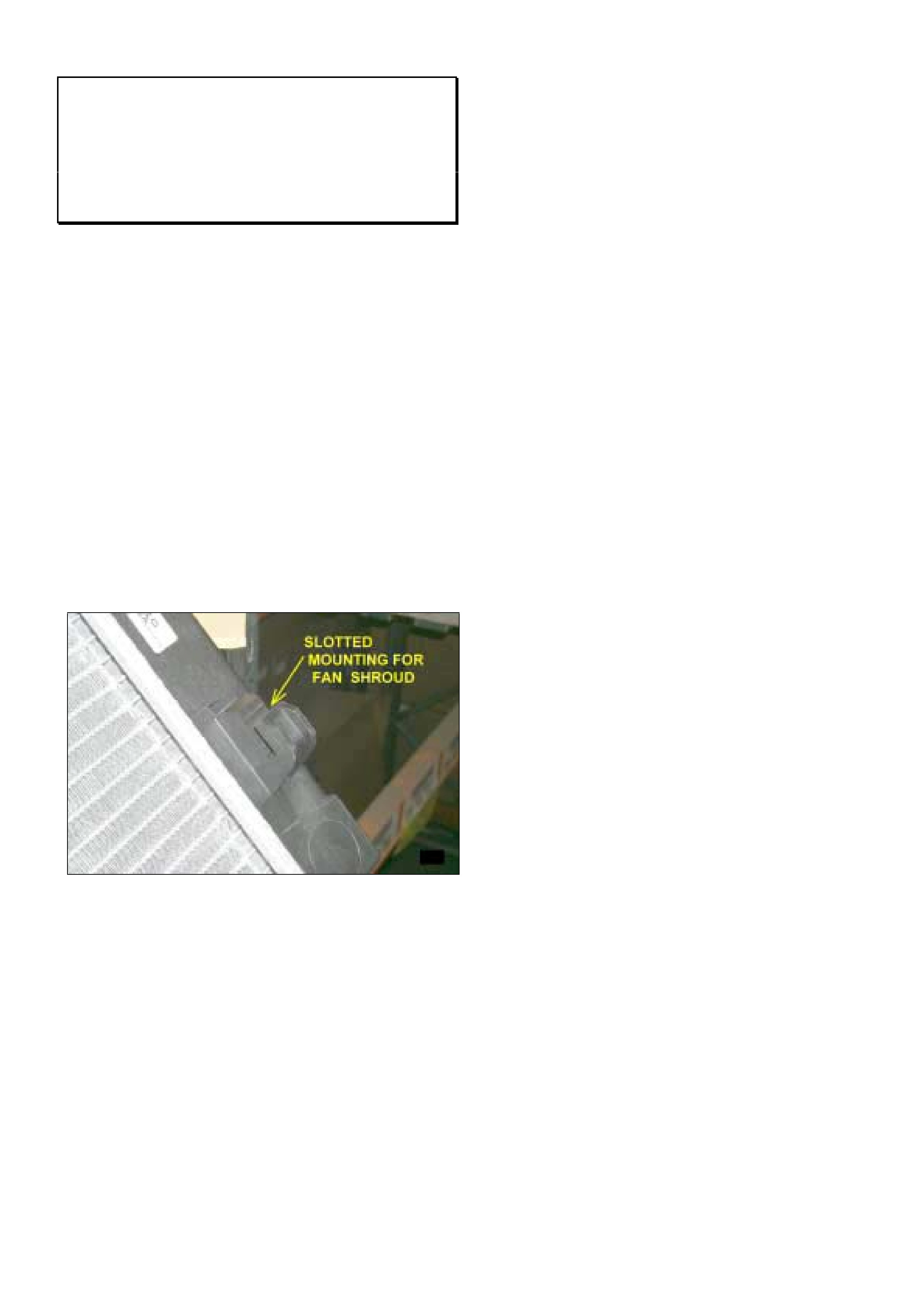
HOLDEN SERVICE TECHLINE_____________________________________________________________OCTOBER, 2002
15
Engine Fan Shroud Mounting Revised –
HSPO Replacement Radiators
VT, VX, VU
(GROUP 6K) TL366-0209
The original method of mounting the fan shroud to the
radiator on models dating back to VT was bolts in 4
places (2 upper, 2 lower).
In vehicle production approximately Nov. 2000, the 2
lower fan shroud to radiator bolts were deleted and
replaced with 2 slotted mountings. Refer Figure 1.
Many of the HSPO replacement radiators for earlier
models now come with the 2 lower slotted mountings
and the 2 lower bolt holes have been deleted.
The original fan shroud fitted to the vehicle can be used
on radiators with this later style of mounting by simply
locating the lower part of the fan shroud into the
mounting 'Lugs' and use the attaching bolts in the top 2
positions only. The 2 lower bolts can be discarded.
Figure 1.
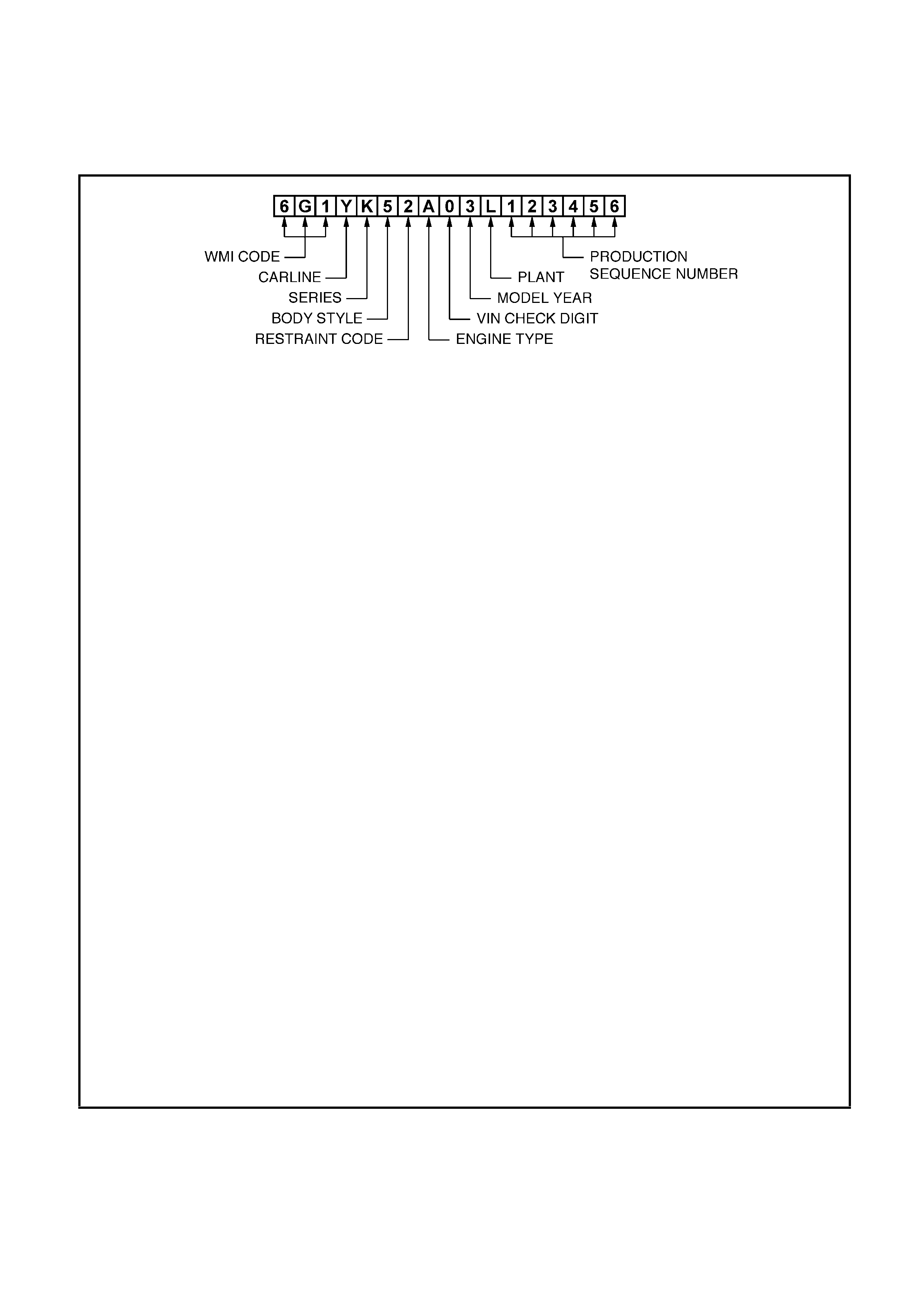
HOLDEN SERVICE TECHLINE_____________________________________________________________OCTOBER, 2002
16
VEHICLE IDENTIFICATION NUMBERING SYSTEM
WMI CODE: 6 – Oceania
G – Australia
1 – Holden
CARLINE: Y – VY series
2 – V2
LUXURY LEVEL: K – Level 1
L – Level 2
X – Level 3
BODY STYLE: 1 – 2 door coupe (37)
4 – 2 door utility (80)
5 – 4 door sedan (69)
8 – 5 door station wagon (35)
RESTRAINT CODE: 1 – Active (manual) seat belts
2 – Active (manual) seat belts with driver & passenger inflatable restraint
system – frontal
3 – Active (manual) seat belts with driver inflatable restraint system – frontal
4 – Active (manual) seat belts with driver & passenger inflatable restraint
system – frontal and side
ENGINE TYPE: A – 3.8 litre V6 engine (domestic variant)
R – 3.8 litre V6 engine supercharged
F – 5.7 litre GEN III V8 engine
VIN CHECK DIGIT: Calculated check digit
MO DEL YEAR: 3 – 2003
4 – 2004
PLANT: L – Adelaide (Elizabeth) South Australia
PRODUCTION SEQUENCE NUMBER:
123456 – Sequential Production Serial Number
NOTE: The production sequence number is sequentially allocated to each vehicle,
regardless of vehicle type.
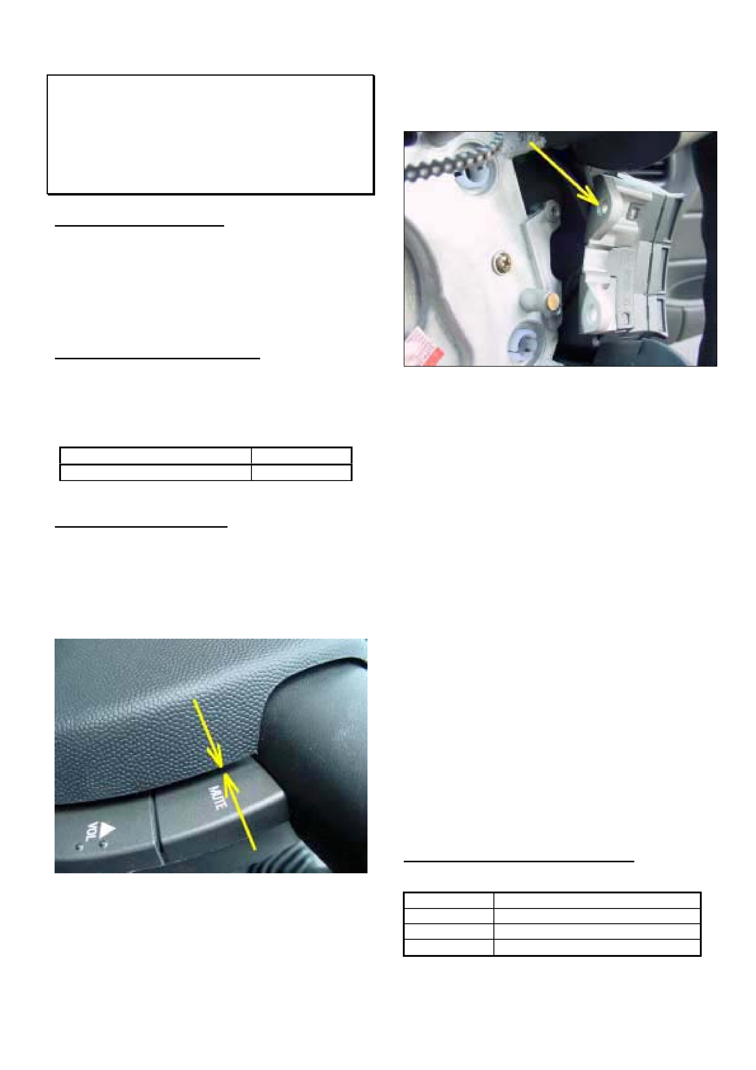
HOLDEN SERVICE TECHLINE_______________________________________________________________NOVEMBER, 2002
7
Horn Bar Activates Radio Remote
Switches
VY All
(GROUP 12) TL369-0210
PROBLEM DESCRIPTION
Horn bar when depressed may activate the top (mode
or mute) radio remote buttons.
Investigations reveal that incorrect assembly of the
radio remote switches to the steering wheel can result
in inadequate clearance between the hornbar and the
switches.
PRODUCTION RECTIFICATION
In addition to a revised assembly procedure for the
switches, the horn bar has also been revised to give
additional clearance. These changes were introduced
from:
ISOVIN: Build Date:
6G1YK52B93L923035 02/10/02
SERVICE RECTIFICATION
Summary: Inspect switches for correct mounting and
rectify if required. If problem persists, trim the sides of
the horn bar to give additional clearance.
Measure the horn bar to switch clearance as shown in
Figure 1.
Figure 1.
If the clearance is less than 4.5mm, the switch
assemblies should be checked as follows.
1. Remove the horn bar/air bag assembly as per SIP
procedure observing all precautions when removing
SRS components.
2. Remove both switch assemblies and inspect the
underside of the upper locating bore as shown in
Figure 2.
Figure 2.
3. A witness mark in the plastic foot around the
locating bore indicates the switch has been
assembled incorrectly. In severe cases the
locating bore may have a burr built up inside it
which can prevent positive seating of the switch to
the mating boss on the steering wheel.
4. Carefully remove any burrs prior to reassembling.
Re-assemble switches to steering wheel as follows:
5. Locate switch on bosses ensuring both locations
are seated correctly.
6. While supporting switch insert 2 screws into
position.
7. TIGHTEN TOP SCREW FIRST.
8. Tighten bottom screw second.
9. Reassemble horn bar.
10. Activate the horn bar to test for actuation of the
radio remote button.
If the condition still exists, trim 1.5mm off each side of
horn bar to provide additional clearance to switches.
WARRANTY CLAIM INFORMATION
Description Inspect Switches, Trim Horn bar
Labour Op. R000106
Time 0.5 hr
Failure Code 62
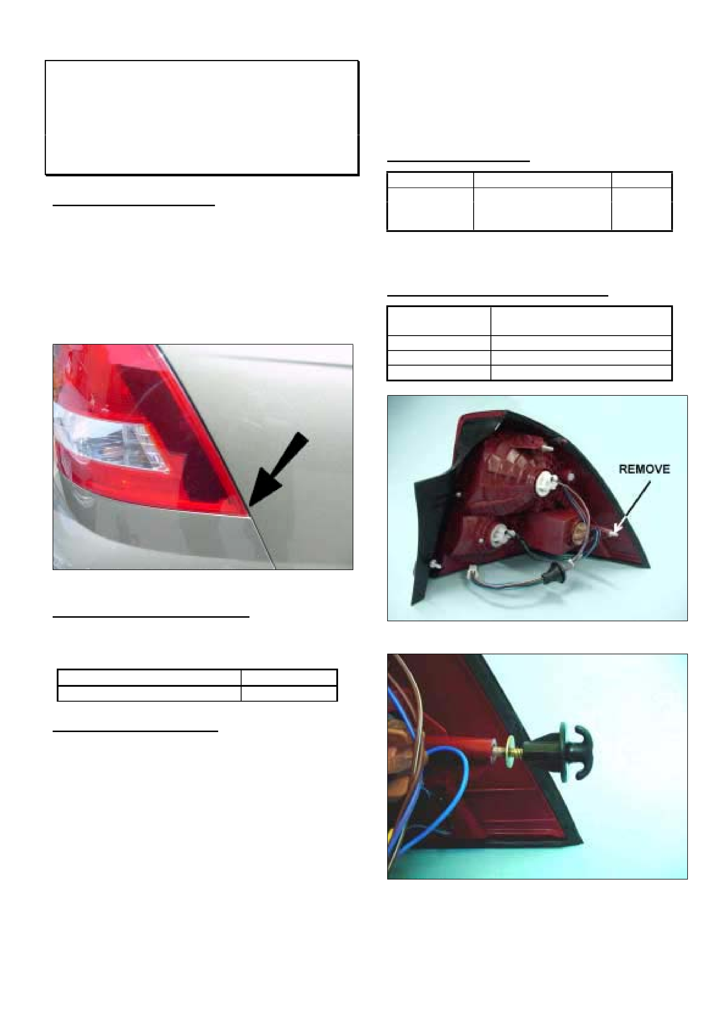
HOLDEN SERVICE TECHLINE_______________________________________________________________NOVEMBER, 2002
8
Tail Lamp Overflush To Rear Quarter
Panel
VY Sedan
(GROUP 12) TL372-0210
PROBLEM DESCRIPTION
On some vehicles the lower, forward facing corner of
the tail lamp may be overflush to the body panel. Refer
Figure 1. This condition can occur on either LH or RH
side tail lamp and may be worse in high ambient
temperatures.
The cause of this condition is an inability of this
particular mounting point on the lamp to provide
sufficient retention under all circumstances.
Figure 1.
PRODUCTION RECTIFICATION
Tail lamps with revised attachment at the lower
outboard mounting have been fitted to vehicles from:
ISOVIN: Build Date:
6G1YL54A73L923486 02/10/02
SERVICE RECTIFICATION
Summary: On complaint vehicles, rework tail lamp by
installing a threaded stud to the lower outboard
mounting point.
1. Remove tail lamp.
2. Remove existing stud shown in figure 2. Use
suitable socket or spanner.
3. Install threaded stud 92146445 as shown in
Figure 3. Before installing, apply 2 drops of Loctite
480 Instant Adhesive to the fine screw thread.
Use nut 92138628 as shown to install stud. When
stud is fully screwed home, hold stud flange firmly
with pliers before removing nut.
4. Install sealing washer 92145533 onto stud.
5. Remove plastic nutsert from sheet metal slot .
6. Reinstall tail lamp using nut 92138628 to attach
lamp at new stud location.
PARTS INFORMATION
Part No.: Description: Qty:
92146445 Mounting stud 1
92145533 Mounting seal 1
92138628 Nut – Tail Lamp 1
Note: Loctite 480 adhesive may be purchased from
most bearing or industrial suppliers.
WARRANTY CLAIM INFORMATION
Description Tail lamp mounting stud -
replace
Labour Op. No. N000405
Time 0.4 hr
Failure Code 55 poor fit
Figure 2.
Figure 3.
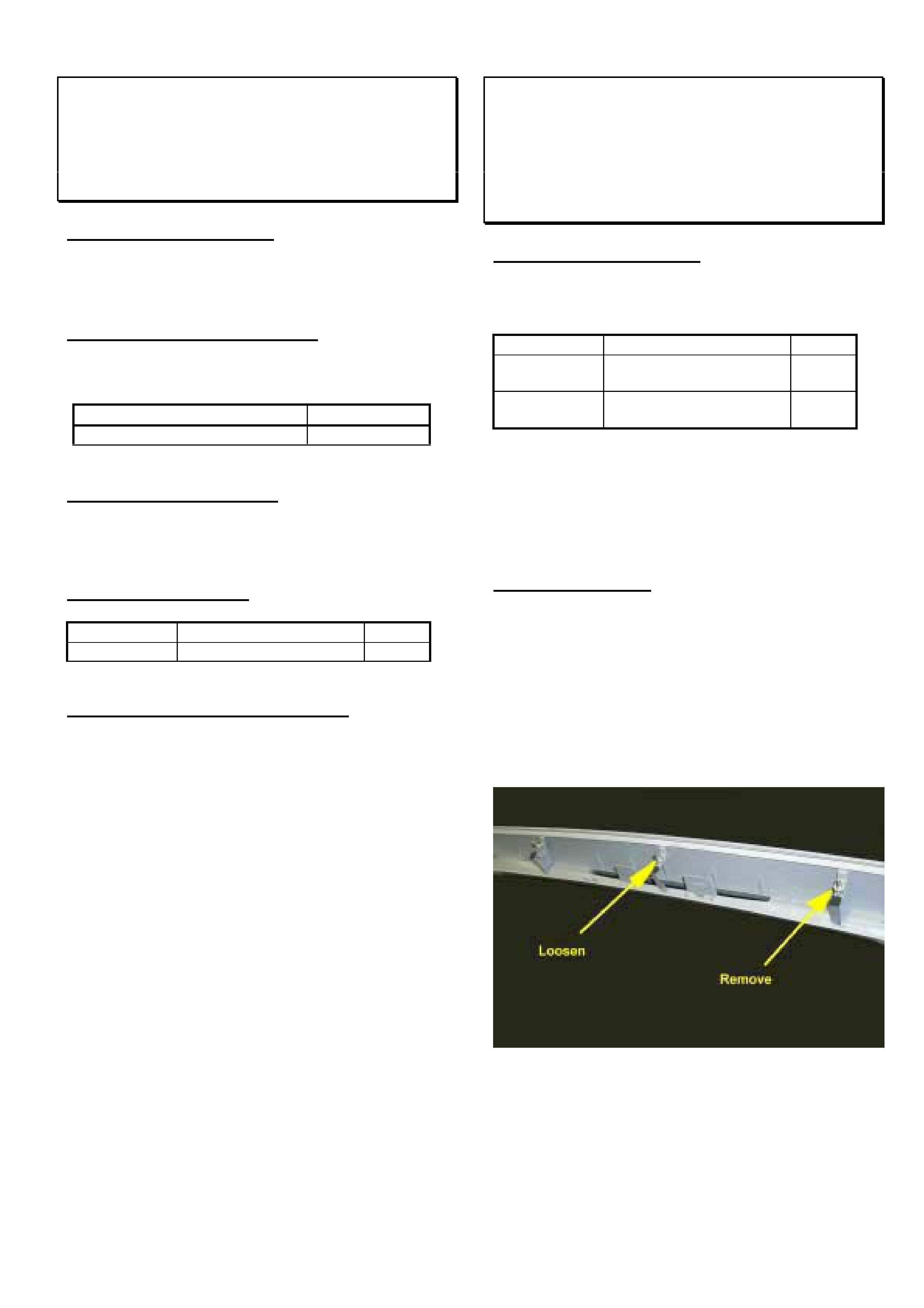
HOLDEN SERVICE TECHLINE_______________________________________________________________NOVEMBER, 2002
9
Wheel Centre Cap Dislodges
V2 Monaro with 18” Alloy Wheel
(GROUP 10) TL324-0210
PROBLEM DESCRIPTION
Under certain operating conditions the wheel centre
caps on the 18 inch alloy wheels may dislodge.
PRODUCTION RECTIFICATION
Revised centre caps with an added spring clip have
been fitted to vehicles from:
ISOVIN: Build Date:
6H8V2X37F2L924425 03/10/02
SERVICE RECTIFICATION
On vehicles where the cap is dislodged or missing, fit
revised design centre cap part number 92121783
PARTS INFORMATION
Part No.: Description: Qty:
92121783 Cap - wheel centre 1
WARRANTY CLAIM INFORMATION
Use Labour Times information in Warranty Information
section of current PV SIP CD
Assembly Instructions for Revised CHMSL
Replacement Parts From HSPO
VU SS
(GROUP 12) TL374-0210
PROBLEM DESCRIPTION
Service Techline Issue 8/2002 contained an item which
recommended the use of new parts as follows:
Part No.: Description: Qty:
92120002 Lamp Asm. Stop –
Centre High Mount
1
92120003 Moulding Asm. roof
rear centre(unpainted)
1
Some retailers have experienced difficulty in
assembling these parts.
The following notes and pictures will help to clarify the
assembly procedure.
ASSEMBLY NOTES
1. Remove the end stud and loosen the centre stud as
shown in Figure 1.
2. Install lamp as shown in Figure 2 and 3.
NOTE. The attaching holes in the ends of the lamp
have no use in this application. The lamp is secured by
the plastic clips in the moulding.
Figure1.
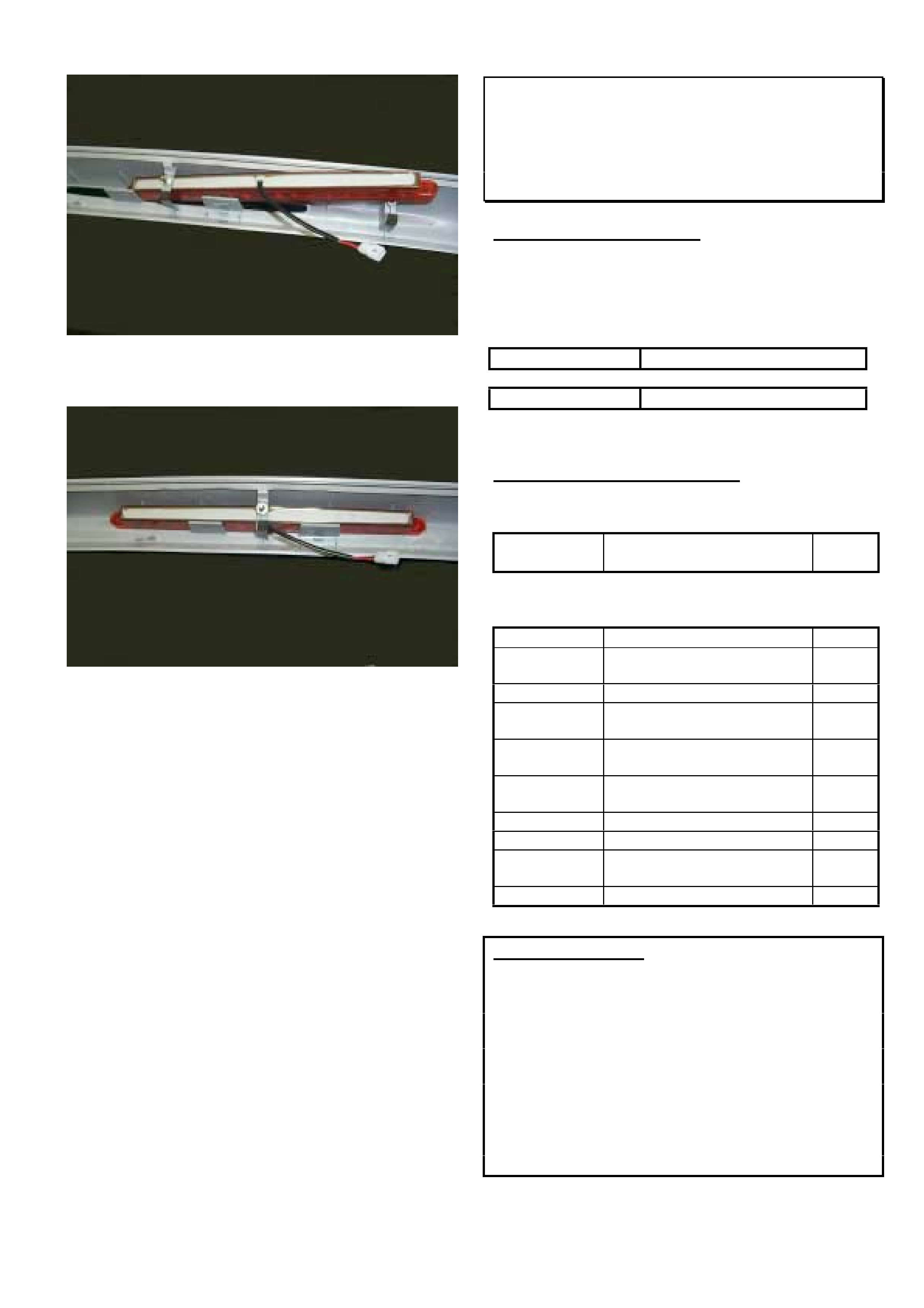
HOLDEN SERVICE TECHLINE_______________________________________________________________NOVEMBER, 2002
10
Figure 2.
Figure 3.
Timing Chain Serviceability
TT & TS with Z22SE Engine
(GROUP 6A) TL314-0210
PROBLEM DESCRIPTION
A number of revisions have been carried out to Z22SE
timing chain/drive components to improve quality and
durability.
These revised components have been fitted to engines
from:
Engine No.: Z22SETA099999
(“TA” in number = built at Tonewanda plant)
Engine No.: Z22SE11099999
(“11” in number = built at Kaiserslautern plant)
SERVICE RECOMMENDATION
When servicing timing chain/drive system, use the
following kit:
Part No.: Description: Qty:
12577164 Timing Chain Service Kit 1
FOR REFERENCE ONLY – Kit 12577164 consists of
the following parts:
Part No.: Description: Qty:
24461834 Timing Chain, Camshaft
Drive
1
12577163 Oil Nozzle (full flow) 1
24448509 Tensioner Asm. (“V”
Groove on end)
1
24449448 Guide – Chain, Moveable
(Tens. Side).
1
90537337 Guide – Upper (Cam to
Cam)
1
13104978 Guide – Chain, Fixed 1
24424758 Crankshaft Sprocket 1
90537632 Cam Sprocket (Inlet &
Exhaust)
2
90537451 Bolt – Camshaft Sprocket 2
PARTS WARNING:
The following (superseded design) timing chain
components must NOT be used in repairs:
13104980 Kit – Timing Chain
90537338 Chain – Timing
90537802 Tensioner Asm – Timing Chain
90537842 Guide – Timing Chain
90537476 Jet Asm. (Oil Nozzle)
Parts Managers Note:
The above parts should be returned to HSPO for credit
via the CRRM system.

HOLDEN SERVICE TECHLINE_______________________________________________________________NOVEMBER, 2002
11
Aftermarket Window Tinting Precautions
All
(GROUP 1) TL379-0210
PROBLEM DESCRIPTION
Some of the problems which can be caused by the
installation of aftermarket window tinting films are
detailed below:
Heated Rear Windows.
Some aftermarket window tint installers may scratch
the heating element or etch the glass (crack initiation
point) during installation of film tint material to the
tailgate glass. Because of the scratches made during
installation, the scratched heating element suffers a
semi-disconnected condition and the resistance
increases on the operating demister lines.
Also, aftermarket tint installers may disconnect the
heating terminals while affixing film tint material to the
tailgate glass and reinstall the heating terminals
loosely.
The above actions can lead to a localised overheat
condition and may result in glass breakage.
Telematics.
Aftermarket window tinting may affect the operation of
the antenna on vehicles fitted with Telematics. A
warning to this effect is given in Holden PV SIP in the
section on Telematics.
Remote Key Operation – TS Astra
There have been isolated reports of remote key
operation being adversely affected by window tinting. A
warning to this effect is given in the TS owners
handbook.
IMPORTANT WARRANTY NOTE
Tailgate glass breakage or any other condition
which can be attributed to the installation of
aftermarket film tint material is not covered under
the new vehicle warranty.
Engine Stall At Idle or High Engine Idle
Speed
TR Astra C18SEL engine
(GROUP 6C) TL375-0210
PROBLEM DESCRIPTION
Some owners may complain of the following symptoms:
With vehicle speed less than 3km/h or vehicle stationary,
the engine idle is too high; e.g. 1100 RPM+, and engine
may later stall or the idle may remain high.
This is caused by a build-up of deposits from engine by-
pass gases (IACV solenoid shaft/bearing wear particles
depositing on the IACV solenoid shaft) which may cause
the IACV to stick at any point in its operating range. This
results in either too high or too low IACV air entry to the
throttle body. When the IACV subsequently “unsticks”
and returns to normal operation, the result may be a stall
or higher than normal idle RPM. It is not possible to
effectively clean the IACV to correct this condition.
This behaviour can be confirmed by using Tech 2 to
monitor the IACV commanded steps compared with any
change in idle speed.
GENERAL MAINTENANCE NOTE
The need to carry out careful checks of all engine
compartment hoses at regular maintenance services is
stressed to all Technicians, to ensure continued, efficient
vehicle operation. This includes checking the engine
PCV and air intake hoses.
SERVICE RECTIFICATION
Summary: Fit revised IACV, Flash Program as required,
check/clean PCV port, check hoses.
On vehicles with the above symptoms perform diagnosis
to determine if the IACV is in fact the cause of the
problem. After confirming that nothing else is causing the
stall, fit the latest “diaphragm type” IACV using the
following procedure.
1. Remove old IACV and install new diaphragm type
IACV and gasket as per procedures shown in TIS
CD.
2. Fit the patch harness (refer Figure 1) – this is an
interface patch harness to connect the existing
vehicle wiring harness to the new IACV.
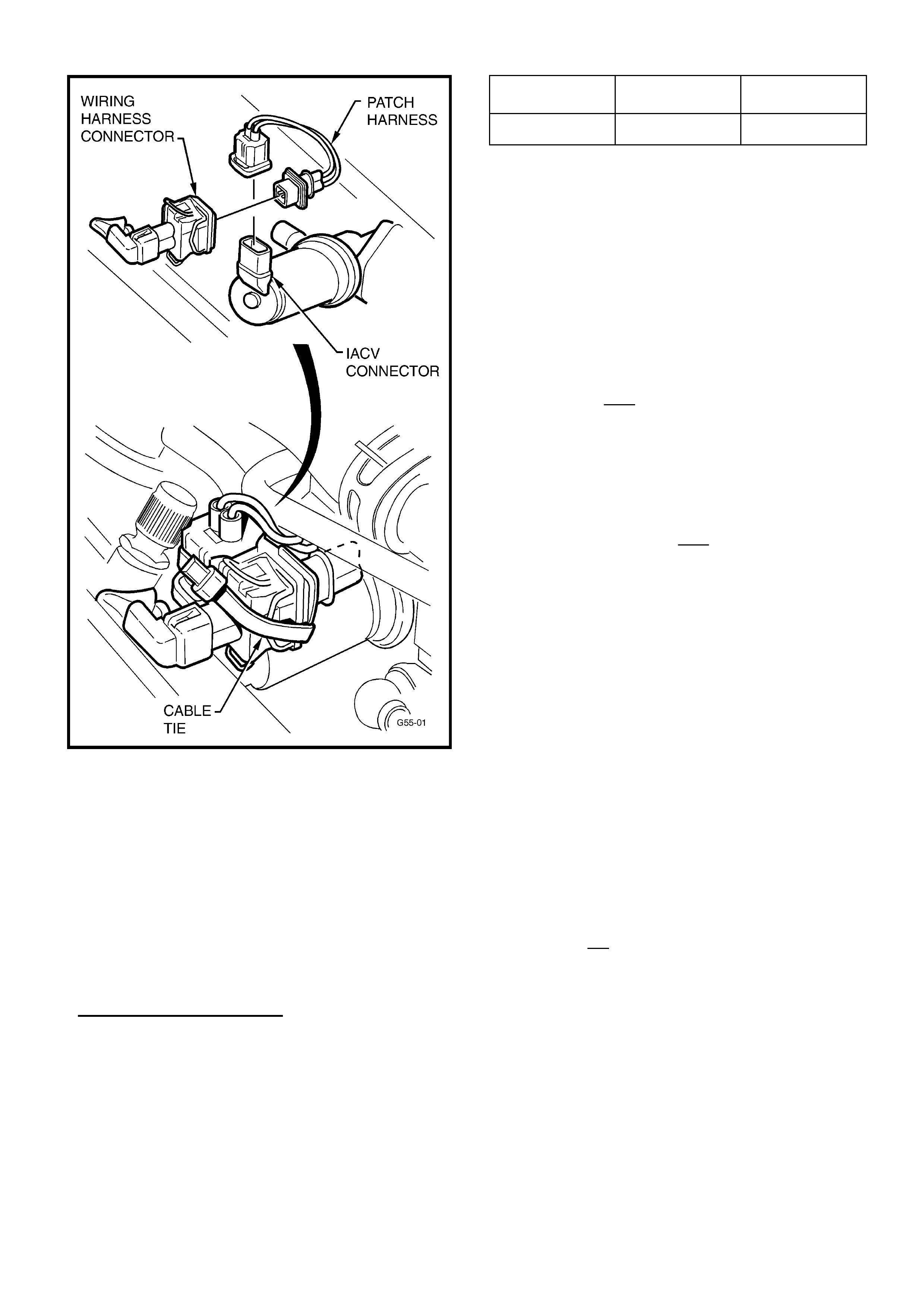
HOLDEN SERVICE TECHLINE_______________________________________________________________NOVEMBER, 2002
12
Figure 1.
3. Use a tie strap to firmly bind the wiring harness
connector to the IACV connector as shown in Figure
1. Cut off any excess strap.
4. Use TIS 2000 CD version 35 or later to flash
program the “New IACV” calibration into the vehicle
via TIS Service Programming System (SPS).
Refer to Flash Programming Details and Calibration
Part Numbers below.
Flash programming Details:
Select the vehicle parameters that apply to the
vehicle being programmed.
For example: Holden; ASTRA-F; 1997; C18SEL
Engine,
THEN, for “Type of Idle Air Control Valve” select
“New IACV (PN.: 92 065 903)”,
Model: Old
Calibration
New
Calibration
TR C18SEL 90562557.**** 93175681.****
(**** = any Number )
After reprogramming is completed proceed as follows.
5. CHECK FOR AND REMOVE ANY PREVIOUSLY
SET BASE IDLE AS PER STEPS (a) to (d) BELOW:
Failure to remove any previously set base idle will
affect the operating characteristics of the new IACV.
(a). With Tech 2 connected select the Data Display
screen, start the vehicle and allow it to come to
operating temperature (over 70 deg C coolant, and
inlet air temp between 20-30 deg C) with moderate
to high underbonnet temperatures)
(b). With A/C OFF check "IACV steps" at idle.
- If "IACV steps" is less than 20 - a base idle was
previously applied – complete step (c) below;
- If "IACV steps" is more than 20 - no adjustment is
required – go to Step 6 below..
(c). Loosen the idle screw and decrease the Throttle
Position until the IACV steps are within the following
range. A/C must be OFF, and transmission in
neutral:
Automatic: 23 - 27 steps.
Manual: 25 - 29 steps.
Re-tighten idle screw and conduct a final check of
the IACV steps.
6. Check and clean (where required) PCV hose/port on
all vehicles. This check and clean ensures no poor
idle/stall/DTC P0100 will result due to blockages,
after IACV fitting. Blockage of the PCV hose/port will
cause the engine to run on IACV air only at times.
Engine system calibration is based on specific air
flow through the PCV port PLUS IACV air at high
vacuum times (idle/decel) and thus, loss of air flow
through the hose/port can result in poor idle and
possibly stall.
Checking for blockages in PVC hose and port:
With engine idling, remove the PCV hose from the cam
cover (Hose 2 in Figure 3.) and check if there is
vacuum at the free end of the hose.
If vacuum is not present, remove the PCV hose from
the manifold port connection and check if there is
vacuum at the port.
(A) If vacuum is present at the port – replace the PCV
hose. No further action required.
(B) If there is no vacuum at port then proceed to clean
the port as follows.
Due to the location of the port in the manifold, it will be
necessary to remove the fitting from the manifold to
clean it. The fitting is shown in Figure 2.
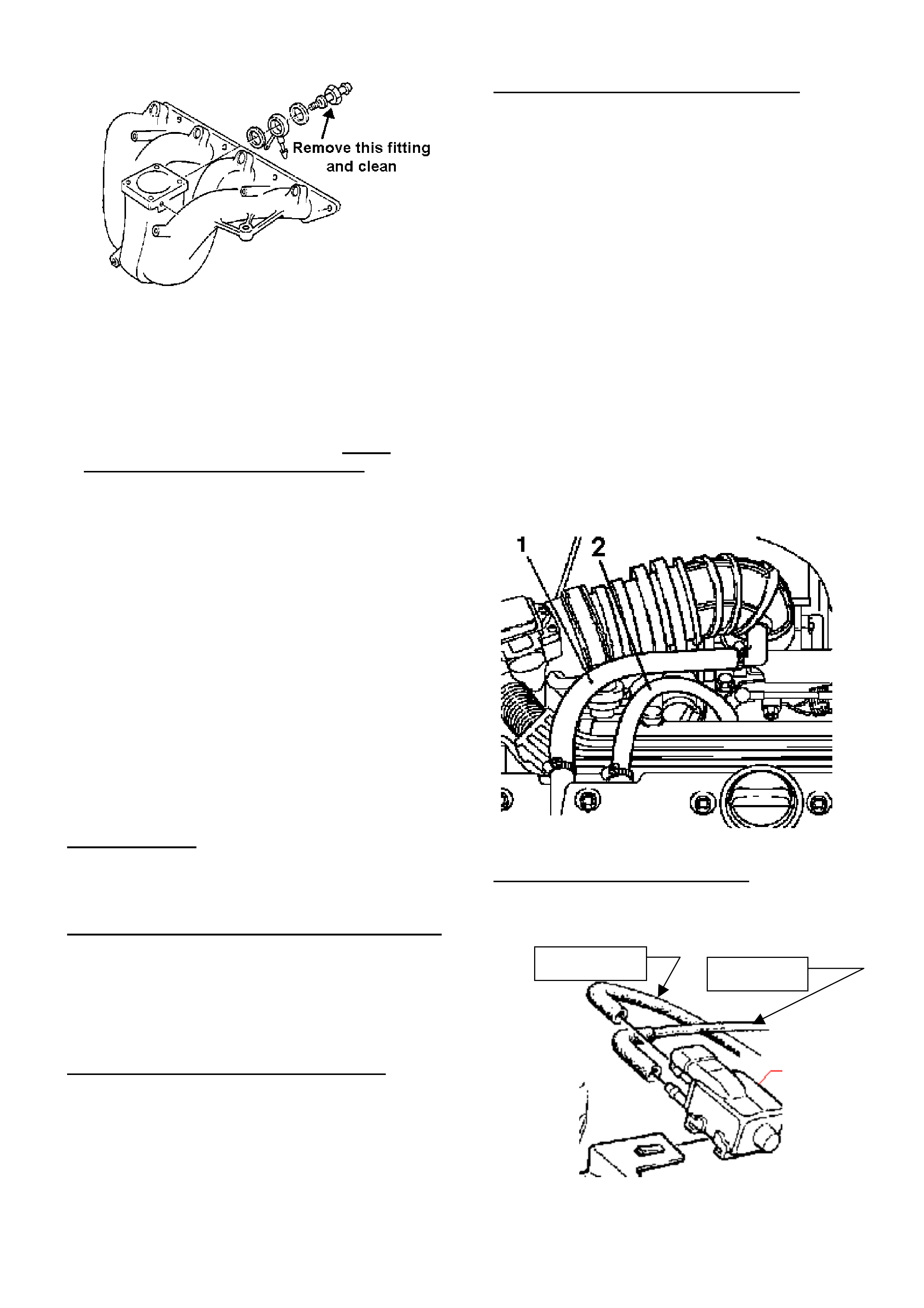
HOLDEN SERVICE TECHLINE_______________________________________________________________NOVEMBER, 2002
13
Figure 2.
This port may become blocked by contaminants carried
in PCV gas and, over time, the build-up will block the
small calibrated hole in the throttle body.
This hole can be carefully cleaned out as follows:
1. Obtain a 1.5mm Diameter drill bit. NOTE: drill bit
MUST not be larger than 1.5 mm Dia., as the hole
is calibrated. Enlarging the hole will result in incorrect
air flow, and cause driveability or further code setting
problems.
2. Using the 1.5mm Dia. drill bit, carefully insert the drill
into the fitting and rotate the drill bit BY HAND until
the deposits in the connection are dislodged and the
drill freely passes through the calibrated hole.
Ensure that the drill passes through the entire fitting.
3. Clean the connection with a solvent or spray cleaner
and remove any debris left in the connection hole.
4. Re-check that the hole is clear using the drill bit, and
re-assemble previously removed components.
5. Fit the PCV hose to the manifold end ONLY and
confirm that vacuum is present at the free end of the
hose. If not – replace PCV hose.
General Checks
The following checks should be done to prevent stalling
or other running problems caused by faults other than
the IACV.
Loose elbow in air intake duct (above throttle body
Should this elbow be “loose” in the main air intake duct,
the additional un-metered air entering the system can
cause driveability problems, poor idle, and a P0100 to
set.
If the elbow is loose – replace the inlet duct (containing
the elbow).
Damaged TPS housing on the throttle body
If the TPS housing has been damaged in any way that
allows air/water/dust, etc, to enter the TPS body, the
resulting contamination will cause incorrect operation
EG: Damage during any service operation,
engine/trans. removal, etc. Any TPS found with
damage to the external body must be replaced with a
new TPS.
Damaged/Degraded Secondary PCV Hose
Stalling may be caused if the secondary PCV hose
(Hose 1 shown in Figure 3) is split or torn, or the inner
hose walls have deteriorated.
Damage (split or torn)
Allows air to by-pass the mass airflow sensor, leading
to incorrect airflow readings which affect the engine
fuel ratio (runs lean). A DTC P0100 may be set.
Degraded
External degradation of the hose can result from age
and exposure to PCV gases, and external
contaminants that affect the hose. The hose should be
carefully examined for physical degradation, EG:
softness, cracking, hardness, etc, and replaced if
necessary.
Internal degradation allows the hose internal walls to
degrade and material will separate from the hose, and
thus become lodged in an ‘early’ or ‘old’ design IACV.
Replace the PCV hose if there is an extreme build-up
of PCV contaminants in the hose. NOTE: for this
reason, kinking the hose, or clamping any other
components to the secondary PCV hose is NOT
permitted.
Figure 3.
Purge valve hoses fitted in reverse
The hoses at the canister purge valve must be fitted
the correct way – with the throttle body hose at the top
purge valve fitting – as shown below:
To Canister
To Manifold

HOLDEN SERVICE TECHLINE_______________________________________________________________NOVEMBER, 2002
14
If these hoses are reversed – damage to the purge
valve may result – if this has occurred it is
recommended that the purge valve be replaced.
MAF SENSOR
The following information is repeated from a previous
Techline on Non-IACV related stall – for reference,
should a cause to P0100 not be found with the above
information.
Stalling associated with the MAF Sensor can occur
either while vehicle is moving or stationary. Usually a
DTC P0100 is set. (this DTC may also be set by a
fluctuating idle, so correct diagnosis of the type of stall
is required).
Some findings on failed MAF Sensors have been:
♦ Fretting corrosion of the MAF Sensor terminals.
(Replace suspect terminals.)
♦ Connectors not fully or correctly installed.
(Check connections and re-install if required.)
♦ Incorrect routing or attachment of sensor wiring.
(Check wiring against a known OK vehicle to ensure
the wiring is not run in an incorrect routing, so it
does not pick up any ‘stray’ electrical signals from
other wiring or components.)
PARTS INFORMATION
Use the following kit for replacement of IACV:
Part No.: Description: Qty:
92066066 IAC valve kit 1
Select other part/s for replacement from Partfinder.
Exhaust Outlet (Chrome) Alignment to
Rear Bumper Facia
VY V6 – “S”, Berlina & Calais
(GROUP 8) TL388-0210
PROBLEM DESCRIPTION
PIR’s have been received advising that some vehicles
have the exhaust outlet chrome extension misaligned
in the rear bumper facia opening - placing the exhaust
outlet on an angle or offset to one side.
PRODUCTION RECTIFICATION
Exhaust mufflers have been revised to improve
alignment from:
ISOVIN: Build Date:
6GIYL52B73L933057 25/10/02
SERVICE RECTIFICATION
Summary: Enlarge tailpipe slot for adjustment.
To reposition the exhaust outlet in the bumper facia
opening:
1. Disconnect the rear muffler assembly from the
exhaust system, immediately behind the rear axle.
2. At the front of the rear muffler (pipe) connection
there is a small slot to “key” the muffler to the
exhaust pipe – enlarge this slot by filing the UPPER
EDGE of the slot until the opening is 11.0mm wide.
3. Refit the rear muffler to the exhaust system –
making sure to centralise the exhaust outlet
chrome extension in the rear bumper facia -
and tightening the pipe attaching clamp bolts.
WARRANTY CLAIM INFORMATION
Use the existing Labour Operation Number AS
SHOWN to claim for the above task:
Description Rear Muffler – Re-Align
Labour Op. No. L503500
Time 0.4 hr
Failure Code 25 (misaligned)

HOLDEN SERVICE TECHLINE_______________________________________________________________DECEMBER, 2002
7
Modular Reservoir Assembly (MRA)
Replacement and Fuel Gauge Calibration
VXII, WHII, VUII, V2
(GROUP 8 & 12) TL352A-0211
The previous Techline on this subject in Issue 8,
Sep/2002 is now cancelled as a result of software
revisions in TIS 36.0B.
All printed versions of that article should be
destroyed.
CAUTION - Do Not Use TIS CD’s 36 or 37
for SPS Programming
VX,VU,V2,VY,WH with Gen III & A/T
(GROUP 6C) TL403-0211
The information in this Service Techline is taken from
Retailer Letter RL84/00, issued on 5 December,
2002.
TIS CD’s 36 & 37
The SPS (flash programming) calibrations for the
above models have errors in the engine torque
management area. This affects the application of
torque during A/T shifts, and may affect A/T durability.
Do NOT use TIS CD’s 36 or 37 to perform SPS
(“flash program”) any VX/VU/V2/WH/VY, Gen III A/T
equipped vehicles.
If SPS programming is necessary on these models,
use only CD 35 or earlier, until CD 38 with corrected
calibrations is available in February, 2003.
VEHICLES NOT AFFECTED:
SPS calibrations are not affected for:
Gen III M/T vehicles,
VT Series II vehicles,
WH built pre-A8A, (before L626038),
and vehicles other than V & W cars
WHEN IS FLASH PROGRAMMING REQUIRED?
Some technicians are flash programming vehicles at
pre-delivery and during maintenance services – this
practice is unnecessary and is to be discouraged.
Flash Programming should only be done in the
following circumstances:
• When recommended in Service Techline/Retailer
letter.
• When recommended by TAS.
• When installing a new PCM
Note: calibrations contained in TIS “lag” behind the
production used calibrations by some months due to
TIS production timing, therefore use of TIS calibrations
without positive advice may be counter-productive.

HOLDEN SERVICE TECHLINE_______________________________________________________________DECEMBER, 2002
8
Customer Complaint - “Scheduled
Service Reminder did not display”
Service Reminder Due - Resetting
Procedure
VY All
(GROUP 12) TL396-0211
The purpose of this Techline is to clarify the
procedures for resetting the “Service Reminder Due”
function and to outline the possible customer
complaint which can occur if the incorrect method is
used.
Customers may advise that they have passed the
scheduled service without the service reminder being
displayed in the instrument cluster.
The service reminder is designed to display 1000
km’s before the service is due. However if the
previous service was performed when the vehicle
was overdue and the service reminder was reset
using the trip computer buttons the instruments
clusters calculation of the next service due may be
incorrect.
There are 3 different methods available to set the
next service due reminder. The method used will
depend upon whether the vehicle odometer reading
is under or over the specified service interval.
Case A. Odometer reading is LESS THAN the
specified service interval.
Example - Next service due - 15,000km.
If the vehicle odometer reading is below the
scheduled service interval (e.g. 14,700 km) reset with
the trip computer buttons or Tech 2.
The next service due will then display at 30,000km.
Case B. Odometer reading is GREATER THAN
the specified interval.
Example. Next service due - 15,000km.
If the current odometer is over the scheduled service
interval (e.g. 15,300 km) a reset should be done
with Tech 2 by selecting the following:
F0: Diagnostic / (3) 2003 / VY Commodore / F3: Body
/ Instrument / F5: Program / F4: Reset Service
Interval.
DO NOT use the trip computer buttons in this case
otherwise the next service due reminder will first
display at 30,500 km.
Case C. Scheduled Service Reminder did not
display.
Checking for the condition.
The “First / Next Service” can be displayed via Tech
2 by selecting the following:
F0: Diagnostic / (3) 2003 / VY Commodore / F3:
Body / Instrument / F2: Data Display / F2:
Configuration.
Repairing the condition
If service interval has already been reset using the
mode switch and caused an incorrect service interval
it can be rectified by reprogramming the instrument
configuration with Tech 2 as per SIP Section 12C / 3.
By selecting the following:
F0: Diagnostic / (3) 2003 / VY Commodore / F3: Body
/ Instrument / F5: Program / F1: Configuration.
Do not change the configuration settings; press
the “Program” soft key. Tech 2 will then recalculate
the service interval while maintaining the current
instrument configuration settings.
PRODUCTION RECTIFICATION
An instrument software revision which will remove the
requirement to use Tech 2 in case B and C is in
progress. The introduction of this revision will be
advised in a future Techline Breakpoint Summary.
IMPORTANT: Vehicles built prior to the introduction
of this revised software will continue to require Tech
2 to reset the service interval if the service is
overdue.
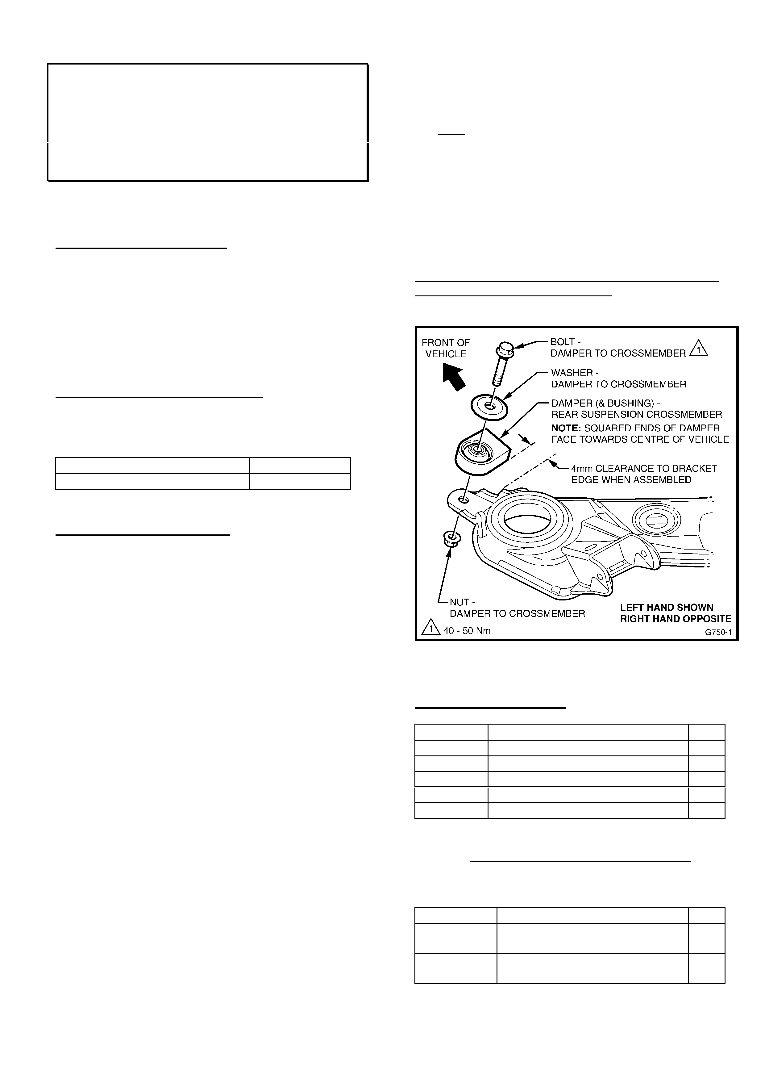
HOLDEN SERVICE TECHLINE_______________________________________________________________DECEMBER, 2002
9
“Moan” Noise From Rear Cross Member
at 105–110 km/h
WH, VX with Gen III V8 & A/T
(GROUP 4) REVISED TL311B-0211
This Techline supersedes the previous one in Issue
8/2002. It is revised by adding Parts Information.
PROBLEM DESCRIPTION
Some vehicles may exhibit a “moan” or “drone” noise
at 105 -110km/h, which is similar to exhaust
resonance or “cavity boom”.
This noise may be caused by excitation of the rear
suspension cross member by input of various
drivetrain and tyre related vibrations.
PRODUCTION RECTIFICATION
Revised cross members with vibration dampers have
been fitted to vehicles with Gen III V8 from:
ISOVIN: Build Date:
6H8VXX69F2L908900 23/08/02
SERVICE RECTIFICATION
Summary: Diagnose for complaint condition. Once
confirmed, obtain zone approval to replace
Xmember.
Rectification of this condition relies on accurate
diagnosis.
The “moan” or “drone” noise occurs:
- between 105km/h and 110km/h
- at constant throttle for some distance
- travelling on a straight road.
When the condition occurs, steer the vehicle from
side to side within the lane the vehicle is travelling in.
If the condition varies significantly, the condition is
confirmed.
The condition should not be confused with any
exhaust or other driveline vibration or resonance that
is NOT reduced by this steering input!
Should you be unsure of correct diagnosis of this
condition – contact TAS for confirmation of your
diagnosis process, as incorrect diagnosis may lead to
replacement of unrelated components, unnecessary
vehicle time off the road, and adverse customer
reaction.
NOTE: ZONE AUTHORISATION IS REQUIRED
BEFORE REPLACING A CROSS MEMBER FOR
THE CONDITION DESCRIBED IN THIS BULLETIN.
After obtaining Zone authorisation:
1. Fit the cross member and parts shown in Figure
1 below.
Note: Vehicles built prior to VX Series II will
require the (unused) LH toe link attaching bracket
to be bent to provide clearance to exhaust
system.
2. Road test to confirm that the condition is
corrected
3. If a TAS case was previously opened,
immediately contact TAS to close the case.
When replacing cross members observe the
procedures outlined in the SIP CD.
Figure 1.
PARTS INFORMATION
Part No.: Description: Qty:
92145688 Cross Member Asm. - RR Susp. 1
92115982 Damper, Rear Susp. C/Member 2
11098391 Bolt – Damper to C/Member 2
11095804 Nut - Damper to C/Member 2
92001572 Washer – Damper to C/Member 2
NOTE: For vehicles built prior to Model Year 2002
that are fitted with Ride Levelling suspension, the
following additional parts are required, for attachment
of ride levelling Height Sensor:
Part No.: Description: Qty:
92102775 Bracket – Height Sensor to
C/Member
1
11081822 Bolt – Sensor Bracket to
C/Member
1
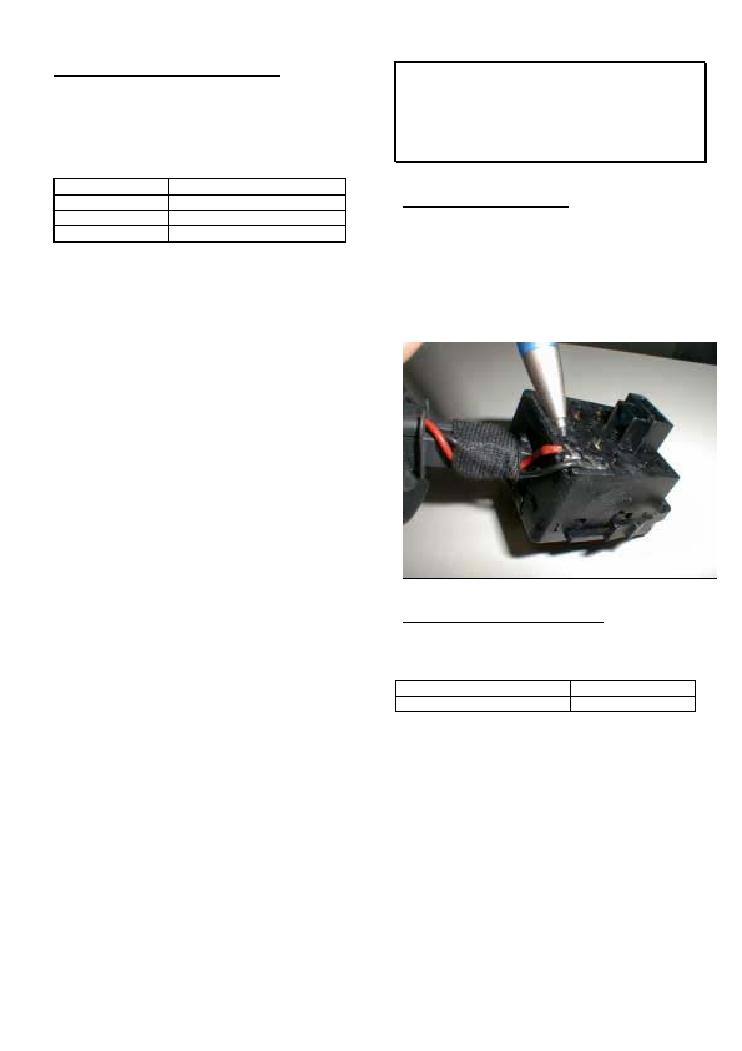
HOLDEN SERVICE TECHLINE_______________________________________________________________DECEMBER, 2002
10
WARRANTY CLAIM INFORMATION
When fitting the cross member and parts described
above use the following information:
NOTE: ZONE AUTHORISATION IS REQUIRED
BEFORE REPLACING A CROSSMEMBER.
Description Cross Member - Replace
Labour Op. No. F000179
Time 3.6 hrs
Failure Code 36
Cruise Control Inoperative
XC SRi
(GROUP 12) TL370-0211
PROBLEM DESCRIPTION
Cruise control function will not operate. Tech 2
shows DTC B3794 - “Cruise control device circuit
open or voltage high”.
Investigation of vehicle complaints reveals that in
majority of cases the red wire in the rear of the turn
signal switch block is broken at the soldered
connection as shown in the photograph below.
PRODUCTION RECTIFICATION
Turn signal switches with wires rerouted to reduce
tension, have been fitted to vehicles from:
ISOVIN: Build Date:
W0L0XCF0834057879 27/9/2002

HOLDEN SERVICE TECHLINE_______________________________________________________________DECEMBER, 2002
11
SERVICE RECTIFICATION
Summary: On complaint vehicles, diagnose cruise
control circuit and install new indicator switch
assembly as necesary.
Step 1. Perform cruise control diagnosis using TIS
procedure. Locate TIS procedure as follows.
Start at TIS main screen then select the following ê
êê
ê
Checking procedures(Tech 2)
Diagnostic mode
Opel
XC Corsa
2002
Z18XE
Body system(double click)
Body control system(double click)
Body control module
Validate vehicle options (skip this screen)
Non guided electronic system diagnosis
B- xx Functional group test
B-02- Data List
T-49 Tester Display Cruise Control Signal
Step 2. If voltages measured in test T-49 are not
within range of listed nominal values then cruise
control circuitry is suspect and indicator switch wiring
should be inspected. If inspection shows that wiring
is okay, then standard diagnosis procedures should
be followed.
PARTS INFORMATION
Part No.: Description: Qty:
09185414 Switch turn signal with
cruise control
1
WARRANTY CLAIM INFORMATION
Use Labour Times information in Warranty
Information section of current PV SIP CD
Fuel Tank Vent Line Routing
TS & Z18XE
(GROUP 8) TL387-0211
PROBLEM DESCRIPTION
On some vehicles the fuel tank vent line may appear
to hang too low underneath the vehicle.
This condition has only arisen since revised fuel
feed, fuel return and fuel vent lines were
introduced on vehicles built from 2/10/2001
(W0L0TGF4825044915).
SERVICE RECTIFICATION
Summary: On any vehicle with above condition,
reposition vent line as per following procedure.
1. Lift vehicle on hoist.
2. Refer figure 1. Move the fuel vent line (#1)
towards rear of vehicle until it is raised nearly
level with the fuel line (#2).
3. Ensure the gap between the vent line and the
heat shield is not reduced to below 10mm as
shown in Figure 2..
4. Ensure vent line is still retained fully within in all
nylon retaining blocks in the underbody.
5. Attach and tighten a nylon tie strap (3mm wide)
to the vent line as shown in Figure 3 just
rearward of the retaining block. This will prevent
the vent line from “creeping” back into its original
position.
6. Procedure is completed.
WARRANTY CLAIM INFORMATION
Description Fuel tank vent line -
reposition
Labour Op. No. L000211
Time 0.3 hr
Failure Code 62 Improper clearance
PRODUCTION RECTIFICATION
A reduced length fuel tank vent pipe is planned for
introduction on December built vehicles. When
breakpoints become available they will be added to a
future Breakpoint Summary.
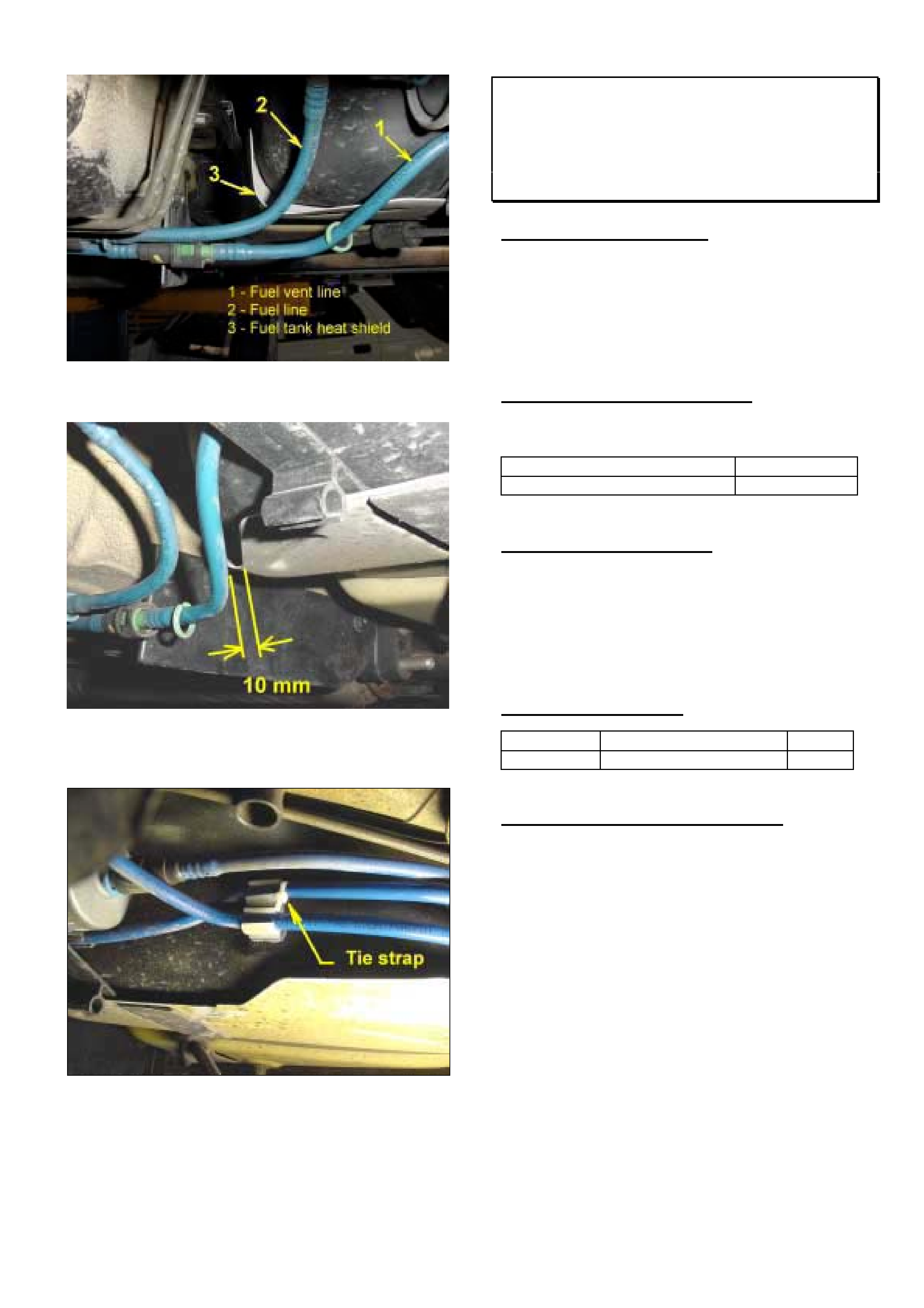
HOLDEN SERVICE TECHLINE_______________________________________________________________DECEMBER, 2002
12
Figure 1. Shows vent line in “lifted up” position.
Figure 2 Minimum clearance, vent line to Heat
shield
Figure 3. Tie strap added to prevent movement
Fuel Filler Cap Hard To Remove
VU, VY Utility
(GROUP 8) TL405-0211
PROBLEM DESCRIPTION
Some owners may complain that the fuel filler cap is
difficult to unscrew.
The root cause of this condition has been traced to
the use of incorrect lubricant to install the o-ring seal
onto the cap during manufacture. This has resulted
in a binding up of the o-ring in the fuel filler neck
PRODUCTION RECTIFICATION
Revised caps with correct lubricant used on o-rings
have been fitted to vehicles from:
ISOVIN: Build Date:
6G1YK43A43L937599 4/11/02
SERVICE RECTIFICATION
On complaint vehicles install a new fuel filler cap with
a date code greater than “06 J 2”. (6 Sep 02).
This date code is moulded into the screw section of
the cap.
All HSPO supplied fuel filler caps are manufactured
after this date code
PARTS INFORMATION
Part No.: Description: Qty:
92027613 Cap asm fuel tank filler 1
WARRANTY CLAIM INFORMATION
Use Labour Times information in Warranty
Information section of current PV SIP CD

HOLDEN SERVICE TECHLINE_______________________________________________________________DECEMBER, 2002
13
Headlamp Range Adjustment
TS Convertible
(GROUP 12) TL384-0211
Some owners may comment that there is no
perceptible change in headlamp angle when moving
headlamp range switch between settings 1 and 2.
This is a design characteristic of this model and is
due to the specific shock absorber/spring system
design for TS convertibles.
SERVICE ADVISERS NOTE
If customers query this condition advise them as
explained above ;
“This is a design characteristic of this model and is
due to the specific shock absorber/spring system
design for TS convertibles.”
NOTE: The owners handbook will be revised at the
next reprint to include reference to the above
condition.
Instrument Cluster DTC 10 (New
Vehicles Only)
VY without Occupant Climate Control
(GROUP 12) TL385-0211
PROBLEM DESCRIPTION
DTC 10 (no serial data from Occupant Climate
Control) has been present on all new vehicles without
OCC from start of VY production due too incorrect
instrument configuration.
This DTC will not cause any symptoms which can be
detected by the customer and is only evident when
DTC’s are checked with Tech 2 or using the
Instrument cluster self diagnostic mode.
PRODUCTION RECTIFICATION
DTC 10 has been corrected in new vehicles
commencing from:
ISOVIN: Build Date:
6G1YK54F63L923932 3/10/02
SERVICE RECTIFICATION
DTC10 can now be rectified using the latest Tech 2
software version 11.6 / TIS 36.0B or later.
It is now possible to re-configure the instrument
cluster for vehicles without OCC by performing the
following steps.
1. Using Tech 2 select the following; F0:
Diagnostics / (3) 2003 / VY Commodore / F3:
Body / Instrument / Program / F1: Configuration
2. Scroll through the configuration menu using the
UP / DOWN arrow keys until the Occupant
Climate Control option is highlighted.
3. Press the ENTER key, this will then allow you to
modify the selection (using the UP / DOWN
arrow keys) from PRESENT to NOT PRESENT.
4. Once the correct selection is highlighted press
the MODIFY soft key, this will then return you to
the selection menu.
5. Press the program soft key to initiate the
programming process.
6. Press the confirm soft key when notified that the
programming has been completed successfully.
7. Turn the ignition off then on again to accept the
programming change.

HOLDEN SERVICE TECHLINE_______________________________________________________________DECEMBER, 2002
14
Spigot Bearing “Squeal” Noise on Cold
Start
VT, VX, VU, V2
(GROUP 7A) “REVISED” TL245A-0211
This Techline supercedes the previous one in Issue
9, Oct, 2002. Revisions have been made to the
breakpoint information.
PROBLEM DESCRIPTION
A “squeal” noise may be heard, from the spigot
bearing, at the first use of the clutch pedal after a
cold start. The noise may repeat several times when
the clutch is disengaged, during engine warm-up.
This noise is caused by a combination of damage to
the spigot bush during initial installation and lubricant
“drying out”.
To avoid possible installation damage, revised tooling
and installation processes have been introduced.
To eliminate the lubricant “dry-out”, the bush is now
impregnated with synthetic oil with 10%
molybdenumdisulphide.
PRODUCTION RECTIFICATION
First engine produced using revised bush installation
processes:
Engine No.: VA221827
First use of engines with revised bush installation
processes:
ISOVIN (for Reference): Build Date:
6H8VUK80A2L865092 13/05/02
First use of engines with revised lubricant for bushes:
ISOVIN: Build Date:
6G1YK52A73L953884 07/12/02
SERVICE RECTIFICATION
Summary: Fit new spigot bush.
To rectify this condition, replace the existing spigot
bush with a new bush, p/n 92116034.
NOTE:
• Do NOT attempt to lubricate a ‘noisy’ spigot
bush. Replace it!
• When lubricating a new spigot bush prior to
assembly – use only synthetic oil. Do NOT use
grease.
PARTS INFORMATION
Part No.: Description: Qty:
92116034 Spigot Bush 1
WARRANTY CLAIM INFORMATION
Use existing Labour Time information in Warranty
Information section of current PV SIP CD.

HOLDEN SERVICE TECHLINE_______________________________________________________________DECEMBER, 2002
15
A/C Condensor Fan Deleted On 2003
Model Year
TS Z18XE with M/T
(GROUP 2) TL404-0211
Some PIRs have been received which report that the
condensor fan is missing from above models.
Please note that this is standard condition for this
new model.
The condensor fan is no longer required because:
• The engine fan motor is replaced by a stronger
one therefore additional fans are not required.
• The engine fan speed is now controlled by three
relays.
• The engine control unit now controls the
operation of the fan motor.
• The MKM Control Unit (cooling system control
module) is no longer required as its functions are
now performed by the engine control unit.
NOTE: The above information can be found in TIS.
as follows.
Start at TIS Main Screen then select the following ê
êê
ê
Service Information
New Technical Features
➞
Model Year 2003
Document List
➞
Contents List New Technical Features for MY 2003
➞
Astra-G
➞
Air Conditioning
➞
Change to cooling module components
Engine Hard To Start After Stop
VS 5.0L V8 Series 3 Statesman, Caprice
and Utility
(GROUP 6C) TL368-0211
PROBLEM DESCRIPTION
Customers may complain of being unable to re-start
the engine after moving the ignition key back to the
‘accessory’ position, EG: For short term stops where
the ignition switch is not turned to the “off” position for
ignition key removal.
Vehicles suffering from this complaint can be started
by fully switching off the ignition, waiting 20 seconds,
and then starting the engine.
The cause of this inability to restart is software
related, whereby the engine “run” injector pulse width
signals are retained in memory when the key is not
cycled to the “Off” position. This minimal pulse width
remains available in memory for re-starting, but will
not provide the “start” injector pulse width (richness)
to allow the engine to re-start.
Memcals with this condition are:
Memcal Code Application
CJYN 175 Kw Auto
CJYM 175 Kw Manual
CNPD 195 Kw Auto
CNPC 195 Kw Manual
SERVICE RECTIFICATION
On complaint vehicles fit revised memcal as shown
below.
PARTS INFORMATION
Revised memcal details:
Part No. Memcal Code Application
12221184 DRRP 175 Kw Auto
12221190 DRRT 175 Kw Manual
12221188 DRRS 195 Kw Auto
12221186 DRRR 195 Kw Manual