
Lighting System Page 12B–1
Page 12B–1
Section 12B
Lighting System
ATTENTION
Before performing any service operation or other procedure described in this Section, refer to Section 00
Warnings, Cautions and Notes for correct workshop practices with regard to safety and/or property damage.
1 General Information, Sedan, Wagon, Utility and Crew Cab...............................................................8
1.1 Headlamp Assembly.............................................................................................................................................. 8
Level 1 Vehicles..................................................................................................................................................... 9
Level 2 and Level 3 Vehicles............................................................................................................................... 10
1.2 Front Fog Lamp Assembly .................................................................................................................................. 11
1.3 Tail Lamp Assembly............................................................................................................................................ 12
1.4 High-mount Stop Lamps..................................................................................................................................... 14
1.5 Interior Illumination ............................................................................................................................................. 15
Level 1................................................................................................................................................................... 15
Level 2 and Level 3.............................................................................................................................................. 16
1.6 Instrument and Switch Illumination ................................................................................................................... 17
Headlamp Switch................................................................................................................................................. 18
Police Lights-out Switch..................................................................................................................................... 18
Daylight Running Lamp (Option T82)................................................................................................................. 18
2 General Information, Coupe................................................................................................................19
2.1 Headlamp Assembly............................................................................................................................................ 19
2.2 Park and Front Fog Lamp Assembly.................................................................................................................. 20
2.3 Tail Lamp Assembly............................................................................................................................................ 21
2.4 High-mount Stop Lamps..................................................................................................................................... 22
2.5 Interior Illumination ............................................................................................................................................. 23
2.6 Instrument and Switch Illumination ................................................................................................................... 24
Headlamp Switch................................................................................................................................................. 24
3 General Information, Regular Cab and Crew Cab with 'Delete Tub' Option...................................25
3.1 Tail Lamp Assembly............................................................................................................................................ 25
3.2 Rear Licence Plate Lamp Assembly................................................................................................................... 26
3.3 Transport Bracket................................................................................................................................................ 27
4 General Information, AWD Wagon......................................................................................................28
4.1 Tail Lamp Assembly............................................................................................................................................ 29
4.2 Backup Lamp Assembly ..................................................................................................................................... 30
4.3 Liftgate Air Deflector Assembly and High-mount Stop Lamp Assembly........................................................ 31
Techline
Techline

Lighting System Page 12B–2
Page 12B–2
5 Service Operations — Exterior Illumination, Sedan, Wagon, Utility and Cre w Cab......................32
5.1 Headlamp and Front Fog Lamp Aiming............................................................................................................. 32
Headlamp Assembly Aim.................................................................................................................................... 32
Front Fog Lamp Assembly Aim.......................................................................................................................... 34
5.2 Headlamp and Park Lamp Assembly Bulbs...................................................................................................... 36
Level 1................................................................................................................................................................... 36
Replace — Low Beam Bulb ............................................................................................................................. 36
Replace — High Beam Bulb............................................................................................................................. 37
Replace — Park Lamp Bulb............................................................................................................................. 39
Level 2 and Level 3.............................................................................................................................................. 40
Replace — Low Beam Bulb ............................................................................................................................. 40
Replace — High Beam Bulb............................................................................................................................. 42
Replace — Park Lamp Bulb............................................................................................................................. 44
5.3 Front Turn Signal Lamp Bulb.............................................................................................................................. 45
Replace................................................................................................................................................................. 45
5.4 Front Fog Lamp Bulb Assemblies...................................................................................................................... 46
S and SS ............................................................................................................................................................... 46
Replace............................................................................................................................................................ 46
Level 2 and Level 3.............................................................................................................................................. 47
Replace............................................................................................................................................................ 47
5.5 Tail Lamp Assembly Bulbs ................................................................................................................................. 49
Sedan.................................................................................................................................................................... 49
Replace............................................................................................................................................................ 49
Wagon................................................................................................................................................................... 50
Replace............................................................................................................................................................ 50
Utility and Crew Cab............................................................................................................................................ 51
Replace............................................................................................................................................................ 51
5.6 Headlamp Assembly............................................................................................................................................ 52
Remove................................................................................................................................................................. 52
Reinstall................................................................................................................................................................ 53
5.7 Front Fog Lamp Assembly .................................................................................................................................. 54
Remove................................................................................................................................................................. 54
Disassembly......................................................................................................................................................... 54
Reassembly.......................................................................................................................................................... 55
Reinstall................................................................................................................................................................ 55
5.8 Tail Lamp Assembly............................................................................................................................................ 56
Sedan.................................................................................................................................................................... 56
Remove............................................................................................................................................................ 56
Replace — Main Seal....................................................................................................................................... 57
Reinstall ........................................................................................................................................................... 57
Wagon................................................................................................................................................................... 58
Remove............................................................................................................................................................ 58
Reinstall ........................................................................................................................................................... 58
Utility and Crew Cab............................................................................................................................................ 59
Remove............................................................................................................................................................ 59
Reinstall ........................................................................................................................................................... 59
5.9 Side Repeater Lamp Assembly........................................................................................................................... 60
Except SS ............................................................................................................................................................. 60
Remove............................................................................................................................................................ 60
Reinstall ........................................................................................................................................................... 60
SS Only................................................................................................................................................................. 61
Remove............................................................................................................................................................ 61
Reinstall ........................................................................................................................................................... 61

Lighting System Page 12B–3
Page 12B–3
5.10 High-mount Stop Lamp Assembly ..................................................................................................................... 62
Sedan Without Rear-end Spoiler........................................................................................................................ 62
Bulb Replacement............................................................................................................................................ 62
Remove............................................................................................................................................................ 62
Reinstall ........................................................................................................................................................... 62
Sedan With Rear-end Spoiler.............................................................................................................................. 63
Wagon................................................................................................................................................................... 63
Bulb Replacement............................................................................................................................................ 63
Remove............................................................................................................................................................ 63
Reinstall ........................................................................................................................................................... 64
Utility (If Fitted)..................................................................................................................................................... 64
Remove............................................................................................................................................................ 64
Reinstall ........................................................................................................................................................... 65
5.11 Rear Licence Plate Lamp Assembly................................................................................................................... 66
Remove................................................................................................................................................................. 66
Reinstall................................................................................................................................................................ 67
Wiring Harnesses................................................................................................................................................. 67
Sedan............................................................................................................................................................... 67
Wagon.............................................................................................................................................................. 67
6 Service Operations — Exterior Illumination, Coupe.........................................................................68
6.1 Headlamp and Front Fog Lamp Aiming............................................................................................................. 68
Headlamp Assembly Aim.................................................................................................................................... 68
Front Fog Lamp Assembly Aim.......................................................................................................................... 70
6.2 Headlamp Assembly Bulbs................................................................................................................................. 71
Replace — Low Beam Bulb................................................................................................................................. 71
Replace — High Beam Bulb................................................................................................................................ 73
6.3 Front Turn Signal Lamp Bulb.............................................................................................................................. 75
Replace................................................................................................................................................................. 75
6.4 Park and Front Fog Lamp Bulb Assemblies...................................................................................................... 76
Replace — Fog Lamp Bulb.................................................................................................................................. 76
Replace — Park Lamp Bulb ................................................................................................................................ 76
6.5 Tail Lamp Assembly Bulbs ................................................................................................................................. 77
Replace................................................................................................................................................................. 77
6.6 Headlamp Assembly............................................................................................................................................ 79
Remove................................................................................................................................................................. 79
Reinstall................................................................................................................................................................ 80
6.7 Park and Front Fog Lamp Assembly.................................................................................................................. 81
Remove................................................................................................................................................................. 81
Reinstall................................................................................................................................................................ 81
6.8 Tail Lamp Assembly............................................................................................................................................ 82
Remove................................................................................................................................................................. 82
Replace — Main Seal........................................................................................................................................... 83
Reinstall................................................................................................................................................................ 83
6.9 Side Repeater Lamp Assembly........................................................................................................................... 84
Remove................................................................................................................................................................. 84
Reinstall................................................................................................................................................................ 84
6.10 High-mount Stop Lamp Assembly ..................................................................................................................... 85
Remove................................................................................................................................................................. 85
Disassembly......................................................................................................................................................... 85
Reassembly.......................................................................................................................................................... 86
Reinstall................................................................................................................................................................ 86
6.11 Rear Licence Plate Lamp Assembly................................................................................................................... 87
Remove................................................................................................................................................................. 87
Reinstall................................................................................................................................................................ 87
Wiring Harness..................................................................................................................................................... 87

Lighting System Page 12B–4
Page 12B–4
7 Service Operations — Exterior Illumination, Regular Cab and Crew Cab with 'Delete Tub'
Option....................................................................................................................................................88
7.1 Tail Lamp Assembly Bulbs ................................................................................................................................. 88
Replace................................................................................................................................................................. 88
7.2 Rear Licence Plate Lamp Bulb............................................................................................................................ 89
Replace................................................................................................................................................................. 89
7.3 Tail Lamp Assembly............................................................................................................................................ 90
Remove................................................................................................................................................................. 90
Reinstall................................................................................................................................................................ 90
7.4 Rear Licence Plate Lamp Assembly................................................................................................................... 91
Remove................................................................................................................................................................. 91
Reinstall................................................................................................................................................................ 91
7.5 Transport Bracket................................................................................................................................................ 92
Remove................................................................................................................................................................. 92
Reinstall................................................................................................................................................................ 92
8 Service Operations — Interior Illumination and Switching, Sedan, Wagon, Utility and Crew Cab93
8.1 Side Door Courtesy Lamp Assembly................................................................................................................. 93
Remove................................................................................................................................................................. 93
Reinstall................................................................................................................................................................ 93
8.2 Instrument Panel Compartment Lamp Assembly............................................................................................. 94
Remove................................................................................................................................................................. 94
Reinstall................................................................................................................................................................ 94
8.3 Instrument Panel Compartment Lamp Switch Assembly................................................................................. 95
Remove................................................................................................................................................................. 95
Reinstall................................................................................................................................................................ 95
8.4 Rear Compartment Courtesy Lamp Assembly.................................................................................................. 96
Remove................................................................................................................................................................. 96
Reinstall................................................................................................................................................................ 96
8.5 Rear Compartment Courtesy Lamp Switch Assembly ..................................................................................... 97
Remove................................................................................................................................................................. 97
Reinstall................................................................................................................................................................ 97
8.6 Dome Lamp Assembly ........................................................................................................................................ 98
Bulb Replace........................................................................................................................................................ 98
Remove................................................................................................................................................................. 98
Reinstall................................................................................................................................................................ 98
8.7 Dome and Reading Lamp Assembly.................................................................................................................. 99
Bulb Replace........................................................................................................................................................ 99
Removal................................................................................................................................................................ 99
Reinstall................................................................................................................................................................ 99
8.8 Roof Console Assembly.................................................................................................................................... 100
Bulb Replace...................................................................................................................................................... 100
Remove............................................................................................................................................................... 101
Reinstall.............................................................................................................................................................. 101
8.9 Door Ajar Switches............................................................................................................................................ 102
Remove............................................................................................................................................................... 102
Reinstall.............................................................................................................................................................. 102
8.10 Stepwell Lamps.................................................................................................................................................. 103
Replace............................................................................................................................................................... 103
8.11 Floor Console Compartment Lamp Assembly................................................................................................ 104
Remove............................................................................................................................................................... 104
Reinstall.............................................................................................................................................................. 104

Lighting System Page 12B–5
Page 12B–5
8.12 Floor Console Compartment Lamp Switch Assembly.................................................................................... 105
Remove............................................................................................................................................................... 105
Reinstall.............................................................................................................................................................. 105
8.13 Roof Rail Courtesy and Reading Lamp Assembly.......................................................................................... 106
Remove............................................................................................................................................................... 106
Reinstall.............................................................................................................................................................. 106
8.14 Automatic Transmission Control Position Lamp............................................................................................ 107
Replace............................................................................................................................................................... 107
8.15 Ignition Lock Cylinder Bulb.............................................................................................................................. 108
Replace............................................................................................................................................................... 108
8.16 Stop Lamp Switch Assembly............................................................................................................................ 109
8.17 Switch Illumination............................................................................................................................................ 110
Auxiliary Switch Bulbs ...................................................................................................................................... 110
Replace.......................................................................................................................................................... 110
T/C or A/S and PWR Switch Bulbs ................................................................................................................... 111
Replace.......................................................................................................................................................... 111
Hazard Warning Switch Bulb............................................................................................................................ 115
Replace.......................................................................................................................................................... 115
8.18 Backup Lamp Switch Assembly....................................................................................................................... 116
8.19 Neutral Safety Backup Switch Assembly ........................................................................................................ 117
8.20 Turn Signal Switch Assembly (and Cruise Control if Fitted) ......................................................................... 118
Remove............................................................................................................................................................... 118
Reinstall.............................................................................................................................................................. 119
Testing................................................................................................................................................................ 119
Turn Signal Switch Assembly......................................................................................................................... 120
8.21 Headlamp Switch Assembly (and Front Fog Lamp if Fitted).......................................................................... 121
Remove............................................................................................................................................................... 121
Reinstall.............................................................................................................................................................. 121
Testing................................................................................................................................................................ 122
Headlamp Switch Assembly (and Front Fog Lamp if Fitted) .......................................................................... 122
8.22 Daylight Running Lamp Assembly (Option T82)............................................................................................. 123
Remove............................................................................................................................................................... 123
Reinstall.............................................................................................................................................................. 123
Testing................................................................................................................................................................ 124
8.23 Hazard Warning Switch Assembly ................................................................................................................... 125
Remove............................................................................................................................................................... 125
Reinstall.............................................................................................................................................................. 125
Testing................................................................................................................................................................ 125
Hazard Warning Switch Assembly................................................................................................................. 125
9 Service Operations — Interior Illumination and Switching, Coupe ..............................................126
9.1 Side Door Courtesy Lamp Assembly............................................................................................................... 126
Remove............................................................................................................................................................... 126
Reinstall.............................................................................................................................................................. 126
9.2 Instrument Panel Compartment Lamp Assembly........................................................................................... 127
Remove............................................................................................................................................................... 127
Reinstall.............................................................................................................................................................. 127
9.3 Instrument Panel Compartment Lamp Switch Assembly............................................................................... 128
Remove............................................................................................................................................................... 128
Reinstall.............................................................................................................................................................. 128
9.4 Rear Compartment Courtesy Lamp Assembly................................................................................................ 129
Remove............................................................................................................................................................... 129
Reinstall.............................................................................................................................................................. 129

Lighting System Page 12B–6
Page 12B–6
9.5 Rear Compartment Courtesy Lamp Switch Assembly ................................................................................... 130
Remove............................................................................................................................................................... 130
Reinstall.............................................................................................................................................................. 130
9.6 Dome and Reading Lamp Assembly................................................................................................................ 131
Bulb Replace...................................................................................................................................................... 131
Removal.............................................................................................................................................................. 131
Reinstall.............................................................................................................................................................. 131
9.7 Door Ajar Switches............................................................................................................................................ 132
Remove............................................................................................................................................................... 132
Reinstall.............................................................................................................................................................. 132
9.8 Stepwell Lamps.................................................................................................................................................. 133
Replace............................................................................................................................................................... 133
9.9 Floor Console Compartment Lamp Assembly................................................................................................ 134
Remove............................................................................................................................................................... 134
Reinstall.............................................................................................................................................................. 134
9.10 Floor Console Compartment Lamp Switch Assembly.................................................................................... 135
Remove............................................................................................................................................................... 135
Reinstall.............................................................................................................................................................. 135
9.11 Automatic Transmission Control Position Lamp............................................................................................ 136
Replace............................................................................................................................................................... 136
9.12 Ignition Lock Cylinder Bulb.............................................................................................................................. 137
Replace............................................................................................................................................................... 137
9.13 Stop Lamp Switch Assembly............................................................................................................................ 138
9.14 Switch Illumination............................................................................................................................................ 139
Auxiliary Switch Bulbs ...................................................................................................................................... 139
Replace.......................................................................................................................................................... 139
T/C Switch or A/S Switch Bulb.......................................................................................................................... 140
Replace.......................................................................................................................................................... 140
Hazard Warning Switch Bulb............................................................................................................................ 140
Replace.......................................................................................................................................................... 140
9.15 Backup Lamp Switch Assembly....................................................................................................................... 141
9.16 Neutral Safety Backup Switch Assembly ........................................................................................................ 142
9.17 Turn Signal and Cruise Control Switch Assembly.......................................................................................... 143
Remove............................................................................................................................................................... 143
Reinstall.............................................................................................................................................................. 144
Testing................................................................................................................................................................ 144
Turn Signal Switch Assembly......................................................................................................................... 145
9.18 Headlamp Switch Assembly ............................................................................................................................. 146
Remove............................................................................................................................................................... 146
Reinstall.............................................................................................................................................................. 146
Testing................................................................................................................................................................ 147
Headlamp Switch Assembly........................................................................................................................... 147
9.19 Hazard Warning Switch Assembly ................................................................................................................... 148
Remove............................................................................................................................................................... 148
Reinstall.............................................................................................................................................................. 148
Testing................................................................................................................................................................ 148
Hazard Warning Switch Assembly................................................................................................................. 148

Lighting System Page 12B–7
Page 12B–7
10 Service Operations, AWD Wagon.....................................................................................................149
10.1 Front Fog Lamps................................................................................................................................................ 149
Front Fog Lamp Assembly................................................................................................................................ 149
Remove.......................................................................................................................................................... 149
Replace.......................................................................................................................................................... 149
Disassembly................................................................................................................................................... 149
Reinstall ......................................................................................................................................................... 149
Front Fog Lamp Assembly Bulbs..................................................................................................................... 149
Replace.......................................................................................................................................................... 149
10.2 Tail Lamps.......................................................................................................................................................... 150
Tail Lamp Assembly.......................................................................................................................................... 150
Remove.......................................................................................................................................................... 150
Reinstall ......................................................................................................................................................... 150
Tail Lamp Assembly Bulbs ............................................................................................................................... 150
Replace.......................................................................................................................................................... 150
10.3 Backup Lamps ................................................................................................................................................... 151
Backup Lamp Assembly ................................................................................................................................... 151
Remove.......................................................................................................................................................... 151
Replace.......................................................................................................................................................... 151
Backup Lamp Assembly Bulbs......................................................................................................................... 151
Replace.......................................................................................................................................................... 151
10.4 Liftgate Air Deflector Assembly and High-mount Stop Lamp Assembly...................................................... 152
11 Specifications.....................................................................................................................................153
11.1 All Models (Except Regular Cab and Crew Cab with 'Delete Tub' Option) ................................................... 153
11.2 Regular Cab and Crew Cab with 'Dele te Tub' Option..................................................................................... 154
12 Torque Wrench Specifications..........................................................................................................155
12.1 Sedan, Wagon, Utility, Crew Cab and Coupe .................................................................................................. 155
12.2 Regular Cab and Crew Cab with 'Dele te Tub' Option..................................................................................... 156
12.3 AWD Wagon ....................................................................................................................................................... 157

Lighting System Page 12B–8
Page 12B–8
1 General Information, Sedan,
Wagon, Utility and Crew Cab
1.1 Headlamp Assembly
Headlamp assemblies inc orp orate the latest headlamp reflector technology. Two headlamp geometries are applicable:
• Level 1, or
• Level 2 and Level 3 vehicles.
Headlamp assemblies hav e the following features:
• All vehicles are equipp ed with low beam, high beam, park and turn signal lamps.
• Beam movement in the vertical and horizontal axes is controlled by the same type of adjustment device.
• Turn signal bulb holders a nd main wiring connectors are identical.
• Turn signal lamps are located on the o utsid e of the assembly; high beam is located in the inside of the assembly.
• The headlamp assemb lies have common mounting holes (that is, they all require three screws in the same
locations to secure the assemblies to the sheetmetal).

Lighting System Page 12B–9
Page 12B–9
Level 1 Vehicles
Level 1 vehicle headlamp assemblies have the following featur es, depending on particular model specifications, refer to
Figure 12B – 1:
• The headlamps use compl ex reflector technology for low beam and high beam.
• Distinctive styling suits the Sedan vehicle bumper fascia.
• Headlamp bezels are either c hrome or b lack.
• Single-filament H1 and dual-filament H4 specification globes are fitted to the inn er and outer beam reflector
pockets respectively.
• The park lamp is located inboard of the low beam headlamp.
Figure 12B – 1
Legend
1 Turn Signal Lamp
2 Turn Signal Wiring Connector 3 Headlamp High Beam Bulb (H1)
4 Headlamp Main Wiring Connector 5 Park Lamp
6 Headlamp Low Beam Bulb (H4)
Lighting System Page 12B–10
Page 12B–10
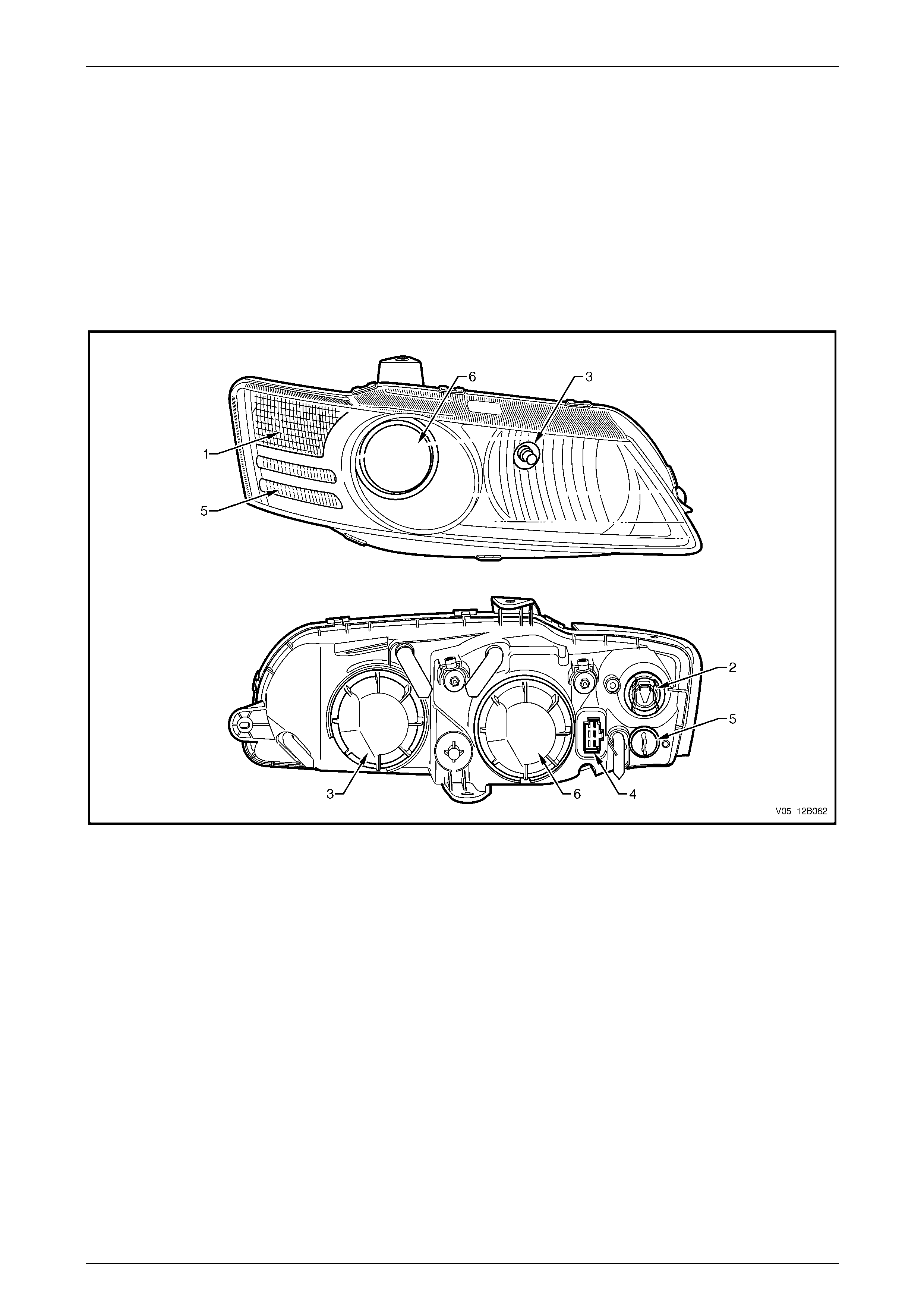
Level 2 and Level 3 Vehicles
Level 2 and Level 3 vehicle head lamp assemblies have the following feat ures, refer to Figure 12B – 2:
• Distinctive styling suits the Level 2 and Level 3 vehicle bumper fascia.
• Headlamp bezels are either c hrome or b lack.
• Single-filament H9 and H11 specification globes are fitted to the high and low beam reflector pockets respectively.
• The low beam uses projector lamp technology to increase illumination and give distinctive styling, while high beam
uses complex reflector technology.
• The park lamp is located below the turn signal lamp in its own reflector housing.
Figure 12B – 2
Legend
1 Turn Signal Lamp
2 Turn Signal Wiring Connector 3 Headlamp High Beam Bulb (H9)
4 Headlamp Main Wiring Connector 5 Park Lamp
6 Headlamp Low Beam Bulb (H11)

Lighting System Page 12B–11
Page 12B–11
1.2 Front Fog Lamp Assembly
Fog lamp assemblies are located in the front fascia assembly and are adjustable in the vertical axis. The fog lamp
assemblies use H3 lamps.
Lighting System Page 12B–12
Page 12B–12
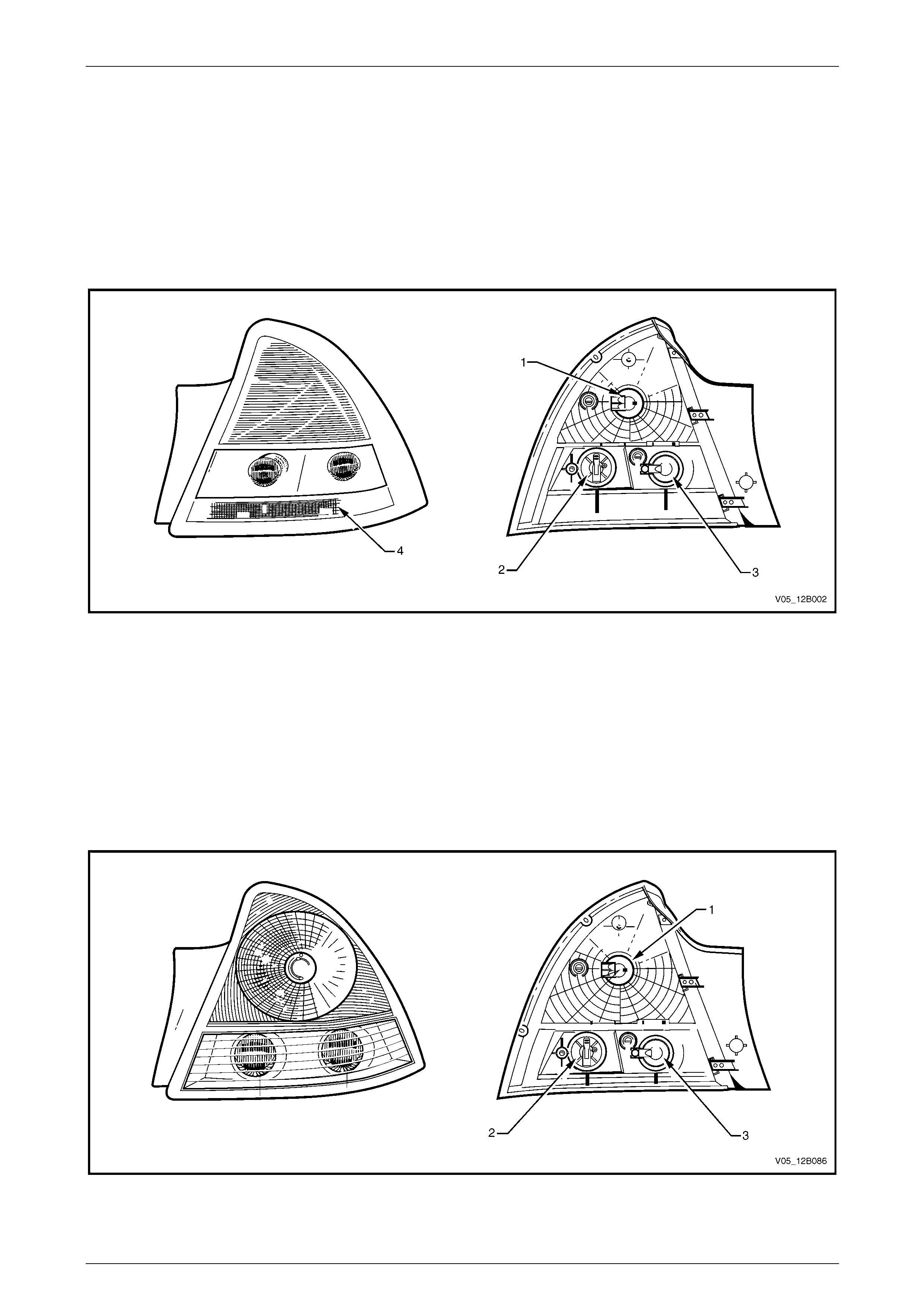
1.3 Tail Lamp Assembly
Tail lamps have three tail lamp geometries; each type is applicable to the following groups of vehicles:
• Refer to Figure 12B – 3 for Level 1 Sedan tail lamp front an d rear views.
• Refer to Figure 12B – 4 for Level 2 and Level 3 Sedan tail lamp front and rear views.
• Refer to Figure 12B – 5 for Utility and Wagon tail lamp front and rear views.
Depending on model specifications, Level 1 Sedan tail lamp assemblies have either chrome or black housings.
Figure 12B – 3
Legend
1 Stop/Tail Lamp
2 Turn Signal Lamp 3 Backup Lamp
4 Reflex Reflector
NOTE
Level 2 and Level 3 vehicles have reflex
reflectors on the rear bumper fascia, immediately
below the tail lamp assembly.
Lighting System Page 12B–13
Page 12B–13
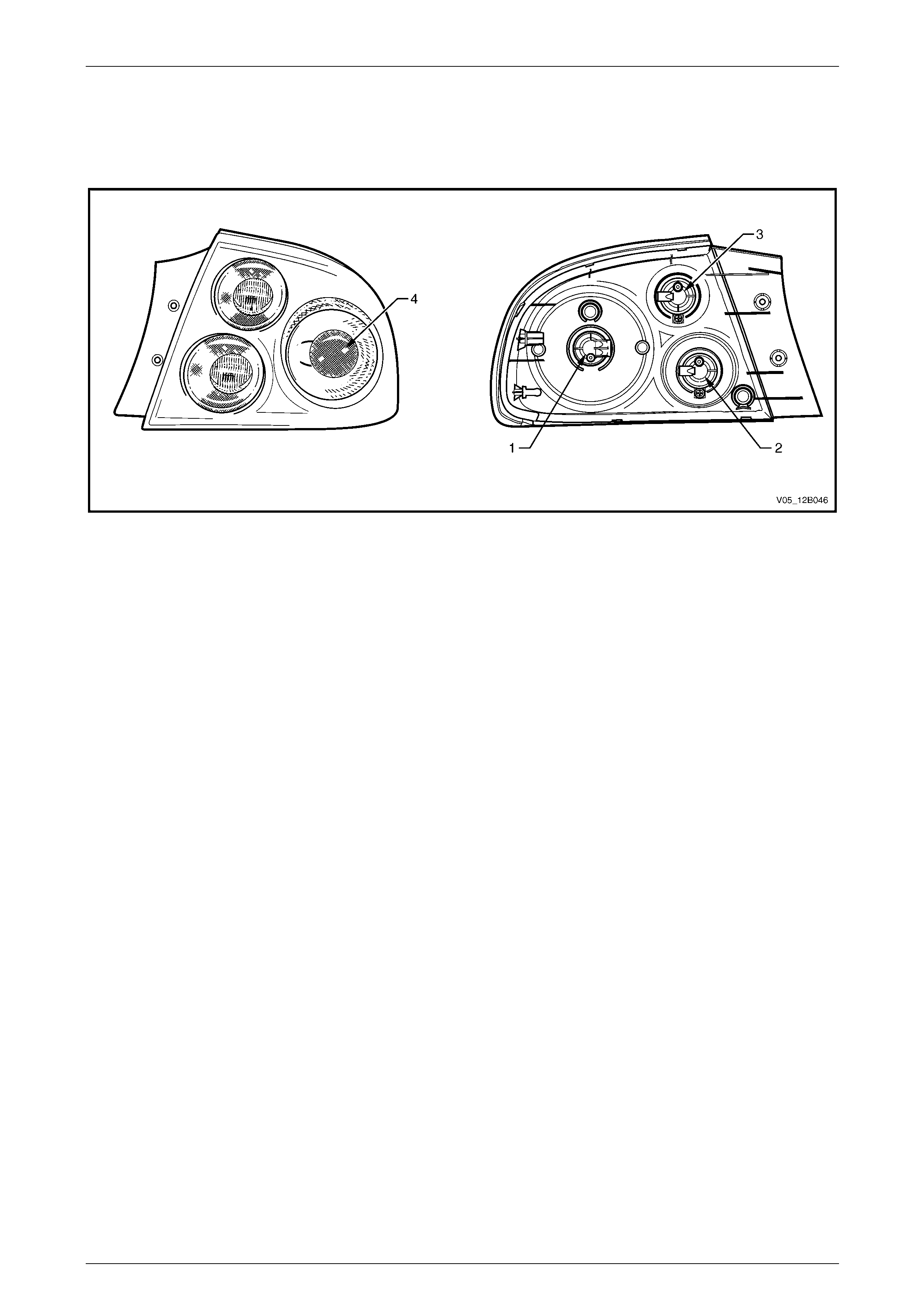
Figure 12B – 4
Legend
1 Stop/Tail Lamp
2 Turn Signal Lamp 3 Backup Lamp
Figure 12B – 5
Legend
1 Stop/Tail Lamp
2 Turn Signal Lamp 3 Backup Lamp
4 Reflex Reflector

Lighting System Page 12B–14
Page 12B–14
1.4 High-mount Stop Lamps
All high-mount stop lamps fitted to the inside of the vehicl e use bulbs for illumination. High-mount stop lamps fitted to
Sedan rear spoilers use LEDs.
Lighting System Page 12B–15
Page 12B–15
1.5 Interior Illumination
The type and number of interior illumination devices depends on the model level of the vehicle. All vehicles are fitted with
lamps adequate to illum inate the cabin area during low light conditions. In addition, all models are equipped with an
instrument panel compartment lamp and a r ear compartment lamp. Many lamps (and the dimming function for the interior
lamps) are controlled by the body control module (BCM), refer to Section 12J Bod y Control Module for further
information.
Refer to Figure 12B – 7 for interior lighting component locations.
Level 1
Level 1 Sedans and Wagons have a roof console assembly, consisting of a dome lamp or a dome lamp with reading
lamps. A roof rail courtesy lamp and readin g lamp assembly is also fitted in vehicles with a roof console assembly.
Level 1 Utility and Level 1 Regular Cab vehicles have a dom e lamp assembly.
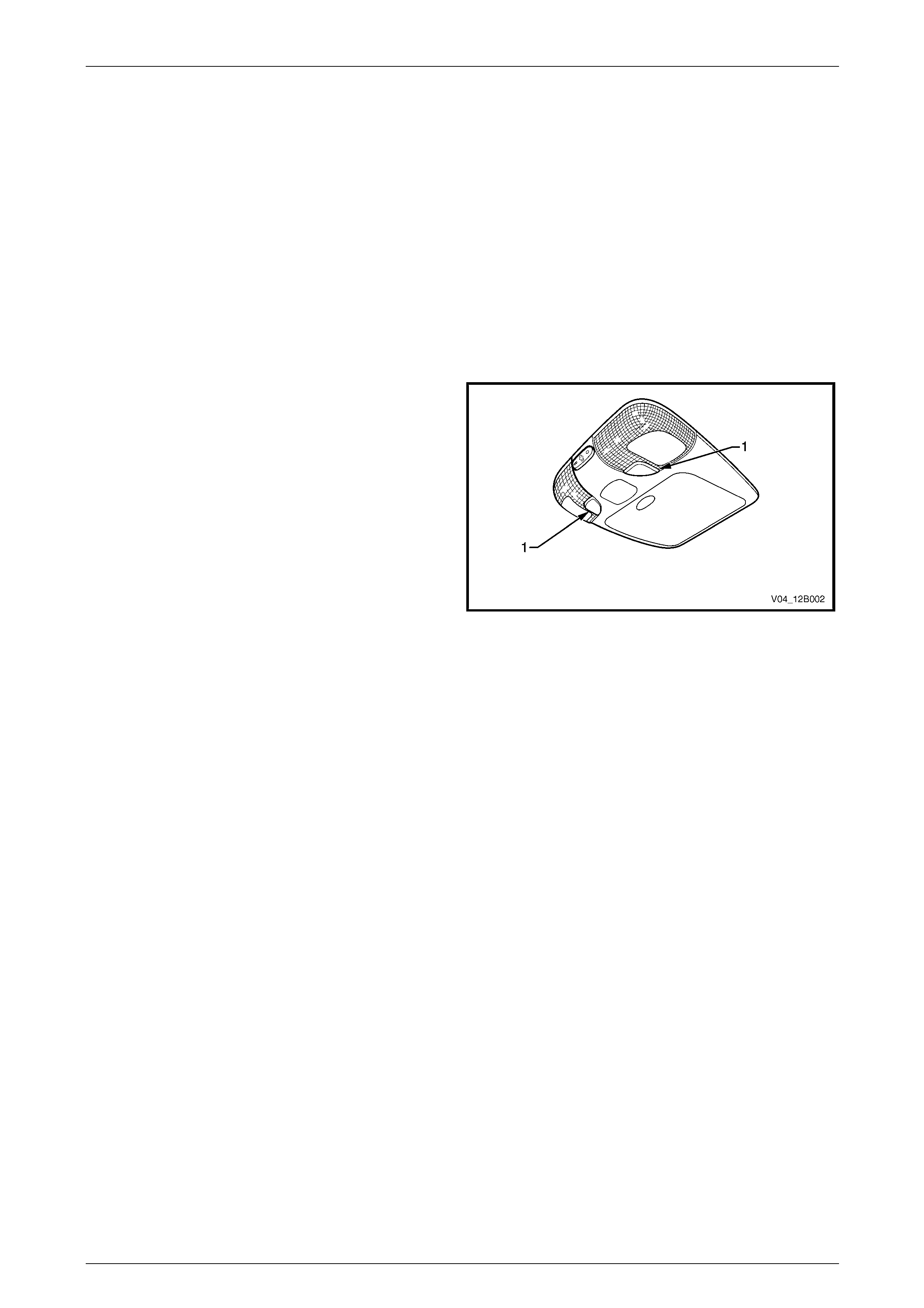
The roof console fitted to low Level vehic les is similar to
those fitted to high Level vehicles except for the two reading
lamps that do not have an individual switch.
A blank plate (1) is fitted in place of each reading lamp
switch. The operation of the reading lamps is automatic.
Figure 12B – 6
Lighting System Page 12B–16
Page 12B–16
Level 2 and Level 3
Level 2 and Level 3 vehicles have:
• roof console lamps,
• roof rail courtesy and reading lamp assembly,
• side door courtesy lamps,
• sunshade vanity mirror lamps (Level 3 onl y),
• stepwell lamps, and/or
• floor console compartment lamp (Level 3 only).
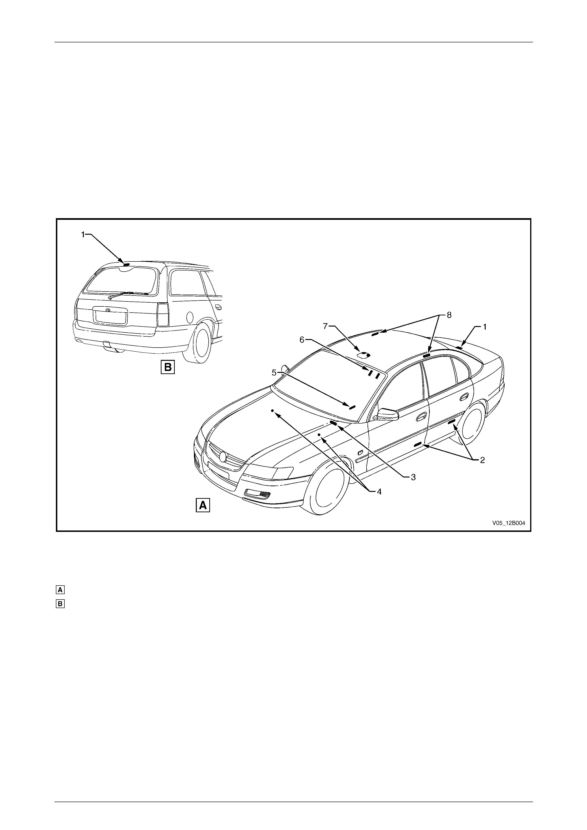
Figure 12B – 7
Legend
Sedan – Interior Illumination
Wagon – Interior Illumination
1 Rear Compartment Courtesy Lamp
2 Side Door Courtesy Lamps
3 Instrument Panel Compartment
Courtesy Lamp
4 Stepwell Lamps
5 Floor Console Compartment Lamp
6 Sunshade Vanity Mirror Lamps
7 Roof Console
8 Roof Rail Courtesy and Reading Lamps
Lighting System Page 12B–17
Page 12B–17
1.6 Instrument and Switch Illumination
All instrument and switch illum ination is provided by LEDs, except the following items that are illuminated with
conventional bulbs:
• hazard warning switch,
• A/S (active select) switch,
• T/C (traction control) switch,
• PWR (power) switch,
• electronic stability program (ESP) switch,
• headlamp switch,
• trip computer switch,
• side window switch assembly, and
• ignition lock cylinder.
The T/C switch (or A/S switch) is located on the right side of the automatic transmission selector.
The headlamp, trip computer and side window switches are sealed units and the conventional bulbs can not be serviced
on these items.
LEDs are used instead of conventio nal bulbs due to their longevity in operation. If the illumination of any LED-equippe d
item no longer operates correctl y and the LE D is isolated as the fault, replace the assembly.
Figure 12B – 8
Legend
1 Headlamp Switch
2 Trip Computer Switch
3 Hazard Warning Switch
4 A/S Switch (or T/C Switch or ESP Switch — 4-speed
Automatic Transmission)
5 PWR Switch
6 Auxiliary Switches

Lighting System Page 12B–18
Page 12B–18
Headlamp Switch
An automatic headlamp control feature is fitted. When the headlamp switch is in the AUTO position, the BCM controls
the function of the low and high beam of the headlam ps, refer to F igure 12B – 116. For further information, refer to
Section 12J Body Control Module .
Police Lights-out Switch
The police lights-out switch is fitted to police vehicles when required. W he n activated, the police lights-out switch turns off
all interior lamps except reading lamps that can be operated individually.
NOTE
The police lights-out switch does not illuminate
when the park lamps are operating.
Daylight Running Lamp (Option T82)
On vehicles fitted with the daylight running lamp feature (option T82), the front headlamps operate while the ignition
switch is on.
Lighting System Page 12B–19
Page 12B–19
2 General Information, Coupe
2.1 Headlamp Assembly
Headlamp assemblies inc orp orate the latest headlamp reflector technology. The headlam p assemblies have the
following features:
• Headlamp assemblies are e quipped with low beam, high beam and turn s ignal lamps; park lamps are mounted on
the front fog lamp assembly.
• Beam movement in the vertical and horizontal axes is controlled by the same type of adjustment device.
• Turn signal bulb holders a nd main wiring connectors are identical.
• Turn signal lamps are located on the o utsid e extremities of the assembly.
• The high beam is located in the inboard side of the assembly.
• The headlamp assembly requires three screws to secure the assembly to the sheetmetal.
The Coupe headl amp assembly has the following features, refer to Figure 12B – 9:
• Distinctive styling suits the Coupe bumper fascia.
• Single-filament H9 and H11 specification globes are fitted to the high and low beam reflector pockets respectively.
• The low beam uses projector lamp technology to increase illumination and give distinctive styling, while high beam
uses complex reflector technology.
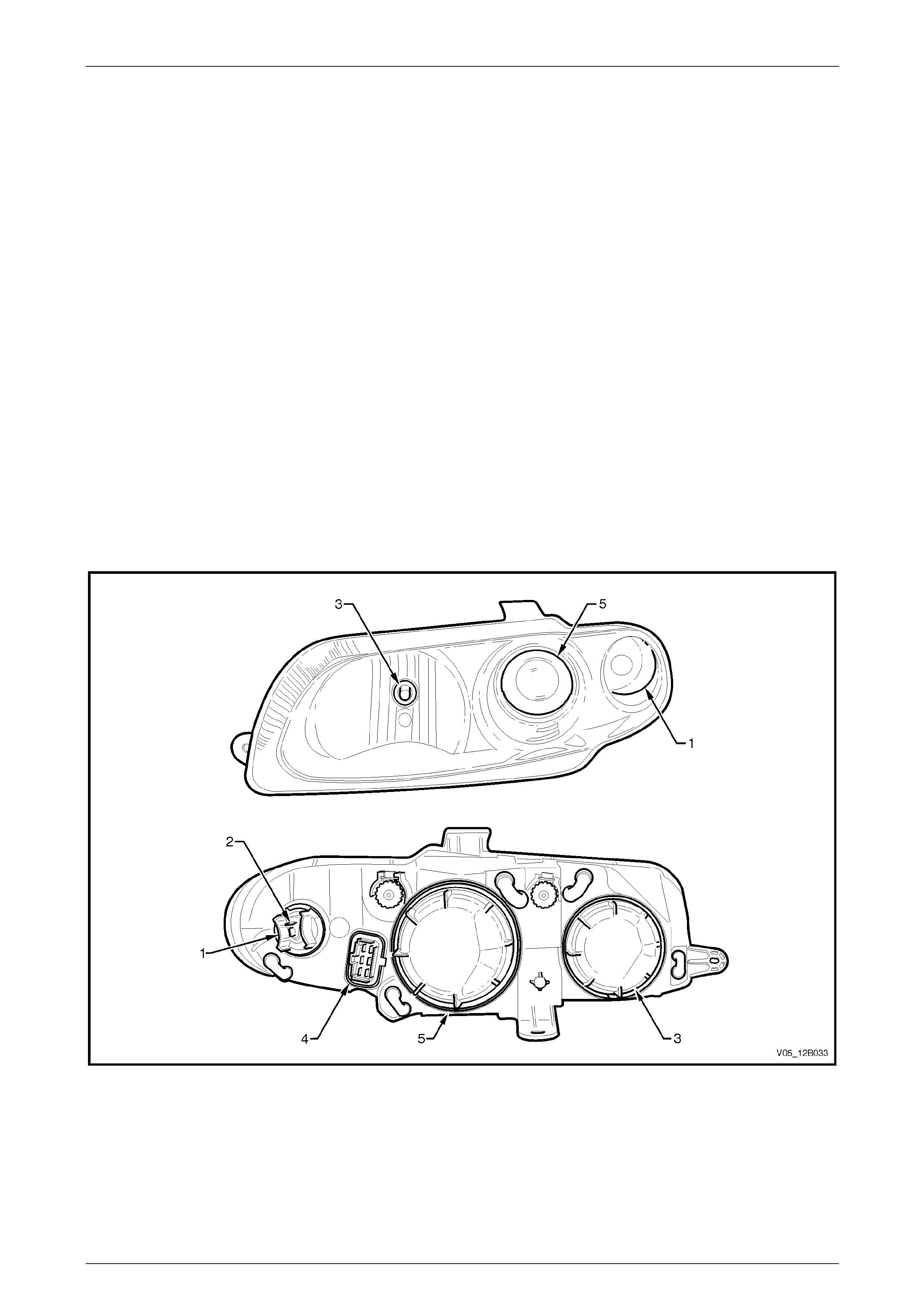
Figure 12B – 9
Legend
1 Turn Signal Lamp
2 Turn Signal Wiring Connector 3 Headlamp High Beam Bulb (H9)
4 Headlamp Main Wiring Connector 5 Headlamp Low Beam Bulb (H11)
Lighting System Page 12B–20
Page 12B–20
2.2 Park and Front Fog Lamp Assembly
The Coupe park and front fog lamp assembly consists of:
• a park lamp (at the top of the park and front fog lamp assembly), and
• a fog lamp (at the bottom of the park and front fog lamp assembly).
The front fog lamp can be adjusted vertically by using an Allen key from the front of the park and front fog lamp
assembly. A wiring connector on the park and front fog lamp assembly connects the park lamp and front fog lamp wires
to the front body wiring harnes s.
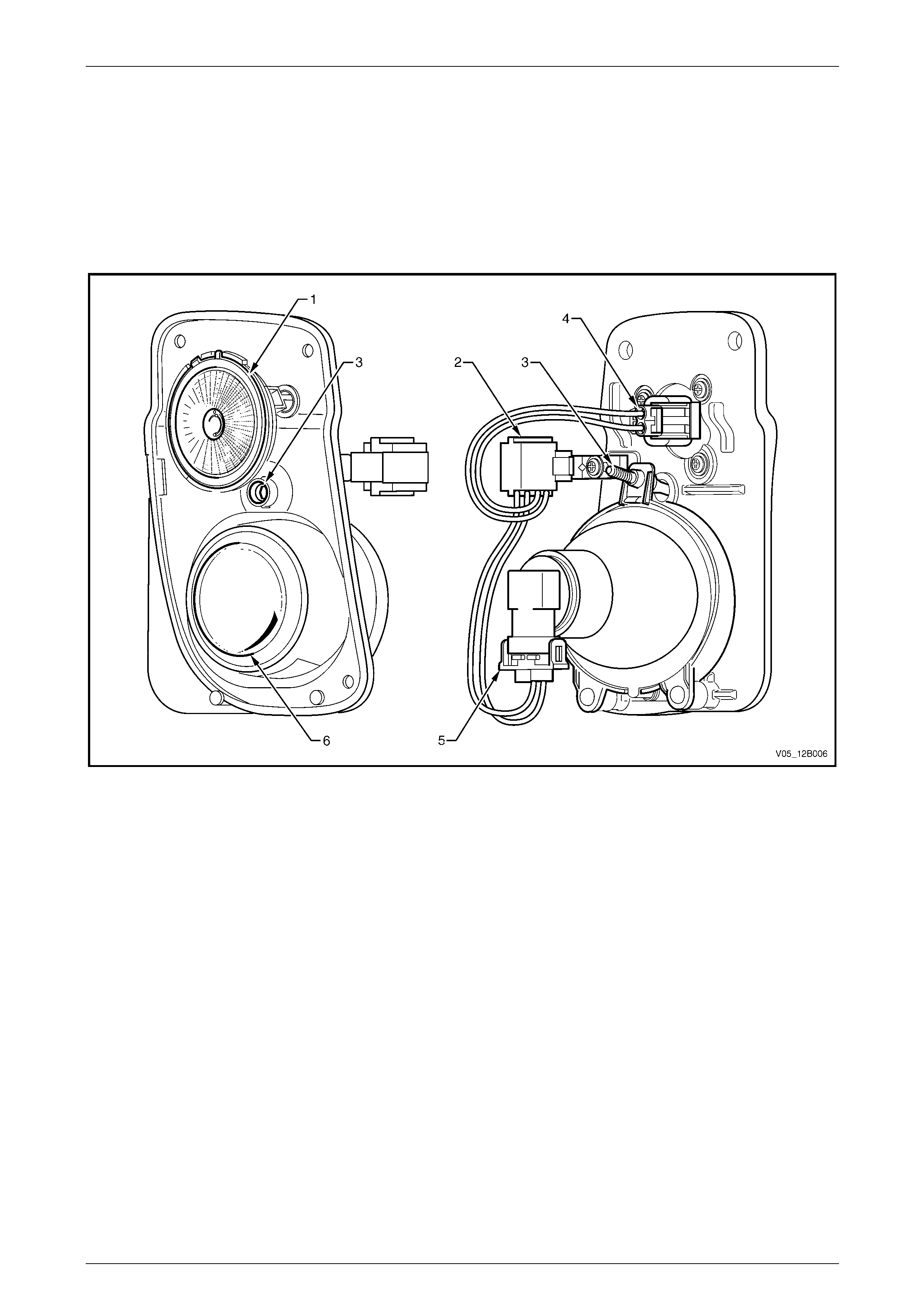
Figure 12B – 10
Legend
1 Park Lamp
2 Front Body Wiring Harness Connector
3 Fog Lamp Adjustment Mechanism
4 Park Lamp Connector
5 Fog Lamp Connector
6 Fog Lamp
Lighting System Page 12B–21
Page 12B–21
2.3 Tail Lamp Assembly
For views of the front and rear of the tail lamp assemblies, refer to Figure 12B – 11, where the following functions are
provided:
Figure 12B – 11
1 Stop/Tail Lamps
2 Turn Signal Lamps 3 Backup Lamps
4 Reflex Reflectors

Lighting System Page 12B–22
Page 12B–22
2.4 High-mount Stop Lamps
The high-mount stop lamp assembly is fitted to the inside of the vehicle and uses a strip of light emitting diodes (LEDs)
for illumination.
Lighting System Page 12B–23
Page 12B–23
2.5 Interior Illumination
Vehicles are fitted with lamps adequate to illuminate the cabin area during l ow light conditions, including an instrument
panel compartment lamp and a rear compart ment lamp. Many lamps (and the dimming function for the interior lamps)
are controlled by the body control module (BCM), refer to Section 12J Body Control Module for further information.
Refer to Figure 12B – 12 for interior lighting compo nent locations. Vehicles have:
• dome and reading lamp assembly,
• side door courtesy lamps,
• stepwell lamps,
• sunshade vanity mirror lamps, and
• floor console compartment lamp.
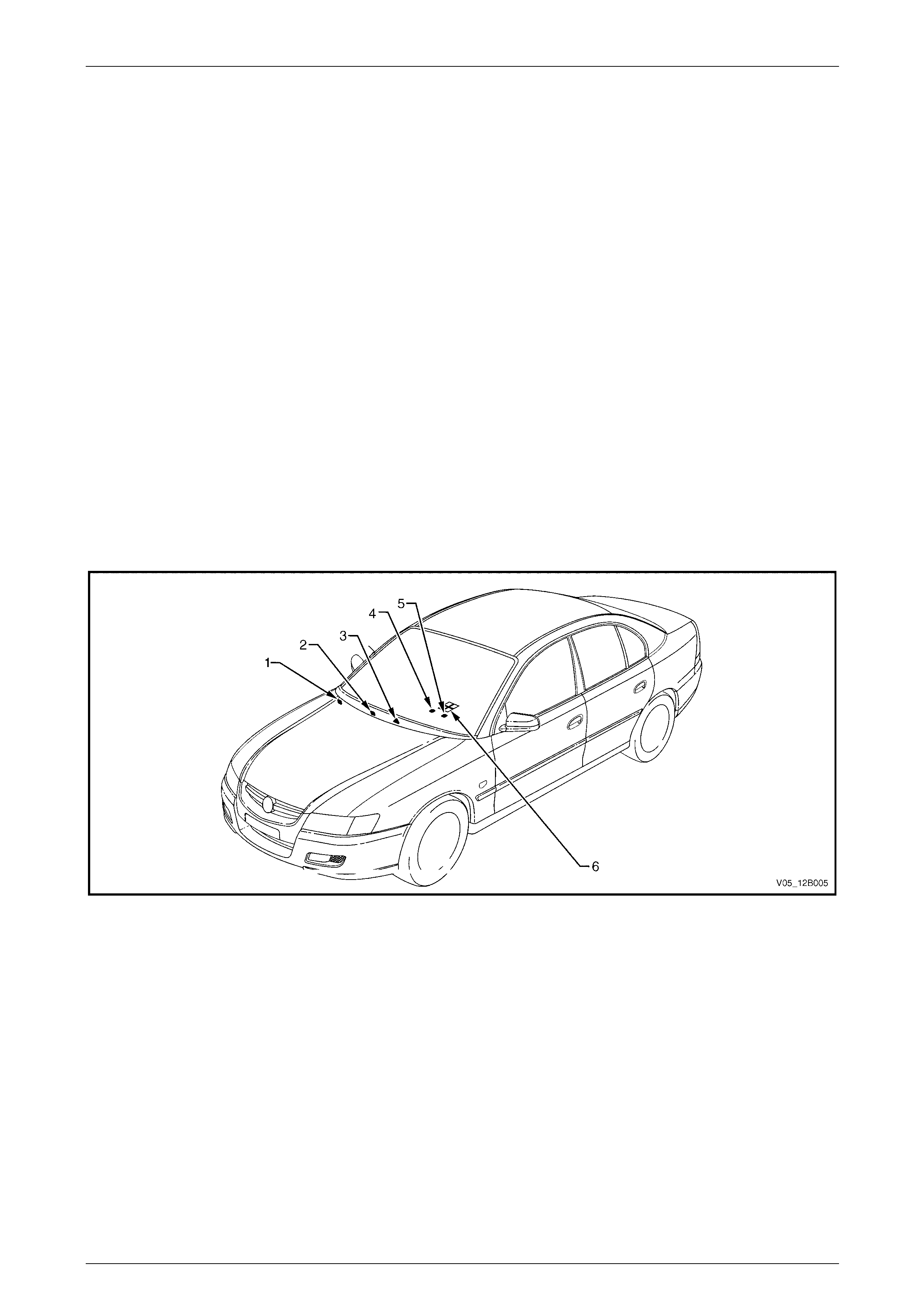
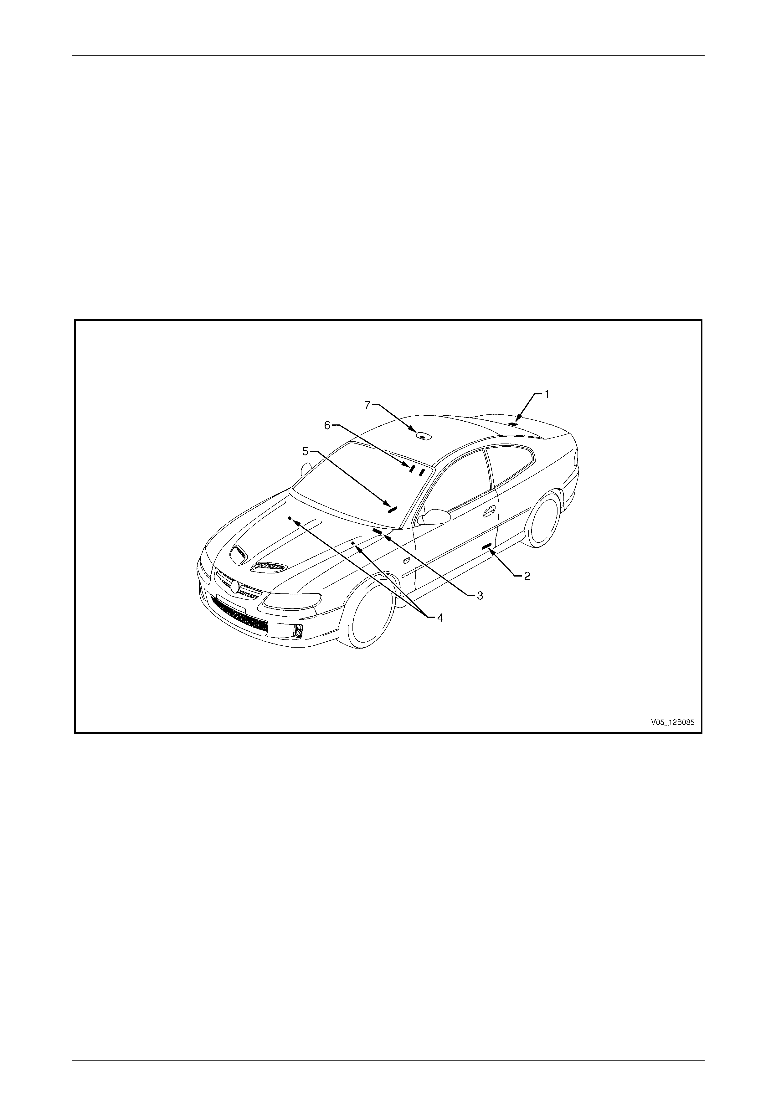
Figure 12B – 12
Legend
1 Rear Compartment Courtesy Lamp
2 Side Door Courtesy Lamps
3 Instrument Panel Compartment Courtesy Lamp
4 Stepwell Lamps
5 Floor Console Compartment Lamp
6 Sunshade Vanity Mirror Lamps
7 Dome and Reading Lamp Assembly
Lighting System Page 12B–24
Page 12B–24
2.6 Instrument and Switch Illumination
All instrument and switch illum ination is provided by LEDs, except the following items that are illuminated with
conventional filament bulbs:
• hazard warning switch,
• T/C switch,
• headlamp switch,
• trip computer switch,
• side window switch assembly, and
• ignition lock cylinder.
The T/C switch is located on the right side of the automatic transmission selector or in the floor console on vehicles with
manual transmission.
The headlamp, trip computer and side window switches are sealed units and the conventional bulbs can not be serviced
on these items.
LEDs are used instead of conventio nal bulbs due to their longevity in operation. If the illumination of any LED-equippe d
item no longer operates correctl y and the LE D is isolated as the fault, replace the assembly.
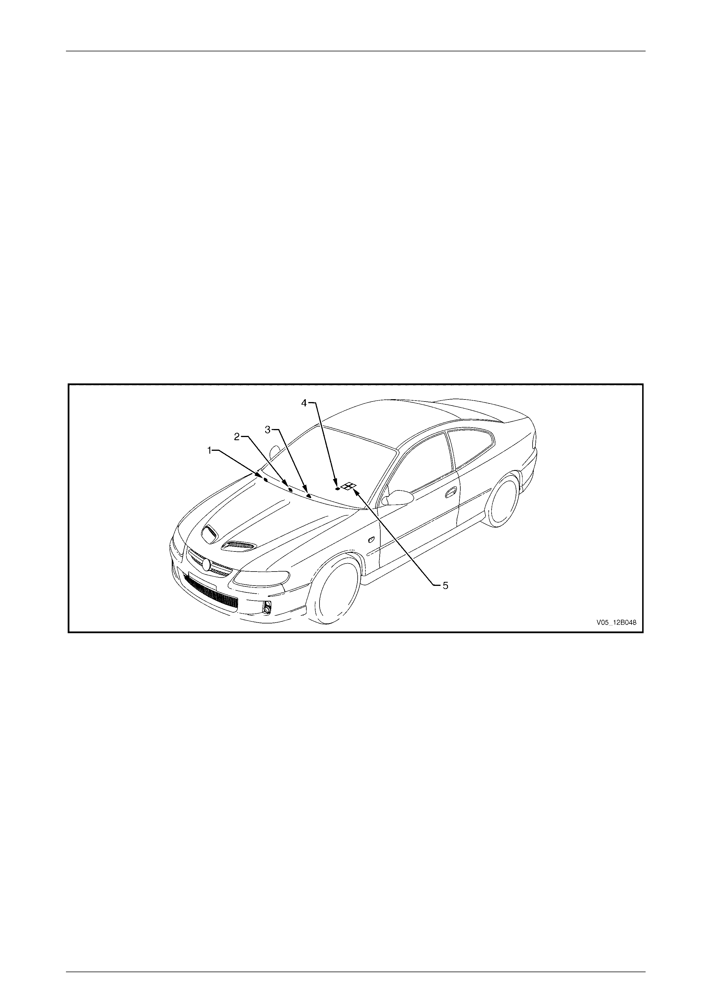
Figure 12B – 13
Legend
1 Headlamp Switch
2 Trip Computer Switch
3 Hazard Warning Switch
4 T/C Switch
5 Auxiliary Switches
Headlamp Switch
An automatic headlamp control feature is fitted. When the headlamp switch is in the AUTO position, the BCM controls
the function of the park lamp and low beam of the hea dlamps, refer to Figure 12B – 116. For further information, refer to
Section 12J Body Control Module .
Lighting System Page 12B–25
Page 12B–25
3 General Information, Regular
Cab and Crew Cab with 'Delete
Tub' Option
For information not contained in this Section, refer to 1 General Informatio n.
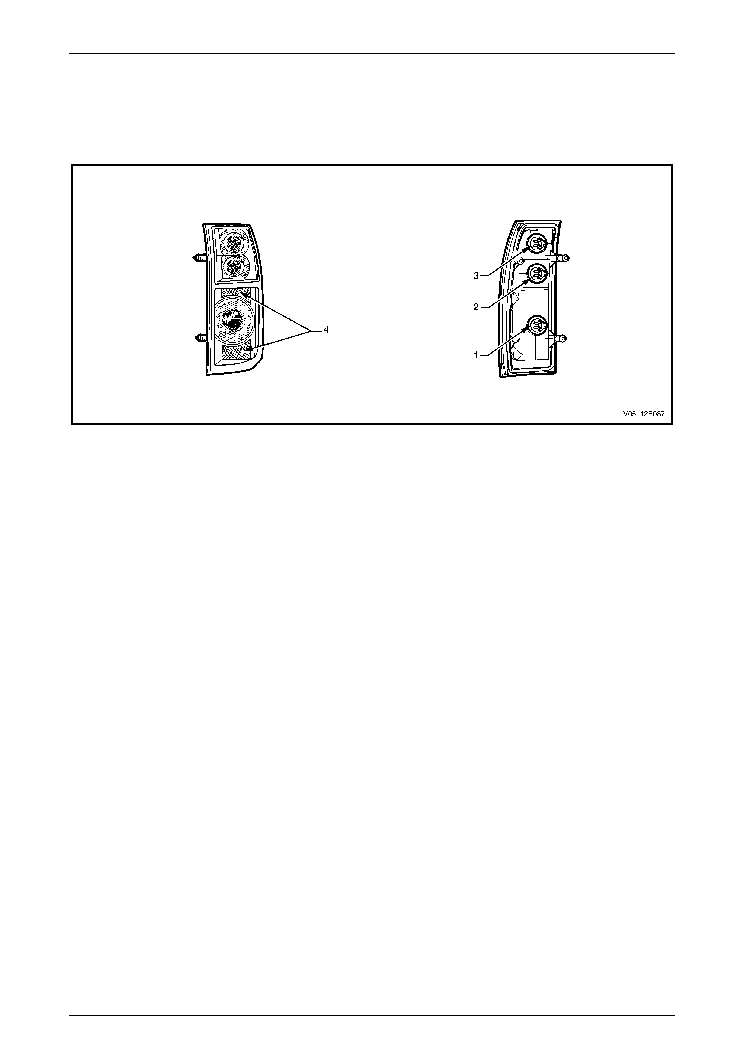
3.1 Tail Lamp Assembly
The tail lamp assemblies are self-contained units. Illumination is provided by bayonet-t yp e conventional bul bs. Electrical
connection is provided by weatherproof harness connectors. The tail lamp assemblies are mounted on the transport
bracket, fixed to the rear of the chassis.
For internal and external views of the tail lamp assemblies, refer to Figure 12B – 14.
The tail lamp assembly provid es the following functions:
• turn signal lamp,
• backup lamp,
• stop lamp,
• tail lamp, and
• reflex reflector.
Figure 12B – 14
Legend
1 Turn Signal Lamp
2 Backup Lamp
3 Stop Lamp
4 Park Lamp
5 Reflex Reflector
NOTE
Figure 12B – 14 shows a left tail lamp assembly.
With a right tail lamp assembly, the location of the
backup lamp and the stop la mp are opposite.
Lighting System Page 12B–26
Page 12B–26
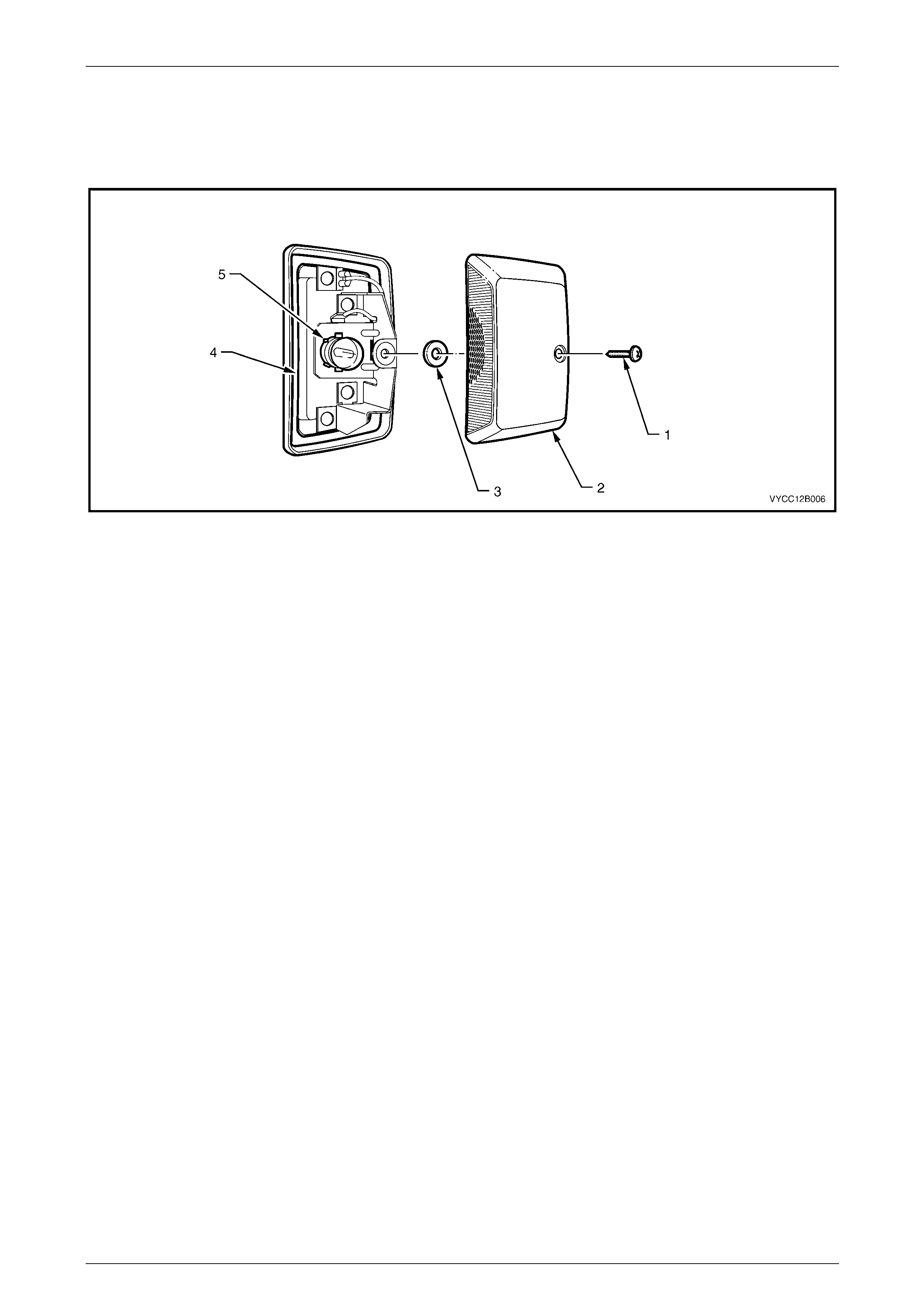
3.2 Rear Licence Plate Lamp Assembly
The rear licence plate lamp assembly is a sealed self-contained unit and has a weatherproof harness connector. The
rear licence plate lamp assembly is mounted on the transport bracket, fixed to the rear of the chassis.
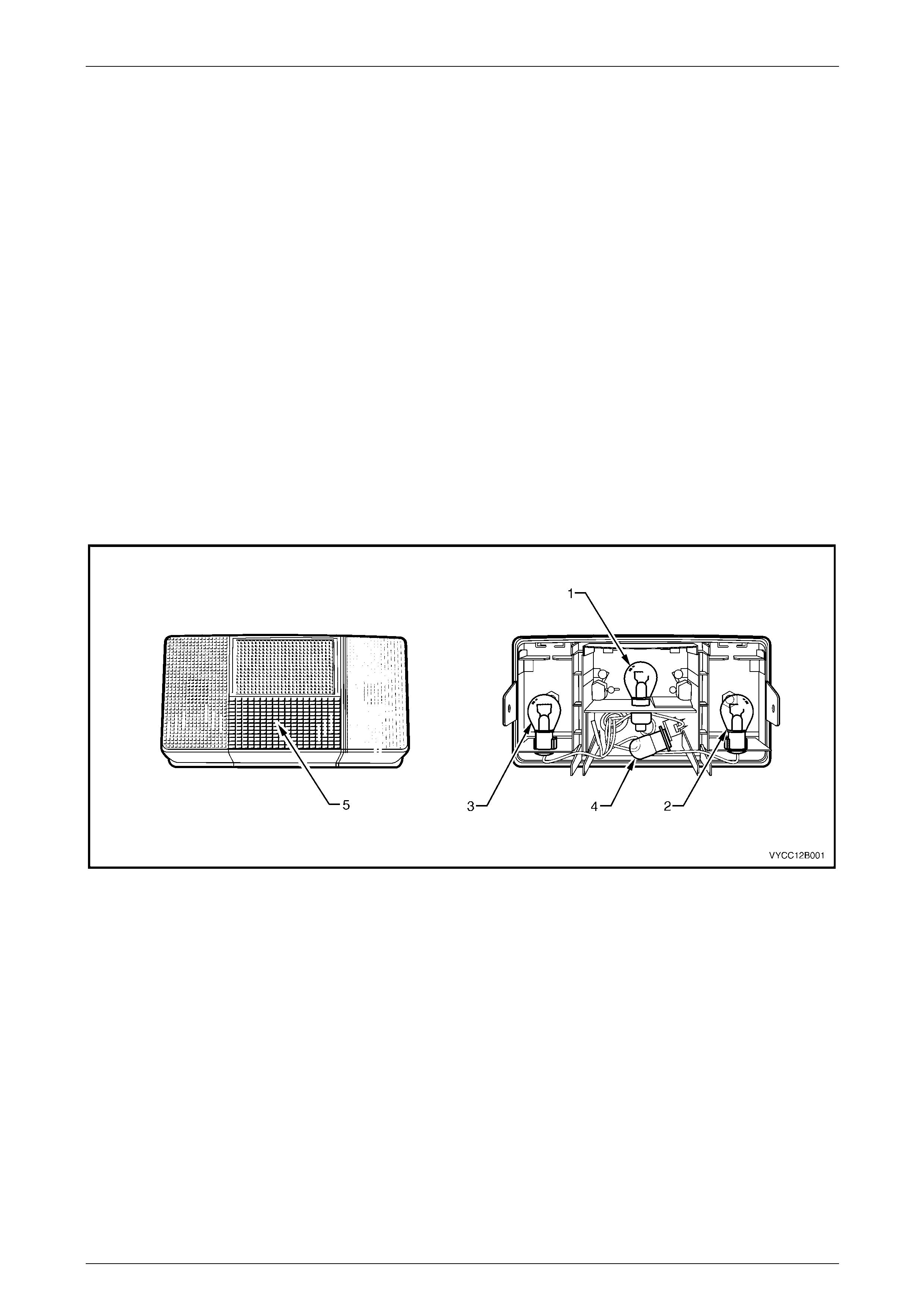
Figure 12B – 15
Legend
1 Screw
2 Rear Licence Lamp Housing
3 Grommet
4 Rear Licence Lamp Base
5 Lamp
Lighting System Page 12B–27
Page 12B–27
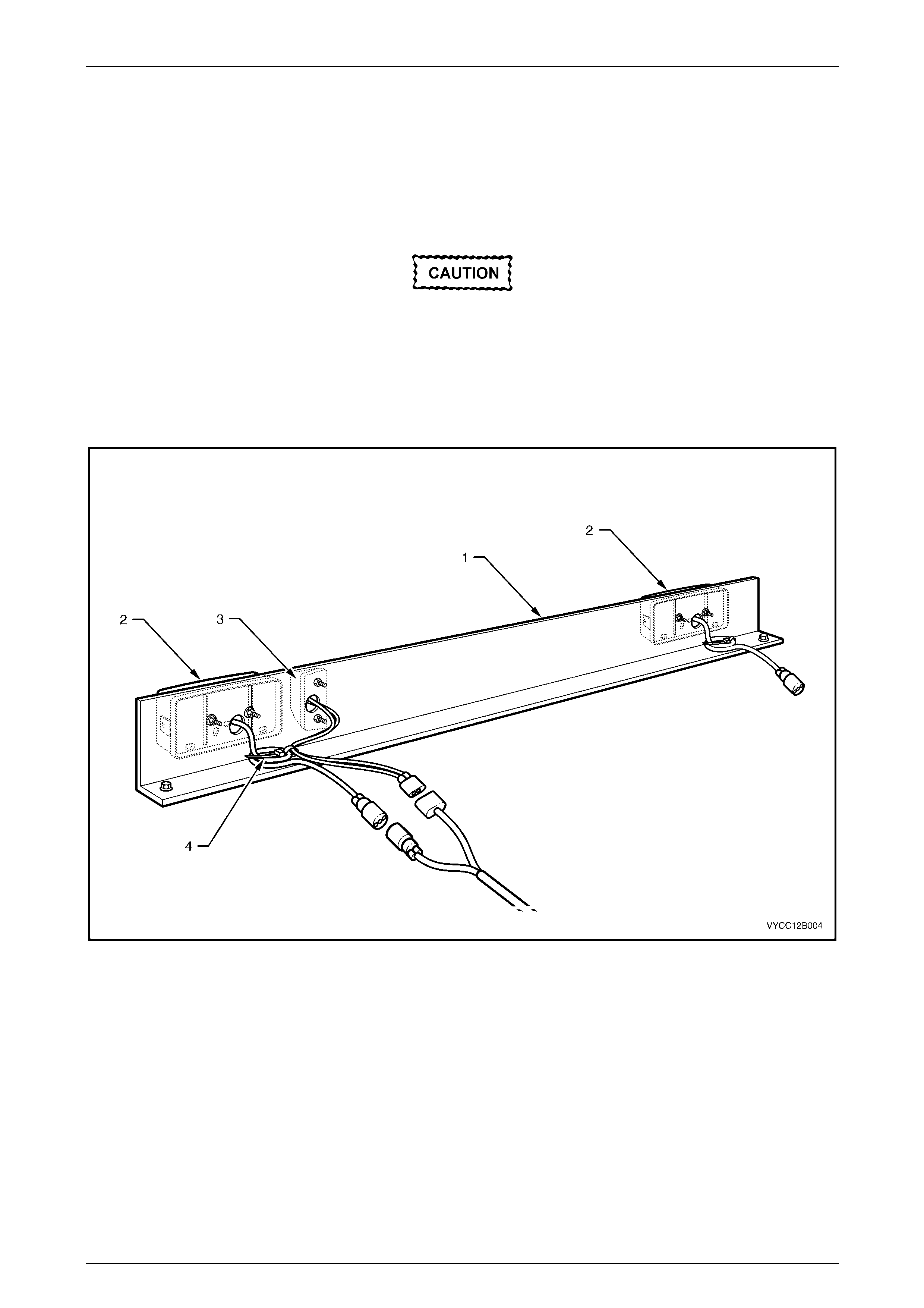
3.3 Transport Bracket
The transport bracket (1) is designed to hold tail lamp assemblies (2) and rear licence plate lamp assembly (3), refer to
Figure 12B – 16.
During tray installation, the tail lamp assembly and rear licence plate lamp assembly are removed from the transport
bracket and installed to the tray. The transport bracket is then discarded.
The attachment method of the lamp
assemblies to the tray should be similar to the
transport bracket. The position of lamp
assemblies fitted to the tray should be legally
compliant.
Custom-built and aftermarket trays are availa ble; refer to the appropriate supplier or body builder for the relevant service
information required for vehicle trays.
Figure 12B – 16
Legend
1 Transport Bracket
2 Tail Lamp Assembly 3 Rear Licence Lamp
4 Cable Tie
Lighting System Page 12B–28
Page 12B–28
4 General Information, AWD
Wagon
The following items on the AWD Wagon differ from other vehicles:
• tail lamps,
• backup lamps,
• liftgate air deflector assembly and high-mou nt stop lamp assembly, and
(A liftgate air deflector assembly and high-m ount stop lamp assembly is fitted as standard equipment on AWD
Wagon vehicles, refer to Section 1A4 Hood, Rear Compartment Lid, Liftgate and Endgate.)
• hill descent control switch.
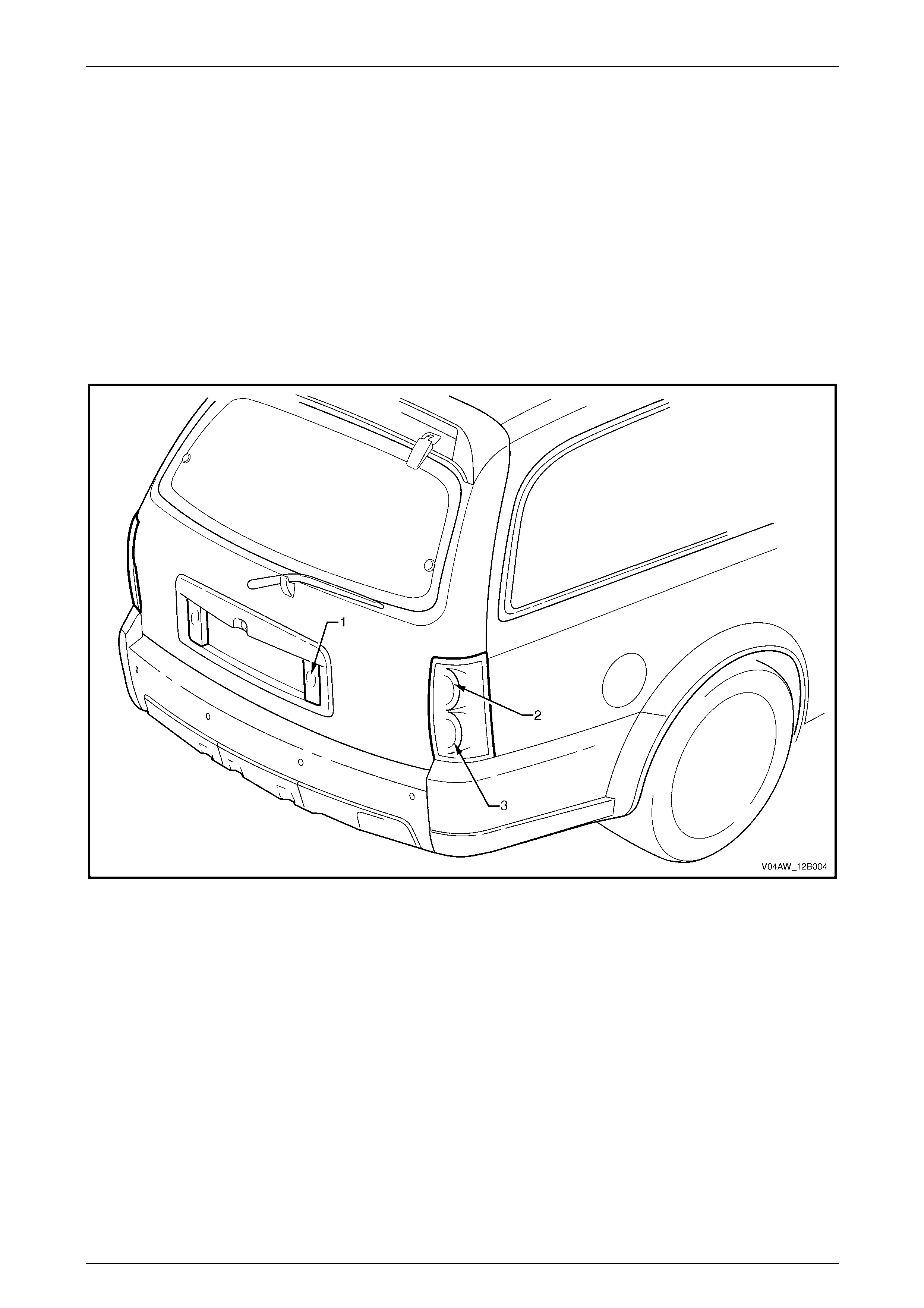
For a general vie w of the tail lamp assembli es and backup lamp assemblies, refer to Figure 12B – 17.
Figure 12B – 17
Legend
1 Backup Lamp
2 Stop/Tail Lamp 3 Turn Lamp
Lighting System Page 12B–29
Page 12B–29
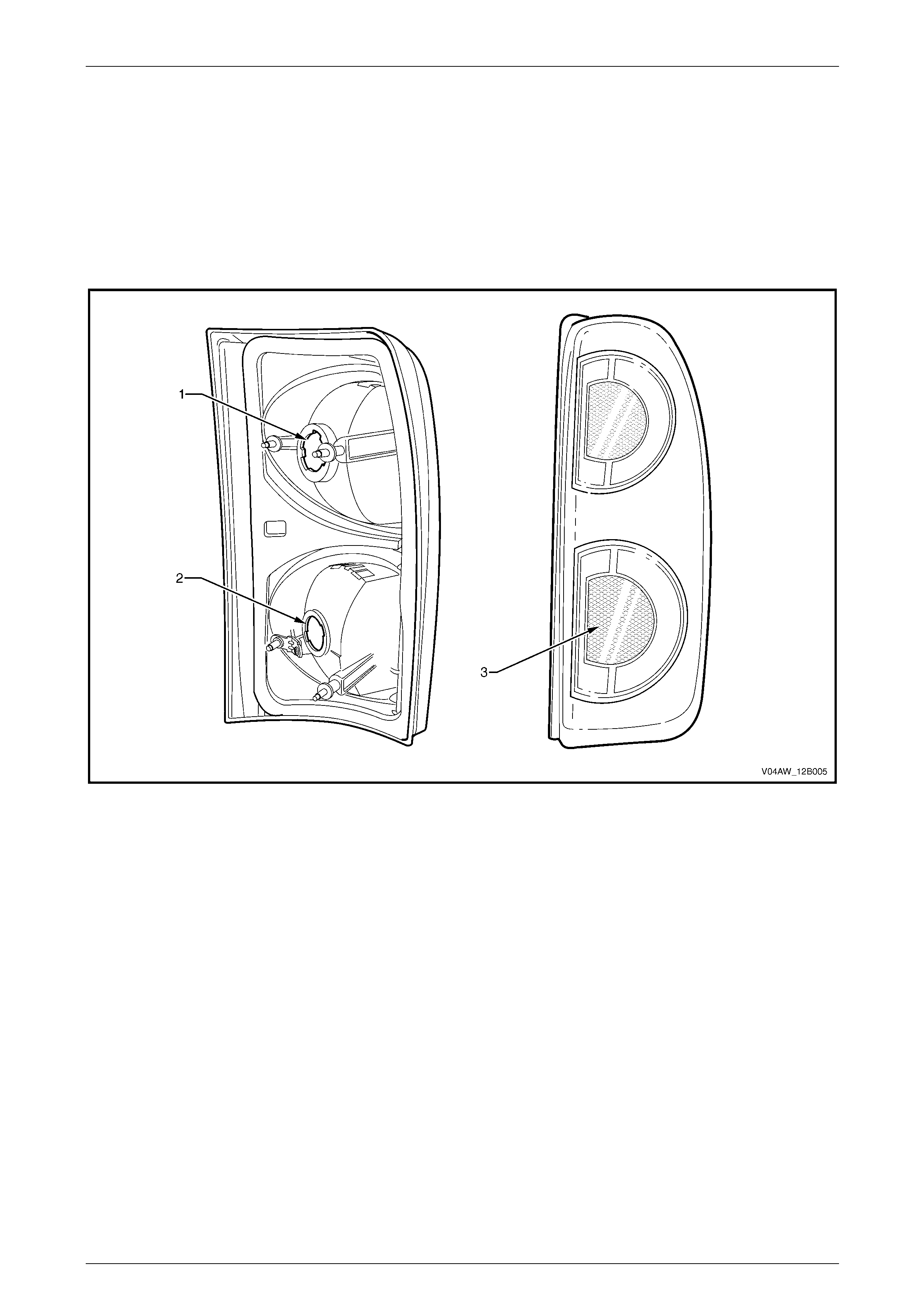
4.1 Tail Lamp Assembly
AWD Wagon tail lamp assemblies c onsist of:
• a turn signal lamp,
• a stop/tail lamp, and
• a reflex reflector.
For internal and external views of the AWD Wagon tail lamp assemb ly, refer to Figure 12B – 18.
Figure 12B – 18
Legend
1 Stop/Tail Lamp
2 Turn Lamp 3 Reflex Reflector
Lighting System Page 12B–30
Page 12B–30
4.2 Backup Lamp Assembly
AWD Wagon backup lamp assembli es are attached to the liftgate appliqué assembly. For internal and external views of
the backup lamp assembly, refer to Figure 12B – 19.
Figure 12B – 19
Legend
1 Backup Lamp Assembly 2 Foam Rubber Seal

Lighting System Page 12B–31
Page 12B–31
4.3 Liftgate Air Deflector Assembly and
High-mount Stop Lamp Assembly
The liftgate air deflector assembl y and high-mount stop lamp assembly is designed specifically for AWD Wagon vehicles
and is fitted as standard equipment on all AWD Wagon vehicles, refer to
Section 1A4 Hood, Rear Compartment Lid, Liftgate and Endgate.
Lighting System Page 12B–32
Page 12B–32
5 Service Operations — Exterior
Illumination, Sedan, Wagon,
Utility and Crew Cab
5.1 Headlamp and Front Fog Lamp Aiming
During headlamp assembly aiming, use a
cloth or similar material to cover the lens of
the headlamp assembly being adjusted. Do
not cover the beam o f the headlamp asse mbly
not being adjusted. Damage to the headlamp
assembly will result if the headlamp beam is
obstructed in this manner.
The headlamp assemblies (and front fog lamp assemblies, if fitted) must be correctly aimed to obtain the maximum road
illumination and safet y. Headl amps and front fog lamps must be checked for correct aim whenever a b ulb or lamp
assembly is replaced and after an y adjustments or repairs to the front-end sheetmetal.
Headlamp aiming devices are in general use. When usin g one of these devices, ensure that it is in good condition;
carefully follow the instructions of the manufacturer.
Regardless of the method used for checking headlam p and front fog lamp aim, the vehicle must be at kerb weight (that
is, with full fuel level, oil, water and spare t yre , but no passengers). Tyres must be unifor mly inflated to their specified
pressure.
NOTE
If the vehicle regularly carries an unusual load in
the rear compartment or if it is used to tow a
trailer, these loads should be on th e vehic le when
the headlamps and front fog lamps are checked.
Headlamp Assembly Aim
LT Section No. — 02–300
NOTE
Use this procedure only when suitable test
equipment is unavailable.
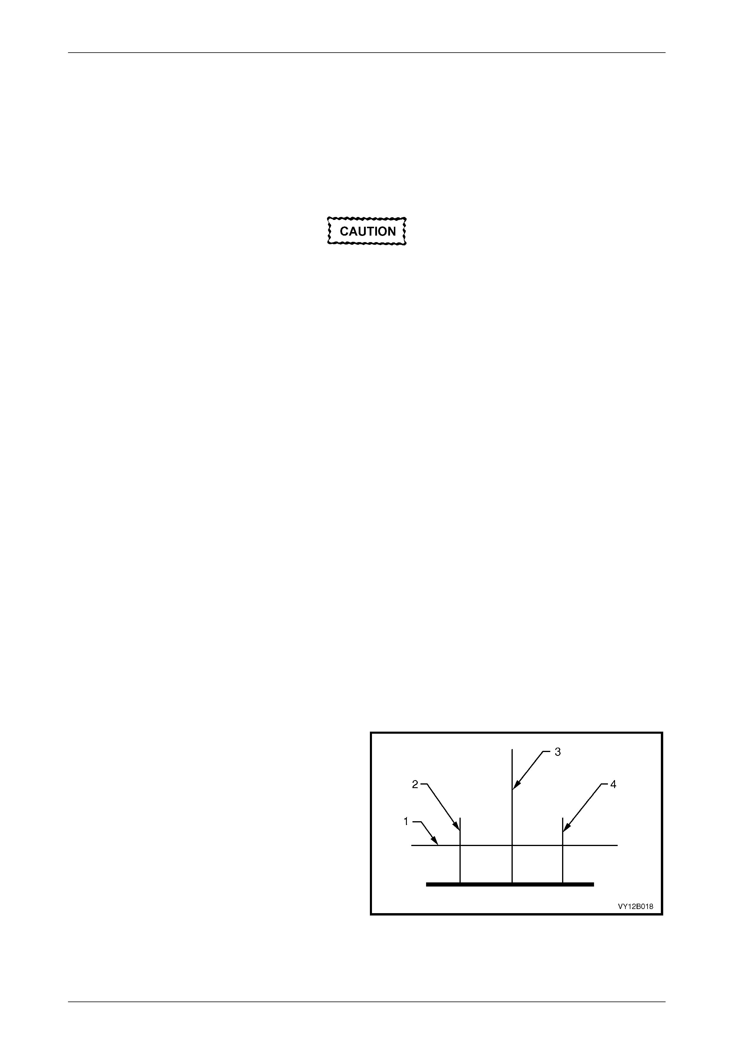
1 Set up a screen or use a vertical wall with a flat
horizontal floor. Park the vehi cle immediately in front
of the screen or wall and mark the follo wing li nes:
a a vertical centre-line (3), corresponding to the
centre of the vehicle;
b two vertical lines (2 and 4), corresponding to the
centre of the low beam bulb on each side of the
vehicle; and
c a horizontal line (1) corresponding to the centre
of the low beam bulb.
2 Turn on the headlights to check if the marks are
correctly positioned. Figure 12B – 20
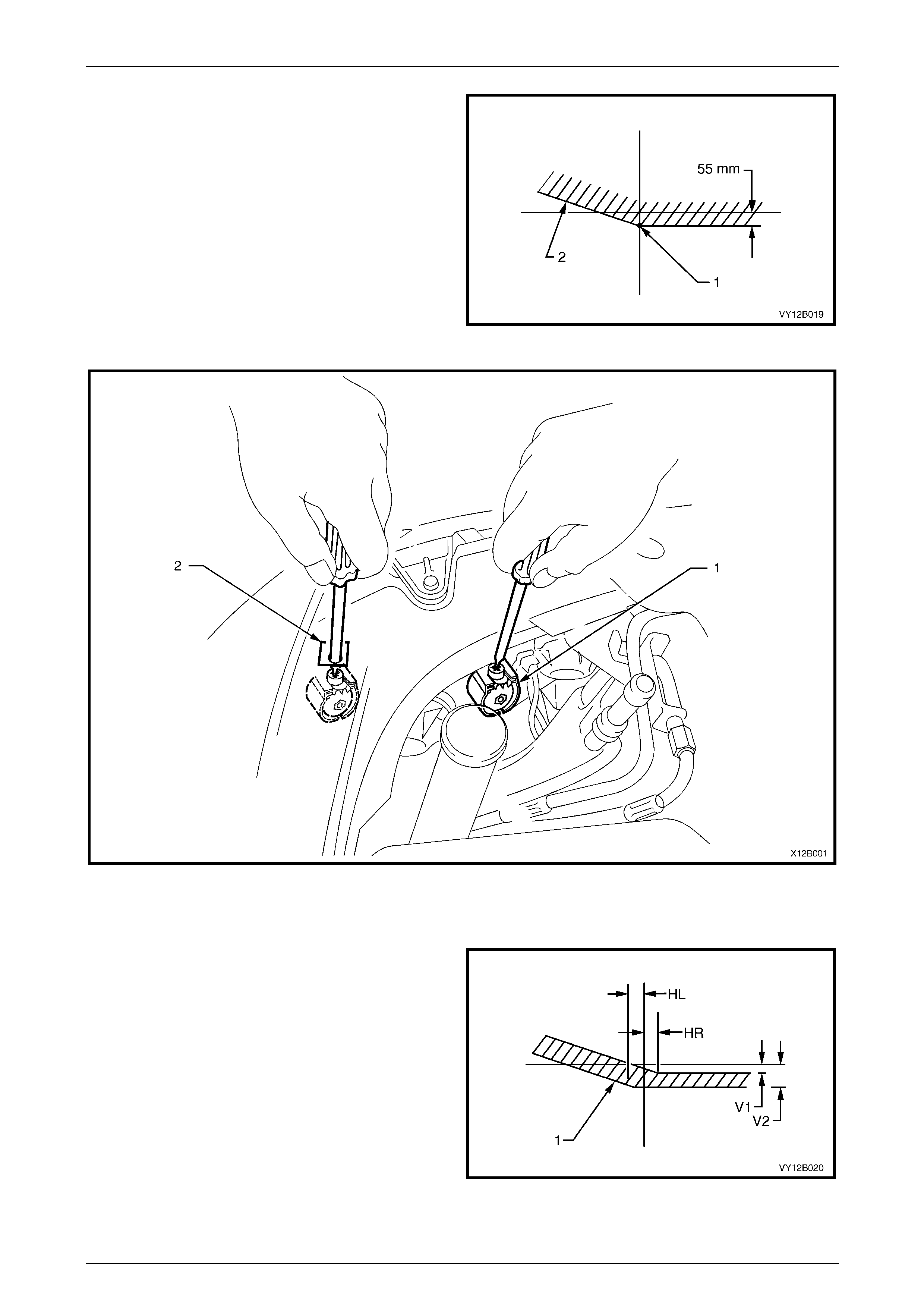
3 Reverse the vehicle straight back so the front is five metres in front of the screen or wall, ensuring the centre of the
vehicle is aligned with the vehicle centre-line mark (3) on the screen.
Lighting System Page 12B–33
Page 12B–33
4 Aim each headlamp to a point (1) on its vertical centre-
line, 55 mm below the headlamp horizontal centre-line.
Item 2 is the cut-off line. To adjust the headlamp
assembly, refer to Figure 12B – 22:
a Rotate the inboard adjuster (1) to move the
beam vertically.
b Rotate the outboard adjuster (2) to move the
beam horizontally.
Aiming directions for each adjuster are printed on the
headlamp assembly.
Figure 12B – 21
Figure 12B – 22
Legend
1 Inboard Adjuster 2 Outboard Adjuster
5 The allowable variations on headlamp aiming point
settings shown in Figure 12B – 23 are:
HL 50 mm
HR 0 mm
V1 50 mm
V2 60 mm
Maximum allowable vertical variation between any pair of
headlamps must not exceed 1 0 mm.
NOTE
The cut-off line must be within the shaded
zone (1). Figure 12B – 23
Lighting System Page 12B–34
Page 12B–34
Front Fog Lamp Assembly Aim
LT Section No. — 02–300
The aiming procedures for front fog lamps is the same for all vehicles.
NOTE
Use this procedure only when suitable test
equipment is unavailable.
1 Set up a screen or use a vertical wall, with a flat
horizontal floor. Park the vehi cle immediately in front
of the screen or wall and mark the follo wing li nes:
a a vertical centre-line (3) that corresponds to the
centre of the vehicle;
b two vertical lines (2 and 4), corresponding to the
centre of the front fog lamp bulb on each side of
the vehicle; and
c a horizontal line (1) that corresponds to the
centre of the front fog lamp bulb.
2 Turn on the front fog lamps to check whether the
marks are correctly positioned.
3 Reverse the vehicle straight back so the front is five
metres in front of the screen or wall, ensuring the
centre of the vehicle is aligned with the vehicle centre-
line mark (3) on the screen.
Figure 12B – 24
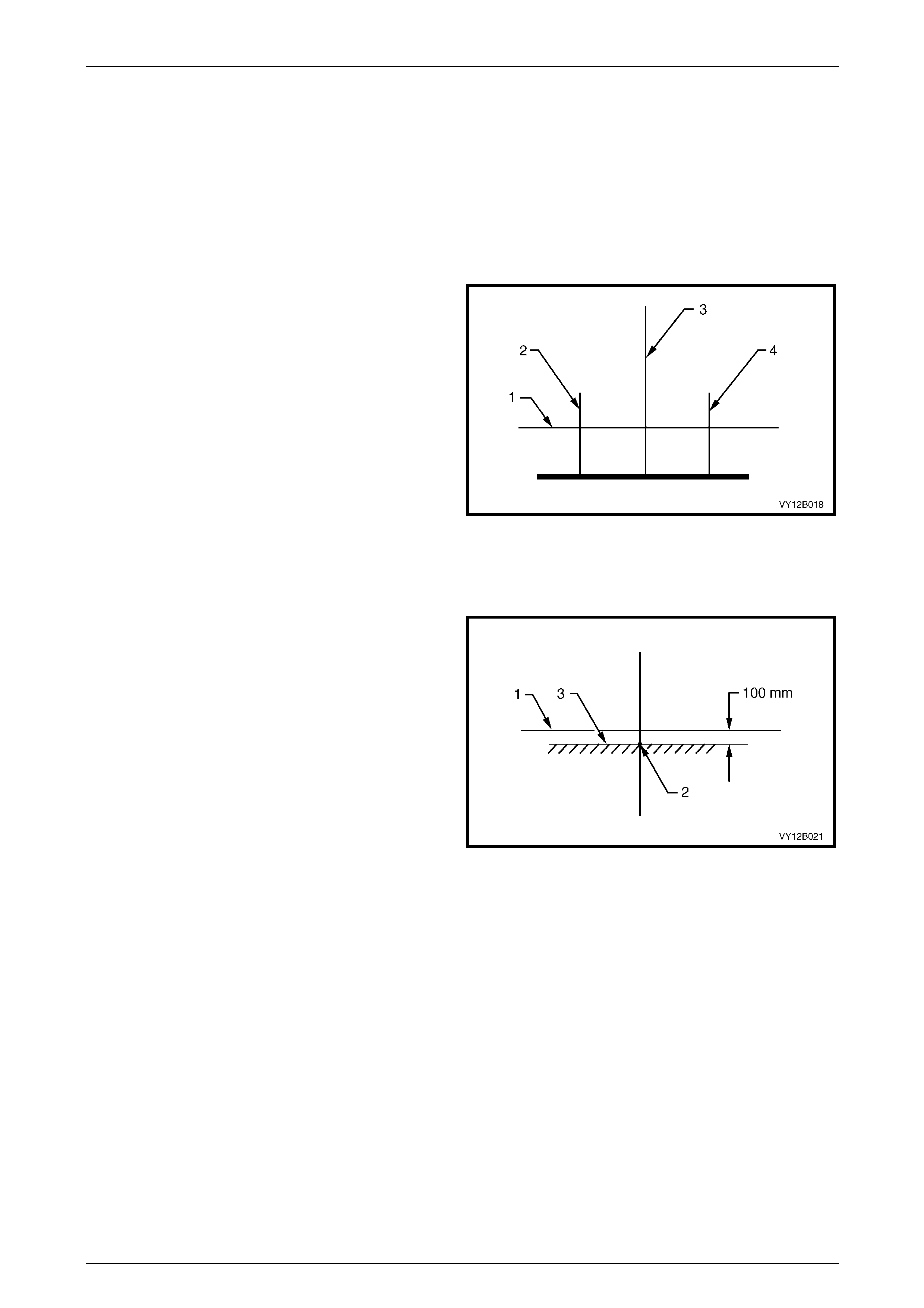
4 Turn on the front fog lamps. Aim each front fog lamp to
a point on its vertical centre-line (2), with the cut-off
line (3) 100 mm below the front fog lamp horizontal
centre-line (1).
NOTE
There is no provision for horizontal adjustment.
Front fog lamps are fixed to a vertical centre-line.
Figure 12B – 25
Lighting System Page 12B–35
Page 12B–35
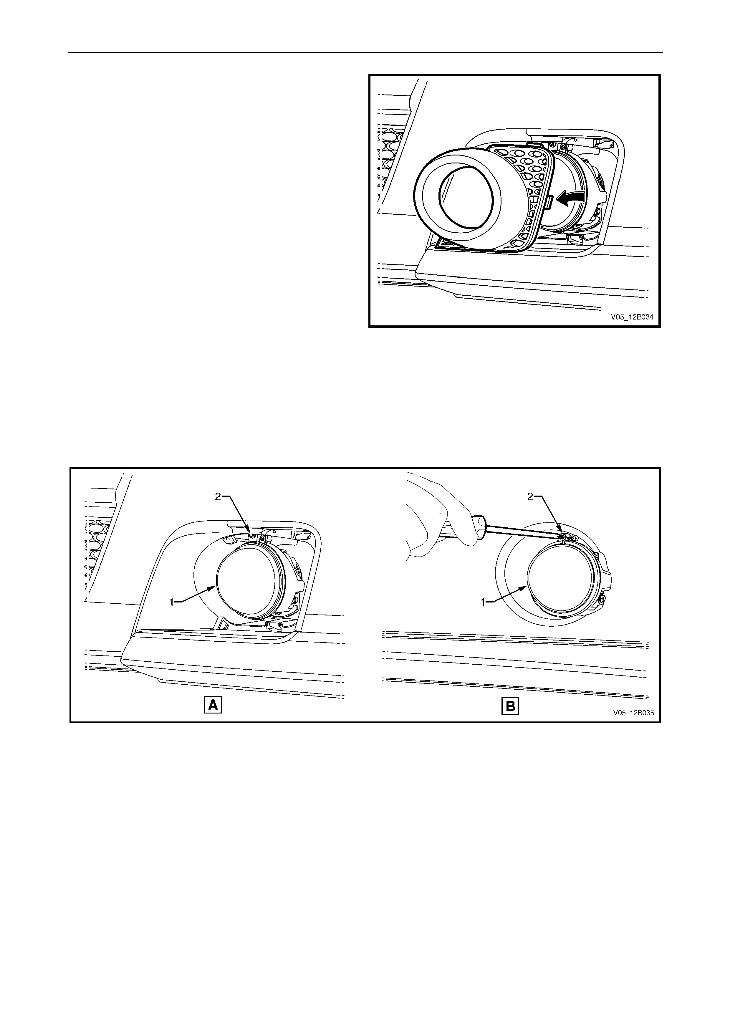
5 For Level 3 vehicles, the front fog lamp bezel
assembly must be removed to access the adjusting
screw. To remove the bezel assembly, refer to
Section 1D Bumper Bars.
Figure 12B – 26
6 Adjust the beam of the front fog lamp (1) by rotating the adjusting screw (2) clockwise to raise the beam and
anticlockwise to lower the beam, refer to Figure 12B – 27 where:
• view A shows a Level 3 vehicle, and
• view B shows an SS front fog lamp assembly.
7 For Level 3 front fog lamp assemblies, install the bezel assembly.
Figure 12B – 27
Lighting System Page 12B–36
Page 12B–36
5.2 Headlamp and Park Lamp Assembly
Bulbs
LT Section No. — 02–300
Level 1
Replace — Low Beam Bulb
1 Remove fusible link F102 from the engine compartment fuse and relay panel assembly, refer to
Section 12O Fuses, Relays and Wiring Harnesses.
2 Open the hood and disconnect the wiring harness connector from the rear of the appropriate hea dlamp assembly.
3 If required, for vehicles with a GEN III V8 engine, remove the four retainers securing the upper ra diator shroud and
remove the shroud, refer to Section Section 6B3 Engine Cooling — GEN III V8.
4 For the right-hand headlamp assembly, it may be necessary to remove the battery to gain the required access:
a If required, remove the battery hold-down bracket and move the battery to gain access,
refer to Section 12A Battery.
Disconnection of the battery affects certain
vehicle electronic systems. Refer to
Section 00 Warnings, Cautions and Notes
before disconnecting the battery.
b If further access is required, remove the battery terminals from the battery and remove the battery from the
engine compartment, refer to Section 12A Battery.
NOTE
For vehicles with a GEN III V8 engine, access the
left-hand bulb via the hole in the top of the air
intake duct.
5 For left-hand headlamp assemblies on vehicles with a V6 engine, remove the coolant filler bottle neck and place in
a safe location away from the immediate worksite.
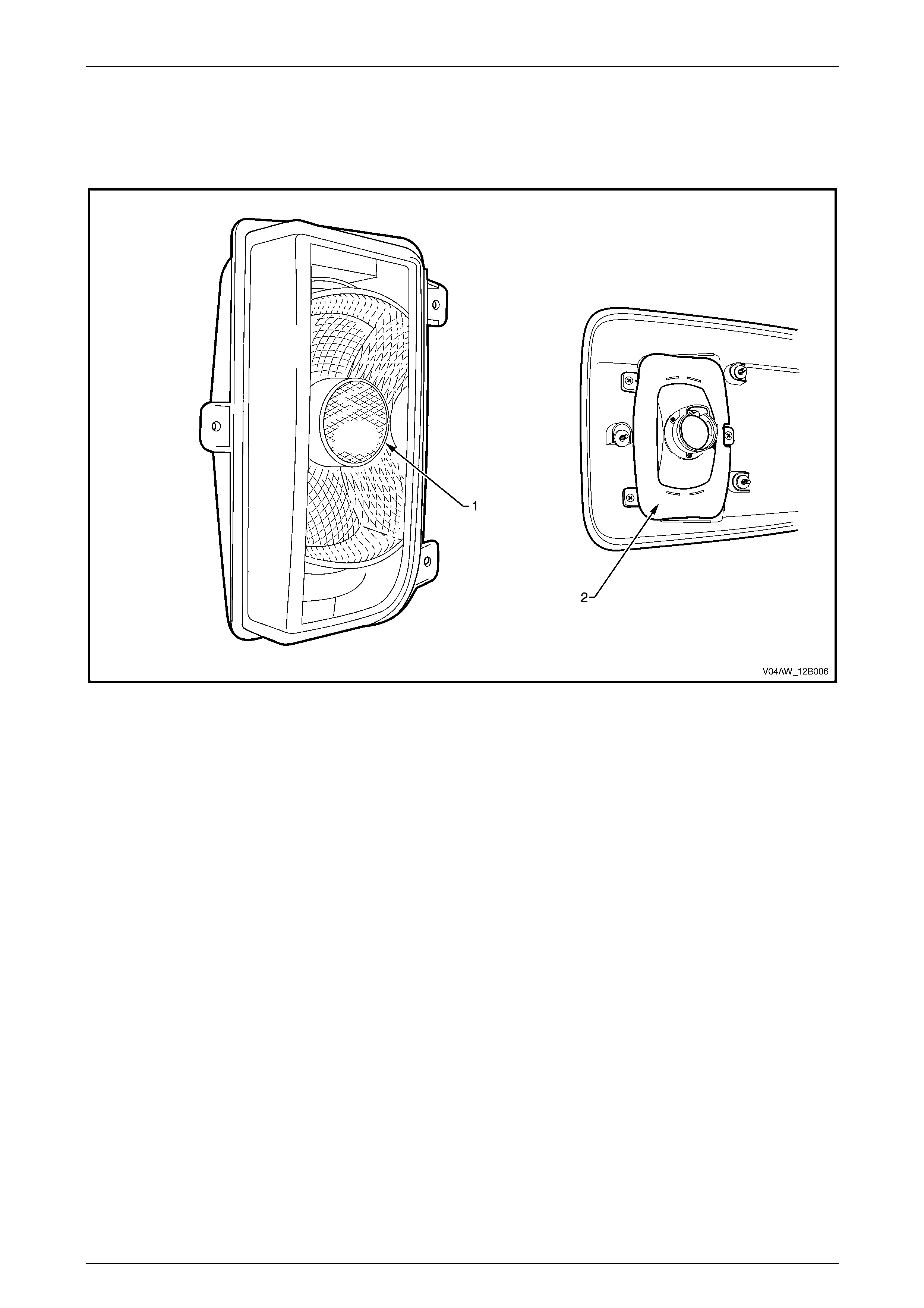
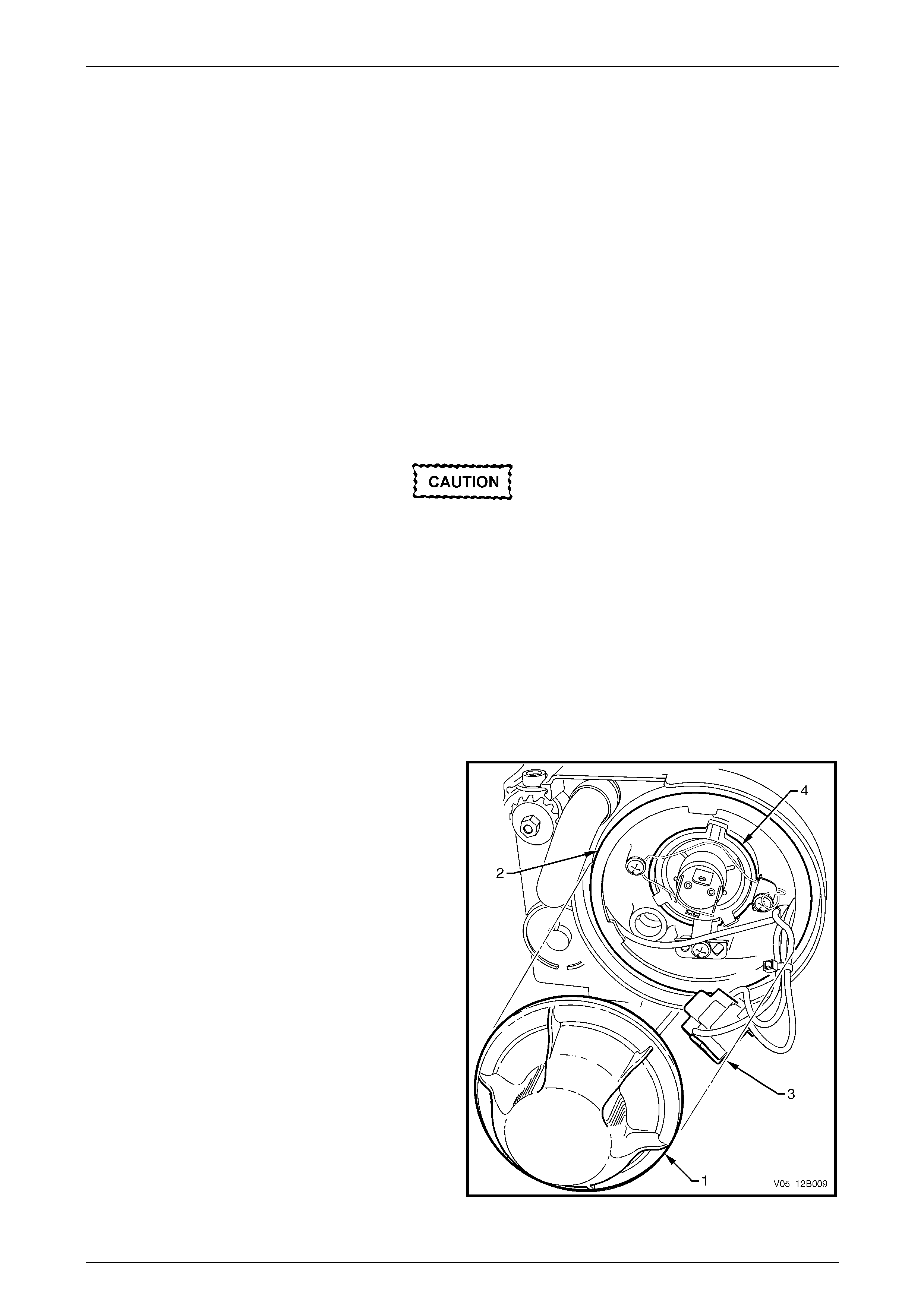
6 Remove the outboard dust cap (1) from the rear of the
headlamp assembly (2) by turning the dust cap
anticlockwise, then pulling it away from the headlamp
assembly. If the dust cap seal stays on the headlamp
assembly, remove the seal and install it onto the dust
cap.
7 Disconnect the wiring harness connector (3) from the
rear of the bulb (4).
Figure 12B – 28
Lighting System Page 12B–37
Page 12B–37
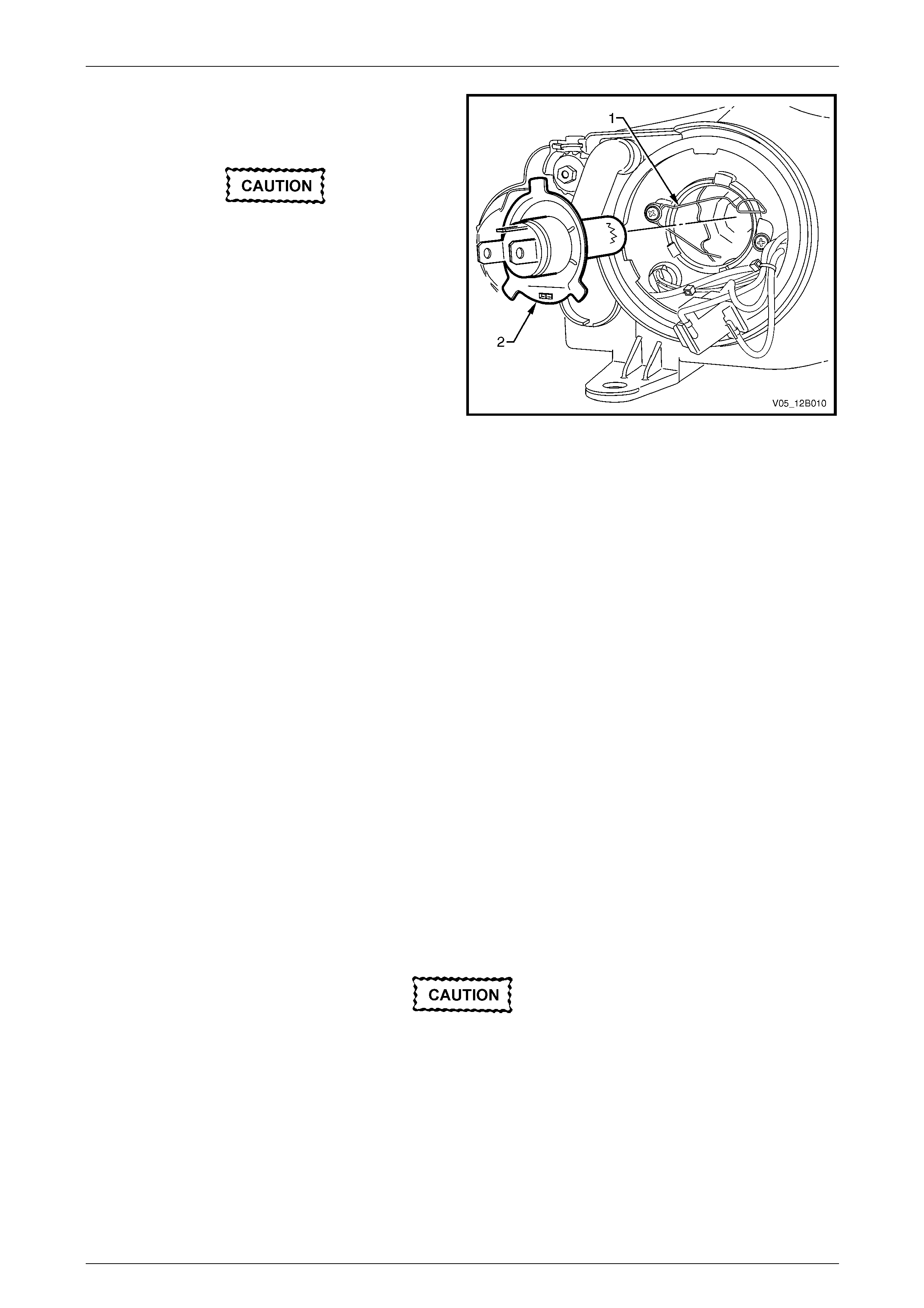
8 Press and unclip the bulb spri ng retainer (1) and pivot
clear of the bulb. Remove the bulb (2) from the
reflector.
Do not handle the quartz envelope of the
headlamp bulb. Wipe the quartz envelope
immediately with methylated spirits if it is
touched accidentally or the performance of
the bulb will deteriorate.
9 Install a new bulb into the reflector, ensuring the
locating tangs on the bulb mate correctly with the cut-
outs in the reflector.
NOTE
The different-sized locating tangs on the bulb
and the mating cut-outs in the reflector a llow the
bulb to seat correctly into the reflector in one
orientation only. This ensures the correct
positioning between the bulb and the reflector.
Figure 12B – 29
10 Install the bulb spring retainer and connect the wiring harness connector to the bulb.
11 Inspect the seal in the dust cap to ensure it is not damaged and it is seated correctly in the dust cap. Replace the
seal if it is damaged.
12 Install the dust cap onto the rear of the headl amp assembly and lock the dust cap into place by turning it clockwise.
Connect the wiring harness connector to the rear of the headlamp assembly.
13 If required, install the coolant filler bottle neck, upper radiator shroud and battery.
14 Install fusible link F102 on the engine compartment fuse and relay panel assembly.
15 Check the headlamp operatio n and adjust the aim; the position of the bulb filament with respect to the reflector may
have changed, refer to 5.1 Headlamp a nd Front Fog Lamp Aiming.
Replace — High Beam Bulb
1 Remove fusible link F102 from the engine compartment fuse and relay panel assembly, refer to
Section 12O Fuses, Relays and Wiring Harnesses.
2 Open the hood and disconnect the wiring harness connector from the rear of the appropriate hea dlamp assembly.
3 If required, for vehicles with a GEN III V8 engine, remove the four retainers securing the upper ra diator shroud and
remove the shroud, refer to Section Section 6B3 Engine Cooling — GEN III V8.
4 For the right-hand headlamp assembly, it may be necessary to remove the battery to gain the required access:
a If required, remove the battery hold-down bracket and move the battery to gain access,
refer to Section 12A Battery.
Disconnection of the battery affects certain
vehicle electronic systems. Refer to
Section 00 Warnings, Cautions and Notes
before disconnecting the battery.
b If further access is required, remove the battery terminals from the battery and remove the battery from the
engine compartment, refer to Section 12A Battery.
NOTE
For vehicles with a GEN III V8 engine, access the
left-hand bulb via the hole in the top of the air
intake duct.
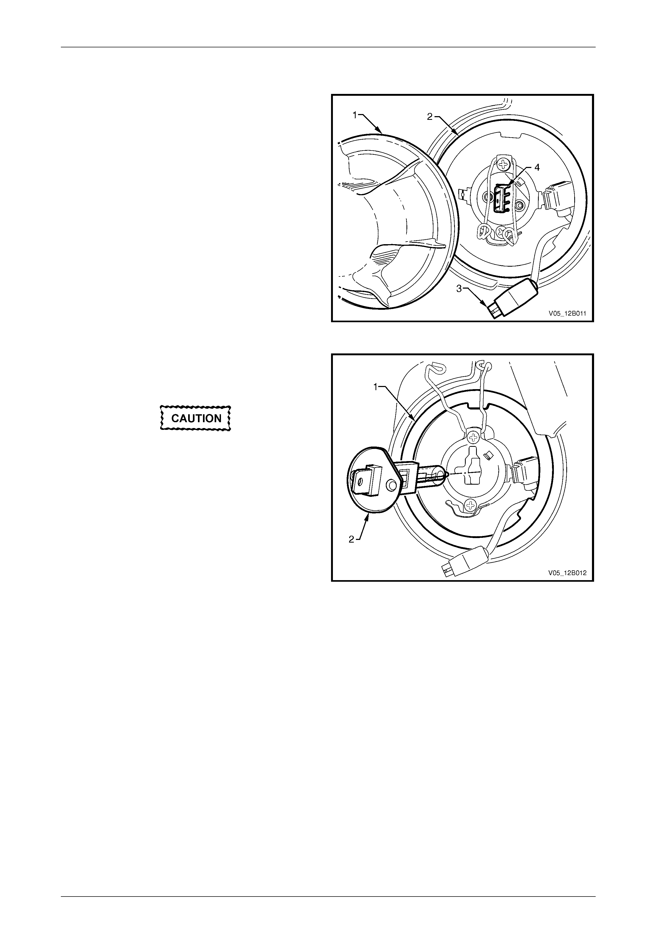
Lighting System Page 12B–38
Page 12B–38
5 For left-hand headlamp assemblies on vehicles with a V6 engine, remove the coolant filler bottle neck and place in
a safe location away from the immediate worksite.
6 Remove the inboard high beam dust cap (1) from the
rear of the headlamp assembly (2) by turning the dust
cap anticlockwise, then pulli ng it away from the
headlamp assembly. If the dust cap seal stays on the
headlamp assembly, remove the seal and install it
onto the dust cap.
7 Disconnect the wiring harness connector (3) from the
rear of the bulb (4).
Figure 12B – 30
8 Press and unclip the bulb spri ng retainer (1) and move
it clear of the bulb (2). Remove the bulb from the
reflector.
Do not handle the quartz envelope of the
inboard high beam bulb. Wipe the quartz
envelope immediately w ith methylated spirits
if it is touched accidentally or the perform-
ance of the bulb will deteriorate.
9 Install a new bulb into the reflector, ensuring the
locating lug on the bulb aligns with the square edge on
the reflector.
10 Install the bulb spring retainer and conn ect the wiring
harness connector to the bulb.
11 Inspect the seal in the dust cap to ensure it is not
damaged and it is seated corr ectly in the dust cap.
Replace the seal if it is damaged.
Figure 12B – 31
12 Install the dust cap onto the rear of the headl amp assembly and lock the dust cap into place by turning it clockwise.
Connect the wiring harness connector to the rear of the headlamp assembly.
13 If required, install the coolant filler bottle neck, upper radiator shroud and battery.
14 Install fusible link F102 on the engine compartment fuse and relay panel assembly.
15 Check the headlamp operatio n and adjust the aim; the position of the bulb filament with respect to the reflector may
have changed, refer to 5.1 Headlamp a nd Front Fog Lamp Aiming.
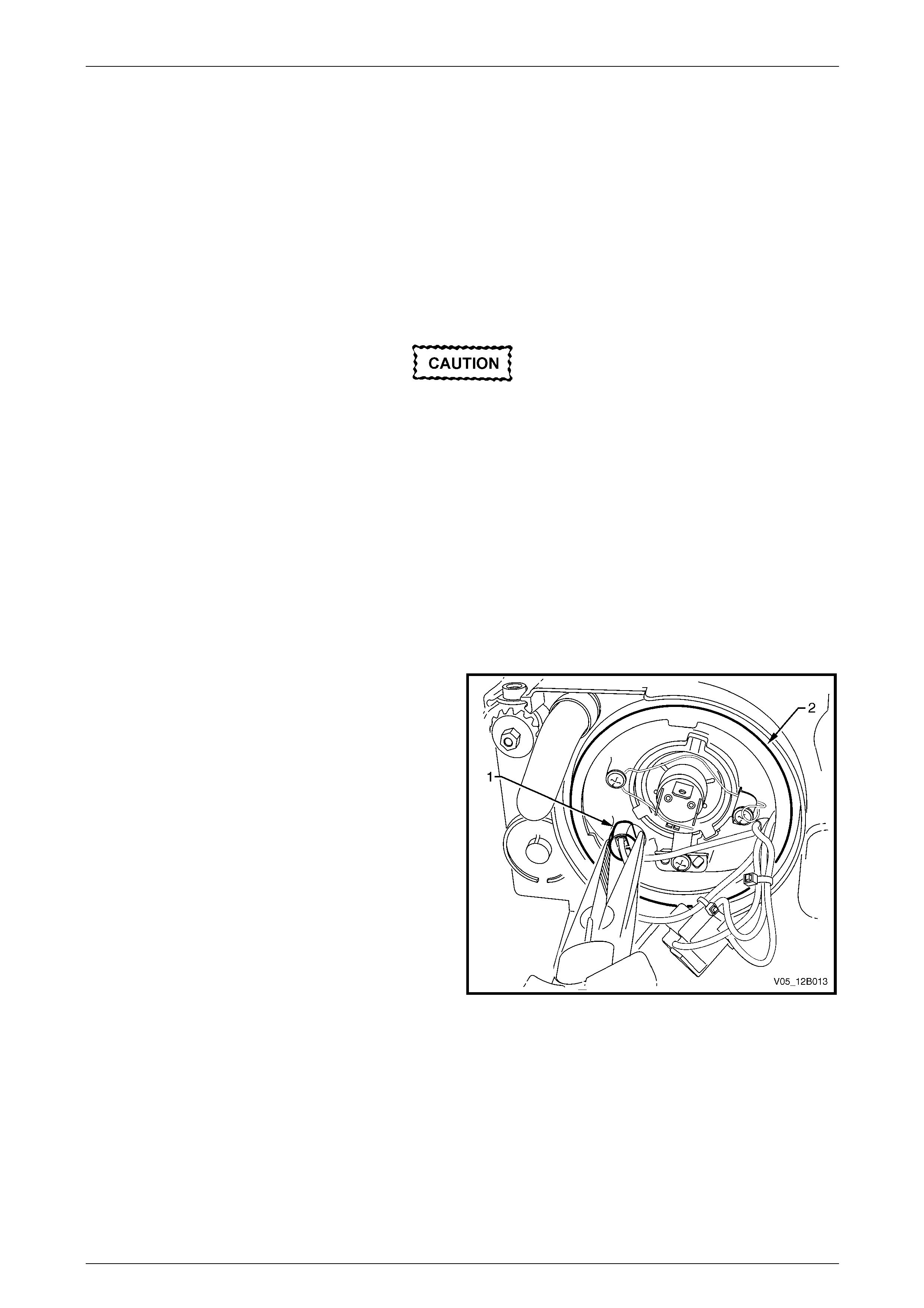
Lighting System Page 12B–39
Page 12B–39
Replace — Park Lamp Bulb
1 Remove fusible link F102 from the engine compartment fuse and relay panel assembl y,
refer to Section 12O Fuses, Relays and Wiring Harnesses.
2 Open the hood and disconnect the wiring harness connector from the rear of the appropriate hea dlamp assembly.
3 If required, for vehicles with a GEN III V8 engine, remove the four retainers securing the upper ra diator shroud and
remove the shroud, refer to Section Section 6B3 Engine Cooling — GEN III V8.
4 For the right-hand headlamp assembly, it may be necessary to remove the battery to gain the required access:
a If required, remove the battery hold-down bracket and move the battery to gain access,
refer to Section 12A Battery.
Disconnection of the battery affects certain
vehicle electronic systems. Refer to
Section 00 Warnings, Cautions and Notes
before disconnecting the battery.
b If further access is required, remove the battery terminals from the battery and remove the battery from the
engine compartment, refer to Section 12A Battery.
NOTE
For vehicles with a GEN III V8 engine, access the
left-hand bulb via the hole in the top of the air
intake duct.
5 For left-hand headlamp assemblies on vehicles with a V6 engine, remove the coolant filler bottle neck and place in
a safe location away from the immediate worksite.
6 Using needle-nose pl iers, pull the park bulb socket (1)
from the headlamp assembly (2).
Figure 12B – 32
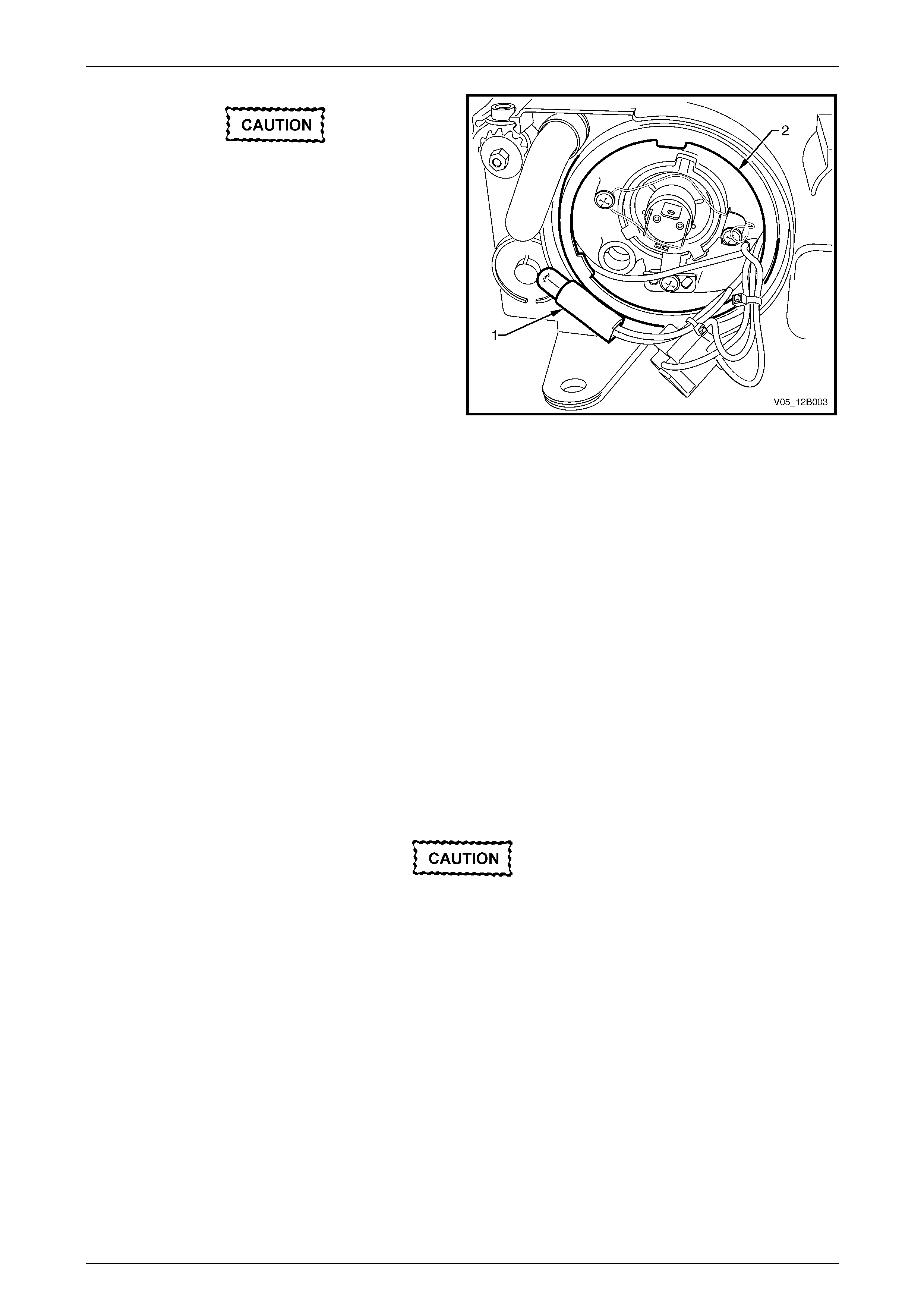
Lighting System Page 12B–40
Page 12B–40
Do not handle the quartz envelope of the
headlamp bulb. Wipe the quartz envelope
immediately with methylated spirits if it is
touched accidentally or the performance of
the bulb will deteriorate.
7 Insert a new bulb into the park bulb socket.
8 Install the park bulb socket into the rear of the
headlamp assembly an d push it into place.
Figure 12B – 33
9 If required, install the coolant filler bottle neck, upper radiator shroud and battery.
10 Install fusible link F102 on the engine compartment fuse and relay panel a ssembly.
11 Check the park lamp operation.
Level 2 and Level 3
Replace — Low Beam Bulb
1 Remove fusible link F102 from the engine compartment fuse and relay panel assembl y,
refer to Section 12O Fuses, Relays and Wiring Harnesses.
2 Open the hood and disconnect the wiring harness connector from the rear of the appropriate hea dlamp assembly.
3 If required, for vehicles with a GEN III V8 engine, remove the four retainers securing the upper ra diator shroud and
remove the shroud, refer to Section Section 6B3 Engine Cooling — GEN III V8.
4 For the right-hand headlamp assembly, it may be necessary to remove the battery to gain the required access:
a If required, remove the battery hold-down bracket and move the battery to gain access,
refer to Section 12A Battery.
Disconnection of the battery affects certain
vehicle electronic systems. Refer to
Section 00 Warnings, Cautions and Notes
before disconnecting the battery.
b If further access is required, remove the battery terminals from the battery and remove the battery from the
engine compartment, refer to Section 12A Battery.
NOTE
For vehicles with a GEN III V8 engine, access the
left-hand bulb via the hole in the top of the air
intake duct.
5 For left-hand headlamp assemblies on vehicles with a V6 engine, remove the coolant filler bottle neck and place in
a safe location away from the immediate worksite.
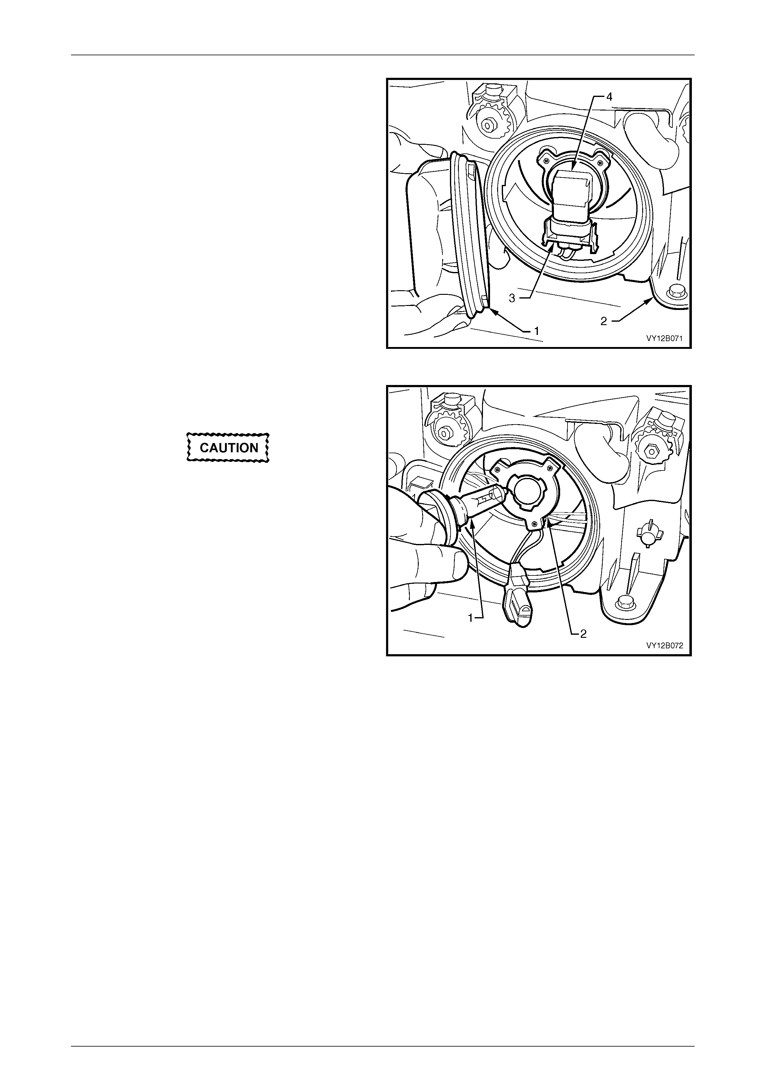
Lighting System Page 12B–41
Page 12B–41
6 Remove the outboard dust cap (1) from the rear of the
headlamp assembly (2) by turning the dust cap
anticlockwise, then pulling it away from the headlamp
assembly. If the dust cap seal stays on the headlamp
assembly, remove the seal and install it onto the dust
cap.
7 Disconnect the wiring harness connector (3) from the
rear of the bulb (4).
Figure 12B – 34
8 Rotate the bulb (1) anticlockwise and rem ove the bulb
from the bulb holder (2).
Do not handle the quartz envelope of the
headlamp bulb. Wipe the quartz envelope
immediately with methylated spirits if it is
touched accidentally or the performance of
the bulb will deteriorate.
9 Install a new bulb into the bulb holder. Lock the bulb in
place by turning it clockwise. Fit the bulb connector by
pushing it into the base of the bulb until the tangs
engage.
NOTE
The different-sized locating lugs on the bulb
base and mating cut-outs in the bulb holder
allow the bulb to seat correctly i n one orientation
only. This ensures the correct positioning
between the bulb and the reflector.
Figure 12B – 35
10 Inspect the seal on the dust cap to ensure it is not damaged and it is seated correctly in the dust cap. Replace the
seal if it is damaged.
11 Install the dust cap onto the rear of the headlamp assembly. The different-sized lugs o n the dust cap a nd the
mating cut-outs on the headlamp assembl y ensure the dust cap can be installed in only one orientation. The
chamfered flats of the dust cap must face inboard for the dust cap to install correctly. Lock the dust cap into place
by turning it clockwise.
12 Connect the wiring harness connector to the rear of the headlamp assembly.
13 If required, install the coolant filler bottle neck, upper radiator shroud and battery.
14 Install fusible link F102 on the engine compartment fuse and relay panel assembly.
15 Check the headlamp operatio n and adjust the aim; the position of the bulb filament with respect to the reflector may
have changed, refer to 5.1 Headlamp a nd Front Fog Lamp Aiming.
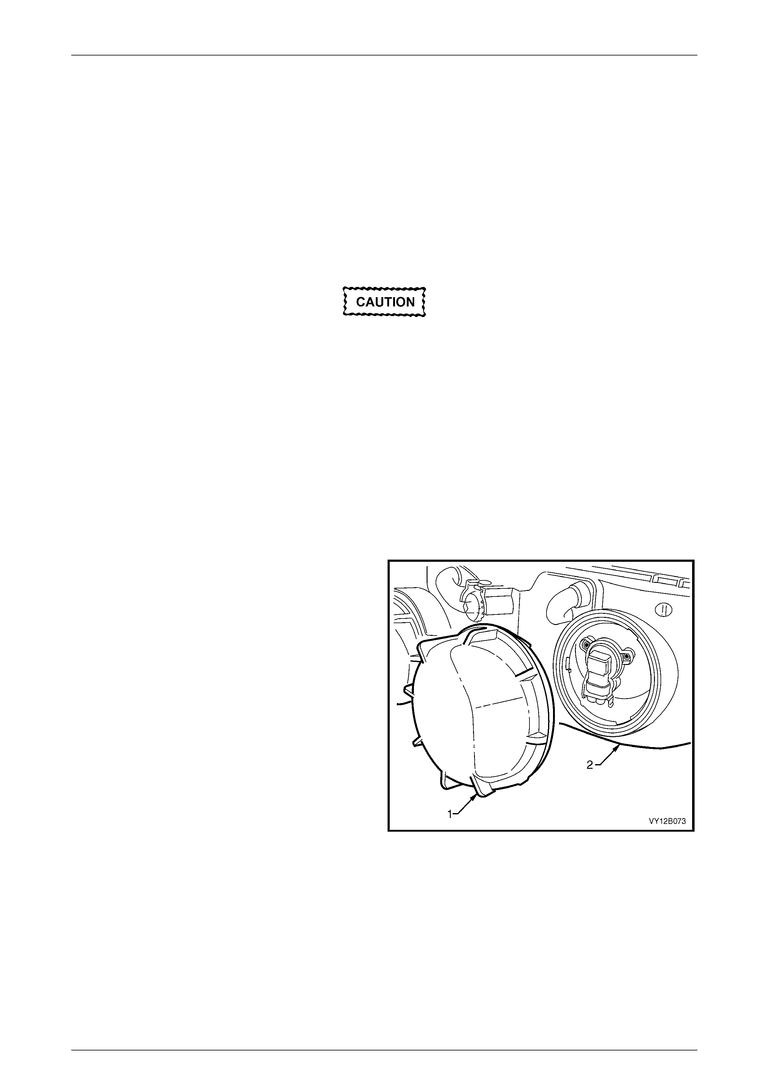
Lighting System Page 12B–42
Page 12B–42
Replace — High Beam Bulb
1 Remove fusible link F102 from the engine compartment fuse and relay panel assembl y,
refer to Section 12O Fuses, Relays and Wiring Harnesses.
2 Open the hood and disconnect the wiring harness connector from the rear of the appropriate hea dlamp assembly.
3 If required, for vehicles with a GEN III V8 engine, remove the four retainers securing the upper ra diator shroud and
remove the shroud, refer to Section Section 6B3 Engine Cooling — GEN III V8.
4 For the right-hand headlamp assembly, it may be necessary to remove the battery to gain the required access:
a If required, remove the battery hold-down bracket and move the battery to gain access,
refer to Section 12A Battery.
Disconnection of the battery affects certain
vehicle electronic systems. Refer to
Section 00 Warnings, Cautions and Notes
before disconnecting the battery.
b If further access is required, remove the battery terminals from the battery and remove the battery from the
engine compartment, refer to Section 12A Battery.
NOTE
For vehicles with a GEN III V8 engine, access the
left-hand bulb via the hole in the top of the air
intake duct.
5 For left-hand headlamp assemblies on vehicles with a V6 engine, remove the coolant filler bottle neck and place in
a safe location away from the immediate worksite.
6 Remove the inboard high beam dust cap (1) from the
rear of the headlamp assembly (2) by turning the dust
cap anticlockwise, then pulli ng it away from the
headlamp assembly. If the dust cap seal stays on the
headlamp assembly, remove the seal and install it
onto the dust cap.
Figure 12B – 36
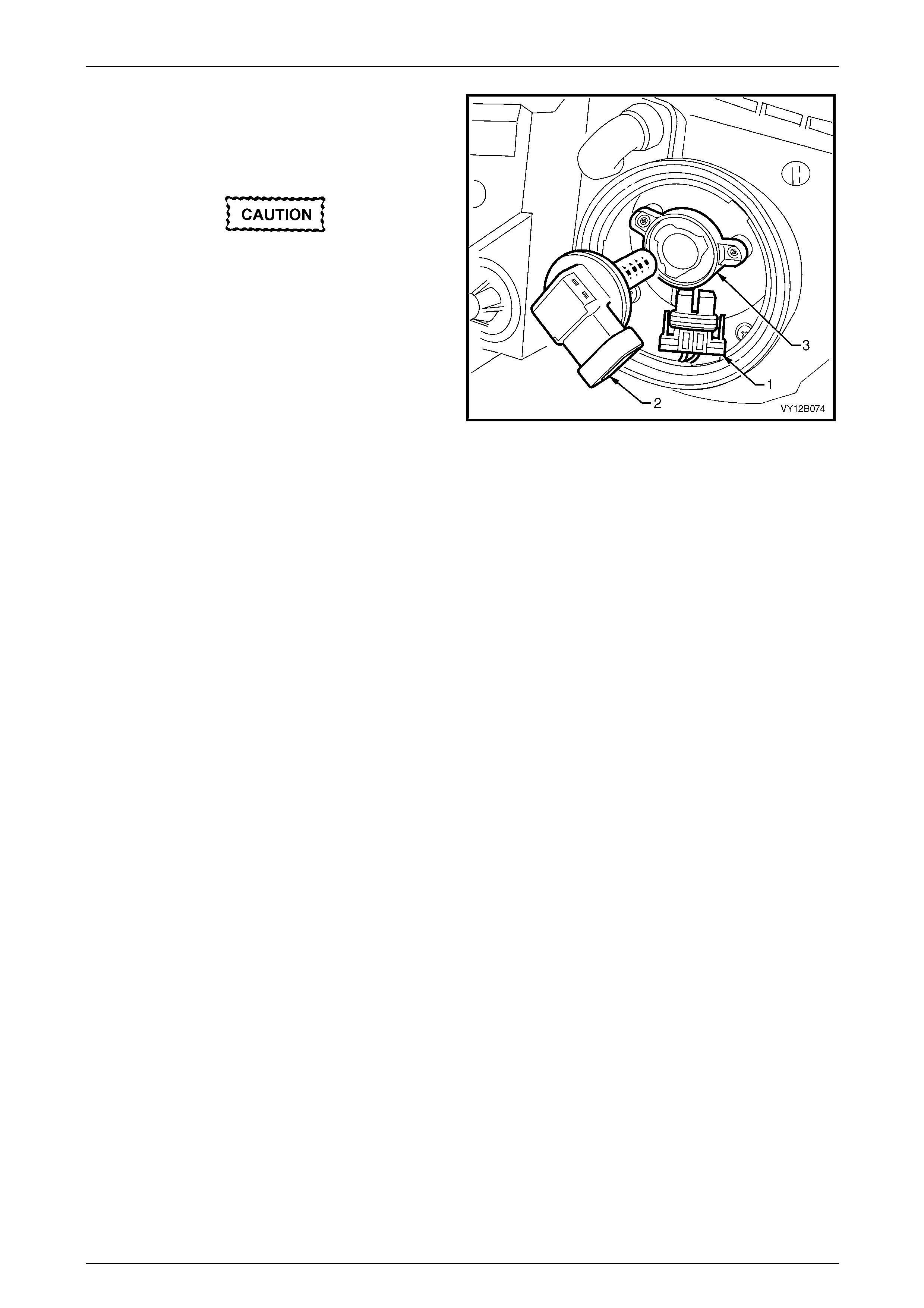
Lighting System Page 12B–43
Page 12B–43
7 Disconnect the wiring harness connector (1) from the
rear of the bulb.
8 Rotate the bulb (2) anticlockwise and rem ove the bulb
from the bulb holder (3).
Do not handle the quartz envelope of the
inboard high beam bulb. Wipe the quartz
envelope immediately w ith methylated spirits
if it is touched accidentally or the perform-
ance of the bulb will deteriorate.
9 Install a new bulb into the bulb holder. Lock the bulb in
place by turning it clockwise. Fit the bulb connector by
pushing it into the base of the bulb until the tangs
engage.
Figure 12B – 37
NOTE
The different-sized locati ng lugs on the bulb base
and mating cut-outs in the bulb holder allow the
bulb to seat correctly in one orientation on ly. This
ensures the correct positioning between the bulb
and the reflector.
10 Inspect the seal on the dust cap to ensure it is not damaged and it is seated correctly on the dust cap. Replace the
seal if it is damaged.
11 Install the dust cap onto the rear of the headlamp assembly. The different-sized lugs o n the dust cap a nd the
mating cut-outs in the headlamp assembly ensure the dust cap can be installed only in on e orientation. The
chamfered flats of the dust cap must face inboard for the dust cap to install correctly. Lock the dust cap into place
by turning it clockwise.
12 Connect the wiring harness connector to the rear of the headlamp assembly.
13 If required, install the coolant filler bottle neck, upper radiator shroud and battery.
14 Install fusible link F102 on the engine compartment fuse and relay panel assembly.
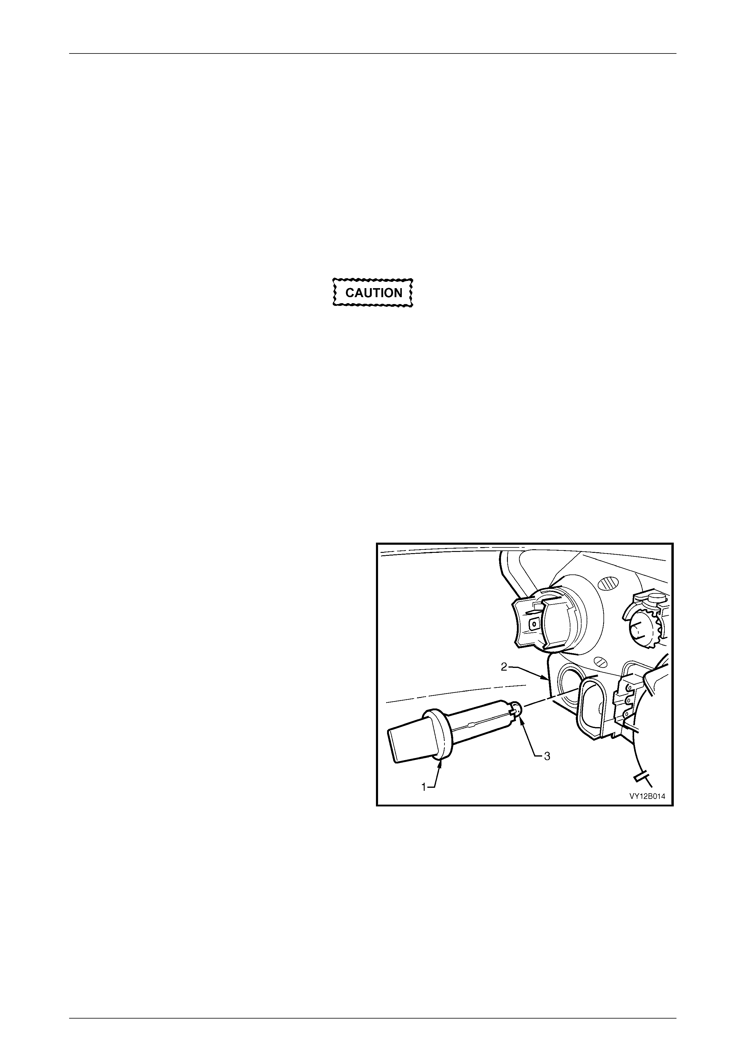
Lighting System Page 12B–44
Page 12B–44
Replace — Park Lamp Bulb
1 Remove fusible link F102 from the engine compartment fuse and relay panel assembl y,
refer to Section 12O Fuses, Relays and Wiring Harnesses.
2 Open the hood and disconnect the wiring harness connector from the rear of the appropriate hea dlamp assembly.
3 If required, for vehicles with a GEN III V8 engine, remove the four retainers securing the upper ra diator shroud and
remove the shroud, refer to Section Section 6B3 Engine Cooling — GEN III V8.
4 For the right-hand headlamp assembly, it may be necessary to remove the battery to gain the required access:
a If required, remove the battery hold-down bracket and move the battery to gain access,
refer to Section 12A Battery.
Disconnection of the battery affects certain
vehicle electronic systems. Refer to
Section 00 Warnings, Cautions and Notes
before disconnecting the battery.
b If further access is required, remove the battery terminals from the battery and remove the battery from the
engine compartment, refer to Section 12A Battery.
NOTE
For vehicles with a GEN III V8 engine, access the
left-hand bulb via the hole in the top of the air
intake duct.
5 For left-hand headlamp assemblies on vehicles with a V6 engine, remove the coolant filler bottle neck and place in
a safe location away from the immediate worksite.
6 Remove the park bulb socket (1) from the headlamp
assembly (2) by rotating it anticlockwise, then pulling it
away from the headlamp assembly.
7 Pull the bulb (3) away from the park bulb socket. Insert
a new bulb into the park bulb socket.
8 Inspect the seal on the park bulb socket to ensure it is
not damaged and it is seated correctly. Replace the
seal if it is damaged.
9 Install the park bulb socket into the rear of the
headlamp assembly and lock into place by turning it
clockwise. Connect the wiring harness con ne c tor to
the rear of the headlamp assembly.
Figure 12B – 38
10 If required, install the coolant filler bottle neck, upper radiator shroud and battery.
11 Install fusible link F102 on the engine compartment fuse and relay panel assembly.
12 Check the park lamp operation.
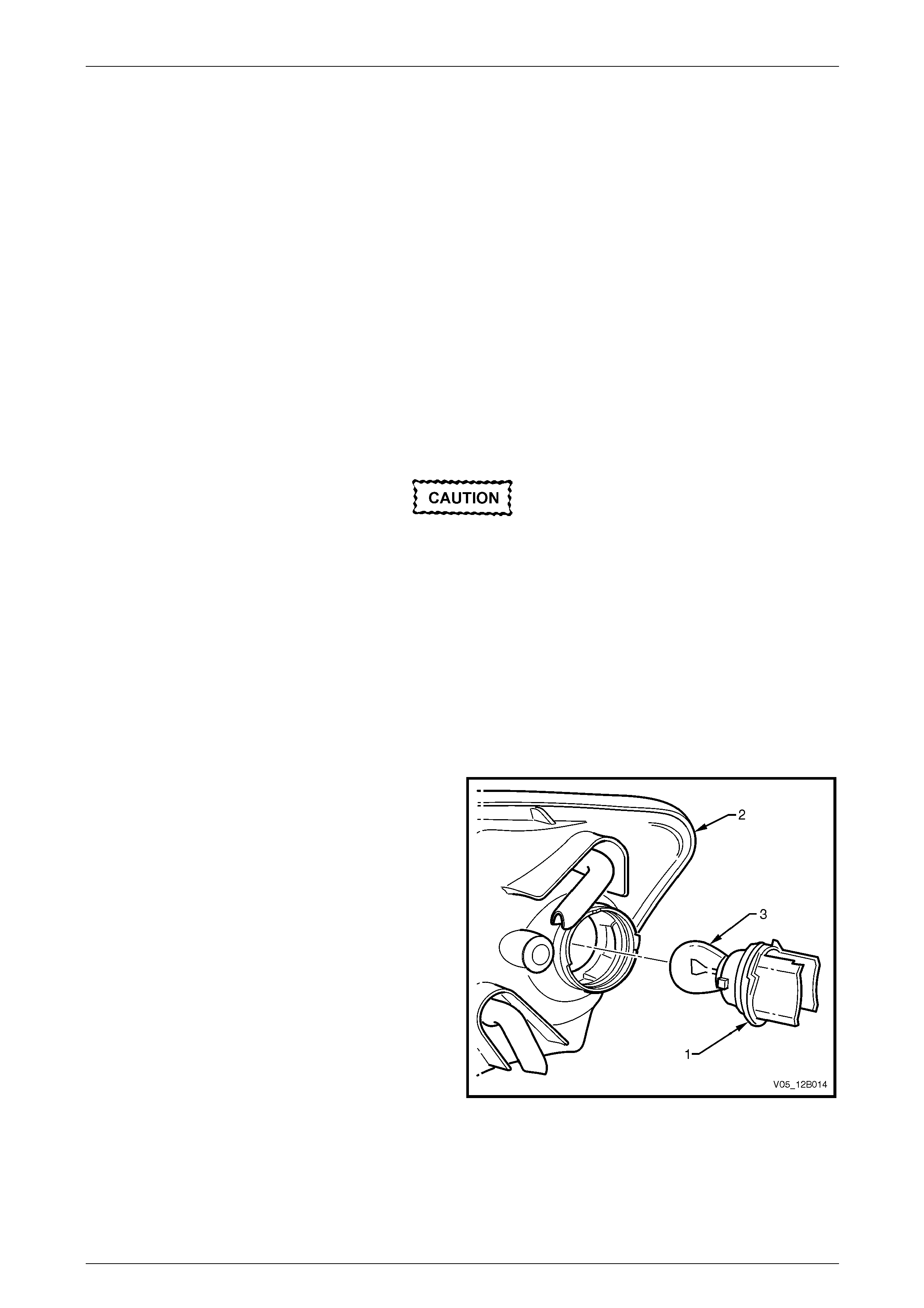
Lighting System Page 12B–45
Page 12B–45
5.3 Front Turn Signal Lamp Bulb
Replace
LT Section No. — 02–310
The turn signal lamp bulb and socket is identical on each model; the turn signal lamp is situated on the outboard
extremity of each headl amp assembly. The turn signal bulb socket is orange and has a separate wiring connector to the
headlamp assembly. To vie w the rear of each head lamp assembly, refer to:
• Figure 12B – 1 (item 1) for Level 1 vehicles, or
• Figure 12B – 2 (item 1) for Level 2 and Level 3 vehicles
1 Remove turn signal lamp fuse F12, refer to Section 12O Fuses, Relays and Wiring Harnesses.
2 If required, for vehicles with a GEN III V8 engine, remove the four retainers securing the upper ra diator shroud and
remove the shroud, refer to Section Section 6B3 Engine Cooling — GEN III V8.
3 For the right-hand headlamp assembly, it may be necessary to remove the battery to gain the required access:
a If required, remove the battery hold-down bracket and move the battery to gain access,
refer to Section 12A Battery.
Disconnection of the battery affects certain
vehicle electronic systems. Refer to
Section 00 Warnings, Cautions and Notes
before disconnecting the battery.
b If further access is required, remove the battery terminals from the battery and remove the battery from the
engine compartment, refer to Section 12A Battery.
NOTE
For vehicles with a GEN III V8 engine, access the
left-hand bulb via the hole in the top of the air
intake duct.
4 For left-hand headlamp assemblies on vehicles with a V6 engine, remove the coolant filler bottle neck and place in
a safe location away from the immediate worksite.
5 Disconnect the turn signal wiring harness co nnector
from the turn signal bulb socket (1).
6 Remove the turn signal bulb socket from the headlamp
assembly (2) by rotating it anticlockwise, then pulling it
away from the headlamp assembly.
7 Press the bulb (3) into the turn signal bul b socket and
rotate anticlockwise, then remove it from the reflector.
8 Inspect the seal on the turn signal bulb sock et for
damage and correct seating. Replace the seal if
necessary.
9 Install the new bulb into the turn signal bulb socket.
Install the turn signal bulb socket into the headlamp
assembly and lock it into place by turning it clockwise.
10 Connect the wiring harness connector to the turn
signal bulb socket.
11 If required, install the coolant filler bottle neck, upper
radiator shroud and battery. Figure 12B – 39
12 Fit turn signal lamp fuse F12.
13 Check the turn signal lamp operatio n.
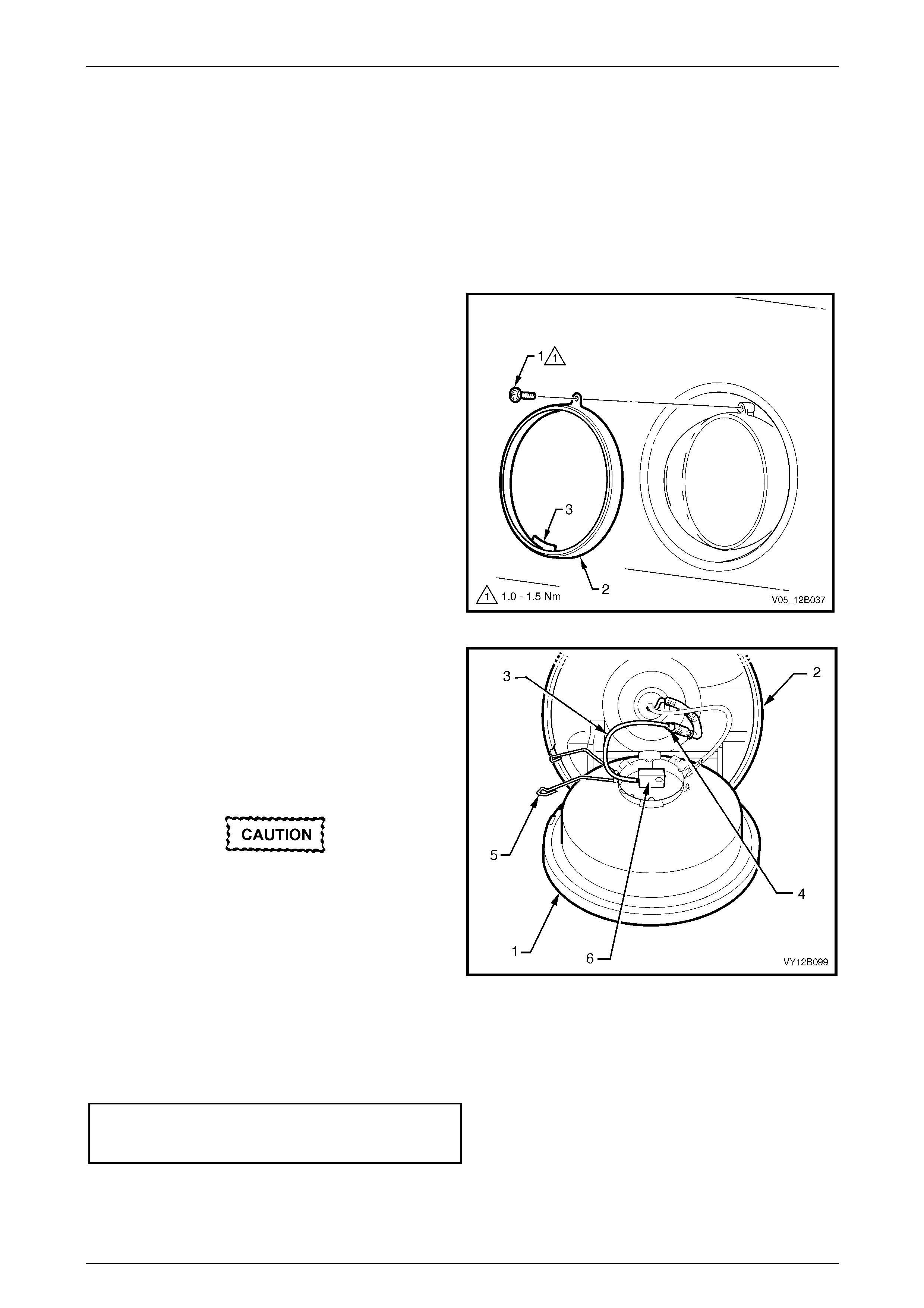
Lighting System Page 12B–46
Page 12B–46
5.4 Front Fog Lamp Bulb Assemblies
LT Section No. — 02–325
S and SS
Replace
1 Remove fusible link F102 from the engine compartment fuse and relay panel assembl y,
refer to Section 12O Fuses, Relays and Wiring Harnesses.
2 Remove the screw (1) to release the clamp ring (2).
3 Rotate the clamp ring clockwise until the retaining
hook (3) is at the 9 o’clock position. Remove the clamp
ring from the front fog lamp.
Figure 12B – 40
4 Pull the lens and reflector assembly (1) from the front
fog lamp housing (2).
5 Disconnect the bulb lead (3) from the wiring harness
connector (4) located inside the insulating sheath.
6 Press both halves of the bulb spring retainer (5)
together and pivot the spring backward clear of the
bulb. Remove the bulb (6) from the lens and reflector
assembly.
Do not handle the quartz envelope of the
headlamp bulb. Wipe the quartz envelope
immediately with methylated spirits if it is
touched accidentally or the performance of
the bulb will deteriorate.
7 Align the new bulb to the notches in the reflector and
install the bulb, then insert the bulb spring retainer. Figure 12B – 41
8 Connect the bulb lead to the wiring harn ess conn ector.
9 Install the lens and reflector assembl y i nto the housing, ensuring the tabs on the rim of the lens a nd reflector
assembly correspond with the cut-outs in the rim of the hous ing.
10 Install the clamp ring and tighten the screw to the correct torque specification.
Front fog lamp assembly
clamp ring securing screw
torque specification.....................................1.0 – 1.5 Nm
11 Install fusible link F102 on the engine compartment fuse and relay panel assembly.
12 Check the front fog lamp operation a nd adjust the aim, refer to 5.1 Headlamp and Front Fog Lamp Aiming.
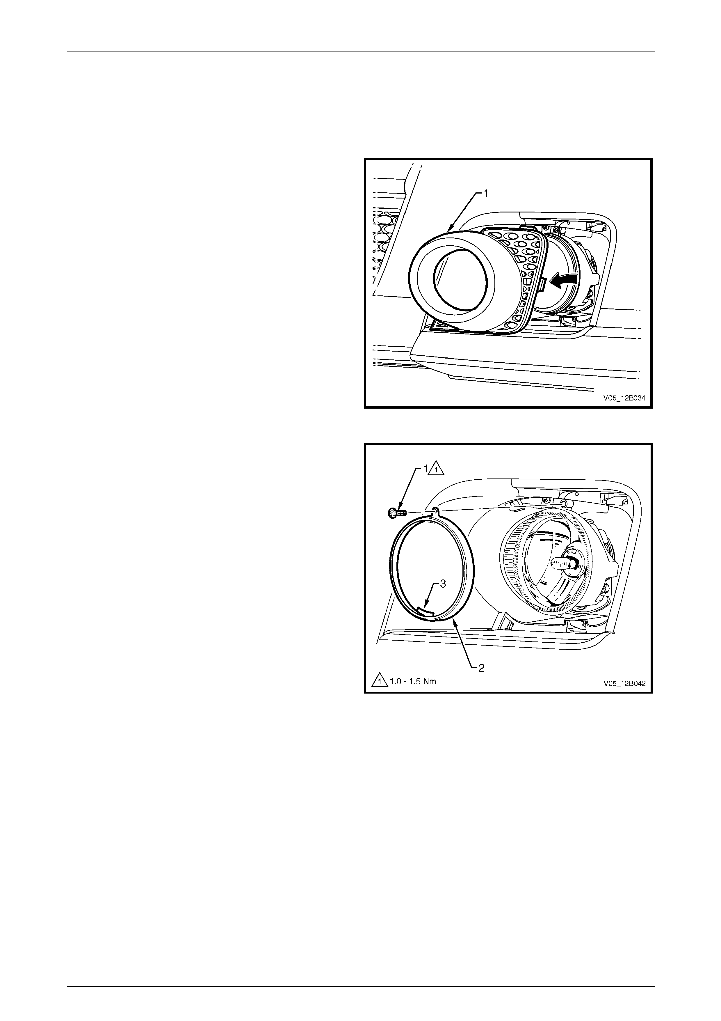
Lighting System Page 12B–47
Page 12B–47
Level 2 and Level 3
Replace
1 Remove fusible link F102 from the engine compartment fuse and relay panel assembl y,
refer to Section 12O Fuses, Relays and Wiring Harnesses.
2 Remove the front fog lamp bezel assembly (1), refer to
Section 1D Bumper Bars.
Figure 12B – 42
3 Remove the screw (1) to release the clamp ring (2).
4 Rotate the clamp ring clockwise until the retaining
hook (3) is at the 9 o’clock position. Remove the clamp
ring from the front fog lamp.
Figure 12B – 43
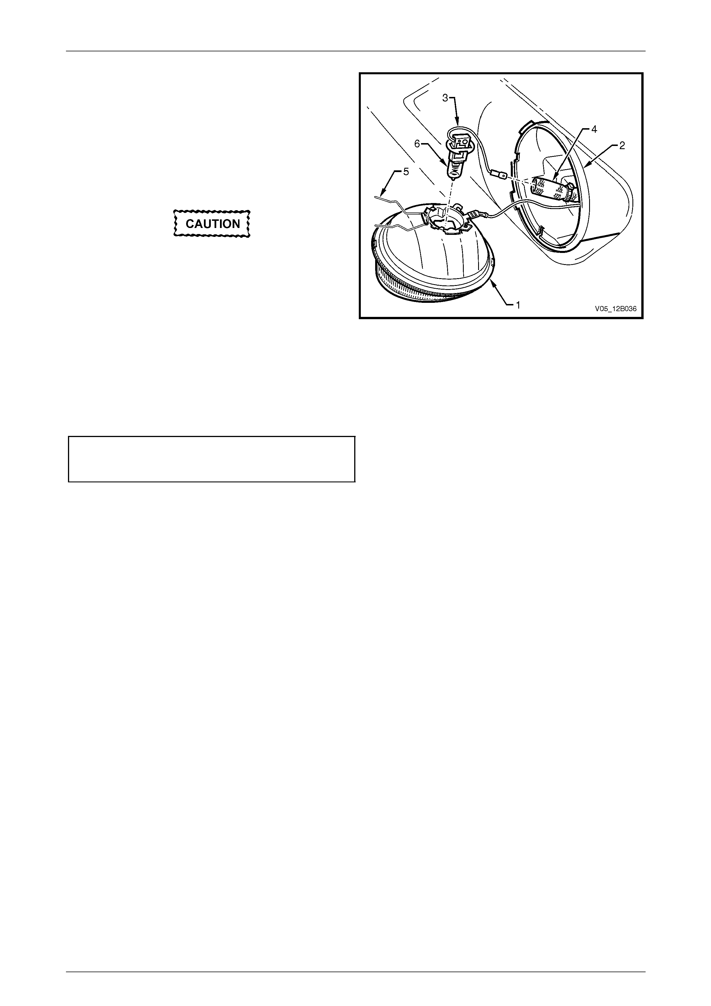
Lighting System Page 12B–48
Page 12B–48
5 Pull the lens and reflector assembly (1) from the front
fog lamp housing (2).
6 Disconnect the bulb lead (3) from the wiring harness
connector located inside the in sulation sheath (4).
7 Press both halves of the bulb spring retainer (5)
together and pivot the spring backward clear of the
bulb. Remove the bulb (6) from the lens and reflector
assembly.
Do not handle the quartz envelope of the
headlamp bulb. Wipe the quartz envelope
immediately with methylated spirits if it is
touched accidentally or the performance of
the bulb will deteriorate.
8 Install the new bulb into the correct locating notches in
the reflector, then insert the bulb spring retainer. Figure 12B – 44
9 Connect the bulb lead to the wiring harn ess conn ector.
10 Install the lens and reflector assembl y i nto the housing, ensuring the tabs on the rim of the lens a nd reflector
assembly correspond with the cut-outs in the rim of the hous ing.
11 Install the lens and reflector assembl y with the clamp ring and tighten the screw to the correct torque specification.
Front fog lamp assembly
clamp ring securing screw
torque specification.....................................1.0 – 1.5 Nm
12 Install fusible link F102 on the engine compartment fuse and relay panel assembly.
13 Check the front fog lamp operation a nd adjust the aim, refer to 5.1 Headlamp and Front Fog Lamp Aiming.
14 Install the front fog lamp bezel assembly, ensuring the tabs lock securely into the bumper fascia assembly.
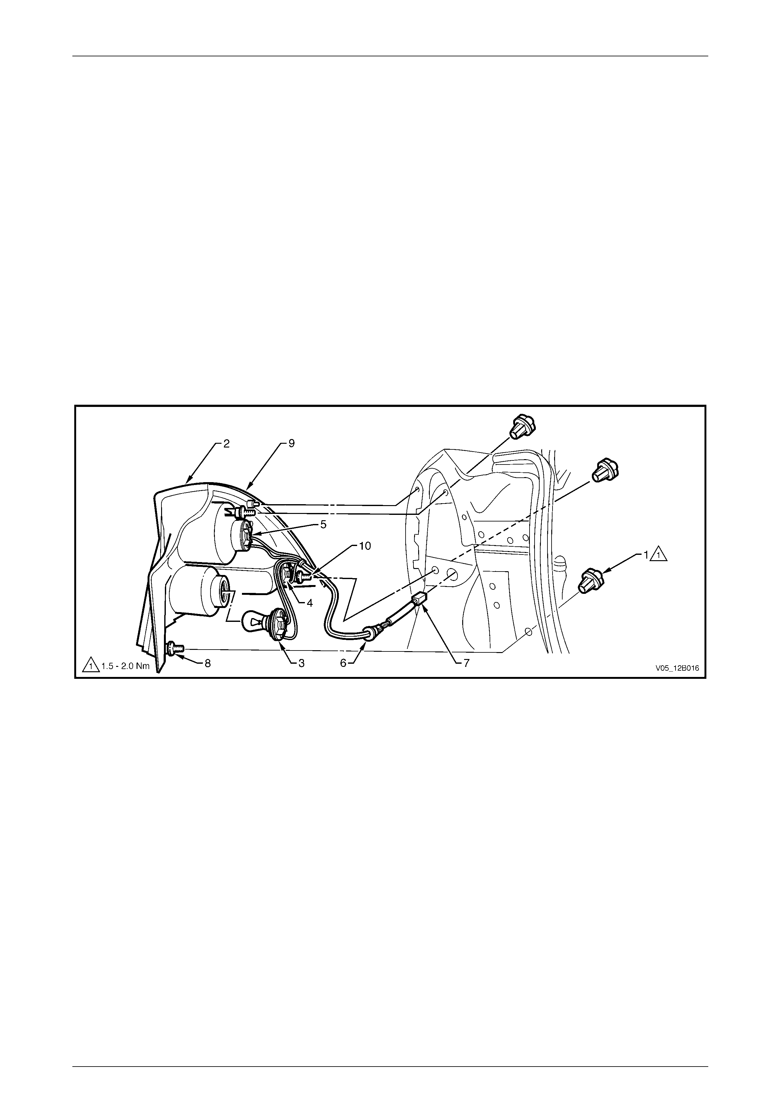
Lighting System Page 12B–49
Page 12B–49
5.5 Tail Lamp Assembly Bulbs
LT Section No. — 02–350
Sedan
Replace
1 Remove fusible link F102 from the engine compartment fuse and relay panel assembl y,
refer to Section 12O Fuses, Relays and Wiring Harnesses.
2 Open the rear compartment lid.
3 Pull the quarter inner rear side carpet from the corner of the rear compartment to expose the tail lamp attaching
nuts (1), refer to Figure 12B – 45.
NOTE
Remove the tail lamp attaching nuts either by
hand or with a 6.0 mm Allen key.
Figure 12B – 45
Legend
1 Tail Lamp Attaching Nut
2 Tail Lamp Assembly
3 Backup Bulb Socket
4 Turn Signal Bulb Socket
5 Stop/Tail Bulb Socket
6 Grommet
7 Electrical Connector
8 Stud Seals
9 Main Seal
10 Attachment Threaded Stud
4 Remove the three tail lamp attaching nuts (1).
5 Remove the tail lamp assembly from the vehicle, while supporting it b y han d.
6 Remove the appropriate bulb socket (3, 4 or 5) b y turning it anticlock wise and pulling it away from the tail lamp
assembly.
7 Remove the bulb from the bulb socket by pressing the bulb, then rotating it anticlockwise.
8 Inspect the bulb socket seal for damage and replace if necessary.
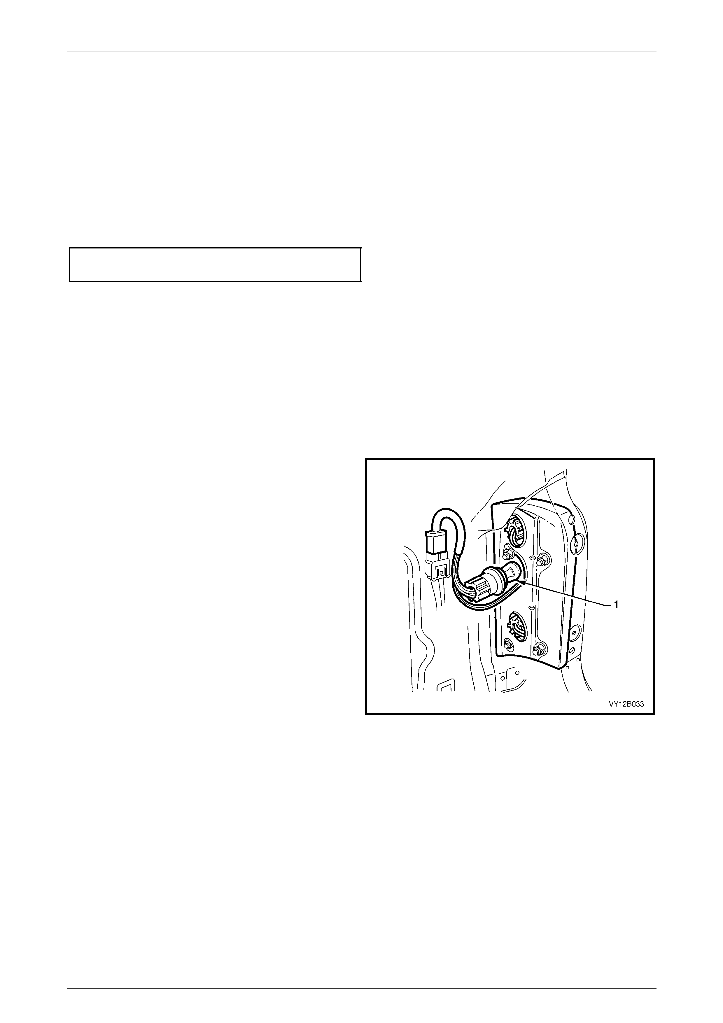
Lighting System Page 12B–50
Page 12B–50
9 Insert a new bulb into the bulb socket and install it into the tail lamp assembly, ensuring it locks securely into place.
NOTE
Bulb sockets have different lug configurations to
prevent installation into the incorrect tail lamp
assembly receptacle.
10 Ensure the main seal (9), stud seals (8) and seal mating areas are cl ean to prevent any paint damage.
11 Install the tail lamp assembly onto the vehicl e.
12 Tighten the tail lamp assembly attaching nuts to the correct torque specification.
Tail lamp assembly attaching nut
torque specification.....................................1.5 – 2.0 Nm
13 Install fusible link F102 on the engine compartment fuse and relay panel assembly.
14 Check the tail lamp operation.
15 Fit the quarter inner rear side carpet in the re ar compartme nt.
Wagon
Replace
1 Remove fusible link F102 from the engine compartment fuse and relay panel assembl y,
refer to Section 12O Fuses, Relays and Wiring Harnesses.
2 Open the liftgate.
3 Remove the quarter trim panel vent with a flat-bladed
screwdriver, taking care not to damage the quarter
inner trim panel assembly, refer to
Section 1A8 Headlining and Interior Trim.
4 Remove the appropriate bulb socket (1) by turning it
anticlockwise, then removing it from the tail lamp
assembly.
Figure 12B – 46
5 Remove the bulb from the bulb socket by pressing the bulb, then rotating it anticlockwise.
6 Inspect the bulb socket and tail lamp assembly seals for damage and replace if necessary.
7 Insert a new bulb into the bulb socket and install it into the tail lamp assembly, ensuring it locks securely into place.
8 Install fusible link F102 on the engine compartment fuse and relay panel assembly.
9 Check the tail lamp operation.
10 Fit the quarter trim panel vent.
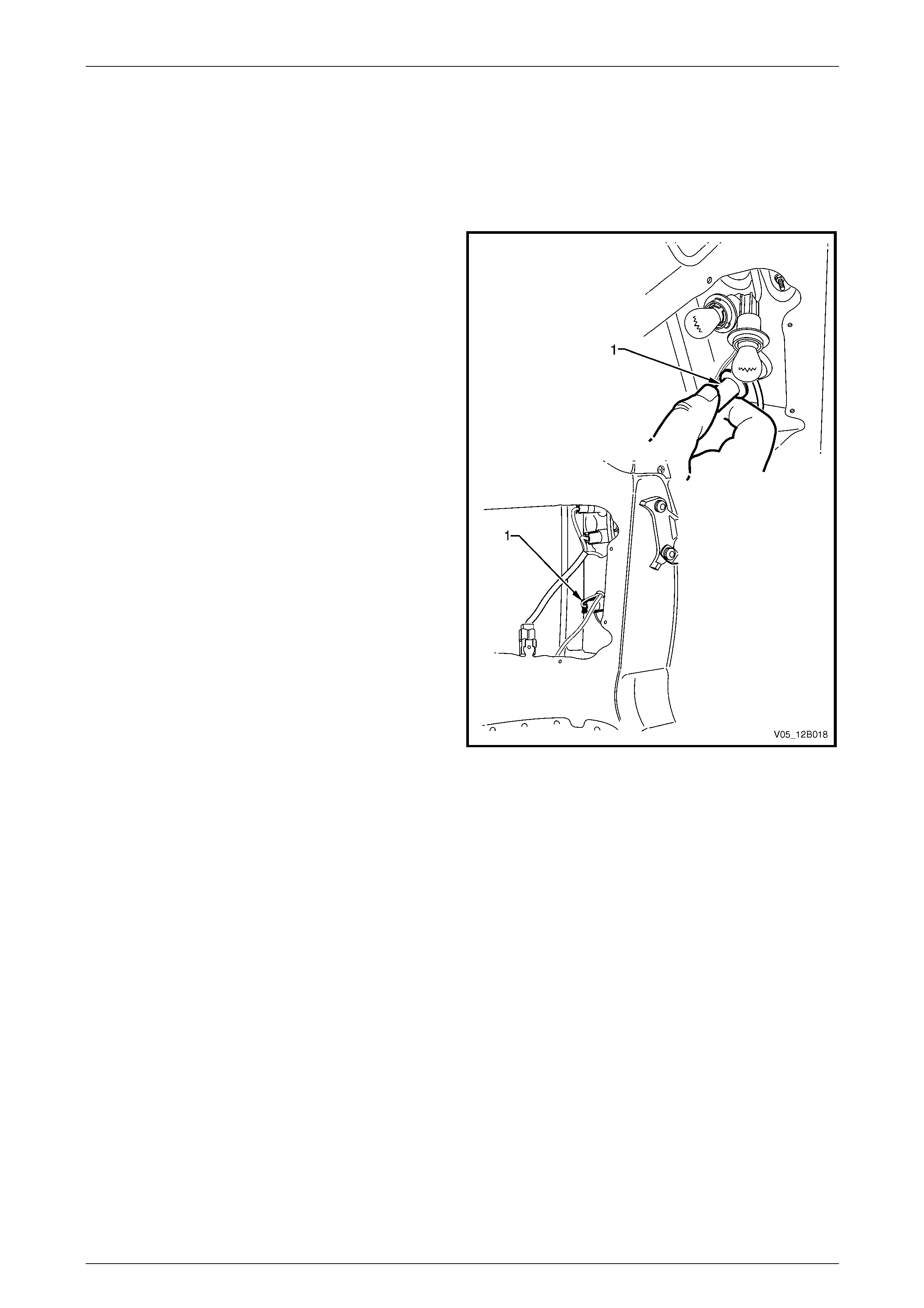
Lighting System Page 12B–51
Page 12B–51
Utility and Crew Cab
Replace
1 Remove fusible link F102 from the engine compartment fuse and relay panel assembly, refer to
Section 12O Fuses, Relays and Wiring Harnesses.
2 Remove the rear inner side panel cover, refer to Section 1B Sheetmetal.
3 Remove the appropriate bulb socket (1) by turning it
anticlockwise and removing it from the tail lamp
assembly.
NOTE
Some difficulty may be experienced removing tail
lamp assembly bulb sockets due to the short
length of the tail lamp assembly wiring harness.
To remove the stop/tail lamp bulb, it may be
necessary to remove the turn signal lamp socket
and backup lamp socket, and the harness
connector before removal.
4 Remove the bulb from the bulb socket by pressing the
bulb, then rotating it anticlockwise.
5 Inspect the bulb socket and tail lamp assembly seals
for damage and replace if necessary.
6 Insert a new bulb into the bulb socket and install it into
the tail lamp assembly, ensuring it locks securely into
place.
Figure 12B – 47
7 Install fusible link F102 on the engine compartment fuse and relay panel assembly.
8 Check the tail lamp operation.
9 Replace the rear inner side pane l cover, refer to Section 1B Sheetmetal.
Lighting System Page 12B–52
Page 12B–52
5.6 Headlamp Assembly
NOTE
All headlamp assemblies have the same retainer
attaching pattern (that is, all are attached to the
sheetmetal with three screws in the same
locations).
LT Section No. — 02–300
Remove
1 Remove fusible link F102 from the engine compartment fuse and relay panel assembl y,
refer to Section 12O Fuses, Relays and Wiring Harnesses.
2 Remove the front bumper fascia assembly, refer to Section 1D Bumper Bars.
3 If required, for vehicles with a GEN III V8 engine, remove the four retainers securing the upper ra diator shroud and
remove the shroud, refer to Section Section 6B3 Engine Cooling — GEN III V8.
4 For the right-hand headlamp assembly, it may be necessary to remove the battery to gain the required access:
a If required, remove the battery hold-down bracket and move the battery to gain access,
refer to Section 12A Battery.
Disconnection of the battery affects certain
vehicle electronic systems. Refer to
Section 00 Warnings, Cautions and Notes
before disconnecting the battery.
b If further access is required, remove the battery terminals from the battery and remove the battery from the
engine compartment, refer to Section 12A Battery.
5 For left-hand headlamp assemblies on vehicles with a V6 engine, remove the coolant filler bottle neck and place in
a safe location away from the immediate worksite.
6 Disconnect the turn signal and headlamp wiring harness connectors (1 and 2) from the rear of the headlamp
assembly (3), refer to Figure 12B – 48.
7 Remove the three headlamp retaining screws (4, 5 and 6) and remove the headlamp assembly.
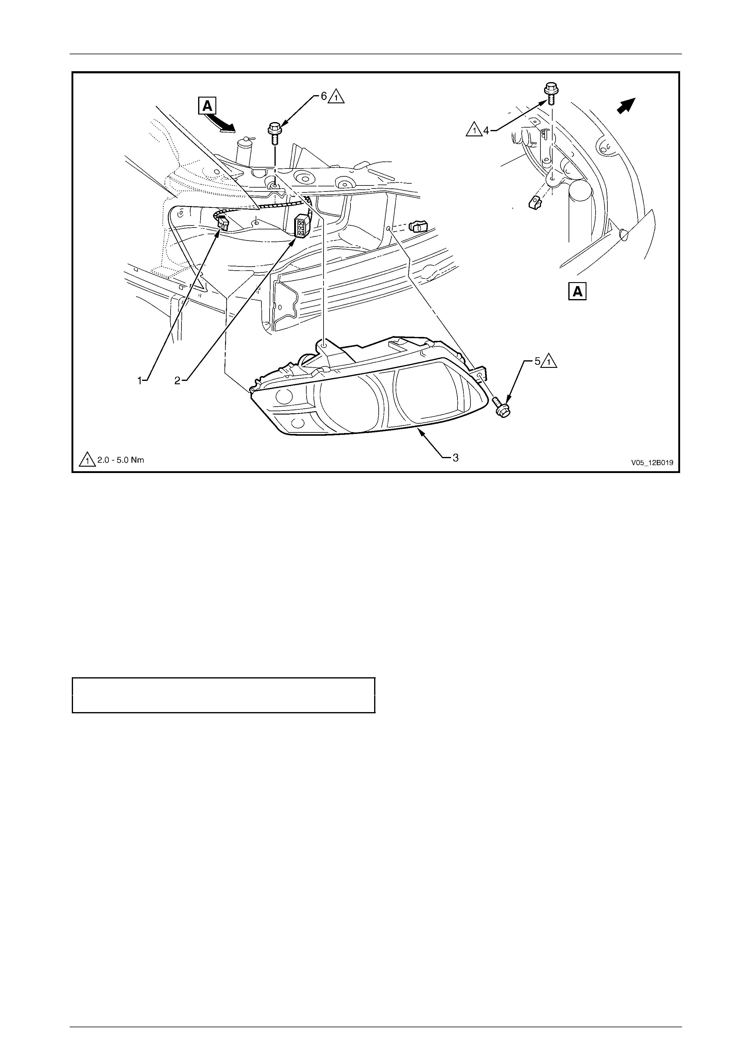
Lighting System Page 12B–53
Page 12B–53
Figure 12B – 48
Legend
1 Turn Signal Lamp Wiring Harness Connector
2 Headlamp Wiring Harness Connector
3 Headlamp Assembly
4 Headlamp Retaining Screw
5 Headlamp Retaining Screw
6 Headlamp Retaining Screw
Reinstall
Reinstallation of the headlamp assembly is the reverse of the removal procedure, notin g the following:
1 Install the headlamp assembly and tighten the headlamp retaini ng screws to the correct torque specification.
Headlamp assembly retaining
screw torque specification...........................2.0 – 5.0 Nm
2 Connect all wiring harness co nnectors, then check the headlamp, turn signal and park lamp operation.
3 Install the front bumper fascia assembly, refer to Section 1D Bumper Bars.
4 Check the headlamp and front fog lamp op eration, and adjust the aim,
refer to 5.1 Headlamp and Front Fog Lamp Aiming.

Lighting System Page 12B–54
Page 12B–54
5.7 Front Fog Lamp Assembly
LT Section No. — 02–325
The following parts may be disassembled from the front fog lamp assembly without removing the front fog lamp
assembly from the vehicle, refer to Figure 12B – 49:
• beam adjusting screw (1),
• spring (2),
• clamp ring (10),
• lens and reflector assembly (14),
• bulb (11), and
• bulb spring retainer (12).
To remove any of these items, refer to 5.4 Front Fog Lamp Bulb Assem blies.
Remove
1 Remove fusible link F102 from the engine compartment fuse and relay panel assembl y,
refer to Section 12O Fuses, Relays and Wiring Harnesses.
2 Remove the front fog lamp assembly, refer to Section 1D Bumper Bars.
Disassembly
1 Remove the beam adjusting screw (1) and spring (2).
NOTE
After removing the beam adj usting scre w, contain
the spring and place it in a safe location away
from the immediate worksite.
2 Remove the nut (3), seals (4), spacer (5) and bolt (6) securing the lens and reflector housing (7) to the mounting
bracket (8). Separate the two items.
3 Remove the screw (9) and clamp ring (10).
4 Disconnect the bulb (11) lead from the wiring harness connector inside the insulation s he ath.
5 Remove the ground lead con nector (13) from the lens and reflector assembly (14).
6 Press both halves of the bulb spring retainer (12) together and pivot the spring backward clear of the bulb. Remove
the bulb from the lens and reflector assembl y.
7 Remove the grommet and the wiring harness from the lens and reflector assembly.
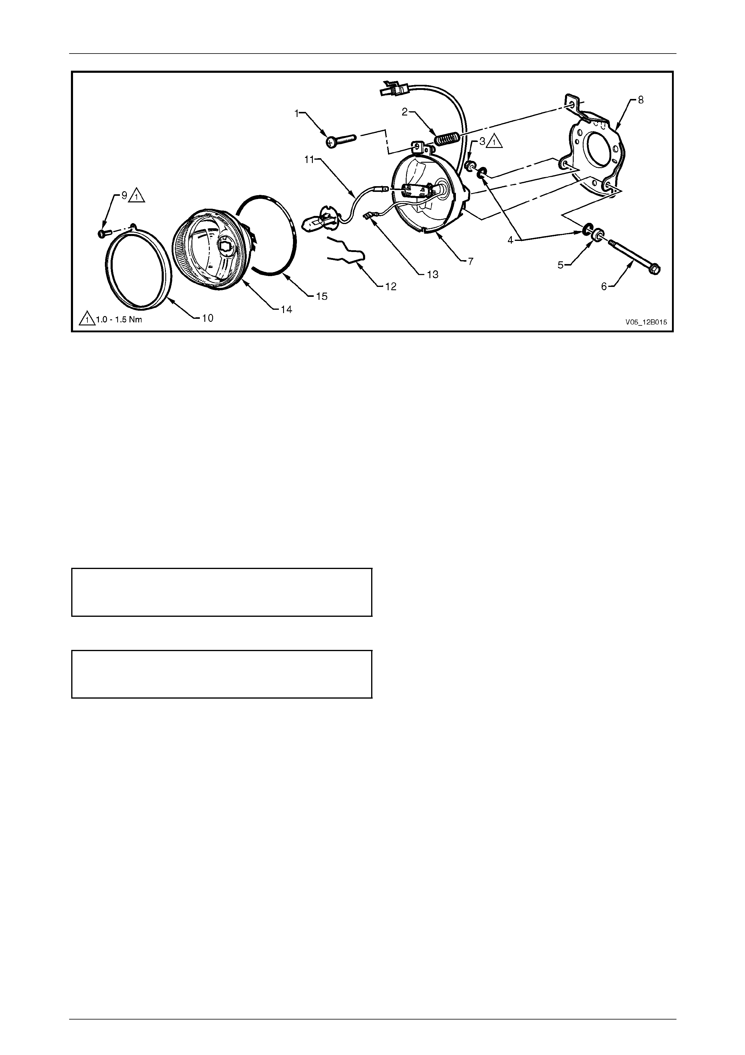
Lighting System Page 12B–55
Page 12B–55
Figure 12B – 49
Legend
1 Beam Adjusting Screw
2 Spring
3 Nut
4 Seals (2 places)
5 Spacer
6 Bolt
7 Lens and Reflector Housing
8 Mounting Bracket
9 Screw
10 Clamp Ring
11 Bulb
12 Bulb Spring Retainer
13 Ground Lead Connector
14 Lens and Reflector Assembly
15 Foam Rubber Sealing Ring
Reassembly
Reassemble the front fog lamp is the reverse of the disassembly procedure, noting the following:
1 Tighten the clamp ring securi ng screw to the correct torque specification.
Front fog lamp assembly
clamp ring securing screw
torque specification.....................................1.0 – 1.5 Nm
2 Tighten the lens and reflector housing hinge bolt nut to the correct torque specification.
Front fog lamp assembly lens
and reflector housing hing e
nut torque specification...............................1.0 – 1.5 Nm
Reinstall
Reinstallation of the front fog lamp ass embly is the reverse of the removal procedure. Check the front fog lamp operation
and adjust the aim, refer to Front Fog Lamp Assembly Aim.
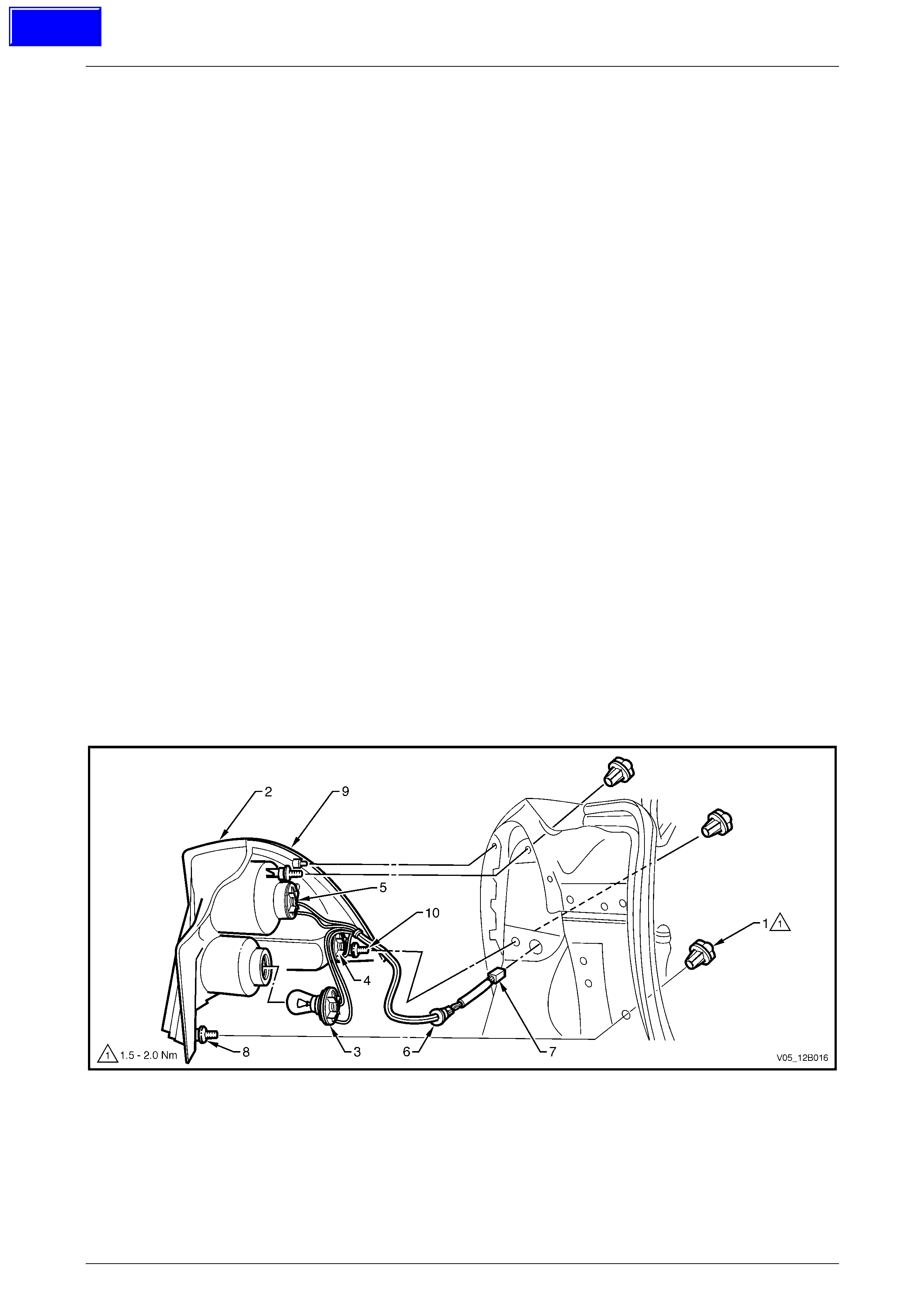
Lighting System Page 12B–56
Page 12B–56
5.8 Tail Lamp Assembly
LT Section No. — 02–350
Sedan
Remove
1 Remove fusible link F102 from the engine compartment fuse and relay panel assembl y,
refer to Section 12O Fuses, Relays and Wiring Harnesses.
2 Open the rear compartment lid.
3 Pull the quarter inner rear side carpet from the corner of the rear comp artment to expose the three tail lamp
attaching nuts (1), refer to Figure 12B – 50.
NOTE
Remove the tail lamp attaching nuts either by
hand or with a 6.0 mm Allen key.
4 Either:
• If leaving the wiring harness installe d:
(1) Remove the three attaching nuts (1).
(2) Remove the tail lamp assembly (2) from the vehicl e, while supporting it by hand.
(3) Remove all the bulb sockets (4, 5 and 6) by t urni ng the bulb sockets anticlockwise and pulling them
away from the tail lamp assembly.
• If removing the wiring harness:
(1) Remove the three attaching nuts (1).
(2) Disconnect the tail lamp wiring harness connector (7).
(3) Remove the tail lamp assembly (2) from the vehicl e, while supporting it by hand.
(4) Remove the tail lamp harness grommet (6) from the sheetmetal, then remove the tail lamp assembly
and tail lamp wiring harness.
Figure 12B – 50
Legend
1 Tail Lamp Attaching Nut (3 places)
2 Tail Lamp Assembly
3 Backup Bulb Socket
4 Turn Signal Bulb Socket
5 Stop/Tail Bulb Socket
6 Grommet
7 Electrical Connector
8 Stud Seals
9 Main Seal
10 Attachment Threaded Stud
Techline

Lighting System Page 12B–57
Page 12B–57
Replace — Main Seal
The main seal is adhered to the tail lamp assembly lens cover with contact adhesive and double-sided tape.
1 To replace the main seal, carefully remove the old seal and clean the surface of the tail lamp assembly with soapy
water. Wipe off any residue from the surface before applying new adhesive and tape.
NOTE
Do not use solvents on the pl astic surfaces of the
tail lamp assembly.
2 Apply a small amount of adhe sive to the main seal and double-sided tape to the tail lamp assembl y.
3 Place the main seal onto the tail lamp assem bly.
4 Allow time for the adhesive to cure befor e installing the tail lamp assembly to the vehicl e.
Reinstall
Reinstallation of the lamp ass embl y is the reverse of the removal procedure, noting the following:
1 Inspect the bulb socket and tail lamp assembly seals for damage and replace if necessary.
2 If required, replace the tail lamp wiring har ness.
3 Install the bulb sockets into the tail lamp assembl y, ens uring they lock securely into place.
NOTE
Bulb sockets have a different number of lugs to
prevent installation into the incorrect tail lamp
receptacle in the tail lamp assembly.
4 Ensure the main seal (9), stud seals (8) and seal mating areas are clean to prevent any paint damage,
refer to Figure 12B – 50.
5 Install the tail lamp assembly onto the vehicl e.
6 Tighten the tail lamp assembly attaching nuts to the correct torque specification.
Tail lamp assembly attaching
nut torque specification...............................1.5 – 2.0 Nm
7 Check the tail lamp operation.
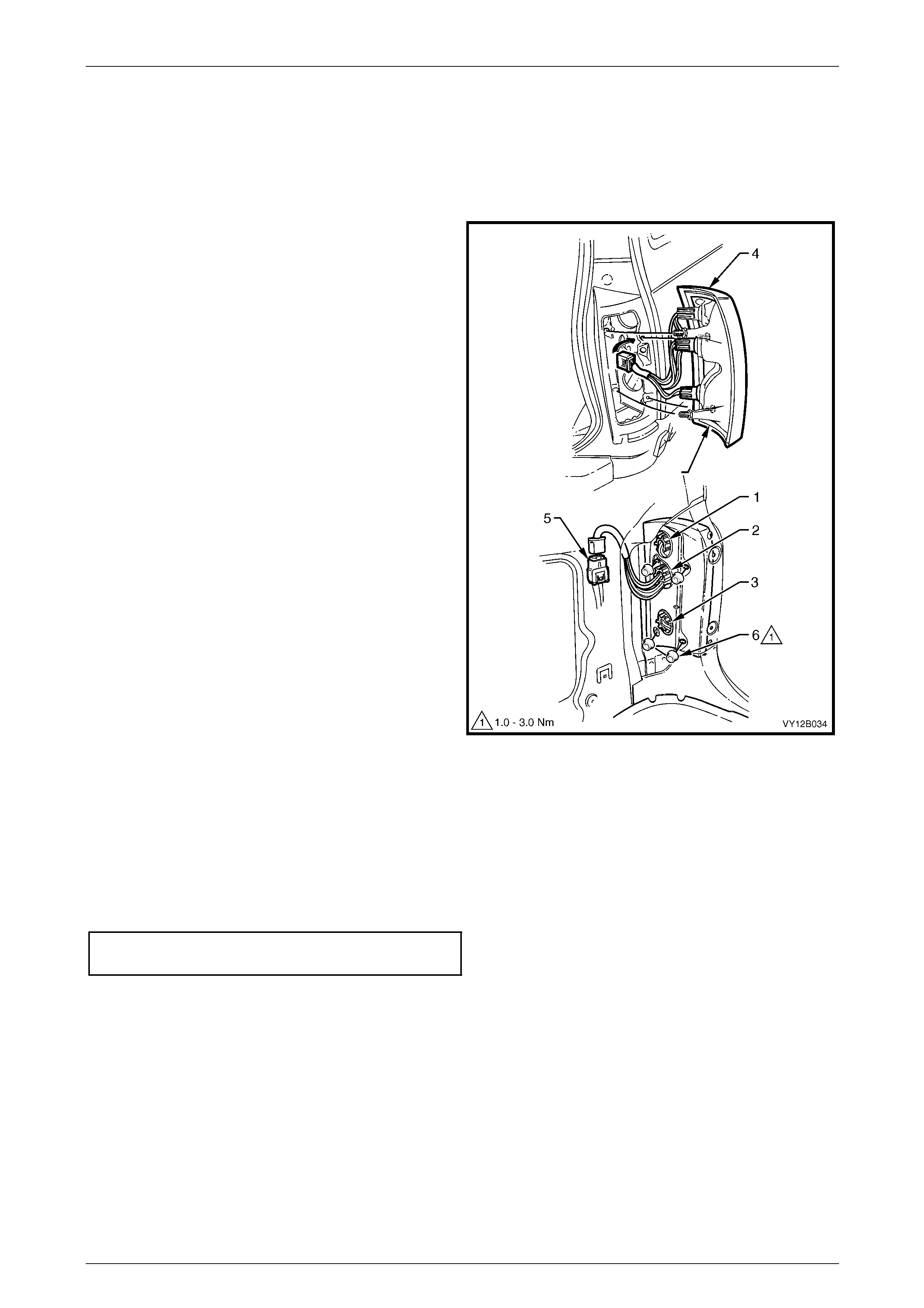
Lighting System Page 12B–58
Page 12B–58
Wagon
Remove
1 Remove fusible link F102 from the engine compartment fuse and relay panel assembl y,
refer to Section 12O Fuses, Relays and Wiring Harnesses.
2 Open the liftgate.
3 Either:
• If leaving the wiring harness installe d:
a Remove the quarter trim panel vent, refer
to Section 1A8 Headlining an d Interior
Trim.
b Remove all bulb sockets (1, 2 and 3) from
the tail lamp assembly (4) by turning them
anticlockwise, then removing them from
the tail lamp assembly.
• If removing the wiring harness:
a Remove the quarter inner trim panel
assembly, refer to Section 1A8 Headlining
and Interior Trim.
b Disconnect the tail lamp wiring harness (5)
from the body wiring harness connector.
4 Remove the four nuts (6) retaining the tail lamp
assembly to the vehicle.
5 Remove the tail lamp assembly.
Figure 12B – 51
Reinstall
Reinstallation of the tail lamp assembly is the reverse of the removal procedure, noting the following:
1 If required, install new bulbs into the bulb so ckets and fit the bulb sockets to the tail lamp assembly.
2 Ensure the main seal and seal mating surface is clean to avoid damage to the paintwork.
3 Tighten the tail lamp assembly attaching nuts to the correct torque specification.
Tail lamp assembly attaching
nut torque specification...............................1.0 – 3.0 Nm
4 Check the tail lamp operation.
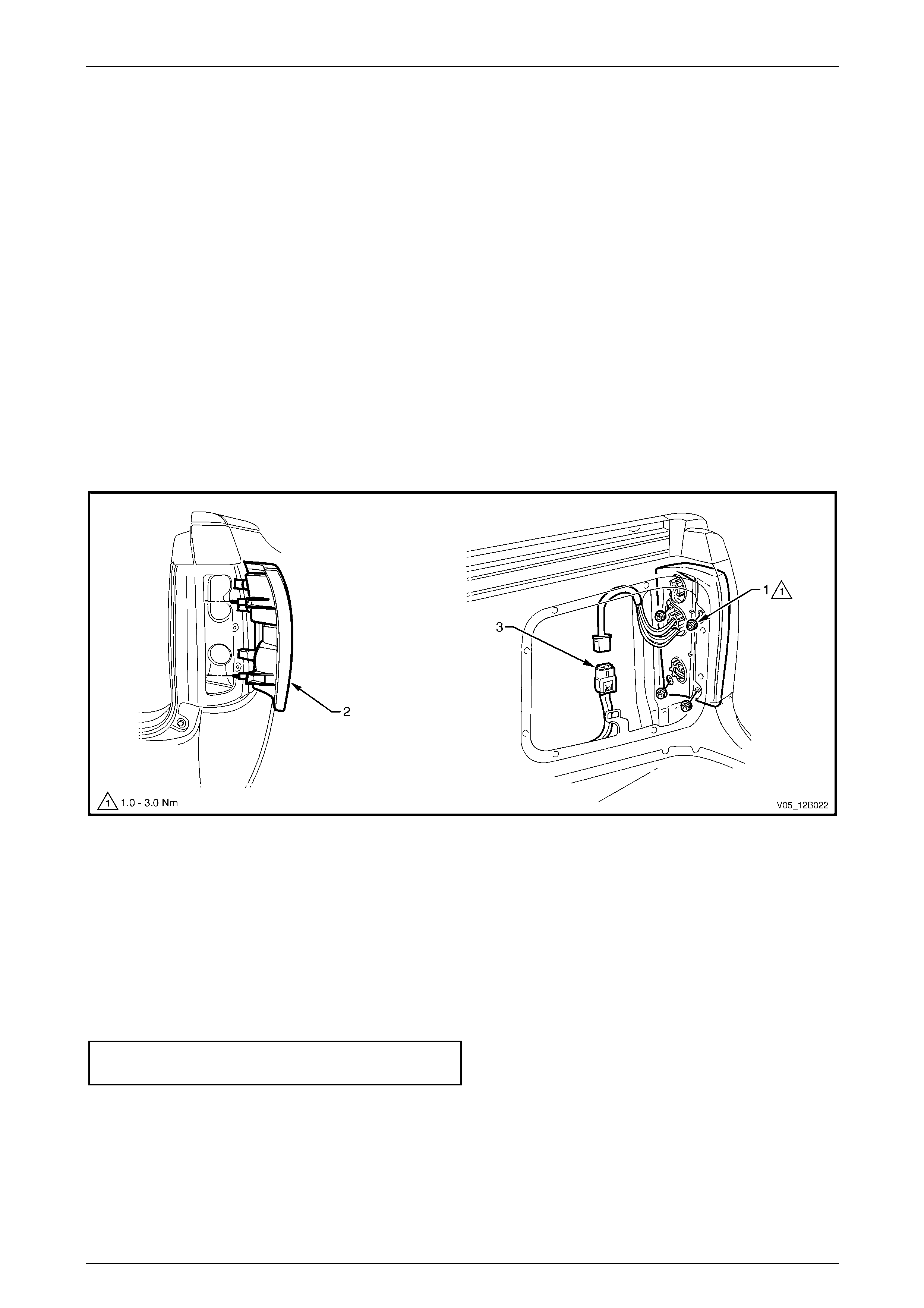
Lighting System Page 12B–59
Page 12B–59
Utility and Crew Cab
Remove
1 Remove fusible link F102 from the engine compartment fuse and relay panel assembl y,
refer to Section 12O Fuses, Relays and Wiring Harnesses.
2 Remove the rear inner side panel cover, refer to Section 1B Sheetmetal.
3 Remove the four nuts (1) securing the tail lamp assembly (2) to the vehicle, refer to Figure 12B – 52.
4 Disconnect the tail lamp wiring harness (3) from the body wiring harness, then carefully remove the tail lamp
assembly.
5 If necessary, remove the bulb sockets from the tail lamp assembly by turning the b ulb sockets anticlockwise and
pulling them away from the tail lamp assembly.
NOTE
When removing the tail lamp assembly, ensure
the tail lamp wiring har ness d oes n ot catch o n the
rear quarter panel. If required, remove the bulbs
from the tail lamp assembly.
Figure 12B – 52
Reinstall
Reinstallation of the tail lamp assembly is the reverse of the removal procedure, noting the following:
1 If required, install new bulbs into the bulb so ckets and fit the bulb sockets to the tail lamp assembly.
2 If necessary, replace the tail lamp wiring harness.
3 Ensure the main seal and seal mating surface is clean to avoid damaging the paintwork.
4 Tighten the tail lamp assembl y retai ning nuts to the correct torque specification.
Tail lamp assembly attaching
nut torque specification...............................1.0 – 3.0 Nm
5 Replace the rear inner side pane l cover, refer to Section 1B Sheetmetal.
6 Install fusible link F102 on the engine compartment fuse and relay panel a ssembly and check the tail lamp
operation.
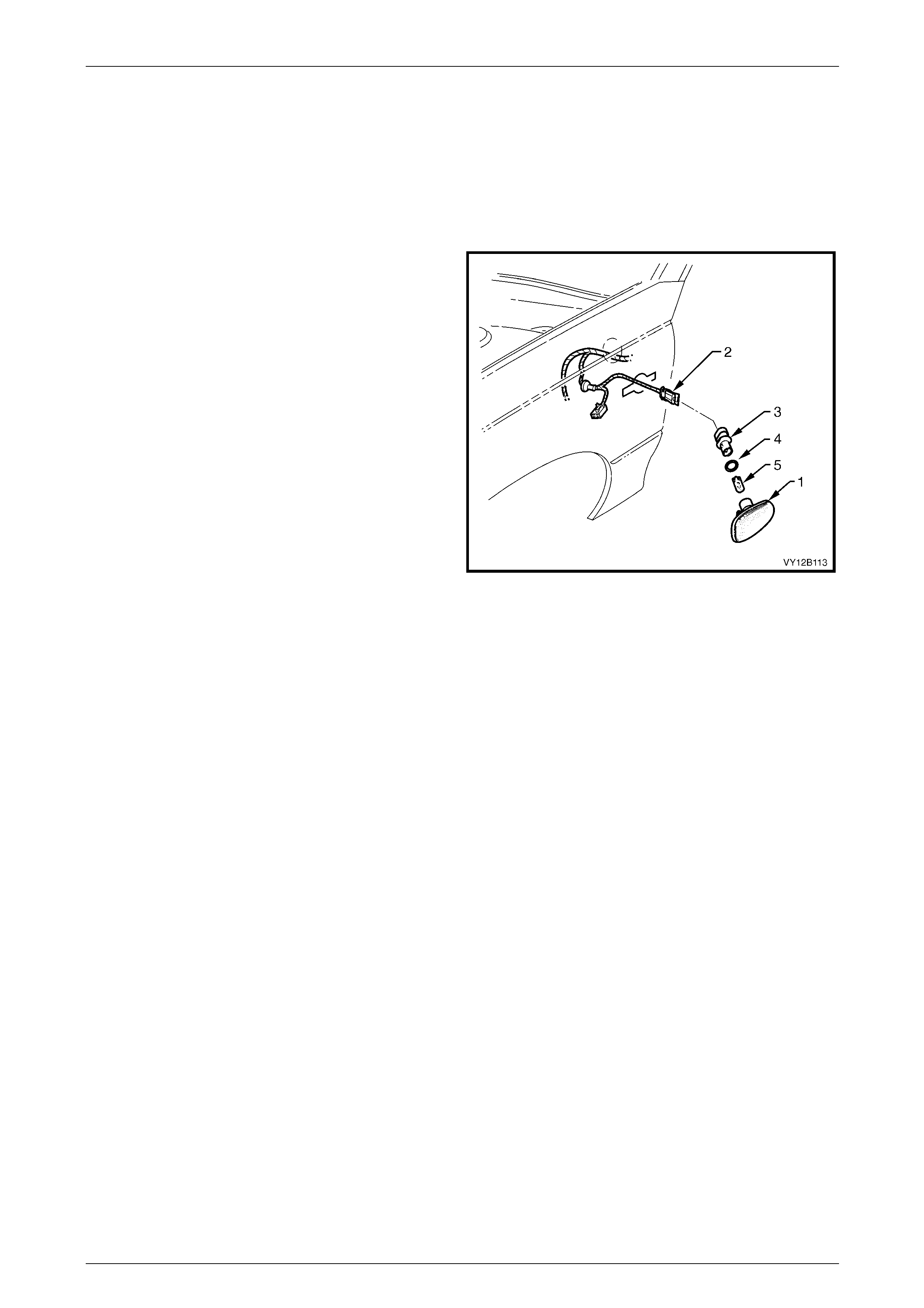
Lighting System Page 12B–60
Page 12B–60
5.9 Side Repeater Lamp Assembly
LT Section No. — 02–310
Except SS
Remove
1 Remove turn signal lamp fuse F12, refer to
Section 12O Fuses, Relays and Wiring Harnesses.
2 Grip the rear edge of the side repeater lamp
assembly (1) with finger tips and pull it forward, then
outwards and away from the front fender.
NOTE
The side repeater lamp assembly on the Sedan
is shown.
3 Disconnect the side repeater lamp assembly wiring
harness connector (2) from the front side turn signal
lamp assembly.
NOTE
Tape the side repeater lamp assembly wiring
harness to the front fender so the side turn
signal lamp assembly wiring harness and the
connector do not fall into the front fender. Figure 12B – 53
4 Twist and remove the bulb socket (3), O-ring (4) and bulb (5) from the side repeater lamp assembly.
5 If required, pull the bulb from the bulb socket.
Reinstall
1 If required, install a new bulb into the bulb socket.
2 Inspect the side repeater lamp assembly and O-ring for damage and replace if necessary.
3 Insert the bulb socket into the side repeat er lamp assembly and twist to lock into position. Connect the side
repeater lamp assembly wiring harness connector to the si de repeater lamp assembly.
4 Install turn signal lamp fuse F12 and check the operation of the lamp assembly.
5 Place the rear of the side repeater lamp ass embl y into the fender an d place the locking tab into the forward end of
the fender aperture. Push the front of the side repeater lamp assembly towards the fender to engage the locking
tab.
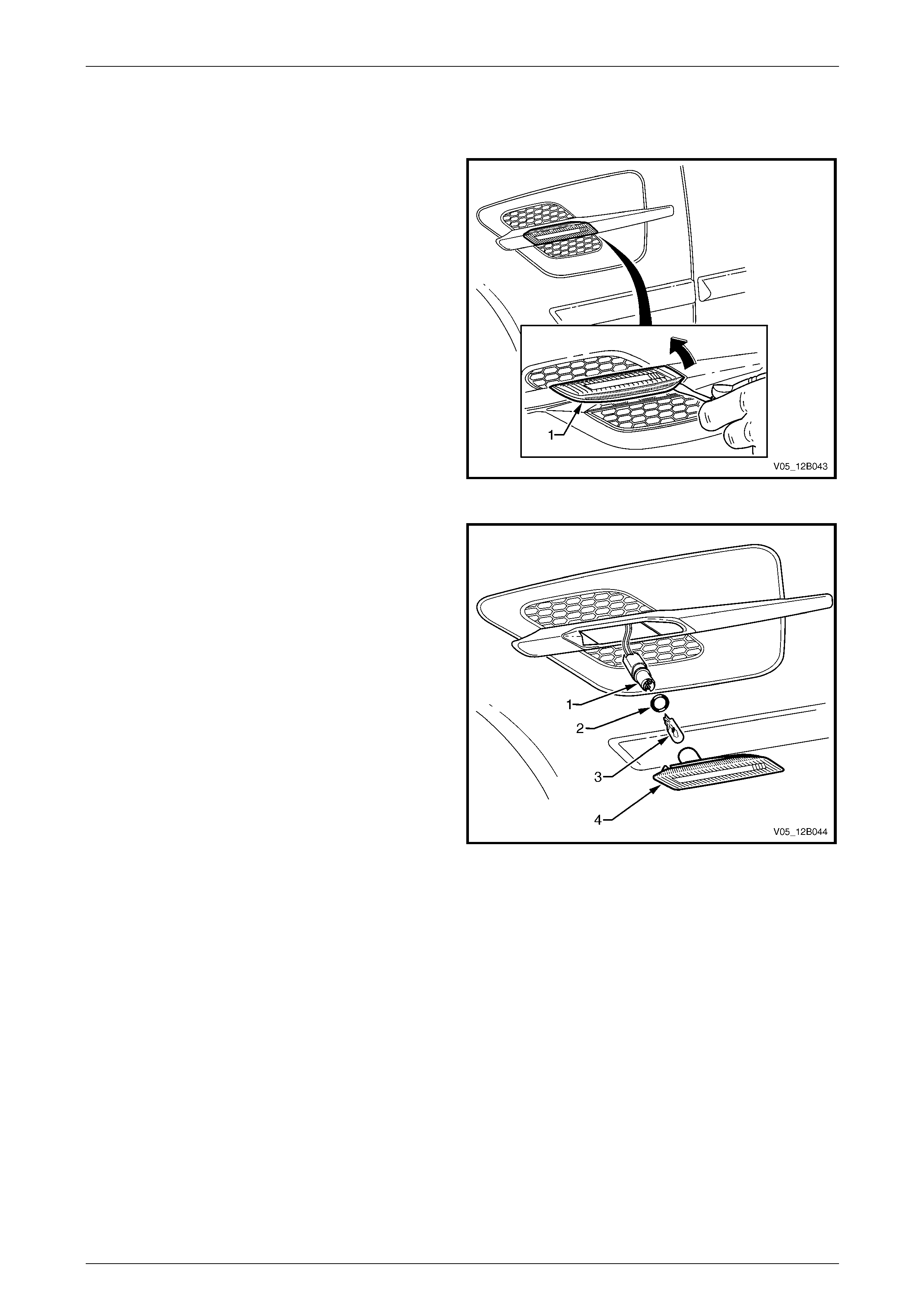
Lighting System Page 12B–61
Page 12B–61
SS Only
Remove
1 Remove turn signal lamp fuse F12, refer to
Section 12O Fuses, Relays and Wiring Harnesses.
2 Using a fine-bladed screwdriver, carefully lever the
side repeater lamp assembly (1) forward, then
outwards and away from the front fender.
NOTE
Protect the panel by wrapping a cloth or tape
around the screwdriver.
Figure 12B – 54
3 Disconnect the side repeater lamp assembl y from the
front fender centre moulding assembly.
NOTE
Tape the side repeater lamp assembly wiring
harness to the front fender so the side repeater
lamp assembly wiring harness does not fall into
the front fender.
4 Twist and remove the bulb socket (1), O-ring (2) and
bulb (3) from the side repeater lamp assembly (4).
5 If required, pull the bulb from the bulb socket.
Figure 12B – 55
Reinstall
1 If required, install a new bulb into the bulb socket.
2 Inspect the side repeater lamp assembly and O-ring for damage and replace if necessary.
3 Insert the bulb socket into the side repeat er lamp assem bl y and twist to lock into position.
4 Place the rear of the side repeater lamp ass embl y into the fender an d place the locking tab into the forward end of
the fender aperture. Push the front of the side repeater lamp assembly towards the fender to engage the locking
tab.
5 Install turn signal lamp fuse F12 and check the operation of the lamp assembly.
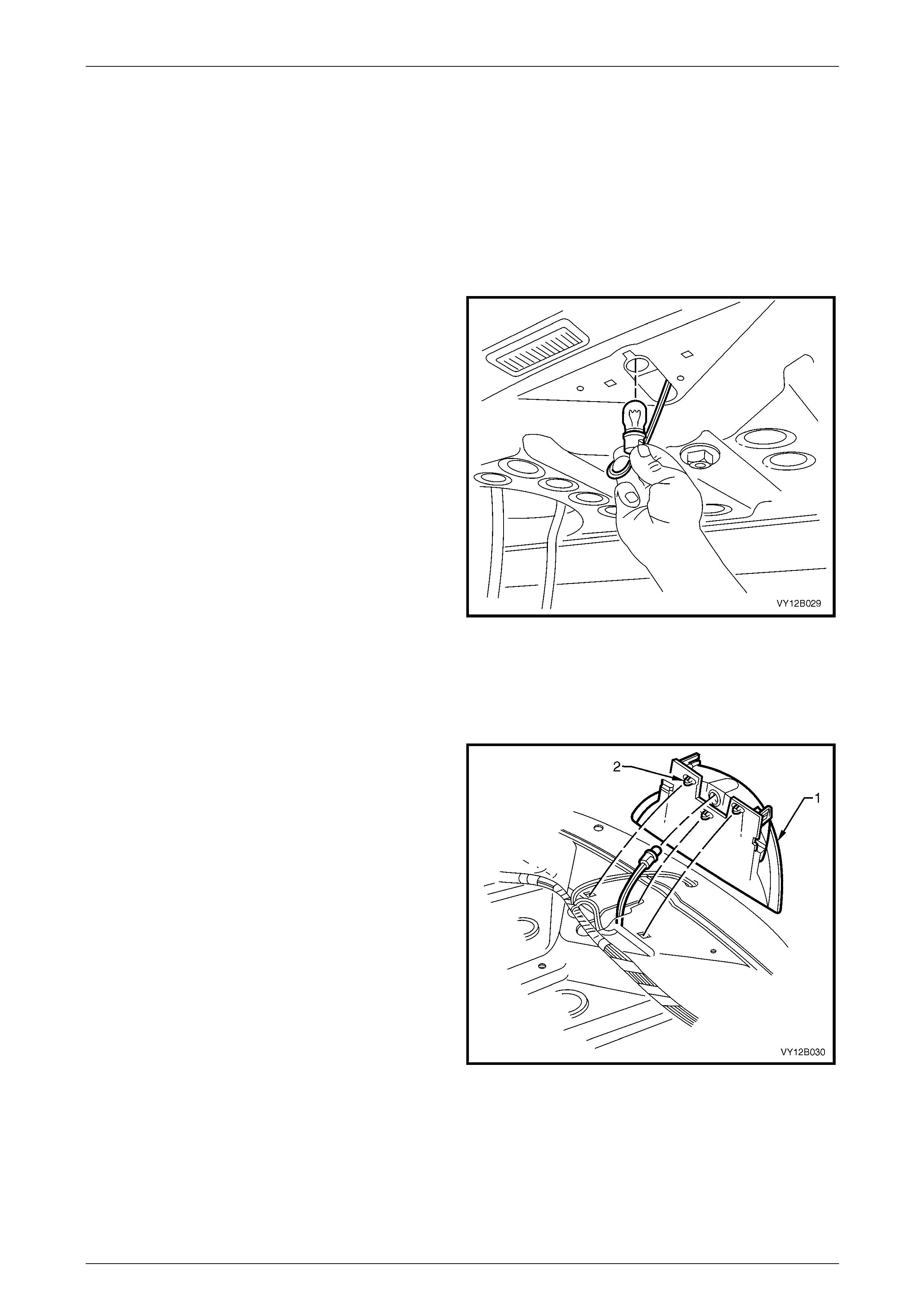
Lighting System Page 12B–62
Page 12B–62
5.10 High-mount Stop Lamp Assembly
LT Section No. — 02–350
Sedan Without Rear-end Spoiler
Bulb Replacement
1 Remove fusible link F102 from the engine compartment fuse and relay panel assembl y,
refer to Section 12O Fuses, Relays and Wiring Harnesses.
2 Open the rear compartment lid.
3 From under the rear window panel assembly, twist the
bulb socket to release it from the high-mount stop
lamp assembly. Pull the bulb socket down, into the
rear compartment.
NOTE
It may be necessary to use a pair of pointed
nose pliers to hold the bulb socket and release
the bulb.
4 Pull the bulb from the bulb socket.
5 Install a new bulb into the bulb socket and install the
bulb socket into the high-mount stop lamp assembly.
Twist the bulb socket and lock it into place.
6 Install fusible link F102 on the engine compartment
fuse and relay panel assembly and check the
operation of the high-mount stop lamp ass embly. Figure 12B – 56
Remove
1 Remove fusible link F102 from the engine compartment fuse and relay panel assembl y,
refer to Section 12O Fuses, Relays and Wiring Harnesses.
2 Remove the rear parcel shelf trim, refer to
Section 1A8 Headlining and Interior Trim.
3 Remove the bulb socket from the tail lamp
assembly (1), refer to Bulb Replacement.
4 From under the rear window panel assembly,
disengage the retaining cl ips (2) securing the high-
mount stop lamp assembly to the rear window panel
assembly. Remove the high-mount stop la mp
assembly.
Figure 12B – 57
Reinstall
Reinstallation of the high-mo unt stop lamp assembly is the reverse of the removal procedure. Ensure the hig h-mo unt
stop lamp assembly is pushed fully rearward before engaging the retaining clips.
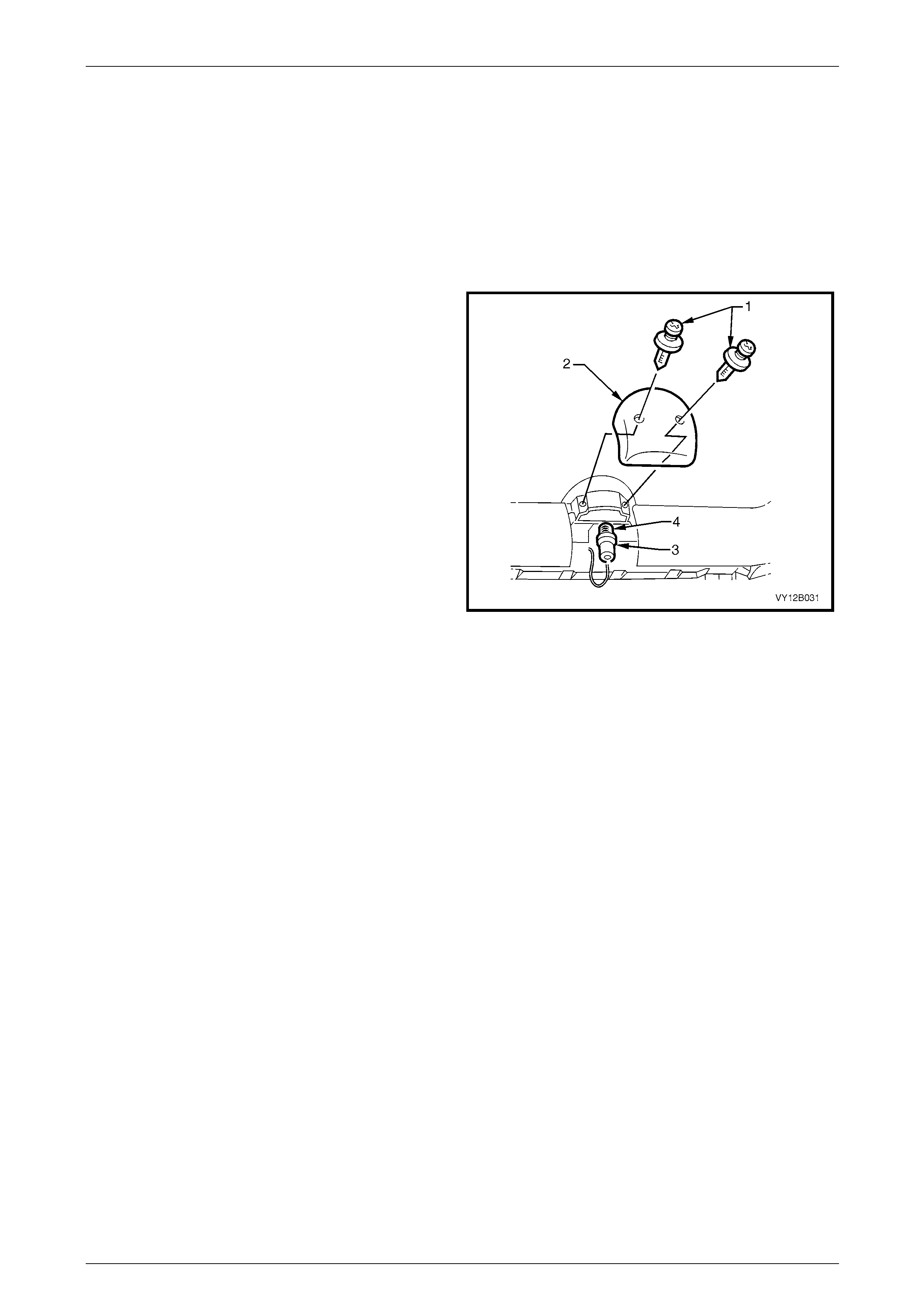
Lighting System Page 12B–63
Page 12B–63
Sedan With Rear-end Spoiler
The high-mount stop lamp assembly fitted to the air spoilers is an LED type. For the removal and installation of the high-
mounted stop lamp assembly, refer to Section 1A4 Hood, Rear Compartment Lid, Liftgate and Endgate.
Wagon
Bulb Replacement
1 Remove fusible link F102 from the engine compartment fuse and relay panel assembl y,
refer to Section 12O Fuses, Relays and Wiring Harnesses.
2 Open the liftgate and remove the two retainers (1)
securing the high-mount stop lamp cover (2). Remove
the high-mount stop lamp cover.
3 Twist and pull the bulb socket (3) away from the high-
mount stop lamp assembly.
4 Pull the bulb (4) from the bulb socket.
5 Install a new bulb into the bulb socket and fit the bulb
socket to the high-mount stop lamp assembly.
6 Install fusible link F102 on the engine compartment
fuse and relay panel assembly and check the
operation of the high-mount stop lamp ass embly.
7 Install the high-mount stop lamp cover.
Figure 12B – 58
Remove
1 Remove fusible link F102 from the engine compartment fuse and relay panel assembl y,
refer to Section 12O Fuses, Relays and Wiring Harnesses.
2 Remove the high-mount stop lamp assembly cover, refer to Sedan Without Rear-end Spoiler.
3 Remove the liftgate windo w upper garnis h,
refer to Section 1A4 Hood, Rear Compartment Lid, Liftgate and Endgate.
4 Twist and unlock the bulb socket (1) from the high-mount stop lamp assembly (2), refer to Figure 12B – 59.
5 Remove both the high-mount stop lamp assembly attaching screws (3).
6 Prise the locking tab (4) back slightly, release the locking tabs (5) from each side and remove the high-mount stop
lamp assembly from the liftgate assembly.
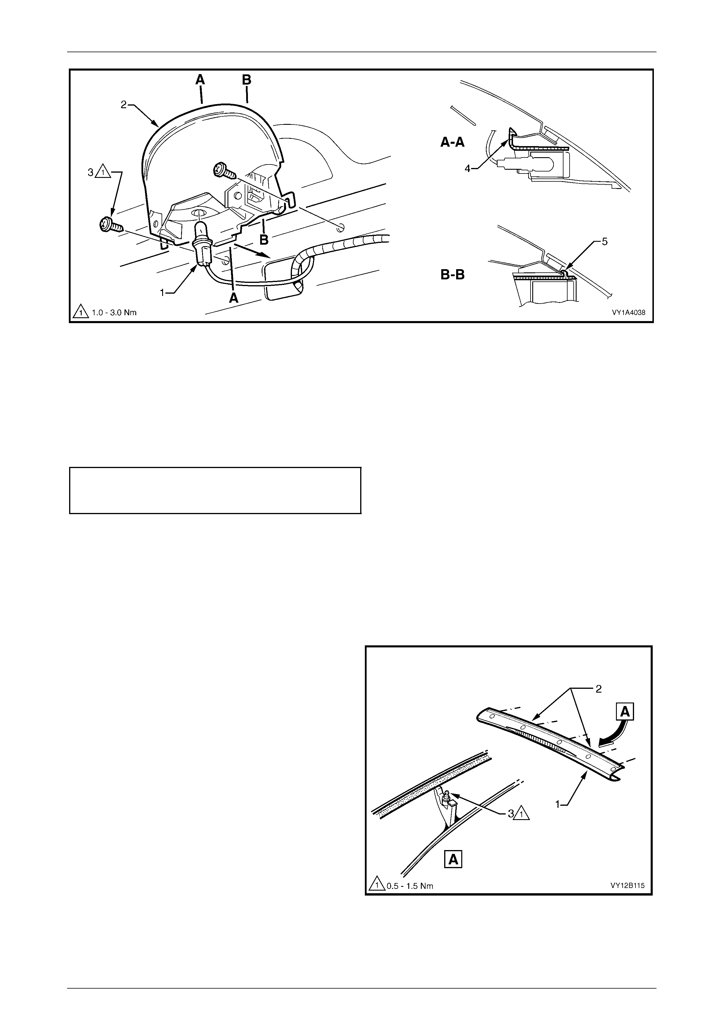
Lighting System Page 12B–64
Page 12B–64
Figure 12B – 59
Reinstall
Reinstallation of the high-mo unt stop lamp assembly is the reverse of the removal procedure, noting the following:
1 Ensure the high-mount stop lamp assembly is correctly loc ated b y inserting the locking tab (4) and pushing the
high-mount stop lamp assembly towards the window to engage the locking tabs (5), refer to Figure 12B – 59.
2 Tighten the high-mount stop lamp assembly attaching scre ws to the correct torque specification.
High-mount stop lamp
assembly attaching screws
torque specification.....................................1.0 – 3.0 Nm
3 Test the operation of the high-mount stop lamp before installing the cover and garnish.
Utility (If Fitted)
Remove
1 Remove fusible link F102 from the engine compartment fuse and relay panel assembl y,
refer to Section 12O Fuses, Relays and Wiring Harnesses.
2 Remove the rear window upper moulding, refer to
Section 1A9 Exterior Ornamentation.
3 Remove one of the studs (3) located either to the right
or left (2) of the high-mount stop lamp assembly.
NOTE
One of the studs must be removed so there is
clearance to remove the high-mount stop lamp
assembly.
Figure 12B – 60

Lighting System Page 12B–65
Page 12B–65
4 Carefully disengag e the retaining tangs from the high-
mount stop lamp assembly (1) and manoeuvre the
high-mount stop lamp assembly free from the cap (2).
Figure 12B – 61
Reinstall
Reinstallation of the high-mo unt stop lamp assembly is the reverse of the removal procedure. T ighten the rear window
moulding attaching stud to the correct torque specification.
Rear window moulding
attaching stud
torque specification.....................................0.5 – 1.5 Nm
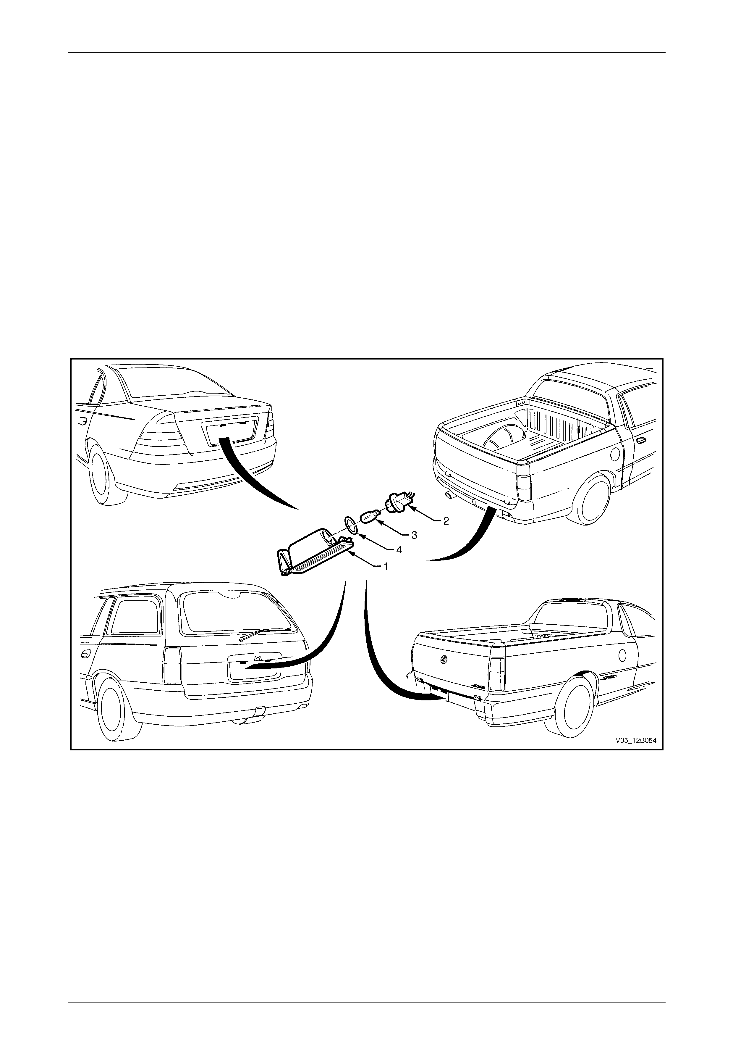
Lighting System Page 12B–66
Page 12B–66
5.11 Rear Licence Plate Lamp Assembly
LT Section No. — 02–375 (Sedan, Utility and Crew Cab)
LT Section No. — 02–385 (Wagon)
Remove
1 Remove fusible link F102 from the engine compartment fuse and relay panel assembly, refer to
Section 12O Fuses, Relays and Wiring Harnesses.
2 Push the locking tang located at the end of the rear licence plate lamp housing (1) to wards the lens. Pivot the rear
licence plate lamp housing down and remove it from the aperture, refer to Figure 12B – 62.
3 Remove the rear licence plate bulb socket (2) from the rear licence plate lamp housing.
4 If required, replace the bulb (3) by pulling it from the rear licence plate bulb socket and installing a new bulb.
5 Inspect the rear licence plate bul b socket se al (4) for damage and replace if required.
Figure 12B – 62

Lighting System Page 12B–67
Page 12B–67
Reinstall
Reinstallation of the rear licence plate lamp assembly is the reverse of the removal procedure, noting the foll owing:
1 If required, push a new bulb into the rear licence plate bu lb socket.
2 Install the rear licence plate bulb socket and bulb into the rear licence plate lamp housing.
3 On Utility vehicles, ensure the rear lice nce pl ate bulb socket seal and seal mating surface are clea n to avoid paint
damage.
NOTE
The rear licence plate lamp housing installs into
the aperture in one direction only.
4 Install the rear licence plate lamp housing into the aperture.
5 Install fusible link F102 on the engine compartment fuse and relay panel assembly.
6 Check the rear licence plate lamp assembly operation.
Wiring Harnesses
Sedan
To remove and install the rear licence plate lamp wiring harness, remove t he rear compartment lid appliqué assembly,
refer to Section 1A4 Hood, Rear Compartment Lid, Liftgate and Endgate.
Wagon
To remove and install the rear licence plate lamp wiring harness, remove the liftgate handle assembly,
refer to Section 1A4 Hood, Rear Compartment Lid, Liftgate and Endgate.
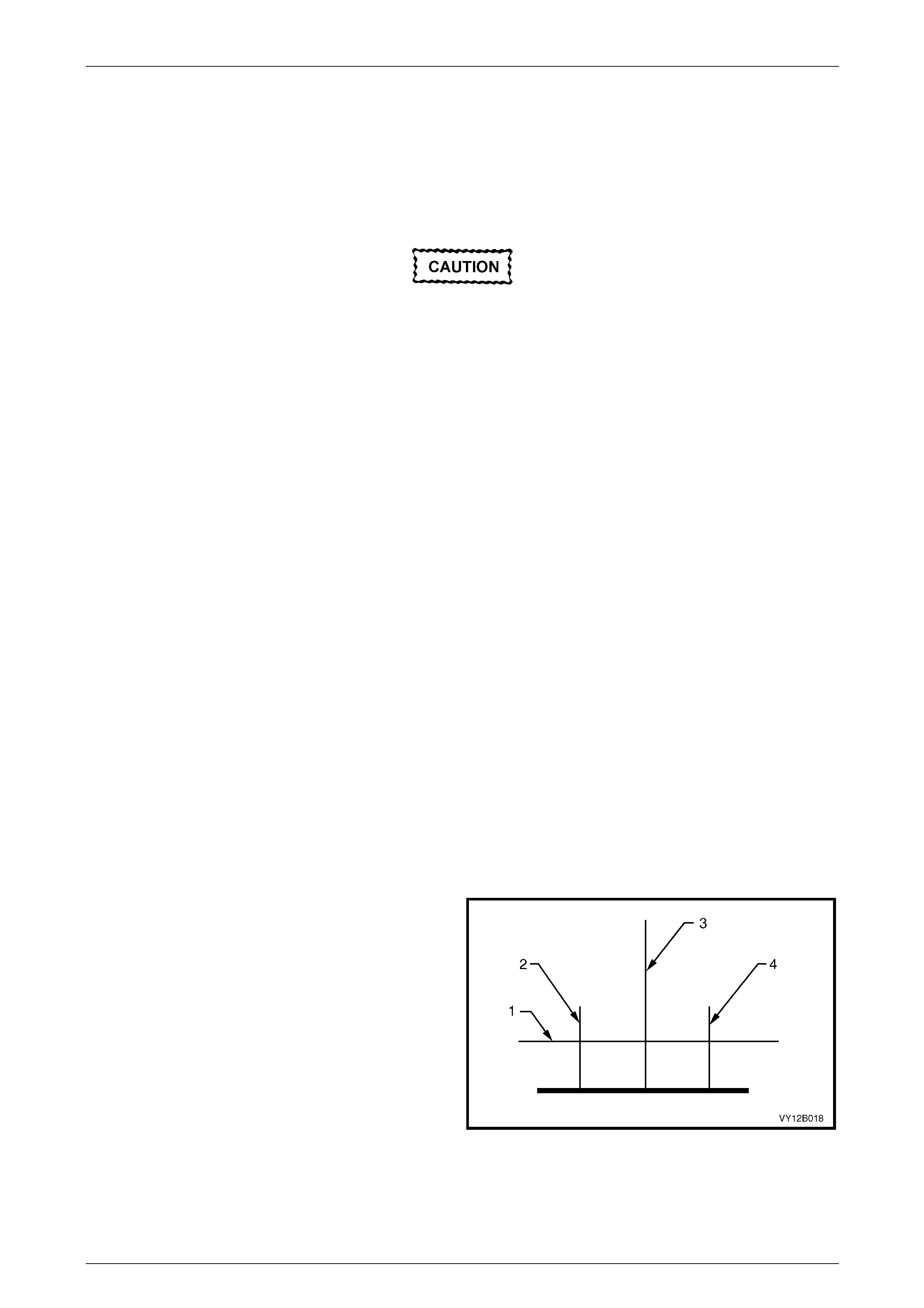
Lighting System Page 12B–68
Page 12B–68
6 Service Operations — Exterior
Illumination, Coupe
6.1 Headlamp and Front Fog Lamp Aiming
During headlamp assembly aiming, use a
cloth or similar material to cover the lens of
the headlamp assembly being adjusted. Do
not cover the beam o f the headlamp asse mbly
not being adjusted. Damage to the headlamp
assembly will result if the headlamp beam is
obstructed in this manner.
The headlamp assemb lies, and park and front fog lamp assemblies must be correctly aimed to obtain the maximum roa d
illumination and safet y. Headl amps and front fog lamps must be checked for correct aim whenever a b ulb or lamp
assembly is replaced and after an y adjustments or repairs to the front-end sheetmetal.
Headlamp aiming devices are in general use. When usin g one of these devices, ensure that it is in good condition;
carefully follow the instructions of the manufacturer.
Regardless of the method used for checking headlam p and front fog lamp aim, the vehicle must be at kerb weight (that
is, with full fuel level, oil, water and spare t yre , but no passengers). Tyres must be unifor mly inflated to their specified
pressure.
NOTE
If the vehicle regularly carries an unusual load in
the rear compartment or if it is used to tow a
trailer, these loads should be on th e vehic le when
the headlamps and front fog lamps are checked.
Headlamp Assembly Aim
LT Section No. — 02–300
NOTE
Use this procedure only when suitable test
equipment is unavailable.
1 Set up a screen or use a vertical wall with a flat
horizontal floor. Park the vehi cle immediately in front
of the screen or wall and mark the follo wing li nes:
a a vertical centre-line (3), corresponding to the
centre of the vehicle;
b two vertical lines (2 and 4), corresponding to the
centre of the low beam bulb on each side of the
vehicle; and
c a horizontal line (1) corresponding to the centre
of the low beam bulb.
2 Turn on the headlights to check if the marks are
correctly positioned. Figure 12B – 63
3 Reverse the vehicle straight back so the front is five metres in front of the screen or wall, ensuring the centre of the
vehicle is aligned with the vehicle centre-line mark (3) on the screen.
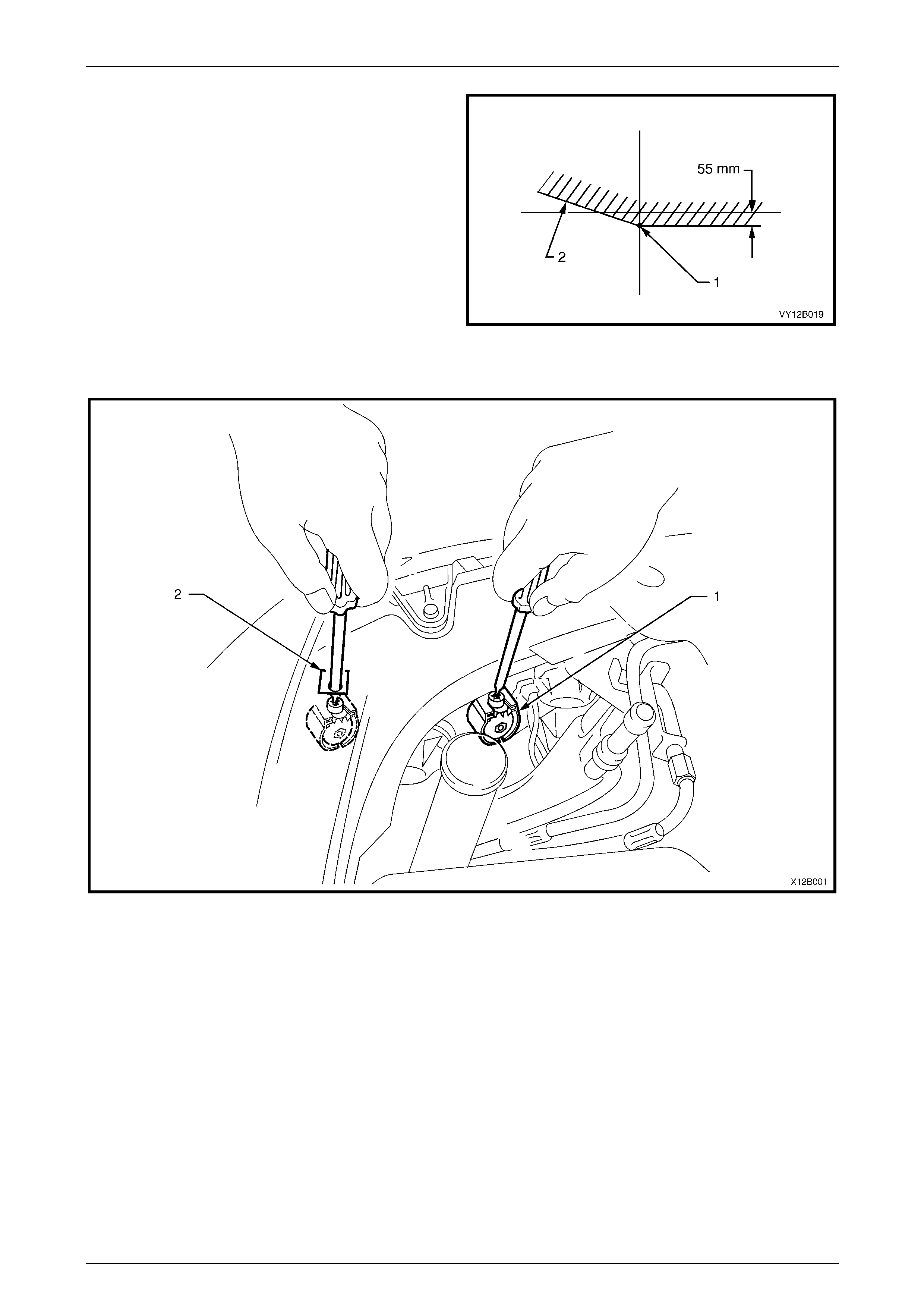
Lighting System Page 12B–69
Page 12B–69
4 Aim each headlamp to a point (1) on its vertical centre-
line, 55 mm below the headlamp horizontal centre-line.
Item 2 is the cut-off line. To adjust the headlamp
assembly, refer to Figure 12B – 65:
a Rotate the inboard adjuster (1) to move the
beam vertically.
b Rotate the outboard adjuster (2) to move the
beam horizontally.
Aiming directions for each adjuster are printed on the
headlamp assembly.
Figure 12B – 64
Figure 12B – 65
Legend
1 Inboard Adjuster 2 Outboard Adjuster
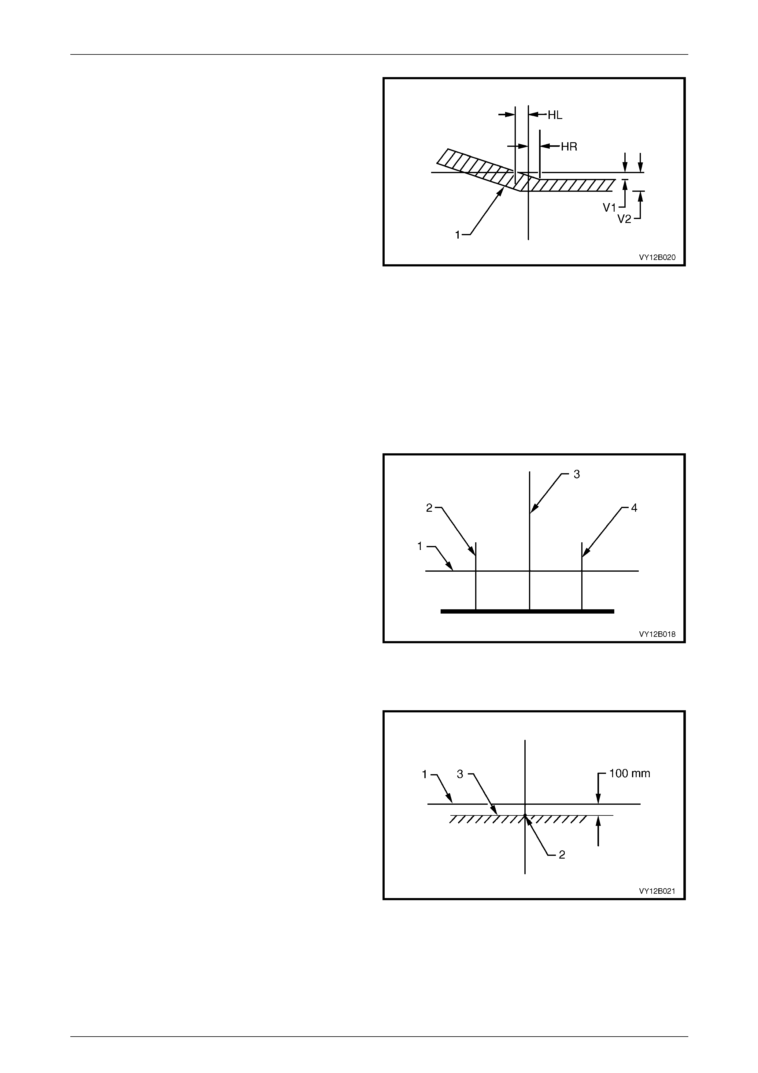
Lighting System Page 12B–70
Page 12B–70
5 The allowable variations on headlamp aiming point
settings shown in Figure 12B – 66 are:
HL 50 mm
HR 0 mm
V1 50 mm
V2 60 mm
Maximum allowable vertical variation between any pair of
headlamps must not exceed 1 0 mm.
NOTE
The cut-off line must be within the shaded
zone (1). Figure 12B – 66
Front Fog Lamp Assembly Aim
LT Section No. — 02–300
The aiming procedures for front fog lamps is the same for all vehicles.
NOTE
Use this procedure only when suitable test
equipment is unavailable.
1 Set up a screen or use a vertical wall, with a flat
horizontal floor. Park the vehi cle immediately in front
of the screen or wall and mark the follo wing li nes:
a a vertical centre-line (3) that corresponds to the
centre of the vehicle;
b two vertical lines (2 and 4), corresponding to the
centre of the front fog lamp bulb on each side of
the vehicle; and
c a horizontal line (1) that corresponds to the
centre of the front fog lamp bulb.
2 Turn on the front fog lamps to check whether the
marks are correctly positioned.
3 Reverse the vehicle straight back so the front is five
metres in front of the screen or wall, ensuring the
centre of the vehicle is aligned with the vehicle centre-
line mark (3) on the screen.
Figure 12B – 67
4 Turn on the front fog lamps. Aim each front fog lamp to
a point on its vertical centre-line (2), with the cut-off
line (3) 100 mm below the front fog lamp horizontal
centre-line (1).
NOTE
There is no provision for horizontal adjustment.
Front fog lamps are fixed to a vertical centre-line.
Figure 12B – 68
5 Remove the bezel to access the park and front fog lamp assembly, refer to Section 1D Bumper Bars.
6 Adjust the beam of the front fog lamp by rotating the adjusting screw clockwise to raise the beam and anticlockwise
to lower the beam.
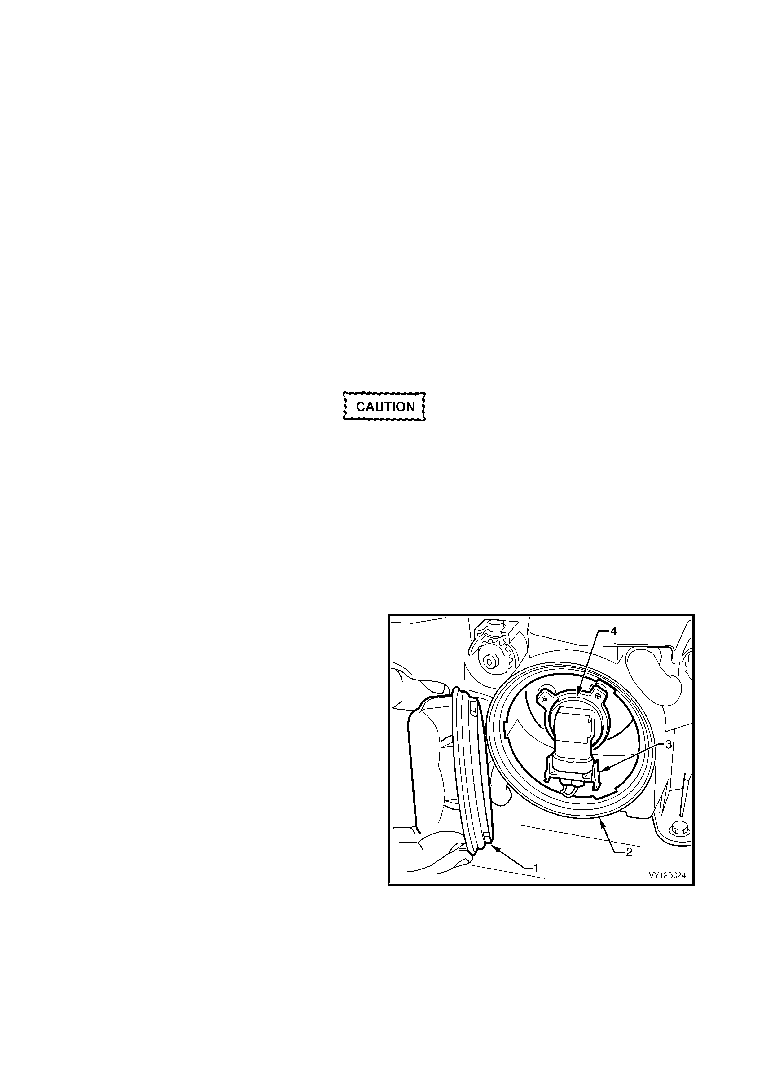
Lighting System Page 12B–71
Page 12B–71
6.2 Headlamp Assembly Bulbs
LT Section No. — 02–300
Replace — Low Beam Bulb
1 Remove fusible link F102 from the engine compartment fuse and relay panel assembl y,
refer to Section 12O Fuses, Relays and Wiring Harnesses.
2 Open the hood and disconnect the wiring harness connector from the rear of the appropriate hea dlamp assembly.
3 Remove the four retainers securing the upper radiator shroud and remove the shroud,
refer to Section Section 6B3 Engine Cooli ng — GEN III V8.
4 For the right-hand headlamp assembly, it may be necessary to remove the battery to gain the required access:
a If required, remove the battery hold-down bracket and move the battery to gain access,
refer to Section 12A Battery.
b If further access is required, remove the battery terminals from the battery and remove the battery from the
engine compartment, refer to Section 12A Battery.
Disconnection of the battery affects certain
vehicle electronic systems. Refer to
Section 00 Warnings, Cautions and Notes
before disconnecting the battery.
NOTE
Access the left-hand bulb via the hole in the top
of the air intake duct.
5 For the left-hand headlamp assembly, remove the coolant filler bottle neck and place in a safe location away from
the immediate worksite.
6 Remove the outboard dust cap (1) from the rear of the
headlamp assembly (2) by turning the dust cap anti-
clockwise, and pulling it away from the headlamp
assembly. If the dust cap seal stays on the headlamp
assembly, remove the seal and install it onto the dust
cap.
7 Disconnect the wiring harness connector (3) from the
rear of the bulb (4) by squeezing both tangs together
and pulling the connector down from the bulb.
Figure 12B – 69

Lighting System Page 12B–72
Page 12B–72
8 Rotate the bulb (1) anticlockwise and rem ove the bulb
from the bulb holder (2).
Do not handle the quartz envelope of the
headlamp bulb. Wipe the quartz envelope
immediately with methylated spirits if it is
touched accidentally or the performance of
the bulb will deteriorate.
9 Install a new bulb into the bulb holder. Lock the bulb in
place by turning it clockwise. Fit the bulb connector by
pushing it into the base of the bulb until the tangs
engage.
NOTE
The different-sized locating lugs on the bulb
base and mating cut-outs in the bulb holder
allow the bulb to seat correctly i n one orientation
only. This ensures the correct positioning
between the bulb and the reflector.
Figure 12B – 70
10 Inspect the seal in the dust cap to ensure it is not damaged and it is seated correctly in the dust cap. Replace the
seal if it is damaged.
11 Install the dust cap onto the rear of the headlamp assembly. The different-sized lugs o n the dust cap a nd the
mating cut-outs in the headlamp assembly ensure the dust cap can be installed only in on e orientation. The
chamfered flats of the dust cap must face inboard for the dust cap to install correctly. Lock the dust cap into place
by turning it clockwise.
12 Connect the wiring harness connector to the rear of the headlamp assembly.
13 If required, install the coolant filler bottle neck, upper radiator shroud and battery.
14 Install fusible link F102 on the engine compartment fuse and relay panel assembly.
15 Check the headlamp operatio n and adjust the aim; the position of the bulb filament with respect to the reflector may
have changed, refer to 6.1 Headlamp a nd Front Fog Lamp Aiming.

Lighting System Page 12B–73
Page 12B–73
Replace — High Beam Bulb
1 Remove fusible link F102 from the engine compartment fuse and relay panel assembl y,
refer to Section 12O Fuses, Relays and Wiring Harnesses.
2 Open the hood and disconnect the wiring harness connector from the rear of the appropriate hea dlamp assembly.
3 Remove the four retainers securing the upper radiator shroud and remove the shroud,
refer to Section Section 6B3 Engine Cooli ng — GEN III V8.
4 For the right-hand headlamp assembly, it may be necessary to remove the battery to gain the required access:
a If required, remove the battery hold-down bracket and move the battery to gain access,
refer to Section 12A Battery.
Disconnection of the battery affects certain
vehicle electronic systems. Refer to
Section 00 Warnings, Cautions and Notes
before disconnecting the battery.
b If further access is required, remove the battery terminals from the battery and remove the battery from the
engine compartment, refer to Section 12A Battery.
NOTE
Access the left-hand bulb via the hole in the top
of the air intake duct.
5 For the left-hand headlamp assembly, remove the coolant filler bottle neck and place in a safe location away from
the immediate worksite.
6 Remove the inboard dust cap (1) from the rear of the
headlamp assembly (2) by turning the dust cap
anticlockwise, then pulling it away from the headlamp
assembly. If the dust cap seal stays on the headlamp
assembly, remove the seal and install it onto the dust
cap.
Figure 12B – 71
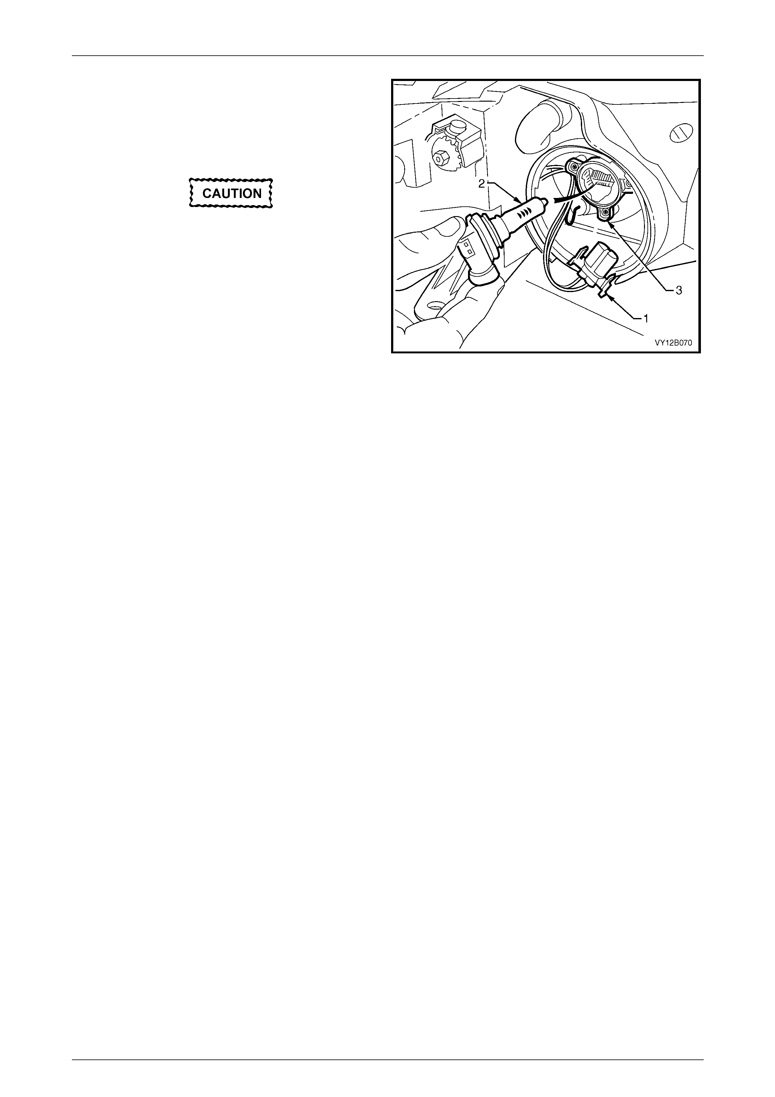
Lighting System Page 12B–74
Page 12B–74
7 Disconnect the wiring connector (1) from the bul b by
squeezing both tangs together and pulling the
connector down from the bulb .
8 Rotate the bulb (2) anticlockwise and rem ove the bulb
from the bulb holder (3).
Do not handle the quartz envelope of the
inboard high beam bulb. Wipe the quartz
envelope immediately w ith methylated spirits
if it is touched accidentally or the perform-
ance of the bulb will deteriorate.
9 Install a new bulb into the bulb holder. Lock the bulb in
place by turning it clockwise. Fit the bulb connector by
pushing it into the base of the bulb until the tangs
engage.
Figure 12B – 72
NOTE
The different-sized locati ng lugs on the bulb base
and mating cut-outs in the bulb holder allow the
bulb to seat correctly in one orientation on ly. This
ensures correct positioni ng between the bulb and
the reflector.
10 Inspect the seal in the dust cap to ensure it is not damaged and it is seated correctly on the dust cap. Replace the
seal if it is damaged.
11 Install the dust cap onto the rear of the headlamp assembly. The different-sized lugs o n the dust cap a nd the
mating cut-outs in the headlamp assembly ensure the dust cap can be installed only in on e orientation. The
chamfered flats of the dust cap must face inboard for the dust cap to install correctly. Lock the dust cap into place
by turning it clockwise.
12 Connect the wiring harness connector to the rear of the headlamp assembly.
13 If required, install the coolant filler bottle neck, upper radiator shroud and battery.
14 Install fusible link F102 on the engine compartment fuse and relay panel assembly.

Lighting System Page 12B–75
Page 12B–75
6.3 Front Turn Signal Lamp Bulb
Replace
LT Section No. — 02–310
The turn signal lamp bulb and socket is situated on the outboard extremity of each headlamp assembly. The turn signal
bulb socket is orange and has a separate wiring connector to the headlamp assembly. To view the rear of the headlamp
assembly, refer to Figure 12B – 9 (item 1).
1 Remove turn signal lamp fuse F12, refer to Section 12O Fuses, Relays and Wiring Harnesses.
2 Remove the four retainers securing the upp er radiator shro ud and remove the shroud, refer to
Section 6B3 Engine Cooling — GEN III V8.
3 For the right-hand headlamp assembly, it may be necessary to remove the battery to gain the required access:
a If required, remove the battery hold-down bracket and move the battery to gain access,
refer to Section 12A Battery.
Disconnection of the battery affects certain
vehicle electronic systems. Refer to
Section 00 Warnings, Cautions and Notes
before disconnecting the battery.
b If further access is required, remove the battery terminals from the battery and remove the battery from the
engine compartment, refer to Section 12A Battery.
NOTE
Access the left-hand bulb via the hole in the top
of the air intake duct.
4 For left-hand headlamp assemblies, remove the upper radiator shroud and coolant filler bottle neck and place in a
safe location away from the immediate worksite.
5 Disconnect the turn signal wiring harness co nnector
from the turn signal bulb socket (1).
6 Remove the turn signal bulb socket from the headlamp
assembly (2) by rotating it anticlockwise, then pulling it
away from the headlamp assembly.
7 Press the bulb (3) into the turn signal bul b socket and
rotate anticlockwise, then remove it from the reflector.
8 Inspect the seal on the turn signal bulb sock et for
damage and correct seating. Replace the seal if
necessary.
9 Install the new bulb into the turn signal bulb socket.
Install the turn signal bulb socket into the headlamp
assembly and lock it into place by turning it clockwise.
10 Connect the wiring harness connector to the turn
signal bulb socket.
11 If required, install the coolant filler bottle neck, upper
radiator shroud and battery. Figure 12B – 73
12 Fit turn signal lamp fuse F12.
13 Check the turn signal lamp operatio n.
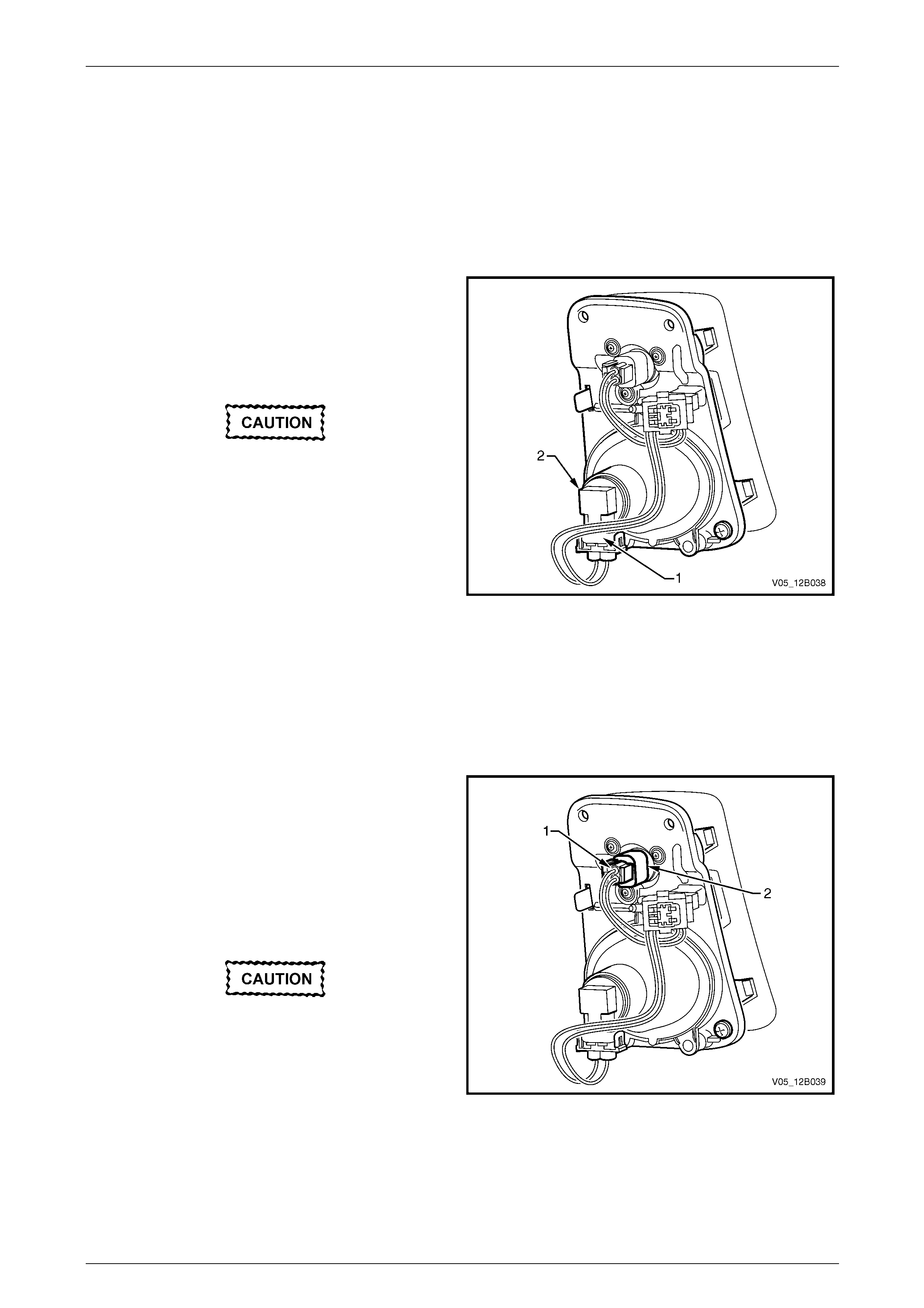
Lighting System Page 12B–76
Page 12B–76
6.4 Park and Front Fog Lamp Bulb
Assemblies
LT Section No. — 02–325
Replace — Fog Lamp Bulb
1 Remove fusible link F102 from the engine compartment fuse and relay panel assembl y,
refer to Section 12O Fuses, Relays and Wiring Harnesses.
2 From behind the front fascia, disconnect the wirin g
harness connector (1) from the front fog lamp bulb by
prying away the connector tangs an d pulling the
connector away from the bulb.
3 Rotate the bulb (2) anticlockwise and rem ove the bulb
from the bulb holder.
Do not handle the quartz envelope of the
headlamp bulb. Wipe the quartz envelope
immediately with methylated spirits if it is
touched accidentally or the performance of
the bulb will deteriorate.
4 Install a new bulb into the bulb holder. Lock the bulb in
place by turning it clockwise.
5 Fit the bulb connector by pushing it into the base of
the bulb until the tangs engage.
6 Install fusible link F102 on the engine compartment
fuse and relay panel assembly.
Figure 12B – 74
7 Check the front fog lamp operation a nd adjust the aim, refer to 6.1 Headlamp and Front Fog Lamp Aiming.
Replace — Park Lamp Bulb
1 Remove fusible link F102 from the engine compartment fuse and relay panel assembl y,
refer to Section 12O Fuses, Relays and Wiring Harnesses.
2 From behind the front fascia, disconnect the wirin g
harness connector (1) from the park lamp bulb by
squeezing the tang and pull ing the connector away
from the bulb holder.
3 Remove the bulb holder from the park and front fog
lamp assembly by rotating the bulb holder
anticlockwise.
4 Remove the park lamp bulb (2) from the bulb holder by
pulling it firmly rearwards.
Do not handle the quartz envelope of the
headlamp bulb. Wipe the quartz envelope
immediately with methylated spirits if it is
touched accidentally or the performance of
the bulb will deteriorate.
5 Install a new park lamp bulb into the bulb holder. Figure 12B – 75
6 Fit the bulb holder to the park and front fog lamp assembly.
7 Fit the bulb connector by pushing it into the base of the bulb holder until the tang engages.
8 Install fusible link F102 on the engine compartment fuse and relay panel assembly.
9 Check the park lamp operation.
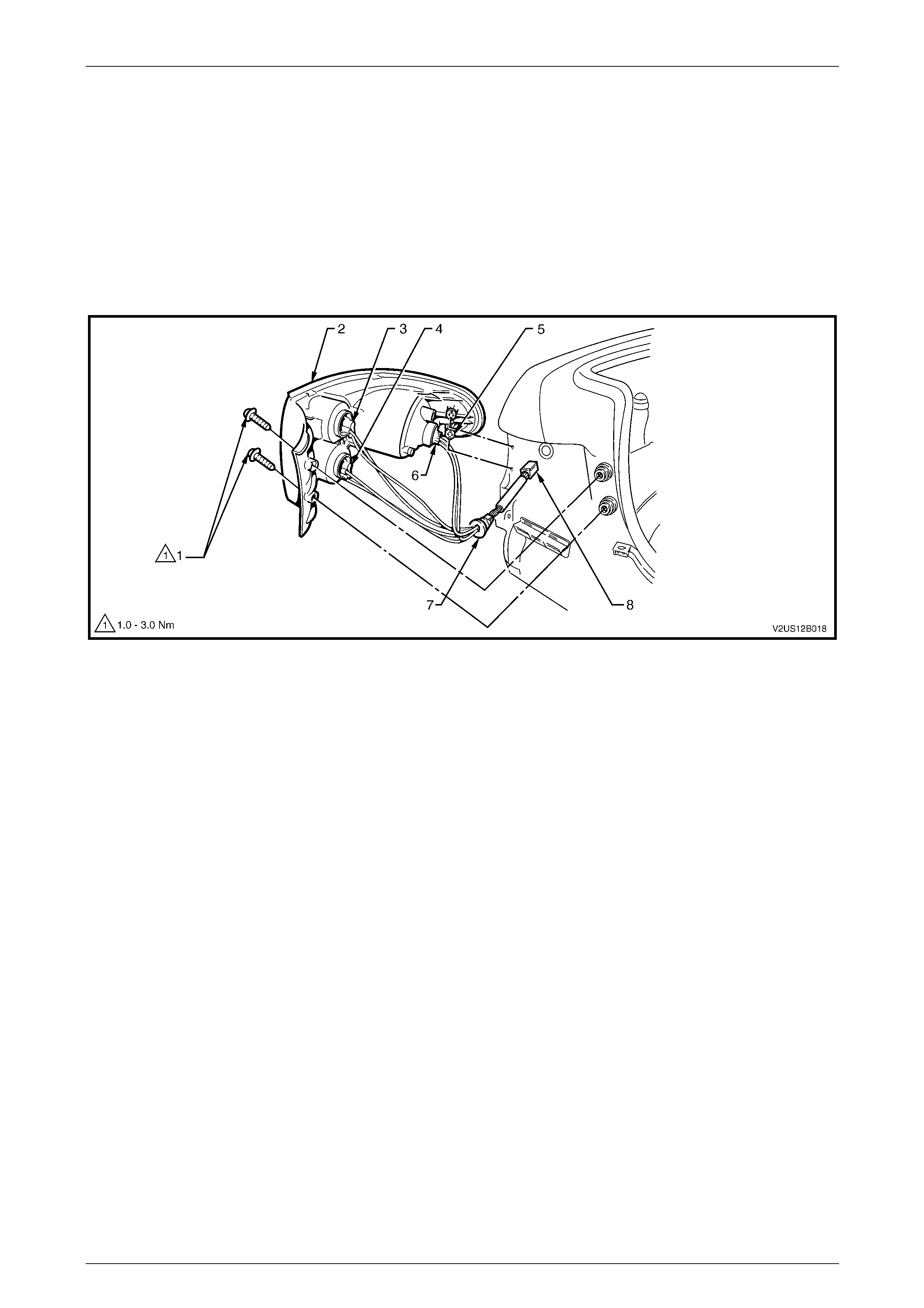
Lighting System Page 12B–77
Page 12B–77
6.5 Tail Lamp Assembly Bulbs
LT Section No. — 02–350
Replace
1 Remove fusible link F102 from the engine compartment fuse and relay panel assembl y,
refer to Section 12O Fuses, Relays and Wiring Harnesses.
2 Open the rear compartment lid.
3 Remove both tail lamp assembly attaching screws (1), refer to Figure 12B – 76.
Figure 12B – 76
Legend
1 Attaching Screw (2 places)
2 Tail Lamp Assembly
3 Backup Bulb Socket
4 Turn Signal Bulb Socket
5 Locating Pegs
6 Stop/Tail Bulb Socket
7 Tail Lamp Harness Grommet
8 Electrical Connector
4 Pull the tail lamp assembly (2) sideways and away from the rear quarter panel so the locating pegs (5) on the side
of tail lamp assembly snap free from the retainers. Support the tail lamp assembly.
NOTE
When removing the tail lamp assembly from the
rear quarter panel, take care not to damage the
locating pegs.
5 Remove the appropriate bulb socket (3, 4 or 6) b y turning it anticlockwise and removing it from the tail lamp
assembly.
6 Remove the bulb from the bulb socket by pressing the bulb, then rotating it anticlockwise.
7 Inspect the bulb socket seal for damage and replace if necessary.

Lighting System Page 12B–78
Page 12B–78
8 Insert a new bulb into the bulb socket and install it into the tail lamp assembly, ensuring it locks securely into place.
NOTE
Bulb sockets have a different number of lugs to
prevent installation into the incorrect tail lamp
assembly receptacle.
NOTE
The length of the tail lamp wiring harness allows
the backup bulb socket and the turn signal bulb
socket to be fitted into their correct locations only.
9 Ensure the tail lamp harness grommet (7) is seated correctly. Fit the tail lamp assembly to the rear quarter panel,
ensuring the locating pegs sn ap into their retainers.
10 Tighten the tail lamp assembly attaching scr ews to the correct torque specification.
Tail lamp assembly attaching
screw torque specification...........................1.0 – 3.0 Nm
11 Install fusible link F102 on the engine compartment fuse and relay panel assembly.
12 Check the tail lamp operation.
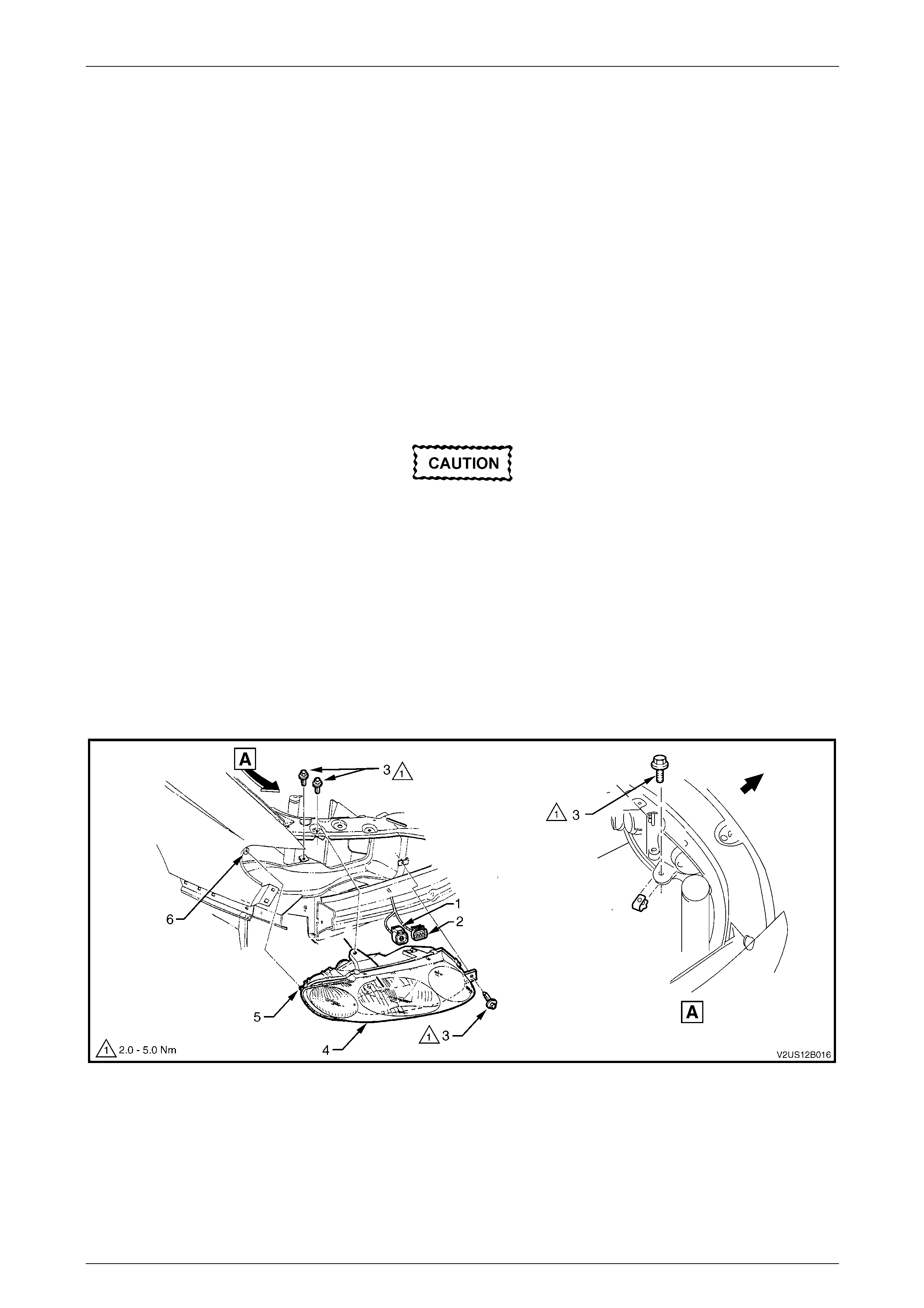
Lighting System Page 12B–79
Page 12B–79
6.6 Headlamp Assembly
LT Section No. — 02–300
Remove
1 Remove fusible link F102 from the engine compartment fuse and relay panel assembl y,
refer to Section 12O Fuses, Relays and Wiring Harnesses.
2 Remove the front bumper fascia assembly, refer to Section 1D Bumper Bars.
3 If required, remove the four retainers securing the upper radi ator shroud and remove the shroud,
refer to Section Section 6B3 Engine Cooli ng — GEN III V8.
4 For the right-hand headlamp assembly, it may be necessary to remove the battery to gain the required access:
a If required, remove the battery hold-down bracket and move the battery to gain access,
refer to Section 12A Battery.
Disconnection of the battery affects certain
vehicle electronic systems. Refer to
Section 00 Warnings, Cautions and Notes
before disconnecting the battery.
b If further access is required, remove the battery terminals from the battery and remove the battery from the
engine compartment, refer to Section 12A Battery.
5 For the left-hand headlamp assembly, remove the upper radiator shroud and coolant filler bottle neck and place in
a safe location away from the immediate worksite.
6 Disconnect the turn signal and headlamp wiring harness connectors (1 and 2) from the rear of the headlamp
assembly (4), refer to Figure 12B – 77.
7 Remove the three headlamp retaining screws (3) and remove the headlamp assemb ly.
Figure 12B – 77
Legend
1 Turn Signal Lamp Wiring Harness Connector
2 Headlamp Wiring Harness Connector
3 Headlamp Retaining Screw
4 Headlamp Assembly
5 Headlamp Guide Pin
6 Fender Hole

Lighting System Page 12B–80
Page 12B–80
Reinstall
Reinstallation of the headlamp assembly is the reverse of the removal procedure, notin g the following:
1 Install the headlamp assembly, ensuring the headlamp guide pin (5) aligns with the fender hole (6), and tighte n the
headlamp retaining screws to the correct torque specification.
Headlamp assembly retaining
screw torque specification...........................2.0 – 5.0 Nm
2 Connect all wiring harness co nnectors, then check the headlamp, turn signal and park lamp operation.
3 Install the front bumper fascia assembly, refer to Section 1D Bumper Bars.
4 Check the headlamp operation, and adjust the aim, refer to Headlamp Assembly Aim.
5 Check the front fog lamp operation, and adjust the aim, refer to Front Fog Lamp Assembly Aim.
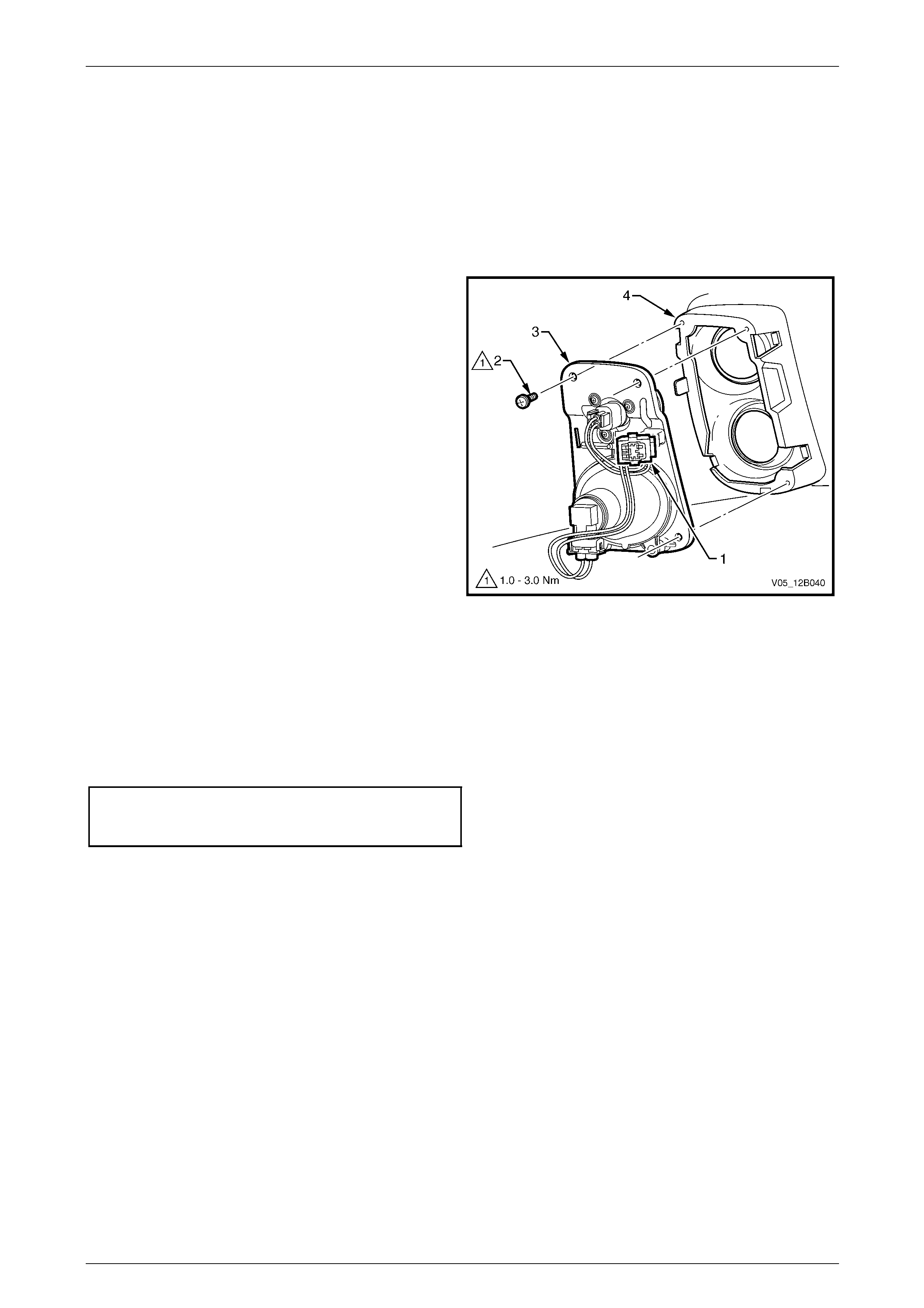
Lighting System Page 12B–81
Page 12B–81
6.7 Park and Front Fog Lamp Assembly
LT Section No. — 02–325
Remove
1 Remove fusible link F102 from the engine compartment fuse and relay panel assembl y,
refer to Section 12O Fuses, Relays and Wiring Harnesses.
2 From behind the bumper fascia assembly, disconnect
the park and front fog lamp assembly harness
connector (1).
3 Remove the screws (2), three places, securing the
park and front fog lamp assembly (3) to the bumper
fascia assembly (4), then remove the park and front
fog lamp assembly.
Figure 12B – 78
Reinstall
Reinstallation of the park and front fog lamp assembly is the reverse of the removal procedure, noting the following:
1 Ensure the park and front fog lamp assembly is located on the fascia datum pins (4), refer to Figure 12B – 78.
2 Tighten the screws securing the park and front fog lamp assembly to the bumper fascia assembly to the correct
torque specification.
Park and front fog lamp
assembly attaching screw
torque specification.....................................1.0 – 3.0 Nm
3 Check the front fog lamp operation a nd, if necessary, adjust the aim, refer to Front Fog Lamp Assembly Aim.
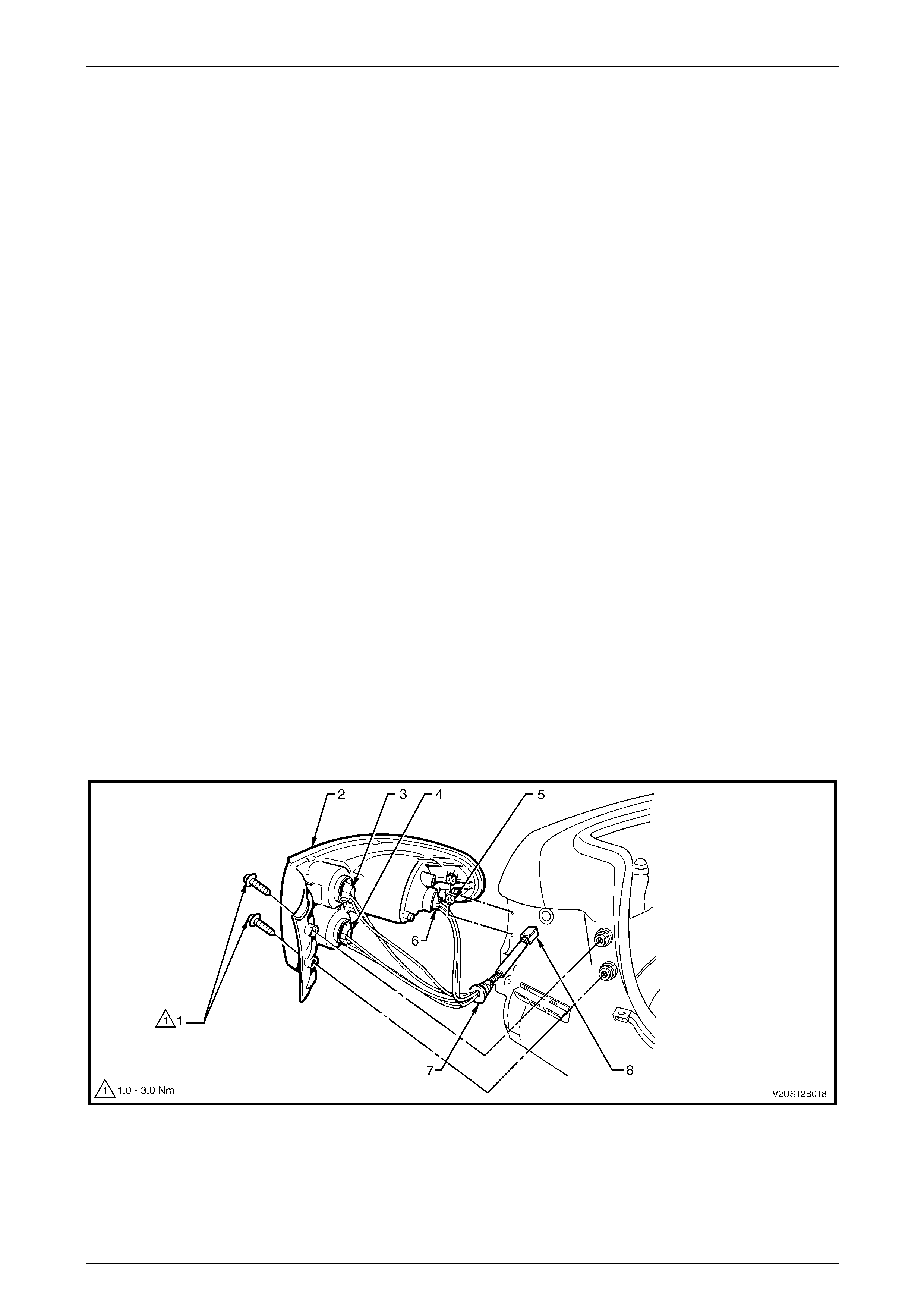
Lighting System Page 12B–82
Page 12B–82
6.8 Tail Lamp Assembly
LT Section No. — 02–350
Remove
1 Remove fusible link F102 from the engine compartment fuse and relay panel assembl y,
refer to Section 12O Fuses, Relays and Wiring Harnesses.
2 Open the rear compartment lid.
3 Remove the two tail lamp assembly attachin g screws (1), refer to Figure 12B – 79.
4 Either:
• If leaving the wiring harness installe d:
(1) Pull the tail lamp assembly (2) sideways and away from the rear quarter panel so the locat ing pegs (5)
on the side of the tail lamp assembly snap free from the retainers. Supp ort the tail lamp assembly.
NOTE
When removing the tail lamp assembly from the
rear quarter panel, take care not to damage the
locating pegs (5).
(2) Remove all the bulb sockets (3, 4 and 6) by t urning them an t iclockwise and pulling them away from the
tail lamp assembly.
• If removing the wiring harness:
(1) Pull the quarter inner rear side carpet away from the vehicle to expose the tail lam p wiring harness
connector (8).
(2) Disconnect the tail lamp wiring harness from the body wiring harness.
(3) Pull the tail lamp assembly (2) sideways and away from the rear quarter panel so the locat ing pegs (5)
on the side of the tail lamp assembly snap free from the retainer.
(4) Pull the tail lamp harness grommet (7) from the sheetmetal; remove the tail lamp assembly and the tail
lamp wiring harness.
Figure 12B – 79
Legend
1 Attaching Screw (2 places)
2 Tail Lamp Assembly
3 Backup Bulb Socket
4 Turn Signal Bulb Socket
5 Locating Pegs
6 Stop/Tail Bulb Socket
7 Tail Lamp Harness Grommet
8 Electrical Connector

Lighting System Page 12B–83
Page 12B–83
Replace — Main Seal
The main seal is adhered to the tail lamp assembly lens cover with contact adhesive and double-sided tape.
1 To replace the main seal, carefully remove the old seal and clean the surface of the tail lamp assembly with soapy
water. Wipe off any residue from the cleaner before applying new adhesive and tape.
NOTE
Do not use solvents on the pl astic surfaces of the
lamp assembly.
2 Apply a small amount of adhe sive to the main seal and double-sided tape to the tail lamp assembl y.
3 Place the main seal on the tail lamp assem bly.
4 Allow time for the adhesive to cure befor e installing the tail lamp assembly to the vehicl e.
Reinstall
Reinstallation of the lamp ass embl y is the reverse of the removal procedure, noting the following:
1 Inspect the tail bulb socket and tail lamp assembly seals for damage and replace if nec essary.
2 If required, replace the tail lamp wiring har ness.
3 Install the bulb sockets into the tail lamp assembl y, ens uring they lock securely into place.
NOTE
The length of the tail lamp wiring harness allows
the backup bulb socket and the turn signal bulb
socket to be fitted into their correct locations only.
4 Tighten the tail lamp assembly attaching screws to the correct torque specification.
Tail lamp assembly attaching
screw torque specification...........................1.0 – 3.0 Nm
5 Check the tail lamp operation.
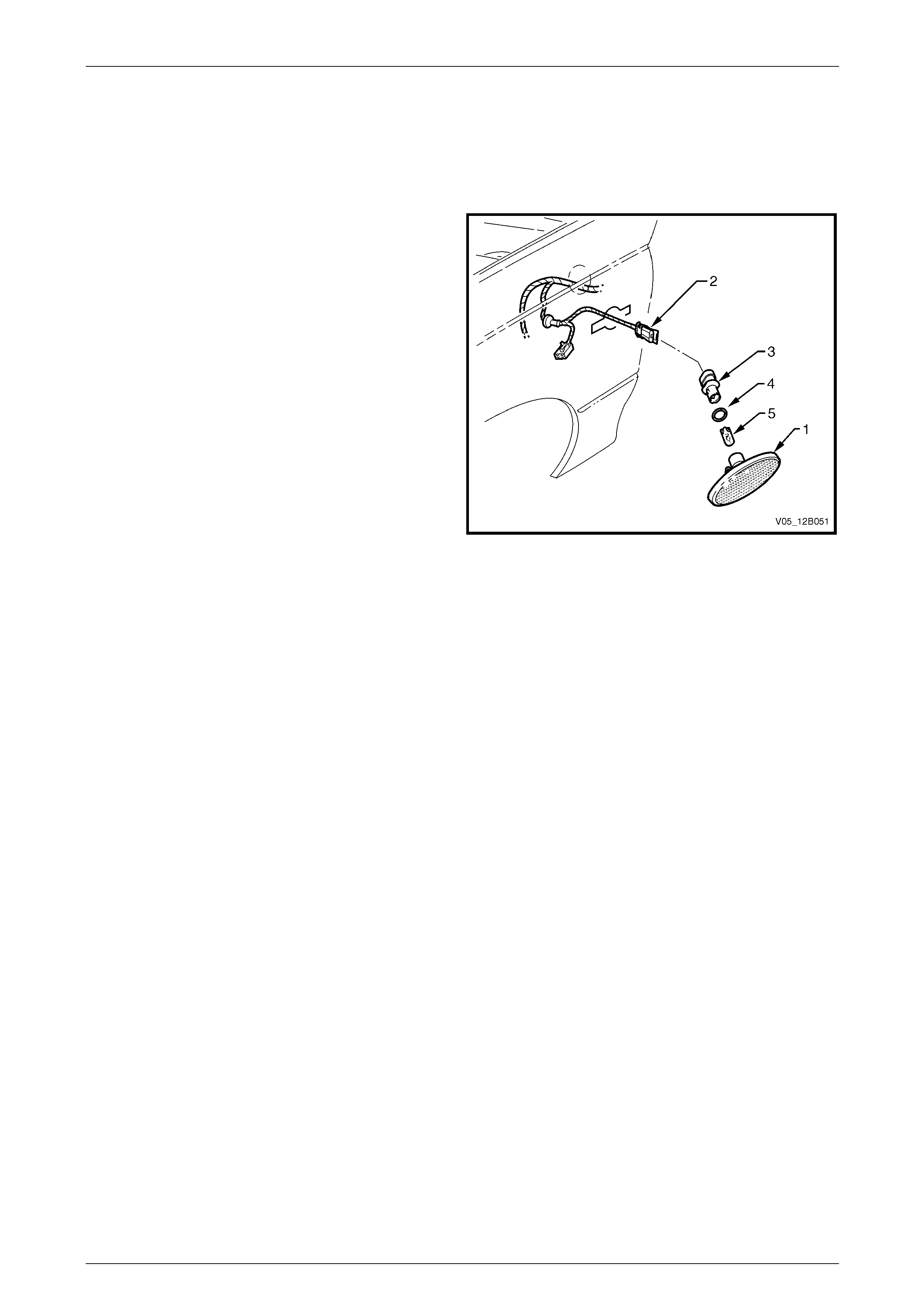
Lighting System Page 12B–84
Page 12B–84
6.9 Side Repeater Lamp Assembly
LT Section No. — 02–310
Remove
1 Remove turn signal lamp fuse F12, refer to
Section 12O Fuses, Relays and Wiring Harnesses.
2 Grip the rear edge of the side repeater lamp
assembly (1) with finger tips and pull it forward, then
outwards and away from the front fender.
3 Disconnect the side repeater lamp assembly wiring
harness connector (2) from the front side turn signal
lamp assembly.
NOTE
Tape the side repeater lamp assembly wiring
harness to the front fender so the side turn
signal lamp assembly wiring harness and the
connector do not fall into the front fender.
4 Twist and remove the bulb socket (3), O-ring (4) and
bulb (5) from the side repeater lamp assembly.
5 If required, pull the bulb from the bulb socket. Figure 12B – 80
Reinstall
1 If required, install a new bulb into the bulb socket.
2 Inspect the side repeater lamp assembly and O-ring for damage and replace if necessary.
3 Insert the bulb socket into the side repeat er lamp assembly and twist to lock into position. Connect the side
repeater lamp assembly wiring harness connector to the si de repeater lamp assembly.
4 Install turn signal lamp fuse F12 and check the operation of the lamp assembly.
5 Place the rear of the side repeater lamp ass embl y into the fender and place the locking tab into the forward end
of the fender aperture. Push the front of the side repeater lamp assembly towards the fender to engage the
locking tab.
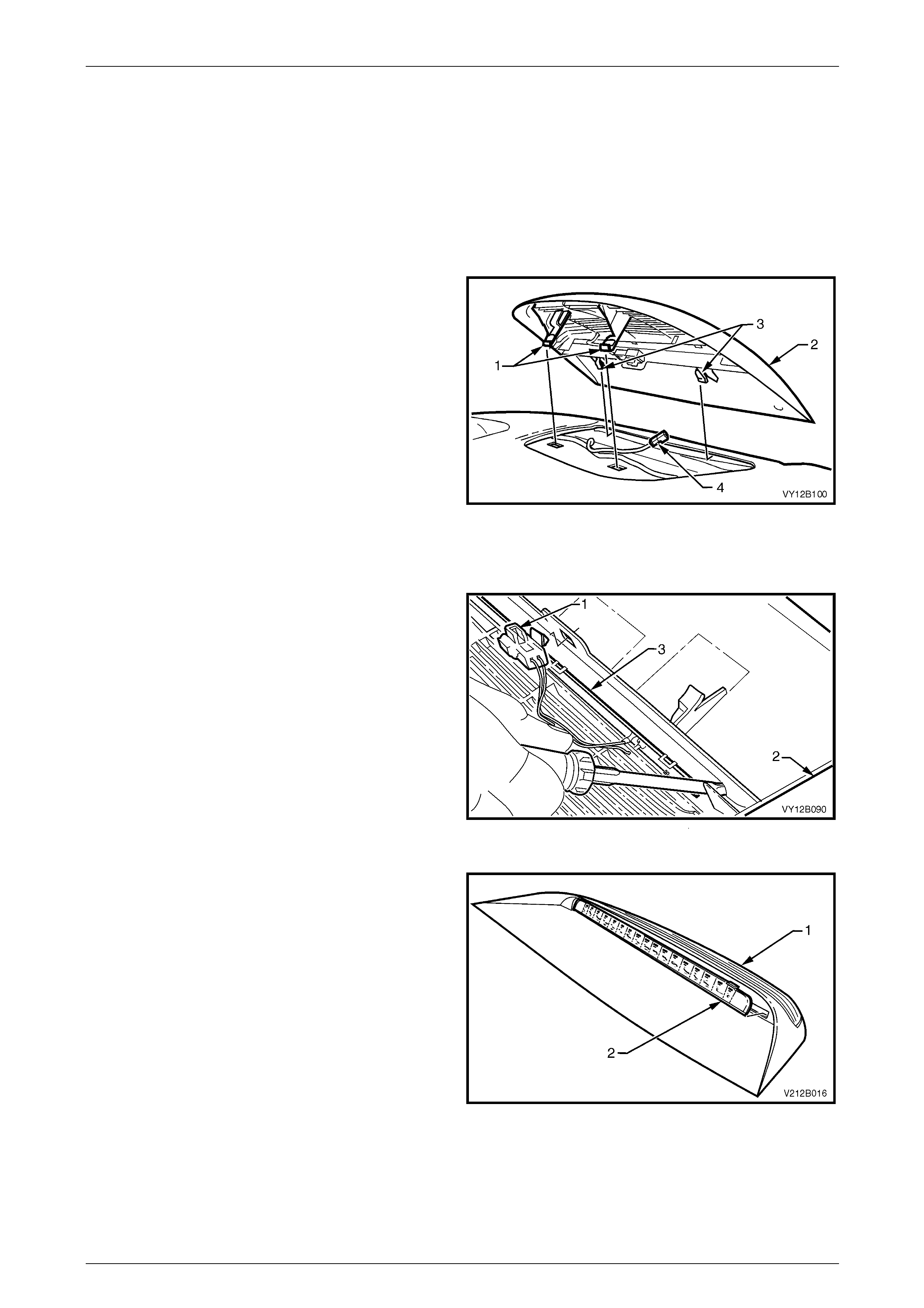
Lighting System Page 12B–85
Page 12B–85
6.10 High-mount Stop Lamp Assembly
LT Section No. — 02–350
Remove
1 Remove fusible link F102 from the engine compartment fuse and relay panel assembl y,
refer to Section 12O Fuses, Relays and Wiring Harnesses.
2 Open the rear compartment lid.
3 From inside the rear compartment, disengage the two
retaining tangs (1) from the rear windo w panel
assembly.
4 From inside the vehicle, grasp the edge of the high-
mount stop lamp assembly (2), then pull the high-
mount stop lamp assembly away from the rear window
until the locating tabs (3) are free from the slots.
5 Disconnect the high-mount stop lamp assembly wiring
harness connector (4) from the high-mount stop lamp
assembly, then remove the high-mount stop lamp
assembly from the vehicle.
Figure 12B – 81
Disassembly
1 Unclip the high-mount stop lamp assembly wiring
harness connector (1) from the high-mount stop lamp
assembly (2).
2 Starting at one end of the LED assembly (3), carefully
disengage the retaining tabs wit h a smal l screwdriver.
Figure 12B – 82
3 Carefully spread the high-mount stop lamp
assembly (1) by hand and work the LED assembly (2)
sideways and rearwards until it is free from the high-
mount stop lamp assembly.
Figure 12B – 83

Lighting System Page 12B–86
Page 12B–86
Reassembly
The reassembly procedure for the high-mount stop lamp assembly is the reverse of the disassembly procedure.
Reinstall
Reinstallation of the high-mo unt stop lamp assembly is the reverse of the removal procedure, noting the following:
1 Ensure the locating tabs are correctly engaged into the slots in the rear of the parcel shelf before engag ing the
retaining tabs.
2 Check the high-mount stop lamp assembly operation.
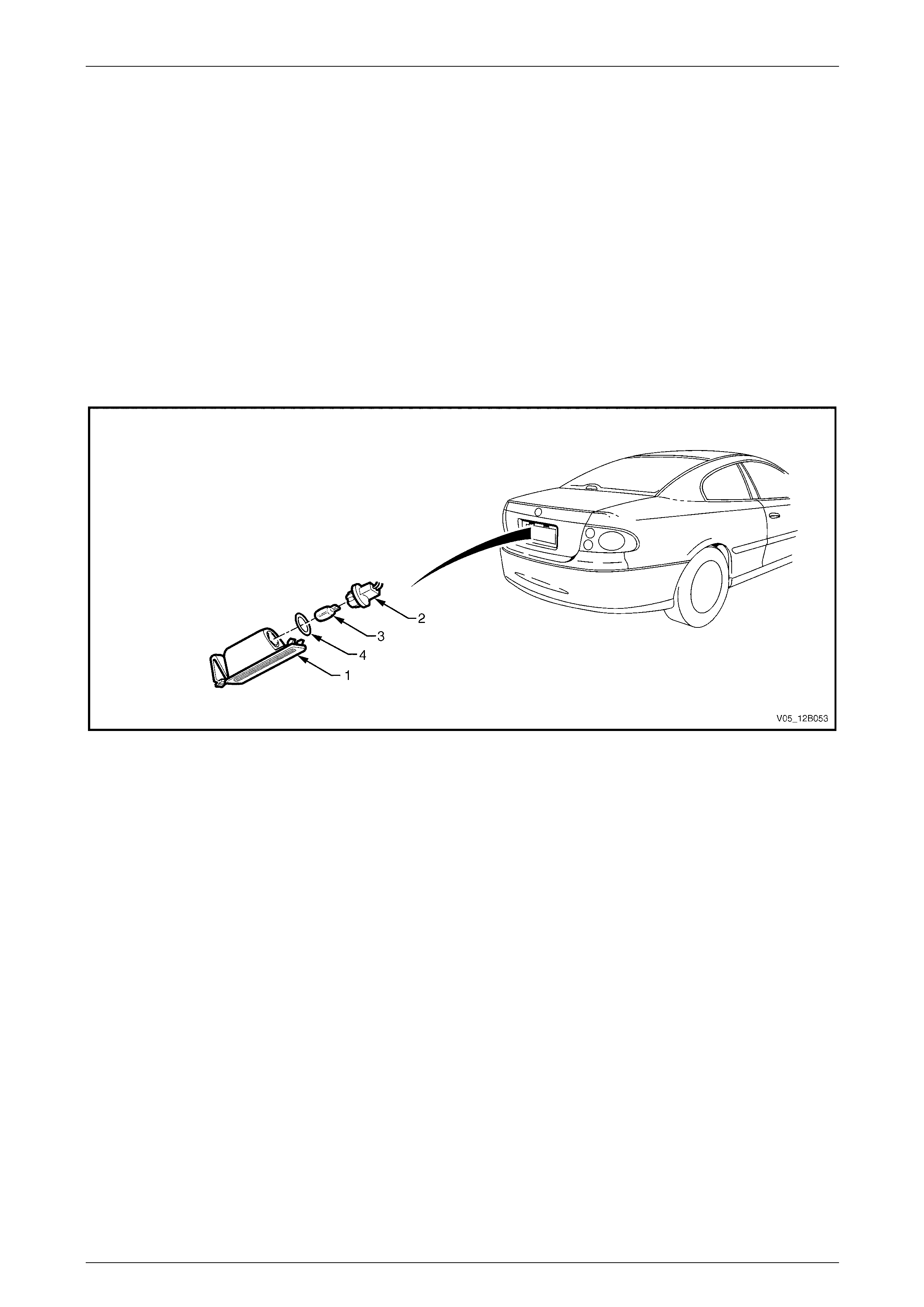
Lighting System Page 12B–87
Page 12B–87
6.11 Rear Licence Plate Lamp Assembly
LT Section No. — 02–375
Remove
1 Remove fusible link F102 from the engine compartment fuse and relay panel assembl y,
refer to Section 12O Fuses, Relays and Wiring Harnesses.
2 Push the locking tang located at the end of the rear licence plate lamp housing (1) to wards the lens. Pivot the rear
licence plate lamp housing down and remove it from the aperture, refer to Figure 12B – 84.
3 Remove the rear licence plate bulb socket (2) from the rear licence plate lamp housing.
4 If required, replace the bulb (3) by pulling it from the rear licence plate bulb socket and installing a new bulb.
5 Inspect the rear licence plate bul b socket se al (4) for damage and replace if required.
Figure 12B – 84
Reinstall
Reinstallation of the rear licence plate lamp assembly is the reverse of the removal procedure, noting the foll owing:
1 If required, push a new bulb into the rear licence plate bu lb socket.
2 Install the rear licence plate bulb socket and bulb into the rear licence plate lamp housing.
NOTE
The rear licence plate lamp housing installs into
the aperture in one direction only.
3 Install the rear licence plate lamp housing into the aperture.
4 Install fusible link F102 on the engine compartment fuse and relay panel assembly.
5 Check the rear licence plate lamp assembly operation.
Wiring Harness
To remove and install the rear licence plate lamp wiring harness, remove t he rear compartment lid appliqué assembly,
refer to Section 1A4 Hood, Rear Compartment Lid, Liftgate and Endgate.
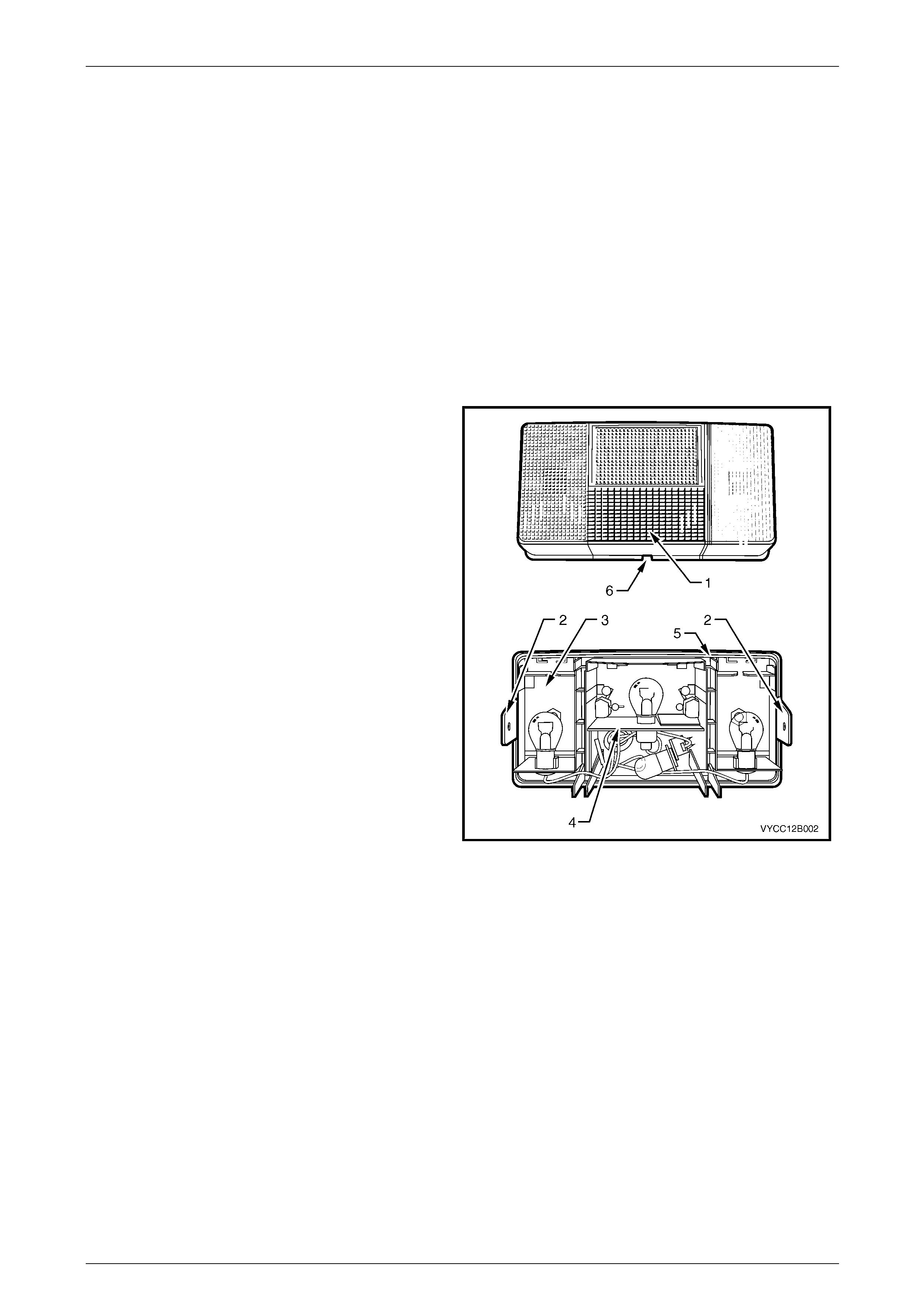
Lighting System Page 12B–88
Page 12B–88
7 Service Operations — Exterior
Illumination, Regular Cab and
Crew Cab with 'Delete Tub'
Option
7.1 Tail Lamp Assembly Bulbs
LT Section No. — 02–350
Replace
1 Remove fusible link F102 from the engine compartment fuse and relay panel assembl y,
refer to Section 12O Fuses, Relays and Wiring Harnesses.
2 Clasping the tail lamp assembly lens (1), carefully
lever out one of the tangs (2) that extends from the
tail lamp assembly (3) and partiall y pull out the lens.
Repeat this procedure with the other tang and remove
the tail lamp assembly lens.
3 Remove the appropriate bulb from the bulb mounting
plate (4) by pressing the bulb, then rotating it.
4 Inspect the tail lamp assembly seal (5) for damage
and replace the tail lamp assembly if necessary.
NOTE
The tail lamp assembly seal is part of the tail
lamp assembly and is not replaced se parately.
5 Insert a new bulb into the bulb mounting pla t e,
ensuring that it locks securely into place.
NOTE
Bulb specifications are moulded into the tail
lamp assembly, near the corresponding bulb
location.
6 Install fusible link F102 on the engine compartment
fuse and relay panel assembly, refer to
Section 12O Fuses, Relays and Wiring Harnesses. Figure 12B – 85
7 Check the tail lamp operation.
8 Install the lens onto the tail lamp assembly, with the cut-out (6) on the lower part and the clear plastic backup lens
inboard of the tail lamp assembly. Ensure both tangs secure the lens to the tail lamp assembly.
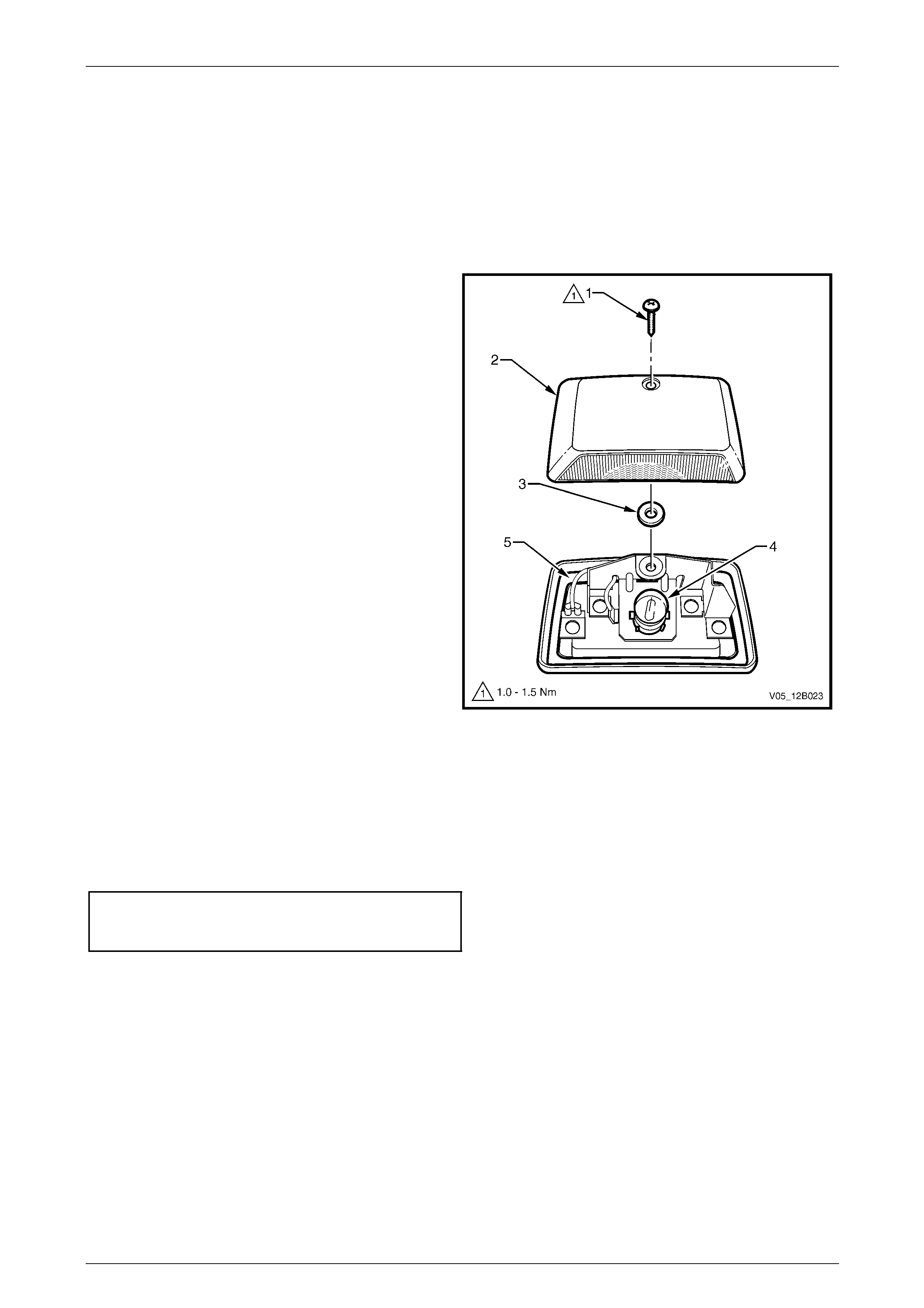
Lighting System Page 12B–89
Page 12B–89
7.2 Rear Licence Plate Lamp Bulb
LT Section No. — 02–375
Replace
1 Remove fusible link F102 from the engine compartment fuse and relay panel assembl y,
refer to Section 12O Fuses, Relays and Wiring Harnesses.
2 Remove the attaching screw (1) from the rear licence
plate lamp assembly (2).
3 Remove the rear licence plate lamp assembly by
pulling it away from the rear licence plate la mp
assembly base. Place the grommet (3) in a safe
location away from the immediate worksite.
4 Remove the bulb (4) from the rear licence plate
lamp assembly base (5) by pressing the bu lb, then
rotating it.
5 Inspect the rear licence plate lamp assem bly seal and
grommet for damage and replace the rear licence
plate lamp assembly if necessary.
NOTE
The rear licence plate lamp assembly seal and
grommet are part of the rear licence plate lamp
assembly and are not replaced separately.
6 Insert a new bulb into the bulb mounting pla t e,
ensuring it locks securely into plac e.
NOTE
Bulb specifications are moulded into the rear
licence plate lamp housing, near the bulb
location. Figure 12B – 86
7 Install fusible link F102 on the engine compartment fuse and relay panel assembly,
refer to Section 12O Fuses, Relays and Wiring Harnesses.
8 Check the rear licence plate lamp assembly operation.
9 Install the lens onto the housing.
10 Tighten the attaching screw to the correct torque specification.
Rear licence plate lamp
assembly attaching screw
torque specification.....................................1.0 – 1.5 Nm
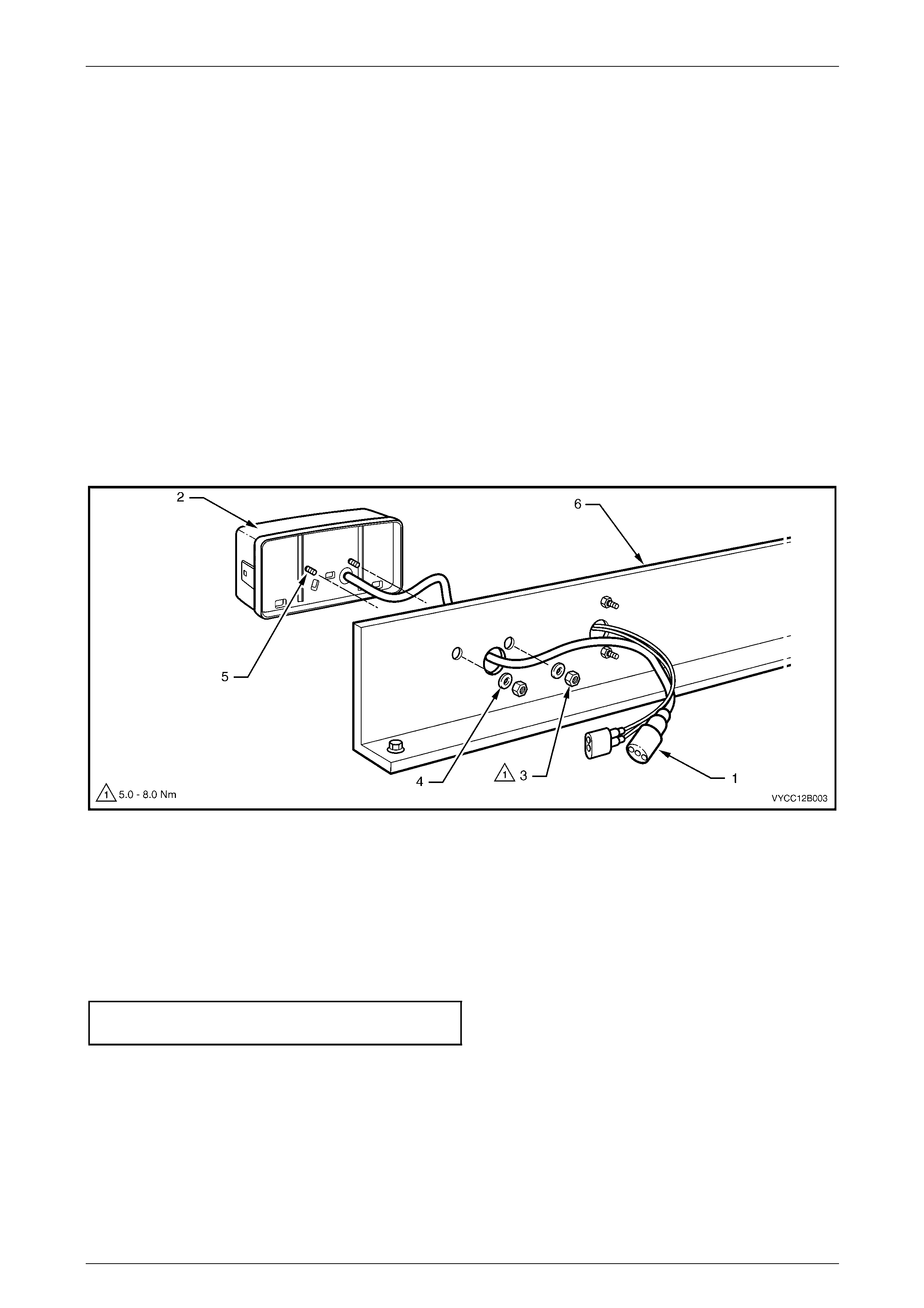
Lighting System Page 12B–90
Page 12B–90
7.3 Tail Lamp Assembly
LT Section No. — 02–350
Remove
1 Remove fusible link F102 from the engine compartment fuse and relay panel assembl y,
refer to Section 12O Fuses, Relays and Wiring Harnesses.
2 Disconnect the tail lamp assembl y wiring harness (1) from the body wiring harness, refer to Figure 12B – 87.
3 While supporting the tail lamp assembly (2), remove the two attaching nuts (3) and washers (4) from the tail lamp
assembly studs (5).
NOTE
Both attaching screws are adhered to the tail
lamp housing assembly (2) and are not
serviceable.
4 Remove the tail lamp assembly from the transport bracket (6).
Figure 12B – 87
Reinstall
Reinstallation of the tail lamp assembly is the reverse of the removal, noting the following:
1 Install fusible link F102 on the engine compartment fuse and relay panel assembly,
refer to Section 12O Fuses, Relays and Wiring Harnesses.
2 Tighten the tail lamp assembly attaching nuts to the correct torque specification.
Tail lamp assembly attaching
nut torque specification...............................5.0 – 8.0 Nm
3 Check the tail lamp assembly operation.
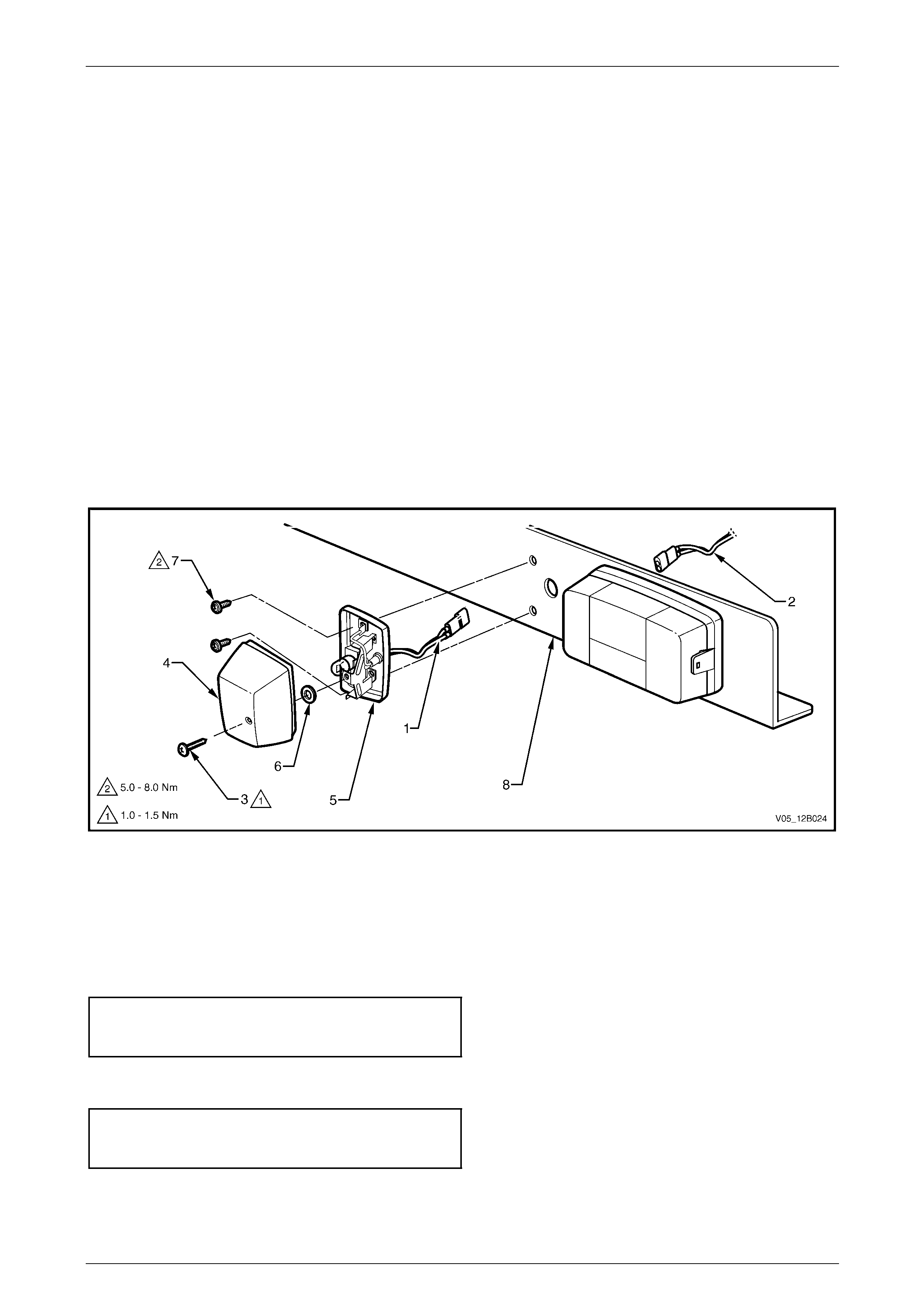
Lighting System Page 12B–91
Page 12B–91
7.4 Rear Licence Plate Lamp Assembly
LT Section No. — 02–375
Remove
1 Remove fusible link F102 from the engine compartment fuse and relay panel assembl y,
refer to Section 12O Fuses, Relays and Wiring Harnesses.
2 Disconnect the rear licence plate lamp assembly wiring harness (1) from the body wiring harness (2),
refer to Figure 12B – 88.
3 Remove the attaching screw (3) from the rear licenc e plate lamp assembly (4).
4 Remove the rear licence plate lamp assembly by pulling it away from the rear licence plate lamp assemb ly
base (5). Place the grommet (6) in a safe location away from the immediat e worksite.
5 Inspect the rear licence plate lamp assembly seal and grommet for damage and replace the rear licence plate
assembly if the rear licence plate lamp assembly seal or gr ommet is faulty.
NOTE
The rear licence plate lamp assembly seal and
grommet are part of the rear licence plate lamp
assembly and are not replaced separately.
6 Remove the two mounting screws (7) from the rear licence plate lamp assembly base.
7 Remove the rear licence plate lamp assem bl y base from the transport bracket.
Figure 12B – 88
Reinstall
Reinstallation of the rear licence plate lamp assembly is the reverse of the removal, noting the following:
1 Install fusible link F102 on the engine compartment fuse and relay panel assembly,
refer to Section 12O Fuses, Relays and Wiring Harnesses.
2 Tighten the rear licence plate lamp assembly mounting screws to the correc t torque specification.
Rear licence plate lamp
assembly mounting screw
torque specification.....................................5.0 – 8.0 Nm
3 Check the rear licence plate lamp assembly operation.
4 Tighten the rear licence plate lamp assembly attaching screw to the correct torque specification.
Rear licence plate lamp
assembly attaching screw
torque specification.....................................1.0 – 1.5 Nm
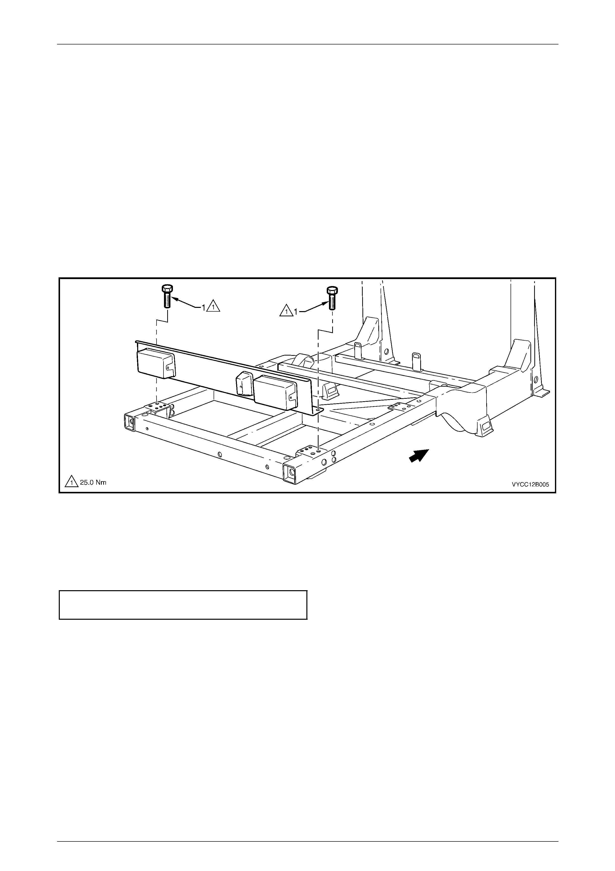
Lighting System Page 12B–92
Page 12B–92
7.5 Transport Bracket
LT Section No. — XX–XXX
Remove
1 Remove fusible link F102 from the engine compartment fuse and relay panel assembl y,
refer to Section 12O Fuses, Relays and Wiring Harnesses.
2 Disconnect both tail lamp ass emblies from the body wiring harness connectors.
3 Disconnect the rear licence plate lamp assembly from the body wiring harness connector.
4 If required, remove the tail lamp assemblies from the transport bracket.
5 If required, remove the rear licence plate lamp assembly from the transport bracket.
6 Remove the two transport bracket attaching screws (1), then remove the transport bracket from the chassis,
refer to Figure 12B – 89.
Figure 12B – 89
Reinstall
Reinstallation of the transport bracket is the reverse of the removal, noting the following:
1 Tighten the transport bracket attaching screws to the corr ect torque specification.
Transport bracket attaching screw
torque specification............................................25.0 Nm
2 Check the rear licence plate lamp operation.
3 Check the tail lamp assembly operation.
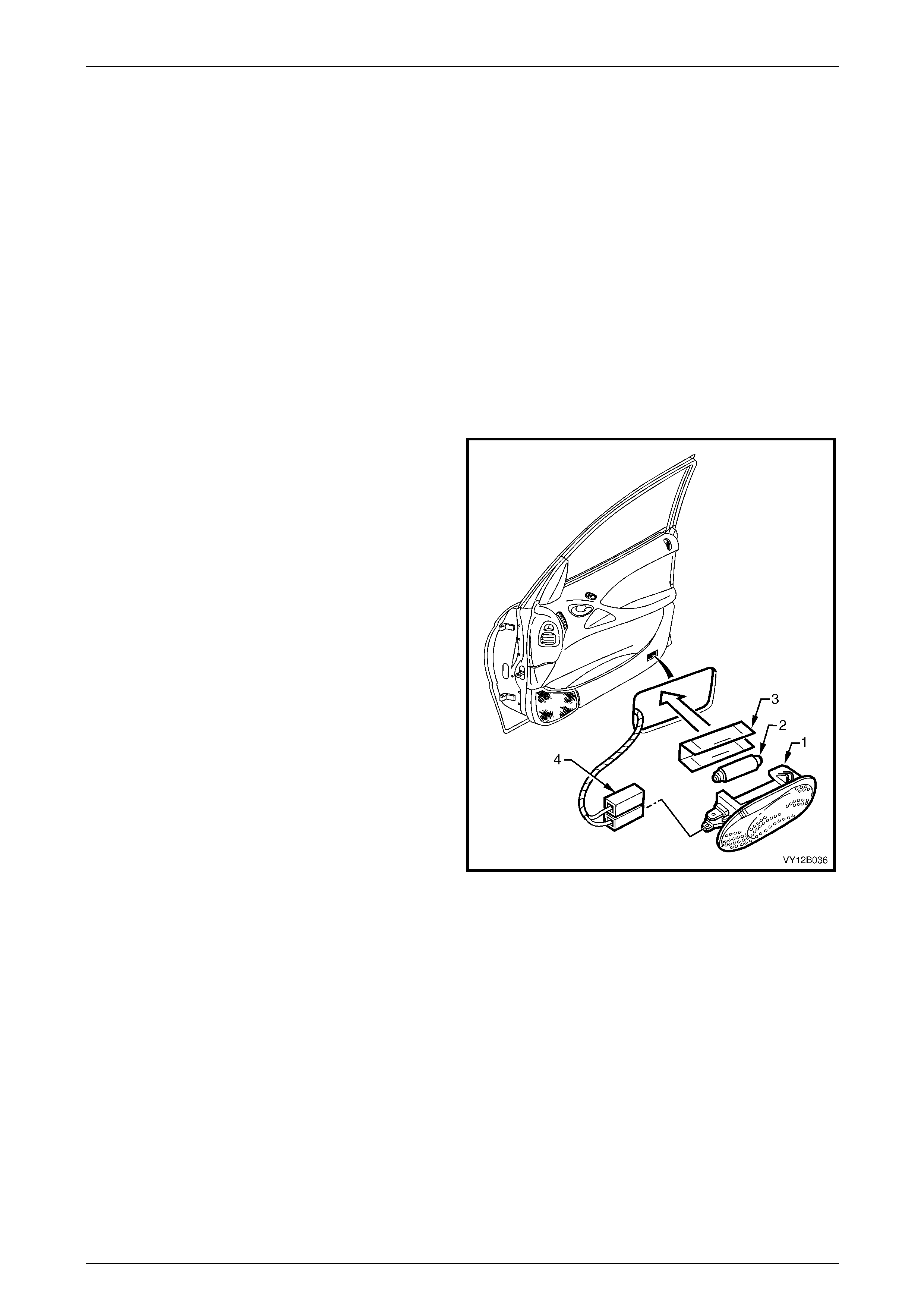
Lighting System Page 12B–93
Page 12B–93
8 Service Operations — Interior
Illumination and Switching,
Sedan, Wagon, Utility and Crew
Cab
The interior lighting configuration is dependent upon the vehicle m odel and trim level, refer to 1.5 Interior Illumination.
8.1 Side Door Courtesy Lamp Assembly
LT Section No. — 02–780
Remove
1 Remove fusible link F102 from the engine compartment fuse and relay panel assembl y,
refer to Section 12O Fuses, Relays and Wiring Harnesses.
2 Insert a fine-bladed screwdriver into the notch at the
bottom edge of the lamp and press the locking tang.
3 Prise the side door courtesy lamp assembly (1) from
the door trim assembly.
4 Disconnect the side door courtesy lamp assembly
wiring harness connector (4) from the side door
courtesy lamp assembly.
5 If removing the bulb from the lamp:
a Pull the protective metal cover (3) from the rear
of the lamp to access the bulb (2).
b Bend back the lever contact retaining the bulb,
then remove the bulb.
6 Check the side door courtesy lamp assembly for
damage and replace if necessary.
NOTE
Ensure the side door courtesy lamp assembly
wiring harness connector does not fall into the
door cavity.
Figure 12B – 90
Reinstall
Reinstallation of the side doo r courtesy lamp assembly is the reverse of the removal procedure, noting the following:
1 If required, insert a new bulb into the side door courtesy lamp assemb ly.
2 Ensure the lens of the side door courtesy lamp assembly is flush with the side of the door trim assembly.
3 Check the side door courtesy lamp ass embl y operation.
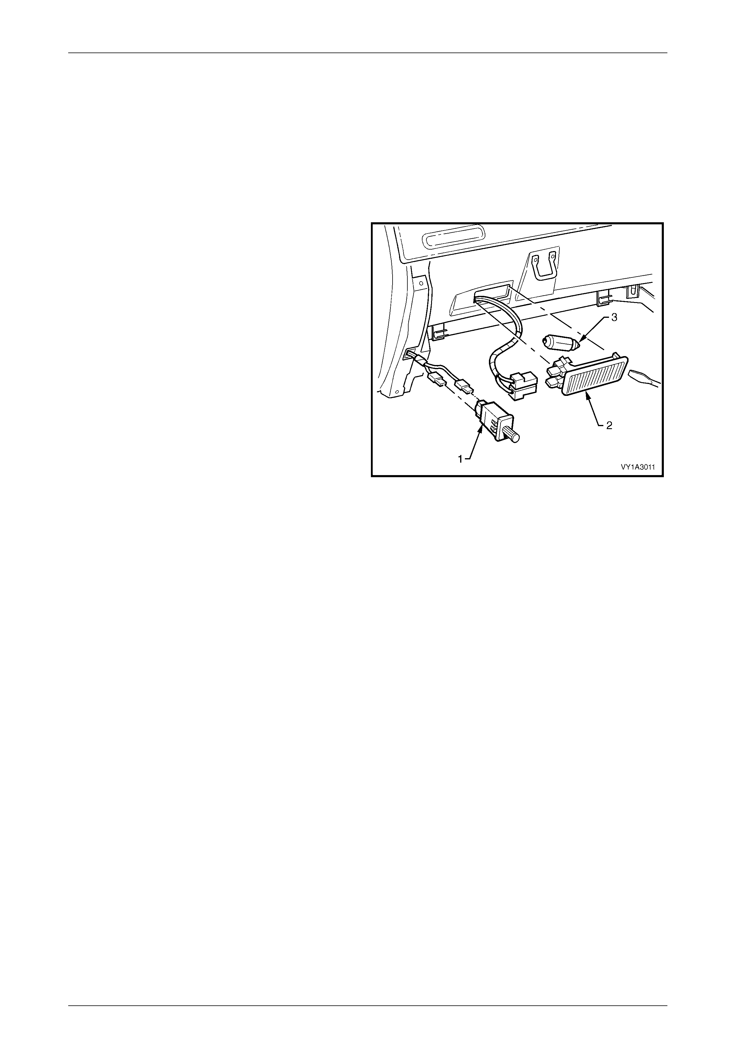
Lighting System Page 12B–94
Page 12B–94
8.2 Instrument Panel Compartment Lamp
Assembly
LT Section No. — 02–780
Remove
1 Remove fusible link F102 from the engine compartment fuse and relay panel assembl y,
refer to Section 12O Fuses, Relays and Wiring Harnesses.
2 Prise the instrument panel compartment lamp
assembly (2) from the compartment using a fine-
bladed screwdriver.
3 Disconnect the instrument panel compartme nt lamp
assembly wiring harness connector from the
instrument panel compartment lamp assembly. Check
the instrument panel compartment lamp assembly for
damage and replace if necessary.
NOTE
Ensure the instrument panel compartment lamp
assembly wiring harness connector does not fall
into the cavity behind the instrument panel
compartment.
4 If necessary, remove the bulb (3) from the instrument
panel compartment lamp assembly by pressing the
metal contact.
Figure 12B – 91
Reinstall
Reinstallation of the instrument panel compartment lamp assembly is the reverse of the removal procedure, noting the
following:
1 Insert a new bulb in the instrument panel compartment lamp assembl y if required.
2 Ensure the lens is flush with the instrument panel compartment.
3 Check the instrument panel compartment lamp assemb ly operation.

Lighting System Page 12B–95
Page 12B–95
8.3 Instrument Panel Compartment Lamp
Switch Assembly
LT Section No. — 02–780
Remove
1 Remove fusible link F102 from the engine compartment fuse and relay panel assembl y,
refer to Section 12O Fuses, Relays and Wiring Harnesses.
2 Prise the instrument panel compartment lamp switch assembly (1) from the instrument panel compartment lamp
assembly using a fine-bladed screwdriver, refer to Figure 12B – 91.
3 Disconnect the instrument panel compartme nt lamp assembly wiring harness connectors from the instrument panel
compartment lamp assembly. Check the inst rument panel compartment lamp switch assembly for damage and
replace if necessary.
NOTE
Ensure the instrument panel compartment lamp
assembly wiring harness connector does not fall
into the cavity behind the instrument panel
compartment.
Reinstall
Reinstallation of the instrument panel compartment lamp switch assembly is the reverse of the removal proce dure.
Check the instrument panel compartment lamp switch assembly operation.
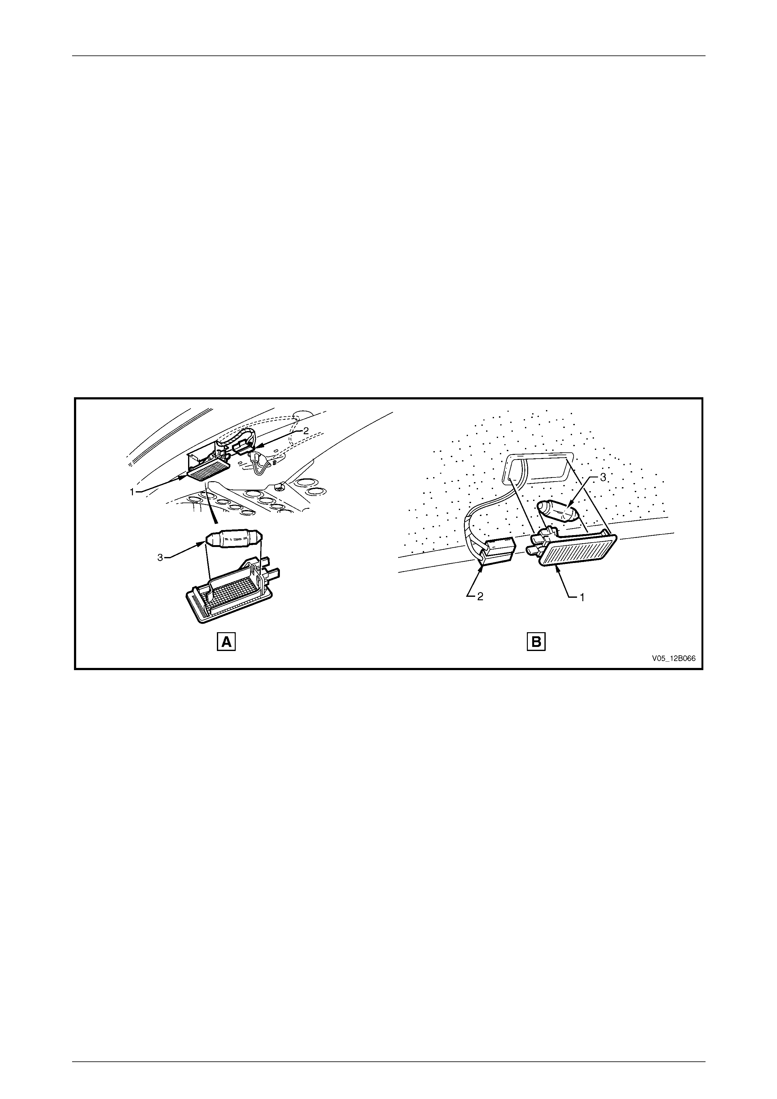
Lighting System Page 12B–96
Page 12B–96
8.4 Rear Compartment Courtesy Lamp
Assembly
LT Section No. — 02–780
Refer to Figure 12B – 92 (view A) for the Sedan lamp assembly installations.
Refer to Figure 12B – 92 (view B) for the Wagon lamp assembly installations.
Remove
1 Remove fusible link F102 from the engine compartment fuse and relay panel assembl y,
refer to Section 12O Fuses, Relays and Wiring Harnesses.
2 Prise the rear compartment courtesy lamp assembly (1) from the mating surface using a fine-bladed screwdriver.
3 Disconnect the rear compartment courtesy lamp assembly wiring harness connector (2) from the rear compartment
courtesy lamp assembly. Check the lamp assembly for damage and replace if necessary.
4 If necessary, remove the bulb (3) from the rear compartment courtesy lamp assembly by pressing the metal
contact.
Figure 12B – 92
Reinstall
Reinstallation of the rear com partment courtesy lamp assembly is the reverse of the removal procedure , noting the
following:
1 Insert a new bulb in the rear compartment courtesy lamp assembly if requ ired.
2 Ensure the lens is flush with the rear compartment roof.
3 Check the rear compartment courtes y lam p assemb ly operation.
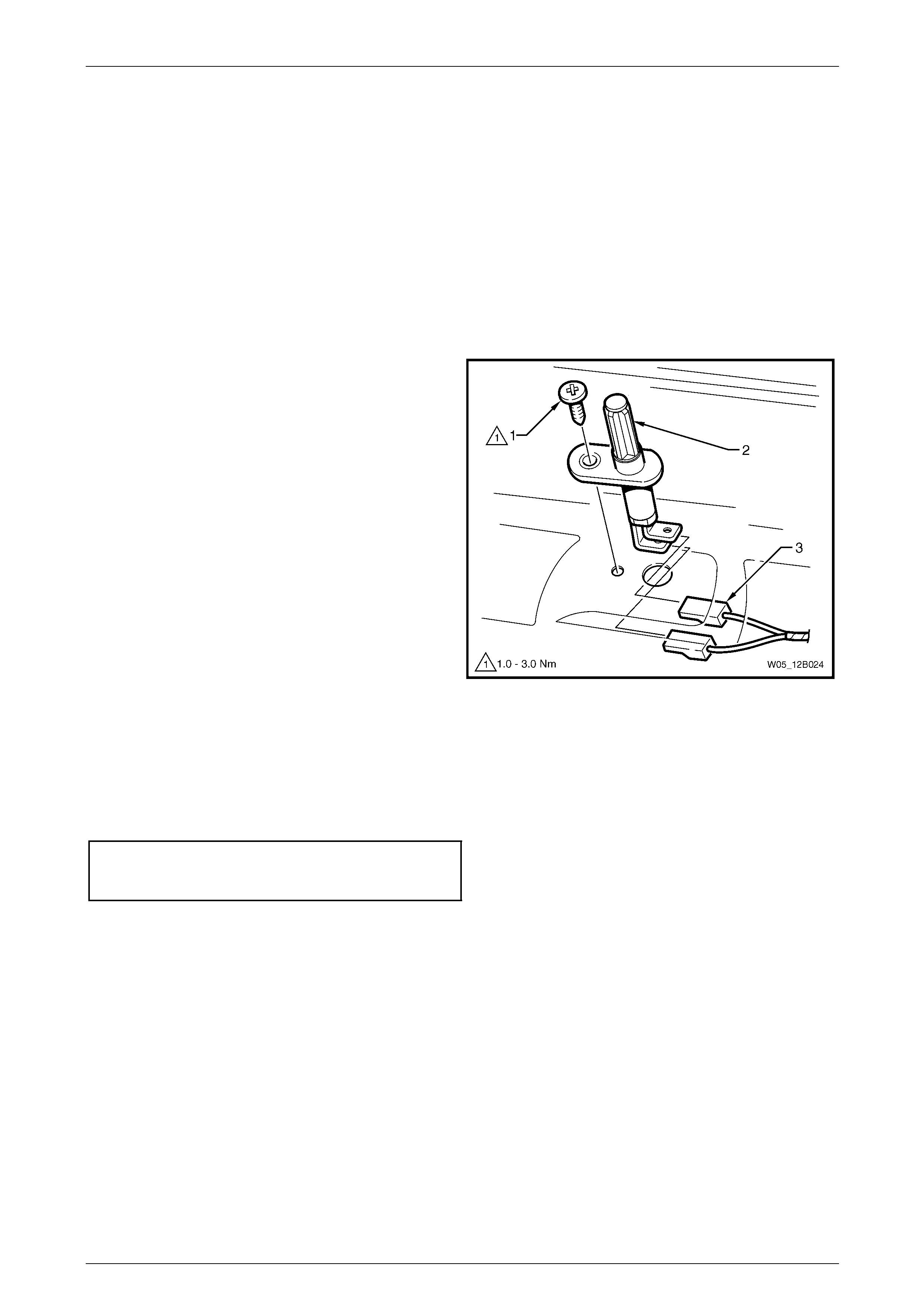
Lighting System Page 12B–97
Page 12B–97
8.5 Rear Compartment Courtesy Lamp
Switch Assembly
LT Section No. — 02–780
The rear compartment courtesy lamp assembly is operated by a switch attached to the rear compartment lid of the
Sedan or the liftgate of the Wagon. T he rear compartment courtesy lamp switch assembly is actuated when either the
compartment lid or liftgate is opened.
Remove
1 Remove fusible link F102 from the engine compartment fuse and relay panel assembl y,
refer to Section 12O Fuses, Relays and Wiring Harnesses.
2 Remove the attaching screw (1) and pull the rear
compartment courtesy lamp switch assembly (2) out
far enough to access the rear compartment courtes y
lamp assembly wiring harness connectors (3).
3 Disconnect the rear compartment courtesy lamp
assembly wiring harness connectors and remove the
rear compartment courtesy lamp switch assembly.
Figure 12B – 93
Reinstall
Reinstallation of the rear com partment courtesy lamp switch assembly is the reverse of the removal procedure, noting
the following:
1 Tighten the attaching screw to the correct torque specification.
Rear compartment courtesy lamp
switch assembly attaching
screw torque specification...........................1.0 – 3.0 Nm
2 Check the rear compartment courtes y lam p assemb ly operation.
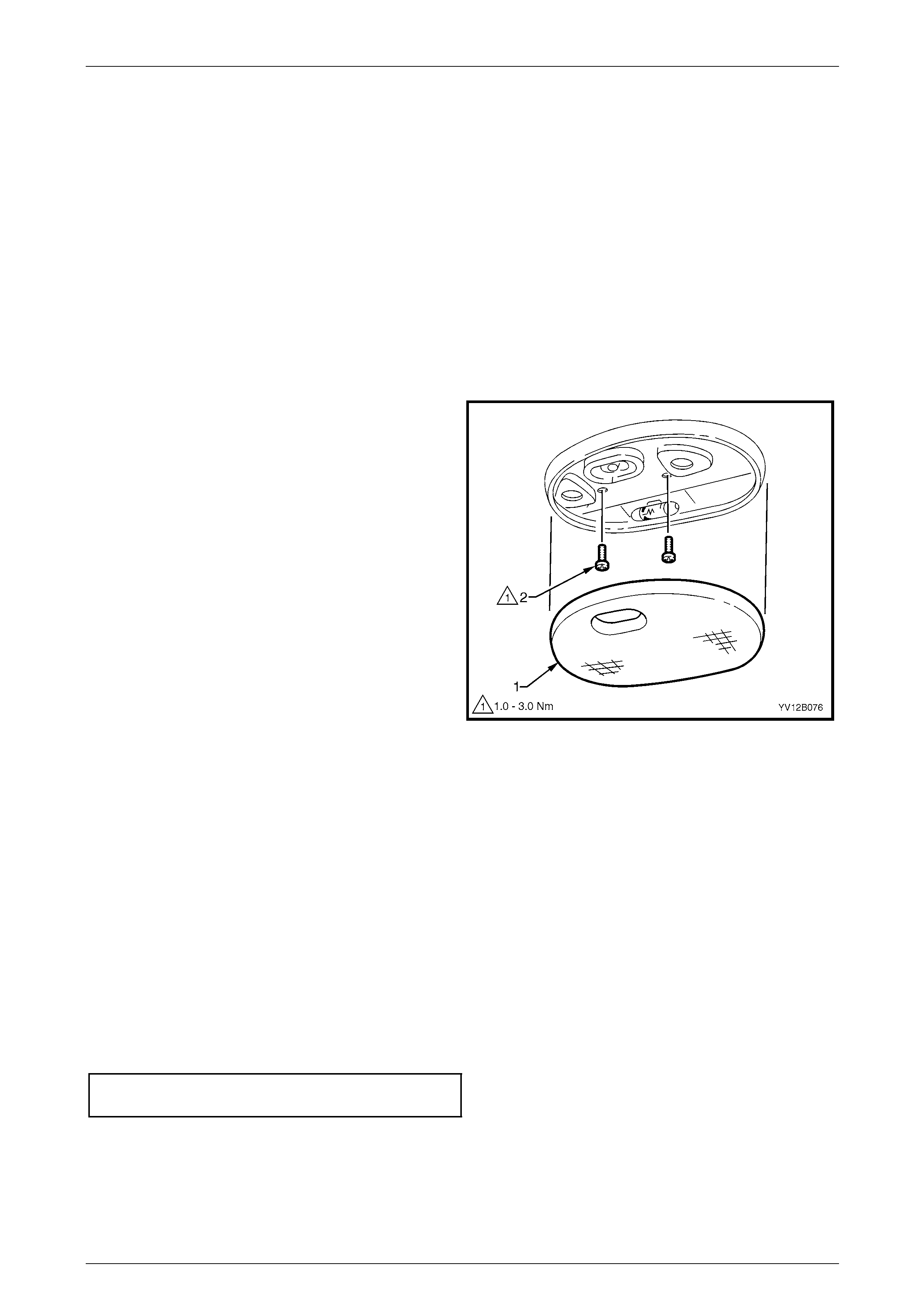
Lighting System Page 12B–98
Page 12B–98
8.6 Dome Lamp Assembly
NOTE
The dome lamp assembly is fitted only to
Level 1 Utility and Level 1 Regular Cab vehicles.
For other vehicles, refer to 8.8 Roof Console
Assembly.
LT Section No. — 02–780
Bulb Replace
1 Remove fusible link F102 from the engine compartment fuse and relay panel assembl y,
refer to Section 12O Fuses, Relays and Wiring Harnesses.
2 Using a fine-bladed screwdriver, start at the centre
notch in the lens (1) and prise the lens from the dome
lamp assembly bulb mounting plate. Use the
screwdriver in the other t wo notches to remove the
lens.
3 Replace the bulb.
4 Carefully install the lens to the dome lamp assembly
bulb mounting plate, ensuring it snaps into place.
Check the lens is flush with the dome lamp assembly.
5 Install fusible link F102 on the engine compartment
fuse and relay panel assembly.
6 Check the dome lamp assembly operation.
Figure 12B – 94
Remove
1 Remove fusible link F102 from the engine compartment fuse and relay panel assembl y,
refer to Section 12O Fuses, Relays and Wiring Harnesses.
2 Using a fine-bladed screwdriver, start at the centre notch in the lens (1) and prise the lens from the dome lamp
assembly bulb mounting plate . Use the screwdriver in the other two notches to remove the lens.
3 Remove both attaching screws (2) from the dome lam p asse mbly.
4 Pull the dome lamp assembly down and disconnect the dome lamp assembly wiring h arness connector from the
dome lamp assembly bulb mounting pl ate.
Reinstall
Reinstallation of the dome lamp assembly is the reverse of the removal procedure, notin g the following:
1 Tighten the attaching screws to the correct torque specification.
Dome lamp assembly attaching
screw torque specification...........................1.0 – 3.0 Nm
2 Check the dome lamp assembly operation.
3 Ensure the lens is installed flush with the lamp assembly.
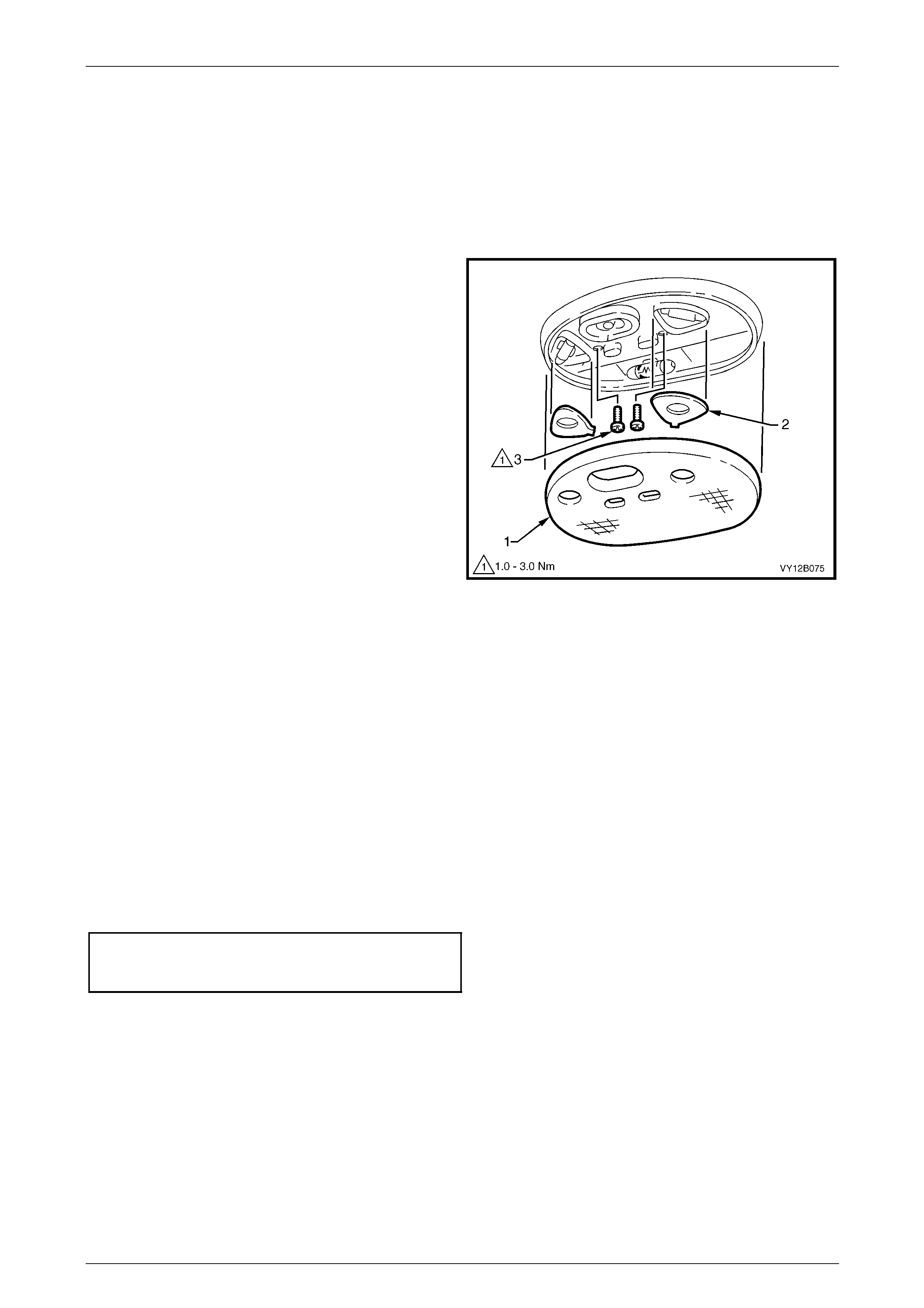
Lighting System Page 12B–99
Page 12B–99
8.7 Dome and Reading Lamp Assembly
LT Section No. — 02–780
Bulb Replace
1 Remove fusible link F102 from the engine compartment fuse and relay panel assembl y,
refer to Section 12O Fuses, Relays and Wiring Harnesses.
2 Using a fine-bladed screwdriver, start at the centre
notch in the lens (1) and prise the lens from the dome
and reading lamp assembly bulb mounting plate. Use
the screwdriver in the other two notches to remove the
lens.
3 If required, remove the bulb cover plates (2).
4 Replace the bulb.
5 If required, install the bulb cover plates.
6 Carefully install the lens to the dome and reading lamp
assembly, ensuring it snaps into place. Check the lens
is flush with the dome and reading lamp assembly.
7 Install fusible link F102 on the engine compartment
fuse and relay panel assembly.
8 Check the dome and reading l amp assembly
operation.
Figure 12B – 95
Removal
1 Remove fusible link F102 from the engine compartment fuse and relay panel assembl y,
refer to Section 12O Fuses, Relays and Wiring Harnesses.
2 Using a fine-bladed screwdriver, start at the centre notch in the lens (1) and prise the lens from the dome and
reading lamp assembly bulb mounting plate. Use the screwdriver in the other two notches to remove the lens.
3 Remove both attaching screws (3) from the dome and reading lamp assembly.
4 Pull the dome and reading l amp assembly down and disconnect the dome and re ading lamp assembly wiring
harness connector from the dome and reading lamp assembly.
Reinstall
Installation of the dome and reading lamp assembly is the reverse of the removal procedure, noting the following:
1 Tighten the attaching screws to the correct torque specification.
Dome and Reading Lamp Assembly
Attaching Screw Torque
Specification................................................1.0 – 3.0 Nm
2 Ensure the lens is installed flush with the do m e and reading lamp assembly.
3 Check the dome and reading l amp assembly operation.
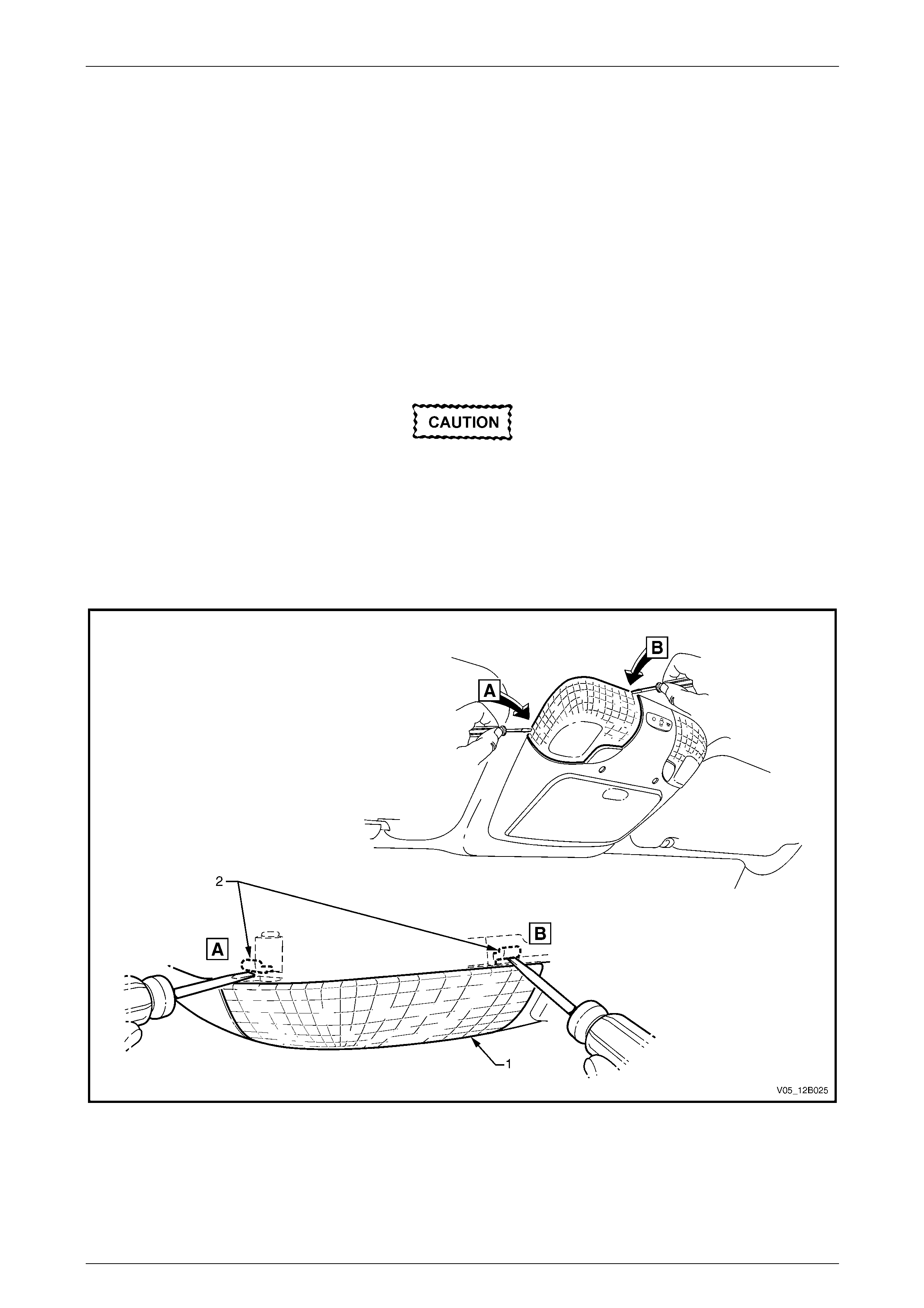
Lighting System Page 12B–100
Page 12B–100
8.8 Roof Console Assembly
LT Section No. — 02–780
Bulb Replace
NOTE
The roof console fitted to Level 1 vehicles has
blank plates fitted in place of the reading lamp
switches; operation of the reading lamps is
automatic.
1 Remove fusible link F102 from the engine compartment fuse and relay panel assembl y,
refer to Section 12O Fuses, Relays and Wiring Harnesses.
Insert the fine-bladed screwdriver only at the
points shown to engage the tabs (2) that act
as a leverage point, refer to Figure 12B – 96.
These tabs are hidden under the headlining
assembly.
2 Place a fine-bladed screwdriv er between the lens (1) and the headlining assembly, refer to Figure 12B – 96.
3 Prise the lens away from the roof console assembly.
Figure 12B – 96
4 Remove the bulb by pressing and turn ing it a quarter of a turn.
5 Insert a new bulb into the socket.
6 Install fusible link F102 on the engine compartment fuse and relay panel assembly.
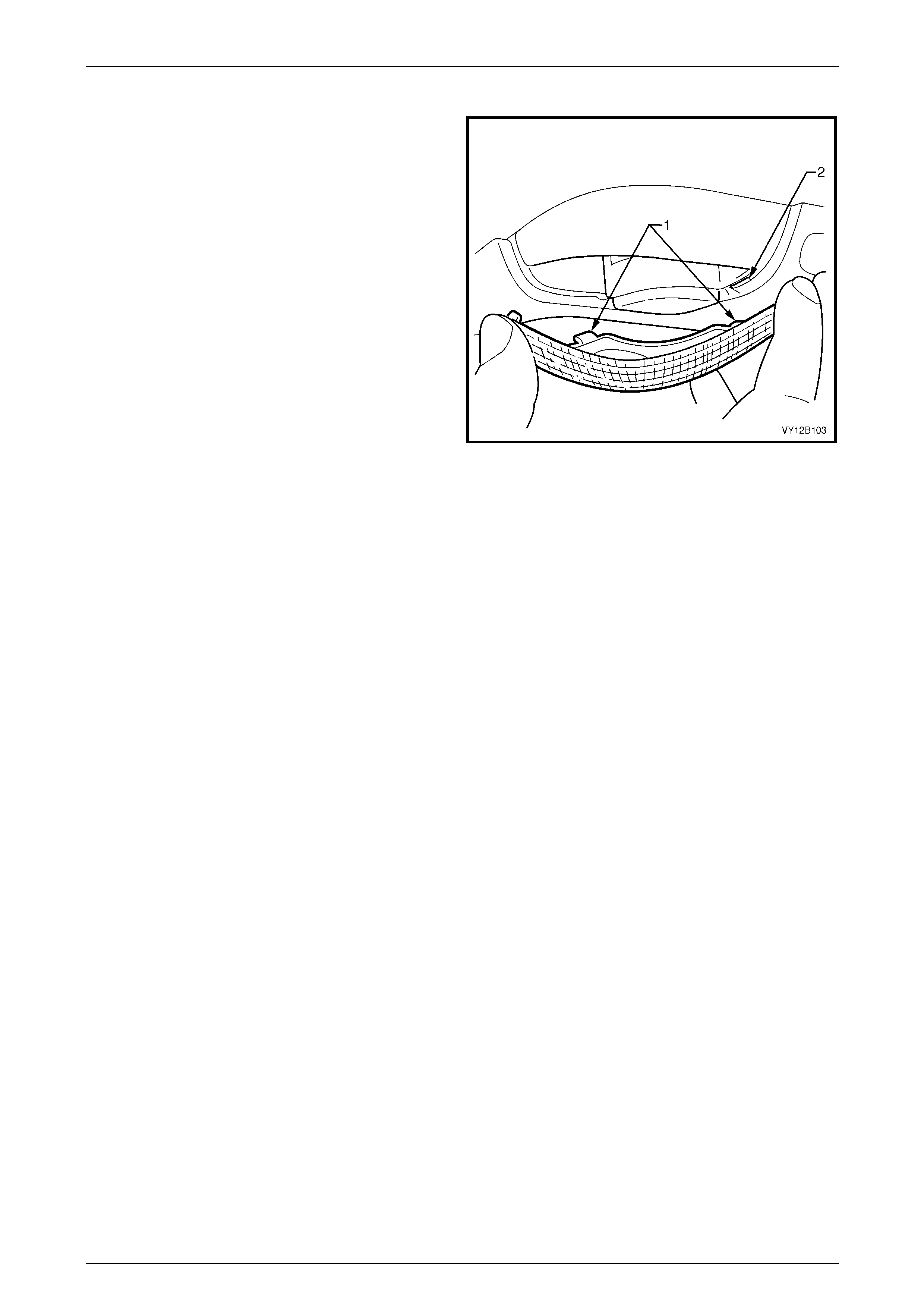
Lighting System Page 12B–101
Page 12B–101
7 Check the dome and reading l amp assembly operation.
8 Fit the lens by inserting both tabs (1) on the lens into
the slots (2) in the roof console assembly.
9 Rotate the lens and lock it into place, ensuring it is
flush with the headlining assembly.
Figure 12B – 97
Remove
To remove the roof console assembly, refer to Section 1A8 Hea dlining and Interior Trim.
Reinstall
To reinstall the roof console assembl y, refer to Section 1A8 Headlining and Interior Trim.
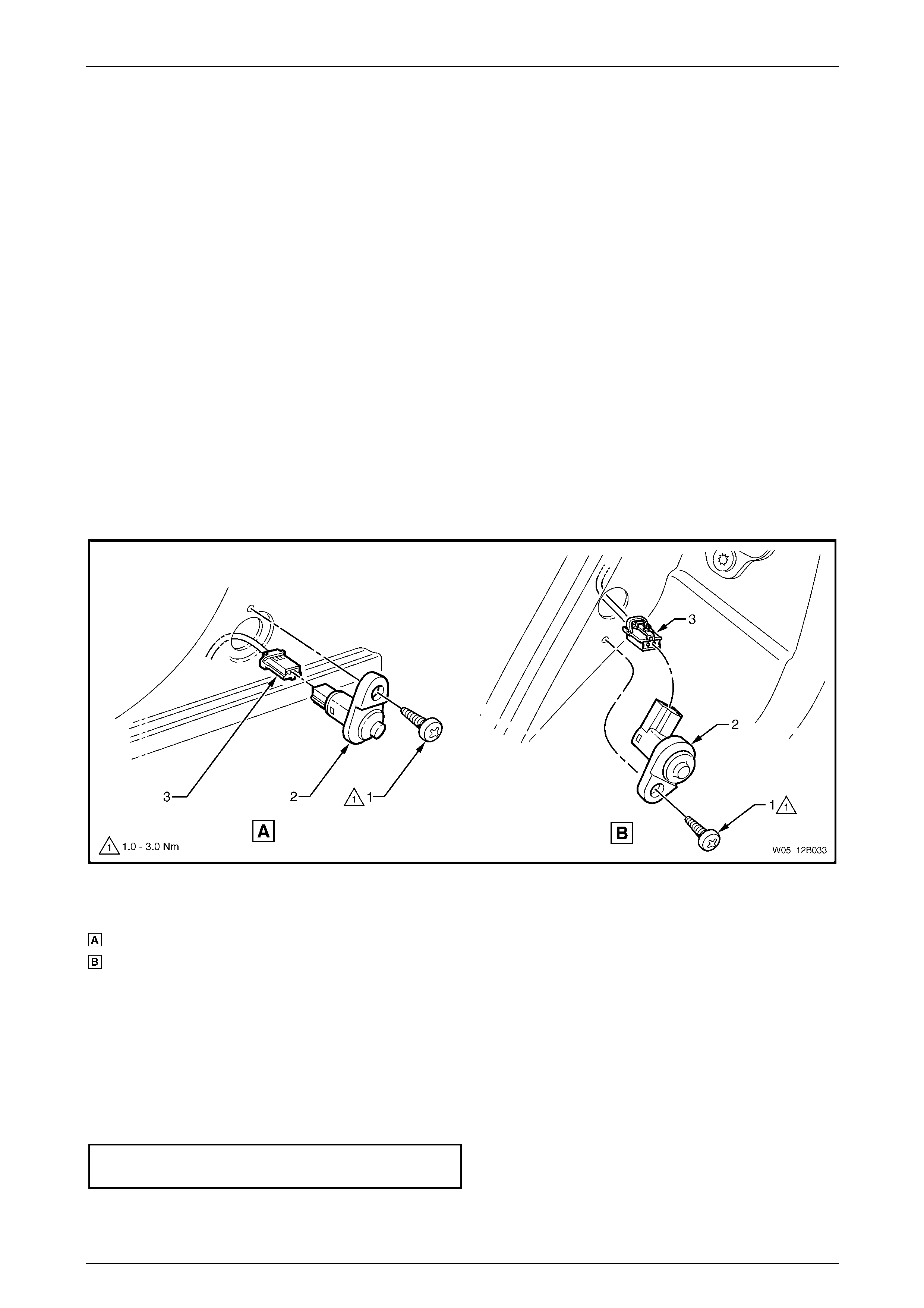
Lighting System Page 12B–102
Page 12B–102
8.9 Door Ajar Switches
The door ajar switches ar e installed in the hinge and centre pill ars. The door ajar switches provide door status data to the
BCM:
• When the plunger is pressed, an open circuit is created, providing 'door closed' data to the BCM.
• When the plunger is released , the switch closes completing a circuit to earth, providing 'door open' data to the
BCM.
To diagnose the door ajar switch circuit, refer to Section 12J Body Control Module .
This data is used by the BCM for many vehicle s ystems (for example, interior illumination dimming).
LT Section No. — 02–780
Remove
1 Remove the attaching screw (1) from the door ajar switch (2).
2 Pull the door ajar switch from the aperture and, if required, remove the doo r ajar switch wiring harness
connector (3).
NOTE
Ensure the door ajar switch wiring harness
connector does not fall into the cavity.
Figure 12B – 98
Legend
Door Ajar Switch (Front Door)
Door Ajar Switch (Rear Door)
1 Attaching Screw
2 Door Ajar Switch
3 Door Ajar Switch Wiring Harness Connector
Reinstall
Reinstallation of the door ajar switches is the reverse of the removal procedure, noting the following:
1 If required, fit the door ajar switch seal (4) to the door ajar switch, refer to Figure 12B – 98.
2 Push the door ajar switch wiring harness connector onto the door ajar switch.
3 Tighten the attaching screw to the correct torque specification.
Door ajar switch attaching
screw torque specification...........................1.0 – 3.0 Nm
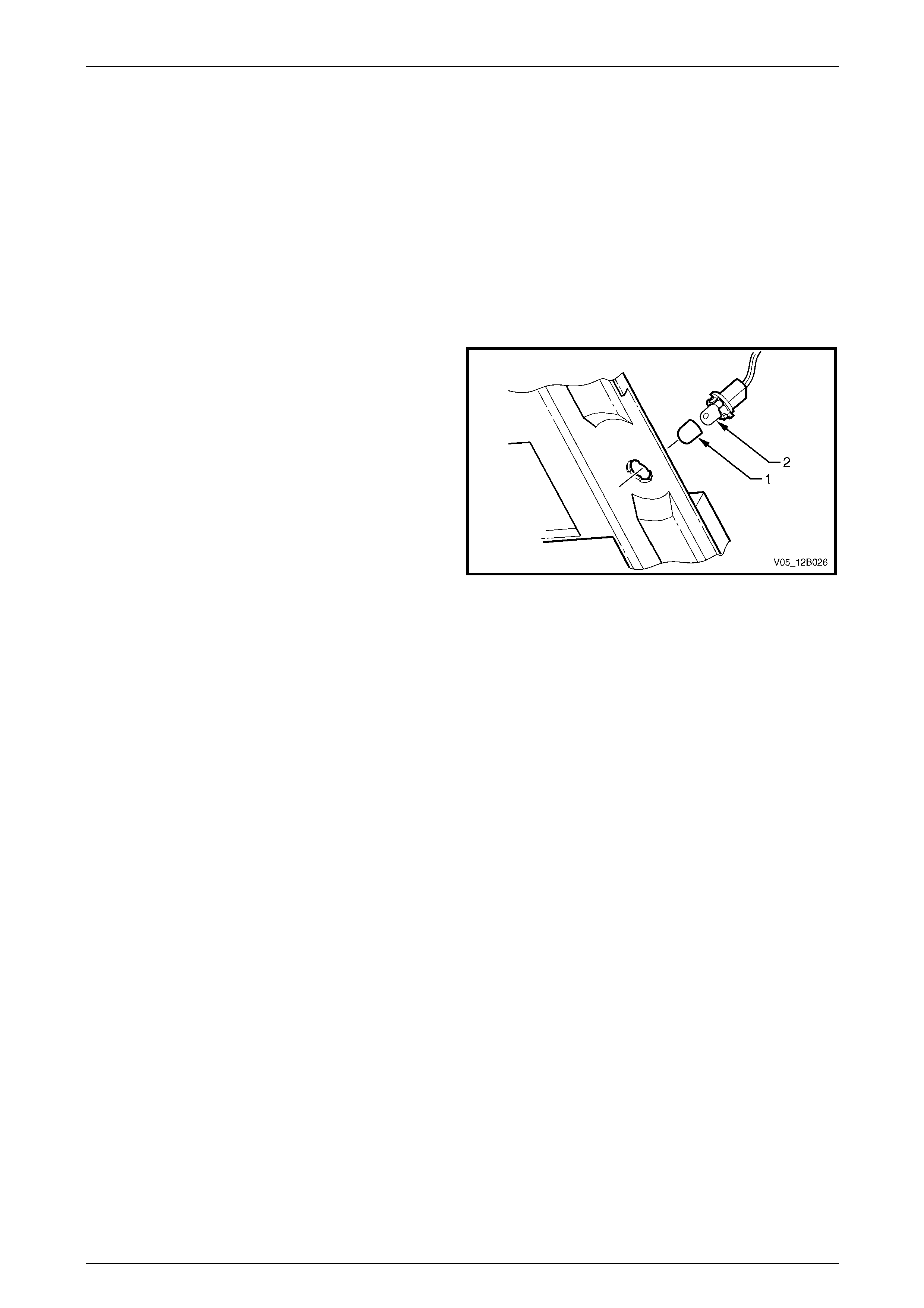
Lighting System Page 12B–103
Page 12B–103
8.10 Stepwell Lamps
LT Section No. — 02–780
Stepwell lamps are located on either side of the vehicle and are attached to the instrument panel lower trim plate
assemblies. The stepwell bulb sockets are pa rt of the body wiring harness.
Replace
1 Remove fusible link F102 from the engine compartment fuse and relay panel assembl y,
refer to Section 12O Fuses, Relays and Wiring Harnesses.
2 Remove the relevant instrument panel lower trim plate assembly,
refer to Section 1A3 Instrument Panel and Consol e.
3 Pull the bulb sleeve off the bulb and pull the bulb from
the bulb socket.
4 Insert a new bulb into the bulb socket and fit the bulb
sleeve to the bulb.
5 Check the operation of the bulb.
6 Install the instrument panel lower trim plate assembly,
refer to Section 1A3 Instrument Panel and Consol e.
Figure 12B – 99
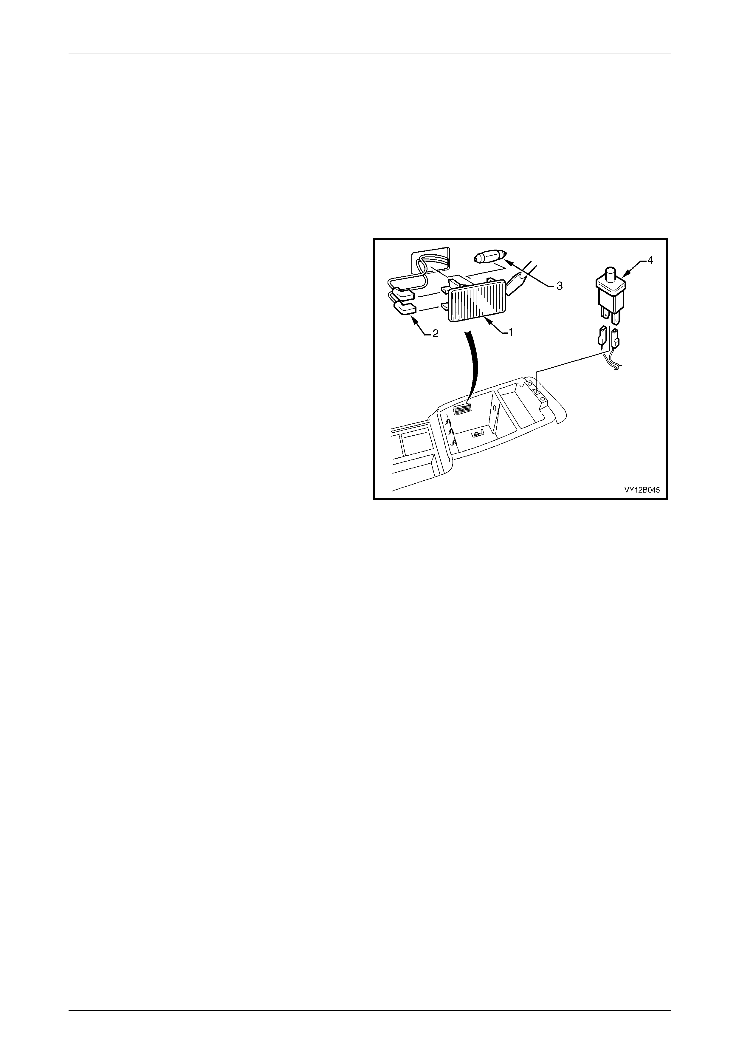
Lighting System Page 12B–104
Page 12B–104
8.11 Floor Console Compartment Lamp
Assembly
LT Section No. — 02–780
Remove
1 Remove fusible link F102 from the engine compartment fuse and relay panel assembl y,
refer to Section 12O Fuses, Relays and Wiring Harnesses.
2 Prise the floor console compartment lamp
assembly (1) from the side of the floor console
compartment using a fine-bladed screwdriver.
3 Disconnect the floor console compartment la mp wiring
harness connectors (2) from the floor console
compartment lamp assembly. Check the lamp
assembly for damage and replace if necessary.
NOTE
Ensure the floor console compartment lamp
assembly wiring harness connectors do not fall
inside the floor console cavity.
4 If necessary, remove the bulb (3) from the floor
console compartment lamp assembly by pressing the
metal contact.
Figure 12B – 100
Reinstall
Reinstallation of the floor console compartment lamp assembly is the reverse of the removal procedure, noting the
following:
1 Insert a new bulb in the floor console compartment lamp assembly if required.
2 Ensure the lens is flush with the floor console compartme nt side.
3 Check the floor console compartment lamp assembly operation.

Lighting System Page 12B–105
Page 12B–105
8.12 Floor Console Compartment Lamp
Switch Assembly
LT Section No. — 02–780
Remove
1 Remove fusible link F102 from the engine compartment fuse and relay panel assembl y,
refer to Section 12O Fuses, Relays and Wiring Harnesses.
2 Prise the floor console compartment lamp switch assembly (4) from the top of the floor console compartment using
a fine-bladed screwdriver, refer to Figure 12B – 100.
3 Disconnect the floor console compartment lamp switch assembly wiring harness from the floor console
compartment lamp assembly. Check the floo r console compartment lamp switch assembly for damage and replace
if necessary.
NOTE
Ensure the floor console compartment lamp
switch assembly wiring connector does not fall
inside the floor console cavity.
Reinstall
Reinstallation of the floor console compartment lamp switch assembly is the reverse of the removal procedure. Check
the floor console compartment lamp switch assembly operation.
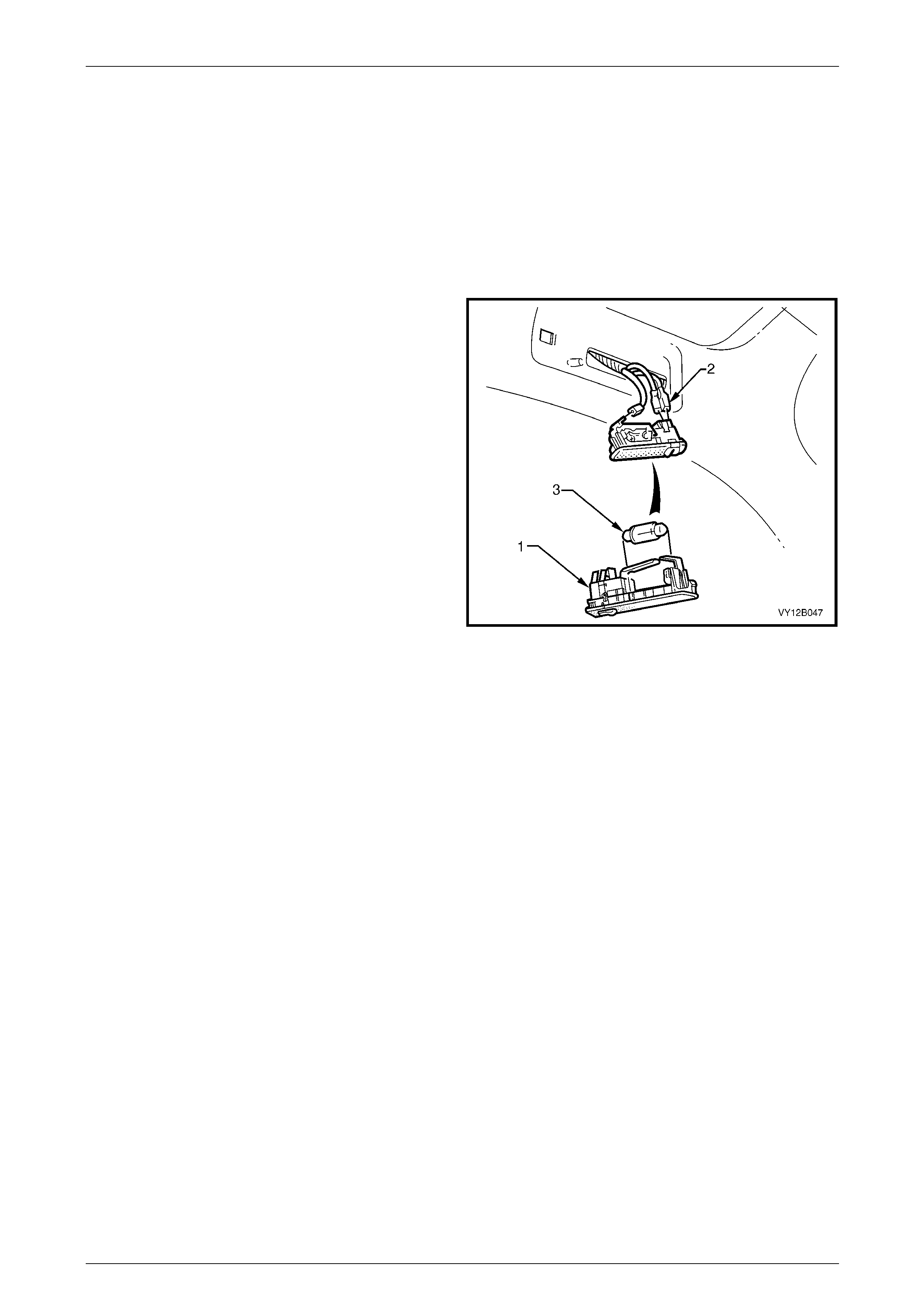
Lighting System Page 12B–106
Page 12B–106
8.13 Roof Rail Courtesy and Reading Lamp
Assembly
LT Section No. — 02–780
Remove
1 Remove fusible link F102 from the engine compartment fuse and relay panel assembl y,
refer to Section 12O Fuses, Relays and Wiring Harnesses.
2 Prise the roof rail courtesy and reading lamp
assembly (1) from the lens surround using a fine-
bladed screwdriver.
3 Disconnect the roof rail courtesy and reading lamp
assembly wiring harness connectors (2) from the roof
rail courtesy and reading lamp assembly. Check the
roof rail courtesy and reading lamp assembly for
damage and replace if necessary.
4 If necessary, remove the bulb (3) from the roof rail
courtesy and reading lamp assembly by pressing the
metal contact.
Figure 12B – 101
Reinstall
Reinstallation of the roof rail courtesy and reading lamp assembly is the reverse of the removal proced ure, noting the
following:
1 If required, insert a new bulb into the roof rail courtesy and reading lamp assembly.
2 Ensure the lens is flush with the lens surround.
3 Check the roof rail courtesy and reading l amp assembly operation.
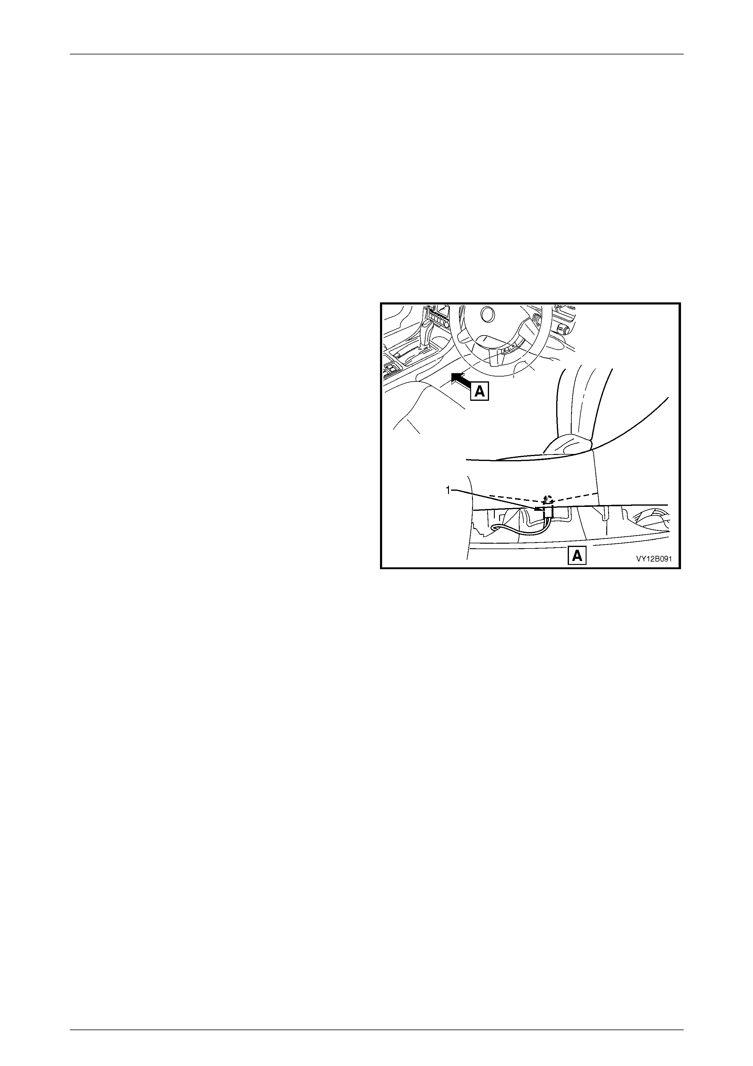
Lighting System Page 12B–107
Page 12B–107
8.14 Automatic Transmission Control
Position Lamp
LT Section No. — 04–190
Replace
1 Remove fusible link F102 from the engine compartment fuse and relay panel assembl y,
refer to Section 12O Fuses, Relays and Wiring Harnesses.
2 Move the front seats to the rearmost position.
3 Remove the right-hand instrument panel l ower extension side trim panel (2),
refer to Section 1A3 Instrument Panel and Consol e.
4 Remove the bulb socket (1) from the automatic
transmission control assembly by twisting
anticlockwise and pulling it down.
5 Insert a new bulb into the bulb socket.
6 Install fusible link F102 on the engine compartment
fuse and relay panel assembly.
7 Check the operation of the bulb by turning on the park
lamps.
8 Insert the bulb socket into the automatic transmission
control assembly and twist to lock into position.
9 Install the instrument panel lower e xtension side trim
panel, refer to Section 1A3 Instrument Panel and
Console.
Figure 12B – 102

Lighting System Page 12B–108
Page 12B–108
8.15 Ignition Lock Cylinder Bulb
LT Section No. — 02–780
Replace
1 Remove fusible link F102 from the engine compartment fuse and relay panel assembl y,
refer to Section 12O Fuses, Relays and Wiring Harnesses.
2 Remove the following items, refer to Section 9 Steering:
a steering column covers,
b ignition barrel and lock cylinder, and
c theft deterrent receiver assembly.
3 Replace the ignition lock c ylinder bulb.
4 Insert the bulb socket into the theft deterrent receiver assembly, then install the theft deterrent receiver assembly
into the steering column lower cover.
5 Install fusible link F102 on the engine compartment fuse and relay panel assembly.
6 Check the ignition lock cylinder bulb operation.
7 Replace the following items, refer to Section 9 Steering:
a theft deterrent receiver assembly,
b ignition barrel and lock cylinder, and
c steering column covers.

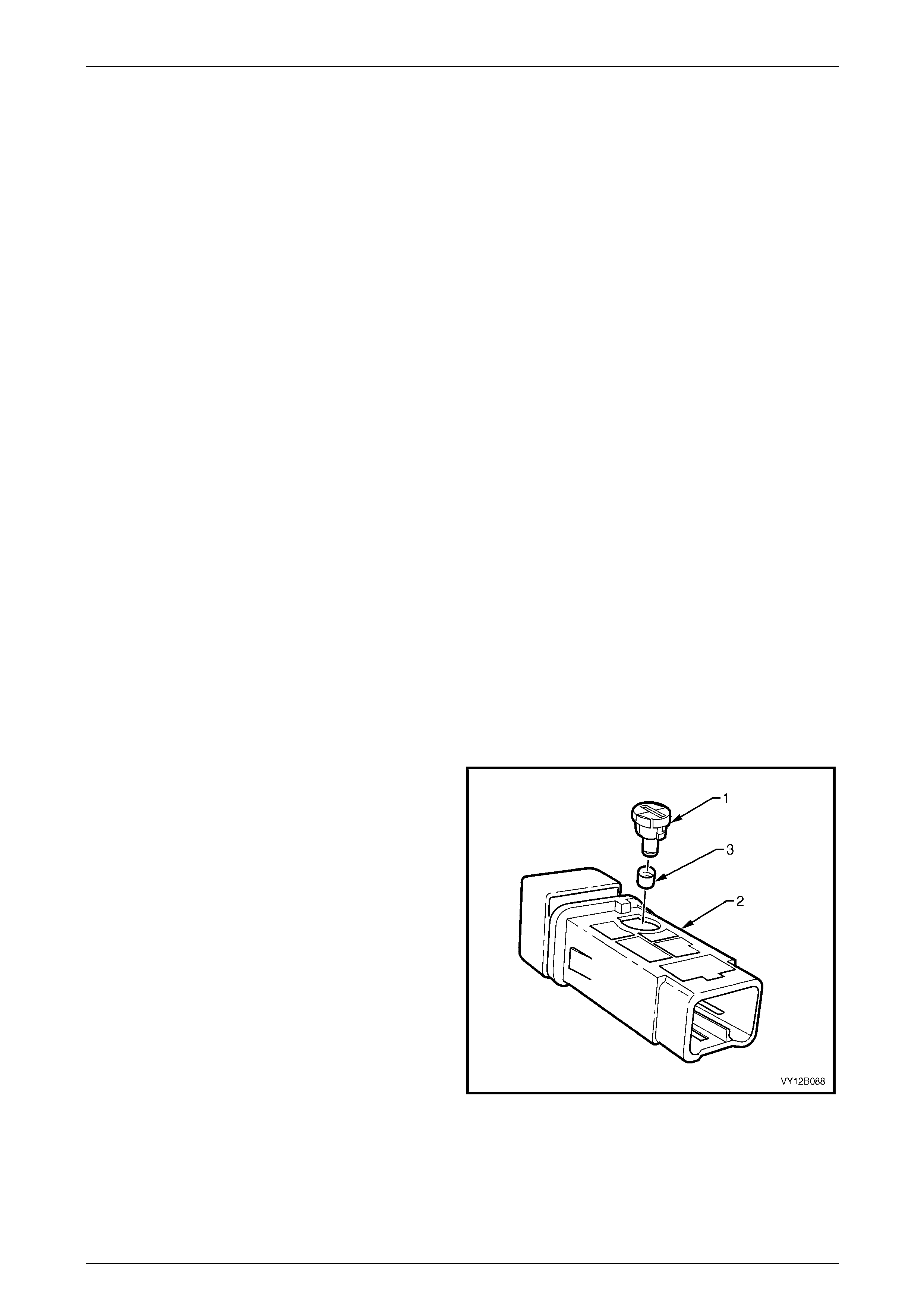
Lighting System Page 12B–110
Page 12B–110
8.17 Switch Illumination
LT Section No. — 02–780
The headlamp switch, trip computer switch and side window switch are illumin ated with filament bulbs, but the switches
are sealed units and the bulbs are not serviceable, refer to Figure 12B – 8.
Auxiliary Switch Bulbs
Spaces are availabl e for auxiliary switches in the:
• floor console compartment cover assembly:
• hill descent switch (AWD Wagon on ly),
• electronic stability program (ESP) switch (5-speed automatic transmission),
• police lights-out switch (not illuminated), and
• T/C switch (manual transmission onl y); and
• behind the automatic transmission selector:
• electronic stability program (ESP) switch (4-speed automatic transmission),
• PWR switch, and
• T/C switch or A/S switch.
Replace
1 Ensure the ignition switch is in the OFF position.
2 Remove fusible link F102 from the engine compartment fuse and relay panel assembl y,
refer to Section 12O Fuses, Relays and Wiring Harnesses.
3 If required, remove the navigation system equipment, refer to Section 12L Navigation System.
4 Remove the floor console front compartment cover assembly, refer to Section 1A3 Instrument Panel and Console.
5 Remove the switch from the floor console front compartment cover assembly.
6 Using a fine-bladed screwdriver inserted into the
groove on the bulb socket, twist the bulb socket and
bulb assembly (1) anticlockwise and remove it from
the switch assembly (2).
7 Remove the green bulb sleeve (3) from the bulb
socket and bulb assembly.
8 Check the bulb sleeve for splits and replace it if
necessary.
9 Fit the bulb sleeve to the new bulb socket and bul b
assembly.
10 Insert the bulb socket and bulb assembly into the
switch assembly.
11 Connect the switch assembly to the wiring harness
connector in the floor console compartme nt cover
assembly.
12 Install fusible link F102 on the engine compartment
fuse and relay panel assembly. Figure 12B – 103
13 Check the switch assembly operati on while the park lamps are on.
14 Replace the floor console front compartment cover assembly, refer to Section 1A3 Instrument Panel and Console.
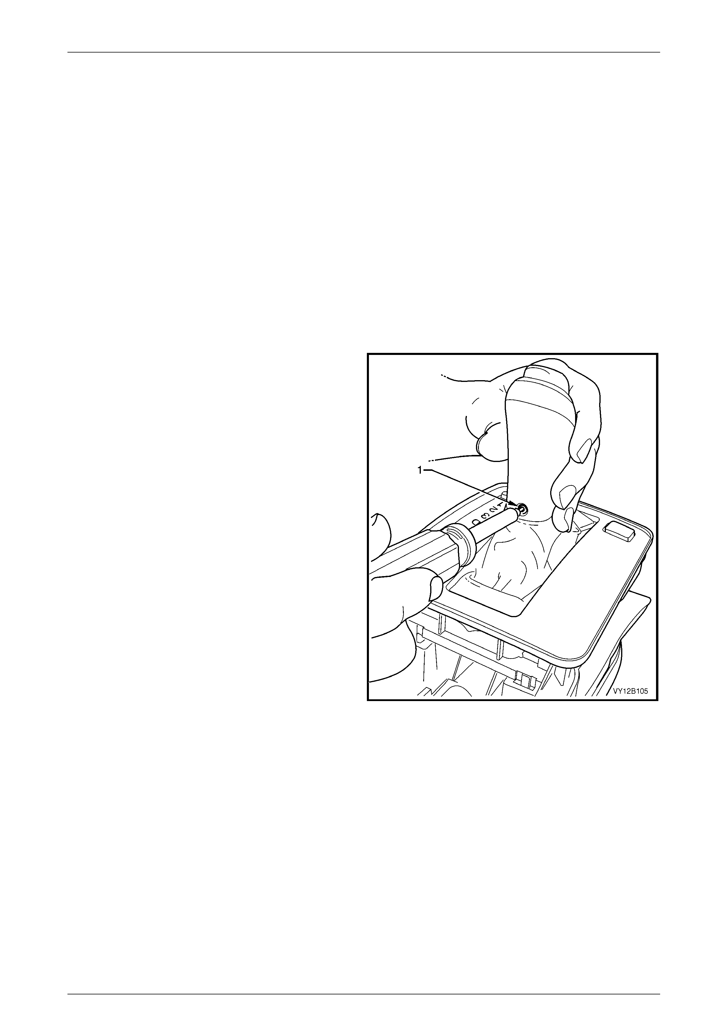
Lighting System Page 12B–111
Page 12B–111
T/C or A/S and PWR Switch Bulbs
Replace
Two switch assemblies can be installed into the automatic control selector indicator assembly:
• PWR switch, and
• either the T/C switch or the A/S switch.
The PWR switch is located at the rear of the shift lever lower housi ng on the side opposite the transmission selector lens
(PRNDL) on vehicles with automatic transmi ssion.
Depending on the model level of the vehicle, the T/C switch (or A/S switch) is located at the rear of the shift lever lower
housing on the same side as the transmission selector lens (PRNDL).
1 Ensure the ignition switch and the headlamp switch assembly are in the OFF position.
2 Ensure the park brake is applied.
3 Remove the floor console compartment cover assembly, refer to Section 1A3 Instrument Panel and Console.
4 Shift the transmission selector into the drive position.
5 Remove the Torx-head scre w (1) using a No. 25 Torx
bit from the transmission selector.
Figure 12B – 104
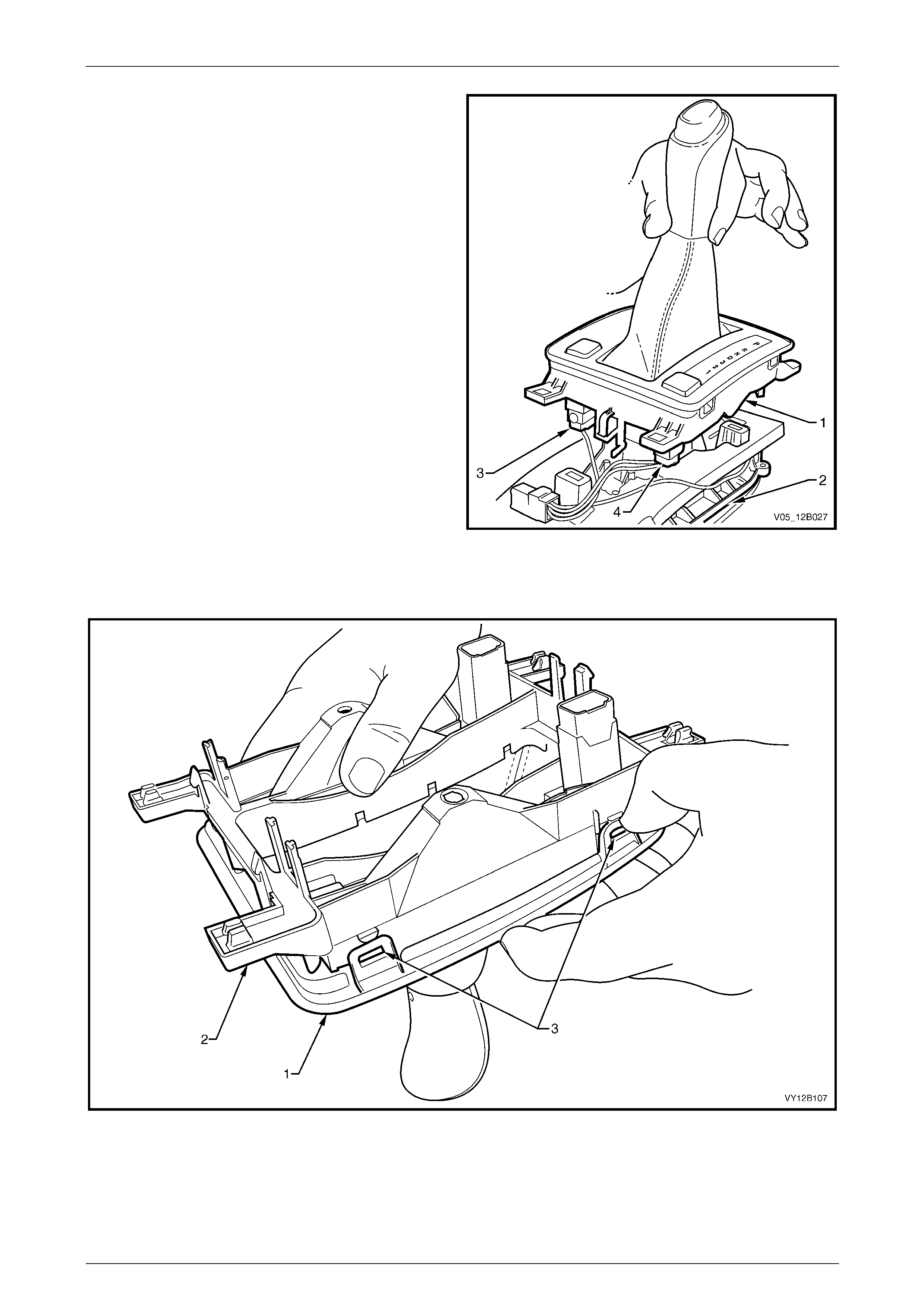
Lighting System Page 12B–112
Page 12B–112
6 Unclip the upper and lower transmission selector
housing assembly (1) from the transmissio n selector
base assembly (2) at three points.
7 Disconnect the wiring harness from the PW R
switch (3) and, if fitted, T/C switch or A/S switch (4).
8 Twist the automatic transmission control po sition lamp
anticlockwise and pull down, then remove it from the
lower transmission selector housing.
Figure 12B – 105
9 With the shift lever knob hanging down, unclip the upper transmission selector housing (1) from the lower
transmission selector housing (2) at four points (3), refer to Figure 12B – 106.
Figure 12B – 106
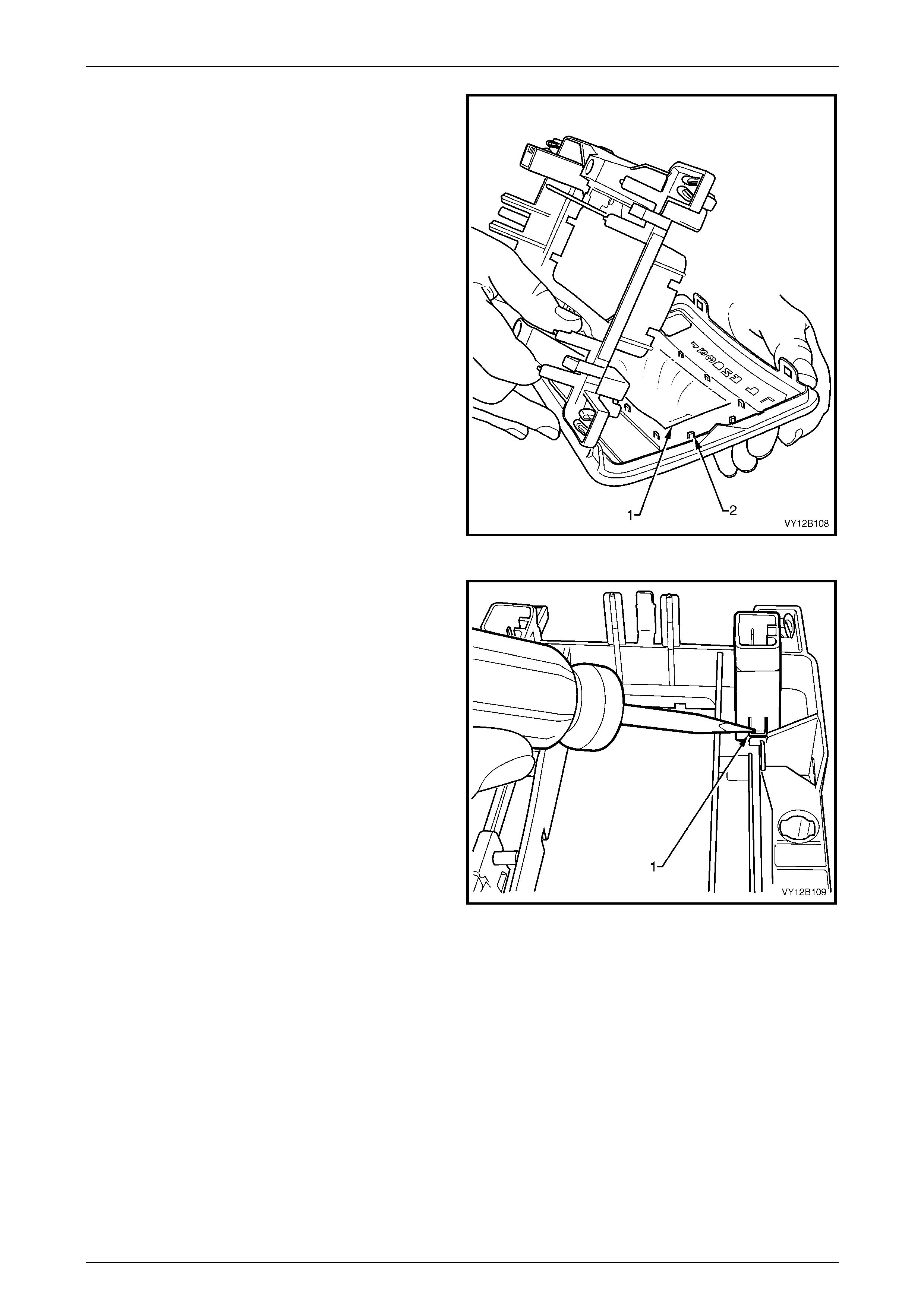
Lighting System Page 12B–113
Page 12B–113
10 Lift the lower transmission selector housin g from the
upper transmission selector housing.
NOTE
Leave the upper transmission selector housing
upside down (that is, with the shifter lever knob
keeping the boot (1) taut). This reduces the risk
of the boot coming a way from the tabs (2) on the
upper transmission selector housing.
Figure 12B – 107
11 Using a thin, flat-bladed screwdriver, press the tab (1)
on either side of the switch assembly and remove it
from the lower transmission selector housing.
NOTE
Figure 12B – 108 shows removal of the
T/C switch or A/S switch.
Figure 12B – 108
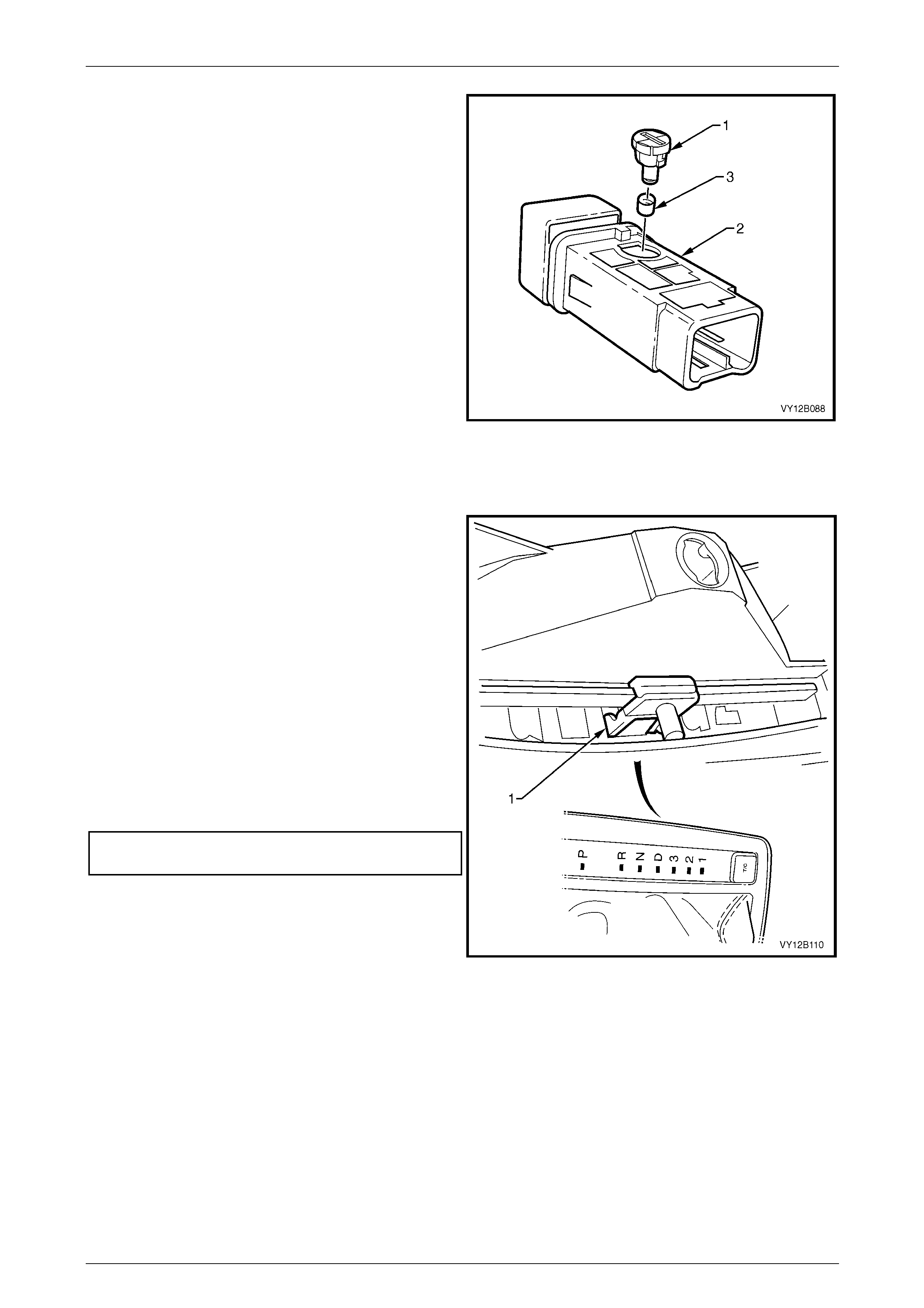
Lighting System Page 12B–114
Page 12B–114
12 Using a fine-bladed screwdriver inserted into the
groove on the bulb socket, twist the bulb socket and
bulb assembly (1) anticlockwise and remove it from
the switch assembly (2).
13 Remove the green bulb sleeve (3) from the bulb
socket and bulb assembly.
14 Check the bulb sleeve for splits and replace it if
necessary.
15 Fit the bulb sleeve to the new bulb socket and bul b
assembly.
16 Insert the bulb socket and bulb assembly into the
switch assembly.
17 Connect the switch assembly to the wiring harness
connector. Turn on the park lamps and check the lamp
operation. Disconnect the wiring harness connector
from the switch assembly.
18 Fit the switch back into the lower transmission selector
housing, ensuring it locks correctl y in place. Figure 12B – 109
19 Turn the lower transmission selector housing upside down. Clip the upper transmission selector housing back into
place, ensuring the skirt is still placed over the tabs, refer to Figure 12B – 107.
20 Place the carrier indicator (1) so the 'D' is selected.
21 Place the upper and lower transmission sel ector
housing assembl y over the shift lever knob and ensure
the shift lever knob is correctly seated on the shift
lever knob.
22 Connect the wiring harness to the PWR switch (and
T/C switch or A/S switch, if fitted).
23 Insert the automatic transmission control po s ition lamp
and turn clockwise to lock it into place.
24 Clip the upper and lower transmission selector
housing assembl y to the transmission selector base
assembly and ensure the carrier indicator engages
correctly in the slot.
25 Tighten the transmission selector knob attaching
screw to the correct torque specification.
Transmission selector knob
attaching screw torque specification...........1.0 – 3.0 Nm
26 Install the floor console compartment cover assembl y,
refer to Section 1A3 Instrument Panel and Consol e.
Figure 12B – 110
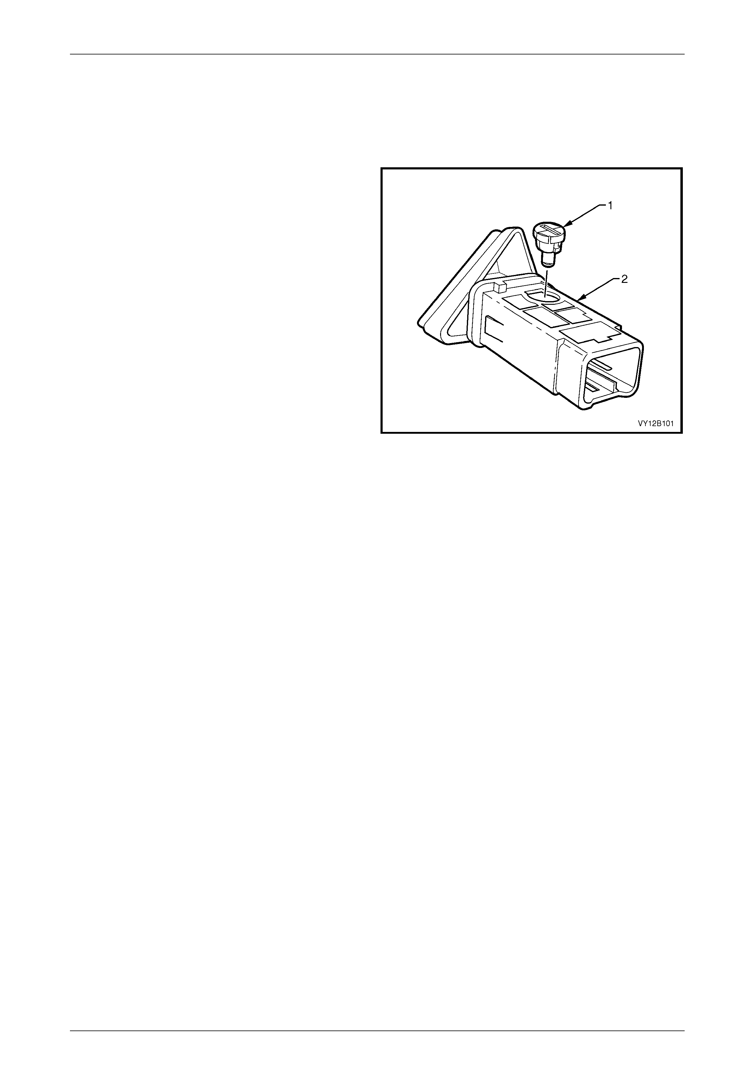
Lighting System Page 12B–115
Page 12B–115
Hazard Warning Switch Bulb
Replace
1 Remove the hazard warning switch assembly , refer to 8.23 Hazard W arnin g Switch Assembly.
2 Using a fine-bladed screwdriver inserted into the
groove on the bulb socket, twist the bulb socket and
bulb assembly (1) anticlockwise and remove it from
the hazard warning switch assembly (2).
3 Pull the bulb socket and bulb assembly from the
hazard warning switch assembly.
4 Insert the new bulb socket and bulb assembly into the
hazard warning switch assembly.
5 Connect the hazard warning switch assembl y to the
wiring harness connector.
6 Install fusible link F102 on the engine compartment
fuse and relay panel assembly.
7 Check the hazard warning lamp operation.
8 Remove fusible link F102 from the engine
compartment fuse and relay panel assembly.
Disconnect the wiring connector from the hazard
warning switch assembly. Figure 12B – 111
9 Install the hazard warning switch assembl y, refer to 8.23 Hazard Warning Switch Assembly.
10 Install fusible link F102 on the engine compartment fuse and relay panel assembly.

Lighting System Page 12B–116
Page 12B–116
8.18 Backup Lamp Switch Assembly
The backup lamp switch assembly is fitted to both manual transmission a ssembly configurations. The backup lamp
switch assembly is not adjustable and is fitted to the right-hand side of the transmission case.
If the backup lamp switch assembly requires chang ing, refer to:
• Section 7B1 Manual Transmission — V6 Engine, or
• Section 7B2 Manual Transmission — GEN III V8 Engine.

Lighting System Page 12B–117
Page 12B–117
8.19 Neutral Safety Backup Switch Assembly
The neutral safet y backup switch assembly is fitted to vehicles with automatic transmission. The neutral safety backup
switch assembly activates the backup lamps when the transmission selector is in the reverse position. If the neutral
safety backup switch assembly requires changing, refer to:
• Section 7C4 Automatic Transmission — On-vehicle Service, or
• Section 7D4 Hydramatic 4L65–E Automatic Transmission On-vehicle Servicing.
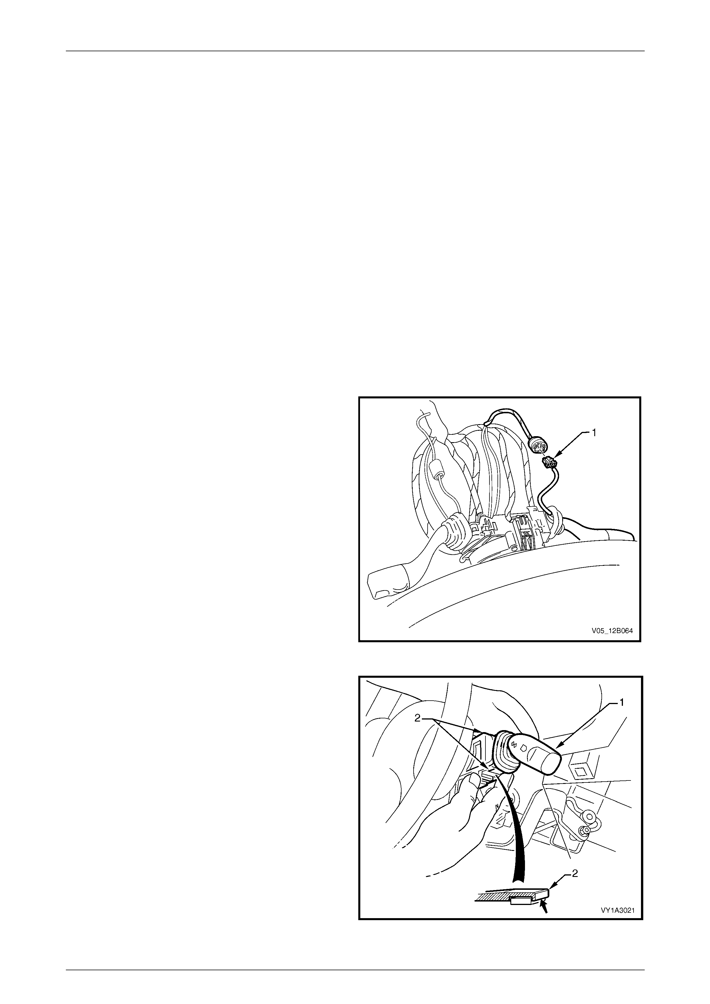
Lighting System Page 12B–118
Page 12B–118
8.20 Turn Signal Switch Assembly (and
Cruise Control if Fitted)
LT Section No. — 06–250
Two turn signal switch assemblies are available and both provide the foll owing functions:
• turn signal,
• pass, and
• high beam control.
If cruise control is fitted, cruise control switching functions are included. For more information on the cruise control
system, refer to Section 12E Cruise Control.
Remove
1 Remove fusible link F102 from the engine compartment fuse and relay panel assembl y,
refer to Section 12O Fuses, Relays and Wiring Harnesses.
2 Remove the instrument lower trim panel assembl y, refer to Section 1A3 Instrument Panel and Console.
3 Remove the steering column lower cover, refer to Section 9 Steering.
4 For turn signal switch assemblies fitted with cruise
control, disconnect the wiring harness con ne c tor (1).
Figure 12B – 112
5 Press the retaining tangs (2) on the turn signal switch
assembly (1) and pull the turn signal switch assembly
away from the steering column.
Figure 12B – 113
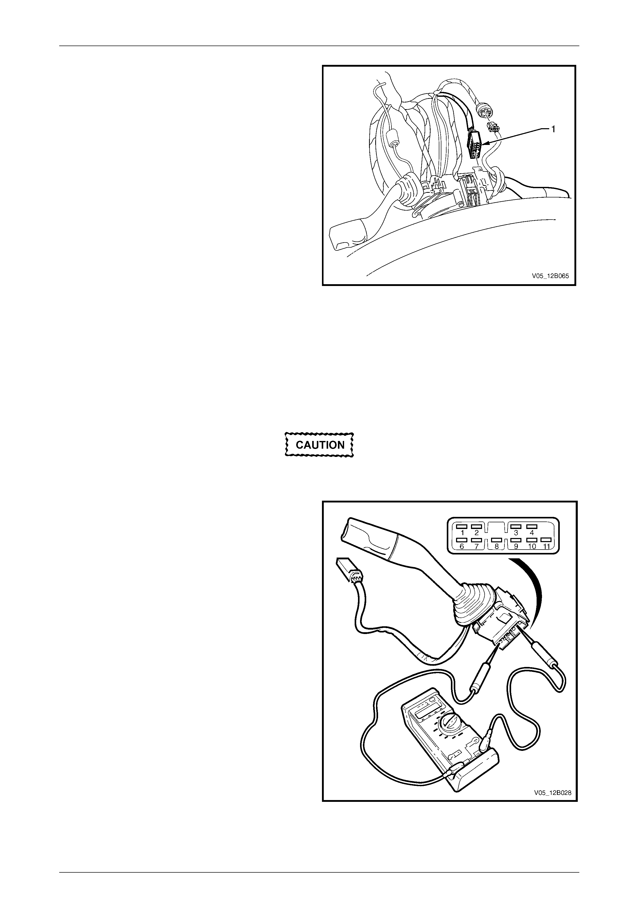
Lighting System Page 12B–119
Page 12B–119
6 Press the wiring harness connector tangs and pull the
connector (1) from the turn signal switch assembly.
Figure 12B – 114
Reinstall
Reinstallation of the turn signal switch assembly is the reverse of the removal procedure.
Testing
To test the turn signal switch assembly, use a multimeter to check the continuity.
To test the cruise control features, refer to
Section 12E Cruise Control.
1 Perform the removal procedure for the turn signal
switch assembly, refer to Remove, but do not unclip
and remove the turn signal switch assem bl y from the
steering column. With the turn signal switch assembly
attached to the steering column, a stable platform with
which to carry out the testing is provided.
2 Place the turn signal switch assembly into the
positions detailed in the following Turn Signal Switch
Assembly table, refer to Turn Signal Switch Assembly.
Position the contacts of the multimeter onto the
terminals and take the reading. Compare the
multimeter readings with the values in the table.
3 If there is continuity between any terminals o t her than
those listed, the turn signal switch assembly is faulty. If
the turn signal switch assembly fails any part of the
test, replace the faulty turn signal switch assembly
with a serviceable item. To replace the turn signal
switch assembly, press the two retaining tangs and
pull the turn signal switch assembly away from the
steering column, refer to Figure 12B – 113. Insert a
new turn signal switch assembly.
4 Perform the reinstallation procedure, refer to Reinstall.
Figure 12B – 115

Lighting System Page 12B–120
Page 12B–120
Turn Signal Switch Assembly
Turn Signal Switch Assembly
Switch
Terminals Switch
Position Indication if Switch
is Serviceable
Turn Signal Switch Terminals
9 and 6 Switch in neutral position open circuit
9 and 6 Switch in left-hand turn position continuity
9 and 10 Switch in neutral position open circuit
9 and 10 Switch in right-hand turn pos ition continuity
Headlamp Pass Terminals
1 and 4 Switch in the neutral position open circuit
1 and 4 Switch pulled to the rear in the pass positio n continuity
Headlamp High Beam Terminals
1 and 3 Switch in neutral position open circuit
1 and 3 Switch pushed forward in the hig h beam position continuity
2 and 3 Switch in neutral position continuity
2 and 3 Switch pushed forward in the high beam position open circuit

Lighting System Page 12B–121
Page 12B–121
8.21 Headlamp Switch Assembly (and Front
Fog Lamp if Fitted)
LT Section No. — 02–800
Two headlamp switch assemblies are used depending upon the level of vehicl e. One he adlamp switch assembly can
turn the front fog lamps on and off.
Vehicles fitted with front fog lamps have a fog lamp icon on the hea dlamp switch assembly.
If replacing a headlamp switch assembly,
ensure the correct type is u sed.
The headlamp switch assembly represents one equipped
with the front fog lamp function and has the fog lamp
icon (1).
The headlamp switch assembly has the following positions:
• Position A — headlamps are off.
• Position B — park lamps are on.
• Position C — headlamps are on (lo w beam).
• Position D — headlamps are controlled automatically
by the BCM.
• Positions E / F — instrumentation lighting brightens
when the dimmer switch is moved position E to F.
• Positions E / G — Instrumentation lighting dims when
the dimmer switch moves from position E to G.
• Position B, C or D — Front fog lamps are turned on
when the switch is pulled out to position H. Figure 12B – 116
NOTE
The front fog lamps do not illuminate if the
headlamp s wit ch assembly is pulled to position H
while also in position A.
Remove
For removal of the headlamp switch assembly, refer to Section 1A3 Instrument Panel and Console.
Reinstall
Reinstallation of the headlamp switch assembly is the reverse of the removal procedure. Ensure the headlamp switch
assembly retaining tangs are correctly seated.

Lighting System Page 12B–122
Page 12B–122
Testing
To test the headlamp s witch assembly, use an ohmmeter to check the continuity or resistance when the switch is
actuated.
NOTE
Refer to Figure 12B – 116 an d Headlamp Switch
Assembly (and Front Fog Lamp if Fitted) for
headlamp s witch assembly positions.
1 Perform the removal procedure for the headlamp
switch assembly, refer to Section 1A3 Instrument
Panel and Console.
2 Place the headlamp switch assembly in the positions
detailed in the table, refer to Headlamp Switch
Assembly (and Front Fog Lamp if Fitted). Position the
contacts of the ohmmeter onto the terminals and take
the reading; compare the readings with those in the
Headlamp Switch Assembly (and Front Fog Lamp if
Fitted) table.
3 If there is continuity between any terminals o t her than
those listed, the headlamp switch assembl y is faulty. If
the headlamp switch assembly fails any part of the
test, replace the headlamp s witch assembl y with a
serviceable item.
4 Perform the reinstallation procedur e, refer to
Section 1A3 Instrument Panel and Co nsole.
Figure 12B – 117
Headlamp Switch Assembly (and Front Fog Lamp if Fitted)
Headlamp Switch Assembly (and Front Fog Lamp if Fitted)
Switch
Terminals Switch
Position Indication if Switch
is Serviceable
5 and 8 Switch in park lamp position; position B Continuity
5 and 8 Continuity
5 and 4 S witch in low beam position; position C Continuity
2 and 4 Continuity
2 and 8 Switch in AUTO position; position D Continuity
7 and 8 Dimmer in neutral position; p osition E 2.68 kΩ
7 and 8 Dimmer in high position, position F 5.36 kΩ
7 and 8 Dimmer in low position, position G 0 kΩ
The headlamp switch assembly must be in park,
low beam or AUTO position for the front fog
lamps to be activated.
5 and 6 Switch with front fog lamps activated; position H and
either park lamps or headlamps (low beam) on Continuity
2 and 6 Switch with front fog lamps activated; position H and
switch in AUTO position Continuity
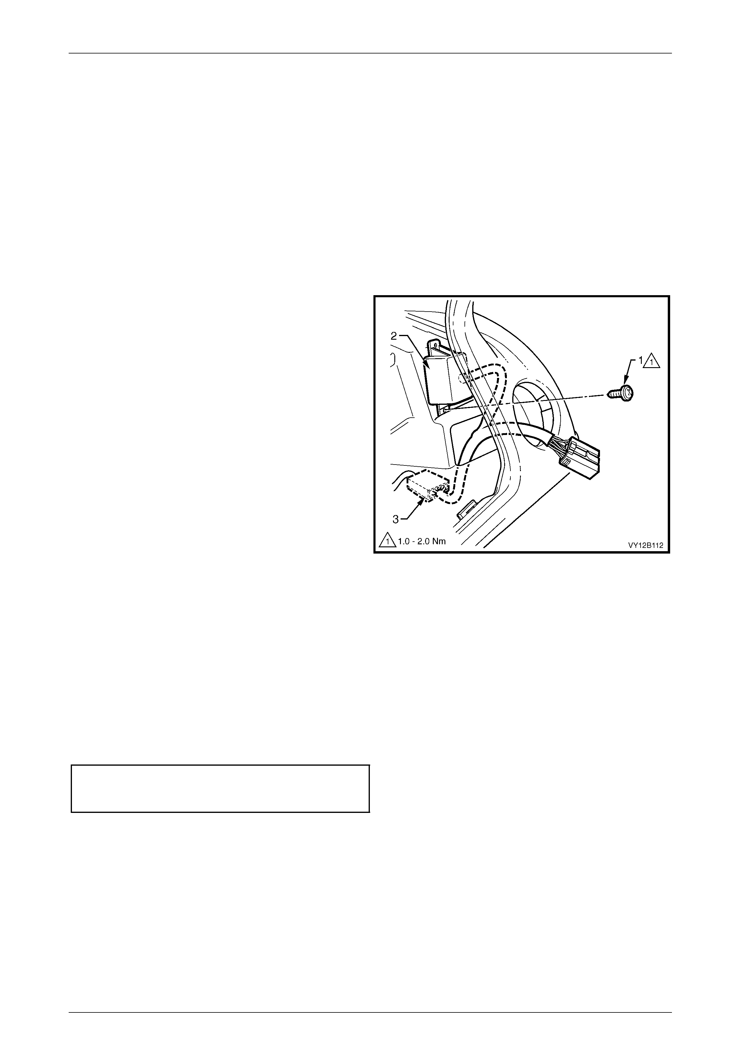
Lighting System Page 12B–123
Page 12B–123
8.22 Daylight Running Lamp Assembly
(Option T82)
LT Section No. — 02–780
For vehicles with the daylight running lamp assembly (option T82), the headlamps operate whenever the ignition s witch
is on.
Remove
1 Remove fusible link F102 from the engine compartment fuse and relay panel assembl y,
refer to Section 12O Fuses, Relays and Wiring Harnesses.
2 Remove the instrument panel lower trim panel assembly and instrument cluster trim assembly,
refer to Section 1A3 Instrument Panel and Consol e.
3 To separate the daylight running lamp assembly from
the instrument panel:
a Remove the attaching screw (1) from the
daylight running lamp assembly and the
instrument panel using a magnetic-tipped
screwdriver. Access the attaching screw through
the headlamp switch assembly cavity.
b Prise the daylight running lamps assembly (2)
away from the instrument panel.
NOTE
The daylight running lamp assembly is fastened
to the instrument panel with double-sided ta pe. lf
necessary, use a flat-bladed screwdriver to
assist removal.
Figure 12B – 118
4 To disconnect the headlamp switch assembly main wiring harness connector (3), carefully remove the daylight
running lamp assembly wiring harness from behind the instrument panel.
5 Press the headlamp switch assembly main wiring harness connector tang and pull the connectors apart.
6 Remove the daylight running lamp assembly.
Reinstall
Reinstallation of the daylight running lamp assembly and daylight running lamp assembly wiring harn ess is the reverse of
the removal procedure, notin g the following:
1 Tighten the attaching scre w to the daylight running lamp assembly to the correct torque specification.
Daylight running lamp assembly
to instrument panel attaching
screw torque specification...........................1.0 – 2.0 Nm
2 Check the daylight running lamp assemb ly operation.
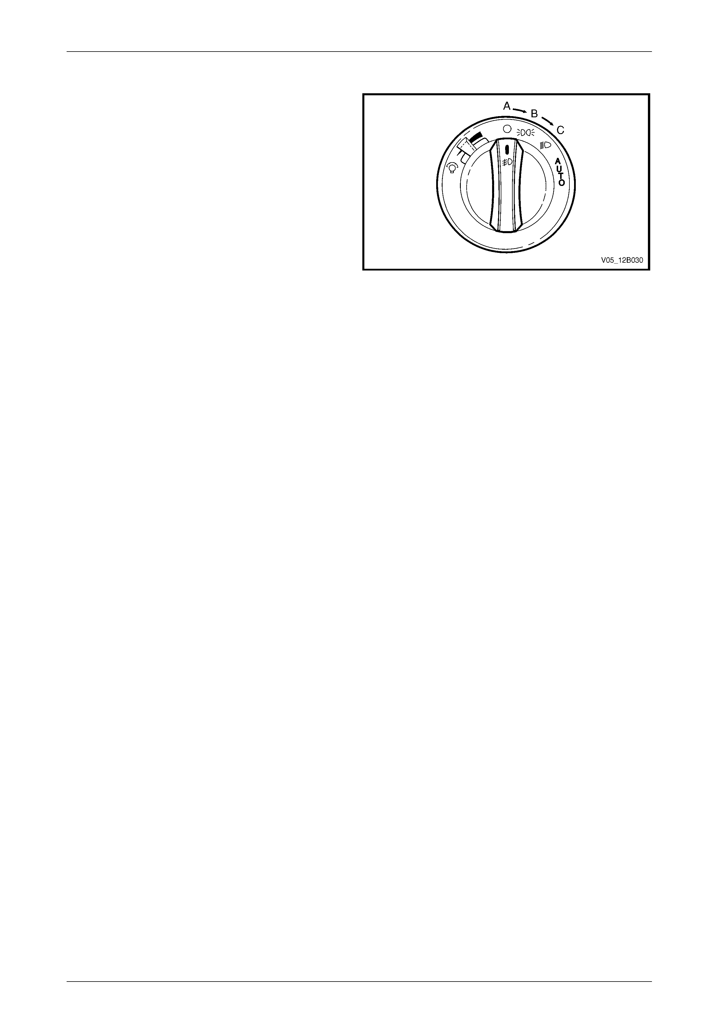
Lighting System Page 12B–124
Page 12B–124
Testing
1 With the headlamp s witch in position A (the OFF
position), turn the ignition on.
2 If the headlamps illuminate, the daylight running lamps
assembly is operating correctly.
3 If the headlamps do not illuminate, turn the headlamp
switch assembly to position C (the hea dlamp low
beam position) and check if the low beam headlamps
illuminate.
4 If the low beam headlamps do not illum inate, replace
fusible link F102 on the engine compartment fuse and
relay panel assembly, refer to Section 12O Fuses,
Relays and Wiring Harnesses.
5 Repeat step 1 and check if the headl amps illuminate. Figure 12B – 119
6 If the headlamps illuminate, the daylight running lamp assembly is operating correctly.
7 If the headlamps do not illuminate, the daylight running lamp assembly and headl amp switch assembly main wiring
harness connector is faulty. Remove and rep lace the daylight running lamp assembly and headl amp switch
assembly main wiring harness connector with a serviceable item.
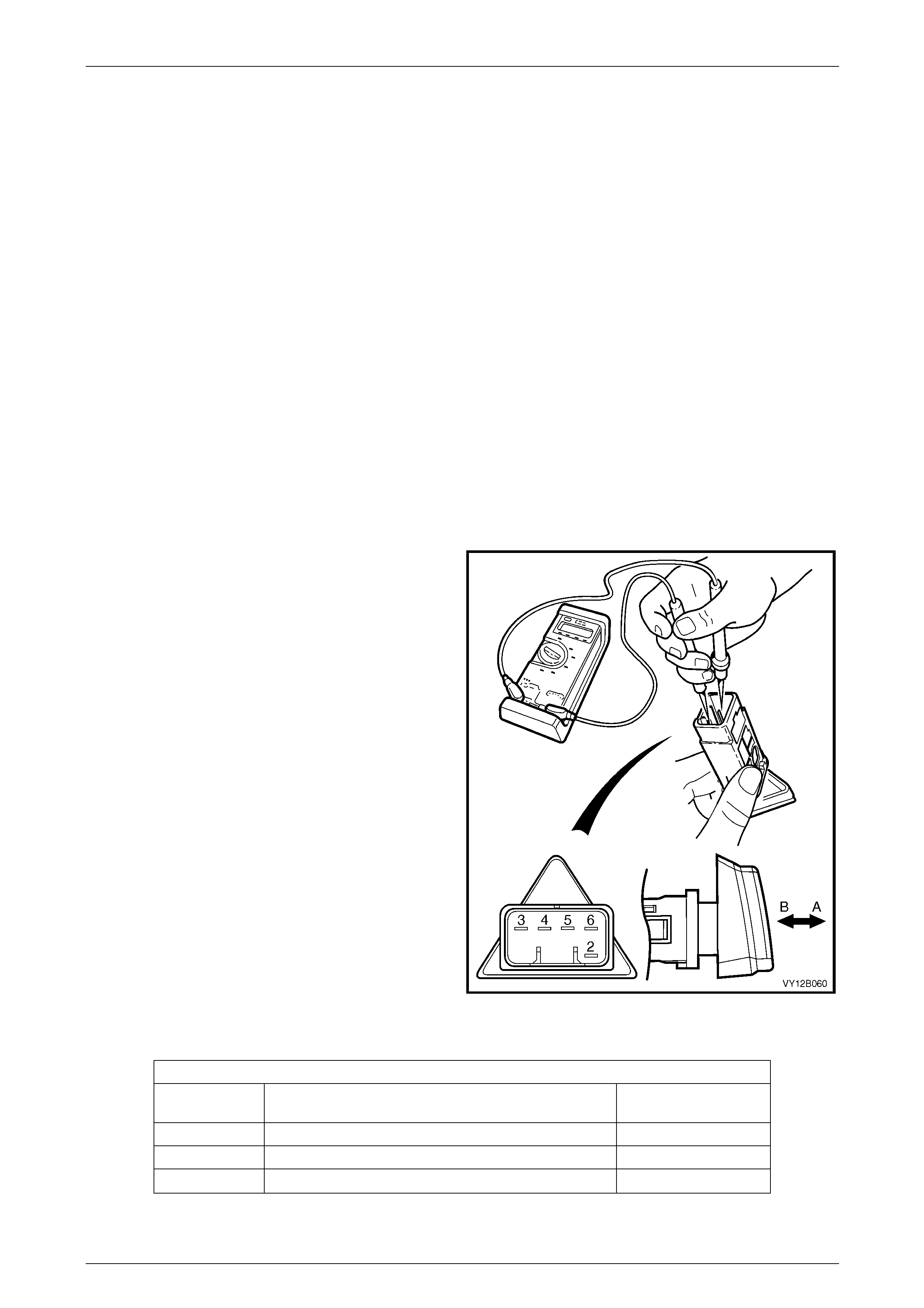
Lighting System Page 12B–125
Page 12B–125
8.23 Hazard Warning Switch Assembly
LT Section No. — 02–800
Remove
1 Remove fusible link F102 from the engine compartment fuse and relay panel assembl y,
refer to Section 12O Fuses, Relays and Wiring Harnesses.
2 Remove the instrument panel centre trim assembly, refer to Section 1A3 Instrument Panel and Console.
Reinstall
Reinstallation of the hazar d warni ng switch assembly is the reverse of the removal process. Check the hazard warning
switch assembly operation.
Testing
To test the hazard warning switch assembly, use a multimeter to check the continuity or resistance.
NOTE
Refer to Figure 12B – 120 and Headlamp Switch
Assembly (and Front Fog Lamp if Fitted) for
headlamp s witch assembly positions.
1 Perform the removal procedure for the hazard warning
switch assembly, refer to Section 1A3 Instrument
Panel and Console.
2 Place the hazard warning s witch assembly in the
positions detailed in the Hazar d W arning Switch
Assembly table, refer to Hazard Warning Switch
Assembly Position the contacts of the ohmmeter onto
the terminals and take the reading; compare the
readings with those in the Hazard Warni ng Switch
Assembly table.
3 If there is continuity between any terminals o t her than
those listed, the hazard warning switch assembly is
faulty. If the hazard warning switch assembly fails any
part of the test, replace the hazard warning switch
assembly with a serviceable item.
4 Perform the reinstallation procedure, refer to Reinstall.
Figure 12B – 120
Hazard Warning Switch Assembly
Hazard Warning Switch Assembly
Switch
Terminals Switch
Position Indication if Switch
is Serviceable
3 and 4 Switch in the OFF position; po sition A Continuity
3 and 5 Switch in the ON position; position B Continuity
2 and 6 Switch in either position, ON or OFF Approximately 30 Ω
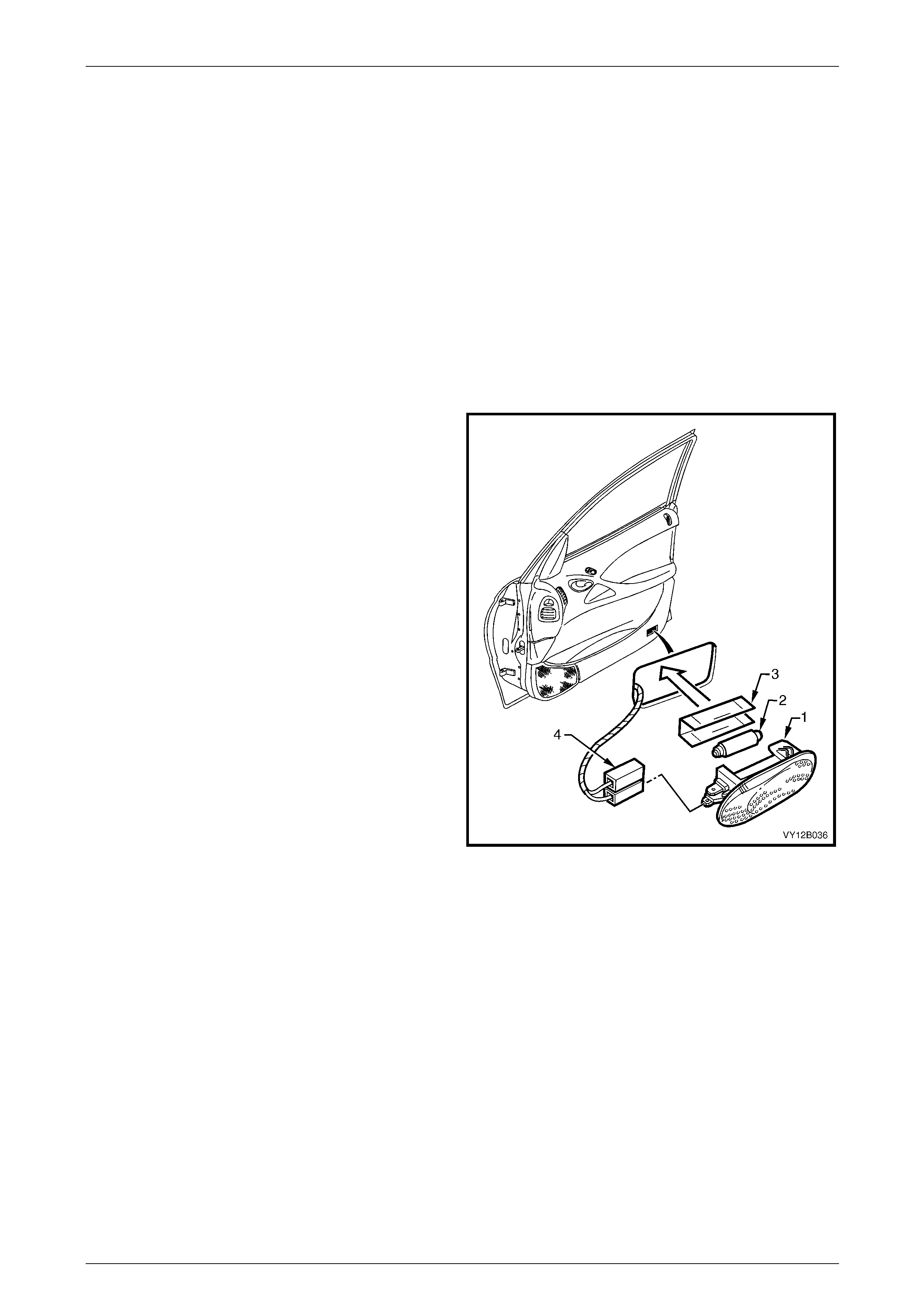
Lighting System Page 12B–126
Page 12B–126
9 Service Operations — Interior
Illumination and Switching,
Coupe
The interior lighting configuration is dependent upon the vehicle m odel and trim level, refer to 2.5 Interior Illumination.
9.1 Side Door Courtesy Lamp Assembly
LT Section No. — 02–780
Remove
1 Remove fusible link F102 from the engine compartment fuse and relay panel assembl y,
refer to Section 12O Fuses, Relays and Wiring Harnesses.
2 Insert a fine-bladed screwdriver into the notch at the
bottom edge of the lamp and press the locking tang.
3 Prise the side door courtesy lamp assembly (1) from
the door trim assembly.
4 Disconnect the side door courtesy lamp assembly
wiring harness connector (4) from the side door
courtesy lamp assembly.
5 If removing the bulb from the lamp:
a Pull the protective metal cover (3) from the rear
of the lamp to access the bulb (2).
b Bend back the lever contact retaining the bulb,
then remove the bulb.
6 Check the side door courtesy lamp assembly for
damage and replace if necessary.
NOTE
Ensure the side door courtesy lamp assembly
wiring harness connector does not fall into the
door cavity.
Figure 12B – 121
Reinstall
Reinstallation of the side doo r courtesy lamp assembly is the reverse of the removal procedure, noting the following:
1 If required, insert a new bulb into the side door courtesy lamp assemb ly.
2 Ensure the lens of the side door courtesy lamp assembly is flush with the side of the door trim assembly.
3 Check the side door courtesy lamp ass embl y operation.
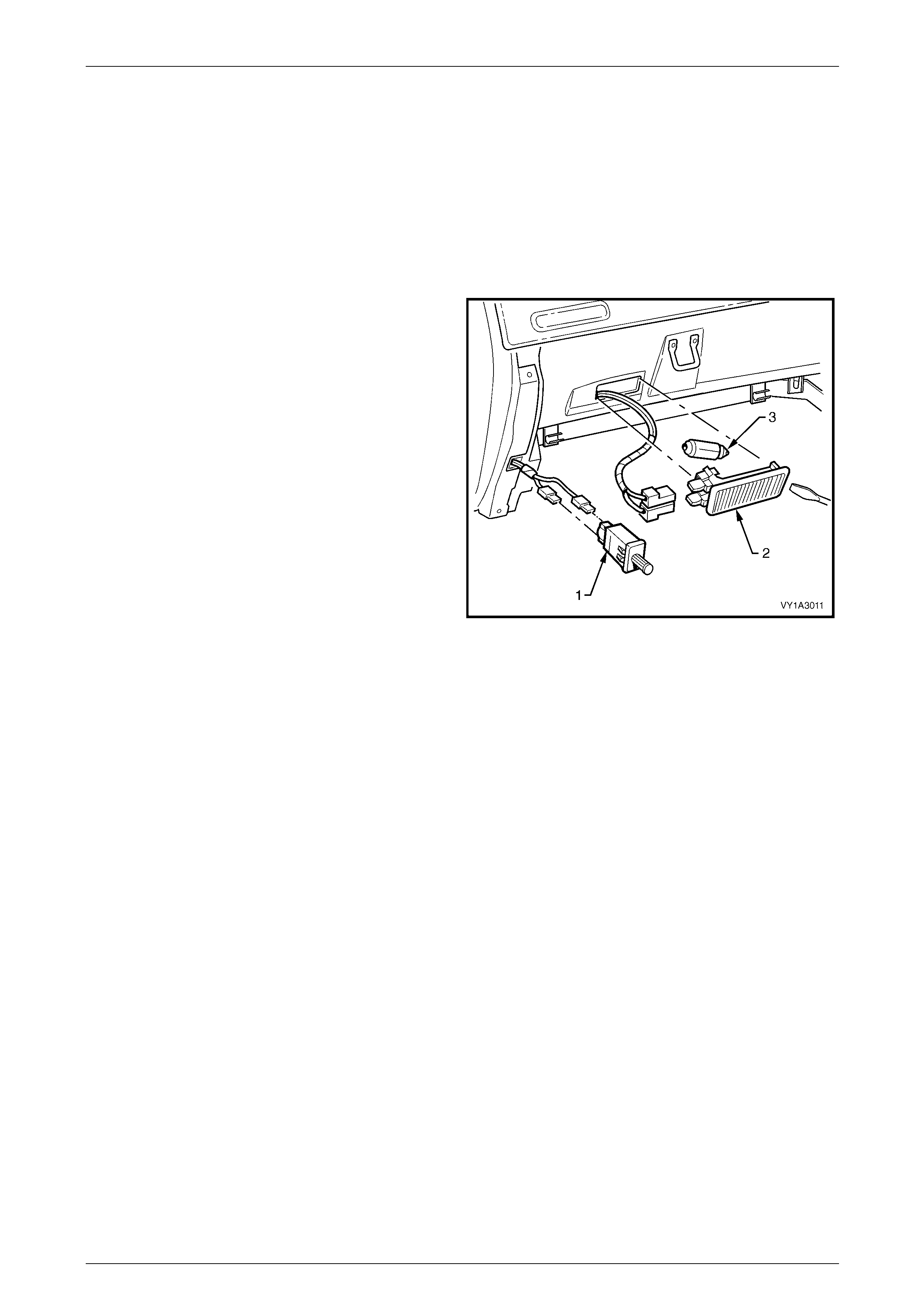
Lighting System Page 12B–127
Page 12B–127
9.2 Instrument Panel Compartment Lamp
Assembly
LT Section No. — 02–780
Remove
1 Remove fusible link F102 from the engine compartment fuse and relay panel assembl y,
refer to Section 12O Fuses, Relays and Wiring Harnesses.
2 Prise the instrument panel compartment lamp
assembly (2) from the compartment using a fine-
bladed screwdriver.
3 Disconnect the instrument panel compartme nt lamp
assembly wiring harness connector from the
instrument panel compartment lamp assembly. Check
the instrument panel compartment lamp assembly for
damage and replace if necessary.
NOTE
Ensure the instrument panel compartment lamp
assembly wiring harness connector does not fall
into the cavity behind the instrument panel
compartment.
4 If necessary, remove the bulb (3) from the instrument
panel compartment lamp assembly by pressing the
metal contact.
Figure 12B – 122
Reinstall
Reinstallation of the instrument panel compartment lamp assembly is the reverse of the removal procedure, noting the
following:
1 Insert a new bulb in the instrument panel compartment lamp assembl y if required.
2 Ensure the lens is flush with the instrument panel compartment.
3 Check the instrument panel compartment lamp assemb ly operation.

Lighting System Page 12B–128
Page 12B–128
9.3 Instrument Panel Compartment Lamp
Switch Assembly
LT Section No. — 02–780
Remove
1 Remove fusible link F102 from the engine compartment fuse and relay panel assembl y,
refer to Section 12O Fuses, Relays and Wiring Harnesses.
2 Prise the instrument panel compartment lamp switch assembly (1) from the instrument panel compartment lamp
assembly using a fine-bladed screwdriver, refer to Figure 12B – 122.
3 Disconnect the instrument panel compartme nt lamp assembly wiring harness connectors from the instrument panel
compartment lamp assembly. Check the inst rument panel compartment lamp switch assembly for damage and
replace if necessary.
NOTE
Ensure the instrument panel compartment lamp
assembly wiring harness connector does not fall
into the cavity behind the instrument panel
compartment.
Reinstall
Reinstallation of the instrument panel compartment lamp switch assembly is the reverse of the removal proce dure.
Check the instrument panel compartment lamp switch assembly operation.
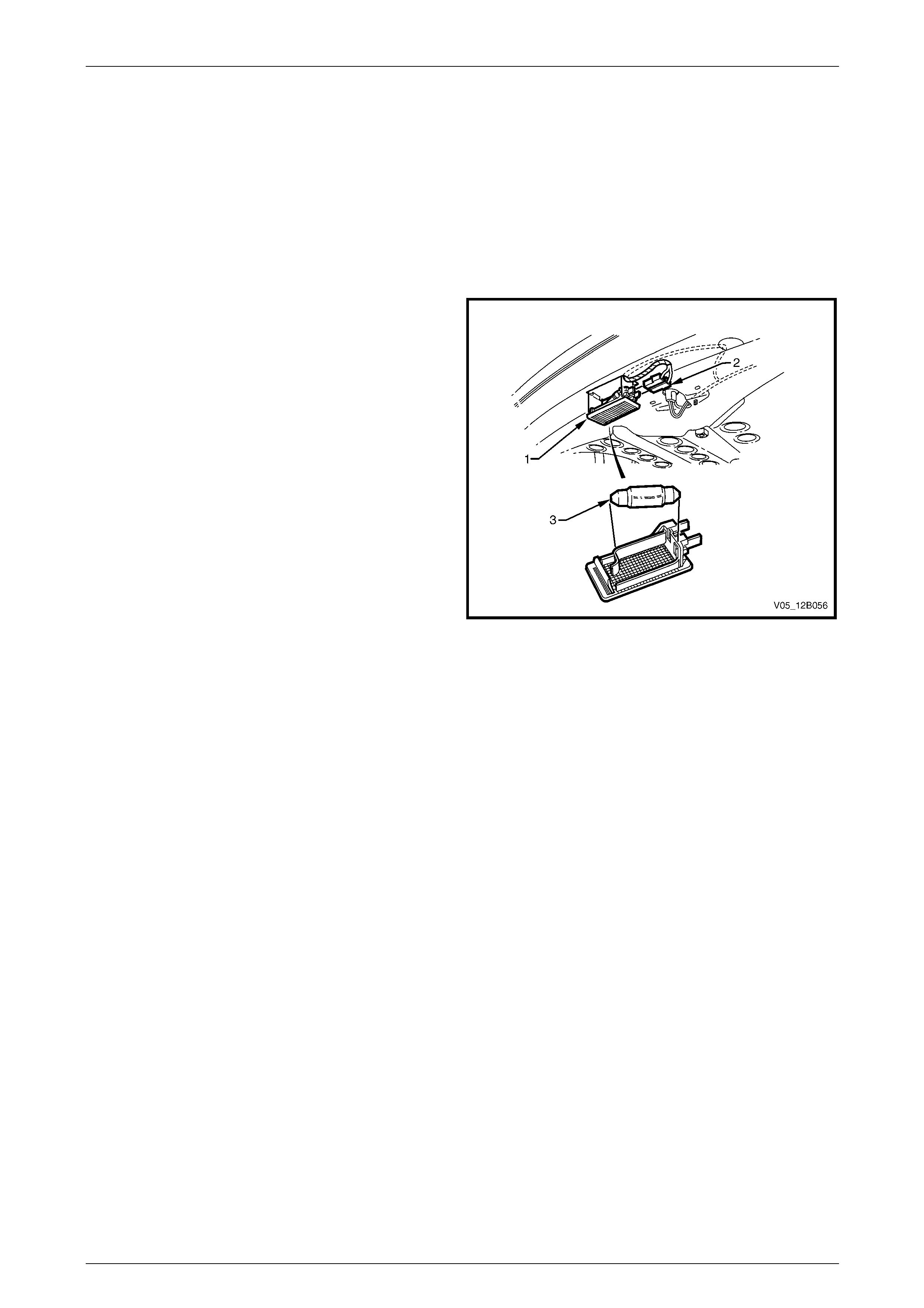
Lighting System Page 12B–129
Page 12B–129
9.4 Rear Compartment Courtesy Lamp
Assembly
LT Section No. — 02–780
Remove
1 Remove fusible link F102 from the engine compartment fuse and relay panel assembl y,
refer to Section 12O Fuses, Relays and Wiring Harnesses.
2 Prise the rear compartment courtesy lamp
assembly (1) from the mating surface using a fine-
bladed screwdriver.
3 Disconnect the rear compartment courtesy lamp
assembly wiring harness connector (2) from the rear
compartment courtesy lamp assembly. Check the
lamp assembly for damage and replace if necessary.
4 If necessary, remove the bulb (3) from the rear
compartment courtesy lamp assembly by pressing the
metal contact.
Figure 12B – 123
Reinstall
Reinstallation of the rear com partment courtesy lamp assembly is the reverse of the removal procedure, noting the
following:
1 Insert a new bulb in the rear compartment courtesy lamp assembly if requ ired.
2 Ensure the lens is flush with the rear compartment roof.
3 Check the rear compartment courtes y lam p assemb ly operation.
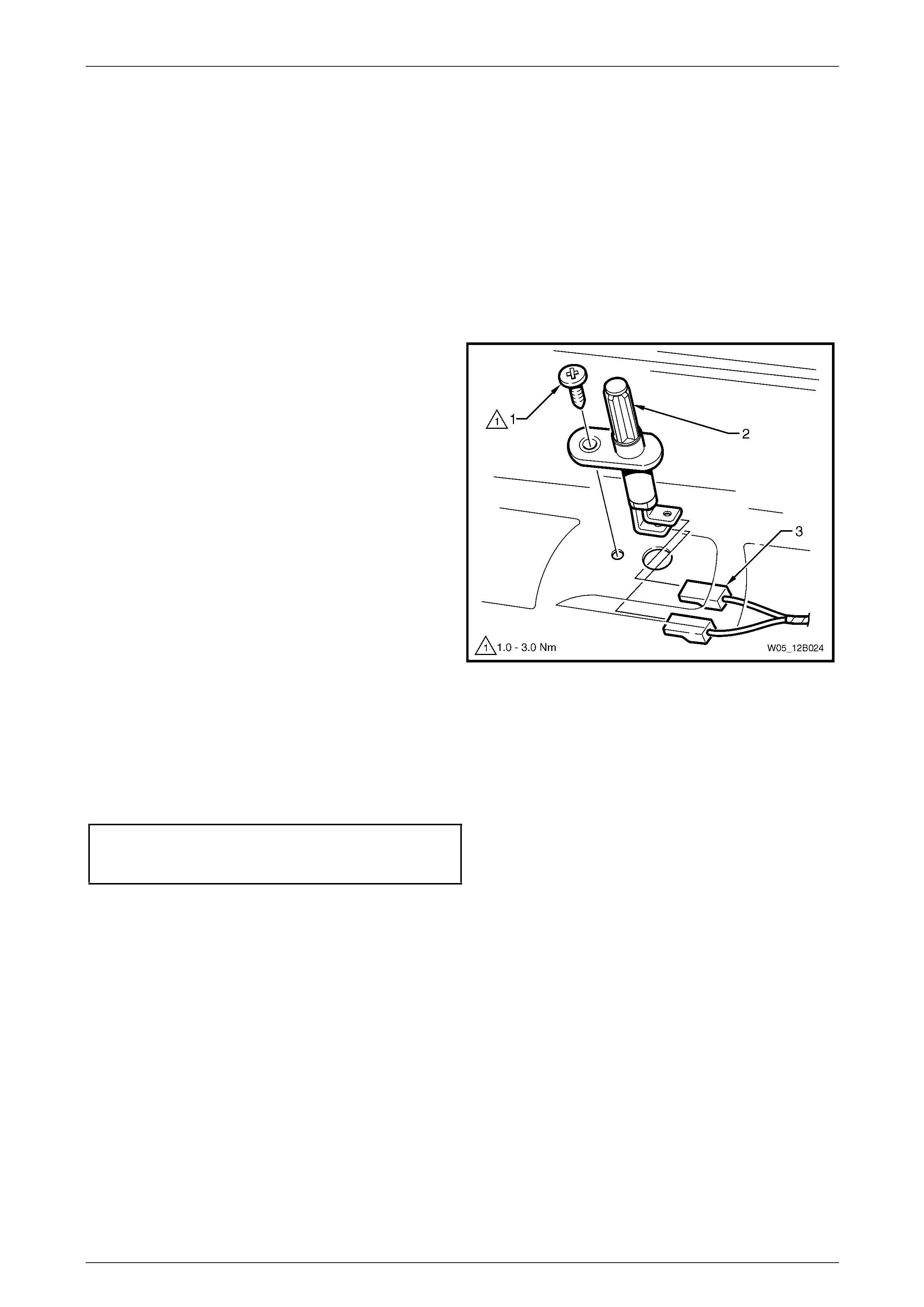
Lighting System Page 12B–130
Page 12B–130
9.5 Rear Compartment Courtesy Lamp
Switch Assembly
LT Section No. — 02–780
The rear compartment courtesy lamp assembly is operated b y a switch attached to the rear compartment lid. The rear
compartment courtesy lamp switch assembly is actuated when either the compartment lid or liftgate is opened.
Remove
1 Remove fusible link F102 from the engine compartment fuse and relay panel assembl y,
refer to Section 12O Fuses, Relays and Wiring Harnesses.
2 Remove the attaching screw (1) and pull the rear
compartment courtesy lamp switch assembly (2) out
far enough to access the rear compartment courtes y
lamp assembly wiring harness connectors (3).
3 Disconnect the rear compartment courtesy lamp
assembly wiring harness connectors and remove the
rear compartment courtesy lamp switch assembly.
Figure 12B – 124
Reinstall
Reinstallation of the rear com partment courtesy lamp switch assembly is the reverse of the removal procedure, noting
the following:
1 Tighten the attaching screw to the correct torque specification.
Rear compartment courtesy lamp
switch assembly attaching
screw torque specification...........................1.0 – 3.0 Nm
2 Check the rear compartment courtes y lam p assemb ly operation.
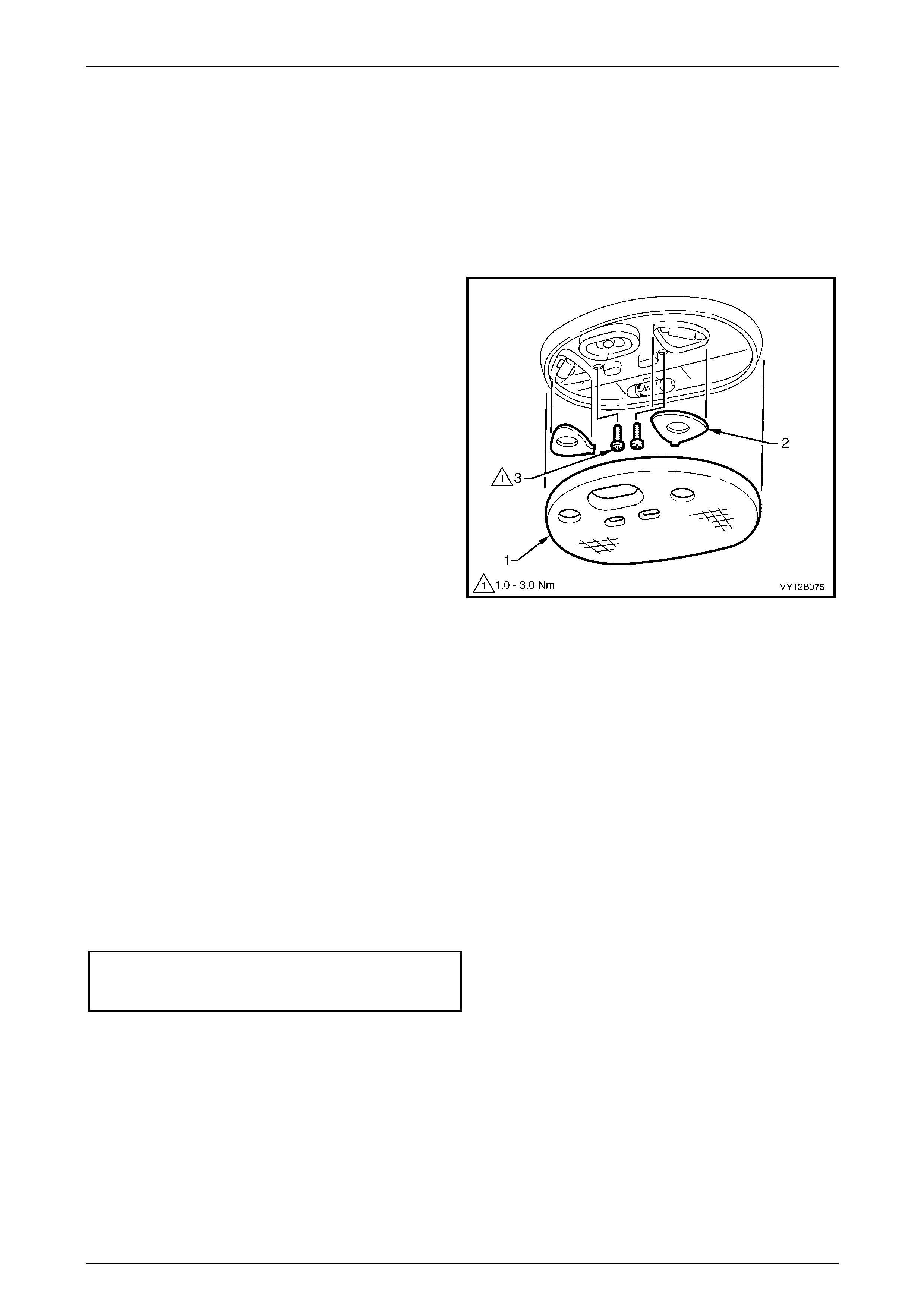
Lighting System Page 12B–131
Page 12B–131
9.6 Dome and Reading Lamp Assembly
LT Section No. — 02–780
Bulb Replace
1 Remove fusible link F102 from the engine compartment fuse and relay panel assembl y,
refer to Section 12O Fuses, Relays and Wiring Harnesses.
2 Using a fine-bladed screwdriver, start at the centre
notch in the lens (1) and prise the lens from the dome
and reading lamp assembly bulb mounting plate. Use
the screwdriver in the other two notches to remove the
lens.
3 If required, remove the bulb cover plates (2).
4 Replace the bulb.
5 If required, install the bulb cover plates.
6 Carefully install the lens to the dome and reading lamp
assembly, ensuring it snaps into place. Check the lens
is flush with the dome and reading lamp assembly.
7 Install fusible link F102 on the engine compartment
fuse and relay panel assembly.
8 Check the dome and reading l amp assembly
operation.
Figure 12B – 125
Removal
1 Remove fusible link F102 from the engine compartment fuse and relay panel assembl y,
refer to Section 12O Fuses, Relays and Wiring Harnesses.
2 Using a fine-bladed screwdriver, start at the centre notch in the lens (1) and prise the lens from the dome and
reading lamp assembly bulb mounting plate. Use the screwdriver in the other two notches to remove the lens.
3 Remove both attaching screws (3) from the dome and reading lamp assembly.
4 Pull the dome and reading l amp assembly down and disconnect the dome and re ading lamp assembly wiring
harness connector from the dome and reading lamp assembly.
Reinstall
Installation of the dome and reading lamp assembly is the reverse of the removal procedure, noting the following:
1 Tighten the attaching screws to the correct torque specification.
Dome and Reading Lamp Assembly
Attaching Screw Torque
Specification................................................1.0 – 3.0 Nm
2 Ensure the lens is installed flush with the do m e and reading lamp assembly.
3 Check the dome and reading l amp assembly operation.
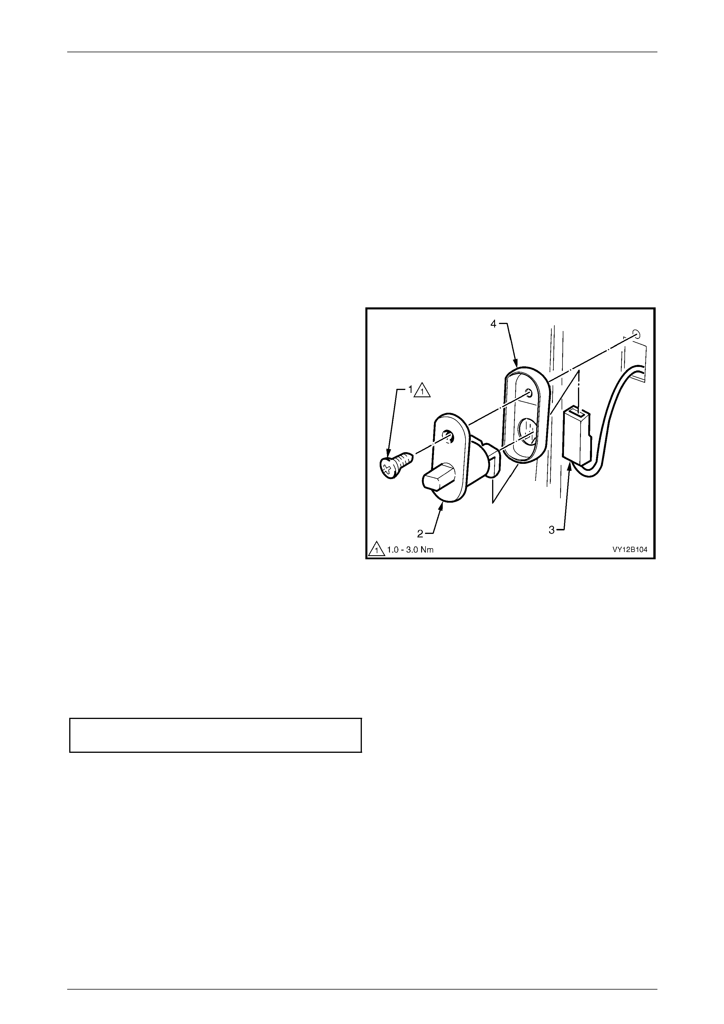
Lighting System Page 12B–132
Page 12B–132
9.7 Door Ajar Switches
The door ajar switches ar e installed in the hinge pillars. The door a jar switches provide door status data to the BCM:
• When the plunger is pressed, an open circuit is created, providing 'door closed' data to the BCM.
• When the plunger is released , the switch closes completing a circuit to earth, providing 'door open' data to the
BCM.
To diagnose the door ajar switch circuit, refer to Section 12J Body Control Module .
This data is used by the BCM for many vehicle s ystems (for example, interior illumination dimming).
LT Section No. — 02–780
Remove
1 Remove the attaching screw (1) from the door ajar
switch (2).
2 Pull the door ajar switch from the aperture and, if
required, remove the door ajar s witch wiring harness
connector (3).
NOTE
Ensure the door ajar switch wiring harness
connector does not fall into the cavity.
Figure 12B – 126
Reinstall
Reinstallation of the door ajar switches is the reverse of the removal procedure, noting the following:
1 If required, fit the door ajar switch seal (4) to the door ajar switch, refer to Figure 12B – 126.
2 Push the door ajar switch wiring harness connector onto the door ajar switch.
3 Install the door ajar s witch in the hing e pillar and tighten the attaching screw to the correct torque specifi cation.
Door ajar switch attaching
screw torque specification...........................1.0 – 3.0 Nm
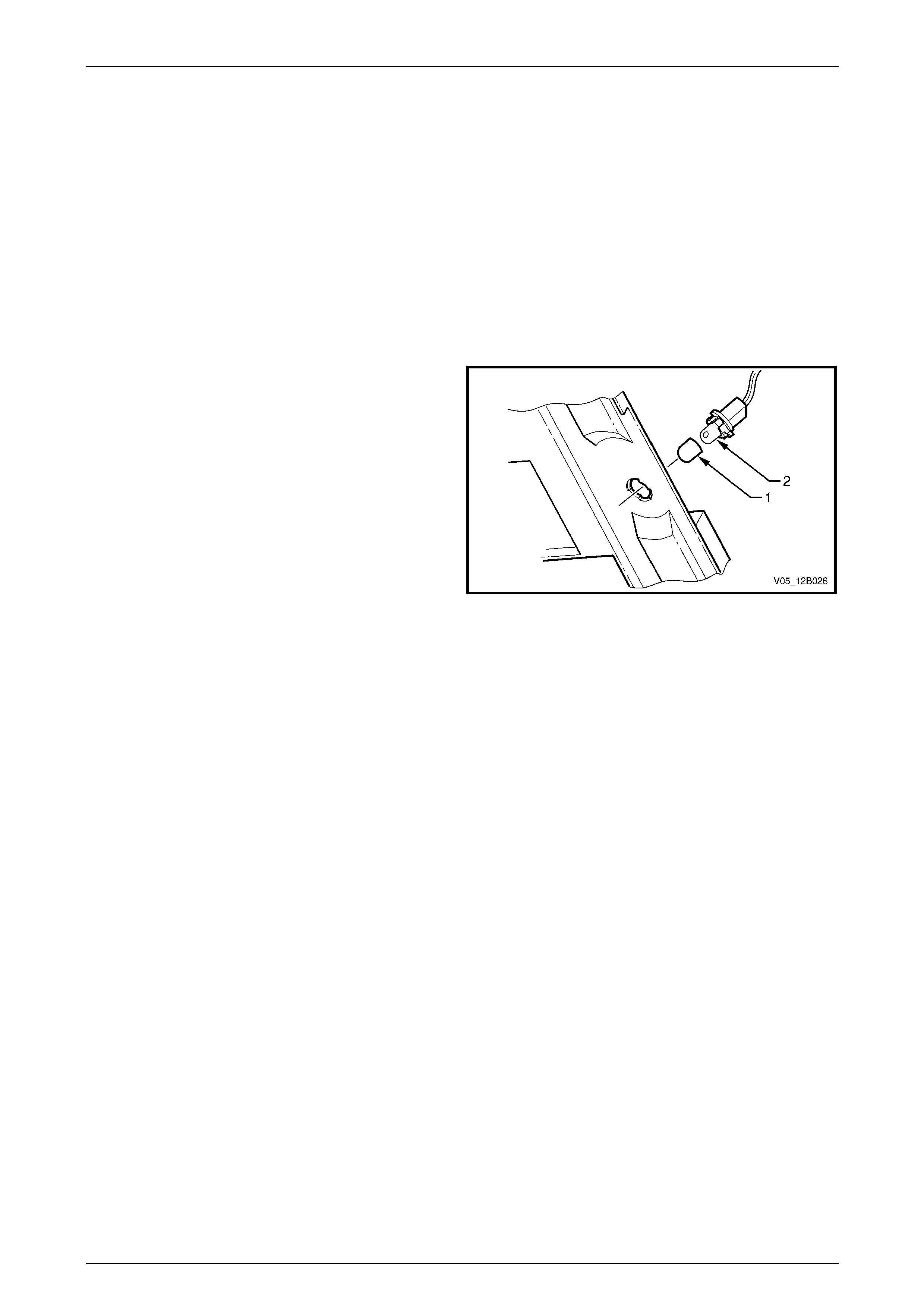
Lighting System Page 12B–133
Page 12B–133
9.8 Stepwell Lamps
LT Section No. — 02–780
Stepwell lamps are located on either side of the vehicle and are attached to the instrument panel lower trim plate
assemblies. The stepwell bulb sockets are pa rt of the body wiring harness.
Replace
1 Remove fusible link F102 from the engine compartment fuse and relay panel assembl y,
refer to Section 12O Fuses, Relays and Wiring Harnesses.
2 Remove the relevant instrument panel lower trim plate assembly,
refer to Section 1A3 Instrument Panel and Consol e.
3 Pull the bulb sleeve off the bulb and pull the bulb from
the bulb socket.
4 Insert a new bulb into the bulb socket and fit the bulb
sleeve to the bulb.
5 Check the operation of the bulb.
6 Install the instrument panel lower trim plate assembly,
refer to Section 1A3 Instrument Panel and Consol e.
Figure 12B – 127

Lighting System Page 12B–134
Page 12B–134
9.9 Floor Console Compartment Lamp
Assembly
LT Section No. — 02–780
Remove
1 Remove fusible link F102 from the engine compartment fuse and relay panel assembl y,
refer to Section 12O Fuses, Relays and Wiring Harnesses.
2 Prise the floor console compartment lamp
assembly (1) from the side of the floor console
compartment using a fine-bladed screwdriver.
3 Disconnect the floor console compartment la mp wiring
harness connectors (2) from the floor console
compartment lamp assembly. Check the lamp
assembly for damage and replace if necessary.
NOTE
Ensure the floor console compartment lamp
assembly wiring harness connectors do not fall
inside the floor console cavity.
4 If necessary, remove the bulb (3) from the floor
console compartment lamp assembly by pressing the
metal contact.
Figure 12B – 128
Reinstall
Reinstallation of the floor console compartment lamp assembly is the reverse of the removal procedure, noting the
following:
1 Insert a new bulb in the floor console compartment lamp assembly if required.
2 Ensure the lens is flush with the floor console compartme nt side.
3 Check the floor console compartment lamp assembly operation.

Lighting System Page 12B–135
Page 12B–135
9.10 Floor Console Compartment Lamp
Switch Assembly
LT Section No. — 02–780
Remove
1 Remove fusible link F102 from the engine compartment fuse and relay panel assembl y,
refer to Section 12O Fuses, Relays and Wiring Harnesses.
2 Prise the floor console compartment lamp switch assembly (4) from the top of the floor console compartment using
a fine-bladed screwdriver, refer to Figure 12B – 128.
3 Disconnect the floor console compartment lamp switch assembly wiring harness from the floor console
compartment lamp assembly. Check the floo r console compartment lamp switch assembly for damage and replace
if necessary.
NOTE
Ensure the floor console compartment lamp
switch assembly wiring connector does not fall
inside the floor console cavity.
Reinstall
Reinstallation of the floor console compartment lamp switch assembly is the reverse of the removal procedure. Check
the floor console compartment lamp switch assembly operation.

Lighting System Page 12B–136
Page 12B–136
9.11 Automatic Transmission Control
Position Lamp
LT Section No. — 04–190
Replace
1 Remove fusible link F102 from the engine compartment fuse and relay panel assembl y,
refer to Section 12O Fuses, Relays and Wiring Harnesses.
2 Move the front seats to the rearmost position.
3 Remove the right-hand instrument panel l ower extension side trim panel (2),
refer to Section 1A3 Instrument Panel and Consol e.
4 Remove the bulb socket (1) from the automatic
transmission control assembly by twisting
anticlockwise and pulling it down.
5 Insert a new bulb into the bulb socket.
6 Install fusible link F102 on the engine compartment
fuse and relay panel assembly.
7 Check the operation of the bulb by turning on the park
lamps.
8 Insert the bulb socket into the automatic transmission
control assembly and twist to lock into position.
9 Install the instrument panel lower e xtension side trim
panel, refer to Section 1A3 Instrument Panel and
Console.
Figure 12B – 129
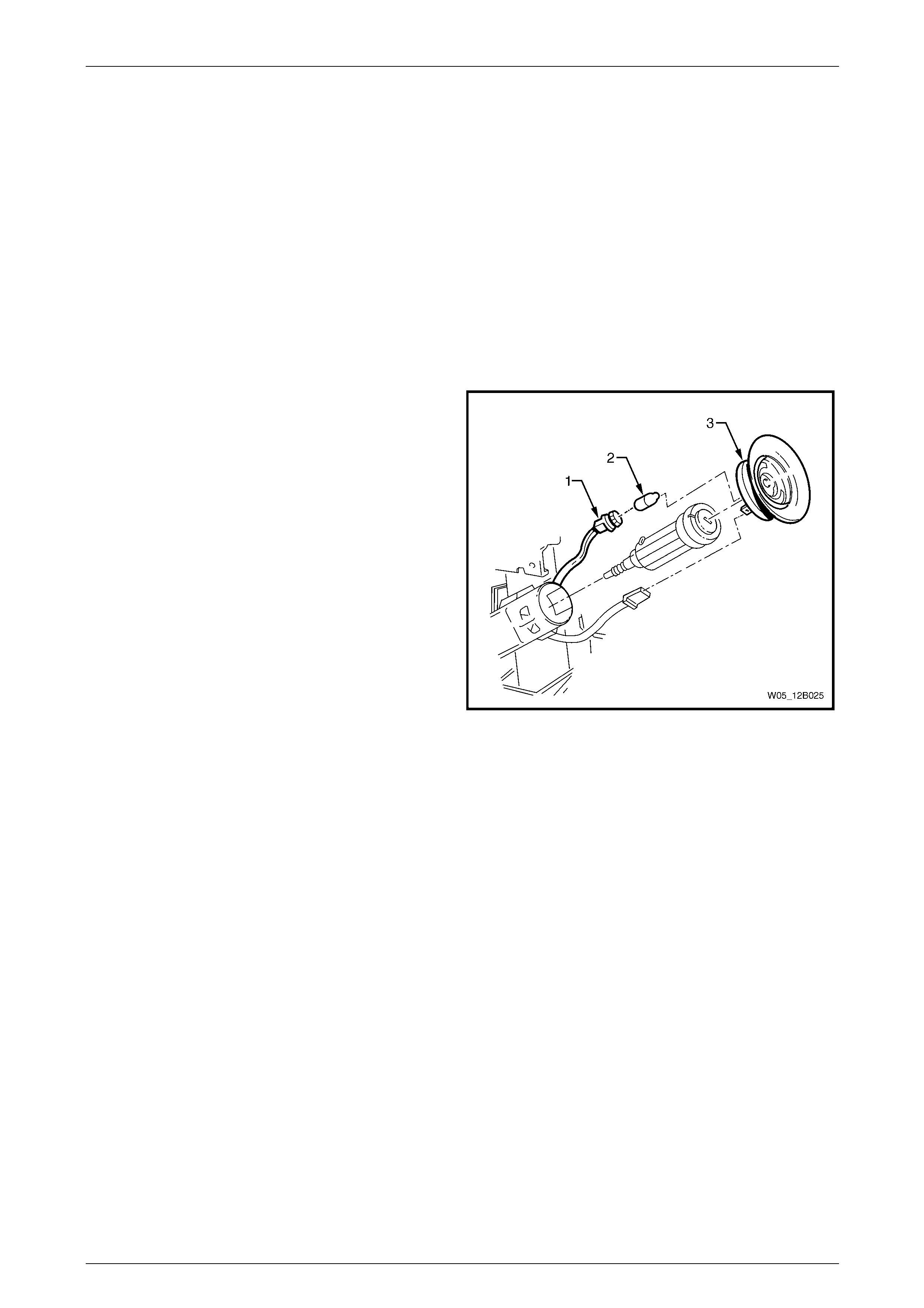
Lighting System Page 12B–137
Page 12B–137
9.12 Ignition Lock Cylinder Bulb
LT Section No. — 02–780
Replace
1 Remove fusible link F102 from the engine compartment fuse and relay panel assembl y,
refer to Section 12O Fuses, Relays and Wiring Harnesses.
2 Remove the following items, refer to Section 9 Steering:
a steering column covers,
b ignition barrel and lock cylinder, and
c theft deterrent receiver assembly.
3 Replace the ignition lock cyli nder bulb (2).
4 Insert the bulb socket into the theft deterrent receiver
assembly, then install the theft deterrent receiver
assembly into the steering column lo wer cover.
Figure 12B – 130
5 Install fusible link F102 on the engine compartment fuse and relay panel assembly.
6 Check the ignition lock cylinder bulb operation.
7 Replace the following items, refer to Section 9 Steering:
a theft deterrent receiver assembly,
b ignition barrel and lock cylinder, and
c steering column covers.

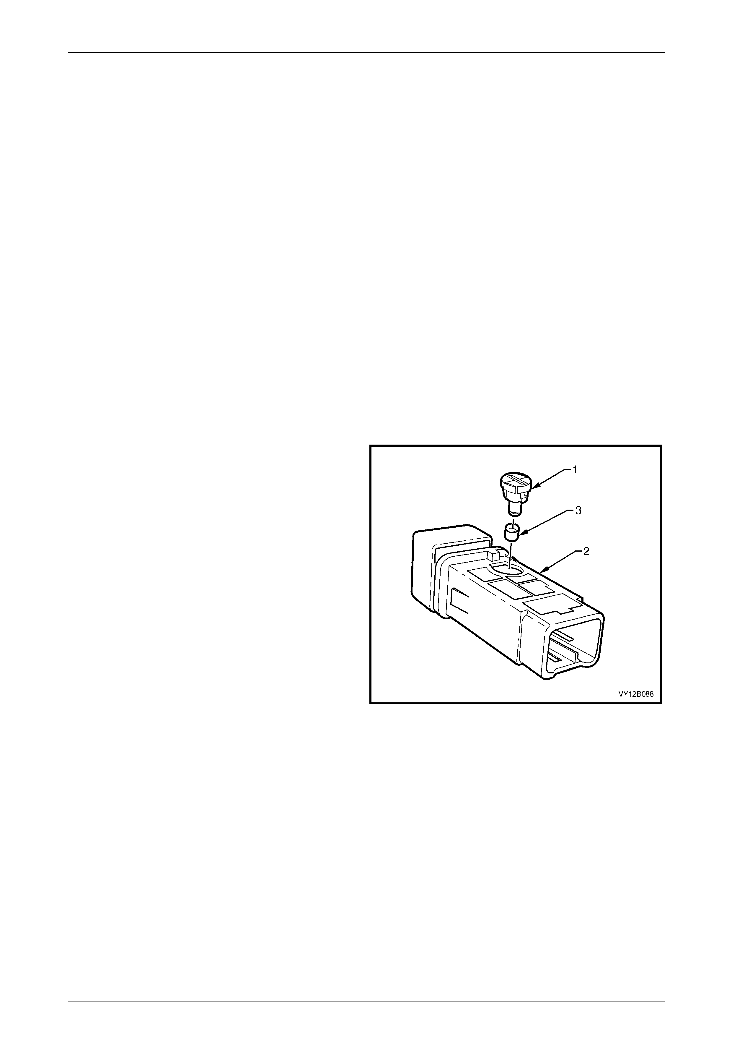
Lighting System Page 12B–139
Page 12B–139
9.14 Switch Illumination
LT Section No. — 02–780
The headlamp switch, trip computer switch and side window switch are illumin ated with filament bulbs, but the switches
are sealed units and the bulbs are not serviceable, refer to Figure 12B – 13.
Auxiliary Switch Bulbs
Spaces are available for auxiliary switches in the floor console compartment cover assembly, for example:
• T/C switch, or
• A/S switch.
Replace
1 Ensure the ignition switch is in the OFF position.
2 Remove fusible link F102 from the engine compartment fuse and relay panel assembl y,
refer to Section 12O Fuses, Relays and Wiring Harnesses.
3 If required, remove the navigation system equipment, refer to Section 12L Navigation System.
4 Remove the floor console front compartment cover assembly, refer to Section 1A3 Instrument Panel and Console.
5 Remove the switch from the floor console front compartment cover assembly.
6 Using a fine-bladed screwdriver inserted into the
groove on the bulb socket, twist the bulb socket and
bulb assembly (1) anticlockwise and remove it from
the switch assembly (2).
7 Remove the green bulb sleeve (3) from the bulb
socket and bulb assembly.
8 Check the bulb sleeve for splits and replace it if
necessary.
9 Fit the bulb sleeve to the new bulb socket and bul b
assembly.
10 Insert the bulb socket and bulb assembly into the
switch assembly.
11 Connect the switch assembly to the wiring harness
connector in the floor console compartme nt cover
assembly.
12 Install fusible link F102 on the engine compartment
fuse and relay panel assembly. Figure 12B – 131
13 Check the switch assembly operati on while the park lamps are on.
14 Replace the floor console front compartment cover assembly, refer to Section 1A3 Instrument Panel and Console.
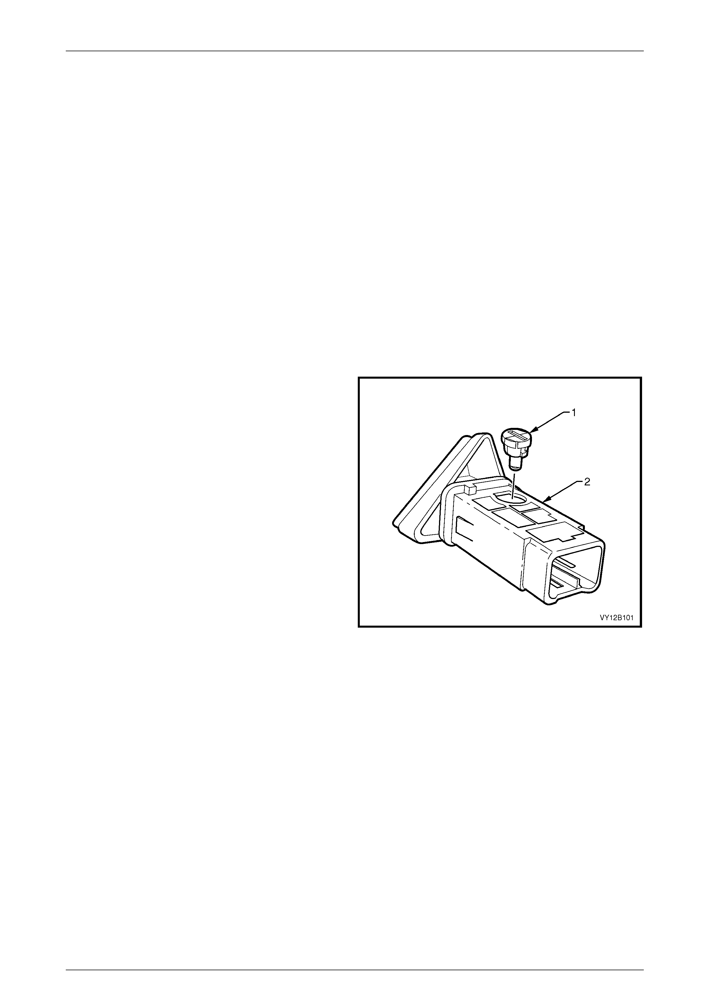
Lighting System Page 12B–140
Page 12B–140
T/C Switch or A/S Switch Bulb
Replace
The T/C switch (or A/S switch) is located at the rear of the shift lever lower housing on the same side as the transmission
selector lens (PRNDL).
1 Ensure the ignition switch and the headlamp switch assembly are in the OFF position.
2 Ensure the park brake is applied.
3 Remove the floor console compartment cover assembly, refer to Section 1A3 Instrument Panel and Console.
4 Shift the transmission selector into the drive position.
5 Separate the transmission selector lower housing from the base and replace the bulb,
refer to Section 7C4 Automatic Transmission — On-vehicle Service.
Hazard Warning Switch Bulb
Replace
1 Remove the hazard warning switch assembly , refer to 9.19 Hazard W arnin g Switch Assembly.
2 Using a fine-bladed screwdriver inserted into the
groove on the bulb socket, twist the bulb socket and
bulb assembly (1) anticlockwise and remove it from
the hazard warning switch assembly (2).
3 Pull the bulb socket and bulb assembly from the
hazard warning switch assembly.
4 Insert the new bulb socket and bulb assembly into the
hazard warning switch assembly.
5 Connect the hazard warning switch assembl y to the
wiring harness connector.
6 Install fusible link F102 on the engine compartment
fuse and relay panel assembly.
7 Check the hazard warning lamp operation.
8 Remove fusible link F102 from the engine
compartment fuse and relay panel assembly.
Disconnect the wiring connector from the hazard
warning switch assembly. Figure 12B – 132
9 Install the hazard warning switch assembl y, refer to 9.19 Hazard Warning Switch Assembly.
10 Install fusible link F102 on the engine compartment fuse and relay panel assembly.

Lighting System Page 12B–141
Page 12B–141
9.15 Backup Lamp Switch Assembly
The backup lamp switch assembly is fitted to vehicles with manual transmission. The backup lamp switch assembly is
not adjustable and is fitted to the right-hand side of the transmission case.
If the backup lamp switch assembly requires changing, refer to Section 7B2 Manual Transmission — GEN III V8 Engine.

Lighting System Page 12B–142
Page 12B–142
9.16 Neutral Safety Backup Switch Assembly
The neutral safet y backup switch assembly is fitted to vehicles with automatic transmission. The neutral safety backup
switch assembly activates the backup lamps when the transmission selector is in the reverse position. If the neutral
safety backup switch assembly requires changing, refer to:
• Section 7C4 Automatic Transmission — On-vehicle Service, or
• Section 7D4 Hydramatic 4L65–E Automatic Transmission On-vehicle Servicing.
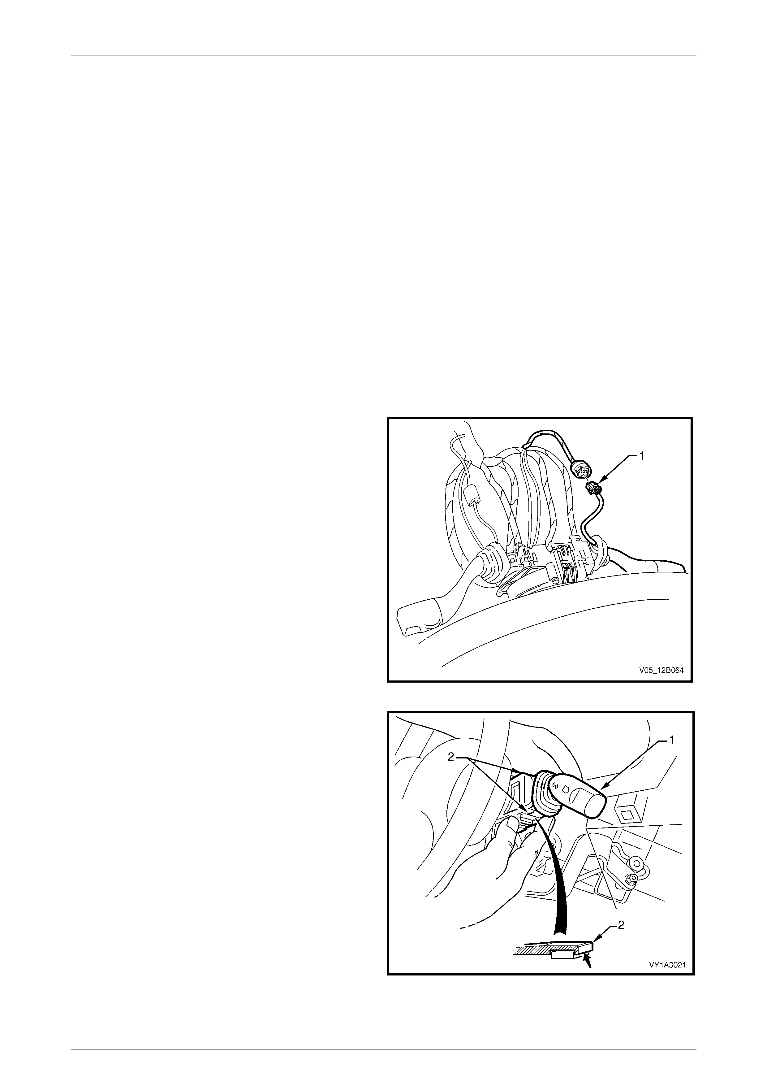
Lighting System Page 12B–143
Page 12B–143
9.17 Turn Signal and Cruise Control Switch
Assembly
LT Section No. — 06–250
The turn signal switch assembly prov ides the following functions:
• turn signal,
• pass,
• high beam control, and
• cruise control.
For more information on the cruise control system, refer to Section 12E Cruise Control.
Remove
1 Remove fusible link F102 from the engine compartment fuse and relay panel assembl y,
refer to Section 12O Fuses, Relays and Wiring Harnesses.
2 Remove the instrument lower trim panel assembl y, refer to Section 1A3 Instrument Panel and Console.
3 Remove the steering column lower cover, refer to Section 9 Steering.
4 Disconnect the wiring harness connector (1).
Figure 12B – 133
5 Press the retaining tangs (2) on the turn signal switch
assembly (1) and pull the turn signal switch assembly
away from the steering column.
Figure 12B – 134

Lighting System Page 12B–144
Page 12B–144
6 Press the wiring harness connector tangs and pull the
connector (1) from the turn signal switch assembly.
Figure 12B – 135
Reinstall
Reinstallation of the turn signal switch assembly is the reverse of the removal procedure.
Testing
To test the turn signal switch assembly, use a multimeter to check the continuity.
To test the cruise control features, refer to
Section 12E Cruise Control.
1 Perform the removal procedure for the turn signal
switch assembly, refer to Remove, but do not unclip
and remove the turn signal switch assem bl y from the
steering column. With the turn signal switch assembly
attached to the steering column, a stable platform with
which to carry out the testing is provided.
2 Place the turn signal switch assembly into the
positions detailed in the following Turn Signal Switch
Assembly table, refer to Turn Signal Switch Assembly.
Position the contacts of the multimeter onto the
terminals and take the reading. Compare the
multimeter readings with the values in the table.
3 If there is continuity between any terminals o t her than
those listed, the turn signal switch assembly is faulty. If
the turn signal switch assembly fails any part of the
test, replace the faulty turn signal switch assembly
with a serviceable item. To replace the turn signal
switch assembly, press the two retaining tangs and
pull the turn signal switch assembly away from the
steering column, refer to Figure 12B – 134. Insert a
new turn signal switch assembly.
4 Perform the reinstallation procedure, refer to Reinstall.
Figure 12B – 136

Lighting System Page 12B–145
Page 12B–145
Turn Signal Switch Assembly
Turn Signal Switch Assembly
Switch
Terminals Switch
Position Indication if Switch
is Serviceable
Turn Signal Switch Terminals
9 and 6 Switch in neutral position open circuit
9 and 6 Switch in left-hand turn position continuity
9 and 10 Switch in neutral position open circuit
9 and 10 Switch in right-hand turn pos ition continuity
Headlamp Pass Terminals
1 and 4 Switch in the neutral position open circuit
1 and 4 Switch pulled to the rear in the pass positio n continuity
Headlamp High Beam Terminals
1 and 3 Switch in neutral position open circuit
1 and 3 Switch pushed forward in the hig h beam position continuity
2 and 3 Switch in neutral position continuity
2 and 3 Switch pushed forward in the high beam position open circuit
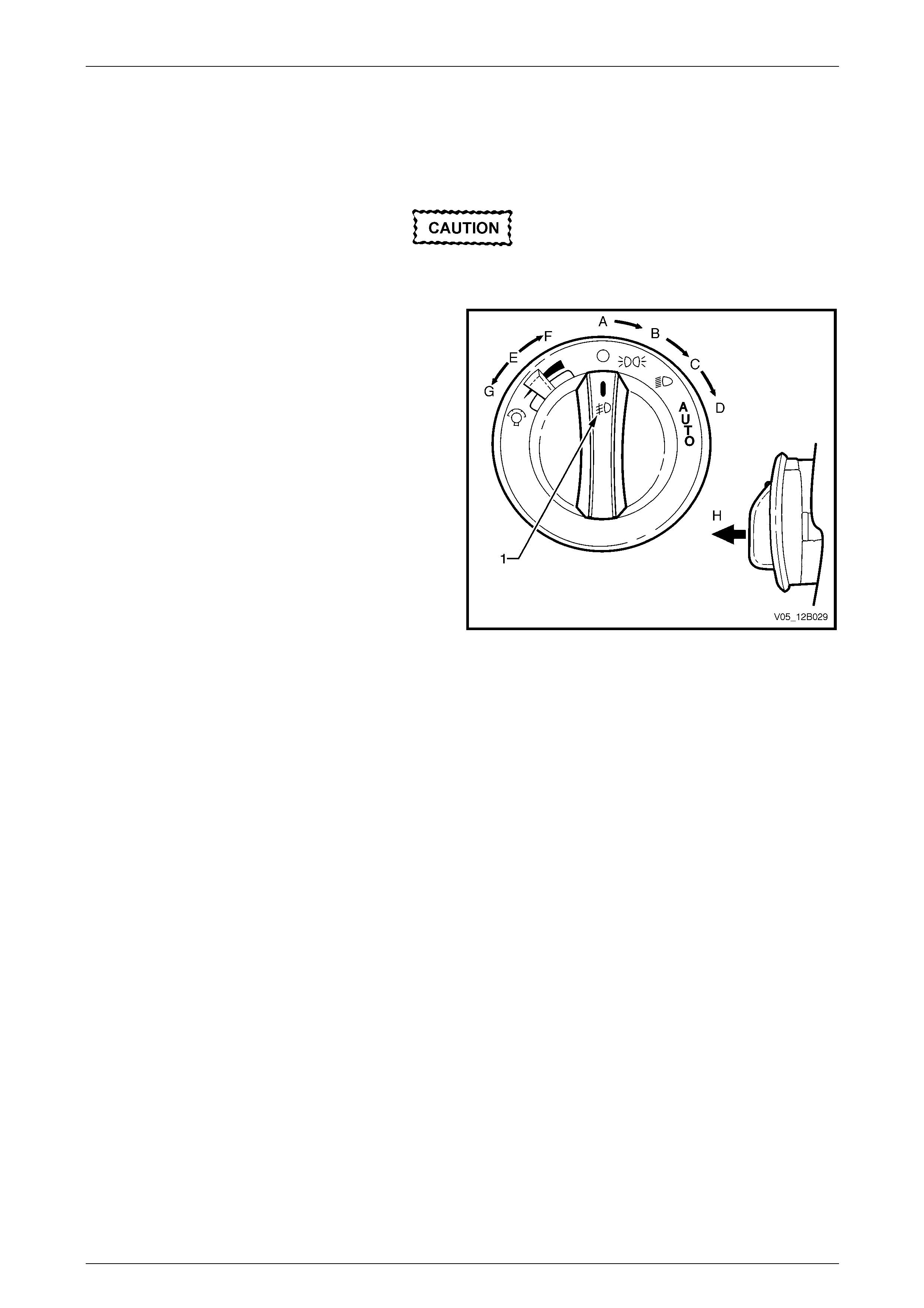
Lighting System Page 12B–146
Page 12B–146
9.18 Headlamp Switch Assembly
LT Section No. — 02–800
If replacing a headlamp switch assembly,
ensure the correct type is u sed.
Figure 12B – 137 shows the headlamp switch assembly and
the fog lamp icon (1).
The headlamp switch assembly has the following positions:
• Position A — headlamps are off.
• Position B — park lamps are on.
• Position C — headlamps are on (lo w beam).
• Position D — headlamps are controlled automatically
by the BCM.
• Positions E / F — instrumentation lighting brightens
when the dimmer switch is moved position E to F.
• Positions E / G — Instrumentation lighting dims when
the dimmer switch moves from position E to G.
• Position B, C or D — Front fog lamps are turned on
when the switch is pulled out to position H. Figure 12B – 137
NOTE
The front fog lamps do not illuminate if the
headlamp s wit ch assembly is pulled to position H
while also in position A.
Remove
For removal of the headlamp switch assembly, refer to Section 1A3 Instrument Panel and Console.
Reinstall
Reinstallation of the headlamp switch assembly is the reverse of the removal procedure. Ensure the headlamp switch
assembly retaining tangs are correctly seated.
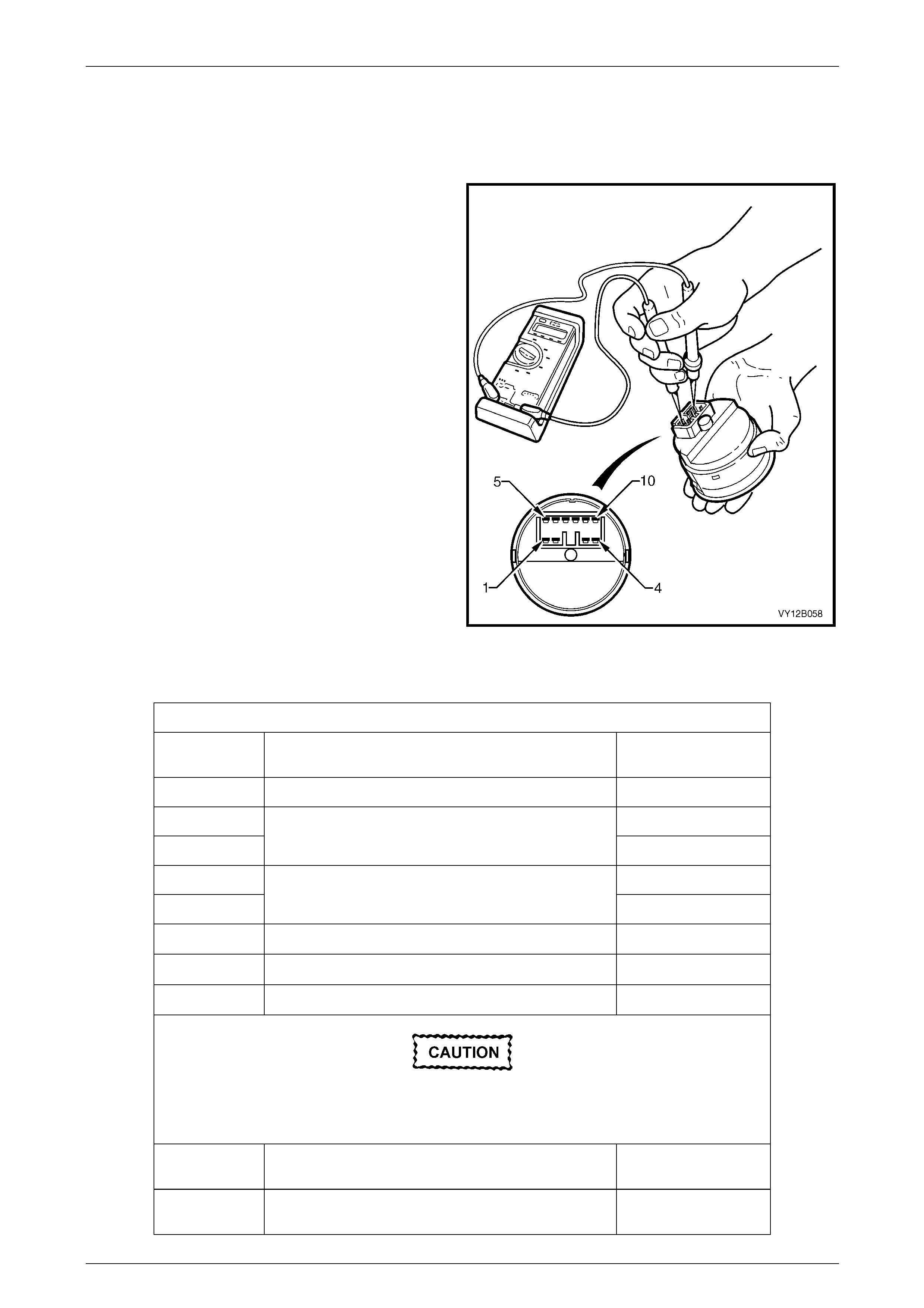
Lighting System Page 12B–147
Page 12B–147
Testing
To test the headlamp s witch assembly, use an ohmmeter to check the continuity or resistance when the switch is
actuated.
NOTE
Refer to Figure 12B – 137 an d Headlamp Switch
Assembly for headlamp switch assembly
positions.
1 Perform the removal procedure for the headlamp
switch assembly, refer to Section 1A3 Instrument
Panel and Console.
2 Place the headlamp switch assembly in the positions
detailed in the table, refer to Headlamp Switch
Assembly. Position the contacts of the ohmmeter onto
the terminals and take the reading; compare the
readings with those in the Headl amp Switch Assembly
table.
3 If there is continuity between any terminals o t her than
those listed, the headlamp switch assembl y is faulty. If
the headlamp switch assembly fails any part of the
test, replace the headlamp s witch assembl y with a
serviceable item.
4 Perform the reinstallation procedur e, refer to
Section 1A3 Instrument Panel and Co nsole.
Figure 12B – 138
Headlamp Switch Assembly
Headlamp Switch Assembly
Switch
Terminals Switch
Position Indication if Switch
is Serviceable
5 and 8 Switch in park lamp position; position B Continuity
5 and 8 Continuity
5 and 4 S witch in low beam position; position C Continuity
2 and 4 Continuity
2 and 8 Switch in AUTO position; position D Continuity
7 and 8 Dimmer in neutral position; p osition E 2.68 kΩ
7 and 8 Dimmer in high position, position F 5.36 kΩ
7 and 8 Dimmer in low position, position G 0 kΩ
The headlamp switch assembly must be in park,
low beam or AUTO position for the front fog
lamps to be activated.
5 and 6 Switch with front fog lamps activated; position H and
either park lamps or headlamps (low beam) on Continuity
2 and 6 Switch with front fog lamps activated; position H and
switch in AUTO position Continuity
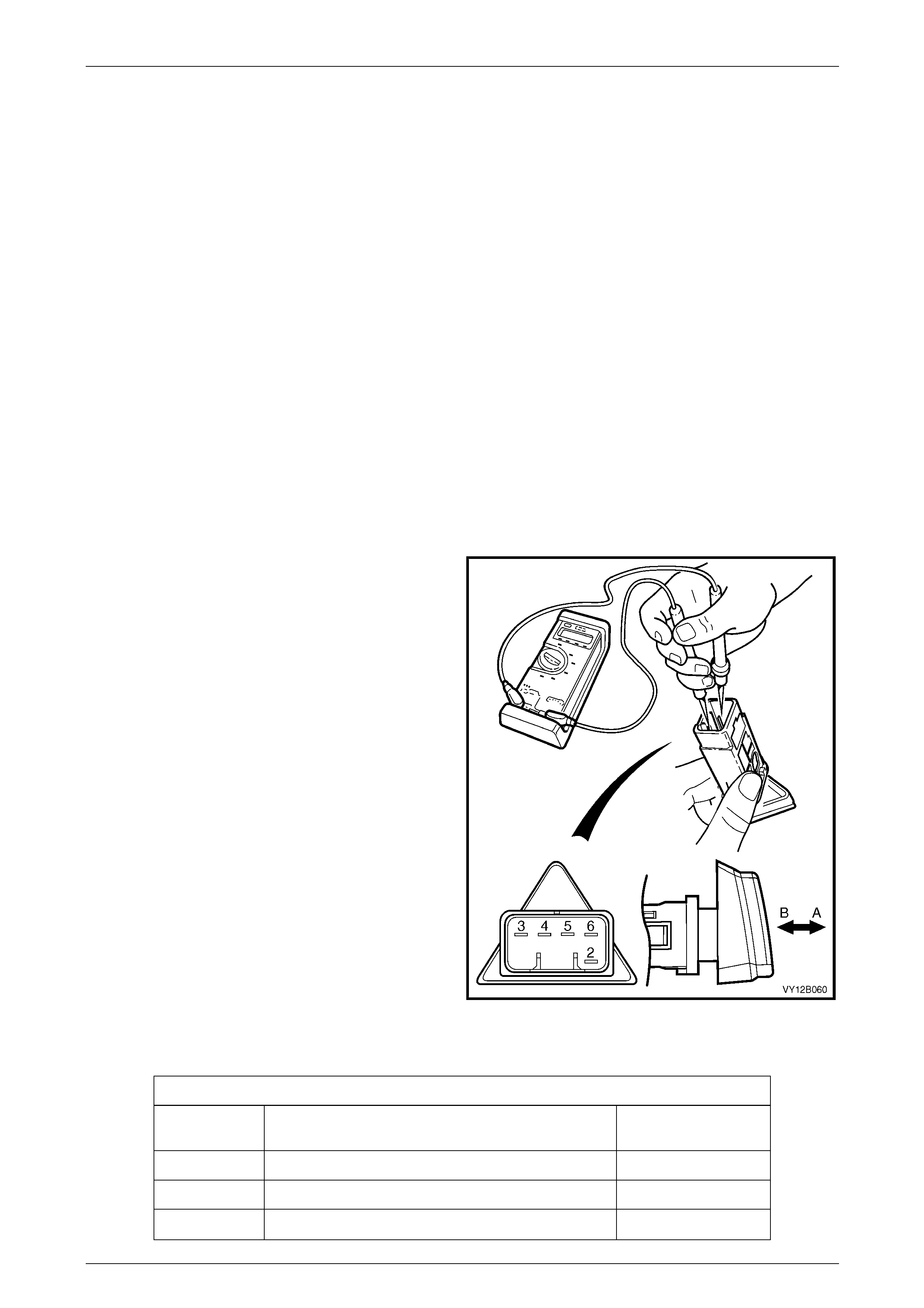
Lighting System Page 12B–148
Page 12B–148
9.19 Hazard Warning Switch Assembly
LT Section No. — 02–800
Remove
1 Remove fusible link F102 from the engine compartment fuse and relay panel assembl y,
refer to Section 12O Fuses, Relays and Wiring Harnesses.
2 Remove the instrument panel centre trim assembly, refer to Section 1A3 Instrument Panel and Console.
Reinstall
Reinstallation of the hazar d warni ng switch assembly is the reverse of the removal process. Check the hazard warning
switch assembly operation.
Testing
To test the hazard warning switch assembly, use a multimeter to check the continuity or resistance.
NOTE
Refer to Figure 12B – 139 and Headlamp Switch
Assembly for headlamp switch assembly
positions.
1 Perform the removal procedure for the hazard warning
switch assembly, refer to Section 1A3 Instrument
Panel and Console.
2 Place the hazard warning s witch assembly in the
positions detailed in the Hazar d W arning Switch
Assembly table, refer to Hazard Warning Switch
Assembly. Position the contacts of the ohmmeter onto
the terminals and take the reading; compare the
readings with those in the Hazard Warni ng Switch
Assembly table.
3 If there is continuity between any terminals o t her than
those listed, the hazard warning switch assembly is
faulty. If the hazard warning switch assembly fails any
part of the test, replace the hazard warning switch
assembly with a serviceable item.
4 Perform the reinstallation procedur e, refer to
Hazard Warning Switch Assembly.
Figure 12B – 139
Hazard Warning Switch Assembly
Hazard Warning Switch Assembly
Switch
Terminals Switch
Position Indication if Switch
is Serviceable
3 and 4 Switch in the OFF position; po sition A Continuity
3 and 5 Switch in the ON position; position B Continuity
2 and 6 Switch in either position, ON or OFF Approximately 30 Ω

Lighting System Page 12B–149
Page 12B–149
10 Service Operations, AWD Wagon
10.1 Front Fog Lamps
LT Section No. — 02–325
Front Fog Lamp Assembly
Remove
For the front fog lamp assembly removal procedure, refer to 5.7 Front Fog Lamp Assembly.
Replace
For the front fog lamp assembly replacement procedure, refer to 5.7 Front Fog Lamp Assembly.
Disassembly
For the front fog lamp assembly disassembly procedure, refer to 5.7 Front Fog Lamp Assembly.
Reinstall
For the front fog lamp assembly disassembly procedure, refer to 5.7 Front Fog Lamp Assembly.
Front Fog Lamp Assembly Bulbs
Replace
For the front fog lamp assembly bulb replacement procedur e, refer to 5.4 Front Fog Lam p Bulb Assemblies.

Lighting System Page 12B–150
Page 12B–150
10.2 Tail Lamps
LT Section No. — 02–350
Tail Lamp Assembly
NOTE
The backup lamp on the AWD Wagon is located
on the liftgate appliqué assembly. The AWD
Wagon tail lamp assembly and the two-wheel
drive Wagon tail lamp assemblies are not
compatible.
Remove
For the tail lamp assembly removal procedure, refer to 5.8 Tail Lamp Assembly.
Reinstall
Reinstallation of the tail lamp assembly is the reverse of the removal procedure, refer to 5.8 Tail Lamp Assembl y , noting
the following:
• The turn signal lamp has an amber bu lb socket assembly and is located in the bottom section of the tail lamp
assembly.
• The stop/tail lamp has a grey bulb socket assembly and is located in the top section of the tail lamp assembly.
Both the turn signal lamp assembly and stop/tail lamp assembly also have different lug configurations to prevent
installation into the incorrect tail lamp assembly receptacle.
Tail Lamp Assembly Bulbs
Replace
For the tail lamp assembly bulb replacement procedure, refer to 5.5 Tail Lamp Assembly Bulbs.
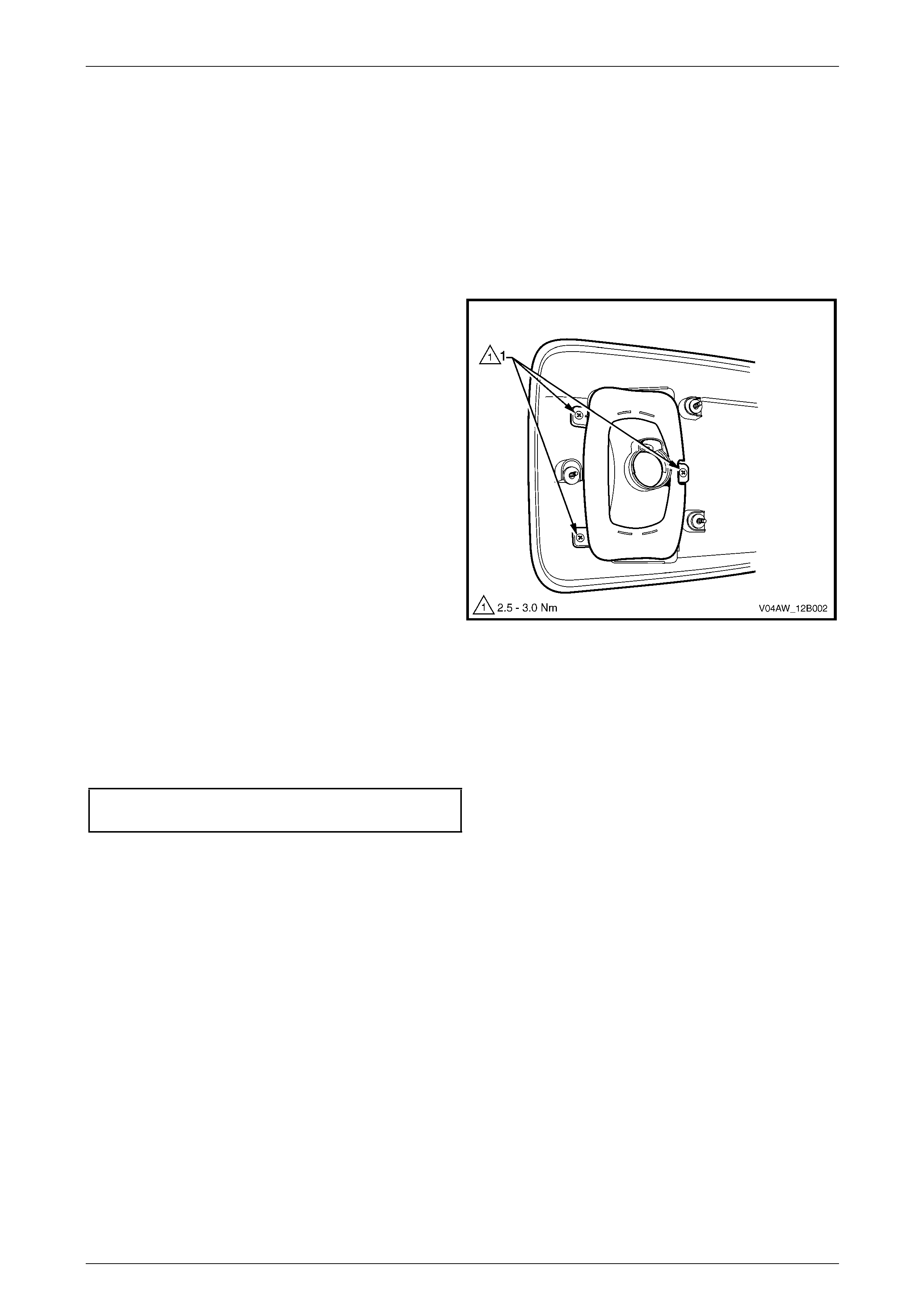
Lighting System Page 12B–151
Page 12B–151
10.3 Backup Lamps
LT Section No. — 02–350
Backup Lamp Assembly
Remove
1 Remove the liftgate appliqué assembl y, refer to Section 1A4 Hood, Rear Compartment Lid, Liftgate and Endgate.
2 Remove the three screws (1) attaching the backup
lamp assembly to the liftgate appliqué assembly.
Figure 12B – 140
Replace
Installation of the backup lamp assembly is the reverse of the removal procedure, noting the following:
1 Inspect the foam rubber seal for damage and replace if necessary, refer to Figure 12B – 19.
2 Tighten the backup lamp assembly attaching screws to the correct torque specification.
Backup lamp assembly screw
torque specification.....................................2.5 – 3.0 Nm
Backup Lamp Assembly Bulbs
Replace
1 Remove fusible link F102 from the engine compartment fuse and relay panel assembl y,
refer to Section 12O Fuses, Relays and Wiring Harnesses.
2 Remove the liftgate lower trim panel, refer to Section 1A4 Hood, Rear Compartment Lid, Liftgate and Endgate.
3 Remove the bulb from the bulb socket assembl y by pressi ng the bulb, then rotating it anticlockwise.
4 Inspect the bulb socket assembly seal for damage and replace if necessary.
5 Insert a new bulb into the bulb socket assembly and fit the bulb socket assembly into the backup lamp assembly,
ensuring the bulb socket assembly locks securely into place.
6 Install fusible link F102 on the engine compartment fuse and relay panel assembly,
refer to Section 12O Fuses, Relays and Wiring Harnesses.
7 Turn on the ignition s witch to the RUN position and check the backup lamp operation and confirm the backup
lamps illuminate.

Lighting System Page 12B–152
Page 12B–152
10.4 Liftgate Air Deflector Assembly and
High-mount Stop Lamp Assembly
LT Section No. — 02–350
For service operations for the liftgate air deflector assembly and high-mount stop lamp assembly,
refer to Section 1A4 Hood, Rear Compartment Lid, Liftgate and Endgate.

Lighting System Page 12B–153
Page 12B–153
11 Specifications
11.1 All Models (Except Regular Cab and
Crew Cab with 'Delete Tub' Option)
Bulb Power Rating
(Watts) Type
Headlamps
• Level 1:
• high/low beam
(outboard)
• inboard high beam
• Level 2 and 3, Coupe:
• low beam (outboard)
• inboard high beam
60 / 55
55
55
65
H4
H1
H11
H9
Tail lamps • stop/tail
• backup
21 / 5
21
P21 / 5W
P21W
Front fog lamps 55 H3
Park lamps (front) 5 Wedge
Side repeater lamps • Seda n, Wagon and Utility
• Coupe
5
5
clear wedge
orange wedge
Turn signal lamps (front) 21 offset pin (orange gl ass)
Turn signal lamps (rear) • Sedan, Wagon, Utility
• Coupe
21
21
offset pin (orange glass)
offset pin (silver vision)
Licence plate lamps 5 wedge
Hazard warning lamp switch bulb 1 bayonet
PWR switch bulb 1 bayonet
T/C switch bulb 1 bayonet
A/S switch 1 bayonet
ESP switch 1 bayonet
Rear compartment lamp 10 festoon
Dome (courtesy) lamp 10 festoon
Front seat reading lamp in dome 8 festoon
Roof console lamps 10 bayonet
Rear seat reading lamp 6 festoon (minixen)
Instrument panel compartment lamp 5 festoon
Front stepwell lamps 2.7 wed ge
Front vanity mirror lamp 1.4 wedge
Door courtesy lamps 5 festoon
Floor console compartment lamp 5 festoon
High-mounted stop lamp
• high-mounted stop lamp
• SV6 and SS spoiler-
mounted
• Coupe
18
5
5
wedge
LED assembly
LED assembly
Front and rear cigar lighter bul b 1.2 wedge
Ignition lock bulb 1.4 wedge

Lighting System Page 12B–154
Page 12B–154
11.2 Regular Cab and Crew Cab with 'Delete
Tub' Option
Bulb Power Rating –
Watts Type
Tail lamp turn signal lamp 21 bayonet
Tail lamp park lamp 10 bayonet
Tail lamp stop lamp 21 bayonet
Tail lamp backup lamp 21 bayonet
Licence plate lamps 10 bayonet

Lighting System Page 12B–155
Page 12B–155
12 Torque Wrench Specifications
12.1 Sedan, Wagon, Utility, Crew Cab and
Coupe
Front Fog Lamp Assembly Clamp Ring Securing Screw...............1.0 – 1.5 Nm
Tail Lamp Assembly Attaching Nut (Sedan)..................................1.5 – 2.0 Nm
Headlamp Assembly Retaining Screw...........................................2.0 – 5.0 Nm
Front Fog Lamp Assembly Clamp Ring Securing Screw...............1.0 – 1.5 Nm
Front Fog Lamp Assembly Le ns and
Reflector Housing Hinge Nut.........................................................1.0 – 1.5 Nm
Tail Lamp Assembly Attaching Nut
(Wagon, Utility and Crew Cab)......................................................1.0 – 3.0 Nm
High-mount Stop Lamp Assembly Attaching Screws ....................1.0 – 3.0 Nm
Rear Window Moulding Attaching Stud.........................................0.5 – 1.5 Nm
Tail Lamp Assembly Attaching Screw ...........................................1.0 – 3.0 Nm
Park and Front Fog Lamp Ass embly
Attaching Screw (Coupe)...............................................................1.0 – 3.0 Nm
Tail Lamp Assembly Attaching Screw (Coupe) .............................1.0 – 3.0 Nm
Rear Compartment Courtesy Lamp Switch
Assembly Attaching Screw............................................................1.0 – 3.0 Nm
Dome Lamp Assembly Attaching Screw........................................1.0 – 3.0 Nm
Dome and Reading Lamp Assembly Attaching Screw..................1.0 – 3.0 Nm
Door Ajar Switch Attaching Screw.................................................1.0 – 3.0 Nm
Transmission Selector Knob Attaching Screw...............................1.0 – 3.0 Nm
Daylight Running Lamps Module Attaching Screw........................1.0 – 2.0 Nm

Lighting System Page 12B–156
Page 12B–156
12.2 Regular Cab and Crew Cab with 'Delete
Tub' Option
Rear Licence Plate Lamp Assembly Attaching Screw...................1.5 – 1.5 Nm
Tail Lamp Assembly Attaching Nut................................................5.0 – 8.0 Nm
Rear Licence Plate Lamp Assembly Mounting Screw...................5.0 – 8.0 Nm
Transport Bracket Attaching Screw......................................................25.0 Nm

Lighting System Page 12B–157
Page 12B–157
12.3 AWD Wagon
Backup Lamp Assembly Attaching Screw.....................................2.5 – 3.0 Nm