
Cockpit Module Page 1E–1
28–NOV–2004 Page 1E–1
Section 1E
Cockpit Module
ATTENTION
Before performing any service operation or other procedure described in this Section, refer to Section 00
Warnings, Cautions and Notes for correct workshop practices with regard to safety and/or property damage.
1 General Description ...............................................................................................................................2
1.1 Precautions ............................................................................................................................................................ 2
General Precautions.............................................................................................................................................. 2
Installation Precautions ........................................................................................................................................ 3
Safety Precautions................................................................................................................................................. 3
2 Service Operations.................................................................................................................................4
2.1 Dash Panel Assembly............................................................................................................................................ 4
Preparation............................................................................................................................................................. 4
Remove................................................................................................................................................................... 5
Installation Preparation....................................................................................................................................... 10
Surface Preparation ......................................................................................................................................... 10
Checklist........................................................................................................................................................... 10
Mixing Adhesive and Catalyst .......................................................................................................................... 10
Reinstall................................................................................................................................................................ 12
Dash Panel Assembly...................................................................................................................................... 12
Components..................................................................................................................................................... 13
2.2 Dash Panel Assembly Repair.............................................................................................................................. 14
Panel Repair......................................................................................................................................................... 14
2.3 Adhesive Repair................................................................................................................................................... 16
3 Torque Wrench Specifications............................................................................................................17
4 Special Tools ........................................................................................................................................18

Cockpit Module Page 1E–2
28–NOV–2004 Page 1E–2
1 General Description
This Section describes the replacement of the dash panel assembly which is part of the cockpit module: a production line
sub-assembly consisting of the instrument panel, heater & A/C module assembly, steering column, pedal assembly,
wiring, etc. mounted to the dash panel asse mbly.
During production, the cockpit module is fitted to the vehicle in one o peration. It is lowered through the windshield
opening and the dash panel a ssembly is fitted into a channel known as the glue-track, which is part of the front floor
panel extension and hinge pillar inner panel assembly.
The glue track is filled with a special silicone adhesive prior to the cockpit module being installed. The dash panel
assembly aligns with several dimples and fo ur bolts secure it to the vehicle; two through the hinge pill ar and two in the
plenum area. Once the adhesive cures, the dash panel assembly becomes an integral part of the bod y structure.
The dash panel assembl y is clearly visible from within the engine compartment. It is the gloss-black body pan el forming
the plenum chamber below the windshield and continuin g to the floor panel. The glue-track can be seen where the dash
panel assembly joins the hinge pillars and floor.
The silicone adhesiv e is a specific type for this application and is suited for the high temperatures generated within the
engine compartment. It has excellent bonding, sealing and longevity characteristics. This technique has been in use for
many years.
The components of the cockpit module, e.g. i nstrument pa n el, steerin g column, heater & A/C module assembly, etc. can
be serviced in the normal manner. The dash panel assembl y can also b e serviced, however due to the fact it is glued-in,
the procedures in this Section must be followed.
Also included in this Section are rep air procedures for a damaged dash panel assembly and adhesive. As the dash panel
is glued to the vehicle, consid eration is needed for the adhesive when repair procedures are performed.
1.1 Precautions
General Precautions
1 Only the correct two-part silicone adhes ive should be used when refitting or repairing the dash panel asse mbly.
NOTE
Remove as much of the old adhesive as pos sible
from the glue track before installation.
2 As the dash panel assembly forms part of the vehicle structure, where it has any damage or cracks in the sheet
metal, or if fire damage has occurred, the dash panel assembly must be removed and replaced.
3 Tears, separation or splitting of the adhesive exceeding 300 mm in len gth requires removal and complet e re-gluing
of the dash panel. The adhes ive may be repaired where damage is less than 300 mm in length, refer to
2.2 Dash Panel Assembly Repair.
4 The silicone adhesiv e used in the glue track must not be replaced with any other type of adhesive or sealant other
than that which is recommended and ava ilable from an authorised dea ler as the Sealant Kit - Dash Panel.
Urethanes, epoxies, acrylic or normal silico nes, etc. are not suitable for use in this application. Failure to correctly
seal the cockpit module panel to the vehicle may allow exhaust, fuel or other fumes to enter the passenger
compartment and compromise the structural integrity of the vehicle.
5 The adhesive is best applied with the SAE 677 barrel gun & follower plate. Refer to an authorised dealer for
availability.

Cockpit Module Page 1E–3
28–NOV–2004 Page 1E–3
Installation Precautions
To obtain a satisfactory bond between the two
parts, the following procedures must be
observed.
1 Prior to installation of the dash panel assembly, remove as much of the remaining adh esi ve from the glue track as
possible.
2 After repairing any damaged sheet metal, completely remove the remaining adhesive in the repaired area and
apply primer and refinish the area according to the paint manufacturer’s specifications.
3 Do not apply paint over any remaining adhesive or allow overspray to get in the glue-track. Apply masking tape to
the track before painting, and install the dash panel assembly after oven baking the paint (where appropriate).
4 Do not use an adhesive other than which is recommended.
5 Body shell assemblies are available with the cockpit module installed, refe r to an authorised dealer for availa bility.
6 Before commencing installation of the dash panel assembly, thoroughly read Instal lation Preparation in this
Section.
7 Although the cockpit module is installed as an assembly on the production line, this method is not practical for
repairing the vehicle. The dash panel assembly should be installed first and once the adhesive has cure d, the
remaining components can b e installed as required.
Safety Precautions
The silicone adhesiv e used in the glue track, once cured, requir es no sp ecial precautions. However, when mixing the
adhesive compound with the catalyst and applying the adhesive, the following precautions should be o bserved.
1 Do not swallow: the catalyst is a toxic substance, keep away from children.
2 Safety glasses should be worn to avoid contact with eyes. If eye contact occurs, wash the area in clean water only,
and seek immediate medical advice.
3 To avoid skin irritation wear protective gloves when handling the adh esive and catalyst. If irritation occurs, wipe the
adhesive/catalyst off with a clean cloth and wash the affected area thoroughly in clea n water.
4 Vapour produced by the adhe sive and catalyst may cause breathing difficulties, use only in a well ventilated area.
5 The catalyst is combustible, keep away from sparks and flame.
Cockpit Module Page 1E–4
28–NOV–2004 Page 1E–4
2 Service Operations
ATTENTION
All fasteners are important attaching parts as they affect the performance of vital components and/or could
result in major repair expense. Where specified in this Section, fasteners must be replaced with parts of the
same part number or a GM approved equivalent. Do not use fasteners of an inferior quality or substitute
design.
Torque values must be used as specified during assembly to ensure proper retention of comp onents.
Fasteners must be replaced after loosening.
If this symbol precedes a fastener torque wrench specification, the recommendation regarding that fastener
must be adhered to.
2.1 Dash Panel Assembly
LT Section No. — 12–425
Preparation
Prior to commencing any of the following
procedures, disconnect the battery to disable
the Occupant Protection System.
As required, first remove the following components:
1 Hood and hinge assemblies, r efer to Section 1A4 Hood, Rear Compartment Lid, Liftgate and Endgate.
2 Drain the engine coolant, refer to Section 6B1 Engine Cooling – V6 or Section 6B3 Engine Cooling – GEN III V8.
3 Discharge the air-conditioning system (Manual or Auto A/C),
refer to Section 2B HVAC Occupant Climate Control (Manual A/C) – Servicing and Diagnosis.
4 Engine, refer to Section 6A1 Engine Mechanical – V6 or Section 6A 3 Engine Mechanical – GEN III V8.
5 Plenum cover assembly and windshield wiper assembly, refer to Section 12N Wipers, Washers and Horn.
6 Windscreen side garnish, refer to Section 1A8 Headlining and Interior Trim.
7 Hinge pillar trim, refer to Section 1A8 Headlining and Interior Trim.
8 Windshield assembly, refer to Section 1A6 Stationary Windows.
9 Floor console and instrument panel assembly, refer to Section 1A3 Instrum ent Panel and Console.
10 Passenger airbag assembly, refer to Section 12M Occupant Protection System.
11 Fuse panel, refer to Section 12O Fuses, Relays and Wiring Harnesses.
12 BCM, refer to Section 12J Body Control Module.
13 Instrument panel brackets and braces, refer to Section 1A3 Instrument Panel and Console.
14 PCM (for V8 Only), refer to Section 6C3 Powertrain Management – GEN III V8.
15 Heater & A/C module assembly,
refer to Section 2C HVAC Climate Control (Manual A/C) – Remov al an d Installation or
Section 2F HVAC Occupant Climate Control (Auto A/C) – Removal and Installation.
16 Steering Column assembly, refer to Section 9 Steering.
17 Brake master cylinder assembly and brake pedal assembly, refer to Section 5A Service a nd Park Braking System.
Cockpit Module Page 1E–5
28–NOV–2004 Page 1E–5
18 Accelerator pedal assembly, refer to Section 6C1-3 Engine Mana geme nt – V6 – Service Operations or
Section 6C3-3 Powertrain Management – GEN III V8 – Service Operations.
19 Clutch master cylinder assembly and cl utch ped al assembly, if fitted, refer to Section 7A1 Clutch – V6 or
Section 7A3 Clutch – GEN III V8.
20 As required, remove the wiring harnesses from the dash panel and lay out of the way,
refer to Section 12O Fuses, Relays and Wiring Harnesses.
NOTE
For the right-hand side, the dash panel ass embly
will be cut from around the wiring harness. This
saves disconnection of the complete main wiring
harness.
NOTE
As required, mark and identify the connectors to
aid reinstallation.
Remove
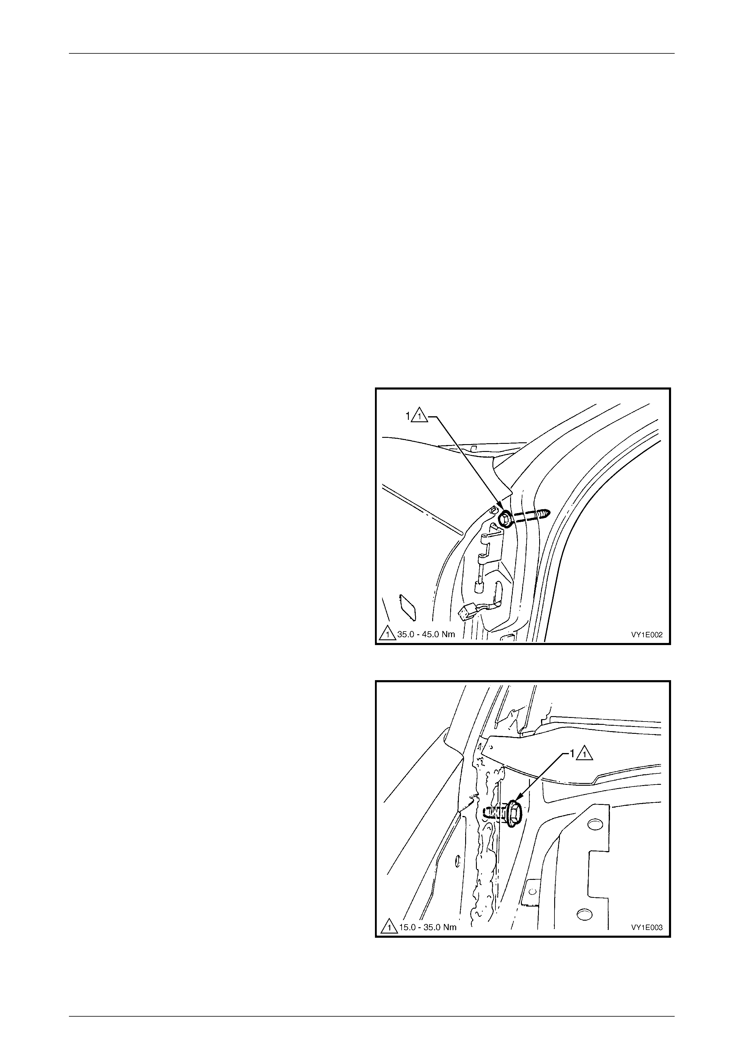
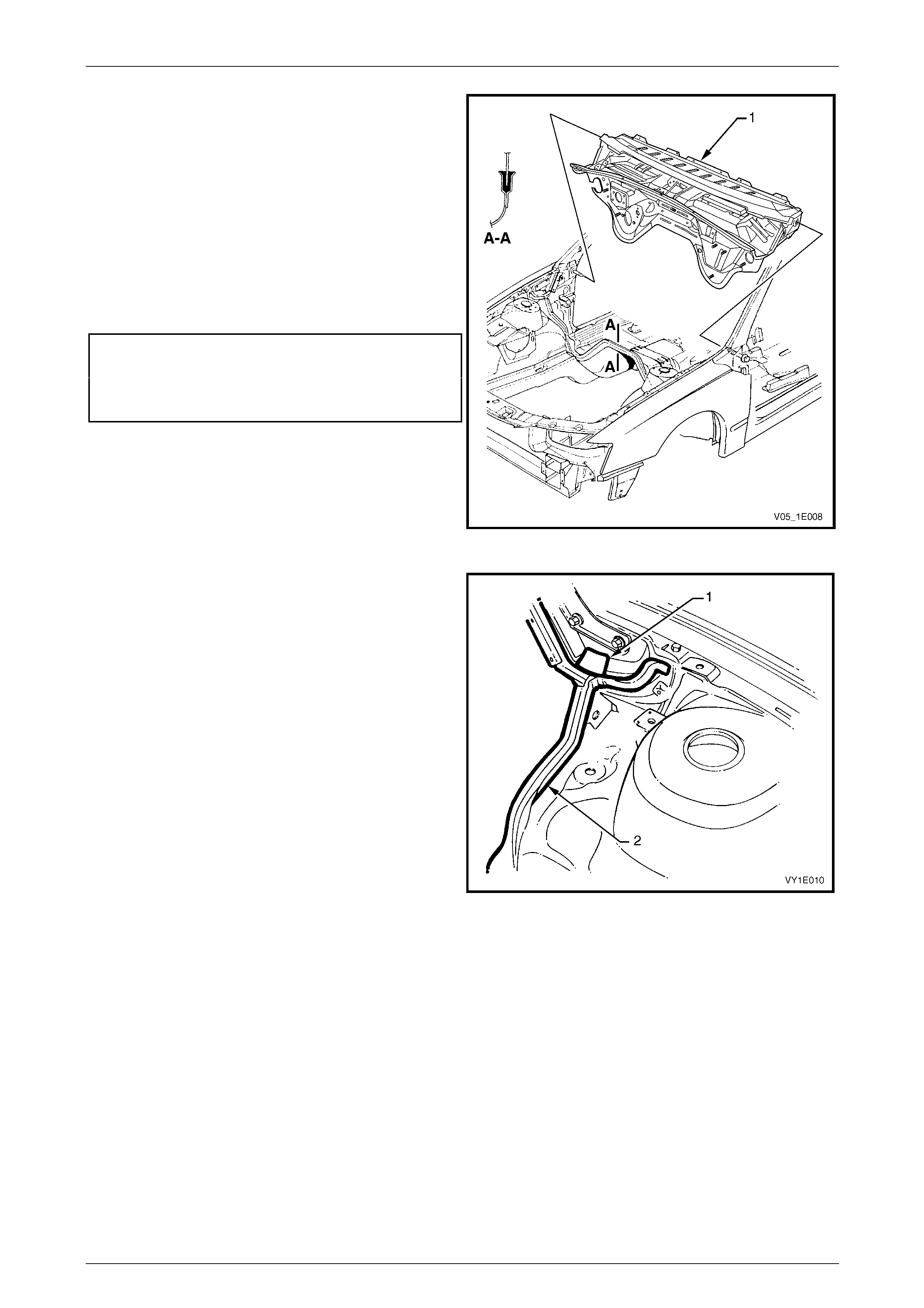
1 Remove the dash panel bolt (1) from each hinge pillar.
Figure 1E – 1
2 From within the plenum chamber, remove the dash
panel screw (1) each side.
Figure 1E – 2
Cockpit Module Page 1E–6
28–NOV–2004 Page 1E–6
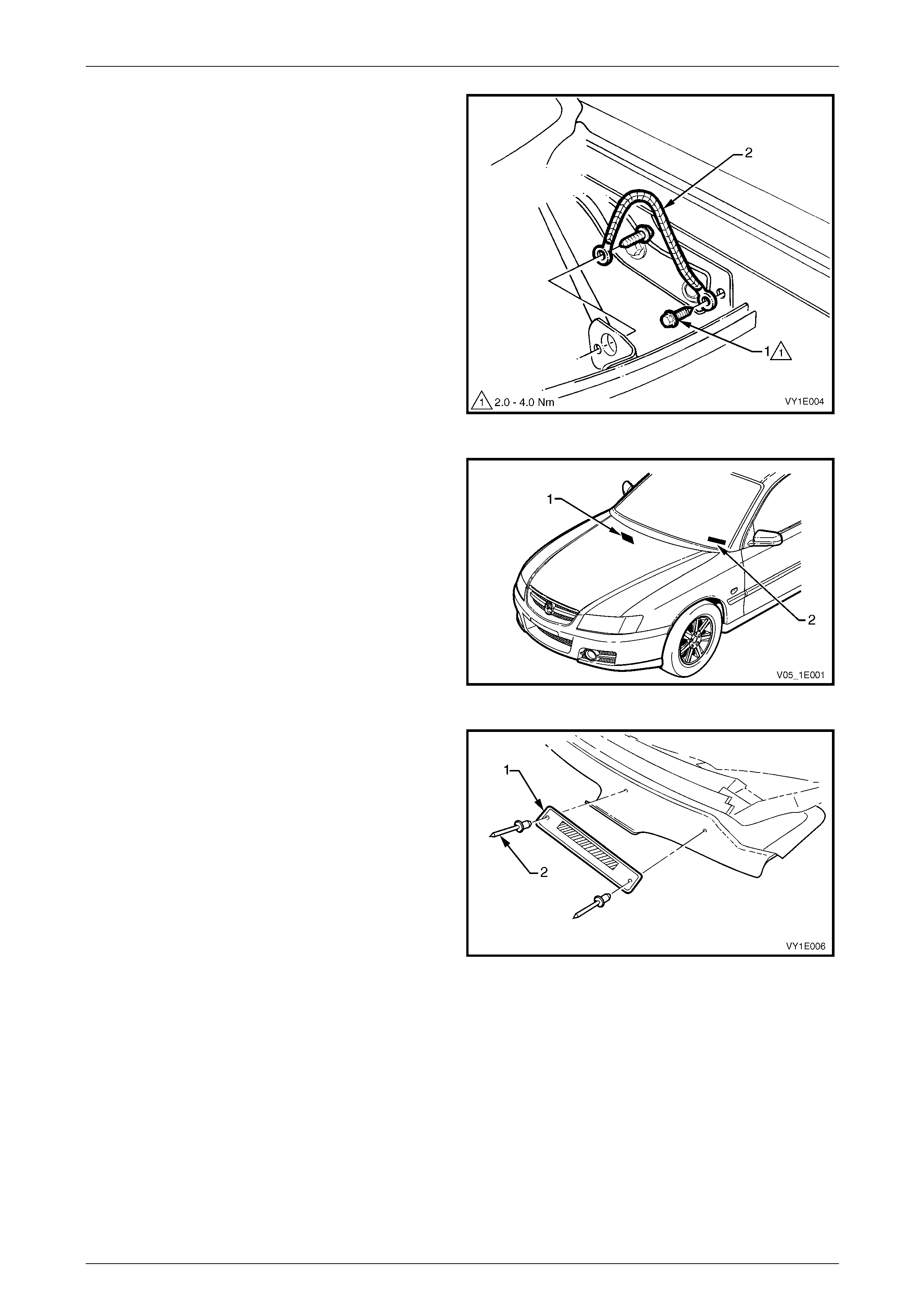
3 Remove the two screws (1) attaching the bo dy earth
strap (2) and remove.
Figure 1E – 3
4 Locate the safety compliance plate (1) near the centre
of the dash panel and VIN plate (2) on the left-hand
side of the dash panel.
5 Using a drill and suitable size drill bit, drill out the
retaining rivets.
Figure 1E – 4
6 Transfer the VIN plate (1) onto the ne w dash pane l
assembly.
7 Using a commerciall y available hand rivet tool and two
new rosette headed rivets (2), secure the VIN plate to
the new dash panel assembly.
Figure 1E – 5
Cockpit Module Page 1E–7
28–NOV–2004 Page 1E–7
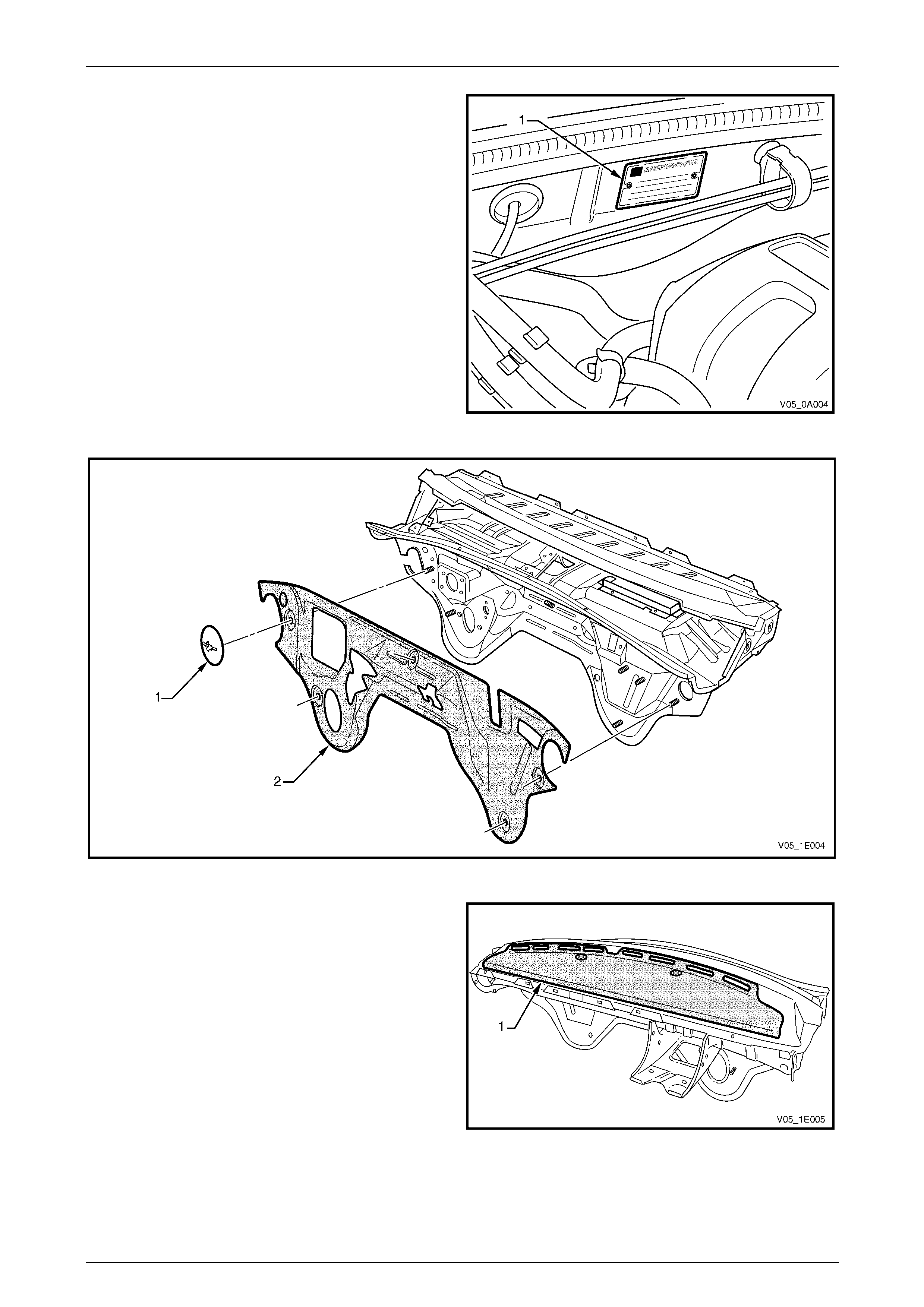
8 Transfer the safety compliance plate (1) onto new
dash panel assembly.
9 Using a commerciall y available hand rivet tool and two
new rosette headed rivets, secure the safety
compliance plat e to the new dash panel assembly.
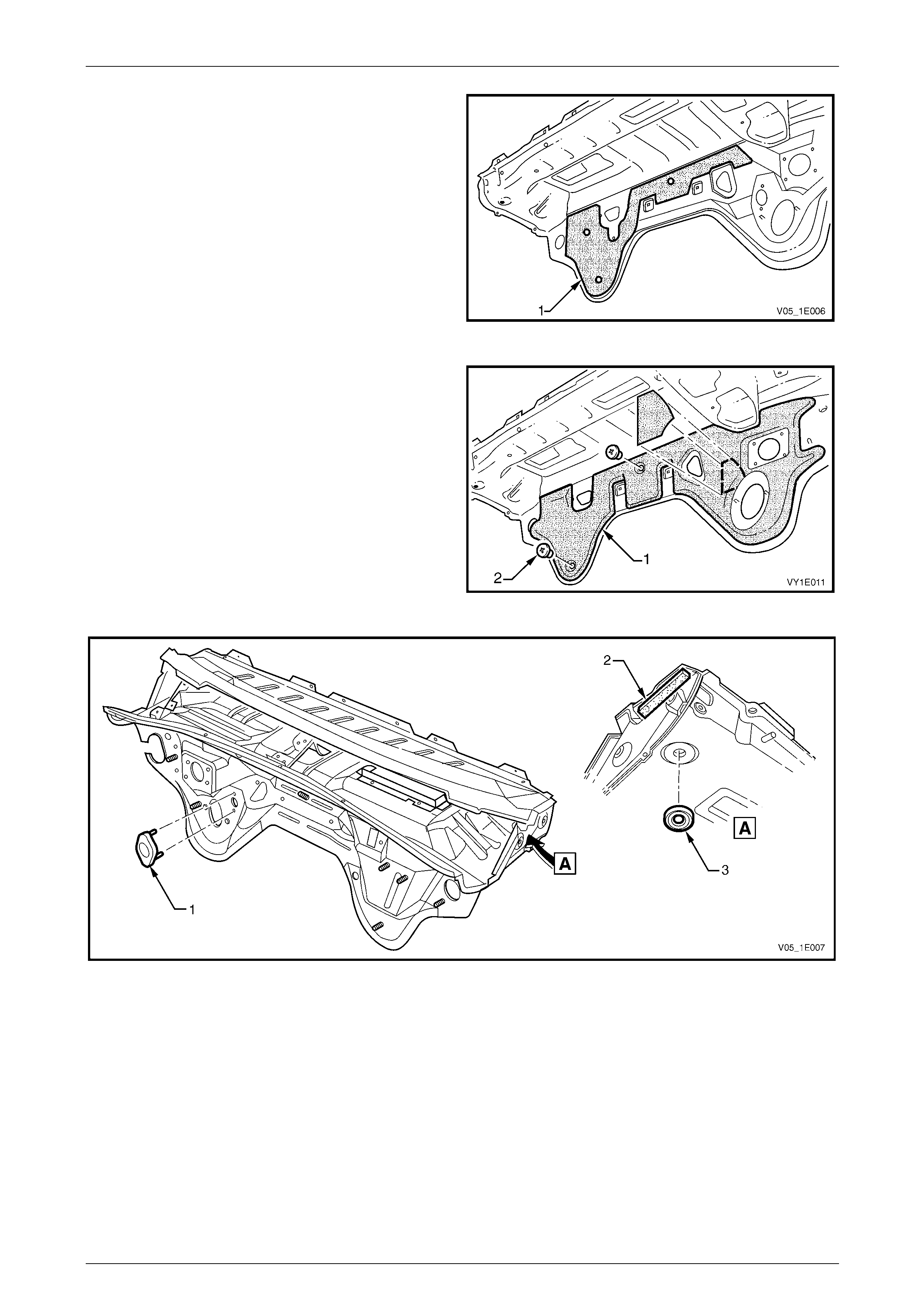
10 Remove the retainer (1) attaching the dash panel
lower insulator outer (2) to the engine compartment
side of the dash panel, refer to Figure 1E – 7.
Figure 1E – 6
Figure 1E – 7
11 Transfer the dash panel upper insulator (1) from the
existing dash panel to the new dash panel.
The insulator is adher ed to the dash panel and care is
required during removal. If required, apply contact
adhesive to the insulator prior to affixing it to the new
dash panel and ensure it follows the form of the dash
panel.
If a new insulator is being fitted, remove the backing
paper prior to fitting and appl y.
Figure 1E – 8
Cockpit Module Page 1E–8
28–NOV–2004 Page 1E–8
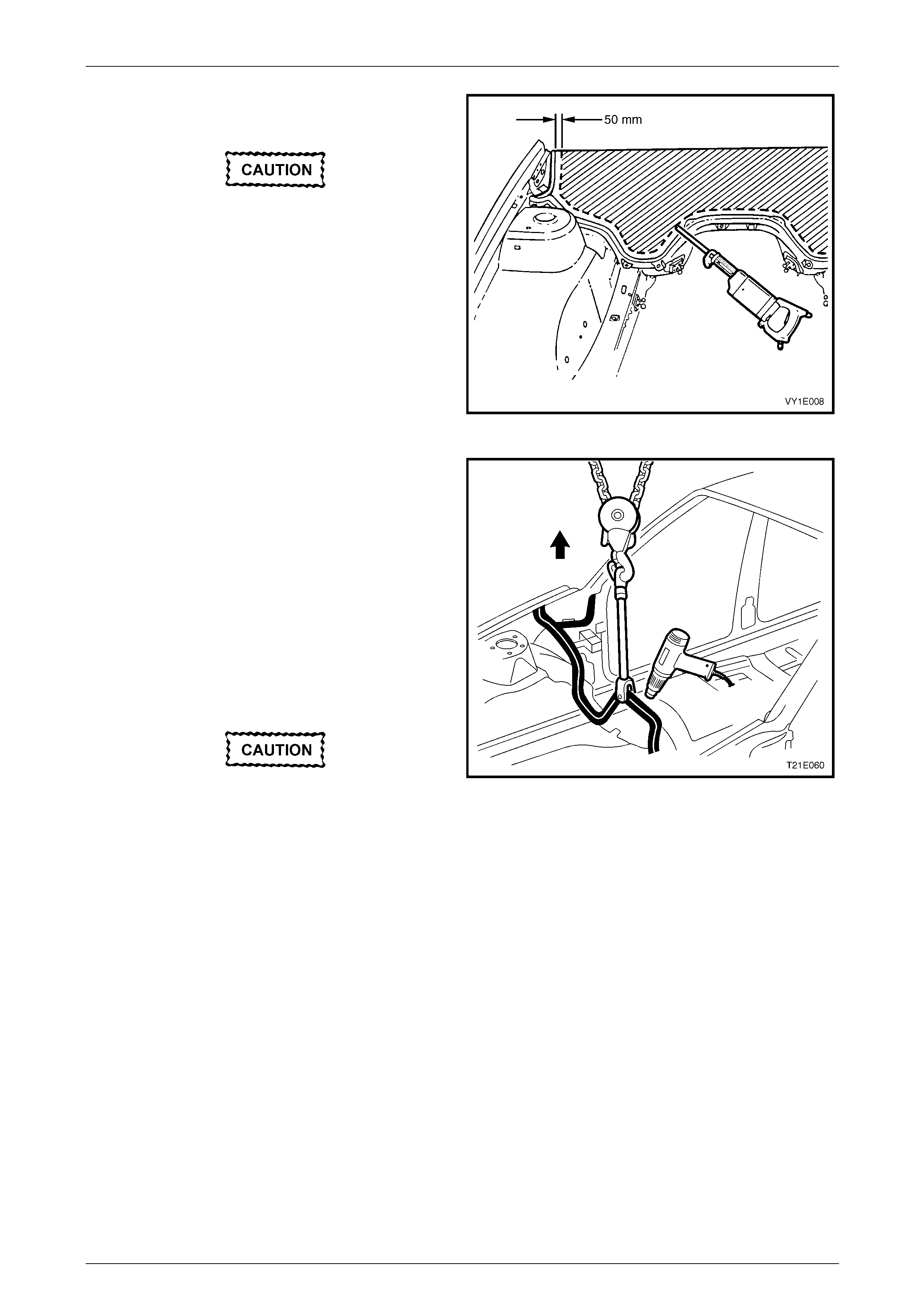
12 The dash panel lower deadener (1) cannot be
transferred to the new dash panel; a new deadener
will be required. Affix the deadener to the new dash
panel now to allow the dash panel lower insulator to
be transferred.
The deadener is a heat-fusible type. Install it in
position with the diamond embosse d side to the panel.
Use a heat gun, heat lamps or such, to cure the
deadener. Smooth the deadener with a roller or such
to expel any air bubbles and to maximise adhesion.
Figure 1E – 9
13 Transfer the dash panel lower insulator inner (1) from
the existing dash panel. The insul ator is attached with
two retainers (2).
14 Transfer the plug (1), if fitted, spacer (2) and plug (3),
refer to Figure 1E – 11.
Figure 1E – 10
Figure 1E – 11
Cockpit Module Page 1E–9
28–NOV–2004 Page 1E–9
15 Using a power saw, cut the dash panel assembly
approximately 50 mm above the gl ue track.
Sparks may ignite petrol in the fuel or
emission control lines if due precautions are
not taken.
NOTE
Take care cutting around the main wiring
harness.
16 Remove the dash panel asse mbly section.
17 Cut the section of remaining panel to enable removal
of the main wiring harness.
Figure 1E – 12
18 Drill a hole in the flange above the transmission
tunnel, and attach a chain block and a clevis.
19 Apply and maintain a light tension to the remaining
part of the dash panel assembly.
20 Either cut the adhesive with a hot knife or heat the
adhesive using a heat gun and pull the panel from the
glue track.
NOTE
This may be required in several places.
21 Clean the excess adhesive from the glue track using a
hot knife or a heat gun and tool.
To avoid fire, do not attempt to burn the
remaining adhesi ve from the glue track u sing
an oxy / acetylene torch . Figure 1E – 13

Cockpit Module Page 1E–10
28–NOV–2004 Page 1E–10
Installation Preparation
NOTE
Do not attempt to install a fully built-up cockpit
module assembly.
Surface Preparation
Clean any remaining a dh esive from the glue track using a hot knife or heat gun.
The vehicle should be painted before installation of the das h panel assembl y. Before painting the vehicle, apply masking
tape to prevent overspray e nterin g the glue track, particularly where any adhesive remains.
The adhesive will not adh ere to old adhesive that has pai nt overspray, oil, grease, etc. The glue track must be free of dirt,
dust, grease, oil and paint or overspra y.
Wipe the glue track with a suit able cleaning agent such as Pr epsol or equivalent, then clean any residue from the area
with a clean, dry, lint free cloth.
Temporarily install the ne w dash pa nel assembly prior to mixing the adhesive to check for correct fit. Rectify any faults
found then remove the panel from the vehic le.
NOTE
Before mixing the adhesive, it is advisable to
have the SAE 677 barrel gun & follower plate.
Refer to the latest Spare Parts Information for
details.
Checklist
Before mixing the adhesive and installing the dash panel assembly, the follo wing items should be checked:
• Familiarise yourself with the precautions in 1.1 Precautions.
• Ensure the adhesive being us ed is the recommended material.
• The vehicle surface shou ld be finished and the paint fully dr y before installation.
• Clean any overspra y, grease, oil, dirt, etc. from the glue track using an agent such as Prepsol or equiv alent and a
clean, dry, lint-free cloth.
• Test fit the module panel in the glue track BEFORE MIXING THE ADHESIVE.
• Is the adhesive applicator gun clean and ready for use?
• Are the cockpit module bolts readily accessible?
Mixing Adhesive and Catalyst
The vapour from the adhesive may cause
breathing difficulties, use only in a well
ventilated area. In case of eye contact, flush
immediately with clean water. Refer to Safety
Precautions in 1.1 Precautio ns.
COMBUSTIBLE – keep away from spark and
flame.

Cockpit Module Page 1E–11
28–NOV–2004 Page 1E–11
This is a two-part, fast cure adhesive. Ensure
the panel is ready for installation before
mixing the adhesi ve. The working time is less
than 20 minutes.
Part A: Adhesive compound, yellow in
colour and supplied in a 1.4 kilogram
container.
Part B: Catalyst, used to accelerate the cure
time of the adhesive compound and is
supplied in a 120 gram tube.
The contents of the Sealant Kit - Dash Panel
is sufficient to install the dash panel
assembly in a vehicle.
1 Remove the lid from the adhesive compound container.
2 Remove the cap from the catalyst and pierce the end of the tube, then squeeze the entire contents of the tube into
the adhesive compound container.
3 Hold the container securel y, and mix the catalyst into the adhesive using a paint mixer or a flat clean wooden
utensil.
4 Continue to mix until the adhesive is a c onsistent grey colour without any streaks.
5 Place the follower plate supplied with the applicator gun into the adhesive container.
6 Remove the front end cap and disposa ble nozzle from the applicator gun.
7 Cut the tip from the nozzle.
8 Place the applicator gun front end over the hole in the follower plate.
NOTE
The easiest method of drawing the adhesive into
the gun is to proceed slowly, allo w the downward
pressure on the plate and the suction of the gun
to draw the compound.
9 Simultaneously push down on the gun and plate with maximum pressure, press the gun’s release plate inward and
slowly pull the T-bar (piston) out ward. This procedure will slowly suck the mixed adhesiv e into the applicator gun.
10 Wipe any excess adhes ive from the applicator gun, scre w the end cap onto the applicator gun and then reinstall
the nozzle.
11 Proceed immediately with installing the panel.
After mixing the silicone adhesive, installation
of the cockpit module panel should be
completed within 15 – 20 minutes. Under
normal conditions, the adhesive will begin to
cure in about 25 – 30 minutes. After
installation, the dash panel assembly or
vehicle should not be moved or disturbed
until the adhesive is fully cured (about 3
hours).
Cockpit Module Page 1E–12
28–NOV–2004 Page 1E–12
Reinstall
Dash Panel Assembly
NOTE
Do not attempt to install a fully built-up cockpit
module assembly.
1 Ensure any remaining adhesi ve is cleaned off the glue track using a hot knife or heat gun.
2 Check each item in Installation Preparation – Checklist.
3 Mix the silicone adhesive and fill the applicator gun as described in
Installation Preparation – Mixing Adhesive and Catalyst.
NOTE
Installation is best performed with the aid of two
people.
4 Begin filling the glue track from the lowest points to prevent air bubbles forming in the adhesive. Completely fill the
channel in a continuous bead.
5 Apply a patch of adhesive approximatel y 50 mm diameter to the base or the windshield pillar.
6 Hold the dash panel assembly in position slightly above the glue track.
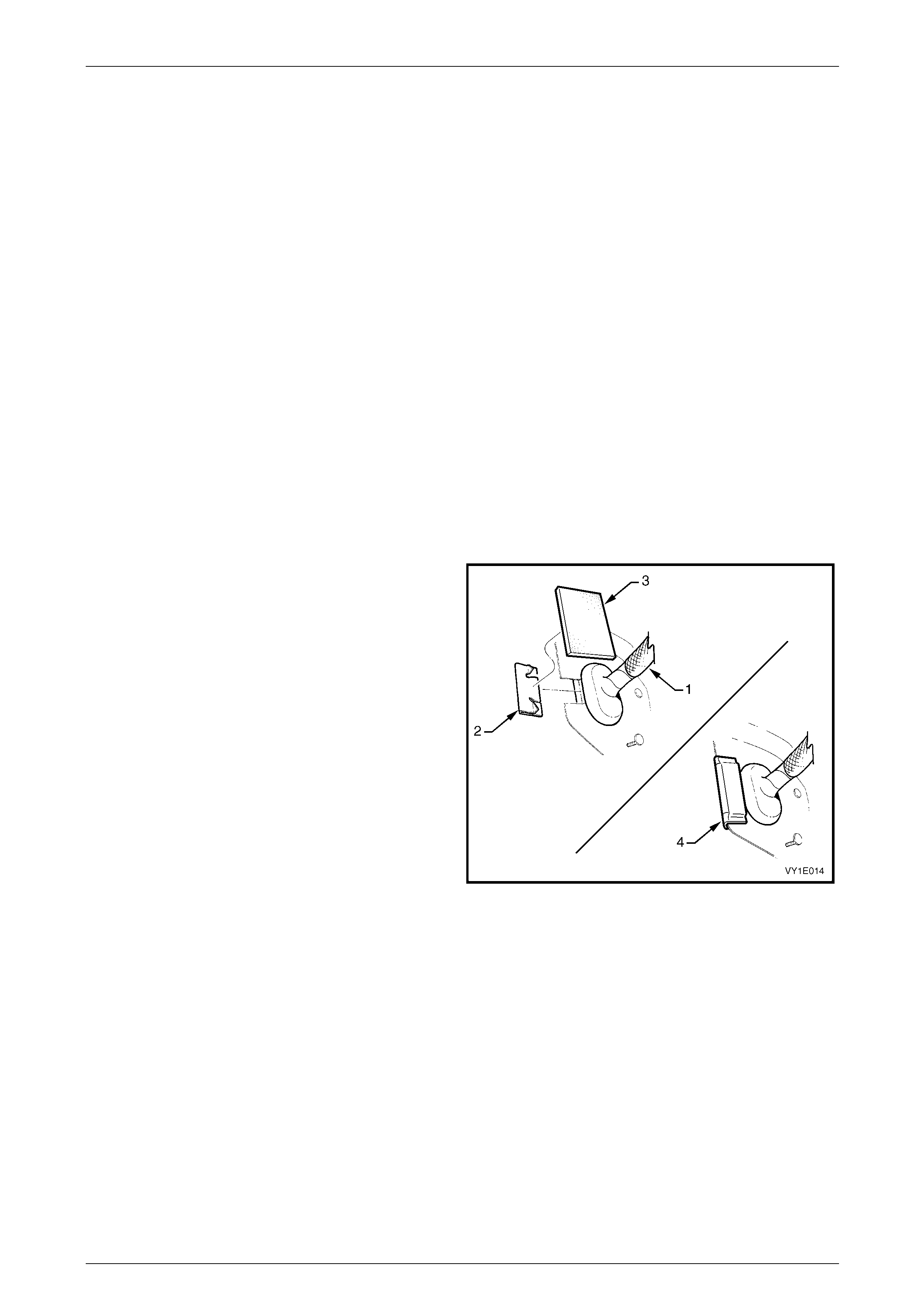
7 Have an assistant pass the main wiring harness (1)
through the opening in the dash panel.
8 Install the dash panel outer opening cover (2) onto the
dash panel assembly.
9 Affix the dash panel side insu lator (3) over the cover
and fold over the back of the panel as shown (4).
Figure 1E – 14
Cockpit Module Page 1E–13
28–NOV–2004 Page 1E–13
10 Lower the dash panel assembly (1), ensuring the
flange seats correctly in the glue track.
11 Push the panel firmly into the glue track channel until
mounting bolt holes align. Check to ensure the section
around the main wiring harness hole is correctly
installed.
12 Install two new dash pane l bolts through the hinge
pillar and two new screws within the plenum chamber
and hand tighten.
13 Recheck the flanges are correctly seated.
14 Tighten the bolts and scre ws to the specified torque.
Dash panel screw (plenum side)
torque specification.................................15.0 – 35.0 Nm
Dash panel bolt (hinge pillar side)
torque specification.................................35.0 – 45.0 Nm
Figure 1E – 15
15 Wipe any exce ss adhesive from the plenum drain hole
(1) each side and the glue track areas (2).
16 Immediately following dash panel ass embl y
installation, clean any adhesive from the applicator
gun and follower plate.
17 Leave adhesive to cure for a minimum of thr ee hours.
Figure 1E – 16
Components
Installation of the cockpit module components is the reverse of the removal, noting the follo wing.
1 Ensure all the rubber grommet s and insulation materials are installed onto the das h panel assembly.
2 Ensure all fasteners are tightene d to the correct torque specification.
3 Ensure the heater & A/C module assembly drain tub e is correctly installed.
4 Ensure that all wiring harness es are correctl y routed and retained correctly, refer to
Section 12O Fuses and Wiring Harness.
5 Ensure the stop lamp switch and cruise control release s witches are adj usted correctl y, refer to
Section 12B Lighting System and Section 12E Cruise Control.
6 On battery reconnection, check the occupant protection sys t em for correct operation, refer to
Section 12M Occupant Protection System and repro gram th e aud io system security PIN, refer to
Section 12D Entertainment System.

Cockpit Module Page 1E–14
28–NOV–2004 Page 1E–14
2.2 Dash Panel Assembly Repair
Panel Repair
The dash panel assembly c an only be levered
against itself. Levering or pulling from other
panels or external objects may cause the
dash panel assembly to separate from the
adhesive and glu e track.
If the dash panel assembly is separated from the glue track for less than 300 mm, due to damage of eith er the dash
panel assembly or surroundin g pan els and the dash panel assembl y is serviceable, it is permissible to repair the panel
without removal.
1 Disassemble the required components to allow access, refer to 2.1 Dash Panel Assembly.
2 Cut the required section of adhesive from the glu e track usi ng a hot knife.
3 Repair the damage to the surrounding panels as required.
4 Secure two clamps or brackets (1) to the dash panel assembly to act as levering points to straighten the damaged
area (2), refer to Figure 1E – 17.
NOTE
Depending on the damage, it may be more
appropriate to pull the area instead of pushing it.
5 Install a suitable hydraulic ram (3) between the clamps.
6 Make the necessary repairs and ad justments to the dash panel to ensure an accurate fit in the glue track.
Figure 1E – 17
Cockpit Module Page 1E–15
28–NOV–2004 Page 1E–15
7 With the dash panel assembly (1) correctly seated in
the glue track (2), fill the glue track with the approved
adhesive (3). Follow the proce dures as required in
2.1 Dash Panel Assembly – Preparation and
2.1 Dash Panel Assembly – Reinstall – Dash Panel
Assembly.
8 Allow the adhesive at least three hours to cure before
performing any further work or painting the ve hicle.
Figure 1E – 18
Cockpit Module Page 1E–16
28–NOV–2004 Page 1E–16
2.3 Adhesive Repair
Adhesive tears or splits of less than 300 mm in length may be repaired using single pack silico ne adhesive. Repairing a
tear or split longer than 300 mm in len gth necessitates removal of the dash panel assembly, as described previously,
with complete replacement of the silic one adhesive.
1 Wipe the surrounding area with a cleaning agent such as Prepsol, then remove any residue from the area with a
dry, lint free cloth.
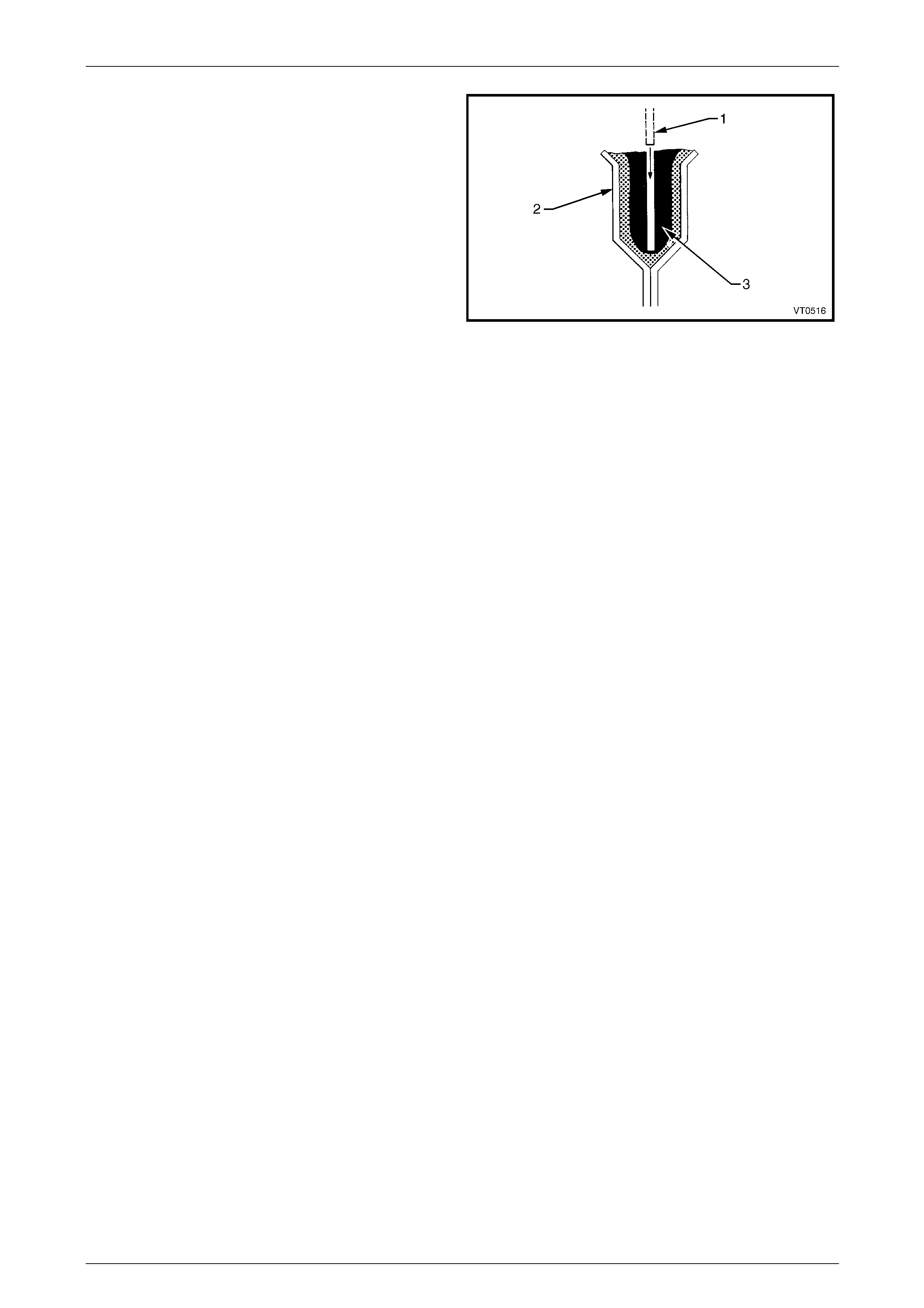
2 Cut a deep V (1) into the adhesive (2), completely
cutting out the torn or split section.
NOTE
The area must be completely clean; free of dirt,
oil, grease, etc. to obtain satisfactory adhesion of
the silicone adhesive.
3 If necessary, wipe the metal area of the glue track with
mineral spirits, then wipe the residue from the surface
using clean, dry, lint free cloth .
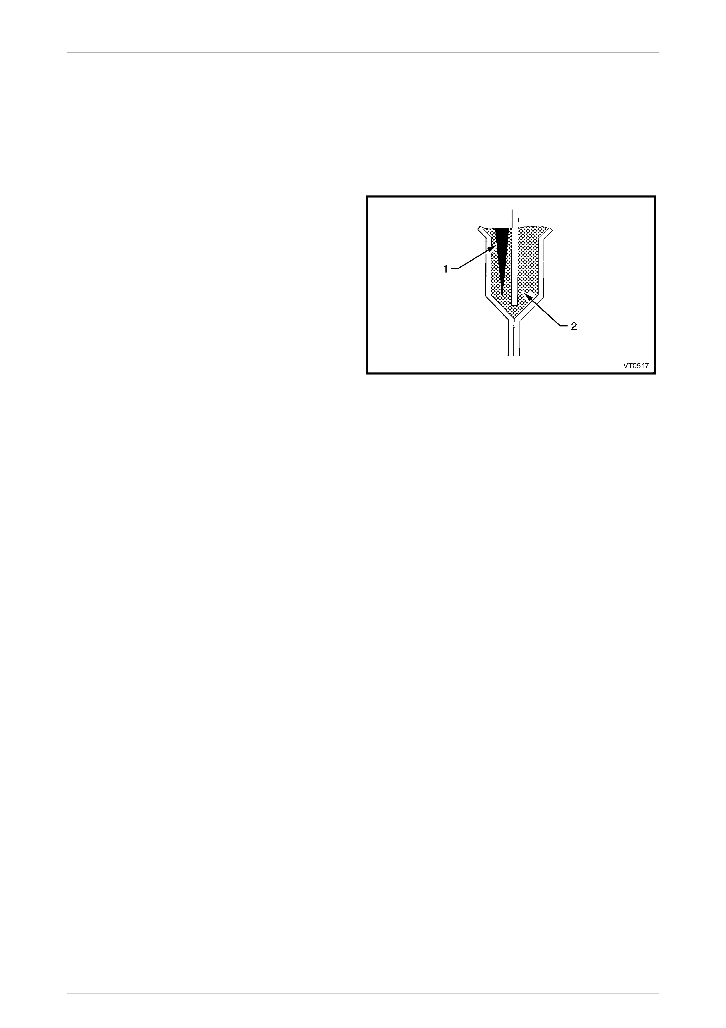
4 Fill the void with silicone adhesive, ensuring no air
bubbles remain trapped in the adhesive.
5 Smooth out the adhesive flush with adjacent area.
6 Clean up any excess before the adhesive cures, using
mineral spirits.
7 Allow the adhesive to cure (up to 24 hours), before
performing any further work on the area.
Figure 1E – 19

Cockpit Module Page 1E–17
28–NOV–2004 Page 1E–17
3 Torque Wrench Specifications
ATTENTION
All fasteners are important attaching parts as they affect the performance of vital components and/or could
result in major repair expense. Where specified in this Section, fasteners must be replaced with parts of the
same part number or a GM approved equivalent. Do not use fasteners of an inferior quality or substitute
design.
Torque values must be used as specified during assembly to ensure proper retention of comp onents.
Fasteners must be replaced after loosening.
If this symbol precedes a fastener torque wrench specification, the recommendation regarding that fastener
must be adhered to.
Dash Panel Screw (Plenum Side).........................................15.0 – 35.0 Nm
Dash Panel Bolt (Hinge Pillar Side)......................................35.0 – 65.0 Nm
Body Earth Strap Screws ..............................................................2.0 – 4.0 Nm
Cockpit Module Page 1E–18
28–NOV–2004 Page 1E–18
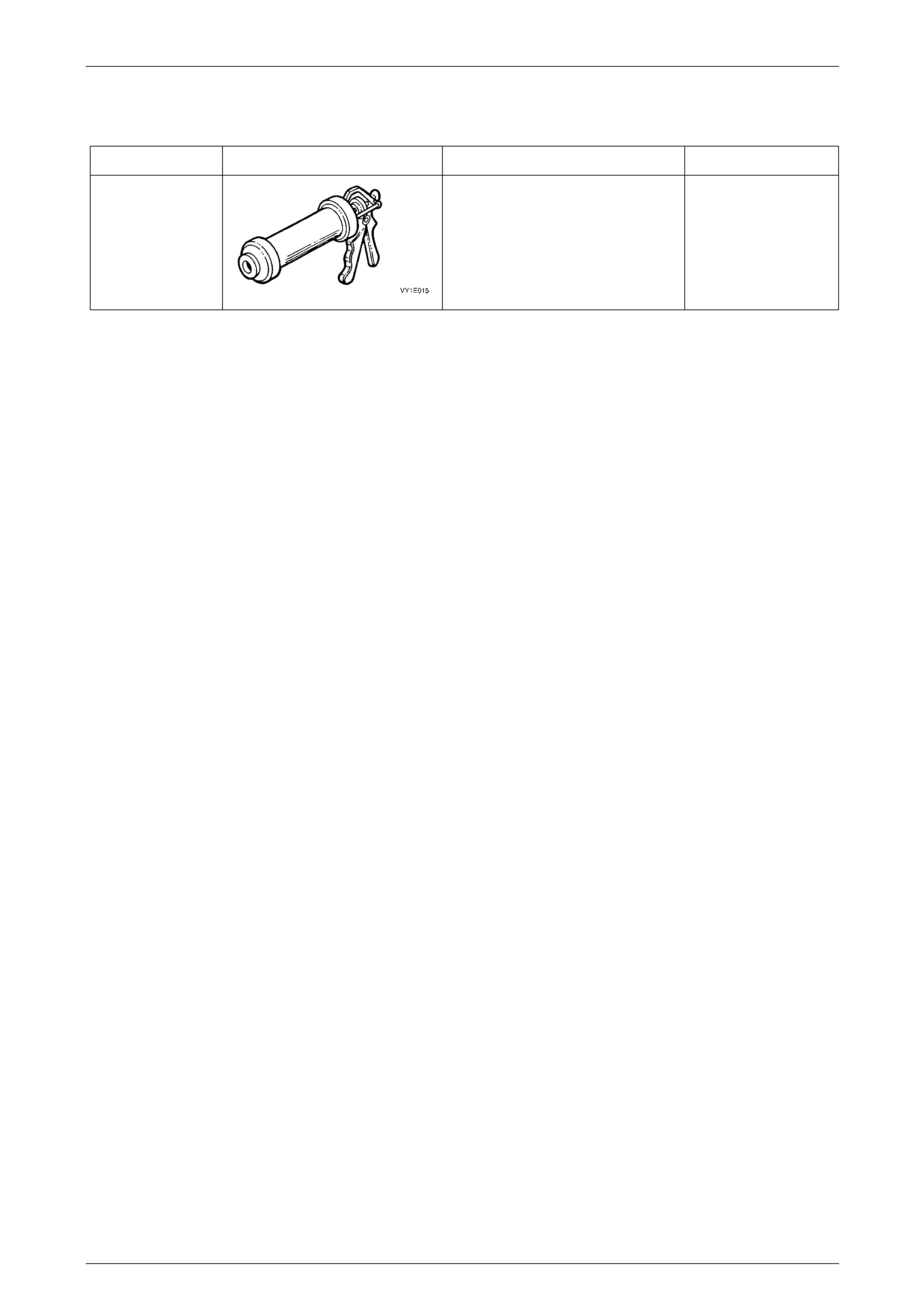
4 Special Tools
Tool Number Illustration Description Tool Classification
—
SAE 677 Barrel Gun & Follower
Plate
Used to apply dash panel assembly
two-part silicone adhesive.
Previously available, refer part s
catalogue
Desirable