
Service and Park Braking System 5A – 1
Section 5A
Service and Park Braking Systems
ATTENTION
Before performing any Service Operation or other procedure described in this Section, refer to Section 00
Warnings, Cautions and Notes for correct workshop practices with regard to safety and/or property damage.
1 General Information ...............................................................................................................................4
1.1 General Description............................................................................................................................................... 4
1.2 Master Cylinder...................................................................................................................................................... 5
Description............................................................................................................................................................. 5
Construction........................................................................................................................................................... 5
Typical Exploded View of Brake Master Cylinder............................................................................................... 6
Operation................................................................................................................................................................ 6
1.3 Vacuum Brake Booster ......................................................................................................................................... 7
Description............................................................................................................................................................. 7
Construction........................................................................................................................................................... 7
Operation................................................................................................................................................................ 7
Mechanical Brake Assist (MBA)......................................................................................................................... 7
1.4 Load Sensing Proportioning Valve – Utility, Regular/Crew Cab Models (excludes MY06 Vehicles).............. 8
Construction....................................................................................................................................................... 8
Operation ........................................................................................................................................................... 8
1.5 Front and Rear Brake Calipe rs ............................................................................................................................. 9
Front Brake Caliper – All Except Coupe and MY2006 SS.................................................................................. 9
Front Brake Caliper – Coupe a nd MY2006 SS Models.................................................................................... 10
Rear Brake Caliper........................................................................................................................................... 11
1.6 Brake Pipes and Ho ses ....................................................................................................................................... 12
Description........................................................................................................................................................... 12
1.7 Rear Brake Backing Plates and ABS Sensors – Live Axle Models Only......................................................... 13
2 Minor Service Operations....................................................................................................................14
2.1 Service Warnings, Cautions and Notes............................................................................................................. 14
2.2 Park Brake Cable, Adjust .................................................................................................................................... 16
2.3 Brake Fluid Level Check ..................................................................................................................................... 17
2.4 Brake System Bleed ............................................................................................................................................ 18
2.5 Brake Fluid, Change............................................................................................................................................ 19
2.6 Brake Pad Wear, Check....................................................................................................................................... 21
Front or Rear........................................................................................................................................................ 21
2.7 Brake Pads, Replace............................................................................................................................................ 22
Preparation........................................................................................................................................................... 22
Front Brake Pads ................................................................................................................................................. 23
Remove............................................................................................................................................................ 23
Brake Pad Installation ...................................................................................................................................... 24
Rear Brake Pads .................................................................................................................................................. 24
Remove............................................................................................................................................................ 24
Reinstall ........................................................................................................................................................... 25
Brake Pad Bedding-In Procedure....................................................................................................................... 26
2.8 Brake Pedal Assembly ........................................................................................................................................ 27
Remove................................................................................................................................................................. 27
Disassemble......................................................................................................................................................... 30
Reassemble.......................................................................................................................................................... 30
Reinstall................................................................................................................................................................ 30
5A – 1

Service and Park Braking System 5A – 2
2.9 Park Brake Lever.................................................................................................................................................. 32
Remove................................................................................................................................................................. 32
Reinstall................................................................................................................................................................ 33
2.10 Park Brake Warning Lamp Switch...................................................................................................................... 34
Remove................................................................................................................................................................. 34
Inspect .................................................................................................................................................................. 34
Reinstall................................................................................................................................................................ 34
2.11 Front Park Brake Cable ....................................................................................................................................... 35
Remove................................................................................................................................................................. 35
Reinstall................................................................................................................................................................ 35
2.12 Rear Park Brake Cab le/s ..................................................................................................................................... 37
Remove................................................................................................................................................................. 37
Reinstall................................................................................................................................................................ 38
2.13 Front Brake H ose................................................................................................................................................. 39
Remove................................................................................................................................................................. 39
Reinstall................................................................................................................................................................ 39
2.14 Rear Caliper Brake Hose..................................................................................................................................... 41
Remove................................................................................................................................................................. 41
Reinstall................................................................................................................................................................ 42
2.15 Rear Brake Hose – All Except Live Axle Models............................................................................................... 43
Remove................................................................................................................................................................. 43
Reinstall................................................................................................................................................................ 44
2.16 Rear Brake Hose/s – L ive Axle Models .............................................................................................................. 45
Remove................................................................................................................................................................. 45
All Live Axle Models......................................................................................................................................... 45
All Except AWD & Live Axle............................................................................................................................. 45
AWD & Live Axle Only...................................................................................................................................... 46
Reinstall................................................................................................................................................................ 47
All Live Axle Models......................................................................................................................................... 47
All Except AWD & Live Axle............................................................................................................................. 47
AWD & Live Axle Only...................................................................................................................................... 47
All Live Axle Models......................................................................................................................................... 47
2.17 Brake Booster Hose & Valve Assembl y – V6 Eng i ne........................................................................................ 48
Replace................................................................................................................................................................. 48
2.18 Brake Booster Hose & Valve Assembl y – V8 Eng i ne........................................................................................ 49
Replace................................................................................................................................................................. 49
2.19 Load Sensing Proportioning Valve (LSPV)........................................................................................................ 50
Remove................................................................................................................................................................. 50
All VZ Models With LSPV................................................................................................................................. 50
Utility Models.................................................................................................................................................... 50
AWD & Live Axle.............................................................................................................................................. 51
Reinstall................................................................................................................................................................ 52
All LSPV Applications....................................................................................................................................... 52
Rear Brake Pipe Layout - Utility W ithout ABS.................................................................................................. 53
2.20 Brake Fluid Level Switch..................................................................................................................................... 54
Test ....................................................................................................................................................................... 54
Replace................................................................................................................................................................. 54
3 Major Service Operations....................................................................................................................55
3.1 Master Cylinder.................................................................................................................................................... 55
Remove................................................................................................................................................................. 55
Reinstall................................................................................................................................................................ 56
3.2 Brake Master Cylinder Reservoir........................................................................................................................ 57
Replace................................................................................................................................................................. 57
3.3 Brake Booster ...................................................................................................................................................... 58
Remove................................................................................................................................................................. 58
Reinstall................................................................................................................................................................ 59
5A – 2

Service and Park Braking System 5A – 3
3.4 Front Brake Caliper.............................................................................................................................................. 60
Remove................................................................................................................................................................. 60
Disassemble......................................................................................................................................................... 60
Coupe and MY2006 SS F r ont Caliper.............................................................................................................. 61
All Models Except Coupe and MY2006 SS ...................................................................................................... 62
Clean and Inspect ................................................................................................................................................ 63
Reassemble.......................................................................................................................................................... 63
Reinstall................................................................................................................................................................ 65
3.5 Rear Brake Caliper............................................................................................................................................... 67
Remove................................................................................................................................................................. 67
Disassemble......................................................................................................................................................... 67
Clean and Inspect ................................................................................................................................................ 69
Reassemble.......................................................................................................................................................... 69
Reinstall................................................................................................................................................................ 71
3.6 Front Brake Disc .................................................................................................................................................. 72
Remove................................................................................................................................................................. 72
Inspect .................................................................................................................................................................. 73
Front Brake Disc and Hub Indexin g Procedure................................................................................................. 75
Part 1. Clean Mating Surfaces ......................................................................................................................... 75
Part 2. Indexing Brake Disc to Hub .................................................................................................................. 76
Part 3. Hub Runout Check ...............................................................................................................................77
Reinstall................................................................................................................................................................ 78
3.7 Rear Brake Disc ................................................................................................................................................... 79
Remove................................................................................................................................................................. 79
Inspect .................................................................................................................................................................. 80
All Models......................................................................................................................................................... 80
All MY 2005 VZ Models With Solid Disc Rot or................................................................................................. 81
All MY 2005 and MY2006 VZ Models W ith Vented Disc Rotor ........................................................................ 81
Rear Brake Disc an d Hub Indexing Pro cedure.................................................................................................. 82
Part 1. Clean Mating Surfaces ......................................................................................................................... 82
Part 2. Indexing Brake Disc to Hub .................................................................................................................. 82
Part 3. Trunnion Hub Runout Check ................................................................................................................ 83
Reinstall................................................................................................................................................................ 84
3.8 Park Brake Linin g W ear, Check.......................................................................................................................... 85
3.9 Park Brake Shoe, Adjust ..................................................................................................................................... 86
3.10 Park Brake Shoe .................................................................................................................................................. 88
Remove................................................................................................................................................................. 88
Reinstall................................................................................................................................................................ 89
3.11 Front Disc Brake Shield ...................................................................................................................................... 91
3.12 Rear Disc Brake Du st Shield – All Except Live Axle Models ........................................................................... 92
Remove................................................................................................................................................................. 92
Reinstall................................................................................................................................................................ 94
3.13 Rear Disc Brake Backing Plate & Dust Shield – Live Axle Models.................................................................. 96
Remove................................................................................................................................................................. 96
Inspect ................................................................................................................................................................ 100
Reinstall.............................................................................................................................................................. 100
4 Diagnosis ............................................................................................................................................101
5 Specifications.....................................................................................................................................102
6 Torque Wrench Specifications..........................................................................................................104
7 Special Tools ......................................................................................................................................105
5A – 3

Service and Park Braking System 5A – 4
1 General Information
1.1 General Description
Some illustrations in this Section may sh ow components that are not fitted to all vehicles. Where differe nces in service
procedures apply, then relevant information relating to those differences are made.
Except for those vehicles equipped with ABS as standard equipment, the front and rear disc brakes on MY 2005 and
MY 2006 VZ Series vehicles, are served by separate brake circuits by means of a tandem master cylinder, working
through a vacuum booster. The dual brake circuit arrangement is design ed to provide adequate braking, shou ld a fault
occur in either circuit. The routing of the rear brake pipe and rear brake hoses on liv e axle models are unique, to
accommodate the load sensin g proportioning valve an d rigid live axle design.
All MY 2005 and MY 2006 VZ Series vehicles exc ept Utilit y ( wit hout ABS or ABS/TC) are fitted with a Stepped Tandem,
Vacuum Suspended t ype brake booster and a 26 mm bore master cylinder , regardless of the brake system used. VZ
Utility models without ABS or ABS/TC are fitted with the same brake booster but the internal design is unique to that
application. Neither brake bo oster is able to be serviced and must be replaced if proven to be defectiv e.
There are a number of different master cylinders that eac h have unique characteristics to suit the application intended.
Therefore, should a master cylinder ne ed to be replaced, then the correct assembly for that applicati on must be fitted.
Refer to the current Partfinder™ parts catalogue for the correct replacement part identification.
All MY 2005 and MY 2006 VZ Series vehicles (except Cou pe and MY 2006 SS ) are fitted with ventilated discs at the
front and solid discs at the rear. Coupe and MY 2006 SS model disc rotors are vented both front and rear. The brake
calipers are the sliding, reaction t ype, with twin pistons in the front calipers and a single in the rear. The rear brake
caliper fitted to VZ Utility models has a reduced piston size of 40.5 mm, while all other VZ models, retain the 45 mm
piston.
With the changed rear caliper piston d iameter on Utility models, the load sensitive proportioning valve fitted to the
vehicles, has been re-calibrated, making it unique to this model vehicle.
The front disc brake caliper is attached to the steering knuckle support by two bolts, while the front wheel bearing hub
attaches to the steering knuckle, using three bolts. The front dust shield (where fitted) is also attached to the steering
knuckle support by three pop rivets except for AWD models, where each front dust shield is attached by three screws.
The front bearing and ABS sensor assem bl y fitted to AWD models are unique to these vehicles and includes a front
brake disc with a revised offset due to the increase i n the front track. Fr ont disc diameter h as bee n increased from
298 mm to 302 mm. The brake pads also ha ve a uni que composition of materials.
The AWD front hub is splined to accommodate the front drive shaft. For optimum performance of the front braking
system it is vital that the front drive shaft is fitted correctly and the securing nut tightened to the correct torque
specification, refer to Section 4B3 Front Final Drive and Drive Shafts.
For all vehicles except live a x le models, the rear brake backing plate assembly is bolted to the trailing arm, as is the disc
brake caliper. The machined inner surface of the disc hub acts as the brake drum for the park brake. Liv e axle model
rear brake backing plate assemblies are bolted to the rear axle housing flanged ends. Liv e a xle models also have the
rear wheel ABS sensors located in a dedicated aperture of each rear brake backi ng plate.
The single shoe, Banksia desi gn park brake is a drum type with a manual adj ustment incorporated into the design. The
park brake is operated by cable, connected to an equaliser bracket. Park brake application force is applied to this
equaliser bracket, via a single cable, connected to the floor mounted, button release, park brake lever. The park brake
cables fitted to live axle models are unique and the routing is changed to accommodate the rigid live rear axl e design.
Adjustment of the parking brake cables on all VZ models is provided for, by a threaded end on the front, single cable, a t
the park brake lever end.
For a description and servicing informati on relating to the Anti-lock Braking System (ABS), Traction Control (TC),
Electronic Stability Program (ESP) and Electronic Brake Assist (EBA), and/or Electronic Brake Distributio n (EBD)
systems or any combination of these, refer to Section 5B ABS / TCS /ESP – General Information where direction to
specific information on any of these systems, is detailed.
5A – 4

Service and Park Braking System 5A – 5
1.2 Master Cylinder
Description
A tandem master cylinder with a 26 mm diameter bore is used on all MY 2005 and MY 2006 VZ Series vehicles,
regardless of the braking syst em. There are however, unique differenc es in design, with a brief summary bei ng:
a The master cylinder used with non-ABS braking has t wo pipes to the front wheels from the primary section and a
single pipe to the rear from the secondary section.
b An ABS type master cylinder has two pipes connected to the ABS hydraulic modulator; one for the front brakes
(primary) and the other (secondar y) for the rear.
c For those MY 2005 and MY 2006 VZ Series vehicles fitted with Electronic Brake Assist (EBA) and Electronic
Stability Program (ESP), the master cylinder has unique internal valving to optimise the ef fect of these features.
d Apart from Utility models that are fitted with the load sensing proportioning valve, no other model in the MY 2005
VZ model range has a brake proportioning valve. Front to rear braking balance is achieved by electronic control
from the ABS module (referred to as ‘Electronic Brak e Differential – EBD), through the hydraulic modulator.
It is vital that the correct replacement master cylinder is fitted to any MY 2005 or MY 2006 VZ Series vehicle. Refer to the
current release of PartFinder™ for the correct part.
Construction
This tandem, centre valve design master cylinder is attached to the vacuum brake booster, which is mounted to the
engine side of the dash panel. The master cylinder provides separate hydraulic circuits for the application of the brakes,
in a front (primary) to rear (secondary) split arrangement.
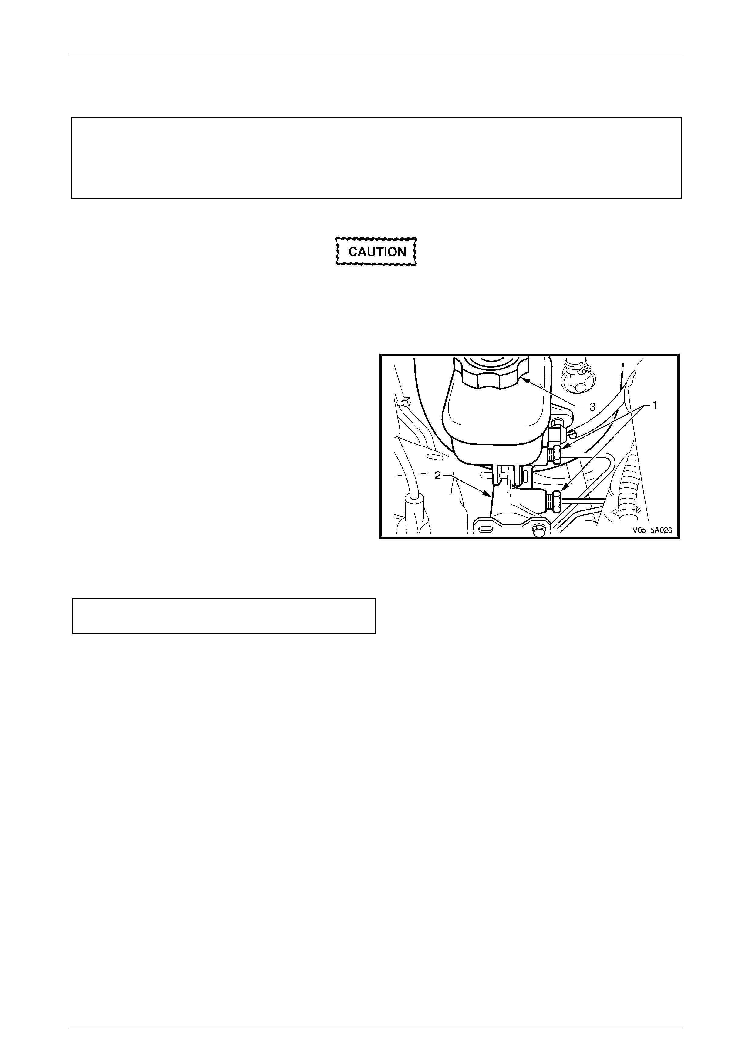
Both of these circuits are fed by separate fluid feed thro ugh a common fluid reservoir (3), that has a seal (2) fitted inside
the reservoir cap (1). This seal provides an effective seal against any atmospheric moisture coming into contact with the
hygroscopic brake fluid. This provision maintains the brake fluid's boiling point, for a maximum period of time.
The internal parts of the alumi nium a lloy master cylinder comprise a primary piston (19) supported by a gui de bush and
O-ring (22), with a recuperation seal (17) and a secondary piston (15) incorporating a ce ntre valve (12), a caged spring
(11), a recuperation (14) and an L type seal (15), a return spring (9) and a piston stop pin (6). The master cylinder bore is
anodised and is not to be hon ed.
An O-ring seal (24) is fitted to the master cylinder mounting flange, to provide a vacuum seal between the master
cylinder and the vacuum suspended brake booster.
The proportioning of the front to rear brake pressure, is effected by electronic control through the ABS or ABS/TC
system, where fitted. The MY 2005 VZ Series Utility has a load sensing proporti oning valve located at the rear of the
vehicle. A pressure differential spoo l valve changes the front to rear braking application dependent on vehicle load.
5A – 5
Service and Park Braking System 5A – 6
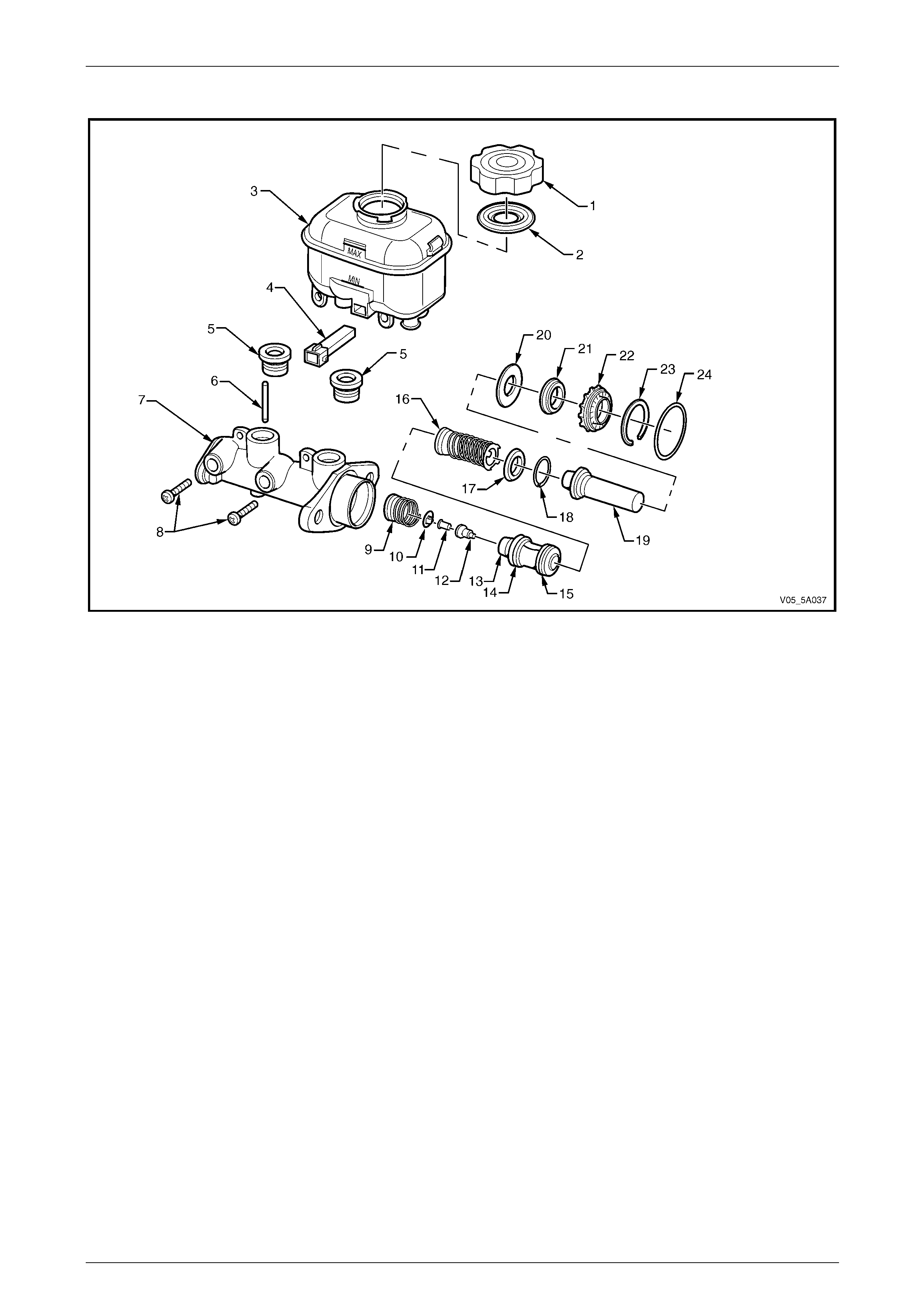
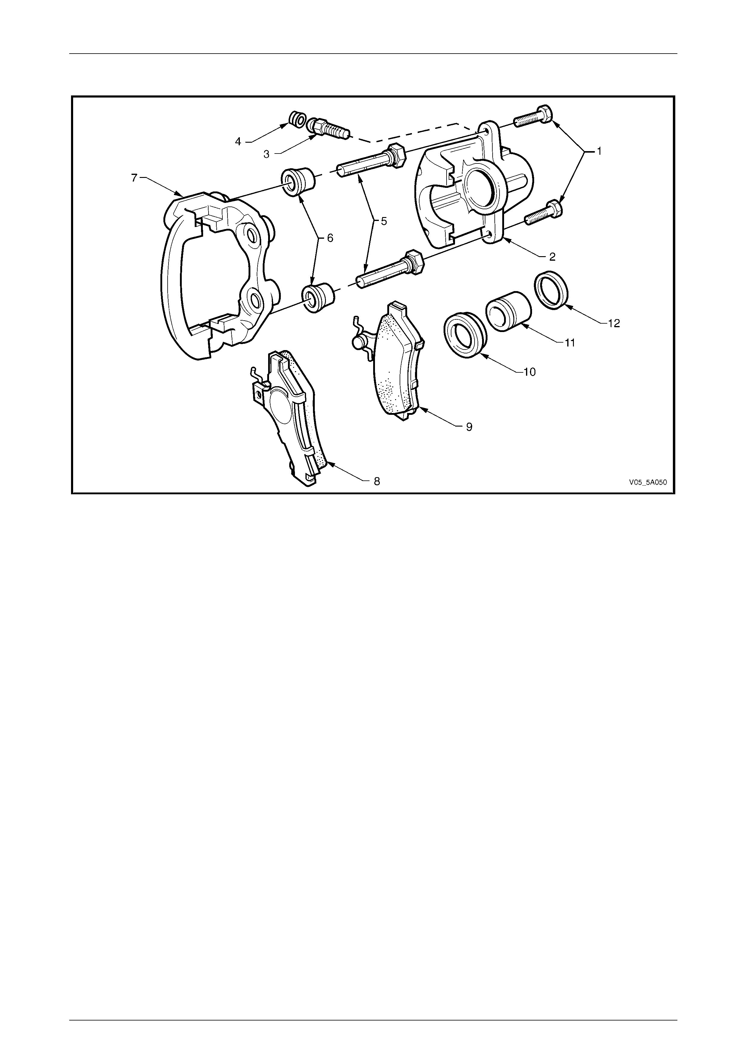
Typical Exploded View of Brake Master Cylinder
Figure 5A – 1
Legend
1 Reservoir Cap
2 Reservoir Cap Seal
3 Brake Fluid Reservoir
4 Fluid Level Switch
5 Sealing Grommets
6 Cylinder Pin
7 Master Cylinder Body
8 Reservoir Retaining Screw
9 Return Spring
10 Centre Valve Sleeve
11 Centre Valve Spring
12 Centre Valve Plunger and Seal
13 Secondary Piston
14 Secondary Recuperating Seal
15 L Type Primary Seal
16 Return Spring and Retainer
17 Primary Recuperating Seal
18 Washer
19 Primary Piston
20 Primary Piston Support Washer
21 Vacuum Seal
22 Primary Piston Guide Bush and O-ring
23 Circlip
24 O-ring Seal
Operation
When the brake pedal is depressed, force is applied by mechanical linkage to the vacuum suspen ded brake booster.
Vacuum assisted force is then applied to the primar y and secondary master cylinder pistons. As the pis t ons are stroked
in the master cylinder bore, the developed hydraulic pressure is used to apply the front and rear disc brakes.
Once the brake pedal is released, the primary and secondary springs return the pistons to the released position and
brake fluid returns to the reservoir.
5A – 6
Service and Park Braking System 5A – 7
1.3 Vacuum Brake Booster
Description
The brake booster is designed to reduce the force required to develop the required brake fluid pressure, necessary to
apply the front and rear brakes.
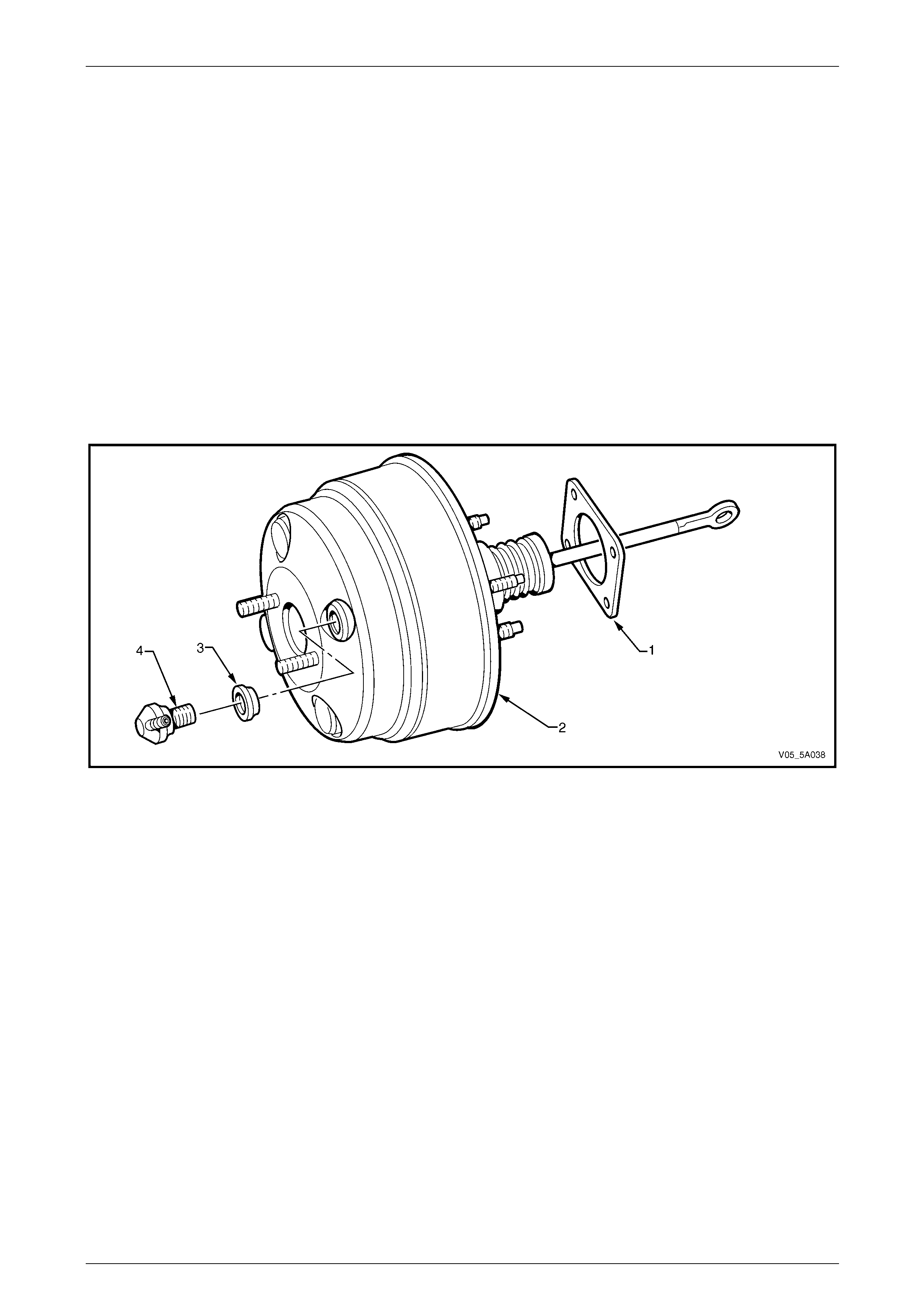
Construction
There are no serviced components within the brake booster (2) assembly and, if found to be faulty, the complete unit
must be replaced. A sealing gasket (1) is positioned between the booster and the instrument panel that is used to both
seal the connection and to dampen noise transfer.
A one-way vacuum valve (4) is fitted to the front casing of the booster assembly, secured by a grommet (3). This non-
return valve is used to maintain the vacuum suppl y in the brake booster for a limited number of brake applications,
should an emergency situ ation occur, such as engine failure.
The barcode label attached to the front of the booster provides the booster part number and build data (e.g. month, day,
year, shift, line number). Check the current release of PartFinder™ for the correct part number for the vehicle requiring
the part.
Figure 5A – 2
Legend
1 Sealing Gasket
2 Vacuum Booster Assembly 3 Sealing Grommet
4 One-way Valve
Operation
When the brake pedal is depressed, movement of the booster input rod controls the opening and closing of internal
valving, allowing atmospheric pressure to enter one side of a diaphragm. W ith engine vacuum always present on the
other side, the pressure difference provides the required assistance in the movement of the master cylin der pistons and
the application of the brakes.
Mechanical Brake Assist (MBA)
The Mechanical Brake Assist (MBA) feature results from a mechanical, two stage valving design within the brake booster
that provides a dual reaction ratio, which has the effect of assisting the driver to reach ABS braking thresho ld more
easily. To assist in an emergenc y situation, MBA produces a quick booster response and reduces pedal effort without
affecting the pedal 'feel'.
MBA however, will change the brake pedal feel above a 0.5 to 0.6 g deceleration a nd is a feature of all vacuum booster s,
fitted to MY 2005 VZ Series vehicles with ABS or ABS/TC.
Those VZ models without ABS therefore, retain the tandem booster assistance except that in this application, a single
ratio (i.e. no MBA) is used. The reason being, that without ABS, the advantage of MBA is not realised.
5A – 7
Service and Park Braking System 5A – 8
1.4 Load Sensing Proportioning Valve –
Utility, Regular/Crew Cab Models
(excludes MY06 Vehicles)
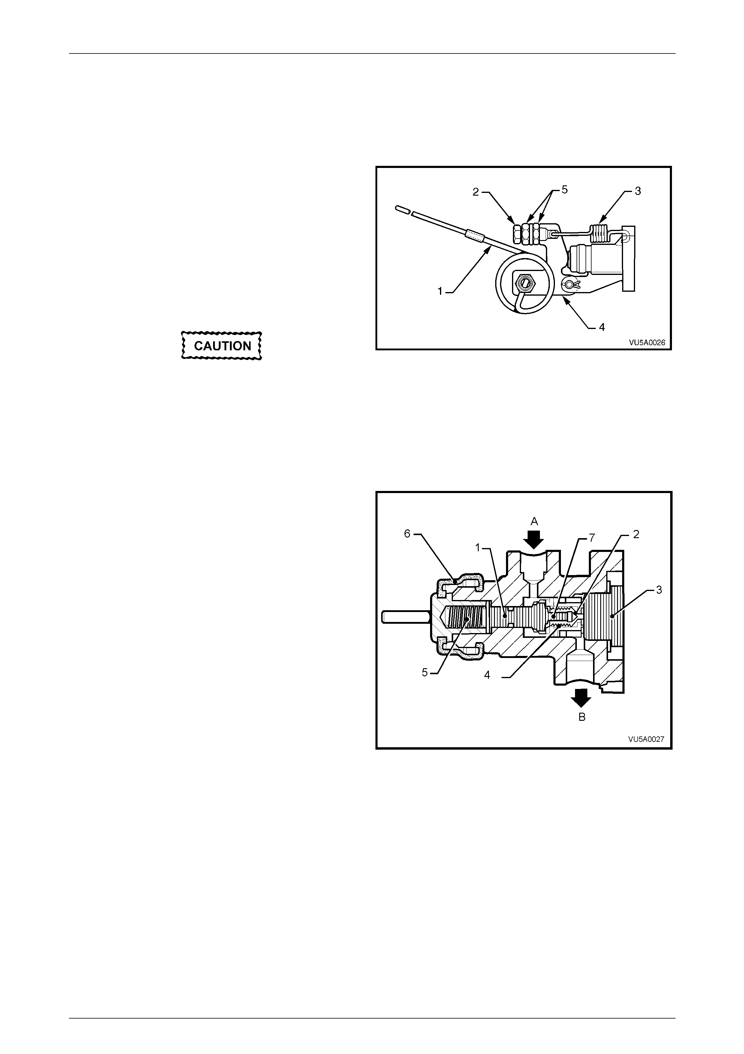
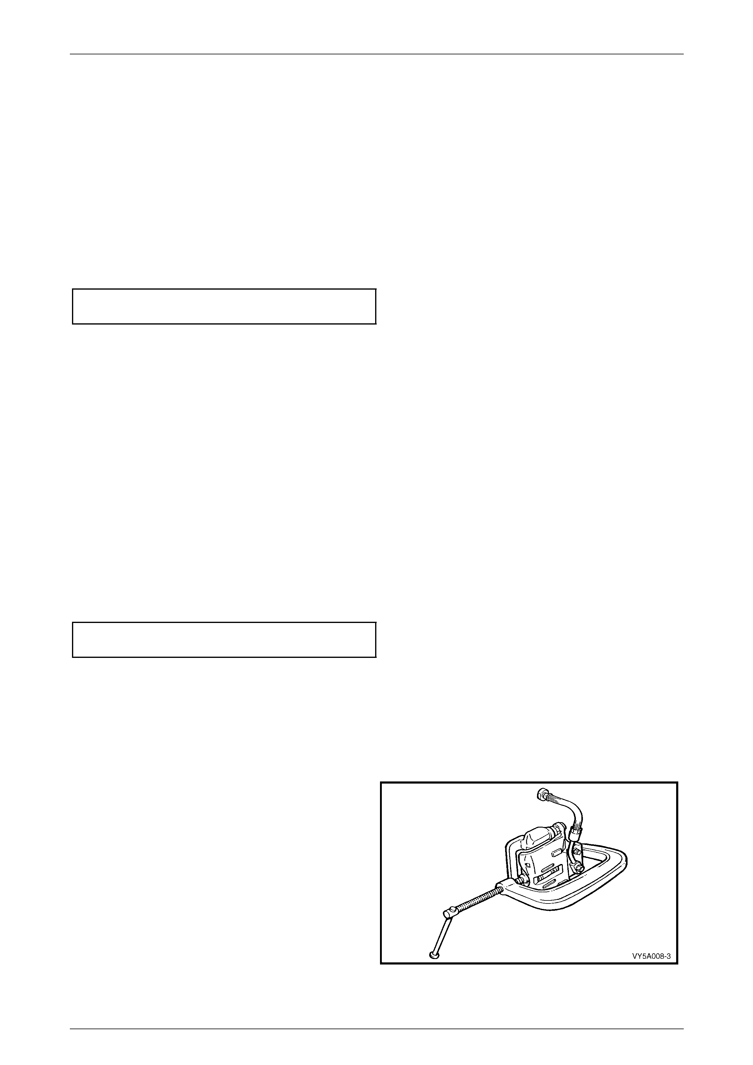
Construction
The load sensing proportioning valve is attached to the right
hand frame, above the final drive assembly. The valve
torsion spring lever (1) is attached to the right hand trailing
arm rod with a bracket, cable and hook.
The load sensing proportioning valve senses load by
monitoring the rear suspensio n ride height, to regulate the
pressure applied to the rear brake calipers. Maximum line
pressure is supplied to the rear brakes when the vehicle is
fully laden, while lightl y loaded conditions provide minimum
line pressure; i.e. line pressur e varies in relation to the
weight of the load.
Under no circumstances is the static spring
tension adjusting screw (2) and lock nuts (5)
to be disturbed nor adjusted, as this
adjustment is set in manufacture.
Figure 5A – 3
The static spring (3) exerts a force on the end of the spoo l valve by means of a lever (4), while a torsion type sensing
spring (1) is attached to the right-hand trailing arm rod, modifying this applied force, dependi ng on the axle load.
Operation
When the vehicle is unladen or lightly loaded, the torsion
spring has the maximum effect and, together with the static
spring force, the total apply force on the plunger and load
sensing valve spool (1) is lowest. This apply force is able to
position the load sensing valve spool (1) to restrict the flow
of fluid through the outlet port (B) to the rear brakes.
However, when the vehicle is load ed, the load sensing valve
spool is positioned so that fluid can flow unrestricted through
the inlet port (A), through the spool sub-assembly, around
the poppet valve (7) and out via the spo ol sub assembly
sealing seat (2) and outlet por t (B) to the rear wheel brake
calipers.
When the brake pedal is released, inlet pressure drops,
allowing the higher pr essure on the rear wheel side of the
sensing valve to force upon the pop pet valve (7), such that
the brake fluid can flow almost unrestricted, back to the
master cylinder. Eventually, the load sens ing valve spool (1)
is forced into its released position by the external spring set
up, to fully open the passage between the front and rear
circuit. Figure 5A – 4
Legend
1 Load sensing valve spool
2 Load sensing valve sp ool sealing seat
3 Load sensing valve end plug
4 Secondary spring
5 Primary spring
6 Load sensing valve boot
7 Load sensing valve poppet and valve
A Brake fluid inlet
B Brake fluid outlet
5A – 8
Service and Park Braking System 5A – 9
1.5 Front and Rear Brake Calipers
Apart from Coupe and MY2006 SS models, both front and rear brake calipe r assemblies are common for all braking
systems fitted to the MY2005 and MY2006 VZ Series range of vehicles. An exploded view of the twin piston front caliper
is shown in Figure 5A – 5, while the Coupe and MY2006 SS version is sho wn in F igure 5A – 6.
For the front brakes, the anchor plate is fixed to the steering knuckle support arm, while the housing slides within the
anchor plate by means of t wo guid e pins bolted to the housing. Rubber bo ots are fitted to the guid e pins to exclude
moisture, dirt and foreign matter.
The rear brake caliper anchor plates are bolted to the trailing arm and a lso have a floating housing, sliding over two
guide pins that are fitted with rubber dust boot s. Refer to Figure 5A – 7.
The housing incorpor ates either twin (front) or a single hydraulic piston (rear), each with a seal. When hydrau lic pressure
is applied, the piston forces the inner pad ag ainst the disc and the reaction of the housi ng pulls the outer pad against the
disc. The forces of the pads on each side of the disc are therefore equal.
When the hydraulic pressure is released, the piston seal/s retracts the piston/s a small amount, allowing the moving parts
to relax sufficiently for the pads to remain in close proximity to the disc without dragging. Adjustment for wear is
automatic.
Refer to 2.7 Brake Pads, Replace, for further information regarding brake pad application.
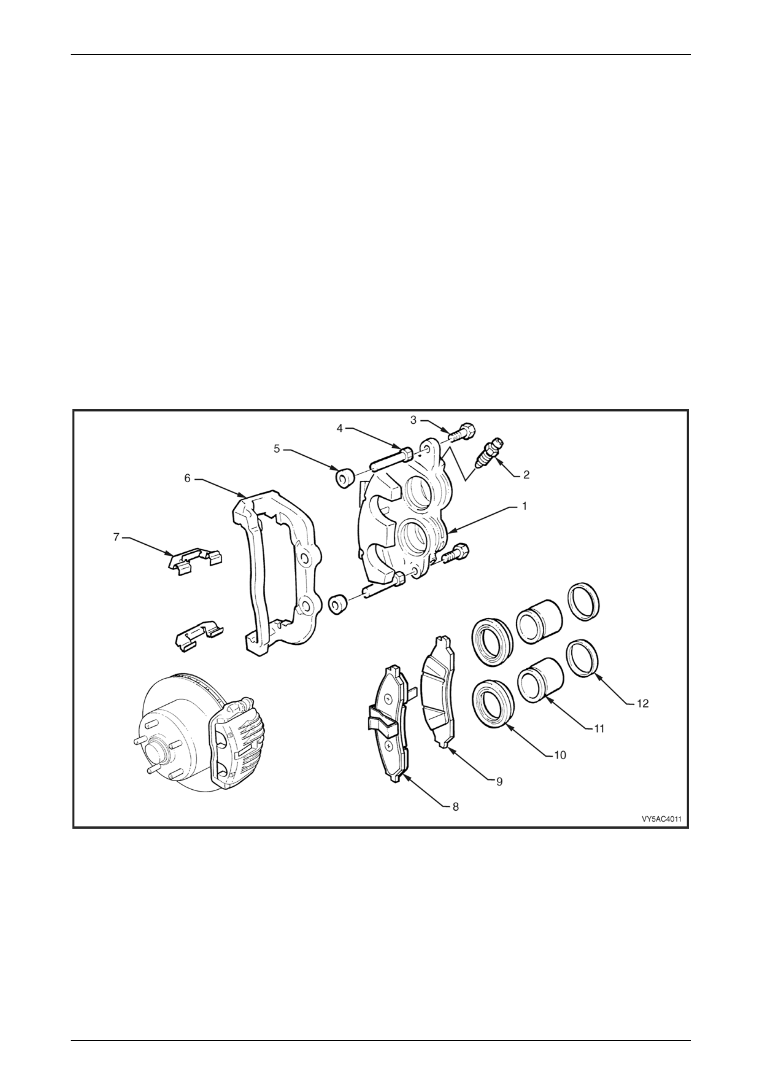
Front Brake Caliper – All Except Coupe and MY2006 SS
Figure 5A – 5
Legend
1 Caliper Housing
2 Bleed Screw
3 Self Locking Bolt (2 places)
4 Guide Pin (2 places)
5 Guide Pin Boot
6 Anchor Plate
7 Clip ( 2 places)
8 Outer Brake Pad
9 Inner Brake Pad
10 Piston Boot (2 places)
11 Piston (2 places)
12 Cylinder Seal (2 places)
5A – 9

Service and Park Braking System 5A – 10
Front Brake Caliper – Coupe and MY 2006 SS Models
Figure 5A – 6
Legend
1 Front Disc Rotor
2 Caliper Assembly
3 Guide Pin Bolt (2 places)
4 Bleed Screw
5 Bleed Screw Cap
6 Guide Pin (2 places) Anchor Plate
7 Anti-Rattle Spring
8 Caliper Anchor Plate
9 Clip ( 2 places)
10 Outer Brake Pad
11 Inner Brake Pad
12 Guide Pin Boot Cylinder Seal (2 places)
13 Piston (2 places)
14 Piston Boot (2 places)
15 Sealing Ring (2 places)
5A – 10
Service and Park Braking System 5A – 11
Rear Brake Caliper
Figure 5A – 7
Legend
1 Guide Pin Bolt (2 places)
2 Caliper Housing
3 Brake Caliper Bleeder
4 Brake Caliper Bleeder Dust Cap
5 Guide Pin (2 places)
6 Guide Pin Boot (2 places)
7 Anchor Plate
8 Outer Brake Pad
9 Inner Brake Pad
10 Piston Boot
11 Piston
12 Piston Sealing Ring
5A – 11
Service and Park Braking System 5A – 12
1.6 Brake Pipes and Hoses
Description
Except for the differences detaile d here, the brake pipe arrangem ent carries over from earlier models:
1 The brake pipe diameter is increased on AWD models and those VZ vehicles fitted with the Electronic Stability
Program (ESP); the front primary pipe diameter is 6.35 mm to increase fluid flow for the ESP and the AWD Traction
Control System. The pipe fitting for the primary front and the rear brake pipes are both 12 mm at the master
cylinder.
2 The rear brake pipes used o n MY 2005 VZ Models with a live axle, regardless of the braking system fitted are
unique. The differences are:
a The rear brake hoses are require d to accommodate the load sensing pr oportioning valve (LSPV) and the rigid
live rear axle design.
b The rear brake pipes are un ique as they must accommodate the load sens ing proportioning valve and the
rigid live rear axle design.
c AWD variants with a live axle, have t win brak e pipes leading to the rear of the vehicle, to enable the ABS/TC
system to operate effectively.
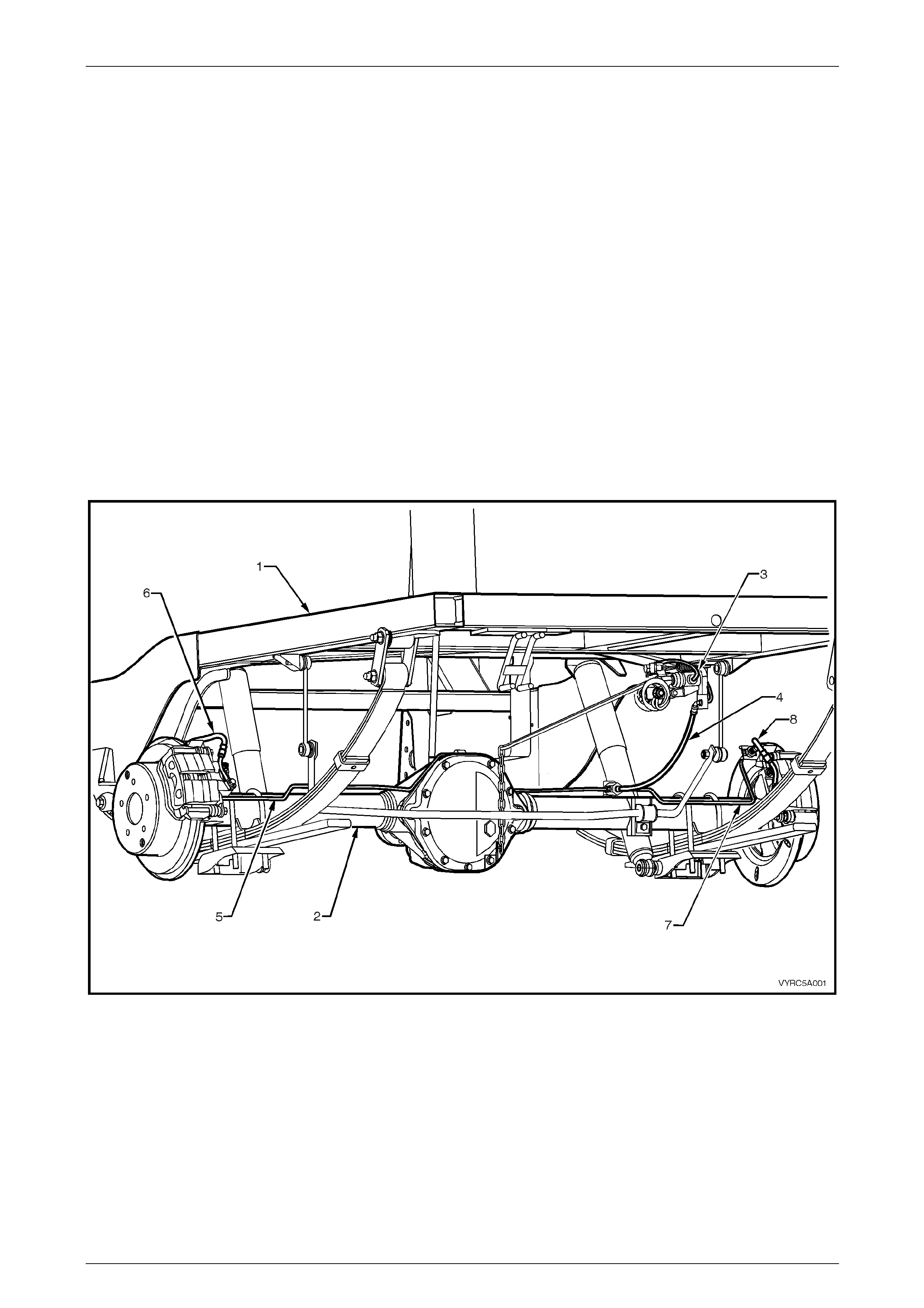
The rear brake hydraulic la yout, including the load sensing proportioning valve is shown next.
Figure 5A – 8
Legend
1 Chassis Assembly
2 Rear Axle Assembly
3 Input Brake Pipe to Load Sensing Proportioning Valve
4 Brake Fluid Hose to Rear Axle Tee Connection
5 Rear Brake Pipe to Brake Caliper – Left-Hand
6 Rear Brake Hose to Caliper – Left-Hand
7 Rear Brake Pipe to Brake Caliper – Right-Hand
8 Rear Brake Hose to Caliper – Right-Hand
5A – 12
Service and Park Braking System 5A – 13
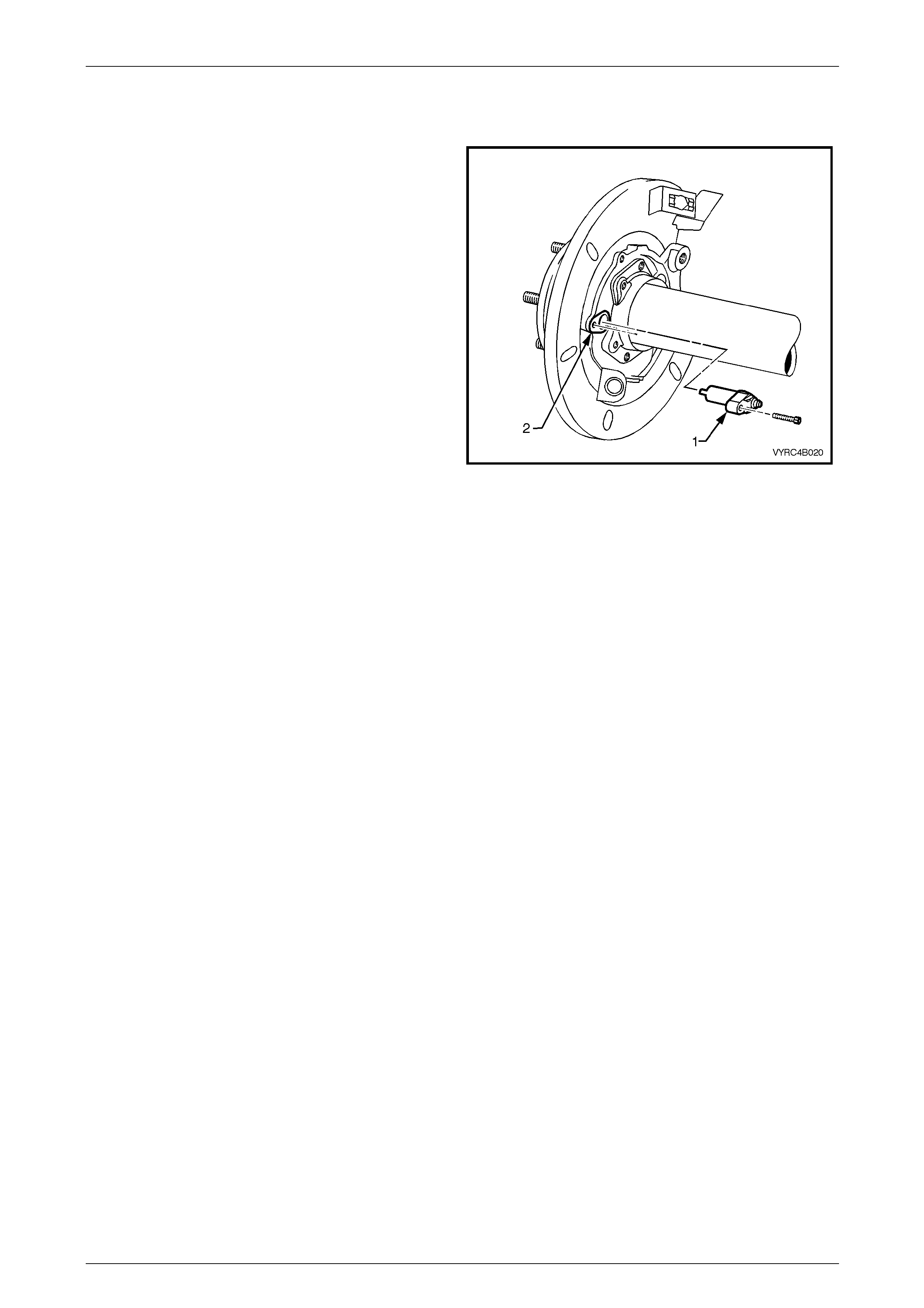
1.7 Rear Brake Backing Plates and ABS
Sensors – Live Axle Models Only
The rear brake backing plate (2) is of cast iron construction,
providing a mounting point for the brake d ust shield, rear
brake caliper, rear brake calip er h ydraulic h ose, parking
brake shoe assembly, park brake cable and ABS sensor (1).
Figure 5A – 9
5A – 13
Service and Park Braking System 5A – 14
2 Minor Service Operations
2.1 Service Warnings, Cautions and Notes
ATTENTION
All fasteners are important attaching parts as they affect the performance of vital components and/or could
result in major repair expense. W here specified in this section, fasteners MUST be replaced w ith parts of the
same part number or an app roved equivalent. Do not use fasteners of an inferior quality or substitute design.
Torque values must be used as specified during reassembly to ensure proper retention of all components.
Throughout this section, fastener torque wrench specifications may be accompanied with the following
identification marks:
Fasteners must be repl aced after loosening.
Vehicle must be at curb height before final tightening.
Fasteners either have micro encapsulated sealant applied or incorporate a mechanical thread lock and
should only be re-used once. If in doubt, replacement is recommended.
If one of these identification marks is present alongside a fastener torque wrench specification, the
recommendation regarding that fastener must be adhered to.
Brake Pads
• While genuine Holden wheel brake parts are not asbestos based in their material composition, a
danger exists that non-g en uine parts replacement may co n t ain asbestos.
Not only is it in the interests of personal safety but also the safe and reliable operation of the
braking system, that only genuine parts are u sed for replacement purpo ses.
• When servicing wheel brake parts, do not create dust by grinding or sanding brake linings, by
cleaning wheel brake parts with a dry brush or with compressed air. Breathing in dust that may
contain asbestos fibres can cause serious bodily harm over a lengthy time period.
A water dampened cloth or water based solution should be used to remove any dust on brake
parts. Equipment is commercially available to perform this washing function. These wet methods
prevent brake component fibres from becoming airborne.
Brake Fluid
• The polyglycol brake fluid used in MY 2005 VZ Series vehicles is hygroscopic and absorbs
moisture from the air through th e brake hoses etc. The boi ling resistance o f the fluid decreas es as
the moisture content increases and so the possibility of a vapour lock under heavy braking
conditions increases with the age of the fluid. Therefore, for maximum brake effecti veness, a two
yearly change of b rake fluid is mandatory, refer to 2.5 Brake Fluid, Change.
• To prevent the absorption of moisture from the air or other contamination, it is recommended that
the brake fluid be stored in small (500 ml) containers and that any surplus fluid remaining in a
container after use be discarded.
• The only approved brake fluid is Super DOT 4 and is available in 250 and 500 ml containers. If
pressure bleed ing equip ment is used, it must be o f an app roved type w ith a di aphragm separatin g
the brake fluid from the air.
• Brake fluid is extremely damaging to paint. If fluid should accidentally come into contact with a
painted surface, immediately wash the fluid from the paint and clean the painted su rface.
ABS/TC Components
• Whenever any component that forms part of the ABS (if fitted) is disturbed during Service
Operations, it is vital that the complete ABS system be ch ecked, refer to Section 5B ABS/TCS/ESP
– General Information for information.
5A – 14
Service and Park Braking System 5A – 15
Road Wheels
• Whenever a road wheel and/or brake rotor is removed from or installed to a MY 2005 VZ Series
vehicle, it MUST be done in accordance with the recommended procedure, refer to Section 10
Wheels and Tyres.
• Whenever a road w heel and/or brake di sc is removed from the vehicle, the relatio nship of the road
wheel and the disc to the hub MUST be marked with a felt tipped pen or similar, to allow those
parts to be reinstalled in their original positions. This is critical to minimise the brake disc and
road wheel runout dimension.
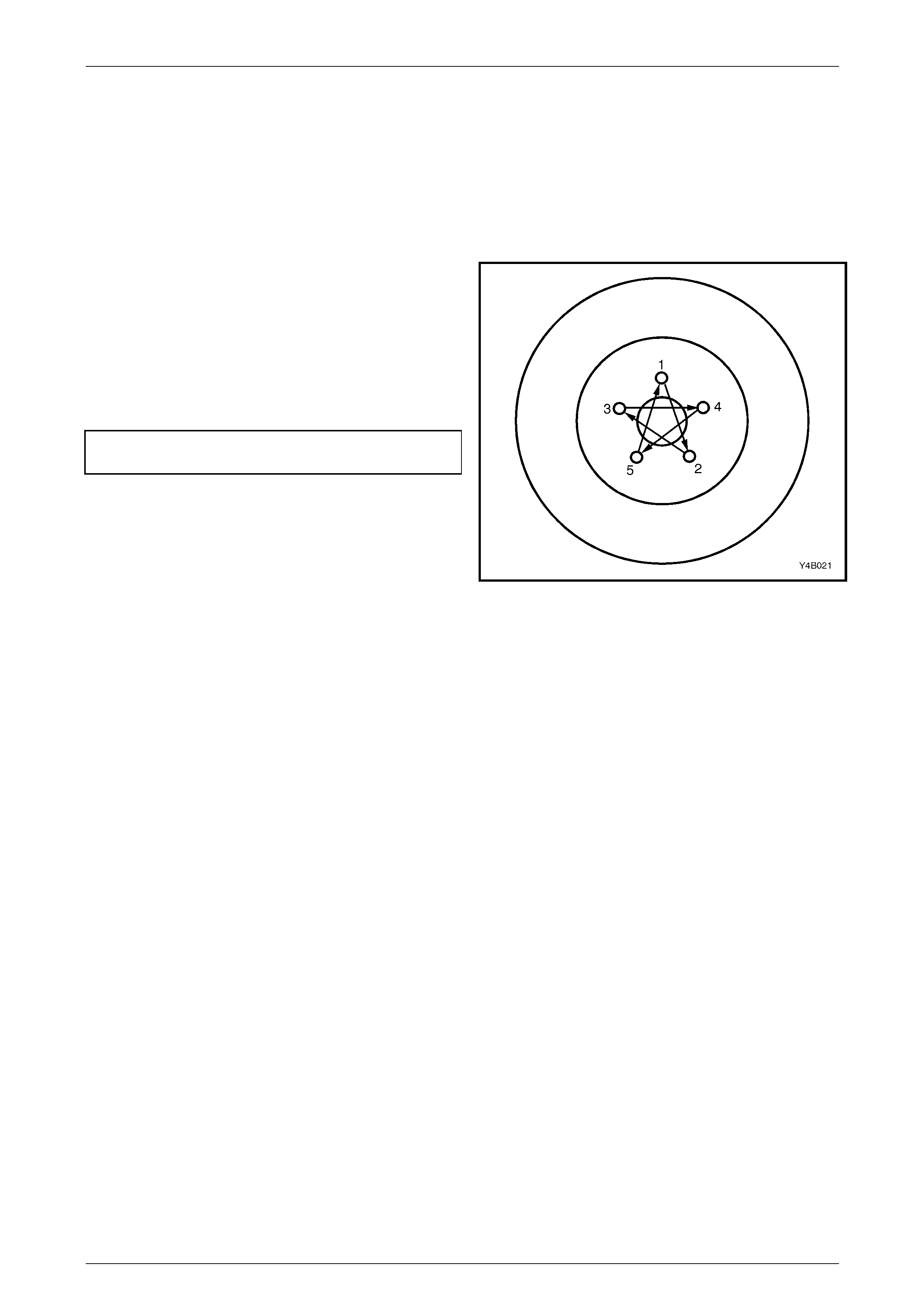
• When reinstalling road wheels, do not
use an impact gun to tighten wheel nuts
unless the impact gun is fitted with a
torque limiter socket (Tool No. AU 534 or
a commercial equivalent). Failure to
correctly tighten wheel nuts to the
correct torque specification and in the
correct order (as show n), may result in a
distorted brake disc, leading to the
development of brake shudder.
Road wheel attaching nut
torque specification......................................110–140 Nm
For a complete description of the method used to measure
both brake disc and trunnion assembly runout and
correction, refer to 3.6 Front Brake Disc or 3.7 Rear
Brake Disc.
Figure 5A – 10
5A – 15
Service and Park Braking System 5A – 16
2.2 Park Brake Cable, Adjust
1 Raise the vehicle and suppor t in a safe manner.
Refer to Section 0A General Information for the
location of recommended lifting and supp ort points
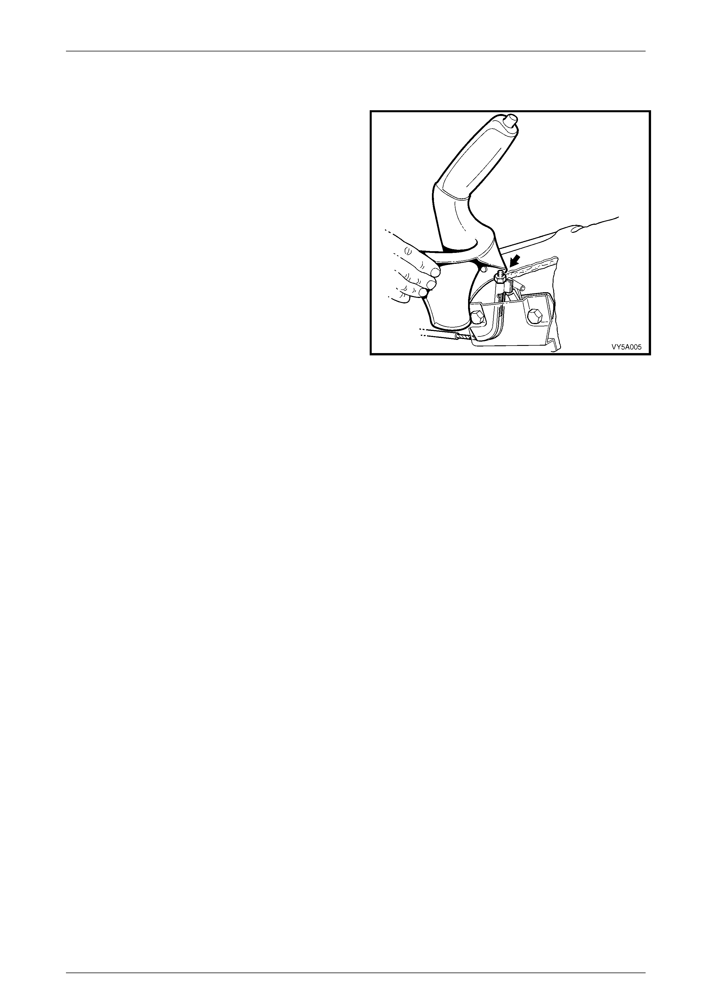
2 Loosen the park brake cable adjustment nut several
turns.
3 Apply the park brake until the lever is extended 4 – 6
clicks.
4 Using a dial type torque wrench and a deep socket,
tighten the cable adjustment nut (arro w) until a
torque of 2 N.m is applied.
5 Check that this adjustment applies the park brake
shoes to a firm drag torque, by turning each rear
wheel.
NOTE
• With a new park brake installation or one
that has the correct park brake shoe
adjustment, the thread on the front cable
should protrude through the adjustment nut
by 15 – 20 mm.
• If the park brake cannot be satisfactorily
adjusted by the above method, it will be
necessary to refer to 3.9 Park Brake Shoe,
Adjust.
Figure 5A – 11
5A – 16
Service and Park Braking System 5A – 17
2.3 Brake Fluid Level Check
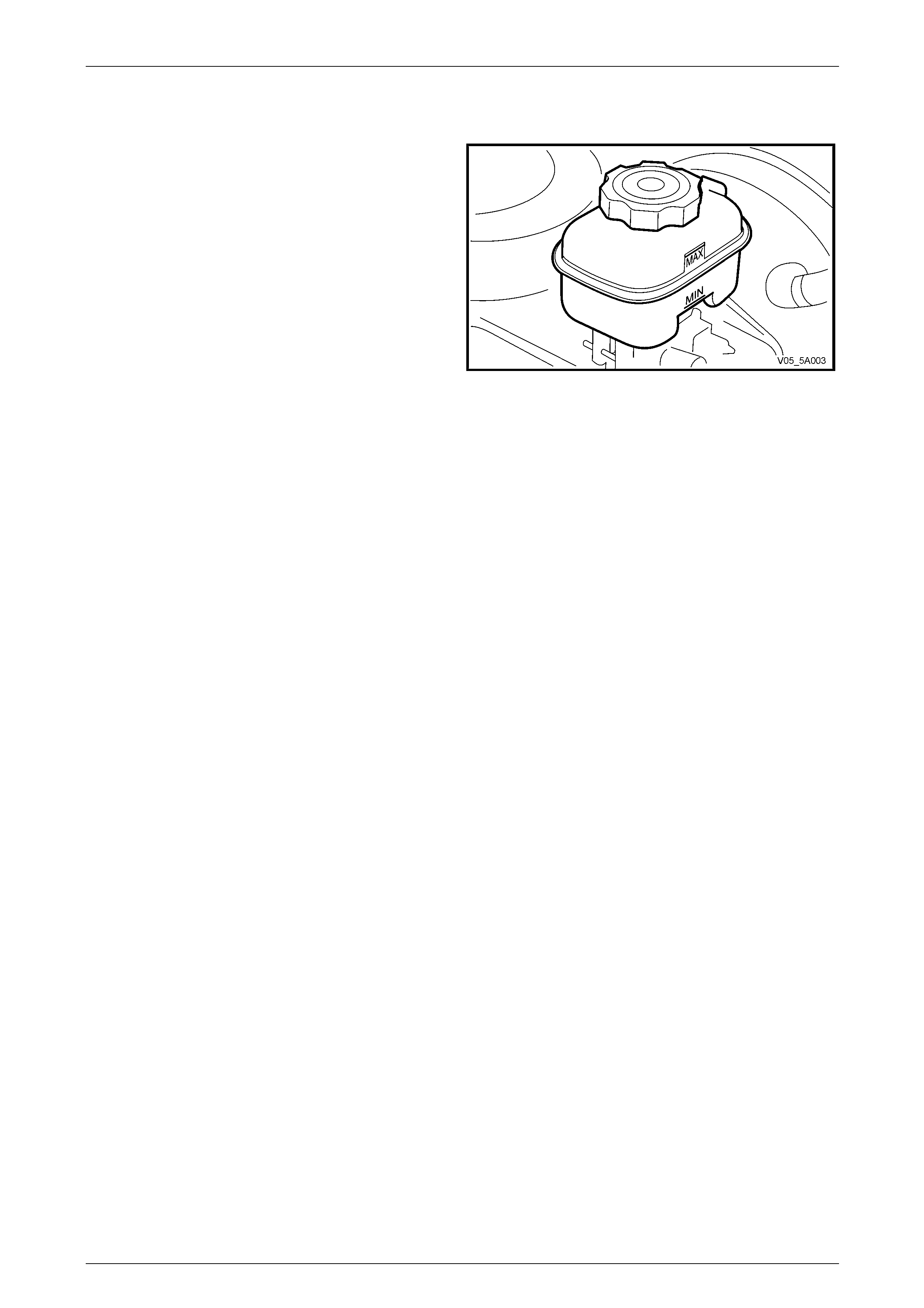
Check that the fluid level is between the MIN and MAX level
markings on the translucent reservoir housing.
NOTE
If the fluid is between the markings, do not
remove reservoir cap, as brake fluid exposed to
the atmosphere will quickly absorb moisture.
Should the addition of fluid be required, wipe the sides of
the reservoir cover clean, then unclip and remove the
reservoir cap. Top up fluid using heavy duty brake flu id that
complies with Super DOT 4.
Figure 5A – 12
5A – 17
Service and Park Braking System 5A – 18
2.4 Brake System Bleed
LT Section No. – 04-725
Do not re-use any brake fluid discharged
during the bleeding process .
Remove air from other components of the brake system as follows:
1 Remove master cylinder reservoir cap (1) and fit a
commercially available pressure bleed cap.
Figure 5A – 13
2 Connect cap to pressure bleed pump and pressurise system to no more than 345 kPa.
3 Open brake bleeder of line to be bled and pump brake pedal one stroke/second for approximately 10 strokes, then
close bleeder. During this operation the pressure bleeder to the master cylinder should not be turned off. It is
essential that this volume and rate of flow is maintained to ensure air trapped in pipes is carried out of the system
with the flow of the fluid and not allowed to retreat between strokes of the brake pedal.
4 At the conclusion of the brake bleeding process, check that all dust caps are installed to the brake bleeder valves.
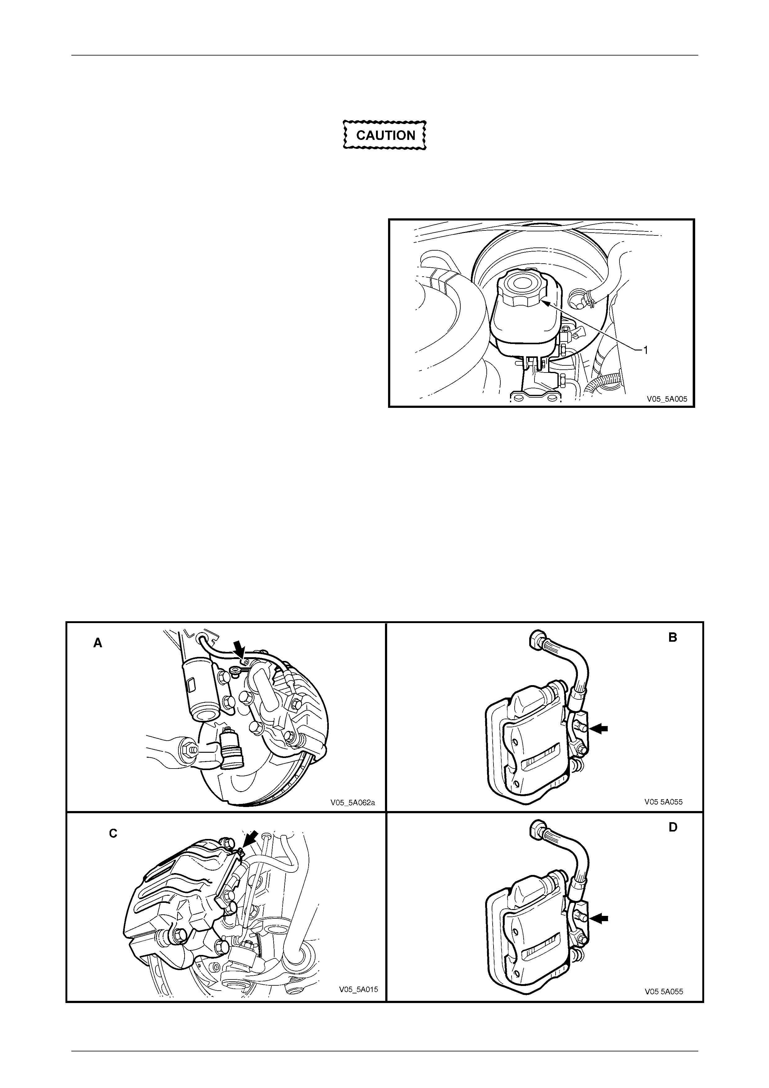
NOTE
View A shows the brake bleeder location for all
VZ except Coupe and MY2006 SS front brake
caliper, view B is for the rear, while views C and
D show the Coupe and MY2006 SS application.
Figure 5A – 14
5A – 18
Service and Park Braking System 5A – 19
2.5 Brake Fluid, Change
ATTENTION
The following fasteners MUST be replaced w hen p erfo rming these operations:
Brake caliper ancho r plate to steering knuckle attachin g bolts and ‘Nord-Lock’™ washers.
Brake fluid will cause damage to the paint
work. If contact does occur, immediately
wash the brake fluid off with water.
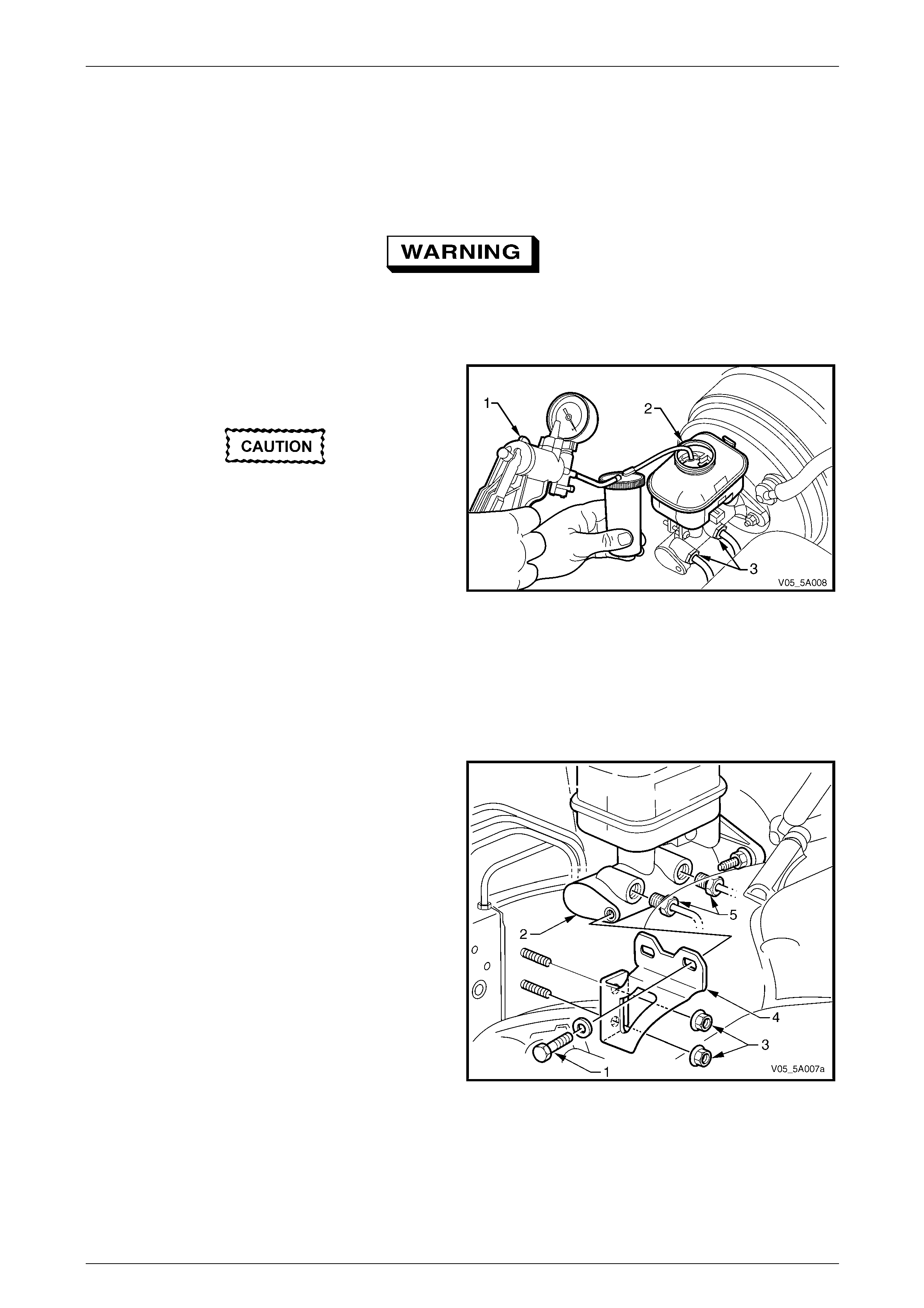
1 Thoroughly cle an master cylinder, especially around wheel brake line connections.
2 Disconnect wheel brake lines (1) from master cylinder
(2), then remove reservoir cap (3).
3 Allow master cylinder to drain into a container until
empty.
4 Fill master cylinder reservoir with fresh, specified
brake fluid from a sealed 500 ml container and ensure
reservoir is maintained at least half full for remainder
of procedure.
5 Allow fluid to flow from open connection ports until
fluid is free of air. Collect discharged fluid in a suitable
container and then discard. Do not allow fluid to
contact paintwork.
Figure 5A – 15
6 Reinstall the brake lines (1) to master cylinder (2) and tighten to specified torque.
Brake pipe to master cylinder
flare nut torque specification................................14 N.m
Drain brake calipers as follows:
7 Raise the vehicle and suppor t in a safe manner. Refer to Section 0A General Information for the location of
recommended lifting and support points.
8 Mark position of wheels relative to hub a nd remove wheels.
9 Loosen the left hand front caliper bl eed screw (bold arrow, in 'A' or ‘C’, in Figure 5A – 14).
10 Remove front left hand caliper anchor p late retaining bolts and locking washers. Discard the bolts and locking
washers.
5A – 19
Service and Park Braking System 5A – 20
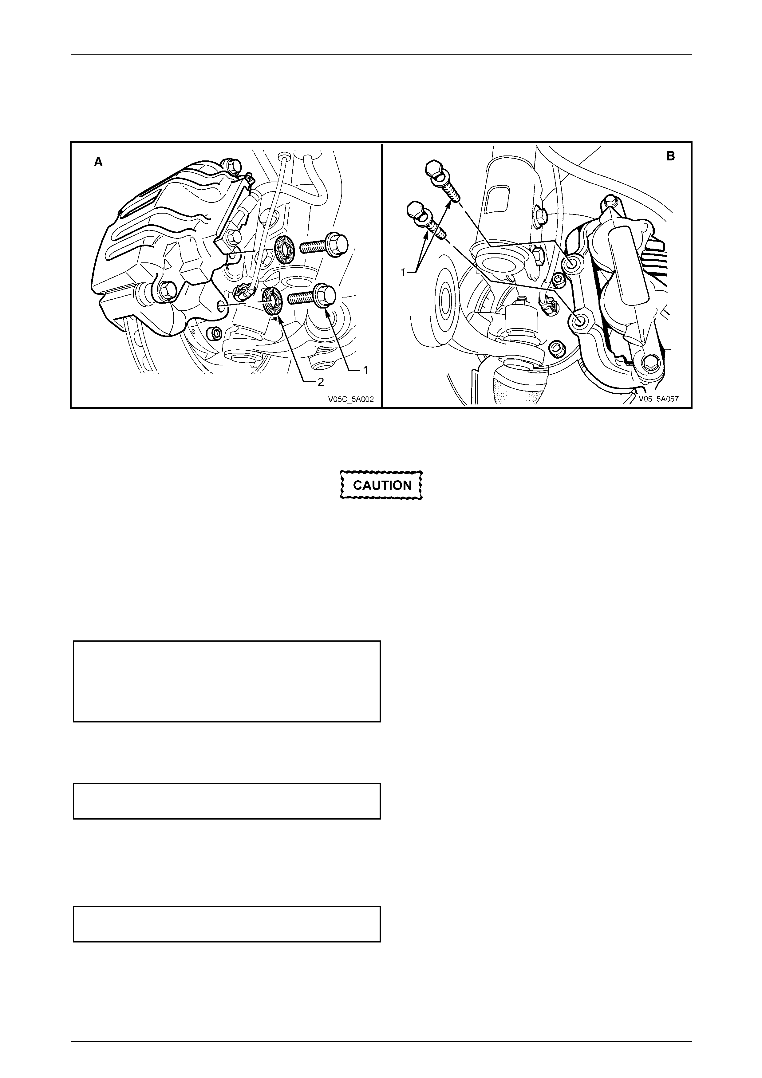
NOTE
View A shows the Coupe and MY2006 SS front
brake caliper while view B shows all other MY
2005 VZ models.
Figure 5A – 16
11 Hold caliper upside down and remove bleed screw to drain contents of caliper into suitable receptacle.
Do not re-use caliper retaining bolts and do
not apply any thread sealant to Coupe and
MY2006 SS bolts. New ‘Nord-Lock’™ washers
must also be fitted to Coupe and MY2006 SS
caliper retaining bolts.
12 Hand tighten bleed screw and reinsta ll caliper assembly, using NEW bolts.
13 Reinstall caliper anchor plate with NEW retaining bolts and NEW ‘Nord-Lock’™ locking washers (where fitted).
Tighten the bolts to the correct torque specification.
() Front brake caliper anchor plate bolt torque
specification (Except Coupe a nd MY2006 SS ) . 85 N.m,
.................. plus 45° turn angle
(Coupe and MY2006 SS )...................................70 N.m,
.................. plus 90° turn angle
14 Repeat steps 8 to 13 for the remaining front caliper and both rear caliper assemblies. A different toque specification
applies to the rear caliper attaching bolts.
15 Tighten the rear brake caliper anchor plate bolts to the correct torque spec ification.
Rear brake caliper anchor
bolt torque specification.......................................85 N.m
16 Bleed brake system, refer to 2.4 Brake System Bleed.
17 Reinstall road wheel in the original position and secure with the wheel nuts but do not fully tighten.
18 Lower the vehicle to the ground an d tighten the wheel nuts to the specified torque, working in a 'star' pattern, refer
to 2.1 Service Warnings, Cautions and Note s.
Road wheel attaching nut
torque specification..................................110 – 140 N.m
19 Reinstall the wheel cover/decorative wheel nut caps.
20 Road test the vehicle to ensure correct brake operation.
5A – 20
Service and Park Braking System 5A – 21
2.6 Brake Pad Wear, Check
Front or Rear
NOTE
The procedure and minimum thickness
specification is common to both front and rear
brake pads, despite the fact that only the front
brake caliper procedure is prov ided.
1 Raise the vehicle and suppor t in a safe manner. Refer to Section 0A General Information for the location of
recommended lifting and support points.
2 Remove rear wheel covers or wheel nut decorative caps.
3 Mark position of road wheels relative to hub, remove road wheel attaching nuts, working in a 'star' pattern, then
remove the road wheels.
4 Remove the pads to be checked, from the caliper
ensuring that the original pad positions are noted.
Refer to 2.7 Brake Pads, Replace.
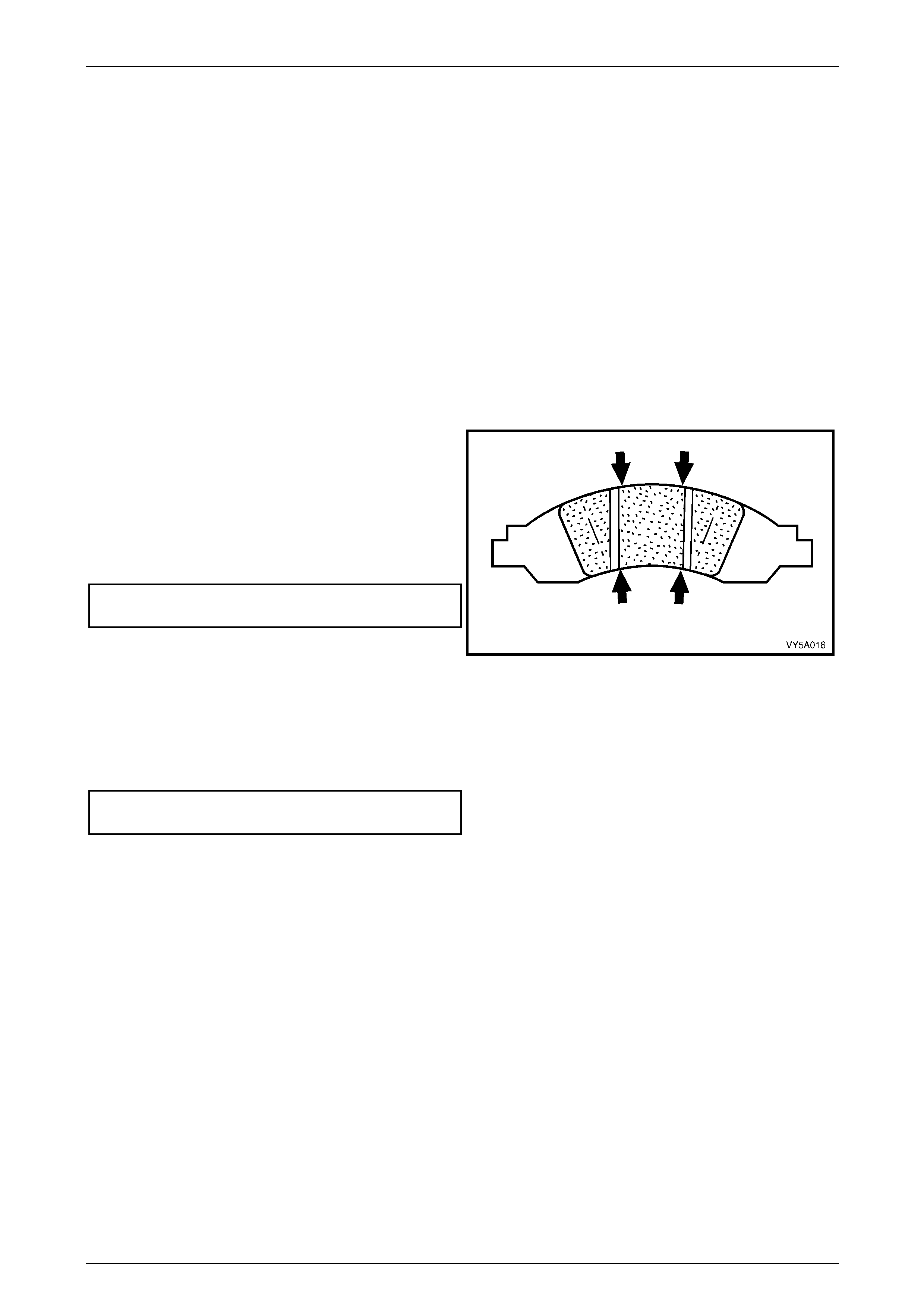
5 Using vernier calipers, check the brake pa d thickness
in the four locations shown. The minimum lining
thickness should be no less that the thickness
specified. Also, pad wear should be even – if not, then
the cause must be established and corrected.
Brake pad minimum lining
thickness before replacement............................ 2 mm
6 If not being replaced, reinstall the brake pads in the
same locations, prior to removal. Refer to 2.7 Brake
Pads, Replace, for the required procedures for this
operation. Figure 5A – 17
7 Reinstall road wheel and secure with the wheel nuts but do not fully tighten.
8 Lower the vehicle to the ground an d tighten the wheel nuts to the specified torque, working in a star pattern, refer to
2.1 Service Warnings, Cautions and Notes.
Road wheel attaching nut
torque specification..................................110 – 140 N.m
9 Reinstall wheel covers (steel wheels) or wheel nut decorative caps (alloy wheels).
10 Road test vehicle to ensure correct brake operatio n.
5A – 21
Service and Park Braking System 5A – 22
2.7 Brake Pads, Replace
LT Section No. – 04-750 and 04-825
ATTENTION
The following fastener has micro-encapsulated sealant applied to the threads and should be replaced () on
reassembly:
Brake caliper guide pin bolts.
Preparation
NOTE
This 'Preparation' stage is common for the front
or rear brake pad replacement.
• Do not completely remove the brake line,
nor empty the reser voir. If this does occur,
complete bleeding of the braking system,
will be necessary.
• Do not attempt to re-use the removed fluid.
• Brake fluid will damage paint-work.
1 Unscrew the master cylinder reservoir cap.
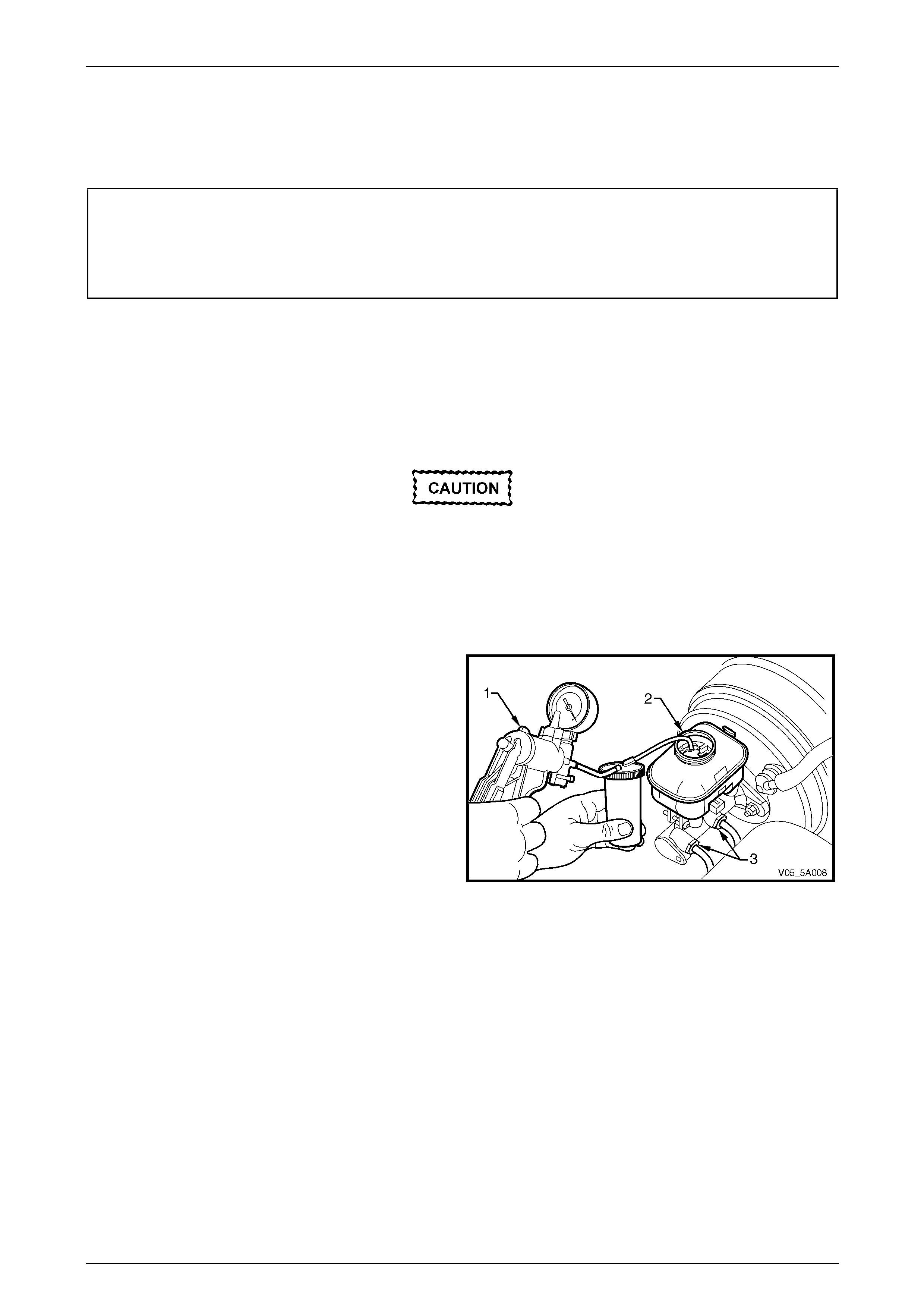
2 Using a hand vacuum pump (1), Tool No. J23738-A or
a commercially available equivalent or syringe,
remove fluid from the reservoir (2) until it is
approximately half full.
NOTE
Hold the brake fluid level float down with the
suction tube, during this operation.
3 Reinstall the reservoir cap.
NOTE
Removal of fluid from the reservoir is needed to
stop reservoir overflow when caliper piston is
pushed back in its bore during pad rep lacement.
Figure 5A – 18
5A – 22
Service and Park Braking System 5A – 23
Front Brake Pads
Remove
1 Raise the vehicle and suppor t in a safe manner. Refer to Section 0A General Information for the location of
recommended lifting and support points.
2 Remove the wheel covers or decorative wheel nut caps, then mark the relationship of the road wheel to one of the
wheel studs.
3 Loosen, then remove the road wheel attaching nuts, working in a 'star' pattern. Refer to 2.1 Service Warnings,
Cautions and Notes, for detailed i nformatio n. Remove the road wheel.
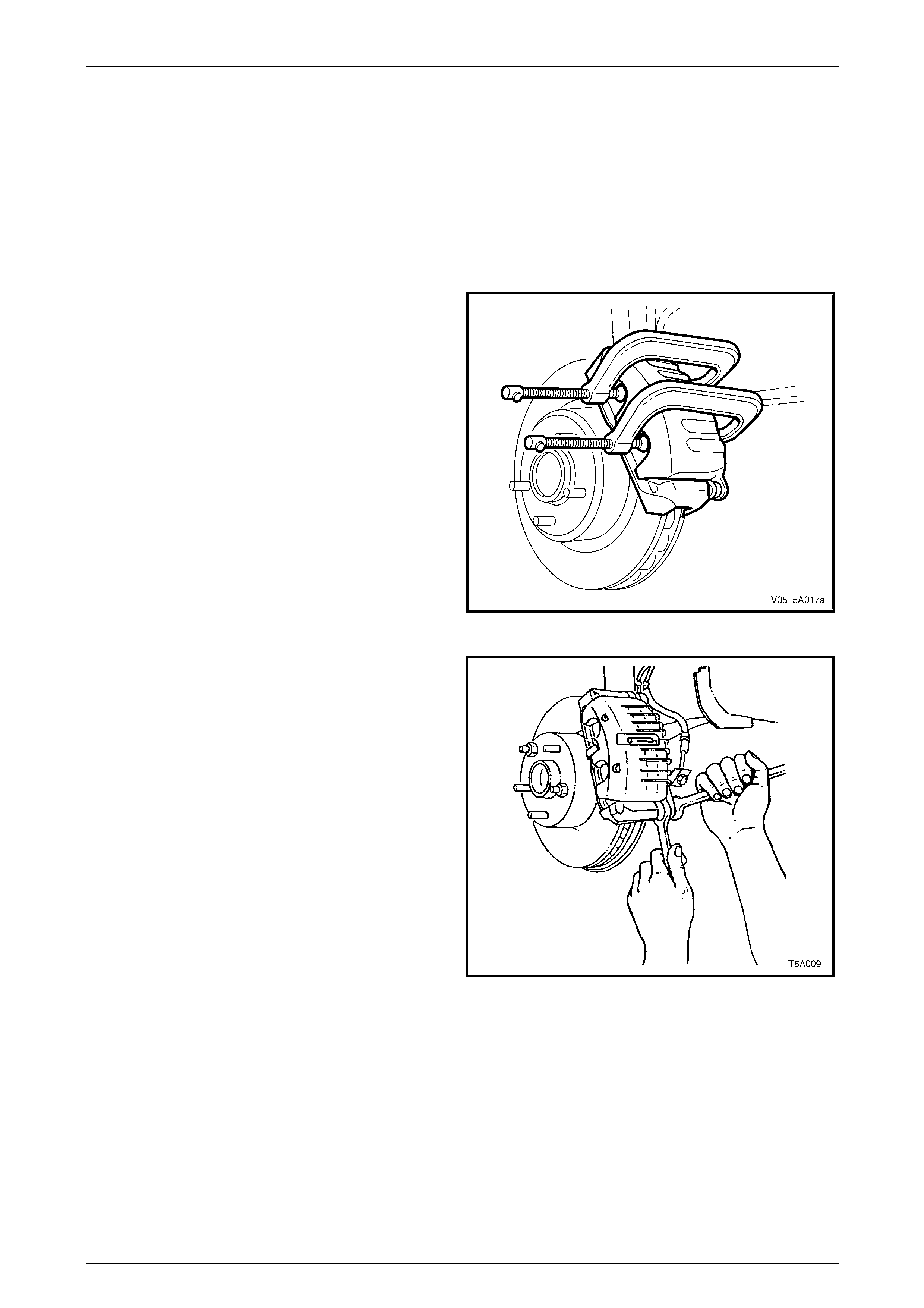
4 Using G-clamps as shown, tighten evenly until the
caliper pistons bottom in each bore.
Figure 5A – 19
5 Using a suitable size open end spanner to hold the
lower guide pin, remove, then discard the guide pin
bolt.
NOTE
Old bolts must not be re-used, as they are vital
safety components which have a micro-
encapsulated sealant on the bolt thread.
6 Swing caliper assembly up from the anchor plate and
disc. Support caliper with a wire hook.
7 Remove worn pads from anchor plate.
8 Inspect condition of brake disc.
9 Check guide pins for free movement in the anchor
plate. If movement is restricted, replace guide pins
and/or guide pin boots. Refer to 3.4 Front Brake
Caliper.
10 Clean any dirt from both the piston face, which
contacts the inner pad, and the caliper head area
which contacts the outer pad.
Figure 5A – 20
11 Install new brake pads.
5A – 23
Service and Park Braking System 5A – 24
Brake Pad Installation
1 Thoroughly cle an both piston contact faces, using a suitabl e solve nt such as Prepsol™, if required.
2 Install the outer pad to the caliper, noting that a leg of the steel spring should sit on top of the inner pad.
NOTE
Coupe and MY2006 SS front calipers have no
steel spring.
3 Reinstall the brake caliper housing, ensuring that the outer spring clip engages with the middle finger of the caliper
housing.
4 Install and tighten the guide pin self locking bolt to the correct torque specification.
() Brake caliper guide pin
bolt torque specification.......................................32 N.m
NOTE
• Use a suitable open end spanner to prevent
the guide pin from rotating when tightening
the guide pin bolt.
• Do not wedge anything bet ween the guide pi n
hex and the caliper as it could cause incorrect
alignment of the pin which would then restrict
the free sliding of the caliper relative to the
anchor plate.
5 Fill master cylinder to correct level with fresh, brake fluid of the correct specification.
6 Depress and hold the br ake pedal down in the applie d position for at least 5 seconds, to ensure that the brake pads
are correctly seated.
7 Refill master cylinder if necessary.
8 Reinstall road wheel in the original position and secure with the wheel nuts but do not fully tighten.
9 Lower the vehicle to the ground an d tighten the wheel nuts to the specified torque, working in a 'star' pattern, refer
to 2.1 Service Warnings, Cautions and Notes.
Road wheel attaching nut
torque specification..................................110 – 140 N.m
10 Reinstall the wheel cover/decorative wheel nut caps.
11 Carry out the Brake Pad Bedding-In Proced ure, detailed in this Section.
Rear Brake Pads
Remove
1 Using a G-clamp as shown, tighten unti l the caliper
piston bottom in its bore.
Figure 5A – 21
5A – 24
Service and Park Braking System 5A – 25
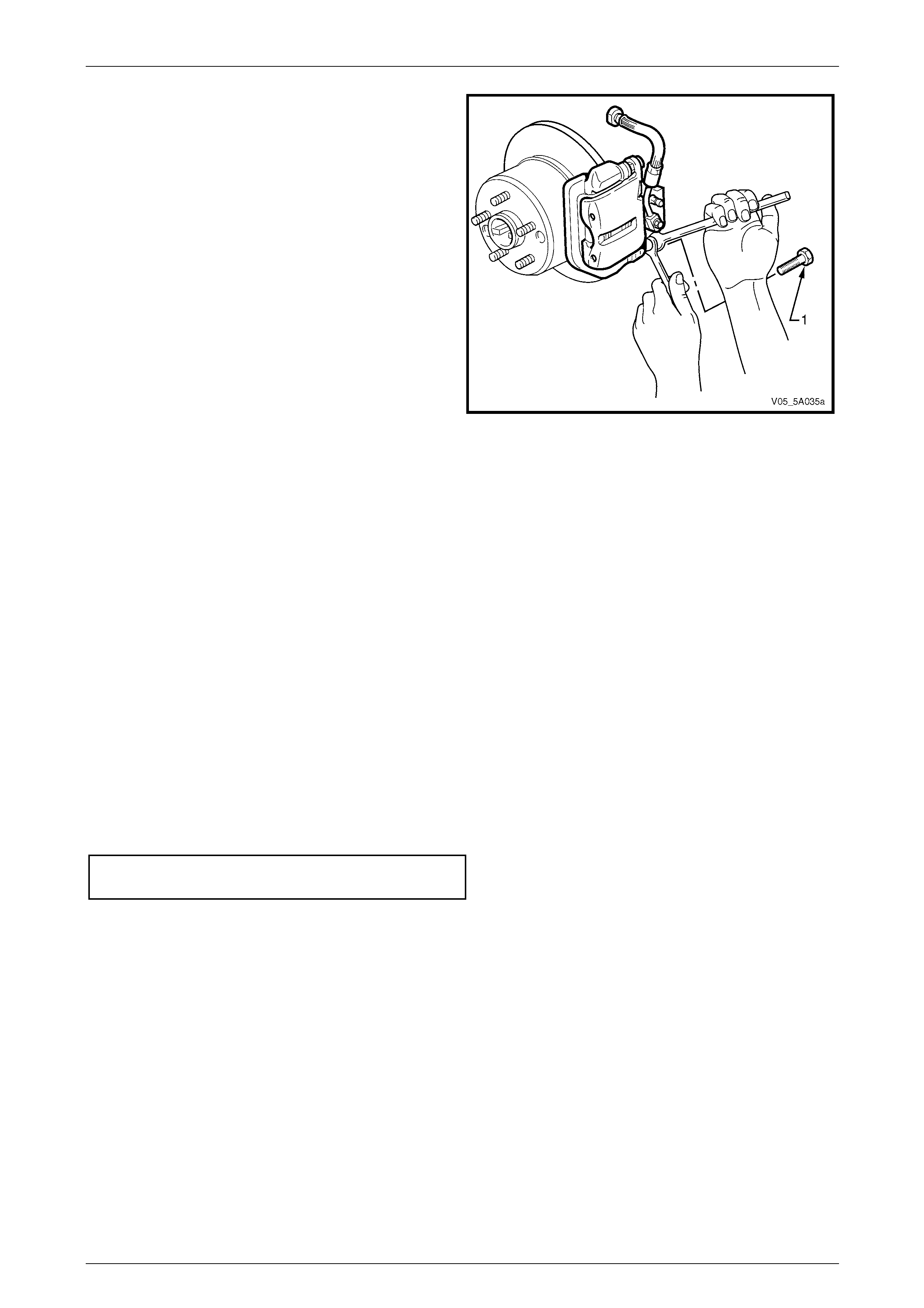
2 Using a suitable set spanner to hol d the lower guide
pin, use a suitable ring spanner remove the guide pin
bolt (1). Discard the removed bolt.
NOTE
• Old bolts must not be re-used as they are
vital safety components which have a micro-
encapsulated adhesive on the bolt threa d.
• While the disc rotor shown is solid, the
Coupe and MY2006 SS arrangement is the
same, except for the vented disc rotor.
3 Swing the caliper assembly up from the anch or plate
and disc. Using a wire hook, support the caliper.
4 Remove the worn pads from the anchor plate.
5 Inspect the brake disc condition. Refer to 3.7 Rear
Brake Disc.
6 Check the guide pins for free movement in the anchor
plate. If there is restriction of movement, replace the
guide pins and/or guide pi n boots. Refer to 3.5 Rear
Brake Caliper.
7 Clean any dirt from both the piston face, which
contacts the inner pad, and the caliper head area
which contacts the outer pad.
Figure 5A – 22
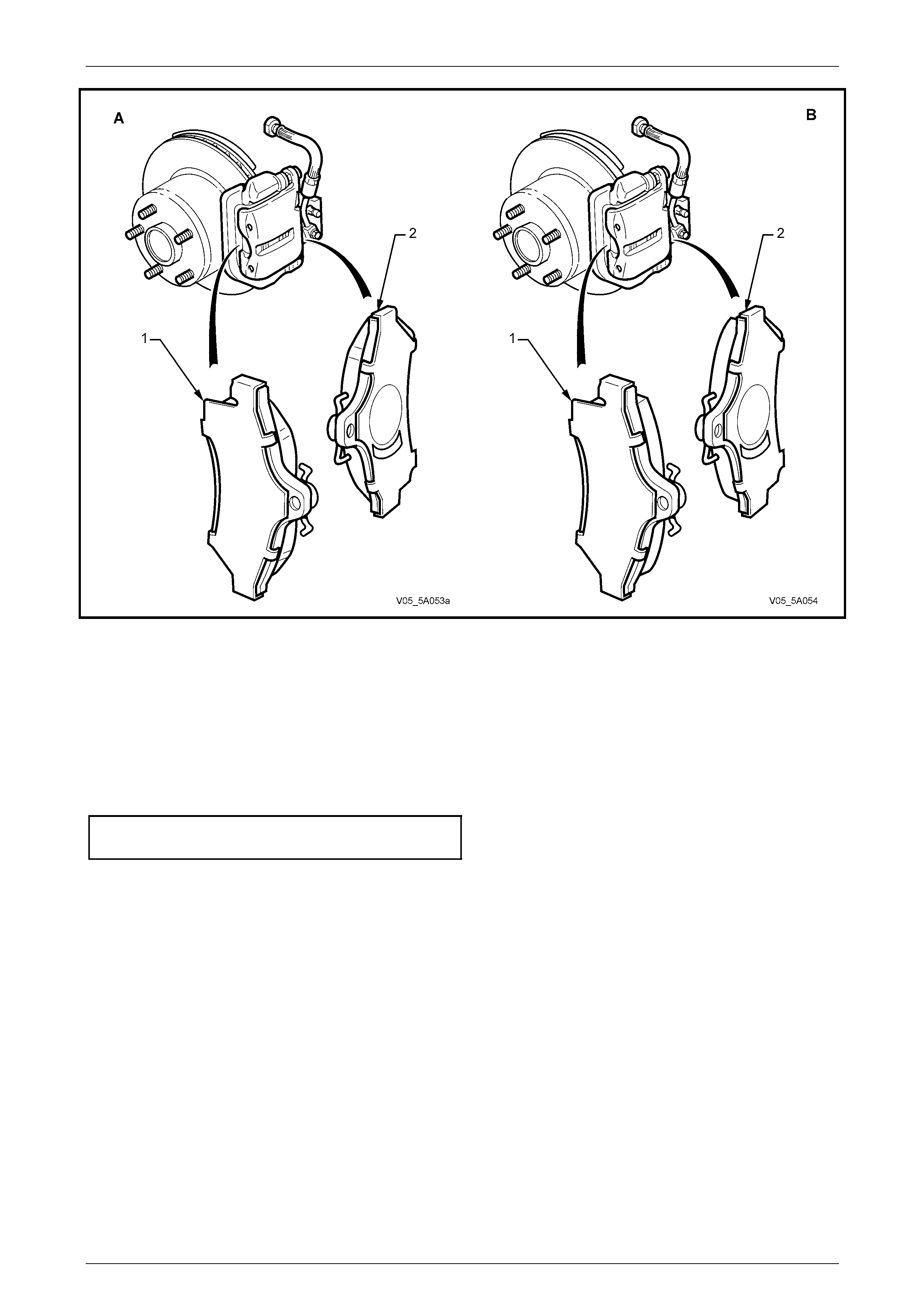
Reinstall
For noise damping effectiveness, it is critical that the brake pad and shim assemblies are installed in the correct
locations. For example:
a The outer pad (1) (which is retained by the fi ngers of the brake caliper housing), has a full shim.
b The inner pad (2) has a shim that has an asymmetrical cut-out above the caliper piston and must be correctly
installed to the caliper by having the cut-out on the lower half of the pad when installed in the caliper (in-car
position).
As illustrated in Figure 5A-23, the brake pads shown, should only be fitted to the left hand side, rear brake caliper.
1 Reinstall caliper housing over the brake pads. Ensure sprin g clip is located correctly in the top of the caliper body.
2 Install NEW guide pin, self locking bolt.
3 Use a suitable set spanner to prevent the guide pin from rotating, then tighten the guide pin bolt to the correct
torque specification.
Brake caliper guide pin
bolt torque specification.......................................32 N.m
NOTE
• Do not wedge anything bet ween the guide pi n
hex and the caliper as this could cause
incorrect alignment of the pin, restricting the
free sliding of the caliper relative to the anchor
plate.
• View ‘A’ shows the Coupe and MY2006 SS
rear brake arrangem ent, while view ‘B’ shows
all other MY 2005 VZ/WL models.
5A – 25
Service and Park Braking System 5A – 26
Figure 5A – 23
4 Fill master cylinder to correct level with fresh brake fluid of the correct spec ification.
5 Depress brake pedal sev eral times to bring pad assemblies into position against disc.
6 Refill master cylinder if necessary.
7 Reinstall wheels, aligning marks made prior to removal and lower vehicle to the ground.
8 Tighten road wheel attaching nuts to the specified torque, working in a star pattern, refer to 2.1 Service Warnings,
Cautions and Notes.
Road wheel attaching
nuts specification .....................................110 – 140 N.m
9 Reinstall wheel cover or wheel nut decorative caps.
10 Carry out the Brake Pad Bedding-In Proced ure, detailed in this Section.
Brake Pad Bedding-In Procedure
Whenever brake pads ar e replaced, they should be burnished, by the following bedding-in procedure:
1 Perform a minimum of 10 moderate (0.3 to 0.4 g deceleration) brake applications from 7 0 km/h down to 40 km/h
every 500 metres.
NOTE
• A panic stop would be classified as being a
0.9 g deceleration braking effort, so a
moderate deceleration rate of 0.4 g would be
one that requir ed ap pro ximatel y half t he brake
pedal effort needed for a panic stop.
• Do not perform this procedure at less than
500 metre intervals, as the excessive heat
build-up, may adversely affect the frictional
characteristics of the new brake pad material.
5A – 26
Service and Park Braking System 5A – 27
2.8 Brake Pedal Assembly
LT Section No. – 04-600
Remove
Disable the SRS (Air Bag). Refer to
Section 12M Occupant Protection System.
1 If fitted, remove front suspension strut tower brace, refer to Section 1A1 Body.
2 Thoroughly cle an around the master cylinder, paying
particular attention to the reservoir cap and b r ake line
connections.
Brake fluid will damage the paint work if it
comes into contact with it. Should spillage
occur onto paint work, immediately wash the
brake fluid off with water.
3 Remove the master cylinder reservoir cap and set to
one side.
4 Using a hand vacuum pump (1), special tool J23738-A
or a commercially available hand vacuum pump or
syringe, siphon as much brake fluid from the master
cylinder reservoir (2) as possible.
NOTE
Hold the brake fluid level float down with the
suction tube, during this operation.
5 Reinstall the reservoir cap.
Figure 5A – 24
6 Disconnect the brake lines (5) from the master cylinder
(2) and allow any residual brake fluid to drain from the
master cylinder into a container.
7 Plug the openings in both the master c ylinder and the
pipes to prevent fluid loss and dirt ingress.
8 Remove the bolt (1) securing the master cylinder
bracket (4) to the end of the master cylinder (2).
NOTE
If the vehicle is fitted with the manual
transmission, support the clutch fluid reservoir
bracket, during bolt (1) removal. Use tie wire to
secure the reservoir and bracket in an upright
position, to one side.
9 Remove the nuts (3) securing the master cylinder
bracket (4) to the adjacent strut tower.
10 Remove the bracket (4) securing the master cylinder
to the adjacent strut tower. Figure 5A – 25
5A – 27
Service and Park Braking System 5A – 28
11 As required, remove the following components:
a Instrument panel lower trim panel assembly, refer to Section 1A3 Instrument Panel and Consol e.
b Driver side instrument panel lower trim plate assembly, refer to Section 1A3 Instrument Panel and Console.
c Instrument panel lower trim panel retainer, refer to Section 1A3 Instrument Pane l and Console.
d Remove the Body Control Module (BCM) from its mounting bracket but le ave all electrical connectors
installed, refer to Section 12J Body Control Modu le .
e If fitted with the manual transmission, remov e the clutch pe dal and bracket assembly, refer to Section 7A1
Clutch – V6, 7A3 Clutch – GEN III V8 or 7A4 Clutch– GEN IV V8.
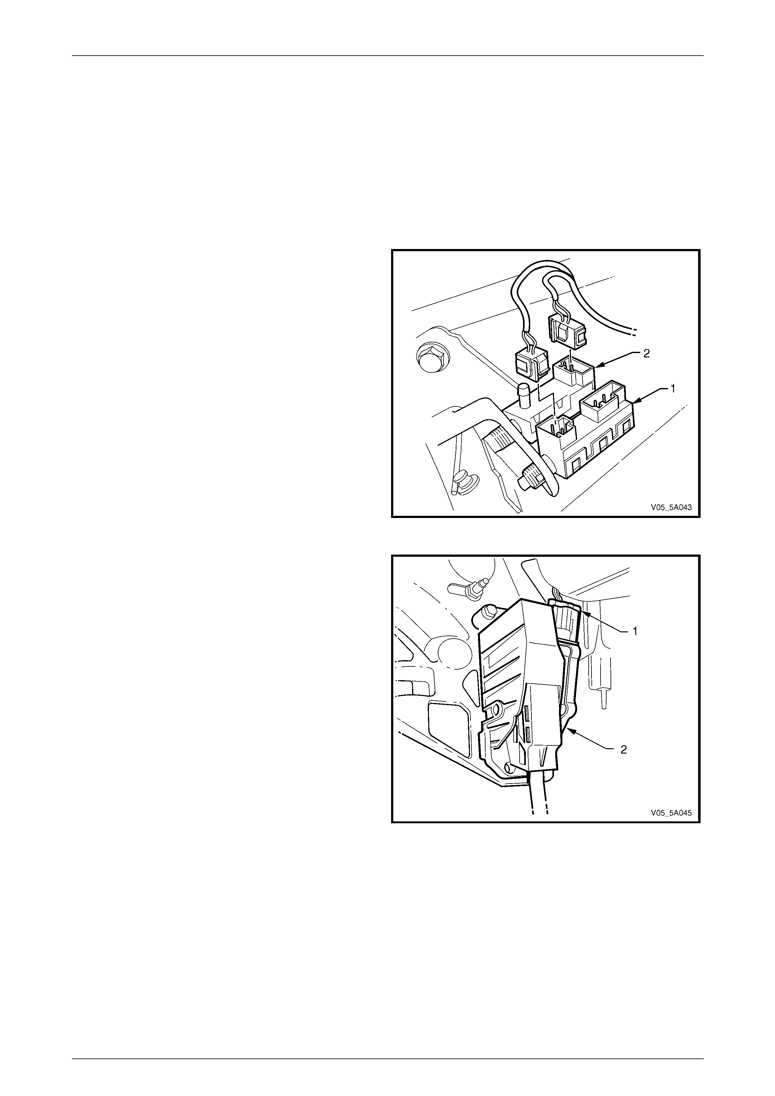
12 Disconnect the wiring harness connectors fro m the
stop lamp switch (1) and the cruise cancel switch (2).
NOTE
Refer to Section 12E Cruise Control for further
information on the cruise control switch.
Figure 5A – 26
13 Disconnect the accelerator pedal wiring harness
connector (1) from the accelerator pedal sens or (2).
Figure 5A – 27
5A – 28
Service and Park Braking System 5A – 29
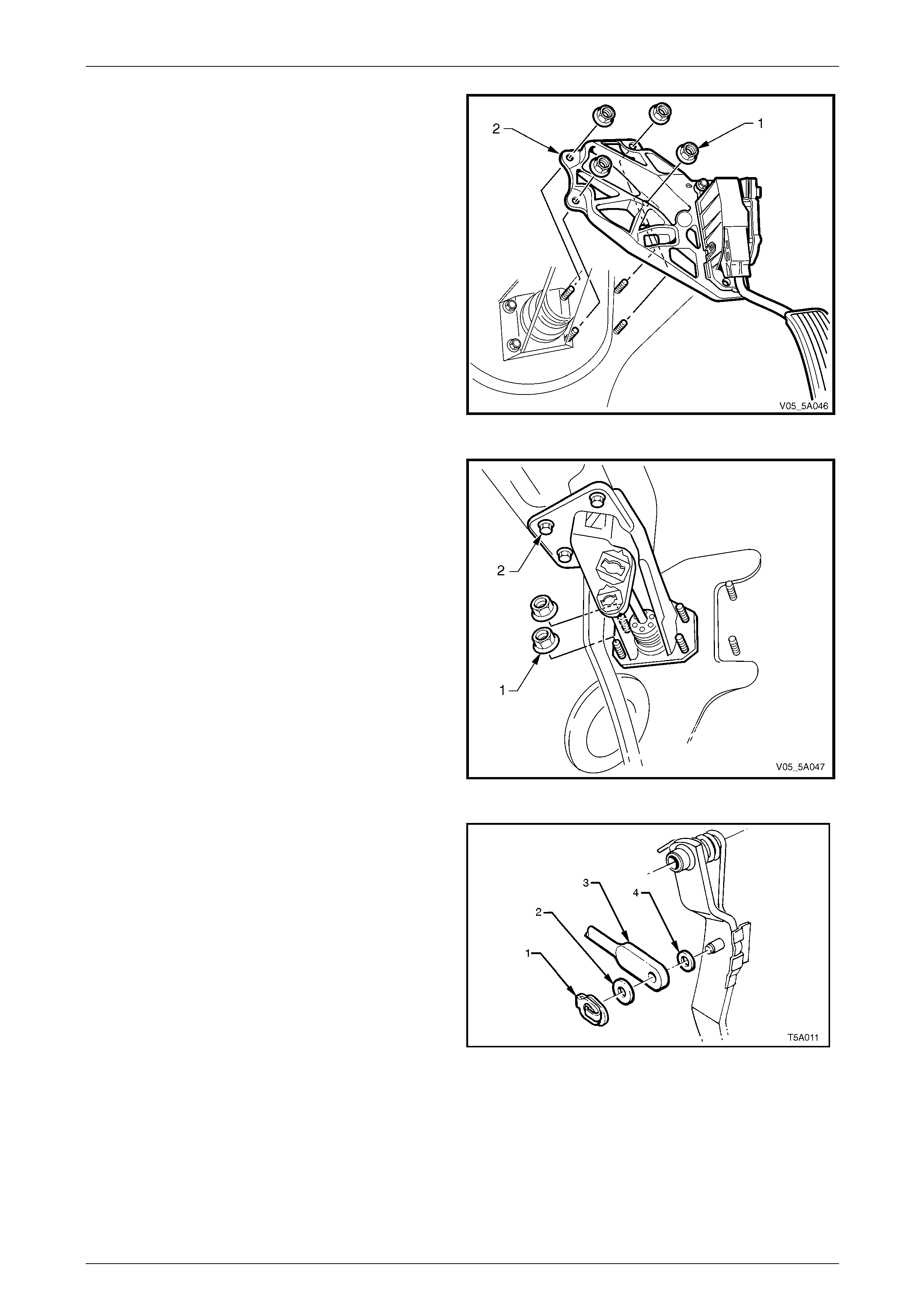
14 Remove the four nuts (1) securing the accelerator
pedal sensor bracket (2) to the brake pedal support
bracket and the dash panel.
Figure 5A – 28
15 Remove the remaining two nuts (1) securing the brake
booster to the brake pedal support bracket.
NOTE
If the manual transmission is fitted, these
remaining two nuts will have already been
removed when the clutch pedal and support
bracket were removed.
16 Remove the three bolts (2) securing the brake pedal
support bracket to the dash reinforcement.
17 From the engine compartment, pull the brake booster
forward, to disengage the four studs from the brake
pedal support bracket.
18 Lower the brake pedal assembly, rear end first and
removed from under the instrument panel.
Figure 5A – 29
19 Remove the push rod retaining clip (1), pus h rod (3)
and washers (2 and 4) from the brake pedal .
Figure 5A – 30
5A – 29
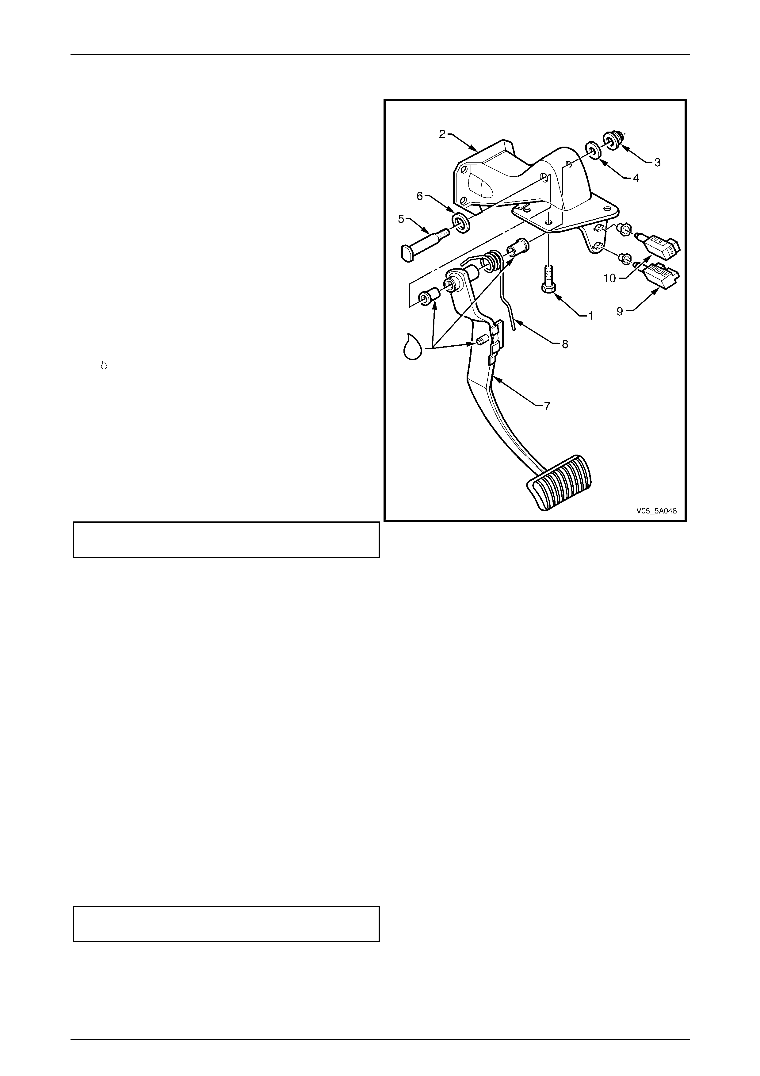
Service and Park Braking System 5A – 30
Disassemble
1 Remove the nut (3) and washer (4) securing the brake
pedal shaft (5) to the brake pedal support (5).
2 Carefully remove the shaft and washer (6) from the
brake pedal support (2).
3 Withdraw the brake pedal (7) and retur n spring (8)
assembly.
4 Turn the stop lamp switch (9), to the left (counter-
clockwise), then pull to remove from the brake pedal
support (2).
5 Turn the cruise cancel switch (10), to the left (counter-
clockwise), then pull to remove from the brake pedal
support (2).
Reassemble
1 Lubricate all bearing surfaces (indicated by the symbol
) with an NLGI No. 2 lithium soap based EP grease
with molybdenum disulphide, such as Shell Retinax
HDX2 grease or BP Energrease LMS-EP 2 3 (or
equivalent).
2 Hold the brake pedal (7) and return spring (8) in
position and insert the brake pedal support shaft (5)
and washer (6) through the brake pe dal support (2).
3 Reinstall the brake peda l shaft retaining washer (4)
and nut (3), then tighten to the correct torque
specification.
Brake pedal support shaft nut
torque specification..............................................55 N.m Figure 5A – 31
4 If removed, reinstall the cruise cancel switch (10):
a Insert the switch into the pedal bracket switch retainer, with the wiring harness con nector at the 1 o'clock
position.
b Push the switch into the retainer and turn clockwise until the wiring harness connector is at the 3 o'clock
position. At this point a click should be felt, indicating that the switch is locked into place. No further
adjustment is required.
5 If removed, reinstall the stop lamp switch (9), following the same proced ure as for the cruise cancel switch.
Reinstall
1 Reinstall the brake pedal assembly into the vehicle an d install the three bolts (2) securing the brake pedal support
assembly to the steering column, refer to Figure 5A – 29. Do not tighten the bolts at this time.
2 Push the brake booster rear ward to engage the four studs with the brake pedal sup port assembly.
3 Reinstall the push rod (3), washers (2 and 4) and retaining clip (1). Refer to Figure 5A – 30.
4 Reinstall the accelerator pedal assembly, refer to Figure 5A – 28.
5 If removed, reinstall the clutch pedal and bracket assembly, refer to Section 7A1 Clutch – V6, 7A3 Clutch – GEN III
V8 or 7A4 Clutch – GEN IV V8, in this Service Information.
6 Tighten the four brake peda l assembly to brake booster nuts to the correct torque specification.
Brake pedal support to brake
booster nut torque specification...........................25 N.m
5A – 30
Service and Park Braking System 5A – 31
7 Reinstall and tighten the two remaining accelerator pedal assembly to dash panel nuts to the specified torque.
Refer to Figure 5A – 28.
Accelerator pedal sensor bracket
attaching nut torque specification.........................25 N.m
8 Reinstall the wiring harness connectors to the stop lamp and the cruise cancel switches.
9 Reinstall the accelerator pedal sensor wiring harness connector, refer to Figure 5A – 27.
10 Tighten the three brake pedal support bracket to the dash reinforcement bolts to the correct torque specification,
refer to '2' in Figure 5A – 29.
Brake pedal support bracket
bolt torque specification.......................................25 N.m
11 Reinstall the master cylinder support bracket and tighten the nuts and bolt to the correct torque specification.
Master cylinder to bracket
bolt torque specification.......................................10 N.m
Master cylinder bracket to strut tower
attaching nuts torque specification.........................8 N.m
12 Place a clean container under the brake master cylinder, unplu g the brake lines and master cylinder outl et ports
and reinstall the pipes to the master cylinder, refer to Figure 5A – 25.
13 Tighten the brake pipe flare nuts to the correct torque specification.
Brake pipe to master cylinder
flare nut torque specification................................14 N.m
14 Bleed the brake system. Refer to 2.4 Brake System Bleed.
15 Reinstall the instrument panel lower trim panel retainer, lower trim panel and driver side lower trim plate, refer to
Section 1A3 Instrument Panel and Co nsole.
Enable the SRS (Air Bag). Refer to
Section 12M Occupant Protection System.
16 Road test the vehicle to check for correct brake, stop lamp and cruise control op eration.
5A – 31
Service and Park Braking System 5A – 32
2.9 Park Brake Lever
LT Section No. – 04-675
Remove
1 Remove the right hand front seat. Refer to Section 1A7 Seat Assemblies .
2 Set the park brake in the fully released position.
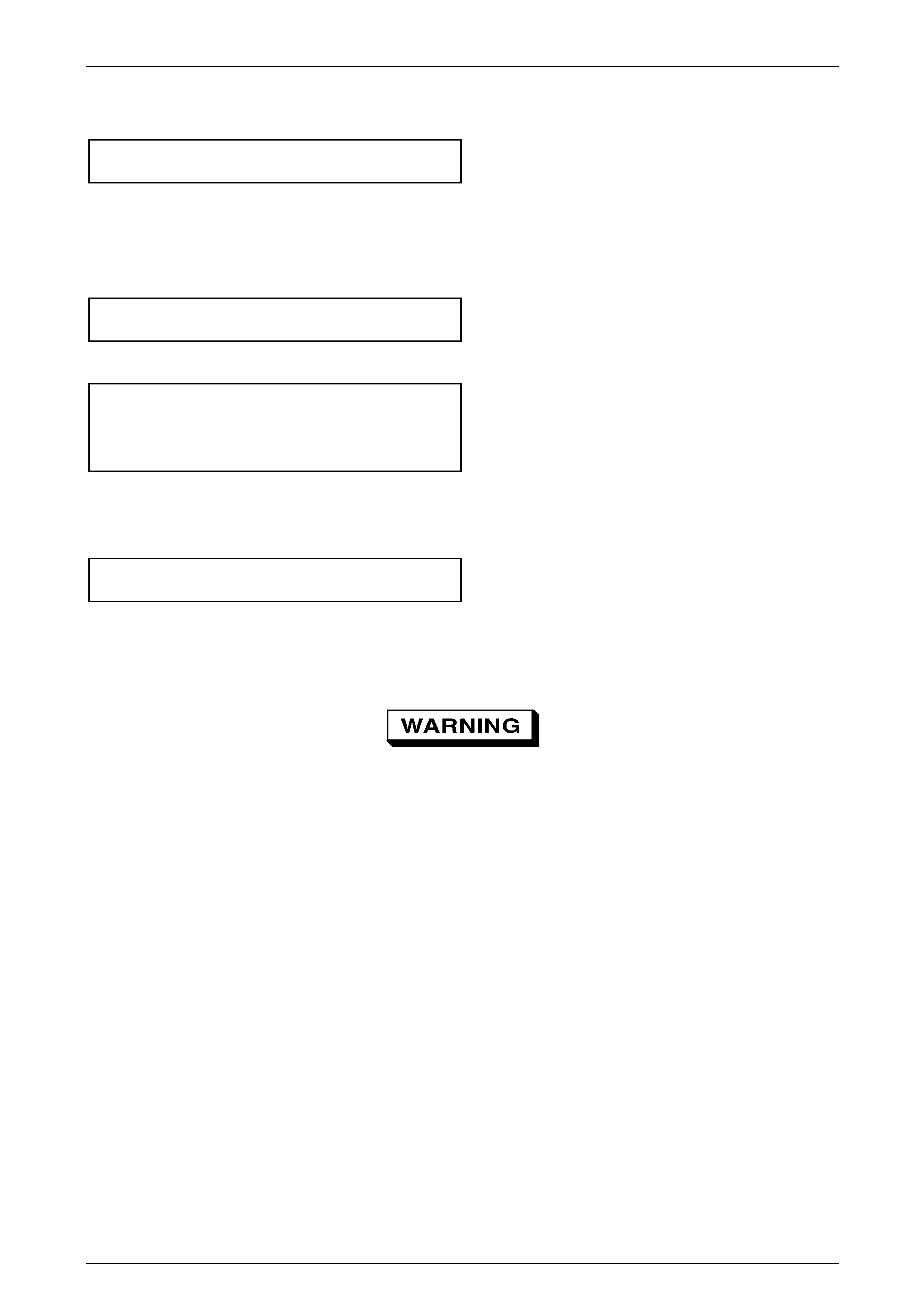
3 Slip the park brake lever boot (1) to one sid e, then
remove the park brake front cable adjusting nut (2),
using a deep socket.
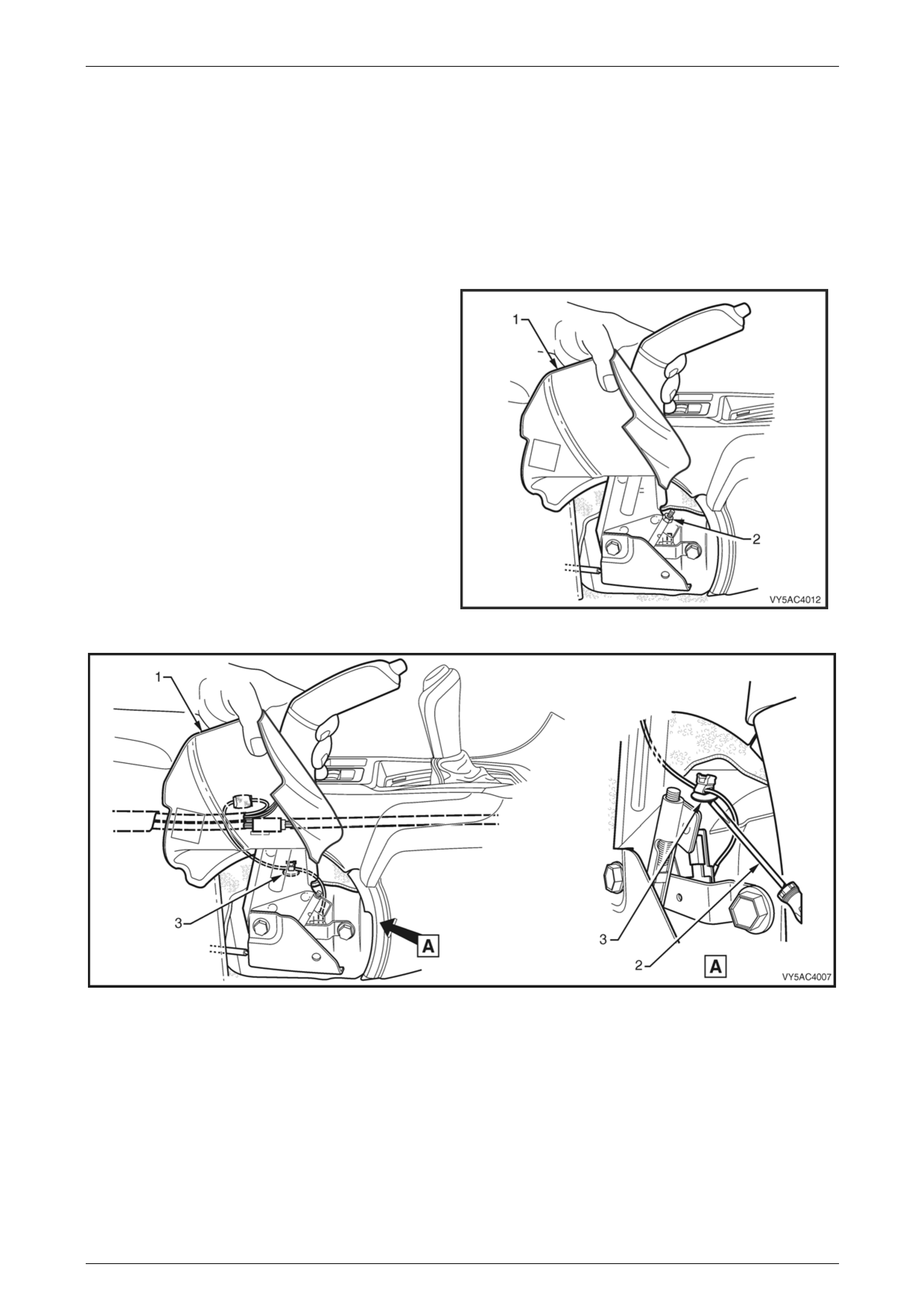
4 Whilst holding the park brake lever bo ot (1) to one
side, use a screwdriver (2) to prise the park brake
warning lamp switch harness r etaining clip (3) from the
transmission tunnel.
Figure 5A – 32
Figure 5A – 33
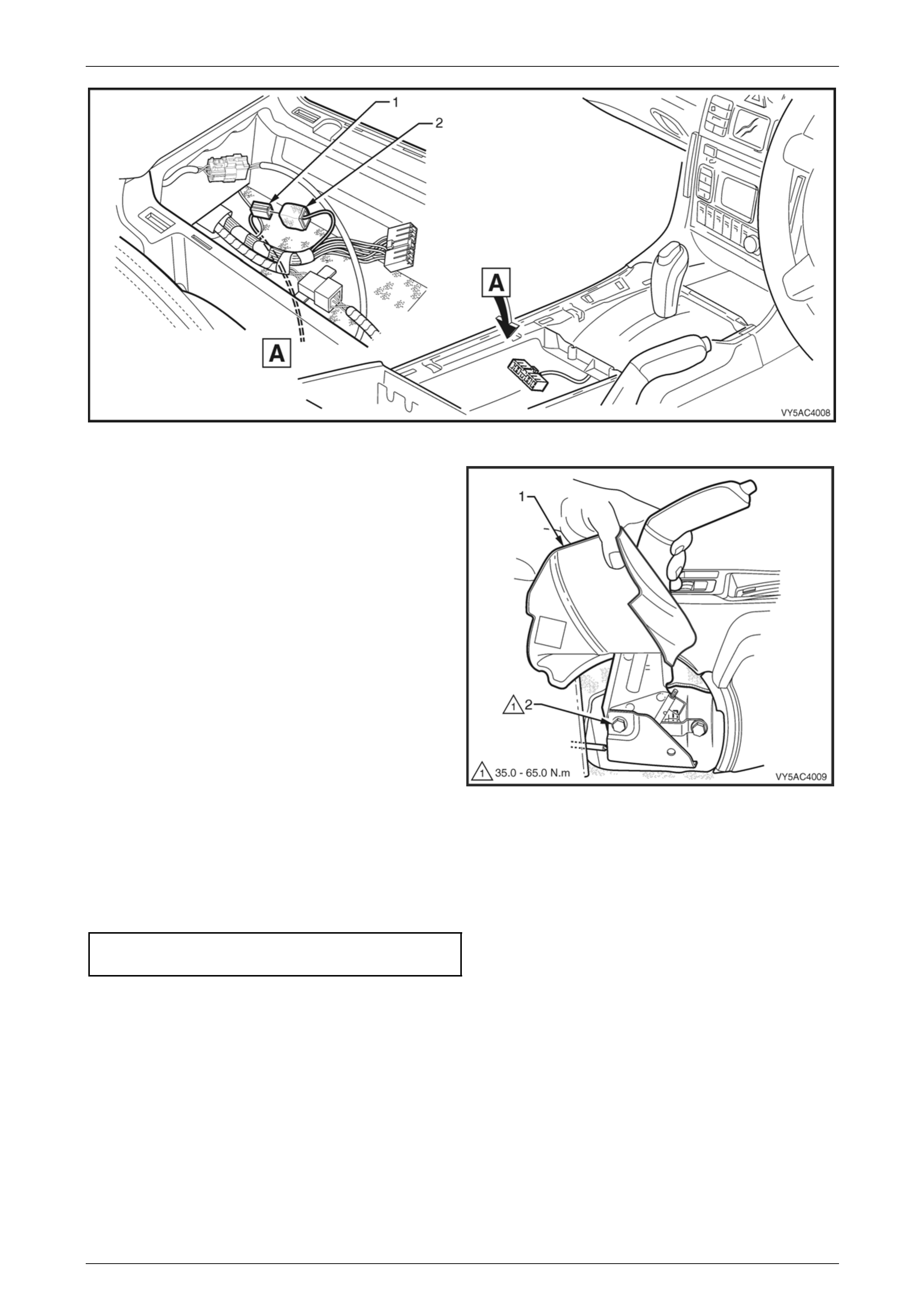
5 Remove the floor console cover assembly. Refer to Section 1A3 Instrument Panel and Console.
6 Disconnect the park brake warning lamp switch harness connector (1) from the main vehicle wiring harness
connector (2).
5A – 32
Service and Park Braking System 5A – 33
Figure 5A – 34
7 While holding the park brake lever boot (1) to one
side, remove the park brake lever retaining bolt (2),
two places.
8 Carefully lift the park brake lever assemb ly upwards to
free the cable (2).
9 Remove the lever assembly from the vehicle.
Figure 5A – 35
Reinstall
Reinstallation is the reverse of the removal procedure, noting the following:
1 Tighten the park brake lev er bolts to specified torque.
Park brake lever bolt
torque specification..............................................50 N.m
2 Reinstall the threaded end of the front park brake cable and then install the adjusting lock nut. Adjust the park
brake cable. Refer to 2.2 Park Brake Cable, Adjust.
5A – 33
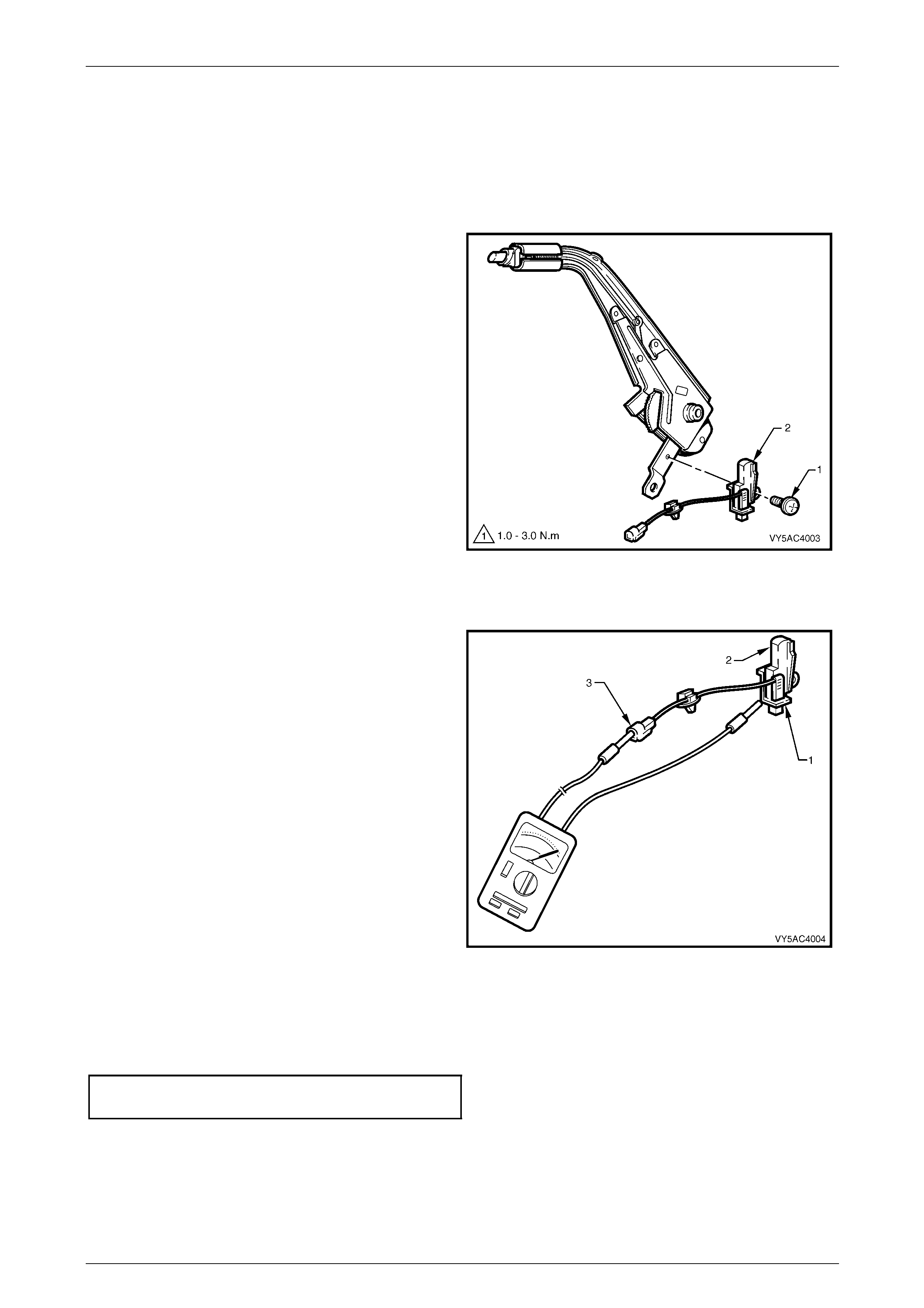
Service and Park Braking System 5A – 34
2.10 Park Brake Warning Lamp Switch
LT Section No. – 04-675
Remove
1 Remove the park brake lever. Refer to 2.9 Park Brake Lever.
2 Remove the park brake warning lamp switch retaining
screw (1), and remove the switch (2).
Figure 5A – 36
Inspect
1 While holding the park brake warning lamp switch (1),
depress and releas e the plunger (2), checking that the
plunger moves freely.
2 Using a multimeter, check that there is continuity
between the terminal (3) and the switch body.
3 With the multimeter still connected, check that there is
no continuity when the switch plunger is depressed.
4 If any of the above tests fail, replace the park brake
warning lamp switch.
Figure 5A – 37
Reinstall
Reinstallation is the reverse to the removal procedure, noting the following:
Tighten the park brake warning lamp switch retaining screw to the specified torque.
Park brake warning lamp switch
screw torque specification......................................2 N.m
NOTE
For further information on the park brake warning
lamp operation, refer to Section 12C
Instrumentation.
5A – 34
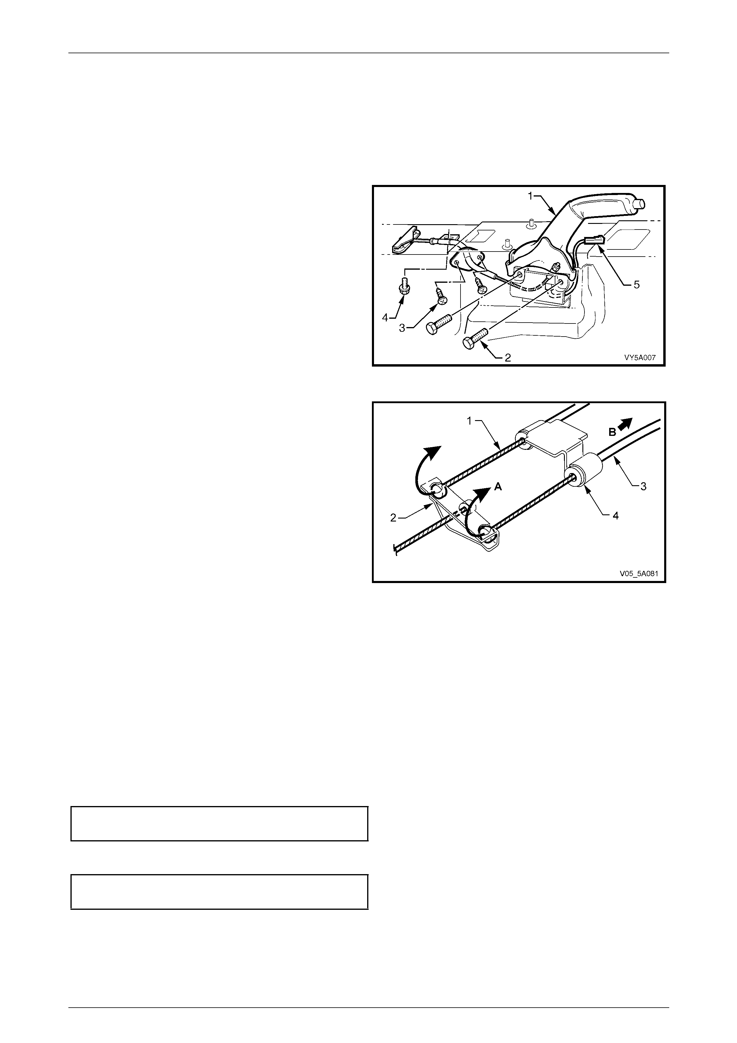
Service and Park Braking System 5A – 35
2.11 Front Park Brake Cable
LT Section No. – 04-675
Remove
1 Set park brake in the fully released p osition.
2 Remove driver’s seat. Refer to Section 1A7 Seat
Assemblies for the procedure.
3 Remove the park brake lever (1). Refer to 2.9 Park
Brake Lever.
4 Remove the centre console and lift the carpet to gain
access to the two front cable escutcheon screws (3).
Refer to Section 1A3 Instrument Panel and Console,
for details.
5 Remove the two screws (3).
Figure 5A – 38
6 Raise the vehicle and suppor t in a safe manner. Refer
to Section 0A General Information for the location of
recommended lifting and support points.
7 Pull each park brake inner rear cable (1) forward and
up (A) to release it from the equaliser bracket (2). Pull
the outer cables (3) to the rear (B) to remove the cable
from the retaining bracket.
8 Remove the front cable outer cable retaining bracket
bolt (4) from the vehicle underbody, refer to F igure 5A
– 38.
NOTE
Depending on the engine/transmission fitted to
the vehicle, it may be necessary to first remove
the propeller shaft to enable access to this bolt.
Refer to Section 4C1 Rear Propeller Shaft and
Universal Joints.
Figure 5A – 39
9 Manoeuvre the front cable assembly and equaliser bracket, through the aperture in the floor pan, removing the
cable assembly from inside the vehic le.
Reinstall
Installation is the reverse to the removal procedure, apart from the following:
1 Manoeuvre the front cable and equaliser bracket assembly, through the hole in the flo or pan, ensuring that the
rubber seal is correctly positioned. Install the two self tapping screws ('3' in Figure 5A – 38) securing the plate to
the floor pan and tighten to the correct torque specification.
Front park brake cable plate retaining
screw torque specification...................................2.0 N.m
2 Reinstall the park brake lever and tighten bolts ('2' in Figure 5A – 38) to the specified torque.
Park brake lever bolt
torque specification..............................................50 N.m
5A – 35

Service and Park Braking System 5A – 36
3 Reinstall the park brake front cable adjusting nut a few threads to secure the cable.
4 Reinstall the outer front cable retaini ng bracket bolt to the vehicle underbod y ('4' in Fig ure 5A – 38) , tightening to
the correct torque specification.
Outer front cable bracket
bolt torque specification.......................................25 N.m
5 As required, reinstall the propeller shaft. Refer to Section 4C1 Rear Propeller Shaft and Universal Jo ints for the
procedure and the specified torque specifications.
6 Reinstall the driver’s seat and centre console. Refer to Section 1A7 Seat Assemblies an d Section 1A3 Instrument
Panel and Console, for the ne cessary procedures.
7 Reinstall the two rear cables to the eq ualiser bracket.
8 Adjust the park brake. Refer to 2.2 Park Brake Cable, Adjust.
9 Lower the vehicle to the ground
10 Check for correct park brake operation.
5A – 36
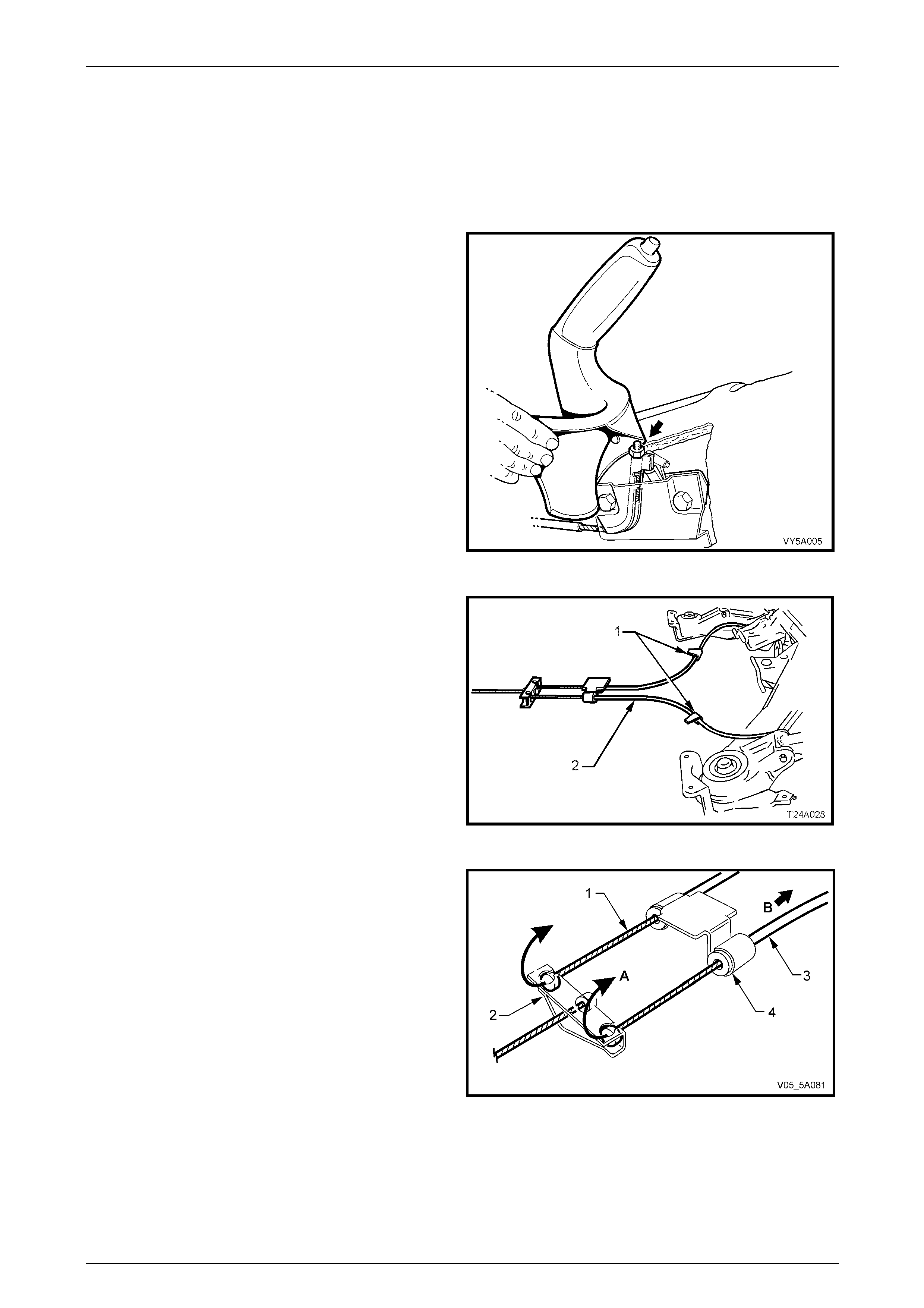
Service and Park Braking System 5A – 37
2.12 Rear Park Brake Cable/s
LT Section No. – 04-675
Remove
1 Release park brake.
2 Using a deep socket, loosen the front cabl e adjusting
nut (arrow) until the nut is almost removed.
3 Raise the vehicle and suppor t in a safe manner. Refer
to Section 0A General Information for the location of
recommended lifting and support points
Figure 5A – 40
4 To provide sufficient access, it may be necessary to
remove the propeller shaft from the vehicle. Refer to
Section 4C1 Rear Propeller Shaft and Universal Joints
for the necessary procedures.
5 As required, unclip the cable/s (2) from the under body
clip/s (1).
Figure 5A – 41
6 Remove the front of the rear inner cable/s (1), by first
wrapping rag around the inner cable (1) to protect it
from damage, then use pliers to pull the ball nipple
forward and up (A), to free from the equaliser bracket
(2).
7 Pull the outer cable (3) rearward (B) to release from
the vehicle underbody bracket (4).
Figure 5A – 42
5A – 37
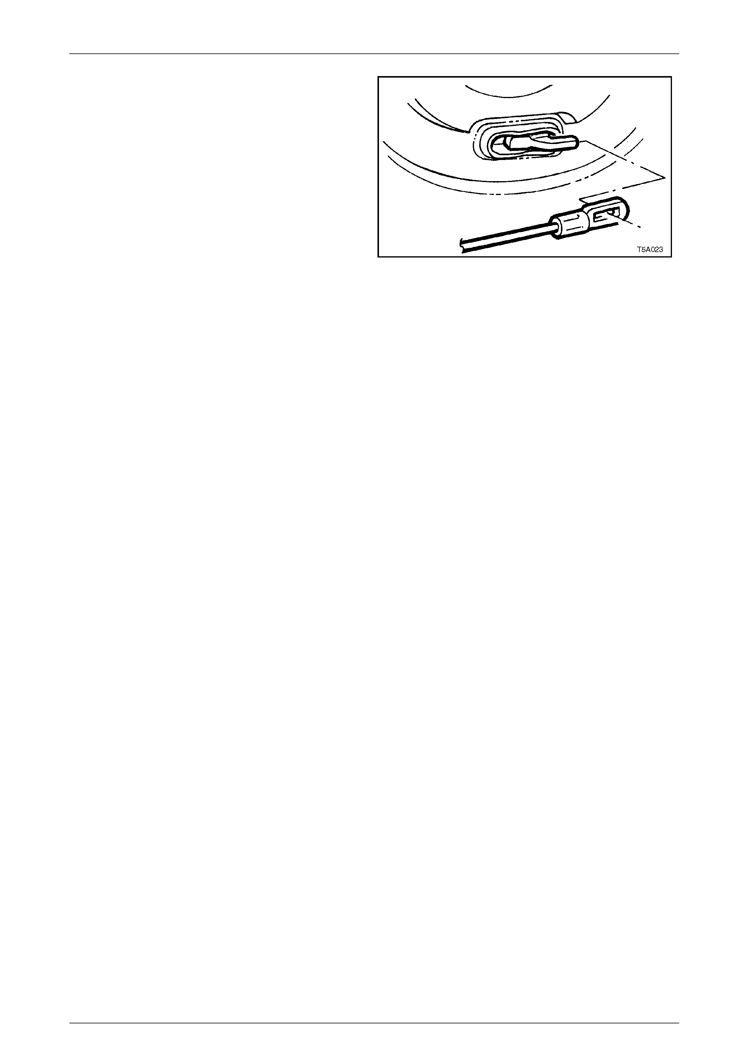
Service and Park Braking System 5A – 38
8 Disconnect the rear clevis from the rear park brake
actuating lever by gripping with pliers and pivoting the
cable rearwards.
Figure 5A – 43
Reinstall
Reinstallation of the rear park brake cable/s is the reverse of removal procedure, except for the following points:
1 Reinstall the cable throu gh the trailing arm retainer, then fit the cable clevis to the park brake actuating lever.
2 Pull the outer cable/s forward to reinstall into the vehicle underbody bracket.
3 Wrap rag around the inner cable to protect it from damage, then use pliers to pull the ball end on the inner cabl e
forward to engage into the equaliser bracket.
4 If removed, reinstall the propeller shaft. Refer to Section 4C1 Rear Propeller Shaft and Universal Joints for all
details.
5 Adjust park brake cable, refer to 2.2 Park Brake Cable, Adjust.
5A – 38
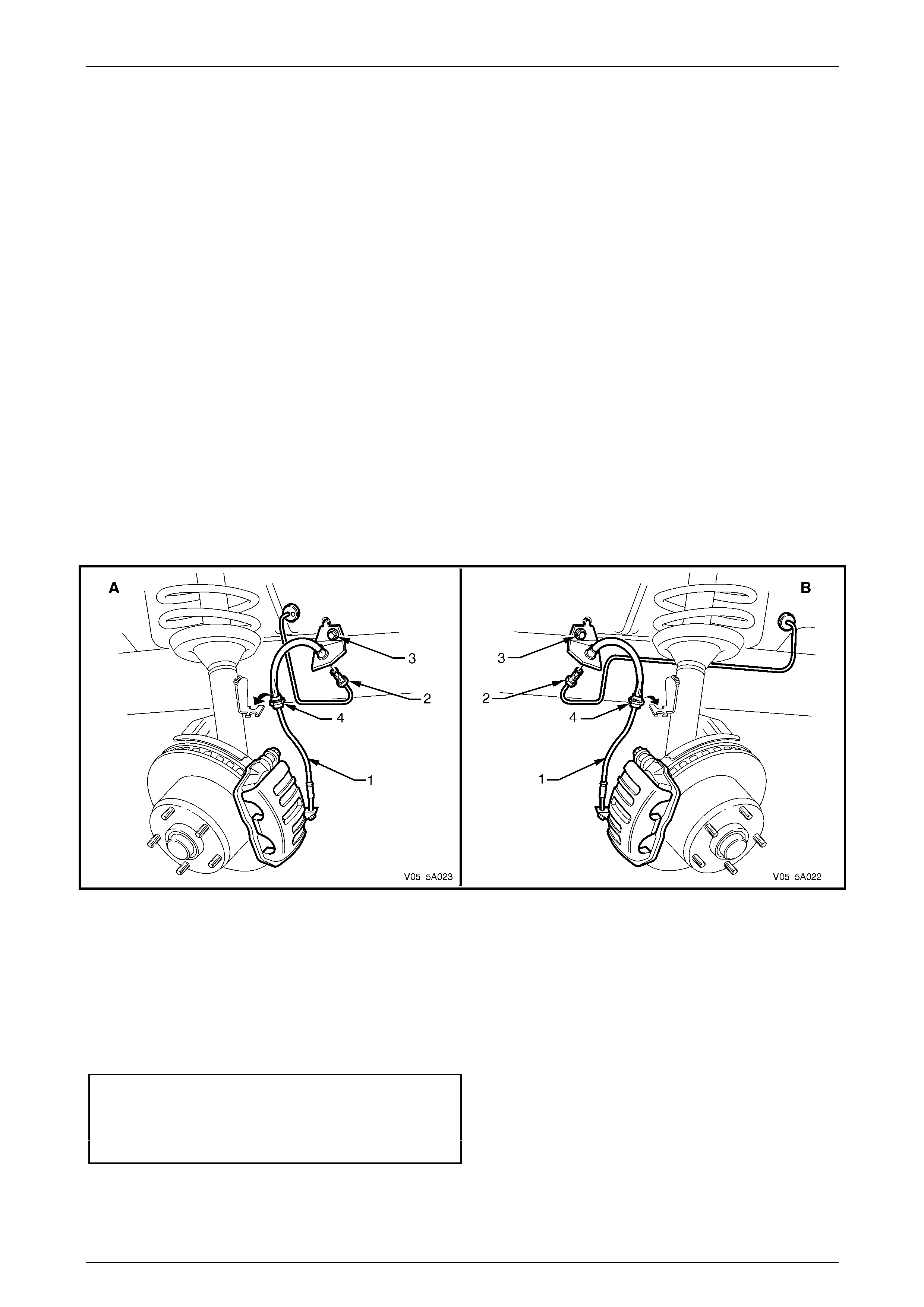
Service and Park Braking System 5A – 39
2.13 Front Brake Hose
LT Section No. – 04-750
Remove
1 Raise the vehicle and suppor t in a safe manner. Refer to Section 0A General Information for the location of
recommended lifting and support points.
2 Remove the wheel covers or decorative wheel nut caps, then mark the relationship of the road wheel to one of the
wheel studs.
3 Loosen, then remove the road wheel attaching nuts, working in a 'star' pattern. Refer to 2.1 Service Warnings,
Cautions and Notes, for detailed i nformatio n. Remove the road wheel.
4 Thoroughly cle an connections at each end of brake hose (1), refer to Figure 5A – 44.
5 Disconnect brake pipe (2) from hose (1), then plug pipe to reduce fluid loss.
6 Remove the screw (3) securing the hose bracket to the inner skirt panel.
7 Unclip hose and grommet (4) from bracket on suspe nsion tower.
NOTE
View 'A' shows the left front brake hose, while
view 'B' shows the right front brake hose.
Figure 5A – 44
8 Unbolt and remove the brake hose from the caliper, refer to Figure 5A – 45.
Reinstall
1 Ensure brake hose and caliper mating surfaces are clean and free from burrs.
2 Reinstall brake hose (1) to caliper, using NEW copper seali ng washers (3), then tighten the ba njo bolt (2) to
specified torque.
Brake hose to caliper banjo b olt torque specification.(All
except Coupe and MY2006 SS )..........................35 N.m
(Coupe and MY2006 SS )...................................12 N.m,
.............. then turn through 90°
5A – 39
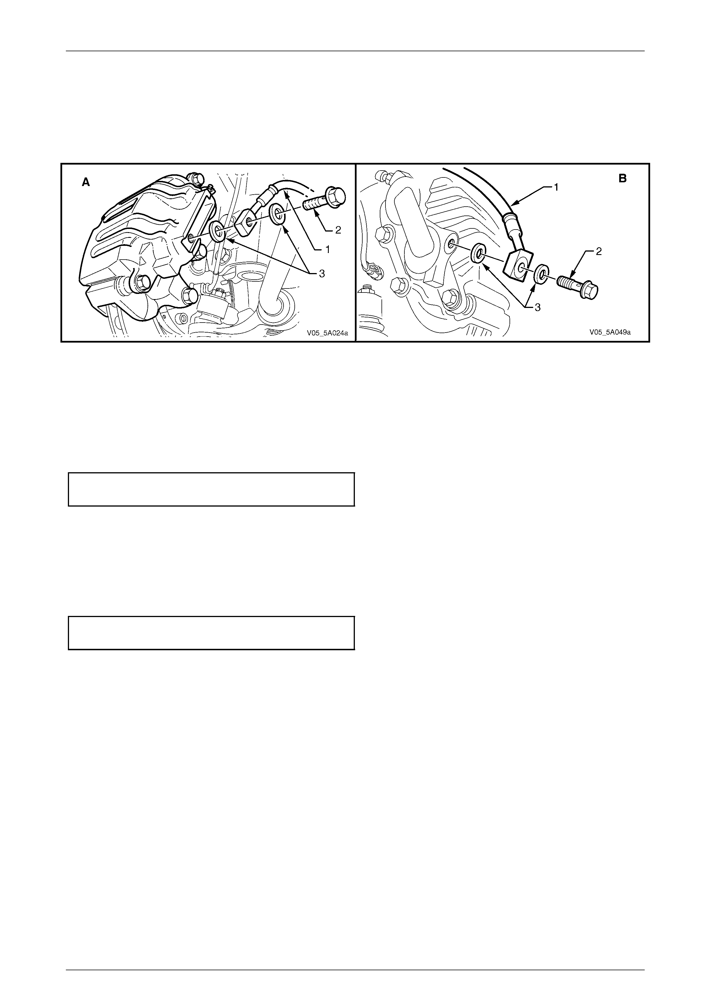
Service and Park Braking System 5A – 40
NOTE
View 'A' shows the Coupe an d MY2006 SS front
caliper and front brake hose, while vie w 'B' sho ws
the arrangement for the remainder of MY 2005
VZ models.
Figure 5A – 45
3 Reinstall hose and gr ommet (4) into suspension strut bracket, refer to Figure 5A – 44. Secure by turning the
grommet through 90°.
4 Reinstall the scre w (3) to retain the hose bra cket to the inner skirt panel.
5 Remove plug from brake pipe and rec on nect to hose (4).
6 Tighten the flare nut to the corr ect torque specification.
Brake pipe to brake hose
flare nut torque specification................................15 N.m
7 Check that the brake hose is not twisted.
8 Bleed brake/s, refer 2.4 Brake System Bleed.
9 Reinstall road wheel, aligning marks made on removal and lower vehicle.
10 Tighten road wheel attaching nuts to the correct torque specification, working in a star pattern, refer to 2.1 Service
Warnings, Cautions and Notes.
Road wheel attaching
nut torque specification............................110 – 140 N.m
5A – 40
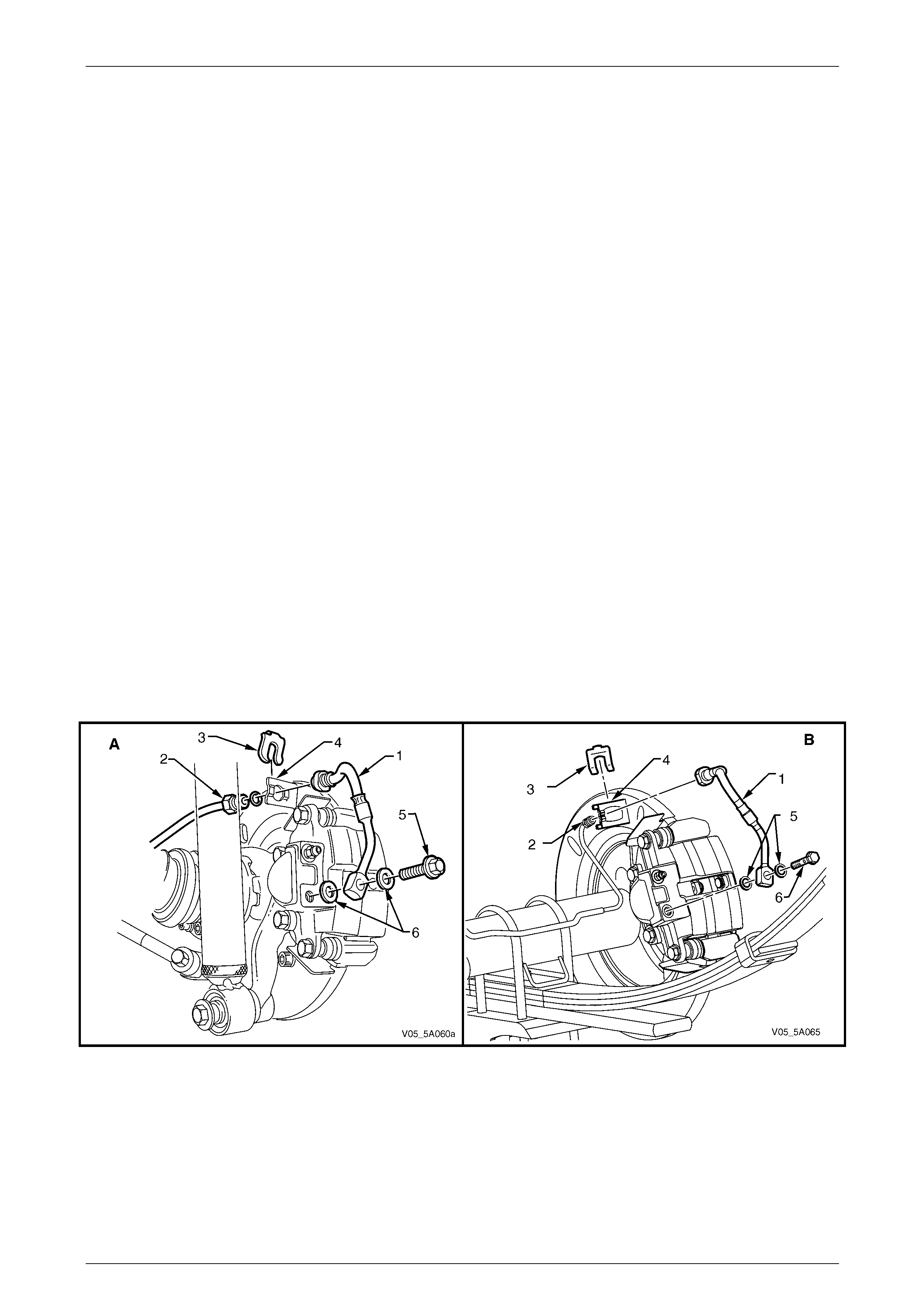
Service and Park Braking System 5A – 41
2.14 Rear Caliper Brake Hose
LT Section No. – 04-750
Remove
NOTE
While a solid disc rotor is shown in the
accompanying diagram (view ‘A’), the procedure
for Coupe and MY2006 SS models is the same
as that described.
1 Raise rear of the vehicle and support in a safe manner. Refer to Section 0A General Information for the location of
recommended lifting and support points.
2 Remove the wheel covers or decorative wheel nut caps, then mark the relationship of the road wheel to one of the
wheel studs.
3 Loosen, then remove the road wheel attachi ng nuts, working in a 'star' pattern. Refer 2.1 Service Warnings,
Cautions and Notes, for detailed i nformatio n. Remove the road wheel.
4 Thoroughly cle an connections at each end of brake hose (1).
5 While holding the hose (1) with a back-up spanner, loosen then disconnect brake pipe (2) from brake hose (1).
Plug the pipe open end.
6 Remove retainer clip (3) from hose and withdraw hose from bracket (4).
7 Remove the banjo bolt (5) and two copper washers (6). Unbolt and remove brake hose from caliper.
NOTE
View 'A' shows the rear caliper hose for all VZ
models except Live Axle vehi cles which is shown
in view 'B'.
Figure 5A – 46
5A – 41

Service and Park Braking System 5A – 42
Reinstall
1 Ensure brake hose and caliper mating surfaces are clean and free of burrs.
2 Reconnect brake hose to caliper, ensuring that the locating peg al igns with the dimple in the caliper. Use NEW
copper sealing washers, then tighten the banjo bolt to specified torque.
Brake hose to caliper banjo
bolt torque specification.......................................35 N.m
3 Fit hose correctly into mountin g plate bracket and reinstall retainer. Check that hose is not twisted.
4 Remove plug from brake pipe and rec on nect to hose. While using a back-up spanner on the brake hose to prevent
twisting, tighten pipe to specified torque.
Brake pipe to brake hose flare
nut torque specification........................................15 N.m
5 Bleed brake/s, refer to 2.4 Brake System Bleed.
6 Reinstall road wheel, aligning marks made on removal and lower vehicle.
7 Tighten road wheel attachi ng nuts to the specified torque, tightening in a star pattern, refer to 2.1 Service
Warnings, Cautions and Notes.
Road wheel attaching bolt
torque specification..................................110 – 140 N.m
8 Road test the vehicle to ensure correct brake operation.
5A – 42
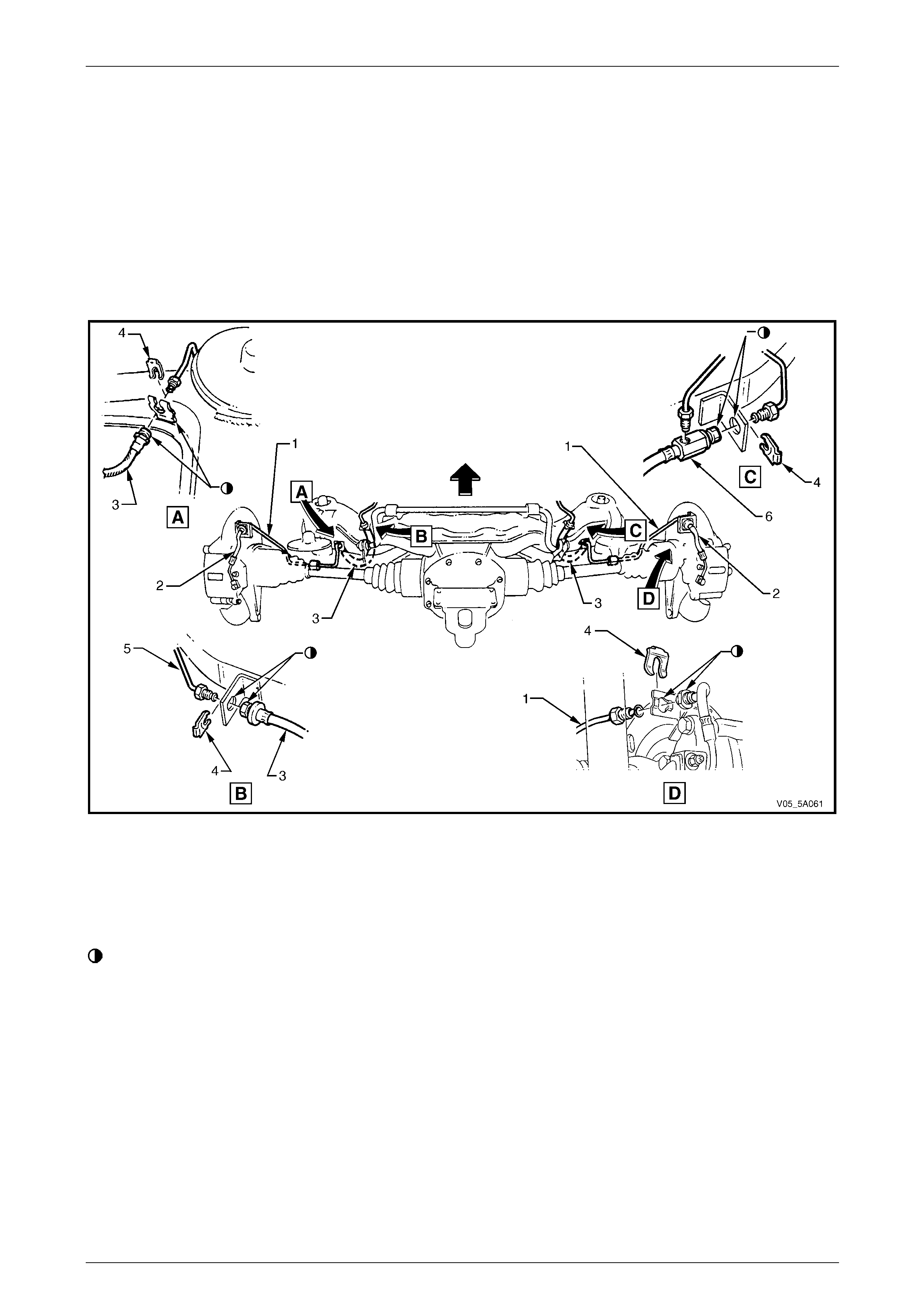
Service and Park Braking System 5A – 43
2.15 Rear Brake Hose – All Except Live Axle
Models
LT Section No. – 04-750
Remove
1 Raise rear of the vehicle and support in a safe manner. Refer to Section 0A General Information in this Service
Information for the location of recommende d lifting and support points.
2 Thoroughly clean connections at each end of the rear brake hose to be removed.
Figure 5A – 47
Legend
View A LH Shown – RH opposite
View B With ABS/TC – LH shown, RH opposite
View C Without ABS/TC – LH only
View D RH shown, LH opposite
Align Flats on Bracket and Hose
1 Rear Brake Pipe
2 Rear Brake Hose, Caliper to Rear Brake Pipe
3 Rear Brake Hose
4 Retaining Clip
5 Brake Hose Connection Pipe
6 Junction Block – RH only (Vehicles without ABS/TC)
3 Disconnect brake pipe (5) from brake hose (3) at trailin g arm brackets (View B). Plug open end of brake pipe/s to
prevent foreign material entry.
4 Disconnect rear brake pipe (1) connection from brake hose (3), while holding the hose with a back-up spa nner. F or
those vehicles without ABS/TC, the RH side brake hose (View C), also has a junction block (6) to provide for a
connection from the master cylinder. Plug all pipe ends to prevent foreign material entr y.
5 Unclip retaining clips (4) from the end of eac h hose end and withdraw hose/s from brackets.
NOTE
Refer to 2.14 Rear Caliper Brake Hose for
procedure to remove the rear caliper hos e (2).
5A – 43

Service and Park Braking System 5A – 44
Reinstall
1 Ensure brake hose ends and pipe mating surfaces are clean and free of burrs.
2 Fit hose (3) into mounting plat e brackets and reinstall retaining clips (4). Check that the hose (3) is n ot twisted.
3 Remove plugs from brake pipes (1 and 5), then reconnect to hose ends. Tighten all pipe nuts to specified torque.
Brake pipe flare nut to brake
hose torque specification .....................................15 N.m
4 Bleed brake/s, see 2.4 Brake S ystem Bleed.
5 Lower vehicle to the ground and roa d test for correct brake operation.
5A – 44
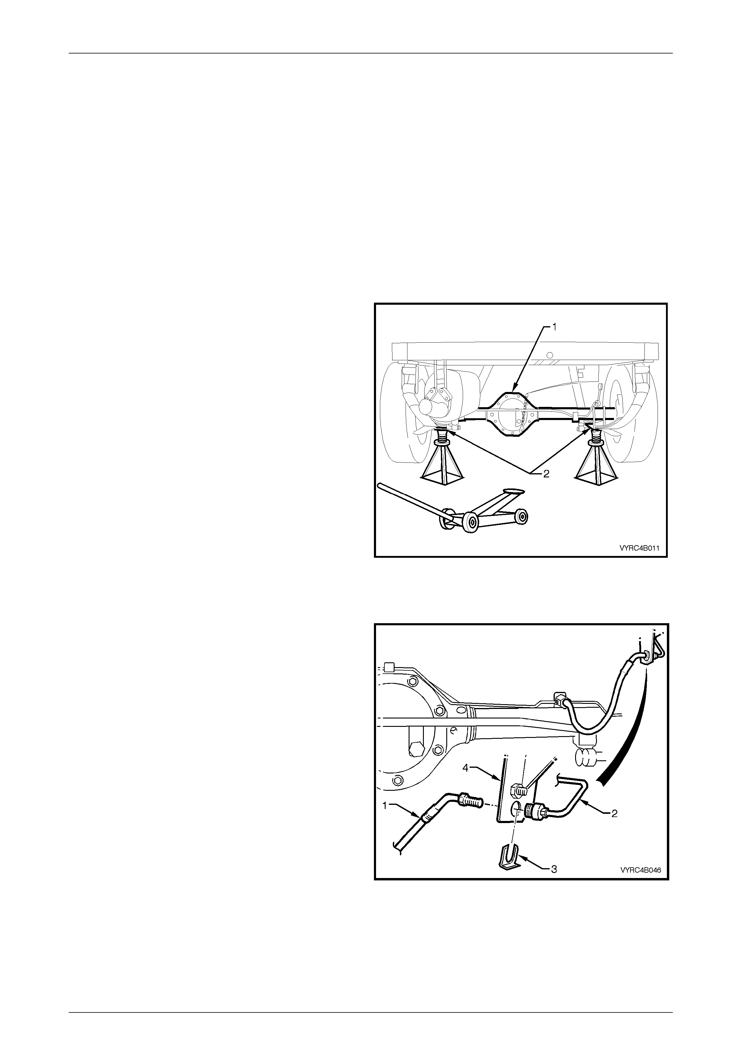
Service and Park Braking System 5A – 45
2.16 Rear Brake Hose/s – Live Axle Models
LT Section No. – 04-750
NOTE
Refer to 2.14 Rear Caliper Brake Hose for the
procedure to remove the rear caliper brake
hoses.
Remove
All Live Axle Models
1 Raise the vehicle and suppor t in a safe manner. Refer
to Section 0A General Information for the location of
recommended lifting and support points
2 Thoroughly clean the connections at each end of the
rear brake hose/s and pipes.
3 Place a suitable drain container under the brake hose
area.
Figure 5A – 48
All Except AWD & Live Axle
4 While holding the hose fitting with a back-up spanner,
disconnect the rear brake pipe (2) connection from the
Load Sensing Proportioning Valve (LSPV) to the brake
hose.
5 Remove the retaining clip (3) from the end of the hose
(1) and withdraw the hose from the bracket (4).
6 Plug all pipe and hose ends to prevent foreign material
entry.
Figure 5A – 49
5A – 45
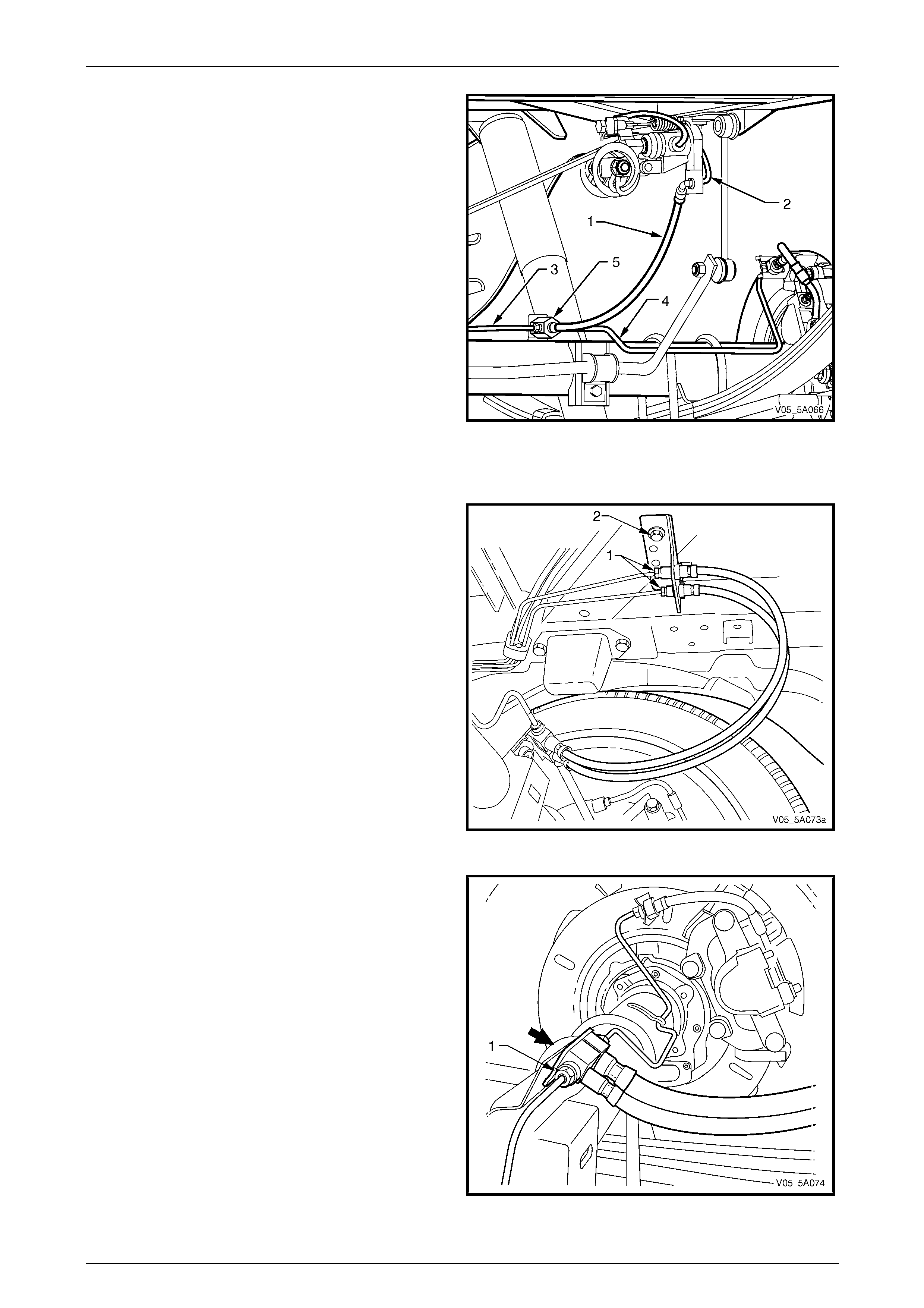
Service and Park Braking System 5A – 46
7 While holding the brake pipe to hose T-piece fitting (5)
with a suitable spanner, remove both brak e pipes ('3'
and '4') from the fitting.
8 Remove the bolt securing the brake pipe to hose T-
piece fitting to the bracket welded to the axle housing.
9 Remove the brake hose (1) a nd T-piece fitting (5) from
the vehicle.
NOTE
The brake hose (1) and T-piece fitting (5) are
only serviced as an assemb ly.
Figure 5A – 50
AWD & Live Axle Only
NOTE
Both hoses and mounting brackets at each end
are only serviced as a single assembl y.
1 In turn, hold each brake hose fitting with a suitable
sized spanner, loosen, then remove each of the brake
pipes (1).
NOTE
Label at least one of the pipes to ensure correct
reinstallation.
2 Plug the open ends of the disconn ected pipe and
hose.
3 Remove the bolt (2) securing the brake hose bracket
to the vehicle frame.
Figure 5A – 51
4 Loosen then remove each of the brake pipe flare nuts
(1) from the hose adaptors.
5 Plug all open ends to prevent unnecessary fluid loss
and/or dirt entry.
6 Remove the bolt (bold arrow) securing the brake hose
adaptor to the bracket welded to the axle tube.
7 Remove the hose assembly from the vehicle.
Figure 5A – 52
5A – 46
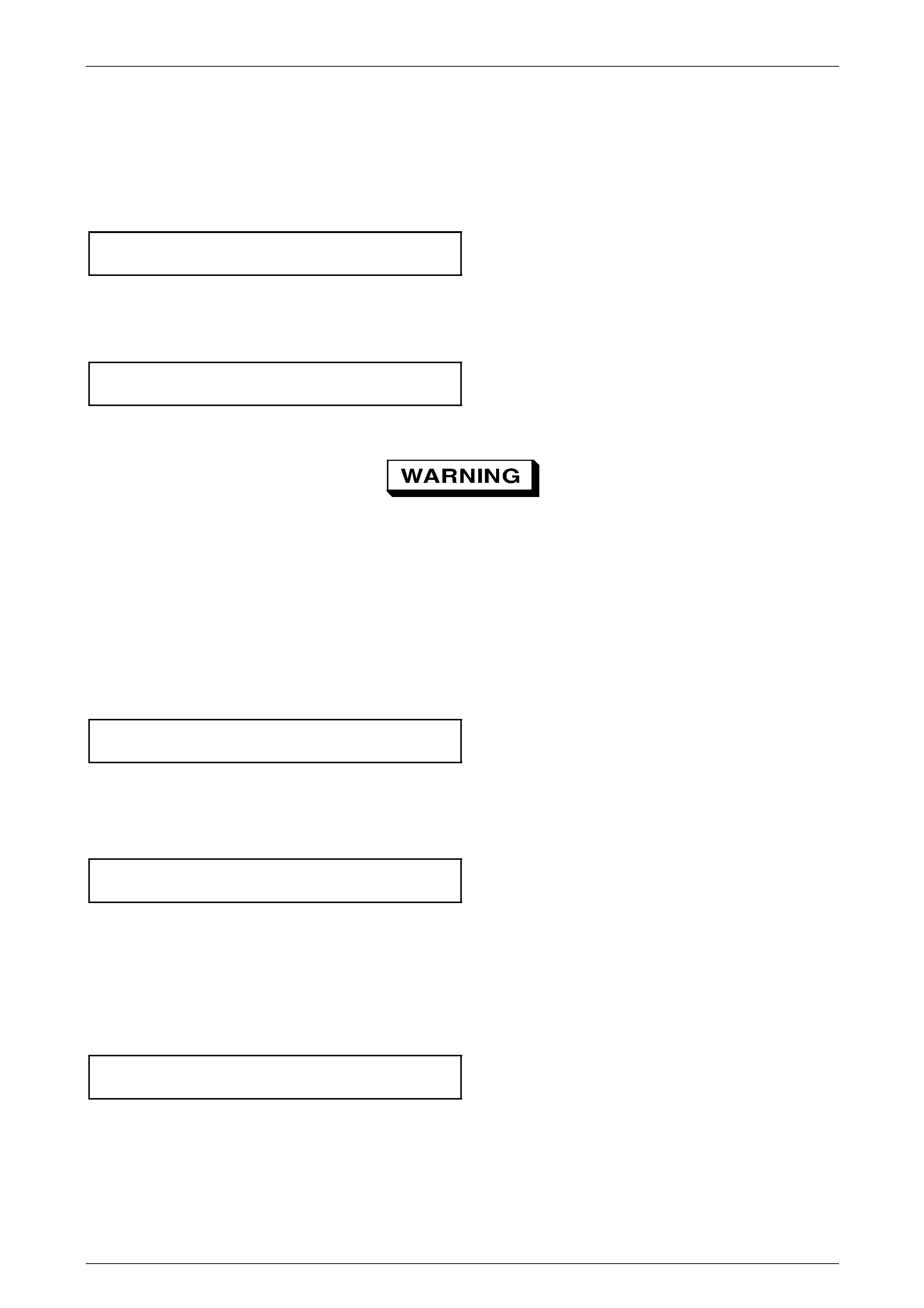
Service and Park Braking System 5A – 47
Reinstall
All Live Axle Models
1 Remove plugs from brake pipes.
2 Reinstall the bolt securing the brake hose T-piece fitting (or adaptors) to the axle tube bracket and tighten to the
correct torque specification.
Brake hose adaptor securing
bolt torque specification.......................................25 N.m
3 Reinstall the brake pipe flare nuts to the brake hose T- piece fitting (or adaptors) at the lower hose end.
4 Using a back-up spanner to hold the br ake hose T-piece fitting (or adaptors), tighten the brake pipe flare nuts to the
correct torque specification.
Brake pipe flare nut
torque specification..............................................15 N.m
All Except AWD & Live Axle
Wear eye protection to prevent potential
injury.
5 Insert the upper end hose fitting into the mo unting bracket and secure with a new retaining clip ('3' in
Figure 5A – 49).
6 Reinstall the brake pipe to the hose fitting.
NOTE
Check that the brake hose is not twisted.
7 Using a back-up spanner to hold the hose fitting, tighten the upper pipe flare nut to the correct torque specification.
Brake pipe flare nut
torque specification..............................................15 N.m
AWD & Live Axle Only
8 Install the brake hoses upper end, mounting plate bracket and secure with the bolt, tightened to the correct torque
specification.
Rear brake hose upper bracket
bolt torque specification.......................................15 N.m
NOTE
Check that the brake hoses are not twisted.
9 Reinstall the brake pipes to th e hose fittings, checking that the correct pipe is installed to the correct brake hose.
10 Using a back-up spanner to hold the hose fittings, tighten each of the upper pipe flare nuts to the correct torque
specification.
Brake pipe flare nut
torque specification..............................................15 N.m
All Live Axle Models
11 Bleed the brakes, refer to 2.4 Brake System Bleed.
12 Lower the vehicle to the ground.
13 Road test the vehicle to ensure correct b rake operation.
5A – 47
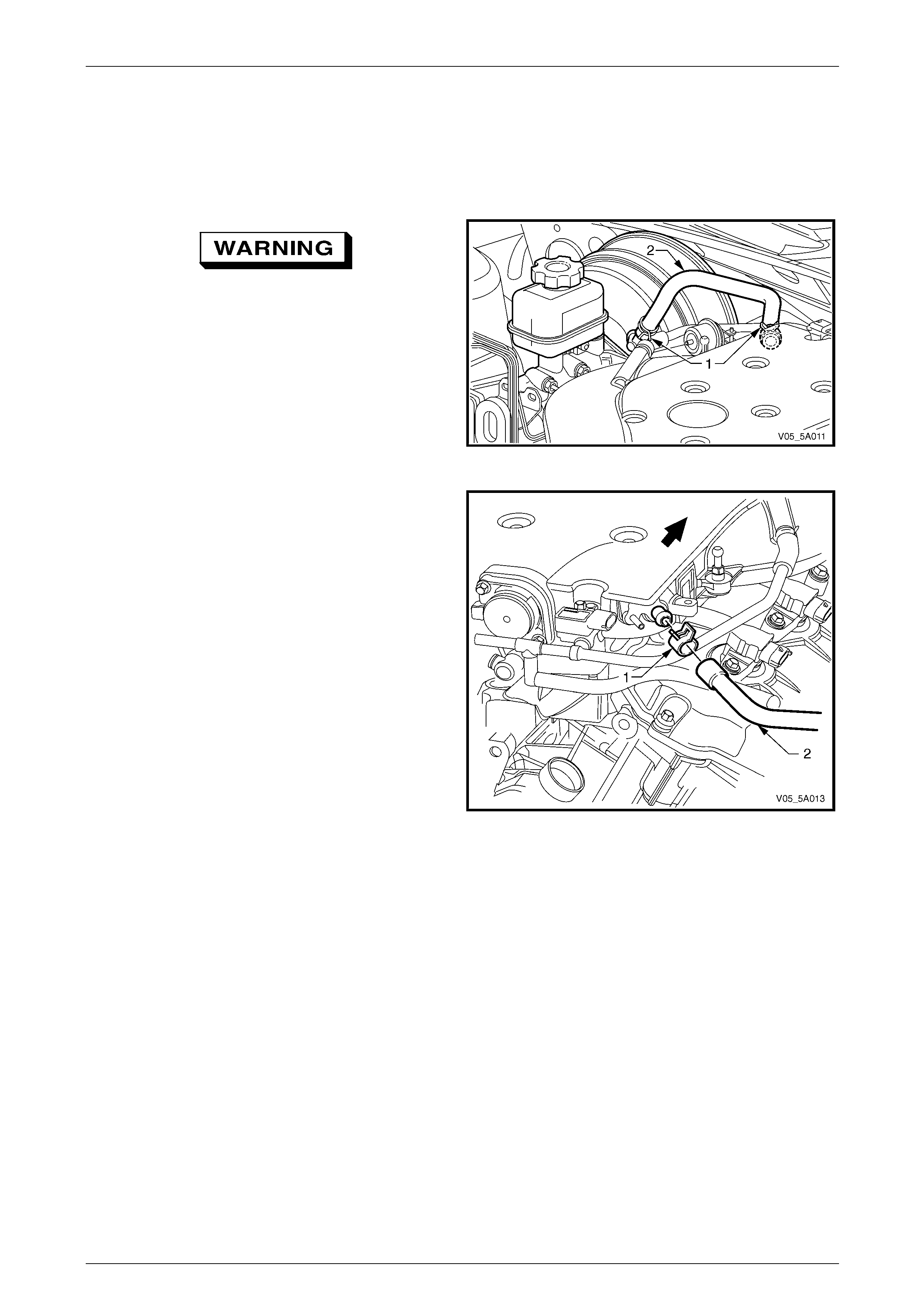
Service and Park Braking System 5A – 48
2.17 Brake Booster Hose & Valve Assembly –
V6 Engine
Replace
1 Unclip and remove the right side engine dress cover.
Wear eye protection to prevent potential
injury.
2 Using suitable pliers, compress the spring hose clamp
(1) at each end of the brake booster vacuum hose (2)
and slide both clamps back al ong the hose.
3 While supporting the vacuum check valve at the
booster end, twist the hose to break the seal, then
remove by twisting back and forth while maintaining a
constant pulling force on the hose.
Figure 5A – 53
4 Repeat step 3 for the intake manifold fitting at the rear
of the engine.
5 Reinstallation is the reverse of the removal process,
except that each hose clip (1) must be reinstalled over
the hose (2) and behind the nipple at each end to
prevent hose premature disengagement.
6 Reinstall the right side, engine dress cover.
Figure 5A – 54
5A – 48
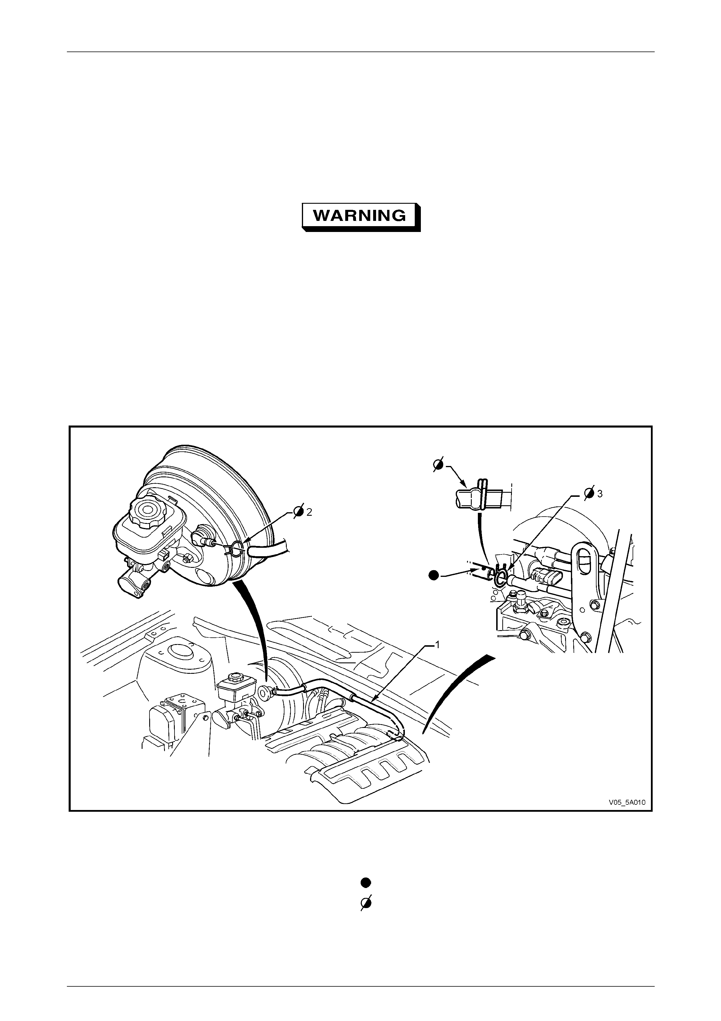
Service and Park Braking System 5A – 49
2.18 Brake Booster Hose & Valve Assembly –
V8 Engine
Replace
1 Remove the suspension tower brace. Refer to Section 1A1 Body.
Wear eye protection to prevent potential
injury.
2 Using suitable pliers, compress the spring hose clamp at each end of the brake booster vacuum hose and slide
both clamps back along the hose.
3 While supporting the vacuum check valve at the booster end, twist the hose to break the seal, then remove by
twisting back and forth while maintaining a constant pulling force on the hose.
4 Repeat step 3 for the intake manifold fitting at the rear of the engine, supporting the fitting during the removal
process.
5 Reinstallation is the reverse of the removal process, except that each hose clip must be reinstalled ov er the hose
and behind the nipple at each end to prevent premature hose disengagement. Also ens ure that the blue alignment
dot on the hose is facing upward.
Figure 5A – 55
Legend
1 V8 brake booster vacuum hose.
2 Retaining clip, brake booster end.
3 Retaining clip, engine manifold end.
Blue spot to be on top.
Ensure hose ends are clamped behind the ridge on the nipple.
5A – 49

Service and Park Braking System 5A – 50
2.19 Load Sensing Proportioning Valve
(LSPV)
Where fitted, the load sensing proportioning
valve (LSPV) fitted to MY 2005 VZ models is
unique to each vehicle application. It is preset
at manufacture and is calibrated for each
vehicle application. Under no circumstances
is this calibration to be tampered with.
Remove
All VZ Models With LSPV
1 Raise rear of the vehicle and support in a safe manner. Refer to Section 0A General Information for the location of
recommended lifting and support points.
2 Thoroughly clean al l pipe connections at the LSPV.
3 Disconnect both brake lines at the load sensing proportioning valve.
4 Plug all openings and lin es to prevent dirt entry.
Utility Models
5 Unhook the load sensing pr oportioning valve connector cable (2) from the load-sensing arm (7) by holding the arm
downward to relieve the tension. Slowly release the arm.
NOTE
The arm may spring up slightly when the hook is
released.
6 Support the load sensing prop ortioning valve, then remove the two nuts (3) securing the proportioni ng valve to the
mounting bracket (6). Remove the t wo bolts (5), then remove the valve assembly from the vehicle.
5A – 50
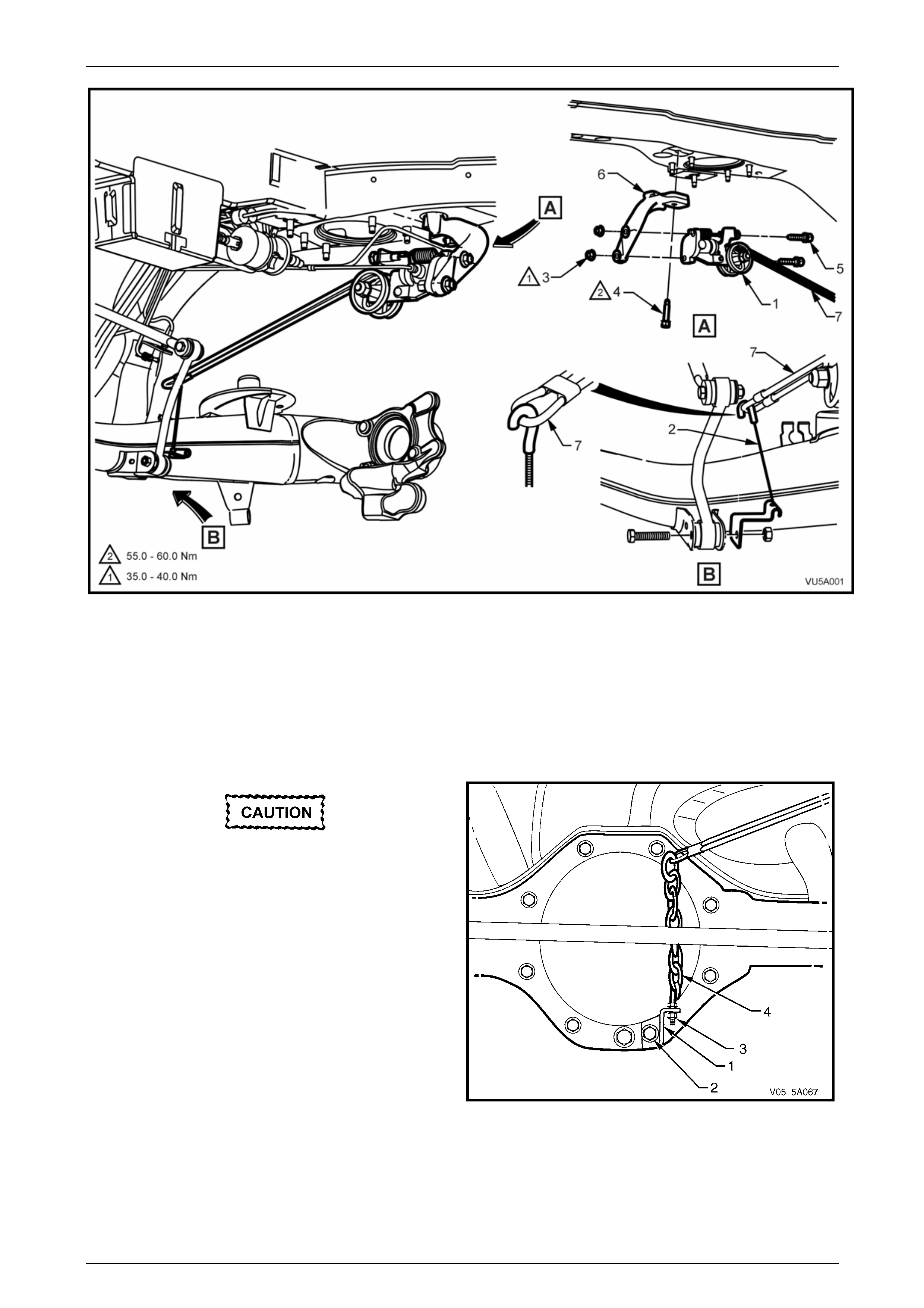
Service and Park Braking System 5A – 51
Figure 5A – 56
Legend
1 Load sensing proportioning valve (LSPV)
2 Connector cable assembly
3 Nut (2 places)
4 Mounting bracket bolt
5 Bolt (2 places) 6 Mounting bracket
7 Load sensing arm
AWD & Live Axle
Do not remove the nut (3) or change the
length of the chain. This is preset and is not
to be disturbed.
7 Remove the load sensin g proportioning valve chain
bracket (1) and attaching bolt (2) as one unit from the
rear axle cover.
NOTE
• When the bracket bolt (2) is removed, final
drive lubricant will leak out. Temporarily
reinstall the bolt quickly to reduce spillage.
• The static spring will have tension until the
chain and attaching bracket (6) is removed
from the rear axle cover and released slowly.
Figure 5A – 57
5A – 51
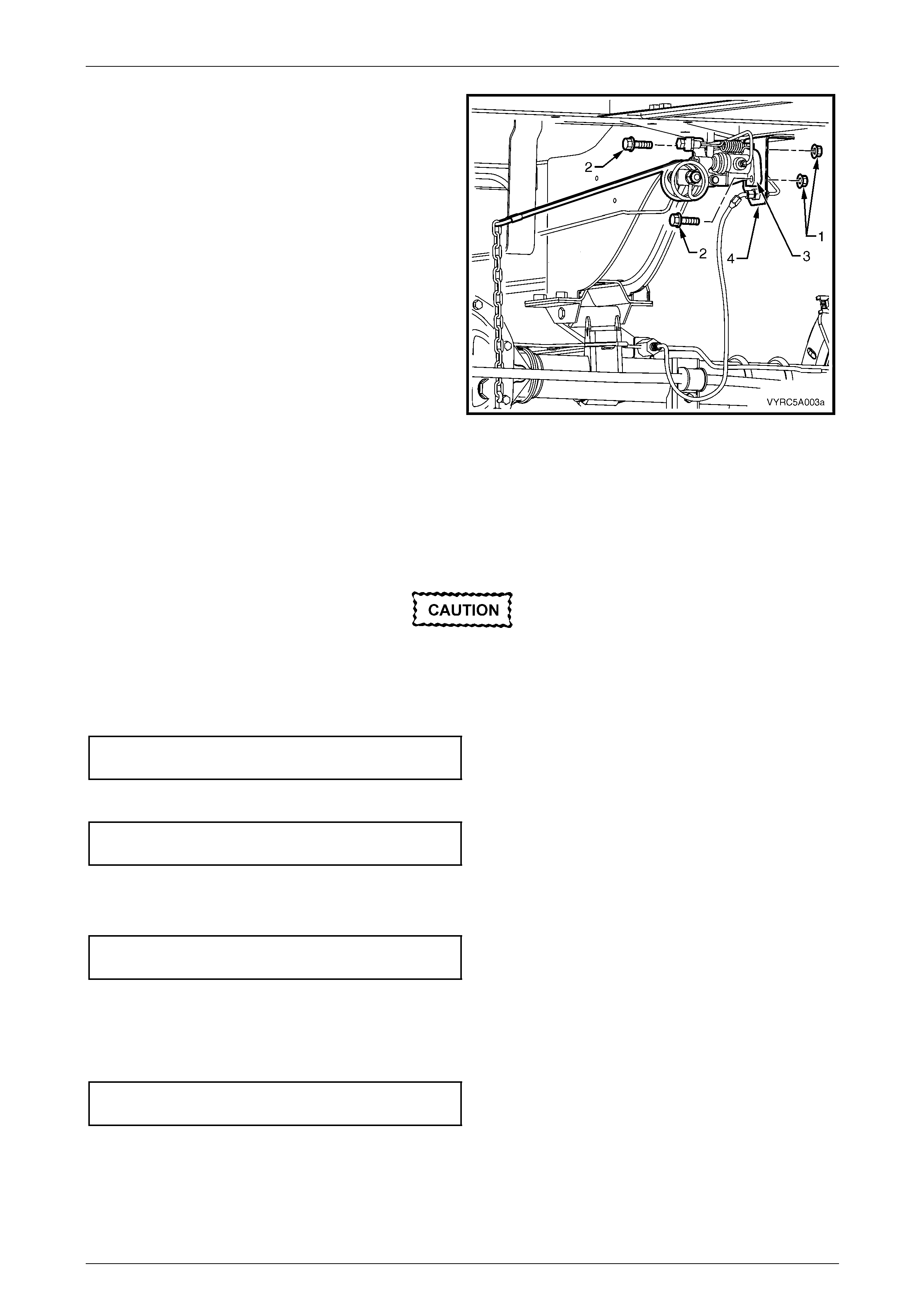
Service and Park Braking System 5A – 52
8 Remove the two LSPV retaining nuts (1) and bolts (2)
from the mounting bracket (4).
9 Remove the LSPV from the vehicle.
Figure 5A – 58
Reinstall
All LSPV Applications
The installation procedure is the reverse to the removal procedure, notin g the following:
The load sensing proportioning valve setting
is preset and is not to be adjusted.
1 If removed, reinstall the load sensing valve mounting bracket and secure with two bolts, tightened to the correct
torque specification.
Load sensing proporti oning valve
mounting bracket bolt torque specification...........58 N.m
2 Position the LSPV on the bracket, install the two bolts and nuts and tighten to the correct torque specification.
Load sensing valve mo unting
nut torque specification........................................38 N.m
3 Unplug pipes and pipe openings and reinstall both brake pipes to the LSPV.
4 Check that the pipes are routed correctly, then tighten the pipe flare nuts to the correct torque specification.
Brake pipe to proportioning valve
flare nut torque specification................................15 N.m
5 For Utility models, reinstall the cable hook (2) to the load sensing arm (7), checking that the orientation i s correct,
refer to Figure 5A – 56.
6 For VZ models with the live axle, reinstall the chai n bracket retaini ng bolt (2) and tighten to the correct torque
specification, refer to Figure 5A – 57.
LSPV link bracket to final drive
cover bolt torque specification..............................28 N.m
7 Bleed the brake system refer to 2.4 Brake System Bleed.
8 Lower the vehicle to the ground.
9 Road test to check for correct brake operation.
5A – 52
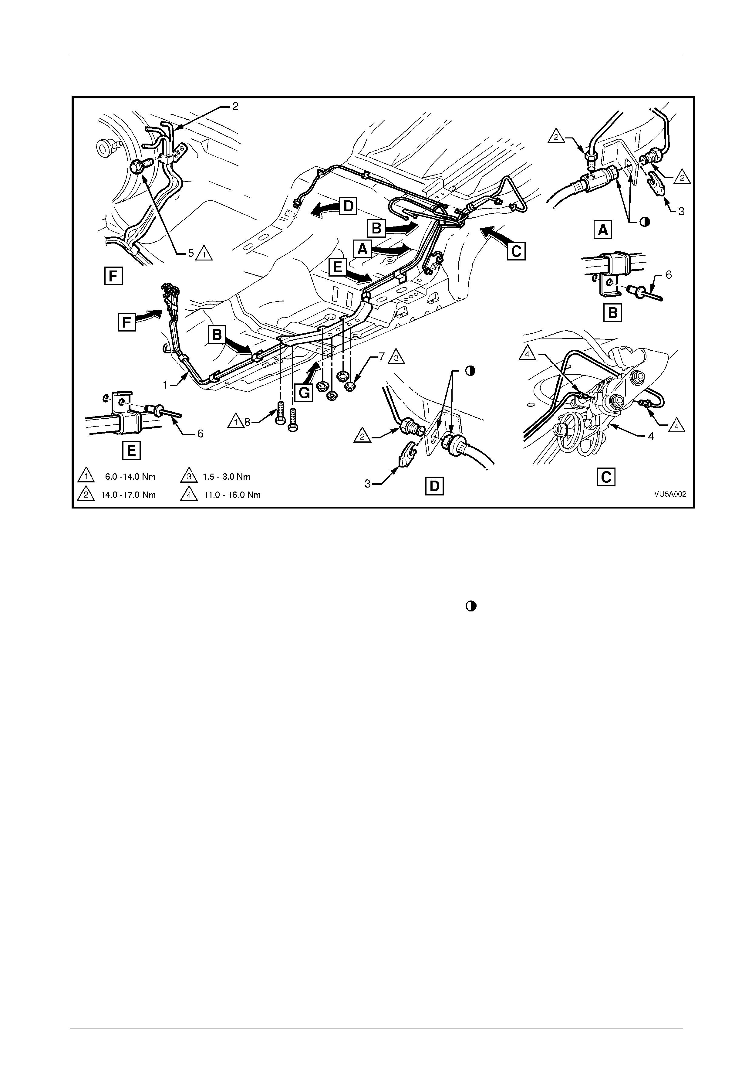
Service and Park Braking System 5A – 53
Rear Brake Pipe Layout - Utility Without ABS
Figure 5A – 59
Legend
1 Brake and fuel line harness
2 Fuel feed and return line
3 Brake hose clip
4 Load sensing proportioning valve
5 Brake pipe clamp to dash panel bolt
6 Rivet (5 places)
7 Nut (4 places)
8 Screw (2 places)
Align flats on hose and bracket
5A – 53
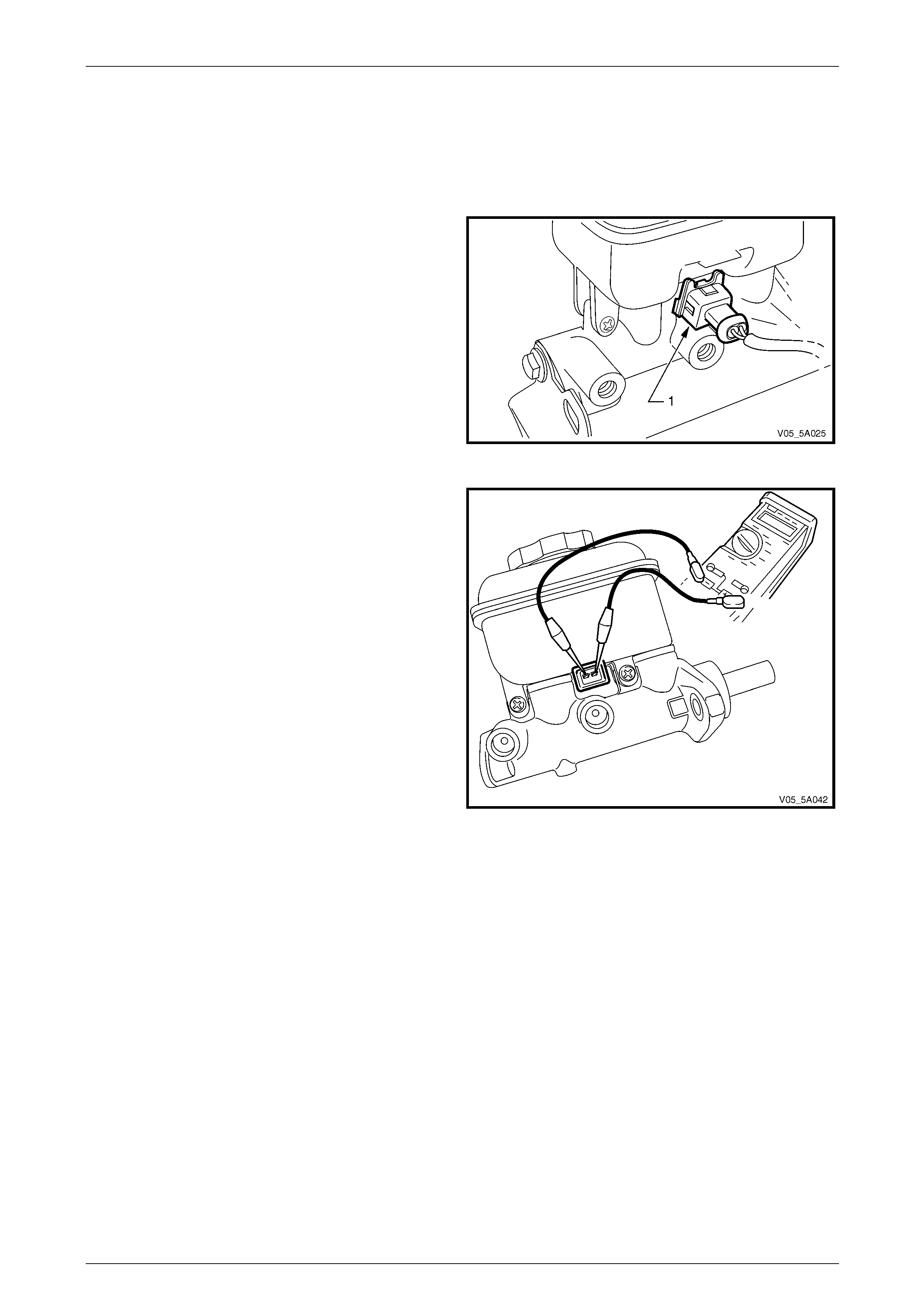
Service and Park Braking System 5A – 54
2.20 Brake Fluid Level Switch
Test
1 Carefully wipe around the reservoir cap, then remove the c ap,
2 Using a small bladed screwdriver, lift the connector
security clip locking the br ake fluid level switch
harness connector, then remove the connect or from
the switch.
Figure 5A – 60
3 Check that the brake fluid level is at the 'MAX' mark.
4 Using a multimeter set to Ohms, check that the
resistance is high (approximately 10 kΩ).
5 While holding the multimeter leads on the switch
terminals, use a thin bladed sc rewdriver to gently push
the brake fluid float to the bottom of the reservoir and
hold in this position.
6 Check that, when the float is fully depressed, the
resistance across the switch terminals drops to a
minimal resistance (approximately 3 Ω).
7 Should either test not meet the above criteria, then the
switch is faulty and must be replaced.
NOTE
As the switch is not serviced separately to the
reservoir, then this too, must be replaced. Refer
to 3.2 Brake Master Cylinder Reservoir. Figure 5A – 61
Replace
1 Replace the brake fluid reservoir. Refer to 3.2 Brake Master Cylinder Reservoir, for the procedure.
5A – 54
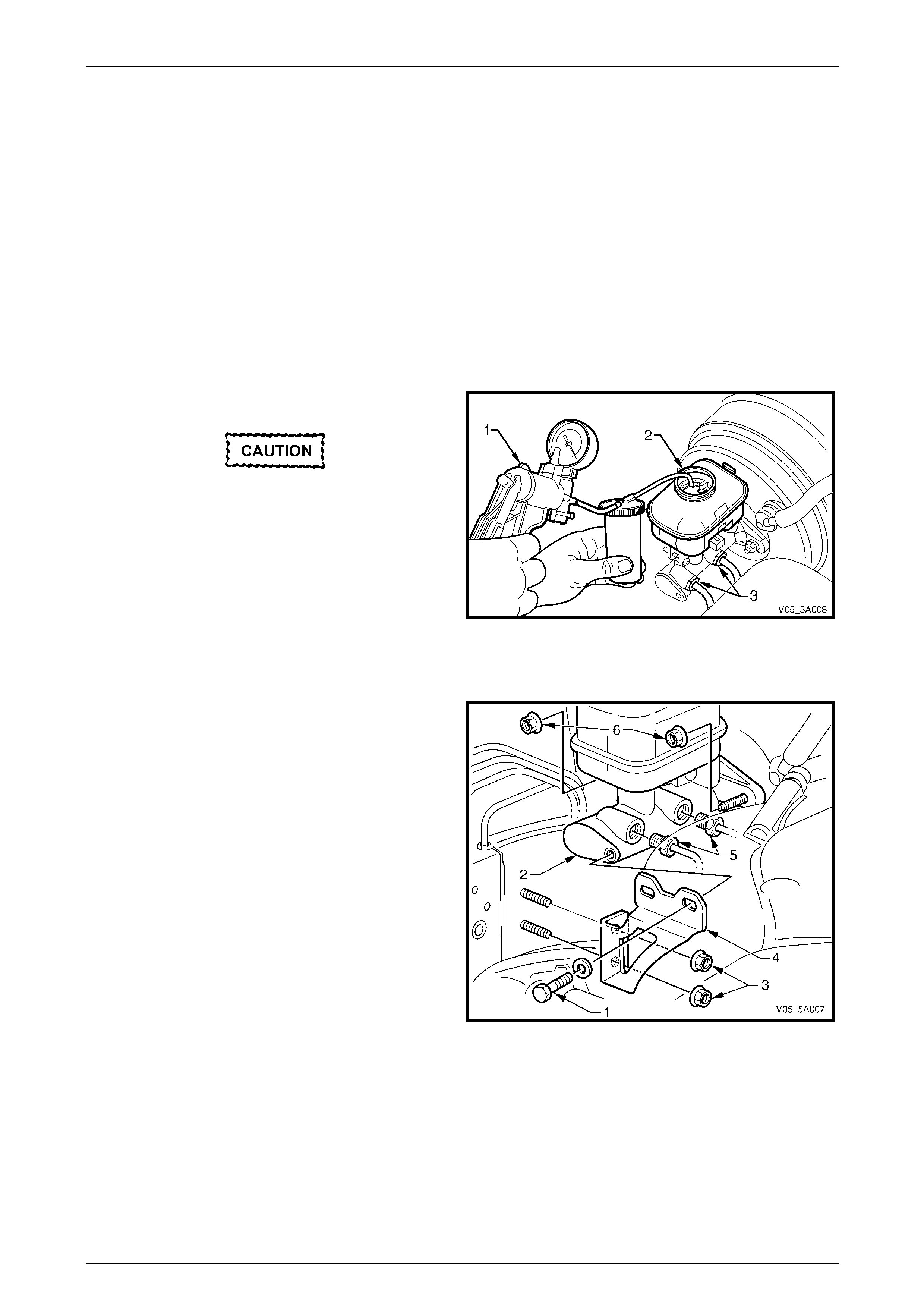
Service and Park Braking System 5A – 55
3 Major Service Operations
3.1 Master Cylinder
LT Section No. – 04-725
Remove
1 If a front suspension strut brace is fitted to the vehicle, removing it will provide easier access to the master cylinder
fasteners. Refer to Section 1A1 Body.
2 Apply the brake pedal at least five times to exhaust all stored vacuum from the braking system.
3 Thoroughly clean the master cylinder, especially arou nd the brake line connections and reservoir cap.
4 Remove the master cylinder reservoir cap.
Brake fluid will cause damage to the paint
work. If contact does occur, immediately
wash the brake fluid off with water.
5 Using a hand vacuum pump (1) such as Tool J23738-
A or a commercially available hand vacuum pump or
syringe, siphon as much brake fluid from the master
cylinder reservoir (2) as possible.
6 Using a small bladed screwdriver, lift the connector
security clip locking the br ake fluid level switch
harness connector, then remove the connect or from
the switch.
Figure 5A – 62
7 Disconnect the brake pipes (5) from the master
cylinder (2) and allow any residual brake fluid to drain
from the master cylinder into a container.
8 Plug all openings in both the master cylinder and the
pipes to prevent fluid loss and dirt ingress.
9 Remove the two nuts (3) securing the master cylinder
bracket (4) to the strut tower.
10 Remove the bolt (1) securing the bracket (4) to the
end of the brake master cylinder (2).
NOTE
For vehicles with manual transmission, removal
of the clutch master cylinder fluid reservoir and
bracket will also occur. After removal of the bolt
(1), secure the clutch reservoir and bracket with
tie wire, to one side and in an upright position.
Figure 5A – 63
11 Remove the nuts (6) securing the master cylinder to the brake booster, then remove the master cylinder and
sealing O-ring from the booster assembl y and the vehicle.
NOTE
DO NOT disturb the brake booster push ro d, and
DO NOT depress the brak e peda l with the m aster
cylinder removed, or internal damage to the
booster may occur.
5A – 55
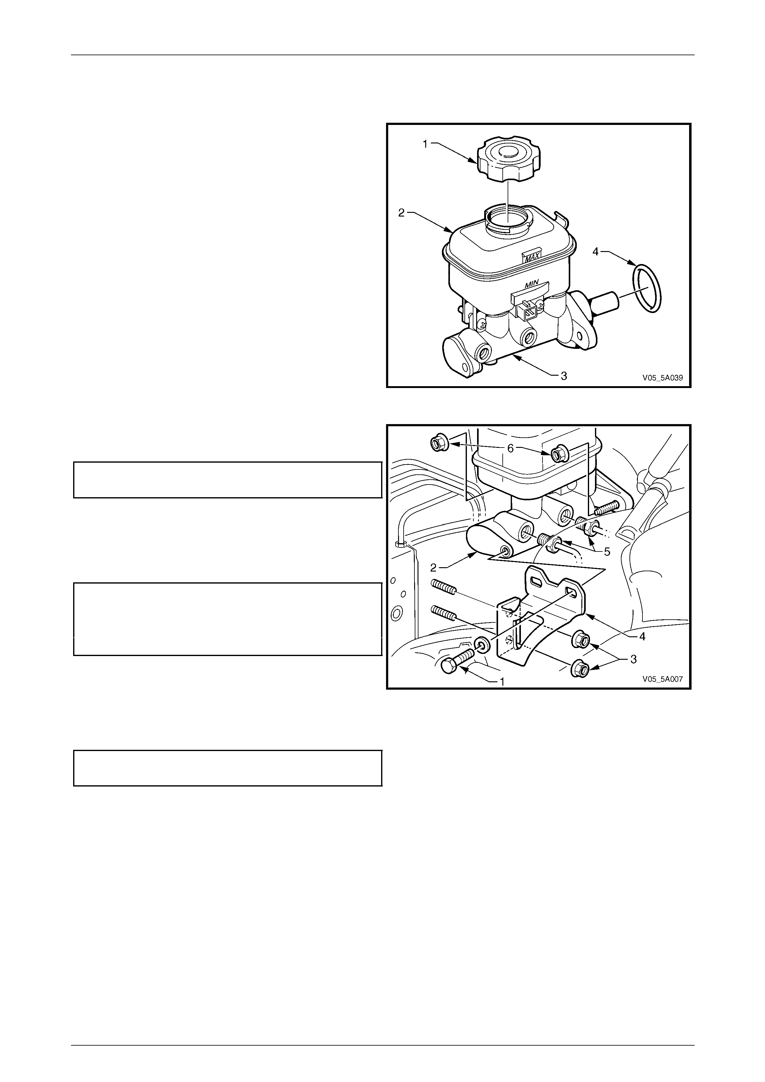
Service and Park Braking System 5A – 56
Reinstall
The reinstallation proced ure for the master cylinder is the reverse of the removal procedure, noting the following:
1 Install a new O-ring (4) to the master cylinder body (3)
on the mounting flange end.
2 Reinstall the master cylinder assembly to the brake
booster, taking care not to disturb the brak e booster
push rod.
Figure 5A – 64
3 Reinstall the master cylinder mounting nuts, then
tighten the nuts to the correct torque specification.
Master cylinder attaching
nut torque specification........................................10 N.m
4 Reinstall the master cylinder s upport bracket (4) (and
clutch fluid reservoir, as required).
5 Reinstall and tighten the nuts (3) and bolt (1) to the
correct torque specification.
Master cylinder to bracket
bolt torque specification.......................................10 N.m
Master cylinder bracket to strut tower
attaching nuts torque specification.........................8 N.m
6 Place a clean container under the master cylinder,
unplug the brake lines and master cylinder outlet
ports, then reinstall the pipes to the master cylinder. Figure 5A – 65
7 Tighten the brake pipe flare nuts to the correct torque specif ication.
Brake pipe to master cylinder
flare nut torque specification................................14 N.m
8 Reconnect the electrical conn ector to the brake fluid level switch. Check that the locking spring clip is correctly
installed.
9 Refill the master cylinder reservoir. Refer to 2.3 Brake Fluid Level Check .
10 Bleed the brakes. Refer to 2.4 Brake System Bleed.
11 Road test the vehicle to ensure correct brake operation.
5A – 56
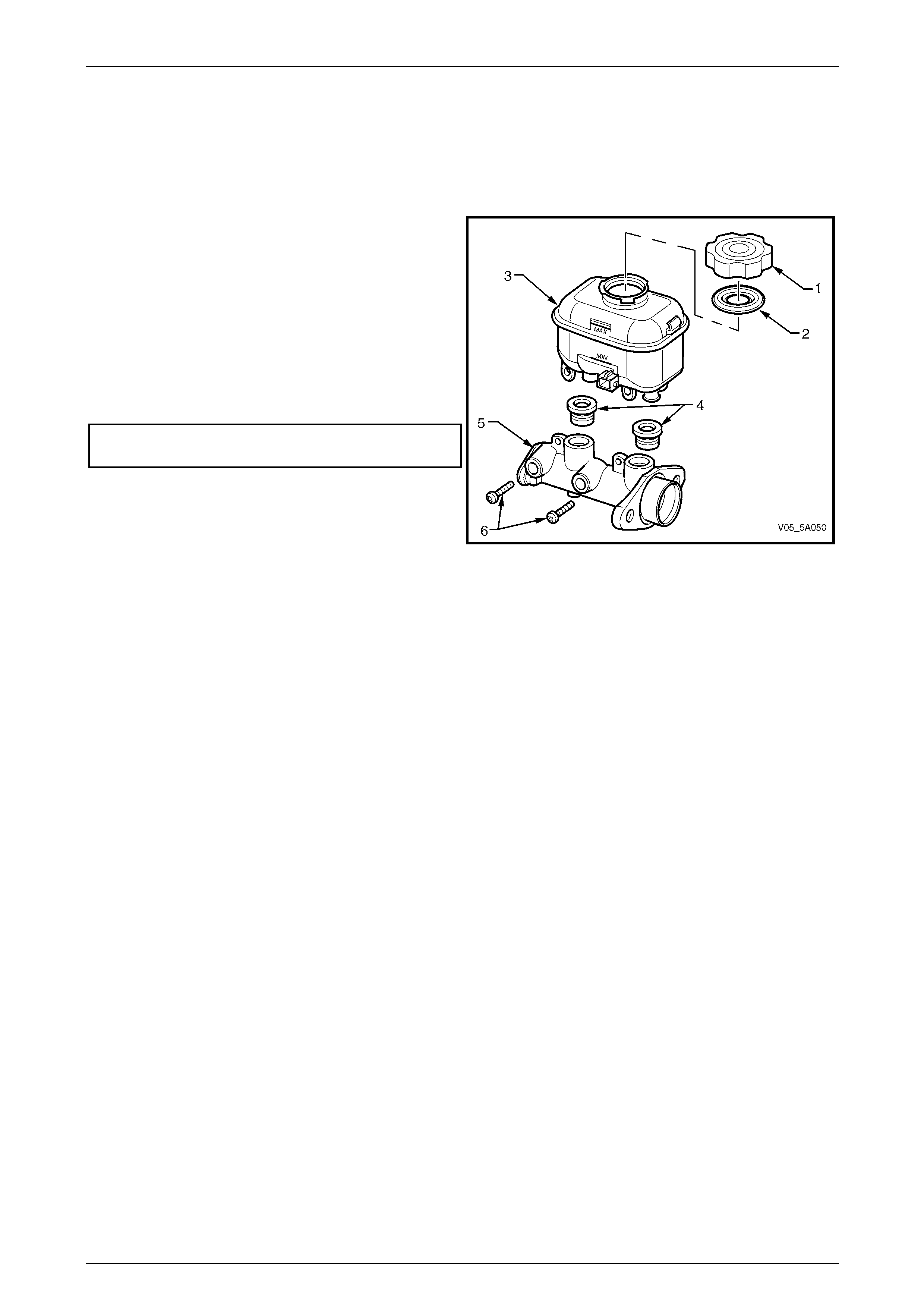
Service and Park Braking System 5A – 57
3.2 Brake Master Cylinder Reservoir
Replace
1 Remove the brake master cylinder from the v ehicle. Refer to 3.1 Master Cylinder.
2 Remove the two screws (6) securing the reservoir (3)
to the master cylinder body (5).
3 Grasp the master cylinder bod y (5) with one hand,
then pull on the reservoir (3) with the other, to remove.
4 Lubricate new seals (4) with brake fluid, then install to
the master cylinder body (5).
5 Install the reservoir (3) to the master cylinder body (5).
6 Reinstall the two securing screws (6) and tighten to
the correct torque specification.
Brake fluid reservoir attaching
screw torque specification...................................2.5 N.m
7 Reinstall the brake master cylinder. Refer to
3.1 Master Cylinder.
8 Bleed the braking system, then road test to ensure
correct brake operation. Refer to 2.4 Brake System
Bleed. Figure 5A – 66
5A – 57
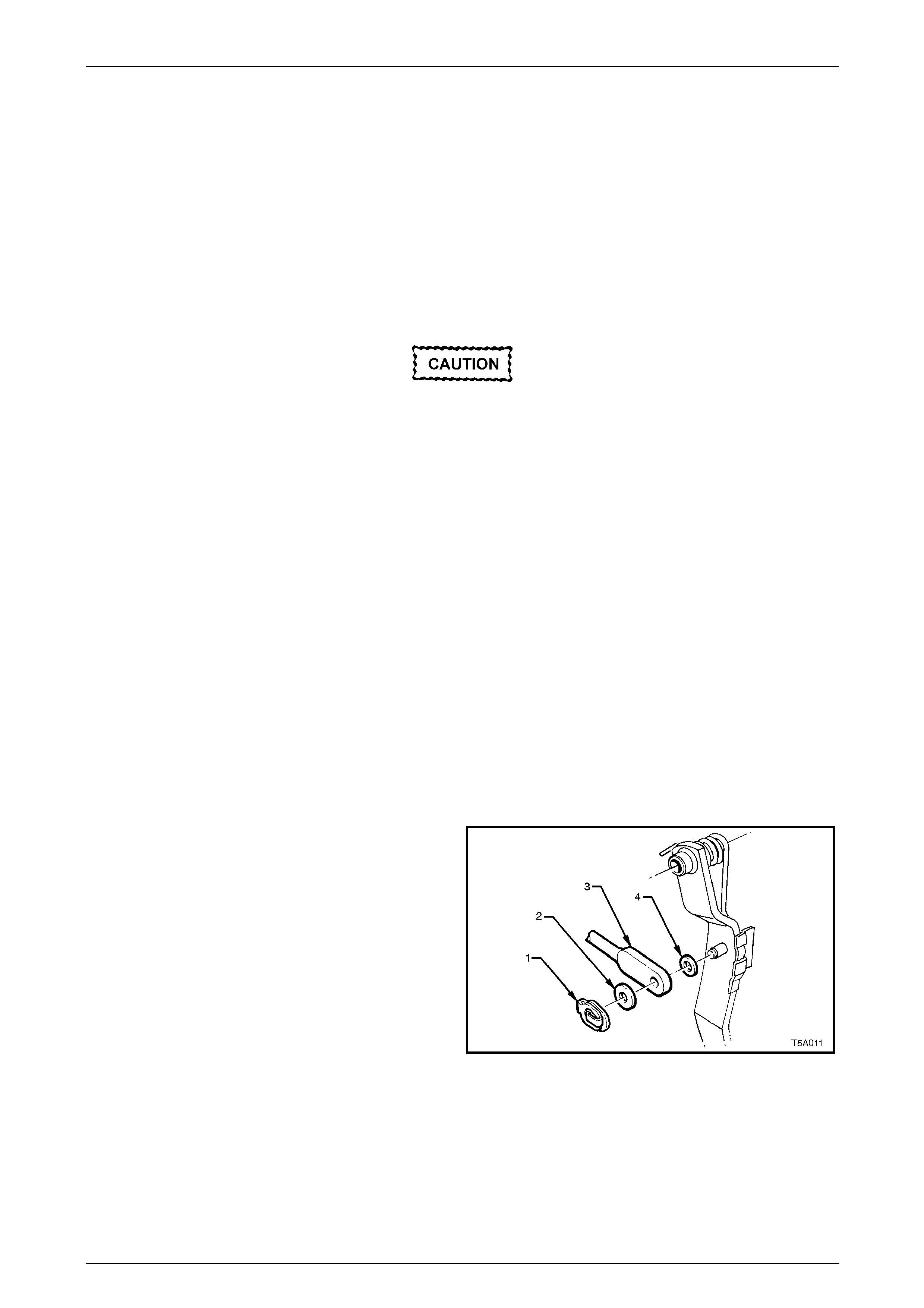
Service and Park Braking System 5A – 58
3.3 Brake Booster
LT Section No. – 04-725
NOTE
The brake booster is not a serviceable item and if
found to be faulty, must be replaced as a unit.
Remove
With the master cylinder removed, do not
disturb the brake booster push rod nor
depress the brake pedal, as the reaction disc
in the booster may become dislodged.
1 Where applicable, remov e the following components:
a Front suspension strut tower brace, refer to Section 1A1 Body.
b Instrument panel lower trim panel assembly, refer to Section 1A3 Instrument Panel and Console.
c Driver side instrument panel lower trim plate assembly, refer to Section 1A3 Instrument Panel and Console.
d Instrument panel lower trim panel retainer, refer to Section 1A3 Instrument Panel and Console.
e Remove the Body Control Module (BCM) from its mounting bracket but le ave all electrical connectors
installed, refer to Section 12J Body Control Modu le .
f If fitted with the manual transmission, remove the clutch pe dal and bracket assembly, refer to Section 7A1
Clutch – V6 or 7A3 Clutch –GEN III V8.
2 Remove master cylinder, refer to 3.1 Master Cylinder.
3 Remove vacuum hose from brake booster va cuum check valve. Refer to 2.17 Brake Booster Hose & Valve
Assembly – V6 Engine or 2.18 Brake Booster Hose & Valve Assembly – V8 Engine.
4 For vehicles fitted with the V6 engine, remove the two heater pipes from the rear of the engine. Refer to
Section 6B1 Engine Co oling – V6 Engine, for details.
5 Remove push rod retaining clip (1), washer (2), push
rod (3) and washer (4) from brake pedal.
Figure 5A – 67
5A – 58
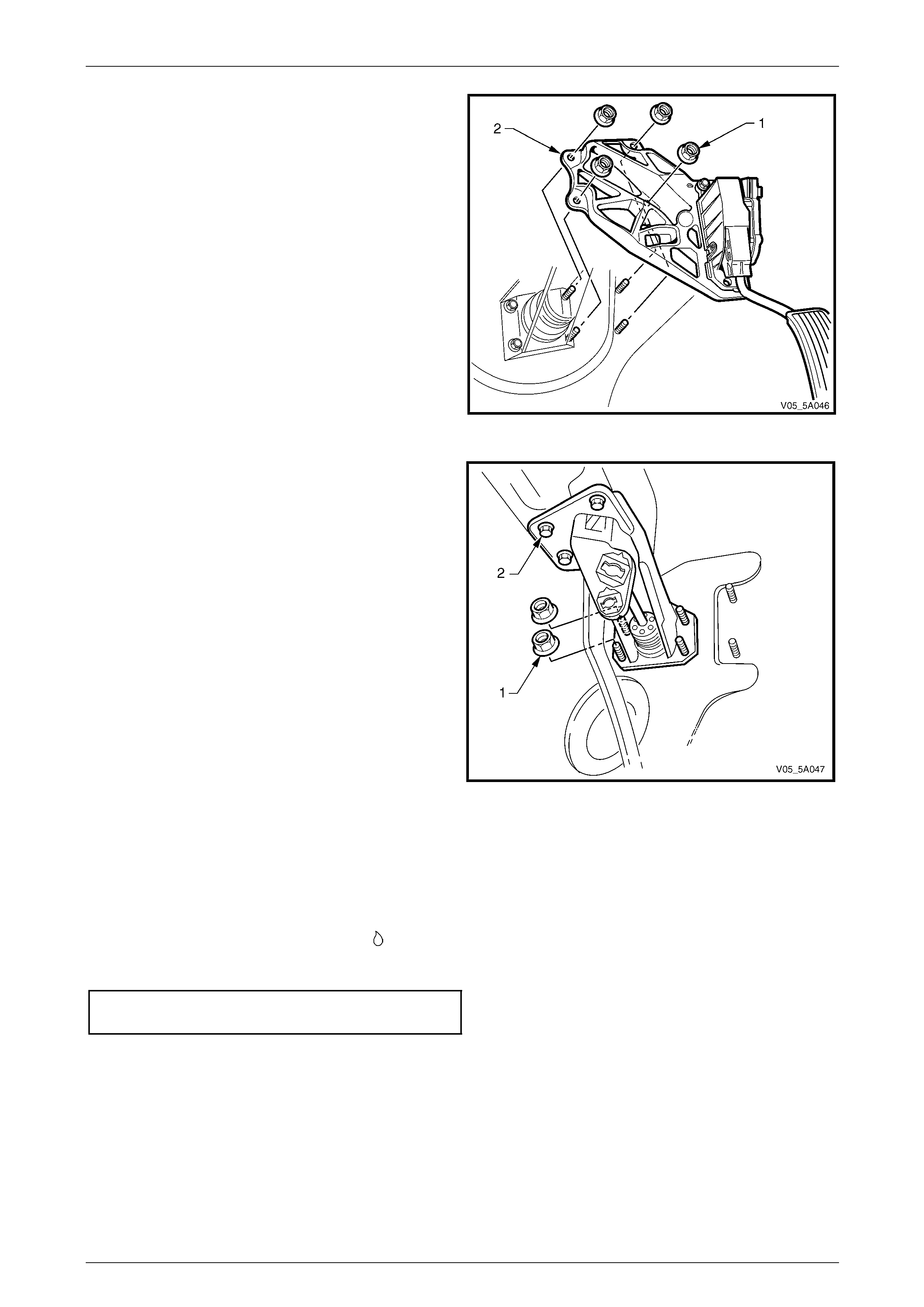
Service and Park Braking System 5A – 59
6 Remove the four nuts (1) securing the accelerator
pedal sensor bracket (2) to the brake pedal support
bracket and the dash panel.
7 Remove the accelerator pedal sensor and bracket
assembly.
Figure 5A – 68
8 Remove the remaining two nuts (1) securing the brake
booster to the brake pedal support bracket.
NOTE
If the manual transmission is fitted, these
remaining two nuts will have already been
removed when the clutch pedal and support
bracket were removed.
9 From the engine compartment, pull the brake booster
forward, disengaging the four studs from the brake
pedal bracket and remove the brake booster from
engine compartment.
Figure 5A – 69
Reinstall
Installation is the reverse of the removal procedure, except for the following:
1 Lubricate brake pedal a nd push rod component bearing surfaces with an NLGI No. 2 lithium soap based EP grease
with molybdenum disulphide, such as She ll Retinax HDX2 greas e or BP Energrease LMS-EP 23 (or equivalent).
Refer to Figure 5A – 31 and the symbol ' ' for the locations.
2 Reinstall the brake booster retaining nuts and tighten to the correct torque specific ation.
Brake booster retaining
nut torque specification........................................25 N.m
3 Reinstall master cylinder. Refer to 3.1 Master Cylinder.
4 Ensure brake booster vacuum hose is routed correctly and check that the retaining hose c lips are installed
correctly, refer to 2.17 Brake Booster Hose & Valve Assembly – V6 Engine or 2.18 Brake Booster Hos e & Valve
Assembly – V8 Engine.
5 Road test vehicle and check for correct brake operation.
5A – 59
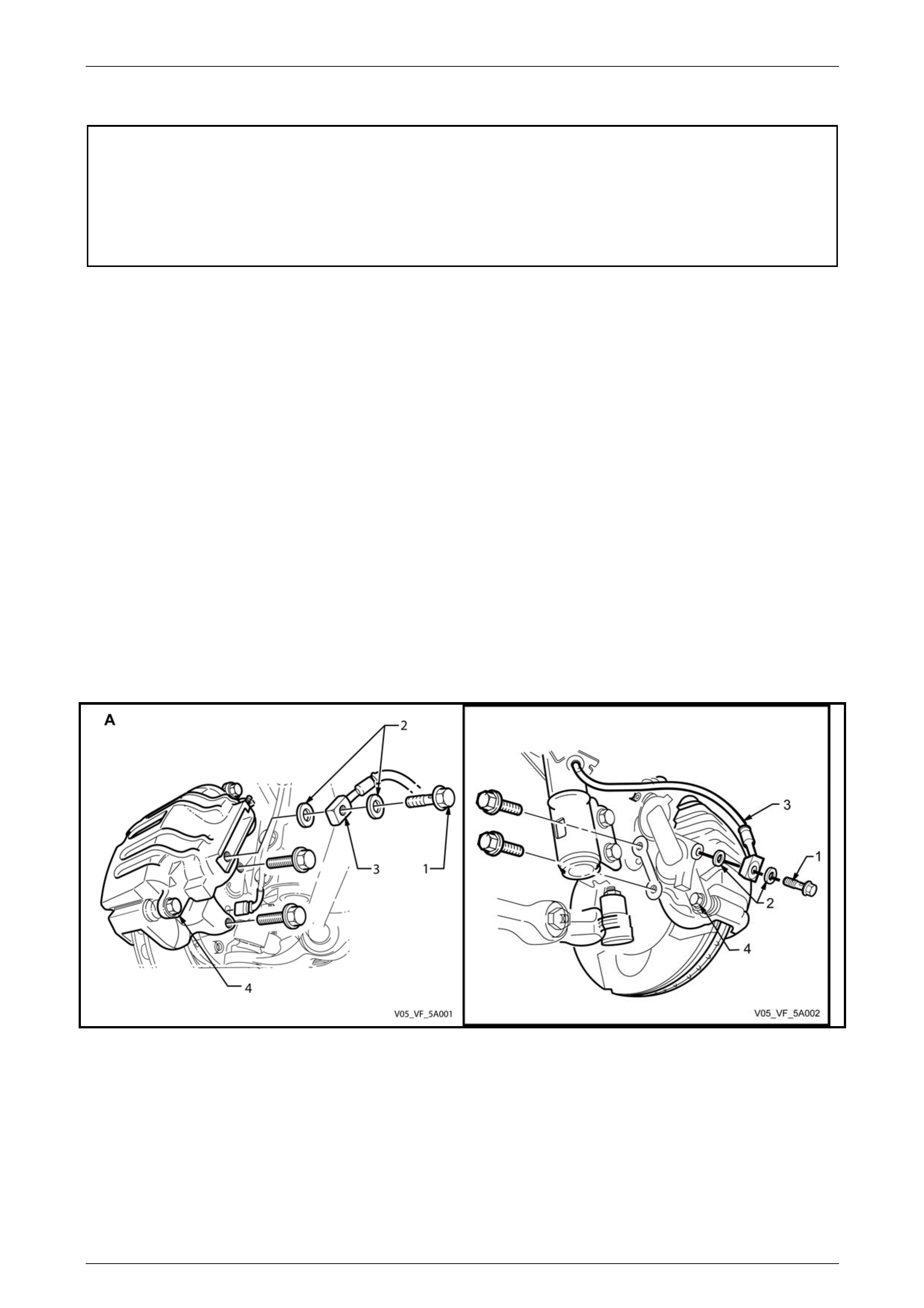
Service and Park Braking System 5A – 60
3.4 Front Brake Caliper
ATTENTION
The following fasteners MUST be replaced w hen p erfo rming these operations:
Front brake caliper anchor plate to steering knuckle attaching bolts and ‘Nord-Lock’™ washers (Coupe
and MY2006 SS only)
Brake caliper gui de pin bolts.
Remove
1 Raise the front of the vehicle and place on safety stands. Refer to Section 0A, General Information for the location
of jacking and support points.
2 Remove the wheel covers or decorative wheel nut caps, then mark the relationship of the road wheel to one of the
wheel studs.
3 Loosen, then remove the road wheel attachi ng nuts, working in a 'star' pattern. Refer 2.1 Service Warnings,
Cautions and Notes, for detailed i nformatio n. Remove the road wheel.
4 Place a drain tray beneath the caliper assembly.
5 Loosen and remove the brake hose to caliper banjo bolt (1). Separate the bolt from the hose (3) and discard the
two sealing washers (2).
6 Plug the open end of the brake hose (3) to prevent fluid loss and foreign m ateria l entry.
7 Remove the two anchor plate retaining bolts (4) and special ‘Nord-L ock’ washers (Coupe and MY2006 SS only),
then lift the caliper assembly out over the disc.
NOTE
View A shows the Coupe and MY2006 SS front
caliper, while view B sho ws all other MY 2005 VZ
models.
Figure 5A – 70
Disassemble
1 Refer to Figure 5A – 71; use an open end spanner to hold the guide pin (4) flat section and remove and discard the
guide pin bolts (3).
2 Separate the caliper housing (1) from the anchor plate (6).
3 Remove the brake pads (7 and 8) and clips (12).
4 Remove the guide pins (4) and boots (5) from the anchor plate (6). Separate boots from pins.
5A – 60
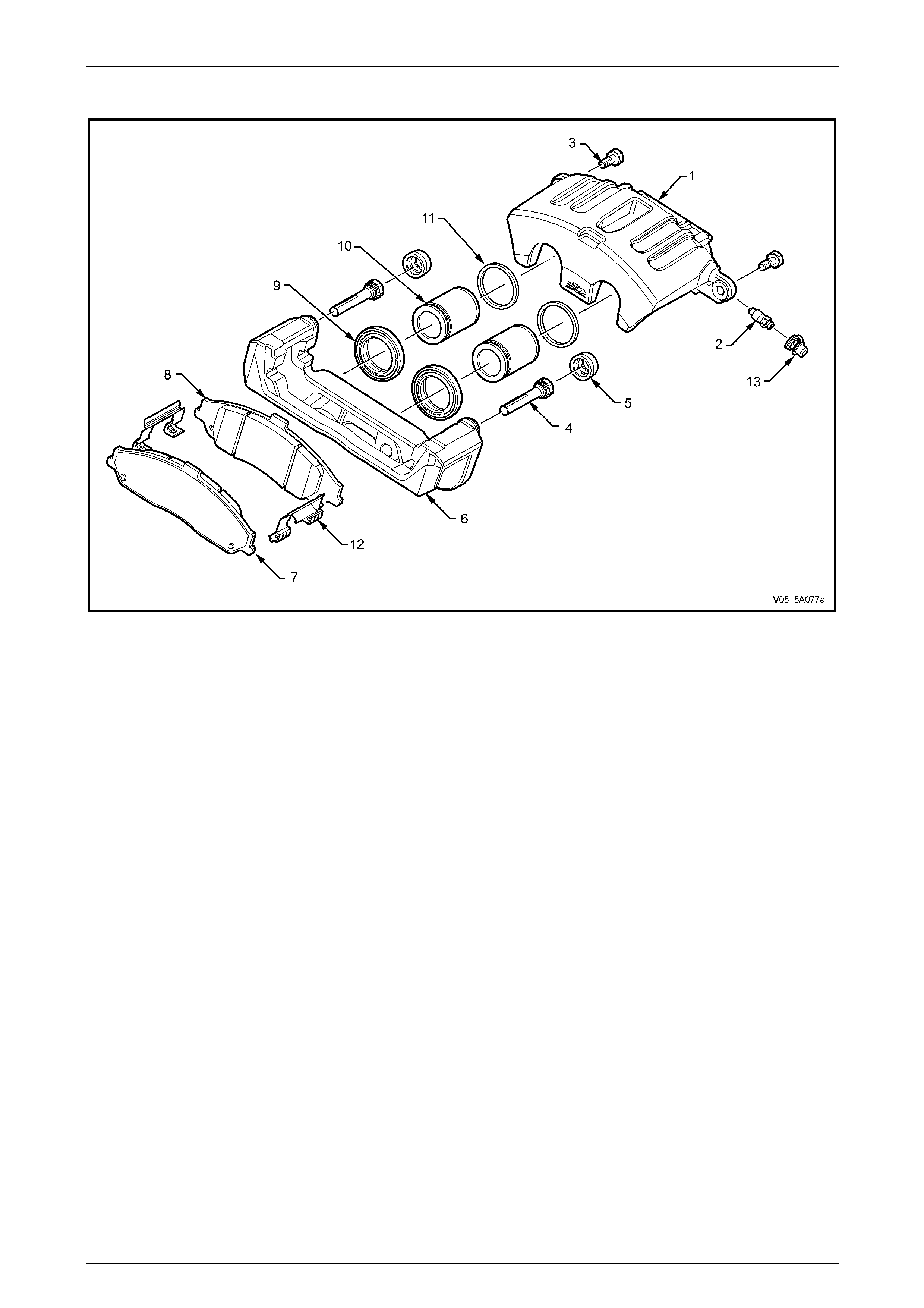
Service and Park Braking System 5A – 61
Coupe and MY2006 SS Front Caliper
Figure 5A – 71
Legend
1 Caliper Housing
2 Bleeder Screw
3 Guide Pin Bolt (2 places)
4 Guide Pin (2 places)
5 Guide Pin Boot (2 places)
6 Caliper Anchor Plate
7 Outer Brake Pad
8 Inner Brake Pad
9 Piston Boot (2 places)
10 Piston (2 places)
11 Piston
Sealing Ring (2 places)
12 Clip ( 2 places)
13 Bleeder Screw Dust Cover
5A – 61
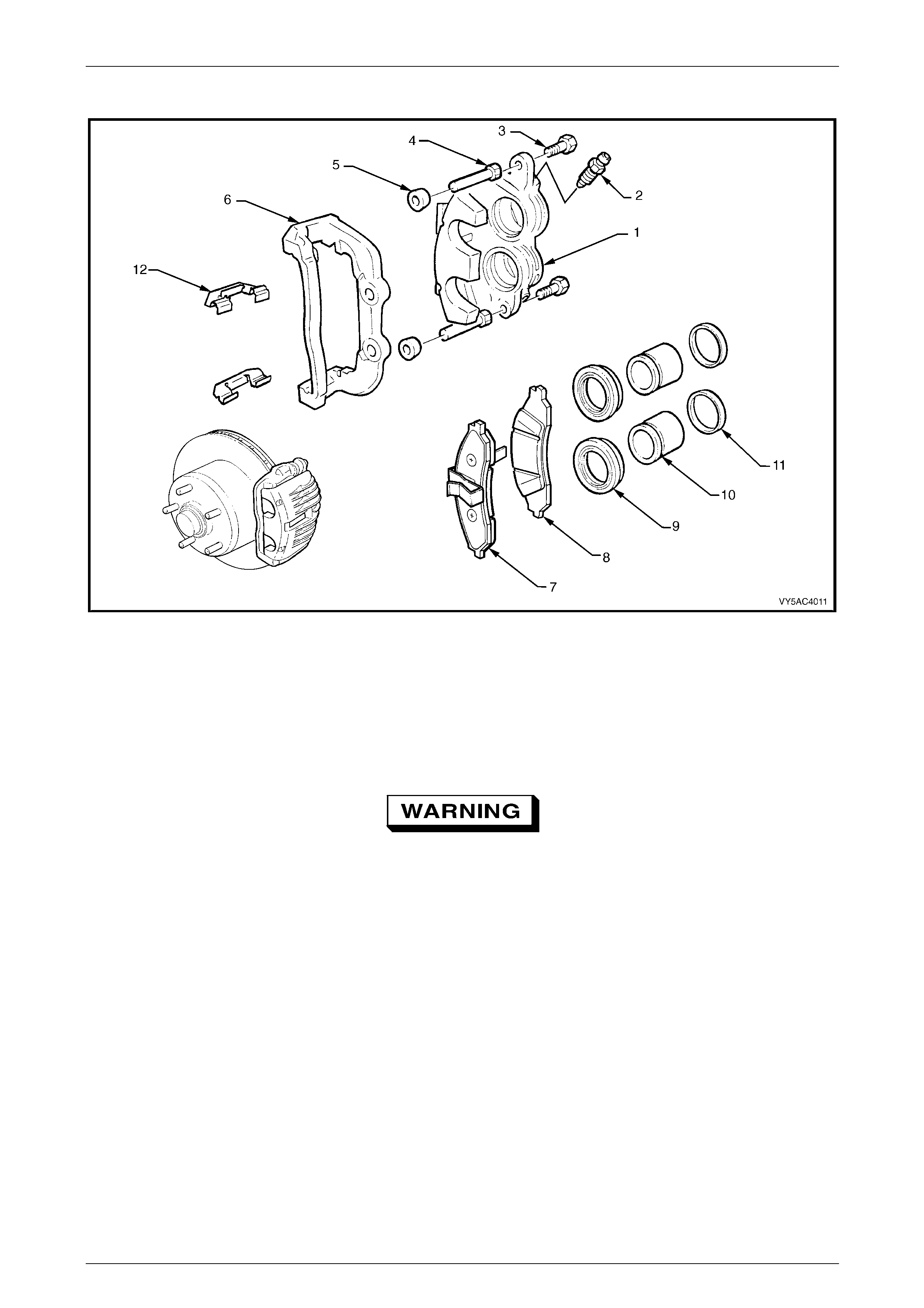
Service and Park Braking System 5A – 62
All Models Except Coupe and MY2006 SS
Figure 5A – 72
Legend
1 Caliper Housing
2 Bleeder Screw
3 Guide Pin Bolt (2 places)
4 Guide Pin (2 places)
5 Guide Pin Boot
6 Caliper Anchor Plate
7 Outer Brake Pad
8 Inner Brake Pad
9 Piston Boot (2 places)
10 Piston (2 places)
11 Piston Sealing Ring (2 places)
12 Clip ( 2 places)
Only apply light air pressure initially and
progressively increase until the piston is
forced out of the bore. This is necessary to
avoid physical injury, as the piston may eject
with considerab le fo rce.
14 Pack a clean piece of cloth between the caliper piston/s and opposite legs on the housing and appl y air pressure at
the brake hose inlet port to eject a piston.
5A – 62
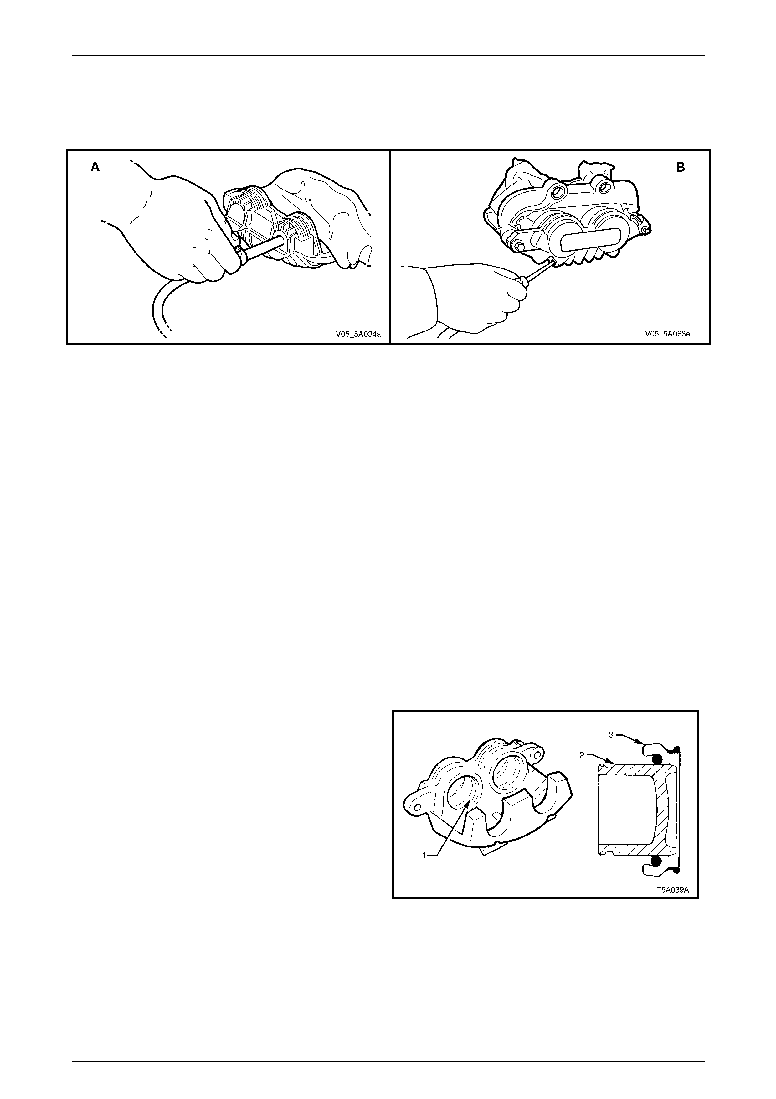
Service and Park Braking System 5A – 63
NOTE
View A shows the Coupe and MY2006 SS front
caliper, while view B sho ws all other MY 2005 VZ
models.
Figure 5A – 73
15 As only one piston in the front caliper will be removed by this method, removal of the second will need to be done
by using internal expandin g circlip pliers, to grasp the inner piston wall. Then, while rotating the piston back and
forth, apply a pulling force to remove the piston from its bore.
16 Remove the piston boots (9) from the piston/s (10).
17 Remove the piston sealing ring (11) from the bore, taking c are not to damage the bore or seal locating groove.
18 Remove the brake caliper ble eder (2) and dust cap (13).
Clean and Inspect
1 Clean all metal parts thoroughly with methylated spirits. Clean rub ber parts with brake fluid only. Use clean, dry
compressed air to dry parts.
2 Examine the bore and piston carefully for signs of damage, abrasion, scuffing or corrosion . Renew the piston if any
of these factors exist or if there is any doubt regarding its condition. If the bore is unserviceable, the cali per
assembly must be replaced.
3 Inspect the guide pins for corrosion. Replace the pins if corroded.
4 Blow through the brake caliper bleeder port with compressed air.
Reassemble
1 Lubricate the cylinder bore 1) and piston (2) with the
recommended brake fluid
2 Fit a new piston sealing ring into the inner groove of
the cylinder bore. Ensure that the seal is not twisted
and is fully seated in its groove.
3 Install the piston boot (3) over the end of the piston
(2).
Figure 5A – 74
5A – 63
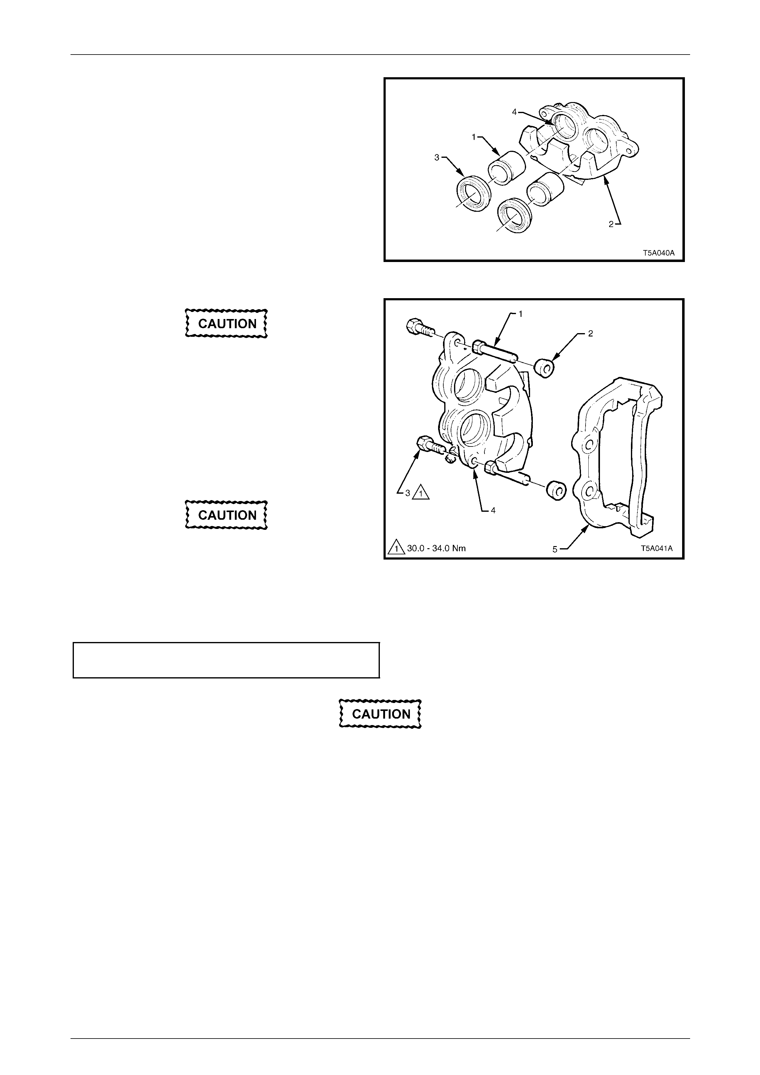
Service and Park Braking System 5A – 64
4 Position each piston (1) into the caliper housing (2),
seating the boot (3) into a groove in the caliper bore
(4). Ensure the boot flange is squarely and firmly
seated in the groove.
5 Push the piston (2) squarel y into the bore by hand until
fully seated. Ensure the piston boot (1) is fully seated
in the piston (2) and caliper bore grooves.
Figure 5A – 75
To avoid uneven pad wear and/or noisy brake
operation, the assembly of the guide pins to
the caliper housing is critical and the
following MUST be followed:
6 Lubricate the guide pins (1) with silicone grease, such
as Dow Corning No. 44 or equivalent.
7 Fully install guide pins (1) into the anchor plate (5),
without the two boots (2).
Do not use the original bolts.
8 Reinstall the caliper housing (4) to the anchor plate (5)
and install NEW guide pin bolts (3). Figure 5A – 76
9 Use an open end spanner to hol d the guide pin flat section, then tighten the new guide pin bolts (3) to the correct
torque.
Brake caliper guide pin
bolt torque specification.......................................32 N.m
Check that the caliper housing and guide pins
slide in and out easily from the anchor plate.
If any binding is evident, then steps 6 to 9
must be repeated.
10 Disengage the caliper ho using from the anchor plate and i nstall new guide pin boots to the guide pins.
11 Reassemble the caliper housing and anchor plate toget her. Squeeze each boot to remove excess air, then ensure
that each guide pin boot is correctly located in the guide p in and anchor plate groov es.
12 Reinstall the brake caliper bleeder.
13 Reinstall the brake pads, refer to 2.7 Brake Pads, Replace, in this Section.
5A – 64
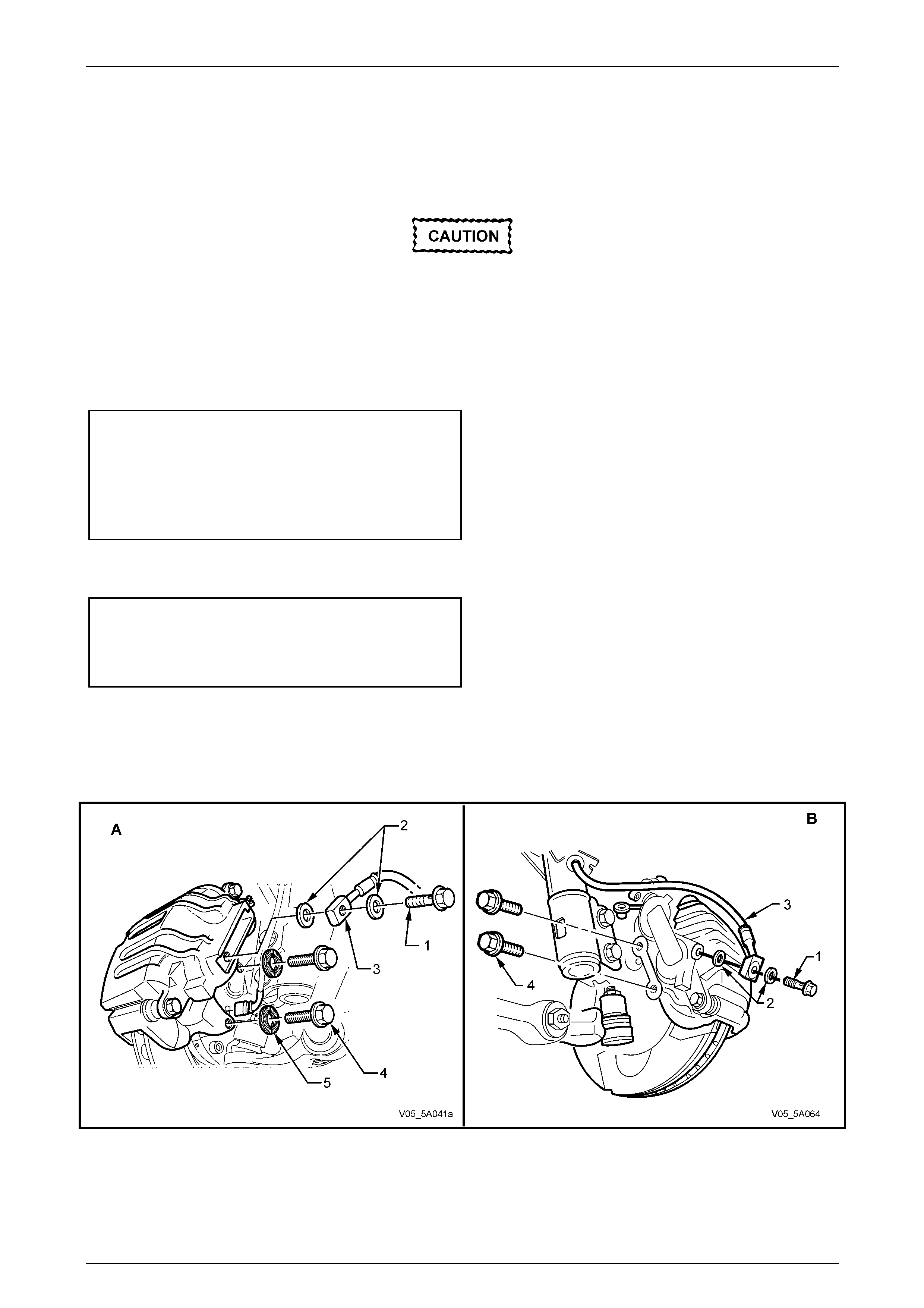
Service and Park Braking System 5A – 65
Reinstall
1 Ensure the anchor plate mounting surfaces are clean.
2 Press the inner brake pad by hand to ensure the piston is bottomed in th e bore.
Do not re-use caliper retaining bolts and do
not apply any thread sealant to Coupe and
MY2006 SS bolts. New ‘Nord-Lock’™ w ashers
must also be fitted to Coupe and MY2006 SS
caliper retaining bolts.
3 Referring to Figure 5A – 76, position the cal iper assembly over the disc. Insert the NEW anchor plate retaining b olts
(4) and NEW ‘Nord-Lock’™ washers (where fitted). Tighten the bolts to the correct torque specification.
Front brake caliper anchor plate b olt torqu e
specification
(All except Coupe and MY2006 SS ) ..........85 N.m, then
turn through 45°
(Coupe and MY2006 SS )...........................70 N.m, then
turn through 90°
4 Reconnect the brake hose (3) using NEW copper sealing washers (2), then tighten the banjo bolt (1) to the correct
torque specification.
Brake hose to caliper banjo bolt torque specification
(All except Coupe and MY2006 SS ) ...................35 N.m
(Coupe and MY2006 SS )...........................12 N.m, then
turn through 90°
NOTE
View A shows the Coupe and MY2006 SS front
caliper, while view B sho ws all other MY 2005 VZ
models.
Figure 5A – 77
5A – 65

Service and Park Braking System 5A – 66
5 Bleed the brake/s. Refer to 2.4 Brake System Bleed, in this Section.
6 Depress the brake pedal several times to bring pads into position against the disc rotor.
7 Top up the master cylinder if necessary.
8 Reinstall road wheel in the original position and secure with the wheel nuts but do not fully tighten.
9 Lower the vehicle to the ground an d tighten the wheel nuts to the specified torque, working in a star pattern, refer to
2.1 Service Warnings, Cautions and Notes, in this Section.
Road wheel attaching nut
torque specification..................................110 – 140 N.m
10 Install the wheel covers or decorative wheel nut caps.
11 Road test the vehicle to check for correct brake operation.
5A – 66
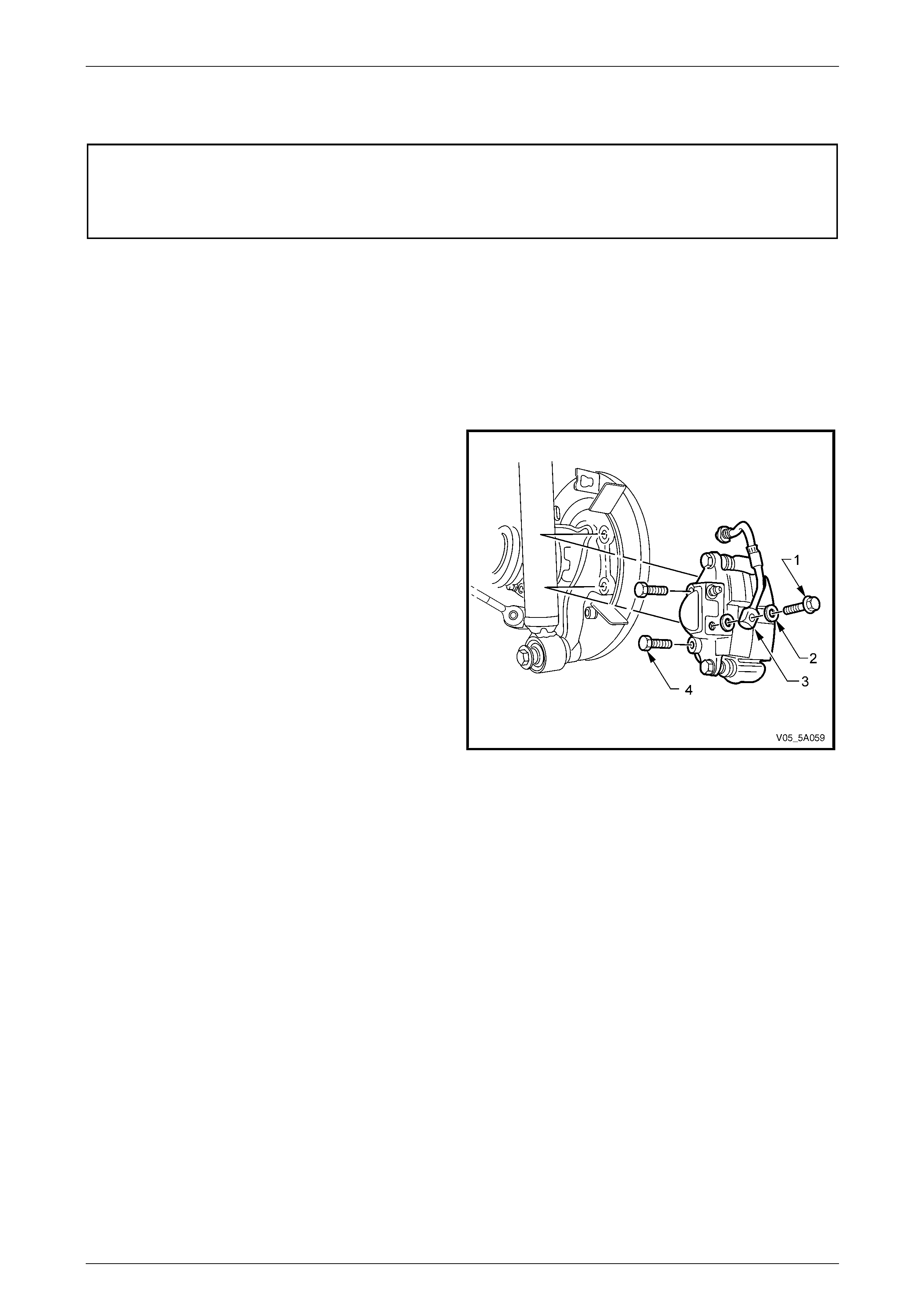
Service and Park Braking System 5A – 67
3.5 Rear Brake Caliper
ATTENTION
The following fasteners MUST be replaced w hen p erfo rming these operations:
Brake caliper gui de pin bolts.
Remove
1 Raise the rear of the vehicle and pl ace on safety stands. Refer to Section 0A General Information for the location of
jacking and support points.
2 Remove the wheel covers or decorative wheel nut caps, then mark the relationship of the road wheel to one of the
wheel studs.
3 Loosen, then remove the road wheel attachi ng nuts, working in a ‘star’ pattern. Refer 2.1 Service Warnings,
Cautions and Notes in this Section, for deta iled information. Remove the road wheel.
4 Place a drain tray beneath the caliper assembly.
5 Loosen and remove the brake hose to caliper banjo
bolt (1). Separate the bolt from the hose and discard
the two sealing washers (2).
6 Plug the open end of the brake hose (3) to prevent
foreign material entry.
7 Remove the two anchor plate retaining b olts (4) and lift
the caliper assembly out over the disc.
NOTE
While the solid rear disc rotor is shown, the
procedure for the Coupe and MY2006 SS rear
caliper is the same.
Figure 5A – 78
Disassemble
1 Use an open end spanner to hol d the guide pin flat section and remove a nd discard the guide pin bolts (1).
2 Separate the caliper housing (2) from the anchor plate (7).
3 Remove the brake pads (8 and 9), together with the anti rattle spring clips.
4 Withdraw the guide pins (5) and boots (6) from the anchor plate (7). Separate boots from pins.
5A – 67
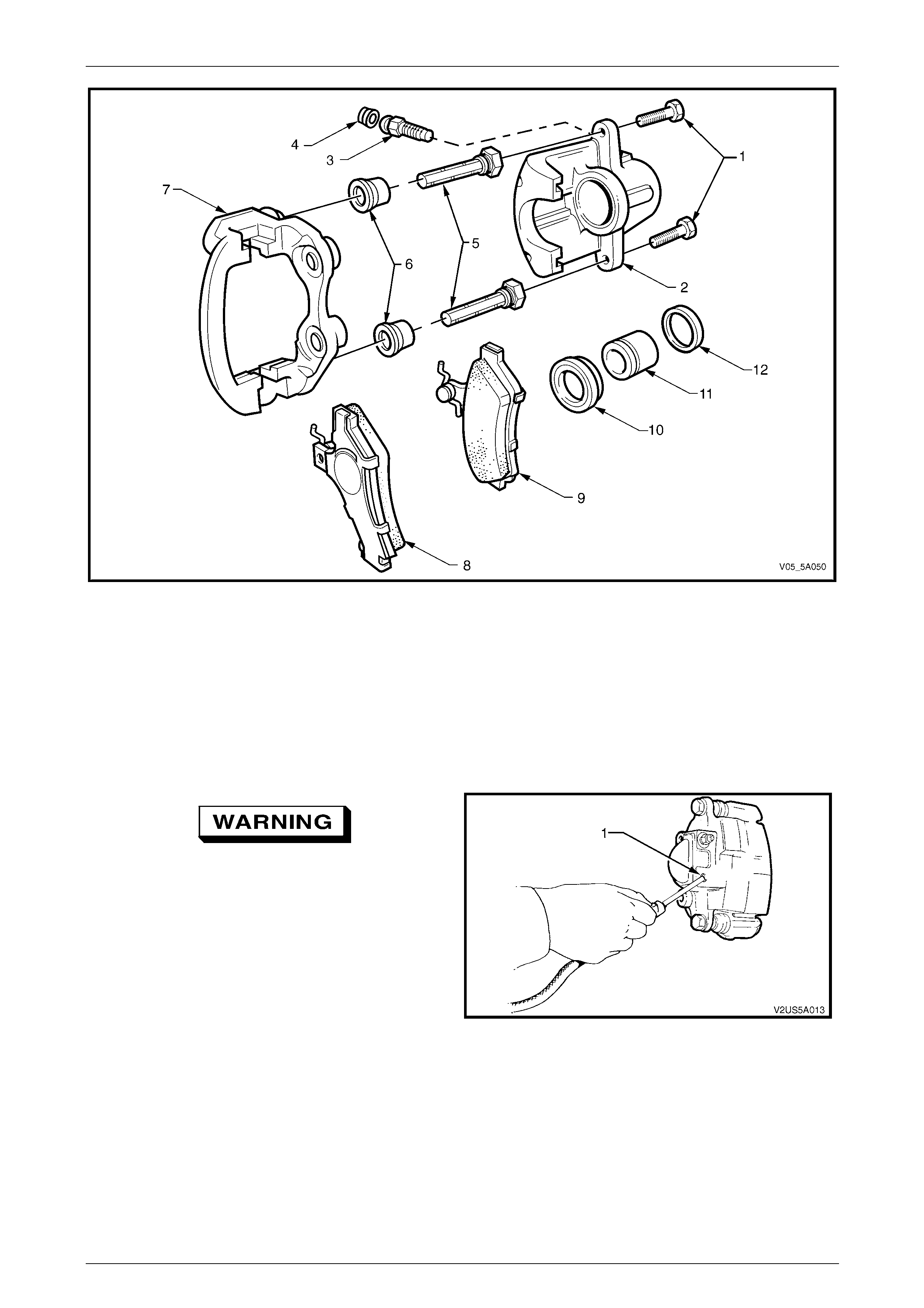
Service and Park Braking System 5A – 68
Figure 5A – 79
Legend
1 Guide Pin Bolt (2 places)
2 Caliper Housing
3 Brake Caliper Bleeder
4 Brake Caliper Bleeder Dust Cap
5 Guide Pin (2 places)
6 Guide Pin Boot (2 places)
7 Anchor Plate
8 Outer Brake Pad
9 Inner Brake Pad
10 Piston Boot
11 Piston
12 Piston Sealing Ring
Only apply light air pressure initially and
progressively increase until the piston is
forced out of the bore. This is necessary to
avoid physical injury, as the piston may eject
with considerab le fo rce.
5 Pack a clean piece of cloth between the caliper
piston/s and opposite legs on the ho using and apply
air pressure at the brake hose inlet port to eject the
piston.
6 Remove the piston boots (10) from the piston (11).
7 Remove the piston sealing rin g (12) from the bore,
taking care not to damage the bore or seal locating
groove.
8 Remove the brake caliper ble eder (3) and dust cap
(4).
Figure 5A – 80
5A – 68
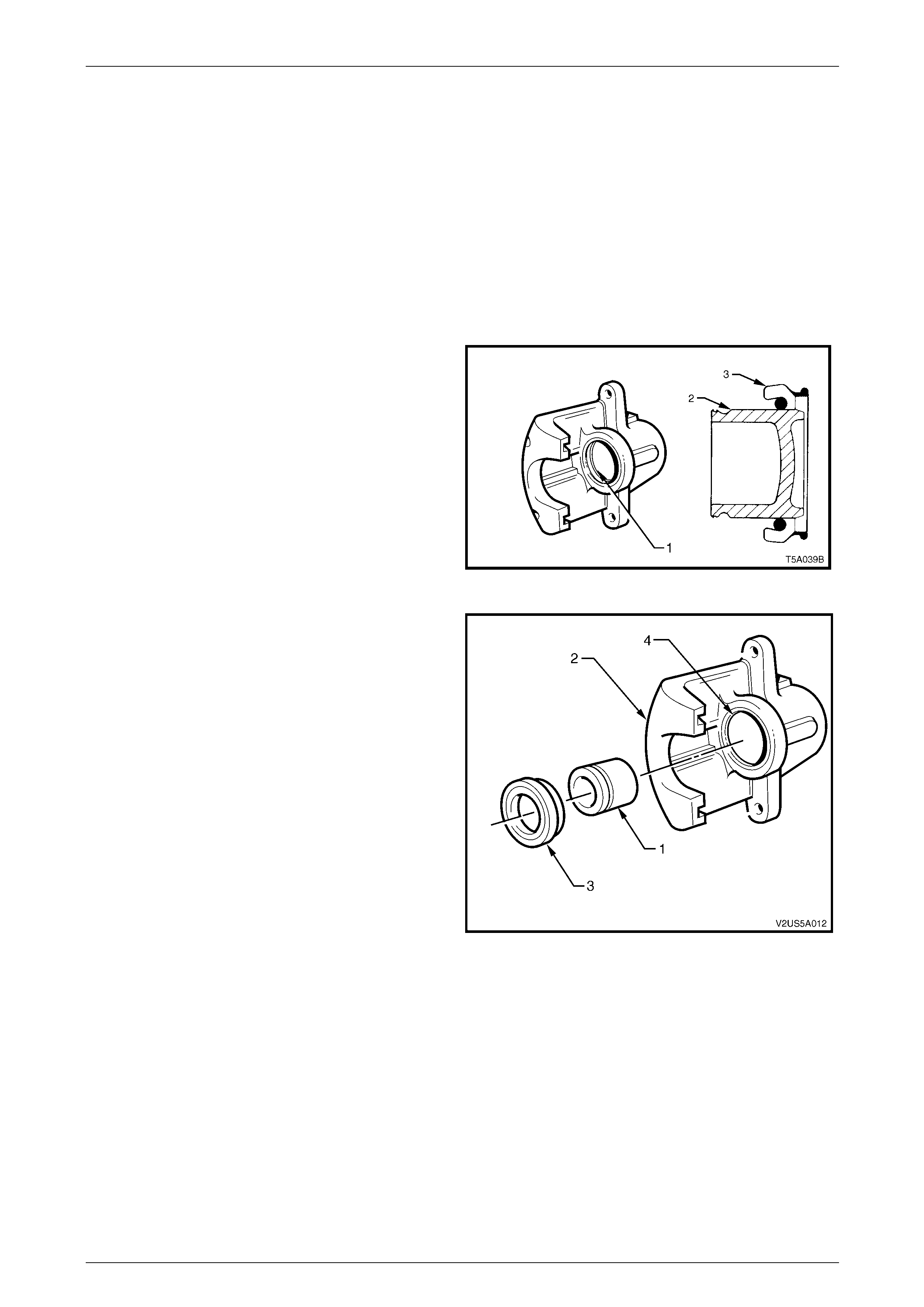
Service and Park Braking System 5A – 69
Clean and Inspect
1 Clean all metal parts thoroughly with methylated spirits. Clean rub ber parts with brake fluid only. Use clean, dry
compressed air to dry parts.
2 Examine the bore and piston carefully for signs of damage, abrasion, scuffing or corrosion . Renew the piston if any
of these conditions exist or if there is any doubt regarding it s condition. If the bore is unserviceable, the caliper
assembly must be replaced.
3 Inspect the guide pins for corrosion. Replace pins if corroded.
4 Blow through the brake caliper bleeder port with compressed air.
Reassemble
1 Lubricate the cylinder bore (1) and piston (2) with the
recommended brake fluid
2 Fit a new piston sealing ring into the inner groove of
the cylinder bore. Ensure that the O-ring is not twisted
and is fully seated in its groove.
3 Install the piston boot (3) over the end of the piston.
Figure 5A – 81
4 Position the piston (1) into the caliper housing (2),
seating the boot (3) into a groove in the caliper bore
(4). Ensure the boot flange is squarely and firmly
seated in the groove.
5 Push the piston squarely into the bore by hand until
fully seated. Ensure the piston boot is fully seated in
the piston and caliper bore grooves.
Figure 5A – 82
5A – 69
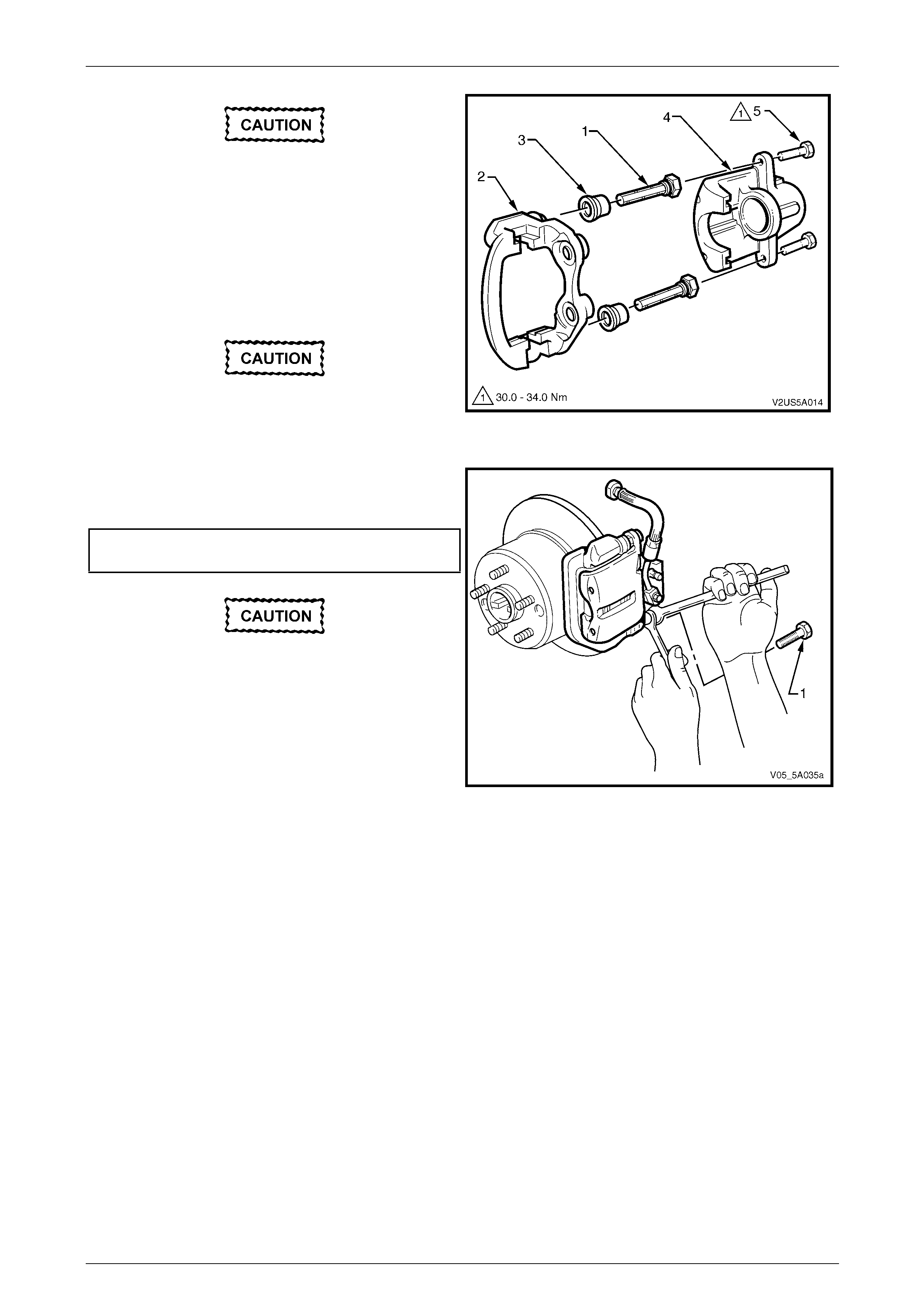
Service and Park Braking System 5A – 70
To avoid uneven pad wear and/or noisy
brake operation, the assembly of the guide
pins to the caliper housing is critical and the
following MUST be followed:
6 Lubricate the guide pins (1) with silicone grease, such
as Dow Corning No. 44 or equivalent.
7 Fully install the guide pins into the anchor plate (2),
without the two boots (3).
Do not use the original bolts.
8 Reinstall the caliper ho using (4) to the anchor plate
and install NEW guide pin bolts (5).
Figure 5A – 83
9 Use an open end spanner to hold the guide pin flat
section, then tighten the guide pin bolts (1) to the
correct torque specification.
Brake caliper guide pin bolt
torque specification..............................................32 N.m
Check that the caliper housing and guide
pins slide in and out easily from the anchor
plate. If any binding is evident, then steps 6
to 9 must be repeated.
10 Reassemble the caliper housing and anchor plate
together. Squeeze each boot to remove exc ess air,
then ensure that each guide pin boot is correctly
located in the guide pin and anchor plate grooves.
11 Reinstall the brake caliper bleeder.
12 Reinstall the brake pads, refer to 2.7 Brake Pads,
Replace.
Figure 5A – 84
5A – 70
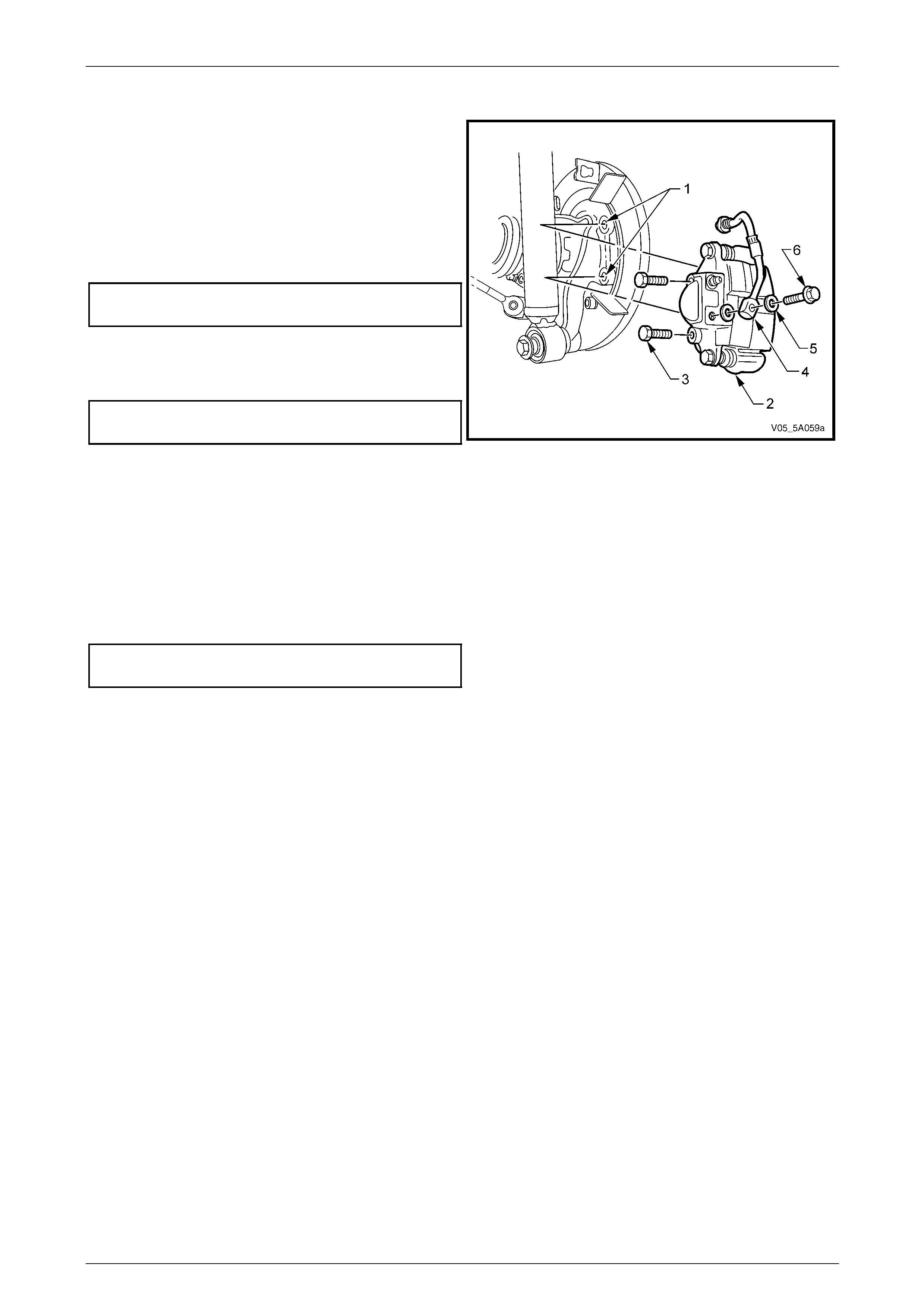
Service and Park Braking System 5A – 71
Reinstall
1 Ensure the anchor plate mounting surfaces (1) are
clean.
2 Press the inner brake pad inwards by hand to ensure
the piston is bottomed in the bore.
3 Position the caliper assembly (2) over the disc rotor.
4 Insert the two anchor plate retaining bolts (3), then
tighten to the correct torque specification.
Rear brake caliper anc hor
plate bolt torque specification...............................85 N.m
5 Reconnect the brake hose (4) using NEW copper
sealing washers (5), then tighten the banjo bolt to the
specified torque.
Brake hose to caliper banjo
bolt torque specification.......................................35 N.m
Figure 5A – 85
6 Bleed the brake/s. Refer to 2.4 Brake System Bleed, in this Section.
7 Top up the master cylinder if necessary.
8 Depress the brake pedal several times to bring pads into position against the disc.
9 Reinstall road wheel in the original position and secure with the wheel nuts but do not fully tighten.
10 Lower the vehicle to the ground an d tighten the wheel nuts to the specified torque, working in a star pattern, refer to
2.1 Service Warnings, Cautions and Notes, in this Section.
Road wheel attaching nut
torque specification..................................110 – 140 N.m
11 Install the wheel cover or decorative wheel nut caps.
12 Road test the vehicle to check for correct brake operation.
5A – 71
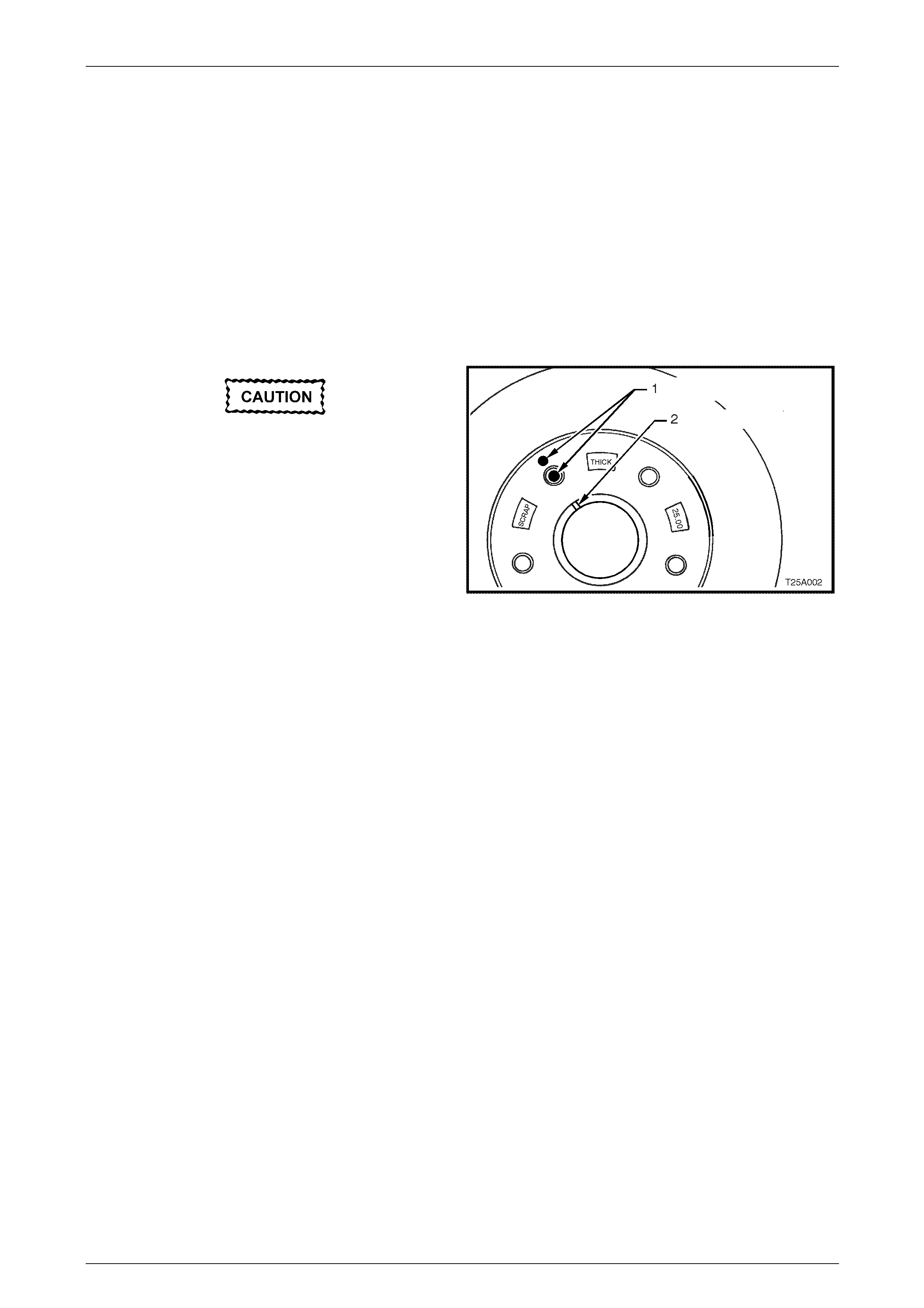
Service and Park Braking System 5A – 72
3.6 Front Brake Disc
LT Section No. – 04-805
Remove
1 Raise the vehicle and suppor t in a safe manner. Refer to Section 0A General Information in this Service Information
for the location of recommended lifting and support points.
2 Remove the wheel covers or decorative wheel nut caps, then mark the relationship of the road wheel to one of the
wheel studs.
3 Loosen, then remove the road wheel attachi ng nuts, working in a ‘star’ pattern. Refer 2.1 Service Warnings,
Cautions and Notes in this Section, for deta iled information. Remove the road wheel.
The brake disc to hub relationship is
carefully matched during production
(indexed), to minimise the effect of a
tolerance stack-up, that could result in disc
runout and subsequent brake shudder.
Therefore, before removal of the front brake
disc/s, check to see whether a paint daub
mark (1) is still visible on the brake disc hub
surface, adjacent to one of the wheel studs
and in alignment with the two marks (2) on
the end of the hub, as shown.
If the paint marks are no longer visible, then
carefully mark the relationship of the brake
disc to the hub for reinstallation, using a felt
tipped pen or similar. If this precaution is not
taken, then a disc runout condition could be
induced that will cause brake shudder.
Figure 5A – 86
NOTE
If the brake disc is being r emoved to rectify brake
shudder, if the brake disc is to be machined or
replaced, or if brake disc to hub matching is not
evident, then the brake disc to the hub must be
indexed. Refer to the procedure in this Section.
4 Remove the brake caliper assembly, refer to 3.4 Front Brake Caliper in this Section.
NOTE
It is not necessary to disconnect the brake hose
from caliper. However, the caliper MUST be
supported with a wire hook to avoid strain on the
brake hose.
5 If the brake disc rotor has rusted and adhered to the wheel hub, first spray with a commercially availab le rust
penetrating fluid, then jar the brake disc loose by carefully tapping the disc in the centre between the wheel studs,
with a soft faced hammer (or similar). Do not damage the wheel stud threa ds during this process.
5A – 72
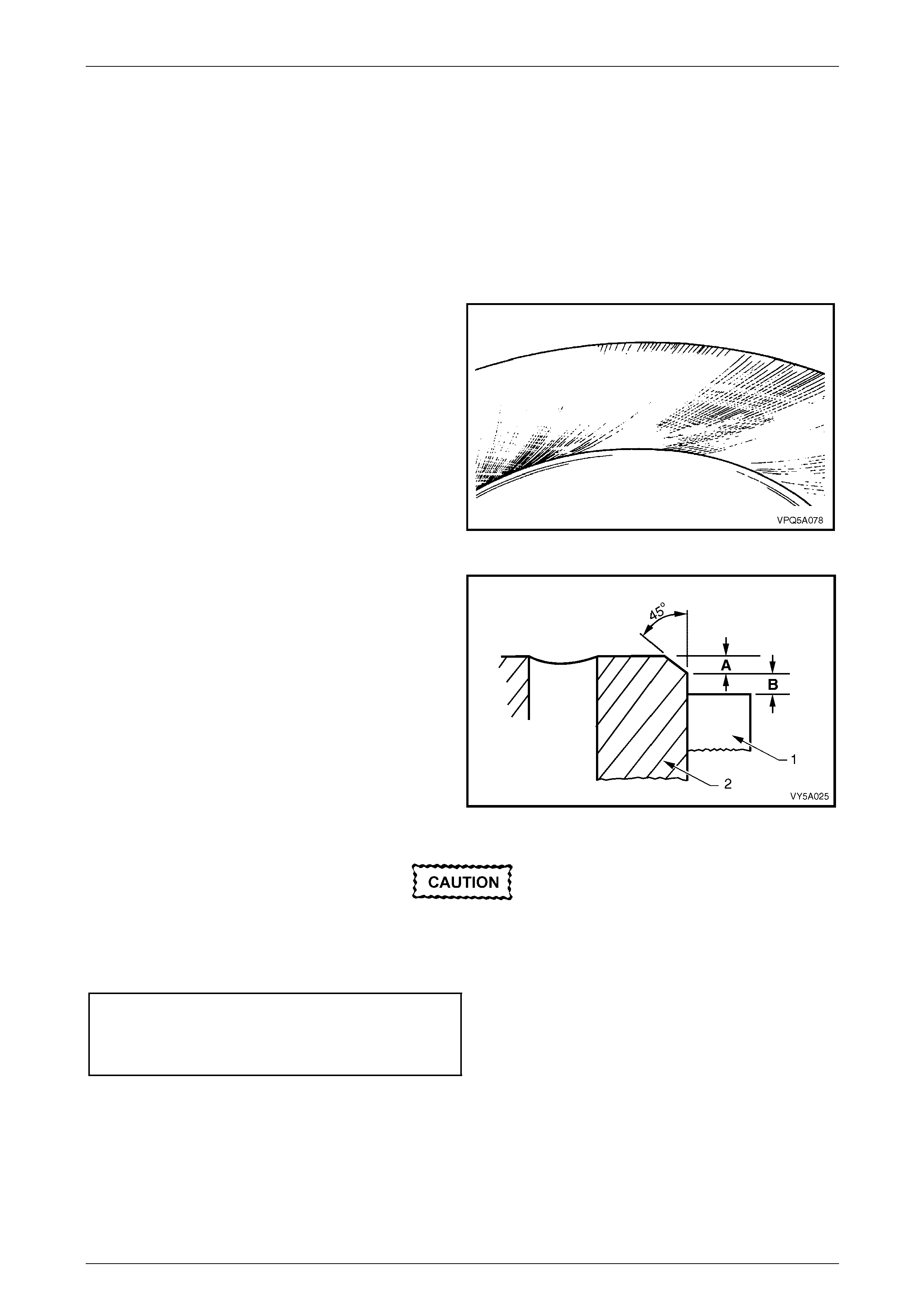
Service and Park Braking System 5A – 73
Inspect
1 If the brake disc surface is rusted or lightl y scored, resurface disc. Scores le ss than 0.4 mm deep will not affect
brake performance.
2 If scoring is deep or if brake disc parameters are out of specification, the disc must be machined.
NOTE
Machine or resurface BOTH sides of disc. D o not
machine or resurface one side onl y.
NOTE
After machining, the brake disc should be
ground to achieve a non-circumferential finish of
0.4 to 2.0 microns.
Figure 5A – 87
NOTE
After machining, the chamfer on the brake disc
outer diameter must be 45 deg x 1 mm
maximum (dimension A) with a pad (1) to
chamfer clearance of 1.3 mm minimum to 2.5
mm maximum (dimension B). This is to prevent
thermal stress cracking at the top of the disc (2).
Figure 5A – 88
The number cast into the hub (1) is the
minimum safe thickness. At this thickness,
the disc MUST be replaced.
Replace disc if specifications cannot be achieved above the minimum disc thickn ess.
Minimum Brake Disc Thickness (replacement r e quired)
All Models Except Coupe and MY2006 SS ...... 25.0 mm
Coupe and MY2006 SS Models Only ...............30.0 mm
5A – 73
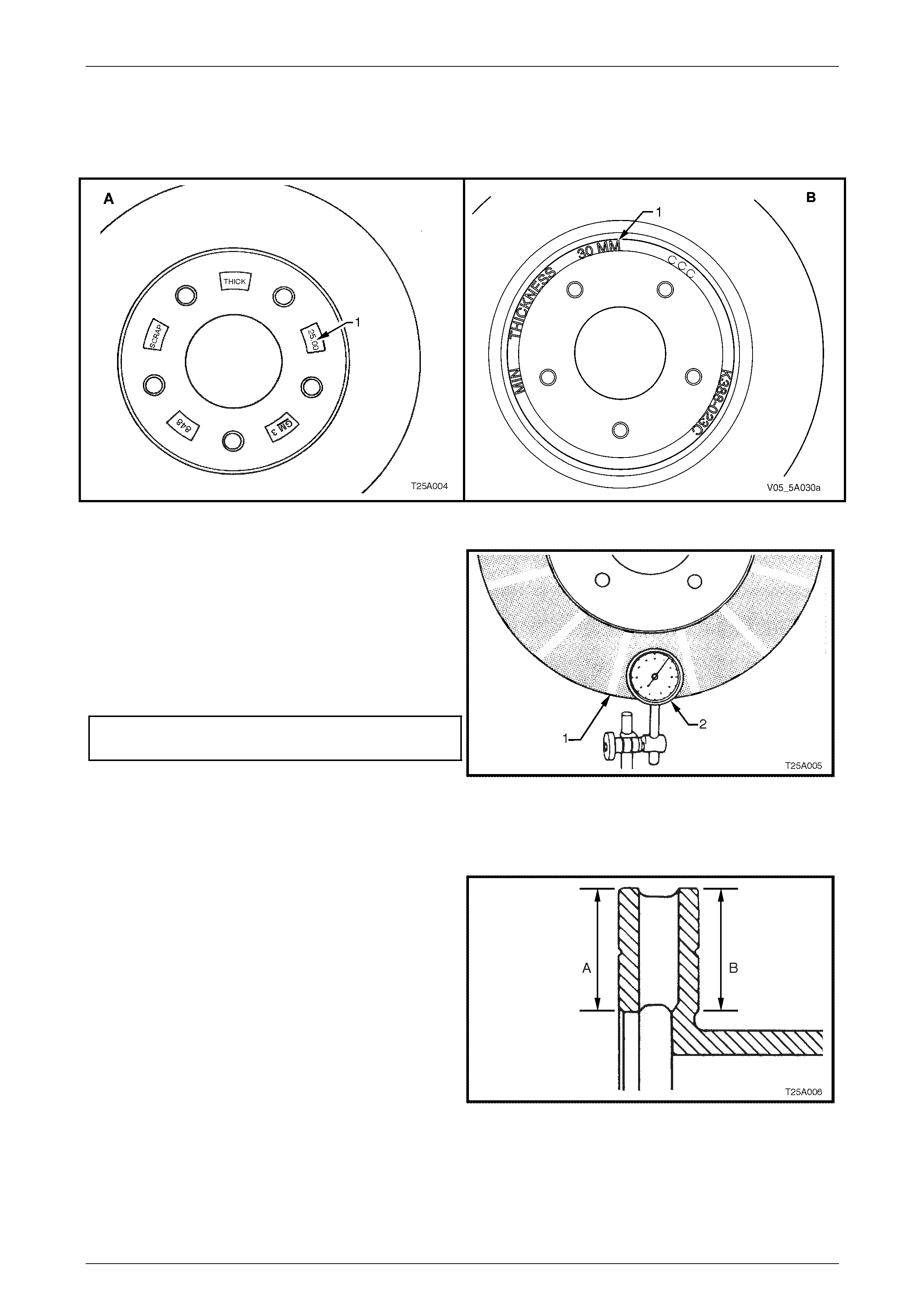
Service and Park Braking System 5A – 74
NOTE
View ‘A’ shows the front disc rotor for all VZ
models except Coupe an d MY2006 SS , which is
shown in view ‘B.
Figure 5A – 89
3 Inspect disc as follows:
a Using a piece of chalk, mark the brake disc
every 30 deg (1).
B Using a dial indicator (2), check that lateral run-
out of each braking surface do es not exceed
0.04 mm Total Indicated Runout (T IR) and that
the rate of change does not exceed 0.03 mm in
30 degrees.
Maximum lateral runout (TIR) ........................... 0.04 mm
Maximum lateral runout in 30°..........................0.03 mm
NOTE
This specification is the lateral run-out of a front
brake disc that has been removed from the
vehicle (do not confuse this with brake disc to
hub assembled lateral run-out.
Figure 5A – 90
4 Check that both surfaces of the brake disc (A & B) are
flat within 0.05 mm TIR.
Figure 5A – 91
5A – 74
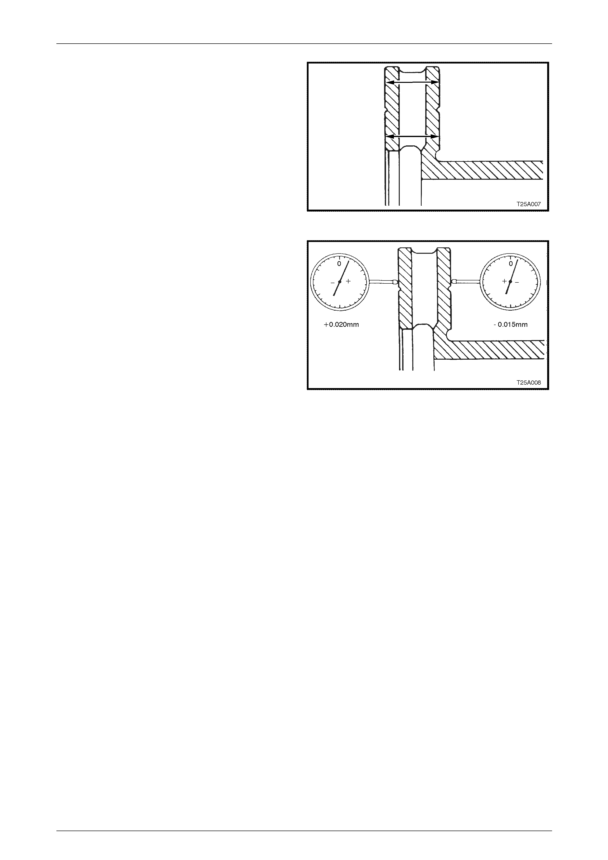
Service and Park Braking System 5A – 75
5 Check that disc surfaces are parallel with each other
to within 0.08 mm, when checked radially.
NOTE
Taper variation must not exceed 0.08 mm.
Figure 5A – 92
6 Check that total circumferential thickness variation,
(also referred to as Disc Thickness Variation) at any
radius, does not exceed 0.00 5 mm in 360 degrees as
the brake disc is rotated.
NOTE
To measure the thickness variation, measure
both sides of the brake disc for runout and add
the two measurements together.
Example:
Total runout on one side = + 0.020 mm
Total runout on other side = – 0.015 mm
Therefore + 0.020 + – 0.015 = + 0.005 mm Figure 5A – 93
Front Brake Disc and Hub Indexing Procedure
NOTE
Brake disc and hub indexing is required so the
minimum installed brake disc runout is achieved.
Brake disc and hub ind exing involv es aligning the
point of maximum runout on the hub with the
point of least runout on the brake disc.
NOTE
This procedure is to be used when reinstalling
brake discs that have been removed for
machining off-car. It must also be used when
installing new brake discs or brake discs that
have been removed for any reason and where
the brake disc to hub matching is not evident.
The procedure consists of three parts:
Part 1. Clean mating surfaces
Part 2. Measure and Match brake disc high poi nt to hub low point. If these measurements are not OK, go to Part 3
Part 3. Checking hub mounting face runout
Part 1. Clean Mating Surfaces
Ensure that brake disc and hub mating surfaces are free fr om dirt, corrosion, etc. If requ ired, use fine emery paper to
clean surfaces.
5A – 75
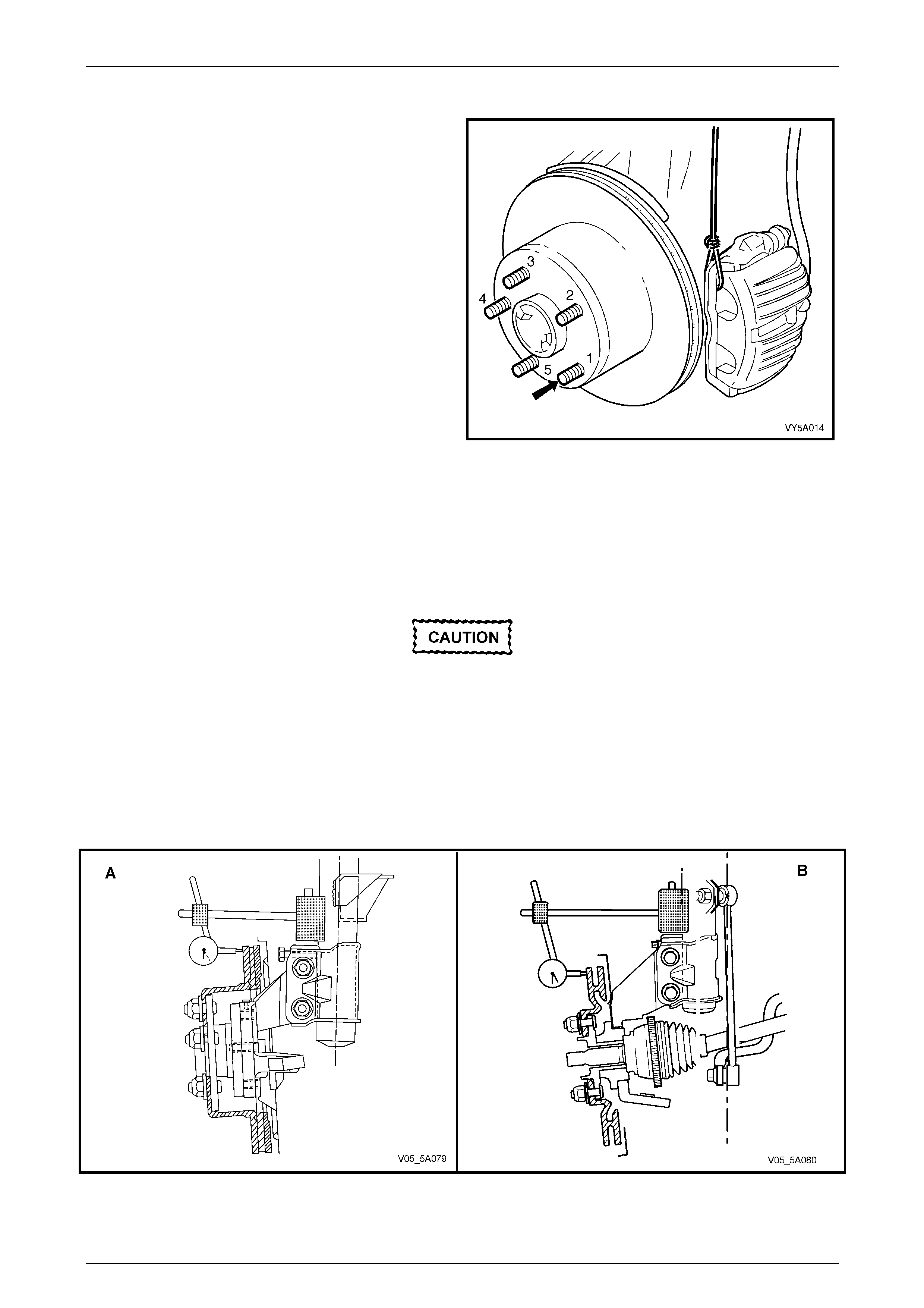
Service and Park Braking System 5A – 76
Part 2. Indexing Brake Disc to Hub
1 Install and secure the brake disc onto the hub with
wheel nuts reversed, to avoid damage to the tapers,
and nip up with a spanner.
2 Number each of the wheel stud holes on the front
surface of the brake disc from 1 to 5. Place a chalk
mark on the end of the wheel stud adjacent to the
number “1” hole (arrow).
NOTE
While the rear disc and caliper are shown, the
procedure for indexing the front brake disc t o the
front hub, is the same.
Figure 5A – 94
3 Set up a dial indicator on a magnetic base and attach to the strut tube above the brake disc. Position the pointer
10 – 15 mm inboard from the outer diameter of the brake disc.
4 Carefully rotate the brake disc and n ote the p oints of minimum and maximum runout on the dial indicator. The
number of divisions bet ween these two points is the total indicated runout. Record this figure together with the
number on the brake disc aligned with the chalk-marked stud.
5 Remove and reinstall the br ake disc with hole number ‘2’ over the marked stud. Repe at Step 4. This procedure is to
be repeated for all 5 hole positions.
If the lowest assembled disc runout achieved
is more than 0.050 mm (50 micron) then the
hub runout should be checked as detailed in
Part 3 of this procedure.
NOTE
• There is no front dust shield fitted to Coupe
and MY2006 SS models.
• View ‘A’ shows the front disc rotor for all VZ
models except AWD Models which is shown
in view ‘B.
Figure 5A – 95
5A – 76
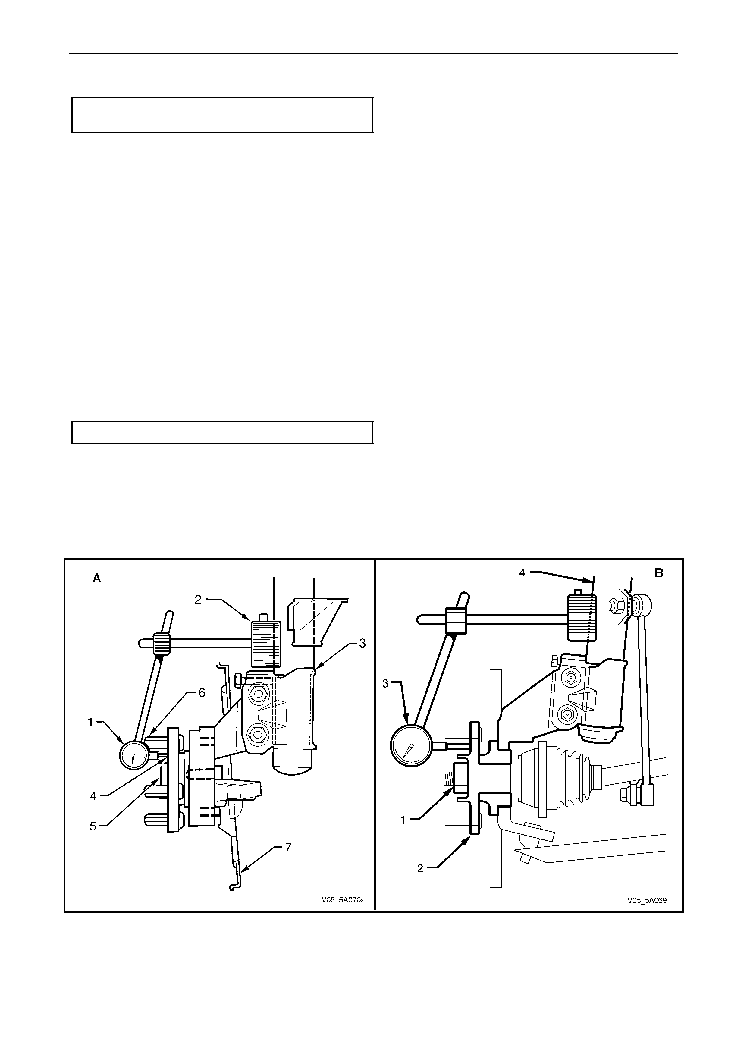
Service and Park Braking System 5A – 77
6 Mount the brake disc to the hub in the stud positio n which recorded the least amount of runout.
Maximum assembled disc and hub
runout at disc outer diameter ............................0.05 mm
Part 3. Hub Runout Check
1 Clean the front hub face by rubbing lightly with fine emery paper.
2 Locate the dial indicator on the strut tube and position the pointer on the hub face about midway between the
spigot and the studs.
NOTE
For this check to be performed with 100 %
accuracy, a flat parallel surface plate attached to
the hub should be used. However, measuring
runout between each of the wheel studs should
yield adequate results.
3 Carefully rotate the hub by the hub spi got (to avoid loading the bearing) and note the points of minimum and
maximum runout on the dial indicator. T he number of divisions between these two points is the total indicated
runout.
4 If the runout measured in Step 3 exceeds 0.025 mm (25 micron) then the hub unit should be replaced. Refer to
Section 3A Front Suspension or Section 3B Fr ont Suspension – AWD.
Maximum runout at hub face – front hub ........ 0.025 mm
NOTE
• View ‘A’ shows the front disc hub for all VZ
models except AWD Models which is shown
in view ‘B.
• The dust shield shown as ‘7’ in ‘A’ is not fitted
to Coupe and MY2006 SS models.
Figure 5A – 96
5A – 77

Service and Park Braking System 5A – 78
Reinstall
1 Reinstall the brake disc over the wheel studs in either the pr e-marked/indexed position or the newly indexed
position.
2 Reinstall the brake caliper assembly, refer to 3.4 Front Brake Caliper, in this Section.
3 Depress the brake pedal several times to bring pads into position against disc.
4 Reinstall road wheel in the original position and secure with the wheel nuts but do not fully tighten.
5 Lower the vehicle to the ground an d tighten the wheel nuts to the specified torque, working in a ‘star’ pattern, refer
to 2.1 Service Warnings, Cautions and Notes, in this Section.
Road wheel attaching nut
torque specification..................................110 – 140 N.m
5A – 78
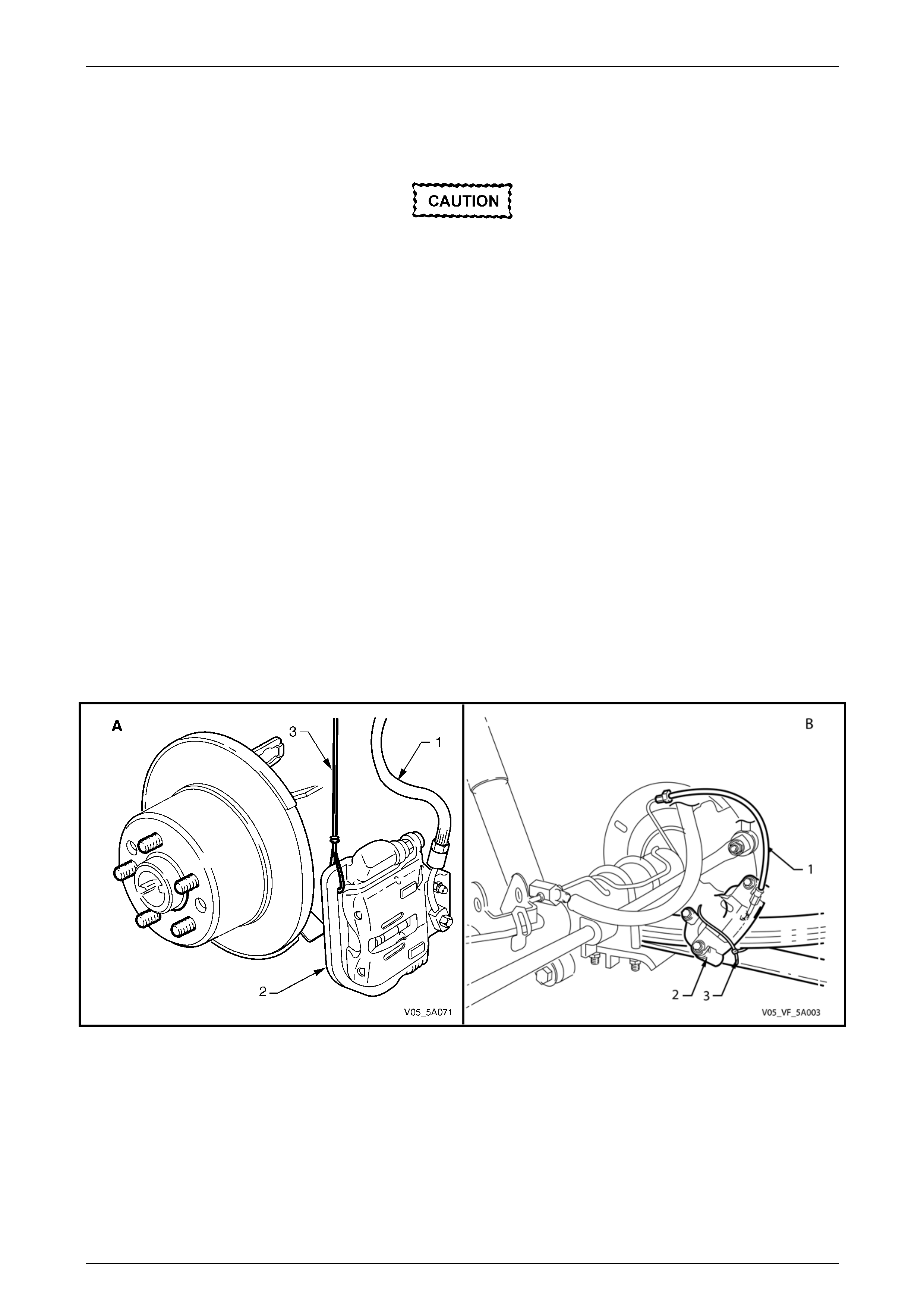
Service and Park Braking System 5A – 79
3.7 Rear Brake Disc
LT Section No. – 04-825
Remove
The brake disc to hub relationship is carefully
matched during production (indexed), to
minimise the effect of a tolerance stack-up,
that could result in disc runout and
subsequent brake shudder.
Carefully mark the relationship of the brake
disc to a wheel stud end for reinstallation. If
this precaution is not taken, then a disc
runout condition could be induced that will
cause brake shudder.
NOTE
If the brake disc is being r emoved to rectify brake
shudder, if the brake disc is to be machined or
replaced, or if brake disc to hub matching is not
evident, the brake disc to the hub must be
indexed, as detailed in this Section.
1 Ensure park brake is fully rele ased.
2 Remove the brake caliper assembly, refer to 3.5 Rear Brake Caliper, in this Section.
3 It is not necessary to disconnect the brake hose (1) from the caliper (2). However, the caliper MUST be supported
with tie wire (3) to avoid strain on brak e hose (1).
NOTE
View ‘A’ shows all VZ models except for live axle
models which is shown in ‘B’.
Figure 5A – 97
4 If necessary, jar the brake disc loose by care fully tapping the disc in the centre between the wheel studs, with a soft
faced hammer (or block of wood and a hard faced h ammer), taking care not to damage the wheel stud threads.
NOTE
It may be necessary to loosen the park brake
shoe adjustment, to allo w the disc to be removed
over the park brake shoes. Refer to 3.9 Park
Brake Shoe, Adjust, in this Section.
5A – 79
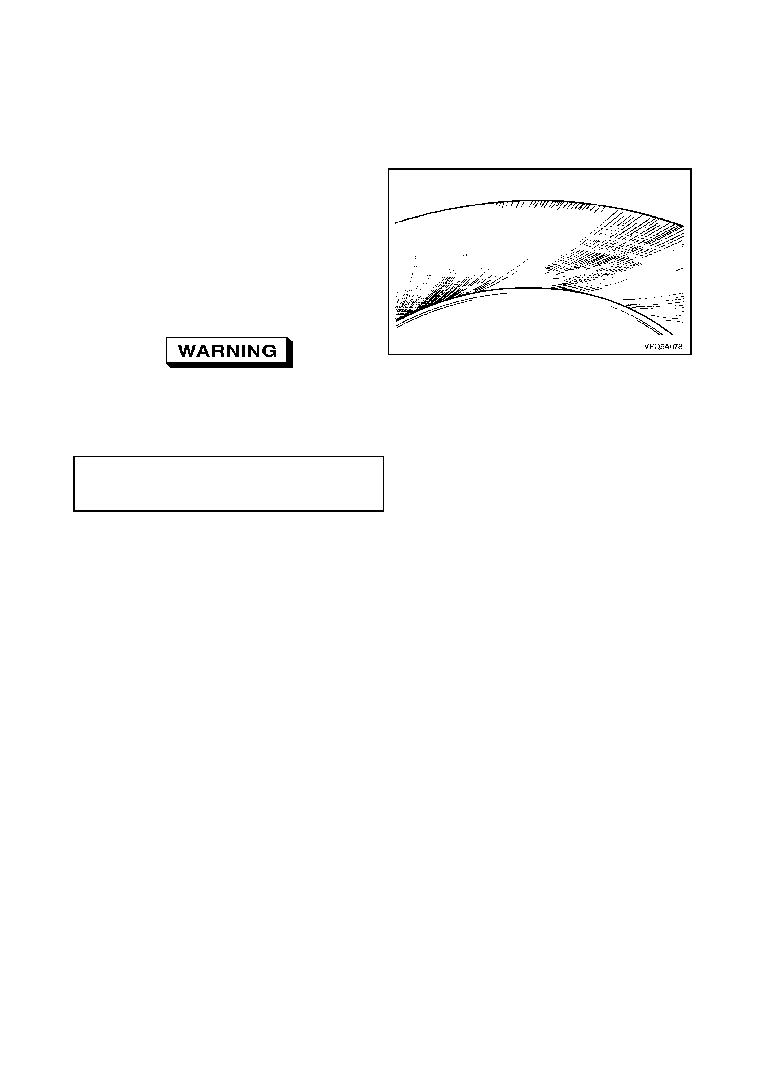
Service and Park Braking System 5A – 80
Inspect
All Models
1 If the brake disc surface is rusted or lightl y scored, resurface disc. Scores le ss than 0.4 mm deep will not affect
brake performance.
NOTES
• If the disc rotor requires conditioning,
machine or resurface BOTH sides of the
disc. Do not machine or resurface one side
only.
• After machining, the disc finis h should be 0.6
to 1.25 microns and should not be
circumferential i.e. disc finish should be non-
directional. The park brake surface finish
should be 20 microns.
If the minimum brake disc thickness, is
reached during machining operations, then
the disc MUST be replaced.
Figure 5A – 98
• Replace the brake disc if the spec ifications cannot be achie ved ab ove the minimum disc thickness.
Minimum brake disc rotor thickness
(Replacement required) Solid Rotor........... 13.9 mm
Vented Rotor....... 16.0 mm
2 If scoring is deep or if disc parameters are out of specification, the disc must be machined or replaced.
5A – 80
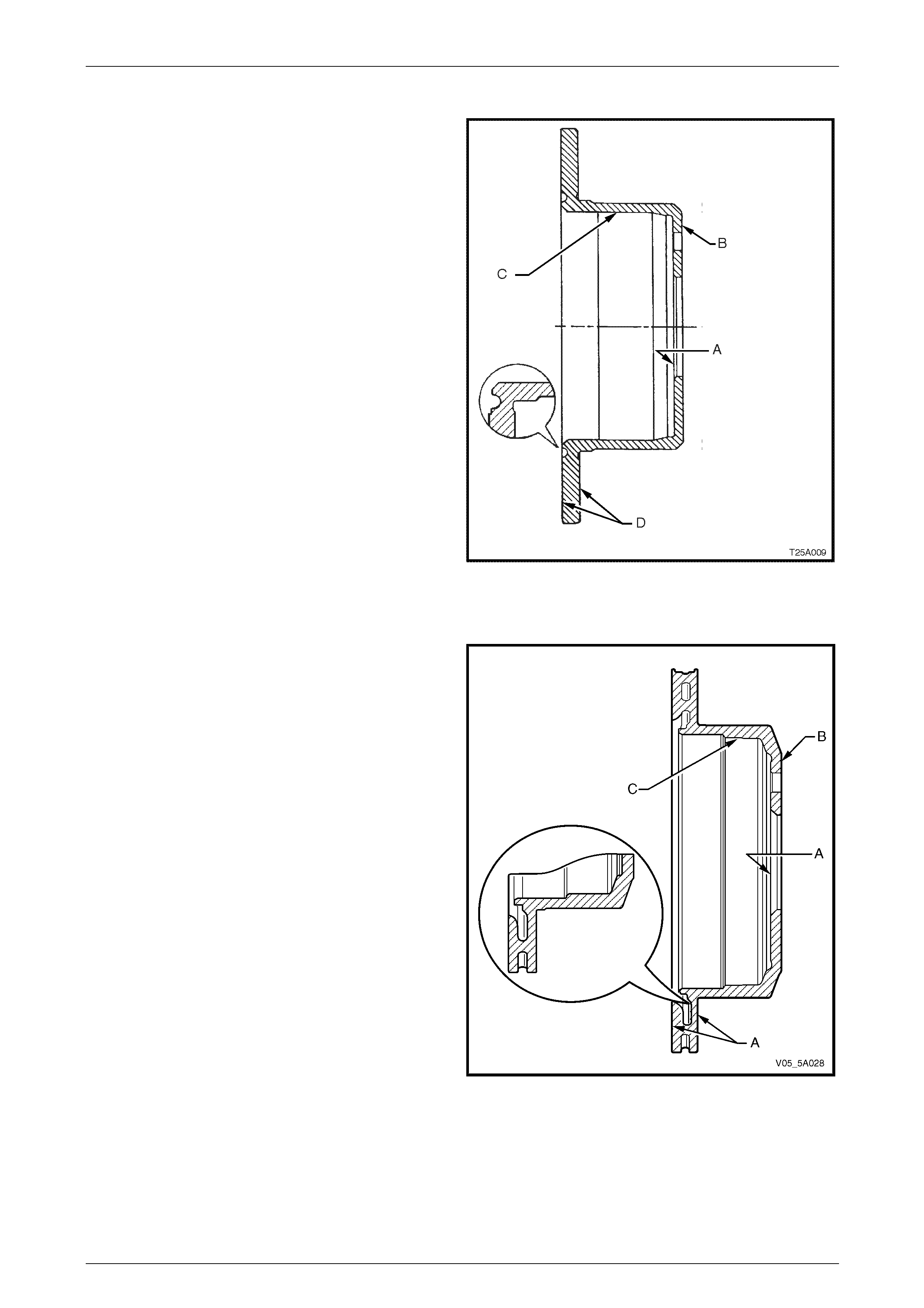
Service and Park Braking System 5A – 81
All MY 2005 VZ Models With Solid Disc Rotor
NOTES
3 Inspect brake disc as follows:
a Check that surface B is flat within 0.08 mm and
is parallel with surface A within 0.08 mm Total
Indicated Runout (TIR).
B Check that surface C circular run-out is less than
0.08 mm and that surface is square to surface A
within 0.05 mm TIR.
C Check that each brake disc surface is flat within
0.05 mm and is parallel to surface A within 0.085
mm TIR.
D Check that lateral run-out of each braking
surface D is less than 0.05 mm when measured
from surface A as shown or when bolted to the
axle and that rate of change does not e xceed
0.03 mm in 30°.
E Check that maximum circumferential thickness
(also referred to as Disc Thickness Variation
(DTV) does not vary by more than 0.013 mm at
any radius when disc is rotated.
Figure 5A – 99
All MY 2005 and MY2006 VZ Models With Vented Disc Rotor
Inspect brake disc as follows:
1 Check that surface B is flat within 0.08 mm and is
parallel with surface A within 0.08 mm T otal Indicated
Runout (TIR).
2 Check that surface C circular run-out is less than 0.0 8
mm and that surface is square to surface A within 0.05
mm TIR.
3 Check that each brake disc surface is flat within 0.05
mm and is parallel to surface A within 0.085 mm T IR.
4 Check that lateral run-out of each braking surface D is
less than 0.05 mm when measured from surface A as
shown or when bolted to the axle and that rate of
change does not exceed 0.03 mm in 30°.
5 Check that maximum circumferential thickness (also
referred to as Disc Thickness Variatio n (DT V ) does not
vary by more than 0.013 mm at any radius when disc
is rotated.
Figure 5A – 100
5A – 81
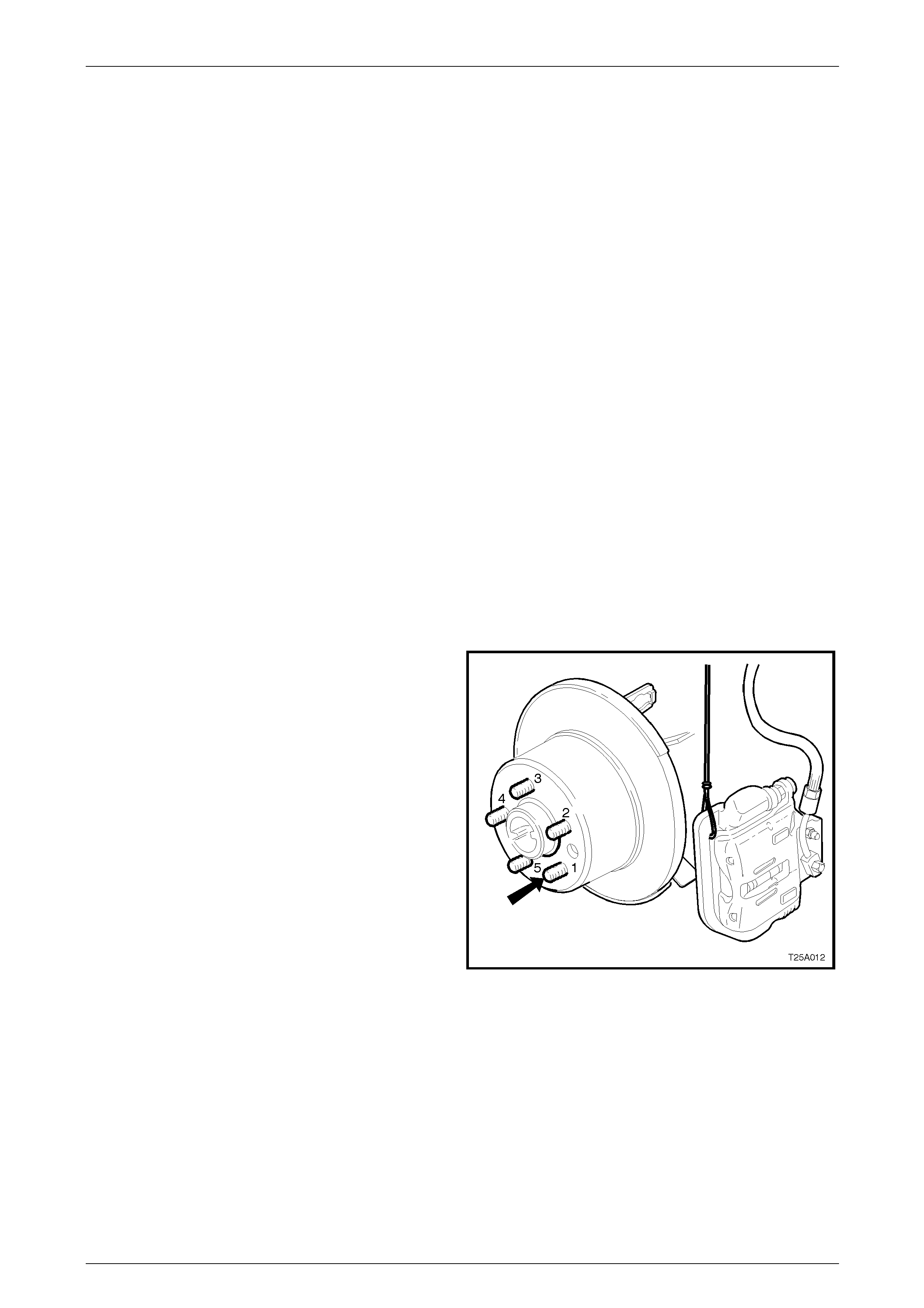
Service and Park Braking System 5A – 82
Rear Brake Disc and Hub Indexing Procedure
NOTE
Brake disc and hub indexing is required so the
minimum installed brake disc runout is achieved.
Brake disc and hub ind exing involv es aligning the
point of maximum runout on the hub with the
point of least runout on the brake disc.
NOTE
This procedure is to be used when reinstalling
brake discs that have been removed for
machining off-car. It must also be used when
installing new brake discs or brake discs that
have been removed for any reason and where
the brake disc to hub matching is not evident.
The procedure consists of three parts:
Part 1 Clean mating surfaces
Part 2 Measure and Match brake disc high p oint to hub low point. If these measurements are not OK, go to Part 3
Part 3 Checking hub mounting face runout
Part 1. Clean Mating Surfaces
Ensure that brake disc and hub mating surfaces are free fr om dirt, corrosion, etc. If requ ired, use fine emery paper to
clean surfaces.
Part 2. Indexing Brake Disc to Hub
1 Fasten the brake disc onto the hub with wheel nuts
reversed to avoid damage to the tapers, and nip up
with a spanner.
2 Number each of the wheel stud holes on the front
surface of the brake disc from 1 to 5. Place a chalk
mark on the end of the wheel stud adjacent to the
number “1” hole (bold arro w).
Figure 5A – 101
5A – 82
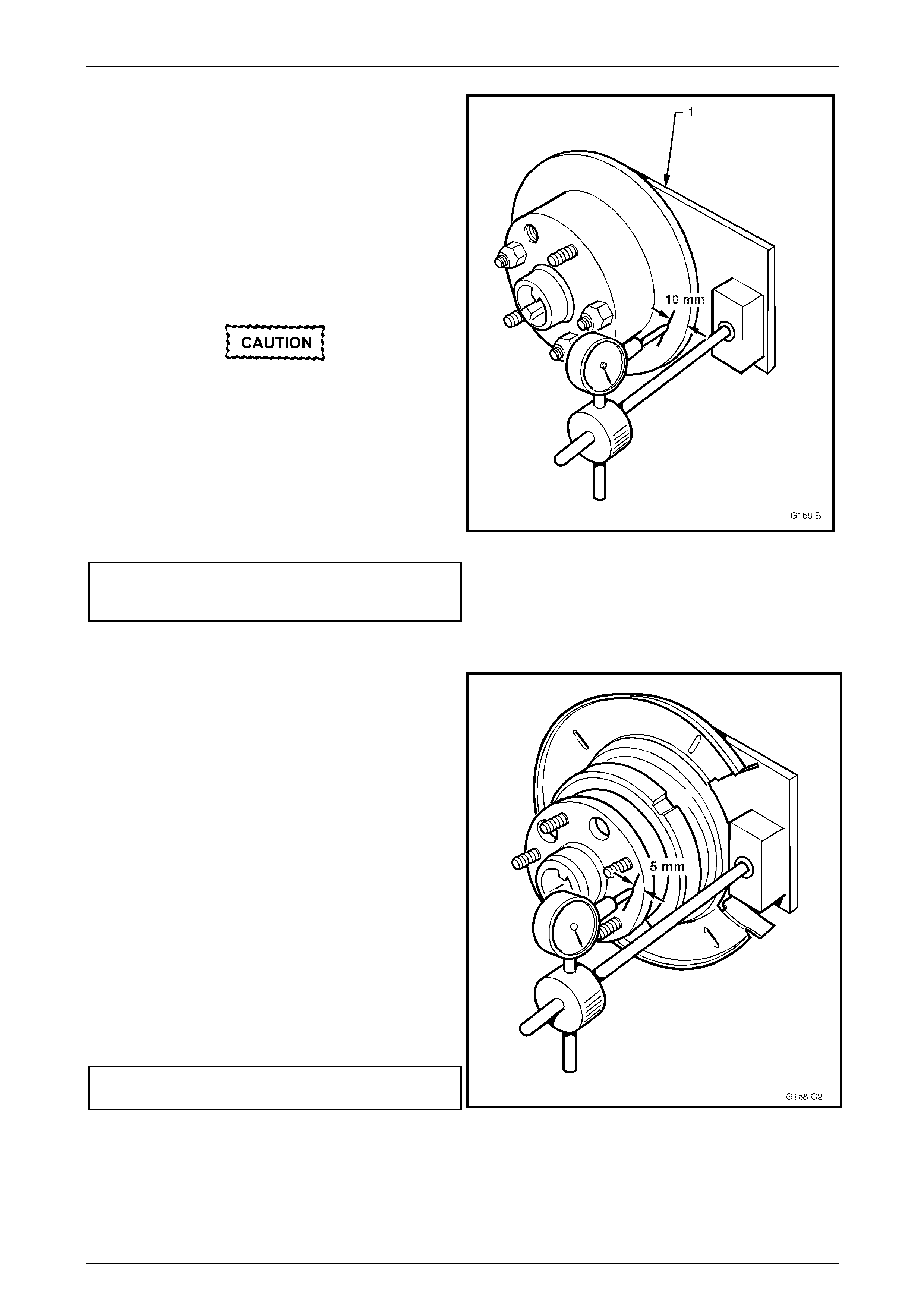
Service and Park Braking System 5A – 83
3 Set up a dial indicator on a magnetic bas e and attach
to a pre-fabricated mounting plate (1) (refer to
7 Special Tools in this Section for pre-fabricated
mounting plate details) bolted to the caliper attaching
points. Position the pointer of the dial indicator 10 mm
inboard from the outer diameter of the brake disc.
4 Carefully rotate the brake disc and note the points of
minimum and maximum runout on the dial indicator.
The number of divisions between these two points is
the total indicated runout. Record this figure together
with the number on the brake disc aligned with the
chalk-marked stud.
If the lowest assembled disc runout achieved
is more than 0.080 mm (80 micron) then the
trunnion hub runout should be checked as
detailed in Part 3 of this procedure.
5 Remove and reinstall brake disc with hole number “2”
over the marked stud and repeat Step 4. This
procedure is to be repeated for all 5 hole p ositions.
6 Mount the disc to the trunnion hub in the stud position
which recorded the least amount of runout.
Maximum assembled brake disc and
trunnion hub runout at brake d isc
outer diameter – rear brake disc....................... 0.08 mm
Figure 5A – 102
Part 3. Trunnion Hub Runout Check
1 Clean the front hub face by rubbing lightly with fine
emery paper.
2 Mount a dial indicator on a pre-fabricated mounting
plate bolted to the caliper mounting points, then
position the pointer on the hub face as shown. Refer to
7 Special Tools in this Section for dimensional details
of the mounting plate.
NOTE
For this check to be performed with 100 %
accuracy, a flat parallel surface plate attached t o
the hub should be used. However, measuring
runout between each of the wheel studs should
yield adequate results.
3 Carefully rotate the hub by the wheel studs and note
the points of minimum and maximum runout on the
dial indicator. The number of divisio ns between these
two points is the total indicated runout.
4 If the runout measured in Step 3 exceeds 0.060 mm
(60 micron) then the trunnion assembl y must be
replaced.
Maximum Trunnion hub total
indicated runout (TIR)................................... 0.06 mm
Figure 5A – 103
5A – 83

Service and Park Braking System 5A – 84
Reinstall
1 Reinstall the brake disc over the wheel studs in either the pr e-marked/indexed position or the newly indexed
position.
2 Reinstall the brake caliper assembly, refer to 3.5 Rear Brake Caliper, in this Section.
3 Depress the brake pedal several times to bring pads into position against disc.
4 Adjust park brake shoe clear ance. Refer to 3.9 Park Brake Shoe, Adjust, in this Section, for details.
5 Reinstall road wheel in the original position and secure with the wheel nuts but do not fully tighten.
6 Lower the vehicle to the ground an d tighten the wheel nuts to the specified torque, working in a ‘star’ pattern, refer
to 2.1 Service Warnings, Cautions and Notes, in this Section.
Road wheel attaching nut
torque specification..................................110 – 140 N.m
7 Road test the vehicle to ensure correct brake operation.
5A – 84

Service and Park Braking System 5A – 85
3.8 Park Brake Lining Wear, Check
1 Remove both rear disc rotors. Refer to 3.7 Rear Brake Disc, in this Section.
2 Check the park brake lining for even wear, both across the shoe and circumferentiall y around each shoe, for each
lining half, using a vernier caliper or simil ar.
3 Wear should be even and no thinner than the specified minimum thickness. If the minimum thickness is at or less
than specified, then the linings must be replaced. The drum section of the r ear disc may also require grin ding.
Refer 3.7 Rear Brake Disc, in this Section for specific detail, regarding grinding operations.
Minimum park brake
shoe lining thickness...........................................1.5 mm
NOTE
If one park brake shoe requires replacement,
then both must be replaced.
4 Reinstall rear discs and adjust the park brake shoe clearances, refer 3.7 Rear Brake Disc and 3.9 Park Brake
Shoe, Adjust, both in this Section.
5A – 85
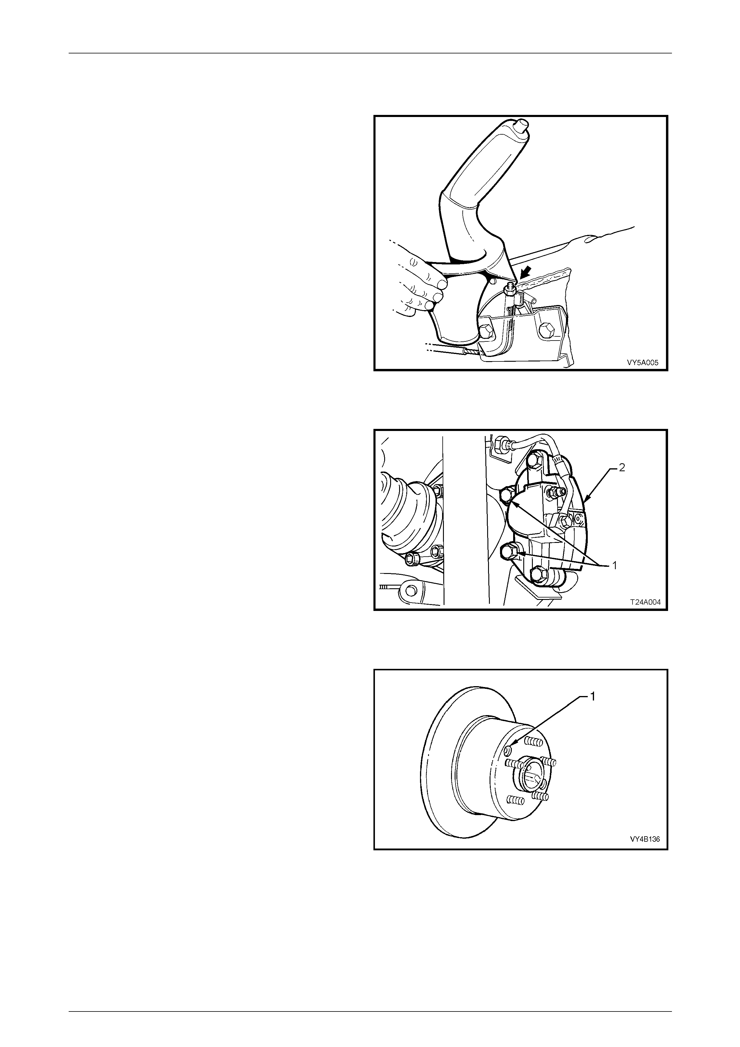
Service and Park Braking System 5A – 86
3.9 Park Brake Shoe, Adjust
1 Raise the vehicle and suppor t in a safe manner. Refer
to Section 0A General Information for the location of
recommended lifting and support points.
2 Remove rear wheel covers (steel wheels) or wheel nut
decorative caps (alloy wheels).
3 Mark relationship of wheels to mounting flanges.
4 Remove road wheel attaching nuts and remove
wheels.
5 Release park brake and ensure that park brake
actuator arms have fully retracted.
If necessary, loosen the front park brake cable
adjustment nut (arrow) with a deep socket, to ensure
slack in the park brake rear cables.
Figure 5A – 104
6 Remove rear brake caliper anc hor plate to trailing arm
attaching bolts (1) (both sides of vehicle), then remove
calipers (2) from discs.
7 Using tie wire, secure calipers to lower end of shock
absorber upper mountings. DO NOT ALLOW
CALIPERS TO HANG BY BRAKE HOSES!
8 Reinstall three wheel nuts, reversed to prev ent
damage to the tapers and lightly tighten to secure the
disc in place.
Figure 5A – 105
9 Remove the access hole pl ug (1). Using a suitable
lever such as a screwdriver, tighten the park brake
shoe screw adjuster, until the disc is locked. Access to
the screw adjuster is through either one of two holes
(1) provided in the disc.
10 Loosen the adjuster 3 – 5 clic ks, then check that the
disc is free and does not drag. Replace the access
hole plug when the adjustme nt procedure has been
completed.
Figure 5A – 106
5A – 86

Service and Park Braking System 5A – 87
11 Reinstall brake calip er, install and tighten caliper anchor plate to trailing arm attaching bolts, to the correct torque
specification.
Brake caliper anchor plate to
trailing arm attaching bolt
torque specification..............................................85 N.m
12 Reinstall road wheel in the original position and secure with the wheel nuts but do not fully tighten.
13 Check park brake cable adjust ment, refer to 2.2 Park Brake Cable, Adjust, in this Section.
14 Lower the vehicle to the ground an d tighten the wheel nuts to the specified torque, working in a ‘star’ pattern, refer
to 2.1 Service Warnings, Cautions and Notes, in this Section.
Road wheel attaching nut
torque specification..................................110 – 140 N.m
15 Refit wheel covers/wheel nut decorative caps.
5A – 87
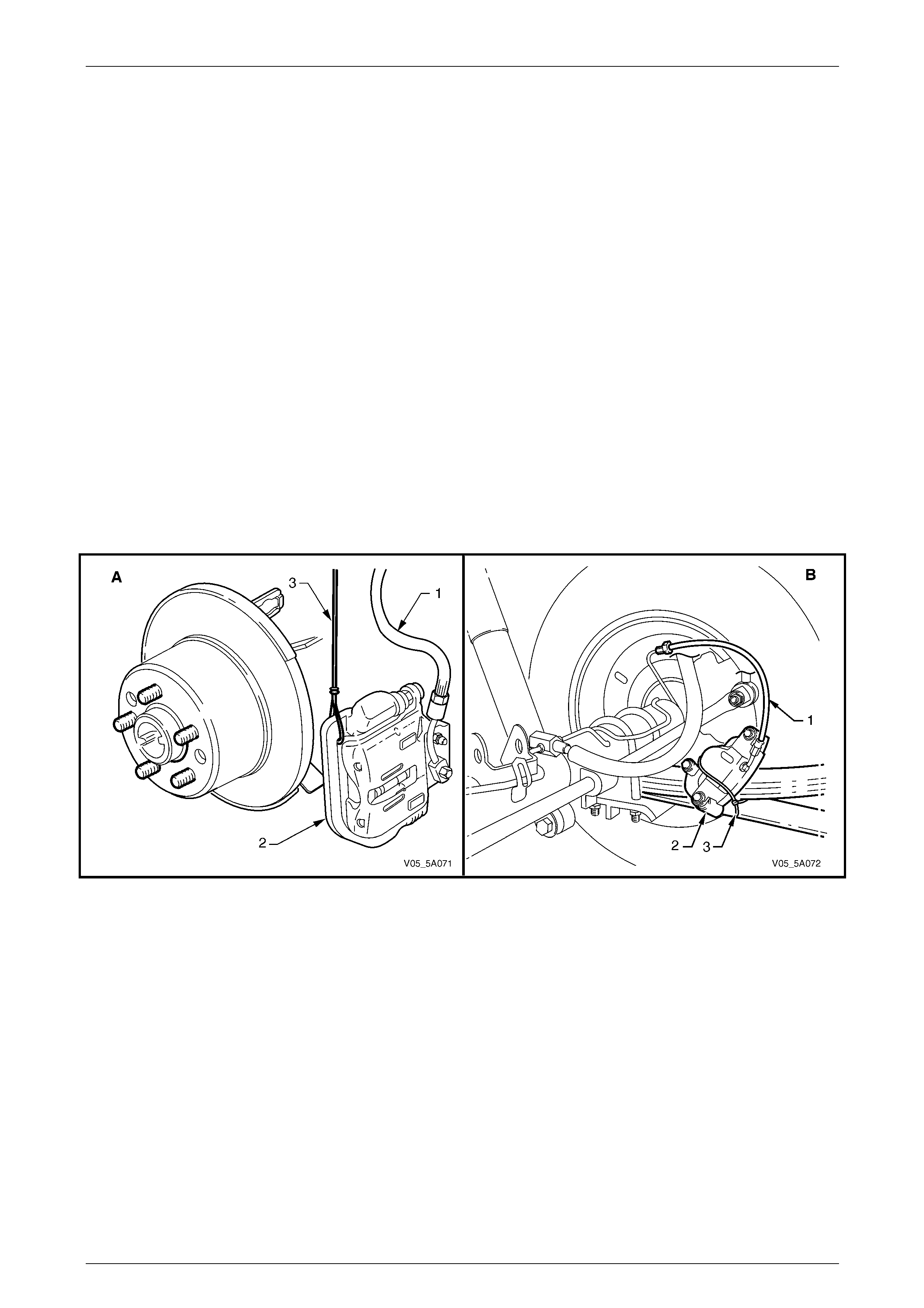
Service and Park Braking System 5A – 88
3.10 Park Brake Shoe
LT Section No. – 04-825
Remove
1 Raise the vehicle at the rear and supp ort in a safe manner. Refer to Section 0A General Information in this Service
Information for the location of recommende d lifting and support points.
2 Remove the wheel covers or decorative wheel nut caps, then mark the relationship of the road wheel to one of the
wheel studs.
3 Loosen, then remove the road wheel attachi ng nuts, working in a ‘star’ pattern. Refer 2.1 Service Warnings,
Cautions and Notes in this Section, for deta iled information. Remove the road wheel.
4 Release park brake.
5 Remove brake caliper anchor plate to trailing arm attaching bolts and remove caliper/s from disc/s.
6 Using tie wire (3), secure the calipers (2) to lower end of shock absorber upper mountings, (or the rear leaf spring).
DO NOT ALLOW CALIPERS TO HANG BY BRAKE HOSES.
NOTE
View ‘A’ shows all VZ models except for live axle
models which is shown in ‘B’.
Figure 5A – 107
7 Index each disc to a wheel stud using a felt tipped pen or similar.
8 Remove brake discs.
NOTE
It may be necessary to loosen the park brake
shoe adjustment, to enable disc removal. Refer to
3.9 Park Brake Shoe, Adjust, in this Section.
5A – 88
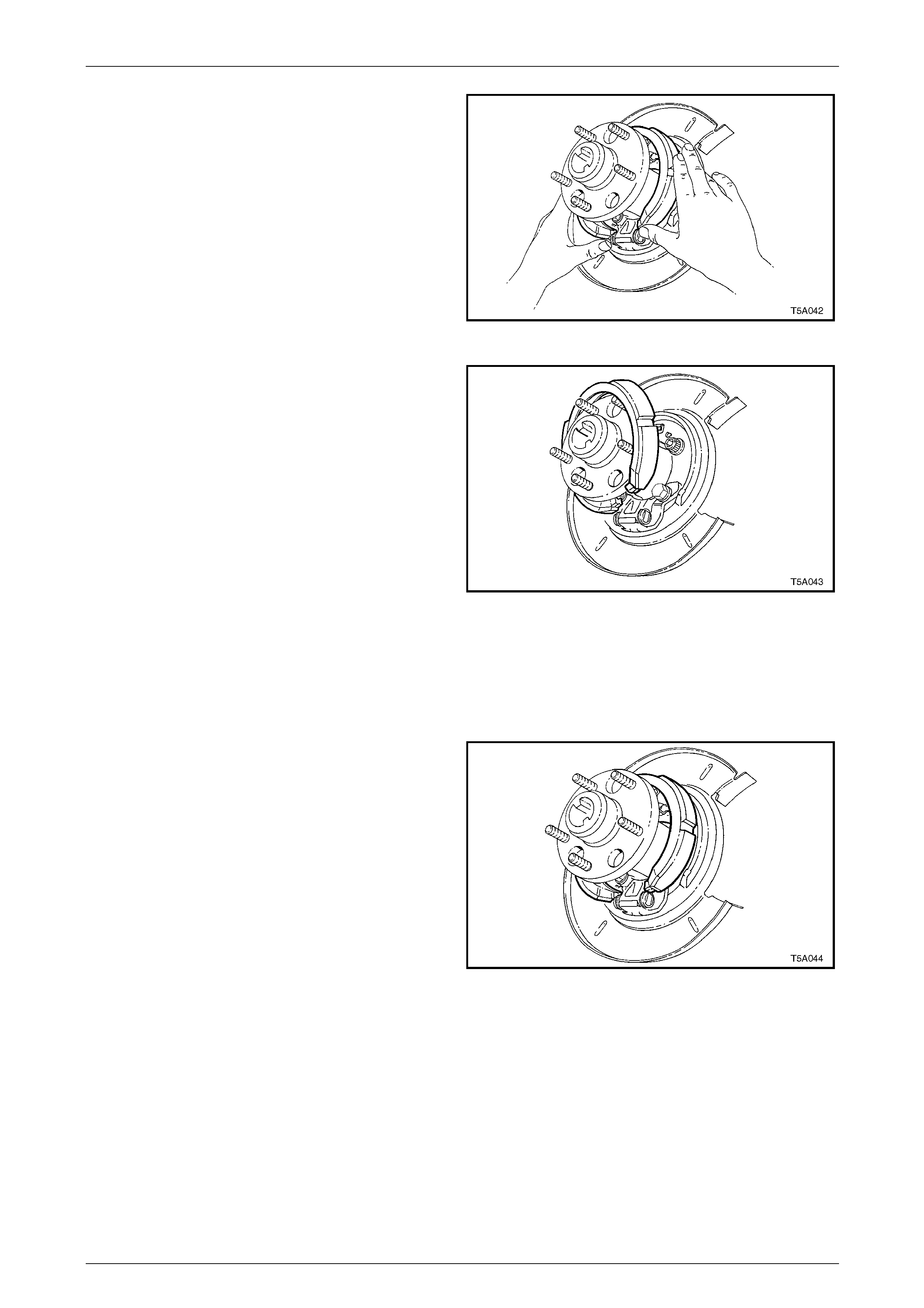
Service and Park Braking System 5A – 89
9 Remove park brake shoe by gr asping each end as
shown. Push up on one end of the shoe, dislodging
the end from the actuator pin and the shoe from the
retaining clip.
Figure 5A – 108
10 Using a screwing motion, rotate the park brake shoe
around the trunnion flange to remove it from the
vehicle.
11 Remove the park brake shoe spring retainer b y prising
from the rear disc shield, with a screwdriver or similar
lever.
12 If required, the actuator screw adjuster and pins can
be removed at this point, but the body and remaining
components are not able to be removed without first
removing the rear disc shield. For this operat ion, refer
to 3.12 Rear Disc Brake Dust Shield – All Except Live
Axle Models, or 3.13 Rear Disc Backing Plate & Dust
Shield – Live Axle Models, bot h in this Section. Figure 5A – 109
Reinstall
1 Apply an NLGI No. 2 lithium soap based EP grease with molybdenum disulphide, such as Shell Retinax HDX2
grease or BP Energrease LMS-EP 23 (or eq uivalent) to the adjusting screw, pins and shoe contact p oin ts on the
shield.
2 Fully wind screw into sleeve and install int o the
adjuster body.
3 Install the park brake shoe over the trunnion flange.
4 With one shoe end located on the adjuster pin, roll the
shoe to engage the other end onto the other pin.
Figure 5A – 110
5A – 89
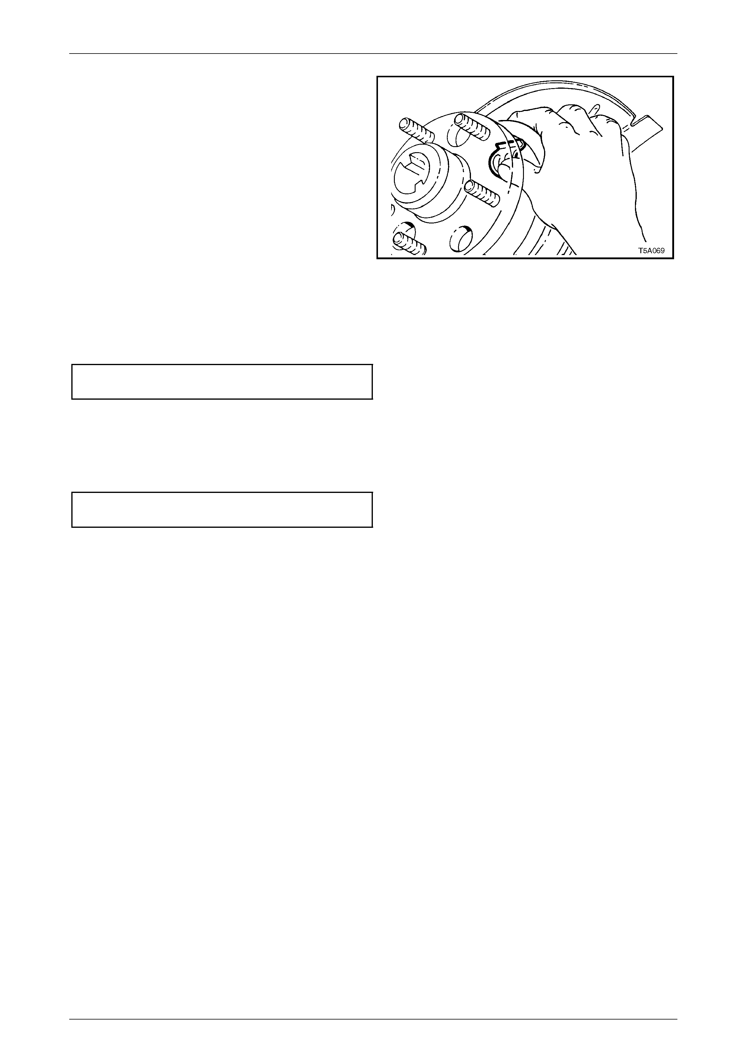
Service and Park Braking System 5A – 90
5 Reinstall park brake shoe ret aining spring clip, by
sliding it into place, ensuring that the sprin g clip is
correctly located by the tangs in the rear brake shield.
Figure 5A – 111
6. Reinstall brake discs, alig ning marks made on removal.
7. Adjust park brake shoe to disc cleara nce. Refer to 3.9 Park Brake Shoe, Adjust, in this Section.
8 Reinstall caliper anchor plate attaching bolts and tighten to the correct torque specification.
Rear brake caliper anc hor plate
bolt torque specification.......................................85 N.m
9 Adjust park brake cable, refer to 2.2 Park Brake Cable, Adjust, in this Section.
10 Reinstall road wheel in the original position and secure with the wheel nuts but do not fully tighten.
11 Lower the vehicle to the ground an d tighten the wheel nuts to the specified torque, working in a ‘star’ pattern, refer
to 2.1 Service Warnings, Cautions and Notes, in this Section.
Road wheel attaching nut
torque specification..................................110 – 140 N.m
12. Refit wheel covers/wheel nut decorative caps.
5A – 90

Service and Park Braking System 5A – 91
3.11 Front Disc Brake Shield
LT Section No. – 04-805
NOTE
• There is no front brake shield fitted to MY
2005 Coupe and MY2006 SS Models.
• For AWD models, the shield is attached with
three screws in each shield. Refer to
Section 3B Front Suspension – AWD, for this
procedure.
• For all VZ vehicles except Coupe and
MY2006 SS and AWD, refer to Section 3A
Front Suspension for the procedure
5A – 91
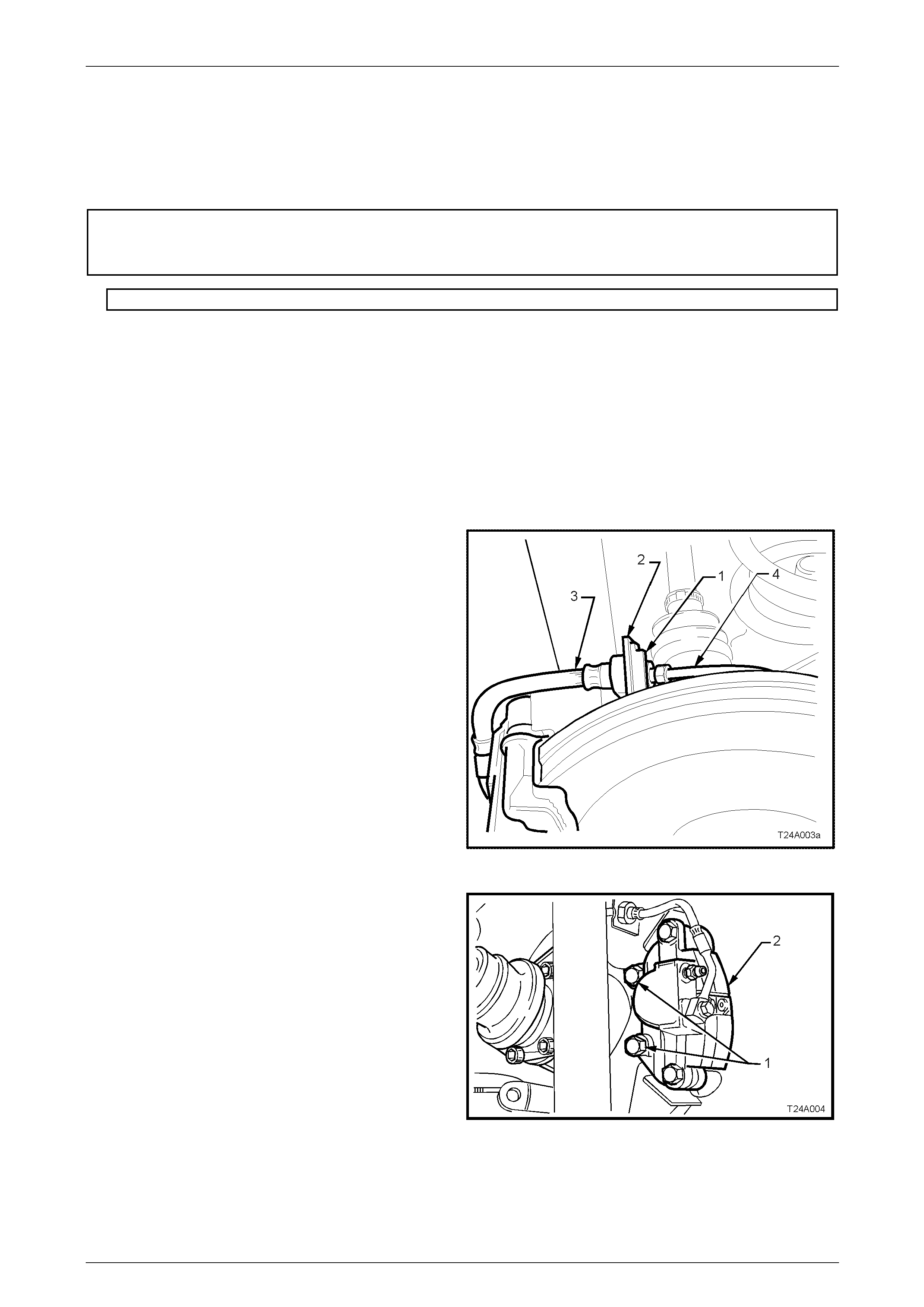
Service and Park Braking System 5A – 92
3.12 Rear Disc Brake Dust Shield – All Except
Live Axle Models
LT Section No. – 04-825
ATTENTION
The following fasteners MUST be replaced w hen p erfo rming these operations:
2. L ower rear disc brake shield to trailing arm bolts.
Remove
1 Raise the rear of the vehicle and support in a safe manner. Refer to Section 0A General Information in this Service
Information for the location of recommende d lifting and support points.
2 Remove the wheel covers or decorative wheel nut caps, then mark the relationship of the road wheel to one of the
wheel studs.
3 Loosen, then remove the road wheel attachi ng nuts, working in a ‘star’ pattern. Refer 2.1 Service Warnings,
Cautions and Notes in this Section, for detailed information. Remove the road wheel.
4 Release park brake.
5 Thoroughly clean around brake hose to pipe
connection at backing plate. Disconnect brake pipe (4)
from the brake hose (3) at backing plate bracket (2)
and remove brake hose retaining clip (2).
Figure 5A – 112
6 Remove brake caliper anchor plate to trailing arm
attaching bolts and remove caliper from disc.
7 Using wire, tie up caliper/s to the lo wer end of the
shock absorber upper mounti ng/s. DO NOT ALLOW
THE CALIPER/S TO HANG BY THE BRAKE HOSE/S.
Figure 5A – 113
5A – 92
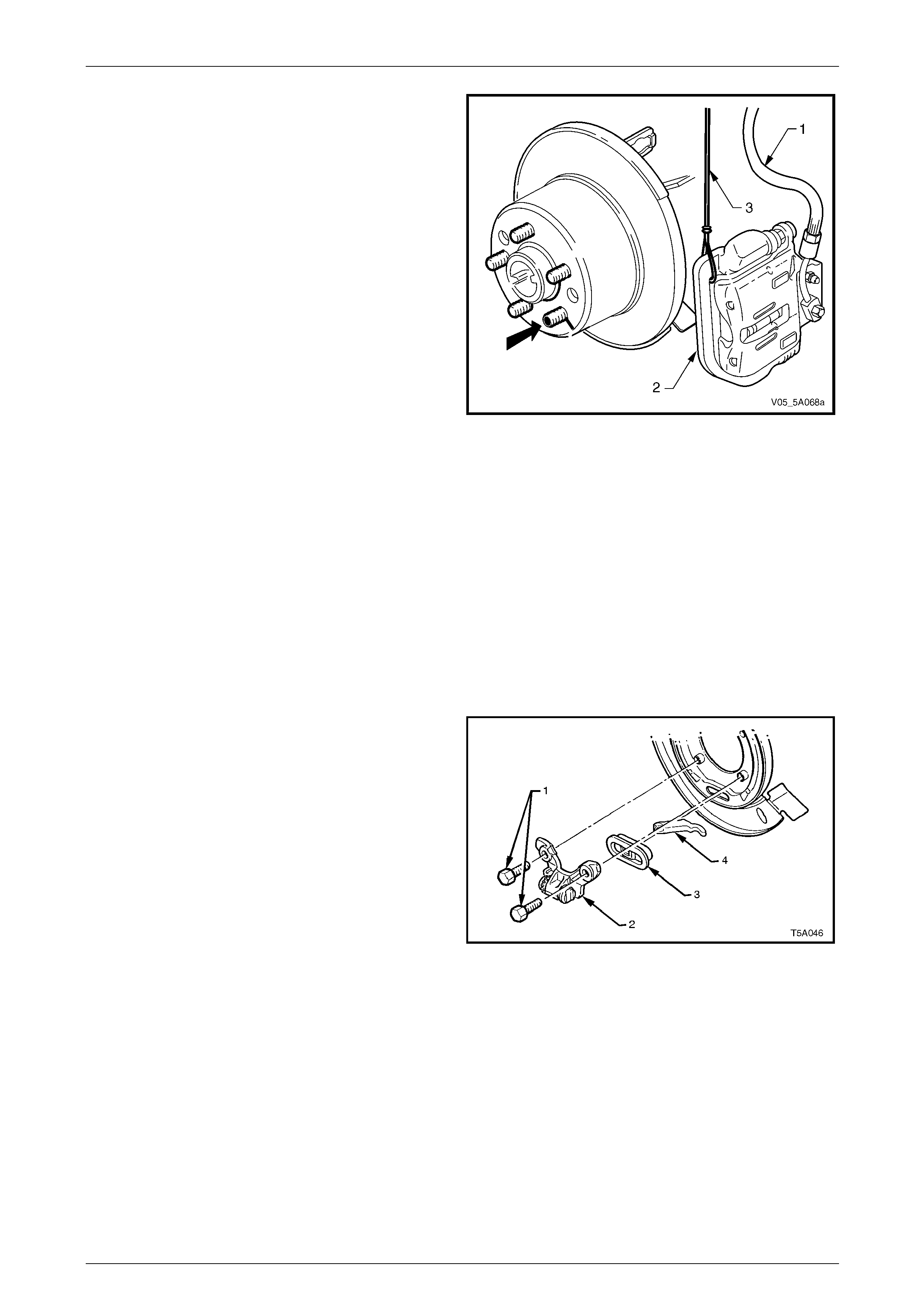
Service and Park Braking System 5A – 93
8 Index each disc to a wheel stud using a felt tipped pen
or similar, as indicated by the bol d arrow.
9 Remove brake disc/s.
NOTE
It may be necessary to loosen the park brake
shoe adjustment, to enable disc removal. Refer
to 3.9 Park Brake Shoe, Adjust, in this Section.
10 Disconnect the park brake cable from the actuator
arm. Refer to 2.12 Rear Park Brake Cable/s, in this
Section, for details.
Figure 5A – 114
11 Remove trailing arm trunnion flange and trunnion assembly, refer to Section 4B1 Rear Final Drive and Drivesh afts,
for the necessary procedure.
NOTE
Because the trunnion flange removal procedure
will cause the rear wheel bearing to be brinelled,
it must be replaced on reassembly. Also refer to
Section 4B1 Rear Final Drive and Drive Shafts,
for the necessary procedure for this task.
12 Following the removal of the trunnion and bearing assembly, the backing plate will be free to be removed, together
with the parking brake shoe assembly.
13 Remove park brake shoe assembly. Refer to 3.10 Park Brake Shoe, in this Section.
14 To disassemble the park brake actuator assembly (2,
3 and 4) from the rear disc shield, support the disc
shield to minimise distortion, then carefull y press the
actuator assembly from the lower extruded bolt hole
sections of the disc plate.
Figure 5A – 115
5A – 93
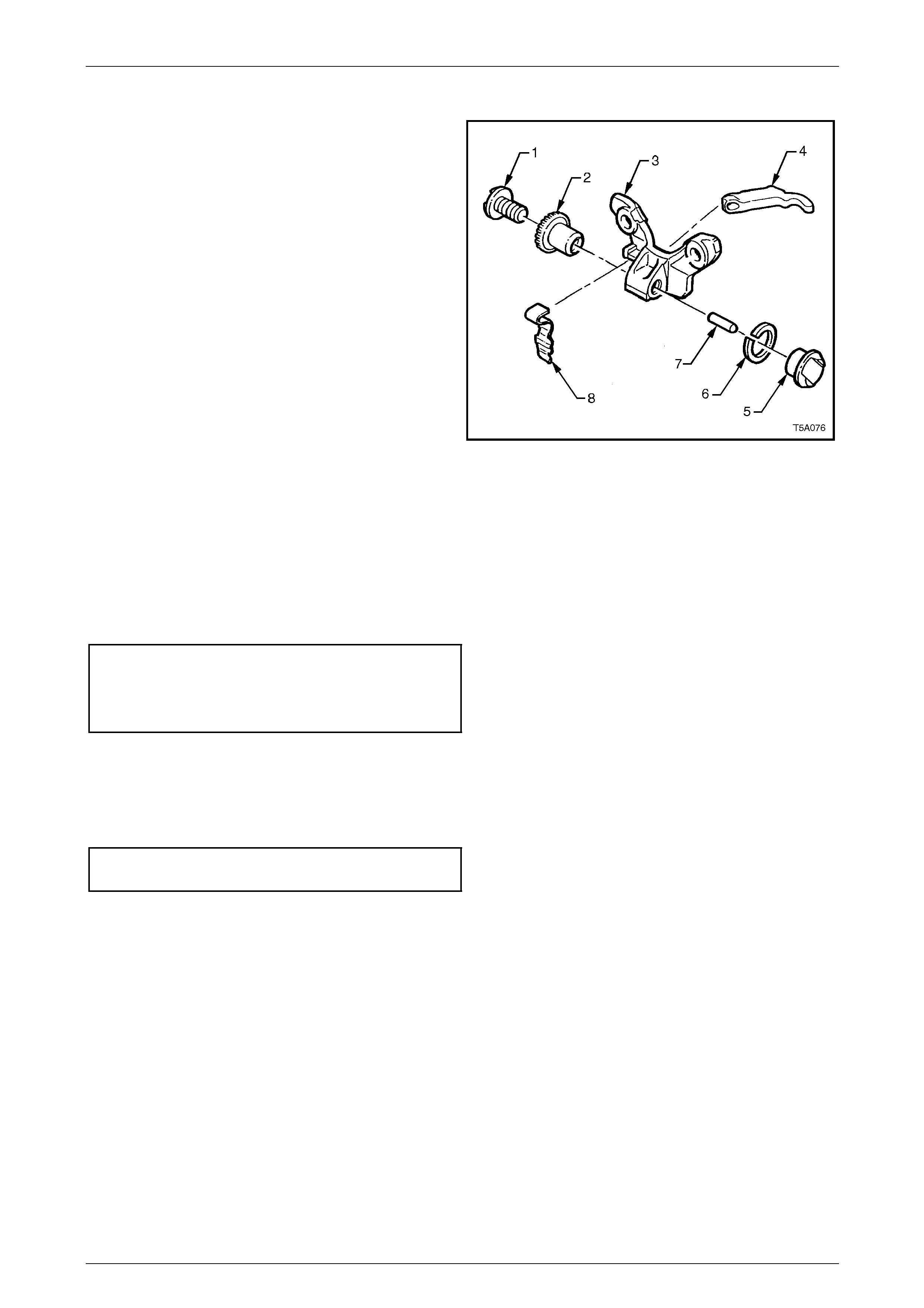
Service and Park Braking System 5A – 94
Reinstall
Reinstallation of the rear disc shield is the reverse to the
removal procedures, except for the following points:
1 As the removed actuator assembly can easily be
disassembled, the view shown, details the
relationships of each, in an exploded view.
2 While supporting the rear disc brake shield, install the
actuator assembly to the extruded bolt hole sections,
after ensuring that the actuator mechanism is correctly
assembled.
Legend
1 Adjusting Screw
2 Adjusting Ratchet Wheel
3 Actuator Body
4 Parking Brake Actuator Lever
5 Brake Shoe Anchor
6 Washer
7 Pin
8 Ratchet Wheel Spring Figure 5A – 116
3 Reinstall trunnion to the trailing arm, using a new wheel bea ring. For the required procedures refer to Section 4B1
Rear Final Drive and Drive Sh afts, for the necessary procedure.
4 Reinstall the two upper rear d isc brake shield to trailing arm attaching Torx bit headed bolts. Do not tighten at this
stage.
5 Install two NEW lower rear disc brake shield to trailing arm bolts.
6 Tighten the four rear disc brake shie ld to trailing arm attaching bolts to the correct torque specifications.
Upper rear disc brake shield to
trailing arm bolt torque specification.....................75 N.m
() Lower rear disc brake shield to
trailing arm bolt torque specification.....................85 N.m
7 Reinstall the park brake shoe. Refer to 3.10 Park Brake Shoe, in this Section.
8 Reinstall the rear disc, aligning the marks made before removal and adjust the park brak e shoe, refer to
3.9 Park Brake Shoe, Adjust, in this Section for the procedure.
9 Install and tighten brake caliper anchor plate to trailing arm attaching bolts to the correct torque specification.
Brake caliper anchor plate to
trailing arm bolt torque specification.....................85 N.m
5A – 94
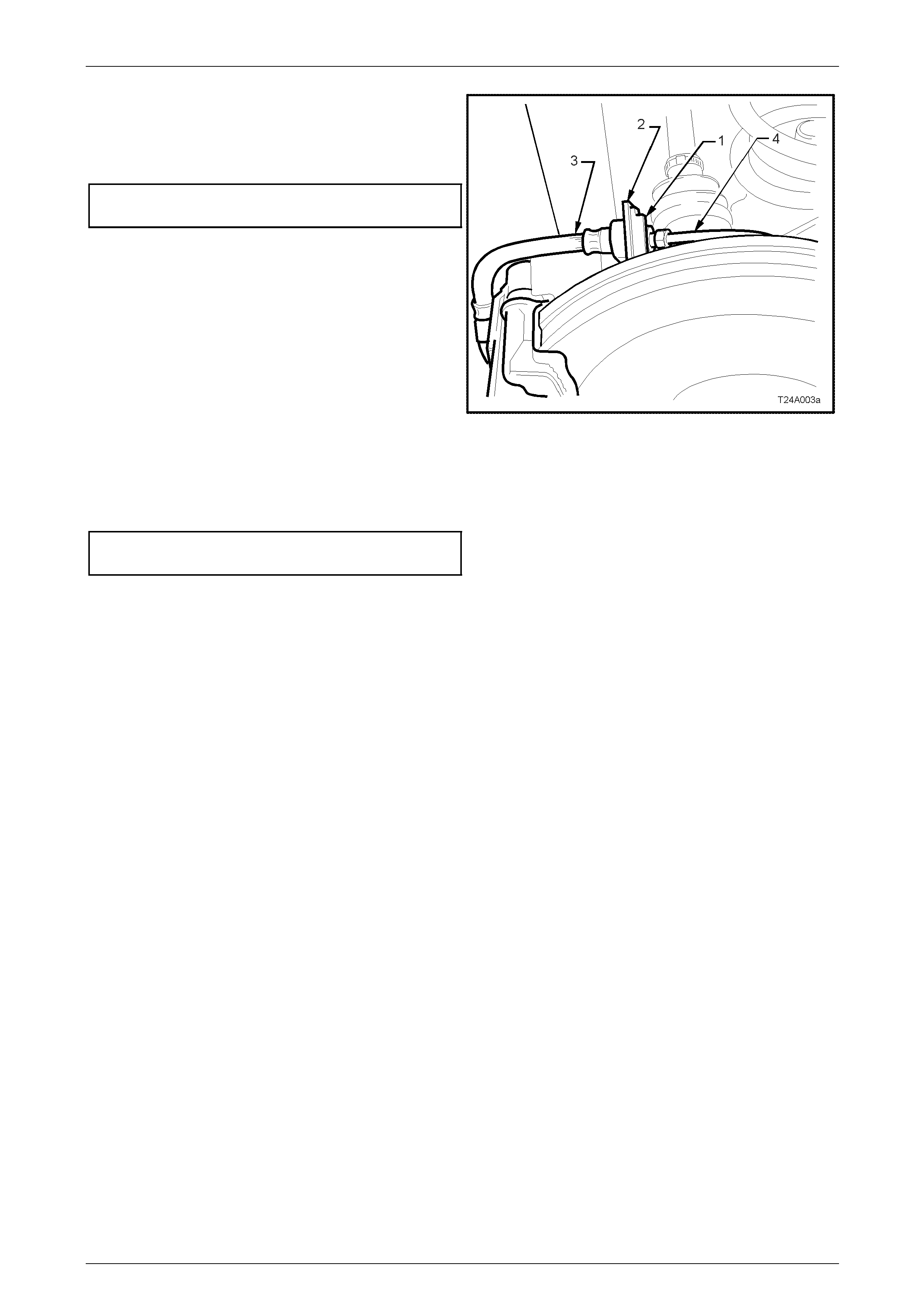
Service and Park Braking System 5A – 95
10 Reinstall the caliper hose (3) to the backing plate
bracket (2) and secure with the retaining clip (1).
11 Reinstall the brake pipe (4) to the caliper hose (3) and
tighten to the correct torque specifications.
Brake pipe flare nut to caliper
brake hose torque specification ...........................15 N.m
Figure 5A – 117
12 Reinstall road wheel in the original position and secure with the wheel nuts but do not fully tighten.
13 Lower the vehicle to the ground an d tighten the wheel nuts to the specified torque, working in a ‘star’ pattern, refer
to 2.1 Service Warnings, Cautions and Notes, in this Section.
Road wheel attaching nut
torque specification..................................110 – 140 N.m
14 Reinstall the wheel cover or decorative wheel nut caps.
15 Check for brake fluid leaks, repair as necessary.
16 Road test vehicle to ensure correct brake operatio n.
5A – 95
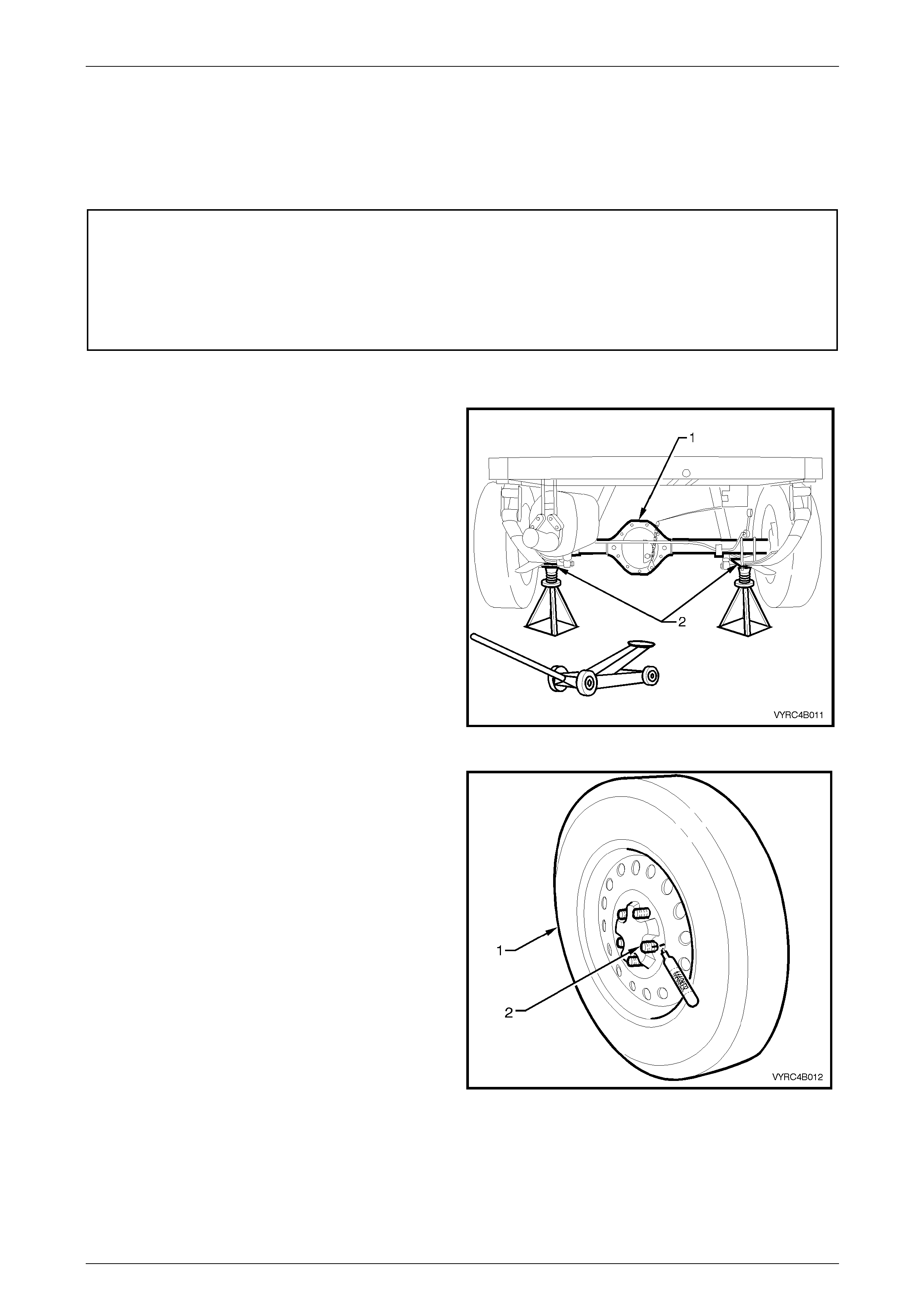
Service and Park Braking System 5A – 96
3.13 Rear Disc Brake Backing Plate & Dust
Shield – Live Axle Models
LT Section No. – 04-825
ATTENTION
The following fasteners either have micro encapsulated sealant applied or incorporate a mechanical thread
lock and should only be re-used once. If in doubt, replacement is recommended.
Rear axle retaining thrust plate retaining bolts
Rear brake caliper anch or plate attaching bolts.
Remove
1 Raise the vehicle and suppor t in a safe manner. Refer
to 0A General Information for the location of
recommended lifting and support points.
Figure 5A – 118
2 Remove the wheel covers or decorative wheel nut
caps.
3 Using a felt tipped marking pen or similar, mark the
relationship of the road wheel (1) to one of the wheel
studs (2).
4 Loosen, then remove the road wheel attaching nuts,
working in a ‘star’ pattern. Refer 2.1 Service Warnings,
Cautions and Notes in this Section, for deta iled
information. Remove the road wheel.
Figure 5A – 119
5A – 96
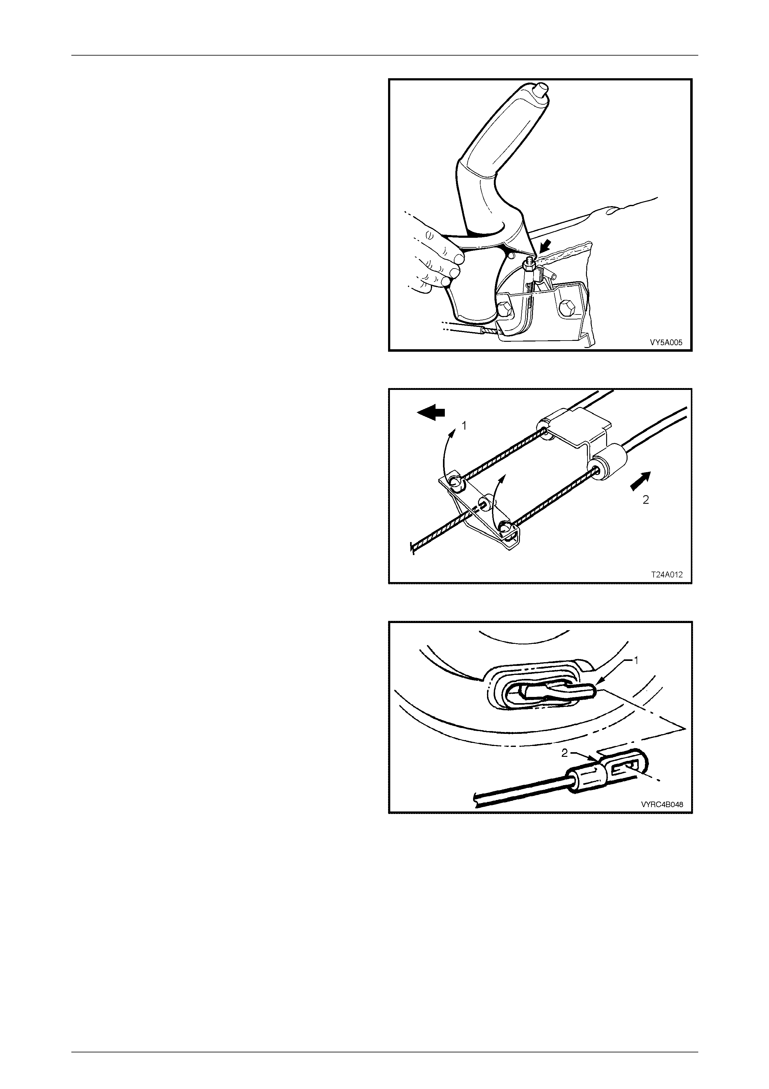
Service and Park Braking System 5A – 97
5 Release the park brake.
6 Using a deep socket, loosen the front cabl e-adjusting
nut (arrow) until the nut is almost removed.
Figure 5A – 120
7 Remove the front of the rear inner cable/s, by first
wrapping a rag around the inner cable to protect it
from damage, then use pliers to pull the ball nipple
forward and up (1), to free it from the equaliser
bracket.
Figure 5A – 121
8 Disconnect the rear clevis (2) from the rear park brake,
actuating lever (1) by gripping with pliers an d pivoting
the cable rearwards.
9 Pull the outer cable forward; out of the support retainer
and tie back the cable so it is clear of the work area.
Figure 5A – 122
5A – 97
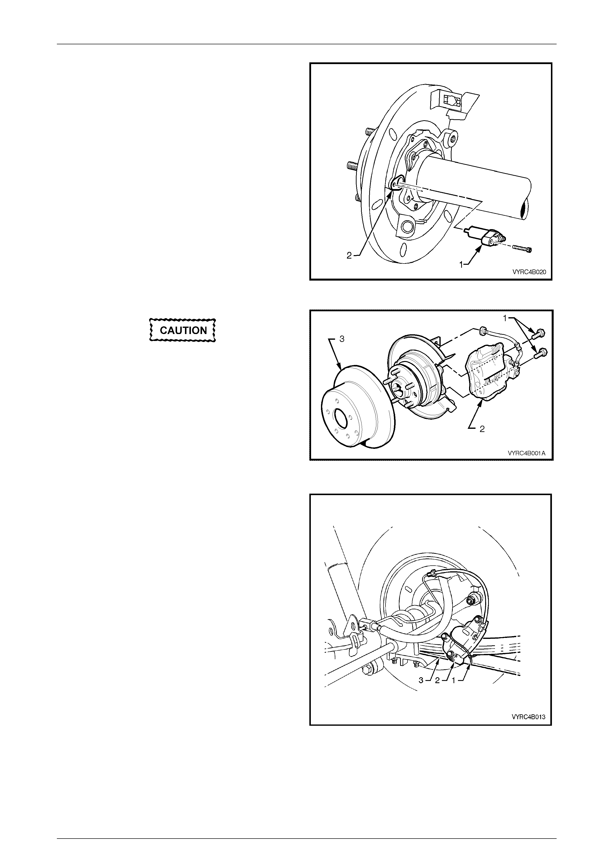
Service and Park Braking System 5A – 98
10 Remove the ABS sensor retaining screw.
11 Remove the ABS sensor (1) from the rear brake
backing plate (2) and tie the sensor away from the
plate to prevent accidental damage.
Figure 5A – 123
Do not allow caliper to hang by brake hose,
as damage to the hose will occur.
12 Remove the rear brake caliper to rear axle anchor
plate attaching bolts (1), then remove the brake caliper
(2) from the disc rotor (3) as shown.
Figure 5A – 124
13 Using tie wire (1), secure the caliper (2) to the top of
the rear leaf spring assembly (3) as shown.
Figure 5A – 125
5A – 98
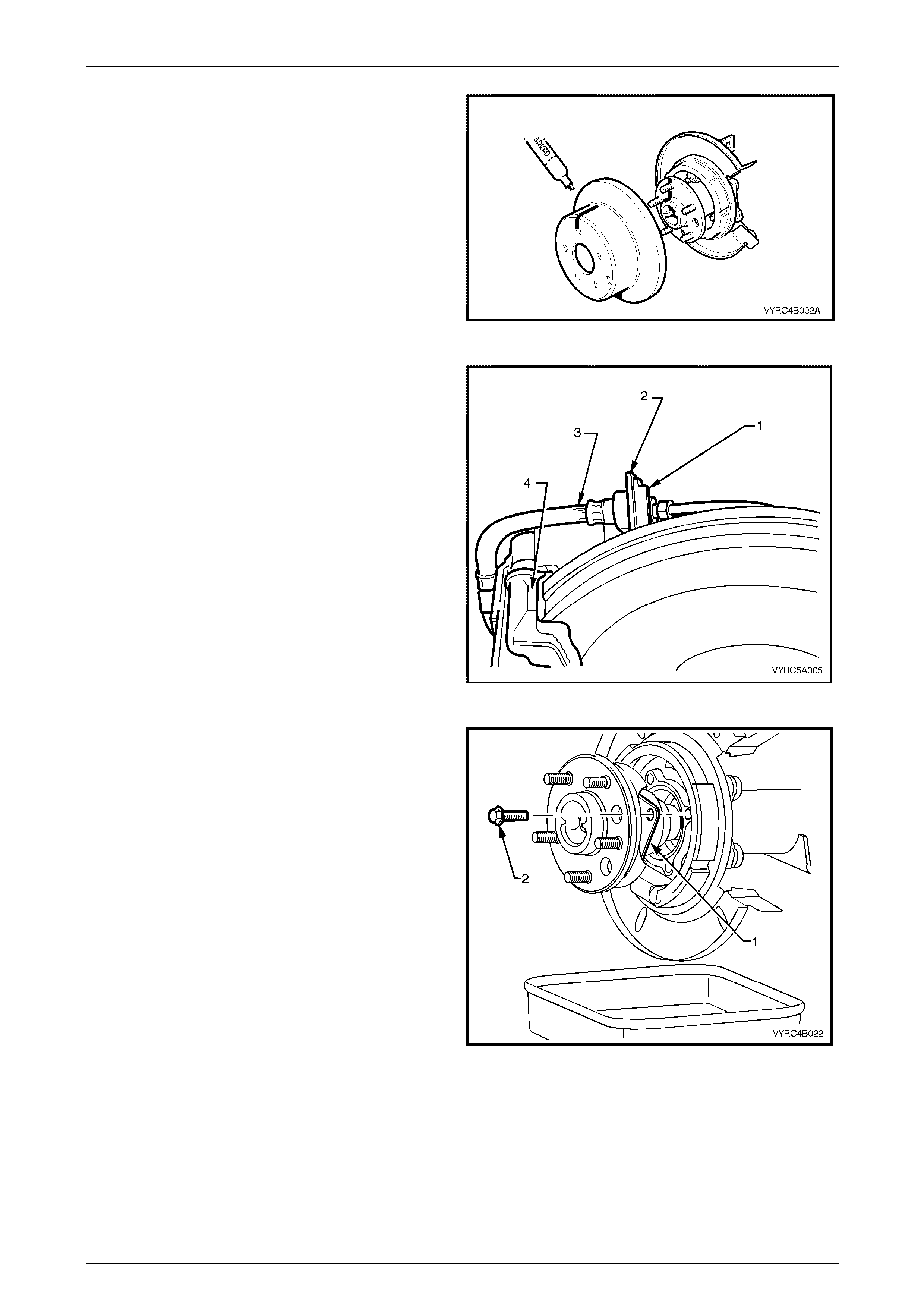
Service and Park Braking System 5A – 99
14 With a felt tipped or suitable marking pen, mark the
relationship of the brake disc rotor positi on to the rear
axle shaft assembly, then remove the brake disc rotor
from the rear axle shaft assembly as shown.
15 Remove the rear axle shaft assembly,
Figure 5A – 126
16 Thoroughly clean around the brake hose to pipe
connection at the backing plat e. Disconnect the brake
pipe from the brake hose (3) at the backing plate
bracket (2) and remove the brake hose retaining clip
(1).
Figure 5A – 127
17 Remove the rear axle assembly and retain er plate (1)
attaching bolts (2). Refer to Section 4B2 Rear Final
Drive and Live Axle in this Service Information, for the
procedure.
Figure 5A – 128
5A – 99
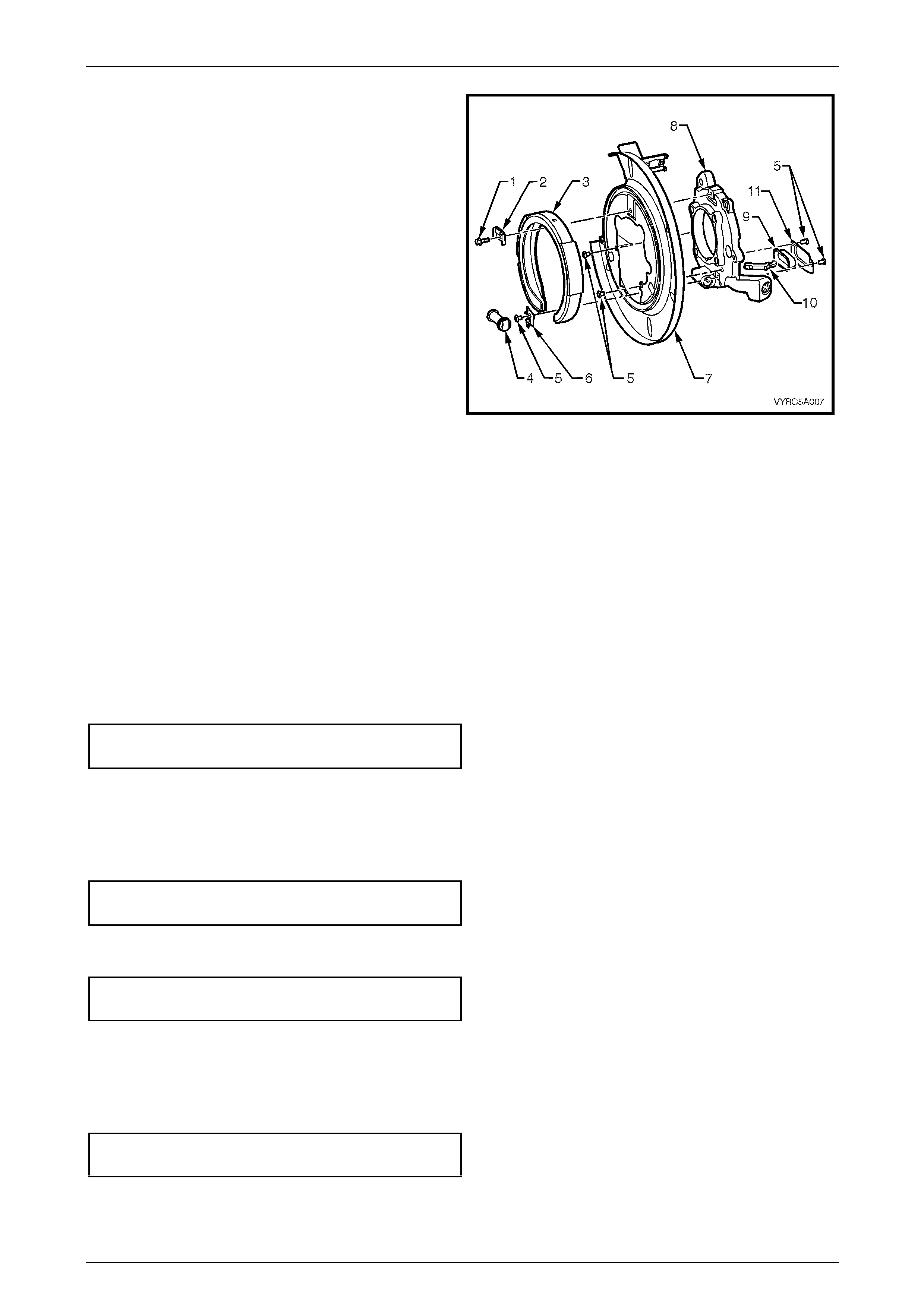
Service and Park Braking System 5A – 100
18 Wind the park brake shoe adjuster wheel (4) back into
the park brake actuator (part of the brake backing
plate ‘8’) to release tension from the brake shoe.
19 Remove the park brake shoe guide (2) a nd attaching
bolt (1).
20 Remove the park brake shoe (3) from the dust shield
(7) and backing plate assembly (8).
21 Remove the park brake actuator and backing plate
assembly (8) and the dust shield (7).
22 If replacing the dust shield (7), it will be necessary to
carefully support the backing plate assembly (8) and
drill out the dust shield (7) attaching rivets (5), in four
places.
23 Disassemble the park brake actuator asse mbly, for
cleaning and inspection.
Figure 5A – 129
Inspect
1 Clean all components with a s uitab le cleaning solvent and dry.
2 Inspect all components for signs of wear or damage and rep lace p arts where necessary.
Reinstall
Reinstallation of the park brake and disc shield is the reverse to the removal proc edures, noting the following:
1 Reassemble the park brake actuator assembly.
2 If removed, reinstall the disc brake dust shield to the backing plate ass embly, using commercially available pop
rivets.
3 Reinstall the backing plat e assembly, park brake actuator and the dust shield assembly to the rear axle housing.
4 Reinstall the rear axle shaft assembly and se cure with the retaining thrust plate attaching bolts. Refer to
Section 4B2 Rear Fina l Drive and Live Axle in this Service Information, for the procedur e.
5 Tighten the rear axle shaft retaining thrust plate attaching bolts to the correct torque specification.
() Rear axle retaining thrust
plate bolt torque specification...............................45 N.m
6 Reinstall the park brake shoe. Refer to 3.10 Park Brake Shoe, in this Section.
7 Reinstall the rear disc, aligning the marks made before removal.
8 Adjust the park brake shoe. Refer to 3.9 Park Brake Shoe, Adjust, in this Section.
9 Reinstall the rear brake caliper anchor plate to rear axle anchor plate attachin g bolts and tighten to the correct
torque specification.
() Rear brake caliper anchor plate
attaching bolt torque specification........................ 85 N.m
10 Reinstall the rear brake caliper hose fitting to the dust shield bracket and secure with the retaining clip.
11 Reinstall the rear brake pipe to the brake hose fitting and tighten to the correct torque specification.
Brake pipe to caliper hose
flare nut torque specification................................15 N.m
12 Bleed the brakes. Refer to 2.4 Brake System Bleed, in this Section.
13 Adjust the park brake cable. Refer to 2.2 Park Brake Cable, Adjust, in this Section.
14 Reinstall road wheel in the original position and secure with the wheel nuts but do not fully tighten.
15 Lower the vehicle to the ground an d tighten the wheel nuts to the specified torque, working in a ‘star’ pattern, refer
to 2.1 Service Warnings, Cautions and Notes, in this Section.
Road wheel attaching nut
torque specification..................................110 – 140 N.m
16 Reinstall the wheel covers or decorative wheel nut caps.
17 Road test the vehicle to ensure correct brake operation.
5A – 100

Service and Park Braking System 5A – 101
4 Diagnosis
Symptom Cause
X – Indicates Probable Cause
XX – Indicates a More Possible Cause
E
xcessive Brake Pedal Travel
B
rake Pedal Travel Gradually Increases
E
xcessive Brake Pedal Effort
E
xcessive Braking Action
B
rakes Slow to Respond
B
rakes Slow to Release
B
rakes Drag
U
neven Braking Action (Side to Side)
U
neven Braking Action (Front to Rear)
S
craping Noise from Brakes
B
rakes Squeak During Applica tion
B
rakes Squeal During a Stop
B
rakes Chatte
r
B
rakes Groan at End of Stop
B
rake Tell-tale Lamp Glows During a Stop
Leaking Brake Line or Connection X X X
Leaking Caliper or Piston Line X X X X X
Leaking Master Cylinder X XX X
Air in Brake System XX X X
Contaminated or Improper Brake F luid X X X X
Leaking Vacuum System XX X
Restricted Air Passage in Vacuum Booster X XX X
Damaged Vacuum Booster X X X X XX
Improperly Assembled Vacuum Booster Valving X X X X XX
Worn Out Disc Pads – Replace X X X X X X X X
Uneven Disc Pad Wear – Replace or Correct X X X X X XX X
Contaminated Disc Pad – Replace XX XX XX X X X X
Heat Spotted or Scored Brake Discs X X X X X XX X
Out-of-Parallel Brake Discs XX
Excessive Brake Disc Run-Out X
Brake Assembly Attachments – Missing or Loose X X X X X X X X
Restricted Brake Fluid Passage or Sticking Caliper
Piston X X X X X X X
Brake Pedal/Linkage Bindin g or Interference X X X XX
Improperly Adjusted Parking Brake X
Incorrect Front Wheel Alignment X XX
Incorrect Tyre Pressures X X
Wheel Bearing Clearance Excessive X X
Loose Front Suspension and/or Components X XX X X
Out-of-Balance Wheel Assemblies XX
Operator Riding Brake Pedal X X X X X X
Table 1
5A – 101

Service and Park Braking System 5A – 102
5 Specifications
Brake Fluid
Type.....................................................................................................................Super DOT 4
Brake Booster
Make..........................................................................................................Mando Corporation
Type...........................................................................................Tandem, Vacuum Suspended
Size – All VZ Models .................................................................................20.3 and 22.9 cm
Master Cylinder
Make..........................................................................................................Mando Corporation
Type.............................................................................................................................Tandem
Bore diameter (nominal)................................................................................................26 mm
Front Disc
Type..........................................................................................................................Ventilated
Diameter (nominal) – All Except Coupe and MY2006 SS .........................296 + 0.0 – 0.2 mm
– AWD Models..........................................................302 + 0.00 – 0.2 mm
– Coupe and MY2006 SS Models Only..............................320 ± 0.2 mm
Thickness – All Except Coupe and MY2006 SS ...............................28.0 ± 0.15 mm
– Coupe and MY2006 SS Models Only...........................32.0 ± 0.15 mm
Lateral Runout (maximum)..........................................0.04 mm Total Indicated Run-out (TIR)
Minimum thickness, requiring replacement – All Except Coupe and MY2006 SS ...25.0 mm
– Coupe and MY2006 SS Mode ls Only30.0 mm
Front Caliper
Make................................................................................................................................. PBR
Type................................................................................................Twin piston, sliding caliper
Bore diameter (nominal) – All Except Coupe and MY2006 SS ..................................42.0 mm
– Coupe and MY2006 SS Models Only..............................40.5 mm
Front Disc Pad
Material ........................................................................................Organic, non-asbestos
Minimum Thickness before Replacement ...............................................................2 mm
Rear Disc
Type – All Except Coupe and MY2006 SS ................................................Solid
– Coupe and MY2006 SS Models Only........................................ Vented
Diameter (nominal).............................................................................................286 ± 0.2 mm
Thickness – All Except Coupe and MY2006 SS ..................15.9 mm ± 0.2 mm
– Coupe and MY2006 SS Models Only............18.0 mm ± 0.15 mm
Lateral Runout (maximum).......................(Rate of change 0.03 mm in 30° rotation) 0.05 mm
Minimum thickness, requiring replacement – All Except Coupe and MY2006 SS ...13.9 mm
– Coupe and MY2006 SS Mode ls Only16.0 mm
5A – 102

Service and Park Braking System 5A – 103
Rear Caliper
Make................................................................................................................................. PBR
Type..............................................................................................Single piston, sliding caliper
Bore diameter (nominal) (All except Utility)..............................................................45.0 mm
(Utility Only.......................................................................40.5 mm
Rear Disc Pad
Material ........................................................................................Organic, non-asbestos
Minimum Thickness before Replacement ...............................................................2 mm
Drum Park Brake
Make................................................................................................................................. PBR
Type................................................................Banksia, single shoe, cable and lever operated
Drum
Inside Diameter (nominal)...................................................................................190 mm
Maximum out of square (TIR with disc surface).................................................0.05 mm
Maximum out of round........................................................................................0.08 mm
Linings
Type.................................................................................................................... Bonded
Width.....................................................................................................................25 mm
Thickness.............................................................................................................3.5 mm
Minimum Thickness before Replacement ............................................................1.5 mm
5A – 103

Service and Park Braking System 5A – 104
6 Torque Wrench Specifications
ATTENTION
Fasteners must be repl aced after loosening.
z Vehicle must be at curb height before final tightening.
Fasteners either have micro encapsulated sealant applied or incorporate a mechanical thread lock and
should only be re-used once. If in doubt, replacement is recommended.
Accelerator pedal sensor bracket attaching nut................................25 N.m
Brake Bleeder Nipple (All Models)....................................................12 N.m
Brake booster retaining nut...............................................................25 N.m
Brake caliper guide pin bolt...............................................................32 N.m
Brake fluid reservoir attaching screw...............................................2.5 N.m
Brake hose to caliper banjo bolt
(Front – All except Coupe and MY2006 SS )35 N.m
(Front – Coupe and MY2006 SS )12 N.m then 90° turn angle
(Rear – All Models)..............................35 N.m
Brake pedal support to brake booster bolt........................................25 N.m
Brake pedal support shaft nut ..........................................................55 N.m
Brake pipe to brake hose flared nut (All positions)............................15 N.m
Brake pipe harness bracket to dash panel bolt.................................10 N.m
Brake pipe to master cylinder flare nut .............................................14 N.m
Front brake caliper anchor bolt
All except Coupe and MY2006 SS 85 N.m, plus 45° turn angle
Coupe and MY2006 SS 70 N.m, plus 9 0° turn angle
Front hub to steering knuckle bolt...................................................130 N.m
Front park brake cable plate retaining screw...................................2.0 N.m
LSPV link bracket to final drive cover bolt (Live axle models)...........28 N.m
Load sensing proportioning valve mounting bracket bolt (Utility)......58 N.m
Load sensing proportioning valve mounting nu t (Utility) ...................38 N.m
Lower brake pipe shield to floor bolt .................................................10 N.m
Lower brake pipe shield to floor nut....................................................2 N.m
Master cylinder attaching nut............................................................10 N.m
Master cylinder to bracket bolt..........................................................10 N.m
Master cylinder bracket to strut tower attaching nut............................8 N.m
Master cylinder reservoir retaining screw.........................................2.5 N.m
Outer front park brake cable bracket retaining bolt...........................25 N.m
Park brake lever bolt.........................................................................50 N.m
Park brake warning lamp switch retaining screw................................2 N.m
Rear brake caliper anchor plate bolt.................................................85 N.m
Rear disc brake shield to trailing arm...............Upper bolt................75 N.m
Lower bolt................85 N.m
Rear axle retaining thrust plate bolt (Live axle models) ....................45 N.m
Road wheel attaching nut .....................................................110 – 140 N.m
Steering knuckle to strut attaching nuts Stage 1.............................85 N.m
Stage 2...........................100 N.m
Stage 3..............Turn through 90°
5A – 104
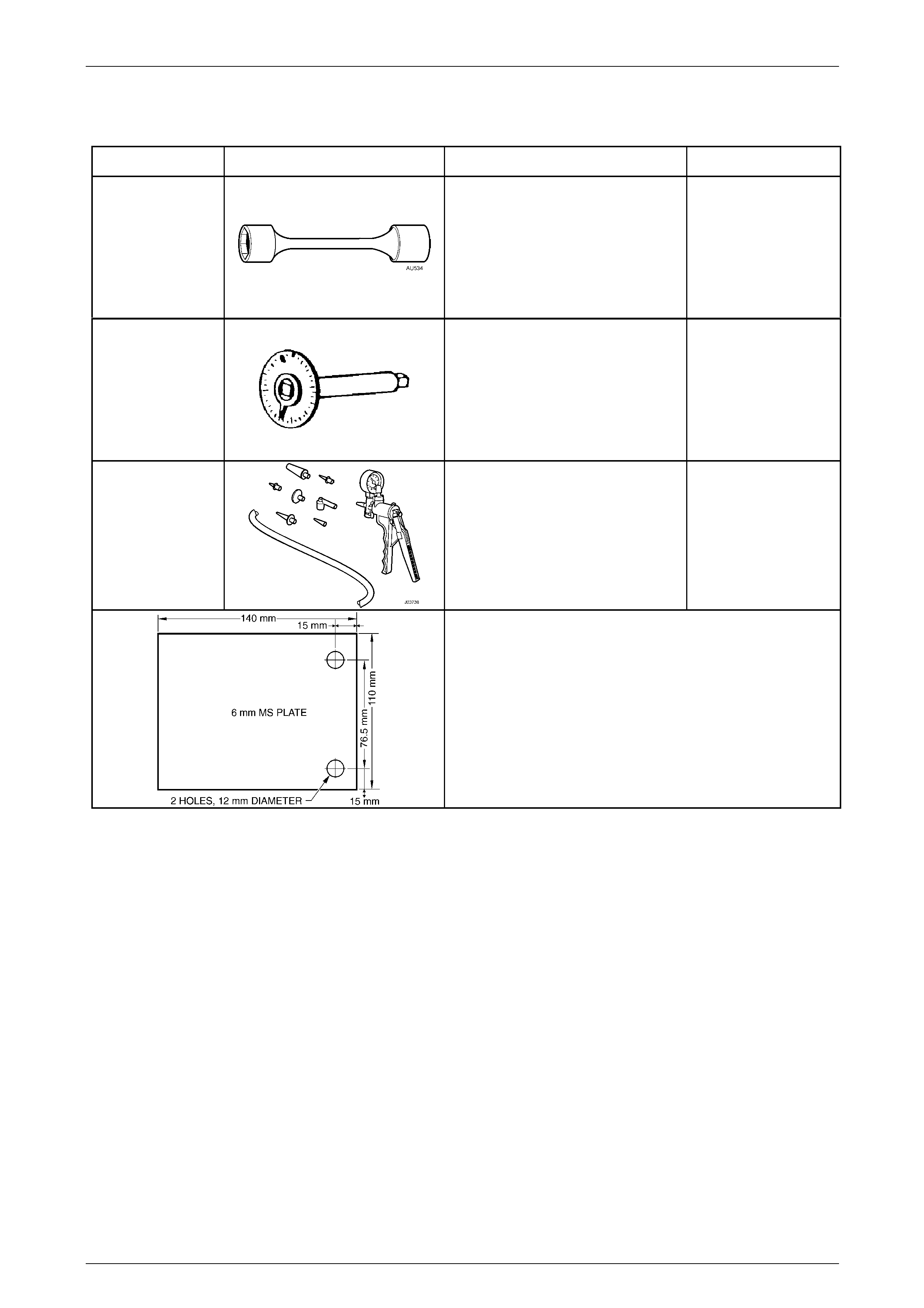
Service and Park Braking System 5A – 105
7 Special Tools
Tool Number Illustration Description Tool Classification
AU 534
Torque Limiting Socket
Used in conjunction with an impact
gun to tighten wheel nuts.
Previously released.
Essential
E 7115
Angle Wrench
1. Previously released as Tool N o.
394.
2. Used to apply an angle torque to
fasteners when required.
Previously released.
Available
J23738-A
Hand Vacuum Pump
Used to apply a vacuum for
diagnostics and emptying the master
cylinder reservoir. Also commerciall y
available.
Previously released.
Mandatory
Dial Indicator Plate
Retailer fabricated from 6 mm Mild Steel Plate.
NOTE
If using the caliper bolts to attach the plate to the
trunnion, a 17 mm spacer will need to be installed
on each bolt, prior to installing .
5A – 105