
Engine Management – V6 – Service Operations Page 6C1-3–1
Section 6C1-3
Engine Management V6 – Service Operations
ATTENTION
Before performing any service operation or other procedure described in this Section, refer to Section 00
Warnings, Cautions and Notes for correct workshop practices with regard to safety and / or property damage.
1 General Information ...............................................................................................................................4
1.1 General Description............................................................................................................................................... 4
1.2 Service Precautions and Notes ............................................................................................................................ 5
1.3 Service Requirements and Precautions .............................................................................................................. 7
Basic Knowledge Required................................................................................................................................... 7
Basic Diagnostic Tools Required......................................................................................................................... 7
2 General Service Operations ..................................................................................................................8
2.1 Service Operations Not Covered In This Section................................................................................................ 8
Fuel System............................................................................................................................................................ 8
Engine Dress Covers............................................................................................................................................. 8
2.2 Fuel Injector Coil Test ........................................................................................................................................... 9
Fuel Injector Coil Quick Test................................................................................................................................. 9
Test Description ................................................................................................................................................. 9
Fuel Injector Harness to Engine Harness Connector ....................................................................................... 10
Injector Coil Test – With Special Tool J39021 ................................................................................................... 10
Engine Coolant Temperature 10 – 32°C .......................................................................................................... 11
Engine Coolant Temperature Outside 10 – 32°C ............................................................................................. 12
2.3 Fuel Injector Balance Test .................................................................................................................................. 14
Fuel Injector Balance Test – With Tech 2 .......................................................................................................... 14
Fuel Injector Balance Test – Without Tech 2..................................................................................................... 14
Fuel Injector Pressure Drop Calculation........................................................................................................... 16
Fuel Injector Pressure Drop Analysis ............................................................................................................... 16
2.4 Fuel Injector Leak Down Test ............................................................................................................................. 17
2.5 Quick Connect Fittings........................................................................................................................................ 19
Evaporative Emission (EVAP) Canister Purge Valve Hose Fitting .................................................................. 19
Disconnect ....................................................................................................................................................... 19
Connect............................................................................................................................................................ 20
2.6 Throttle Body Relearn ......................................................................................................................................... 21
Engine Control Module Throttle Body Relearn ................................................................................................. 21
Tech 2 Throttle Body Relearn ............................................................................................................................. 21
3 Component Replacement ....................................................................................................................22
3.1 Components Not Covered In This Section ........................................................................................................ 22
Air-conditioning System ..................................................................................................................................... 22
Electrical Components ........................................................................................................................................ 22
Fuel System.......................................................................................................................................................... 22
Transmission – Automatic .................................................................................................................................. 22
Transmission – Manual ....................................................................................................................................... 22
3.2 Accelerator Pedal Position Sensor .................................................................................................................... 23
Remove................................................................................................................................................................. 23
Reinstall................................................................................................................................................................ 24
3.3 Accelerator Pedal Position Sensor Support Bracket........................................................................................ 25
Remove................................................................................................................................................................. 25
Reinstall................................................................................................................................................................ 25
3.4 Air Cleaner Assembly.......................................................................................................................................... 26
Air Cleaner Upper Housing ................................................................................................................................. 26
Remove............................................................................................................................................................ 26
Reinstall ........................................................................................................................................................... 26
Page 6C1-3–1
Techline
Techline

Engine Management – V6 – Service Operations Page 6C1-3–2
Air Cleaner Lower Housing Assembly ............................................................................................................... 27
Remove............................................................................................................................................................ 27
Reinstall ........................................................................................................................................................... 27
3.5 Barometric Pressure Sensor............................................................................................................................... 28
Remove................................................................................................................................................................. 28
Reinstall................................................................................................................................................................ 28
3.6 Camshaft Position Actuator Solenoid................................................................................................................ 29
Bank 1 (RHS) ........................................................................................................................................................ 29
Remove............................................................................................................................................................ 29
Reinstall ........................................................................................................................................................... 30
Bank 2 (LHS)......................................................................................................................................................... 31
Remove............................................................................................................................................................ 31
Reinstall ........................................................................................................................................................... 32
Test ....................................................................................................................................................................... 33
Resistance Inspection ...................................................................................................................................... 33
Functional Test................................................................................................................................................. 33
3.7 Camshaft Position Sensor .................................................................................................................................. 34
Bank 1 (RHS) ........................................................................................................................................................ 34
Remove............................................................................................................................................................ 34
Reinstall ........................................................................................................................................................... 35
Bank 2 (LHS)......................................................................................................................................................... 36
Remove............................................................................................................................................................ 36
Reinstall ........................................................................................................................................................... 37
3.8 Crankshaft Position Sensor................................................................................................................................ 38
Remove................................................................................................................................................................. 38
Test ....................................................................................................................................................................... 39
Resistance Check ............................................................................................................................................ 39
Reinstall................................................................................................................................................................ 39
3.9 Engine Coolant Temperature Sensor................................................................................................................. 40
Remove................................................................................................................................................................. 40
Test ....................................................................................................................................................................... 41
Resistance Check ............................................................................................................................................ 41
Reinstall................................................................................................................................................................ 42
3.10 Engine Control Module........................................................................................................................................ 43
Remove................................................................................................................................................................. 43
Reinstall................................................................................................................................................................ 44
ECM Reset ............................................................................................................................................................ 45
3.11 Engine Control Module Bracket Assembly........................................................................................................ 46
Remove................................................................................................................................................................. 46
Reinstall................................................................................................................................................................ 46
3.12 Engine Oil Level and Temperature Sensor........................................................................................................ 47
Remove................................................................................................................................................................. 47
Test ....................................................................................................................................................................... 48
Engine Oil Level Sensor Check........................................................................................................................ 48
Reinstall................................................................................................................................................................ 48
3.13 Engine Oil Pressure Sensor................................................................................................................................ 49
Remove................................................................................................................................................................. 49
Reinstall................................................................................................................................................................ 50
3.14 Evaporative Emission Canister Purge Valve..................................................................................................... 51
Remove................................................................................................................................................................. 51
Test ....................................................................................................................................................................... 52
Resistance Check ............................................................................................................................................ 52
Functional Test................................................................................................................................................. 52
Reinstall................................................................................................................................................................ 53
3.15 Fuel Rail Assembly .............................................................................................................................................. 54
Remove................................................................................................................................................................. 54
Disassemble......................................................................................................................................................... 55
Fuel Injector ..................................................................................................................................................... 55
Fuel Injector Wiring Harness Assembly............................................................................................................ 57
Reinstall................................................................................................................................................................ 59
Page 6C1-3–2

Engine Management – V6 – Service Operations Page 6C1-3–3
3.16 Heated Oxygen Sensor........................................................................................................................................ 60
Service Precautions............................................................................................................................................. 60
Six Wire Sensor................................................................................................................................................ 60
Four Wire Sensor ............................................................................................................................................. 62
Test ....................................................................................................................................................................... 63
Heater Resistance Check – Six Wire HO2S..................................................................................................... 63
Heater Resistance Check – Four Wire HO2S .................................................................................................. 64
3.17 Ignition Coil .......................................................................................................................................................... 65
Ignition Coils ........................................................................................................................................................ 65
Remove............................................................................................................................................................ 65
Disassemble..................................................................................................................................................... 66
Reassemble ..................................................................................................................................................... 66
Test .................................................................................................................................................................. 66
Reinstall ........................................................................................................................................................... 67
3.18 Intake Air Duct Assembly.................................................................................................................................... 68
Remove................................................................................................................................................................. 68
Reinstall................................................................................................................................................................ 69
3.19 Intake Air Temperature Sensor........................................................................................................................... 70
Test ....................................................................................................................................................................... 70
Resistance Check ............................................................................................................................................ 70
3.20 Intake Manifold Runner Control Solenoid Valve – Alloytec190 Engine .......................................................... 71
Remove................................................................................................................................................................. 71
Test ....................................................................................................................................................................... 71
Resistance Check ............................................................................................................................................ 71
Functional Test................................................................................................................................................. 72
Reinstall................................................................................................................................................................ 73
3.21 Knock Sensor, Bank 2 (LHS)............................................................................................................................... 74
Remove................................................................................................................................................................. 74
Reinstall................................................................................................................................................................ 75
3.22 Knock Sensor, Bank 1 (RHS) .............................................................................................................................. 76
Remove................................................................................................................................................................. 76
Reinstall................................................................................................................................................................ 77
3.23 Mass Air Flow Sensor.......................................................................................................................................... 78
Handling Precautions .......................................................................................................................................... 78
Remove................................................................................................................................................................. 78
Reinstall................................................................................................................................................................ 79
3.24 Schrader Valve – Fuel Pressure Gauge Connection Point............................................................................... 80
Remove................................................................................................................................................................. 80
Reinstall................................................................................................................................................................ 80
3.25 Spark Plugs .......................................................................................................................................................... 81
Service Precautions............................................................................................................................................. 81
Remove................................................................................................................................................................. 81
Inspect .................................................................................................................................................................. 82
Spark Plug Inspection ......................................................................................................................................... 82
Poor Spark Plug Performance.......................................................................................................................... 82
Analysis of Spark Plug Condition ..................................................................................................................... 84
Reinstall................................................................................................................................................................ 86
3.26 Throttle Body Assembly...................................................................................................................................... 87
Handling Precautions .......................................................................................................................................... 87
Remove................................................................................................................................................................. 87
Inspect .................................................................................................................................................................. 89
Reinstall................................................................................................................................................................ 90
4 Specifications .......................................................................................................................................91
5 Assembly Lubricants ...........................................................................................................................94
6 Torque Specifications..........................................................................................................................95
7 Special Tools ........................................................................................................................................96
Page 6C1-3–3
Engine Management – V6 – Service Operations Page 6C1-3–4
1 General Information
1.1 General Description
This Section describes the correct service procedures to repair and test components of the V6 engine management
system. Emphasis is placed on the proper procedures and repair of components related to this specific system.
For component description, operation and location, refer to Section 6C1-1 Engine Management – V6 – General
Information.
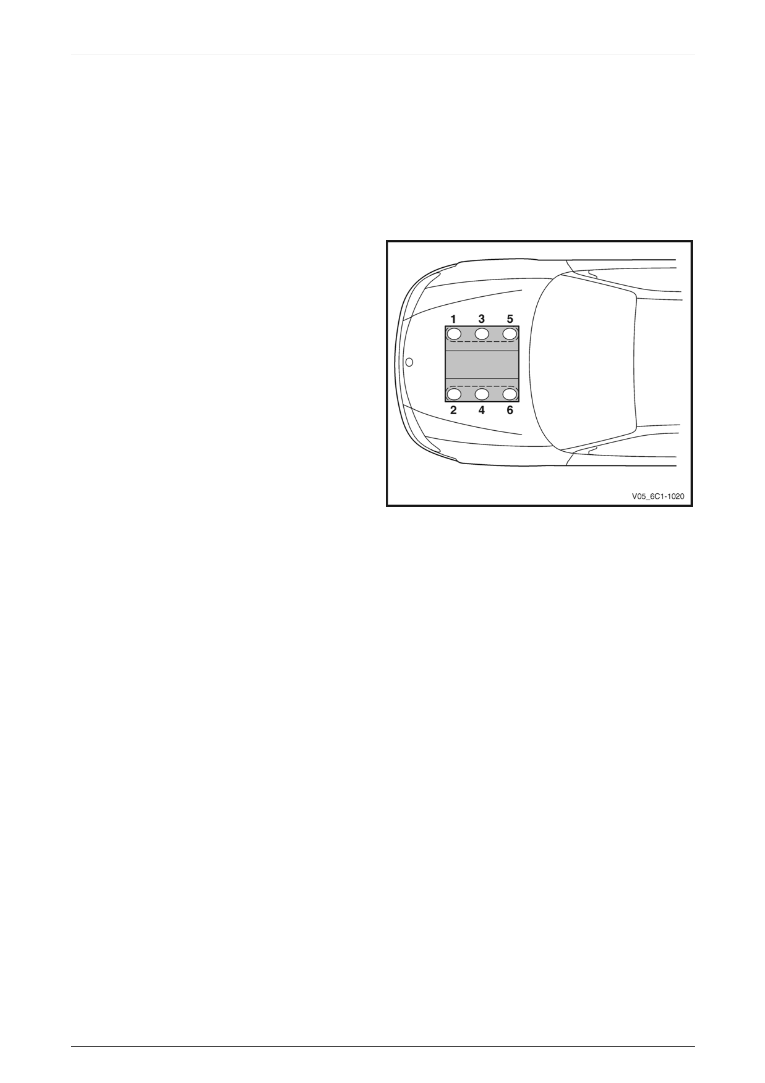
Engine cylinder identification follows the international
standard OBD II. This standard calls for the engine cylinder
bank number one to be identified by the location of cylinder
number one. Therefore the numbering for the V6 engine is:
• 1, 3, 5 – Right-hand side (Bank 1).
• 2, 4, 6 – Left-hand side (Bank 2).
The engine firing order is 1, 2, 3, 4, 5, 6.
Figure 6C1-3 – 1
Page 6C1-3–4

Engine Management – V6 – Service Operations Page 6C1-3–5
1.2 Service Precautions and Notes
The following safety and precautionary
directions must be followed when servicing
the engine management system otherwise
personal injury and / or improper system
operation may occur:
• If working on a vehicle which has been subjected to an under bonnet thermal incident (fire), wear appropriate
protective clothing to prevent personal injury. Components that contain fluoro-elastomer may produce a corrosive
bi-product when subjected to extreme heat.
• Disconnection of the battery affects certain vehicle electronic systems. Refer to the battery disconnection
procedure in Section 00 Warnings, Cautions and Notes before disconnecting the battery.
• Disconnect the battery negative lead when performing the following procedures:
• disconnecting the engine control module (ECM) connectors, or
• charging the battery.
• Disconnect the battery negative lead and the ECM connectors before attempting any electric welding on the
vehicle.
• Do not start the engine if the battery terminal is not properly secured to the battery.
• Do not disconnect or reconnect the following while the ignition is switched on or when the engine is running:
• any engine management system component wiring connector, or
• battery terminal leads.
• Ensure the correct procedure for disconnecting and connecting engine management system wiring connectors is
always followed.
• Ensure that all wiring connectors are fitted correctly.
• The engine management system wiring connectors are designed to fit only one way; there are indexing tabs and
slots on both halves of the connector. Forcing the connector into place is not necessary if it is being installed with
the correct orientation. Failure to take care to match the indexing tabs and slots correctly can cause damage to the
connector, the module, or other vehicle components or systems.
• Never touch the connector pins of any electronic component, such as an ECM, as electrostatic discharge (ESD)
damage may result. For further information, refer to Section 00 Warnings, Cautions and Notes.
• When steam or pressure cleaning engines, do not direct the cleaning nozzle at engine management system
components.
• Never subject the ECM to temperatures less than -40° C and greater than 125° C.
• Prior to disconnection or removal of any components associated with the fuel system, clean the area around any
connection points to avoid possible contamination of the fuel system.
• A depressurised fuel system contains fuel in the fuel system and fuel lines that can be spilled during service
operations. To reduce the chance of personal injury, cover the fittings with a shop towel to absorb any fuel spillage
prior to performing the service operation. Once the service operation has been completed, place the towel in an
approved container for disposal.
• To avoid accidental fuel discharge, it is advisable to disconnect the battery and remove the fuel pump relay if the
fuel line between the fuel pump and the fuel rail is to be disconnected / open for an indefinite period.
• Always tighten fasteners to the correct tightening torque, and where indicated in the service procedure, follow the
correct tightening sequence, precautions and recommendations to prevent premature failure of the fastener or
component. Refer to Section 00 Warnings, Cautions and Notes for further information on fasteners.
• After removing components, such as the upper or lower intake manifold, front engine pipe, heated oxygen sensor,
etc. always plug any openings to prevent dirt and other contaminants from entering.
• Do not use silicone based assembly lubricants as damage to the heated oxygen sensors may result.
Page 6C1-3–5

Engine Management – V6 – Service Operations Page 6C1-3–6
Use of incorrect electrical test equipment
when performing engine management service
procedures could result in incorrect results or
component damage.
• Use only the test equipment specified in the diagnostic tables. Use of other test equipment may either give
incorrect results or damage serviceable components, refer to, Section 6C1-2 Engine Management – V6 –
Diagnostics.
• After completing the required service operations, road test the vehicle to ensure correct engine management
system operation.
Page 6C1-3–6

Engine Management – V6 – Service Operations Page 6C1-3–7
1.3 Service Requirements and Precautions
Basic Knowledge Required
A lack of basic understanding of electronics,
electrical wiring circuits and use of electrical
circuit testing tools when performing certain
service procedures could result in incorrect
results or damage to components.
In addition, a general understanding of the engine management system and its component operation is essential to
prevent misdiagnosis and component damage.
Basic Diagnostic Tools Required
Use of incorrect electrical circuit diagnostic
tools when performing certain service
procedures could result in incorrect
diagnostic results or damage to components.
The following electrical circuit testing tools are required to perform the diagnostic procedures detailed in this Section:
• Tech 2, refer to Section 0C Tech 2 for further information.
• Test lamp, refer to Section 12P Wiring Diagrams for further information.
• Digital multimeter with 10 MΩ ohms impedance, refer to Section 12P Wiring Diagrams for further information.
• Connector test adapter kit Tool No. J35616-A.
Page 6C1-3–7

Engine Management – V6 – Service Operations Page 6C1-3–8
2 General Service Operations
2.1 Service Operations Not Covered In This
Section
Fuel System
For the following fuel system service procedures, refer to Section 8A1 Fuel System:
• fuel system cleaning,
• fuel system leak and pressure test,
• fuel feed hose to fuel rail replacement, and
• fuel line quick connect fittings.
Engine Dress Covers
For service procedures of the engine dress covers, refer to Section 6A1 Engine Mechanical – V6.
Page 6C1-3–8

Engine Management – V6 – Service Operations Page 6C1-3–9
2.2 Fuel Injector Coil Test
NOTE
The fuel injector coil test is divided into two parts.
Begin by performing the fuel injector coil quick
test. Then only perform the Injector Coil Test –
With Special Tool J39021 procedure if, after
performing the quick test, it is determined there is
a faulty fuel injector.
Fuel Injector Coil Quick Test
Test Description
The following numbers refer to the step numbers in the diagnostic table:
1 This step checks if the engine coolant temperature is within the correct range.
2 This step tests each fuel injector resistance within a specific temperature range.
3 This step determines if all of the fuel injectors are within 3 ohms of each other.
Step Action Value(s) Yes No
1 Using Tech 2, observe the engine coolant temperature
(ECT). Refer to 0C Tech 2.
Is the ECT within the specified range? 10 – 32°C Go to Step 2 Go to Step 3
2 1 Disconnect the fuel injector harness connector,
refer to 3.15 Fuel Rail Assembly.
2 Using a digital ohmmeter and connector test
adaptor kit J 35616-A, measure the resistance of
each fuel injector between the ignition voltage
circuit and the fuel injector control circuit. Refer to
12P Wiring Diagrams for information on testing for
continuity and to Figure 6C1-3 – 2 and Figure
6C1-3 – 3 for the fuel injector harness connector.
Do any of the fuel injectors display a resistance outside
the specified range? 11 – 14 Ω
Refer to Injector Coil
Test – With Special
Tool J39021 in this
Section Injectors OK
3 1 Disconnect the fuel injector harness connector,
refer to 3.15 Fuel Rail Assembly.
2 Using a digital ohmmeter and connector test
adaptor kit J 35616-A, measure the resistance of
each fuel injector between the ignition voltage
circuit and the fuel injector control circuit. Refer to
12P Wiring Diagrams for information on testing for
continuity and to Figure 6C1-3 – 2 and Figure
6C1-3 – 3 for the fuel injector harness connector.
3 Record each fuel injector value.
4 Subtract the lowest resistance value from the
highest.
Is the difference equal to, or less than, the specified
value? 3 Ω Injectors OK
Refer to Injector Coil
Test – With Special
Tool J39021 in this
Section.
Page 6C1-3–9

Engine Management – V6 – Service Operations Page 6C1-3–10
Figure 6C1-3 – 2
Fuel Injector Harness to Engine Harness Connector
Pin Description
Pin Function Circuit
Number
1 Ignition Voltage Circuit – Cyl. 1, 3, 5 639
2 Ignition Voltage Circuit – Cyl. 2, 4, 6 1039
3 Injector 1 Control Circuit 1744
4 Injector 3 Control Circuit 1746
5 Injector 5 Control Circuit 845
6 Injector 2 Control Circuit 1745
7 Injector 4 Control Circuit 844
8 Injector 6 Control Circuit 846
Figure 6C1-3 – 3
Injector Coil Test – With Special Tool J39021
1 Depressurise the fuel system, refer to Section 8A1 Fuel System.
2 Turn the ignition off.
NOTE
After removing the upper intake manifold, plug
the lower manifold opening to prevent dirt and
other contaminants from entering.
3 Remove the upper intake manifold assembly, refer to Section 6A1 Engine Mechanical – V6.
4 Using Tech 2, observe the engine coolant temperature (ECT), refer to Section 0C Tech 2. If the ECT is 10 – 32°C,
refer to Engine Coolant Temperature 10 – 32°C, or if the ECT is outside this range, refer to Engine Coolant
Temperature Outside 10 – 32°C.
Page 6C1-3–10

Engine Management – V6 – Service Operations Page 6C1-3–11
Engine Coolant Temperature 10 – 32°C
Step Action Value(s) Yes No
1 1 Set the amperage supply selector switch on the
fuel injector tester (1), special tool J 39021 to the
Coil Test 0.5 A position. Refer to
Figure 6C1-3 – 4.
2 Connect the fuel injector tester leads (4 and 5) to
B+ and ground.
3 Connect the digital multimeter (2) positive and
negative lead to the fuel injector tester. Set the
multimeter to read DC Voltage.
4 Connect the fuel injector tester, using fuel injector
harness adapter, special tool J44602 to a fuel
injector.
5 Press the Push to Start Test button on the fuel
injector tester.
6 Observe and record the voltage reading on the
digital multimeter.
NOTE
The voltage reading may rise during the test.
Record the voltage reading after one second
of the test.
7 Repeat steps 4 through 6 for each fuel injector.
NOTE
The table in Figure 6C1-3 – 5 shows an
example of the results from a fuel injector
coil test.
Did any fuel injector have an erratic voltage reading
(large fluctuations in voltage that did not stabilise), or
voltage readings outside of the specified value? 5.5 – 6.6 V
Replace the faulty
fuel injector/s. Refer
to
3.15 Fuel Rail
Assembly System OK
When all repairs are completed, check the system for fuel leaks and correct operation.
Page 6C1-3–11

Engine Management – V6 – Service Operations Page 6C1-3–12
Engine Coolant Temperature Outside 10 – 32°C
Step Action Value(s) Yes No
1 1 Set the amperage supply selector switch on the
fuel injector tester (1), special tool J 39021 to the
Coil Test 0.5 A position. Refer to
Figure 6C1-3 – 4.
2 Connect the fuel injector tester leads (4 and 5) to
B+ and ground.
3 Connect the digital multimeter (2) positive and
negative lead to the fuel injector tester. Set the
multimeter to read DC Voltage.
4 Connect the fuel injector tester, using injector
harness adapter, special tool J44602 to a fuel
injector.
5 Press the Push to Start Test button on the fuel
injector tester.
6 Observe and record the voltage reading on the
digital multimeter.
NOTE
The voltage reading may rise during the test.
Record the voltage reading after one second
of the test.
7 Repeat steps 4 through 6 for each fuel injector.
8 Identify the highest voltage reading recorded from
the six fuel injectors tested that is 9.5 V or less.
NOTE
Disregard those voltage readings that are
greater than 9.5 V. Voltage readings greater
than 9.5 V indicate a faulty fuel injector.
9 Subtract the remaining voltage readings recorded
in Step 8, from the highest voltage reading.
Are any of the values recorded in Step 9 greater than
the specified value? 0.6 V Go to Step 2 System OK
2 Replace any fuel injector that had any of the following:
• a subtracted value exceeding 0.6 V,
• an initial reading greater than 9.5 V, and
• an erratic reading.
NOTE
The table in Figure 6C1-3 – 6 shows an
example of the results from a fuel injector
coil test.
Has the repair been completed? – System OK. –
When all repairs are completed, check the system for fuel leaks and correct operation.
Page 6C1-3–12
Engine Management – V6 – Service Operations Page 6C1-3–13
Figure 6C1-3 – 4
Legend
1 Fuel Injector Tester – Special Tool J39021
2 Digital Multimeter
3 Fuel Injector Harness Adapter – Special Tool J44602
4 To Battery Positive Terminal
5 Battery Earth
Fuel Injector Coil Test Example – Engine Coolant Temperature 10 – 32°C (Typical Values Shown)
Fuel Injector No. Voltage Reading Pass / Fail (acceptable range 5.5 - 6.6 V)
1 6.6 Pass
2 5.4 Fail
3 6.2 Pass
4 6.1 Pass
5 6.7 Fail
6 6.0 Pass
Figure 6C1-3 – 5
Fuel Injector Coil Test Example – Engine Coolant Temperature Greater / Less Than 10 – 32°C (Typical Values
Shown)
Fuel Injector No. Voltage Reading Highest Voltage Reading
(9.5 V or less)
Subtracted Value
(acceptable voltage 0.6 V)
Pass / Fail
1 9.8 – –
Fail
2 6.4 7.0 0.6 Pass
3 6.9 7.0 0.1 Pass
4 5.8 7.0 1.2 Fail
5 7.0 7.0 0.0 Pass
6 6.3 7.0 0.7 Fail
Figure 6C1-3 – 6
Page 6C1-3–13

Engine Management – V6 – Service Operations Page 6C1-3–14
2.3 Fuel Injector Balance Test
To avoid irregular fuel pressure readings, do
not perform this procedure if the engine
coolant temperature is greater than 94°C.
Fuel Injector Balance Test – With Tech 2
1 Check the engine coolant temperature is less than 94°C.
2 Perform the fuel injector coil test and replace anAnalysis of Spark Plug Conditiony fuel injectors that are not functioning correctly before proceeding.
Refer to 2.2 Fuel Injector Coil Test.
3 Perform the fuel system pressure check and ensure the fuel system is functioning correctly before proceeding with
the fuel injector balance test. Refer to Section 8A1 Fuel System.
4 While the fuel pressure gauge is still connected to the fuel pressure test point, pressurise the fuel system. Refer to
Section 8A1 Fuel System.
5 When the fuel pressure reading stabilises, record the fuel pressure reading indicated by the fuel pressure gauge.
NOTE
The fuel pressure reading taken in Step 5 is
known as the first pressure reading.
6 Connect Tech 2 to the data link connector (DLC) and turn the ignition on.
7 On Tech 2 select Engine / V6 Engine / Actuator Test / Fuel Injector Balance.
8 Follow the Tech 2 prompts, recording the fuel pressure gauge reading for each injector.
NOTE
The fuel pressure readings taken in Step 8 are
known as the second pressure reading
9 Perform the Fuel Injector Pressure Drop Calculation in this Section.
Fuel Injector Balance Test – Without Tech 2
1 Check the engine coolant temperature is less than 94°C.
2 Perform the fuel injector coil test and replace any fuel injectors that are not functioning correctly before proceeding.
Refer to 2.2 Fuel Injector Coil Test.
3 Perform the fuel system pressure check and ensure the fuel system is functioning correctly before proceeding with
the fuel injector balance test. Refer to Section 8A1 Fuel System.
4 While the fuel pressure gauge is still connected to the fuel pressure test point, pressurise the fuel system. Refer to
Section 8A1 Fuel System.
5 When the fuel pressure reading stabilises, record the fuel pressure reading indicated by the fuel pressure gauge.
NOTE
The fuel pressure reading taken in Step 5 is
known as the first pressure reading.
Page 6C1-3–14
Engine Management – V6 – Service Operations Page 6C1-3–15
6 Remove the upper intake manifold assembly, refer to Section 6A1 Engine Mechanical – V6.
NOTE
After removing the upper intake manifold, plug
the lower manifold opening to prevent dirt and
other contaminants from entering.
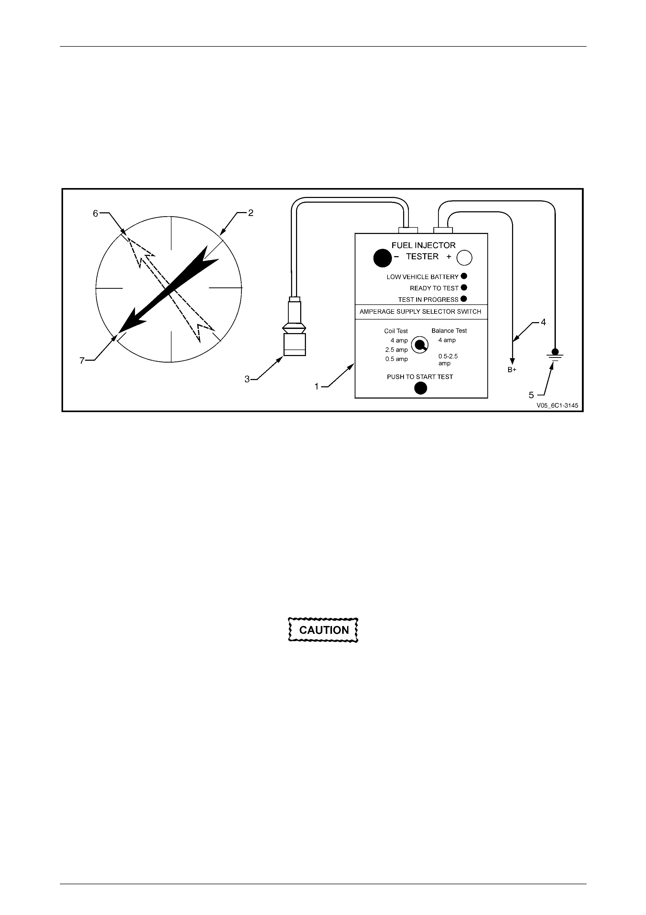
7 Connect Tool No. J 39021 Fuel Injector Tester (1), and Tool No. J 44602 (3) to the fuel injector connector. Refer to
Figure 6C1-3 – 7.
Figure 6C1-3 – 7
Legend
1 Fuel Injector Tester – Special Tool J39021
2 Fuel Pressure Gauge – Special Tool SD28018
3 Fuel Injector Harness Adapter – Special Tool J44602
4 To Battery Positive Terminal
5 Battery Earth
6 First Pressure Reading
7 Second Pressure Reading
8 Connect the fuel injector tester battery positive lead (4) and battery negative lead (5) to the battery, refer to Figure
6C1-3 – 7.
9 Set the amperage supply selector of the fuel injector tester to the Balance Test 0.5 – 2.5 A position.
As the fuel pressure tends to increase after
the fuel injector stops fuel delivery, record the
fuel pressure value immediately after the fuel
injector stops fuel delivery. Do not record the
higher fuel pressure value.
10 Press the Push to Start Test Button on the fuel injector tester to activate the fuel injector.
11 Record the fuel pressure reading indicated by the fuel pressure gauge.
NOTE
The fuel pressure readings taken in Step 10 is
known as the second pressure reading
12 Repeat the balance test pressure reading for each fuel injector.
13 Perform the Fuel Injector Pressure Drop Calculation in this Section.
Page 6C1-3–15

Engine Management – V6 – Service Operations Page 6C1-3–16
Fuel Injector Pressure Drop Calculation
Fuel Injector Balance Test Example – Typical Values Shown
Cylinder 1 2 3 4 5 6
1st Pressure
Reading
360 kPa 360 kPa 360 kPa 360 kPa 360 kPa 360 kPa
2nd Pressure
Reading
155 kPa 131 kPa 155 kPa 200 kPa 146 kPa 150 kPa
Amount of
Pressure Drop
205 kPa 229 kPa 205 kPa 160 kPa 214 kPa 210 kPa
Average Range
194 - 214 kPa
Injector OK Replace fuel
injector –
too much
pressure drop
Injector OK Replace fuel
injector –
too little
pressure drop
Injector OK Injector OK
Figure 6C1-3 – 8
1 Subtract the second pressure reading from the first pressure reading to calculate the pressure drop value. Refer to
Figure 6C1-3 – 8, typical results.
2 Calculate the pressure drop value for each fuel injector.
3 Add all the individual pressure drop values of each fuel injector to calculate the total pressure drop.
4 Divide the total pressure drop by the number of fuel injectors to calculate the average pressure drop.
Fuel Injector Pressure Drop Analysis
1 A fuel injector is faulty if its pressure drop value deviates from the average pressure drop by more than 10 kPa.
Do not repeat any portion of the test before
running the engine to prevent the engine from
flooding.
2 Re-test any fuel injector that does not meet the specification.
3 Replace all faulty fuel injectors, refer to 3.15 Fuel Rail Assembly.
Page 6C1-3–16
Engine Management – V6 – Service Operations Page 6C1-3–17
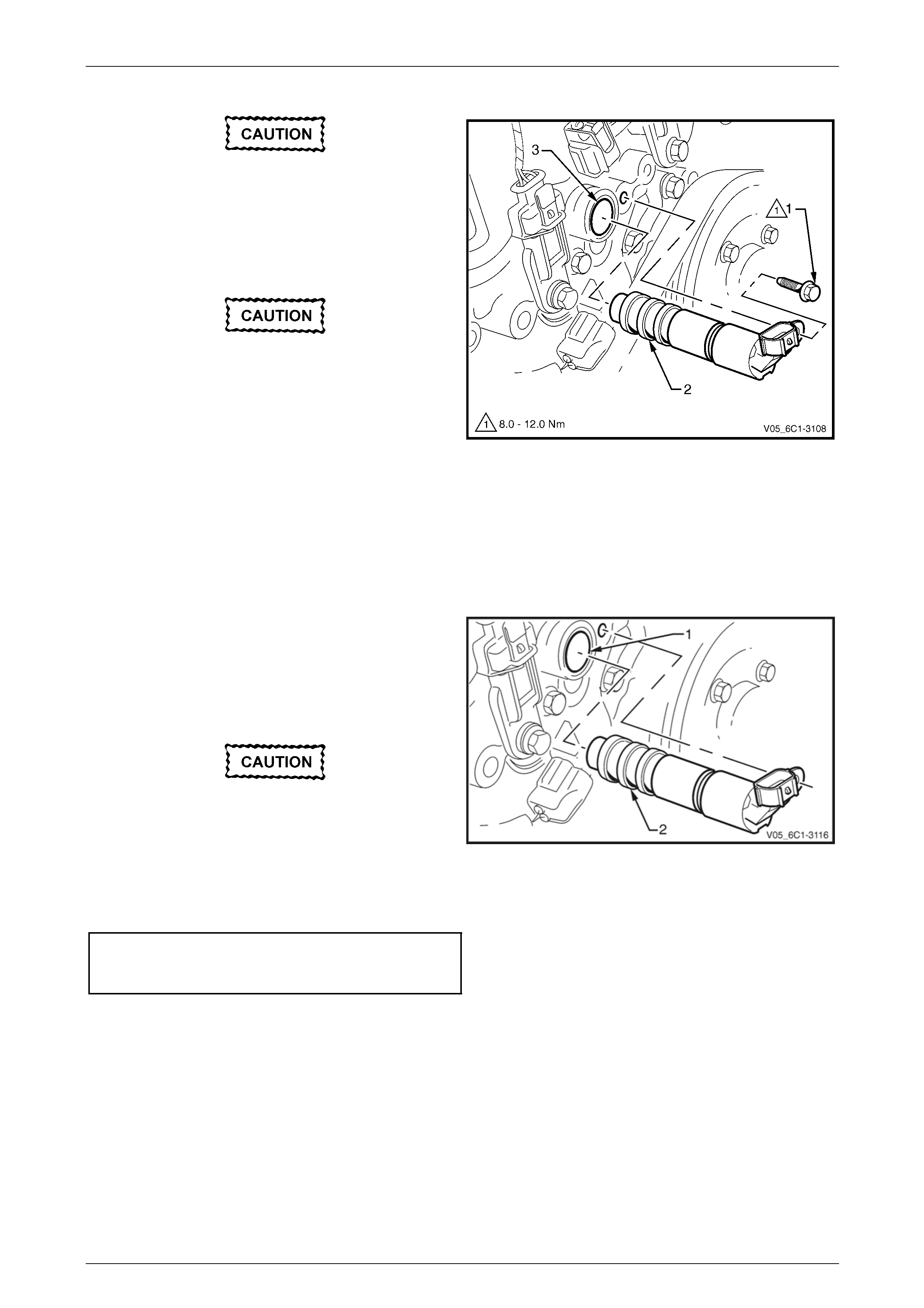
2.4 Fuel Injector Leak Down Test
1 Turn the ignition switch off.
NOTE
After removing the upper intake manifold, plug
the lower manifold opening to prevent dirt and
other contaminants from entering.
2 Remove the upper intake manifold assembly, refer to Section 6A1 Engine Mechanical – V6.
Clean around the area where the fuel
injectors enter the lower intake manifold.
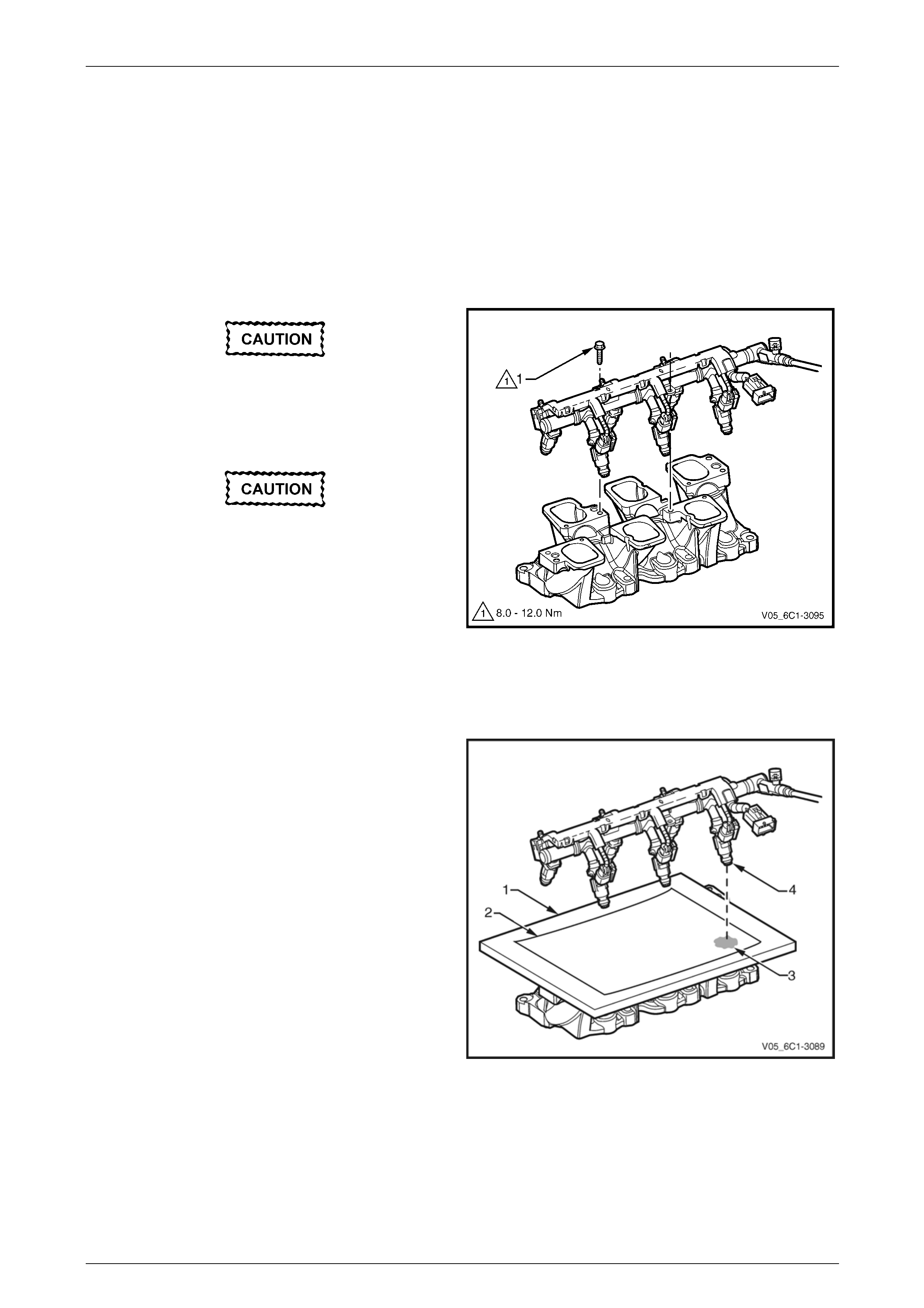
3 Remove the bolt (1), three places, attaching the fuel
rail to the lower intake manifold.
Care must be taken when removing the fuel
rail and injector assembly to prevent damage
to the injector spray tips and injector harness
connector terminals.
Support the fuel rail and injector assembly
after removal.
4 Lift up and support the fuel rail and injector assembly.
NOTE
Do not disconnect the fuel feed hose from the
fuel rail.
Figure 6C1-3 – 9
5 Place a board (1) with a sheet of clean paper (2),
preferably white, onto the lower intake manifold.
6 Using Tech 2, enable the fuel pump to pressurise the
fuel system, refer to Section 0C Tech 2 for this
procedure.
7 Whilst the fuel system is pressurised, check the
following:
• Signs of fuel stains on the paper (3).
• Signs of weeping at the fuel injector spray
tips (4).
8 If any of the above conditions are present, replace the
leaking fuel injector/s, refer to 3.15 Fuel Rail
Assembly.
9 Carefully reinstall the fuel rail and injector assembly.
Figure 6C1-3 – 10
Page 6C1-3–17

Engine Management – V6 – Service Operations Page 6C1-3–18
Ensure the fuel injectors are correctly seated
in the lower intake manifold, and the fuel rail
attaching brackets are correctly located prior
to tightening the attaching bolts.
10 Tighten the fuel rail bolts to the correct torque specification.
Fuel rail attaching bolt
torque specification ..................................8.0 – 12.0 Nm
11 Reinstall the upper intake manifold assembly, refer to Section 6A1 Engine Mechanical – V6.
12 Inspect the fuel rail and quick connect fitting for leaks, refer to Section 8A1 Fuel System.
13 Road test the vehicle and check for correct operation.
Page 6C1-3–18
Engine Management – V6 – Service Operations Page 6C1-3–19
2.5 Quick Connect Fittings
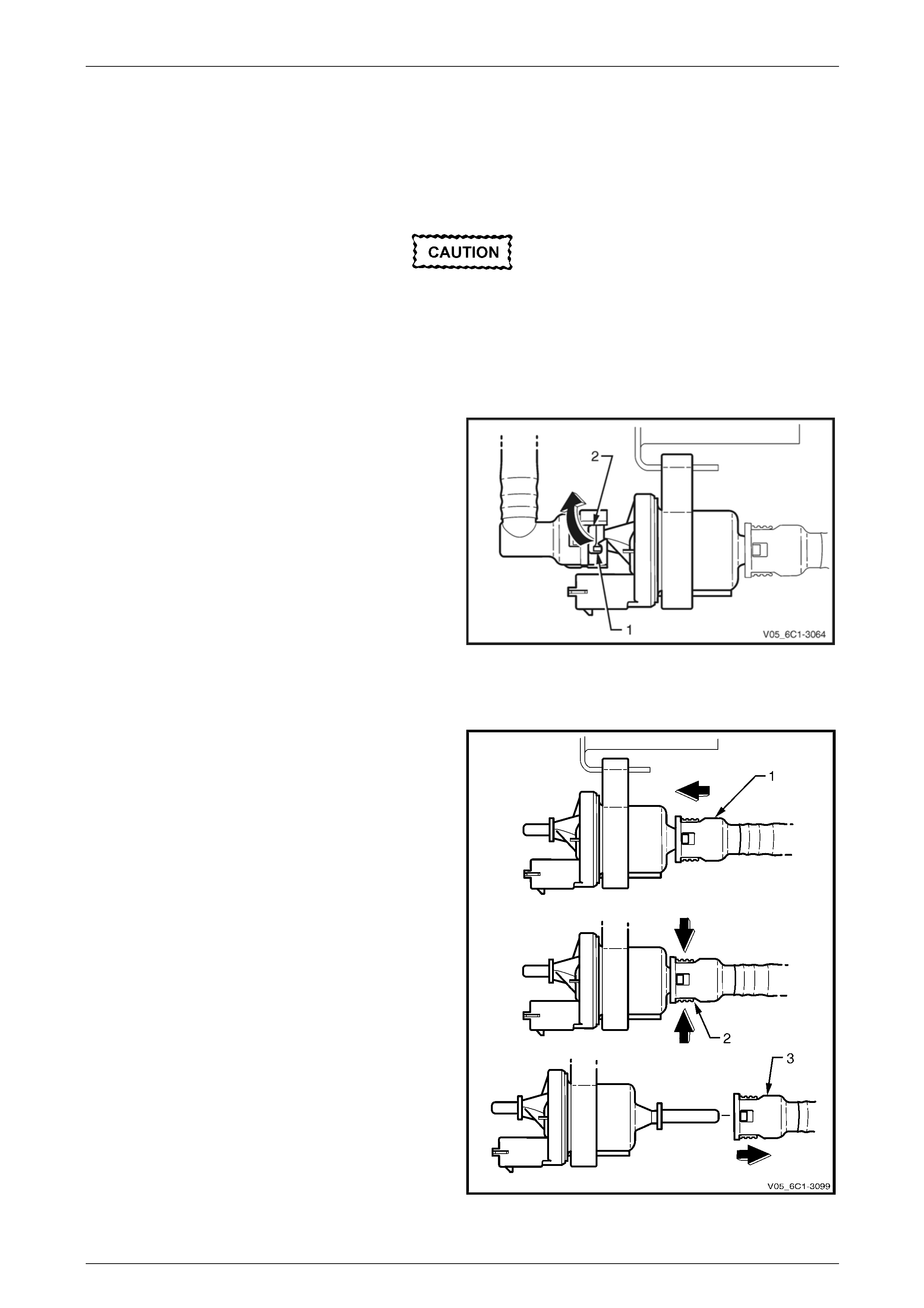
Evaporative Emission (EVAP) Canister Purge Valve Hose Fitting
Disconnect
Clean the area around the evaporative
emission (EVAP) canister purge valve before
disconnecting the quick connect fitting to
avoid debris from entering EVAP canister
purge valve.
Locking Lever Type
1 Rotate the quick connect locking lever (1) in the
direction of the arrow.
2 Whilst holding the lever against its stop (2), pull the
hose away from the EVAP canister purge valve.
Figure 6C1-3 – 11
Latch Type
1 Push the quick connect fitting (1) in the direction of
arrow.
2 Whilst pressing the two latches (2) in the direction of
the arrows, pull the quick connect fitting (3) away from
the EVAP canister purge valve.
Figure 6C1-3 – 12
Page 6C1-3–19
Engine Management – V6 – Service Operations Page 6C1-3–20
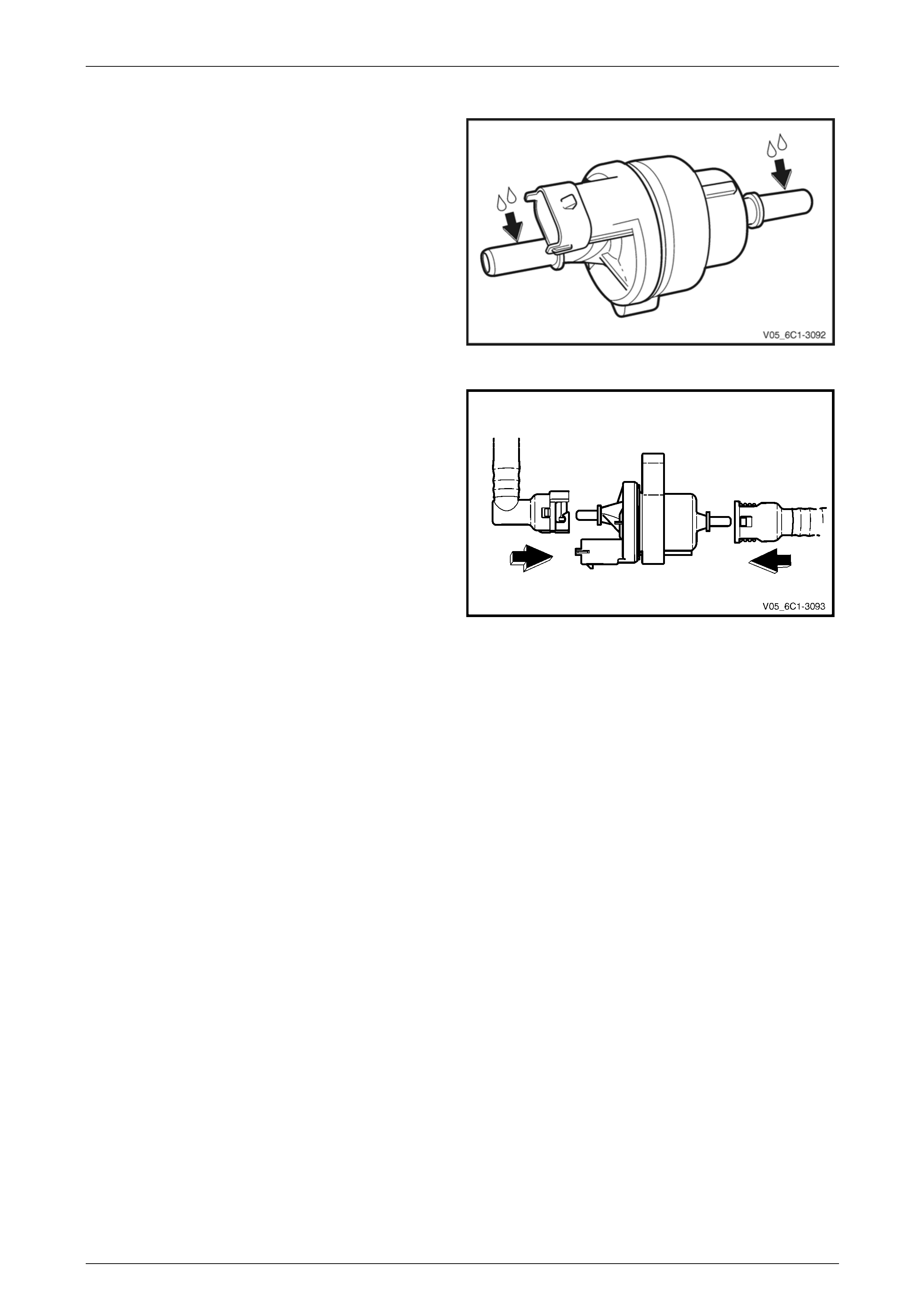
Connect
1 Lubricate the evaporative emission (EVAP) canister
purge valve with clean engine oil.
Figure 6C1-3 – 13
2 Push the hose quick connect fitting onto the purge
valve fitting. There will be an audible click as the quick
connect fitting engages.
3 Check the locking lever has returned to its rest
position.
4 Check the quick connect fittings have fully engaged by
gently pulling the quick connect fitting away from the
purge valve.
Figure 6C1-3 – 14
Page 6C1-3–20

Engine Management – V6 – Service Operations Page 6C1-3–21
2.6 Throttle Body Relearn
A throttle body relearn procedure is performed in one of two ways:
• Engine Control Module initiated throttle body relearn, or
• Tech 2 initiated throttle body relearn.
Engine Control Module Throttle Body Relearn
The engine control module (ECM) will automatically perform a throttle body relearn procedure if either of the following
conditions exist:
• The battery has been disconnected, or
• The ignition switch is in the ON position for greater than 29 seconds, and the following conditions are met:
• engine speed is less than 40 r.p.m.,
• vehicle speed is 0 km/h,
• engine coolant temperature is 5 – 60°C,
• intake air temperature is 5 – 60°C,
• accelerator pedal position sensor angle is less than 14.9%, and
• ignition voltage 1 voltage is greater than 10 V.
Tech 2 Throttle Body Relearn
To perform a throttle body relearn using Tech 2, using the following procedure:
NOTE
Tech 2 will not initiate a throttle body relearn if the
engine is running.
1 Connect Tech 2 to the data link connector (DLC) and turn the ignition on.
2 On Tech 2 select Engine / Programming / Throttle Body Relearn.
3 When Tech 2 displays Do you really want to Reset?, press the Yes soft key.
4 When Tech 2 displays Programming Completed, and the electronic throttle control value displayed by Tech 2 is 11,
press the Confirm soft key to return to the Tech 2 Programming screen.
5 The throttle body relearn is now complete.
Page 6C1-3–21

Engine Management – V6 – Service Operations Page 6C1-3–22
3 Component Replacement
3.1 Components Not Covered In This
Section
There are cases where components used by the powertrain management system are covered in other Sections of the
service documentation. To aid technicians in locating the necessary service procedures for these components, refer to
the following references.
Air-conditioning System
For A/C pressure switch replacement procedure, refer to Section 2B HVAC Climate Control (Manual A/C) – Servicing
and Diagnosis.
Electrical Components
For the following electrical system component replacement procedures, refer to the appropriate Sections as follows:
• Extended brake pedal travel switch and stop lamp switch service operations, refer to Section 5A Service and Park
Braking System.
• Fuse and relay locations, refer to Section 12O Fuses, Relays and Wiring Harnesses.
• Cruise control cancel switch and clutch start switch service operations, refer to Section 7A1 Clutch – V6.
• Cruise control switch assembly service operations, refer to Section 12E Cruise Control.
• Powertrain interface module PIM removal and installation procedure, refer to Section 6E1 Powertrain Interface
Module – V6.
• Neutral start and back-up lamp switch, refer to:
• Section 7C4 Automatic Transmission – 4L60E – On-vehicle Servicing, or
• Section 7E4 Automatic Transmission – 5L40E – On-vehicle Servicing, or
• Vehicle speed sensor service operations, refer to:
• Section 7C4 Automatic Transmission – 4L60E – On-vehicle Servicing, or
• Section 7E4 Automatic Transmission – 5L40E – On-vehicle Servicing, or
• Section 7B1 Manual Transmission – V6
Fuel System
For the following fuel system component replacement procedures, refer to Section 8A1 Fuel System:
• evaporative emission control canister,
• fuel filter,
• fuel hose / pipes layout,
• fuel pump motor assembly and fuel pressure regulator assembly,
• fuel sender assembly service operations, and
Transmission – Automatic
For automatic transmission sensors and components, refer to:
• Section 7C4 Automatic Transmission – 4L60E – On-vehicle Servicing, or
• Section 7E4 Automatic Transmission – 5L40E – On-vehicle Servicing, or
Transmission – Manual
For manual transmission sensors and other components, refer to Section 7B1 Manual Transmission – V6.
Page 6C1-3–22
Engine Management – V6 – Service Operations Page 6C1-3–23
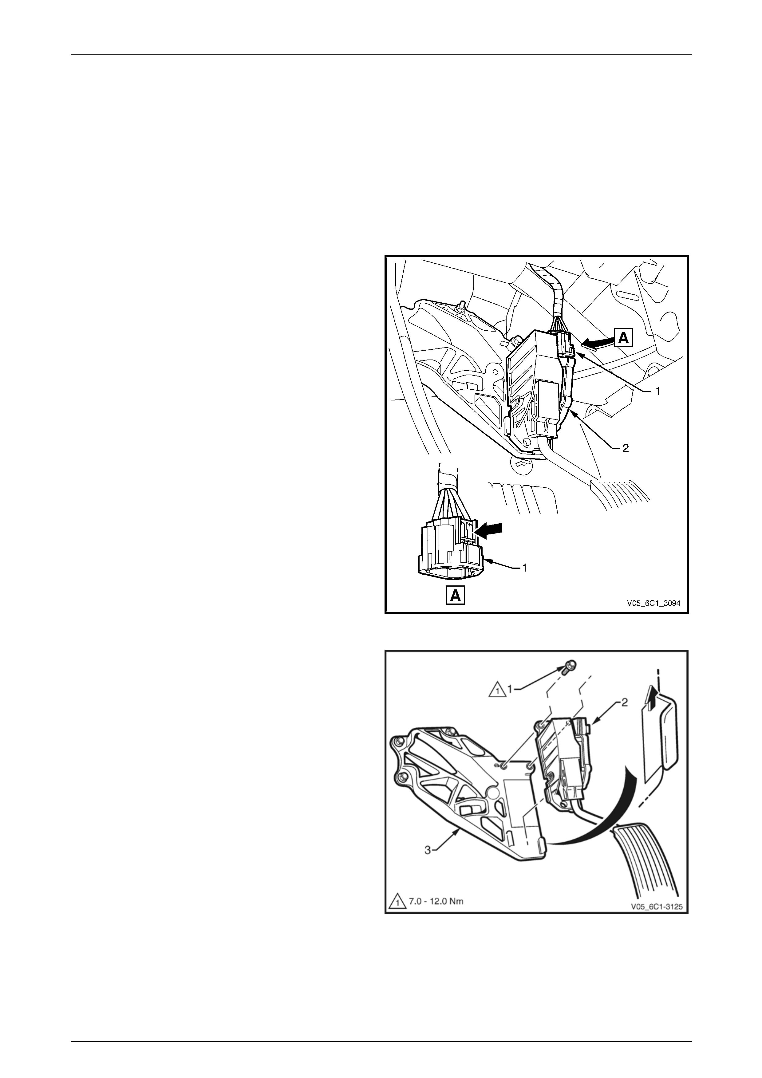
3.2 Accelerator Pedal Position Sensor
LT Section No. — 03–650
Remove
1 Turn the ignition switch off.
2 Remove the drivers side instrument panel lower trim plate assembly, refer to Section 1A3 Instrument Panel and
Console.
3 Disconnect the wiring harness connector (1) from the
accelerator pedal position (APP) sensor (2) by
depressing the latch in the direction of the arrow.
NOTE
If difficulty is experienced in disconnecting the
harness connector from the APP sensor, remove
the sensor from the APP support bracket and
then disconnect the harness connector.
Figure 6C1-3 – 15
4 Remove the bolt (1), two places, attaching the APP
sensor (2) to the accelerator pedal position (APP)
sensor support bracket (3).
5 Slide the APP sensor upwards in the direction of the
arrow, to disengage the sensor from the support
bracket.
Figure 6C1-3 – 16
Page 6C1-3–23

Engine Management – V6 – Service Operations Page 6C1-3–24
Reinstall
Reinstallation of the accelerator pedal position (APP) sensor is the reverse of the removal procedure, noting the
following:
Ensure the APP sensor engages the APP
support bracket, refer to
Figure 6C1-3 – 16.
1 Reinstall the bolts attaching the APP sensor to the support bracket and tighten to the correct torque specification.
Accelerator pedal position sensor attaching bolt
torque specification ...................................7.0 – 12.0 Nm
2 Road test the vehicle and check for correct operation.
Page 6C1-3–24
Engine Management – V6 – Service Operations Page 6C1-3–25
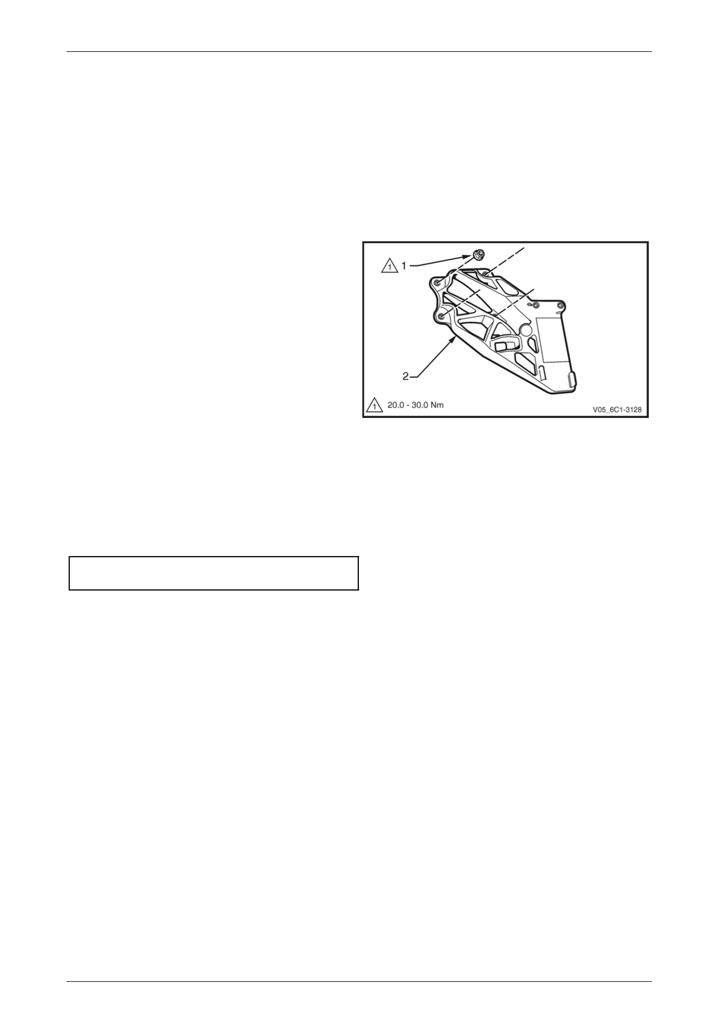
3.3 Accelerator Pedal Position Sensor
Support Bracket
LT Section No. — 03–650
Remove
1 Turn the ignition switch off.
2 If required, remove the accelerator pedal position (APP) sensor, refer to 3.2 Accelerator Pedal Position Sensor.
3 Remove the nut (1), four places, attaching the APP
sensor support bracket (2) to the dash panel and
remove the support bracket.
Figure 6C1-3 – 17
Reinstall
Reinstallation of the accelerator pedal position sensor (APP) sensor support bracket is the reverse of the removal
procedure, noting the following:
1 Reinstall the nuts attaching the APP sensor support bracket to the dash panel and tighten to the correct torque
specification.
Accelerator pedal position sensor
attaching nut torque specification............20.0 – 30.0 Nm
2 Road test the vehicle and check for correct operation.
Page 6C1-3–25
Engine Management – V6 – Service Operations Page 6C1-3–26
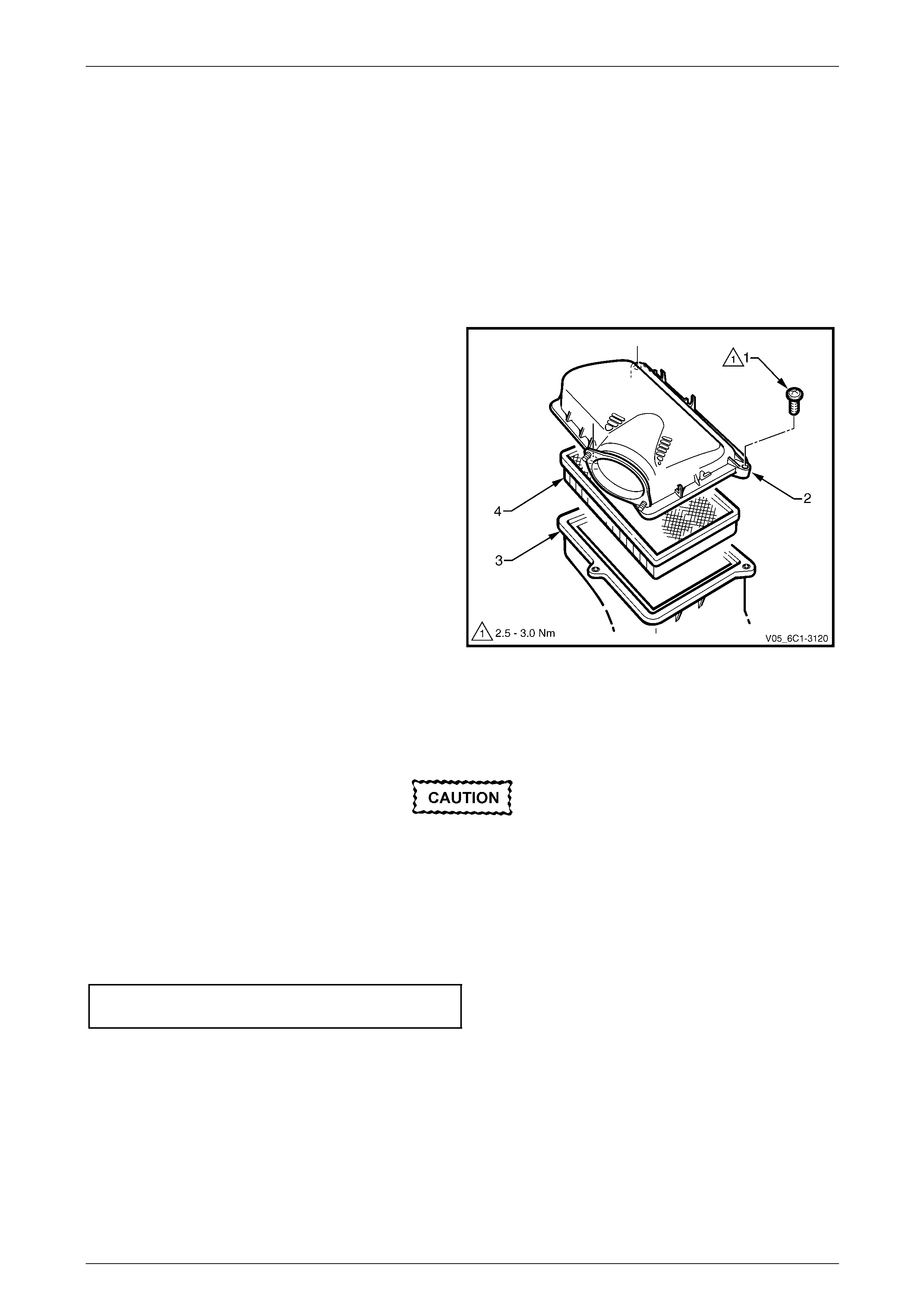
3.4 Air Cleaner Assembly
LT Section No. — 03–250
Air Cleaner Upper Housing
Remove
1 Turn the ignition switch off.
2 Remove the mass air flow (MAF) sensor, refer to 3.23 Mass Air Flow Sensor.
3 Remove the screw (1), three places, attaching the air
cleaner upper housing (2) to the air cleaner lower
housing (3).
4 Remove the upper housing and air cleaner
element (4).
Figure 6C1-3 – 18
Reinstall
Reinstallation of the air cleaner upper housing is the reverse of the removal procedure, noting the following:
Ensure the air cleaner sealing rubber is
correctly located in the air cleaner lower
housing. Failure to do this may result in
engine damage due to unfiltered air entering
the engine intake system.
1 Reinstall the air cleaner element.
2 Reinstall the screws, attaching the air cleaner upper housing and tighten to the correct torque specification.
Air cleaner upper housing attaching
screw torque specification...........................2.5 – 3.0 Nm
3 Road test the vehicle and check for correct operation, taking particular note that no air leaks are evident.
Page 6C1-3–26
Engine Management – V6 – Service Operations Page 6C1-3–27
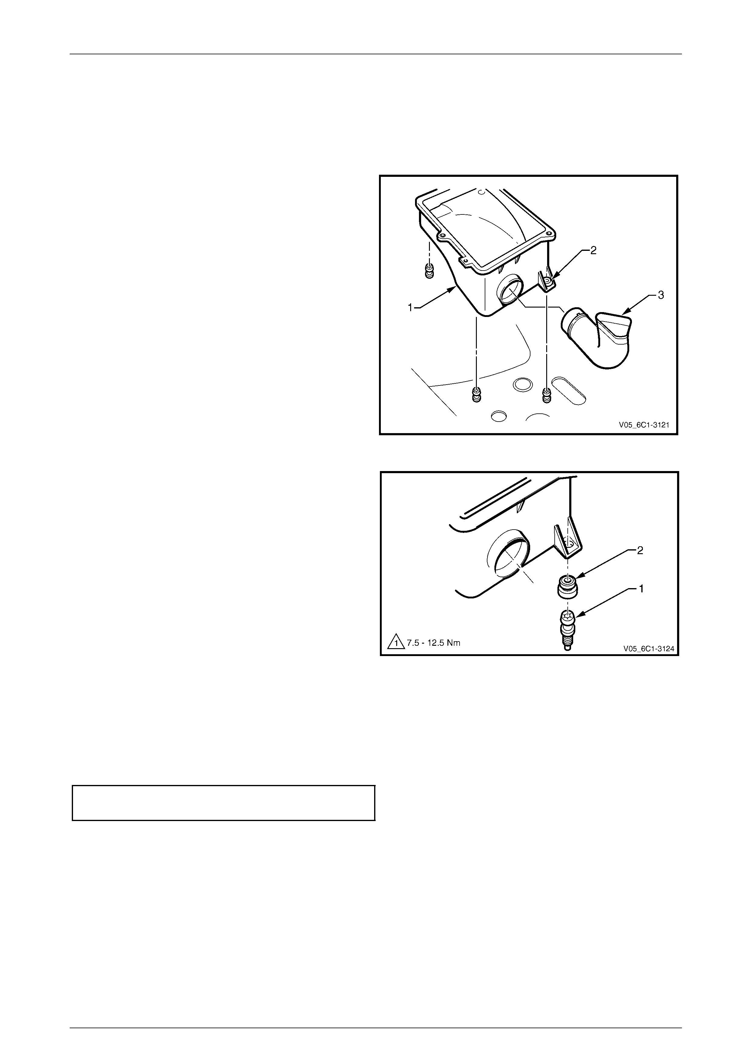
Air Cleaner Lower Housing Assembly
Remove
1 Turn the ignition switch off.
2 Remove the air cleaner upper housing as described previously.
3 Grasp the air cleaner lower housing assembly (1), and
pull upward to release the insulator (2), three places,
from the attaching studs and remove the lower
housing.
4 If required, disengage the air cleaner air inlet duct (3)
from the lower housing.
Figure 6C1-3 – 19
5 If required, remove the stud (1) and air cleaner
housing insulator (2) from the air cleaner lower
housing.
Figure 6C1-3 – 20
Reinstall
Reinstallation of the air cleaner lower housing assembly is the reverse of the removal procedure, noting the following:
1 If previously removed, reinstall the stud, three places, attaching the air cleaner lower housing to the fender inner
panel and tighten to the correct torque specification.
Air cleaner lower housing attaching
stud torque specification ...........................7.5 – 12.5 Nm
2 Road test the vehicle and check for correct operation, taking particular note that no air leaks are evident.
Page 6C1-3–27
Engine Management – V6 – Service Operations Page 6C1-3–28
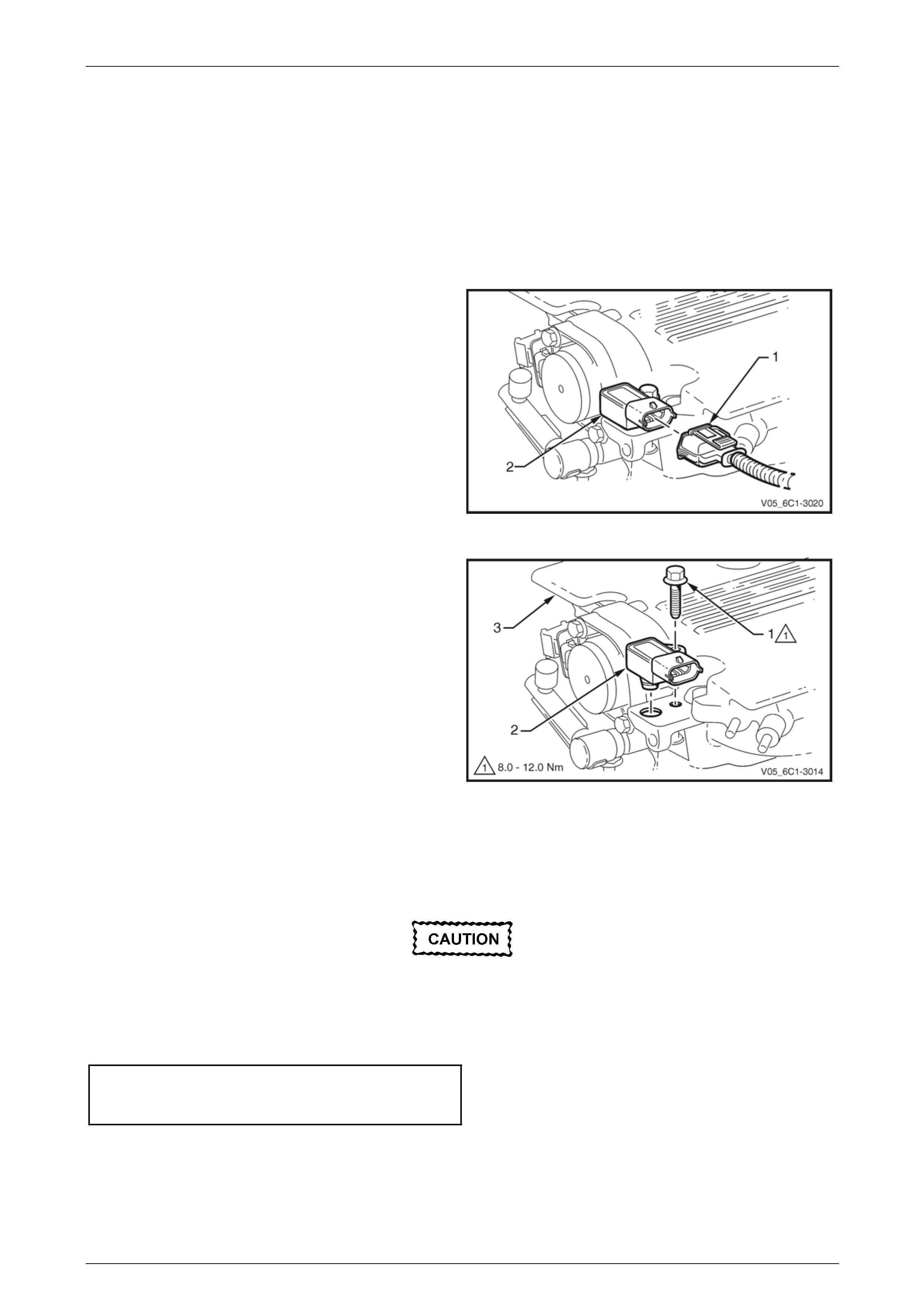
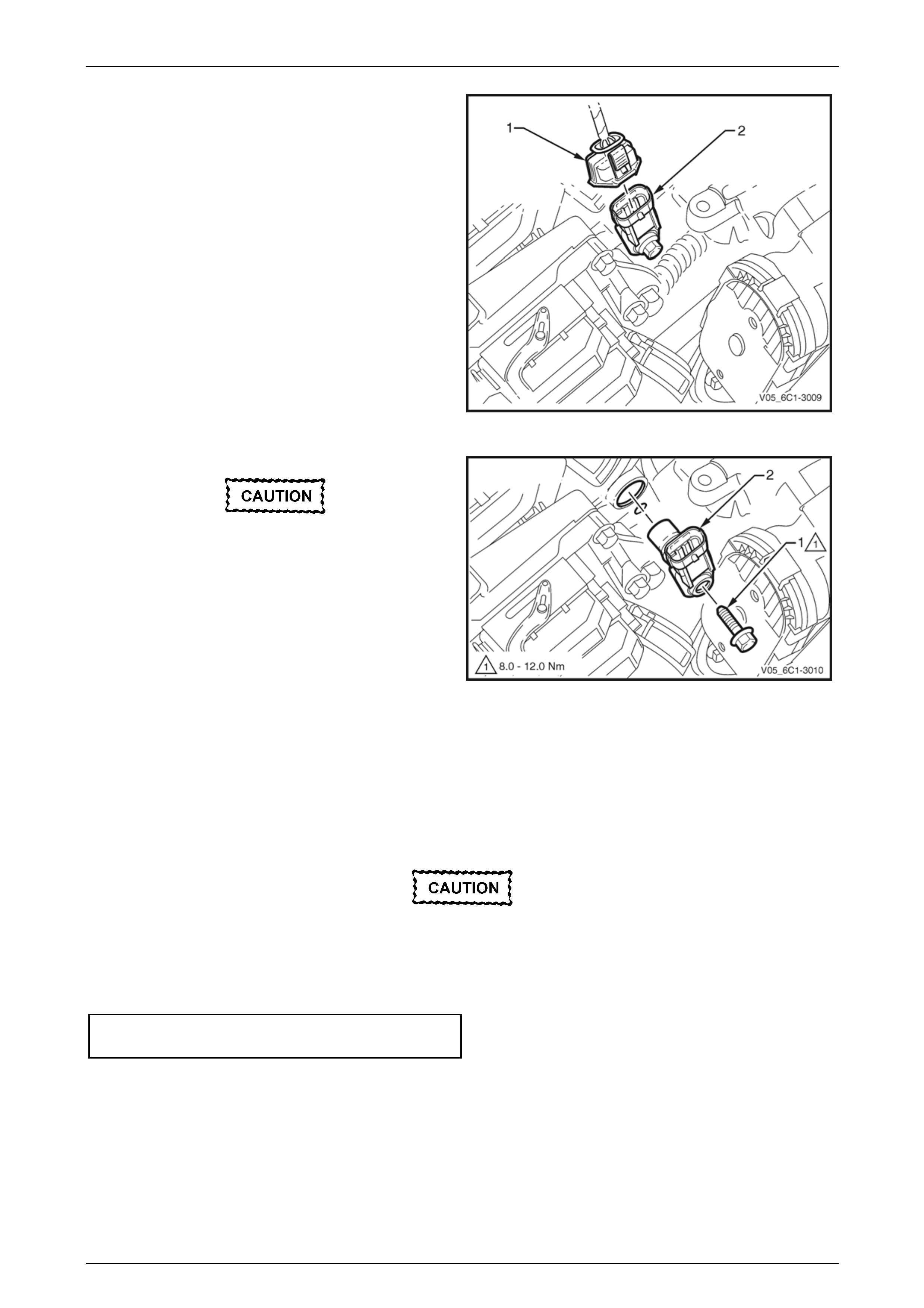
3.5 Barometric Pressure Sensor
LT Section No. —
Remove
1 Turn the ignition switch off.
2 Remove the Bank 1 (RHS) engine dress cover, refer to Section 6A1 Engine Mechanical – V6.
3 Disconnect the wiring harness connector (1) from the
barometric pressure (BARO) sensor (2).
Figure 6C1-3 – 21
4 Remove the bolt (1) attaching the BARO sensor (2) to
the upper intake manifold (3).
5 Remove the BARO sensor from the manifold by first,
twisting the sensor to release it, and then pulling it
upwards to remove it.
Figure 6C1-3 – 22
Reinstall
Reinstallation of the barometric pressure (BARO) sensor is the reverse of the removal procedure, noting the following:
Ensure the BARO sensor is fully seated
before tightening the attaching bolt to the
specified torque.
1 Reinstall the BARO sensor bolt and tighten to the correct torque specification.
Barometric pressure sensor
attaching bolt
torque specification ...................................8.0 – 12.0 Nm
2 Road test the vehicle and check for correct operation.
Page 6C1-3–28
Engine Management – V6 – Service Operations Page 6C1-3–29
3.6 Camshaft Position Actuator Solenoid
LT Section No. — 02–000
NOTE
Vehicles fitted with the Alloytec190 engine have
two intake and two exhaust camshaft position
(CMP) actuators
NOTE
Vehicles fitted with the Alloytec engine have only
two intake CMP actuators.
Bank 1 (RHS)
The replacement procedure for the inlet (1) and exhaust (2)
camshaft position (CMP) actuator solenoids are typically the
same, with the following procedure being specific to the inlet
CMP actuator solenoid.
NOTE
View shown with the engine control module
(ECM) bracket assembly removed.
Figure 6C1-3 – 23
Remove
1 Turn the ignition switch off.
2 Remove Bank 1 (RHS) engine dress cover, refer to Section 6A1 Engine Mechanical – V6.
3 Remove the ECM bracket assembly, refer to 3.11 Engine Control Module Bracket Assembly.
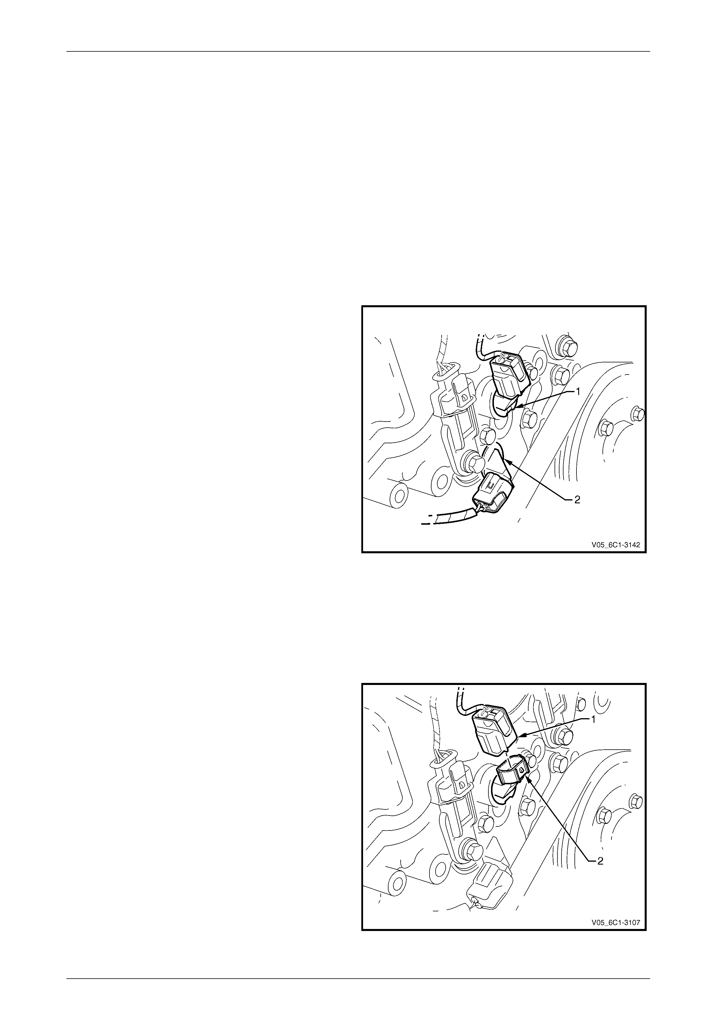
4 Disconnect the wiring harness connector (1) from the
CMP actuator solenoid (2).
Figure 6C1-3 – 24
Page 6C1-3–29
Engine Management – V6 – Service Operations Page 6C1-3–30
Clean the area around the CMP actuator
solenoid before removal to avoid debris from
entering the engine.
5 Remove the bolt (1) attaching the CMP actuator
solenoid (2).
When removing the CMP actuator solenoid,
care must be taken to prevent the annular
grooves of the actuator from damaging the
CMP actuator solenoid seal (3).
6 Remove the CMP actuator solenoid by first twisting
the actuator to release it, and then pulling it away from
the front engine cover to remove it.
7 If required, test the CMP actuator solenoid, refer to the
CMP actuator Test in this Section.
Figure 6C1-3 – 25
Reinstall
Reinstallation of the camshaft position (CMP) actuator solenoid is the reverse of the removal procedure, noting the
following:
1 Inspect the CMP actuator solenoid seal (1) for
damage, and replace if necessary. Refer to
Section 6A1-1 Engine Mechanical - V6.
2 Lubricate the lip of the CMP actuator solenoid seal
with clean engine oil.
When installing the CMP actuator solenoid,
care must be taken to prevent the annular
grooves (2) of the actuator from damaging
the CMP actuator solenoid seal.
3 Reinstall the CMP actuator solenoid.
Figure 6C1-3 – 26
4 Reinstall the CMP actuator solenoid bolt and tighten to the correct torque specification.
Camshaft position actuator
solenoid attaching bolt
torque specification ...................................8.0 – 12.0 Nm
5 Road test the vehicle and check for correct operation, taking particular note there is no engine oil leak from the
CMP actuator solenoid seal.
Page 6C1-3–30
Engine Management – V6 – Service Operations Page 6C1-3–31
Bank 2 (LHS)
The replacement procedure for the inlet (1) and exhaust (2)
camshaft position (CMP) actuator solenoids are typically the
same, with the following procedure being specific to the inlet
CMP actuator solenoid. Where there are differences in the
removal procedures, these will be highlighted.
NOTE
View shown with components removed for
clarity.
Figure 6C1-3 – 27
Remove
1 Turn the ignition switch off.
2 Remove Bank 2 engine dress cover, refer to Section 6A1 Engine Mechanical – V6.
3 Remove the power steering reservoir from the power steering reservoir mounting bracket, refer to
Section 9 Steering.
NOTE
Do not disconnect the power steering hoses from
the reservoir.
4 Reposition the reservoir to provide access to the CMP actuator solenoid.
5 If removing the exhaust CMP actuator solenoid, remove the accessory drive belt, refer to
Section 6A1 Engine Mechanical – V6.
6 Disconnect the wiring harness connector (1) from the
CMP actuator solenoid (2).
Figure 6C1-3 – 28
Page 6C1-3–31

Engine Management – V6 – Service Operations Page 6C1-3–32
Clean the area around the CMP actuator
solenoid before removal to avoid debris from
entering the engine.
7 Remove the bolt (1) attaching the CMP actuator
solenoid (2).
When removing the CMP actuator solenoid,
care must be taken to prevent the annular
grooves of the actuator from damaging the
CMP actuator solenoid seal (3).
8 Remove the CMP actuator solenoid by first twisting
the actuator to release it, and then pulling it away from
the front engine cover to remove it.
9 If required, test the CMP actuator solenoid, refer to the
Test in this Section.
Figure 6C1-3 – 29
Reinstall
Reinstallation of the camshaft position (CMP) actuator solenoid is the reverse of the removal procedure, noting the
following:
1 Inspect the CMP actuator solenoid seal (1) for
damage, and replace if necessary. Refer to
Section 6A1-1 Engine Mechanical – V6.
2 Lubricate the lip of the CMP actuator solenoid seal
with clean engine oil.
When installing the CMP actuator solenoid,
care must be taken to prevent the annular
grooves (2) of the actuator from damaging
the CMP actuator solenoid seal.
3 Reinstall the CMP actuator solenoid.
Figure 6C1-3 – 30
4 Reinstall the CMP actuator solenoid bolt and tighten to the correct torque specification.
Camshaft position actuator
solenoid attaching bolt
torque specification ...................................8.0 – 12.0 Nm
5 Road test the vehicle and check for correct operation, taking particular note there is no engine oil leak from the
CMP actuator solenoid seal.
Page 6C1-3–32
Engine Management – V6 – Service Operations Page 6C1-3–33
Test
To prevent component damage:
• Use connector test adaptor kit
J 35616-A.
• When applying 12 V to a component,
always use a 3 A fused wire.
Resistance Inspection
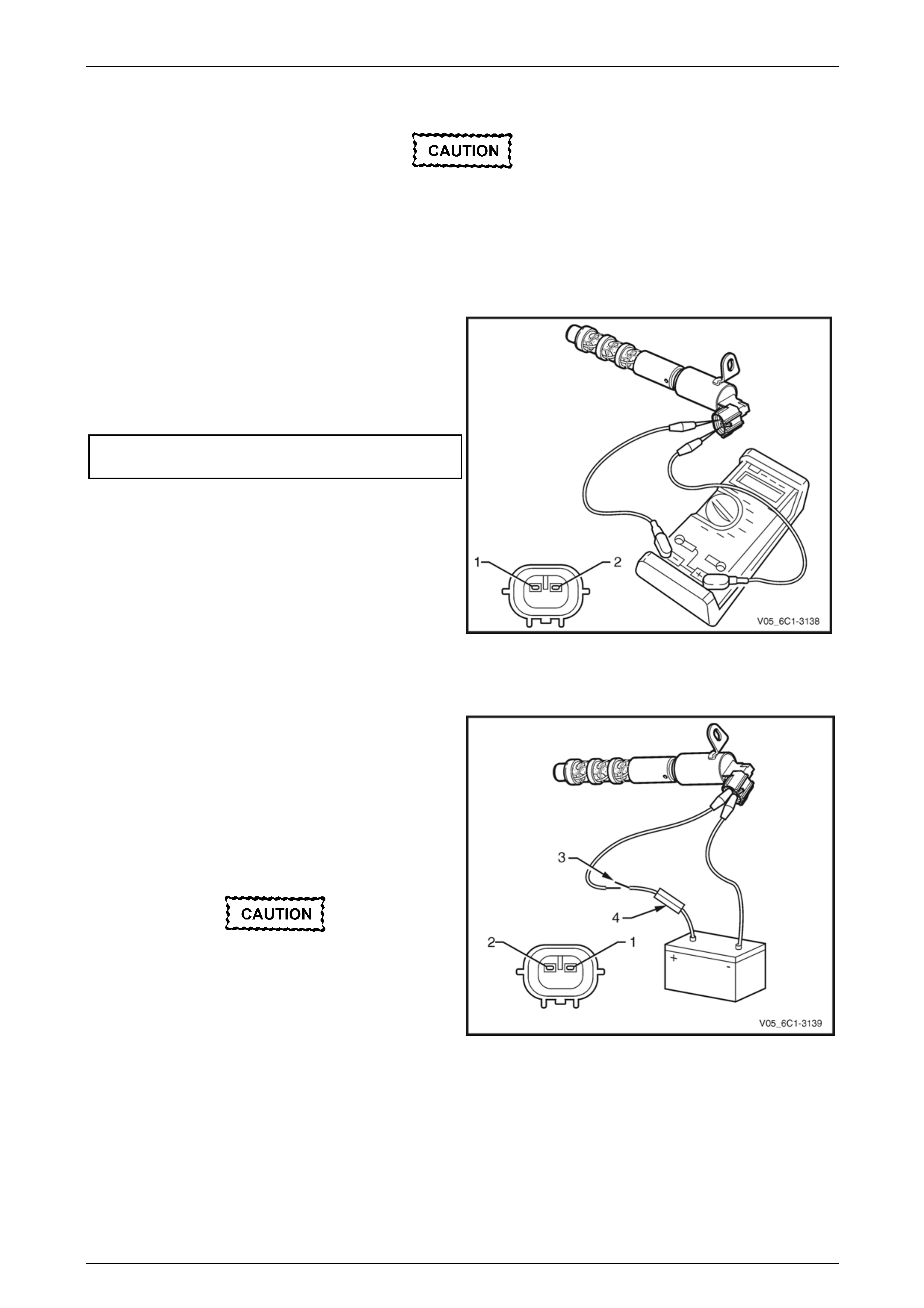
1 Connect a digital ohmmeter using connector test
adaptor kit J 35616-A to the camshaft position (CMP)
actuator.
2 Measure the resistance across terminals 1 and 2.
3 Compare the reading against the specification.
Camshaft position (CMP) actuator solenoid
resistance @ 20°C.........................................6.7 – 7.7 Ω
4 If the resistance is not within specification, replace the
CMP actuator solenoid.
Figure 6C1-3 – 31
Functional Test
1 Using connector test adaptor kit J 35616-A, connect a
12 V battery, an on / off switch (3) and a 3 A fused
wire (4) to the CMP actuator solenoid terminals as
follows:
• Positive lead to the CMP actuator solenoid
terminal 1.
• Negative lead to the CMP actuator solenoid
terminal 2.
Do not apply 12 V to the CMP actuator
solenoid continuously, for more than three
seconds as the CMP actuator solenoid will be
damaged.
2 Whilst observing the CMP actuator solenoid, turn the
switch on and off. A clicking noise should be heard.
3 If no clicking sound is heard, replace the CMP actuator
solenoid.
Figure 6C1-3 – 32
Page 6C1-3–33

Engine Management – V6 – Service Operations Page 6C1-3–34
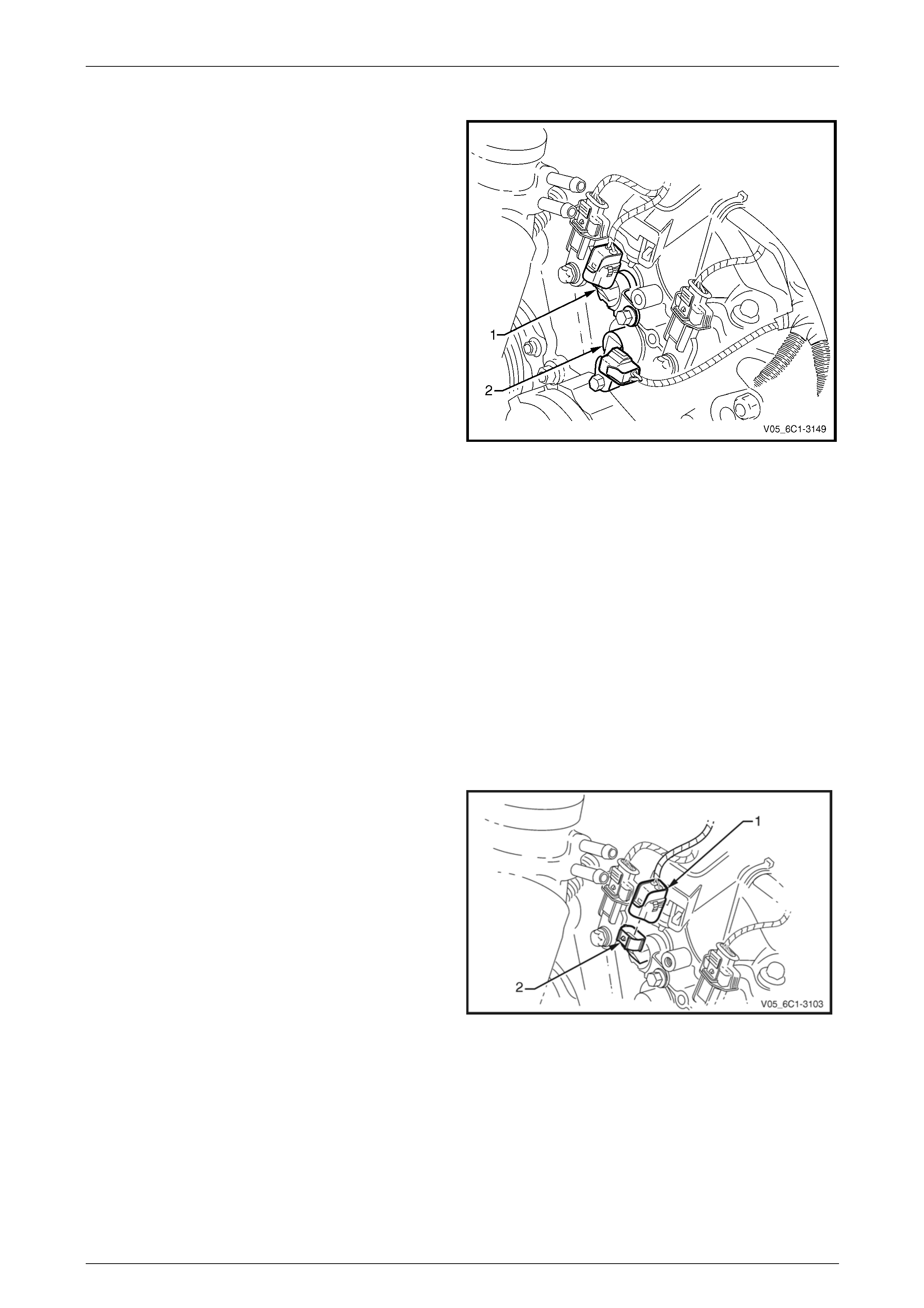
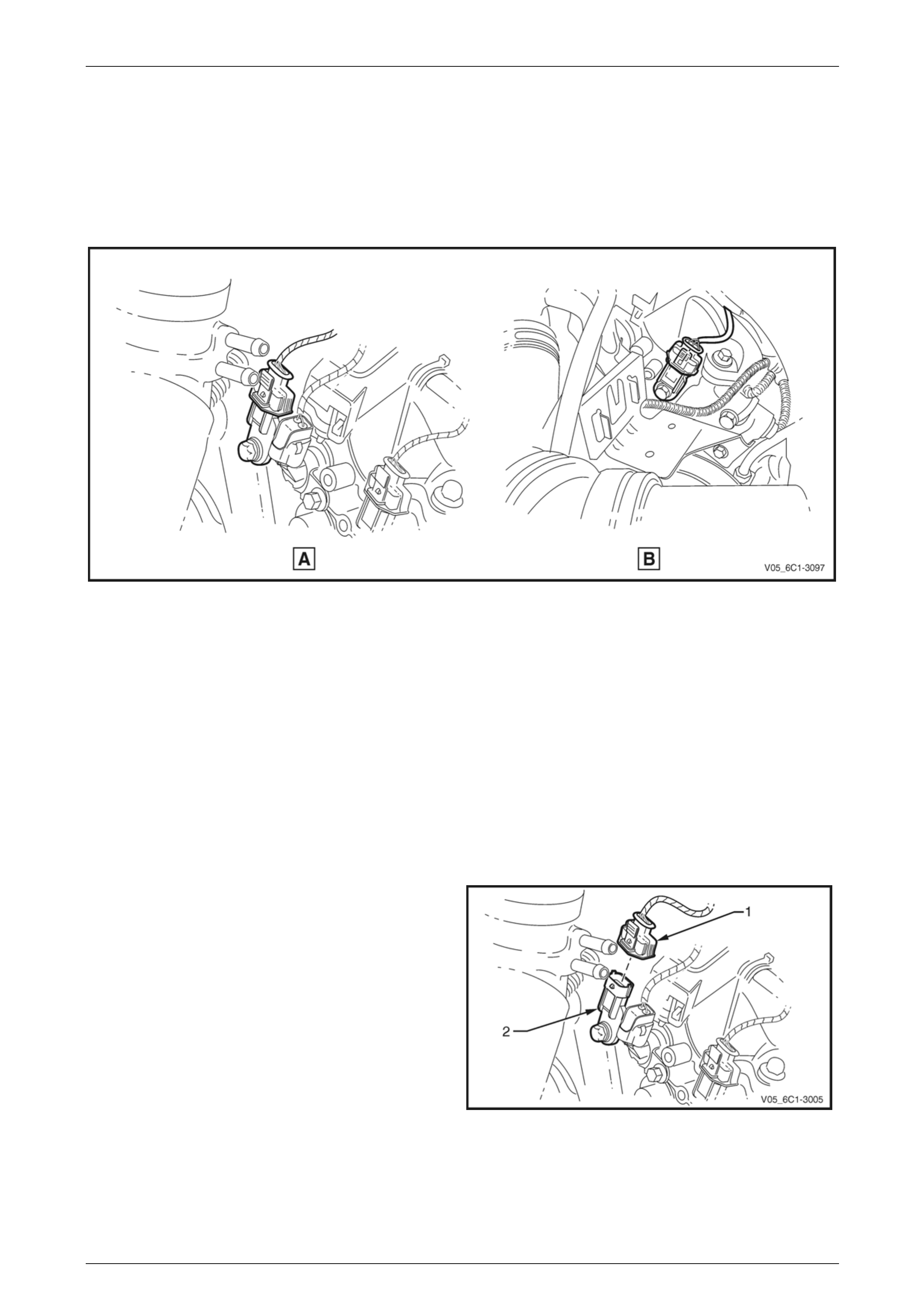
3.7 Camshaft Position Sensor
LT Section No. — 02–000
Bank 1 (RHS)
The replacement procedure for the inlet (View A) and exhaust (View B) camshaft position (CMP) sensors are typically
the same, with the following procedure being specific to the inlet CMP sensor, refer to Figure 6C1-3 – 33. Where there
are differences in the removal procedure, these will be highlighted.
NOTE
View B shows the CMP sensor with the engine
control module (ECM) bracket assembly
removed.
NOTE
Only the Alloytec190 engine has the exhaust
CMP sensor.
Figure 6C1-3 – 33
Remove
1 Turn the ignition switch off.
2 Remove Bank 1 (RHS) engine dress cover, refer to Section 6A1 Engine Mechanical – V6.
3 If replacing the exhaust CMP sensor, remove the ECM bracket assembly, refer to 3.11 Engine Control Module
Bracket Assembly.
Page 6C1-3–34
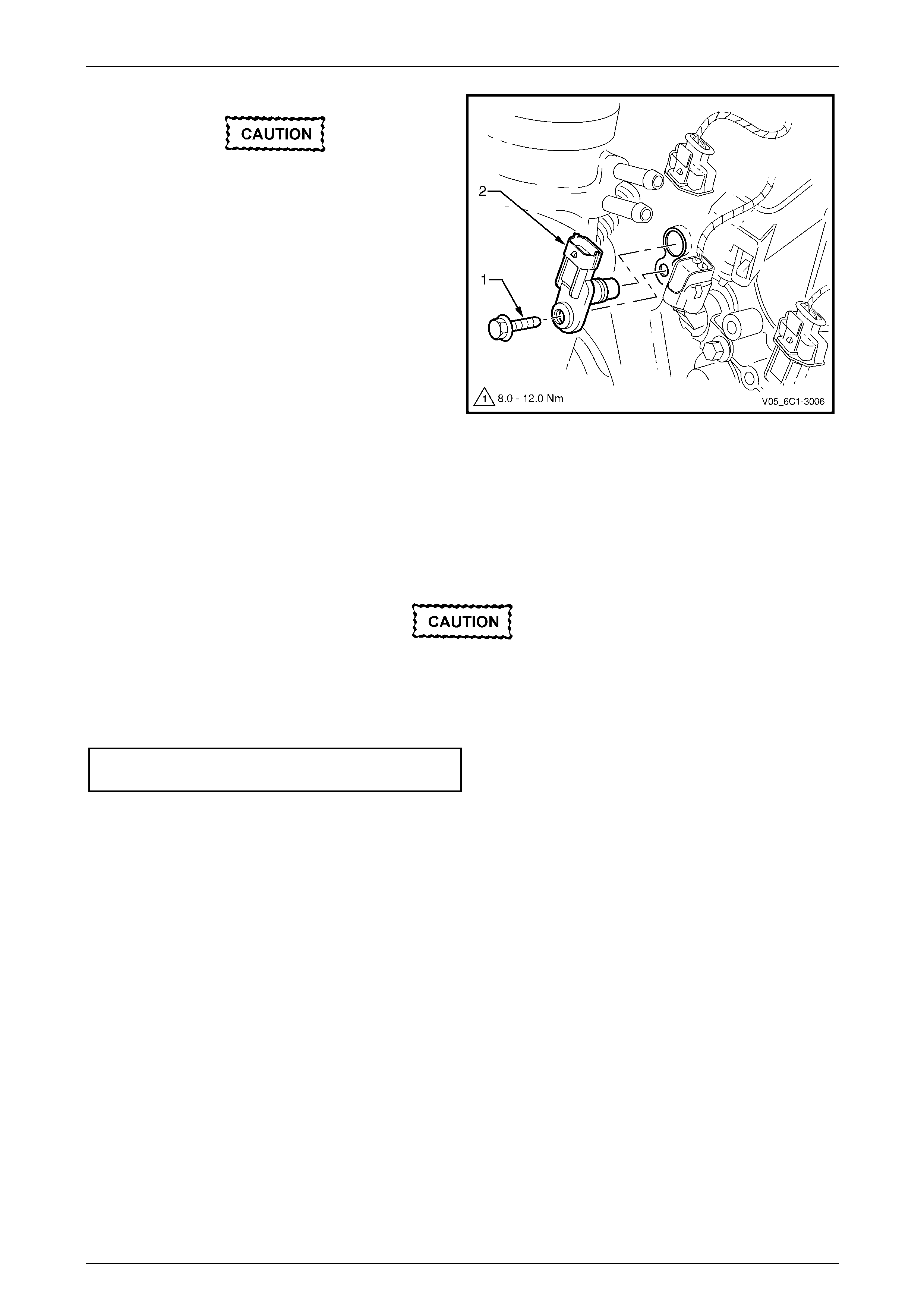
Engine Management – V6 – Service Operations Page 6C1-3–35
4 Disconnect the wiring harness connector (1) from the
CMP sensor (2).
Figure 6C1-3 – 34
Clean the area around the CMP sensor before
removal to avoid debris from entering the
engine.
5 Remove the CMP sensor attaching bolt (1).
6 Remove the CMP sensor (2) by first twisting the
sensor to release it, and then pulling it away from the
front engine cover to remove it.
Figure 6C1-3 – 35
Reinstall
Reinstallation of the camshaft position (CMP) sensor is the reverse of the removal procedure, noting the following:
1 Lubricate the CMP sensor O-ring with clean engine oil.
2 Reinstall the CMP sensor by pushing in on the sensor to engage the sensor O-ring in the front engine cover.
Ensure the CMP sensor is fully seated before
tightening the attaching bolt to the specified
torque.
3 Reinstall the CMP sensor bolt and tighten to the correct torque specification.
Camshaft position sensor attaching bolt
torque specification ...................................8.0 – 12.0 Nm
4 Road test the vehicle and check for correct operation, taking particular note there is no engine oil leak from the
CMP sensor.
Page 6C1-3–35
Engine Management – V6 – Service Operations Page 6C1-3–36
Bank 2 (LHS)
The replacement procedure for the inlet (View A) and exhaust (View B) camshaft position (CMP) sensors are typically
the same, with the following procedure being specific to the inlet CMP sensor, refer to Figure 6C1-3 – 36.
NOTE
Only the Alloytec190 engine has the exhaust
CMP sensor.
Figure 6C1-3 – 36
Remove
1 Turn the ignition switch off.
2 Remove the Bank 2 (LHS) engine dress cover, refer to Section 6A1 Engine Mechanical – V6.
3 Remove the power steering reservoir from the power steering reservoir mounting bracket, refer to
Section 9 Steering.
NOTE
Do not disconnect the power steering hoses from
the reservoir.
4 Reposition the reservoir to provide access to the CMP sensor.
5 Disconnect the wiring harness connector (1) from the
CMP sensor (2).
Figure 6C1-3 – 37
Page 6C1-3–36
Engine Management – V6 – Service Operations Page 6C1-3–37
Clean the area around the CMP sensor before
removal to avoid debris from entering the
engine.
6 Remove the CMP sensor attaching bolt (1).
7 Remove the CMP sensor (2) by first twisting the
sensor to release it, and then pulling it away from the
front engine cover to remove it.
Figure 6C1-3 – 38
Reinstall
Reinstallation of the camshaft position (CMP) sensor is the reverse of the removal procedure, noting the following:
1 Lubricate the CMP sensor O-ring with clean engine oil.
2 Reinstall the CMP sensor by pushing down on the sensor to engage the sensor O-ring in the front engine cover.
Ensure the CMP sensor is fully seated before
tightening the attaching bolt to the specified
torque.
3 Reinstall the CMP sensor bolt and tighten to the correct torque specification.
Camshaft position sensor attaching bolt
torque specification ...................................8.0 – 12.0 Nm
4 Road test the vehicle and check for correct operation, taking particular note there is no engine oil leak from the
CMP sensor.
Page 6C1-3–37
Engine Management – V6 – Service Operations Page 6C1-3–38
3.8 Crankshaft Position Sensor
LT Section No. — 02–000
Remove
1 Turn the ignition switch off.
2 Raise the front of the vehicle and support on safety stands, refer to Section 0A General Information for location of
the jacking points.
3 Disconnect the wiring harness connector (1) from the
crankshaft position (CKP) sensor (2).
Figure 6C1-3 – 39
Clean the area around the CKP sensor before
removal to avoid debris from entering the
engine.
4 Remove the CKP sensor attaching bolt (1).
5 Remove the CKP sensor (2), by first twisting the
sensor to release it, and then pulling it away from the
engine block to remove it.
6 If required, test the CKP sensor, refer to the Test in
this Section. Figure 6C1-3 – 40
Page 6C1-3–38
Engine Management – V6 – Service Operations Page 6C1-3–39
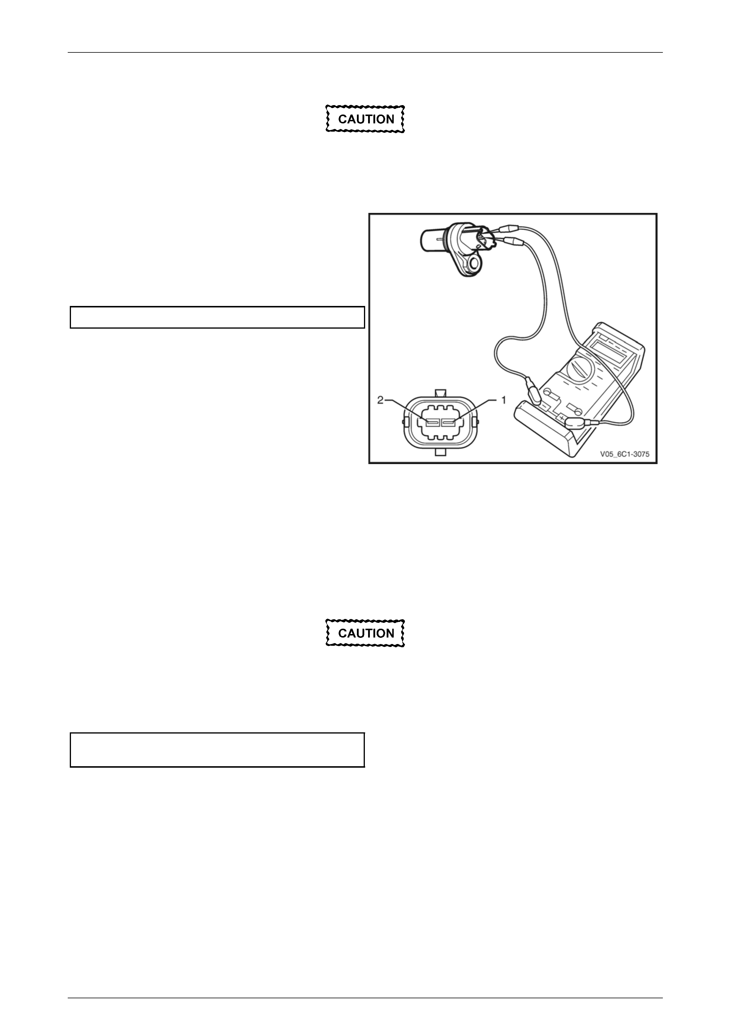
Test
To prevent component and damage use
connector test adaptor kit J 35616-A.
Resistance Check
1 Connect a digital ohmmeter using connector test
adaptor kit J 35616-A to the crankshaft position (CKP)
sensor.
2 Measure the resistance across terminals 1 and 2.
3 Compare the reading against the specification.
CKP sensor resistance @ 20°C.................850 – 1040 Ω
4 If the resistance is not within specification, replace the
CKP sensor.
Figure 6C1-3 – 41
Reinstall
Reinstallation of the crankshaft position (CKP) sensor is the reverse of the removal procedure, noting the following:
1 Lubricate the CKP sensor O-ring with clean engine oil.
2 Reinstall the CKP sensor by pushing down on the sensor to engage the sensor O-ring in the engine block.
Ensure the CKP sensor is fully seated before
tightening the attaching bolt to the specified
torque.
3 Reinstall the CKP sensor bolt and tighten to the correct torque specification.
Crankshaft position sensor attaching bolt
torque specification ...................................8.0 – 12.0 Nm
4 Road test the vehicle and check for correct operation, taking particular note there is no engine oil leak from the
CKP sensor.
Page 6C1-3–39
Engine Management – V6 – Service Operations Page 6C1-3–40
3.9 Engine Coolant Temperature Sensor
LT Section No. — 02–000
Remove
To avoid serious personal injury, never
remove the engine coolant temperature (ECT)
sensor when the engine is hot. Allow the
engine to cool to ambient temperature (less
than 50°C) before performing this procedure.
1 Turn the ignition switch off.
2 Remove Bank 2 (LHS) engine dress cover, refer to Section 6A1 Engine Mechanical – V6.
To avoid serious personal injury, never
remove the coolant filler cap when the engine
is hot. Allow the engine to cool to ambient
temperature (less than 50°C) before
performing this procedure.
3 Allow the engine to cool to ambient temperature less than 50°C, and slowly remove coolant filler cap located on the
coolant outlet housing.
4 Drain approximately two litres of coolant into a suitable container, refer to Section 6B1 – Engine Cooling – V6.
5 Disconnect the wiring harness connector (1) from the
ECT sensor (2).
Figure 6C1-3 – 42
Page 6C1-3–40
Engine Management – V6 – Service Operations Page 6C1-3–41
Clean the area around the ECT before
removal to avoid debris from entering the
engine.
6 Remove the ECT sensor (1).
NOTE
If coolant leaks from the cylinder head as the
sensor is removed, screw the sensor back into
the cylinder head and drain more coolant from
the cooling system.
7 If required, test the ECT sensor, refer to the Test in
this Section.
Figure 6C1-3 – 43
Test
To prevent component damage, use
connector test adaptor kit J 35616-A.
Resistance Check
1 Suspend the engine coolant temperature (ECT) sensor and a suitable thermometer in a container of 50/50 DEX-
COOL® long life coolant or equivalent and water.
NOTE
Neither the ECT sensor or thermometer should
rest on the bottom of the container due to an
uneven concentration of heat at this point when
the container is heated.
2 Connect a digital ohmmeter using connector test
adaptor kit J 35616-A to the ECT sensor.
3 Measure the resistance across terminals 1 and 2.
4 Whilst heating the container, observe the resistance
values as the temperature increases and compare the
temperature / resistance change to the specifications.
Figure 6C1-3 – 44
Page 6C1-3–41

Engine Management – V6 – Service Operations Page 6C1-3–42
5 If the resistance is not within specifications, replace
the ECT sensor.
Engine Coolant Temperature Vs Resistance
Temperature °C Resistance – Ohms (Ω)
-40 40490 – 50136
-20 14096 – 16827
-10 8642 – 10152
0 5466 – 6326
20 2351 – 2649
25 1941 – 2173
40 1118 – 1231
60 573 – 618
80 313 – 332
100 182 – 191
120 109 – 116
140 68 – 74
Reinstall
Reinstallation of the engine coolant temperature (ECT) sensor is the reverse of the removal procedure, noting the
following:
1 Tighten the ECT sensor to the correct torque specification.
Engine coolant temperature sensor
torque specification ............................................22.0 Nm
2 Refill the cooling system, refer to Section 6B1 Engine Cooling – V6.
3 Road test the vehicle and check for correct operation, taking particular note there is no coolant leakage.
Page 6C1-3–42
Engine Management – V6 – Service Operations Page 6C1-3–43
3.10 Engine Control Module
LT Section No. — 02–245
Service of the engine control module (ECM) should normally consist of either replacement or ECM programming. If the
diagnostic procedures call for the ECM to be replaced, it should be first checked to ensure it is the correct part. If it is,
replace the faulty ECM.
Do not touch the ECM connector pins as
electrostatic discharge (ESD) damage may
result. For further information on ESD, refer to
Section 00 Warnings, Cautions and Notes.
When removing or reinstalling the ECM wiring
harness connector/s, ensure the ignition
switch is in the OFF position and the battery
has been disconnected. Failure to do so may
result in damage to the ECM and / or
associated componentry.
Disconnection of the battery affects certain
vehicle electronic systems. Refer to
Section 00 Warnings, Cautions and Notes
before disconnecting the battery.
Remove
If replacing the ECM, it must be reset prior to
removal. Failure to perform this procedure
will result in the inability to test the ECM for
warranty purposes, refer to ECM Reset in this
Section.
1 Turn the ignition switch off.
2 Disconnect the battery.
3 Remove the Bank 1 (RHS) engine dress cover, refer to Section 6A1 Engine Mechanical – V6.
4 Disconnect the engine harness connector (1) and the front body harness connector (2) from the ECM (3). To
release each connector, lift the connector locking lever (4) whilst simultaneously pushing the connector locking
slide (5), refer to Figure 6C1-3 – 45.
Page 6C1-3–43
Engine Management – V6 – Service Operations Page 6C1-3–44
Figure 6C1-3 – 45
5 Remove the screw (1) attaching the ground
terminal (2) to the ECM (3).
6 Remove the bolt (4), four places, attaching the ECM to
the mounting bracket (5) and remove the ECM.
Figure 6C1-3 – 46
Reinstall
Reinstallation of the engine control module (ECM) is the reverse of the removal procedure, noting the following:
NOTE
During installation of the ECM, the
SICHTMUSTER ME 9.6 label (1) is positioned at
the top right-hand corner.
1 Reinstall ECM attaching bolts and tighten to the
correct torque specification.
Engine control module attaching bolt
torque specification ...................................8.0 – 12.0 Nm
2 Reinstall the ground terminal screw and tighten to the
correct torque specification.
Ground terminal attaching screw
torque specification ..............................................4.5 Nm
Figure 6C1-3 – 47
Page 6C1-3–44

Engine Management – V6 – Service Operations Page 6C1-3–45
3 Reinstall the main vehicle wiring harness connector, and engine wiring harness connector, ensuring the connector
locking lever is fully seated, refer to Figure 6C1-3 – 45.
4 If the ECM has been replaced, perform the following procedures:
• ECM service programming, refer to Section 0C Tech 2.
• ECM / PIM / BCM security link, refer to Section 6E1 Powertrain Interface Module – V6.
• Main diagnostic table functional check, refer to Section 6C1-2 Engine Management – V6 – Diagnostics.
5 If the ECM has been removed, but not replaced, perform the main diagnostic table functional check, refer to
Section 6C1-2 Engine Management – V6 – Diagnostics.
6 Start the vehicle and allow to idle.
ECM Reset
Do not perform the reset procedure within
sixty seconds of turning the ignition on.
Failure to comply may result in the ECM
failing to reset.
When an ECM is installed onto a vehicle, it is security linked to the body control module (BCM) and powertrain interface
module (PIM). Once this linking has been performed, the ECM cannot be installed in any other vehicle unless the
security linking between the BCM and the PIM has been reset using the following procedure.
NOTE
Prior to resetting the ECM, obtain the Security
Code and the BCM Security Number. This
information is found on the vehicle security card
issued with the vehicle when new. For further
information on the vehicle security card, refer to
Section 6E1 Powertrain Interface Module – V6.
1 Connect Tech 2 to the data link connector (DLC) and turn the ignition on.
2 On Tech 2 select Engine / Programming / Reset ECU.
NOTE
When Tech 2 requests programming approval,
obtain TIS approval. For further information on
TIS approval, refer to Section 0C Tech 2.
3 When Tech 2 displays Enter Security Code, enter the security code, press the Enter key and then the Okay soft
key.
4 When Tech 2 displays Turn Ignition on, press the Confirm soft key.
After resetting the ECM, the ignition switch
must be turned off for at least 10 seconds
then turned on for at least sixty seconds,
before commencing communications between
TECH 2 and the ECM.
5 When Tech 2 displays Reset Completed Successfully, press the Confirm soft key to return to the Tech 2
Programming screen.
Page 6C1-3–45
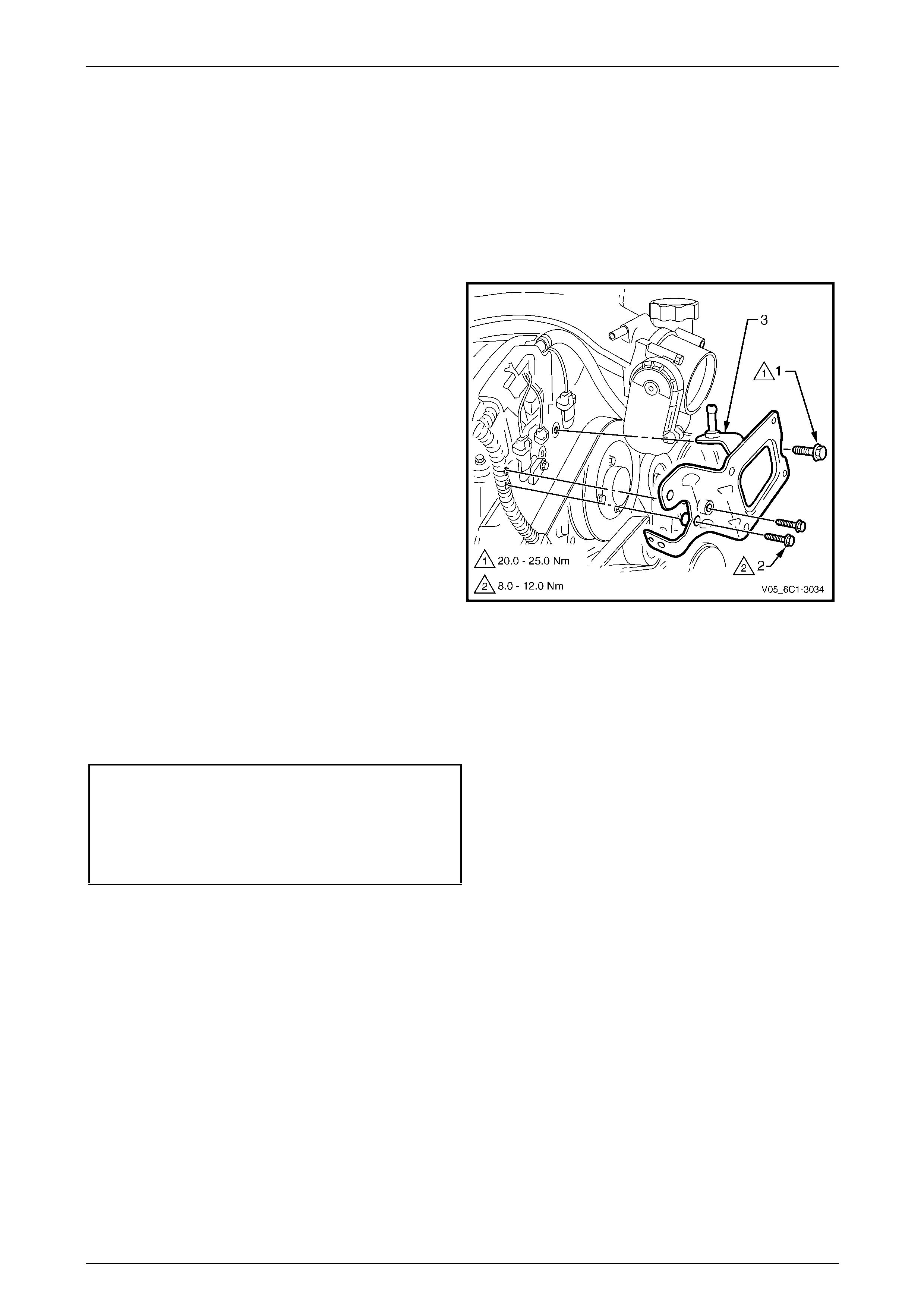
Engine Management – V6 – Service Operations Page 6C1-3–46
3.11 Engine Control Module Bracket
Assembly
LT Section No. — 02–245
Remove
1 Remove the engine control module (ECM), refer to 3.10 Engine Control Module .
2 Remove the bolt (1) and the two bolts (2), attaching
the ECM bracket assembly (3) to the front engine
cover and remove.
Figure 6C1-3 – 48
Reinstall
Reinstallation of the engine control module (ECM) bracket assembly is the reverse of the removal procedure, noting the
following:
1 Tighten the ECM bracket assembly bolts to the correct torque specification.
Engine control module bracket
assembly attaching bolt
torque specification (6mm)........................8.0 – 12.0 Nm
Engine control module bracket
assembly attaching bolt
bolt torque specification (8mm) ...............20.0 – 25.0 Nm
2 Perform the main diagnostic table functional check, refer to Section 6C1-2 Engine Management – V6 –
Diagnostics.
3 Road test the vehicle and check for correct operation.
Page 6C1-3–46
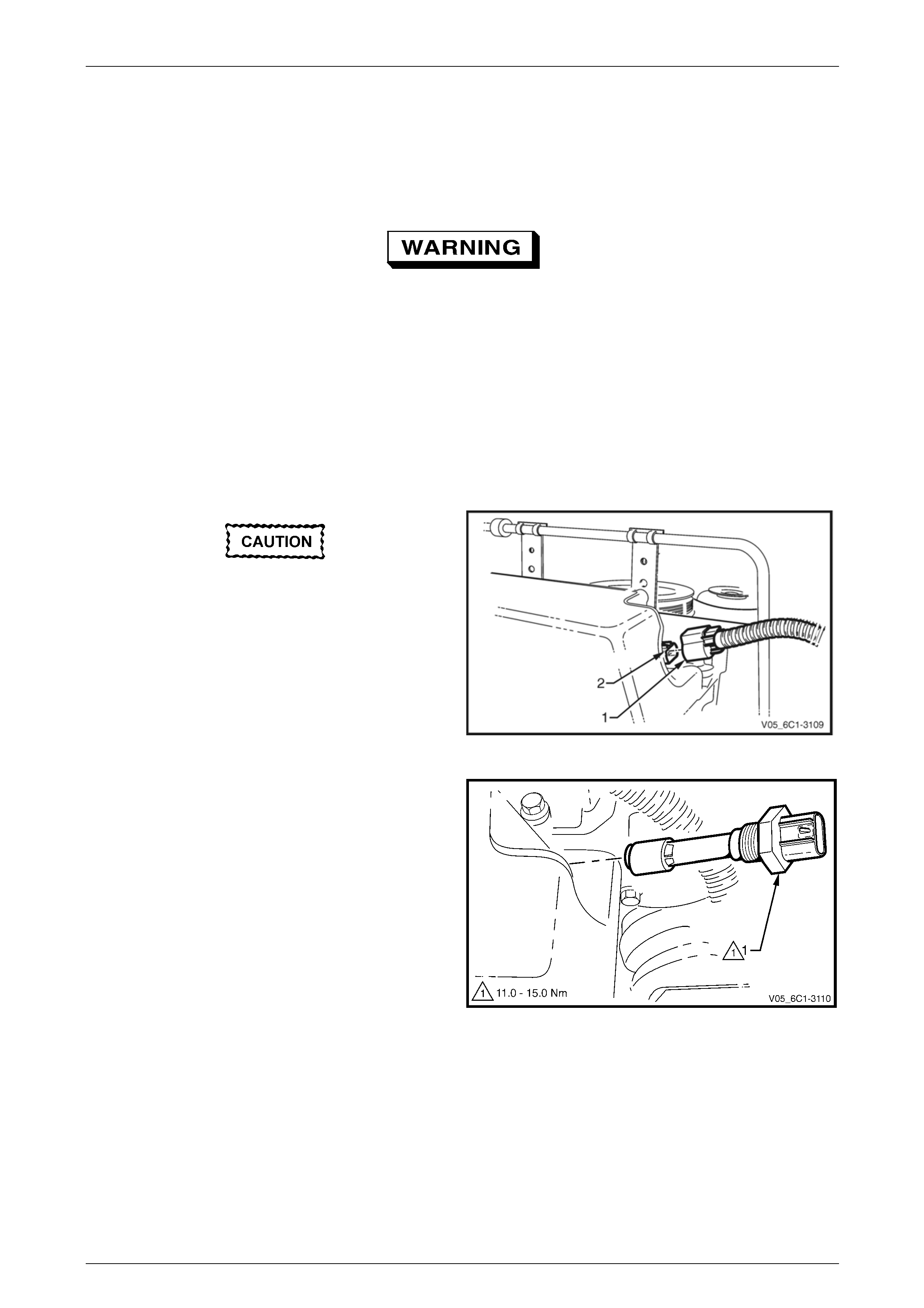
Engine Management – V6 – Service Operations Page 6C1-3–47
3.12 Engine Oil Level and Temperature
Sensor
LT Section No. —
To avoid personal injury, take care when
draining the engine oil or removing the engine
oil level and temperature sensor whilst the
engine is hot. Allow the engine to cool before
performing this procedure.
Remove
1 Turn the ignition switch off.
2 Raise the front and rear of the vehicle and support on safety stands, refer to Section 0A General Information for
location of the jacking points.
3 Drain the engine oil, refer to Section 6A1 Engine Mechanical.
Clean the area around the engine oil level
and temperature sensor before removal to
avoid debris from entering the engine.
4 Disconnect the wiring harness connector (1) from the
engine oil level and temperature sensor (2).
Figure 6C1-3 – 49
5 Using a 11/8" deep socket and socket bar, remove the
engine oil level and temperature sensor (1).
6 If required, test the Engine Oil Level and Temperature
sensor as follows, refer to the Test in this Section.
Figure 6C1-3 – 50
Page 6C1-3–47
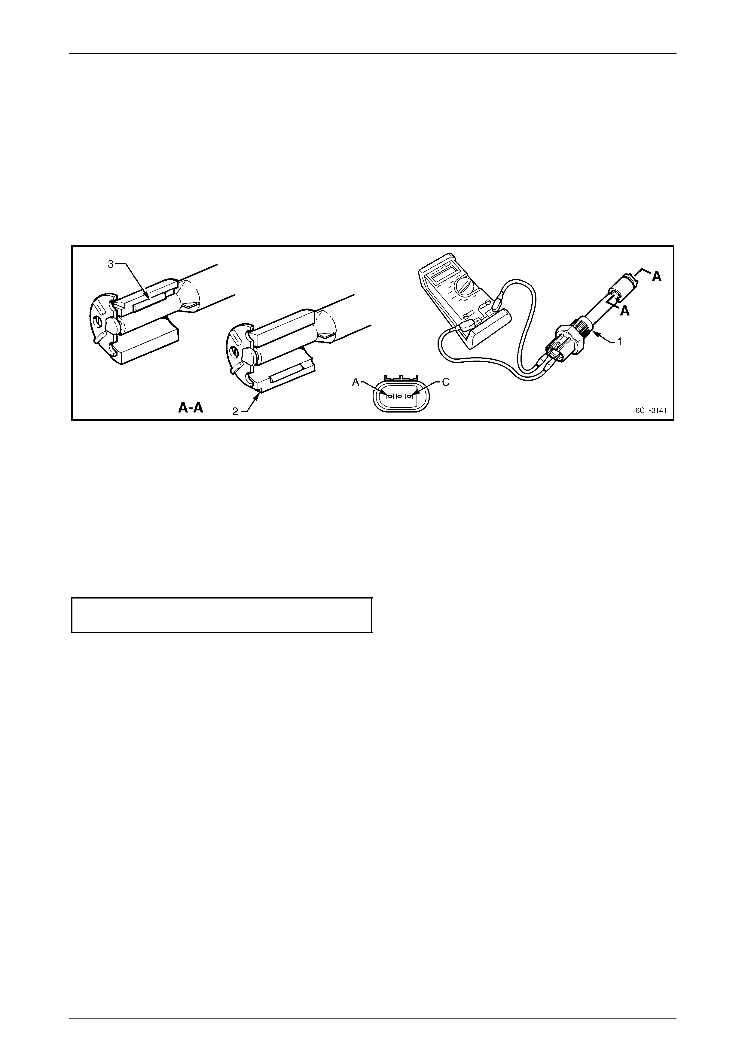
Engine Management – V6 – Service Operations Page 6C1-3–48
Test
Engine Oil Level Sensor Check
1 With the aid of an assistant, perform the following:
a Whilst holding the engine oil level and temperature sensor (1) in a level position, connect a digital ohmmeter
using connector test adaptor kit J 35616-A to terminals A and C, refer to Figure 6C1-3 – 51.
b With the flat surface of the float (2) positioned at the bottom, ensure continuity does not exist.
c Push the float upwards so the magnetic pin (3), on the inside of the float (the side of the float with the flat
side) contacts the engine oil level sensor. Check for continuity whilst holding the float in this position.
Figure 6C1-3 – 51
2 If any of the above tests fail, replace the engine oil level sensor.
Reinstall
Reinstallation of the engine oil level and temperature sensor is the reverse of the removal procedure, noting the
following:
1 Lubricate the O-ring and threaded portion of the sensor with clean engine oil.
2 Tighten the engine oil level and temperature sensor to the correct torque specification.
Engine oil level and temperature sensor
torque specification – wet .......................11.0 – 15.0 Nm
3 Refill the engine with engine oil, refer to Section 6A1 Engine Mechanical.
4 Road test the vehicle and check for correct operation, taking particular note there is no engine oil leakage from the
oil level and temperature sensor.
Page 6C1-3–48
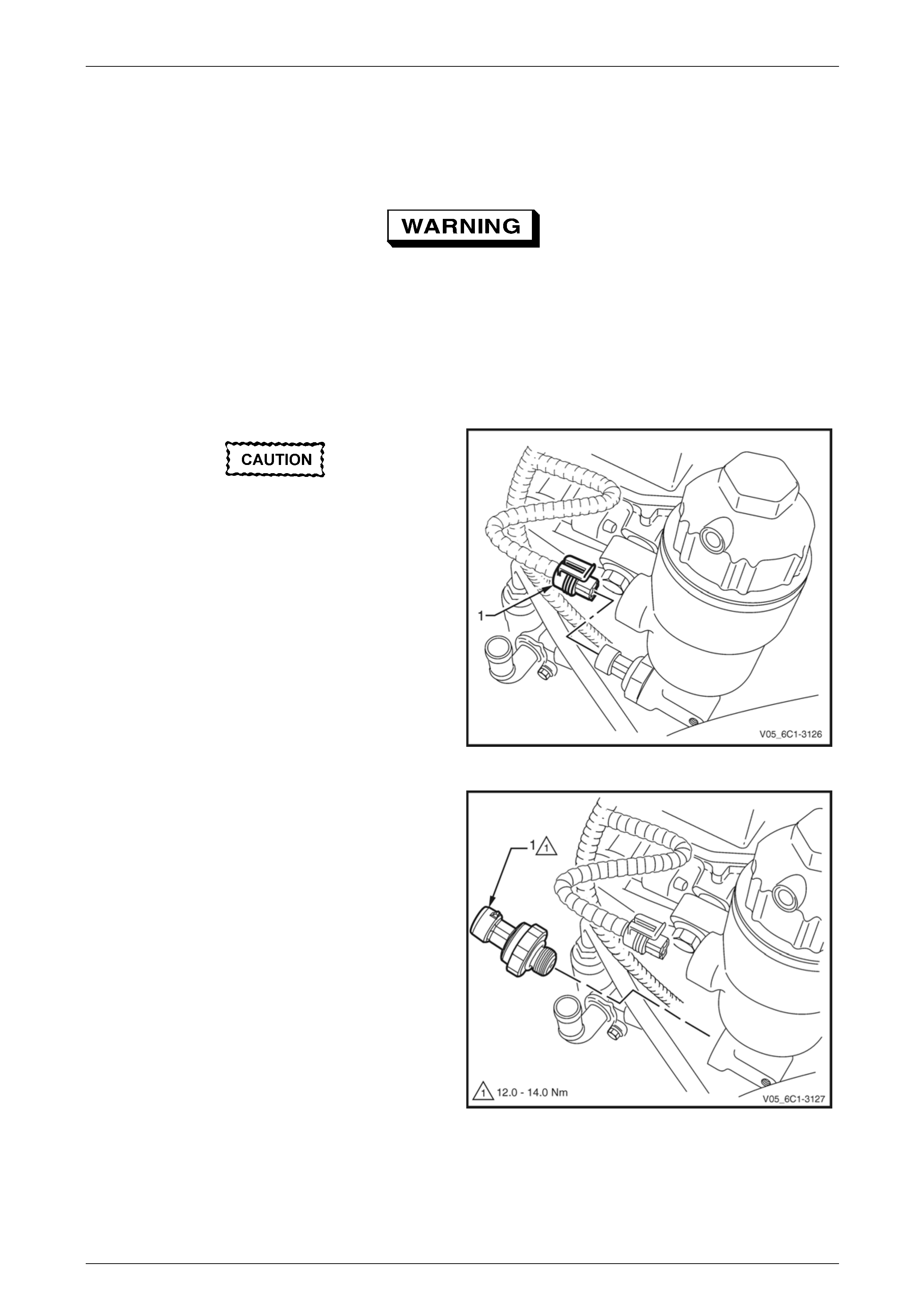
Engine Management – V6 – Service Operations Page 6C1-3–49
3.13 Engine Oil Pressure Sensor
LT Section No. —
To avoid personal injury, take care when
removing the engine oil pressure sensor
when the engine is hot. Allow the engine to
cool before performing this procedure.
Remove
1 Turn the ignition switch off.
2 Remove the Bank 2 (LHS) engine dress cover, refer to Section 6A1 Engine Mechanical – V6.
Clean the area around the engine oil pressure
sensor before removal to avoid debris from
entering the engine.
3 Disconnect the wiring harness connector (1) from the
engine oil pressure sensor.
Figure 6C1-3 – 52
NOTE
A small amount of oil will drain from the oil filter
housing when the engine oil pressure sensor is
removed. Use a shop towel to absorb the oil.
4 Using special tool J 41712 or a 11/16" deep socket
and socket bar, remove the engine oil pressure
sensor (1).
Figure 6C1-3 – 53
Page 6C1-3–49

Engine Management – V6 – Service Operations Page 6C1-3–50
Reinstall
Reinstallation of the engine oil pressure sensor is the reverse of the removal procedure, noting the following:
1 Tighten the engine oil pressure sensor to the correct torque specification.
Engine oil pressure sensor
torque specification .................................12.0 – 14.0 Nm
2 Check the engine oil level and top up if necessary, refer to Section 6A1 Engine Mechanical.
3 Road test the vehicle and check for correct operation, taking particular note there is no engine oil leakage from the
engine oil pressure switch.
Page 6C1-3–50
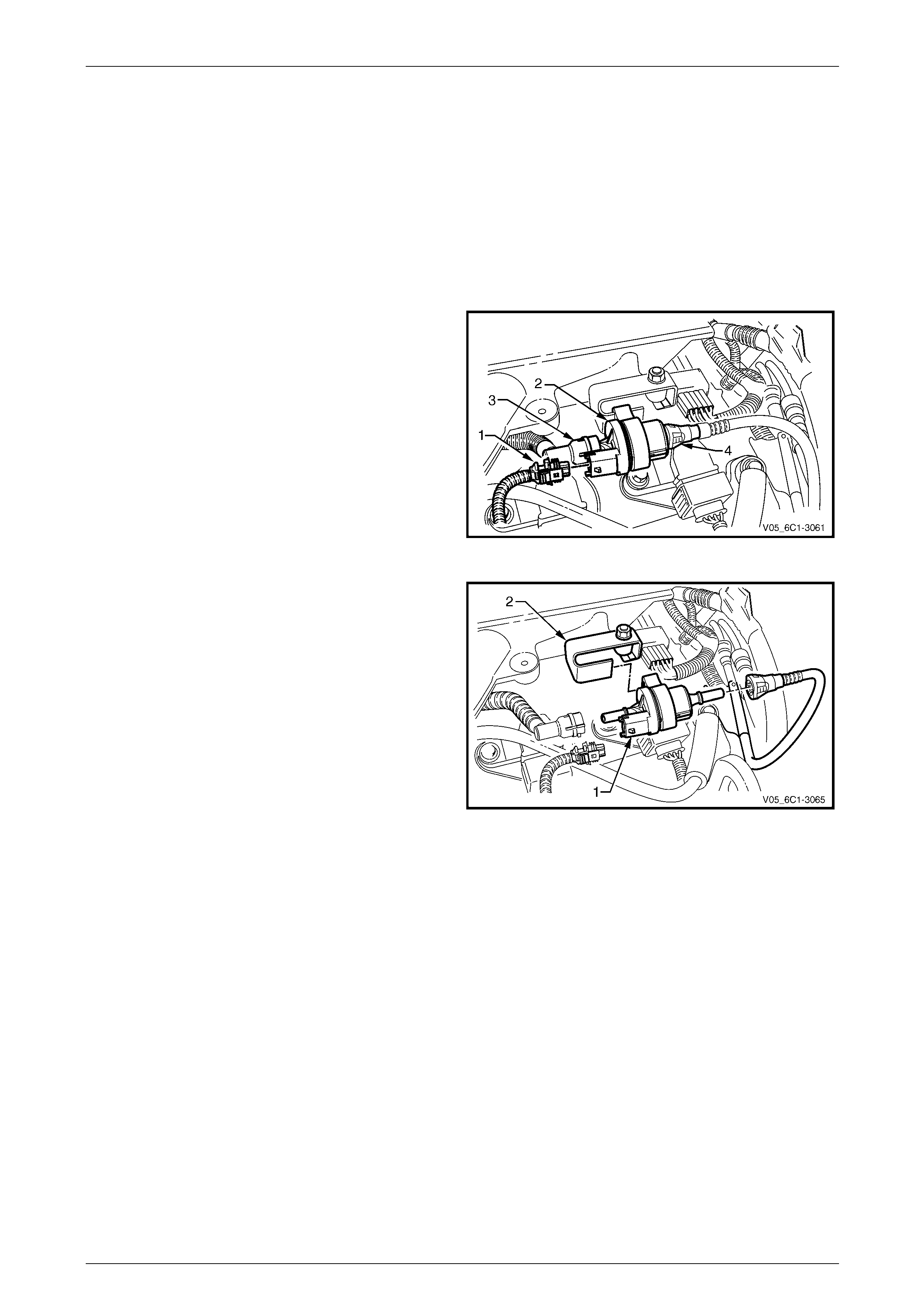
Engine Management – V6 – Service Operations Page 6C1-3–51
3.14 Evaporative Emission Canister Purge
Valve
LT Section No. — 03–165
Remove
1 Turn the ignition switch off.
2 Remove the Bank 2 (LHS) engine dress cover, refer to Section 6A1 Engine Mechanical – V6.
3 Disconnect the wiring harness connector (1) from the
evaporative emission (EVAP) canister purge valve (2).
4 Disconnect the two EVAP canister purge valve hoses
(3 and 4), refer to 2.5 Quick Connect Fittings.
Figure 6C1-3 – 54
5 Slide the EVAP canister purge valve (1) from the
purge valve mounting bracket (2).
6 If required, test the EVAP canister purge valve, refer to
the Test in this Section.
Figure 6C1-3 – 55
Page 6C1-3–51
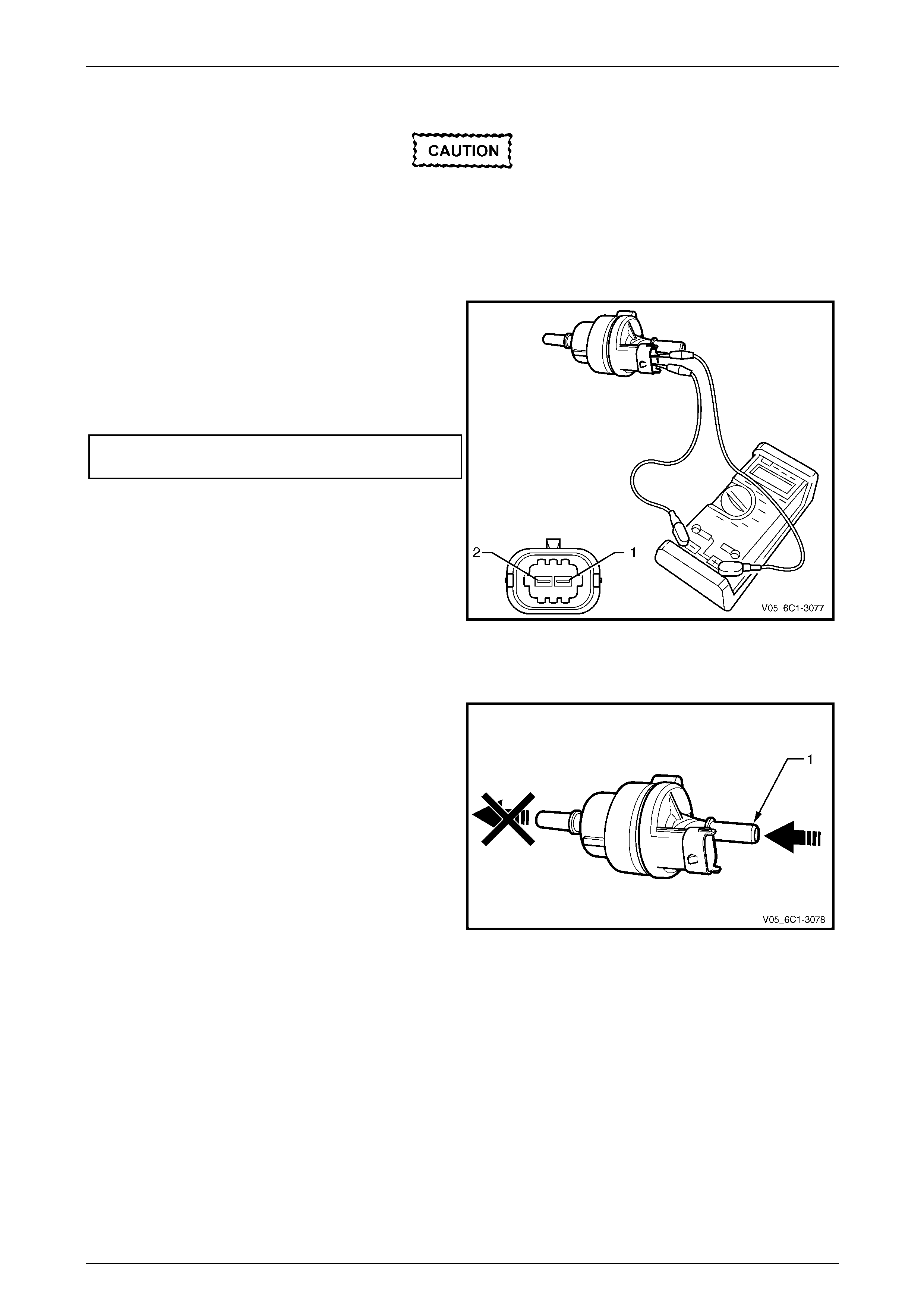
Engine Management – V6 – Service Operations Page 6C1-3–52
Test
To prevent component damage:
• Use connector test adaptor kit J 35616-A.
• When applying 12 V to a component,
always use a 3 A fused wire.
Resistance Check
1 Using a digital ohmmeter and connector test adaptor
kit J 35616-A, measure the resistance across
terminals 1 and 2.
2 Compare the reading against the specification.
3 If the resistance is not within specification, replace the
EVAP canister purge valve.
EVAP canister purge valve
resistance @ 20°C.....................................24.0 – 28.0 Ω
Figure 6C1-3 – 56
Functional Test
1 Attempt to blow air through the EVAP canister purge
valve inlet port (1). If air passes through the valve, the
valve is faulty and should be replaced.
Figure 6C1-3 – 57
Page 6C1-3–52

Engine Management – V6 – Service Operations Page 6C1-3–53
2 Using connector test adaptor kit J 35616-A, connect a
12 V battery, an on / off switch and a 3 A fused wire to
the EVAP canister purge valve terminals as follows:
• Positive lead to terminal 1.
• Negative lead to terminal 2.
Figure 6C1-3 – 58
Do not apply 12 V to the EVAP canister purge
valve continuously for more than three
seconds as the EVAP canister purge valve
will be damaged.
3 Turn the switch on, and listen for an audible click as the EVAP canister purge valve operates. Whilst the switch is in
the on position, blow air through the inlet port.
4 If no air passes through the EVAP canister purge valve, check the valve inlet and outlet ports for any obstructions
and rectify if necessary. If there are no obstructions, replace the valve.
Reinstall
Reinstallation of the evaporative emission canister purge valve is the reverse of the removal procedure, noting the
following:
1 Connect the purge valve hose quick connect fittings, refer to 2.5 Quick Connect Fittings.
2 Road test the vehicle and check for correct operation, taking particular note that no air leaks are evident.
Page 6C1-3–53
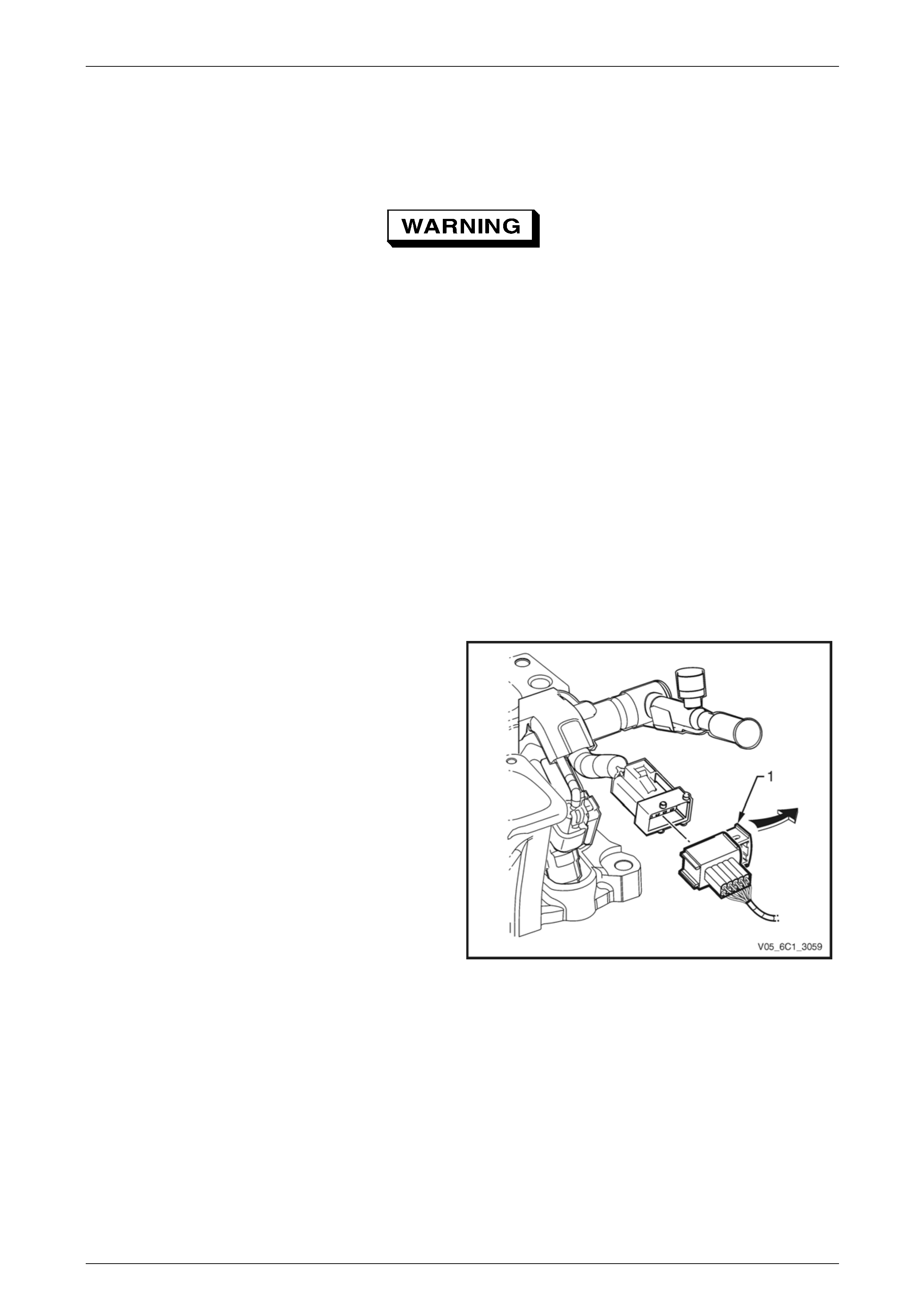
Engine Management – V6 – Service Operations Page 6C1-3–54
3.15 Fuel Rail Assembly
LT Section No. — 03–375
A depressurised fuel system contains
residual fuel that can be spilled during service
operations, refer to Section 00 Warnings,
Cautions and Notes for further information on
handling fuel.
Remove
1 Depressurise the fuel system, refer to Section 8A1 Fuel System.
2 Turn the ignition switch off.
NOTE
After removing the upper intake manifold, plug
the lower manifold opening to prevent dirt and
other contaminants from entering.
3 Remove the upper intake manifold assembly, refer to Section 6A1 Engine Mechanical.
4 Disconnect the fuel feed hose from the fuel rail, refer to Section 8A1 Fuel System. Plug the fuel line openings to
prevent dirt and other contaminants from entering.
5 Slide the engine wiring harness connector retaining
latch (1) in the direction of the arrow to disconnect the
connector from the fuel injector harness.
Figure 6C1-3 – 59
Page 6C1-3–54
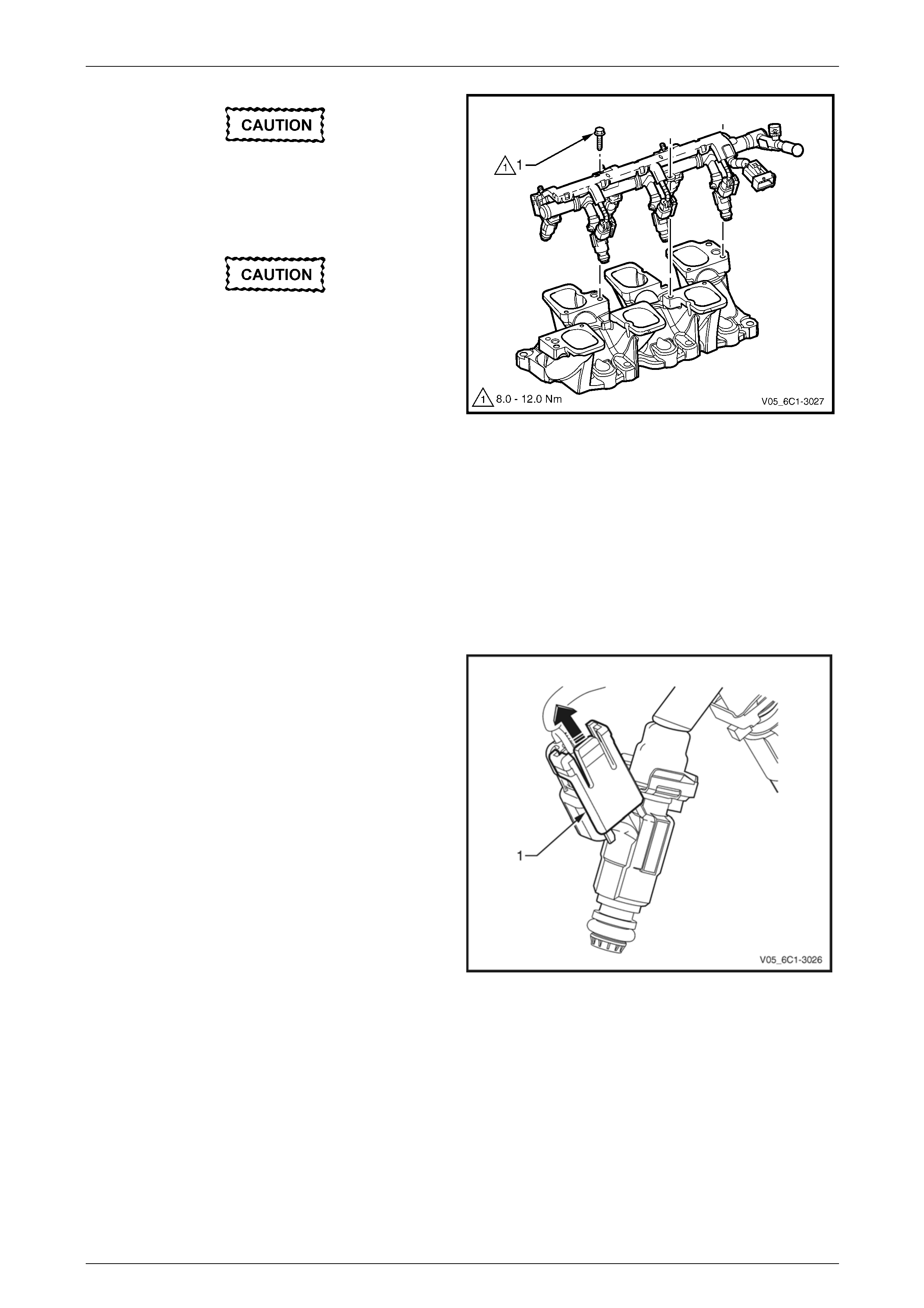
Engine Management – V6 – Service Operations Page 6C1-3–55
Clean around the area where the fuel
injectors enter the lower intake manifold.
6 Remove the bolt (1), three places, attaching the fuel
rail to the lower intake manifold.
Care must be taken when removing the fuel
rail and injector assembly to prevent damage
to the injector spray tips and injector harness
connector terminals.
Support the fuel rail and injector assembly
after removal.
7 Remove the fuel rail and injector assembly.
8 Plug all fuel line and manifold openings after removal
to prevent dirt and other contaminants from entering.
Figure 6C1-3 – 60
Disassemble
Fuel Injector
Remove
For each fuel injector:
1 Slide the fuel injector wiring connector locking tab (1)
upwards in the direction of the arrow.
2 Disconnect the connector from the fuel injector.
Figure 6C1-3 – 61
Page 6C1-3–55
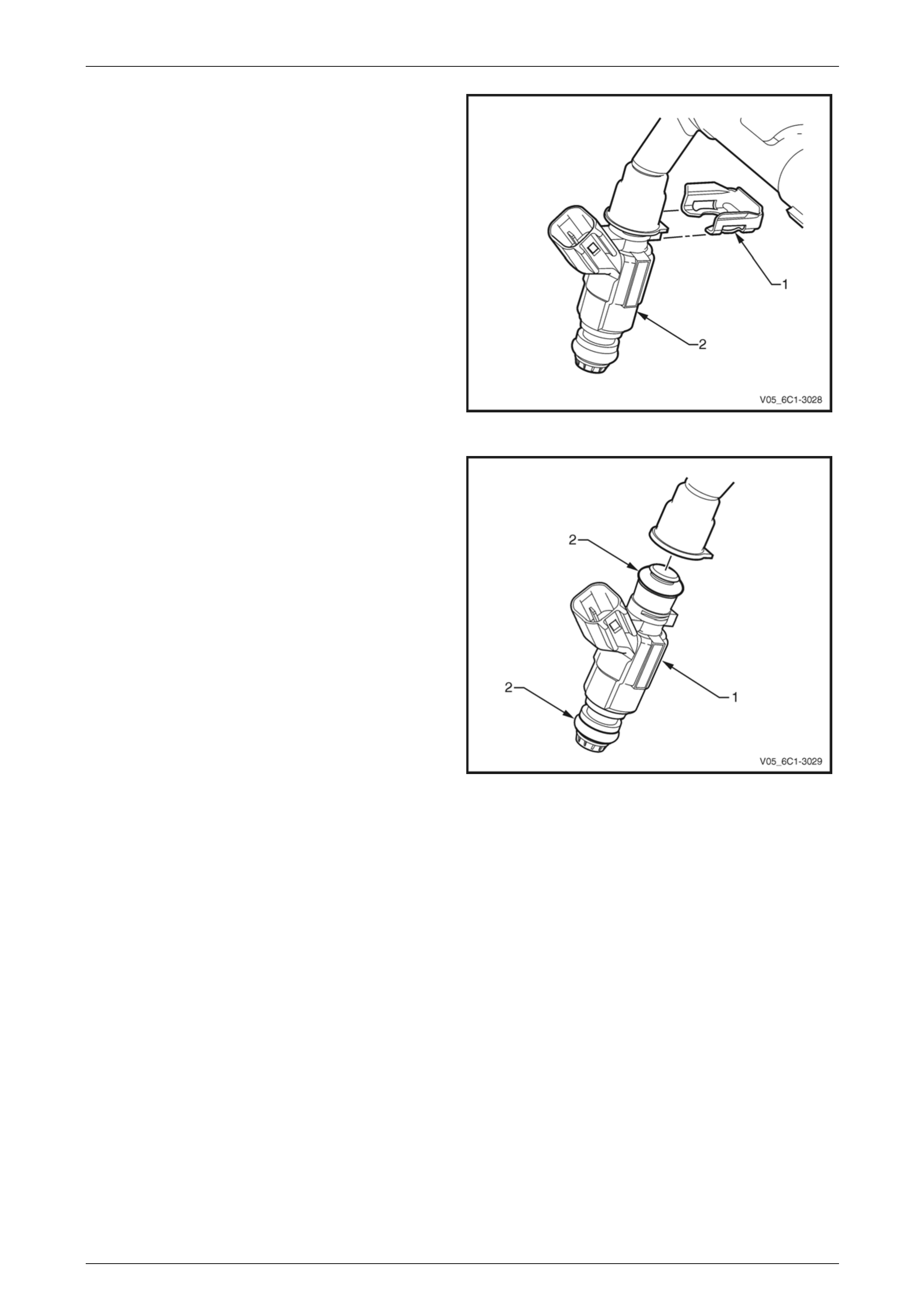
Engine Management – V6 – Service Operations Page 6C1-3–56
3 Using a flat blade screwdriver, remove the fuel injector
retaining clip (1) from the fuel injector (2). Discard the
retaining clip.
Figure 6C1-3 – 62
4 Remove the fuel injector (1) from the fuel rail.
5 Remove and discard the fuel injector seals (2).
6 As required, repeat for the remaining injectors and test
each fuel injector, refer to the Test in this Section.
Figure 6C1-3 – 63
Page 6C1-3–56
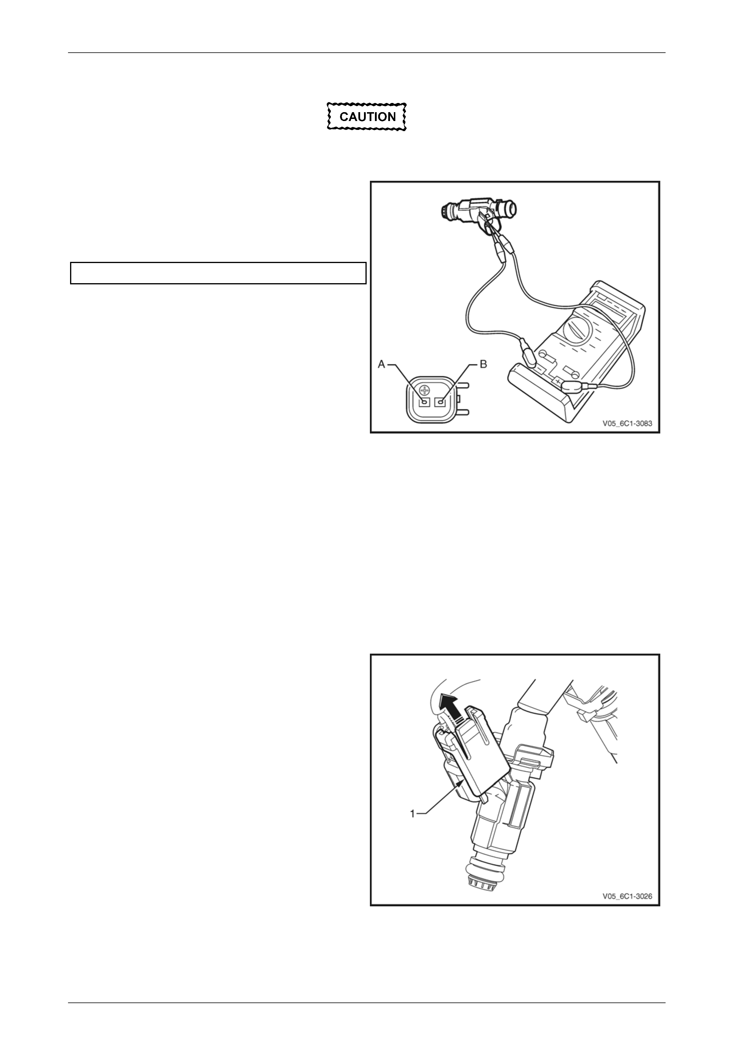
Engine Management – V6 – Service Operations Page 6C1-3–57
Test
To prevent component damage use connector
test adaptor kit J 35616-A.
1 Connect a digital ohmmeter using connector test
adaptor kit J 35616-A to the fuel injector.
2 Measure the resistance across terminals A and B.
3 Compare the reading against the specification.
Fuel injector resistance @ 20°C ...............11.4 – 12.6 Ω
4 If the resistance is not within specifications, replace
the fuel injector.
Figure 6C1-3 – 64
Reinstall
Reinstallation of the fuel injector is the reverse of the removal procedure, noting the following:
1 Install new fuel injector seals and lubricate with clean engine oil.
2 Install a new fuel injector retaining clip, refer to Figure 6C1-3 – 62.
Fuel Injector Wiring Harness Assembly
Remove
1 For each fuel injector wiring harness connector, slide
the locking tab (1) upwards in the direction of the
arrow and disconnect the connector from the fuel
injector.
Figure 6C1-3 – 65
Page 6C1-3–57
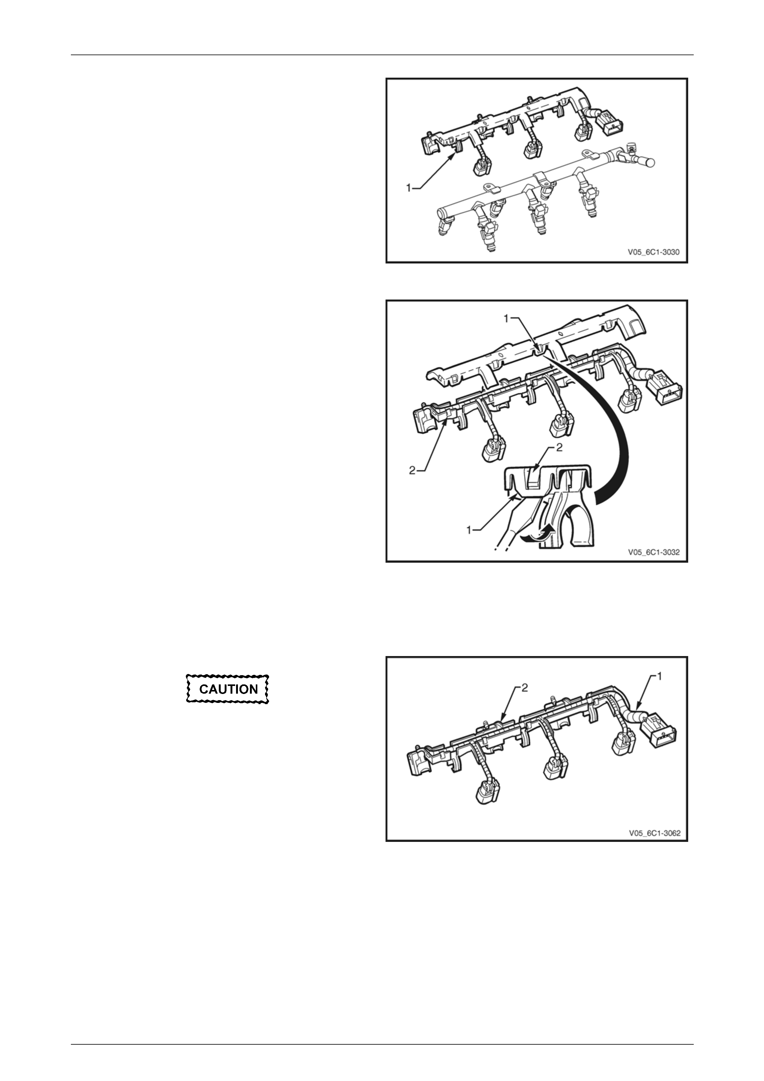
Engine Management – V6 – Service Operations Page 6C1-3–58
2 Unclip the fuel injector harness assembly (1), three
places, from the fuel rail.
Figure 6C1-3 – 66
3 Using a flat blade screwdriver, prise the fuel injector
harness upper tray retainer (1), eight places, from the
lower tray locking tang (2).
4 Remove the fuel injector harness from the lower tray.
Figure 6C1-3 – 67
Reinstall
Reinstallation of the fuel injector wiring harness assembly is the reverse of the removal procedure, noting the following:
Ensure there is no undue strain placed on the
fuel injector wiring harness (1) once it has
been positioned in the tray (2).
1 Lay the fuel injector wiring harness in the lower tray.
2 Clip the upper and lower fuel injector harness trays
together, ensuring that all eight retainers are correctly
seated.
Figure 6C1-3 – 68
Page 6C1-3–58
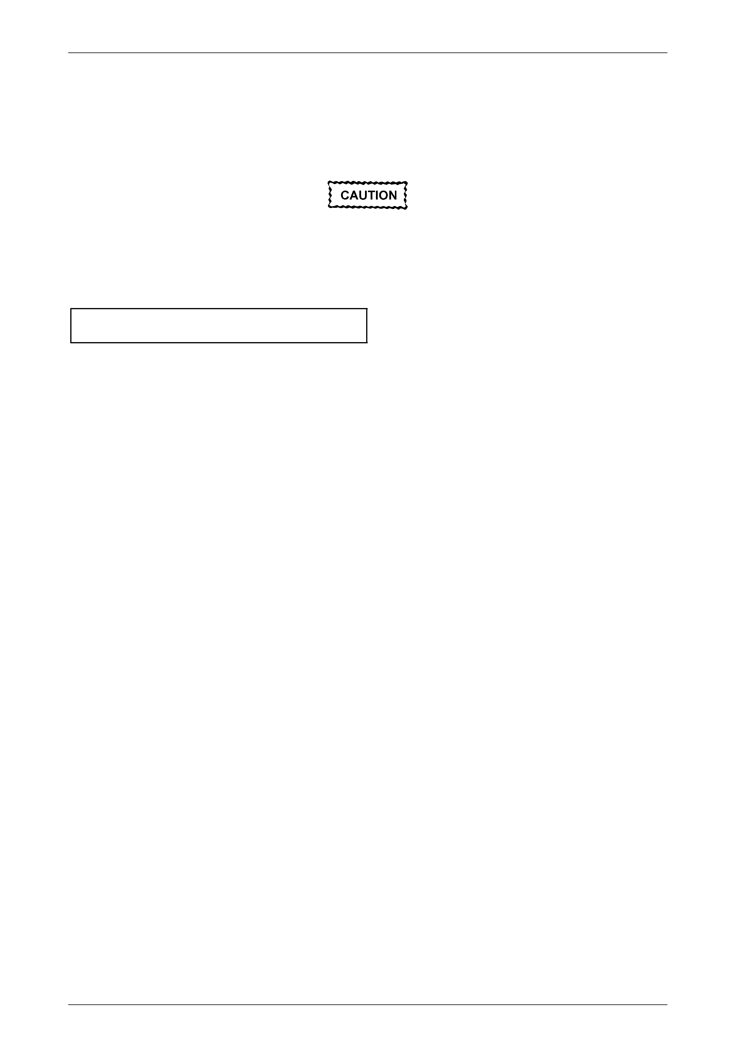
Engine Management – V6 – Service Operations Page 6C1-3–59
Reinstall
Reinstallation of the fuel rail assembly is the reverse of the removal procedure, noting the following:
1 Lubricate the fuel injector O-rings with engine oil.
2 Carefully reinstall the fuel rail and injector assembly.
Ensure the fuel injectors are correctly seated
in the lower intake manifold, and the fuel rail
attaching brackets are correctly located prior
to tightening the attaching bolts.
3 Reinstall the fuel rail attaching bolts and tighten to the correct torque specification
Fuel rail attaching bolt
torque specification ..................................8.0 – 12.0 Nm
4 Reconnect the fuel feed hose to the fuel rail, refer to Section 8A1 Fuel System.
5 Inspect the fuel rail and quick connect fitting for leaks, refer to Section 8A1 Fuel System.
6 Road test the vehicle and check for correct operation.
Page 6C1-3–59
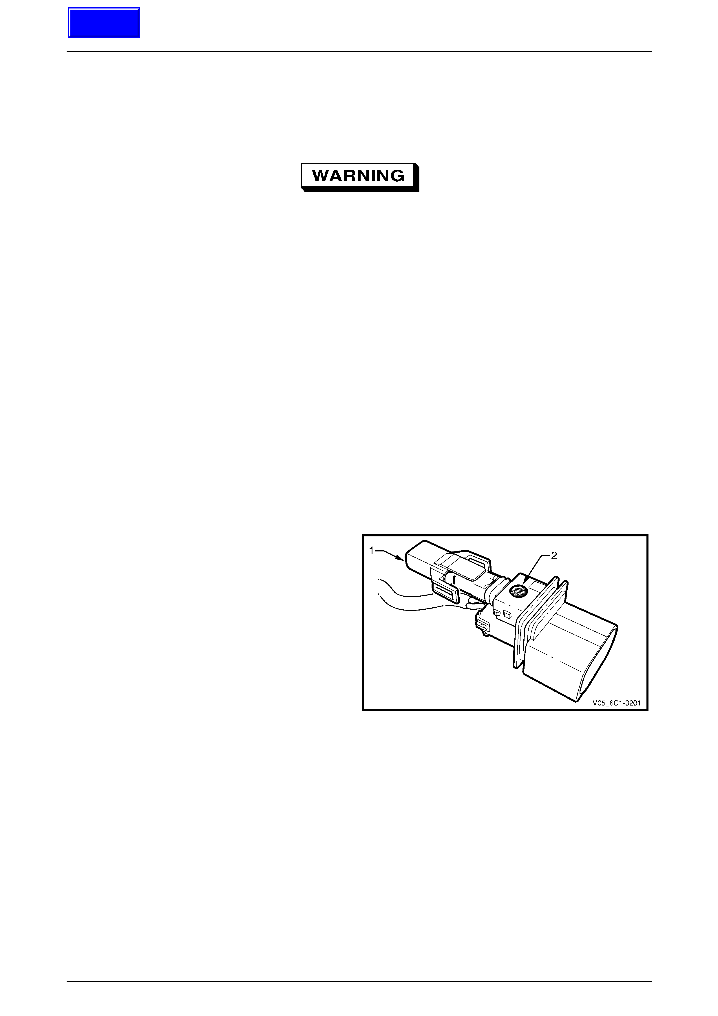
Engine Management – V6 – Service Operations Page 6C1-3–60
3.16 Heated Oxygen Sensor
LT Section No. — 00–450
To avoid the possibility of personal injury,
allow the exhaust pipe to cool to ambient
temperature (less than 50°C) before
attempting to remove the oxygen sensor.
Vehicles fitted with the Alloytec190 engine have four heated oxygen sensors (HO2S), with the pre-catalytic converter
HO2S being of the six wire wide-band type, and the post-catalytic converter HO2S the four wire planar type.
The pre-catalytic converter HO2S wiring connects to the engine wiring harness, whilst the post-catalytic converter HO2S
connect to the transmission wiring harness.
Vehicles fitted with the Alloytec engine have two pre-catalytic converter, four wire heated planar type HO2S which are
connected to the transmission wiring harness.
Service Precautions
• Handle the HO2S carefully. Do not drop it, and keep it free of grease, dirt and other contaminants. Do not use
cleaning solvents of any type on the HO2S.
• Do not repair the HO2S or any of its parts. Replace the HO2S if any damage is evident.
• The HO2S may be difficult to remove when the engine is cold. Excessive force may damage the threads in the
exhaust manifold or exhaust pipe.
• If the HO2S has been removed, but not replaced, anti-seize compound must be applied to the threads prior to
installation. New HO2S will already have the anti-seize compound applied
• For vehicles with the six wire HO2S sensor, under no
circumstances should the protective cover (1) be
removed, or the gortex filter (2) be covered and / or
sealed.
Figure 6C1-3 – 69
Six Wire Sensor
The replacement procedure for Bank 1 and Bank 2 six wire heated oxygen sensor (HO2S) are typically the same, with
the following procedure being specific to Bank 1.
Remove
1 Turn the ignition switch off.
2 Remove the engine dress cover, refer to Section 6A1 Engine Mechanical – V6.
3 Unclip the HO2S wiring harness connector assembly (1) from the ignition coil wiring harness tray, refer to Figure
6C1-3 – 70. View A refers to Bank 1, and View B refers to Bank 2.
4 Slide the connector locking tang (2) away from the harness connector.
5 Separate the harness connector (3).
Page 6C1-3–60
Techline
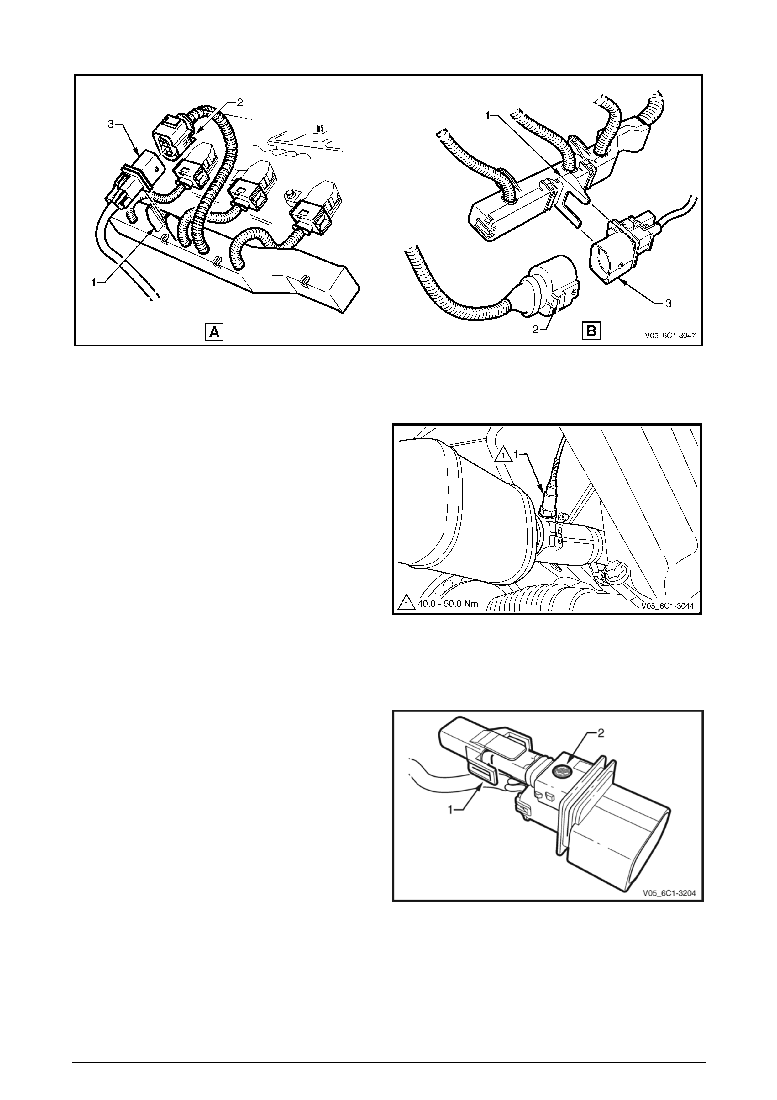
Engine Management – V6 – Service Operations Page 6C1-3–61
Figure 6C1-3 – 70
6 Raise the front of the vehicle and support on safety stands. Refer to Section 0A General Information for location of
the jacking points.
7 Unscrew the HO2S (1) from the exhaust pipe and
remove.
8 If required, test the HO2S, refer to the Test in this
Section.
Figure 6C1-3 – 71
Reinstall
Reinstallation of the heated oxygen sensor (HO2S) is the reverse of the removal procedure, noting the following:
1 Ensure the protective cover (1) is securely in place,
and the gortex filter (2) has not been covered or
sealed.
Figure 6C1-3 – 72
Page 6C1-3–61
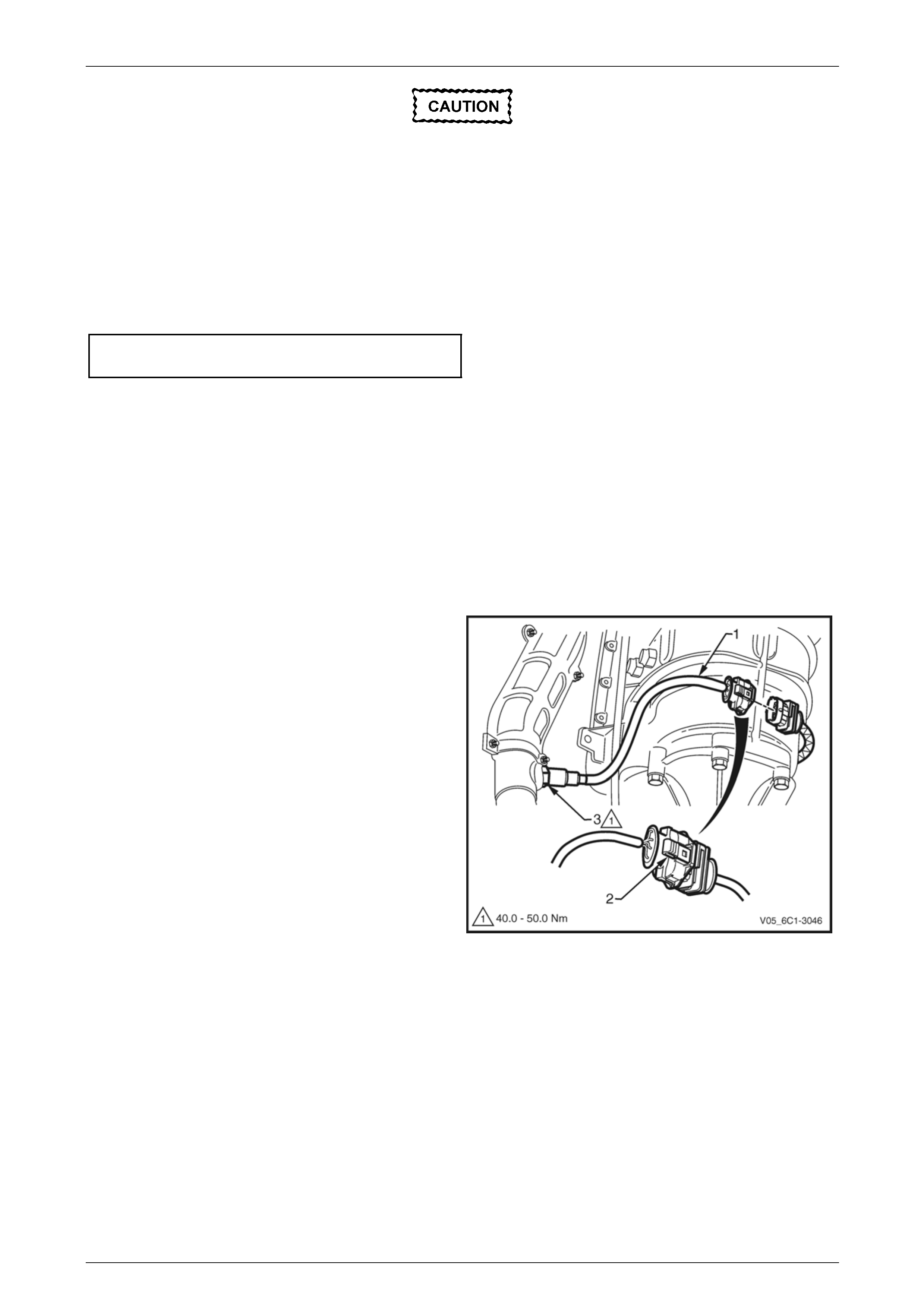
Engine Management – V6 – Service Operations Page 6C1-3–62
A special anti-seize compound is used on the
HO2S threads. A new HO2S will already have
the anti-seize compound applied to the
threads.
If a HO2S has been removed, but not
replaced, an anti-seize compound must be
applied to the threads prior to installation.
2 Coat the cleaned threads of the HO2S with anti-seize compound.
3 Tighten the HO2S to the correct torque specification.
Heated oxygen sensor
torque specification .................................40.0 – 50.0 Nm
4 Road test the vehicle and check for correct operation, taking particular note that no exhaust leakage is evident.
Four Wire Sensor
The replacement procedure for Bank 1 (LHS) and Bank 2 (RHS) four wire heated oxygen sensor (HO2S) are typically the
same, with the following procedure being specific to Bank 2.
Remove
1 Turn the ignition switch off.
2 Raise the front of the vehicle and support on safety stands, refer to Section 0A General Information for location of
the jacking points.
3 Unclip the HO2S wiring harness (1) from the
transmission.
4 Depress the harness connector retaining clip (2) and
separate the harness connectors.
5 Unscrew the HO2S (3) from the exhaust pipe and
remove.
6 If required, test the HO2S, refer to the Test in this
Section.
Figure 6C1-3 – 73
Page 6C1-3–62
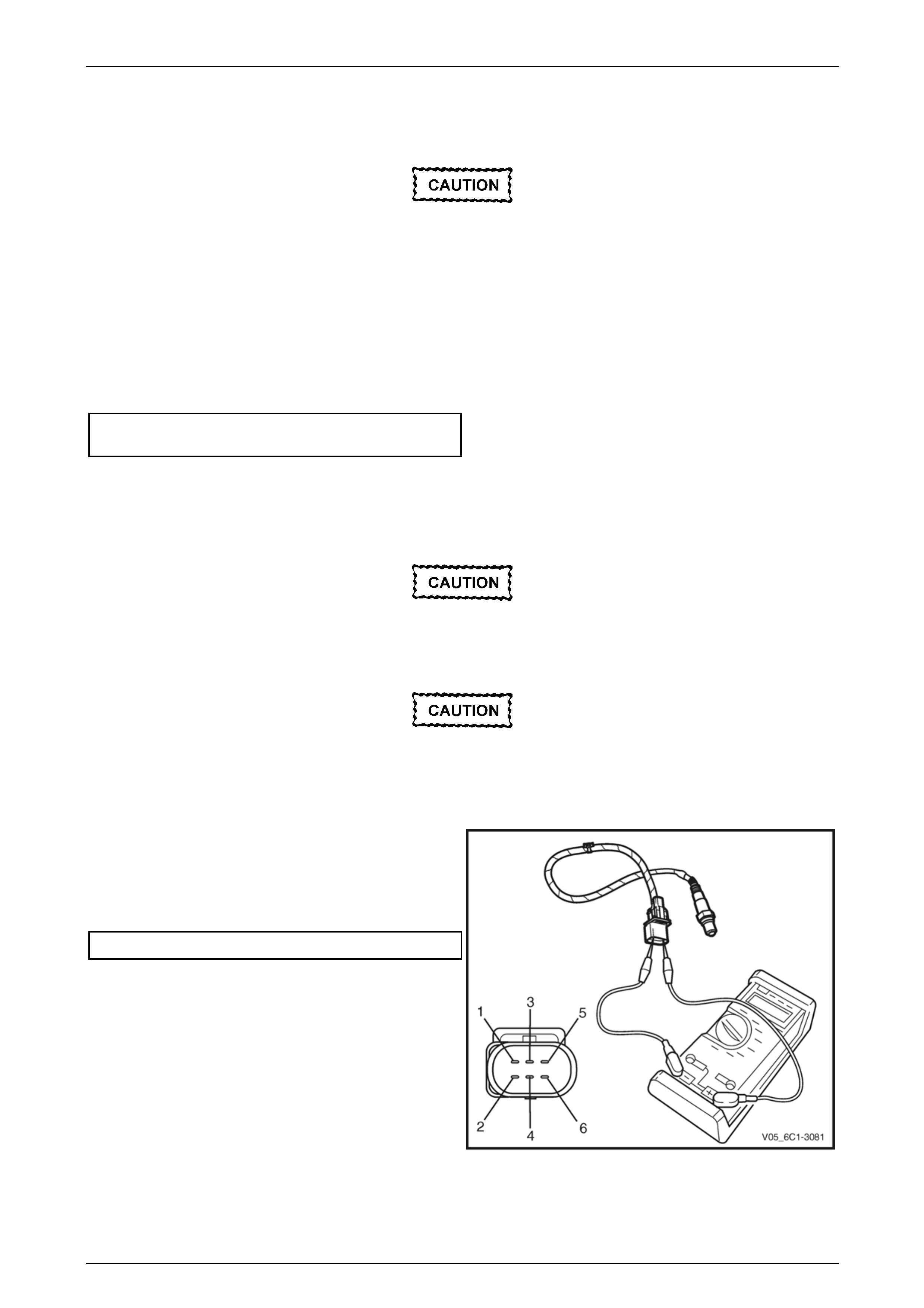
Engine Management – V6 – Service Operations Page 6C1-3–63
Reinstall
Reinstallation of the heated oxygen sensor (HO2S) is the reverse of the removal procedure, noting the following:
A special anti-seize compound is used on the
HO2S threads. A new HO2S will already have
the anti-seize compound applied to the
threads.
If a HO2S has been removed, but not
replaced, then anti-seize compound must be
applied to the threads prior to installation.
1 Coat the cleaned threads of the sensor with anti-seize compound.
2 Tighten the HO2S to the correct torque specification.
Heated oxygen sensor
torque specification .................................40.0 – 50.0 Nm
3 Road test the vehicle and check for correct operation, taking particular note that no exhaust leakage is evident.
Test
Under no circumstances should battery
voltage be applied to the heated oxygen
sensor (HO2S) heater.
To prevent component damage use connector
test adaptor kit J 35616-A.
Heater Resistance Check – Six Wire HO2S
1 Connect a digital ohmmeter using connector test
adaptor kit J 35616-A to the HO2S
2 Measure the resistance across terminals 3 and 4.
3 Compare the reading against the specification.
HO2S heater resistance @ 20°C .................8.0 – 10.0 Ω
4 If the resistance is not within specification, replace the
HO2S.
Figure 6C1-3 – 74
Page 6C1-3–63
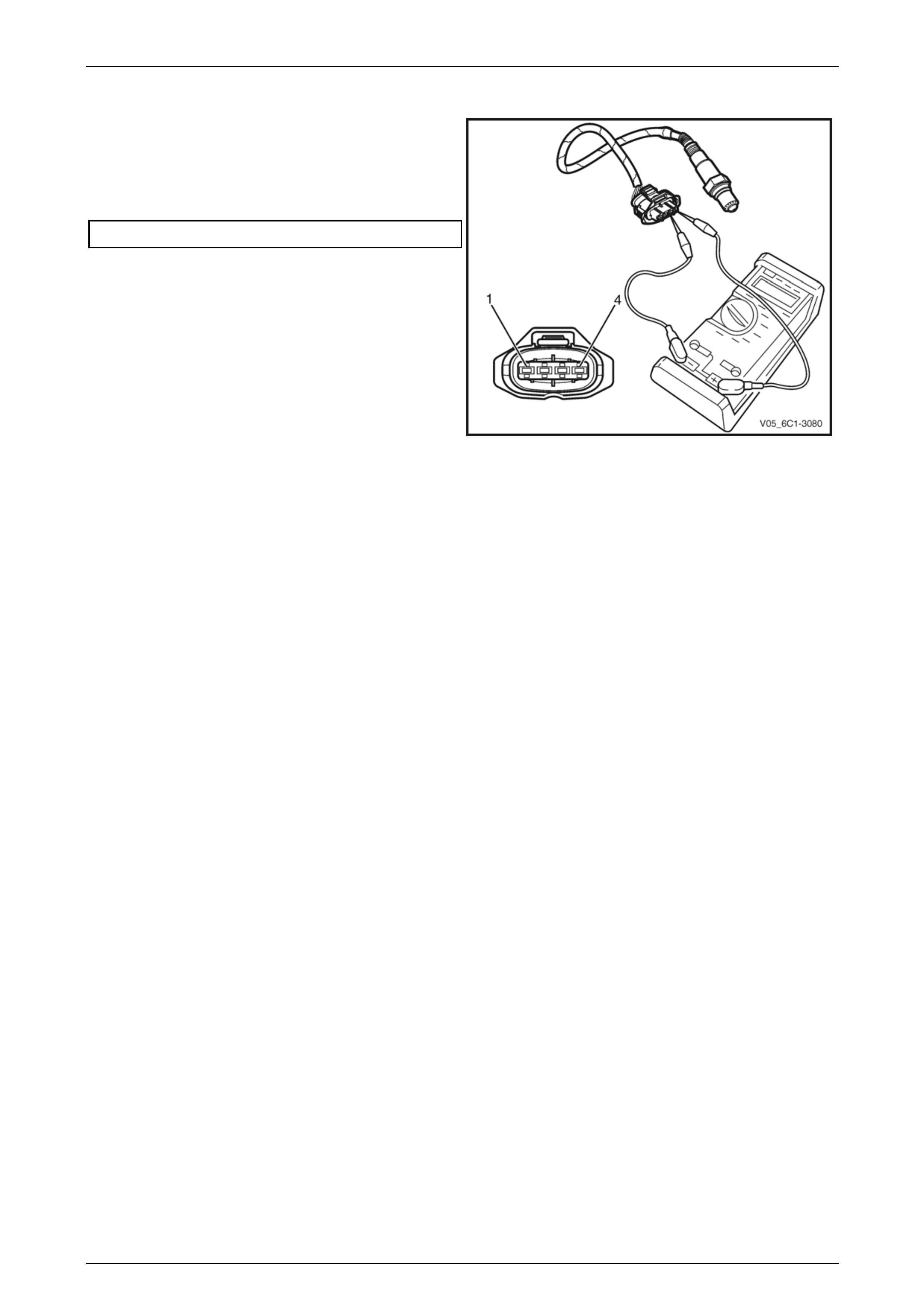
Engine Management – V6 – Service Operations Page 6C1-3–64
Heater Resistance Check – Four Wire HO2S
1 Connect a digital ohmmeter using connector test
adaptor kit J 35616-A to the HO2S
2 Measure the resistance across terminals 1 and 2.
3 Compare the reading against the specification.
HO2S heater resistance @ 20°C .................8.0 – 10.0 Ω
4 If the resistance is not within specification, replace the
HO2S.
Figure 6C1-3 – 75
Page 6C1-3–64
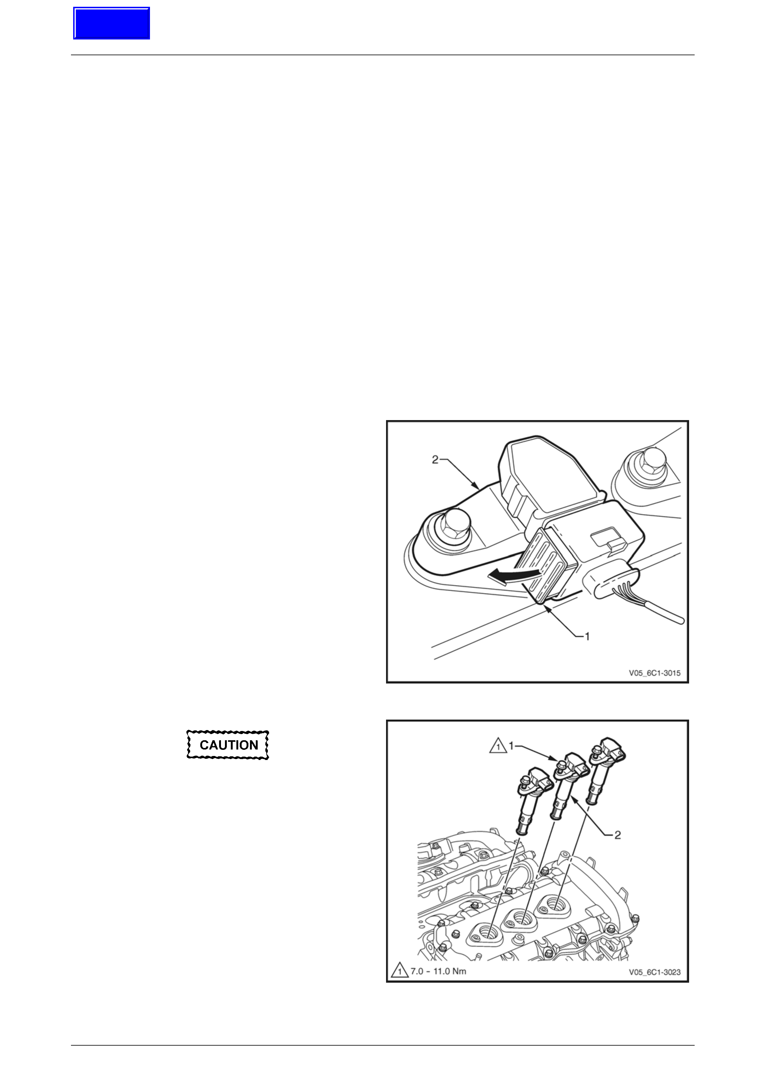
Engine Management – V6 – Service Operations Page 6C1-3–65
3.17 Ignition Coil
LT Section No. — 02–225
Ignition Coils
The replacement procedure for all ignition coils is the same except for the removal of the ignition coil on cylinder No's 1,
3 and 4, it is necessary to remove the upper intake manifold assembly.
Remove
1 Turn the ignition switch off.
2 Remove Bank 1 (RHS) engine dress cover, refer to Section 6A1 Engine Mechanical – V6.
NOTE
If the upper intake manifold has been removed,
plug the lower manifold openings to prevent dirt
and other contaminants from entering.
3 If required, remove the upper intake manifold assembly, refer to Section 6A1 Engine Mechanical – V6.
4 Using a flat-blade screwdriver, slide the connector
retaining latch (1) in the direction of the arrow.
5 Remove the wiring harness connector from the ignition
coil (2).
Figure 6C1-3 – 76
Clean the area around the ignition coil before
removal to avoid debris from entering the
engine.
6 Fully loosen the bolt (1) attaching the ignition coil (2) to
the camshaft cover.
NOTE
The ignition coil bolts are captive. Do not attempt
to remove the bolts from the ignition coil.
7 Remove the ignition coil by first, twisting the coil to
release it, and then pulling the ignition coil upwards to
remove it.
Figure 6C1-3 – 77
Page 6C1-3–65
Techline
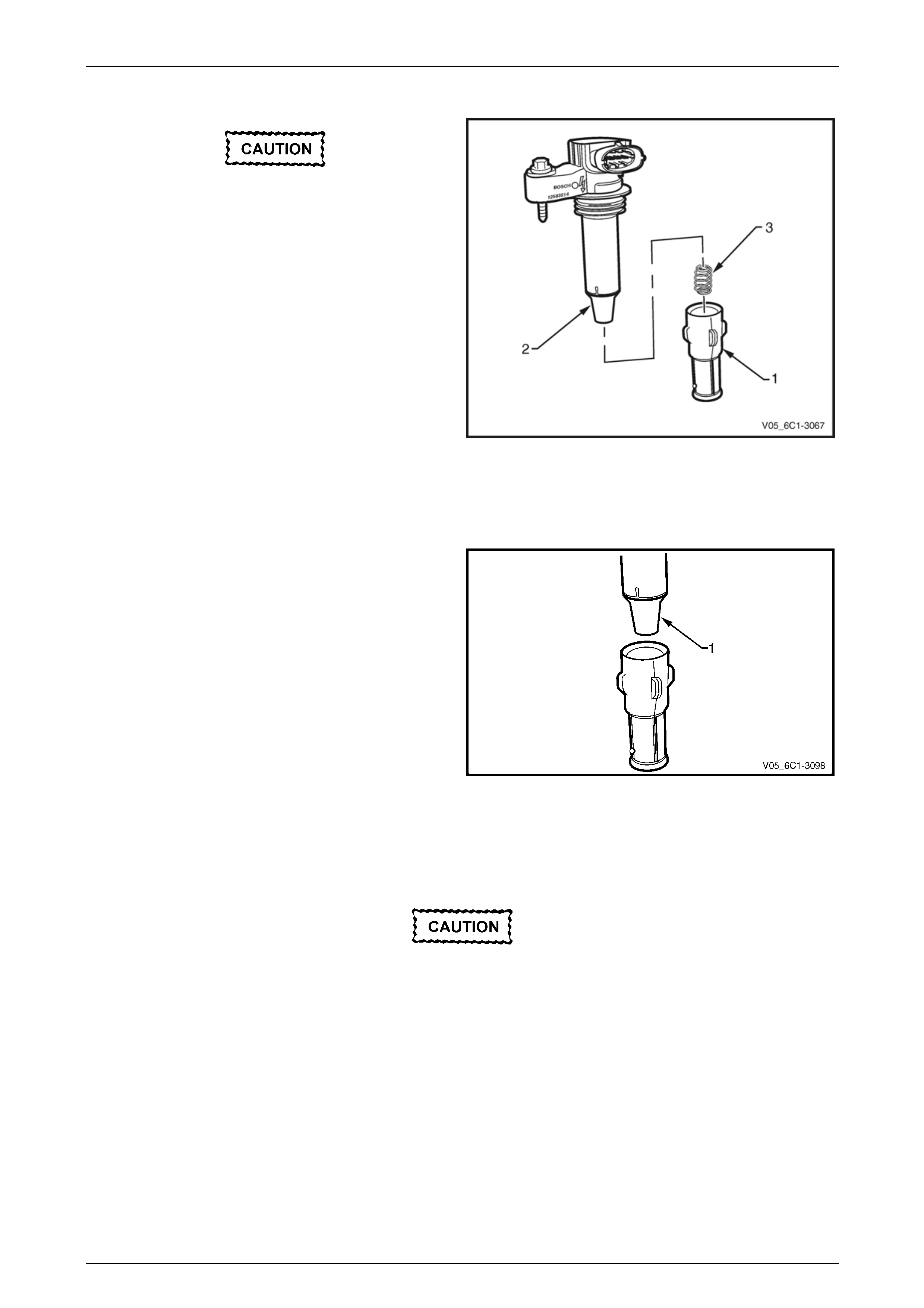
Engine Management – V6 – Service Operations Page 6C1-3–66
Disassemble
Do not use a sharp implement such as a knife
to cut the ignition coil boot (1) from the
ignition coil. Using a sharp implement may
damage the ignition coil insulator (2).
1 Using your thumb, work the ignition coil boot off the
ignition coil insulator.
NOTE
Take care the spring (3) does not become
dislodged as the boot is removed.
To aid removal of the boot, use a blunt
instrument to lift the boot edge away from the
coil insulator and spray a release agent between
the boot and the coil insulator.
2 Remove the spring from the ignition coil insulator. Figure 6C1-3 – 78
Reassemble
1 Position the spring (3) in the insulator recess, refer to Figure 6C1-3 – 78
2 Lubricate the ignition coil insulator (1) with talcum
powder.
3 Fit the ignition coil boot, ensuring it is fully seated at
the top of the insulator.
Figure 6C1-3 – 79
Test
Never probe the ignition coil with a 12 V tester
as the ignition coil will be damaged.
Due to the internal components of the ignition coil assembly, it is not possible to perform any primary and / or secondary
resistance checks. For further information on the ignition coil operation, refer to Section 6C1-1 Engine Management – V6
– General Information.
Page 6C1-3–66
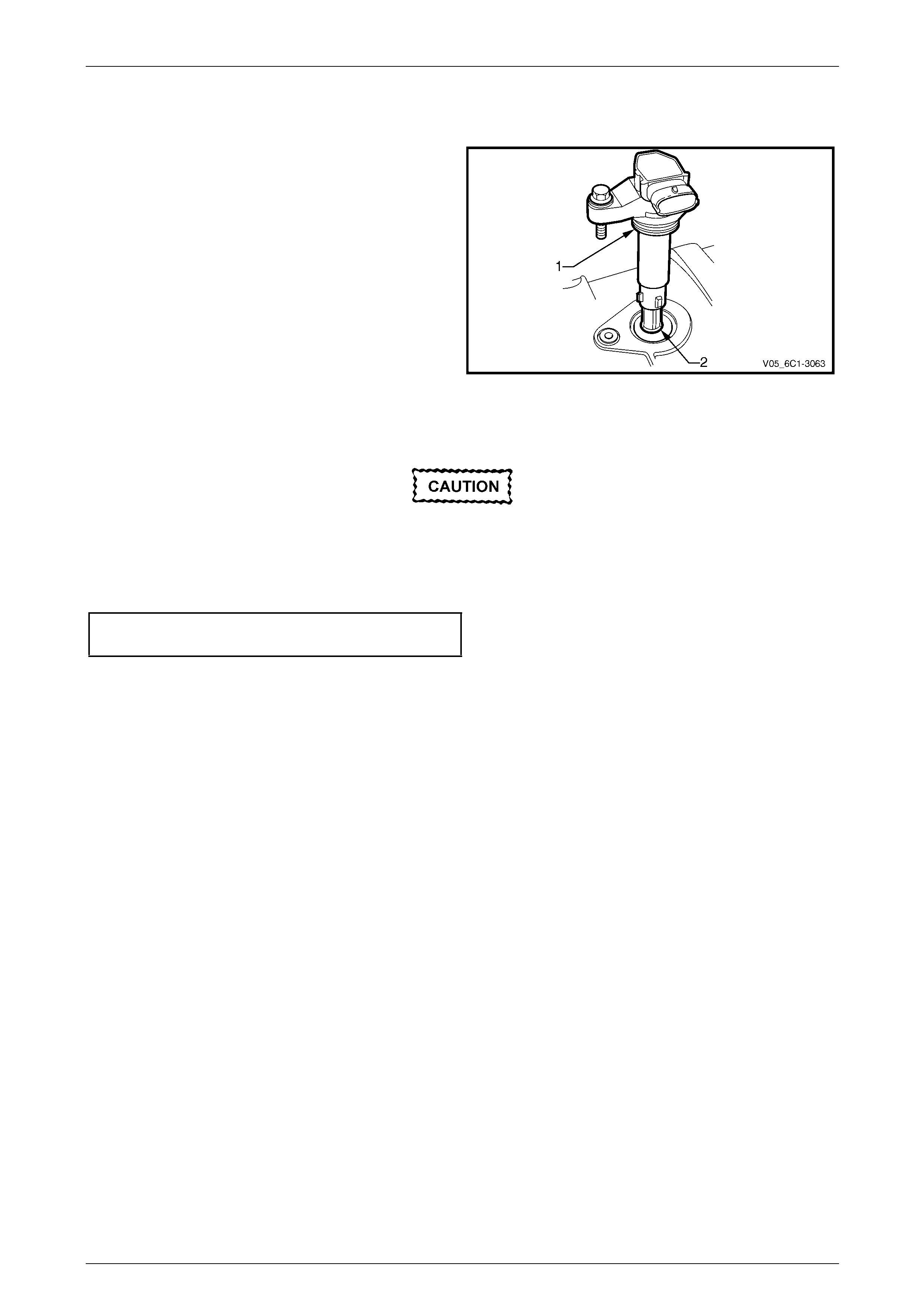
Engine Management – V6 – Service Operations Page 6C1-3–67
Reinstall
Reinstallation of the ignition coil is the reverse of the removal procedure, noting the following:
1 Lubricate the ignition coil sealing rubber (1) with clean
engine oil, and the inside of the ignition coil boot (2)
with talcum powder.
Figure 6C1-3 – 80
2 Reinstall the ignition coil by pushing down on the ignition coil to engage the sealing rubber in the camshaft cover.
Ensure the ignition coil is fully seated before
tightening the attaching bolt to the specified
torque.
3 Reinstall the ignition coil bolt and tighten to the correct torque specification.
Ignition coil attaching bolt
torque specification ...................................7.0 – 11.0 Nm
4 Road test the vehicle and check for correct operation.
Page 6C1-3–67
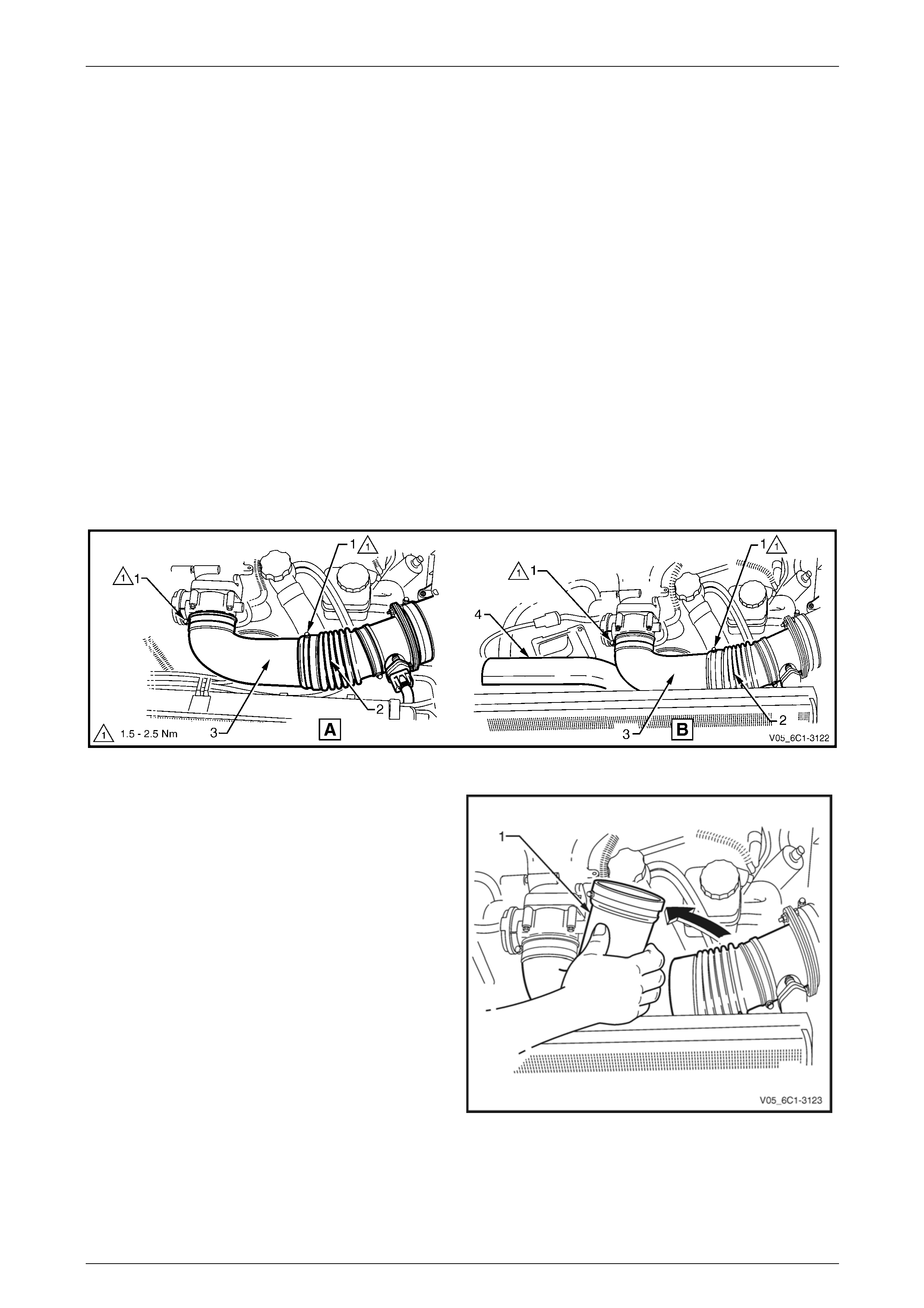
Engine Management – V6 – Service Operations Page 6C1-3–68
3.18 Intake Air Duct Assembly
LT Section No. — 03–250
Remove
1 Turn the ignition switch off.
2 Remove the upper radiator shroud, refer to Section 6B1 – Engine Cooling – V6 Engine.
NOTE
View A in Figure 6C1-3 – 81 refers to the Alloytec
engine.
NOTE
View B in Figure 6C1-3 – 81 refers to the
Alloytec190 engine.
3 Loosen the two air intake duct retaining clamps (1), refer to Figure 6C1-3 – 81.
4 Pull the flexible air intake duct (2) away from the air intake duct (3).
Figure 6C1-3 – 81
5 Rotate the air intake duct (1) in the direction of the
arrow and pull it from the throttle body.
NOTE
When rotating the air intake duct on vehicles
with Alloytec190 engine, guide the intake duct
resonance tube (4) to prevent it fouling the
radiator. Refer to View B, Figure 6C1-3 – 81.
Figure 6C1-3 – 82
Page 6C1-3–68

Engine Management – V6 – Service Operations Page 6C1-3–69
Reinstall
Reinstallation of the air intake duct is the reverse of the removal procedure, noting the following:
Ensure the air intake duct sealing rubber is
correctly positioned on the throttle body.
Failure to do this may result in engine
damage due to unfiltered air entering the
engine intake system.
1 Reinstall the air intake duct and tighten the retaining clamps to the correct torque specification.
Air intake duct retaining clamp
torque specification .....................................1.5 – 2.5 Nm
2 Road test the vehicle and check for correct operation, taking particular note that no air leaks are evident.
Page 6C1-3–69
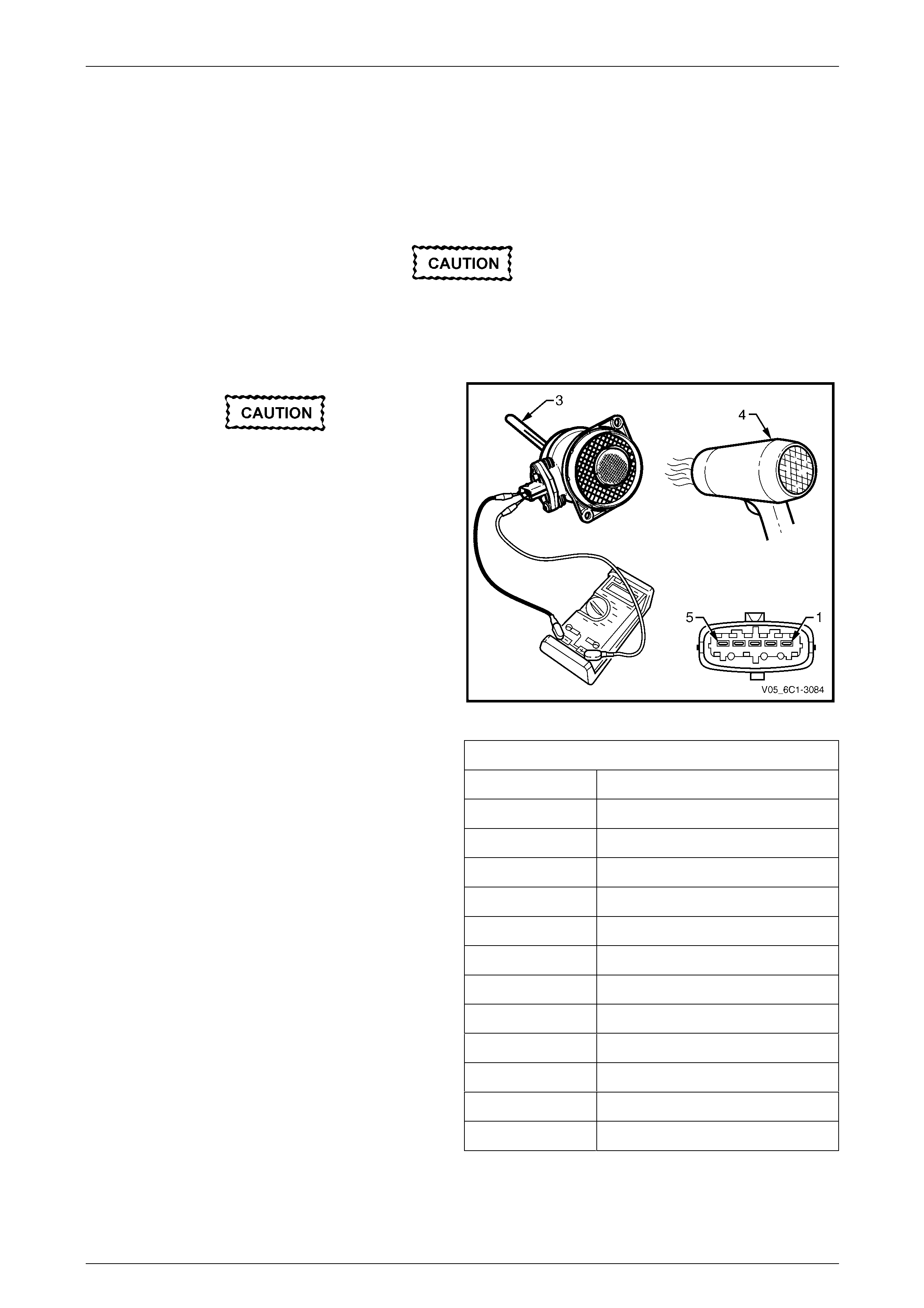
Engine Management – V6 – Service Operations Page 6C1-3–70
3.19 Intake Air Temperature Sensor
The intake air temperature (IAT) sensor is part of the mass air flow (MAF) sensor assembly, refer to
3.23 Mass Air Flow Sensor for the replacement procedure.
Test
To prevent component damage use connector
test adaptor kit J 35616-A.
Resistance Check
Do not use a high temperature heat gun as
damage to the MAF sensor will result.
1 Connect a digital ohmmeter using connector test
adaptor kit J 35616-A to the MAF sensor.
2 Whilst holding a thermometer (3), use a commercially
available hair dryer (4) to blow warm air through the
MAF sensor.
3 Measure the resistance across terminals 1 and 2.
Figure 6C1-3 – 83
4 Observe the resistance values as the temperature
increases and compare the temperature / resistance
change to the specifications.
5 If the resistance is not within specifications, replace
the MAF sensor.
Intake Air Temperature Vs Resistance
Temperature °C Resistance – Ohms (Ω)
-40 35140 – 43760
-20 12660 – 15120
-10 7943 – 9307
0 5119 – 5892
20 2290 – 2551
25 1900 – 2100
40 1096 – 1238
60 565 – 654
80 312 – 370
100 184 – 222
120 114 – 141
140 74 – 93
Page 6C1-3–70
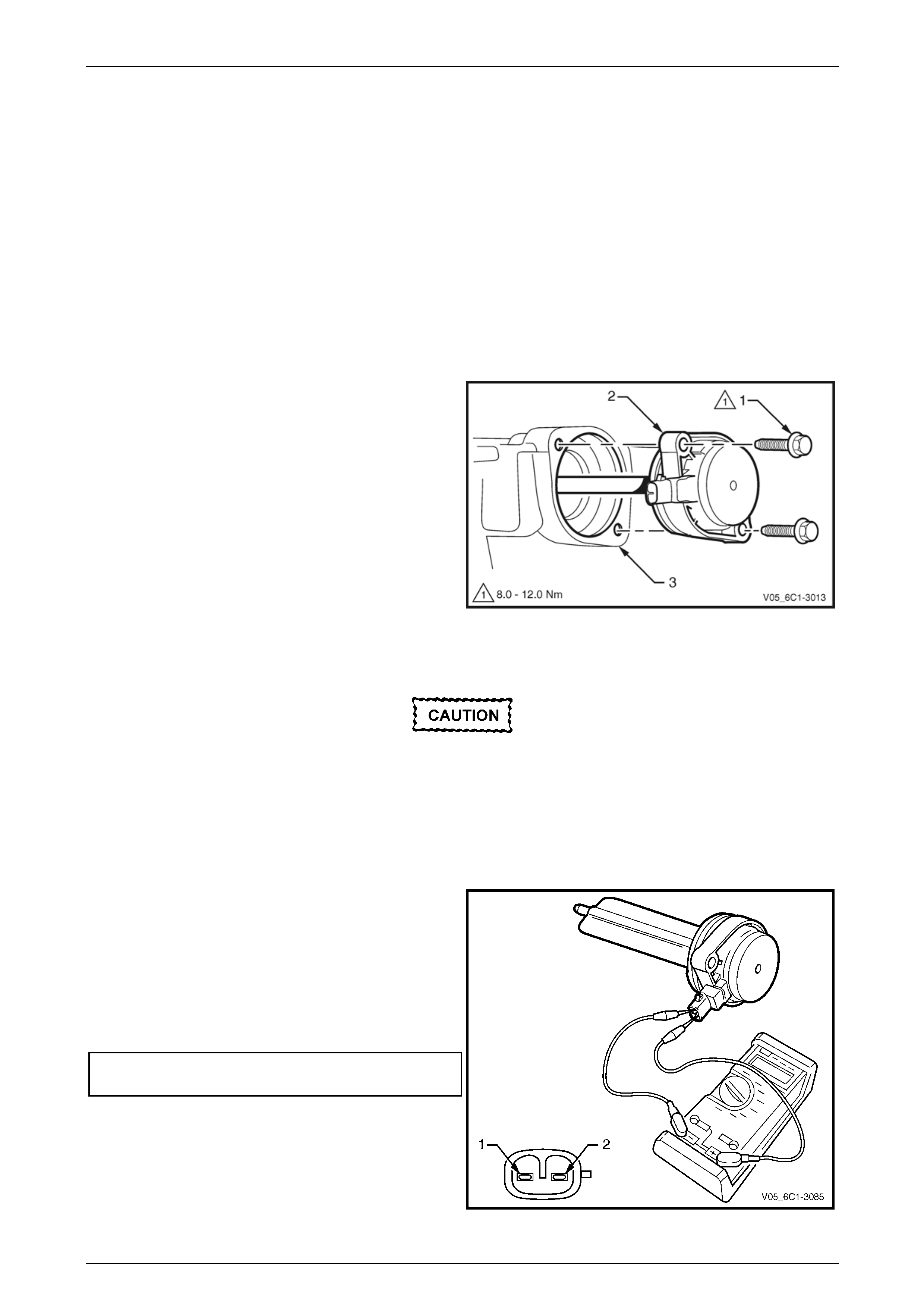
Engine Management – V6 – Service Operations Page 6C1-3–71
3.20 Intake Manifold Runner Control Solenoid
Valve – Alloytec190 Engine
LT Section No. —
Remove
1 Turn the ignition switch off.
NOTE
After removing the upper intake manifold, plug
the lower manifold opening to prevent dirt and
other contaminants from entering.
2 Remove the upper intake manifold assembly, refer to Section 6A1 Engine Mechanical – V6.
3 Remove the two bolts (1), attaching the intake
manifold runner control (IMRC) solenoid valve (2) to
the upper intake manifold (3).
4 Remove the IMRC solenoid valve from the upper
intake manifold by first twisting the solenoid valve to
release it, and then pulling the solenoid valve away
from the manifold.
5 If required, test the IMRC solenoid valve, refer to Test
in this Section.
Figure 6C1-3 – 84
Test
The following should be followed to prevent
component damage:
• Use connector test adaptor kit
J 35616-A.
• When applying 12 V to a component,
always use a 3 A fused wire.
Resistance Check
1 Connect a digital ohmmeter using connector test
adaptor kit J 35616-A to the intake manifold runner
control (IMRC) solenoid valve
2 Measure the resistance across terminals 1 and 2.
3 Compare the reading against the specification.
4 If the resistance is not within specification, replace the
IMRC solenoid valve.
IMRC solenoid valve
resistance @ 20°C.........................................6.5 – 7.5 Ω
Figure 6C1-3 – 85
Page 6C1-3–71
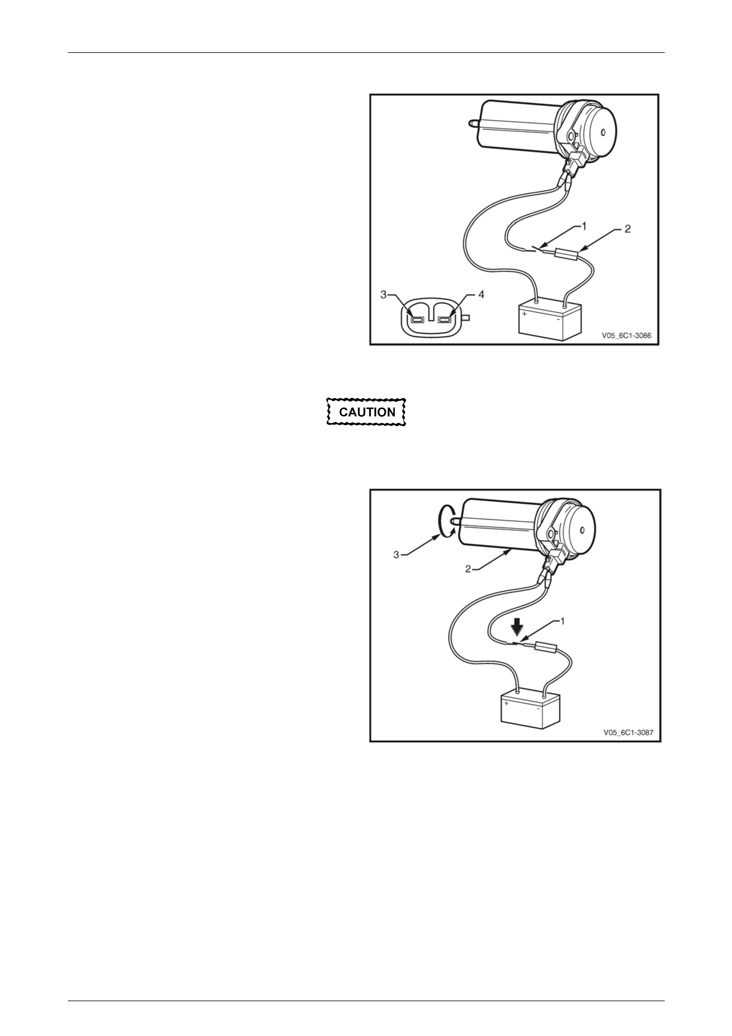
Engine Management – V6 – Service Operations Page 6C1-3–72
Functional Test
1 Using connector test adaptor kit J 35616-A, connect a
12 V battery, an on / off switch (1) and a 3 A fused
wire (2) to the IMRC solenoid valve terminals as
follows:
• Positive lead to terminal (3).
• Negative lead to terminal (4).
Figure 6C1-3 – 86
Do not apply 12 V to the IMRC solenoid valve
continuously for more than three seconds as
the IMRC solenoid valve will be damaged.
2 Turn the switch (1) on. The IMRC solenoid valve flap
(2) will rotate in the direction of the arrow (3) until it
reaches its stop (approximately 67.5°).
3 If the flap moves slowly, or fails to move, replace the
IMRC solenoid valve.
Figure 6C1-3 – 87
Page 6C1-3–72
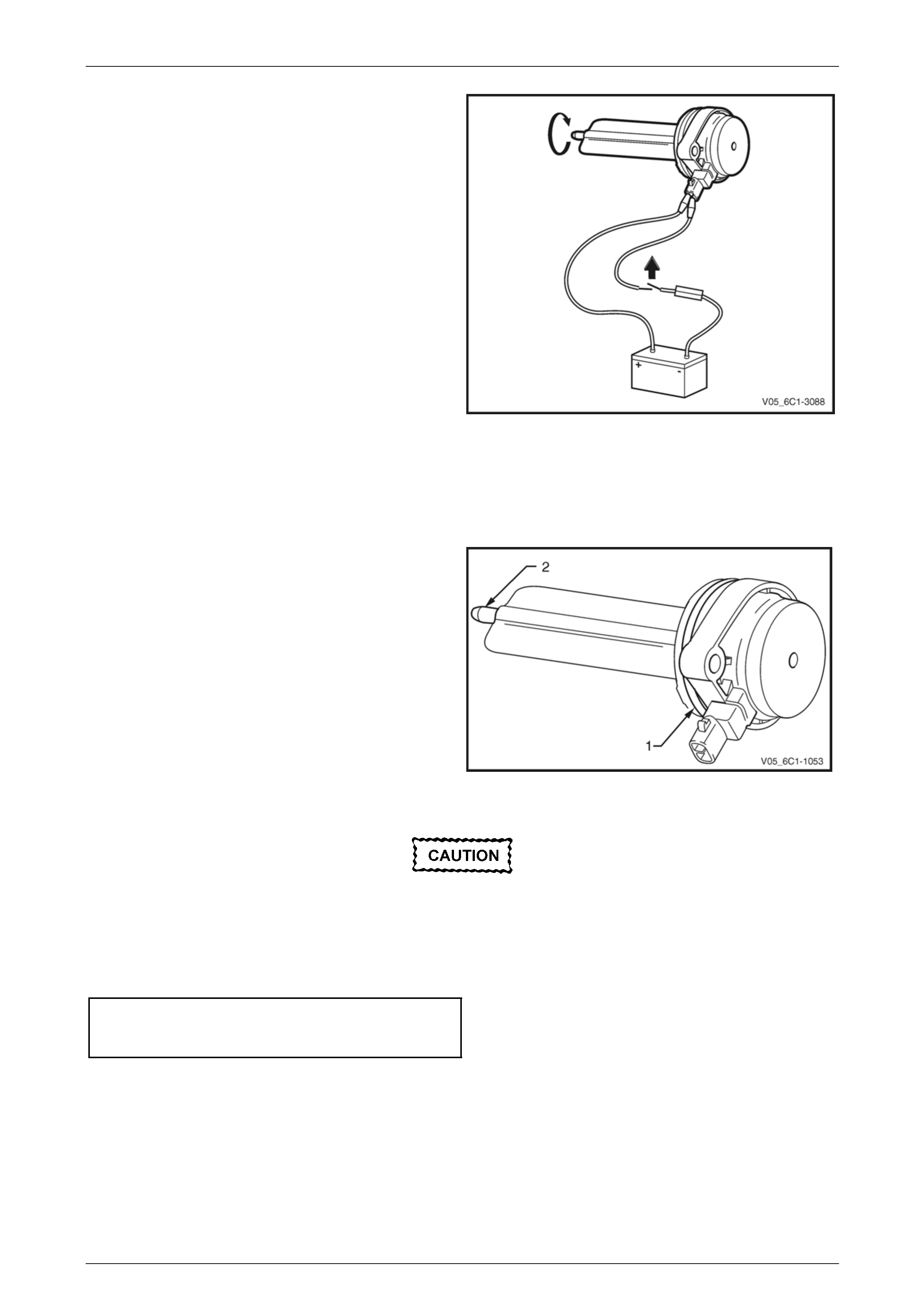
Engine Management – V6 – Service Operations Page 6C1-3–73
4 Turn the switch off. The IMRC solenoid valve flap will
return, under spring tension, to its rest position.
5 If the flap moves slowly, or fails to return to its rest
position, replace the IMRC solenoid valve.
Figure 6C1-3 – 88
Reinstall
Reinstallation of the intake manifold runner control (IMRC) solenoid valve is the reverse of the removal procedure, noting
the following:
1 Lubricate the IMRC solenoid O-ring (1) and spigot (2)
with NLGI No.2 Lithium Grease.
Figure 6C1-3 – 89
Ensure the IMRC solenoid valve is fully
seated before tightening the attaching bolt to
the specified torque.
2 Reinstall the bolt, two places, attaching the IMRC solenoid valve to the upper intake manifold and tighten to the
correct torque specification.
Intake manifold runner control
solenoid valve attaching bolt
torque specification ...................................8.0 – 12.0 Nm
3 Road test the vehicle and check for correct operation, taking particular note that no air leaks are evident.
Page 6C1-3–73
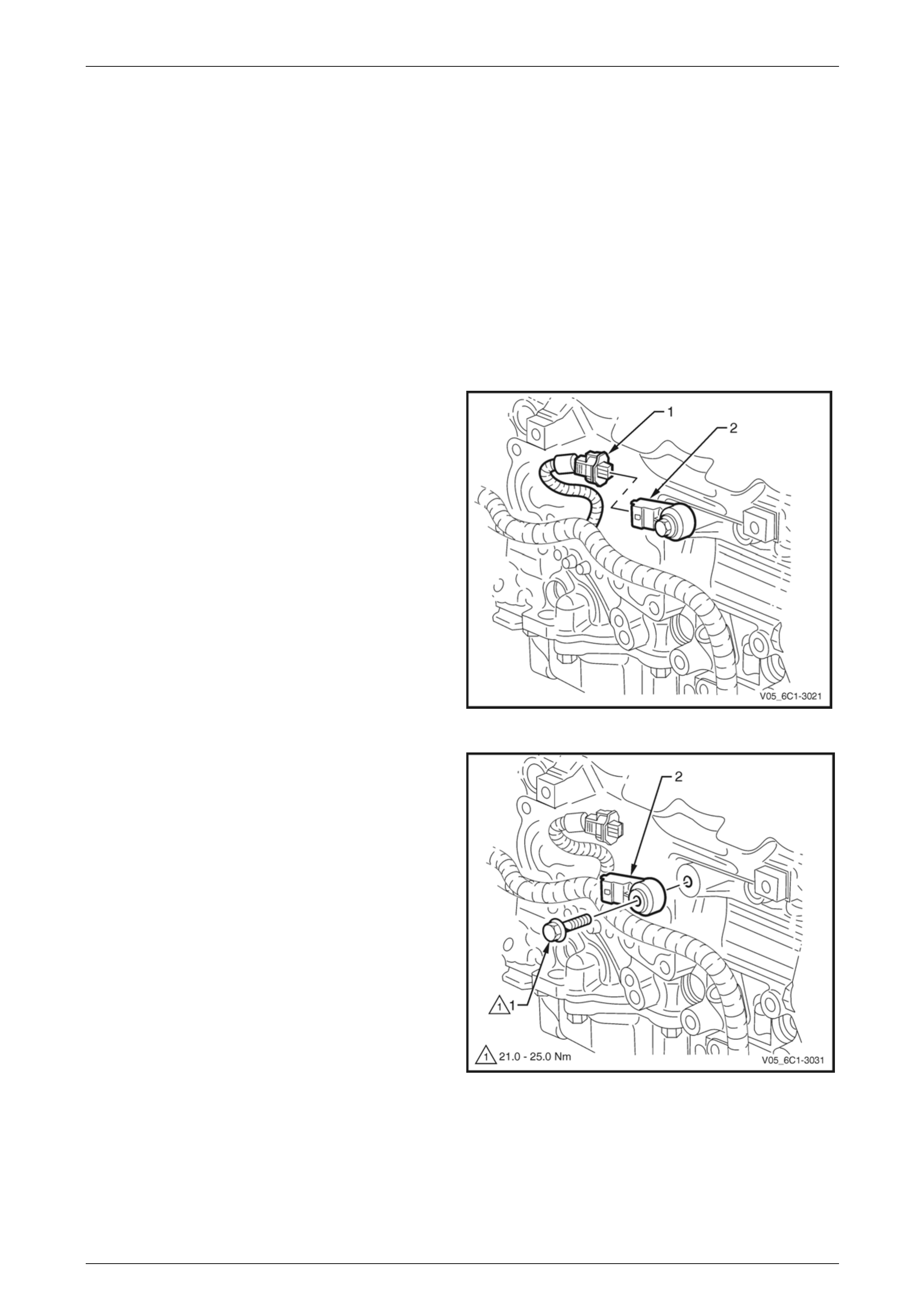
Engine Management – V6 – Service Operations Page 6C1-3–74
3.21 Knock Sensor, Bank 2 (LHS)
LT Section No. — 02–000
Remove
1 Turn the ignition switch off.
2 Remove Bank 2 engine dress cover, refer to Section 6A1 Engine Mechanical – V6
3 Disconnect Bank 2 pre-catalytic converter HO2S wiring harness connector, refer to 3.16 Heated Oxygen Sensor.
4 Raise the front of the vehicle and support on safety stands. Refer to Section 0A General Information for location of
the jacking points.
5 Remove Bank 2 front exhaust assembly, refer to Section 8B Exhaust System.
6 Disconnect the wiring harness connector (1) from the
knock sensor (2).
Figure 6C1-3 – 90
7 Remove the bolt (1) attaching the knock sensor (2) to
the engine block and remove the knock sensor.
Figure 6C1-3 – 91
Page 6C1-3–74
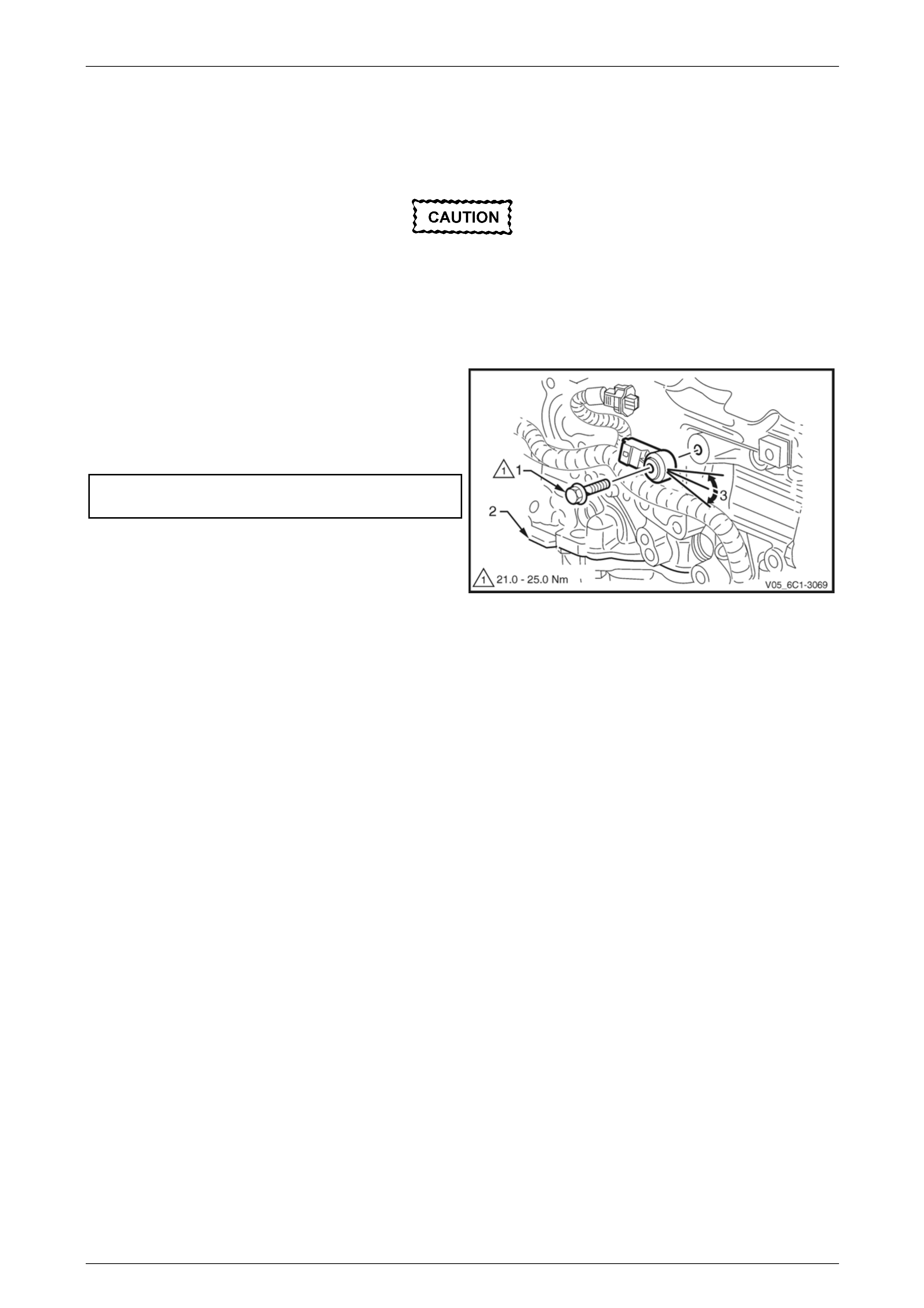
Engine Management – V6 – Service Operations Page 6C1-3–75
Reinstall
Reinstallation of the knock sensor is the reverse of the removal procedure, noting the following:
1 Ensure the knock sensor mounting surface is flat and free of any dirt, oxidisation, etc.
Ensure the knock sensor is fully seated and
correctly aligned before tightening the
attaching bolt.
Do not over-tighten the attaching bolt as
incorrect operation of the knock sensor may
result
2 Reinstall the knock sensor and bolt (1). Align the
knock sensor so that it is parallel to the engine oil pan
mounting surface (2), ± 3° (3).
3 Tighten the knock sensor bolt to the correct torque
specification.
Knock sensor attaching bolt
torque specification .................................21.0 – 25.0 Nm
4 Road test the vehicle and check for correct operation,
taking particular note that no exhaust leaks are
evident.
Figure 6C1-3 – 92
Page 6C1-3–75
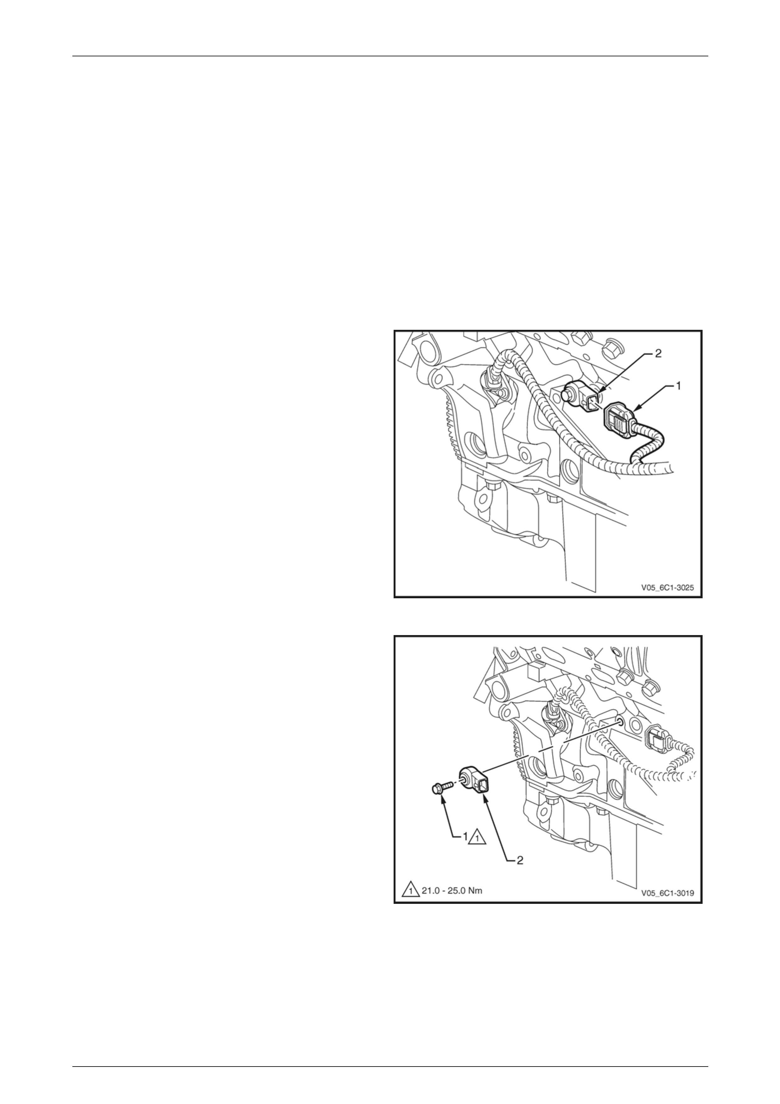
Engine Management – V6 – Service Operations Page 6C1-3–76
3.22 Knock Sensor, Bank 1 (RHS)
LT Section No. — 02–000
Remove
1 Turn the ignition switch off.
2 Remove Bank 1 engine dress cover, refer to Section 6A1 Engine Mechanical – V6
3 Disconnect Bank 1 pre-catalytic converter HO2S sensor harness connector, refer to 3.16 Heated Oxygen Sensor.
4 Raise the front of the vehicle and support on safety stands, refer to Section 0A General Information for location of
the jacking points.
5 Remove Bank 1 front exhaust assembly, refer to Section 8B Exhaust System.
6 Disconnect the wiring harness connector (1) from the
knock sensor (2).
Figure 6C1-3 – 93
7 Remove the bolt (1) attaching the knock sensor (2) to
the engine block, and remove the knock sensor.
Figure 6C1-3 – 94
Page 6C1-3–76
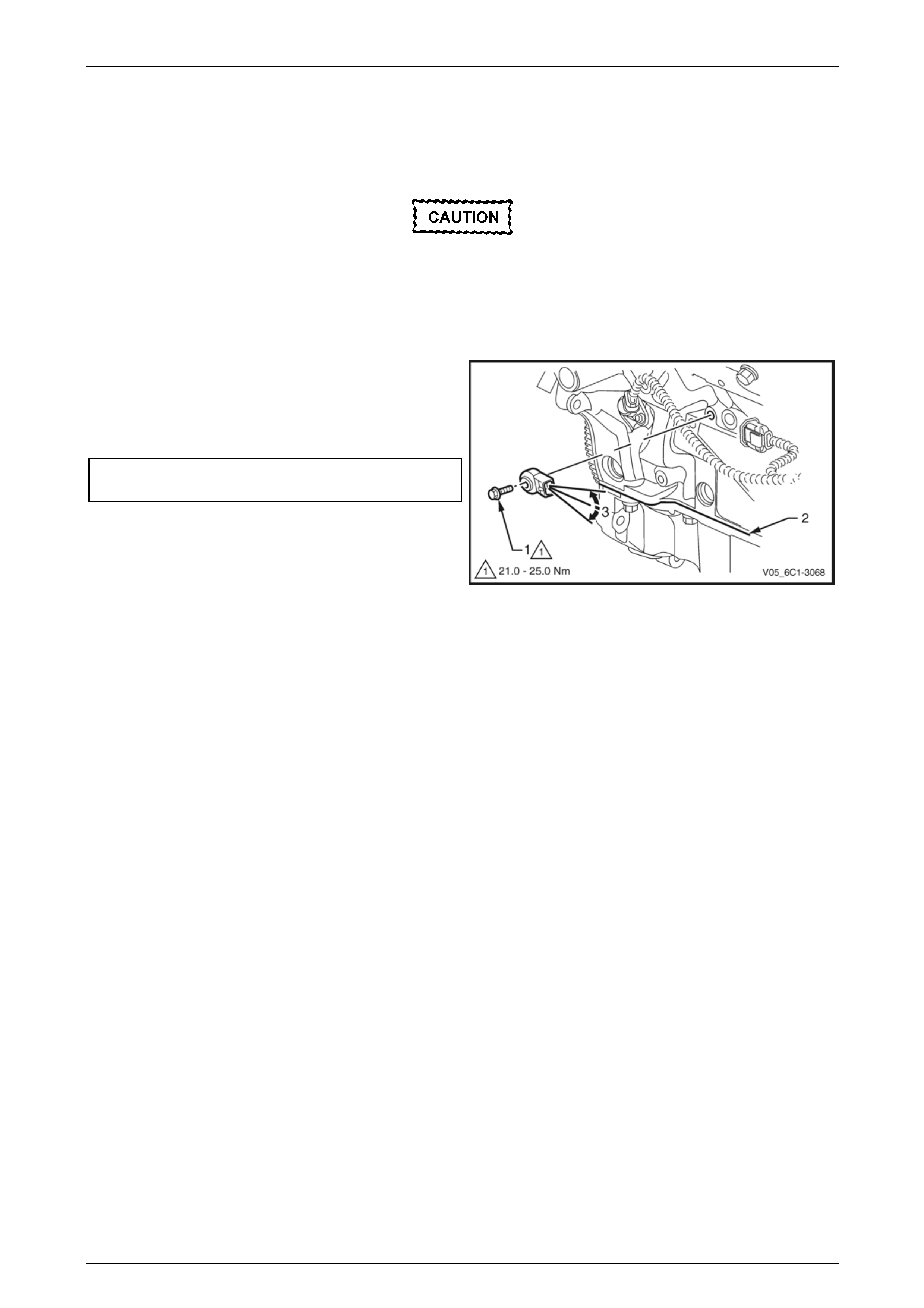
Engine Management – V6 – Service Operations Page 6C1-3–77
Reinstall
Reinstallation of the knock sensor is the reverse of the removal procedure, noting the following:
1 Ensure the knock sensor mounting surface is flat and free of any dirt, oxidisation, etc.
Ensure the knock sensor is fully seated
before tightening the attaching bolt.
Do not over-tighten the attaching bolt as
incorrect operation of the knock sensor may
result.
2 Reinstall the knock sensor and bolt (1). Align the
knock sensor so that it is parallel to the engine oil pan
mounting surface (2), ± 3° (3).
3 Tighten the knock sensor bolt to the correct torque
specification.
Knock sensor attaching bolt
torque specification .................................21.0 – 25.0 Nm
4 Road test the vehicle and check for correct operation.
Figure 6C1-3 – 95
Page 6C1-3–77
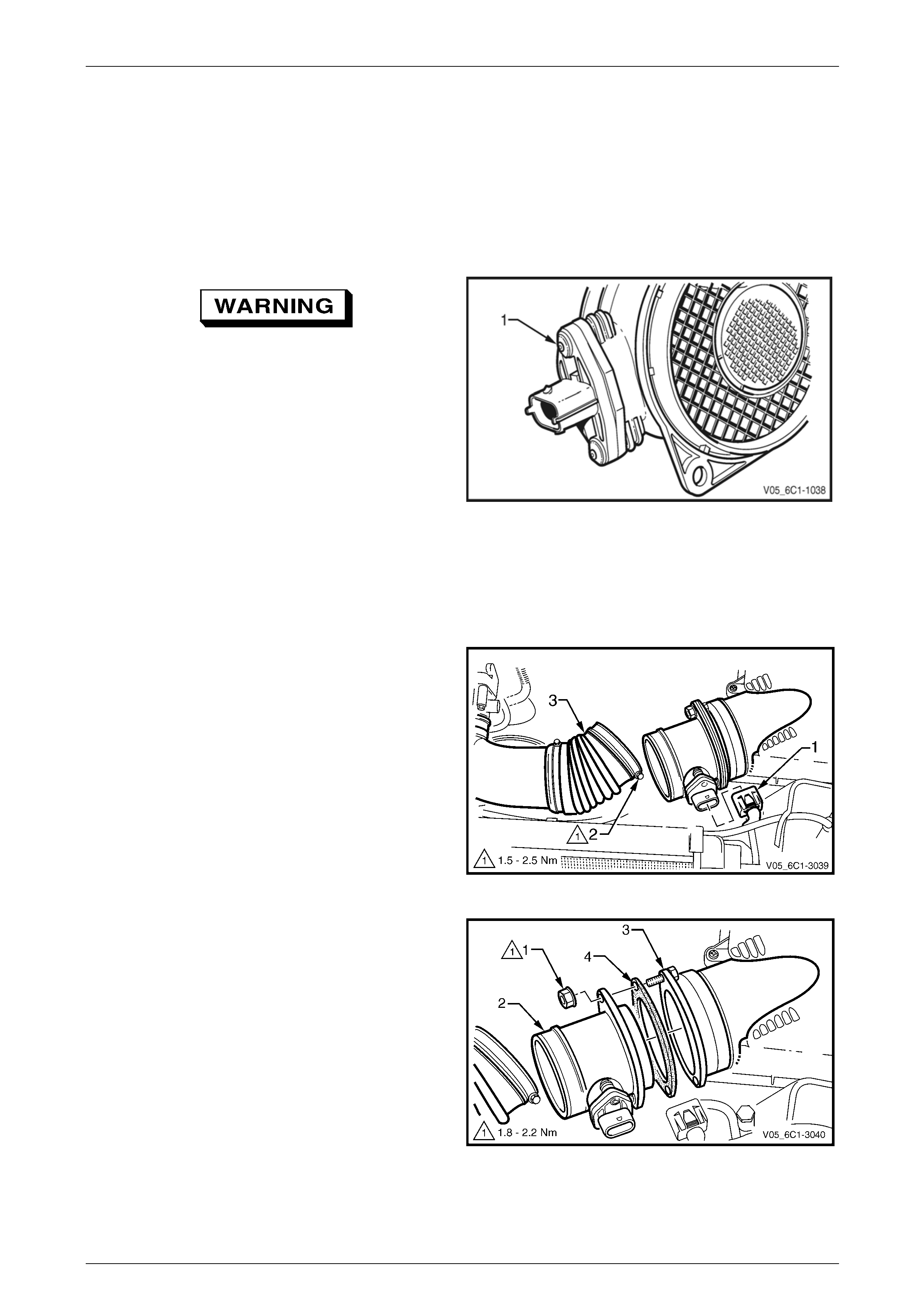
Engine Management – V6 – Service Operations Page 6C1-3–78
3.23 Mass Air Flow Sensor
LT Section No. — 03–250
The intake air temperature (IAT) sensor is part of the mass air flow (MAF) Sensor. For the IAT sensor test procedure
refer to 3.19 Intake Air Temperature Sensor.
Handling Precautions
Under no circumstances should the MAF
sensor retaining screws (1) be loosened or
removed as the MAF will become
unserviceable and will require replacement.
Figure 6C1-3 – 96
Remove
1 Turn the ignition switch off.
2 Remove the upper radiator shroud, refer to Section 6B1 – Engine Cooling – V6.
3 Disconnect the wiring harness connector (1) from the
MAF sensor.
4 Loosen the air intake duct retaining clamp (2).
5 Pull the flexible air intake duct (3) away from the MAF
sensor.
Figure 6C1-3 – 97
6 Remove the nut (1), two places, attaching the MAF
sensor (2) to the upper air cleaner housing (3).
7 Position the flexible air intake duct away from the MAF
sensor and remove the MAF sensor.
NOTE
The MAF sensor seal (4) is part of the air cleaner
upper housing and is not serviced as a separate
item.
Figure 6C1-3 – 98
Page 6C1-3–78
Engine Management – V6 – Service Operations Page 6C1-3–79
Reinstall
Reinstallation of the mass air flow (MAF) sensor is the reverse of the removal procedure, noting the following:
Care must be taken not to over tighten the
MAF sensor attaching nuts. Over tightening
the nuts may cause damage to the MAF
sensor seal and allow unfiltered air to enter
the air intake system.
1 Tighten the MAF sensor nuts to the correct torque specification.
Mass air flow sensor attaching nut
torque specification .....................................1.8 – 2.2 Nm
2 Tighten the air intake duct retaining clamp screw to the correct torque specification.
Air intake duct retaining clamp
torque specification .....................................1.5 – 2.5 Nm
3 Start the engine and check for any air leaks between the air intake duct, the MAF and the upper air cleaner
housing.
4 Road test the vehicle and check for correct operation, taking particular note that no air leaks are evident.
Page 6C1-3–79
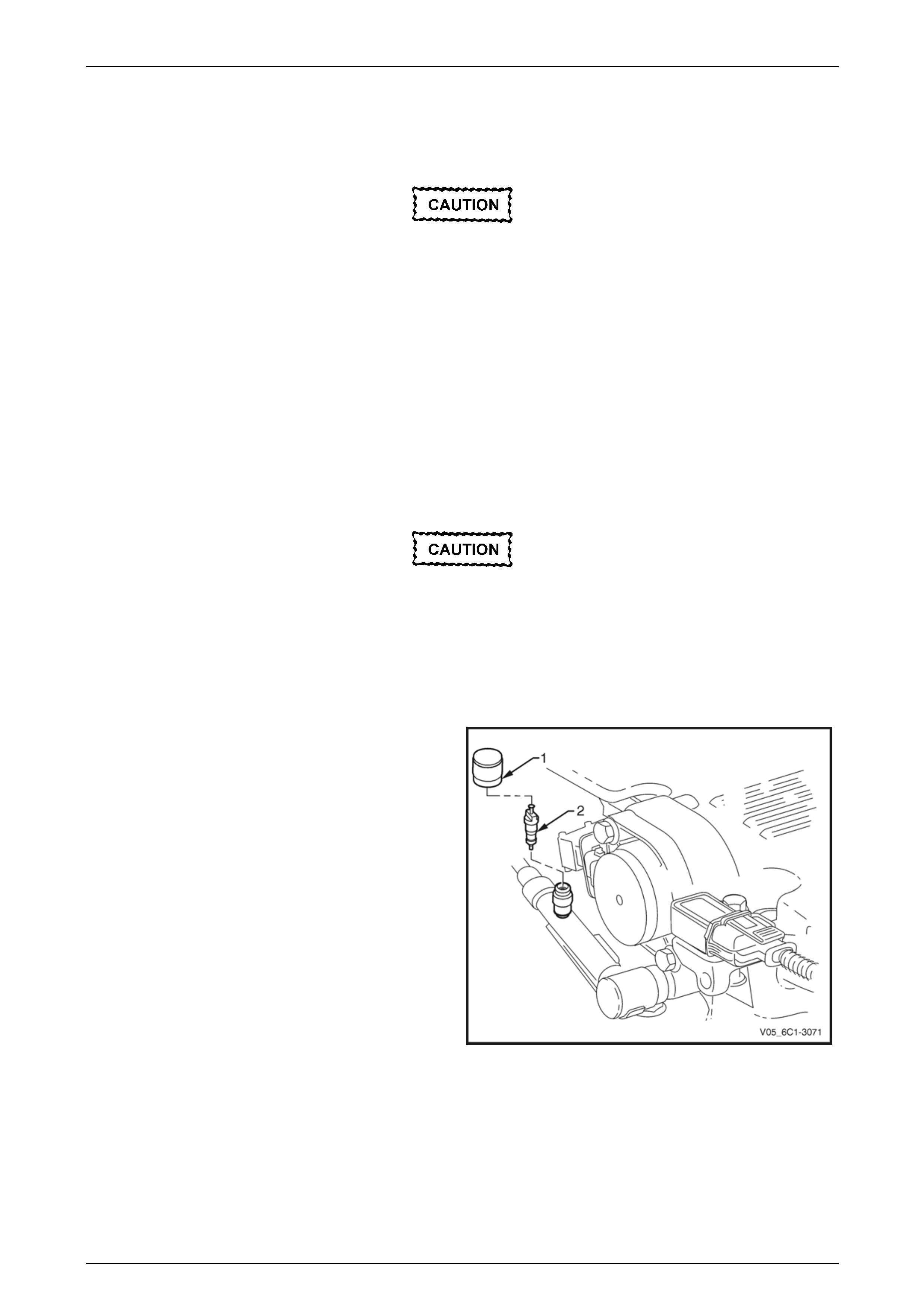
Engine Management – V6 – Service Operations Page 6C1-3–80
3.24 Schrader Valve – Fuel Pressure Gauge
Connection Point
If the Schrader valve is to be removed but not
replaced immediately, it is advisable to
disconnect the battery to avoid possible fuel
discharge if an accidental attempt is made to
start the engine.
Disconnection of the battery affects vehicle
electronic systems. Refer to Section 00
Warnings, Cautions and Notes before
disconnecting the battery.
Remove
1 Depressurise the fuel system, refer to Section 8A1 Fuel System.
2 Turn the ignition off.
A small amount of fuel may be released when
servicing the fuel pressure test point. To
reduce the chance of personal injury, cover
the fuel pressure test point with a shop towel
to absorb any fuel spillage when the Schrader
valve sealing cap and Schrader valve are
removed. After the procedure, place the towel
in an approved container for disposal.
3 Remove the Schrader valve sealing cap (1).
4 Remove the Schrader valve (2) using a standard valve
core removal tool.
Figure 6C1-3 – 99
Reinstall
Reinstallation of the Schrader valve is the reverse of the removal procedure, noting the following:
1 Inspect the fuel rail and quick connect fitting for leaks, refer to Section 8A1 Fuel System.
2 Road test the vehicle and check for correct operation.
Page 6C1-3–80
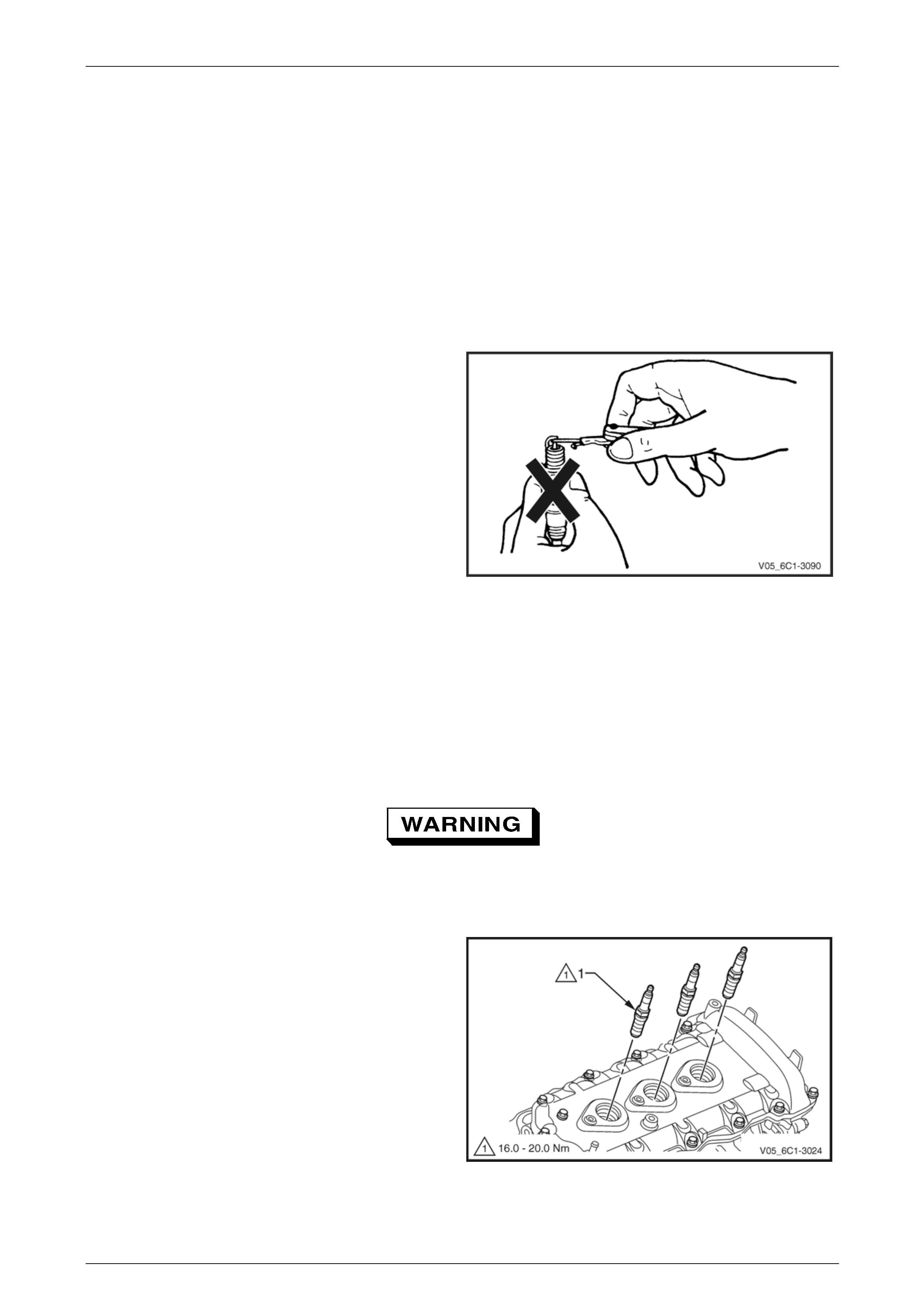
Engine Management – V6 – Service Operations Page 6C1-3–81
3.25 Spark Plugs
LT Section No. — 02–030
Service Precautions
1 Allow the engine to cool (to at least 50°C) before attempting to remove spark plugs. Attempting to remove spark
plugs from a hot engine may cause the plug / cylinder head threads to bind, resulting in tearing of the alloy cylinder
head threads.
2 Clean the spark plug recess area before removing any spark plug. Failure to do so could result in engine damage
because of dirt or other foreign material entering the cylinder head or by the contamination of the cylinder head
threads. The contaminated threads may then prevent the correct seating of the new or replaced plug. If required,
use a thread chaser to clean the threads of any contamination where this is suspected.
3 Under no circumstances should the spark plug/s gap
be adjusted. If the gap is not within specifications,
replace the spark plug.
Figure 6C1-3 – 100
Remove
1 Turn the ignition switch off.
2 Remove the left and / or right-hand engine dress cover, refer to Section 6A1 Engine Mechanical – V6.
3 Remove the ignition coil/s, refer to 3.17 Ignition Coil.
4 Using a suitable spark plug socket, loosen the spark plug slightly and then re-tighten to break away any carbon
deposits on the threads.
Wear eye protection to avoid injury.
5 Loosen the spark plug once again one or two turns, then use compressed air to remove any foreign material that
may otherwise enter the combustion chamber.
6 Remove the spark plug (1).
7 Repeat as required for the remaining spark plugs.
NOTE
Place each spark plug in the same order as that
of removal. This will enable any abnormal spark
plug condition to be identified with the cylinder.
NOTE
If the spark plugs are removed for an indefinite
period before installation, plug the spark plug
openings to prevent foreign particle ingress.
8 Repeat steps 2 to 5 for the remaining spark plugs as
required.
Figure 6C1-3 – 101
Page 6C1-3–81
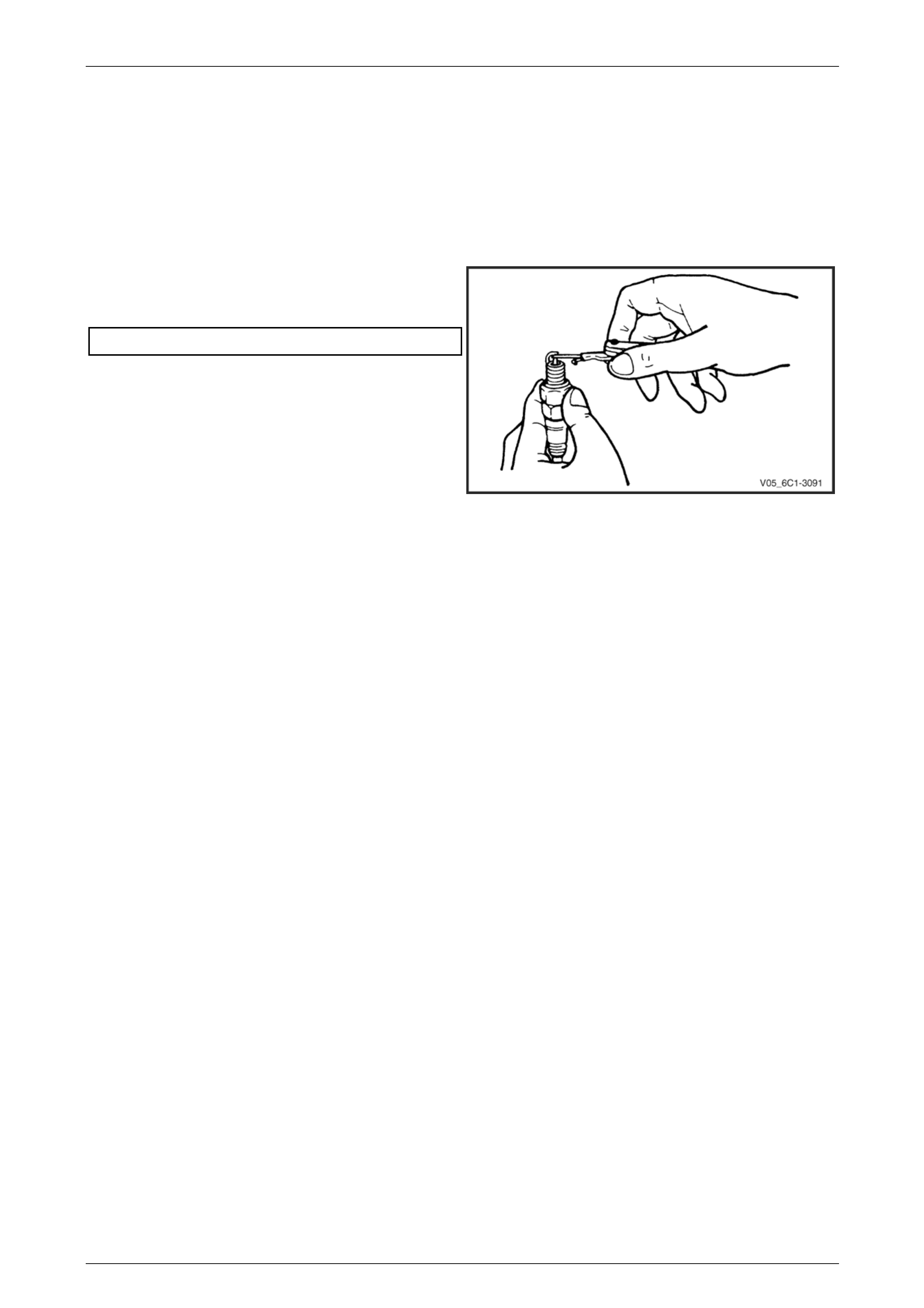
Engine Management – V6 – Service Operations Page 6C1-3–82
Inspect
The spark plugs must not be re-gapped. If the gap of a spark plug is outside the specified range, replace the spark plug.
In addition, replace spark plugs that shows excessive dirt deposit or broken insulators.
1 Replace any plug that has cracked and / or broken insulation or loose electrodes.
2 Inspect the spark plugs for defects. Refer to Analysis of Spark Plug Condition in this Section for identification of the
condition of spark plugs.
3 Ensure the threads are clean and in good order.
4 Use a round wire feeler gauge to check the spark plug
gap. If the gap is not within specifications, replace the
spark plug.
Spark plug gap........................................... 1.1 – 1.2 mm
Figure 6C1-3 – 102
Spark Plug Inspection
Poor Spark Plug Performance
A spark plug can perform poorly due to wear, dirt, carbon fouling, excessive electrode wear, a broken insulator or
excessive gap.
Worn or Dirty Plugs
Worn or dirty plugs can give satisfactory operation while the vehicle is idling, but break down under load.
This can cause:
• poor fuel economy,
• power loss,
• acceleration loss,
• difficult starting, or
• poor engine performance.
Carbon Fouling
Carbon fouling is indicated by black carbon deposits. The black deposits are usually the result of slow-speed driving and
short runs. In these circumstances, the optimum engine operating temperature is seldom reached.
Fouling can also be caused by:
• worn piston rings,
• faulty ignition,
• rich fuel mixture, or
• spark plugs that are rated too cold.
Page 6C1-3–82

Engine Management – V6 – Service Operations Page 6C1-3–83
Excessive Electrode Wear
This often indicates:
• the engine is operating at high speeds,
• the engine is operating at levels that are consistently greater than normal,
• a plug that is rated too hot,
• excessively lean fuel mixture, or
• plug/s overheating due to insufficient tightening (caused by combustion gases leaking past the threads).
Broken Insulator
Broken insulators are usually the result of improper installation or carelessness.
Breaks in the upper insulator can result from a poor fitting spark plug socket or impact. The cracked insulator may not
show up until oil or moisture penetrates the crack. The crack is often just below the crimped part of the shell and may not
be visible.
Breaks in the lower insulator often result from careless re-gapping and are usually visible.
This can also result from the plug operating too hot. For example, in periods of high speed operation or under heavy
loads.
Page 6C1-3–83
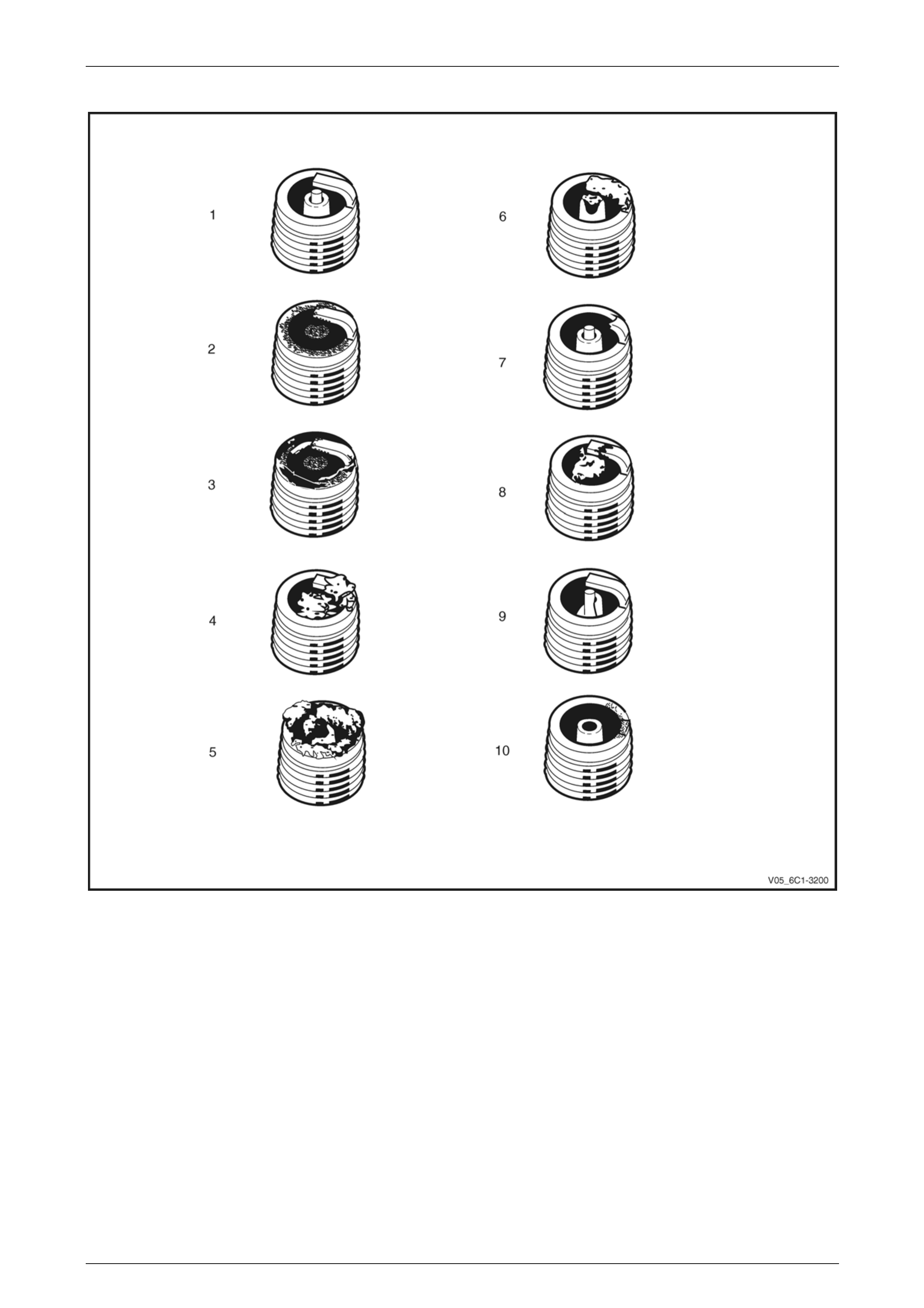
Engine Management – V6 – Service Operations Page 6C1-3–84
Analysis of Spark Plug Condition
Figure 6C1-3 – 103
Legend
1 Normal
2 Carbon Fouled
3 Oil Fouled
4 Deposit Fouling A
5 Deposit Fouling B
6 Deposit Fouling C
7 Detonation
8 Pre-ignition
9 Heat Shock Failure
10 Insufficient Installation Torque
Page 6C1-3–84

Engine Management – V6 – Service Operations Page 6C1-3–85
Normal Operation (1)
Brown or greyish-tan deposits and slight electrode wear indicate correct spark plug heat range and mixed periods of high
and low speed driving.
Carbon Fouled (2)
Dry, fluffy black carbon deposits possibly due to poor ignition output, a weak coil, excessive idling or slow speeds under
light load. If spark plug temperatures remain too low for normal combustion, the deposits are not burned off.
Oil Fouled (3)
Wet, oily deposits with minor electrode wear possibly due to oil leaking past worn piston rings.
Breaking in a new or recently overhauled engine before the rings are fully seated may also result in this condition.
Deposit Fouling A (4)
Red brown, yellow and white coloured coatings on the insulator tip which are by-products of combustion. They come
from fuel and lubricating oil which generally contain additives. Most powdery deposits have no adverse effect on spark
plug operation, however, they may cause intermittent missing under severe operating conditions.
Deposit Fouling B (5)
Deposits similar to those identified in deposit fouling A (4). These are also by-products of combustion from fuel and
lubricating oil. Excessive valve stem clearances and / or defective intake valve seals allow too much oil to enter the
combustion chamber. The deposits will accumulate on the portion of the spark plug that projects into the chamber and
will be heaviest on the side facing the intake valve. If this condition is only detected in one or two cylinders, check the
valve stem seals.
Deposit Fouling C (6)
Most powdery deposits identified in deposit fouling A (4) have no adverse effect on the operation of the spark plug as
long as they remain powdery.
Under certain conditions of operation however, these deposits melt and form a shiny glaze coating on the insulator.
When hot, this acts as a good electrical conductor allowing the current to flow along the deposit instead of sparking
across the gap.
Detonation (7 )
Commonly referred to as engine knock or pinging, detonation causes severe shocks inside the combustion chamber
causing damage to parts.
Pre-ignition (8)
Burnt or blistered insulator tip and badly eroded electrodes probably due to the excessive heat.
This is often caused by a cooling system blockage, sticking valves, improperly installed spark plugs or plugs that are the
wrong heat rating (too hot).
Sustained high speed with a heavy load can produce temperatures high enough to cause pre-ignition.
Heat Shock Failure (9)
A rapid increase in spark plug tip temperature under severe operating conditions can cause heat shock and result in
fractured insulators. This is a common cause of broken and cracked insulator tips.
Insufficient Installation Torque (10)
Poor contact between the spark plug and the cylinder head seat.
The lack of proper heat transfer that results from poor seat contact causes overheating of the spark plug. In many cases,
severe damage occurs. Dirty threads in the cylinder head can cause the plug to seize before it is seated.
Ensure the cylinder head and spark plug threads are free of deposits, burrs and scale before installation.
Page 6C1-3–85
Engine Management – V6 – Service Operations Page 6C1-3–86
Reinstall
Reinstallation of the spark plug is the reverse of the removal procedure, noting the following:
• Discard the spark plug if it has been
dropped.
• Do not use anti-seize compound or similar
lubricant on the spark plug threads.
1 Using a suitably sized rubber tube attached to the spark plug terminal post, hand start each spark plug into the
cylinder head thread.
Failure to tighten a spark plug to the correct
torque specification may result in premature
spark plug failure, and / or engine damage.
2 Tighten the spark plug/s to the correct torque specification.
Spark plug torque specification ...............16.0 – 20.0 Nm
3 Road test the vehicle and check for correct operation.
Page 6C1-3–86
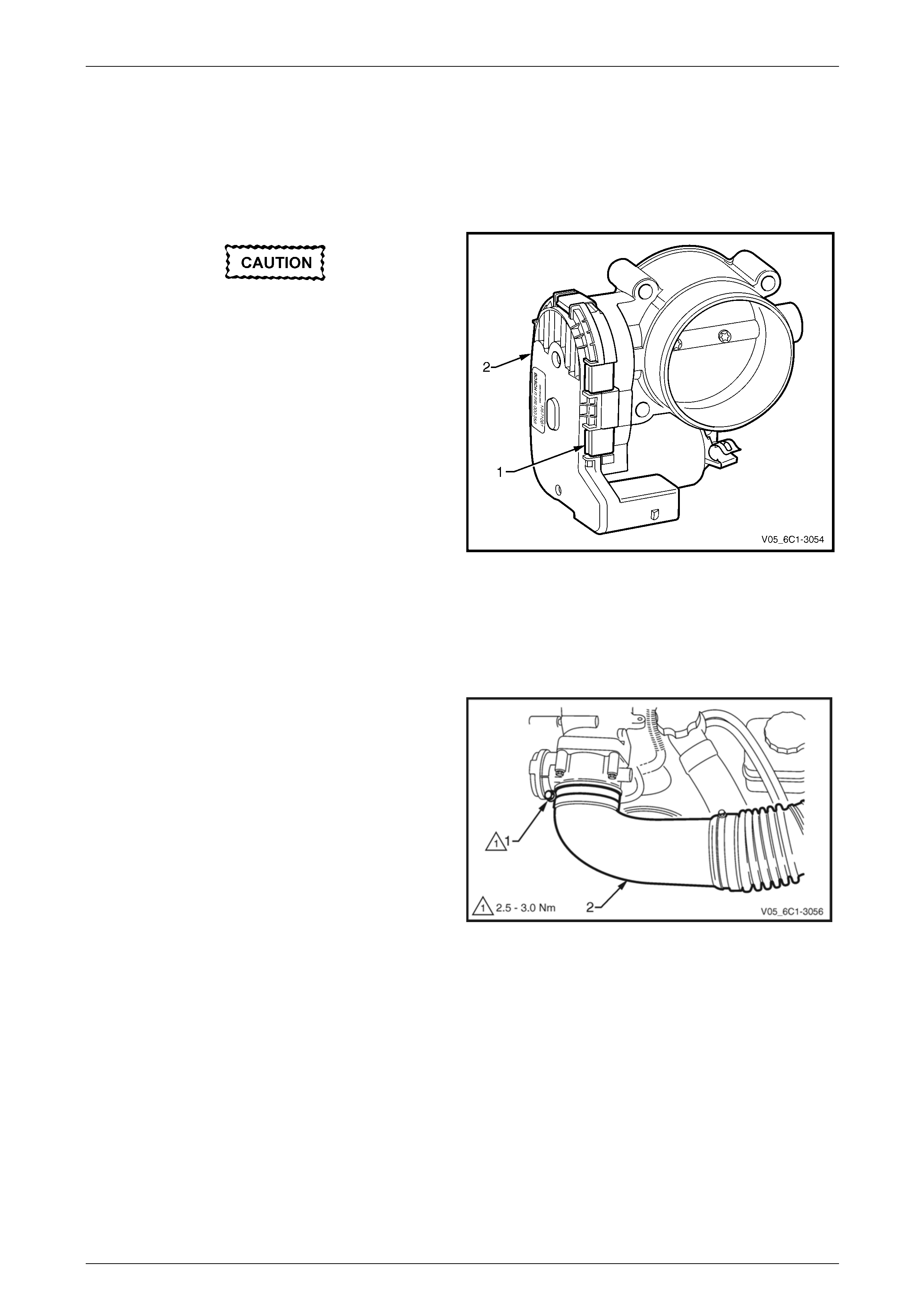
Engine Management – V6 – Service Operations Page 6C1-3–87
3.26 Throttle Body Assembly
LT Section No. — 03–300
Handling Precautions
Under no circumstances should the clip (1),
six places, retaining the cover plate (2) to the
throttle body be removed. If the cover is
removed, the vacuum seal between the cover
plate and the throttle body will be broken.
This will allow the ingress of foreign particles
and / or moisture and render the throttle body
unserviceable
The throttle body must not be subjected to
any form of shock such as dropping it. If the
throttle body is subjected to shock, damage
may result to the fragile motor magnets
within the throttle body.
Figure 6C1-3 – 104
Remove
1 Turn the ignition switch off.
2 Remove the upper radiator shroud, refer to Section 6B1 – Engine Cooling – V6.
3 Loosen the air intake duct to throttle body assembly
retaining clamp (1).
4 Pull the air intake duct (2) away from the throttle body
assembly.
NOTE
If difficulty is experienced in removing the air
intake duct from the throttle body, completely
remove the air intake duct assembly, refer to
3.18 Intake Air Duct Assembly.
Figure 6C1-3 – 105
Page 6C1-3–87
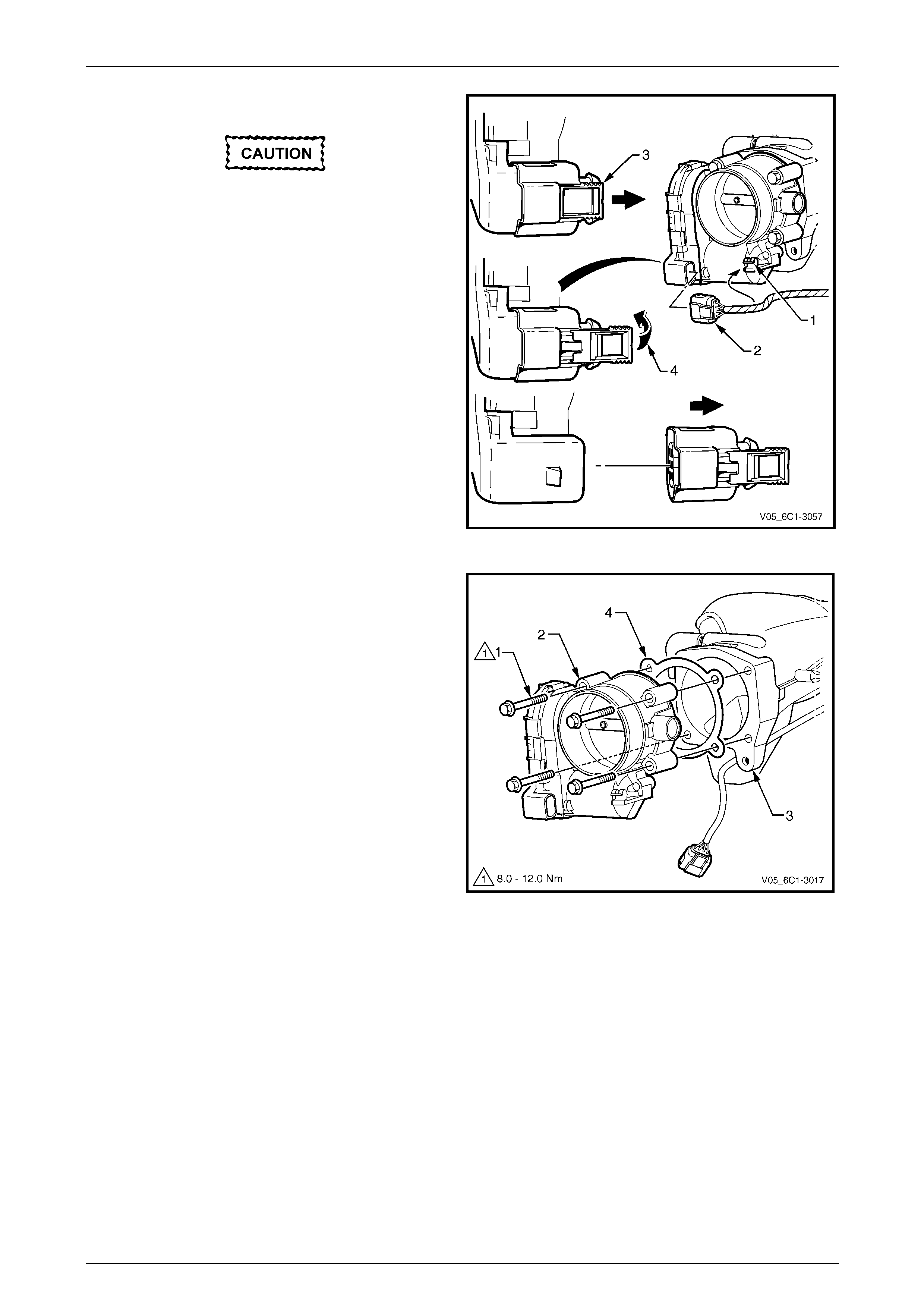
Engine Management – V6 – Service Operations Page 6C1-3–88
5 Unclip the wiring harness from the retaining clip (1).
Do not use any mechanical device such as a
screwdriver to disengage the harness
connector (2) from the throttle body.
6 Disconnect the wiring harness connector by:
NOTE
When sliding the connector lock, take care not to
disengage it from the connector.
• Sliding the connector lock (3) in the direction of
the arrow, then
• press the connector latch in the direction of the
arrow (4), and remove the connector from the
throttle body.
Figure 6C1-3 – 106
7 Remove the four bolts (1), attaching the throttle body
(2) to the upper intake manifold (3).
8 Remove the throttle body and gasket (4).
Figure 6C1-3 – 107
Page 6C1-3–88

Engine Management – V6 – Service Operations Page 6C1-3–89
Inspect
The following throttle body inspection procedure may be carried out with the throttle body installed on the vehicle. Prior to
performing a throttle body on-vehicle inspection:
• Turn the ignition switch off.
• Disconnect the throttle body wiring harness connector. Refer to Remove in this Section.
• Remove the air intake duct, refer to 3.18 Intake Air Duct Assembly.
To avoid serious personal injury, never
attempt to rotate the throttle plate manually
whilst the throttle body harness connector is
connected to the throttle body.
1 Fully open the throttle plate by hand and inspect the throttle body bore and throttle plate for any deposits.
When cleaning / inspecting the throttle body:
• Do not subject the throttle body assembly
to an immersion cleaner or a strong
solvent. Damage to the throttle position
sensor and / or sealed throttle shaft
bearings will result.
• Never use a wire brush or scraper to clean
the throttle body. A wire brush or sharp
tool may damage the throttle body
components.
2 Use a clean shop towel and a spray type hydro-carbon cleaner to clean the throttle body bore and throttle plate. If
necessary, use a parts cleaning brush to remove heavy deposits.
3 Inspect the throttle body for a binding throttle plate by fully opening and closing the throttle plate by hand. It should
open and close smoothly.
4 Inspect the throttle body for a bent or damaged throttle plate, cracks, corrosion, or distortion in the throttle body
housing.
NOTE
The throttle body contains no serviceable parts
and should not be disassembled. If the throttle
body is damaged it must be replaced as an
assembly.
5 If the throttle body is affected by any of the above conditions, it must be replaced.
6 If an on-vehicle throttle body inspection was performed, perform the following:
• Reinstall the air intake duct, refer to 3.18 Intake Air Duct Assembly.
• Reconnect the throttle body wiring harness connector, refer to Reinstall in this Section.
• Road test the vehicle and check for correct operation, taking particular note that no air leaks are evident.
Page 6C1-3–89
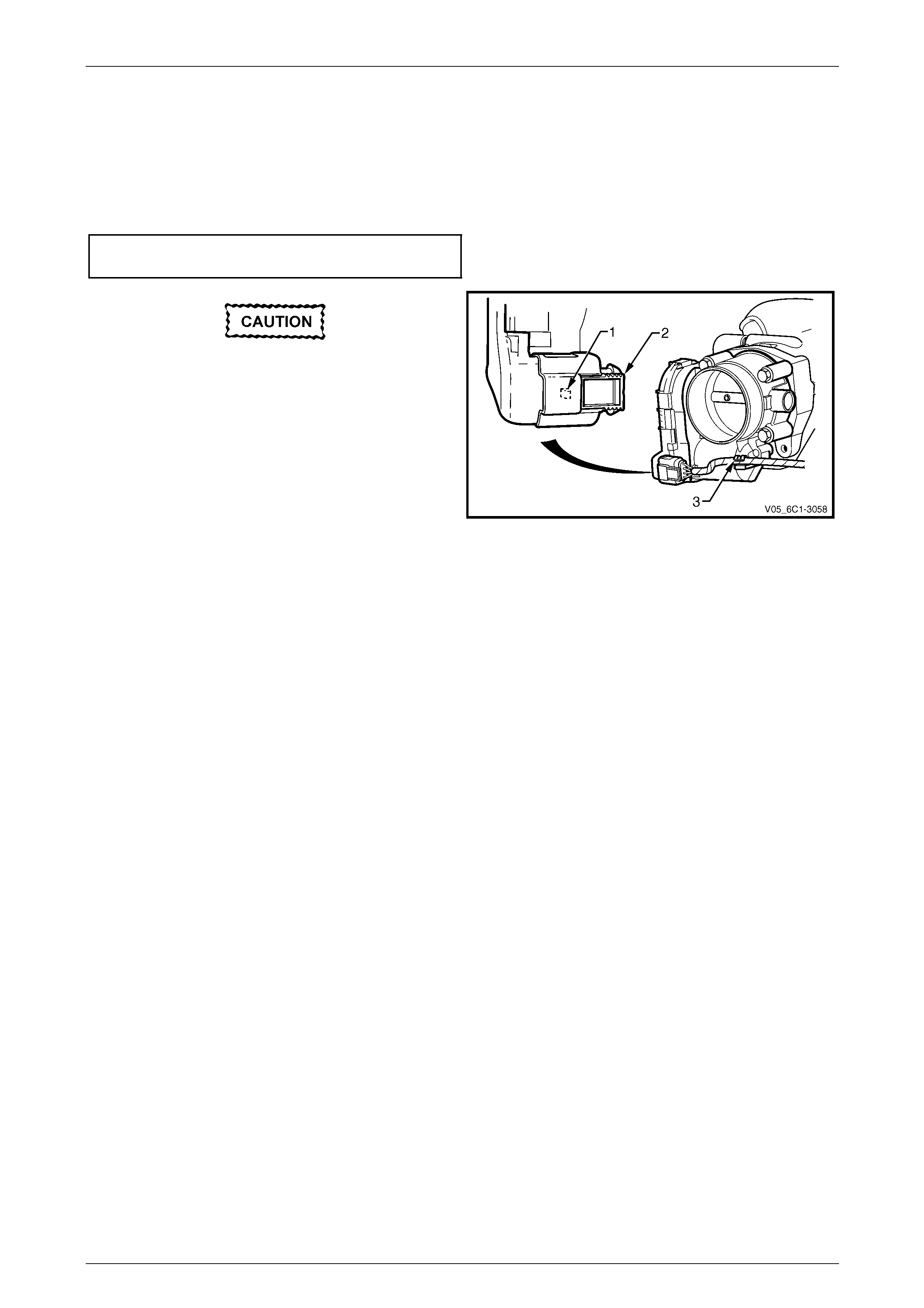
Engine Management – V6 – Service Operations Page 6C1-3–90
Reinstall
Reinstallation of the throttle body assembly is the reverse of the removal procedure, noting the following:
1 Ensure the throttle body and upper intake manifold mating surfaces are clean and free of foreign material.
2 Install a new throttle body to upper intake manifold gasket.
3 Reinstall the throttle body bolts and tighten to the correct torque specification.
Throttle body assembly attaching bolt
torque specification ...................................8.0 – 12.0 Nm
After reinstalling the wiring harness
connector, ensure the connector latch (1) and
connector lock (2) have fully engaged.
4 Reinstall the wiring harness connector to the throttle
body, ensuring the connector latch and connector slide
have fully engaged.
5 Ensure the wiring harness is correctly routed and
attached securely in the throttle body harness
retaining clip (3).
Figure 6C1-3 – 108
6 Road test the vehicle and check for correct operation, taking particular note that no air leaks are evident.
Page 6C1-3–90

Engine Management – V6 – Service Operations Page 6C1-3–91
4 Specifications
Accelerator Pedal Position Sensor 1
Type.....................................................Three wire potentiometer
Accelerator pedal at rest ...................................Less than 1.25 V
Accelerator pedal fully depressed .......................5.0 V maximum
Accelerator Pedal Position Sensor 2
Type.....................................................Three wire potentiometer
Accelerator pedal at rest ...................................Less than 1.25 V
Accelerator pedal fully depressed .......................5.0 V maximum
Camshaft Position (CMP) Sensor
Type....................................Hall effect, interrupted ring triggered
Air gap ....................................................................0.1 – 1.8 mm
Air gap adjustment ................................................No adjustment
Camshaft Position (CMP) Actuator Solenoid
Type...............................................................................Solenoid
Resistance @ 20°C ...................................................6.7 – 7.7 Ω
Crankshaft Position (CKP) Sensor
Type....................................................... Inductive magnetic type
Coil resistance @ 20°C..........................................850 – 1040 Ω
Air gap ....................................................................0.1 – 1.5 mm
Air gap adjustment ............................................... No adjustment
Engine Coolant Temperature Sensor
Type.......................................................... Negative temperature
....................................................................coefficient thermistor
Engine Coolant Temperature Vs Resistance
Temperature °C Resistance – Ohms (Ω)
-40 40490 – 50136
-20 14096 – 16827
-10 8642 – 10152
0 5466 – 6326
20 2351 – 2649
25 1941 – 2173
40 1118 – 1231
60 573 – 618
80 313 – 332
100 182 – 191
120 109 – 116
140 68 – 74
Page 6C1-3–91

Engine Management – V6 – Service Operations Page 6C1-3–92
Engine Oil Level and Temperature Sensor
Level sensor type....................................... Magnetic reed switch
Temperature sensor type .......................... Negative temperature
....................................................................coefficient thermistor
Engine Oil Temperature Vs Resistance
Temperature °C Resistance – Ohms (Ω)
0 7570 – 8000
20 2351 – 2649
30 2225 – 2375
40 1118 – 1231
50 1050 – 1150
80 380 – 470
100 270 – 290
Evaporative Emission (EVAP) Canister Purge Valve
Type...............................................................................Solenoid
Resistance @ 20°C .....................................................24 – 28 Ω
Operating voltage................................................... 12.0 – 16.0 V
Engine Firing Order ......................................................................1, 2, 3, 4, 5, 6
Fuel Injector
Type...............................................................................Solenoid
Fuel Injector Resistance @ 20°C...........................11.4 – 12.6 Ω
Heated Oxygen Sensor (HO2S) – Four wire
Type...................................................... Four wire, planar sensor
Operating range (greater than 360°C) .................. 10 – 1000 mV
Closed loop operating range................................. 300 – 600 mV
Heater resistance @ 20°C .......................................8.0 – 10.0 Ω
Heated Oxygen Sensor (HO2S) – Six Wire
Type....................................... Six wire, wide band planar sensor
Heater resistance @ 20°C .......................................8.0 – 10.0 Ω
Intake Manifold Runner Control (IMRC) Solenoid – Alloytec190
Type...............................................................................Solenoid
Resistance @ 20°C .................................................. 6.5 – 7.5 Ω
Operating voltage................................................... 12.0 – 16.0 V
Page 6C1-3–92

Engine Management – V6 – Service Operations Page 6C1-3–93
Intake Air Temperature (IAT) Sensor
Type.......................................................... Negative temperature
...................................................................Coefficient thermistor
Intake Air Temperature Vs Resistance
Temperature °C Resistance – Ohms (Ω)
-40 35140 – 43760
-20 12660 – 15120
-10 7943 – 9307
0 5119 – 5892
20 2290 – 2551
25 1900 –2100
40 1096 –1238
60 565 – 654
80 312 – 370
100 184 – 222
120 114 –141
140 74 –93
Knock Sensor
Type........................................................ Piezo ceramic element
Mass Air Flow Sensor
Type...................................................... Hot film air-mass sensor
Spark Plug
Type....................................................................................J gap
Gap .........................................................................1.1 – 1.2 mm
Adjustment........................................................... No adjustment
Throttle Position Sensor 1
Type.....................................................Three wire potentiometer
Closed throttle.................................................. Less than 1.25 V
Wide open throttle...............................................5.0 V maximum
Throttle Position Sensor 2
Type.....................................................Three wire potentiometer
Closed throttle.................................................. Less than 1.25 V
Wide open throttle...............................................5.0 V maximum
Page 6C1-3–93

Engine Management – V6 – Service Operations Page 6C1-3–94
5 Assembly Lubricants
Camshaft Position (CMP) Actuator Solenoid Seal............................. Engine Oil
Camshaft Position (CMP) Sensor O-ring........................................... Engine Oil
Crankshaft Position (CKP) Sensor .................................................... Engine Oil
Evaporative Emission (EVAP) Canister Purge Valve
Quick Connect Fitting ........................................................................ Engine Oil
Fuel Feed Hose Quick Connect Fitting.............................................. Engine Oil
Fuel Injector Seals............................................................................. Engine Oil
Heated Oxygen Sensor (HO2S) – All .............................. Anti-seize Compound
Ignition Coil Boot .......................................................................Talcum Powder
Ignition Coil Sealing Rubber .............................................................. Engine Oil
Intake Manifold Runner Control (IMRC) Solenoid Valve
O-ring ................................................................................................ Engine Oil
Intake Manifold Runner Control (IMRC)
Solenoid Valve Spigot ............................................. NLGI No.2 Lithium Grease
Page 6C1-3–94

Engine Management – V6 – Service Operations Page 6C1-3–95
6 Torque Specifications
Fuel Rail Attaching Bolt ............................................................... 8.0 – 12.0 Nm
Accelerator Pedal Position Sensor Attaching Bolt ....................... 7.0 – 12.0 Nm
Accelerator Pedal Position Sensor Support Bracket Nut........... 20.0 – 30.0 Nm
Air Cleaner Upper Housing Attaching Screw................................. 2.5 – 3.0 Nm
Air Cleaner Lower Housing Attaching Stud ................................. 7.5 – 12.5 Nm
Barometric Pressure Sensor Attaching Bolt ................................ 8.0 – 12.0 Nm
Camshaft Position Actuator Solenoid Attaching Bolt ................... 8.0 – 12.0 Nm
Camshaft Position Sensor Attaching Bolt .................................... 8.0 – 12.0 Nm
Crankshaft Position Sensor Attaching Bolt .................................. 8.0 – 12.0 Nm
Engine Coolant Temperature Sensor ................................................... 22.0 Nm
Engine Control Module Attaching Bolt ......................................... 8.0 – 12.0 Nm
Ground Terminal Attaching Screw.......................................................... 4.5 Nm
Engine Control Module Bracket Assembly
Attaching bolt (6mm Bolt) ............................................................ 8.0 – 12.0 Nm
Engine Control Module Bracket Assembly
Attaching bolt (8mm Bolt) .......................................................... 20.0 – 25.0 Nm
Engine Oil Level and Temperature Sensor – Wet ..................... 11.0 – 15.0 Nm
Engine Oil Pressure Sensor ...................................................... 12.0 – 14.0 Nm
Heated Oxygen Sensor ............................................................. 40.0 – 50.0 Nm
Ignition Coil Attaching Bolt........................................................... 7.0 – 11.0 Nm
Air Intake Duct Retaining Clamp ................................................... 1.5 – 2.5 Nm
Intake Manifold Runner Control Solenoid
Attaching Bolt .............................................................................. 8.0 – 12.0 Nm
Knock Sensor Attaching Bolt ..................................................... 21.0 – 25.0 Nm
Mass Air Flow Sensor Attaching Nut ............................................. 1.8 – 2.2 Nm
Spark Plug................................................................................. 16.0 – 20.0 Nm
Throttle Body Assembly Attaching Bolt ....................................... 8.0 – 12.0 Nm
Page 6C1-3–95
Engine Management – V6 – Service Operations Page 6C1-3–96
7 Special Tools
Tool Number Illustration Description Tool Classification
7000086i
Tech 2 scan tool
Used for diagnosis of vehicle electrical
systems.
Previously released.
Mandatory
3588
Digital Multimeter
Previously released as j 39200, 3545
GM.
Available
J 35616
Connector Test Adaptor Kit
Used when carrying out electrical
diagnostic circuit checks.
Previously released.
Desirable
J 34142-a
Un-powered Test Lamp
Previously released as CT-40-C and
also commercially available.
Must have a current draw less than
0.3 A.
Mandatory
J 34730-2C
Injector Test Light
Used to check for power and the
control circuit of the fuel injector, for
proper operation.
Also previously released as
ST- 8329
Mandatory
J 39021 Fuel Injector Coil / Balance Tester
Used in conjunction with a DMM for
testing the fuel injector coil windings
and for injector balance testing.
Previously released
Mandatory
J 44602 Injector Test Adapter Mandatory
Page 6C1-3–96

Engine Management – V6 – Service Operations Page 6C1-3–97
Tool Number Illustration Description Tool Classification
J 41712
Oil Pressure Sensor Socket
Used in conjunction with 3/8” drive
socket equipment to remove / reinstall
oil pressure sensor.
Previously released
Desirable
J 23738-A
Vacuum Pump (20 in. Hg Minimum)
Used for many applications where a
controlled vacuum is required to be
applied.
Previously released and also
commercially available
Mandatory
N/A
Technical Information System
(TIS) CD ROM
Available to Authorised Dealers.
Mandatory
Page 6C1-3–97