
Powertrain Management GEN III V8 – Service Operations Page 6C3-3–1
Page 6C3-3–1
Section 6C3-3
Powertrain Management GEN III V8 –
Service Operations
ATTENTION
Before performing any service operation or other procedure described in this Section, refer to Section 00
Warnings, Cautions and Notes for correct workshop practices with regard to safety and/or property damage.
1 General Information ...............................................................................................................................4
1.1 General Description............................................................................................................................................... 4
1.2 Service Precautions and Notes ............................................................................................................................ 5
2 General Service Operations..................................................................................................................6
2.1 Service Operations Not Covered in This Section................................................................................................ 6
Fuel System............................................................................................................................................................ 6
Engine Dress Covers............................................................................................................................................. 6
2.2 Fuel Injector Coil Test ........................................................................................................................................... 7
Engine Coolant T emperature Between 10 – 35°C ............................................................................................. 7
Engine Coolant Temperature Outside 10 – 35°C............................................................................................... 8
2.3 Fuel Injector Balance Test .................................................................................................................................. 10
Fuel Injector Balance Test – With Tech 2 .......................................................................................................... 10
Fuel Injector Balance Test – Without Tech 2..................................................................................................... 10
Fuel Injector Pressure Drop Calculation........................................................................................................... 12
Fuel Injector Pressure Drop Analysis............................................................................................................... 12
2.4 Fuel Injector Leak Down Test ............................................................................................................................. 13
2.5 Power Balance Test............................................................................................................................................. 14
3 Component Replacement....................................................................................................................15
3.1 Components Not Covered In This Section........................................................................................................ 15
Air-conditioning System ..................................................................................................................................... 15
Electrical Components........................................................................................................................................ 15
Fuel System.......................................................................................................................................................... 15
Transmission – Automatic.................................................................................................................................. 15
Transmission – Manual ....................................................................................................................................... 15
3.2 Accelerator Pedal Position Sensor .................................................................................................................... 16
Remove................................................................................................................................................................. 16
Reinstall................................................................................................................................................................ 16
3.3 Accelerator Pedal Position Sensor Support Bracket ........................................................................................ 17
Remove................................................................................................................................................................. 17
Reinstall................................................................................................................................................................ 17
3.4 Air Cleaner Assembly.......................................................................................................................................... 18
Air Cleaner Upper Housing................................................................................................................................. 18
Remove............................................................................................................................................................ 18
Reinstall ........................................................................................................................................................... 18
Air Cleaner Lower Housing Assembly............................................................................................................... 19
Remove............................................................................................................................................................ 19
Reinstall ........................................................................................................................................................... 19
3.5 Camshaft Position Sensor .................................................................................................................................. 20
Remove................................................................................................................................................................. 20
Reinstall................................................................................................................................................................ 20
Techline

Powertrain Management GEN III V8 – Service Operations Page 6C3-3–2
Page 6C3-3–2
3.6 Crankshaft Position Sensor................................................................................................................................ 21
Remove................................................................................................................................................................. 21
Reinstall................................................................................................................................................................ 21
3.7 Engine Coolant Temperature Sensor................................................................................................................. 22
Remove................................................................................................................................................................. 22
Test ....................................................................................................................................................................... 23
Resistance Check ............................................................................................................................................ 23
Reinstall................................................................................................................................................................ 24
3.8 Engine Oil Pressure Sensor................................................................................................................................ 25
Remove................................................................................................................................................................. 25
Reinstall................................................................................................................................................................ 25
3.9 EVAP Canister Purge Solenoid Valve ................................................................................................................ 26
Remove................................................................................................................................................................. 26
Test ....................................................................................................................................................................... 26
Resistance Check ............................................................................................................................................ 26
Functional Test................................................................................................................................................. 27
Reinstall................................................................................................................................................................ 27
3.10 Fuel Pulse Dampener .......................................................................................................................................... 28
Remove................................................................................................................................................................. 28
Reinstall................................................................................................................................................................ 28
3.11 Fuel Rail Assembly.............................................................................................................................................. 29
Remove................................................................................................................................................................. 29
Disassemble......................................................................................................................................................... 30
Fuel Injector Assembly..................................................................................................................................... 30
Reinstall................................................................................................................................................................ 32
3.12 Heated Oxygen Sensor........................................................................................................................................ 33
Service Precautions............................................................................................................................................. 33
Remove................................................................................................................................................................. 33
Test ....................................................................................................................................................................... 34
Heater Resistance Check................................................................................................................................. 34
Reinstall................................................................................................................................................................ 34
3.13 Ignition Coil Assembly........................................................................................................................................ 35
Remove................................................................................................................................................................. 35
Test ....................................................................................................................................................................... 36
Reinstall................................................................................................................................................................ 36
3.14 Intake Air Temperature Sensor........................................................................................................................... 37
Test ....................................................................................................................................................................... 37
Resistance Check ............................................................................................................................................ 37
3.15 Knock Sensor....................................................................................................................................................... 38
Remove................................................................................................................................................................. 38
Reinstall................................................................................................................................................................ 38
3.16 Manifold Absolute Pressure Sensor .................................................................................................................. 39
Remove................................................................................................................................................................. 39
Reinstall................................................................................................................................................................ 39
3.17 Mass Air Flow Sensor and Intake Air Duct........................................................................................................ 40
Remove................................................................................................................................................................. 40
Reinstall................................................................................................................................................................ 41
3.18 Powertrain Control Module................................................................................................................................. 42
Remove................................................................................................................................................................. 42
Reinstall................................................................................................................................................................ 43
3.19 Powertrain Control Module Bracket Assembly................................................................................................. 44
Remove................................................................................................................................................................. 44
Reinstall................................................................................................................................................................ 44
3.20 Schrader Valve – Fuel Pressure Test Point....................................................................................................... 45
Remove................................................................................................................................................................. 45
Reinstall................................................................................................................................................................ 45

Powertrain Management GEN III V8 – Service Operations Page 6C3-3–3
Page 6C3-3–3
3.21 Spark Plugs.......................................................................................................................................................... 46
Service Precautions............................................................................................................................................. 46
Remove................................................................................................................................................................. 46
Clean, Inspect and Adjust................................................................................................................................... 47
Spark Plug Inspection ......................................................................................................................................... 47
Poor Spark Plug Performance.......................................................................................................................... 47
Analysis of Spark Plug Condition ..................................................................................................................... 49
Reinstall................................................................................................................................................................ 51
3.22 Spark Plug Leads................................................................................................................................................. 52
Remove................................................................................................................................................................. 52
Inspect .................................................................................................................................................................. 52
Reinstall................................................................................................................................................................ 52
3.23 Throttle Actuator Control Module....................................................................................................................... 53
Remove................................................................................................................................................................. 53
Reinstall................................................................................................................................................................ 53
3.24 Throttle Body Assembly...................................................................................................................................... 54
Handling Precautions.......................................................................................................................................... 54
Remove................................................................................................................................................................. 54
Inspect .................................................................................................................................................................. 55
Reinstall................................................................................................................................................................ 56
4 Specifications.......................................................................................................................................57
5 Torque Wrench Specifications............................................................................................................59
6 Special Tools ........................................................................................................................................60
Powertrain Management GEN III V8 – Service Operations Page 6C3-3–4
Page 6C3-3–4
1 General Information
1.1 General Description
This Section describes the correct service procedures to repair components of the powertrain management system used
with the GEN III V8 engine. Emphasis is placed on the proper procedures and repair of components related to this
specific system.
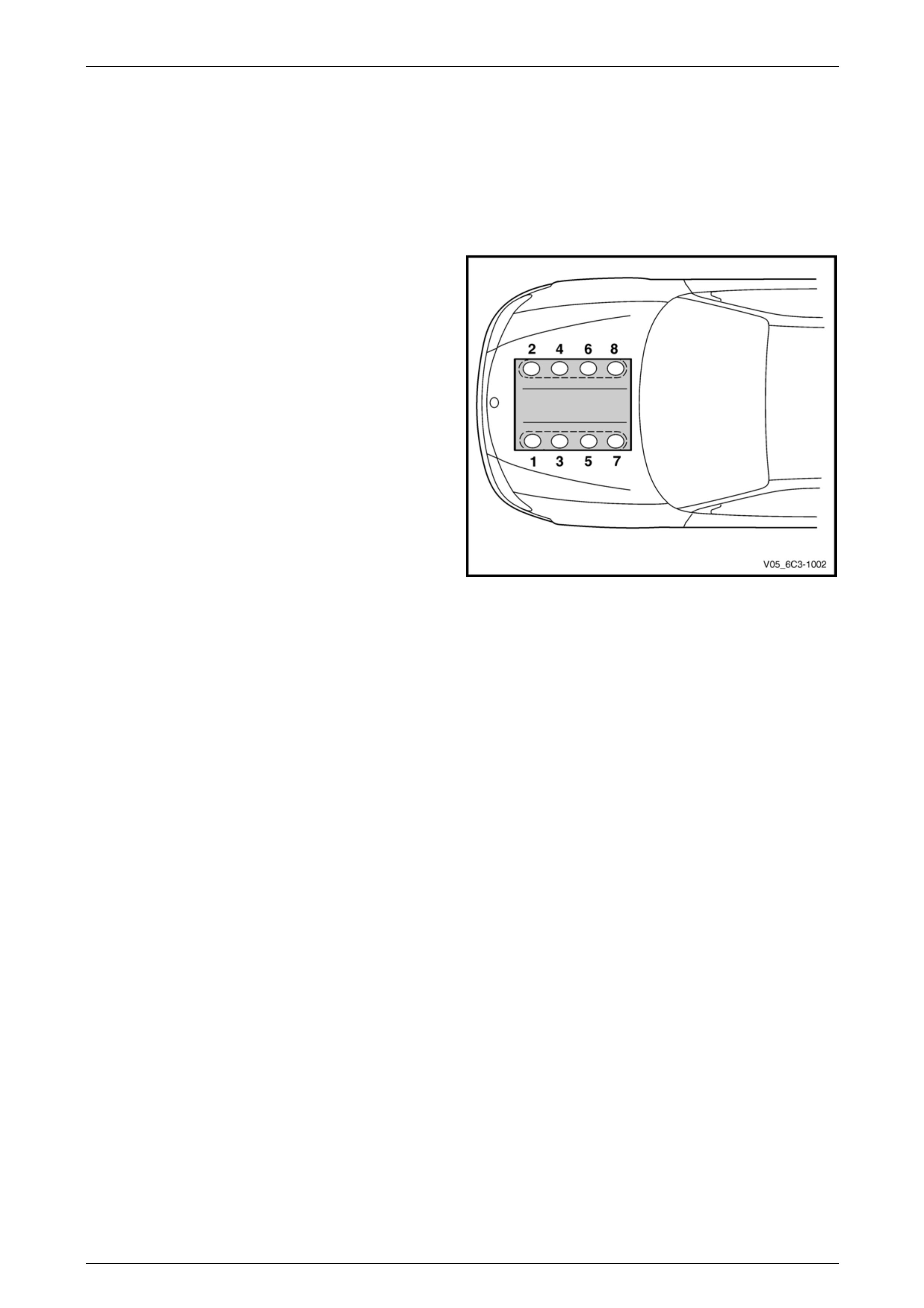
Engine cylinder identification follows the international
standard OBD II. This standard calls for the engine cylinder
bank number one to be identified by the location of cylinder
number one. Therefore the numbering for the GEN III V8
engine is:
• 1, 3, 5, 7 – Left-hand side (Bank 1),
• 2, 4, 6, 8 – Right-hand side (Bank 2).
The engine firing order is 1, 8, 7, 2, 6, 5, 4, 3.
Figure 6C3-3 – 1

Powertrain Management GEN III V8 – Service Operations Page 6C3-3–5
Page 6C3-3–5
1.2 Service Precautions and Notes
When servicing the po wertrain management system, failure to follow the safety and precautionary directions can lead to
personal injury and/or improper system operation:
• If working on a vehicle which has been sub jected to an under bonnet thermal incident (fire), wear appropriate
protective clothing to prevent personal injury. Components that contain fluoro-elastomer may produce a corrosive
bi-product when subjected to extreme heat.
• Disconnection of the battery affects certain vehicle electronic systems.
Refer to Section 00 Warnings, Cautio ns and Notes before disconnecting the battery.
• Prior to disconnection or removal of any components associated with the fuel system, clean the area around any
connection points to avoid possible contamination of the fuel system.
• A depressurised fuel system contains residual fuel that can be spilled during service operations. To reduce the
chance of personal injury, cover the fittings with a shop towel to absorb any fuel spillage prior to performing the
service operation. Once the service operation has been completed, place the towel in an approved container for
disposal.
• To avoid accidental fuel discharge, it is advisable to disconnect the battery and remove the fuel pum p relay if the
fuel line between the fuel pump and the fuel rail is to be disconnected/open for an indefinite period.
• Always tighten fasteners to the correct tightening torque, and where indicated in the service proce dure, follow the
correct tightening sequence, precautions and recommendations to prevent premature failure of the fastener or
component, refer to Section 00 Warnings, Cautions and No tes for further information on fasteners.
• Do not use silicone based assembly lubricants as damage to the heated oxygen sensors may result.
• After completing the required service operations, road test the vehicle to ensure correct powertrain management
system operation.
• Before removing the PCM, disconnect the ba ttery ground lead.
• Never start the engine without the battery being securely connected.
• Never disconnect the battery while the engine is running or when charging the battery.
• Never touch the connector pins of any electronic component, such as a PCM, as electrostatic discharge (ESD)
damage may result. For further information, refer to Section 00 Warnings, Cautions and Notes .
• Never subject the PCM to temperatures below -40°C and above 125°C.
• Ensure that all cable harness plugs are connected securely and that battery termin als are thoroughly cle an.
• The powertrain management system harness connectors are designed to fit only one way; there are indexing tabs
and slots on both halves of the connector. Forcing the connector into place is not necessary if it is being installed
with the correct orientation. Failure to take care to match the indexing tabs and slots correctly can cause damage to
the connector, the module, or other vehicle components or systems.
• Never connect or disconnect a cable harness plug at the PCM, or fuel system component when the ignition is
switched on.
• Before attempting any electric welding on the vehicle, disconnect the battery leads and the PCM connectors.
• When steam or high pressure cleaning the engine, do not direct the cleaning nozzle at the PCM or other powertrain
management system components. If this happens, corrosion of the terminals can occur.
Use of incorrect electrical test equipment
when performing the powertrain management
service procedures could result in incorrect
results or damage to PCM system
components.
• Use only the test equipment specified in the diagnostic tables, since other test equipment may
either give incorrect results or damage servic eable components,
refer to Section 6C3-2 Powertrain Management – GEN III V8 – Diag nostics.

Powertrain Management GEN III V8 – Service Operations Page 6C3-3–6
Page 6C3-3–6
2 General Service Operations
2.1 Service Operations Not Covered in This
Section
There are cases where service operations used by the powertrain management system are covered in other Sections of
the service documentation. To aid technicians in locating the necessary service procedures, refer to the following
references.
Fuel System
For the following fuel system service procedures, refer to Section 8A1 Fuel System:
• fuel system cleaning,
• fuel system leak and pressure test,
• fuel feed hose to fuel rail replacement, and
• fuel line quick connect fittings.
Engine Dress Covers
For service procedures of the engine dress covers, refer to Section 6A3 Engine Mechanical – GEN III V8.

Powertrain Management GEN III V8 – Service Operations Page 6C3-3–7
Page 6C3-3–7
2.2 Fuel Injector Coil Test
1 Depressurise the fuel system, refer to Section 8A1 Fuel System.
2 Turn the ignition off.
3 Remove the engine dress cover, refer to Section 6A3 Engine Mechanical – GEN III V8.
4 Using Tech 2, observe the engine coolant temperature (ECT), refer to Section 0C Tech 2. If the ECT is between
10 – 35°C, refer to Engine Coolant T emperature Between 10 – 35°C, or if the ECT is outside this range, refer to
Engine Coolant Temperature Outside 10 – 35°C.
Engine Coolant Temperature Between 10 – 35°C
Step Action Value(s) Yes No
1 1 Set the amperage supply selector switch on the
fuel injector coil/balance tester (1), special tool
J 39021 to the Coil Test 0.5 Amp position. Refer
to Figure 6C3-3 – 2.
2 Connect the fuel injector tester leads (4 and 5) to
B+ and ground.
3 Connect the digital multimeter (2) positive a nd
negative lead to the fuel injector tester. Set the
multimeter to read DC Voltage.
4 Connect the fuel injector tester to a fuel injector.
5 Press the Push to Start Test button on the fuel
injector tester.
6 Observe and record the voltage reading on the
digital multimeter.
NOTE
The voltage reading ma y ris e during the test.
Record the voltage reading after one secon d
of the test.
7 Repeat steps 4 through 6 for each fuel injector.
NOTE
The table in Figure 6C3-3 – 3 shows an
example of the results from a fuel injector
coil test.
Did any fuel injector have an erratic voltage reading
(large fluctuations in voltage that did not stabilise), or
voltage readings outside of the specified value? 5.5 – 6.6 V
Replace the faulty
fuel injector/s. Refer
to 3.11 Fuel Rail
Assembly System OK
When all repairs are comp leted, check the system for fuel leaks and correct operation .

Powertrain Management GEN III V8 – Service Operations Page 6C3-3–8
Page 6C3-3–8
Engine Coolant Temperature Outside 10 – 35°C
Step Action Value(s) Yes No
1 1 Set the amperage supply selector switch on the
fuel injector coil/balance tester (1), special tool
J 39021 to the Coil Test 0.5 Amp position. Refer
to Figure 6C3-3 – 2.
2 Connect the fuel injector tester leads (4 and 5) to
B+ and ground.
3 Connect the digital multimeter (2) positive a nd
negative lead to the fuel injector tester. Set the
multimeter to read DC Voltage.
4 Connect the fuel injector tester to a fuel injector.
5 Press the Push to Start Test button on the fuel
injector tester.
6 Observe and record the voltage reading on the
digital multimeter.
NOTE
The voltage reading ma y ris e during the test.
Record the voltage reading after one secon d
of the test.
7 Repeat steps 4 through 6 for each fuel injector.
8 Identify the highest voltage reading recorded from
the six fuel injectors tested that is 9.5 V or below.
NOTE
Disregard those voltage readings that are
above 9.5 V. Voltage readings above 9.5 V
indicate a faulty fuel injector.
9 Subtract the remaining voltage readings recorded
in Step 8, from the highest voltage reading.
Are any of the values recorded in Step 9 greater than
the specified value? 0.6 V Go to Step 2 System OK
2 Replace any fuel injector that had any of the following:
• a subtracted value exceeding 0.6 V,
• an initial reading above 9.5 V, and
• an erratic reading.
NOTE
The table in Figure 6C3-3 – 4 shows an
example of the results from a fuel injector
coil test.
Has the repair been completed? – System OK. –
When all repairs are comp leted, check the system for fuel leaks and correct operation .
Powertrain Management GEN III V8 – Service Operations Page 6C3-3–9
Page 6C3-3–9
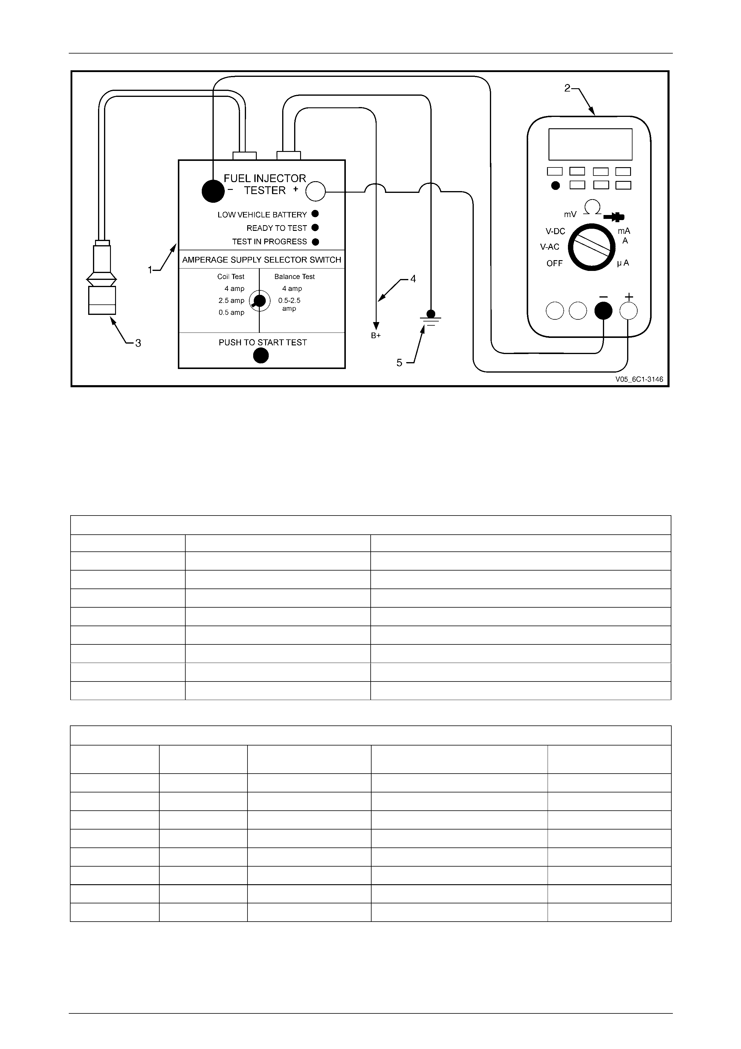
Figure 6C3-3 – 2
Legend
1 Fuel Injector Coil/Balance Tester – Special Tool J39021
2 Digital Multimeter
3 Fuel Injector Harness Connector
4 To Battery Positive Terminal
5 Battery Earth
Fuel Injector Coil Test Example – Engine Coolant Temperature b etween 10 – 35°C (Typical Values Shown)
Fuel Injector No. Voltage Reading Pass / Fail (acceptable range 5.5 - 6.6V)
1 6.6 Pass
2 5.4 Fail
3 6.2 Pass
4 6.1 Pass
5 6.7 Fail
6 6.0 Pass
7 6.2 Pass
8 6.7 Fail
Figure 6C3-3 – 3
Fuel Injector Coil Test Exampl e – En gine Coolant Temperature Above / Below 10 – 35°C (Typical Values Shown)
Fuel Injector No. Voltage Reading Highest Voltage Reading
(9.5V or less) Subtracted Value
(acceptable voltage 0.6 V) Pass / Fail
1 9.8 – –
Fail
2 6.4 7.0 0.6 Pass
3 6.9 7.0 0.1 Pass
4 5.8 7.0 1.2 Fail
5 7.0 7.0 0.0 Pass
6 6.3 7.0 0.7 Fail
7 6.9 7.0 0.1 Pass
8 6.4 7.0 0.6 Pass
Figure 6C3-3 – 4

Powertrain Management GEN III V8 – Service Operations Page 6C3-3–10
Page 6C3-3–10
2.3 Fuel Injector Balance Test
To avoid irregular fuel pressure readings, do
not perform this procedure if the engine
coolant temperature is above 94°C.
Fuel Injector Balance Test – With Tech 2
1 Check the engine coolant temperature is below 94°C.
2 Perform the fuel injector coil test and replace any fuel inj ectors that are not functioning correctly before proceeding.
Refer to 2.2 Fuel Injector Coil Test.
3 Perform the fuel system pressure check and ensure the fuel system is functioning correctly before proceeding with
the fuel injector balance test. Refer to Section 8A1 Fuel Sys t em.
4 While the fuel pressure gauge is still connected to the fuel pressure test point, pressurise the fuel s ystem.
Refer to Section 8A1 Fuel System.
5 When the fuel pressure reading stabilises, record the fuel pressure reading indicated by the fuel press ure gauge.
NOTE
The fuel pressure reading taken in Step 5 is
known as the first pressure reading.
6 Connect Tech 2 to the data link connector (DLC) and turn the ignition on.
7 On Tech 2 select Engine / V8 GEN III / Actuator Test / Fuel Injector Balance.
8 Follow the Tech 2 prompts, recording the fue l pressure gauge reading for each injector.
NOTE
The fuel pressure readings taken in Step 8 are
known as the second pressure read ing
9 Perform the Fuel Injector Pressure Drop Calculati on is this Section.
Fuel Injector Balance Test – Without Tech 2
1 Check the engine coolant temperature is below 94°C.
2 Perform the fuel injector coil test and replace any fuel inj ectors that are not functioning correctly before proceeding.
Refer to 2.2 Fuel Injector Coil Test.
3 Perform the fuel system pressure check and ensure the fuel system is functioning correctly before proceeding with
the fuel injector balance test. Refer to Section 8A1 Fuel Sys t em.
4 While the fuel pressure gauge is still connected to the fuel pressure test point, pressurise the fuel s ystem.
Refer to Section 8A1 Fuel System.
5 When the fuel pressure reading stabilises, record the fuel pressure reading indicated by the fuel press ure gauge.
NOTE
The fuel pressure reading taken in Step 5 is
known as the first pressure reading.
6 Remove the engine dress covers, refer to Section 6A3, Engine Mech anical – GEN III V8.
7 Connect Tool No. J 39021 fuel injector coil/balance tester (1), to the fuel injector connector.
Refer to Figure 6C3-3 – 5.
Powertrain Management GEN III V8 – Service Operations Page 6C3-3–11
Page 6C3-3–11
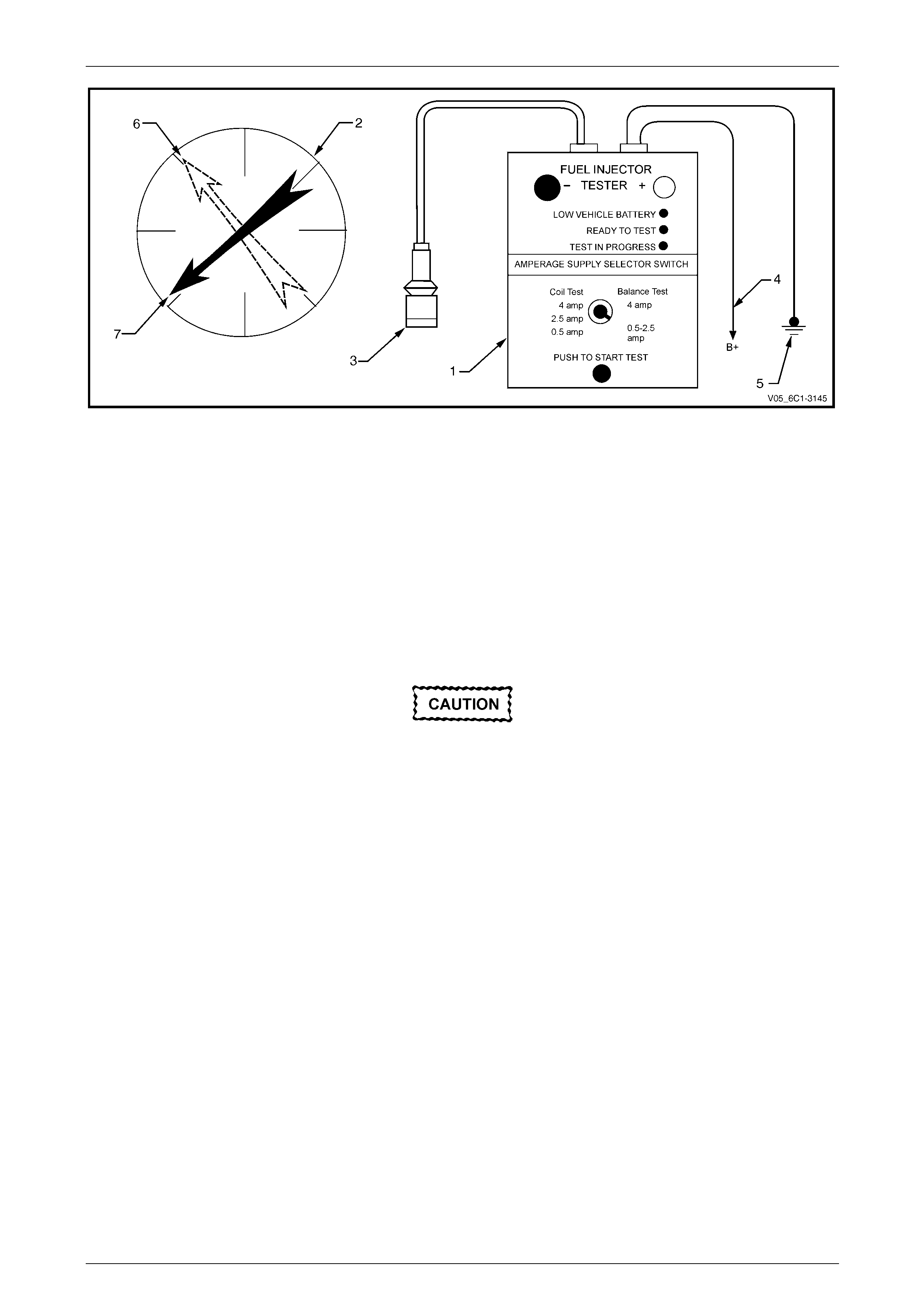
Figure 6C3-3 – 5
Legend
1 Fuel Injector Coil/Balance Tester – Special Tool J39021
2 Fuel Pressure Gauge – Special Tool SD28018
3 Fuel Injector Harness Connector
4 To Battery Positive Terminal
5 Battery Earth
6 First Pressure Reading
7 Second Pressure Reading
8 Connect the fuel injector tester battery positive lead (4) and battery negative lead (5) to the battery.
9 Set the amperage supply selector of the fuel injector tester to the Balance Test 0.5 – 2.5 amp position.
As the fuel pressure tends to increase after
the fuel injector stops fuel delivery, record the
fuel pressure value immediately after the fuel
injector stops fuel delivery. Do not record the
higher fuel pressure value.
10 Press the Push to Start Test Button on the fuel injector tester to activate the fuel injector.
11 Record the fuel pressure readi ng in dicated by the fuel pressure gaug e.
NOTE
The fuel pressure readings taken in Step 10 is
known as the second pressure read ing
12 Repeat the balance test press ure reading for each fuel injector.
13 Perform the Fuel Injector Pressure Drop Calculation is this Section.

Powertrain Management GEN III V8 – Service Operations Page 6C3-3–12
Page 6C3-3–12
Fuel Injector Pressure Drop Calculation
Fuel Injector Balance Test Example – Typical Values Sh own
Cylinder 1 2 3 4 5 6 7 8
1st Pressure
Reading 360 kPa 360 kPa 360 kPa 360 kPa 360 kPa 360 kPa 360 kPa 360 kPa
2nd Pressure
Reading 155 kPa 131 kPa 155 kPa 200 kPa 146 kPa 150 kPa 146 kPa 131 kPa
Amount of
Pressure Drop 205 kPa 229 kPa 205 kPa 160 kPa 214 kPa 210 kPa 214 kPa 229 kPa
Average
Range
198 - 218 kPa
Injector OK Replace
fuel injector
– to much
pressure
drop
Injector OK Replace
fuel injector
– to little
pressure
drop
Injector OK Injector OK Injector OK Replace
fuel injector
– to much
pressure
drop
Figure 6C3-3 – 6
a Subtract the second pressure reading from the first pressure reading to calculate the pressure drop value.
Refer to Figure 6C3-3 – 6, typical results.
b Calculate the pressure drop value for each fuel injector.
c Add all the individual pressure drop values of each fuel injector to calculate the total pressure drop.
d Divide the total pressure drop by the number of fuel injectors to calculate the average pr essure drop.
Fuel Injector Pressure Drop Analysis
a A fuel injector is faulty if its pressure drop va lue deviates from the average pressure drop by more than 1 0 kPa.
Do not repeat any portion of the test before
running the engine to prevent the engine from
flooding.
b Re-test any fuel injector that does not meet the specification.
c Replace all faulty fuel injectors, refer to 3.11 Fuel Rail Assembly.
Powertrain Management GEN III V8 – Service Operations Page 6C3-3–13
Page 6C3-3–13
2.4 Fuel Injector Leak Down Test
1 Turn the ignition switch off.
NOTE
Do not disconnect the fuel feed hose from the
fuel rail.
2 Remove the fuel rail assembly, refer to 3.11 Fuel Rail Assembly.
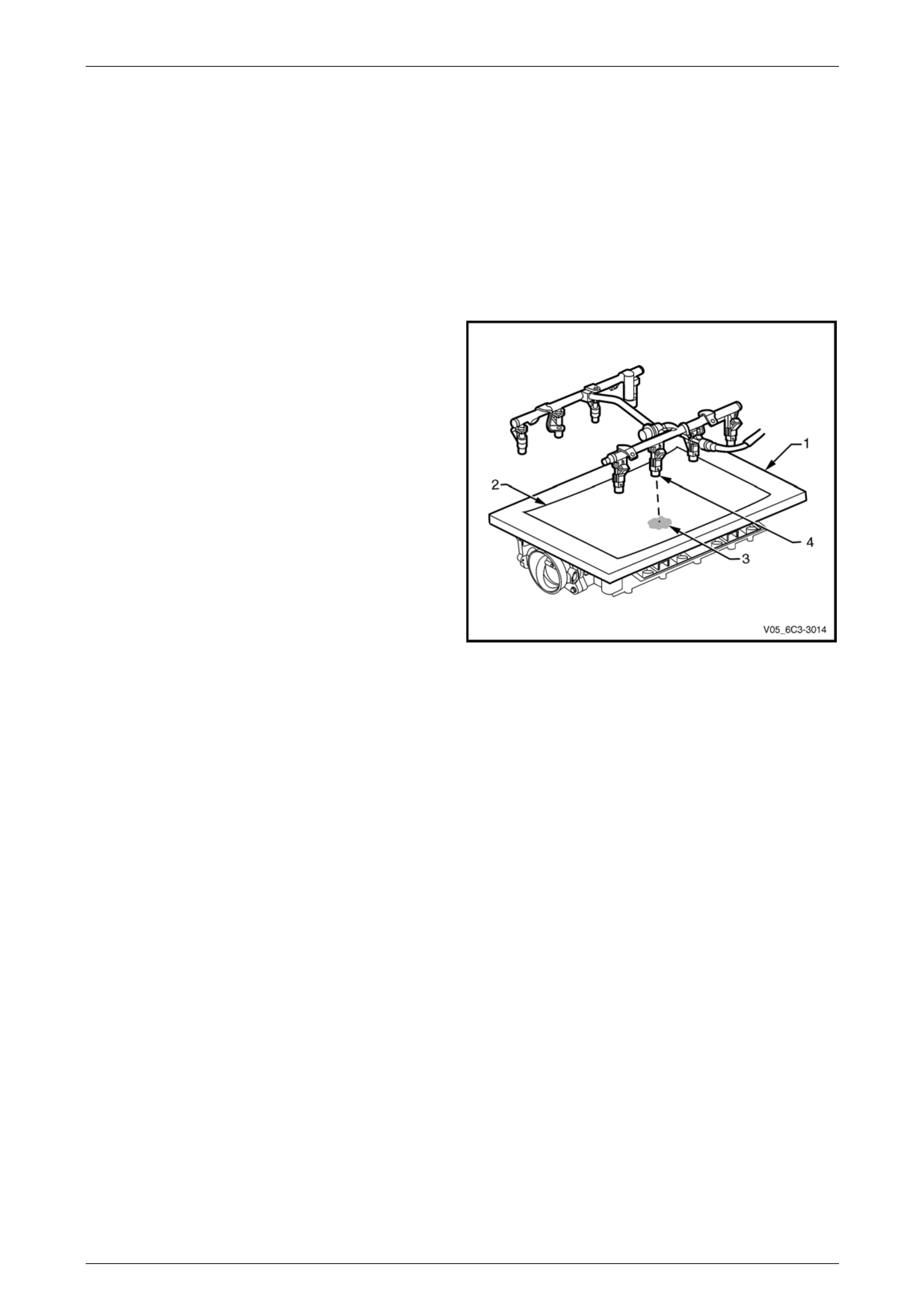
3 Lift up and support the fuel rail and injector assembly.
4 Place a board (1) with a sheet of clean paper (2),
preferably white, onto the intake manifold.
5 Using Tech 2, enable the fuel pump to pressurise the
fuel system. Refer to Section 0C Tech 2 for this
procedure.
6 Whilst the fuel system is pressurised, check the
following:
• Signs of fuel stains on the paper (3).
• Signs of weeping at the fuel injector spra y
tips (4).
7 If any of the above conditions are present, replace the
leaking fuel injector(s),
refer to 3.11 Fuel Rail Assembly.
8 Carefully reinstall the fuel rail assembly,
refer to 3.11 Fuel Rail Assembly.
9 Perform the following procedur e to inspect for fuel
leaks at the fuel rail:
a Turn the ignition switch on for two seconds.
Figure 6C3-3 – 7
b Turn the ignition switch off for 10 seconds.
c Turn the ignition switch on.
d Inspect for fuel leaks at the fuel rail.
10 Road test the vehicle and check for correct operati on.

Powertrain Management GEN III V8 – Service Operations Page 6C3-3–14
Page 6C3-3–14
2.5 Power Balance Test
The power balance test is used to determine the condition of each cylinder. Once a problem cylinder(s) has been
identified, the cause of the fault – such as fuel, spark or a mechanical failure – must be rectified.
1 Turn the ignition switch off.
2 Connect Tech 2 to the data link connector (DLC) and turn the ignition on.
3 On Tech 2 select Engine / V8 GEN III / Function Tests / Power Balance.
4 Follow the Tech 2 prompts and perform the power balance test.
NOTE
• RPM readings displayed should be within 50
rpm of the idle speed for all cylinders.
• Any cylinder that does not cause a drop in
engine idle speed is misfiring.

Powertrain Management GEN III V8 – Service Operations Page 6C3-3–15
Page 6C3-3–15
3 Component Replacement
3.1 Components Not Covered In This
Section
There are cases where components use d b y the powertrain management system are covered in other Sections of the
service documentation. To aid technicians in locating the necessary service procedures for these components, refer to
the following references.
Air-conditioning System
For A/C pressure switch replacement procedure,
refer to Section 2B HVAC Climate Control (Manual A/C) – Servicing and Diagnosis.
Electrical Components
For the following electrical system component replacement procedures, refer to the appr opriate Sections as follows:
• Extended brake pedal trave l switch an d stop lamp switch service operations,
refer to Section 5A Service and Park Braking Systems.
• Fuse and relay locations, refer to Section 12O Fuses, Relays and Wiring Harnesses.
• Cruise control cancel switch and clutch start switch service operations, refer to Section 7A3 Clutch – GEN III V8.
• Cruise control switch assembly service operations, refer to Section 12E Cruise Control.
• Powertrain interface module PIM removal and installation procedure,
refer to Section 6E3 Powertrain Interface Module – GEN III V8 Engine.
• Neutral start and back-up lamp switch,
refer to Section 7C4 Automatic Transmission – 4L60-E – On-vehicle Servicing.
• Vehicle speed sensor service operations,
refer to Section 7C4 Automatic Transmission – 4L60-E – On-vehicle Servicing for autom atic transmission or
Section 7B2 Manual Transmission – GEN III V8 for manual transmission.
Fuel System
For the following fuel system component replacement procedures, refer to Section 8A1 F uel System:
• evaporative emission control canister,
• fuel filter,
• fuel hose/pipes layout,
• fuel pump motor assembly and fuel pressure regulator assembly,
• fuel sender assembly service operations, and
• fuel tank pressure sensor – Coupe only.
Transmission – Automatic
For automatic transmission sensors and compon ents,
refer to Section 7C4 Automatic Transmission – 4L60-E – On-vehicle Servicing.
Transmission – Manual
For manual transmission sensors and other components, refer to Section 7B2 Manual Transmission – GEN III V8 .
Powertrain Management GEN III V8 – Service Operations Page 6C3-3–16
Page 6C3-3–16
3.2 Accelerator Pedal Position Sensor
LT Section No. — 03–650
Remove
1 Turn the ignition switch off.
2 Remove the driver's side instrument panel lower trim plate assembly,
refer to Section 1A3 Instrument Panel and Consol e.
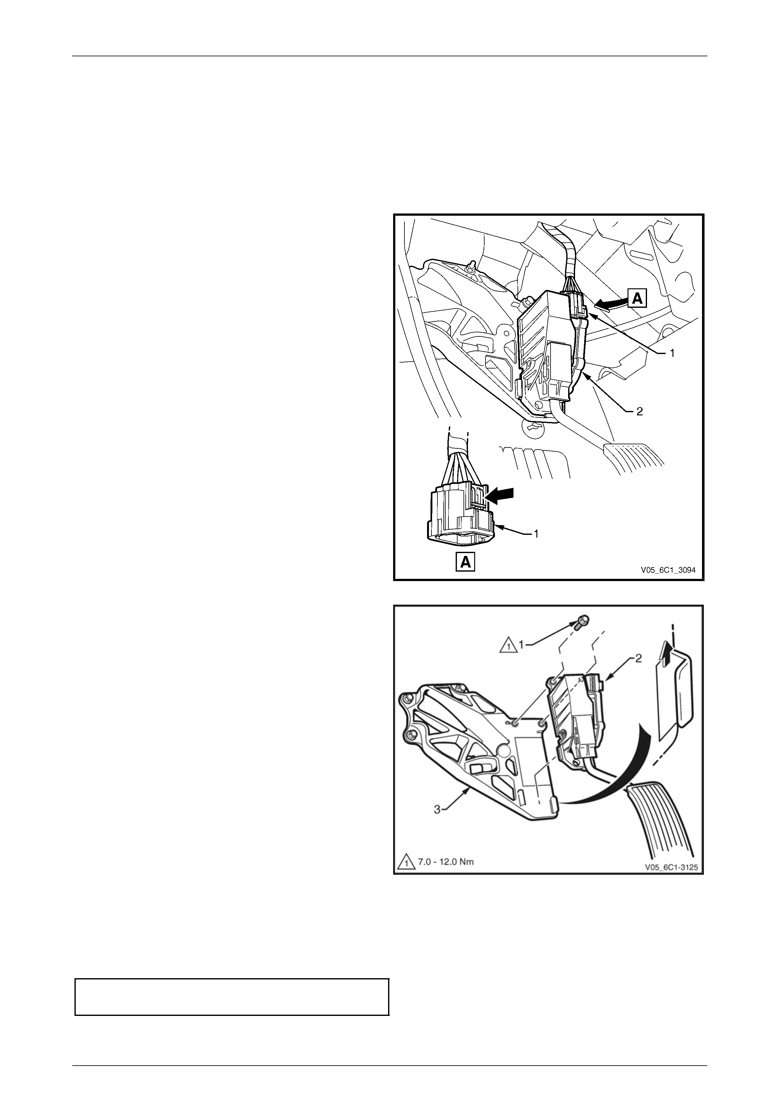
3 Disconnect the wiring connector (1) from the
accelerator pedal position (APP) sensor (2) by
depressing the latch in the direction of the ar row.
NOTE
If difficulty is experienced in disconnecting the
connector from the APP sensor, remove the
sensor from the accelerator pedal position (APP)
support bracket and then disconnect the
connector.
Figure 6C3-3 – 8
NOTE
If required, the APP sensor can be removed as
an assembly with the APP sensor support
bracket, refer to 3.3 Accelerator Pedal Position
Sensor Support Bracket.
4 Remove the bolt (1), two places, attaching the APP
sensor (2) to the APP sensor support bracket (3).
5 Slide the APP sensor upwards in the direction of the
arrow, to disengage the sensor from the support
bracket.
Figure 6C3-3 – 9
Reinstall
Reinstallation of the accelerator pedal position (APP) sensor is the reverse of the removal procedure, noting the
following:
1 Reinstall the bolts and tighten to the correct torque specification.
Accelerator pedal position sensor
attaching bolt torque specification.............7.0 – 12.0 Nm
2 Road test the vehicle and check for correct operation.
Powertrain Management GEN III V8 – Service Operations Page 6C3-3–17
Page 6C3-3–17
3.3 Accelerator Pedal Position Sensor
Support Bracket
LT Section No. — 03–650
Remove
1 Turn the ignition switch off.
NOTE
The accelerator pedal position (APP) sensor
support bracket may be remo ved as an assembly
with the accelerator pedal position APP sensor
attached.
2 If required, remove the APP sensor, refer to 3.2 Accelerator Pedal Position Sensor.
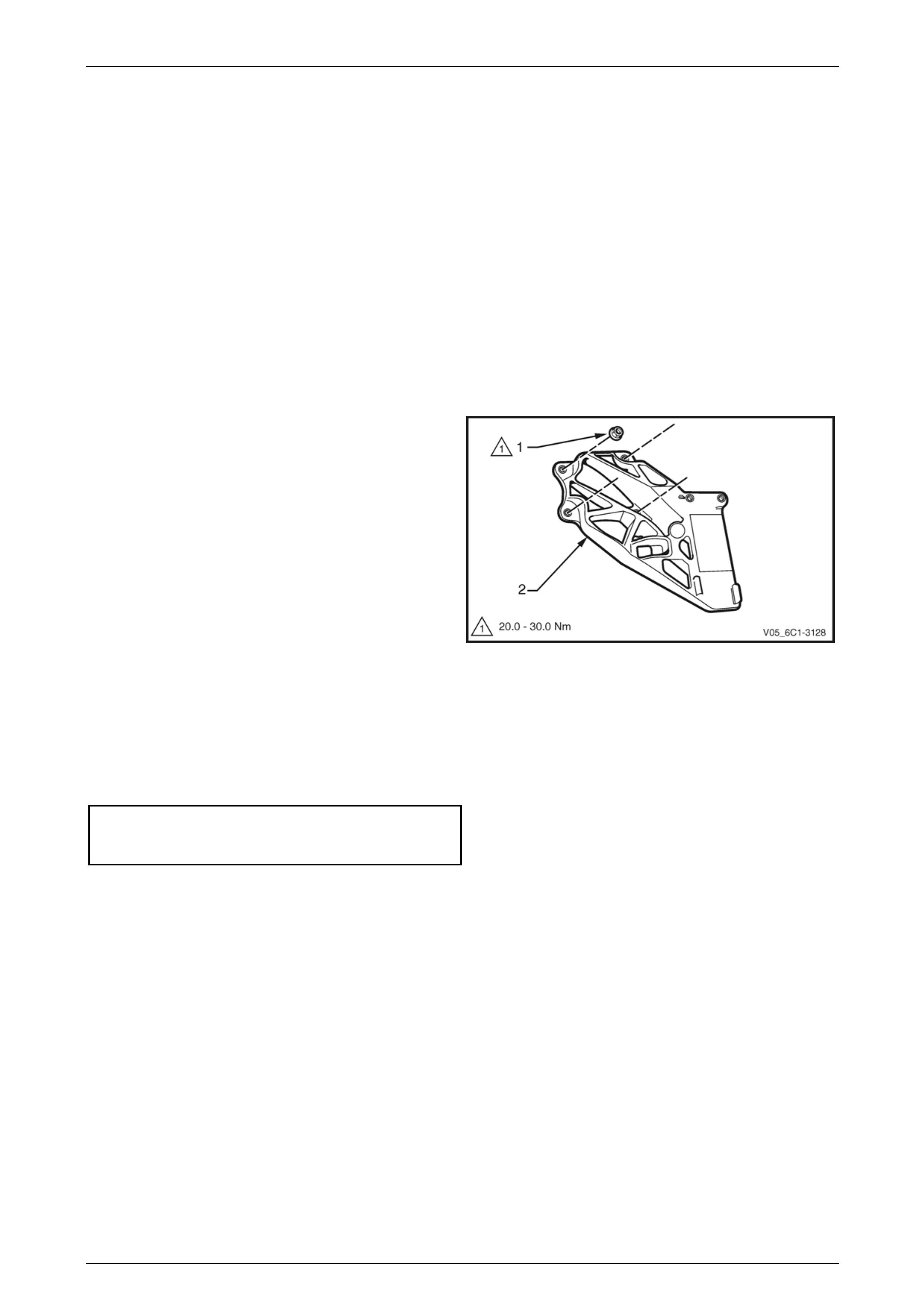
3 Remove the nut (1), four places, attaching the APP
sensor support bracket (2) to the dash panel and
remove the support bracket.
Figure 6C3-3 – 10
Reinstall
Reinstallation of the accelerator pedal position (APP) sensor support bracket is the reverse of the removal procedure,
noting the following:
1 Reinstall the nuts and tighten to the correct torque specification.
Accelerator pedal position (APP)
sensor support bracket attaching
nut torque specification...........................20.0 – 30.0 Nm
2 Road test the vehicle and check for correct operation.
Powertrain Management GEN III V8 – Service Operations Page 6C3-3–18
Page 6C3-3–18
3.4 Air Cleaner Assembly
LT Section No. — 03–250
Air Cleaner Upper Housing
Remove
1 Turn the ignition switch off.
2 Remove the upper radiator shroud, refer to Section 6B3 Engine Cooling – GEN III V8.
3 Remove the intake air duct, refer to 3.17 Mass Air Flow Sensor and Intake Air Duct.
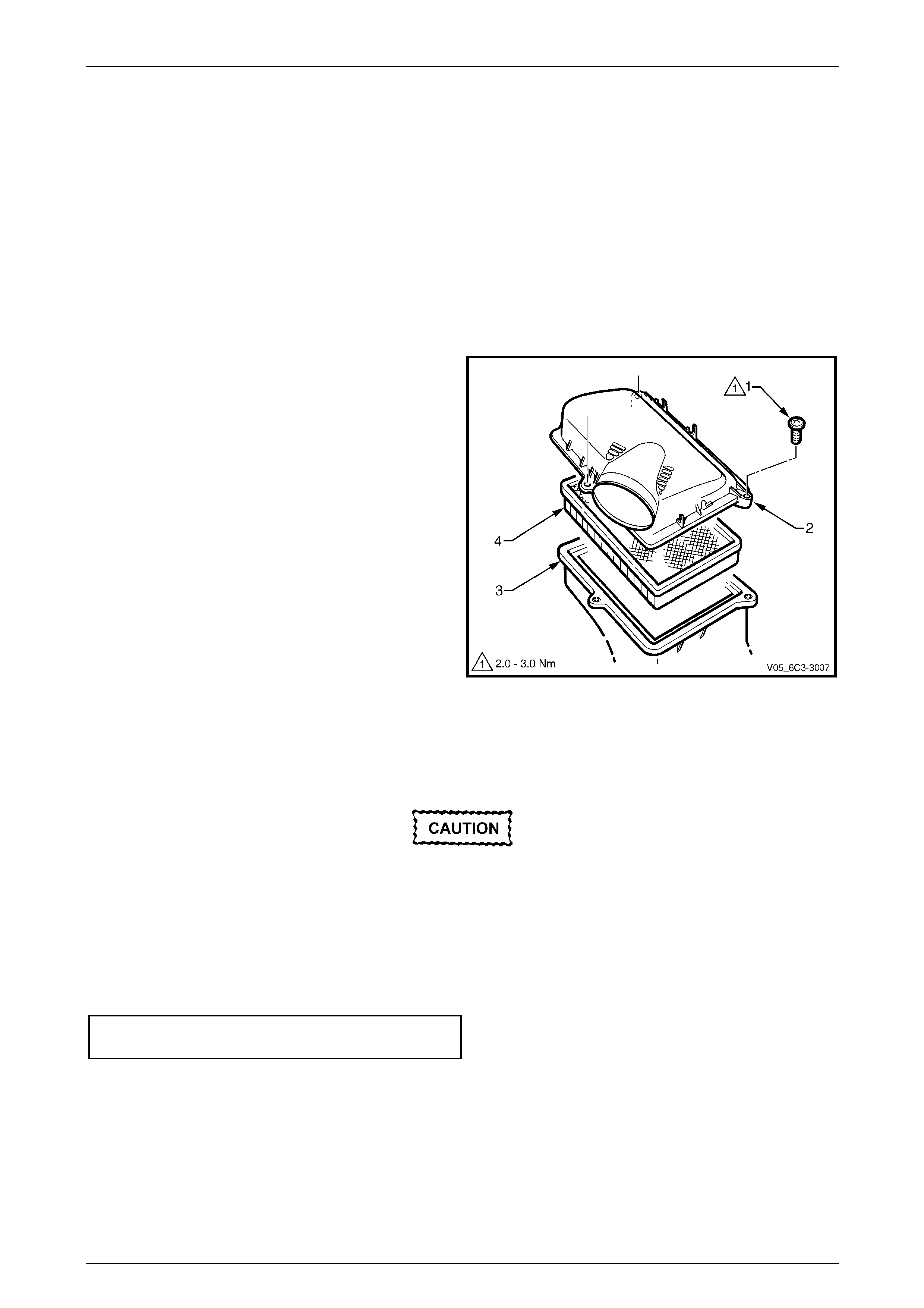
4 Remove the screw (1), three places, attaching the air
cleaner upper housing (2) to the air cleaner lower
housing (3).
5 Remove the upper housing and air cleaner
element (4).
Figure 6C3-3 – 11
Reinstall
Reinstallation of the air cleaner upper housing is the reverse of the removal procedure, noting the follo wing:
Ensure the air cleaner element seal is
correctly located in the air cleaner lower
housing during installation. Failure to do this
may result in engine damage due to unfiltered
air entering the engin e air intake s ystem.
1 Reinstall the air cleaner element.
2 Reinstall the screws and tighten to the correct torque specification.
Air cleaner upper housing attaching
screw torque specification...........................2.0 – 3.0 Nm
3 Road test the vehicle and check for correct operation, taking particular note that no air leaks are evident.
Powertrain Management GEN III V8 – Service Operations Page 6C3-3–19
Page 6C3-3–19
Air Cleaner Lower Housing Assembly
Remove
1 Turn the ignition switch off.
2 Remove the air cleaner up per housing and element as described previously.
3 Unclip the mass airflow sensor and air-conditioner pressure sensor wiring harness.
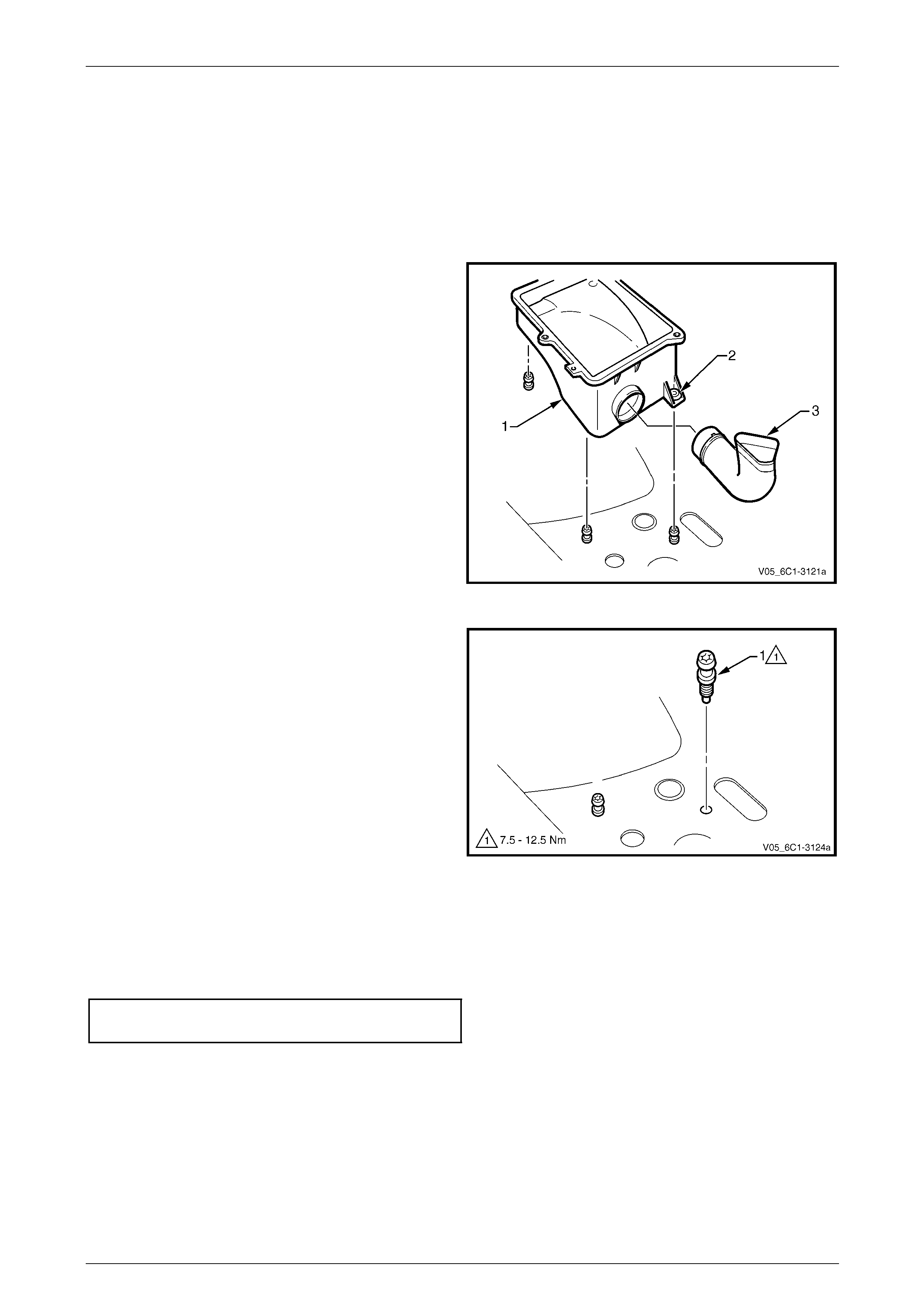
4 Grasp the air cleaner lower housing assemb ly (1), and
pull upward to release the i nsulator (2), three places,
from the retaining studs and remove the lower
housing.
5 If required, disengage the air cleaner air inlet duct (3)
from the lower housing.
Figure 6C3-3 – 12
6 If required, remove the stud (1), three places, from the
fender inner panel.
Figure 6C3-3 – 13
Reinstall
Reinstallation of the air cleaner lower housing assembly is the reverse of the removal procedure, noting the following:
1 If previously removed, reinstall the studs and tighten to the correct torque specification.
Air cleaner lower housing assembly
retaining stud torque specification.............7.5 – 12.5 Nm
2 Road test the vehicle and check for correct operation, taking particular note that no air leaks are evident.
Powertrain Management GEN III V8 – Service Operations Page 6C3-3–20
Page 6C3-3–20
3.5 Camshaft Position Sensor
LT Section No. — 02–000
Remove
1 Turn the ignition switch off.
2 Remove both engine dress covers, refer to Section 6A3 Engine Mechanical – GEN III V8.
3 Depressurise the fuel system, refer to Section 8A1 Fuel System.
4 Remove the intake manifold, refer to Section 6A3 Engine Mechanical – GEN III V8.
To avoid debris from entering the engine,
clean the area around the engine camshaft
position (CMP) sensor before removal and
plug or cover the opening once removed.
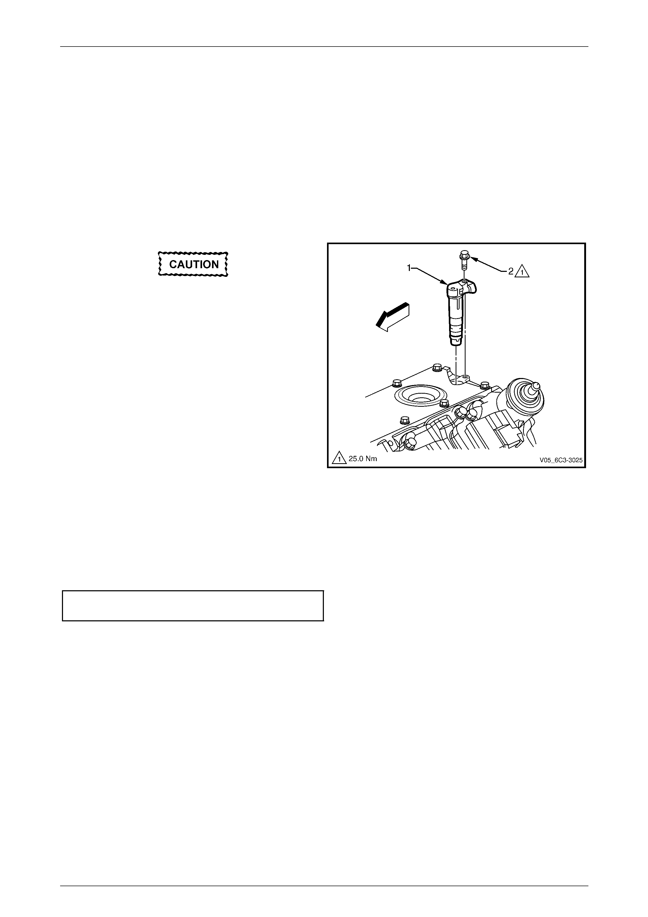
5 Disconnect the wiring connector from the CMP sensor
(1).
6 Remove the CMP sensor retaining bolt (2).
7 Remove the CMP sensor, by first twisting the sensor
to break the O-ring seal, then pull upward with a
twisting back and forth motion.
Figure 6C3-3 – 14
Reinstall
Reinstallation of the camshaft position (CMP) sensor is the reverse of the removal procedure, noting the following:
1 Lubricate the CMP sensor O-ring with clean engine oil prior to installation.
2 Reinstall the bolt and tighten to the correct torqu e specification.
Camshaft position (CMP) sensor
retaining bolt torque specification.......................25.0 Nm
Powertrain Management GEN III V8 – Service Operations Page 6C3-3–21
Page 6C3-3–21
3.6 Crankshaft Position Sensor
LT Section No. — 02–000
Remove
1 Turn the ignition switch off.
2 Remove the starter motor, refer to Section 6D3-2 Starting System – GEN III V8.
Clean the area around the crankshaft
position (CKP) sensor before removal to
avoid debris from entering the engine.
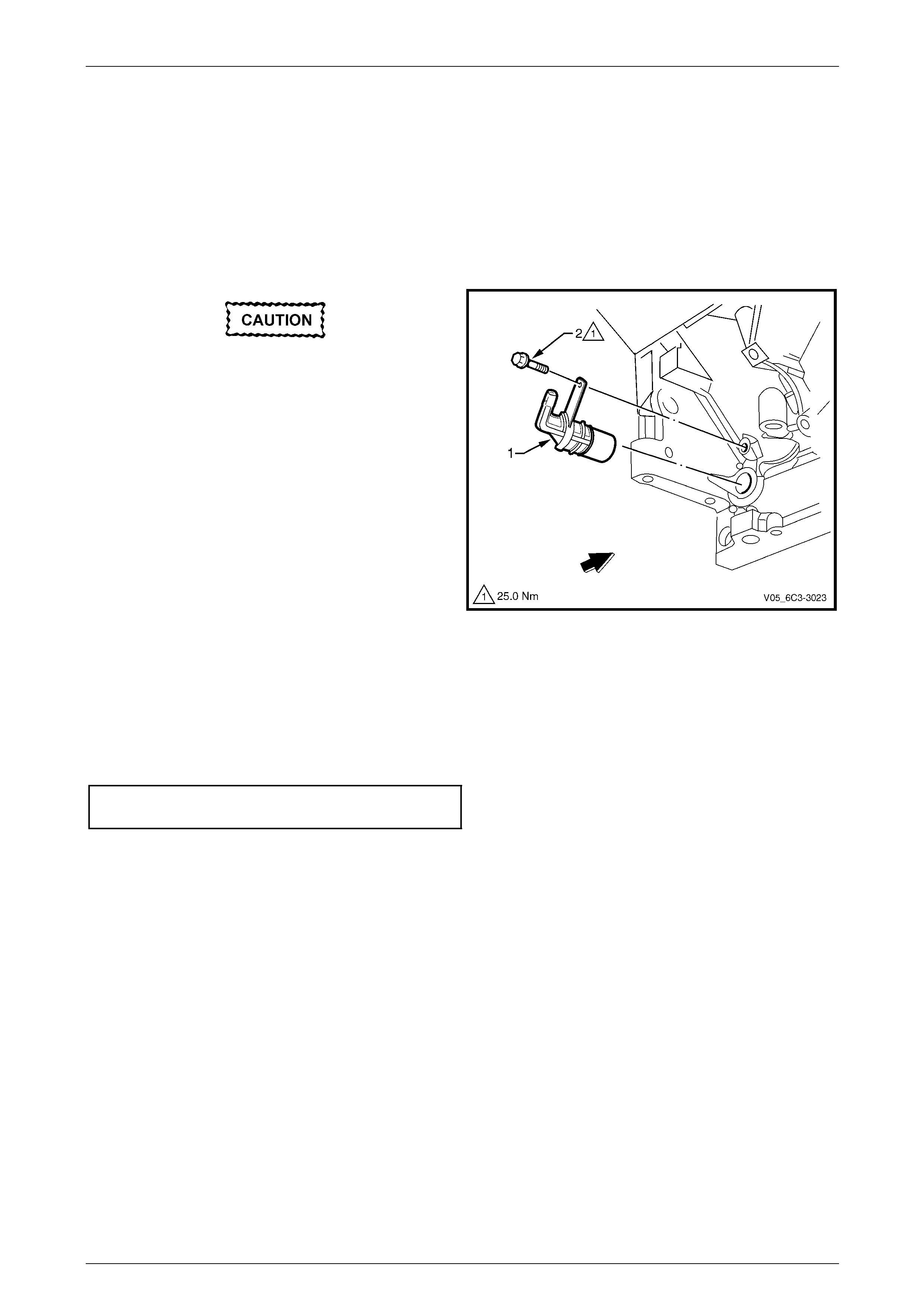
3 Disconnect the wiring connector from the CKP sensor
(1).
4 Remove the bolt (2) and remove the sensor.
Figure 6C3-3 – 15
Reinstall
Reinstallation of the crankshaft position (CKP) sensor is the reverse of the removal procedure, noting the following:
1 Lubricate the CKP sensor O-ring with clean engine oil prior to installatio n.
2 Reinstall the bolt and tighten to the correct torqu e specification.
Crankshaft position (CKP) sensor
retaining bolt torque specification.......................25.0 Nm
3 Road test the vehicle and check for correct operation.
Powertrain Management GEN III V8 – Service Operations Page 6C3-3–22
Page 6C3-3–22
3.7 Engine Coolant Temperature Sensor
LT Section No. — 02–000
Remove
To avoid serious personal injury, never
remove the engine coolant temperature ECT
sensor when the engine is hot. Allow the
engine to cool to ambient temperature (less
than 50° C) before performing this procedure.
1 Raise the vehicle and suppor t on safety stands, refer to Section 0A General Information for the location of jacking
and support points.
2 Drain the engine coolant, refer to Section 6B3 Engine Cooling – GEN III V8.
3 Lower the vehicle.
4 Remove the left-hand engine dress cover, refer to Section 6A3 Engine Mechanical – GEN III V8.
Clean the area around the engine coolant
temperature (ECT) sensor before removal to
avoid debris from entering the engine.
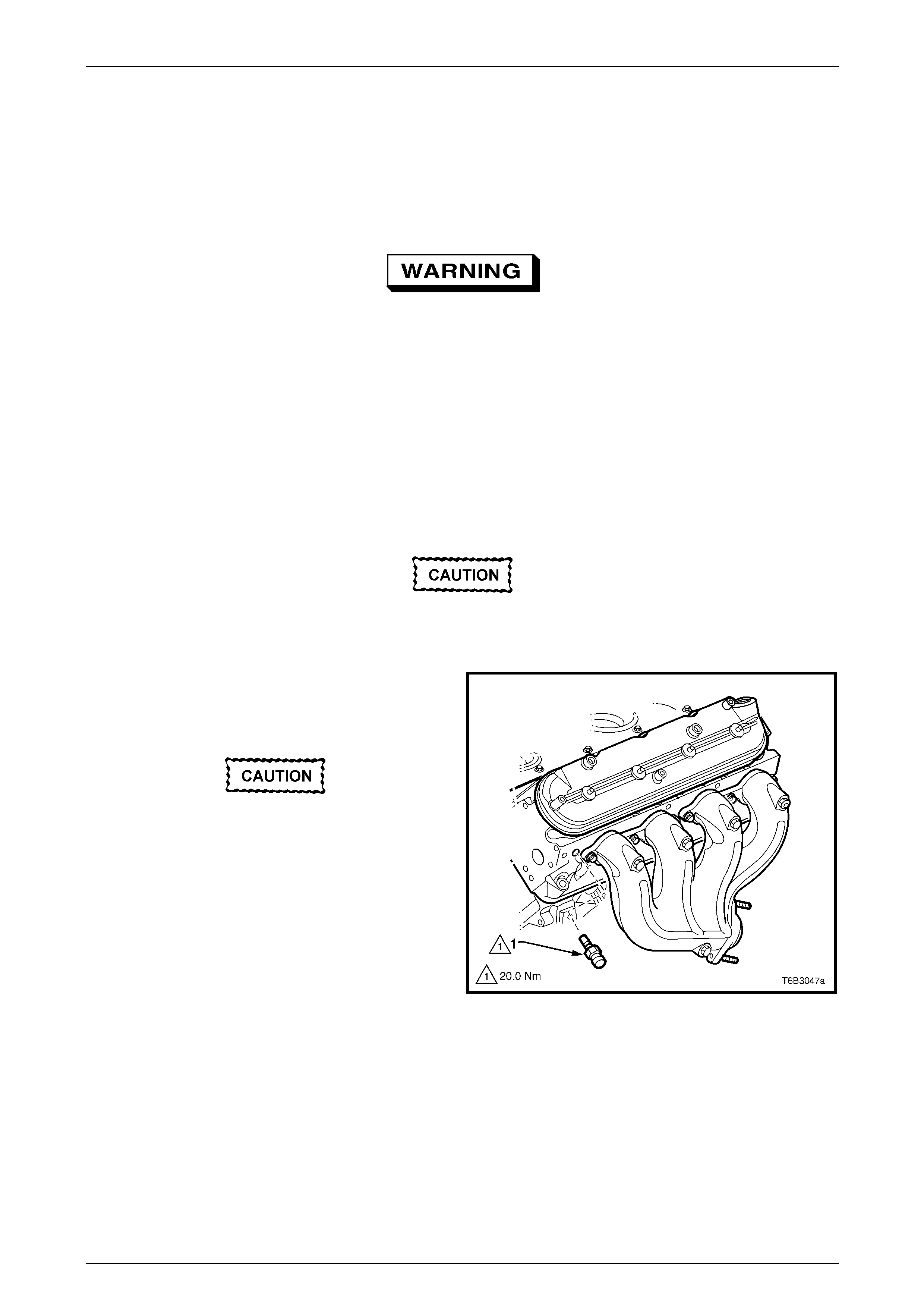
5 Disconnect the wiring connector from the ECT sensor
(1).
6 Remove the No. 1 spark plug lead from the spark plug.
Use care when handling the ECT sensor as
damage will affect the operation of the fuel
control system.
7 Remove the ECT sensor.
Figure 6C3-3 – 16
Powertrain Management GEN III V8 – Service Operations Page 6C3-3–23
Page 6C3-3–23
Test
To prevent component damage, use
connector test adaptor kit J 35616-A.
Resistance Check
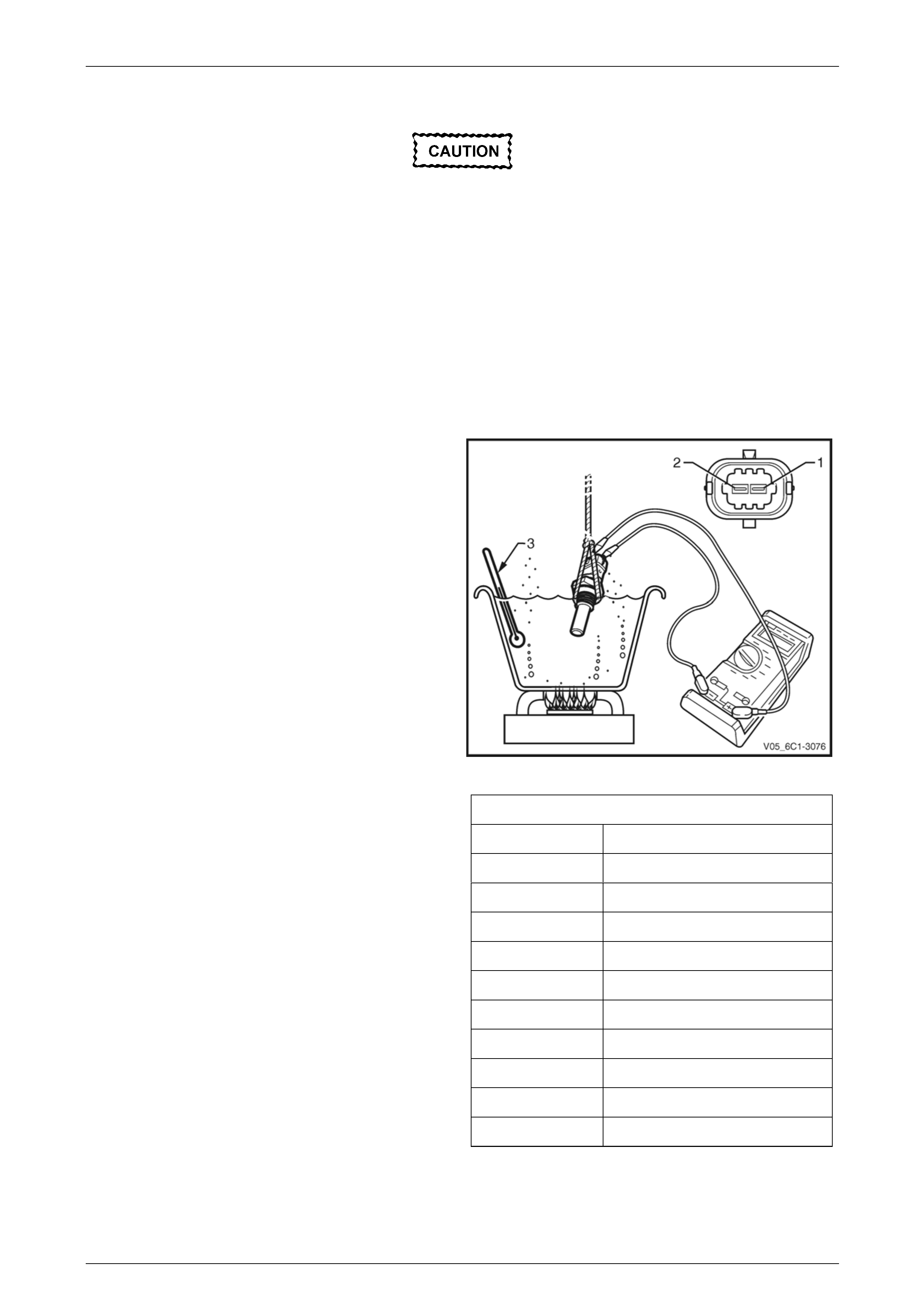
1 Suspend the ECT sensor and a suitable thermometer in a container of 50/50 DEX-COOL® long life co olant or
equivalent and water.
NOTE
Neither the ECT sensor or thermometer should
rest on the bottom of the container due to an
uneven concentration of heat at this point when
the container is heated.
2 Connect a digital ohmmeter using connector test
adaptor kit J 35616-A to the ECT sensor and measur e
the resistance across terminals 1 and 2.
3 Whilst heating the container, observe the resistance
values as the temperature increases and compare the
temperature/resistance chang e to the specifications.
Figure 6C3-3 – 17
4 If the resistance is not within specifications, replace
the ECT sensor.
Engine Coolant Temperature Vs Resistance
Temperature °C Resistance – Ohms (Ω)
-10 16,180
0 9,420
20 3,520
25 2,796
40 1,459
60 667
80 332
100 177
120 100
140 60

Powertrain Management GEN III V8 – Service Operations Page 6C3-3–24
Page 6C3-3–24
Reinstall
Reinstallation of the engine coolant temperature (ECT) sensor is the reverse of the removal proc edure, noting the
following:
1 Coat the ECT sensor thread with Loctite 242 or equivalent.
2 Tighten the ECT sensor to the correct torque specification.
Engine coolant temperature (ECT)
sensor torque specification ................................20.0 Nm
3 Refill the cooling system, refer to Section 6B3 Engine Cooling – GEN III V8.
4 Road test the vehicle and check for correct operation, taking particular note there is no coolant leakage.
Powertrain Management GEN III V8 – Service Operations Page 6C3-3–25
Page 6C3-3–25
3.8 Engine Oil Pressure Sensor
LT Section No. — 02–000
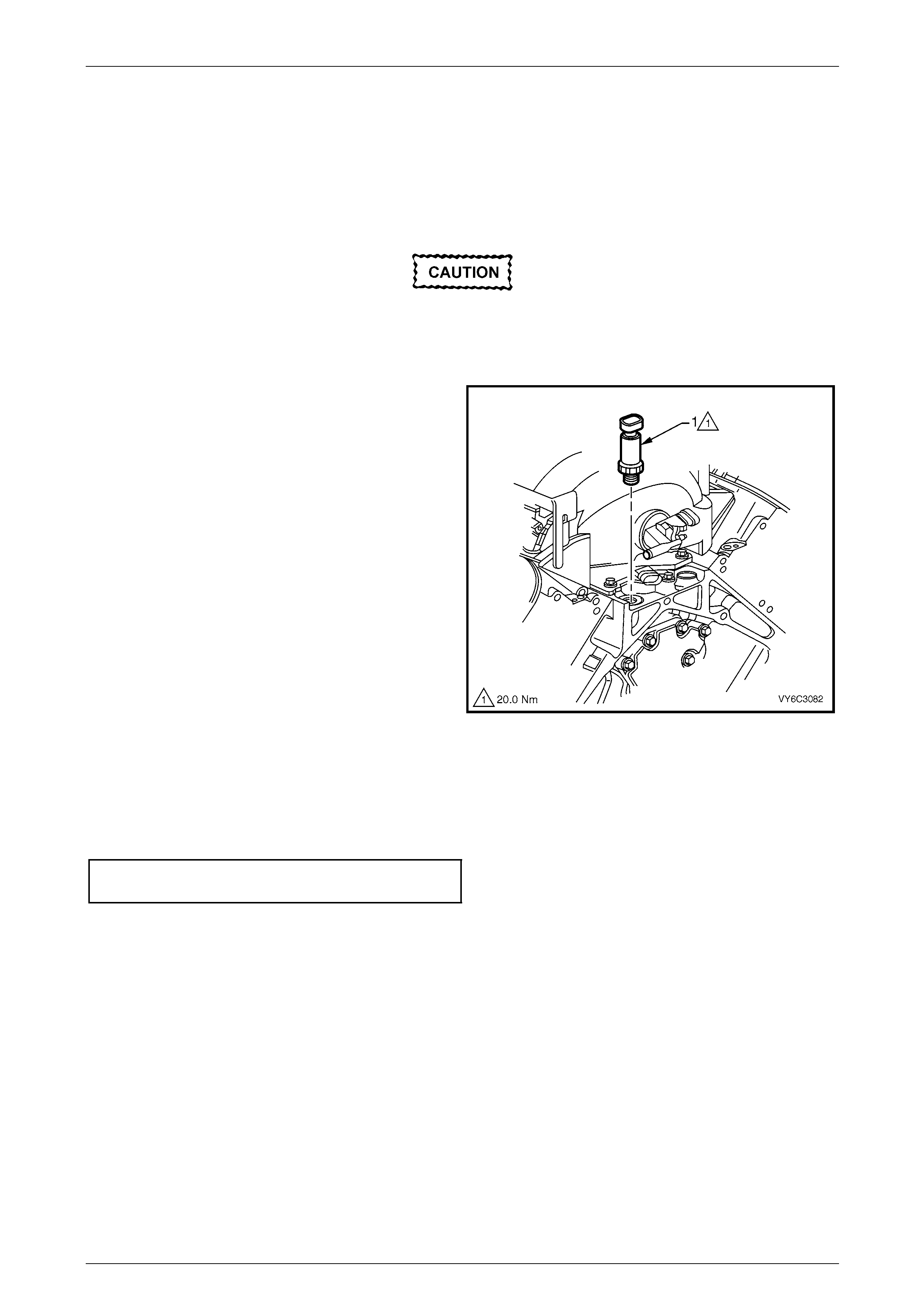
Remove
To avoid debris from entering the engine,
clean the area around the engine oil pressure
(EOP) sensor before removal and plug or
cover the opening once removed.
1 Disconnect the wiring connector from the engine oil
pressure (EOP) sensor (1).
2 Using tool J 41712, remove the EOP sensor.
Figure 6C3-3 – 18
Reinstall
Reinstallation of the engine oil pressure (EOP) sensor is the reverse of the removal procedure, noting the following:
1 Reinstall the EOP sensor and tighten to the correct torque specification.
Engine oil pressure (EOP) sensor
torque specification............................................20.0 Nm
2 Check the engine oil level and top up if necessary.
3 Start the engine and inspect for oil leaks.
Powertrain Management GEN III V8 – Service Operations Page 6C3-3–26
Page 6C3-3–26
3.9 EVAP Canister Purge Solenoid Valve
LT Section No. — 03–165
Remove
1 Remove the left-hand engine dress cover, refer to Section 6A3 Engine Mechanical – GEN III V8.
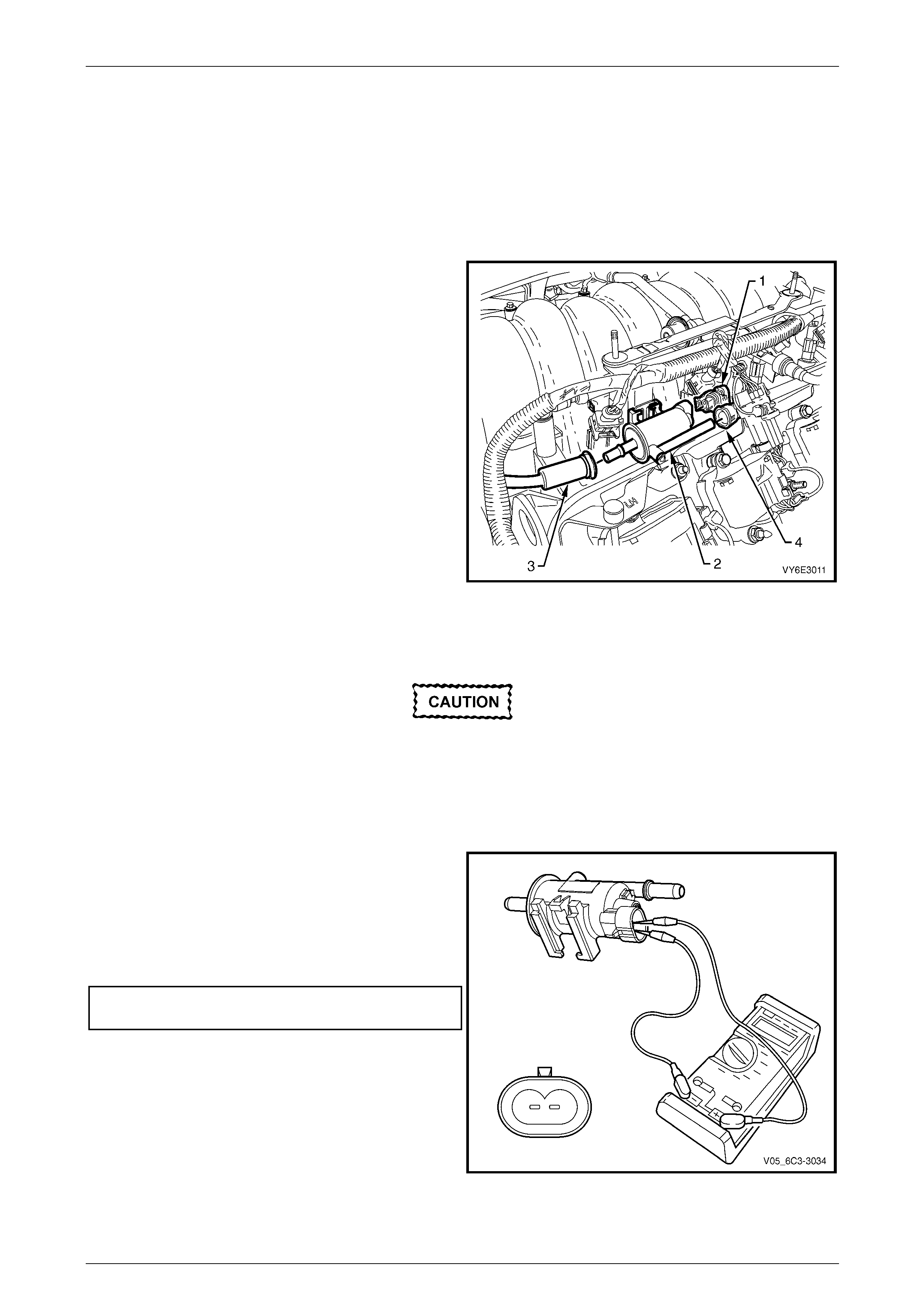
2 Disconnect the wiring connector (1) from the EVAP
canister purge solenoid valve (2).
3 Disconnect the front hose (3) by squeezing the
retaining clip and pulling the hose from the solenoid
valve.
4 Disconnect the rear hose quick connect (4) from the
solenoid valve, refer to Section 8A1 Fuel System.
5 Lift and remove the solenoid valve from the mounting
bracket.
Figure 6C3-3 – 19
Test
To prevent component damage:
• Use connector test adaptor kit J 35616-A.
• When applying 12 Volts to a component,
always use a 3 Amp fused wire.
Resistance Check
1 Using a digital ohmmeter and connector test adaptor
kit J 35616-A, measure the resistance acr oss the
wiring connector terminals.
2 Compare the reading against the specification.
3 If the resistance is not within specification, replace the
EVAP canister purge valve.
EVAP canister purge valve
resistance @ 20° C....................................18.0 – 22.0 Ω
Figure 6C3-3 – 20
Powertrain Management GEN III V8 – Service Operations Page 6C3-3–27
Page 6C3-3–27
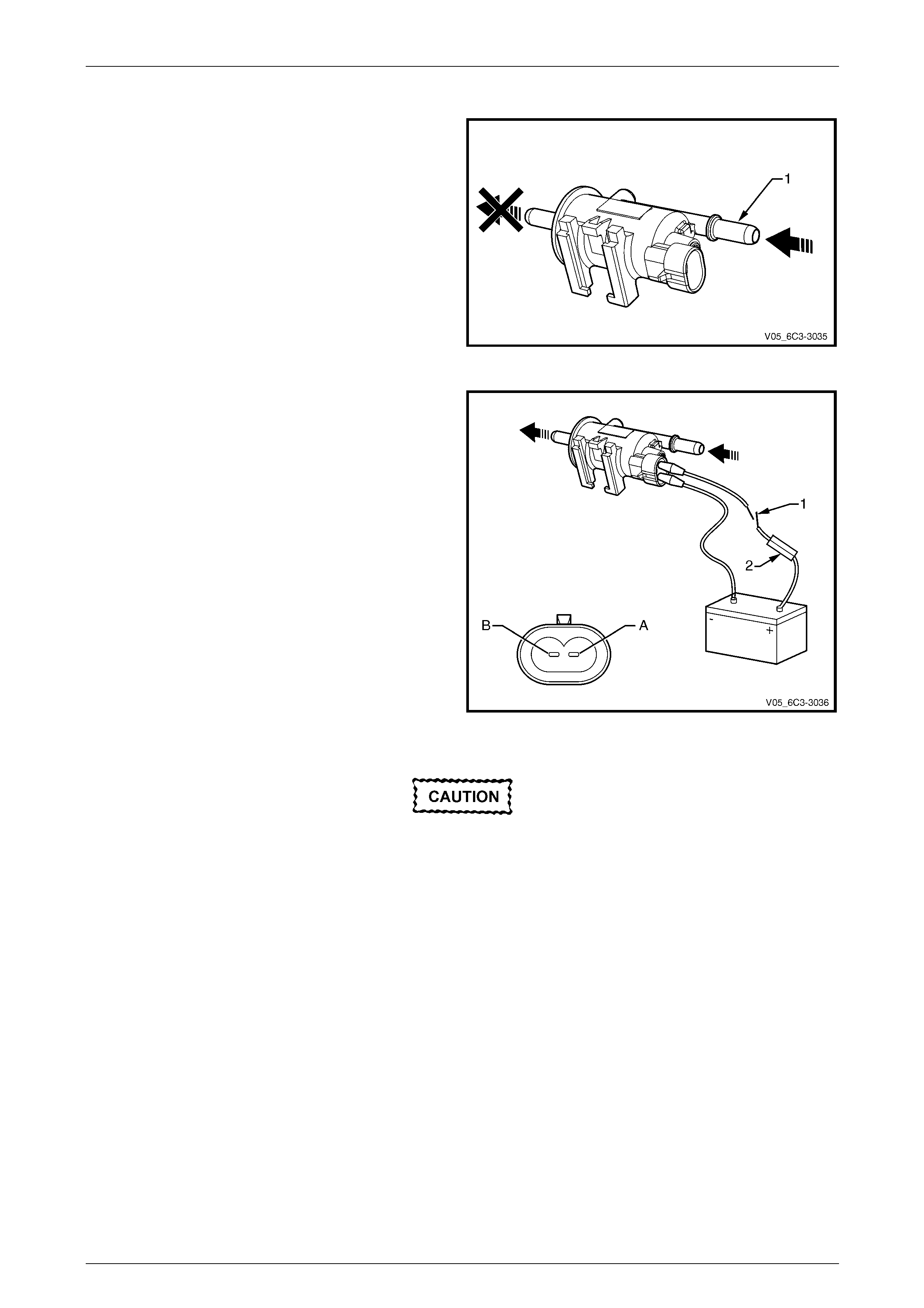
Functional Test
1 Attempt to blow air through the EVAP canister purge
valve inlet port (1). If air passes through the valve, the
valve is faulty and should be replaced.
Figure 6C3-3 – 21
2 Using connector test adaptor kit J 35616-A, connect a
12 Volt battery, an on/off switch (1) and a 3 Amp fused
wire (2) to the EVAP canister purge valve terminals as
follows:
• Positive lead to terminal (A).
• Negative lead to terminal (B).
Figure 6C3-3 – 22
Do not apply 12 Volts to the EVAP canister
purge valve continuously for more than three
seconds as the EVAP canister purge valve
will be damaged.
3 Turn the switch on, and listen for an audi ble click as the EVAP canister purge valve operates. Whilst the switch is in
the on position, blow air through the inlet port.
4 If no air passes through the EVAP canister purge valve, check the valve inlet and outlet ports for any obstructions
and rectify if necessary. If there are no o bstru ctions, replace the valve.
Reinstall
Reinstallation of the EVAP canister pur ge solenoid valve is the reverse of the removal procedure.
Powertrain Management GEN III V8 – Service Operations Page 6C3-3–28
Page 6C3-3–28
3.10 Fuel Pulse Dampener
LT Section No. — 03–375
Remove
A depressurised fuel system contains
residual fuel that can be spilled durin g ser vice
operations. Refer to Section 00 Warnings,
Cautions and Notes for further information
on handling fuel.
1 Depressurise the fuel system, refer to Section 8A1 Fuel System.
2 Turn the ignition switch off.
3 Remove left-hand engine dress cover, refer to Section 6A3 Engine Mechanical – GEN III V8.
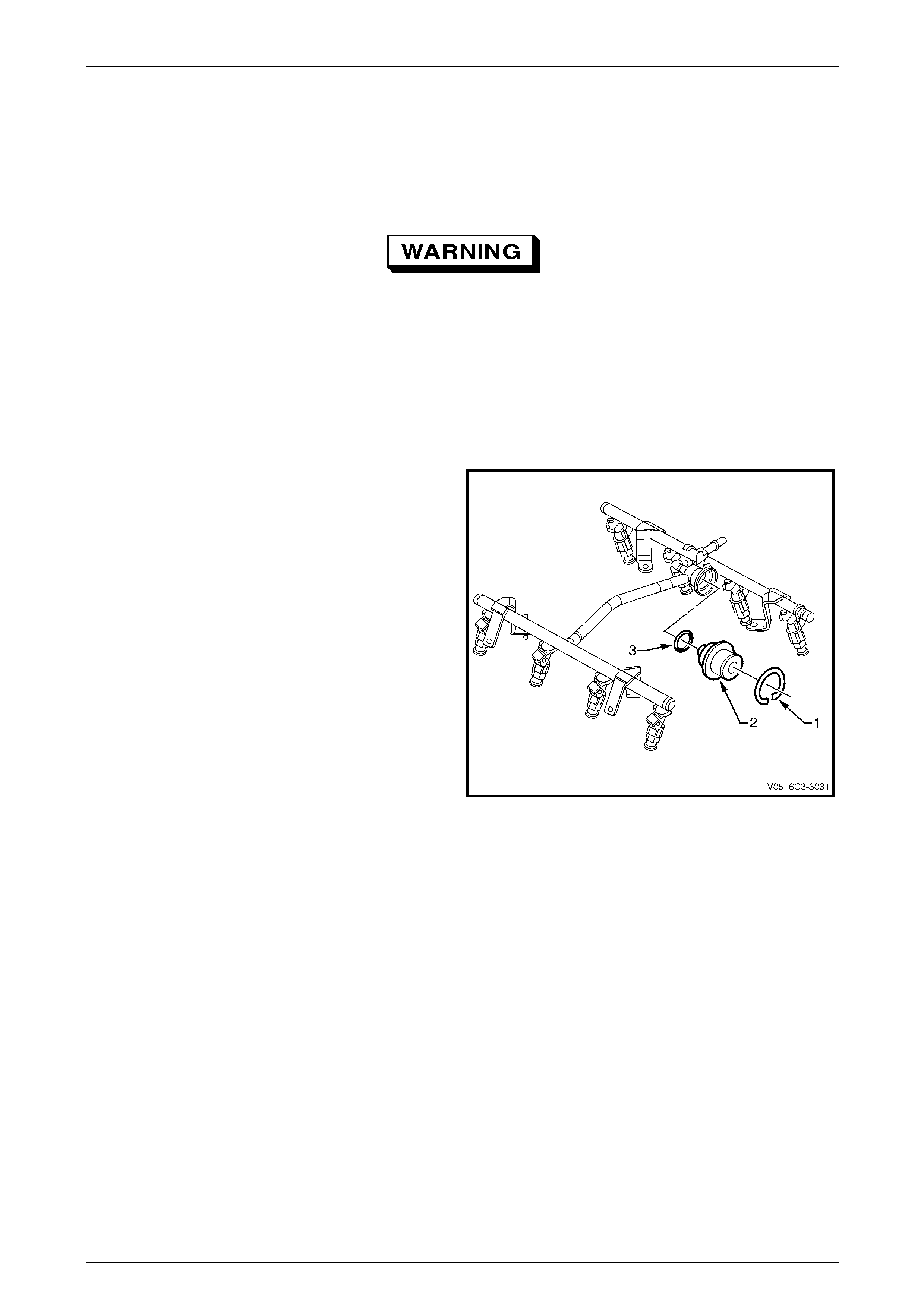
4 Clean any dirt from the fuel rail around the fu el pulse
dampener.
5 Remove the circlip (1) and dis c ard.
6 Remove the fuel pulse dampener (2) from the fuel rail.
7 Remove and discard the O-ring (3) from the fuel pulse
dampener.
Figure 6C3-3 – 23
Reinstall
Reinstallation of the fuel pulse dampener is the reverse of the removal procedure, noting the following:
1 Install a new O-ring on the fuel pulse damp en er and lubricate with clean engin e oil.
2 Install a new fuel pulse dampener circlip.
3 Perform the following procedure to inspect for leaks:
a Turn the ignition switch on for 2 seconds.
b Turn the ignition switch off for 10 seconds.
c Turn the ignition switch on.
d Inspect for fuel leaks at the fuel pulse dampener.
4 Road test the vehicle and check for correct operation.
Powertrain Management GEN III V8 – Service Operations Page 6C3-3–29
Page 6C3-3–29
3.11 Fuel Rail Assembly
LT Section No. — 03–375
A depressurised fuel system contains
residual fuel that can be spilled durin g ser vice
operations, refer to Section 00 Warnings,
Cautions and Notes for further information
on handling fuel.
Remove
1 Remove both engine dress covers, refer to Section 6A3 Engine Mechanical – GEN III V8.
2 Depressurise the fuel system, refer to Section 8A1 Fuel System.
Disconnection of the battery affects certain
vehicle electronic systems. Refer to
Section 00 Warnings, Cautions and Notes
before disconnecting the battery.
3 Disconnect the negative battery cable.
4 If fitted, remove the front suspension strut brace, refer to Section 1A1 Body.
Wear safety glasses when using compressed
air. Do not blow compressed air onto any
body part, refer to Section 00 Warnings,
Cautions and Notes for correct workshop
practices when using co mpressed air.
5 If required, use compressed air to remove an y foreign material from around the area where the fuel injectors enter
the intake manifold.
6 Disconnect the fuel feed hose from the fuel rail, refer to Section 8A1 Fuel System.
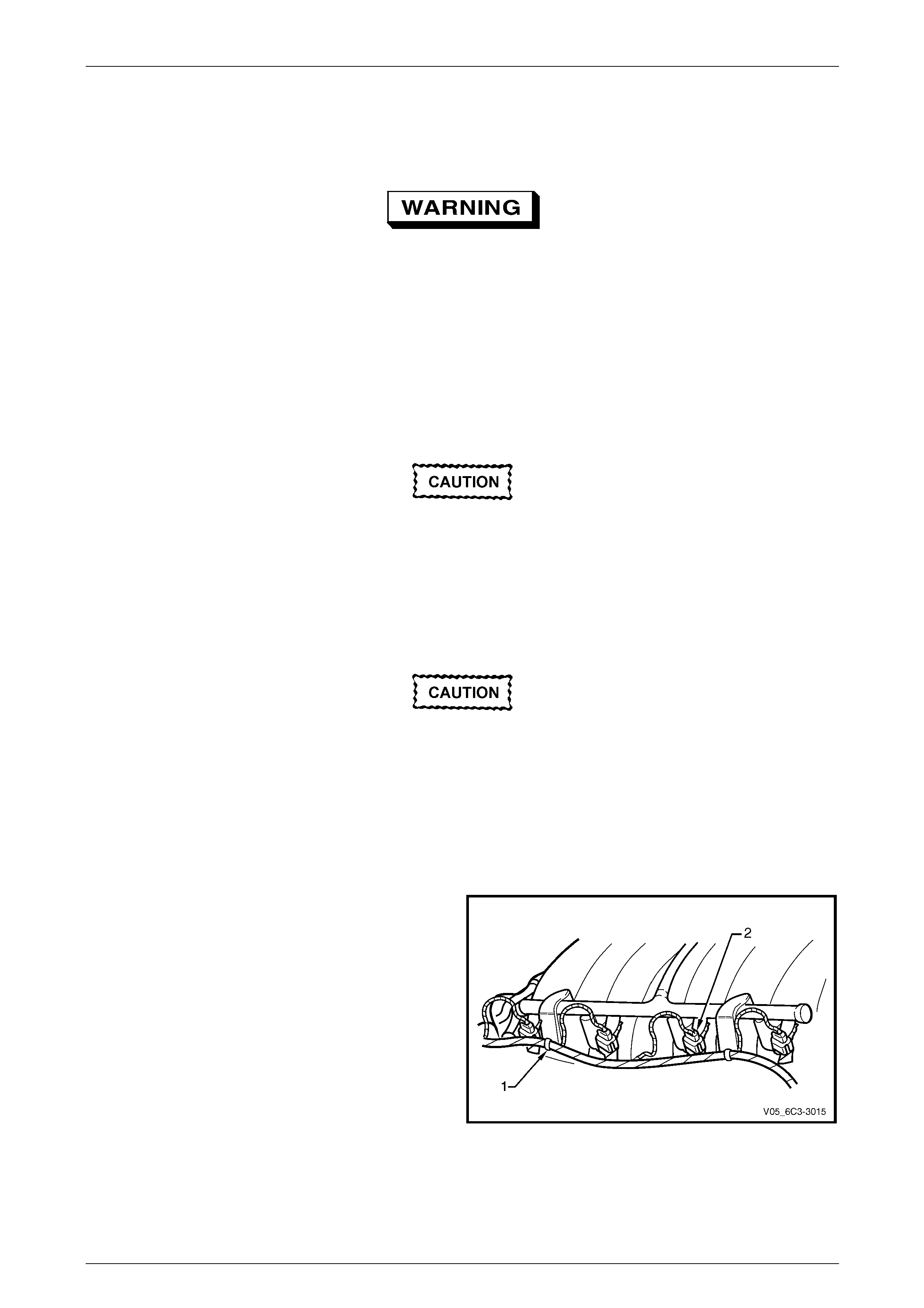
7 Detach the wiring harness clips (1), four places.
8 Disconnect the wiring connector (2), eight places, from
the fuel injectors. Identify the connectors with their
corresponding injectors to ensure correct sequential
injector firing order after reassembly.
Figure 6C3-3 – 24
Powertrain Management GEN III V8 – Service Operations Page 6C3-3–30
Page 6C3-3–30
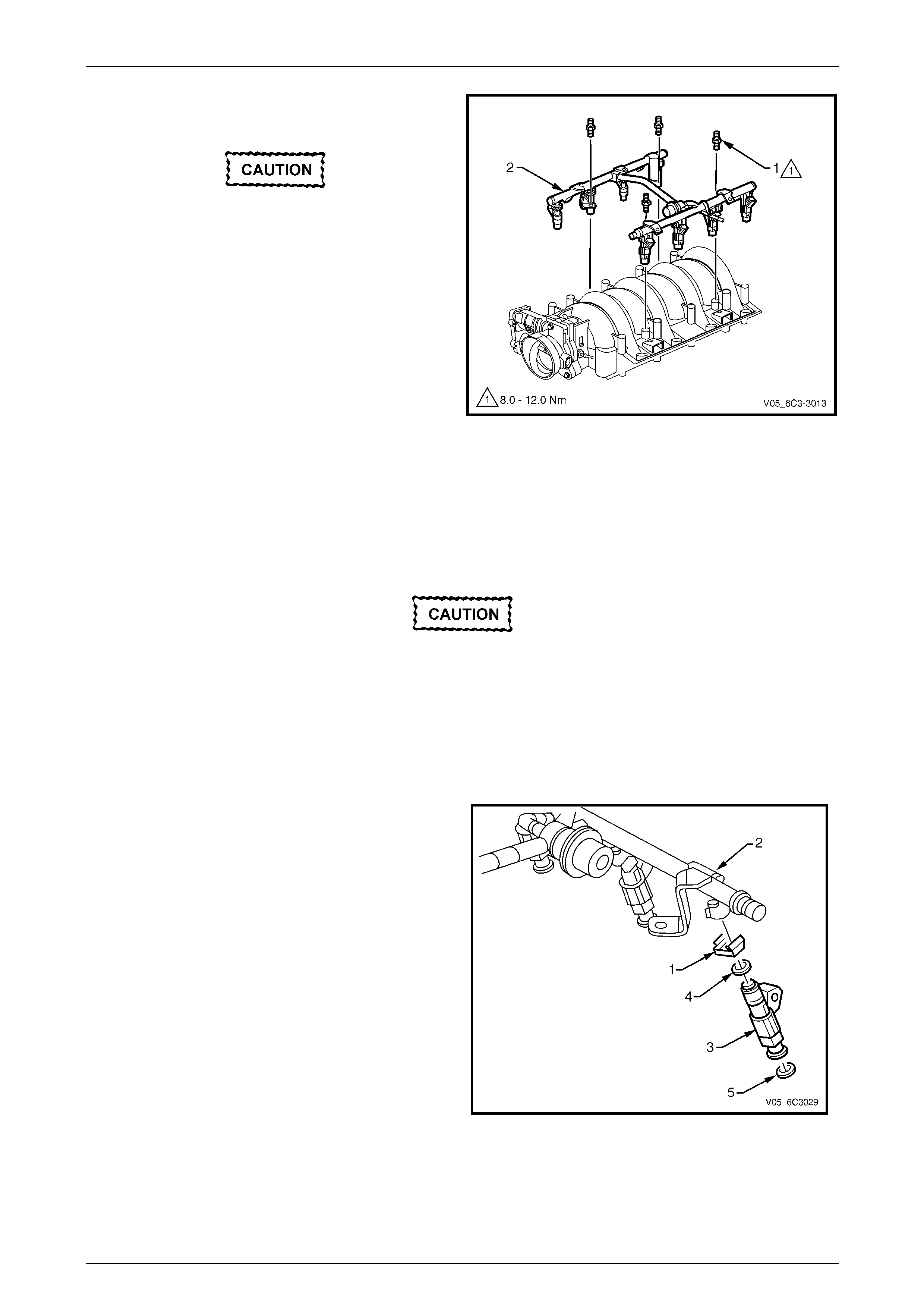
9 Remove the four double ende d studs (1) securing the
fuel rail (2) to the intake manifold.
Remove the fuel rail assembly carefully to
avoid damage to the injector spray tips.
Support the fuel rail after the fuel rail is
removed to avoid damaging the fuel rail
components.
10 Carefully lift the fuel rail assembl y (2) clear of the
intake manifold.
11 Cap the fittings and plug the h oles when servicing the
fuel system to prevent dirt and other contamina nts
from entering open pipes and passa ges.
12 Remove and discard the in jector lower O-ring seal
from the spray tip end of each injector. Figure 6C3-3 – 25
Disassemble
Fuel Injector Assembly
Remove
Take care when remo ving the fuel injectors to
prevent damage to the electrical connector
pins on the injector and to prevent damage to
the nozzle. Service the fuel injector as a
complete assembly only. The fuel injector is
an electrical component. Do not immerse the
fuel injector in any type of cleaner.
1 Remove the fuel pulse dampener, refer to 3.10 Fuel Pulse Dampener.
2 Pull the injector retainer clip (1) to release the injector
from the fuel rail (2).
3 Remove the fuel injector (3) and discard the injector
retainer clip.
4 Remove and discard the injector O-ring seals (upper
4 and lower 5) from each end of the injector.
5 Repeat for each of the remaining injectors as
required.
Figure 6C3-3 – 26

Powertrain Management GEN III V8 – Service Operations Page 6C3-3–31
Page 6C3-3–31
Test
To prevent component damage use connector
test adaptor kit J 35616-A.
1 Connect a digital ohmmeter using connector test
adaptor kit J 35616-A to the fuel injector.
2 Measure the resistance across terminals A and B.
3 Compare the reading against the specification.
Fuel injector resistance @ 20° C ..............11.4 – 12.6 Ω
4 If the resistance is not within specifications, replace
the fuel injector.
Figure 6C3-3 – 27
Reinstall
When ordering new fuel injectors, ensure to
order the correct injector for the application
being serviced. The fuel injector assembly is
stamped with a part number identification, a
manufacturing date, a week code, and a
production plant number.
1 Lubricate a new upper injector O-ring seal (1) with
clean engine oil and install onto each injector.
2 Push the fuel injector into the fuel rail injector socket
with the electrical connector (2) facing outward.
3 Reinstall a new retainer clip to retain each injector.
The retainer clip locks on to a flange on the fuel rail
injector socket.
4 Reinstall the fuel pulse dampe ner,
refer to 3.10 Fuel Pulse Dampener.
Figure 6C3-3 – 28

Powertrain Management GEN III V8 – Service Operations Page 6C3-3–32
Page 6C3-3–32
Reinstall
Reinstallation of the fuel rail assembly is the reverse of the removal procedure, noting the following:
1 Lubricate a new lower injector O-ring seal (1) with clean engine oil and install onto each injector.
2 Apply Loctite 242 or equiv ale nt to the cleaned threads of the fuel rail attachin g studs and tighten to the correct
torque specification.
Fuel rail attaching stud
torque specification...................................8.0 – 12.0 Nm
3 Connect the injector wiring connectors, ens uring the correct connector is installed to its corresponding injector to
ensure the correct sequential injector firing order.
NOTE
Rotate the injectors as required to avoid
stretching the wire harness.
4 Perform the following procedure to inspect for leaks:
a Turn the ignition switch on for 2 seconds.
b Turn the ignition switch off for 10 seconds.
c Turn the ignition switch on.
d Inspect for fuel leaks at the fuel injectors and fuel feed hose.
5 Road test the vehicle and check for correct operation.
Powertrain Management GEN III V8 – Service Operations Page 6C3-3–33
Page 6C3-3–33
3.12 Heated Oxygen Sensor
LT Section No. — 00–450
To avoid the possibility of personal injury,
allow the exhaust pipe to cool to ambient
temperature (less than 50° C) before
attempting to remove the oxygen sensor.
NOTE
Some vehicles may be fitted with an additional
HO2S downstream of each catalytic converter.
These are fitted for production purposes but are
not used by the powertrain management s ystem.
Service Precautions
• Handle each heated oxygen sensor (HO2S) carefully. Do not drop it, and keep it free of grease, dirt and other
contaminants. Do not use cleaning solvents of any type on the sensor.
• Do not repair the sensor or any of its parts, including the wiring and connector. Replace the oxygen sensor if any
damage is evident.
• The oxygen sensor may be di fficult to remove when the engine is cold. Excessive force may damage the threads in
the exhaust manifold or exhaust pipe.
• It may be necessary to lower the exhaust system to gain sufficient access to a HO2S and/or its connector, refer to
Section 8B Exhaust System.
• If the HO2S has been removed, but not replaced, apply anti-seize compound to the threads prior to installation.
New oxygen sensors will already have the anti-seize compound applied.
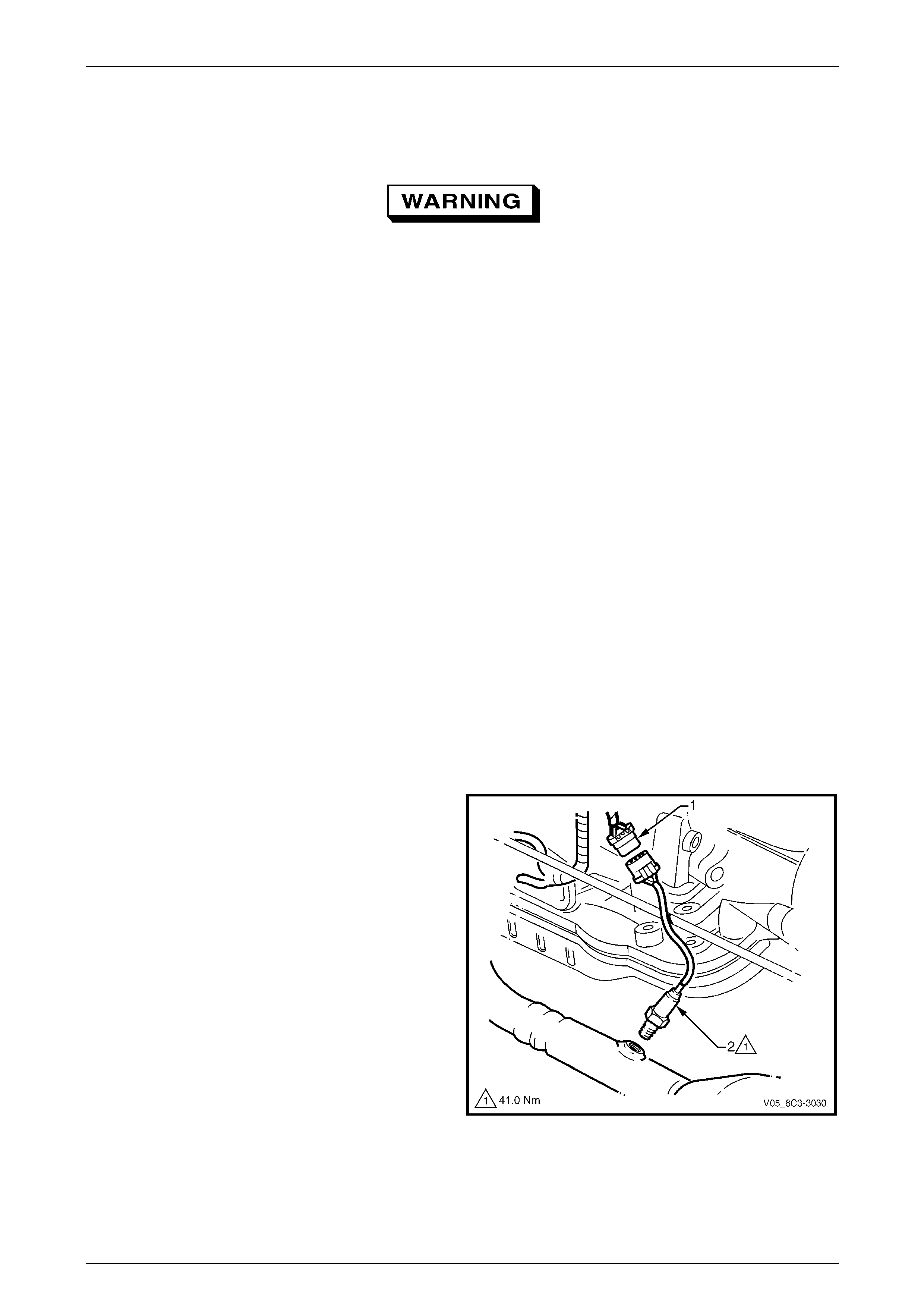
Remove
NOTE
While only the left-hand HO2S (bank 1) is sho wn,
the procedure for the right-hand sensor (bank 2)
is similar.
1 Raise the front of vehicle and support on safety stands, refer to Section 0A General Information for the location of
jacking and support points.
2 Disconnect the HO2S wiring harness connector (1).
3 Loosen and carefully remove the HO2S (2) from the
exhaust pipe.
Figure 6C3-3 – 29
Powertrain Management GEN III V8 – Service Operations Page 6C3-3–34
Page 6C3-3–34
Test
• Under no circumstances should battery
voltage be applied to the HO2S heater.
• To prevent component damage use
connector test adaptor kit J 35616-A.
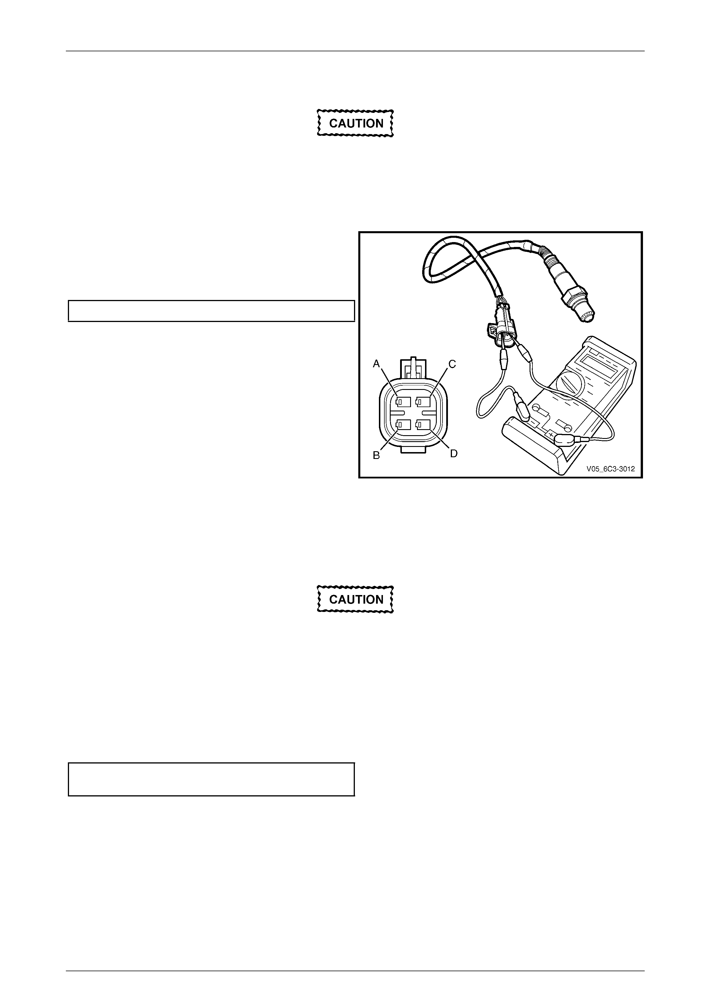
Heater Resistance Check
1 Using a digital ohmmeter and connector test adaptor
kit J 35616-A, measure the resistance acr oss
terminals C and D of the wiring harness connector.
2 Compare the reading against the specification.
HO2S heater resistance @ 20° C..................4.7 – 5.7 Ω
3 If the resistance is not within specification, replace the
HO2S.
Figure 6C3-3 – 30
Reinstall
Reinstallation of the heated o x ygen sensor (HO2S) is the reverse of the removal proced ure, notin g the following:
A special anti-seize compound is used on the
HO2S threads. New HO2S will already have
the anti-seize compound applied.
If an HO2S has been removed, but not
replaced, then anti-seize compound must be
applied to the threads prior to installation.
1 Coat the cleaned threads of the sensor with anti-seize compound.
2 Tighten the HO2S to the correct torque specificatio n.
Heated oxygen sensor (HO2S )
torque specification............................................41.0 Nm
3 Road test the vehicle and check for correct operation, taking particular note that no exhaust leakage is evident.
Powertrain Management GEN III V8 – Service Operations Page 6C3-3–35
Page 6C3-3–35
3.13 Ignition Coil Assembly
LT Section No. — 02–235
NOTE
The ignition module is incorporated into the
ignition coil assembly and is not serviced
separately.
Remove
1 Turn the ignition switch off.
2 Remove the appropriate engin e dress cover(s), refer to Section 6A3 Engine Mechanical – GEN III V8.
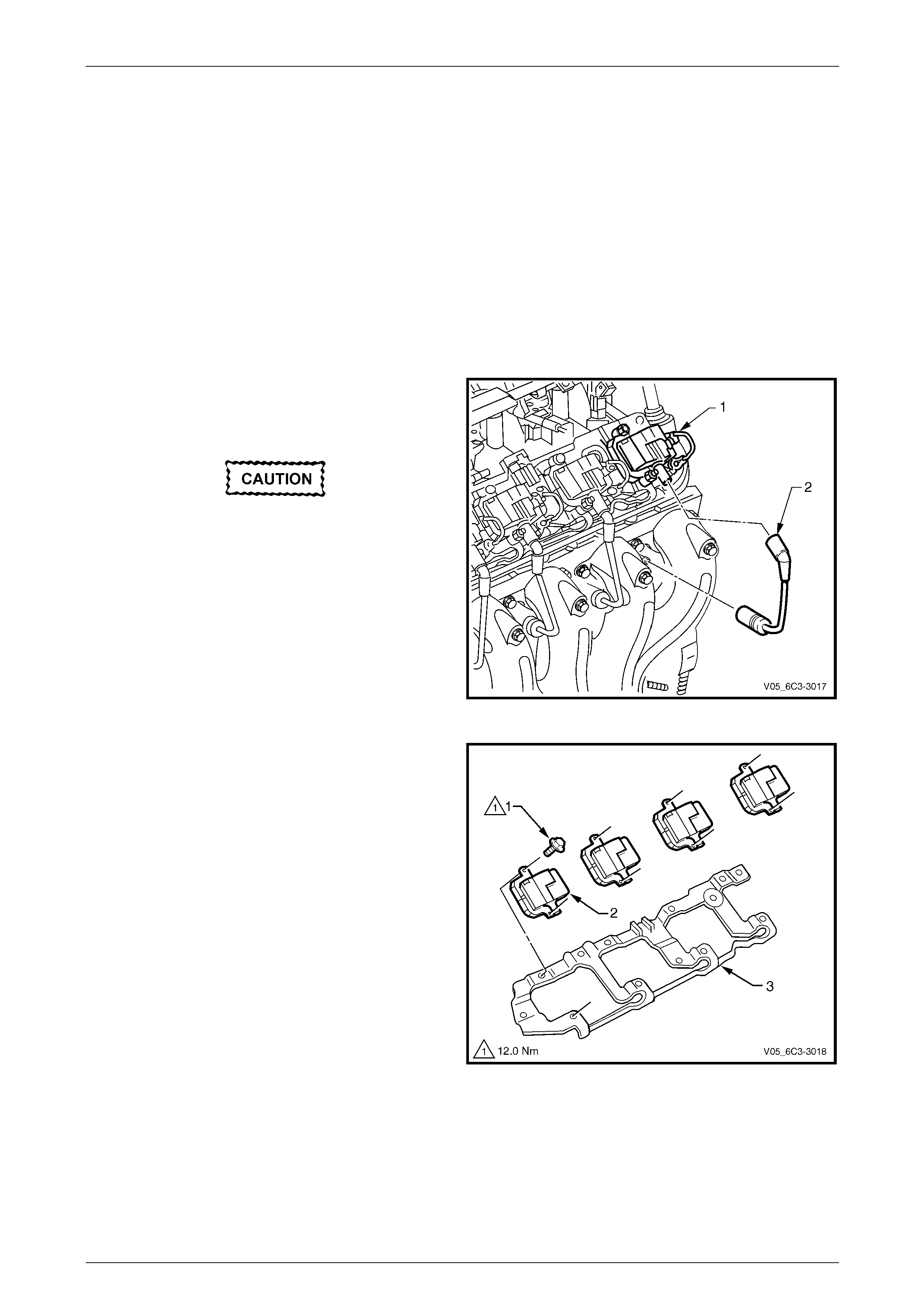
3 Remove the connector protection assurance (CPA)
lock (1) securing the wiring connector to the ignition
coil assembly and disconnect the wiring connector.
Never pull on the ignition lead. Grasp the
ignition coil boot and twist to break the seal
before pulling directly from each coil
assembly.
4 Disconnect the spark plug wire (2) at the coil
assembly.
Figure 6C3-3 – 31
5 Remove the attaching screw (1), two places.
6 Remove the ignition coil (2) from the mounti ng bracket
(3).
7 Repeat for the remaining ignition coil assemblies as
required.
Figure 6C3-3 – 32

Powertrain Management GEN III V8 – Service Operations Page 6C3-3–36
Page 6C3-3–36
Test
Never probe the ignition coil with a 12 Volt
tester as the ignition coil will be damaged.
Due to the internal components of the ignition coil assembly, it is not possible to perform any primar y and/or secondary
resistance checks. For further information on the ignition coil operation,
refer to Section 6C3-1 Powertrain Management – GEN III V8 – General Info rmation.
Reinstall
Reinstallation of the ignition coil(s) is the reverse of the removal procedure, noting the following:
1 Reinstall the screws and tighten to the correct torque specification.
Ignition coil assembly attaching
screw torque specification..................................12.0 Nm
2 Road test the vehicle and check for correct operation.
Powertrain Management GEN III V8 – Service Operations Page 6C3-3–37
Page 6C3-3–37
3.14 Intake Air Temperature Sensor
The intake air temperature (IAT ) sensor is not serviced separately as it is part of the MAF sensor assembly,
refer to 3.17 Mass Air Flow Sensor and Intake Air Duct for the replacement procedure.
Test
To prevent component damage use connector
test adaptor kit J 35616-A.
Resistance Check
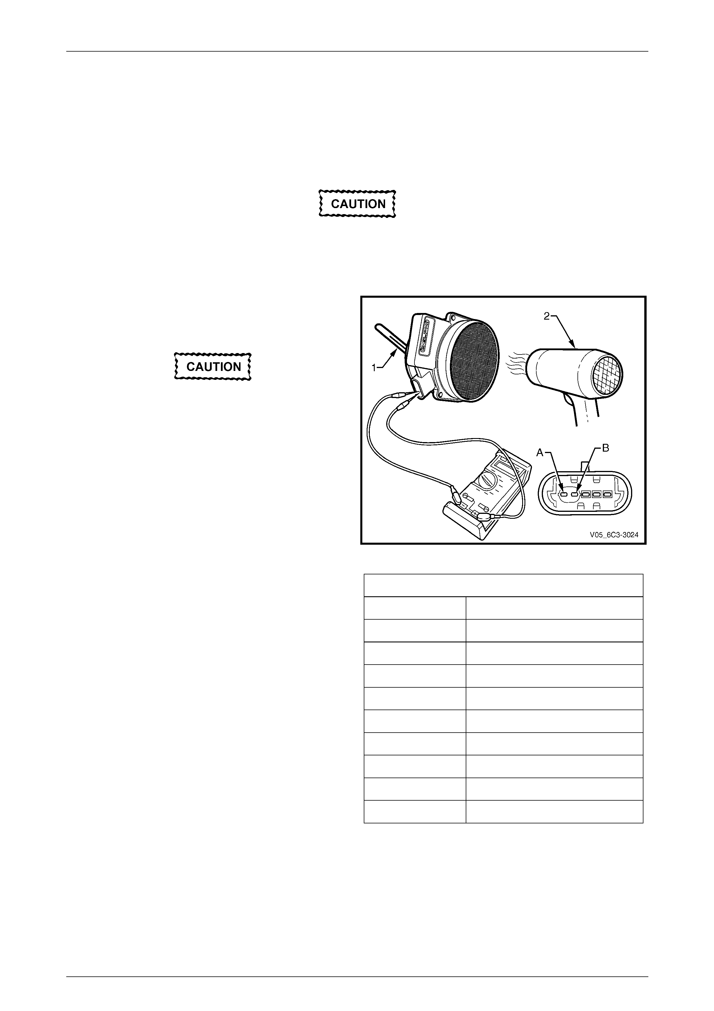
1 Connect a digital ohmmeter using connector test
adaptor kit J 35616-A to the mass air flow (MAF)
sensor wiring connector terminals (A) and (B).
Do not use a high temperature heat gun as
damage to the MAF sensor will resu lt.
2 Whilst holding a thermometer (1), use a commercially
available hair dryer (2) to blow warm air through the
MAF sensor.
Figure 6C3-3 – 33
3 Observe the resistance values as the temperature
increases and compare t he temperature/resistance
change to the specifications.
4 If the resistance is not within specifications, replace
the MAF sensor.
Intake Air Temperature Vs Resistance
Temperature °C Resistance – Ohms (Ω)
-10 16177
0 9423
20 3515
30 2238
40 1459
60 667.5
80 332
100 176
120 99.8
Powertrain Management GEN III V8 – Service Operations Page 6C3-3–38
Page 6C3-3–38
3.15 Knock Sensor
LT Section No. — 02–000
Remove
1 Depressurise the fuel system, refer to Section 8A1 Fuel System.
2 Turn the ignition switch off.
3 Remove both engine dress covers, refer to Section 6A3 Engine Mechanical – GEN III V8.
4 Remove the intake manifold,
refer to Section 6A3 Engine Mechanical – GEN III V8.
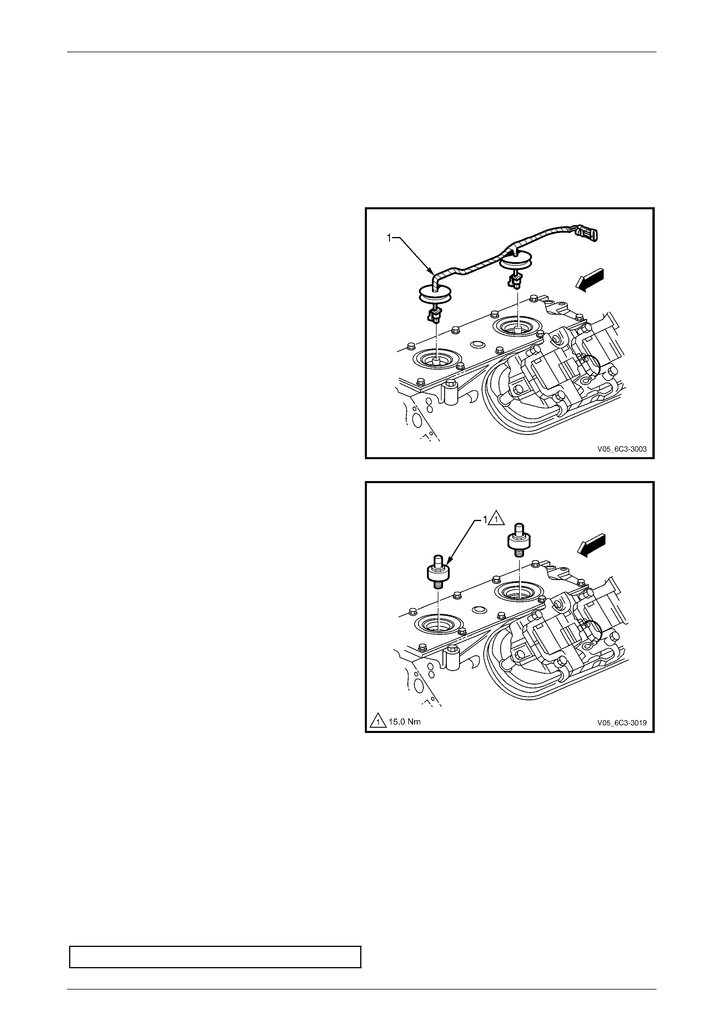
5 Remove the knock sensor patch wiring harness (1).
Figure 6C3-3 – 34
NOTE
Unless a deep socket is used, damage to the
sensor connector will result.
6 Remove the knock sensor (1), using a 22 mm deep
socket and suitable socket equipment.
7 Repeat for the remaining knock sensor as re quired.
Figure 6C3-3 – 35
Reinstall
Reinstallation of the knock sensor is the reverse of the removal procedure, noting the following:
NOTE
• Do not apply sealant to the thread of a new
sensor as it is coated with a sealant during
manufacture. Applying additional sealant may
affect the sensor's ability to detect engine
knock.
• Ensure the knock sensor is never over
tightened, as damage to the sensor can
occur.
1 Reinstall the knock sensor(s) and tighten to the correct torque spec ification.
Knock sensor torque specification .....................15.0 Nm
Powertrain Management GEN III V8 – Service Operations Page 6C3-3–39
Page 6C3-3–39
3.16 Manifold Absolute Pressure Sensor
LT Section No. — 02–000
Remove
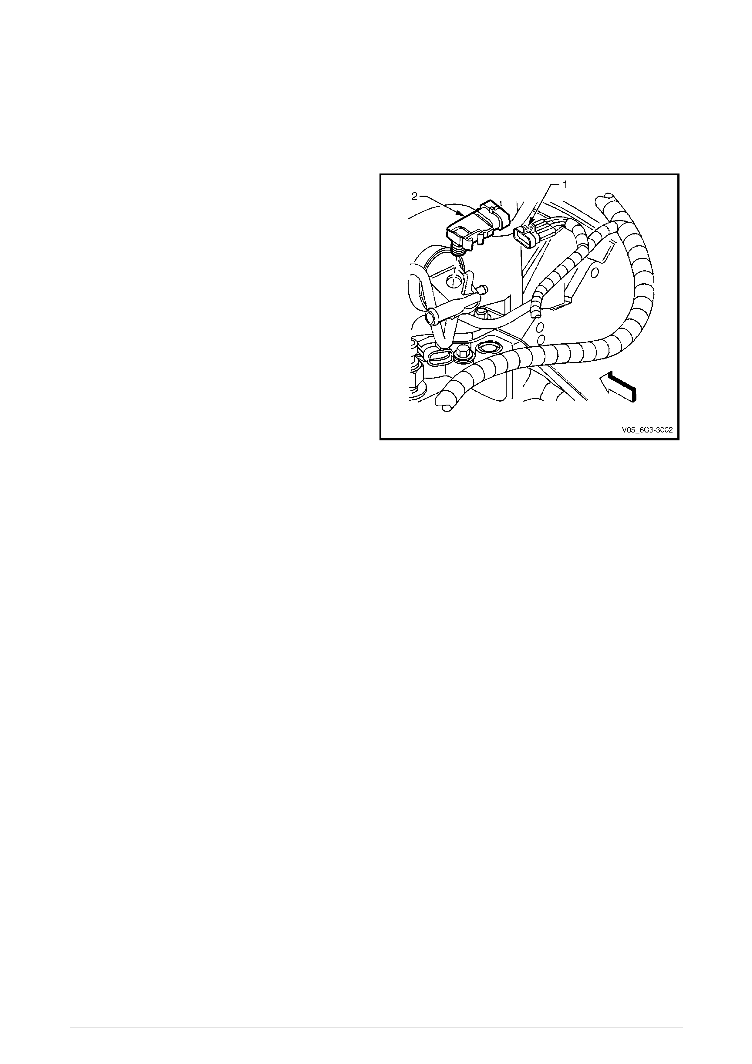
1 Disconnect the manifold absol ute pressure (MAP)
sensor wiring connector (1).
2 Twist the MAP sensor (2) forward to release it from the
intake manifold adaptor.
3 Pull the MAP sensor upward.
Figure 6C3-3 – 36
Reinstall
Reinstallation of the manifold absolute pressure (MAP) sensor is the reverse of the removal procedure, noting the
following:
1 Lightly coat the MAP sensor seal with clean engine oil.
2 Run the engine and check for vacuum leaks.
Powertrain Management GEN III V8 – Service Operations Page 6C3-3–40
Page 6C3-3–40
3.17 Mass Air Flow Sensor and Intake Air
Duct
LT Section No. — 03–250
Remove
1 Remove the upper radiator shroud, refer to Section 6B3 Engine Cooling – GEN III V8.
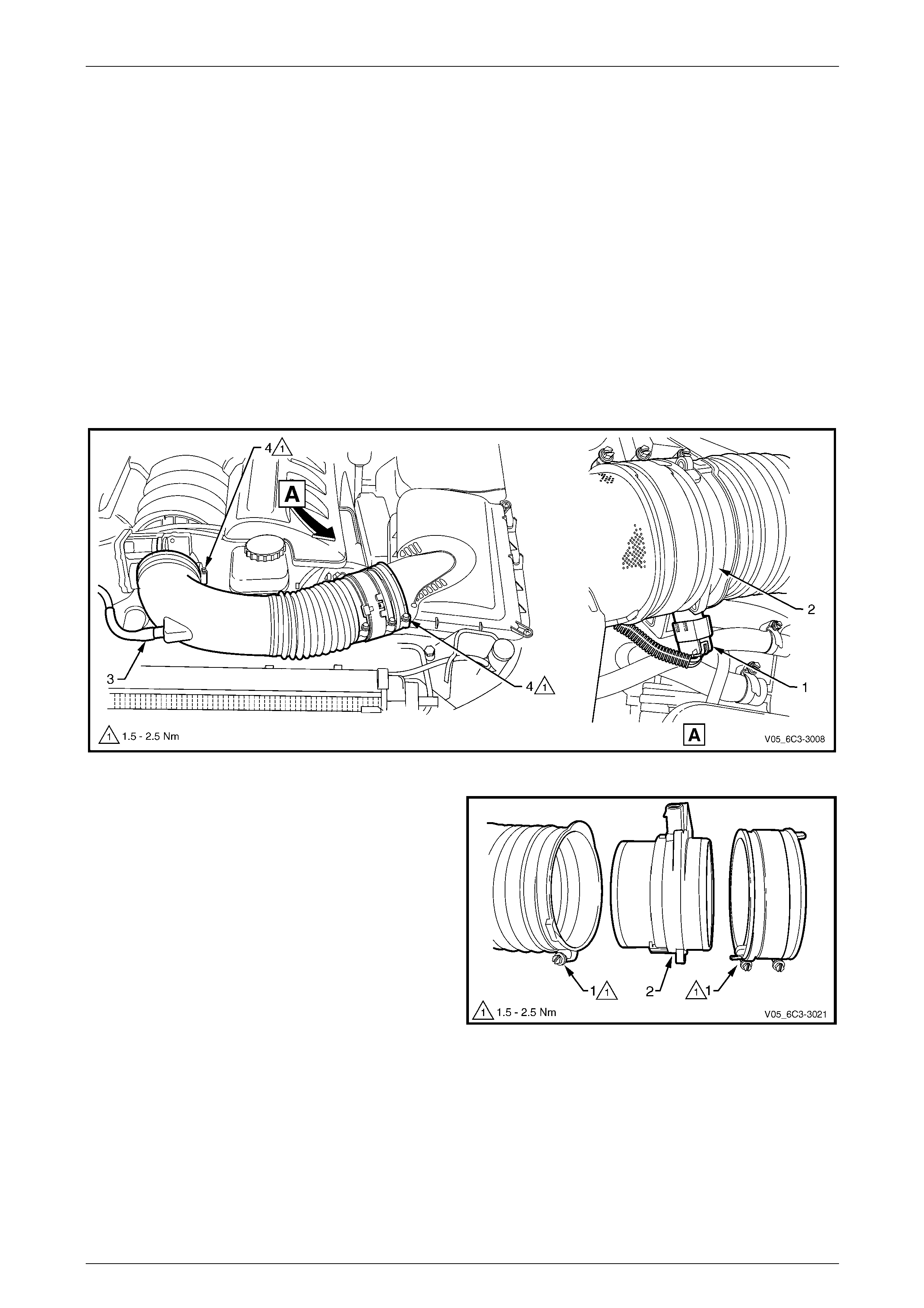
2 Remove the intake air duct:
a Lift up the locking tang on the mass air flow (MAF) sensor wiring connector (1) and remove the connector
from sensor (2).
b Disconnect the PCV hose (3) from the intake air duct.
c Loosen the clamps (4) at each end securing the intake air duct to the throttle body and the air clean er upper
housing. Remove the duct.
Figure 6C3-3 – 37
3 Loosen the two clamps (1) securing the air intake duct
and the air duct adaptor to the MAF sensor (2).
Figure 6C3-3 – 38

Powertrain Management GEN III V8 – Service Operations Page 6C3-3–41
Page 6C3-3–41
Reinstall
Reinstallation of the mass air f low (MAF) sensor and intake air duct is the reverse of the removal proced ure, noting the
following:
NOTE
• The embossed arrows on the MAF sensor
indicate the correct airflow direction. The
arrows must point towards the engine.
• The air duct adaptor (between air cleaner and
MAF sensor), retaining clamps, air duct and
MAF sensor, all have locating notches.
Ensure all notches are aligned.
1 Reinstall the retaining clam ps, aligning the notches, and tighten to the correct torque specification.
Intake air duct clamp
torque specification.....................................1.5 – 2.5 Nm
2 Run the vehicle and check for air leaks.
Powertrain Management GEN III V8 – Service Operations Page 6C3-3–42
Page 6C3-3–42
3.18 Powertrain Control Module
LT Section No. — 02–245
Service of the powertrain control modu le (PCM) should normally consist of either replacement or programming. If the
diagnostic procedur es call for the PCM to be replaced, it should be first checked to ensure it is the correct part. If it is,
replace the faulty PCM.
• Do not touch the PCM connector pins as
electrostatic discharge (ESD) damage may
result. For further information on ESD,
refer to Section 00 Warnings, Cautions and
Notes .
• When removing or reinstalling the PCM
wiring connector/s, ensure the ignition
switch is in the OFF position and the
battery has been disconnected. Failure to
do so may result in damage to the PCM
and/or associated components.
• Disconnection of the battery affects
certain vehicle electronic systems. Refer
to Section 00 Warnings, Cautions and
Notes before disconnecting the battery.
Remove
1 Turn the ignition switch off.
2 Disconnect the battery negative lead.
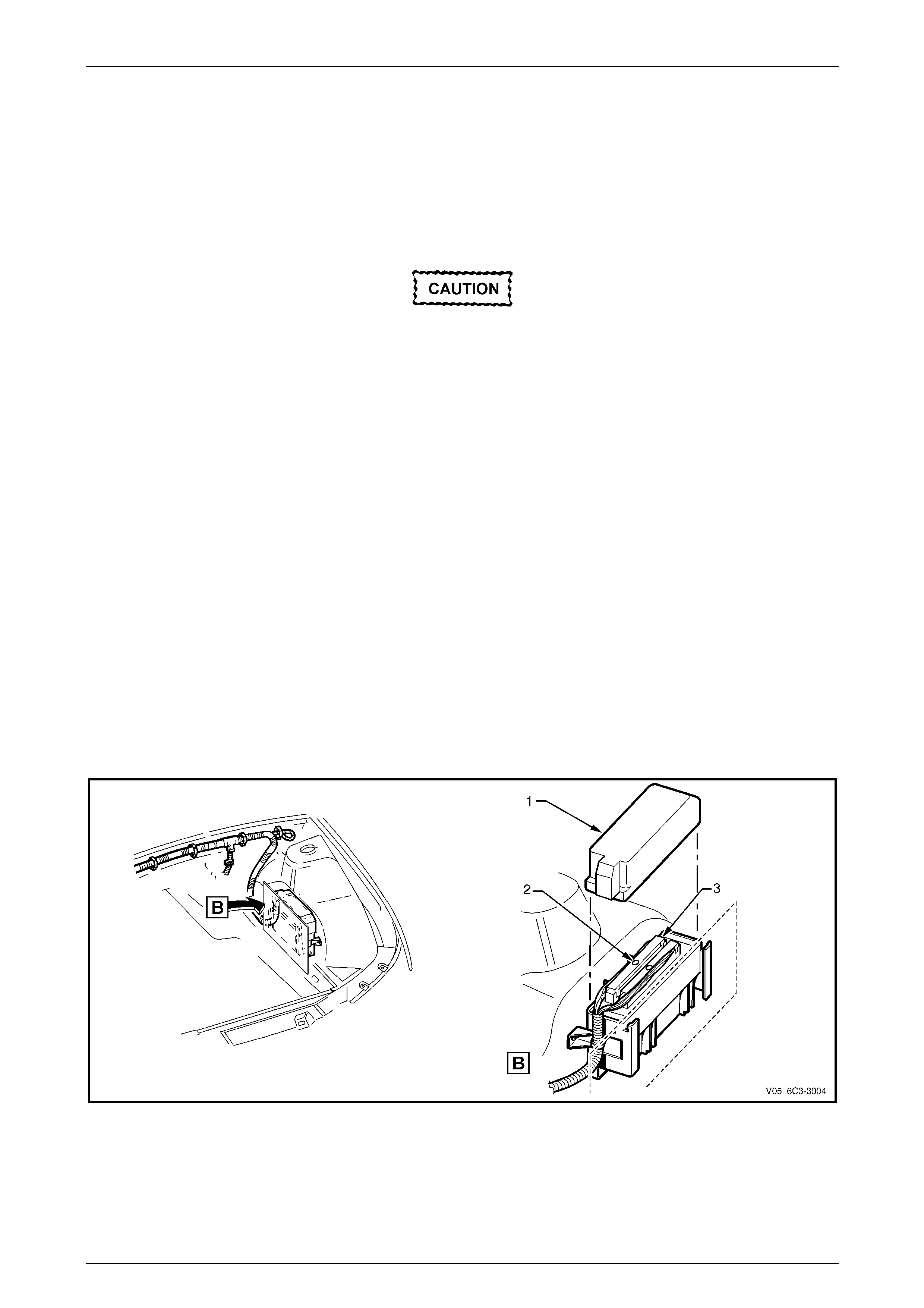
3 Remove the air cleaner assembly, refer to 3.4 Air Cleaner Assembly.
4 Remove PCM wiring connector cover (1).
5 Loosen the connector retaining screw (2) on the PCM wiring connector (3), two places and disconnect the
connectors.
Figure 6C3-3 – 39
Powertrain Management GEN III V8 – Service Operations Page 6C3-3–43
Page 6C3-3–43
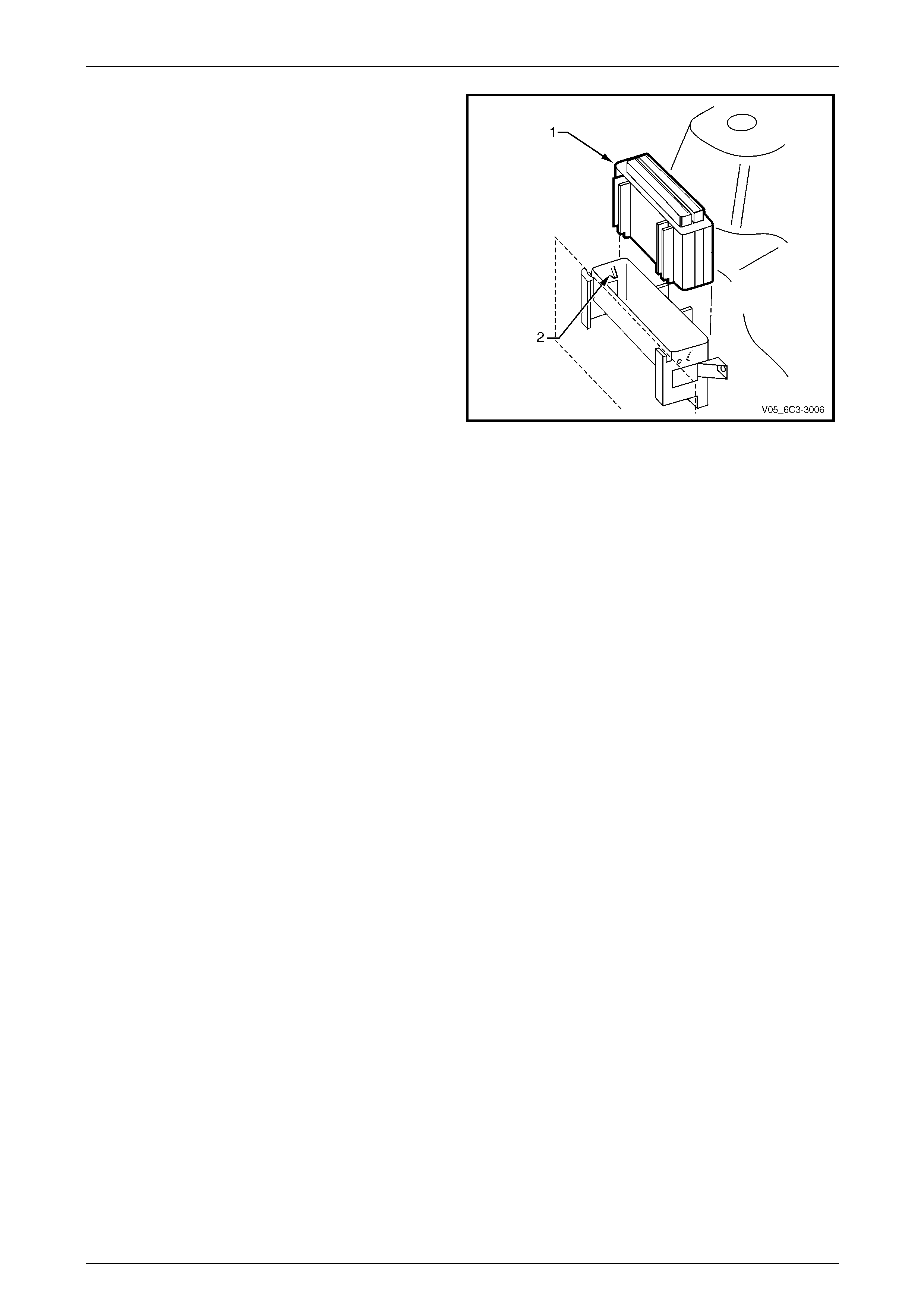
6 Lift the PCM (1) from the mounting bracket by levering
back the bracket retainers (2) at each end.
Figure 6C3-3 – 40
Reinstall
Reinstallation of the PCM is the revers e of the removal procedure, noting the following:
1 If the PCM has been replaced, perform the following proced ures:
• PCM service programming, refer to Section 0C Tech 2.
• PCM / PIM / BCM security link, refer to Section 12J Body Control Module.
• Main diagnostic functional check, refer to Section 6C3-2 Powertrain Management – GEN III V8 – Diagnostics.
2 If the PCM has been removed, but not replaced, perform the main diagnostic table functional check,
refer to Section 6C3-2 Powertrain Management – GEN III V8 – Diag nostics.
Powertrain Management GEN III V8 – Service Operations Page 6C3-3–44
Page 6C3-3–44
3.19 Powertrain Control Module Bracket
Assembly
LT Section No. — 02–245
Remove
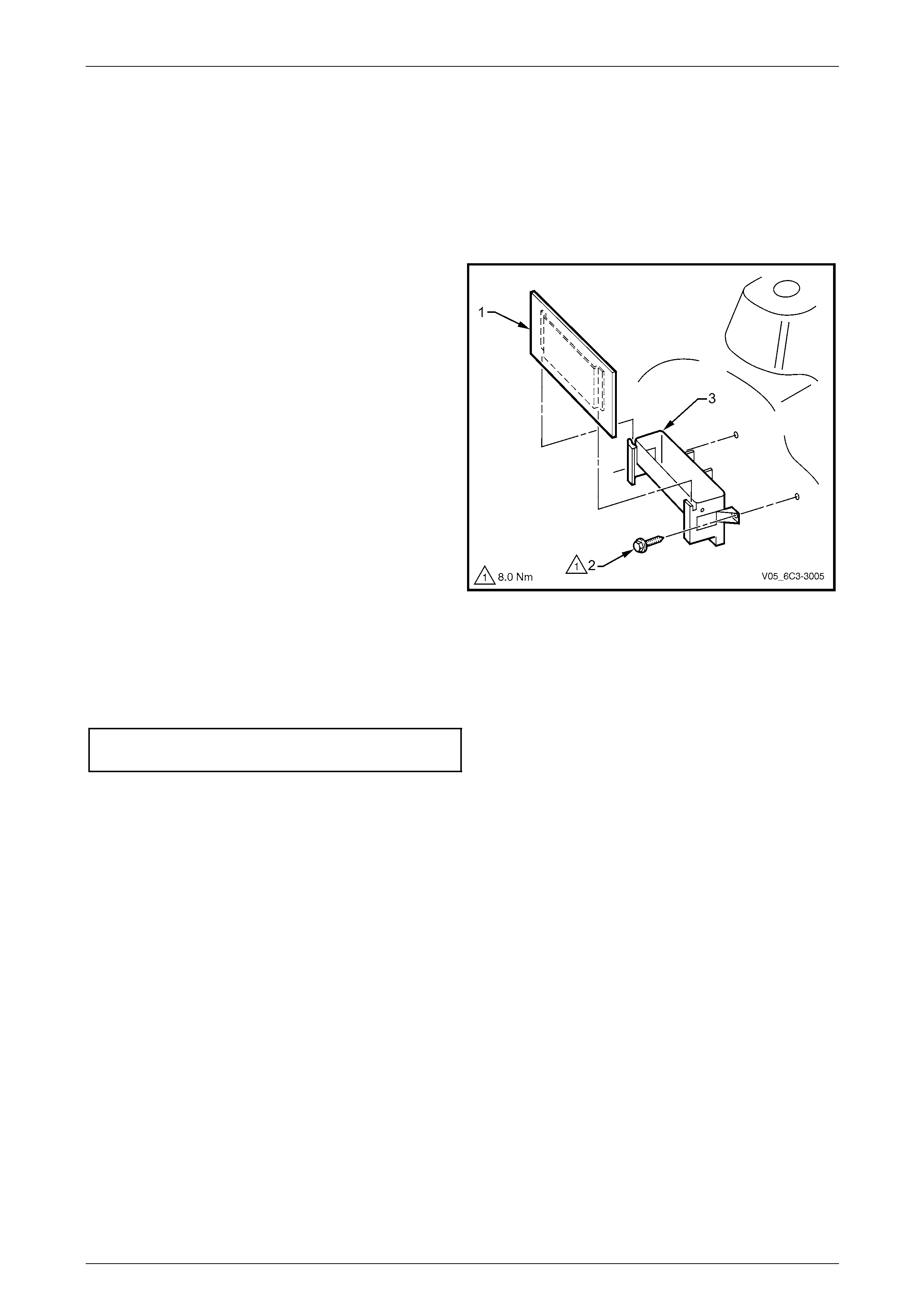
1 Remove the powertrain control module (PCM ), refer to 3.18 Powertrain Control Module.
2 Remove the PCM heat shield (1) by pulling it upwards.
3 Remove the screw (2), two places, attaching the
powertrain control module (PCM) mounting bracket (3)
to the fender inner panel.
4 Remove the mounting bracket from the vehicle.
Figure 6C3-3 – 41
Reinstall
Reinstallation of the powertrain control module (PCM) mounting bracket is the reverse of the removal procedure. Tighten
the screws to the correct torque specification.
Powertrain control module (PCM) mounting
bracket attaching screw torque specification........ 8.0 Nm
Powertrain Management GEN III V8 – Service Operations Page 6C3-3–45
Page 6C3-3–45
3.20 Schrader Valve – Fuel Pressure Test
Point
LT Section No. — XX–XXX
If the Schrader valve is to be removed but not
replaced immediately, it is advisable to
disconnect the battery to avoid possible fuel
discharge if an accidental attempt is made to
start the engine.
Disconnection of the battery affects vehicle
electronic systems. Refer to Section 00
Warnings, Cautions and Notes before
disconnecting the battery.
Remove
1 Depressurise the fuel system, refer to Section 8A1 Fuel System.
2 Turn the ignition off.
A small amount of fuel may be released when
servicing the fuel pressure test point. To
reduce the chance of personal injury, cover
the fuel pressure test point with a shop towel
to absorb any fuel spillage when the Schrader
valve sealing cap and Schrader valve are
removed. After the pro cedure, place the towel
in an approved container for disposal.
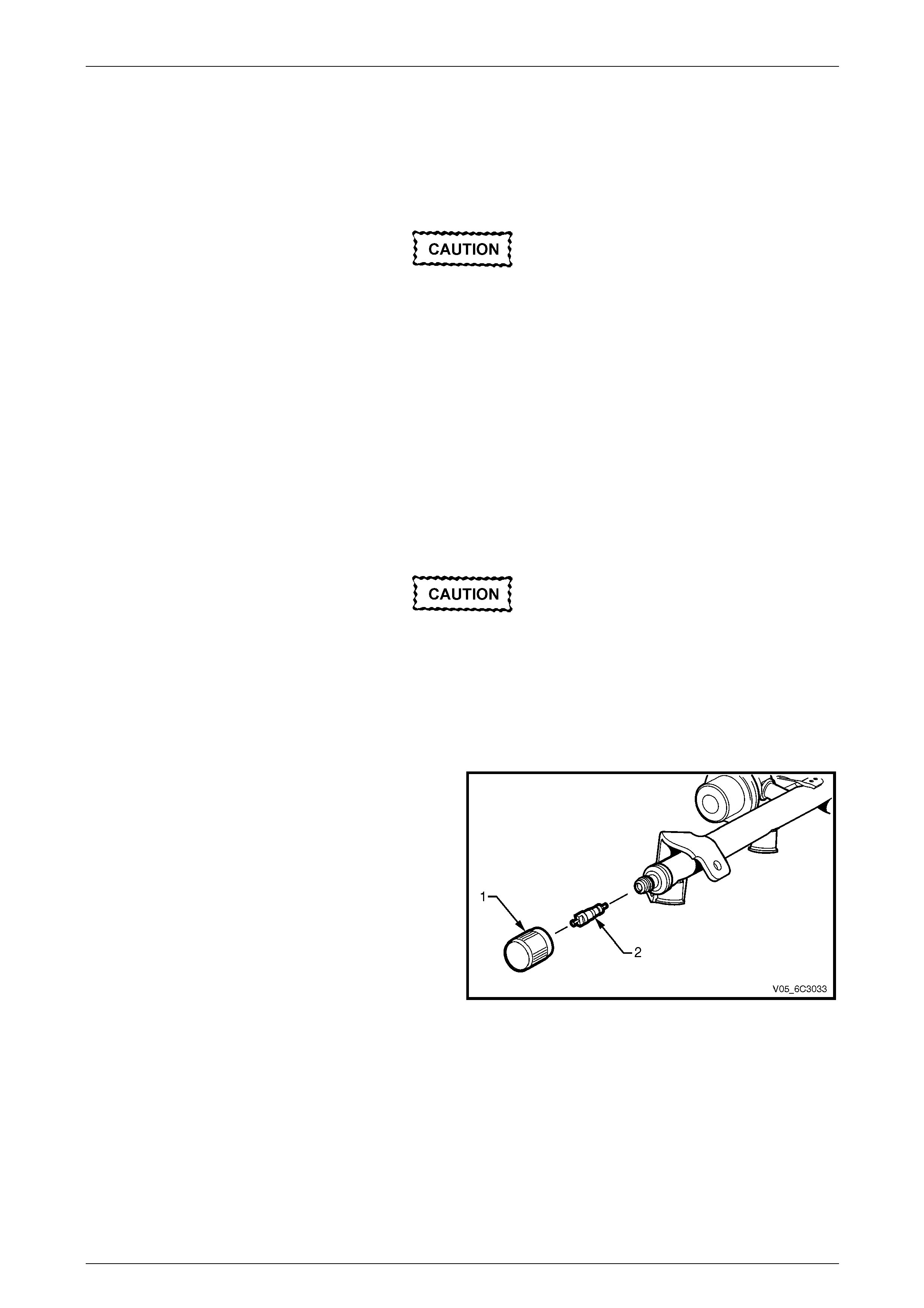
3 Remove the Schrader valve sealing cap (1).
4 Remove the Schrader valve (2) using a stan dard valve
core removal tool.
Figure 6C1-3 – 42
Reinstall
Reinstallation of the Schrader valve is the reverse of the removal procedure, noting th e following:
1 Inspect the fuel rail and quick connect fitting for leaks, refer to Section 8A1 Fuel System.
2 Road test the vehicle and check for correct operation.
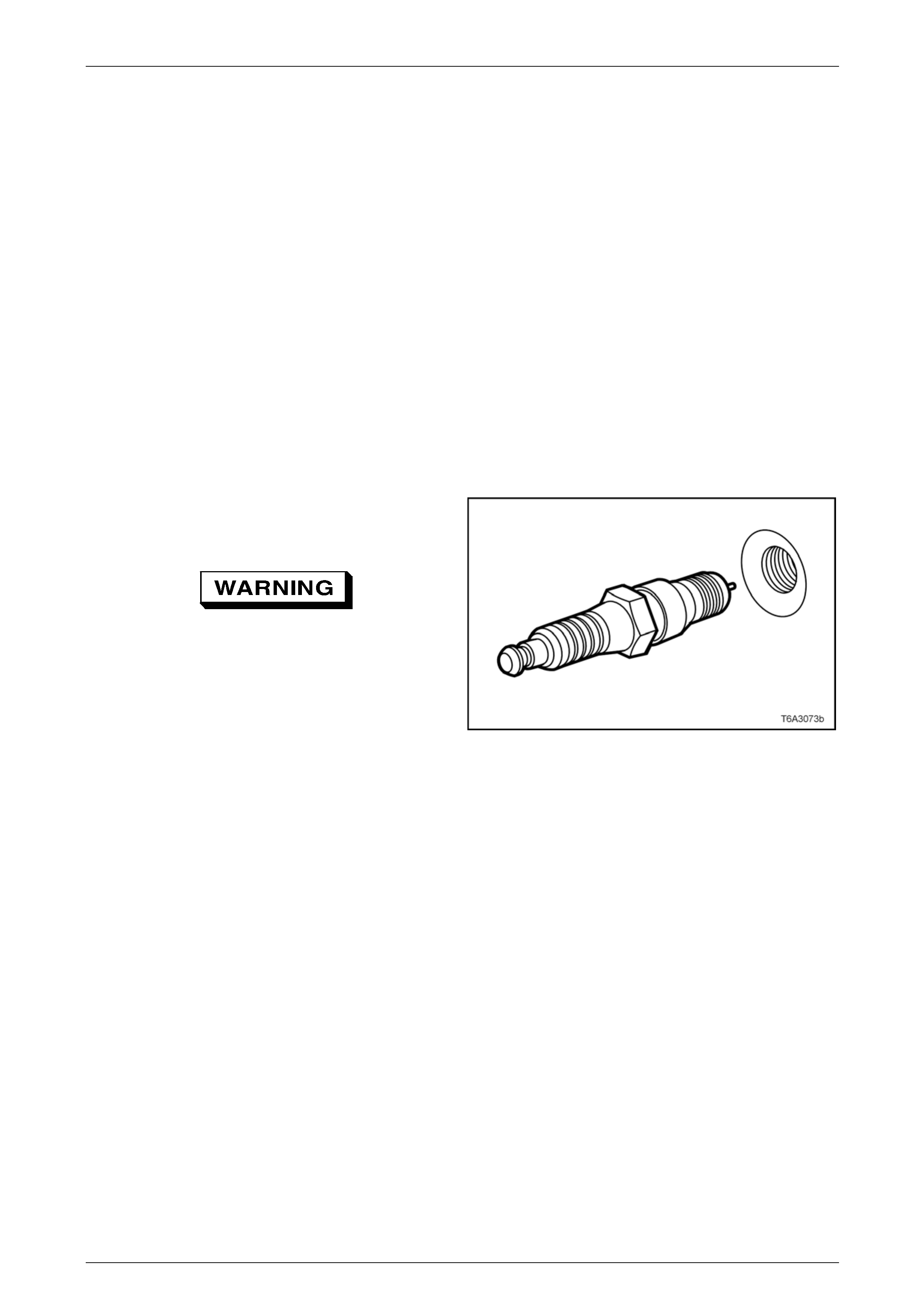
Powertrain Management GEN III V8 – Service Operations Page 6C3-3–46
Page 6C3-3–46
3.21 Spark Plugs
LT Section No. — 02–030
Service Precautions
1 Allow the engine to cool (to at least 50° C) before attempting to remove spark plugs. Attempting to remove spark
plugs from a hot engine may cause the plug/cylinder head threads to bind, resulting in tearing of the alloy cylinder
head threads.
2 Clean the spark plug recess area before removing any spark plug. Failure to do so could result in engine damage
because of dirt or other foreign material enter ing the cylinder head or by the contamination of the cylinder head
threads. The contaminated threads may the n preve nt the correct seating of the new or replaced plug. If required,
use a thread chaser to clean the threads of any contamination where this is suspected.
3 Only ever handle the spark plug lead boot when removing the coil lead from a spark plug. Do not pu ll on the lead
itself. Twist the boot first, to break the seal then pull to remove.
Remove
1 Remove both engine dress covers, refer to Section 6A3 Engine Mechanical – GEN III V8.
2 Remove the spark plug lead.
3 Using a suitable spark plug socket, loosen the spark
plug slightly and then re-tighten to break away any
carbon deposits on the thread s.
Wear eye protection to avoid injury.
4 Loosen the spark plug once again one or two turns,
then use compressed air to remove any foreign
material that may otherwise enter the combustion
chamber.
Figure 6C3-3 – 43
NOTE
Place each spark plug in order as they are
removed. This will enable any abnormal spark
plug condition to be identified with the correct
cylinder.
5 Remove the spark plug.
6 Repeat steps 2 to 5 for the remaining spark plugs as req uired.
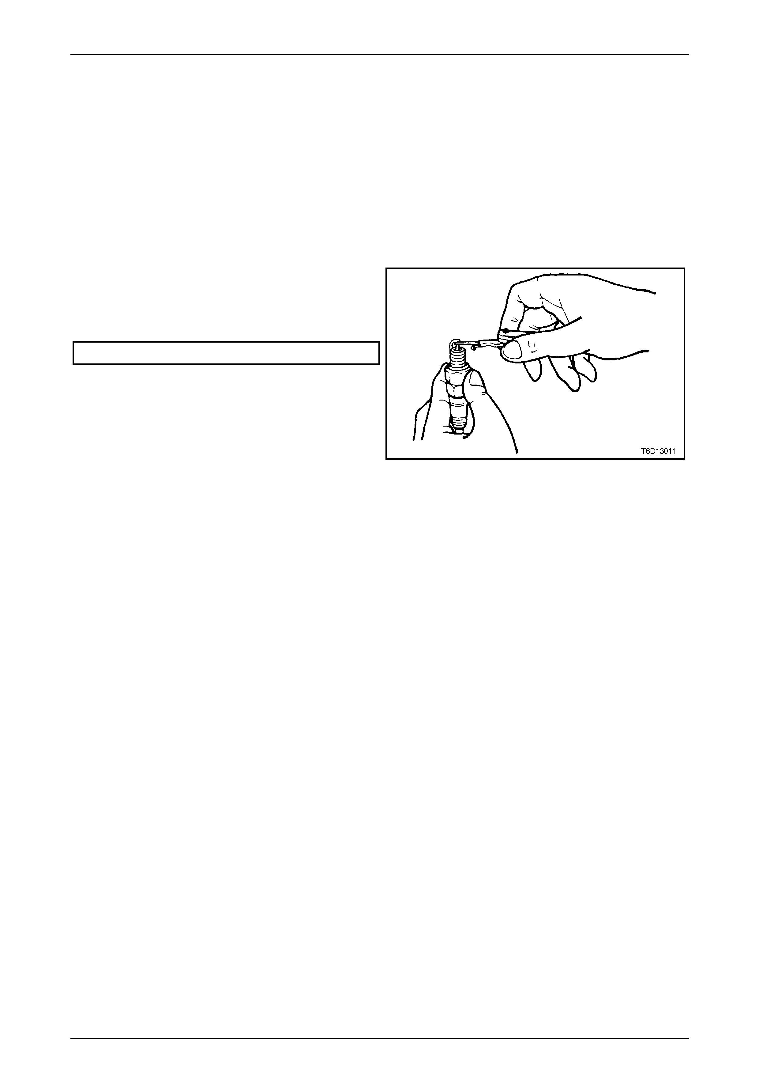
Powertrain Management GEN III V8 – Service Operations Page 6C3-3–47
Page 6C3-3–47
Clean, Inspect and Adjust
1 Replace any spark plug that has cracke d insulation, broken insulation or loose e lectro de s.
2 Clean any oil from the spark plugs us ing a degreasing agent.
3 Dry the spark plugs using compresse d air.
4 Clean the spark plugs using a purpose-built machine (sand blasting type).
5 Inspect the spark plugs for defects. Refer to Analysis of Spark Plug C ondition in this Section for identification of the
condition of spark plugs.
6 Ensure the threads are clean and in good order.
7 Use a round wire feeler gauge to check the spark pl ug
gap.
8 Adjust the gap to the correct specification by gently
bending the outer electrode.
Spark plug gap....................................................1.5 mm
Figure 6C3-3 – 44
Spark Plug Inspection
Poor Spark Plug Performance
A spark plug can perform poorly due to wear, dirt, carbon fouling, excessive electro de wear, a broken insulator or
excessive gap.
Worn or Dirty Plugs
Worn or dirty plugs can give satisfactory operation while the vehicle is idling, but break down under load.
This can cause:
• Poor fuel economy,
• Power loss,
• Acceleration loss,
• Difficult starting, and/or
• Generally poor engine p erformance.
Carbon Fouling
Carbon fouling is indicated by black carbon deposits. The black deposits are usually the result of slow-speed driving and
short runs. In these circumstances, the optimum engine operating temp erature is seldom reached.
Fouling can also be caused by:
• Worn piston rings,
• Faulty ignition,
• Rich fuel mixture, and/or
• Spark plugs that are rated too cold.

Powertrain Management GEN III V8 – Service Operations Page 6C3-3–48
Page 6C3-3–48
Excessive Electrode Wear
This often indicates:
• The engine is operating at high speeds,
• The engine is operating at levels that are consistently greater than normal,
• A plug that is rated too hot,
• Excessively lean fuel mixture, and/or
• Plug/s overheating due to insufficient tightening (caused by combustion gases leaking past the threads).
Broken Insulator
Broken insulators are usually the result of improper installation or carelessness.
Breaks in the upper insulator can result from a poor fitting spark plug socket or an impact. The cracked insulator ma y not
show up until oil or moisture penetrates the crack. The crack is often just below the crimped part of the s hell and may not
be visible.
Breaks in the lower insulator often result from careless re-gapping and are usually visible.
This can also result from the plug operating too hot. For example, in periods of high-speed operation or under heavy
loads.
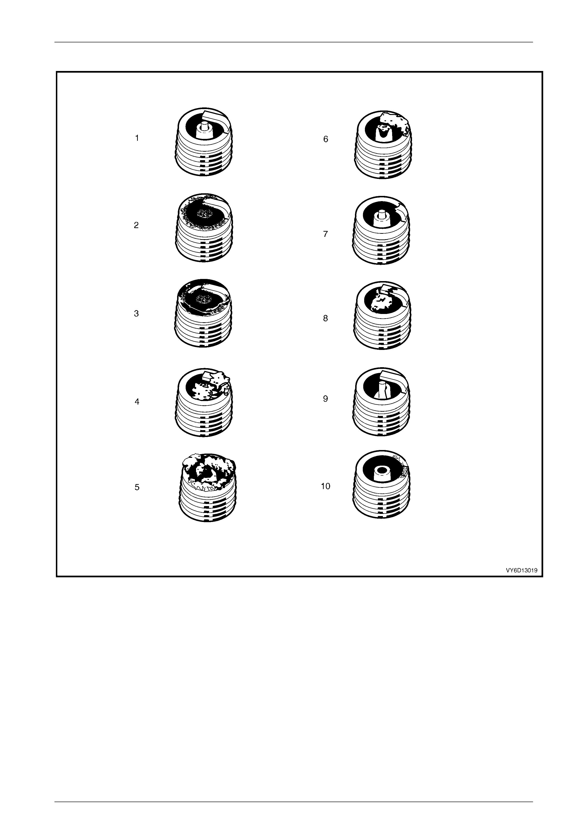
Powertrain Management GEN III V8 – Service Operations Page 6C3-3–49
Page 6C3-3–49
Analysis of Spark Plug Condition
Figure 6C3-3 – 45
Legend
1 Normal
2 Carbon Fouled
3 Oil Fouled
4 Deposit Fouling A
5 Deposit Fouling B
6 Deposit Fouling C
7 Detonation
8 Pre-ignition
9 Heated Shock Failure
10 Insufficient Installation Torque

Powertrain Management GEN III V8 – Service Operations Page 6C3-3–50
Page 6C3-3–50
Normal Operation (1)
Brown or greyish-tan deposits and slight electrode wear indi cate correct spark plug heat range and mixe d periods of high
and low speed driving.
Carbon Fouled (2)
Dry, fluffy black carbon deposits possib ly due to poor ignition output, a weak coil, a faulty spark plu g lead, excessive
idling or slow speeds un der light load. If spark plug temperatures remain too low for normal combustio n, the dep osits are
not burned off.
Oil Fouled (3)
Wet, oily deposits with minor electrode wear possibly due to oil leaking pas t worn piston rings.
Breaking in a new or recently overhauled engine before the rings are fully seated may also result in this condition.
Deposit Fouling A (4)
Red brown, yellow and white coloured coatings on the insula tor tip which are by-products of combustion. They come
from the fuel and the lubricati ng oil which generally contain additives. Most powdery deposits have no adverse effect on
spark plug operation; however, they may cause intermittent missing under severe operating conditions.
Deposit Fouling B (5)
Deposits similar to those identified in deposit fouling A (4). These are also by-products of combustion from the fuel and
lubricating oil. Excess ive valve stem clearances and/or defective intake valve seals allow too much oil to enter the
combustion chamber. The deposits will accumulate on the portion of the spark plug that projects into the chamber and
will be heaviest on the side facing the i ntake valve. When you detect this condition in only one or t wo cyli nders, check the
valve stem seals.
Deposit Fouling C (6)
Most powdery deposits identified in deposit fouling A (4) hav e no adverse effect on the operation of the spark plug as
long as they remain powdery.
Under certain conditions of op eration however, these deposits melt and form a shiny glaze coating on the insulator.
When hot, this acts as a good electrical conductor allowing the current to flow along the deposit instead of sparkin g
across the gap.
Detonation (7)
Commonly referred to as engine knock or pinging, detonation causes severe shocks inside the combustion chamber
causing damage to parts.
Pre-ignition (8)
Burnt or blistered insulator tip and b adly eroded electrodes probably due to the excessive heat.
This is often caused by a cooling system blockage, sticking valves, improperly installed spar k plugs or plugs that are the
wrong heat rating (too hot).
Sustained high speed with a heavy load can prod uce temperatures high enoug h to cause pre-ignition.
Heat Shock Failure (9)
A rapid increase in spark plug tip temperature under severe operating c onditions can cause heat shock and result in
fractured insulators. This is a common cause of broken and cracked insulator tips.
Insufficient Installation Torque (10)
Poor contact between the spark plug and the cylinder head seat.
The lack of proper heat transfer that results from poor seat contact causes overheating of the spark plug. In many cases,
severe damage occurs. Dirty threads in the cylinder head can cause the plug to seize before it is seated.
Ensure the cylinder head and spark plug threads are free of deposits, burrs and scale befo re installation.

Powertrain Management GEN III V8 – Service Operations Page 6C3-3–51
Page 6C3-3–51
Reinstall
Reinstallation of the spark plugs is the reverse of the removal procedure, noting the following:
NOTE
When replacing spark plugs, use the
recommended spark plugs of the correct heat
range.
1 Hand start each spark plug into the cylinder head thread.
Ensure the spark plug has fully seated on the
cylinder head before the specified torque is
reached.
2 Tighten the spark plugs to the correct torque specific ation using a spark plug socket and accurate torque wrench.
Spark plug torque specification:
New cylinder head only......................................20.0 Nm
Existing cylinder head........................................15.0 Nm
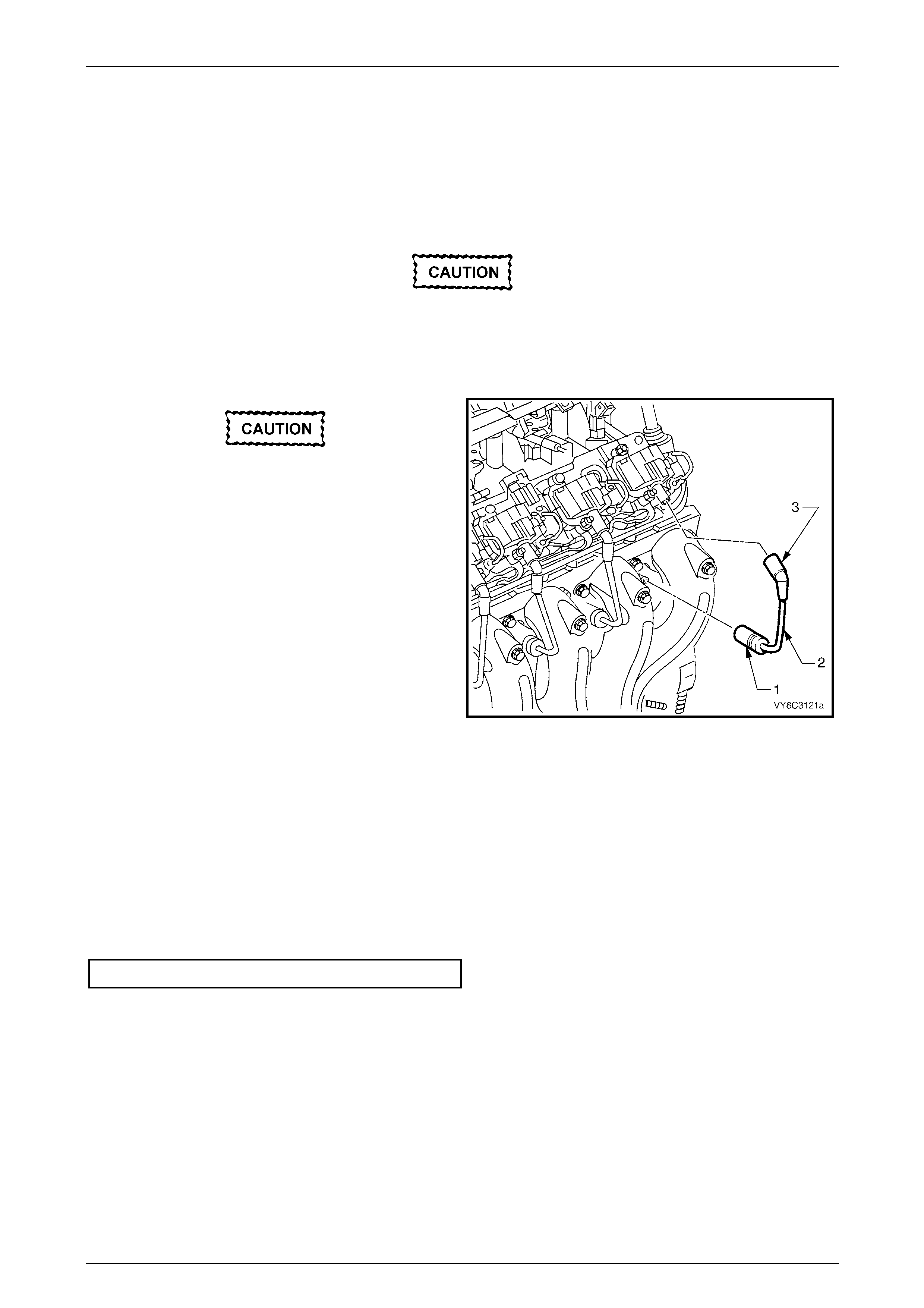
Powertrain Management GEN III V8 – Service Operations Page 6C3-3–52
Page 6C3-3–52
3.22 Spark Plug Leads
LT Section No. — 02–030
Remove
Pulling or bending spark plug leads can
cause hidden damage. Follow the removal
steps carefully to avoid such damage.
1 Remove both engine dress covers, refer to Section 6A3 Engine Mechanical – GEN III V8.
Grasp the spark plug lead bo o t , not the lead.
2 Firmly grasp the boot (1) at the spark plug end of the
lead (2).
3 Twist the boot in both directions, to relieve any suction
and to break the seal.
4 Pull the boot straight off the spark plug.
5 Repeat Steps 2 and 3 for the ignition coil end of the
lead (3).
6 Carefully set the lead to one side.
NOTE
Place each spark plug lead in order as it is
removed. This will enable any abnormal
condition to be identified with the correct
cylinder.
Figure 6C3-3 – 46
7 Repeat for the remaining leads as required.
Inspect
1 Connect and Ohmmeter capable of accuratel y readi ng to 20 kΩ to each end of a lead.
2 Record the reading for each lead.
3 Compare the resistance readings taken against the specification.
Spark plug lead resistance....................700 Ω Maximum
4 Replace any lead that is signif icantly different from the stated specification.
Reinstall
Reinstallation of the spark plug leads is the reverse of the removal procedure, noting the following:
1 Push on the boot until the lead connection is fully engaged with the spark plug and coil terminals. Ensure the actual
lead connection has connected with the spark plug.
2 Start the engine and check for correct operat ion.
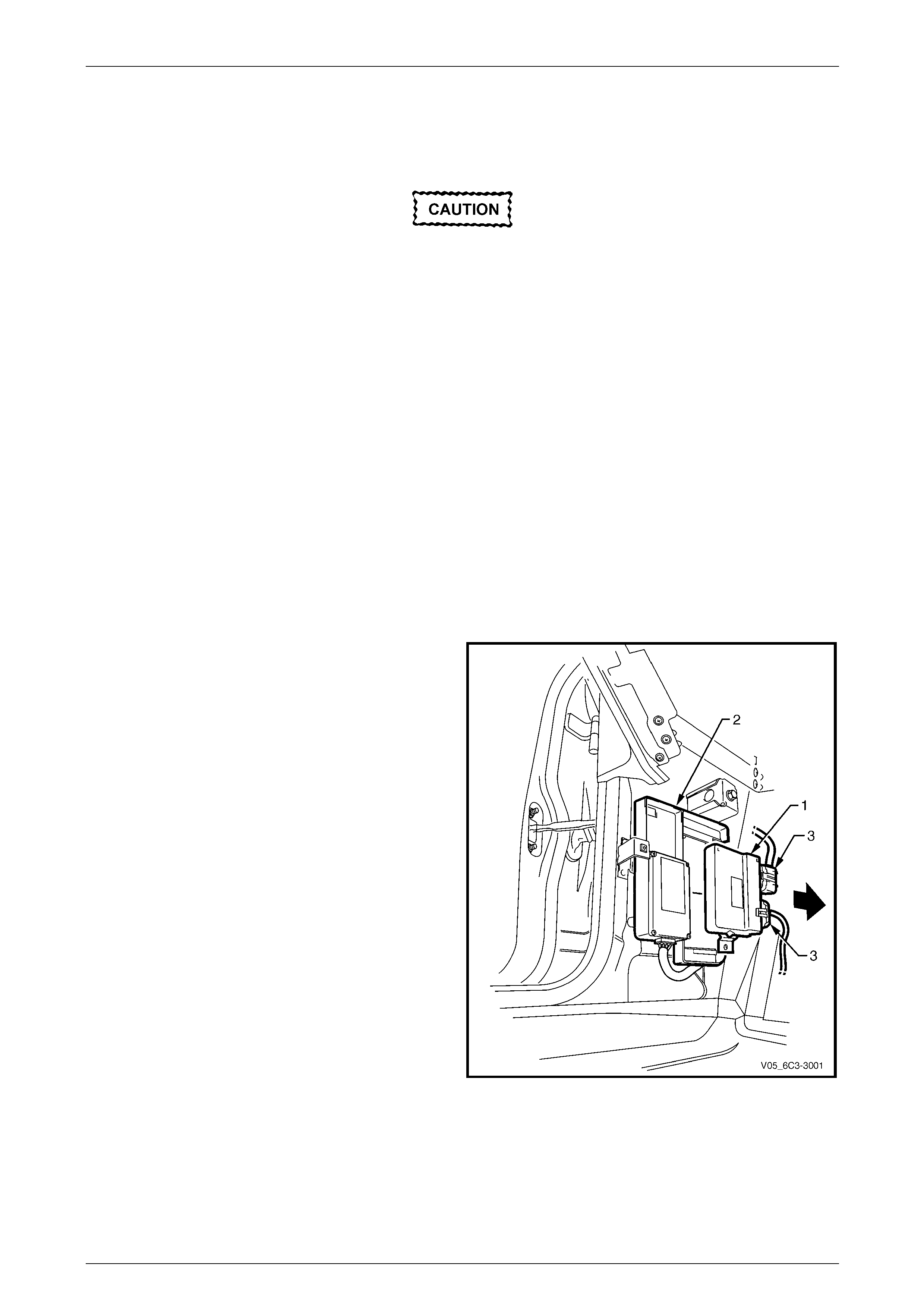
Powertrain Management GEN III V8 – Service Operations Page 6C3-3–53
Page 6C3-3–53
3.23 Throttle Actuator Control Module
LT Section No. — 02–245
• Do not touch the throttle actuator control
module (TACM) connector pins as
electrostatic discharge (ESD) damage may
result. For further information on ESD,
refer to Section 00 Warnings, Cautions and
Notes .
• When removing or reinstalling the TACM
wiring connectors, ensure the ignition
switch is in the OFF position and the
battery has been disconnected. Failure to
do so may result in damage to the TACM
and/or associated components.
• Disconnection of the battery affects
certain vehicle electronic systems. Refer
to Section 00 Warnings, Cautions and
Notes before disconnecting the battery.
Remove
1 Turn the ignition switch off.
2 Disconnect the battery negative lead.
3 Remove the left-hand front body hinge pillar trim assembly, refer to Section 1A8 Headlining and Interior Trim.
4 Slide the TACM (1) forward to release it from the
Powertrain Interface Module (2).
5 Disconnect the wiring connectors (3).
Figure 6C3-3 – 47
Reinstall
Reinstallation of the throttle actuator control module TACM is the reverse of the removal procedure.
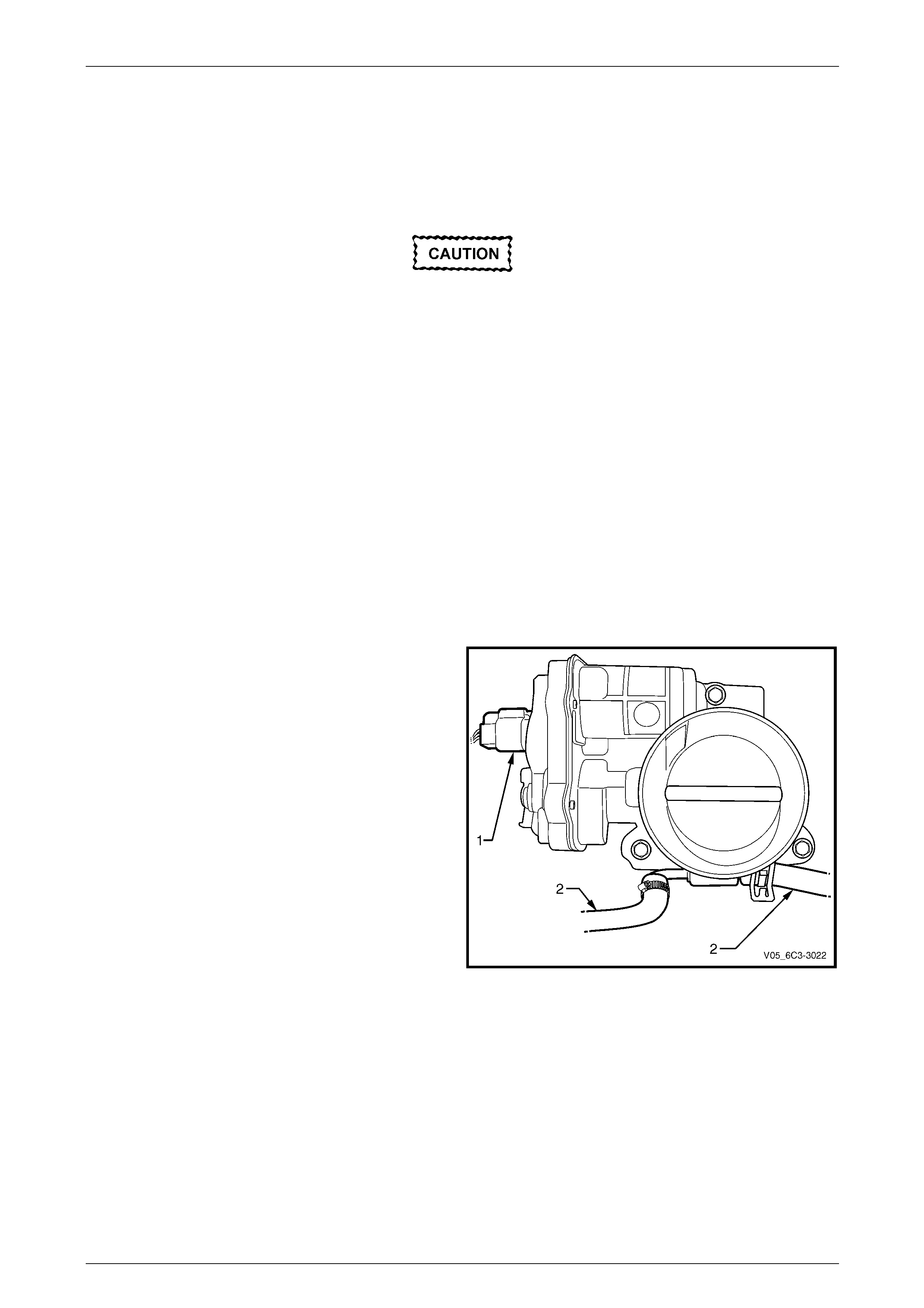
Powertrain Management GEN III V8 – Service Operations Page 6C3-3–54
Page 6C3-3–54
3.24 Throttle Body Assembly
LT Section No. — 03–300
Handling Precautions
• Under no circumstances should the
throttle body assembly be disassembled
as the vacuum seal between the cover
plate and throttle body will be broken. This
will allow the ingress of foreign particles
and or moisture and render the throttle
body unserviceable.
• The throttle body assembly must not be
subjected to any form of shock such as
being dropped, as damage may result to
the fragile motor magnets within the
throttle body.
Remove
1 Turn the ignition switch off.
2 Partially drain the cooling system before removing the cooling system hoses at the throttle body,
refer to Section 6B3 Cooling System – GEN III V8 Engine Engine.
3 Remove the intake air duct, refer to 3.17 Mass Air Flow Sensor and Intake Air Duct.
4 Disconnect the throttle body electrical connector (1).
5 Disconnect the cooling system hoses (2) fro m the
throttle body assembly.
Figure 6C3-3 – 48
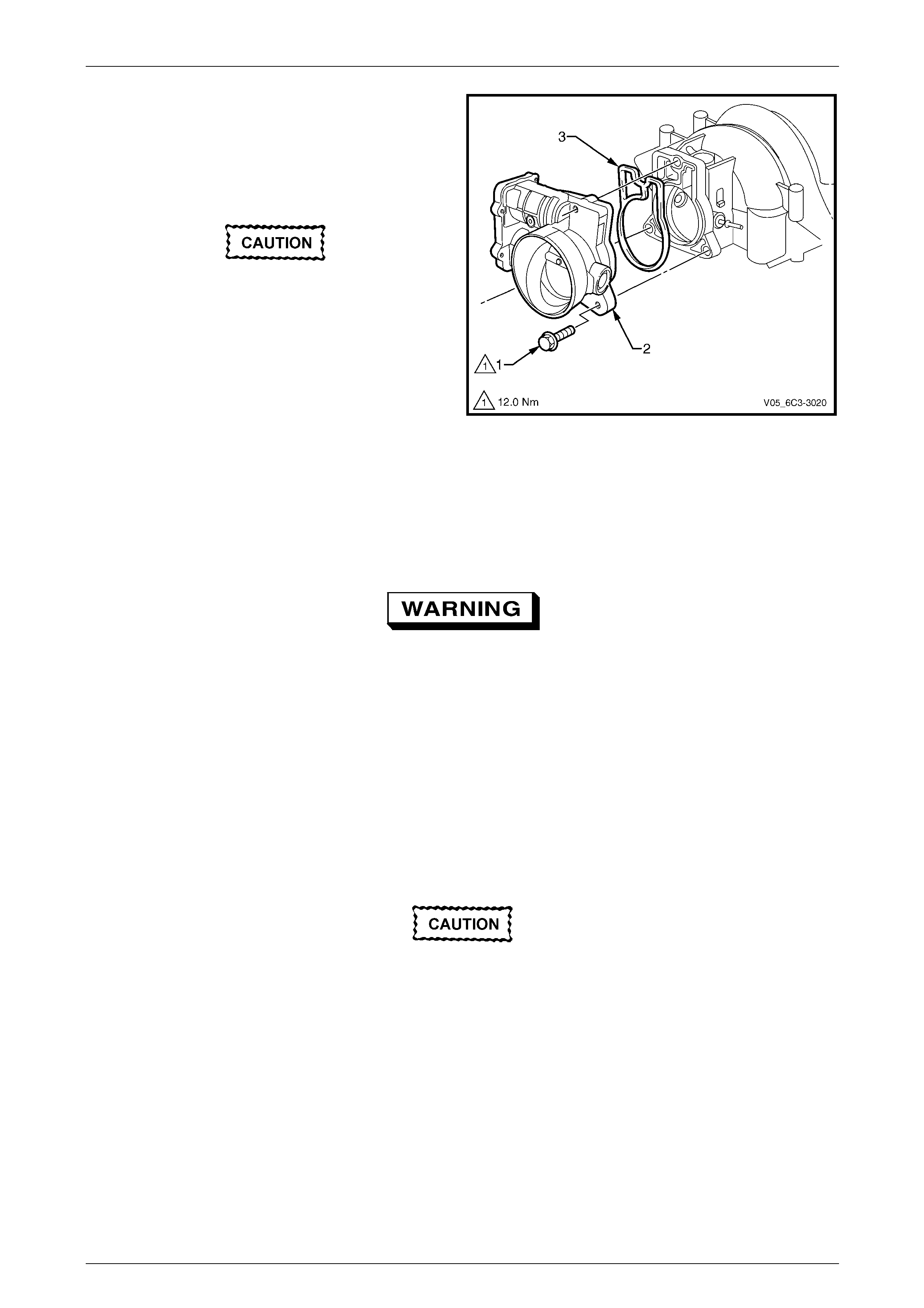
Powertrain Management GEN III V8 – Service Operations Page 6C3-3–55
Page 6C3-3–55
6 Remove the throttle body assembly attachin g bolt (1),
three places.
7 Remove the throttle body assembly (2) and the seal
(3).
8 Discard the removed seal.
• To prevent damage to the sealing
surfaces, it is preferred that only plastic
scrapers are used for cleaning deposits
from machined alloy surfaces.
• Do not soak the throttle body assembly in
cold immersion type cleaner. To clean the
throttle body following disassembly, use
a spray type hydrocarbon cleaner and a
shop towel to remove heavy deposits.
• The throttle body assembly contains
electrical components that should not
come in contact with solvent or cleaner,
as damage may result.
9 Clean the both sealing surfaces.
Figure 6C3-3 – 49
Inspect
To avoid serious personal injury, never
attempt to rotate the throttle plate manually
whilst the throttle body wiring connector is
connected to the throttle bod y asse mbly.
The following inspection pr ocedure may be carried out with the throttle body assembly installed on the vehicle. Prior to
the inspection, perform the following:
1 Switch the ignition off.
2 Disconnect the throttle body wiring connector.
3 Remove the intake air duct, refer to 3.17 Mass Air Flow Sensor and Intake Air Duct.
4 Fully open the throttle plate b y hand and inspect the throttle body bore a nd the throttle plate for any deposits.
When cleaning / inspecting the throttle body
assembly:
• Do not subject the throttle body assembly
to an immersion cleaner or a strong
solvent. Damage to the throttle position
sensor and / or sealed throttle shaft
bearings will result.
• Never use a wire brush or scraper to clean
the throttle body. A wire brush or sharp
tool may damage the throttle body
components.

Powertrain Management GEN III V8 – Service Operations Page 6C3-3–56
Page 6C3-3–56
5 Use a clean shop towel and a spray type hydrocarbon cleaner to clean the throttle body bore and throttle plate. If
necessary, use a parts cleaning brush in order to remove heavy deposits.
6 Inspect the throttle body for a bent or damaged throttle plate, and cracks, corrosion, or distortion in the t hrottle body
housing.
7 To inspect the throttle body for a binding throttle plate, fully open and close the throttle plate by hand: it should
open and close smoothly.
NOTE
The throttle body contains no serviceable parts
and should not be disassembled. If the throttle
body is damaged it must be replaced as an
assembly.
8 If the throttle body is affected by any of the above conditions, the throttle body must be replaced.
9 If an on-vehicle throttle body inspection was performed, reinstall the intake air duct,
refer to 3.17 Mass Air Flow Sensor and Intake Air Duct.
10 Road test the vehicle and check for correct operati on, taking particular note that no air leaks are evident.
Reinstall
Reinstallation of the throttle bod y is the reverse of the removal procedure, noting the following:
1 Install a new throttle body seal .
2 Reinstall the bolts and tighten to the correct torque specification.
Throttle body attaching bolt
torque specification............................................12.0 Nm
3 Refill the cooling system, refer to Section 6B3 Cooling System – GEN III V8 Engine.
4 Road test the vehicle and check for correct operation, taking particular note that no air leaks are evident.

Powertrain Management GEN III V8 – Service Operations Page 6C3-3–57
Page 6C3-3–57
4 Specifications
Accelerator Pedal Position Sensor 1
Type.....................................................Three wire potentiometer
Accelerator pedal at rest........................................ Below 1.25 V
Accelerator pedal fully depressed.......................5.0 V maximum
Accelerator Pedal Position Sensor 2
Type.....................................................Three wire potentiometer
Accelerator pedal at rest........................................ Below 1.25 V
Accelerator pedal fully depressed.......................5.0 V maximum
Camshaft Position (CMP) Sensor
Type............................Twin Hall effect, interrupter ring triggered
Air gap ....................................................................0.1 – 1.8 mm
Air gap adjustment................................................No adjustment
Crankshaft Position (CKP) Sensor
Type............................Twin Hall effect, interrupter ring triggered
Coil resistance @ 20° C.........................................850 – 1040 Ω
Air gap ....................................................................0.1 – 1.5 mm
Air gap adjustment............................................... No adjustment
Engine Coolant Temperature Sensor
Type........................ Negative temperature coefficient thermistor
Engine Coolant Temperature Vs Resistance
Temperature °C Resistance – Ohms (Ω)
-10 16,180
0 9,420
20 3,520
25 2,796
40 1,459
60 667
80 332
100 177
120 100
140 60
Evaporative Emission (EVAP) Canister Purge Valve
Type...............................................................................Solenoid
Resistance @ 20° C ..............................................18.0 – 22.0 Ω
Operating voltage................................................... 12.0 – 16.0 V
Engine Firing Order..............................................................1, 8, 7, 2, 6, 5, 4, 3
Fuel Injector
Type...............................................................................Solenoid
Fuel Injector Resistance @ 20° C..........................11.4 – 12.6 Ω
Fuel System Pressure
Regulated Pressure............................................. 380 – 440 kPa
Heated Oxygen Sensor (HO2S)
Type..........................................Four wire, Zirconia, galvanic cell
Operating range (above 360° C)........................... 10 – 1000 mV
Closed loop operating range................................. 300 – 600 mV
Heater resistance @ 20° C........................................4.7 – 5.7 Ω

Powertrain Management GEN III V8 – Service Operations Page 6C3-3–58
Page 6C3-3–58
Intake Air Temperature (IAT ) Sensor
Type........................ Negative temperature coefficient thermistor
Intake Air Temperature Vs Resistance
Temperature °C Resistance – Ohms (Ω)
-10 16177
0 9423
20 3515
30 2238
40 1459
60 667.5
80 332
100 176
120 99.8
Knock Sensor
Type........................................................ Piezo ceramic element
Mass Air Flow Sensor
Type......................................................Hot film air-mass sensor
Spark Plug
Type........................................................................... AC 41-985
Gap..............................................................1.52 mm ± 0.05 mm
Adjustment........................................................... No adjustment
Spark Plug Lead Resistance
Resistance........................................................ 700 Ω maximum
Throttle Position Sensor 1
Type.....................................................Three wire potentiometer
Closed throttle....................................................... Below 1.25 V
Wide open throttle...............................................5.0 V maximum
Throttle Position Sensor 2
Type.....................................................Three wire potentiometer
Closed throttle....................................................... Below 1.25 V
Wide open throttle...............................................5.0 V maximum
Vehicle Speed Sensor
Type......................................................Inductive Magnetic Type
Coil Resistance @ 20° C ...................................................945 Ω

Powertrain Management GEN III V8 – Service Operations Page 6C3-3–59
Page 6C3-3–59
5 Torque Wrench Specifications
Accelerator Pedal Position Sensor Attaching Bolt.......................7.0 – 12.0 Nm
Accelerator Pedal Position Se nsor Support Bracket
Attaching Nut.............................................................................20.0 – 30.0 Nm
Air Cleaner Upper Housing Attaching Screw.................................2.0 – 3.0 Nm
Air Cleaner Lower Housing Assembly Retaining Stud.................7.5 – 12.5 Nm
Camshaft Position (CMP) Sensor Retaining Bolt .................................25.0 Nm
Crankshaft Position (CKP) Sensor Retaining Bolt................................25.0 Nm
PCM Mounting Bracket Attaching Screw................................................8.0 Nm
Engine Coolant Temperature (ECT) Sensor.........................................20.0 Nm
Engine Oil Pressure (EOP) Sensor ......................................................20.0 Nm
Fuel Rail Attaching Studs............................................................8.0 – 12.0 Nm
Heated Oxygen Sensor (HO2S)...........................................................41.0 Nm
Ignition Coil Assembly Attaching Screw ...............................................12.0 Nm
Knock Sensor.......................................................................................15.0 Nm
Intake Air Duct Clamp....................................................................1.5 – 2.5 Nm
Spark Plug:
- with New Cylinder Head.....................................................................20.0 Nm
- with Existing Cylinder Head................................................................15.0 Nm
Throttle Body Assembly Attaching Bolt ................................................12.0 Nm
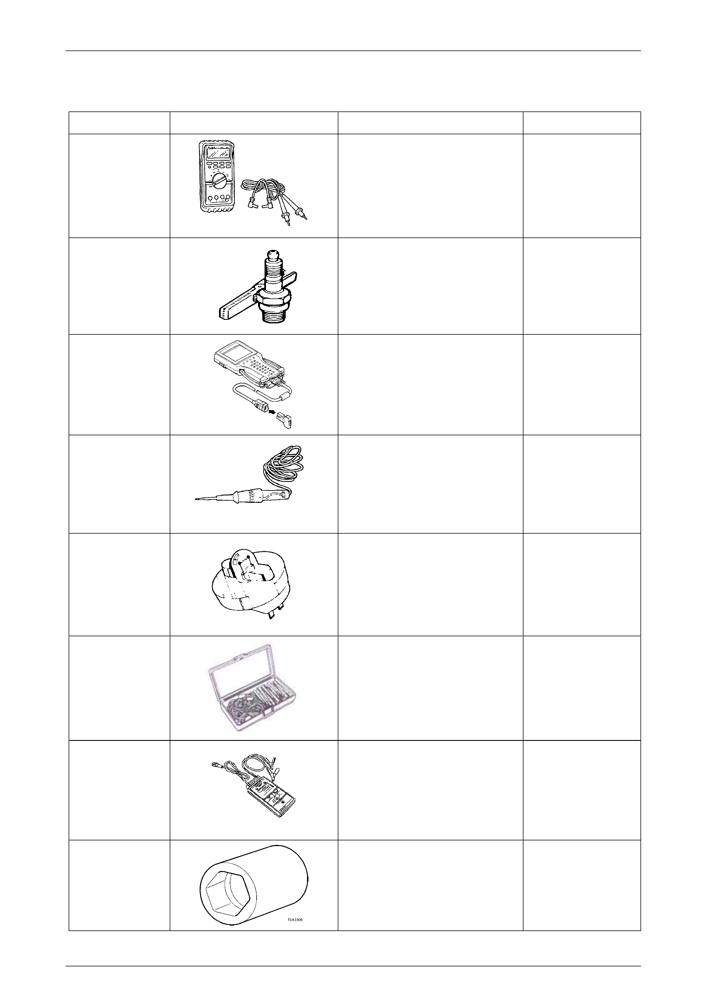
Powertrain Management GEN III V8 – Service Operations Page 6C3-3–60
Page 6C3-3–60
6 Special Tools
Tool Number Illustration Description Tool Classification
3588
Digital Multimeter
Used for various measurement
functions as detailed in the text.
Previously released as j 39200, 3545
GM and also commercially av ailable
with a minimum of 10 MΩ impedance.
Available
7230
HEI Tester
Also previously released as ST-125.
Mandatory
7000086i
Tech 2 Scan Tool
Used for diagnosis of vehicle electrical
systems.
Previously released.
Mandatory
J 34142-a
Unpowered Test Lamp
Previously released as CT -40-C and
also commercially avail able
Must have a current draw less than
0.3 Amp.
Mandatory
J 34730-2C
Injector Test Light
Used to check for power and the
control circuit of the fuel injector, for
proper operation.
Also previously released as
ST- 8329
Mandatory
J 35616-A
Connector Test Adaptor Kit
Used when carrying out electric al
diagnostic circuit checks.
Previously released
Desirable
J 39021
Fuel Injector Coil/Balance Tester
Used in conjunction with a DMM for
testing the fuel injector coil windings
and for injector balance testing
Previously released
Mandatory
J 41712
Oil Pressure Sensor Socket
Used in conjunction with 3/8” drive
socket equipment to remove/reinstall
oil pressure sensor.
Previously released
Desirable