
Engine Mechanical Page 6A4–1
Page 6A4–1
Section 6A4
Engine Mechanical – GEN IV V8
ATTENTION
Before performing any service operation or other procedure described in this Section, refer to 00 Warnings,
Cautions and Notes for correct workshop practices with regard to safety and/or property damage.
1 General Information ...............................................................................................................................8
1.1 AWD Vehicles......................................................................................................................................................... 8
1.2 Engine Views.......................................................................................................................................................... 9
Engine View Left-hand Side.................................................................................................................................. 9
Lower Front.......................................................................................................................................................... 10
Lower Engine Assembly, Except AWD.............................................................................................................. 11
Lower Engine Assembly, AWD........................................................................................................................... 13
Cylinder Head....................................................................................................................................................... 15
Intake Manifold..................................................................................................................................................... 16
1.3 Engine Serial Number.......................................................................................................................................... 17
1.4 Engine Construction............................................................................................................................................ 18
Cylinder Block...................................................................................................................................................... 18
Cylinder Heads..................................................................................................................................................... 19
Valve Train............................................................................................................................................................ 20
Crankshaft............................................................................................................................................................ 20
Piston and Connecting Rod................................................................................................................................ 21
Camshaft and Drive ............................................................................................................................................. 21
Intake Manifold..................................................................................................................................................... 22
Exhaust Manifold................................................................................................................................................. 23
Oil Pan .................................................................................................................................................................. 24
Excluding AWD Vehicles.................................................................................................................................. 24
AWD Vehicles .................................................................................................................................................. 24
1.5 Engine Lubrication Sy s t em................................................................................................................................. 25
Oil pump ............................................................................................................................................................... 25
Oil Flow................................................................................................................................................................. 25
Oil Seals................................................................................................................................................................ 27
Positive Crankcase Ventilation System............................................................................................................. 27
1.6 Service Notes....................................................................................................................................................... 29
Cleanliness and Care........................................................................................................................................... 29
Replacing Engine Gaskets.................................................................................................................................. 29
Re-using Gaskets and Applying Sealant.......................................................................................................... 29
Cleaning Gasket Surfaces................................................................................................................................ 29
Assembling Components ................................................................................................................................. 29
Room Temperature Vulcanising (RTV) and Anaerobic Sealers....................................................................... 29
Pipe Joint Compound....................................................................................................................................... 29
RTV Sealer....................................................................................................................................................... 30
Anaerobic Sealer.............................................................................................................................................. 30
Separating Components ..................................................................................................................................... 30
Special Tools and Equipment............................................................................................................................. 31
Fasteners.............................................................................................................................................................. 31
Clamp Load...................................................................................................................................................... 32
Torque Angle and Torque to Yield Fasteners................................................................................................... 32
2 Displacement on Demand (DoD).........................................................................................................33
2.1 General Description............................................................................................................................................. 33
2.2 System Description ............................................................................................................................................. 34
System Operation................................................................................................................................................ 34
Valve Lifter Oil Manifold Assembly.................................................................................................................... 34
Displacement on Demand Valve Lifters............................................................................................................. 35
Techline
Techline

Engine Mechanical Page 6A4–2
Page 6A4–2
Engine Block........................................................................................................................................................ 36
New Product Information .................................................................................................................................... 36
Torque Values and/or Fastener Tightening Strategies..................................................................................... 36
New Sealants and/or Adhesives......................................................................................................................... 36
Disassembly and Assembly Procedure Revisions........................................................................................... 36
Engine Mechanical Diagnostic Procedure Revisions....................................................................................... 36
New Special Tools Required............................................................................................................................... 36
A Component Comparison from the Previous Year ......................................................................................... 37
Lubrication Description (Main Pressure Below 55 psi - DoD Off).................................................................... 37
Lubrication Description (Main Pressure Above 55 psi - DoD Off)................................................................... 38
Lubrication Description (Main Pressure Below 55 psi - DoD On).................................................................... 39
Lubrication Description (Main Pressure Above 55 psi - DoD On) ...................................................................40
Cleanliness and Care........................................................................................................................................... 41
Separating Parts .................................................................................................................................................. 41
Separate, mark, or organize the following components:................................................................................... 41
Replacing Engine Gaskets.................................................................................................................................. 41
Tools Required................................................................................................................................................. 41
Gasket Use and Applying Sealants.................................................................................................................... 41
Separating Components ..................................................................................................................................... 41
Cleaning Gasket Surfaces................................................................................................................................... 42
Assembling Components.................................................................................................................................... 42
Use of Room Temperature Vulcanizing (RTV) and Anaerobic Sealer ............................................................. 42
Pipe Joint Compound....................................................................................................................................... 42
RTV Sealer....................................................................................................................................................... 43
Anaerobic Sealer.............................................................................................................................................. 43
Tools and Equipment .......................................................................................................................................... 43
2.3 Minor Service Operations for DoD ..................................................................................................................... 44
Valve Lifter Oil Filter Replacement..................................................................................................................... 44
Removal Procedure.......................................................................................................................................... 44
Installation Procedure....................................................................................................................................... 44
Valve Lifter Oil Manifold Replacement............................................................................................................... 45
Removal Procedure.......................................................................................................................................... 45
Installation Procedure....................................................................................................................................... 47
Valve Lifter Replacement .................................................................................................................................... 48
Tools Required................................................................................................................................................. 48
Removal Procedure.......................................................................................................................................... 48
Installation Procedure....................................................................................................................................... 49
Valve Lifter Removal............................................................................................................................................ 49
Tools Required................................................................................................................................................. 49
Valve Lifters and Guides Cleaning and Inspection........................................................................................... 51
Non Displacement on Demand Valve Lifters ................................................................................................... 51
Displacement on Demand Valve Lifters ........................................................................................................... 51
Valve Lifter Oil Manifold Cleaning and Inspection............................................................................................ 52
Valve Lifter Installation........................................................................................................................................ 53
Valve Lifter Oil Filter Installation........................................................................................................................ 55
Valve Lifter Oil Manifold Installation.................................................................................................................. 55
2.4 Displacement on Demand Diagnostic Procedures........................................................................................... 57
Displacement on Demand (DoD) System Compression Test........................................................................... 57
Cylinder Leakage Test......................................................................................................................................... 57
Tools Required................................................................................................................................................. 57
Oil Consumption Diagnosis................................................................................................................................ 58
Oil Pressure Diagnosis and Testing................................................................................................................... 58
Tools Required................................................................................................................................................. 58
Displacement on Demand (DoD) Oil Pressure Relief Valve Diagnosis and Testing...................................... 59
Tools Required................................................................................................................................................. 59
Displacement on Demand (DoD) Valve Lifter Oil Manifold Diagnosis and Testing........................................ 61
Tools Required................................................................................................................................................. 61

Engine Mechanical Page 6A4–3
Page 6A4–3
3 Diagnosis ..............................................................................................................................................64
3.1 Engine Diagnosis................................................................................................................................................. 64
Procedure............................................................................................................................................................. 64
3.2 Engine Noise........................................................................................................................................................ 66
Procedure............................................................................................................................................................. 66
3.3 Valve Train Noise................................................................................................................................................. 68
Procedure............................................................................................................................................................. 68
3.4 Oil Consumption.................................................................................................................................................. 69
3.5 Oil Pressure.......................................................................................................................................................... 70
Oil Pressure Check.............................................................................................................................................. 70
Diagnosis.............................................................................................................................................................. 71
3.6 Oil Leaks............................................................................................................................................................... 72
3.7 Compression Check ............................................................................................................................................ 74
Interpreting Compression Readings.................................................................................................................. 74
4 Minor Service Operations....................................................................................................................75
4.1 Air Intake Duct...................................................................................................................................................... 75
Remove................................................................................................................................................................. 75
Reinstall................................................................................................................................................................ 75
4.2 Engine Dress Cover............................................................................................................................................. 76
Remove................................................................................................................................................................. 76
Reinstall................................................................................................................................................................ 76
4.3 Engine Oil and Filter............................................................................................................................................ 77
Oil Level Check.................................................................................................................................................... 77
Oil Change............................................................................................................................................................ 77
Oil Filter and Adapter .......................................................................................................................................... 79
Remove............................................................................................................................................................ 79
Reinstall ........................................................................................................................................................... 79
4.4 Oil pressure Sensor............................................................................................................................................. 80
Remove................................................................................................................................................................. 80
Reinstall................................................................................................................................................................ 80
4.5 Oil Level Indicator and Tube............................................................................................................................... 81
Remove................................................................................................................................................................. 81
Reinstall................................................................................................................................................................ 81
4.6 Engine Drive Belts and Pulleys .......................................................................................................................... 82
Accessory Drive Belt........................................................................................................................................... 82
Remove............................................................................................................................................................ 82
Reinstall ........................................................................................................................................................... 82
Accessory Drive Belt Idler Pulley....................................................................................................................... 82
Remove............................................................................................................................................................ 82
Reinstall ........................................................................................................................................................... 83
Accessory Drive Belt Tensioner......................................................................................................................... 83
Remove............................................................................................................................................................ 83
Reinstall ........................................................................................................................................................... 83
Air Conditioner Drive Belt................................................................................................................................... 84
Remove............................................................................................................................................................ 84
Reinstall ........................................................................................................................................................... 84
Air Conditioner Drive Belt Idler Pulley............................................................................................................... 84
Remove............................................................................................................................................................ 84
Reinstall ........................................................................................................................................................... 85
Air Conditioner Drive Belt Tensioner................................................................................................................. 85
Remove............................................................................................................................................................ 85
Reinstall ........................................................................................................................................................... 85
4.7 Intake Manifold Assembly................................................................................................................................... 86
Remove................................................................................................................................................................. 86
Disassemble..................................................................................................................................................... 92
Clean and Inspect ............................................................................................................................................ 93
Reassemble ..................................................................................................................................................... 94
Reinstall................................................................................................................................................................ 95

Engine Mechanical Page 6A4–4
Page 6A4–4
4.8 Vapour Vent Pipe and Covers............................................................................................................................. 97
Remove................................................................................................................................................................. 97
Reinstall................................................................................................................................................................ 98
4.9 Engine Valley Cover ............................................................................................................................................ 99
Remove................................................................................................................................................................. 99
Clean and Inspect ............................................................................................................................................ 99
Reinstall.............................................................................................................................................................. 100
4.10 Camshaft Lobe Lift ............................................................................................................................................ 101
Measure .............................................................................................................................................................. 101
4.11 Valve Rocker Arm Cover................................................................................................................................... 102
Remove............................................................................................................................................................... 102
Clean and Inspect .......................................................................................................................................... 106
Reinstall.............................................................................................................................................................. 106
4.12 Valve Rocker Arms and Push Rods................................................................................................................. 108
Remove............................................................................................................................................................... 108
Clean and Inspect.............................................................................................................................................. 109
Reinstall.............................................................................................................................................................. 109
4.13 Valve Stem Oil Seal and Valve Spring.............................................................................................................. 111
Remove............................................................................................................................................................... 111
Reinstall.............................................................................................................................................................. 112
4.14 Exhaust Manifold............................................................................................................................................... 114
Remove............................................................................................................................................................... 114
Inspect ................................................................................................................................................................ 115
Reinstall.............................................................................................................................................................. 115
4.15 Cylinder Head..................................................................................................................................................... 117
Remove............................................................................................................................................................... 117
Disassemble....................................................................................................................................................... 119
Clean................................................................................................................................................................... 120
Inspect ................................................................................................................................................................ 121
Cylinder Head................................................................................................................................................. 121
Valve Springs................................................................................................................................................. 122
Valves ............................................................................................................................................................ 122
Valve Guides.................................................................................................................................................. 123
Valve Stem Oversize...................................................................................................................................... 124
Valve Seats.................................................................................................................................................... 124
Reassemble........................................................................................................................................................ 125
Reinstall.............................................................................................................................................................. 127
4.16 Hydraulic Valve Lifters...................................................................................................................................... 129
Remove............................................................................................................................................................... 129
Disassemble....................................................................................................................................................... 130
Non Displacement on Demand Valve Lifters ................................................................................................. 130
Displacement on Demand Valve Lifters ......................................................................................................... 131
Clean and Inspect.............................................................................................................................................. 131
Reassemble........................................................................................................................................................ 132
Testing Lifter Leak-down Rate.......................................................................................................................... 133
Reinstall.............................................................................................................................................................. 134
Valve Lifter Oil Manifold Cleaning and Inspection.......................................................................................... 134
Valve Lifter Installation................................................................................................................................... 135
4.17 Crankshaft Balancer.......................................................................................................................................... 137
Remove............................................................................................................................................................... 137
Clean and Inspect.............................................................................................................................................. 139
Reinstall.............................................................................................................................................................. 139
4.18 Crankshaft Front Oil Seal.................................................................................................................................. 142
Remove............................................................................................................................................................... 142
Reinstall.............................................................................................................................................................. 142
4.19 Engine Mounts................................................................................................................................................... 143
Inspect ................................................................................................................................................................ 143
Remove............................................................................................................................................................... 143
Reinstall.............................................................................................................................................................. 145

Engine Mechanical Page 6A4–5
Page 6A4–5
5 Major Service Operations..................................................................................................................146
5.1 Engine Assembly, Except AWD........................................................................................................................ 146
Remove............................................................................................................................................................... 146
Disassemble – Ancillary Equipment ................................................................................................................ 152
Automatic Transmission Vehicles................................................................................................................... 152
Manual Transmission..................................................................................................................................... 154
Reassemble........................................................................................................................................................ 155
Reinstall Set-up and Testing............................................................................................................................. 155
5.2 Engine Assembly, AWD .................................................................................................................................... 157
Remove............................................................................................................................................................... 157
Disassemble – Ancillary Equipment ................................................................................................................ 164
Reassemble........................................................................................................................................................ 167
Reinstall Set-up and Testing............................................................................................................................. 167
5.3 Oil Pan Assembly, Except AWD ....................................................................................................................... 169
Remove............................................................................................................................................................... 169
Disassemble....................................................................................................................................................... 169
Clean and Inspect.............................................................................................................................................. 171
Reassemble........................................................................................................................................................ 171
Reinstall.............................................................................................................................................................. 172
5.4 Oil Pan Assembly, AWD.................................................................................................................................... 175
Remove............................................................................................................................................................... 175
Disassemble....................................................................................................................................................... 176
Clean and Inspect.............................................................................................................................................. 177
Reassemble........................................................................................................................................................ 178
Reinstall.............................................................................................................................................................. 179
5.5 Engine Front Cover............................................................................................................................................ 181
Remove............................................................................................................................................................... 181
Clean and Inspect.............................................................................................................................................. 181
Reinstall.............................................................................................................................................................. 182
5.6 Engine Flywheel and Flexplate......................................................................................................................... 184
Remove............................................................................................................................................................... 184
Clean and Inspect.............................................................................................................................................. 185
Crankshaft...................................................................................................................................................... 185
Flywheel......................................................................................................................................................... 186
Flexplate......................................................................................................................................................... 186
Reinstall.............................................................................................................................................................. 187
5.7 Crankshaft Spigot Bearing................................................................................................................................ 189
Remove............................................................................................................................................................... 189
Reinstall.............................................................................................................................................................. 189
5.8 Engine Rear Cover............................................................................................................................................. 191
Remove............................................................................................................................................................... 191
Clean and Inspect.............................................................................................................................................. 191
Reinstall.............................................................................................................................................................. 192
Crankshaft Rear Main Oil Seal....................................................................................................................... 195
5.9 Oil Pump, Pump Screen and Deflector ............................................................................................................ 196
Remove............................................................................................................................................................... 196
Oil Pump Disassemble ...................................................................................................................................... 197
Clean and Inspect.............................................................................................................................................. 198
Oil Pump Reassemble ....................................................................................................................................... 199
Reinstall.............................................................................................................................................................. 199
5.10 Timing Chain and Sprockets............................................................................................................................. 201
Remove............................................................................................................................................................... 201
Clean and Inspect.............................................................................................................................................. 202
Reinstall.............................................................................................................................................................. 203
5.11 Camshaft ............................................................................................................................................................ 205
Remove............................................................................................................................................................... 205
Clean and Inspect.............................................................................................................................................. 206
Reinstall.............................................................................................................................................................. 208

Engine Mechanical Page 6A4–6
Page 6A4–6
5.12 Piston, Connecting Rod and Bearing............................................................................................................... 209
Remove............................................................................................................................................................... 209
Disassemble....................................................................................................................................................... 210
Clean and Inspect.............................................................................................................................................. 211
Piston and Pin................................................................................................................................................ 211
Connecting Rods and Bearings...................................................................................................................... 213
Measuring Piston Ring End Gap.................................................................................................................... 216
Reassemble........................................................................................................................................................ 216
Piston Selection.............................................................................................................................................. 216
Piston to Connecting Rod............................................................................................................................... 218
Piston Rings................................................................................................................................................... 219
Reinstall.............................................................................................................................................................. 219
5.13 Crankshaft and Bearings .................................................................................................................................. 221
Crankshaft Thrust End Play.............................................................................................................................. 221
Measure......................................................................................................................................................... 221
Remove............................................................................................................................................................... 221
Clean and Inspect.............................................................................................................................................. 224
Main Bearings Inspect.................................................................................................................................... 226
Main Bearing Oil Clearance ........................................................................................................................... 227
Reinstall.............................................................................................................................................................. 229
5.14 Cylinder Block Plugs......................................................................................................................................... 232
Remove............................................................................................................................................................... 232
Reinstall.............................................................................................................................................................. 234
5.15 Cylinder Block.................................................................................................................................................... 236
Cylinder Block Clean, Inspect and Measure.................................................................................................... 236
Clean.............................................................................................................................................................. 236
Inspect............................................................................................................................................................ 236
Cylinder Bore – Measure................................................................................................................................ 237
Cylinder Boring and Honing ............................................................................................................................. 238
Honing Procedure .......................................................................................................................................... 238
Deglazing Procedure...................................................................................................................................... 239
Camshaft Bearings............................................................................................................................................ 239
Remove.......................................................................................................................................................... 239
Reinstall ......................................................................................................................................................... 242
6 Thread Repair .....................................................................................................................................243
6.1 General Information........................................................................................................................................... 243
6.2 General Thread Repair ...................................................................................................................................... 244
6.3 Cylinder Head Bolt Hole Thread Repair........................................................................................................... 247
Procedure........................................................................................................................................................... 247
6.4 Main Bearing Cap Bolt Hole Thread Repair.................................................................................................... 251
Procedure........................................................................................................................................................... 251
6.5 Thread Repair Specifications............................................................................................................................ 255
Cylinder Block – Front View.............................................................................................................................. 255
Cylinder Block – Rear View............................................................................................................................... 256
Cylinder Block – Left-hand View ...................................................................................................................... 257
Cylinder Block – Right-hand View.................................................................................................................... 259
Cylinder Block – Bottom View.......................................................................................................................... 261
Cylinder Block – Top View................................................................................................................................ 263
Cylinder Head – Top View................................................................................................................................. 264
Cylinder Head – End View................................................................................................................................. 265
Cylinder Head – Exhaust Manifold Side View.................................................................................................. 266
Cylinder Head – Inlet Manifold Side View........................................................................................................ 267
7 Specifications.....................................................................................................................................268
7.1 Engine................................................................................................................................................................. 268
General ............................................................................................................................................................... 268
Camshaft ............................................................................................................................................................ 268
Connecting Rod................................................................................................................................................. 268

Engine Mechanical Page 6A4–7
Page 6A4–7
Crankshaft.......................................................................................................................................................... 269
Cylinder Bore ..................................................................................................................................................... 269
Cylinder Head..................................................................................................................................................... 269
Cylinder Block.................................................................................................................................................... 270
Intake Manifold................................................................................................................................................... 270
Oil Pan – Front and Rear Cover Alignment...................................................................................................... 270
Piston.................................................................................................................................................................. 270
Piston Rings....................................................................................................................................................... 271
Valve Train.......................................................................................................................................................... 271
Valve Spring....................................................................................................................................................... 272
Sealants and Adhesives.................................................................................................................................... 272
7.2 Lubrication System............................................................................................................................................ 273
8 Torque Wrench Specifications..........................................................................................................274
8.1 Engine................................................................................................................................................................. 274
8.2 Special Tool Fasteners...................................................................................................................................... 276
9 Special Tools ......................................................................................................................................277

Engine Mechanical Page 6A4–8
Page 6A4–8
1 General Information
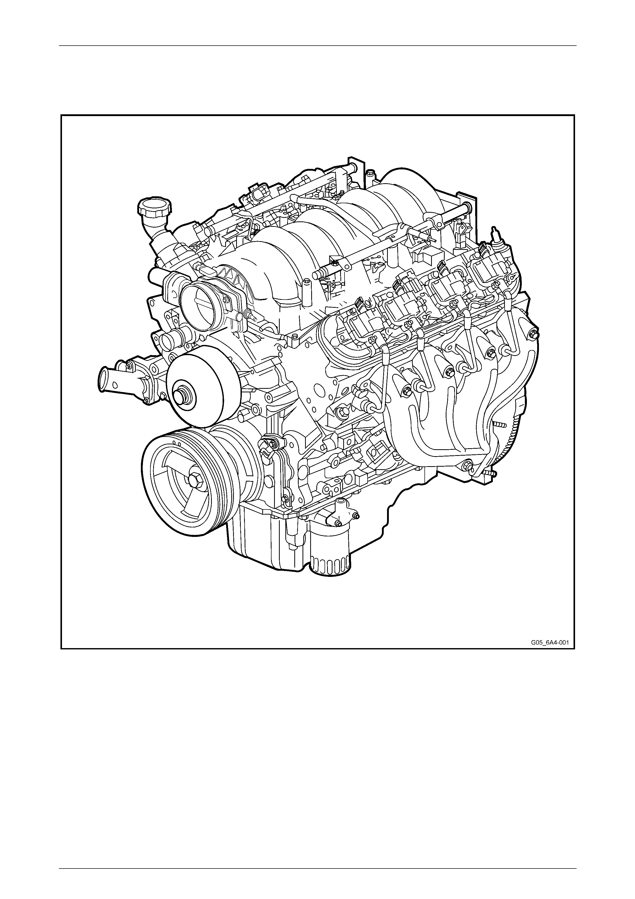
MY 2006 VZ vehicles are fitted with a 6.0 litre GEN IV V8 engine. The GEN IV engine is based on the previous GEN III
engine and features many revisions, enhancements and larger displaceme nt.
Cylinder layout is 1, 3, 5, and 7 for the left-hand bank an d 2, 4, 6 and 8 for the right-hand bank, with a firing order of 1-8-
7-2-6-5-4-3. The engine has a compression ratio of 10.4:1.
Two knock sensors are attached externally, one between cylinders 3 and 5 for the left bank and one between cylinders 4
and 6 for the right bank, behind the exhaust manifolds. The camshaft sensor is attached to the engine front cover and a
reluctor incorporated into the camshaft timing gear. A Manifold Absolute Pressure Sensor is fitted to the front of the
intake manifold. For further information relating to engine management sensors fitted to the GEN IV V8 engine, refer to
Section 6C4 Engine Management – GEN IV V8.
Engine throttle control is achieved by an electronic throttle body, which is controlled through the engine management
system, refer to Section 6C4 Engine Management – GEN IV V8.
NOTE
Unless noted otherwise, the information
contained in this Section is appropriate for both
manual and automatic transmission vehicles.
1.1 AWD Vehicles
To accommodate the AWD drivetrain assemblies, a different oil pan assembly is fitted which has a provision for the front
driveshaft. Unique service operations for AWD are included in this Section, specifically those for the oil pan, oi l and filter
change, and engine removal and reinstallation procedures.
Engine Mechanical Page 6A4–9
Page 6A4–9
1.2 Engine Views
Engine View Left-hand Side
Figure 6A4 – 1
Engine Mechanical Page 6A4–10
Page 6A4–10
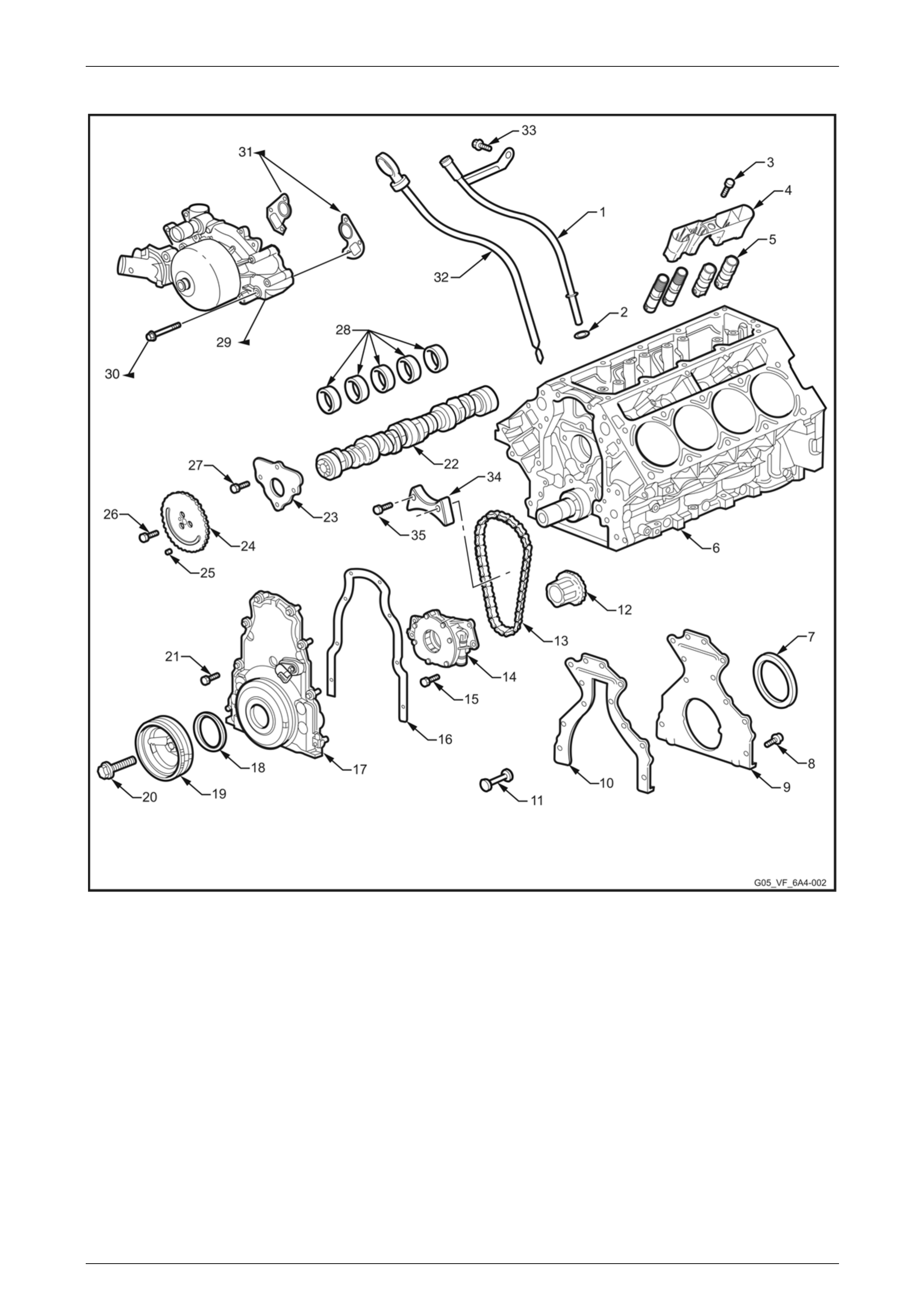
Lower Front
Figure 6A4 – 2
Legend
1 Oil Level Indicator Tube
2 Oil Level Indicator Tube O-ring
3 Valve Lifter Guide Attaching
Bolt, 4 places
4 Valve Lifter Guide, 4 places
5 Valve Lifter, 16 places
6 Engine Block
7 Crankshaft Rear Oil Seal
8 Engine Rear Cover Attaching
Bolt, 11 places
9 Engine Rear Cover
10 Engine Rear Cover Gasket
11 Engine Block Rear Oil Gallery
Plug
12 Crankshaft Sprocket
13 Camshaft Timing Chain
14 Oil Pump Assembly
15 Oil Pump Assembly Attaching Bolt, 4
places
16 Engine Front Cover Gasket
17 Engine Front Cover
18 Crankshaft Front Oil Seal
19 Crankshaft Balancer
20 Crankshaft Balancer Attaching Bolt
21 Engine Front Cover Attaching Bolt, 10
places
22 Camshaft
23 Camshaft Retainer
24 Camshaft Sprocket
25 Camshaft Sprocket Locating Pin
26 Camshaft Sprocket Attaching Bolt
27 Camshaft Retainer Attaching Bolt, 4
places
28 Camshaft Bearings
29 Coolant Pump
30 Coolant Pump Attaching Bolt, 6 places
31 Carrier Gaskets – Coolant Pump
32 Oil Level Indicator
33 Oil Level Indicator Tube Attaching Bolt
34 Chain Dampener
35 Chain Dampener bolt, 2 places
Engine Mechanical Page 6A4–11
Page 6A4–11
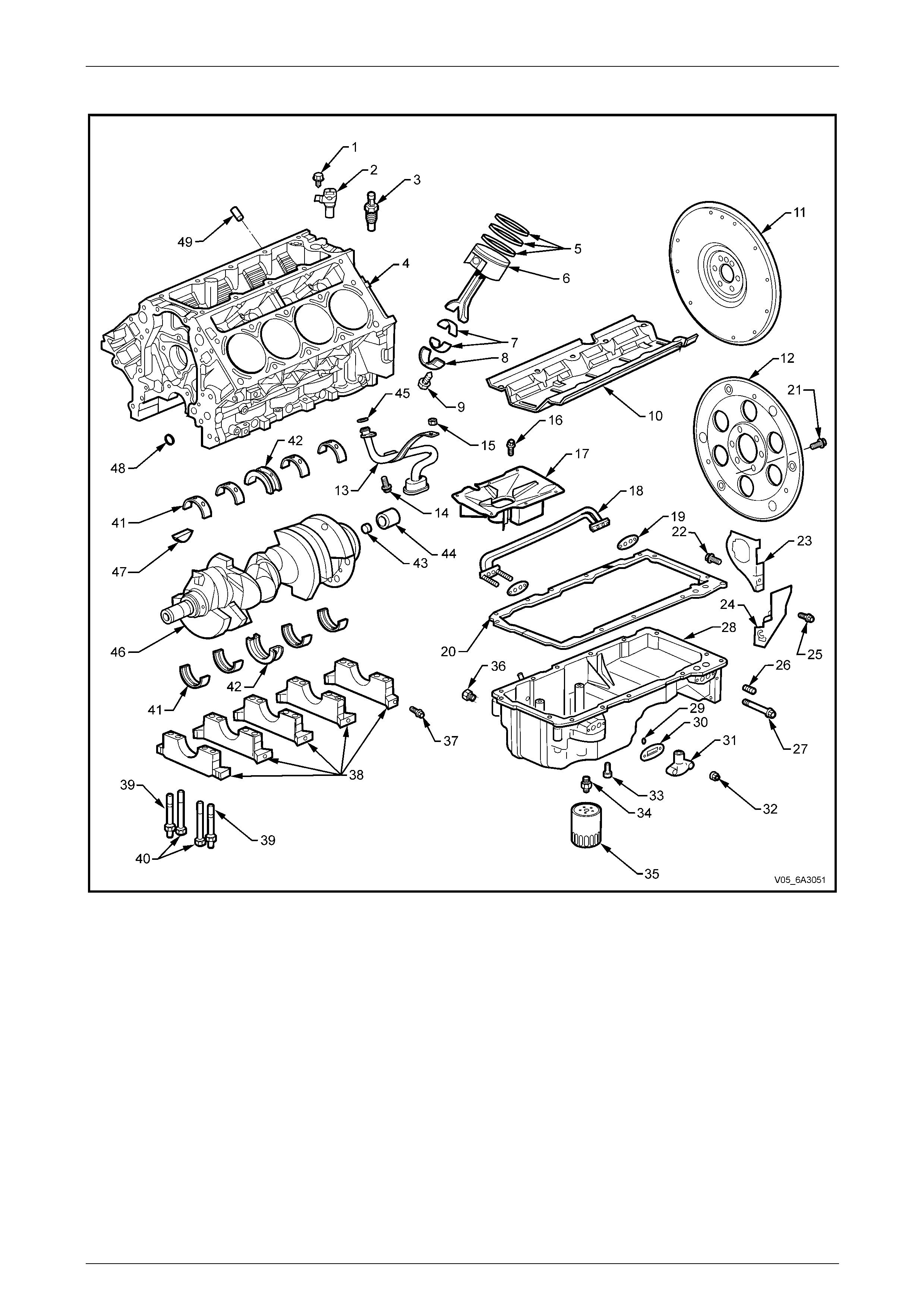
Lower Engine Assembly, Except AWD
Figure 6A4 – 3

Engine Mechanical Page 6A4–12
Page 6A4–12
Legend
1 Camshaft Position Sensor
Attaching Bolt
2 Camshaft Position Sensor
3 Oil Pressure Sensor
4 Cylinder Block
5 Piston Rings
6 Piston and Connecting Rod
Assembly
7 Connecting Rod Bearings
8 Connecting Rod Cap
9 Connecting Rod Attaching Bolt,
2 places
10 Crankshaft Oil Deflector
11 Engine Flywheel – Manual
Transmission.
12 Engine Flexplate – Automatic
Transmission.
13 Oil Pump Pick-up Screen and
Pipe
14 Oil Pump Pick-up to Pump
Attaching Screw
15 Oil Deflector and Oil Pump Pick-
up Attaching Nut
16 Oil Pan Baffle Attaching Bolt
17 Oil Pan Baffle
18 Oil Transfer Tube
19 Oil Transfer Tube Gasket, 2 places
20 Oil Pan Gasket
21 Engine Flywheel/Flexplate Attaching
Bolt, 6 places
22 Oil Pan Closeout Cover Attaching Bolt
(right-hand)
23 Oil Pan Closeout Cover (right-hand)
24 Oil Pan Closeout Cover (left-hand)
25 Oil Pan Closeout Cover Attaching Bolt
(left-hand)
26 Oil Pan Gallery Plug
27 Oil Pan Transfer Tube Attaching Bolt
28 Oil Pan
29 Oil Transfer Cover Stud O-ring, 2 places
30 Oil Transfer Cover Gasket
31 Oil Transfer Cover
32 Oil Transfer Cover Attaching Nut, 2
places
33 Oil Bypass Valve
34 Oil Filter Adaptor
35 Oil Filter
36 Oil Drain Plug
37 Crankshaft Main Bearing Cap Side
Attaching Bolt, 10 places
38 Crankshaft Main Bearing Caps
39 Main Bearing Cap Attaching Stud, 5
places
40 Main Bearing Cap Attaching Bolt, 5
places
41 Crankshaft Main Bearings
42 Crankshaft Main Thrust Bearings
43 Crankshaft Rear Plug
44 Manual Transmission Spigot Bearing
45 Oil Pump Pick-up O-ring
46 Crankshaft
47 Crankshaft Sprocket Key
48 Cylinder Block Front Oil Gallery Plug
49 Cylinder Block Plug, 3 places
Engine Mechanical Page 6A4–13
Page 6A4–13
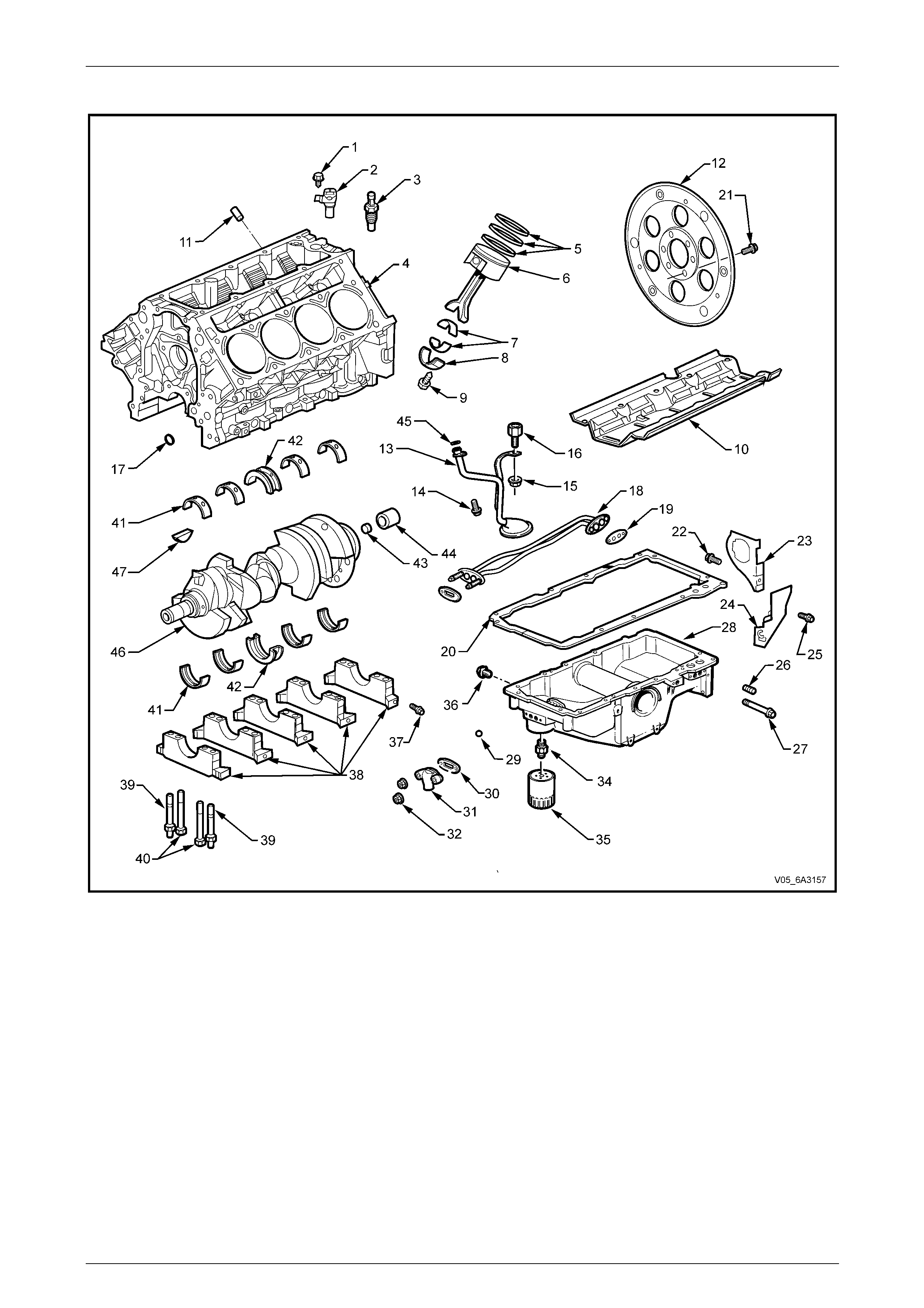
Lower Engine Assembly, AWD
Figure 6A4 – 4

Engine Mechanical Page 6A4–14
Page 6A4–14
Legend
1 Camshaft Position Sensor
Attaching Bolt
2 Camshaft Position Sensor
3 Oil Pressure Sensor
4 Cylinder Block
5 Piston Rings
6 Piston and Connecting Rod
Assembly
7 Connecting Rod Bearings
8 Connecting Rod Cap
9 Connecting Rod Attaching Bolt,
2 places
10 Crankshaft Oil Deflector
11 Cylinder Block Plug, 3 places
12 Engine Flexplate – Automatic
Transmission.
13 Oil Pump Pick-up Screen and
Pipe
14 Oil Pump Pick-up to Pump
Attaching Screw
15 Oil Deflector and Oil Pump Pick-
up Attaching Nut
16 Oil Deflector and Oil Pump Pick-up
Attaching Stud
17 Cylinder Block Front Oil Gallery Plug
18 Oil Transfer Tube
19 Oil Transfer Tube Gasket, 2 places
20 Oil Pan Gasket
21 Engine Flywheel/Flexplate Attaching
Bolt, 6 places
22 Oil Pan Closeout Cover Attaching Bolt
(right-hand)
23 Oil Pan Closeout Cover (right-hand)
24 Oil Pan Closeout Cover (left-hand)
25 Oil Pan Closeout Cover Attaching Bolt
(left-hand)
26 Oil Pan Gallery Plug
27 Oil Pan Transfer Tube Attaching Bolt
28 Oil Pan
29 Oil Transfer Cover Stud O-ring, 2 places
30 Oil Transfer Cover Gasket
31 Oil Transfer Cover
32 Oil Transfer Cover Attaching Nut, 2
places
33 Oil Bypass Valve
34 Oil Filter Adaptor
35 Oil Filter
36 Oil Drain Plug
37 Crankshaft Main Bearing Cap Side
Attaching Bolt, 10 places
38 Crankshaft Main Bearing Caps
39 Main Bearing Cap Attaching Stud, 5
places
40 Main Bearing Cap Attaching Bolt, 5
places
41 Crankshaft Main Bearings
42 Crankshaft Main Thrust Bearings
43 Crankshaft Rear Plug
44 Manual Transmission Spigot Bearing
45 Oil Pump Pick-up O-ring
46 Crankshaft
47 Crankshaft Sprocket Key
Engine Mechanical Page 6A4–15
Page 6A4–15
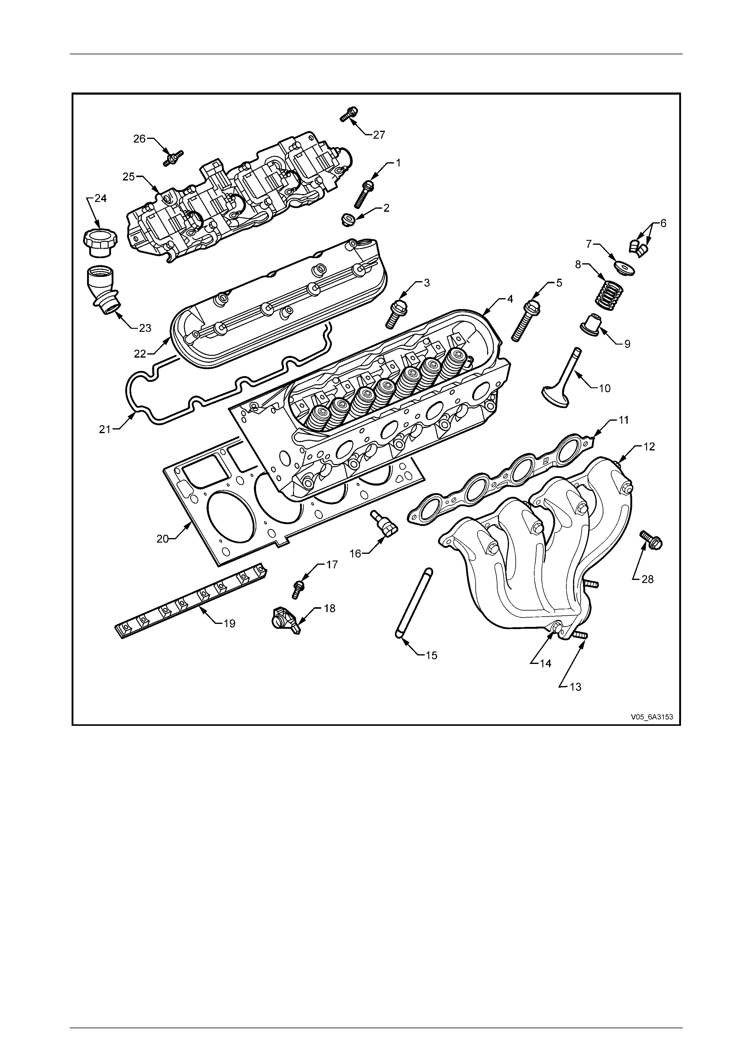
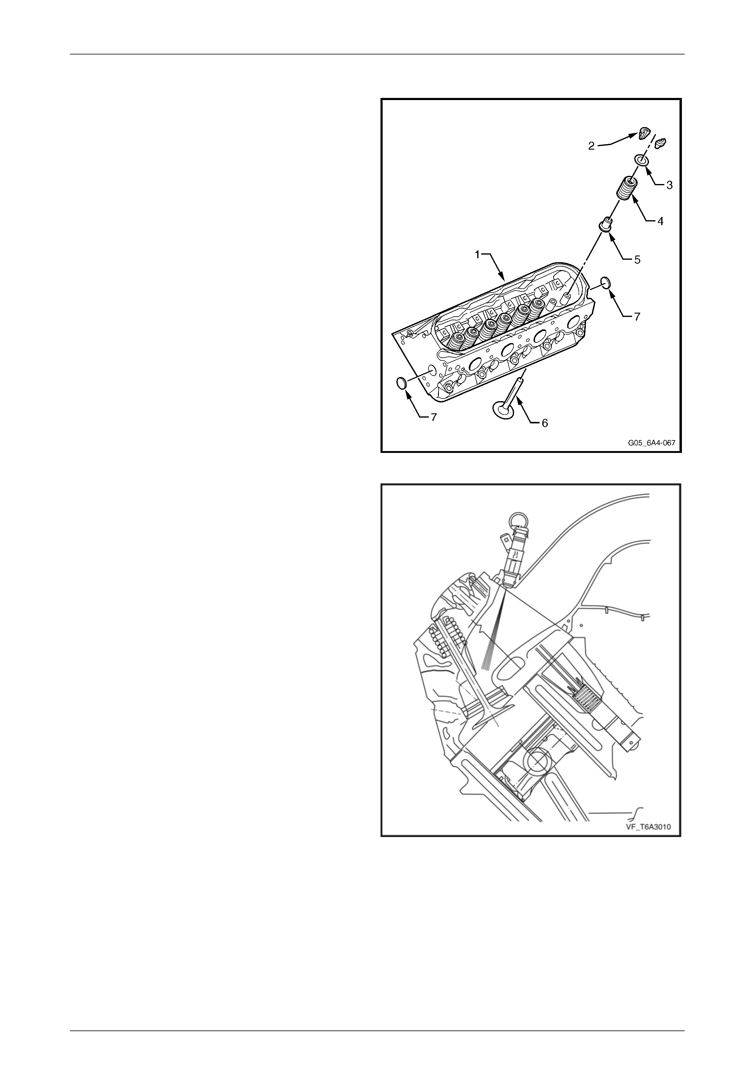
Cylinder Head
Figure 6A4 – 5
Legend
1 Valve Rocker Arm Cover Attaching Bolt, 4 places
2 Valve Rocker Arm Cover Grommet, 4 places
3 Cylinder Head Bolt (M8), 5 places
4 Cylinder Head
5 Cylinder Head Attaching Bolt (M11), 10 places
6 Valve Stem Collets
7 Valve Spring Cap
8 Valve Spring
9 Oil Seal Incorporating the Valve Spring Shim
10 Valve
11 Exhaust Manifold Gasket
12 Exhaust Manifold Assembly
13 Exhaust Manifold to Exhaust Pipe Flange Attaching Stud
14 Exhaust Manifold Heat Shield Attaching Bolt
15 Pushrod, 8 places
16 Coolant Temperature Sensor
17 Valve Rocker Arm Attaching Bolt
18 Valve Rocker Arm
19 Valve Rocker Arm Pivot Support
20 Cylinder Head Gasket
21 Valve Rocker Arm Cover Gasket
22 Valve Rocker Arm Cover
23 Oil Fill Tube
24 Oil Fill Tube Cap
25 Ignition Coil and Bracket Assembly
26 Ignition Coil Bracket Assembly Attaching Stud, 7 places
27 Ignition Coil Bracket Assembly Attaching Screw. (Rear on
each side)
28 Exhaust Manifold Attaching Bolt, 6 places
Engine Mechanical Page 6A4–16
Page 6A4–16
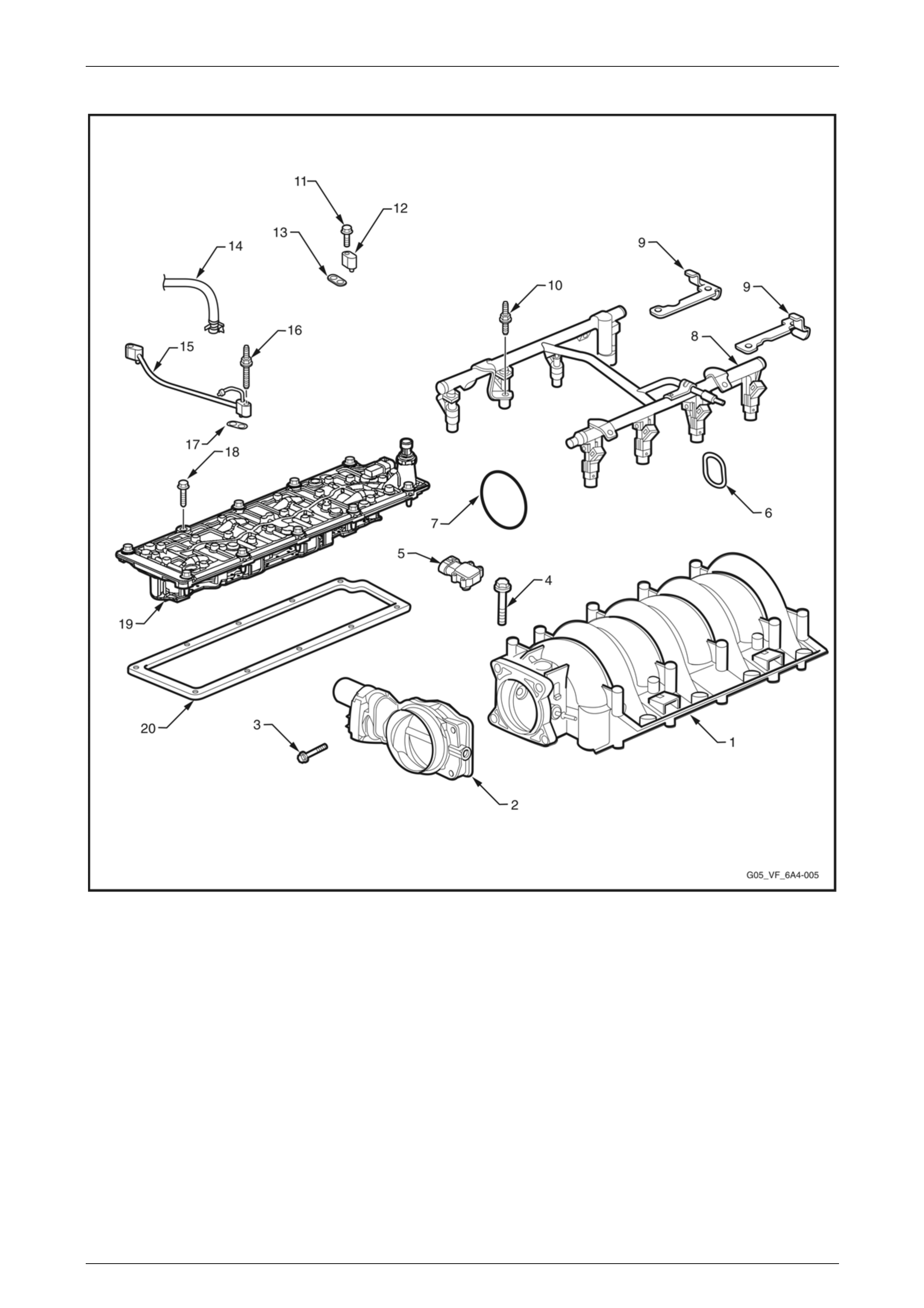
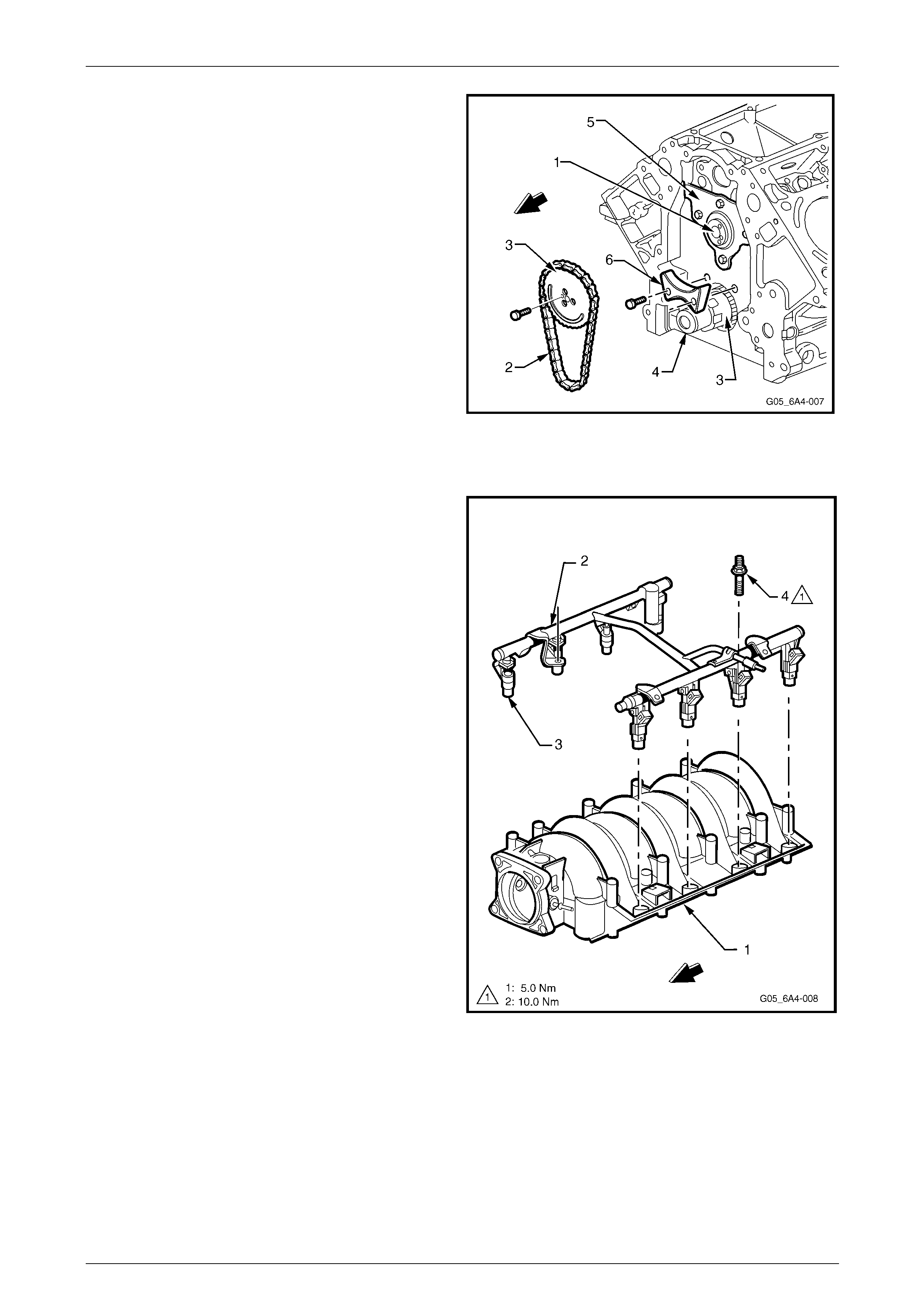
Intake Manifold
Figure 6A4 – 6
Legend
1 Intake Manifold
2 Throttle Body
3 Throttle Body Bolt, 4 places
4 Intake Manifold Bolt, 10 places
5 Manifold Absolute Pressure (MAP) Sensor
6 Intake Manifold Gaskets, 8 places
7 Throttle Body O-ring
8 Fuel Rail
9 Fuel Rail Stop Brackets
10 Fuel Rail Stud, 4 places
11 Vapour Vent Tube Bolt, 2 places
12 Vapour Vent Cover, 2 places
13 Vapour Vent Cover Gasket, 2 places
14 Vapour Vent Hose
15 Vapour Vent Tube
16 Vapour Vent Tube Stud
17 Vapour Vent Tube Gasket
18 Valley Cover Bolt, 11 places
19 Valley Cover
20 Valley Cover Gasket
Engine Mechanical Page 6A4–17
Page 6A4–17
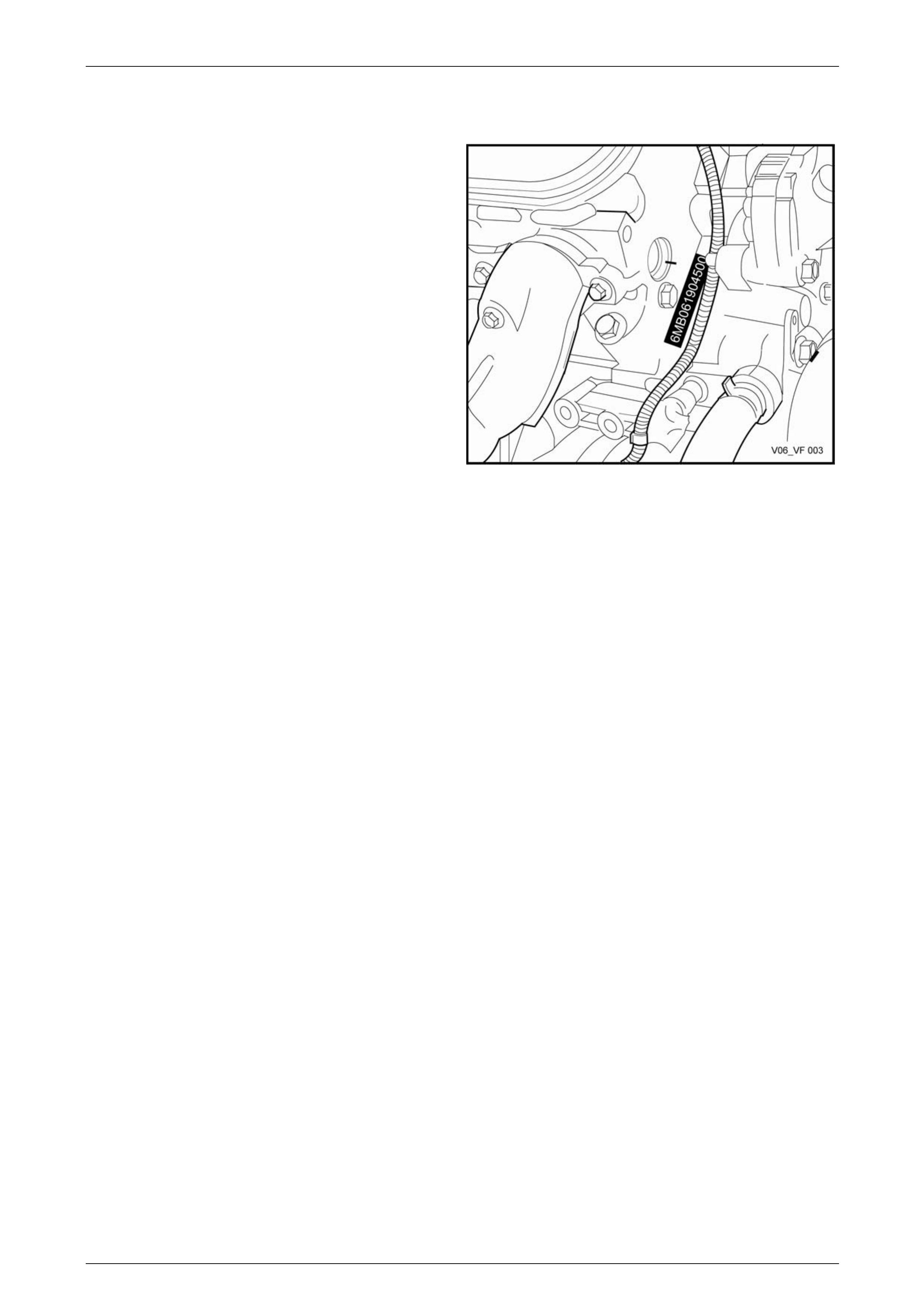
1.3 Engine Serial Number
The engine serial number is stamped on the right-hand side
at the front of the engine cylinder bl ock. The number is
prefixed by two letters. As an example, (VF) is used.
The following is a breakdown of the engine numbering
system using 6MB06190450 0 as an example;
• The first two numbers, 06 = 2006 i ndicates the engine
model year.
• The next three numbers, 190 i s the Julian date, which
is the day of the year the engine was manufactured.
• The next four numbers are the daily sequential build
number.
Figure 6A4 – 7
Engine Mechanical Page 6A4–18
Page 6A4–18
1.4 Engine Construction
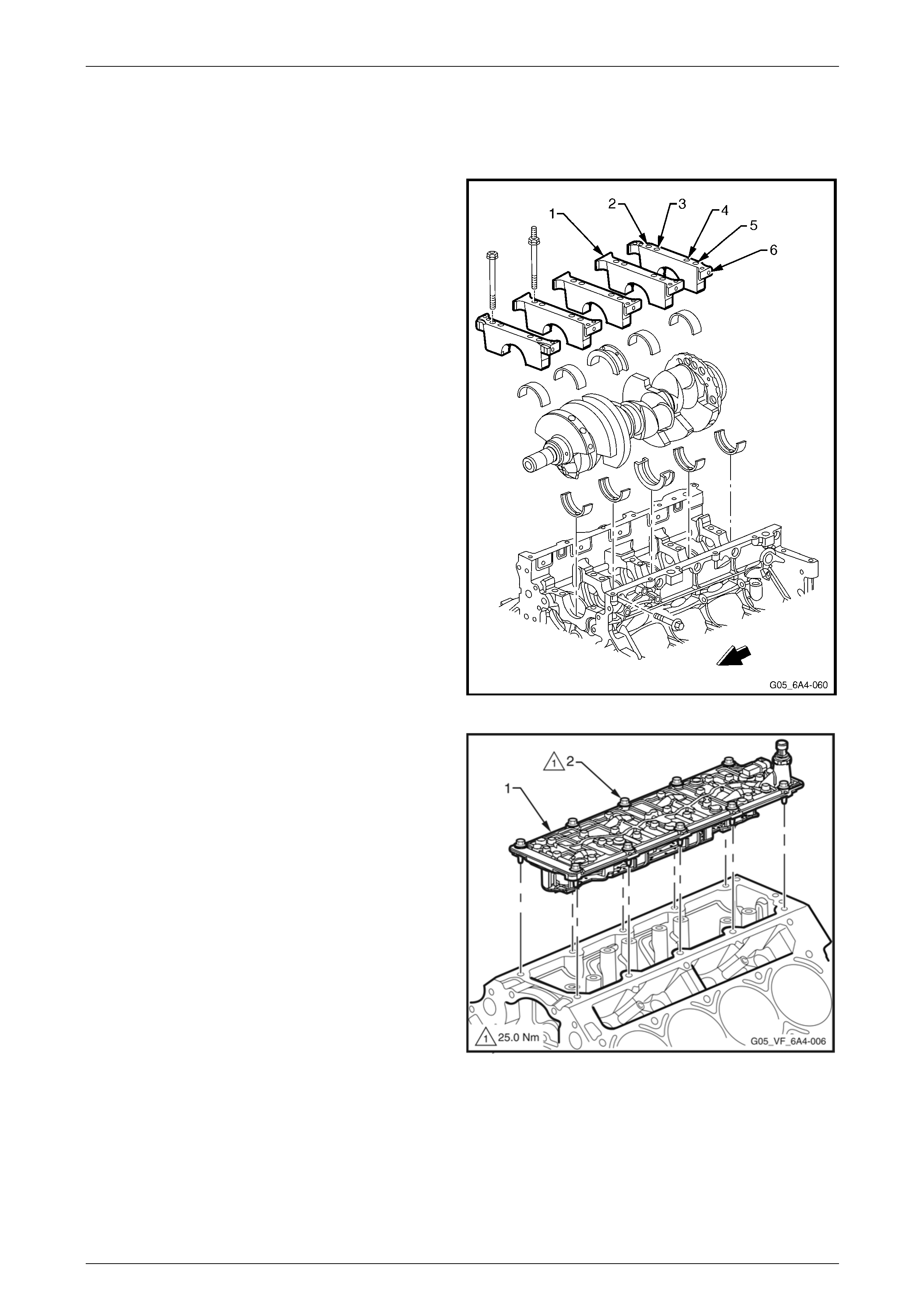
Cylinder Block
The engine cylinder block is a cam-in-block, deep skirt,
90° V configuration with five crankshaft bea ring caps,
manufactured from forged powdered metal. The engine
block is aluminium with cast-in-place cast iron cylinder bore
liners. The five cross-bolted cr ankshaft bearing caps each
have four vertical M10 (2, 3, 4, and 5) and two horizontal
M8 (1 and 6) mounting bolts. The cylinder bore must not
be bored and only cylinder bore honing is permitted.
The crankcase skirt length, bearing cap width, deck width
and upper rails have been optimised for strength using finite
element analysis.
The camshaft is supported by five camshaft bear ings
pressed into the block.
Figure 6A4 – 8
A structural die cast aluminium valley cov er (1) is attached
to the block using 11 M6 bolts (2). Having a closed valley
area prevents hot oil from contacting the lower surface of
the intake manifold. This allo ws cooler air to enter the
cylinders.
The cylinder block incorporates enclosed valve lifter bores
under each cylinder head that results in a mo re stiff
structure with quieter operation.
Overall, the cylinder block construction weighs 48% less
than an equivalent cast iron block. This structural d esig n
combined with the aluminium cylinder heads results in a
lightweight engine with unique stiffness.
Figure 6A4 – 9
Engine Mechanical Page 6A4–19
Page 6A4–19
Cylinder Heads
The cylinder head assemblies are cast aluminium with
powdered metal valve guides and valve seats pressed into
the cylinder head casting.
The intake and exhaust ports are identica l fo r each cylinder,
ensuring a balanced airflow distribution for balanced
combustion.
The cylinder head is attached to the cylinder block using 10
M11 and five M8 bolts, with the M11 bolts being a deep
threaded arrangement. This arrangement reduces distortion
of the cylinder bore, which then allows low friction pistons
and piston rings to be used for improved fuel consumption.
Cylinder head gaskets are a laminated steel type and
feature stainless steel PTFE coated flang es and lacing.
Legend
• Cylinder Head (1)
• Valve Stem Collets (2)
• Valve Spring Cap (3)
• Valve Spring (4)
• Valve Stem Oil Seal/Shim Combination (5)
• Valve (6)
• Cylinder Head Core Plugs (7)
Figure 6A4 – 10
The additional hei ght of the intake ports are designed to
enhance fuel injector targeting. As the air flows down to the
valve guide, the port narrows then widens to the size of the
intake valve seat.
Figure 6A4 – 11

Engine Mechanical Page 6A4–20
Page 6A4–20
Valve Train
Motion is transmitted from the camshaft (1) to the hydraulic
valve lifters (2) and the tubular pushrod (3) then to the
rocker arms (4), which pivot and in doing so, control the
opening and closing of the valves.
Hydraulic valve lifter guides (5) mounted within the cylinder
block position and retain the hydraulic roller valve lifters
within the cylinder block.
The valve rocker arms for each bank of the cylinders are
mounted on pivot supports. The pivot supports are attached
to the cylinder head by a bolt. Valve lash is adjusted
automatically with oil pressure through each cycle of the
hydraulic valve lifters.
Both the inlet and exhaust valves are angled at 15° to the
cylinder bore centreline. This allows a shallow combustion
chamber and a flat top piston to be used resulting in a
compression ratio of 10.1:1.
Both the exhaust and intake valve seat angle s are at 46°
with an intake valve head diameter of 50.8 mm and exhau st
valve head diameter of 39.4 mm. Figure 6A4 – 12
The valve springs are conical in shap e and are made from chromium silicone spring steel. T he reduced diameter end
coils allow a smaller diameter, lower mass, steel spring retainer to be used with single bead valve stem collets. This
spring design also reduces spring mass and coupled with the increased stiffness in the valve train, results in a reduction
in the valve spring pre-load, thereby reducing friction and valve train noise.
The rocker arms are manufactured from inve stment cast steel and have a ratio of 1.7:1. This allows a lower cam lobe lift
resulting in lower valve train loading and less noise.
The valve rocker arm covers are cast aluminium an d use a pre-moulded silicone gasket for sealing. T here are four
individual ignition coils mounted to each rocker cover. Incorporated into the rocker covers is the oil fill tube and the fitting
for the fresh air hose, which is part of the Positive Crankcase Ventilation (PCV) s ystem.
Crankshaft
The crankshaft (1) is manufactured from nodular cast iro n
and is supported by five main bearings. Each main bearing
cap is attached to the cylinder block by six bol t s, two of
which are attached from the side. The main bearing caps
are machined with the cylinder block for cor rect alignment
and clearance and must be kept in their original location
when servicing.
A 24X reluctor ring (2) is attached to the rear of the number
eight crankshaft counter weight. The reluctor ring is not
serviced separately.
Thrust is controlled by a thrust bearing at the centre (No. 3)
main bearing. This location is used to reduce the expansion
differences between the cast iron crankshaft and the
aluminium cylinder block.
The crankshaft has a 25.4 mm hole drilled through the
centre of the main journals 2, 3, 4 and 5. Apart from a
reduction in crankshaft weight, this also enhances engine
breathing at low speeds.
Figure 6A4 – 13
Engine Mechanical Page 6A4–21
Page 6A4–21
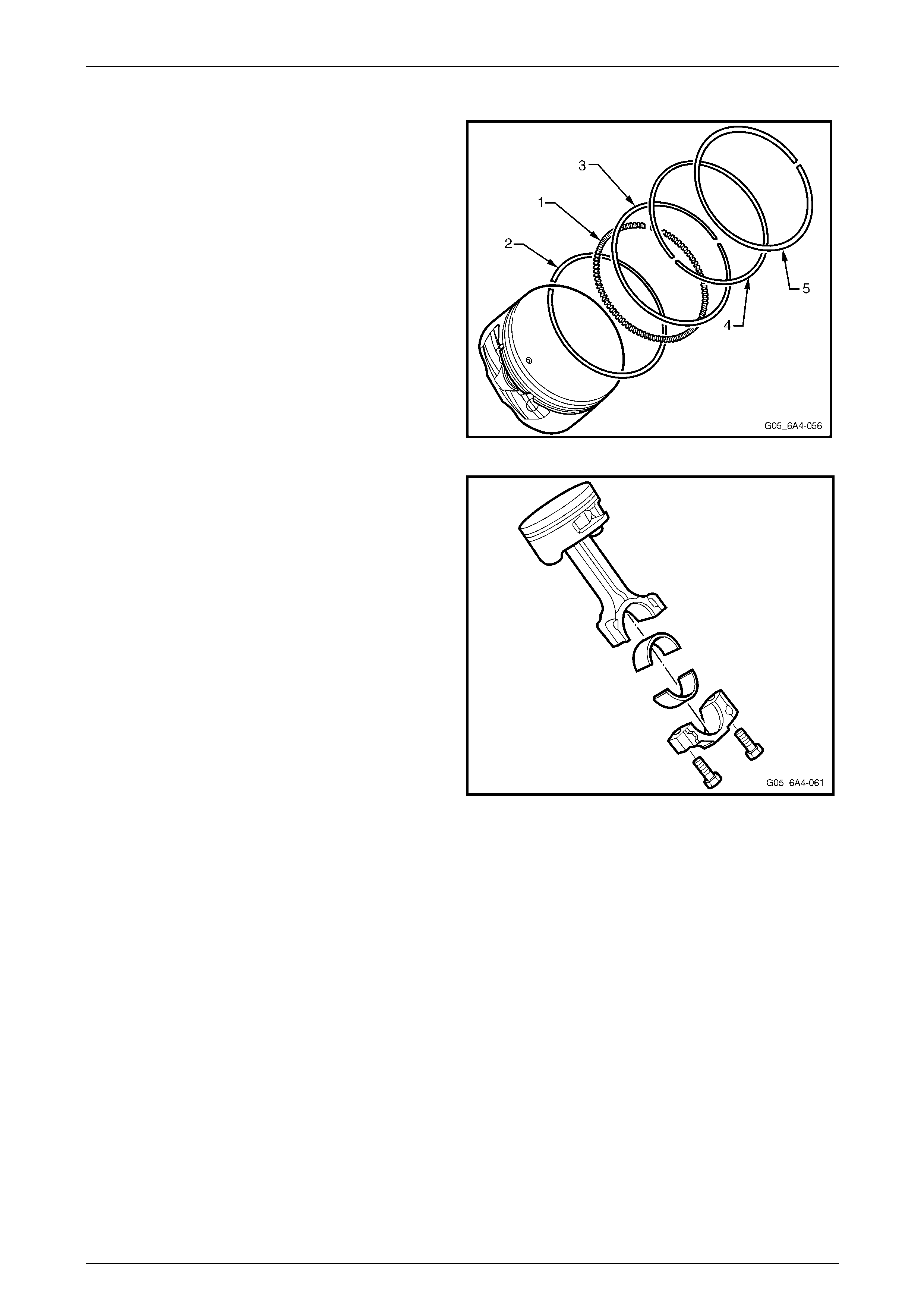
Piston and Connecting Rod
The cast aluminium pistons are fitted with t wo compression
rings (4, 5) and one oil control ring ass embly (1,2,3). The
piston rings are a thin low friction des ign. The top ring is
located close to the top of the piston crown to reduce
hydrocarbon emissions and blow-by. The pistons are a lo w
friction lightweight design with a flat top and a barrel shaped
skirt.
The piston pins are chromium steel and are a floating fit in
the piston and the connecting rod. The piston pin is retained
by a circlip in each side of the piston.
Figure 6A4 – 14
The connecting rods are forged powdered metal. The
connecting rod cap is separated during the manufacturing
process using the fracture method. This creates a stronger
visually seamless rod to cap union. The reassembled rod is
then machined for the correct clearance.
A 0.25 mm oversize piston and piston ring set is available
for service should cylinder honing be re quired. Boring of the
cylinder is not permitted.
Figure 6A4 – 15
Camshaft and Drive
The camshaft is machined from a steel billet and is supported by five bearings pressed into the cylinder block. It also has
a machined camshaft sensor reluctor ring incorporated between the fourth and fifth bearing journals and has a 17 mm
hole drilled down its length to reduce weight. The intake and exhaust cam lobes have slow velocity closing ramps to
reduce valve train noise.
Engine Mechanical Page 6A4–22
Page 6A4–22
The camshaft (1) is driven by a traditional 9.52 mm pitch
roller chain (2) and powdered metal timing sprockets (3)
mounted to the front of the camshaft and crankshaft (4). A
retaining plate (5) mounted to the front of the engine block
maintains the camshaft location.
The crankshaft sprocket is splined internally and drives the
oil pump.
A timing chain dampener (6) is used to red uce chain noise
and resonance and is attached to the eng ine block just
above the crankshaft timing gear.
Figure 6A4 – 16
Intake Manifold
The intake manifold (1) is a one-piece composite design that
incorporates metal threaded inserts for attaching the fuel rail
(2) and the throttle body.
The intake manifold is sealed to the cylinder heads by eight
separate non-reusable si licone gaskets, which press into the
grooves of the intake housing.
The electronic controlled throttle body assembly bolts to the
front of the intake manifold. The throttle body is sealed to
the intake manifold by a one piece push in place silicone
gasket.
The fuel rail assembly has eight separate fu el injectors (3)
and is attached to the intake manifold by four studs (4). The
injectors are seated in their individual manifold bores with O-
ring seals to provide sealin g.
Fuel rail stop brackets are positioned both sides at the rear
of the fuel rail and are attached by the intake manifold
attaching bolts, refer to Figure 6A4 – 104.
There are no coolant passage s within the intake manifold.
The Manifold Absolute Pressure (MAP) sensor is instal led in
the front of the Intake manifold and is sealed by an O-ring
seal, refer to Section 6C3-3 Engine Manage m ent Service
Operations.
Figure 6A4 – 17
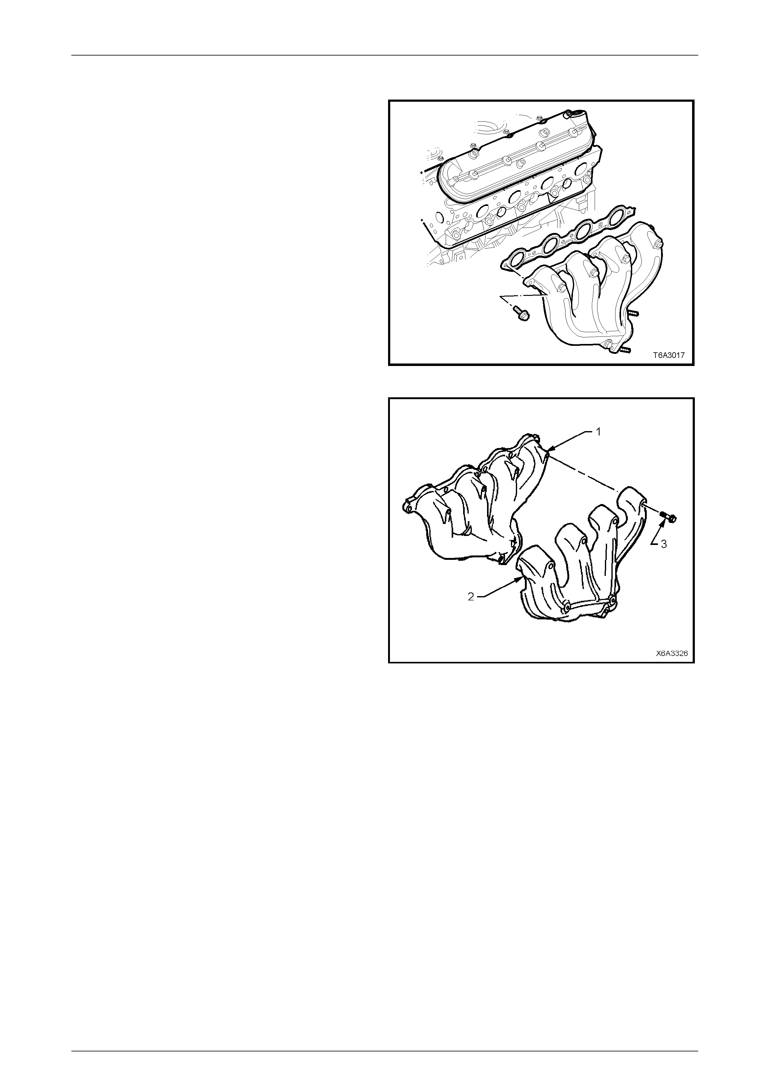
Engine Mechanical Page 6A4–23
Page 6A4–23
Exhaust Manifold
The exhaust manifolds are one piece, high temperature
silicone molybdenum cast iron manifold.
The exhaust manifolds dir ect the e xhaust gases from the
combustion chambers to the exhaust system.
The exhaust manifolds are attached to each cylinder head
using six M8 bolts.
Figure 6A4 – 18
Each exhaust manifold (1) has an externall y mounted dual
wall heat shield (2) made of aluminised steel that is attached
to the manifold by five M6 bolts (3).
Figure 6A4 – 19
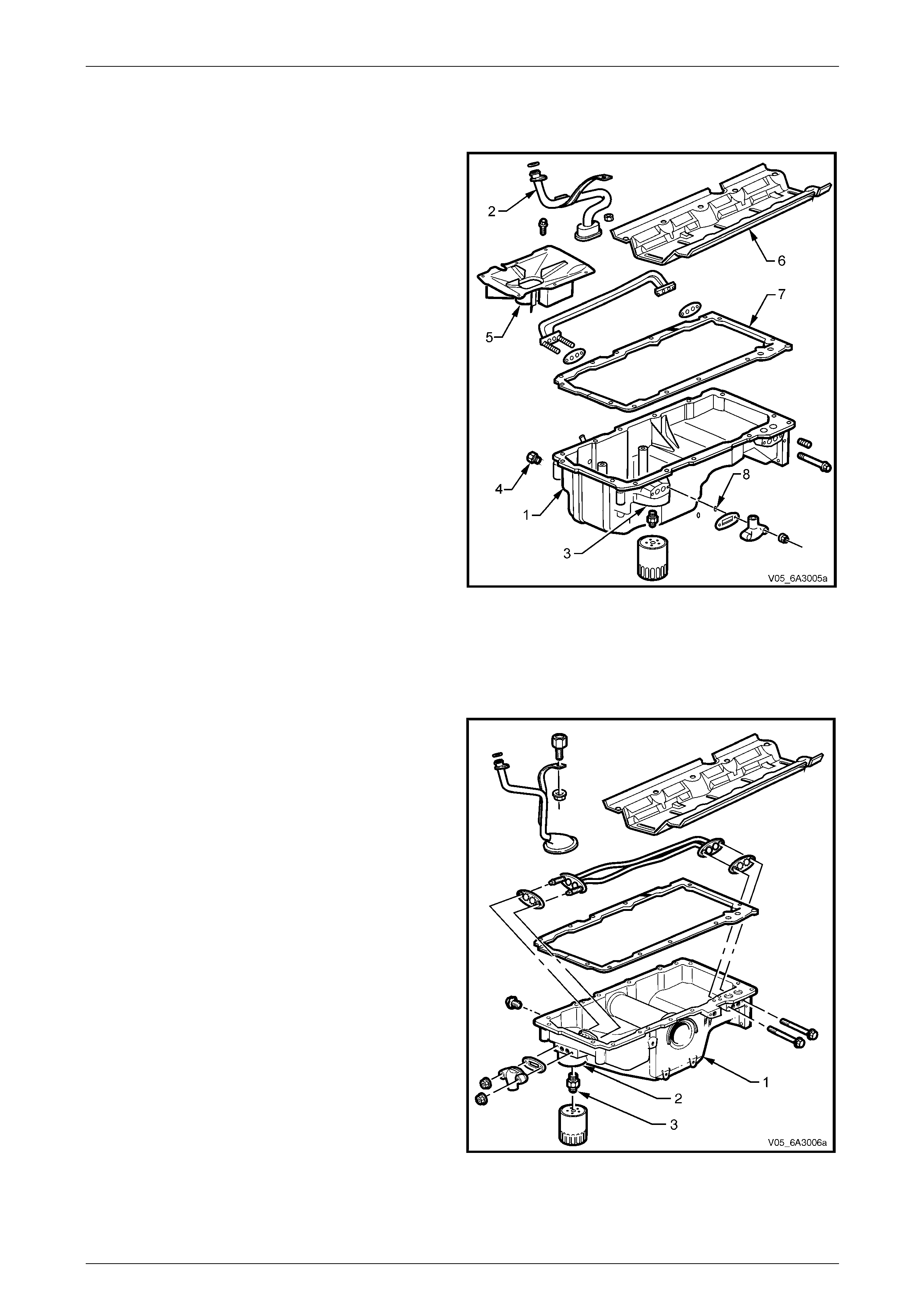
Engine Mechanical Page 6A4–24
Page 6A4–24
Oil Pan
Excluding AWD Vehicles
The cast aluminium oil pan (1) forms a structural part of the
Engine by providing a 360° mounting for the transmission,
whether it be manual or automatic.
Incorporated into the oil pan casting are cast-in dams.
These dams minimise oil migration during braking and
cornering manoeuvres an d assist in guiding oil to the pick-
up screen (2) via the strategically placed openings in the
dam walls.
Also incorporated in the oil p an casting is the oil filter
mounting boss (3), an opening for the drain plug (4) and a
stamped oil pan baffle (5). The oil pan baffle mainta ins an
area around the pick-up screen to prevent oil starvation and
aeration.
A crankshaft oil deflector (6) is attached to the main bearing
caps and controls windage, removes return oil from the
crankshaft and facilitates drain back, thus reducing aeration.
The oil pan gasket (7) is a controlled compression
aluminium carrier gasket with silicone used as the sealing
agent.
Two O-ring seals (8) are fitted to stop oil leaks along the
studs attaching the oil transfer cover to the oil pan.
Figure 6A4 – 20
AWD Vehicles
The engine oil pan fitted to AWD vehicles has undergone an extensive re -design process from the conventional oil pa n.
In addition to providing fixture points for the front final drive and bearing support assemblies, the oil filter a nd the oil
transfer tube have been relocated to the front of the oil pan.
The AWD cast aluminium oil pan (1) is an integra l part of the
Engine structure that creates a 360° mountin g for the
automatic transmission.
The oil filter mounting boss (2) is incorporated into the front
of the oil pan with the oil filter screwing onto the oil filter
adaptor (3).
Internally, the engine oil pan design results in an increased
engine oil capacity with some features retained from the
conventional oil pan.
These include:
• The crankshaft oil deflector is attached to the main
bearing caps and further improves the flow of return oil
by:
• Controlling windage
• Removing return oil from the crankshaft
• Facilitating the return oil drain back into the oil
pan
• Reducing engine oi l aeration
• Controlled compression al uminium carrier oil pan
gasket and is coated with a silicon e materia l as a
sealing agent.
Figure 6A4 – 21
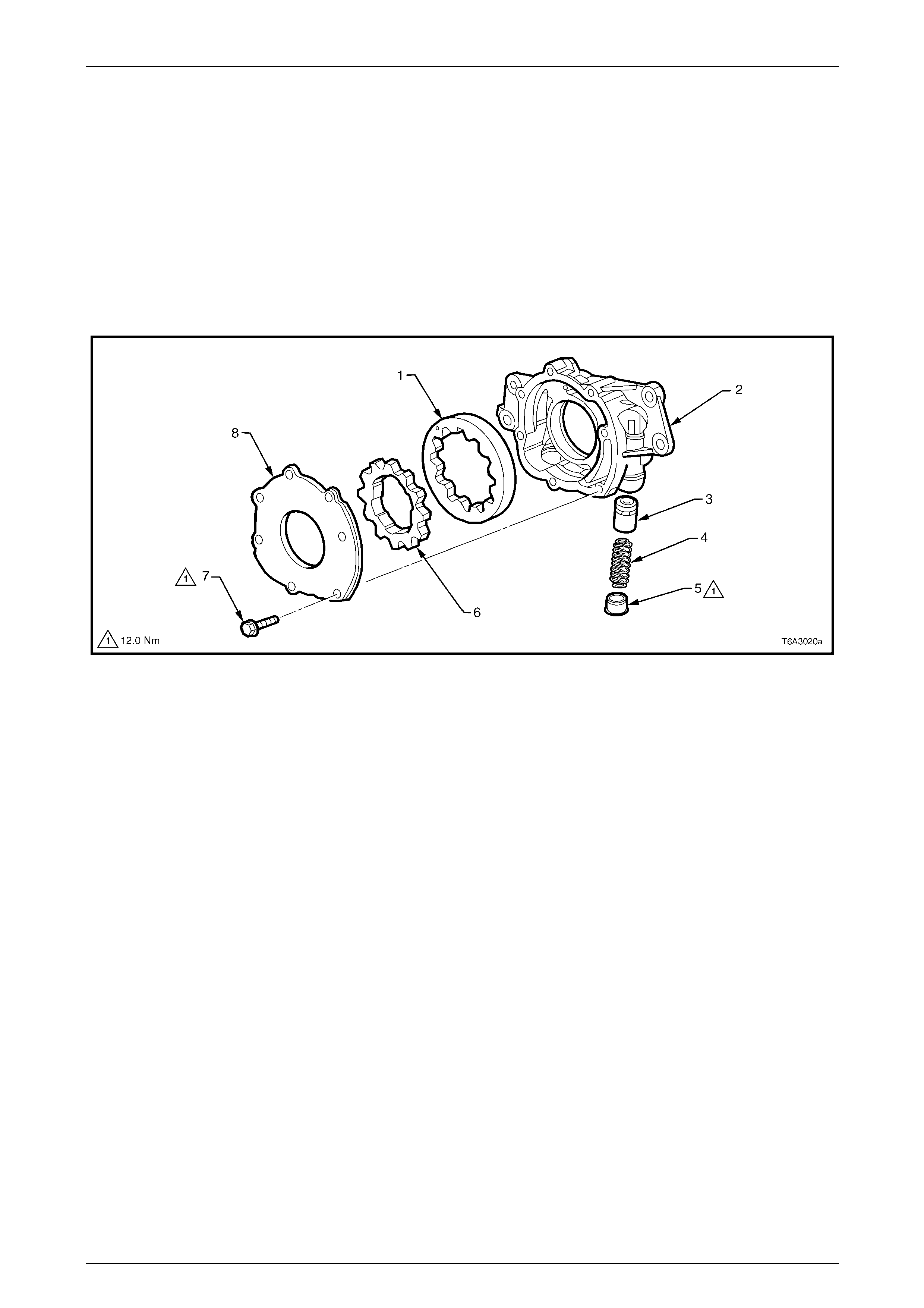
Engine Mechanical Page 6A4–25
Page 6A4–25
1.5 Engine Lubrication System
Oil pump
A Gerotor type oil pump assembly supplies the engine lubrication, refer to Figure 6A4 – 22. The pump is attached to the
front of the cylinder block and is driven directly by the crankshaft sprocket. The pump gears rotate and draw oil from the
oil pan sump through a pick-up screen and p ipe. Contained within the oil pump assembly is a pressure relief valve that
maintains oil pressure within a specified rang e.
Pressurised oil is directed thr ough the lower gallery to the full flow oil filter where harmful contaminants are removed.
Incorporated into the oil filter is a bypass valve, which allows oil to flow through the engine in the event the filter becomes
blocked.
The oil is pressurised as it passes through the pump and is then pumped through the cylinder block via the oil galleries,
refer to Figure 6A4 – 23.
Figure 6A4 – 22
Legend
1 Driven Gear
2 Oil Pump Housing
3 Pressure Relief Valve
4 Pressure Relief Valve Spring
5 Plug
6 Drive Gear
7 Cover Bolt, 7 places
8 Cover
Oil Flow
Oil is directed to the drilled upper main oil g al leries just above the camshaft assembly at the rear of the cylinder block,
refer to Figure 6A4 – 23. From there, oil is then directe d to the crankshaft and camshaft bear ings. Oil that has entered
the upper main oil galler ies also pressurises the valve lifter assemblies and is then pumped through the pushrods to
lubricate the valve rocker arms and valve stems. The crankshaft oil deflector directs oil returnin g to the pan back to the
sump, also refer to 2 Displacement on Demand (D oD)
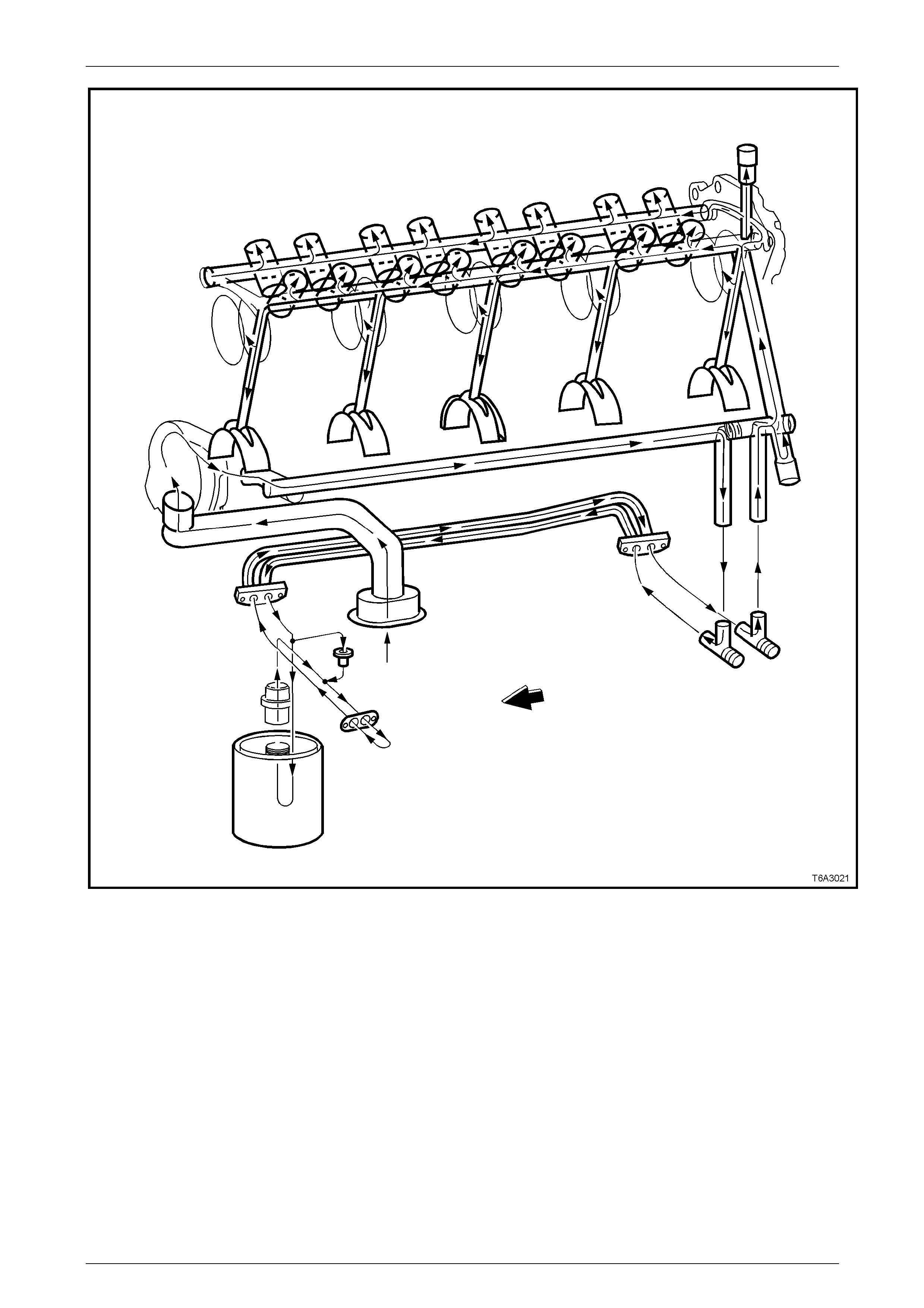
Engine Mechanical Page 6A4–26
Page 6A4–26
Figure 6A4 – 23
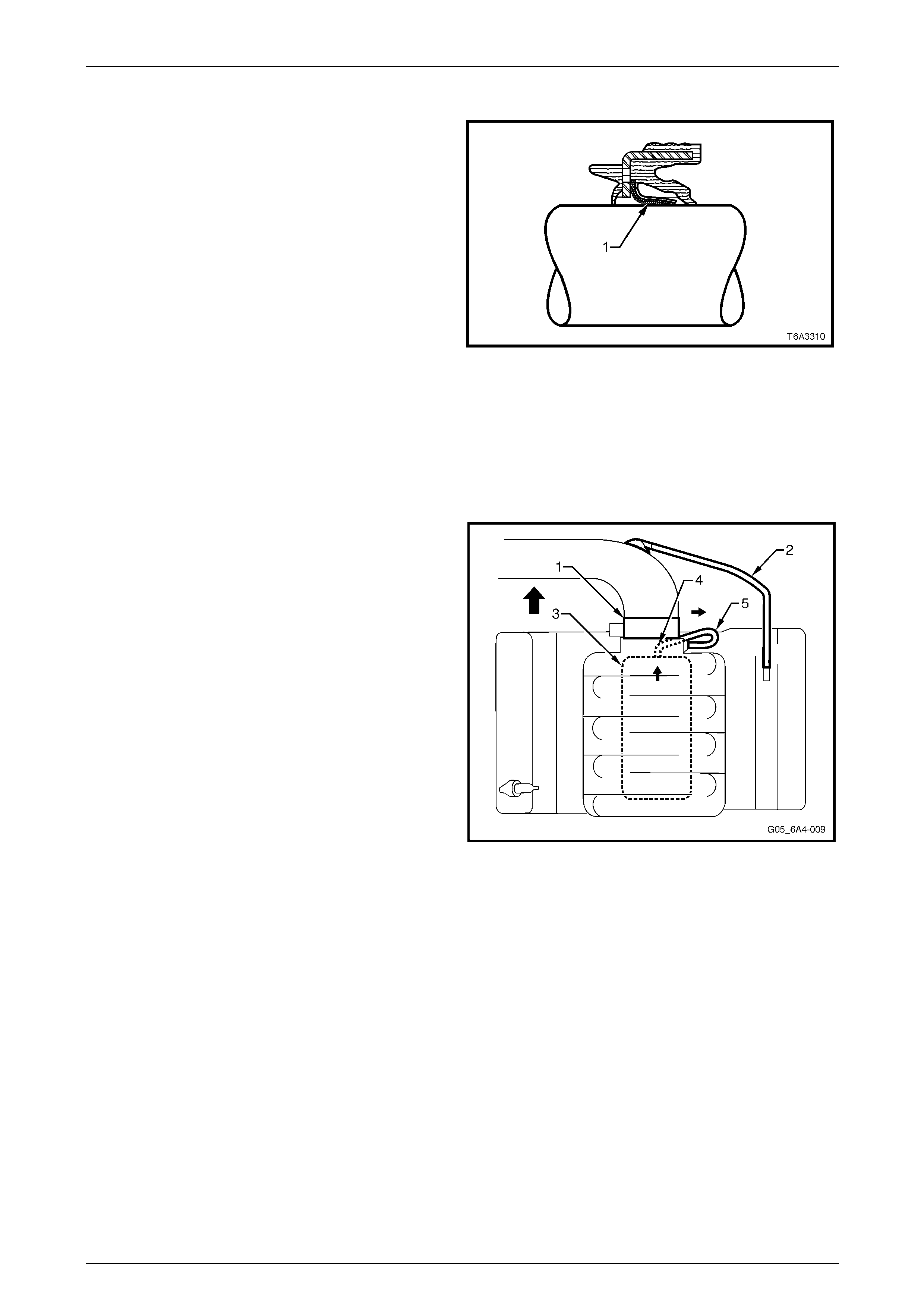
Engine Mechanical Page 6A4–27
Page 6A4–27
Oil Seals
The rear main oil seal is a multiple lip oil seal designed for
long life operation.
The seal includes a Polytetrafluoro ethylene (PTFE) Teflon
centre lip (1) to minimise rear main oil seal leaks. T he anti-
friction property of the PTFE reduces the chances of
choking or build-up of degraded oil on the lip causing the lip
to lift off the shaft resulting in a leak.
Similar to the rear main oil seal, the front crankshaft oil seal
also incorporates a PTFE lip.
The PTFE is actually deposited on the dry crankshaft seal
surface during initial operation by the heat generated from
the rotating shaft.
NOTE
Lubricant must not be applied to the PTFE seal
lip or the shaft on which it runs during installatio n
as this will prevent correct break-in of the seal.
The outside of the seal may be lubricated
sparingly for ease of installation.
Figure 6A4 – 24
Positive Crankcase Ventilation System
The crankcase ventilation s ys t em was developed to remove
the engine combustion blow-by vapours and minimise the
following:
• Crankcase pressure build-up
• Oil deterioration
• Oil consumption
• Evaporative/exhaust emissions
During normal idle and part throttle operation, filtered fresh
air is routed from upstream of the throttle body (1) blade to
the front of the right-hand rocker cover via the fresh air inlet
hose (2).
Blow-by gas (oil vapour) in the crankcase valley passes
through the oil separator (3) attached to the valley cover and
then flows through the fixed internal flow-restricting orifice
(4) within the valley cover then via the foul ai r hose (5). The
blow-by gas is directed from the valley cover right-hand
corner to the Intake manifold on the engine side of the
throttle plate.
Under heavy load operation and high engine speeds, a n
acceptable reverse flow condition may occur in the fresh air
inlet hose.
Figure 6A4 – 25
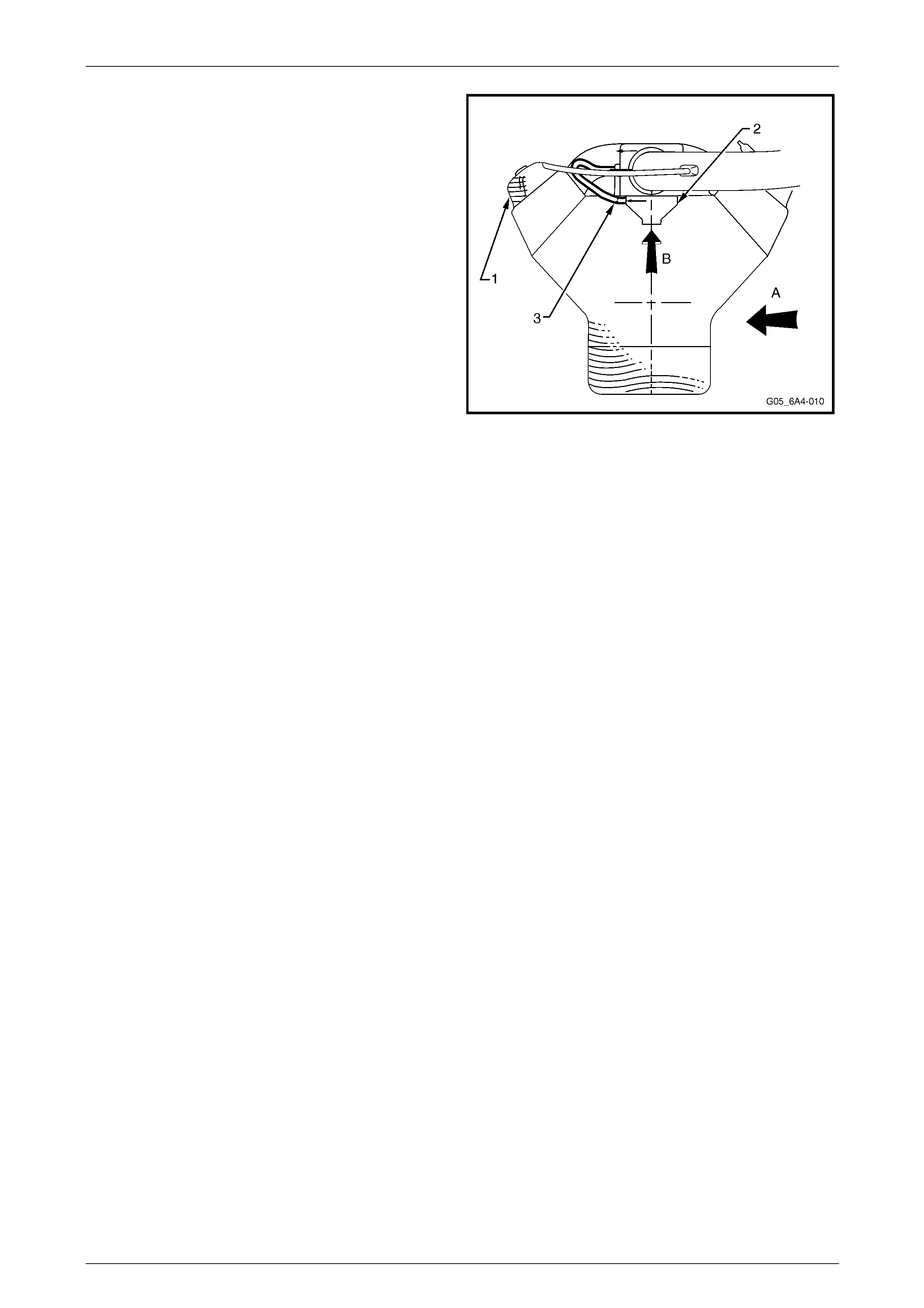
Engine Mechanical Page 6A4–28
Page 6A4–28
During sustained maximum lateral acceleration (A), the
outboard rocker cover may be overlo aded with oil (1). If the
blow-by gas is dra wn from the rocker cover as in previous
designs, oil may be ingested into the intak e manifo ld.
Instead of the blow-by gas be ing drawn from the rocker
cover, a high efficiency oil separator (2) in conju nction with
an internal flow-restricting orifice (3) is fitted under the valley
cover to draw the blow-by gas from the crankcase (B),
preventing oil from being ingestion during severe vehicle
cornering manoeuvres.
Figure 6A4 – 26

Engine Mechanical Page 6A4–29
Page 6A4–29
1.6 Service Notes
Cleanliness and Care
Throughout this Section, correct cleaning and protection of machined surfaces and friction areas is a vital part of the
service procedure and is considered to be a standard workshop practice even if it is not specifically stated. When any of
the internal engine parts are serviced, care and cleanliness is important.
When components are removed for service, they should be marked, organised or retained in a specific order for
reassembly. Further information, refer to Separating Comp onents. At the time of reinstallation, components should be
installed in the same location and with the same mating surface as when removed.
Any engine is a combination of many machined, honed, polished and lapped surfaces with tolerances that are measured
in hundredths of millimetres. These surfaces should be covered or protected to avoid component damage.
A liberal coating of clean engine oil should be applied to all friction areas durin g compo nent assembly. Proper lubrication
of engine components dur ing assembly will protect and lubricate friction surfaces during the initial engine start-up.
Replacing Engine Gaskets
Re-using Gaskets and Applying Sealant
Do not re-use any gasket unless specified in the service procedure. Gaskets that can be re-used will be identified within
the procedure.
Do not apply sealant to any gasket or sealing surface unless instructed in the service procedure and if instructed, use
only the recommended sealant or the equivalent as stated.
Cleaning Gasket Surfaces
Remove all gasket and sealing materials from aluminium components using a plastic or wood scraper. Do not use any
other method or technique to remove sealant or gasket material from a part. Care must be used to avoid gouging or
scraping the sealing surfaces.
Do not use abrasive pads, sand paper, or power tools to clean the gasket surfaces. These methods of cleaning can
cause damage to the component sealin g surfaces. Abrasive pads also produce fine grit the oil filter cannot remove from
the oil. This grit is abrasive and can cause internal engine damage.
Assembling Components
When assembling com ponents, use only the sealant spec ified or equivalent as recommended in the service procedure.
When applying sealant to a component, apply the amount specified in the service proced ure. Do not allow the sealant to
enter into any blind threaded hol es as this can cause the bolt to bottom out and prevent it from clamping properly or
cause component damage when tightened. Sealing surfaces should be clean and free of debris or oil.
Specific components such as valve stem oil seals ma y re quire lubrication during assembly. Components requirin g
lubrication will be identified in the service procedure.
Ensure all fasteners are tightene d to the correct torque specification.
Room Temperature Vulcanising (RTV) and Anaerobic Sealers
NOTE
• A number of sealant types are commonly
used in engines. Examples are; Room
Temperature Vulcanising (RTV) sealer,
anaerobic gasket eliminator sealer, anaerobic
thread sealant and pipe joint compound.
• The correct sealant and am ount must b e us ed
in the specified location to prevent oil and
coolant leaks.
• Do not interchange the different types of
sealers and use only the specified sealer or
equivalent as recommended in the service
procedure.
Pipe Joint Compound
Pipe joint compound is a pliable sealer that does not completely harden. This type of sealer is used where two non-rigid
parts (such as pressed steel and machined s urfaces) are assembled together.
Do not use pipe joint compound in areas where extreme temperatures are expected. These areas include exhaust
manifold to cylinder head or other surfaces where a gasket eliminator is specified.
Follow all safety precautions a nd directions for use that are on the container. To remove the sealant or the gasket
material, refer to Replacing Engine Gaskets above.

Engine Mechanical Page 6A4–30
Page 6A4–30
Apply pipe joint compound to a clean and dry surface. Use a bead size or quantity as specified in the procedure and run
the bead to the inside of any bolt holes. Do not allow the sealer to enter any blind threaded holes as it may cause the
fastener to bottom out and prevent the fastener from clamping correctly or cause component damage when the fastener
is tightened. Tighten fasteners to the correct torque specification.
Examples of locations where a pipe sealant type material such as Loctite 565 or equivalent is to be used are:
• Cylinder block coolant an d oil gallery plugs
• Oil pressure sensor threads
• Cylinder block oil pan surface
RTV Sealer
Room Temperature Vulcanising (RTV) sealant hardens when exposed to air. This type of sealer is used where two non-
rigid parts such as the intake manifold and the cylinder head are assembled together.
Do not use RTV sealant in areas where extreme temperatures are experienced. These areas include exhaust man ifold to
cylinder head or other surfaces where a gasket eliminator is specified.
Follow all safety precautions and directions for use that are on the container.
To remove the sealant or the gasket material, refer to Replacing Engine Gaskets.
Apply RTV to a clean and dry surface and use a bead size as specified in the service procedure. Run the bead to the
inside of any bolt holes. Do not allow the sealer to enter any blind threaded holes as it may prevent the fastener from
clamping correctly or cause compo nent damage when the fastener is tightened.
Assemble components and tighten fasteners to the correct torque specification while the RTV is still wet (within 3
minutes at room temperature of 20 to 25 Degrees C). Do not wait for RTV to skin over.
Anaerobic Sealer
Anaerobic gasket elimi nator or thread sealant hardens with the absence of air. T his type of sealer is used where the two
rigid parts (such as castings) are assembled together, where fasteners are subjected to vibration or where the holes are
not blind. When two rigid parts are disassembled and no sealer or gasket is readil y noticeable, the parts were probably
assembled using a gasket eliminator.
Follow all safety precautions and directions for use that are on the container.
To remove the sealant or the gasket material, refer to Replacing Engine Gaskets.
Apply a continuous bead of gasket eliminator to one flange or on the bolt/stud thread. All surfaces must be clean and dry.
Spread the sealer evenly on the sealing surface. Do not allow the sealer to enter any b lind threaded holes as it may
prevent the fastener from clamping correctly or cause component damag e when the fastener is tightened.
Incorrect shimming and sealing of the joint
will occur if an anaerobic sealed joint is
partially tightened and the sealer allowed to
cure for more than five minutes before the
final correct torque specification is applied.
Tighten all fasteners to the correct torque specification. After correctly tightening the faste ners, remove any excess
sealer from the outside of the joint.
Examples where thread locking sealant such as Loctite 242, Loctite 272 or equivalent are to be used are:
• Fuel rail attaching studs (Loctite 242)
• Intake manifold attaching bolts (Loctite 242)
• Cylinder head M8 bolts (Loctite 242)
• Exhaust manifold attaching bolts (Loctite 272)
Separating Components
Use a rubber mallet or a similar soft-headed hammer to separate components. Gently tap the part sideways to loosen
the components.
NOTE
• Tapping a component loose should be done
at bends or on the reinforce d areas to preve nt
distortion of the parts.
• Do not use screwdrivers or similar between
joints to prise them apart as this will damage
the sealing surfaces.
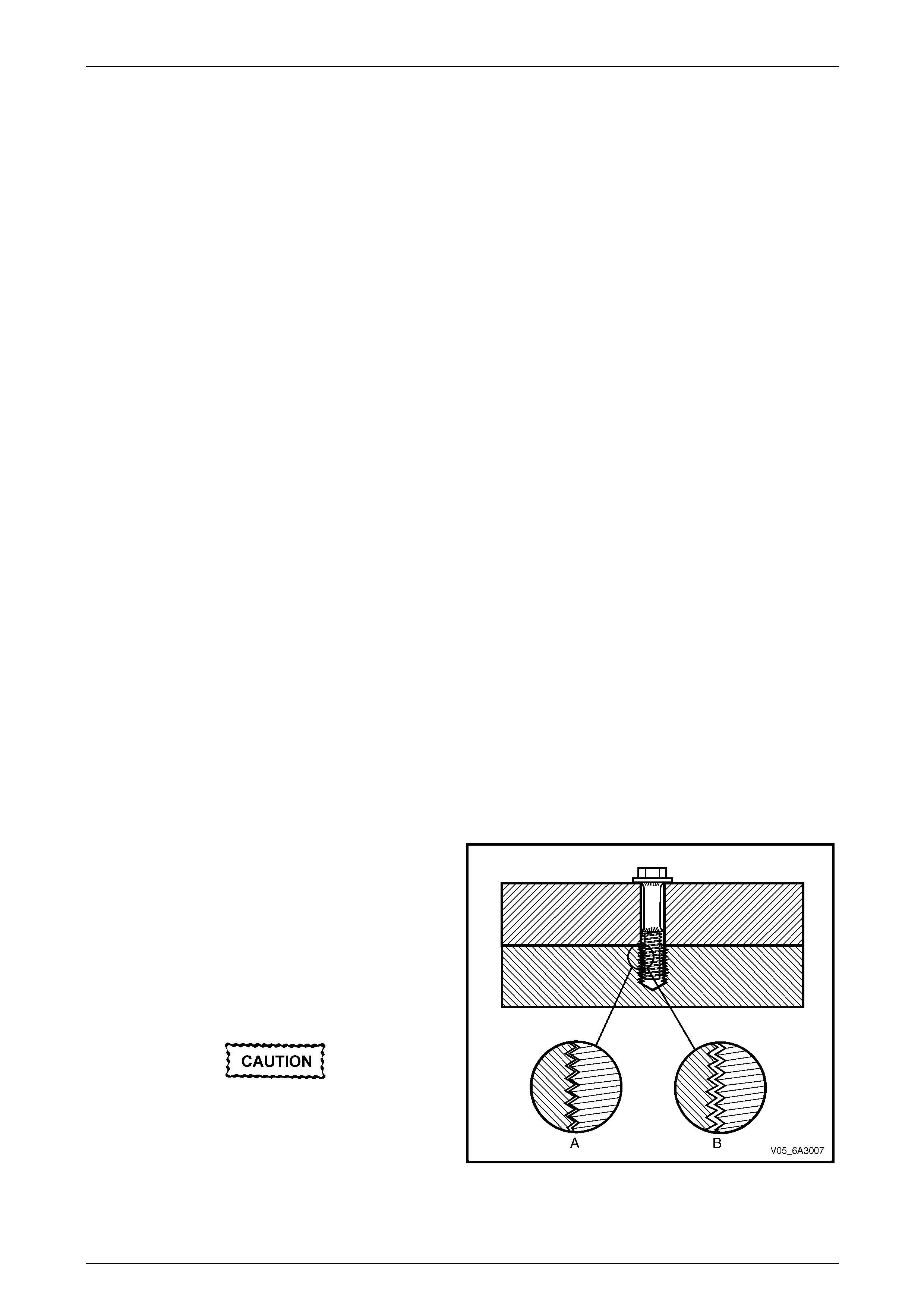
Engine Mechanical Page 6A4–31
Page 6A4–31
Many internal engine c omponents will develop specific wear patterns on their friction sur faces. The internal components
when separated, must be marked or organised in a way to ensure they are reinstalled to their original location and
position.
Separate, mark or organise the following compon ents:
• Piston and piston pin
• Piston to the specific cylinder bore
• Piston rings to the specific piston
• Connecting rod to the crankshaft journal
• Connecting rod to the bearing cap
• Crankshaft main and connecti ng rod bearings
• Camshaft and hydraulic valve lifters
• Hydraulic valve lifters, guides, pushrods, pivot supports and rocker arms
• Hydraulic valve to the valve guide
• Hydraulic valve spring and where fitted, the shim to the cylinder head l ocation
• Cylinder block main beari ng cap location and direction
• Oil pump drive gears
Special Tools and Equipment
Special tools are listed and illustrated throughout this Section with a complete listing at the end of this S ection,
refer to 9 Special Tools.
These tools or their equivalents are spec ially designed to quickly and safely accompl ish the operation for which they are
intended. The use of the special tools listed will a lso minimise possible damage to engin e compo nents. Some precision
measuring tools are required for inspection of certain critical components. Torque wrenches and torque angl e tools are
necessary for correct tightening of various fasteners.
To correctly service the engine assemb ly, the following items shoul d be readily available:
• Approved eye protection and appropriate safety gloves
• Clean well lit work area
• Suitable parts cleaning tank
• Compressed air suppl y
• Trays or storage containers to keep parts and fasteners organised
• Adequate set of hand tools
• Approved engine repair stan d such as Tool AU 591
• Approved engine lifting device that will adequately supp ort the weight of the engine and transmission assembly
Fasteners
Fasteners are important to the reliable operation of the
engine.
Due to the greater thermal expansion of aluminium, the bolt
threads will change dimension to a greater extent when hot
(A) when compared to cast iron.
It is recommended to allow the engine to cool to at least 50°
Celsius (B) before attempting fastener removal.
If a bolt or other threaded component is remo ved before the
engine is allowed to cool, the threads could be pulled from
the cylinder block or cylinder head.
Do not use impact tools to remove bolts
during engine disassembly. While this may
be a common practice with cast iron engine
components, use of these tools is more likely
to damage the aluminium threads in the
cylinder block or head of the engine. Figure 6A4 – 27
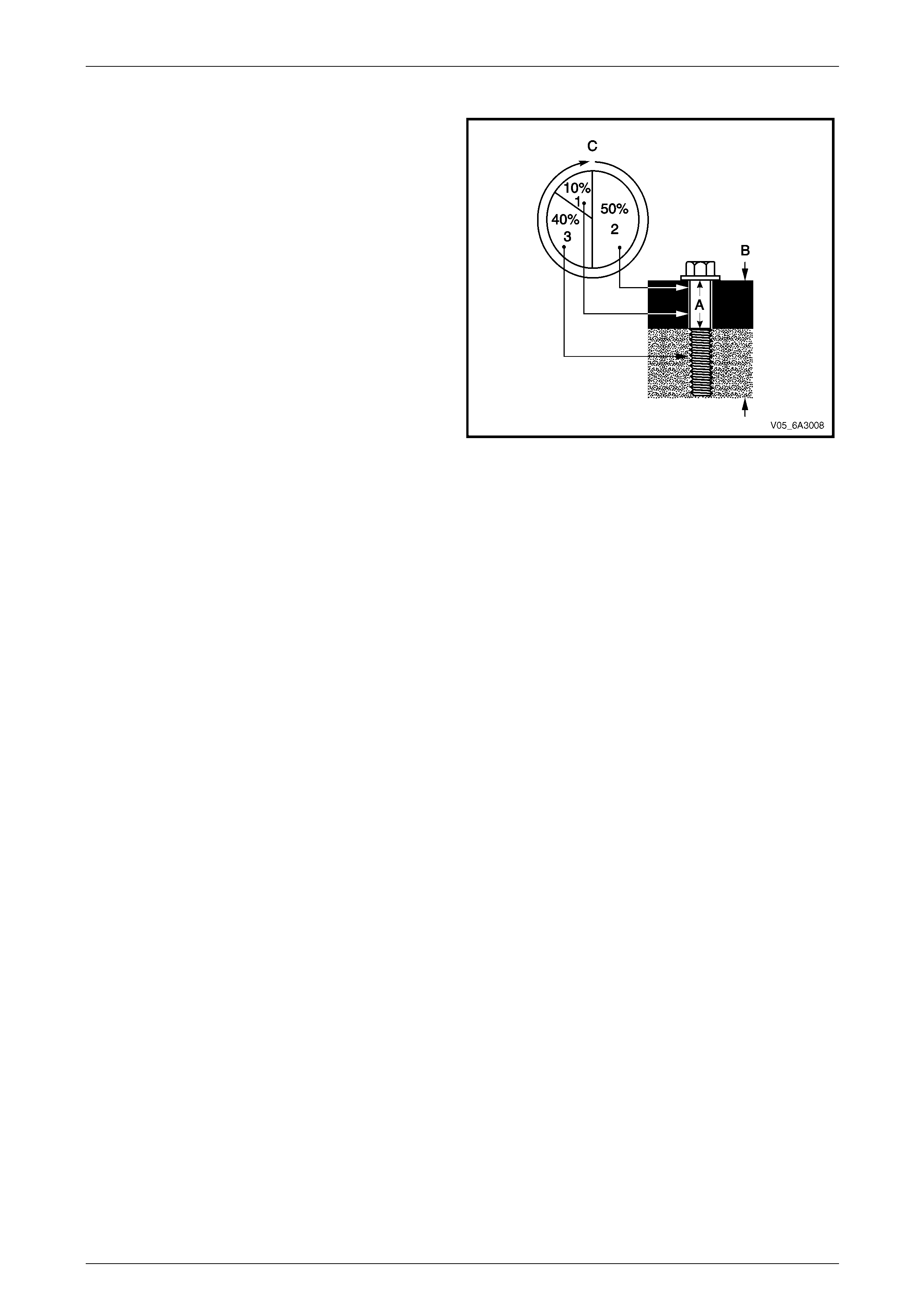
Engine Mechanical Page 6A4–32
Page 6A4–32
Clamp Load
When torque is applied to a fastener, the fastener stretches
and the joint compresses. The force developed in the
fastener due to its stretch is called tension (A), while the
force applied to the joint is called clamp load (B).
Only a small portion of the applied torque (C) is transferred
to the clamp load (1). Friction under the bo lt head (2) and in
the threads (3) absorbs much of the applied torque.
Typically, only 10% of the torq ue is available to develop
stretch (or tension) in the fastener and clamp load in the
joint. Therefore, a slight variation in friction in the thread or
under the bolt head results in a wide variati on in the clamp
load applied to the joint.
Figure 6A4 – 28
Torque Angle and Torque to Yield Fasten ers
The torque angle method of applying torque to a fastener has been developed to overcome the effects of friction
variations in the fastener application.
The application of the torque angle method does not always mean the fastener has to be replaced after loosening. It is
only when the fastener has been an gle tightened to the extent the yield point of the fastener has been exceeded the
fastener must be replaced.
Examples are the main bearing caps that are angle tightened but the bolts can be re-used, whereas the M11 cylinder
head bolts that are torque to yield fasteners must be replaced when loosened.

Engine Mechanical Page 6A4–33
Page 6A4–33
2 Displacement on Demand (DoD)
2.1 General Description
The General Motors Displacement on Dem and® (DoD) system is fitted to the GEN IV V8 engine, however the system is
not active for the Australian market. The system is very reliable and rarely a cause for concern. However the technician
should familiarise themselves with the system as it will aid accurate diagnosis of mechanical concerns with the engine.
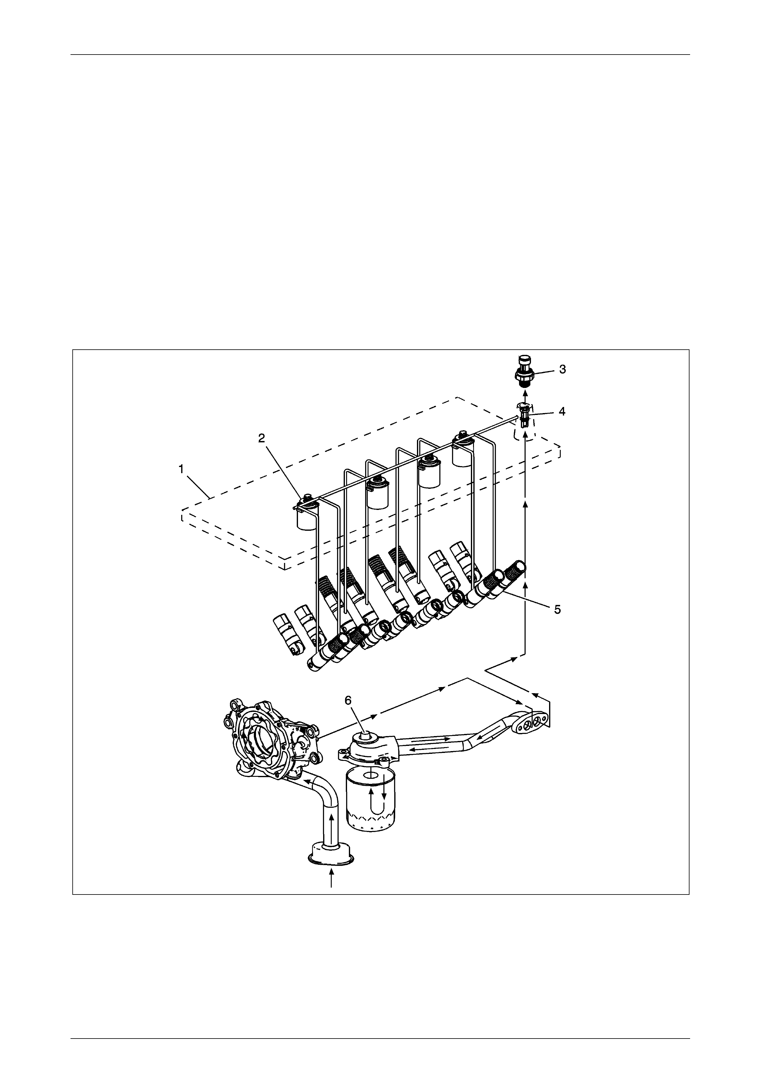
Engine Mechanical Page 6A4–34
Page 6A4–34
2.2 System Description
System Operation
General Motors Displacement on Demand® (DoD) engine control system has the ability, under certain light load driving
conditions, to provide maximum fuel economy by deactivating 4 of the engines 8 cylinders. The engine will normally
operate on 8 cylinders in V8 mode during starting, idling, and medium or heavy throttle conditions. When commanded
ON, the engine control module (ECM) will direct the DoD system to deactivate cylinders 1 and 7 on the left bank and
cylinders 4 and 6 on the right bank, forcing V4 mode.
Refer to:
Lubrication Description (Main Pressure Below 55 psi - DoD Off)
Lubrication Description (Main Pressure Above 55 psi - DoD Off)
Lubrication Description (Main Pressure Below 55 psi - DoD On)
Lubrication Description (Main Pressure Above 55 psi - DoD On)
Displacement on Demand (DoD) Diagnostics
Valve Lifter Oil Manifold Assembly
Figure 6A4 – 29
The valve lifter oil manifold (VLOM) assembly (1) is bolted t o the top of the engine block beneath the intake manifold
assembly. The oil manifold consists of 4 elec trically operated and normally closed solenoids (2). Each solenoid directs
the flow of pressurised engine oil to the DoD intake and exhaust valve lifters (5). The oil pressure relief valve (6), located
in the oil pan, regulates engine oil pressure to the lubrication system and the oil manifo ld.
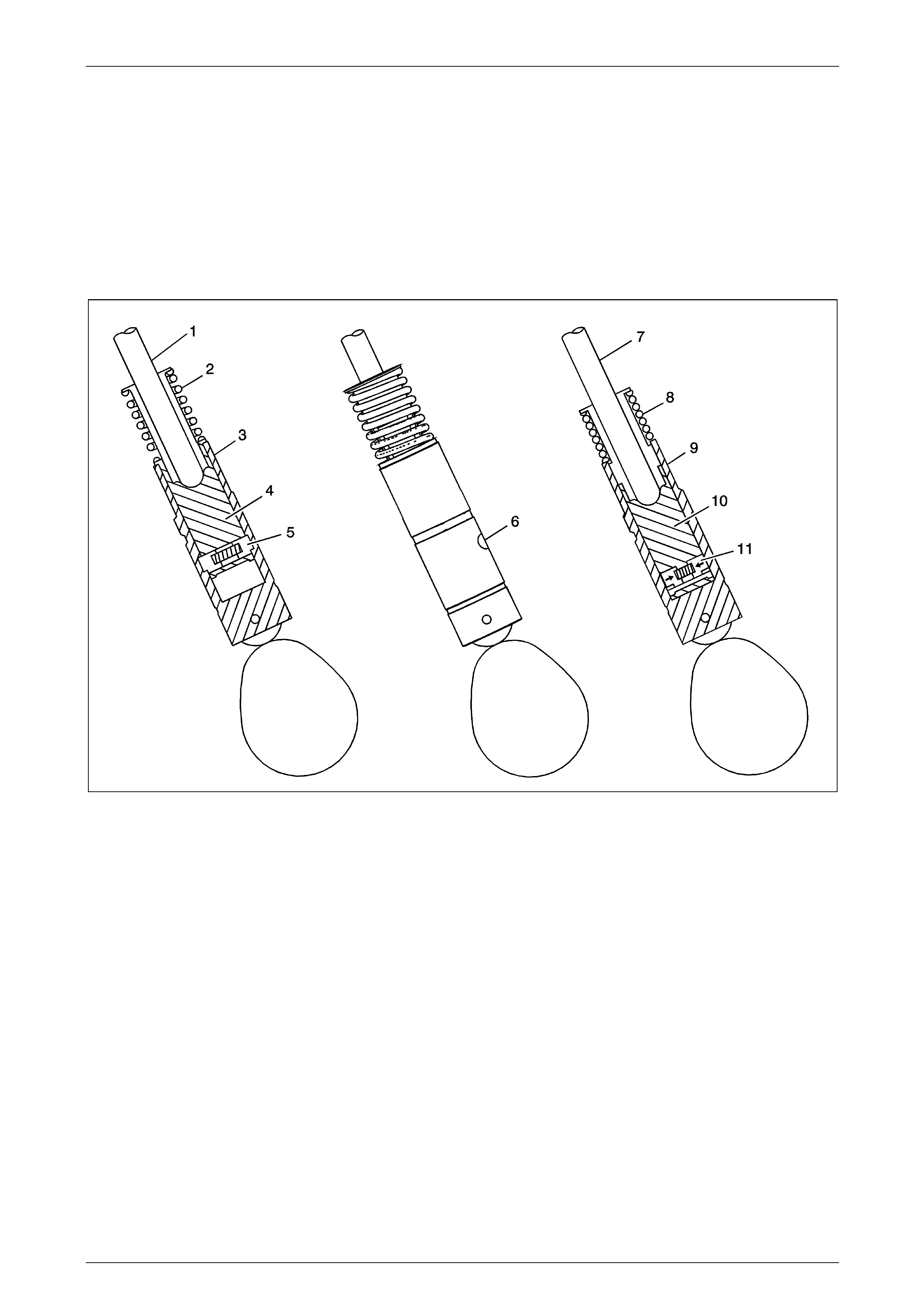
Engine Mechanical Page 6A4–35
Page 6A4–35
When enabling conditions are met for DoD operation, the ECM will ground each solenoid c ontrol circuit in firing order
sequence, allowing current to flow through the solenoid windings. With the windings ener gized, the solenoid valves open
and direct pressurised engine oil through the VLOM into 8 vertical passages in the engine block lifter valley. The 8
vertical passages, 2 per cylinder, direct pressurised oil to the valve lifter bores of the cylinders to be deactivated. When
vehicle operating conditions require a return to V8 mode, the ECM will turn OFF the ground circuit for the solenoids,
allowing the solenoid valves to close. When the solenoid valves are closed, remaining oil pressure is exhausted through
the bleed passages of the VLOM into the engine block lifter valley. The housing of the oil manifold incorporates several
oil bleed passages that continually purge trapped air from the manifold and engin e block.
To help control contamination within th e DoD hydraulic system, a small replaceable oil filter (4) is located in the VLOM oil
inlet passage. The oil pressure sensor (3) monitors engine oil pressure and provides info rmation to the ECM.
Displacement on Demand Valve Lifters
Figure 6A4 – 30
When operating in V8 mode, the Do D valve lifters function similar to the non-DoD valve lifters. The DoD oil manifold
solenoids are in the closed position, with no pressurised oil directed to the valve lifters. The pushrod (1) travels upward
and downward to actuate the rocker arm and valve. The spring loaded locking pins (5) of the lifter are extended outward
and mechanically lock the pin housing (4) to the outer body of the valve lifter (3).
When the DoD system is commanded ON, the ECM will direct the solenoids of the oil man ifold to op en and direct
pressurised oil to the valve lifters. Oil travels through the VLOM and engine block oil galleries and enters the inlet port (6)
of the valve lifter.
When operating in V4 mode, pressurised oil forces the locking pins (11) inward. The pushrod (7) remains in a constant
position and does not travel upward and do wnward. The outer body of the lifter (9) moves upward and downward
independently from the pin housin g (10). The valve lifter spring (8) retains tension on the valve train components to
eliminate valve train noise.
When the DoD system is commanded OF F, the ECM directs the solenoids of the oil manifold to close, stopping the flow
of pressurised oil to the valve lifters. The oil pressure within the lifter will decrease and the locking pins will move outward
to mechanically lock the pin h ousing and outer body.
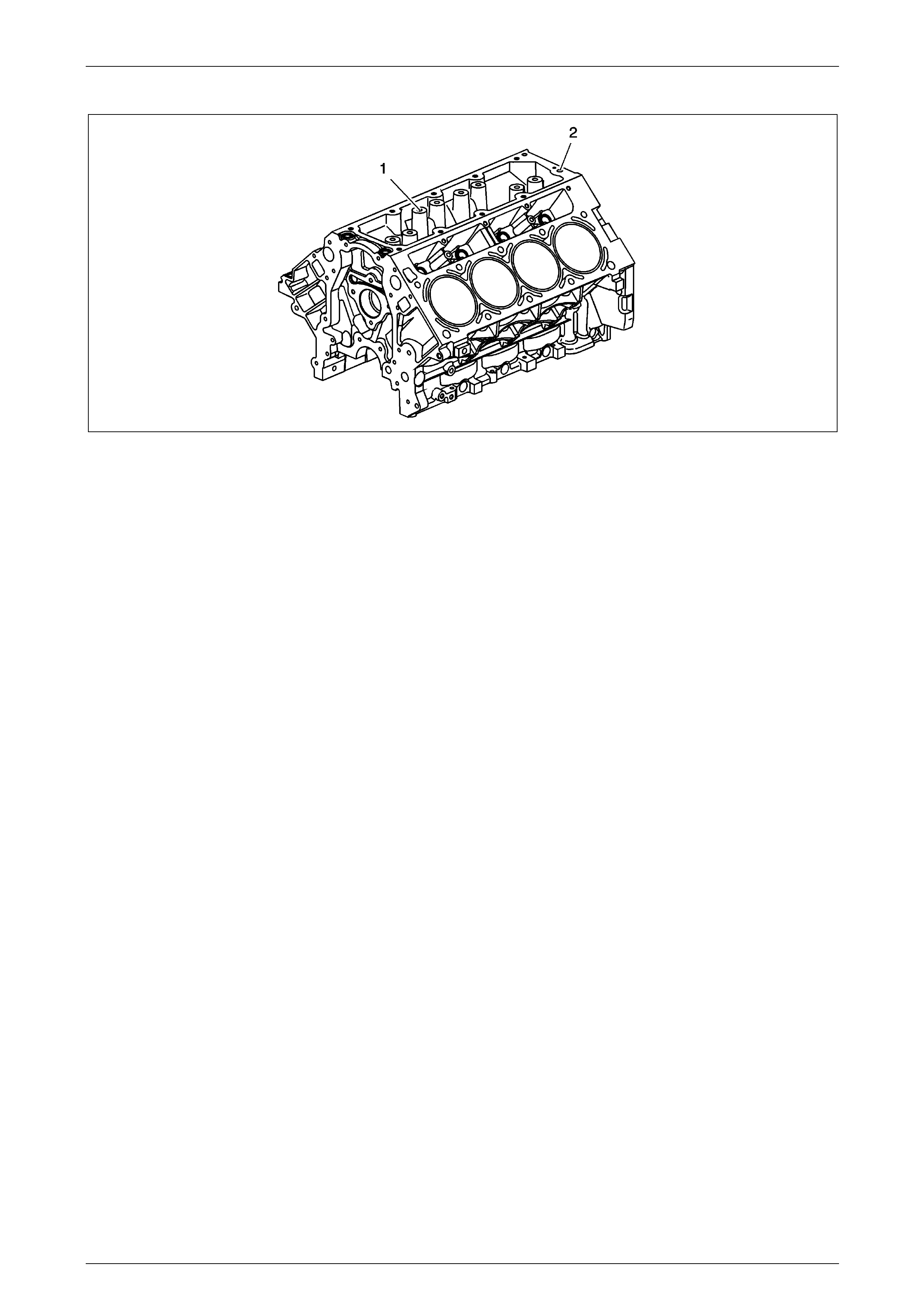
Engine Mechanical Page 6A4–36
Page 6A4–36
Engine Block
Figure 6A4 – 31
The DoD engine block incorporates additional features to support DoD system operation. Engi ne oil pressure is routed to
the VLOM assembly from an oil gallery (2) in the rear of the cylinder block. Cylinders 1, 4, 6, and 7 each have 2 vertical,
cast-in-block oil passages (1). The vertical oil passages permit oil flow from the manifold assembly to the valve lifter
bores.
New Product Information
The purpose of New Product Information is to highlight, or indicate, important product changes from the
previous model year. Changes may include 1 or more of the following items:
• Torque values and/or fastener tighteni ng strategies
• Changed engine specifications
• New sealants and/or adhesives
• Disassembly and assembly pr ocedure revisions
• Engine mechanical dia gnostic procedure revisions
• New special tools required
• A component comparison from the previous year
Torque Values and/or Fastener Tightening Strategies
• All fasteners and threaded holes on the LH6 engines utiliz e metric threads.
• Certain fasteners should not be used aga in. Bolts, studs, or other fasteners that must be replaced, will be called out
in the specific service procedure.
• Some applications may use a second design camshaft retainer plate and bolts. Refer to Camshaft Installation .
New Sealants and/or Adhesives
Sealers and adhesives, as req uired, are identified within the specific service procedures. Refer to
Sealers, Adhesives, and Lubricants .
Disassembly and Assembly Procedure Revisions
The piston and piston pin are to be serviced as an assembly.
Engine Mechanical Diagnostic Procedure Revisions
All diagnosis on a vehicle should follow a logical process. Strategy based diagnostics is a uniform a pproach for repairing all
systems. The diagnostic flow may always be used in order to resolve a system condition. The diagn ostic flow is the place to
start when repairs are necessary. For a detailed explanation, refer to Diagnostic Starting Point - Engine Mechanical .
New Special Tools Required
• EN-46999 Displacement-on-Demand Tester
• EN-46999-1 Displacement-on-Demand Tester Air Adapter
• EN-46999-5 Displacement-on-Demand Tester Harness – Small Block V8
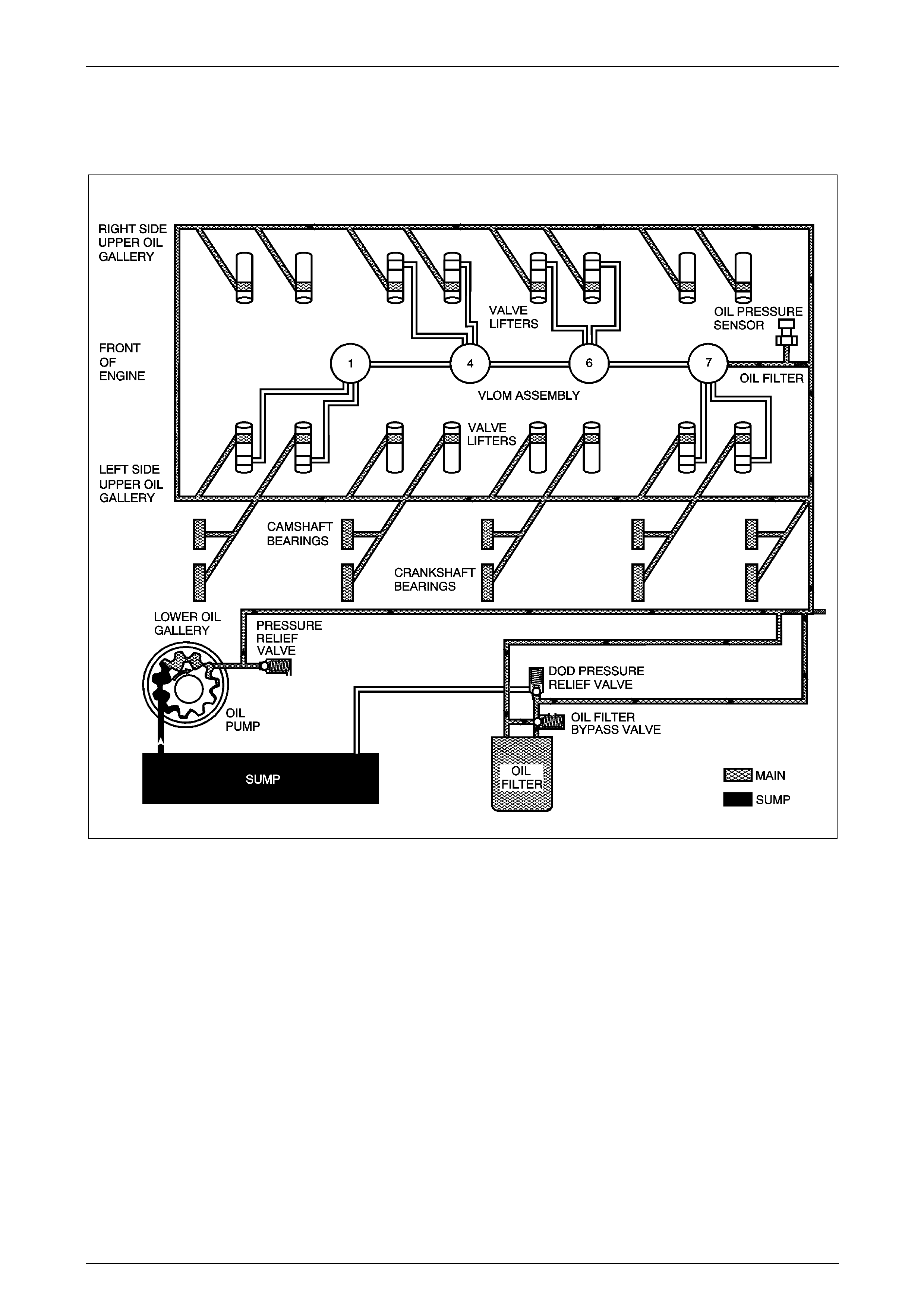
Engine Mechanical Page 6A4–37
Page 6A4–37
A Component Comparison from the Previous Year
Some applications may use a second design camshaft retainer plate and bolts. Refer to Camshaft Installation.
Lubrication Description (Main Pressure Below 55 psi - DoD Off)
Figure 6A4 – 32
Engine lubrication is supplied by a gear rotor type oil pump assembly. The pump is mounted on the front of the engine
block and driven directly by the crankshaft sprocket. The pump gears rotate and draw oil from the oil pan sump through a
pick-up screen and pipe. The oil is pr essurised as it passes through the pump and is sent through the engin e block l ower
oil gallery. Containe d within the oil pump assembly is a pressure relief valve that maintai ns oil pressure within a specified
range.
Pressurised oil is directed thr ough the engine block lower oil gallery and th rough the oil filter tube to the full flow oil filter
where harmful contaminants are remove d. A bypass valve is incorporated into the oil pan at the oil filter boss, which
permits oil flow in the event the filter becomes restricted. A second valve, the displac eme nt on demand (DoD) oil
pressure relief valve is incorporated into the oil filter tub e. The Do D oil pressure relief valve limits oil pressure directed to
the upper oil galleries and oil manifold assembly to 379–517 kPa (55–75 psi) maximum. Oil is then directed from the filter
to the upper main oil galleries and the valve lifter oil manifold (VLOM) assembly. Oil from the left upper oil gallery is
directed to the crankshaft and camshaft bearings. Oil that has entered both the up per main oil galleries also pressurizes
the valve lifter assemblies and is then pumped through the pushrods to lubricate the valve rocker arms and valve stems.
Oil returning to the pan is directed by the crankshaft oil deflector. The oil pressure se nsor is located at the top rear of the
engine. Refer to Displacemen t on Demand (DoD), 2.2 System Description.
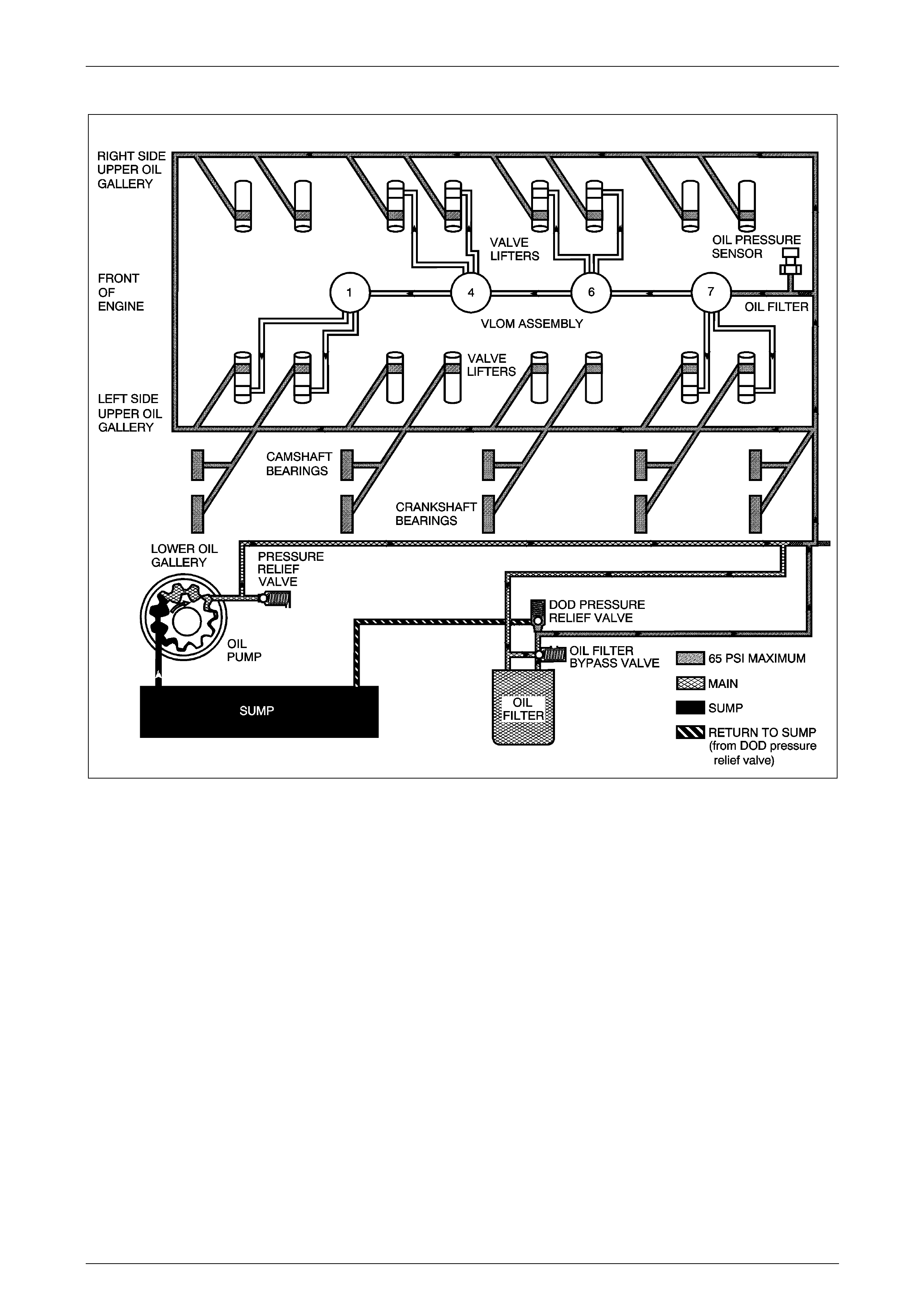
Engine Mechanical Page 6A4–38
Page 6A4–38
Lubrication Description (Main Pressure Above 55 psi - DoD Off)
Figure 6A4 – 33
Engine lubrication is supplied by a gerotor type oil pump assembly. The pump is mounted on the front of the engine block
and driven directly by the crankshaft sprocket. The pump gears rotate and draw oil from the oil pan sump through a pick-
up screen and pipe. The oil is pressurised as it passes through the pump and is sent through the engine block lower oil
gallery. Contained within the oil pump assembly is a press ure relief valve that maintains oil pressure within a specified
range.
Pressurised oil is directed thr ough the engine block lower oil gallery and through the oil filter tube to the full flow oil filter
where harmful contaminants are remove d. A bypass valve is incorporated into the oil pan at the oil filter boss, which
permits oil flow in the event the filter becomes restricted. A second valve, the displac eme nt on demand (DoD) oil
pressure relief valve is incorporated into the oil filter tube. The DoD oil pressure relief valve limits oil pressure directed to
the upper oil galleries and valve lifter oil manifold (VLOM) assembly to 379–517 kPa (55– 75 psi) maximum. When main
oil pressure exceeds 379 kPa (55 psi), the D oD oil pressure relief valve exhausts excess oil to the sump.
Oil is then directed from the filter to the upper main oil galleries and the VLOM assembly. Oil from the left upper oil
gallery is directed to the crankshaft and camshaft bearings. Oil that has entered both the upper main oil galleries also
pressurizes the valve lifter assemblies an d is then pumped through the pushrods to lubricate the valve rocker arms and
valve stems. Oil returning to the pan is directed by the cran kshaft oil deflector. T he oil pressure sensor is located at the
top rear of the engine. Refer to Displacement on Demand (DoD), 2.2 System Description.

Engine Mechanical Page 6A4–39
Page 6A4–39
Lubrication Description (Main Pressure Below 55 psi - DoD On)
Figure 6A4 – 34
Engine lubrication is supplied by a gerotor type oil pump assembly. The pump is mounted on the front of the engine block
and driven directly by the crankshaft sprocket. The pump gears rotate and draw oil from the oil pan sump through a pick-
up screen and pipe. The oil is pressurised as it passes through the pump and is sent through the engine block lower oil
gallery. Contained within the oil pump assembly is a press ure relief valve that maintains oil pressure within a specified
range.
Pressurised oil is directed thr ough the engine block lower oil gallery and through the oil filter tube to the full flow oil filter
where harmful contaminants are remove d. A bypass valve is incorporated into the oil pan at the oil filter boss, which
permits oil flow in the event the filter becomes restricted. A second valve, the displac eme nt on demand (DoD) oil
pressure relief valve is incorporated into the oil filter tube. The DoD oil pressure relief valve limits oil pressure directed to
the upper oil galleries and oil manifold assembly to 379–517 kPa (55–75 psi) maximum.
Oil is then directed from the filter to the upper main oil galleries and the valve lifter oil manifold (VLOM) assembly. Oil
from the left upper oil gallery is directed to the cranksh aft and camshaft bearings. Oil that has entere d b oth the up per
main oil galleries also pressurizes the valve lifter assemblies and is then pumped through the pushrods to lubricate the
valve rocker arms and valve stems. Oil returnin g to the pan is directed by the crankshaft oil deflector. The oil pressure
sensor is located at the top rear of the engine.
With DoD activated, the engine control module (ECM) commands the 4 solenoids to open, directing oil through the
engine block oil gall eries to the intake and exhaust valve lifters for cylinders 1, 4, 6, and 7. Refer to Displacement on
Demand (DoD), 2.2 System Description.
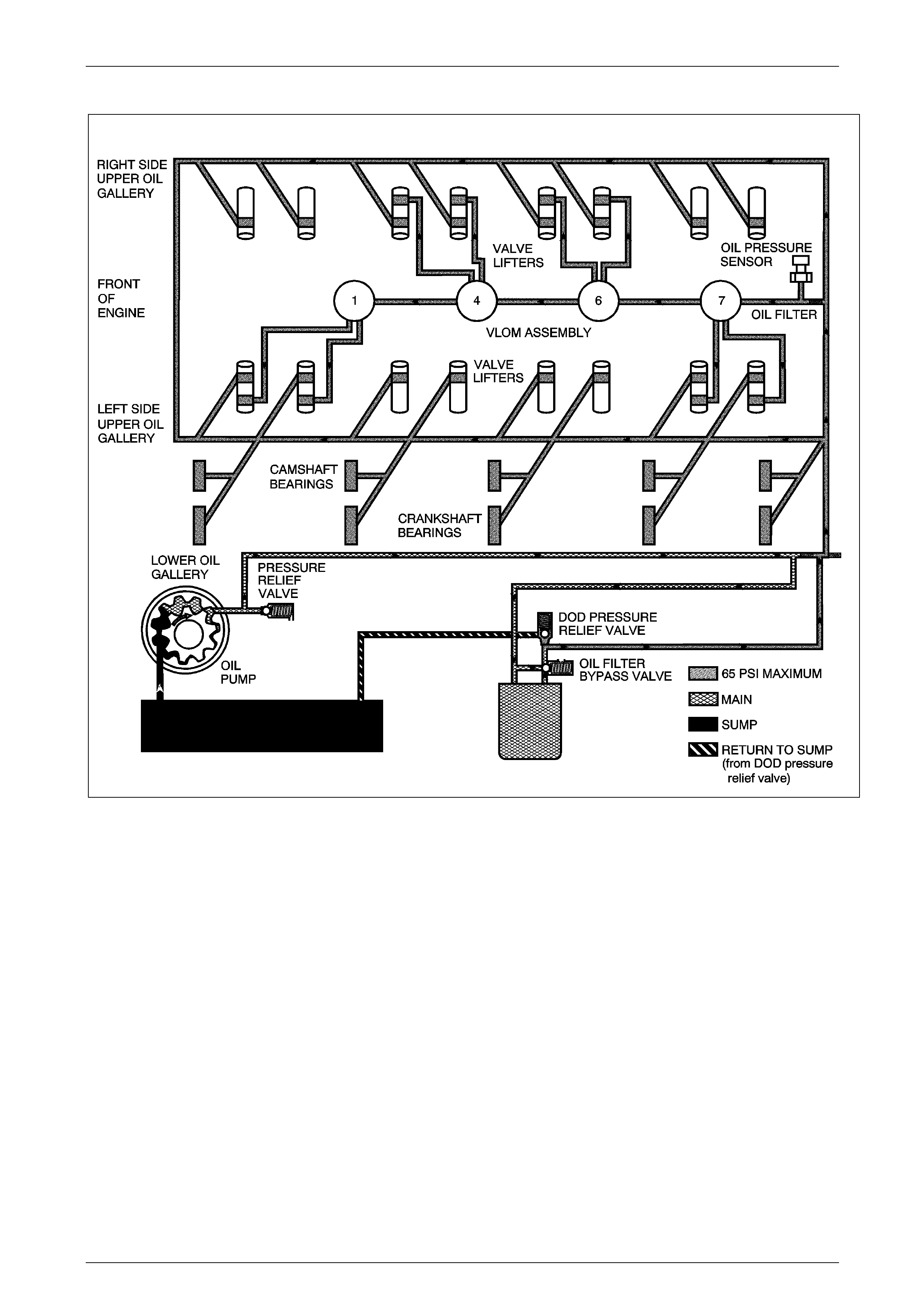
Engine Mechanical Page 6A4–40
Page 6A4–40
Lubrication Description (Main Pressure Above 55 psi - DoD On)
Figure 6A4 – 35
Engine lubrication is supplied by a gerotor type oil pump assembly. The pump is mounted on the front of the engine block
and driven directly by the crankshaft sprocket. The pump gears rotate and draw oil from the oil pan sump through a pick-
up screen and pipe. The oil is pressurised as it passes through the pump and is sent through the engine block lower oil
gallery. Contained within the oil pump assembly is a press ure relief valve that maintains oil pressure within a specified
range.
Pressurised oil is directed thr ough the engine block lower oil gallery and through the oil filter tube to the full flow oil filter
where harmful contaminants are remove d. A bypass valve is incorporated into the oil pan at the oil filter boss, which
permits oil flow in the event the filter becomes restricted. A second valve, the displac eme nt on demand (DoD) oil
pressure relief valve is incorporated into the oil filter tube. The DoD oil pressure relief valve limits oil pressure directed to
the upper oil galleries and valve lifter oil manifold (VLOM) assembly to 379–517 kPa (55– 75 psi) maximum. When main
oil pressure exceeds 379 kPa (55 psi), the D oD oil pressure relief valve exhausts excess oil to the sump.
Oil is then directed from the filter to the upper main oil galleries and the VLOM assembly. Oil from the left upper oil
gallery is directed to the crankshaft and camshaft bearings. Oil that has entered both the upper main oil galleries also
pressurizes the valve lifter assemblies an d is then pumped through the pushrods to lubricate the valve rocker arms and
valve stems. Oil returning to the pan is directed by the cran kshaft oil deflector. T he oil pressure sensor is located at the
top rear of the engine.
With DoD activated, the engine control module (ECM) commands the 4 solenoids to open, directing oil through the
engine block oil gall eries to the intake and exhaust valve lifters for cylinders 1, 4, 6, and 7. Refer to Displacement on
Demand (DoD), 2.2 System Description.

Engine Mechanical Page 6A4–41
Page 6A4–41
Cleanliness and Care
Throughout this section, it should be understood that proper cleaning and protection of machined surfac es and friction
areas is part of the repair procedure. This is considered standard shop practice even if not specifically stated.
• When any internal engine parts are serviced, care and cleanliness is important.
• When components are removed for service, they should be marked, organized or retained in a specific order for
assembly. Refer to Separating Parts .
• At the time of installation, components should be installed in the same location a nd with the same mating surface
as when removed.
• An automobile engine is a combination of many machined, honed, polished and lapped surfaces with tolerances
that are measured in millimeters or thousandths of an inch. These surfaces should be covered or protected to avoid
component damage.
• A liberal coating of clean engine oil should be applied to friction areas during assembly.
• Proper lubrication will protect and lubric ate friction surfaces during initial operation.
Separating Parts
IMPORTANT:
Many internal engine components will
develop specific wear patterns on their
friction surfaces.
When disassembling the engine, internal components MUST be separated, marked, or organized in a way to ensure
installation to their original location a nd position.
Separate, mark, or organize the following components:
• Piston and the piston pin
• Piston to the specific cylinder bore
• Piston rings to the piston
• Connecting rod location and orientation to the crankshaft journal
• Connecting rod to the bearing cap
• A paint stick or etching/engraving type tool are recommended. Stamping the connecting rod or cap near the
bearing bore may affect component geometry.
• Crankshaft main and connecti ng rod bearings
• Camshaft and valve lifters
• Valve lifters, lifter guides, pushrods and rocker arm assemblies
• Valve to the valve guide
• Valve spring to the cylinder head location
• Engine block main bearing cap location and direction
• Oil pump drive and driven gears
Replacing Engine Gaskets
Tools Required
• J 28410 Gasket Remover
Gasket Use and Applying Sealants
• Do not use any gasket again unless specified.
• Gaskets that can be used again will be identified in the service procedure.
• Do not apply sealant to any gasket or sealing surface unless called out in the service information.
Separating Components
• Use a rubber mallet to separate components.
• Bump the part sideways to loosen the components.
• Bumping should be done at bends or reinforced areas to prevent distortion of parts.
Engine Mechanical Page 6A4–42
Page 6A4–42
Cleaning Gasket Surfaces
• Remove all gasket and sealing material from the part using the J 28410 or equivalent.
• Care must be used to avoid gouging or scraping the sealing surfaces.
• Do not use any other method or technique to remove sealant or gasket material from a part.
• Do not use abrasive pads, sand paper, or power tools to clean the gasket surfaces.
• These methods of cleaning can cause damage to the component sealing surfaces.
• Abrasive pads also produc e a fine grit that the oil filter cannot remove from the oil.
• This grit is abrasive and has been known to cause internal eng ine damage.
Assembling Components
Refer to Sealant Notice in Section 00 Cautions and Notices .
• When assembling com ponents, use only the sealant specified or equivalent in the service procedure.
• Sealing surfaces should be clean and free of debris or oil.
• Specific components such as crankshaft oil seals or va lve stem oil seals may require lubrication during assembly.
• Components requiring lubrication will be identified in the service procedure.
• When applying sealant to a component, apply the amount specified in the service procedure.
• Tighten bolts to specifications. Do not overtighten.
Use of Room Temperature Vulcanizing (RTV) and Anaerobic Sealer
CAUTION
3 types of sealer are commonly used in
engines. These are room temperature
vulcanizing (RTV) sealer, anaerobic gasket
eliminator sealer, and pipe joint compound.
The correct sealerand amount must be used
in the proper location to pre vent oil leaks. DO
NOT interchange the 3 types of sealers. Use
only the specific sealer, or the equivalent as
recommended in th e service procedure
Pipe Joint Compound
• Pipe joint compound is a pliable sealer that does not completely harden. This type of sealer is used where 2 non-
rigid parts, such as the oil pan and the engine block, are assembled together.
• Do not use pipe joint compound in areas where extreme temperatures are expected. These areas include: exhaust
manifold, head gasket, or other surfaces where gasket elim inator is specified.
• Follow all safety recommendations and directions that are on the container.
• To remove the sealant or the gasket material, refer to Replacing Engine Gaskets .
NOTE
Refer to Sealant Notice in Section 00 Cautions
and Notices.
• Apply the pipe joint compou nd to a clean surface.
• Use a bead size or quantity as specifie d in the procedure. Run the bead to the inside of any bolt holes.
• Apply a continuous bead of pipe joint compound to 1 sealing surface. Sealing surfaces to be reseale d must be
clean and dry.
• Tighten the bolts to specifications. Do not overtighten.
Engine Mechanical Page 6A4–43
Page 6A4–43
RTV Sealer
• RTV sealant hardens when exposed to air. This type of sealer is used where 2 non-rigid parts, such as the intake
manifold and the engine block, are assembled together.
• Do not use RTV sealant in areas where extreme temperatures are e xpected. These areas include: exhaust
manifold, head gasket, or other surfaces where a gasket eliminator is specified.
• Follow all safety recommendations and directions that are on the container.
• To remove the sealant or the gasket material, refer to Replacing Engine Gaskets.
NOTE
Refer to Sealant Notice in Section 00 Cautions
and Notices.
• Apply RTV sealant to a clean surface. Use a bead size as specified in the procedure. Run the bead to the inside of
any bolt holes.
• Assemble components while the RTV sealant is still wet, within 3 minutes. Do not wait for the RTV sealant to skin
over.
• Tighten bolts to specifications. Do not overtighten.
Anaerobic Sealer
• Anaerobic gasket elimi nator hardens in the absence of air. This type of sealer is used where 2 rigid parts, such as
castings, are assembled together. When 2 rigid p arts are disassembled and no sealer or gasket is readily
noticeable, the parts were probably assembled using a gasket eliminator.
• Follow all safety recommendations and directions that are on the container.
• To remove the sealant or the gasket material, refer to Replacing Engine Gaskets.
• Apply a continuous bead of gasket eliminator to 1 flange. Surfaces to be sealed must be clean and dr y.
NOTE
Refer to Sealant Notice in Section 00 Cautions
and Notices.
• Spread the sealer evenly with your finger to get a uniform coating on the sealing surface.
CAUTION
Anaerobic sealed joints that are partially
torqued and allowed to cure more than 5
minutes may result in incorrect sh imming and
sealing of the joint.
• Tighten bolts to specifications. Do not overtighten.
• After properly tightening the fasteners, remove the excess sealer from the outsid e of the joint.
Tools and Equipment
Special tools are listed and il lustrated throughout this section, with a complete listing at the end of the section. These
tools, or their equivalents, are specially designed to quickly and safely accomplish the op erations for which they are
intended. The use of these special tools also minimise possible damage to engine components. Some pr ecision
measuring tools are required for inspection of certain critical components. Torque wrenches and a torque angle meter
are necessary for the proper tighten ing of various fasteners. To properly service the engine assembly, the
following items should be readily available:
• Approved eye protection and safety gloves
• A clean, well lit, work area
• A suitable parts cleaning tank
• A compressed air supply
• Trays or storage containers to keep parts and fasteners organized
• An adequate set of hand tools
• Approved engine repair stan d
• An approved engine lifting device that will adequately support the weight of the components
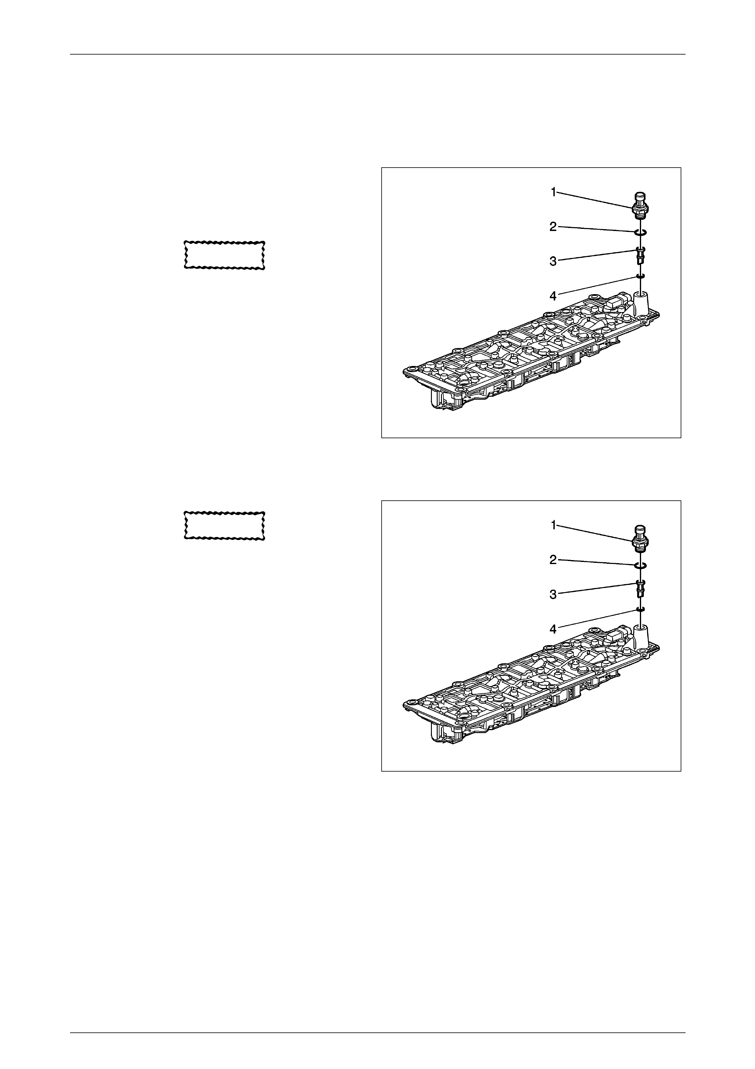
Engine Mechanical Page 6A4–44
Page 6A4–44
2.3 Minor Service Operations for DoD
Valve Lifter Oil Filter Replacement
Removal Procedure
1 Remove the intake manifold. Refer to
4.7 Intake Manifold Replacement .
2 Disconnect the electrical connector from the oil
pressure sensor.
CAUTION
Do not allow dirt or debris to enter the
passages of the manifold. Plug as required.
3 Remove the oil pressure sensor (1) and washer (2).
4 Remove the oil filter (3).
5 Inspect the O-ring (4) for cuts or damage. If the filter is
plugged or the O-ring is cut or damaged, replace the
filter and O-ring as an assembly.
Figure 6A4 – 36
Installation Procedure
CAUTION
Do not allow dirt or debris to enter the
passages of the manifold. Plug as required.
1 Install a NEW oil filter (3) and O-ring (4) assembly.
2 Apply sealant to the threads of the sensor. Refer to
Sealers, Adhesives, and Lubricants for the correct part
number.
NOTE
Refer to Fastener Notice in Section 00 Cautions
and Notices.
3 Install the oil pressure sensor (1) and washer (2).
4 Tighten the oil pressure sensor to 20 Nm (15 lb ft).
5 Connect the electrical connector to the oil pressure
sensor.
6 Install the intake manifold. Refer to
4.7 Intake Manifold Replacement .
Figure 6A4 – 37

Engine Mechanical Page 6A4–45
Page 6A4–45
Valve Lifter Oil Manifold Replacement
Removal Procedure
1 Remove the intake manifold. Refer to
4.7 Intake Manifold Replacement.
2 Disconnect the electrical connector from the oil
pressure sensor.
3 Remove the valve lifter oil manifold bolts (2).
CAUTION
Do not allow dirt or debris to enter the oil
passages of the manifold. Plug as required.
4 Remove the valve lifter oil manifold (1).
Figure 6A4 – 38
5 Do not lift the manifold by the electrical lead frame.
Figure 6A4 – 39
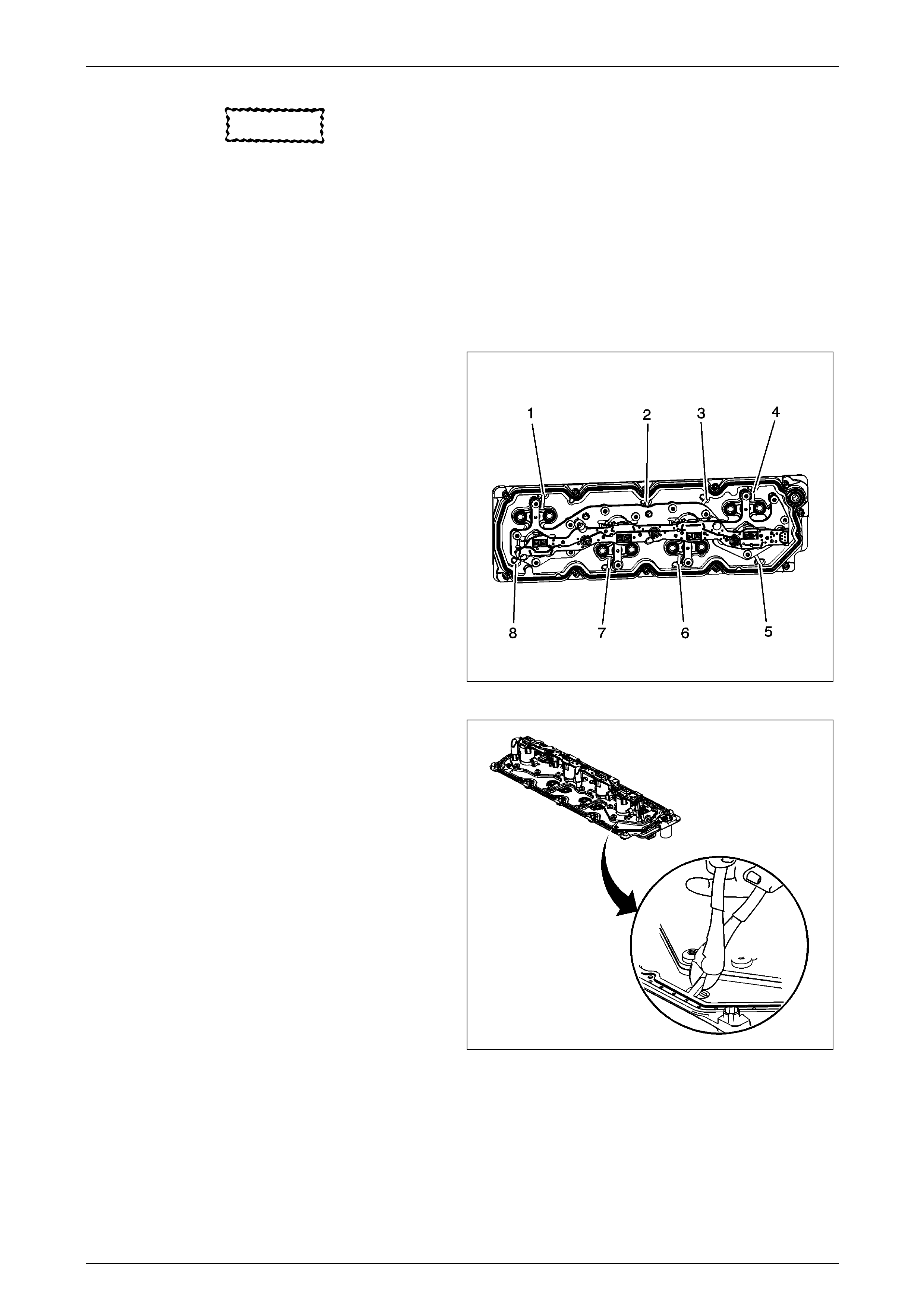
Engine Mechanical Page 6A4–46
Page 6A4–46
CAUTION
• Remove only the outer gasket from the
manifold.
• Do not disassemble any of the internal
components of the manifold in an attempt
to remove the 8 inner sealing gaskets.
• If the inner gaskets are cut or damaged,
replace the manifo ld as an assembly.
• Only use a wire-cutter type tool in order to
minimise the amount of debris.
• Do not use a rotary-type cutting tool on
the retaining straps.
6 Identify the 8 gasket retaining strap locations (1–8).
Figure 6A4 – 40
7 Using a wire-cutter type tool, cut the 8 retaining straps
of the outer gasket.
Figure 6A4 – 41
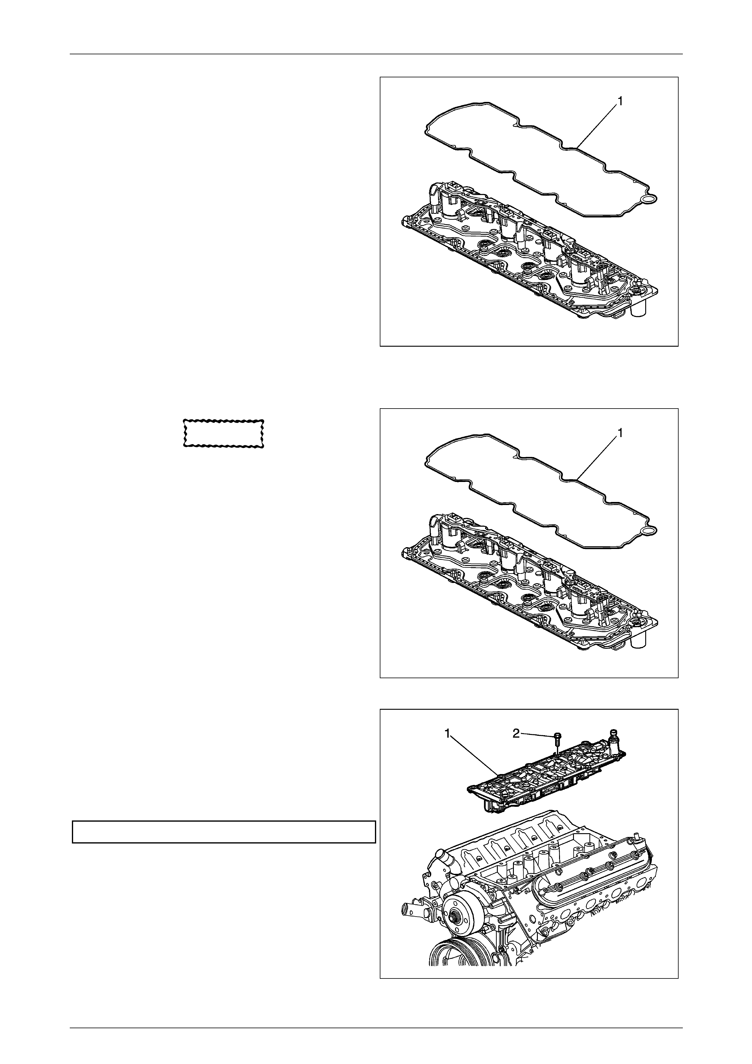
Engine Mechanical Page 6A4–47
Page 6A4–47
8 Remove the outer gasket (1) from the manifold.
Figure 6A4 – 42
Installation Procedure
CAUTION
All gasket surfaces should be free of oil or
other foreign material d u ring assembly
Do not allow dirt or debris to enter the
manifold. Plug as required.
1 Install the service gasket (1) onto the manifold.
Figure SectNum – 43
2 Install the manifold (2) with gasket.
NOTE
Refer to Fastener Notice in Section 00 Cautions
and Notices.
3 Install the manifold bolts (1) and tighten to the
specified torque.
Manifold Attaching Bolts ....................................25.0 Nm
4 Connect the electrical connector to the oil pressure
sensor.
5 Install the intake manifold. Refer to
4.7 Intake Manifold Replacement.
Figure 6A4 – 44
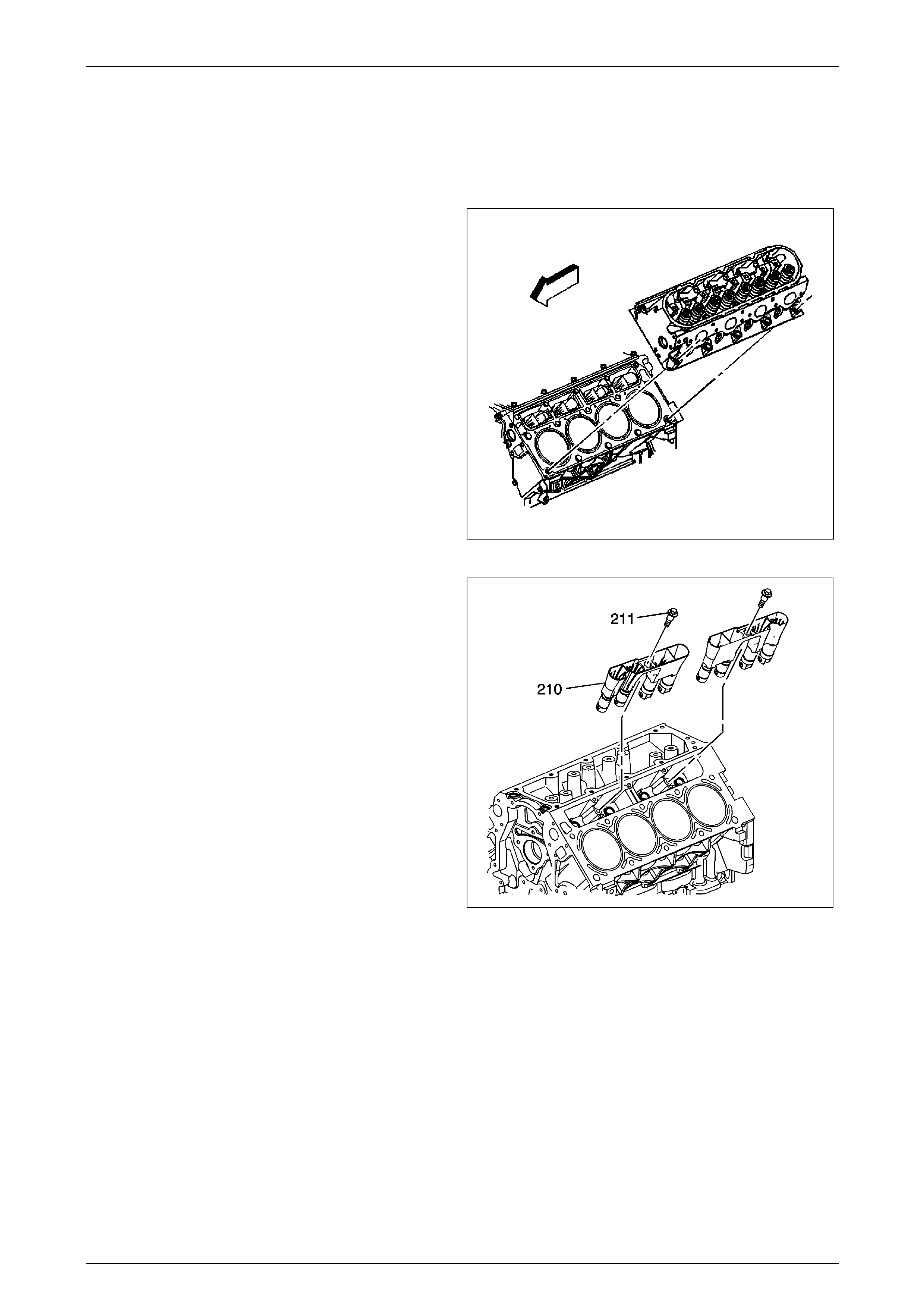
Engine Mechanical Page 6A4–48
Page 6A4–48
Valve Lifter Replacement
Tools Required
J 3049-A Valve Lifter Remover
Removal Procedure
1 Remove the cylinder head and gasket. Refer to:
• 4.15 Cylinder Head Replace m ent - Left
or to
• 4.15 Cylinder Head Replac ement – Right
Figure 6A4 – 45
2 Remove the valve lifter. Refer to 4.16 Valve Lifter
Removal.
3 Clean and inspect the valve lifters. Refer to
Valve Lifters and Guides Cleaning and Inspection .
Figure 6A4 – 46

Engine Mechanical Page 6A4–49
Page 6A4–49
Installation Procedure
1 Install the valve lifter. Refer to 4.16 Valve Lifter
Installation.
Figure 6A4 – 47
2 Install the cylinder head and g asket. Refer to
• 4.15 Cylinder Head Replace m ent - Left
or to
• 4.15 Cylinder Head Replac ement - Right .
Figure 6A4 – 48
Valve Lifter Removal
Tools Required
• J 3049-A Valve Lifter Remover
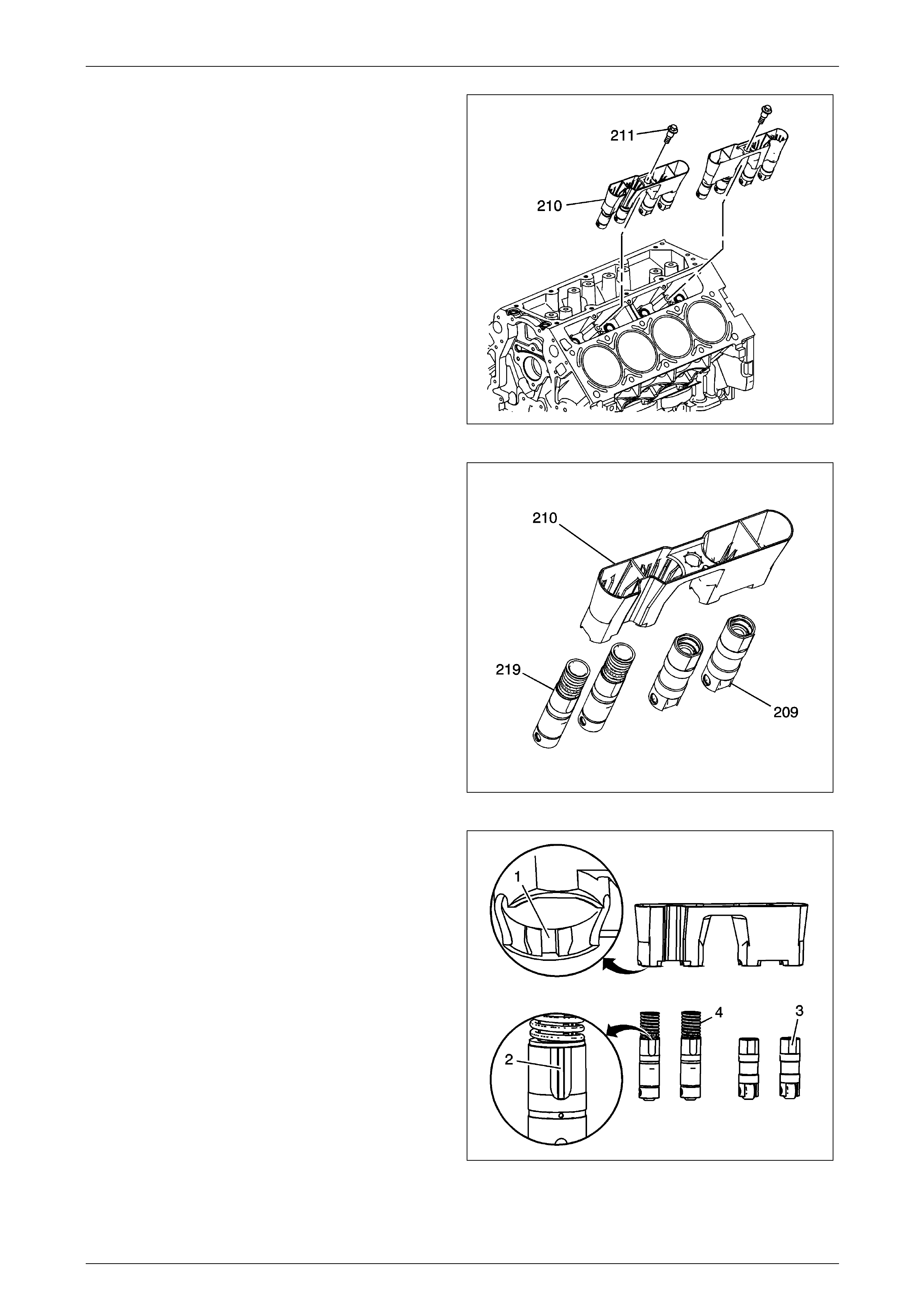
Engine Mechanical Page 6A4–50
Page 6A4–50
1 Remove the bolts (211).
2 Remove the guides (210) with lifters.
NOTE
For correct installation, the notched area of the
guide is to align with the locating tab of the
block.
Figure 6A4 – 49
3 Remove the valve lifters (209, 219) from the guide
(210).
Figure 6A4 – 50
4 Organize or mark the components so they can be
installed in the same location from which they were
removed. The displacement on dema nd lifters (4) are
installed into the guide by aligning the notched area of
the guide (1) with the raised surface on the side of the
lifter (2). Refer to Separating Parts.
Figure 6A4 – 51
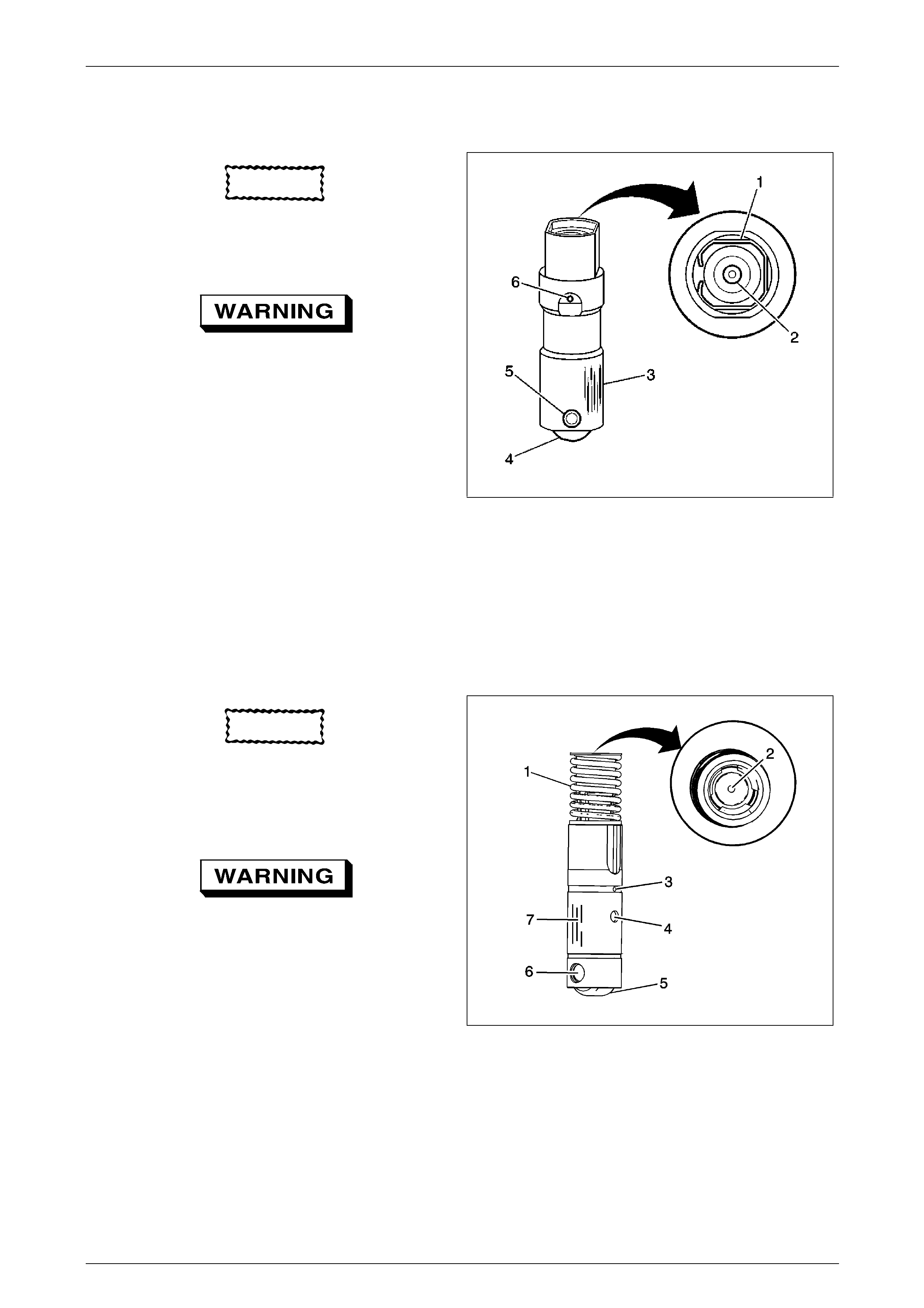
Engine Mechanical Page 6A4–51
Page 6A4–51
Valve Lifters and Guides Cleaning and Inspection
Non Displacement on Demand Valve Lifters
CAUTION
Components that are to be used again must
be marked, sorted or organized for assembly.
1 Clean the components in cleaning solvent
Refer to Safety Glasses Caution in Section 00
Cautions and Notices.
2 Dry the components with compressed air.
3 Inspect the valve lifters for the following conditions:
• Bent or broken clip (1)
• Worn pushrod socket (2)
• Scuffed or worn sides (3)
If the valve lifter shows wear, inspect the engine block lifter
bores for wear or damage
• Flat spots on the roller (4)
• Loose or damaged pin (5)
• Plugged oil hole (6)
• Worn or damaged roller bearing The roller should
rotate freely with no binding or roughness
Figure 6A4 – 52
Displacement on Demand Valve Lifters
CAUTION
Components that are to be used again
must be marked, sorted or organized for
assembly
1 Clean the components in cleaning solvent.
Refer to Safety Glasses Caution in Section 00
Cautions and Notices
2 Dry the components with compressed air.
3 Inspect the valve lifters for the following conditions:
• Broken or collapsed spring (1)
• Worn pushrod socket (2)
• Plugged lubric ation hole (3)
• Plugged lifter oil-switching hole (4)
• Flat spots on the roller (5)
• Worn or damaged roller bearing (6) The roller
should rotate freely with no binding or
roughness.
• Scuffed or worn sides (7)
Figure 6A4 – 53
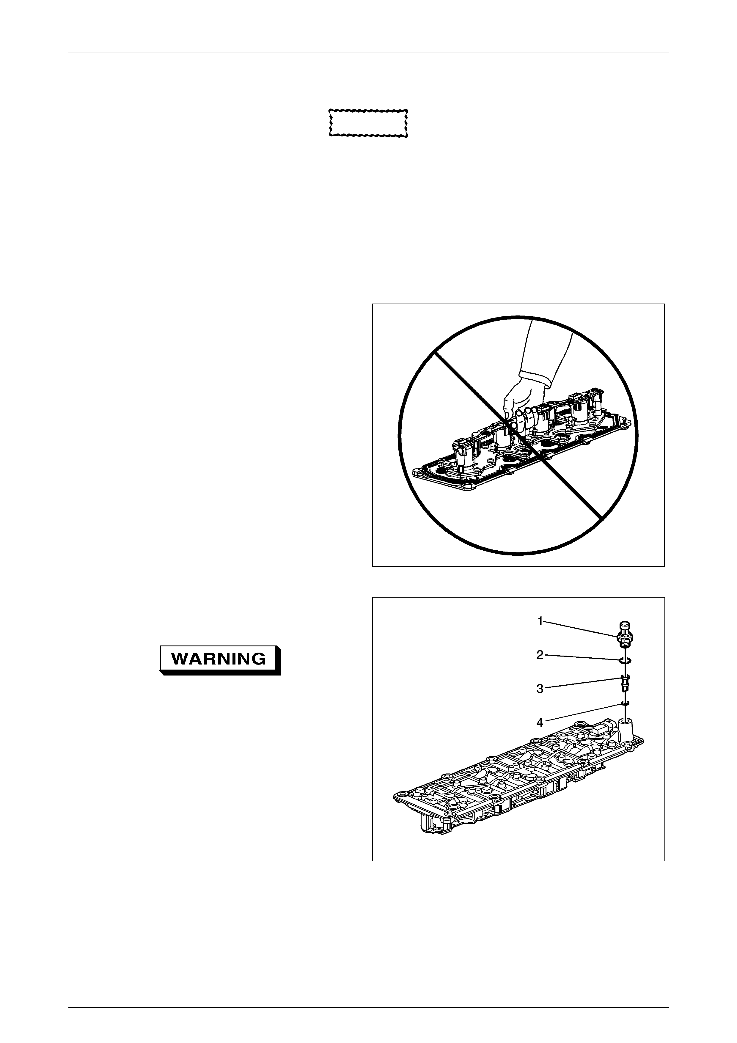
Engine Mechanical Page 6A4–52
Page 6A4–52
Valve Lifter Oil Manifold Cleaning and Inspection
CAUTION
• Do not allow dirt or debris to enter the oil
passages of the manifold. Plug, as
required.
• Do not disassemble the electrical
components from the manifold.
• Do not submerge the electrical
components in cleaning solvent.
• Do not use the manifold exterior gasket
again.
• Remove the exterior gasket and install a
NEW service gasket during asse mbly
1 Do not lift the manifold assembly by the electrical le ad
frame.
Figure 6A4 – 54
2 Remove the oil pressure sensor (706) and washer
(707).
3 Remove the oil screen (452) with O-ring (454).
Refer to Safety Glasses Caution in Section 00
Cautions and Notices.
4 Clean the manifold with compressed a ir.
Figure 6A4 – 55
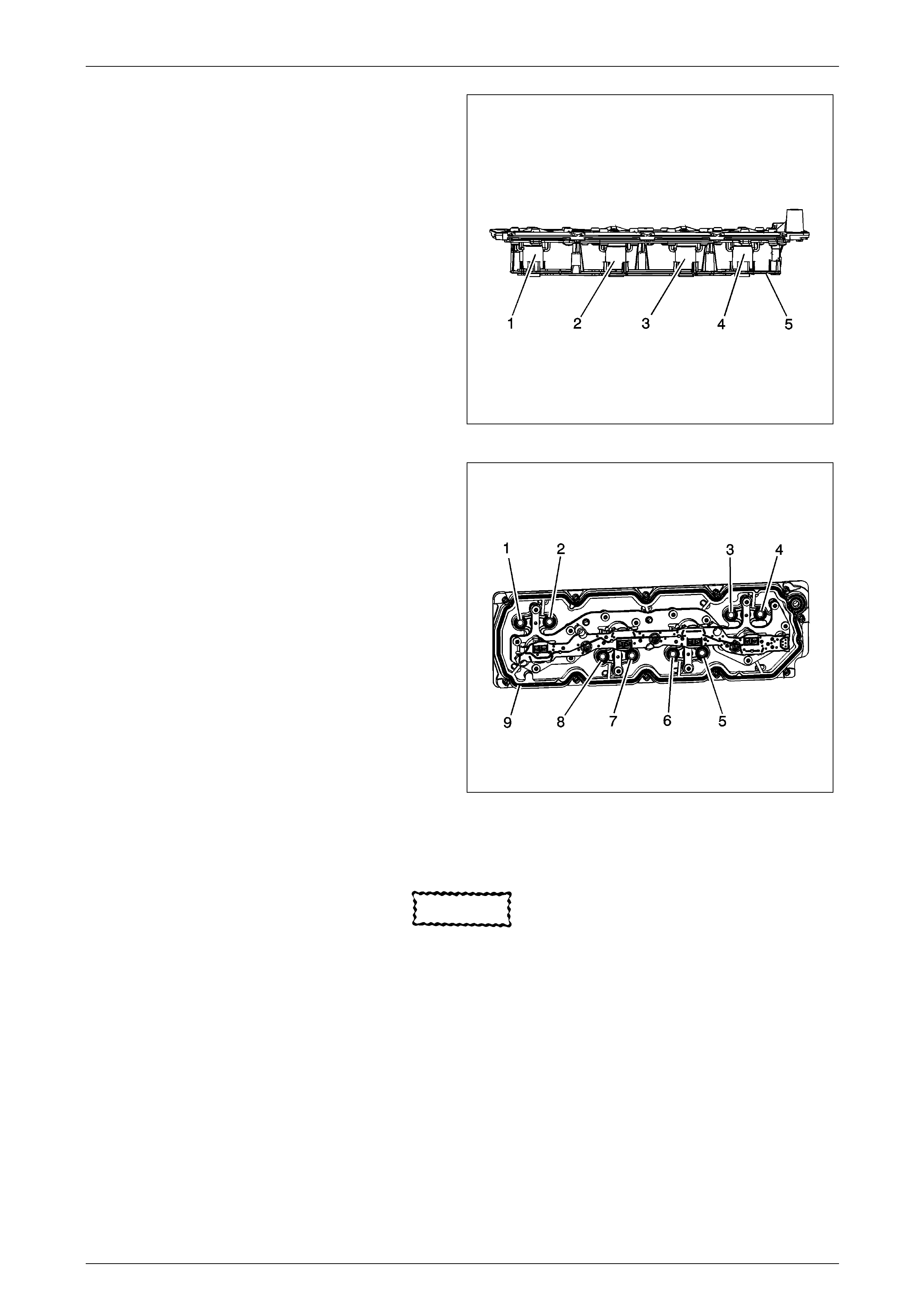
Engine Mechanical Page 6A4–53
Page 6A4–53
5 Inspect for loose electrical solenoids (1–4) or loose or
missing bolts.
6 Inspect for damage to the electrical lead frame (5).
7 Inspect for a damaged electrical connector, for bent or
corroded pins.
Figure 6A4 – 56
8 Inspect for damaged interior sealing gaskets (1–8). If
the interior sealing gaskets are damaged, the manifold
must be replaced as an assembly.
9 Inspect for a damaged exterior sealing gasket (9) or
scored gasket surfaces.
10 Inspect for debris or restrictions within the oil
passages of the manifold. Refer to Displ acement on
Demand (DoD), Valve Lifter Oil Manifold D iagnosis
and Testing
Figure 6A4 – 57
Valve Lifter Installation
CAUTION
• When using the valve lifters again, install
the lifters to their original locations.
• If camshaft replacement is required, the
valve lifters must also be replaced.
• Each of the 4 valve guide assemblies will
contain 2 displacement on demand valve
lifters and 2 non-displacement on demand
valve lifters.
• With the lifters and guides properly
installed, cylinders 1, 4, 6, and 7 lifter
bores will each contain 2 displacement on
demand valve lifters
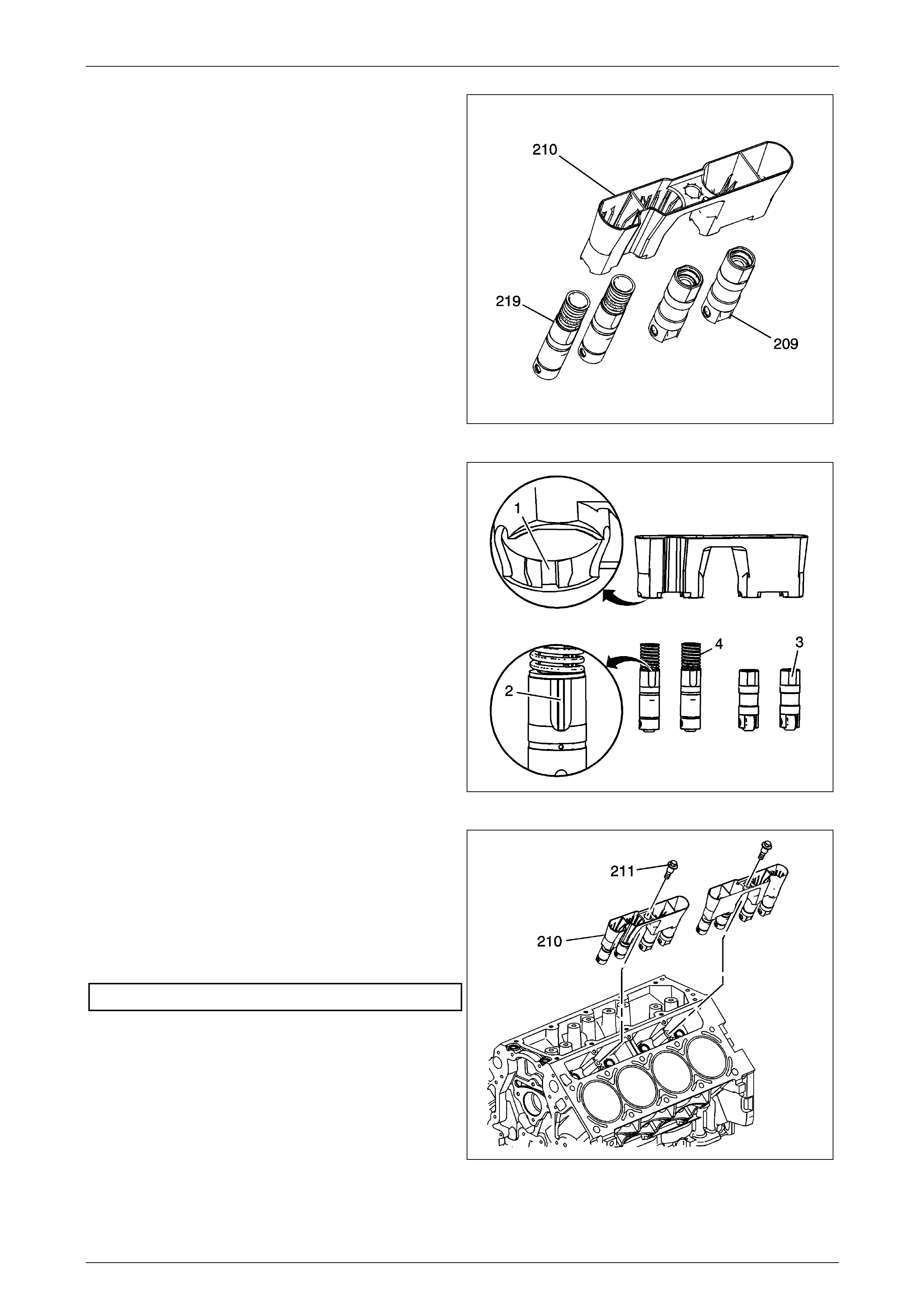
Engine Mechanical Page 6A4–54
Page 6A4–54
1 Lubricate the valve lifters (209, 219) and engine block
valve lifter bores with clean engine oil
Figure 6A4 – 58
2 Insert the valve lifters into the lifter guides.
• Align the flat area (3) on the top of the non
displacement on demand lifter with the flat area
in the lifter guide bore. Push the lifter completely
into the guide bore.
• The displacement on demand lifters (4) are to be
installed into the guide, with the notch in the
guide (1) aligned with the raised area (2) of the
lifter.
Figure 6A4 – 59
3 Install the valve lifters and guide assembl y (210) to the
engine block.
NOTE
Refer to Fastener Notice in Section 00 Cautions
and Notices.
4 Install the valve lifter guide bolts (211) and tighten to
the specified torque.
Valve Lifter Guide Bolts .....................................10.0 Nm
Figure 6A4 – 60
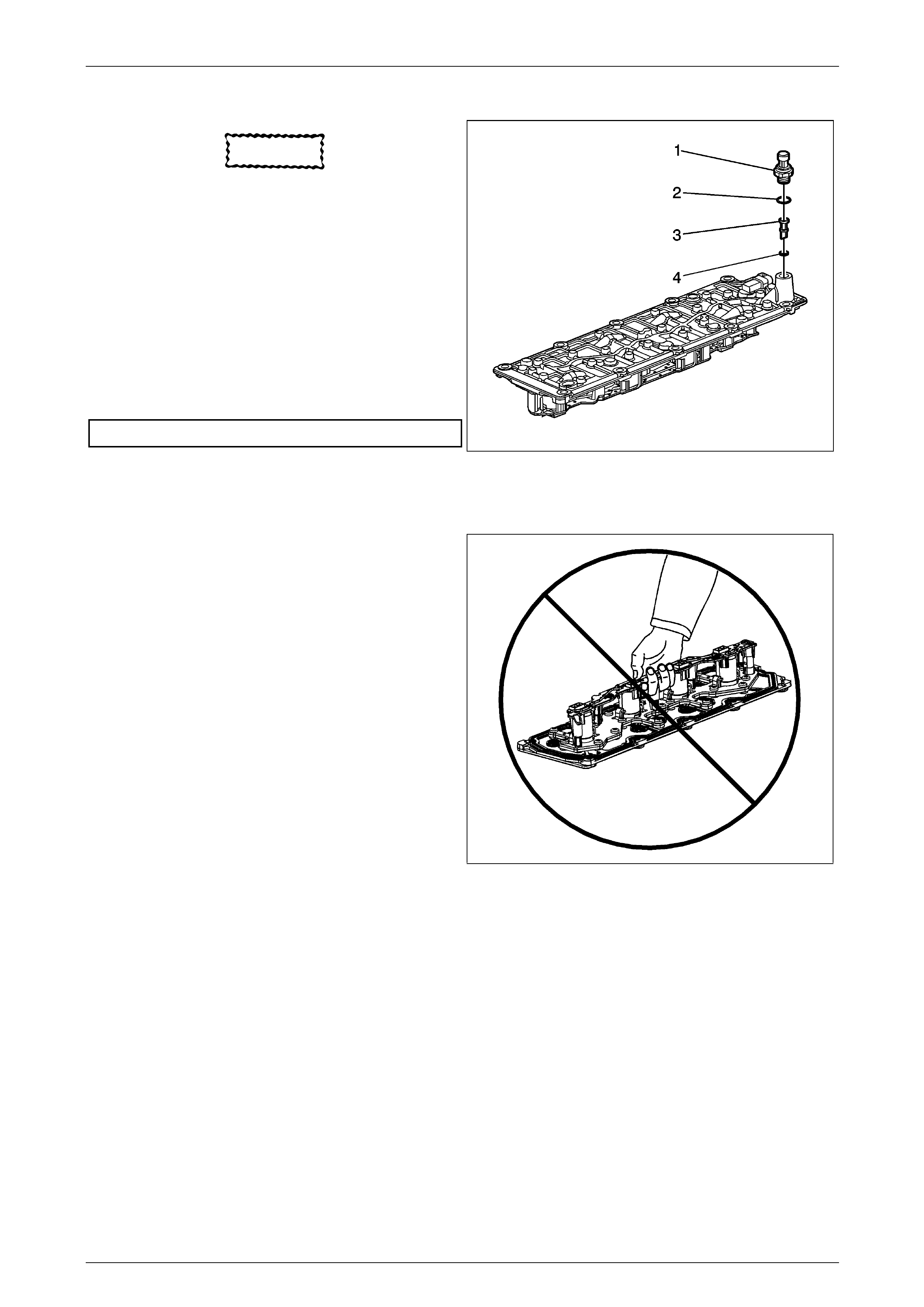
Engine Mechanical Page 6A4–55
Page 6A4–55
Valve Lifter Oil Filter Installation
CAUTION
Do not allow dirt or debris to enter the oil
passages of the manifold. Plug, as required
1 Install a NEW oil filter (452) and O-ring (454)
assembly.
2 Apply sealant GM P/N 12346004 (Canadian P/N
10953480) to the threads of the sensor.
NOTE
Refer to Fastener Notice in Section 00
Cautions and Notices.
3 Install the oil pressure sensor (706) and washer (707)
and tighten to the specified torque.
Oil Pressure Sensor...........................................35.0 Nm
Figure 6A4 – 61
Valve Lifter Oil Manifold Installation
1 Do not lift the manifold assembly by the electrical le ad
frame.
Figure 6A4 – 62
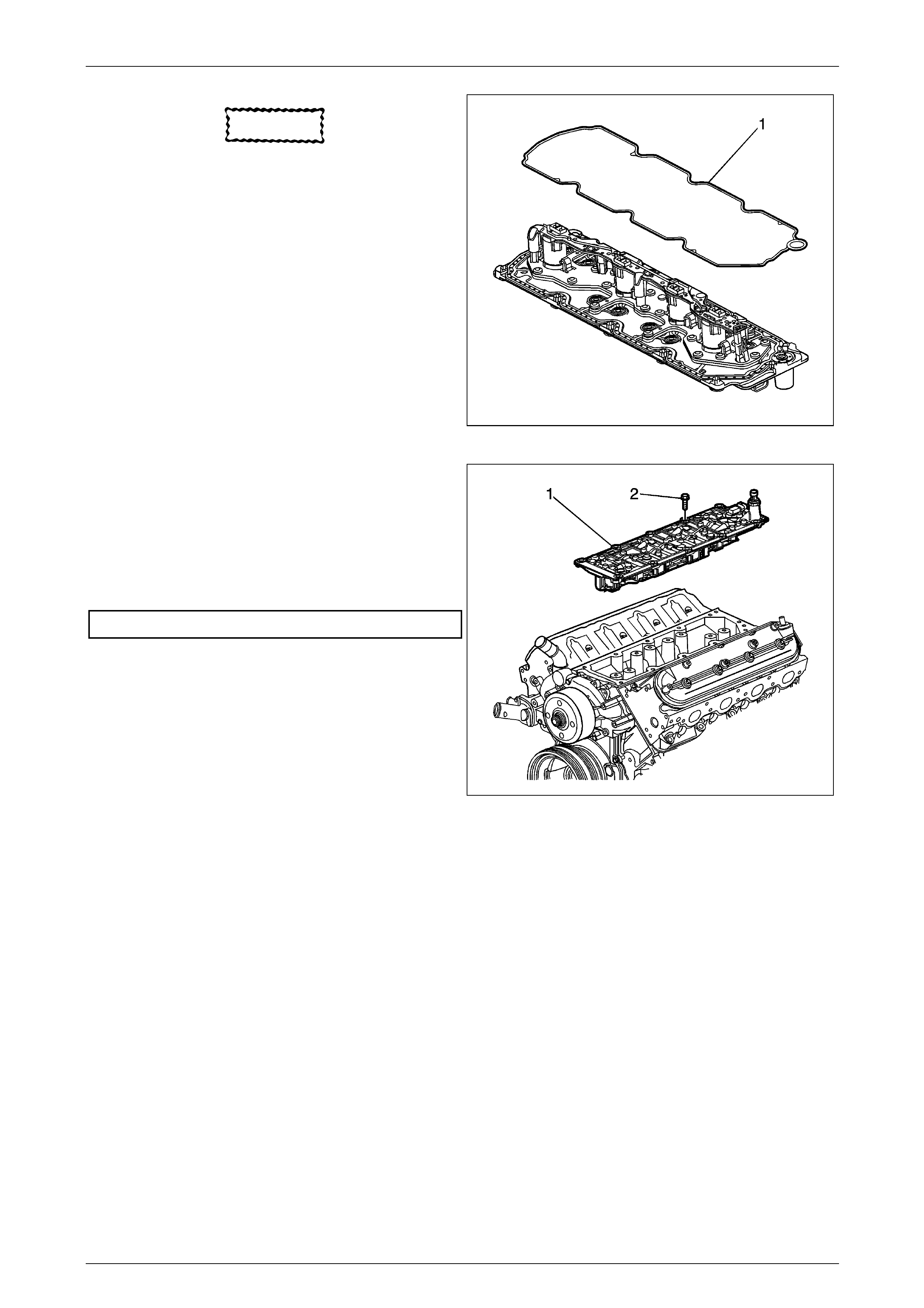
Engine Mechanical Page 6A4–56
Page 6A4–56
CAUTION
All gasket surfaces should be free of oil or
other foregn material d u ring assembly
Do not allow dirt or debris to enter the
manifold plug
2 Install the service gasket (1) onto the manifold
Figure 6A4– 63
3 Install the manifold (1) with gasket.
NOTE
Refer to Fasterner Notice in Section 00 C autions
and Notices.
4 Install the manifold bolts (2), and tighten to the
specified torque.
Manifold Attaching Bolts ....................................25.0 Nm
Figure 6A4 – 64
Engine Mechanical Page 6A4–57
Page 6A4–57
2.4 Displacement on Demand Diagnostic
Procedures
Displacement on Demand (DoD) System Compression Test
The Displacement on Deman d (DoD) System Compression Test is a functional test of the valve lifter oil manifold (VLOM)
and valve lifters. Using a compression gage, the technician can monitor the specific cylinders ability to go into and out of
DoD as commanded by the scan tool. The actual pressure values on the compression gage are not as critical as is
observing the on-off switching action of the solenoid and valve lifters.
1 Measure the engine oi l level. Fill, as required.
2 Perform the Diagnostic System Check – Vehicle. Refer to Diagnostic S ys t em Check - Vehicle in Vehicle DTC
Information.
3 Disable the ignition system for the cylinder to be tested, by disconnecting the electric al wire harness to the ignition
coil.
4 Disable the fuel injection s ystem for the cylinder to be tested, by disconnecting the electrical wire harness to the
fuel injector.
5 Remove the spark plug and wire for the cylinder to be tested.
6 Install a 0–1378 kPa (0–200 psi) compression gage.
7 Start the engine.
8 Using the scan tool output controls, command the solenoid ON, for the cylinder to be deactivated.
9 Depress the Schrader valve on the compression gage in order to release the pressure and zero the gage. With the
engine running and the c ylinder in DoD mode, the compression reading should be less than 172 kPa (25 psi).
10 Using the scan tool, de-energize the solenoid while observing the reading on the compression gage. With the
engine running and the c ylinder NOT in DoD mode, the compression gage reading shou ld increase quickly to
greater than 345 kPa (50 psi).
CAUTION
Only 1 cylinder can be tested at a time.
When testing has been completed on a specific cylinder, the wire harness electrical conn ectors, spark plug, and spark
plug wire must be installed prior to testing of each additional cylinder.
1 Test each of the 4 DoD cylinders, 1 at a time. If the readings are not within specifications, remove and test the
VLOM, as required. Refer to Valve Lifter Oil Manifold Replacement and Displacement on Demand (DoD)
Valve Lifter Oil Manifold Diagnosis and Testing .
2 If the compression test has been performed and all DoD cylinders are operating within specifications, the DoD
system is performing as designed and no repairs are re quired.
3 Clear the DTCs with a scan tool.
Cylinder Leakage Test
Tools Required
• J 35667-A Cylinder Head Leakdown Tester, or equivalent
NOTE
A leakage test may be performed in order to
measure cylinder/combustion chamber leakage.
High cylinder leakage may indicate 1 or more of
the following conditions:
• Worn or burnt valves
• Broken valve springs
• Stuck valve lifters
• Incorrect valve lash
• Damaged piston
• Worn piston rings
• Worn or scored cylinder bore
• Damaged cylinder head g asket
• Cracked or damaged cylinder head
• Cracked or damaged engine block

Engine Mechanical Page 6A4–58
Page 6A4–58
Refer to Battery Disconnect Caution in
Section 00 Cautions and Notices.
1 Disconnect the battery ground negative cable.
2 Remove the spark plugs. Refer to Spark Plug Replacement in Engine Controls – 6L.
3 Rotate the crankshaft to place the piston in the cylinder being tested at top dead center (TDC) of the compression
stroke.
4 Install the J 35667-A , or equivalent.
NOTE
It may be necessary to hold the crankshaft
balancer bolt to prevent the crankshaft from
rotating.
5 Apply shop air pressure to the J 35667-A and adjust according to the manufacturers instructions.
6 Record the cylinder leakage value. Cylinder leakage that exceeds 25 percent is considered excessive and may
require component service. In excessive leakage situations, inspect for the following conditions:
• Air leakage noise at the throttle body or air inlet hose that may indicate a worn or burnt intake valve or a
broken valve spring.
• Air leakage noise at the exhaust system tailpipe that may indicate a worn or burnt exhaust valve or a broken
valve spring.
• Air leakage noise from the crankcase, oil level indicator tube, or oil fill tube that may indicate worn piston
rings, a damaged piston, a worn or scored cylinder bore, a damaged engine block or a damaged cylinder
head.
• Air bubbles in the cooling s ystem ma y indicate a damaged cylinder head or a damaged c ylinder head gasket.
7 Perform the leakage test on the remaining cylinders and record the values.
Oil Consumption Diagnosis
Checks Causes
Preliminary The causes of excessive oil consumption may include the following conditions:
• External oil leaks Refer to Oil Leak Diagnosis .
• Incorrect oil level or improper reading of the oil level indicator
• With the vehicle on a level surf ace, run the engine for a few minutes, allow
• adequate drain down time, 2–3 minutes, and check for the correct engine oil level.
• Improper oil viscosity
Refer to the vehicle owners manual and use the recommended SAE grade and viscosity for the
prevailing temperatures.
• Continuous high speed driving and/or severe usage
• Crankcase ventilation system restrictions or malfunctioning components
• Worn valve guides and/or valve stems
• Worn or improperly installed valve stem oil seals
• Piston rings broken, worn, or not seated properly
Allow adequate time for the rings to seat.
Replace worn piston rings as necessary.
• Piston and rings improperly installed or not fitted to the cylinder bore
Oil Pressure Diagnosis and Testing
Tools Required
• J 21867 Pressure Gage
• J 42907 Oil Pressure Tester

Engine Mechanical Page 6A4–59
Page 6A4–59
1 With the vehicle on a level surf ace, run the vehicle for
a few minutes, allow adequate drain d own time, 2–3
minutes, and measure the oil level.
2 If required, add the recommended grad e engine oil
and fill the crankcase until the oil level measures full
on the oil level indic ator.
3 Run the engine briefly, 10–15 seconds, and verify low
or no oil pressure on the vehicle gage or light.
4 Listen for a noisy valve train or a knocking noise.
5 Inspect for the following conditions:
• Oil diluted by water or glycol a ntifreeze
Refer to Coolant in Engine Oil .
• Foamy oil, which may be caused by a cut or
damaged oil pump screen O-ring seal
Figure 6A4 – 65
6 Remove the oil filter and install the J 429 07 (1).
7 Install the J 21867 (2), or equivalent to the J 42907 (1).
8 Run the engine and measure the engine oil pressure.
9 Compare the readings to Eng ine Mechanical Specifications .
10 If the engine oil pressure is below specifications, inspect the engine for 1 or more of the following conditions:
• Oil pump worn or dirty Refer to Oil Pump Cleaning and Inspection.
• Oil pump-to-engine block bolts loose Refer to Oil Pump, Screen and Crankshaft Oil Deflector Installation.
• Oil pump screen loose, plugged, or damaged
• Oil pump screen O-ring seal missing or damaged
• Oil filter tube loose or a leaking or damaged gasket
• Malfunctioning oil pump pressure relief valve
• Excessive bearing clearance
• Cracked, porous, or restricted oil galleries
• Oil gallery plugs missing or in correctly installed Refer to 5.14 Engine Block Plug Installation.
• Improper operation of the displacement on demand (DoD) oil pressure relief valve Refer to Displacement on
Demand (DoD) Oil Pressure Relief Valve Diagnosis and Testing .
Displacement on Demand (DoD) Oil Pressure Relief Valve Diagnosis and Testing
Tools Required
• J 21867 Pressure Gage
• J-21867-16 Oil Pressure Adapter
• J 42907 Oil Pressure Tester
NOTE
This test is performed to verify the operation of
the displacement on demand (DoD) oil pressure
relief valve.
Refer to;-Displacement on Demand (DoD) 2.2 System Description and
Lubrication Description:
• Main Pressure Below 55 psi - DoD Off.
• Main Pressure Above 55 psi - DoD Off
• Main Pressure Below 55 psi - DoD On
• Main Pressure Above 55 psi - DoD On
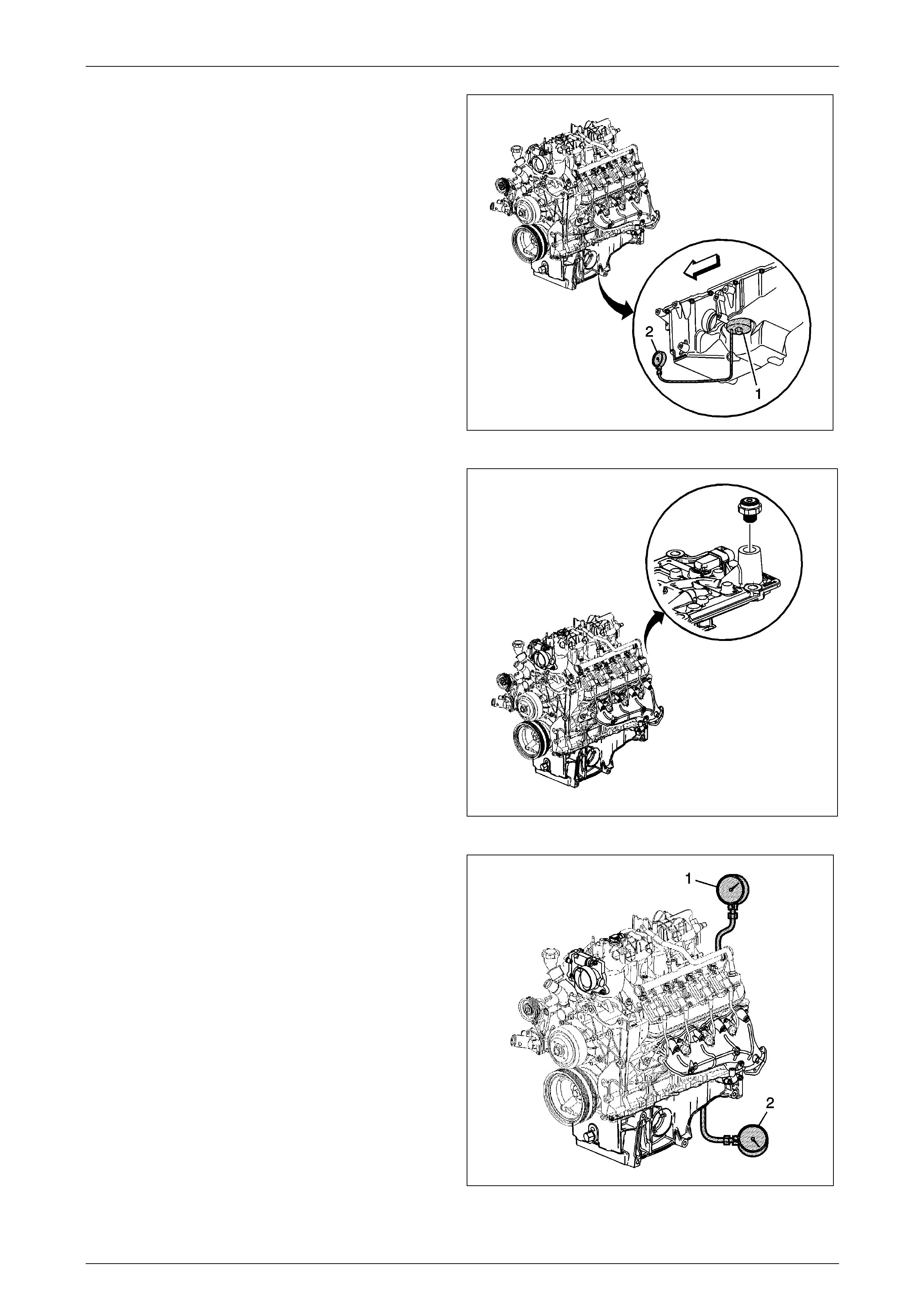
Engine Mechanical Page 6A4–60
Page 6A4–60
1 Remove the oil filter and install the J 429 07 (1).
2 Install the J 21867 (2), or equivalent to the J 42907
(1).
Figure 6A4 – 66
3 Remove the oil pressure sensor and install the
J-21867-16
Figure 6A4 – 67
4 Install the J 21867 (1), or equivalent to the J-21867-16
(2).
5 Run the engine and measure the engine oil pressure
while observing both gages
Operate the throttle, as required, to increase and decrease
the engine oil pressure
• With the engine running and the lower pressure gage
(2) measuring below 379 kPa (55 psi), both gages
should display the same pressure rea din g. If the
readings are not the same and the lower gage (2) has
a higher reading, the DoD oil pressure relief valve is
stuck in the open position or the valve lifter oil manifold
filter is plugged.
• With the engine running and the lower pressure gage
(2) measuring above 379 kPa (55 psi), the upper gage
(1) should display no greater than 379–517 kPa (55–
75 psi). If the reading on the upper ga ge (1) is greater
than 517 kPa (75 psi), the DoD oil pressure relief valve
is stuck in the closed position.
6 Repair, as required Figure 6A4 – 68
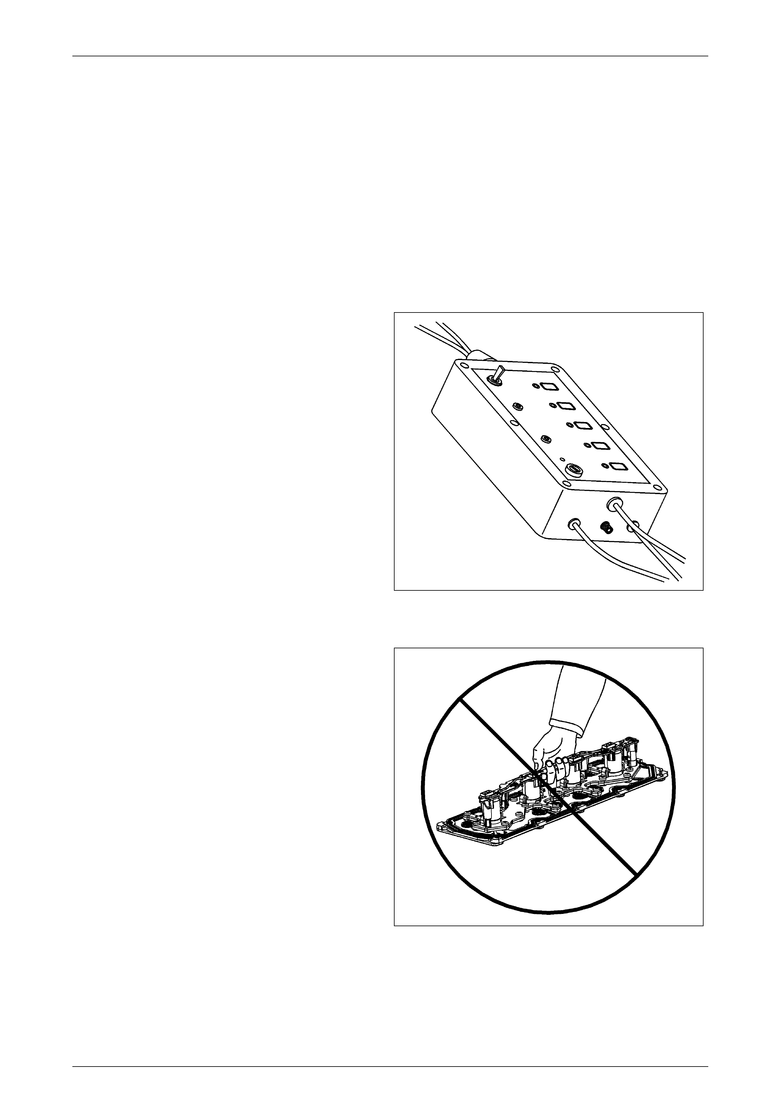
Engine Mechanical Page 6A4–61
Page 6A4–61
Displacement on Demand (DoD) Valve Lifter Oil Manifold Diagnosis and Testing
Tools Required
• EN-46999 Displacement-on-Demand Tester
• EN-46999-1 Displacement-on-Demand Tester Air Adapter
• EN-46999-5 Displacement-on-Demand Tester Harness – Small Block V8
NOTE
This component test applies only to vehicles with
functional displacement-on-de mand.
• A minimum shop air source of 206 kPa (30 psi) is required for manifold testing.
• A water bleed is located on the side of the EN-46 99 . Occasionall y, depress the valve in order to remove excess
water from the tool.
The manifold bench test provides a maximum 206 kPa (30
psi) of filtered shop air to the manifold and will test each
solenoid/valve for the following conditions:
• Proper operation
• A stuck open condition – cons tant air flow
• A stuck closed condition – no air flow
• A flow restriction within the manifold
1 Individually depress each of the buttons 1–4 on the
EN-46999 in order to activate each of the
solenoid/valves. W hen activating each solenoid/valve,
a loud click should be heard from the solenoid and an
increased amount of air will exit the outlet ports.
• Button 1 will energize the solenoid/valve 1 for
engine cylinder number 1.
• Button 2 will energize the solenoid/valve 2 for
engine cylinder number 4.
• Button 3 will energize the solenoid/valve 3 for
engine cylinder number 6.
• Button 4 will energize the solenoid/valve 4 for
engine cylinder number 7
Figure 6A4 – 69
2 Do not lift the manifold assembly by the electrical le ad
frame.
Figure 6A4 – 70
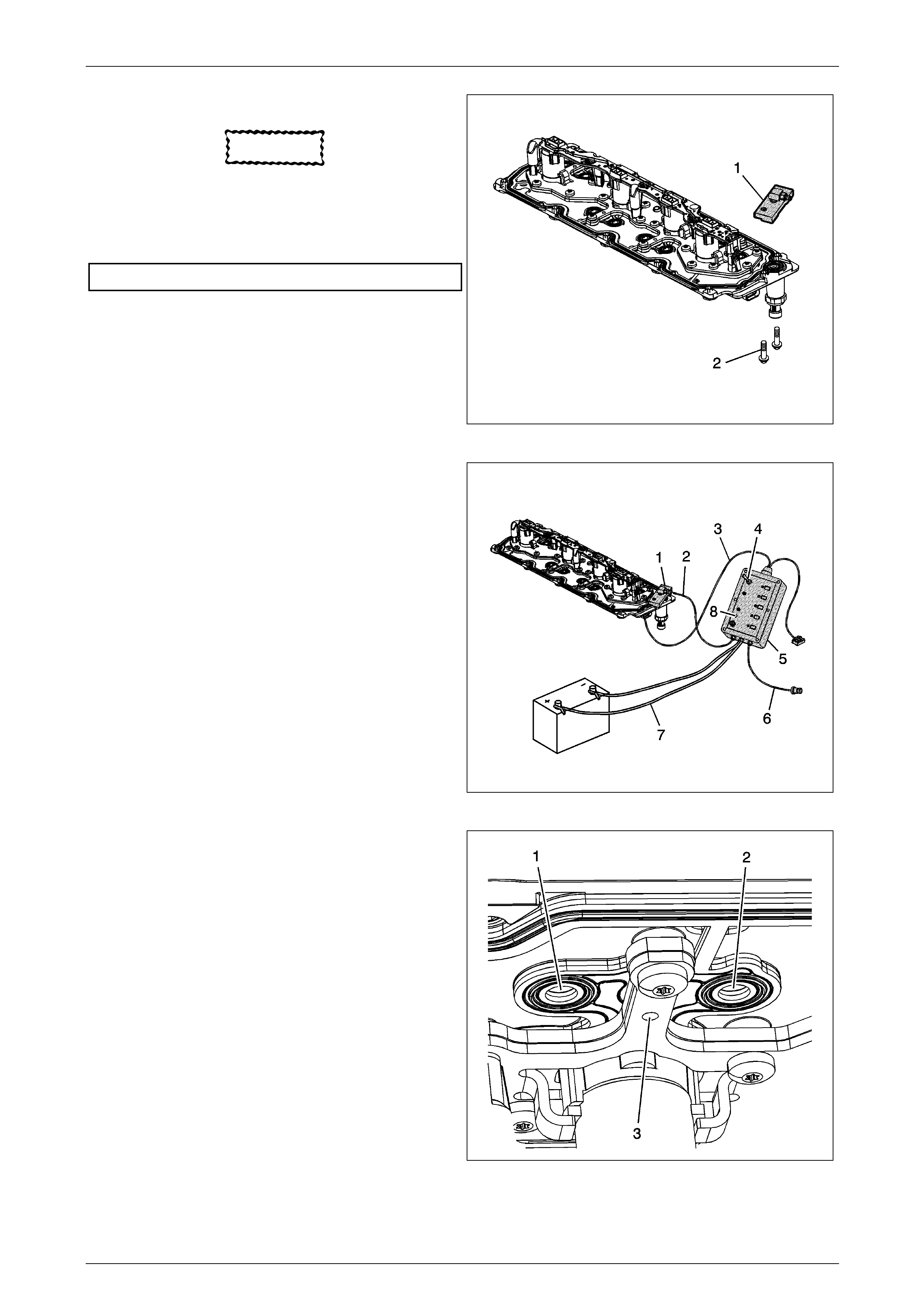
Engine Mechanical Page 6A4–62
Page 6A4–62
3 Install the EN-46999-1 (1) to the manifold.
CAUTION
Refer to Fastener Notice in Section 00
Cautions and Notices.
4 Install two of the manifold bolts (2) to the
EN-46999-1 and tighten to the specifie d torque.
Manifold bolts.....................................................25.0 Nm
Figure 6A4 – 71
5 Connect the air out hose (2) of the EN-469 99 (5) to the
EN-46999-1 (1). Verif y the air supply switch (4) is in
the off position.
6 Connect the air in hose (6) of the EN-46999 (5) to a
shop air source.
7 Connect the 12 volt power supply connectors (7) of the
EN-46999 (5) to a 12 volt power supply. Verify the
Power light (8) on the tool is illuminated. If the light on
the tool is not illuminated when connected to a 12 volt
power supply, test and/or replace the 3 am p fuse.
8 Connect the EN-46999-5 power cable (3) to the
electrical connector of the manifold.
Figure 6A4 – 72
9 Turn the air supply s witch of the EN-469 99 to the ON
position. With the air supply c onnected to the manifold
assembly and the solenoid/valves in the closed
position, a limited amount of a ir will exit each of the
bleed holes (3) and outlet port s (1, 2) of the manifold.
Figure 6A4 – 73
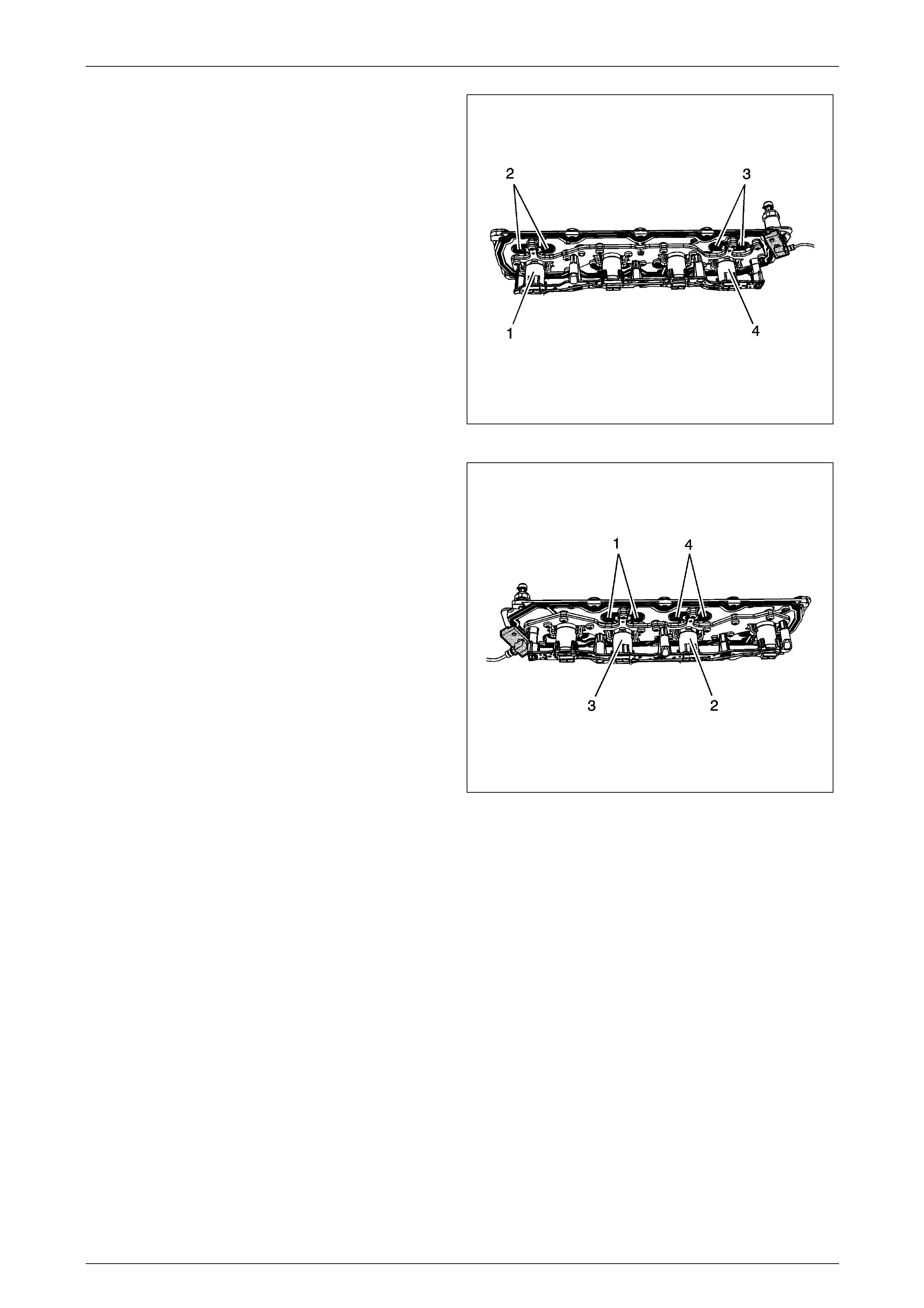
Engine Mechanical Page 6A4–63
Page 6A4–63
NOTE
The manifold must be tested in the proper
position to ensure the sole noi d/valves oper at e as
designed
10 Position the manifold assembly onto a bench at a 45
degree angle in order to test sole noid/valves 1 and 4.
11 Depress button number 1 on the tool to activate
solenoid/valve 1. With button 1 depressed, the
solenoid/valve (1) should o pen, allowing an increased
amount of air to exit the outlet ports (2) of the
manifold.
12 Depress button number 4 on the tool to activate
solenoid/valve 4. With button 4 depressed, the
solenoid/valve (4) should o pen, allowing an increased
amount of air to exit the outlet ports (3) of the
manifold.
Figure 6A4 – 74
13 Reposition the manifold assembl y onto a bench at a
45 degree angle in order to test solenoid/valves 2 and
3.
14 Depress button number 2 on the tool to activate
solenoid/valve 2. With button 2 depressed, the
solenoid/valve (2) should o pen, allowing an increased
amount of air to exit the outlet ports (4) of the
manifold.
15 Depress button number 3 on the tool to activate
solenoid/valve 3. With button 3 depressed, the
solenoid/valve (3) should o pen, allowing an increased
amount of air to exit the outlet ports (1) of the
manifold.
16 When the test is completed, turn the air source switch
on the EN-46999 to the off position and disconn ect the
tool from the 12-volt power supply, shop air source
and manifold assembly.
17 If after testing, it has been determined that 1 or more
of the solenoid/valves is not functioning properly,
replace the manifold as an assembl y.
18 If after testing, it has been determined that the
solenoid/valves are functioning properly, replace the
valve lifters, as required. Both intake and exhaust
lifters should be replaced in pairs.
Figure 6A4 – 75

Engine Mechanical Page 6A4–64
Page 6A4–64
3 Diagnosis
3.1 Engine Diagnosis
Engine performance diagnosis procedures are covered in Section 6 C4-2 Engine Management – GEN IV V8 – Diagnostics
and should be referred to for diagnosis of any driveability, emissions, or Engine diagnostic trouble codes (DTC) problems.
The following diagnosis cov ers common problems and possible causes. When the correct diagnosis is made, the cause
should be corrected by adjustment, repair or replacement as required.
Refer to the appropriate Section of the service information for each sp ecific procedure.
This diagnostic table will assist in diagnosis of an engine mechanical fault such as a faulty camshaft, worn or damaged
bearings or bent pushrod.
Also refer to 2.4 Displacement on Demand Diagnostic Pro cedures
This diagnostic table will not isolate a crossed injector wire, faulty injector or any other electrical component failure that
may cause a misfire. The Engine On-Board Diagnostic System checks must be performed first. Refer to
Section 6C4-2 Engine Management – GEN IV V8 – Diagnostics.
When using this table to perform the Engine Misfire diagnosis, begin with the preliminary information below and then
proceed to the specific category.
Procedure
Checks Action
Preliminary Perform a visual inspection of the following:
• A loose or incorrectly installed crankshaft balancer and if required check the
flywheel or flexplate for loose or incorrect installation.
• Worn, damaged, or misaligned accessor y dr ive system components.
• Listen to the engine for any abnormal internal engine noises.
• Inspect the engine for acceptable oil pressure. Refer to 3.5 Oil Pressure.
• Verify if the engine has excess ive oil consumption. Refer to 3.4 Oil Consumption.
• Verify if the engine is consuming coola nt.
• Perform a compression test on the engine.
Intake manifold leaks An intake manifold that h as a vacuum leak ma y cause a misfire which is m ore prominent
at idle.
Inspect for the following:
• Incorrectly installed or damag ed vacuum hoses.
• Faulty or incorrectly installed intake manifold and / or gask ets.
• Cracks or damage to the intake manifold, also inspect the areas between the intake
runners.
• Incorrectly installed or damag ed Manifold Absolute Pressure (MAP) sensor or
O-ring seal. The MAP sensor is located at the rear of the intake manifold.
• Incorrectly installed throttle body or damaged gasket.
• Warped intake manifold.
• Warped or damaged cylinder head sealing surface.
Coolant consumption Coolant consumption may or may not cause the engine to overheat. However, an engine
that has been overheated may ca use premature failure of head gaskets and distortion of
gasket surfaces.
Inspect for the following:
• External coolant leaks.
• Faulty cylinder head gasket.
• Distorted cylinder head.
• Cracked or corroded c ylinder head.
• Damaged cylinder block.
• Thermostat operation.

Engine Mechanical Page 6A4–65
Page 6A4–65
Checks Action
Abnormal internal engi ne
noises 1 With the engine running, try to determine the knock speed. That is if the noise is
timed to camshaft speed or crankshaft speed.
NOTE
• Camshaft speed is half the speed of the crankshaft. Use a timing light to
determine the knock spee d. Two knocks per flash is cra nkshaft speed and
one knock per flash is camshaft speed.
• A slight COLD knock or p iston slapping noise could be con sidered normal
if it is not present after the engine has reached normal operating
temperatures.
2 If the noise is timed to camshaft speed, inspect the following:
• Missing or loose valve train components.
• Worn or loose valve rocker arms.
• Worn or bent pushrods.
• Faulty valve springs.
• Bent or burnt valves.
• Worn camshaft lobes.
• Worn or damaged timing chain and/or sprockets.
3 If the knock is timed to crankshaft speed, inspect the following:
• Worn crankshaft main or connecting rod bearings.
• Piston or cylinder damage.
• Worn piston or piston pin.
• Damaged or faulty connecting rod.
• Excessive carbon build-up on the top of the piston.
Engine misfire 1 Remove the valve rocker arm cover on the side of the en gine with the cylinder that
is misfiring.
2 Inspect for the following:
• Loose valve rocker arm bolts.
• Bent push rods.
• Faulty valve springs.
• Faulty valve lifters (bleeding d own).
• Worn or Incorrectly seated valves.
• Worn camshaft lobes.

Engine Mechanical Page 6A4–66
Page 6A4–66
3.2 Engine Noise
There are four steps to diagnosing engine noise that must be determined.:
1 The type of noise.
• Determine if the noise a light rattle/tapping or a low rumble/knocking noise.
2 The exact operating condition under which the noise exists.
• Factors such as the ambient temperature, the amount of engine warm-up time, the engine temperature,
engine speed and load and other specifics.
3 At what rate the noise occurs, and at what location in the engin e.
• Remember, engine noises are generally synchronised to either engine speed (crankshaft, flywheel,
connecting rods, balancer, or pistons and related components) or one-half engine speed (valve train noise
such as rocker arms, valve lifters, and timing chain). Try to determine the r ate at which the noise is occurring.
Use a timing light to assist in determining the knock speed. Two knocks per flash is crankshaft speed and one
knock per flash is camshaft speed.
4 Compare the engine sounds to other engines.
• If possible, compare the engine noise to an other engine as this will verify that you are not trying to correct a
normal condition.
Procedure
Checks Action
Noise on start-up but only lasts a
few seconds This noise condition may be cause d b y:
• Incorrect oil viscosity. Change the engine oil with the recommended oil
viscosity for the expected temperatures.
• Incorrect oil filter without the anti-drain back feature.
• Worn or dirty hydraulic valve lifters.
• Excessive piston to bore clearance.
• Excessive piston pin to piston cleara nce.
• Excessive crankshaft bearing clearance.
Knocks when cold and continues
for 1 to 2 minutes Common causes for a cold start knock are:
• Loose or broken crankshaft bala ncer or accessory drive components.
• Excessive piston to bore clearance.
• Cracked piston.
NOTE
A cold engine knock usually disappears when the specific cylinder's
secondary ignit ion circuit is isolated.
Intermittent noise on idle,
disappearing when the engine
speed is increased
Intermittent noises at idle can be caused by:
• Incorrect oil viscosity. Change the engine oil with the recommended oil
viscosity for the expected temperatures.
• Lower than specified oil pressure. Install an oil pressure gauge and
measure the engine oil pressure.
• Dirty or worn hydraulic valve lifter.

Engine Mechanical Page 6A4–67
Page 6A4–67
Checks Action
Valve train noise (rattle/tapping) The following conditions may cause valve train noise:
• Lower than specified oil pres sure.
• Worn or faulty oil pump.
• Loose oil pump to cylinder block bolts.
• Loose or damaged oil transfer tube and/or gaskets.
• Loose valve rocker arm attaching bolt.
• Worn valve rocker arm bearings.
• Worn valve rocker arm and/or pushrod.
• Broken valve spring.
• Sticking valves.
• Worn, dirty, or faulty hydraulic valve lifters.
• Worn hydraulic valve lifter guides.
• Worn camshaft lifter lobes.
• Worn valve guides or valve stems.
• Bent, broken, or damaged timing chain sprocket teeth.
Knocks at idle when hot
(rumble/knocking) The following conditions may cause a knocking noise:
• Malfunctioning accessory dr ive system components.
• Loose or broken crankshaft bala ncer.
• Detonation (Pinging). Check for correct operation of the coolin g, knock, and
ignition control components. Refer to diagnos tic information in 6C4-2
Engine Management – GEN IV V8 – Diagnostics.
• Excessive piston pin to bore clearance.
• Bent connecting rod.
• Excessive connecting rod bearing, crankshaft main or thrust bearing
clearance.
• Loose torque converter and/or fl ywheel/flexplate bolts.
• Cracked or damaged flywheel or flexplate.
• Exhaust leak at the manifold.
Exhaust system noise and/or
leakage Exhaust system noise and/or leakage may be caused by the following conditions:
• Incorrectly installed or misaligned exhaust system components.
• Cracked or broken exhaust manifold.
• Damaged or worn gaskets.
• Burnt or corroded exhaust system components.
• A broken or loose exhaust clamp and/or br acket.

Engine Mechanical Page 6A4–68
Page 6A4–68
3.3 Valve Train Noise
A light tapping noise at one-half engine speed, or any varying frequency, may indicate a valve train problem. These
tapping noises will typically increase with engine speed.
Before attempting to diagnose valve train noise, check for correct oil level and thoroughly warm up the engine. By doing
this you will bring all engine components to a normal state of expansion.
While sitting in the drivers seat, run the engine at various speeds and listen for any abnor m al engine noise.
When diagnosing a valv e lifter noise, always use a listening device such as a stethoscope. Tools such as this will help to
isolate any lifter noise and identify noises that could be mis-diagnosed as lifter noise.
Also refer to 2.4 Displacement on Demand Diagnostic Pro cedures
Procedure
Checks Action
Light tapping noise similar to
valve train noise
This light type of noise may be caused b y the following:
• Fuel injectors.
• Evaporative emission (EVAP) purge so lenoid.
• Detonation (Pinging).
• Loose heat shields.
Causes of valve train noise 1 Any or a combination of the following can cause valve train noise:
• Loose valve rocker arm attachments caus ing excessive valve lash.
• Worn or damaged valve rocker arm bear ings.
• Worn valve rocker arm and/or pushrod.
• Broken valve spring.
• Sticking valves.
• Worn, dirty, or faulty hydraulic valve lifters
• Broken hydraulic valve lifter guide.
• Camshaft lobes worn.
• Worn valve guides or valve stems.
• Worn, damaged, or missing valve collets.
• Bent pushrods.
• Excessive play in the camshaf t timing chain.
• Bent, broken, or damaged timing chain sprocket teeth.
2 Low engine oil pressure caused by the following:
• Poor oil quality caused by water contamination, aeration, or fuel
dilution or incorrect oil viscosity.
• Worn or faulty oil pump.
• A loose oil pump pick-up tube.
• Blocked oil pump pick-up tube screen.
• Loose or damaged oil transfer tube.

Engine Mechanical Page 6A4–69
Page 6A4–69
3.4 Oil Consumption
NOTE
Excessive oil consumption (not due to leaks) is
the use of 0.75 litres or more of engine oil within
2,500 kilometres (3 litres / 10,000 kilometres ).
Checks Action
Preliminary 1 The causes of excessive oil consumption may include the following
conditions:
• External oil leaks. Refer to 3.6 Oil Leaks.
• Incorrect oil level or reading of the oil level indicator. With the vehicle
on a level surface, run the engine for a few minutes, allow adequate
drain down time (2-3 minutes) and check for the correct en gine oil
level.
• Incorrect oil viscosity. Refer to the vehicle Owners Manua l and use
the recommended SAE grade and viscosity for the operating
environment.
• Continuous high speed driving and/or severe usage.
• Crankcase ventilation system restrictions or malfunction.
• Worn valve guides and/or valve stems.
• Worn or incorrectly installed valve stem oil seals.
• Broken, worn or incorrectly seated piston rings. Allow adequate time
for the rings to seat. Replace worn piston rings as necessar y.
• Piston and rings incorrectly installed or incorrectly fitted to the cylinder
bore.
• Excessive piston to bore clearance.
2 Perform a cylinder compression test. Refer to 3.7 Compression Check.
3 If the compression test indicates a worn valve train, inspect for the
following:
• Worn valve guides.
• Worn valve stems.
• Worn or burnt valves or valve seats.
• Worn, brittle, or incorrectly installed valve stem oil seals.
4 If the compression test indicates worn or damaged piston rings, inspect the
following:
• Broken or incorrectly seated piston rings.
• Excessive piston ring end gap.
• Excessive cylinder bor e wear or taper.
• Cylinder damage.
• Piston damage.
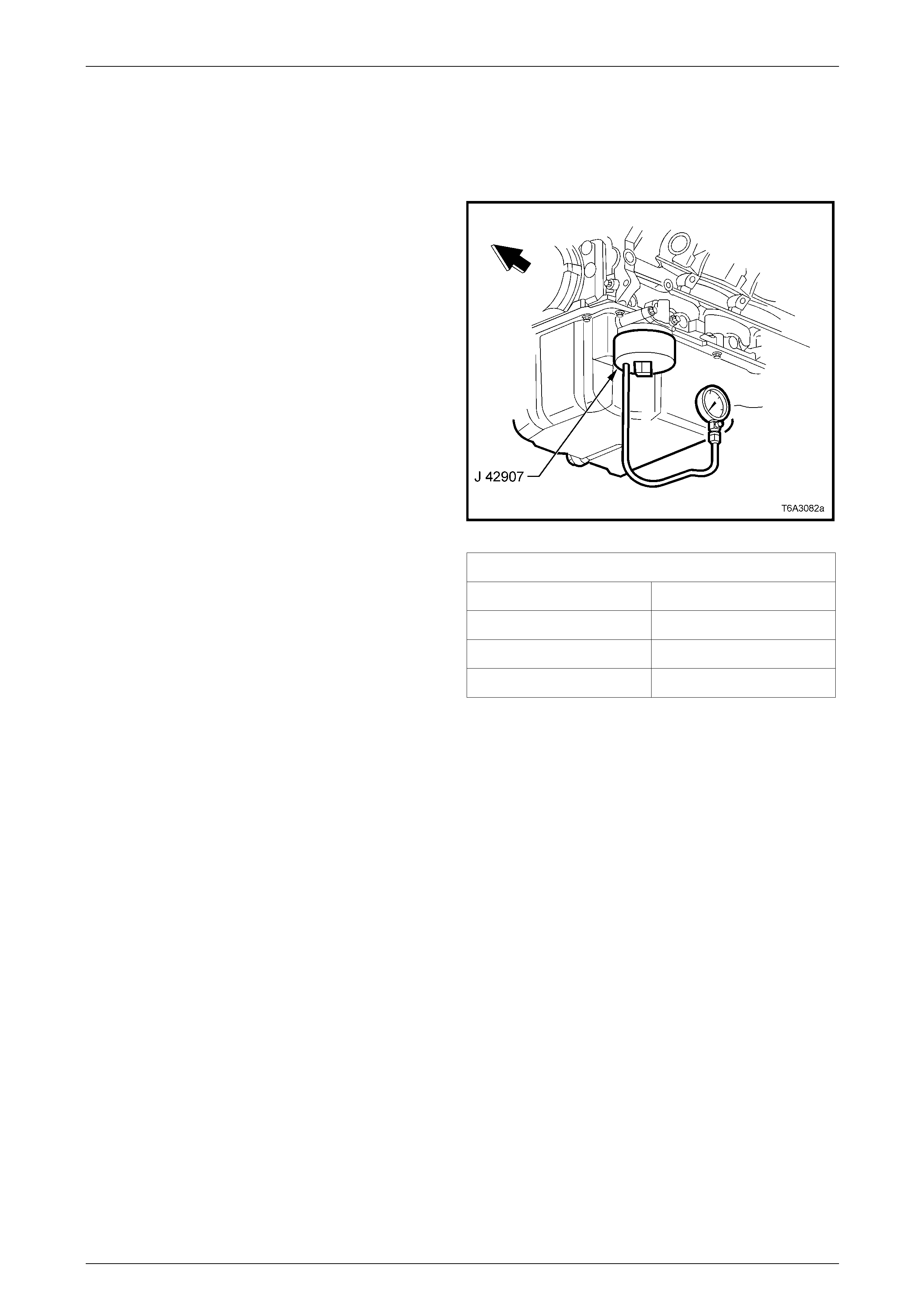
Engine Mechanical Page 6A4–70
Page 6A4–70
3.5 Oil Pressure
Oil Pressure Check
Also refer to 2.4 Displacement on Demand Diagnostic Pro cedures
1 Ensure the engine is at operating temper ature. Driving
a cold vehicle for a minimum of 15 minutes should be
sufficient to bring the engine to operating temperature.
2 Remove the oil filter, refer to 4.3 Engine Oil and Filter.
3 Install adaptor Tool No. J 42907 to the oil filter
adaptor.
4 On a level surface check the engine oil level, topping
up as required. Refer to 4.3 Engine Oil a nd Filter.
5 Install an accurate oil pressure gauge that is capable
of reading 800 kPa or higher a nd a suitably rated
pressure hose to adaptor Tool No. J 42907.
6 Start the engine and check the oil pressure with the
engine running under a no lo ad condition.
Figure 6A4 – 76
7 Check the oil pressure is within the specifications.
NOTE
If the oil pressure check indicates the oil
pressure is not within specification, refer to
Diagnosis in this Section.
Engine Oil Pressure Specification
Engine Speed (RPM) Oil pressure Reading
1000 45 kPa (Minimum, Hot)
2000 125 kPa (Minimum, Hot)
4000 165 kPa (Minimum, Hot)
Figure 6A4 – 77
8 Switch off the engine and remove the oil pressure gauge and adaptor assembly.
9 Install the oil filter, refer to Oil Filter and Adapter.
10 Top up the engine oil level as required, refer Oil Level Check.

Engine Mechanical Page 6A4–71
Page 6A4–71
Diagnosis
Checks Action
Oil Pressure Below Specification Inspect the engine for one or more of the following:
• Oil pump worn or dirty.
• Loose oil pump to cylinder block attaching bolts.
• Oil pump pick-up tube screen blocked or damaged.
• Loose oil pump pick-up tub e
• Missing or damaged oil pump pick-up tube O-ring seal.
• Malfunctioning oil pump oi l pressure relief valve.
• Excessive bearing cl earances.
• Cracked, porous or restricted oil galleries.
• Oil gallery plugs leaking, missi ng or incorrectly installed.
• Broken or malfunctioning hydraulic v alve l ifters.
• Worn or damaged hydraulic valve lifters.
Oil Pressure Above Specification Inspect for one or more of the following:
• Blocked or incorrect oil filter fitted.
• Malfunctioning oil by-pass valve.
• Malfunctioning oil pressure gauge or sensor creating a higher reading than
the actual reading.
• Incorrect oil viscosity.

Engine Mechanical Page 6A4–72
Page 6A4–72
3.6 Oil Leaks
NOTE
Most fluid leaks can be repaired by visually
locating the leak, repairing or replacing the
component, tightening fasteners to the correct
torque specification or by resealing the gasket
surface.
Step Action Yes No
1 1 Operate the vehicle until it reaches normal operating tempe rature.
2 Park the vehicle on a level surface, over a large sheet of paper or
other clean surface.
3 Wait for at least 15 minutes.
4 Check for oil drips.
Are oil drips present? Go to Step 2 Go to Step 3
2 Identify the type of fluid and the approximate location of the leak.
Can you identify the type of fluid and the approximate l ocation of the leak? Go to Step 8 Go to Step 3
3 1 Visually, inspect the suspected area. Use a small mirror to assist in
looking at hard to see areas.
2 Check for leaks at the following locatio ns:
• Sealing surfaces
• Fittings
• Cracked or damaged components
Can you identify the source of the leak? Go to Step 8 Go to Step 4
4 1 Thoroughly clean the entire engine a nd surrounding components.
2 Operate the vehicle for several kilometres at normal operating
temperature and at varying speeds.
3 Park the vehicle on a level surface, over a large sheet of paper or
another clean surface.
4 Wait for at least 15 minutes.
5 Identify the type of fluid, and the approximate location of the leak.
6 Using a small mirror to assist in looking at hard to see areas, visually
inspect the suspected area.
Can you identify the type of fluid, the source of the leak and the
approximate location ? Go to Step 8 Go to Step 5
5 1 Completely clean the entire engine and surrounding components.
2 Apply an aerosol-type powder (baby powder, foot powder, etc.) to the
suspected area.
3 Operate the vehicle for several kilometres at normal operating
temperature and at varying speeds.
4 Cracked or damaged components.
5 Identify the type of fluid, and the approximate location of the leak,
from the powder surface discolouration.
6 Using a small mirror to assist in looking at hard to see areas, visually
inspect the suspected area.
Can you identify the type of fluid, the source of the leak and the
approximate location ? Go to Step 8 Go to Step 6
6 1 Using the Dye and Black Light Kit, Tool J 42220 to assist in identifying
the type of fluid and the approximate location of the leak. Refer to the
manufacturer's instructions when using the tool.
2 Using a small mirror to assist in looking at hard to see areas, visually
inspect the suspected area.
Can you identify the type of fluid, the source of the leak and the
approximate location ? Go to Step 8 Go to Step 7

Engine Mechanical Page 6A4–73
Page 6A4–73
Step Action Yes No
7 1 Check for the following conditions:
• Higher than recommended fluid levels
• Higher than recommended fluid pr essures
• Blocked or malfunctioning fluid filters or pressure bypass valve
• Blocked or malfunctioning engine ventilation system
• Incorrectly tightened, missing or damaged fasteners
• Cracked or porous componen ts
• Incorrect sealants or gaskets where required
• Improper sealant or gasket installation
• Damaged or worn gaskets or seals
• Damaged or worn sealing sur faces
2 Can you identify the type of fluid, the source of the leak and the
approximate location ?
Repair or
replace all
damaged
components. Go to Step 8
8 Check the engine for mechanical damage.
Is there any mechanical damage to the engine?
Repair or
replace all
damaged
components. System OK
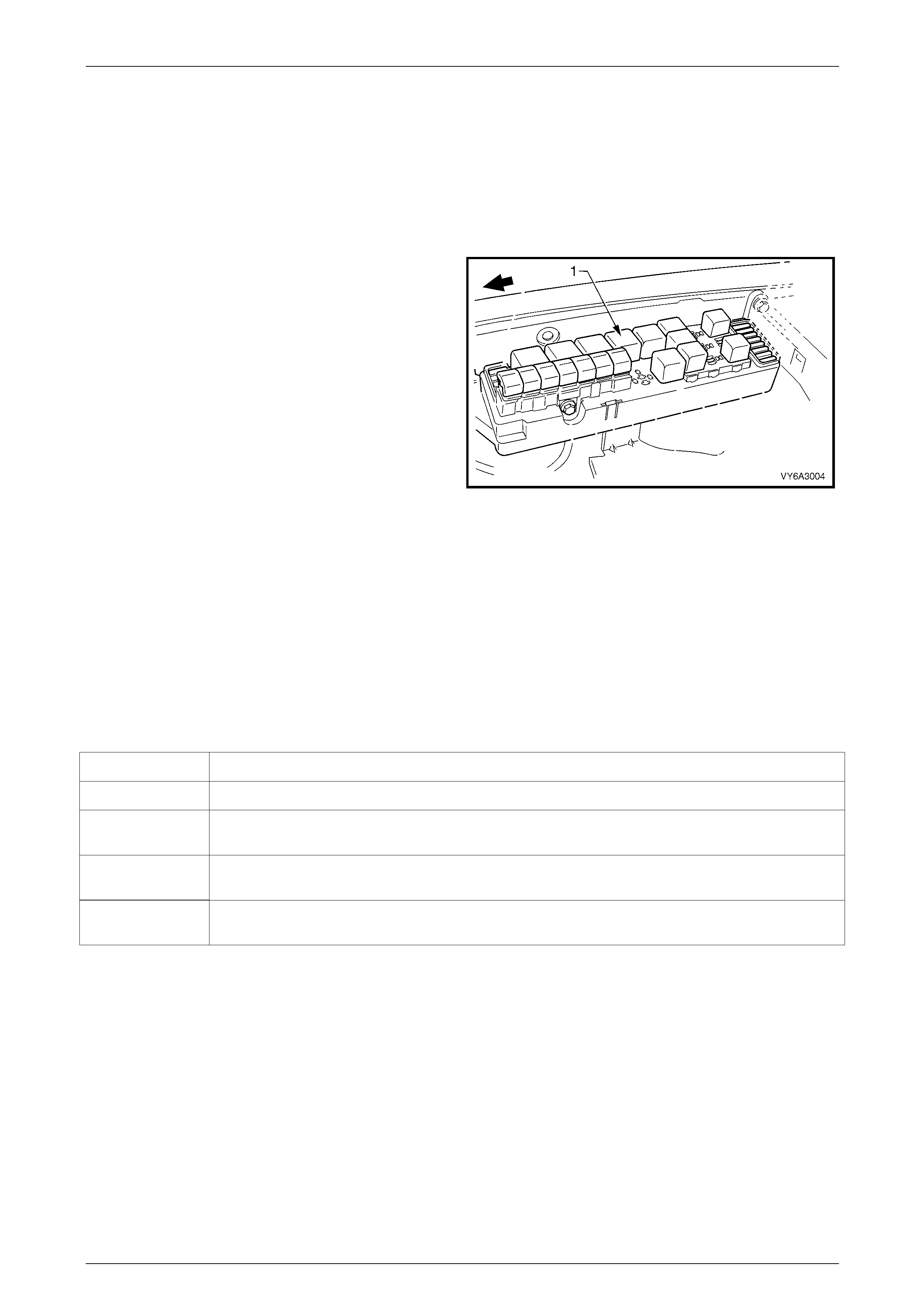
Engine Mechanical Page 6A4–74
Page 6A4–74
3.7 Compression Check
Also refer to 2.4 Displacement on Demand Diagnostic Pro cedures
1 Before conducting this check inspect the following:
• The battery is at or near a full state of charge
• The throttle plate is held wide open
2 Remove the spark plugs, refer to Section 6C4-3 Engine Management – GEN IV V8 – Service Operations.
3 With the ignition switched off, disable the ignition
system and fuel injectors, by removing the Engine
Control relay R4 (1), located in the engine
compartment fuse and relay panel assembly.
4 Install an accurate compression tester that has been
reset to zero.
5 Crank the engine through app r oximately four
compression strokes and record the reading. Repeat
for each cylinder, recording the read ing.
6 If a cylinder has low compression, inject abo ut 15 ml
(one tablespoon) of engine o il into the combustion
chamber through the spark plug hole. Cra nk the
engine over for appro x imately four turns to distribute
the oil.
7 Recheck the compression and record the reading.
8 Compare the compression readi ngs, refer to
Interpreting Compression Readings.
Figure 6A4 – 78
Interpreting Compression Readings
The minimum compression in any one cylind er should not be less than 70% of the highest cylinder. For example, if the
highest pressure in any o ne cylinder were 1035 kPa, the lowest allowable pressure for any other cylinder would be 725
kPa. (1,035 x 70% = 725).
NOTE
No cylinder should have a reading less than
690 kPa.
Condition Symptom
Normal Compression builds up q uickl y and evenly to the specified compression for each cylinder.
Worn Piston
Rings (Leaking) Compression is low on the first stroke. Compression then builds up with the following strokes but
does not reach normal. Compression improves considerably when you add oil.
Valves Leaking Compression is low on the first stroke. Compression usually does not build up on the following
strokes. Compression does not improve much when you add oil.
Cylinder Head
Gasket Leaking If two adjacent cylinders have lower than normal compression and injecting oil into the cylinders
does not increase the compression.
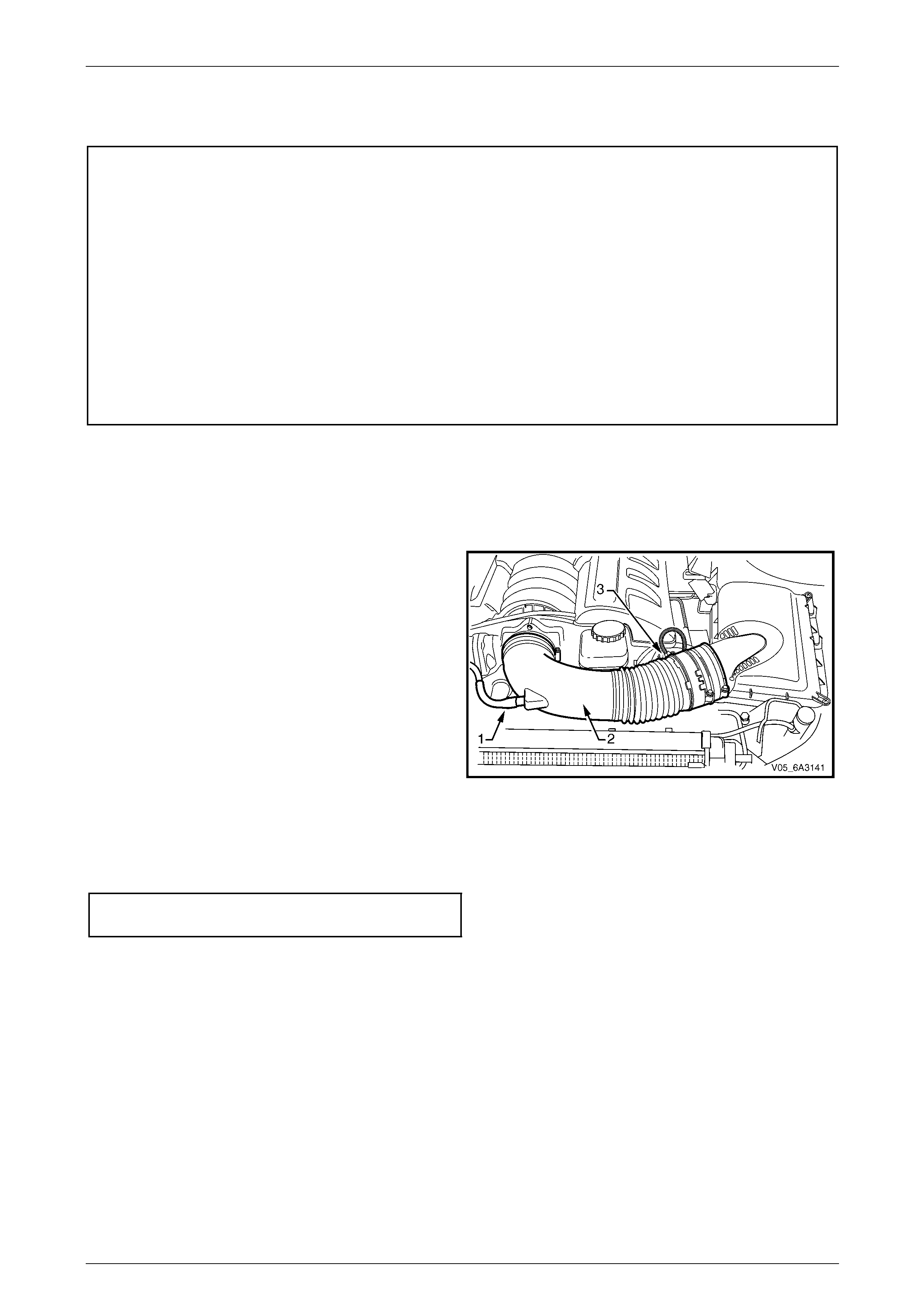
Engine Mechanical Page 6A4–75
Page 6A4–75
4 Minor Service Operations
ATTENTION
All engine fasteners are important attaching parts as they affect th e performance of vital componen ts and/or
could result in majo r repair expense. Where specified in this Section, fasteners MUST be rep laced with parts
of the same part number or an approved equivalent. Do not use fasteners of an inferior quality or substitute
design.
Torque values must be used as specified during reassembly to ensure correct retention of all components.
Throughout this Section, fastener torque wrench specifications may be accompanied with the following
identification marks:
Fasten ers must be replaced after loosening .
Fasteners either have micro encapsulated sealant applied or incorporate a mechanical thread lock and
should only be re-used once. If in doubt, replacement is recommended.
If one of these identification marks is present alongside a fastener torque wrench specification, the
recommendation regarding that fastener must be adhered to.
4.1 Air Intake Duct
LT Section No. — 03–250
Remove
1 Remove the fresh air hose (1) from the air intake duct
(2) and lay it to the side of the engine.
2 Remove the air intake sensor wiring harness
connector (3)
3 Loosen the hose clamps attachin g the intake duct to
the air box and the throttle body and remove the duct
from the engine.
Figure 6A4 – 79
Reinstall
Reinstallation of the air intak e duct is the re verse of the removal procedure ensuring all hose clamps are tightened to the
correct torque specification.
Air intake duct clamp
torque specification.....................................1.5 – 2.5 Nm
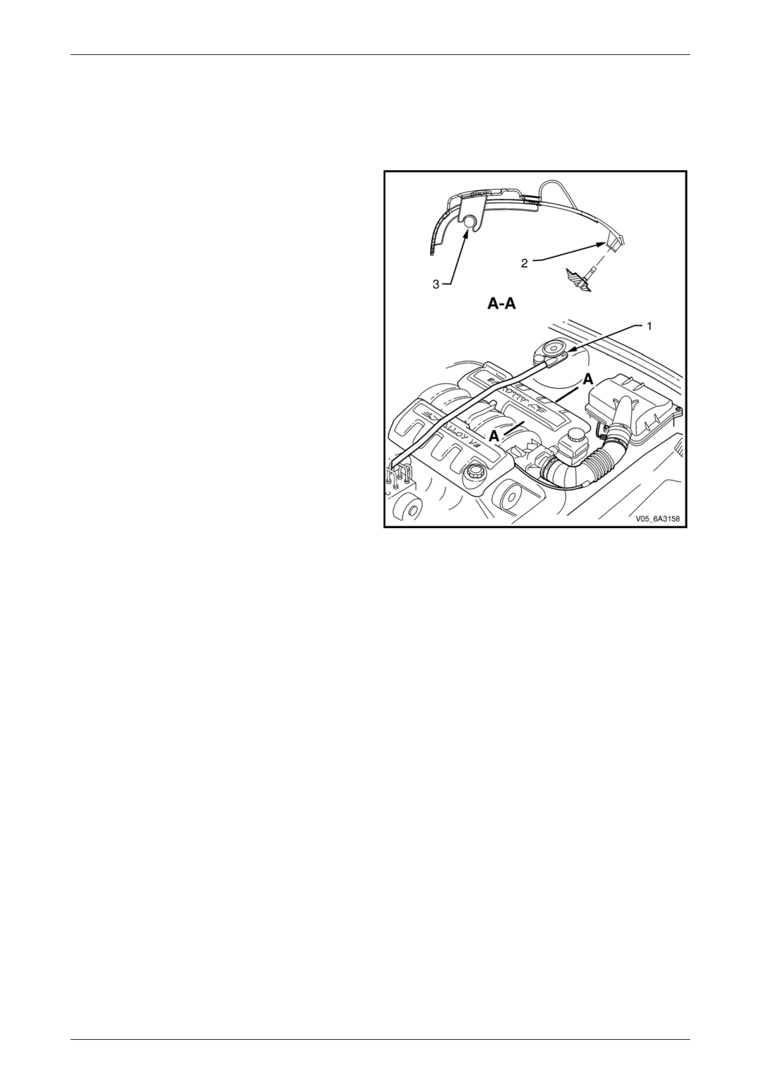
Engine Mechanical Page 6A4–76
Page 6A4–76
4.2 Engine Dress Cover
LT Section No. — 00–508
Remove
1 If required, remove the strut tower brace (1), refer to
Section 1A1 Body.
2 Disengage the engine dress cover retaining clips (2)
by pulling upward.
3 Rotate the cover to unlock it from the fuel rail (3) and
remove the cover.
Figure 6A4 – 80
Reinstall
Reinstallation of the engine dress covers is the reverse of the removal procedure ens uring the retaining clips are fully
engaged.
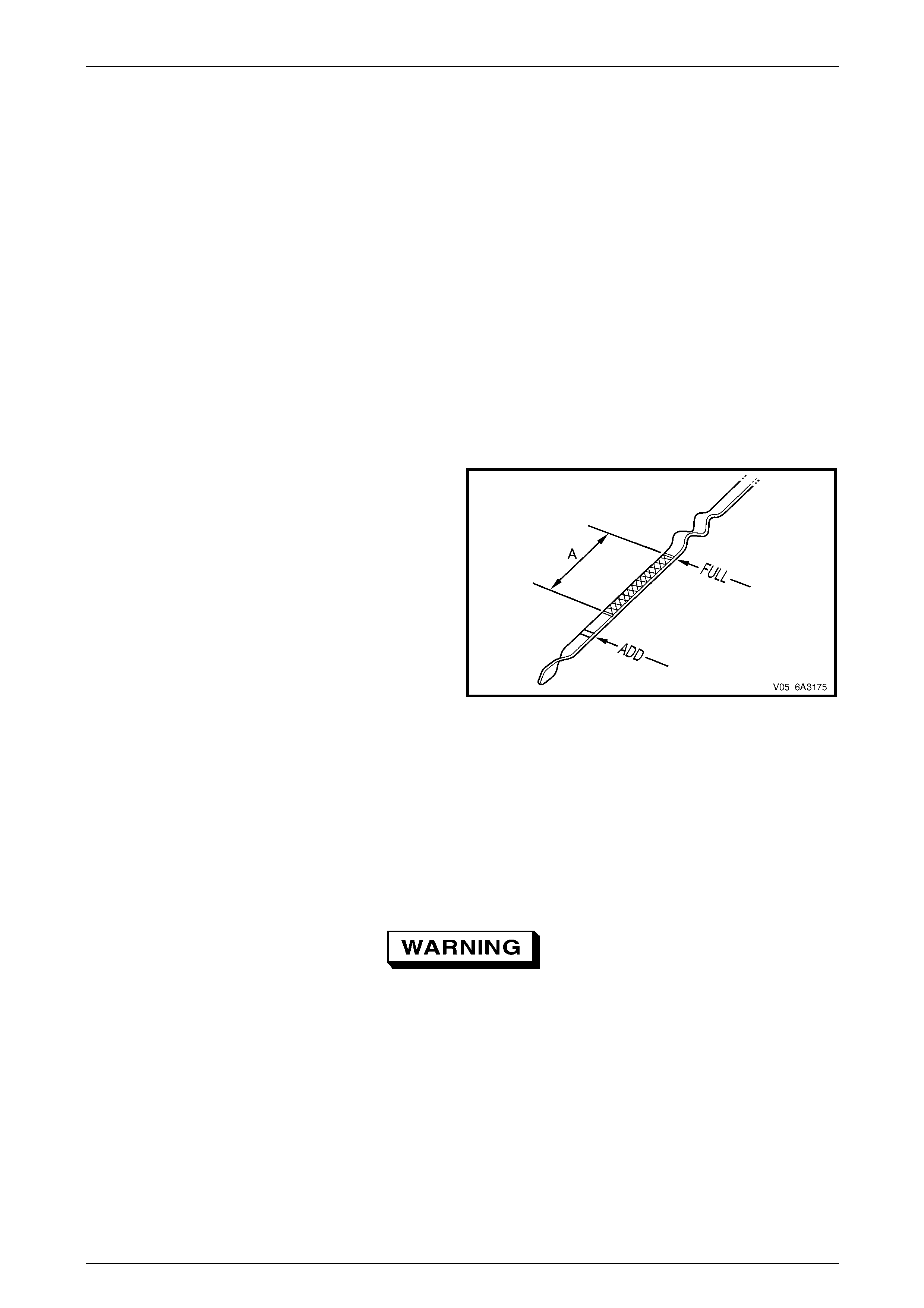
Engine Mechanical Page 6A4–77
Page 6A4–77
4.3 Engine Oil and Filter
LT Section No. — 01–500
Oil Level Check
1 The engine must be at normal operating temperature. This can be achieved by driving the vehicle for minimum of
15 minutes.
2 Park the vehicle on a level surface.
NOTE
Allow sufficient time for the oil to drain back t o the
oil pan after the engine is switched off. A sloping
surface will also affect the accuracy of the
measurement.
3 Remove the oil level indicator and wipe clean.
4 Reinstall the indicator and ensure that it is fully seated. Leave for several seconds and remove slowly to avoid
smearing the oil (level).
5 Hold the indicator horizontally to prevent the oil (level) moving along the indicator.
6 Observe the oil level where it passes over the centre
line of the indicator.
NOTE
As an easy guide for how much oil to add, the
crosshatch area (A) represents 1 litre of oil and
the ADD mark represents 1.6 litres of oil is
required.
7 If the oil level is lower than, or close to the ADD mark,
top-up the engine with enough oil to reach the FULL
mark.
NOTE
Do not fill beyond the FULL mark. If overfilling
occurs drain the excess oil from the engine.
8 Allow several minutes for the added oil to drain down
into the oil pan then recheck the oil level.
Figure 6A4 – 81
Oil Change
While the oil pan is aluminium, it is fitted with a steel thread insert for the drain plug. This is to increase the durability of
the thread and to avoid thread tearing when the drain plug is removed from a hot engine. It is recommended the oil filter
be changed at each engine oil change, refer to Oil Filter and Adapter. A quicker and a more complete draining will occur
if the engine oil is at operating temperature. However, care must be taken to avoid scalding from the hot oil.
Use care when draining the engine oil or
removing the oil filter when the engine oil is
hot. Wear safety glasses and the appropriate
gloves for protection from the hot oil or filter.
1 Raise the engine hood and remove the oil fill cap.
NOTE
Ensure the vehicle is level with the floor surface.
This is to ensure complete draining. Refer to
Section 0A General Information.
2 Raise the front and rear of the vehicle and support the vehicl e using safety stands or use a hoist. For hoist pad,
lifting and safety stand locations, refer to Section 0A General Information.
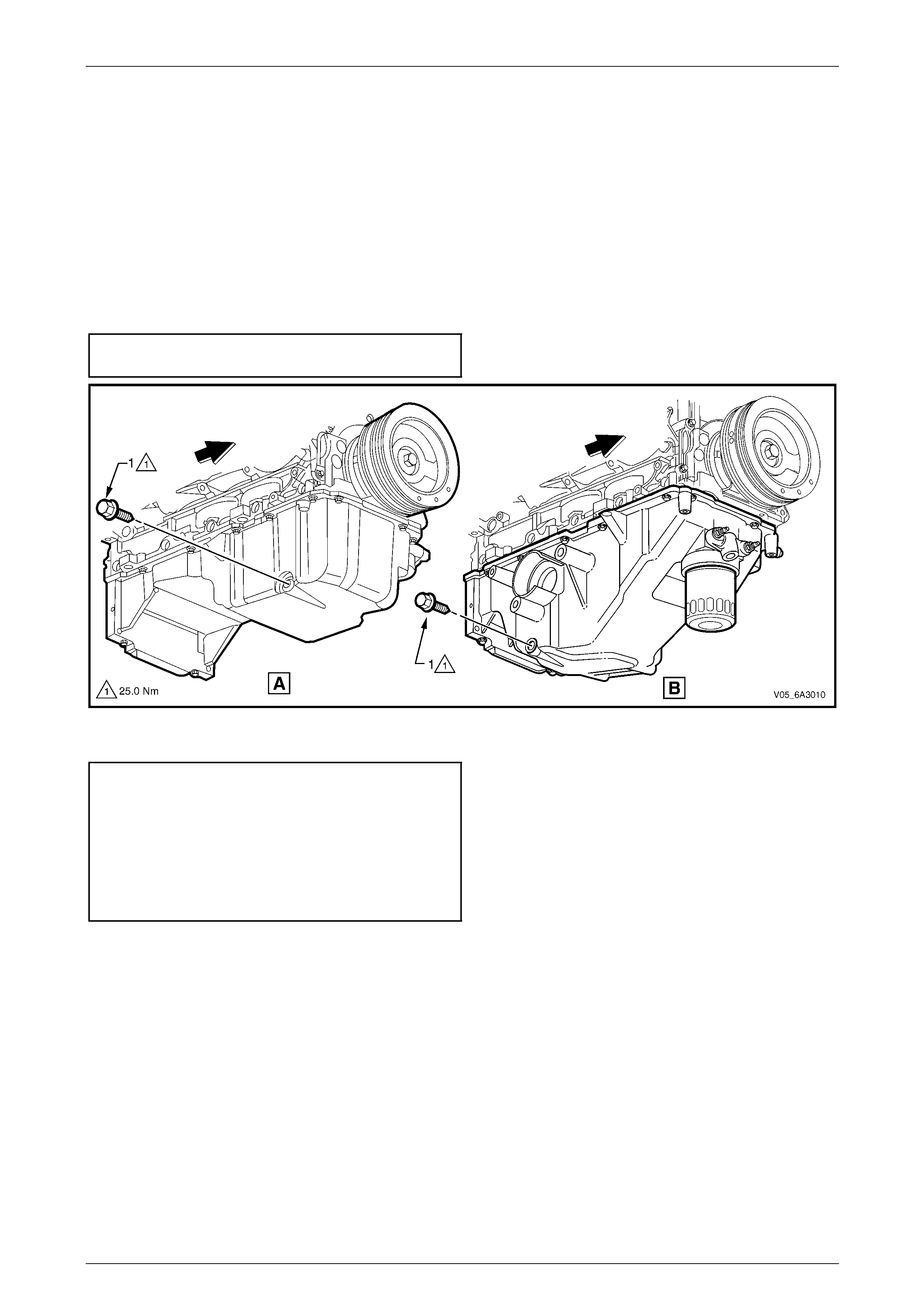
Engine Mechanical Page 6A4–78
Page 6A4–78
3 Clean any foreign materi al from around the oil pan drain plug (1), refer to Figure 6A4 – 8 2 View A for all vehicles
excluding AWD and View B for AWD vehicles .
4 Place a suitable oil drain tra y beneath the engine.
5 Using a 15 mm ring spanner, remove the drain plug taking care to avoid scalding with the hot waste oil.
6 Inspect and clean the threads and the magnetic end of the drain plug of ferrous material.
NOTE
The drain plug O-ring seal may be re-used if not
cut or damaged, however it is recommended the
seal be replaced when removed.
7 When the oil has drained c ompletely, reinstall the drain plug and tighten the drain plug to the correct torque
specification.
Engine oil pan drain plug
torque specification............................................25.0 Nm
Figure 6A4 – 82
8 Lower the vehicle and fill the crankcase with the correct quantity of the recommended engine oil.
Engine oil viscosity and quantity specifications :
Viscosity..............GF3 5W – 30 SJ or GF3 10W – 30 SJ
Capacity without oil filter change:
Except AWD.......................................................5.7 litres
AWD ..................................................................7.6 litres
Capacity with oil filter change:
Except AWD.......................................................6.2 litres
AWD ..................................................................8.0 litres
9 Start the engine and allo w to run for three to five minutes checking for oil leaks, stop the e ngine, rectify any leaks
and then recheck the oil level topping up as required, refer to Oil Level Check.
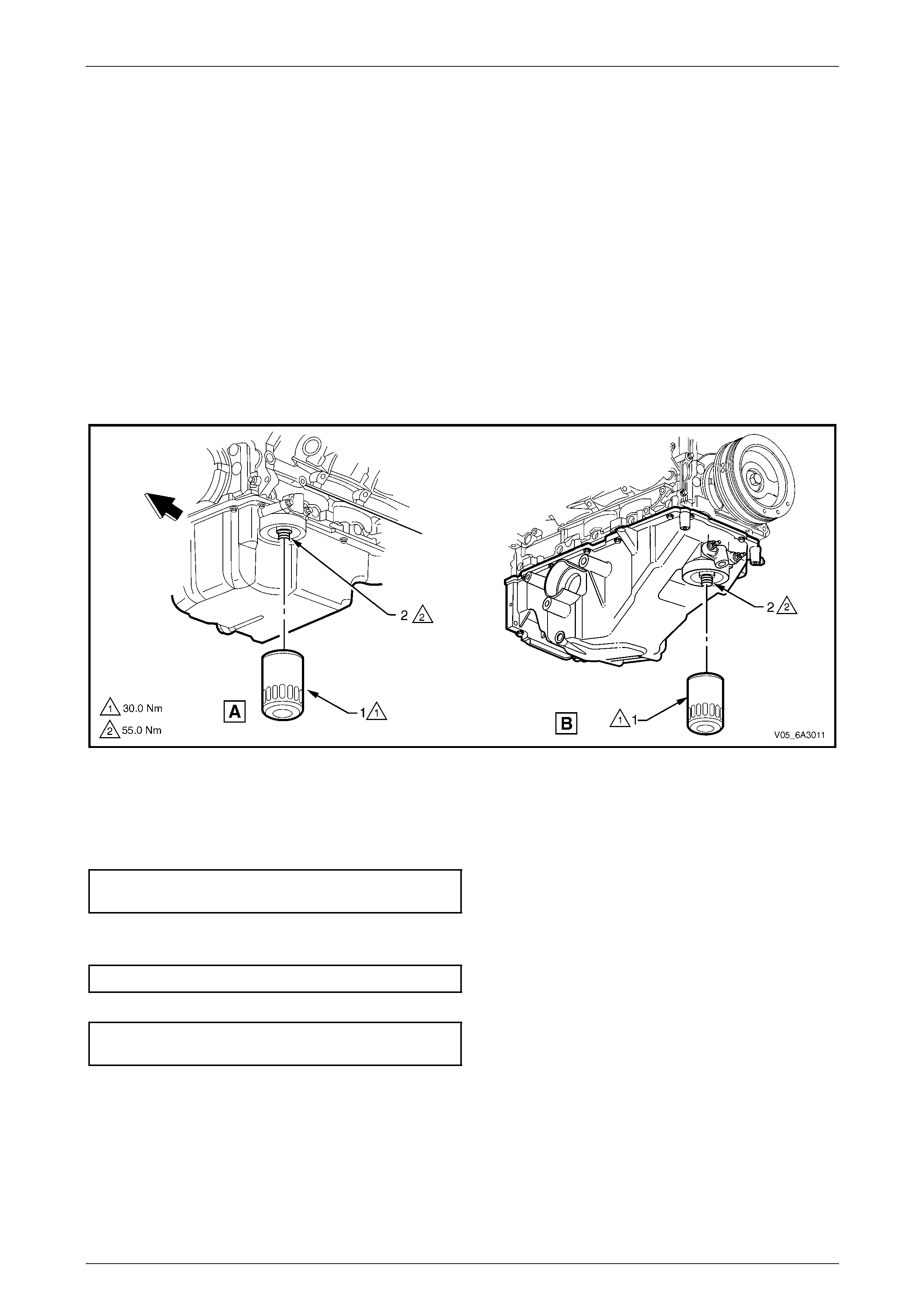
Engine Mechanical Page 6A4–79
Page 6A4–79
Oil Filter and Adapter
NOTE
The oil filter should be replaced at the time or
distance intervals specified in the Owner’s
Handbook or whenever the engine oil is changed.
Remove
1 If required, drain the engine oil, refer to Oil Change .
2 Remove the oil filter (1), taking care to avoid being scalded with the hot waste oil, refer to Figure 6A4 – 83 View A
for all vehicles excluding AWD and View B for AWD vehicles.
NOTE
Ensure the vehicle is level with the floor surface.
This is to ensure complete draining. Refer to
Section 0A General Information.
3 If required, remove the oil filter adaptor (2) from the oil filter mounting boss.
Figure 6A4 – 83
Reinstall
1 After checking the oil filter seal has not adhered to the oil filter mounting boss, inspect the oil filter sealing surface
for scratches or other damage and check the oil filter adapto r threads for damage.
2 If removed, reinstall the oil filter adaptor and tighten to the correct torque specification. Refer to Figure 6A4 – 83.
Oil filter adapter
torque specification............................................55.0 Nm
3 Apply a coating of clean engine oil to the new oil filter seal and install the oil filter to the engine.
4 Tighten the oil filter to the correct torque spec ification.
Engine oil filter torque specification....................30.0 Nm
5 Reinstall the drain plug and tighten to the correct torque specification.
Engine oil pan drain plug
torque specification............................................25.0 Nm
6 Lower the vehicle and fill the crankcase with the correct quantity of the recommended engine oil, refer to
Oil Change.
7 Start the engine and allo w to run for three to five minutes checking for oil leaks. Stop the e ngine, rectify any leaks
and then recheck the oil level topping up as required, refer to Oil Level Check.
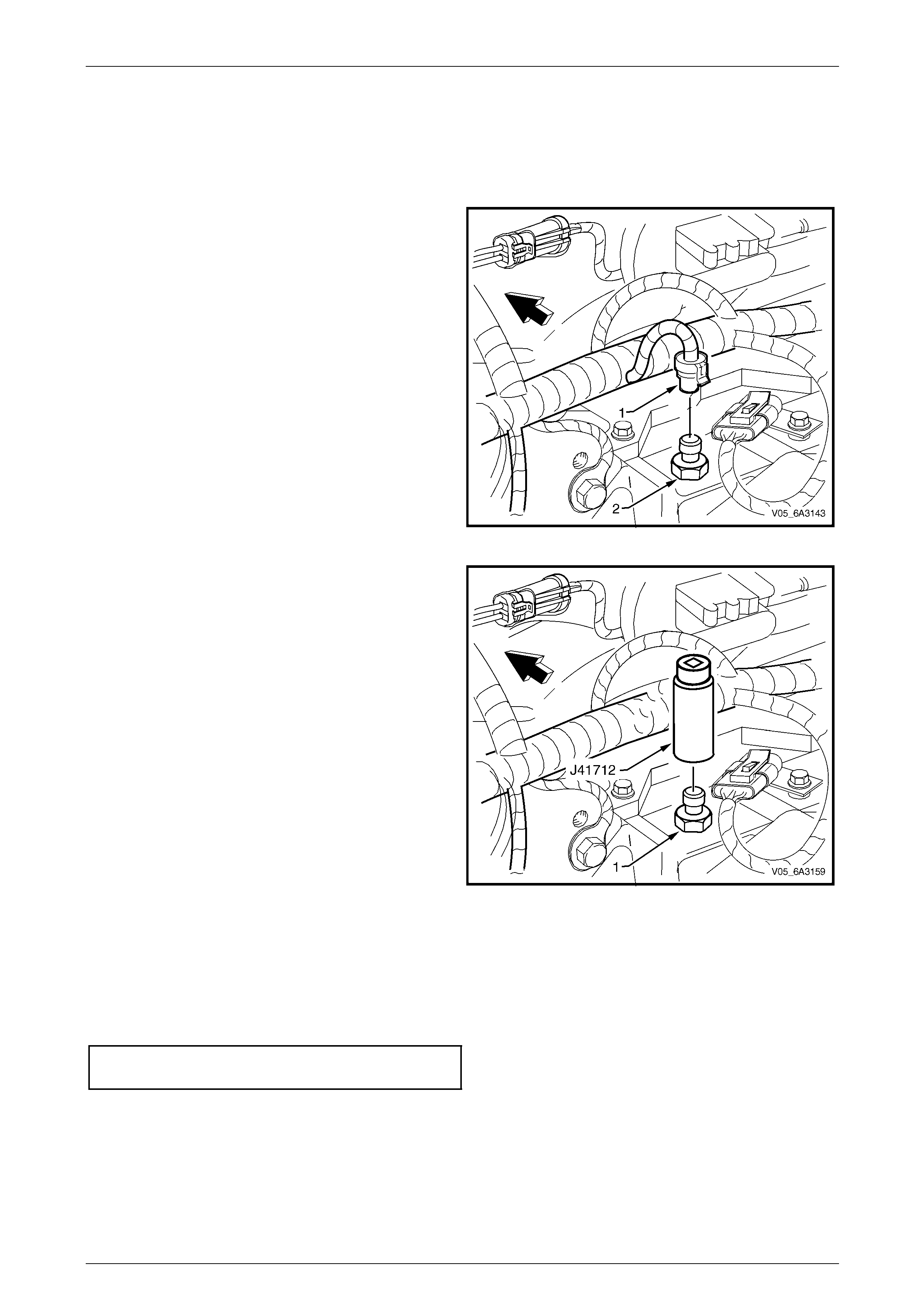
Engine Mechanical Page 6A4–80
Page 6A4–80
4.4 Oil pressure Sensor
LT Section No. — 02–000
Remove
1 Release the wiring harness c onnector (1) locking tang
from the oil pressure sensor (2) and remove the
connector from the sensor.
Figure 6A4 – 84
2 Using the oil pressure sensor socket, T ool No. J41712
and suitable 3/8” drive sock et equipment, remove the
oil pressure sensor (1) from the left-hand rear of the
cylinder block.
Figure 6A4 – 85
Reinstall
1 Clean the threads of the oil pressure sensor.
2 Apply Loctite 565 sealant or equiv ale nt to the cleaned oil pressure sensor threads.
3 Reinstall the oil pressure sensor and tighten to the correct torque specification using oil pressure sensor socket
Tool No. J 41712 and suitable 3/8” drive socket equipment.
Oil pressure sensor
torque specification............................................20.0 Nm
4 Start the engine and check for correct operat ion and leaks.
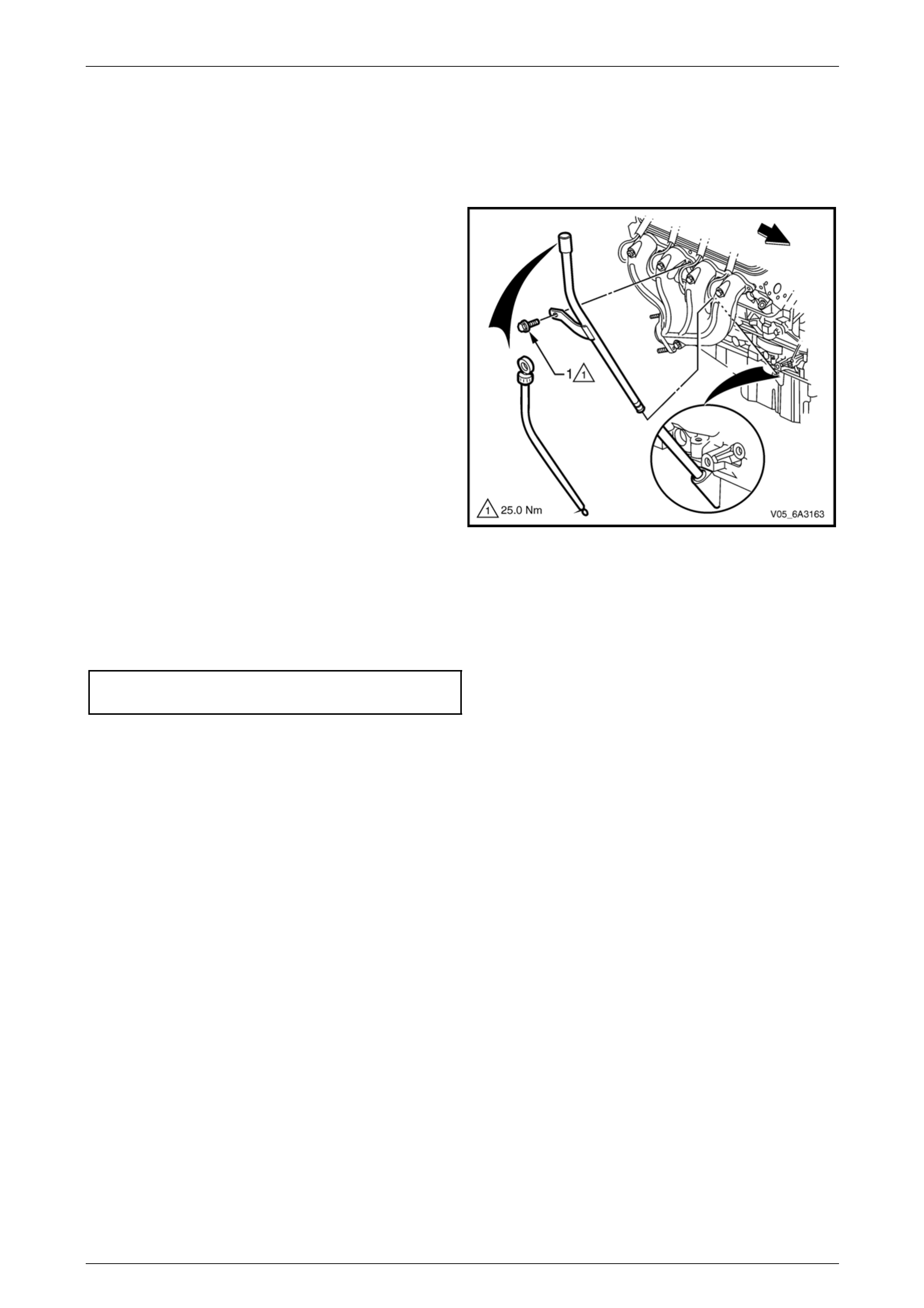
Engine Mechanical Page 6A4–81
Page 6A4–81
4.5 Oil Level Indicator and Tube
LT Section No. — 00–580
Remove
1 Remove the oil level indicator from the oil level
indicator tube.
2 Remove the oil level indicator tube bracket attaching
bolt (1) from the right hand exhaust manifold.
3 Remove the oil level indicator tube from the engine.
4 Remove the O-ring from the tube and discard .
NOTE
If the oil level indicator tube is not to be
reinstalled immediately, plug the opening to
prevent dirt entry.
Figure 6A4 – 86
Reinstall
1 Clean the oil level indicator tube an d install a new O-ring to the lower end of the tube.
2 Reinstall the oil level indicator tube to the engine and rotate it to the correct position.
3 Reinstall the oil level indicator tube bracket attaching bolt and tighten to the correct torque specification.
Oil level indicator tube attaching bolt
torque specification............................................25.0 Nm
4 Reinstall the oil level indicator to the tube.
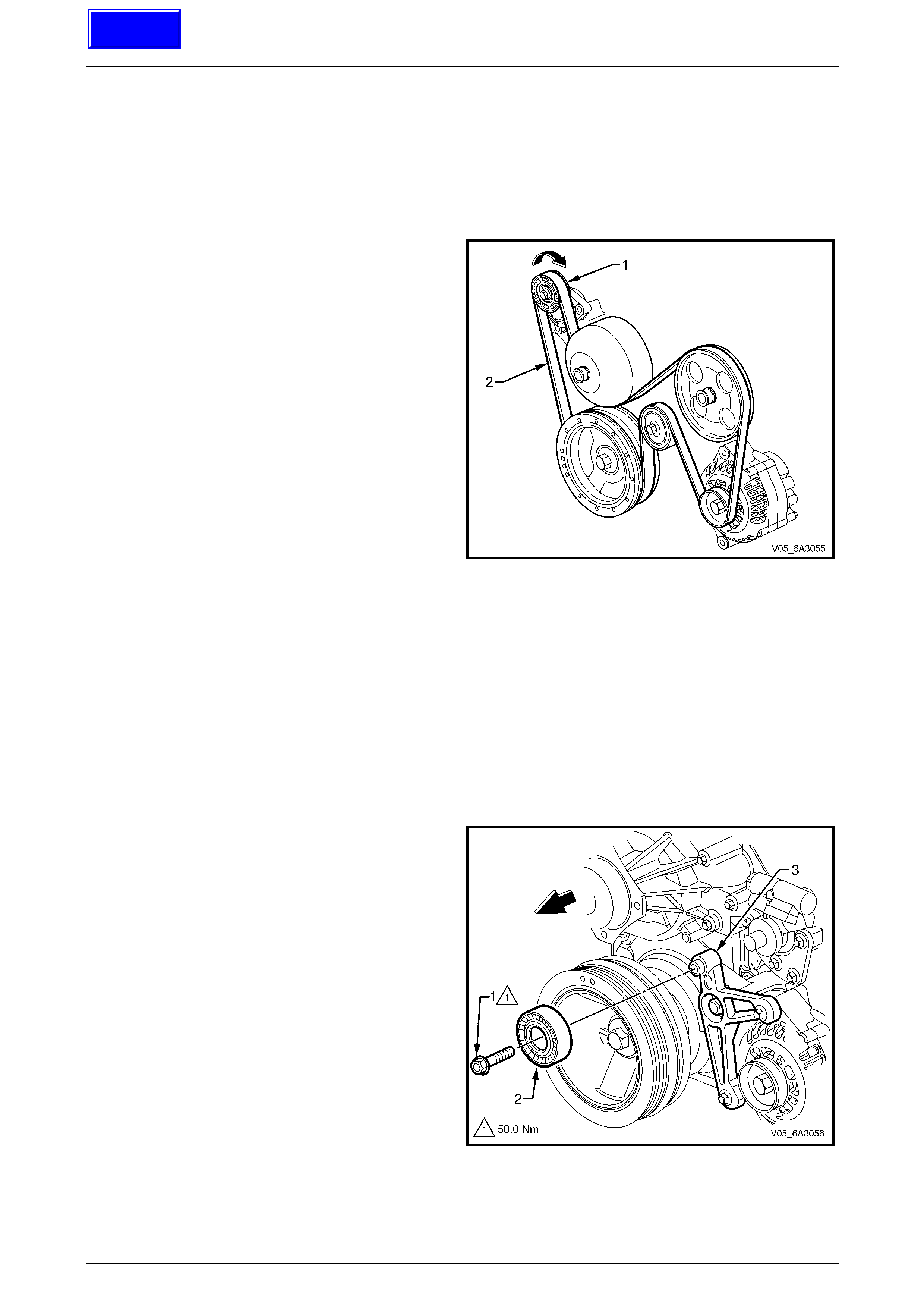
Engine Mechanical Page 6A4–82
Page 6A4–82
4.6 Engine Drive Belts and Pulleys
LT Section No. — 01–003
Accessory Drive Belt
Remove
1 Rotate the engine accessory dr ive belt tensioner
pulley attaching bolt (1) in the direction indicated to
reduce belt tension.
2 While holding the tensi on er in the reduced tension
position, remove the accessory drive be lt (2) from the
pulleys, taking note of the belt routing.
3 Clean the accessory drive b elt running surfaces and
inspect the belt for damage, replac e as required.
Figure 6A4 – 87
Reinstall
1 Route the belt around the pull eys except the wat er pump pulley, ensuring that it is seated correctly in the pulley
grooves.
2 Rotate the tensioner and then slide th e belt over the water pump pulley and ensure the belt is positioned in the
grooves of the pulleys correctly.
3 Start the engine and check for correct operat ion.
Accessory Drive Belt Idler Pulley
Remove
1 Remove the engine accessory drive belt. Refer to Accessory Drive Belt.
2 Remove the idler pulley attach ing bolt (1) and remove
the pulley (2) from its mounting boss on the gen erator
mounting bracket (3).
Figure 6A4 – 88
Techline

Engine Mechanical Page 6A4–83
Page 6A4–83
Reinstall
1 Install the idler pulley to the mounting boss.
2 Install the idler pulley attach ing bolt and tighten to the correct torque specification.
Accessory belt idler pulley attaching bolt
torque specification............................................50.0 Nm
3 Install the engine accessory dr ive belt. Refer to Accessory Drive Belt.
Accessory Drive Belt Tensioner
Remove
1 Remove the engine accessory drive belt. Refer to Accessory Drive Belt.
2 Remove the two bolts (1) attaching the tensioner
assembly (2) to the engine and remove the tensioner
assembly.
Figure 6A4 – 89
Reinstall
1 Install the tensioner assembly and tighten the two attaching bolts to the correct torque specification.
Accessory belt tensioner attaching bolt
torque specification............................................50.0 Nm
2 If required, reinstall the accessory drive b elt i dler p ulley, refer to Accessory Drive Belt Idler Pulley.
3 Reinstall the engine acc essory drive belt, refer to Accessory Drive Belt.
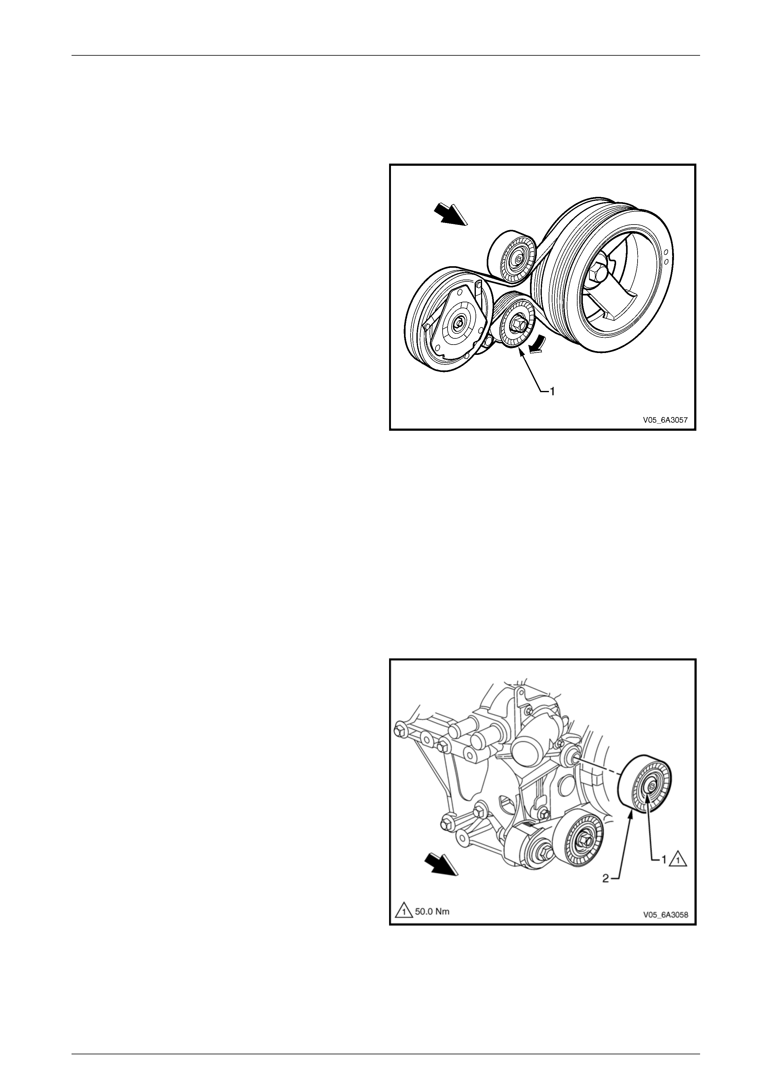
Engine Mechanical Page 6A4–84
Page 6A4–84
Air Conditioner Drive Belt
Remove
1 Raise the vehicle and suppor t with safety stands. Refer to Section 0A General Information.
2 Remove the accessory drive belt to allow access to air conditioner belt. Refer to Accessory Drive Belt.
3 From under the vehicle, rotate the air conditioner drive
belt tensioner pulley (1) in the directi on of the arrow to
relieve the belt tension.
4 While maintaining the tensioner in the required
position remove the drive belt from the pulleys.
5 Clean the air conditioner drive belt run ni ng surfaces
and inspect the belt for damage, replacing as required.
Figure 6A4 – 90
Reinstall
1 While holding the air conditioner drive belt tensioner in the direction indicated, refer to Figure 6A4 – 90, install the
drive belt over the pulleys routing the belt correctly.
2 Reinstall the accessory drive belt, refer to Accessor y Drive Belt.
3 Inspect the installation to ensure the belt is co rrectly aligned on all pulleys.
4 Start the engine to ensure correct operation.
Air Conditioner Drive Belt Idler Pulley
Remove
1 Remove the air conditioner drive belt, refer to Air Conditioner Drive Belt.
2 Remove the bolt (1) attaching the air conditioner drive
belt idler pulley (2) to the mounting boss on the
coolant pump housing and remove the pulley.
Figure 6A4 – 91
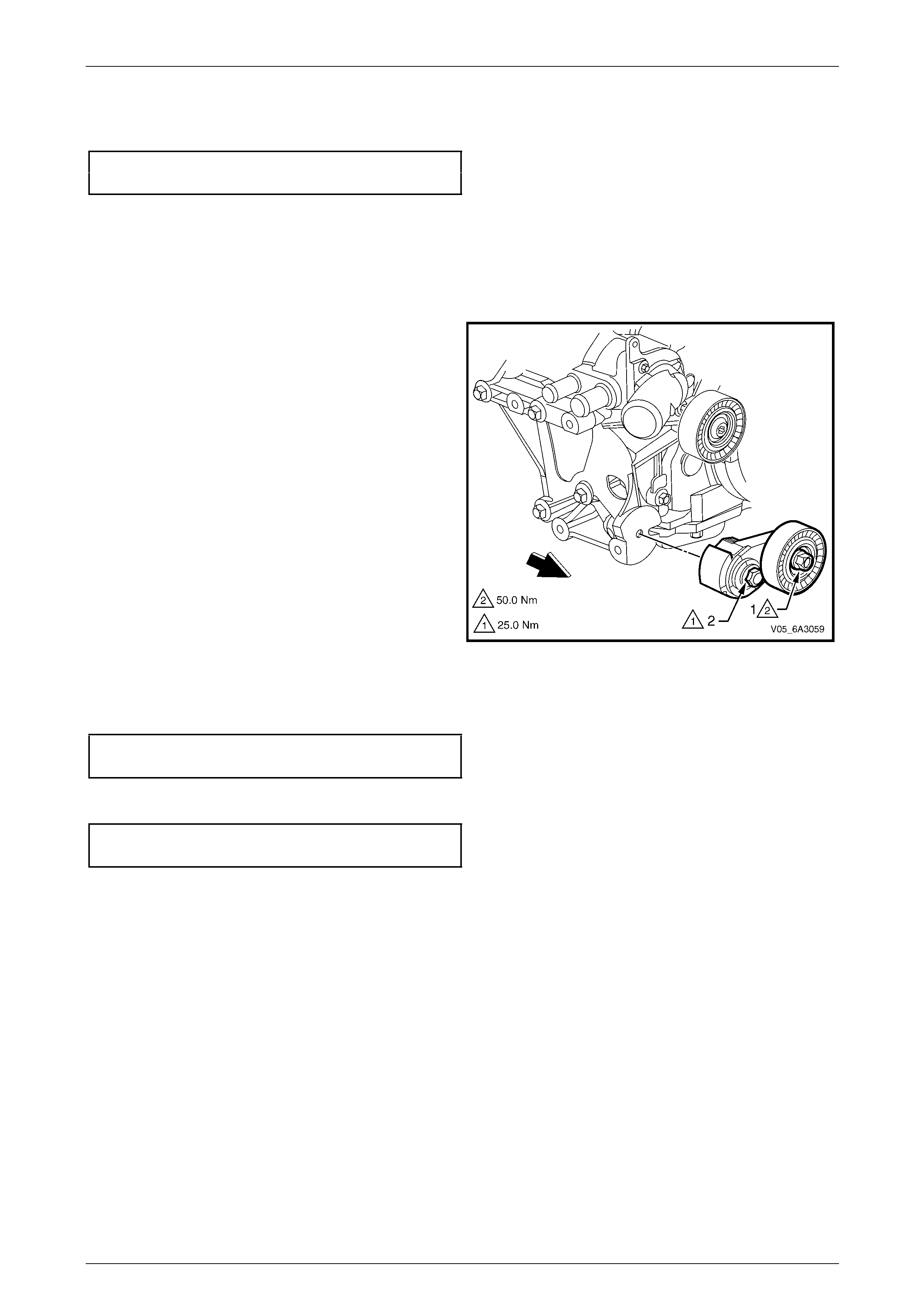
Engine Mechanical Page 6A4–85
Page 6A4–85
Reinstall
1 Install the idler pulley (2) to the mounti ng boss. Install the attaching bolt and tighten to the correct torque
specification, refer to Figure 6A4 – 91.
Air conditioner belt idler pulle y attaching bolt
torque specification............................................50.0 Nm
2 Install the air conditioner drive belt, refer to Air Con ditioner Drive Belt.
Air Conditioner Drive Belt Tensioner
Remove
1 Remove the air conditioner drive belt, refer to Air Conditioner Drive Belt.
2 If required, remove the air conditioner tensioner pul ley
attaching bolt (1) and remove the pulley.
3 Remove the bolt (2) attaching the air conditioner drive
belt tensioner to the bracket and then remove the
assembly.
Figure 6A4 – 92
Reinstall
1 Install the tensioner assembly and the attaching bolt (2). Tighten the bolt to the correct torque specification.
Air conditioner belt tensioner attaching bolt
torque specification............................................25.0 Nm
2 If required, reinstall the air conditioner tensi oner pulley and attaching bolt. Tighten the bolt to the correct torque
specification.
Air conditioner tensioner pulley attaching bolt
torque specification............................................50.0 Nm
3 Install the air conditioner drive belt, refer to Air Con ditioner Drive Belt.
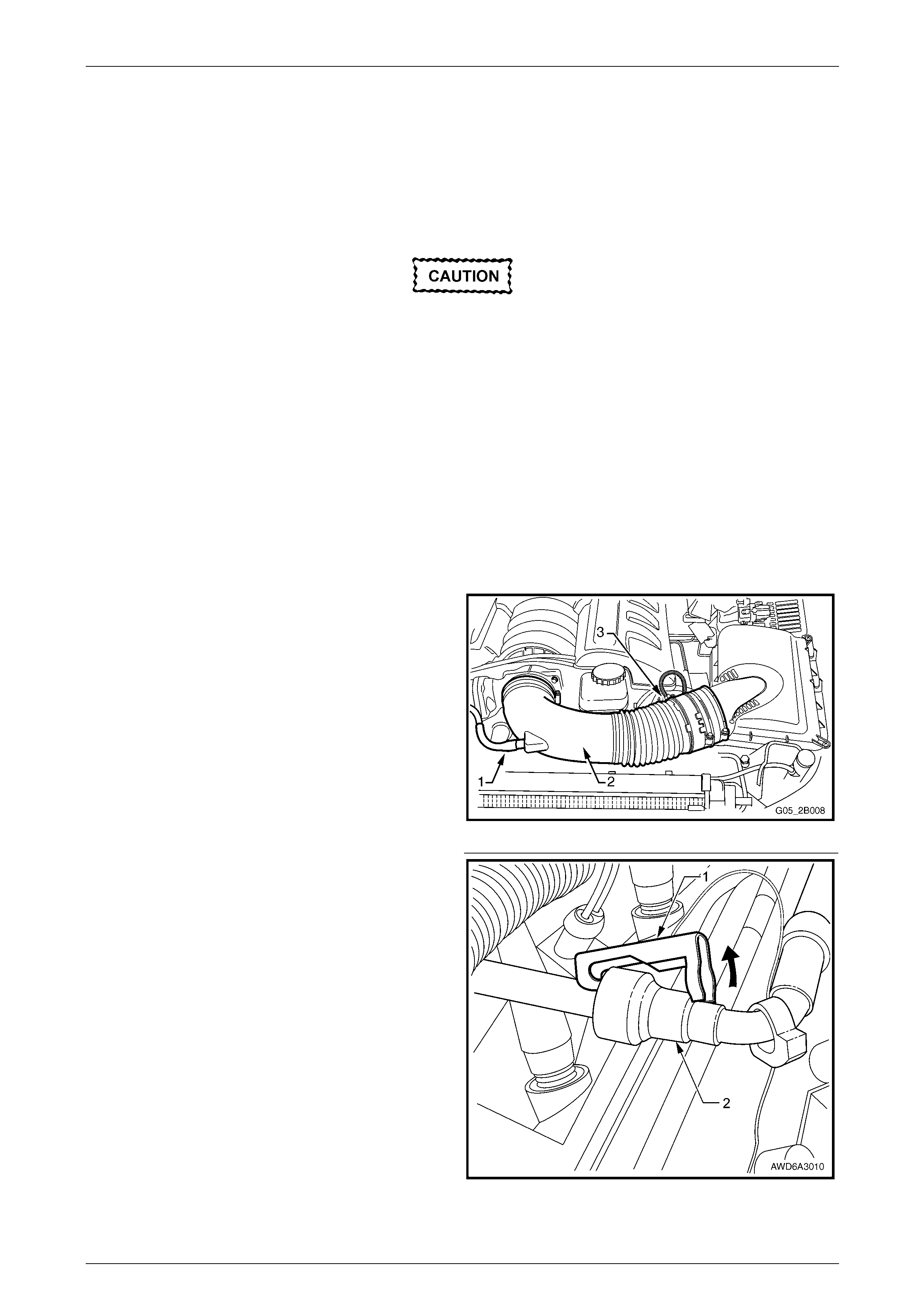
Engine Mechanical Page 6A4–86
Page 6A4–86
4.7 Intake Manifold Assembly
LT Section No. — 00–375
NOTE
Remove
Disconnection of the battery affects certain
vehicle electronic systems. Refer to Section
00, 5. Battery Disconnection Procedures in
the MY 2006 VZ Service Information before
disconnecting the battery.
NOTE
Unless components such as the throttle body,
fuel injection rail and/or injectors are to be
removed individually, the n it is recommende d that
the complete intake manifold assembly be
removed.
1 Disconnect the negative battery cable from the battery.
2 Drain the cooling system. Refer to Section 6B4 Engine Cooling – GEN IV V8.
3 Remove the strut tower brace. Refer to Section 1A1 Body in the MY 2006 VZ Service Informatio n.
4 Remove the fresh air hose (1) from the air intake duct
(2) and lay it to the side of the engine.
5 Remove the air intake sensor wiring harness
connector (3).
6 Loosen the hose clamps attachin g the intake duct to
the air box and the throttle body and remove the duct
from the engine.
7 Remove the duct from the engine.
8 Remove the engine dress covers, refer to
4.2 Engine Dress Cover
9 De-pressurise the fuel rail. Refer to Section 8A1 Fuel
System, section 4.1 in the MY 2006 VZ Service
Information. Figure 6A4 – 93
10 Using a small scre wdriver, release the s ecurity lock
(1), at each of the fuel supply hose quick connect
fittings (2).
NOTE
The security lock at the fuel rail side onl y, is fitted
to a tether to prevent loss.
11 Install the quick connect release Tool No. 7371 over
the fuel line, refer to Section 6C4 Engine Management
– GEN IV V8.
Figure 6A4 – 94
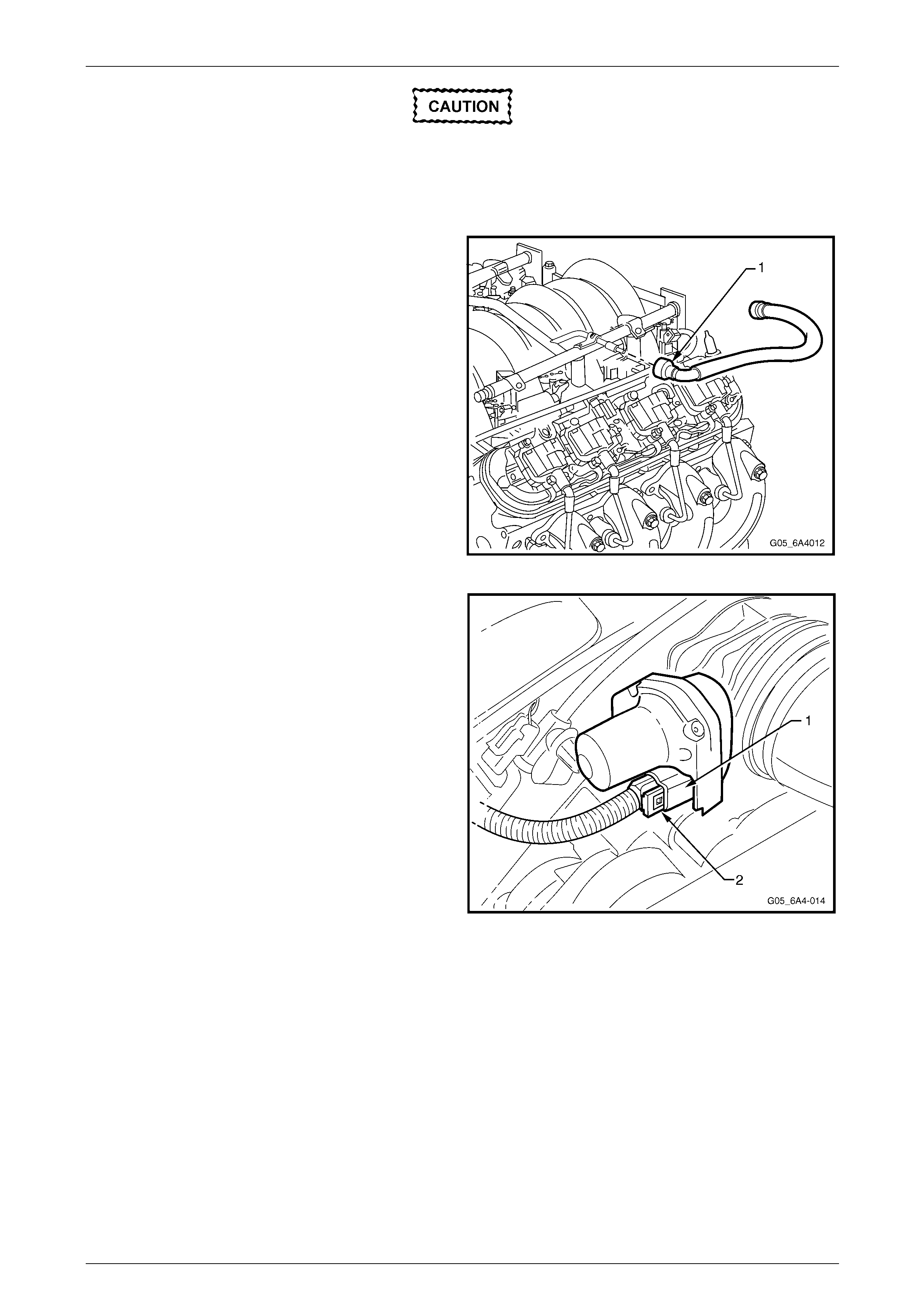
Engine Mechanical Page 6A4–87
Page 6A4–87
Ensure the fuel system has been
depressurised before removing the fuel line
from the fuel rail, refer to Section 8A1 Fuel
System, section 4.1 in th e MY 2006 VZ Service
Information.
12 While holding the fuel l in e quick connect (1), push on
Tool 7371 to release the qu ick connect fitting from the
fuel rail. Pull back on the quick connect and remove
the fuel line.
Figure 6A4 – 95
13 Disconnect the electronic throttle control body wiring
harness connector (1) from the throttle body by
removing the connector lock (2) and the n pulling on
the connector.
Figure 6A4 – 96
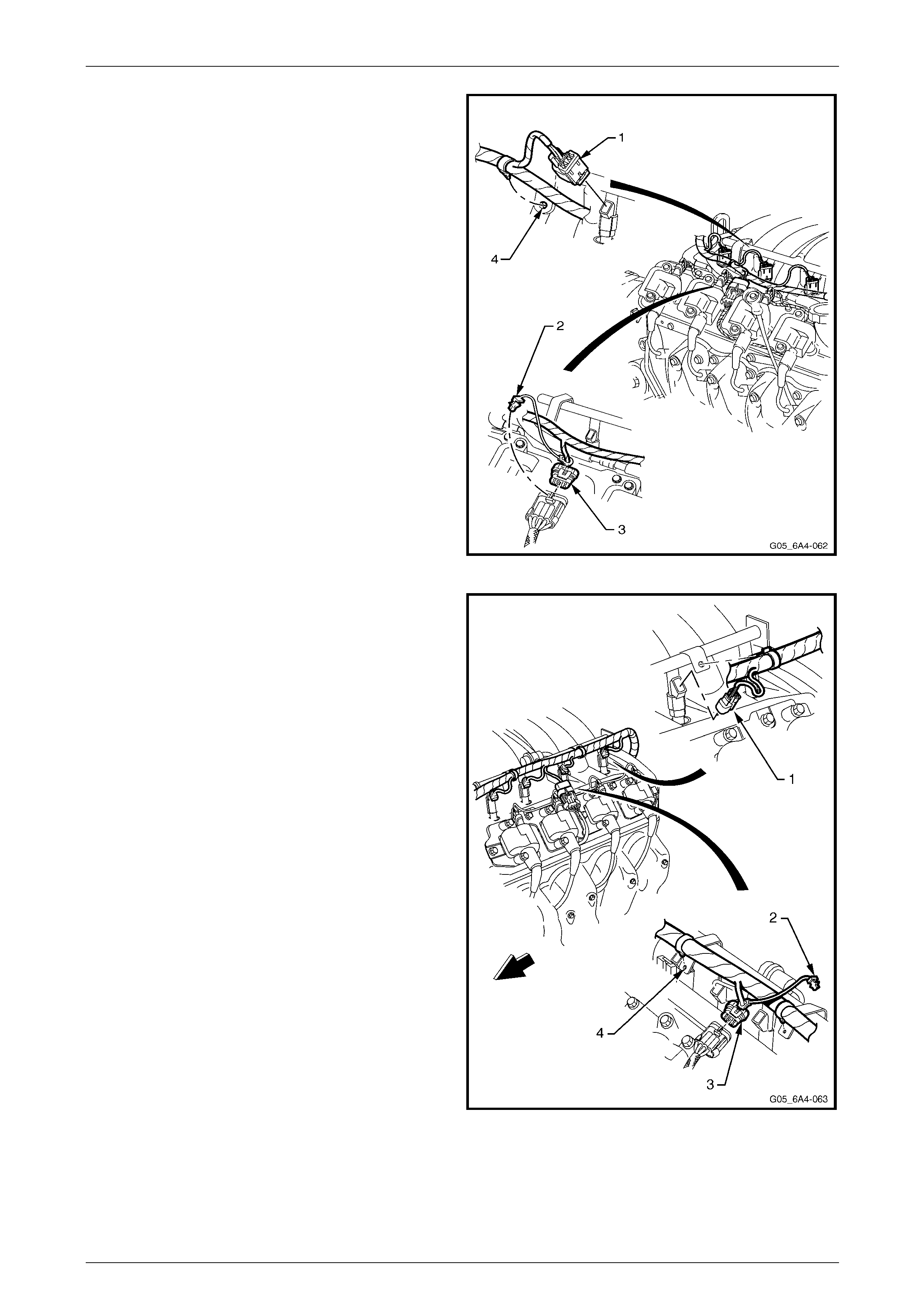
Engine Mechanical Page 6A4–88
Page 6A4–88
14 Disconnect the fuel injector wiring harness connectors
(1), four places, from the right-hand bank of fuel
injectors.
15 Remove the CPA lock (2) from the ignition coil mai n
connector (3) on the right-hand side. Remove the
connector then the harness attaching clips fr om the
fuel rail brackets (4) and set the harness to one sid e.
Figure 6A4 – 97
16 Disconnect the fuel injector wiring harness connectors
(1), four places, from the left-hand bank of fuel
injectors.
17 Remove the CPA lock (2) from the ignition coil mai n
connector (3) on the left-hand side, then rem ove the
connector.
18 Remove the wiring harness connector from the
canister purge valve (4).
19 Remove the harness securing clips from the fuel rail
brackets (5) and set the harness to one side.
20 Disconnect the manifold absol ute pressure (MAP)
sensor wiring harness connector, refer to
Section 6C4-3 Engine Management GEN IV – Service
operations.
Figure 6A4 – 98
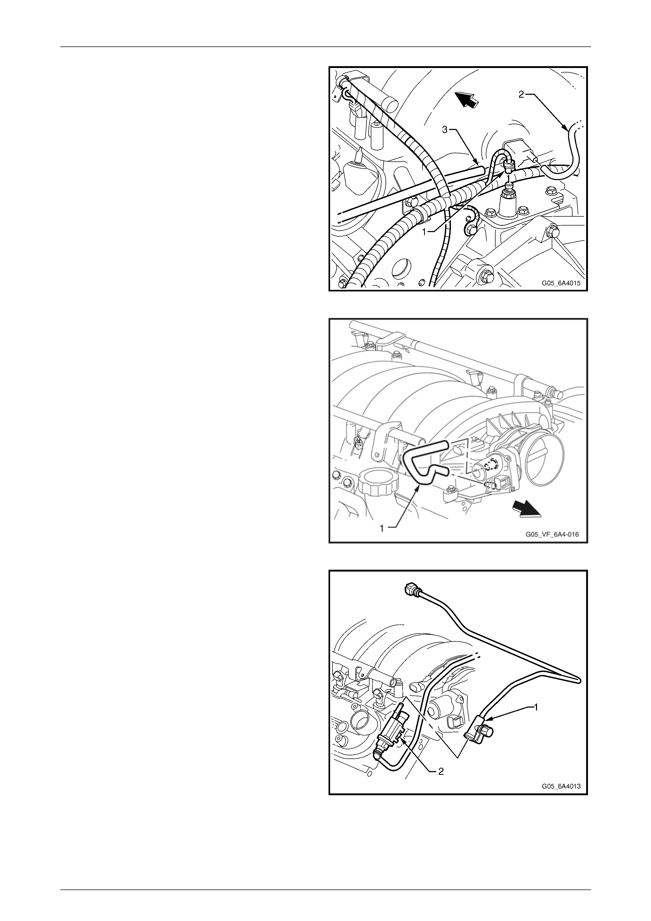
Engine Mechanical Page 6A4–89
Page 6A4–89
21 Disconnect the oil pressure sensor wiring harness
connector (1).
22 Remove the HVAC vacuum hose (2) and the brake
booster hose (3).
Figure 6A4 – 99
23 Remove the foul air hose (1) from the throttle body
and the restricting orifice external connector from the
valley cover.
Figure 6A4 – 100
24 Disconnect the EVAP purge valve vapour line
connector (1) from the EVAP purge valve (2).
NOTE
Cap the fuel line fittings and plug the holes after
separating the fuel lines to prevent fuel leaking
and/or dirt and other contaminants from e ntering
the fuel system.
Figure 6A4 – 101
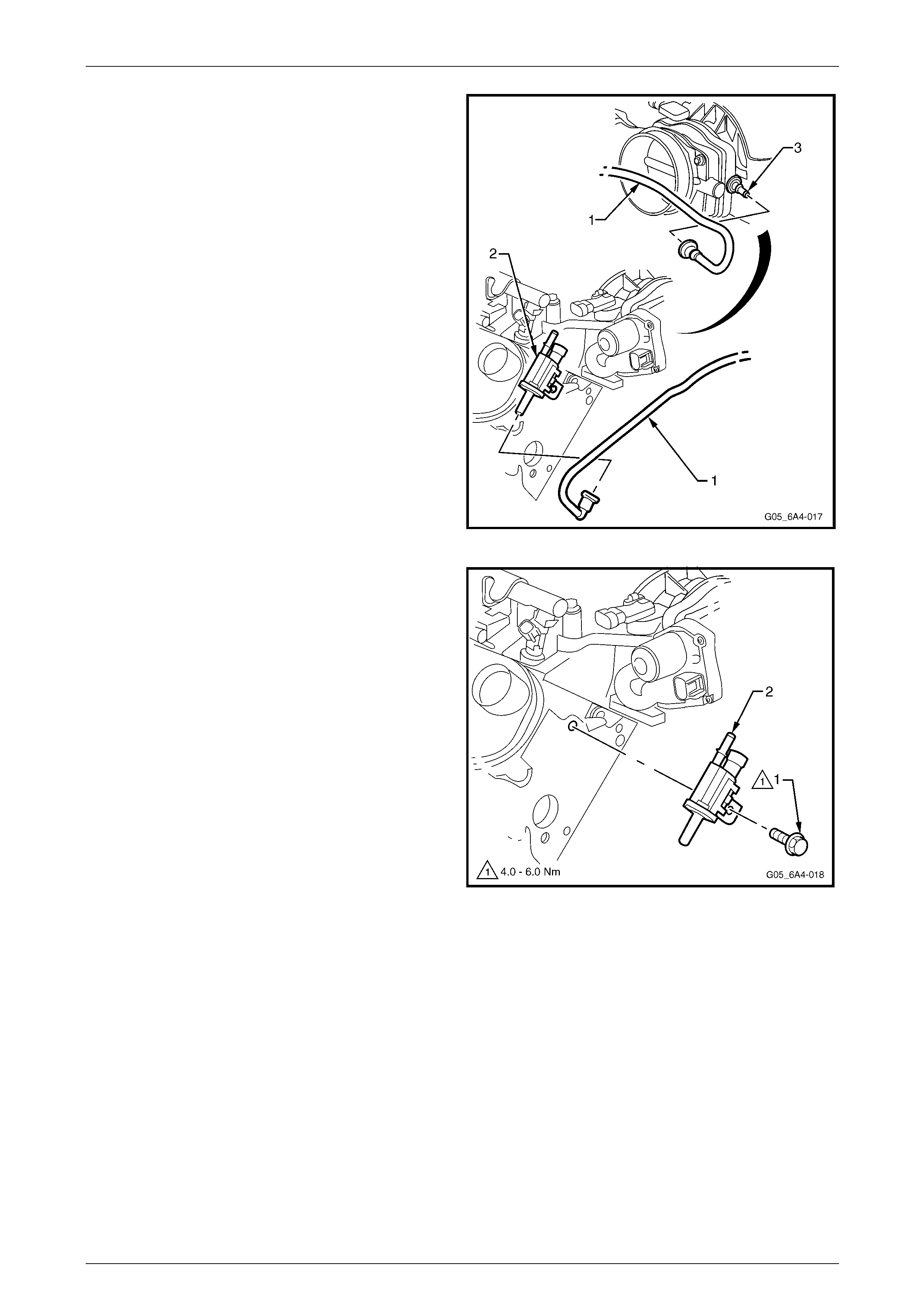
Engine Mechanical Page 6A4–90
Page 6A4–90
25 Remove the evaporative (EVAP) canister purge valve
tube (1) from the purge valve (2) and the intake
manifold (3).
Figure 6A4 – 102
26 Remove the bolt (1) attaching the EVAP canister
purge valve and bracket assembly (2) from the right-
hand cylinder head.
NOTE
It is recommended to remove the purge valve
from the cylinder head to avoid damage to the
valve when removing the Intake manifold.
Figure 6A4 – 103
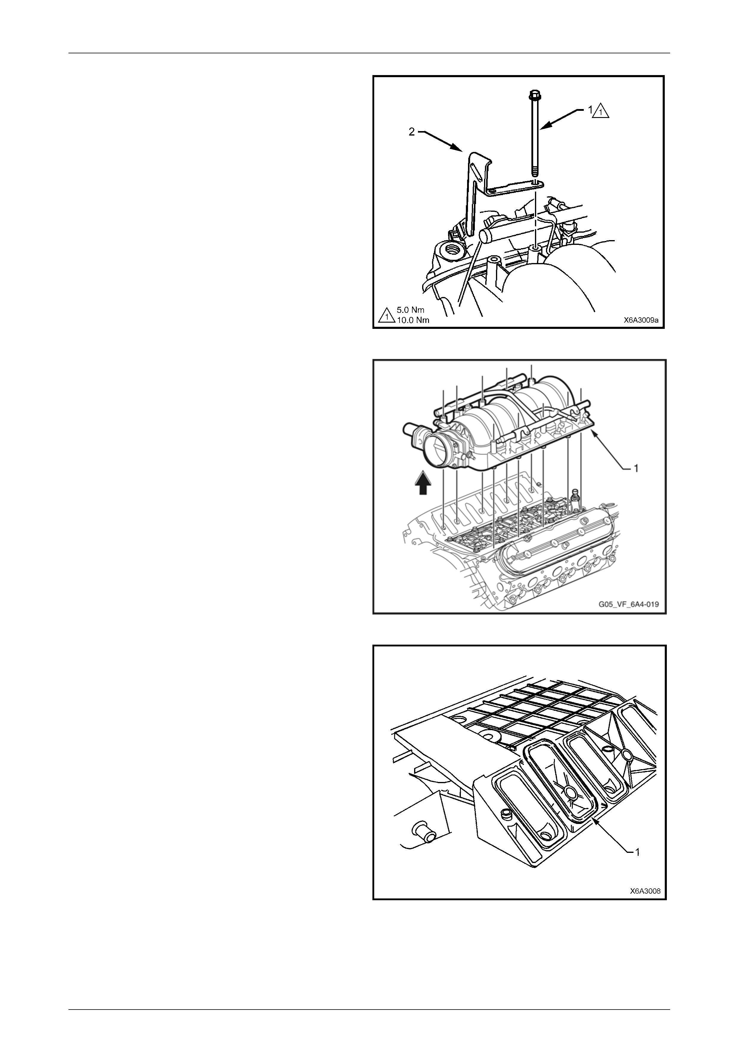
Engine Mechanical Page 6A4–91
Page 6A4–91
27 Progressively loosen all the intake manifold retaining
bolts (1), working diagonally from outside to inside.
28 Remove the fuel rail stop bracket (2), two places and
set to one side.
NOTE
The fuel rail stop brackets are attache d using the
two rear bolts on each sid e (3, 9, 5 and 8) of the
Intake manifold. Refer to Figure 6A4 – 114.
Figure 6A4 – 104
29 Carefully tap the intake manifold assembly (1) with a
rubber mallet to break the gasket seal and then lift it
from the engine.
Figure 6A4 – 105
30 Remove the intake manifold to cylinder head gaskets
(1) and discard the gaskets.
NOTE
New Intake manifold gaskets must be used
when reinstalling the Intake manifold.
Figure 6A4 – 106
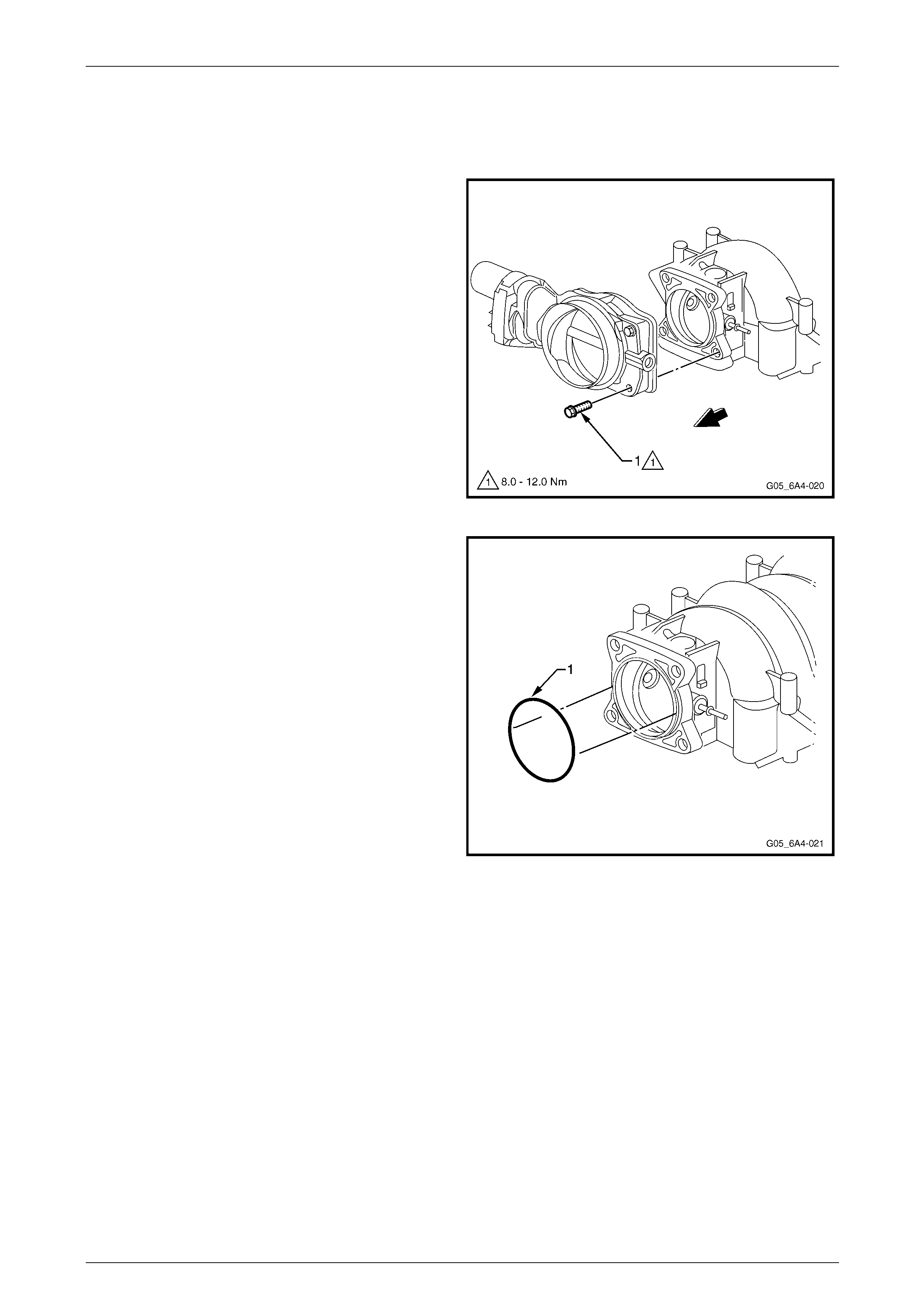
Engine Mechanical Page 6A4–92
Page 6A4–92
Disassemble
If required, remove the following components from the intake manifold
1 Remove the Manifold Absolute Pressure (MAP) sensor from the intake manifold, refer to
Section 6C4-3 Engine Management – GEN IV V8 – Service Operations.
2 Remove the throttle body attaching bolt (1), four
places and remove the throttle bod y.
Figure 6A4 – 107
3 Remove the throttle body O-ring (1) from the Intake
manifold and discard.
NOTE
Do not re-use the throttle body O-ring.
Figure 6A4 – 108

Engine Mechanical Page 6A4–93
Page 6A4–93
4 Remove the four studs (1) attaching the fuel rail (2)
and injectors to the intake manifold and then carefully
remove the fuel rail and inject ors as an assembly.
NOTE
Should further disassembly of the fuel injectors
be required, refer to Section 6C4 Engine
Management – GEN IV V8.
Figure 6A4 – 109
Clean and Inspect
Wear the appropriate safety glasses and
gloves when using compressed air and
cleaning fluids to avoid eye and skin injury.
1 Clean the intake manifold in a commercially available cleaning fluid and then blow dry using compressed air.
2 Ensure that the intake manifold gasket grooves and the vacuum passages in the rear of the intake manifold are all
clean and clear from obstructions.
3 Inspect the throttle body and fuel rail bolt inserts in the intake manifold for looseness and/or damaged threads,
repair as required. Refer to 6 T hread Repair in the MY 2006 VZ Service Information.
4 Inspect the intake manifold for cracks or damage includi ng the areas between the intake runners.
5 Inspect the fuel injector bores for excessive scoring or damage.
6 Inspect the intake manifold to cylinder head f aces for warpage as follows:
a Place a straight edge across each of the two surfaces and check for warpage using feeler gauges.
b An intake manifold with warpage in excess of 0.5 mm must be replaced.
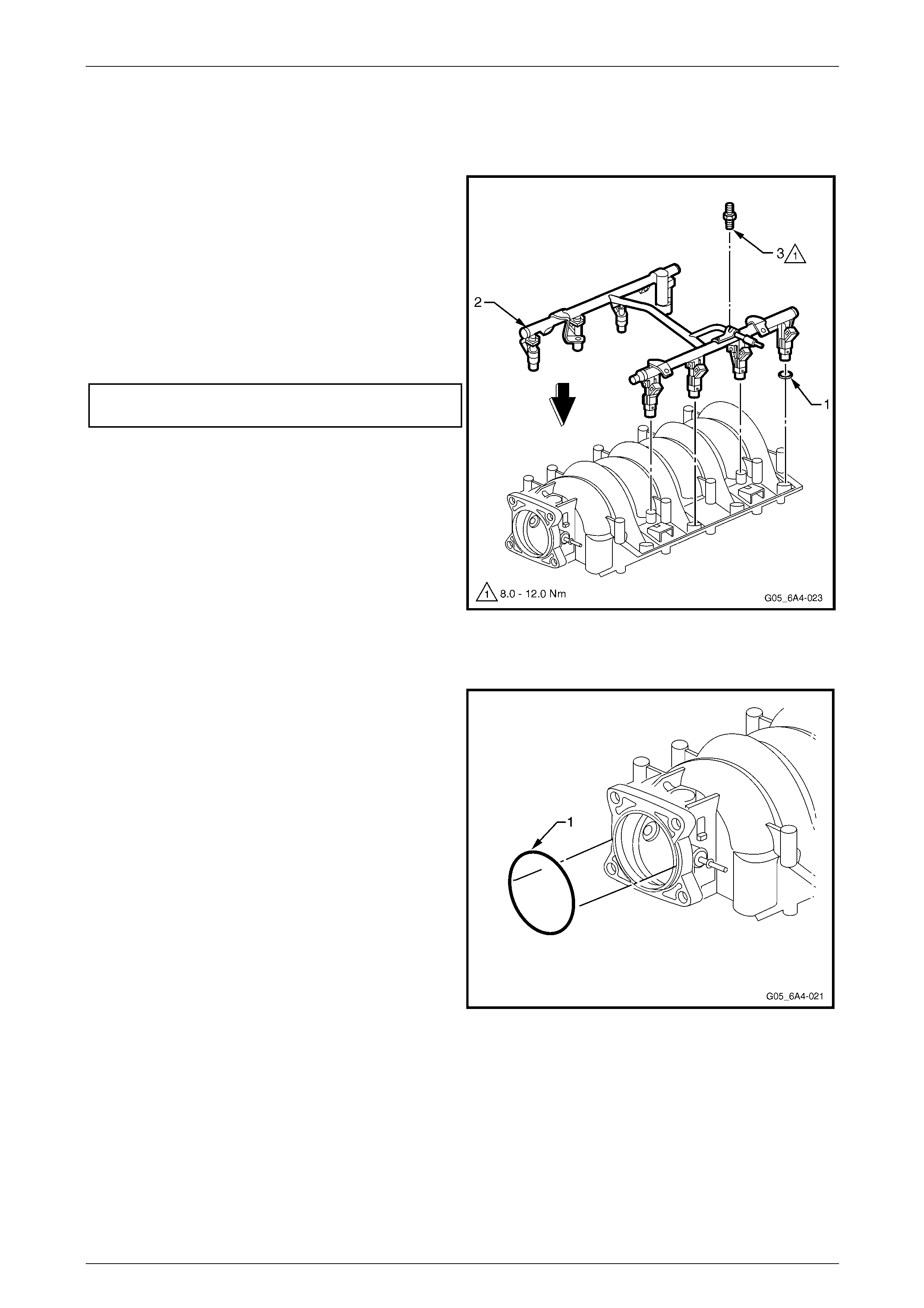
Engine Mechanical Page 6A4–94
Page 6A4–94
Reassemble
1 Reinstall the MAP sensor, refer to Section 6C4-2 Engin e Manageent – GEN IV V8 – Service Operations.
Fuel Rail and Injectors
1 Lubricate the new injector O-ring seals (1), eight
places, with clean engine oil.
2 Install the new O-rings onto the fuel injectors.
3 Install the fuel rail and injector assembly (2) into the
intake manifold, pressing even ly on each side until the
injectors are all full y seated i n their bores.
4 Apply a 5 mm band of thread sealant such as Loctite
242 or equivalent to the cleaned threads of the fuel rail
attaching studs (3), four places, and install.
5 Tightening the studs to the correct torque
specification.
Fuel rail attaching studs
torque specification...................................8.0 – 12.0 Nm
Figure 6A4 – 110
Throttle Body
1 Install a new throttle body O-ring (1) to the intake
manifold, ensuring it is pressed firmly into place.
Figure 6A4 – 111
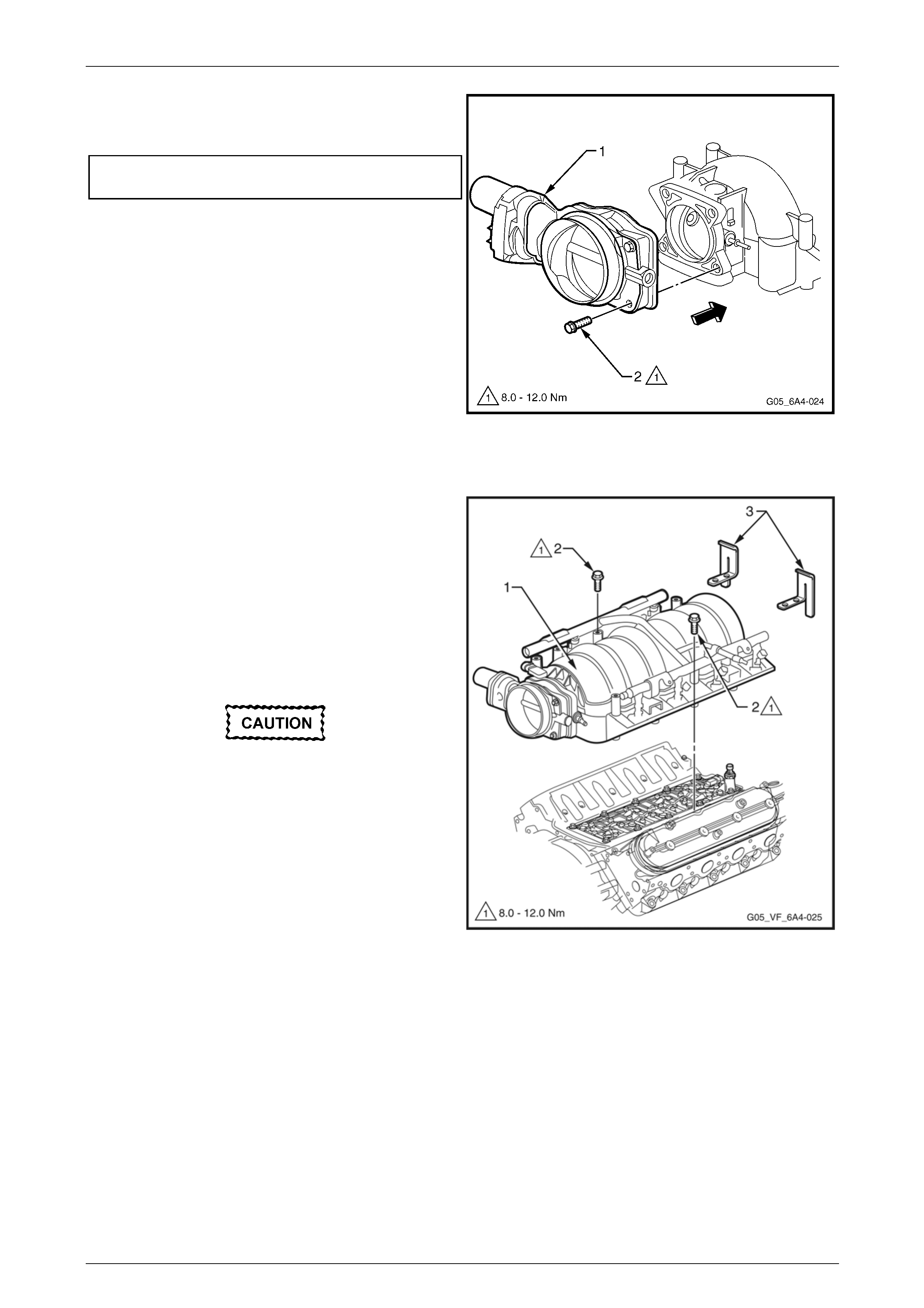
Engine Mechanical Page 6A4–95
Page 6A4–95
2 Install the throttle body (1), ho ldin g it in place by hand.
3 Install the throttle body attac hi ng bolt (2), four places,
and tighten to the correct torque specification.
Throttle body attaching bolt
torque specification...................................8.0 – 12.0 Nm
Figure 6A4 – 112
Reinstall
1 Install the eight ne w intake manifol d to cylinder head
gaskets, refer to Figure 6A4 – 106, and then carefully
lower the intake manifold assembly (1) to the cylinder
heads.
2 Apply a 5 mm band of thread sealant such as Loctite
242 or equivalent, to the cleaned threads of the two
intake manifold attaching bolts (2) and the n tighten
these by hand.
3 Apply a 5 mm band of thread sealant such as Loctite
242 or equivalent, to the cleaned threads of the eight
remaining intake manifold attaching bolts.
Do not overlook installing the two fuel stop
brackets (3). The stop brackets serve as a
protective shield for the fuel rails in the event
of a vehicle front end collision. If the fuel rail
stop brackets are not installed and the
vehicle is involved in a collision, the rails
may become damaged, causing the
pressurised fuel in the rails to leak, possibly
causing a fire and personal injury from
burns. The fuel stop b rackets are attached b y
bolts (3, 9, 5 and 8), refer to Figure 6A4 – 114.
4 Install the eight remaining i nta ke manifold bolts,
including the two at the rear on each side, which also
attach the fuel rail stop brackets.
Figure 6A4 – 113
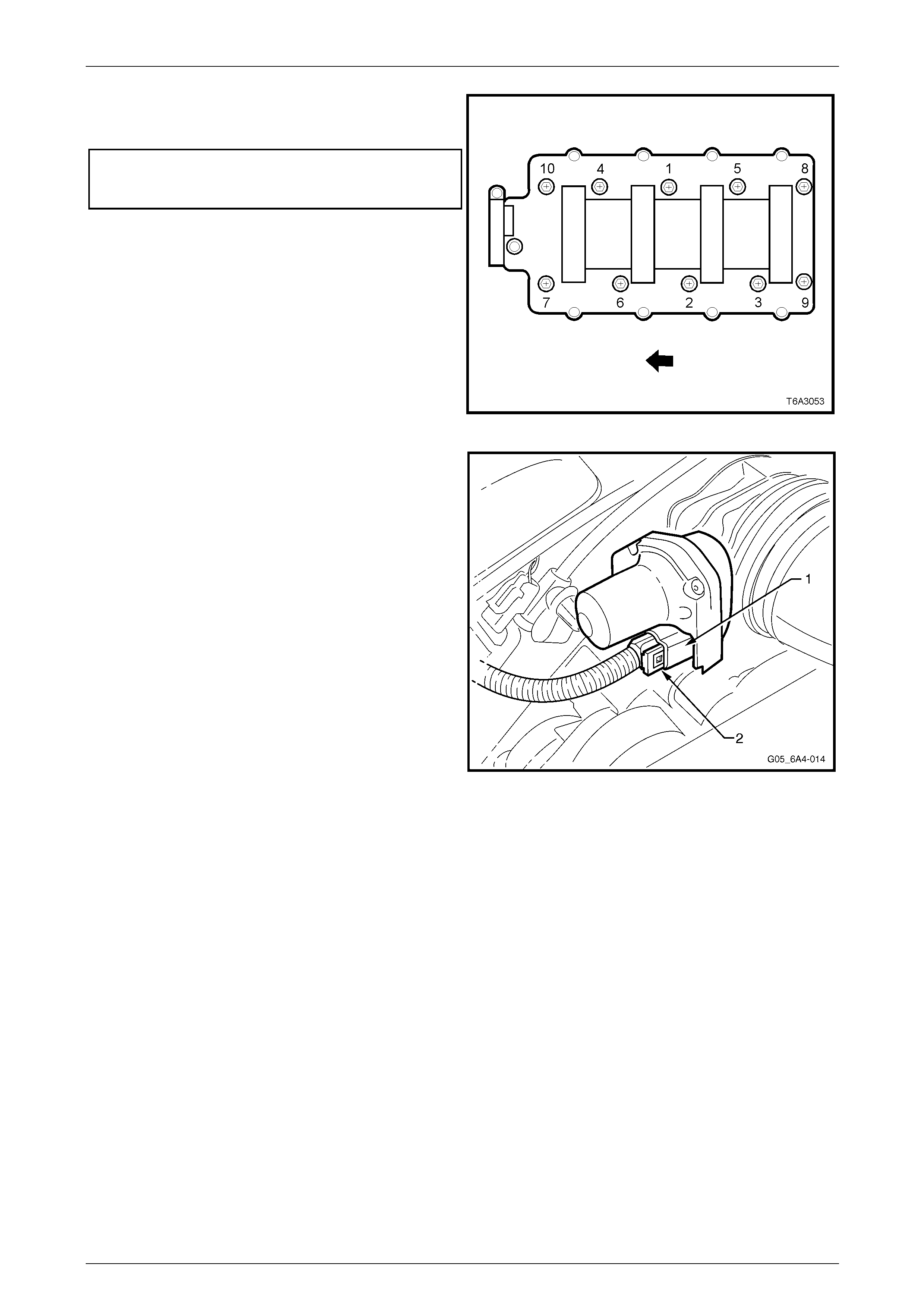
Engine Mechanical Page 6A4–96
Page 6A4–96
5 Tighten the ten intake manifold bolts in two stages in
the sequence shown to the correct torque
specification.
Intake manifold bolts torque specification
Stage 1 ................................................................5.0 Nm
Stage 2 .....................................................8.0 – 12.0 Nm
NOTE
The fuel stop brackets are attached by bolts
(3, 9, 5 and 8).
Figure 6A4 – 114
6 Reconnect the throttle body wiring harness connector
(1) and reinstall the connector lock (2).
7 The remainder of the intake manifo ld reinstallation
process is the reverse of the removal procedure.
Figure 6A4 – 115
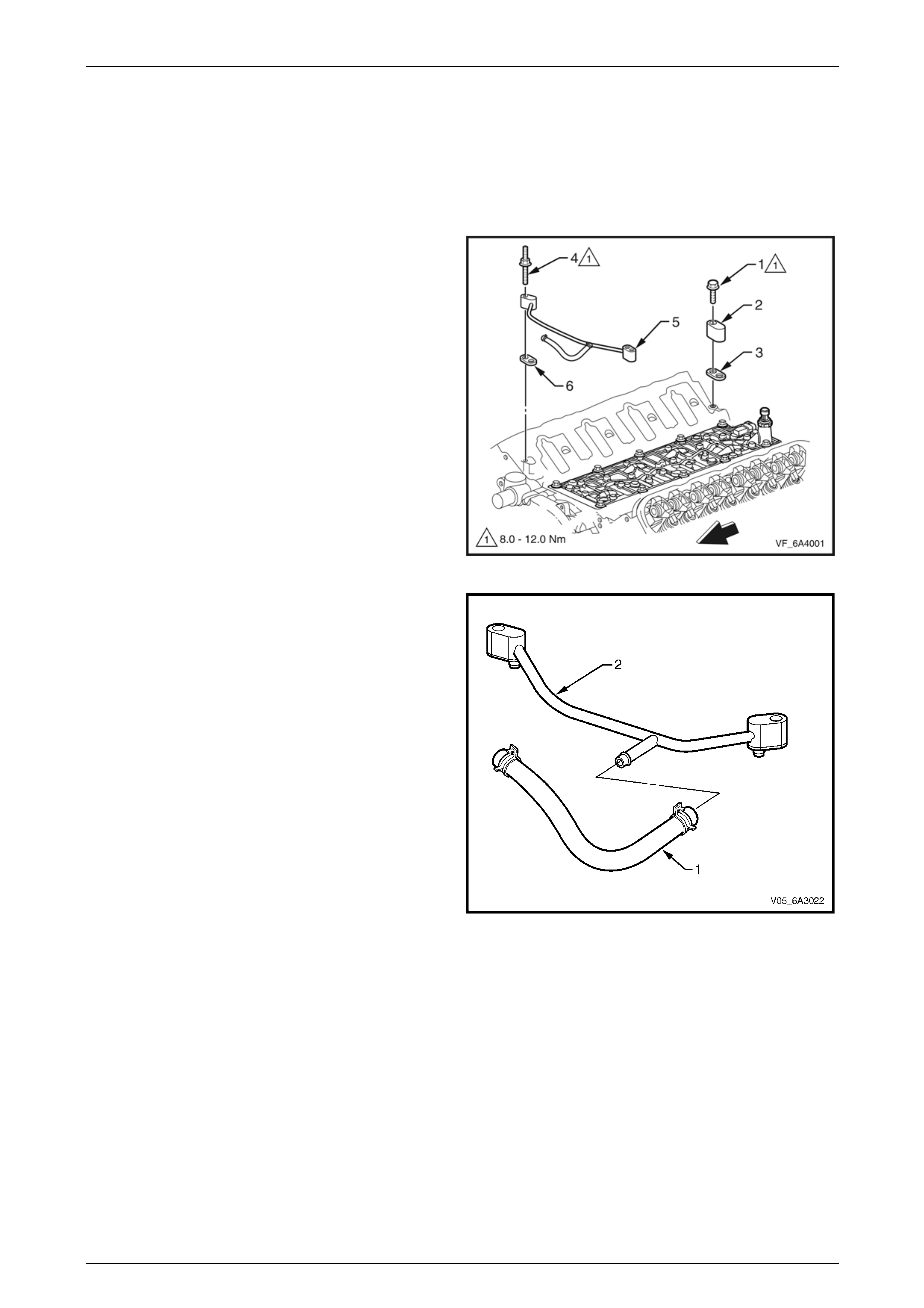
Engine Mechanical Page 6A4–97
Page 6A4–97
4.8 Vapour Vent Pipe and Covers
LT Section No. — 00–249
Remove
1 Remove the intake manifold, refer to 4.7 Intake Manifold.
2 If required, remove the attaching bolt (1) from the rear
engine coolant vapour ble ed vent cover (2).
3 Remove the cover and gasket (3) and discard the
gasket. If required, repeat for the other vapour vent
cover.
4 Remove the vapour vent pipe stud (4), t wo places,
attaching the vapour vent pip e (5) togeth er with both
gaskets (6) to the cylinder block. Discard the gaskets.
Figure 6A4 – 116
5 If required, remove the clamp retaining the engine
coolant to vent pipe and remove the hose (1) from the
vent pipe (2).
Figure 6A4 – 117
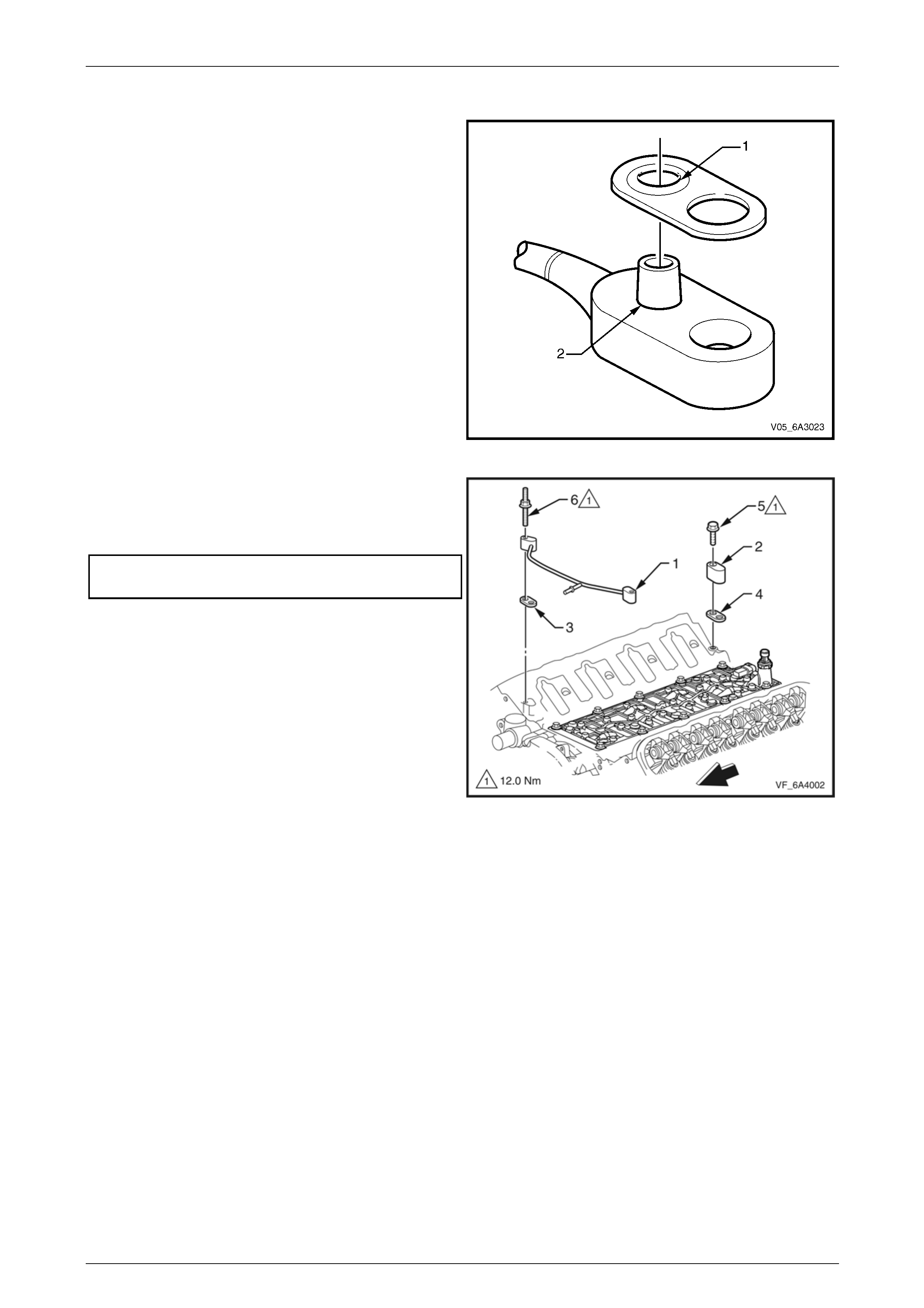
Engine Mechanical Page 6A4–98
Page 6A4–98
Reinstall
1 Correctly install a ne w vapour pipe gasket by fitting the
O-ring seal section (1) over the pipe fitting ni pple (2).
Figure 6A4 – 118
2 Install the vapour vent pipe (1), vapour vent cover (2)
and gasket (3) to the cylinder heads.
3 Install the vapour vent pipe attaching bolts/studs (5
and 6) and tighten to the correct torque specification.
Vapour vent pipe bolt/stud
torque specification............................................12.0 Nm
4 Reinstall the intake manifold, refer to
4.7 Intake Manifold.
Figure 6A4 – 119
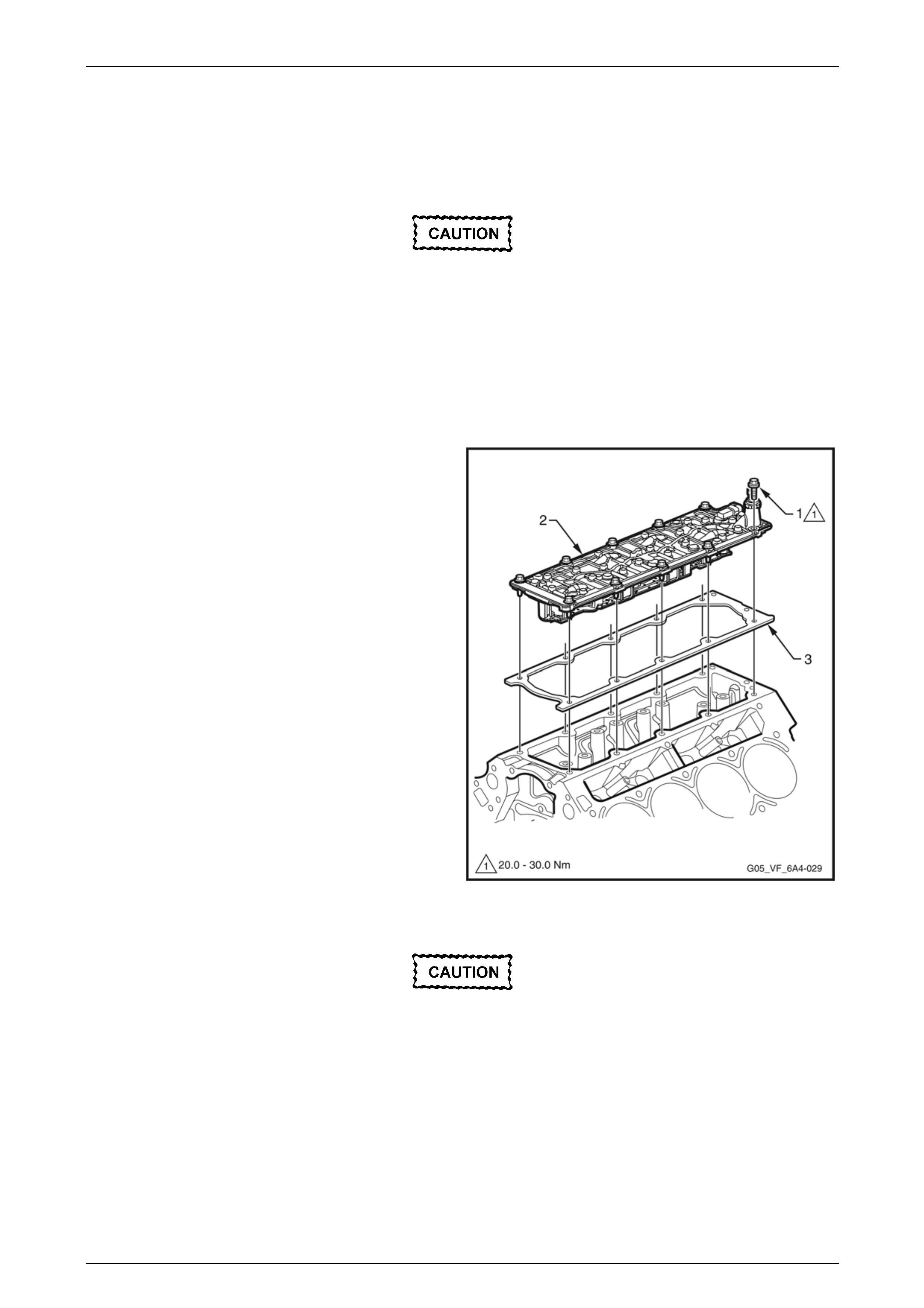
Engine Mechanical Page 6A4–99
Page 6A4–99
4.9 Engine Valley Cover
LT Section No. —
Remove
Disconnection of the battery affects certain
vehicle electronic systems. Refer to Section
00, 5. Battery Disconnection Procedures in
the MY 2006 VZ Service Information before
disconnecting the battery.
1 Disconnect the negative battery cable terminal from the battery.
2 Drain the cooling system. Refer to Section 6B4 Engine Cooling – GEN IV V8.
3 Remove the intake manifold. Refer to 4.7 Intake Manifold Assembly.
4 Remove the vapour vent pipe. Refer to 4.8 Vapour Vent Pi pe in the MY 2 006 VZ Service Information.
NOTE
The valley cover can be removed without
removing the cylinder hea ds, however the heads
are not shown for clarity.
5 Remove the bolt (1), 11 places, attaching the
valley cover (2) to the c ylinder block.
6 Remove the valley cover and gasket (3) from the block
and discard the gasket.
Figure 6A4 – 120
Clean and Inspect
Wear the appropriate safety glasses and
gloves when using compressed air and
cleaning fluids to avoid eye and skin injury.
1 Clean the valley cover in a commercially available cleaning fluid and blow dry using compressed a ir.
2 Clean the gasket surface with a plastic scrap er or similar.
NOTE
Do not use a metal scraper to remove gaskets.
as damage to aluminium components can occur
resulting in oil leaks.
3 Inspect the valley cover sealing surfaces for excessive scratches or other damage.
4 Ensure the fixed internal flo w-restricting or if ice is clean and free from foreign obstructions.

Engine Mechanical Page 6A4–100
Page 6A4–100
Reinstall
Reinstallation of the valley cover is the reverse of the removal procedure notin g the following:
1 Install a new gasket to the valley cover and install the cov er to the engine.
2 Install the 11 valley cover attaching bolts a n d tighten to the correct torque specification.
Valley cover attaching bolt
torque specification.................................20.0 – 30.0 Nm

Engine Mechanical Page 6A4–101
Page 6A4–101
4.10 Camshaft Lobe Lift
Measuring the camshaft lobe lift is a procedure used to d etermine if the camshaft lobes are worn without removin g the
camshaft from the engine. This test is to be performed prior to engine disassembly and with the camshaft, push rods and
valve lifters installed in the engine.
Measure
1 Remove the following:
• The valve rocker arm cover, refer to 4.11 Valve Rocker Arm Cover.
• The valve rocker arms and bolts, refer to 4.12 Valve Rocker Arms and Push Rods
2 Install an M8 x 1.25 dial indicator mounting stud into the
valve rocker arm bolt hole.
3 Assemble the components of Dial Gauge, Tool No.
J 8520 or an equivalent and position it onto the installe d
stud.
4 Position the shaft of the dial indicator onto the end of
the pushrod.
5 Zero the dia l in dicator dial.
6 Slowly, rotate the crankshaft clockwise until the dial
indicator obtains its lowest reading and re-zero the dial
indicator gauge.
7 Rotate the crankshaft clockwise until the dial indicator
obtains its highest reading an d record the reading.
8 If required, repeat for all camshaft lobes and ensure th e
readings are to the specification.
Camshaft lobe lift specification:
Intake lobe:
Except Coupe ...................................................7.43 mm
Coupe............................................................... 6.96 mm
Exhaust lobe:
Except Coupe ...................................................7.43 mm
Coupe............................................................... 7.13 mm
NOTE
If any of the camshaft lobe readings are not to
the specified limits that particular camshaft lobe
is worn. The camshaft will require replacement.
Refer to 5.11 Camshaft for wear limits. Figure 6A4 – 121
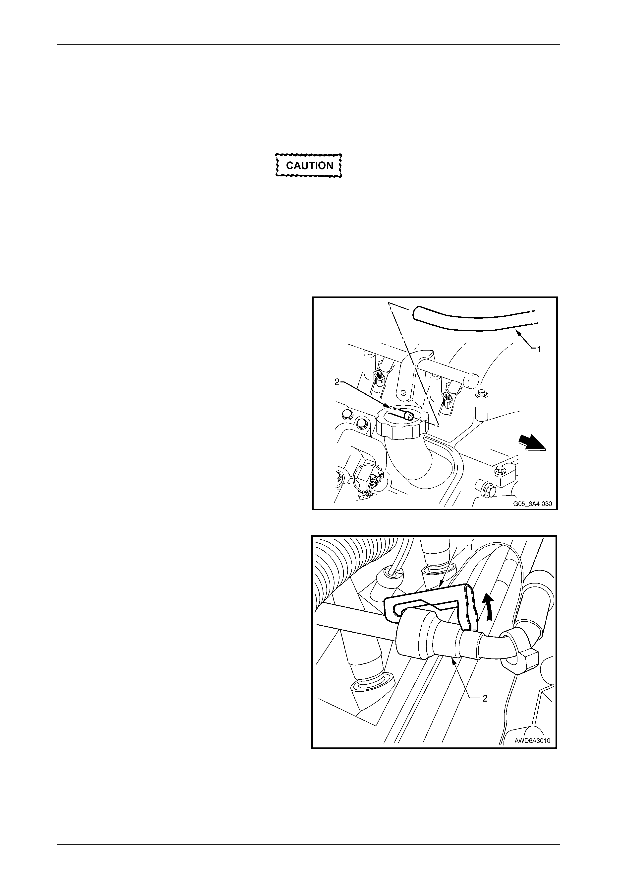
Engine Mechanical Page 6A4–102
Page 6A4–102
4.11 Valve Rocker Arm Cover
LT Section No. — 00–025
Remove
Disconnection of the battery affects certain
vehicle electronic systems. Refer to Section
00, 5. Battery Disconnection Procedures in
the MY 2006 VZ Service Information before
disconnecting the battery.
1 Disconnect the negative battery cable terminal from the battery.
2 If required, remove the strut tower brace, refer to Section 1A1 Body in the MY 2006 VZ Service Informat ion.
3 Remove the engine dress cover, refer to 4.2 Engine Dress Cover
4 If required, remove the fresh air hose (1) from the
fitting (2) at the front of the right-hand valve rocker arm
cover.
Figure 6A4 – 122
5 Using a small scre wdriver, release the s ecurity lock
(1), at each of the fuel supply hose quick connect
fittings (2).
NOTE
The security lock, which is located at the fuel rail
side only, is fitted to a tether to prevent loss.
Figure 6A4 – 123

Engine Mechanical Page 6A4–103
Page 6A4–103
6 Using the quick connect release Tool No. 7371, install
the tool over the fuel line. Refer to Section 6C4 Engine
Management – GEN IV V8.
Figure 6A4 – 124
Ensure the fuel system has been
depressurised prior to disconnecting the fuel
line. Refer to Section 8A1 Fuel System,
section 4.1 in the MY 2006 VZ Service
Information.
7 While holding the fuel line quick connect fitting (1),
push on Tool No.7371 to release the quick connect
fitting from the fuel rail. Pull back on the quick connect
fitting and remove the line.
NOTE
Cap the fuel line fittings and plug the holes after
separating the fuel lines to prevent fuel leaking
and or dirt and other contam inants from entering
the fuel system.
Figure 6A4 – 125
8 Disconnect the EVAP purge valve vapour line
connector (1) from the EVAP purge valve (2).
Figure 6A4 – 126
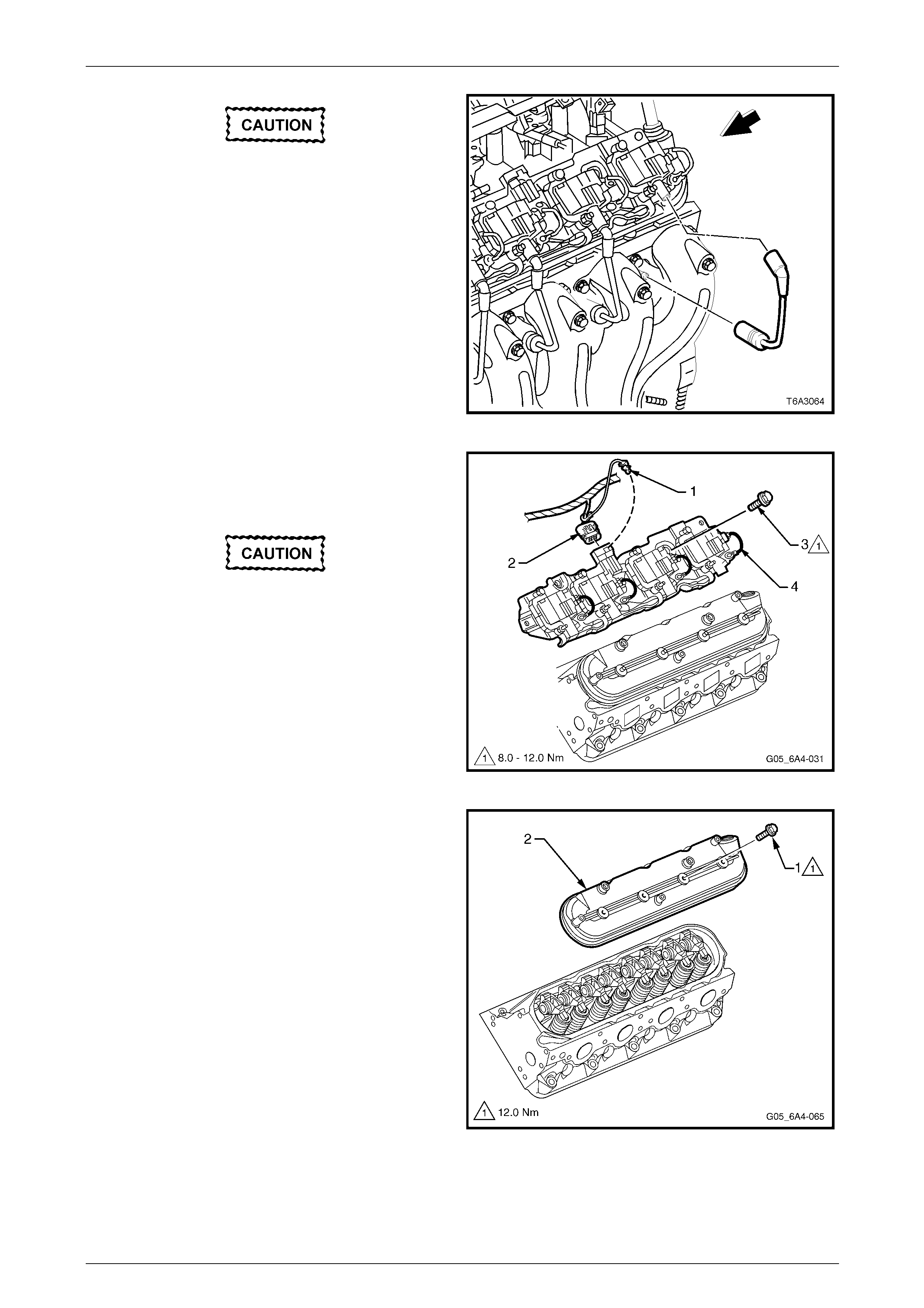
Engine Mechanical Page 6A4–104
Page 6A4–104
Handle the spark plug boot only. Do not pull
on the lead. To remove the lead, twist the
boot first to break the seal and then gently
pull on the boot.
9 Remove the spark plug leads.
Figure 6A4 – 127
10 Remove the CPA lock (1) from the ignition coil main
connector on the valve rocker arm cover that is being
removed and then remove the wiring harness
connector (2).
The rear attaching bolt on each coil assemb l y
is a conventional screw and not a stepped
stud. Fitment of this screw in the correct
position on reassembly is important to avoid
possible chaffing of the fuel line or EVAP
vapour line.
11 Remove the bolt, four and one fastener (3) attaching
the ignition coil mounting bracket (4) to the cover
being removed.
12 Lift the ignition coils, wiring and bracket from the
engine. Figure 6A4 – 128
13 Remove the bolt (1), four places, then remove the
cover (2) and gasket from the cylinder head.
Figure 6A4 – 129
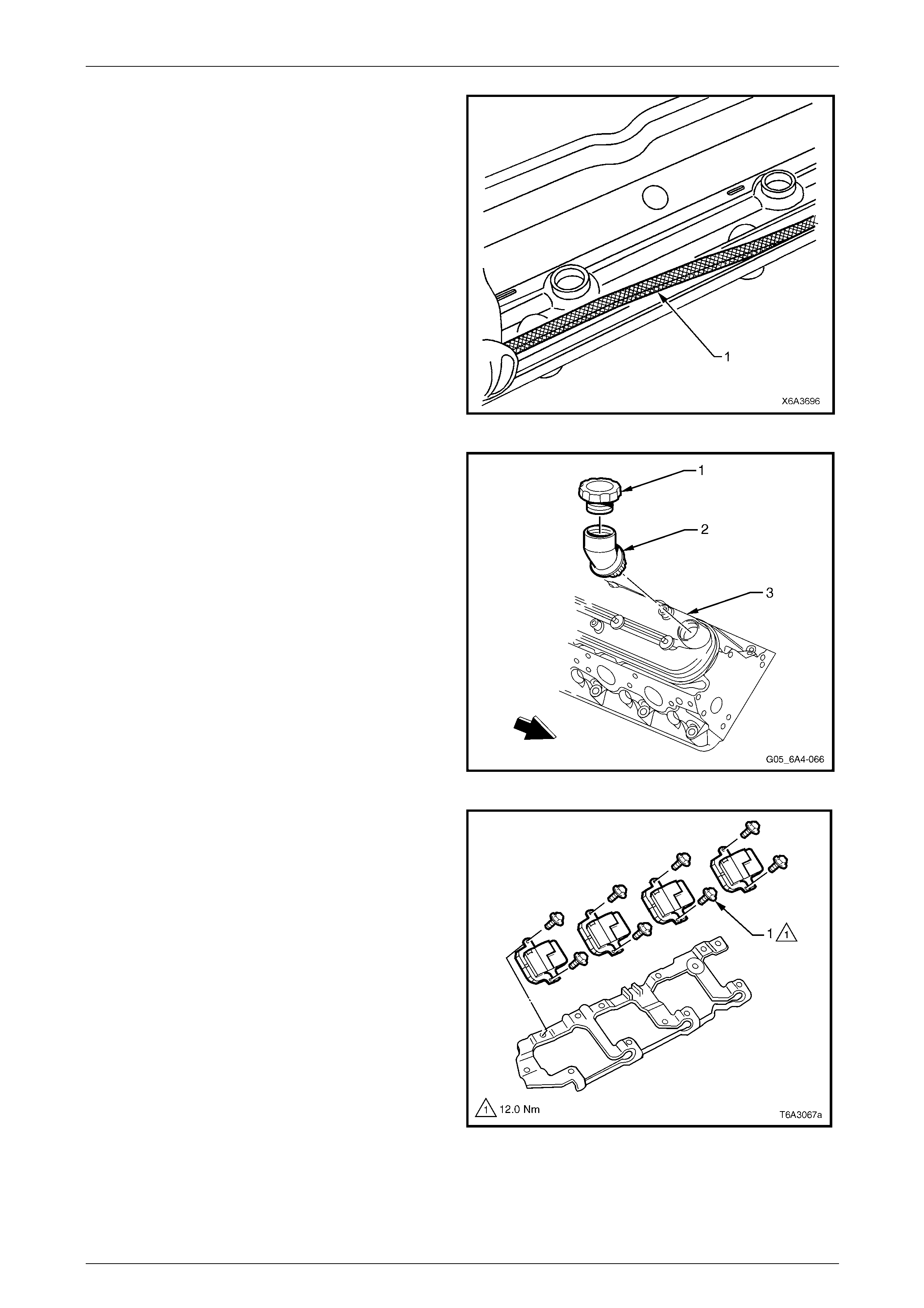
Engine Mechanical Page 6A4–105
Page 6A4–105
14 Remove the gasket (1) from the cover and discard.
NOTE
The attaching bolt grommets may be re-used if
not damaged.
Figure 6A4 – 130
15 If required, remove the oil fill cap (1) and/or fil l tube (2)
from the right-hand valve rocker arm cover (3).
Discard the oil fill tube, as it will have permanent
damage when it is removed.
Figure 6A4 – 131
16 If required, remove the eight bolts (1) attaching the
ignition coils to the mounting bracket and remove the
coils.
Figure 6A4 – 132
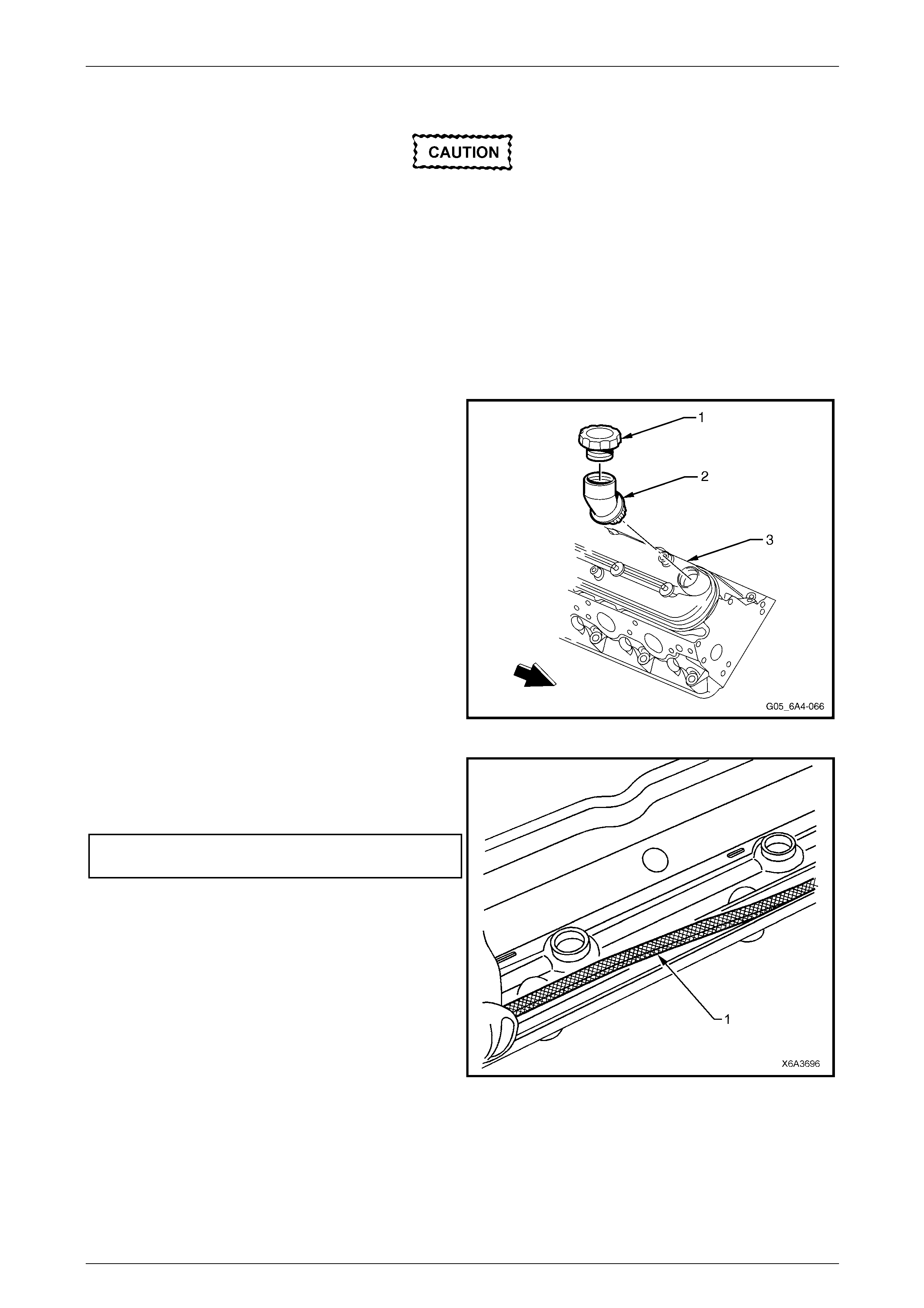
Engine Mechanical Page 6A4–106
Page 6A4–106
Clean and Inspect
Wear the appropriate safety glasses and
gloves when using compressed air and
cleaning fluids to avoid eye and skin injury.
1 Clean the valve rocker arm cover in a commercially available cleaning fluid and dry using compressed air.
2 Inspect the ventilation system passages for restriction, clean as require d.
3 Inspect the cover gasket groove for damage.
4 Inspect the ignition coil mounting boss threads for damage.
Reinstall
Reinstallation of the valve roc k er arm cover is the reverse of the removal procedure noting the following items.
1 If the oil fill tube (2) was removed from the right-hand
rocker cover, it must be replaced with a new part.
2 Lubricate the O-ring seal of the new oil fill tube with
clean engine oil.
3 Install the oil fill tube into the cover rotating the tube
clockwise until it is locked into the correct position.
4 Install the oil fill cap (1) rotating clockwise until it is
locked into place.
NOTE
Do not remove the oil fill tube from the right hand
cover unless replacement is required. The oil fill
tube will be damaged in the removal process
and must be replaced.
Figure 6A4 – 133
5 Install a new gasket (1) to the rocker cover.
6 Reinstall the rocker cover onto the cylinder head and
tighten the rocker cover attaching bolts to the correct
torque specification.
Valve rocker arm cover attaching bolt
torque specification............................................12.0 Nm
Figure 6A4 – 134
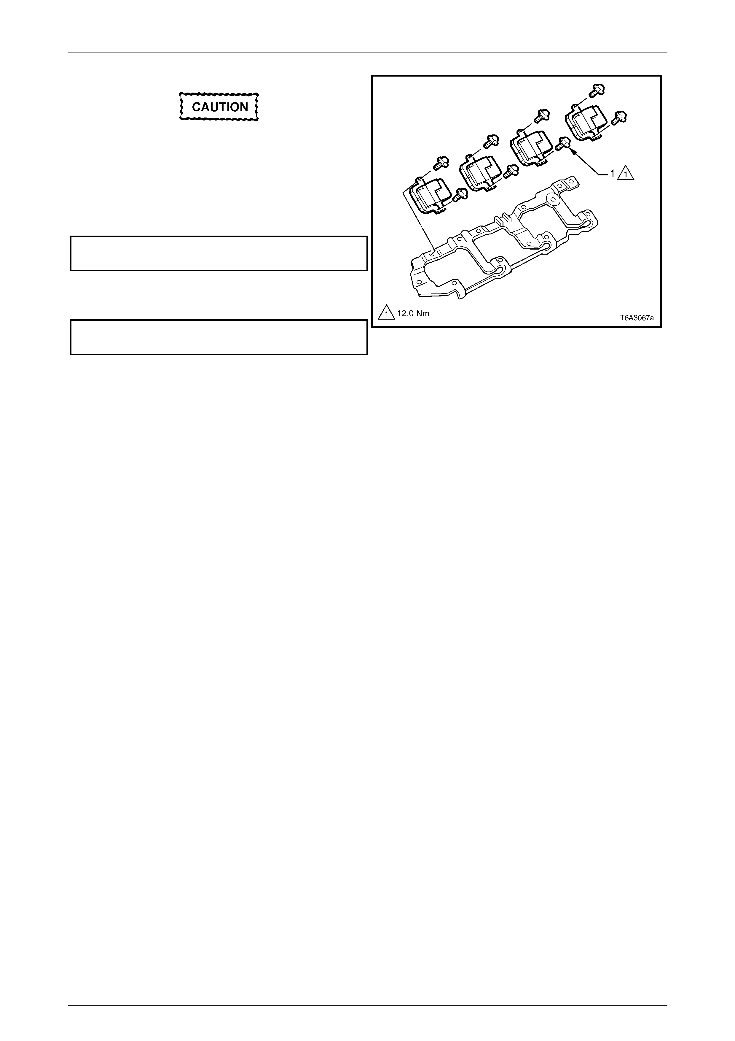
Engine Mechanical Page 6A4–107
Page 6A4–107
The left-hand, rear coil mounting bracket
fastener is a plain screw and not a stepped
stud as are the others. Fitment of this screw
in the correct position is important to avoid
fuel/vapour line chaffing.
7 Install the ignition coils onto the mounting bracket and
tighten the bolts (1) to the correct torque specification.
Ignition coil to mounting bracket bolts
torque specification............................................12.0 Nm
8 Install the ignition coil and mounting bracket assembly
to the rocker cover. Tighten the stud and screws to the
correct torque specification.
Ignition coil mounting bracket fastener
torque specification...................................8.0 – 12.0 Nm
9 Install the ignition coil main wiring harness connector
then install the CPA lock ensuring it is fitted securely.
Figure 6A4 – 135
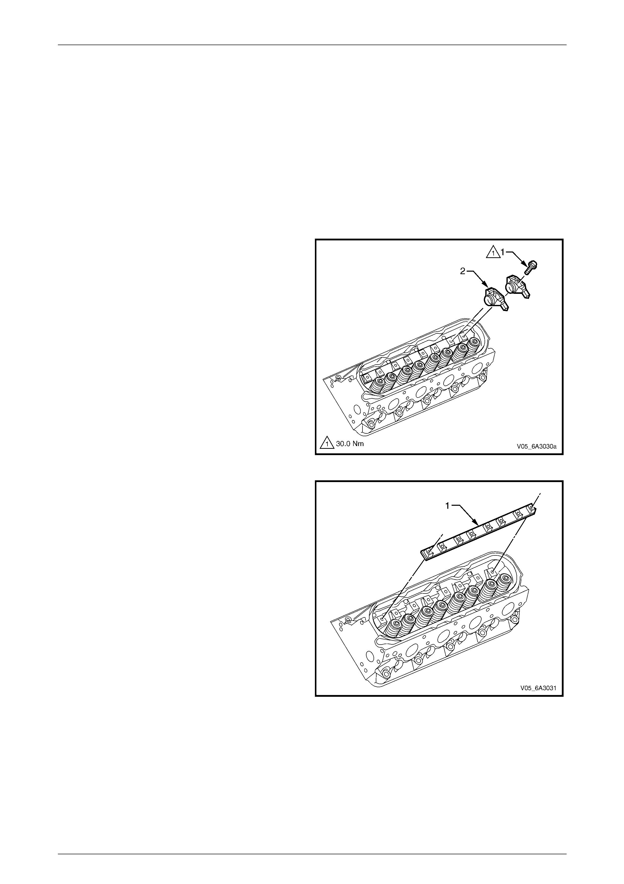
Engine Mechanical Page 6A4–108
Page 6A4–108
4.12 Valve Rocker Arms and Push Rods
LT Section No. — 00–050
Remove
1 Remove the valve rocker arm cover, refer to 4.11 Valve Rocker Arm Cover.
NOTE
Store all removed valve train components in the
same order they were removed. This will ensure
that when they are reinstalled in the same
relationship as on removal.
2 Remove the rocker arm attaching bolt (1) on each
valve rocker arm (2) for the cylinder head being
serviced.
3 Remove the associated valve rocker arm.
Figure 6A4 – 136
4 Remove the valve rocker arm pivot support (1).
NOTE
Mark the rocker arm pivot support orientation in
relation to the cylinder head to ensure it is
reinstalled in the same orientat ion.
Figure 6A4 – 137
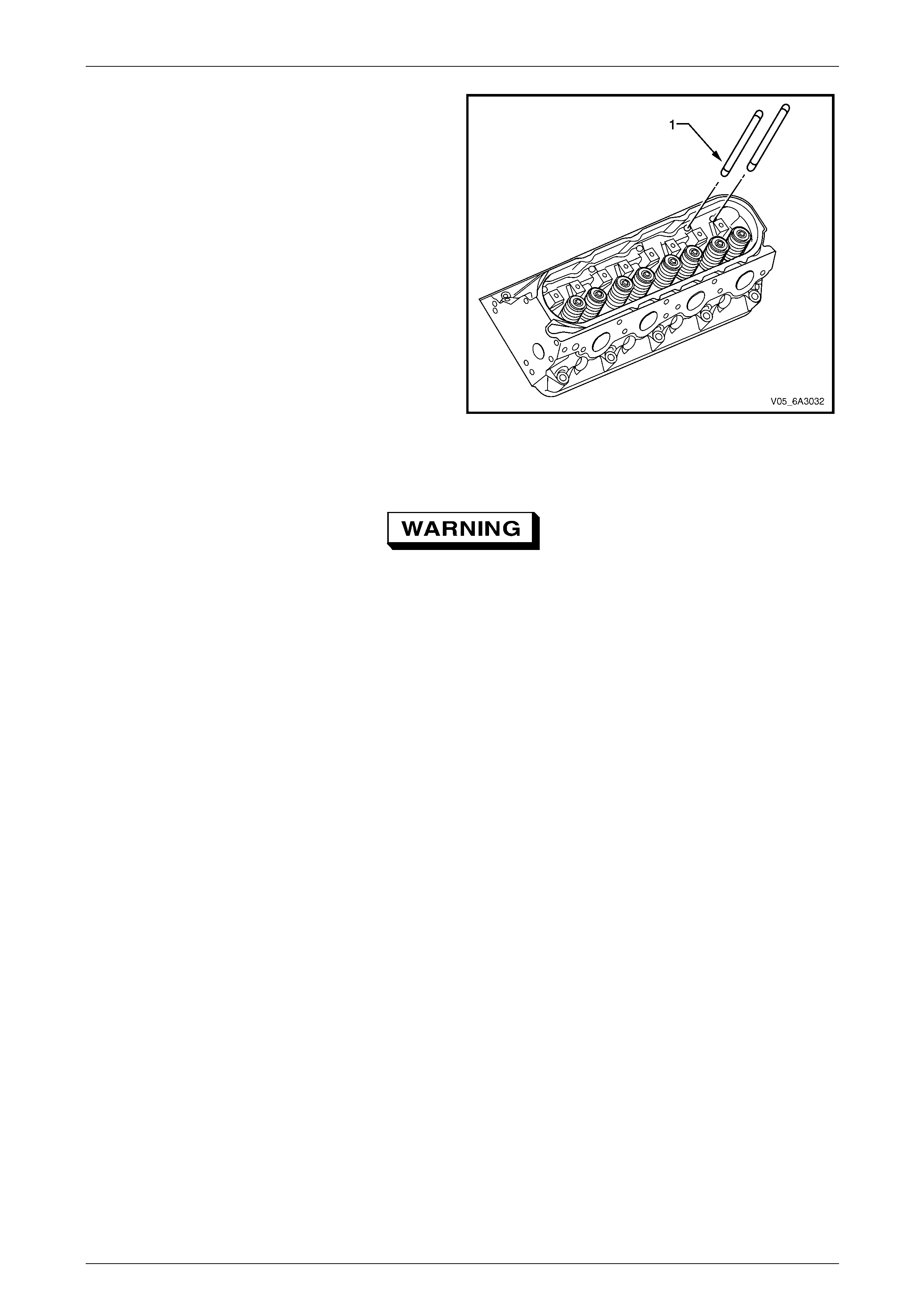
Engine Mechanical Page 6A4–109
Page 6A4–109
5 Remove the push rod (1), eight places, ensuring they
are kept in the order removed.
Figure 6A4 – 138
Clean and Inspect
To avoid personal injury, wear safety glasses
and the appropriate gloves when using
compressed air and cleaning fluid.
1 Clean the parts in a commercially available cleaning fluid and blo w dry with compresse d air.
2 Inspect the rocker arms, pivot support and p ushrods for excessive wear and replace as required.
Reinstall
Reinstallation of the valve roc ker arms is the reverse of the removal procedure, noting the following:
1 Remove the spark plugs to reduce the effort required to turn the engine over by hand, refer to
Section 6C4-3 Engine Management – GEN IV V8 – Service Operations.
2 Lubricate the follo wing parts in clea n engine oil before installation:
• All valve rocker arms and pushrods.
• The flanges of all rocker arm bolts.
3 Install all push rods ensuring that each push rod seats correctly in the hydraulic valve lifter sockets.
4 Install the rocker arm pivot support noting the orie ntatio n as marked in Step 4 of the removal procedure.
5 Install all the rocker arms, bearings and the attaching bolts but do not tighten fully at this time.
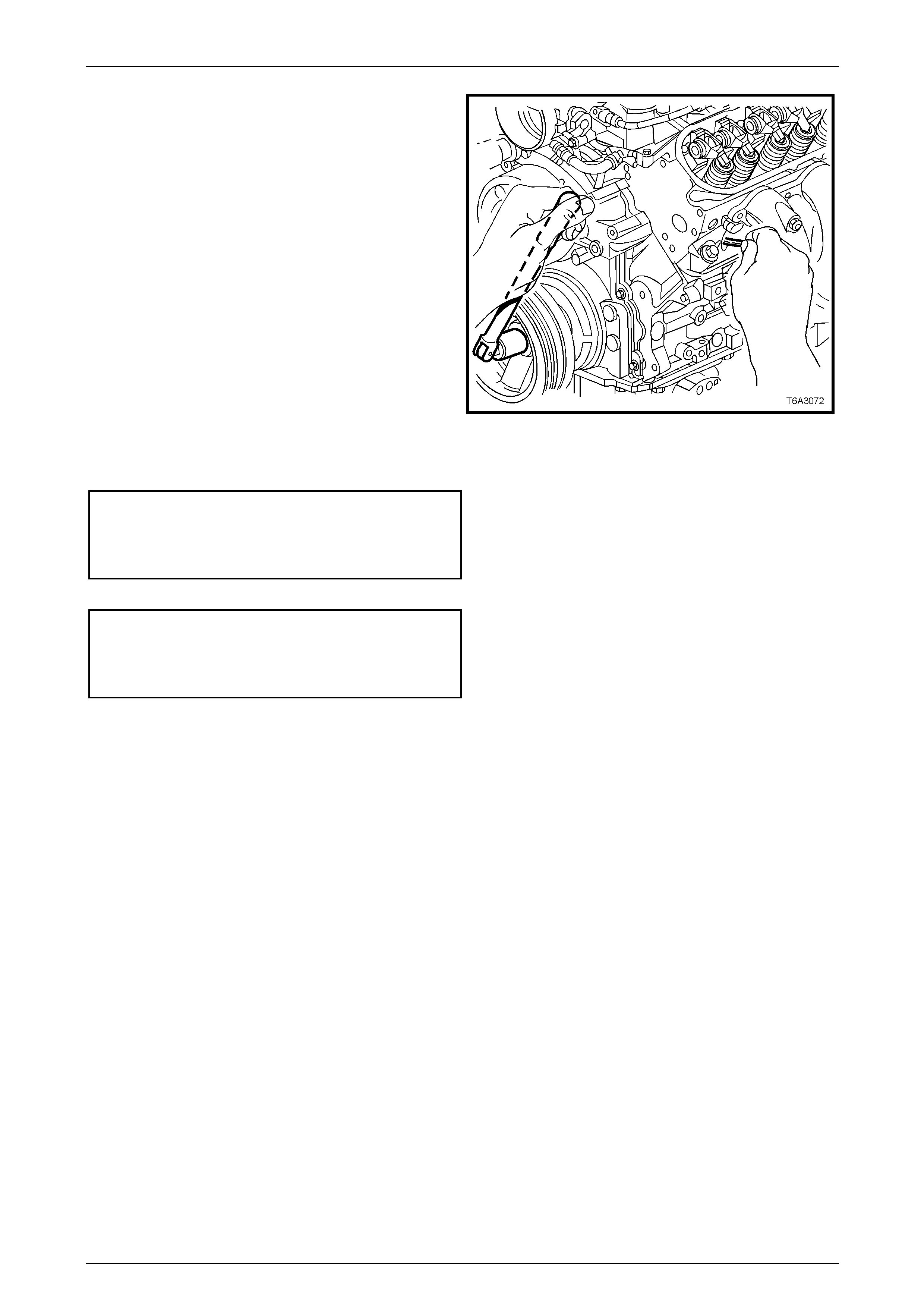
Engine Mechanical Page 6A4–110
Page 6A4–110
6 Using a socket and handle on the crankshaft pulley
attaching bolt, rotate the crankshaft until the No. 1
piston is at the Top Dead Centre (TDC) on the
compression stroke.
NOTE
The No.1 piston is at the compression stroke
when the No.6 cylinder inlet and exhaust valves
are rocking, that is when the exhaust valve is at
the end of its upward travel while the intake
valve starts its downward movement.
NOTE
The engine firing order is 1-8-7-2-6-5-4-3.
Cylinder numbers are 1-3-5-7 are on the left
bank and 2-4-6-8 are on the right bank.
Figure 6A4 – 139
7 With No. 1 piston at TDC on the compression stroke, tighte n the following rocker arm bolts to the correct torque
specification.
Rocker arm attaching bolt
torque specification.................................25.0 – 35.0 Nm
Exhaust valve cylinder No's........................ 1, 2, 7 and 8
Intake valve cylinder No's ........................... 1, 3, 4 and 5
8 Rotate the crankshaft 360° and tighten the following rocker arm bolts to the correct torque specification.
Rocker arm attaching bolt
torque specification.................................25.0 – 35.0 Nm
Exhaust valve, cylinder No's....................... 3, 4, 5 and 6
Intake valve, cylinder No's. ......................... 2, 6, 7 and 8
9 Reinstall the rocker cover, refer to 4.11 Valve Rocker Arm Cover.
10 Reinstall the engine dress c over, refer to 4.2 Engine Dress Cover.
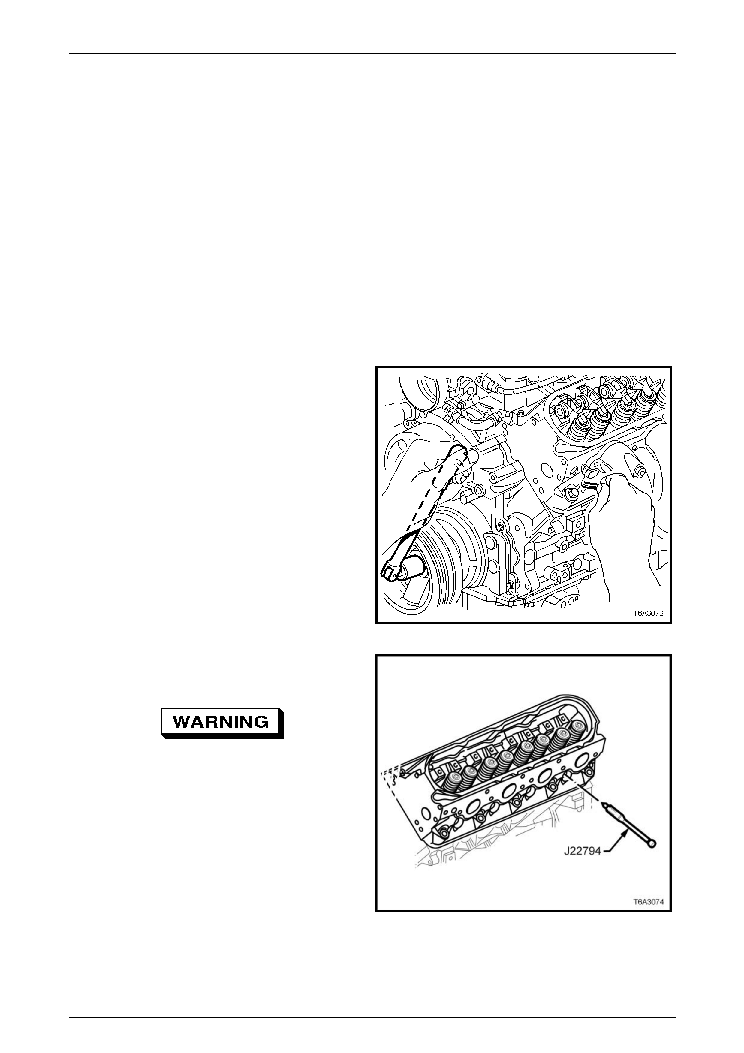
Engine Mechanical Page 6A4–111
Page 6A4–111
4.13 Valve Stem Oil Seal and Valve Spring
LT Section No. — 00–075
Remove
NOTE
Valve train components when separated must be
marked or organised in a way to ensure they are
reinstalled to their original loc ation and position.
1 Remove the spark plugs from the cylinder/s being serviced, refer to Section 6C4-3 Engine Management – GEN IV
V8 – Service Operations.
2 Refer to 4.12 Valve Rocker Arms and Push Rods and remove the following components from the cylinder head
being serviced:
• Valve rocker arms
• Valve rocker arm pivot suppor t
• Pushrods
3 Using a socket and handle on the crankshaft pulley
attaching bolt, rotate the crankshaft until the piston of
the cylinder being servic ed is at the Top Dead Centre
(TDC) on the compression stroke.
NOTE
This operation can be performed with the
cylinder at the bottom of its stroke, however with
the piston at TDC the valve will not fall into the
cylinder if the air supply is accidentally
disconnected during the op eration.
Figure 6A4 – 140
4 Install the Spark Plug Port Adaptor, T ool J 22794 or
equivalent into the spark plug hole of the cylinder
being serviced.
The engine may spin over when the air line is
connected. To avoid being caught by rotating
pulleys and belts, keep clear of the drive
belts and pulleys when connecting the air
line.
5 Using suitable adaptors, attach a compressed air line
to Tool No. J 22794 and appl y a constant supply of
compressed air to the cylinder being service d.
Figure 6A4 – 141
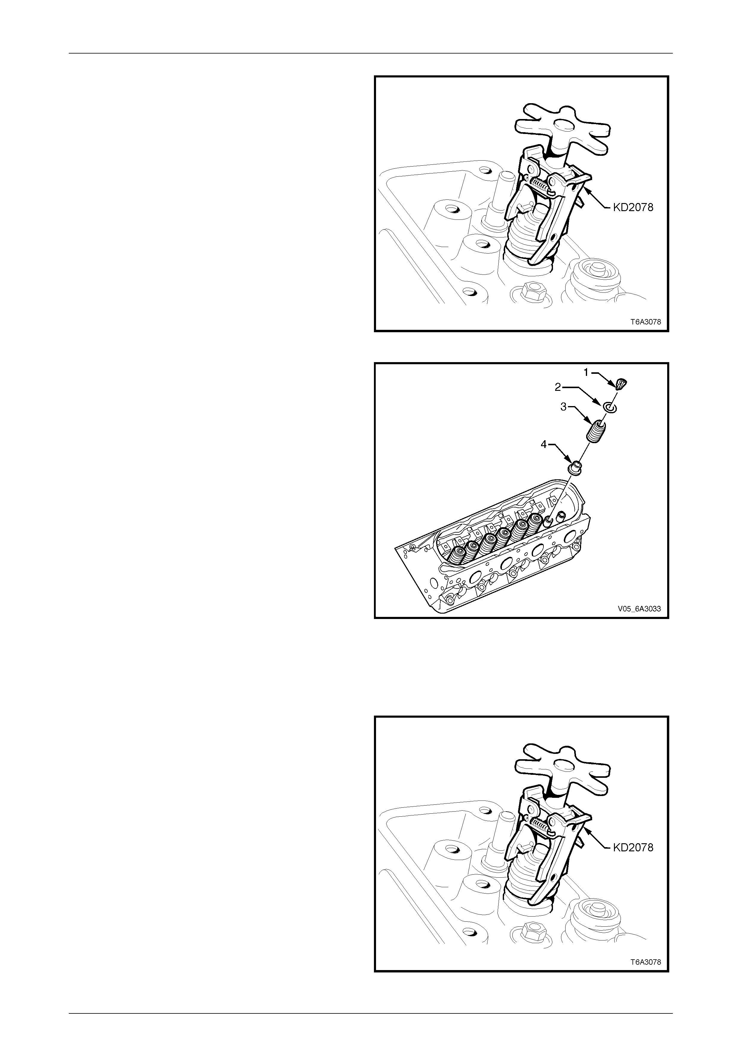
Engine Mechanical Page 6A4–112
Page 6A4–112
6 Compress one of the valve springs using a
commercially available valve spring compressor Tool
No. KD2078. A slight tap on the valve spring cap with
a soft faced hammer may be required to dislodge the
valve spring cap retaining collets.
NOTE
Do not disconnect the airline while the valve
spring is being compressed and/or the valve
spring cap retaining collets are removed.
Figure 6A4 – 142
7 Remove the valve spring cap retaining collets (1) two
places.
NOTE
Valve train components when separate d m ust be
marked or organised in a way to ensure they are
reinstalled to their original loc ation and position.
8 Remove in order, the following:
a Valve spring cap (2).
b Valve spring (3).
c If required, the oil seal and spring sh im
combination (4).
NOTE
Only one cylinder at a time can be done using
this method to remove the valve stem seals
and/or sprigs.
9 Repeat Steps 3 to 8 to replace the remaining valve
springs and/or valve stem seals in the other cylind ers. Figure 6A4 – 143
Reinstall
1 Reinstall a new valve stem oil seal and shim assembly to the valve guide by hand until the shim seats against the
cylinder head.
2 Reinstall the valve spring with the smaller wound coils
facing up then install the spring cap.
3 Compress the spring using spring compressor Tool
No. KD2078 until sufficient space is allo wed for the
valve spring cap retaining collets to be installed.
4 Reinstall both the valve spring retaining collets using
clean grease or petroleum jelly to retain.
5 Release the valve spring com pressor e nsuring that
both valve stem collets are seated correctly.
6 Lightly tap the valve stem with a soft faced hammer to
seat the valve stem collets.
7 Remove the compressed air supp ly.
8 Remove the spark plug adapt or Tool No. J 22794,
refer to Figure 6A4 – 141.
Figure 6A4 – 144
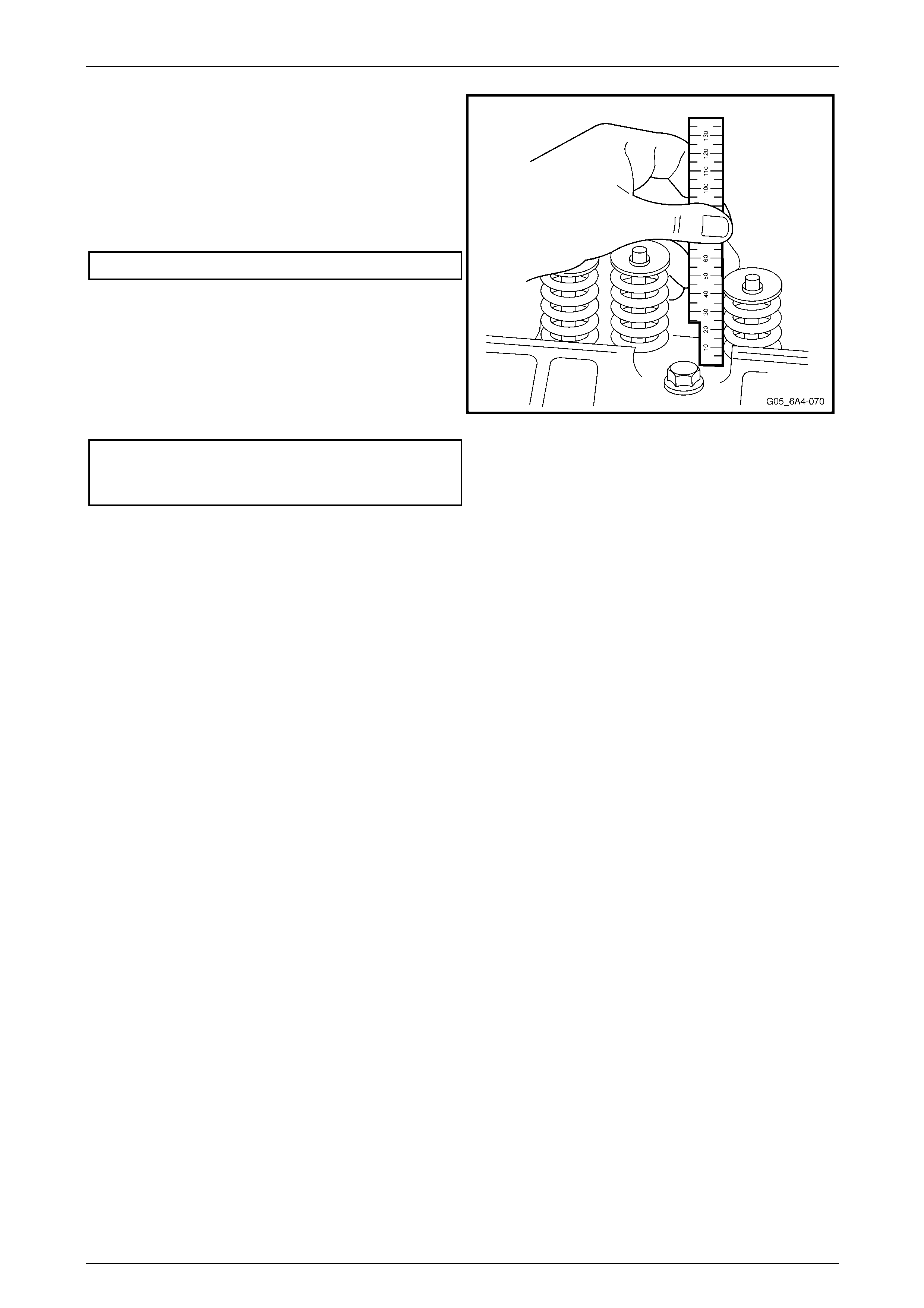
Engine Mechanical Page 6A4–113
Page 6A4–113
9 If replacing the valve spring or shim, measure the
installed height of the valve spring using a ruler or
vernier calipers. The measure m ent is to be taken from
the base of the valve spring to the top.
10 If the measurement exceeds the specified limit, a
commercially availabl e stainless steel shim must be
installed between the valve stem oil seal/shim
combination and the cylin der head to achieve the
required spring height.
Installed valve spring height.....................45.75 mm Max
NOTE
Do not shim the valve spring to obtain less than
the specified height.
11 Repeat Steps 1 to 10 to replace the remaining valve
springs and/or valve stem seals in the other cylind ers.
12 Reinstall the spark plug a nd tighten to the correct
torque specification.
Spark plug torque specification:
Used cylinder head............................................15.0 Nm
New cylinder head .............................................20.0 Nm
13 Reinstallation of the remaining components is the
reverse of the removal procedure.
Figure 6A4 – 145
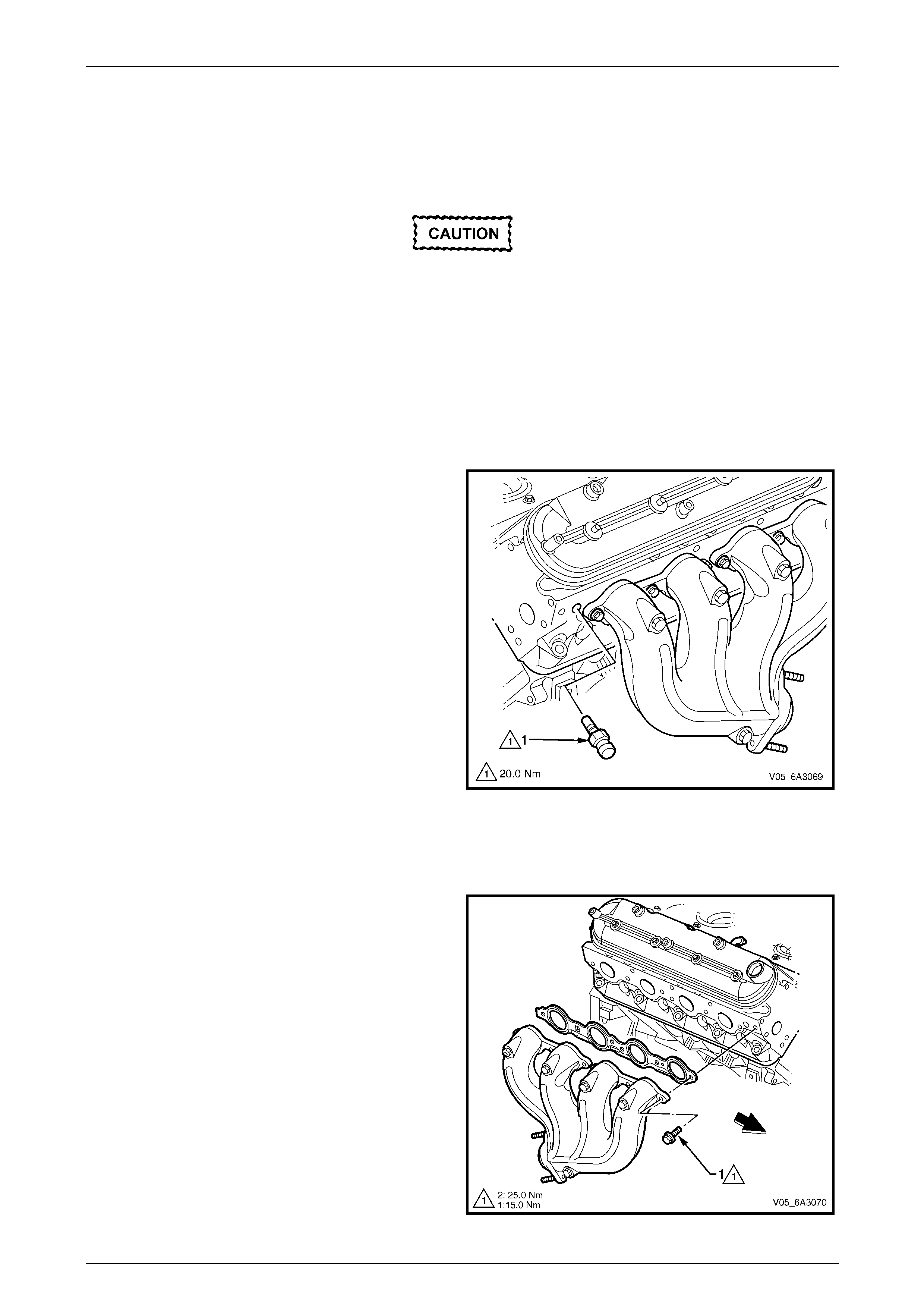
Engine Mechanical Page 6A4–114
Page 6A4–114
4.14 Exhaust Manifold
LT Section No. — 00–450
Remove
Disconnection of the battery affects certain
vehicle electronic systems. Refer to
Section 00 Warnings, Cautions and Notes
before disconnecting the battery.
1 Disconnect the ground battery cable termi nal from the battery.
2 If required, remove the strut tower brace, refer to Section 1A1 Body.
3 Remove the air intake duct, refer to 4.1 Air Intake Duct.
4 Remove the engine dress cover for the side the manifold is t o be removed, refer to 4.2 Engine Dress Cover.
5 Raise the front of the vehicle and place on safety stands. Refer to Section 0A General Information for the location
of jacking and support points.
6 For the left hand side exhaust manifold, remove the
engine coolant temperature sensor (1) from the
cylinder head to avoid possible damage during
exhaust manifold removal.
7 For the right-hand side exhaust manifold, re move
the engine oil level indic ator and tube, refer to
4.5 Oil Level Indicator and Tube.
NOTE
Plug the opening of the oil level indicator tube in
the cylinder block to prevent entry of foreign
debris.
8 While not essential, it is recommended the oxygen
sensor/s be removed from the exhaust pipe/s to avoid
accidental damage. Refer to Section 6C4-3 Engine
Management – GEN IV V8 – Service Operations.
9 Remove the exhaust manifold to exhaust pipe flange
attaching nuts, refer to Section 8B Exhaust System.
10 Lower the vehicle to the ground.
11 Remove the spark plugs from the cylinder head on the
side the exhaust manifold is being removed. Refer to
Section 6C4-3 Engine Management – GEN IV V8 –
Service Operations.
Figure 6A4 – 146
12 Working from the outside into the centre, progressively
loosen and remove the bolt (1), six pl aces, attaching
the exhaust manifold to the cylinder head.
13 Remove the exhaust manifold and gasket from the
cylinder head.
Figure 6A4 – 147
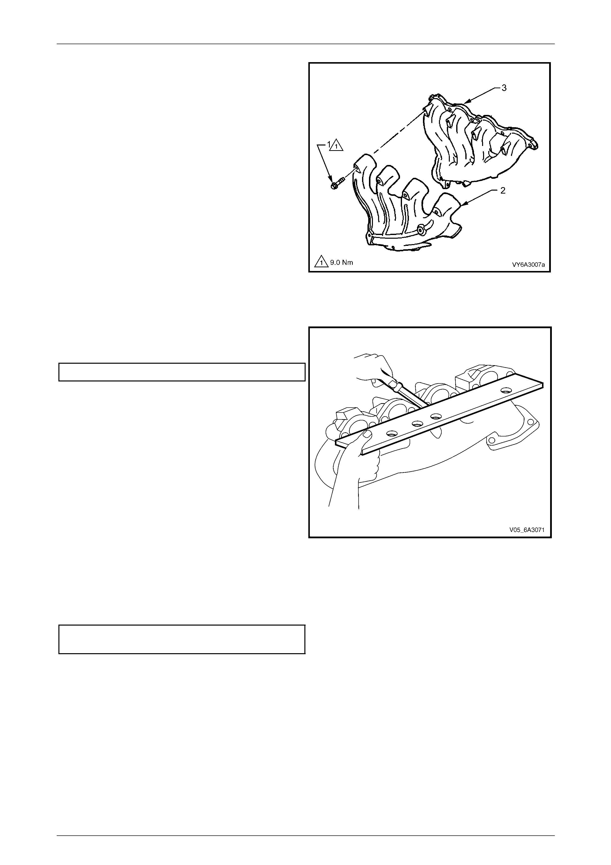
Engine Mechanical Page 6A4–115
Page 6A4–115
14 If required, remove the heat shield attaching bolt (1),
five places and the heat shield (2) from the exhaust
manifold (3).
NOTE
While the right-hand side exhaust manifold is
shown, the left-hand side arrangement is the
same.
Figure 6A4 – 148
Inspect
1 Using a straight edge and feeler gauges, check the
cylinder head mounting face of the exhaust manifold
does not exceed the maximum distortion specification.
Distortion limit ............................................0.25 mm Max
NOTE
An exhaust manifold exceeding this maximum
distortion specification must be machined to
within the specification to correct any distortion.
2 Inspect the heat shield for damage.
3 Inspect the exhaust pipe flange stud threads for
damage, replace as required, refer to
Section 8B Exhaust System.
4 Inspect the exhaust manifold to cylinder head
mounting surface for scratches or damage.
Figure 6A4 – 149
Reinstall
1 If the heat shield was removed, apply an anti-seize compound such as Caltex Kopr-Kote or equivalent to the
cleaned heat shield bolt threads. Reinstall the heat shield to the exhaust manifold and tighten the attaching bolts to
the correct torque specification.
Exhaust manifold heat shield attaching
bolt torque specification.......................................9.0 Nm
NOTE
Exhaust manifold bolt hole threads must be clean
and free of debris or thread locking compound.
All gaskets, O-rings and seals must be replaced
with new parts on reinstallation.
2 Apply a 5 mm wide band of L octite 272 thread sealant or equivalent to the threads of the exhaust manifold
mounting bolts.
NOTE
Do not apply thread sealant to the first three
threads of any exhaust manifold mounting bolt.
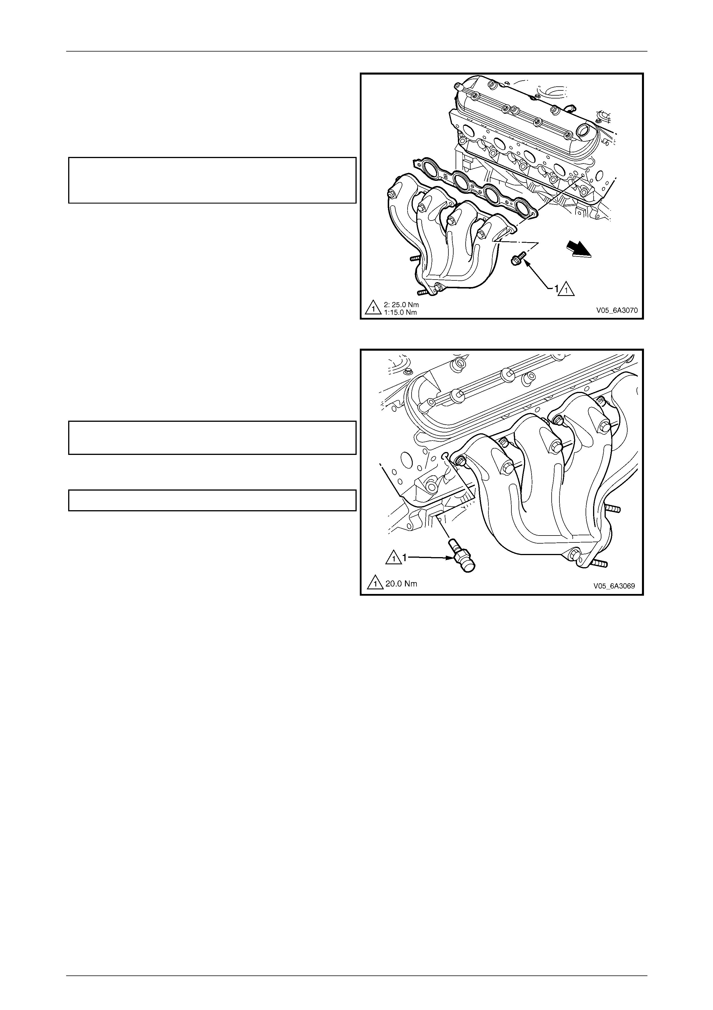
Engine Mechanical Page 6A4–116
Page 6A4–116
3 Install a new gasket between the e xhaust manifold
and cylinder head, and reinsta ll the manifold and bolts.
4 Tighten the exhaust manifold bolts (1) in two stages to
the correct torque specification. Start with the centre
two bolts and alternate from side to side to the outside
bolts.
Exhaust manifold bolt torque specification
Stage 1 ............................................................. 15.0 Nm
Stage 2 ............................................................. 25.0 Nm
5 Using a suitable size pin pu nch, bend the exposed
edge of the exhaust manifold gasket over at the front
of the right hand cylinder head and the rear of the left-
hand cylinder head.
6 If removed, reinstall the oxygen sens or/s, refer to
Section 8B Exhaust System.
7 Reinstall and tighten the exhaust pipe to the manifold
flange attaching nuts, refer to Section 8B Exhaust
System. Figure 6A4 – 150
8 Apply thread a sealant such a s Loctite 565 or
equivalent, to the cleaned threads of the coolant
temperature sensor (1).
9 Reinstall and tighten the coolant temperature
sensor (1) to the correct torque specification.
Coolant temperature sensor
torque specification............................................20.0 Nm
10 Reinstall the spark plugs a nd tighten to the correct
torque specification and reinstall the spark plug leads.
Spark plug torque specification..........................15.0 Nm
11 Reinstall the engine dress c over and air intake duct in
the reverse of the removal procedure.
Figure 6A4 – 151
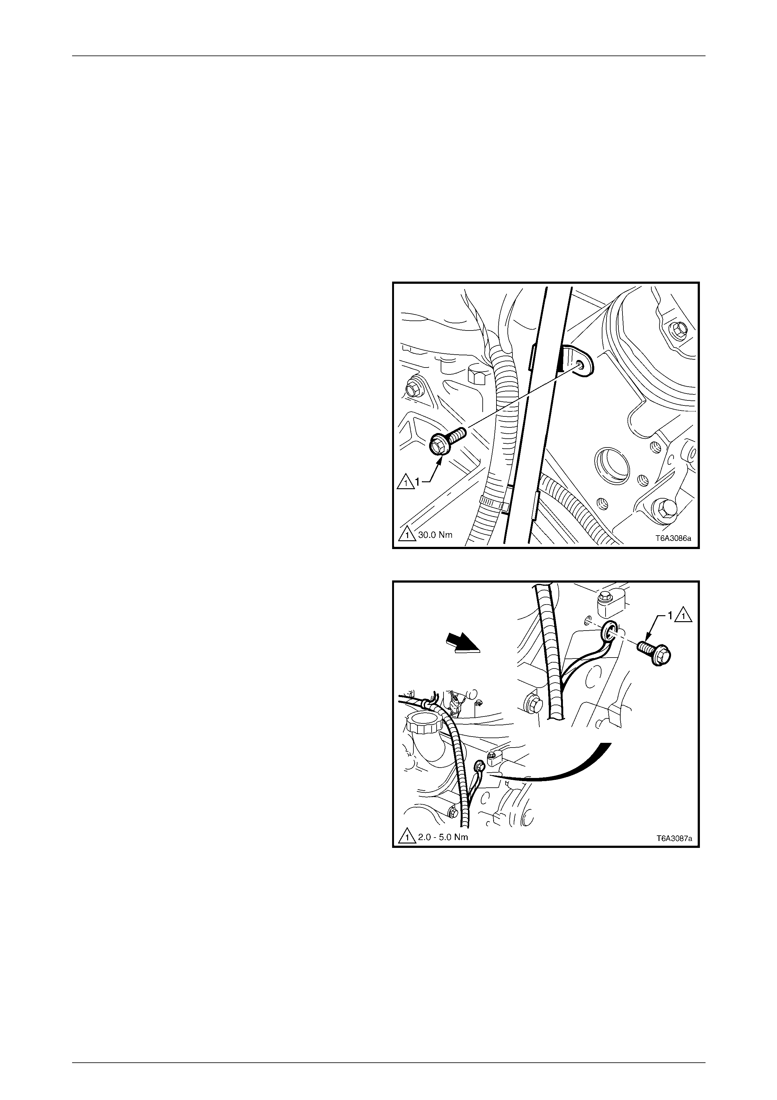
Engine Mechanical Page 6A4–117
Page 6A4–117
4.15 Cylinder Head
LT Section No. — 00–075
Remove
1 Remove vapour vent pipe. Refer to 4.8 Vapour Vent Pipe and Covers
2 Remove the valve rocker arms and pus h rods on the cylinder head to be removed. Refer to
4.13 Valve Stem Oil Seal and Valve Spring
3 Remove the spark plugs from the cylinder head being removed. Refer to Section 6C4-3 Engine Managem ent –
GEN IV V8 – Service Operations.
4 Remove the exhaust manifold on the c ylinder head to be removed. Refer to 4.14 Exhaust Manifold.
5 For the right-hand cylinder head, remove th e bolt
attaching the automatic transmission indicator tube
bracket bolt (1) at the rear of the cylinder head.
Figure 6A4 – 152
6 Remove the bolt (1) attaching the Engine harness
ground strap at the front of the right hand c yli nder
head.
Figure 6A4 – 153
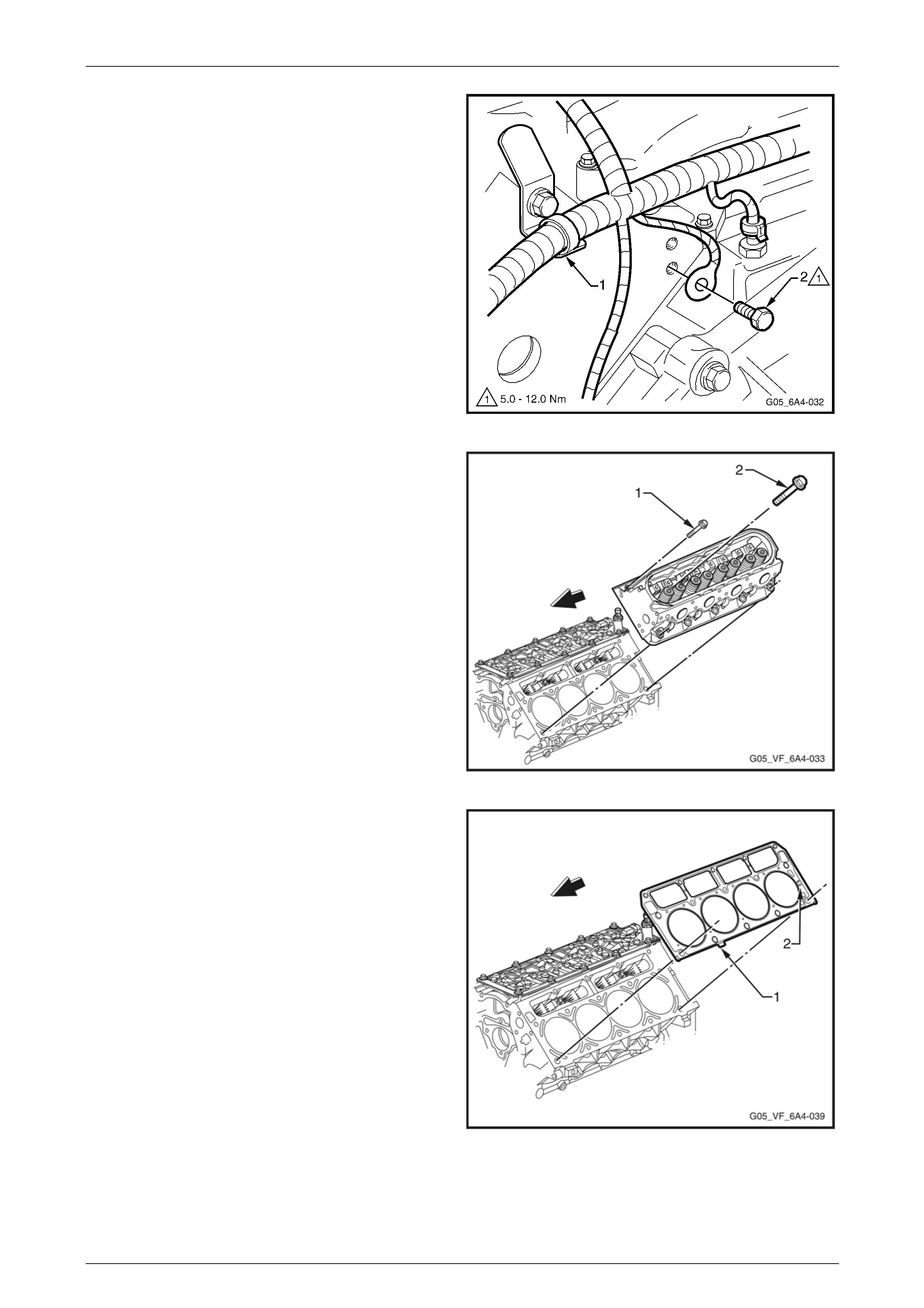
Engine Mechanical Page 6A4–118
Page 6A4–118
7 For the left-hand cylinder head:
a Remove the Engine wiring harness strap (1)
from the bracket at the rear of the cylinder head.
b Remove the bolt (2) attaching the Engine
harness ground cable at the rear of the cylinder
head.
c Remove the power steering pump. Refer to
Section 9 Steering.
Figure 6A4 – 154
8 Progressively, loosen the M8 (1) and M1 1 (2) cylinder
head bolts starting with the M8 bolts working from the
outside to the centre.
NOTE
Discard all M11 bolts after removal as these are
torque to yield bolts. The M8 bolts can be re-
used.
9 Remove the cylinder head from the cylinder block and
place on two blocks of wood to avoid scratching the
machined surface.
Figure 6A4 – 155
10 Remove the cylinder head ga sket and discard.
Figure 6A4 – 156
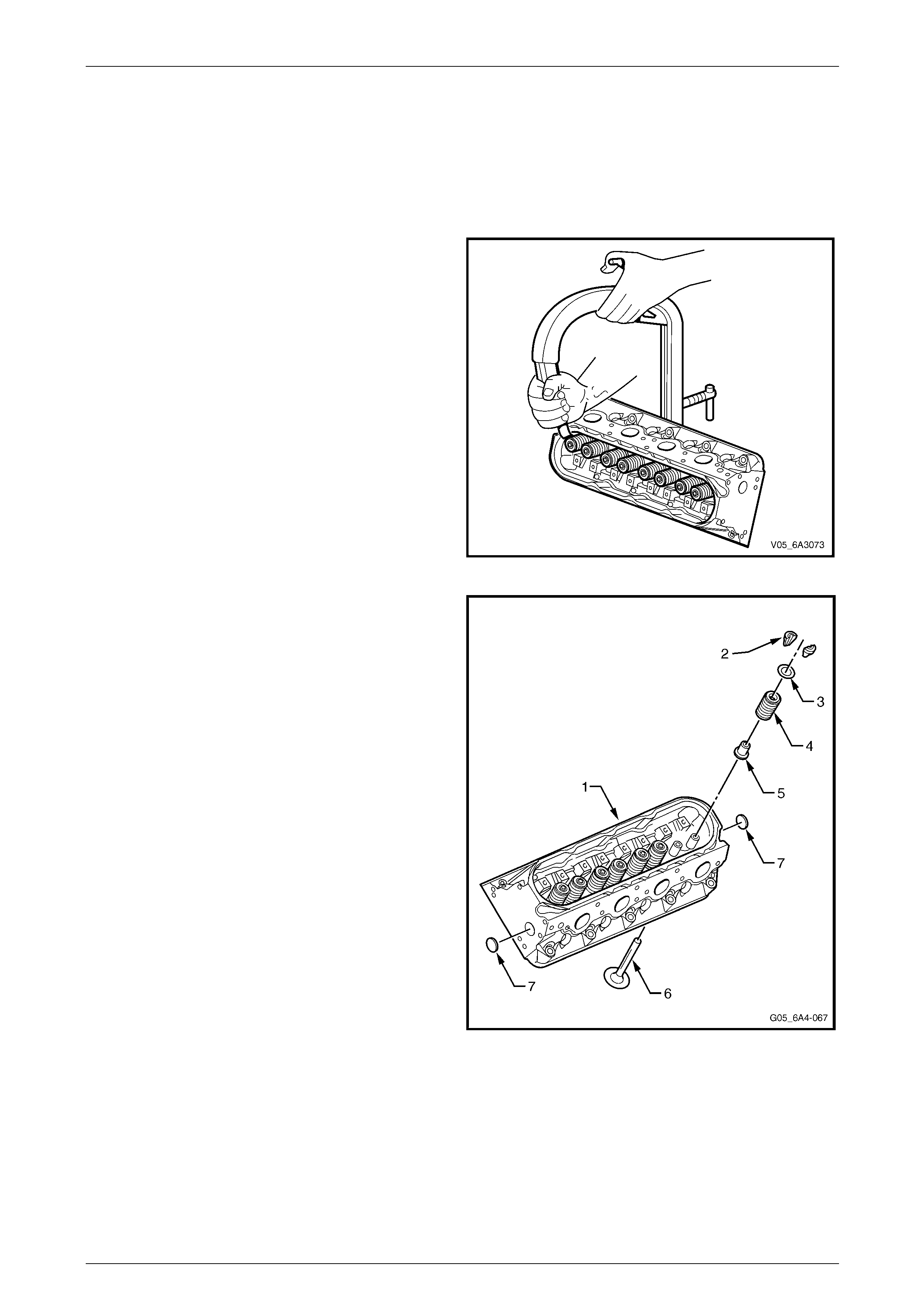
Engine Mechanical Page 6A4–119
Page 6A4–119
Disassemble
NOTE
Do not mix the removed valve train components.
Organise all components in the order they were
removed to ensure that when reinstalled, the y are
fitted to their original locations.
1 Compress the valve spring using a commercially
available valve spring compressor.
NOTE
It may be necessary to tap the valve spring cap
with a soft faced hammer to loosen jammed
valve collets prior to compressing the valve
spring.
Figure 6A4 – 157
2 Remove the following components from the cylinder
head (1):
a Valve spring cap retaining collets (2)
b Valve spring cap (3)
c Valve spring (4)
d Valve stem oil seal and shim assembly (5)
e Valves (6)
NOTE
Do not remove the coolant core plugs (7) unless
servicing is required. These will be damaged on
removal and must be replaced.
Figure 6A4 – 158
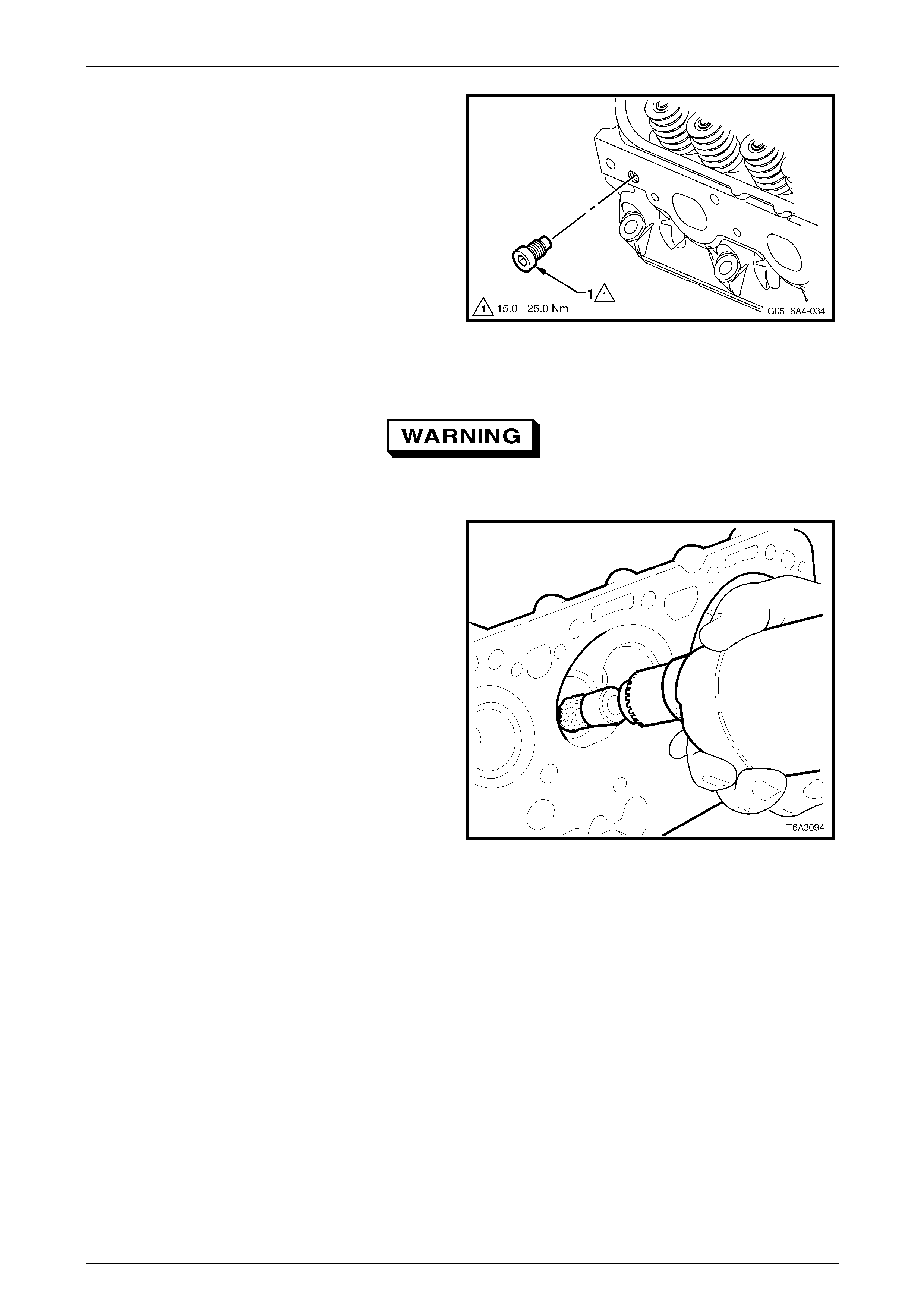
Engine Mechanical Page 6A4–120
Page 6A4–120
NOTE
The core plug must not be reused. If the plug is
loosened, it must be replaced wit h a new one.
3 If required, remove the core plug (1) from the right-
hand cylinder head.
Figure 6A4 – 159
Clean
Use the appropriate safety glasses and
protective gloves for the following operation.
1 Clean all carbon deposits from the combusti on
chambers and valve ports using a commerc ially
available rotary wire brush. Do not scuff or damage
the aluminium cylinder head surfaces.
2 Clean any carbon deposits from valve stems and
heads using a wire buffing wheel.
3 Check all the bolt threads for damage and remove any
remaining thread locking compound from both the
threaded holes and bolts.
Figure 6A4 – 160
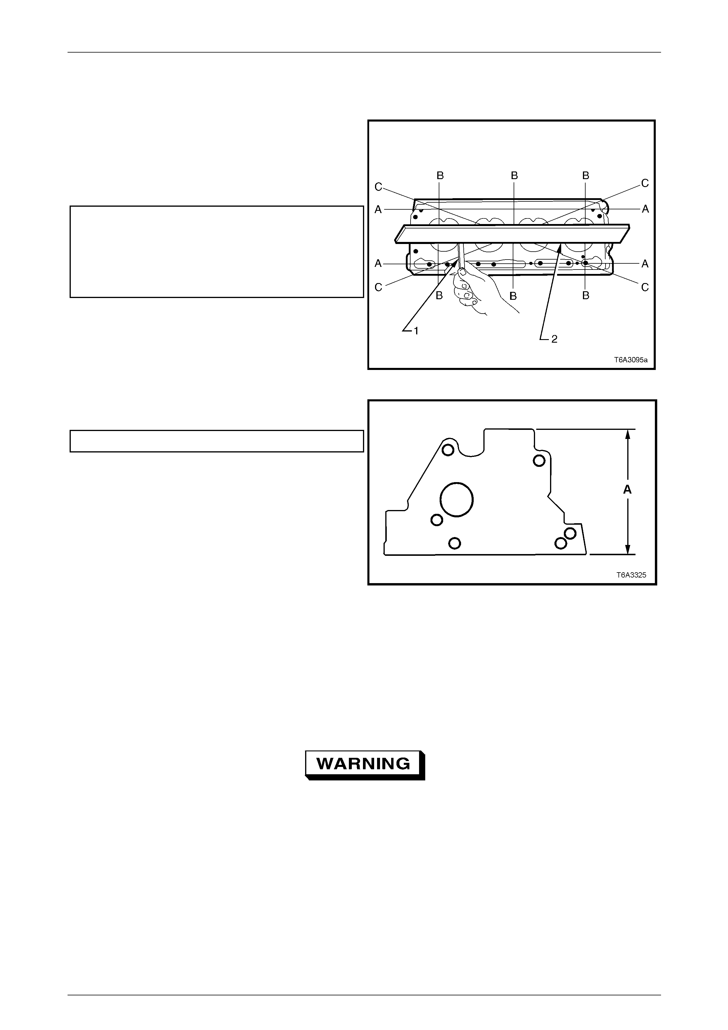
Engine Mechanical Page 6A4–121
Page 6A4–121
Inspect
Cylinder Head
1 Check the cylinder head deck and the i nlet and
exhaust manifold mating surfaces for distortion. Use a
set of feeler gauges (1) and a straight edge (2). Check
along the length (A), laterall y (B) and diagonally (C).
2 Check the cylinder head to exhaust an d intake
manifold mating surfaces for flatness.
Cylinder head flatness specification:
(measured over the cylinder head length)
Cylinder head to cylinder block surface ............ 0.22 mm
Cylinder head to exhaust manifold surface.......0.22 mm
Cylinder head to intake manifold surface..........0.22 mm
NOTE
If cylinder head to block surface is outside the
specified limit, the cylinder head may be
machined provided th e mi nim um over all he ig ht is
not exceeded. Figure 6A4 – 161
3 Measure the overall height of the cylinder head (A)
and ensure it is within the specified limit.
Cylinder head height.................................120.2 mm Min
Figure 6A4 – 162
4 Inspect all threaded holes for damage, repairing as required with suitable thread inserts. Refer to 6 Thread Repair
5 Clean any residue of cylinder head attaching bolt thread seala nt from the cylinder block threads using installer Tool
No. J-42385-107. This tool is part of the thread repair kit Tool No. J-42385.
NOTE
Do not use anything but Tool No. J-4238 5-107 to
clean the cylinder head threads in the cylinder
block.
To avoid personal injury, wear safety glasses
when using compressed air.
6 Use compressed air to clean all residue from the bolt holes.
7 Inspect the coolant jacket coolant core plugs for signs of corrosio n, replace the plugs as required.
NOTE
If replacing the expansion plugs, apply a coating
of Loctite 242 or equivalent around the plug
sealing surface.
8 Inspect the cylinder head for cracks, especially between the valve seats and exhaust ports.
9 Inspect the cylinder block deck surface for distortion, refer to 5.15 Cylind er Block.
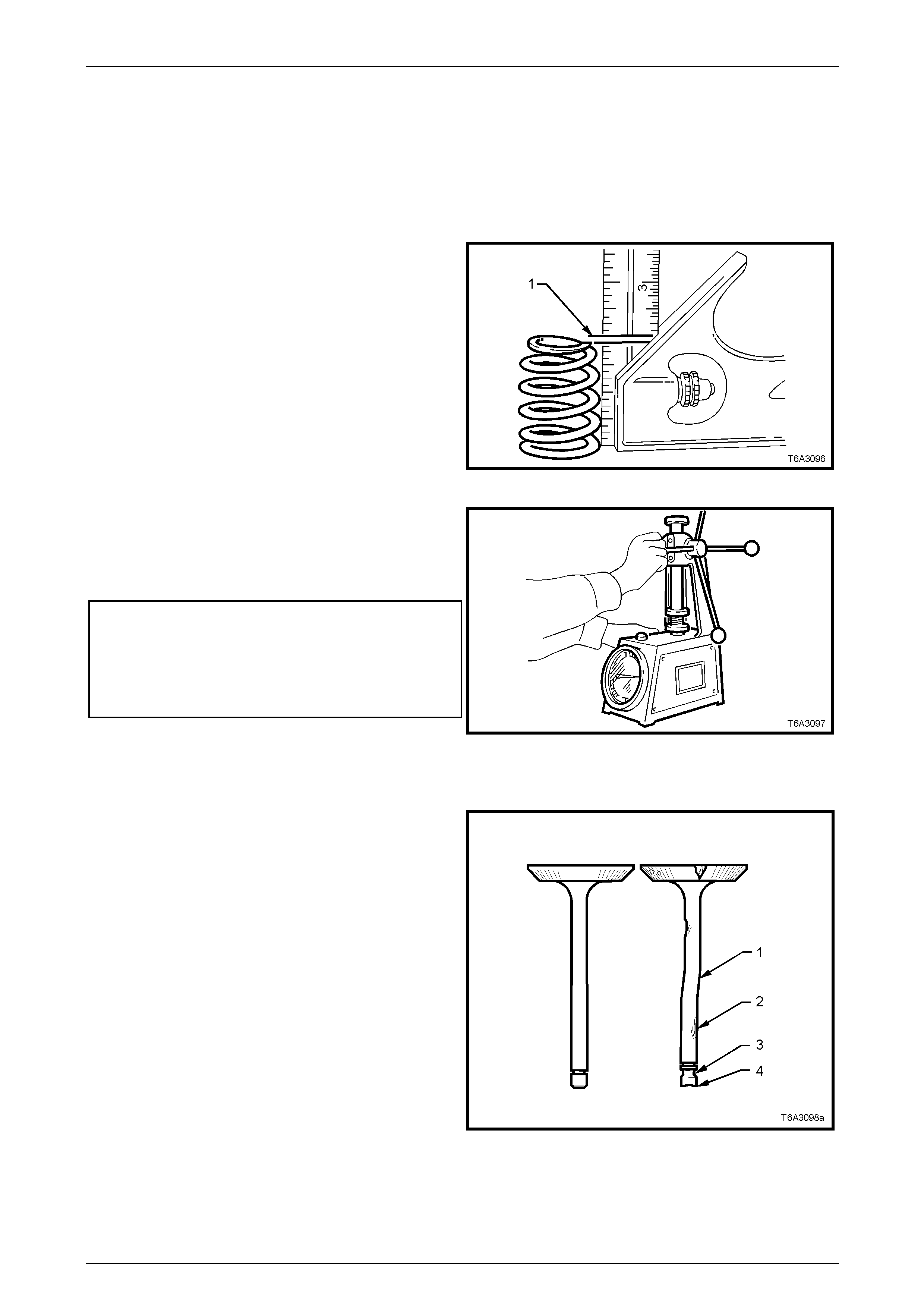
Engine Mechanical Page 6A4–122
Page 6A4–122
10 Clean the M8 cylinder head bolt threads. Replace any bolt that has a suspect thread and repair any damage to the
cylinder head caused b y the i m proper use of tools.
NOTE
Discard all M11 bolts after removal, as these are
torque to yield bolts and must be rep lace d.
Valve Springs
1 Check all valve springs for dist ortion. There should be
no more than 1.6 mm variance (1) of the spring end
while the spring is being rotat ed on a flat surface.
Replace springs that exceed this specification.
Figure 6A4 – 163
2 Use a commercially available valve spring tester,
measure each valve spring for free height and tension.
3 Measure the valve spring tens ion by compressing the
valve spring and noting the load at the given
compressed spring lengths.
Valve spring specifications:
Free height intake and exhaust......................... 54.9 mm
Valve spring tension specification:
Compressed to 45.75 mm.....................380 – 420 N Min
Compressed to 33.0 mm.....................935 – 1025 N Min
4 Discard any valve spring that does n ot confo rm to
specification. Figure 6A4 – 164
Valves
1 Inspect the valve stems for burrs and scratches. If
minor, these can be removed by polishing with a fine
grade of emery cloth.
2 Valves with excessive stem wear or are warped (1 an d
2), should be replaced.
3 Inspect the valve spring cap retaining collet retaining
groove (3) for wear or damage.
4 Inspect the valve stem end (4) for wear. If required
wear can be corrected by grinding, provided the stem
end is ground at right angles to the valve stem.
NOTE
A commercially availa ble valv e gr inder sho uld be
used to resurface valves faces and stems.
Figure 6A4 – 165
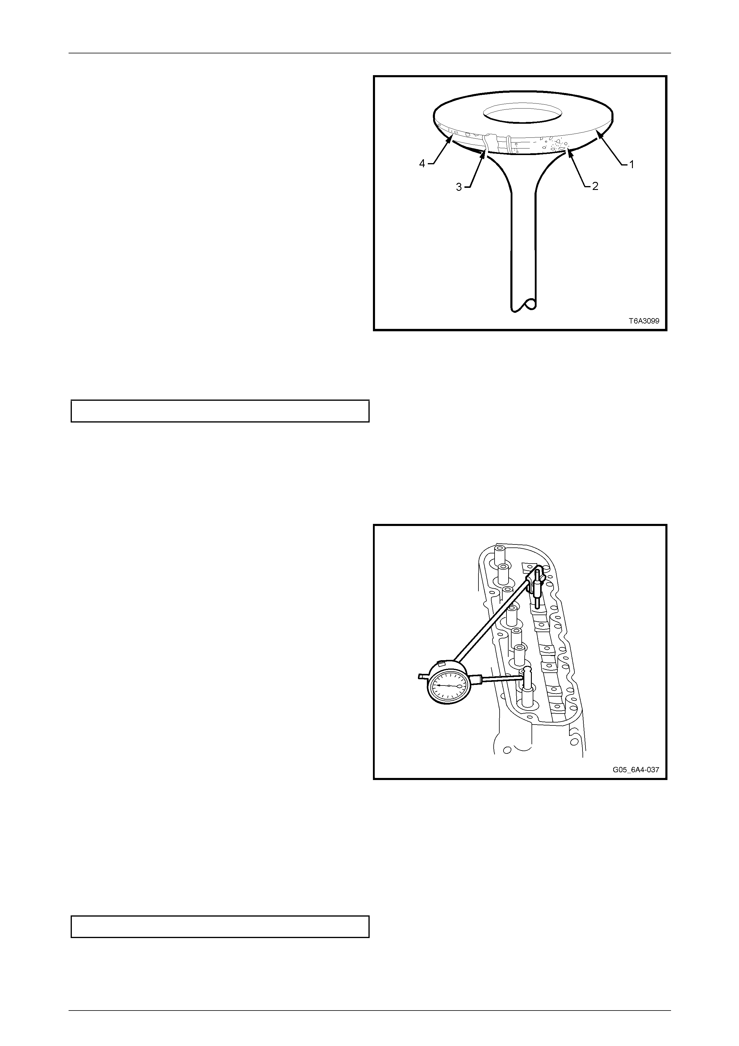
Engine Mechanical Page 6A4–123
Page 6A4–123
5 Check the valve face for:
• Margin (1) of less than 1.25 mm after grinding (4)
• Excessive pitting (2)
• Burnt or corroded areas (3)
6 If an exhaust valve is to be reconditioned, the face can
be ground, using a valve gri nding machine. The valve
seat angle is 45°.
NOTE
• If an exhaust valve face is reground, it may
be necessary to shim the valve spring to
achieve the correct spring installed height.
Refer to 4.15 Cylinder Head.
• Intake valve faces must not be refaced.
Intake valves that are worn or have face
damage must be replaced.
7 The equipment manufacturer’s recommendations must
be carefully follo wed to achieve the required standard
of finish.
8 Measure the valve stem diam eter. A valve stem with a
diameter of less than the specification must be
replaced.
Valve stem diameter...................................7.95 mm Min
Figure 6A4 – 166
Valve Guides
Excessive valve stem to guide clearance may cause noisy valve train operation, premature valve stem oil seal wear,
component damage and/or excess ive oil consumption.
Insufficient valve stem to guide clearance will result in noisy or sticking valves. Valves that are too tight may disturb
engine smoothness or lead to compon ent damage.
Measure the clearance as outlined in the following steps.
1 Insert the valve into its guide.
2 Clamp dial indicator such as Tool No. J 8520 or an
equivalent to a valve rocker arm bolt that has been
temporarily installed. Place the dial gauge in a position
where sideways movement of the valve stem will
cause movement of the indicator needle.
NOTE
To obtain a correct indication of the wear, the
indicator stem must contact the side of the valve
stem, between 8 – 12 mm above the top of the
valve guide and the gauge is to be at right
angles to the valve stem.
3 With the valve head dropped by approximately 2 mm
off its seat, move the stem of the valve side to side
against the dial indicator usin g light force to obtain a
clearance reading.
NOTE
This may need to be done in two directions and
requiring the dial indicator to be repositioned.
4 If the valve stem diameter is within specifica tions and
the valve stem to guide clearance exceeds the
specified limit, either the valve is to be replaced or the
valve guide reamed out and an oversize valve fitted.
Refer to Valve Stem Oversize.
Valve stem to guide clearance.................0.093 mm Max
Figure 6A4 – 167
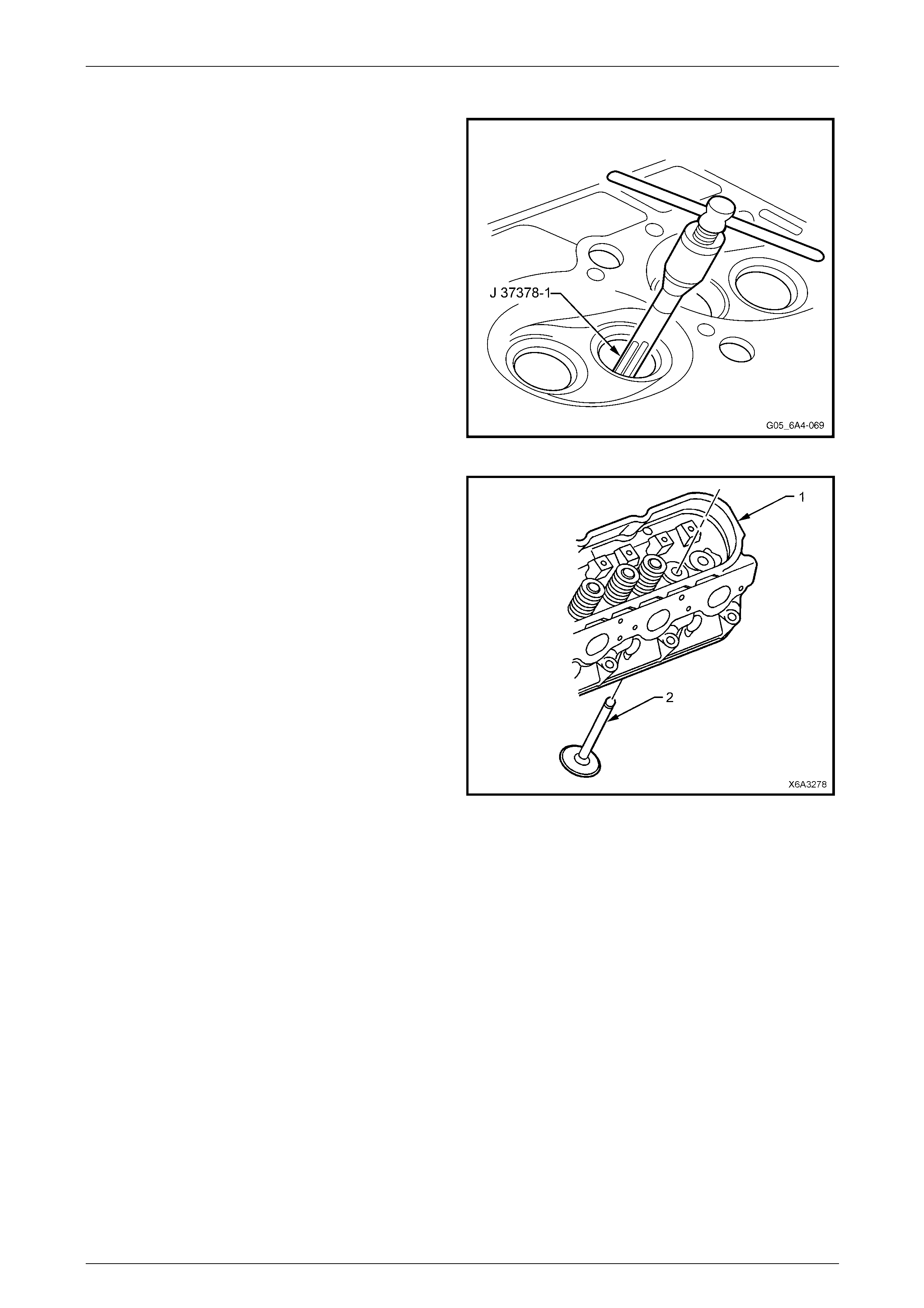
Engine Mechanical Page 6A4–124
Page 6A4–124
Valve Stem Oversize
1 Ream the valve guide us ing reamer, Tool
No. J 37378-1.
2 Clean the valve guide bore of all metal shavings and
debris.
Figure 6A4 – 168
3 Install the oversize valve (2) into the ream ed valve
guide and recheck the clearance as previously
described.
4 The valve should slide freely without resistance or
drag. The clearance must not exc eed specification.
Figure 6A4 – 169
Valve Seats
Check the valve seats for any evidence of pitting or damage at the valve contact surface. If pitting is evident, the valve
seats will need to be reconditioned.
Reconditioning the valve seats is a very important process because the seating of the valves must be precise for proper
cooling of the valve head. Good contact between each valve and its seat in the cylinder head is imperative to ensure the
heat in the valve head will be transferred efficiently.
Although there are several different types of equipment available for reconditioning valv e seats, an oscillating type valve
seat grinder is preferred. The manufactur er’s recommendations for the equipment being used should be carefully
followed to attain the correct results.
NOTE
Since the valve guide serves to support
and centre the valve seat grinder, it is essential
that valve guide wear is checked,
Valve Guides.

Engine Mechanical Page 6A4–125
Page 6A4–125
1 Both the intake and exhaust valve seat angles are ground at 46°and the seat width should not exceed the
specification.
Valve seat width specification:
Intake.........................................................1.02 mm Max
Exhaust......................................................1.78 mm Max
NOTE
New valves must not be lapped to the valve seat
as this will destroy the protective coating on the
valve face.
2 If valve seats are reconditioned and the exhaust valve faces ground, then light lapping of the valve will ensure a
gas tight seal when closed.
3 After refacing an existing valve or installing a new valve, correct seating of the valve must be checked as follows:
a Lightly coat the valve face with Bearing (Prussian) Bl ue.
b Insert the valve and rotate about 1/6th of a turn.
c Remove valve and check its contact with the seat.
d If full contact is indicated, the valve and seat are acceptable. However, if only partial contact is shown,
reinstall the valve and rotate for one full turn. If the bearing blue now indicates a full contact then the valve
must be refaced or replaced. If the bearing blue contact still only shows partial contact then regrind the valve
seat.
e Clean all traces of bearing blue from the valves and seats then clean thoroughly b efore applying clean engine
oil to both surfaces to protect from rusting.
Reassemble
NOTE
Ensure that all re-used parts are reinstalled to
their original locations.
1 Lubricate all valve stems, guides and valve faces with
clean engine oil and install th e valves to their correct
ports.
2 Install a new valve stem oil seal and shim assembly by
hand, until the shim seats against the cylinder head.
No special tools are required for this operation.
NOTE
The valve stem oil seal alignment and position
on the valve stem is critical. An improperly
installed valve stem oil seal will lead to excessive
oil consumption and increased exhaust
emissions.
Figure 6A4 – 170
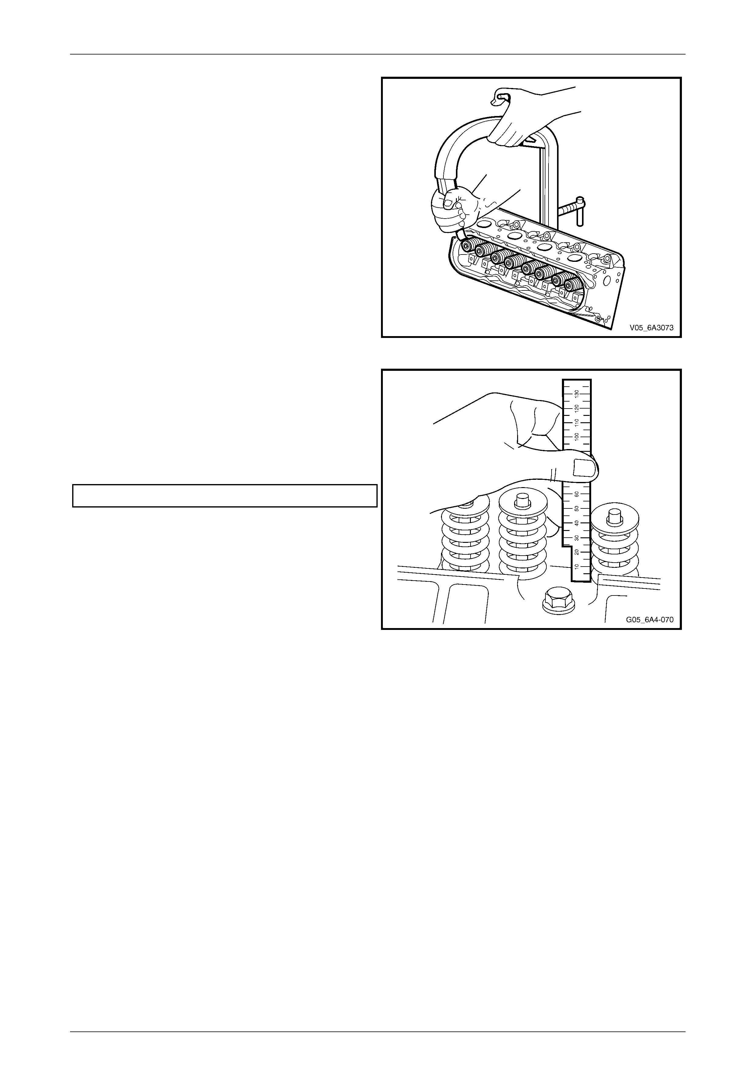
Engine Mechanical Page 6A4–126
Page 6A4–126
3 Install the valve springs and caps to each valve stem.
4 Compress the valve spring using a commercially
available spring compressor.
5 Install the valve spring cap retainer collets, retaining
with petroleum jelly if required.
6 Ensure that both the collets are correctly located
before releasing the valve spri ng compressor.
7 Tap the end of each installed valve stem, with a soft
faced hammer to seat the collets.
Figure 6A4 – 171
8 Measure the installed hei ght of the valve spring using
a ruler or vernier calipers. The measuremen t is to be
taken from the base of the valve spring to the top.
9 If the measurement exceeds the specified limit, a
commercially availabl e stainless steel shim must be
installed between the valve stem oil seal/shim
combination and the cylin der head to achieve the
required spring height.
Installed valve spring height.....................45.75 mm Max
NOTE
Do not shim the valve spring to obtain less than
the specified height.
10 Install the remaining valves, springs and other
components. Checking each v alve spring height as it
is assembled.
11 If the cylinder head core plugs were removed, install
with sealant such as Loctite 565 or equivale nt before
plug installation.
NOTE
If the screw in core plug at the rear of the right-
hand cylinder head has been loosened or
removed, it must be replaced.
Figure 6A4 – 172
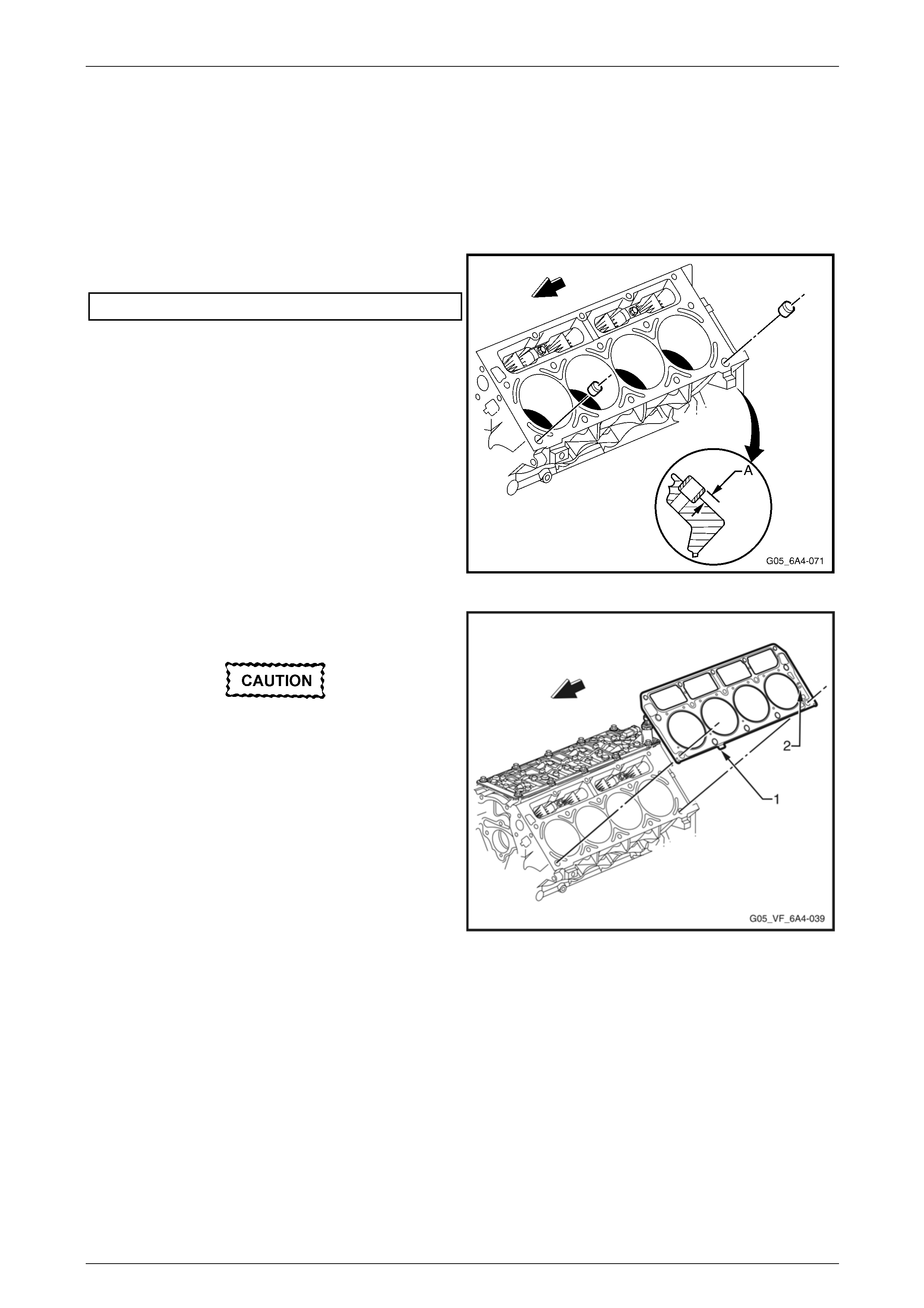
Engine Mechanical Page 6A4–127
Page 6A4–127
Reinstall
NOTE
Discard all used M11 c ylinder head bolts. Al ways
use new M11 bolts when installing a cylinder
head. Do not use any sealant on the cylinder
head gasket or threa d l ock compound on the M11
cylinder head bolts.
1 Install the cylinder head locating sleeves and ensure
they are installed to the maximum specification (A).
Dimension (A).............................................8.3 mm max.
Figure 6A4 – 173
2 Install a new cylinder head gasket correctly over the
locating sleeves.
The tab (1) on the cylinder head gasket is
located to the front half point. This applies
with either cyl inder head gasket. The cylind er
head gaskets will fit on either side of the
engine. The only condition is that the word
FRONT stamped on the gasket must face the
engine front. The gasket should also have 6.0
(2) imprinted on it
Figure 6A4 – 174
3 Referring to Figure 6A4 – 175:
a Install the cylinder head over the locating sleeves and the previously installed gask et.
b Apply a 5 mm band of thread lock such as Loctite 242 to the threads of the five M8 bolts only (1) and install
the bolts.
c Loosely install 10 new M11 cylinder head bol ts (2).
d Tighten the cylinder head bolts in the sequence shown and to the correct torque specification.
NOTE
Use a torque angle meter such as Tool No.
E 7115 to achieve an accurate turn angle
reading. Bolt numbers 1 to 10 are the M11 bolts
while bolts 11 to 15 are the M8 bolts.
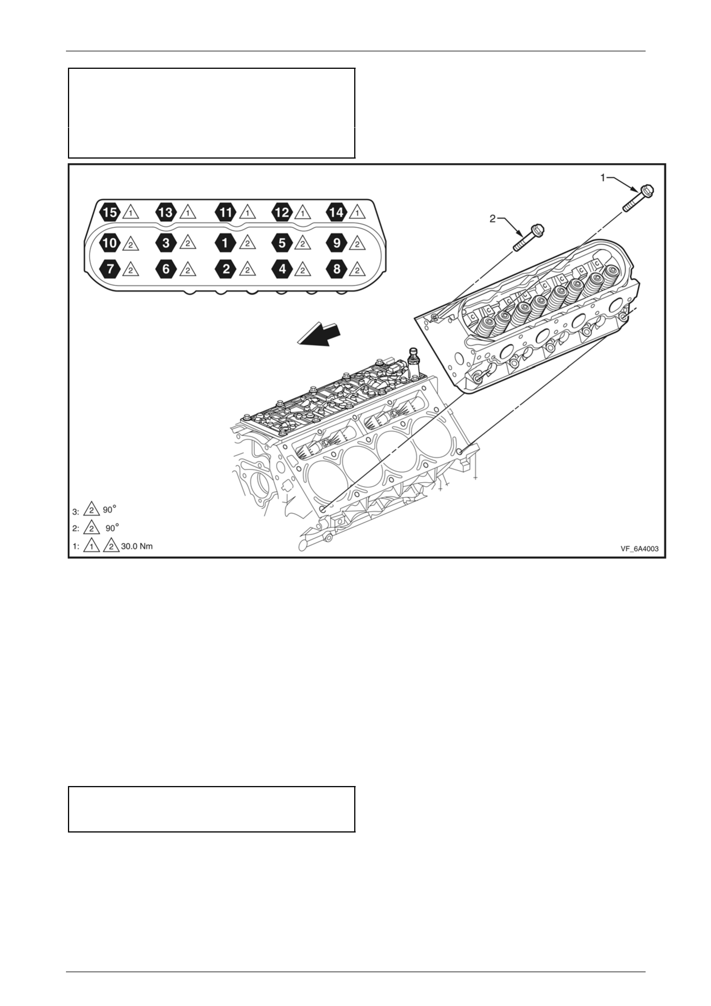
Engine Mechanical Page 6A4–128
Page 6A4–128
Cylinder head bolt torque specification:
M8 Bolts (11 to 15).............................................30.0 Nm
M11 Bolts only (1 to 10)
Stage 1 ..............................................................30.0 Nm
Stage 2 ....................................................90° turn angle
Stage 3 .....................................................90° turn angle
Figure 6A4 – 175
4 For the remainder of reinstallation procedure, reinstall the following:
a Valve rocker arms and push rods, refer to 4.12 Valve Rocker Arms and Push Rods
b Valve rocker arm cover, refer to 4.11 Valve Rocker Arm Cover.
c Vapour vent pipe, refer to 4.8 Vapour Vent Pipe and Covers
d Intake manifold, refer to 4.7 Intake Manifold.
e Exhaust manifold, refer to 4.14 Exhaust Manifold.
f Oil level indicator and tube, refer to 4.5 Oil Level Indicator and Tube.
5 Reinstall the spark plugs, refer to Section 6C4-3 Engine Management – GEN IV V8 – Service Operations.
NOTE
If the cylinder head is replaced, the initial spark
plug torque specification must be adhered to:
Spark plug torque specification:
Used cylinder head............................................15.0 Nm
New cylinder head .............................................20.0 Nm
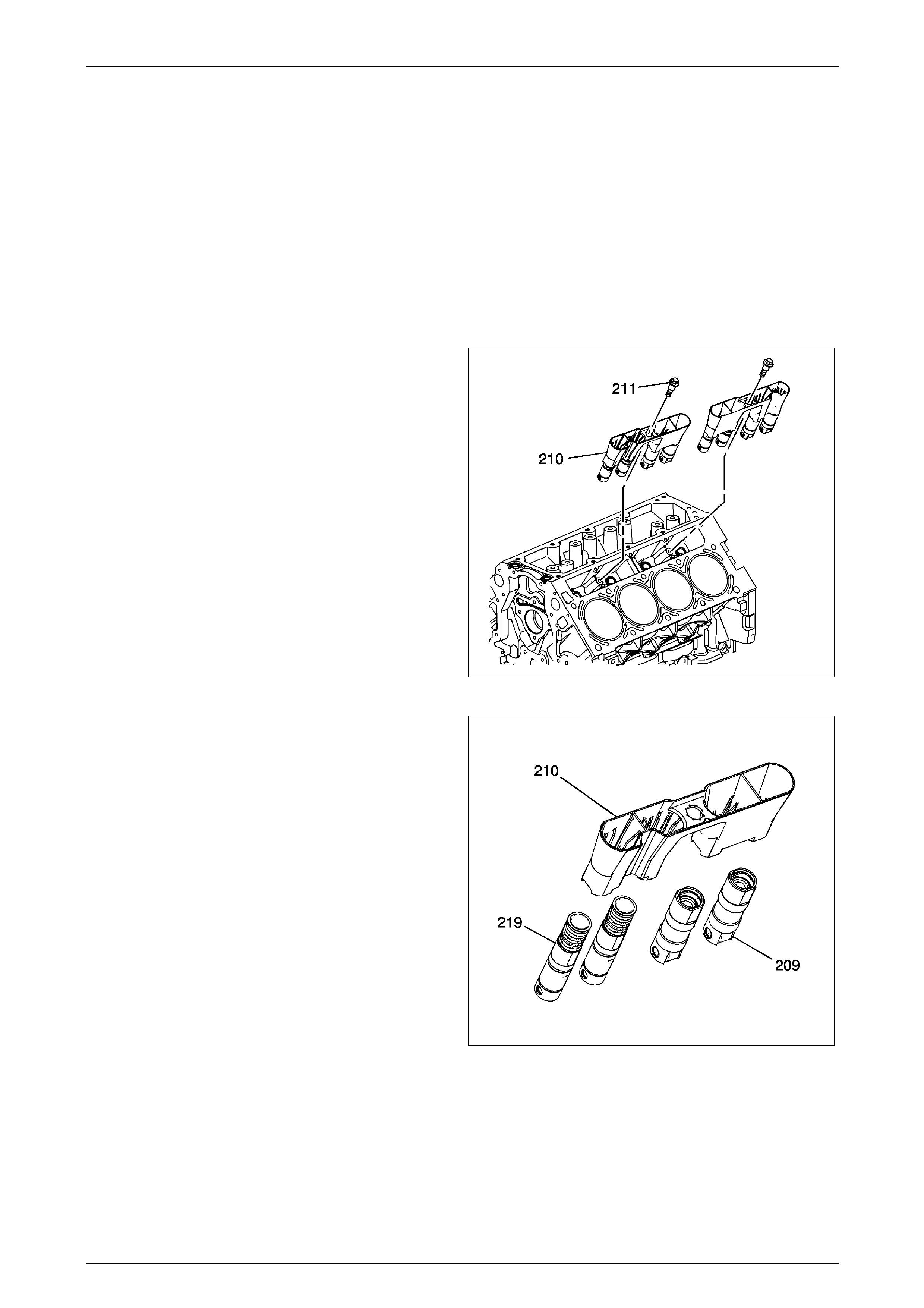
Engine Mechanical Page 6A4–129
Page 6A4–129
4.16 Hydraulic Valve Lifters
LT Section No. — 00–050
Remove
NOTE
Store all removed valve train components in the
same order they were removed. This will ensure
that when they are reinstalled in the same
relationship as on removal.
1 Remove the cylinder head on the side requiring the hydraulic valve lifter removal. Refer to 4.15 Cylinder Head.
2 Remove the valve lifter.
NOTE
There is one bolt and four hydraulic valve lifters
in each guide.
3 Clean and inspect the valve lifters. Refer to Valve
Lifters and Guides Cleaning and Inspection.
NOTE
Use care when removing the hydraulic valve
lifter guide as the hydraulic valve lifter may fall
out of the guide while the guide is being
removed.
Figure 6A4 – 176
4 Remove the valve lifters (209, 219) from the guide
(210).
Figure 6A4 – 177
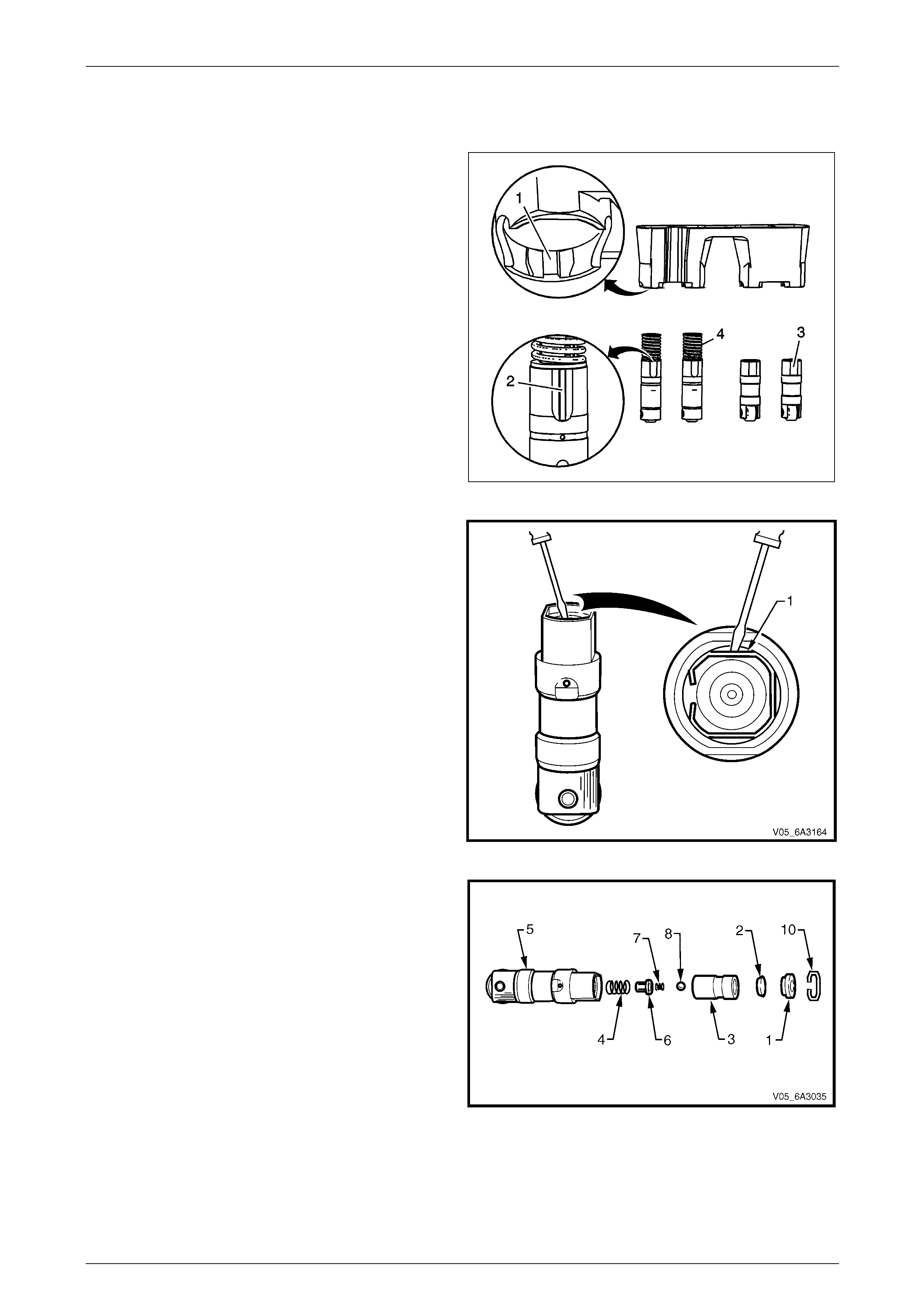
Engine Mechanical Page 6A4–130
Page 6A4–130
Disassemble
Non Displacement on Demand Valve Lifters
1 Organize or mark the components so they can be
installed in the same location from which they were
removed. The displacement on dema nd lifters (4) are
installed into the guide by aligning the notched area of
the guide (1) with the raised surface on the side of the
lifter (2). Refer to Separating Parts
Figure 6A4 – 178
2 Remove the push rod seat retaining clip (1) by using a
small flat bladed screwdriver and carefully prising the
clip out of the groove in the lifter.
Figure 6A4 – 179
3 Remove in order the following:
• Push rod seat (1).
• Oil metering valve (2).
• Plunger assembly (3).
• Plunger spring (4) from the lifter body (5).
NOTE
If the plunger is stuck in the lifter body, turn the
lifter body upside down and tap the lifter body on
a block of wood. If this is not effective, soak the
lifter assembly in a suitable cleaning fluid.
4 Remove the ball check retainer (6), ball check spring
(7) and ball (8) from the plunger. Figure 6A4 – 180
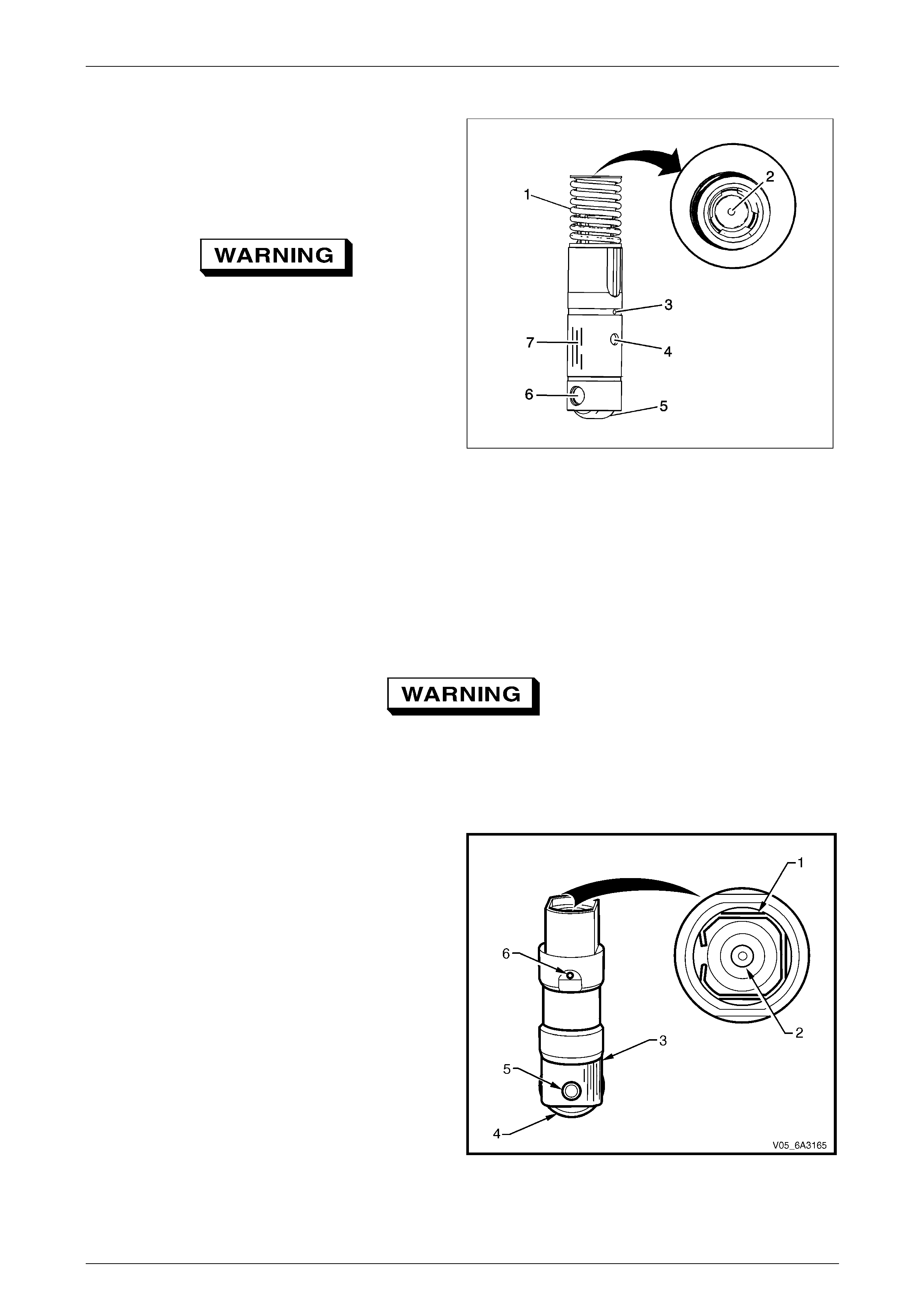
Engine Mechanical Page 6A4–131
Page 6A4–131
Displacement on Demand Valve Lifters
NOTE
Components that are to be used again must be
marked, sorted or organized for assembly
1 Clean the components in cleaning solvent.
Refer to Safety Glasses Caution in Section 00
Cautions and Notices.
2 Dry the components with compressed air.
3 Inspect the valve lifters for the following conditions:
• Broken or collapsed spring (1)
• Worn pushrod socket (2)
• Plugged lubric ation hole (3)
• Plugged lifter oil-switching hole (4)
• Flat spots on the roller (5)
• Worn or damaged roller bearing (6) The roller
should rotate freely with no binding or
roughness.
• Scuffed or worn sides (7)
Figure 6A4 – 181
Clean and Inspect
It is recommended the hydraulic valve lifter be replaced if faulty. However, cleaning of the lifter can remove a build up of
deposits that sometimes can cause the lifter internals to stick causing valve train noise.
To avoid personal injury, wear safety glasses
and the appropriate gloves when using
compressed air and cleaning fluids.
1 Thoroughly cle an all parts in a commercially available cleaning fluid and blow all the parts dry using compressed
air.
2 Inspect the valve lifters for:
• Bent or broken clip (1).
• Worn pushrod socket (2). If the seat is worn,
inspect the matching push rod and replace the
push rod if worn.
• Scuffed or worn lifter body (3).
NOTE
Inspect the lifter bore in the cylinder block.
• Worn or damaged roller bearing (4). Replace the
lifter if the roller binds or roughness can be felt.
• Loose or damaged pin (5).
• Partially blocked oil hole (6).
NOTE
If the roller bearing on the lifter is worn, inspect
the camshaft for wear. Refer to 5.11 Camshaft Figure 6A4 – 182
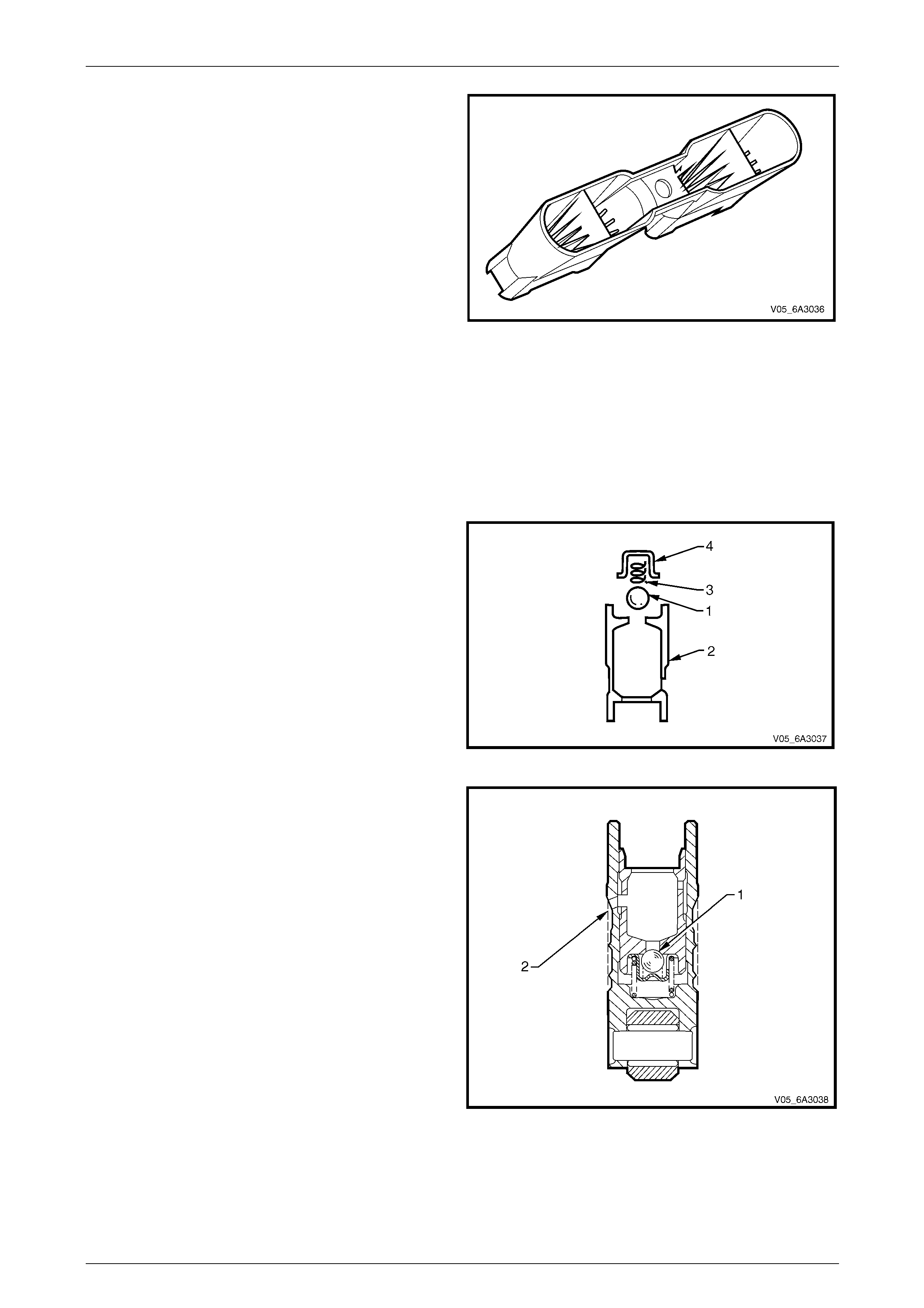
Engine Mechanical Page 6A4–132
Page 6A4–132
3 Inspect the valve lifter guides for:
• Cracks or damage.
• Excessive wear in the lifter mounting b ores.
Figure 6A4 – 183
Reassemble
NOTE
Do not attempt to recondition a lifter by taking
parts from other unserviceabl e lifters. Cleanliness
is extremely important when handling valve
lifters. Lint or dirt can result in a failed lifter.
1 Place the check ball (1) over the small hole in the
plunger (2).
2 Carefully place the check ball spring (3) and the
retainer (4), over the check ball and press the retainer
into position within the plun ger with a small flat blade
screwdriver.
3 Half fill the valve lifter body with the test fluid SPX No.
E1151 or oil with a viscosity rating of 10W.
Figure 6A4 – 184
4 Reinstall the plunger spring into the lifter body.
5 Install the plunger assembly in the body taking care to
align oil feed holes.
6 Using a 1 mm diameter pin punch or similar, unseat
the check ball (1) in the plunger then push the plunger
down to the full extent of its travel.
7 Use Tool 6A24 (or a suitable sized pin punch) to align
the oil feed holes (2) in the body and plunger.
8 Fill the lifter with specified test fluid.
9 Reinstall the oil metering valve, push rod seat (cup
side facing out) and the retaining clip.
Figure 6A4 – 185
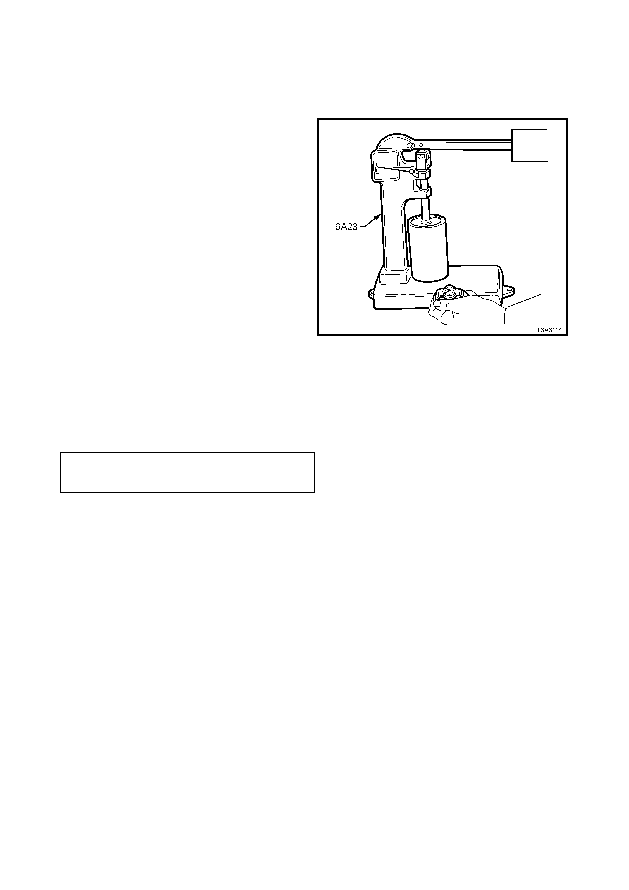
Engine Mechanical Page 6A4–133
Page 6A4–133
Testing Lifter Leak-down Rate
After the hydraulic lifter has been cleaned, in spected and reassembled, it must be tested before being reinstalled. Lifter
test fixture Tool No 6A23 has been designed to test the leak-down rate of the lifter to ensure the lifter will operate as
intended when reinstalled.
1 Ensure the test cup is clean. Install the cup on the
fixture and place the lifter in the cup.
NOTE
Some versions of Tool No. 6A23 may require
modification to hold the base of the lifter inside
the tester cup.
2 Add the test fluid SPX No. E1151 or engine oil with a
viscosity rating of 10W to completely cover the
hydraulic valve lifter when in Tool No 6A23.
3 Place the ball bearing supp lied with the test fixture in
the push rod seat of the hydraulic v alve l ifter.
4 Lower the test fixture ram so it can rest on the ball
bearing.
5 Operate the lifter plunger through its maximum travel
to force all the air out of the lifter by using a vigorous
pumping action on the test fixture weight arm.
Continue the pumping action until considerable
resistance is built up in the lifter and the lifter becomes
solid.
6 Raise the weight arm to allow the lifter plunger to
come up to its retainer then lower the arm to rest on
the ram.
7 Using a stop watch, measure the time required for the
indicator needle on the tester to travel from the Start
position to the 0.125" positi on on the scale and ensure
the lifter is within the specified limit.
Hydraulic valve lifter
bleed down rate specified lim it:
Start to 0.125"......................................10 to 30 seconds
Figure 6A4 – 186
NOTE
A suspect lifter should be tested several times
before being discarded. Cl ean the test fixture cup
and refill with clean test fluid after several lifters
have been tested.
8 Stand the tested lifters in an upright position so the fluid does not drain from the oil holes.
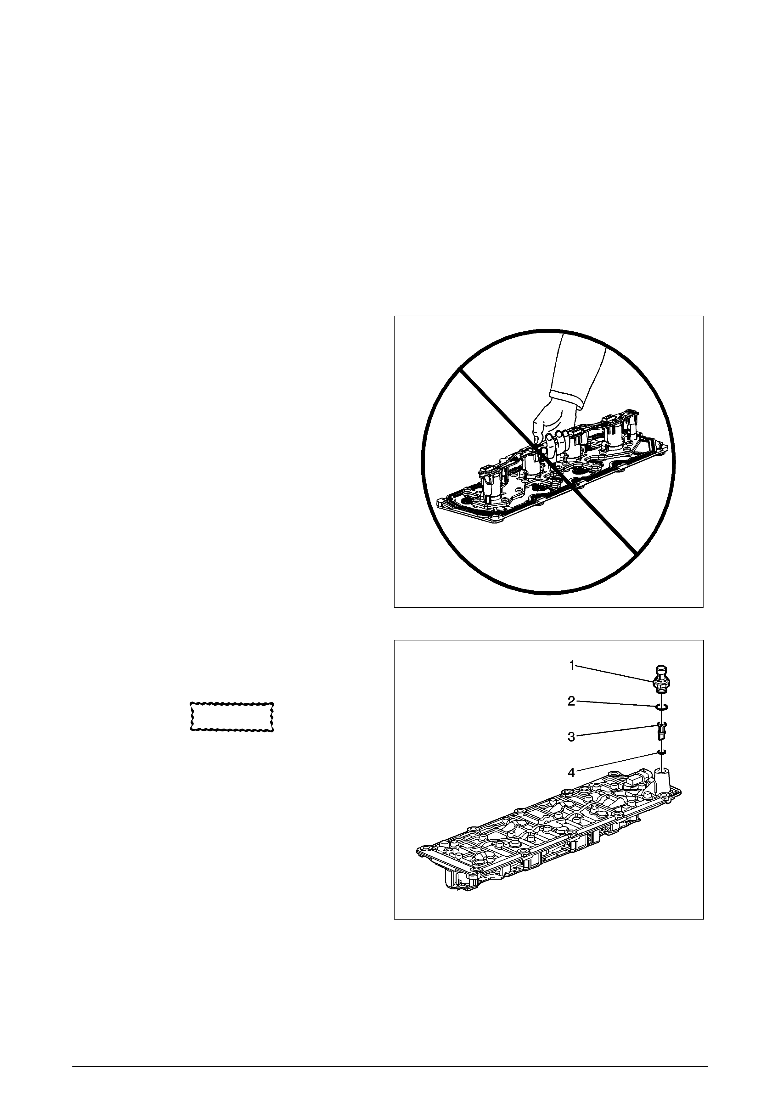
Engine Mechanical Page 6A4–134
Page 6A4–134
Reinstall
Valve Lifter Oil Manifold Cleaning and Inspection
NOTE
• Do not allow dirt or debris to enter the oil
passages of the manifold. Plug, as required.
• Do not disassemble the el ectrical component s
from the manifold.
• Do not submerge the electric al components in
cleaning solvent.
• Do not use the manifold exterior gasket again.
• Remove the exterior gasket and install a NEW
service gasket during assembly
1 Do not lift the manifold assembly by the electrical le ad
frame.
Figure 6A4 – 187
2 Remove the oil pressure sensor (706) and washer
(707).
3 Remove the oil screen (452) with O-ring (454).
CAUTION
Refer to Safety Glasses Caution in Section 00
Cautions and Notices.
4 Clean the manifold with compressed a ir.
Figure 6A4 – 188
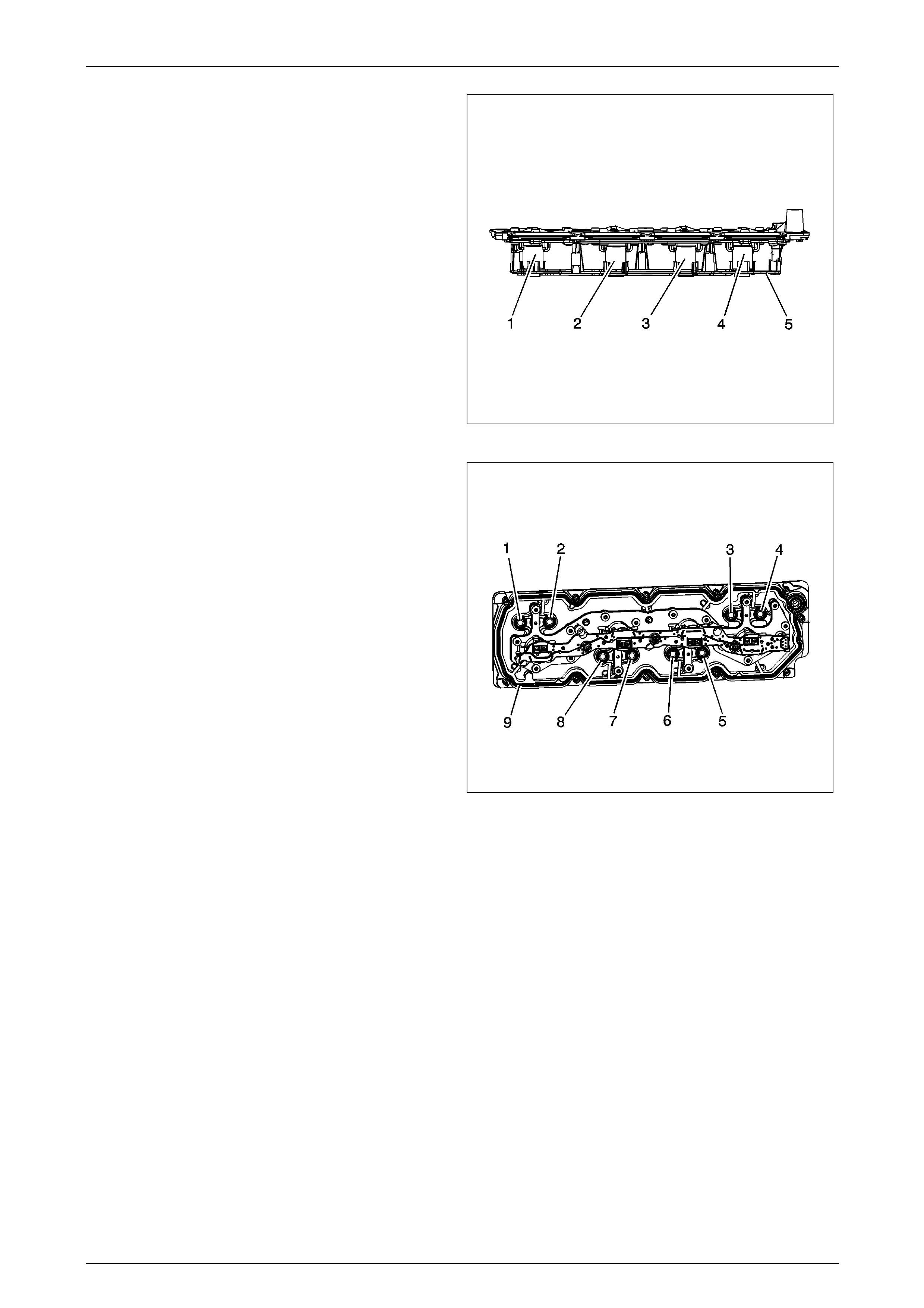
Engine Mechanical Page 6A4–135
Page 6A4–135
5 Inspect for loose electrical solenoids (1–4) or loose or
missing bolts.
6 Inspect for damage to the electrical lead frame (5).
7 Inspect for a damaged electrical connector, for bent or
corroded pins.
Figure 6A4 – 189
8 Inspect for damaged interior sealing gaskets (1–8). If
the interior sealing gaskets are damaged, the manifold
must be replaced as an assembly.
9 Inspect for a damaged exterior sealing gasket (9) or
scored gasket surfaces.
10 Inspect for debris or restrictions within the oil
passages of the manifold. Refer to Displ acement on
Demand (DoD) Valve Lifter Oil Manifold Diagnosis and
Testing
Figure 6A4 – 190
Valve Lifter Installation
NOTE
• When using the valve lifters again, install the
lifters to their original locations.
• If camshaft replacement is required, the v alve
lifters must also be replaced.
• Each of the 4 valve guide assemblies will
contain 2 displacement on demand valve
lifters and 2 non-displacement on demand
valve lifters.
• With the lifters and guides properly installed,
cylinders 1, 4, 6, and 7 lifter bores will each
contain 2 displacement on demand valve
lifters
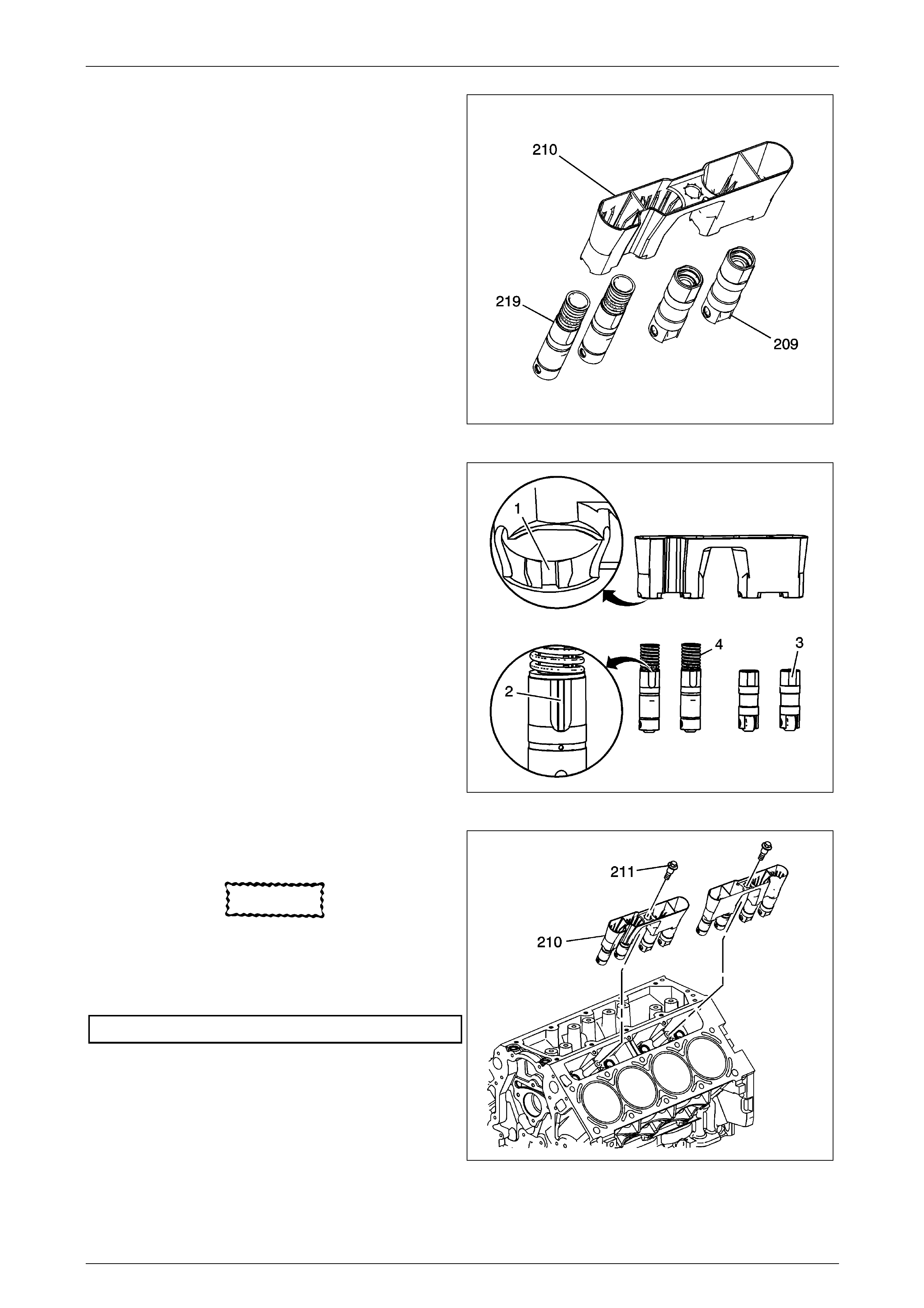
Engine Mechanical Page 6A4–136
Page 6A4–136
1 Lubricate the valve lifters (209, 219) and engine block
valve lifter bores with clean engine oil
Figure 6A4 – 191
2 Insert the valve lifters into the lifter guides.
• Align the flat area (3) on the top of the non
displacement on demand lifter with the flat area
in the lifter guide bore. Push the lifter completely
into the guide bore.
• The displacement on demand lifters (4) are to be
installed into the guide, with the notch in the
guide (1) aligned with the raised area (2) of the
lifter.
Figure 6A4 – 192
3 Install the valve lifters and guide assembl y (210) to the
engine block.
CAUTION
Refer to Fastener Notice in Section 00
Cautions and Notices.
4 Install the valve lifter guide bolts (211) and tighten to
the specified torque.
Valve Lifter Guide Bolts .....................................10.0 Nm
Figure 6A4 – 193
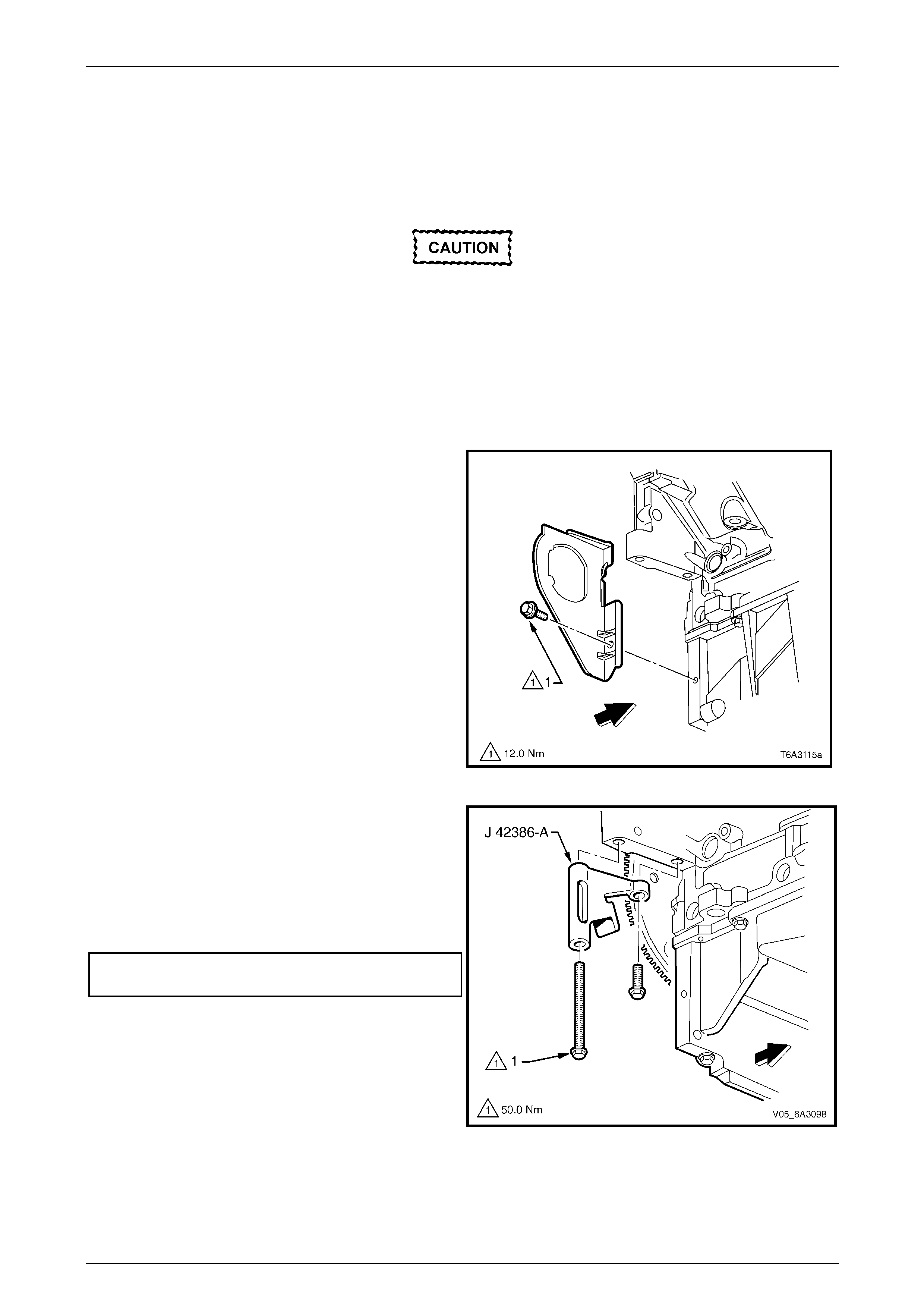
Engine Mechanical Page 6A4–137
Page 6A4–137
4.17 Crankshaft Balancer
LT Section No. — 00–540
Remove
Disconnection of the battery affects certain
vehicle electronic systems. Refer to
Section 00 Warnings, Cautions and Notes
before disconnecting the battery.
1 Disconnect the ground battery cable termi nal from the battery.
2 Remove the radiator, refer to Section 6B3 Engine Cooling – GEN IV V8.
3 Remove the engine accessory and air conditioner drive belts. Refer to 4.6 Engine Drive Belts and Pulleys.
4 Remove the starter motor. Refer to Section 6D3-2 Starting System – GEN IV V8.
5 Remove the bolt (1), attaching the right-hand close- out
cover to the cylinder block.
NOTE
The close out covers seal off the area between
the cylinder block and transmission assembly.
Figure 6A4 – 194
NOTE
Ensure the teeth of the holding tool engage
correctly with the ring gear before tightening the
fasteners.
6 Using the two starter motor bolts, install the ring gear
holding Tool No. J 42386-A a nd tighten the bolts to the
correct torque specification.
Ring gear holding tool, Tool NO. J 42386-A
attaching bolt torque specification......................50.0 Nm
Figure 6A4 – 195
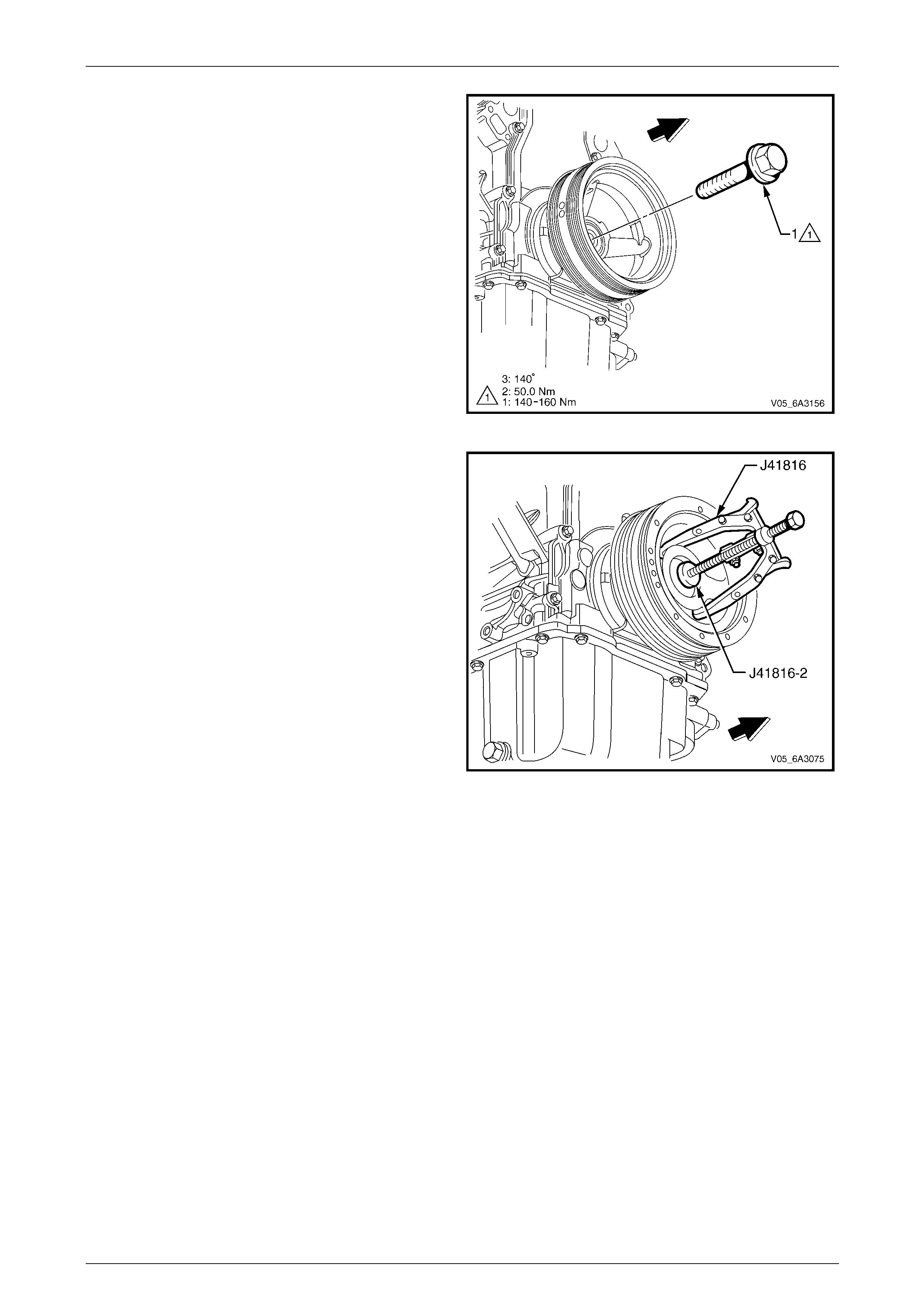
Engine Mechanical Page 6A4–138
Page 6A4–138
7 Remove the bolt (1) attaching the crankshaft bal ancer.
NOTE
Do not discard the bolt at this stage, as it will be
required later for the reinstallation process. The
crankshaft bolt is to be replaced during the final
stage of the assembly procedure.
Figure 6A4 – 196
8 Use the crankshaft end protector, T ool No. J 41816-2
and puller, Tool No.J4181 6 or equivalent to remove
the crankshaft balancer.
Figure 6A4 – 197
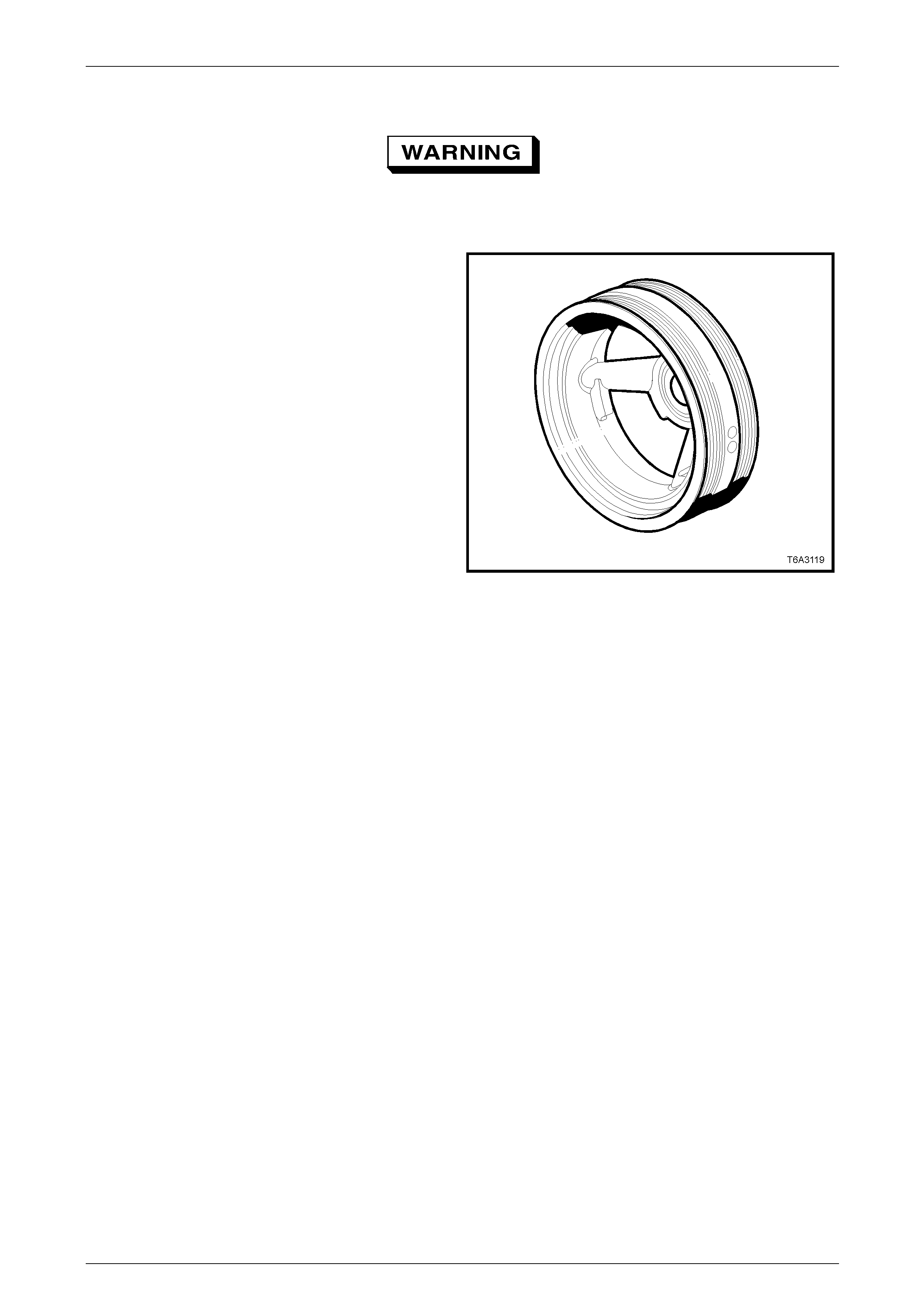
Engine Mechanical Page 6A4–139
Page 6A4–139
Clean and Inspect
To avoid personal Injury, wear safety glasses
and the appropriate gloves when using
compressed air and cleaning fluids.
1 Clean the crankshaft balancer in a suitable cleaning
fluid and dry the crankshaft bala ncer using
compressed air.
NOTE
Do not use solvent based cleani ng fluids to clea n
the crankshaft balancer as this may damage the
rubber in the balancer.
2 Using a wire brush, clean the belt grooves to remove
all dirt or debris.
3 Inspect the crankshaft balancer for:
• Excessive scoring, grooves or rust on the hub
seal surface. Minor imperfections on the hub
seal surface may be removed with a polishing
compound or a fine grade of em ery cloth.
• Rusted or damaged belt grooves.
• Worn, chunking or deteriorated rubber between
the hub and pulley.
NOTE
The balancer belt grooves should be free of any
nicks, gouges, or other damage that may not
allow the belt to track correctly. For the belt to
track correctly, the belt grooves should be free of
all dirt or debris. Minor imperfections may be
removed with a fine file.
Figure 6A4 – 198
Reinstall
NOTE
The crankshaft balancer reinstallation and bolt
tightening involves a multi-stage tightening
process. The first pass uses the used bolt and
ensures the balancer is installed completely onto
the crankshaft. The remaining passes tighten the
new bolt to the correct torque specification.
1 Ensure the teeth of the ring gear locking T ool No. J 42386-A are correctly engaged.
2 Apply a smear of clean engine oil onto th e seal surface of the balancer then install the balancer onto the end of the
crankshaft.
NOTE
The balancer should be positioned onto the end
of the crankshaft as straight as possible before
the tool installation.
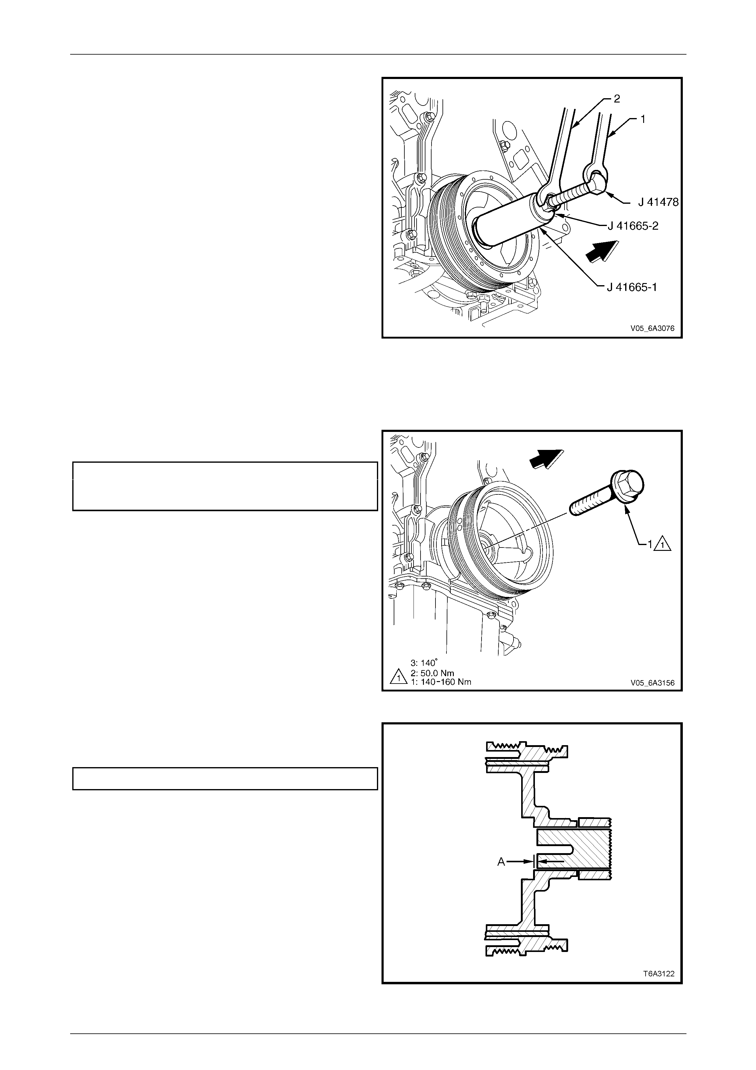
Engine Mechanical Page 6A4–140
Page 6A4–140
3 Use installer, Tool No. J 41665 and instal l the tool to
the crankshaft balancer as follo ws:
a Select the threaded rod, nut, washer and
installer from Tool No. J 41478.
b Insert the installer sleeve, Tool No. J 41665-1
into the front of the balancer and back up with
the plate, Tool No. J 41665-2.
NOTE
Insert the stepped end of sleeve Tool No.
J 41665-1 into the balancer in this initial stage.
4 Use a suitable spanner (1) to hold the hexagonal end
of the threaded rod. Use a second span ner (2) to
rotate the installation tool nut clockwise until the
balancer is started onto the crankshaft.
5 Remove the stepped sleeve of Tool No. J 41665-1 and
reverse it so the larger end of the installer is against
the front of the balancer.
6 Use a suitable spanner to hold the hexagonal end of
the threaded rod. With a second spanner, rotate the
installation tool nut clockwise until the balancer is
installed into the crankshaft.
6 Remove the balancer installation tool.
Figure 6A4 – 199
7 Install the used crankshaft balancer bolt and tighten to
the correct torque specification.
Crankshaft balancer installation
torque specification
Stage 1 ...............................................140.0 – 160.0 Nm
8 Remov e the used balancer bolt and discard.
Figure 6A4 – 200
9 Measure the distance the balancer protrudes from the
crankshaft nose and ensure dimension (A) is to
specification.
Dimension (A)........................................ 2.40 – 4.48 mm
10 If the dimension is not correct, repeat Steps 1 to 8.
Figure 6A4 – 201
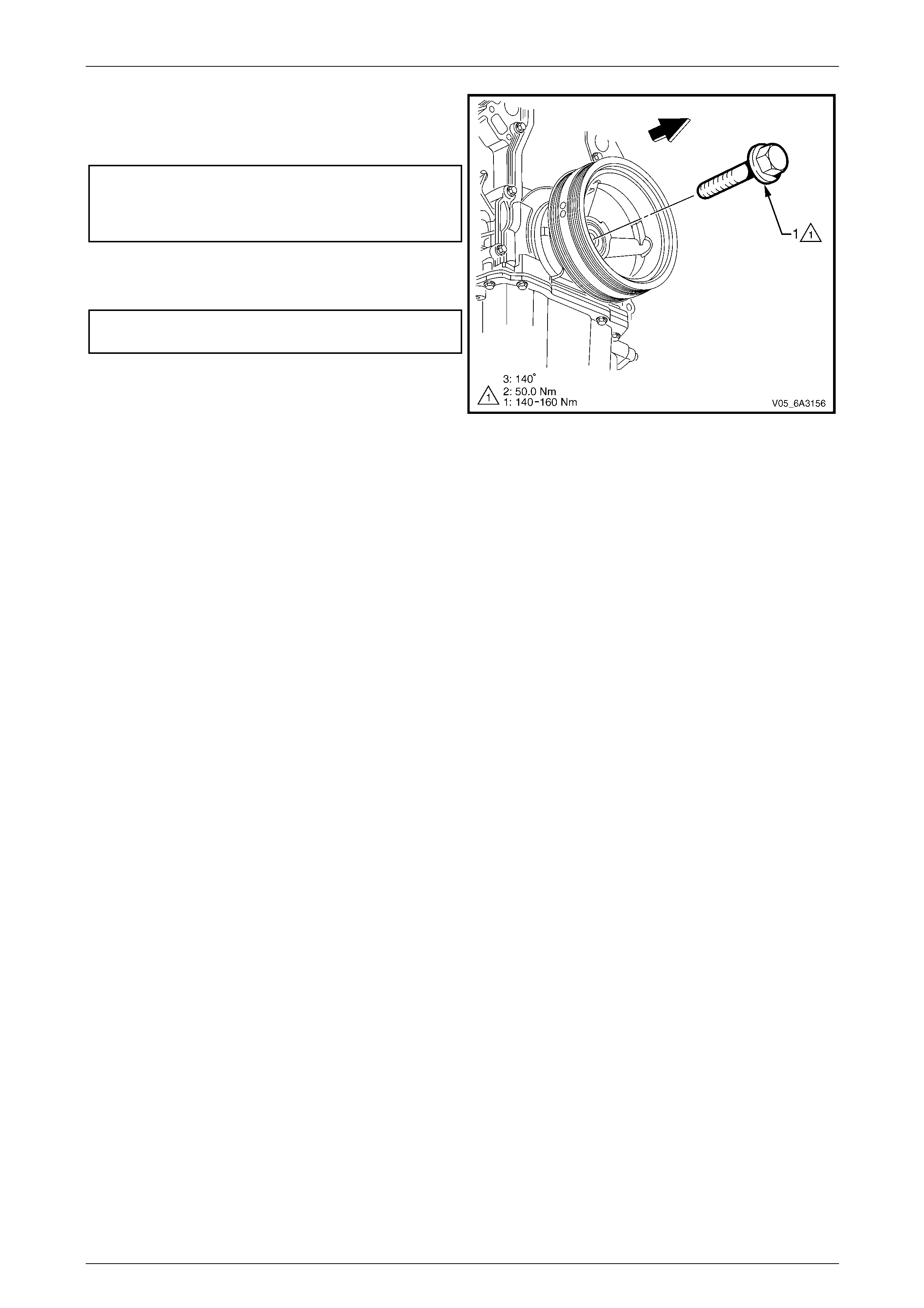
Engine Mechanical Page 6A4–141
Page 6A4–141
11 Install a new crankshaft balancer bolt (1) and tighten
to the correct torque specification in two stages using
a suitable torque wrench and a torque a ngle wrench
Tool No. E 7115 or similar.
Crankshaft balancer bolt
torque specification
Stage 2 ..............................................................50.0 Nm
Stage 3 ..................................................140° turn angle.
12 Remove the ring gear holding Tool No. J 42386-A.
13 Reinstall the close-out cover and tighten the attaching
bolt to the correct torque specification.
Right-hand close-out cover at taching bolt
torque specification............................................10.0 Nm
14 Reinstall the starter motor, refer to Section 6D3-2
Starting System – GEN IV V8.
15 Reinstall the radiator, refer to Section 6B3 E ngine
Cooling – GEN IV V8. Figure 6A4 – 202
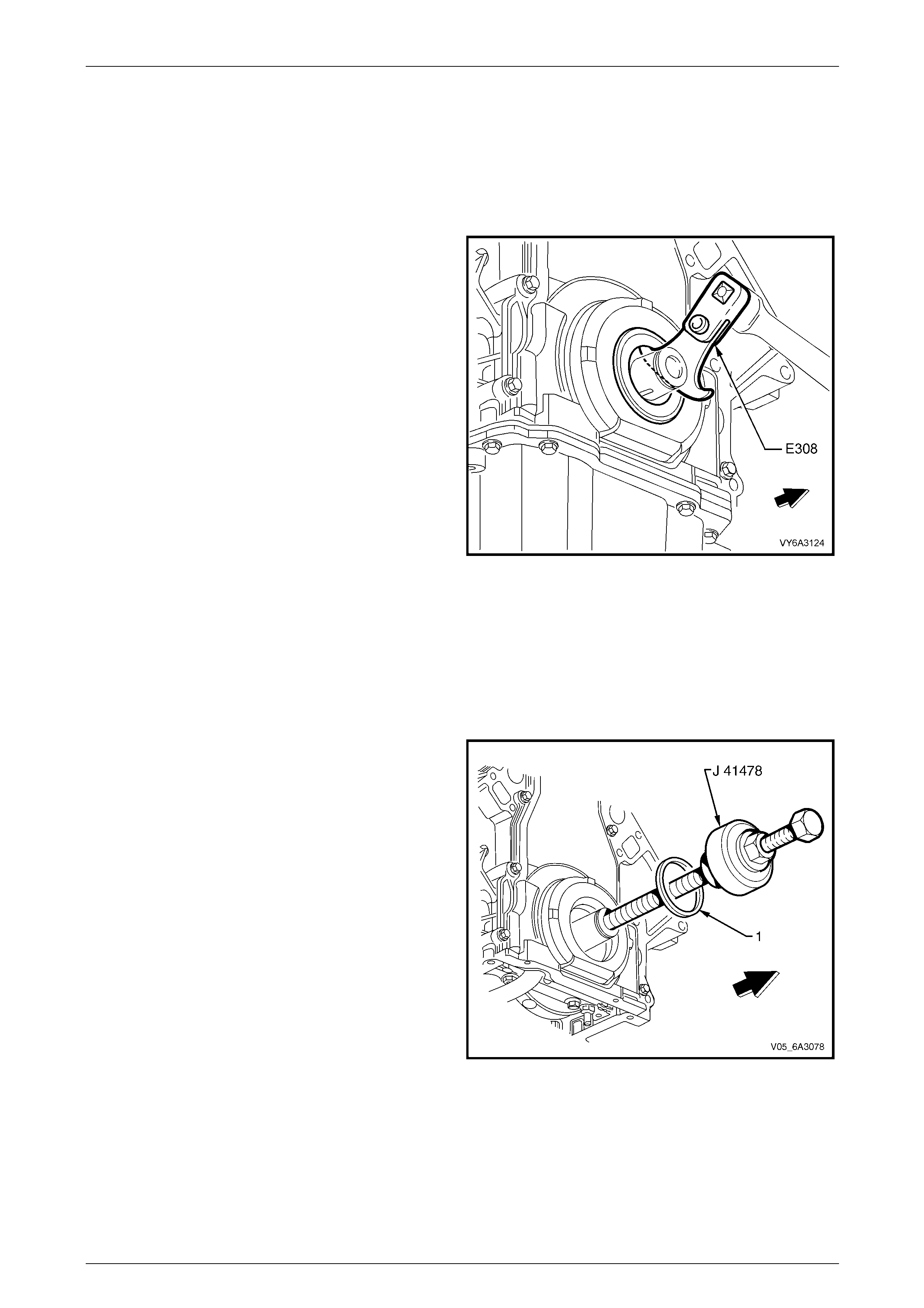
Engine Mechanical Page 6A4–142
Page 6A4–142
4.18 Crankshaft Front Oil Seal
LT Section No. — 00–325
Remove
1 Remove the crankshaft balancer, refer to 4.17 Crankshaft Balancer.
2 Using Tool No. E308 or e quivalent, carefully prise the
seal from the front engine cover.
NOTE
Use care to avoid scratching the front engine
cover when removing the seal.
Figure 6A4 – 203
Reinstall
NOTE
Do not lubricate the oil seal sealing surface.
For further information refer to 1.5 Engine
Lubrication System
1 Lubricate the outer edge of the new oil seal (1) and the
front cover oil seal bore with clean engine oil.
2 Install the crankshaft front oil seal onto the guide of
Tool No. J 41478.
3 Install the threaded rod with the nut, washer, guide,
and oil seal of Tool No. J 41478 into the end of the
crankshaft.
4 Using a suitable spanner, ho ld the head of the installer
bolt. Using a second spanner rotate the installer nut
clockwise until the seal bottoms in the front cover
bore.
5 Remove the tool from the crankshaft.
6 Inspect the oil seal for correct installation. The oil seal
should be installed evenly and completely into the
front cover.
7 Reinstall the crankshaft bala ncer. Refer to
4.17 Crankshaft Balancer.
Figure 6A4 – 204
Engine Mechanical Page 6A4–143
Page 6A4–143
4.19 Engine Mounts
LT Section No. — 00–475
Inspect
1 Check the area around the engin e mounts fo r any signs of fluid leakage. If an oil leak coming from the mount is
visible, the mount is defective.
To protect the aluminium oil pan from damage
when using a floor jack, position a suitable
piece of wood or similar between the oil pan
and the jack.
2 Using a suitable engine lifting crane or a floor jack, raise the engine slightly to remove the weight from the mounts
and to place the rubber slightly in tensio n. Check the mount ing rubber has not deteriorated, split or has separated
from its metal plates.
NOTE
If either fluid is visible or the rubber has
deteriorated or separated the engine mount must
be replaced.
Remove
Disconnection of the battery affects certain
vehicle electronic systems. Refer to
Section 00 Warnings, Cautions and Notes
before disconnecting the battery.
1 Disconnect the ground battery cable termi nal from the battery.
2 If required, remove the strut tower brace, refer to Section 1A1 Body.
3 If required, remove the engine dress covers, refer to 4.2 Engine Dress Cover.
4 Raise the front of vehicle and place on safety stands. For the location of vehicle jacking and support locations, refer
to Section 0A General Information.
5 Remove the exhaust pipe to manifold flange attaching nuts on the side the engine mount is to be removed. Refer to
Section 8B Exhaust System.
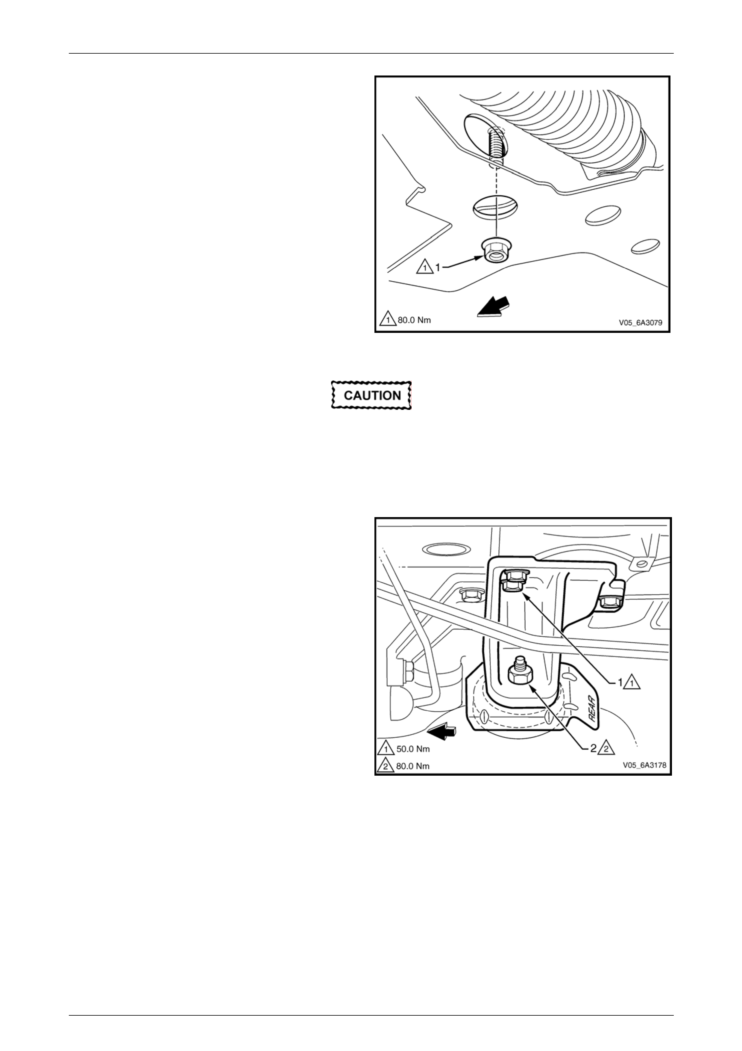
Engine Mechanical Page 6A4–144
Page 6A4–144
6 From under the vehicle, remove the lower mounting to
crossmember attaching nut (1) for both mounts.
7 Lower the vehicle to the ground an d remove the
exhaust manifold on the side the engine mount is to be
removed. Refer to 4.14 Exhaust Manifold.
Figure 6A4 – 205
To protect the aluminium oil pan from damage
when using a floor jack, position a suitable
piece of wood or similar between the oil pan
and the jack.
8 Using suitable engine lifting equipment or a floor jack, raise the engine and remove the weight from the engine
mounts.
9 Remove the three bolts (1), attaching the engine
mount bracket to the cylinder block.
10 Lift the engine mount and bracket assembl y from the
crossmember and remove it from the vehicle.
11 Using a marker pen or similar, mark the relationship of
the heat shield to the bracket to maintain correct
rotation in the reinstallation pr ocess.
12 With the engine mount and bracket assembly removed
from the vehicle, mount the bracket assembly in a vice
and remove the nut (2) attaching the engine mount to
the bracket and separate the heat shield and mount
from the bracket.
NOTE
While the left-hand mount is shown, the
operation is similar for either engine mount with
the exception that for the right-hand engine
mount, the battery harness bracket attaching
bolt must be removed before removing the
mounting bracket to the cylinder block bolts.
Refer to Section 12O Fuses, Relays and Wiring
Harnesses.
Figure 6A4 – 206
Engine Mechanical Page 6A4–145
Page 6A4–145
Reinstall
1 If removed from the bracket, reinstall the engine mount an d heat shiel d then tighten the attaching nut to the correct
torque specification.
Engine mount and bracket attaching nut
torque specification............................................80.0 Nm
2 Fit the engine mount stud into the crossmember an d install the mounting bracket assembly so the attaching bolts
can be installed.
3 Once all the mounting bracket to cylinder block attaching bolts are installed, tighten the bolts to the correct torque
specification.
Engine mounting bracket and
cylinder block attaching bolt
torque specification............................................50.0 Nm
4 Lower the engine allowing the weight to settle on the crossmember before installing the lower engine mount
attaching nut and tighten to the correct torque specification.
Engine mount to crossmember
attaching nut
torque specification............................................80.0 Nm
5 Reinstall the exhaust manifold, refer to 4.14 Exhaust Manifold.
6 Reinstallation of the remainder of the components removed is the reverse of the removal procedure.
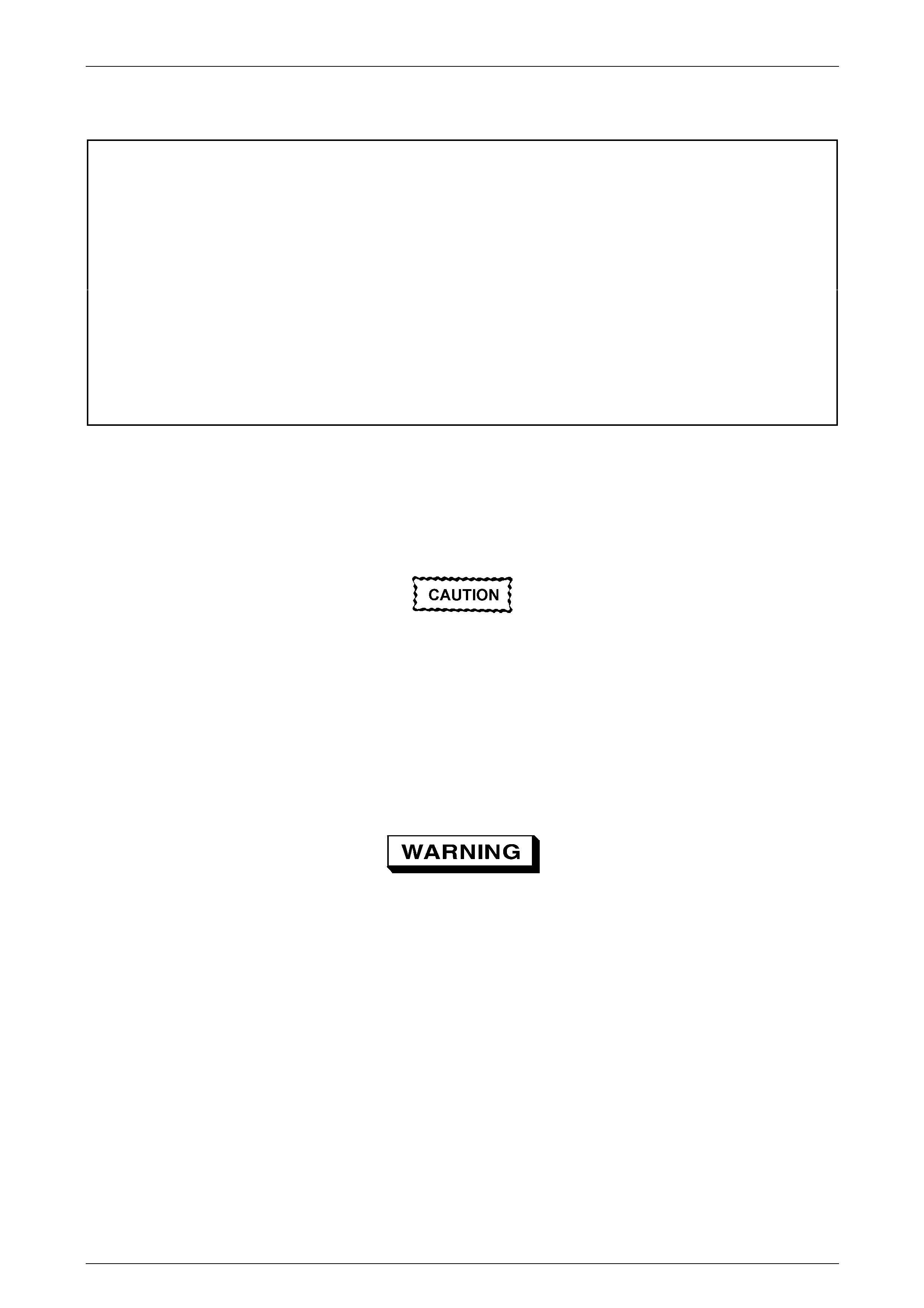
Engine Mechanical Page 6A4–146
Page 6A4–146
5 Major Service Operations
ATTENTION
All engine fasteners are important attaching parts as they affect th e performance of vital componen ts and/or
could result in majo r repair expense. Where specified in this Section, fasteners MUST be rep laced with parts
of the same part number or a GM approved equivalent. Do not use fasteners of an inferior quality or
substitute design.
Torque values must be used as specified during reassembly to ensure proper retention of all engine
components.
Through out this Section, fastener torque wrench specifications may be accompanied with the following
Identification marks:
Fasteners must be repl aced after loosening.
Fasteners either have micro encapsulated sealant applied or incorporate a mechanical thread lock and
should only be re-used once. If in doubt, replacement is recommended.
If one of these identification marks is present alongside a fastener torque wrench specification, the
recommendation regarding that fastener must be adhered to.
5.1 Engine Assembly, Except AWD
LT Section No. — 00–500
Remove
Disconnection of the battery affects certain
vehicle electronic systems. Refer to
Section 00 Warnings, Cautions and Notes
before disconnecting the battery.
1 Disconnect the battery ground terminal from the battery.
2 Remove the strut brace, refer to Section 1A1 Body.
3 Remove the hood assembly, refer to Section 1A4 Ho od, Rear Compartment Lid, Liftgate and Endgate.
4 Remove the air intake duct, refer to 4.1 Air Intake Duct.
5 Remove the engine dress covers, refer to 4.2 Engine Dress Cover.
• Do not remove the screw-on radiator
pressure cap while the engine coolant
temperature is above 50° C, as personal
injury could occur.
• Throughout this Section spring type hose
clamps are required to be removed, always
wear eye protection when handling spring
type clamps to avoid possible eye inju ry.
6 Refer to Section 6B3 Engine Cooling – GEN IV V8 and remove the following:
• Top and lower radiator hos es from the engi ne and radiator
• Radiator fan and shroud assembl y
• Radiator
7 Remove the accessory and air conditioner drive belts, refer to 4.6 Engine Drive Belts and Pulle ys.
8 Disconnect the suction/discharge hose pad from the air conditioner compressor, refer to Section 2C HVAC Climate
Control (Manual A/C) – Removal and Installation.
9 Drain the engine oil into a suit able container and reinstall the drain plug once the oil has drained sufficiently, refer
to 4.3 Engine Oil and Filter.
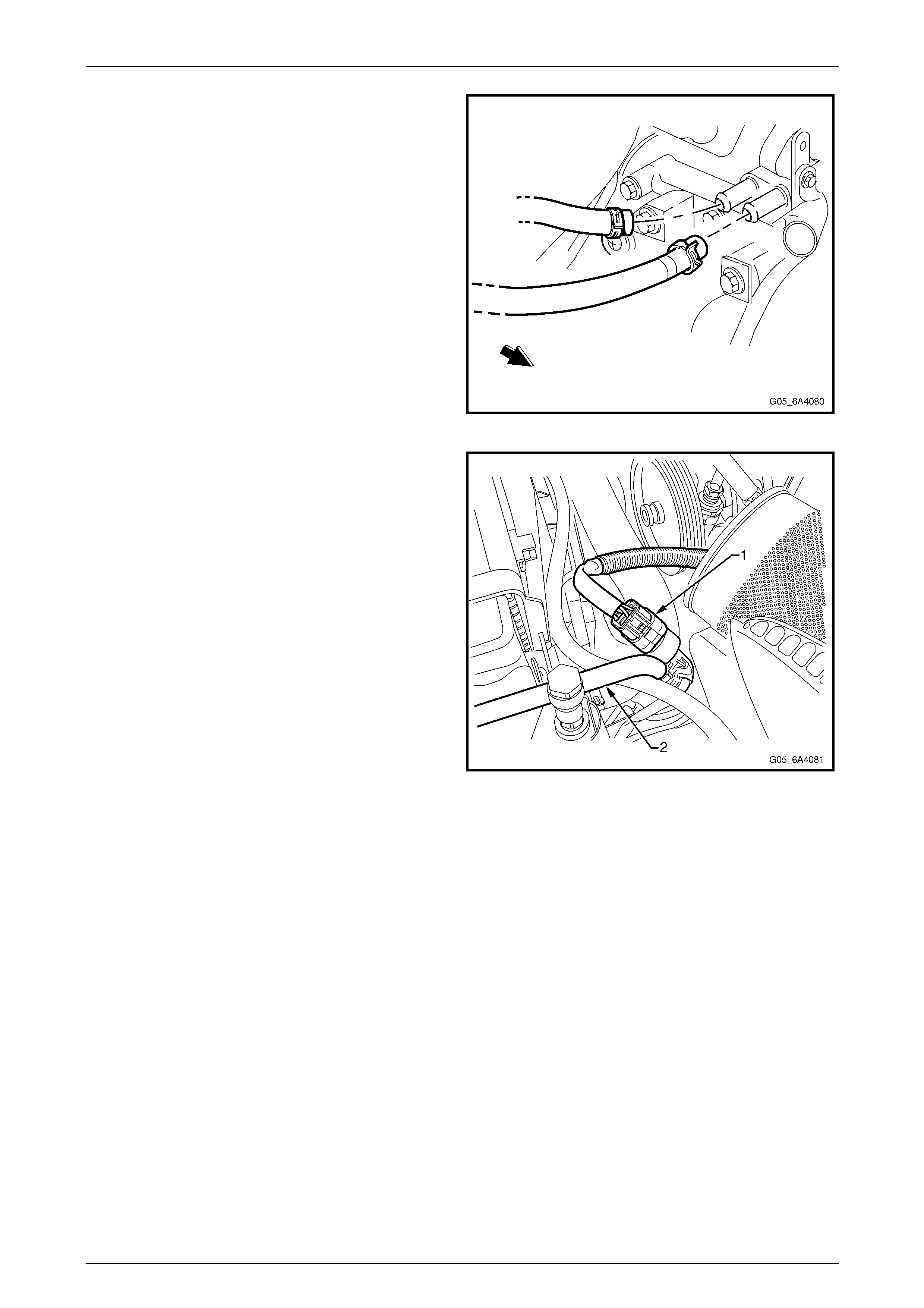
Engine Mechanical Page 6A4–147
Page 6A4–147
10 Remove the heater hose clamps at the eng ine coolant
pump, taking note of the hose layout. Plug the open
ends to prevent the entry of foreign material.
NOTE
If required, mark the hoses prior to removal with
a paint pen or similar.
11 Remove the ground le ad to the engine cylinder block
and from the left hand engine mount and remove the
positive terminal from the battery and lay the harness
on the engine, refer to Section 12O Fuses, Relays and
Wiring Harnesses.
Figure 6A4 – 207
12 Disconnect the air conditioning pressure switch and
front wiring harness connector (1) attached to the A/C
condenser pipe (2).
13 Remove the left hand kick p anel trim and glove box
assembly, refer Section 1A3 Instrument Panel and
Console.
14 Disconnect the Engine Interface Module (PIM) wiring
harness connector and front body harness connector.
Refer to Section 12O Fuses, Relays and Wir ing
Harnesses.
15 Release the harness to dash panel grommet and pass
the harness and connectors out into the engi ne bay
and place the Engine wiring harness on top of the
engine.
Figure 6A4 – 208
16 Referring to Figure 6A4 – 209, remove or disconn ect the following:
a Engine wiring harness retaining clips (1) from the engine compartment dash panel.
b Wiring harness connector (2) from the theft deterrent horn.
c Cover (3) from the Engine Control Module (ECM) (4).
d Two screws (5) retaining the ECM wiring harness connectors to the ECM.
e ECM wiring harness retaining clip (6) from the ECM contain er to free the h arness.
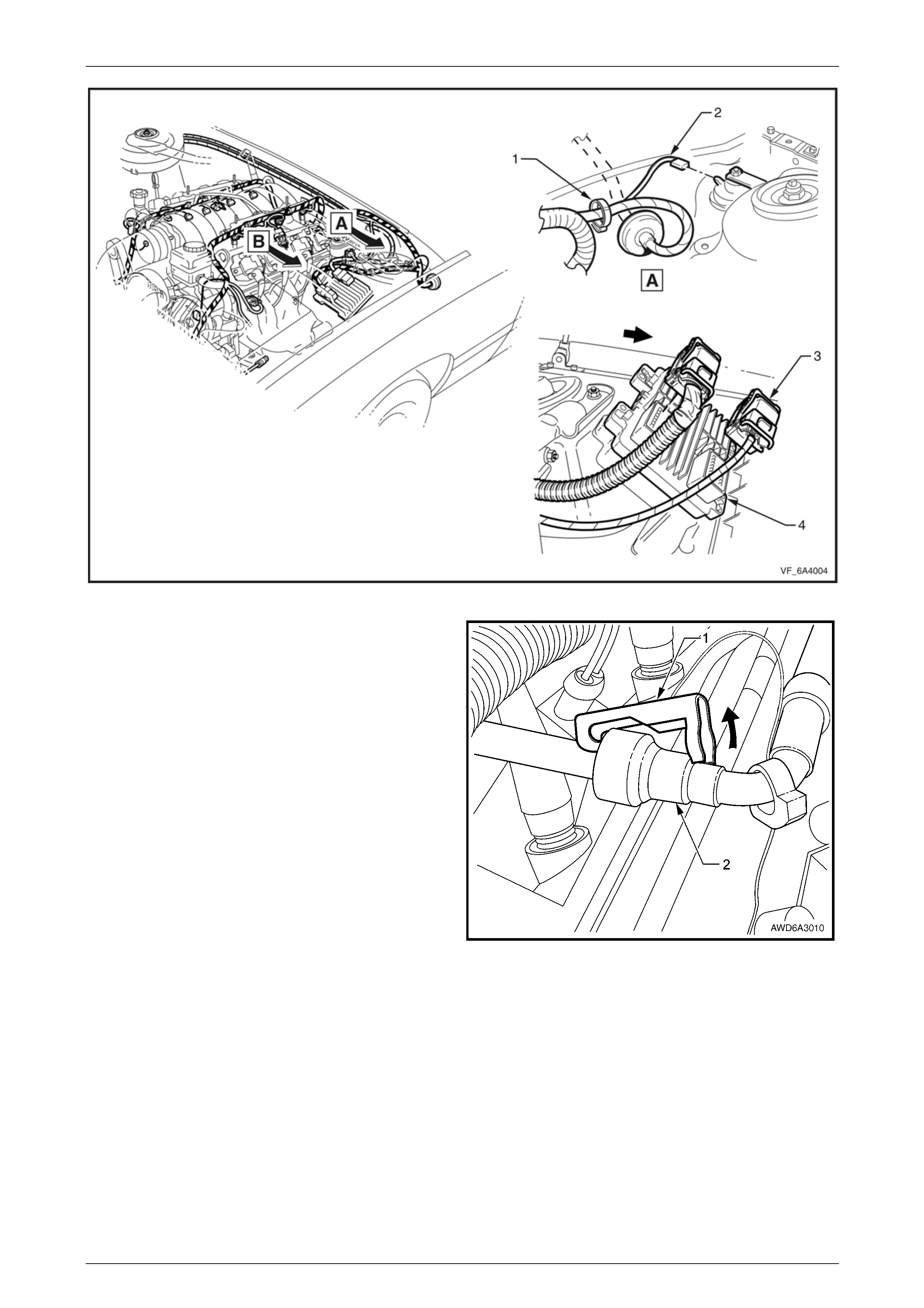
Engine Mechanical Page 6A4–148
Page 6A4–148
Figure 6A4 – 209
17 De-pressurise the fuel system, refer to
Section 8A1 Fuel System.
18 Using a small scre wdriver, release the s ecurity lock
(1), at each of the fuel supply hose quick connect
fittings (2).
NOTE
The security lock at the fuel rail side is fitted with
a tether to prevent loss.
Figure 6A4 – 210
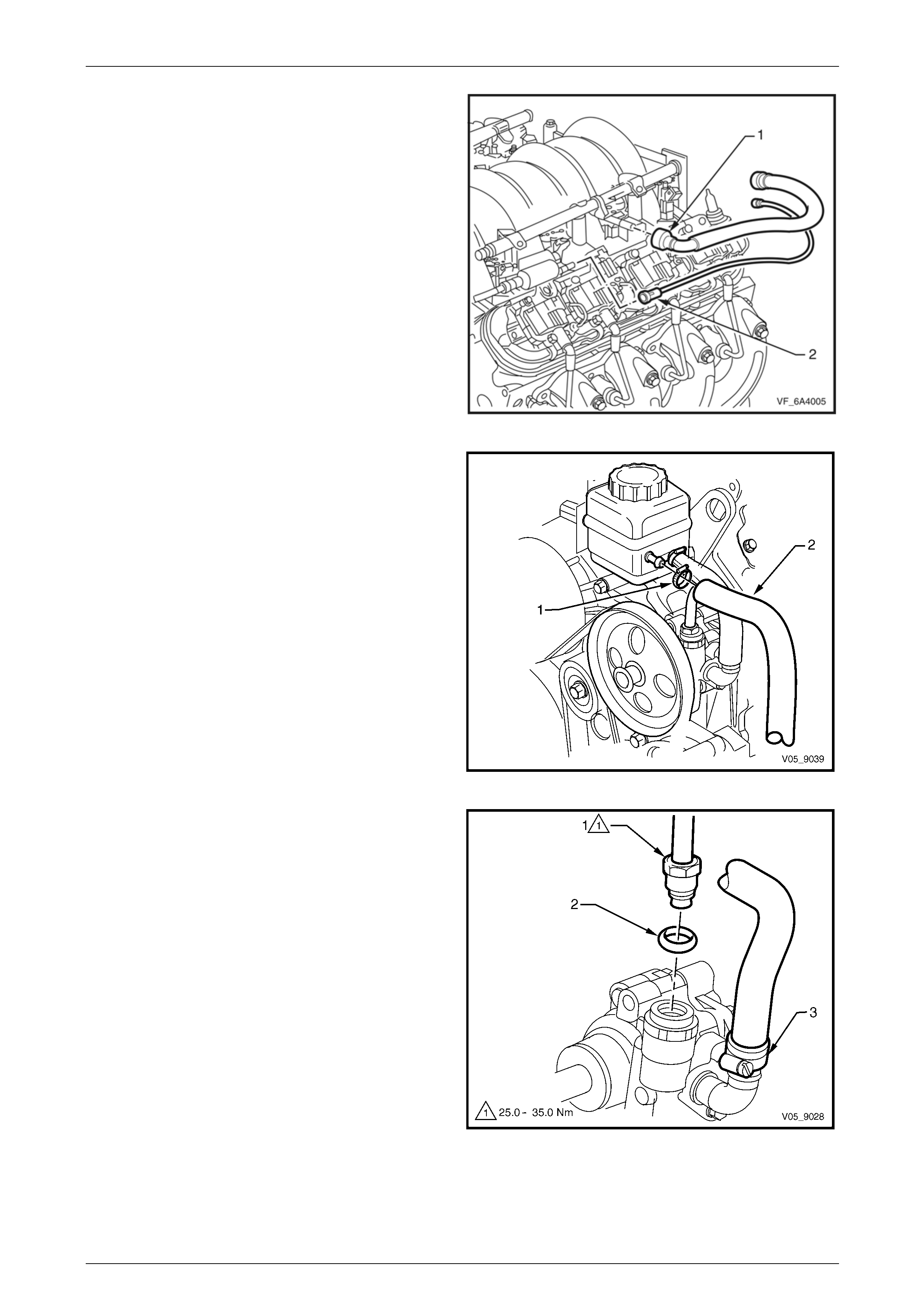
Engine Mechanical Page 6A4–149
Page 6A4–149
19 Remove the fuel line quick connector (1) from the fuel
rail, refer to Section 6C4-3 Engine Managem ent –
GEN IV V8 – Service Operations.
20 Disconnect the vapour line co nnection (2) to the EVAP
purge control valve and place it to one sid e.
NOTE
Plug all openings to prevent fuel leaking and
foreign matter from entering the fuel system.
Figure 6A4 – 211
21 Loosen the low pressure power steering return hose
clamp (1) and the remove the hose (2).
NOTE
Plug the hose ends to prevent an y foreign matter
from entering the system and fluid loss.
22 If required, remove the power steering pump and/or
reservoir, refer to Section 9 Steering.
Figure 6A4 – 212
23 Remove the power steering high pressure line flare
nut (1) and O-ring (2) from the pump outlet fitting.
24 Loosen the low pressure hose clamp (3) and remove
the hose from the pump inlet fitting.
NOTE
Plug the pump and hose fittings to prevent
foreign matter from entering the s ystem and fluid
loss.
Figure 6A4 – 213
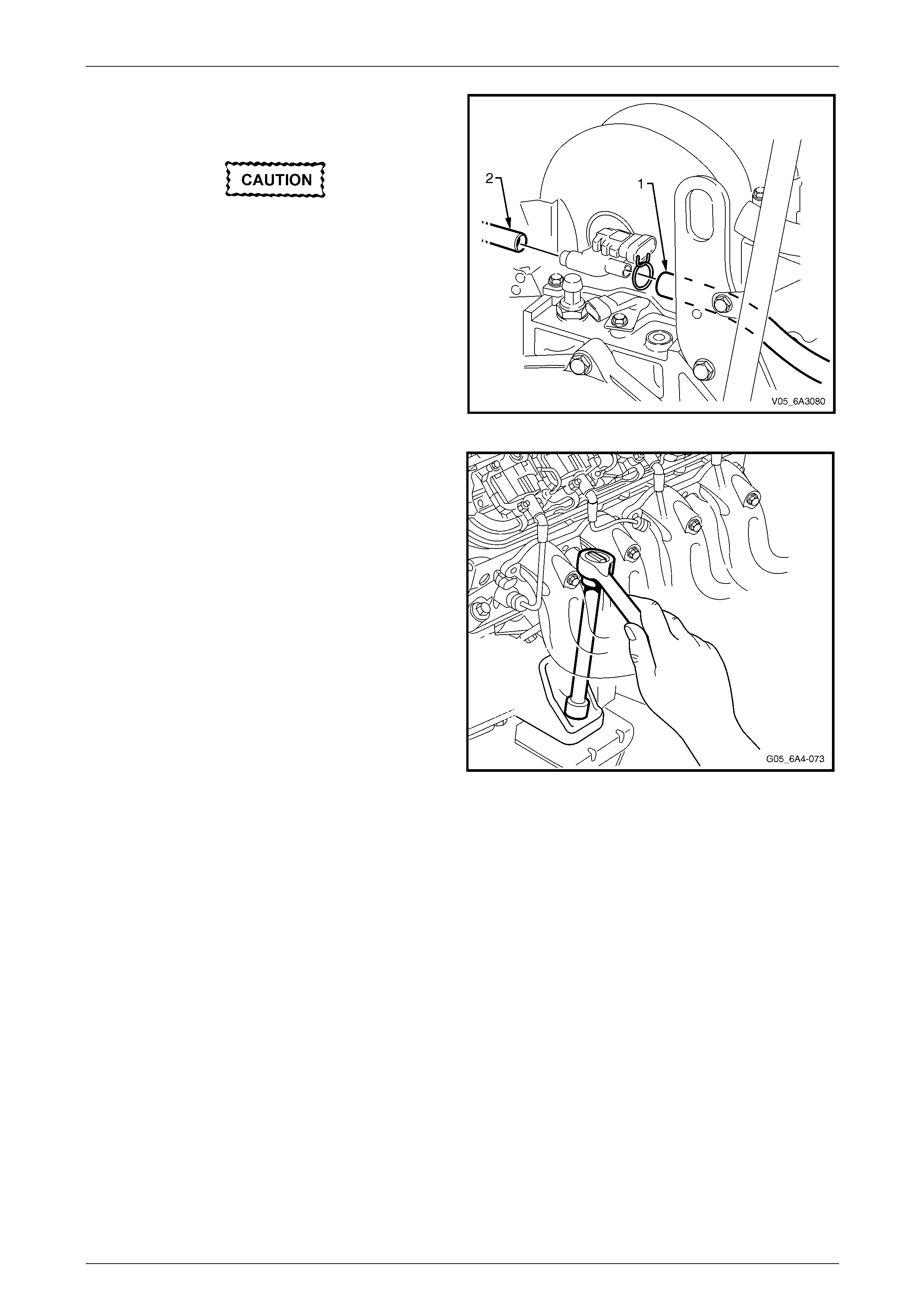
Engine Mechanical Page 6A4–150
Page 6A4–150
25 Disconnect the brake booster vacuum hose (1) and
HVAC control vacuum hose (2) from the rear of the
intake manifold.
Handle the spark plug boot only. Do not pull
on the lead. To remove the lead, twist the
boot first to break the seal and then gently
pull on the boot.
26 Remove the No. 3 spark plug lead and plug from the
left-hand bank.
Figure 6A4 – 214
27 Remove the upper left engine mount to engine bracket
attaching nut.
28 Remove the No. 4 spark plug lead and plug from the
right bank.
29 Remove the upper right engine mount to en gine
bracket attaching nut. To improve the removal
process, remove the lower mount attaching nut.
NOTE
To improve access to the upper engine mount
to bracket attaching nuts if required, remove
both exhaust manifolds, refer to 4.14 Exhaust
Manifold.
30 Remove the ignition coil and module for cylinder No. 7.
Refer to Section 6C4-3 Engine Management – GEN IV
V8 – Service Operations.
NOTE
This step is necessary to gain additional
clearance around the brake vacuum booster,
when the engine is lifted during the removal
process.
Figure 6A4 – 215
31 For manual transmission equipped vehicles, either:
• Remove the clutch master cylinder reservoir bracket attached to the end of the master cylinder, refer to
Section 7A3 Clutch – GEN IV V8, or
• Disconnect the clutch slave cylinder hydr aulic line at the bracket attached to the vehicle subframe, refer to
Section 7B2 Manual Transmission – GEN IV V8.
NOTE
This step is necessary to reduce the possibi lity of
damage to the reservoir, during the engine
removal procedure.
32 Using a hoist, raise the vehicle or alternative ly use a floor jack and support the vehicle on safety stands. For
location of hoist pad, vehicle j ackin g an d support locations, refer to Section 0A General Information.
33 Remove the propeller shaft, refer to Section 4C1 Rear Propeller Shaft and Universal Joints.
NOTE
If required, use tie wire to secure the sliding yoke
to the rear of the transmission.
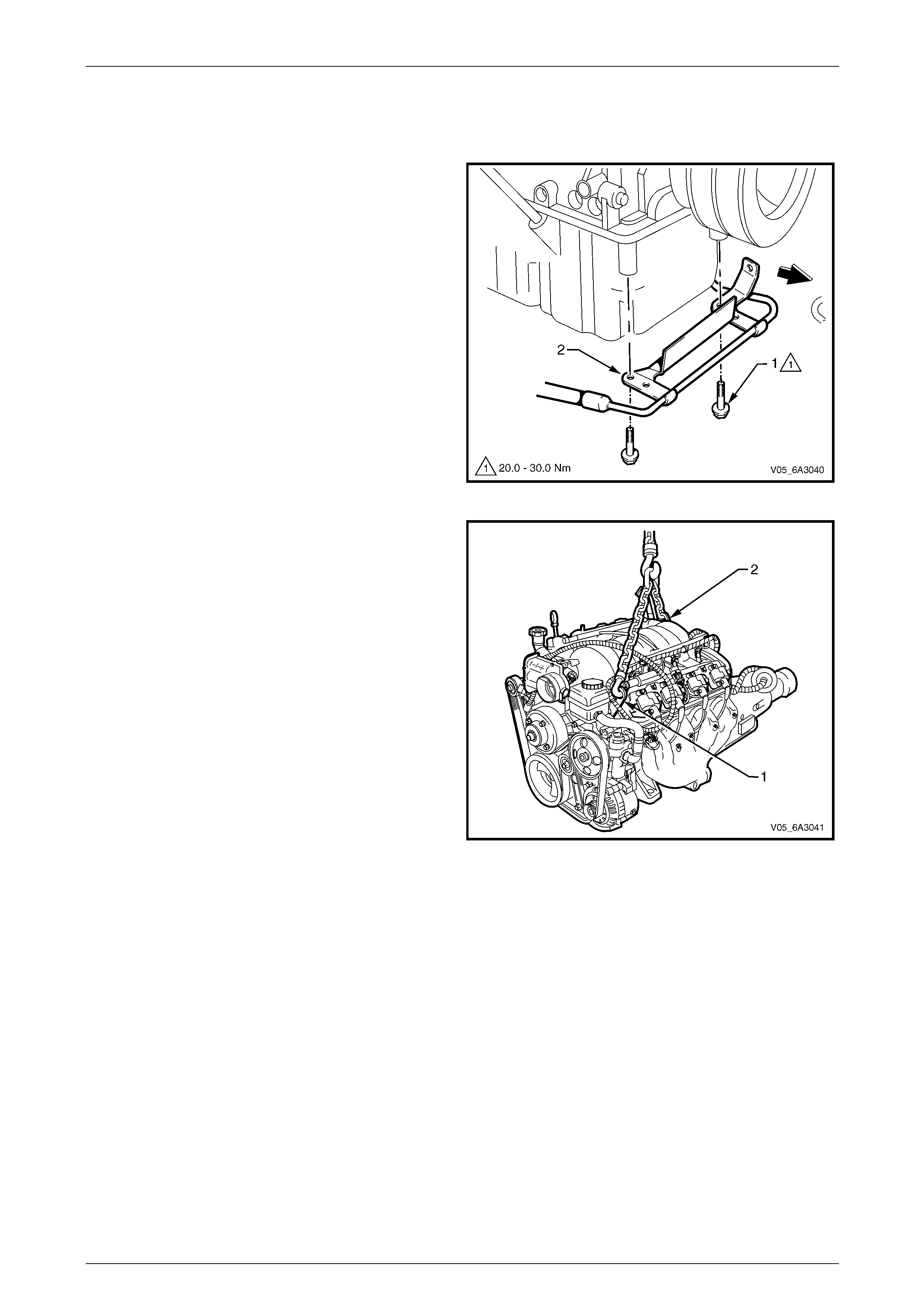
Engine Mechanical Page 6A4–151
Page 6A4–151
34 Disconnect the gear shift control from the transmission. Refer to either:
• Section 7B2 Manual Transmission – GEN IV V8.
• Section 7C4 Automatic Transmission – 4L60E – On vehicle Servicing.
35 Remove the two bolts (1) attaching the power steering,
high pressure hose (2) bracket to the oil pa n.
36 While not essential, it is recommended the oxygen
sensors be removed from the exhaust pipes, to avoid
accidental damage. Refer to Section 6C4-3 Engine
Management – GEN IV V8 – Service Operations.
37 If the exhaust manifolds have not bee n removed,
remove the front exhaust assemblies, refer to
Section 8B Exhaust System.
38 Lower the vehicle enou gh to allow the connection of
the lifting chains but also allo wing th e removal of the
transmission support.
Figure 6A4 – 216
39 Attach a suitable lifting chain and hooks to the engine
lifting brackets located at the left-hand front (1) and
right-hand rear (2) corners of the engi ne.
40 Using a suitable lifting crane, raise the eng ine slightly
to take the weight off the engine mounts.
NOTE
The following step is critical to ensure correct
Engine alignment on reassembly. If this is not
carried out, vehicle vibration and/or handling
problems could result.
Figure 6A4 – 217
41 Mark the relationship of the engine rear cros smember (1) to the vehicle underbody to assist with alignment on
reassembly, refer to Figure 6A4 – 218. For further information relating to crossmember alignment, refer to
Section 1A2 Body Dimensions.
42 Place a floor jack with a block of wood under the transmission and ra ise the jack slightly to support the weight of
the transmission.
43 Referring to Figure 6A4 – 218, remove the bolt (1), four places, attaching the rear crossmember (2) to the vehicle.
NOTE
View A is for Manual Transmission vehicles and
View B is for Automatic transmission vehicles.
44 Remove the rear mount to crossmember attaching nut (3), two places and then remove th e crossmember from the
vehicle.
a For vehicles with manual transmission (A), remove the rear mount to transmission bolt (4), four places and
the exhaust resonator bracket base to transmission extension bolt (5) and nut, two places and remove the
exhaust resonator bracket base (6) from the vehicle.
b For vehicles with automatic transmission (B), remove the rear mount to transmission extension housing bolt
(7), two places and nut (8), two places and remove the mount (9) and the exhaust resonator bracket base
(10) from the vehicle.
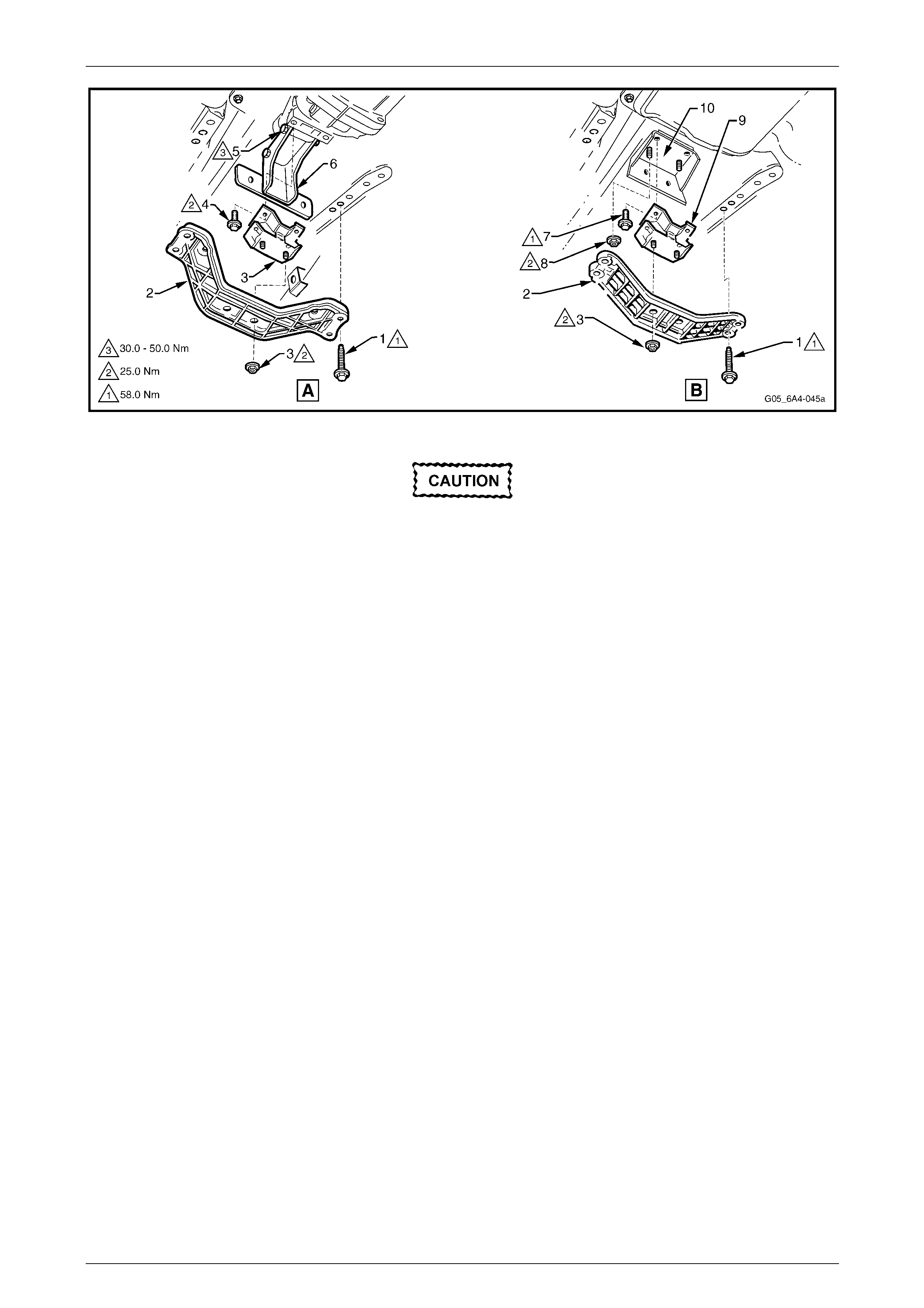
Engine Mechanical Page 6A4–152
Page 6A4–152
Figure 6A4 – 218
• Take care when removing the engine and
transmission assembly that no part of the
assembly is allowed to rest on the power
steering rack.
• Do not allow the engine to swing forward
and damage the air conditioning
condenser.
45 Raise the engine and transmission assembly with the front tilted upward and a floor jack supporting the rear of the
transmission assembly.
46 Continue to lift and manoeuvr e the en gine and transmission assembly until it is clear of the engine bay.
Disassemble – Ancillary Equipment
The engine removal and rei nstallation procedures cover the removal and reinstallation of the engine and transmission as
a complete assembly. To perform major engi ne service operations, it is required the engine and transmission be
separated and the ancillary equipment that is attached to the engine be removed. Once a ll ancillary components and the
transmission have been removed, major e ng ine service operations can then be performed, by referring to the appro pri ate
major service operation.
Automatic Transmission Vehicles
1 Remove the wiring harness conn ectors and earth connections from the engine and transmission assembly and
carefully set the wiring harness to one side, refer to Section 12O Fuses, Re lays and Wiring Harnesses.
2 Remove the starter motor, refer to Section 6D3 – 2 Starting System – GEN IV V8.
3 Remove the right-hand close-out cover (A) and left-hand close out cover (B) attaching bolts (1) and remove the
covers (2). Refer to Figure 6A4 – 219.
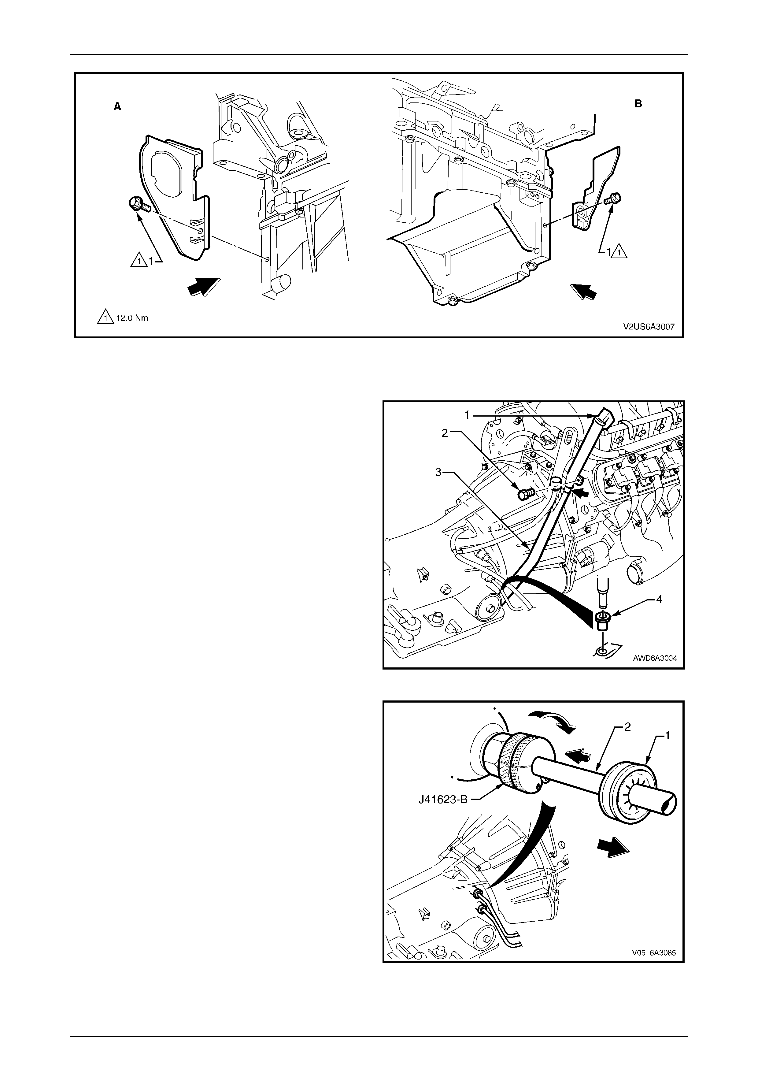
Engine Mechanical Page 6A4–153
Page 6A4–153
Figure 6A4 – 219
4 Remove the three bolts attaching the torque converter to the engine flexplate using the right-hand close -out cover
opening for access to the bolts.
5 Release the lock down lever (1) and remove the
transmission oil level indicator.
6 Remove the bolt (2) attaching the transmissio n filler
tube to the right-hand cylinder head.
7 Release the transmission breat her tube from the filler
tube (3) bracket (arrow).
8 Using a twisting/pulling motio n, remove the filler tu be
from the transmission case seal (4). Set the filler tube
to one side.
9 Plug the filler tube opening in the automatic
transmission to prevent dirt entry and fluid leakage.
Figure 6A4 – 220
10 Disconnect the transmission cooler lines from the
transmission end, as follows:
a Release the verifier disc (1) by pulling b ack with
your fingertips and slide th e disc back down the
cooler pipe (2).
b Open the cooler line releas e T ool J-41623-B and
slip it over the cooler pipe to be discon nected
from the transmission, ahead of the verifier disc
as shown.
c Slide the release tool alon g the pipe to engage
with the quick-connect fitting.
d While pushing in wards, rotate the tool about one
sixth of a turn clockwise to release the s pring clip
holding the pipe.
e With the release tool held in this position, pull
back on the cooler pipe to release. Repe at this
process with the remaining pipe an d quick-
connect fitting.
f Plug all openings to prevent fl uid loss and/or dirt
entry. Figure 6A4 – 221
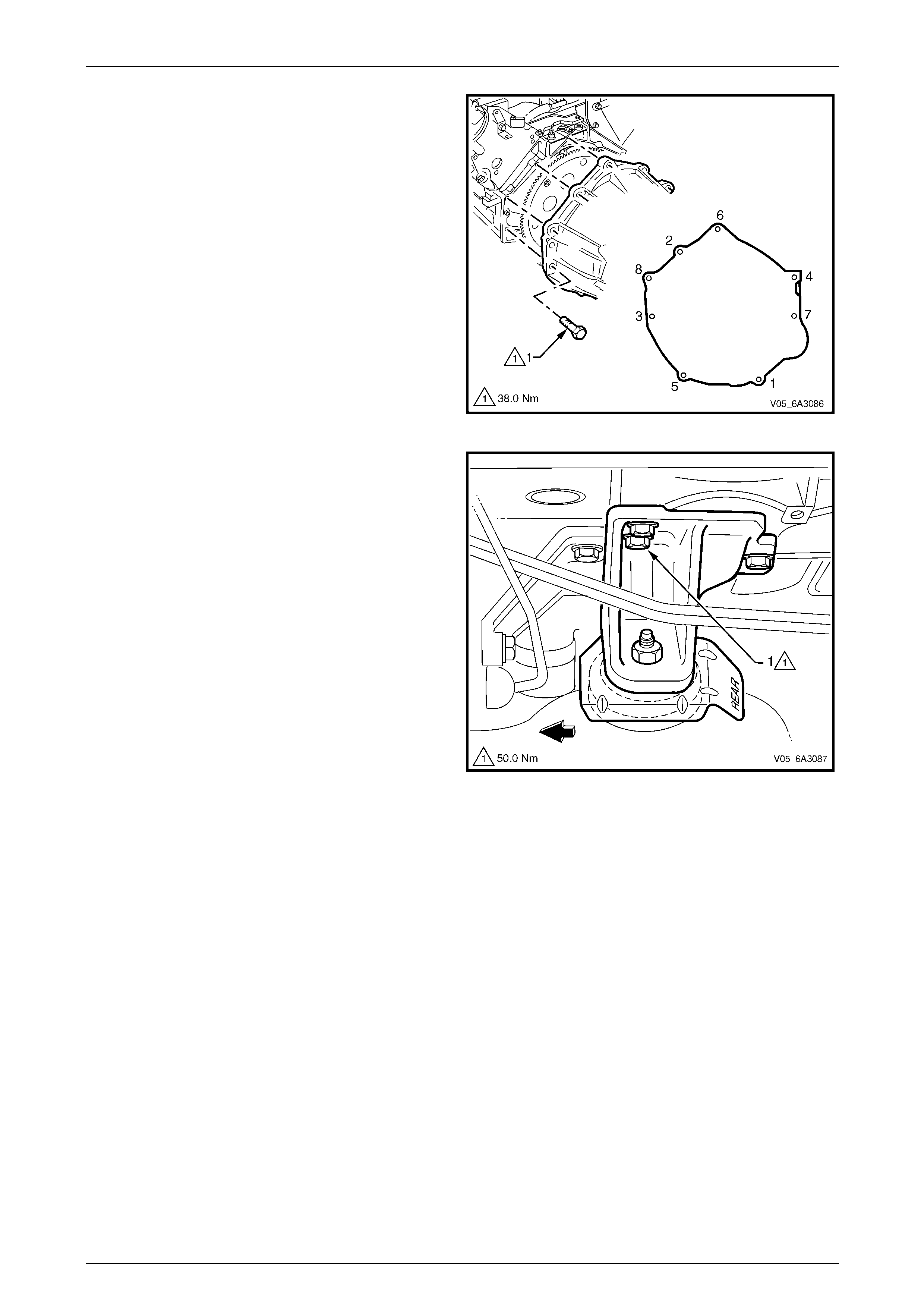
Engine Mechanical Page 6A4–154
Page 6A4–154
11 Remove the transmission housing to eng ine assembly
attaching bolt (1), eight places in the seq uence shown
and then slide or lift the transmission free from the rear
of the engine.
NOTE
Ensure the torque converter stays with the
transmission when the transmission is being
removed from the engine assembly.
Figure 6A4 – 222
12 Remove the three bolts (1), attaching the left-hand
engine mount bracket to the cylinder bl ock and set the
bracket and mount, together with the heat shield, to
one side. Repeat for the remaining engine mount.
13 Mount the engine in a suitable engine stand such as
Tool No AU 591 or similar. Preferab ly, use a stand that
will mount the engine on it from its side using the
engine mount bracket bolt hol es.
14 As required, remove the following:
• Power steering reservoir and pump, refer to
Section 9 Steering.
• Exhaust manifolds, refer to 4.14 Exhaust
Manifold.
• Coolant pump, refer to Section 6B3 Engine
Cooling – GEN IV V8.
• Ignition coils and bracket assembly, refer to
Section 6C4-3 Engine Management – GEN IV
V8 – Service Operations.
• Accessory and air conditioner drive belt idler and
tension pulley assemblies, refer to
4.6 Engine Drive Belts and Pulleys.
• Air conditioning compressor, refer to
Section 2C HVAC Climate Control (Manual A/C)
– Removal and Installation.
• Generator and mounting bracket, refer to
Section 6D3-1 Charging System – GEN IV V8.
Figure 6A4 – 223
Manual Transmission
1 Remove the wiring harness conn ectors and earth connections from the engine and transmission assembly and
carefully set the wiring harness to one side. For wiring harness informati on, refer to Section 12O, Fuses, Relays
and Wiring Harnesses.
2 Remove the starter motor, refer to Section 6D3 – 2 Starting System – GEN IV V8.
3 Remove the left and right-han d close-out cover attaching bolts (1) and remove the covers (2). Refer to
Figure 6A4 – 219.
4 Remove the transmission housing to engine assembly attaching bolts (1), refer to Figure 6A4 – 222 and then slide
the transmission free from the rear of the engine.
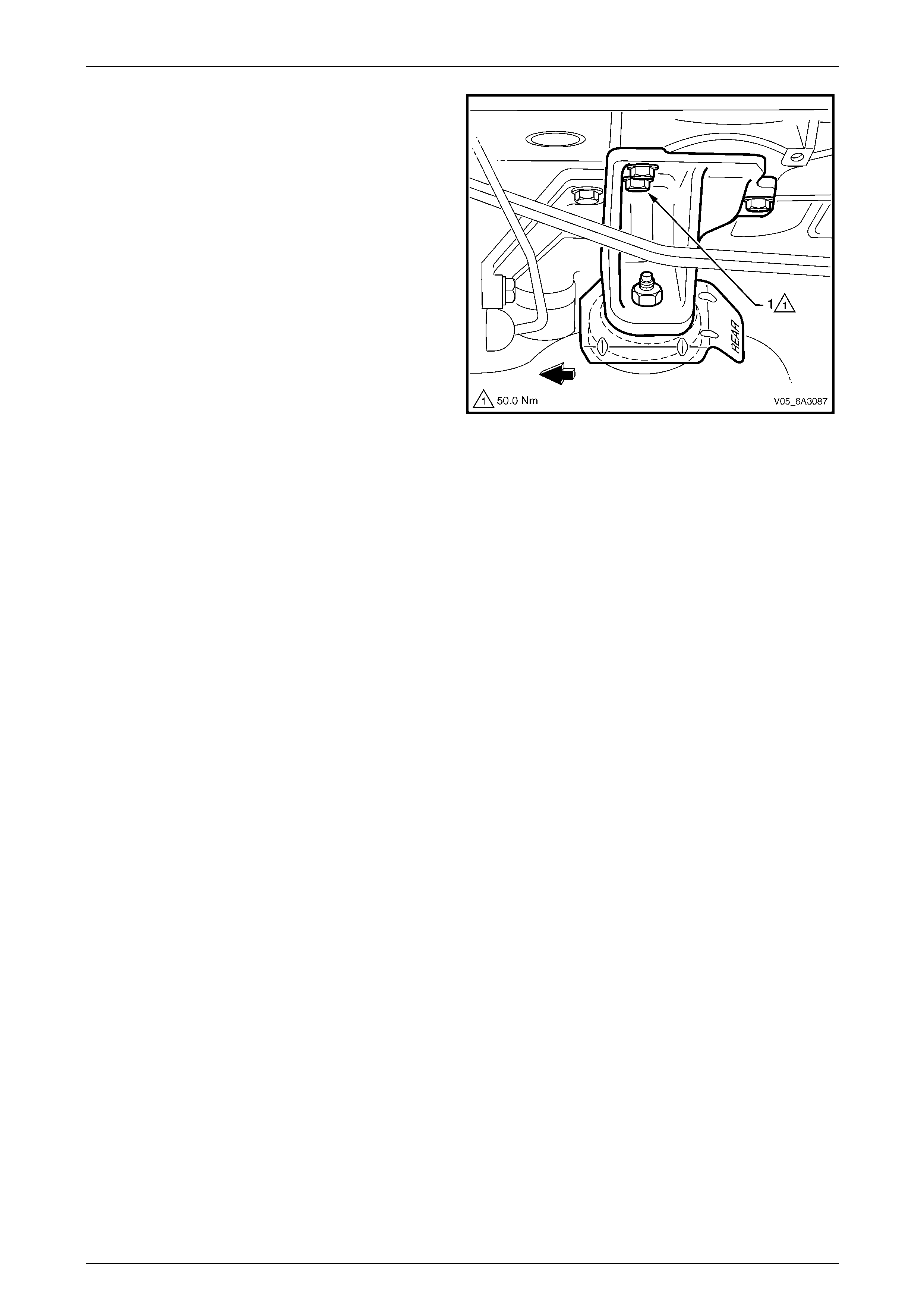
Engine Mechanical Page 6A4–155
Page 6A4–155
5 Remove the three bolts (1), attaching the left-hand
hydraulic engine mount bracket to the cylinder block
and set the bracket and mount, together with the heat
shield, to one side. Repeat for the remaining engine
mount.
6 Mount the engine in a suitable engine stand such as
Tool No AU 591 or similar. Preferab ly, use a stand that
will mount the engine from its side usi ng the engine
mount bracket bolt holes.
7 As required, remove the following:
• Clutch assembly, refer to Section 7A3 Clutch –
GEN IV V8.
• Power steering reservoir and pump, refer to
Section 9 Steering.
• Exhaust manifolds, refer to 4.14 Exhaust
Manifold.
• Coolant pump, refer to Section 6B3 Engine
Cooling – GEN IV V8.
• Ignition coils and bracket assembly, refer to
Section 6C4-3 Engine Management – GEN IV
V8 – Service Operations.
• Accessory and air conditioner drive belt idler
and tension pulley assem blies, refer to
4.6 Engine Drive Belts and Pulleys.
• Air conditioning compressor, refer to
Section 2C HVAC Climate Control (Manual A/C)
– Removal and Installation.
• Generator and mounting bracket, refer to
Section 6D3-1 Charging System – GEN IV V8.
Figure 6A4 – 224
Reassemble
Reassembly of the ancillar y c ompo nents for all vehicles is the reverse of the disassemble procedure noting the following:
1 Ensure all fasteners are tightene d to the correct torque specification, refer to 8 Torque Wrench Specifications or
refer to the specific Section for the particular component bei ng installed.
2 Ensure all transmission lines where fitted and power steering lines are free from obstruction and are not rubbing on
any components.
3 Tighten the transmission to engine attach ing bolts to the correct torque specification in the reverse order of the
removal procedure, refer to Figure 6A4 – 2 22.
4 Both close-out covers are installed.
5 The transmission filler tube where fitted is in stalled and sealed in the transmission correctly.
Reinstall Set-up and Testing
Reinstallation of the engine assembly is the reverse of removal procedure, noting the following:
1 Ensure that all fasteners where requ ir ed are either replaced or cleaned, thread seal ant is reapplied and they are
tightened to the correct torque specifications, refer to 8 Torque Wrench Specifications or refer to the specific
Section in the service information for the part icular component.
2 Use only the specified engine lubricant type and quantity.
3 Fill the cooling system with the correct quantity and grade of coolant, refer to Section 6B3 Engine Cooling – GEN IV V8
4 Check and top up the transmission fluid level as required, refer to either:
• Section 7C4 Automatic Transmission – 4L60E – On Vehicle Servicing
• Section 7B2 Manual Transmission – GEN IV V8
5 Disable the ignition system, refer to 3.7 Compression Ch eck and then crank the engine several times. Listen for
any unusual noises or evidence that parts are binding.
6 Enable the ignition system, start the engine and listen for unusual noises.
7 Check the vehicle oil pressure gauge or warning lamp and confirm the engine has an acceptable oil pressure. If
necessary, install an oil press ure ga uge and measure the engine oil pressure, refer to 3.5 Oil Pressure.
8 Run the engine speed at about 1,000 rpm until the engine has reached normal operating temperature.
9 Listen for sticking lifters and other unusual noises.

Engine Mechanical Page 6A4–156
Page 6A4–156
10 Check for oil, fuel, coolant and exhaust leak s while the engine is running, stopping the engine and correcting as
required.
11 Perform a final inspection for the correct engine oi l and coolant levels.
12 Reinstall the engine dress c over, refer to 4.2 Engine Dress Cover.
13 If required, ensure the engine hood alignment is correct, refer to Section 1A4 Hood, Rear Compartment Lid,
Liftgate & Endgate.

Engine Mechanical Page 6A4–157
Page 6A4–157
5.2 Engine Assembly, AWD
LT Section No. — 00–500
With the front engine components of the AWD system being attache d to the oi l pa n, the preferred method of removing
the engine from the vehicle, is to lower the engine, transmission/transfer case and front crossmember as a complete
assembly below the vehicle.
To perform this operation, it is recommended that a hydraulic scissor lift table with a capacity of 750 Kg or greater be
used. If this approach is used, then the engine hoo d does not need to be removed. However, if a scissor lift is not
available the engine hood will need to be removed to allow suitable overhead lifting equipment to be used to lower the
assembly from the vehicle.
There are many alternative methods for removing and reinstalling the engine, transmissio n/transfer case and
crossmember assembly. However, the procedure describ ed in this Section is the preferred method and allows the
braking system hydraulics to remain intact, eliminating the need to perform lengthy bleeding procedures. This procedure
also eliminates the need for two e xtra people to support the front suspension strut legs during the removal and
reinstallation procedure. The suspension struts once disconnected from the steering arms are supported in the vehicle
using wooden props against the wheelhouse panel. However, if circumstances require the removal of the front
suspension struts from the vehicle, the service procedure described in this Section will need to be modified accordingly
by the technician performing the service operation.
When diverting from the procedures describ ed, refer to the appropriate Section in the service information for the relevant
service procedures. Examples of these Sections would be:
• Section 3 Front Suspension
• Section 5A Service and Park Braking Systems
• Section 5B AWD ABS – TCS
• Section 9 Steering
Disconnection of the battery affects certain
vehicle electronic systems. Refer to
Section 00 Warnings, Cautions and Notes
before disconnecting the battery.
Remove
1 Disconnect the battery ground terminal from the battery.
• Do not remove the screw-on pressure cap
while the engine coolant temperature is
above 50° C, as personal injury could
occur.
• Throughout this Section spring type hose
clamps are required to be removed, always
wear eye protection when handling spring
type clamps to avoid possible eye inju ry.
2 Allow the engine to cool to ambient temperature (less than 50°C) and slowly remove the screw-on pressure cap
from the radiator, refer to Section 6B3 Engine Coo ling GEN IV V8.
3 Remove the strut tower brace, refer to Section 1A1 Body.
4 Remove the air intake duct, refer to 4.1 Air Intake Duct
5 Remove the engine dress covers, refer to 4.2 Engine Dress Cover.
6 Refer to Section 6B3 Engine Cooling – GEN IV V8 and remove the following:
• Top and lower radiator hos es from the engi ne and radiator
• Radiator fan and shroud assembl y
• Radiator
7 Remove the accessory and air conditioner drive belts, refer to 4.6 Engine Drive Belts and Pulle ys.
8 Recover the refrigerant charge and disconnect the suction/discharge hose pad from the air conditioner compressor,
refer to Section 2C HVAC Climate Control (Manual A/C) – Remov al an d Installation.
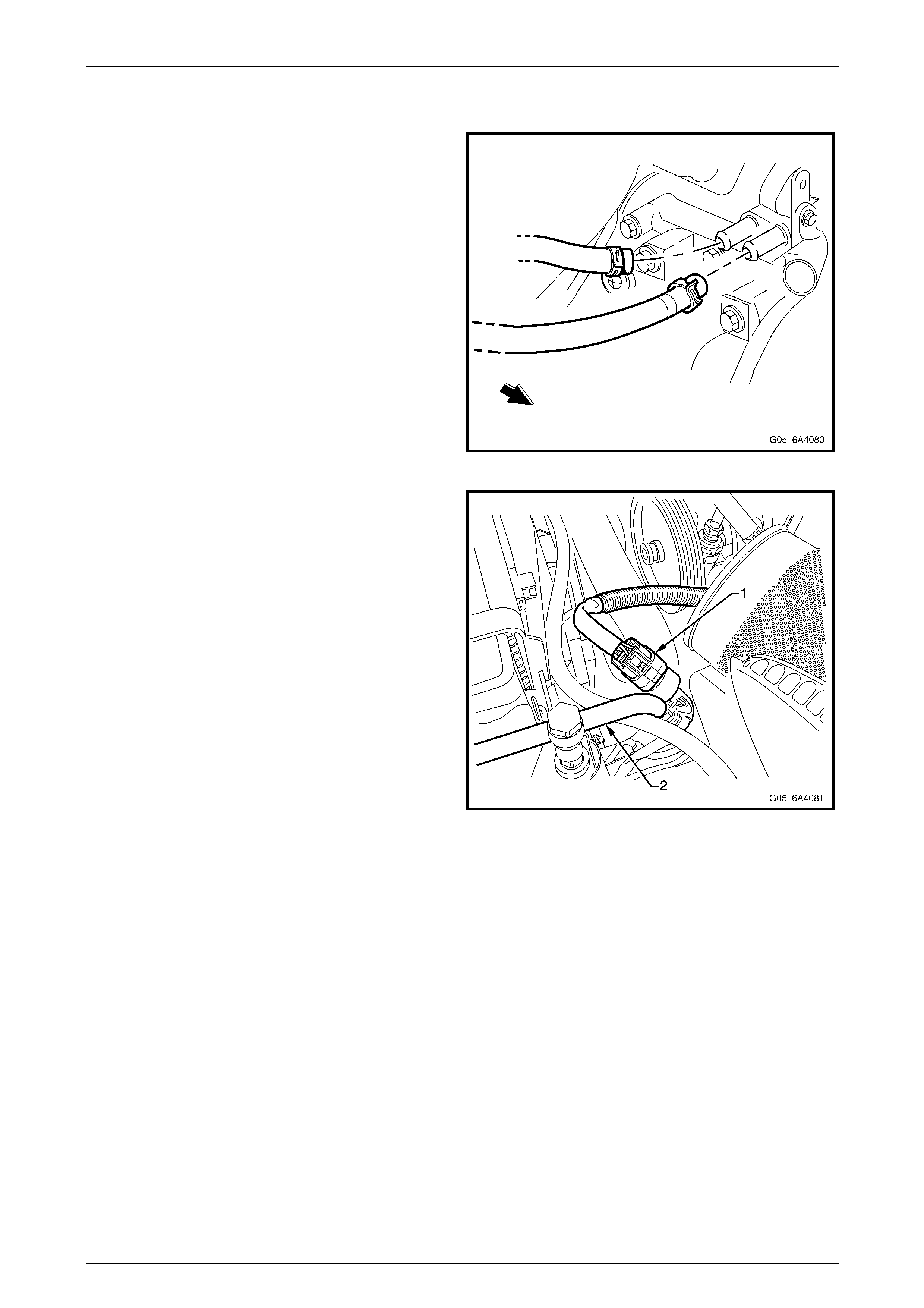
Engine Mechanical Page 6A4–158
Page 6A4–158
9 Drain the engine oil into a suit able container and reinstall the drain plug once the oil has drained sufficiently. Refer
to 4.3 Engine Oil and Filter.
10 Remove the heater hose clamps at the engine water
pump, taking note of the hose layout. Plug the open
ends to prevent the entry of foreign material.
NOTE
If required, mark the hoses prior to removal with
a paint pen or similar.
11 Remove the ground le ad to the engine cylinder block
and from the left hand engine mount and remove the
positive terminal from the battery and lay the harness
on the engine, refer to Section 12O Fuses, Relays and
Wiring Harnesses.
Figure 6A4 – 225
12 Disconnect the air conditioning pressure switch and
front wiring harness connector (1), which is attached
to the A/C condenser pipe (2).
13 Disconnect the Engine Interface Module (PIM) wiring
harness connector and front body harness connector.
Refer to Section 12O Fuses, Relays and Wir ing
Harnesses.
14 Release the harness to dash panel grommet and feed
the harness and connectors out into the engi ne bay
and place the Engine wiring harness on top of the
engine.
15 Referring to Figure 6A4 – 227, remove or disconn ect
the following:
a Engine wiring harness retaining clips (1) from
the engine compartment dash pan el.
b Wiring harness connector (2) from the theft
deterrent horn.
c Cover (3) from the Engine Control Module
(ECM) (4).
d Two screws (5) retaining the ECM wiring
harness connectors to the ECM.
e ECM wiring harness retaining clip (6) from the
ECM container to free the harness.
Figure 6A4 – 226

Engine Mechanical Page 6A4–159
Page 6A4–159
Figure 6A4 – 227
16 De-pressurise the fuel line. Re fer to Section 8A1 Fuel
System.
17 Using a small scre wdriver, release the s ecurity lock
(1), at each of the fuel supply hose quick connect
fittings (2).
NOTE
The security lock at the fuel rail side is fitted with
a tether to prevent loss.
Figure 6A4 – 228
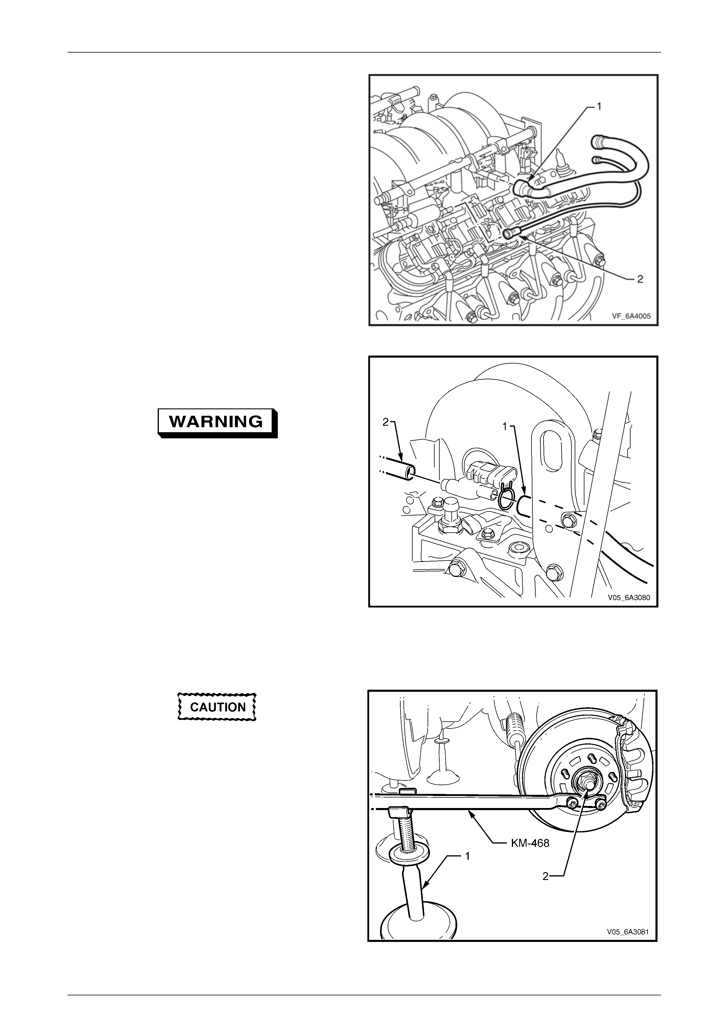
Engine Mechanical Page 6A4–160
Page 6A4–160
18 Remove the fuel line quick connector (1) from the fuel
rail, refer to Section 6C4-3 Engine Managem ent –
GEN IV V8 – Service Operations.
19 Disconnect the vapour line co nnection (2) to the EVAP
purge control valve and place it to one sid e.
NOTE
Plug all openings to prevent fuel leaking and
foreign matter from entering the fuel system.
Figure 6A4 – 229
20 Disconnect the brake booster vacuum hose (1) and
HVAC control vacuum hose (2) from the rear of the
intake manifold.
If using a hoist during the engine removal
procedure, ensure the vehicle is positioned
correctly so that it remains balanced when
the engine, transmission and crossmember
assembly is remo ved from the vehicle.
Figure 6A4 – 230
21 Raise the vehicle front and rear and su pport on safety stands or ensure the vehicle is positioned correctl y on a
hoist. For the location of vehicle lifting and support locations, refer to Section 0A General Information.
22 Remove the front road wheels, refer to Section 10 Wheels and Tyres.
Do not use the tapered side of the wheel nut
as possible damage to the wheel nut and/or
stud may occur.
23 Attach holding Tool KM-468 to the front wheel hub
with two inverted wheel nuts. Support the tool on a
safety stand (1).
24 Using suitable socket equipment, loosen and remove
the driveshaft attaching nut (2) and flat washer.
NOTE
Discard the removed nut as a new nut must be
installed in the reinstallati on procedure.
25 Remove the holding tool and reinstall an inverted nut
to retain the front rotor to the hub assembly. Figure 6A4 – 231
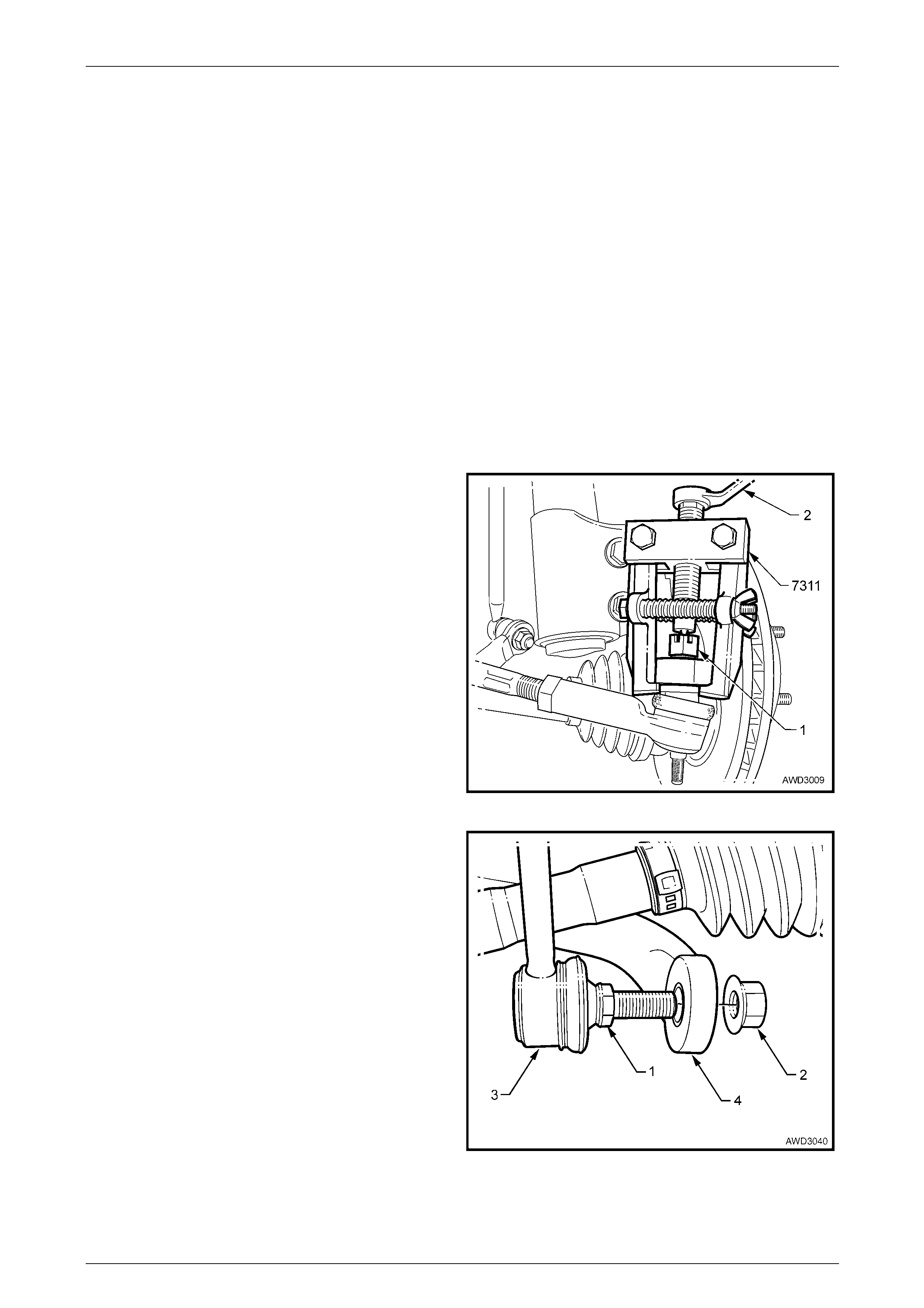
Engine Mechanical Page 6A4–161
Page 6A4–161
26 Remove the front plastic air baffles from the front bumper and front suspension cradle, refer to
Section 6B3 Engine Cooling – GEN IV V8.
27 Remove the rear propeller shaft, refer to Section 4C1 Rear Propeller Shaft and Universal Joints.
28 Disconnect the gearshift control cable from the transmissio n bracket and the selector lever. Refer to
Section 7C4 Automatic Transmission – 4L60E – On Vehicle Servicing.
NOTE
To prevent oil leaking from the front final drive
when the driveshaft is removed, either plug the
seal opening in the front final drive or if required,
drain the lubricant prior to removal of the
driveshaft.
29 Remove both front driveshafts from the vehicle, refer to Section 4B3 Front Final Drive and Driveshafts.
NOTE
The procedure for separating the ball joint is
included within the front driveshaft procedure.
30 With the lower ball joint disconnected, insert a suitable length wooden prop with a 'V' cut out of the outer end to
support the front suspension strut and hub assembly against the inner wheelhouse.
31 Remove the split pin from the outer tie rod end
castellated nut (1) and loosen the nut until it is flush
with the end of the tie rod end stud.
32 Using the tie rod ball joint remover Tool No. 7311 and
a ring spanner (2) separate the outer tie rod end stud
from the steering knuckle. Repeat for the op posite
side.
Figure 6A4 – 232
33 Using a second spanner, hold the stabiliser bar link
inner stud hexagonal (1). With a second spanner,
remove the nut (2) attaching the li nk (3) to the
stabiliser bar (4). Repeat for the remaini ng side.
Figure 6A4 – 233
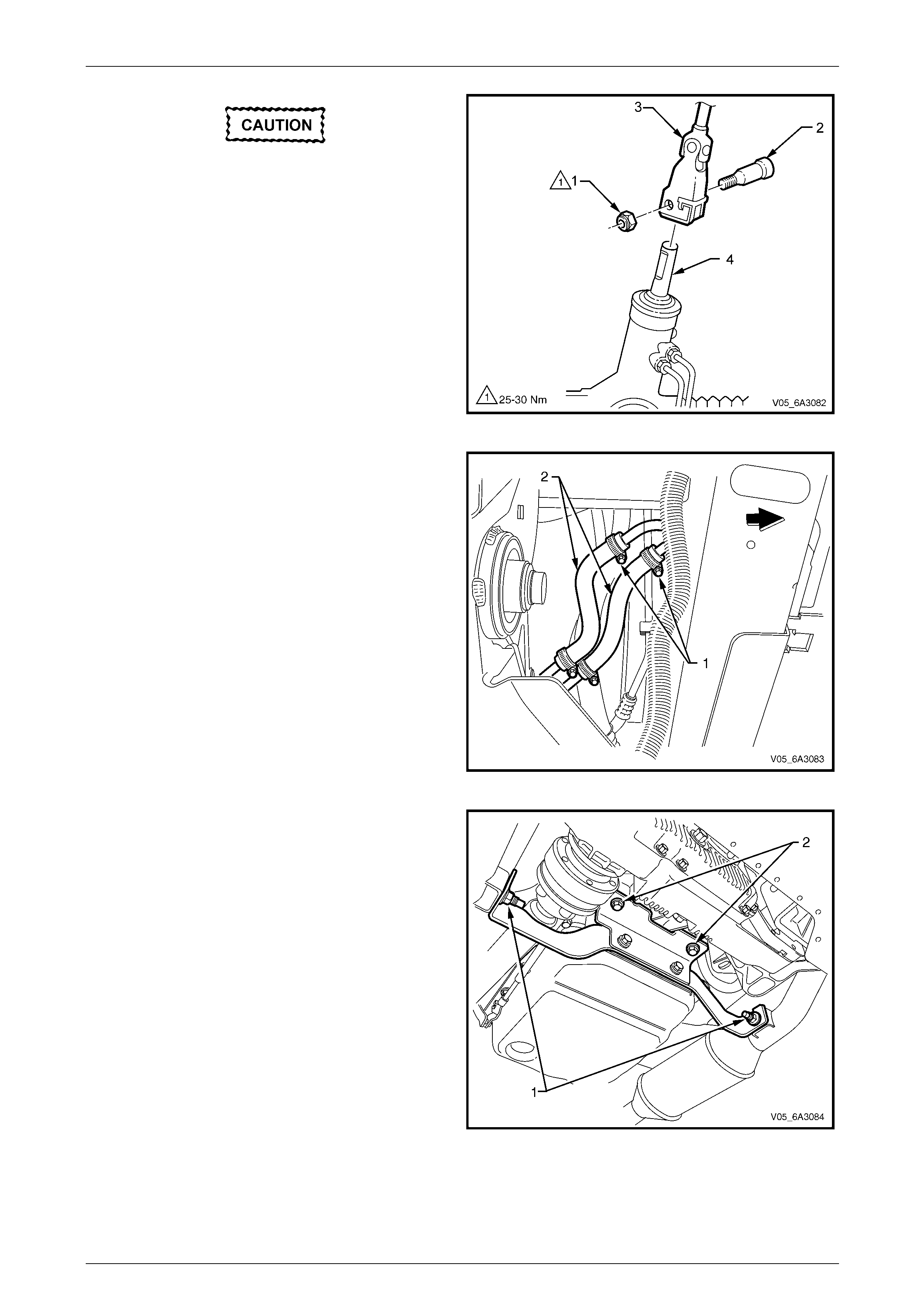
Engine Mechanical Page 6A4–162
Page 6A4–162
Ensure the ignition key is turned to the lock
position and the key is removed before
disconnecting the steering column coupling.
This will prevent the steering column from
rotating when the coupling is removed and
damaging the clock spring.
34 Remove the lower steering coupling cam bolt retaining
nut (1) and discard.
35 Remove the cam bolt (2) from the lower coupling (3).
36 Pull on the coupling to free it from the steering rack
input shaft (4).
Figure 6A4 – 234
37 From under the vehicle, loosen the p ower steering
cooler line hose clamps (1) and disconnect both hoses
(2). Plug all openings to prevent fluid loss and/or dirt
entry.
Figure 6A4 – 235
38 Remove the two nuts (1) attaching the exhaust pipe
bracket to each catalytic converter.
39 Remove the two bolts (2) attaching the bracket to the
transfer case adaptor housing and remove the bracket
from the vehicle.
40 Remove the front exhaust assemblies, refer to
Section 8B Exhaust Systems.
Figure 6A4 – 236
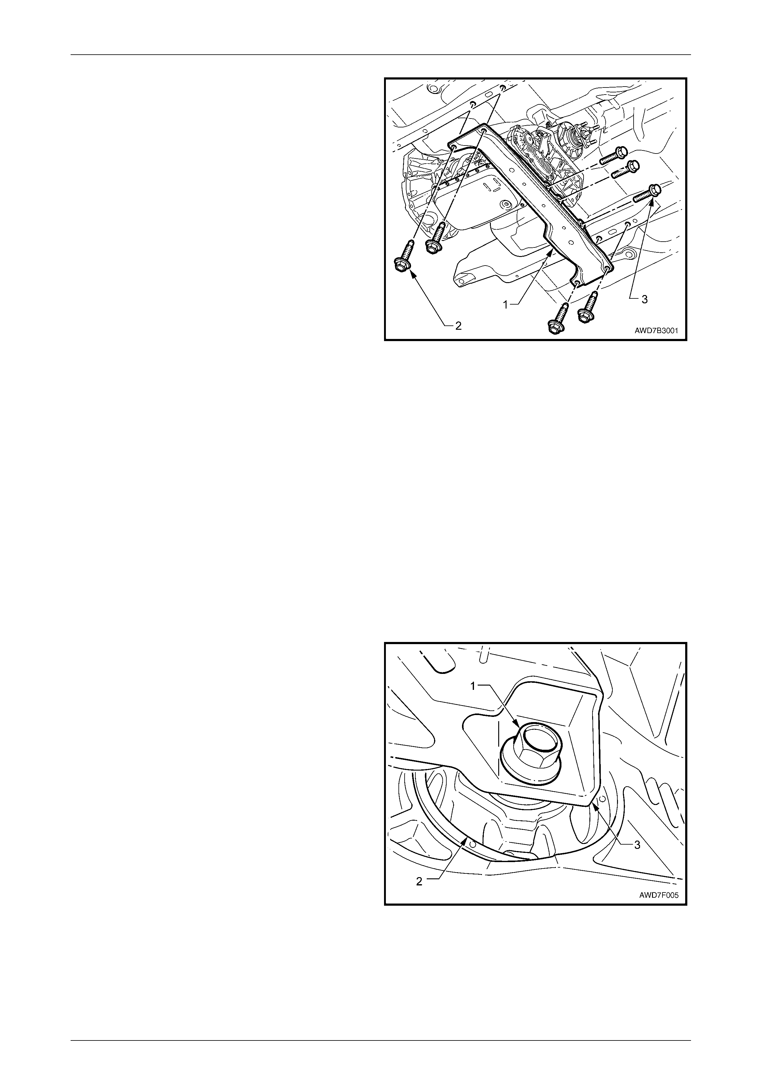
Engine Mechanical Page 6A4–163
Page 6A4–163
41 Using a felt tipped pen or similar (e.g. Paint marker),
mark the position of the rear crossmember (1) to the
underbody side rails.
NOTE
This will assist in realigning the crossmemb er on
reinstallation.
42 Remove the four bolts (2) attaching the rear
crossmember to the underbody side rails.
43 Remove the three bolts (3) attaching the rear
crossmember to the transfer case mounting bracket
and remove the crossmember from the vehicle.
NOTE
Support of the transmission is not required at
this stage.
Figure 6A4 – 237
NOTE
A suitable size block of wood may be needed to
help support the rear of the transmission and
keep it level.
44 Using a commercially available hydraulic scissor lift mobile trolley of 750 kg capacity, pos ition the lift centrally under
the engine, transmission and crossmember assembly and support the front suspension cradle.
NOTE
If a suitable scissor lift is not available, an
alternative would be to use suitable lifting
equipment to support and lower the engine from
above using the two engine lifting brackets
attached to the cylinder heads. This procedure
requires the removal of the hood, refer to
Section 1A4 Hood, Rear Compartment Lid,
Liftgate and Endgate.
45 With the front suspension cradle, engine and
transmission/transfer case assembly supported,
remove the bolt (1) attaching the transfer case rubber
mount (2) to the transfer case rear mounting bracket
(3).
Figure 6A4 – 238
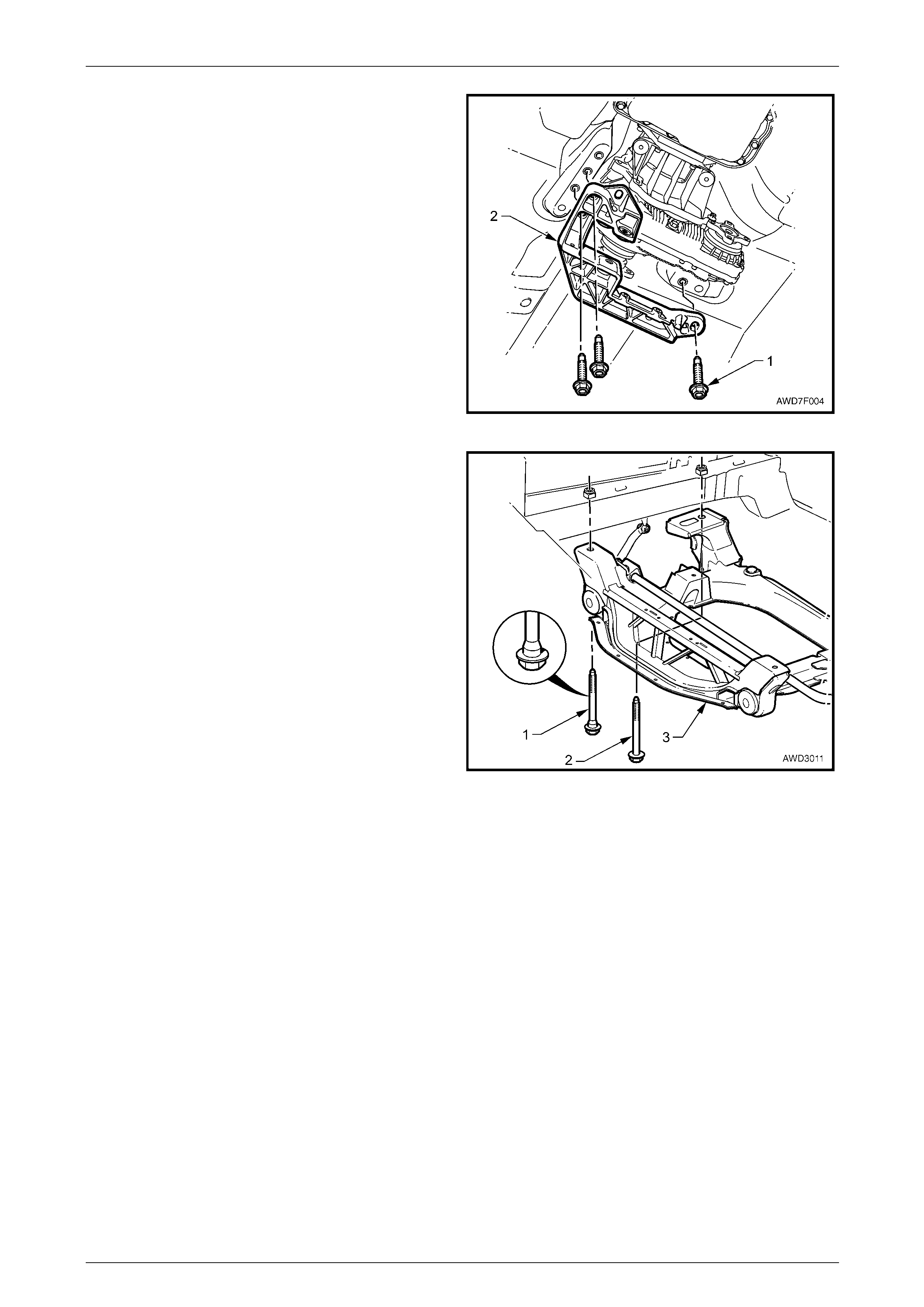
Engine Mechanical Page 6A4–164
Page 6A4–164
46 Using a felt tipped pen or similar (e.g. paint marker),
mark the position of the transfer case rear mounting
bracket to the vehicle underbody.
NOTE
This will assist in realigning th e mounti ng br acket
on reinstallation.
47 Remove the three bolts (1) attaching the transfer case
rear mounting bracket (2) to the vehicle underbody
and remove the rear mounting bracket from the
vehicle.
Figure 6A4 – 239
48 Mark the location of the front crossmember cradle to
the side rails and remove the four bolts (1 and 2),
attaching the crossmember cradle (3) to the side ra il
members.
NOTE
The engine is not shown in this view to clearly
show the front suspension cradle attaching bolt
locations.
49 Lower and remove the engine, transmission/transfer
case and crossmember assembly from under the
vehicle.
NOTE
During the lowering process ensure that all
wiring harnesses, hoses or other accessories
have been disconnected and are not caught by
the body or the engine, transmission/transfer
case and crossmember assembly. Figure 6A4 – 240
Disassemble – Ancillary Equipment
The engine removal and rei nstallation procedures cover the removal and reinstallation of the engine, transmission /
transfer case and front crossmember as a complete assembly. To perform major service operations, the engine and
transmission / transfer case has to be separated and the ancillary equipment that is attached to the engine removed.
Once all ancillary components and the transmission / transfer case have been removed, major e ngine service operations
can be performed by referring to the appropriate major service operation.
1 Remove the wiring harness conn ectors and earth connections from the engine and transmission assembl y and
carefully set the wiring harness to one side. For wiring harness informati on, refer to Section 12O Fuses, Relays and
Wiring Harnesses.
2 Remove the front propeller shaft from the transfer case and the front final drive, refer to
Section 4C2 Front Propeller Shaft and Universal Joints.
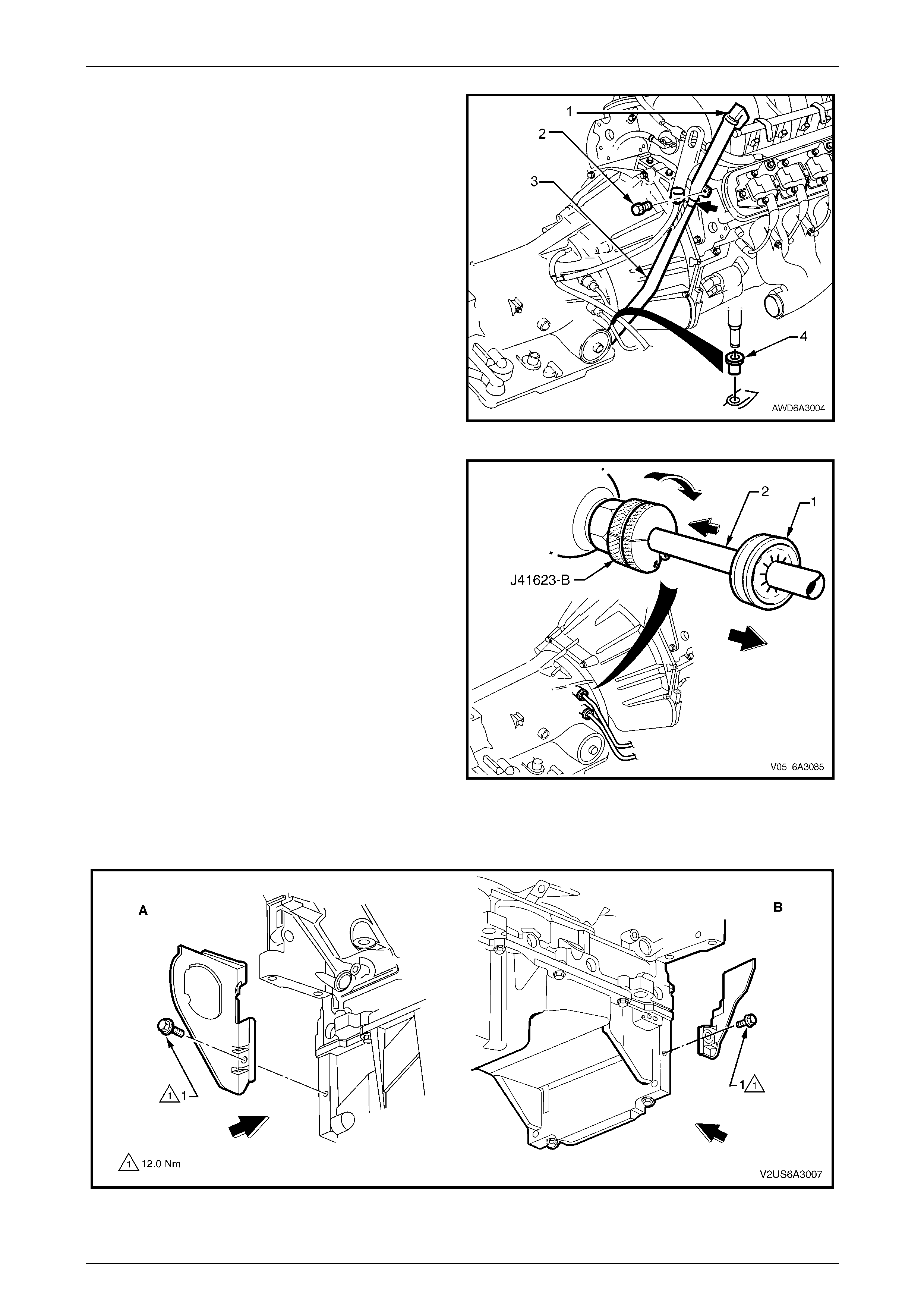
Engine Mechanical Page 6A4–165
Page 6A4–165
3 Release the indicator lock down lever (1) and remove
the transmission indicator.
4 Remove the bolt (2) attaching the transmissio n filler
tube to the right-hand cylinder head.
5 Release the transmission breather tube (3) from the
indicator bracket (arrow).
6 Using a twisting/pulling motio n, remove filler tube (3)
from transmission case seal (4). Set the filler tube to
one side.
7 Plug the filler tube opening in the automatic
transmission.
8 Remove the starter motor, refer to Section 6D3 – 2
Starting System GEN IV V8.
Figure 6A4 – 241
9 Disconnect transmission cooler lines from the
transmission end, as follows:
a Release the verifier disc (1) by pulling b ack with
your fingertips and slide th e disc back down the
cooler line (1).
b Open the cooler line releas e T ool J-41623-B and
slip it over the cooler line to be disconnected
from the transmission ahead of the verifier disc
as shown.
c Slide the release tool along the line to engage
with the quick-connect fitting.
d While pushing in wards, rotate the tool about one
sixth of a turn clockwise to release the s pring clip
holding the line.
e With the release tool held in this position, pull
back on the cooler line to release. Repeat this
process with the remaining line and quick-
connect fitting.
f Plug all openings to prevent fl uid loss and/or dirt
entry Figure 6A4 – 242
10 Remove the right-hand (A) and left-hand (B) close-out cover attaching bolts (1) and remove the cover (2). Refer to
Figure 6A4 – 243.
Figure 6A4 – 243
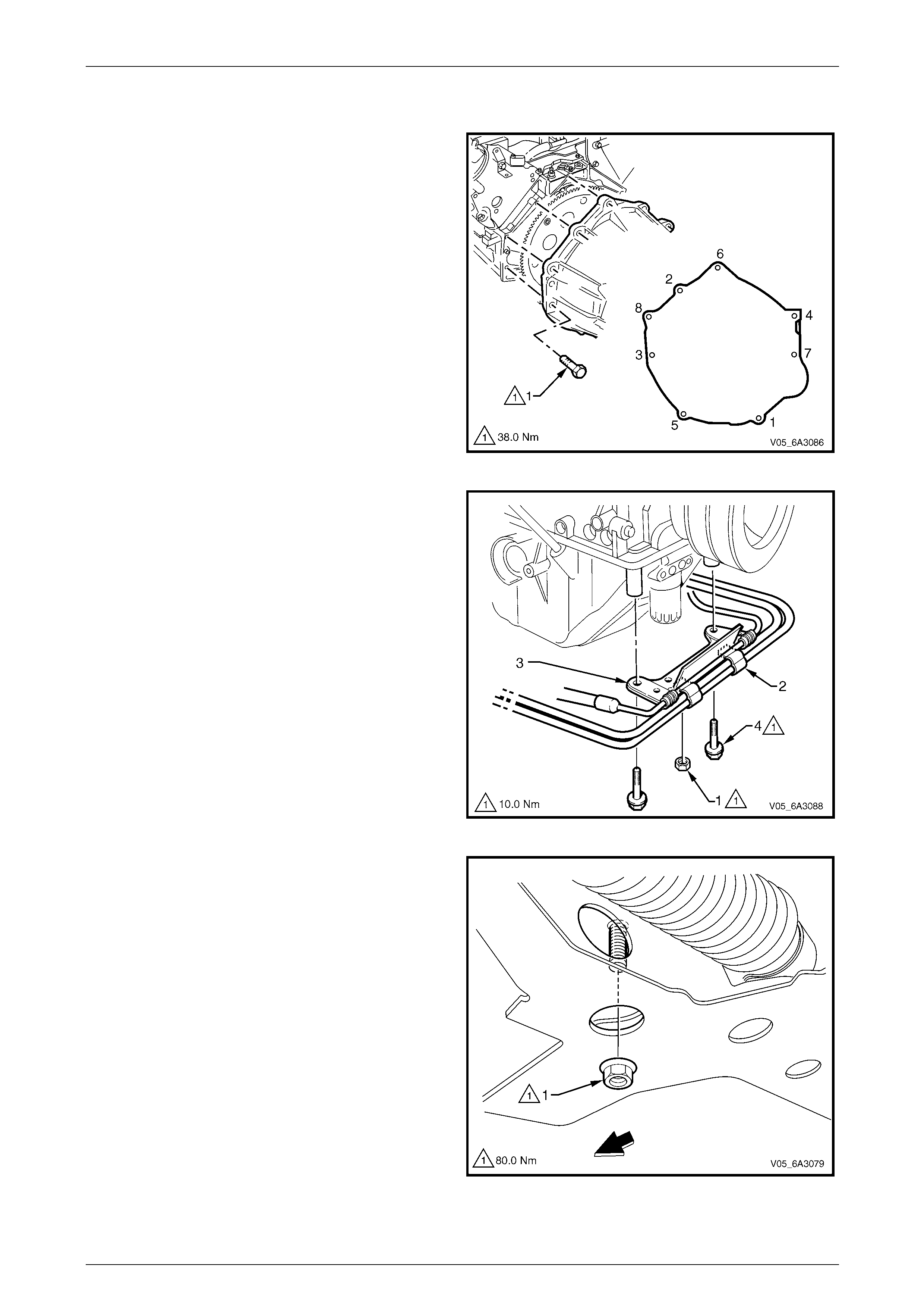
Engine Mechanical Page 6A4–166
Page 6A4–166
11 Remove the three bolts attaching the torque converter to the engine flexplate, using the right-hand side close- out
cover opening for access to the bolts.
12 Remove the bolt (1), eight places, attaching the
transmission housing to the engine assembly and then
slide or lift the transmission/transfer case assembly
free from the rear of the engine.
NOTE
Ensure the torque converter stays with the
transmission when the transmission is being
removed from the engine assembly.
Figure 6A4 – 244
13 Remove the nut (1), two places, attaching the
transmission cooling lines (2) to the power steering
hose bracket (3) and remove the transmission cooling
lines.
14 Remove the two bolts (4) attaching the power steering
hose bracket to the oil pan and lower it away from the
oil pan.
Figure 6A4 – 245
15 Remove the nut (1) attaching the engine mount to the
front crossmember cradle. Repeat for the other side
engine mount.
Figure 6A4 – 246

Engine Mechanical Page 6A4–167
Page 6A4–167
NOTE
Using suitable lifting equipment attached to the
engine lifting brackets, ensure the engine is
supported before removing the eng ine mounts.
16 Remove the three bolts (1) attaching the left-hand
engine mount bracket to the cylinder bl ock and set the
bracket and hydraulic mount, together with the heat
shield, to one side. Repeat for the other engine mount.
17 Use suitable lifting equipment fitted to the engine lifting
brackets and lift the engine clear from the front
suspension crossmember cradle
18 Mount the engine in a suitable engine stand such as
Tool No AU 591 or similar. Preferab ly, use a stand that
will mount the engine from its side usi ng the engine
mount bracket bolt holes.
Figure 6A4 – 247
19 As required, remove the following:
• Power steering reservoir and pump, refer to Section 9 Steering .
• Drive shaft bearing support and front final drive, refer to Section 4B3 Front F inal Drive and Drive Shafts.
• Exhaust manifolds, refer to 4.14 Exhaust Manifold.
• Coolant pump, refer to Section 6B3 Engine Cooling – GEN IV V8.
• Ignition coils and bracket assembly, refer to Section 6C4 Engine Managem ent – GE N IV V8 – Service Operations.
• Accessory and air conditioner drive belt idler and tension pulley assemblies, refer to
4.6 Engine Drive Belts and Pulleys.
• Remove the air conditioning compressor, refer to Section 2B HVAC Climate Control (Manual A/C) Servicing
and Diagnosis.
• Generator and mounting bracket, refer to Section 6D3-1 Charging System GEN IV V8.
Reassemble
Reassembly of the ancillar y c ompo nents for all vehicles is the reverse of the disassemble procedure noting the following:
1 Ensure all fasteners are tightene d to the correct torque specification, refer to 8 Torque Wrench Specifications or
refer to the specific Section for the particular component bei ng installed.
2 Ensure all transmission lines where fitted and power steering lines are free from obstruction and are not rubbing on
any components.
3 Tighten the transmission to engine attach ing bolts to the correct torque specification in the reverse order of the
removal procedure, refer to Figure 6A4 – 2 44.
4 Both close-out covers are installed.
5 The transmission filler tube where fitted is in stalled and sealed in the transmission correctly.
6 Ensure the front propeller shaft is reinstalled in the correct locatio n as ma rked in the removal procedure.
Reinstall Set-up and Testing
Reinstallation of the engine, transmission/transfer case and front crossmember assembly is the reverse of removal
procedure, noting the follo wing:
1 Ensure that all fasteners where requ ir ed are either, replaced or cleaned, thread sealant is reapplied and they are
tightened to the correct torque specifications, refer to 8 Torque Wrench Specifications or refer to the specific
Section in the service information for the part icular component.
2 Use only the specified engine lubricant type and quantity.
3 Fill the cooling system with the correct quantity and grade of coolant, refer to Section 6B3 Engine Cooling – GEN IV V8
4 Check and top up the transmission fluid level, as required refer to Section 7C4 Automatic Transmission – 4L60E –
On Vehicle Servicing.
5 Disable the ignition system, refer to 3.7 Compression Ch eck and then crank the engine several times. Listen for
any unusual noises or evidence that parts are binding.
6 Enable the ignition system, start the engine and listen for unusual noises.
7 Check, the vehicle oil pressure gauge or warning lamp and confirm the engin e has a n acceptable oil pressure. If
necessary, install an oil press ure ga uge and measure the engine oil pressure, refer to 3.5 Oil Pressure.

Engine Mechanical Page 6A4–168
Page 6A4–168
8 Run the engine speed at about 1,000 rpm until the engine has reached normal operating temperature.
9 Listen for sticking lifters and other unusual noises.
10 Check for oil, fuel, coolant and exhaust leak s while the engine is running, stopping the engine and correcting as
required.
11 Perform a final inspection for the correct engine oi l and coolant levels.
12 Reinstall the engine dress c over, refer to 4.2 Engine Dress Cover.
13 If required, ensure the engine hood alignment is correct, refer to Section 1A4 Hood, Rear Compartment Lid,
Liftgate & Endgate.
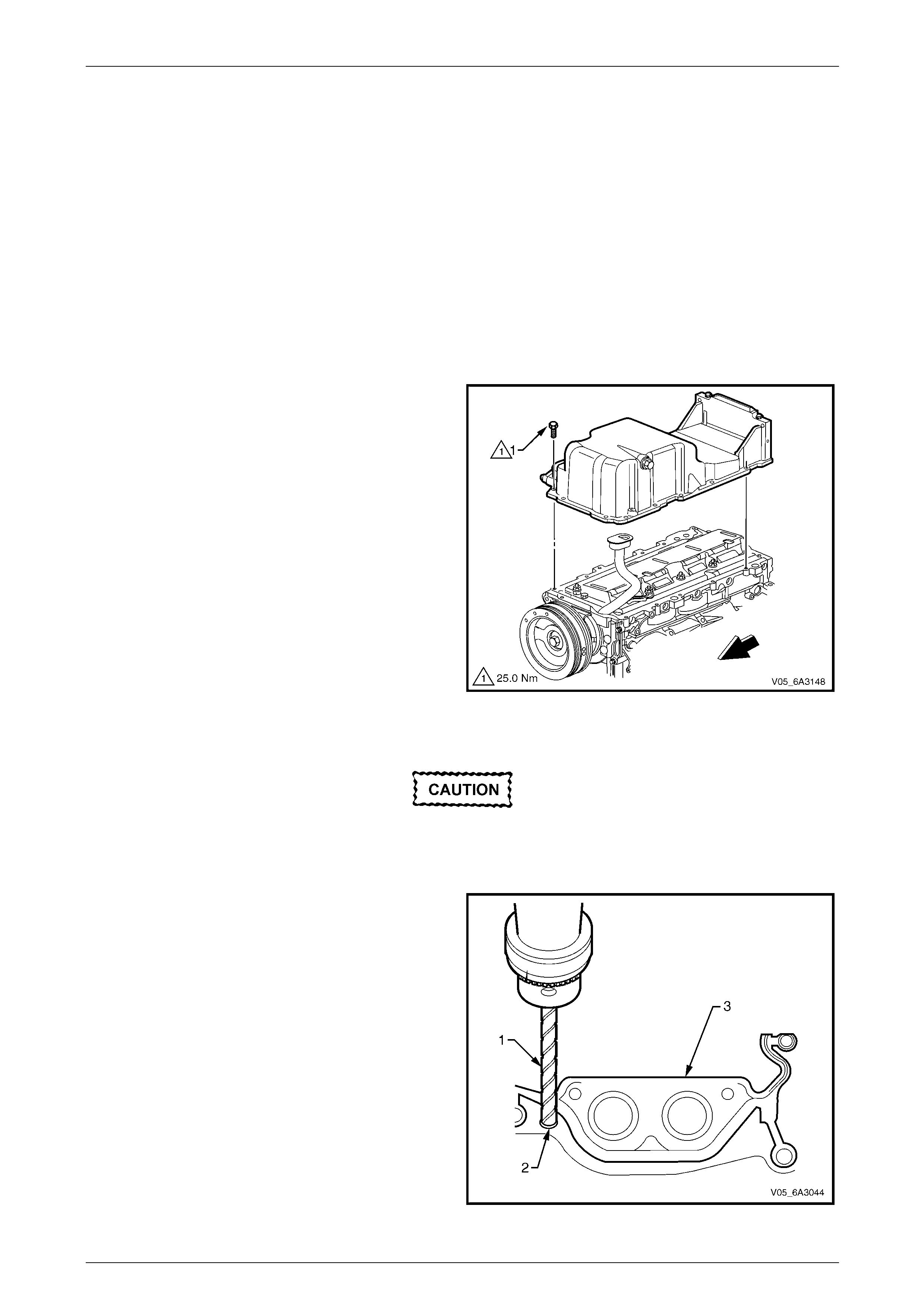
Engine Mechanical Page 6A4–169
Page 6A4–169
5.3 Oil Pan Assembly, Except AWD
LT Section No. — 00–275
Remove
NOTE
Due to the critical alignment procedures required
for oil pan installation, it is strong ly recommended
the engine assembly be removed from the
vehicle before the oil pan is removed.
1 Remove the engine from the vehicle and if required, mount the engine in an engine stand such as Tool No.
AU 591. Refer to 5.1 Engine Assembly.
2 Remove the flywheel/flexplate, refer to 5.6 Engine Flywheel and Flexplate.
3 Ensure the oil pan has drained completely and if required, place a suitable sized container underneath the engine.
4 Invert the engine assembly.
5 Remove the oil pan attaching bolt (1), 14 places, by
loosening grad ually from the outside and working
inwards toward the centre.
6 Tap the oil pan side ways with a rubber mallet to
dislodge the seal.
Figure 6A4 – 248
Disassemble
Do not allow metal shavings or other foreign
material to enter the oil passages in the oil
pan during gasket removal. Plug all openings
before commencing drilling operations.
1 Use a sharp twist drill (1), drill out each of the oil pan
gasket retaining rivets (2) as required.
2 Remove the oil pan gasket (3) from the oil pan and
discard the gasket and rivets.
NOTE
The original oil pan gasket is retained and
aligned to the oil pan by rivets for production
purposes only. When installing a new gasket as
a service replacement, it is not necessary to
install new oil pan gasket rivets.
Figure 6A4 – 249
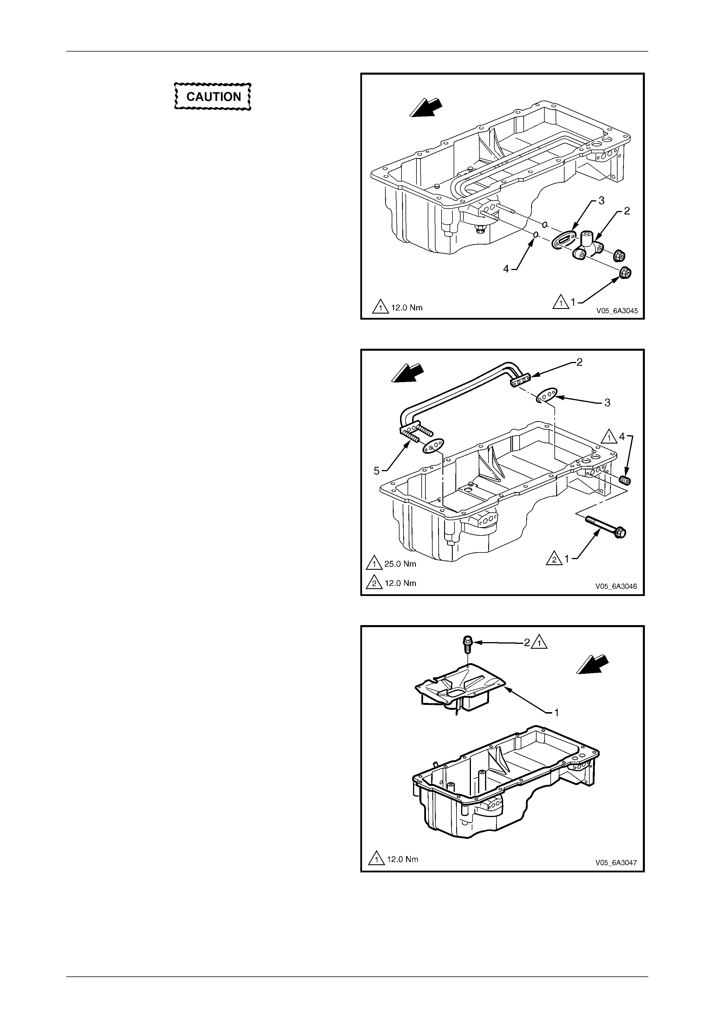
Engine Mechanical Page 6A4–170
Page 6A4–170
If the removal of the oil transfer cover
attaching nuts is required while the oil pan is
still installed (e.g. during fitment of an
external oil cooler), the studs must not be
removed. Otherwise, the transfer pipes and
gasket inside the oil pan may become
dislodged.
3 Remove the two oil transfer cover attaching nuts (1),
cover (2), and gasket (3) and discard the gasket.
4 Remove the two O-rings (4) and discard.
Figure 6A4 – 250
5 Remove the bolt (1), two places, attaching the oil filter
transfer tubes.
6 Remove the oil filter transfer tubes (2) and discard the
gaskets (3).
7 If required, remove the oil gallery plug (4).
NOTE
Due to the thread sealant applied to th e threads,
it is recommended the front studs (5) remain
attached to the transfer tube assembly and the
whole assembly withdrawn from inside the oil
pan.
Figure 6A4 – 251
8 Remove the oil pan baffle plat e (1) attaching bolts (2),
six places and remove the baffle.
Figure 6A4 – 252
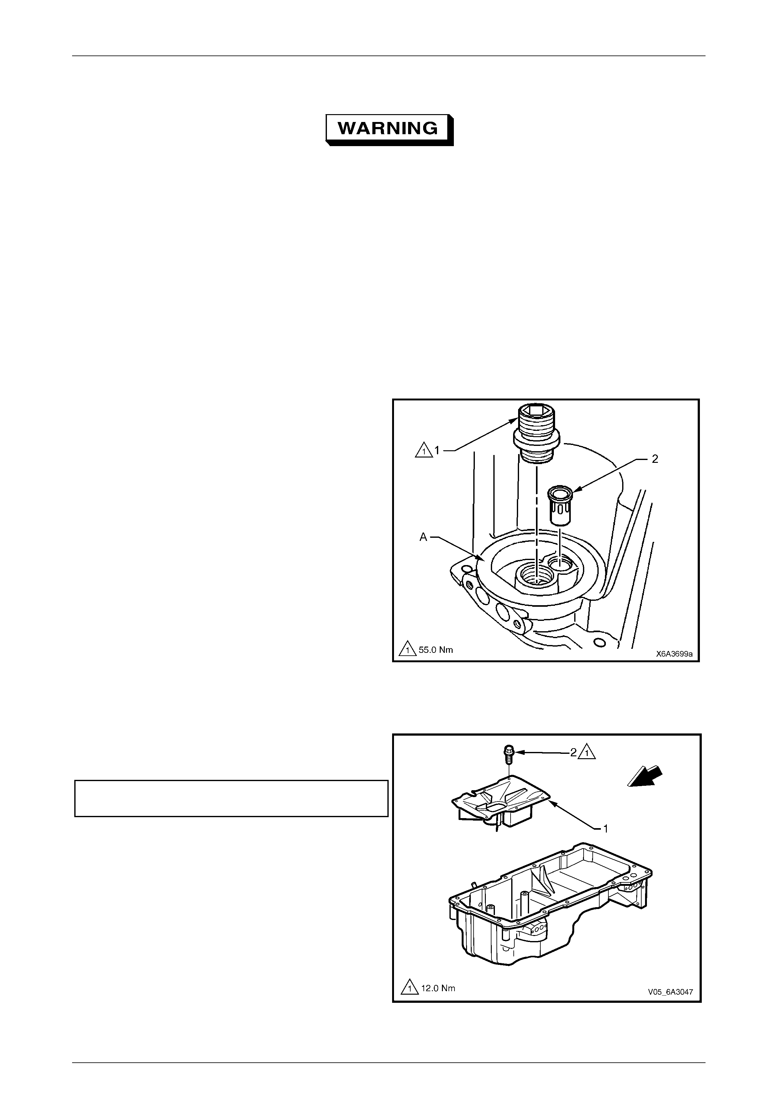
Engine Mechanical Page 6A4–171
Page 6A4–171
Clean and Inspect
To avoid personal injury, wear safety glasses
and the appropriate gloves when using
compressed air and cleaning fluids.
1 Clean the oil pan in a commercially available cleaning fluid and blow dry using compressed air.
2 Ensure that all oil passages and recesses are thoroughly cleaned.
3 Clean the oil pan gasket surfaces, using a p lastic scraper to avoid scratching or damaging the machined surfaces.
4 Inspect the oil pan for the following:
• Gasket sealing surfaces for excessive scratches or go uging
• Oil pan drain plug an d threaded drain hole for damaged threads
NOTE
The drain plug O-ring seal may be reused if not
cut or damaged.
• Oil filter sealing surface (A) for scratches or
gouging
• Oil filter adaptor (1) for a loose fit or damaged
threads
• Oil passages for restrictions
• Oil filter bypass valve (2) located in the oil filter
flange for correct operation by lightly pushi ng the
bypass valve into the bore, when released the
valve spring should reseat the valve to the
proper position.
5 Inspect the oil transfer tube for damage or restrictions.
Figure 6A4 – 253
Reassemble
1 Install the oil pan baffle plate (1) and the attaching
bolt (2), six places, tightening the bolts to the correct
torque specification.
Oil pan baffle attaching bolt
torque specification............................................12.0 Nm
Figure 6A4 – 254
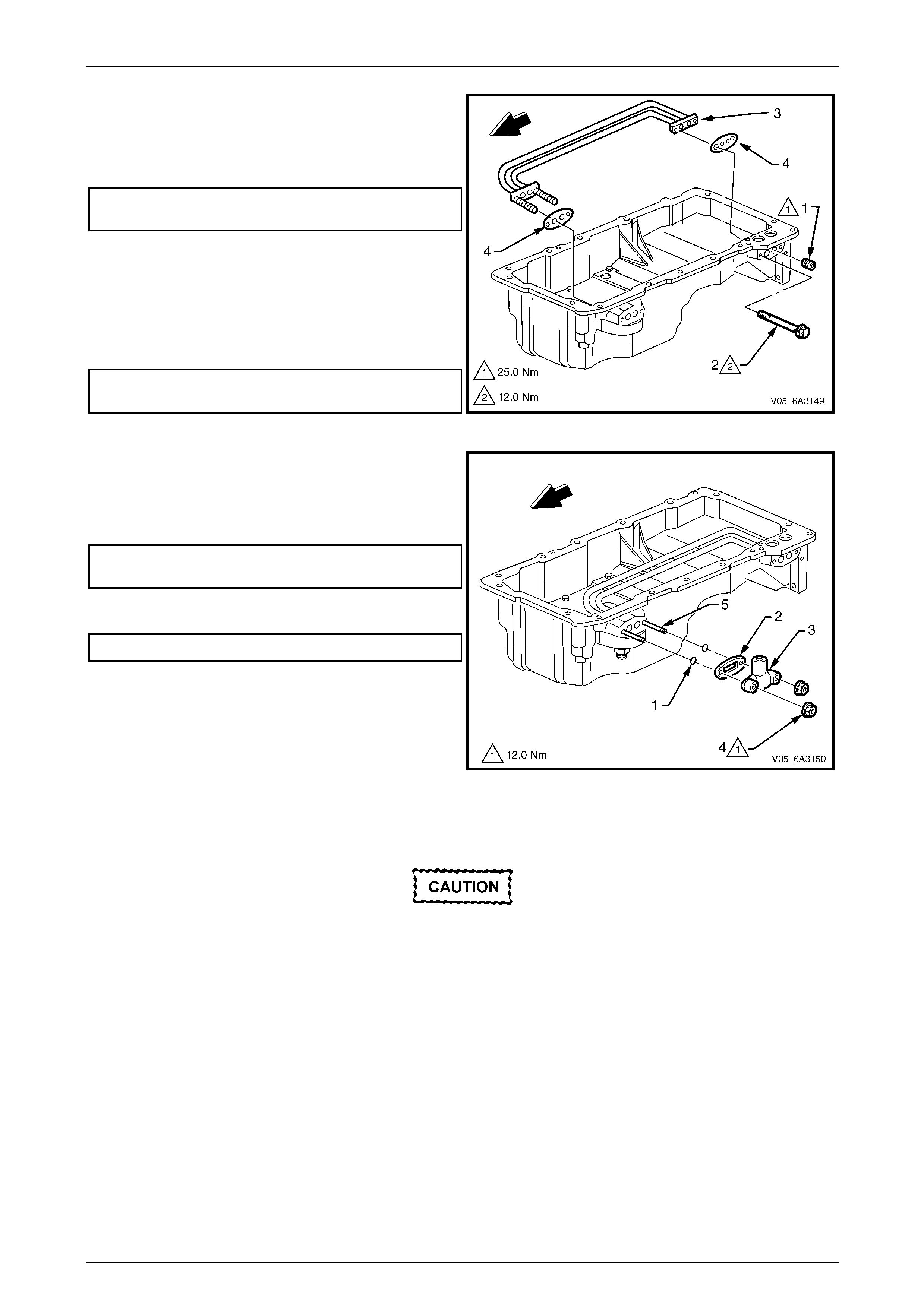
Engine Mechanical Page 6A4–172
Page 6A4–172
2 If removed, apply thread lock compound s uch as
Loctite 242 or equivalent to the clea ned threads of the
oil gallery plug (1).
3 Tighten the oil galler y plugs to the correct torque
specification.
Oil gallery plug
torque specification............................................25.0 Nm
4 Apply thread lock compound such as Loctite 242 or
equivalent to the cleaned threads of the oil transfer
tube attaching bolt (2), two places.
5 Install the oil filter transfer tubes (3) using new gaskets
(4).
6 Tighten the oil transfer tubes attaching bolts to the
correct torque specification.
Oil transfer tube attaching bolt
torque specification............................................12.0 Nm
Figure 6A4 – 255
7 Install two new oil transfer cover O-rings (1), gasket
(2), cover (3) and the two attaching nuts (4) to the two
oil transfer tube studs (5).
8 Tighten the attaching nuts to the correct torque
specification.
Oil transfer cover attaching nut
torque specification............................................12.0 Nm
9 If removed, install the oil filter adaptor an d tighten to
the correct torque specification.
Oil filter adaptor torque specification..................55.0 Nm
10 If required, install a new oil filter bypass valve using a
suitable size socket and hammer, by tapping the valve
in the oil filter flange to fully seat.
Figure 6A4 – 256
Reinstall
The alignment of the structural oil pan is
critical. The rear bolt hole locations of the oil
pan provide mounting points for the
transmission torque converter housing. To
ensure the rigidity of the Engine and correct
transmission alignment, it is important the
rear of the cylinder block and the rear of the
oil pan are flush. The rear of the oil pan must
NEVER protrude beyond the cylinder block
and transmission torque converter housing
plane.
NOTE
The original oi l pan gasket is retained and aligned
to the oil pan by rivets for production purposes
only. When installing a new gasket as a service
replacement, it is not necessary to install new oil
pan gasket rivets. Do not reuse the oil pan
gasket.
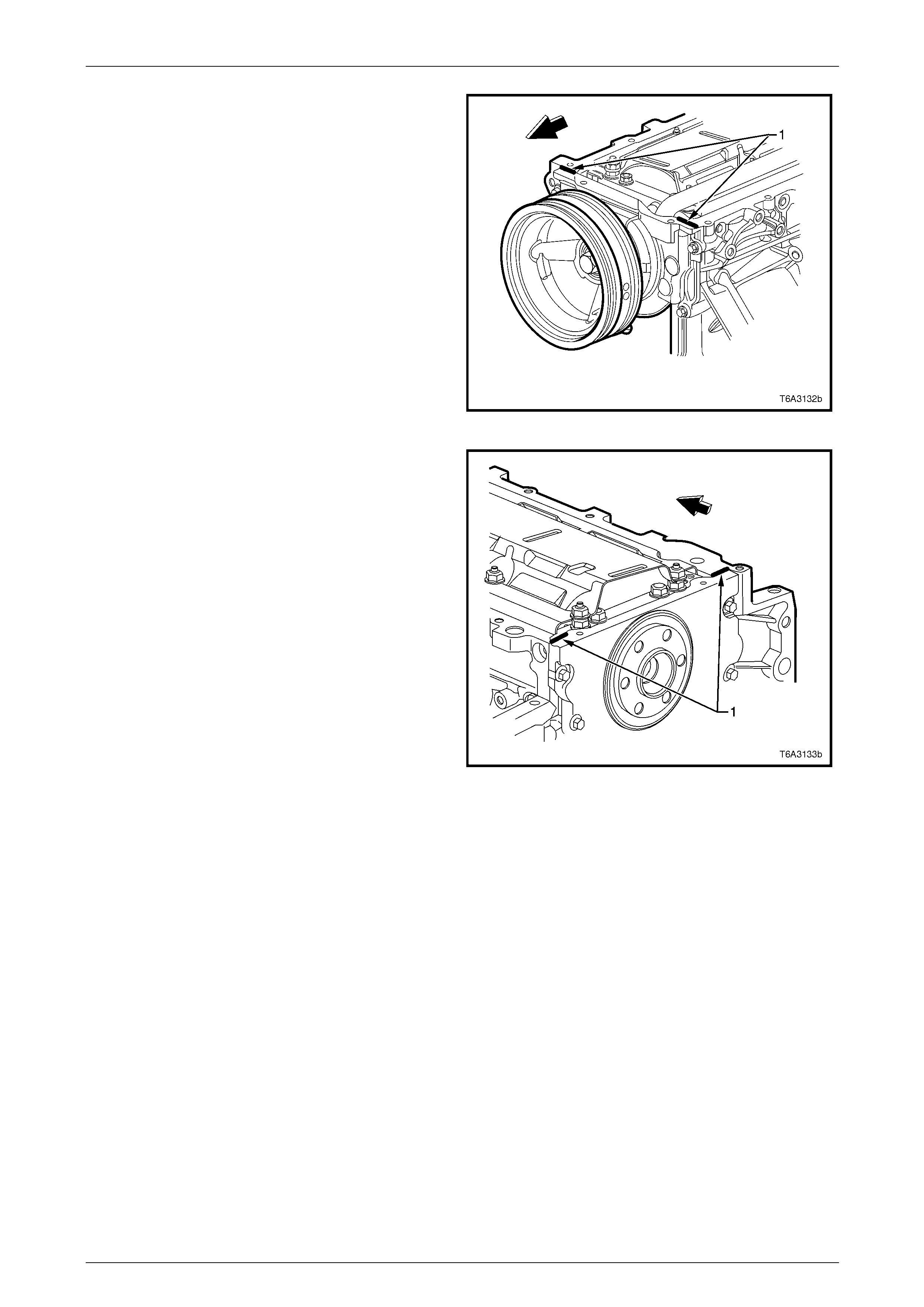
Engine Mechanical Page 6A4–173
Page 6A4–173
1 Apply a 5 mm wide by 20 mm long bead of sealant (1)
such as Loctite 565 or equiv al ent directly onto the tabs
of the front cover gasket that protrude into the oil pan
surface.
Figure 6A4 – 257
2 Apply a 5 mm wide by 20 mm long bead of sealant (1)
such as Loctite 565 or equiv al ent, directly onto the
tabs of the rear cover gasket that protrude into the oil
pan surface.
Figure 6A4 – 258
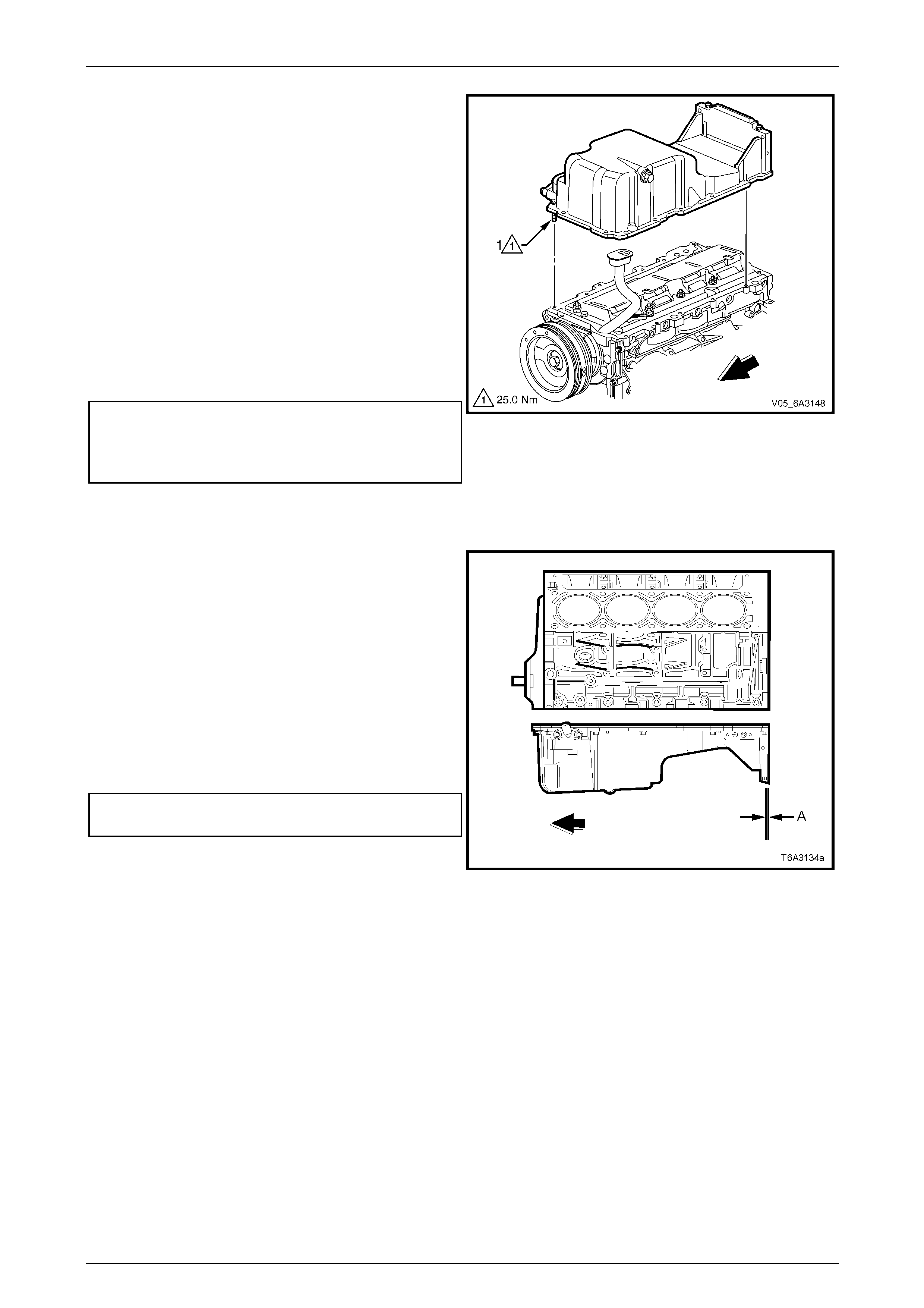
Engine Mechanical Page 6A4–174
Page 6A4–174
3 Install a new oil pan gasket to the oil pan.
NOTE
Align the oil gallery passages in the oil pan and
cylinder block correctly with the oil pan gasket.
4 Install the oil pan bolt (1), 14 places to the oil pan and
through the gasket.
5 Install the oil pan, gasket and bolts to the cylinder
block and tighten the bolts finger tight.
6 Place a straight edge across the rear of the cylinder
block and the rear of the oil pan at the transmission
bell housing mounting surfaces.
7 Align the oil pan until the re ar of cylinder block and
rear of oil pan are flush or even.
8 Tighten the oil pan to front cover attaching bolts to the
correct torque specifications.
Oil pan/front cover attaching bolt
torque specification............................................25.0 Nm
Oil pan/rear cover attaching bolt
torque specification............................................12.0 Nm
9 Place a straight edge across the rear of the cylinder
block and the rear of oil pan at the transmission bell
housing mounting surfaces an d recheck the alignment.
Figure 6A4 – 259
10 Insert a feeler gauge between the straight edge and
the oil pan transmission bell housing mounting
surface. Ensure the oil pan is flush to no more than a
0.25 mm gap between the pan and straight edge (A).
NOTE
• The rear of the oil pan must never protrude
beyond the cylinder block and transmission
bell housing mounting surfaces.
• If the oil pan alignment is not within
specification, remove the oil pan and repeat
Steps 3 to 8.
11 Tighten the remaining oil pan to cylinder block
attaching bolts to the correct torque specificat ion.
Oil pan to cylinder block attaching bolt
torque specification............................................25.0 Nm
12 The remainder of the oil pan reinstallation procedure is
the reverse of the removal procedure. Figure 6A4 – 260
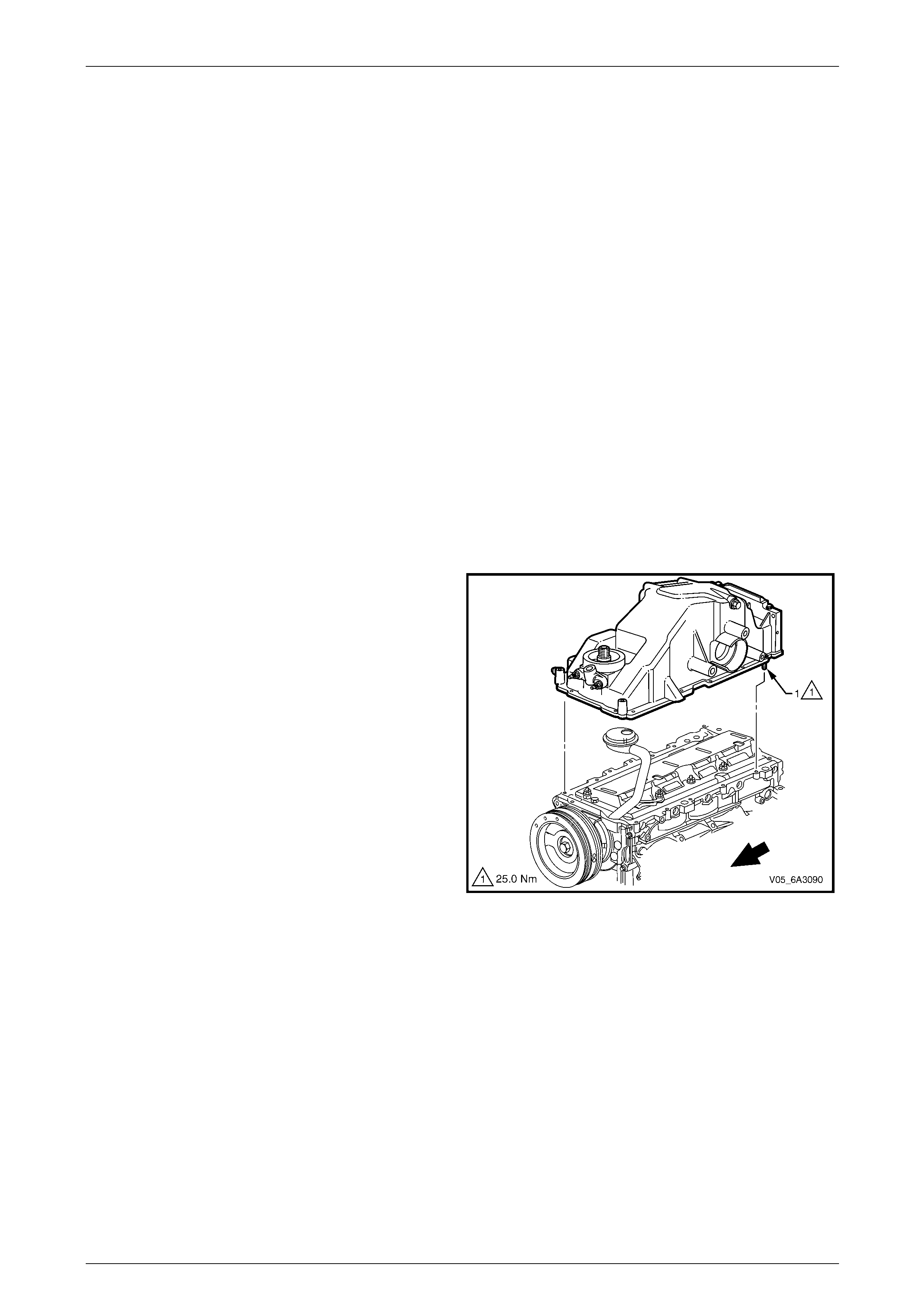
Engine Mechanical Page 6A4–175
Page 6A4–175
5.4 Oil Pan Assembly, AWD
LT Section No. — 00–275
Remove
NOTE
Due to the critical alignment procedures required
for oil pan installation, it is strong ly recommended
the engine assembly be removed from the
vehicle before the oil pan is removed.
1 Remove the engine from the vehicle and if required, mount the engine in an engine stand such as Tool No.
AU 591. Refer to 5.1 Engine Assembly.
2 Ensure the oil has drained co mpletely and if required, place a suitable sized container underneath the engine.
NOTE
This procedure will have removed the front final
drive and the driveshaft support bearing
assembly from the engine oil pan.
3 Remove the flexplate, refer to 5.6 Engine Flywheel and F le x plate.
NOTE
Removal of the flexplate is necessary to remove
the engine oil pan.
4 Invert the engine assembly.
5 Remove the engine oil pan attaching bolt (1), 14
places, loosening gra dually from the outside and
working towards the centre.
6 Use a rubber mallet to tap the sides of the engi ne oil
pan to dislodge the seal.
7 Lift the engine oil pan clear of the c ylinder block while
moving oil pan to the rear to clear the oil pick-up pipe
and screen from the baffle.
8 Lift the engine oil pan clear from the c ylinder block.
Figure 6A4 – 261
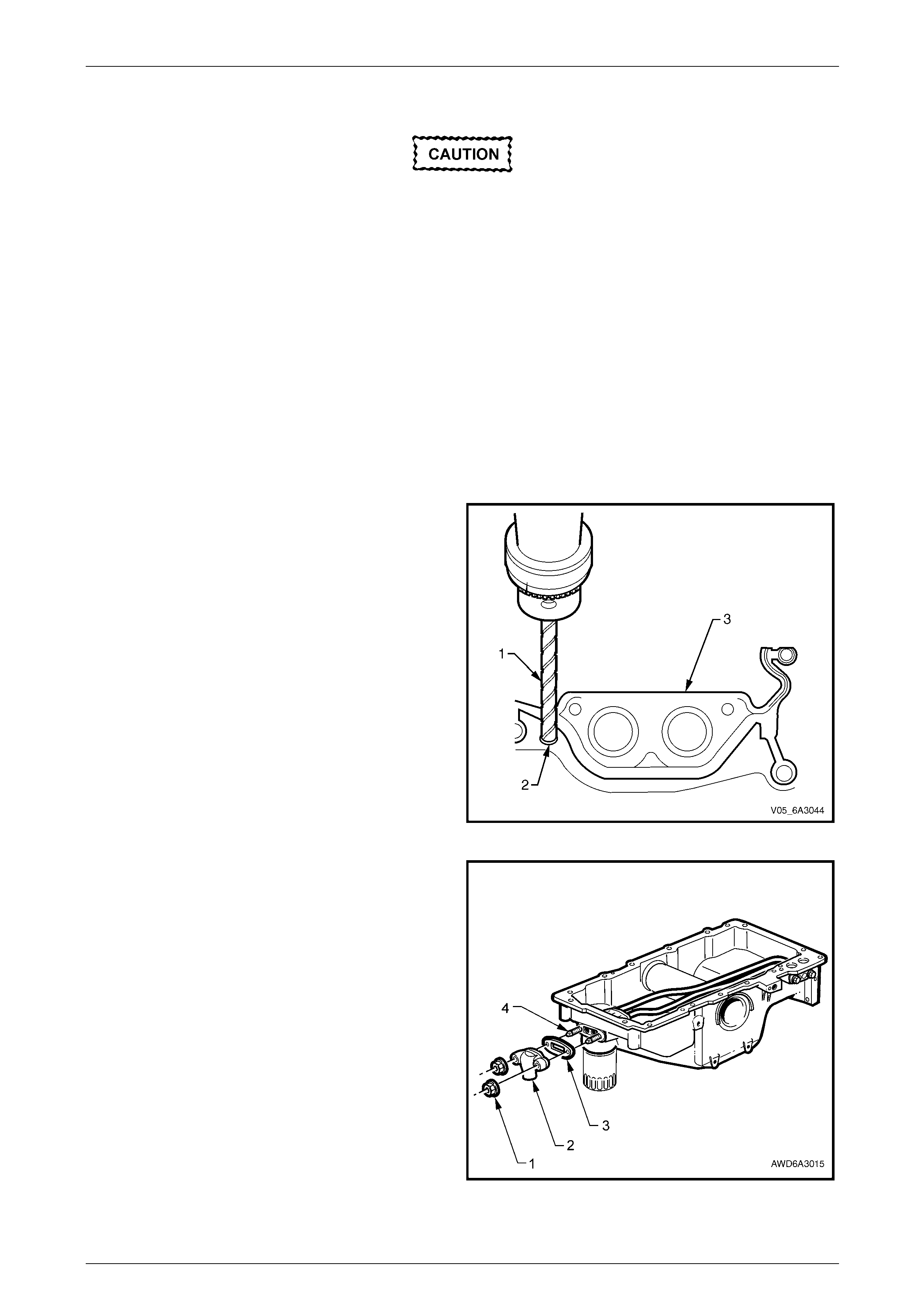
Engine Mechanical Page 6A4–176
Page 6A4–176
Disassemble
Plug all openings before removal of the
original gasket rivets, to prevent metal
shavings or other foreign material from
entering the oil passages in the oil pan.
NOTE
• The original oil pan gasket is retained and
aligned to the oil pan by pop rivets. When
reinstalling a new gasket as a service
replacement, it is not necessar y to install ne w
oil pan gasket rivets.
• If removal of the oil transfer cover nuts is
required while the o il pan is still installed (e. g.
during the fitment of an external oil cooler),
hold the studs with an E5 Torx bit to prevent
the studs from being loosened or removed. If
the studs are removed, the internal oi l transfer
tube gasket can become dislodged.
1 Use a sharp twist drill (1) to drill out each of the
retaining rivets (2) as required.
2 Remove the oil pan gasket (3) from the oil pan and
discard the gasket and rivets.
Figure 6A4 – 262
3 Remove the two oil transfer cover attaching nuts (1),
cover (2) and gasket (3) from the front of the oil pan.
Discard the removed gasket (3).
4 Remove both oil filter transfer tube studs (4) using an
E5 Torx bit.
NOTE
Removal of the transfer tubes without removing
the two studs is not possible.
Figure 6A4 – 263
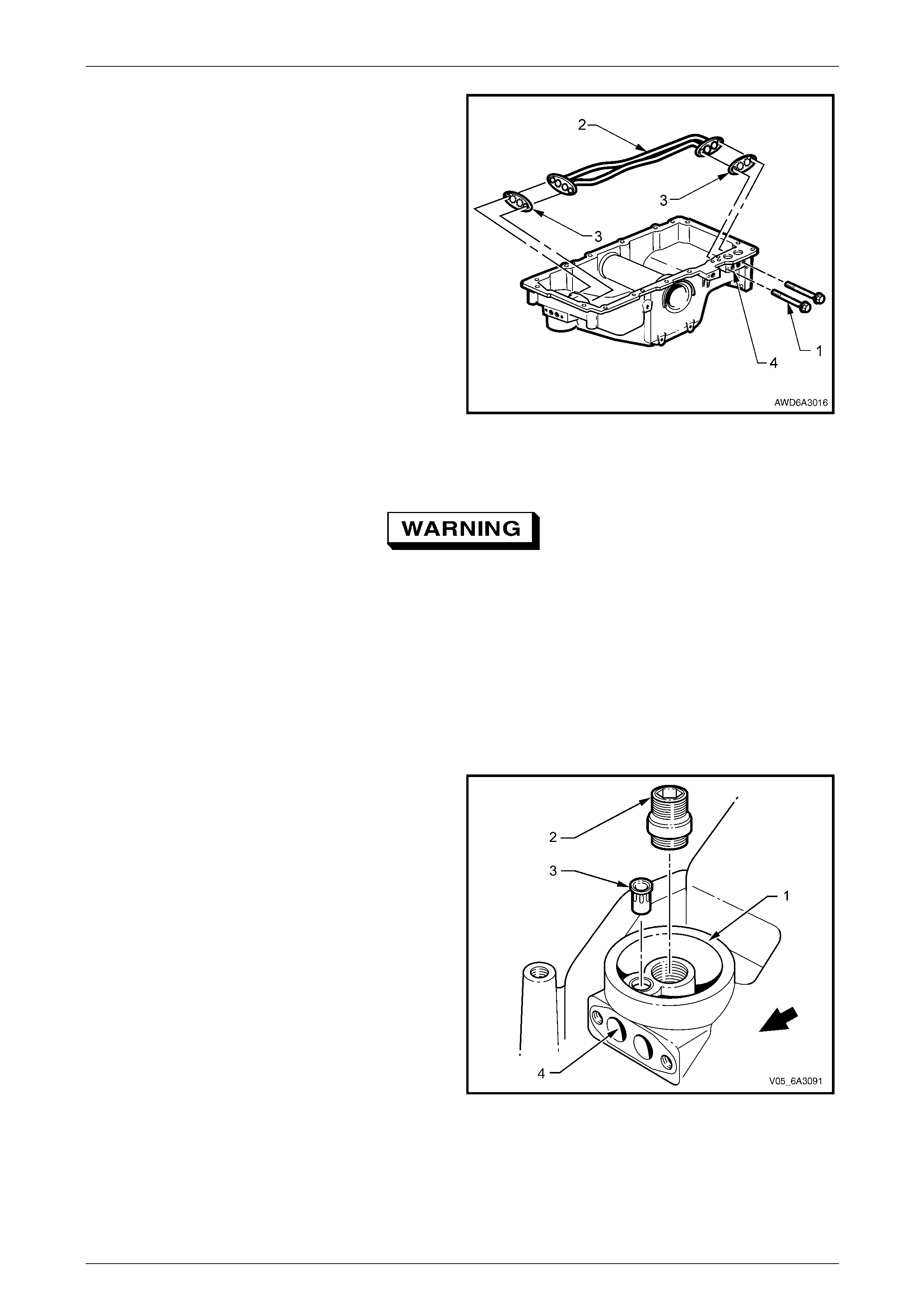
Engine Mechanical Page 6A4–177
Page 6A4–177
5 Remove the two oil transfer tube attaching bolts (1).
6 Remove the oil transfer tubes (2) and discard the two
gaskets (3).
7 If required, use an Allen key to remove the oil gallery
plugs (4).
Figure 6A4 – 264
Clean and Inspect
To avoid personal injury, wear safety glasses
and the appropriate gloves when using
compressed air and cleaning fluids.
1 Clean the oil pan in a comme r cially available cleaning fluid and ensur e that all oil passages and recesses are
thoroughly cleaned and blow dry using compressed air.
2 Clean the oil pan gasket surfaces using a plastic scraper to avoid scratching or damaging the machined surfaces.
3 Inspect the oil pan for:
• Gasket sealing surfaces for excessive scratches or go uging.
• Oil pan drain plug and threaded drain hole for damaged threads. T he drain plug O-ring seal may be reused if
it is not cut or damaged.
• Oil filter sealing surface (1) for scratches or
gouging.
• Oil filter adaptor (2) for a loose fit or damaged
threads.
• Oil passages for restrictions.
• Oil filter bypass valve (3) in the oil filter flange for
proper operation Lightly pus h the bypass valve
into the bore. The valve spring should res ea t the
valve to the proper position.
• Check the cup plug installed in drilling (4) is in
place and secure.
4 Inspect the oil transfer tubes for damage or
restrictions.
Figure 6A4 – 265
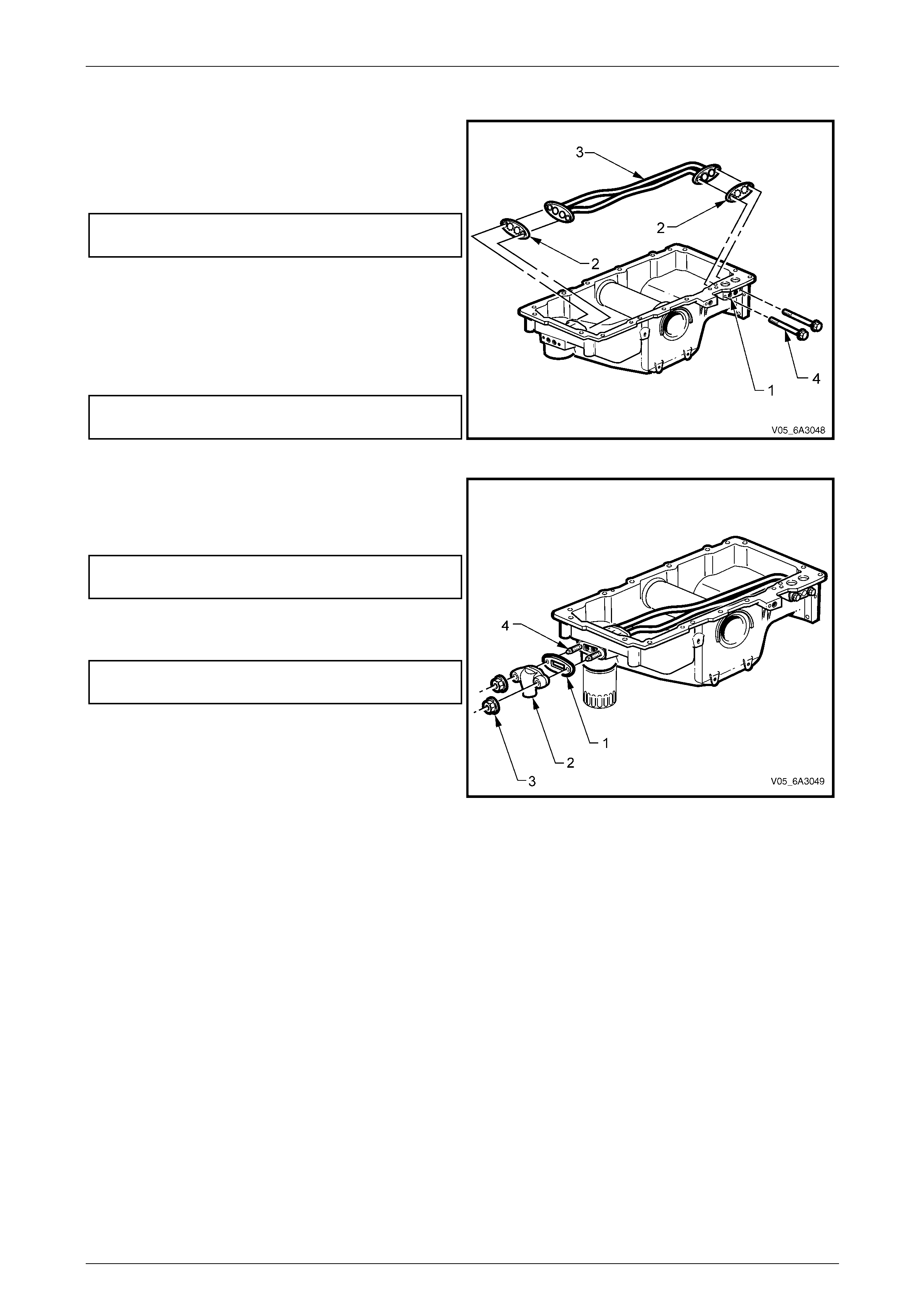
Engine Mechanical Page 6A4–178
Page 6A4–178
Reassemble
1 If removed, apply thread lock compound s uch as
Loctite 242 or equivalent to the clea ned threads of the
oil gallery plug (1).
2 Use an Allen key and tighten the oil gallery plug to the
correct torque specification.
Oil gallery plug
torque specification............................................25.0 Nm
3 Install two new oil transfer tube gaskets (2) and the oil
transfer tubes (3) to the oil pan.
4 Apply thread lock compound such as Loctite 242 or
equivalent to the cleaned threads of the oil transfer
tube bolts and studs.
5 Install the two oil transfer tube attaching bolts (4) and
studs, tightening to the correct torque specification.
Oil transfer tube bolt
and stud torque specification .............................12.0 Nm
Figure 6A4 – 266
6 Install a new oil pan transfer cover gasket (1), cover
(2) and nuts (3).
7 While holding the studs (4) with an E5 Torx socket,
tighten the nuts to the correct torque specification.
Oil transfer cover nut
torque specification............................................12.0 Nm
8 If removed, reinstall the oil filter adaptor an d tighten to
the correct torque specification. Refer to
Figure 6A4 – 265
Oil filter adaptor
torque specification............................................55.0 Nm
9 If required, install a new oil filter bypass valve, using a
suitable size socket and hammer to fully seat the valve
in the oil filter flange of the oil pan.
Figure 6A4 – 267
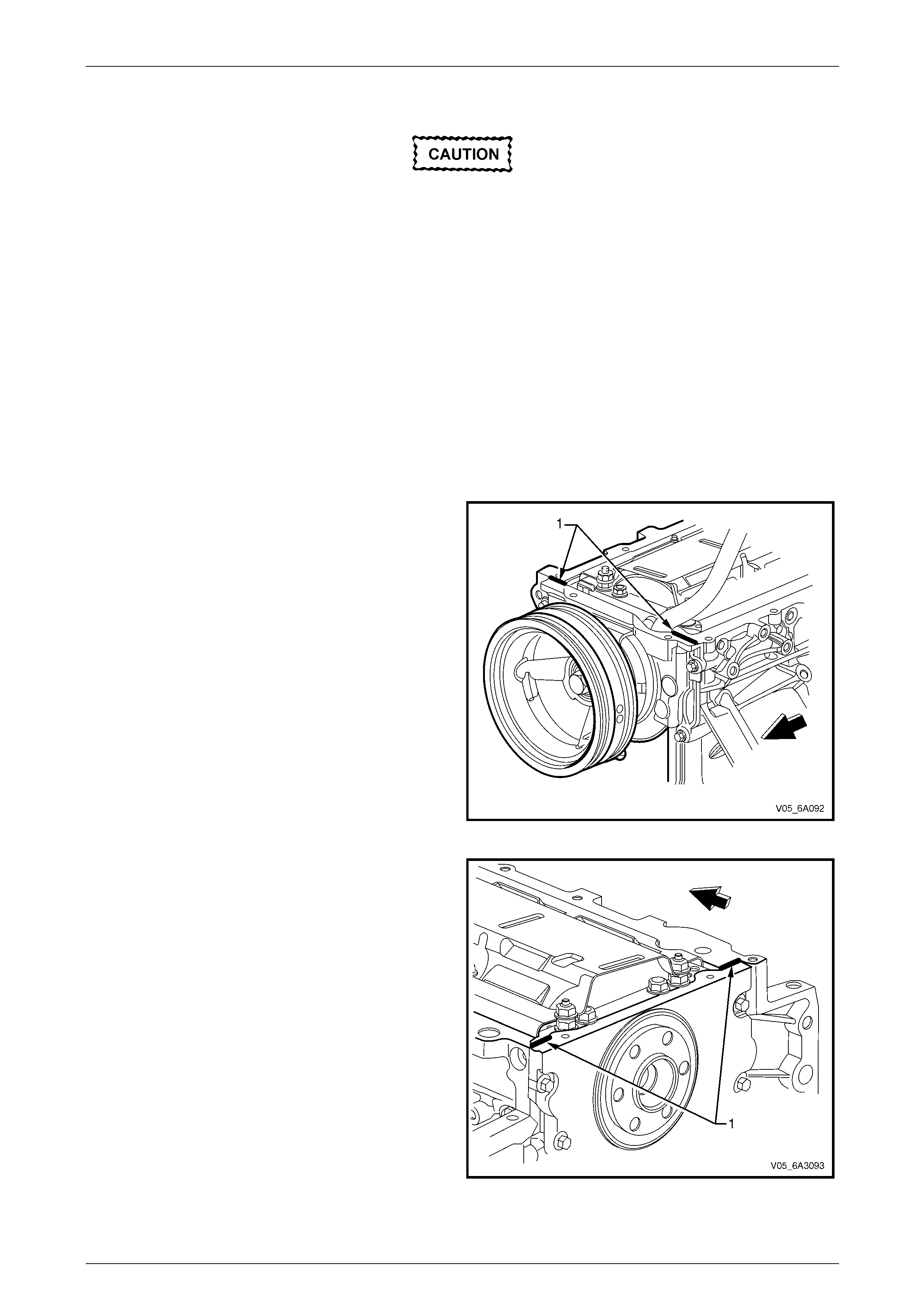
Engine Mechanical Page 6A4–179
Page 6A4–179
Reinstall
The alignment of the structural oil pan is
critical. The rear bolt hole locations of the oil
pan provide mounting points for the
transmission torque converter housing. To
ensure the rigidity of the Engine and correct
transmission alignment, it is important the
rear of the cylinder block and the rear of the
oil pan are flush. The rear of the oil pan must
NEVER protrude beyond the cylinder block
and transmission torque converter housing
plane.
NOTE
The original oi l pan gasket is retained and aligned
to the oil pan by rivets for production purposes
only. When installing a new gasket as a service
replacement, it is not necessary to install new oil
pan gasket rivets.
1 Apply a 5 mm wide bead of sealant (1) such as Loctite
565 or equivalent, 20 mm long to the cylinder block.
Apply the sealant directly onto the tabs of the front
cover gasket that protrude into the oil pan surface.
Figure 6A4 – 268
2 Apply a 5 mm wide bead of sealant (1) such as Loctite
565 or equivalent, 20 mm long, to the cylinder block,
as shown. Apply the sealant directly onto the tabs of
the rear cover gasket that protrude into the oil pan
surface.
Figure 6A4 – 269
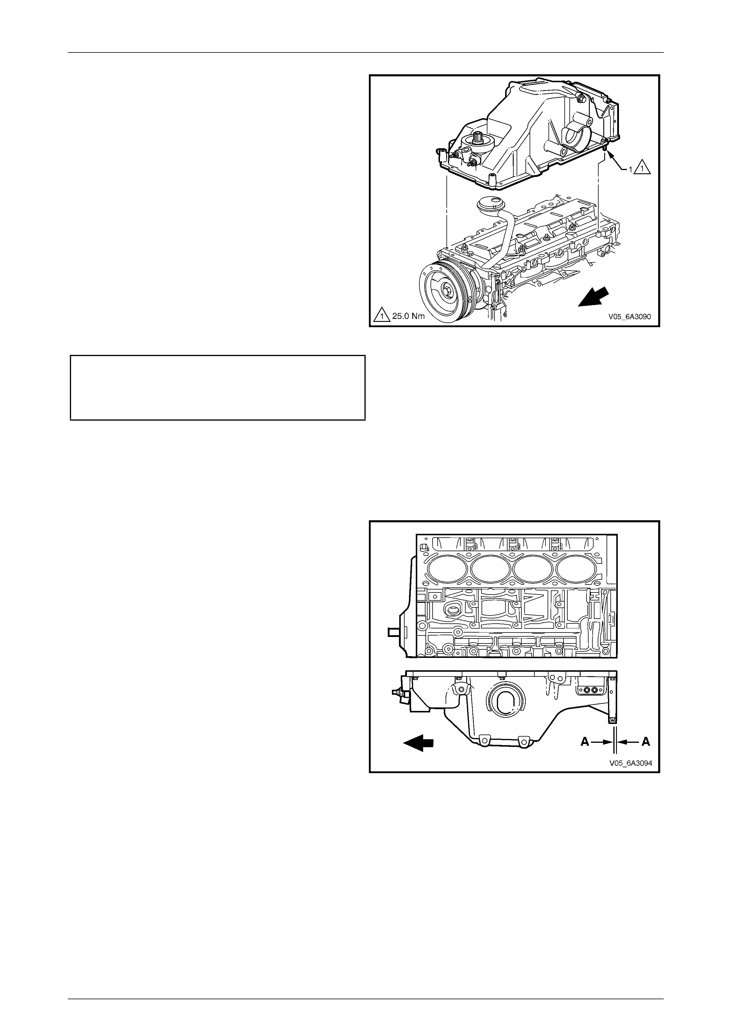
Engine Mechanical Page 6A4–180
Page 6A4–180
3 Install a new oil pan gasket to the oil pan.
NOTE
Align the oil gallery passages in the oil pan and
cylinder block properly with the oil pan gasket. It
is not necessary to rivet the new gasket to the oil
pan.
4 Install the oil pan bolt, 14 places to the oil p an and
through the gasket.
5 Install the oil pan, gasket and bolts to the cylinder
block and tighten the bolts finger tight.
6 Place a straight edge across the rear of the cylinder
block and the rear of the oil pan at the transmission
torque converter housing mounting surfaces.
7 Align the oil pan until the re ar of cylinder block and the
rear of oil pan are flush or even.
8 Install the oil pan to front cover bolts and the oil pan to
rear cover bolts, tightening to the correct torque
specification.
Oil pan to front cover attaching bolt
torque specification............................................25.0 Nm
Oil pan to rear cover attaching bolt
torque specification............................................12.0 Nm
Figure 6A4 – 270
NOTE
This preliminary step is needed to avoid oil pan
creep and creating a misalig nment condition.
9 Place a straight edge across the rear of the cylinder
block and the rear of oil pan at the transmission torque
converter housing mounting surfaces and recheck the
alignment.
10 Insert a feeler gauge between the straight edge and
the oil pan transmission bell housing mounting
surface. Ensure the oil pan is flush with no more than
a 0.25 mm gap between the pan and straight edge (A).
11 If the oil pan alignment is not within specific ation,
remove the oil pan and repeat Steps 5 to 10.
12 Remainder of the reinstallation process is the reverse
of the removal procedure.
Figure 6A4 – 271
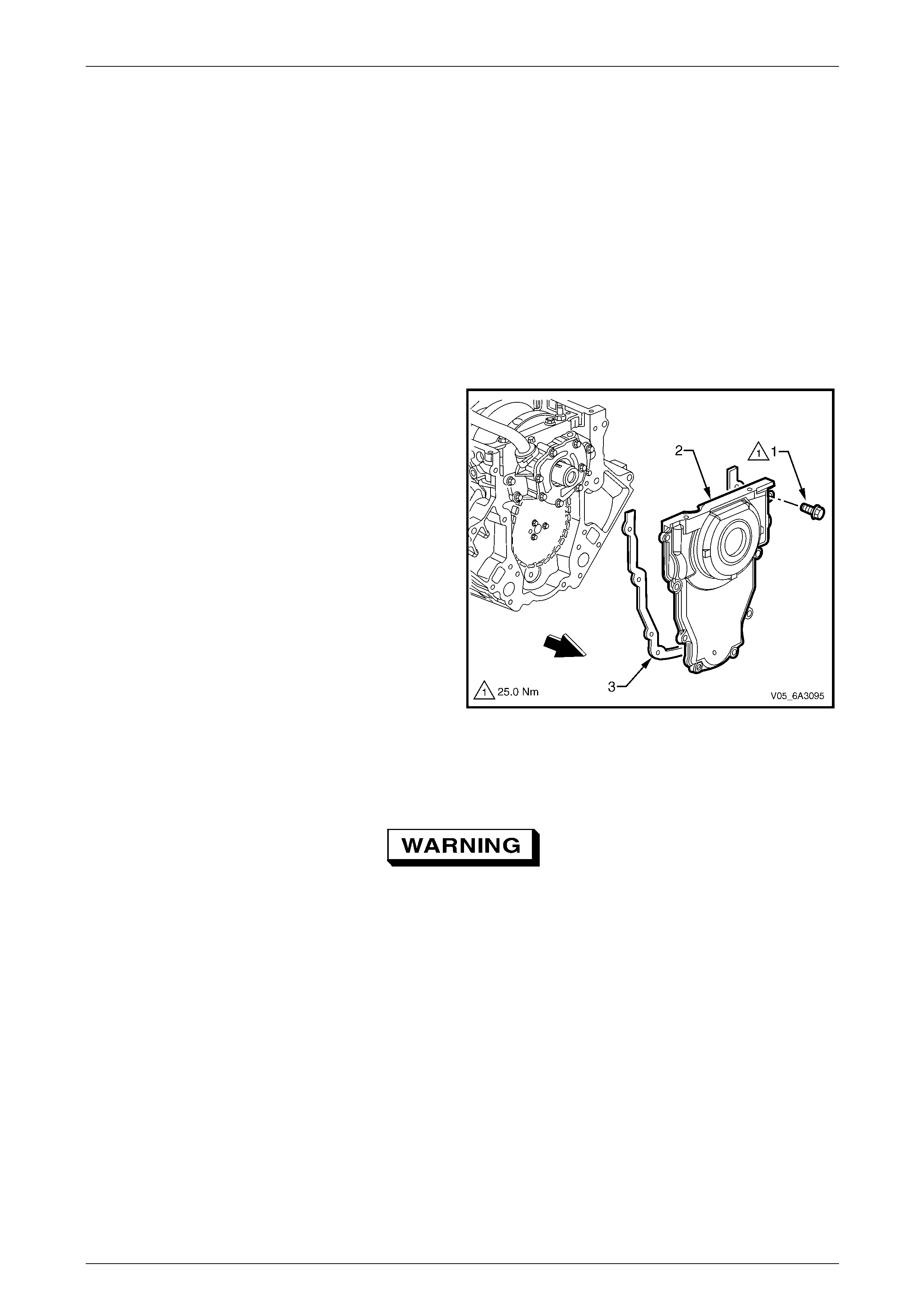
Engine Mechanical Page 6A4–181
Page 6A4–181
5.5 Engine Front Cover
LT Section No. — 00–325
Remove
NOTE
Due to critical alignment procedures required for
the reinstallation of the front cover and oil pan, it
is strongly recommended the engine assembly is
removed from the vehicle, before oil pan removal.
1 Remove the coolant pump, refer to Section 6B3 Engine Cooling – GEN IV V8.
2 Remove the engine oil pan, refer to 5.3 Oil Pan Assembly, Except AWD or 5.4 Oil Pan Assembly, AWD.
3 Remove the crankshaft balancer, refer 4.17 Crankshaft Bal ancer.
4 Remove the bolt (1), eight places, attaching the front
engine cover (2) to the cylinder block.
5 Remove the front cover and gasket (3).
Figure 6A4 – 272
Clean and Inspect
1 Prise the old oil seal from the front cover and discard.
To avoid personal injury, wear safety glasses
and the appropriate gloves when using
compressed air and cleaning fluids.
2 Clean the front cover in a commercially available cleaning fluid and blow dry with compressed air.
3 Inspect the front cover sealing surfaces for excessiv e scra tches and/or gouges.
4 Inspect the front cover gasket for damage to the membrane or distortion to the aluminium carrier.
5 Inspect the front cover to oil pan threaded holes for damaged threads or debris, refer to 6 Thread Repair if
rectification is required.
6 Inspect the front cover crankshaft oil seal bore for damage.
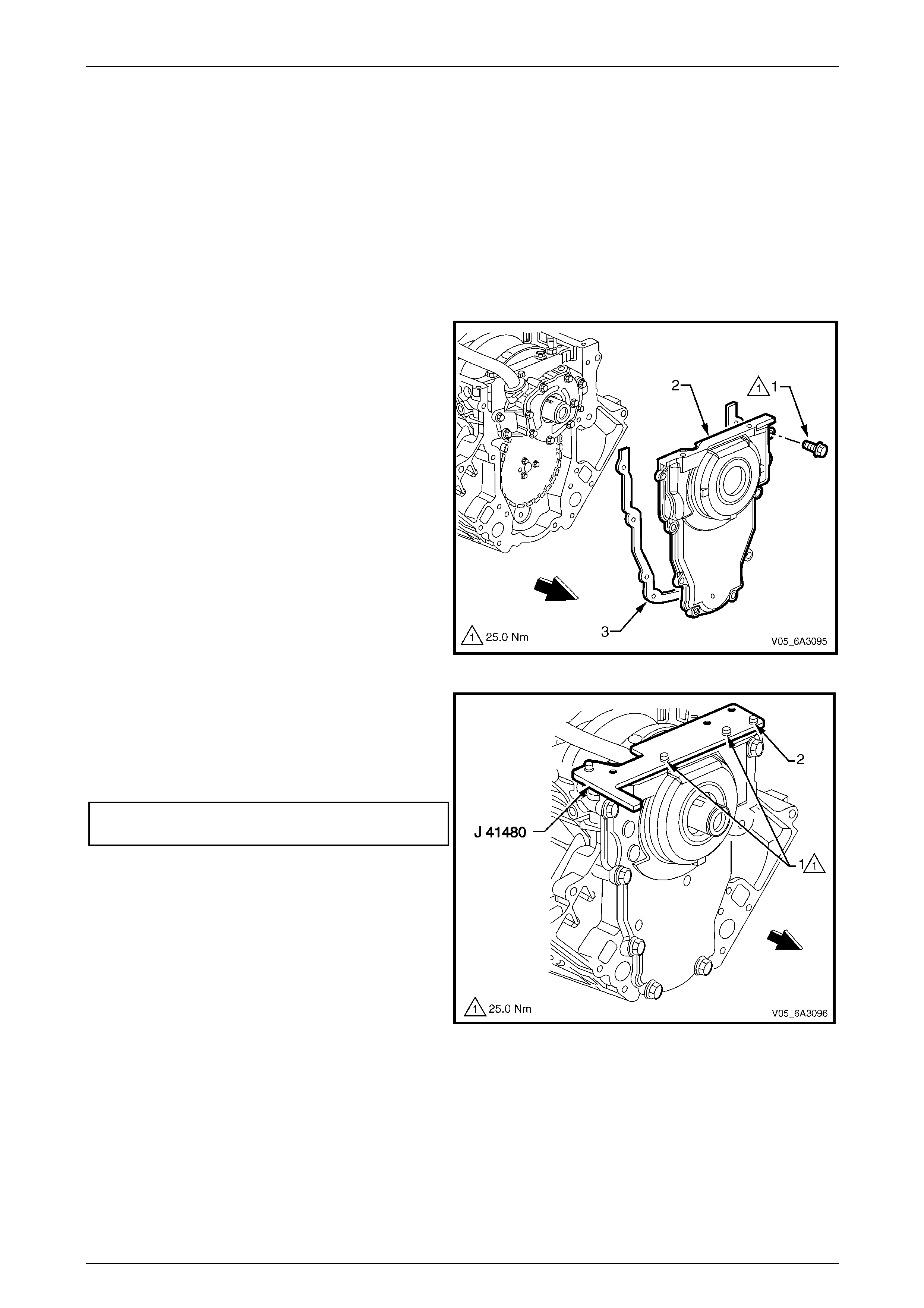
Engine Mechanical Page 6A4–182
Page 6A4–182
Reinstall
Prior to reinstallation of the engine front cover, observe the follo wing:
• Do not reuse the crankshaft oil seal.
• Do not apply any type of sealant to the front cover gasket.
• The special tools in this procedure must be used to correctly align the engine front cover at the oil pan surface and
to centre the crankshaft front oil seal.
• All gasket surfaces should be free of oil or other foreign material during assembly.
• The crankshaft front oil seal must be centred in relation to the crankshaft.
• The oil pan sealing surface at the front cover and cylinder block must also be aligned within specifications.
• An incorrectly aligned front cover may caus e premature front oil seal wear and/or engine assembly oil leaks.
1 Install the front cover attaching bolt (1), eight places,
through the front cover (2) and gasket (3).
2 Install the front cover with the bolts and gasket and
finger tighten the bolts.
Figure 6A4 – 273
3 Assemble alignment Tool No. J 41480 to the front
cover and install the bolts (1) (part of Tool No. J
41480) in the locations shown, but do not tighten.
4 Install the two bolts (2) from alignment Tool No
J 41480 to the cylinder block and tighten to the
correct torque specification.
Front cover alignment tool to cylinder block
attaching bolt torque specification......................25.0 Nm
Figure 6A4 – 274
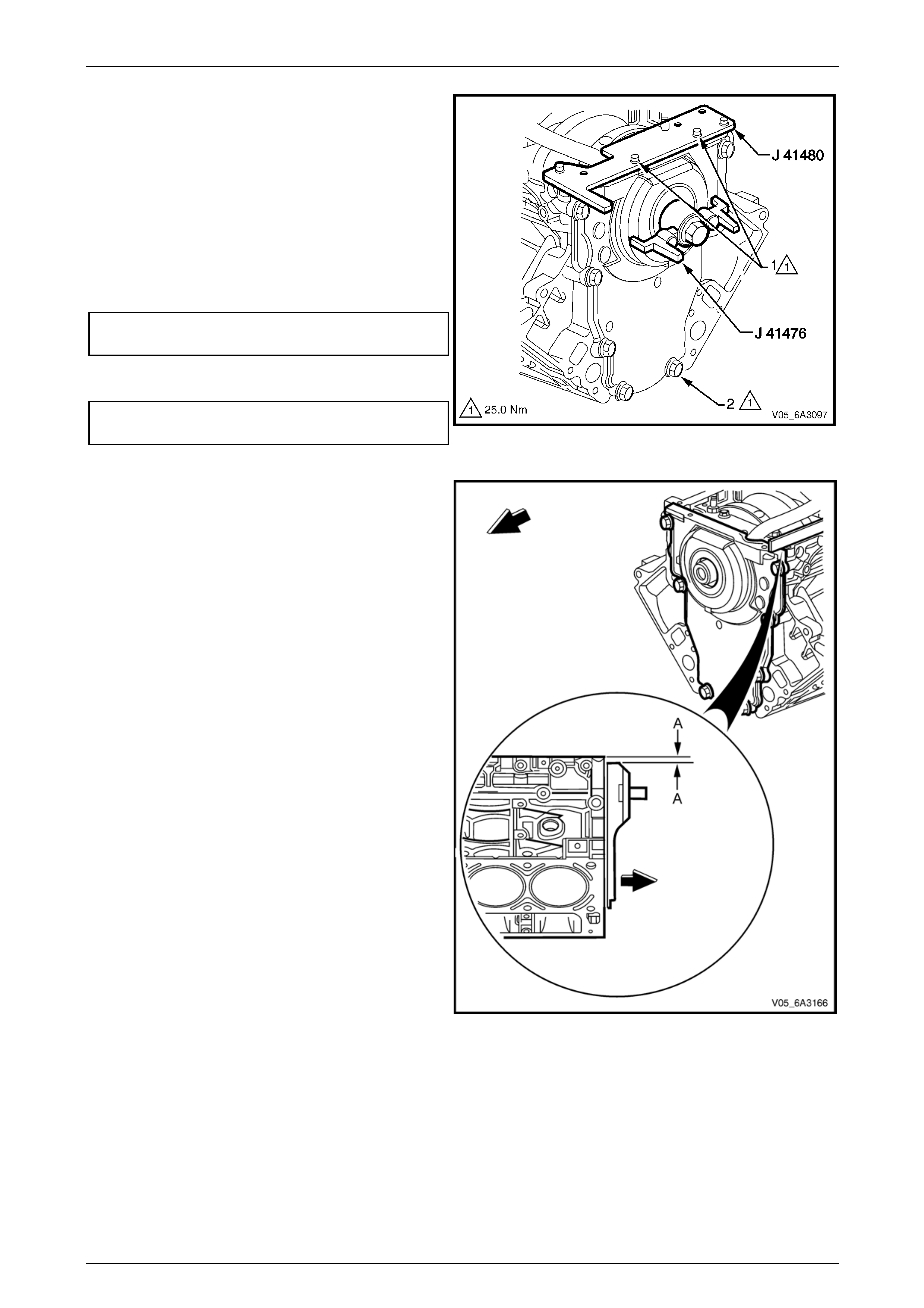
Engine Mechanical Page 6A4–183
Page 6A4–183
5 Install the centralising Tool J 41476 and hold it in
position by hand. Align the tapered legs of th e tool
with the machined alignment surfaces on the front
cover.
NOTE
Do not tighten the crankshaft balancer bolt to
retain the alignment tool. If the bolt is installed
and over-tightened the alignment tool will be
damaged.
6 Tighten the bolt (1), two places, attaching Tool No.
J 41480 to the front cover to the specified torque.
Alignment tool to front cover
bolt torque specification.....................................25.0 Nm
7 Tighten the engine front cover attaching bolts (2) to
the correct torque specification.
Engine front cover attaching bolt
torque specification............................................25.0 Nm
8 Remove the alignment tools. Figure 6A4 – 275
9 Measure the oil pan surface to front cover for
flatness, as follows:
a Place a straight edge across the cylinder block
and front cover oil pan sealin g surfaces. Avoid
contact with the portion of the gasket that
protrudes into the oil pan surface.
b Insert a feeler gauge between the front cover
and the straight edge tool. T he clear ance
should not exceed 0.25 mm (A).
c If the front cover-to-cylinder block oil pan
surface alignment is not within specifications,
repeat the cover alignment procedure.
10 If the correct front cover to cylinder block alignment
cannot be obtained, replace the front cover.
11 Install crankshaft front oil seal. Refer to
4.18 Crankshaft Front Oil Seal.
12 Install the crankshaft balancer, refer to
4.17 Crankshaft Balancer.
13 Reinstall the oil pan. Refer to 5.3 Oil Pan.
Figure 6A4 – 276

Engine Mechanical Page 6A4–184
Page 6A4–184
5.6 Engine Flywheel and Flexplate
LT Section No. — 00–400
Remove
NOTE
If replacing a flywheel, note the location of any
existing balance weight pins relative to the
position of the flywheel locating hole. Use a
suitable pin punch and remove the pins from the
old flywheel and then reinstall them in the same
relative location in the replacement part.
Balance weight pins are fitted to the flywheel where they are required to balance the crankshaft/flywheel assembly of
engines that have been dynamically balanced at manufacture. Hence the need to reinstall them to the new flywheel in
the same position.
A correctly installed balance weight pin will be either flush or just below flush with the machined s urface of the flywheel.
NOTE
• Observe the position and direction of the
engine flywheel before removal. The flexplate
does not use a locating pin for alignment.
Mark or scribe the end of the crankshaft and
the flywheel before component removal. The
engine flywheel must be reinstalled to the
original position and direction.
• The flywheel/flexplate will not initially seat
against the crankshaft flange but will be pulled
onto the crankshaft by the attaching bolts as
they are progressively tightened. This
procedure requires a three stage tightening
process.
1 If this operation is to be carried out with the engine installed in the vehicle, remove the transmission and/or clutch
assembly. Refer to:
• Section 7B2 Manual Transmission – GEN IV V8 or
• Section 7C4 Automatic Transmission – 4L60E – On Vehicle Servicing
2 For manual transmission vehicles, remove the clutch assembl y, refer to Section 7A3 Clutch – GEN IV V8.
3 Mark or scribe the end of the crankshaft and the flywheel/flexplate with a marker pen or similar.
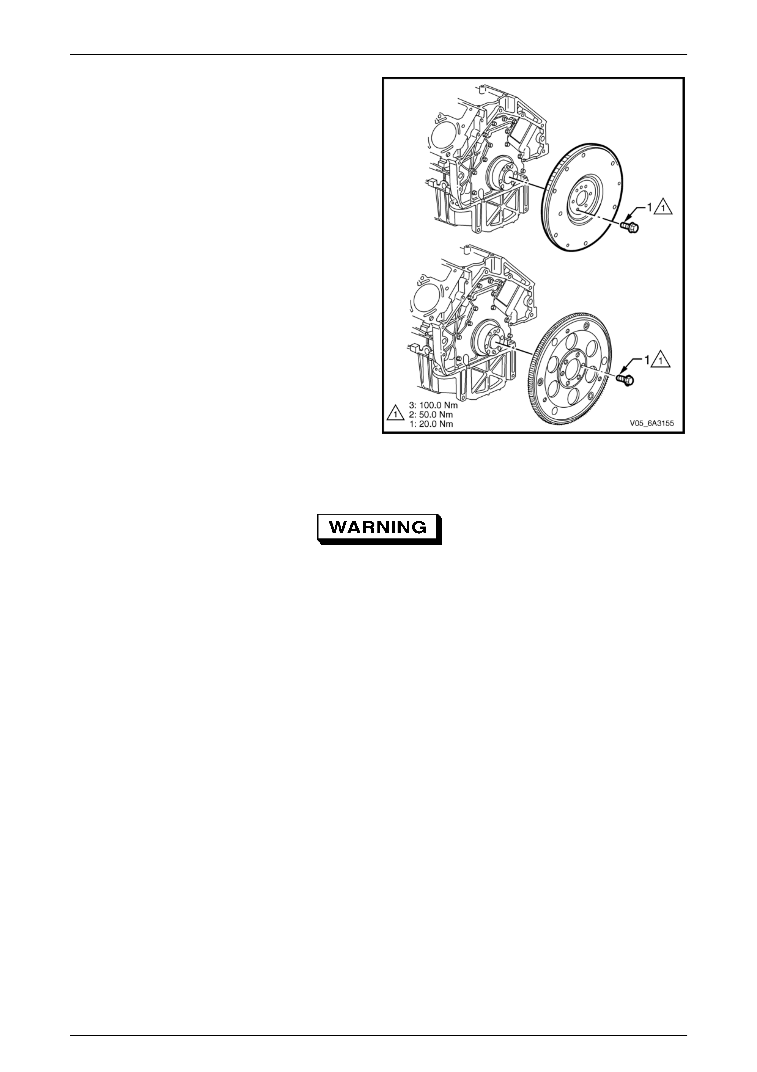
Engine Mechanical Page 6A4–185
Page 6A4–185
4 Remove the bolt (1), six places, attaching either the
engine flywheel or flexplate to the rear of the
crankshaft and then remove the engine
flywheel/flexplate from the crankshaft.
Figure 6A4 – 277
Clean and Inspect
Throughout this Section, cleaning fluids and
compressed air are used in the service
procedure. Where compressed air and
cleaning fluids are to be used, wear safety
glasses and the appropriate gloves to avoid
personal injury.
Crankshaft
1 Inspect the threaded holes in the crankshaft for damaged threads. Any damage to the threads will require a
replacement crankshaft.
2 Clean the threads of any remaining thread locking compound using a commercially available cleaning fluid a nd
blow dry using compressed air.
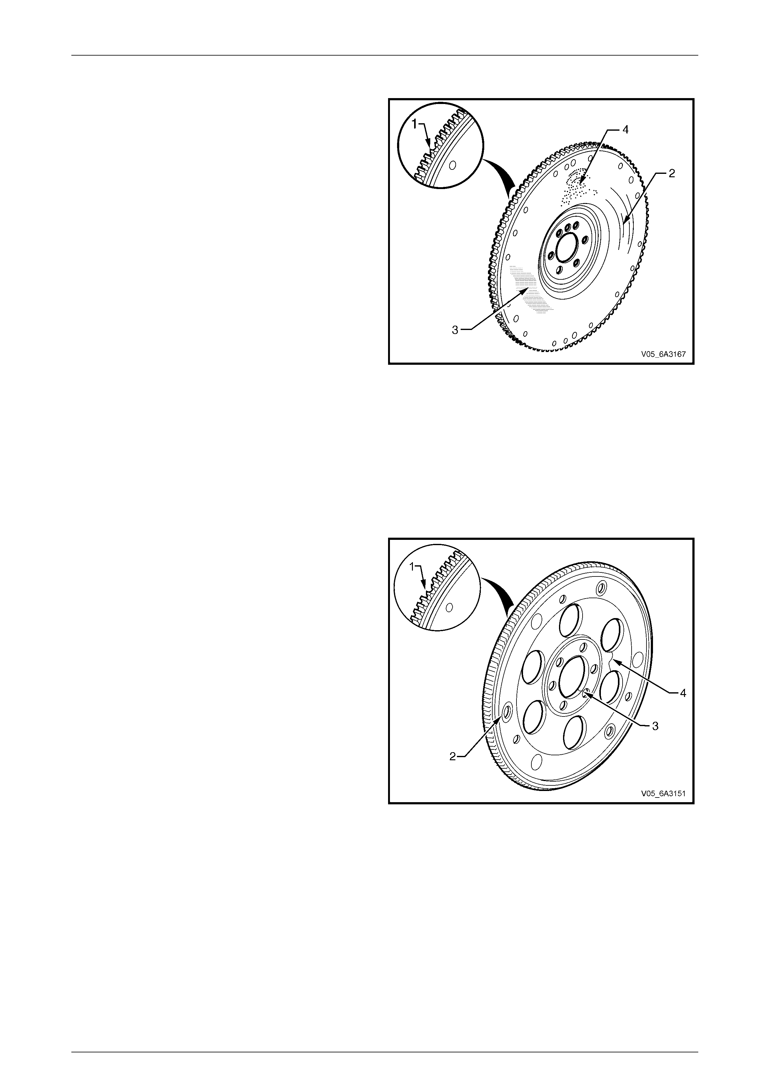
Engine Mechanical Page 6A4–186
Page 6A4–186
Flywheel
1 Clean the flywheel in a commercially available
cleaning fluid and bl ow dry using compressed air.
2 Inspect the flywheel for loose or incorrectly install ed
balance weights (if applicable). A correctly installed
balance weight should be either flush or below the
machined surface of the flywheel.
3 Inspect the flywheel for the following:
• Damaged ring gear teeth (1)
• Grooves or scoring (2)
• Rusted surface (3)
• Pitted surfaces (4)
• Damaged clutch plate bolt holes
• Loose or incorrectly positioned ring gear. The
ring gear is an interference fit onto the flywheel
and should be positione d completely against the
flange of the flywheel.
• Missing, bent or damaged pre ssure plate
locating pins. The two locating pins are pr essed
into the flywheel and are spaced 170° apart.
NOTE
In order to maintain the correct component
balance, contact surface tape r and heat transfer,
the flywheel must not be machined. If the
flywheel is damaged, it must be replaced.
Figure 6A4 – 278
Flexplate
1 Inspect the flexplate for the following:
• Damaged ring gear teeth (1)
• Elongation of the crankshaft or torque converter
bolt holes (2)
• Stress cracks around the crankshaft or torque
converter bolt hole locations (3)
• Cracks between pressing holes (4)
• Welded areas that retain the ring gear to the
flexplate for cracks
NOTE
Do not attempt to repair any welded areas that
retain the ring gear to the flexplate. Replace the
flexplate assembly if any welds are cracked or
damage is found.
Figure 6A4 – 279
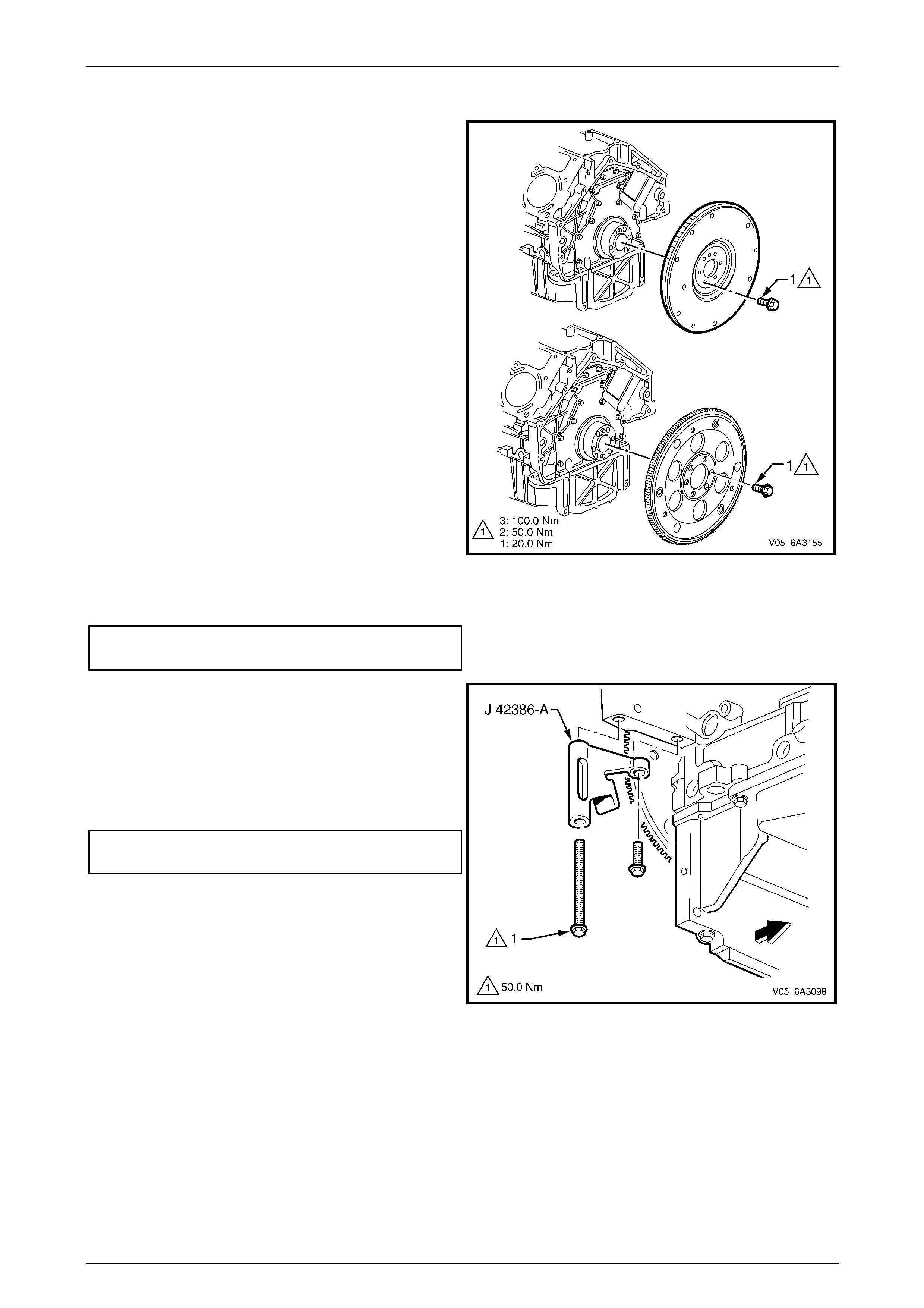
Engine Mechanical Page 6A4–187
Page 6A4–187
Reinstall
NOTE
Balance weight pins ar e fitted to the flywheels of
engines that have been dynamically balanced at
manufacture. It is important to reinstall them to
the new flywheel in the same position. A
correctly installed balance weight pin will be
either flush or below flush with the machined
surface of the flywheel.
1 If replacing the flywheel, install any balance weights as
required in the same locations as noted on the old
flywheel.
2 Use the flywheel locating hol e as a reference and
scribe an alignment mark corresponding to the one on
the original flywheel.
3 Clean the threads in the crankshaft and ens ure there
is no remaining encapsul ated sealer remaining in the
holes.
4 Install the flywheel/flexplate aligning the scribed marks
on the crankshaft and the flywheel/fle xplate.
NOTE
Do not reuse the flywheel/flexplate bolts. Only
new bolts are to be used when reinstalling the
flywheel/flexplate.
5 Install new flywheel/flexplate bolts and tig hten to the
correct Stage 1 torque specification. Refer to
Figure 6A4 – 282.
Flywheel/flexplate torque specification
Stage 1 ..............................................................20.0 Nm
Figure 6A4 – 280
6 Install the ring gear holding Tool No. J 4238 6-A, using
the two starter motor attaching bolts. Tighten both
bolts to the correct torque specification.
NOTE
Ensure the teeth of the holding tool engage
correctly with the ring gear teeth, before
tightening the fasteners.
Tool No J 42386-A attaching bolt
torque specification............................................50.0 Nm
Figure 6A4 – 281
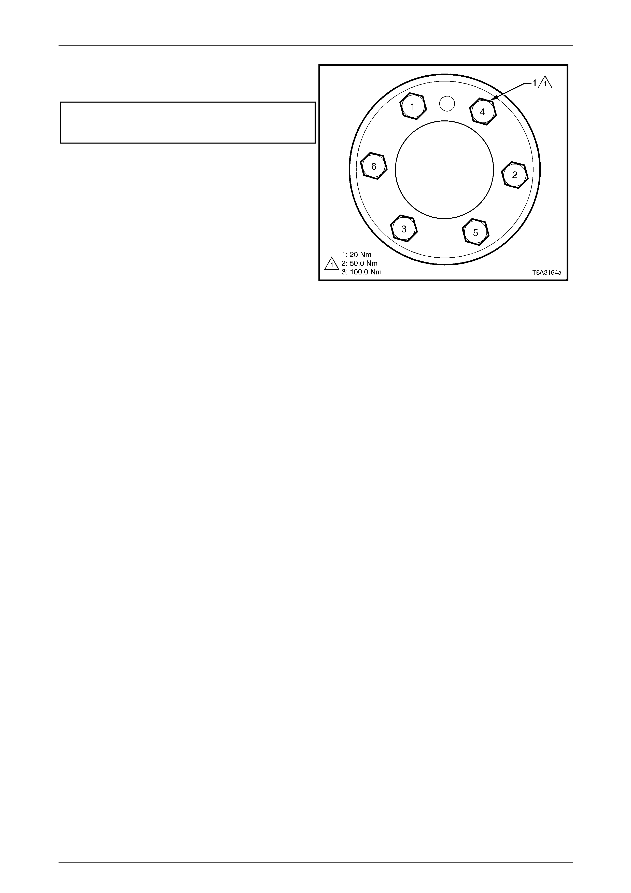
Engine Mechanical Page 6A4–188
Page 6A4–188
7 Continue to tighten the flywheel/flexplate bolts in
sequence in two additional stages to the correct torque
specification.
Flywheel/Flexplate attaching bolt torque specification
Stage 2 ..............................................................50.0 Nm
Stage 3 ............................................................100.0 Nm
8 Reinstall the clutch and/or transmission, as required.
Refer to either:
• Section 7A3 Clutch – GEN IV V8
• Section 7B2 Manual Transmission – GEN IV V8
• Section 7C4 Automatic Transmission – 4L60E –
On Vehicle Servicing
Figure 6A4 – 282
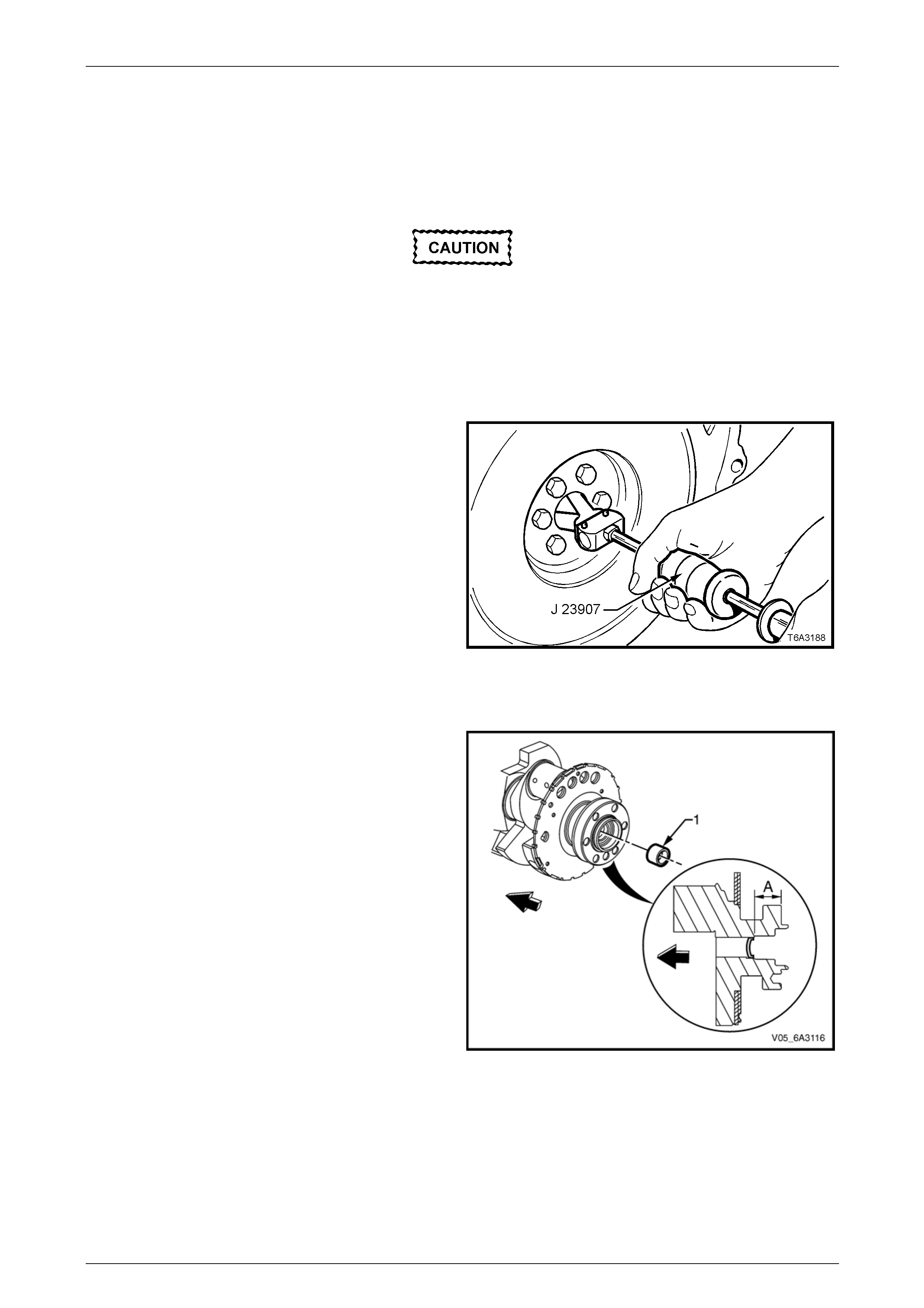
Engine Mechanical Page 6A4–189
Page 6A4–189
5.7 Crankshaft Spigot Bearing
LT Section No. — 00–200
Remove
Disconnection of the battery affects certain
vehicle electronic systems. Refer to
Section 00 Warnings Cautions and Notes
before disconnecting the battery.
1 Disconnect the ground battery cable termi nal from the battery.
2 Remove the manual transmission and the clutch assembly, Refer to Section 7B2 Manual Transmission – GEN IV V8
and Section 7A3 Clutch – GEN IV V8.
3 Using the Tool No. J 23907, (also released as Tool
No. 6A22-2 and the slide hammer Tool No. 7A28) or
equivalent, remove the spigot bearing from the rear of
the crankshaft and discard the removed bea r ing.
Figure 6A4 – 283
Reinstall
1 Check the crankshaft rear oil galler y plug (1) is not a
loose fit, damaged or leaking.
2 If replacement is required, apply sealant such as
Loctite 242 or equivalent, to the sid es of a n ew plug
and install it to the correct depth.
NOTE
Ensure the crankshaft rear oil gallery plug depth
A is fitted to the correct depth of 31.2
to 31.6 mm.
Figure 6A4 – 284
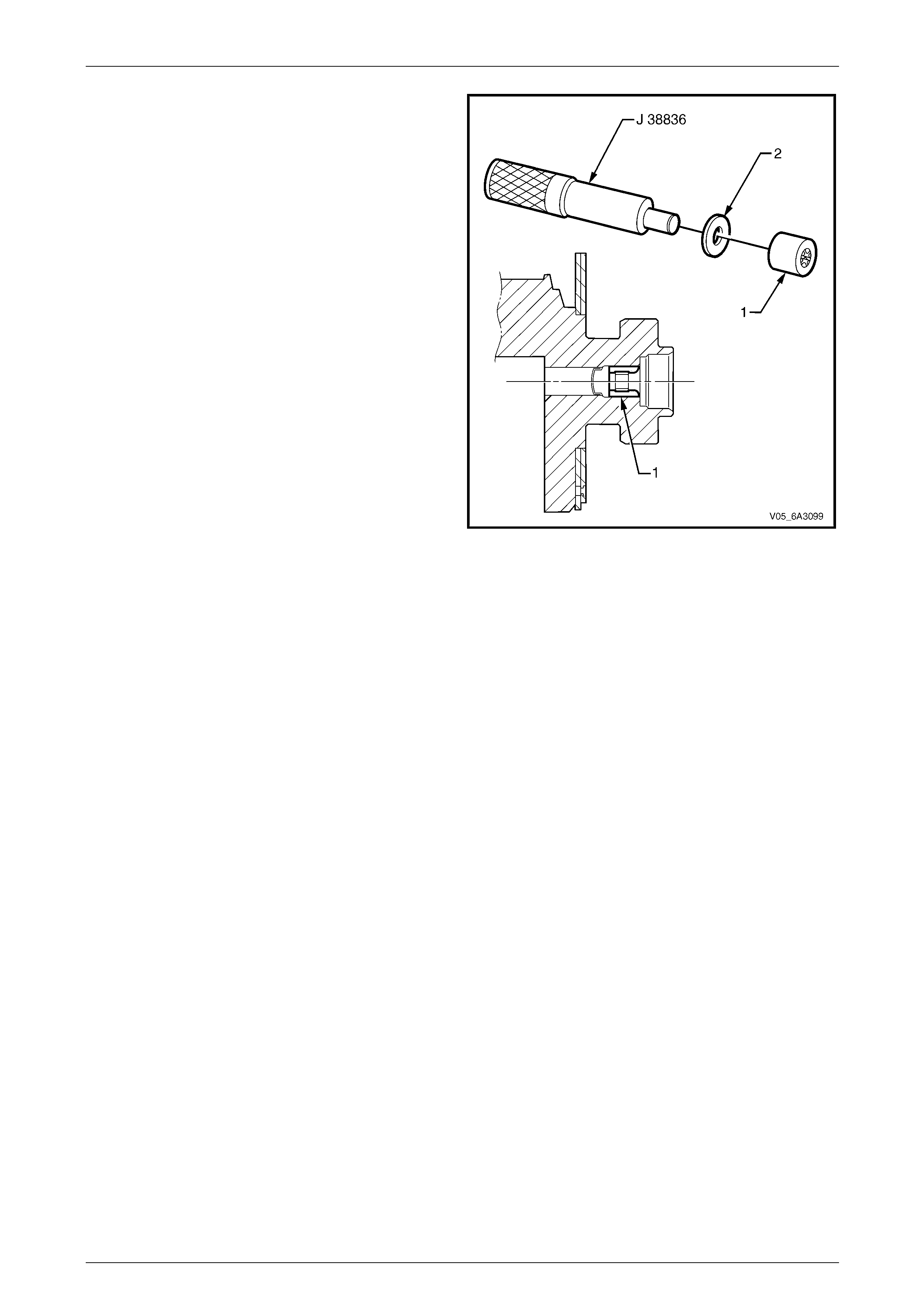
Engine Mechanical Page 6A4–190
Page 6A4–190
3 Using a suitable stepped driver such as Tool J 38836,
install the replacement bearing (1) to the rear of the
crankshaft using a flat washer (2) against the tool to
support the bearing races. Install the bearing until it is
flush with the crankshaft counter-bore.
4 Reinstall the clutch assembly and manual
transmission, refer to Section 7B2 Manual
Transmission – GEN IV V8 and
Section 7A3 Clutch – GEN IV V8.
5 Reconnect the battery ground lead, refer to
Section 00 Warnings, Cautions and Notes.
Figure 6A4 – 285
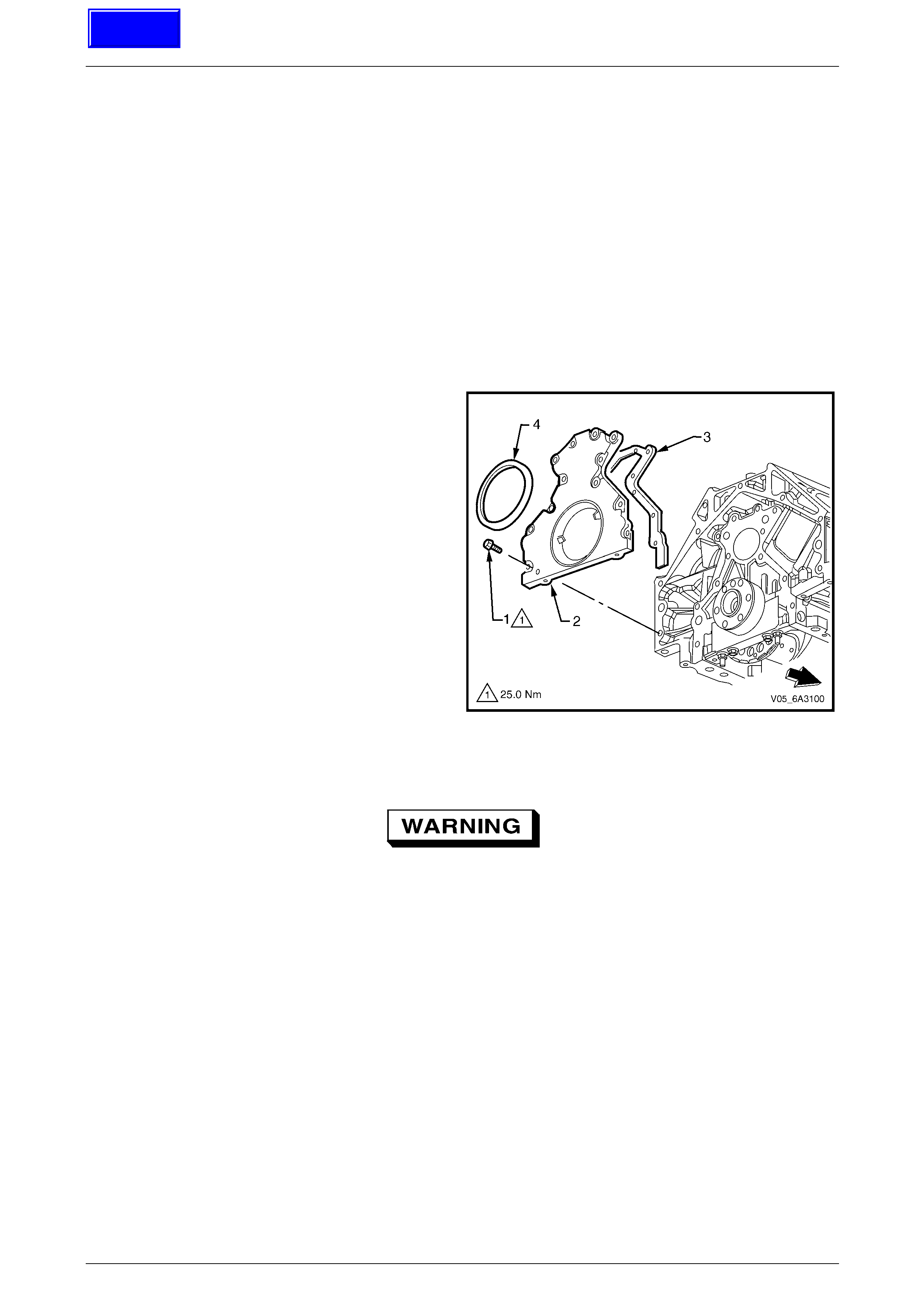
Engine Mechanical Page 6A4–191
Page 6A4–191
5.8 Engine Rear Cover
LT Section No. — 00–200
Remove
NOTE
Due to the critical alignment procedures required
for the reinstallation of the rear cover an d oil pan,
it is strongly recommended the engine assembly
be removed from the vehicle before oil pan
removal.
1 Remove the oil pan, refer to 5.3 Oil Pan.
2 Remove the flywheel/flexplate, refer to 5.6 Engine Flywheel and Flexplate.
3 Remove the bolt (1), 12 places, attaching the engi ne
rear cover (2) and remove the rear cover and gasket
(3).
4 Prise the rear main oil seal (4) from the rear cover
taking care not to distort the cover or scratch the oil
seal bore in the cover.
Figure 6A4 – 286
Clean and Inspect
To avoid personal injury, wear safety glasses
and the appropriate gloves when using
compressed air and cleaning fluids.
1 Clean the cover in a commercially available cleaning fluid and blow dry with compressed air.
2 Inspect the gasket sealing surface for e xcessive scratching or gouging.
3 Inspect the gasket for damage to the seal membrane or distortion to the al uminium carrier.
4 Inspect the cover to oil pan threaded h oles fo r debris or damage. Refer to 6 Thread Repair if rectification is
required.
5 Inspect the rear main oil seal bore for damage.
Techline
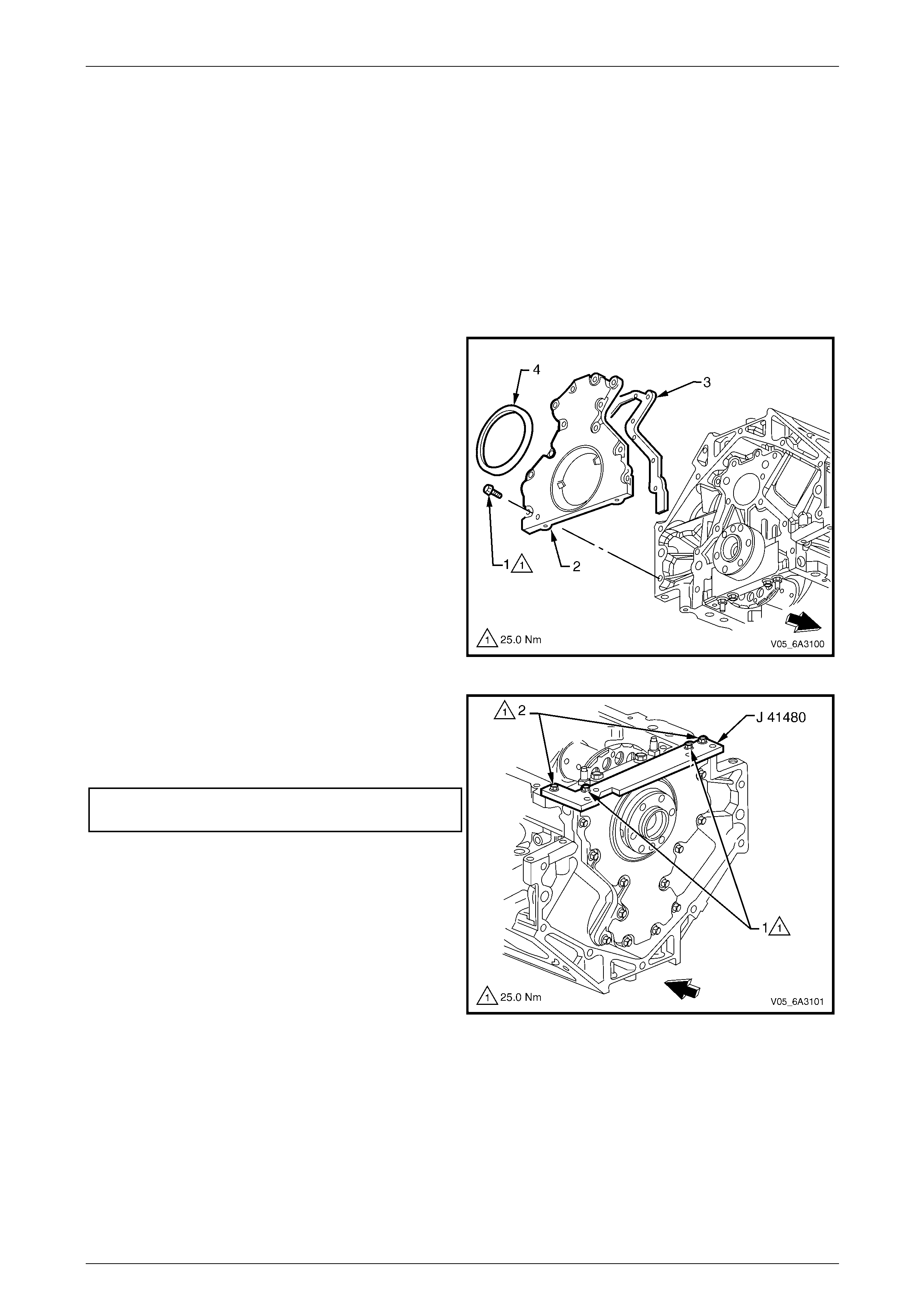
Engine Mechanical Page 6A4–192
Page 6A4–192
Reinstall
Observe the following prior to reinstallati on:
• Do not reuse the crankshaft rear oil seal.
• Do not apply any type of sealant to the rear cover gasket.
• The special tools in this procedure are used to correctly align the engine rear cover at the oil pan surface and to
centre the crankshaft rear main oil seal.
• All gasket surfaces should be free of oil or other foreign material during assembly.
• The crankshaft rear oil seal must be centred in relation to the crankshaft and is to be installed after the rear cover
installation.
• The oil pan sealing surface at the rear cover and cylinder block must also be aligned within specifications.
• An improperly aligned rear cover may cause premature oil s eal wear and/or engine assembly oil leaks.
1 Install the rear cover (2) and gasket (3) to the rear of
the engine.
2 Install the rear cover attaching bolt (1), 12 plac es, and
tighten the rear cover bolts finger tight onl y at this
stage.
NOTE
Do not install the rear main oil seal (4) at this
stage.
Figure 6A4 – 287
3 Assemble the alignment Tool No. J 41480 to the rear
cover and tighten the two attaching bolts (1) finger
tight.
4 Install the attaching bolts (2) to the cylinder block and
tighten to the specified torque.
Rear cover alignment tool to cylinder block
attaching bolt torque specification......................25.0 Nm
Figure 6A4 – 288
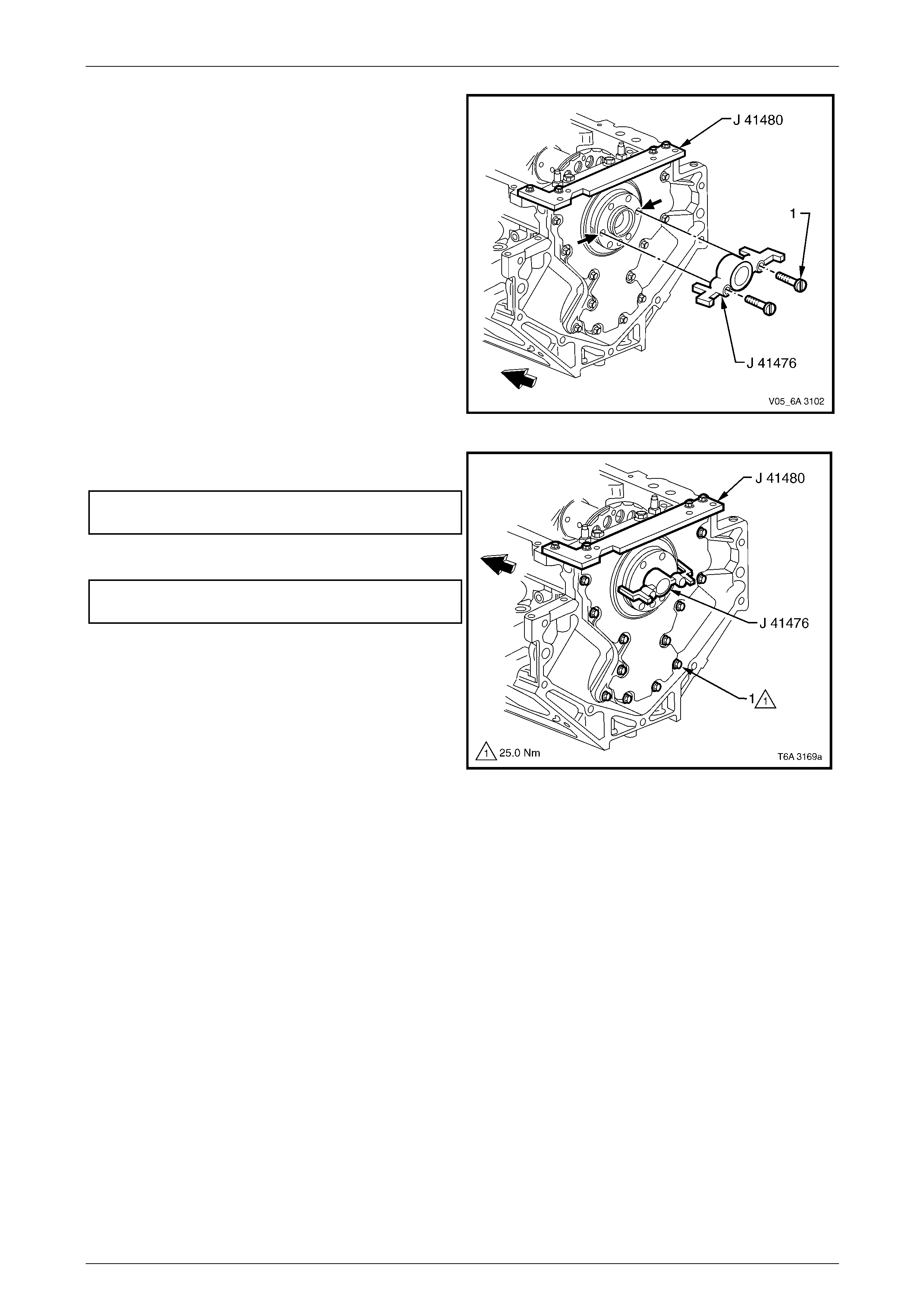
Engine Mechanical Page 6A4–193
Page 6A4–193
5 Rotate the crankshaft until two opposing
flywheel/flexplate mounting bolt holes are parallel to
the oil pan surface of the cylin der block.
6 Install the alignment Tool No. J 41476 to the rear of
the crankshaft.
NOTE
The tapered legs of the alignment tool must
enter the rear cover oil seal bore.
7 Install the two screws (1) supplied with Tool No.
J 41476 and tighten firmly with a screwdriver.
Figure 6A4 – 289
8 Tighten the alignment Tool No. J 41480 to the rear
cover to the correct torque specification.
Rear cover alignment tool to rear cover
attaching bolt torque specification......................12.0 Nm
9 Tighten the engine rear cover attaching bolts (1) to the
correct torque specification.
Engine rear cover attaching bolt
torque specification............................................25.0 Nm
10 Remove the alignment tools.
Figure 6A4 – 290
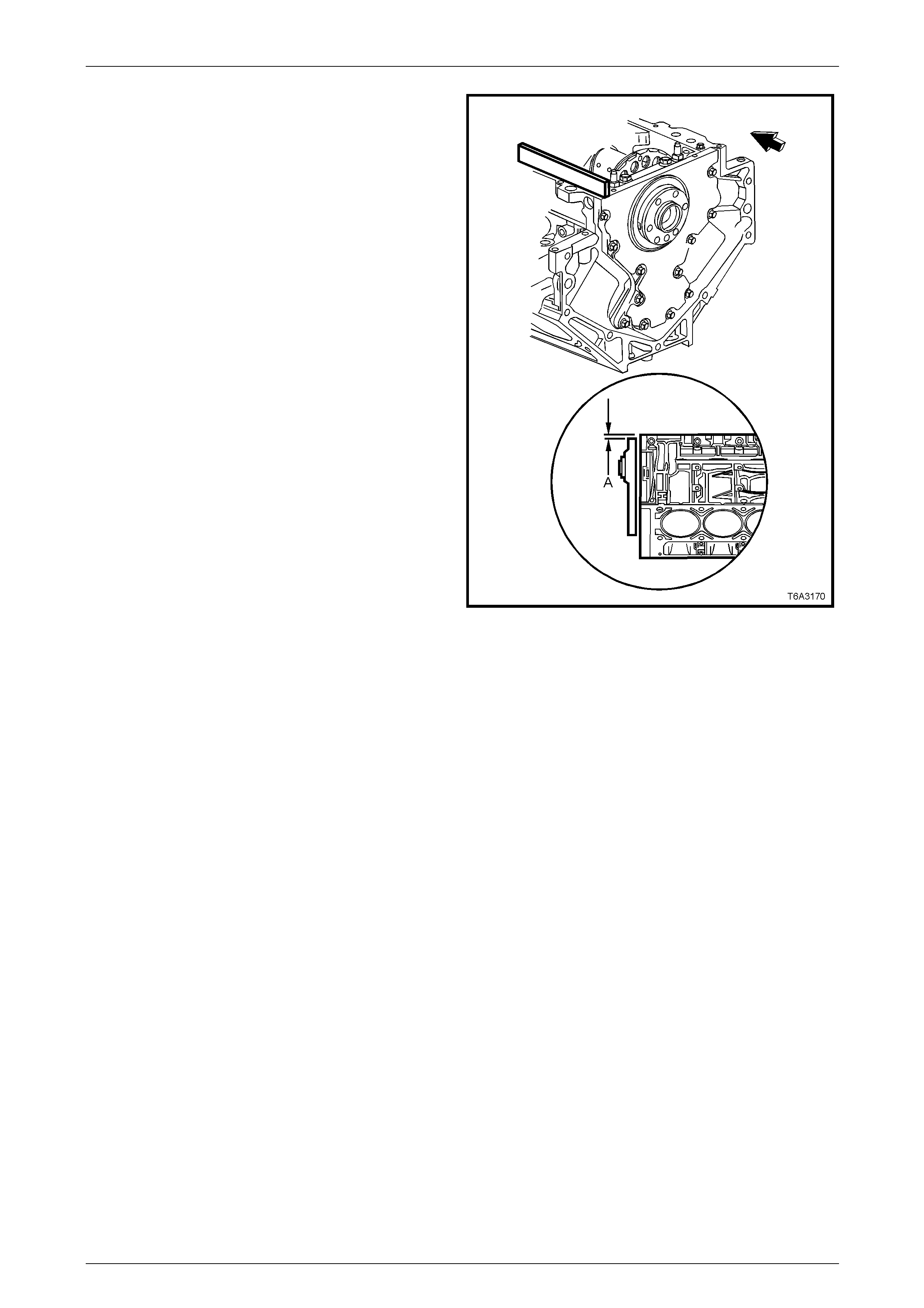
Engine Mechanical Page 6A4–194
Page 6A4–194
11 Measure the oil pan surface to rear cover for flatness
as follows:
• Place a straight edge across the cylinder block
and rear cover oil pan seali ng surfaces. Avoid
contact with the portion of the gasket that
protrudes into the oil pan surface.
• Insert a feeler gauge between the rear cover and
the straight edge tool. The cover must be flush
with the oil pan surface to no more than
0.25 mm (A).
• If the rear cover-to-cylinder block oil pan surface
alignment is not within specification, repeat the
cover alignment procedure.
NOTE
If the correct rear cover to cylinder block
alignment cannot be obtained, replace the rear
cover.
Figure 6A4 – 291
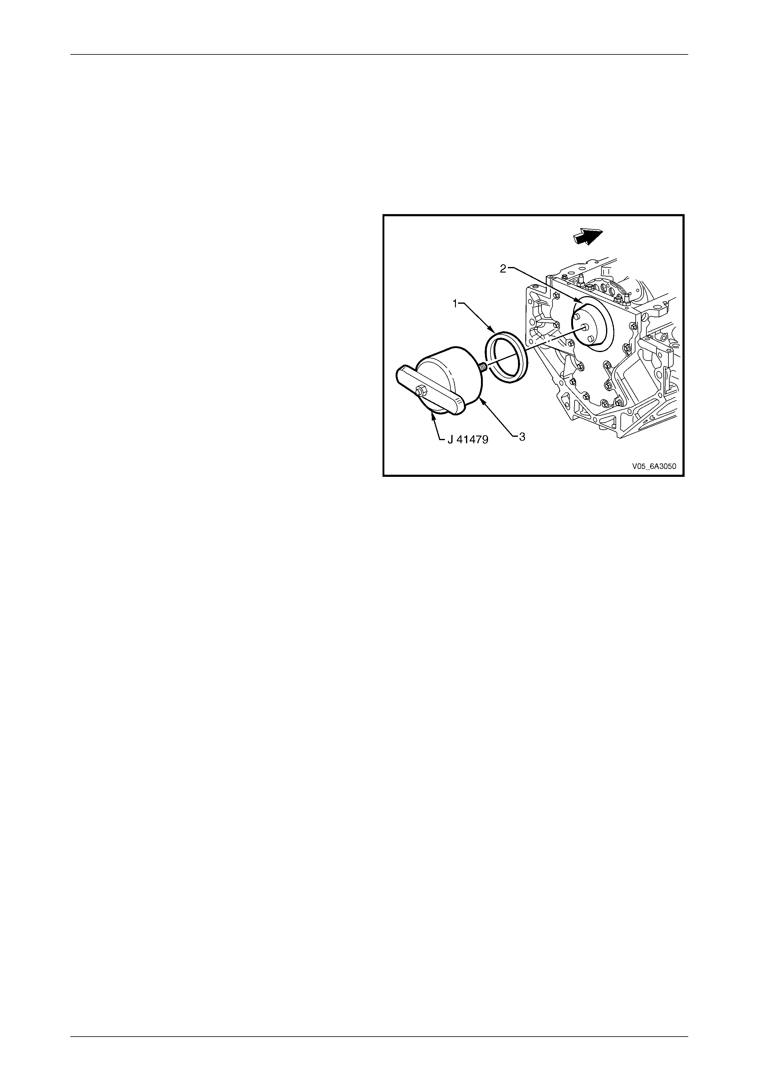
Engine Mechanical Page 6A4–195
Page 6A4–195
Crankshaft Rear Main Oil Seal
Install
NOTE
Do not lubricate the oil seal inside diameter (ID)
or the crankshaft seal surface. For further
information, refer to 1.5 Engine Lubrication
System.
1 Lubricate the outer edge of the oil seal (1) (OD) with
clean engine oil.
2 Lubricate the engine rear c over oil se al bore (2) with
clean engine oil.
3 Install the cone (3) of installation Tool No. J 41479
with bolts, to the rear of the crankshaft. Tighten the
bolts until secure.
4 Install a new oil seal onto the taper of the installation
tool and push the seal to the rear cover bore.
5 Position Tool No. 41479 into the tapered part until the
tool contacts the oil seal.
6 Align the oil seal with the tool then rotate the handle of
the tool clockwise until the seal enters then bottoms
into the rear cover bore.
7 Remove both parts of the installation tool.
8 Reinstall the flywheel. Refer to 5.6 Engine Flywheel
and Flexplate.
9 Reinstall the clutch and/or transmission. Refer to
either:
• Section 7B2 Manual Transmission – GEN IV V8
• Section 7A3 Clutch – GEN IV V8
• Section 7C4 Automatic Transmission – 4L60E –
On Vehicle Servicing
Figure 6A4 – 292
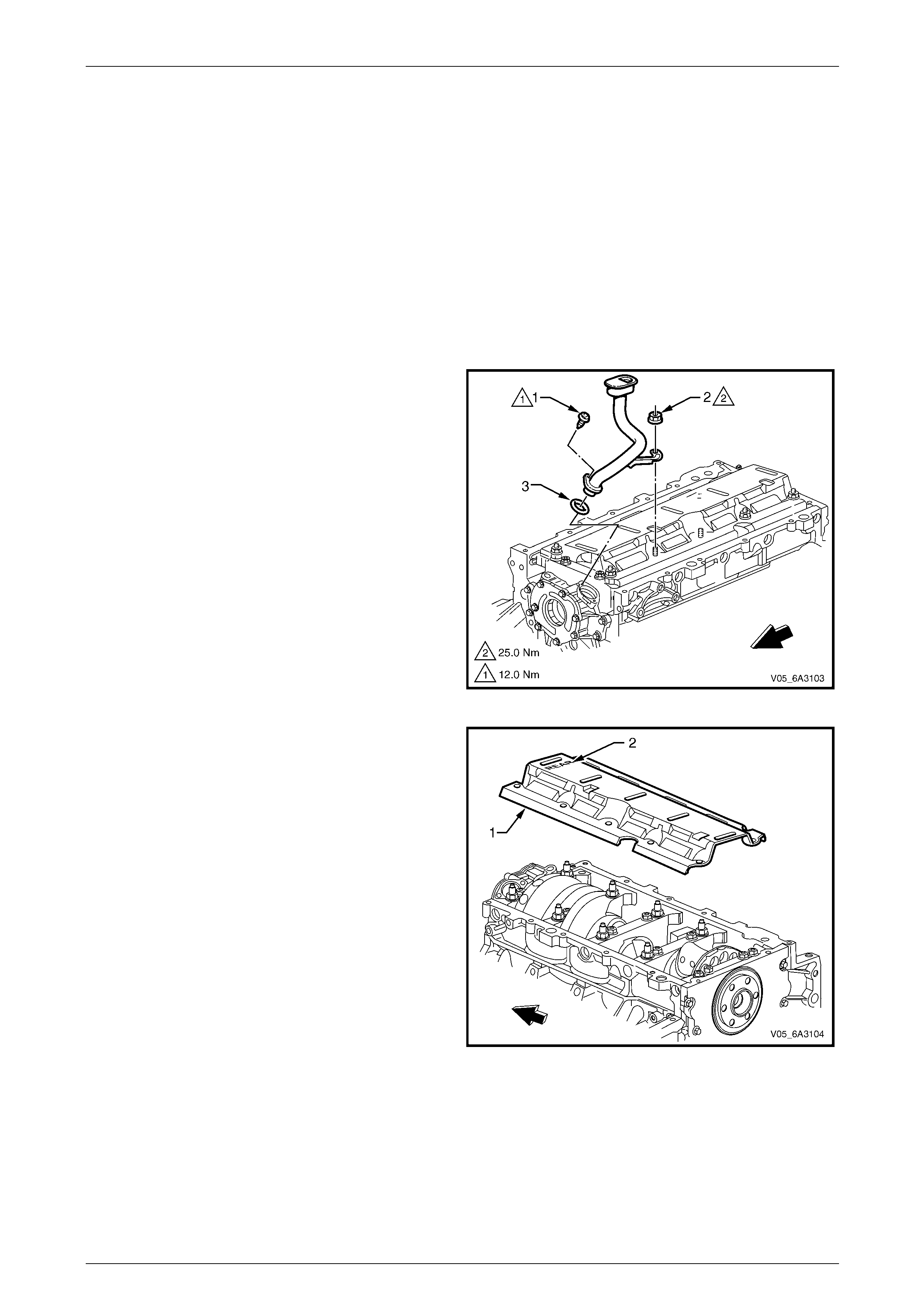
Engine Mechanical Page 6A4–196
Page 6A4–196
5.9 Oil Pump, Pump Screen and Deflector
LT Section No. — 00–251 and 01–500
Remove
NOTE
Due to the critical alignment procedures required
for the reinstallation of the rear cover an d oil pan,
it is strongly recommended the engine assembly
be removed from the vehicle before oil pan
removal.
1 Remove the engine front cover, refer to 5.5 Engine Front Cover.
2 Remove the oil pump pick-up screen and tube
attaching screw (1) and crankshaft oil deflector
attaching nut (2), which also attaches the oil pump
pick-up screen and tube to the cylinder block.
3 Remove the oil pump pick-up screen and tube
assembly and the O-ring seal (3) from the oil pump
bore. Discard the O-ring.
Figure 6A4 – 293
4 Remove the remaining cranks haft oil deflector
attaching nuts, nine places.
5 Remove the crankshaft oil deflector (1), noting the
cover orientation is stamped "REAR" (2) to assist in
the correct installation.
Figure 6A4 – 294
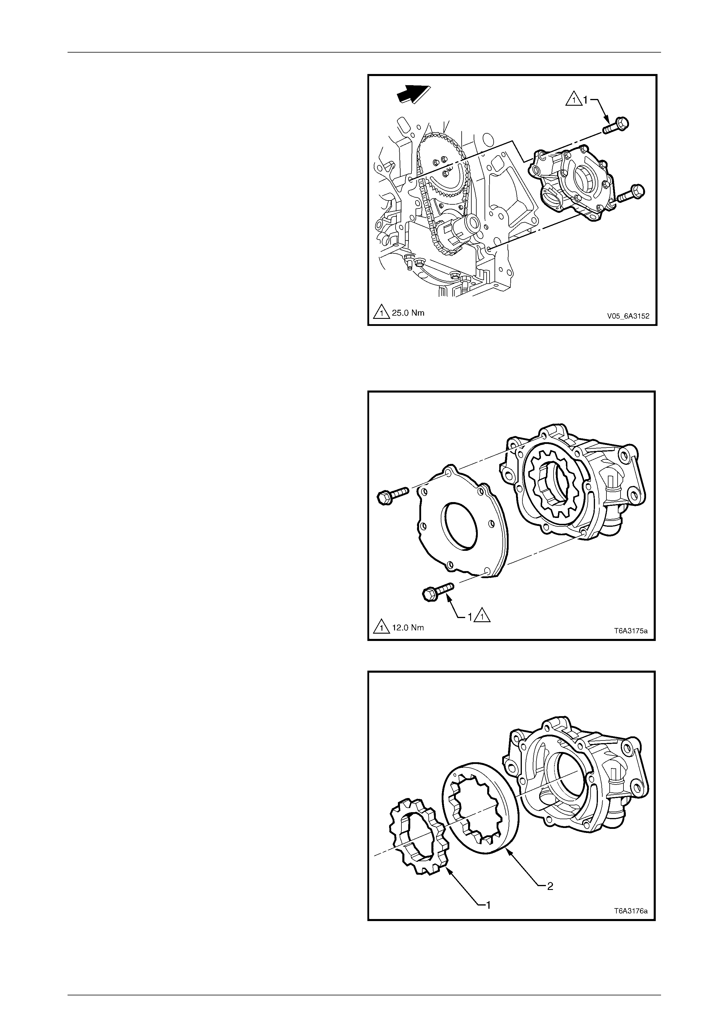
Engine Mechanical Page 6A4–197
Page 6A4–197
6 Remove the bolt (1), four places, attaching the oil
pump to the front of the engine and remove t he oil
pump from the crankshaft.
7 If the oil pump is not being serviced, plug all openings
to avoid the entry of foreign material in the system.
Figure 6A4 – 295
Oil Pump Disassemble
1 Remove the bolt (1), seven places, attaching the oil
pump cover to the pump and remove the cover.
Figure 6A4 – 296
NOTE
Prior to disassembly, mark or identify the
relationship of the gears for reassembly.
2 Remove the inner drive gear (1) and the outer driven
ring (2), from the oil pump body.
Figure 6A4 – 297
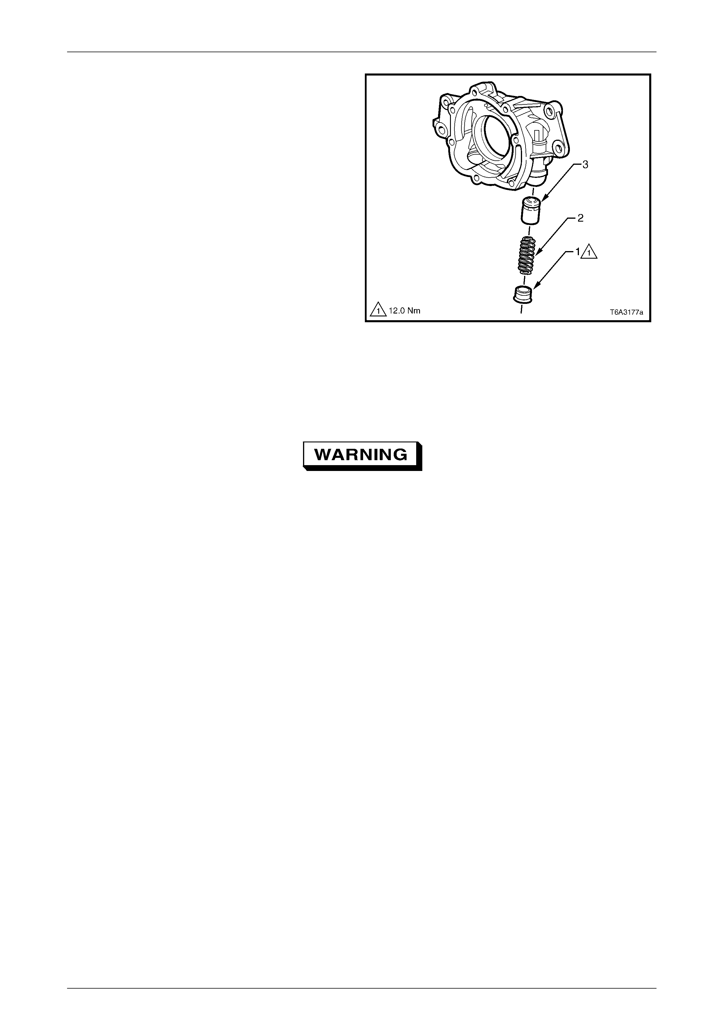
Engine Mechanical Page 6A4–198
Page 6A4–198
3 Unscrew the oil pressure relief valve plug (1) and
remove the spring (2), and valve (3) from the oil pump
body.
Figure 6A4 – 298
Clean and Inspect
With the exception of the oil p r essure relief valve spring there are no parts in the oil pump or the oil pump pick-up screen
and pipe that are serviced separately. If either component is found to be worn or damaged the assembly must be
replaced.
To avoid personal injury, wear safety glasses
and the appropriate gloves when using
compressed air and cleaning fluids.
1 Clean all parts in a commerciall y avai lable cleaning fluid and blow dry using compressed air.
2 Inspect the following components:
a Oil pump housing for cracks, excessive wear, scoring or casting imperfections.
b Oil pump housing to cylinder block oil gallery surface for scratches or gouging.
c Inspect the oil pump housing for damag ed bolt hole threads Refer to 6 Thread Repair, if repairs are required.
d Oil pump relief valve plug and bore for scratched or damaged surfaces and the screw thread for damage. The
pressure relief valve must be able to move freely within its bore with no restrictions.
e Oil pump internal oil passages for restrictions.
f Inspect the drive and driven gears for chipping or wear. Minor burrs or imperfections on the gears can be
removed with a fine oil stone.
g Inner gear drive splines for excessive wear.
h Oil pump pick-up screen and pipe assembly and replace if either of the following conditions are observed.
• Oil pump pick-up screen is clogg ed with debris or restriction.
• Screen mesh is broken or has loose stran ds.
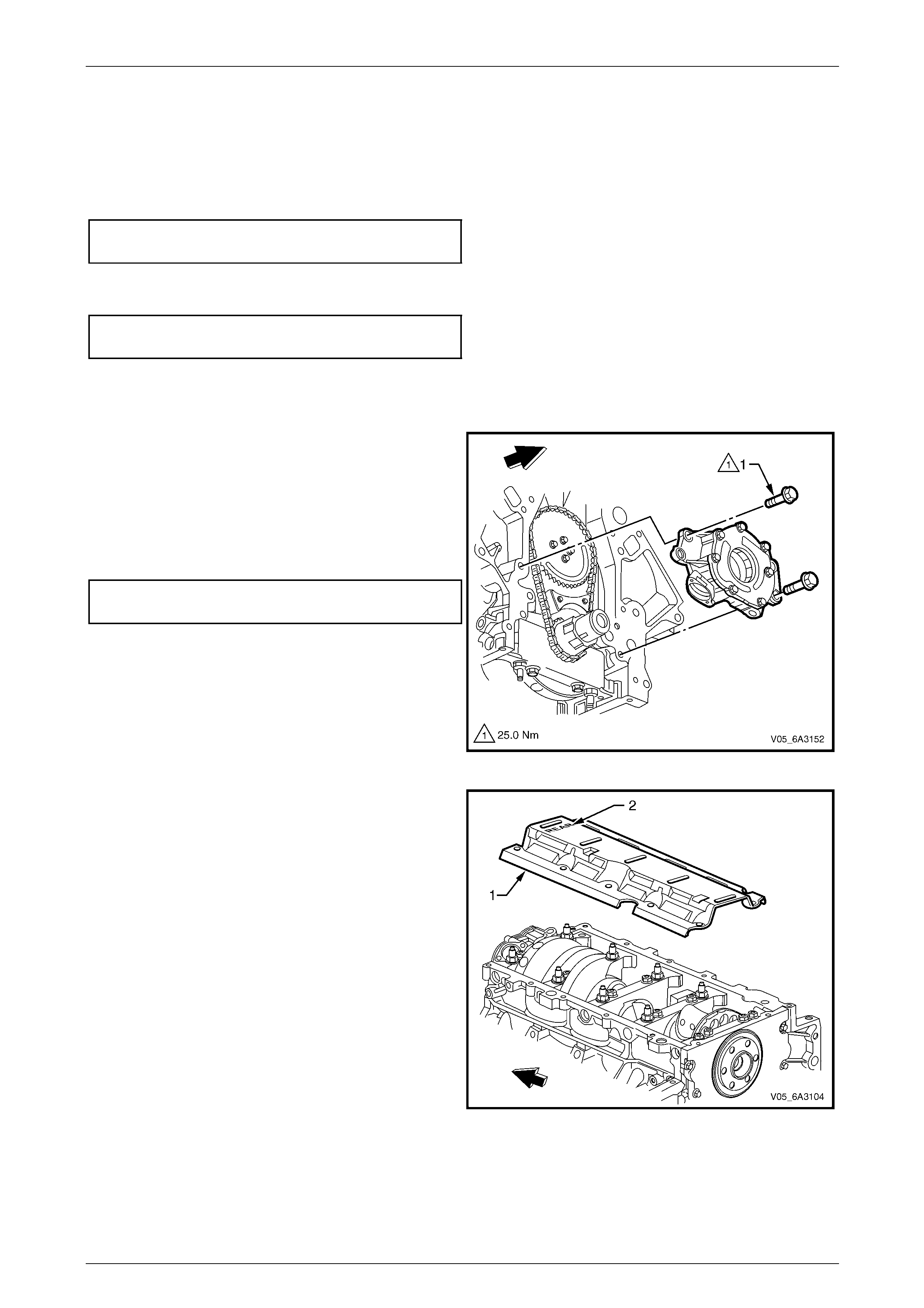
Engine Mechanical Page 6A4–199
Page 6A4–199
Oil Pump Reassemble
Reassembly of the oil pump is the reverse of the disassemble procedure, noting the following:
1 Liberally coat all oil pump components with clean engine oil before assembly.
2 When assembling the oil pump, ensure the relationship of the inner to the outer oil pump gears is matched as
marked in the removal procedure.
3 Tighten the oil pump cover attaching screws to the correct torque specification.
Oil pump cover/pump body attaching bolt
torque specification............................................12.0 Nm
4 Install a new pressure relief valve spri ng.
5 Tighten the pressure relief valv e plug to the correct torque specification.
Oil pump pressure relief plug
torque specification............................................12.0 Nm
6 Rotate the assembled pump checking for smoothness of operation by rotating the inner drive gear.
Reinstall
1 Ensure the oil pump and c ylinder block oil gallery
passages are free from any debris or fore ign material.
2 Align the splined surfaces of the crankshaft sprocket
and the oil pump drive gear and install the oil pump
onto the sprocket until the pu m p housing contacts the
face of the cylinder block.
3 Install the two oil pump attaching bolts (1) an d tighten
to the correct torque specification.
Oil pump attaching bolt
torque specification............................................25.0 Nm
Figure 6A4 – 299
4 Install the crankshaft oil deflector (1), ensuri ng the
"REAR" stamping (2) on the deflector is located at the
rear of the engine.
Figure 6A4 – 300
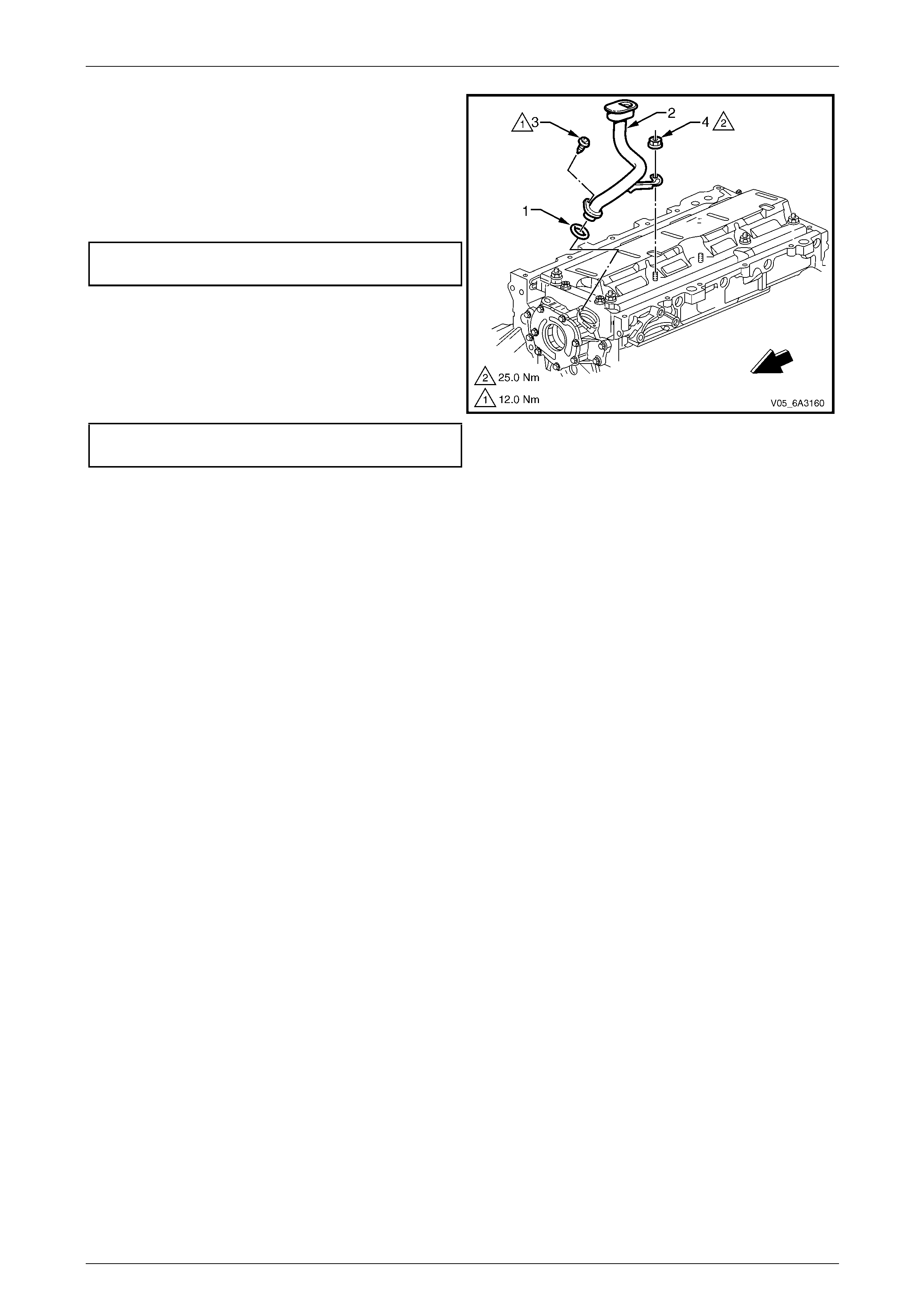
Engine Mechanical Page 6A4–200
Page 6A4–200
5 Lubricate a new oil pump pic k-up tube O-ring (1) with
clean engine oil and install into the oil pump pick-up
tube (2).
6 Fully install the pick-up tube into the oil p ump housing
aligning the support bracket with the main bearing cap
stud.
7 Install the pick-up tube attaching screw (3) and tighten
to the correct torque specification.
Oil pump pick-up tube attaching screw
torque specification............................................12.0 Nm
NOTE
Ensure the pick-up tube is fully installed before
tightening the attaching screw.
8 Install the crankshaft oil deflector attaching nut (4) 10
places, to the main bearing cap studs and tighten to
the correct torque specification.
Crankcase oil deflector attaching nut
torque specification............................................25.0 Nm
9 Reinstall the front engin e cover, refer to
5.5 Engine Front Cover.
Figure 6A4 – 301
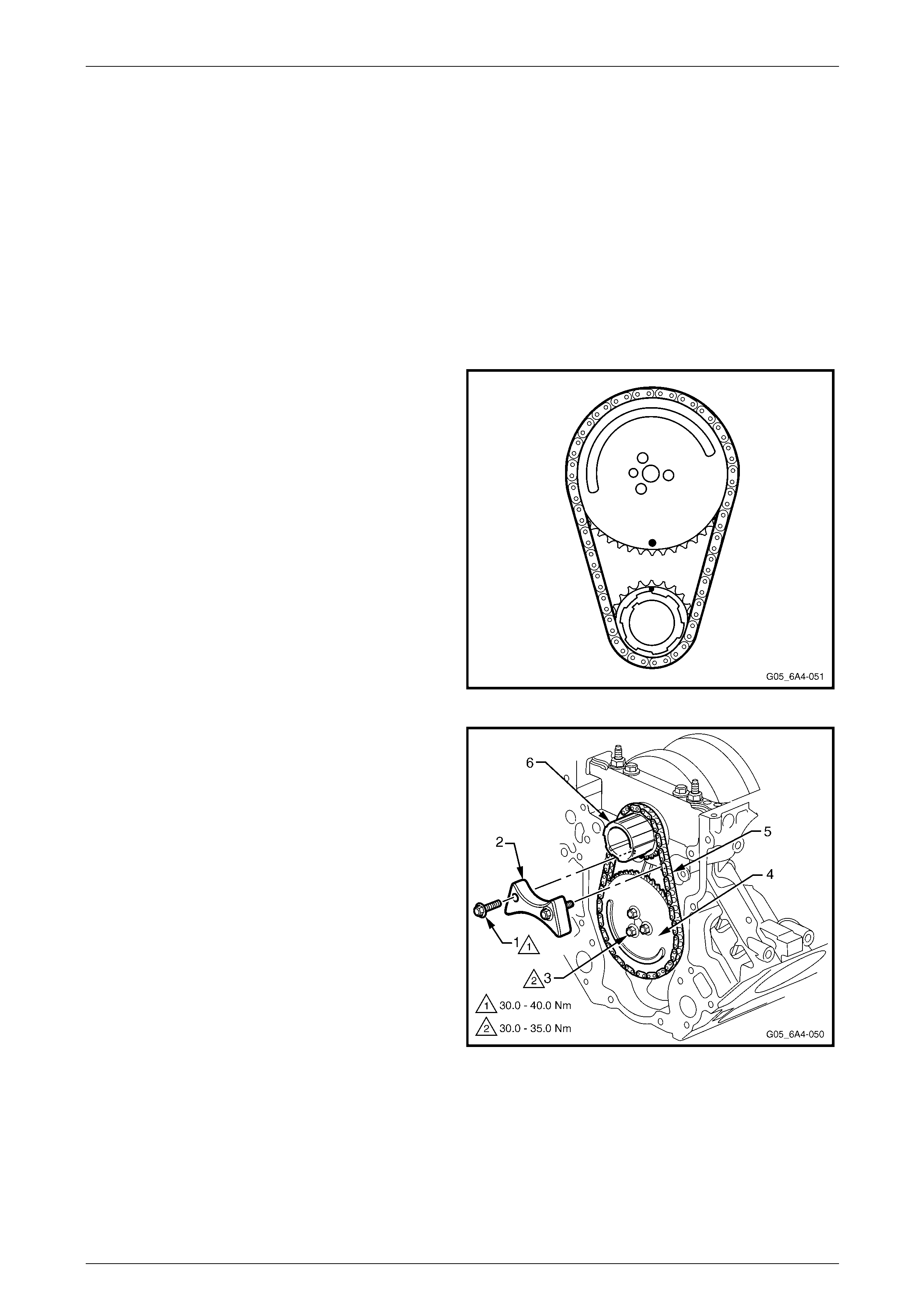
Engine Mechanical Page 6A4–201
Page 6A4–201
5.10 Timing Chain and Sprockets
LT Section No. — 00–225
Remove
NOTE
Due to the critical alignment procedures required
for the reinstallation of the engine front cover and
oil pan, it is strongly recommended the engine
assembly be removed from the vehicle before oil
pan removal.
1 Remove the harmonic balancer and front engine cover, refer to 5.5 Engine Front Cover.
2 Temporarily install the harmonic balancer bolt and turn
the engine over by hand until the timing marks on the
crankshaft and camshaft sprockets are aligned.
3 Remove the oil pump, refer to 5.9 Oil Pump, Pump
Screen and Deflector.
Figure 6A4 – 302
4 Remove the bolt (1), two places, attaching the timing
chain dampener (2) to the cylinder block.
5 Remove the three camshaft sprocket attaching bolts
(3) and then remove the sprocket (4) and chain (5)
from the camshaft and crankshaft (6).
Figure 6A4 – 303
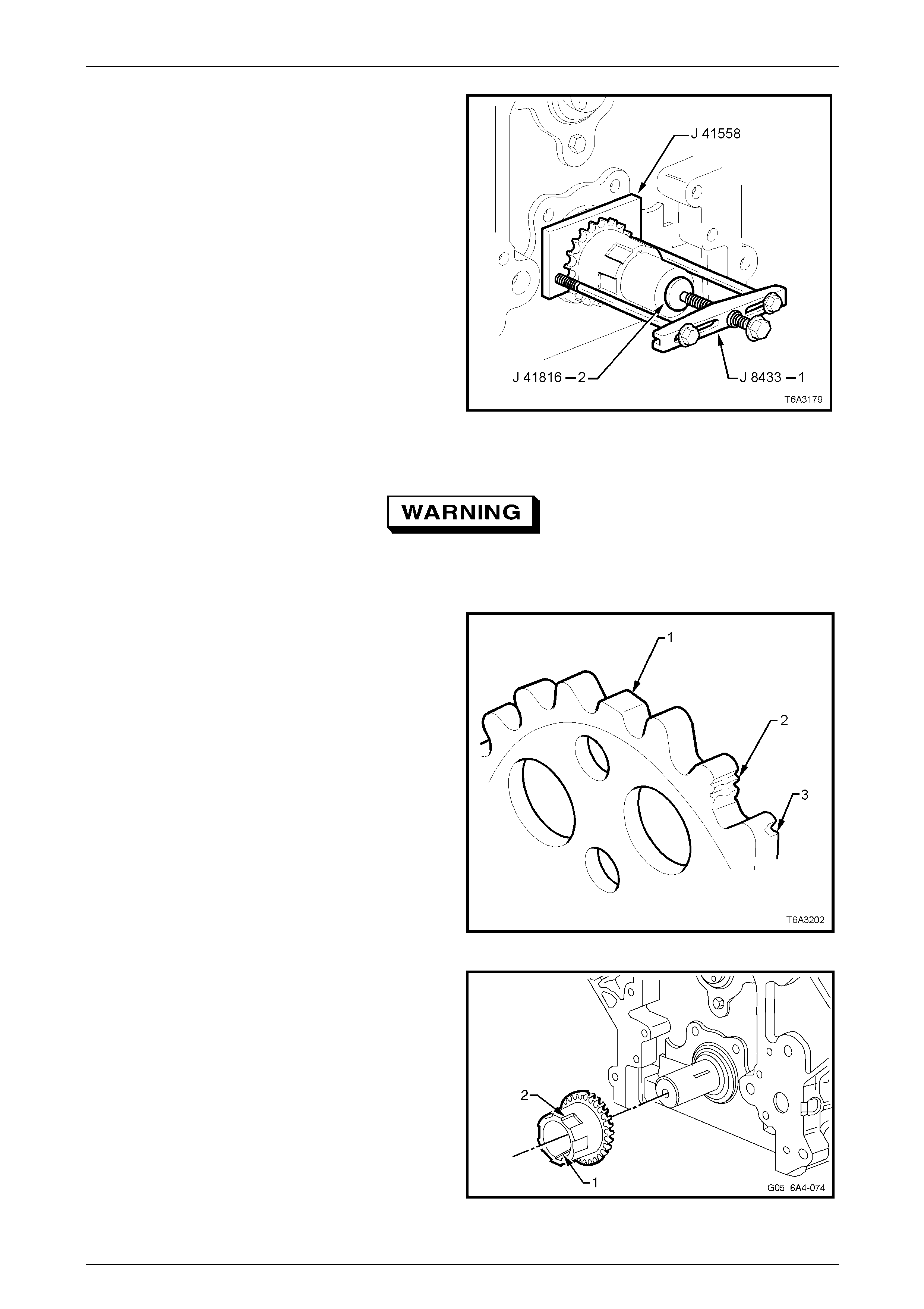
Engine Mechanical Page 6A4–202
Page 6A4–202
6 Use Tool No’s J 41558, J 41816-2, the b olts from
J 1427-01 and puller J 8433-1 to remove the
crankshaft sprocket from the nose of the crankshaft
7 If required, remove the crankshaft timing sprocket
drive key from the crankshaft nose.
Figure 6A4 – 304
Clean and Inspect
To avoid personal injury, wear safety glasses
and the appropriate gloves when using
compressed air and cleaning fluids.
1 Clean the timing sprockets and timing chain in
commercially available cleaning fluid and blow dry with
compressed air.
2 Inspect the timing chain for binding or wear.
3 Inspect the camshaft and crankshaft sprockets for:
• Worn teeth (1)
• Damaged teeth (2)
• Chipped teeth (3)
• Worn valleys between the sprocket teeth
Figure 6A4 – 305
4 Inspect the crankshaft timing sprocket keyway (1) for
wear.
5 Inspect the crankshaft timing sprocket oil pump drive
splines (2) for wear.
NOTE
Replace any worn parts with new components.
Although not mandatory, it is also rec ommended
the timing gears and chain be relaced as a
complete set.
Figure 6A4 – 306
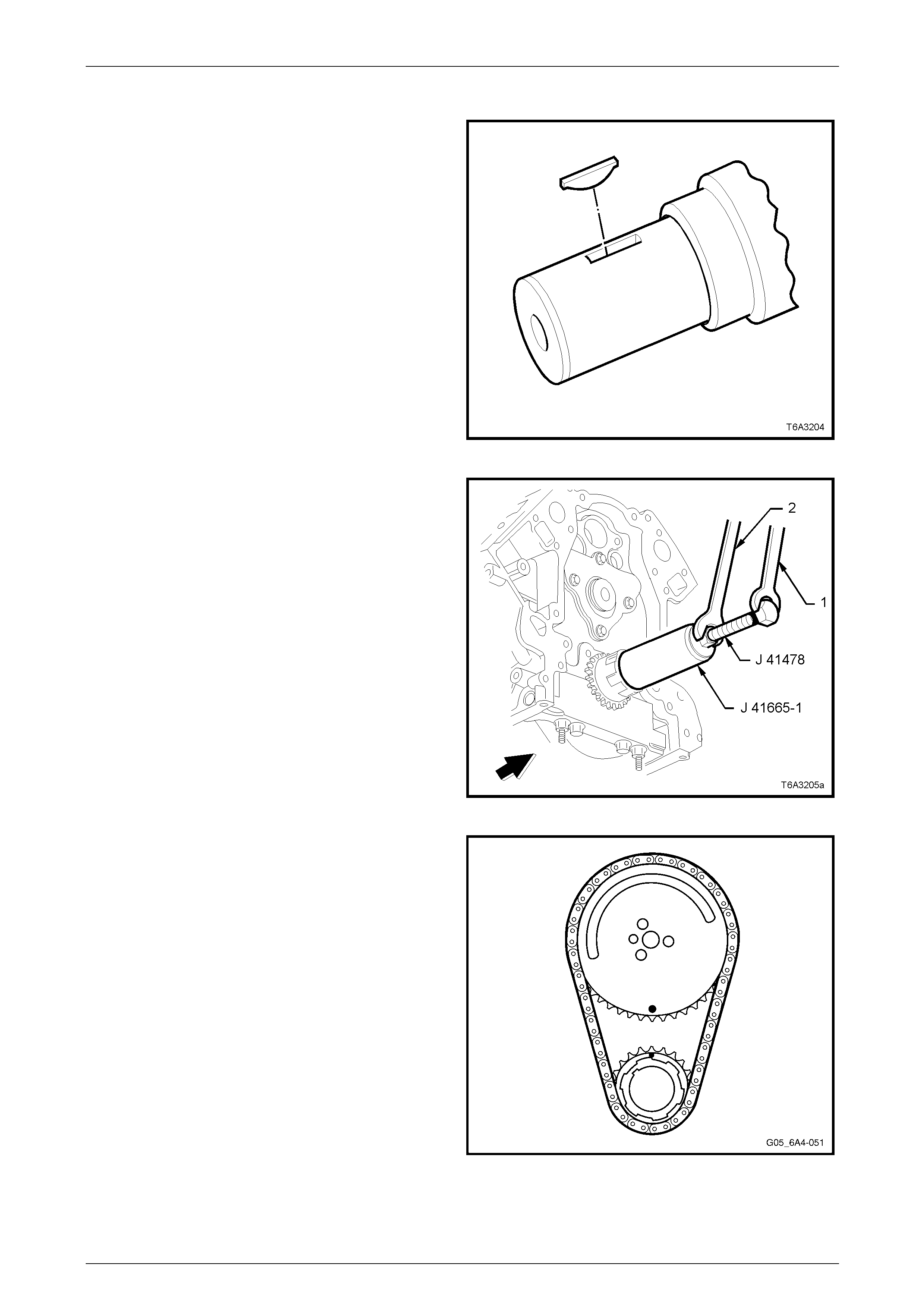
Engine Mechanical Page 6A4–203
Page 6A4–203
Reinstall
1 If removed, reinstall the crankshaft sprocket drive
keyway into the crankshaft. The key should be tapped
into place until each end bottoms on the crankshaft.
2 Reinstall the crankshaft sprocket onto the cranksh aft
aligning the keyway with the key.
Figure 6A4 – 307
3 Use the installer Tool No. J 41665 to reinsta ll the
crankshaft sprocket, as follows:
a Install the threaded bolt, nut and flat washer from
Tool No. J 41478 through the end plate and
stepped sleeve of Tool No. J 41665-1.
b Screw the threaded bolt into the crankshaft,
using a spanner (1).
c While holding the threade d bo lt with the spanner,
turn the nut with a second set spanner (2),
moving the installer Tool No. J 41665 to fully
install the crankshaft sprocket onto the
crankshaft nose.
d When the crankshaft sprocket has been fully
installed, remove the installation tools.
Figure 6A4 – 308
4 If required, temporarily reinstall the harmo nic balancer
bolt and rotate the crankshaft until the cranks haft and
camshaft timing gears are aligned
5 If required, temporarily install the camshaft sprocket
bolts and use a suitable lever to carefully rotate the
camshaft sprocket until the timing mark is correctl y
aligned. Remove the bolts and sprocket.
6 Install the timing chain to the camshaft sprocket. Align
the camshaft peg with the camshaft sprocket hole and
then install the timing chain to the cranksh aft sprocket.
7 Install the camshaft sprocket over the camshaft peg.
8 Before installing the camshaft sprocket attaching bolts,
check the timing marks are aligned. If not, repeat
Steps 4 to 8 above.
Figure 6A4 – 309

Engine Mechanical Page 6A4–204
Page 6A4–204
9 Install the camshaft sprocket attaching bolts and tighten to the correct torque specification.
Camshaft sprocket attaching bolt
torque specification.................................30.0 – 35.0 Nm
10 Reinstall the timing chain dampener and tighten the two attaching bolts to the correct torque specification.
Timing chain dampener attaching
attaching bolt torque specification...........30.0 – 40.0 Nm
11 Reinstall the oil pump, refer to 5.9 Oil Pump, Pump Screen and Deflector.
12 Reinstall the front cover and harmonic balancer. Refer to 5.5 Engine Front Cover.
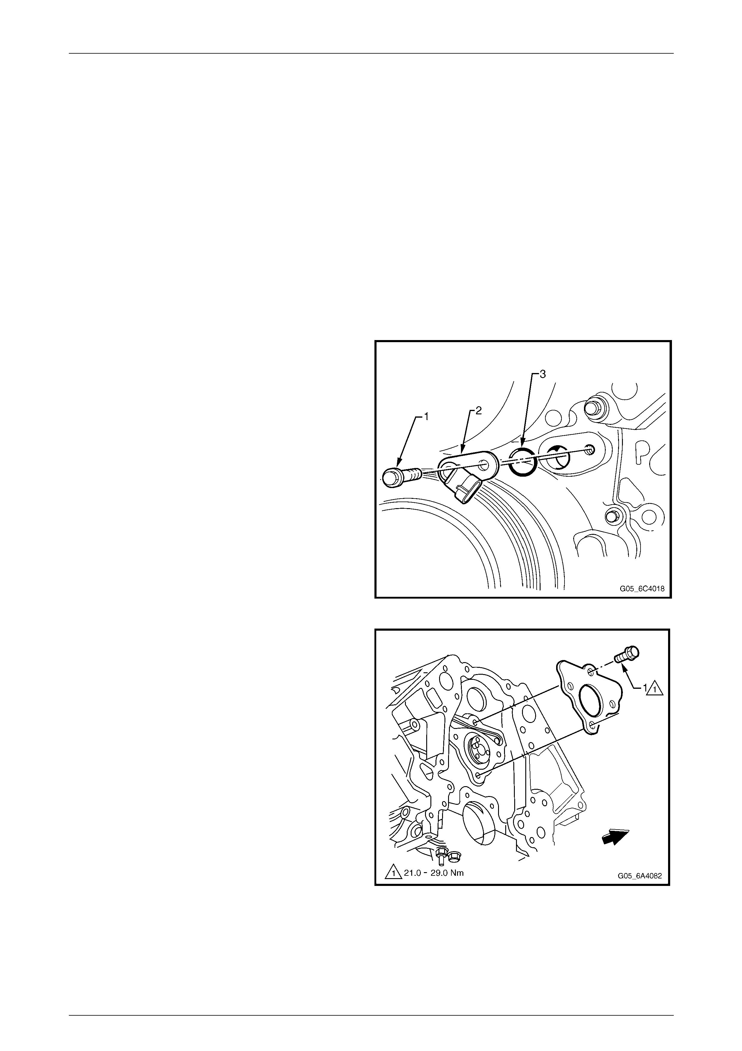
Engine Mechanical Page 6A4–205
Page 6A4–205
5.11 Camshaft
LT Section No. — 00–175
Remove
NOTE
• Due to the critical alignment procedures
required for the reinstallation of the engine
front cover and the oil pan, it i s recommended
the engine assembly be removed from the
vehicle before oil pan removal.
• If required, before removing the camshaft
perform a camshaft lobe lift test, refer to
4.10 Camshaft Lobe Lift
1 Remove the hydraulic valve lifters, refer to 4.16 Hydraulic Valve Lifters.
2 Remove the front engine cover, refer to 5.5 Engine F ront Cover.
3 Remove the bolt (1), attaching the camshaft sensor
and remove the sensor. Refer to Section 6C4-3
Engine Management - Service Operatio ns
4 Remove the oil pump, refer to 5.9 Oil Pump, Pump
Screen and Deflector.
5 Remove the camshaft chain and sprocket. Refer to
5.10 Timing Chain and Sprockets.
Figure 6A4 – 310
6 Remove the camshaft retainer attaching bolt (1), four
places and remove the retainer an d gasket.
Figure 6A4 – 311
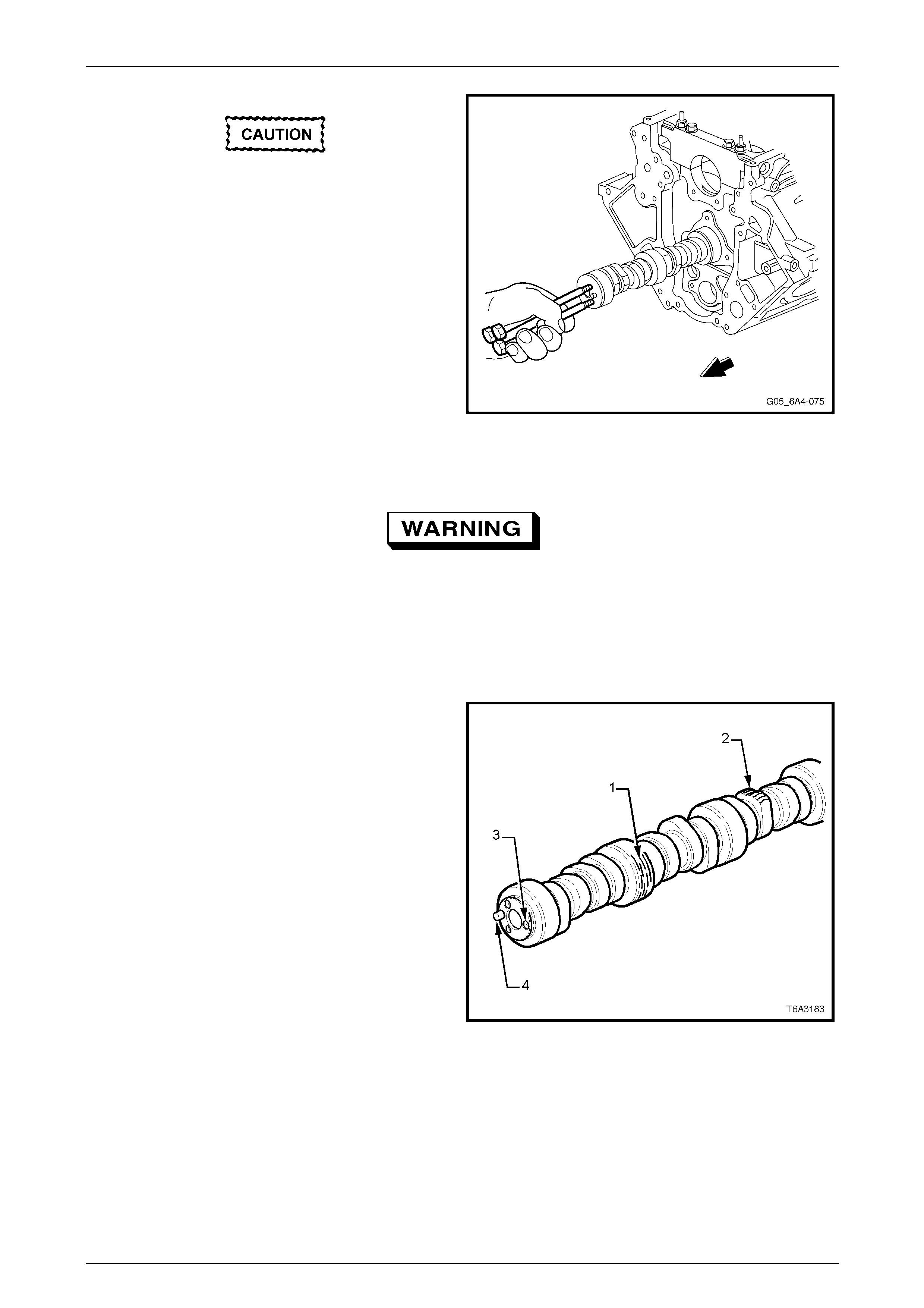
Engine Mechanical Page 6A4–206
Page 6A4–206
All camshaft bearing journals are the same
size and care must be taken when removing
the camshaft to avoid damaging the
bearings.
7 Install three, M8 x 1.25 x 100 mm bolts (e.g. removed
coolant pump bolts) in the front of the camshaft and
use as a handle to rotate and remove the camshaft
from the cylinder block.
8 Remove the three bolts from the camshaft.
Figure 6A4 – 312
Clean and Inspect
To avoid personal injury, wear safety glasses
and the appropriate gloves when using
compressed air and cleaning fluids.
NOTE
If camshaft replacement is required, the valve
lifters must also be renewed.
1 Clean all components with a commercially available
cleaning fluid and bl ow dry with compressed air.
2 Inspect the camshaft for:
• Scoring or excessive wear to the bearin g
journals (1)
• Nicks or damage to the camshaft position
reluctor ring (2)
• Damaged threads (3) or debris in the threaded
holes
• Damage to the camshaft sprocket pin (4)
• Scoring or excessive wear to the camshaft lobes
Figure 6A4 – 313
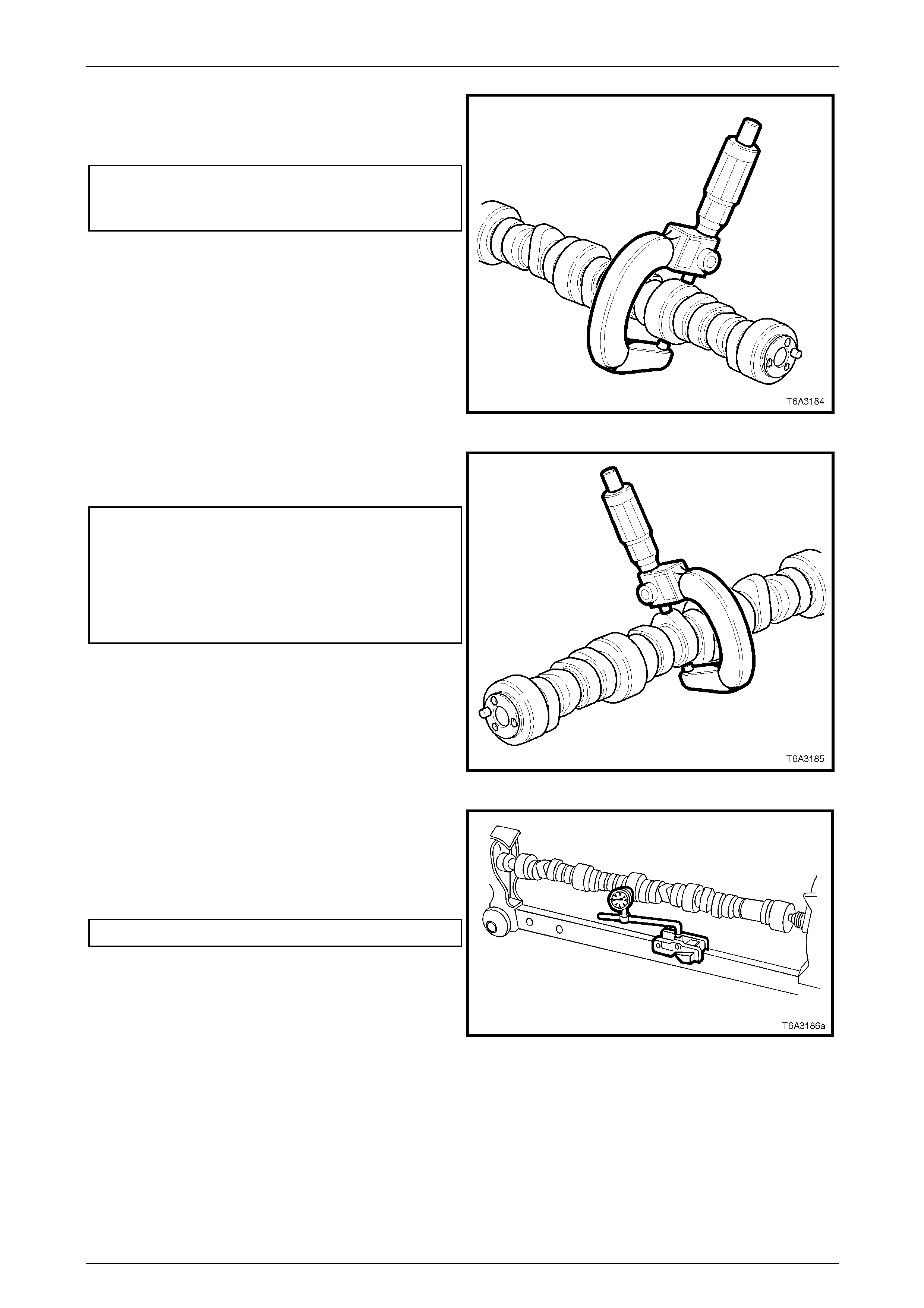
Engine Mechanical Page 6A4–207
Page 6A4–207
3 Measure the camshaft journals for wear and out-of-
round using a micrometer. Repl ace the camshaft if
either of these measurements are outsid e th e
specification.
Camshaft journal specifications:
Journal out-of-round.................................0.025 mm Max
Bearing journal diameter...........................54.99 mm Min
Figure 6A4 – 314
4 Measure the camshaft lobes for wear using a
micrometer. Replace the camshaft if any of the
camshaft lobe dimensions are not within spec ification.
Camshaft lobe wear limit:
Intake lobe diameter:
Except Coupe ...........................................46.67 mm Min
Coupe .......................................................46.21 mm Min
Exhaust lobe diameter:
Except Coupe ...........................................46.67 mm Min
Coupe .......................................................46.37 mm Min
Figure 6A4 – 315
5 Mount the camshaft either in Vee blocks or between
centres.
6 Using a suitable dial indicator, rotate the camshaft and
check the runout on the centre bearing journal.
Replace the camshaft if the runout exceeds t he
specification.
Camshaft runout specification....................0.05 mm Max
7 Inspect the camshaft retainer plate for wear or a
damaged sealing gask et. If the gasket is not cut or
damaged, it may be re-used.
Figure 6A4 – 316
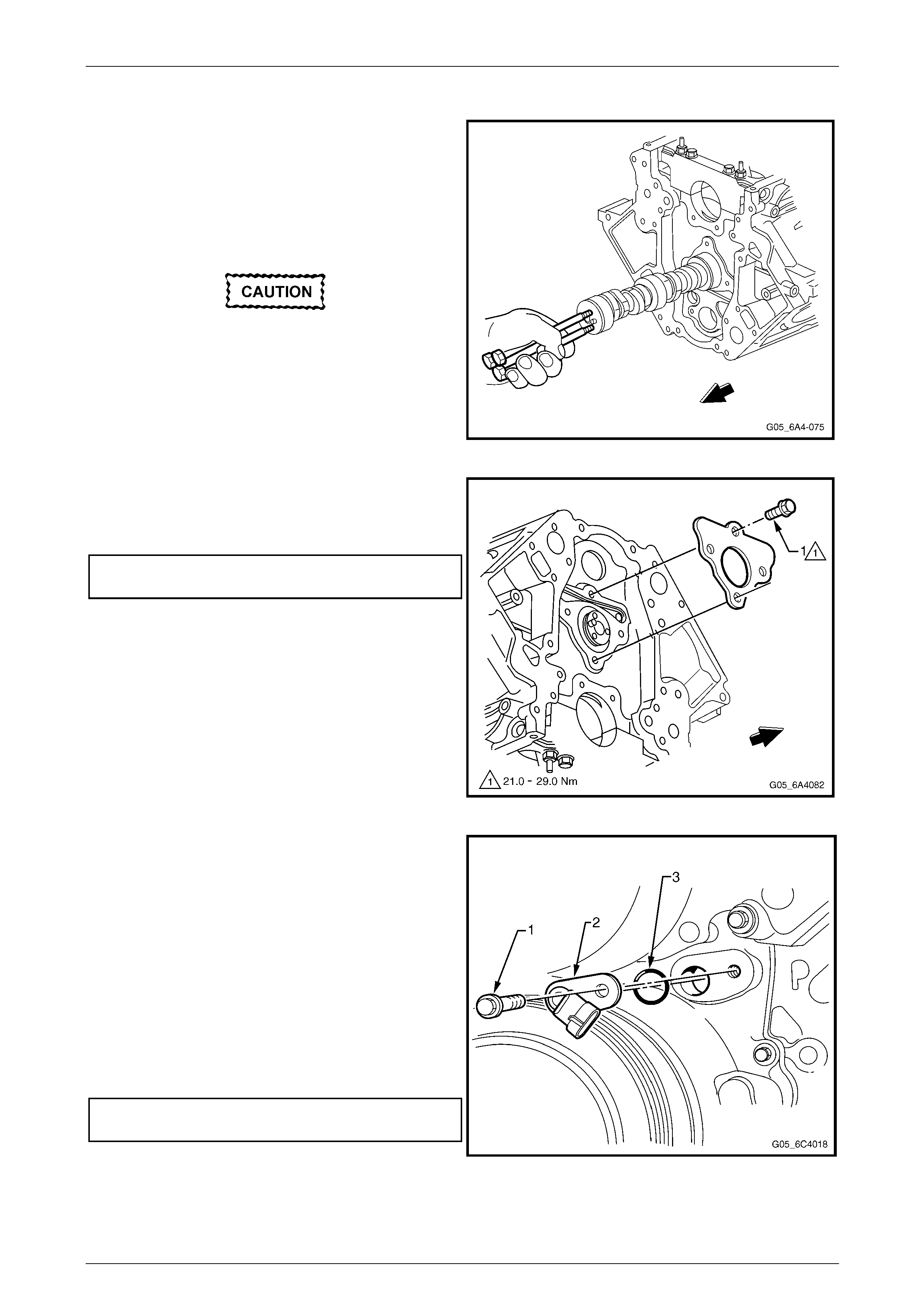
Engine Mechanical Page 6A4–208
Page 6A4–208
Reinstall
1 Ensure the cylinder block mating surface is clean and
free of debris.
2 Lubricate the camshaft journals and bearings with
clean engine oil.
3 Install three M8 x 1.25 x 100 mm bolts into the
camshaft front journal (e.g. removed coolant pump
bolts).
All camshaft bearing journals are the same
size and care must be taken wh en reinstalling
the camshaft to avoid damaging the
bearings.
4 Using the bolts as a handle, carefully reinstall the
camshaft into the cylinder block.
5 Remove the three bolts after camshaft installation. Figure 6A4 – 317
6 Install the camshaft retainer plate with the sealing
gasket facing the cylinder block.
7 Install the camshaft retainer attaching bolt (1 ), four
places, and tighten to the correct torque specificatio n.
Camshaft retainer attaching bolt
torque specification.................................21.0 – 29.0 Nm
Figure 6A4 – 318
8 Reinstall the camshaft timing chai n and sprocket.
Refer to 5.10 Timing Chain and Sprock ets .
9 Reinstall the oil pump, refer to 5.9 Oil Pump, Pump
Screen and Deflector.
10 Reinstall the engine front cov er, refer to
4.17 Crankshaft Balancer.
11 Inspect the camshaft position sensor O-ring and
replace the O-ring if it is cut or damaged.
12 Lubricate the O-ring with clean engine oil and install it
to the sensor.
13 Install the camshaft position sensor and the attaching
bolt (1) and tighten to the correct torque specification.
Refer to Section 6C4-3 Engine Management - Service
Operations.
Camshaft position sensor attaching bolt
torque specification............................................25.0 Nm
14 Reinstall the hydraulic valve lifters, refer to
4.16 Hydraulic Valve Lifters. Figure 6A4 – 319
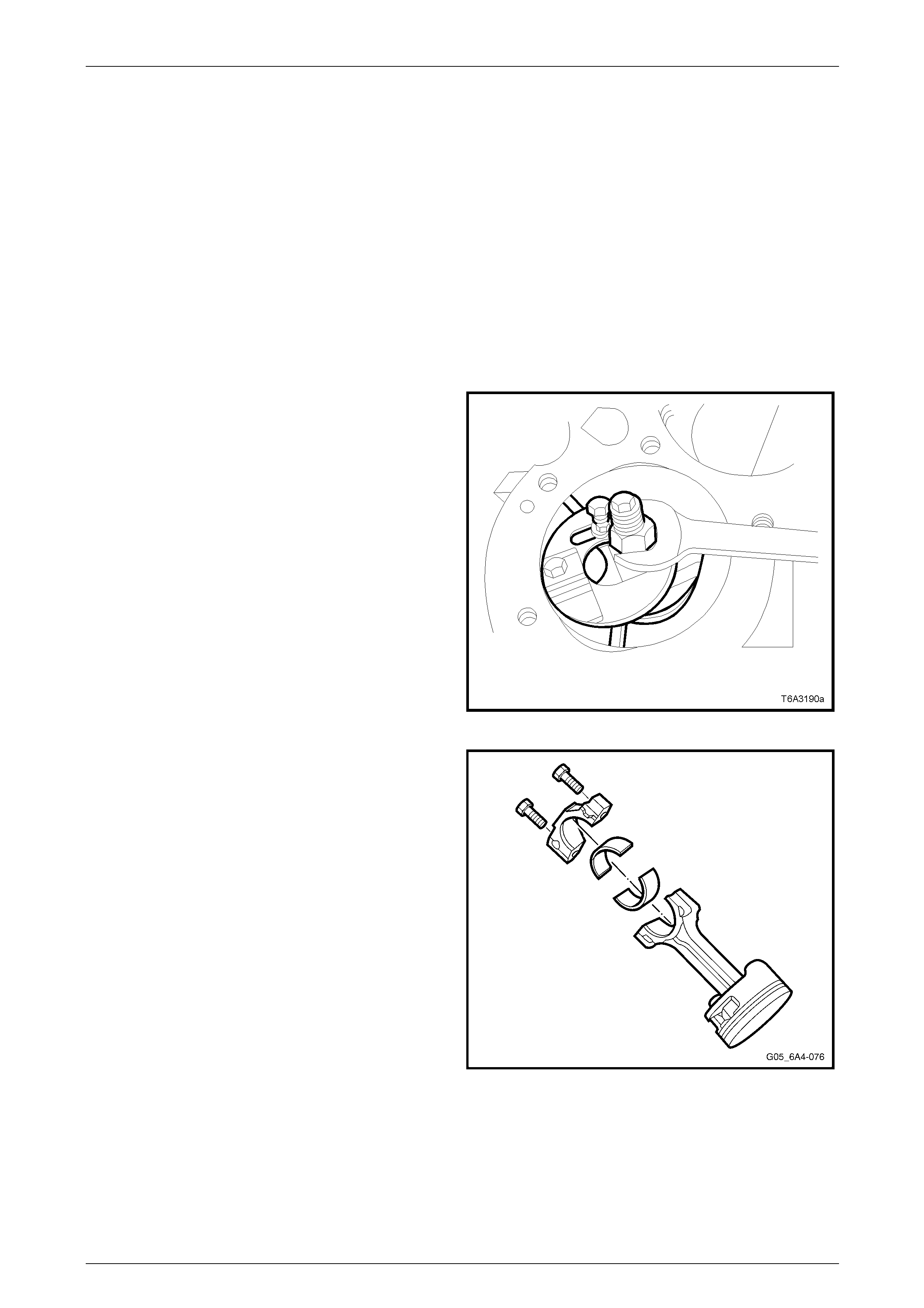
Engine Mechanical Page 6A4–209
Page 6A4–209
5.12 Piston, Connecting Rod and Bearing
LT Section No. — 00–550
Remove
NOTE
Due to the critical alignment procedures required
for the reinstallation of the engine front cover and
oil pan, it is strongly recommended the engine
assembly be removed from the vehicle before oil
pan removal.
1 Remove both cylinder heads. Refer to 4.15 Cylinder Head.
2 Remove the oil pan, refer to 5.3 Oil Pan.
3 If required, remove any cylinder ridg e present with the
following procedure:
• Rotate the crankshaft until the piston to be
serviced is at the bottom of its stroke (BDC).
• Place a cloth on top of the piston.
• Use a commercially available cylinder ridge
remover to remove the cylinder ridge.
NOTE
Follow the manufacturer's operating instructions
for the ridge remover being used.
4 Rotate the crankshaft again until the piston is at the
top of its stroke (TDC).
5 Remove the cloth and any metal shavings from the
piston crown.
Figure 6A4 – 320
NOTE
Do not apply a stampin g mark on the side of the
connecting rod and/or cap as this may affect
alignment and the geometry of the assembly.
6 Using a marker pen or etching tool, mark each
connecting rod and its cap. The connecti ng rod caps
must be reassembled to the original position and
direction.
7 Mark the top of each piston to identify its specific bore.
8 Remove the connecting rod b olts loosening
progressively from side to side.
NOTE
Ensure the connecting rod bearings are
organised so the y can be installed in the original
position and location.
9 Remove each connecting rod cap. Figure 6A4 – 321
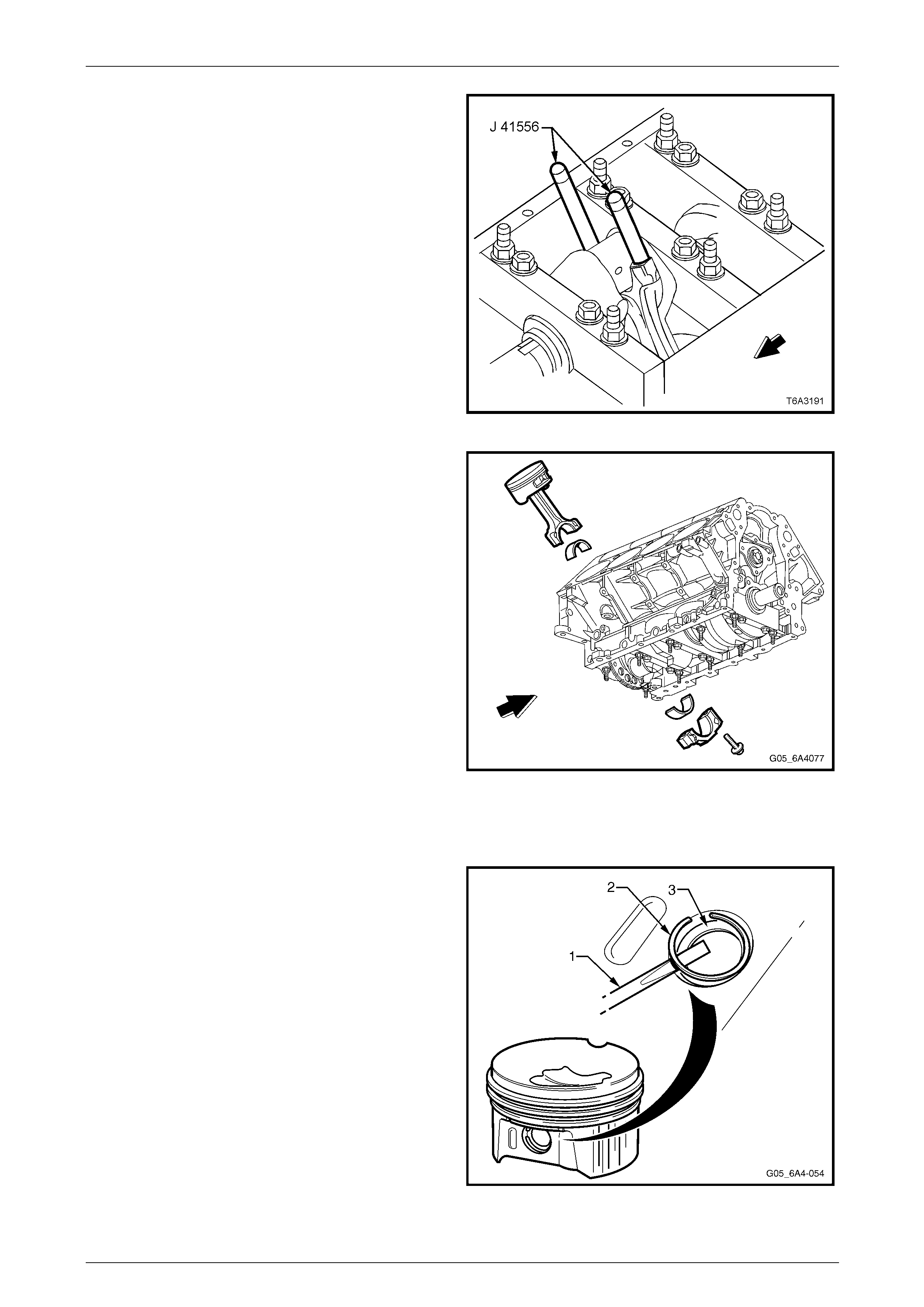
Engine Mechanical Page 6A4–210
Page 6A4–210
10 Install the guide pins, Tool No. J 41556 to th e
connecting rod to be removed.
11 Use a hammer handle, lightly tap on the end of the
guide pin and remove the piston and connecting rod
from the cylinder bore.
Figure 6A4 – 322
12 Once removed, assemble the connecting rod cap,
bearing shells and bolts to the matching connecting
rod.
Figure 6A4 – 323
Disassemble
1 Use a paint or marker pen and mark the orientation of
the piston to the connecting rod and the bore number
from which it was removed.
2 Using a small scre wdriver (1), carefull y prise out the
C clip (2) retaining the piston pin (3). If required,
repeat for the other circlip.
3 Remove the piston pin from the piston and connecting
rod by pushing the pin from the piston by hand.
NOTE
The piston and piston pin are a matched set an d
are not serviced separately. Mark the piston pin
to piston to ensure correct reassembly if the
original parts are to be re-used.
Figure 6A4 – 324
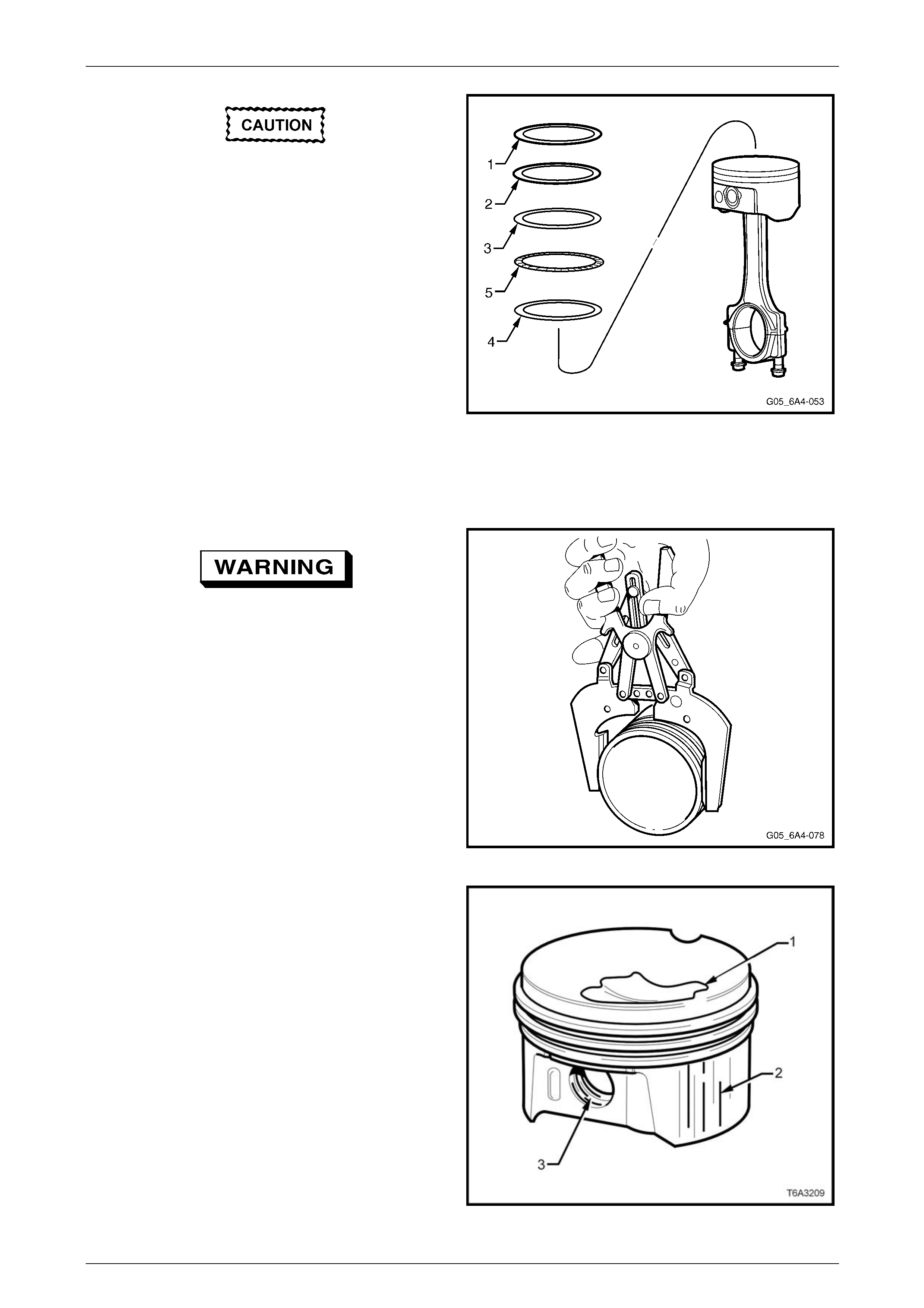
Engine Mechanical Page 6A4–211
Page 6A4–211
Use piston rings pliers and only expand the
piston ring sufficiently to slid e them over the
piston. Excessi ve expansion will permanently
distort the piston ring.
4 Remove the piston rings from the piston by expan din g
the ring at the end gaps in the follo wing order.
a Top compression ring (1).
b Second compression ring (2).
c Oil control upper ring (3).
d Oil control lower ring (4).
e Oil control segment ring (5).
Figure 6A4 – 325
Clean and Inspect
Piston and Pin
To avoid personal injury, wear safety glasses
and the appropriate gloves when using
compressed air and cleaning fluids.
1 Clean any varnish from the piston and pin with a
commercially available cleaning fluid. Do not use a
wire brush for this process.
2 Dry the cleaned parts using compressed air.
3 Clean the piston ring groov es wit h a commercially
available ring groove cleaning tool.
4 Clean the oil lubrication holes and slots in the ring
grooves.
Figure 6A4 – 326
5 Inspect each piston and pin for the following:
• Cracks in the piston lands, skirt or the pin bosses
• Piston ring grooves for nicks, burrs or warpage
that may cause the piston ring to bind
• Eroded areas on top of the piston (1)
• Scuffed or damaged skirts (2)
• Scoring to the piston pin bore (3) or the piston
pin
NOTE
Minor imperfections may be removed by using a
fine file.
Figure 6A4 – 327
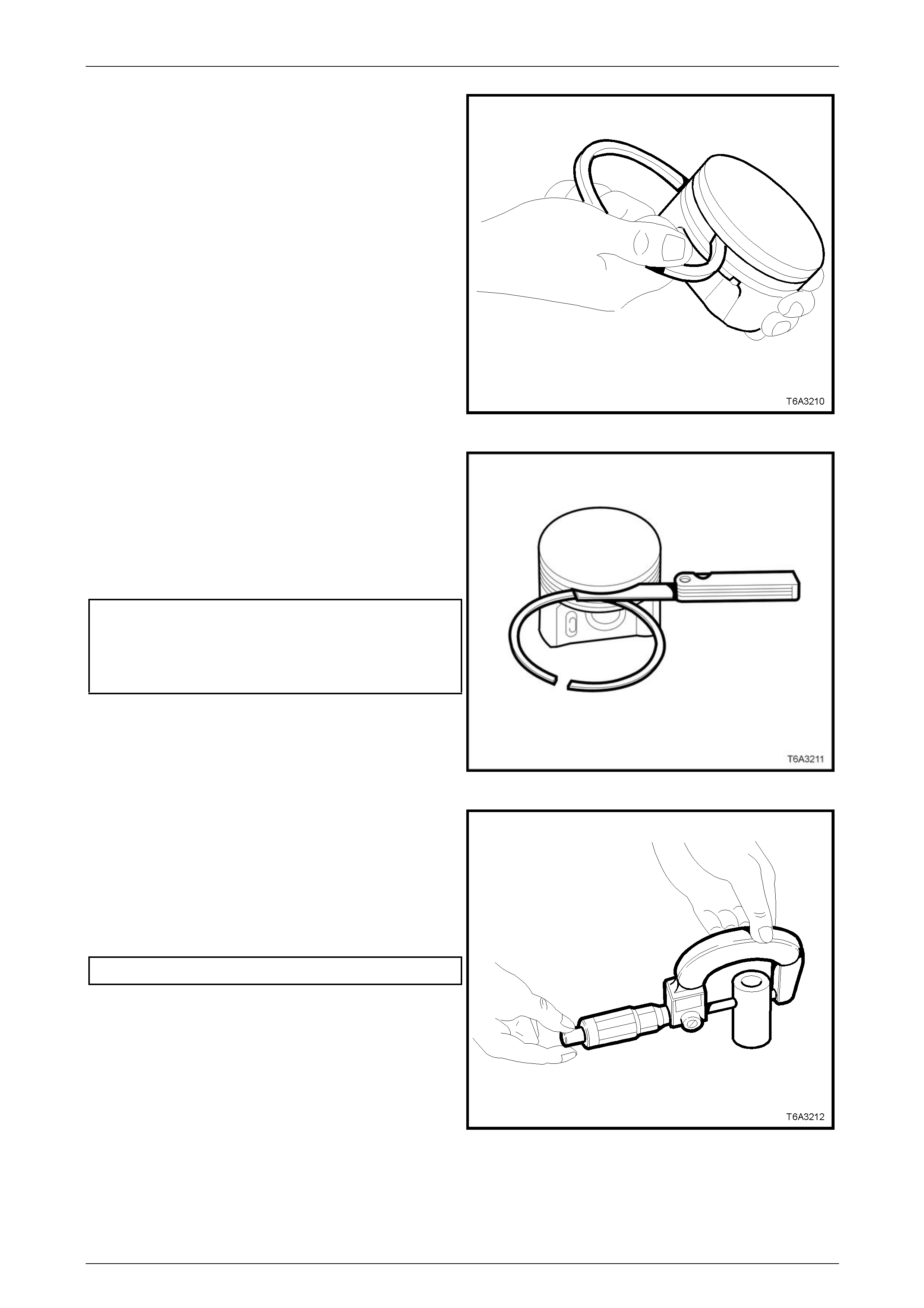
Engine Mechanical Page 6A4–212
Page 6A4–212
6 Insert the edge of a new piston ring into the correct
piston ring groove and roll the piston ring around the
groove.
NOTE
If binding is caused by a distorted piston ring
groove, minor ring groove imperfections may be
removed with a fine file.
7 Measure the piston ring to piston groove side
clearance by inserting a new piston ring into the
correct piston ring groove as shown.
Figure 6A4 – 328
8 Check the side clearance using a feeler g au ge. If the
side clearance excee ds specification, try another
piston ring set before replacing the piston.
NOTE
The oil control upper and lower rings must be
installed with the segment ring in order to check
the clearance.
Piston ring side clearance specification:
Top compression ring ........................ 0.040 – 0.085 mm
Second compression ring .................. 0.040 – 0.080 mm
Oil control ring.................................... 0.010 – 0.220 mm
9 If the piston ring side clearance exceeds the
specification, the piston and pin assembly must be
replaced.
Figure 6A4 – 329
NOTE
For each of the following measurem ents, ensure
the micrometer is reset to zero and the
measurements are all taken with components at
room temperature.
10 To measure the pin-to-bore clearance, first measure
the pin with a micrometer.
Piston pin diameter........................ 23.997 – 24.000 mm
Figure 6A4 – 330
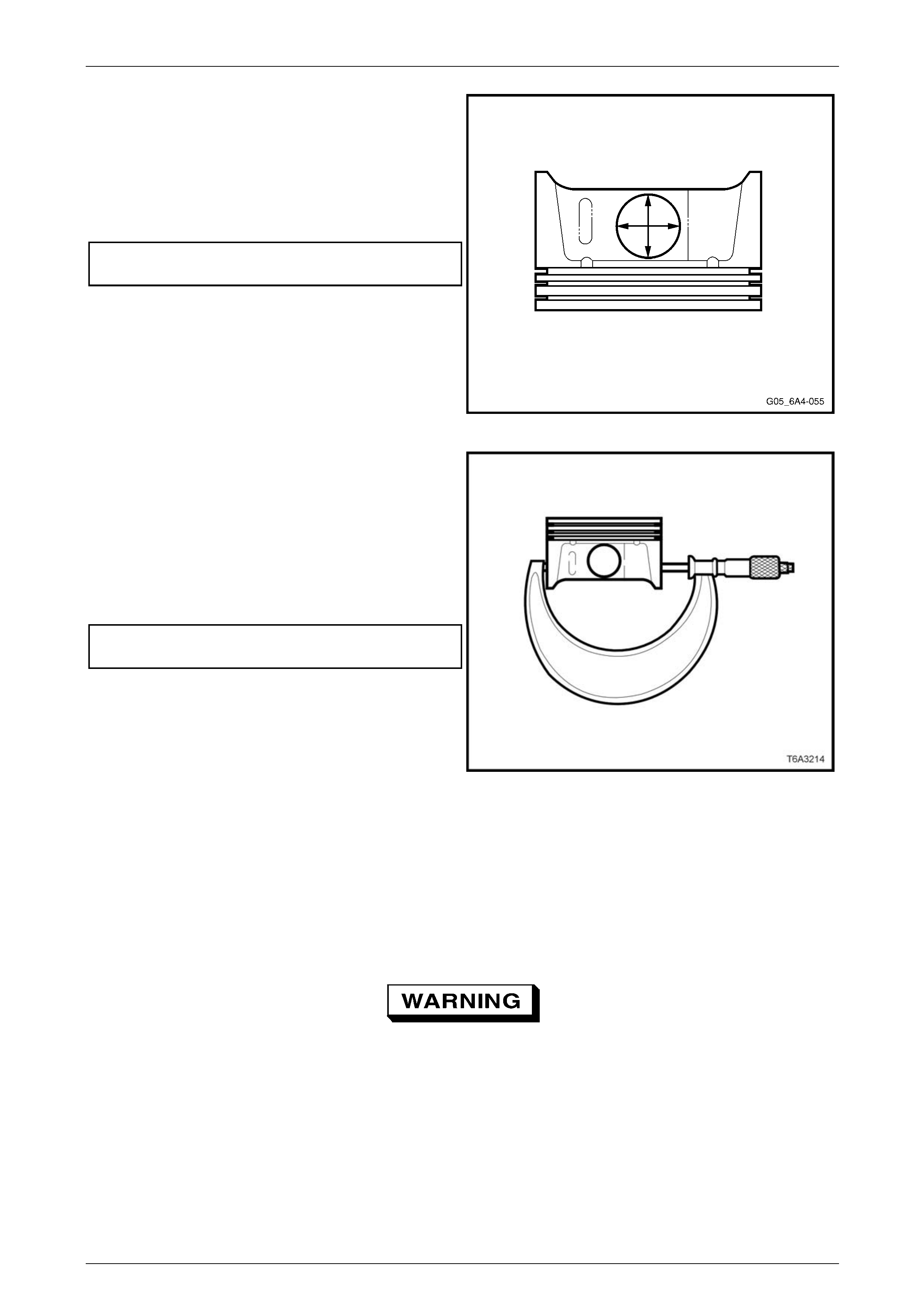
Engine Mechanical Page 6A4–213
Page 6A4–213
11 Using a suitable inside micro m eter, measure the
matching piston pin bore in both directions on each
side of the piston. This is to ensure the piston pin bore
has not worn unevenly.
12 Subtract the piston pin dimension from the piston pin
bore size to obtain the clearance.
13 If the clearance exceeds the specific ation, the piston
and pin assembly must be replaced.
Piston pin to bore clearance
specification................................0.010 – 0.020 mm Max
Figure 6A4 – 331
14 Measure the piston for out-of-round as follows:
• With a suitable sized micrometer, measure the
piston skirt dimension at right angles to the
piston pin bore 11 mm above the bottom of the
skirt.
• Measure the piston at two different points and
compare the readings
• If the difference exceeds the specification,
replace the piston and pin ass embly.
Piston skirt out-of round
specification.............................................0.018 mm Max
Figure 6A4 – 332
Connecting Rods and Bearings
NOTE
The powdered metal connecting rod and cap are
machined for the correct clearances. The
connecting rod and the cap must be used as an
assembly, with no repairs or modific ations carried
out to either mating surface.
To avoid personal injury, wear safety glasses
and the appropriate gloves when using
compressed air and cleaning fluids.
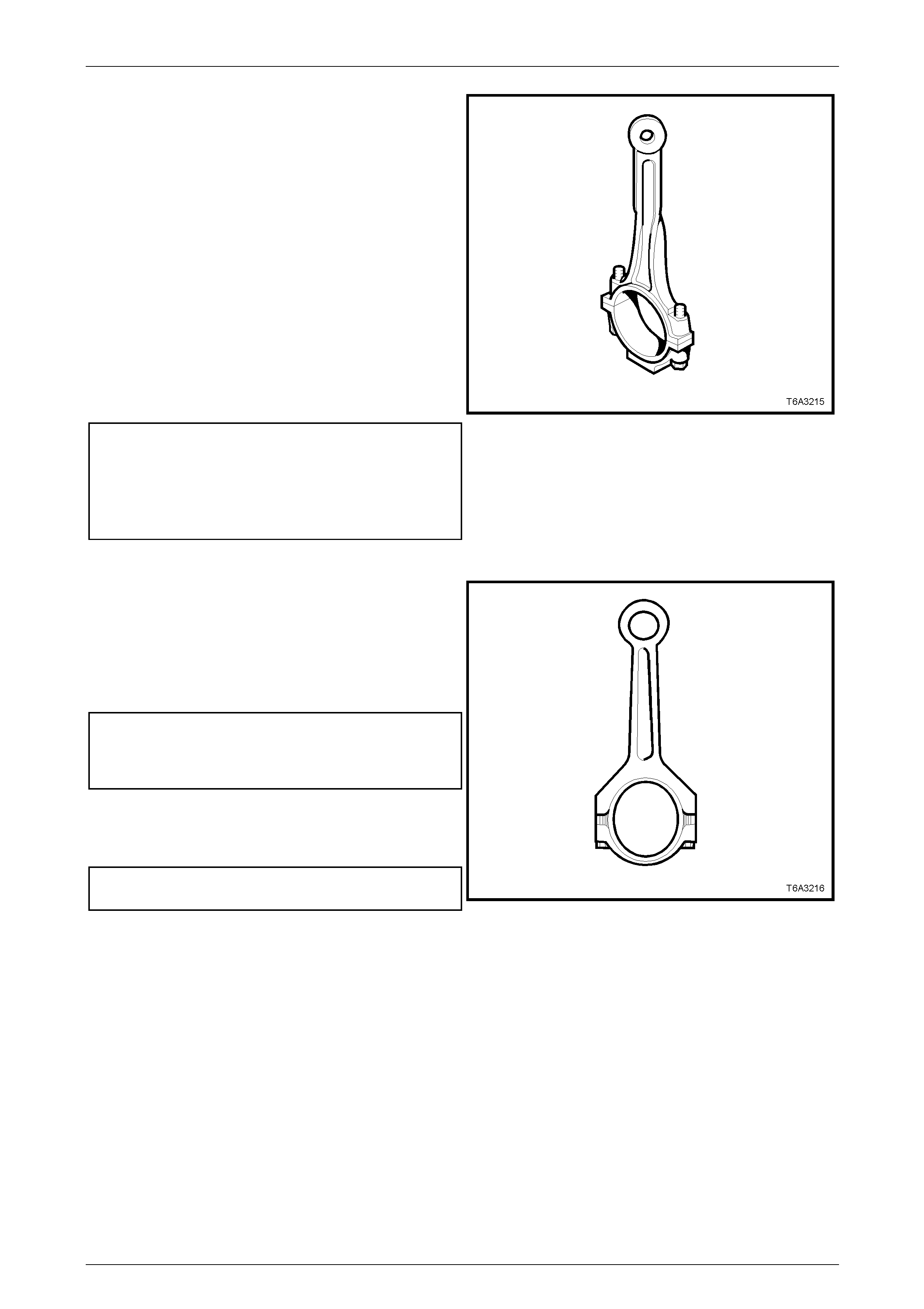
Engine Mechanical Page 6A4–214
Page 6A4–214
1 Clean each connecting ro d and matching cap in a
commercially available cleaning fluid and blow dry
using compressed air.
2 Clean the connecting rod bolt threads a nd inspect for
damage. Do not attempt to repair damaged threads in
this location. Replace the con necting rod, cap and
bolts as an assembly if thread damage is found.
3 Inspect the connecting rod for:
• Twisting, using commercially available alignment
equipment
• Bending, check the lengt h with suitable
measuring equipment
• Nicks or gouging in the bear ing bore
• Damage to the bearing locating slots in the
bearing bore
• Correct fit of the connecting rod and bearing cap
mating surfaces.
Connecting rod specification:
Centre to centre length ...................... 154.90 ± 0.02 mm
Width.................................................... 24.00 ± 0.05 mm
Twist ........................................................0.010 mm Max
Bend ..........................................................0.02 mm Max
Figure 6A4 – 333
NOTE
The used connecting rod cap bolts can be used
for this procedure, however the bolts must be
replaced for the final assembly.
4 Reinstall the connectin g rod big end cap and bolts.
Tighten the bolts to the correct torque specification.
Connecting rod bearing cap attaching bolt
torque specification.
Stage 1 ..............................................................20.0 Nm
Stage 2 .....................................................75° turn angle
5 Measure the connecting rod big end bore with a
suitable inside micrometer and check the b ore for out
of round. Replace any connecting rod assembly that
exceeds the specification.
Connecting rod big end out-of round
specification.............................................0.008 mm Max Figure 6A4 – 334
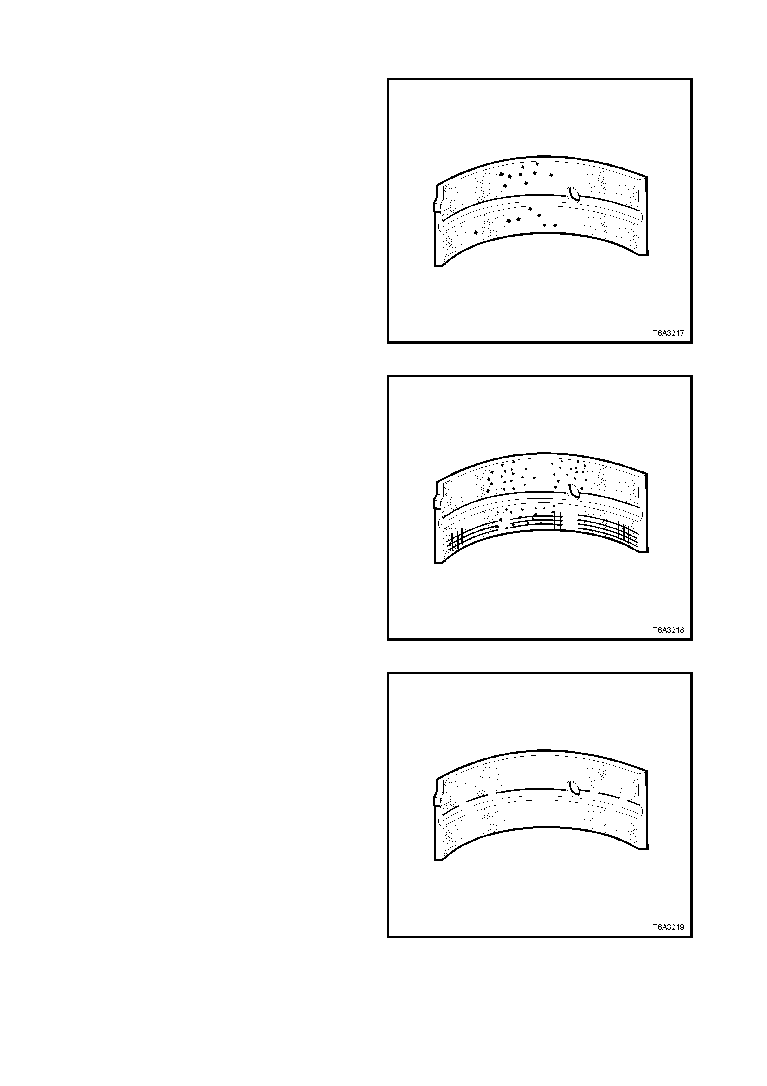
Engine Mechanical Page 6A4–215
Page 6A4–215
6 Inspect the connecting rod bearing halves for craters
or pockets. Flattened sections on the bearing halves
also indicate fatigue. Repl ace as required.
Figure 6A4 – 335
7 Inspect the connecting rod bearing halves fo r
excessive scoring or discolouration, dirt or debris
embedded into the bearing m ateria l or backing metal.
Replace as required.
Figure 6A4 – 336
8 Inspect the connecting rod bearing halves for improper
seating indicated b y bri ght polished section/s on the
bearing material. Rep lace as required.
Figure 6A4 – 337
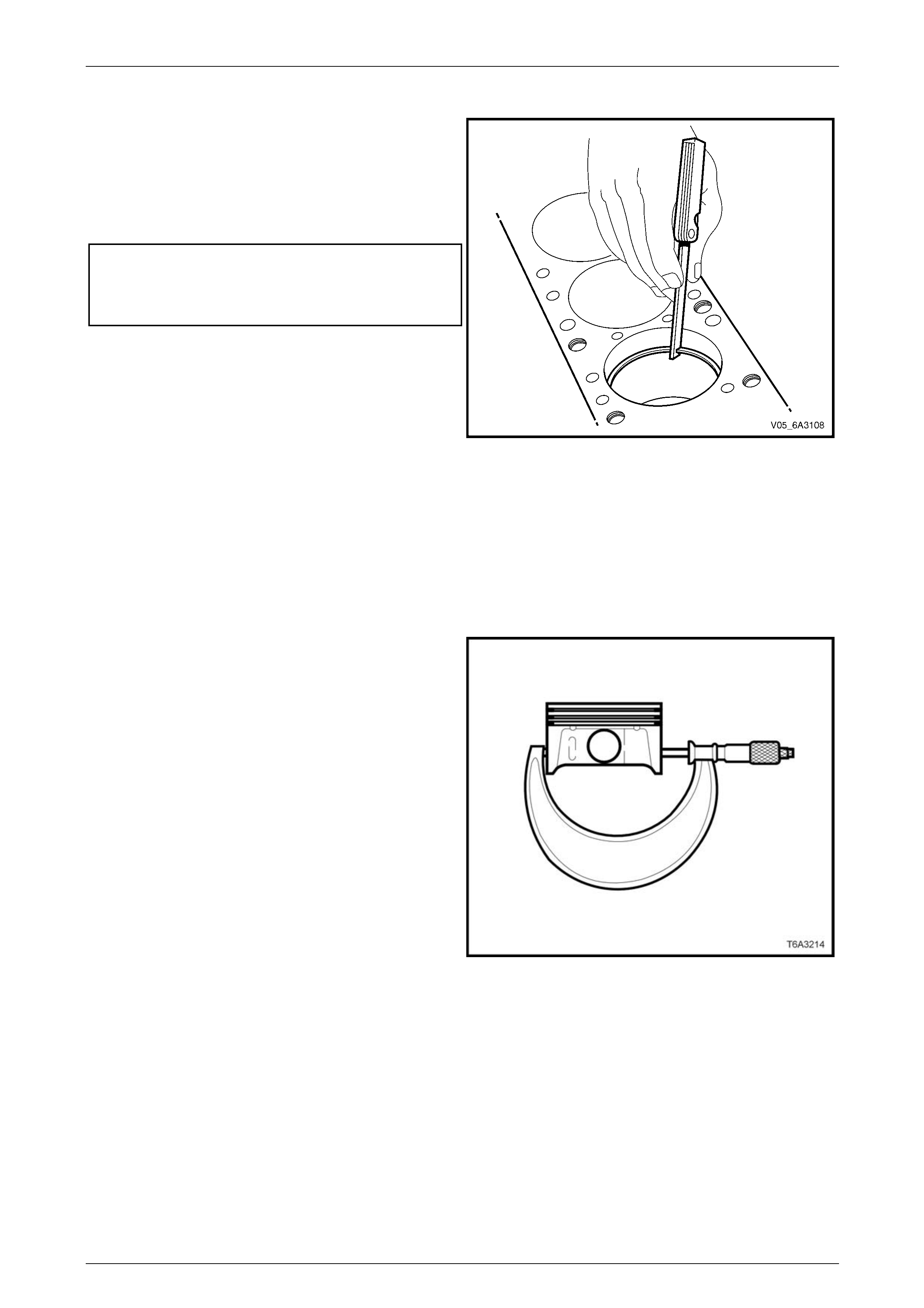
Engine Mechanical Page 6A4–216
Page 6A4–216
Measuring Piston Ring End Gap
1 Insert a new piston ring into the cylinder bore that it is
to be fitted to and push it down the bore using the
piston inverted in the bore until the ring is
approximately 6.5 mm below the piston ring top and
bottom travel area.
2 Insert a feeler gauge and measure the piston ring end
gap. End gap specifications are as follows:
Piston ring end gap specifications:
Top compression ring ........................ 0.230 – 0.380 mm
Second compression ring .................. 0.440 – 0.640 mm
Oil control ring.................................... 0.180 – 0.690 mm
NOTE
If the ring end gap is not within specification,
select another new set of rings and re measure
the gap. If the specification cannot be obtained,
hone the cylinder and install an oversize piston
and ring set. Figure 6A4 – 338
Reassemble
Piston Selection
Observe the following:
• The cylinder bore must be checked for bore out-of-round and taper before this operation is attempted. Refer
5.15 Cylinder Block. All measurements should be taken at normal room temperature.
• A used piston and pin set may be reinstalled if, after cleaning and inspection, they are both within specifications.
1 With a micrometer at right angles to the piston pin
bore, measure the piston skirt 11 mm from the lower
edge.
2 Record the piston diameter.
Figure 6A4 – 339

Engine Mechanical Page 6A4–217
Page 6A4–217
3 Check the micrometer is at the recorded piston
diameter.
4 With cylinder bore checking gauge Tool No. J 8087 or
equivalent held between the micrometer anvils, zero
the dial indicator.
Figure 6A4 – 340
5 Use a bore gauge Tool J 8087 or equivalent, measure
the cylinder bore diam eter at a point 57 mm from the
top of the bore.
6 Record the cylinder bore diam eter.
7 Subtract the piston diameter from the c ylinder bore
measurement in order to determine the piston to bore
clearance.
Piston to bore clearance
specification....................................... 0.018 – 0.054 mm
8 If the clearance is outside this specification, select
another new piston. Measure and re-c alculate the
clearance. If the correct clearance cannot be obtai ned
using this method then the cylinder b ore may require
honing for an oversize piston fitment or the cylind er
block will need to be replace d.
NOTE
Before honing the cylinders, refer to
5.15 Cylinder Block
9 When the correct piston to bore clearance is obtained,
mark the piston crown for correct installation.
Figure 6A4 – 341
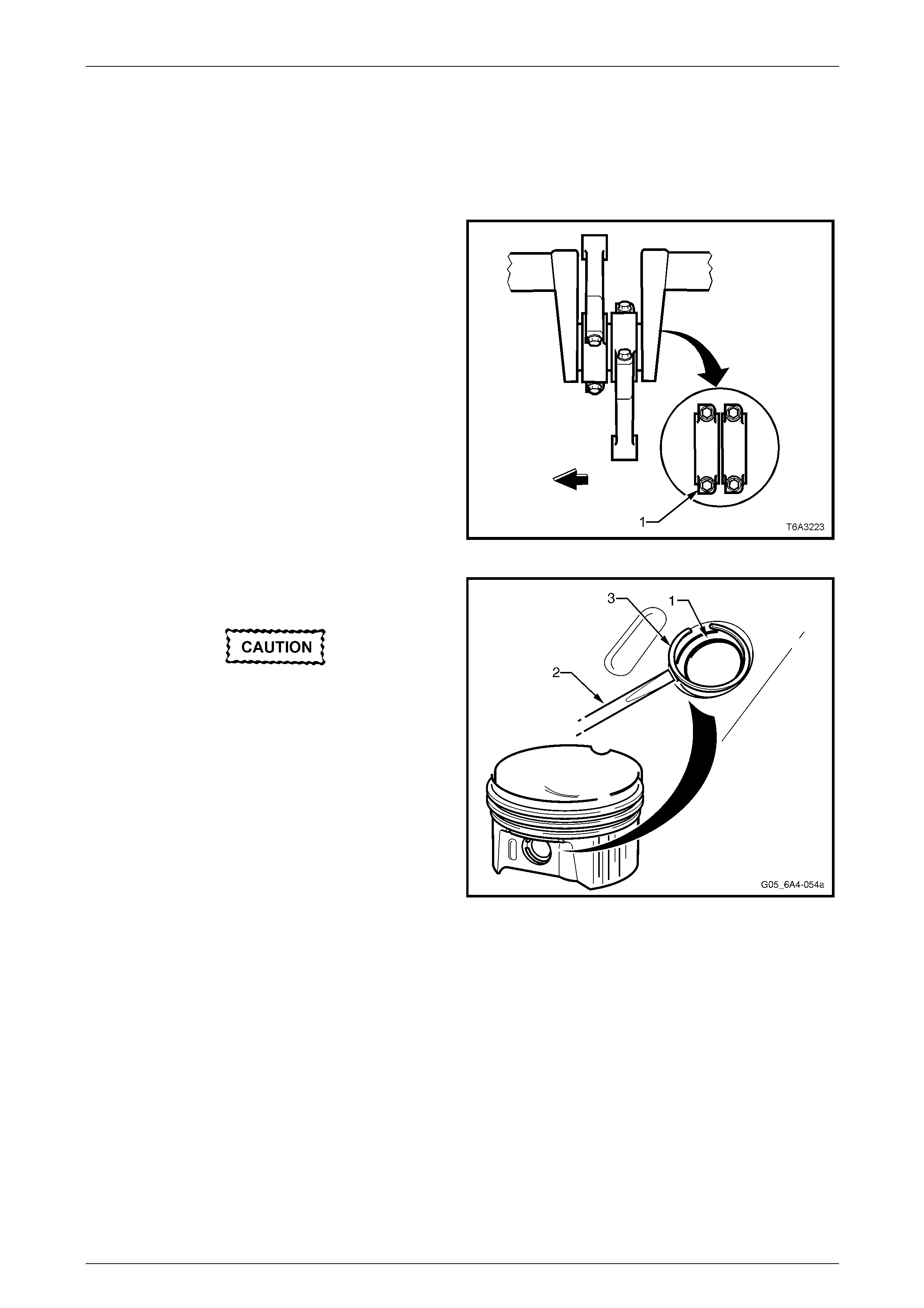
Engine Mechanical Page 6A4–218
Page 6A4–218
Piston to Connecting Rod
NOTE
Take particular care when assembling the piston
to the connecting rod the component matching
and orientation is correct.
1 The connecting rod alignment should be with the flat
portion of the bolt flange (1) facing forward. Also check
the piston alignment mark has the correct ori entation.
Figure 6A4 – 342
2 Lubricate the piston pin bore, connecting rod bore and
piston pin (1) with clean engine oil.
Ensure a new piston pin retaining circlip is
installed and it is correctly seated in the
groove. Circlip failure could result in major
engine damage resulting in the block being
damaged beyond repair.
3 Using a suitable scre wdriver (2), carefully install a new
piston pin retaining circlip (3) into one side of the
piston.
4 Reinstall the piston pin into the piston and connecting
rod, ensuring the piston and conn ecting rod orientation
is correct.
5 Install the remaining circlip into the piston as in Step 3.
NOTE
Ensure the piston is free to move on the pin and
the piston pin retain ing circlip on eac h side of the
piston are seated in the grooves correctly.
Figure 6A4 – 343
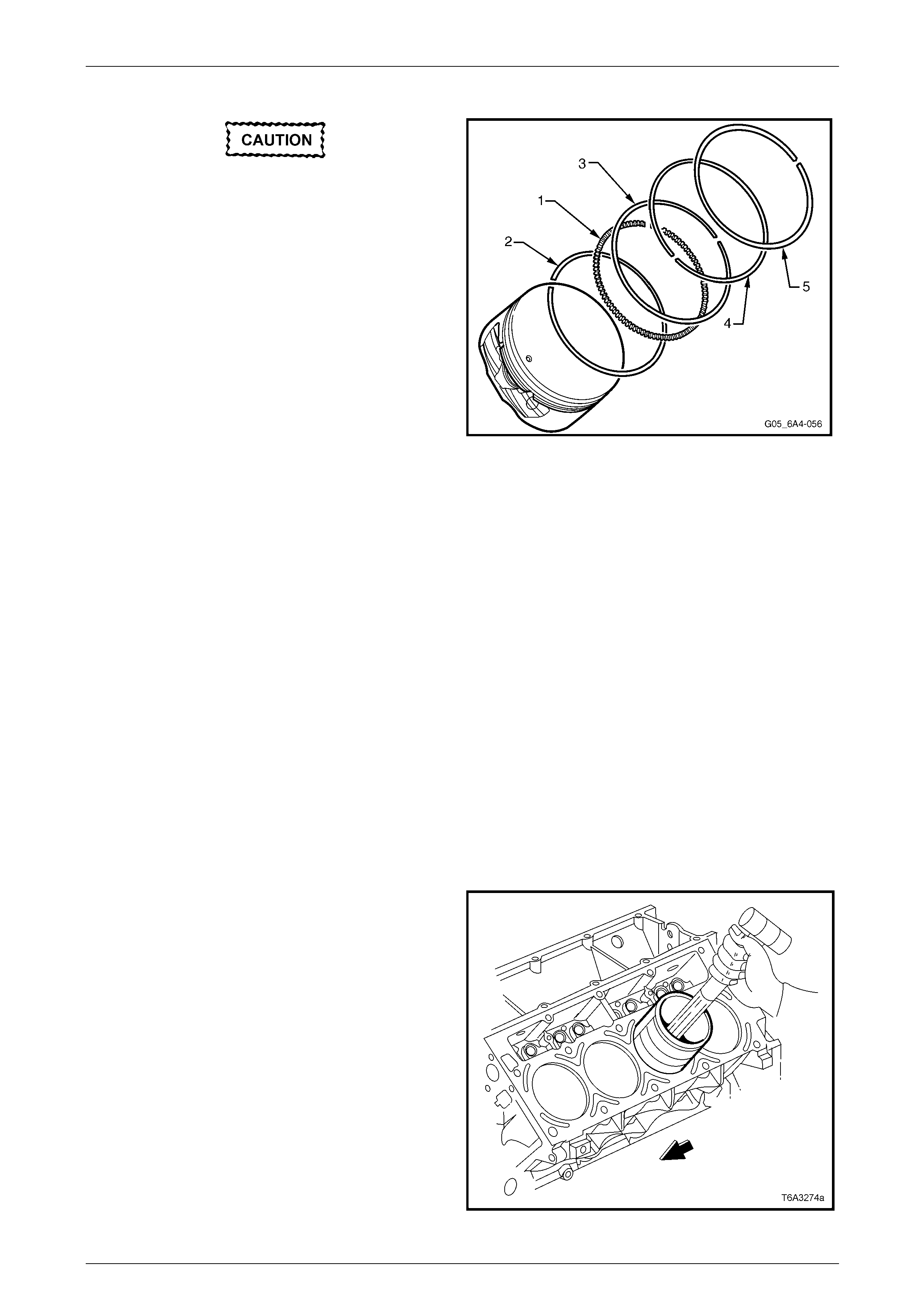
Engine Mechanical Page 6A4–219
Page 6A4–219
Piston Rings
Use piston ring pliers to install the piston
ring and only expand the ring sufficiently to
slide over the piston. Excessive expansion
will permanently distort the piston ring .
1 Install the piston rings onto each piston, in the
following manner:
a Install the oil control segment ring (1) into the
lower ring groove and ensure the ends do not
overlap.
b Install the lower oil control ring (2). There are no
identifying marks, indicating orientation as this
ring may be installe d in either direction.
c Install the upper oil control ring (3) in a similar
manner.
d Stagger the ends of the three oil control ring
components by at least 90°.
e Install the second compression ring (4) noting
the dimple or orientation mark must face
upwards to the piston crown.
f Install the top compression ring (5). This ring has
no orientation marks and may be installed in
either direction.
Figure 6A4 – 344
Reinstall
NOTE
Before installation, check the piston ring end
gaps are staggered correctly and the piston has
been assembled to the correct connecting rod
and in the correct orientation.
1 If required, install the connecting rod bearings.
2 Lightly lubricate the pisto n, cylinder bore, piston rings and bearing surfaces with clean engine oil.
3 Remove the connecting rod cap an d bearing shell from the connecting rod being insta lled and install the
connecting rod guide pins, Tool No. J 41556, refer to Figure 6A4 – 345.
4 Install a commercially available piston ring compressor over the piston rings and compr ess the rings.
NOTE
Follow the manufacturer's operating instructions
for the type of piston ring compressor being used.
5 Install the piston and connecti ng rod assembly into the
correct cylinder bore, checking the piston alignment
mark is facing the front of the engine.
6 While holding the piston rin g compressor squarely and
firmly against the cylinder block, gently tap the piston
into the bore using a wooden hammer handle until all
piston rings have entered the bore.
7 Complete the installation by us ing the connecting rod
guide pins, Tool No. J 41556 to guide the connecting
rod onto the crankshaft journal.
Figure 6A4 – 345

Engine Mechanical Page 6A4–220
Page 6A4–220
8 Remove the connecting rod guides, Tool No. J 41556
and check the upper bearing shell is correctly installed
in the connecting rod. Apply c lean engine oil to the
upper bearing shell.
Figure 6A4 – 346
9 Install the lower connecting rod bear ing into the cap
and lubricate with clean en gine oil, install the cap
ensuring the cap orientation is correct.
NOTE
The bearing oil clearance must be checked
before final installation of the connecting rod
caps. Refer to 5.13 Crankshaft and Bearings.
10 Install new connecting rod cap bolt (1), two plac es and
tighten the connecting rod bolts in two stages to the
correct torque specification.
Connecting rod bearing cap attaching bolt
torque specification
Stage 1 ..............................................................20.0 Nm
Stage 2 .....................................................75° turn angle
NOTE
Use torque angle wrench Tool No. E7115 or
equivalent to achieve the second reading. Figure 6A4 – 347
11 With a pair of connecting rods installed onto the same
crankshaft journal, use a plastic faced hammer to
lightly tap each connecting rod sideways to settle and
ensure that side clearance exists.
12 Using feeler gauges, check the connecting rod side
clearance is within the required specification.
Connecting rod side clearance
specification........................................... 0.11 – 0.51 mm
NOTE
If side clearance is insufficient, re-check bearing
oil clearance and/or connecting rod a lignment.
13 Reinstall the oil pan, oil pump screen and deflector,
refer to 5.9 Oil Pump, Pump Screen and Deflector.
14 Reinstall both cylinder heads. Refer to
4.15 Cylinder Head.
Figure 6A4 – 348

Engine Mechanical Page 6A4–221
Page 6A4–221
5.13 Crankshaft and Bearings
LT Section No. — 00–200
Crankshaft Thrust End Play
Measure
1 Remove engine from vehicle, refer to 5.1 Engine Assembly and the n sep arate the engine from the transmission.
2 Mount the engine in an engine stand such as Tool No. AU591 or an equivalent.
3 Remove the following items from the eng ine assembly:
• Starter motor, refer to Section 6D3 Starting System – GEN IV V8.
• Oil pump, screen and deflector, refer to 5.9 Oil Pump, Pump Screen and Deflector.
• Remove each of the connecting rod b earing caps, refer to 5.12 Piston, Connecting Rod and Bearing.
4 Prise the crankshaft rearward then forward using a
suitable lever.
5 Insert a feeler gauge (1) between the centre main
bearing and the crankshaft thrust beari ng surface and
measure the crankshaft end play.
Crankshaft end play specification ...... 0.040 – 0.020 mm
6 If the thrust bearing clearance is less than 0.040 mm,
inspect the thrust surfaces for nicks, gouges or raised
metal. Remove the crankshaft, refer to Remove in this
Section and inspect the thrust face and the thrust
bearings.
NOTE
If there are minor imperfections, they can be
removed with a fine stone. If the bearing
clearance is greater than 0.20 mm select and
install an undersized crankshaft thrust bearing.
Re-check the crankshaft end play. Figure 6A4 – 349
Remove
1 Remove the bolt (2), attaching the crankshaft position
sensor (1) and remove the sensor from the cylinder
block.
Figure 6A4 – 350
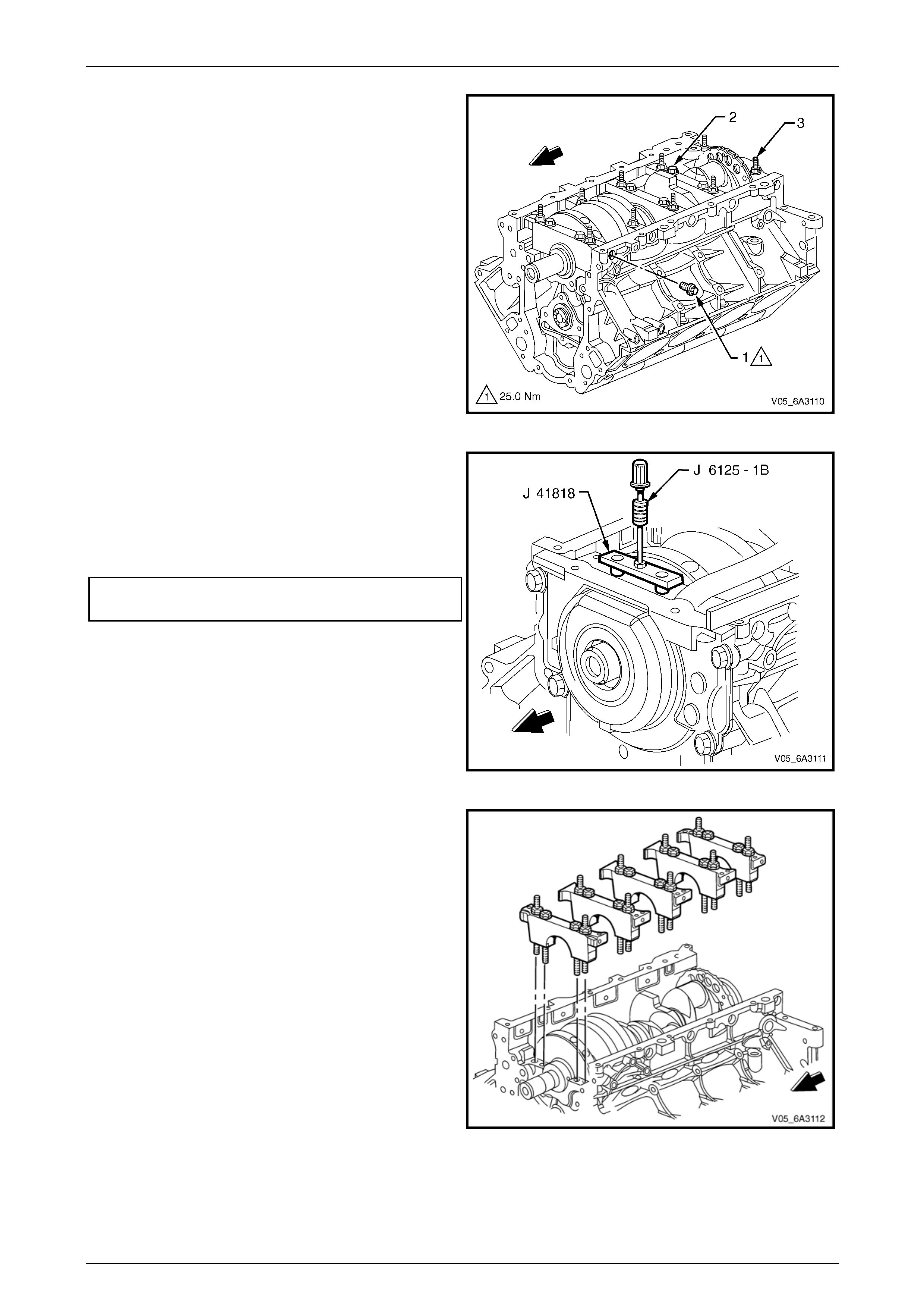
Engine Mechanical Page 6A4–222
Page 6A4–222
NOTE
If required, prior to removing the crankshaft
check the crankshaft end play, refer to
Crankshaft Thrust End Play.
2 Remove the crankshaft main bearing cap M8 side b olt
(1), 10 places.
NOTE
While these bolts must be replaced during the
final assembly process, place the removed bolts
to one side as they will be required when
checking the main bearing oil clearance.
3 Remove the main bearing cap M10 bo lt (2), 10 places
and studs (3), 10 places, loosening each pair
gradually. Take note of the stud positions for
reassembly.
Figure 6A4 – 351
4 Loosen the bolts of the main bearing removal Tool No.
J 41818 to separate the chamfered collets. Install the
chamfered sections into the main bearing cap bolt
hole, aligning the flats of the collets with thos e in the
holes.
5 Tighten the bolts of Tool No. J 41818 to the correct
torque specification.
Main bearing removal tool attachi ng bolt
torque specification............................................11.0 Nm
6 Install the slide hammer, Tool No. J 6125-1B to Tool
No. J 41818 and remove the main beari ng cap.
Figure 6A4 – 352
7 Mark and remove the remaining main bearing caps in
the same way. Check the lo wer main beari ng shells
are also removed with each cap.
Figure 6A4 – 353

Engine Mechanical Page 6A4–223
Page 6A4–223
Lift the crankshaft from the cylinder block
evenly to avoid jamming the crankshaft
against the main thrust bearing , and to avo id
damaging the reluctor ring. The reluctor ring
is an integral part of the crankshaft and is no t
serviced separately, therefore damage to the
reluctor ring will require the crankshaft
assembly to be replaced.
8 Remove the crankshaft from the cylinder block.
Figure 6A4 – 354
• When the crankshaft has been removed
from the cylinder block, take particular
care the reluctor ring is not damaged.
• Crankshafts when stored should be hung
vertically from the rear flange, however if
this is not possible, it is suggested the
removed crankshaft be supported on
three wooden V blocks or another
suitable soft surface that are large
enough to raise the crankshaft reluctor
wheel from contacting the surface. The
wooden vee blocks should be placed
under the main bearing journals.
Figure 6A4 – 355
9 Remove the crankshaft main bearings from the
cylinder block and the main beari ng caps.
10 Using a marker pen or etching tool, mark each main
bearing cap. The main bearing caps must be
reassembled to the original positio n an d direction.
NOTE
Take particular care to organ ise all parts so they
can be reinstalled in their original positions.
Figure 6A4 – 356
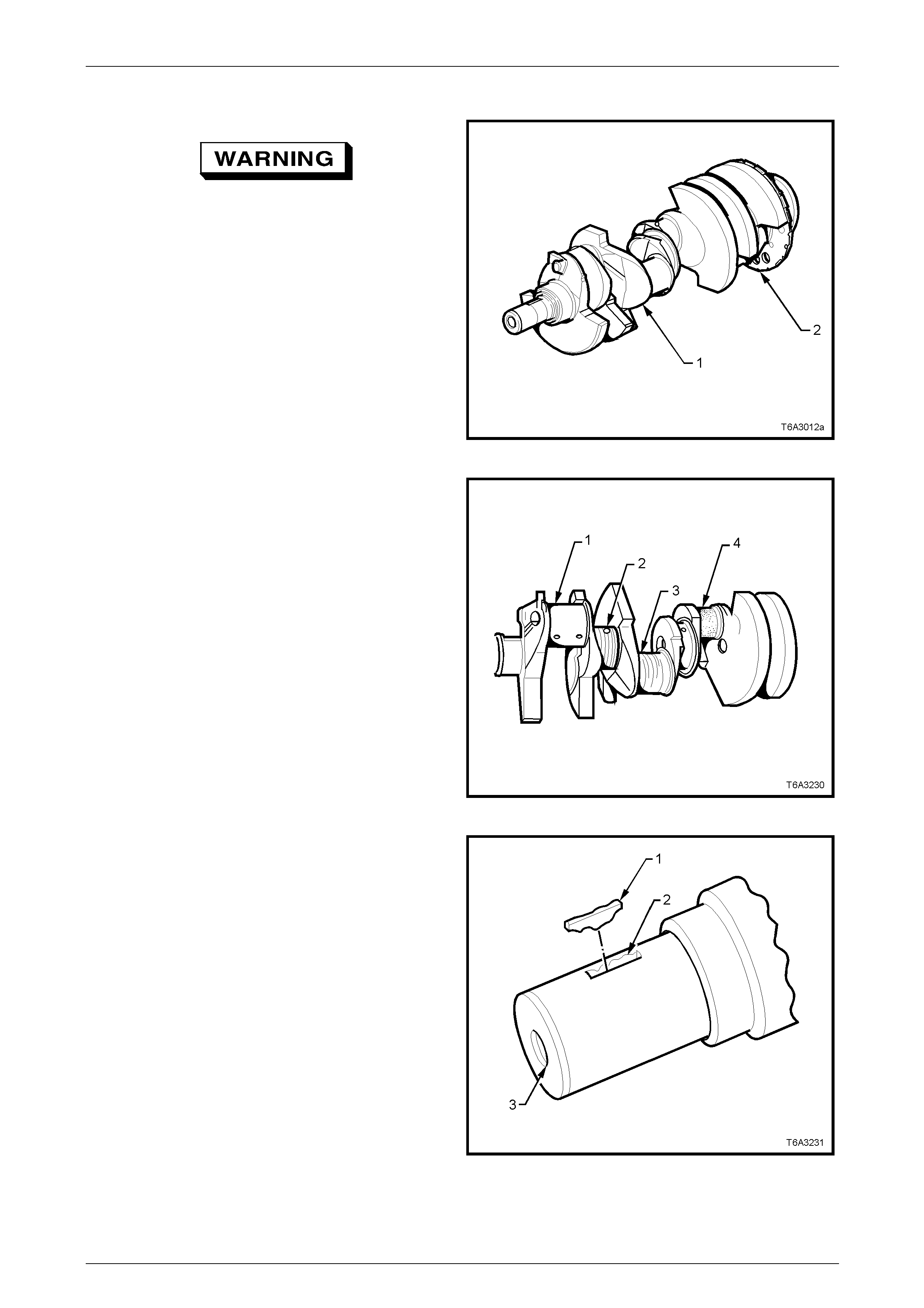
Engine Mechanical Page 6A4–224
Page 6A4–224
Clean and Inspect
To avoid personal injury, wear safety glasses
and the appropriate gloves when using
compressed air and cleaning fluids.
1 Clean the crankshaft with a commercially available
cleaning fluid and bl ow dry using compressed air.
2 Thoroughly cle an all the oil passages and inspect for
restrictions or burrs.
3 Carry out a visual inspection of the cranksh aft for
damage.
4 Inspect the crankshaft reluctor ring lobes for damage.
The reluctor ring teeth should not have imperfections
on either the rising or falling edges.
Figure 6A4 – 357
5 Inspect the crankshaft journals for the following:
• Wear (1)
• Grooves or scoring (2)
• Scratches (3)
• Pitting or embedded material (4)
NOTE
The journals should be smooth with no signs of
scoring, wear or damage. Re-grind the
crankshaft and install undersize bearings if
damage or wear is found.
Figure 6A4 – 358
6 Inspect the crankshaft key (1), keyway (2) and
threaded hole (3) for damage or wear.
Figure 6A4 – 359
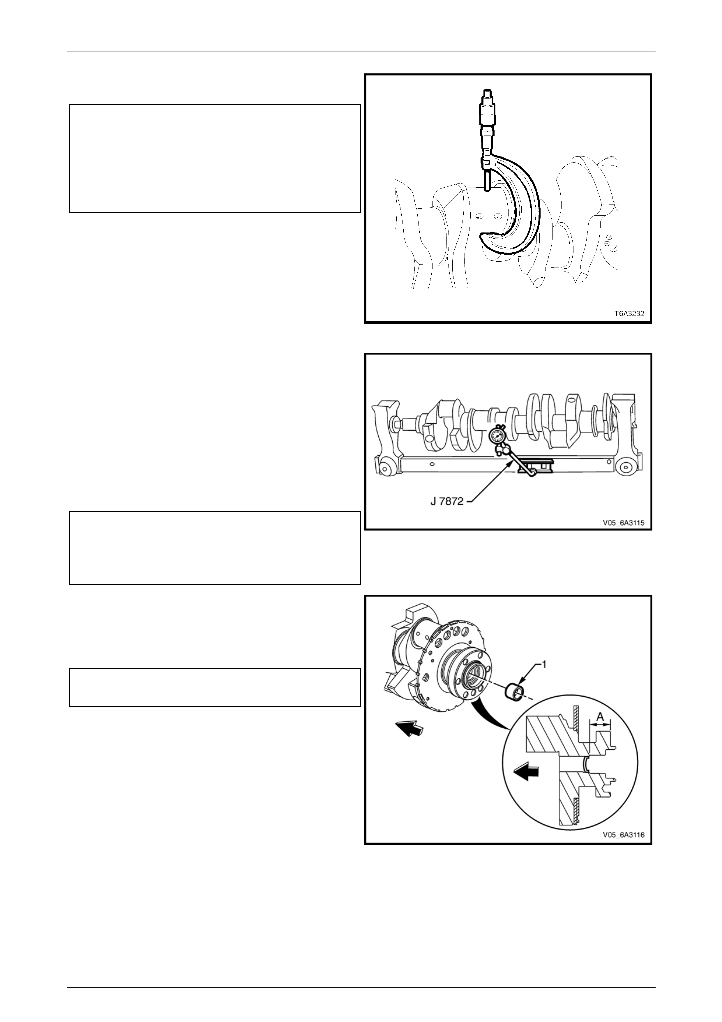
Engine Mechanical Page 6A4–225
Page 6A4–225
7 Measure all crankshaft journals for wear and out-of-
round.
Crankshaft journal specifications:
Connecting rod journal diameter.............53.308 mm Min
Connecting rod journal out of round.........0.010 mm Max
Main bearing journal diameter.................64.993 mm Min
Main bearing journal out of round ............0.008 mm Max
Main bearing journal taper ........................0.020 mm Min
Figure 6A4 – 360
8 Support the crankshaft on V blocks or in a commercial
jig.
9 Using a commerciall y available dial indicator mounted
to a magnetic stand, measure the following crankshaft
main bearing journal runout dimensions:
• Crankshaft runout at the main bearing jo urnals
• Crankshaft rear flange
• Reluctor ring (measur ed 1.00 mm below the
minimum tooth diameter) at the rear surface
• Crankshaft thrust wall at the centre main bearing
Main bearing journal runout specifications:
Reluctor ring lateral runout.......................0.250 mm Max
Crankshaft thrust wall runout ...................0.025 mm Max
Crankshaft rear flange runout ..................0.050 mm Max
Figure 6A4 – 361
10 Check the rear crankshaft oil gallery plug (1) for a
loose fit or evidence of leaking.
11 If replacement is required, apply sealant such as
Loctite 242 or equivalent, to the sid es of a n ew plug
(1) and install to the correct depth.
Crankshaft rear oil gallery plug depth specification:
Distance A.............................................. 31.2 – 31.6 mm
NOTE
If a manual transmission is fit ted to the vehi cle, it
will be necessary to first remove the spigot
bearing. Refer to 5.7 Crankshaft Spigot Bearing.
Figure 6A4 – 362
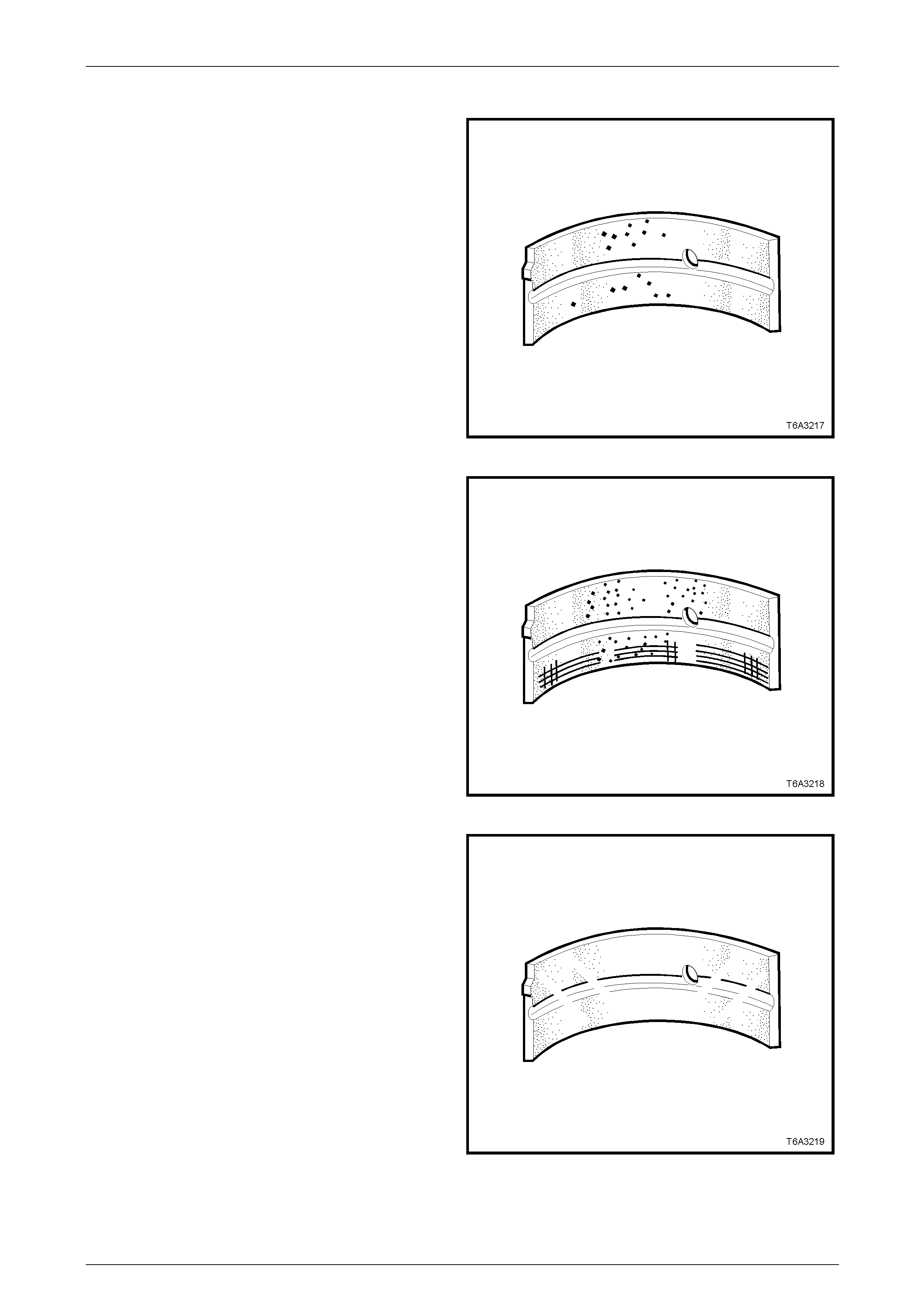
Engine Mechanical Page 6A4–226
Page 6A4–226
Main Bearings Inspect
1 Inspect the crankshaft main bearing halves f or craters
or pockets. Flattened sections on the bearing halves
also indicate fatigue. Repl ace as required.
Figure 6A4 – 363
2 Inspect the crankshaft main bearings for excessive
scoring or discolouration and dirt or debris embedded
into the bearing material or backing metal. Replace as
required.
Figure 6A4 – 364
3 Inspect the crankshaft main bearings for incorrect
seating, indicated by bright or polished section/s on
the bearing material. Replace as required.
Figure 6A4 – 365
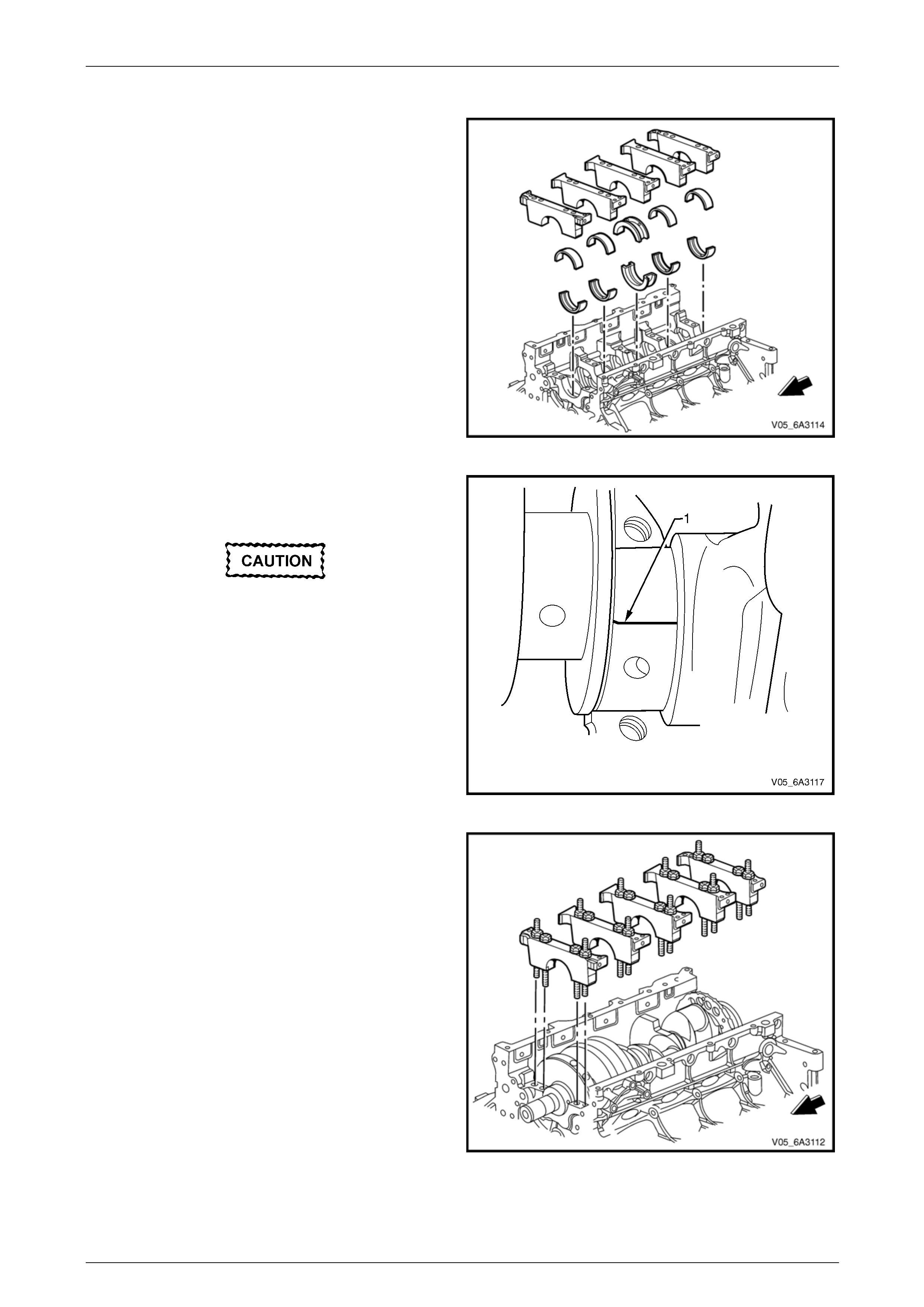
Engine Mechanical Page 6A4–227
Page 6A4–227
Main Bearing Oil Clearance
1 After thoroughly cleaning all the relevant parts, install
the bearing halves into the c ylinder block and main
bearing caps.
Figure 6A4 – 366
2 Install the crankshaft to the cylinder block ensuring the
crankshaft is held square to avoid damagin g the
centre main thrust bearing and the reluctor ring.
Ensure the cranksh aft does not rotate during
this process. Any rotation of the crankshaft
will result in the plastigauge being deformed
and a true oil clearance reading will not be
possible.
3 Install a small strip of plastigauge (1) across the full
width of each main bearing journal.
NOTE
Do not place the plastigauge across an oil feed
hole and ensure the crankshaft does not rotate
during this process. Figure 6A4 – 367
4 Install the main bearings, caps, bolts and studs in the
reverse order of the removal proced ure, ensuring the
bearings and caps are i nstalled in their original
location.
Figure 6A4 – 368
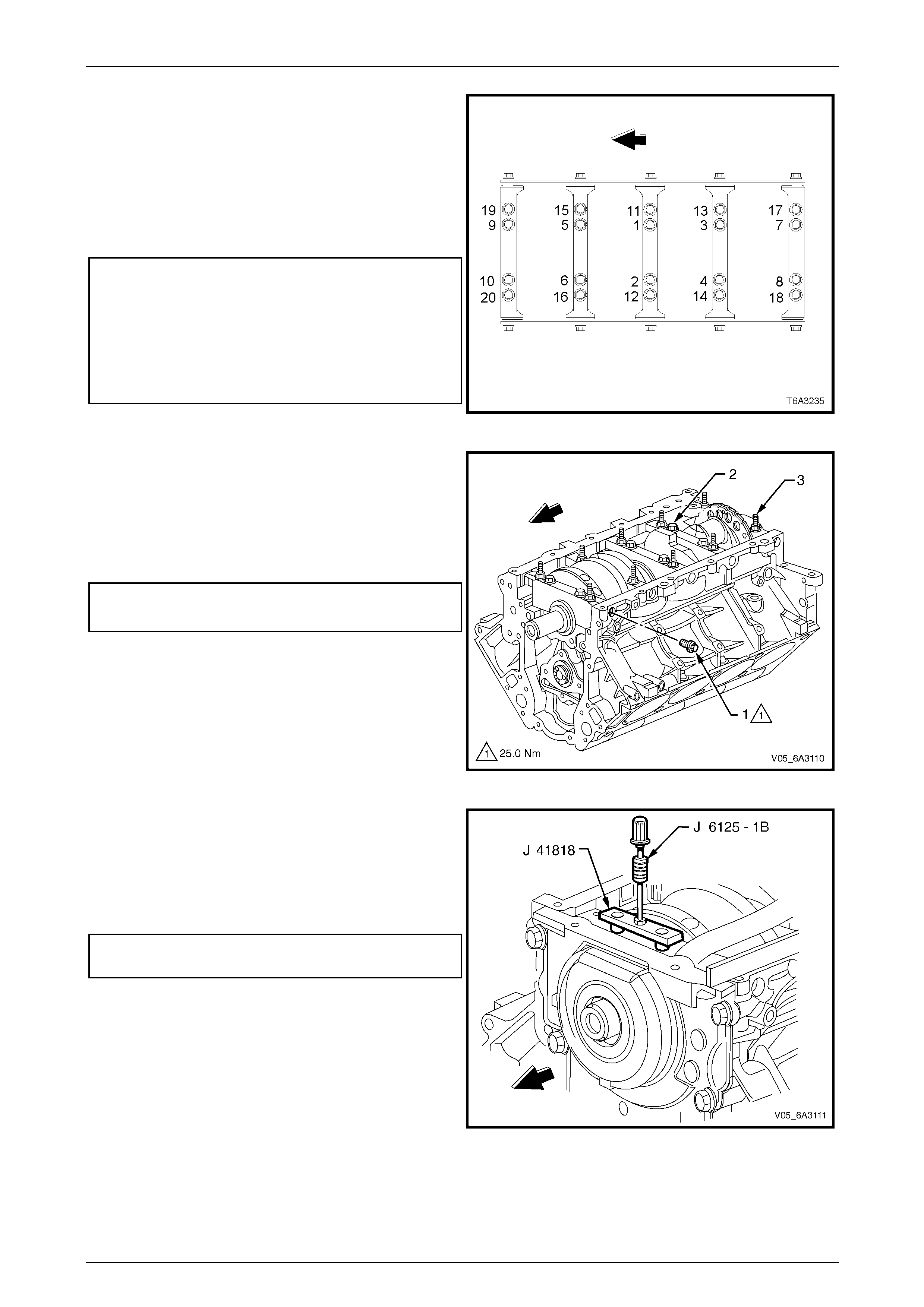
Engine Mechanical Page 6A4–228
Page 6A4–228
5 Tighten the main bearing cap bolts and studs in
numerical order to the correct torque specific ation.
NOTE
Perform Stage 1 for all the bolts and studs. T hen
continue with Stage 2 using a torque angle
meter Tool No. E7115 to achieve an accurate
second reading, noting the different turn angles
for the bolts and the studs.
Main bearing inner attaching bolts (1 – 10)
torque specification
Stage 1 ..............................................................20.0 Nm
Stage 2 .....................................................80° turn angle
Main bearing outer attaching studs (11 – 20)
torque specification
Stage 1 ..............................................................20.0 Nm
Stage 2 ......................................................53°turn angle
Figure 6A4 – 369
NOTE
For this procedure, the used main bearing cap
side bolts can be used.
6 Tighten the main bearing cap side bolts (1) to the
correct torque specification, first on one side then on
the other.
Main bearing cap side bolts
torque specification............................................25.0 Nm
7 Remove the main bearing cap side b olts an d discard
as new bolts must be used on final assembly.
8 Remove the main bearing cap M10 bo lts (2) and studs
(3), loosening each pair gradually. Take note of the
stud positions for reassembly.
Figure 6A4 – 370
9 Loosen the bolts attaching the main bearing removal
Tool No. J 41818 to separate the chamfered collets
then install the chamfered sect ions into the main
bearing cap bolt hole, aligning the flats of the collets
with those in the holes.
10 Tighten the bolts of Tool No. J 41818 to the specified
torque.
Main bearing removal tool attachi ng bolt
torque specification............................................11.0 Nm
11 Install the slide hammer, Tool No. J 6125-1B to Tool
No. J 41818 and remove the main beari ng cap.
Figure 6A4 – 371

Engine Mechanical Page 6A4–229
Page 6A4–229
Ensure the cranksh aft does not rotate during
this process. Any rotation of the crankshaft
will result in the plastigauge being deformed
and a true oil clearance reading will not be
possible.
12 Remove the remaining main b earing caps in the same
way.
Figure 6A4 – 372
13 Using the scale supplied with the plastigauge,
measure the deformed plastigauge at its widest part,
noting the following.
a If the deformed strip shows a width variation
exceeding 0.020 mm, remove the crankshaft and
measure the journal with a micrometer.
b If the bearing clearance is greater than 0.076
mm (connecting rod) or 0.065 mm (main), select
and install an undersized bearing set and then
re-check the oil clearance.
c If the clearance specification cannot be obtained,
the crankshaft must be reground for use with the
next under-sized bearin gs.
NOTE
Ensure all traces of the plastigauge have been
removed from the crankshaft once measuring is
complete.
14 If required, measure the crankshaft end play, refer to
Crankshaft Thrust End Play. Figure 6A4 – 373
Reinstall
1 Reinstall the main beari ng shells into the caps and the
cylinder block in their original locatio n or as requ ired
after performing an oil clearance check.
NOTE
Do not apply engine oil to the back of the main
bearing shells.
2 Apply clean engine oil to the bearing halves and
crankshaft journals.
Figure 6A4 – 374
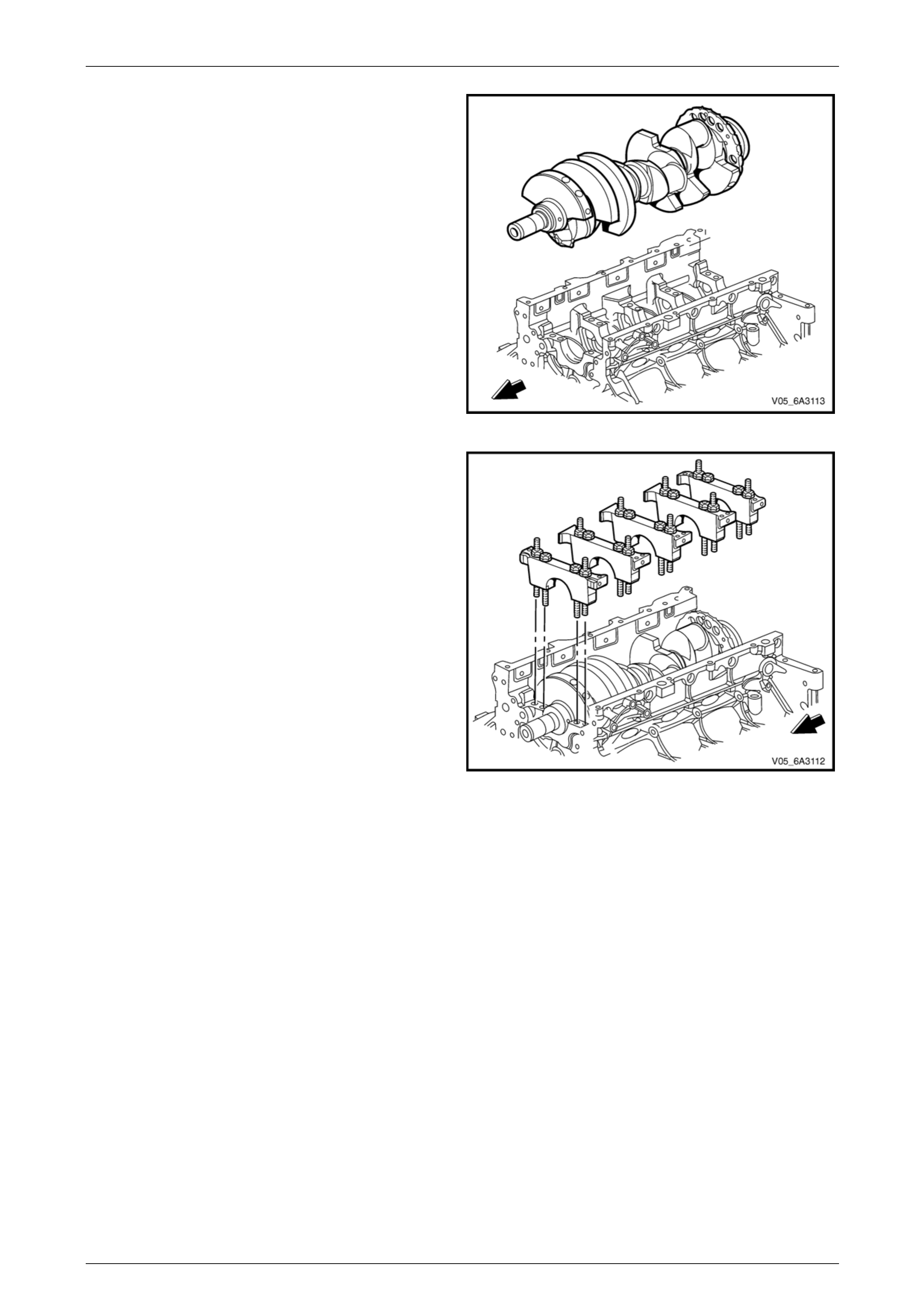
Engine Mechanical Page 6A4–230
Page 6A4–230
3 Install the crankshaft to the cylinder block ensuring the
crankshaft is held square to avoid damagin g the
centre main thrust bearing or the reluctor ring.
Figure 6A4 – 375
4 Install the crankshaft main bearings caps with the
bearings installed and install the main bearing cap
bolts and studs in the correct order as removed.
Figure 6A4 – 376
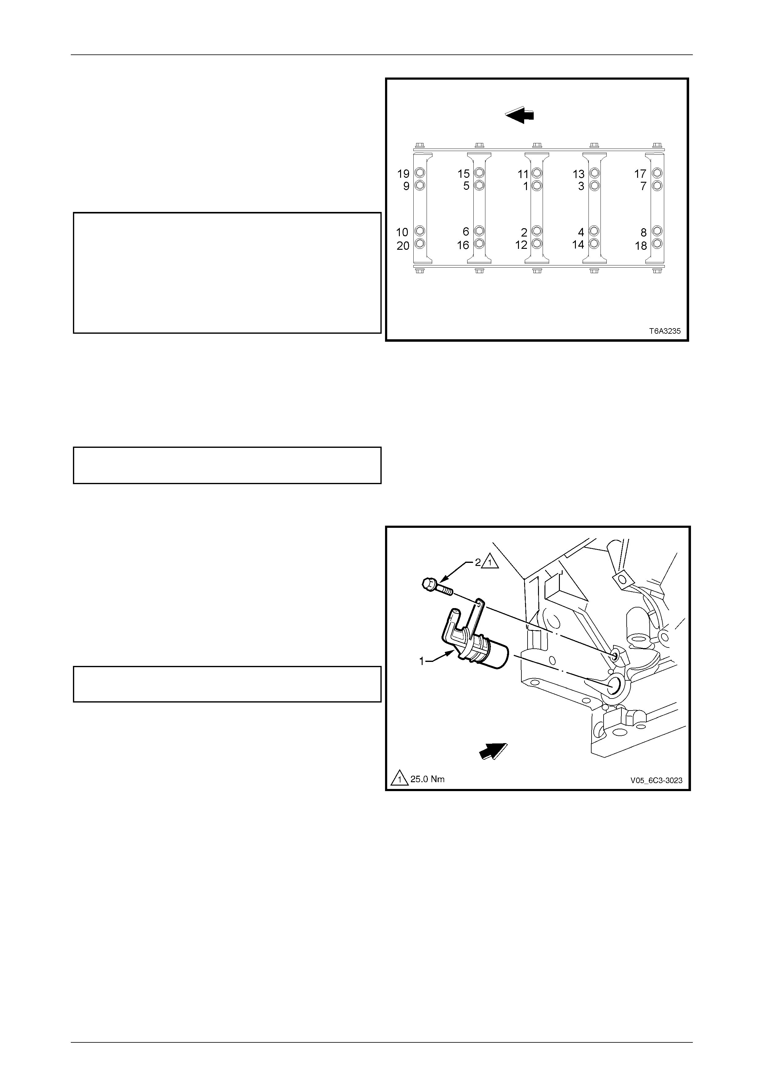
Engine Mechanical Page 6A4–231
Page 6A4–231
5 Tighten the main bearing cap bolts and studs to the
correct torque specification, in the correct sequence.
NOTE
Perform the Stage 1 for bolts and studs 1–20
and then continue with Stage 2. Use a torque
angle meter Tool No. E7115 to achieve an
accurate second reading, noting the different
turn angles for the bolts and the studs.
Main bearing inner attaching bolts (1 – 10)
torque specification
Stage 1 ..............................................................20.0 Nm
Stage 2 .....................................................80° turn angle
Main bearing outer attaching studs (11 – 20)
torque specification
Stage 1 ..............................................................20.0 Nm
Stage 2 .....................................................53° turn angle
6 Install new M8 main bearing cap sid e bolts and tighten
to the correct torque specification, first on one side
then on the other.
NOTE
New main bearing cap side bolts have a sealant
patch applied to the bolt flange.
Main bearing side cap bolts
torque specification............................................25.0 Nm
7 If required, recheck the crankshaft thrust end play,
refer to Crankshaft Thrust End Play.
Figure 6A4 – 377
8 Inspect the crankshaft position sensor (1) O-ring for
nicks, cuts or other damage. If undamaged, the O-ring
may be re-used.
9 Smear the O-ring with clean engine oil.
10 Install the crankshaft position sensor a ligning the
retaining bracket bolt hole with the threaded hole in
the cylinder block.
11 Install the attaching bolt (2) and tighten to the correct
torque specification.
Crankshaft position sensor attaching bolt
torque specification............................................25.0 Nm
NOTE
Lever the crankshaft to the forward position,
particularly when a manual transmission is fitted
to the engine. This will reduce the effect of
bearing shock when the engine is started and
the clutch is first released. Figure 6A4 – 378
12 Reinstall the following items to the engin e a ssembly;
• Connecting rod bearing caps, refer to 5.12 Piston, Connecting Rod and Bearing.
• Rear engine cover, refer to 5.8 Engine Rear Cover.
• Timing chain and sprockets, refer to 5.10 Timing Chain and Sprockets.
• Oil pump, pump screen and deflector, refer to 5.9 Oil Pump, Pump Screen and Deflector.
• Starter motor, refer to Section 6D3-2 Starting System – GEN IV V8.
13 If required, reassemble the transmission to the engine and reinstall the engine into vehicle, refer to
5.1 Engine Assembly.
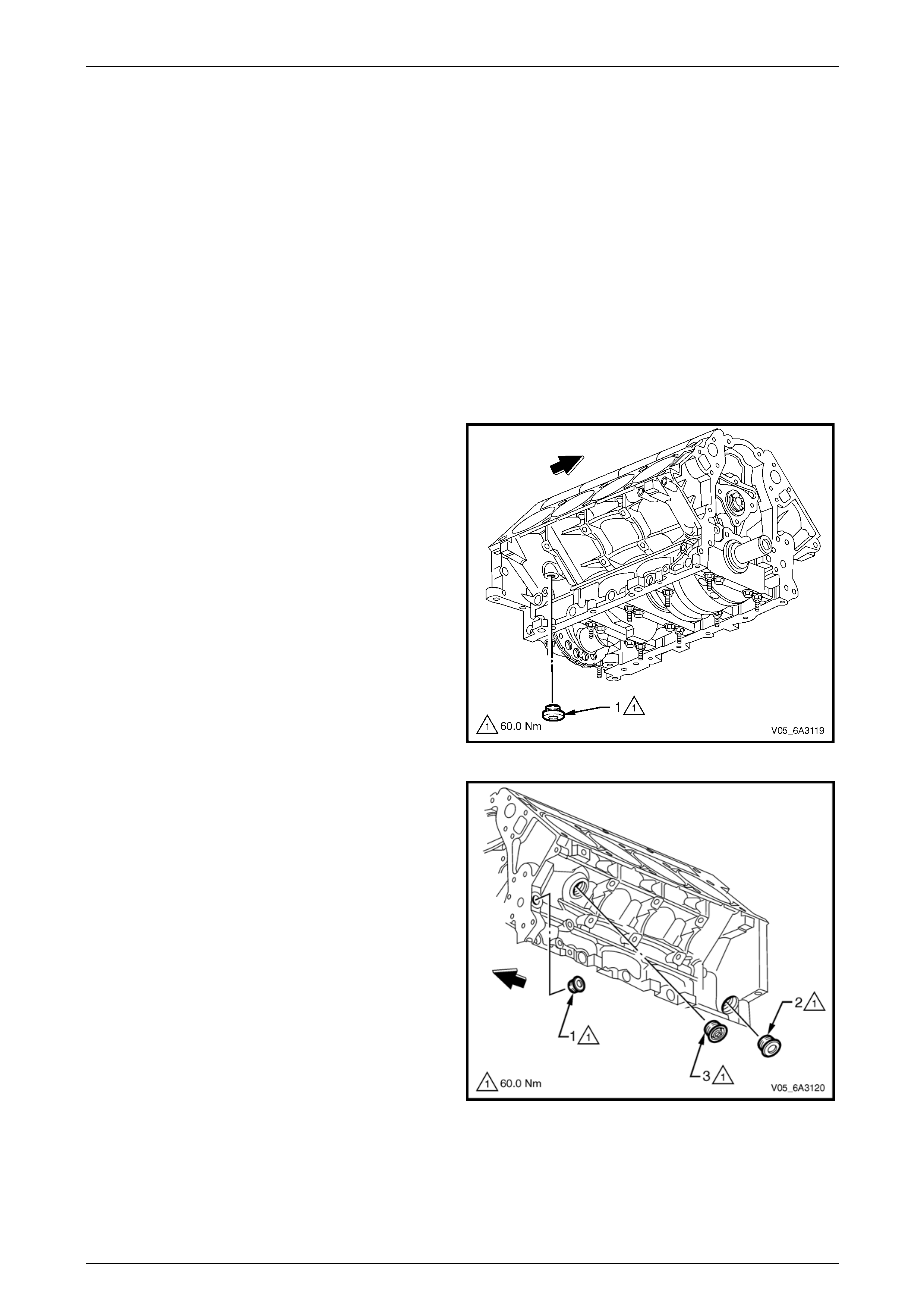
Engine Mechanical Page 6A4–232
Page 6A4–232
5.14 Cylinder Block Plugs
LT Section No. — 00–248
Coolant drain plugs can be removed with the engine assembly installed in the vehicle. The oil gallery plugs will require
the engine to be removed from the vehicle and either, the front or rear engine covers to be removed.
NOTE
All screw-in coolant and oil gallery plugs must be
replaced if removed or loosened.
Refer to either:
a 5.1 Engine Assembly, for engine assembl y removal procedures.
b 5.5 Engine Front Cover, for front engine cover removal procedures.
c 5.8 Engine Rear Cover, for rear engine cover removal procedures.
Remove
1 Remove the coolant drain plug (1) from the right-h and
rear of the cylinder block.
Figure 6A4 – 379
2 Remove the three plugs (1, 2 and 3) from the left-hand
side of the cylinder block.
NOTE
Plugs (1 and 2) are oil gallery plugs and (3) is a
coolant plug.
Figure 6A4 – 380

Engine Mechanical Page 6A4–233
Page 6A4–233
NOTE
• Remove the plug from the front of the
cylinder block only if its replacement is
required.
• The engine front cover will need to be
removed to perform this procedure, refer to
5.5 Engine Front Cover.
3 Remove the cylinder block front oil gallery plug.
A suggested method is to:
a Drill a small pilot hole through the plug.
b Install a self tapping screw into the plug.
c Using a slide hammer with a suitable fitting,
remove the plug.
d Discard the removed plug.
Figure 6A4 – 381
NOTE
The engine assembly and rear engine cover
must be removed to perform this procedure.
4 Remove the rear oil gallery plug (1) by either one of
the following two methods:
a With the front plug removed, use a suitable
length of metal rod (e.g. 5 mm) inserted from the
front of the cylinder block and a hammer to tap
the rear oil gallery plug free.
To avoid personal injury, wear safety glasses
and the appropriate gloves when using
compressed air and cleaning fluids.
b With the cylinder block plug removed, use a
small screwdriver inserted in the plug aperture to
prise the oil galley plug free.
5 Inspect the O-ring seal on the removed gallery pl ug
and if it is undamaged, it may be re-used d uring
assembly.
Figure 6A4 – 382
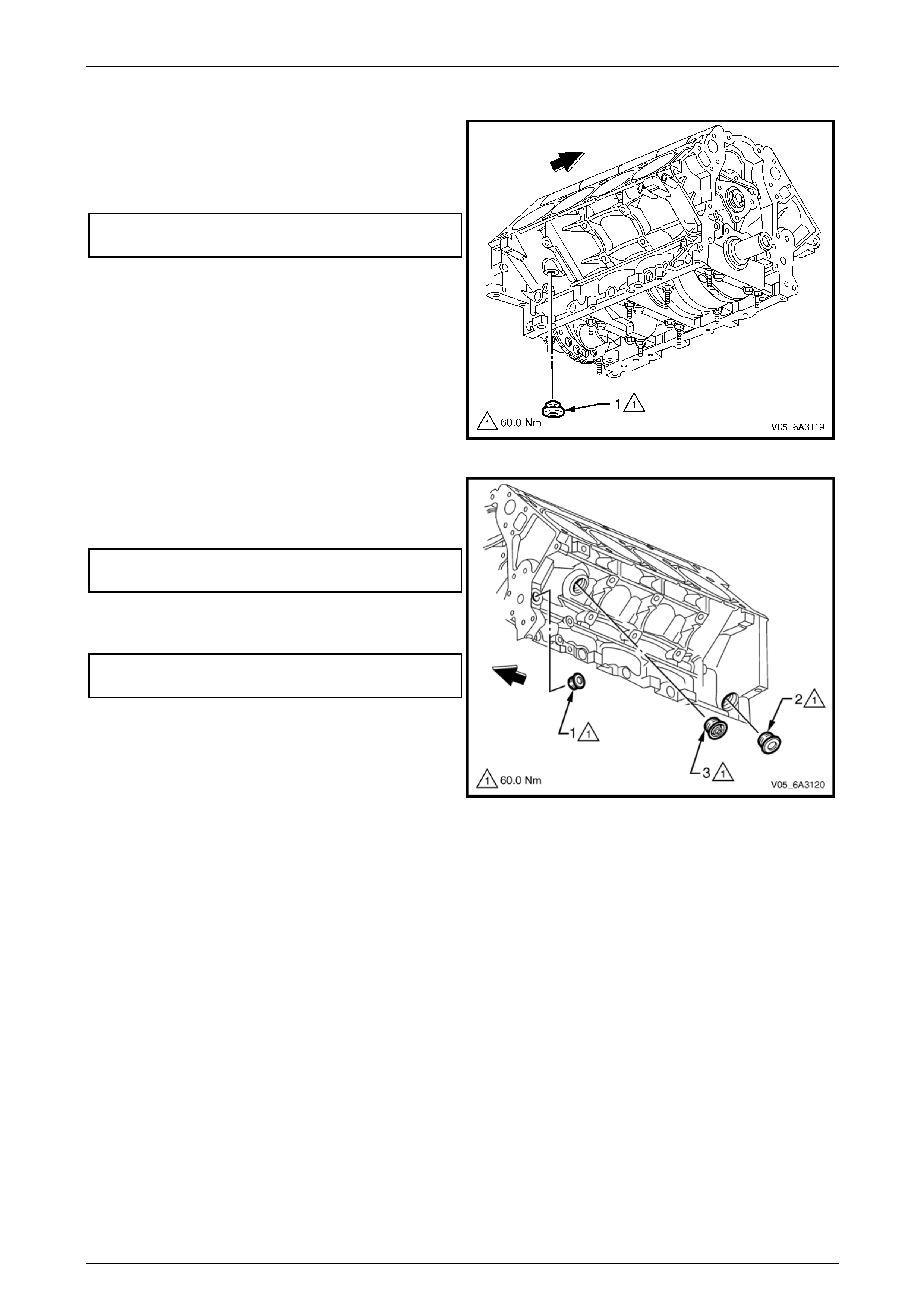
Engine Mechanical Page 6A4–234
Page 6A4–234
Reinstall
1 Apply a 3 mm bead of sealan t such as Loctite 565 or
equivalent to the drain plug sealing washer on a new
right-hand cylinder block cool ant plug.
2 Install the plug and tighten to the correct torque
specification.
■ Coolant drain plug
torque specification............................................60.0 Nm
Figure 6A4 – 383
3 Apply a 3 mm bead of sealan t such as Loctite 565 or
equivalent to the new oil gallery plugs (1 and 2 )
sealing washer and tighten to the correct torque
specification.
■ Oil gallery plug
torque specification............................................60.0 Nm
4 Apply a 3 mm bead of sealan t such as Loctite 565 or
equivalent to the new coolant drain plug (3) sealing
washer and tighten to the correct torque spe cification.
■ Coolant drain plug
torque specification............................................60.0 Nm
Figure 6A4 – 384
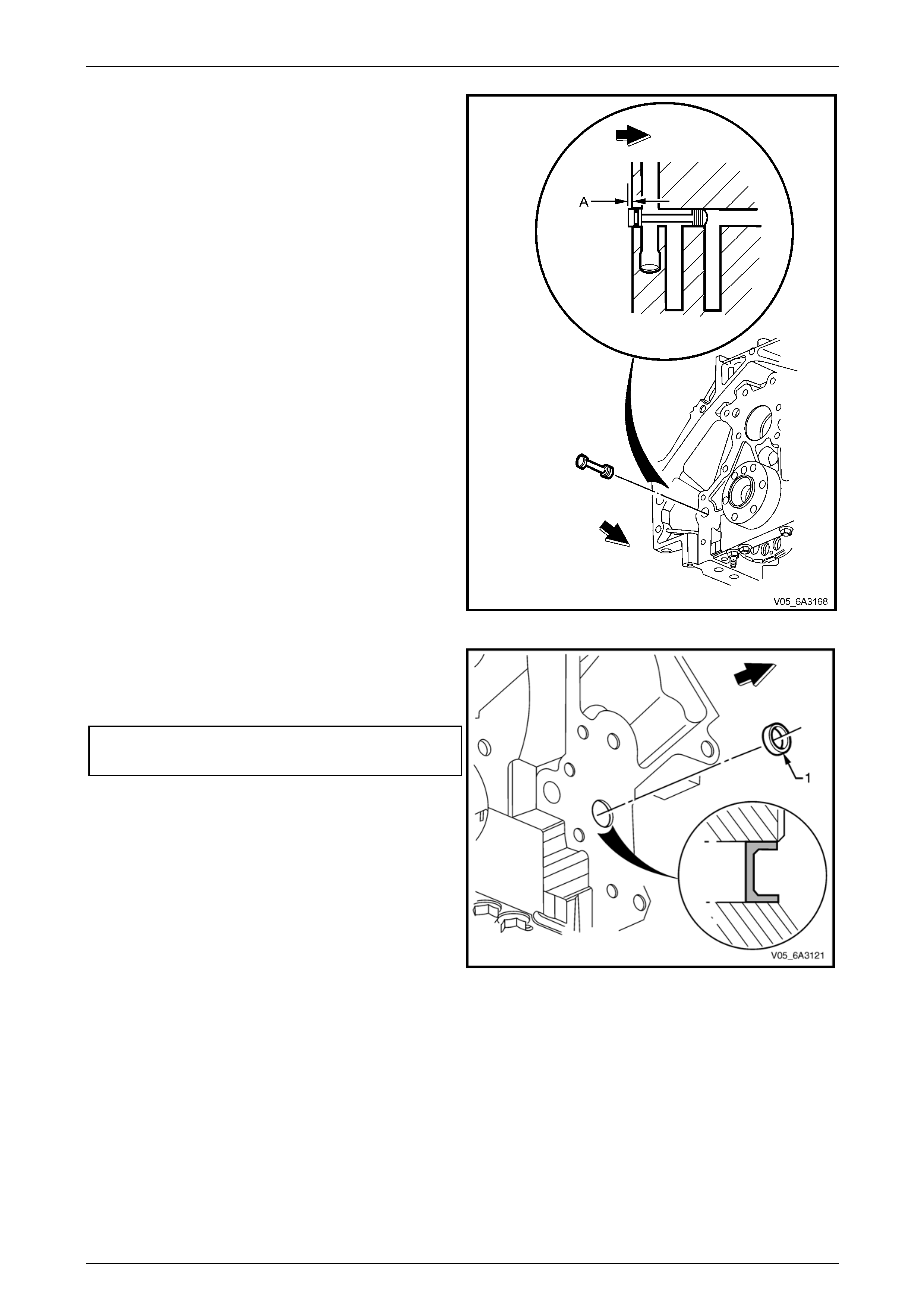
Engine Mechanical Page 6A4–235
Page 6A4–235
5 Lubricate the oil gallery plug O-ring with clean engine
oil and install the plug into the rear of the cylinder
block.
6 Carefully install until the plug until it comes to a stop
against the stepped bore of the oil g allery. At this
point, the plug should be protruding by approximately
1.2 mm (A).
NOTE
When the rear engine cover and gasket are
installed, the plug protrusion will rest against the
rear engine cover machined internal surface.
Figure 6A4 – 385
7 Apply a sealant such as Loctite 242 or equivalent to
the side of a new front oil gallery plug (1).
8 Install the new front oil gallery plug into the cylinder
block to the specified depth.
Front oil gallery plug installation specification:
Distance below flush.................................. 2.0 – 2.8 mm
Figure 6A4 – 386

Engine Mechanical Page 6A4–236
Page 6A4–236
5.15 Cylinder Block
Cylinder Block Clean, Inspect and Measure
Clean
1 Disassemble the cylinder block as required.
2 Remove all cylinder block plugs, refer to 5.14 Cylinder Block Plugs and then clean all the coolant passages and o il
galleries.
• Do not use any caustic solutions to clean
the aluminium cylinder block. When
cleaning an cylinder block in a thermal
type washer, do not exceed 232°C.
• Wear safety glasses and the appropriate
gloves when using compressed air and
cleaning fluids to avoid personal injury.
3 Clean the cylinder block in a commercially available cleanin g fluid to remove all sludge, dirt, or debris and blow dry
using compressed air. An alte rnative is to clean the block in a commercially available thermal type washer,
providing the temperatur e does not exceed 232° C.
4 Clean all gasket surfaces using a plastic scraper to avoid damaging machined surfaces.
5 Clean the main bearing caps, ensuring they stay in their original order.
6 Clean the residue of cylinder head bolt thread sealant from the cylinder block threads. Use installer T ool No.
J 42385-107. This tool is part of the thread repair kit, J-42385.
NOTE
Do not use anything but this thread tool to clean
the cylinder head threads in the cylinder block.
7 Use compressed air to clean all residue from the bolt holes.
Inspect
Inspect the following areas:
• The cylinder walls for excessive scratches, g ouging, or piston ring ridge
• The coolant jacket for cracks or corrosion
• The valve lifter bores for excessive scoring or wear
• The crankshaft bearing webs for cracks
• The gasket sealing surfaces for excessive scratches or gouging
• The oil galleries for restrictions
• All threaded bolt holes for damage
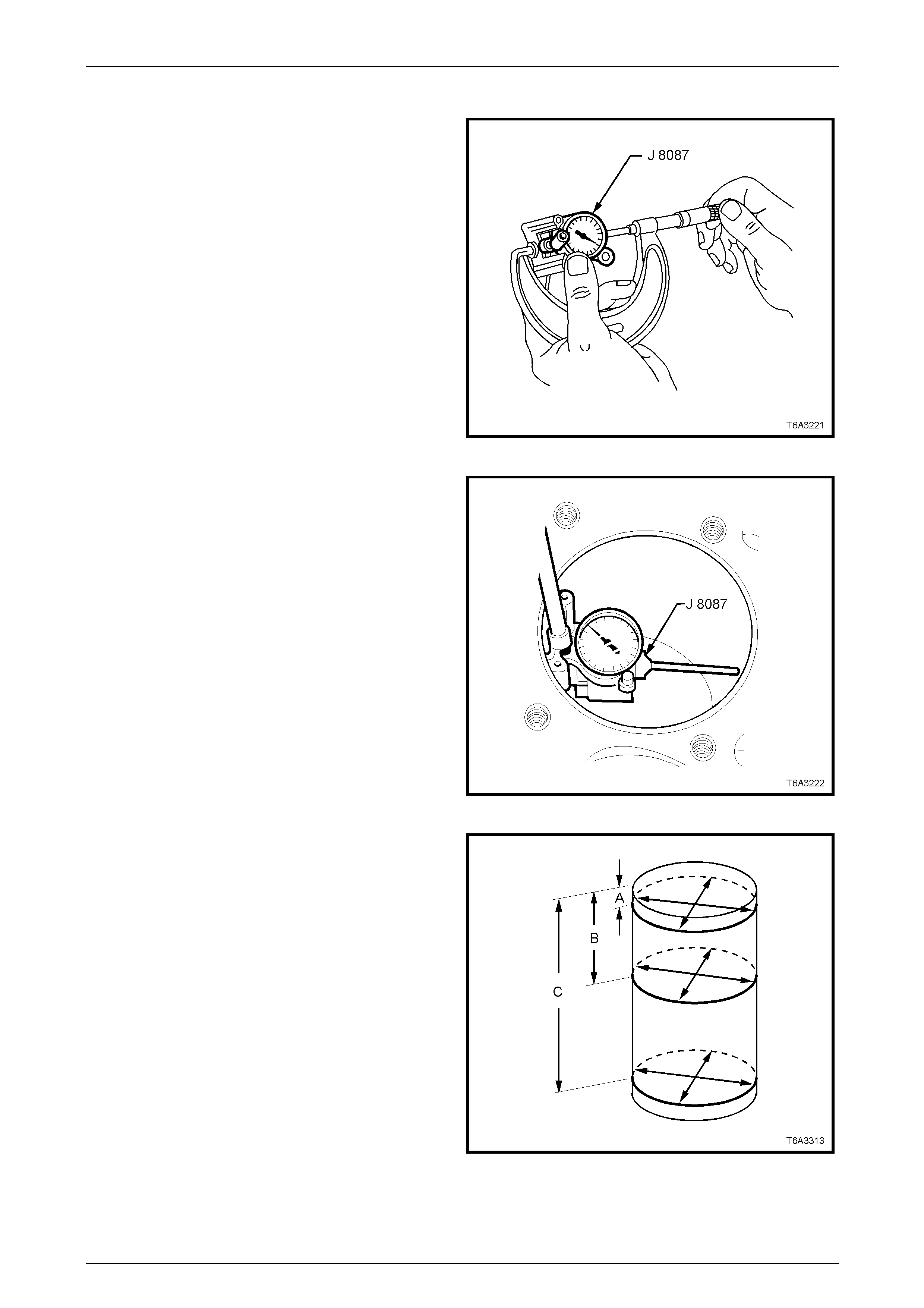
Engine Mechanical Page 6A4–237
Page 6A4–237
Cylinder Bore – Measure
1 Adjust the micrometer to 96.0 mm.
2 Insert the bore gauge into the micrometer and zero the
bore gauge dial, Tool No. J 80 87 or a commercially
available equivalent.
Figure 6A4 – 387
3 Using a bore gauge, Tool J8087, measure the cylinder
bore for taper by sliding the bore gaug e up and down
throughout the length of the cylinder bore. Ch eck the
bore both parallel and p erpendicular to the centreline
of the crankshaft.
4 Recondition cylinders with less than 0.018 mm taper
with by honing the cylinder, refer to Cylinder Boring
and Honing.
NOTE
Cylinders with more than 0.018 mm taper must
be honed and fitted with an oversize piston.
Figure 6A4 – 388
5 Using a bore gauge, measure the cylinder bore at
points (A, B and C), measure the bore both in line with
the centreline and perpendicular to the engine
centreline. Check for bore out-of-round at a depth of:
a 9 mm (A).
b 57 mm (B).
c 127 mm (C) from the cylinder head surfaces.
6 Calculate the difference between the two
measurements at each location. T he results will
indicate any out-of-round bore conditi on.
NOTE
Cylinders with more than 0.18 mm out-of-round
must be honed and fitted with an oversize piston.
Figure 6A4 – 389
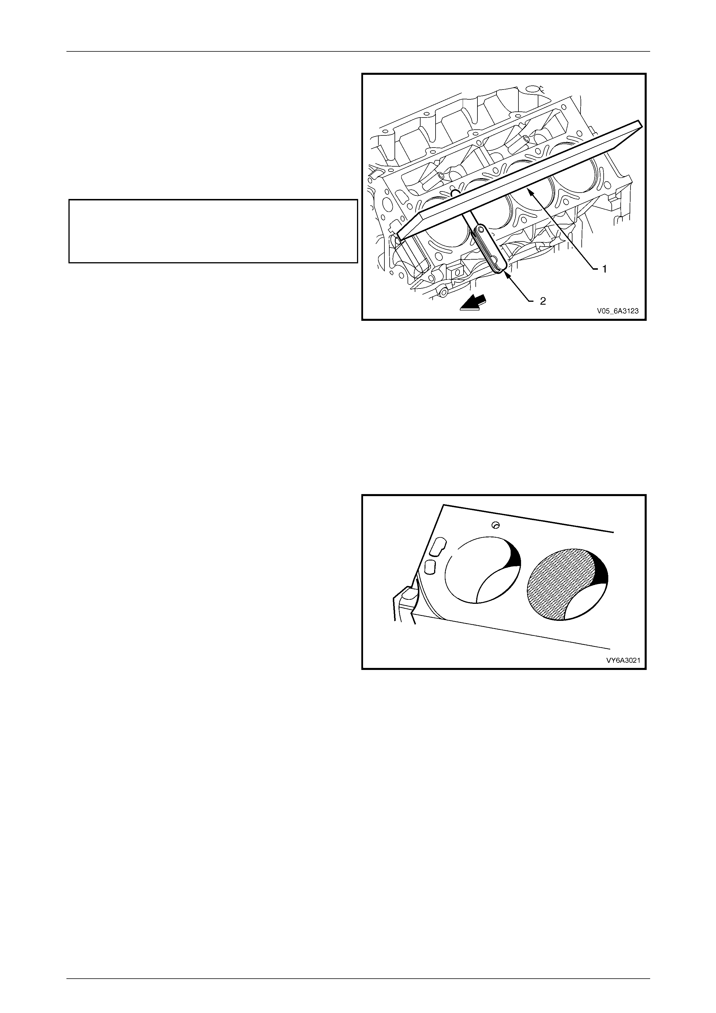
Engine Mechanical Page 6A4–238
Page 6A4–238
7 Measure the cylinder block cylinder head deck using a
straight edge(1) and feeler gauges (2). Check the
flatness of the cylinder block and cyl ind er head deck
surfaces.
NOTE
If the measurement is not within specification,
the cylinder block must be replaced. Machining
is not recommended.
Cylinder block cylinder head flatness specification:
Measured:
Within a 150 mm area............................... 0.11 mm Max
Over the cylinder block length....................0.22 mm Max
Figure 6A4 – 390
Cylinder Boring and Honing
NOTE
Boring of the cylinder is not permitted. Pisto n and
piston ring service sets are available in 0.25 mm
oversize. It is recommended to hone the cylinder
to achieve the correct fit for the oversize piston.
Honing Procedure
1 When honing the cylinders observe the following:
a Follow the equipment manufacturer's
recommendations.
b Use only clean, sharp hone stones of the proper
grade recommended for the amount of material
that is required to be remove. Dull and dirty hone
stones cut unevenly and generate excessive
heat.
c Do not hone to the final clearance with a coarse
or medium-grade stone. Leave sufficient metal
so that all stone marks may be removed with
fine-grade stones. Perform final honing with a
fine-grade stone to hone the cylinder to the
correct clearance. Figure 6A4 – 391
2 During the cylinder honing operation observe or monitor the following:
• Constantly clean the cylinder bore and check the cylinder bore for fit with the selected piston. All
measurements of the piston or the cylinder bore should be made with the components at normal room
temperature.
• When honing a c ylinder for fit to an oversize piston, first perform the preliminary honing with a 100 grit stone.
• Perform the final cylinder honing with a 240 grit stone and obtain a 45°cross hatch pattern. A 240 grit stone is
preferred for final honing. If a 240 grit stone is not available, a 220 grit stone may be used as a substitute.
• When honing to eliminate taper in the cylinder, make full strokes over the complete bore length. Constantly
check the measurement at the top, the middle, and the bottom of the bore. When completed, the
reconditioned cylind er bore should have less than or meet the specified out-of-round and taper requirements.
• The finish marks should be clean but not sharp. The finish marks should also be free from embedded
particles, torn or folded metal.
• By measuring the selected pist on at the specified point and by adding the average to the clearance
specification, the final cylinder honing dimension required c an be determined.
3 After the final honing, clean the c ylinder bores with hot water and detergent by scrubbing the bores with a stiff
bristle brush and then rinse t he bores thoroughly with hot water.
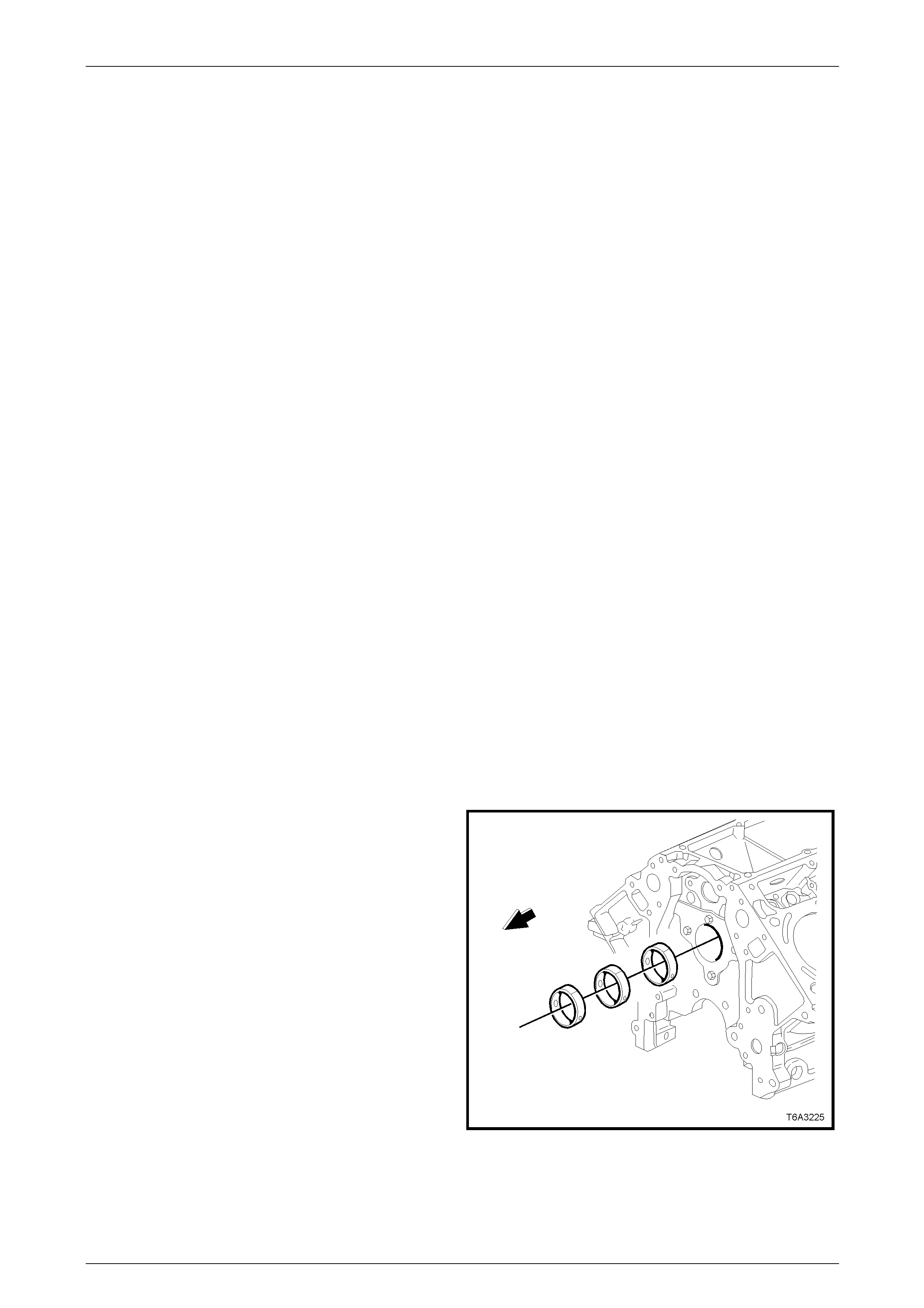
Engine Mechanical Page 6A4–239
Page 6A4–239
NOTE
Do not allow any abrasive material to remain in
the cylinder bores. This abrasive material may
cause premature wear of the new piston, piston
rings and the cylinder bores. Abrasive material
will also contaminate the engine oil and may
cause premature wear of the bearings. After
washing the cylinder bore, dry the bore with a
clean rag.
4 Perform final measurements of the piston an d the cylinder bore and permanently mark the top of the piston for the
specific cylinder to which it is to been fitted.
5 Apply clean engine oil to each cylinder bore in order to prevent rusting.
Deglazing Procedure
If a cylinder becomes glazed, that cylinder will need to be deglazed to allow the piston rings to bed in. Deglazing of the
cylinder bore is performed using a ball type (Bottle Brush) or self centring honing tool to lightly deglaze the cylinder bore.
Deglazing should only be don e to remove any deposits that may have formed.
Use a 240 grit silicone carbide stone or e quivalent material when performing the deglazing proce dure.
NOTE
A 240 grit stone is preferred for deglazing,
however if a 240 grit stone is not available a 220
grit stone may be used as a substitute.
Camshaft Bearings
Remove
The following service operatio n involves the use of a universal camshaft bearing remover /installer, Tool No. J 33049 and
finished size camshaft bearings. If installing unfinished size bearings, installation must be carried out by a specialist
machine shop and then line bored to the correct finished size.
Camshaft bearings once removed sho uld be replaced with new ones. The bearings should only be removed if
replacement is required or cyli nder block service operations require the block to be compl etely disassembled.
While it is preferred the camshaft bearings are removed and installed in a bare cylinder bl ock, the operation can be
carried out by removing the crankshaft and the camshaft. However, it will be difficult to negotiate the tool past the
connecting rod big end journa ls.
The camshaft can be removed without havin g to remove the cylinder heads and hydraulic lifters. This is achieved by
removing the pushrods and inverting the eng ine. This will allow the hydraulic lifters to drop sufficiently to clear the
camshaft journals. However, use extreme care when removing the camshaft and be arings using this procedure to ensure
either the camshaft or hydraulic lifters are no t damaged.
1 Prior to bearing removal, inspect all camsh aft bearin gs
for a loose fit in the cylinder block bearing bores.
NOTE
If a bearing is found to be loose, it may have
been caused by an enlarged, out of round or
damaged cylinder block bearing bore.
Figure 6A4 – 392
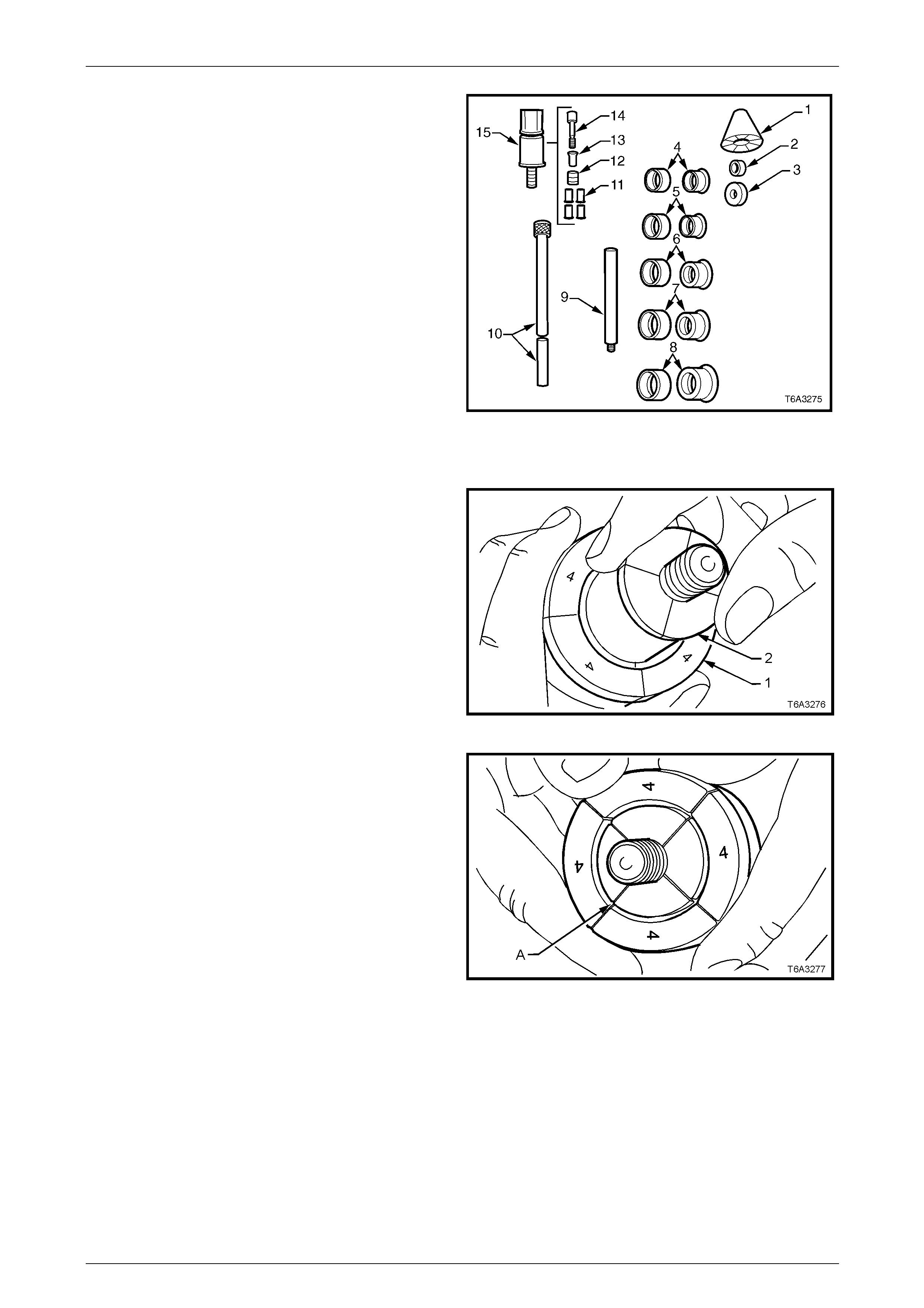
Engine Mechanical Page 6A4–240
Page 6A4–240
2 The universal camshaft bearin g remover/installer,
Tool No. J 33049 consists of the following
components;
• Nylon guide cone (1)
• Small driving washer (2)
• Large driving washer (3)
• Expanding drivers and rubber sleeves (4 – 8)
• Driver extension bar (9)
• Driver bar (10)
• Expander assembly (15) consisting of parts
11 – 14
3 To replace the camshaft beari ngs, select the following
components from Tool No. J 33049:
• Nylon guide cone (1)
• Large driving washer (3)
• Expanding drivers and rubber sleeve (7)
• Driver bar (10)
• Expander assembly (15)
Figure 6A4 – 393
4 Install the expanding driver with the rubber sleeve (1)
over the expander assembly (2) and with the
numbered flanges of the expanding driver facing the
threaded end of the expan der assembly.
Figure 6A4 – 394
5 Once installed, ensure the se parations in the expander
assembly segments are aligned with those of the
expanding driver as shown (A).
Figure 6A4 – 395
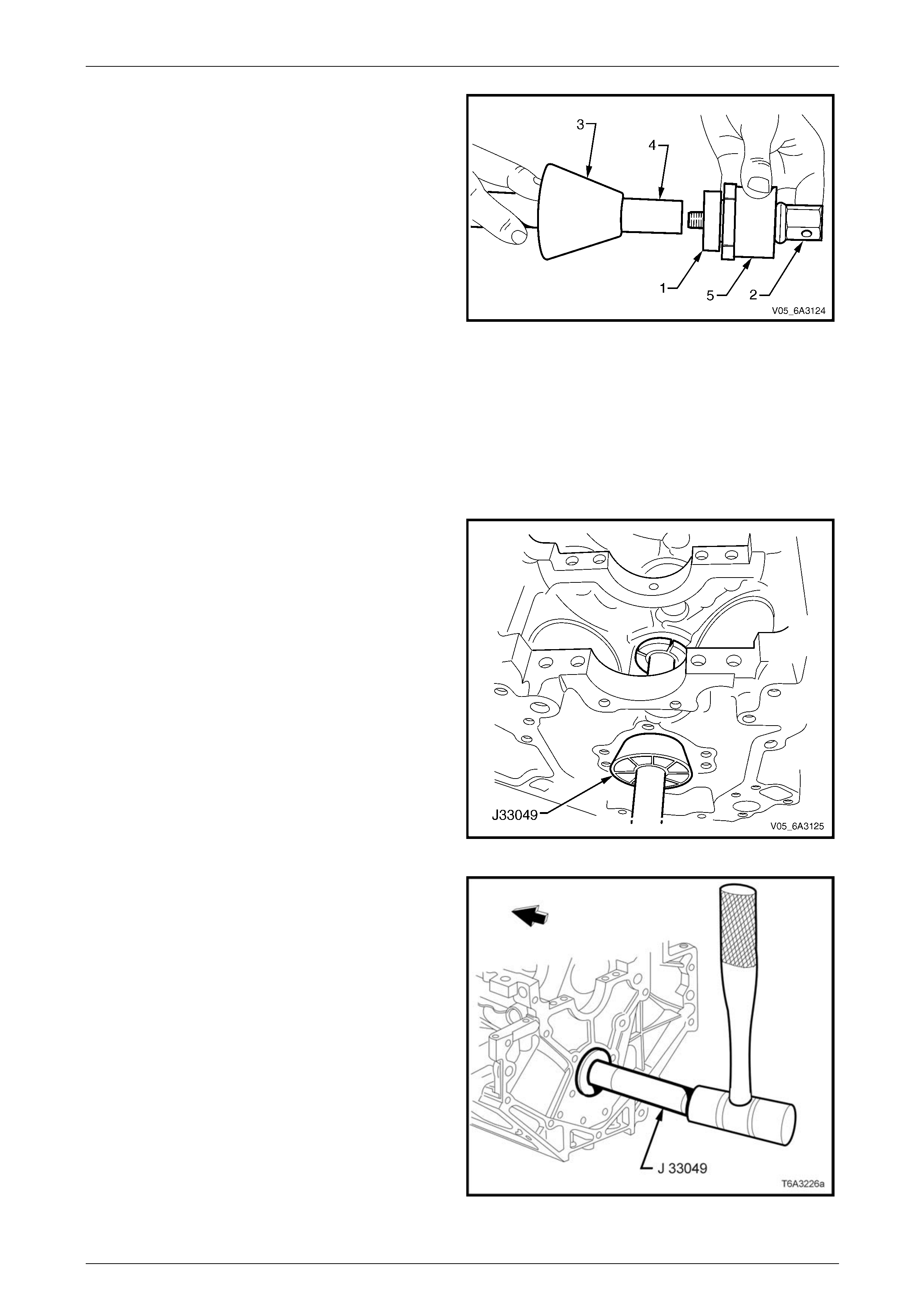
Engine Mechanical Page 6A4–241
Page 6A4–241
6 Manoeuvre the assembly into the cylinder block in
front of the bearing to be removed and install the large
driving washer (1) over the threaded end of the
expander assembly (2).
7 Slide the nylon cone (3) over the driver bar (4) with the
smaller diameter toward the cylinder block.
NOTE
The components shown are shown removed
from the cylinder block for clarity.
8 Carefully insert the driving bar through the camshaft
bearings from the front of the cylinder block and screw
the bar to the expander assembly.
NOTE
Do not overlook fitting the driving washer over
the threaded end of the expander assembly
before installing the driver bar.
9 With the expander assembly inserted into th e
camshaft bearing, hold the hexagonal end of the
expander assembly with a spanner an d hand tighten
the driver bar until the expanding driver (5) is tight in
the bearing shell.
Figure 6A4 – 396
10 Push the guide cone into the front camshaft bearing to
align the driver bar.
11 While holding the guide cone in place with one hand,
drive the bearing from the cylinder block.
12 Repeat this process with the remainin g bearings being
removed.
Figure 6A4 – 397
13 To remove the front bearing, install the driver bar from
the rear of the cylinder block, using the guide cone in
the rear camshaft bearing bore.
Figure 6A4 – 398

Engine Mechanical Page 6A4–242
Page 6A4–242
Reinstall
1 Reinstallation of the camshaft bearings is the reverse
of the removal procedure, noting the following:
• The joint in the new camshaft bearing (1) must
be aligned with the top of the cylinder block
centreline (2). To assist with alignment of the
bearing, use a felt tip pen to mark the back of the
bearing 180° from the join, as this will be visible
when installing the bearing.
• While the oil feed is generous in length and
allows some degree of hole misalignment, as
much care as possible must be made during
installation to ensure the beari ng is installed
correctly allowing maximum exposure to the oil
feed hole.
• Install each bearing until it is centrally located in
the cylinder block bore and th en use a thin piece
of wire to ensure the oil feed passage has not
been obstructed.
• To install the front camshaft bearing, install the
driver bar into the rear bearing and use the guide
cone at that location.
NOTE
Take care when installing the driver bar through
the newly installed bearings to avoid damage.
Figure 6A4 – 399
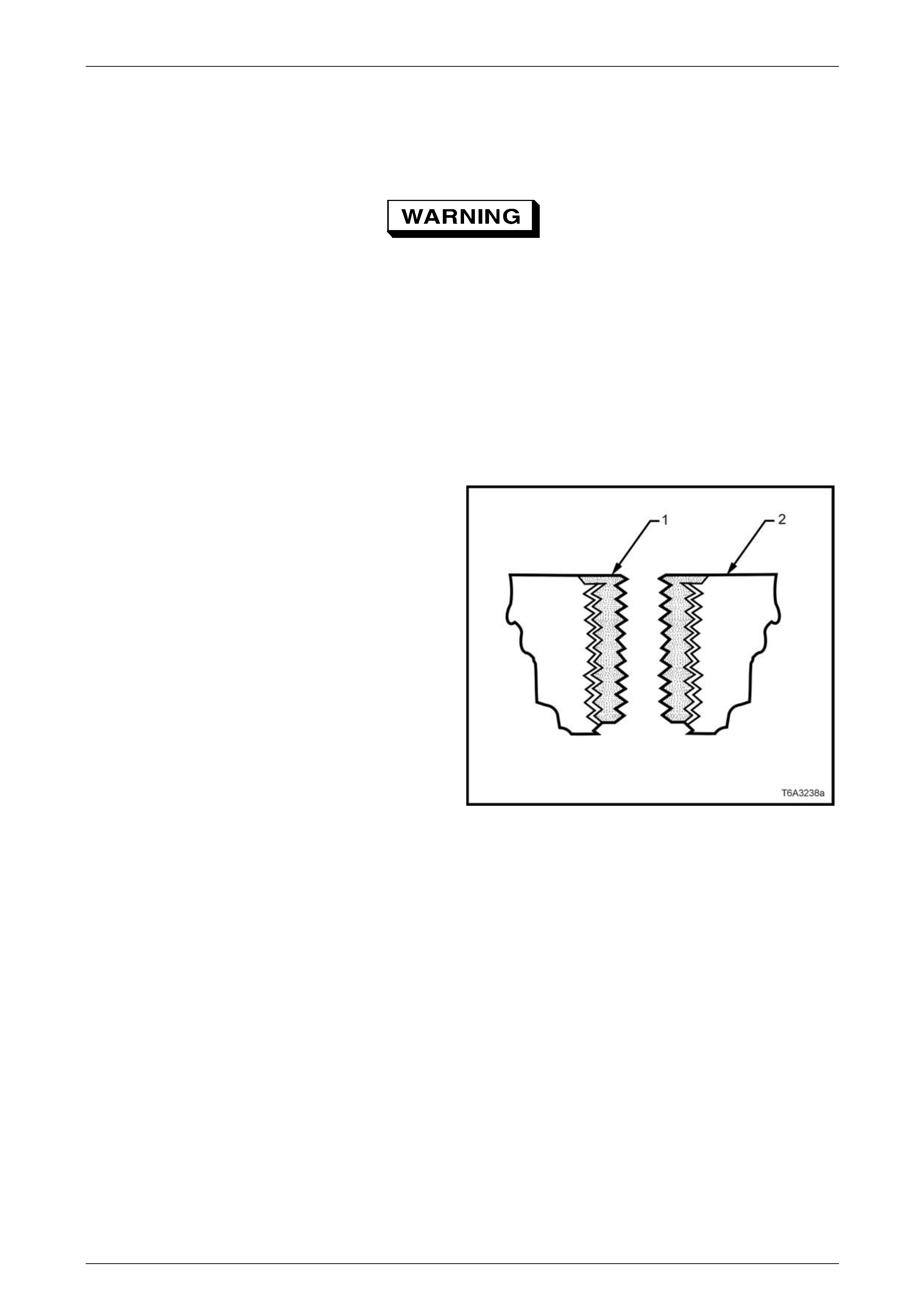
Engine Mechanical Page 6A4–243
Page 6A4–243
6 Thread Repair
6.1 General Information
Throughout this Section, compressed air is
used for the cleaning of debris wh en repairing
threads. When using compressed air, ensure
safety glasses are used to avoid eye injury.
With the extensive use of aluminium alloy in the construction of the GEN IV V8 engine, thread repairs will be required at
times to repair damaged threads caused b y the corros ion of fasteners, careless handling or over-tightening of fasteners.
This Section describes the recommended method of repairing threads in three specific areas of the engine:
• General thread repair
• Cylinder head bolt hole thread repa ir
• Main bearing cap bolt hole thread repair
Detailed descriptions of all thread specifications used in this engine are listed in 6.5 Thread Re pair Specifications.
The available Thread Repair Kit, Tool No. J 42385/100/200/
300 uses the Time Sert® thread repair process that involves
a solid thin walled self-locking carbon steel bushing type
insert (1).
During the bushing installati on process the driver tool
expands the bottom external threads of the i nsert into the
base material (2). This action mechanically locks the insert
in place.
When installed to the proper depth the flange of the insert
will be seated against the counter-bore of the repaired hole.
Driver oil must be used on the installer driver tool.
NOTE
The use of a cutting or drilling fluid is
recommended when performi ng drilling, counter-
boring and tapping proce dures.
The tool kits are designed for use with a suitable tap wrench
and electric drill. Figure 6A4 – 400
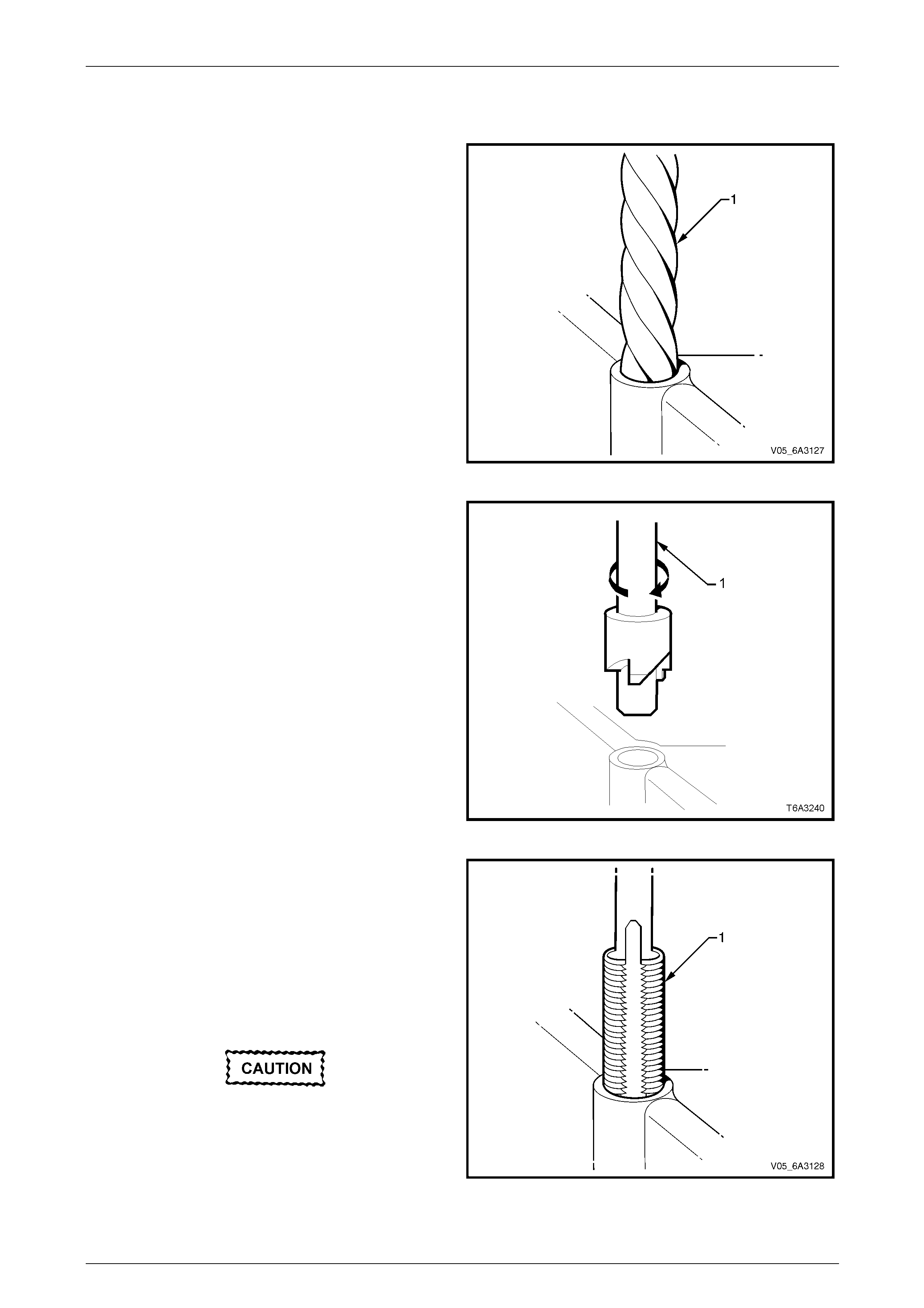
Engine Mechanical Page 6A4–244
Page 6A4–244
6.2 General Thread Repair
1 Drill out the threads of the damaged hole (1) to the
correct depth for the thread being repaire d.
2 Observe the following recommend ed drilling depths:
• M6 inserts require a minimum drill depth of
15 mm
• M8 inserts require a minimum drill depth of
20 mm
• M10 inserts require a minimu m drill depth of
23.5 mm
3 Using compressed air, clean out any foreign material
from the holes.
Figure 6A4 – 401
4 Counter-bore the hole to the full depth permitted by
the tool (1).
5 Using compressed air, clean out any foreign material
from the holes.
Figure 6A4 – 402
6 Using a tap wrench (1), tap the threads of the drilled
hole to the correct depth for the thread bei ng repaired.
7 Observe the following recommend ed tapping depths:
• M6 inserts require a minimum tap depth of
15 mm
• M8 inserts require a minimum tap depth of
20 mm
• M10 inserts require a minimum tap depth of
23.5 mm
Do not use any cleaning agents that contain
Trichloralethane as this is harmful to the
aluminium.
8 Spray a suitable cleaner int o the hole.
9 Using compressed air, clean out any foreign material
from the holes. Figure 6A4 – 403

Engine Mechanical Page 6A4–245
Page 6A4–245
10 Lubricate the threads by applying a small amount of
driver oil (1) to the threads of the installer (2).
NOTE
Do not allow oil or other foreign material to
contact the outside diameter of the insert.
Figure 6A4 – 404
11 Install the insert (1) onto the driver tool (2).
Figure 6A4 – 405
12 Apply a small amount of thread locki ng compound,
such as Loctite 272 (1) or equivalent to the thread
insert OD threads (2).
Figure 6A4 – 406
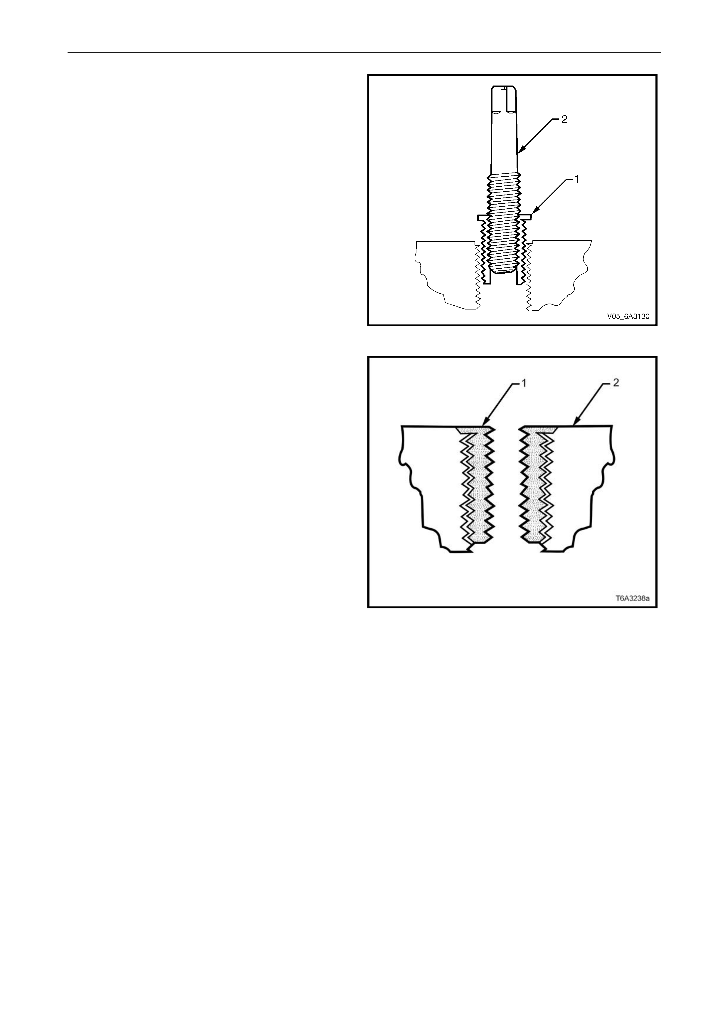
Engine Mechanical Page 6A4–246
Page 6A4–246
13 Install the insert (1) until the flang e of the insert
contacts the counter-bored surface.
14 Continue to rotate the installer tool (2) through the
insert. The installer tool will tighten up before screwing
completely through the insert. This is normal since the
bottom threads of the insert are being formed and
mechanically locked into the hol e.
15 Remove the driver.
Figure 6A4 – 407
16 Inspect the insert for proper installation into the hole.
17 A properly installed insert (1) will be either flush or
slightly below flush with the surface of the base
material (2).
Figure 6A4 – 408
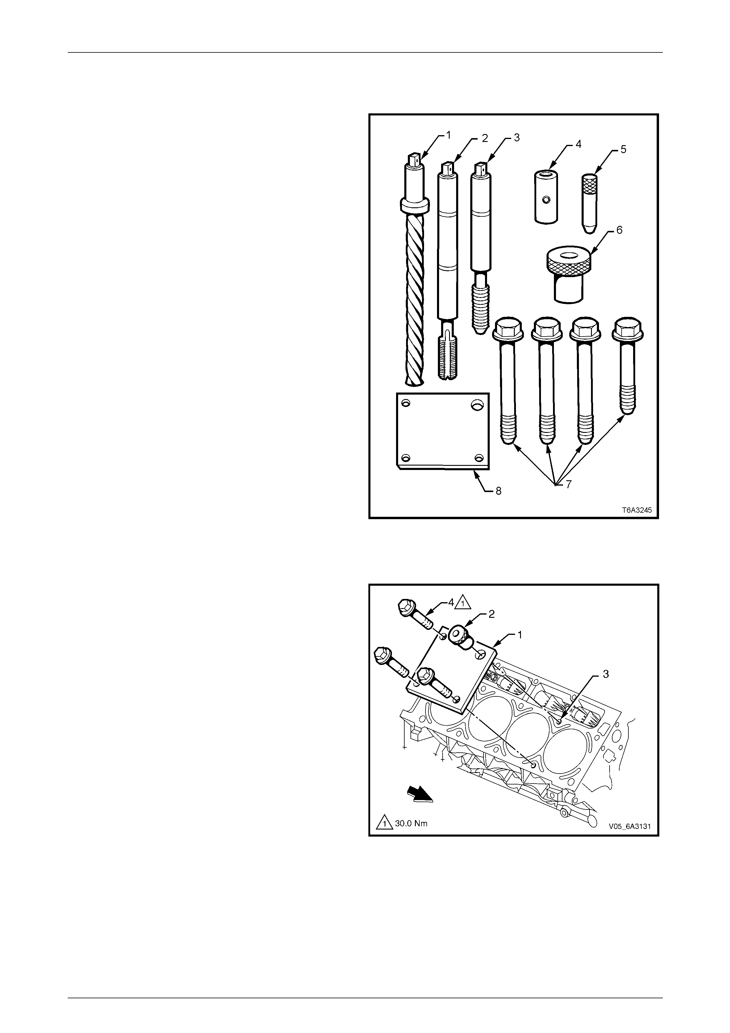
Engine Mechanical Page 6A4–247
Page 6A4–247
6.3 Cylinder Head Bolt Hole Thread Repair
The cylinder head bolt hole thread repair kit from T ool No.
J 42385/100/200/300 cons ists of the following items:
• Drill (1)
• Tap (2)
• Installer (3)
• Sleeve (4)
• Alignment pin (5)
• Bushing (6)
• Attaching bolts (7)
• Fixture plate (8)
NOTE
The use of a cutting type fluid (WD 40®), or
equivalent is recommended when performing the
drilling, counter-boring and tapping procedures.
Figure 6A4 – 409
Procedure
NOTE
• Driver oil must be used on the install er driver
tool.
• The tool kits are designed for use with either
a suitable tap wrench or electric drill.
1 Position the fixture plate (1) and bushing (2) over the
hole that is to be repaired (3).
2 Install the fixture plate bolts (4) finger tight and fit the
bushing onto the cylinder blo ck deck.
Figure 6A4 – 410
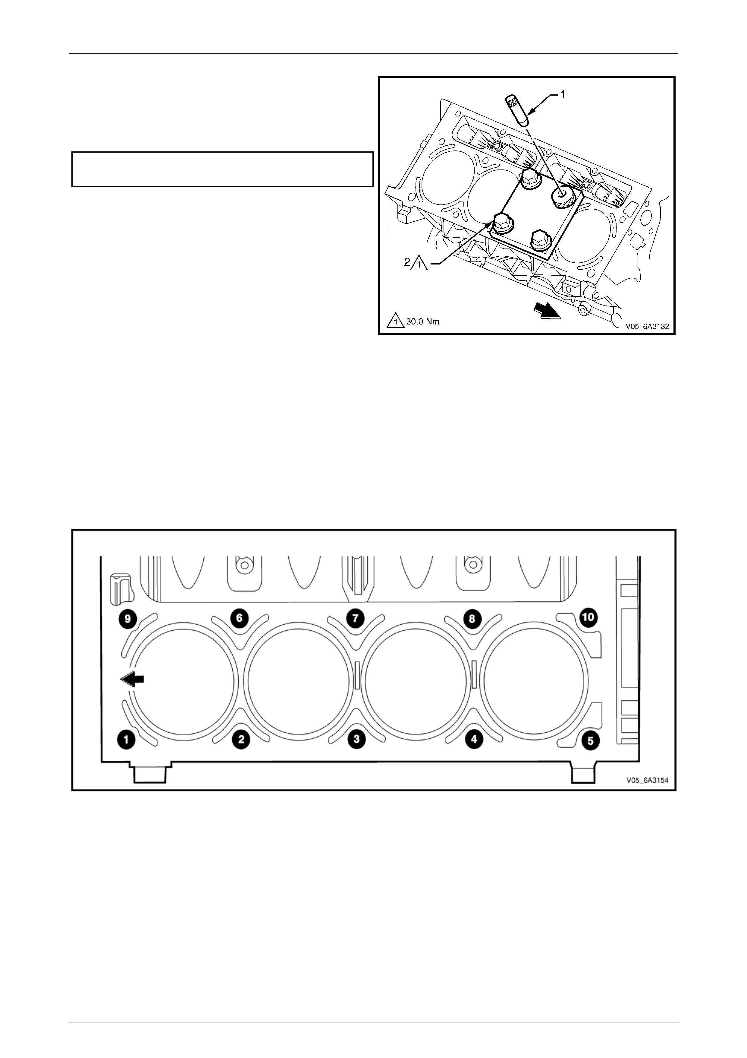
Engine Mechanical Page 6A4–248
Page 6A4–248
3 Position the alignment pin (1) through the bushing and
into the hole.
4 With the alignment pin in the desire d hol e, tighten the
fixture attaching bolts (2) to the correct torque
specification.
Cylinder head fixture attaching bolt
torque specification............................................30.0 Nm
5 Remove the alignment pin from the hole ensuring it is
not binding on the sleeve when being removed.
Figure 6A4 – 411
6 Referring to Figure 6A4 – 412, drill the hole that is to be repair ed noting the following:
• Cylinder head bolt holes 1 to 8 are deep holes and can be drilled without the drill sle eve.
• Cylinder head bolt holes 9 an d 10 are the more shallow holes so drilling must be done with the drill sleeve in
place.
NOTE
Figure 6A4 – 412 shows the left-hand side of the
engine. However, the procedure for the right
hand side is the same with holes 9 and 10 being
reversed.
Figure 6A4 – 412
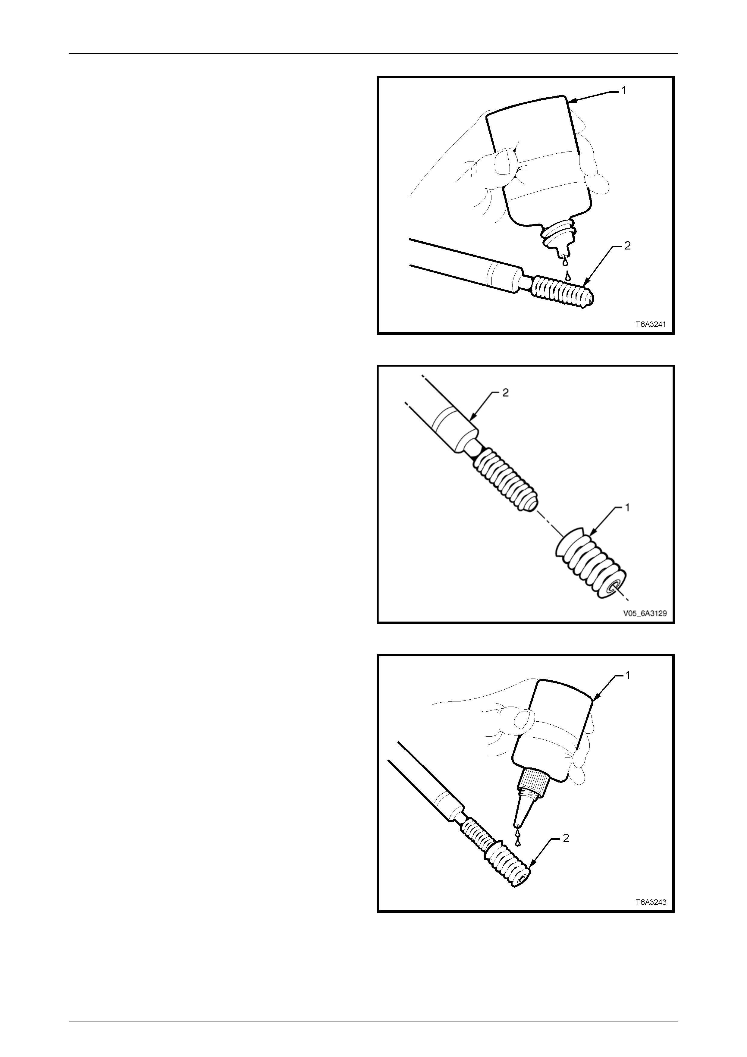
Engine Mechanical Page 6A4–249
Page 6A4–249
7 Lubricate the threads by applying a small amount of
driver oil (1) to the threads of the installer (2).
NOTE
Do not allow oil or other foreign material to
contact the outside diameter of the insert.
Figure 6A4 – 413
8 Install the insert (1) onto the dr iver tool (2).
Figure 6A4 – 414
9 Apply a small amount of thread locki ng compound,
such as Loctite 272 (1) or equivalent to the thread
insert OD threads (2).
Figure 6A4 – 415

Engine Mechanical Page 6A4–250
Page 6A4–250
10 Install the insert (1) until the flang e of the insert
contacts the counter-bored surface.
11 Continue to rotate the installer tool (2) through the
insert. The installer tool will tighten up before screwing
completely through the insert. This is normal since the
bottom threads of the insert are being formed and
mechanically locked into the hol e.
12 Remove the driver.
Figure 6A4 – 416
13 Inspect the insert for proper installation into the hole.
14 A properly installed insert (1) will be either flush or
slightly below flush with the surface of the base
material (2).
Figure 6A4 – 417
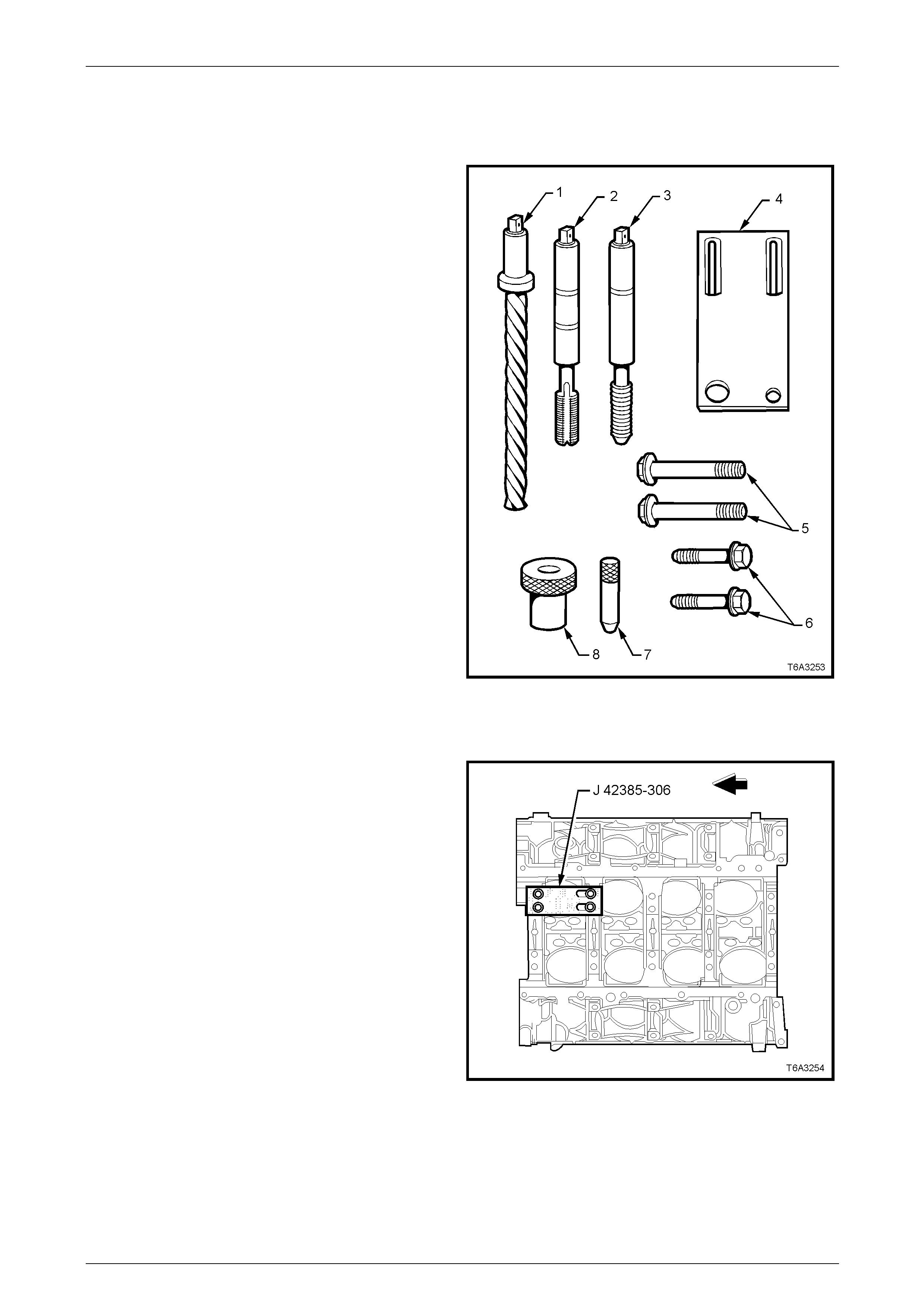
Engine Mechanical Page 6A4–251
Page 6A4–251
6.4 Main Bearing Cap Bolt Hole
Thread Repair
The main cap bolt hole thread repa ir kit from T ool No.
J 42385/100/200/300, consists of the following items:
• Drill with stop collar(1)
• Tap (2)
• Installer (3)
• Fixture Plate (4)
• Long Bolts (5)
• Short Bolts (6)
• Alignment Pin (7)
• Bushing (8)
NOTE
The use of a cutting or drilling fluid is
recommended when performing the drilling,
counter-boring and tapping procedures.
Figure 6A4 – 418
Procedure
NOTE
• The tool kits are designed for use with either
a suitable tap wrench or electric drill.
• Driver oil must be used on the install er driver
tool.
1 Position the fixture plate an d bushing over the hole
that is to be repaired. Position the alignment pin in the
desired hole and tighten the fixture retaining bolts.
2 Remove the alignment pin from the hole ensuring it is
not binding on the sleeve when being removed.
Figure 6A4 – 419
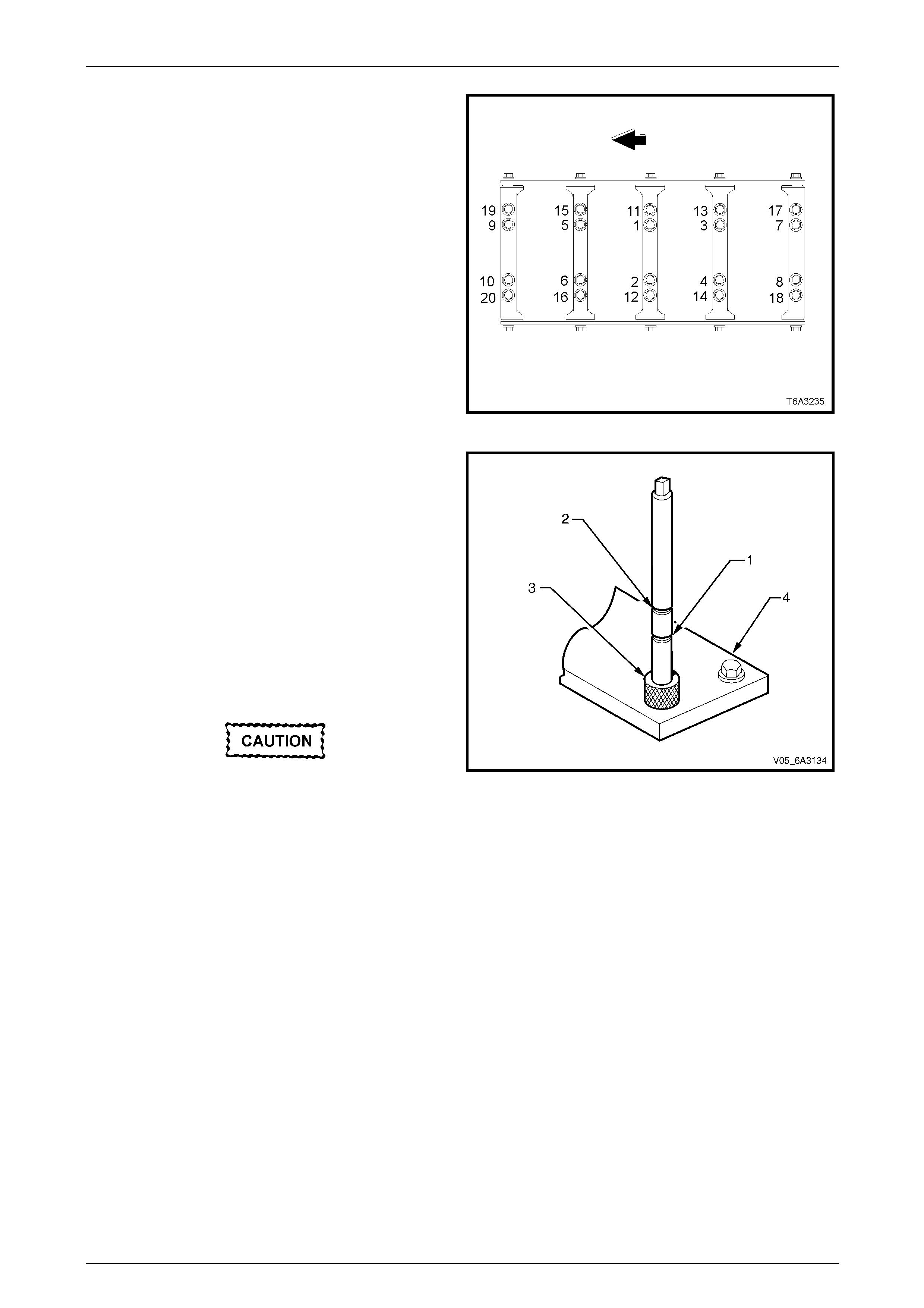
Engine Mechanical Page 6A4–252
Page 6A4–252
3 Drill out the damaged hole.
NOTE
The outer bolt hole locations (11-20) have the
shallower counter-bores. Use bushing (8) from
Tool No. J 42385-316 with the drill, refer Figure
6A4 – 418.
4 Drill until the stop collar of the drill bit or the sleeve
contacts the bushing.
5 Clean out any foreign material using compressed air.
Figure 6A4 – 420
6 In order to tap the new threads to the correct depth,
rotate the tap into the hole until the marks (1 or 2) on
the tap align with the top of the drill bushing (3) as
follows:
• For the deeper main cap holes (1-10), rotate the
tap until the upper mark (2) on the tap aligns with
the top of the bushing.
• For the shallower main cap holes (11- 20), refer
to Figure 6A4 – 420, rotate the tap until the lower
mark (4) on the tap aligns with top of the
bushing.
7 Remove the fixture plate (4) bushing and attachi ng
bolts.
8 Clean out any debris using compressed air.
Do not use any cleaning agents that contain
Trichloralethane as this is harmful to
aluminium.
9 Spray a suitable cleaner int o the hole.
10 Using compressed air clean any cutting oil and foreign
material out of the hole.
Figure 6A4 – 421
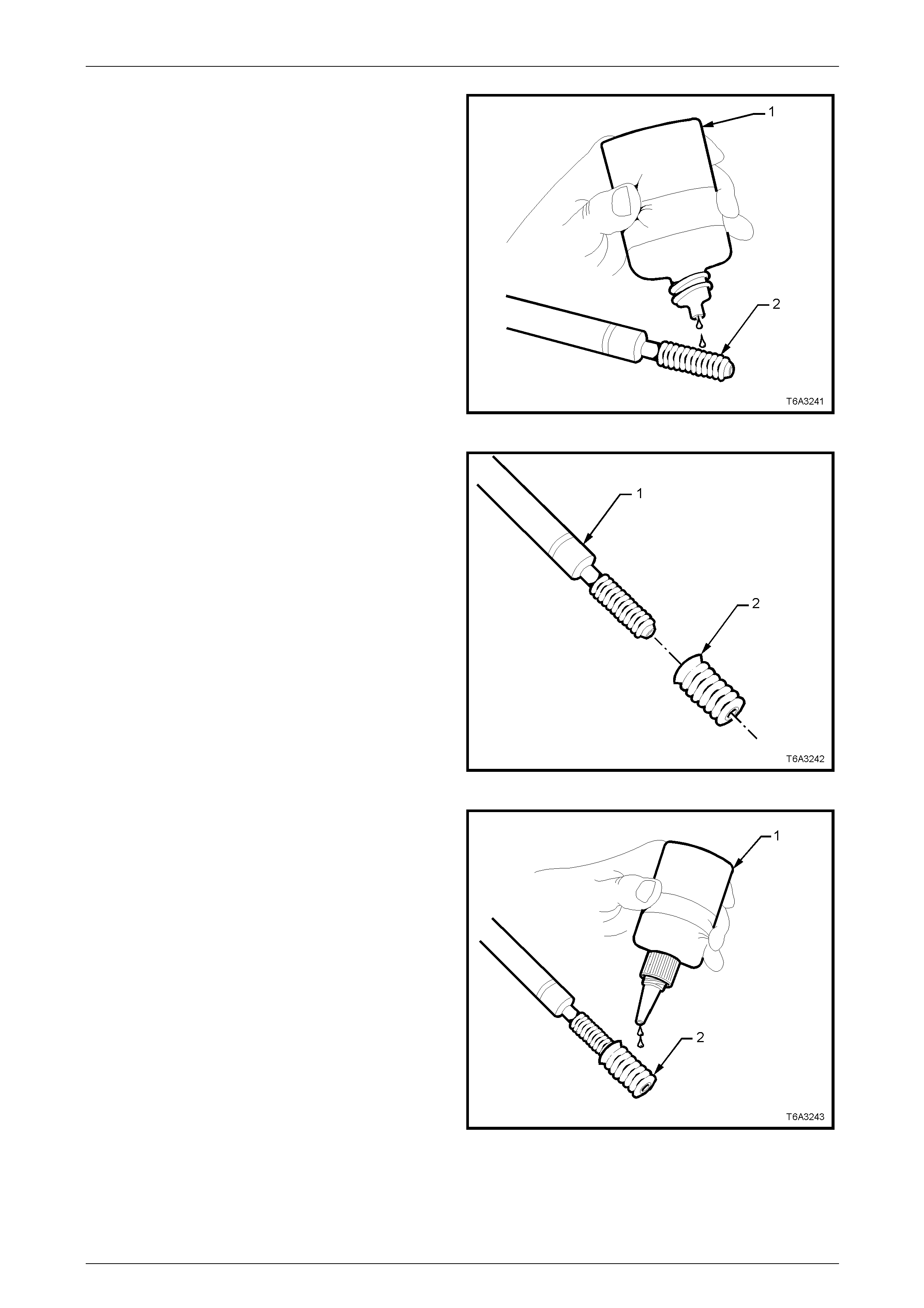
Engine Mechanical Page 6A4–253
Page 6A4–253
11 Apply a small amount of driver oil (1) and lubricate the
threads of the installer tool (2).
NOTE
Do not allow oil or other foreign material to
contact the outside diameter of the insert.
Figure 6A4 – 422
12 Install the driver tool (1) into the insert (2).
Figure 6A4 – 423
13 Apply thread lock Loctite 272 (1) or equivalent to the
insert outer threads (2).
Figure 6A4 – 424
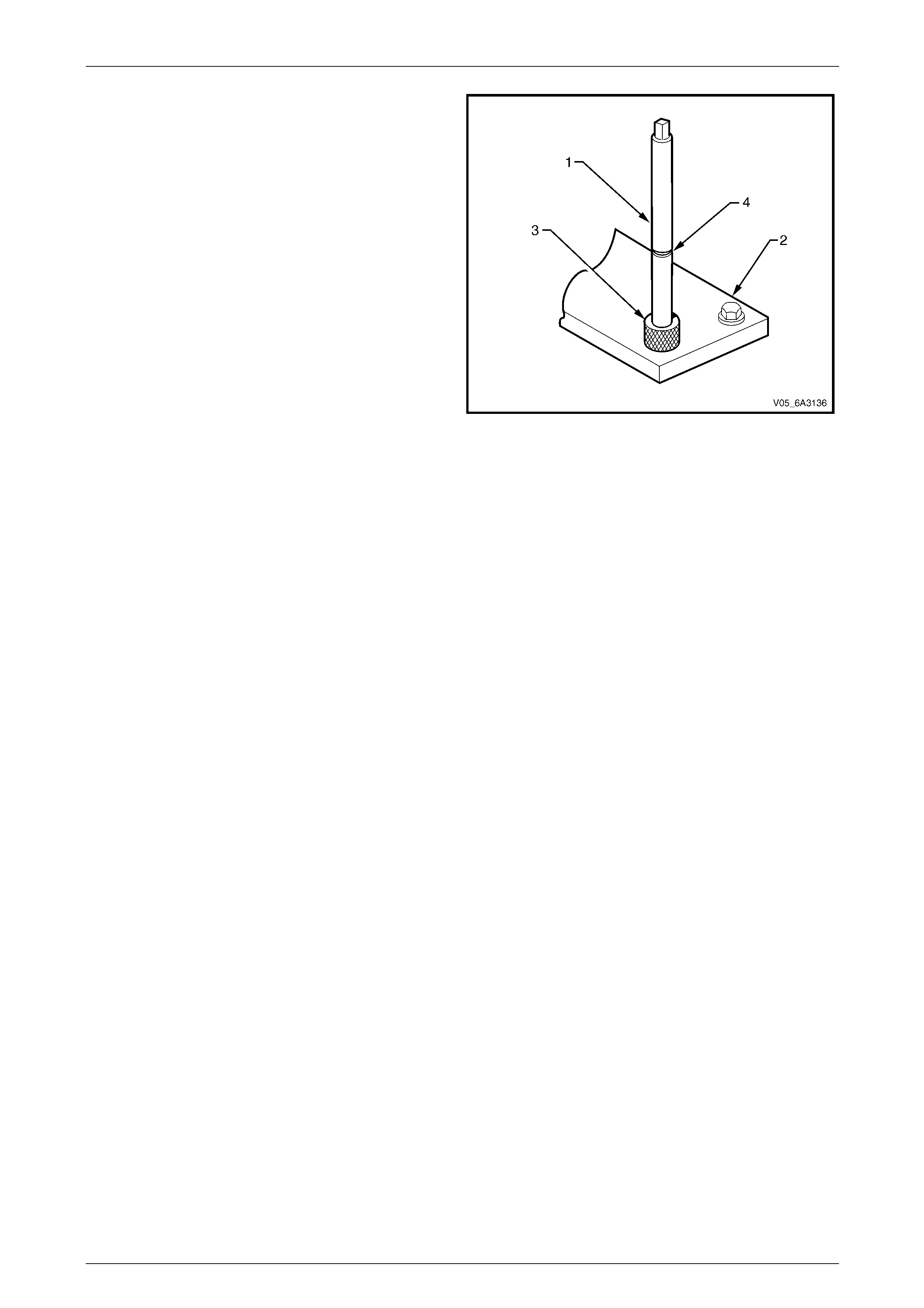
Engine Mechanical Page 6A4–254
Page 6A4–254
14 Install the insert and installer tool (1) thro ugh the
fixture plate (2) and bushing (3) and into the hole.
NOTE
The fixture plate and bushing remains installed
onto the cylinder block during the insert
installation procedure.
15 Rotate the driver tool until the mark (4) on the tool
aligns with the top of the bushing.
NOTE
The installer tool will tighten up before screwing
completely through the insert. This is normal
since the bottom threads of the insert are being
formed and mechanically locked into the hole.
16 Remove the driver and fixture plate.
Figure 6A4 – 425
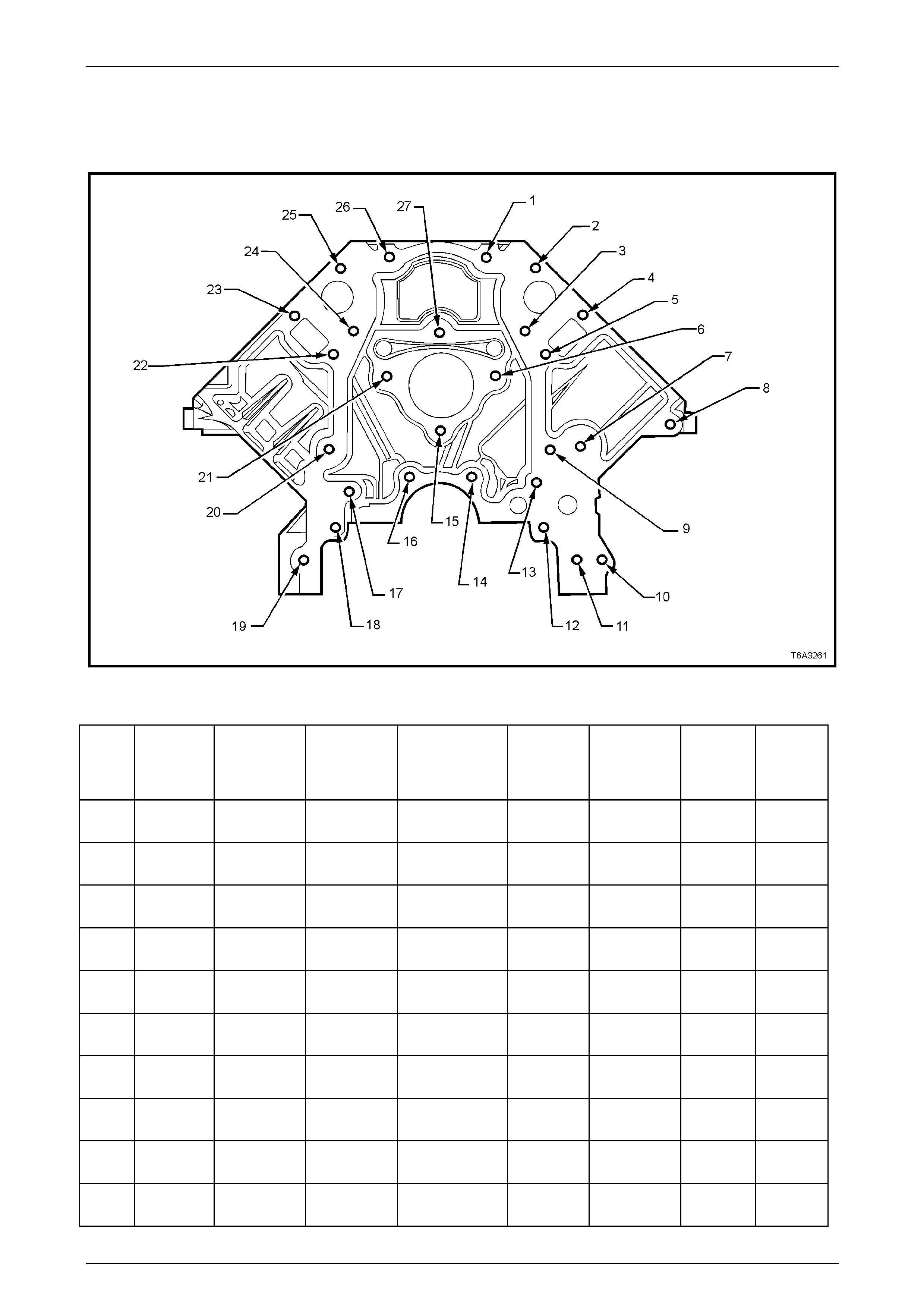
Engine Mechanical Page 6A4–255
Page 6A4–255
6.5 Thread Repair Specifications
Cylinder Block – Front View
Figure 6A4 – 426
Legend
Hole Thread
Size Insert Drill Counterbore
Tool Tap Driver Max
Drill
Depth
mm
Max Tap
Depth
mm
1-6 M8 x 1.25 J 42385-
210 J 42385-
206 J 42385-207 J 42385-
208 J 42385-
209 22.5 17.5
7 M10 x 1.5 J 42385-
215 J 42385-
211 J 42385-212 J 42385-
213 J 42385-
214 25.0 19.5
8 M10 x 1.5 J 42385-
215 J 42385-
211 J 42385-212 J 42385-
213 J 42385-
214 32.5 25.0
9 M8 x 1.25 J 42385-
210 J 42385-
206 J 42385-207 J 42385-
208 J 42385-
209 22.5 17.5
10 M10 x 1.5 J 42385-
215 J 42385-
211 J 42385-212 J 42385-
213 J 42385-
214 Through Through
11–
13 M8 x 1.25 J 42385-
210 J 42385-
206 J 42385-207 J 42385-
208 J 42385-
209 22.5 17.5
14 M8 x 1.25 J 42385-
210 J 42385-
206 J 42385-207 J 42385-
208 J 42385-
209 Through 18.0
15 M8 x 1.25 J 42385-
210 J 42385-
206 J 42385-207 J 42385-
208 J 42385-
209 22.5 17.5
16 M8 x 1.25 J 42385-
210 J 42385-
206 J 42385-207 J 42385-
208 J 42385-
209 Through 18.0
17–
27 M8 x 1.25 J 42385-
210 J 42385-
206 J 42385-207 J 42385-
208 J 42385-
209 22.5 17.5
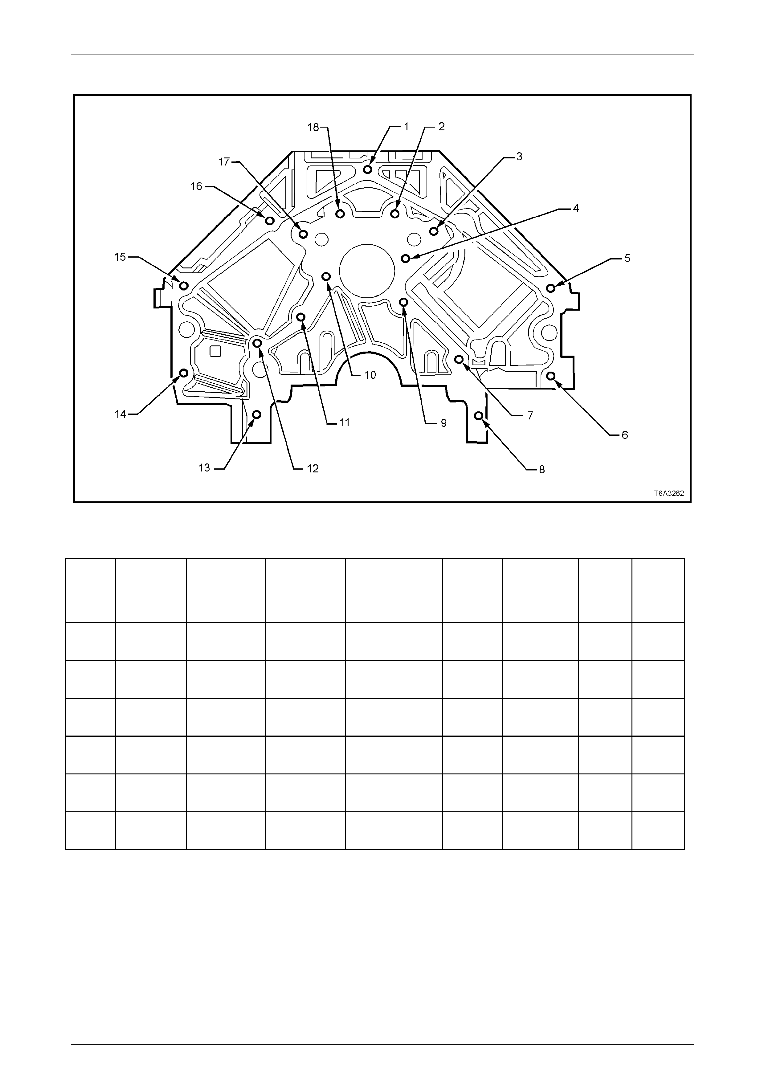
Engine Mechanical Page 6A4–256
Page 6A4–256
Cylinder Block – Rear View
Figure 6A4 – 427
Legend
Hole Thread
Size Insert Drill
Counterbore
Tool Tap Driver
Max
Drill
Depth
mm
Max
Tap
Depth
mm
1 M10 x 1.5 J 42385-215 J 42385-211 J 42385-212 J 42385-
213 J 42385-
214 27.0 21.5
2-4 M8 x 1.25 J 42385-210 J 42385-206 J 42385-207 J 42385-
208 J 42385-
209 22.5 17.5
5-6 M10 x 1.5 J 42385-215 J 42385-211 J 42385-212 J 4238 5-
213 J 42385-
214 27.0 21.5
7-13 M8 x 1.25 J 42385-210 J 42385-206 J 42385-2 07 J 4238 5-
208 J 42385-
209 22.5 17.5
14-16 M10 x 1.5 J 42385-215 J 42385-211 J 42385-212 J 42385-
213 J 42385-
214 27.0 21.5
17-18 M8 x 1.25 J 42385-210 J 42385-206 J 42385-207 J 42385-
208 J 42385-
209 22.5 17.5
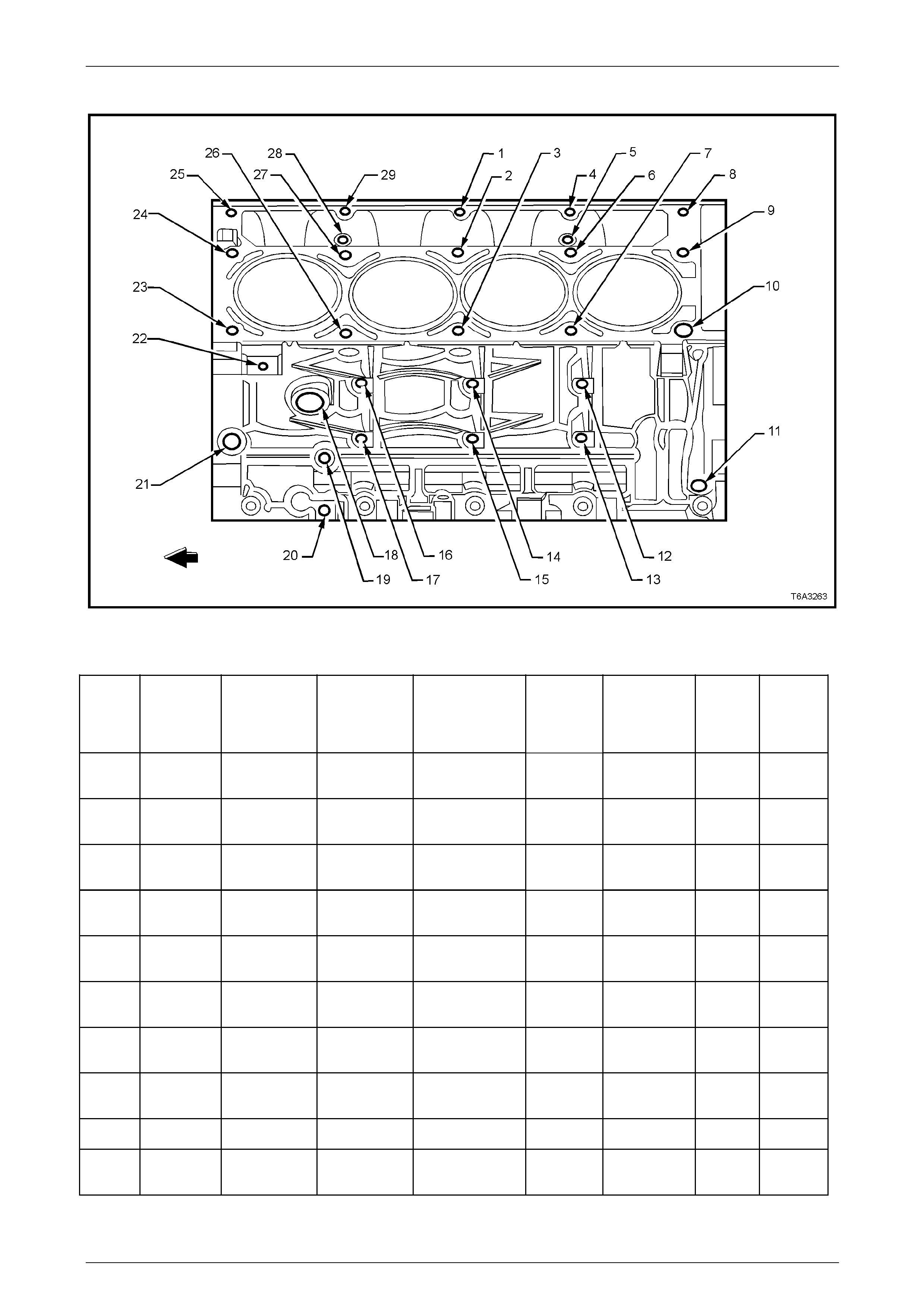
Engine Mechanical Page 6A4–257
Page 6A4–257
Cylinder Block – Left-hand View
Figure 6A4 – 428
Legend
Hole Thread
Size Insert Drill
Counterbore
Tool Tap Driver
Max
Drill
Depth
mm
Max
Tap
Depth
mm
1 M8 x 1.25 J 42385-210 J 42385-2 06 J 42385-207 J 42385-
208 J 42385-
209 26.5 19.0
2-3 M11 x 2.0 J 4238 5-108 J 42385-1 05 ⎯ J 42385-
106 J 42385-
107 124.0 115.0
4 M8 x 1.25 J 42385-210 J 42385-2 06 J 42385-207 J 42385-
208 J 42385-
209 26.5 19.0
5 M6 x 1.0 J 42385-205 J 42385-201 J 42385-202 J 42385-
203 J 42385-
204 22.5 16.0
6-7 M11 x 2.0 J 4238 5-108 J 42385-1 05 ⎯ J 42385-
106 J 42385-
107 124.0 115.0
8 M8 x 1.25 J 42385-210 J 42385-2 06 J 42385-207 J 42385-
208 J 42385-
209 26.5 19.0
9 M11 x 2.0 J 4238 5-108 J 42385-1 05 ⎯ J 42385-
106 J 42385-
107 69.0 60.0
10 M11 x 2.0 J 42385-108 J 42385-105 ⎯ J 42385-
106 J 42385-
107 124.0 115.0
11 ⎯ ⎯ ⎯ ⎯ ⎯ ⎯ ⎯ ⎯
12-17 M10 x 1.5 J 4238 5-215 J 42385-2 11 J 42385-212 J 42385-
213 J 42385-
214 29.0 23.0

Engine Mechanical Page 6A4–258
Page 6A4–258
Hole Thread
Size Insert Drill
Counterbore
Tool Tap Driver
Max
Drill
Depth
mm
Max
Tap
Depth
mm
18 M28 x
1.25 ⎯ ⎯ ⎯ ⎯ ⎯ ⎯ ⎯
19-20 M8 x 1.25 J 42385-210 J 42385-2 06 J 42385-207 J 42385-
208 J 42385-
209 21.0 16.0
21 M16 x 1.5 ⎯ ⎯ ⎯ ⎯ ⎯ ⎯ ⎯
22 M10 x 1.5 J 42385-215 J 42385-211 J 42385-212 J 42385-
213 J 42385-
214 27.0 21.5
23 M11 x 2.0 J 42385-108 J 42385-105 ⎯ J 42385-
106 J 42385-
107 124.0 115.0
24 M11 x 2.0 J 42385-108 J 42385-105 ⎯ J 42385-
106 J 42385-
107 69.0 60.0
25 M8 x 1.25 J 4238 5-210 J 42385-2 06 J 42385-207 J 42385-
208 J 42385-
209 26.5 19.0
26-27 M11 x 2.0 J 4238 5-108 J 42385-1 05 ⎯ J 42385-
106 J 42385-
107 124.0 115.0
28 M6 x 1.0 J 42385-205 J 42385-201 J 42385-202 J 42385-
203 J 42385-
204 22.5 16.0
29 M8 x 1.25 J 4238 5-210 J 42385-2 06 J 42385-207 J 42385-
208 J 42385-
209 26.5 19.0
Bolt holes 2, 3, 6, 7, 10, 23, 26, and 27 have a 85 mm counter-bore included in the 124.0 mm drill depth.
Bolt holes 9 and 24 have a 30 mm counter-b ore included in the 69.0 mm drill depth. Use sleeve J 42385-315 with the
drill and tap.
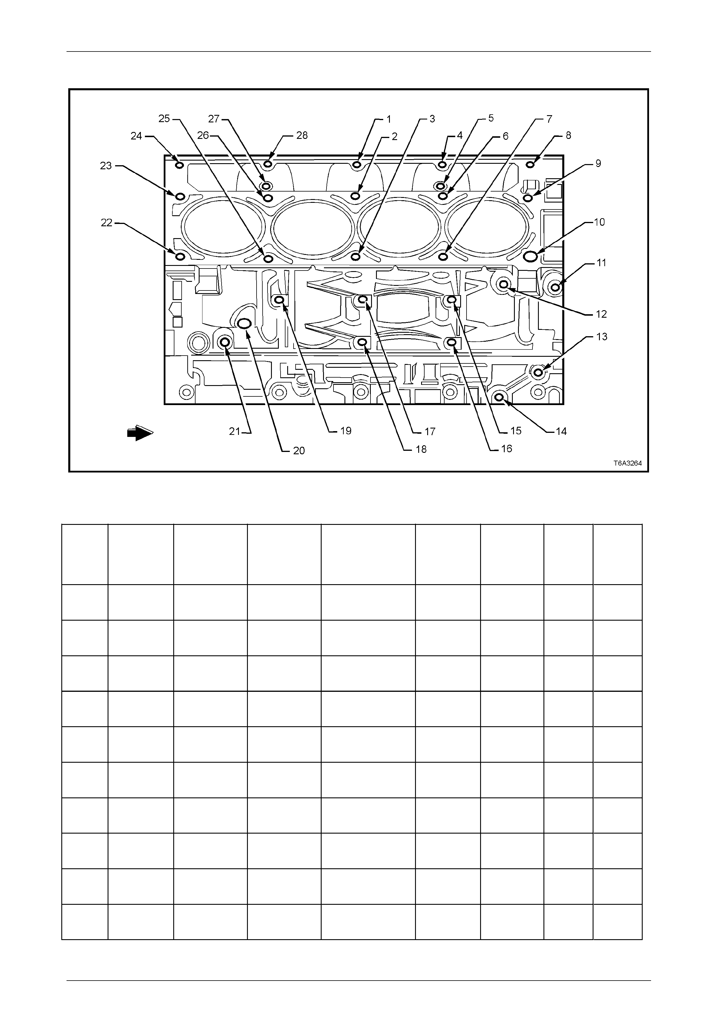
Engine Mechanical Page 6A4–259
Page 6A4–259
Cylinder Block – Right-hand View
Figure 6A4 – 429
Legend
Hole Thread
Size Insert Drill
Counterbore
Tool Tap Driver
Max
Drill
Depth
mm
Max
Tap
Depth
mm
1 M8 x 1.25 J 42385-210 J 42385-206 J 42385-207 J 42385-
208 J 42385-
209 26.5 19.0
2-3 M11 x 2.0 J 42385-108 J 42385-105 ⎯ J 42385-
106 J 42385-
107 124.0 115.0
4 M8 x 1.25 J 42385-210 J 42385-206 J 42385-207 J 42385-
208 J 42385-
209 26.5 19.0
5 M6 x 1.0 J 42385-205 J 42385-201 J 42385-202 J 42385-
203 J 42385-
204 22.5 15.0
6-7 M11 x 2.0 J 42385-108 J 42385-105 ⎯ J 42385-
106 J 42385-
107 124.0 115.0
8 M8 x 1.25 J 42385-210 J 42385-206 J 42385-207 J 42385-
208 J 42385-
209 26.5 19.0
9 M11 x 2.0 J 42385-108 J 42385-105 ⎯ J 42385-
106 J 42385-
107 69.0 60.0
10 M11 x 2.0 J 42385-108 J 42385-105 ⎯ J 42385-
106 J 42385-
107 124.0 115.0
11-14 M10 x 1.5 J 42385-215 J 42385-211 J 42385-212 J 4238 5-
213 J 42385-
214 27.0 21.5
15-19 M10 x 1.5 J 42385-215 J 42385-211 J 42385-212 J 4238 5-
213 J 42385-
214 29.0 23.0

Engine Mechanical Page 6A4–260
Page 6A4–260
Hole Thread
Size Insert Drill
Counterbore
Tool Tap Driver
Max
Drill
Depth
mm
Max
Tap
Depth
mm
20 M16 x 1.5 ⎯ ⎯ ⎯ ⎯ ⎯ ⎯ ⎯
21 M8 x 1.25 J 42385-210 J 42385-206 J 42385-207 J 42385-
208 J 42385-
209 22.5 17.5
22 M11 x 2.0 J 42385-108 J 42385-105 ⎯ J 42385-
106 J 42385-
107 124.0 115.0
23 M11 x 2 J 42385-108 J 42385-105 ⎯ J 42385-
106 J 42385-
107 69.0 60.0
24 M8 x 1.25 J 42385-210 J 42385-206 J 42385-207 J 42385-
208 J 42385-
209 26.5 19.0
25-26 M11 x 2.0 J 42385-108 J 42385-105 ⎯ J 42385-
106 J 42385-
107 124.0 115.0
27 M6 x 1.0 J 42385-205 J 42385-201 J 42385-202 J 42385-
203 J 42385-
204 22.5 15.0
28 M8 x 1.25 J 42385-210 J 42385-206 J 42385-207 J 42385-
208 J 42385-
209 26.5 19.0
Bolt holes 2, 3, 6, 7, 10, 22, 25, and 26 have a 85 mm counterbore included in the 124.0 mm drill depth.
Bolt holes 9 and 23 have a 30 mm counterbo re included in the 69.0 mm drill depth. Use sleeve J 42385-315 with the
drill and tap.
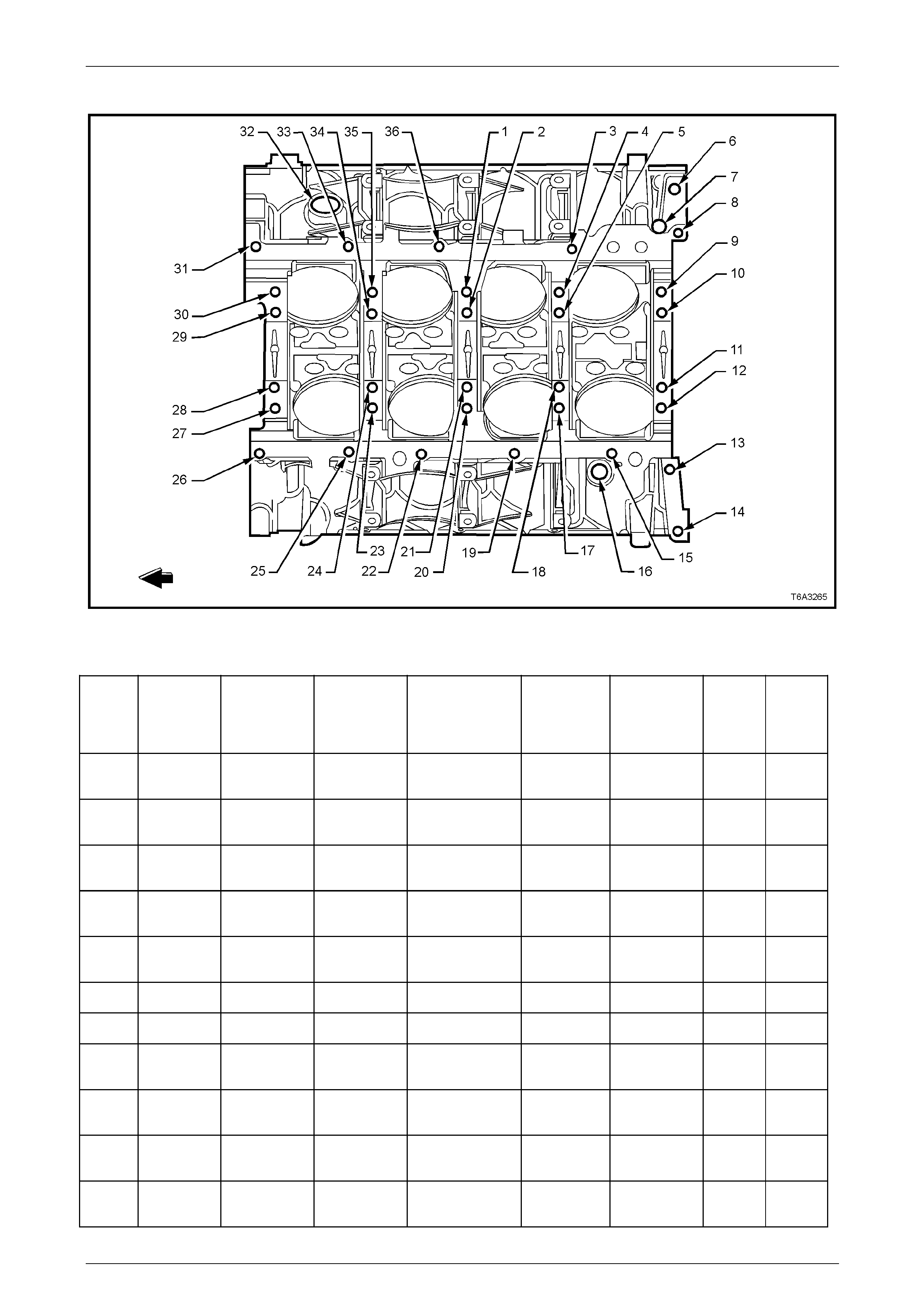
Engine Mechanical Page 6A4–261
Page 6A4–261
Cylinder Block – Bottom View
Figure 6A4 – 430
Legend
Hole Thread
Size Insert Drill
Counterbore
Tool Tap Driver
Max
Drill
Depth
mm
Max
Tap
Depth
mm
1 M10 x 2.0 J 42385-
104 J 42385-
101 ⎯ J 42385-
102 J 42385-
103 31.0 25.5
2 M10 x 2.0 J 42385-
104 J 42385-
101 ⎯ J 42385-
102 J 42385-
103 53.5 44.0
3 M8 x 1.25 J 4238 5-
210 J 42385-
206 J 42385-207 J 42385-
208 J 42385-
209 22.5 17.5
4 M10 x 2.0 J 42385-
104 J 42385-
101 ⎯ J 42385-
102 J 42385-
103 31.0 25.5
5 M10 x 2.0 J 42385-
104 J 42385-
101 ⎯ J 42385-
102 J 42385-
103 53.5 44.0
6 M16 x 1.5 ⎯ ⎯ ⎯ ⎯ ⎯ ⎯ ⎯
7 N/A ⎯ ⎯ ⎯ ⎯ ⎯ ⎯ ⎯
8 M8 x 1.25 J 4238 5-
210 J 42385-
206 J 42385-207 J 42385-
208 J 42385-
209 22.5 17.5
9 M10 x 2.0 J 42385-
104 J 42385-
101 ⎯ J 42385-
102 J 42385-
103 31.0 25.5
10-11 M10 x 2.0 J 42385-
104 J 42385-
101 ⎯ J 42385-
102 J 42385-
103 53.5 44.0
12 M10 x 2.0 J 42385-
104 J 42385-
101 ⎯ J 42385-
102 J 42385-
103 31.0 25.5

Engine Mechanical Page 6A4–262
Page 6A4–262
Hole Thread
Size Insert Drill
Counterbore
Tool Tap Driver
Max
Drill
Depth
mm
Max
Tap
Depth
mm
13-14 M10 x 1.5 J 42385-
215 J 42385-
101 ⎯ J 42385-
213 J 42385-
214 42.5 37.0
15 M8 x 1.25 J 42385-
210 J 42385-
206 J 42385-207 J 42385-
208 J 42385-
209 22.5 17.5
16 M16 x 1.5 ⎯ ⎯ ⎯ ⎯ ⎯ ⎯ ⎯
17 M10 x 2.0 J 42385-
104 J 42385-
101 ⎯ J 42385-
102 J 42385-
103 53.5
18 M10 x 2.0 J 42385-
104 J 42385-
101 ⎯ J 42385-
102 J 42385-
103 31.0 25.5
19 M8 x 1.25 J 42385-
210 J 42385-
206 J 42385-207 J 42385-
208 J 42385-
209 22.5 17.5
20 M10 x 2.0 J 42385-
104 J 42385-
101 ⎯ J 42385-
102 J 42385-
103 53.5 44.0
21 M10 x 2.0 J 42385-
104 J 42385-
101 ⎯ J 42385-
102 J 42385-
103 31.0 25.5
22 M8 x 1.25 J 42385-
210 J 42385-
206 J 42385-207 J 42385-
208 J 42385-
209 22.5 17.5
23 M10 x 2.0 J 42385-
104 J 42385-
101 ⎯ J 42385-
102 J 42385-
103 31.0 25.5
24 M10 x 2.0 J 42385-
104 J 42385-
101 ⎯ J 42385-
102 J 42385-
103 53.5 44.0
25-26 M8 x 1.25 J 4238 5-
210 J 42385-
206 J 42385-207 J 42385-
208 J 42385-
209 22.5 17.5
27 M10 x 2.0 J 42385-
104 J 42385-
101 ⎯ J 42385-
102 J 42385-
103 31.0 25.5
28-29 M10 x 2.0 J 42385-
104 J 42385-
101 ⎯ J 42385-
102 J 42385-
103 53.5 44.0
30 M10 x 2.0 J 42385-
104 J 42385-
101 ⎯ J 42385-
102 J 42385-
103 31.0 25.5
31 M8 x 1.25 J 42385-
210 J 42385-
206 J 42385-207 J 42385-
208 J 42385-
209 22.5 17.5
32 M28 x
1.25 ⎯ ⎯ ⎯ ⎯ ⎯ ⎯ ⎯
33 M8 x 1.25 J 42385-
210 J 42385-
206 J 42385-207 J 42385-
208 J 42385-
209 22.5 17.5
34 M10 x 2.0 J 42385-
104 J 42385-
101 ⎯ J 42385-
102 J 42385-
103 53.5 44.0
35 M10 x 2.0 J 42385-
104 J 42385-
101 ⎯ J 42385-
102 J 42385-
103 31.0 25.5
36 M8 x 1.25 J 42385-
210 J 42385-
206 J 42385-207 J 42385-
208 J 42385-
209 22.5 17.5
Bolt holes 2, 5, 10, 11, 18, 21, 24, 28, 29, and 34 have a 20.5 mm counterbore i ncluded in the 53.5 mm drill depth.
Bolt holes 1, 4, 9, 12, 17, 20, 23, 27, 30, and 35 have a 1.5 mm counterbore included in the 31.0 mm drill depth. Use
sleeve J 42385-316 with the drill and tap.
Bolt holes 13 and 14 have a 11.5 mm counterbore included in the 42.5 mm drill depth. Use sleeve J 42385-311 with
the drill and tap.
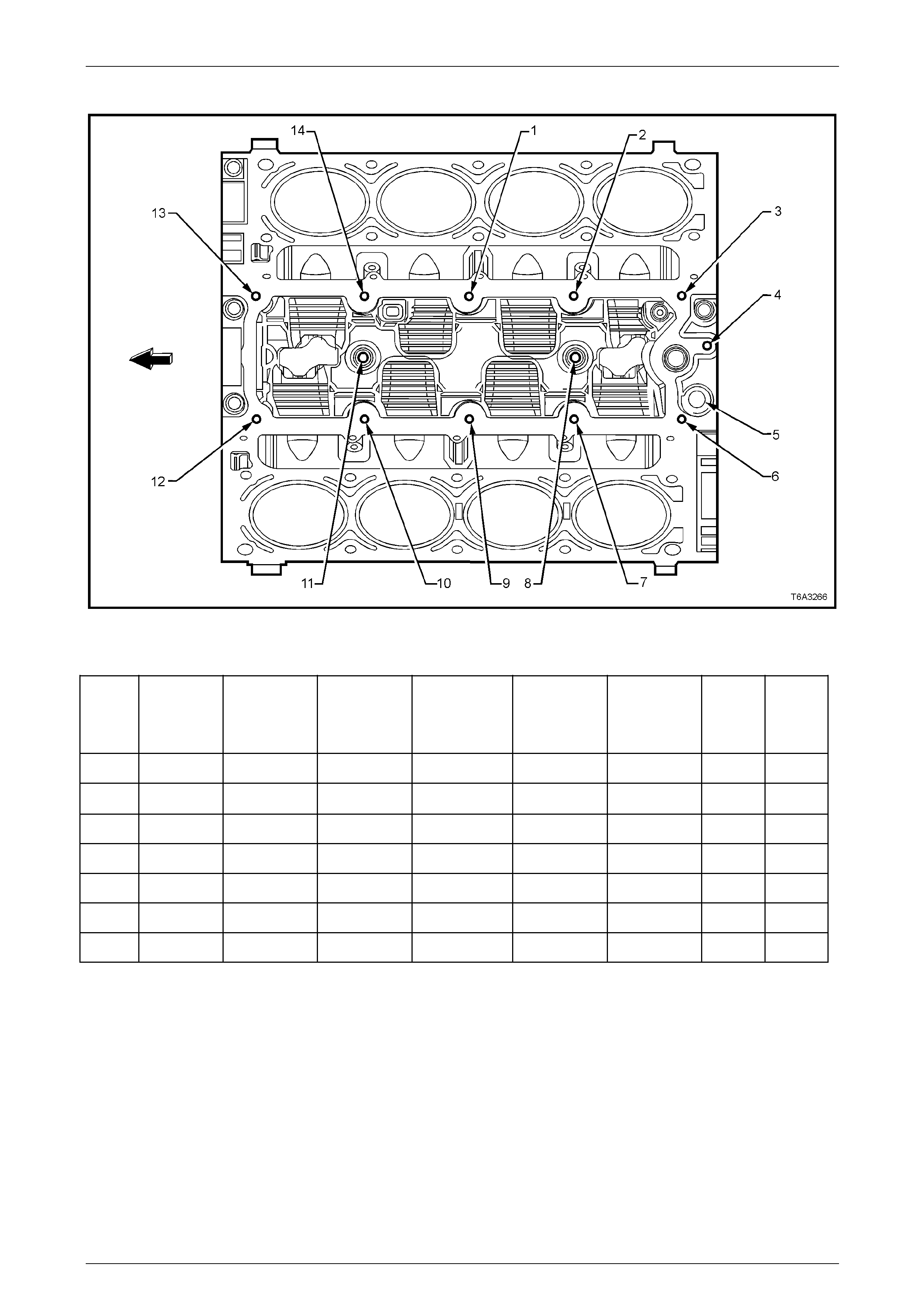
Engine Mechanical Page 6A4–263
Page 6A4–263
Cylinder Block – Top View
Figure 6A4 – 431
Legend
Hole Thread
Size Insert Drill
Counterbore
Tool Tap Driver
Max
Drill
Depth
mm
Max
Tap
Depth
mm
1-4 M8 x 1.25 J 42385-210 J 42385-206 J 42385-207 J 42385-208 J 42385-209 26.5 19.0
5 M16 x 1.5 ⎯ ⎯ ⎯ ⎯ ⎯ ⎯ ⎯
6-7 M8 x 1.25 J 42385-210 J 42385-206 J 42385-207 J 42385-208 J 42385-209 26.5 19.0
8 M10 x 1.5 J 42385-216 J 42385-211 J 42385-212 J 42385-213 J 42385-214 22.5 17.0
9-10 M8 x 1.25 J 42385-210 J 42385-206 J 42385-207 J 42385-208 J 42385-209 26.5 19.0
11 M10 x 1.5 J 42385-2 16 J 42385-211 J 42385-2 12 J 42385-213 J 42385-214 22.5 17.0
12-14 M8 x 1.25 J 42385-210 J 42385-206 J 42385-207 J 42385-208 J 42385-209 26.5 19.0
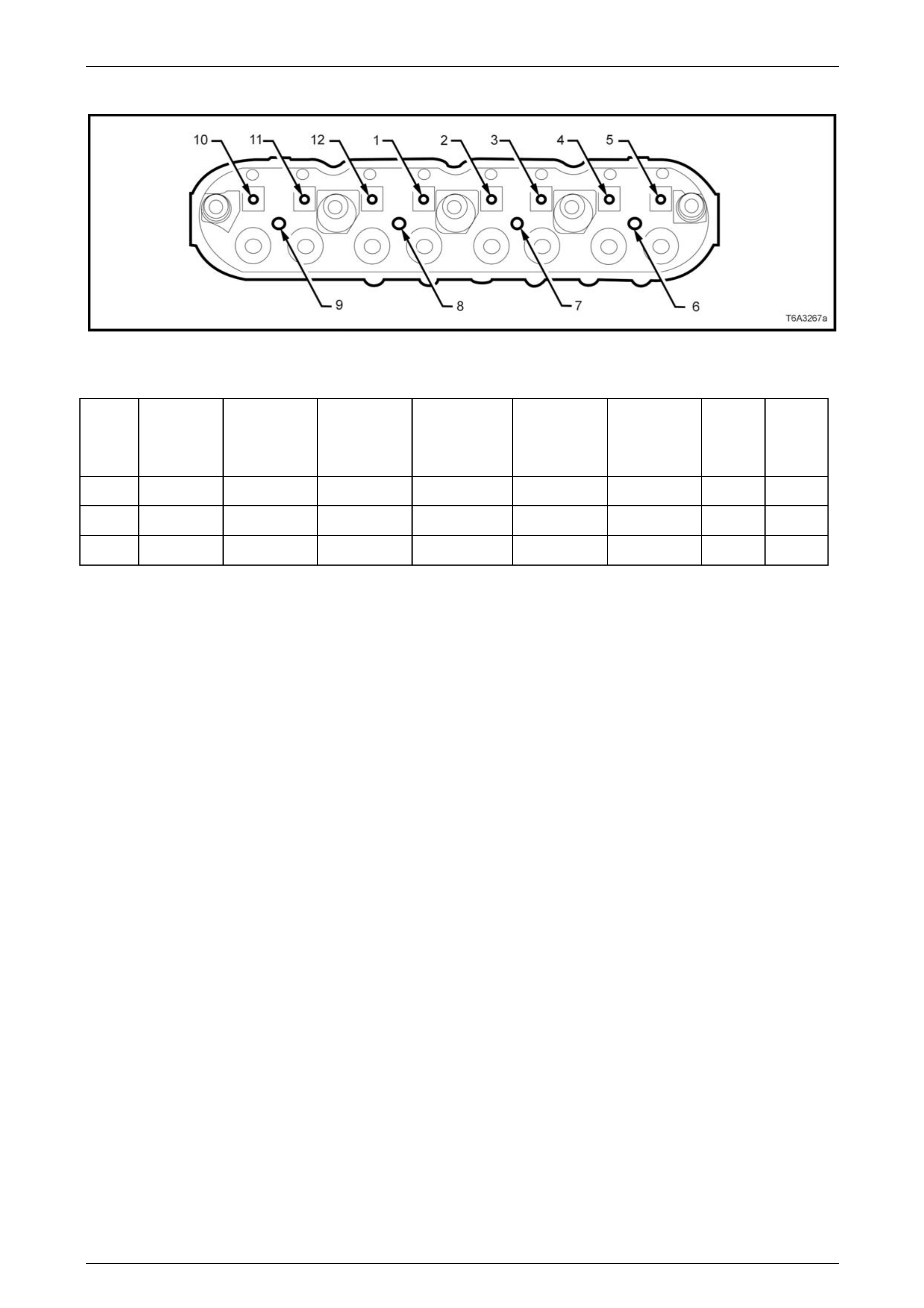
Engine Mechanical Page 6A4–264
Page 6A4–264
Cylinder Head – Top View
Figure 6A4 – 432
Legend
Hole Thread
Size Insert Drill
Counterbore
Tool Tap Driver
Max
Drill
Depth
mm
Max
Tap
Depth
mm
1-5 M8 x 1.25 J 42385-210 J 42385-206 J 42385-207 J 42385-208 J 42385-209 26.5 19.0
6-9 M6 x 1.0 J 42385-205 J 42385-201 J 42385-202 J 42385-203 J 42385-204 20.05 16.05
10-12 M8 x 1.25 J 42385-210 J 42385-206 J 42385-207 J 42385-208 J 42385-209 26.5 19.0
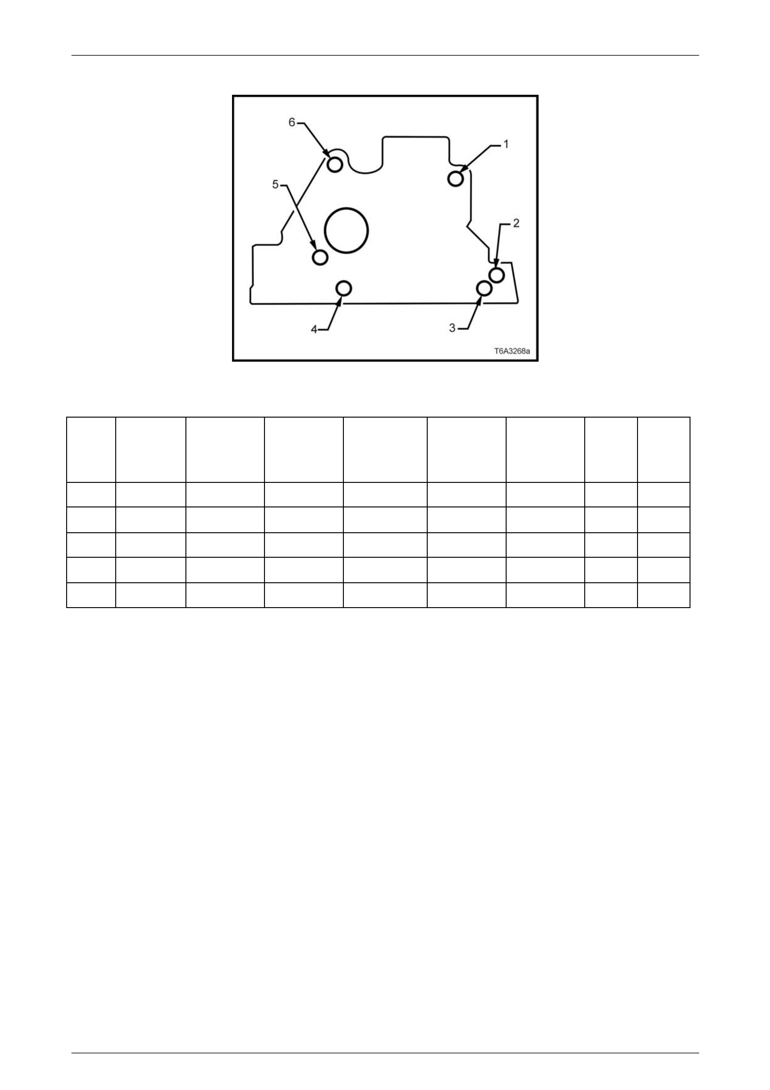
Engine Mechanical Page 6A4–265
Page 6A4–265
Cylinder Head – End View
Figure 6A4 – 433
Legend
Hole Thread
Size Insert Drill
Counterbore
Tool Tap Driver
Max
Drill
Depth
mm
Max
Tap
Depth
mm
1 M10 x 1.5 J 42385-215 J 42385-211 J 42385-212 J 42385-213 J 42385-214 28.0 20.0
2 N/A ⎯ ⎯ ⎯ ⎯ ⎯ ⎯ ⎯
3 M10 x 1.5 J 42385-215 J 42385-211 J 42385-212 J 42385-213 J 42385-214 28.0 20.0
4 N/A ⎯ ⎯ ⎯ ⎯ ⎯ ⎯ ⎯
5-6 M10 x 1.5 J 42385-215 J 42385-211 J 42385-212 J 42385-213 J 42385-214 28.0 20.0
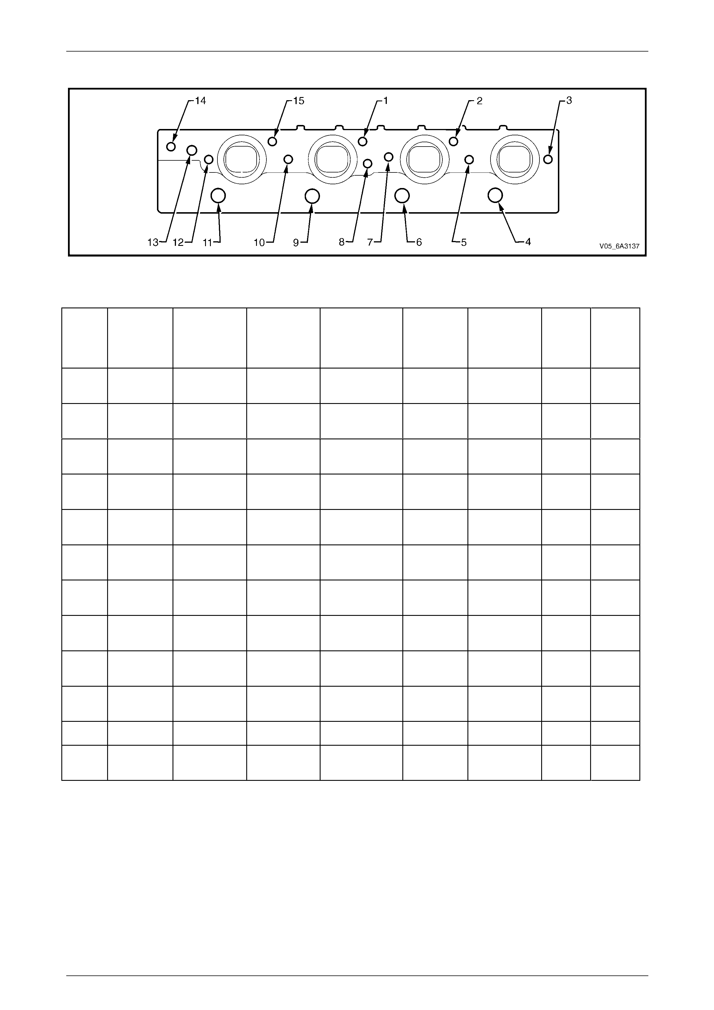
Engine Mechanical Page 6A4–266
Page 6A4–266
Cylinder Head – Exhaust Manifold Side View
Figure 6A4 – 434
Legend
Hole Thread
Size Insert Drill
Counterbore
Tool Tap Driver
Max
Drill
Depth
mm
Max
Tap
Depth
mm
1-2 M10 x 1.5 J 42385-215 J 42385-211 J 42385-2 12 J 42385-
213 J 42385-214 28.0 20.0
3 M8 x 1.25 J 42385-210 J 42385-206 J 4238 5-207 J 42385-
208 J 42385-209 21.0 16.0
4 M14 x
1.25 ⎯ ⎯ ⎯ ⎯ ⎯ ⎯ ⎯
5 M8 x 1.25 J 42385-210 J 42385-206 J 4238 5-207 J 42385-
208 J 42385-209 21.0 16.0
6 M14 x
1.25 ⎯ ⎯ ⎯ ⎯ ⎯ ⎯ ⎯
7-8 M8 x 1.25 J 42385-210 J 42385-206 J 42385-207 J 42385-
208 J 42385-209 21.0 16.0
9 M14 x
1.25 ⎯ ⎯ ⎯ ⎯ ⎯ ⎯ ⎯
10 M8 x 1.25 J 42385-210 J 42385-206 J 42385-207 J 42385-
208 J 42385-209 21.0 16.0
11 M14 x
1.25 ⎯ ⎯ ⎯ ⎯ ⎯ ⎯ ⎯
12 M8 x 1.25 J 42385-210 J 42385-206 J 42385-207 J 42385-
208 J 42385-209 21.0 16.0
13 M12 x 1.5 ⎯ ⎯ ⎯ ⎯ ⎯ ⎯ ⎯
14-15 M10 x 1.5 J 42385-215 J 42385-211 J 42385-212 J 42385-
213 J 42385-214 28.0 20.0
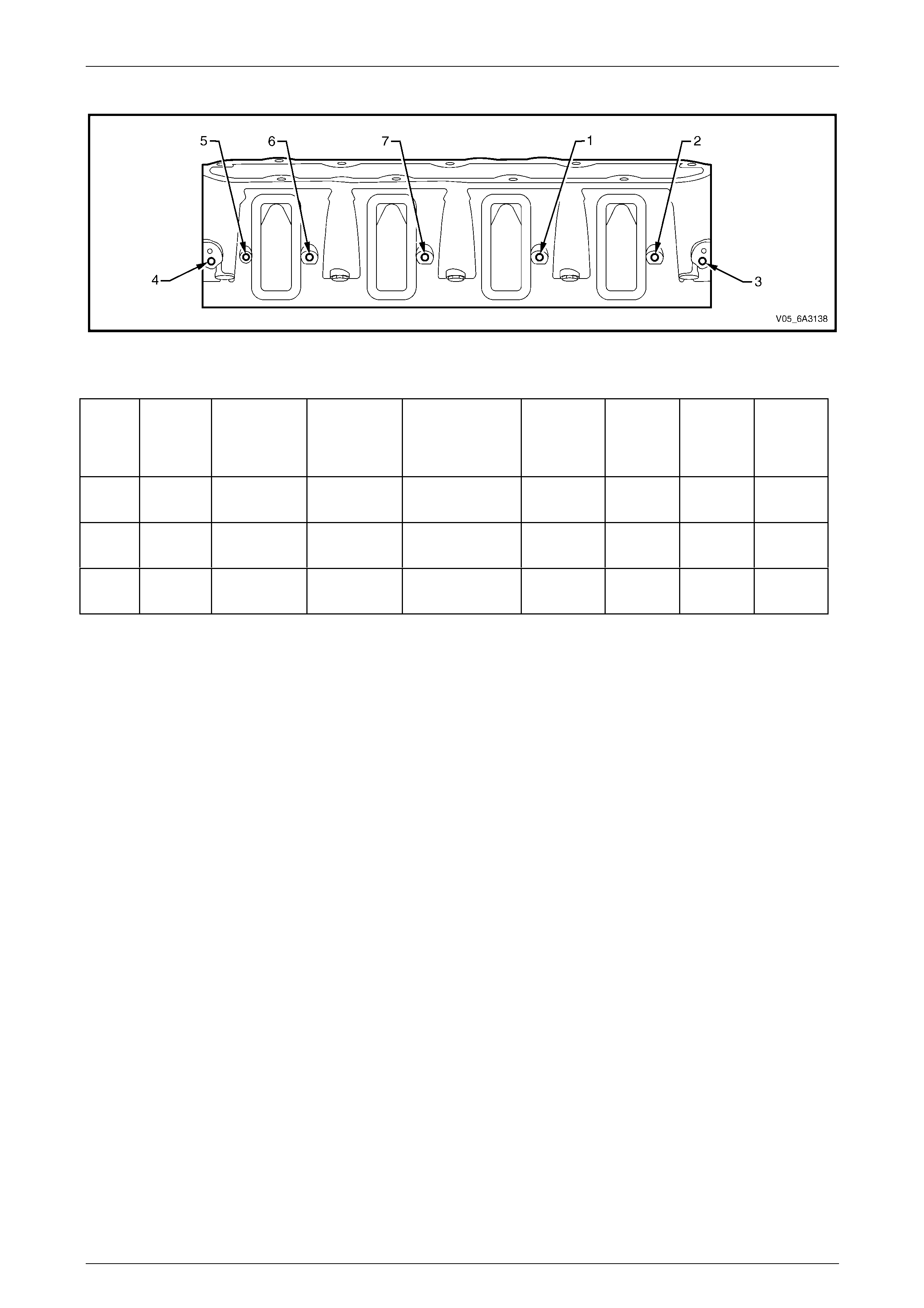
Engine Mechanical Page 6A4–267
Page 6A4–267
Cylinder Head – Inlet Manifold Side View
Figure 6A4 – 435
Legend
Hole Thread
Size Insert Drill
Counterbore
Tool Tap Driver
Max
Drill
Depth
mm
Max Tap
Depth
mm
1-2 M6 x 1.0 J 42385-205 J 42385-201 J 42385-202 J 42385-
203 J 42385-
204 Through Through
3-4 M6 x 1.0 J 42385-205 J 42385-201 J 42385-202 J 42385-
203 J 42385-
204 22.5 15.0
5-7 M6 x 1.0 J 42385-205 J 42385-201 J 42385-202 J 42385-
203 J 42385-
204 Through Through
Engine Mechanical Page 6A4–268
Page 6A4–268
7 Specifications
7.1 Engine
General
Engine Type V8 OHV
Displacement 5.7 litre (5,667 cm3 – 346 in3)
Bore 99.009 mm
Stroke 92.0 mm
Compression Ratio 10.1:1
Firing Order 1-8-7-2-6-5-4-3
Cylinder layout, front to rear:
Left-hand bank
Right-hand bank
1, 3, 5, and 7
2, 4, 6 and 8
Spark Plug:
Type
Gap
AC Delco 41-985
1.02 +0.08 / -0.07 mm
Camshaft
End Play 0.025 - 0.305 mm
Journal Diameter 54.99 - 55.04 mm
Journal Diameter Out-of-round 0.025 mm (Maximum)
Lobe Lift:
Intake
Exhaust
Except Coupe:
7.43 mm
7.43 mm
Coupe:
6.96 mm
7.13 mm
Lobe Height (Wear Limits):
Intake
Exhaust
Except Coupe:
46.67 mm
46.67 mm
Coupe:
46.21 mm
46.37 mm
Runout
(Measured at the Intermediate Journals) 0.050 mm
Timing Check (referenc e only) -
Cam Lift at Top Dead Centre:
Exhaust Closing
Intake Opening
Except Coupe:
0.62 mm
0.15 mm
Coupe:
0.60 mm
0.38 mm
Connecting Rod
Centre to Centre Length 154.90 ± 0.02 mm
Width 24.00 ± 0.05 mm
Bearing Bore Diameter 56.505 - 56.525 mm
Bearing Bore Out-of-round (Production) 0.004 mm
Bearing Bore Out-of-round (Service Limit) 0.008 mm
Bearing Clearance (Prod uction) 0.023 – 0.065 mm
Bearing Clearance (Service Limit) 0.023 – 0.076 mm
Side Clearance 0.110 - 0.510 mm
Twist 0.010 mm Maximum
Bend 0.02 mm Maximum
Engine Mechanical Page 6A4–269
Page 6A4–269
Crankshaft
Stroke 92.00 ± 0.08 mm
End Play 0.040 - 0.200 mm
Connecting Rod Journal 0.065 mm
Bearing Clearance (Production) 0.023 – 0.065
Bearing Clearance (Service Limit) 0.023 – 0.076 mm
Diameter (Production) 53.318 - 53.338 mm
Diameter (Service Limit) 53.308 mm (Minimum)
Taper (Production) 0.005 mm (Maximum for 1/2 of the Journal Length)
Taper (Service Limit) 0.020 mm (Maximum)
Out-of-round (Production) 0.005 mm
Out-of-round (Service Limit) 0.010 mm Main Journal
Bearing Clearance (Prod uction) 0.020 – 0.052 mm
Bearing Clearance (Service Limit) 0.020 – 0.065 mm
Diameter (Production) 64.993 - 65.007 mm
Diameter (Service Limit) 64.993 mm (Minimum)
Out-of-round (Production) 0.003 mm
Out-of-round (Service Limit) 0.008 mm
Taper (Production) 0.010 mm
Taper (Service Limit) 0.020 mm (Maximum)
Reluctor Ring Runout 0.700 mm (Maximum) (Measured 1.0 mm below Tooth Diameter)
Runout (at Rear Flange) 0.050 mm (Maximum)
Thrust Wall Runout 0.025 mm
Thrust Wall Width (Production) 26.22 mm
Thrust Wall Width (Service) 26.20 mm (Maximum)
Cylinder Bore
Cylinder Bore Diameter 99.0 - 99.018 mm
Cylinder Bore Taper and Out-of-round 0.018 mm (Maximum)
Cylinder Head
0.080 mm
(Measured within a 150 mm area)
Cylinder Block Deck Flatness
0.100 mm
(Measured over Full Length of Cylinder Head)
Exhaust Manifold Deck Flatness 0.220 mm
Intake Manifold Deck Flatness 0.220 mm
Height 120.2 mm (Minimum)
(Measured from the Cylinder Head Deck
to the Valve Rocker Arm Cover Seal Surface)
Combustion Chamber Volume 66.67 ± 1.00 cc
Engine Mechanical Page 6A4–270
Page 6A4–270
Cylinder Block
Camshaft Bearing Bore Diameter 55.063 - 55.088 mm
0.080 mm
(Measured within a 150 mm area)
Cylinder Head Deck Surface Flatness
0.220 mm
(Measured over Full Length of the cylinder block deck)
Cylinder Head Deck Height 234.57 - 234.82 mm
(Measured from Crankshaft centreline to D eck Face)
Main Bearing Bore Diameter (Producti on) 69.871 - 69.889 mm
Valve Lifter Bore Diameter (Production) 21.417 - 21.443 mm
Main Bearing Bore Out-of-round 0.005 mm
Intake Manifold
Intake Manifold Cylinder Head
Deck Flatness 0.50 mm
(Measured at Gasket Sealing Surfaces)
Oil Pan – Front and Rear Cover Alignment
Oil Pan to Rear of Cylinder Block
Alignment 0.000 - 0.250 mm
(Maximum at Transmission Housing Mounting Surface)
Front Cover Alignment 0.00 - 0.50 mm (at Oil Pan Surface)
Rear Cover Alignment 0.00 - 0.50 mm (at Oil Pan Surface)
Piston
Piston Outside Diameter (at Size Point &
incl. coating) 98.995 - 99.027 mm
Piston Skirt, Dimensional Variation 0.032 mm (Maximum)
Piston to Bore Clearance (Pro duction)
Interference Clearance 0.027 mm – 0.023 mm
Piston to Bore Clearance (Service Limit)
Interference Clearance 0.027 mm – 0.023 mm
Piston Pin Clearance to Piston Bore
(Production 0.008 - 0.016 mm
Pin Clearance to Piston Bore (Service
Limit) 0.008 - 0.016 mm (Maximum)
Pin Diameter 23.997 - 24.0 mm
Pin Fit in Connecting Rod 0.020 - 0.043 mm (Interference)
Engine Mechanical Page 6A4–271
Page 6A4–271
Piston Rings
Top Compression Ring En d Gap
(Production) 0.230 - 0.380 mm (Measured in C ylinder Bo re)
2nd Compression Ring End Gap
(Production) 0.440 - 0.640 mm (Measured in C ylinder Bo re)
Oil Control Ring End Gap (Production) 0.180 - 0.690 mm (Measured in Cylinder Bore)
Top Compression Ring En d Gap (Service) 0.230 - 0.380 mm (Maxim um) (Measured in Cylinder Bore)
2nd Compression Ring End Gap (Service) 0.440 - 0.640 mm (Maximum) (Measured in Cylinder Bore)
Oil Control Ring End Gap (Service) 0.180 - 0.690 mm (Maximum ) (Measured in Cylinder Bore)
Top Compression Ring Groove Clearance
(Production) 0.040 - 0.085 mm
2nd Compression Ri ng Groove Clearance
(Production) 0.040 - 0.080 mm
Oil Control Ring Groove Clearance
(Production) 0.010 - 0.220 mm
Top Compression Ring Groove Clearance
(Service) 0.040 - 0.085 mm (Maximum)
2nd Compression Ri ng Groove Clearance
(Service) 0.040 - 0.080 mm (Maximum)
Oil Control Ring Groove Clearance
(Service Limit) 0.010 - 0.220 mm (Maximum)
Valve Train
Valve Lifter Hydraulic Roller
Valve Rocker Arm Ratio 1.70:1
Valve Lash No Adjustment
Valve Margin 1.25 Minimum
Valve Face Angle 45 degrees
Valve Seat Angle 46 degrees
Valve Seat Runout 0.050 mm (Maximum)
Width (Intake) 1.020 mm (Maximum)
Width (Exhaust) 1.780 mm (Maximum)
Valve Stem Clearance (Production Intake) 0.025 - 0.066 mm
Clearance (Production Exha ust) 0.025 - 0.066 mm
Clearance (Service Intake) 0.093 mm (Maximum)
Clearance (Service Exha ust) 0.093 mm (Maximum)
Diameter (Production) 7.955 - 7.976 mm
Diameter (Service) 7.95 mm (Minimum)
Engine Mechanical Page 6A4–272
Page 6A4–272
Valve Spring
Free Length 52.9 mm
Pressure (Closed Valve) 340 N at 45.75 mm (Minimum)
Pressure (Open Valve) 980 N at 33.55 mm (Minimum)
Installed Height:
Intake
(Exhaust
45.75 mm
45.75 mm
Valve Lift:
Exhaust
Intake
12.11 mm
11.83 mm
Valve Guide Installed Height
(From Cylinder Head Sprin g Seat Surface
to Top of the Valve Guide) 17.32 mm
Sealants and Adhesives
Coolant Sensor Threads Loctite 565 or equivalent
Crankshaft Rear Oil Gallery Plug Loctite 242 or equivalent
Cylinder Head Core Hole Plugs Loctite 242 or equival ent
Cylinder Head Expansion Plugs Loctite 242 or equivalent
Cylinder Head M8 Bolt Threads Loctite 242 or equivalent
Cylinder Block Front Oil Gallery Plug Loctite 242 or equivalent
Cylinder Block Coolant Drain Plug Sealing
Washers Loctite 565 or equivalent
Engine Flywheel Bolt Threads Loctite 242 or equivalent
Exhaust Manifold Bolt Threads Loctite 272 or equivalent
Fuel Rail Bolt Threads Loctite 242 or equivalent
Ignition Coil and Bracket Assembly Bolt
Threads Loctite 242 or equivalent
Intake Manifold Bolt Threads Loctite 242 or equivalent
Oil Pan Surface at Front and Rear Covers Loctite 565 or equivalent
Oil Pressure Sensor Threads Loctite 565 or equivalent
Oil Transfer Tube Bolts and Stud Threads Loctite 242 or equivalent

Engine Mechanical Page 6A4–273
Page 6A4–273
7.2 Lubrication System
Oil Capacity:
Without Oil Filter Change
With Oil Filter Change
Except AWD
5.7 litres
6.2 litres
AWD
7.6 litres
8.0 litres
Minimum Oil Pressure
(Hot) 45 kPa @ 1,000 rpm
125 kPa @ 2,000 rpm
165 kPa @ 4,000 rpm
Oil Type:
Initial Fill
Service Refill
5W - 30 SJ GF4
5W - 30 SJ GF3 or
10W - 30 SJ GF3

Engine Mechanical Page 6A4–274
Page 6A4–274
8 Torque Wrench Specifications
ATTENTION
All engine fasteners are important attaching parts as they affect th e performance of vital componen ts and/or
could result in majo r repair expense. Where specified in this Section, fasteners MUST be rep laced with parts
of the same part number or an approved equivalent. Do not use fasteners of an inferior quality or substitute
design.
Torque values must be used as specified during reassembly to ensure proper retention of all engine
components.
Throughout this Section, fastener torque wrench specifications may be accompanied with the following
identification marks:
Fasten ers must be replaced after loosening .
Fasteners either have micro encapsulated sealant applied or incorporate a mechanical thread lock and
should only be re-used once. If in doubt, replacement is recommended.
If one of these identification marks is present alongside a fastener torque wrench specification, the
recommendation regarding that fastener must be adhered to.
8.1 Engine
Air Intake Hose Clamp...................................................................1.5 – 2.5 Nm
Engine Oil Pan Drain Plug....................................................................25.0 Nm
Oil Filter Adapter ..................................................................................55.0 Nm
Engine Oil Filter....................................................................................30.0 Nm
Oil Pressure Sensor .............................................................................20.0 Nm
Oil Level Indicator Tube Attaching Bolt.................................................25.0 Nm
Accessory Belt Idler Pulley Attaching Bolt............................................50.0 Nm
Accessory Belt Tensioner Attaching Bolt..............................................50.0 Nm
A/C Compressor Belt Idler Pulley Attaching Bolt..................................50.0 Nm
A/C Compressor Belt Tensioner Attaching Bolt....................................25.0 Nm
Fuel Rail Attaching Bolts ......................................................................10.0 Nm
Throttle Body Attaching Bolt.................................................................12.0 Nm
Intake Manifold Attaching Bolts
Stage 1...................................................................................................5.0 Nm
Stage 2........................................................................................8.0 – 12.0 Nm
Vapour Vent Pipe Bolt/Stud..................................................................12.0 Nm
PCV Oil Separator Attaching Bolt................................................6.0 – 10.0 Nm
Valley Cover Attaching Bolt..................................................................25.0 Nm
Knock Sensor.......................................................................................20.0 Nm
Valve Rocker Cover Attaching Bolt .....................................................12.0 Nm
Ignition Coil Attaching Screw................................................................12.0 Nm
Ignition Coil Bracket Attaching Stud/Screw ..........................................12.0 Nm
Rocker Arm Attaching Bolts
With No. 1 Cylinder at TDC
Exhaust Valve, Cylinder No.1, 2, 7 and 8..................................25.0 – 35.0 Nm
Intake Valve, Cylinder No.1, 3, 4 and 5 ....................................25.0 – 35.0 Nm
After 360 Deg Crankshaft Rotation
Exhaust Valve, Cylinder No. 3, 4, 5 and 6.................................25.0 – 35.0 Nm
Intake Valve, Cylinder No. 2, 6, 7 and 8 ...................................25.0 – 35.0 Nm
Spark plug:
Used Cylinder Head .............................................................................15.0 Nm
New Cylinder Head ..............................................................................20.0 Nm
Exhaust Manifold Heat Shield Attaching Bolt .........................................9.0 Nm
Exhaust Manifold Attaching Bolt
Stage 1................................................................................................ 15.0 Nm
Stage 2................................................................................................ 25.0 Nm
Coolant Temperature Sensor ...............................................................20.0 Nm

Engine Mechanical Page 6A4–275
Page 6A4–275
Cylinder Head Attaching Bolts
All M11 and M8 Bolts
Stage 1.................................................................................................30.0 Nm
M11 Bolts only
Stage 2........................................................................................ 90° turn angle
Stage 3........................................................................................ 90° turn angle
Hydraulic Valve Lifter Guide Attaching Bolt..........................................12.0 Nm
Crankshaft Balancer Attaching Bolt
Stage 1 (installation with used bolt).......................................140.0 – 160.0 Nm
Stage 2:............................................................................................50.0 Nm
Stage 3......................................................................................140° turn angle
Right and Left-hand Close-Out Cover Attaching Screw .......................10.0 Nm
Engine Mount and Bracket Attaching Nut.............................................80.0 Nm
Engine Mounting Bracket and Cylinder Block Attaching Bolt................50.0 Nm
Engine Mount and Crossmember Attaching Nut ..................................80.0 Nm
Oil Pan Baffle Attaching Bolt ................................................................12.0 Nm
Oil Gallery Plug ....................................................................................25.0 Nm
Oil Filter Transfer Tube Attaching Bolt..................................................12.0 Nm
Oil Pan Transfer Cover Attaching Nut ..................................................12.0 Nm
Oil Pan/Front Cover Attaching Bolt.......................................................25.0 Nm
Oil Pan/Rear Cover Attaching Bolt .......................................................12.0 Nm
Oil Pan/Cylinder Block Attaching Bolt...................................................25.0 Nm
Engine Front Cover Attaching Bolt.......................................................25.0 Nm
Flexplate Attaching Bolt
Stage 1.................................................................................................20.0 Nm
Stage 2.................................................................................................50.0 Nm
Stage 3...............................................................................................100.0 Nm
Engine Rear Cover Attaching Bolt........................................................25.0 Nm
Oil pump Cover to Pump Body Attaching Bolt......................................12.0 Nm
Oil Pump Pressure Relief Plug.............................................................12.0 Nm
Oil Pump Attaching Bolt........................................................................25.0 Nm
Oil Pump Pick-up Tube Attaching Screw..............................................12.0 Nm
Crankcase Oil Deflector Attaching Nut.................................................25.0 Nm
Camshaft Sprocket Attaching Bolt.............................................30.0 – 35.0 Nm
Timing Chain Dampener Attaching Bolt.....................................30.0 – 40.0 Nm
Camshaft Retainer Attaching Bolt ........................................................25.0 Nm
Camshaft Position Sensor Attaching Bolt.............................................25.0 Nm
Connecting Rod Bearing Cap Attaching Bolt
Stage 1.................................................................................................20.0 Nm
Stage 2........................................................................................75° turn angle
Main Bearing Inner Attaching Bolts (1 – 10)
Stage 1.................................................................................................20.0 Nm
Stage 2........................................................................................80° turn angle
Main Bearing Outer Attaching Studs (11 – 20)
Stage 1.................................................................................................20.0 Nm
Stage 2........................................................................................53° turn angle
Main Bearing Side Cap Bolts...........................................................25.0 Nm
Crankshaft Position Sensor..................................................................25.0 Nm
Coolant Drain Plug ..............................................................................60.0 Nm
Oil Gallery Drain Plug...........................................................................60.0 Nm

Engine Mechanical Page 6A4–276
Page 6A4–276
8.2 Special Tool Fasteners
Flywheel Holding Tool, No. J 42386-A Attaching Bolts ........................50.0 Nm
Alignment Tool to Front Cover Attaching Bolt.......................................25.0 Nm
Front Engine Cover Alignment Tool to Cylinder Block
Attaching Bolt.......................................................................................25.0 Nm
Rear Cover to Engine Alignment Tool Attaching Bolt...........................25.0 Nm
Rear Engine Cover to Rear Cover Alignment Tool Attaching Bolt........12.0 Nm
Main Bearing Removal Tool Attaching Bolt..........................................11.0 Nm
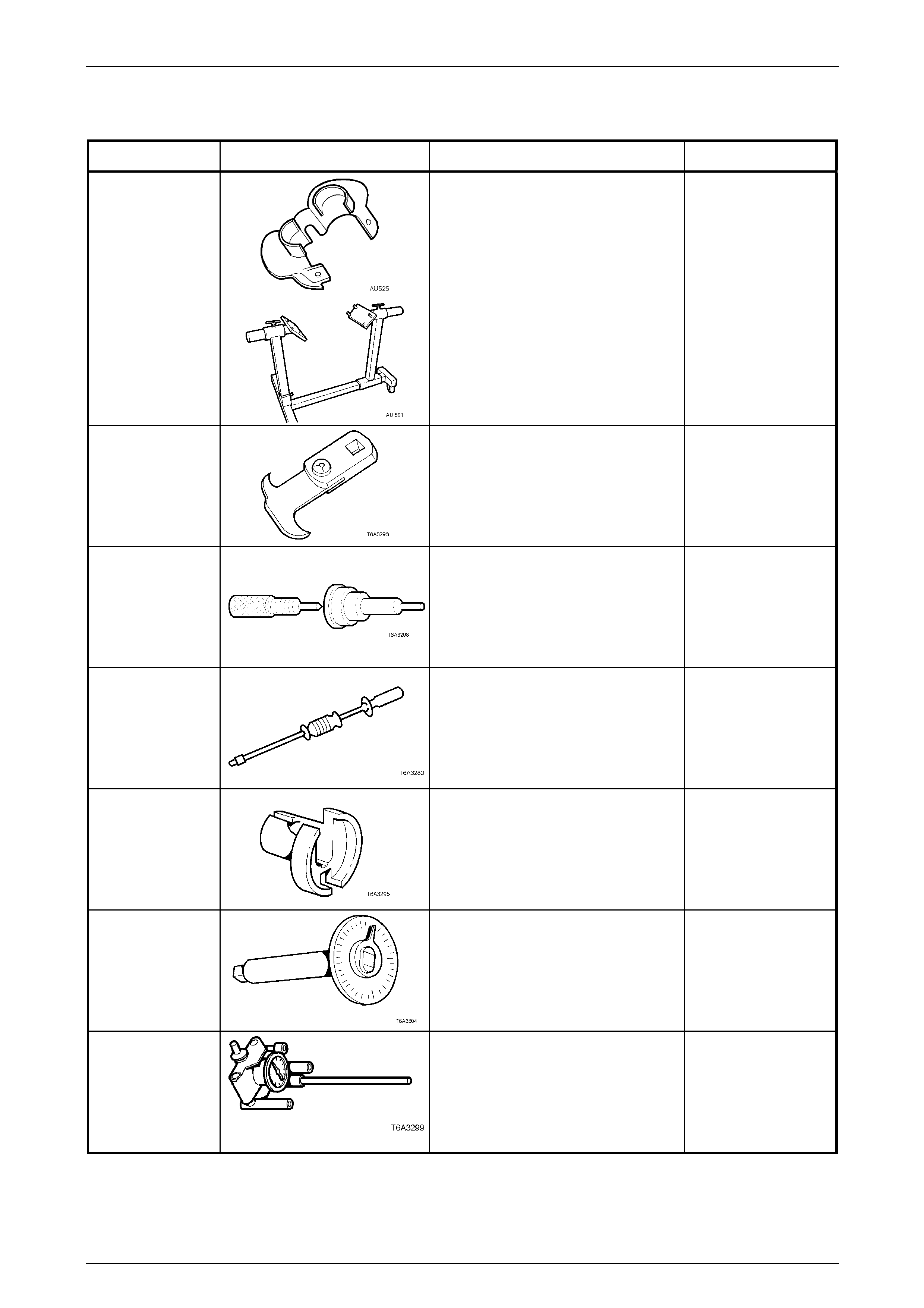
Engine Mechanical Page 6A4–277
Page 6A4–277
9 Special Tools
Tool Number Illustration Description Classification
AU 525
Quick connect release too l
Use to release the quick connect
fittings on the automatic transmission
fluid cooler lines at the radiator end,
when the vehicle is so equipp ed.
Previously released.
Mandatory
AU 591 Engine stand
Used to support the GEN IV V8 engine
at the engine mount location s.
Allows for a 360° rotation capability.
Previously released.
Available
E308
Seal remover
Previously released.
Also numbered 56750
Desirable
E1152
Valve lifter assembly tools
Used to assist in assembly of the
hydraulic valve lifters.
Previously released as 6A24.
Unique
J6125-1B Slide hammer
Used in conjunction with J 41818 to
remove main bearing caps.
Previously released.
Unique
7371
Quick connect release too l
Previously released for releasing fuel
line quick connects after fuel system
has been de-pressurised.
Mandatory
E 7115
Torque angle w rench
Used to accurately tighten fasteners
when an angle torque is required.
Previously released.
Unique
J 8087 Cylinder bore checking gauge
Also as a commercial equivalent.
Previously released.
Unique
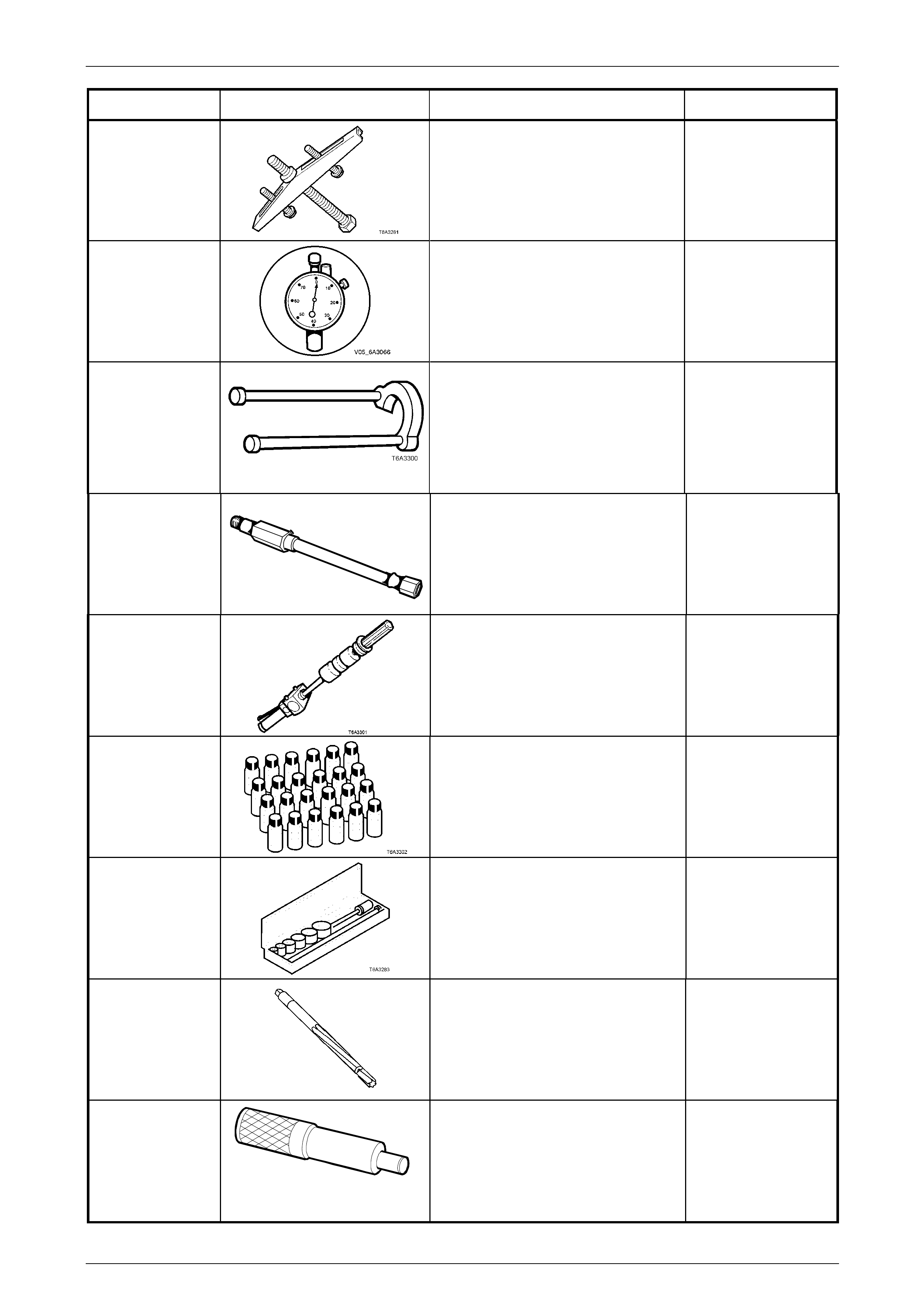
Engine Mechanical Page 6A4–278
Page 6A4–278
Tool Number Illustration Description Classification
J 8433-1
Pulley puller
Used to remove crankshaft timing
gear sprocket, in conjunction with J
41558 and J 41816 –2.
Previously released.
Unique
J 8520
Dial Gauge
Used to measure valve guide wear
and camshaft lobe lift.
Previously released
Desirable
J 21427-01 Puller adaptor
Used in conjunction with J 8433-1,
J 41558 and J 41816-2 to remove
crankshaft timing gear sprocket.
Previously released to remove
automatic transmission speed sensor
ring.
Unique
J 22794
T6A
Adaptor
Used to facilitate the application of air
pressure to a cylinder when replacing
a valve spring or valve stem oil seal
with the cylinder head installed.
Previously released.
Desirable
J 23907
Slide hammer
Also released as remover, 6A22-2 and
slide hammer 7A28.
Previously released.
Unique
J 28431-B
Fluid dye
Used in conjunction with black light,
leak detection lamp J 42220 to locate
various types of vehicle fluid leaks.
Supplied in packs of 24, 30Ml bottles.
Previously released.
Desirable
J 33049
Camshaft bearing remover/ installer
Universal tool containing selective
components to suit multiple engine
applications.
Previously released.
Unique
J 37378-1
Valve guide reamer
Used to ream worn valve guides to
suit oversize valve stem.
Previously released.
Unique
J 38836
T6A3 189b
Pilot driver
Used to install the spigot bush in the
crankshaft.
Previously released.
Unique
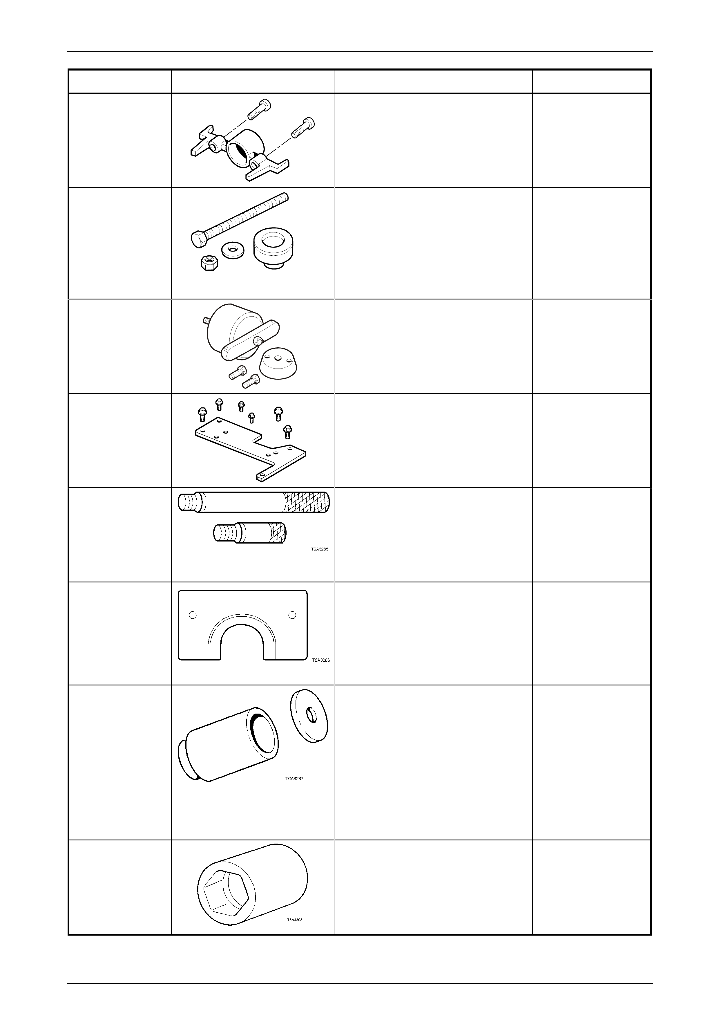
Engine Mechanical Page 6A4–279
Page 6A4–279
Tool Number Illustration Description Classification
J 41476
T6A3257a
Front and rear cover alignment tool
Used to align both the front and rear
engine covers during installation.
Previously released.
Mandatory
J 41478
T6A3258a
Crankshaft front oil seal installer
Threaded bolt, nut and washer are
also used in conjunction with
J 41665 to install the crankshaft
balancer.
Previously released.
Desirable
J 41479
T6A3259
Crankshaft rear oil seal installer
Previously released. Desirable
J 41480
T6A3260a
Front and rear cover alignment tool
Used in conjunction with alignm ent
tool J 41476, to correctly align the
front and rear engine covers.
Previously released.
Mandatory
J 41556 Connecting rod guides
Used to assist in piston and
connecting rod installation.
Previously released.
Desirable
J 41558 Crankshaft sprocket remover
Used in conjunction with the bolts
from J 21427-01 and pulley puller J
8433, to remove the crankshaft
sprocket.
Previously released.
Desirable
J 41665 Crankshaft balancer installer
Comprises:
Stepped sleeve, J 41665-1 and end
plate J 41665-2. Used in conj unction
with Tool J 41478, to install the
crankshaft balancer and crankshaft
sprocket.
Previously released.
Mandatory
J 41712
Oil pressure sensor socket
Used in conjunction with 3/8” drive
socket equipment to remove/reinstall
oil pressure sensor.
Previously released.
Desirable
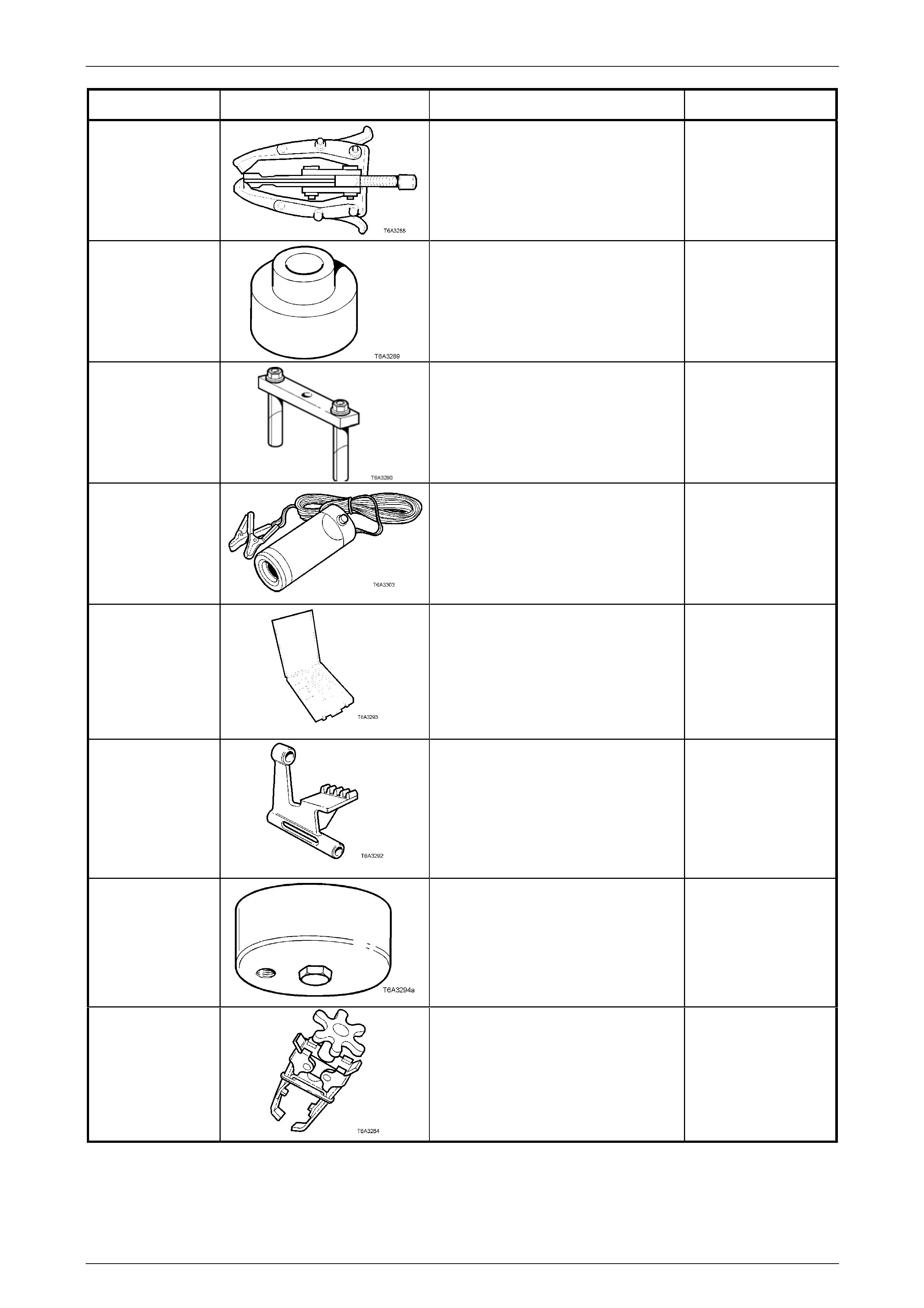
Engine Mechanical Page 6A4–280
Page 6A4–280
Tool Number Illustration Description Classification
J 41816
Three legged puller
Used in conjunction with J 41816-2 to
remove crankshaft balancer.
Also commercially available.
Previously released.
Desirable
J 41816-2 Adaptor
Used in conjunction with puller J
41816 to remove crankshaft balancer.
Previously released.
Desirable
J 41818 Crankshaft bearing cap remover
Used in conjunction with slide hammer
J 6125-1B to remove main bearing
caps.
Previously released.
Desirable
16296 Black light, leak detection lamp
Used with dye, Tool J 28431-B to
locate the source of various vehicle
fluid leaks.
Previously released.
Desirable
J 42385
/100/200/300
Thread repair kit
Comprises;
Cylinder Head/Rear Mai n
Bearing Cap Kit J 42385-100
General Kit J 42385-200
Fixtures/Hardware Kit J 42385 -300
Previously released.
Unique
J 42386 A
Flywheel holding tool
Previously released. Desirable
J 42907
Oil pressure adaptor
Fitted to the oil filter adaptor and use d
in conjunction with a commerc ially
available oil pr essure gauge and
hose.
Previously released.
Desirable
J38606
Valve spring comp ressor
Used in conjunction with spark plug
adaptor J 22794 to remove valve
springs with cylinder head/s installed.
Desirable
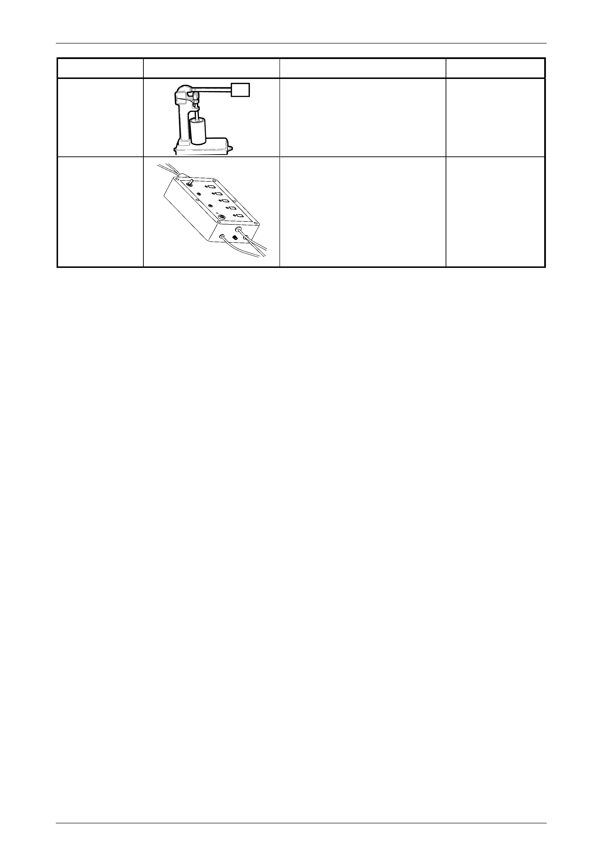
Engine Mechanical Page 6A4–281
Page 6A4–281
Tool Number Illustration Description Classification
49 U012 006
T6A3114b
Hydraulic valve lifter tester
Previously released.
Used in conjunction with testing fluid
SPX No. E1151
Also numbered 6A23.
Unique
EN-46999
Displacement on Demand (DoD)
tester
Used to activate the DoD soleniods
Unique